Embed Size (px)
Citation preview

Ln-%
NASA ... Y TM
x-64614' c. l (R)
e-4 ' '* N 7 2 - 10373
D E V E L O P M E N T O F S K Y L A B E N V I R O N M E N T A L P R O T E C T I Q N F O R P H O T O G R A P H I C F I L M
W e C. A s k e w , e t a1
G e o r g e Ce M a r s h a l l S p a c e F l i g h t C e n t e rM a r s h a l 1 S p a c e F l i g h t C e n t e r , A I a b a m a
1 S e p t e m b e r 1 9 7 1
LOAN COPY: RETURN TO AFWL TECHNICAL LIBRAR?
KIRTLAND AFP -.. ---I-m-=2 =r0-z
I+=
"JJ ==* I+,,g-I + B n -mB" - 2 -=
Dislributed ...' to foster, serve and promote the nation's
economic development and technological
advancement.'
t.., x. G,' ' ' .,.
.. ~.. ~ . . . .. . . ___
This document has been approved for public release and sale.
https://ntrs.nasa.gov/search.jsp?R=19720002724 2018-09-01T15:45:22+00:00Z

1 . x- L 4L /f
NASA TECHNICAL 4
MEMORANDUM &. y I Y
NASA TM X- 64614 :..
872- 10373 (NA.SA-TM-X-64614) DEVELOPHENT GF S K Y L A E E N V I R O N M E N T A L P R O T E C T I O N FOR P B O T O G H A P H T C F l L E W.C. Askew, et a 1 (NASA) 1 Sep. 1971
Unclas 9 2 P CSCL 1 4 E 08465 G3/14
By W. C. Askew, W. A. Clarke, and C. A. Be& Astronautics Laboratory
NASA !
George C. Mar~baZZSpace FZkht Center Mar~haZZspdce FZkbt Center, AZabama

.. . -
NOTICE
Because of a waiver initiated and signed in compliance with NASA Policy Directive (NPD) 2220.4, para. 5-b, the International System of Units of measurement has not been used in this document.
J
s
.
... I

TECHNICA 1. R E P O R T NO. 2. G O V E R N M E N T A C C E S S I O N NO.
NASA TM X-64614 1 4. T l T L E A N 0 S U E T l T L E
Development of Skylab Environmental Protection for Photographic Film
7 A U T H O R ( S )
W. C. Askew, W. A. Clarke, andC. A. Best 9. P E R F O R P I I N G O R G A N I Z A T I O N N A M E AND A D D R E S S
George C . Marshall Space Flight Center Marshall Space Flight Center, Alabama 35812
1 2 SPONSORING AGENCY NAMEAND ADDRESS
National Aeronautics and Space Administration Washington, D. C. 20546
1 5 . S U P P L E M E N T A R Y N O T E S
Prepared by Astronautics Laboratory, Science and Engineering
___
R E P O R T S T A N D A R D T ITLE P A G E 3. R E C I P I E N T ' S C A T A L O G NO.
5 R E P O R T D A TSeptember e, 1971
8. P E R F O R M l N G O R G A N l Z A T l O N R E P O R T A
10. WORK U N I T NO.
1 1 . C O N T R A C T OR G R A N T NO.
13. T Y P E O F R E P O R T 8 P E R l O D C O V E R E D
Technical Memorandum . ~- .
14. S P O N S O R f N G A G E N C Y C O D E
The problems of providing adequate environmental protection for photographic film on three Skylab missions and the technical and management approach to resolving these problems are presented. The radiation, temperature, and humidity environments to which film will be exposed for up to 230 days in space and the effects of these environments on film are discussed. The report concludes with a definition of the design requirements for the Skylab Film Repository.
EDITOR'S NOTE
Use of trade names or names of manufacturers in this report does not constitute an official endorsement of such products or manufacturers, either expressed or implied, by the National Aeronautics and Space Administration or any other agency of the United States Government.
-~ 1 7 . K E Y W O R D S 18. O l S T R l B U T l O N S T A T E M E N T
Skylab Humidity I Unclassified-Unlimited ~
Film Planning Film storage Simulation Radiation Film test Shielding Temperature I 19. S E C U R I T Y C L A S S l F . (ofchla nport) 20. S E C U R I T Y C L A S S I F . (ofthin pmge) 1 2 1 . NO. OF P A G E S 22. P R l C E
Unclassified Unclassified 92 I$3.00 1 1 I
WSFC - P a m 3192 (M*Y 1969)
i

l l l l l l l l l l l I
ACKNOWLEDGMENT
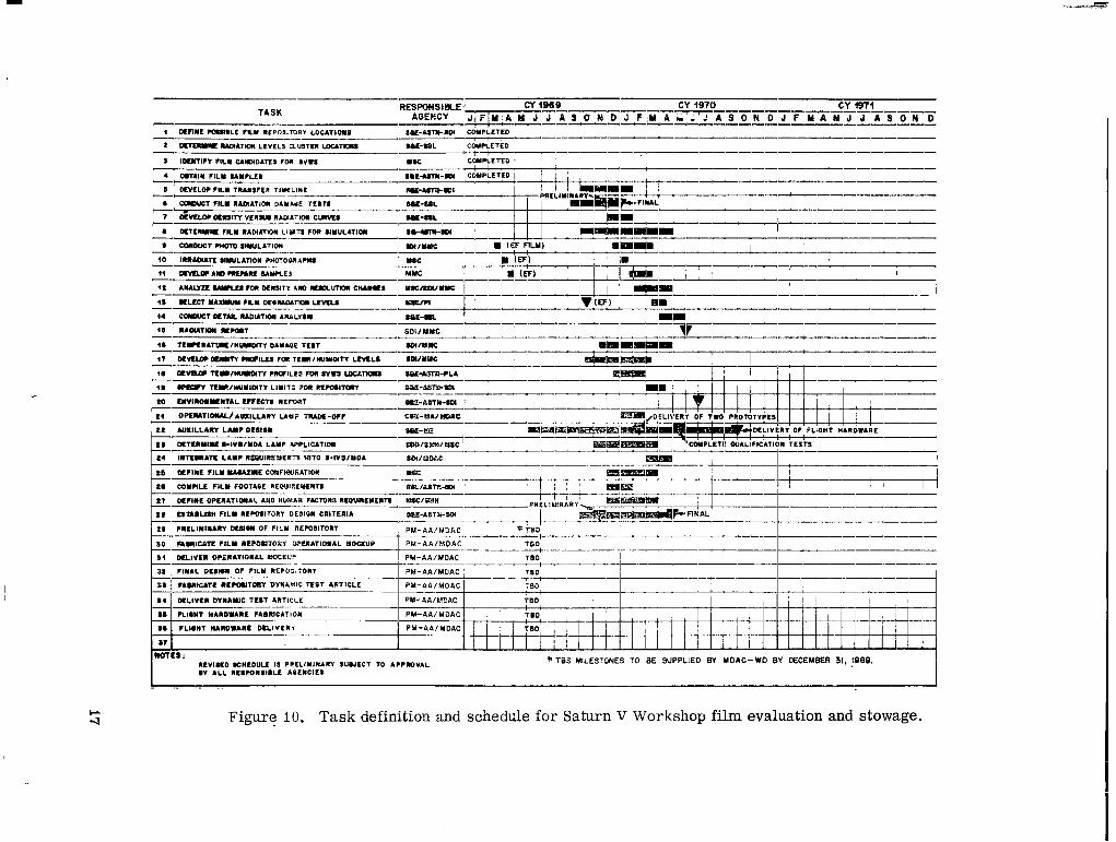
Acknowledgment is made to C. E. DeSanctis and W. F. Gillespie, Central Systems Engineering, and J. W. Thomas, Skylab Program Office, for their assistance in establishing the Skylab film vault desigti. R. L. Ruffin, J. A. McClendon, and E. C. Holt, Teledyne Br'own Engineering Company, have made significant contributions to all phases of this task, including preparatioli of this document. In addition, many other organizations associated with MSC and MSFC have performed invaluable services to this effort. Although it is impractical to list these organizations here, they are identified in the schedule shown in Figure 10.
r
-................ 1 1 , . , . 1.111.. ,.I1111 I". .I I I , , , , 1 1 1 I I I I m o r I '

TABLE OF CONTENTS
Page
INTRODUCTION . . . . . . . . . . . . . . . . . . . . . . . . . . . . . . . . . . . . . I
PROBLEM STATEMENT . . .j . . . . . . . . . . . . . . . . . . . . . . . . . . . . i
SKYLAB ENVIRONMENT AND ITS EFFECTS ON FILM . . . . . . . . . . . 4
Radiation Effects on Film . . . . . . . . . . . . . . . . . . . . . . . . . . 4 Temperature. Humidity. and Vacuum Effects on Film . . . . . . . 6 Characteristics of Skylab Predicted Environment . . . . . . . . . . 7
PLANNING . . . . . . . . . . . . . . . . . . . . . . . . . . . . . . . . . . . . . . . . 12
IMPLEMELWATION . . . . . . . . . . . . . . . . . . . . . . . . . . . . . . . . . . . 18
Identification of Film Candidates . . . . . . . . . . . . . . . . . . . . . 18 Availability of Test Film . . . . . . . . . . . . . . . . . . . . . . . . . . 18 Radiation Testing . . . . . . . . . . . . . . . . . . . . . . . . . . . . . . . . 18 Temperature and Humidity Testing . . . . . . . . . . . . . . . . . . . 22 Space Radiation Environment Prediction . . . . . . . . . . . . . . . . 23 Film Magazine Configuration' . . . . . . . . . . . . . . . . . . . . . . . 23 Experiment Photographic Operations . . . . . . . . . . . . . . . . . 23 Design Criteria for Portable Photographic Lamp . . . . . . . . . . 24 Calculation of Radiation Shielding . . . . . . . . . . . . . . . . . . . . 24 Film Vault Design Criteria . . . . . . . . . . . . . . . . . . . . . . . . 25 Film Vault Design . . . . . . . . . . . . . . . . . . . . . . . . . . . . . . . . 27 . .
CONCLUSIONS . . . . . . . . . . . . . . . . . . . . . . . . . . . . . . . . . . . . . 29
APPENDIX A: DISCTJSSION OF SELECTED PHOTOGRAPHY-RE.LATED TERMS ......................... 33
APPENDIX B: GLOSSARY OF UNUSUAL TERMS . . . . . . . . . . . . . . 39
APPENDIX C: DISCUSSION OF FILM SHIELDING CALCULATION LOGIC ................................. 45
APPENDIX D: REPOSITORY DESIGN CRITERIA . . . . . . . . . . . . . . . 53
APPENDIX E: REPOSITORY DESIGN ...................... 63
iii
J
.

TABLE OF CONTENTS (Concluded) Page
REFERENCES ..................................... 77
BLBLIOGRAPHY .................................... 78
iv
............

LIST OF ILLUSTRATIONS Title PageFigure
I.
2.
3.
4.
5.
6.
7.
a.
9.
I O .
11.
12.
c-1.
c-2.
E-I.
E-2.
Radiation effects on film characteristic curve. . . . . . . . South Atlantic Anomaly diagram . . . . . . . . . . . . . . . . . Constant flux coiltours of the SAA . . . . . . . . . . . . . . . . Free space proton dose as a fugction of time for passes through the SAA ........................... AP7-50 incident proton spectrum . . . . . . . . . . . . . . . . Dose rate versus shield thickness for 1968 electrons in 240-n. -mi. , 50-deg orbit . . . . . . . . . . . . . . . . . . . Diagram of Skylab photography system . . . . . . . . . . . . System level functional diagram for Skylab photography . . . . . . . . . . . . . . . . . . . . . . . . . . . . . . Proposed film evaluation and stowage plan . . . . . . . . . Task definition and schedule for Saturn V Workshop film evaluation and stowage . . . . . . . . . . . . . . . . . . . Skylab film vault shield thickness calculation logic . . . . Skylab film vault for corollary experiment film . . . . . . Median spectral energy behind various thicknesses of aluminum shielding . . . . . . . . . . . . . . . . . . . . . .
Allowable daily radiation dose behind various thicknesses of aluminum shielding . . . . . . . . . . . . . . Orbital Workshop stowage area on-orbit stowage . . . . . Orbital Workshop film vault requirements . . . . . . . . . .
5
8
8
9
10
I1
14
16
16
17
26
30
50
52
65
66
V
I

... __ .. ,- . . . . .
Figure
E-3.
E-4.
E-5.
E-6.
E-7.
E-8.
E-9.
E-IO.
E-11.
E-12.
E-13.
LIST OF ILLUSTRATIONS (Concluded) Title Page
Orbital Workshop film vault . . . . . . . . . . . . . . . . . . . 67 *
Orbital Workshop film vault design features . . . . . . . . 68
Orbital Workshop stowage system film-to-film vault mechanical interface ........................ 69
Orbital Workshop film vault exterior . . . . . . . . . . . . . 70
Orbital Workshop film vault interior . . . . . . . . . . . . . 71
Orbital Workshop stowage system film vault door latch . . . . . . . . . . . . . . . . . . . . . . . . . . . . . . . . . . . 72
Orbital Workshop stowage system vault drawer . . . . . . 73
Orbital Workshop stowage system film stowage bag . . . . 7 4
Orbital Workshop prelaunch film handling . . . . . . . . . . 75
Orbital Workshop on-orbit film location . . . . . . . . . . . 75
Schematic of drawer/film vault . . . . . . . . . . . . . . . . . 76
J
,
v i

LIST OF TABLES
Table
1.
2.
C - i .
D-1.
D- 2.
D-3.
D-4.
Title Page
Skylab Corollary Experiments Requiring Photography . . . . . . . . . . . . . . . . . . . . . . . . . . . . . . 2
Descriptions of Film Types Tested . . . . . . . . . . . . . . . 19
Calculation Data for Skylab Experiment Film Shielding Requirements . . . . . . . . . . . . . . . . . . . . . . . . . . . . . 48
Shielding Requirements . . . . . . . . . . . . . . . . . . . . . . 59
70" Film Stowage List ..................... 60
16" Film Stowage List . . . . . . . . . . . . . . . . . . . . . 61
Configurations to be Integrated into the OWS Film Repos i tory . . . . . . . . . . . . . . . . . . . . . . . . . . . . . . . 62
vii

BRM
CCBB
ECR
H&D Cufve
MDAC
MNIC
MSC
OWS
RM
SAA
SCN
SL-1, 2, 3, 4
s w s
AB B REV IA%IONS Baseline Reference Mission
Configuration Control Board Directive
Engineering Change Request
Hurter and Driffielld Film Characteristic Curve
McDomell. Douglas Astronautics Cornpany
Martin Marietta Corporation
Manned Spacecriift Center
Orbital Workshop
Relative humidity
South Atlantic Anomaly
Specification. Change N13$ice
Skylab Missions 8 tirough 4
Saturn V Workshop (early program notation)
.
viii

NASA TECHNICAL MEMORANDUM X-64616
DEVELOPMENT OF SKYLAB ENVl RONMENTAL PROTECTION FOR PHOTOGRAPHIC FILM
INTRODUCTION
The Skylab Program includes the corollary experiments shown in Table 1 that depend on photographic film as the primary source for data return. The scientific nature of the individual experiments requires that many differerht types of film be carried into space and returned without film degradation sufficient to mask the desired experimental data. The orbital characteristics and extended mission duration of the Skylab subject the film to a hostile environment beyond that seen on any previous missions.
During the early analyses of payload integration problems, it w a s recognized that photographic films could not withstand the Skylab space environment and that additional protection from radiation, temperature , and humidity extremes would be required. The Payload Integration Section (%E-ASTN-SDI) , Astronautics Laboratory, at the George C. Marshall Space Flight Center ( MSFC) continued the work of its organizational predecessor (R-P&VE-VAC) in developing a film vault to provide the required environmental protection.
The purpose of this report is to describe the problems encountered, the systematic approach to the problem solution, and the capability that has been developed to solve similar problems that are certain to arise on future missions. It is hoped that this report will serve to develop an awareness of the early planning required to effect a film protection solution for future missions using photographic film for data return.
PROBLEM STATEMENT
3
The predominant problem was to control the environment for the corollary experiment photographic films within the limitations imposed by the Skylab systems. Proper control would minimize environmental degradation effects on the films to allow defined photographic experimental data to be obtained from the returned Skylab mission films. To attack this problem systematically, it w a s necessary to identify the environmental factors which

tu TABLE i. SKYLAB COROLLARY EXPERIMENTS REQUIRING PHOTOGRAPHY
I 1Principal Investigator (P . I. )/ Development Proposed
:xperhant So./Title Organizationa Center Film Type Photography Objectives I
M512,
d151. Time md Motion j jtudy
Dr. J. Kubis/Fordham University, N. Y.
MSC SO168 ! Mcvie coverage of repetitive and routine tasks performed by the astronauts on space I flights will be used to provide data for time and motion ulalyses.
6479, Zero Gravity J. H. Kimzey, MSC MSFC 3443 To provide motion pictures of all events during tests and sample identification prior qammability to testing.
6487, Habitability/ C. C. Johnson MSC SO168 To record the habitability features of the crew quarters and work areas of the OWS. :rew Quarters I
11509, Astronaut Maneuvering 3quipment
Ma). C. F. Whitsett Loa Angeles A i r Station Calif.
1 MSC
I SO168 Movie coverage of all maneuvering tasks associated wftt, astronaut evaluations of
various types of inflight maneuvering devices.
Materials G. Parks I MSFC SO168 Movie coverage will be used to record the Materials Melting Facility operation and Processing
3009, Nuclear Emulsion
Dr. M. Shapiro Naval Research Lab I Nuclear
Emulsion To record the presence and direction of heavy primary nuclei in galactic cosmic radiation.
Washington, D. C.
9019, UV Sel la r Dr. K. Henize I hlSC sc-5 To obtain moderate dispersion stellar spectra df early type stars and low dispersion Astronomy I UV spectra of Milky Way fields of sufficient resolution to permit the study of the UV
line spectra and spectral energy distribution.
in Space the experiment task operation for metal melting and spherical casting.
I
s020, uv/x-Ray Solar Photography
Dr. R. Tousey Naval Research Lab Washington, D. C.
I CISC
i sc-5 To photngraph the extreme UV and X-ray spectrum of the su6 in the 10-to-100 8, range. I
5063, UV Airglow Horizon Photography
Dr. D. M. Packer Naval Research Lab Washington, D. C. I MSC
2485 A photographic study of the airglc,...a r. .ttbc earth horizon in several UV wave lengths by day and by night.
5073, Gegenschein/ Zodiacal Light
Dr. J. Weinberg Dudley Observatory Albany, N. Y.
i MSFC I
I 2485 To photographically record the surface brightness and polarization of the night sky
light over as large a portion of the celestial sphere a s possible, using the TO!B photometer system.
Si83, Ultraviolet Dr. G. Courtes MSFC 1 0 d To photograph specifically selected starfields in the UV spectrum. ‘using the experi-PaWranra Lab of Spatial Astronomy sc-5 ment spectrograph.
Marseilles, France I SlOO, Multispectral Photography
A. Grandfield (P. I. Representative)
1 MSC 1 I
S0242, 3443 2-12-1. 3401
Photographs will be taken in six discrete spectral bands of the visible and near infrared portions of the elcctroniagnetic spectrum to determine the extent to which multispectral photography of the earth from epace may be applied to the Earth Resources disciplines.
Sl91, Infrared Dr. T. Barnett MSC so242 To provide photographs of the target area during spectrometer operation. Spectrometer
T013, Crew Vehicle B. A. Conway/ i Langley ~ SO168 To record by motion picture photography the total body motions of the astronauts Disturbances Langley Research Research as they apply forces to the vehicle in a zero-gravity environment.
Center 1 Center/MSFC]
I
I
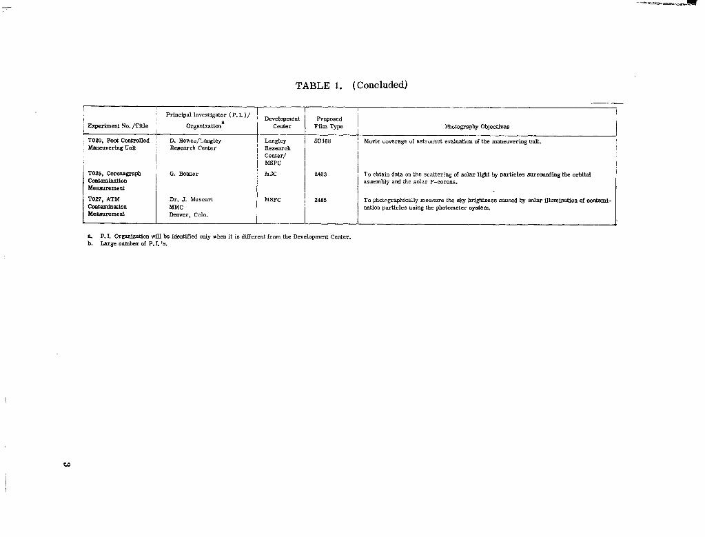
TABLE 1. (Concluded)
I principal Investigator ( P. I. ) / I ,j
I I Proposed
Fi l"h= ,I
Photography Objectives II SO168 ' I Movie coverage of astronaut evaluation of the maneuvering unit.
~
I I
2485 To photographically measure the sky brightness caused by solar illuminationof contamlnation particles using the photometer system.
i Experiment No. /Title Organizationa
T020. Fock Cootrolled I D. Hewes/Langley: MaaeuveringUnit i Research Center
T025, Coronagraph G. Bonner Contamination Measurement
TOZI, ATM Dr. J. Muscari Contamination Mensurement Denver, Colo.
Center
Langley Research Center/ MSFC
i h X
MSFC
8. P. I. Organization wiU be identified only when it is different from the Development Center. b. Largenumber of P.I. '6.
w
1

IIIIIII l l .. -==--
contributed to degradation of photographic film, establish the relative importance of each of these factors and obtain quantitative data for the effects of these factors on each proposed film type. Environmental degradation data from each film were compared with the environmental factors existing during the skylab mission. Where an incompatibility was found between the susceptibility of a film type to environmental factors and the mission environment, one or more of the following actions was taken:
1. Initiated modification of the spacecraft mission o r vehicle systems to improve the environment.
2. Provided local environmental protection for the film.
3. Selected a film type less susceptibfe to the attainable environment.
4. Accepted film degradation at a predicted level.
SKYLAB ENVIRONMENT AND ITS EFFECTS ON FILM
Radiation Effects on Film
In general, the effect of all high-enesgy radiation (e. g. , X-ray, gamma ray, electrons, and protons) exposure on a photographic film is an increase in background density (gross fog), and a reduction in gw” and film speed for optical photographic use. (&e Appendix A for a discussion of technical te rms and Appendix B for definitions. ) These effects as related to the characteristic curve are shown in Figure I.The increase in background density causes loss of detailed information in the low light level region because of masking by the fog. The -total range of contrast available on a film emulsion is reduced by the rise in background denrsity. The reduction in gamma causes a decrease in contrast between areas of varying light level exposure that may, in some‘ cases , cause loss of detail in the recorded information. The redaction in film speed causes the appearance of underexposure of the photograph. Some of these effects can be mitigated to 8 certain extent by changing tha exposure to take maximum advantage of the altered emulsion o r by making changes in processing the exposed film. To make use of these correctiong, it is necessary to h o w the effects of the high-energy radiation.
The effects of the high-energy radiations vary in intensity with the level of accumulated radiation and with the type and energy level of the radiation.
4

2.0 , NOT�: ADD 1.0318 TO LOG EXPOSURE (m-c-sec) TO CONVERT TO LOG EXPOSURE (ftC-SeC)
1
1.6
0.4
I - /
0.0 3.0 2.0 1.o ‘0.0
LOG EXPOSURE (m-c-sec)
Figure I.Radiation effects on film characteristic curve.
I

I l l l l l l l l I l l I 1 I I - ..
Current photographic theory cannot be used either t o predict the effects of a given radiation on a particilar emulsion or to extrapolate the results from one emdsikn to a different emulsion. To det6rmine the intensity of the effects of a particular type of radiation at a given eliergy levei, it was necessary to perform empirical tests OR the candidate emulsion types for the Skylab missions.
Temperature, Humidity, and Vacuum Effects on Film
Time, temperature, and humidity a re factors that can cause photographic deterioration of film. These factors are inseparable and can only be varicd in their proportional effects. A s time elapses the speed and contrast of an emulsion generally decreases,, the fog level increases, and the maximum attainable density decreases. Higher-than-normal temperatures and higher-than-normal humidities will accelerate this process. Lower-than-normal temperatures , within limits, will generally retard this process. Low humidity seems, with a f& exceptione, to have little effect on the photographic properties. of the film. Low humidity does, however, have a strong effect on the physical properties of the film. The effect is evident primarily when the film is used in a dry condition and takes the form of cracks and tears in the emulsion and static electric markings. High humidities produce physical effects on film. The.se effects consist of "moisture static" markings, sticking together of layers of rolled film, and can even result in separation o� the emulsion from the backing during unwinding from rolls.
Vacuum effects are , for the most part, the same as the effects of low humidity. The static markings that occur under low-humidity conditions lose their discrete character and often s h ~ was a diffuse overall fogging of the film under vacuum conditions.
Since no useful test data were available on the temperature or humidity sensitivity of the film, a compatibility analysis could not be performed. The extremes expected during the orbital mission were beyond film manufacturers normal recommended environment; therefore, a program w a s established to obtain temperature, humidity, and radiation sensitivity data on candidate films. Design requirements were derived from the sensitivity data for the development of a protection system.
6

Characteristics of Skylab Predicted Environment Radiation. The radiation environment encountered during earth-orbital
missions was studied extensively; the results indicated that the radiation environment could severely damage unprotected film.
The radiation environment consists of charged particles from three sources: (I)cosmic rays from intergalactic space, (2) protons from solar flare proton events, and (3) electrons and protons trapped in the magnetic field of the earth.
The energy level of the intergalactic cosmic rays is so high that no practical method exists for eliminating cosmic radiation damage. This degrading factor must be accepted and, though significant, it should not be unacceptable for short-term exposure or with relatively insensitive film types. Solar flare proton events that envelope the earth a r e infrequent and of unpredictable magnitude. To attempt to provide shielding for such events would not prove economical because of the probabilities of a significant occurrence. Therefore, the primary particles of concern are those trapped in the magnetic field of the earth. The regions where these particles are trapped a r e called the Van Allen belts [ I,21.
The Van Allen belts consist primarily of free protons and electrons trapped in the magnetic field of the earth. However, the distribution of these charged particles throughout the field is not uniform. Because of several factors - including charge, mass , velocity of the particles, and strength of the magnetic field of the earth - only a portion of the magnetic field can trap and retain these charged particles. The intensity of the magnetic field at a given point. controls the particle density at tnat point; since the intensity of the magnetic field of the earth is not completely uniform, it follows that the spatial distribution of charged particles in the Van Allen belts is not uniform. The spatial distribution of the particles in the Van Allen belts is further complioated by the fact that ( I ) the center of the magnetic field of the earth is not located at the geometrical center of tlie ear th , and (2) the axis of the magnetic field is not parallel with the spin %is of the earth. These factors together give rise to an apparent distortion of the Van Allen belts when viewed in geocentric coordinates ( Fig. 2 ) . This apparent distortion is called the South Atlantic Anomaly (SAA) .
The intensity of the proton radiation in the SAA is shown in Figure 3. The orbits with an inclination of greater than 10 deg (Fig. 3) will at some time pass through a portion of the SAA. Figure 4 shows the radiation dose for each pass as a function of time during the first 120 h r of the mission. The vehicle itself provides adequate shiel+ing against the electrons and protons for the
7

N
I_ SOUTH ATLANTIC
Figure 2. South Atlantic Anomaly diagram.
Figure 3. Constant flux contours of the SAA (Vette's proton data API) .
8

.-
\ 10.0 -
Q
2
2 -s w I
d -Y VJ0P z0 a I02 1.0 w
\\
0.1 0.00 0.05 0.10 0.15 0.20 0.25 0.30
SHIELD THICKNESS (in. of aluminum)
Figure 6. Dose rate versus shield thickness for 1968 electrons in 240-n. -mi., 50-deg orbit.
ii

Predicted Temperature, Humidity, Pressure. Since the Orbital Workshop (OWS) wil l be thestorage location for the corollary experiment film, the predicted temperature, humidity, and pressure variationsi were obtained fof a period of time during which the film is onboard. A ground cooling system wi l l maintain tk.e OWS interior between 40 and 55" F from 'Ibutton-up" to launch. During orbital hatitation periods, the OWS environmental control system wi l l maintain the temperzture between 65 and 80" F, and during the unmanned periods the predicted temperature is between 45 and 80" F with the minimum temperature maintained by radiant heaters.
The relative humidity during prilaunch and after button-up wi l l be near zero because of pressurization with dry nitrogen. This condition wi l l exist until shortly after the beginning of the first habitation period. During habitation, moisture is added by the astronauts' presence, and the environmental control s y s t e i maintains the relative humidity between 27 and 65 percent with 45 to 55 percent expected during most of the habitation period. During orbital storage periods, relative humidity is expecied to be between 27 and 100 percent at the s tar t of the period and to fall to between 4 and 16 percent near the end of the period,
After button-up the OWS wi l l be pressurized to 17.5 psia with dry nitrogen and before launch wi l l be increased to 26 psia. During orbital coast the pressure wil l be decreased to 1.3 psia and before habitation wi l l be pressurized to 5.0 psia with oxygen. For the orbital stowage period, the pressure is allowed to leak down to approximately 0 . 5 psia.
Some Sky1a.b experiments w i l i require that film be exposed to space vacuum conditions for relatively short time periods and wi l l require special attention to temperature and drying effects.
PLANNING
A s a part of the payload integration activity, each of the Skylab corollary experiments required analysis to establish i ts compatibility with the carr ier and to identify problems that required solution. A systems engineering approach" was used to define experiment functional requirements. This method utilized
-___ 1. H. G . Paul: OWS, AM, a d MDA Internal Environment Profiles. NASA MSFC Memorandum S& E-ASTN-PL-70-M-224, Marshall Space Flight Center, October 6 , 1970.
12

1
0.16
0.13
0.11 -iI 0.08
s
i 0.07
H 0.06
0.03
0.01
0
1 ALTITUDE: 240 nimi. 5od.p INCLINATION-I, CIRCULAR ORBIT
1‘ Iii iII 1 I111 IIll
1
-1 I1ll
I
I 80
ll GROUND ELAPSED TIME (GET) (hr)
Figure 4. Free space proton dose as a function of time for passes through the MA.
crew internal to the Skylab [I].However, because of the transmitted spectrum inside the Skylab, extra shielding is required to protect the film.
The Skylab mission will be in a 240-11.-mi. orbit with a 50-deg inclination. Passes through the SAA wi l l be subjected to the proton radiation spectrum shown in Figure 5. The skin and structure of the Skylab w i l l stop most of the lower energy protons but wi l l allow the remaining higher energy particles to penetrate into the Skylab interior. The spectrum inside the Skylab is expected to have a median energy of 50 MeV, and the spectrum inside the film vault is expect’ed to have a median energy of 130 MeV in the heavier shielded areas.
The skin of the Skylab is sufficient to nearly eliminate all radiation caused by electrons internal to the Skylab. However, an electron radiation problem exists for unprotected fi lms used external to the Sb lab . The radiation dose caused by electrons for the 240-n. -mi. , 50-deg orbit and varying shield thicknesses is shown in Figure 6. This curve indicates that if the films used external to the Skylab are protected by an aluminum shield of 0.3-in. thickness, the electron dose is reduced by approximately 90 percent. However, a shield would generate bremsstrahlung, which c o d d be virtually eliminated by a thin lead foil inside the aluminum shield.
9

__._ . I lllll I l l I Ill1I1 I I1 I 1 I l l I I1 I
\ 6 . 4 5 ~ 1 0 ~
i.45x103
.45x102
100 200 300
PROTON ENERGY (MeV)
Figure 5. AP7-50 incident proton spectrum.
10
- _...._.

three levels (fop level, system level, and subsystem level) of functional vlock diagrams. . Requirements were identified for each subsystem functional block and were farmally documented with Requirements Allocation Sheets.
Because of the large number and complexity of photographic requirements that were identified, a similar systems approach w a s applied to the Slylab photography system as shown in Figure 7. The system level functional diagram (Fig. 3) shows the major photographic functions. The development of requirements to accomplish functions 1.0, 7 .0 , and 11.0 revealed a void in planning for photography. It w a s evident that no effective lneans 'of stdwing and transferring film had been devised. Contacts with film manufacturers, technical l ibraries, and photographic scientists revealed that little quantitative data w e r e available on film environmental effects. Thus, the responsible experiment personnel could not establish environmental limits ( radiation, temperature, and humidity) for their films. These circumstances , revealed by the early use of systems engineering techniques , dictated that testing programs be undertaken to:
1. Define in quantitative terms the film degradation caused by temperature, humidity, and radiation.
2. Define maximum allowable film degradation for each experiment.
3. Establish design requirements for a film vault for environmental protection and stowage of corollary experiment film.
Figure 9 represents the results of an early analysis to define the tasks required, their interrelations, and the organizations involved. This task flow diagram w a s used to develop a schedule that would be compatible with the program. A typical revised schedule is shown in Figure 10. In addition, compatibility status analyses were performed at several intervals to define photographic or film problems. A photography data summary w a s computerized and maintained regularly to identify current film quantities, types, weights, and volumes.
A rather large integration and liaison effort, involving many osganizations from MSFC, Manned Spacecraft Center (MSC) , and numerous contractors w a s required to implement the plan as described.
13

SKYLAB Photography
Hasselblad Filmi---zJMaguinos Magazines
Power Mounting Provisions Stowage Cables Provision
Provisions $
IContmlI Cables
Cabla t- m Light
Rutraining Provisions i-11 I
Batteries *if required.U Figure 7. Diagram of Skylab photography system.
I
I

f o r Launch t o O r b i t a l Stowage from Stowage Boxes Loca t ion t o Experiment Work-
s i t e
I I I I I
-= 5.0 6.0 Perform Photography Dismant le Equipment T r a n s f e r Film of Experiment a t Experiment
Work site Fi lm Stowage BOX
I i-1 -8.0 9.0 T r a n s f e r Repeat Funct ions 4.0 Equipment r ' rom
I Experiment1 t o Experiment
-=+-
I *
1
t h r u 8.0 f o r Experf-' m e n t s Requ i r ing /Pho tographyI 1
I -1 , 10.0 11.0 I
T r a n s f e r , Stow Fi lm i n Terminate Skylab Equipment from +' Command Module (CM)+ Photography Experiment Works t o f o r Return O r b i t a l Stowage 1 i
Figure 8. System level functional diagram for Skylab photography.

1,
I
Figure 9. Proposed film evaluation and stowage plan.
I
i
P U - A A I M D A C
PM-AA/YDAC
PH-dA/YDAC
PY-AA/UDAC
Iw m a : l E V l l C 0 8CUEDUU I S PCLLlYll l4RY IUIJLCT TO ACCDOVAL * TBS MILESTONES TO BE SUPPLIED BY MDAC-WD BY DECEMBER 31, ! O W . D l ALL R L S W I 8 I R L E AOLMCIES
- .. .- ..
Figure 10. Task definition and schedule for Saturn V Workshop film evaluation and stowage.

I I l l l l l
IMPLEMENTATION
The following paragraphs ivill describe the major efforts during the implemektation.
Identification of Film Candidates
Because of the lead time required to perform film tests, to analyze the sesialts, and to design and fabricate hardware, i t w a s necessary to identify c o r o h r y experiment film candidates at an early date. &!the time this identification w a s necessary, many of the experiment operatiods were "defined and the definition of which proposed experiments would actually fly w a s not available. With the support of Program Management, discussions with experiment Principal Investigators, and data from Experiment Requirements Docwnchts, a list of 14 film types was identified as probable candidates for flight, Table 2 lists the-14 films identified for testing. In a few instances certain films were deleted from testing where data were already available. Two additional film types were identified after testing was begun which allowed only partial test data to be obtained for them.
Availability of Test Film
M a ~ yof the film types required for test purposes were nat readily available. Some of the film types a r e available only on special order f rom Eastman Kodak Company with minimum quantities being prohibitive from a cost standpoint. One special-order film w a s availahre only from Kodak Pskthe in France. The MSC Photography Laboratory assisted in obtaining and supplying the required films.
Radiation Testing
Early in the problem definition phase it was noted that no radiation sensitivity data were available on the color films planned for use. Some
. ! - '
applicable film types were found locally; NISFC Space Sciences Laboratory exposed these films to an existing Cobalt-60 source to assess their gross radiation sensitivity. The test results indicated a lack of repeatability on dif-ferent samples subjected to the same conditions. The apparent problem w a s a combination of radiation backscatter in the exposure facility and inadequate control of film processing. The test did provide a warning that future testing would require rather extreme controls in order to obtain useful information.
'I
18
I

TABLE 2. DESCRIPTIONS O F FILM TYPES TESTEG
1 S0114a Panatomic X; B & W, very high resolution, 2.5-mil ESTAR base. With dyed gel backing, and without a-gelatin overcoat to enhance XUV and attenuate proton sensitivities.
sc-5 Short Wave Radiation Kodak-Pathe (French) manufactured. 5.2-mil triacetate clear base with Anti-Halation backing. In 35-mm x 180-mm strips only. Has about eight times the sensitivity of SWR above 170
SWRa Short Wave Radiation; for ultraviolet applicationg in wavelengths shorter than 2200 A. 5. %mil triacetate clear base , Anti-Halation backing.
103-0, UV Spectroscopic; for low-intensity
luv or short-durationosources (high speed) in 2500- to 5090-A band. 5.2-mil clear triacetate base with Anti-Halation backing.
SO392a Solar Flare Patrol; fine grain, high contrast, panchromatic emulsion with extended Ted sensitivity (maximum at 6563 A ) . 4-mil ESTAR base with 0. 1 density Anti-Halation dye and fast-dry PX backing.
3400 Panatomic X; B& W , very high resolution. 2.5-mil ESTAR base, dyed backing. ASA 40. Resolution: TOC 1000:1, 170 lines/"; TOC 1.6: 1, 65 lines/".
340I Plus X; B & W , high resolution aerial n i r r r . 2-5mil ESTAR base, dyed gel backing. ASA 125. Resolution: TOC l n O O : i , 105 lines/"; TOC 1. 6:1, 40 lines/".
2403 Tri X Aerographic; panchromatic with extended red sensitivity. 4.0-mil ESTAR base, fast-drying PX backing. AEI 250. Resolution: TOC 1000:1, 71 lines/"; TGC-I. 6:1, 22 lines/".
103a-F Spectroscopic; Felective Sensitizing in 4500- to 6800-A band; 4-mi1 ESTAR base.
SO166 High Speed Recording Film, currently designated 2485; Panchromatic with extended red sensitivity, 4-mil ESTAR base dyed to 0. Idensity to provide halation protection, fast drying PX back. ASA 6000 normal, 16 000 possible, Resolution: TOC 1000:1, 55 lines/"; TOC 1.6:1, 20 lines/".

TABLE 2. (Concluded) W _ I I . _ _ 1 _ _ 1 _ _ _ _ _ _ _
SO168
SO368
5242
Ektachrome EF; Reversal color, daylight, low light level applications. 2.5-mil EBTAB base, dear gel backing. ASA 160 normal, range 500 to 1000. Resolution: TOC 1000:i , 80 lines/"; TOC I.6:i, 36 lines/mm.
Ektachrome MS; Reversal color, daylight general application. 2.5-mil ESTAR base, fast-dry PX back. ASA 64, range 16 to 250. %solution: TOC 1000:1, 80 lines/"; TOC I.6:1, 35 lines/".
Ektaehrome EFB; Reversal color , tungsten-balanced emulsion , high speed. 5.2-mil triacetate base. ASA 160, range 64 to 1000. Resolution: TOC 1OOO:i , 80 lines/"; TOC I.6:1, 36 lines/mm.
Aer ia l Color; Reversal. color , daylight, high resolution. 2.5-mil ESTAR base with Anti-Halation undercoat and clear gel backing. ASA 64, R E I & Resolution: TOC l O O O : i , 160 lines/"; TOC I. &I, 80 lines/mm.
back. Sensitized to blue, red, and infrared. AEI 100. Resolution: TQC 1000:1,
A11 films a re manufactured by Eastman-Kodak, except SC-5.
ASA and AEI ratings shown are nominal values given '
in the Kodak literature. They are not the test values and are supplied only for general information.
a. These firm types a re not corollary experiment candidates but were included in the testing for the ATM program.
.
1 .I

An OW S Photograp.hic Simulation Test was conducted. The largest quantity of film required on the Skylab missions is Kodak E F (S0168) color film. A test was performed in the OWS mockup (old "wet workshop'' configuration) to evaluate the use of the Kodak E F film by testing at three light levels, three film speeds, and six radiation levels. Four scenes simulating actual experiment operations w e r e photographed. Af te r the scenes were photographed, the film w a s irradiated and developed at MSC. The test samples w e r e then evaluated by Experiment Mi51 personnel and others to establish optimum light levels and film speed and to establish an acceptable radiation limit. Detailed information on this test program is given in a technical letter. 2
The major effort in the radiation test program was accomplished by Martin Marietta Corporation (MMC) as reported in detail in References 3 and 4. The 14 corollary experiment films tested were irradiated by a Cobalt-60 source to various levels at MSC and shipped to MMC, where test strips were exposed to X-ray, ultraviolet, visible, and near infrared as required to simulate actual experiment requirements. Imagery was placed on the test samples to give pictorial evaluation capability. Hurter and Driffield (H&D) curves; film base plus fog, gamma, and modulation plots w e r e prepared from sensitometric analysis of the test samples. When all testing was completed, Experiment Principal Investigators were invited to attend reviews conducted on the test samples for their experiment. Recommended maximum radiation levels w e r e established from these reviews.
The radiation testing previously mentioned exposed the film only to a Cobalt-60 source. To predict the radiation sensitivity of the film to the predicted environment behind varying shield thicknesses, it w a s necessary to determine the film sensitivity to proton sources at various energy levels. Some of the films had previously been tested in this manner. The untested films and one tested film (for correlation purposes) were exposed to proton radiation by personnel of the MSFC Space Sciences Laboratory. Cobalt-60 exposures of each film type were made at MSFC, and the proton exposures of 51 and 131 MeV w e r e made at the Harvard University cyclotron. Film processing w a s performed by the MSFC Photographic Division. Radiation test results of net density versus exposure a re shown in Reference 5.
I__
2. R. Ruffin, Jr. : Addendum I to AAP-2 Photography Simulation, Evaluation of Test Results. Technical Letter ASD-ASTNL-639, Teledyne Brown Engineering Co. , Huntsville, A la . , Aug. 14, 1969,
3. K. Huff and M. Cleare: Unpublished Film Radiation Test Curves. Eastman Kodak Co., Rochester, N. Y.,August 1968.
,
21

Temperature and Humidity Testing
Temperature and relative humidity limits, recommended by Eastman Kodak for optimum keeping of the candidate film types for extended time periods, would have placed an inordinate penalty both in weight and power consumption on the design of a film stowage vault. To stow the film efficiently, it was necessary to establish a single environmental condition that would not seriously ,
degrade any of the candidate firms and would minimize any penally caused by maintaining that condition. A search of the literahre available - including Kodak information on the relationship between film characteristics and time, temperature, and humidity - was conducted. From sources consulted, very few data were available and the available data provided limited criteria for stowage design.
Martin Marietta Corporation, Denver Division, performed the necessary tests to obtain the required data for the candidate films. Because of time and financial limitations, only the temperature, relative humidity, and time effects on th.3 latent image (i.e. , film exposed before storage) were studied in the test progj*am. No environmental effects on physical properties were studied. The progi-am consisted Q� obtaining measurements of the latent image degradation for specific values of temperature, relative humidity, and time storage periods. Test parameters for 14 corollary experiment film types included three levels of temperature and three values of relative humidity for each temperature level. Each of the nine temperature/humidity combinations w a s evaluated for environmental storage periods ranging from 1 to 28 days. One temperature/humidity environment { 80"F, 50 percent relative humidity) was utilized for longer storage periods of 56 and 84 days. The evaluation included sensitometric analysis of all films for photographic respdnse after environmental storage.
A $%percent o r greater relative humidity was found to be unacceptable as storage conditions for the Skylab film vault. A storage temperature of 120"F or greater was determined to be unacceptable. Storage temperatures as high a s 100" F w e r e considered marginal but still acceptable for limited periods oftime for most fi lms, if low humidity is maintained. Testing for periods up to 84days indicated a temperature of 80"I? and 50-percent relative humidity to be generally an acceptable storage environment for the film types tested. Reference 4 presents details concerning the temperature/humldity test program and results on specific films tested.
22

Space Radiation Environment Prediction
A rediction of the film radiation doses ‘-forthe corollary experiment film environment was generated. This prediction [ 61 takes the space radiation environment from Vette models I21 and, with a computes model, projects the. attenuation caused by the configur,ation of the space vehicle and payload. The radiation dose behind various shield thicknesses at the film stowage and operhtional locations was predicted on an average daily basis. .
F iIm Magazine Configuration
Rather heavy shielding requirements were anticipated as indicated by radiation test results and predicted radiation environments. To reduce shielding weight a minimum film stowage volume w a s a design goal. Early definition of film magazine configuration was , therefore, an important task. Considerable effort w a s expended in obtaining experiment hardware documentation and information on planned operational equipment. Although some of the equipment w a s not designed, best estimates of configuration have been carried forward through the program. A t the time that film vault drawings were completed, detailed drawings of certain magazines were not available, and Configuration Control Board action may be required to solve future dimensional incompatibilities. Magazine envelope dimensions, approximations, and status reports were provided by the Flight Crew Integration Divjsion (MSC) and MSFC Program Management.
Experiment Photographic Operations
During the operation of an experiment, a film magazine is not afforded the additional environmental protection of the film vault. The radiation dose while outside the vault must be considered in limiting the total accumulated radiation dose. The dose while outside the vault depends on the operational location, time at the location, and the orbital location of the spacecraft with respect to the SAA. Since detailed mission timelines for experiment operations w e r e not available, it w a s assumed that the spacecraft passed through the w o r s t daily orbits while the magazines w e r e in use. If radiation doses are unacceptable when detailed mission timelines are available, constraints on experiment operation in the SAA may be required. Experiment Requirements Documents and Astronaut Review Sequences were examined to estimate the experiment operational characteristics and times. Radiation dose rates were estimated from predictions [ 61 at various locations in the spacecraft.
23

A computer program was developed' to define the operatiobal timelines for individual film magazines. Experiment performance times were taken from the Baseline Reference Mission (BRM) document, an6 photographic operations were defined from Experiment Requirements DocumeDts and Astronaut Review Sequences. The computer program output included for each film magazine an accounting of time out of the film vault, translation time, number of translations, shoot time, wafting time, and performance locations;
Design Criteqia for Portable Photographic Lamp
During the OWS Photographic Simulation Test (see the preceding section on Radiation Testing), the operational light levels In'the OW§ crew quarte rs and forward dome areas were determined to be inadequate to provide acceptable photography using Kodak EF film. The resultb of the test indicated that, in general, 20 ft-c of light incident 0% the test scenes w a s required for good results, This level was available onl;r in certain areas in the crew quarters; Design criteria were developed �or a portable photographic lamp and were implemented through Product Engineering and Process Technology Laboratory at MSFC. A subsequent contract with Iota Engineering, Inc. , Tucson, Arizona, was initiated for the development of the lamp. Detailed specifications for this lamp are given in an end-item specification. *
Calculation of Radiation Shielding
The MMC film radiation test program resulted in large quantities of radiation response data for individual fi lni types. Radiation tolerance levels for specific experiment film applications were established as a result of the test program.
The allowable radiation dose is the initial data required to establish film radiation shielding requirements. A s previously discussed, there will be some image degradation from the radiation of extended missions, regardless of the film protection provided. The mass required to shield large quantities of film quickly becomes a weight factor. Although a light metal such as aluminum is one of the more efficient proton attenuators, putting several inches of thickness around a few cubic feet of film requires hundreds'of pounds of aluminum. It is necessary, then, to determine the optimum amount of shielding to reason-
'ably protect the film and at the same time be aware'of the weight factor.
~
4. skylab Program End-Item Specification for High Intensity Portable Light. NASA S&E-ME-MEI, 95M 10550-1, Marshall Space Flight Center, March 16, 1970.
24

- -
A p o c e d u r e was developed to calculat; the shielding requirements for a particular film type when given the allowable radiation limit and orbital time in and out of the film vault. This procedure w a s refined for greater accuracy and w a s subsequently developed into a computer program to allow fully repeatable calculation logic and ease of recalculation for new input data. The basic logic of the shielding calculation is prssented in Figure li. Each step of the calculation procedure is discussed in Appendix C.
Film Vault Design Criteria Preliminary Design Criteria. To integrate the film vault into the OWS.. ._
hardware schedule, MSFC Program Management requested in November 1969 that the schedule for providing film vault design criteria be compressed approximately 6 months. In response, a study was initiated to provide preliminary design requirements for the film vault without the benefit of the results of the planned MMC radiation, temperature, and humidity test programs. Shielding calculations based on best estimates of film radiation sensitivity w e r e made, and temperature humidity conditions were specified in a manner that, hopefully, would prec1l;de film damage. Other basic ground rules and design requirements were established, and the results of the study were reported in an MSFC memorandum. The tradeoff studies involved various vault configurations resulting from film storage assumptions. The preliminary film vault criteria given to McDonnell Douglas Astronautics Company (MDAC) for preliminary design purposes assumed that the more sensitive film would be resupplied by the Command Module on W l a b Missions 3 and 4 (SL-3and SL-4) and that the less sensitive film would be launched on Skylab Mission I(SL- I)and remain stored until used.
Final Design Criteria. A t the conclusion of the MMC film test program, new shielding calculations w e r e based on the test results; these calculations incorporated updated radiation environment predictions [ 71 . Meetings with Eastman Kodak personnel, discussion with other experts, and analysis of the results of the MMC temperature-humidity film tests w e r e used to establish temperature-humidity limits for film vault design criteria.
. . -.
5. R. L. Ruffin, Jr. : Calculation of Radiation Shielding Thickness for Skylab A Experiment Film. ASD-ASTN-40784, Teledyne Brown Engineering Co. , Huntsville, Ala., Sept. 30, 1970.
6. + G . B. Hardy: Design Criteria for Corollary Film Stowage. NASA MSFC Memorandum PM-AA-EI-318-69, Marshall Space Flight Center, Oct. 30, 1969.
7. T. P. Isbell: Preliminary Design Requirements for Saturn V Workshop ( S W S ) Film Repositories. NASA MSFC Memorandum S&E-ASTN-SD- 69-99, Marshall Space Flight Center, Nbv. 18, 1969.
25
I

DEDUCT CM
RADIATION
I
CORRECT FOR DETERMINE DETERMINE A SSUME T E M P E W T U R AD3USTED ALLOWABLE RADIATION AND HUMIDITY DAILY RAD- SPECTRA IN
LIMIT IATION DOSF F I L M VAULT8
I ,I
I I .. t
CORRECT D N L k DETERMINE DETERMINE COMPARE ESTABIJSKRADIATION DOSE PRELIMINARY SPECTRA F O R +TO ASSUMED SHIELD
SHIELD PRELIMINARY SPECTRA THICK NESS
9 THICKNESS
10 , SHIELDINCll
I3 ,.
I 1
Figure ii . Skyiab film vault shield thickness calculation logic.
L' .
I
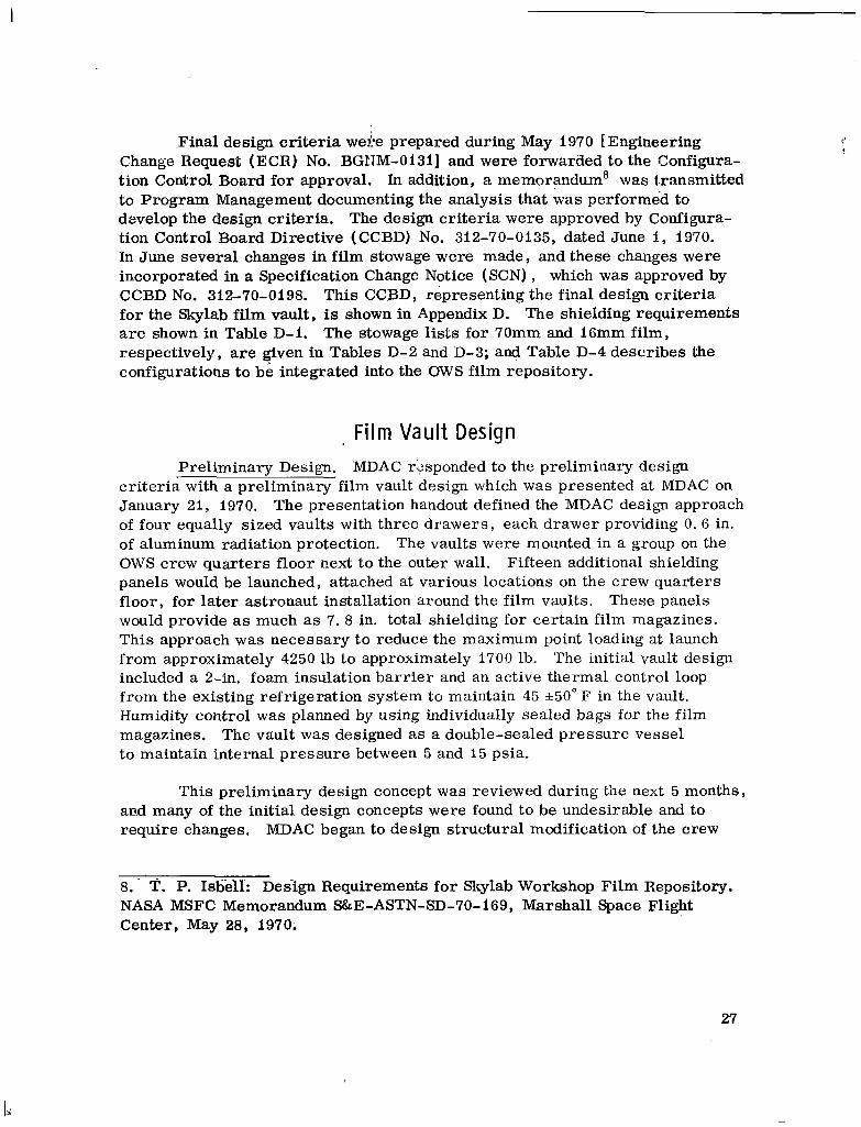
Final design criteria wei-e prepared during May 1970 [Engineering Change Request (ECR) No. BGITM-O131] and were forwarded to the Configuration Control Board for approval. In addition, a memorandum' was transmitted to Program Management documenting the analysis that w a s performed to dsvelop the design criteria. The design criteria w e r e approved by Configuration Control Board Directive (CCBD) No. 312-70-0135, dated June 1, 1970. In June several changes in film stowage were made, and these changes were incorporated in a Specification Change Notice (SCN) , which was approved by CCBD No. 312-70-0198. This CCBD, representing the final design criteria for the Skylab film vault, is shown in Appendix D. The shielding requirements are shown in Table D-1. The stowage lists for 70" and 16" film, respectively, are given in Tables D-2and D-3; and Table D-4 describes the configurations to be integrated into the OWS film repository.
. Film Vault Design Preliminary Design. MDAC rSsponded to the preliminary design
criteria with a preliminary film vault design which w a s presented at MDAC on January 21, 1970. The presentation handout defined the MDAC design approach of four equally sized vaults with three drawers, each drawer providing 0. G in. of aluminum radiation protection. The vaults w e r e mounted in a group on the OWS crew quarters floor next to the outer wall. Fifteen additional shielding panels would be launched, attached at various locations on the crew quarters floor, for later astronaut installation around the film vaults. These panels would provide as much as 7. 8 in. total shielding for certain film magazines. This approach w a s necessary to reduce the maximum point loading at launch from approximately 4250 lb to approximately 1700 lb. The initial vault design included a 2-in. foam insulation barr ier and an active thermal control loop from the existing refrigeration system to maintain 45 +50° F in the vault. Humidity control w a s planned by using individually sealed bags for the film magazines. The vault w a s designed as a double-sealed pressure vessel to maintain internal pressure between 5 and 15 psia.
This preliminary design concept w a s reviewed during the next 5 months, ac.d many of the initial design concepts were found to be undesirable and to require changes. MDAC began to design structural modification of the crew
8. T. P. Isbelf: Design Requirements for Skylab Workshop Film Repository. NASA MSFC Memorandum S&E-ASTN-SD-70-169, Marshall Space Flight Center, May 28, 1970.
27

quarters floor at a new location for the film vault. A more suitable vault location was defined on the forwaTd tank floor. A redesign of the 400-ft film magazine .significantly reduced the volume d stowed film , thereby reducing the lai&El weight of shielding. The removable shielding panels were not only undesirable from an astronaut time standpoint , but the mission timelines would delay the installation of the panels several days after orbital habitation, thereby allowing appreciable radiation fogging for some films. The proposed film vault thermal control system was undesirable. Since the film could tolerate the predicted thermal environment during orbit but not during prelaunch, only ground cooling w a s required. MDAC began to design an onboard heat exchanger to provide ground cooling of the entire OWS. Because of the expected pressure variations in the film vault, the sealed film magazine bags were deleted from consideration. To preclude the necessity of qualification testing for pressure integrity, the film vault w a s designed to provide controlled leakage. To provide humidity control, an effort w a s begun to select a suitable desiccant or salt for this purpose. During this review phase of the preliminary vault design, seveml changes in experiment film quantities reduced the vault volumes and, therehy, the total vault weight.
Final Design. The revised design criteria presented to MDAC in May 1970 represented a reduction in film quantity and a considerable reduction in required shielding because of new film test results and new predicted radiation environments. The MDAC response was presented at MDAC on June 26, 1970. MDAC �ound that the new criteria. would allow a single large film vault to be mounted on the modified forward tank floor. One large aluminum castirg with f2 drawers, 2 with 0.25 in. of shielding, 6 with 4. 9 in. , and 4 with 3. 4 in. was designed. The total weight of the vault w a s reported to be 2820 Pb including contingencies and 445 lb of film magazines. The foam insulation har r ie r was deleted. Temperature control of the 7~au'itwas not required since the mission temperature profile in the QWS was considered acceptable, with the. ground heat exchanger providing a prelaunch maximum of 80"F. Changes resulting from this review dealt primarily with the Experiment; Si9Q personnelpsdesire to store all their film in a particular manner. This required that all Si90 film magazines be located in the 3.4-in. area of the vault with three drawers to be removable as magazine handling containers. This change was accepted and, along with other minor changes, was included in a SCN approved by CCBD No. 312-70-0198 (see subheading, Final Design Criteria, under the heading, Film Vault Design Criteria) to define final design criteria.
9. Skylab-A Stowage System/Systems EngineeFing Study Summary Presentation. MeDonnell Douglas Astronautics Co., June 26, 1970.
28

MDAC responded to this CCBD by redesigning the vault to accommodate the Experiment SI90 handling requirements and to increase shielding on one drawer from 1. 9 to 2. 9 in. , thereby improving the allowance for any future additions of highly sensitive film to the Skylab experiment requirements. Potassium thiocyanate (KSCN) salt pads were incorporated into the vault design to control relative humidity to 45 +I5 percent throughout the Skylab missions. These and other details of the final Skylab film vault design were presented at MDAC on September 14-17, 1970, and ai-e shown in Appendix E in Figures E-1 through E-13. An illustration of the f i l c i vault as of June 1971 is shown in
iFigure 12.
CONCLUS IONS
This report has described only the major tasks encountered during the effort to provide environmental protection for the Skylab corollary experiment film. A major part of the success in the effort can be attributed to the early systems definition, planning, and scheduling.
Some of the significant findings resulting from this effort were:
1. Comprehensive data do not exist on the sensitometric and physical response of specific film emulsions to radiation, temperature, humidity, pressure , or chemical environments.
2. A l l experimenters desired the highest possible image quality in their photographic data, but they found it difficult to define acceptable and objective limits on degradation of quality.
3. Techniques for analyzing the combined effect of various film-degrading factors had not been developed.
4. The level of confidence in predicted space radiation environments w a s significantly low to the extent that considerable spacecraft weight penalties resulted from shielding sensitive photographic film.
5. A trade-off was required between the shielding weight for long-term orbital storage of film a&dthe launch payload capability for film resupply on later missions.
6. In general, films of the slowest speed compatible with experiment photographic requirements should be used to reduce sensitivity to unwanted radiation.
29

.
Figure 12. Skylab film vault for corollary experiment film.
30

7. Intepation efforts to insure compatibility of photographic and spacecraft systems and adequate film protection a re long lead time tasks that must be initiated at the earliest possible date in any space flight program
The capability and experience have been developed to perform the integration tasks necessary to insure compatibility of photographic and spacecraft systems and to develop film protection design criteria.
Any future space mission involving experiment photographic systems wi l l require an early analysis of the photographic requirements and implementation of a program designed to obtain sati.dactory data. It is hoped that this report has succeeded in stressing this need and the capability that has been developed to satisfy the need.
31

D I SCUSS18N OF SELECTED PHBTOGRAPHY-RELATED TERMS
33

H ” G PAGE BLANK NOT FDLMEL
The information in the following paragraphs is intended to familiarize the reader with some of the more important system relationships, definitions, and characteristics.
RELATED CAMERA AND F ILM CHARACTERISTICS
The camera, lens, film-holding mechanism, and the film form a complete information-gathering system. Just as the finest camera and lens combination cannot produce good results if the film is inadequate to give the contrast gradations or resolution required, the best film available cannot produce good results if the lens quality is nct sufficiently high, the camera body is not properly adjusted, or the film-holding mechanism cannot position the film properly. The film and camera characteristics are inextricably combined in the photographic data that result. Flare in the lens causes degradation in contrast levels in adjacent areas and, consequently, loss in resolution. Spherical and chromatic aberrations also cause loss in resolution. These effects can be mitigated by a proper choice of material in the lens elements or by special coatings on the lens elements; however, they cannot be eliminated completely in a practical lens.
The relationship between camera settings and film speed can be expressed as:
Kft = SLmin ’
where
t = exposure’tinie (sec) ,
f = lens aperture in f/stop number,
S = film speed,
L min = scene illumination (ft-L) - generally taken to be some minimum illumination that is ‘desired tob.reccrdcd,
K = a cqrrection factor that accounts for such items as lens flare and dimensional proportionality.
35
I

. I l l I l l . - .. -
FILM DENSITY Information is stored on the processed 'photographic negative in the form
of deposits of metallic silver grainE. The amount of silver grains present in ally area of the photographic negative is proportional to the amount of light to which the area of the film was exposed. To determine the response of a film to different amounts of light o r to compare the response of different films to the same m o u n t of light, a method for measuring the quantity and quality (i. e. , size and physical form) of the silver grains in a given area of the negative had to be devised. The measurement used for this purpose is called density (D).
Density is defined as the logarithm of the opacity of the silver deposit for figms. Opacity (0)is derived from transmission (T) , which is the ratio between transmitted light and incident light striking the film. Opacity is defined as the inverse of the transmission:
iD = l o g 0 = log-T .
H&D CURVES
The H&D curve, o r characteristic curve , represents the relationship between optical density and the logarithm of the exposure for a given film. Su* a curve is obtained by subjecting the photographic film to a series of exposures, each greater than the preceding expotlure by a constant factor, and reading the resaltant densities on the processed film with a densitometer. When the density of each silve:: deposit is plotted against the logarithm of the exposure that produced that density, a curve can be drawn through the plotted points. This curve is ed led the characteristic curve or the H&D curve mer Hurter and Driffield, who first presented photographic data in this form in a paper published in j89S.
Figure 1 illustrates a typical characteristic curve. Because of its geaeral shapes the characteristic curve can be divided into three distinct regions: the toe, the straight-line portion, and the shoulder. The toe begins at a level where no image density results upon development. It is characterized by a rapid increase in slope. The level of no developable image is known as the
36

"gross fog" o r base plus fog of the film. The straight-line portion of the characteristic curve, as the name implies, is a section with a constant slope. Most of the photographic information is recorded in this section. The slope of the straight-line portion of the characteristic curve is designated as gamma <r>, and the numerical value of gamma is defined as the tangent of the angle made with the exposure axis. Gamma serves as a convenient method of expressing the contrast of the film. This straight-line portion i d used in some way to determine the film speed for practically all systems that a r e currently in use. The shoulder is characterized by a rapidly decreasing slope. It can be said to end at the point of maximum density. Exposures above this level will not produce an increase in density and may even produce a decrease in density.
37

APPEND ax
GLOSSARY OF UNUS
39

GLOSSARY
_____.Bremsstrahlung - A continuous spectrum of x-radiation that results from the interaction of fast-moving electrons with matter. The electron source may be direct or'secondary because of some other charged particle or ionizing radiation exposure. !
Contrast - The te rm generally used to describe the gradations that a film is capable of reproducing between the lightest and darkest areas of a scene. 1t:may be defined as a combination of the steepness or slope of the straight-line portion of a photographic film characteristic curve and the length of the straight-line portion as referred to the density axis of the curve plot.
Corollary Experiments - Those medical, scientific, and technical investigations on the Skylab missions, other than Apollo Telescope Mount (ATM) investigations, recommended by the Manned Space Flight Experiments Board and assigned to the Skylab Program by the NASA Headquarters Program Office.
Film Density - Film density is measured by the logarithm of the reciprocal of the light transmission of the developed film, the transmission being the ratio of the transmitted light (light that passes through) to the incident light impinging on the film.
Film Emulsion - The thin, light-sensitive layer that forms the active elementof a photographic film.
Film Speed - A photographic film emulsion speed value is any convenient way of indicating the average sensitivities of different films and is useful in estimating the proper exposure for the best results.
Gamma ( y ) - The slope of the .straight-line portion of the characteristic curve. The numerical value is defined as the tangent of the angle made with the exposure axis.
Gross Fog - The sum of the densities of the film support, the suspending gelatin, and any unwanted developed grains that do not occur because of light exposure.
_-__Hurter and Driffield Curve - The curve obtained from a plot of resultant values of density against the logarithm of the exposure [measured in meterscandles-seconds (foot-candles-seconds) ] that produced the measured density for any specific film; also referred to as the characteristic curve for any specific film.
41

Modulation Plot - A graph compzhng modu1:ition transfer factor at a given spatial frequency to the gamma-radiation exposure of the film. The modulation transfer factor gives a relative measurement of the fidelity of reproduction of a cyclical pattern on the film.
Net Fog - The difference between the total measured density and the normal gross fog density for a given film sample, both ciensities being taken in areas that have no picture information,
PrincipalInvestiga&r - A qualified scientist, educational institution, private industry, or Government agency that has conceived or identified an experiment aimed at advancing knowledge.
-- The rad is defined as the radiation-energy flux that will depositRad 100 ergs/g in an absorbing material.
~ . - - -Sensitometq-- The quantitative measurement of the relation between the__
image produced on a photographic material and the treatment to which it has been subjected , including exposure and develop-ment.
Skylab - A prototype earth-orbiting assembly consisting of a Multiple Docking Adapter (MDA) , Apollo Telescope Mount (ATM) Airlock Module (AM) , Instrument Unit (IU) , and an S-IVB Stage, modified as an Orbital Workshop (OWS) . Its o5Bjectives are to extend the duration of inmaed space flight and to carry out a broad spectrum of investigations consisting of approximately 30 medical scientific, and technological corollary experiments and 5 ATM solar astronomy experiments
Skylab Mission - The total Skylab fli&i consists of three extended duration manned missions: the first mission of up to 28 days and the second and thkd missions of up to 56 days with two orbital storage periods interspersed between the manned missions. The first orbital storage period will be 60 days and the second period 90 days. Al l three missions will evaluate the orbital. assembly ( 0 . A ) , consisiing of Skylab and the Apollo Command Service Module ( CSM) as a habitable workshop and perform a number of medical, scientific, and technological experiments.
South Atlantic Anomah - A portion of the Van Allen belts of trapped particles that are unusually close to the earth 's sur�ace because of misalignments between the geometric axis systeinand the magnetic field of the earth.
42

I
Van Allen Belts - Two doughnut-shaped belts of high energy charged particles trapped in the magnetic field of the earth.
Vette Data - Flux maps of the protons and electrons trapped in the Van Allen Belts compiled by J. Vette from 1962 satellite measurement and subsequently revised to include later measurements.
43
I

I IIIIII I1 I I I1 II __ - -.
PREC.WNG PAGE BLANK NOT FILME13
APPENDIX c
45

PItECmaqG PAGE BLANK NOT FILMEL,
The following paragraphs provide a detailed discussion of the calculation logic, as shown in Figure 11. The paragraph numbers correspond to the blocks shown in the logic diagram.
i. Establish Allowable Radiation Dose. A final selection of a l l o ~ a b l e dose was made after evaluating the results of the Radiation Test Program and additional discussion with certain Principal Investigators ( PI'S). The values selected were all in te rms of tolerance to an equivalent radiation dose from a Cobalt-60 source. These values are shown in Table C-I. For some experiments the allowable dose was taken as that which corresponds to a limit on change in density of the film rather than from a subjective evaluation of the test results. These cases are noted in Table C-I.
2. Deduct Cosmic Dose. Cosmic radiation or galactic primaries contribute to the accumulated radiation dose seen by the film during orbit. An effort w a s made to define the magnitude of this radiation source, and the results were reported. loThe value of 0. i rad per 30 days in orbit has been used in the calculations as the cosmic dose rate. The cosmic dose is deducted directly from the established allowable radiation dose for each experiment film since it will penetrate, without significant loss of energy, any shielding that could reasonably be provided for Skylab A. The cosmic dose is the product of the dose rate mentioned above and the orbital time for each experiment/film use.
3. Deduct Command Module (CM) Stowage Dose. A deduction w a s made from the allowable dose for film vault shielding for the time during which film is not stored in the vault. A l l film must eventually be removed from the vault and transferred to stowage in the CM for reentry. Some film is not launched in the film vault but is brought up in the CM and transferred in orbit to the film vault. The radiation dose accumulated while film is in the CM is the product of the CM dose rate and the time the film is stowed in the CM. The calculations assume that film launched in the CM will not be transferred to the film vault for 2 days and that all film will be transferred from the film vault in the CM 4 days before reentry. The actual CM stowage radiation dose is the product of the time stowed in the CM and the anticipated dose rate in the CM corrected to an equivalent Cobalt-60 dose. The dose rate in the CM was taken a s 0.047 rad/day [ 71. For conversion to ap equivalent Cobalt-60 dose; it w a s assumed that the median energy was 50 MeV, and for a constant change in film density the ratio of 50 MeV to Cobalt-60 rad levels was taken from curves for each film type in the references given in footnotes 1 and 2 of this report .
IO. J. A. McClendon: Galactic Primary Radiation Values for Use in Defining Film Repository Design Requirements. AVO-ASD-SHI-3, Teledyne Brown Engineering Co. , Huntsville, Ala. , Nov. 5, 1969.
47

TABLE C-1. CALCULATION DATA FOR SKYLAB EXPERIMENT FILM SHIELDING REQIrlREMENTS
Film Typ
103-0 UF 2485
2485 SO73 7242 M512 2403 TO25
3403 TO27 101-01 SO20 sc5 so19
SO168 M151, M487, M507, M508, M509, TO20
SO168 Operational
SO168 '9'013
SQ368 Operational
SO180 M479
so180 8690a
so121 s190a
3401 a 9 0 a
80246 si9oa
4
Missioi Cobalt 60 Shielding Length Cobalt-60 Oper. Dose T h i c k " (Days) Rad Limit (rad) (in. )
~ .. -
56 2. 0 0.07 1. 35 56 1.0 0.05 2. 60
56 I.0 0.31b 3. 40
30 6.0 0.5 0.10 56 3.0 0.04 0.32
30 3.0 0.26b 0.10
30 1.5 0.06 1. 15 30 1.5 0. 05 0.42 56 1. 5 0.05 1. 75 30 3.0 0. 06 0.10 144 3.0 0.06 1. 80 230 3.0 0. 06 3.00 30 3.5 0.06 0.10
144 3.5 0.06 1. 50 230 3.5 0.06 2.70 144 2.5 0.06 2.20
30 8. 0 0. lib 0. 10
56 8. 0 0. k 4b 0. 10
144 8. 0 0.11b
1. 00
230 8. 0 0. iib 1.70 '
144 1.5 0.04 4.30
30 ' 0.65 0.04 2. 80 56 1.35 0.04 3. 20 30 0.35 0. 64 3.88 56 0.73 0.04 3. 60 30 1.0 0.04 0; 88 56 1.0 0.04 2.70 30 1.0 0.04 0.45 56 a. 0 0.04 1. 90
a. Radiation limit converted from PI specification as limit on change in net density of film. b. Detailed operational analysis to include electron and bremsstrahlung effects
48

4. Deduct Operational Dose. Each f h is removed from the film vault ,;rid transported to the experiment operational location as required. It was !qsumed that the film would be returned to the fiIm vault as soon as possible after each experiment operational phase requiring photography. Experiment Requirement Documents were used along with the Experiment Task Analysis to lefine individual experiment operational locations and time out of the film vault. 4nticipated radiation dose rate@taken at the various locations were from Reference 7. The results of ths computerized analysis shown in Reference 3 w e r e used as guidelines for assumption of operational times �or each experiment/ film combination. In general, it was assumed for the calculation of the operational dose that all films were exposed to a typical radiation environment equivalent to that encountered during SAA passes �oran average 24-hr period. It was impractical in most cases to attempt to arrive at discrete conclusions �or the operational time for individual film magazines. This attempt was made for film magazines extended outside the spacecraft. As more finite operational information becomes available, the calculations should be refined to insure that adequate protection of the film is provided. Table C-1 shows the operational assumptions that were input to the computer program. The dose rates taken from Reference 7 at the various operational locations w e r e corrected to an equivalent Cobalt-60 dose, as indicated under the previous paragraphs, except for those located outside the spacecraft, where electrons were assumed to be equal to Cobalt-60 and bremsstrahlung were assumed 10 times as damaging as Cobalt-60. The calculated doses were then subtracted from the allowable dose.
5. Correct for Temperature and Humidity Effects. It was intended that corrections would be made for'fogging of the film caused by temperature and humidity effects by deducting from the allowable radiation dose an amount equivalent for each film to the density rise resulting from these temperature and humidity effects. It was found by inspection of the test data in Reference 4 that, considering the time in orbit of each film type and its sensitivity to the normal cabin environment, the fogging effects of temperature and humidity would generally be insignificant with respect to radiation fogging and would generally affect the opposite end of the sensitometric curve. Therefore, no corrections have been made in the present calculations for temperature and humidity effects. However, the calculation logic is available in the computer program, and as new films or procedures are introduced, this correction should be reviewed and possibly incorporated in the calculation.
6. Determine Adjusted Radiation Limit. The first block of the logic diagram establislhed the allowable radiation dose of Cobalt-60 radi .tion for each experiment/film combination. Subsequent headings discussed deductions to be made from each of the allowable doses. The adjusted radiation limit represents for each experiment/film combination the total radiation dose that should be allowed on the film during the entire mission.
49

7. Determine Allowable Radiation Ease. . This step in the calculation logic allocates the accumulated allowable mission dose to a daily dose by dividing the adjusted radiation limit for each experiment/film combination by the time the film is actually in the film vault. Radiation spectra within the film are a function of the vault shielding thickness (Fig. C-I) . In order to translate the preceding allowable radiation dose into the required shield thickness, the radiation spectra must be ueed witb the matching value of shielding thickness. In order to match the two values, an iterative process must occur, beginning with assuming the spectra and calculating the required shielding, then reversing the process to determine whether the proper spectra were assumed. This iterative psmese is automatically cycled by the computer; however, blocks 8 through 12 will be explained to allow preliminary hand calculation of single-case shielding requirement values.
8. A s s m e Radiation Spectra in Film Vault. Using the relationship of radiation spectra and shielding thickness presented in Figure C - I , an iterative
0 1.8 2 0 3.0 4.0 5.0
SHIELDRNG THICKNESS (in.)
Figure C-I. Median spectral energy behind various thicknesses of aluminum shielding.
50

procedure is necessary to establish a desired shielding thickness. The first step in the iterative procedure is to assume radiation spectra. A shielding thickness calculation is made and compared to determine whether the relation to the assumed radiation spectra agrees with Figure C-I. The procedure is continued until agreement is reached.
9. Correct Daily Radiation Dcse to Assumed Spectra. From the curves in Reference 5 and footnote' 3 of this report relating film density cliange and accumulated radiation dose for various spectral energies, the ,daily radiation dose is converted from a Cobalt-60 dose tothe proton dose at the median spectral energy assumed under the preceding heading. This conversion is accomplished at an equivalent density change for each film type.
10. Determine Preliminary Shield Thickness. Figure C-2 was derived from data given in footnote 9. Representative values of daily dose rate behind various shielding thicknesses were taken from the simulated film vault modeled in the reference given in that footnote. The corrected daily radiation dose having been established in the previous paragraph, a shielding thickness can be directly read from this curve.
1I. Determine Spectra for Preliminary Shielding. The median radiation spectra behind the calculated preliminary shielding may be determined directly from Figure C-I. The solid line represents the relationship that has been incorporated in the computer program, and the dotted line indicates the step re1,ationship assumed for simplification of the iterative calculation procedure used in hand calculations.
12. Compare with Assumed Spectra. A t this point in the iterative calculation procedure, a comparison is made to determine whether the calculated shielding thickness and the assumed radiation spectra in the film vault agree with the relationship shown in Figure C-I. If agreement is not reached, new radiation spectra are assumed, and the calculation is repeated. If agreement is reached, a final shield thickness can be established.
13. Establish Shield Thickness. This value is actually derived as a result of the last iteration of the functions described in paragraphs 8 through 12 and does not require further manipulation.
The values of required shielding for the Skylab A film types which were derived using this calculation procedure are given in Table C-I.
51

- -
. . -
L .
. ~ .-. .
. -
0.1 0.3 B
52
I

I
APPENDIX D
REPOS ITORY DES I GN CR ITER IA ( Configuration Control Board Directive No. 312-70-0198)
53
I

lllIllllllIlllll l l l l l l I

1 CC9D NUMBER 2. L E V E L CONFIGURATION C,ONTROL O O A R D
312-7 0-0198 IPAGE 1 O F 2 3. EQUIP A F F E C T E D 0 FLIGHT ITEM ~ S a t u r n Workshop P r o j e c t D A T E
0G S E 0 F A C I L I T Y July 31, 1970 ~....
6. K C & t ~ U U B E R 6i-1 D A T E Workshop Fi lm Vault ECR BGNM-0131 5/14/7 0
7,n, DATE 118 . NOl4ENCLATURE. CONTRACT END I T E M 7. S U P t R S t I J E S E L P NUMBER
N/A N /A -OWS
8. SUPERSEDES CCED 19. E F F E C T I V I T I E S
Nt,,312-70-0135 D A T E 6/1/7( 9. END I T E M NUMBER
DSV7-1-1 OWS-1 and Backup IO. EN11 I T E M P A R T NUMBER
N 14 1 1 , TCTR NUMBER AND T Y P E 20 S P E C I A L PROCUREMENT I N S T R U C T I O N S FtECUIRED
12 PA; yNEU5MbEH C H A z E N O I 21 SPECS A F F E C T E D A P O L L V PROGHAM SPEC N U M B t P
SATURN PROGRAM SPEC N L M B E R . 13. SPARES A F F E C T E D
C E I SPEC NUMBER CPzQ8O.l l C C R I T I C A L COP*PONENT S P t C N U M B E R . __
R E M A R K S This CCBD supersedes CCBD 312-70-0135,dated 6/1/70. DOCUMENTATION CHANGE
1 1. ECR BGNM-0131 i s approved with changes. The changes haw 0 APPROVED AS W R I T T E N been incorporated i n the a t t ached PSCN. These changes t l 0 DISAPPROVED 1 ECR BGNM-0131 are t h e r e s u l t of memosPM-SL-EI-347-70,0 APPROVED W I T H CHANGES AS
l dated 6/11/70 and S&E-ASTN-SD-70-207, dated 7/16/70.W T L D B E L O W
2 . MDAC-WD s h a l l s t o p all work as d i r e c t e d under Change CCB M E M D E R S
O r d e r s 20, 58, and 97.
3. MDAC-WD s h a l l i nco rpora t e t h e requirements of t h e a t t ached PSCN i n t o the C E I Spec CP208OJlC.
4 . The des ign s h a l l b e i n accordance w i t h t h e r e s u l t s of the Stowage Design Review on 6/26/70.
5 . MDAC-WD s h a l l prepare a formal ECP in accordance w i t h t h e a t tached PSCN.
C H A I R M A N SATURN CCO
C H A I R M A N APOLLO PROGRAM CCR
55
--
C C 6 D I R E C T I V E - D A T A ' A M P*LI F I C A T I O M S H E E T-____"_.. . . . . . . . CCBD NUMBER A N 0 DATE
312-. -.- i_PAGf'_.J. OF>_ 2, - . -70-0198 - JdY.31?:_1_970
R TO NUMBER AND T I T L E OF BLOCK ON CCBD FORM]:
6 . mAC-WD i s directed to design and fabricate mounting provisions f o r the OWS f i lm vau l t .
7 . Next Actio? Requirej: Contractual authorization to proceed.
8. In a l l responses t o the abow, reference PCN BT-06891.
~-_. - __I_-- . -MSFC - Form 2312-1 (JmnuPry 196s)
56

~ - 1. E C P N o . N j A 2. C o n t r a c t End I t e m No. 3. Spec i f i ca t ion No.-
E C R NO.. CP2 0d'2JIC
4. C o n t r a c t 5. C o n t r a c t u a l Au thor i ty F i l e Oppos i te S p e c P a g e No. IUS 3 -5555 Schedule I1
57

7. Text Change (continued)
(2) Provide s to rage f o r two assemblies, each c o n s i s t i n g of a 600/900 Hasselblad f i l m magazine, take-up magazine, and a t r a n s p o r t mechanism.
e . Mult iple f i lm v a u l t s are to be based on f i l m sh ie ld ing thickness and experiment assigned mission durat ion.
f . Film v a u l t s w i l l be assembled with necessary f i l m i n s t a l l e d p r i o r t o launch.
g. An i d e n t i f i c a t i o n of a l l fil-m loca t ions , by f i l m type, experiment number, and mission assignment. This w i l l include documentation as well as v a u l t i den t i f i c a t ion.
h. Temporary f i l m magazine stowage ( r e s t r i i n t ) immediately ad jacen t t o v a u l t f o r temporary stowage (ou t s ide the v a u l t ) , durdng the v a u l t door/drawer operat ion.
i. Foot r e s t r a i n t s must be provided a t t he v a u l t t o permit continuous use during door/drawer operagion.
j . The th ree drawers f o r S190 w i l l be made detachable and t o be used as handling con ta ine r s f o r t h a t f i lm. The drawer a t t a c h po in t s t o the v a u l t w i l l be defined by MDAC-WD and furnished t o M r . Granfield (MSC) f o r mounting provis ions on t h e EREP equipment rack. (This should be a drawing t h a t could be turned i n t o an i n t e r f a c e c o n t r o l drawing (ICD) i f necessary.) These drawers t o have t ransp o r t a t i o n handles, be capable of p o s i t i v e l y r e t a i n i n g the f i lm magazines during movement, a l l edges and co rne r s rounded f o r crew sa fe ty .
5. Provide c a p a b i l i t y t o ground monitor temperature i n the f i l m v a u l t from the time f i lm i s loaded i n the VAB p r i o r t o launch u n t i l launch (hourly sampling would be adequate),
6 . mAC-WD is t o provide p r o t e c t i o n for f i l m magazines f r o m shock and v i b r a t i o n envi romect .
7. MDAC-WQ is t o provide launch v i b r a t i o n c r i t e r i a a t t he i n t e r f a c e of t he f i l m magazines and the f i l m v a u l t drawers.
58
2.

TABLE D- 1. SHIELDING REQUIREMENTS
-. _I~ .. .
Magazinea Aluminum Shielding Fi lm Type Experiment
.. .~___. - . ~ .. . - .--. .- .. ~ .I . W a n t ity/Type I Thickness (in. 1 .
-~
s c - 5 so19 101-01 so20 SO180 s i 9 0 SO246 s i 9 0 3401 s i 9 0
1 2485 S063, SO73 103-OUV SO63 2403 TO25 s c - 5 so19 SO180 s i 9 0 SO246 s i 9 0I
s i 9 0 so121 SI90 SO368 Opera
___-_____
1 SO168 I
SO168 SO368 Opera SO180 M479
M487, M508, M509, M151,
I TO20
I _-___
:"o:: 1 Mi51, M487 1Opera SO168 Opera
__- ~ - . .
1K 0. 42 1L 1. 15 3G 3. 40 6G 3. 4 6G 3. 4
3. 4 0. 10
0.10 0. 10 0. 10 2. 9
__. ...
--I______--.---._I_. l E , 1A 3. 40
1E 1. 35 1E 0. 32 IK 1. 70 3G 3. 40 GG 3. 4 6G 3. 4 3G 3. 40
2A, 2E 0. 10 --__
F o r 144 Days
1. 50 2. 20 1. 00 3.40 1. 80
-_ __-_ .
F o r 230 Days __ __
23B 3. 00 2B, 1H 1. 70 3B, 1H 2. 70
_ - -__-__ a. Tables D-2 through D-4 define the magazine type and configuration associated with the magazine codes shown.
59

aa 0 TABLE D-2. 70” FILM STOWAGE LIST
‘ementMission-3
s o b
0
0
750
600
ab
B 150
150
150
9oooc
1960
9oooc
1.50
2 x 10 &ripe
4-1601’
0
0
750
600
0
0
0
0
0
90OOc
1500
soooc
-
-
Packagl
900/600-Frame Cassette Vehiclea
mer Film same as Above
No. of Magazines
Experiment
M481
Y509
TO20
Operatid
Operational
DO21
DO24
SO63
TO25
S190
Si90 TOTAL
Rowaga Li& Unassigned
1 SO19I SO20
I5009 (,
~~~ ~~
S0168EF
S0168EF
50168EF
90168EF
SO368
S0368)
SO368
uv (TBD)
Visible (TJ3D)
2403
Several
PI Rec
1/2
i50b
20b
i Ob
750
600
ab
B
90OOc
1540
9oooc
150
2 x i o strips
I-..
150-Frame Cassette Vehlc:e*
a. b. c. d.
Numbers in these columna without parentheses represent launch quantlfies ol film magazines, and numbers wlth parentheses represent retnrn quantltles ot film magazlasr. This film requirement ta included iu operailonal magazine qunntttles. Si90film magazine under development. Two film magazines are contained in o m film magazine stowage box for 5020.

--
TABLE D-3. i6mm FILM STOWAGE LIST
P=ka%ng
PI Requirement Mission 400-ft Cassette Vehiclea 140-ft Magazine Vehiclea
Experiment Film- i i z 3 4 1 2 3 4 1 2 3 4
Mi51 S0168EF 9 400
M487 S0168EF 1 1 7 0
M507 S0168EF 400
M508 S0168EF 2 000
M509 S0168EF 3 000
TO13 SO168EF
TO20 SOl68EF 1600
Operational S0168EF 1 200
C p W a t i O n a l SO368 1 0 8 0
DO21 SO368 130'
M512 7242 400
ATM-C&D SO392 390
SO73 2485
TO27 3403 130
M479 SO180 2 600
Totals 23 700
Unassigned
Stowage List Total
11 000
1170
0
2 000
7000
930b
0
1 200
1 480
0
0
780
130
0
0
23 570
8 000
1 170
0
0
0
0
0
1 200
1 0 8 0
0
0
780
0
0
0
12 230
72
9
1
10
26
2
4
9
7
1
5
7
153
153
a. Numbers in these columns without parentheses represent launch quantities cf film magazines, and numbers with parentheses represent return quantities of film magazines. b. 130 f t for this experiment included in operational quantities.

TABLE D-4. CONFIGURATIONS 'EOBE INTEGRATED INTO THE BWS FILM REPOSITORY
I Weight Volumea Envelope
Code Description (Ib) (ft7 Part Number/Suppliera-A 16" Maurer 1.0 0.009 3.7 x 5. 4 x 0. 88 SEB33100125-203/FCSD
(1 4 0 4 ) Magazine AB 1 6 " Maurer 1.75 6.5 X 6.5 X 1.0
I
E ' 1
7 0 " Hasselblad (160-frame) Magazine
1. 75 0.027 3.54 x 3.35 x 3. 94a SEB33100082-2il/FCSD I
F I
i
7 0 " (500-frame)Cassette
1. 5 0.045 i 5.0diam x 4C'd TBD/TBD Experiment Si90
G 7 0 " (500-frame)Magazine includes takeup
a 7 .0 0.183 7.0 X 9.0 X 5. O C v d TBD/TBD Experiment S1.90
reel and transporter
H , 7 0 " (600-900 frame) 0. 7 0.013 3.6 X 3.4 X 4.0 b ,d TBD/ FCSD
Cassette I 1
I 70" (600-900 frame) 3, 6 0 .081 12.0 x 4.0 x 4.0b,d TBD/FCSD 1 Magazine 1
1
J SO09 Detector Package 30. 0 ' 0.15 5. 0 X 6. 0 X 8. 95 TBD/TBD
' K S019FilmCaniater i i3.7 f . 068 9.0 x 9. 0 x 8. oa TBD/Northwestern University I1
5.67 X 5. 5 X 10.0 TBD/Naval Research Laboratory I 4
___I
a. As listed in the March 31. 1970 Skylab Stowage List. b. MSC camera project engineer estimate. Item not contracted for and is not designed. c. Experiment Si90 PI estimate. Contrac&ed but not designed. d. These dimensions are estimates obtained from the cognizant engineer and are considered to be the upper limit. Final envelope will not be known until design is complete.
U.
1

APPENDIX E
REPOS ITORY DES IGN
McDonnell Douglas Astronautics Company Presentation September 1970
63


Figure E-1. Orbital Workshop stowage area on-orbit stowage.

I llllIllllllllllllllll
FILM VAULT DESIGN REQUIREMENTS
0 MAWMUM 80" F VAB/ON PAD TEMPERATURE CONTROL
MAXIMUM 75-PERCENT RELATIVE HUMIDITY CONTROL-TOTAL MISSION
0 FILM RADIATION PROTECTION
0 CONTINGENCY VOLUME FOR EACH VAULT COMPARTMENT
0 FILM MAGAZINE/CASSETTE STOWAGE DESIGN FLEXIBILITY
, 0 EFFICIENT STORAGE FOR REVISITATIONS
0 MULTIPLE FILM VAULT COMPARTMENTS BASED ON SHIELDING THICKNESS
0 (2) 400-FT MAURER MAGAZINE, TAKEUP REEL AND TRANSPORT MECHANISM STORAGE
0 (2) 600/900 HASSELBLAD MAGAZINE, TAKE-U P MAGAZINE AND TRANSPORT MECHAhqSM STORAGE
0 FILM ASSEMBLED IN VAULT DRAWERS IN BOND ROOM PRIOR TO LAUNCH
0 IDENTIFICATION OF FILM LOCATION, TYPE, EXPERIMENT NO. , AND MISSION ASSIGNMENT
0 TEMPORARY FILM MAGAZINE STOWAGE
0 FILM VAULT FOOT RESTRAINTS
0 VAULT TEMPERATURE GROUND MONITORING -VAB TO LAUNCH
0 DRAWERS LOADED IN BOND ROOM
Figure E-2. Orbital workshop film vault requirements.
66
.

DESIGN FEATURES
8 ALUMINUM CASTING, 54 x 40 x 22 IN.
0 TWO MACHINED ALUMINUM DOORS, 54 X 20 X 3.5IN.
0 FOUR VAULT COMPARTMENTS
0 CENTRAL HINGE
0 DOOR LATCHES
0 REMOVABLE FILM DRAWERS (12)
WELDED ALUMINUM CONSTRUCTION
BONDED VELCRO RESTRAINTS (INTERNAL AND EXTERNAL)
SPRING LOADED HANDLES
0 BOND ROOM LOADING
0 EXTERNAL VELCRO RESTRAINT (HOOK AND PILE)
CONTENTS LABEL ON DOOR FACE
0 CONTENTS LABELS ON INDIVIDUAL DRAWER FACES
e FILM STOWAGE OPTIMIZED FOR MISSION -_ ~ _ _
Figure E-3. Orbital Workshop film vault.
67

I
-i -
SIZE - OVERALL
0 HEIGHT - 55.5
0 WIRTH - 40.0 (+3.00 FOR MOUNTING ANGLES)
0. DEPTH - 25.0 (+I.50 FOR MOUNTING ANGLES)
VAULT.RADIATION PROTECTION
0 I - 0.25-IN. ALUMINUM
0 i - 1.90-IN. ALUMINUM
0 i - 2.90-IN. ALUMINUM
e i - 3.40-IN. ALUMINUM
DRAWERS 12 TOTAL IN VAULT (SIZE OF INDIVIDUAL DRAWERS)
HEIGHT - 7.0-8.50 IN.
WIDTH - 15. 32 IN.
0 DEPTH - 18.22IN.
TOTAL AREA OF DRAWERS - APPROXIMATELY 270 IN.
Figure E-4. Orbital Workshop film vault design features.
68

- __-- - _ -
DOCUMENT 13M13519 (EXPERIMENT AND OPERATIONAL FILM TO OWS FILM VAULT MECHANICAL INTERFACES) DEFINES:
0 FILM STOWAGE REQUIREMENTS
FILM CONTAINER ( e .g . , CASSETTE, CANISTER) PHYSICAL ENVELOPE
0 FILM CONTAINER WEIGHT
WORKSHOP-IMPOSED ENVIXONMENT
0 ACOUSTICAL, SHOCK AND VIBRATION
0 PRESSURES
0 TEMPERATURE
0 HUMIDITY -__ _____ - _ _ _ _ _
Figure E-5. Orbital Workshop stowage system film-to-film vault mechanical interface.
69
I

4 0
Figure E-6. Orbital Workshop film vault exterior. I
i I 1'

VELCRO RESTRA INT
COMPARTMENT NO. 1
COMPARTMENT NO. 2
COMPARTMENT NO. 3
I -
CENTER H I N G E 1
FILM VAULT DRAWERS
F l l M VAULT DOOR (LEFT SIDE]
REF. 1B85758 (INSTALLATION) 1B85759 (A S S EM6LY)
Figure E-7. Orbital Workshop film vault interior.

1;-
Figure E-8. Orbital Workshop stowage system film vault door latch.
I
I

LAUNC LOCK REF. 1885185 STRIP ARi)UNDTAB TOP OF CONTAINER
Figure E-9. Orbital Workshop stowage system vault drawer.

c
/
Figure E-10. Qrbitasb Workshop atowage system film stowage bag.
4 I i
I

Figure E- 11. Orbital Workshop prelaunch film handling.
VAULT INDEX TAB LABEL
*S190 - THREE DRAWERS, EACH OF WHICH SERVES AS A TRANSPORT CONTAINER FOR 6 FILM MAGAZINFC
- -Figure E-12. Orbital Workshop on-orbit film location.
75

l l l l l I l l l l l I
, 1.Q7 1
NOTE ALL DIMENSIONS ARE IN INCHES.
Figure E- 13. Schematic of drawer/film vault.
76

REFERENCES
:A. Watts, John W. , Jr. : Charged Particle Dose Rate in Low Altitude 30" Inclination Orbits. NASA TM X-53696, Feb. 15, 1968.
2. Vette, J. I. : Models of the Trapped Radidion Environment. NASA SP-3024, VOlS. 1-3, 1966-1967.
3. Ress, Ernest B. , et al. : Skylab Radiation Film Studies, Final Report. ED-202-dllO, Martin Marietta Corp., June 30, 1970.
4. Oldham, Lloyd P. , et al. : Corollary Experiment Film Environment Degradation Tests. ED-202-1009, Martin Marietta Corp. , June 30, 1970.
5. Oran, William: Radiation Degradation of Selected Films. NASA TMX-64524, June 22, 1970.
6. Hill, C. W. ;Davis, D. N. ;and Davis, H. H. : Space Radiation Hazards to Project Skylab Photographic Film. ER-10725, Lockheed Georgia Co. , June 1970.
7. Hill, C. W. , et al. : Space Radiation Hazards to Photographic Film in the Apollo Telescope Mount and Orbiting Workshop. ER-10156, Lockheed Georgia Co., May 1969.
77
I

I l l l l l l l l l l l l l l l l l l
B IBLCOGRAPHY
Brinkman, John R. : Space Photography. Space/Aeronautics , February 1966.
Burrel, Martin 0.: The Calculation of P5oton Penetration and Dose Rates. NASA TM X-53063, Aug. 1.6,1964.
Kodak Plates and Films for Science and Industry. First ed. , Third printing, Eastman Kodak Co., Rochester, N. Y., 1967.
Kodak Tech Bits. No. 4, Eastman Kodak Co. ,Rochester, N. Y., 1964.
Lewis, Jack C. , and Watts, Harold V. : Effects of Nuclear Radiation on the Sensitometric Properties ofReconnaissance Films. Technical Report AFAL-TR-65-112,Wright-Patterson A i r Force Bases April 1965.
Mees and James: Theory of the Photographic Process. Third ed. , The Macmillan Co. , New York, 1966.
Bod,er, Richarc A. : Proton Sensitivity of Films Used in Apollo Telescope Mount Satellite Missions. Research Achievements Review, vol. 3, No. 7, NASA TM X-53845, Marshall Space Flight Center, 1969.
'78

APPROVAL
DEVELOPMENT OF SKYLAB ENVI R0,JENTAL PROTECTION FOR PHOTOGRAPHIC FILM
By W. C. Askew, W. A. Clarke, and C. A. Best
The information in this report has been reviewed for security classification. Review of any information concerning Department of Defense o r Atomic Energy Commission programs has been made by the MSFC Security Classification Officer. This report, in its entirety, has been determined to be unclassified.
This document has also been reviewed and approved for technical accuracy.
W. C. ASKEW Chief, Mission Development Branch
Integration Division
uc -KARL L. KEZMBURG Director, Astronautics Laboratory
79