Embed Size (px)
Citation preview

co '~ l ""'
HYDRAULICS BRANCH OFFICIAL FILE COPY
JJiv is.ion o !.!.Jl"1.ne<3rin.; LabDr ·tr. ries Hydrdulic La.box;_~.~?~ ,. ilruach
~ )/ ·: ,
, ED STATES DEPARTMENT OF THE INTERIOR
BUREAU OF RECLAMATION
OFFlC.E
FILE COPY BUREAU OF RECLAMATION HYDl2.1':.Y~ TC ~ A30B ATOBY
HIG!l HEAD MODEL TESTS FOR THE FLATIRON
AND POLE HILL FRANCIS -TYPE TURBINES
AND TWO TURBINE BYPASS ENERGY ABSORBERS
Hydraulic Laboratory Report No. Hyd-348
DIVISION OF ENGINEERING LABORATORIES
COMMISSIONER'S OFFICE DENVER, COLORAPO
March 12, 1956

CONT-ENTS
Page
Purpose • • • • • • • • • • • • • • • • • • • • • . 1
Conc.lusions • • • • • . • . • • • . • • • • • • • • • 1
Referenc::.e:s .. • . • • • • • • • • • ·• • • . • • . • • • 2
Acknowledgment • • • • • . • • • • • • • • • • . • • ,3
Introduction • • • • • • • .. • • • • • • • • • • • • • 3
Turbine Tests . •· • • • • •· • • • • • • • • • • • • • • ·4
Permanent Facilities at Estes Powerpla:nt-': • • • • • • 4 Model Installation . • • • • . • • • • • • • • • • • 4 Model Tests • • • • • . . . • . • • • , • • • • • • 6
Energy Absorber Test. • • . . • • • • . • • • . . • • • 7 :·;.1
Pelton Energy A'l:>sorber. • • . • • . . • • • . • . .. 8 Three-stage Energy Absorber • •· ·• -~- • • • • • . • • 9
Comments .. •. •. • • . • • . • ·• • •' .... .. • • . .. • • . 11
Fisure ' I
Locatj.on map • • . . l . • • fl. • . • . •· • .. , ...• • . • • .. • • •
E~tes, Powerp].a.n~- -General plan and section • • • • • • • 2
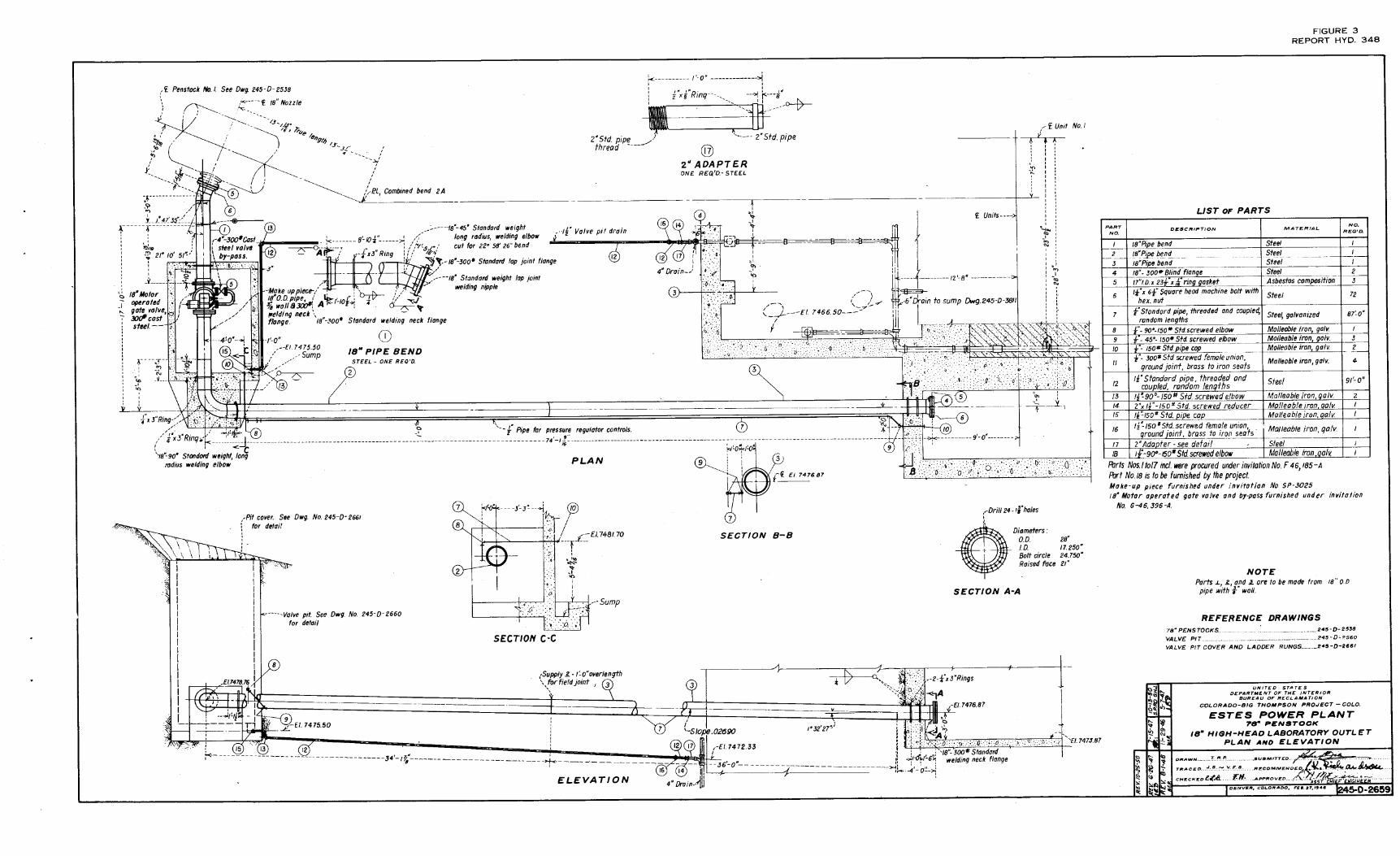
Estes :fowerplant- -18-inch high head laboratory outlet • .. 3
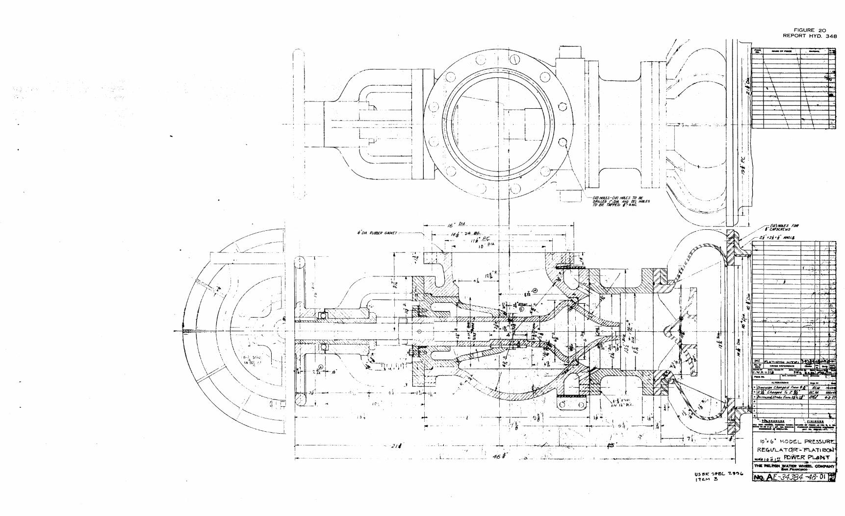
Flatiron model·turbine and pressq,re regulator--General arrangement. .. • . • • • . • • . " • .. • • .. • • 4
Model turbine installation on pO\yerplant deck • • • .. • • 5·
Turbine section • •· • •· • • • . . • . . . • • • • . • • • • 6
Model runner, SF-4. 7 • • • . • . • . • • • • • . • • . Spiral case • • • • • . • . • • • • • ' • • • • . • • • 8
Stay ring. • • . • • • . . • . • lo • . • • • . • • • • 9
Outer bottom ring • • • • • • • • • • • • • • • • • • • 10
Inner he$d cover • ._ • • • • • • • • • • ' • • • • • • 11

CONTENTS- -Continued
Outer head cover ~ . . • • • •
Inner bottom ring • • • • . . . Wicket gate. ·- .. . . . • • • •
. . . . . . . . . .
. . . . . . . • • • . . . . • • • • . . .
I
. . . • •
. . . . • • • •
• • • •
• • • • Main shaft
Draft tube . ._ . . . ~ . . . . . . . . . . . . . . . Photographs of rµodel tµrbine . . . ' . • • • • • . . •· .. Performanc~ curves of.model turbine, SF-4 and SF-4A ·.
runners .. . ._ · . . . ._ . .., . • . • ., . • . . . . • ..
Performance curves of turbine with SF-4A runner • • •
• • . . . ~ Pressure regulator--Pelton design • • • •
Discharge Uner- -Pelton energy absorber . . . -• . . . ' Photographs of Pelton energy absorber • •
Perf orma.nce curves - - Pelton energy absorber •
. . . .
Pressure regulator--Three-stage energy absorber •
Photographs, of three -stage. ,energy absorber • • • •
Performance curves - -Three-stage energy absorber
. . • •
. ., '
. . Velocity distribution measuring instruments and stations--
Figure
12
13
14
15
16
17
ta
19
20
,21
·22
23
24
25
26
Model energy absorbers. • • • • • • • • • • • • • 27
Modified seat ring contours, pressure relief valve .
Valve pit entra,nce and butterfly valve repairs • • •
ii
• •
• •
28
29

Specific Speed, Ns, the speed in revolutions per minute at which the ) :: ~j ~ ~ Jf4._-·'J,· ;,·· ': ··~. : ,-;;½: ; ; • ;. ';· _· ' • :' ,,• '
mathematically reduced turbine runner would operate to develop one 0i.:'t'~'..'~' ·;: ,:·~·~ '},('·.~---'.~ f!J~ ~~'.'; ~jr.c;.:)[;"f,::;,·.ij J, ,_;,,!?-::;:;:·.:,·; ·:~-::• .•: ·; · ? ., ·; ' ·
n.orsepower under one foot of head.· ,, ; "\• ·. ~
Phi, ;, the ratio of the J;>eripheral velocity of the-turbine runner at
. fl 1 . " vDtN the throat to the theoretical ow ve ocity, 11 = sov2gHe
Sigma,u, the ratio of the net pressure above the vapor pressure at
.the runner throat to the effective head on the turbine
Ha -Hm -Hs u=------QwHe
Water horsepower = :. 550
He
211' LNW Turbine Horsepower output • 33, ooo
. · . _ Water Horsepower Turbme efficiency - Turbine HP Output
U it H. Horsepower Output n orsepower = 372 2 1
He Dt
' Q Unit Discharge = l Dt2 -\/H;
.,,. = 3.1416· • •
Dt = Diameter of runner throat, feet
N = Rotative speed of runner, revolutions per minute
He = Effective ·head on the turJ:>ine, feet of water
Ha = Atmospheric pressure - feet of wate~ absolute
Hm = Vapor presqure of water, feet of water
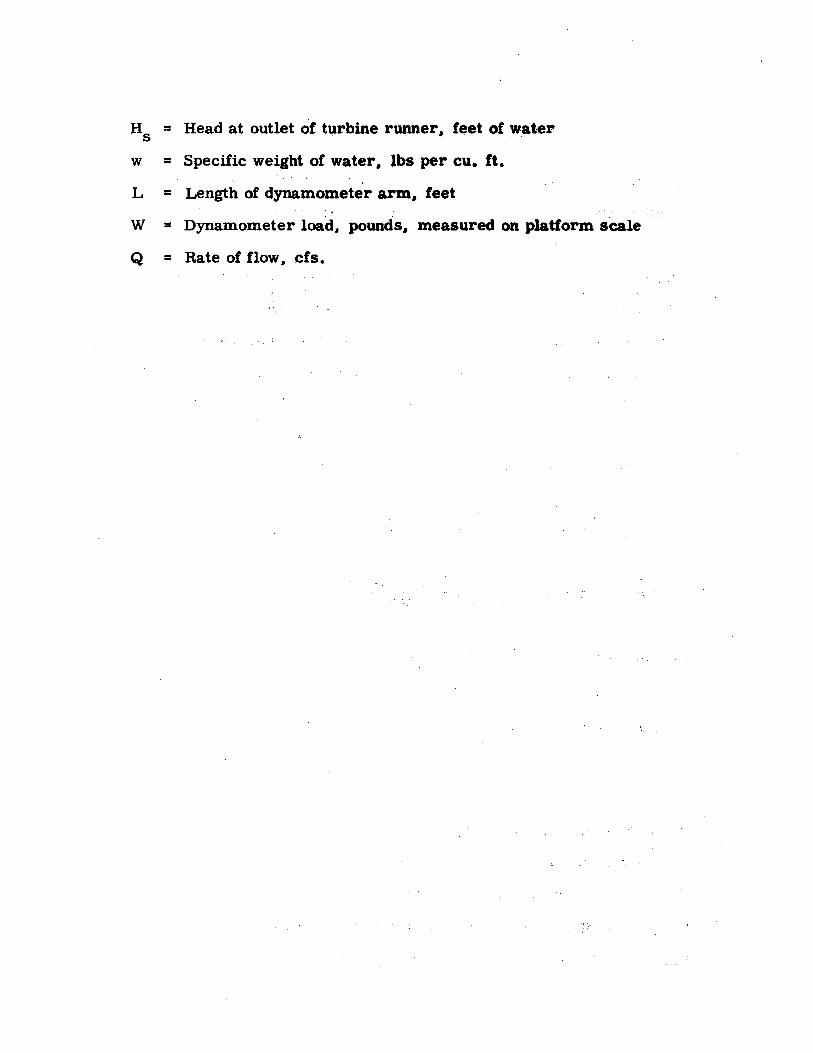
H5 = Head at outlet of turbine runner, feet of water
w = Specific weight of water, lbs per cu. ft.
L = Length of dynamometer arm, feet
W = Dynamometer load, pounds, measured on platform scale
Q = Rate of flow, cfs.

UNITED ~'!'A.TES DEPARTl\IB~T OF' T~.INTERIOR.
BUREAU OF RECLAMATION
'Cbrriihissioner Is Offibe- -Deiiver Div:is:idri:~{ Enginee:r;-ing · ·
La'bbratori.es . '
. Laboratory Report No. Hyd ..:348 Wfftten by: W. P. Simmons, Jr.
Hydraulic Laboratory Branch Denver, Colorado. Mareri r2~ 1956 - ·
· L. V. Wilson fteviewed and
cb,ecked . by: ,T. W. Ball Subinitt.ed by: H. M. Martin
High h,ead rp.odel.le,st for the Flatiron and Pole Hill 'Francis '-type turbines and two turbin~ pypass ene:rgy absorbers--Colorado~Big Thompson··pfoject, Colorado.
PUB.POSE.
· :" -; . . The: purpos~s of th~ stud.f~$ :were to investigate the suitability ofthereaction-type _tur6,ine'tothe.~us1µ11ly high heads at . whfoh'-thefuli s'fze. units· will op~i-ate,. to. detern;ii11e, as a basis for acceptance, the pe'rf6rmance characteristics of the proposed turbine, a.nd. to investigate two energy absorber des_igns. ·- . . . : d _;L~ ;. . .
CONCLUSIONS . ~ ' •,;· . .., • .1"
,_: ·r. The- triociel tests show that tlle. Francis-type reaction tur-. bine proposed by the Pelton Water Wheel Company and using the SF-4A, runner_ satJsfa.ctorily fulfills the requirements set forth in Specificati'onS' No. 2996. The SF~4A r·u:nner was a modification of the SF-4 .runri~r'·where the outlet ends 'of the tila~es were.cut back 3/16 inch (model) to increise the· outlet flow area (Figure 7). _
2. The peak efficiency at the def$ign Phi .of O. ~_80 was 89 .-60 percent at'wif~et gate opening ,D, (corre$pon,ding to 1 O degrees) (Figure 18C). A best efficiency of 90~ 00 percent was obtained at Phi of O. 495.
3. The SF-4 runner did not provide the margin of power output desired by the manufacturer.JFigures 7 .a.nd 18). The runner was modified by cutting back the outlet ·ends of the runner blades 3 / 16 inch t,o ,open:Jll,e flow 0 pa.ssages and increase the power output (Figure 7). This rnod'ified runner, designat~d SF-4A, produced the power margin desired. · ·
- - '
4. The outlet piping from the inodel presented too much re-sistanc~ to anow,the tur:l;>ine outlet, pressure to b~ lovvered enough to produce''a "break" in the· sigma-vs-efficiency curve (Figure 19C). However, values of sigma considerably below·the design value of O. 030 w~re _obtained and the _efficiency. remained satisfactory. ,,"J·,' ; ' - ' ; - - . - ' ' -

5. The .admission of air into the inlet oft.he turbine draft tube . had no noticeable effect upon the turbine p.erformance.
6. The Pelton energy absorber (pressure regulator) vibrated and made a great deal of noise when it was operated (Figures 20. 21. and 22). The admission of air. as is required by the manufS:ctuter. quiets the conditions appreciably. but at the larger valve openJ.ngs · the air inlet system seemed. to b~ inadequate (Figure 23). ·
7. · No definite evidence of cavitation damage was found in the· Pelton absorber (Figure· 22). · · ' ·
8. The velocity distribution at the outlet of the absorber draft tube was poor (Figure 23C). · · ·
9. The three-stage energy absorber vibrated very severely and made much more noise than the Pelton absorber (Figures 24 and 25). Air was admitted just below the relief valve (Stage 1) in the tests with small valve openings; but due to the presen,ce of higher pressures in this region at large valve openings. the air inlet was sealed off. · Air admission below Stage 3 under all operating condi-tions quieted the vibration and noise to some extent. · · ·
10. Definite evidence of cavitation damage was _;found in the region of Stage 2 (Figure 2 5) •
11. Changes in the area of the second stage control produced changes in the pressure distribut~on and in the discharge:. · (Figure 26A, B. and D). . . . .
12. The velocity distribution at the outlet of the abspr.ber.draft tube was fair when no air was admitted at Stage 3 bl;lt became-.extremely poor with a high-velocity central jet when a:ir was admitted (Figure 26C).
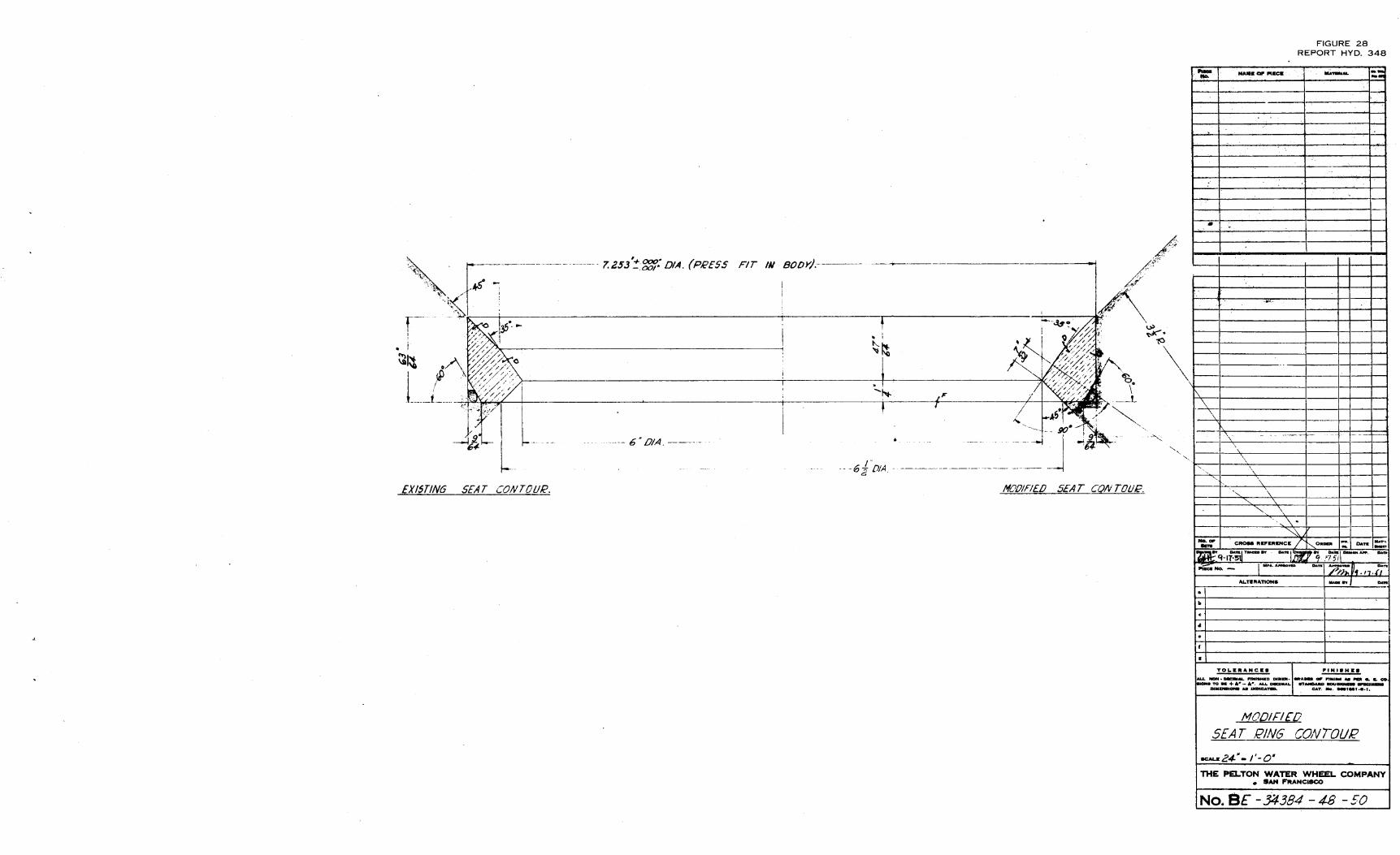
13. A minor change in the seat ring of the relief valve to remove an abrupt change in surface profile did not affect.the oper~tioh of the absorber (Figure 28). · · 1
•
REFERENCES
1. Pelton Water Wheel Company reports submit~ed wit.h a letter of transmittal dated November 30. 1951: · · ·
(a) Flatiron Model Turbine Tests
(b) Flatiron Model Pressure Regulator and Pelton Type · Energy Absorber . ·
2. Field trip report dated February 18. 1952 and ent1tled "Model studies for hydraulic turbine and energy absorber--Flatiron Powerplant- -Colorado-Big Th.ompson Project."
2

C
3. Specifications No. 2996 entitled "Hydraulic Turbines For Pole Hill Power Plant and Flatiron Power Plant--Colorado-Big Thompson Project."
ACKNOWLEDGMENT
Respective phases of the test program were coordinated between the Hydraulic Machinery Branch, the Hydraulic Laboratory Branch, Region 7, and the Pelton Water Wheel Company.
INTRODUCTION
Pole Hill and Flatiron Powerplants are parts of the Colorado-Big Thompson Project and are located on the eastern side of the Continental Divide about 16 and 11 miles southwest of Loveland, -Colorado (Figure 1). The rated head is about 825 feet at the Pole Hill plant and about 1, 045 feet at the Flatiron plant. A single turbine with a 35,000 kva generator is installed in the Pole Hill plant. Two generally similar units are installed in the Flatiron plant, and these units have a combined peaking capacity of 63,000 kilowatts, the additional flow of water for the peak load being supplied by Rattlesnake Reservoir which forms the forebay to the Flatiron plant.
The 1, 045-foot rated. head at the Flatiron plant is somewhat above the 900- to 1, 000-foot head limit usually accepted for Francis-type reaction turbines. However, it was believed that the best overall economy and performance could be obtained in this installation by the use of the Francis-type instead of an impulse wheel turbine. Specifications were issued stating the operating conditions----:--to prevail and the performance to be required of a Francis-type turbine (Specifications No. 2996). The specifications also stated that high head model tests would be required and that a test report was to be supplied to the Bureau of Reclamation, and that acceptance of the design would be based upon the results shown in the model tests. The specific speed of the model was to be numerically equal to that of the prototype,. and the model head was to be as nearly equal to that of th~_Erotot;y~ as feasibl~.fulC119J __ l~si_§_ tl!~!l_-~pg_aj __ §_QQ .feel~. -J Tne·test~acilitites and water at Estes Powerplant, where a 550-foot shut off head was available, were made available to the contractor without cost (Figures 2 and 3). The Pelton Water Wheel Company was awarded the contract on the basis of its bid and design propos -als, and the company built a 4.21 scale model turbine. Low head tests were conducted in the manufacturer's plant and then high head tests were conducted at Estes Powerplant.
In addition to the turbine tests, tests were made on a 4. 5 scale model of the contractor's proposed turbine pressure-regulating valve and energy absorber and on a 3-stage energy absorber proposed by the Bureau of Reclamation. The latter was called the "3-stage energy absorber" because energy dissipation was achieved by throttling, followed by sudden expansion at three points within the
3
•

absorber. The models. together with the heavy test equipment and related piping, (Figure 4) were the. property of the contractor and were shipped by him to Estes Park and assembled for the tests. At the completion of the program they were disassembled and returned to San Francisco. Precision test gages, counters, manometers, etc •• were supplied by the Government. The tests were made under the direction of the contractor through its representative. Mr. Alex Sementovsky. The remainder of the 4 to 5 man test crew was supplied by the ·Bureau of Reclamation. A temporary timber and canvas enclosure was provided by the Government to shelter the models and test equipment that were located on the open draft tube deck of the powerplant (Figure 5).
Very brief reports of the model turbine and the Pelton energy absorber test results were prepared and submitted by the contractor. Also, a brief field trip report was prepared by the participating Bureau personnel (February 18, 1952). Many of the details of the test procedures, the test results, and the difficulties encountered in the high head test were omitted from these reports. In order to more fully discuss the test program and test results. and to provide a better knowledge of the problems and requirements of high head testing. this more extensive report has been prepared.
TURBINE TESTS
Permanent Facilities at Estes Powerplant
During the construction of Estes Powerplant an outlet was provided in the No. 1 penstock. An 18-inch pipeline and valve were attached. The pipeline entered the lower level of the powerhouse at elevation 7476. 87 (Figures 2 and 3). The valve was motordriven and could be operated from within the valve pit or at any location to which control lines were extended. The power lines to the valve motor were energized through a master switch in the powerplant control room. Provisions were also made for opening or closing the valve manually. A 4-inch, manually operated bypass was provided around the control gate so that the line could b,e filled before the 18-inch valve was opened. A 17. 25- by 8. 95-inch Herschel-type venturi meter was attached to the outlet end of the 18-inch pipeline inside the powerplant. This meter had previously been calibrated by an eastern university, and this calibration had been verified and .extended· by the Hydraulic Laboratory in Denver.
Model Installation
Temporary 12-inch piping was installed from the venturi meter through an opening in. the powerhouse wall and then upward to the draft tube deck where the models were located (Figures 4 and 5). An expanding section increased the pipeline size to 16 ·
4
incJ;i~s and vaned 90-degree elbows .turned the flow into the 11-foot .. long by.16-3/3.2-incb diameter horizontal inlet.pipe. The inlefpipe was followed .by a 26-inch long, 16-3/32- by 12-,inch conic reducer and then;by a 12- by 12- by 10-inch wye. Flow entered the turbine scroll case straight through this wye and flow entered the bypass energy absorbers through the wye branch (Figure 4). A needle valve at the entrance to the model ;ener,gy absorbers prevented flow fr.om entering the absorbers during turbine operation.
; ,. The model turbine, the turbine s~ft, and the water brake
dynamometer (Figures 6 through 16) wer~ supported on a welded structural steel frame. This frame was welded to three heavy 1.., beams which were held to the draft tube deck by tie bolts that passed through holes drilled in the deck. Angle-iron straps were placed under the deck beams and over the I-beams, the I-beams were then shimmed to grade and the bolts drawn tight •
. For convenience in testing; the turbine ·shaft was placed horizontal. This shaft was carried on ball bearings whose outer races .were ;carried in sleeves that wer~ in turn supported in other ball bearings (Figure 6). The sleeves carrying the outer races. of · the shaft bearings were prevented from rotating more than a few de -grees by an arm that extended through the bearing housing. By measuring the force required to prevent ·rotation in the sleeves, the power lost in the bearings was .. determined. The torque load exerted by the 7 -foot long dynamometer arm was measured with_ a platform scale. This scale was fitted with an auxiliary indicating beam and an oil dashpot which reduced the; beam movement caused by the pulsating load from the water brake.
. '
· · The draft tube discharged horizontally into a 5-1/2-foot diameter cylipdrical tank. A 16-inch line carried the discharge from this tank over the side of the powerplant deck and dovvn into the tailrace. A chain-operated butterfly valve in the line near the level of the tailrace was used to regulate the back pressure in the cylindrical tank. Although: not shown in Figure 4, a gate-controlled standpipe was provided on the draft tube tank, au.d a 6-inch gate-controlled air inlet was :provided on the· 16-inch oµtlet line near the powerplant deck (Figure 5). A spring-loaded pressure relief valve was located in this air inlet line between the 16-inch pipe and the 6-,inch valve.
A magneto-type tachomet.er gave the approximate instantaneous shaft speed of the turbine and was used to. make the speed settings. This tachometer began to function erratically during the latter part· of the tests and it was replaced by a strobotac.hometer. Speed, regulation was made by adjustil)-g the load on the .dynamometer. An accurate count of the revolutions-turned by the shaft in a given period of time was made with an electronic counter and an electronic interval timer. The counter recorded the nµmber of impulses generated in a pickup coil by four permanent magnets as they were carried past the coil in a disk fastened on the end of the turbine shaft. The magnets were mounted at 90-degree intervals around the disk,
5
thereby giving an· impulse every quarter of a revolution. The elec -tronic · interval timer. was connected to the counter with a double pole single-throw switch so that the counter and timer were started and stopped Simultaneously. The average time to obtain a test point was 20 seconds. ·
The rate of flow wa.s measured with the calibrated ven -turi meter and the turbine inlet pressure was measured with a Crosby 300-psi fluid pressure scale. The pressure in the draft tube tank was measured with open-.water manometers when positive and with a mercury-filled U -tube1 when negative. A mercury barometer was used to measure the barometric pressure.
Model Tests
Two turbine runners, designated SF-1 and SF-4, were tested at Estes Park. The SF-1 runner was used in low head tests conducted at the manufacturer's plant, and only a few tests were made with it at Estes Park for the purpose of correlating the high head data with the -low head data. Good correlation was obtained and the runner was removed from the test rig and the SF -4 runner was installed.
The model was placed in operation by closing the wick~t gates and opening the air vents in the scroll case and then opening the 4-inch bypass-to fill the lines. After the lines were full, the 18-inch valve was opened and the wicket .gates were slowly opened to the desired setting. The -speed of the turbine was regulated by adjusting the quantity of water within the water brake, and the flow through the brake was adjusted to a sufficiently high rate to prevent overheating. Runs were made through an appropriate range of speeds, at wicket gate openings of B, C, D, E, F, G, H, and J. These gate openings correspond to 6, 8;, 10, 11, 12, 13, 14 and 16 degrees. The designation "I" was omitted to avoid confusion.
The efficiency of the SF -4 runner at the various wicket gate openings for the appropriate range of Phi (see Symbols and Definitions) is shown in Figure 18A. A peak efficiency of 89. 5 percent was obtained at Gate D for Phi= O. 504. The design Phi was 0.48, at which the best efficiency was 88. 9 percent. The unit horsepower versus Phi for the various gate openings is shown in Figure 18B. In stepping the power output up to the actual plant operating conditions and turbine size it was determined that the turbine met and slightly exceeded the 48,000 horsepower requirement of the specifications. The turbine manufacturer decided that there was too little margiri a.nd: changed the runner to enable it to develop more power. The modification consisted of increasing the outlet passage areas by cutting back the ends of the runner blades 3/16 inch (Figure 7). The modified runner wa,s designated the SF-4A runner.
The efficiency and the unit horsepower of the SF-4A runner for various wicket gate openings is shown plotted against Phi in Figure 18C and D. The efficiency increased to a peak of 90 percent for .
6

Gate D at Phi= 0.495.and was 89.6 at the design Phi of 0.48. The unit horsepowe.r was sufficiently hig~ to insure an adequate margin over the required 48,000 horsepower output for the powerplant installation.
The curve showing the relation of efficiency to the unit horsepower, HP1, at the design Phi of o. 48 is shown in Figure 19A, while the relation of efficiency to the full size turbine power output is shown in Figure 19B. The relation of efficiency to sigma, u, is shown in Figure 19C. The lowest sigma obtained in the model tests was O. 0135. No lower values could be:obtained with the outlet piping provided because the pressure in the outlet line could not be lowered further, and thus the point where the efficiency began to drop with decreases in sigma .(the sigma break point) was not reached. This was not considered a serious shortcoming because the design sigma for the plant is O. 030, and. the model tests were of sufficient range to show that the sigma break. occurred at sigma values below O. 0135 -to O. 0238, depending upon the wicket gate opening (Figure 19C).
The relation of the~ unit discharge to the throat Phi for the various .wicket gate openings is shown in Figure 19D. The total discharge as plotted against horsepower output is shown in Figure 19E.
Tests were lllade in which air was admitted into the tur..bine draft-tube through:the piping show~ in Figure l 7C. No notice-_ able effect was found on the turbine efficiency and the piping was removed. All the test data reported above were obtained without air admission into the draft tube and with the piping removed from the tube.
-ENERGY ABSORBER.TESTS
Two very different types ,of turbine bypass energy absorbers were tested. The first was the type the· Pelton Water Wheel Company has used for many years and was proposing for use at the Flatiron plant (Figures 20, 21, and 22)~ In this absorber, the jet from the bypass or pressure-regulating valve strikes a baffle which deflects the stream radially outward into a bowl. The bowl then deflects the water back under the baffle into the center of the passage and into the discharge diffuser.tube •.
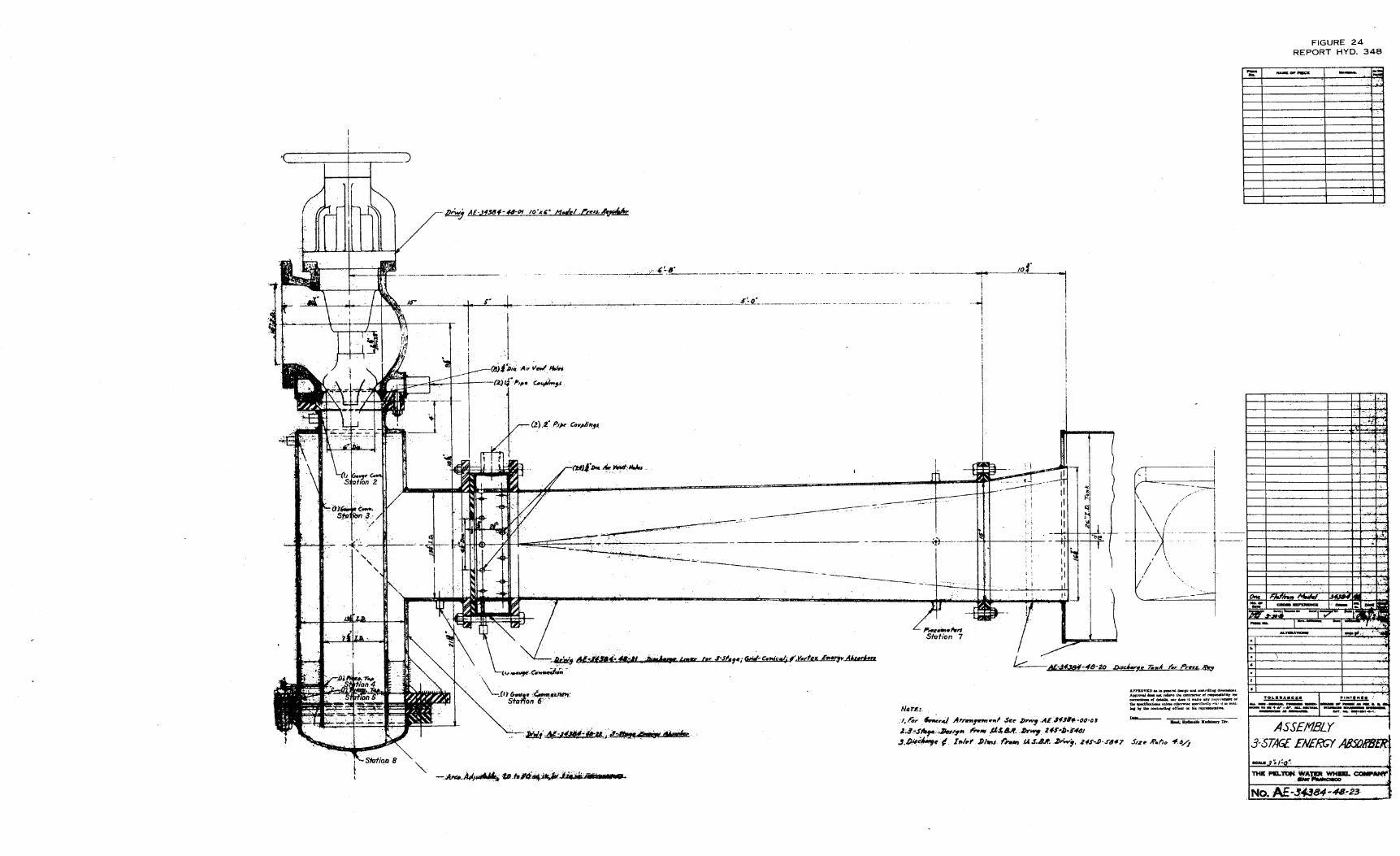
The second absorber was an experimental design proposed by the Hydraulic Machinery Branch of the Bureau of Reclamation (Figures 24 and 25). It was- called the 3-stage energy absorber because energy dissipa.~ion occurred primarily at three stages within the unit. Water entered this absorber through the turbine bypass valve, the valve forming the control of the first stage in the absorber (Figure 24). The flow traveled vertically downward through the inner tube and was then deflected radially outward and
7

upward by the absorber bottom. The annular orifice created by the end of the inner tube and the absorber bottom provided control for the second stage of energy dissipation.. The area of this orifice was adjustable from 20 to 50 square inches by shims placed between the cover and outer tube. After being tu:rned upward, the flow passed between the inner and outer tubes and then entered the horizontal discharge tube~ A fixed area orifice near the entrance of the discharge tube provided the control for the third stage of energy dissipation. A horizontal .diffusing discharge tube completed the absorber. Air inlet manifolds were provided at the absorber entrance just downstream from the inlet valve and immediately downstream from the third-stage orifice.
The absorbers were connected, one at a time. to the discharge end of the needle valve which represented the turbine pres~ sure regulator, or relief valve. This valve was connected by a short 10-inch diameter pipeline to the side outlet of the wye branch at the turbine scroll case inlet (Figure 4). Water was prevented from passing through the turbine during the absorber tests by a: blind flange placed over the .t~rbine outl~t.
The Pelton energy absorber requires the admission of air just below the inlet valve to minimize cavitation and cavitation damage. Provisions were made for supplying this air, and the rate of flow was measured by suitable flat-plate orifices mounted at the inlet of a small tank connected to the air inlet manifold (Figure 22A). Similarly, provisions were made to supply air just below. the inlet valve in the 3-stage absorber and in a manifold just downstream from the ~hird-stage orifice (Figure 25A).
The flow from the absorbers passed from the absorber discharge tubes into a 26-inch diameter tail-water tank and then into the discharge line leading to the tailrace (Figure 4). Pressure measurements were made at the bypass valve inlet (Station 1) and at suitable stations in the absorbers. Flow measurements were made with an 18-inch venturi meter. The velocity distribution at the exit of the absorber discharge tubes was determined by impacttube traverses at the station shown in Figure 4. Air traps were effectively employed to keep the gage lines free of air and .full of water.
Pelton Energy Absorber
In addition to ,the piezometer ring at the inlet valve entrance, piezometer rings were provided in the elbow of the discharge section just below the bowl and near the outlet of the discharge tube (Stations 2,and ·3, Figures 4 and 21). The back pressure on the system, as controlled by the 16-inch butterfly valve and the 6-inch air inlet on the discharge line to the tailrace, was measured in the turbine draft tube tank (Station 4, Figure 21).
8
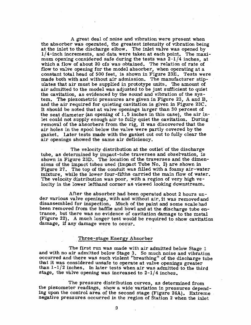
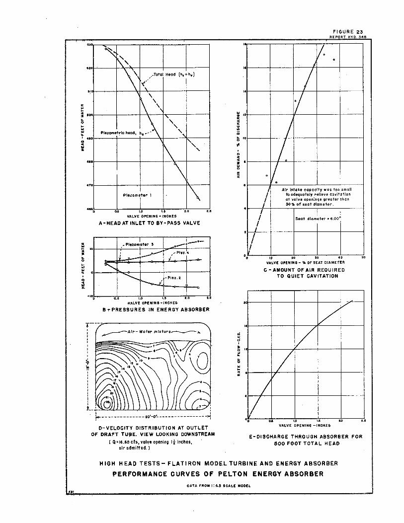
A great deal of noise and vibration were present when the absorber was operated, the greatest intensity of vibration being at the inlet to the discharge elbow. The inlet valve was opened by 1/4-inch increments, and data were taken at each point. The maximum opening considered safe during the tests was 2-1 /4 inches, at which a flow of about 20 cfs was''.Obtained. The relation of rate of flow to valve opening·for-the model absorber, when operating at a constant total head of 500 feet,· is shown in Figure 23E. Tests were made both with and without air admission.- The manufacturer stipulates that air must be supplied in prototype units. 'Ihe amount of air admitted to the model was adjusted to be just sufficient to quiet the cavitation, as evidenced by the sound and vibration of the system. The piezometric pressures are given in Figure 23, A and B, and the air required for quieting cavitation is given in Figure 23C. It should be ·noted that at valve openings larger than 30 percent of the seat diameter (an opening of 1. 5 inches in this case), the air i,i- . let could. not supply enough air to fully quiet the cavitation. During removal of the absorbers ·from the rig, it was discovered that the air holes in the spool below the valve were partly covered by the gasket. Later tests made with the gasket cut out to fully clear the air openings showed_ the same air deficiency.
The velocity distribution at 'the outlet of the discharge tube, as determined by impact-tube traverses arid observation., is shown in Figure 231). The location of the traverses a_nd the dimensions of the impa<;:ftubes used (Impact Tube No. 2) are shown in Figure 27. The top of the conduit was filled with a foamy air-water mixture~ whil~ the lower four-fifths carried the main flow of water. The velocity distribution was poor, with a region o:f very high velocity in the lower lefthand corner as viewed looking downstream.
· After the absorber had been operated about 2 hours under various valve openings.,·with and Without air, it was removed and disassembled for inspection. Much of the pa.int and some scale h,ad been removed from the baffle and bowl and at the cilischarge tube entrance., but there was no evidence of ca:vitatio11 damage to the metal (Figure 22). A much longer test would be required to show cavitation damage., ii any damage were to occ·ur. · . · ·
. Three-stage E·nerg;y Absorber
The first run was made with air admitted below Stage 1 and with no air admitted below Stage 3. So much noise and vibration occurred and there was such violent "breathing" of the· discharge tube that it was considered unsafe to _operate at -valve openings· greater than l-1/2 inches. In later tests when air was admitted-to the third sta·ge., the valve: opening was increased to 2-:.1/4 inches. ·
·· The pressure distribution curves., as ·determined from the· piezometer readings., show a wide· variation in pressures depending upon the control area of the second stage (Figure 26A). Extreme . negative pressures occurred in the region of Station 2 when the inlet
9

valve was first opened, and air was required, to reduce the cavitation. At. larger openings the negative pressure changed to a posi- · tive pressure~ This change occurred at 0. 6-inch valve_ opening for the minimum second-stage area of 20 square inches and at o. 9-inch opening for the maximum second-stage area of 50 square incheso As the valve was opened more, the pressure lJecame strongly positive and there_ was danger of rupturing the lightly built air inlet manifold. It was therefore necessary to block off the inlet manifold with a blind flange, which· prevented air beingadmitted below the first stage.
· The -~ressure at Station 4 was negative at valve openings between O. and 1/2 inch and "o/as positive at valve openings greate_r-. than 1/2 inch, regardless of the second-stage area. The maximum negative pressure measured was 24 feet of water. The pressure at Station 5. decreased with a reduction of area in the second stage, and with ari area of. 20 square inches the pressure was -20 feet for valve openings of 1-1/2 to 2-i/4 inches. At Stations 2, 6, and 8 the pressures. were consistently positive. The head loss curves show the apportionment of the losses through the respective stages (Figure. 26B). A reduction in the second-stage area for a given discharge decreases the loss from the inlet. to the second stage and increases the loss from the 13econd. stage to the third stage. The loss from the third. stage to the discharge tube outlet is constant because the third-stage area remained fixed. The amount that the second-stage area affects the discharge is shown on Figure 26D •.
The velocity distribution at the absorber outlet, without . air being admitted at the third stage, was better than the distribution with the Pelton absorber with air admission (Figure 26C). The flow distribution patterns for the two absorbers cannot be directly compared because they were obtained for different valve openings and dis~harges. The 3-stage absorber was operated at the maximum valve opening considered safe without air admission to the .third stage, or 1-1/4 inches. The Pelton absorber tests, which were completed prior to the 3-stage tests, were made with a valve opening of 1-:-1/2 inchesand with air admission into the absorber. When air was admitted to the third stage of the 3-stage absorber so that the valve could be safely opened to 1-1/2 inches, the jet from the orifice continued through the discharge tube without appreciable expansion or diffusion. No data were taken for this condition because the instrumentation was. not of sufficient capacity or strength to withstand the high velocity jet ..
Definite evidence of cavitation d~mage was fot11J.d when the model was disassembled after about 2 hours of operation. Metal had been removed in an annular ring on the n1side of the outer sleeve just above the bottom flange, and on the inner tube supports and the inner and outer sleeves where the supports were welded (Figure 25). In acJdition, paint was removed from the inner pipe and at the entrance to the third stage. Paint was also removed from portions of the outside
10
of the inner tube. The paint removal was not considered conclusive evidence of cavitation erosion in these regions, hut it suggests that such ero~ sion might occur Q
In general, the 3-stage absorber was noisier and vibrated with greater intensity than the Pelton absorber. When air was admitted at the third stage, there seemed to be a small decrease in the violence of these conditions. but there was little or no dissipation of energy within the third stage of the absorber.
COMMENTS
A number of difficulties were encountered during the test program and are enumerated here to serve as a guide in future high head testing.
At first the 18-inch motor-operated valve in the supply line could not be operated because, due to· improper tagging in the control room, the electrical lines could not be energized. This was remedied by the plant electrician after he traced the wires from the pump. pit to the control room. The valve also gave trouble in that is could not be closed under a high differential head. It was necessary to make all closures by shutting the flow off as much as possible at the models and then closing the 18-inch. valve, while the ,4 inch bypass remained openo After the 18-inch .valve was closed,. the bypass was closed. This malfunctioning of the 18-inch valve was corrected after it was· pointed out in the field trip report dated February 18, 1952.
, . Entry into the valve pit was difficult and hazardous be
cause of inade.quat~ handholds and the fact that the .open cover had to be grasped in order to reach the ladder rungs (Figure 29A). This difficulty has largely been eliminated by the addition of more handholds.
Shut-off valves were used in the high-pressure gage lines to facilitate bleeding the instruments and to make it possible to remove gage lines where necessary. Unfortunately, the valves used did not come toa stop when fully opened, as is usually the case. As a result, on several oc.casions early in the test program, the valves were backed out so far that the stems were blown from the body and water at a 250-pc:>Und pressure squirted over.the personnel and test apparatµs. After these dangerous and unpleasant experiences, considerable care was taken to a void opening the valves too far. ·
The veloci~y traverses made at the exits of the energy absorber draft tubes. were not anticipated when the test program was planned, but were a last mliuite aecfsion, As a result, and due to the limited time then available, inadequate preparations wer,e made. A standard laboratory Pitot-static tube was used in the first test (Fig-ure 27) •. It was damaged ahnost immediately in the high velocity flow. It was replaced with a cylindrical Pitot-static tube made of 1/2-inch galvanized pipe .and supported in a cantilever arrangement by a boss at
11
the left side of the conduit (Impact Tube No. 1.; Figure 27). This tube was bent backwards at a 30-degree angle by the flow. The traverses were finally made by using cylindrical-Pitot-static tul?es that extended through the passage and were supported in bosses on each side of the conduit ,(Impact Tube No. 2, Figure 27). Bothtotalheadandpiezometric head were measured with these tubes, the tubes being rotated in the stream to balance the two static pressure readings, thereby causing the total h.ead opening to face squarely into the stream •. The three No. 2 tubes. were all in place during the runs and the gage lines were kept free of air by air traps (Figure 27).
The amount of energy released into the draft tube of the 3-stage energy absorber was so gr.eat that the draft tube "breathed 11
violently and began to fail by splitting at the welded seams. It was necessary to· repair these breaks and to reinforce the driaft tube with bands of channel iron before the testing could continue.
Considerable pressure was 'built up in the region of the Stage 1 air manifold of the 3-stage absorber when_ the valve o_pening reached. 1-1 / 4 inches. This manifold was lightly built and not ca·· . pable of withstanding heavy internal pressures, and it was necessary to seal it off by a sheet metal ring so that tests could be made at larger valve openings.
The SF-4 turbine runner was received directly from the manufacturer's shops, and it had not been previously assembled on the turbine ·shaft. When assembly was attempted, it was found that. the bore was tapered and oversize and that the seal rings were ecce_ntric. It was necessary to rebuild the bore and the seal rings in the laboratory shops in Denver by building up the sections with metal spray and th~n remachining to the proper dimensions.
The 1/ 2-inch.;,;thick transparent plastic spool used by the manufacforer in the low head test to connect the turbine outlet to the draft tube was used for the preliminary tests at Estes Powerplant , (Figure 1 7C). The section ruptured after only a few minutes of testing, and tests were discontinued until the metal spool that had been shipped by the manufacturer arrived at Estes Park . . Upon receiving the spool, it was found that no holes had been drilled in the spool flanges, and it was therefore necessary to lay out and drill bolt holes at the proper radius and spacings· to match the turbine case and the draft tube inlet.
During the turbine tests. difficulty was experienced in setting the lower speed· points at large wicket gate openings because the water brake dynamometer was barely able to handle these hightorque loads. A d~amometer with greater capacity would have greatly facilitated this part of the test program •.
The electronic timer and counter had to be moved inside the powerplant during the latter part of the test program because their performance became erratic in the cold, wet atmosphere on
12

the powerplant deck. This considerably increased the difficulty of coordinating the taking of data when the test points were set. The necessary coordination was finally obtained by installing a set of field telephones.
The 16 -inch butterfly valve located in the discharge line a few feet above the tailrace caused more trouble and delay in the test program than any other item. The loads that were imposed upon this valve were greatly underestimated, and, as a result, a relatively lightweight valve was installed. Almost every conceivable type of failure occurred on the valve. After the shaft broke, it was replaced with a new shaft of higher quality steel. When the cast iron valve leaf broke a new leaf was made of 1 / 2 -inch boiler plate and a much heavier shaft was installed. This was followed by repeated shearing of the pin which held the worm gear to the shaft. When heavier pins were installed, the teeth of the cast iron worm gear failed. This gear was replaced with a steel one which lasted just long enough so that the tests could be completed. Each time repairs were required, it was necessary to row a boat into the tailrace, remove the valve while working from this boat, and row back down to the dock (Figure 29B). The valve was then transported to the machine shop of the powerplant, where repairs were made. To reinstall the valve, it was necessary to repeat the boat trip. This consumed a great deal of time and entailed ~onsiderable risk to the men working from the boat in the powerplant tailrace. ·
It was anticipated that the testing would be done during the summer, and if so, there. would have been no particular trouble from the weather. A,.s it turned out, the testing was not started until late in September and was not completed until the 9th of Novem -ber. During this time there were several snow storms, considerable freezing weather, and a period of subzero temperatures. To protect the piping and the hydraulic equipment, it was necessary to drain them at the end of each day. The addition of electric heaters in the temporary canvas enclosure around the test equipment did not pre -vent freezing of the gage lines during operation in the coldest weather. During those times when all reasonable attempts failed to keep the gage lines open, the testing was discontinued and was not resumed until the weather moderated. All of these difficulties added considerably to the time required for completing the tests and to the cost of the program. Any future outdoor tests at the Estes Powerplant should be conducted not later than the end of September.
Intierior .. Reclamation - Denver, Colo.
13

Elevation for excavation in this area, see
I g\
~\ \
D1t19. Z45·0-Z462------ --=-:::---:=::=------ -,. ' J
J J I I I I I I I I I I I ,,_
1 b-
~ I---'"
,!.._ ~
,,.__ l'-1,._
fl-,.....
f-.
~~·--<
0 ' /4
0 ~ ~ ' : - ' i--, "', -\ ...;\ _ _ .--Slope as shown on
-<:- -. - ----~ '~\ Campacfe?>:.;..~:- ------ '
0
FIGURE 2 REPORT HYD. 348
\ o\ \
~\ ~\ ~'.1 ~ ~\ ~! : ~ ~
' \ - \ I , _ ~---this drawing
,~ ri11--- .'t(;.,. ~ ,Mox. T.WS.
\ r-t of rood ~°--(5r!f:ri: suit r-- ---- --------20'-o"-- ------ ---------------~ Slope not~ \
- Min channel_ 1;!fgJgJ1'!.'1_J.L7!~2'EP---,.... ---------------------
~-Slape --------::i; ---- ', var,e! ----- -- s,
' . I " '" I I ' -~it",--:5-lf->+< ----------ld-0----------- --------10-0---------->- steeper than , : l , i l " n 12,. ,, ----+- in 12" I if \
[,.1.~--;----- I I -+-- ' \
· 4"Compacted grovel ,,· -~---- 'f>
:Max. r.ws. -Et. 7475. oa
, !l!, 3-1
: - -Subgrade \
surfa;~;l·;~-L ROAD SECTION -----
TYPICAL SIDE SLOPE DETATLS TAILRACE CHANNEL
Pipe.
~ Q 15~ IQ.0
SCALE OF FEET
,$/ope to suit ~------------------ -----
1
-~~~~:-u::_1:cc::o:0
~~~------------------~ '\
,' material : n • . :
/ : { of rood-- ,-2- Bituminous surface course , : \ t , , H I H : , \ f H ! ,
' -~11'><-:5-0-"-'-<-f-o- ---------------- 12-d'-------- f ,------ -------12--0 ---------·3'd'->-l I : : f I • \ • : !
·'- : 1: ; ! --- j intt' , i Jm12" ------.10- ~ )
:/.-~}-1~- I f i-.m~b.... Ni6 aoo_ I ~ I • l~ • - 1::.--
--4' Compacted base course. Slope not steeper, '----subgrode than 1i · 1-----
TYPICAL ROAD SECTION (ACC£SS ROAO-HIGHWAY TO PARKING AR£AJ
i----. ---------2d o· ---------- ----------->-1 >'o, Ii' 'r-<-i-o' >f' 2'-d',t<---- ----d-o"- ----->k ------B'0~-------~ i~
I ; I I " 1
" I I r-Sbpe not steeper \ than if. , !J_l _____ J J --+-- Jin ii' I J in 12''-----t- ~ i
:~!l' ' \
'--4" Compacted
Point to prevent. bond-, Chamfer ,::_- - - /
\, ' ,,'
TYPICAL ROAD SECTION /SWITCHYARD ACCESS ROAD/
~ ---,-,",- -,,- -f I •
_., cc 3 1,:f ~,;· ;· 0 -'.<?-,r-s,~pe-,-.. ~--,2~. 40 - 0 -----------~--t of parki~g area E_ti~ a @, n _, .... " f • in .. ·1 symmetrical about ~-I'.! . __ -_- -, -'-------_-L-f ,.-SIOf~ Jin (,2" ~ ,l: ' . . l,if;,:!-~'" """' .: -::~,,,,,.... ,,.,.. ' · ... ;·. :_-:.
: , c--·· .. ~- , y • -----.._ --- -Subgrade :i._ ___ ~---- :~1- : 4 Compacted base course-' , --t2" Drain pipe
Reinforcemen I--SECTION A-A REFERENCE DRAWINGS
WAT£R SUPPLY L/N£ _____________________________ 245-P·597
ORA/NAG£ SYSTEM, PLAN ANO PROFIL£$_ ___ _____ 245-P-59:S
TRANSFORMER AR£A 0£TAIL5-_____________ 245-P-594
IIIISC£UANEOUS STRUCTURES ANO 0£TAIL5- _____ 24S-P-595
ACCESS ROAO AND PARKING AREA _________ _245-P-599
S£WAG£ OISRiSAL SYST£M ________________ 245-P-596
SWITCH YA RO GENERAL PLAN_ _______________ 245-0-4129
SW/TCHYARD FENCE PLAN ________________ 245-SP-59B
LIGHTING INSTALLATION _________________ 245-SP-1399
ELECTRICAL UNDERGROUND DIST. SYST£/tl __ __ __ 245-P-591
~-
------------ \ ------1---~--===-------- _____ '6 ..... __ R:.::_:IG::.:H.:_T:__·O=-F'---W=A.:_Y ___ __ _ ... _, ,-,,
"'' ,.;'
---,- - -
---------.. ,,.----r---UN1TCD STATES
DEPARTMENT OF THE INTERIOR
BUREAU OF RECLAMATION
COLORAOO -BIG THOMPSON PROJECT - COLO-
EST ES POWER PLANT
GENERAL PLAN AND SECTIONS
DRAWN_ ----~f!,_H4 ______ suaM1rreD~_/ ~-----------
TRAClO. ·--~,__C_,_I?, ______ .':'ECOMMEIIDE.OX....)Jflr~~--- __
cH~.:,u.oJJ7fl.a, _______ APPROVED_~H1'F· · 1
·
01!.NVER,COLORAOO, FEB, 8,19 5-0-25951

01dMon .. ;W1--.: Mtn. - ,,. -
R. 72 W.
30 29 28
" 36 31
5 irJ'l ~~ 3 I
t ]?(~ 12
R. 71 W. ,-i
35 36
t?It 31
R. 69W.
33 34
FIGURE 1 REPORT HYD. 3,18
u
"
i !&r~x ·1;f,.~ Ii 10
' . ,, ,,,, ' , " ,. '" It~~ '"*-~k--- ...,, ·~c~~r!-f-J,_Lovela_nd 1/\,- , I 1 ~NV,l 1 ~I'
. ' , \ I " "}"~ " I ,._,, " _ ._'' _1
-, ,.,, " , ,,r 18 ,,-.J' '"f--· ,-, \_ J L -----"' '";--,··'Ccf'>=.--:- oedecter- I~ · J ,: : ij _ ji
/
I \_ , ·--------f----r:,: I -~ / Lake . =zli: _J~ _J1 ~-7! I " r>~:;;~-, I--,._ --- r ~- !ti I
¢~~ -i-- ~-/ i--,-OREST ~' - Nh- ' "'2 ~ I ~v I\\ ~~----it ·~~J r_· ~" ~J
I I I 19 O }r r~r .. .!!l I, 26/,1 ,· I i' ~ I 24 ---!'-T--"--'~~~ .... >OJID:!1,'.°"'4 ZB I 27
1
'!fl : ESTES I 20; -~ 'I., __j ---! , 30 ~
9
I~ -- ,, ~\ I! POWER PLANT
1
/ / S ~ , /. _ . - C- < Ii II
/ OLYMPU z ,J::,· _ -•. - !E',~,-.,c,- 'M!~'J'il?,,'';'l /,) i~ -==-~ ,-- . ..J ,, ,s--,.... """"' ' ,,,· ' " " --• ' r ' I
14 17
,~~1')'_ ,._,, - .... .,". -.-.,~_c_z,., __ ,e_,,s..,-,.,,----.. L_ -------(·--:--r" "" ,11 • - ·,:;- '. ~ ->" ~ i*tM+ Olympus ' P0
1
1;\ I 25 l 30 Sugo~loaf 2\r ,.,.,,l_c;, ' ] < A 34 ]I
35
'. " ~~- ): 2_!l,J~:x~~~· 27 I <' 1 -"-' Mtn _\ ""1"'-~~·;·0/ -- .:o:·,-..- 31 :: 32 / i ~\ :,I • 11 '~:::~::o=='}-=~ . , , ,, '' ' J - ' , - ' ' , • , , camo,co ,~, •• ,.,,,_ ,, - _, C --- < 0 - ~ '~ ,., , SIPHON-__J _ -~ ~~~Mf--=,:,;-T""°$' __ F-"~ L____ , II t :1
' - C' · c '¾ •W ,,.,,. , , 'i 'i la i'i
I • • ' ' , 0 I I 2 I" I f' \ ~ '¾, 34 ' 35 ' 36 :-'----r-:=--- I ' I II """' I 3 ' (' ' '"pf"' " . ", • ' ' C'>, I ,,
I ,; I, ' I • ""'""'~'fr·/:;>¼ J ~ L J;
/;
, .,1'-J lg ---t-----r~-- II RES , I((/ i..A - 1-~, I' ,- · ' 'l~~-1,
0
.'~@ 11 ~i i
, .;- - I ' , ' . - 'c ,£ ,: ; ' ' ,, ' , } ' ' ',_ • ' ' d ',; c_ -,- T -.ry~ W , I _, , , , ':; _' ! ' _ •. __ : . I ,1, " • 1 ' '!;;c "'-' 'r1 ::f r\ i ~1"1 J! ~ ;--;}Krugec ~J~~-,~ t~·=~>'~J 1_ ~:..,.J---- I 12 '~:~. 8 ~pa-- I ~,11-~I r~ll -----::1~ :~ ' ' ' "' -· I:\ • O -- - - '<,_ ~ -----"'.,--:C_~d', . [-] .')".)1/
1
!t~.
1
,.' ' if'\. I --- ',. "">' ' ~+-----t--·--t----17 -- - ~ l I ~-il- 14 :~':'..i~ '- - - ' "' '
.N'
~!
1
·7 ---IL.,," "I :, ,i:, ~I "I " " I U~:~, .. ,, .. .,L-7~-- t1 "'· 17 11 , " I ''
! _L --,,- , ! / II 21 ! \22 23 \
t " '" : " ,,,, ' " " : c,.~, ' r---:--.._ _, ,, ~ 1 i\ Berthoud \
II ; , 19 20 ' \
I " :1 _J:_ .. r---t +v---' ===== ===1r=-1 I i , - -- 76 r 11
11
28 i 1· 2• II 1130 . 29 1 oiVel: 11 6
25 11 i j r-
26 25 ·:t _JL==L===== ======~ii-----· --- ------- __ \~ ... ==--== =--,, T I ---, -i--~--1 -,, I II ' so ' 35
- ii I II 1 ~ 33 I 3
~ · f - -----t-- \\ ' 1 31)~., ! 320¢', 1· ls IE 3511 I #~ ... ~ >o
35 I 36 ,, , -~ -~115------+-L : , r.,ittle " = ======l - · ~I,~ __L --- 8'" _,,..,,_..,.._ 1 ,;::_71 I ~,.1---
- 4 I 5 I 4 >\3
0
SCALE OF MILES
";6 VIV II
UNIT~D STATES DEPARTMENT OF THE INTERIOR
BUREAU OF RECLAMATION
COLORADO-BIG THOMPSON PROJ-ECT - COLORADO
ESTES PARK- FOOTHILLS POWER AQUEDUCT
FLATIRON POWER AND PUMPING PLANT LOCATION MAP
DRAWN fl_.~--~~ - SUBMITTED
TRACED .. __ ~~f:. W~ . RECOMMENDED_
CHECKED. J.,:/_ '?/!_/,_ ~'- ___ APPROVED_ ~ - -c H ,\_!__~~/,;.il,/ DENVER, COLORADO - NOV. 7, 19.50 245-0-5890
/E Penstock No. I. See Owg. 245-0-2538
\ ~ «---··£ 18" Nozzle ; I ; ---......_ ~ ....
~
: : , ·-----;-......__:-----,3-,,1,r , /G, ~be
t / le11 ~ ~ :!7/';} />•
'o ~ ) ~-.Jr '
f -~- ~----<-;,./ ' ~ '
J:.... t ' .......... •• { ,,, ',,_ ·* --- -: ' - ' '-"" - ', I --............. I
,d'",_ I I
.~-------' __ ·,_ _ ~ ~ ,;,-P.L, Combined bend 2A
.'i' / "' '
f<---------- I '-0" ----------~~~~ ---f '
1" 1"R,.nq -.__ r' ~
' - xs -- ' , -~ V : 2 -, -,,J i1/--
2'5td. pipe _./ thread -----
·------ 2" Std. pipe
@ 2d ADAPTER ON£ R£Q'D.- ST££L
,, t Unit No. I
i n
·r
.: £ Units----J .. J~!l.f.31/. . .j+
t ~ k~ J 1 __ >----19"-45• Standard weight ,··If Valve pit drain ~;;7ni ____ ---==0==,~~--
' , , .. , ,,;- lo~g radius, welding elbow ' t.2.,-----i,- -=----=----8----- -, ~'°"'-----~- t<·------ 8-IO-. ------: /,~: • : cut for 22• 58' 26" bend : I )04
' ' I .':>
~ I
~
• I
"' I
"' "' 'c IB'Motor _1 operated ,.__ gate valve,~
. ~-0,,· Ct~;,, w ~7-··-,00• """"' ,., i•M ""'" t f:*I' ----1--------12'-8" 3
- - - - -'..---18• Standard weight lop joint : -, ~ ,, , -- • welding nipple 1----,-,,.....,- ,,-- ) L _
6"dram to sump Owg.245-D-3811
-Make uppiece-/ , : 'b--r!r-- // /-,, ,_.,,_1 .... 7' T I 18"0.DpJP__::,.,,;' A't:1c1ofJ, 1 !/ 7,-..::J (_J----EI 7466.50------ :1:1 1 wo//a~\ , _ ~ 1 I
l'.
JOdlcost · steel.--
' I I y__~
11elding neck \ 18._,00• Standard welding neck flange f -~ flange. -
CD -/'-0" ,--[/. 74 75.50
:' _.-Sump ,' _,.----
13
IS" PIPE BEND STEEL - ONE REQ'D.
2
.l"x 3''Rin • .,..,: -·· ·:. .,;_,· '\. .. 1
.,
~ g/ ::~:·. ,., .. . , .. :0:•. l C) --.l Pipe far pressure
,/j•;3"Rinq.- / ___ j'.~~!j-@ ______________________________________ --- __ :-:_ ________________ ---- _! --------74'-I {------------- -- --- ---------- ~'~~,~;~----- - ------ ------- ----
' <c , ,~ \9•-90• Stondord weight, long PLAN (9l l !
radius welding elbow ' I {Ii. £1 7476.87
,-Pit cover. See Owg. No. 245-0-2661
\ for detail
' -I
'
----·-Valve pit. See Owg. No. 245-D-2660 for detail
,---- El. 7481. 70 __ Tj __ _ I ., .. .,,.... _,
'O i
L----....-...-·-;\l~ts,mp SECTION C-C
rSupply .z.- J'.o"overlength \.~r field joint , (3
,,
SECTION B-B
* t7
;:._ . . Oj_;_ o v
,--Drill 24 -1f holes I
•
,, Diameters:
0.0. 28" I. D. 17. 250" Bolt circle 24.750" Raised face 21"
SECTION A·A
,. 32'27'; ii=0 I ) [l ---~ "( 7, : . ,., T ==-iJU ,-E/7476.87 ~=
I\ -:.,11,;, . . ·c -0 -.(;f'E/.747.l'.87 --:: - . ·• ..
ELEVATION
FIGURE 3 REPORT HYD. 348
PART
NO.
LIST OF PARTS
DESCRIPTION
l8"Pipe ben_d_ I Steel
2 18" Pipe bend_ Steel
NO.
REQ'D. MATERIAL
3 18" Pipe bend Ste-el 4 18" - Joo• Blind flange t-s--te-el-~---_-_-_-_-_-_-_--+I -'---11
5 I7"1.D.x 23fx ~·ring gasket Asbestos composit1_·o_n_· ...._ _ __,
6 1:f x 6f Square head machine bait with . - ...
Steel
7
hex. nut
f Standard pipe, threaded and coupled, rondom lengths
f- 90'-150# Std.screwed elbow -f- 45°- 150" Std. screwed elbow · ·-_f.E.O# Std.pipe cop
-f- 300"Std screwed female union, qroundj_oint, brass to iron seats
12 I 1i" Standard pipe, threaded and
coupled, random lenqths
/3 I 1-i_!90°-150# Std screwed elbow
14 I 2"x 1;."-1so" Std. screwer:/_ reducer /5 I il~tso" Std. pif!_e ca
Steel, galvanized
Malleoble iron, g_alv. Molleoble iron, galv. Molleable ;,-p_n, golv.
Malleable iron, gatv.
Steel
Malleable iron
Malleable ir<Jfl. Malleable iron,
72
87'.0"
3 2
4-
91'-o"
2
16 1i:1so•std.screwed female union, M 1 . round ·oint, brass to iron seats· I at eable iron, qa!v. I I
17 Z"Adapter -see detail Steel
,a I 1f-90°:.i5011Std screwed elbow I Malleable iron,galv,
Rlrts Nos.lto/7 incl. were procured under invitation No. F 46, t85-A
Rlrt No. 18 is to be furnished by the project.
Make-up piece furnished under invitation No SP-3025
tB" Motor operated gate valve and by-poss furnished under invitation
No. G--4 6, 396-A.
~ !~ ~ >:
~
NOTE Ports .L, E., and~ are to be mode from 18"' o.o pipe with -F wall.
REFERENCE DRAWINGS 78" PENS TOCKS .. ·-·····2•5·0-2538
VALVE PIT···-··-··-···· .. 245-0-~560
VALVE PIT COVER AND LADDER RUNGS ····---2•5-D-266/
UNITED STATES DEPARTMENT OF THE INTERIOR
BUREAU OF RECLAMATION
COLORADO-BIG THOMPSON PROJECT - COLO.
ESTES POWER PLANT 79• ,,.ENSTOOK
1s• HIGH-HEAD LABORATORY OUTLET PLAN AND ELEVATION
DRAWN ........ !-.~:."': .. .
TRACED ... •!: .. ~: .~ .. Y: .. ~.~--
CHECKED.(.i(,6._. 1:11.,. OEN-VER, COLORADO, FE9. 17, 194e

' I
~-TllR: (fur.,, J.v Gov'f) ~ 18~3oo"' F/0 nJ.- ~l-f I I I ' . ---1 j' I I ~ ___ _/Q_:JJ_ ___ ~-
I ~- I 14--+---t I ,. - f ' ' I I " ' l -., I / /l / - / /
1 -1-+-- LI/ 4 ., /j • ' I 1 1 · t r<-1 ' I I I 0
1j ~i I I ~m 1_ I I Fi.I,(. Wr/d· ,I N«rs,.,.,-_, L_V----"' -- - 1
I
! ,I
' )_
Lf/
- _L7~"'. -
~
·_-/--_ . ,. - _/ , . ,/
--l
~ ----7
I ~//·_;,, ' ----i
'
/ , / / \//'!/>1/. , ,/>/>~/ ,j,/ -<~-.---,_/ ,:_____~___;_ _ ___,/--;; . -_u- . u_ . -
B~s'
1 I
- I I I
" b..__) L'.\iffiO:• ~~ 1 ~N0-:tJ.~ , 1
~- i ---_ __j_,..-
I '
I .·+- -·-- -+--- ---
--· ---1 'o, ____ T ___ _
-r I -'?-~ -----
t--- __ j __
' -+-, ~ ~! a· ,:! l
\' "' ,:
--'---'------
-f!jJ
--, -,,, -
i- -
I !
I
b~J
~~ ! I
~~---
~----
1 --i-
___J~J_
___j_ \ - - - ~" I 7tf,~ _ ___:_ . ----- ···-
18:10'
1 ID j ~
\ T~o· \ I
\l l l\ ~ ' '"111 \
I \ ',_• +---~---_ ' \
/~iezomrler No.Z I Mc ___ . __ --
-l--!
7:s· -~ /
-~ _()
1'4' tlj;
I -
! 1i ~J
I i '
I ' l~-,
I : : ' ' '
\'1•:.EK "'" _,, . T-- ' ' '
,.;;:"ti' #-'.,' __,,., (
• j ~i 'I_
--- !<.' c.,,,,,,,,.,,f./ /:""'I'- Co 8..#~dt, Valv~
Cha,,, W/i.,d 0_.Gr-ral'.-<t(
I
FIGURE 4 REPORT HYO. 348
.,_ - ~11:0P'NICE 1
,-
,,.,. L LJ
I 1· _j -· "··:
I -~
-l
"'"· I,,
I .... - -~
1-
\
l I II1 -c--1:::.....:: --
J,i,., F/:sf,,,,>, ,A,1.,..-'e-/ f:4' ~ aaoa~DIC& o-. .,u..1=: -- __ , __ ,-- --tt b'-1-•r,\ -- - I Pa:sND.- ,----
--.-- Ila -- --~!Aq,~ ....... ._.
• IG~'!',t-1 ~,,,,,_, • l<;e~I Rf"llt~,.._
l'f'.Jlf 12·/~p . Z.-1'-l'f -
-=~~-= ~c.i.~t~& _,__,,_,. O.T-----·-·· GENERAL ARR'G;· RA f/R()N-MO/J£L T{iST'
.~URBII;,/£· {PRE:$_$ k.lG-..-.,t•f-o" . •· - , ,
-- WATER WHEE. COMJP~ 'nt.ltPlllo'l'ON --No: .Af-J-~.3~4~00··03 l;

IDGB BEAD TESTS • FLATIRON MODEL TURBINE AND ENERGY ABSORBER Test equipment installed on deck of Estes Power Plant.
= C'D O 'Ill o.,.. :ig t= • enc.,
It

i \,
r
..
--
,. .
.. -
.,
\
. ' -
. :!)\ . ' I
...
' \
j ~' I
j
I i I
! ~: I
,,, r,,. ,,.,.,,., __ __Jj~L'-
1
I I -I

I
/
-~t /
~. 'f9/tPl./lt" " ~J: &"' . ~Fl•,:~,'/ Al•i)II.!,
/
I ___ ___..
,r, Ji I.
I
i(~- --
" \ -, ~-- ~'-'="~
\ \' ; / --=:::-.~ ....... ~
:,,. \ .) ~l. --~ . --------- -I \ t - --- -- - ~-...__
\ --- - -...a._ .--...._,
\ I,· /• -· ;,-' ,.- i- ----. .::___-----.' ·,, \. ' . /' ,, I --- . ------- ' ' \ , , _,,.· ,- -- ~
~- 1 :/ • 1 • ! {'!!_)/110·.U V('. T-4P-...__ '·,.__ • ••
·I .1
_.-, '/'"J"OcEP~UtJT'/:¥r'llJ:~', 1 . · .">- , 1 • / 'TltR.IIJE~SPl/(FPflN-lc '.-,
>' ·' !· / . ~ Tf7AIAZl'lt:~Y£A>.P.v,r. 0 '· ! 1 ;/-1 / 1
(· / 'Dlh,I, $4IN-11/·()$ SThzdfk. , ', / \ / \ .t -1 ' - ,,
1 ,, ' • I , \
I //' \ , , / \~\ ··. \ ,, J ,.. ,.--,...__ -. \
/ , \ ' f _/, \ \' \
I ·' . ' , ' ,--r - ', \ . / ,' . -· ------ ·, . \'· ' / , ' ' -\
,if \ it • / '\ ~,;t. • \ \ \ -'-,' 1 t, ///_...,..-- '... \' \ \ 1
I Jj j ~ f / -Cutback / ' ' · · · \ \ \ \ \
I •j• I f I ~--,, / - - __ ............... _ -- - ---1-
' 1'1' ;, .' \ / 1 / \ radial /I. ,,-- , • \\, ' 1 ' \ • \ ~ J /' J W' · /( Llf: ' Z ' \\ \ '1
I : -;-;----,t-- .. J- . I I ' I I \ ' I I l. l 1 i ·' __ -,,~ - , · ! -+-----r-J._ ' , ;f '\ ·
+ • --4,, - .-.. -- i l "_ " ,,f•· 1---- · I .. _ • _· 1 • -=-==---.-.--- - ,,, ·-j -,-· •• -----;e~---•, 1~ l · lj ~,, · ,' '. _ t1
•. , • I - t, /,· }
\ ~i\ \\ \ ~\Outlet ends offa~f~· \ \ \ ' 1 j I · ,' f j / i
._ i \ . <::ut '?ack 'lo increas;e \ ' \ , / t2J 'F-NC ,
\ ~ ·· maximum -power. \ · .\ , . ~ . 1lfl' liti,fp 1
' . 1} \. Modified runner · \_ , · , '- · / Jll(fT.,,,lL i
\ \ ,, I
,., ·t··
J I I \ ~. \ ' '\) "''~""" ,,_,, <''<> . ~-. . ~-/ .fl;.' -'! J
,\ \'-\._J '-.__ .• 1=-"~.--;- ' '/ ! 'j . ' -. , . '.,_ - 'c • __, / . . -· .
\ \\ '\ ., ··--+--~-- .' . ',; 'I ·/ . I
\ ~ \ 1 ~- .;, \ \.:_. '\·,_ ·- ... _ . ~. 4 - .-- _;- . . /2-· ;.:_/ i/
\
\ ',"'
\, . ' ' ~~y: ~ \ t-. ·· ~ t . , . ) ,._ - . I ~ /-~
\ '". ',. ~_([[~~~ . /;,// \ '···, ',~ ..
\,,._ . ~-.:~..::: ::::// / :f
I ~ ' '~ ·- .
-~~--;:.;-.,--;_....,,"'_',.:.--·o;-~ ._;::::-:--
~,,~.
'~'-'- .. ...._
·-, ____ ---~-----,.r---
,
.-;:-_.--/
·'/
....,,. . .:~~
, 1/
_.,< ,,.
//· l ,.j ,/
,f ;!-_,;,
/ /
/
\
I I
I I
\ \
I
. i l I
I
I '
! ; ' i -·~ ;
~-i tti I .. r. ;;~j. ' . ,,()' 'i;: .
~~; i i : j' ~~-/,}·:__ I ! 'h 1~ I : ,I).- . '
!tl~-,1-·!: l-~i <;)I •· 1f'Nl-<'.'.··
':.l 'iw ~ ~ ·~ ; -~ "! ' • ~ j ·, ' '
011 . ' I I
. I
_; i l
! ! I 1 ' I 1
j I I I l ' : • -i ~i
. !\
·~-,..- j ----~ .,,,.a: -~-~--- .. £'/fr/.
·-~-~:~. .. l M 188
if i -,;'.:.Hi
i
i _-.i I _l '_ ·11 i f .
' I " i f f .··-. i ~ . .
-'I r j ~ • J , '
i ; \ ! , I ' I I
'< -1· I. . . I . , l I 1\ • I
',,$~ L,;i~ T t ·,.__ . , ---;. . ;,_~ -' I --..... , , x·. . , iJ. -., ~---t;~~~ci~iP"-1 ,
~-:::~~~\ ·--<.( i J" - I
00---.. - \ ~ ,..-------. I ....._,-K- ' .
f$- . '--..., .,/ :
~---"··
~ ~ ~
I,~ ·\, I ~, ..
~ ' . '·
~-~
·"'(~-~
.... ... ··-..
i
FIGURE7 REPORT HYO. 348
~

I
I
t I
,( 1.1:1,;1, __,.,
: , l r " . -- ·r-------
- ------ ---------- .
-
----.. - ~·---. -- - _______ : .. ~- ... - .

••
-- l
I i ~-·. ~\ \ \
n IJ :
' \
-~---·
. / . I
·--,
."'
' I
. ' ..
... ~
-. ~
I
' '
' . 1~--.
. . .,, -- \
: ~ ,
.. -~ _..,,.. __ - --Z4.1U"----,.;,,,·; ,- .:,.=-· ::: : .
,..___,,,,
+
__, __ -- --.I,.
. I
•
•
~
'
4:c,.,,Ac r,~ -
~ : ;. ;- '
l ~-"" t' .. :~" ... ,ii
....
::u "' 'V
i':!! ~@· ~-~ p•
. ii_·-~ •• . ~ . ~-. - ._ ~- '
-- - -- ·-·- J •• . -------·- -- -

!! . ~i
~ ... _
0 I . ' ~
i I ~ ' . , ,, ' ~c ~-
~ -. ____ ,, --~
-.
'
. --- '
---~,.f

• UI -
I
! U..(F.
.-~ t
4 .
11· -. ~ - -.1.· , ,· - - -1;· .......... "':
I I ..
'
I '
~
• ' .. , ,,.
I ~
' '
1
t ' •• .,
I
/
I -( I I
/,,_ --/
/
4t -
' r
I l ;~ ~
I •
... -~,1~--
::0 f'Tl 1)
0 "Tl ::o-, G)
C ..:. ;o -< ,.., ~ ::: w ~ CD

...
. ·,
-- _.,.- •,
..... ,
.,. ff .
c,t --,;~
I ,; ' a· ,,.
I ti .. i it -,; ·~ ,I I •
. --r -1
1• ... / I
.~
I ... I
,~ ~1
I ., I I - I i
\ I '
a . ~-~ I\
" .r t
i 1·
i I
.. -l ...

t
:( '
,I
~ ~ ~
_/ - .- ,., ($,
r---- ___ $If - ---· --------
NOTE: a#IAlrlllL Slilflll'CIJ~N#"S
,J.R
'
0 " . ~\
' ~ ~,\ ·• ~f/-,W' 1AP I "o,rp £()UAUY , !J/ ,n,,,uN ,,,.,,, s,~AM1r4
' .... ,
_/
6f.c ,AP I Pl"FI' F'1UlfUY Slftllt.rD ,,_., 1~'1 II/IC, IN'
u_F !)/S,9~!'!!!.T_P _
-1
14 / ,,_·.,,, ! .. .,__ ..
----- - J '.Ji V~ i lj1/~ Ji _s- ,_ .:.& -- .a ·-..
I
i I I
_j
~-,~<
d.
~
I ~ ~ "' ~
----
FIGURE 13 REPORT HYO. 348
,,,,,.,, ----···-__ ... 1 I
INNER BOTTOM RING
-- ~-,,, .. , .• -
it~ _........., ·:,
... 1 fl,'
! I

' '~ ,,
. r ·- . . ·, ·.....-..
t--·a. t
-----
,I",·
I,
-----
•• ~-
- '
-
~
h. ;t !
, i
. --·
----·-- - ----~-- .. ~.
- ....
• •
l
' ; . ll
bJ.ll/,-i.c,.
-- .. 1~J~.~ . ---· ilJJ°';,;,, .,, i., •
- . '-''' .f, . .,.I a I --
lra.., .-.. 1EA9N >-L
~
t Jib:_.~~ <na ·,
---·- --.--
,.
p,~----·- ~,t \Ii i:; I
:
~
' _J .. ~,
,iti
'i ~~t ,~ ~. ~~
r 'I; . ..
----

( -
, __ ··~ --
.
~ \ ....-,- . , ...
iif -.... ! I j~' l'J I I Im ~ ~-I~ I ~. i ·, . - I ., f ~. . I .1 I I .
! , r J; , a '111 1 -~ Q
I lg Um! l r-1
..
I I l
' '
.J.00,-.~=~
·~ .... -~ -- .J
-- ,,.,, ~ .... '" A,10,0QI" ......... , _,._ .J
L__t -~ · .. ' . '
-
I I I I l I
• t ... I
• ... -"' <"
f-
~ ~ ~
~ -
I -
. .
. -~---
' ' .. •I .. "'" .. ~ ~
\~ ~ 1 I \i !'I' =
-· ! I ~
.. -.... Ill II, 'lli.

..
r-,:-.......
,. .
·-.. ..
~--···· c.t -· .... ...
~tit r" • .... "' Ji" .. • !II
i I I {•J I \ ~! f I I .,!·1,· ! I I \, \ ,~
I ; \ I , . , I
1
;~, ·-~ .. .. -+-~ \'' ~1;
- ' '. \ \ i {
1----t--' ' -\ - \
j _. . '
.. ,J
. . ' --~ - --
..
-I
..
lJ 1'11 ,, 0 -rt lJ Cl -tc :c lJ -< 1'11 o. °' w ~ 0) ·-

A. Turbine test arrangement. Water Brake dynamometer at left rear. penstock in foreground, and draft tube at right. Spool from turbine to draft tube not installed.
C. Wicket gate assembly with runner and spool to draft tube installed. This spool was replaced by a steel spool when the 1 / 2-inch thick plastic shattered. Pipe for admitting air into draft tube is shown.
FIGURE 17 Report Hyd. 348
B. Wicket gate assembly, runner removed.
D. SF-1 turbine runner
HIGH HEAD TESTS - FLATIRON MODEL TURBINE AND ENERGY ABSORBER
Model Turbine 1 :4. 21 scale model

-· ; ·~- ~~
1:1·; I\ .1 ,I
I. / ,I ,,, .. ,..r-. Ill \
/I ',/11 ,I\ \ •• "i-.." C J / H _.
E• a. / ,I .... ~ ;-.. I\ .I I\ \
a, ~
'- \, ' "° V ' \ \
V \ ' '
I ~' l/ \ H \
,.
' ~ \ l
' I
70
~
~ .. Q,O OAO OAS 050 QH ....
PHI AT THROAT A-EFFICIENCY CURVES -ORIGINAL SF-4 RUNNER
" ~. ...,,..:\ ,, I/• ~ ... • .
. v.,, 1""'1,6" ) '\\
J~"' I'! • "it" i-,..1'-
., ""' .... r--i-..r-. ,~
I\ ' .. , ... 'l'I '
,, ~ •I\
I 1'-r-, 'll.' ' ~ C .... '"'i-, I\ [\\~I\ J
I\ \ ,, ~ \ ' • " \
I\ ' l\ ., I\\
' ~
T5 1\1\
WIOICET GAT~ OPENING 1£
L INCN1e:a
• . 0.14 I
• • o .. D IO ct; • " "' F 12 . " . ,. "
,. 018
' ,. ... \ ,
TO
.. ..
Q88
0.07
....
I .. ~0.04
! z :,
I
E ,. .. a
i :c .. ~
....
T 0.0
O.DI
f 0,06 .. i5 .. f
~ I .. 15 0.04
I !!
i ·O
:c
o.o •
. .
""' i--111
" I\. ~i-.. i:-r> 1,'
' '\'' I'- ~-
FIGURE 18
IIEPORT HVD. S4B
' '·" ~ '~r-, ''\ l\N~
\ ' ~ \ \. ~ ~
\ I\
'"'i-..,.._ I\ i\ 11," l'I
"~ ' ' \ E
"' D ., [\
""r- \ ~" 'c
' "' . ' I\
~. DAO DAI PHI arGfHROAT D.55 Q80 0.86
B-UNIT HORSEPOWER CURVES-ORIGINAL SF-4 RUNNER
', ,.,
I\ I\
·- .. l'l)
" ""i-- ~~ ,1, . I\,·, ' "" :\ \\
' ~, ';" ~
r.,. . " l'i ' \ }r,. ' 1\
. ', . H . .. 0 ~
""i,, i-..1\.
1, ' ' " I\
'f
.... ~ ....
' '
'\
' [\ IA
OH OAO 0.4& O.IO 0.55 Q.60 O.U • 0.0 O.l9 GAO GAi PHI A-rfHROAT QH o.so 0.6' PHI AT THROAT
C-EFFICIENCY CURVES-MODIFIED SF-4 RUNNER D-UNIT HORSEPOWER CURVES -MODIFIED SF-4 RUNNER
HIGH HEAD. TESTS- FLATIRON MODEL TURBINE AND ENERGY ABSORBER
PERFORMANCE CURVES OF SF-4 AND SF-4A RUNNERS DATA FROIII It 4,21 SCALE MODEL

" ... : 88 u ::: .. I ,.. .. u :!: u ~ eo
90
..
••
••
-
....
0.012
Dej;red ~est ltticilnci-139,odoH.P 1at - 1,055 foot head,55.s·throot- --- -- -- I • r---
~ i--""f F 'i ~~ i-1---"' Required mo~imu~ outrut-4~00~ H.P. -->I
..... Gate settings, model _ ..
52,000Ht at ~axi~um gate ?penirg--
Phi=p.4eo
"
~I..--'
~ 1....,,-' -[}! --- r>J
...... ....-- -...... . Required maximum output I 148,000H.P---r--
I I
FIGURE 19 REPORT HYO. 348
"r--. --..
~
' 52,p<>OHt at ;muxifum 1gote 1opening- --1>
.036 .010 -044 .048 M2 .056 .060 .064 .(Mia .O'PI!: 9 ~ ~ 40 M .. .. HORSEPOWER UNDER I FOOT HEAD FOR I FOOT THROAT DIAMETER - H P1 HORSEPOWER OUTPUT~ THOUSANDS
A-UNIT HORSEPOWER VS EFFICIENCY B-TOTAL HORSEPOWER VS EXPECTEO EFFICIENCY
• .. Phi=-0.504- ... ,...,
r---. 0 - .. H-,
r-ix... ._
r,,-... 1
~ATE 0 0.469·· ·-i--, ~r-,..
I"-,.. ,-.., ......
,...__ __
)I--"-," ? ·-rr- 1·-- ,.__ -r-,- t"--- r'---x J ~ ,.,_ - ,~
0.437-' rx- rx- r--, r-,,._ r,,..., -..,~ H ,..._ ~ r-,...
~, '
,.___ . ·- r--1-, ,.._ GATE C 1.-!Phi=~.504 .--. '--, '--
,__ ~- •-·- •· C ,~ ,.._
X
0.4,69-
-_ ,_. X d --0.437 _
,_ 1-- i-..
' ~. .016 .Oto .024 .OH ·"'' SIGMA
.036 .040 .044 .048 .002 Q40 0.44 0.48 0.02 0.56
PHI AT THROAT-OIAMETERal3.U!I• 0.60 ...
C- SIGMA VS EFFICIENCY D- PHI AT THROAT VS UNIT DISCHARGE
040
,oo
~-" I 420
"' .. "' .. " g '80
0
340
260 24
. __ .., 52,000H.P. at maximum opening-· J
V
I/ /
/ / i<--
' / \
/ ' Required ma1imum output~'
/ 48,000H.P. -t-
V ,,,,v
V / ,,
32 l6 40 44 .. ,2 HORSEPOWER OUTPUT- THOUSANDS
E-TOTAL HORSEPOWER VS TOTAL, DISCHARGE
NOTE These curves ore replotted from the
curves in the Pelton Water Wheel Company's report to the Bureau of Reclamation.
HIGH HEAD TESTS - FLATIRON MODEL TURBINE AND ENERGY ABSORBER
PERFORMANCE CURVES OF SF-4A RUNNER
DATA FROM t: 4.21 SCALE MODEL
~---ii L_· 11 r . . --:·-.c..::~---= -~----11
I -/. --,
I // I ~'.::~::- ,,~ /9- ,, // -!
!": ·/ [l ( I :_J ~-1j, -- , :-, ,,· ~ '-· -· - ~- -- . ---~---/:
'\ ~ i . ~
. . ' '. . ' ., ' ', .'
I : t,-:. ~'•'v. ·-. J., \ \t•IG-\ ·' I I
\ ·' ""'· \~-,, ~ /::\', I-~--~
/ 11 I ,·1 ~ -~·/ ii',',
/ -~---------
-.; '-f
------1..
/
,,,.· !
/ --- . ; _L fr -----·---, , r--. ~, .. L 7 r--r· · -- · · ·· ·:- __ L:J\ ------
, l I -I l' ---·---:----.·--:_~-_---=--::::~=--:~
-·-- - I •-·· . - ---- .. -i . i
I L . ! -·=:i)·
I - -- ,--. .. ·~---·, __ , __ _
\ ~
:/ 1)/A i'i.1/!BE/i' GASKET
.7'\-1 ; )
l-- ·;1
~~
.__........,;
i
i----~
" .9
'
.,
I
//
I
\
" 3;{ ~ --.__:...c - -~ ~ --.at-
)
1c-,
i ~ ~
I I --;r·-
r--1~
"" -+--- +-
I
' 4 q
211
'
/<~ / _j
(0
I I +-L.
."-Ji-lrn ~ Iii~
; i
! I : I i I
i
:1 . , I QI 1·,
:).(/ .,_',·'
,- ! ! ./ : ' I
' l ! l
\ ! : f ' _, . ---\ i i ;,.-----·--·< \ _.I ' \ I ' ( )
··-r-t
t ! I
' ---
•• . \ ' I I , ~ \ ! I . !
· • I , ---) / \i-L-J L ____ ~_j _) 1 '\ __ ; _,//. I j' . -- --- ~- ___ _/ Dli'li.UIJ /";D/tl. AND (2) Hl1l£S
- - ____-- ' '-(/2} lf(JI.ES-{II?) m.ES TO B£
-- - ------ /6 .. DI,(_
I ,,, -_,, , .. ~ + 1
~ · --- 14,f: ,. l'~-~,. -- .
-- · 11-J."Et;. 1
-i ---- ---- -- -- --- ----- I -·---- . ---j ··1 -
.. .., :""
>1 ' .+-~--
J
- L. --- -
'DIA ,o -
i - --·1- f !;' .,_ --- ! ·- ',' 8
-1... ,--+--·
4:6 F .. '..
!
:A
' . I' ---', 0~1 I
i ) . - \ .....
{ -,;>.' ~- .:....i.. --·- '5 :....:__ ,,, -1-'"---- ---~---"II-.!~-,_.··~-----
I_,, / ;'/' /,., ... ------" '
:l' ' \ r ., /
I _.,
L_/' 1· . ·Ji·
;?/// /
·r, -~ '"-_ ~... .-'-.. . ~ \ - -:--' ~ i 'i- ---·· 1 \\ ,- - \ ·.
-~\-\' '.__ '. _', ·-•. _ .• ·• I
\ , . I
\<"- ~- -'-._:.. ... _".--~ -------
. ----- ·-- ------=- -
FIGURE 20 REPORT HYO. 348
_.,/j ff).::fzs .FIJH
/ ,· i. / ,,,-zz •2 •i -·~
U;,1'R ":>Pf!(.. 'l.,-,(. 1-t e;.,-, :!!,
.Ah 1-~ I .! I

ffJ i · No.¥ c-p1;,y ~ S-. 0,,-;1 ·:a -
., • .- . . /,., •c .,,t, ~ /Ji,, Dnllsd Ho/ea, on If§ ,. , E,-n/y Sp,e•~_:!_r•M. ~ S -r
i----
I
7 ·•=•" f .99.f- ••r"r",.,
I ,, 7~ : ' - ___ /.s;." ,-3xlzx.l. L ~ z I iq;, ..
r-- --'-"·~..1""
...:1~t· ""' I ..
Piezometer Station 2
I (,#~,
J' Pt;,. t;,,f Le,.iJM t~ Jv,f I r.,,.., llf,,-r.~..,( ~'. S/,J f',f",., y,,,~,d-,, ~4~ J)rw.'l___l,:1.··•i•~J/44.~-u-- . Afilt; r.-.. .-1 ~,:it;..~~"P' ,..~ ti-·~-
I
I I
.,1 - -~~
1o! ,,
' "-- Hj#0 _Lf!!!b;-_ __
~ "
.. ---+-!
- - - --=------ ---'7~,
' \ ! I
1--
~..,:,~
80
">lit
~ I
.... 64"'
.....---- .... --<
,..........--:: -~
_.,-
~- - ::.:::.--· ---------· -- ... ......- --· ---- .-- - -
CvfA,,,I'"'' .2j."1)-..J..l,,I, "' t.,-,,,, r~·w.1,1 o,. -IJ>,.-:/ M,I P/•I./
J'E.x.1-/v'y l°'l'r 6-,,,/,"J· ks.-rf A,r v-,,.; ~ Pt./14,,U-1147--£ Alr.-*.IV'µ
f F,f · to Vorf•.it En•r!JI A/.Hrkr. r,.,., M-1,I ff!cu,,/.. · ,,( P/,.,e aJ ,l"-"w• #,l*r Pufs J Th~ r.,;,.----,E,.~,yy;AH~•,: a/I·~,., .... ~--··~,: e .. ~ .. ~ ,14,s..,.,,r. ,; .,,.,,.,1.u.-, ,4,;. -1?ir ;t,. :_"~ -~-'4
,.__--
l --::--·---_,
- ---·· . -·-·- ·- ------~-----+ . '
---,:::-::-::-
----...... ,_
(.,.) ;f&h' f:~pllnff -· s.. D,,-;1 8
~Ii. ~: -~--- -
.------
-~
~
·--Ji-
..,
' -, A--
~-
L
\ A- t-
~--12-1··
, ,.
'2Sit
.. ] ~ ": .. , ~!
' I ~,.,; ·:-, :q,
I I
_t_
FIGURE 21 REPORT HYO. 348
"=" HAMS o, .. aca ... _
-~ .,_,.., '(Ji.re"-'.- L;,,.r Pt sn, A·r-16 I ". "'" •25°'• I" Th~ GMII - I • ·< ~'"·".t:llOI. ,;1·,._. 1-"h.r I ., -o ~- StQ P,oe P/uo Shur/ 8 .. ·£ -r.so~c,q/ p,,,,. I
/-·f·lfolf n .. e Coup/;"9
~tv--
J! l/r,1/ 1~. 6,ind- - · . Smooth lo 1 • Hodius
Deto,J B_ (B)_F1e..::01tt_!_Ter Co-,,-n\.,
/18) f ·ih,,r IJ,1/Jed Nt,~s,
[:,,1:r rc~e~ 6 Allrch /'hie$ In Dis -char~• Jani(
'
-. 1--
-1-1----c
--r--· ·- / __ ,,£ __ I ,C/ .. t ,,,., Model 13-l-!6-# - J·SI « -~ QIIOallE"Clllutell: - = DI!." -· - -'-1~ <!:I -r·l
I ~
·~-·4,. 0 I '
"'.:; ;_ -i\ C --Et)---~ .'0 f17'\
I '
- ... ~-... l.tc:.w r.~1~,r-~ ~X' =-~No.3-flH7 1-·- ....
t -................ _,. ... . ,_ ~· ~CM J'ltl-SI
t.. Wct•il.A• ·- =· ,,,,..._,- ~-~-.,/
f-.
l I ' '
:..,. l!l
i, i ~· .,, I •
J',1,· \.
. Li__· ..
B-l ....
Ilg
!.,w;
"';4:
-:i :
-~,4=--- ,h -H . -;-tt.t:: ..i...
9$· l,!irr'atAA
y ·7 0·
B·
. • . ( . TOL....... ~I ......... ~E:'";.~ -=-_:a;.;~.:..--
16' DISCHARGE LINER FPIP
ffLTON Trf'£ £/-E/i'(,,Y ABSOf!B£R
....... ~··I-P"
1ltlC F'Q.TON :!!~ COl\lll'AAY
No. AE ~384-48_;_09 !l . ___ ........... __ ._
./Jrvttj AE-J,f.18,f-,14-ot ,~-"~· M•l,:I /"'rm.~
. ----· ~-
£"
(BJl~1ii Air V...,I !Wri
lb-, ....-fG I I r2.1iJ· ,.,,.. c..,/1 ... ,-t
(2) .2." .P.,µ Covµi'1p_
a4JJ.i,,.+~~ --
-:..__ .. --·
-----~S~{l__" ____________ ---- -· ...... - - - --- --·-- -
~---:-.-:-=---~ .
-~ • 10$"
-~
·-· :r-· t-tffltff' --- -- -- . I :---*-'-- .-_. ---- .. ·, ~ ~- . :::::+"" ::--... ; • . ----~--~- --- ~ ', . -- ·- --~ . . . --·*·~-' . -. I .. -'-:-~_ ,,
'- I - ' . -· --' ~ --
tr /
~t"i Gd,1-C•?ifc,a/; f'. V.r:f,:,c l;,!f1•~
- - -r------ll.:I . I -~-
,.;....,.,-,i Station 7
''
"1
I
--
I
~ I
' -
FIGURE 24 REPORT HYO. 348
........ _. ... _ I::
.. '!''{.
---J--:J.-1.c~~ ...
----- I I°"" IF,Y.t. .. ,M,.,w" ~ dlDa.....-..:S ~a... 1- !"!:'!Ill!!!
~ --~7:- -,-: ........ --- 1111,;.,~ -,- ·r_:~: ............. ~-•/ =··~Ml
\ 'V___~ tH·i~ll.4,'- -~" . it:tf,.,- "8ft ·(~--c.-.. ~-.. -
~.(1~6 ..... _. ,4.mi.i.lMOli
k:. .AE·,#-l,JBf-48-20 ,D,sclkY/t r.,..f ,-., Prr.s. ~
Stat'i/Jn 6" ·
-~,:-41.,,.,,,~,:;.,,-~~
"' ---,.Ar,r.,,#J~ f/J..toJVi$4J,lrJ,,!Jii, ti 5iC I flFIIIVk
NarL.:.
.IJor ~,,.) Arnnt,n,,r.,f ,Se11 Z>i'wt-AE.4'1.li-,.-t1t1·tJJ
.1..4.,-.tt.r.4/esr~,. ,.-,..,,.,. _P.t.M . .Dr""I· US"•J),r,1o,
.J.~~'-,11 /. /,./rt J);,ns -f',-, f,U.4./f. JJr'wj, 2ll-.f)-.s-4.-7
A.PPltOVED u to ..-.1 dN11D and controJllnl' di~•A...-.i ._ 1M1t Nl...,e the centndor of napoutllnity ha ~ .t ~ nor does it wain an, roq•,irement of
1M fPIClll,:aU- unleu otllenriae spe,,lne.~lly .,.., d 1n writ•
btc llo¥ tall -tnctlnc off"ieer or bi1 "'p-tat~
....,__ Bad,:B,...&K~Dh'.
S1zr ..f'olio 1"-6/2
TOL••ANCf• !.!.!:!.!.!!!.! : I""'----.~-· - "".,_ _.,...._ • • t--c'l'O•+ .. -li,'. ML~ -----__ __, CAT.:::....:::::.::
ASSEMBLY 3·5TAGE ENERGY A/J5()/fB£R KN.S~
1~/!Q,",
11-IE Pll.TON ~,_TIER WHaL C'-'IIRf' ·-""""-
No. AE-fflB-l:'!8~23
--- ------ 7.2531
-.!:.}!Jf:: DIA. (PRESS FIT IN BODY/.
• I i
• I
"~ ~~ I
. ---~ F"
--- 6. DIA.---···
/' ·- -62 DIA.·
£XISTIN6 SEAT CONTOUR.
/ "
.r~,:f A'
·····-· ·-J .J MOOIFl£lJ SEAT CON TOUI?.
~-"to
\ \
,>..,,
' --...
FIGURE 28 REPORT HYD. 348
"=" NAIIKQPIIIIIC& _.._ :.:
. .
_...,_
I\ \
\
---1 \\ - -----L--- ---~
\
\ ·, .. \
'-. \ ', \
'- \ "-- '\
·., \. ~
':.,: . CRON RIEP'SIIENCE /' ~ 01tDD -:· DAn: = vp~a,, ..._-_,Tucuay lkftj~ "a.!, DA• DnleNA#> . .,,.... .t.Ut-' q.,7.511 l nr 'I !'J 5 I ,._-aca No. _ I M••· ,.,,...,vu DAnl A~ fl DAn:
;?')-,,.1/4.n.ft A.LTIIRATIONS MAN ST / kn .
h
C
• . I
I
TOLEIIANCll:8 P'INl•Ha•
ALL NON • DKIIIAL l'fflleHa:O DIIIIN· .. ADD 0, 1'11Q... U PG1 .. &. CO 8IOfle TO M + 1t• - 1t•. ALL DaCIMAL ffANDAIID IICMJ- ..,.___
DIM.,.IONe M INDICA,..._ CAT, No .... tUt-••t,
MODIF/£0
SEAT EING CONTOUR
IICAI.K 24-• - 1' -o· THE PELTON WATER WHEEL COMPANY
• SAN FRANCISCO
No. 8£ -34384 - 4-B - 50

A. Pelton energy absorber installed for testing.
E. Discharge tube looking downstream.
FIGURE 22 Report Hyd. S48
B. Flow spreader looking downstream.
C. Bowl and flow spreader looking upstream.
D. Bowl looking upstream.
HIGH HEAD TESTS - FLATIRON MODEL TURBINE AND ENERGY ABSORBER
·Pelton Energy ·Absorber (Pressure Regulator) 1:4. 5 scale model
4$1
FIGURE 23 REPORT HYO, 348
a: .. .. ; soo,~---+----+--4----h----+----, ... 0 .. .. .. ... Plezometrlc head, h, ---I 4~1~---+----+---~~--~,------j 0 .. .. :
Plezometer I
••00L----o.a.J,-.---,1,_.,..o ----,.,_1,,,----,2,L:.o,------=2::-!.,
VALVE OPENING - INCHES
A-HEAD AT INLET TO BY-PASS VALVE
~ 1011-------l-+--+---h,,-""'+~---++ ___ +_-_7 • .,,. Piez. 4 u.. ,' I 0 .. "' t I
0
~ ""
-Piez. 2
0.1 1.0 1.s t.o 2.5
!IALVE OPENING-INCHES
B.,. PRESSURES IN ENERGY ABSORBER
r----..... ---Air-water mixture __________ .,._
' ' ' I I
~-------------. 20'-011 ----------------~
D-VELOCITY DISTRIBUTION AT OUTLET OF DRAFT TU~E. VIEW LOOKING DOWNSTREAM
( Q=16.60 cfs, vql~e opening I½ inches, air admitted. l
.. .. a: C : .. "' ii
•
...
2
l!i l
#
0
I 0 z C 2 .. 0
a: 4
... !;i a:
•
e
4
z
0 0
..
I
•
4
I 0
~
I I
I /
0/ 0
I Air intake capacity was too smoll to adequately relleve cavitation
I at valve openings greater than 30% of seot diameter.
I I I }
Seat diameter • 6.00
I I
I I I
·~ 20 10 40 VALVE OPENING - % OF SEAT DIAMETER
C • AMOUNT OF AIR REQUIRED TO QUIET CAVITATION
V
/ V
/ /
I
-
,I Ii
0 0 0.1 1.0 I.I 2D
VALVE OPENING -INCHES
E·DISCHARGE THRO~GH ABSORBER FOR
500 FOOT TOTAL HEAD
HIGH HEAD TESTS- FLATIRON MODEL TURBINE AND ENERGY ABSORBER
PERFORMANCE CURVES OF PELTON ENERGY ABSORBER
DATA FROM I: 4.5 SCALI! MODEL
50

FIGURE 25 Report Hyd. 348
A. Three-stage energy absorber installed for testing.
E. Outlet of main absorber at point where orifice for stage 3 is attached. Stage 2 is at bottom of photo.
B. Inlet of absorber looking downstream.
C. Stage 2 of absorber with bottom cover removed.
D. Closeup of stage 2 region showing cavitation damage.
HIGH HEAD TESTS - FLATIRON MODEL TURBINE AND ENERGY ABSORBER
Three-stage Energy Absorber 1:4. 5 scale model

•
01
"' "'
110---.....----...----,------,-----,
-""i"---Lf·'°J;z I +101-----1-----+----+----- ( INLET)
400
znd stage area 50 sq.In. znd stage areo· zosq.ln.
/
,, ,..PIEZ4
. "' "' .. " !I
FIGURE 2Ei REPORT HYO. 348
L lnl~t total head
z nd stagearea usq.in. z nd stage area 26 sq. in. 2nd stage area fO sq.In.
l!; 4001-----lf-':..-~_.,._---+---+---+-=-----+--1 .. "' "' ~ uo II. I
! 110 Loss from inlet I !I ... 0
., to Ind. stage,: . ,-. .. "' ::! 1411
9 .. ., __ ___,,__'-.;_,' ___ ---f'r--r:....+...---~---t-----1 Q
" "' :c I Q
" "' :c 110
VALVE OPENING -INCHES
A-PRESSURES AT INLET AND WITHIN ENERGY ABSORB~R
C- VELOCITY DISTRIBUTIO!II AT OUTLET OF DRAFT TUBE. VIEW LOOKING DOWNSTREAM
( 0•12.68 cfs, valve opening 1¼ inches. No air admitted at third stage. I
~ 1101--..------11---+---t--\-:,~.....,j.--~:::.;__---f>...-----::aP~
" Q
" "' :c •t----lb"'+?'IC,.;:t--:::,,,1,-=.F---t---+--+-f \.Jrd stage, ( some qs 2nd stage
.,
..: u I
:.._ loss for J2 sq. in. I ' '-Loss from Jrd stage to outlet - llO .... zoo •••
I RATE OF FLOW-C.F.S. 11
&-LOSSES IN ABSORBER WITH VARIOUS SECOND STAGE AREAS
,0,1----+----+----+-----+----,
Area of second stage orifice 50 sq. In.•, , .
~ 12t----+----iP-r'-::-a-t-===:......-tt ... ... ... 0
"' .. " "'
0o~--~Q~.,---~,.o----,.~,---,·.o----',., VALVE OPENING -INCHES
D-DISCHARGE THROUGH AEl!!ORBER FOR
500 FOOT TOTAL HEAD
HIGH HEAD TESTS- Fl,ATIRON MODEL TURBINE AND ENERGY ABSORBER
PERFORMANCE CURVES OF 3-STAGE ENERGY ABSORBER
DATA FROM I: 4.5 SCALE MOOEL
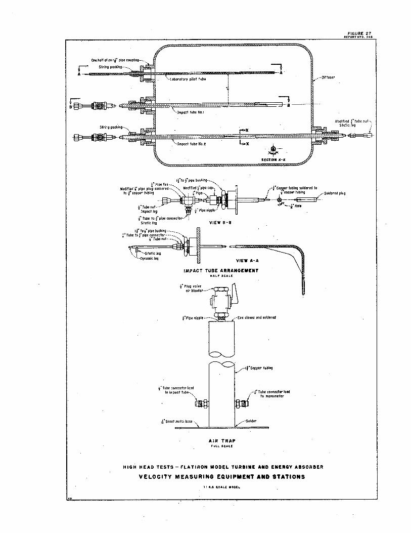
r Siring packing-----
A ·
String packing-.. ,\
-~-
··-Laborafory pilot lube
i
1 ··-Impact tube No. I
. '·-Impact lube No.2
tfto f pipe bushing-- .. -.. f4 Pipe tee--.... . . .. . .. __
7 •• --Diffuser
:7 ·a----..--
--•-· -~
SECTION X•X
FIGURE 27 REPORT HYO, 348
Modlfie_d f tube nut-,, Slal1c 1eg ;
~-
Modified f pipe plug soldered--.,',, Modified f pipe coil-: ' ,,,·~:~;;~JJJ ~-~-' .-f Copeer lubing soldered ta f . ¼ copper lubing .-·Soldered plug
~-~-
f Tube lo ¼"pipe connecfor-· i Slalicleg VIEW B·B
1t" !of pipe bushing-----. f Tube to f pipe connector----........
¼ 11 Tube nut----.. :',,
\ · '·-Static leg ·-J •. Oynamic leg
VIEW A•A
IMPACT TUBE ARRANGEMENT HALF SCALE
t" Plug valve air bleeder-----
f Pipe nipple------- --End closed and soldered r----'-~~~
_ •• -··lfCopper lubing
' ..... ii" Hole
f Tube connector lead to impact tube-.. ,,\ 1-·f Tube connector lead
/ to mtinometer
_ •• --·Solder
AIR TRAP FULL SGAt.E
HIGH HEAD TESTS - Fl-AT IRON MODF;I- TURBINE AND ENERGY ABSORBER
VELOCITY MEASURING EQUIPMENT AND STATIONS
·1: 4,5 $,CALE MODEL
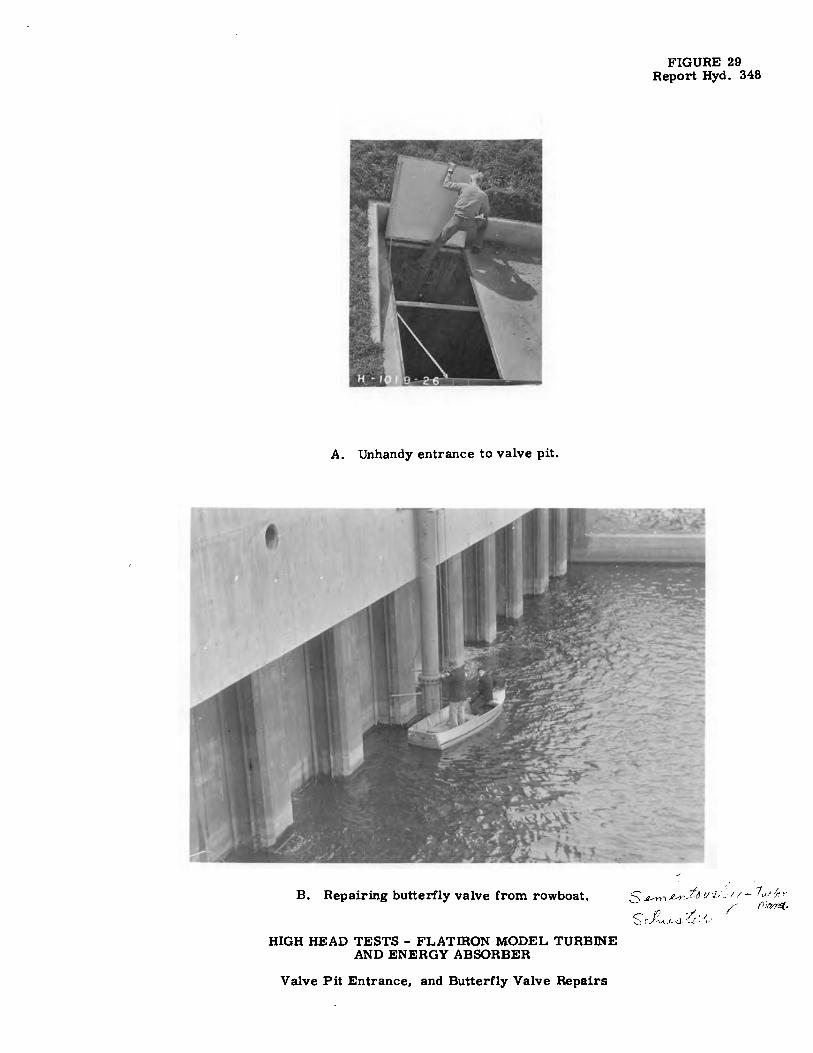
A. Unhandy entrance to valve pit.
B. Repairing butterfly valve from rowboat.
HIGH HEAD TESTS - FLATIRON MODEL TURBINE AND ENERGY ABSORBER
Valve Pit Entrance, and Butterfly Valve Repairs
FIGURE 29 Report Hyd. 348
' ' s V>",~~1f~11i,'~-j/- T..,:f,· . r' f)/M1Gf.. s (',/?.,._,L<J_ ·0;". 1v


![22 12 Umbruch PL - · PDF file= ]h ;>+! 9>* *> 9>* (*= >( # % & ! ! ( "&! ,'$ '# , &&& " " "](https://img.dokumen.tips/doc/110x75/5a78aebd7f8b9a70648b4846/22-12-umbruch-pl-h-9-9-.jpg)
![>'8dd+ 2-9o&%' 2> 8 :+.k':2 + &@>@ - Valor Econô · PDF filefff @qikuy]nmpiauy`y^b^]@`qs@an fff @bn]ccq`q@`qs@an =!$= =!$$ =!$= =!$$](https://img.dokumen.tips/doc/110x75/5a71c3547f8b9aa7538d17e8/8dd-2-9o-2-8-k2-valor-econmicowwwvalorcombrsitesdefaultfilesuploadelement07-03arezzopdf.jpg)


![Ç#Õ S ì æ ? ^ @ #' 1 >& ì&à>' - 神奈川県ホームページ º* b q3 _ ? ? ] ^ z / @ _ ¹ w K > K Z v) s 4 u Z 8 C S u b S ^4 ) )Ê Ç#Õ S ì æ ? ^ @ #' 1 >& ì&à>' l b](https://img.dokumen.tips/doc/110x75/5abd79bd7f8b9aa15e8b9c7a/-s-1-b-q3-z-w-k-k.jpg)