Embed Size (px)
Citation preview

GE
Grid Solutions
MiCOM Agile P642, P643, P645Advanced Transformer Protection, Control and Condition Monitoring
Transformers are high capital cost assets in electrical power systems. Internal faults are a risk for all transformers, with short-circuits dissipating the highest localised energy. Unless cleared quickly, the possibility of rewinding will diminish and core damage may become irreparable.
The MiCOM Agile P642, P643 and P645 address all these issues - preserving service life and offering fast protection for transformer faults. A transient bias technique has been included, enhancing relay stability and CT requirements. CT saturation and no gap detection techniques have been included to improve the low set differential element operating time during CT saturation where the second harmonic blocking might be asserted. An external fault detection algorithm has been incorporated to prevent the CT saturation and no gap detection from affecting the second harmonic blocking when there is an external fault.
Hosted on an advanced IED platform, the P64x incorporates differential, REF, thermal, and overfluxing protection, plus backup protection for uncleared external faults. Model variants cover two and three-winding transformers (including auto-transformers), with up to five sets of 3-phase CT inputs. Large CT counts are common in ring bus/mesh corner applications, where the P64x summate currents to create each total winding current, easing application of backup protection. Backup overcurrent can be directionalised, where the user includes the optional 3-phase VT input or 2-phase VT input in their chosen model.
Customer Benefits
� Universal IED for all transformer configurations
� Protection, control, monitoring, measurements and recording in one device.
� Backup and logging of through faults
� Simple to configure, set, and commission
� Programmable function keys
� Programmable Scheme Logic (PSL) allows easy customization of the protection and control functions
� IEC 61850-9-2 process bus ready & Cyber Security
imagination at work
Key Features� High-speed transformer differential protection
� Simple settings – wizard requires only nameplate data
� Novel CT saturation and no gap detection techniques enhances the low set differential element operating time
� Transient bias algorithm enhances relay stability and reduces CT requirements
� High and low impedance
� Restricted Earth Fault (REF) boosts trip sensitivity
� Voltage, frequency, thermal and overfluxing elements, CT, VT, trip circuit and self- supervision
� Patented CT supervision ensures no spurious trip for CT or wiring failures
� Integrated backup overcurrent per winding or CT input
� Fast reset (less than 1 cycle) circuit breaker failure element
� Readily interfaces with multiple automation protocols, including IEC 61850 with optional redundancy including IEC 62439 PRP, RSTP and software based Ethernet failover (Hot Standby)

As well as transformer protection, the
P64x range may be applied to other unit
applications, such as reactors and
motors. The P64x series is supplied with
a full suite of protection and control
functions as standard.
The configuration column of the menu is
used to control which functions the user
requires in the intended application, and
which may be disabled. Disabled
functions are completely removed from
the menu, to simplify settings.
Differential elements have an inbuilt
configuration wizard to avoid
settings errors.
GEGridSolutions.com
P642, P643, P645 Transformer Protection
Application
The M iC O M Agile P642 is intended for two-
winding transformer applications, with one
set of 3 - phase C Ts per winding. The P643
covers up to 3 bias inputs (three C T sets) -
either a three-winding application, or two-
winding with dual C Ts on one side. W here
4 or 5 feeding connections to the protected transformer exist, the P645 offers five bias
input sets. All models have a single-phase
V T input, mainly for overfluxing protection.
An additional single phase V T input can be
ordered in the P642 to provide N PS over
voltage and directional functions to
some extent.
The P643 and P645 allow an additional 3 -
phase V T input to be connected. This
allows overcurrent back up to be
directionalized, and expands the
measurement and recording analog
channels available. The P643 and P645 can
be configured to protect transformers for
differential protection and the unused C T
inputs can be used to protect other
circuits over current protection of
auxiliary transformers.
2
P642, P643, P645 Transformer Protection
KEY: BRACKETS (•) DENOTE OPTIONAL FEATURES
GEGridSolutions.com
Functional Overview
3

FIGURE 1: System Overview of the P64x series – example 3-winding, 4 bias application)
GEGridSolutions.com
P642, P643, P645 Transformer Protection
Functional Overview
1. The three-phase VT input is optional. The additional single-phase VT input in P643/5 is optional.2. The 27, 59, 59N functions require the three-phase VT input.3. The frequency measurement required by the 81 function is obtained from any analogue signal, but the voltage signals have priority over the current signals.
4
Fast, Sensitive Protection for our Customers' Valuable Assets

FIGURE4: Restricted earth fault application
P642, P643, P645 Transformer Protection
FIGURE3: Typical magnetizing inrush
waveform –showing harmonic distortion
Main Protection
87T Transformer Differential
The algorithm has a triple slope percentage bias restraint, as shown in Figure 2. An internal fault will generate differential current. The bias current is that which merely flows through the protected unit, as a load or through-fed external fault. The initial characteristic is
flat, for ease of commissioning, rising then to bias slope (k1). K1 is a low slope for sensitivity to faults whilst allowing for mismatch when the power transformer is at the limits of its tapchanger range, in addition to any current transformer ratio errors. At currents above rated, extra errors may be gradually introduced as a result of CT saturation, hence the bias slope increases to k2.
The P64x incorporates a transient bias characteristic that increases dynamically the operating current threshold during external faults, thus enhancing differential element stability and CT requirements. To improve the low set differential element operating times, the P64x has a CT saturation and no gap detection technique that prevents the second harmonic blocking from affecting the low set differential element. As a result, fast operating times are achieved during CT saturation and fault levels below high set one and two elements.
R E F : R estricted E arth ( G rou nd ) F au lt
Restricted earth fault protection is included to cover a larger percentage of the transformer windings than might be possible with the main differential
elements. A separate element per winding is provided (P642: HV and LV).
P643/P645: HV, LV, and if required, the TV tertiary too). Low impedance and high impedance REF for conventional transformers and autotransformers are available.
Figure 4 shows a typical restricted earth fault application. B iased REF is used, to avoid the need for any stabilising resistor
or varistor/ metrosil. REF elements operate independently of inrush detection, potentially offering faster tripping for low or moderate fault currents, in addition to enhanced sensitivity. Low impedance REF element stability is enhanced by transient bias algorithm.
GEGridSolutions.com
FIGURE 2: Biased differential protection (87T)
5
The CT saturation and no gap detection distinguish between magnetising inrush and saturated current waveforms. An external fault detection technique has been included to prevent the CT saturation and no gap detection from affecting the second harmonic blocking during external faults, thus maintaining stability.
Energization of a transformer causes magnetising inrush current to flow in one winding only and the differential elements may need stabilising whilst the inrush persists (see Figure 3). A proven second harmonic current ratio scheme is used. The differential protection may also be restrained when the transformer is overfluxed so that an instantaneous trip is not issued for transient overfluxing. O verfluxing restraint is conditioned by the percentage of fifth harmonic current present. Two high set instantaneous differential elements, not subject to
harmonic restraint, are provided to ensure rapid clearance of high current faults.
The differential protection setting configuration utility requires only known data – that which resides on the transformer rating plate, the CT rating plate and information on any in-zone earthing transformer.

Back-up Protection
The P642, P643, and P645 are delivered with comprehensive back-up protection. Typically this will be used in time-delayed mode to improve fault detection dependability for system (out-of-zone) faults. System integrity can also be improved, utilising internal elements for load-shedding, interlocking, alarm, or other purposes.
Current-Based Protection
Each winding, whether the current is directly measured from one CT input, or is a virtual summation from two CTs, has the followingelements available:
� Phase fault overcurrent
� Negative sequence overcurrent
� Earth (ground) fault
2ndndndnd Harmonic Blocking
The 2nd harmonic blocking detects high inrush current inflows that occur when downstream transformers or machines are connected. The function will block the phase overcurrent, earth fault and REF.
Up to four stages of each element, per winding, are available – with a choice of standard IEC and ANSI/IEEE IDMT curves, instantaneous, and definite time operation. Where a P643/P645 has the 3-phase VT or a P642 has the 2 single phase VTs, any of the current protection applied on the same winding as the VT location may be directionalised. Overcurrent elements, directionalised if necessary, can be useful to clear reverse-fed upstream faults, or for protection of adjacent busbars. At distribution and industrial voltage levels, low-cost bus protection schemes can be configured using the “reverse interlocking” principle. This is a logic-based scheme, which will trip should a fault current flow onto the busbar not be accompanied by an external fault start on an outgoing circuit.
The earth fault protection is configurable to operate either in measured, or derived mode. “Measured” denotes that the winding (or external earthing transformer) has a star-point single phase CT availablein the Y-ground connection, and the user wishes this current to be used to implement standby earth fault (SBEF). “Derived” is set for delta windings, or other cases where the user prefers to use the calculated residual current from the 3-phase CTs.
GEGridSolutions.com
P642, P643, P645 Transformer Protection
Thermal Overload
All models offer thermal overload protection based on the IEEE Standard C57 .9 1-19 9 5, with the extent of protection being the choice of the customer. The most simple application employs I² t characteristic. Time constants are set, such that the thermal model can follow the correct exponential heating and cooling profile, replicating the winding hotspot temperature. Four cooling modes are available, and the oil exponent and winding
exponent can be set independently for each mode. Alarm and trip thresholds are available as outputs.
To enhance the thermal replica, ambient and/or top-oil temperature compensation may be applied. This is achieved by fitting the RTD board option, and positioning the PT10 0 probes appropriately (outdoors, or within the transformer tank). Additionally, alarm and trip setpoints can be applied for any probe input, should an absolute measured temperature at the probe location be of interest. Ten independent probe inputs are available, making radiator pump and fan control an additional possibility using the relay’s programmable scheme logic (PSL).
Thermal overload protection is a closely-related companion function to the Loss of Life monitoring feature described later.
V/Hz Overfluxing Protection
The single-phase voltage input may be connected ph-ph or ph-neutral and is provided to enable overfluxing detection. Alarm and tripping characteristics, which are based on a measurement of the voltage/ frequency ratio, are provided.
The alarm is definite time delayed whilst the trip characteristic may be applied with up to four definite time (DT) elements, or an IDMT curve plus up to three DT elements.
The optional additional 3-phase VT input available in the P643 and P645 allows overfluxing to be applied on both HV and LV sides of the transformer, to ensure optimum protection, irrespective of the loadflow direction. Both thermal overload and overfluxing elements are essentially thermal based, modelling winding and oil heating, or heating of core bolts and laminations. Due to time constants being in minutes (rather than seconds), heating and cooling of both replicas can be relatively slow.
6
A pre-trip countdown is provided, displaying the time remaining to trip if the present level of load, or flux were to be maintained. A pre-trip alarm can be applied, notifying the dispatcher that he/she has a certain number of minutes for remedial action, before a trip is likely. After any injection testing, all replicas can be forced to reset via a user command.
Circuit Breaker Failure
The breaker failure protection may be initiated from internal protection within the P64x, and also from external devices. In the case of Buchholz (sudden pressure) relays, the CBF elements for all breakers must be initiated in parallel. Where external feeder or busbar protection is applied to trip only one (or more) breaker(s), the P64x has the ability to initiate the CBF scheme on a per breaker basis. Retripping and back-tripping schemes are supported, all with a fast reset. A zero crossing detection algorithm has been implemented to allow fast reset of the CBF element considering subsidence current. The CBF element resets in less than 1 cycle. Independent settings per circuit breaker have been implemented.
A neutral earth fault undercurrent element is available per circuit breaker, and it can be set as either measured or derived. A maximum of three single phase CT inputs are available to be used by the CBF.
Supervisory Functions
Voltage transformer supervision is provided to detect loss of one, two or three VT signals (P643 and P645 models fitted with a 3-phase VT and P642 fitted with 2 single phase VT inputs). Current transformer supervision is provided to
detect loss of phase CT input signals. Using the “differential CTS” feature (patented), the relay performs an intelligent comparison of the negative sequence current imbalance at all CT terminals, to determine which, if any, CTs have failed. This comparison detects all CT shorts, open circuits, and wiring disconnections without an inherent time delay. Operation of the differential protection can be restraint during the failure to avoid an unwanted trip. The CTS thus assures real-time stability of the differential elements, and any applicable REF protection.

Condition Monitoring
Loss of Life (LoL)
Frequent excesses of transformer rated current or operation at elevated temperatures will shorten the life expectancy of the transformer. The P64x provides a transformer loss-of-life calculation, using a thermal model that estimates the hot spot temperature. The insulation deterioration is assumed to follow an adaptation of the Arrhenius theory where insulation life and absolute temperature are inversely proportional (as per IEEE Std. C57.91-1995).
The LoL implementation includes:
� Daily writing into non-volatile memory
� Accumulated Loss of Life, Rate of Loss of Life, Ageing Acceleration Factor, and Residual Life Hours stored
� Alarm setpoints available on attaining instantaneous or cumulative levels
� Statistics can be reset if a device is relocated to monitor another transformer
P642, P643, P645 Transformer Protection
Programmable scheme logic
Powerful graphical logic allows the user to customise the protection and control
functions. The gate logic includes OR, AND and MAJORITY gate functions, with the ability to invert the inputs and outputs and provide feedback. Also logic counters are available. The system is optimised to ensure that the protection outputs are not delayed by the PSL operation. The programmable scheme logic is configured using the graphical S1 Agile software, as shown in Figure 5. The relay outputs may be configured as latching (e.g. "Lockout") or self-reset. Time delays and interlocking schemes are possible within the PSL.
Voltage Protection*
Two stages each are available for phase overvoltage and phase undervoltage in the P643/5 when the 3-phase VT is ordered. One stage is available for negative phase sequence overvoltage when the 3-phase VT is ordered (P643/5) or the 2 single phase VTs is ordered (P642). Residual overvoltage (neutral
displacement) is also available when the 3 phase VT is ordered (P643/5). Such elements are particularly useful to detect voltage regulation errors and earth faults.
Voltage Dependent Overcurrent Protection *
In order to provide backup phase fault protection for generator-transformers or to provide more sensitive overcurrent protection for close up faults, a voltage dependent overcurrent element (either controled or restrained) is included. Two
definite time or IDMT stages are available.
* Available when optional 3-phase VT input is
ordered in P643 or P645 and 2 single phase VT
inputs is ordered in P642
Frequency Protection
Four stages of underfrequency and two stages of overfrequency are provided, permitting load shedding and restoration schemes to be implemented. The frequency protection may consider any analogue signal, having the voltage signal the preference.
Control
User Interface
Integrated user function keys and programmable LEDs provide a cost-effective solution for full transformer schemes. The P643 and P645 offer higher functionality, with ten function keys operating in two modes, normal and toggled, each with an associated tricolour
LED for clear indication of the logic status. Typical control, maintenance, and commissioning options are initiated directly from simple key presses, rather than the need to navigate a menu.
Programmable Scheme Logic
Powerful graphical logic allows the user to customise the protection and control
functions. The gate logic includes OR, AND and MAJORITY gate functions, with the ability to invert the inputs
Figure 5 Programmable scheme logic & S1 Agile:
a powerful and intuitive PC-toolsuite
GEGridSolutions.com
Through Fault Monitoring
Through faults are a major cause of
transformer damage and failure, stressing the insulation and mechanical integrity. An I²t calculation based on recorded duration and maximum current is stored for each phase. Calculation results are added to cumulative values, and monitored so that users can schedule transformer maintenance or identify a need for system reinforcement. The last five triggers are stored as special individual records.
Measurement and Recording
Pow er System Measurements
(MMX U)
Multiple measured analog quantities, with phase angles, are provided. These include:
� Phase and neutral currents for all windings, plus sequence components and 2nd harmonic component magnitudes
� Measurements of all voltage inputs
� Frequency, power factor, Watts and VArs
� Maximum demand and rolling values
� Bias currents, differential currents
� All thermal states, temperatures, and loss-of-life
� Measurements can be assigned to CLIO
Event records
Time-tagged event records are stored in battery backed memory. An optional modulated or demodulated IRIG-B port is available for accurate time synchronization.
7
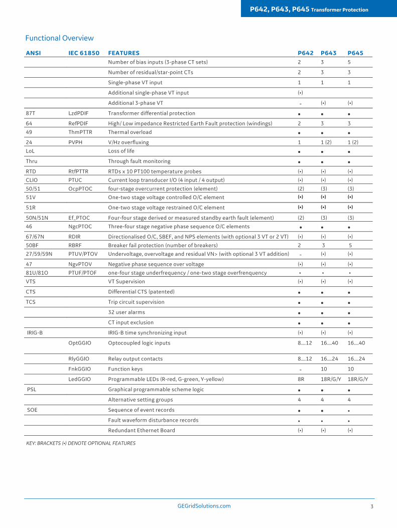
Communication to Remote Operators and Substation Automation
Two auxiliary communication ports are available; a rear port providing remote communications and a front port providing local communications.
An additional, second rear port can be ordered as an option. Any of the following rear port protocols can be chosen at the time of ordering: Courier/K-Bus, MODBUS, IEC 60870-5- 103, DNP3.0, or IEC 61850. An Ethernet port is available as an option for IEC61850 or DNP3.0. Px4x devices can be enhanced with an optional redundant Ethernet board. The redundancy is managed by the market's fastest recovery time protocols: IEC 62439-3 PRP and HSR allowing bumpless redundancy and RSTP (Rapid Spanning Tree) protocol, offering multi-vendor interoperability. The redundant Ethernet board supports either modulated or demodulated IRIG-B and the SNTP protocol for time synchronisation. The redundant Ethernet board also has a watchdog relay contact and an SNMP interface to alarm in case of a failure.
Second Rear Courier Port
The optional second port is designed typically for dialup modem access by protection engineers / operators, when the main port is reserved for SCADA traffic.
MiCOM P40 Agile
GE’s philosophy is one of continuous improvement in our products and solutions. Our emphasis on communication in MiCOM has become a focus which secures leadership in the digital substation. To mark this phase of evolution, the brand “P40 Agile” is applied to the range. P40 Agile is a mark of performance and quality, proudly available from GE, and only from GE.
Fault Records
� Indication of the faulted phase
� Protection operation
� Active setting group
� Relay and CB operating time
� Pre-fault and fault currents
� Bias and differential currents
Disturbance Records
High performance waveform records contain all CT and VT input channels, plus up to 32 digital states, extracted in COMTRADE format.
IEC 61850-9-2 Process Bus Interface
An optional process bus interface is available, allowing the relay to receive current and voltage sampled data from non-conventional instrument transformers such as optical and Rogowski devices. In other digital substation architectures, the -9-2 data is generated by merging units in the yard, which digitize conventional 1 A/5 A and 100/120 V secondaries, for safer and more economical cross-site communication to IEDs by fibre optic. Grid Solutions' -9-2 implementation has been designed to be especially resilient and reliable in the presence of "noise", such as latency, jitter or missing/suspect data.
Plant Supervision
Trip Circuit Supervision
Supervision of the trip circuit can be implemented using optocoupled inputs and the programmable scheme logic.
Analog (Current Loop) Inputs and Outputs (CLIO)
Four inputs are provided for transducers with ranges of 0-1 mA, 0-10 mA, 0-20 mA or 4-20 mA. Associated with each input there are two time delayed protection stages, one for alarm and one for trip. Each stage can be set for 'Over' or 'Under' operation.
For more information please contact
GE Grid Solutions
Worldwide Contact CenterWeb: www.GEGridSolutions.com/contact
Phone: +44 (0) 1785 250 070
GEGridSolutions.com
IEC is a registered trademark of Commission Electrotechnique Internationale. IEEE is a registered trademark of the Institute of Electrical Electronics Engineers, Inc.
GE and the GE monogram are trademarks of General Electric Company.
GE reserves the right to make changes to specifications of products described at any time without notice and without obligation to notify any person of such changes.
Grid-GA-L3-P64x-0688-2016_12-EN. © Copyright 2016, General Electric Company. All Rights Reserved.
imagination at work

![Total No. of Questions : 6] SEAT No. : P645 [Total …...Total No. of Questions : 6] [Total No. of Pages : 3 [4325]-201 (Semester - II) ˘ˇˆ˙ ˝˛ˇ˘˚˜ !ˆ˚˚˝˜"# ˘ ˇ ˆˇ](https://img.dokumen.tips/doc/110x75/5e72c45e8370205112736b07/total-no-of-questions-6-seat-no-p645-total-total-no-of-questions-.jpg)


![Home [] · ˆ =ˆ - $ #$ ˆ =ˆ ˆ # # #$ ˙ 8 ˆ # > $ # =ˆ ) # $ˆ 8 # # # # # #$ ˆ](https://img.dokumen.tips/doc/110x75/60ebdcabf181280b2f133a78/home-8-8-.jpg)