Embed Size (px)
Citation preview

© 2014 Atego
Modeling Systems-of-Systems and Management of Design Variations
Matthew Hause – Atego

© 2014 Atego 2

© 2014 Atego 3
Agenda
• Introduction
• Model Based Systems & Software Engineering (MBSE)
• Systems of Systems
• Asset-Based Modular Design
• Model-based Product Lines– Variant Modeling– Variant Selection– Product Model Creation
• Model-based Product Line Engineering (MB-PLE)
• Summary

© 2014 Atego 4
Applying Model-Based Product Line Engineering can Reduce Total Development Costs by 62% and Deliver 23% More Projects on Time*
* (EMF 2013 Independent Survey Results from 667 Systems Engineering respondents)
Starting With What’s Possible …

© 2014 Atego 5
Issues/Challenges Facing Systems Engineering Organizations
Business Based Increasing Time Pressures
• Shorter Development Cycles
• Delivering on Schedule Cost Reduction Demands
• Total Development Cost
• Risks/Costs associated with delays and cancellations Larger & More Distributed Teams
• Communication & Collaboration
• Implementing Common, Architected Goals Quality Assurance
• Risk of Building the Wrong System
• Increased Costs of Later Stage Errors

© 2014 Atego 6
Issues/Challenges Facing Systems Engineering Organizations
Technical/Technology Based Growing Complexity & Functionality of Systems & Software
• Software comprises growing share of total systems Cost & Capability
• System & Sub-system Integration
• Certification, Regulation & Standards Compliance
• The Move to ‘Systems Thinking’ – Requirements, Design, Integration, Testing

© 2014 Atego 7
Agenda
• Introduction
• Model Based Systems & Software Engineering (MBSE)
• Systems of Systems
• Asset-Based Modular Design
• Model-based Product Lines– Variant Modeling– Variant Selection– Product Model Creation
• Model-based Product Line Engineering (MB-PLE)
• Summary
© 2014 Atego 8
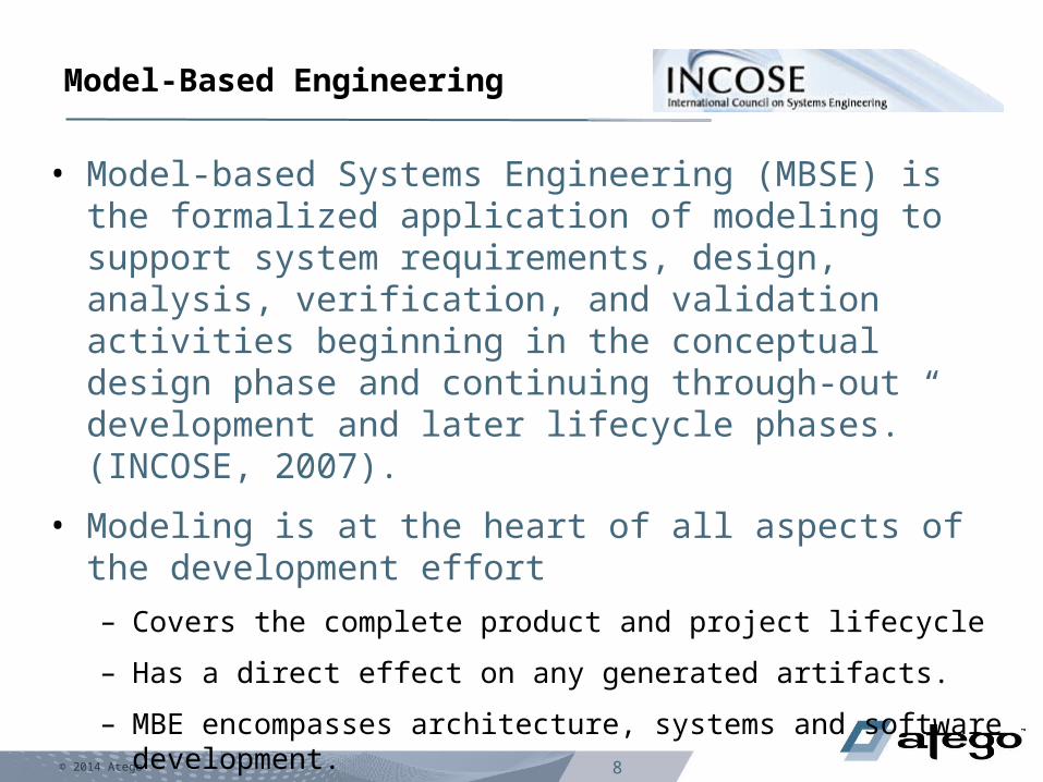
Model-Based Engineering
• Model-based Systems Engineering (MBSE) is the formalized application of modeling to support system requirements, design, analysis, verification, and validation activities beginning in the conceptual design phase and continuing through-out development and later lifecycle phases.” (INCOSE, 2007).
• Modeling is at the heart of all aspects of the development effort
– Covers the complete product and project lifecycle
– Has a direct effect on any generated artifacts.
– MBE encompasses architecture, systems and software development.

© 2014 Atego 9
Changes in Systems Engineering Practice
Requirement SpecificationsInterface DefinitionsSystem ArchitectureSystem FunctionalityTrade-off AnalysisTest SpecificationsEtc.
Change from Document centric to Model centric
AirplaneATC Pilot
Request to proceed
Authorize
Power-up
Initiate power-up
Direct taxiway
Report Status
Executed cmds
Initiate Taxi
Old Approach New Approach

© 2014 Atego 10
The Four Pillars of SysML
ibd [Block] Anti-Lock Controller1
«Block»Anti-Lock Controller
«BlockProperty»d1 : Traction Detector
«BlockProperty»m1 : Brake Modulator
«BlockProperty»d1 : Traction Detector
«BlockProperty»m1 : Brake Modulator
c1:modulator interface
Use
Interaction
par [constraint] StraightLineVehicleDynamics [Parametric Diagram]
Structure
Parametrics
Vehicle SystemSpecification
Braking SubsystemSpecification
«requirement»
id#102
txtThe vehicle shall stop from60 mph within 150ft on aclean dry surface.
Stopping Distance
«requirement»
id#337
txtThe Braking subsystem shallprevent wheel lockup underall braking conditions.
Anti-Lock Performance
req [Package] Vehicle Specifications [Braking]
«deriveReqt»
Requirements
bdd [Package] Vehicle [ABS]
«Block»Library::
ElectronicProcessor
«Block»Anti-LockController
«Block»Library::
Electro-HydraulicValve
«Block»TractionDetector
«Block»Brake
Modulator
d1 m1
Definition
Gripping Slipping
LossOfTrac tion/
RegainTrac tion/
stm Tire [Traction] State Machine
Detect Loss Of Traction
TractionLoss Modulate Braking Force
act PreventLockup
Activity/Function
Behavior
© 2014 Atego 11
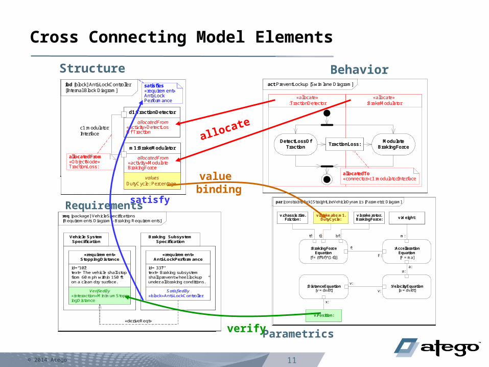
Cross Connecting Model Elements
ibd [block] Anti-LockController [Internal Block Diagram]
d1:Traction Detector
m1:Brake Modulator
c1:modulator interface
ibd [block] Anti-LockController [Internal Block Diagram]
allocatedFrom«activity»DetectLosOfTraction
d1:TractionDetector
allocatedFrom «activity»Modulate BrakingForce
m1:BrakeModulator
allocatedFrom«ObjectNode»TractionLoss:
c1:modulatorInterface
act PreventLockup [Activity Diagram]
DetectLossOf Traction
Modulate BrakingForce
TractionLoss:
par [constraintBlock] StraightLineVehicleDynamics [Parametric Diagram]
:AccellerationEquation[F = ma]
:VelocityEquation[a = dv/dt]
:DistanceEquation[v = dx/dt]
:BrakingForceEquation
[f = (tf*bf)*(1-tl)]
tf: bf:tl:
f:
F:
c
a:a:
v:
v:
x:
Structure Behavior
Parametrics
act PreventLockup [Swimlane Diagram]
«allocate»:TractionDetector
«allocate»:BrakeModulator
allocatedTo«connector»c1:modulatorInterface
DetectLossOf Traction
Modulate BrakingForce
TractionLoss:
req [package] VehicleSpecifications [Requirements Diagram - Braking Requirements]
Braking Subsystem Specification
Vehicle System Specification
id=“102”text=”The vehicle shall stop from 60 mph within 150 ft on a clean dry surface.”
«requirement»StoppingDistance
id=”337"text=”Braking subsystem shall prevent wheel lockup under all braking conditions.”
«requirement»Anti-LockPerformance
«deriveReqt»
ibd [block] Anti-LockController [Internal Block Diagram]
allocatedFrom«activity»DetectLosOfTraction
d1:TractionDetector
allocatedFrom «activity»Modulate BrakingForce
m1:BrakeModulator
allocatedFrom«ObjectNode»TractionLoss:
c1:modulatorInterface
satisfies«requirement»Anti-LockPerformance
req [package] VehicleSpecifications [Requirements Diagram - Braking Requirements]
Braking Subsystem Specification
Vehicle System Specification
id=“102”text=”The vehicle shall stop from 60 mph within 150 ft on a clean dry surface.”
«requirement»StoppingDistance
SatisfiedBy«block»Anti-LockController
id=”337"text=”Braking subsystem shall prevent wheel lockup under all braking conditions.”
«requirement»Anti-LockPerformance
«deriveReqt»
ibd [block] Anti-LockController [Internal Block Diagram]
allocatedFrom«activity»DetectLosOf Traction
d1:TractionDetector
valuesDutyCycle: Percentage
allocatedFrom «activity»Modulate BrakingForce
m1:BrakeModulator
allocatedFrom«ObjectNode»TractionLoss:
c1:modulatorInterface
satisfies«requirement»Anti-LockPerformance
par [constraintBlock] StraightLineVehicleDynamics [Parametric Diagram]
:AccellerationEquation[F = ma]
:VelocityEquation[a = dv/dt]
:DistanceEquation[v = dx/dt]
:BrakingForceEquation
[f = (tf*bf)*(1-tl)]
tf: bf:tl:
f:
F:
m:
a:a:
v:
v:
x:
v.Position:
v.Weight:v.chassis.tire.
Friction:v.brake.abs.m1.
DutyCycle:v.brake.rotor.BrakingForce:
req [package] VehicleSpecifications [Requirements Diagram - Braking Requirements]
Braking Subsystem Specification
Vehicle System Specification
VerifiedBy«interaction»MinimumStoppingDistance
id=“102”text=”The vehicle shall stop from 60 mph within 150 ft on a clean dry surface.”
«requirement»StoppingDistance
SatisfiedBy«block»Anti-LockController
id=”337"text=”Braking subsystem shall prevent wheel lockup under all braking conditions.”
«requirement»Anti-LockPerformance
«deriveReqt»
satisfy
verify
value binding
allocate
Requirements

© 2014 Atego 12
Agenda
• Introduction
• Model Based Systems & Software Engineering (MBSE)
• Systems of Systems
• Asset-Based Modular Design
• Model-based Product Lines– Variant Modeling– Variant Selection– Product Model Creation
• Model-based Product Line Engineering (MB-PLE)
• Summary

© 2014 Atego 13
• Increasingly important in civilian and military systems– An SoS is a “set or arrangement of systems that
results when independent and useful systems are integrated into a larger system that delivers unique capabilities.” • DoD Defense Acquisition Guidebook
– “Key to addressing the evolution of complex systems of systems. SE principles and tools can be used to apply systems thinking and engineering to the enterprise levels.”• FEAF, 1999
Systems of Systems (SoS)
© 2014 Atego 14
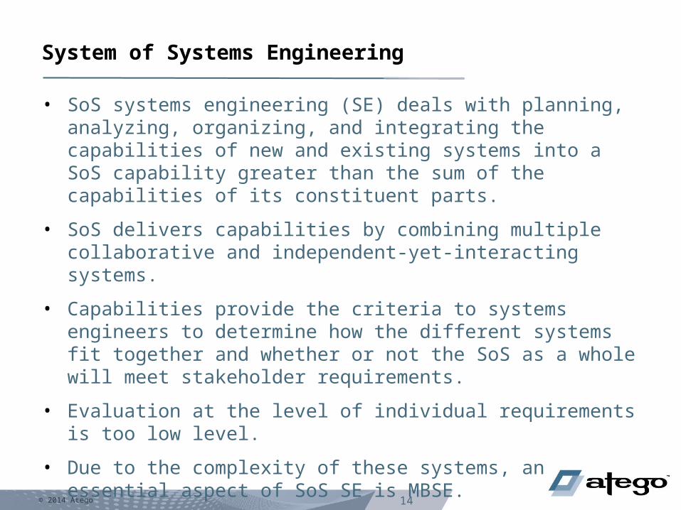
• SoS systems engineering (SE) deals with planning, analyzing, organizing, and integrating the capabilities of new and existing systems into a SoS capability greater than the sum of the capabilities of its constituent parts.
• SoS delivers capabilities by combining multiple collaborative and independent-yet-interacting systems.
• Capabilities provide the criteria to systems engineers to determine how the different systems fit together and whether or not the SoS as a whole will meet stakeholder requirements.
• Evaluation at the level of individual requirements is too low level.
• Due to the complexity of these systems, an essential aspect of SoS SE is MBSE.
System of Systems Engineering

© 2014 Atego 15
DoD Architecture Framework 2.0 Views
All V
iewp
oin
tO
verarchin
g asp
ects of arch
itecture co
ntext th
at relate to all
mo
dels
Data an
d In
form
ation
View
po
int
Articu
late the d
ata relation
ship
s and
align
men
t structu
res in th
e arch
itecture co
nten
t
Stan
dard
s Vie
wp
oin
t A
rticulate ap
plicab
le Op
eration
al, Bu
siness, Tech
nical, an
d
Ind
ustry p
olicy, stan
dard
s, gu
idan
ce, con
straints, an
d fo
recasts
Systems ViewpointArticulate the legacy systems or
independent systems, their composition, interconnectivity, and context providing for,
or supporting, DoD functions
Services Viewpoint Articulate the performers, activities,
services, and their exchanges providing for, or supporting, DoD functions
Operational ViewpointArticulate operational scenarios, processes,
activities & requirements
Capability/Strategic Viewpoint Articulate the capability requirement,
delivery timing, and deployed capability
Pro
ject/A
cqu
isition
View
po
int
Describ
es the relatio
nsh
ips b
etween
op
eration
al and
capab
ility req
uirem
ents an
d th
e variou
s pro
jects bein
g im
plem
ented
; D
etails dep
end
encies b
etween
capab
ility man
agem
ent an
d th
e D
efense A
cqu
isition
System
pro
cess.
Architecture viewpoints are composed of data that has been organized to facilitate understanding.
© 2014 Atego 16
The Unified Profile for DoDAF and MODAF (UPDM)
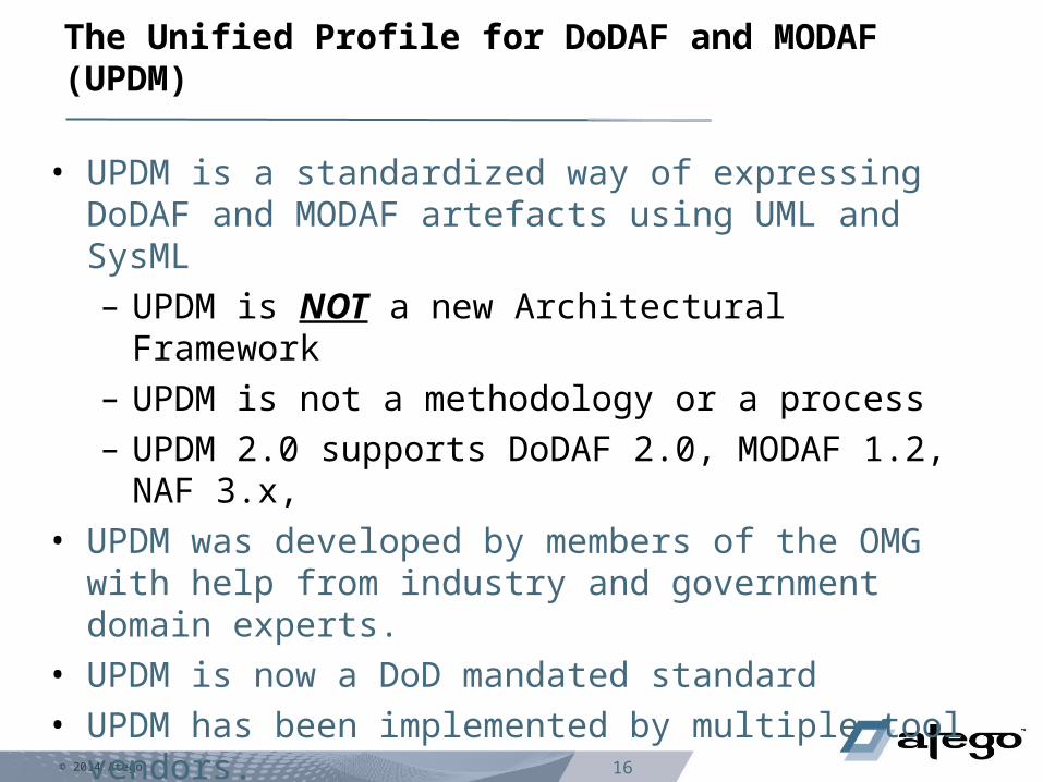
• UPDM is a standardized way of expressing DoDAF and MODAF artefacts using UML and SysML– UPDM is NOT a new Architectural Framework– UPDM is not a methodology or a process– UPDM 2.0 supports DoDAF 2.0, MODAF 1.2, NAF
3.x,• UPDM was developed by members of the OMG with
help from industry and government domain experts.• UPDM is now a DoD mandated standard• UPDM has been implemented by multiple tool vendors.– Tools supporting UPDM are available now, including
of course by Atego.
International Workshop26 Jan – 29 Jan 2013
Jacksonville, FL, USA
MBSE Workshop
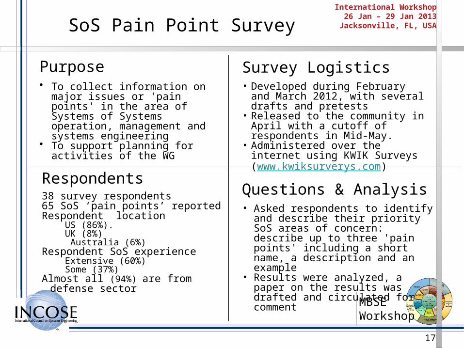
SoS Pain Point Survey
Purpose• To collect information on major issues
or 'pain points' in the area of Systems of Systems operation, management and systems engineering
• To support planning for activities of the WG
Respondents38 survey respondents 65 SoS ‘pain points’ reportedRespondent location
US (86%). UK (8%) Australia (6%)
Respondent SoS experienceExtensive (60%)Some (37%)
Almost all (94%) are from defense sector
Survey Logistics• Developed during February and March
2012, with several drafts and pretests• Released to the community in April
with a cutoff of respondents in Mid-May.
• Administered over the internet using KWIK Surveys (www.kwiksurverys.com)
Questions & Analysis• Asked respondents to identify and
describe their priority SoS areas of concern: describe up to three 'pain points' including a short name, a description and an example
• Results were analyzed, a paper on the results was drafted and circulated for comment
17

International Workshop26 Jan – 29 Jan 2013
Jacksonville, FL, USA
MBSE Workshop
SoS Pain Points
Pain Points QuestionLack of SoS Authorities & Funding
What are effective collaboration patterns in systems of systems?
Leadership What are the roles and characteristics of effective SoS leadership?
Constituent Systems What are effective approaches to integrating constituent systems into a SoS?
Capabilities & Requirements How can SE address SoS capabilities and requirements?
Autonomy, Interdependencies & Emergence
How can SE provide methods and tools for addressing the complexities of SoS interdependencies and emergent behaviors?
Testing, Validation & Learning How can SE approach the challenges of SoS testing, including incremental validation and continuous learning in SoS?
SoS Principles What are the key SoS thinking principles, skills and supporting examples?
Survey identified seven ‘pain points’ raising a set of SoS SE questions
18

© 2014 Atego 19
How NOT to Model Systems of Systems

© 2014 Atego 20
Disaster Relief Challenge….Provide Ice:
• Goals and Objectives: For the challenge, show how today’s tools can be used and
integrated together to support planning, analysis, decision making, communications,
and documentation and reporting while minimizing duplication of effort, or data entry.
Refer to the listing of Goals and Objectives posted on the TVC page for a full listing of
all Goals and Objectives to consider including as part of your demonstration.
• Challenge: It is summer time in Pleasantville, a rural US town located in a temperate
climate zone currently experiencing temperatures ranging between 70 – 100 degrees
Fahrenheit (20-35 C). A recent natural disaster has devastated the area within a 100
mile radius. An estimated 3000 people lost their homes due to the destruction, and
need to find shelter. Most roads are impassible by public so there is limited vehicle
transportation and the electricity is out in most of the disaster area. As part of
emergency response requirements, shelters must be set up within 24 hours from
when the evacuations begin to help sustain those who need to relocate. As part of
the initial emergency response, ice must be provided to sustain perishables such as
medicine and foods, and to support first aid needs. Power and potable water are to
be provided with the shelter solution.

© 2014 Atego 21
Operational Concept for Disaster Relief

© 2014 Atego 22
Operational Concept for Disaster Relief Internals

© 2014 Atego 23
Dictionary of Project Capabilities

© 2014 Atego 24
Capability Dependencies for Manage Environmental Incidents

© 2014 Atego 25
System Structure for Disaster Response

© 2014 Atego 26
System Structure for Victim Support

© 2014 Atego 27
Agenda
• Introduction
• Model Based Systems & Software Engineering (MBSE)
• Systems of Systems
• Asset-Based Modular Design
• Model-based Product Lines– Variant Modeling– Variant Selection– Product Model Creation
• Model-based Product Line Engineering (MB-PLE)
• Summary

© 2014 Atego 28
Methods for Re-Use are Not New…
A standards-based Integrated, Practical & Pragmatic Solution Combining 2 Powerful Paradigms for ‘Model-Based Product Line Engineering’ Model-base Systems & Software Engineering (MBSE) Extending into Variable Product Families (PLE) with a Well Documented Value Proposition
(Linda Northrop, SEI SSPL 2008-2012)
System & Software Product
Lines
2005+ Software Product Lines
2000sServices
1990sComponents
1980sObjects
1970sModules
1960sSubroutines

29 © 2013 Atego
Asset-based Modular Design
Design the same way you Build− Construct Systems of Sub-Systems (SoS)
− Use Services to build your Application (SOA)
− Plug Components together (CBD)
Modular Design− Top-Down, Architected
− Specification (& Requirements) Driven− Parallel Working− Separation of Concerns
− Bottom-Up, Asset Mining− Un-modeled Assets− Other Modeling Tools− Legacy Integration− Published Interfaces (e.g. IDL)

© 2014 Atego 30
• Defines reusable assets, their interfaces, characteristics and supporting elements.
• Three dimensions describe reusable assets:
– Granularity describes problems or solution alternatives a packaged asset addresses.
– Variability and visibility vary from black-box assets, to white box assets, clear-box and gray-box assets.
– Articulation describes the degree of completeness of the artifacts in providing the solution.
– Asset specifications includes supporting documentation, requirements addressed, interfaces, etc.
– A modular, multi-level approach avoids the spaghetti diagrams
The Reusable Asset Specification (RAS)

31 © 2013 Atego
Asset-Based Modular Design
Models + Asset Library = Configuration Models
System Model 2System Model 1
Sub-System 2
Sub-System 1
Asset Library
Asset 1(Sub-System
Model)
Asset 2(Sub-System
Model)
Asset 3(Sub-System
Model)
Asset 4(Sub-System NO
Model)
Sub-System 2
Asset 1 Asset 2 Asset 3 Asset 4
Higher LevelModels
Links via Assets
Lower LevelModels
etc.
V1.0 V1.1
V2.0
V2.0
V2.0
V3.0
V3.0
V3.0
V3.0
V4.0

© 2014 Atego 32
View of Asset Library connectivity (OSLC)

© 2014 Atego 33
System Overview of an Ice Plant

© 2014 Atego 34
Atego Asset Library View in other model

© 2014 Atego 35
Block Definition Diagram of Distiller
bdd [Package] Distiller Structure [Structural Breakdown]
«block»
operationspowerOn ()powerOff ()Remove Latent Heat of Vaporisation ()Add Latent Heat of Vaporisation ()
Boiler«block»
operationsRemove Latent Heat of Vaporisation ()Add Latent Heat of Vaporisation ()
Valve
«block»
operationsTurnOn ()TurnOff ()Remove Latent Heat of Vaporisation ()Add Latent Heat of Vaporisation ()
Distiller
«block»
operationsRemove Latent Heat of Vaporisation ()Add Latent Heat of Vaporisation ()
Heat Exchanger
hx1 bx1 drain
satisfies«requirement» HeatExchanger
satisfies«requirement» HeatExchanger
satisfies«requirement» Boiler
satisfies«requirement» Boiler
satisfies«requirement» Drain
satisfies«requirement» Drain

© 2014 Atego 36
Block Definition Diagram of Types
bdd [Package] Item Types
«block»
valuesdegrees C : tempkg/gm^2 : pressgm/sec : massFlowRate
Residue
«block»
valuesdegrees C : tempkg/gm^2 : pressgm/sec : massFlowRate
Fluid«block»
valuescal/sec : dQ/dt
Heat
«block»
operationsRemove Latent Heat of Vaporisation ()Add Latent Heat of Vaporisation ()
valuesdegrees C : tempkg/gm^2 : pressgm/sec : massFlowRatecal/gm : specificHeatcal/(gm*deg C) : latentHeat
H2O

© 2014 Atego 37
Distiller model complete system

© 2014 Atego 38
• Lack of SoS Authorities and Funding– Modeling cannot provide authority or funding. – MBSE has begun to demonstrate true ROI– These techniques will provide ROI to decrease the
cost of developing SoS. – The Asset library provides metrics to demonstrate
cost savings for reuse. • Includes the development effort required to create the
original asset, and the estimated effort to reuse the asset.
• The reuse effort subtracted from the development effort provides an estimated time saving.
• The overall total savings for each asset library is also summarized.
Addressing Pain Points

© 2014 Atego 39
• Constituent Systems– Integrating constituent systems is difficult– Clearly defined system interfaces, capabilities,
requirements, behavior, characteristics, etc. is essential for any meaningful integration.
– Integrating system models as black box systems, means engineers can concentrate on the individual system definitions.
– With clearly defined system interfaces, development of these systems can take place in parallel without affecting the other models.
– The SoS model can then examine the interaction of the individual systems as a whole.
Addressing Pain Points

© 2014 Atego 40
• Capabilities and Requirements– Defining systems with capabilities specifies the
purpose and benefits of a system at a high level. – Capabilities describe desired outcomes as well as
specifying stakeholders and realizing resources.– Architects and engineers can determine capability
overlaps as well as capability gaps. – Shows how systems work together at a capability
level.– Useful when no model exists of the existing system. – When models do exist, system functions and
requirements they satisfy provide more detailed analysis examination.
Addressing Pain Points

© 2014 Atego 41
• Autonomy, Interdependencies and Emergence– Emergent behavior is often unpredictable. – The real problems of systems integration only come
to light when they are integrated together in the field under real conditions.
– Modeling and simulation of SoS can help, but no test or set of tests can predict all possible outcomes.
– As modeling simulation techniques improve and a critical mass of system models is built up, problems involving emergent behavior can be found, diagnosed and mitigated before the systems are fielded.
Addressing Pain Points
© 2014 Atego 42
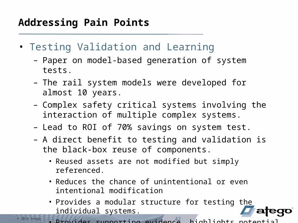
• Testing Validation and Learning– Paper on model-based generation of system tests.
– The rail system models were developed for almost 10 years.
– Complex safety critical systems involving the interaction of multiple complex systems.
– Lead to ROI of 70% savings on system test.
– A direct benefit to testing and validation is the black-box reuse of components. • Reused assets are not modified but simply referenced.
• Reduces the chance of unintentional or even intentional modification
• Provides a modular structure for testing the individual systems.
• Provides supporting evidence, highlights potential problems, and increases confidence in the proposed solution.
Addressing Pain Points

43Copyright © 2013 Atego.
Agenda
Introduction
Model Based Systems & Software Engineering (MBSE)
Systems of Systems
Asset-Based Modular Design
Model-based Product Lines- Variant Modeling- Variant Selection- Product Model Creation
Model-based Product Line Engineering (MB-PLE)
Summary

© 2014 Atego 44
Enhancing MBSE with Product Line Engineering (PLE)
• The Goal of PLE is to Reduce the Time, Cost and Effort required to
Create, Deploy and Maintain Similar Products– By Leveraging Product & System Commonality – And Designed-in Variation (More than just Asset Reuse)
• To achieve this goal, the solution must– Minimize duplicate effort– Maximize commonality– Optimize reuse across similar products– Manage product line variations and complexity
Model Based PLE offers a fundamental shift in approach
– “A broader perspective that views product line engineering as designing a
single system rather than as creating a multitude of products”
Designing your products as a single system can deliver considerable development cost
savings (Dr Jerry Krasner, EMF 2013)

45Copyright © 2013 Atego.
Model Based Systems Engineering
Package Diagram
pkg 01 [PD] Automotive Package Diagram
Automotive Drivetrain Example
HMI Power Plant «Asset»TransmissionSystem
Car Body
Fuel System
Electrical Network
Infotainment Braking

46Copyright © 2013 Atego.
Modeling Based Systems Engineering
Block Definition Diagram
1
1
1
1
1
1
1
1
3
1
1
1
bdd 02 [BDD] System Breakdown Structure
Power Plant
Internal CombustionEngine
HMI
Accelerator pedal
GearSelector
HMI
Clutch pedal
«Asset»Transmission System
Transmission
Electrical Network
ElectricalNetwork
Starter
DrivetrainSystem
Alternator
1
1
1
1
1
1
1
1
3
1
1
1

47Copyright © 2013 Atego.
Model Based Systems Engineering
Internal Block Diagram
IBD 03 [IBD] Drivetrain System Connections
[Rear Axle]
: Wheel Hub : UJoint4
: Leaf Spring3
Gasoline Engine : Gas Engine Spline Hole
: Gas Engine Bolt
[Chassis]
: Hole1 : Hole2 : Hole3
Diesel Engine : Diesel Spline Hole
: Diesel Bolt
[Transmission] : Spline1
: Bolt2
: UJoint1[Drive Shaft]
: UJoint3
: UJoint2

48Copyright © 2013 Atego.
Product Line Engineering
Artisan StudioProduct Line Model
Variability Model
Base Model
Decision Set
Artisan StudioProduct Model
Remaining(Unresolved)
Variability Model
ProductBase Model
Create Product Model
DecisionSet
Editor
VariantSelector
12
3MBSE
MBSE
49Copyright © 2013 Atego.
VV
11
bdd [Package] Automotive Drivetrain Example [1]
«block»«component»
proxyPorts«ProxyPort» : Diesel Spline Hole«ProxyPort» : Diesel Bolt
references«BlockProperty» : Alternator«BlockProperty» : Electronic Control Unit«BlockProperty» : Clutch
Automotive Drivetrain Example::Components::Diesel Engine
«block»
proxyPorts«ProxyPort» : Gas Engine Spline Hole«ProxyPort» : Gas Engine Bolt
references«BlockProperty» : Alternator«BlockProperty» : Electronic Control Unit«BlockProperty» : Clutch
Automotive Drivetrain Example::Components::Gasoline Engine
«block»«component»
references«BlockProperty» : Clutch«BlockProperty» : 6 gears Gearbox«BlockProperty» : Internal Combustion Engine«BlockProperty» : Internal Combustion Engine
Automotive Drivetrain Example::Components::Electronic Control Unit
«block»«component»
references«BlockProperty» : Alternator«BlockProperty» : Electronic Control Unit«BlockProperty» : Clutch
Automotive Drivetrain Example::Power Plant::Internal Combustion Engine
Fast
V
Efficient
V
11
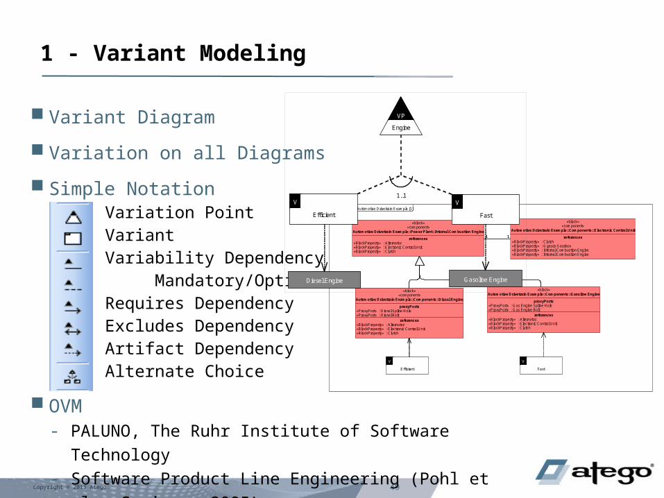
1 - Variant Modeling
Variant Diagram
Variation on all Diagrams
Simple NotationVariation PointVariantVariability Dependency Mandatory/OptionalRequires DependencyExcludes DependencyArtifact DependencyAlternate Choice
OVM- PALUNO, The Ruhr Institute of Software Technology- Software Product Line Engineering (Pohl et al - Springer 2005)
VP
V V
Diesel Engine Gasoline Engine
Engine
VP
Efficient
V
Fast
V1..1

50Copyright © 2013 Atego.
2 - Variant Selection
Variant Selector- Browser User Interface- External Variation Points Only- Jump to Next Decision/Problem- Progress Bar
Decision Set Editor- Variant Debug- External & Internal Variation Points- Jump to Next Decision/Problem
Both Edit the Same Decision Sets

51Copyright © 2013 Atego.
3 - Product Model Creation
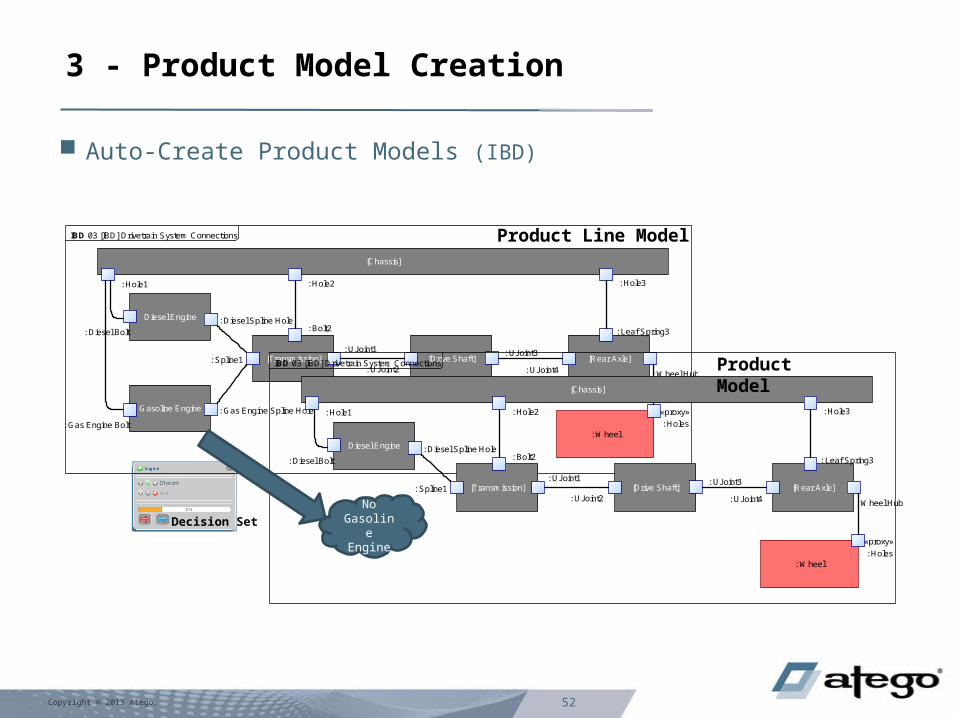
Auto-Create Product Models- Applies Variability Decisions- Unnecessary Variation Points, Variants & Base Model Artefacts Removed
Creates New Product Model Branch, Original Product Line Model Retained
Product Model suitable for Trade Studies, Simulation, Documentation & Generation
Decision Set
Product Line Model
Product Model
VP
V V
Diesel Engine Gasoline Engine
Engine
VP
Efficient
V
Fast
V1..1
52Copyright © 2013 Atego.
3 - Product Model Creation
Auto-Create Product Models (IBD)
Product Line Model
Decision Set
IBD 03 [IBD] Drivetrain System Connections
[Rear Axle]
: Wheel Hub : UJoint4
: Leaf Spring3
[Chassis]
: Hole1 : Hole2 : Hole3
Diesel Engine : Diesel Spline Hole
: Diesel Bolt
[Transmission] : Spline1
: Bolt2
: UJoint1[Drive Shaft]
: UJoint3
: UJoint2
: Wheel
«proxy»
: Holes
Gasoline Engine
: Gas Engine Bolt
: Gas Engine Spline Hole
IBD 03 [IBD] Drivetrain System Connections
[Rear Axle]
: Wheel Hub : UJoint4
: Leaf Spring3
[Chassis]
: Hole1 : Hole2 : Hole3
Diesel Engine : Diesel Spline Hole
: Diesel Bolt
[Transmission] : Spline1
: Bolt2
: UJoint1[Drive Shaft]
: UJoint3
: UJoint2
: Wheel
«proxy»
: Holes
No Gasoline Engine
Product Model

53Copyright © 2013 Atego.
Agenda
Introduction
Model Based Systems & Software Engineering (MBSE)
Systems of Systems
Asset-Based Modular Design
Model-based Product Lines- Variant Modeling- Variant Selection- Product Model Creation
Model-based Product Line Engineering (MB-PLE)
Summary
54Copyright © 2013 Atego.
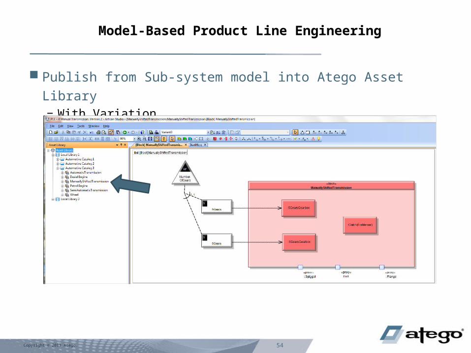
Model-Based Product Line Engineering
Publish from Sub-system model into Atego Asset Library− With Variation

55Copyright © 2013 Atego.
Model-Based Product Line Engineering
Use Sub-system from Atego Asset Library in Super-system Model (BDD)
− With Variation

56Copyright © 2013 Atego.
Model-Based Product Line Engineering
Include Asset Variation in Super-system Model Variation Design & Make Decisions
Super-model Variation
Asset Variation

57Copyright © 2013 Atego.
Model-Based Product Line Engineering
Create Product Model – Including Super-model and Asset Variation
Both Manual and 5 Gears selected

© 2014 Atego 58
Model- Based Product Line Engineering
Product ModelProduct Line Super-system Model
Sub-System 2
Sub-System 1
Asset Library
Asset 1(Sub-System
Model)
Asset 2(Sub-System
Model)Asset 3
(Sub-System Model)
Asset 4(Sub-System NO
Model)
Sub-System 2
Asset 1 Asset 2 Asset 3 Asset 4
Product LineModels
Links via Assets
Sub-system Product Line
Models
etc.
V V V
V V
V V
V
VP
V
Decision Set
V
VP
V
Decision Set
V
VP
V
Decision Set
• Integrated MBSE, Modular Design & Variability
Modeling = Model-based Product Line Engineering
© 2014 Atego 59
Agenda
• Introduction
• Model Based Systems & Software Engineering (MBSE)
• Systems of Systems
• Asset-Based Modular Design
• Model-based Product Lines– Variant Modeling– Variant Selection– Product Model Creation
• Model-based Product Line Engineering (MB-PLE)
• Summary

60Copyright © 2013 Atego.
Development Cost Reduction & Delivery Time Improvements
SE (Non-Modeled Systems Engineering)- 59% of Projects Delivered on Time
MBSE (Model Based Systems Engineering)- 62% of Projects Delivered on TimeCompared to SE- 55% Reduction in Total Development Cost per Project- 16% More Project Delivered on Time
MB-PLE (Model Based Product Line Engineering)- 75% of Projects Delivered on TimeCompared to MBSE- 17% Reduction in Total Development Cost per Project- 6% More Projects Delivered on TimeCompared to SE- 62% Reduction in Total Development Cost per Project- 23% More Projects Delivered on Time
(EMF 2013 Independent Survey Results from 667 Systems engineering respondents)
Development Cost per Project
SE
MBSEMBPLE
On Time Delivery
SEMBSE
MBPLE
59%
75%
62%

© 2014 Atego 61
• Systems of Systems have long been in existence
– Their inherent complexity complicates things
• Modeling has both helped and hindered
• SysML, UPDM, & RAS provide a standard way to model and reuse SoS
– MBSE provides proven ROI
• This combination helps address the SoS Pain Points
• Product Line Engineering provides a means of managing product variants
• Model-Based Product Line Engineering provides proven ROI
Conclusion

© 2014 Atego 62
Questions and Answers
DescriptionDescription You:Attendee
Me:Speaker
loop1
You:Attendee
Me:Speaker
loop1 while open questions existQuestion1.1
end loop
while open questions existQuestion1.1 Question
Answer1.1.1Question
Answer1.1.1 AnswerAnswerend loop
{Speech Time}{Speech Time}