Embed Size (px)
Citation preview
Instruction Manual
Fuji Electric Co.,Ltd.
ZIRCONIA OXYGEN
ANALYZER CONVERTER(SINGLE-CHANNEL TYPE)
TYPE: ZRM
INZ-TN1ZRMa-E
i
PREFACE
We are grateful for your purchase of Fuji Electric’s Zirconia Oxygen Analyzer Converter (ZRM).
• First read this instruction manual carefully until an adequate understanding is acquired,and then proceed to installation, operation and maintenance of the analyzer converter.Wrong handling may cause an accident or injury.
• The specifications of this analyzer converter will be changed without prior notice forfurther product improvement.
• Modification of this analyzer converter is strictly prohibited unless a written approval isobtained from the manufacturer. Fuji Electric will not bear any responsibility for a troublecaused by such a modification.
• This instruction manual shall be stored by the person who actually uses the analyzer con-verter.
• After reading the manual, be sure to store it at a place easier to access.• This instruction manual should be delivered to the end user without fail.
Manufacturer: Fuji Electric Co., Ltd.Type: Described in Fuji Electric’s company nameplate on main frameDate of manufacture: Described in Fuji Electric’s company nameplate on main frameProduct nationality: Japan
Request
• It is prohibited to transfer part or all of this manual without FujiElectric’s permission in written format.
• Description in this manual will be changed without prior noticefor further improvement.
© Fuji Electric Co., Ltd. 1993
Issued in Nov., 1993
Rev. 1st edition Sep., 1997
ii
Caution on installation and transport of gas analyzer
• This unit is not explosion-proof type. Do not use it in aplace with explosive gases to prevent explosion, fire or otherserious accidents.
• This unit should be installed in a place which conforms tothe conditions noted in the instruction manual. Otherwise, itmay cause electric shocks, fire or malfunction of the unit.
• During installation work, care should be taken to keep theunit free from entry of cable chips or other foreign objects.Otherwise, it may cause fire, trouble or malfunction of theunit.
• For installation, observe the rule on it given in the instruc-tion manual and select a place where the weight of gas ana-lyzer can be endured.Installation at an unsuited place may cause turnover or falland there is a risk of injury.
• For lifting the gas analyzer, be sure to wear protective gloves.Bare hands may invite an injury.
• Before transport, fix the casing so that it will not open. Oth-erwise, the casing may be separated and fall to cause an in-jury.
• The gas analyzer is heavy. It should be transported carefullyby two or more persons if manually required. Otherwise,body may be damaged or injured.
• For installation and maintenance accessible by qualified per-sonnel only.
DANGER
CAUTION
CAUTION ON SAFETY
First of all, read this “Caution on safety” carefully, and then use the analyzer in the correct way.
• The cautionary descriptions listed here contain important information about safety, so they shouldalways be observed. Those safety precautions are ranked 2 levels; DANGER and CAUTION.
Wrong handling may cause a dangerous situation, in whichthere is a risk of death or heavy injury.
Wrong handling may invite a dangerous situation, in whichthere is a possibility of medium-level trouble or slight injuryor only physical damage is predictable.
• Even an undesirable action described in “ CAUTION” may lead to a grave result depending onsituation. Be sure to observe DANGER and CAUTION because they are both important for ensuringsafety.
DANGER
CAUTION
iii
Caution on wiring
• The unit must be earthed as specified. Otherwise, it may cause electric shocks, malfunction, etc.• Be sure to use a power supply of correct rating. Connection of power supply of incorrect rating
may cause fire.• Wiring work must be performed with the main power set to OFF to prevent electric shocks.• Use wiring materials that match the rating of the unit. Use of wiring materials out of rating may
cause fire.• The supply voltage category of this instrument is II. Relay contact is category I.• Analog output and digital input of this instrument are Safe Separated (SELV) circuit.• Establish an external over-current protection device (e.g. circuit-breaker) with a rating of no
more than 5A as per the general product specification.• Connect correctly wiring L (live)/N (neutral) to the power supply terminal.• Enforce construction of protective earth wiring by all means.• Install correctly according to regulation of each country, as not being External Disconnection
Device for this instrument.
DANGER
Caution on piping
• If leaked gas contains oxygen at a high concentration, there is a risk of fire.• Connect pipes correctly referring to the instruction manual. Wrong piping may cause gas leak-
age.
CAUTION
CAUTION
Caution on use
• During operation, avoid opening the casing and touching the internal parts. Otherwise, you maysuffer a burn or shock hazard.
• Avoid touching the detector with bare hand during operation. Otherwise, you may suffer a burnbecause the detector may have reached a high temperature (about 800°C).
• During operation, avoid removing and placing the detector on or near a combustible material.Otherwise, fire may occur.
iv
Caution on maintenance and check
• Before maintenance and check, be sure to turn off the main power supply and wait until thedetector is cooled adequately. Otherwise, you may suffer a burn.
• Before removing the detector from the flue for maintenance and check, make sure the furnace isstopped. Otherwise, you may suffer a burn.
• Before working, take off a wrist watch, finger ring or the like metallic accessories. And nevertouch the instrument with a wet hand. Otherwise, you will have a shock hazard.
• If the fuse is blown, eliminate the cause, and then replace it with the one of the same capacity andtype as before. Otherwise, shock hazard or fault may be caused.
CAUTION
CAUTION
Others
• If the cause of any fault cannot be determined despite reference to the instruction manual, besure to contact your dealer or Fuji Electric’s technician in charge of adjustment. If the instrumentis disassembled carelessly, you may have a shock hazard or injury.
• Do not use a replacement part other than specified by the instrument maker. Otherwise, ad-equate performance will not be provided. Besides, an accident or fault may be caused.
• Replacement parts such as a maintenance part should be disposed of as incombustibles.
v
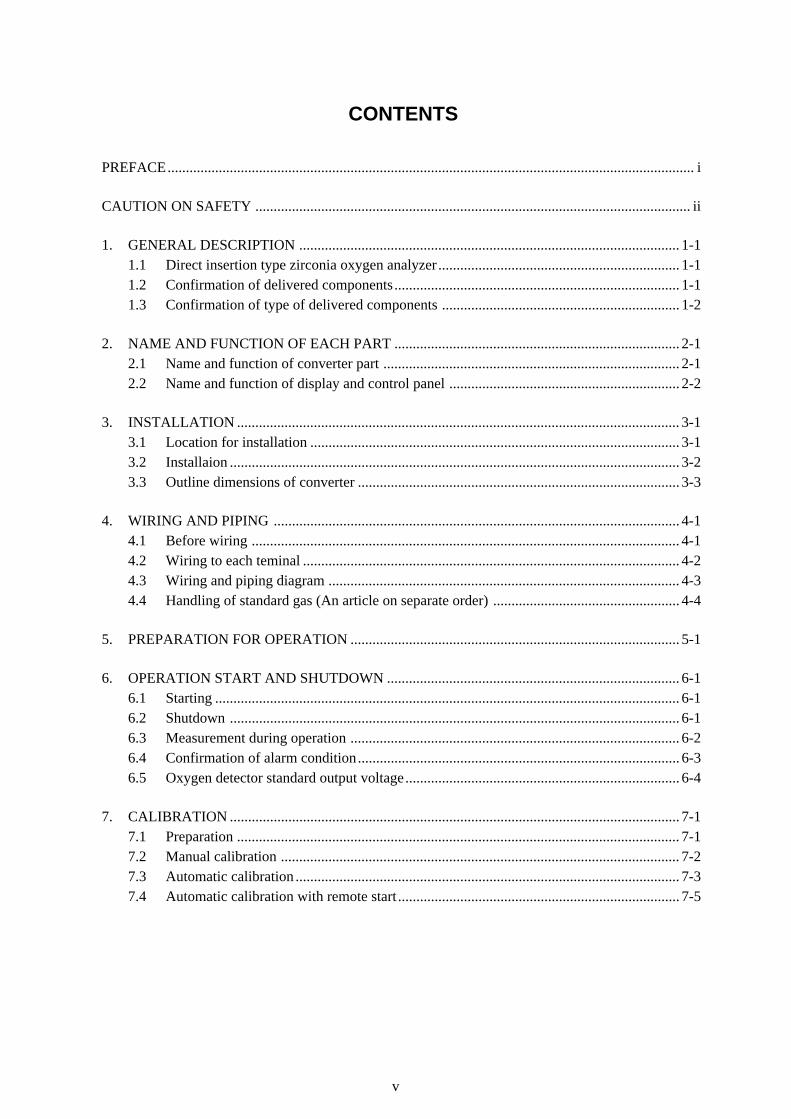
CONTENTS
PREFACE................................................................................................................................................ i
CAUTION ON SAFETY ....................................................................................................................... ii
1. GENERAL DESCRIPTION ........................................................................................................ 1-11.1 Direct insertion type zirconia oxygen analyzer .................................................................. 1-11.2 Confirmation of delivered components .............................................................................. 1-11.3 Confirmation of type of delivered components ................................................................. 1-2
2. NAME AND FUNCTION OF EACH PART .............................................................................. 2-12.1 Name and function of converter part ................................................................................. 2-12.2 Name and function of display and control panel ............................................................... 2-2
3. INSTALLATION ......................................................................................................................... 3-13.1 Location for installation ..................................................................................................... 3-13.2 Installaion ........................................................................................................................... 3-23.3 Outline dimensions of converter ........................................................................................ 3-3
4. WIRING AND PIPING ............................................................................................................... 4-14.1 Before wiring ..................................................................................................................... 4-14.2 Wiring to each teminal ....................................................................................................... 4-24.3 Wiring and piping diagram ................................................................................................ 4-34.4 Handling of standard gas (An article on separate order) ................................................... 4-4
5. PREPARATION FOR OPERATION .......................................................................................... 5-1
6. OPERATION START AND SHUTDOWN ................................................................................ 6-16.1 Starting ............................................................................................................................... 6-16.2 Shutdown ........................................................................................................................... 6-16.3 Measurement during operation .......................................................................................... 6-26.4 Confirmation of alarm condition........................................................................................ 6-36.5 Oxygen detector standard output voltage........................................................................... 6-4
7. CALIBRATION ........................................................................................................................... 7-17.1 Preparation ......................................................................................................................... 7-17.2 Manual calibration ............................................................................................................. 7-27.3 Automatic calibration ......................................................................................................... 7-37.4 Automatic calibration with remote start ............................................................................. 7-5
vi
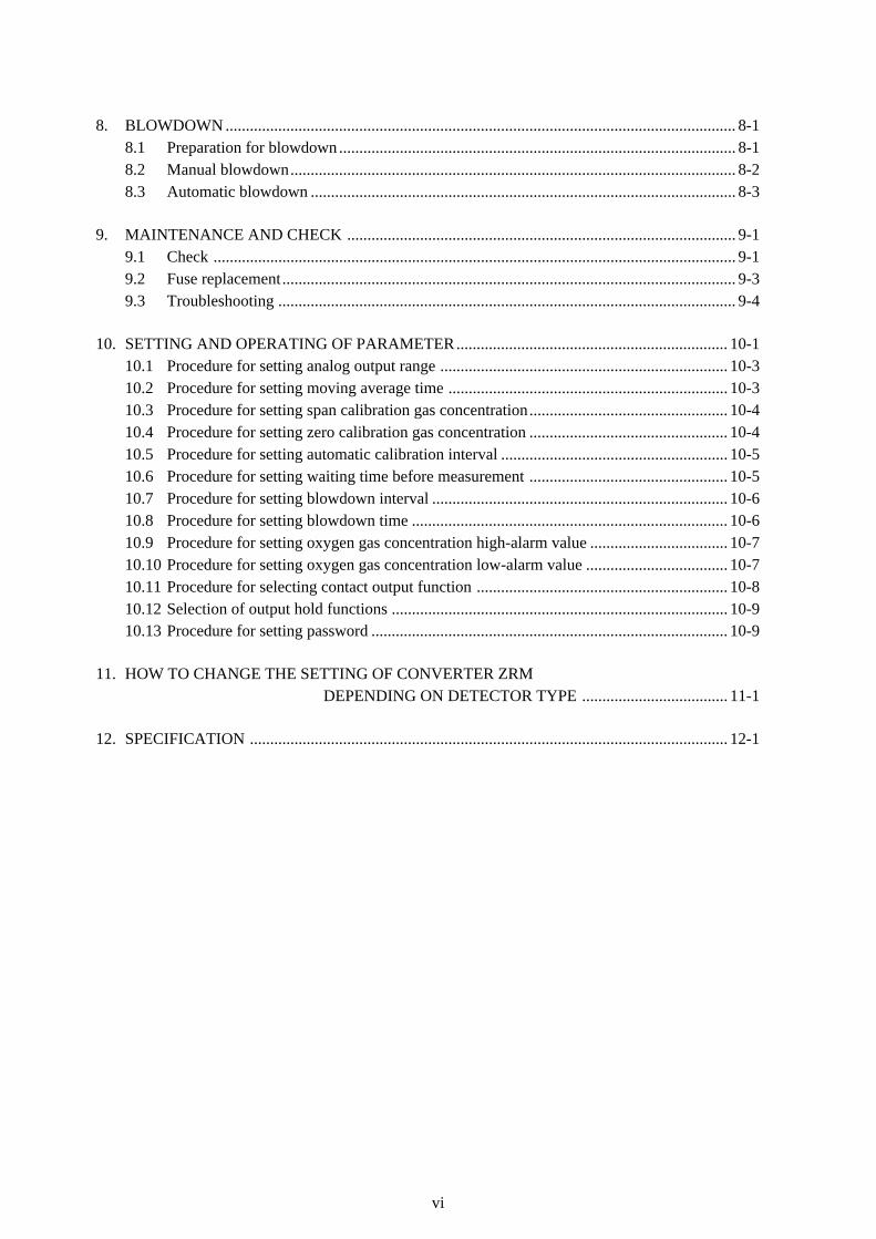
8. BLOWDOWN .............................................................................................................................. 8-18.1 Preparation for blowdown.................................................................................................. 8-18.2 Manual blowdown.............................................................................................................. 8-28.3 Automatic blowdown ......................................................................................................... 8-3
9. MAINTENANCE AND CHECK ................................................................................................ 9-19.1 Check ................................................................................................................................. 9-19.2 Fuse replacement................................................................................................................ 9-39.3 Troubleshooting ................................................................................................................. 9-4
10. SETTING AND OPERATING OF PARAMETER................................................................... 10-110.1 Procedure for setting analog output range ....................................................................... 10-310.2 Procedure for setting moving average time ..................................................................... 10-310.3 Procedure for setting span calibration gas concentration................................................. 10-410.4 Procedure for setting zero calibration gas concentration ................................................. 10-410.5 Procedure for setting automatic calibration interval ........................................................ 10-510.6 Procedure for setting waiting time before measurement ................................................. 10-510.7 Procedure for setting blowdown interval ......................................................................... 10-610.8 Procedure for setting blowdown time .............................................................................. 10-610.9 Procedure for setting oxygen gas concentration high-alarm value .................................. 10-710.10 Procedure for setting oxygen gas concentration low-alarm value ................................... 10-710.11 Procedure for selecting contact output function .............................................................. 10-810.12 Selection of output hold functions ................................................................................... 10-910.13 Procedure for setting password ........................................................................................ 10-9
11. HOW TO CHANGE THE SETTING OF CONVERTER ZRM DEPENDING ON DETECTOR TYPE .................................... 11-1
12. SPECIFICATION ...................................................................................................................... 12-1
1-1
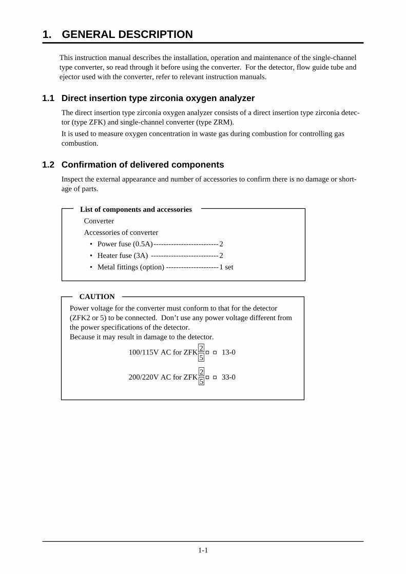
CAUTION
Power voltage for the converter must conform to that for the detector(ZFK2 or 5) to be connected. Don’t use any power voltage different fromthe power specifications of the detector.Because it may result in damage to the detector.
100/115V AC for ZFK 13-0
200/220V AC for ZFK 33-0
1. GENERAL DESCRIPTION
List of components and accessories
Converter
Accessories of converter
• Power fuse (0.5A)--------------------------2
• Heater fuse (3A) ---------------------------2
• Metal fittings (option) ---------------------1 set
This instruction manual describes the installation, operation and maintenance of the single-channeltype converter, so read through it before using the converter. For the detector, flow guide tube andejector used with the converter, refer to relevant instruction manuals.
1.1 Direct insertion type zirconia oxygen analyzer
The direct insertion type zirconia oxygen analyzer consists of a direct insertion type zirconia detec-tor (type ZFK) and single-channel converter (type ZRM).
It is used to measure oxygen concentration in waste gas during combustion for controlling gascombustion.
1.2 Confirmation of delivered components
Inspect the external appearance and number of accessories to confirm there is no damage or short-age of parts.
52
52
1-2
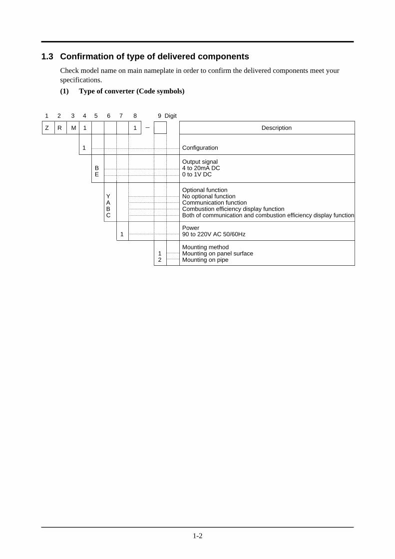
1.3 Confirmation of type of delivered components
Check model name on main nameplate in order to confirm the delivered components meet yourspecifications.
(1) Type of converter (Code symbols)
1 2 3 4 5 7 8 9 Digit
Z R M 1 1
6
Description
Configuration
Output signal4 to 20mA DC0 to 1V DC
BE
Optional functionNo optional functionCommunication functionCombustion efficiency display functionBoth of communication and combustion efficiency display function
Power90 to 220V AC 50/60Hz1
Mounting methodMounting on panel surfaceMounting on pipe
12
YABC
1
1-3
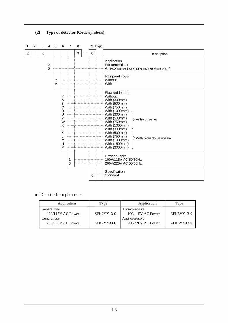
Application
General use100/115V AC Power
General use200/220V AC Power
Type
ZFK2YY13-0
ZFK2YY33-0
Application
Anti-corrosive100/115V AC Power
Anti-corrosive200/220V AC Power
Type
ZFK5YY13-0
ZFK5YY33-0
(2) Type of detector (Code symbols)
1 2 3 4 5 7 8 9 Digit
Z F K 3 0
6
Description
ApplicationFor general useAnti-corrosive (for waste incineration plant)
Rainproof coverWithoutWith
YA
Power supply100V/115V AC 50/60Hz200V/220V AC 50/60Hz
SpecificationStandard0
Anti-corrosive
With blow down nozzle
Flow guide tubeWithoutWith (300mm)With (500mm)With (750mm)With (1000mm)With (300mm)With (500mm)With (750mm)With (1000mm)With (300mm)With (500mm)With (750mm)With (1000mm)With (1500mm)With (2000mm)
YABCDUVWXJKLMNP
13
25
Detector for replacement
1-4
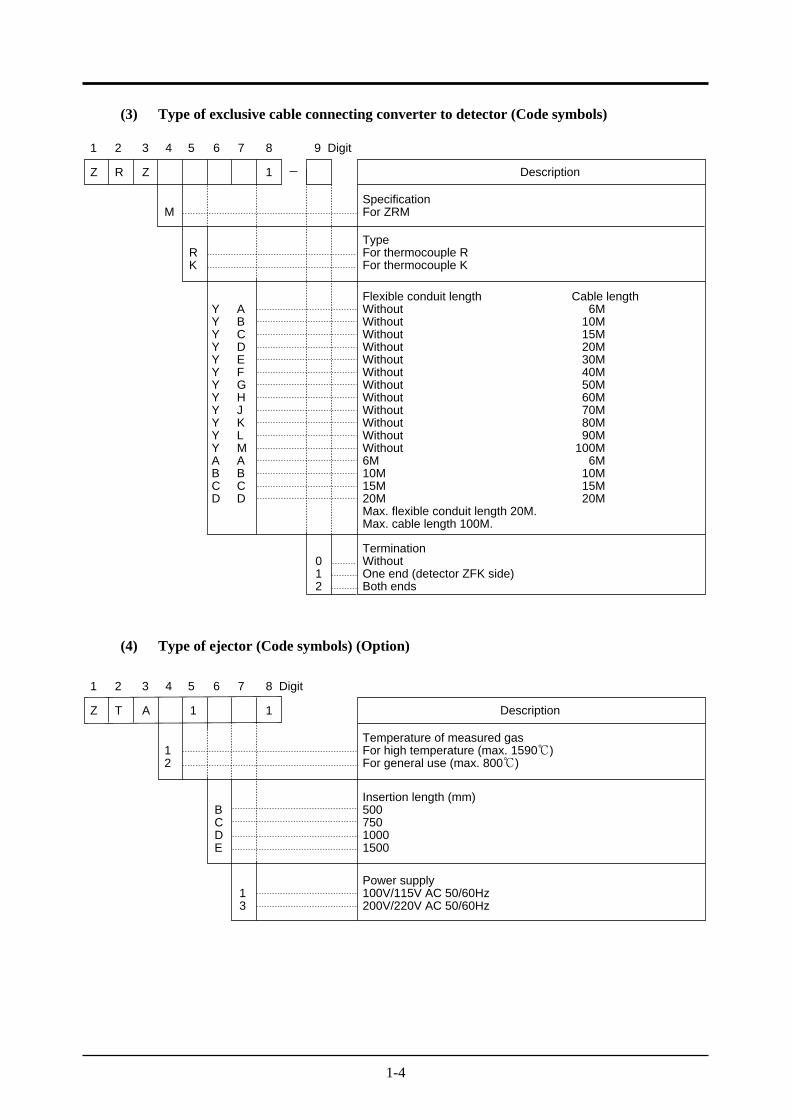
(3) Type of exclusive cable connecting converter to detector (Code symbols)
1 2 3 4 5 7 8 9 Digit
Z R Z 1
6
Description
SpecificationFor ZRM
TypeFor thermocouple RFor thermocouple K
RK
TerminationWithoutOne end (detector ZFK side)Both ends
012
Flexible conduit lengthWithoutWithoutWithoutWithoutWithoutWithoutWithoutWithoutWithoutWithoutWithoutWithout6M10M15M20MMax. flexible conduit length 20M.Max. cable length 100M.
YYYYYYYYYYYYABCD
ABCDEFGHJKLMABCD
Cable length6M
10M15M20M30M40M50M60M70M80M90M
100M6M
10M15M20M
M
(4) Type of ejector (Code symbols) (Option)
1 2 3 4 5 7 8 Digit
Z T A 1 1
6
Description
Temperature of measured gasFor high temperature (max. 1590)For general use (max. 800)
Insertion length (mm)50075010001500
BCDE
Power supply100V/115V AC 50/60Hz200V/220V AC 50/60Hz
13
12
2-1
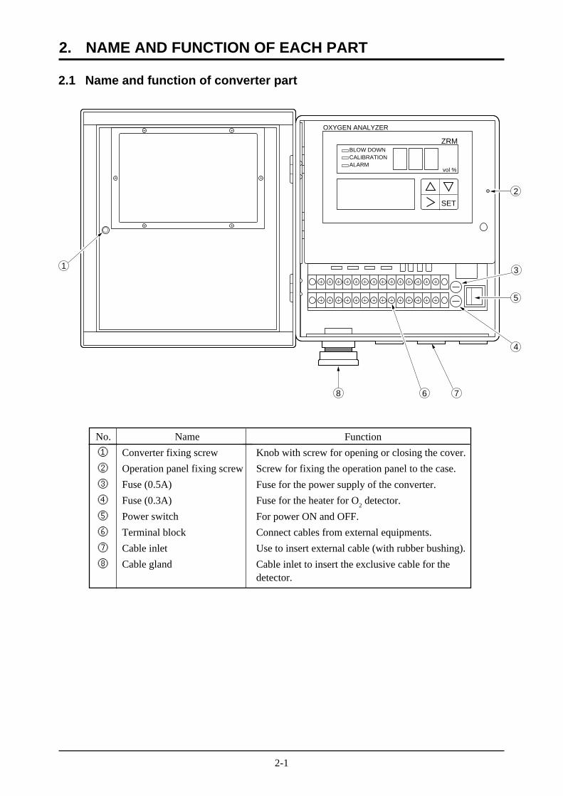
2. NAME AND FUNCTION OF EACH PART
2.1 Name and function of converter part
SET
OXYGEN ANALYZER
BLOW DOWNCALIBRATIONALARM
ZRM
vol %
1
8 7
5
2
3
4
6
No.
①
②
③
④
⑤
⑥
⑦
⑧
Name
Converter fixing screw
Operation panel fixing screw
Fuse (0.5A)
Fuse (0.3A)
Power switch
Terminal block
Cable inlet
Cable gland
Function
Knob with screw for opening or closing the cover.
Screw for fixing the operation panel to the case.
Fuse for the power supply of the converter.
Fuse for the heater for O2 detector.
For power ON and OFF.
Connect cables from external equipments.
Use to insert external cable (with rubber bushing).
Cable inlet to insert the exclusive cable for thedetector.
2-2
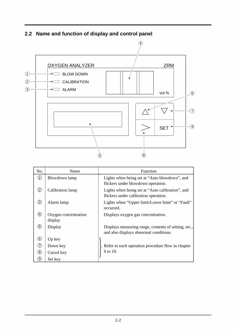
2.2 Name and function of display and control panel
SET
BLOW DOWN
CALIBRATION
ALARM
ZRM
vol %
OXYGEN ANALYZER
1
2
3
5 8
9
7
6
4
No.
①
②
③
④
⑤
⑥
⑦
⑧
⑨
Name
Blowdown lamp
Calibration lamp
Alarm lamp
Oxygen concentrationdisplay
Display
Up key
Down key
Cursol key
Set key
Function
Lights when being set at “Auto blowdown”, andflickers under blowdown operation.
Lights when being set at “Auto calibration”, andflickers under calibration operation.
Lights when “Upper limit/Lower limit” or “Fault”occurred.
Displays oxygen gas concentration.
Displays measuring range, contents of setting, etc.,and also displays abnormal conditions.
Refer to each operation procedure flow in chapter6 to 10.
3-1
CAUTION• Installation the analyzer safely and securely so that it will not fall.
3.1 Location for installation
The location for installation should meet the following conditions.
(1) For installation in restricted areas (i. e. enclose with a fence) only, accessible by qualifiedpersons only.
(2) Space for routine inspection and wiring available.
(3) Vibration, dust, dirt and humidity are minimal.
(4) No direct influence of radiation from heating furnace or the like (converter).
(5) Non-corrosive atmospheric environment.
(6) No electric machinery nearby, which may cause noise trouble (such as motor, transformer) orproduce electromagnetic and electrostatic induction.
(7) Ambient temperature within -10 to +50 and ambient humidity less than 90%RH (converter).
• The supply voltage category of this instrument is II. Relay contact is category I.
• Analog output and digital input of this instrument are Safe Separated (SELV) circuit.
• Establish an external over-current protection device(e.g. circuit-breaker) with a rating of no morethan 5A as per the general product specification.
• Connect correctly wiring L(live)/N(neutral) to the power supply terminal.
• Enforce construction of protective earth wiring by all means.
• Install correctly according to regulation of each country, as not being External DisconnectionDevice for this instrument.
• For installation and maintenance accessible by qualified personnel only.
3. INSTALLATION
3-2
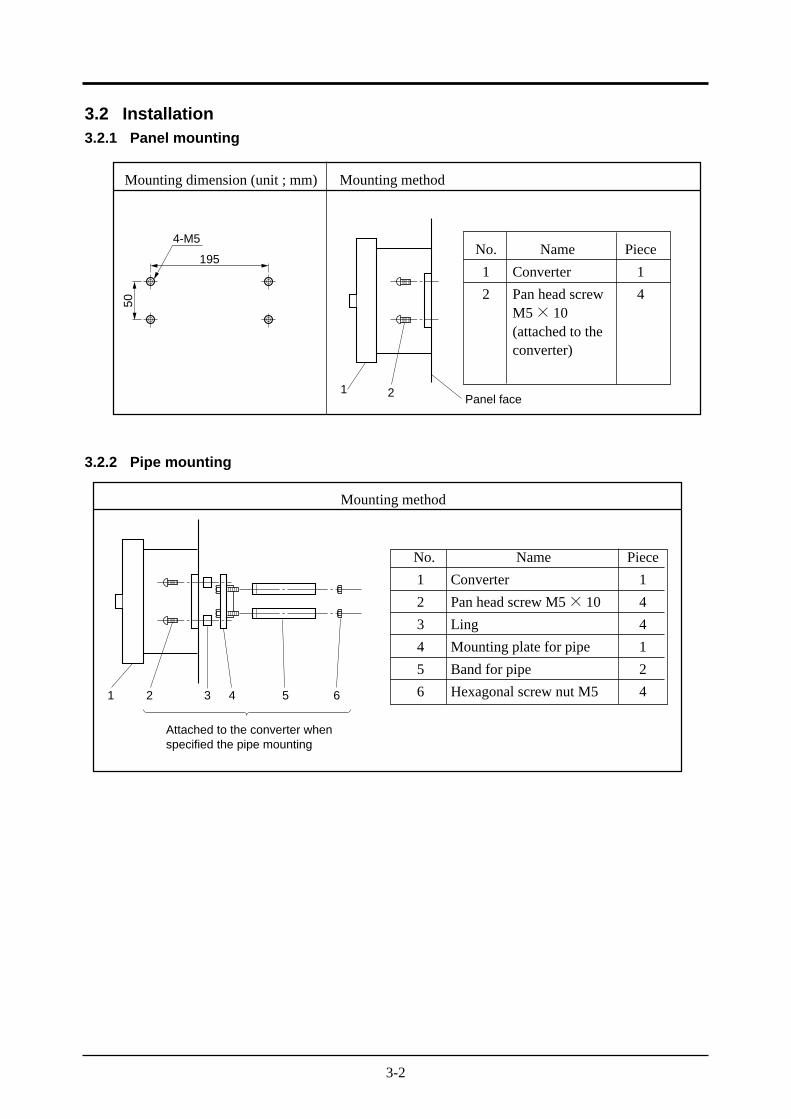
3.2 Installation3.2.1 Panel mounting
3.2.2 Pipe mounting
Mounting dimension (unit ; mm) Mounting method
No. Name Piece
1 Converter 1
2 Pan head screw 4M5× 10(attached to theconverter)
195
4-M5
50
1 2 Panel face
Mounting method
No. Name Piece
1 Converter 1
2 Pan head screw M5× 10 4
3 Ling 4
4 Mounting plate for pipe 1
5 Band for pipe 2
6 Hexagonal screw nut M5 41 2 3 4 5 6
Attached to the converter whenspecified the pipe mounting
3-3
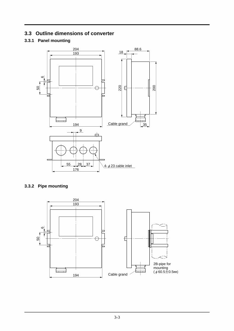
3.3 Outline dimensions of converter3.3.1 Panel mounting
193
194
9
35
50
204 88.6
220
Cable grand
6
18
200
176
55 28 37 4-φ23 cable inlet
3.3.2 Pipe mounting
193
194
50
204
Cable grand
6
2B-pipe formounting(φ60.5±0.5A)
4-1
4. WIRING AND PIPING
CAUTION• Wiring work must be carried out with all power supplies turned off.
Otherwise, you may suffer electric shock.
• The analyzer should be grounded without fail (Class 3 grounding).
4.1 Before wiring
① For installation and maintenance accessible by qualified personnel only.
② Install correctly according to regulation of each country, as not being External DisconnectionDevice for this instrument.
③ Establish an external over-current protection device (e.g. circuit-breaker) with a rating of nomore than 5A as per general product specification.
④ The over voltage category of this instruments is II. But the parts of output terminals is categoryI.
⑤ Analog output and digital input of this instrument are Safe Separated (SELV) circuit.
⑥ Make sure that the power voltage for the converter conforms to that for the detector (ZFK2 or 5)to be connected.
⑦ For power supply use 600V vinyl insulation wire with AWG18 (34/0.18) or equivalent inquality.
⑧ Provide adequate protection of the exclusive cable (6 cores in total), which connects the detectorto converter, using wire protection tube, etc.Separate these cables from the power cable (noise prevention).
⑨ Keep the wire for output signals as far as possible (more than 30cm) from the power line andheavy current lines to prevent induced noise. Use a shielding cable as much as possible andground the shields as the same point.
Caution :Connection of wiring to the external terminals, exclusive use of ring crimp lugswith proper insulating sleeve.
⑩ Connect correctly wiring L (live)/N (neutral) to the power supply terminal.
⑪ Enforce construction of protective earth wiring by all means.
4-2
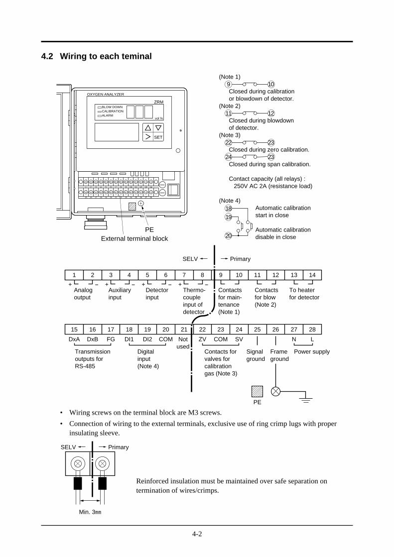
4.2 Wiring to each teminal
9 10(Note 1)
Closed during calibration or blowdown of detector.(Note 2)
Closed during blowdown of detector.(Note 3)
Closed during zero calibration.
Closed during span calibration.
Contact capacity (all relays) : 250V AC 2A (resistance load)
(Note 4) Automatic calibration start in close
Automatic calibration disable in close
22 23
24
1819
20
23
11 12
SET
OXYGEN ANALYZER
BLOW DOWNCALIBRATIONALARM
ZRM
vol %
1 2 3 4 5 6 7 8 9 10 11 12 13 14
15 16 17 18 19 20 21 22 23 24 25 26 27 28
PEExternal terminal block
1 2 3 4 5 6 7 8 9 10 11 12 13 14
+ - + - + - + -
15 16 17 18 19 20 21 22 23 24 25 26 27 28
SELV Primary
Analogoutput
Auxiliaryinput
Detectorinput
Contactsfor main-tenance(Note 1)
Contactsfor blow(Note 2)
To heaterfor detector
Thermo-coupleinput ofdetector
DxA DxB FG DI1 DI2 COM Notused
ZV COM SV N L
Transmissionoutputs forRS-485
Digitalinput(Note 4)
Contacts forvalves forcalibrationgas (Note 3)
Signalground
PE
Frameground
Power supply
• Wiring screws on the terminal block are M3 screws.
• Connection of wiring to the external terminals, exclusive use of ring crimp lugs with properinsulating sleeve.
SELV Primary
Min. 3A
Reinforced insulation must be maintained over safe separation ontermination of wires/crimps.
4-3
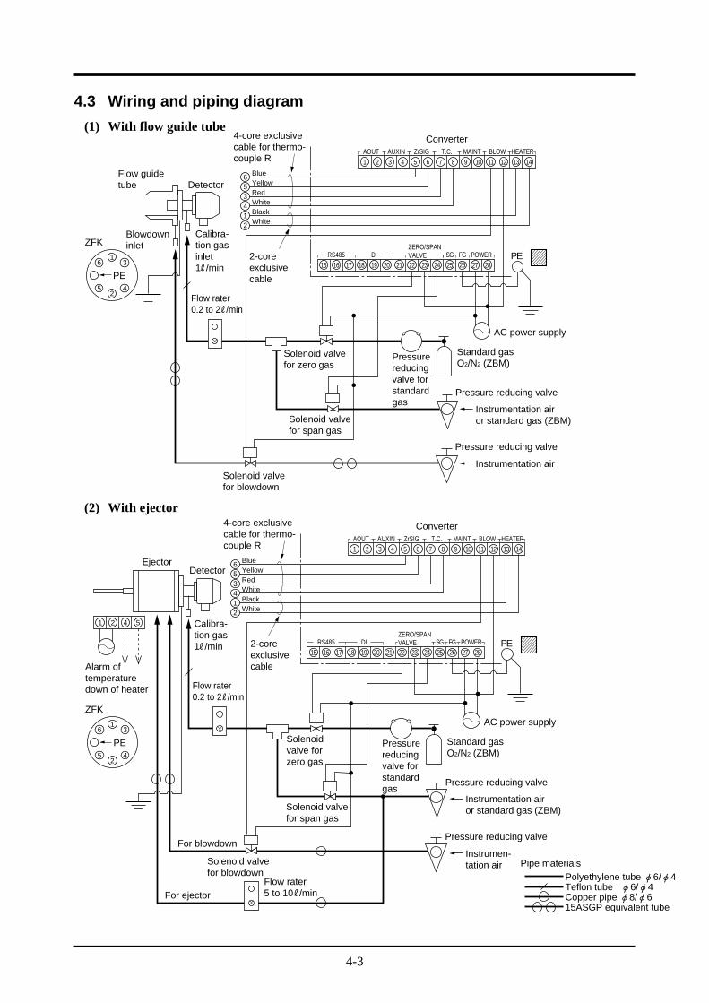
4.3 Wiring and piping diagram
(1) With flow guide tube
1
214356
2 3 4 5 6 7 8 9 10 11 12 13 14
15 16 17 18 19 20 21 22 23 24 25 26 27 28
BlueYellowRedWhiteBlackWhite
4-core exclusivecable for thermo-couple R
AOUT AUXIN ZrSIG T.C. MAINT BLOW HEATER
RS485 DIZERO/SPANVALVE SG FG POWER
Converter
2-coreexclusivecable
Flow guidetube Detector
Blowdowninlet
Calibra-tion gasinlet1R/min
ZFK
16
52
4
3
PE
PE
AC power supply
Solenoid valvefor zero gas
Solenoid valvefor span gas
Solenoid valvefor blowdown
Pressurereducingvalve forstandardgas
Standard gasO2/N2 (ZBM)
Pressure reducing valve
Pressure reducing valve
Instrumentation airor standard gas (ZBM)
Instrumentation air
Flow rater0.2 to 2R/min
(2) With ejector
1 2 4 5
1 2 3 4 5 6 7 8 9 10 11 12 13 14
15 16 17 18 19 20 21 22 23 24 25 26 27 28
AOUT AUXIN ZrSIG T.C. MAINT BLOW HEATER
RS485 DIZERO/SPANVALVE SG FG POWER
Converter
214356 Blue
YellowRedWhiteBlackWhite
4-core exclusivecable for thermo-couple R
2-coreexclusivecable
Calibra-tion gas1R/min
ZFK
16
52
4
3
PE
Flow rater0.2 to 2R/min
Flow rater5 to 10R/min
Detector
Alarm oftemperaturedown of heater
Ejector
AC power supply
Pressurereducingvalve forstandardgas
Standard gasO2/N2 (ZBM)
Pressure reducing valve
Pressure reducing valve
Instrumentation airor standard gas (ZBM)
Instrumen-tation air
Solenoidvalve forzero gas
Solenoid valvefor span gas
Solenoid valvefor blowdown
For ejector
For blowdown
PE
Polyethylene tube φ6/φ4Teflon tube φ6/φ4Copper pipe φ8/φ615ASGP equivalent tube
Pipe materials
4-4
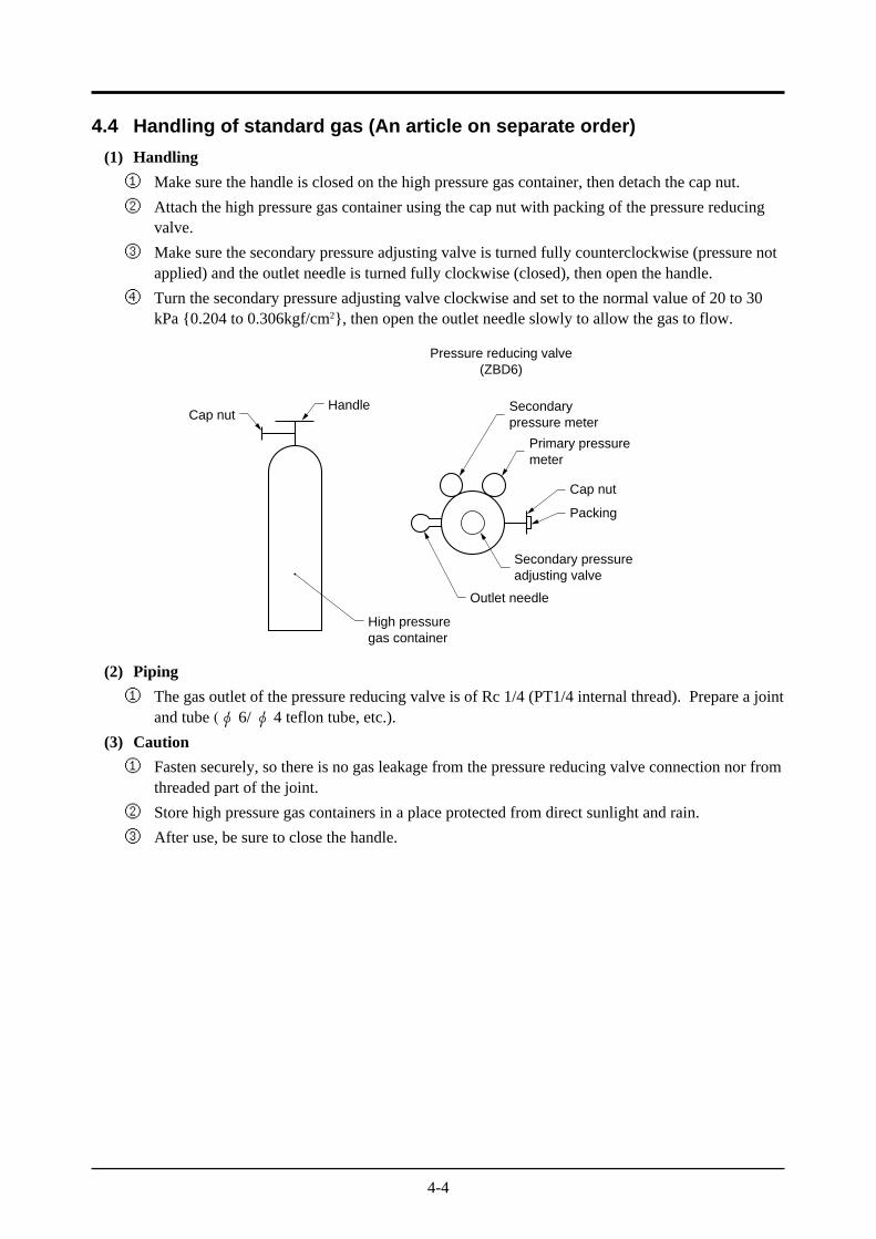
4.4 Handling of standard gas (An article on separate order)
(1) Handling
① Make sure the handle is closed on the high pressure gas container, then detach the cap nut.
② Attach the high pressure gas container using the cap nut with packing of the pressure reducingvalve.
③ Make sure the secondary pressure adjusting valve is turned fully counterclockwise (pressure notapplied) and the outlet needle is turned fully clockwise (closed), then open the handle.
④ Turn the secondary pressure adjusting valve clockwise and set to the normal value of 20 to 30kPa 0.204 to 0.306kgf/cm2, then open the outlet needle slowly to allow the gas to flow.
Handle Secondarypressure meter
Primary pressuremeter
Secondary pressureadjusting valve
Outlet needle
Cap nut
Packing
High pressuregas container
Cap nut
Pressure reducing valve(ZBD6)
(2) Piping
① The gas outlet of the pressure reducing valve is of Rc 1/4 (PT1/4 internal thread). Prepare a jointand tube (φ 6/φ 4 teflon tube, etc.).
(3) Caution
① Fasten securely, so there is no gas leakage from the pressure reducing valve connection nor fromthreaded part of the joint.
② Store high pressure gas containers in a place protected from direct sunlight and rain.
③ After use, be sure to close the handle.
5-1
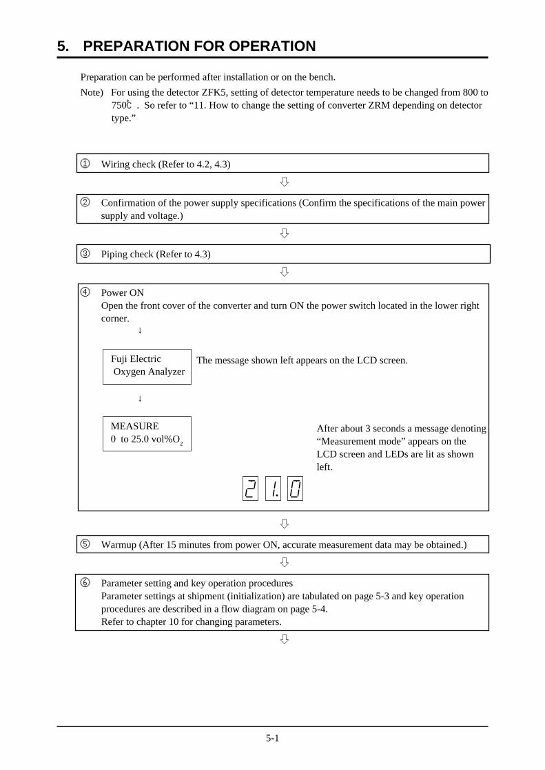
Preparation can be performed after installation or on the bench.
Note) For using the detector ZFK5, setting of detector temperature needs to be changed from 800 to750. So refer to “11. How to change the setting of converter ZRM depending on detectortype.”
① Wiring check (Refer to 4.2, 4.3)
h
② Confirmation of the power supply specifications (Confirm the specifications of the main powersupply and voltage.)
h
③ Piping check (Refer to 4.3)
h
④ Power ONOpen the front cover of the converter and turn ON the power switch located in the lower rightcorner.
↓
The message shown left appears on the LCD screen.
↓
After about 3 seconds a message denoting“Measurement mode” appears on theLCD screen and LEDs are lit as shownleft.
h
⑤ Warmup (After 15 minutes from power ON, accurate measurement data may be obtained.)
h
⑥ Parameter setting and key operation proceduresParameter settings at shipment (initialization) are tabulated on page 5-3 and key operationprocedures are described in a flow diagram on page 5-4.Refer to chapter 10 for changing parameters.
h
5. PREPARATION FOR OPERATION
Fuji Electric Oxygen Analyzer
MEASURE0 to 25.0 vol%O
2
5-2
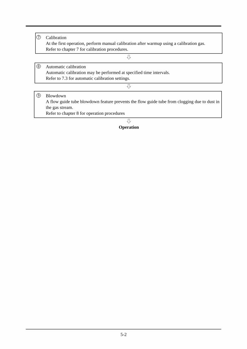
⑦ CalibrationAt the first operation, perform manual calibration after warmup using a calibration gas.Refer to chapter 7 for calibration procedures.
h
⑧ Automatic calibrationAutomatic calibration may be performed at specified time intervals.Refer to 7.3 for automatic calibration settings.
h
⑨ BlowdownA flow guide tube blowdown feature prevents the flow guide tube from clogging due to dust inthe gas stream.Refer to chapter 8 for operation procedures
hOperation
5-3
Displayed message
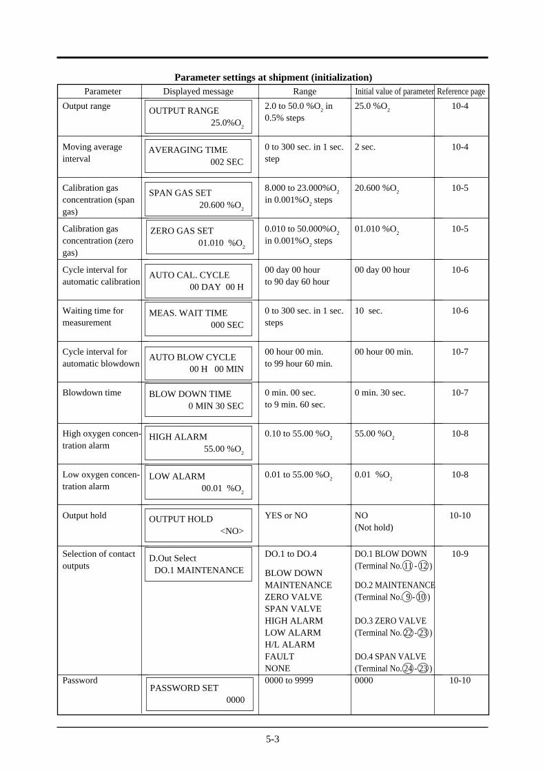
Parameter settings at shipment (initialization)Parameter
Output range
Moving averageinterval
Calibration gasconcentration (spangas)
Calibration gasconcentration (zerogas)
Cycle interval forautomatic calibration
Waiting time formeasurement
Cycle interval forautomatic blowdown
Blowdown time
High oxygen concen-tration alarm
Low oxygen concen-tration alarm
Output hold
Selection of contactoutputs
Password
Range
2.0 to 50.0 %O2 in
0.5% steps
0 to 300 sec. in 1 sec.step
8.000 to 23.000%O2
in 0.001%O2 steps
0.010 to 50.000%O2
in 0.001%O2 steps
00 day 00 hourto 90 day 60 hour
0 to 300 sec. in 1 sec.steps
00 hour 00 min.to 99 hour 60 min.
0 min. 00 sec.to 9 min. 60 sec.
0.10 to 55.00 %O2
0.01 to 55.00 %O2
YES or NO
DO.1 to DO.4
BLOW DOWNMAINTENANCEZERO VALVESPAN VALVEHIGH ALARMLOW ALARMH/L ALARMFAULTNONE0000 to 9999
OUTPUT RANGE25.0%O
2
AVERAGING TIME002 SEC
SPAN GAS SET20.600 %O
2
ZERO GAS SET01.010 %O
2
AUTO CAL. CYCLE00 DAY 00 H
MEAS. WAIT TIME000 SEC
AUTO BLOW CYCLE00 H 00 MIN
BLOW DOWN TIME0 MIN 30 SEC
HIGH ALARM55.00 %O
2
LOW ALARM00.01 %O
2
OUTPUT HOLD<NO>
D.Out SelectDO.1 MAINTENANCE
PASSWORD SET0000
Initial value of parameter
25.0 %O2
2 sec.
20.600 %O2
01.010 %O2
00 day 00 hour
10 sec.
00 hour 00 min.
0 min. 30 sec.
55.00 %O2
0.01 %O2
NO(Not hold)
DO.1 BLOW DOWN(Terminal No. 11 - 12 )
DO.2 MAINTENANCE(Terminal No. 9 - 10 )
DO.3 ZERO VALVE(Terminal No. 22 - 23 )
DO.4 SPAN VALVE(Terminal No. 24 - 23 )0000
Reference page
10-4
10-4
10-5
10-5
10-6
10-6
10-7
10-7
10-8
10-8
10-10
10-9
10-10
5-4
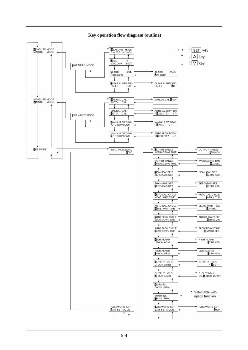
Key operation flow diagram (outline)
MAINTE MODEMEASURE MODE
SET MODE
AUTO CALMANUAL CAL
0 to 25.0 vo1%O2
MEASURE HOLD
1000.0mV 800CELL R
High alarmALARM 1234s ALARM 2345s
Low alarm
FAULT NOCLEAR ALARM AND
FAULT NOCLEAR ALARM AND
AUTO CALIBRATION
MEASURE MODEMAINTE MODE
EXIT MEAS. MODE
EXIT MAINTE MODE
MANUAL CALAUTO CAL
MANUAL CAL SPAN
: key
key
key
:
:
SET
AUTO BLOW DOWN
MANUAL BLOW DOWNAUTO BLOW DOWN
INPUT PASSWORD 0000
MANUAL BLOW DOWN
AVERAGEING TIMEOUTPUT RANGE OUTPUT RANGE
AVERAGEING TIME
MEAS. WAIT TIMEAUTO CAL. CYCLE
BLOW DOWN TIMEAUTO BLOW CYCLE
LOW ALARMHIGH ALARM HIGH ALARM
D. OUT SelectOUTPUT HOLD
Comm. SelectStation No.
EXIT SET MODEPASSWORD SET
Station No.
AUTO BLOW CYCLE
AUTO CAL. CYCLE
ZERO GAS SETSPAN GAS SET SPAN GAS SET
SPAN GAS SET
OUTPUT RANGE
MANUAL BLOW DOWN< START? N >
AUTO BLOW DOWN
AVERAGEING TIME
ZERO GAS SET
MEAS. WAIT TIME
002 SEC
20.600 %O2
ZERO GAS SET 02.600 %O2
AUTO CAL. CYCLE 00 DAY 01 H
AUTO BLOW CYCLE 00 H 00 MIN
BLOW DOWN TIME 0 MIN 00 SEC
0 000 SECMEAS. WAIT TIME
BLOW DOWN TIME
HIGH ALARMLOW ALARM
OUTPUT HOLDD. OUT Select
D. OUT SelectDO. 1 BLOW DOWN
Comm. Select
PASSWORD SETEXIT SET MODE 0000
PASSWORD SET
25.0%O2
00.01 %O2
LOW ALARM
OUTPUT HOLD
55.00 %O2
< YES >
** Selectable with option function
< EXECUTE? N >
< EXECUTE? N >
6-1
6.1 Starting
After correct wiring and piping has been completed, turn the power switch in the converter ON,and measuring operation will begin.
Note : 15 min. of warmup time is necessary after power ON.
Caution of before starting
① Furnace operation should only be started after 15 min. or more of warmup time has elapsed.
② When a detector is to be installed in a furnace already in operation, take care to blow outharmful gas from the furnace and then install the fully warmed up detector quickly.
6.2 Shutdown
(1) When a process (furnace etc.) is to be shutdown for a short time i.e. a week or soIt is strongly recommended to keep the detector in operation to avoid possible deteriorationof platinum electrodes in the detector and destruction of the wet sensor element (dependingon the condition in furnace and/or ambient conditions) due to power ON-OFF.In case of the detector with an ejector (option), shutdown the air source.
(2) When a process (furnace etc.) is to be shutdown for a long timeTurn OFF the power switch of the instrument after gas in the furnace has been replacedcompletely by ambient air.
6. OPERATION START AND SHUTDOWN
6-2
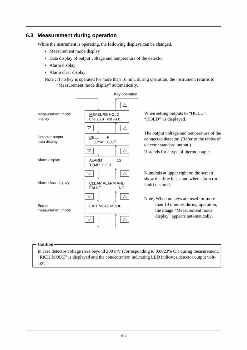
6.3 Measurement during operation
While the instrument is operating, the following displays can be changed.
• Measurement mode display
• Data display of output voltage and temperature of the detector
• Alarm display
• Alarm clear display
Note : If no key is operated for more than 10 min. during operation, the instrument returns to“Measurement mode display” automatically.
When setting outputs to “HOLD”,“HOLD” is displayed.
The output voltage and temperature of theconnected detector. (Refer to the tables ofdetector standard output.)
R stands for a type of thermocouple.
Numerals at upper right on the screenshow the time in second when alarm (orfault) occured.
Note) When no keys are used for morethan 10 minutes during operation,the image “Measurement modedisplay” appears automatically.
Caution
In case detector voltage rises beyond 200 mV (corresponding to 0.0023% O2) during measurement,
“RICH MODE” is displayed and the concentration indicating LED indicates detector output volt-age.
Measurement modedisplay
Detector outputdata display
Alarm display
Alarm clear display
End of measurement mode
MEASURE HOLD0 to 25.0 vol %O2
CELL R 30mV 800
ALARM 1STEMP. HIGH
CLEAR ALARM ANDFAULT NO
EXIT MEAS MODE
Key operation
6-3
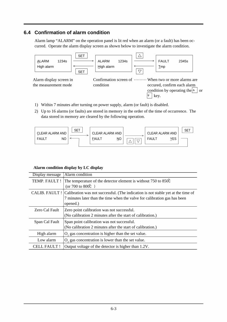
6.4 Confirmation of alarm condition
Alarm lamp “ALARM” on the operation panel is lit red when an alarm (or a fault) has been oc-curred. Operate the alarm display screen as shown below to investigate the alarm condition.
SET
SET
ALARM 1234s
High alarm
ALARM 1234s
High alarm
FAULT 2345s
Tmp
1) Within 7 minutes after turning on power supply, alarm (or fault) is disabled.
2) Up to 16 alarms (or faults) are stored in memory in the order of the time of occurrence. Thedata stored in memory are cleared by the following operation.
SET SETCLEAR ALARM AND
FAULT NO
CLEAR ALARM AND
FAULT NO
CLEAR ALARM AND
FAULT YES
Alarm condition display by LC display
Display message
TEMP. FAULT !
CALIB. FAULT !
Zero Cal Fault
Span Cal Fault
High alarm
Low alarm
CELL FAULT !
Alarm condition
The temperature of the detector element is without 750 to 850 (or 700 to 800)
Calibration was not successful. (The indication is not stable yet at the time of7 minutes later than the time when the valve for calibration gas has beenopened.)
Zero point calibration was not successful.(No calibration 2 minutes after the start of calibration.)
Span point calibration was not successful.(No calibration 2 minutes after the start of calibration.)
O2 gas concentration is higher than the set value.
O2 gas concentration is lower than the set value.
Output voltage of the detector is higher than 1.2V.
Alarm display screen inthe measurement mode
Confirmation screen ofcondition
When two or more alarms areoccured, confirm each alarmcondition by operating the or key.
………
6-4
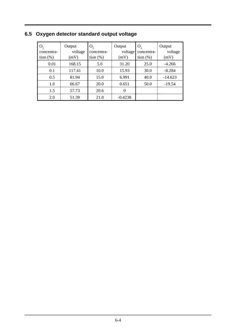
O2
concentra-tion (%)
0.01
0.1
0.5
1.0
1.5
2.0
Output voltage (mV)
168.15
117.41
81.94
66.67
57.73
51.39
O2
concentra-tion (%)
5.0
10.0
15.0
20.0
20.6
21.0
Output voltage (mV)
31.20
15.93
6.991
0.651
0
-0.4238
O2
concentra-tion (%)
25.0
30.0
40.0
50.0
Output voltage (mV)
-4.266
-8.284
-14.623
-19.54
6.5 Oxygen detector standard output voltage
7-1
In order to maintain good accuracy, proper calibration using calibration gas is necessary.
The following 3 methods of calibration are provided.
• Manual calibration (Refer to 7.2)
• Automatic calibration (Refer to 7.3)
• Automatic calibration with remote start (Refer to 7.4)
7.1 Preparation
• Wiring/piping check
Wiring and piping work should be made correctly referring to Item. 4.3. At this time, the mainplug of standard gas should be left open. Since high pressure is present at piping connections,use blind-nut type joints and take special care with regard to air-tightness. Calibration gas flowshould be 1.5 ±0.5r/min.
• Setting of calibration gas concentration
Referring to Chapter 10 “Setting”, set the oxygen concentration in standard gas cylinder to beused.
• Contact output check
Referring to Chapter 10 “Setting”, check to make sure that the contact functions of the externalterminals block are allocated for ZERO VALVE and SPAN VALVE.
7. CALIBRATION
7-2
How to interrupt
(1) Before calibration start
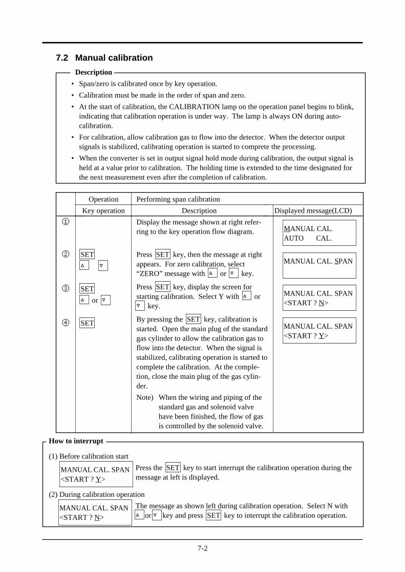
Press the SET key to start interrupt the calibration operation during themessage at left is displayed.
(2) During calibration operation
The message as shown left during calibration operation. Select N with or key and press SET key to interrupt the calibration operation.
7.2 Manual calibration
Description
• Span/zero is calibrated once by key operation.
• Calibration must be made in the order of span and zero.
• At the start of calibration, the CALIBRATION lamp on the operation panel begins to blink,indicating that calibration operation is under way. The lamp is always ON during auto-calibration.
• For calibration, allow calibration gas to flow into the detector. When the detector outputsignals is stabilized, calibrating operation is started to comprete the processing.
• When the converter is set in output signal hold mode during calibration, the output signal isheld at a value prior to calibration. The holding time is extended to the time designated forthe next measurement even after the completion of calibration.
MANUAL CAL. SPAN<START ? Y>
MANUAL CAL. SPAN<START ? N>
Operation
Key operation
SET
SET
or
SET
Performing span calibration
Description
Display the message shown at right refer-ring to the key operation flow diagram.
Press SET key, then the message at rightappears. For zero calibration, select“ZERO” message with or key.
Press SET key, display the screen forstarting calibration. Select Y with or key.
By pressing the SET key, calibration isstarted. Open the main plug of the standardgas cylinder to allow the calibration gas toflow into the detector. When the signal isstabilized, calibrating operation is started tocomplete the calibration. At the comple-tion, close the main plug of the gas cylin-der.
Note) When the wiring and piping of thestandard gas and solenoid valvehave been finished, the flow of gasis controlled by the solenoid valve.
Displayed message(LCD)
①
②
③
④
MANUAL CAL.AUTO CAL.
MANUAL CAL. SPAN
MANUAL CAL. SPAN<START ? N>
MANUAL CAL. SPAN<START ? Y>
7-3
7.3 Automatic calibration
Description
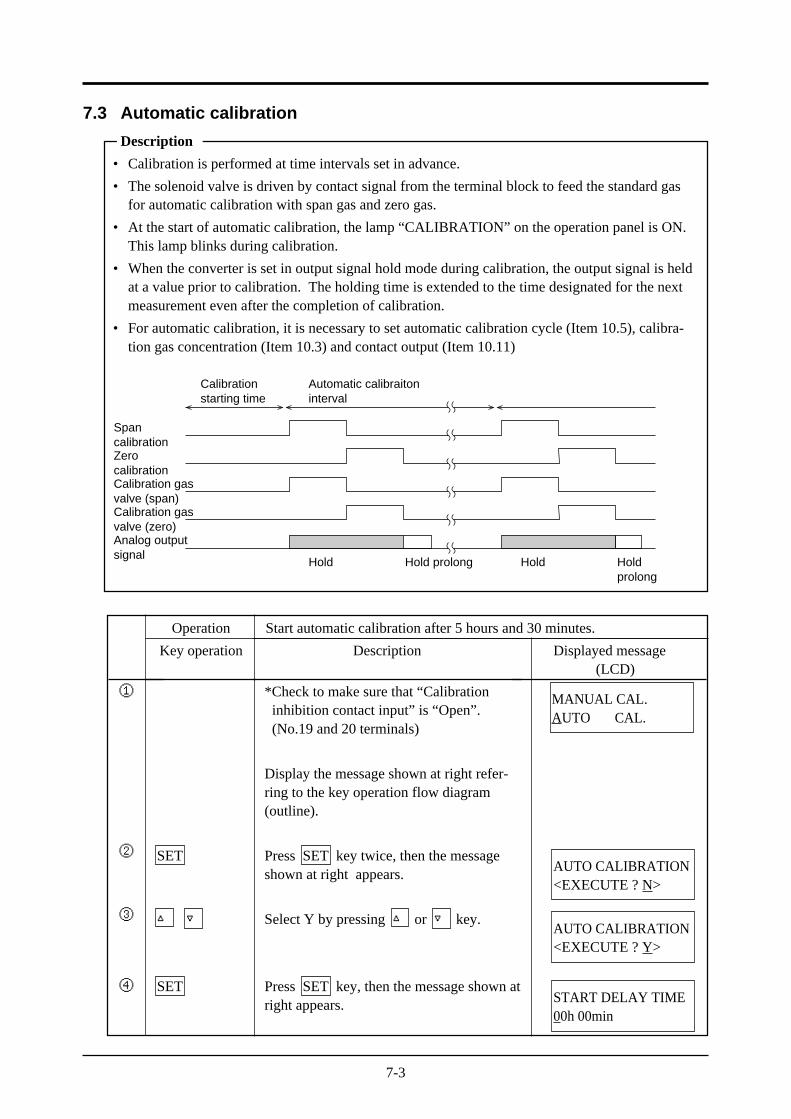
• Calibration is performed at time intervals set in advance.
• The solenoid valve is driven by contact signal from the terminal block to feed the standard gasfor automatic calibration with span gas and zero gas.
• At the start of automatic calibration, the lamp “CALIBRATION” on the operation panel is ON.This lamp blinks during calibration.
• When the converter is set in output signal hold mode during calibration, the output signal is heldat a value prior to calibration. The holding time is extended to the time designated for the nextmeasurement even after the completion of calibration.
• For automatic calibration, it is necessary to set automatic calibration cycle (Item 10.5), calibra-tion gas concentration (Item 10.3) and contact output (Item 10.11)
Calibrationstarting time
Automatic calibraitoninterval
SpancalibrationZerocalibrationCalibration gasvalve (span)Calibration gasvalve (zero)Analog outputsignal
Hold HoldHold prolong Holdprolong
MANUAL CAL.AUTO CAL.
Operation
Key operation
SET
SET
Description
*Check to make sure that “Calibrationinhibition contact input” is “Open”.(No.19 and 20 terminals)
Display the message shown at right refer-ring to the key operation flow diagram(outline).
Press SET key twice, then the messageshown at right appears.
Select Y by pressing or key.
Press SET key, then the message shown atright appears.
Displayed message(LCD)
①
②
③
④
Start automatic calibration after 5 hours and 30 minutes.
START DELAY TIME00h 00min
AUTO CALIBRATION<EXECUTE ? N>
AUTO CALIBRATION<EXECUTE ? Y>
7-4
How to interrupt
(1) Before calibration start
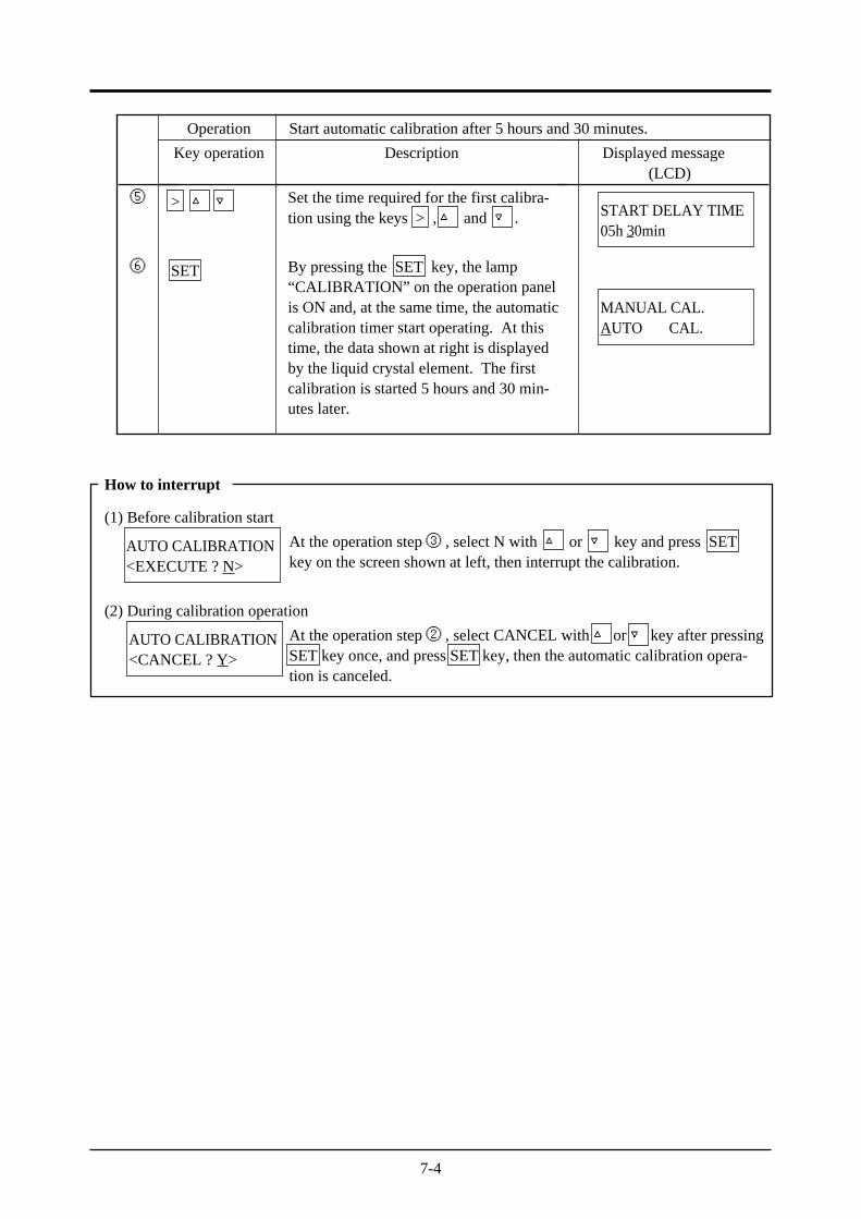
At the operation step ③ , select N with or key and press SETkey on the screen shown at left, then interrupt the calibration.
(2) During calibration operation
At the operation step ② , select CANCEL with or key after pressingSET key once, and press SET key, then the automatic calibration opera-tion is canceled.
AUTO CALIBRATION<EXECUTE ? N>
AUTO CALIBRATION<CANCEL ? Y>
START DELAY TIME05h 30min
⑤
⑥
Operation
Key operation
>
SET
Description
Set the time required for the first calibra-tion using the keys > , and .
By pressing the SET key, the lamp“CALIBRATION” on the operation panelis ON and, at the same time, the automaticcalibration timer start operating. At thistime, the data shown at right is displayedby the liquid crystal element. The firstcalibration is started 5 hours and 30 min-utes later.
Displayed message(LCD)
Start automatic calibration after 5 hours and 30 minutes.
MANUAL CAL.AUTO CAL.
7-5
7.4 Automatic calibration with remote start
Automatic calibration is started by the contact input of external terminal block. Set the calibrationcycle referring to Chapter 10.
For remote calibration, wiring and piping work should be performed for the standard gas cylinderand solenoid valve as explained in Chapter 4. Then, set the contact output for ZERO VALVE andSPAN VALVE.
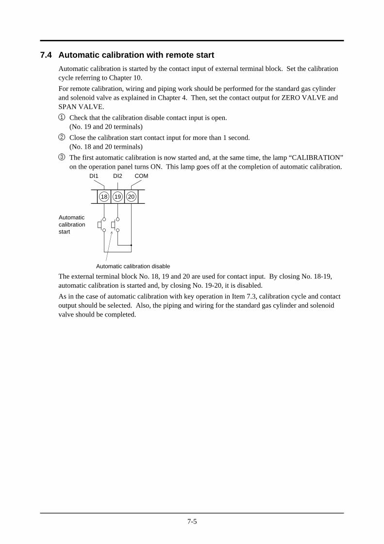
① Check that the calibration disable contact input is open.(No. 19 and 20 terminals)
② Close the calibration start contact input for more than 1 second.(No. 18 and 20 terminals)
③ The first automatic calibration is now started and, at the same time, the lamp “CALIBRATION”on the operation panel turns ON. This lamp goes off at the completion of automatic calibration.
18 19 20
Automaticcalibrationstart
Automatic calibration disable
DI1 DI2 COM
The external terminal block No. 18, 19 and 20 are used for contact input. By closing No. 18-19,automatic calibration is started and, by closing No. 19-20, it is disabled.
As in the case of automatic calibration with key operation in Item 7.3, calibration cycle and contactoutput should be selected. Also, the piping and wiring for the standard gas cylinder and solenoidvalve should be completed.
8-1
8. BLOWDOWN
In order to prevent the flow guide tube from being clogged with dust contained in gas being mea-sured, dust desposits in the flow guide tube is removed by blowing compressed air such as instru-mentation air, etc. When utilizing this blowdown fuction, a flow guide tube with blowdown nozzleis required. There are the following 2 different methods for blowdown.
• Manual blowdown
• Automatic blowdown (cyclic operation)
8.1 Preparation for blowdown
• Wiring/piping check
Perform wiring and piping correctly referring to Item.4.3. Since high pressure is applied to thepiping, be sure to use blind-nut type joints at connections. Special care should be take withregard to air-tightness.
• Setting of blowdown time
Referring to Chapter 10 “Setting”, set blowdown time.
• Contact output check
Referring to Chapter 10 “Setting”, check to make sure that the contact functions of the externalterminals block are allocated for BLOWDOWN.
8-2
8.2 Manual blowdown
Description
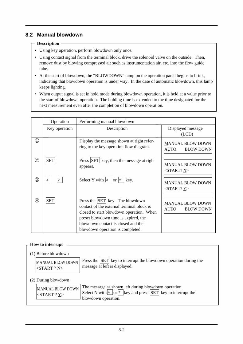
• Using key operation, perform blowdown only once.
• Using contact signal from the terminal block, drive the solenoid valve on the outside. Then,remove dust by blowing compressed air such as instrumentation air, etc. into the flow guidetube.
• At the start of blowdown, the “BLOWDOWN” lamp on the operation panel begins to brink,indicating that blowdown operation is under way. In the case of automatic blowdown, this lampkeeps lighting.
• When output signal is set in hold mode during blowdown operation, it is held at a value prior tothe start of blowdown operation. The holding time is extended to the time designated for thenext measurement even after the completion of blowdown operation.
How to interrupt
(1) Before blowdown
Press the SET key to interrupt the blowdown operation during themessage at left is displayed.
(2) During blowdown
The message as shown left during blowdown operation.Select N with or key and press SET key to interrupt theblowdown operation.
MANUAL BLOW DOWN<START ? N>
MANUAL BLOW DOWN<START ? Y>
Operation
Key operation
SET
SET
Performing manual blowdown
Description
Display the message shown at right refer-ring to the key operation flow diagram.
Press SET key, then the message at rightappears.
Select Y with or key.
Press the SET key. The blowdowncontact of the external terminal block isclosed to start blowdown operation. Whenpreset blowdown time is expired, theblowdown contact is closed and theblowdown operation is completed.
Displayed message(LCD)
①
②
③
④
MANUAL BLOW DOWNAUTO BLOW DOWN
MANUAL BLOW DOWN<START? N>
MANUAL BLOW DOWN<START? Y>
MANUAL BLOW DOWNAUTO BLOW DOWN
8-3
8.3 Automatic blowdown
Description
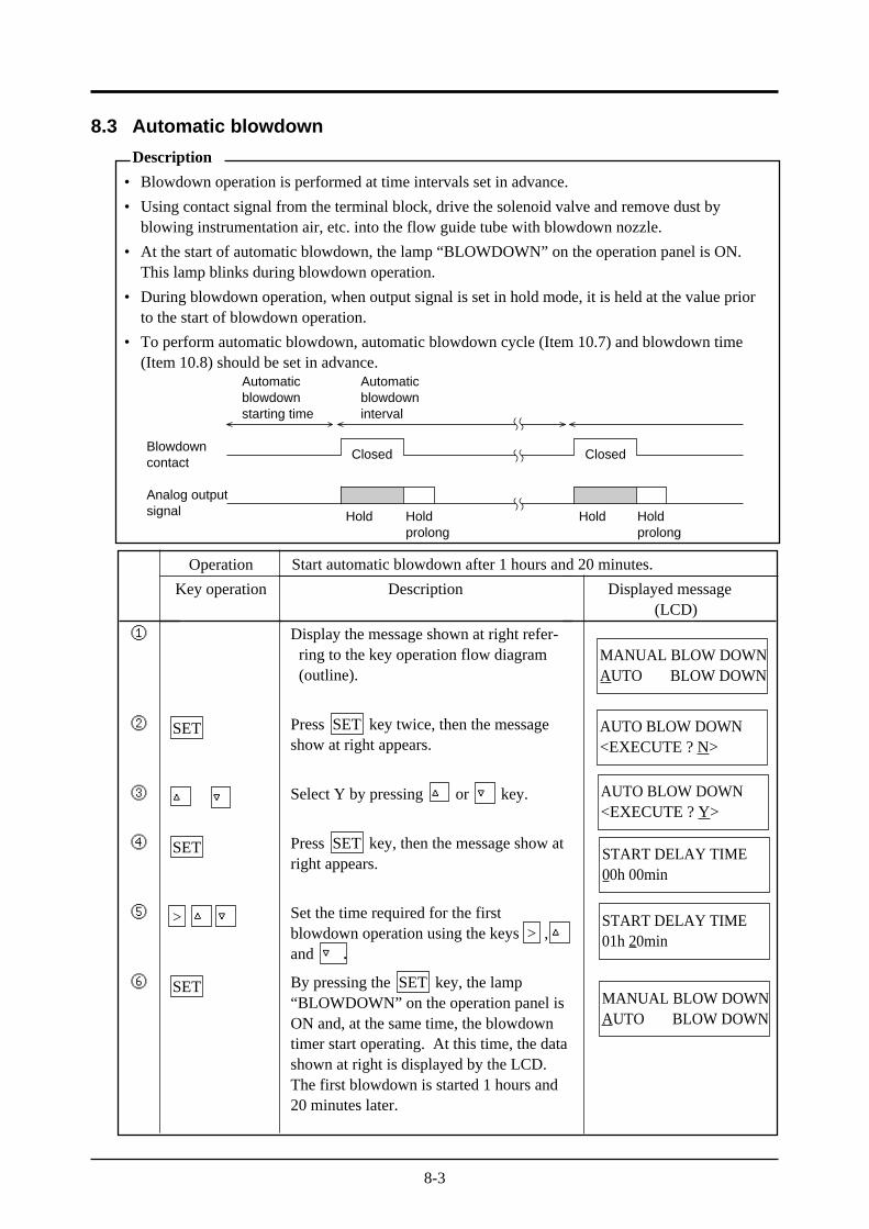
• Blowdown operation is performed at time intervals set in advance.
• Using contact signal from the terminal block, drive the solenoid valve and remove dust byblowing instrumentation air, etc. into the flow guide tube with blowdown nozzle.
• At the start of automatic blowdown, the lamp “BLOWDOWN” on the operation panel is ON.This lamp blinks during blowdown operation.
• During blowdown operation, when output signal is set in hold mode, it is held at the value priorto the start of blowdown operation.
• To perform automatic blowdown, automatic blowdown cycle (Item 10.7) and blowdown time(Item 10.8) should be set in advance.
Automaticblowdownstarting time
Automaticblowdowninterval
Blowdowncontact
Analog outputsignal
Closed Closed
Holdprolong
HoldHold Holdprolong
Operation
Key operation
SET
SET
>
SET
Description
Display the message shown at right refer-ring to the key operation flow diagram(outline).
Press SET key twice, then the messageshow at right appears.
Select Y by pressing or key.
Press SET key, then the message show atright appears.
Set the time required for the firstblowdown operation using the keys > ,and .
By pressing the SET key, the lamp“BLOWDOWN” on the operation panel isON and, at the same time, the blowdowntimer start operating. At this time, the datashown at right is displayed by the LCD.The first blowdown is started 1 hours and20 minutes later.
Displayed message(LCD)
①
②
③
④
⑤
⑥
Start automatic blowdown after 1 hours and 20 minutes.
MANUAL BLOW DOWNAUTO BLOW DOWN
AUTO BLOW DOWN<EXECUTE ? N>
AUTO BLOW DOWN<EXECUTE ? Y>
START DELAY TIME00h 00min
START DELAY TIME01h 20min
MANUAL BLOW DOWNAUTO BLOW DOWN
8-4
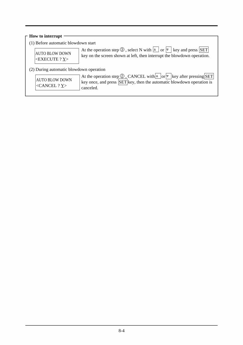
How to interrupt
(1) Before automatic blowdown start
At the operation step ③ , select N with or key and press SETkey on the screen shown at left, then interrupt the blowdown operation.
(2) During automatic blowdown operation
At the operation step ② , CANCEL with or key after pressing SETkey once, and press SET key, then the automatic blowdown operation iscanceled.
AUTO BLOW DOWN<EXECUTE ? Y>
AUTO BLOW DOWN<CANCEL ? Y>
9-1
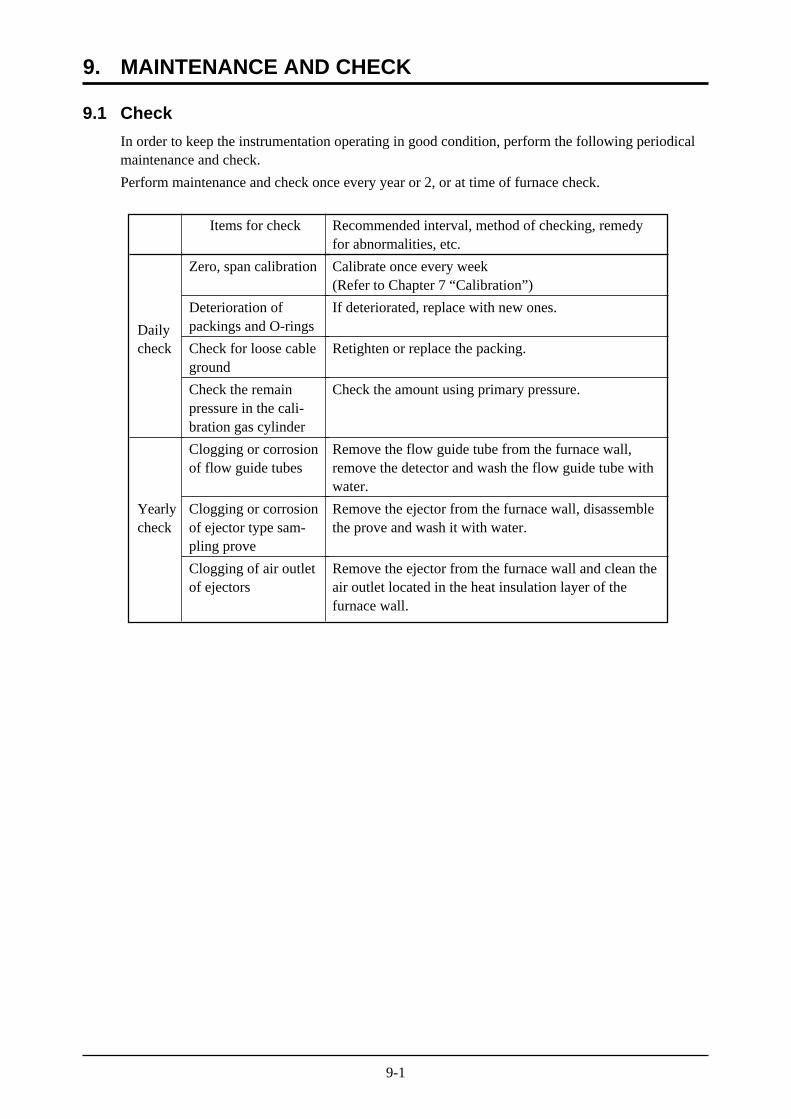
9.1 Check
In order to keep the instrumentation operating in good condition, perform the following periodicalmaintenance and check.
Perform maintenance and check once every year or 2, or at time of furnace check.
9. MAINTENANCE AND CHECK
Items for check
Zero, span calibration
Deterioration ofpackings and O-rings
Check for loose cableground
Check the remainpressure in the cali-bration gas cylinder
Clogging or corrosionof flow guide tubes
Clogging or corrosionof ejector type sam-pling prove
Clogging of air outletof ejectors
Recommended interval, method of checking, remedyfor abnormalities, etc.
Calibrate once every week(Refer to Chapter 7 “Calibration”)
If deteriorated, replace with new ones.
Retighten or replace the packing.
Check the amount using primary pressure.
Remove the flow guide tube from the furnace wall,remove the detector and wash the flow guide tube withwater.
Remove the ejector from the furnace wall, disassemblethe prove and wash it with water.
Remove the ejector from the furnace wall and clean theair outlet located in the heat insulation layer of thefurnace wall.
Dailycheck
Yearlycheck
9-2
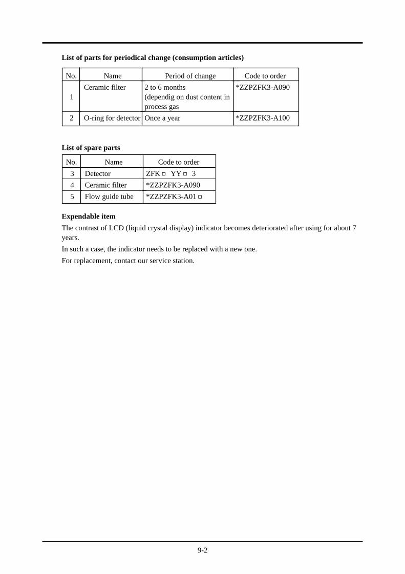
List of parts for periodical change (consumption articles)
List of spare parts
Expendable item
The contrast of LCD (liquid crystal display) indicator becomes deteriorated after using for about 7years.
In such a case, the indicator needs to be replaced with a new one.
For replacement, contact our service station.
No.
1
2
Name
Ceramic filter
O-ring for detector
Period of change
2 to 6 months(dependig on dust content inprocess gas
Once a year
Code to order
*ZZPZFK3-A090
*ZZPZFK3-A100
No.
3
4
5
Name
Detector
Ceramic filter
Flow guide tube
Code to order
ZFKYY 3
*ZZPZFK3-A090
*ZZPZFK3-A01
9-3
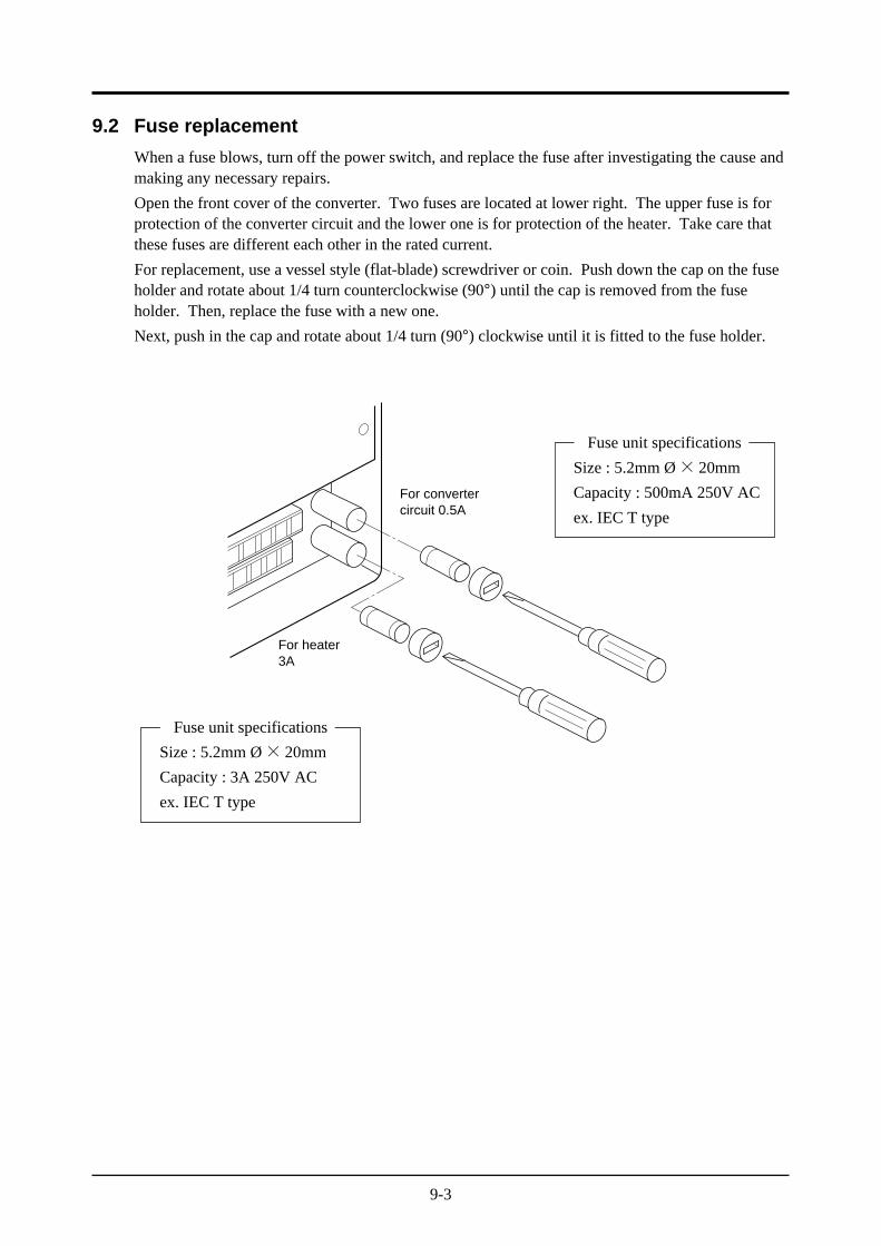
9.2 Fuse replacement
When a fuse blows, turn off the power switch, and replace the fuse after investigating the cause andmaking any necessary repairs.
Open the front cover of the converter. Two fuses are located at lower right. The upper fuse is forprotection of the converter circuit and the lower one is for protection of the heater. Take care thatthese fuses are different each other in the rated current.
For replacement, use a vessel style (flat-blade) screwdriver or coin. Push down the cap on the fuseholder and rotate about 1/4 turn counterclockwise (90°) until the cap is removed from the fuseholder. Then, replace the fuse with a new one.
Next, push in the cap and rotate about 1/4 turn (90°) clockwise until it is fitted to the fuse holder.
Fuse unit specifications
Size : 5.2mm Ø× 20mm
Capacity : 3A 250V AC
ex. IEC T type
Fuse unit specifications
Size : 5.2mm Ø× 20mm
Capacity : 500mA 250V AC
ex. IEC T type
For convertercircuit 0.5A
For heater3A
9-4
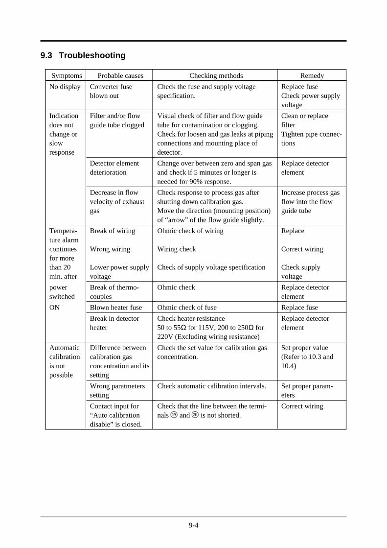
9.3 Troubleshooting
Probable causes
Converter fuseblown out
Filter and/or flowguide tube clogged
Detector elementdeterioration
Decrease in flowvelocity of exhaustgas
Break of wiring
Wrong wiring
Lower power supplyvoltage
Break of thermo-couples
Blown heater fuse
Break in detectorheater
Difference betweencalibration gasconcentration and itssetting
Wrong paratmeterssetting
Contact input for“Auto calibrationdisable” is closed.
Checking methods
Check the fuse and supply voltagespecification.
Visual check of filter and flow guidetube for contamination or clogging.Check for loosen and gas leaks at pipingconnections and mounting place ofdetector.
Change over between zero and span gasand check if 5 minutes or longer isneeded for 90% response.
Check response to process gas aftershutting down calibration gas.Move the direction (mounting position)of “arrow” of the flow guide slightly.
Ohmic check of wiring
Wiring check
Check of supply voltage specification
Ohmic check
Ohmic check of fuse
Check heater resistance50 to 55Ω for 115V, 200 to 250Ω for220V (Excluding wiring resistance)
Check the set value for calibration gasconcentration.
Check automatic calibration intervals.
Check that the line between the termi-nals ⑲ and ⑳ is not shorted.
Remedy
Replace fuseCheck power supplyvoltage
Clean or replacefilterTighten pipe connec-tions
Replace detectorelement
Increase process gasflow into the flowguide tube
Replace
Correct wiring
Check supplyvoltage
Replace detectorelement
Replace fuse
Replace detectorelement
Set proper value(Refer to 10.3 and10.4)
Set proper param-eters
Correct wiring
Symptoms
No display
Indicationdoes notchange orslowresponse
Tempera-ture alarmcontinuesfor morethan 20min. after
powerswitched
ON
Automaticcalibrationis notpossible
9-5
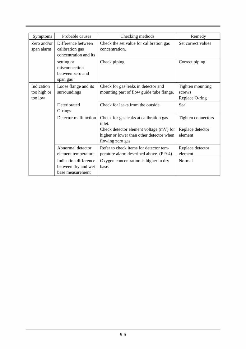
Probable causes
Difference betweencalibration gasconcentration and its
setting ormisconnectionbetween zero andspan gas
Loose flange and itssurroundings
DeterioratedO-rings
Detector malfunction
Abnormal detectorelement temperature
Indication differencebetween dry and wetbase measurement
Checking methods
Check the set value for calibration gasconcentration.
Check piping
Check for gas leaks in detector andmounting part of flow guide tube flange.
Check for leaks from the outside.
Check for gas leaks at calibration gasinlet.Check detector element voltage (mV) forhigher or lower than other detector whenflowing zero gas
Refer to check items for detector tem-perature alarm described above. (P.9-4)
Oxygen concentration is higher in drybase.
Remedy
Set correct values
Correct piping
Tighten mountingscrewsReplace O-ring
Seal
Tighten connectors
Replace detectorelement
Replace detectorelement
Normal
Symptoms
Zero and/orspan alarm
Indicationtoo high ortoo low
10-1
10. SETTING AND OPERATING OF PARAMETER
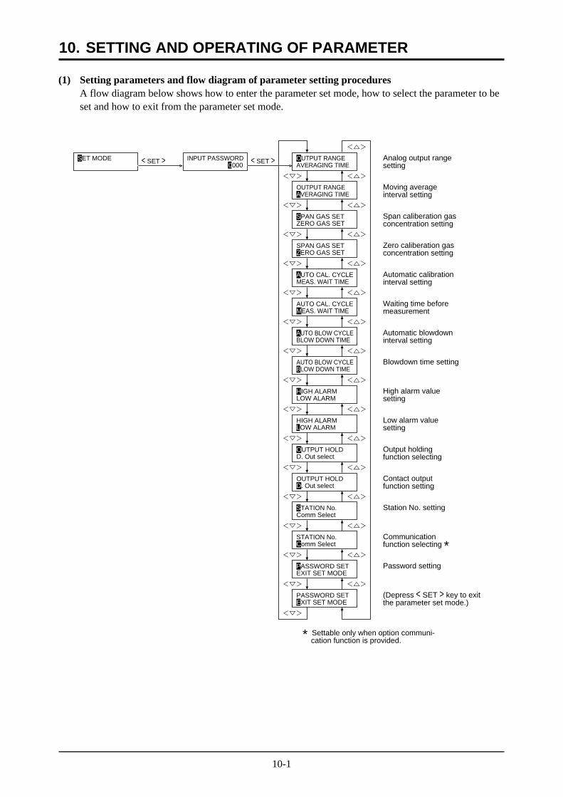
(1) Setting parameters and flow diagram of parameter setting proceduresA flow diagram below shows how to enter the parameter set mode, how to select the parameter to beset and how to exit from the parameter set mode.
AVERAGING TIMEOUTPUT RANGE Analog output range
setting
Moving averageinterval setting
Span caliberation gasconcentration setting
Zero caliberation gasconcentration setting
Automatic calibrationinterval setting
Waiting time beforemeasurement
Automatic blowdowninterval setting
Blowdown time setting
High alarm valuesetting
Low alarm valuesetting
Output holdingfunction selecting
Contact outputfunction setting
Station No. setting
Communicationfunction selecting *Password setting
(Depress < SET > key to exitthe parameter set mode.)
MEAS. WAIT TIME
BLOW DOWN TIMEAUTO BLOW CYCLE
LOW ALARMHIGH ALARM
D. Out selectOUTPUT HOLD
Comm SelectSTATION No.
EXIT SET MODEPASSWORD SET
PASSWORD SET
STATION No.
AUTO BLOW CYCLE
AUTO CAL. CYCLE
ZERO GAS SETSPAN GAS SET
SPAN GAS SET
OUTPUT RANGEAVERAGING TIME
ZERO GAS SET
MEAS. WAIT TIME
BLOW DOWN TIME
HIGH ALARMLOW ALARM
OUTPUT HOLDD. Out select
Comm Select
<> <>
<> <>
<> <>
<> <>
<> <>
<> <>
<> <>
<> <>
<> <>
<> <>
<> <>
<> <>
<> <>
<>
<>
<>
<> <>
<>
SET MODE INPUT PASSWORD 0000
< SET >< SET >
EXIT SET MODE
* Settable only when option communi- cation function is provided.
AUTO CAL. CYCLE
10-2
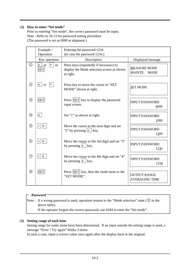
(2) How to enter “Set mode”Prior to entering “Set mode”, the correct password must be input.Note : Refer to 10.13 for password setting procedure.(The password is set as 0000 at shipment.)
Example :Operation
Key operation
or orSET
or
SET
>
>
>
SET
Entering the password 1234(In case the password 1234.)
Description
Press keys (repeatedly if necessary) todisplay the Mode selection screen as shownat right.
Press key to move the cursor to “SETMODE” shown at right.
Press SET key to display the passwordinput screen.
Set “1” as shown at right.
Move the cursor to the next digit and set"2” by pressing key.
Move the cursor to the 3rd digit and set "3”by pressing key.
Move the cursor to the 4th digit and set "4”by pressing key.
Press SET key, then the mode turns to the“SET MODE”.
Displayed message
①
②
③
④
⑤
⑥
⑦
⑧
MEASURE MODEMAINTE. MODE
SET MODE
INPUT PASSWORD0000
INPUT PASSWORD1000
INPUT PASSWORD1200
INPUT PASSWORD1230
INPUT PASSWORD1234
OUTPUT RANGEAVERAGING TIME
Password
Note : If a wrong password is used, operation returns to the “Mode selection” state (② in theabove table).If the operator forgets the correct password, use 6284 to enter the “Set mode”.
(3) Setting range of each itemSetting range for some items have been determined. If an input outside the setting range is used, amessage “Error ! Try again” blinks 3 times.In such a case, input a correct value once again after the display back to the original.
10-3
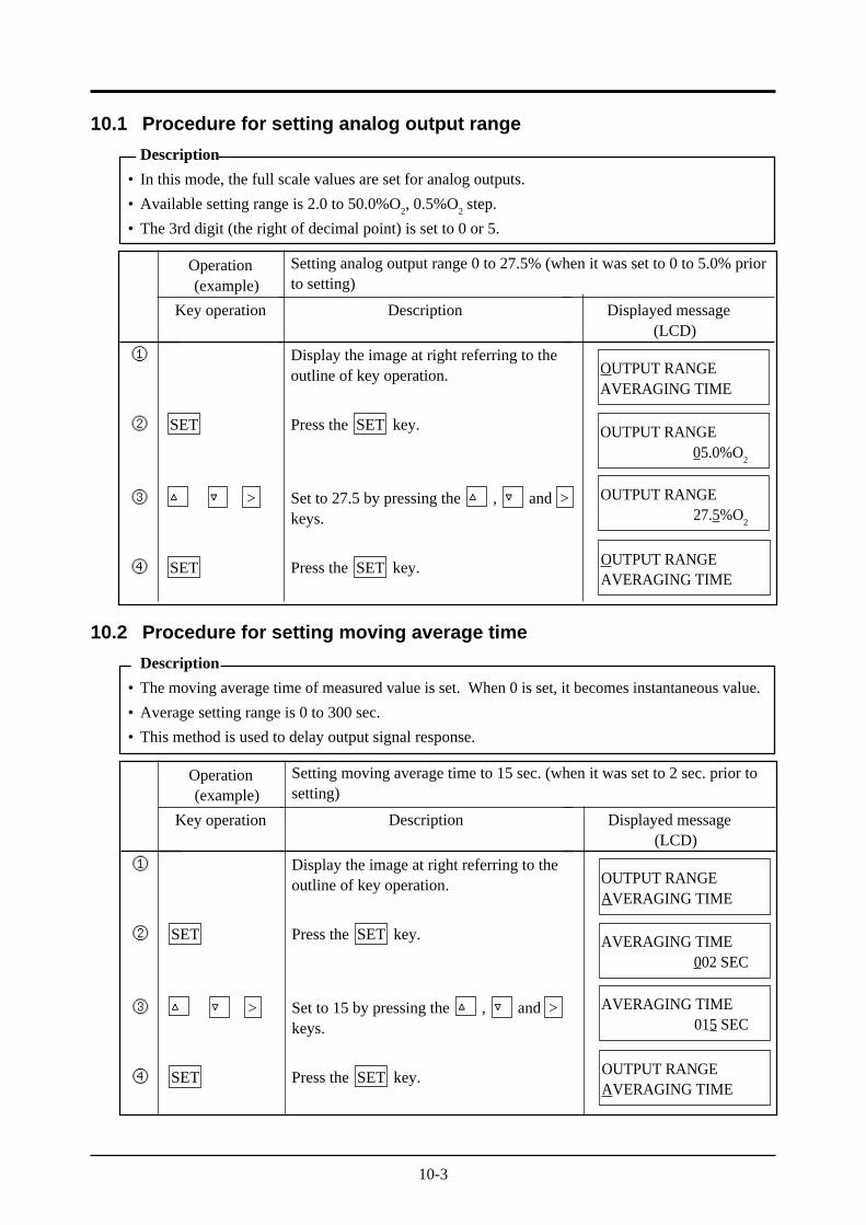
10.2 Procedure for setting moving average time
Description
• The moving average time of measured value is set. When 0 is set, it becomes instantaneous value.
• Average setting range is 0 to 300 sec.
• This method is used to delay output signal response.
10.1 Procedure for setting analog output range
Description
• In this mode, the full scale values are set for analog outputs.
• Available setting range is 2.0 to 50.0%O2, 0.5%O
2 step.
• The 3rd digit (the right of decimal point) is set to 0 or 5.
Operation(example)
Key operation
SET
>
SET
Description
Display the image at right referring to theoutline of key operation.
Press the SET key.
Set to 27.5 by pressing the , and >keys.
Press the SET key.
Displayed message(LCD)
①
②
③
④
OUTPUT RANGEAVERAGING TIME
OUTPUT RANGE05.0%O
2
OUTPUT RANGE27.5%O
2
OUTPUT RANGEAVERAGING TIME
Setting analog output range 0 to 27.5% (when it was set to 0 to 5.0% priorto setting)
Operation(example)
Key operation
SET
>
SET
Description
Display the image at right referring to theoutline of key operation.
Press the SET key.
Set to 15 by pressing the , and >keys.
Press the SET key.
Displayed message(LCD)
①
②
③
④
OUTPUT RANGEAVERAGING TIME
AVERAGING TIME002 SEC
AVERAGING TIME015 SEC
OUTPUT RANGEAVERAGING TIME
Setting moving average time to 15 sec. (when it was set to 2 sec. prior tosetting)
10-4
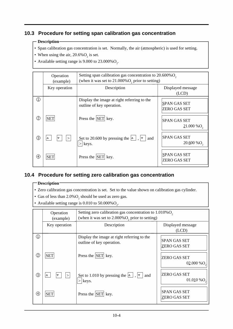
10.4 Procedure for setting zero calibration gas concentration
Description
• Zero calibration gas concentration is set. Set to the value shown on calibration gas cylinder.
• Gas of less than 2.0%O2 should be used as zero gas.
• Available setting range is 0.010 to 50.000%O2.
10.3 Procedure for setting span calibration gas concentration
Description
• Span calibration gas concentration is set. Normally, the air (atmospheric) is used for setting.
• When using the air, 20.6%O2 is set.
• Available setting range is 9.000 to 23.000%O2.
Operation(example)
Key operation
SET
>
SET
Description
Display the image at right referring to theoutline of key operation.
Press the SET key.
Set to 20.600 by pressing the , and> keys.
Press the SET key.
Displayed message(LCD)
①
②
③
④
SPAN GAS SETZERO GAS SET
SPAN GAS SET21.000 %O
2
SPAN GAS SET20.600 %O
2
SPAN GAS SETZERO GAS SET
Setting span calibration gas concentration to 20.600%O2
(when it was set to 21.000%O2 prior to setting)
Operation(example)
Key operation
SET
>
SET
Description
Display the image at right referring to theoutline of key operation.
Press the SET key.
Set to 1.010 by pressing the , and> keys.
Press the SET key.
Displayed message(LCD)
①
②
③
④
SPAN GAS SETZERO GAS SET
ZERO GAS SET02.000 %O
2
ZERO GAS SET01.010 %O
2
SPAN GAS SETZERO GAS SET
Setting zero calibration gas concentration to 1.010%O2
(when it was set to 2.000%O2 prior to setting)
10-5
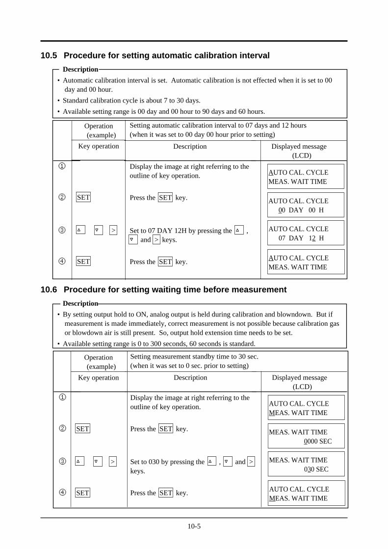
10.6 Procedure for setting waiting time before measurement
Description
• By setting output hold to ON, analog output is held during calibration and blowndown. But ifmeasurement is made immediately, correct measurement is not possible because calibration gasor blowdown air is still present. So, output hold extension time needs to be set.
• Available setting range is 0 to 300 seconds, 60 seconds is standard.
10.5 Procedure for setting automatic calibration interval
Description
• Automatic calibration interval is set. Automatic calibration is not effected when it is set to 00day and 00 hour.
• Standard calibration cycle is about 7 to 30 days.
• Available setting range is 00 day and 00 hour to 90 days and 60 hours.
Operation(example)
Key operation
SET
>
SET
Description
Display the image at right referring to theoutline of key operation.
Press the SET key.
Set to 07 DAY 12H by pressing the , and > keys.
Press the SET key.
Displayed message(LCD)
①
②
③
④
AUTO CAL. CYCLEMEAS. WAIT TIME
AUTO CAL. CYCLE00 DAY 00 H
AUTO CAL. CYCLE07 DAY 12 H
AUTO CAL. CYCLEMEAS. WAIT TIME
Setting automatic calibration interval to 07 days and 12 hours(when it was set to 00 day 00 hour prior to setting)
Operation(example)
Key operation
SET
>
SET
①
②
③
④
Description
Display the image at right referring to theoutline of key operation.
Press the SET key.
Set to 030 by pressing the , and >keys.
Press the SET key.
Displayed message(LCD)
AUTO CAL. CYCLEMEAS. WAIT TIME
MEAS. WAIT TIME0000 SEC
MEAS. WAIT TIME030 SEC
AUTO CAL. CYCLEMEAS. WAIT TIME
Setting measurement standby time to 30 sec.(when it was set to 0 sec. prior to setting)
10-6
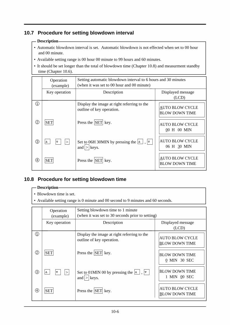
10.8 Procedure for setting blowdown time
Description
• Blowdown time is set.
• Available setting range is 0 minute and 00 second to 9 minutes and 60 seconds.
10.7 Procedure for setting blowdown interval
Description
• Automatic blowdown interval is set. Automatic blowdown is not effected when set to 00 hourand 00 minute.
• Available setting range is 00 hour 00 minute to 99 hours and 60 minutes.
• It should be set longer than the total of blowdown time (Chapter 10.8) and measurment standbytime (Chapter 10.6).
Operation(example)
Key operation
SET
>
SET
Description
Display the image at right referring to theoutline of key operation.
Press the SET key.
Set to 06H 30MIN by pressing the , and > keys.
Press the SET key.
Displayed message(LCD)
①
②
③
④
AUTO BLOW CYCLEBLOW DOWN TIME
AUTO BLOW CYCLE00 H 00 MIN
AUTO BLOW CYCLE06 H 30 MIN
AUTO BLOW CYCLEBLOW DOWN TIME
Setting automatic blowdown interval to 6 hours and 30 minutes(when it was set to 00 hour and 00 minute)
Operation(example)
Key operation
SET
>
SET
Description
Display the image at right referring to theoutline of key operation.
Press the SET key.
Set to 01MIN 00 by pressing the , and > keys.
Press the SET key.
Displayed message(LCD)
①
②
③
④
AUTO BLOW CYCLEBLOW DOWN TIME
BLOW DOWN TIME0 MIN 30 SEC
BLOW DOWN TIME1 MIN 00 SEC
AUTO BLOW CYCLEBLOW DOWN TIME
Setting blowdown time to 1 minute(when it was set to 30 seconds prior to setting)
10-7
Operation(example)
Key operation
SET
>
SET
Description
Display the image at right referring to theoutline of key operation.
Press the SET key.
Set to 30.00 by pressing the , and> keys.
Press the SET key.
Displayed message(LCD)
①
②
③
④
HIGH ALARMLOW ALARM
HIGH ALARM55.00 %O
2
HIGH ALARM30.00 %O
2
HIGH ALARMLOW ALARM
Setting high-alarm value to 30.00%O2
(when it was set to 55.00%O2 prior to setting)
Operation(example)
Key operation
SET
>
SET
Description
Display the image at right referring to theoutline of key operation.
Press the SET key.
Set to 01.00 by pressing the , and> keys.
Press the SET key.
Displayed message(LCD)
①
②
③
④
HIGH ALARMLOW ALARM
LOW ALARM00.01 %O
2
LOW ALARM01.00 %O
2
HIGH ALARMLOW ALARM
Setting low-alarm value to 1.00%O2
(when it was set to 0.01%O2 prior to setting)
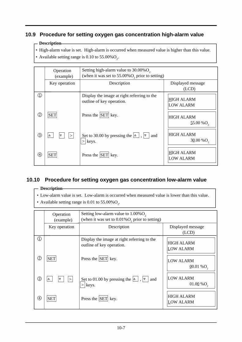
10.9 Procedure for setting oxygen gas concentration high-alarm value
Description
• High-alarm value is set. High-alarm is occurred when measured value is higher than this value.
• Available setting range is 0.10 to 55.00%O2.
10.10 Procedure for setting oxygen gas concentration low-alarm value
Description
• Low-alarm value is set. Low-alarm is occurred when measured value is lower than this value.
• Available setting range is 0.01 to 55.00%O2.
10-8
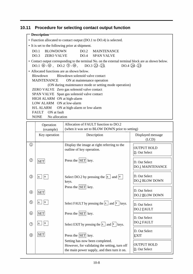
Description
Display the image at right referring to theoutline of key operation.
Press the SET key.
Select DO.2 by pressing the and keys.
Press the SET key.
Select FAULT by pressing the and keys.
Press the SET key.
Select EXIT by pressing the and keys.
Press the SET key.
Setting has now been completed.However, for validating the setting, turn offthe main power supply, and then turn it on.
①
②
③
④
⑤
⑥
⑦
⑧
Operation(example)
Key operation
SET
SET
SET
SET
Displayed message(LCD)
OUTPUT HOLDD. Out Select
D. Out SelectDO.1 MAINTENANCE
D. Out SelectDO.2 BLOW DOWN
D. Out SelectDO.2 BLOW DOWN
Allocation of FAULT function to DO.2(when it was set to BLOW DOWN prior to setting)
D. Out SelectDO.2 FAULT
D. Out SelectDO.2 FAULT
D. Out SelectEXIT
OUTPUT HOLDD. Out Select
10.11 Procedure for selecting contact output function
Description
• Function allocated to contact output (DO.1 to DO.4) is selected.
• It is set to the following prior at shipment.
DO.1 BLOWDOWN DO.2 MAINTENANCEDO.3 ZERO VALVE DO.4 SPAN VALVE
• Contact output corresponding to the terminal No. on the external terminal block are as shown below.DO.1 ⑪ -⑫, DO.2 ⑨ -⑩ , DO.3 22 - 23, DO.4 24 - 23
• Allocated functions are as shown below.Blowdown Blowdown solenoid valve contactMAINTENANCE ON at maintenance operation
(ON during maintenance mode or setting mode operation)ZERO VALVE Zero gas solenoid valve contactSPAN VALVE Span gas solenoid valve contactHIGH ALARM ON at high-alarmLOW ALARM ON at low-alarmH/L ALARM ON at high-alarm or low-alarmFAULT ON at faultNONE No allocation
10-9
①
②
③
④
Operation(example)
Key operation
SET
SET
Description
Display the image at right referring to theoutline of key operation.
Press the SET key.
Set to YES by pressing the and keys.
Press the SET key.
Note) When output hold is set to YES,HOLD is displayed on the measure-ment mode display.
Displayed message(LCD)
OUTPUT HOLDD. Out Select
OUTPUT HOLD<NO>
OUTPUT HOLD<YES>
OUTPUT HOLDD. Out Select
Setting output hold to YES(when it was set to NO prior to setting)
Operation(example)
Key operation
SET
>
SET
Description
Display the image at right referring to theoutline of key operation.
Press the SET key.
Set to 1234 by pressing the , and> keys.
Press the SET key.
Displayed message(LCD)
①
②
③
④
PASSWORD SETEXIT SET MODE
PASSWORD SET0000
PASSWORD SET1234
PASSWORD SETEXIT SET MODE
Setting password to 1234(When it was set to 0000 prior to setting)
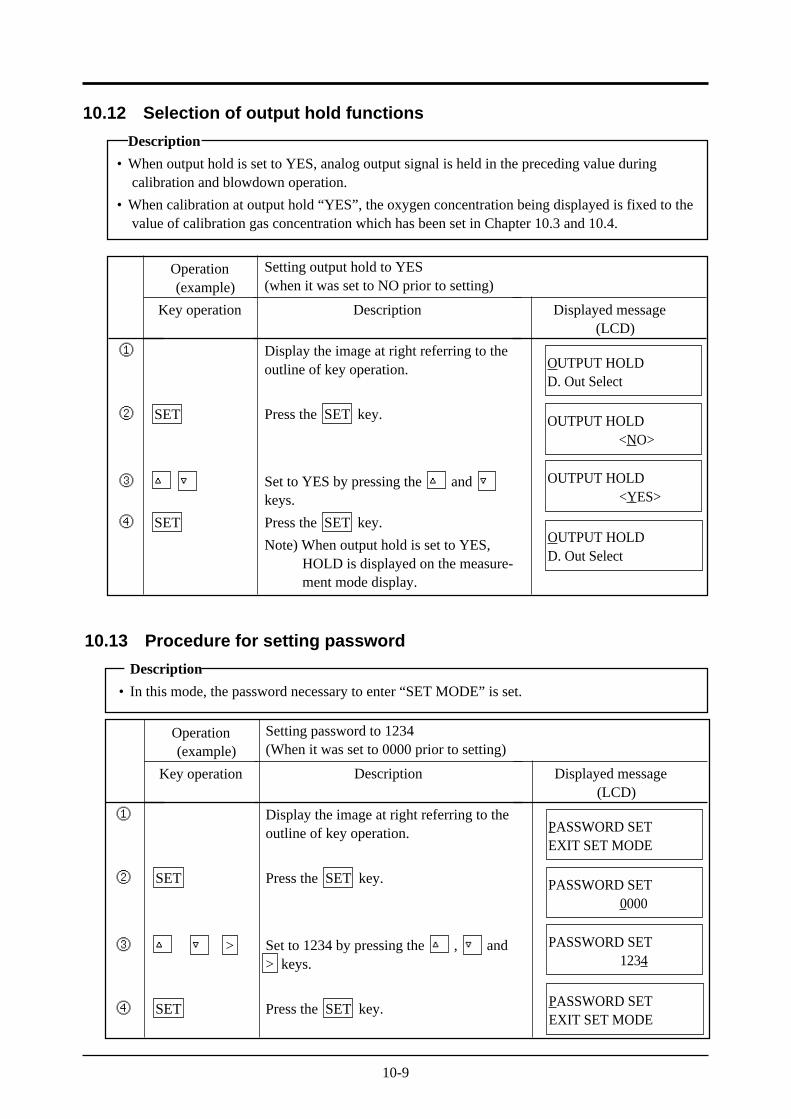
10.12 Selection of output hold functions
Description
• When output hold is set to YES, analog output signal is held in the preceding value duringcalibration and blowdown operation.
• When calibration at output hold “YES”, the oxygen concentration being displayed is fixed to thevalue of calibration gas concentration which has been set in Chapter 10.3 and 10.4.
10.13 Procedure for setting password
Description
• In this mode, the password necessary to enter “SET MODE” is set.
11-1
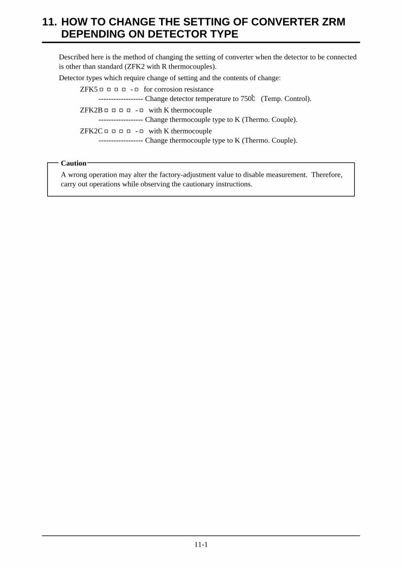
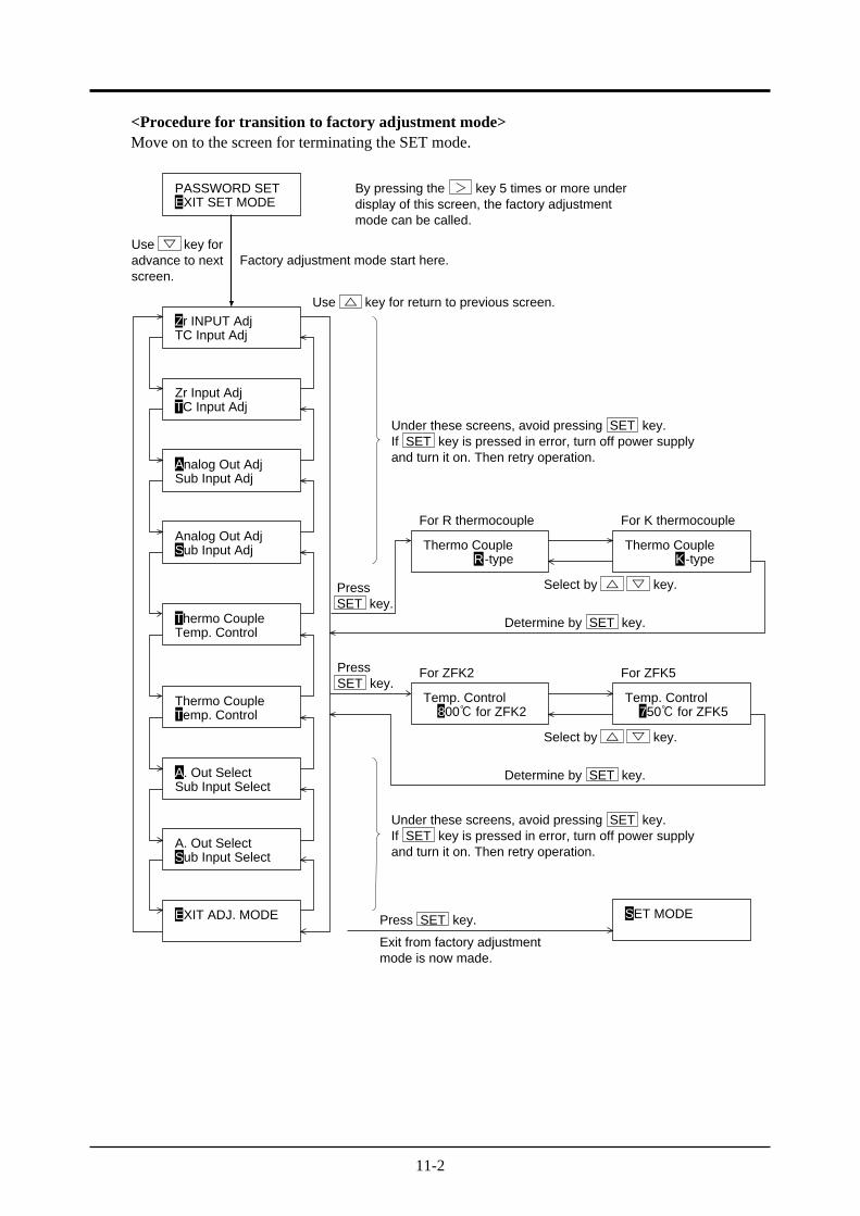
Described here is the method of changing the setting of converter when the detector to be connectedis other than standard (ZFK2 with R thermocouples).
Detector types which require change of setting and the contents of change:
ZFK5 - for corrosion resistance------------------ Change detector temperature to 750 (Temp. Control).
ZFK2B - with K thermocouple------------------ Change thermocouple type to K (Thermo. Couple).
ZFK2C - with K thermocouple------------------ Change thermocouple type to K (Thermo. Couple).
Caution
A wrong operation may alter the factory-adjustment value to disable measurement. Therefore,carry out operations while observing the cautionary instructions.
11. HOW TO CHANGE THE SETTING OF CONVERTER ZRMDEPENDING ON DETECTOR TYPE
11-2
<Procedure for transition to factory adjustment mode>Move on to the screen for terminating the SET mode.
PASSWORD SET
Thermo Couple
For R thermocouple
For ZFK2 For ZFK5
For K thermocouple
R-type K-typeThermo Couple
TC Input AdjZr INPUT Adj
Zr Input Adj
Sub Input AdjAnalog Out Adj
Sub Input AdjAnalog Out Adj
Temp. ControlThermo Couple
Temp. ControlThermo Couple
800 for ZFK2Temp. Control
750 for ZFK5Temp. Control
Sub Input SelectA. Out Select
A. Out Select
EXIT ADJ. MODE SET MODE
EXIT SET MODE
TC Input Adj
Sub Input Select
By pressing the > key 5 times or more underdisplay of this screen, the factory adjustmentmode can be called.
Use key foradvance to nextscreen.
Use key for return to previous screen.
PressSET key.
PressSET key.
Under these screens, avoid pressing SET key.If SET key is pressed in error, turn off power supplyand turn it on. Then retry operation.
Factory adjustment mode start here.
Select by key.
Determine by SET key.
Determine by SET key.
Under these screens, avoid pressing SET key.If SET key is pressed in error, turn off power supplyand turn it on. Then retry operation.
Press SET key.
Exit from factory adjustmentmode is now made.
Select by key.
12-1
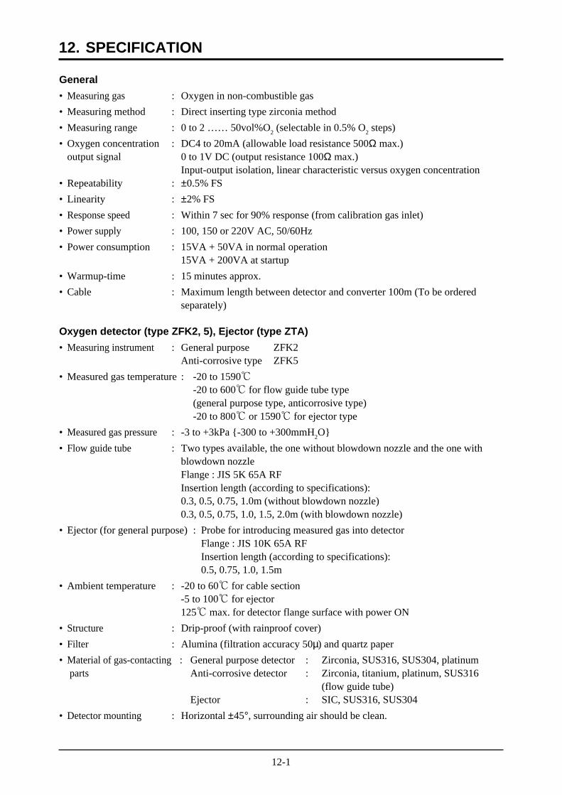
General
• Measuring gas : Oxygen in non-combustible gas
• Measuring method : Direct inserting type zirconia method
• Measuring range : 0 to 2 …… 50vol%O2 (selectable in 0.5% O
2 steps)
• Oxygen concentration : DC4 to 20mA (allowable load resistance 500Ω max.)output signal 0 to 1V DC (output resistance 100Ω max.)
Input-output isolation, linear characteristic versus oxygen concentration• Repeatability : ±0.5% FS
• Linearity : ±2% FS
• Response speed : Within 7 sec for 90% response (from calibration gas inlet)
• Power supply : 100, 150 or 220V AC, 50/60Hz
• Power consumption : 15VA + 50VA in normal operation15VA + 200VA at startup
• Warmup-time : 15 minutes approx.
• Cable : Maximum length between detector and converter 100m (To be orderedseparately)
Oxygen detector (type ZFK2, 5), Ejector (type ZTA)
• Measuring instrument : General purpose ZFK2Anti-corrosive type ZFK5
• Measured gas temperature : -20 to 1590-20 to 600 for flow guide tube type(general purpose type, anticorrosive type)-20 to 800 or 1590 for ejector type
• Measured gas pressure : -3 to +3kPa -300 to +300mmH2O
• Flow guide tube : Two types available, the one without blowdown nozzle and the one withblowdown nozzleFlange : JIS 5K 65A RFInsertion length (according to specifications):0.3, 0.5, 0.75, 1.0m (without blowdown nozzle)0.3, 0.5, 0.75, 1.0, 1.5, 2.0m (with blowdown nozzle)
• Ejector (for general purpose) : Probe for introducing measured gas into detectorFlange : JIS 10K 65A RFInsertion length (according to specifications):0.5, 0.75, 1.0, 1.5m
• Ambient temperature : -20 to 60 for cable section-5 to 100 for ejector125 max. for detector flange surface with power ON
• Structure : Drip-proof (with rainproof cover)
• Filter : Alumina (filtration accuracy 50µ) and quartz paper
• Material of gas-contacting : General purpose detector : Zirconia, SUS316, SUS304, platinum parts Anti-corrosive detector : Zirconia, titanium, platinum, SUS316
(flow guide tube)Ejector : SIC, SUS316, SUS304
• Detector mounting : Horizontal ±45°, surrounding air should be clean.
12. SPECIFICATION
12-2
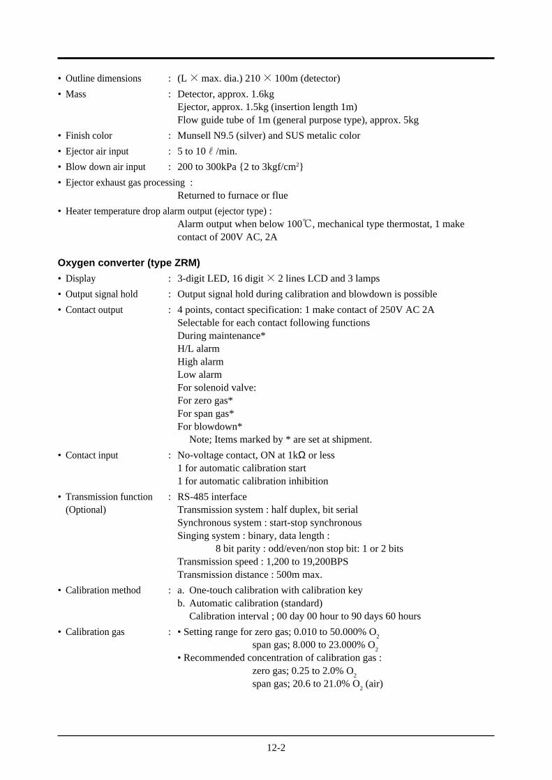
• Outline dimensions : (L×max. dia.) 210× 100m (detector)
• Mass : Detector, approx. 1.6kgEjector, approx. 1.5kg (insertion length 1m)Flow guide tube of 1m (general purpose type), approx. 5kg
• Finish color : Munsell N9.5 (silver) and SUS metalic color
• Ejector air input : 5 to 10r/min.
• Blow down air input : 200 to 300kPa 2 to 3kgf/cm2
• Ejector exhaust gas processing :Returned to furnace or flue
• Heater temperature drop alarm output (ejector type) :Alarm output when below 100, mechanical type thermostat, 1 makecontact of 200V AC, 2A
Oxygen converter (type ZRM)
• Display : 3-digit LED, 16 digit× 2 lines LCD and 3 lamps
• Output signal hold : Output signal hold during calibration and blowdown is possible
• Contact output : 4 points, contact specification: 1 make contact of 250V AC 2ASelectable for each contact following functionsDuring maintenance*H/L alarmHigh alarmLow alarmFor solenoid valve:For zero gas*For span gas*For blowdown*
Note; Items marked by * are set at shipment.
• Contact input : No-voltage contact, ON at 1kΩ or less1 for automatic calibration start1 for automatic calibration inhibition
• Transmission function : RS-485 interface(Optional) Transmission system : half duplex, bit serial
Synchronous system : start-stop synchronousSinging system : binary, data length :
8 bit parity : odd/even/non stop bit: 1 or 2 bitsTransmission speed : 1,200 to 19,200BPSTransmission distance : 500m max.
• Calibration method : a. One-touch calibration with calibration keyb. Automatic calibration (standard)
Calibration interval ; 00 day 00 hour to 90 days 60 hours
• Calibration gas : • Setting range for zero gas; 0.010 to 50.000% O2
span gas; 8.000 to 23.000% O2
• Recommended concentration of calibration gas :zero gas; 0.25 to 2.0% O
2
span gas; 20.6 to 21.0% O2 (air)
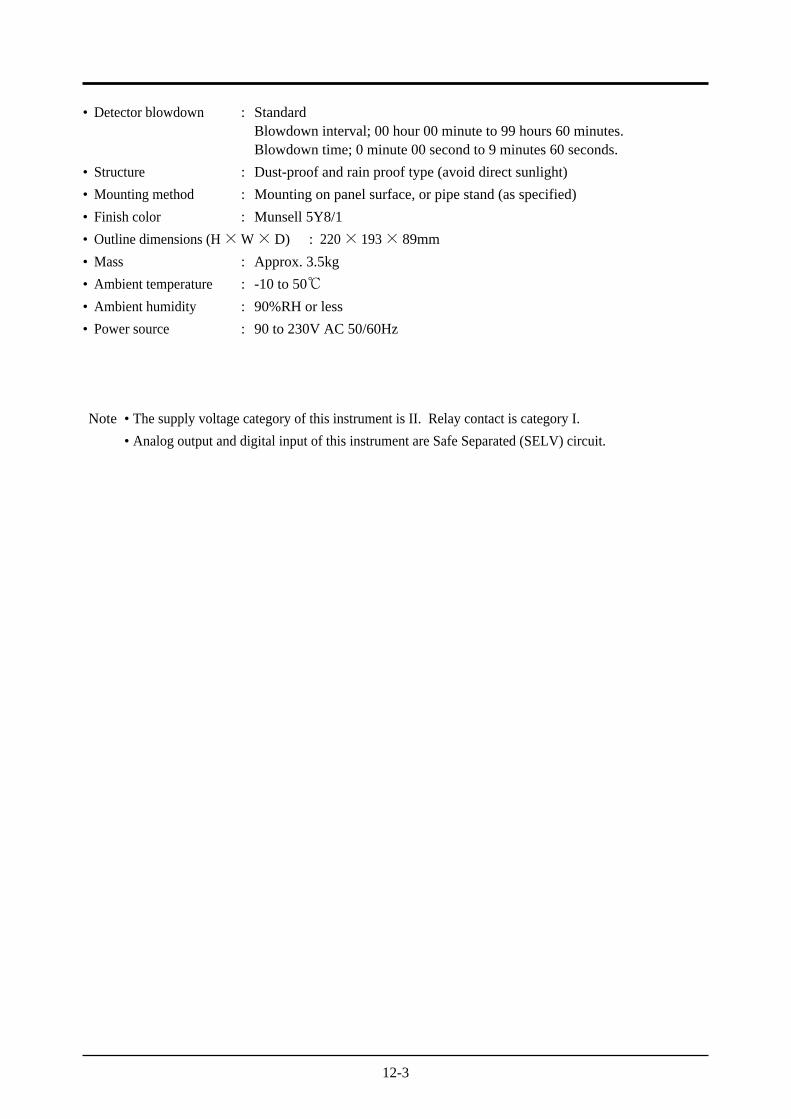
12-3
• Detector blowdown : StandardBlowdown interval; 00 hour 00 minute to 99 hours 60 minutes.Blowdown time; 0 minute 00 second to 9 minutes 60 seconds.
• Structure : Dust-proof and rain proof type (avoid direct sunlight)
• Mounting method : Mounting on panel surface, or pipe stand (as specified)
• Finish color : Munsell 5Y8/1
• Outline dimensions (H×W×D) : 220× 193× 89mm
• Mass : Approx. 3.5kg
• Ambient temperature : -10 to 50• Ambient humidity : 90%RH or less
• Power source : 90 to 230V AC 50/60Hz
Note • The supply voltage category of this instrument is II. Relay contact is category I.
• Analog output and digital input of this instrument are Safe Separated (SELV) circuit.
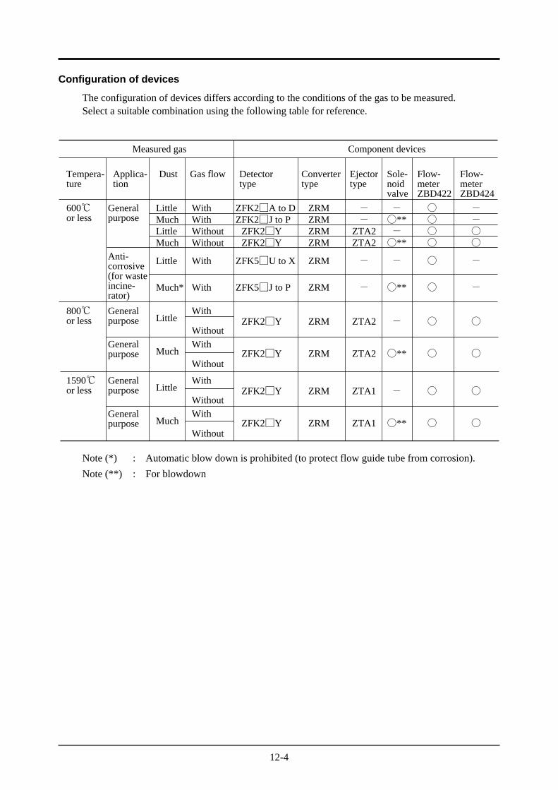
12-4
Configuration of devices
The configuration of devices differs according to the conditions of the gas to be measured.Select a suitable combination using the following table for reference.
Measured gas
Tempera-ture
600or less
Generalpurpose
Little WithMuch WithLittle WithoutMuch Without
ZFK2A to D ZRMZFK2J to P ZRM
ZFK2Y ZRMZFK2Y ZRM
Applica-tion
Dust Gas flow Detectortype
Convertertype
Ejectortype
Sole-noidvalve
Flow-meterZBD422
Flow-meterZBD424
Component devices
800or less
Generalpurpose
Generalpurpose
LittleWith Without
MuchWith Without
ZFK2Y ZRM
ZFK2Y ZRM
1590or less
Generalpurpose
Generalpurpose
LittleWith Without
MuchWith Without
ZFK2Y ZRM
ZFK2Y ZRM
Anti-corrosive(for wasteincine-rator)
Little With
Much* With
ZFK5U to X ZRM
ZFK5J to P ZRM
--
ZTA2ZTA2
ZTA2
ZTA2
ZTA1
ZTA1
-
-
-**-**
-
**
-
**
-
**
--
-
-
Note (*) : Automatic blow down is prohibited (to protect flow guide tube from corrosion).
Note (**) : For blowdown


