Embed Size (px)
Citation preview
Edition 2014
Wireless infrastructureSolutions for remote radios and cell sites
Count on proven wireless technology

Your partner for connectivity solutions
The HUBER+SUHNER group is a leading global supplier of components and systems for electrical and optical connectivity. Our customers in communication, industry and transportation appreciate that we are specialists with detailed knowledge of practical applications. We offer expertise in radio frequency, fiber optics and low frequency all under one roof, thus provi-ding a unique basis for continual innovation which is focused on the needs of our customers all over the world.
Our motto: “EXCELLENCE in CONNECTIVITY SOLUTIONS”. At the heart of our offering is a broad range of products that can be relied on to meet high quality standards, backed up by flexible, dependable services with fast response times and excellence in delivery performance. In the wireless market, we concentrate on solutions that allow mobile operators to reduce their total cost of ownership and to make their mobile network future-proof and reliable.
4 HUBER+SUHNER Wireless infrastructure
Centered around your excellence:Our global presence and experience
HUBER+SUHNER’s continuous involvement with mobile network rollouts across the globe has helped us to become a leader in the wireless infrastucture market. Our partners and customers have been able to take advantage of our global manufacturing, assembly and distribution network covering the Americas, Asia Pacific, Europe, Middle East and Africa enabling successful completion of their infrastructure builds.
● Worldwide manufacturing: Being close to our customers is a must. HUBER+SUHNER operates manufacturing plants in Poland, Tunisia, China, India, Malaysia, Mexico, Brazil and Switzerland so that we can respond immediately to our customers’ needs and provide best-in-class support throughout all regions of the world.
● Worldwide assembly: HUBER+SUHNER is globally co-operating with numerous third-party fiber optic assembly shops to extend the capa city and coverage of the HUBER+SUHNER brand. All of our assembly shops follow the same stringent processes and quality controls as our own group companies.
● Worldwide distribution: Customers can rely on HUBER+SUHNER’s wordwide sales and support network. Market proximity is the advantage of our global presence with 14 subsidiaries and repre-sentatives in over 60 countries. Our customers benefit from our strength to deliver local solutions and services tailored to their requirements.
Ericsson BrazilEricsson is globally the leading equipment manufac-turer and service provider for mobile communications with more than 100 000 employees world wide. HUBER+SUHNER is a core supplier to Ericsson for FTTA (fiber-to-the-antenna) solutions in all geographi-cal regions, for example in Brazil where we support with local production, logistics and engineering to specific local telecomunication standards.
SaskTelSaskatchewan Telecommunications Holding Corpora-tion is the leading full service communications provider in Saskatchewan, Canada with over 1.4 million customer connections. For their 3G Network Upgrade and subsequent LTE overlays HUBER + SUHNER delivered MASTERLINE Extreme and MASTERLINE Extreme Power, a plug-and-play RRH cabling system which supports up to 12 RRHs per fibre riser without the need for any mast mount distribution boxes.
Sprint/T-Mobile USACollectively Sprint and T-Mobile provide over 90 million subscribers mobile network services in the highly competitive US market. For their respective 4G network roll-outs HUBER+SUHNER’s MASTERLINE hybrid solutions are deployed in there nationwide networks to connect the RRHs with the base station. No other hybrid cabling system can be installed faster and more efficiently.
5HUBER+SUHNER Wireless infrastructure
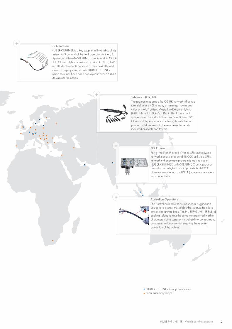
Australian OperatorsThe Australian market requires special ruggedisedsolutions to protect the cable infrastructure from bird attack and animal bites. The HUBER+SUHNER hybrid cabling solutions have become the preferred market choice providing superior «installability» compared to competing solutions whilst ensuring the required protection of the cables.
US Operators HUBER+SUHNER is a key supplier of Hybrid cabling systems to 3 out of 4 of the tier1 operators in the US. Operators utilise MASTERLINE Extreme and MASTER-LINE Classic Hybrid solutions for critical UMTS, AWS and LTE deployments because of their flexibility and speed of deployment, to date HUBER+SUHNER hybrid solutions have been deployed in over 55 000 sites across the nation.
SFR FrancePart of the French group Vivendi, SFR's nationwide network consists of around 18 000 cell sites. SFR’s network enhancement program is making use of HUBER+SUHNER’s MASTERLINE Classic product portfolio and a hybrid box to provide both FTTA (fiber-to-the-antenna) and PTTA (power-to-the-anten-na) connectivity.
Telefonica (O2) UKThe project to upgrade the O2 UK network infrastruc-ture, delivering 4G to many of the major towns and cities of the UK utilises Masterline Extreme Hybrid (MLEH) from HUBER+SUHNER. This labour and space saving hybrid solution combines FO and DC into one high performance cable system delivering power and data feeds to the remote radio heads mounted on masts and towers.
HUBER+SUHNER Group companiesLocal assembly shops
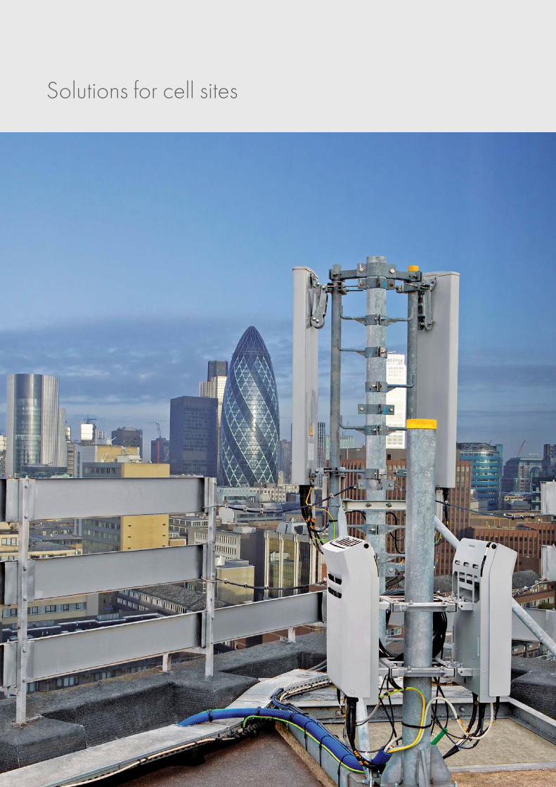
Solutions for cell sites
Introduction 3
Remote radio installation solutions 8
Discrete feeders for single RRH 14
MASTERLINE Ultimate (MLU) 24
MASTERLINE Extreme (MLE) 30
MASTERLINE Classic (MLC) 42
MASTERLINE Ultimate Hybrid (MLUH) 60
MASTERLINE Extreme Hybrid (MLEH) 70
MASTERLINE Classic Hybrid (MLCH) 88
Re-use of corrugated coax cables 100
Fiber optic interfaces for remote radio heads 106
Accessories 122
Conventional cell site solutions 130
LISCA – RF jumpers 130
SUCOFEED corrugated cables 138
SUCOFEED aluminium corrugated cables 147
QUICK-FIT coaxial connectors 150
HUBER+SUHNER ECO connectors 154
Cable stripping tools 158
Lightning protectors 162
Accessories 174
Power splitters 180
GPS antennas 184
PIM test kit 186
RF Feederline components selection guide 190
Content
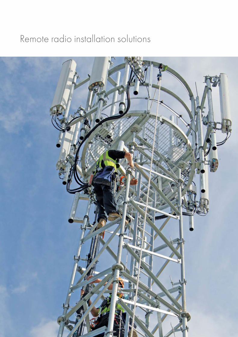
Remote radio installation solutions
9HUBER+SUHNER Wireless infrastructure
Work with the leader for remote radio installation solutions
Remote radio technology
Remote radio systems have evolved as the dominating technology in the wireless communication industry. Remote radios signifi-cantly reduce the network’s energy consumption while at the same time improving the network performance. The explosion of mobile data demand has triggered global investments to upgrade existing 3G networks and to build 4G infrastructure. Mobile operators, installers and system integrators face new challenges to commonly install up to 18 RRHs per site, to integrate new dualmode radios and antenna integrated radios (AIR), to rollout ever increasing network complexity and to simply boost the net-work capacity. HUBER+SUHNER guarantees to build reliable cable infrastructures which are easy and most cost effective to install and which fulfills today’s and tomorrow’s network requirements.
HUBER+SUHNER provides complete installation solutions
HUBER+SUHNER is the global leader for remote radio installation solutions. We have a comprehensive offering of FTTA (fiber-to the-antenna) and PTTA (power-to-the-antenna) products which are tailored to the customer’s needs. We advise operators about which installation methods are available and what are their advantages. We are experts on how to make savings on installation costs and how expensive follow-up costs can be saved. HUBER+SUHNER implements future-proof passive cable network infra-structures which are compatible with all system vendor products and endure the future generations of active equipment.
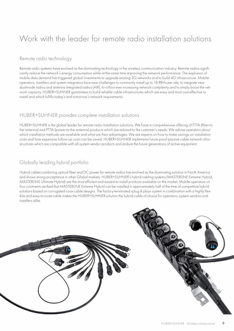
Globally leading hybrid portfolio
Hybrid cables combining optical fiber and DC power for remote radios has evolved as the dominating solution in North America and shows strong acceptance in other Global markets. HUBER+SUHNER’s hybrid cabling systems (MASTERLINE Extreme Hybrid, MASTERLINE Ultimate Hybrid) are the most efficient and easiest-to-install products available on the market. Mobile operators on four continents verified that MASTERLINE Extreme Hybrid can be installed in approximately half of the time of competitive hybrid solutions based on corrugated coax cable designs. The factory-terminated «plug & play» system in combination with a highly flex-ible and easy-to-route cable makes the HUBER+SUHNER solution the hybrid cable of choice for operators, system vendors and installers alike.
10 HUBER+SUHNER Wireless infrastructure
Benefit from HUBER+SUHNER’s expertise
www.wireless-infrastructure.com
Power design tool for remote radios
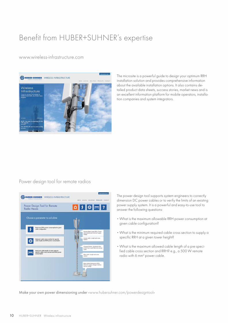
The microsite is a powerful guide to design your optimum RRH installation solution and provides comprehensive information about the available installation options. It also contains de-tailed product data sheets, success stories, market news and is an excellent information platform for mobile operators, installa-tion companies and system integrators.
The power design tool supports system engineers to correctly dimension DC power cables or to verify the limits of an existing power supply system. It is a powerful and easy-to-use tool to answer the following questions:
• What is the maximum allowable RRH power consumption at given cable configuration?
• What is the minimum required cable cross section to supply a specific RRH at a given tower height?
• What is the maximum allowed cable length of a pre-speci-fied cable cross section and RRH? e.g., a 500 W remote radio with 6 mm2 power cable.
Make your own power dimensioning under «www.hubersuhner.com/powerdesigntool»
11
Edition 2013
Remote radio installationWhite paper
HUBER+SUHNER Wireless infrastructure
Best practices guide 2013: How to install remote radio systems
Total cost of ownership analysis
The installation of remote radio systems poses new challenges for mobile operators, installers and system integrators. What installation methods are available and what are their advan-tages? How can a network operator install a future-proof pas-sive infrastructure? How can savings be made on installation costs and follow-up costs? What are the advantages and dis-advantages of hybrid cabling systems? HUBER+SUHNER offers expert answers to these questions and discusses opti-mum installation solutions.
Download the new version 2013 of the white paper: www.hubersuhner.com/RRHinstallation
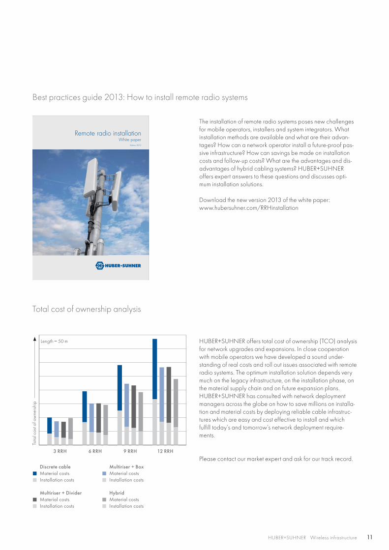
HUBER+SUHNER offers total cost of ownership (TCO) analysis for network upgrades and expansions. In close cooperation with mobile operators we have developed a sound under-standing of real costs and roll out issues associated with remote radio systems. The optimum installation solution depends very much on the legacy infrastructure, on the installation phase, on the material supply chain and on future expansion plans. HUBER+SUHNER has consulted with network deployment managers across the globe on how to save millions on installa-tion and material costs by deploying reliable cable infrastruc-tures which are easy and cost effective to install and which fulfill today’s and tomorrow’s network deployment require-ments.
Please contact our market expert and ask for our track record. Discrete cable
Material costs Installation costs
Multiriser + Divider Material costs Installation costs
Multiriser + Box Material costs Installation costs
Hybrid Material costs Installation costs
3 RRH 6 RRH 9 RRH 12 RRH
Tota
l cos
t of o
wne
rshi
p
Length = 50 m
12
Laun
ch Q
1/20
14
HUBER+SUHNER Wireless infrastructure
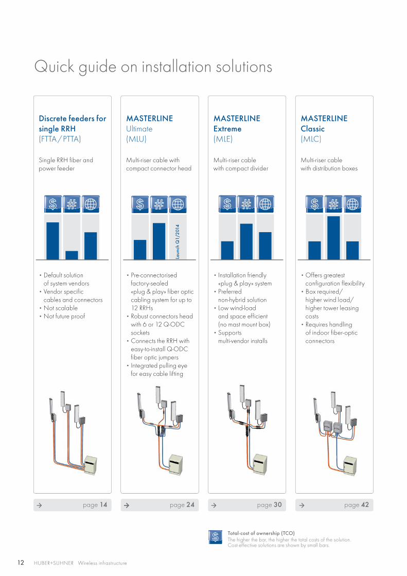
Quick guide on installation solutions
MASTERLINE Classic (MLC)
Multi-riser cable with distribution boxes
Discrete feeders for single RRH (FTTA/PTTA)
Single RRH fiber and power feeder
MASTERLINEUltimate(MLU)
Multi-riser cable with compact connector head
MASTERLINE Extreme (MLE)
Multi-riser cable with compact divider
• Offers greatest configuration flexibility
• Box required/ higher wind load/ higher tower leasing costs
• Requires handling of indoor fiber-optic connectors
• Default solution of system vendors
• Vendor specific cables and connectors
• Not scalable • Not future proof
• Pre-connectorised factory-sealed «plug & play» fiber optic cabling system for up to 12 RRHs
• Robust connectors head with 6 or 12 Q-ODC sockets
• Connects the RRH with easy-to-install Q-ODC fiber optic jumpers
• Integrated pulling eye for easy cable lifting
• Installation friendly «plug & play» system
• Preferred non-hybrid solution
• Low wind-load and space efficient (no mast mount box)
• Supports multi-vendor installs
page 42page 14 page 24 page 30
Total-cost of ownership (TCO)The higher the bar, the higher the total costs of the solution. Cost-effective solutions are shown by small bars.
13
Con
vers
ions
onl
y
HUBER+SUHNER Wireless infrastructure
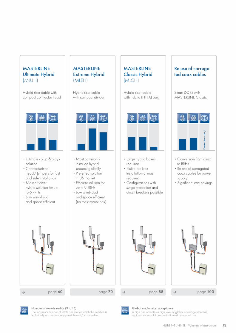
MASTERLINE Ultimate Hybrid (MLUH)
Hybrid riser cable with compact connector head
Re-use of corruga-ted coax cables
Smart DC kit with MASTERLINE Classic
MASTERLINE Classic Hybrid (MLCH)
Hybrid-riser cable with hybrid (HTTA) box
MASTERLINE Extreme Hybrid (MLEH)
Hybrid-riser cable with compact divider
• Ultimate «plug & play» solution
• Connectorised head/ jumpers for fast and safe installation
• Most efficient hybrid solution for up to 6 RRHs
• Low wind-load and space efficient
• Conversion from coax to RRHs
• Re-use of corrugated coax cables for power supply
• Significant cost savings
• Large hybrid boxes required
• Elaborate box installation at mast required
• Configurations with surge protection and circuit breakers possible
• Most commonly installed hybrid product globally
• Preferred solution in US market
• Efficient solution for up to 9 RRHs
• Low wind-load and space efficient (no mast mount box)
page 88page 60 page 100page 70
Number of remote radios (3 to 15)The maximum number of RRHs per site for which this solution is technically or commercially possible and/or advisable.
Global use/market acceptanceA high bar indicates a high level of global coverage whereas regional niche solutions are indicated by a small bar.
14 HUBER+SUHNER Wireless infrastructure
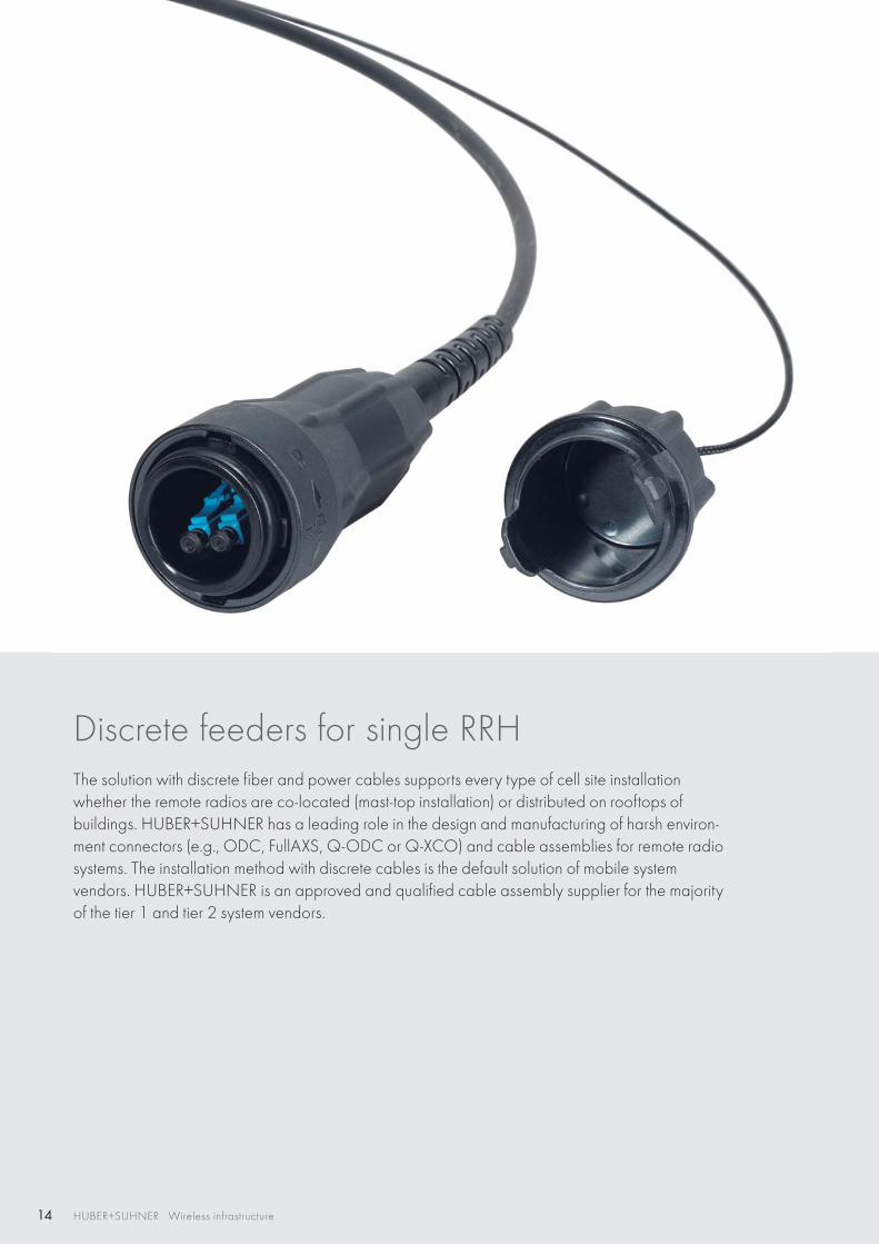
Discrete feeders for single RRHThe solution with discrete fiber and power cables supports every type of cell site installation whether the remote radios are co-located (mast-top installation) or distributed on rooftops of buildings. HUBER+SUHNER has a leading role in the design and manufacturing of harsh environ-ment connectors (e.g., ODC, FullAXS, Q-ODC or Q-XCO) and cable assemblies for remote radio systems. The installation method with discrete cables is the default solution of mobile systemvendors. HUBER+SUHNER is an approved and qualified cable assembly supplier for the majority of the tier 1 and tier 2 system vendors.
15
RFXTTA FTTA PTTA HTTA
RF
PTTA
FTTA
PTTA
FTTA
XTTA
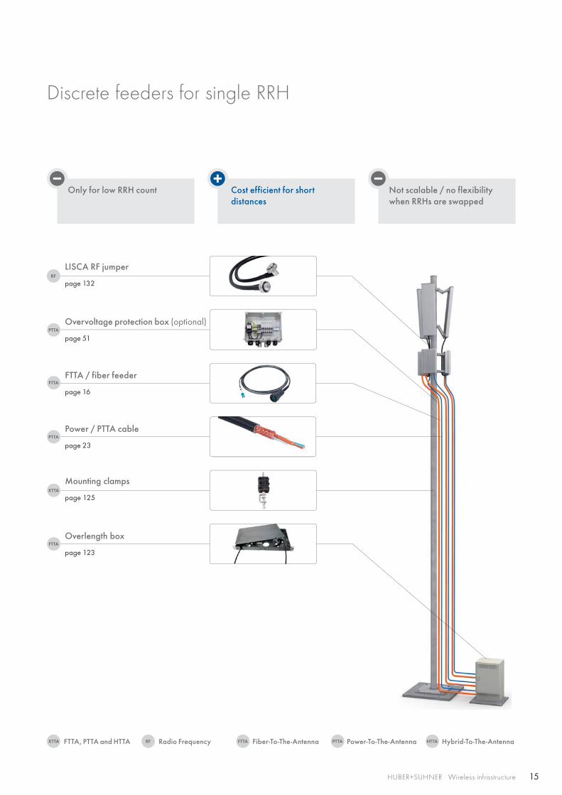
Cost efficient for short distances
HUBER+SUHNER Wireless infrastructure
Only for low RRH count Not scalable / no flexibility when RRHs are swapped
Overvoltage protection box (optional)
page 51
LISCA RF jumper
page 132
FTTA / fiber feeder
page 16
Power / PTTA cable
page 23
Mounting clamps
page 125
Overlength box
page 123
Discrete feeders for single RRH
Radio FrequencyFTTA, PTTA and HTTA Fiber-To-The-Antenna Power-To-The-Antenna Hybrid-To-The-Antenna
16 HUBER+SUHNER Wireless infrastructure
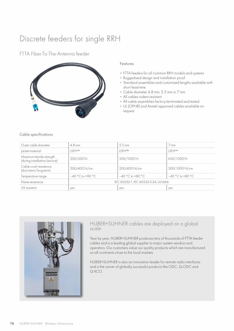
FTTA Fiber-To-The-Antenna feeder
Features
• FTTA feeders for all common RRH models and systems • Ruggedised design and installation proof• Standard assemblies and customised lengths available with
short lead-time• Cable diameter 4.8 mm, 5.5 mm or 7 mm• All cables rodent resistant• All cable assemblies factory-terminated and tested • UL (OFNR) and Anatel approved cables available on
request
Cable specifications
Outer cable diameter 4.8 mm 5.5 mm 7 mm
Jacket material LSFH™ LSFH™ LSFH™
Maximum tensile strength(during installation/service) 300/500 N 500/1000 N 650/1000 N
Cable crush resistance(short-term/long-term) 200/400 N/cm 200/400 N/cm 300/1000 N/cm
Temperature range –40 °C to +90 °C –40 °C to +80 °C –40 °C to +80 °C
Flame resistance IEC 60332-1, IEC 60332-3-24, UL1666
UV resistant yes yes yes
HUBER+SUHNER cables are deployed on a global scale
Year by year, HUBER+SUHNER produces tens of thousands of FTTA feeder cables and is a leading global supplier to major system vendors andoperators. Our customers value our quality products which are manufactured on all continents close to the local markets.
HUBER+SUHNER is also an innovation leader for remote radio interfaces and is the owner of globally successful products like ODC, Q-ODC and Q-XCO.
Discrete feeders for single RRH
17HUBER+SUHNER Wireless infrastructure
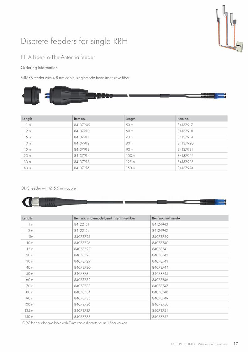
ODC feeder with Ø 5.5 mm cable
Length Item no. singlemode bend insensitive fiber Item no. multimode
1 m 84122151 84124943
2 m 84122152 84124942
5m 84078725 84078739
10 m 84078726 84078740
15 m 84078727 84078741
20 m 84078728 84078742
30 m 84078729 84078743
40 m 84078730 84078744
50 m 84078731 84078745
60 m 84078732 84078746
70 m 84078733 84078747
80 m 84078734 84078748
90 m 84078735 84078749
100 m 84078736 84078750
125 m 84078737 84078751
150 m 84078738 84078752
ODC feeder also available with 7 mm cable diameter or as 1-fiber version.
FTTA Fiber-To-The-Antenna feeder
Ordering information
FullAXS feeder with 4.8 mm cable, singlemode bend insensitive fiber
Length Item no. Length Item no.
1 m 84137909 50 m 84137917
2 m 84137910 60 m 84137918
5 m 84137911 70 m 84137919
10 m 84137912 80 m 84137920
15 m 84137913 90 m 84137921
20 m 84137914 100 m 84137922
30 m 84137915 125 m 84137923
40 m 84137916 150 m 84137924
Discrete feeders for single RRH
18 HUBER+SUHNER Wireless infrastructure
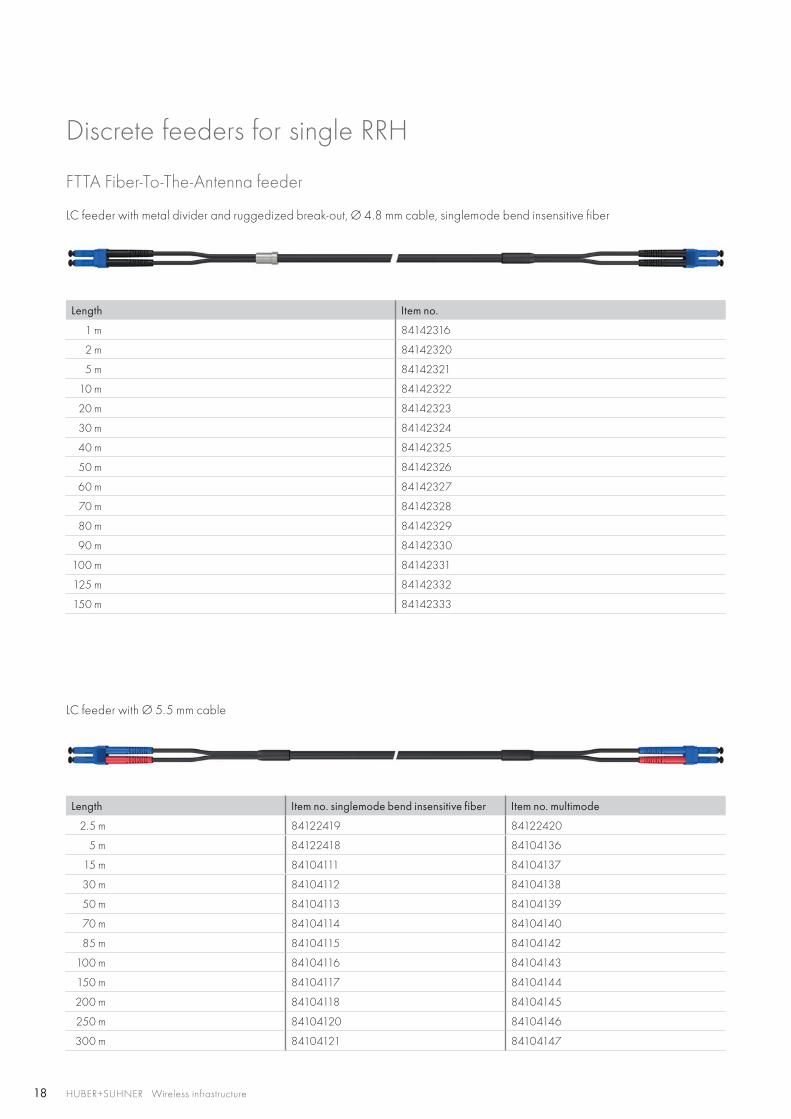
FTTA Fiber-To-The-Antenna feeder
LC feeder with Ø 5.5 mm cable
Length Item no. singlemode bend insensitive fiber Item no. multimode
2.5 m 84122419 84122420
5 m 84122418 84104136
15 m 84104111 84104137
30 m 84104112 84104138
50 m 84104113 84104139
70 m 84104114 84104140
85 m 84104115 84104142
100 m 84104116 84104143
150 m 84104117 84104144
200 m 84104118 84104145
250 m 84104120 84104146
300 m 84104121 84104147
LC feeder with metal divider and ruggedized break-out, Ø 4.8 mm cable, singlemode bend insensitive fiber
Length Item no.
1 m 84142316
2 m 84142320
5 m 84142321
10 m 84142322
20 m 84142323
30 m 84142324
40 m 84142325
50 m 84142326
60 m 84142327
70 m 84142328
80 m 84142329
90 m 84142330
100 m 84142331
125 m 84142332
150 m 84142333
Discrete feeders for single RRH
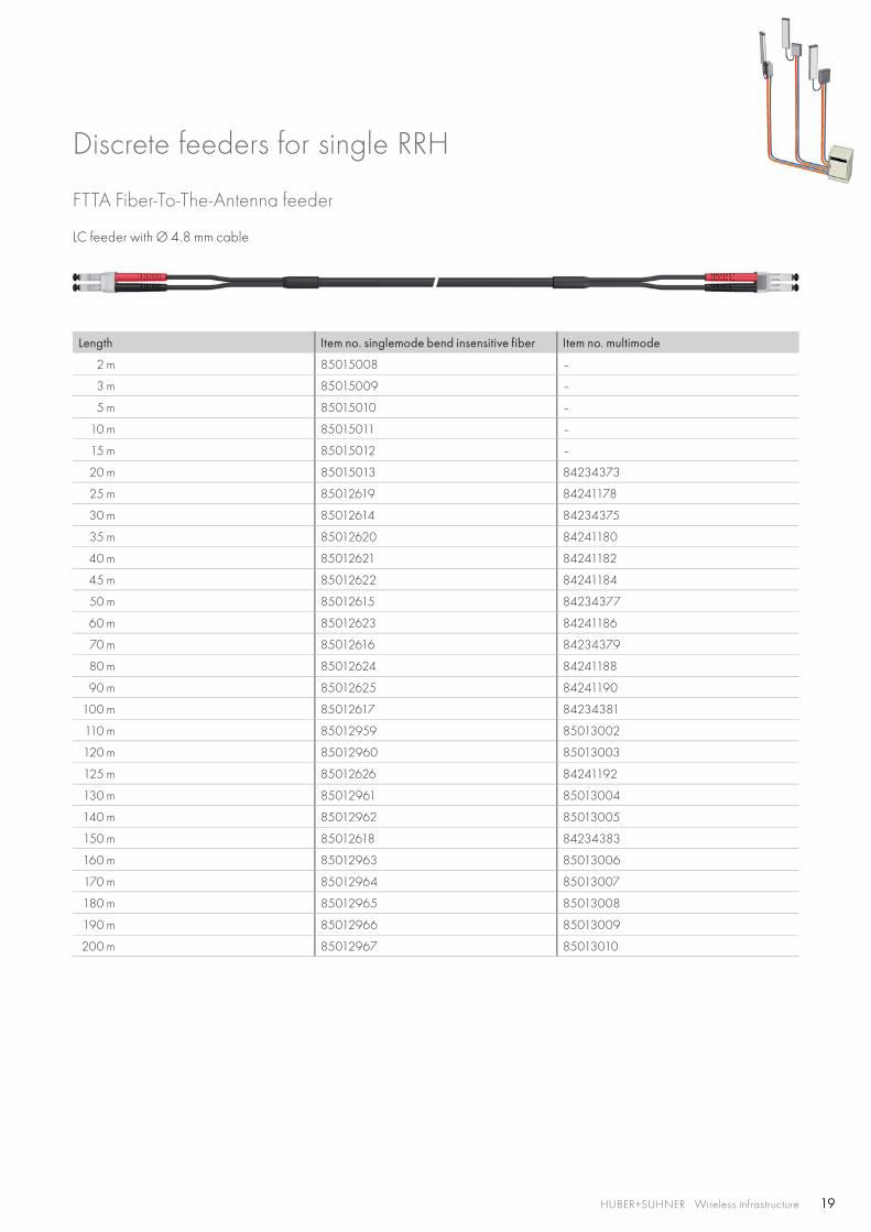
19HUBER+SUHNER Wireless infrastructure
LC feeder with Ø 4.8 mm cable
Length Item no. singlemode bend insensitive fiber Item no. multimode
2 m 85015008 –
3 m 85015009 –
5 m 85015010 –
10 m 85015011 –
15 m 85015012 –
20 m 85015013 84234373
25 m 85012619 84241178
30 m 85012614 84234375
35 m 85012620 84241180
40 m 85012621 84241182
45 m 85012622 84241184
50 m 85012615 84234377
60 m 85012623 84241186
70 m 85012616 84234379
80 m 85012624 84241188
90 m 85012625 84241190
100 m 85012617 84234381
110 m 85012959 85013002
120 m 85012960 85013003
125 m 85012626 84241192
130 m 85012961 85013004
140 m 85012962 85013005
150 m 85012618 84234383
160 m 85012963 85013006
170 m 85012964 85013007
180 m 85012965 85013008
190 m 85012966 85013009
200 m 85012967 85013010
FTTA Fiber-To-The-Antenna feeder
Discrete feeders for single RRH

20 HUBER+SUHNER Wireless infrastructure
FTTA Fiber-To-The-Antenna feeder
LC feeder with 90° boot, Ø 5 mm cable, OFNR, multimode fiber
Only available for vendor approved companies.
Length Item no.
2 m 84082925
5 m 84122156
10 m 84083054
20 m 84083071
30 m 84083074
40 m 84083079
50 m 84083081
75 m 84083084
100 m 84083086
200 m 84083087
PDLC feeder with Ø 7 mm, singlemode bend insensitive fiber
Length [m] Fiber type
1 m 84150633
2 m 84150634
5 m 84150635
10 m 84208599
15 m 84208601
20 m 84208603
30 m 84208605
40 m 84208607
50 m 84208609
60 m 84208611
70 m 84208613
80 m 84208615
90 m 84208617
100 m 84208619
125 m 84208621
150 m 84208623
Discrete feeders for single RRH
21HUBER+SUHNER Wireless infrastructure
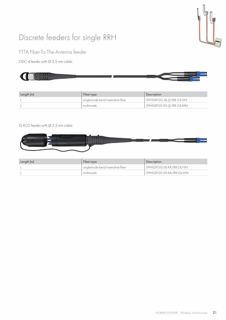
FTTA Fiber-To-The-Antenna feeder
ODC-4 feeder with Ø 5.5 mm cable
Length [m] Fiber type Description
L singlemode bend insensitive fiber 09H04FGG-LB-J2/88-3-L NN
L multimode 09H04FG0-50-J2/88-3-L MM
Q-XCO feeder with Ø 5.5 mm cable
Length [m] Fiber type Description
L singlemode bend insensitive fiber 09H02FGG-LB-XA/88-2-L NN
L multimode 09H02FG0-50-XA/88-2-L MM
Discrete feeders for single RRH
22 HUBER+SUHNER Wireless infrastructure
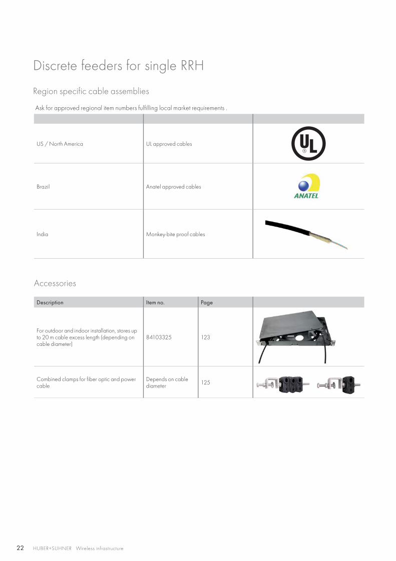
Region specific cable assemblies
Ask for approved regional item numbers fulfilling local market requirements .
US / North America UL approved cables
Brazil Anatel approved cables
India Monkey-bite proof cables
Accessories
Description Item no. Page
For outdoor and indoor installation, stores up to 20 m cable excess length (depending on cable diameter)
84103325 123
Combined clamps for fiber optic and power cable
Depends on cable diameter 125
Discrete feeders for single RRH
23HUBER+SUHNER Wireless infrastructure
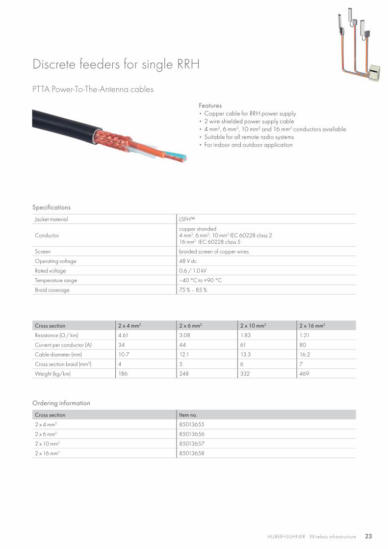
PTTA Power-To-The-Antenna cables
Features • Copper cable for RRH power supply• 2 wire shielded power supply cable• 4 mm2, 6 mm2, 10 mm2 and 16 mm2 conductors available• Suitable for all remote radio systems• For indoor and outdoor application
Specifications
Jacket material LSFH™
Conductorcopper stranded4 mm2, 6 mm2, 10 mm2 IEC 60228 class 216 mm2 IEC 60228 class 5
Screen braided screen of copper wires
Operating voltage 48 V dc
Rated voltage 0.6 / 1.0 kV
Temperature range –40 °C to +90 °C
Braid coverage 75 % – 85 %
Cross section 2 x 4 mm2 2 x 6 mm2 2 x 10 mm2 2 x 16 mm2
Resistance (Ω / km) 4.61 3.08 1.83 1.21
Current per conductor (A) 34 44 61 80
Cable diameter (mm) 10.7 12.1 13.3 16.2
Cross section braid (mm2) 4 5 6 7
Weight (kg/km) 186 248 332 469
Ordering information
Cross section Item no.
2 x 4 mm2 85013655
2 x 6 mm2 85013656
2 x 10 mm2 85013657
2 x 16 mm2 85013658
Discrete feeders for single RRH
24 HUBER+SUHNER Wireless infrastructure
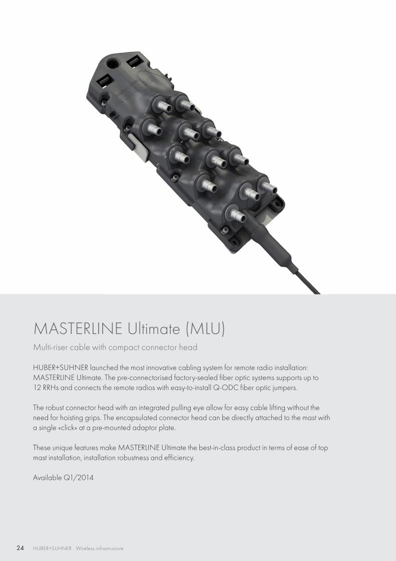
MASTERLINE Ultimate (MLU)Multi-riser cable with compact connector head
HUBER+SUHNER launched the most innovative cabling system for remote radio installation: MASTERLINE Ultimate. The pre-connectorised factory-sealed fiber optic systems supports up to 12 RRHs and connects the remote radios with easy-to-install Q-ODC fiber optic jumpers.
The robust connector head with an integrated pulling eye allow for easy cable lifting without the need for hoisting grips. The encapsulated connector head can be directly attached to the mast with a single «click» at a pre-mounted adaptor plate.
These unique features make MASTERLINE Ultimate the best-in-class product in terms of ease of top mast installation, installation robustness and efficiency.
Available Q1/2014
25
RF
PTTA
FTTA
FTTA
XTTA
PTTA
FTTA
FTTA
FTTA
RFXTTA FTTA PTTA HTTA
HUBER+SUHNER Wireless infrastructure
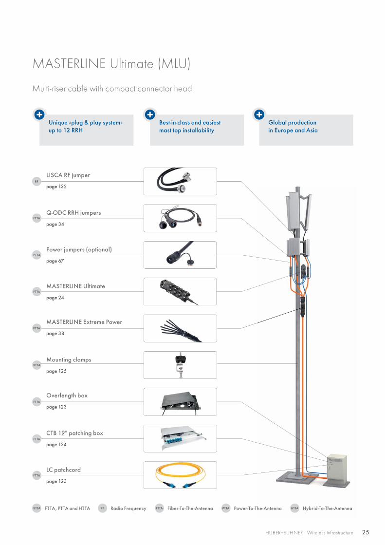
Unique «plug & play system» up to 12 RRH
Best-in-class and easiest mast top installability
Global production in Europe and Asia
Q-ODC RRH jumpers
page 34
LISCA RF jumper
page 132
Power jumpers (optional)
page 67
MASTERLINE Ultimate
page 24
MASTERLINE Extreme Power
page 38
Mounting clamps
page 125
CTB 19" patching box
page 124
Overlength box
page 123
LC patchcord
page 123
MASTERLINE Ultimate (MLU)
Multi-riser cable with compact connector head
Radio FrequencyFTTA, PTTA and HTTA Fiber-To-The-Antenna Power-To-The-Antenna Hybrid-To-The-Antenna
26 HUBER+SUHNER Wireless infrastructure
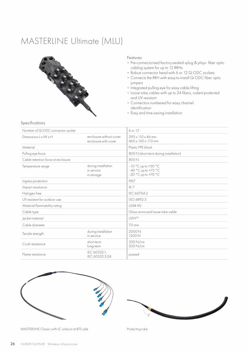
MASTERLINE Ultimate (MLU)
Features • Pre-connectorised factory-sealed «plug & play» fiber optic
cabling system for up to 12 RRHs• Robust connector head with 6 or 12 Q-ODC sockets• Connects the RRH with easy-to-install Q-ODC fiber optic
jumpers• Integrated pulling eye for easy cable lifting• Loose tube cables with up to 24 fibers, rodent protected
and UV resistant• Connectors numbered for easy channel
identification• Easy and time-saving installation
Specifications
Number of Q-ODC connector socket 6 or 12
Dimensions L x W x H enclosure without coverenclosure with cover
293 x 110 x 46 mm 460 x 160 x 110 mm
Material Plastic PPE black
Pulling eye force 800 N (short-term during installation)
Cable retention force at enclosure 800 N
Temperature range during installation in servicein storage
–10 °C up to +50 °C –40 °C up to +75 °C –20 °C up to +70 °C
Ingress protection IP67
Impact resistance IK 7
Halogen free IEC 60754-2
UV resistant for outdoor use ISO 4892-3
Material flammability rating UL94-V0
Cable type Glass-armoured loose-tube cable
Jacket material LSFHTM
Cable diameter 7.0 mm
Tensile strength during installationin service
2000 N1200 N
Crush resistance short-term long-term
500 N/cm 200 N/cm
Flame resistance IEC 60332-1, IEC 60332-3-24 passed
MASTERLINE Classic with LC uniboot at BTS side Protecting tube
27
HUBER+SUHNER Wireless infrastructure
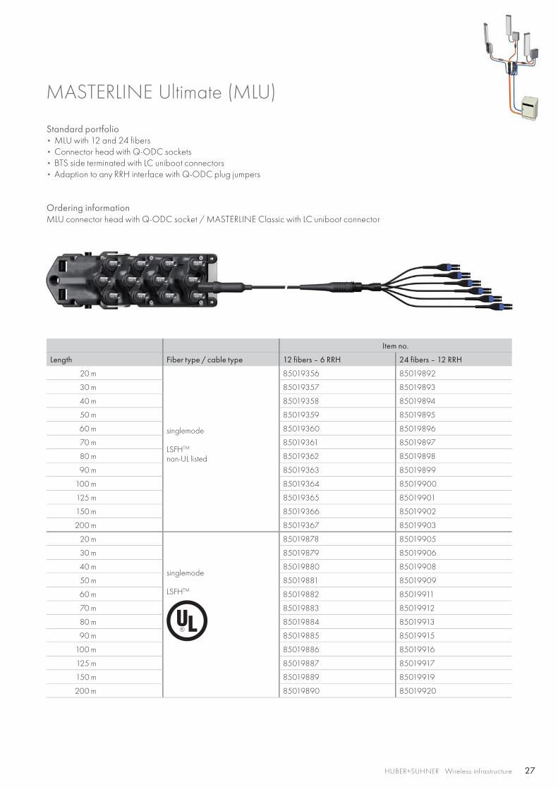
MASTERLINE Ultimate (MLU)
Standard portfolio• MLU with 12 and 24 fibers• Connector head with Q-ODC sockets• BTS side terminated with LC uniboot connectors• Adaption to any RRH interface with Q-ODC plug jumpers
Ordering informationMLU connector head with Q-ODC socket / MASTERLINE Classic with LC uniboot connector
Item no.
Length Fiber type / cable type 12 fibers – 6 RRH 24 fibers – 12 RRH
20 m
singlemode
LSFHTM
non-UL listed
85019356 85019892
30 m 85019357 85019893
40 m 85019358 85019894
50 m 85019359 85019895
60 m 85019360 85019896
70 m 85019361 85019897
80 m 85019362 85019898
90 m 85019363 85019899
100 m 85019364 85019900
125 m 85019365 85019901
150 m 85019366 85019902
200 m 85019367 85019903
20 m
singlemode
LSFHTM
85019878 85019905
30 m 85019879 85019906
40 m 85019880 85019908
50 m 85019881 85019909
60 m 85019882 85019911
70 m 85019883 85019912
80 m 85019884 85019913
90 m 85019885 85019915
100 m 85019886 85019916
125 m 85019887 85019917
150 m 85019889 85019919
200 m 85019890 85019920
28 HUBER+SUHNER Wireless infrastructure
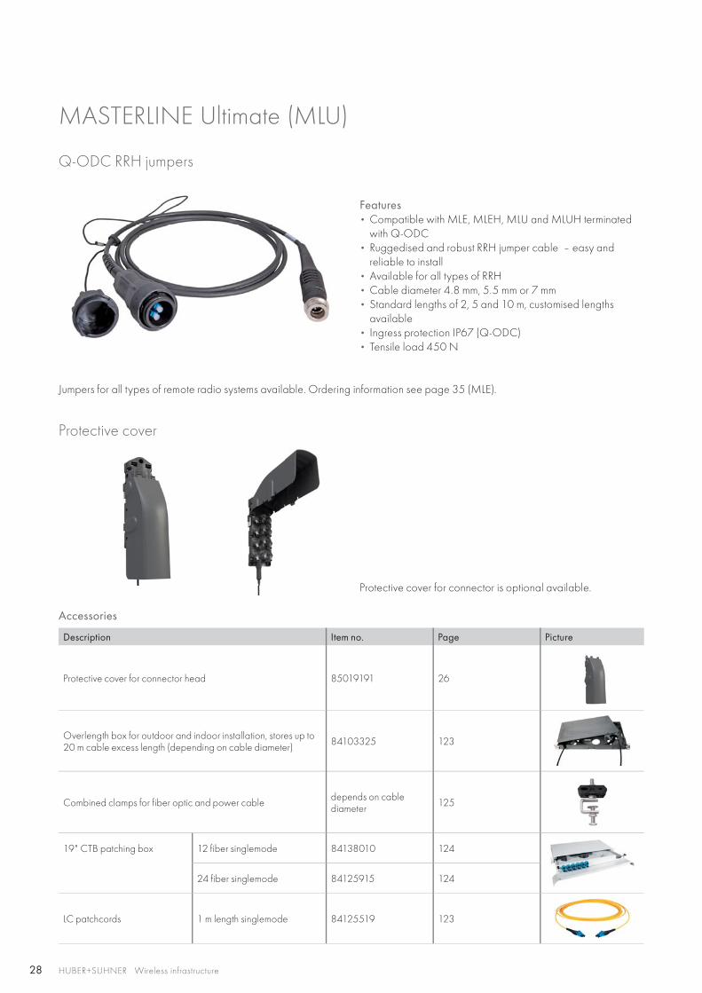
Q-ODC RRH jumpers
Features • Compatible with MLE, MLEH, MLU and MLUH terminated
with Q-ODC• Ruggedised and robust RRH jumper cable – easy and
reliable to install• Available for all types of RRH• Cable diameter 4.8 mm, 5.5 mm or 7 mm• Standard lengths of 2, 5 and 10 m, customised lengths
available• Ingress protection IP67 (Q-ODC) • Tensile load 450 N
MASTERLINE Ultimate (MLU)
Accessories
Description Item no. Page Picture
Protective cover for connector head 85019191 26
Overlength box for outdoor and indoor installation, stores up to 20 m cable excess length (depending on cable diameter) 84103325 123
Combined clamps for fiber optic and power cable depends on cablediameter 125
19" CTB patching box 12 fiber singlemode 84138010 124
24 fiber singlemode 84125915 124
LC patchcords 1 m length singlemode 84125519 123
Jumpers for all types of remote radio systems available. Ordering information see page 35 (MLE).
Protective cover
Protective cover for connector is optional available.
29HUBER+SUHNER Wireless infrastructure
30 HUBER+SUHNER Wireless infrastructure
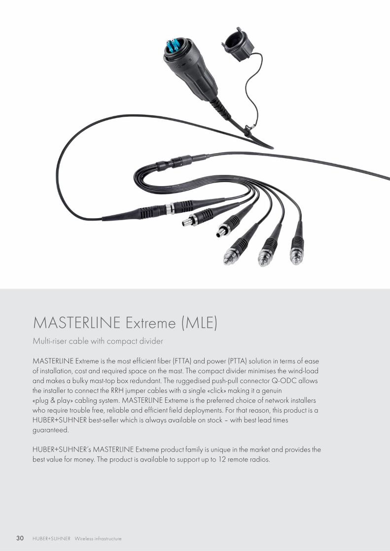
MASTERLINE Extreme (MLE)Multi-riser cable with compact divider
MASTERLINE Extreme is the most efficient fiber (FTTA) and power (PTTA) solution in terms of ease of installation, cost and required space on the mast. The compact divider minimises the wind-load and makes a bulky mast-top box redundant. The ruggedised push-pull connector Q-ODC allows the installer to connect the RRH jumper cables with a single «click» making it a genuin«plug & play» cabling system. MASTERLINE Extreme is the preferred choice of network installers who require trouble free, reliable and efficient field deployments. For that reason, this product is a HUBER+SUHNER best-seller which is always available on stock – with best lead timesguaranteed.
HUBER+SUHNER’s MASTERLINE Extreme product family is unique in the market and provides the best value for money. The product is available to support up to 12 remote radios.
31
RF
PTTA
FTTA
FTTA
XTTA
PTTA
FTTA
FTTA
FTTA
RFXTTA FTTA PTTA HTTA
HUBER+SUHNER Wireless infrastructure
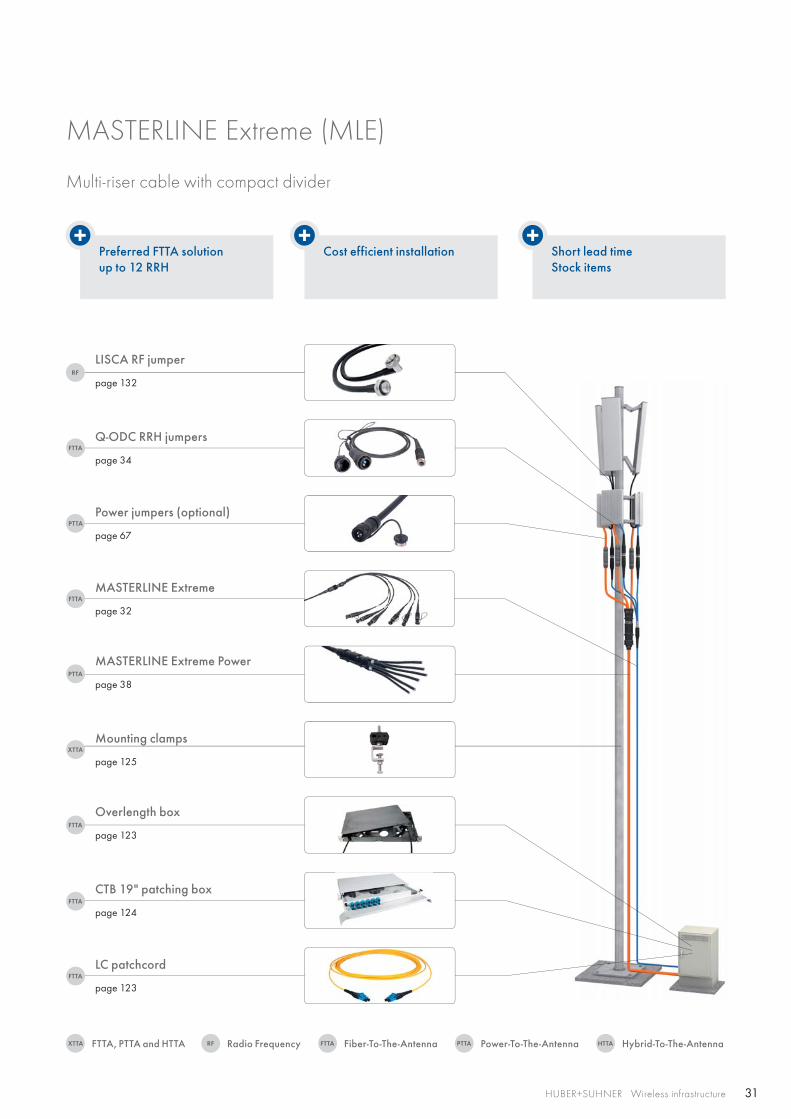
Preferred FTTA solutionup to 12 RRH
Cost efficient installation Short lead timeStock items
Q-ODC RRH jumpers
page 34
LISCA RF jumper
page 132
Power jumpers (optional)
page 67
MASTERLINE Extreme
page 32
MASTERLINE Extreme Power
page 38
Mounting clamps
page 125
CTB 19" patching box
page 124
Overlength box
page 123
LC patchcord
page 123
MASTERLINE Extreme (MLE)
Multi-riser cable with compact divider
Radio FrequencyFTTA, PTTA and HTTA Fiber-To-The-Antenna Power-To-The-Antenna Hybrid-To-The-Antenna
32 HUBER+SUHNER Wireless infrastructure
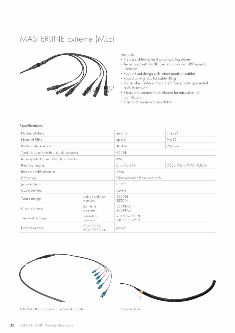
MASTERLINE Extreme (MLE)
Features • Pre-assembled «plug & play» cabling system• Terminated with Q-ODC extension or with RRH-specific
interface• Ruggedised design with robust breakout cables• Robust pulling tube for cable lifting• Loose tube cables with up to 24 fibers, rodent protected
and UV resistant• Fibers and connectors numbered for easy channel
identification• Easy and time-saving installation
Specifications
Number of fibers up to 12 18 to 24
Numer of RRHs up to 6 9 to 12
Build-in hole dimension 16.0 mm 26.0 mm
Tensile load on individual break-out cables 600 N
Ingress protection with Q-ODC connector IP67
Break-out lengths 0.55 / 0.64 m 0.55 / 0.64 / 0.73 / 0.82 m
Break-out cable diameter 5 mm
Cable type Glass-armoured loose-tube cable
Jacket material LSFHTM
Cable diameter 7.0 mm
Tensile strength during installationin service
2000 N1200 N
Crush resistance short-term long-term
500 N/cm 200 N/cm
Temperature range installation in service
–10 °C to +50 °C –40 °C to +75 °C
Flame resistance IEC 60332-1, IEC 60332-3-24 passed
MASTERLINE Classic with LC uniboot at BTS side Protecting tube
33
HUBER+SUHNER Wireless infrastructure
MASTERLINE Extreme (MLE)
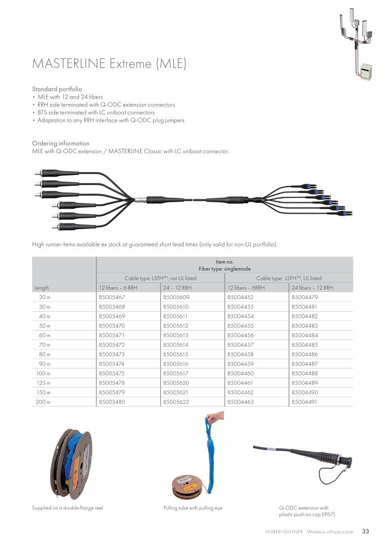
Standard portfolio• MLE with 12 and 24 fibers• RRH side terminated with Q-ODC extension connectors• BTS side terminated with LC uniboot connectors• Adaptation to any RRH interface with Q-ODC plug jumpers
Ordering informationMLE with Q-ODC extension / MASTERLINE Classic with LC uniboot connector.
High runner items available ex stock at guaranteed short lead times (only valid for non-UL portfolio).
Length
Item no.Fiber type: singlemode
Cable type: LSFHTM, not UL listed Cable type: LSFHTM, UL listed
12 fibers – 6 RRH 24 – 12 RRH 12 fibers – 6RRH 24 fibers – 12 RRH
20 m 85005467 85005609 85004452 85004479
30 m 85005468 85005610 85004453 85004481
40 m 85005469 85005611 85004454 85004482
50 m 85005470 85005612 85004455 85004483
60 m 85005471 85005613 85004456 85004484
70 m 85005472 85005614 85004457 85004485
80 m 85005473 85005615 85004458 85004486
90 m 85005474 85005616 85004459 85004487
100 m 85005475 85005617 85004460 85004488
125 m 85005478 85005620 85004461 85004489
150 m 85005479 85005621 85004462 85004490
200 m 85005480 85005622 85004463 85004491
Supplied on a double-flange reel Pulling tube with pulling eye Q-ODC extension with plastic push-on cap (IP67)
34
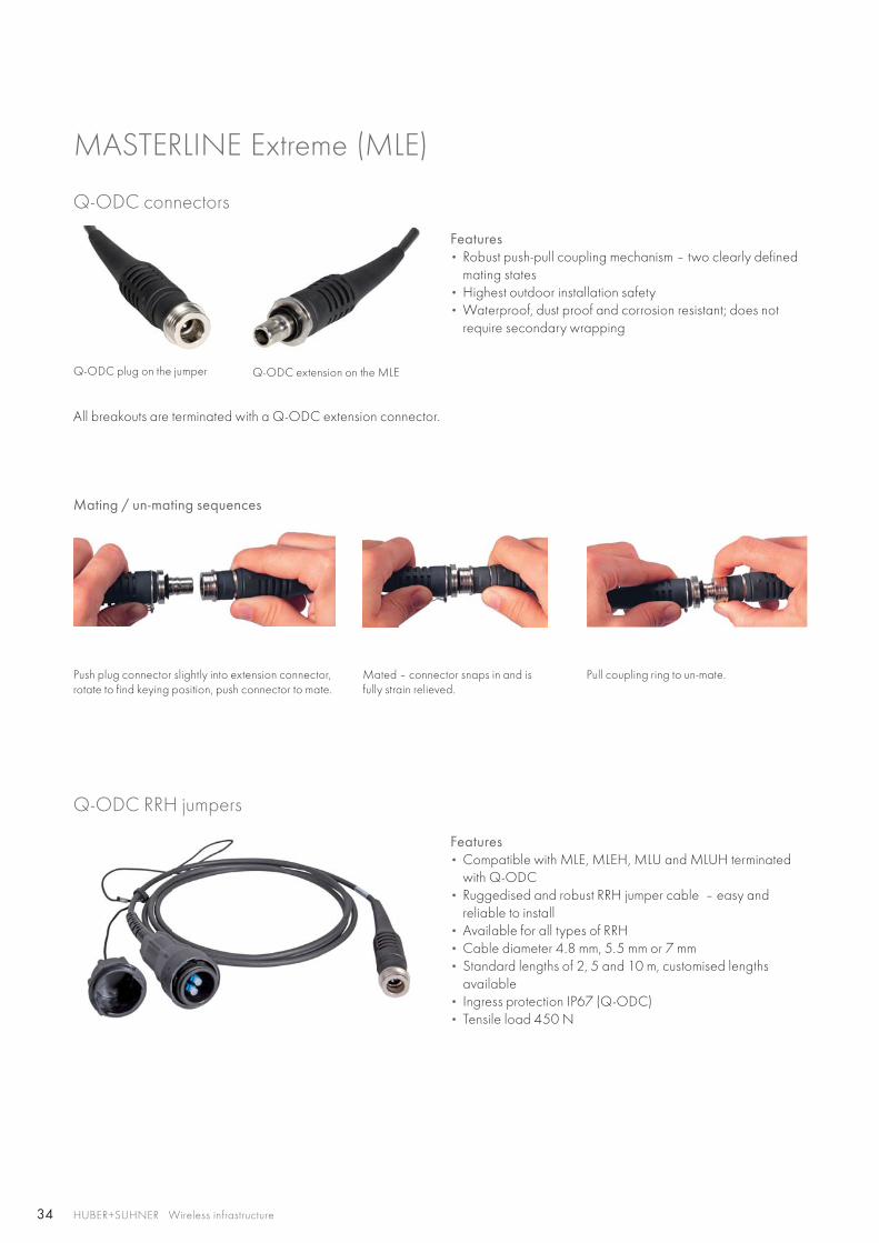
Push plug connector slightly into extension connector, rotate to find keying position, push connector to mate.
Mated – connector snaps in and is fully strain relieved.
Pull coupling ring to un-mate.
HUBER+SUHNER Wireless infrastructure
Q-ODC RRH jumpers
Q-ODC connectors
Features • Compatible with MLE, MLEH, MLU and MLUH terminated
with Q-ODC• Ruggedised and robust RRH jumper cable – easy and
reliable to install• Available for all types of RRH• Cable diameter 4.8 mm, 5.5 mm or 7 mm• Standard lengths of 2, 5 and 10 m, customised lengths
available• Ingress protection IP67 (Q-ODC) • Tensile load 450 N
Features • Robust push-pull coupling mechanism – two clearly defined
mating states• Highest outdoor installation safety• Waterproof, dust proof and corrosion resistant; does not
require secondary wrapping
Q-ODC plug on the jumper Q-ODC extension on the MLE
All breakouts are terminated with a Q-ODC extension connector.
Mating / un-mating sequences
MASTERLINE Extreme (MLE)
35HUBER+SUHNER Wireless infrastructure
Q-ODC RRH jumpers
MASTERLINE Extreme (MLE)
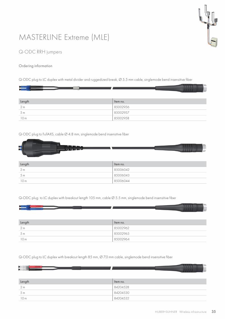
Ordering information
Q-ODC plug to LC duplex with metal divider and ruggedized break, Ø 5.5 mm cable, singlemode bend insensitive fiber
Length Item no.
2 m 85002956
5 m 85002957
10 m 85002958
Q-ODC plug to FullAXS, cable Ø 4.8 mm, singlemode bend insensitive fiber
Length Item no.
2 m 85006042
5 m 85006043
10 m 85006044
Q-ODC plug to LC duplex with breakout length 105 mm, cable Ø 5.5 mm, singlemode bend insensitive fiber
Length Item no.
2 m 85002962
5 m 85002963
10 m 85002964
Q-ODC plug to LC duplex with breakout length 85 mm, Ø 7.0 mm cable, singlemode bend insensitive fiber
Length Item no.
2 m 84204528
5 m 84204530
10 m 84204532
36 HUBER+SUHNER Wireless infrastructure
Q-ODC RRH jumpers
MASTERLINE Extreme (MLE)
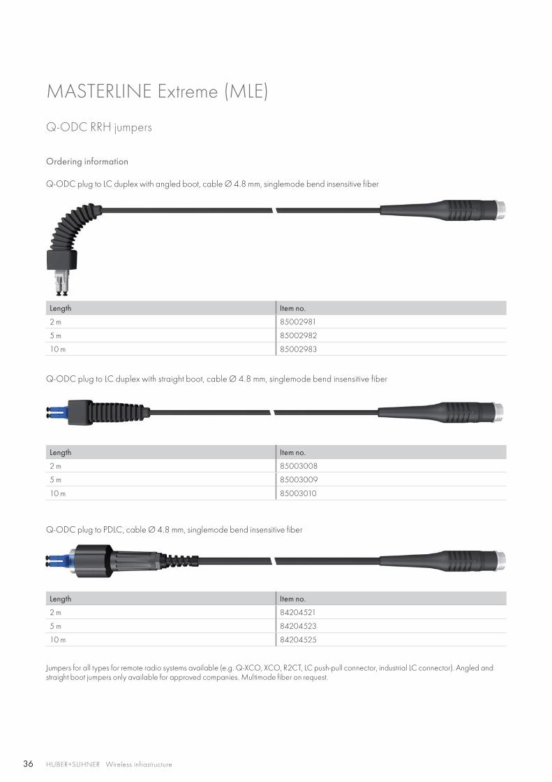
Ordering information
Q-ODC plug to LC duplex with angled boot, cable Ø 4.8 mm, singlemode bend insensitive fiber
Length Item no.
2 m 85002981
5 m 85002982
10 m 85002983
Q-ODC plug to LC duplex with straight boot, cable Ø 4.8 mm, singlemode bend insensitive fiber
Length Item no.
2 m 85003008
5 m 85003009
10 m 85003010
Q-ODC plug to PDLC, cable Ø 4.8 mm, singlemode bend insensitive fiber
Length Item no.
2 m 84204521
5 m 84204523
10 m 84204525
Jumpers for all types for remote radio systems available (e.g. Q-XCO, XCO, R2CT, LC push-pull connector, industrial LC connector). Angled and straight boot jumpers only available for approved companies. Multimode fiber on request.
37HUBER+SUHNER Wireless infrastructure
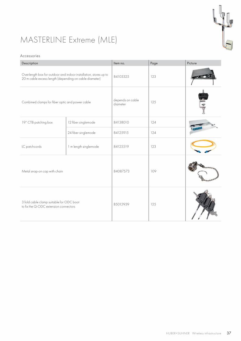
Accessories
Description Item no. Page Picture
Overlength box for outdoor and indoor installation, stores up to 20 m cable excess length (depending on cable diameter) 84103325 123
Combined clamps for fiber optic and power cable depends on cablediameter 125
19" CTB patching box 12 fiber singlemode 84138010 124
24 fiber singlemode 84125915 124
LC patchcords 1 m length singlemode 84125519 123
Metal snap-on cap with chain 84087573 109
3 fold cable clamp suitable for ODC boot to fix the Q-ODC extension connectors
85012939 125
MASTERLINE Extreme (MLE)
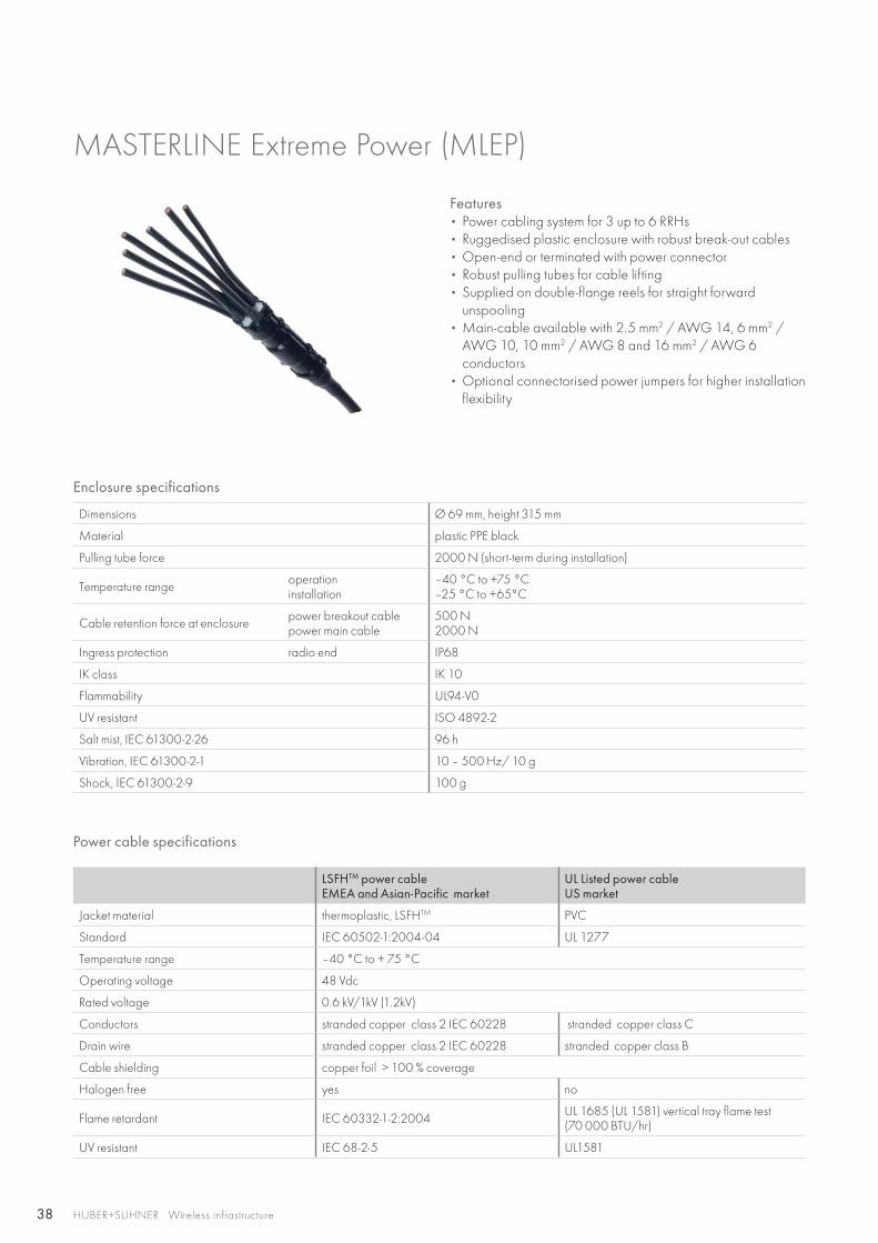
38 HUBER+SUHNER Wireless infrastructure
Features • Power cabling system for 3 up to 6 RRHs• Ruggedised plastic enclosure with robust break-out cables• Open-end or terminated with power connector• Robust pulling tubes for cable lifting• Supplied on double-flange reels for straight forward
unspooling• Main-cable available with 2.5 mm2 / AWG 14, 6 mm2 /
AWG 10, 10 mm2 / AWG 8 and 16 mm2 / AWG 6 conductors
• Optional connectorised power jumpers for higher installation flexibility
Enclosure specifications
Dimensions Ø 69 mm, height 315 mm
Material plastic PPE black
Pulling tube force 2000 N (short-term during installation)
Temperature range operationinstallation
–40 °C to +75 °C–25 °C to +65°C
Cable retention force at enclosure power breakout cablepower main cable
500 N2000 N
Ingress protection radio end IP68
IK class IK 10
Flammability UL94-V0
UV resistant ISO 4892-2
Salt mist, IEC 61300-2-26 96 h
Vibration, IEC 61300-2-1 10 – 500 Hz/ 10 g
Shock, IEC 61300-2-9 100 g
Power cable specifications
LSFHTM power cableEMEA and Asian-Pacific market
UL Listed power cableUS market
Jacket material thermoplastic, LSFHTM PVC
Standard IEC 60502-1:2004-04 UL 1277
Temperature range –40 °C to + 75 °C
Operating voltage 48 Vdc
Rated voltage 0.6 kV/1kV (1.2kV)
Conductors stranded copper class 2 IEC 60228 stranded copper class C
Drain wire stranded copper class 2 IEC 60228 stranded copper class B
Cable shielding copper foil > 100 % coverage
Halogen free yes no
Flame retardant IEC 60332-1-2:2004 UL 1685 (UL 1581) vertical tray flame test(70 000 BTU/hr)
UV resistant IEC 68-2-5 UL1581
MASTERLINE Extreme Power (MLEP)
39HUBER+SUHNER Wireless infrastructure
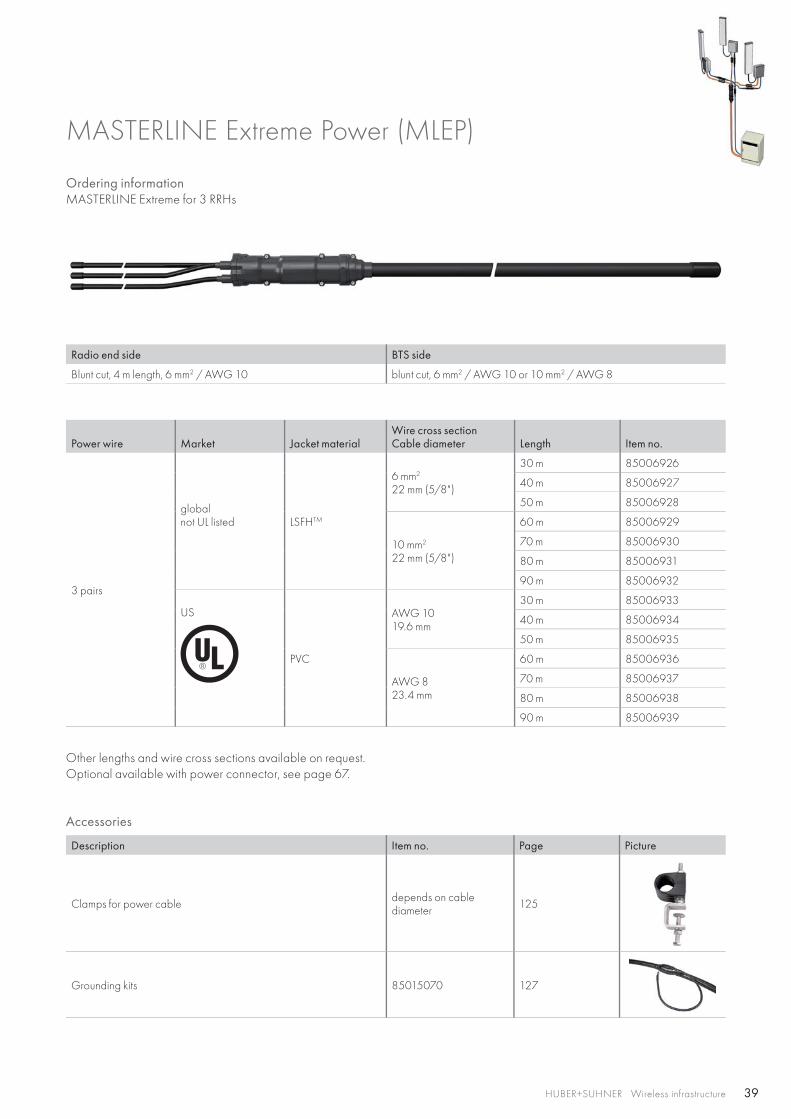
Ordering information MASTERLINE Extreme for 3 RRHs
Radio end side BTS side
Blunt cut, 4 m length, 6 mm2 / AWG 10 blunt cut, 6 mm2 / AWG 10 or 10 mm2 / AWG 8
Power wire Market Jacket materialWire cross sectionCable diameter Length Item no.
3 pairs
globalnot UL listed LSFHTM
6 mm2
22 mm (5/8")
30 m 85006926
40 m 85006927
50 m 85006928
10 mm2
22 mm (5/8")
60 m 85006929
70 m 85006930
80 m 85006931
90 m 85006932
US
PVC
AWG 1019.6 mm
30 m 85006933
40 m 85006934
50 m 85006935
AWG 823.4 mm
60 m 85006936
70 m 85006937
80 m 85006938
90 m 85006939
Other lengths and wire cross sections available on request.Optional available with power connector, see page 67.
MASTERLINE Extreme Power (MLEP)
Accessories
Description Item no. Page Picture
Clamps for power cable depends on cable diameter 125
Grounding kits 85015070 127
40 HUBER+SUHNER Wireless infrastructure
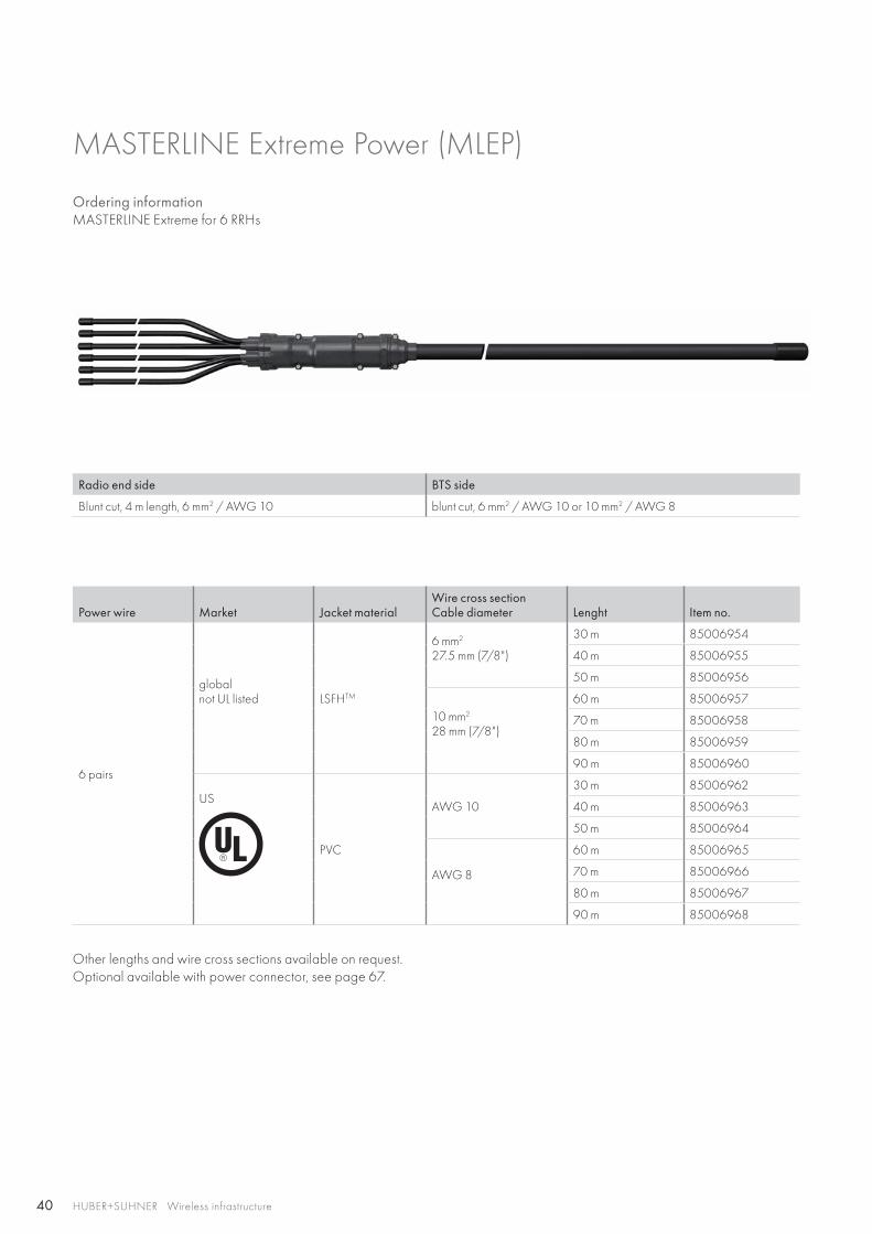
Ordering informationMASTERLINE Extreme for 6 RRHs
Radio end side BTS side
Blunt cut, 4 m length, 6 mm2 / AWG 10 blunt cut, 6 mm2 / AWG 10 or 10 mm2 / AWG 8
Power wire Market Jacket materialWire cross sectionCable diameter Lenght Item no.
6 pairs
globalnot UL listed LSFHTM
6 mm2
27.5 mm (7/8")
30 m 85006954
40 m 85006955
50 m 85006956
10 mm2
28 mm (7/8")
60 m 85006957
70 m 85006958
80 m 85006959
90 m 85006960
US
PVC
AWG 10
30 m 85006962
40 m 85006963
50 m 85006964
AWG 8
60 m 85006965
70 m 85006966
80 m 85006967
90 m 85006968
Other lengths and wire cross sections available on request.Optional available with power connector, see page 67.
MASTERLINE Extreme Power (MLEP)
41HUBER+SUHNER Wireless infrastructure
42 HUBER+SUHNER Wireless infrastructure
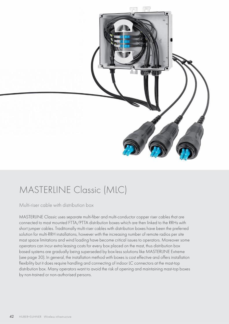
MASTERLINE Classic (MLC) Multi-riser cable with distribution box
MASTERLINE Classic uses separate multi-fiber and multi-conductor copper riser cables that are connected to mast mounted FTTA/PTTA distribution boxes which are then linked to the RRHs with short jumper cables. Traditionally multi-riser cables with distribution boxes have been the preferred solution for multi-RRH installations, however with the increasing number of remote radios per site mast space limitations and wind loading have become critical issues to operators. Moreover some operators can incur extra leasing costs for every box placed on the mast, thus distribution box based systems are gradually being superseded by box-less solutions like MASTERLINE Extreme (see page 30). In general, the installation method with boxes is cost effective and offers installation flexibility but it does require handling and connecting of indoor LC connectors at the mast-top distribution box. Many operators want to avoid the risk of opening and maintaining mast-top boxes by non-trained or non-authorised persons.
43
RF
FTTA
PTTA
FTTA
FTTA
FTTA
FTTA
PTTA
PTTA
XTTA
RFXTTA FTTA PTTA HTTA
HUBER+SUHNER Wireless infrastructure
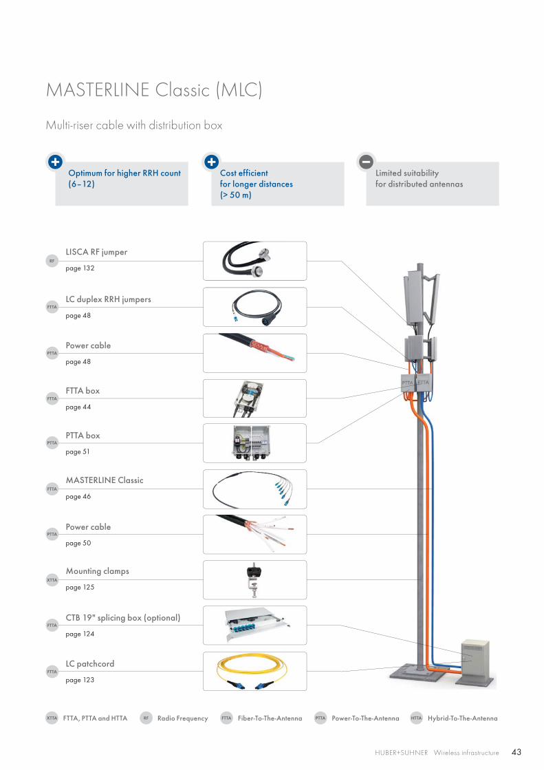
Optimum for higher RRH count(6–12)
Cost efficient for longer distances(> 50 m)
Limited suitability for distributed antennas
LC duplex RRH jumpers
page 48
Power cable
page 48
LISCA RF jumper
page 132
FTTA box
page 44
PTTA box
page 51
MASTERLINE Classic
page 46
Power cable
page 50
CTB 19" splicing box (optional)
page 124
Mounting clamps
page 125
LC patchcord
page 123
MASTERLINE Classic (MLC)
Multi-riser cable with distribution box
Radio FrequencyFTTA, PTTA and HTTA Fiber-To-The-Antenna Power-To-The-Antenna Hybrid-To-The-Antenna
44 HUBER+SUHNER Wireless infrastructure
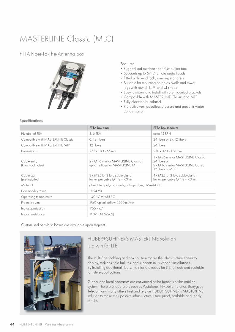
FTTA Fiber-To-The-Antenna box
Features • Ruggedised outdoor fiber distribution box• Supports up to 6/12 remote radio heads• Fitted with bend radius limiting mandrels• Suitable for mounting on poles, walls and tower
legs with round-, L-, V- and -shape.• Easy to mount and install with pre-mounted brackets• Compatible with MASTERLINE Classic and MTP• Fully electrically isolated• Protective vent equalises pressure and prevents water
condensation
Specifications
FTTA box small FTTA box medium
Number of RRH 3, 6 RRH up to 12 RRH
Compatible with MASTERLINE Classic 6, 12 fibers 24 fibers or 2 x 12 fibers
Compatible with MASTERLINE MTP 12 fibers 24 fibers
Dimensions 255 x 180 x 65 mm 250 x 320 x 138 mm
Cable entry(knock-out holes)
2 x Ø 16 mm for MASTERLINE Classicup to 12 fibers or MASTERLINE MTP
1 x Ø 26 mm for MASTERLINE Classic 24 fibers or2 x Ø 16 mm for MASTERLINE Cassic 12 fibers or MTP
Cable exit (pre-installed)
2 x M25 for 3-fold cable glandfor jumper cable Ø 4.8 – 7.0 mm
4 x M25 for 3-fold cable glandfor jumper cable Ø 4.8 – 7.0 mm
Material glass filled polycarbonate, halogen free, UV resistant
Flammability rating UL 94 V0
Operating temperature –40 °C to +85 °C
Protective vent IP67, typical airflow 2500 ml/min
Ingress protection IP66 / 67
Impact resistance IK 07 (EN 62262)
Customised or hybrid boxes are available upon request.
HUBER+SUHNER’s MASTERLINE solution is a win for LTE
The multi-fiber cabling and box solution makes the infrastructure easier to deploy, reduces field failures, and supports multi-vendor installations. By installing additional fibers, the sites are ready for LTE roll-outs and scalable for future applications.
Global and local operators are convinced of the benefits of this cabling system. Therefore, operators such as Vodafone, T-Mobile, Telenor, Bouygues Telecom and many others trust and rely on HUBER+SUHNER’s MASTERLINE solution to make their passive infrastructure future-proof, scalable and ready for LTE.
MASTERLINE Classic (MLC)
45HUBER+SUHNER Wireless infrastructure
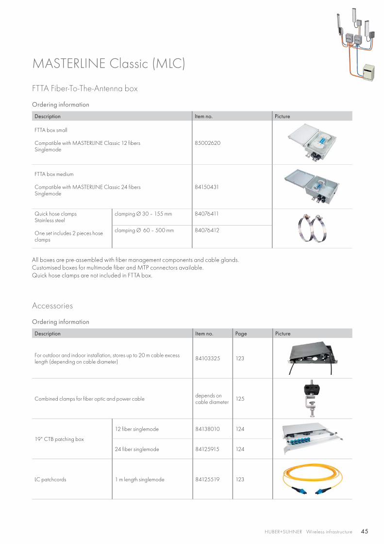
FTTA Fiber-To-The-Antenna box
Ordering information
Description Item no. Picture
FTTA box small
Compatible with MASTERLINE Classic 12 fibersSinglemode
85002620
FTTA box medium Compatible with MASTERLINE Classic 24 fibersSinglemode
84150431
Quick hose clampsStainless steel
One set includes 2 pieces hose clamps
clamping Ø 30 – 155 mm 84076411
clamping Ø 60 – 500 mm 84076412
All boxes are pre-assembled with fiber management components and cable glands.Customised boxes for multimode fiber and MTP connectors available.Quick hose clamps are not included in FTTA box.
Accessories
Ordering information
Description Item no. Page Picture
For outdoor and indoor installation, stores up to 20 m cable excess length (depending on cable diameter) 84103325 123
Combined clamps for fiber optic and power cable depends on cable diameter 125
19" CTB patching box
12 fiber singlemode 84138010 124
24 fiber singlemode 84125915 124
LC patchcords 1 m length singlemode 84125519 123
MASTERLINE Classic (MLC)
46 HUBER+SUHNER Wireless infrastructure
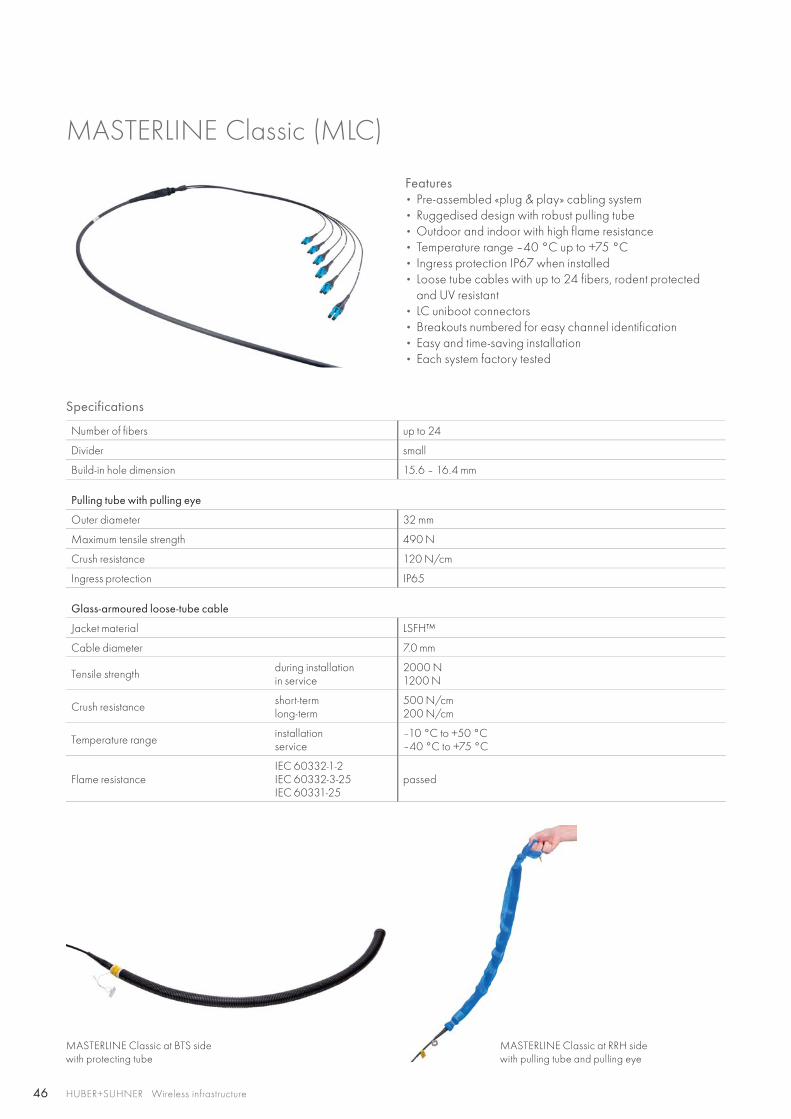
MASTERLINE Classic (MLC)
Features • Pre-assembled «plug & play» cabling system• Ruggedised design with robust pulling tube• Outdoor and indoor with high flame resistance• Temperature range –40 °C up to +75 °C• Ingress protection IP67 when installed• Loose tube cables with up to 24 fibers, rodent protected
and UV resistant• LC uniboot connectors• Breakouts numbered for easy channel identification• Easy and time-saving installation• Each system factory tested
Specifications
Number of fibers up to 24
Divider small
Build-in hole dimension 15.6 – 16.4 mm
Pulling tube with pulling eye
Outer diameter 32 mm
Maximum tensile strength 490 N
Crush resistance 120 N/cm
Ingress protection IP65
Glass-armoured loose-tube cable
Jacket material LSFH™
Cable diameter 7.0 mm
Tensile strength during installationin service
2000 N1200 N
Crush resistance short-term long-term
500 N/cm200 N/cm
Temperature range installationservice
–10 °C to +50 °C–40 °C to +75 °C
Flame resistance IEC 60332-1-2IEC 60332-3-25IEC 60331-25
passed
MASTERLINE Classic at BTS side with protecting tube
MASTERLINE Classic at RRH side with pulling tube and pulling eye
47HUBER+SUHNER Wireless infrastructure
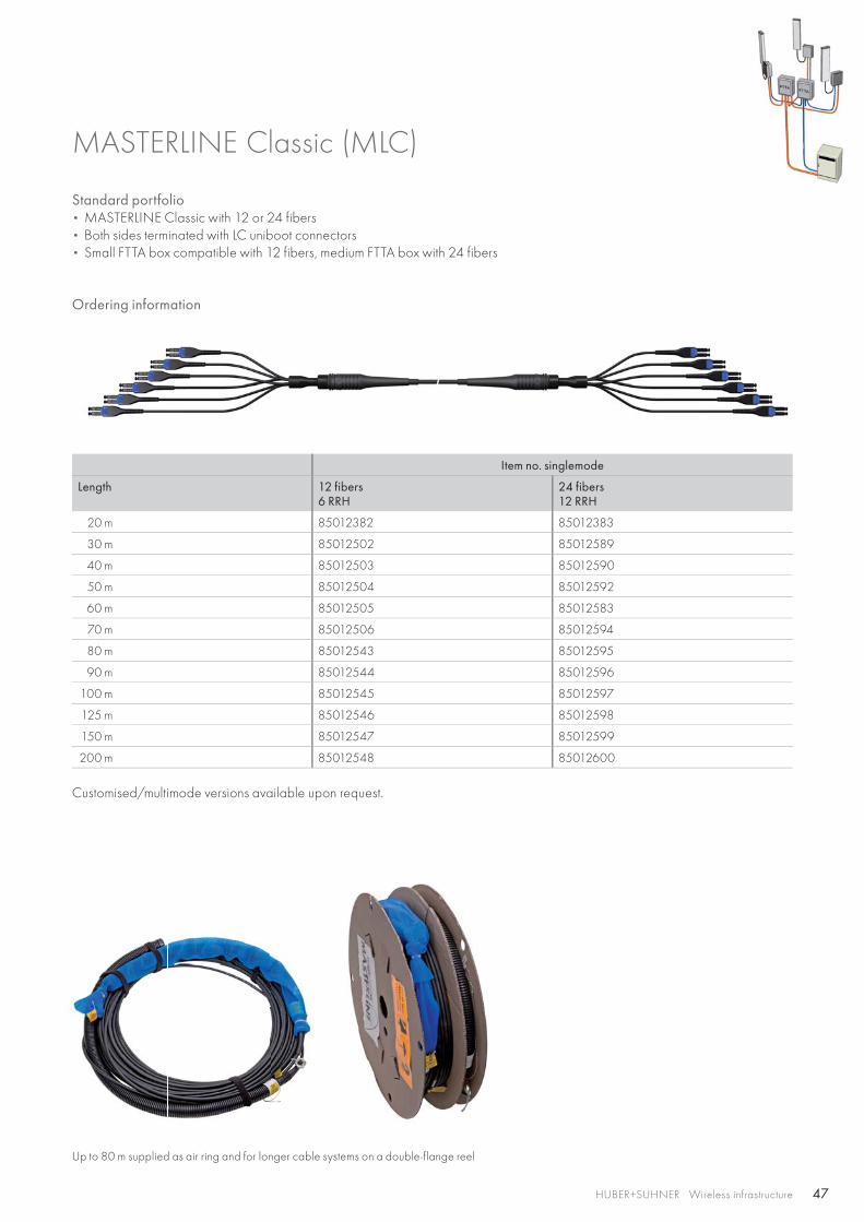
MASTERLINE Classic (MLC)
Standard portfolio• MASTERLINE Classic with 12 or 24 fibers• Both sides terminated with LC uniboot connectors• Small FTTA box compatible with 12 fibers, medium FTTA box with 24 fibers
Ordering information
Item no. singlemode
Length 12 fibers6 RRH
24 fibers12 RRH
20 m 85012382 85012383
30 m 85012502 85012589
40 m 85012503 85012590
50 m 85012504 85012592
60 m 85012505 85012583
70 m 85012506 85012594
80 m 85012543 85012595
90 m 85012544 85012596
100 m 85012545 85012597
125 m 85012546 85012598
150 m 85012547 85012599
200 m 85012548 85012600
Customised/multimode versions available upon request.
Up to 80 m supplied as air ring and for longer cable systems on a double-flange reel
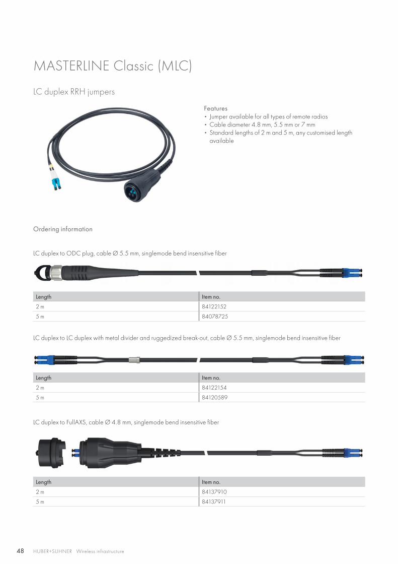
48 HUBER+SUHNER Wireless infrastructure
LC duplex RRH jumpers
Features • Jumper available for all types of remote radios• Cable diameter 4.8 mm, 5.5 mm or 7 mm • Standard lengths of 2 m and 5 m, any customised length
available
Ordering information
LC duplex to ODC plug, cable Ø 5.5 mm, singlemode bend insensitive fiber
Length Item no.
2 m 84122152
5 m 84078725
LC duplex to LC duplex with metal divider and ruggedized break-out, cable Ø 5.5 mm, singlemode bend insensitive fiber
Length Item no.
2 m 84122154
5 m 84120589
LC duplex to FullAXS, cable Ø 4.8 mm, singlemode bend insensitive fiber
Length Item no.
2 m 84137910
5 m 84137911
MASTERLINE Classic (MLC)
49HUBER+SUHNER Wireless infrastructure
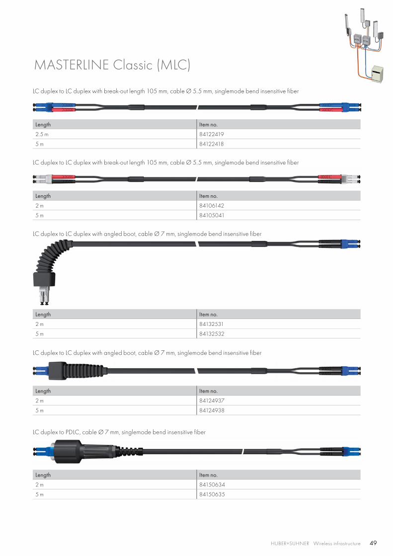
LC duplex to LC duplex with break-out length 105 mm, cable Ø 5.5 mm, singlemode bend insensitive fiber
Length Item no.
2.5 m 84122419
5 m 84122418
LC duplex to LC duplex with break-out length 105 mm, cable Ø 5.5 mm, singlemode bend insensitive fiber
Length Item no.
2 m 84106142
5 m 84105041
LC duplex to LC duplex with angled boot, cable Ø 7 mm, singlemode bend insensitive fiber
Length Item no.
2 m 84132531
5 m 84132532
LC duplex to LC duplex with angled boot, cable Ø 7 mm, singlemode bend insensitive fiber
Length Item no.
2 m 84124937
5 m 84124938
LC duplex to PDLC, cable Ø 7 mm, singlemode bend insensitive fiber
Length Item no.
2 m 84150634
5 m 84150635
MASTERLINE Classic (MLC)
50 HUBER+SUHNER Wireless infrastructure
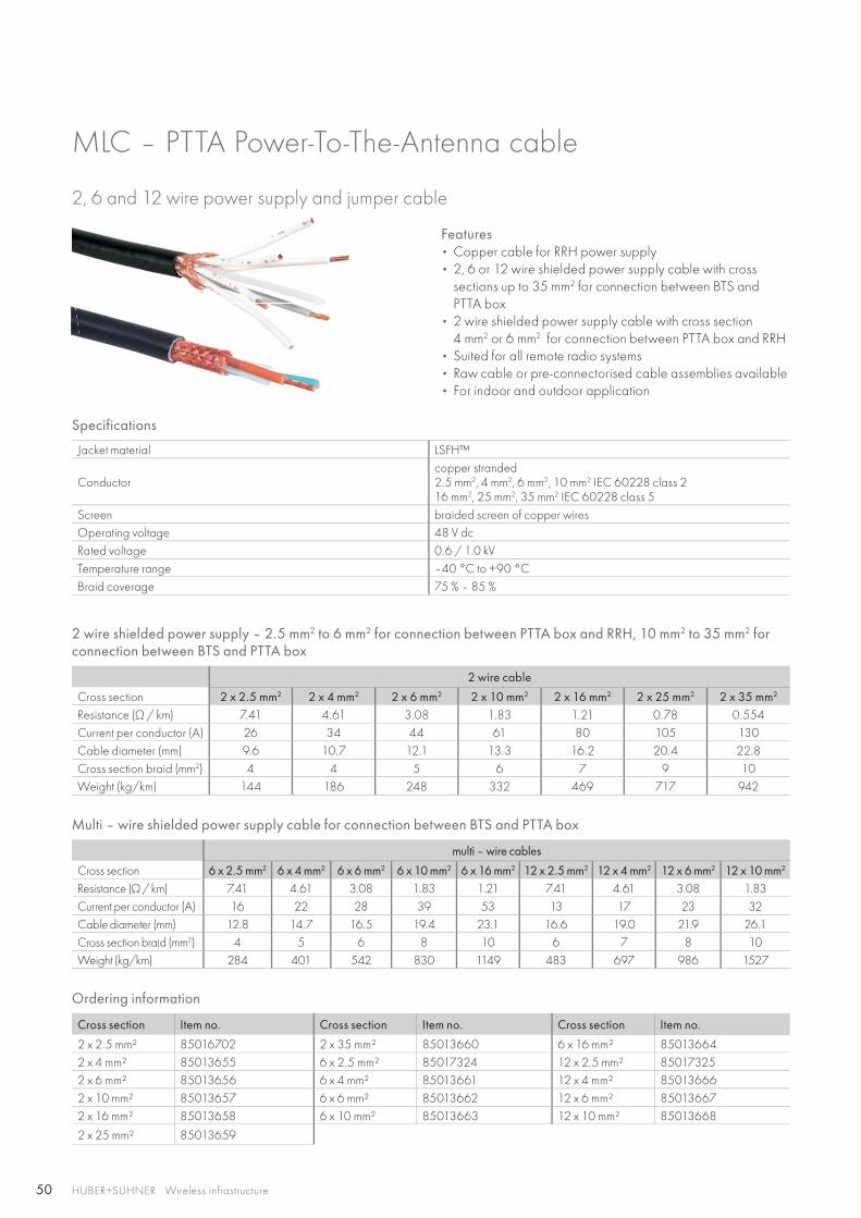
MLC – PTTA Power-To-The-Antenna cable
2, 6 and 12 wire power supply and jumper cable
Features • Copper cable for RRH power supply• 2, 6 or 12 wire shielded power supply cable with cross
sections up to 35 mm2 for connection between BTS andPTTA box
• 2 wire shielded power supply cable with cross section4 mm2 or 6 mm2 for connection between PTTA box and RRH
• Suited for all remote radio systems• Raw cable or pre-connectorised cable assemblies available• For indoor and outdoor application
Specifications
Jacket material LSFH™
Conductorcopper stranded2.5 mm2, 4 mm2, 6 mm2, 10 mm2 IEC 60228 class 216 mm2, 25 mm2, 35 mm2 IEC 60228 class 5
Screen braided screen of copper wiresOperating voltage 48 V dcRated voltage 0.6 / 1.0 kVTemperature range –40 °C to +90 °CBraid coverage 75 % – 85 %
2 wire shielded power supply – 2.5 mm2 to 6 mm2 for connection between PTTA box and RRH, 10 mm2 to 35 mm2 for connection between BTS and PTTA box
2 wire cable
Cross section 2 x 2.5 mm2 2 x 4 mm2 2 x 6 mm2 2 x 10 mm2 2 x 16 mm2 2 x 25 mm2 2 x 35 mm2
Resistance (Ω / km) 7.41 4.61 3.08 1.83 1.21 0.78 0.554Current per conductor (A) 26 34 44 61 80 105 130Cable diameter (mm) 9.6 10.7 12.1 13.3 16.2 20.4 22.8Cross section braid (mm2) 4 4 5 6 7 9 10Weight (kg/km) 144 186 248 332 469 717 942
Multi – wire shielded power supply cable for connection between BTS and PTTA box
multi – wire cables
Cross section 6 x 2.5 mm2 6 x 4 mm2 6 x 6 mm2 6 x 10 mm2 6 x 16 mm2 12 x 2.5 mm2 12 x 4 mm2 12 x 6 mm2 12 x 10 mm2
Resistance (Ω / km) 7.41 4.61 3.08 1.83 1.21 7.41 4.61 3.08 1.83Current per conductor (A) 16 22 28 39 53 13 17 23 32Cable diameter (mm) 12.8 14.7 16.5 19.4 23.1 16.6 19.0 21.9 26.1Cross section braid (mm2) 4 5 6 8 10 6 7 8 10Weight (kg/km) 284 401 542 830 1149 483 697 986 1527
Ordering information
Cross section Item no. Cross section Item no. Cross section Item no.
2 x 2.5 mm² 85016702 2 x 35 mm² 85013660 6 x 16 mm² 850136642 x 4 mm² 85013655 6 x 2.5 mm² 85017324 12 x 2.5 mm² 850173252 x 6 mm² 85013656 6 x 4 mm² 85013661 12 x 4 mm² 850136662 x 10 mm² 85013657 6 x 6 mm² 85013662 12 x 6 mm² 850136672 x 16 mm² 85013658 6 x 10 mm² 85013663 12 x 10 mm² 85013668
2 x 25 mm² 85013659
51HUBER+SUHNER Wireless infrastructure
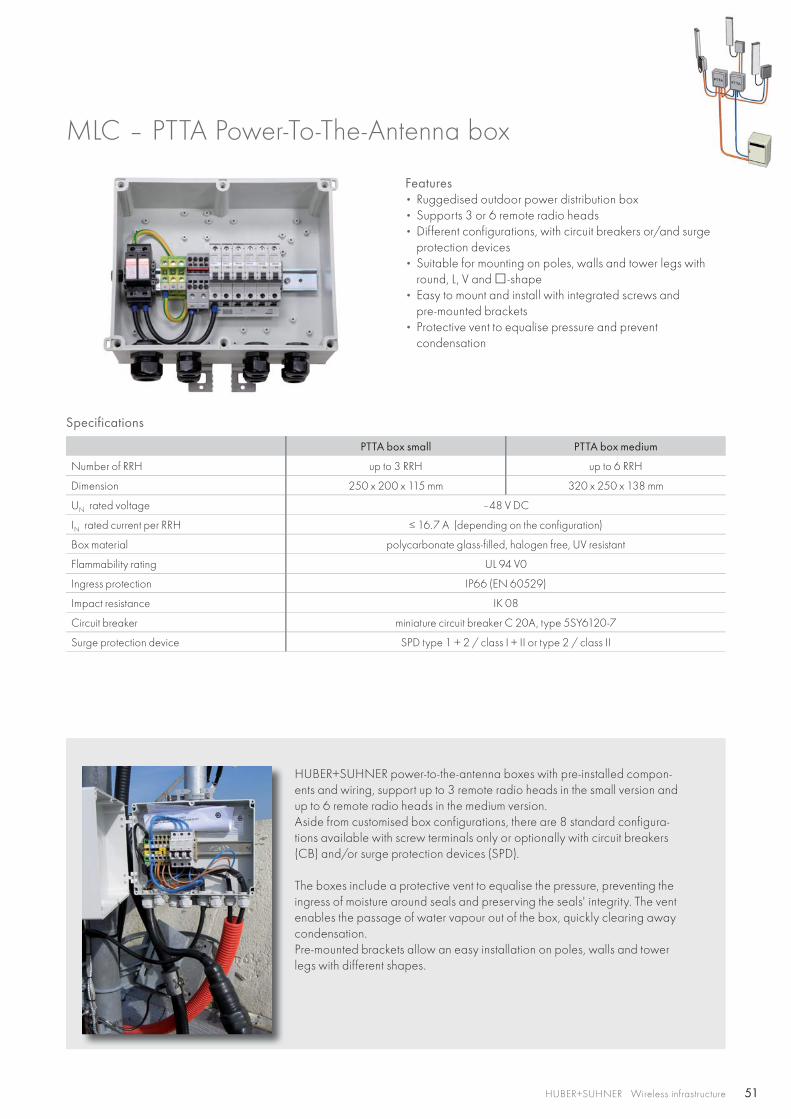
Specifications
PTTA box small PTTA box medium
Number of RRH up to 3 RRH up to 6 RRH
Dimension 250 x 200 x 115 mm 320 x 250 x 138 mm
UN rated voltage –48 V DC
IN rated current per RRH ≤ 16.7 A (depending on the configuration)
Box material polycarbonate glass-filled, halogen free, UV resistant
Flammability rating UL 94 V0
Ingress protection IP66 (EN 60529)
Impact resistance IK 08
Circuit breaker miniature circuit breaker C 20A, type 5SY6120-7
Surge protection device SPD type 1 + 2 / class I + II or type 2 / class II
Features • Ruggedised outdoor power distribution box• Supports 3 or 6 remote radio heads• Different configurations, with circuit breakers or/and surge
protection devices• Suitable for mounting on poles, walls and tower legs with
round, L, V and -shape• Easy to mount and install with integrated screws and
pre-mounted brackets• Protective vent to equalise pressure and prevent
condensation
HUBER+SUHNER power-to-the-antenna boxes with pre-installed compon-ents and wiring, support up to 3 remote radio heads in the small version and up to 6 remote radio heads in the medium version. Aside from customised box configurations, there are 8 standard configura-tions available with screw terminals only or optionally with circuit breakers (CB) and/or surge protection devices (SPD).
The boxes include a protective vent to equalise the pressure, preventing the ingress of moisture around seals and preserving the seals' integrity. The vent enables the passage of water vapour out of the box, quickly clearing away condensation.Pre-mounted brackets allow an easy installation on poles, walls and tower legs with different shapes.
MLC – PTTA Power-To-The-Antenna box
52 HUBER+SUHNER Wireless infrastructure
Power entryHuber + Suhner offers a broad range of power cables suitable to PTTA (Power-To-The-Antenna) boxes. 6 wire cables from 4 mm2 to 16 mm2 are available for individual power supply of 3 RRH and 12 wire cables from 4 mm2 to 6 mm2 for individual power supply of 6 RRH. The 2 wire cable with cross section range from 4 mm2 to 35 mm2 fits to PTTA boxes with surge protection devices.
EarthingAll boxes have a cable gland and screw terminals for an earthing cable with a cross section up to 16 mm2.
Circuit breakerPTTA boxes with 3 or 6 circuit breaker are optional available. The 20 A circuit breaker with tripping characteristic C have 6 kA switching capacity.For more information see page 59.
Surge protection deviceThe PTTA boxes are optional with lightning protection equipped. The varistor-based lightning arrester is for applications with grounded return conductor (positive pole) or optional for applications with common return conductor (positive pole) and ground. The surge protection device is a combined type 1/2 arresters with lightning test current of 12.5 kA and a total discharge surge current of 25 kA (10/350 μs) and 50 kA (8/20 μs).For more information see page 57.
MLC – PTTA Power-To-The-Antenna box
Ordering information
Description Item no. Description Item no.
PTTA box for 3 RRH• Power distribution 84137118 PTTA box for 6 RRH
• Power distribution 85015656
PTTA box for 3 RRH• Power distribution• 3 circuit breaker 20A
84137119PTTA box for 6 RRH• Power distribution • Circuit breaker 20 A
85015657
PTTA box for 3 RRH• Power distribution• Surge protection type 2
84137120PTTA box for 6 RRH• Power distribution • Surge protection type 1/2
85015658
PTTA box for 3 RRH• Power distribution• 3 circuit breaker 20A• Surge protection type 2
84137121
PTTA box for 6 RRH• Power distribution • Circuit breaker 20 A• Surge protection type 1/2
85015659
Ordering information for accessories
Description Feature Item no. Picture
Quick hose clampsStainless steel One set includes 2 pieces
clamping diameter 30 – 155 mm 84076411
clamping diameter 60 – 500 mm 84076412
Quick hose clamps are not included in PTTA box.
53HUBER+SUHNER Wireless infrastructure
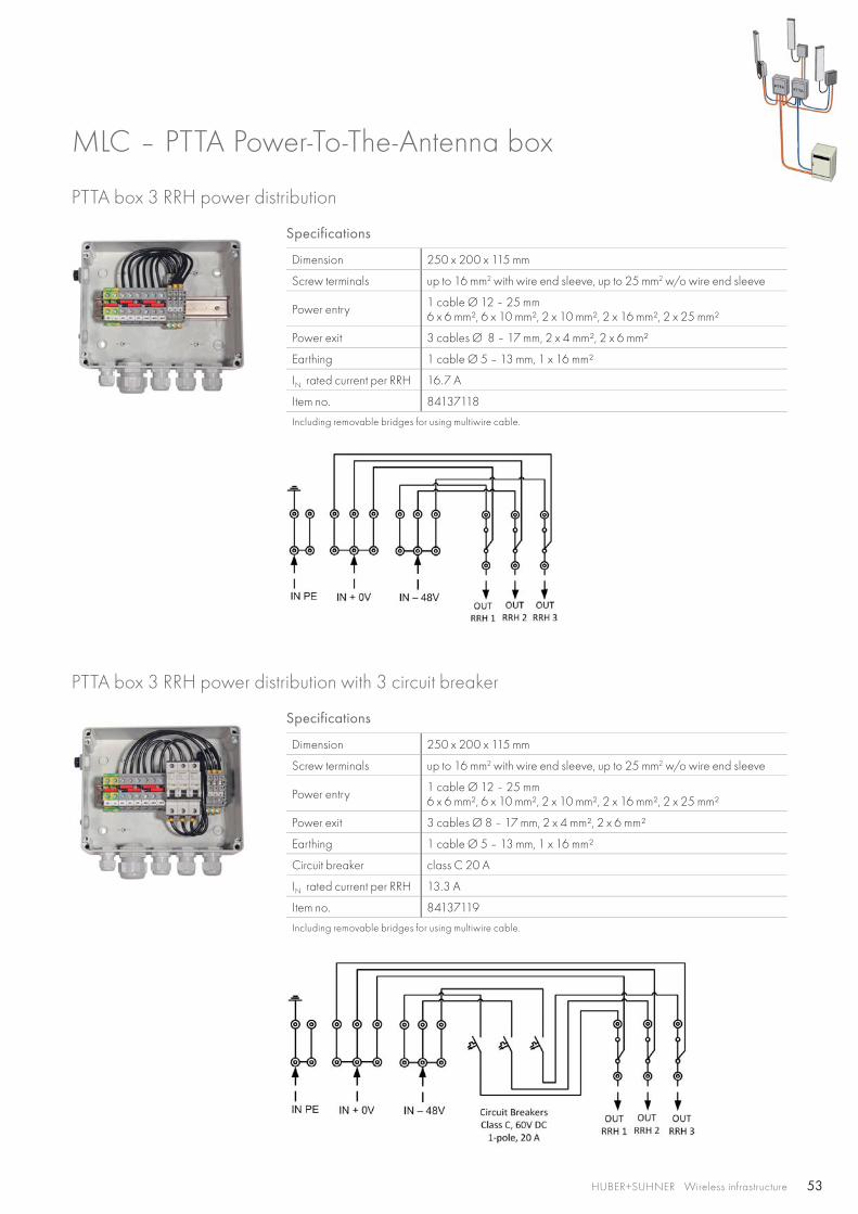
PTTA box 3 RRH power distribution
Specifications
Dimension 250 x 200 x 115 mm
Screw terminals up to 16 mm2 with wire end sleeve, up to 25 mm2 w/o wire end sleeve
Power entry 1 cable Ø 12 – 25 mm6 x 6 mm², 6 x 10 mm², 2 x 10 mm², 2 x 16 mm², 2 x 25 mm²
Power exit 3 cables Ø 8 – 17 mm, 2 x 4 mm², 2 x 6 mm²
Earthing 1 cable Ø 5 – 13 mm, 1 x 16 mm²
IN rated current per RRH 16.7 A
Item no. 84137118
Including removable bridges for using multiwire cable.
Specifications
Dimension 250 x 200 x 115 mm
Screw terminals up to 16 mm2 with wire end sleeve, up to 25 mm2 w/o wire end sleeve
Power entry 1 cable Ø 12 – 25 mm6 x 6 mm², 6 x 10 mm², 2 x 10 mm², 2 x 16 mm², 2 x 25 mm²
Power exit 3 cables Ø 8 – 17 mm, 2 x 4 mm², 2 x 6 mm²
Earthing 1 cable Ø 5 – 13 mm, 1 x 16 mm²
Circuit breaker class C 20 A
IN rated current per RRH 13.3 A
Item no. 84137119
Including removable bridges for using multiwire cable.
PTTA box 3 RRH power distribution with 3 circuit breaker
MLC – PTTA Power-To-The-Antenna box
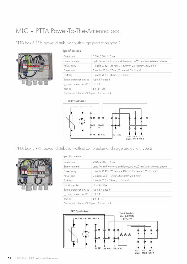
54 HUBER+SUHNER Wireless infrastructure
MLC – PTTA Power-To-The-Antenna box
Specifications
Dimension 250 x 200 x 115 mm
Screw terminals up to 16 mm2 with wire end sleeve, up to 25 mm2 w/o wire end sleeve
Power entry 1 cable Ø 12 – 25 mm, 2 x 10 mm², 2 x 16 mm², 2 x 25 mm²
Power exit 3 cables Ø 8 – 17 mm, 2 x 4 mm², 2 x 6 mm²
Earthing 1 cable Ø 5 – 13 mm, 1 x 16 mm²
Surge protection device type 2 / class II
IN rated current per RRH 16.7 A
Item no. 84137120
Optional available with SPD type1 + 2 / class I + II.
PTTA box 3 RRH power distribution with surge protection type 2
Specifications
Dimension 250 x 200 x 115 mm
Screw terminals up to 16 mm2 with wire end sleeve, up to 25 mm2 w/o wire end sleeve
Power entry 1 cable Ø 12 – 25 mm, 2 x 10 mm², 2 x 16 mm², 2 x 25 mm²
Power exit 3 cables Ø 8 – 17 mm, 2 x 4 mm², 2 x 6 mm²
Earthing 1 cable Ø 5 – 13 mm, 1 x 16 mm²
Circuit breaker class C 20 A
Surge protection device type 2 / class II
IN rated current per RRH 13.3 A
Item no. 84137121
Optional available with SPD type1 + 2 / class I + II.
PTTA box 3 RRH power distribution with circuit breaker and surge protection type 2
55
INPE
RRH1+2PE
IN+ 0V
IN– 48V
RRH3+4PE
RRH5+6PE
RRH10V
RRH20V
RRH30V
RRH40V
RRH50V
RRH60V
RRH1
- 48V
RRH2
- 48V
RRH3
- 48V
RRH4
- 48V
RRH5
- 48V
RRH6
- 48V
INPE
RRH1+2PE
IN+ 0V IN
– 48V
RRH3+4PE
RRH5+6PE
RRH10V
RRH20V
RRH30V
RRH40V
RRH50V
RRH60V
RRH1
- 48V
RRH2
- 48V
RRH3
- 48V
RRH4
- 48V
RRH5
- 48V
RRH6
- 48V
HUBER+SUHNER Wireless infrastructure
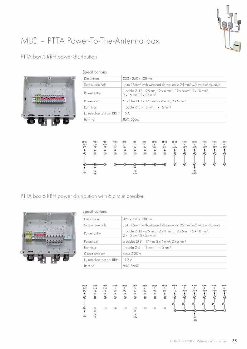
Specifications
Dimension 320 x 250 x 138 mm
Screw terminals up to 16 mm2 with wire end sleeve, up to 25 mm2 w/o wire end sleeve
Power entry 1 cable Ø 12 – 25 mm, 12 x 4 mm2 , 12 x 6 mm2, 2 x 10 mm2, 2 x 16 mm2, 2 x 25 mm2
Power exit 6 cables Ø 8 – 17 mm, 2 x 4 mm², 2 x 6 mm²
Earthing 1 cable Ø 5 – 13 mm, 1 x 16 mm²
IN rated current per RRH 15 A
Item no. 85015656
PTTA box 6 RRH power distribution
Specifications
Dimension 320 x 250 x 138 mm
Screw terminals up to 16 mm2 with wire end sleeve, up to 25 mm2 w/o wire end sleeve
Power entry 1 cable Ø 12 – 25 mm, 12 x 4 mm2 , 12 x 6 mm2, 2 x 10 mm2, 2 x 16 mm2, 2 x 25 mm2
Power exit 6 cables Ø 8 – 17 mm, 2 x 4 mm², 2 x 6 mm²
Earthing 1 cable Ø 5 – 13 mm, 1 x 16 mm²
Circuit breaker class C 20 A
IN rated current per RRH 11.7 A
Item no. 85015657
PTTA box 6 RRH power distribution with 6 circuit breaker
MLC – PTTA Power-To-The-Antenna box
56
INPE
RRH1+2PE
RRH3+4PE
RRH5+6PE
IN0V
RRH10V
RRH20V
RRH30V
RRH40V
RRH50V
RRH60V
L NIN
– 48V
RRH1
- 48V
RRH2
- 48V
RRH3
- 48V
RRH4
- 48V
RRH5
- 48V
RRH6
- 48V
INPE
RRH1+2PE
IN– 48V
RRH3+4PE
RRH5+6PE
RRH1
- 48V
RRH2
- 48V
RRH3
- 48V
RRH4
- 48V
RRH5
- 48V
RRH6
- 48V
IN0V
RRH10V
RRH20V
RRH30V
RRH40V
RRH50V
RRH60V
L N
HUBER+SUHNER Wireless infrastructure
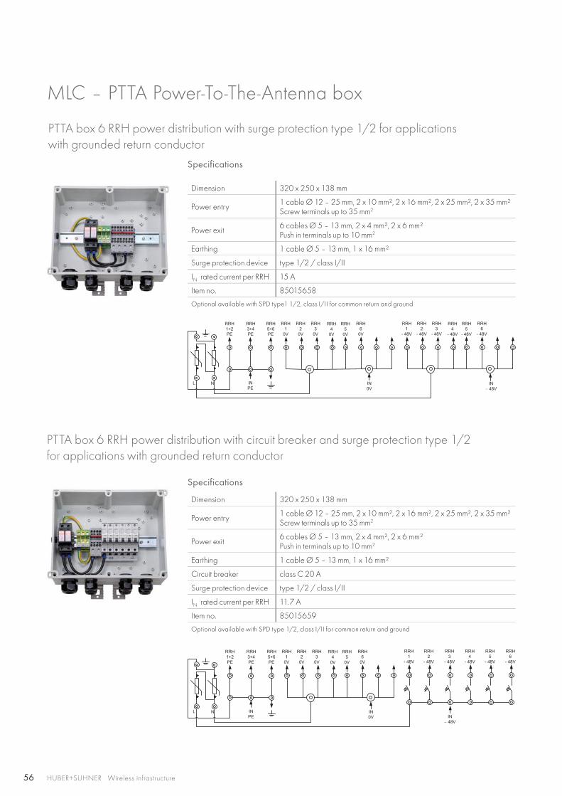
Specifications
Dimension 320 x 250 x 138 mm
Power entry 1 cable Ø 12 – 25 mm, 2 x 10 mm², 2 x 16 mm², 2 x 25 mm², 2 x 35 mm²Screw terminals up to 35 mm2
Power exit 6 cables Ø 5 – 13 mm, 2 x 4 mm², 2 x 6 mm²Push in terminals up to 10 mm2
Earthing 1 cable Ø 5 – 13 mm, 1 x 16 mm²
Surge protection device type 1/2 / class I/II
IN rated current per RRH 15 A
Item no. 85015658
Optional available with SPD type1 1/2, class I/II for common return and ground
PTTA box 6 RRH power distribution with surge protection type 1/2 for applications with grounded return conductor
MLC – PTTA Power-To-The-Antenna box
Specifications
Dimension 320 x 250 x 138 mm
Power entry 1 cable Ø 12 – 25 mm, 2 x 10 mm², 2 x 16 mm², 2 x 25 mm², 2 x 35 mm²Screw terminals up to 35 mm2
Power exit 6 cables Ø 5 – 13 mm, 2 x 4 mm², 2 x 6 mm²Push in terminals up to 10 mm2
Earthing 1 cable Ø 5 – 13 mm, 1 x 16 mm²
Circuit breaker class C 20 A
Surge protection device type 1/2 / class I/II
IN rated current per RRH 11.7 A
Item no. 85015659
Optional available with SPD type 1/2, class I/II for common return and ground
PTTA box 6 RRH power distribution with circuit breaker and surge protection type 1/2 for applications with grounded return conductor
57
L N
–48 V (L–)
Return (L+)
Ground ( )
66
FSPE
RS
VAL-MS
VAL-MS
L NSPE
F
S2S2
= 160 A= 25 mm2
= 25 mm2 a
b
SPD
*(a+b) ≤ 0.5 m
HUBER+SUHNER Wireless infrastructure
MLC – PTTA Power-To-The-Antenna box
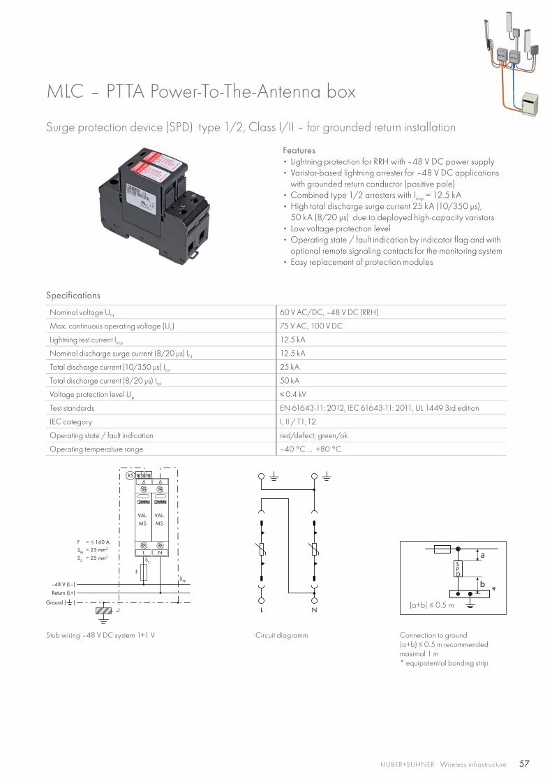
Surge protection device (SPD) type 1/2, Class I/II – for grounded return installation
Features • Lightning protection for RRH with –48 V DC power supply• Varistor-based lightning arrester for –48 V DC applications
with grounded return conductor (positive pole)• Combined type 1/2 arresters with Iimp = 12.5 kA • High total discharge surge current 25 kA (10/350 μs),
50 kA (8/20 μs) due to deployed high-capacity varistors• Low voltage protection level• Operating state / fault indication by indicator flag and with
optional remote signaling contacts for the monitoring system• Easy replacement of protection modules
Specifications
Nominal voltage UN 60 V AC/DC, –48 V DC (RRH)
Max. continuous operating voltage (Uc) 75 V AC, 100 V DC
Lightning test current Iimp 12.5 kA
Nominal discharge surge current (8/20 μs) IN 12.5 kA
Total discharge current (10/350 μs) Itot 25 kA
Total discharge current (8/20 μs) Itot 50 kA
Voltage protection level Up ≤ 0.4 kV
Test standards EN 61643-11: 2012, IEC 61643-11: 2011, UL 1449 3rd edition
IEC category I, II / T1, T2
Operating state / fault indication red/defect; green/ok
Operating temperature range –40 °C … +80 °C
Stub wiring –48 V DC system 1+1 V Circuit diagramm Connection to ground(a+b) ≤ 0.5 m recommendedmaximal 1 m* equipotential bonding strip
58
L
N / PEN
L+
L-
VAL-MS
L+L-
s 2
s 1
F1
L+
L-
VAL-MS
L+L-
s 2
F1F2
SPD
*
*
SPD
b ≤ 0.5 m b
b
a
(a + b) ≤ 0.5 m
HUBER+SUHNER Wireless infrastructure
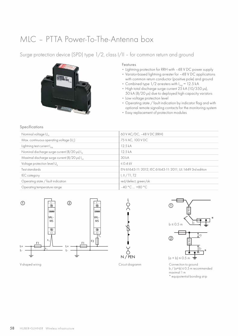
Surge protection device (SPD) type 1/2, class I/II – for common return and ground
Features • Lightning protection for RRH with –48 V DC power supply• Varistor-based lightning arrester for –48 V DC applications
with common return conductor (positive pole) and ground• Combined type 1/2 arresters with Iimp = 12.5 kA • High total discharge surge current 25 kA (10/350 μs),
50 kA (8/20 μs) due to deployed high-capacity varistors• Low voltage protection level• Operating state / fault indication by indicator flag and with
optional remote signaling contacts for the monitoring system• Easy replacement of protection modules
MLC – PTTA Power-To-The-Antenna box
Specifications
Nominal voltage UN 60 V AC/DC, –48 V DC (RRH)
Max. continuous operating voltage (Uc) 75 V AC, 100 V DC
Lightning test current Iimp 12.5 kA
Nominal discharge surge current (8/20 μs) IN 12.5 kA
Maximal discharge surge current (8/20 μs) Itot 30 kA
Voltage protection level Up ≤ 0.4 kV
Test standards EN 61643-11: 2012, IEC 61643-11: 2011, UL 1449 3rd edition
IEC category I, II / T1, T2
Operating state / fault indication red/defect; green/ok
Operating temperature range –40 °C … +80 °C
V-shaped wiring Circuit diagramm Connection to groundb / (a+b) ≤ 0.5 m recommendedmaximal 1 m* equipotential bonding strip
59HUBER+SUHNER Wireless infrastructure
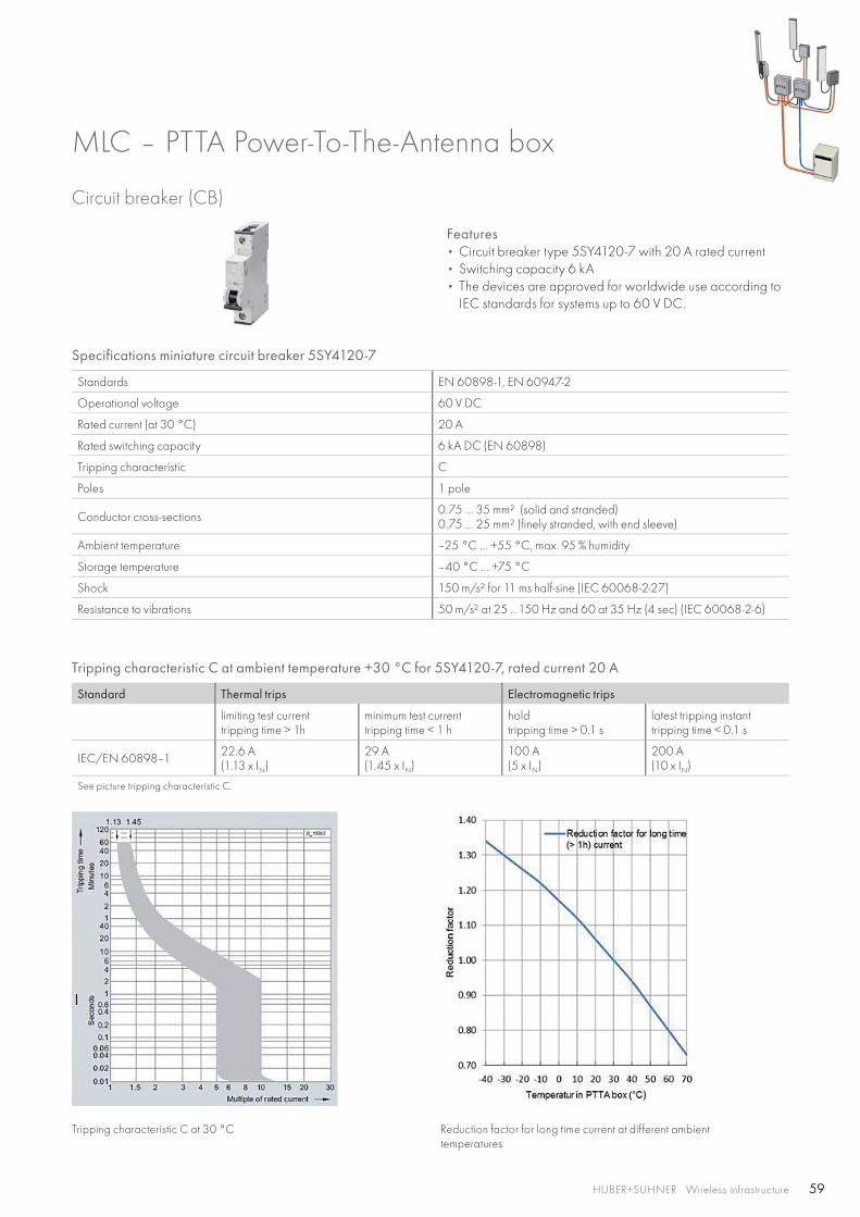
Specifications miniature circuit breaker 5SY4120-7
Standards EN 60898-1, EN 60947-2
Operational voltage 60 V DC
Rated current (at 30 °C) 20 A
Rated switching capacity 6 kA DC (EN 60898)
Tripping characteristic C
Poles 1 pole
Conductor cross-sections 0.75 … 35 mm² (solid and stranded)0.75 … 25 mm² (finely stranded, with end sleeve)
Ambient temperature –25 °C … +55 °C, max. 95 % humidity
Storage temperature –40 °C … +75 °C
Shock 150 m/s² for 11 ms half-sine (IEC 60068-2-27)
Resistance to vibrations 50 m/s² at 25 .. 150 Hz and 60 at 35 Hz (4 sec) (IEC 60068-2-6)
Tripping characteristic C at ambient temperature +30 °C for 5SY4120-7, rated current 20 A
Standard Thermal trips Electromagnetic trips
limiting test currenttripping time > 1h
minimum test currenttripping time < 1 h
holdtripping time > 0.1 s
latest tripping instanttripping time < 0.1 s
IEC/EN 60898–1 22.6 A(1.13 x IN)
29 A(1.45 x IN)
100 A(5 x IN)
200 A(10 x IN)
See picture tripping characteristic C.
Circuit breaker (CB)
Features • Circuit breaker type 5SY4120-7 with 20 A rated current• Switching capacity 6 kA• The devices are approved for worldwide use according to
IEC standards for systems up to 60 V DC.
MLC – PTTA Power-To-The-Antenna box
Tripping characteristic C at 30 °C Reduction factor for long time current at different ambienttemperatures
60 HUBER+SUHNER Wireless infrastructure
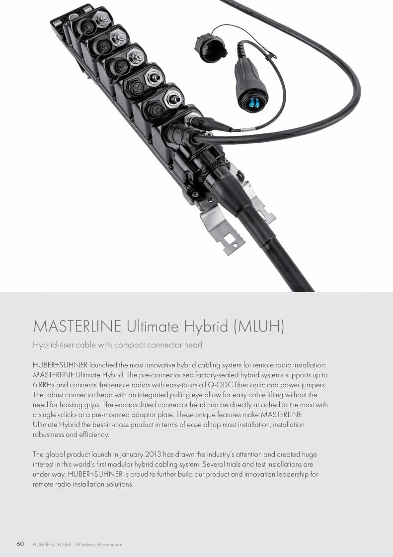
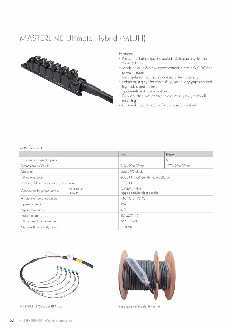
MASTERLINE Ultimate Hybrid (MLUH)Hybrid-riser cable with compact connector head
HUBER+SUHNER launched the most innovative hybrid cabling system for remote radio installation: MASTERLINE Ultimate Hybrid. The pre-connectorised factory-sealed hybrid systems supports up to 6 RRHs and connects the remote radios with easy-to-install Q-ODC fiber optic and power jumpers. The robust connector head with an integrated pulling eye allow for easy cable lifting without the need for hoisting grips. The encapsulated connector head can be directly attached to the mast with a single «click» at a pre-mounted adaptor plate. These unique features make MASTERLINEUltimate Hybrid the best-in-class product in terms of ease of top mast installation, installation robustness and efficiency.
The global product launch in January 2013 has drawn the industry’s attention and created huge interest in this world’s first modular hybrid cabling system. Several trials and test installations are under way. HUBER+SUHNER is proud to further build our product and innovation leadership for remote radio installation solutions.
61
RF
HTTA
FTTA
PTTA
FTTA
XTTA
FTTA
RFXTTA FTTA PTTA HTTA
HUBER+SUHNER Wireless infrastructure
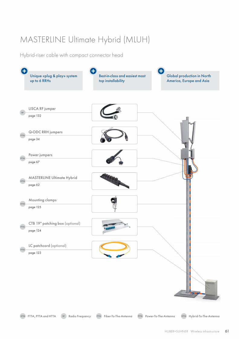
Unique «plug & play» systemup to 6 RRHs
Best-in-class and easiest masttop installability
Global production in NorthAmerica, Europe and Asia
Q-ODC RRH jumpers
page 34
LISCA RF jumper
page 132
Power jumpers
page 67
MASTERLINE Ultimate Hybrid
page 62
Mounting clamps
page 125
CTB 19" patching box (optional)
page 124
LC patchcord (optional)
page 123
MASTERLINE Ultimate Hybrid (MLUH)
Hybrid-riser cable with compact connector head
Radio FrequencyFTTA, PTTA and HTTA Fiber-To-The-Antenna Power-To-The-Antenna Hybrid-To-The-Antenna
62 HUBER+SUHNER Wireless infrastructure
MASTERLINE Ultimate Hybrid (MLUH)
Features • Pre-connectorised factory-sealed hybrid cable system for
3 and 6 RRHs• Modular «plug & play» system compatible with Q-ODC and
power jumpers• Encapsulated IP67 sealed connector head housing • Robust pulling eye for cable lifting, no hoisting grips required,
high cable strain relieve• Space-efficient, low wind-load • Easy mounting with adaptor plate, mast-, pole-, and wall-
mounting• Optional protection cover for cable exits available
Specifications
Small Large
Number of connector pairs 3 6
Dimensions L x W x H 310 x 90 x 97 mm 477 x 90 x 97 mm
Material plastic PPE black
Pulling eye force 2000 N (short-term during installation)
Hybrid cable retention force at enclosure 2000 N
Connectors for jumper cable fiber opticpower
Q-ODC socketrugged circular plastic socket
Ambient temperature range –40 °C to +75 °C
Ingress protection IP67
Impact resistance IK 7
Halogen free IEC 60754-2
UV resistant for outdoor use ISO 4892-3
Material flammability rating UL94-V0
MASTERLINE Classic at BTS side supplied on a double-flange reel
63HUBER+SUHNER Wireless infrastructure
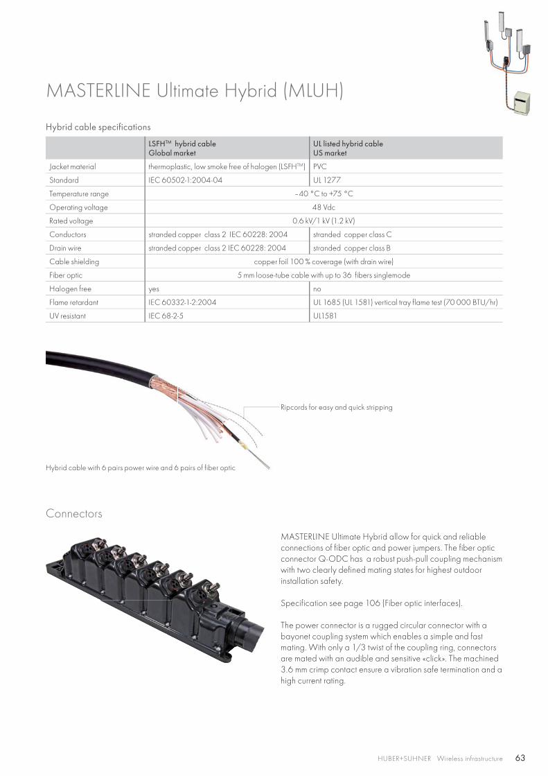
Connectors
MASTERLINE Ultimate Hybrid allow for quick and reliable connections of fiber optic and power jumpers. The fiber optic connector Q-ODC has a robust push-pull coupling mechanism with two clearly defined mating states for highest outdoor installation safety.
Specification see page 106 (Fiber optic interfaces).
The power connector is a rugged circular connector with a bayonet coupling system which enables a simple and fast mating. With only a 1/3 twist of the coupling ring, connectors are mated with an audible and sensitive «click». The machined 3.6 mm crimp contact ensure a vibration safe termination and a high current rating.
Hybrid cable specifications
LSFHTM hybrid cableGlobal market
UL listed hybrid cableUS market
Jacket material thermoplastic, low smoke free of halogen (LSFHTM) PVC
Standard IEC 60502-1:2004-04 UL 1277
Temperature range –40 °C to +75 °C
Operating voltage 48 Vdc
Rated voltage 0.6 kV/1 kV (1.2 kV)
Conductors stranded copper class 2 IEC 60228: 2004 stranded copper class C
Drain wire stranded copper class 2 IEC 60228: 2004 stranded copper class B
Cable shielding copper foil 100 % coverage (with drain wire)
Fiber optic 5 mm loose-tube cable with up to 36 fibers singlemode
Halogen free yes no
Flame retardant IEC 60332-1-2:2004 UL 1685 (UL 1581) vertical tray flame test (70 000 BTU/hr)
UV resistant IEC 68-2-5 UL1581
MASTERLINE Ultimate Hybrid (MLUH)
Ripcords for easy and quick stripping
Hybrid cable with 6 pairs power wire and 6 pairs of fiber optic
64 HUBER+SUHNER Wireless infrastructure
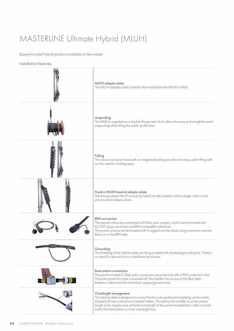
MASTERLINE Ultimate Hybrid (MLUH)
Installation features
MLUH adaptor plateThe MLUH adaptor plate is fixed to the mast before the MLUH is lifted.
UnspoolingThe MLEH is supplied on a double-flange reel which allows for easy and straight-forward unspooling while lifting the cable up the mast.
PullingThe robust connector head with an integrated pulling eye allow for easy cable lifting with-out the need for hoisting grips.
Hook-in MLUH head at adaptor plateThe encapsulated MLUH connector head can be locked-in with a single «click» to the pre-mounted adaptor plate.
RRH connectionThe remote radios are connected with fiber optic jumpers, which are terminated with Q-ODC plug connectors and RRH compatible interfaces.The power jumpers are terminated with a rugged circular plastic plug connector and are blunt cut on the RRH side.
GroundingThe shielding of the hybrid cable can be grounded with standard grounding kits. There is no need for special tools or installation processes.
Base station connectionThe pre-terminated LC fiber optic connectors are protected with a IP65 protection tube. Once the protection tube is screwed-off, the installer has access to the fiber optic breakout cables and the individual copper/ground wires.
Overlength managementThe hybrid cable is designed in a way that the outer jacket and shielding can be easily stripped off over a distance of several meters. This allows the installer to cut the excess length of the copper wire while the overlength of the pre-terminated fiber cable is stored inside the base station or in an overlength box.
Easiest-to-install hybrid product available on the market.
65HUBER+SUHNER Wireless infrastructure
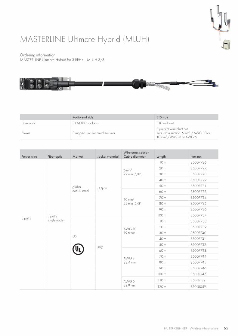
Ordering information MASTERLINE Ultimate Hybrid for 3 RRHs – MLUH 3/3
MASTERLINE Ultimate Hybrid (MLUH)
Radio end side BTS side
Fiber optic 3 Q-ODC sockets 3 LC uniboot
Power 3 rugged circular metal sockets3 pairs of wire blunt cutwire cross section 6 mm2 / AWG 10 or10 mm2 / AWG 8 or AWG 6
Power wire Fiber optic Market Jacket materialWire cross sectionCable diameter Length Item no.
3 pairs 3 pairssinglemode
globalnot UL listed LSFHTM
6 mm2
22 mm (5/8")
10 m 85007726
20 m 85007727
30 m 85007728
40 m 85007729
50 m 85007731
10 mm2
22 mm (5/8")
60 m 85007733
70 m 85007734
80 m 85007735
90 m 85007736
100 m 85007737
US
PVC
AWG 1019.6 mm
10 m 85007738
20 m 85007739
30 m 85007740
40 m 85007741
50 m 85007742
AWG 823.4 mm
60 m 85007743
70 m 85007744
80 m 85007745
90 m 85007746
100 m 85007747
AWG 623.9 mm
110 m 85016182
120 m 85018059
66 HUBER+SUHNER Wireless infrastructure
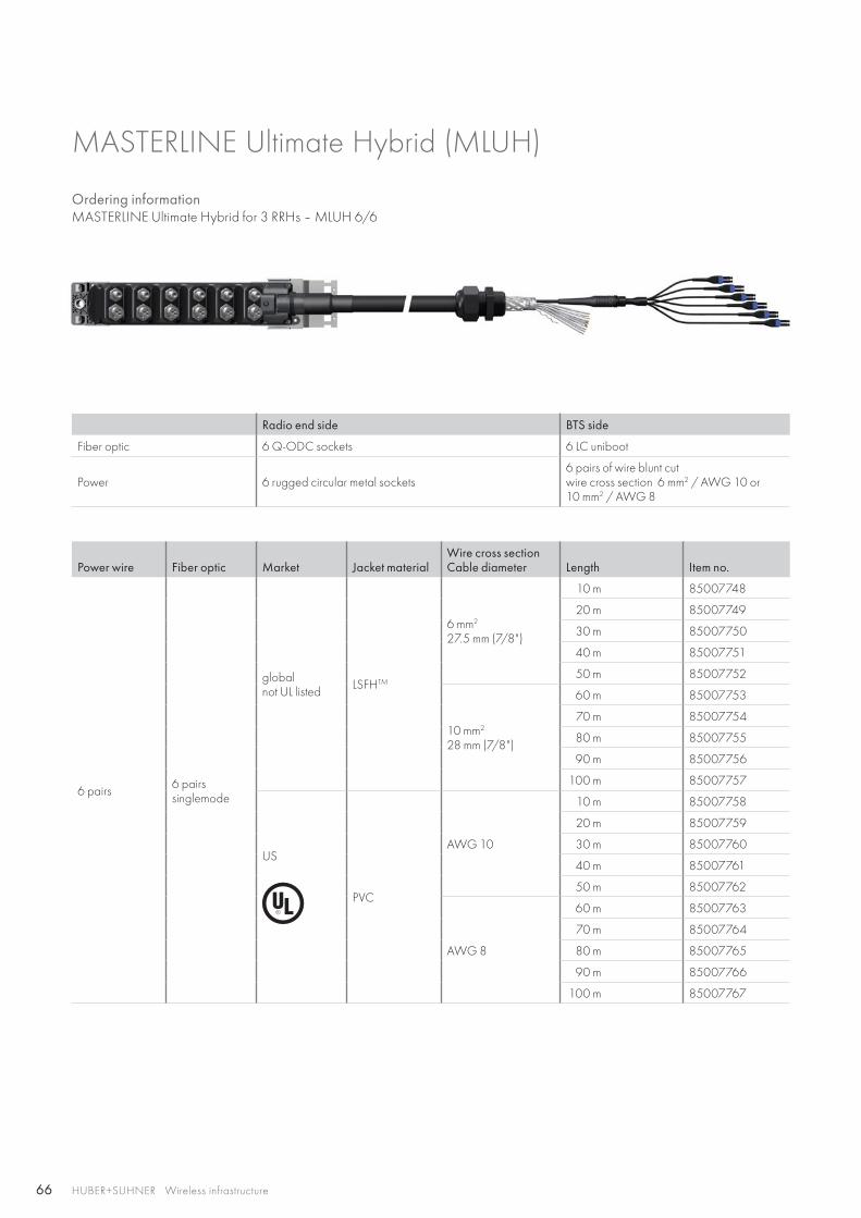
Ordering information MASTERLINE Ultimate Hybrid for 3 RRHs – MLUH 6/6
MASTERLINE Ultimate Hybrid (MLUH)
Radio end side BTS side
Fiber optic 6 Q-ODC sockets 6 LC uniboot
Power 6 rugged circular metal sockets6 pairs of wire blunt cutwire cross section 6 mm2 / AWG 10 or10 mm2 / AWG 8
Power wire Fiber optic Market Jacket materialWire cross sectionCable diameter Length Item no.
6 pairs 6 pairssinglemode
globalnot UL listed LSFHTM
6 mm2
27.5 mm (7/8")
10 m 85007748
20 m 85007749
30 m 85007750
40 m 85007751
50 m 85007752
10 mm2
28 mm (7/8")
60 m 85007753
70 m 85007754
80 m 85007755
90 m 85007756
100 m 85007757
US
PVC
AWG 10
10 m 85007758
20 m 85007759
30 m 85007760
40 m 85007761
50 m 85007762
AWG 8
60 m 85007763
70 m 85007764
80 m 85007765
90 m 85007766
100 m 85007767
67HUBER+SUHNER Wireless infrastructure
MASTERLINE Ultimate Hybrid (MLUH)
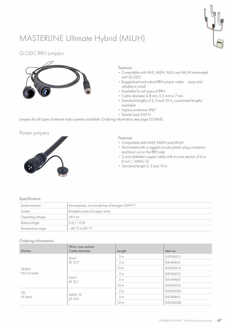
Q-ODC RRH jumpers
Features• Compatible with MLE, MLEH, MLU and MLUH terminated
with Q-ODC• Ruggedised and robust RRH jumper cable – easy and
reliable to install• Available for all types of RRH• Cable diameter 4.8 mm, 5.5 mm or 7 mm• Standard lengths of 2, 5 and 10 m, customised lengths
available• Ingress protection IP67• Tensile load 450 N
Jumpers for all types of remote radio systems available. Ordering information see page 35 (MLE).
Power jumpersFeatures• Compatible with MLEP, MLEH and MLUH • Terminated with a rugged circular plastic plug connector
and blunt cut on the RRH side• 2 wire shielded copper cable with a cross section of 4 or
6 mm2 / AWG 10• Standard length 2, 5 and 10 m
Specification
Jacket material thermoplastic, low smoke free of halogen (LSFHTM)
Screen Braided screen of copper wires
Operating voltage 48 V dc
Rated voltage 0.6 / 1.0 kV
Temperature range –40 °C to 90 °C
Ordering information
MarketWire cross sectionCable diameter Length Item no.
Global Not UL listed
4mm2
Ø 10.7
2 m 85006013
5 m 84149463
10 m 85006014
6mm2
Ø 12.1
2 m 85006015
5 m 84149464
10 m 85006016
USUL listed
AWG 10Ø 10.0
2 m 85006026
5 m 84149465
10 m 85006028
68 HUBER+SUHNER Wireless infrastructure
MASTERLINE Ultimate Hybrid (MLUH)
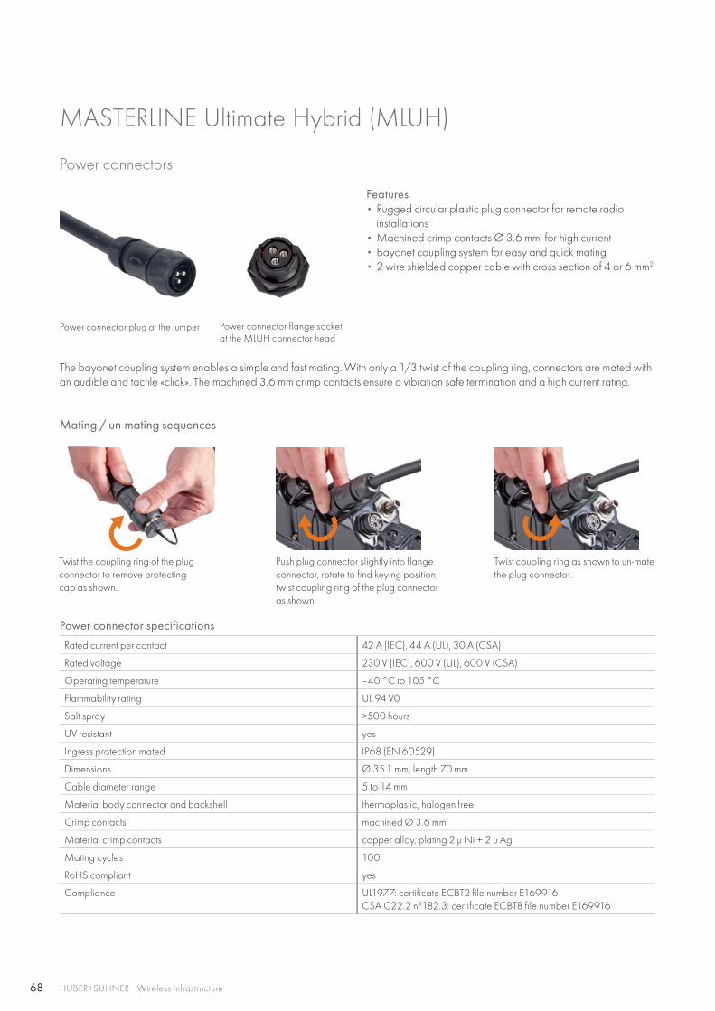
Power connectors
Features• Rugged circular plastic plug connector for remote radio
installations• Machined crimp contacts Ø 3.6 mm for high current• Bayonet coupling system for easy and quick mating• 2 wire shielded copper cable with cross section of 4 or 6 mm2
Power connector plug at the jumper Power connector flange socket at the MLUH connector head
The bayonet coupling system enables a simple and fast mating. With only a 1/3 twist of the coupling ring, connectors are mated with an audible and tactile «click». The machined 3.6 mm crimp contacts ensure a vibration safe termination and a high current rating.
Mating / un-mating sequences
Rated current per contact 42 A (IEC), 44 A (UL), 30 A (CSA)
Rated voltage 230 V (IEC), 600 V (UL), 600 V (CSA)
Operating temperature –40 °C to 105 °C
Flammability rating UL 94 V0
Salt spray >500 hours
UV resistant yes
Ingress protection mated IP68 (EN 60529)
Dimensions Ø 35.1 mm, length 70 mm
Cable diameter range 5 to 14 mm
Material body connector and backshell thermoplastic, halogen free
Crimp contacts machined Ø 3.6 mm
Material crimp contacts copper alloy, plating 2 μ Ni + 2 μ Ag
Mating cycles 100
RoHS compliant yes
Compliance UL1977: certificate ECBT2 file number E169916CSA C22.2 n°182.3: certificate ECBT8 file number E169916
Power connector specifications
Twist the coupling ring of the plug connector to remove protecting cap as shown.
Push plug connector slightly into flange connector, rotate to find keying position, twist coupling ring of the plug connector as shown.
Twist coupling ring as shown to un-mate the plug connector.
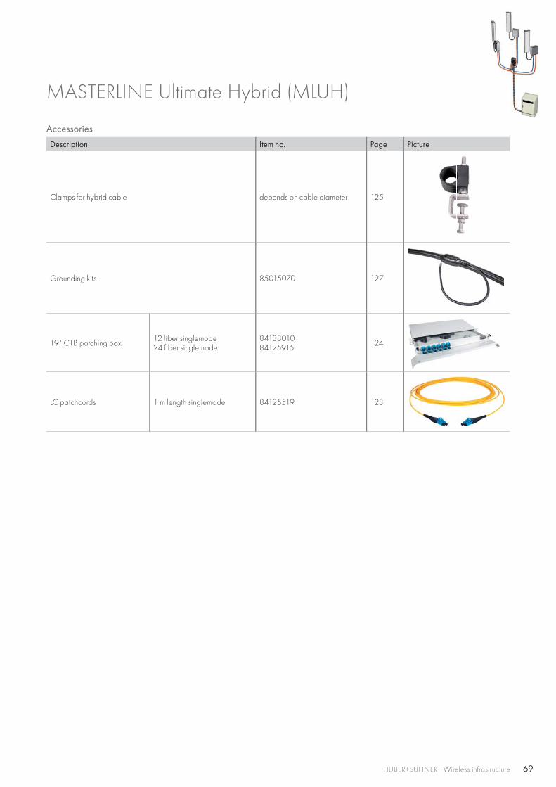
69HUBER+SUHNER Wireless infrastructure
Accessories
Description Item no. Page Picture
Clamps for hybrid cable depends on cable diameter 125
Grounding kits 85015070 127
19" CTB patching box 12 fiber singlemode24 fiber singlemode
8413801084125915 124
LC patchcords 1 m length singlemode 84125519 123
MASTERLINE Ultimate Hybrid (MLUH)
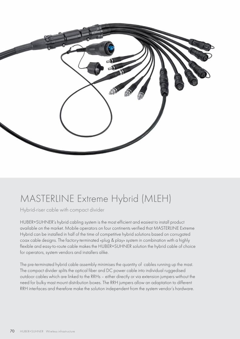
70 HUBER+SUHNER Wireless infrastructure
MASTERLINE Extreme Hybrid (MLEH)Hybrid-riser cable with compact divider
HUBER+SUHNER’s hybrid cabling system is the most efficient and easiest to install productavailable on the market. Mobile operators on four continents verified that MASTERLINE Extreme Hybrid can be installed in half of the time of competitive hybrid solutions based on corrugated coax cable designs. The factory-terminated «plug & play» system in combination with a highly flexible and easy-to-route cable makes the HUBER+SUHNER solution the hybrid cable of choice for operators, system vendors and installers alike.
The pre-terminated hybrid cable assembly minimises the quantity of cables running up the mast. The compact divider splits the optical fiber and DC power cable into individual ruggedisedoutdoor cables which are linked to the RRHs – either directly or via extension jumpers without the need for bulky mast mount distribution boxes. The RRH jumpers allow an adaptation to different RRH interfaces and therefore make the solution independent from the system vendor’s hardware.
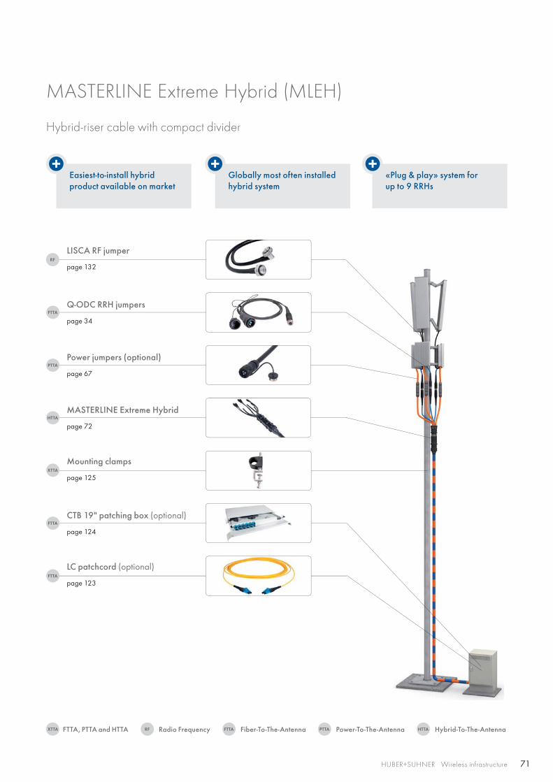
71
RF
HTTA
FTTA
PTTA
FTTA
XTTA
FTTA
RFXTTA FTTA PTTA HTTA
HUBER+SUHNER Wireless infrastructure
Easiest-to-install hybrid product available on market
Globally most often installed hybrid system
«Plug & play» system forup to 9 RRHs
Q-ODC RRH jumpers
page 34
LISCA RF jumper
page 132
Power jumpers (optional)
page 67
MASTERLINE Extreme Hybrid
page 72
Mounting clamps
page 125
CTB 19" patching box (optional)
page 124
LC patchcord (optional)
page 123
MASTERLINE Extreme Hybrid (MLEH)
Hybrid-riser cable with compact divider
Radio FrequencyFTTA, PTTA and HTTA Fiber-To-The-Antenna Power-To-The-Antenna Hybrid-To-The-Antenna
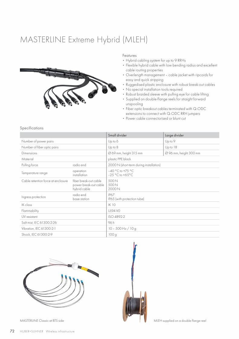
72 HUBER+SUHNER Wireless infrastructure
MASTERLINE Extreme Hybrid (MLEH)
Features • Hybrid cabling system for up to 9 RRHs• Flexible hybrid cable with low bending radius and excellent
cable routing properties• Overlength management – cable jacket with ripcords for
easy and quick stripping • Ruggedised plastic enclosure with robust break-out cables• No special installation tools required• Robust braided sleeve with pulling eye for cable lifting• Supplied on double-flange reels for straight forward
unspooling• Fiber optic breakout cables terminated with Q-ODC
extensions to connect with Q-ODC RRH jumpers• Power cable connectorised or blunt cut
Specifications
Small divider Large divider
Number of power pairs Up to 6 Up to 9
Number of fiber optic pairs Up to 8 Up to 18
Dimensions Ø 69 mm, height 315 mm Ø 96 mm, height 300 mm
Material plastic PPE black
Pulling force radio end 2000 N (short-term during installation)
Temperature range operationinstallation
–40 °C to +75 °C–25 °C to +65°C
Cable retention force at enclosure fiber break-out cablepower break-out cablehybrid cable
500 N500 N2000 N
Ingress protection radio endbase station
IP67IP65 (with protection tube)
IK class IK 10
Flammability UL94-V0
UV resistant ISO 4892-2
Salt mist, IEC 61300-2-26 96 h
Vibration, IEC 61300-2-1 10 – 500 Hz / 10 g
Shock, IEC 61300-2-9 100 g
MASTERLINE Classic at BTS side MLEH supplied on a double-flange reel
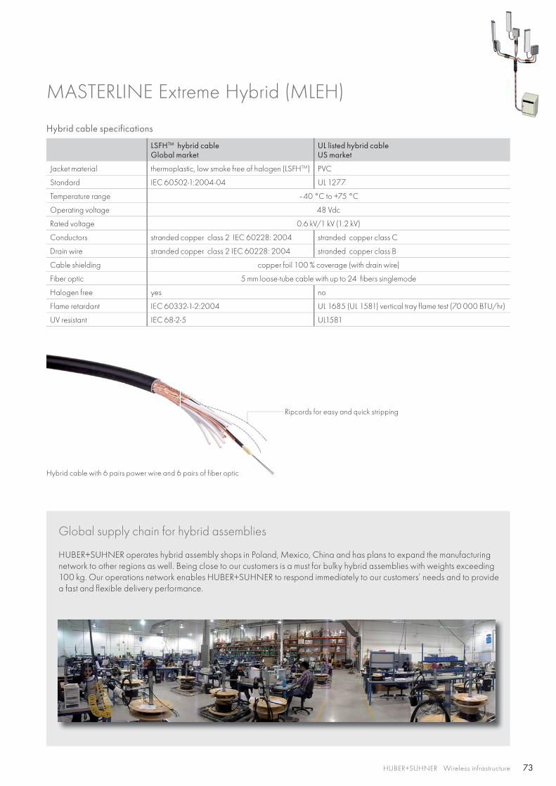
73HUBER+SUHNER Wireless infrastructure
Hybrid cable specifications
LSFHTM hybrid cableGlobal market
UL listed hybrid cableUS market
Jacket material thermoplastic, low smoke free of halogen (LSFHTM) PVC
Standard IEC 60502-1:2004-04 UL 1277
Temperature range –40 °C to +75 °C
Operating voltage 48 Vdc
Rated voltage 0.6 kV/1 kV (1.2 kV)
Conductors stranded copper class 2 IEC 60228: 2004 stranded copper class C
Drain wire stranded copper class 2 IEC 60228: 2004 stranded copper class B
Cable shielding copper foil 100 % coverage (with drain wire)
Fiber optic 5 mm loose-tube cable with up to 24 fibers singlemode
Halogen free yes no
Flame retardant IEC 60332-1-2:2004 UL 1685 (UL 1581) vertical tray flame test (70 000 BTU/hr)
UV resistant IEC 68-2-5 UL1581
MASTERLINE Extreme Hybrid (MLEH)
Global supply chain for hybrid assemblies
HUBER+SUHNER operates hybrid assembly shops in Poland, Mexico, China and has plans to expand the manufacturing network to other regions as well. Being close to our customers is a must for bulky hybrid assemblies with weights exceeding 100 kg. Our operations network enables HUBER+SUHNER to respond immediately to our customers’ needs and to provide a fast and flexible delivery performance.
Ripcords for easy and quick stripping
Hybrid cable with 6 pairs power wire and 6 pairs of fiber optic
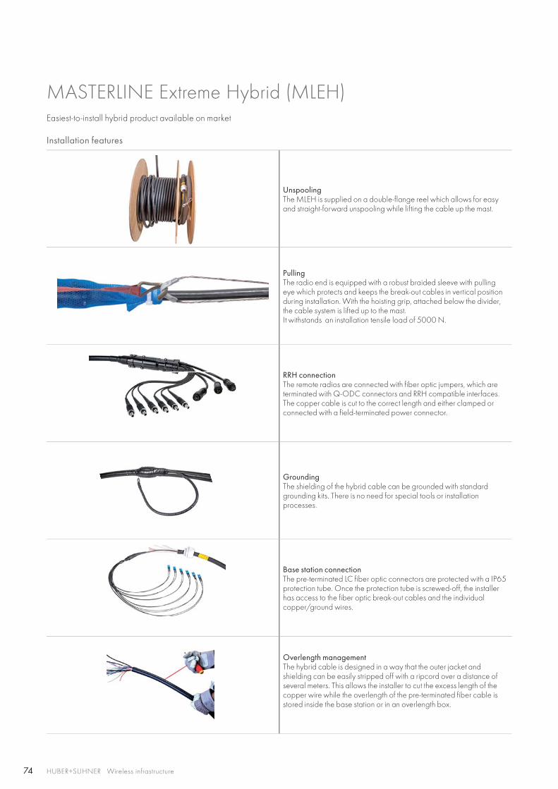
74 HUBER+SUHNER Wireless infrastructure
MASTERLINE Extreme Hybrid (MLEH)
Installation features
UnspoolingThe MLEH is supplied on a double-flange reel which allows for easy and straight-forward unspooling while lifting the cable up the mast.
PullingThe radio end is equipped with a robust braided sleeve with pulling eye which protects and keeps the break-out cables in vertical position during installation. With the hoisting grip, attached below the divider, the cable system is lifted up to the mast. It withstands an installation tensile load of 5000 N.
RRH connectionThe remote radios are connected with fiber optic jumpers, which are terminated with Q-ODC connectors and RRH compatible interfaces.The copper cable is cut to the correct length and either clamped or connected with a field-terminated power connector.
Grounding The shielding of the hybrid cable can be grounded with standard grounding kits. There is no need for special tools or installation processes.
Base station connectionThe pre-terminated LC fiber optic connectors are protected with a IP65 protection tube. Once the protection tube is screwed-off, the installer has access to the fiber optic break-out cables and the individual copper/ground wires.
Overlength managementThe hybrid cable is designed in a way that the outer jacket and shielding can be easily stripped off with a ripcord over a distance of several meters. This allows the installer to cut the excess length of the copper wire while the overlength of the pre-terminated fiber cable is stored inside the base station or in an overlength box.
Easiest-to-install hybrid product available on market
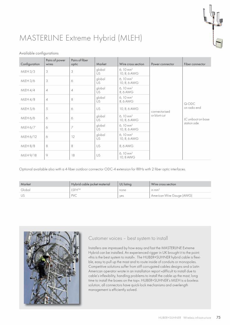
75HUBER+SUHNER Wireless infrastructure
MASTERLINE Extreme Hybrid (MLEH)
Available configurations
ConfigurationPairs of power wires
Pairs of fiber optic Market Wire cross section Power connector Fiber connector
MLEH 3/3 3 3 globalUS
6, 10 mm2
10, 8, 6 AWG
connectorisedor blunt cut
Q-ODCon radio end
LC uniboot on base station side
MLEH 3/6 3 6 globalUS
6, 10 mm2
10, 8, 6 AWG
MLEH 4/4 4 4 globalUS
6, 10 mm2
8, 6 AWG
MLEH 4/8 4 8 globalUS
6, 10 mm2
8, 6 AWG
MLEH 5/6 5 6 US 10, 8, 6 AWG
MLEH 6/6 6 6 globalUS
6, 10 mm2
10, 8, 6 AWG
MLEH 6/7 6 7 globalUS
6, 10 mm2
10, 8, 6 AWG
MLEH 6/12 6 12 globalUS
6, 10 mm2
10, 8, 6 AWG
MLEH 8/8 8 8 US 8, 6 AWG
MLEH 9/18 9 18 US 6, 10 mm2
10, 8 AWG
Optional available also with a 4-fiber outdoor connector ODC-4 extension for RRHs with 2 fiber optic interfaces.
Market Hybrid cable jacket material UL listing Wire cross section
Global LSFHTM none in mm2
US PVC yes American Wire Gauge (AWG)
Customer voices – best system to install
Installers are impressed by how easy and fast the MASTERLINE Extreme Hybrid can be installed. An experienced rigger in UK brought it to the point: «this is the best system to install». The HUBER+SUHNER hybrid cable is flexi-ble, easy to pull up the mast and to route inside of conduits or monopoles. Competitive solutions suffer from stiff corrugated cables designs and a Latin American operator wrote in an installation report «difficult to install due to cable’s inflexibility, handling problems to install the cable up the mast, long time to install the boxes on the top». HUBER+SUHNER’s MLEH is a boxless solution, all connectors have quick-lock mechanisms and overlengthmanagement is efficiently solved.

76 HUBER+SUHNER Wireless infrastructure
Ordering information MASTERLINE Extreme Hybrid for 3 RRHs – MLEH 3/3
MASTERLINE Extreme Hybrid (MLEH)
Radio end side BTS side
Fiber optic Q-ODCbreakout length 0.50 m LC uniboot
Power blunt cutwire cross section 6 mm2 / AWG 10breakout length 4 m
blunt cutwire cross section 6 mm2 / AWG 10 or10 mm2 / AWG 8
Power wire Fiber optic Market Jacket materialWire cross sectionCable diameter Length Item no.
3 pairs 3 pairssinglemode
globalnot UL listed LSFHTM
6 mm2
22 mm (5/8")
10 m 85006998
20 m 85006999
30 m 85007000
40 m 85007001
50 m 85007002
10 mm2
22 mm (5/8")
60 m 85007003
70 m 85007004
80 m 85007005
90 m 85007006
100 m 85007007
US
PVC
AWG 1019.6 mm
10 m 85007008
20 m 85007009
30 m 85007010
40 m 85007011
50 m 85007012
AWG 823.4 mm
60 m 85007013
70 m 85007014
80 m 85007015
90 m 85007016
100 m 85007017
Longer length on request.
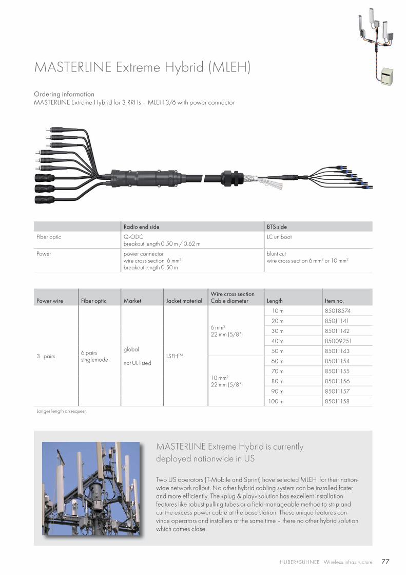
77HUBER+SUHNER Wireless infrastructure
MASTERLINE Extreme Hybrid is currently deployed nationwide in US Two US operators (T-Mobile and Sprint) have selected MLEH for their nation-wide network rollout. No other hybrid cabling system can be installed faster and more efficiently. The «plug & play» solution has excellent installation features like robust pulling tubes or a field-manageable method to strip and cut the excess power cable at the base station. These unique features con-vince operators and installers at the same time – there no other hybrid solution which comes close.
Ordering information MASTERLINE Extreme Hybrid for 3 RRHs – MLEH 3/6 with power connector
MASTERLINE Extreme Hybrid (MLEH)
Radio end side BTS side
Fiber optic Q-ODCbreakout length 0.50 m / 0.62 m
LC uniboot
Power power connectorwire cross section 6 mm2
breakout length 0.50 m
blunt cutwire cross section 6 mm2 or 10 mm2
Power wire Fiber optic Market Jacket materialWire cross sectionCable diameter Length Item no.
3 pairs 6 pairssinglemode
global
not UL listedLSFHTM
6 mm2
22 mm (5/8")
10 m 85018574
20 m 85011141
30 m 85011142
40 m 85009251
50 m 85011143
10 mm2
22 mm (5/8")
60 m 85011154
70 m 85011155
80 m 85011156
90 m 85011157
100 m 85011158
Longer length on request.
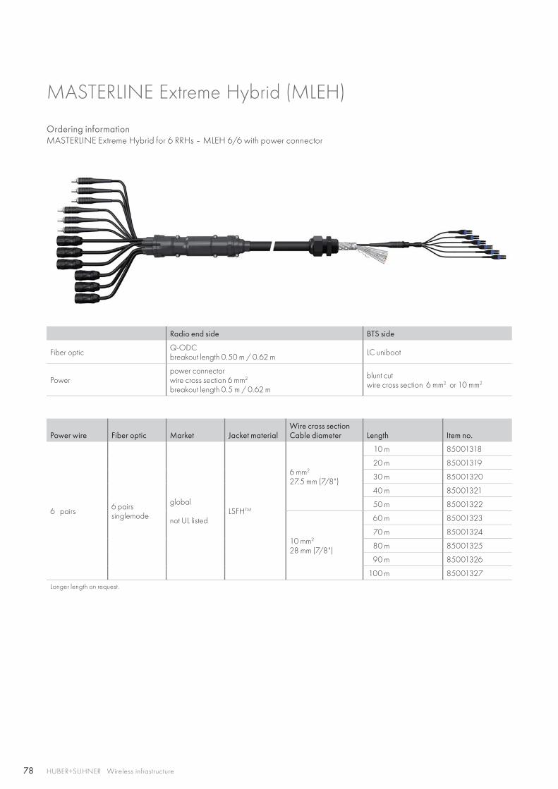
78 HUBER+SUHNER Wireless infrastructure
Ordering information MASTERLINE Extreme Hybrid for 6 RRHs – MLEH 6/6 with power connector
MASTERLINE Extreme Hybrid (MLEH)
Radio end side BTS side
Fiber optic Q-ODCbreakout length 0.50 m / 0.62 m LC uniboot
Power power connectorwire cross section 6 mm2 breakout length 0.5 m / 0.62 m
blunt cutwire cross section 6 mm2 or 10 mm2
Power wire Fiber optic Market Jacket materialWire cross sectionCable diameter Length Item no.
6 pairs 6 pairssinglemode
global
not UL listedLSFHTM
6 mm2
27.5 mm (7/8")
10 m 85001318
20 m 85001319
30 m 85001320
40 m 85001321
50 m 85001322
10 mm2
28 mm (7/8")
60 m 85001323
70 m 85001324
80 m 85001325
90 m 85001326
100 m 85001327
Longer length on request.
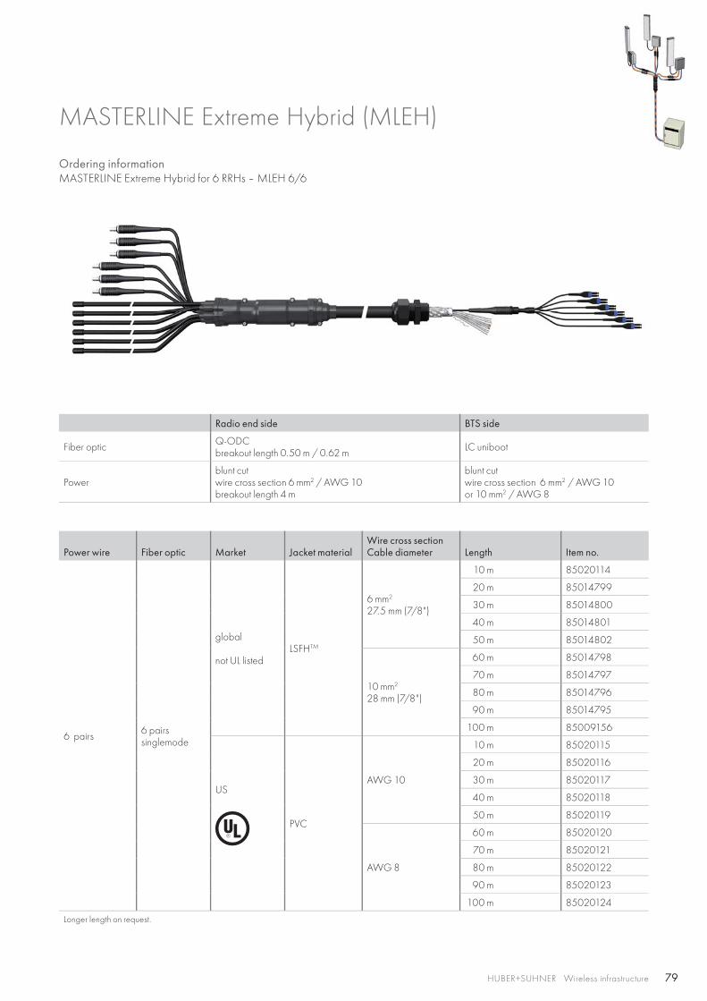
79HUBER+SUHNER Wireless infrastructure
Ordering information MASTERLINE Extreme Hybrid for 6 RRHs – MLEH 6/6
MASTERLINE Extreme Hybrid (MLEH)
Radio end side BTS side
Fiber optic Q-ODCbreakout length 0.50 m / 0.62 m LC uniboot
Power blunt cutwire cross section 6 mm2 / AWG 10breakout length 4 m
blunt cutwire cross section 6 mm2 / AWG 10 or 10 mm2 / AWG 8
Power wire Fiber optic Market Jacket materialWire cross sectionCable diameter Length Item no.
6 pairs 6 pairssinglemode
global
not UL listedLSFHTM
6 mm2
27.5 mm (7/8")
10 m 85020114
20 m 85014799
30 m 85014800
40 m 85014801
50 m 85014802
10 mm2
28 mm (7/8")
60 m 85014798
70 m 85014797
80 m 85014796
90 m 85014795
100 m 85009156
US
PVC
AWG 10
10 m 85020115
20 m 85020116
30 m 85020117
40 m 85020118
50 m 85020119
AWG 8
60 m 85020120
70 m 85020121
80 m 85020122
90 m 85020123
100 m 85020124
Longer length on request.
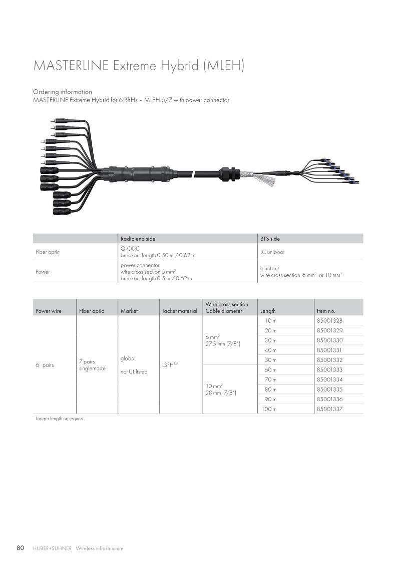
80 HUBER+SUHNER Wireless infrastructure
Ordering information MASTERLINE Extreme Hybrid for 6 RRHs – MLEH 6/7 with power connector
MASTERLINE Extreme Hybrid (MLEH)
Radio end side BTS side
Fiber optic Q-ODCbreakout length 0.50 m / 0.62 m LC uniboot
Power power connectorwire cross section 6 mm2 breakout length 0.5 m / 0.62 m
blunt cutwire cross section 6 mm2 or 10 mm2
Power wire Fiber optic Market Jacket materialWire cross sectionCable diameter Length Item no.
6 pairs 7 pairssinglemode
global
not UL listedLSFHTM
6 mm2
27.5 mm (7/8")
10 m 85001328
20 m 85001329
30 m 85001330
40 m 85001331
50 m 85001332
10 mm2
28 mm (7/8")
60 m 85001333
70 m 85001334
80 m 85001335
90 m 85001336
100 m 85001337
Longer length on request.
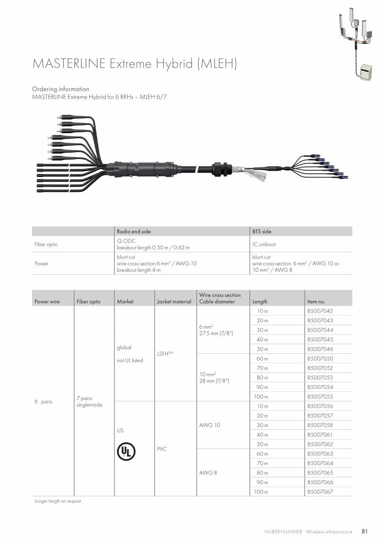
81HUBER+SUHNER Wireless infrastructure
Ordering information MASTERLINE Extreme Hybrid for 6 RRHs – MLEH 6/7
MASTERLINE Extreme Hybrid (MLEH)
Radio end side BTS side
Fiber optic Q-ODCbreakout length 0.50 m / 0.62 m LC uniboot
Power blunt cutwire cross section 6 mm2 / AWG 10breakout length 4 m
blunt cutwire cross section 6 mm2 / AWG 10 or10 mm2 / AWG 8
Power wire Fiber optic Market Jacket materialWire cross sectionCable diameter Length Item no.
6 pairs 7 pairssinglemode
global
not UL listedLSFHTM
6 mm2
27.5 mm (7/8")
10 m 85007042
20 m 85007043
30 m 85007044
40 m 85007045
50 m 85007046
10 mm2
28 mm (7/8")
60 m 85007050
70 m 85007052
80 m 85007053
90 m 85007054
100 m 85007055
US
PVC
AWG 10
10 m 85007056
20 m 85007057
30 m 85007058
40 m 85007061
50 m 85007062
AWG 8
60 m 85007063
70 m 85007064
80 m 85007065
90 m 85007066
100 m 85007067
Longer length on request.
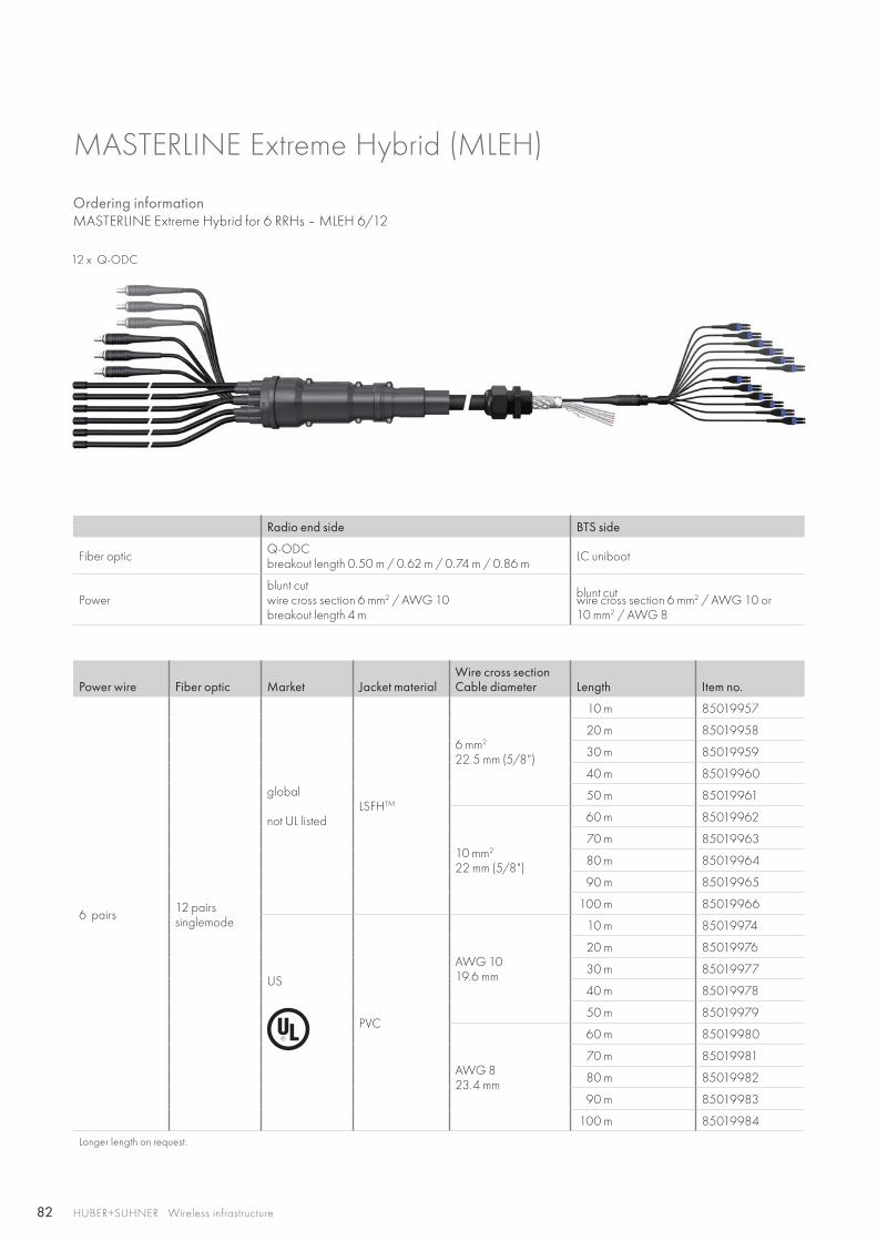
82 HUBER+SUHNER Wireless infrastructure
Ordering informationMASTERLINE Extreme Hybrid for 6 RRHs – MLEH 6/12
MASTERLINE Extreme Hybrid (MLEH)
Radio end side BTS side
Fiber optic Q-ODCbreakout length 0.50 m / 0.62 m / 0.74 m / 0.86 m LC uniboot
Power blunt cutwire cross section 6 mm2 / AWG 10breakout length 4 m
blunt cutwire cross section 6 mm2 / AWG 10 or 10 mm2 / AWG 8
Power wire Fiber optic Market Jacket materialWire cross sectionCable diameter Length Item no.
6 pairs 12 pairssinglemode
global
not UL listedLSFHTM
6 mm2
22.5 mm (5/8")
10 m 85019957
20 m 85019958
30 m 85019959
40 m 85019960
50 m 85019961
10 mm2
22 mm (5/8")
60 m 85019962
70 m 85019963
80 m 85019964
90 m 85019965
100 m 85019966
US
PVC
AWG 1019.6 mm
10 m 85019974
20 m 85019976
30 m 85019977
40 m 85019978
50 m 85019979
AWG 823.4 mm
60 m 85019980
70 m 85019981
80 m 85019982
90 m 85019983
100 m 85019984
Longer length on request.
12 x Q-ODC
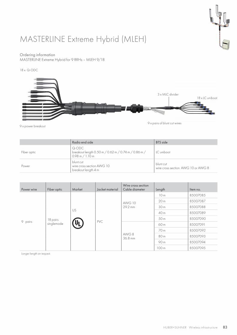
83HUBER+SUHNER Wireless infrastructure
Ordering informationMASTERLINE Extreme Hybrid for 9 RRHs – MLEH 9/18
MASTERLINE Extreme Hybrid (MLEH)
Radio end side BTS side
Fiber opticQ-ODCbreakout length 0.50 m / 0.62 m / 0.74 m / 0.86 m / 0.98 m / 1.10 m
LC uniboot
Power blunt cutwire cross section AWG 10breakout length 4 m
blunt cutwire cross section AWG 10 or AWG 8
Power wire Fiber optic Market Jacket materialWire cross sectionCable diameter Length Item no.
9 pairs 18 pairssinglemode
US
PVC
AWG 1029.2 mm
10 m 85007085
20 m 85007087
30 m 85007088
40 m 85007089
50 m 85007090
AWG 836.8 mm
60 m 85007091
70 m 85007092
80 m 85007093
90 m 85007094
100 m 85007095
Longer length on request.
18 x Q-ODC
9 x power breakout
3 x MLC divider
9 x pairs of blunt cut wires
18 x LC uniboot
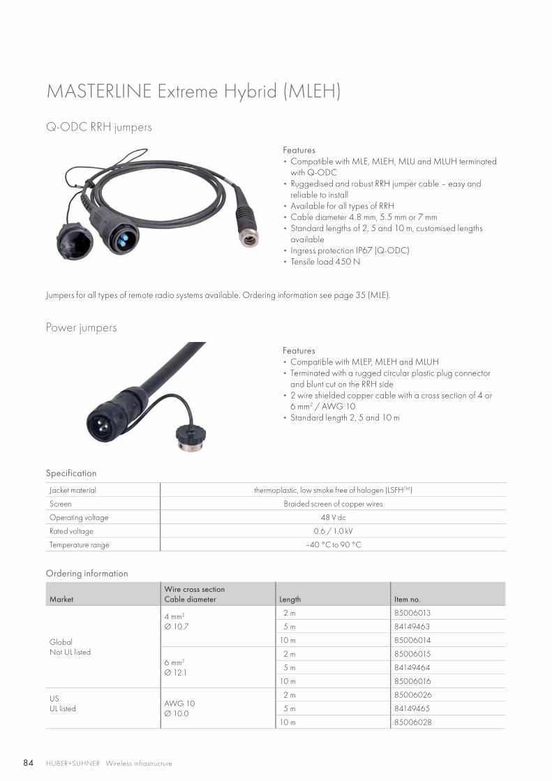
84 HUBER+SUHNER Wireless infrastructure
Power jumpers
Features• Compatible with MLEP, MLEH and MLUH • Terminated with a rugged circular plastic plug connector
and blunt cut on the RRH side• 2 wire shielded copper cable with a cross section of 4 or
6 mm2 / AWG 10• Standard length 2, 5 and 10 m
Specification
Jacket material thermoplastic, low smoke free of halogen (LSFHTM)
Screen Braided screen of copper wires
Operating voltage 48 V dc
Rated voltage 0.6 / 1.0 kV
Temperature range –40 °C to 90 °C
Ordering information
MarketWire cross sectionCable diameter Length Item no.
Global Not UL listed
4 mm2
Ø 10.7
2 m 85006013
5 m 84149463
10 m 85006014
6 mm2
Ø 12.1
2 m 85006015
5 m 84149464
10 m 85006016
USUL listed
AWG 10Ø 10.0
2 m 85006026
5 m 84149465
10 m 85006028
Q-ODC RRH jumpers
Features • Compatible with MLE, MLEH, MLU and MLUH terminated
with Q-ODC• Ruggedised and robust RRH jumper cable – easy and
reliable to install• Available for all types of RRH• Cable diameter 4.8 mm, 5.5 mm or 7 mm• Standard lengths of 2, 5 and 10 m, customised lengths
available• Ingress protection IP67 (Q-ODC)• Tensile load 450 N
Jumpers for all types of remote radio systems available. Ordering information see page 35 (MLE).
MASTERLINE Extreme Hybrid (MLEH)
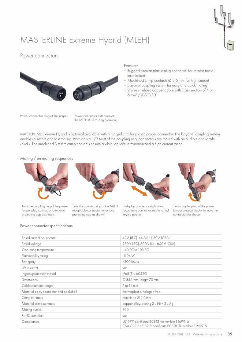
85HUBER+SUHNER Wireless infrastructure
MASTERLINE Extreme Hybrid (MLEH)
Power connectors
Features• Rugged circular plastic plug connector for remote radio
installations• Machined crimp contacts Ø 3.6 mm for high current• Bayonet coupling system for easy and quick mating• 2 wire shielded copper cable with cross section of 4 or
6 mm2 / AWG 10
Power connector plug at the jumper Power connector extension at the MLEH (0.5 m long breakout)
MASTERLINE Extreme Hybrid is optional available with a rugged circular plastic power connector. The bayonet coupling system enables a simple and fast mating. With only a 1/3 twist of the coupling ring, connectors are mated with an audible and tactile «click». The machined 3.6 mm crimp contacts ensure a vibration safe termination and a high current rating.
Mating / un-mating sequences
Twist the coupling ring of the power jumper plug connector to remove protecting cap as shown.
Twist the coupling ring of the MLEH receptable connector to remove protecting cap as shown.
Push plug connector slightly into recaptacle connector, rotate to find keying position.
Twist coupling ring of the power jumper plug connector to mate the connectors as shown.
Rated current per contact 42 A (IEC), 44 A (UL), 30 A (CSA)
Rated voltage 230 V (IEC), 600 V (UL), 600 V (CSA)
Operating temperature –40 °C to 105 °C
Flammability rating UL 94 V0
Salt spray >500 hours
UV resistant yes
Ingress protection mated IP68 (EN 60529)
Dimensions Ø 35.1 mm, length 70 mm
Cable diameter range 5 to 14 mm
Material body connector and backshell thermoplastic, halogen free
Crimp contacts machined Ø 3.6 mm
Material crimp contacts copper alloy, plating 2 μ Ni + 2 μ Ag
Mating cycles 100
RoHS compliant yes
Compliance UL1977: certificate ECBT2 file number E169916CSA C22.2 n°182.3: certificate ECBT8 file number E169916
Power connector specifications
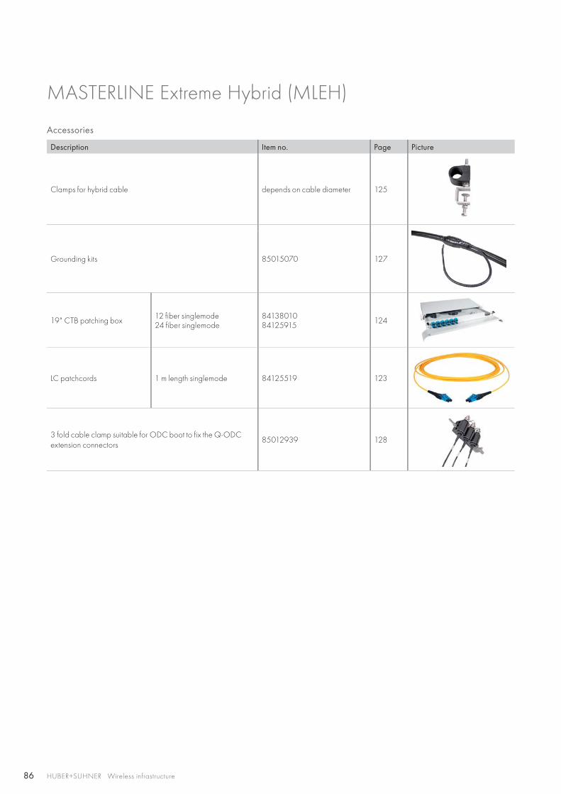
86 HUBER+SUHNER Wireless infrastructure
Accessories
MASTERLINE Extreme Hybrid (MLEH)
Description Item no. Page Picture
Clamps for hybrid cable depends on cable diameter 125
Grounding kits 85015070 127
19" CTB patching box 12 fiber singlemode24 fiber singlemode
8413801084125915 124
LC patchcords 1 m length singlemode 84125519 123
3 fold cable clamp suitable for ODC boot to fix the Q-ODC extension connectors
85012939 128
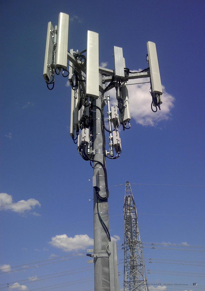
87HUBER+SUHNER Wireless infrastructure 87878787878777787777877878788788778HUBHUBHUBHUBHHUBHUBHUBHUBHUBHUBHUBHUBHUHUHUBUBUBHUBHUBHUBUUUUBHUBHUBBHUBHUBHUBHUBHUBHUBHUBHUBHUBUHUHUHUUUBHUBUBHUBHUBHUHHHUBHUUHUBHUBHUBHUBBHHHUBHUBHUBHUUBHHUBHUUBHUBUUUBBBHUUBHUHUUBHUBBBUBHUHUBHUBBHUHUHUHUHUBHUBHUBHUBUHUUHHHHUHUUUBBHUBBHHHUUHHUBHHUHUBHHHHHHUUHUHUHUHUHUUBHHHHH BBBHHUBBBBBBBUBBEEEEEEEERR+R+R+R+R+EEEEER+ER+R+R+EEERR+R+R+EER+ER+ER+ER+ER+R+ER++ER++ER+R+++++EEEER+EEE SUHSUHSUHSUHSUHSUHUHSUHSUHSUHUSSUHSUHSUHSUHSUHSUSUHSUSUHSUHSUUUHUHHNENERNERNERNERNEREENERNERNERNNENERRNERNERRNERNERNERNNENERNEERNNERNERNERNERNER WirWWirWirWirWirWirWirWirWWWWirWirWiWirWWirWirWirrWirWirWWirrrWirWWW releeleeleleleeleeleleleelelleleeleeleeleeleeeleeleeleleleeless ss ssss ssssssssssssssssssss infinfnfinfnffinfinnfinfninfiii fnfffrasrasrasrraasasrasrasrasrraaaaarasaasaasrasastrutrururutrutrutrurutrutruttrutruruuuuut ctuctuctuctuctuctuctctuctuuucctucctututctuctutcctctuctuctuuuctuc rereeereeerererreeeerereeeeree
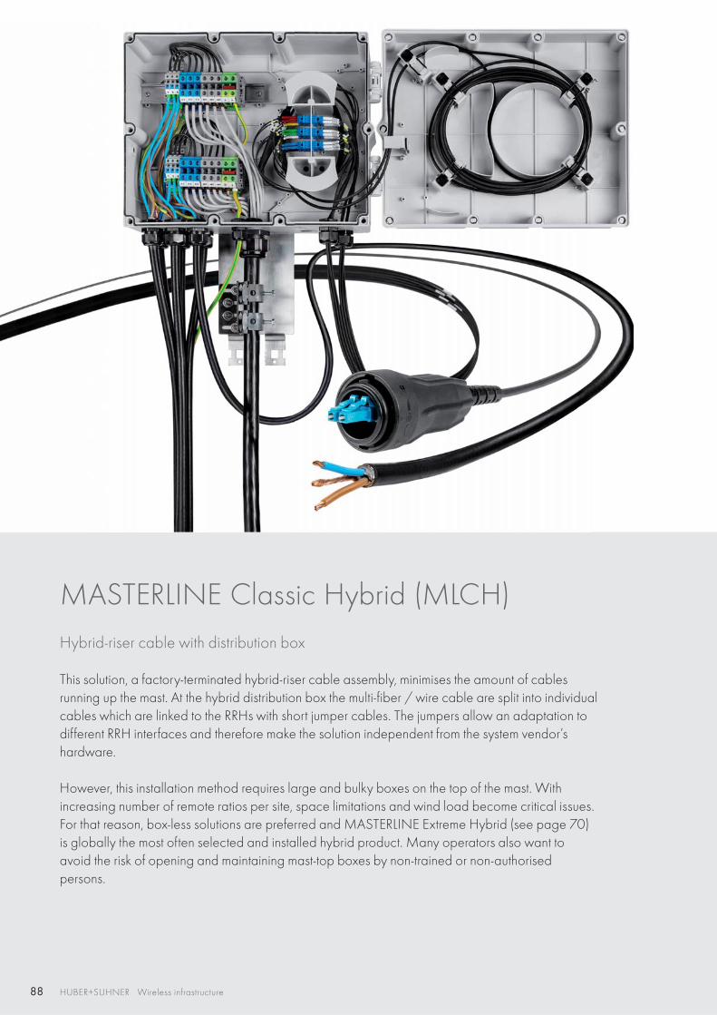
88 HUBER+SUHNER Wireless infrastructure
MASTERLINE Classic Hybrid (MLCH) Hybrid-riser cable with distribution box
This solution, a factory-terminated hybrid-riser cable assembly, minimises the amount of cables running up the mast. At the hybrid distribution box the multi-fiber / wire cable are split into individual cables which are linked to the RRHs with short jumper cables. The jumpers allow an adaptation to different RRH interfaces and therefore make the solution independent from the system vendor’s hardware.
However, this installation method requires large and bulky boxes on the top of the mast. With increasing number of remote ratios per site, space limitations and wind load become critical issues. For that reason, box-less solutions are preferred and MASTERLINE Extreme Hybrid (see page 70) is globally the most often selected and installed hybrid product. Many operators also want to avoid the risk of opening and maintaining mast-top boxes by non-trained or non-authorisedpersons.
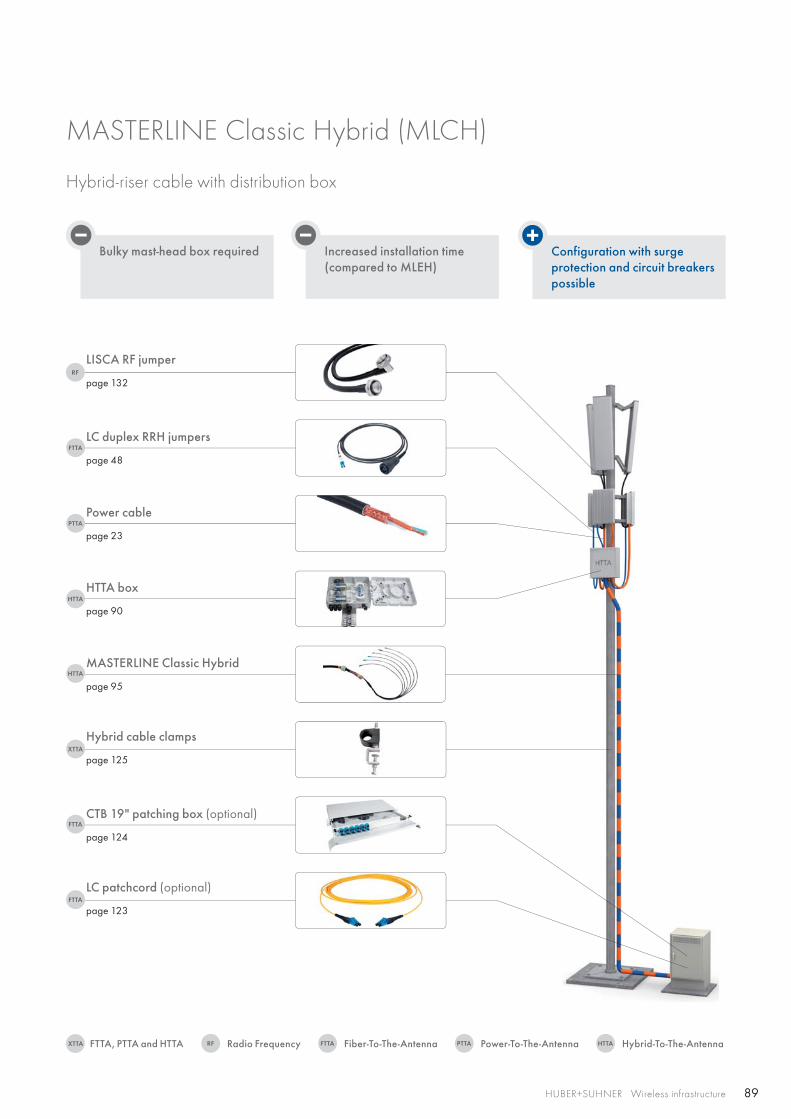
89
RF
FTTA
PTTA
HTTA
XTTA
FTTA
HTTA
FTTA
RFXTTA FTTA PTTA HTTA
HUBER+SUHNER Wireless infrastructure
Bulky mast-head box required Increased installation time(compared to MLEH)
Configuration with surgeprotection and circuit breakers possible
LC duplex RRH jumpers
page 48
Power cable
page 23
LISCA RF jumper
page 132
HTTA box
page 90
MASTERLINE Classic Hybrid
page 95
Hybrid cable clamps
page 125
CTB 19" patching box (optional)
page 124
LC patchcord (optional)
page 123
MASTERLINE Classic Hybrid (MLCH)
Hybrid-riser cable with distribution box
Radio FrequencyFTTA, PTTA and HTTA Fiber-To-The-Antenna Power-To-The-Antenna Hybrid-To-The-Antenna
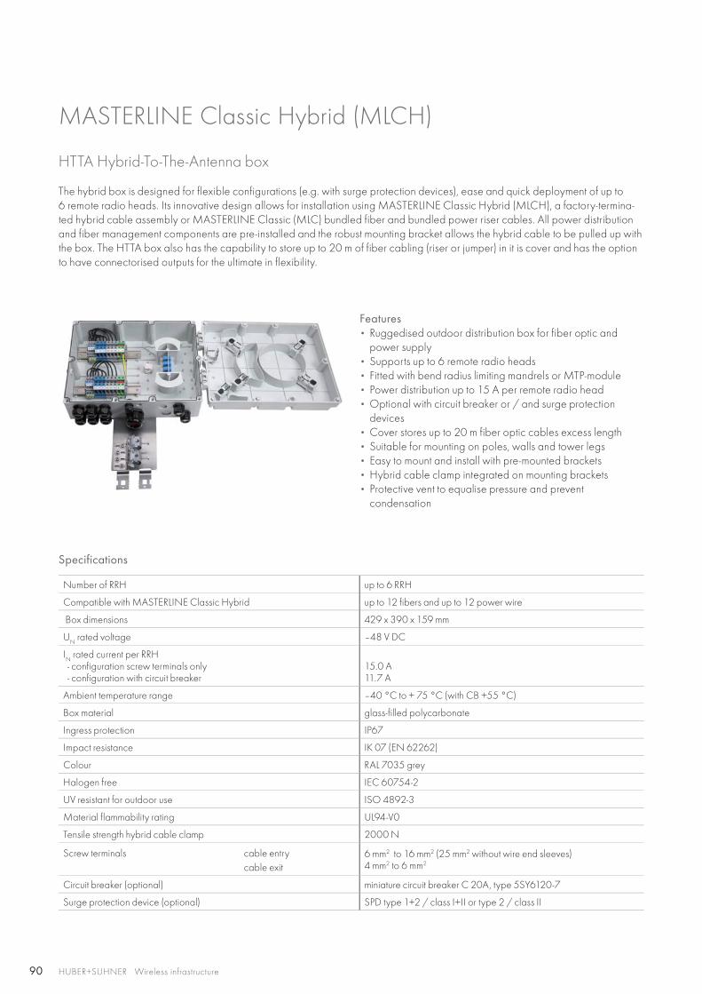
90 HUBER+SUHNER Wireless infrastructure
HTTA Hybrid-To-The-Antenna box
Features • Ruggedised outdoor distribution box for fiber optic and
power supply• Supports up to 6 remote radio heads• Fitted with bend radius limiting mandrels or MTP-module• Power distribution up to 15 A per remote radio head• Optional with circuit breaker or / and surge protection
devices• Cover stores up to 20 m fiber optic cables excess length• Suitable for mounting on poles, walls and tower legs• Easy to mount and install with pre-mounted brackets• Hybrid cable clamp integrated on mounting brackets• Protective vent to equalise pressure and prevent
condensation
Specifications
Number of RRH up to 6 RRH
Compatible with MASTERLINE Classic Hybrid up to 12 fibers and up to 12 power wire
Box dimensions 429 x 390 x 159 mm
UN rated voltage –48 V DC
IN rated current per RRH
- configuration screw terminals only - configuration with circuit breaker
15.0 A 11.7 A
Ambient temperature range –40 °C to + 75 °C (with CB +55 °C)
Box material glass-filled polycarbonate
Ingress protection IP67
Impact resistance IK 07 (EN 62262)
Colour RAL 7035 grey
Halogen free IEC 60754-2
UV resistant for outdoor use ISO 4892-3
Material flammability rating UL94-V0
Tensile strength hybrid cable clamp 2000 N
Screw terminals cable entry cable exit
6 mm2 to 16 mm2 (25 mm2 without wire end sleeves)4 mm2 to 6 mm2
Circuit breaker (optional) miniature circuit breaker C 20A, type 5SY6120-7
Surge protection device (optional) SPD type 1+2 / class I+II or type 2 / class II
MASTERLINE Classic Hybrid (MLCH)
The hybrid box is designed for flexible configurations (e.g. with surge protection devices), ease and quick deployment of up to6 remote radio heads. Its innovative design allows for installation using MASTERLINE Classic Hybrid (MLCH), a factory-termina-ted hybrid cable assembly or MASTERLINE Classic (MLC) bundled fiber and bundled power riser cables. All power distribution and fiber management components are pre-installed and the robust mounting bracket allows the hybrid cable to be pulled up with the box. The HTTA box also has the capability to store up to 20 m of fiber cabling (riser or jumper) in it is cover and has the option to have connectorised outputs for the ultimate in flexibility.
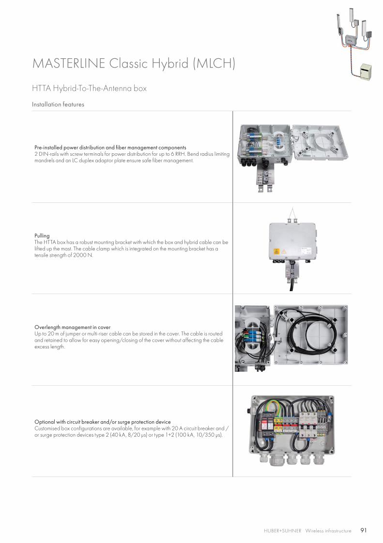
91HUBER+SUHNER Wireless infrastructure
HTTA Hybrid-To-The-Antenna box
Installation features
Pre-installed power distribution and fiber management components 2 DIN-rails with screw terminals for power distribution for up to 6 RRH. Bend radius limiting mandrels and an LC duplex adaptor plate ensure safe fiber management.
PullingThe HTTA box has a robust mounting bracket with which the box and hybrid cable can be lifted up the mast. The cable clamp which is integrated on the mounting bracket has a tensile strength of 2000 N.
Overlength management in coverUp to 20 m of jumper or multi-riser cable can be stored in the cover. The cable is routed and retained to allow for easy opening/closing of the cover without affecting the cable excess length.
Optional with circuit breaker and/or surge protection deviceCustomised box configurations are available, for example with 20 A circuit breaker and / or surge protection devices type 2 (40 kA, 8/20 μs) or type 1+2 (100 kA, 10/350 μs).
MASTERLINE Classic Hybrid (MLCH)
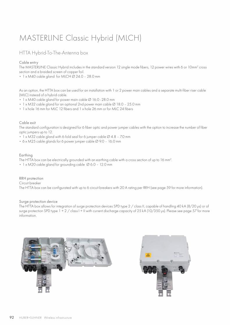
92 HUBER+SUHNER Wireless infrastructure
HTTA Hybrid-To-The-Antenna box
Cable entryThe MASTERLINE Classic Hybrid includes in the standard version 12 single mode fibers, 12 power wires with 6 or 10mm2 cross section and a braided screen of copper foil.• 1 x M40 cable gland for MLCH Ø 24.0 – 28.0 mm
As an option, the HTTA box can be used for an installation with 1 or 2 power main cables and a separate multi-fiber riser cable (MLC) instead of a hybrid cable. • 1 x M40 cable gland for power main cable Ø 16.0 - 28.0 mm• 1 x M32 cable gland for an optional 2nd power main cable Ø 18.0 – 25.0 mm• 1 x hole 16 mm for MLC 12 fibers and 1 x hole 26 mm or for MLC 24 fibers
Cable exitThe standard configuration is designed for 6 fiber optic and power jumper cables with the option to increase the number of fiber optic jumpers up to 12.• 1 x M32 cable gland with 6-fold seal for 6 jumper cable Ø 4.8 – 7.0 mm• 6 x M25 cable glands for 6 power jumper cable Ø 9.0 – 16.0 mm
EarthingThe HTTA box can be electrically grounded with an earthing cable with a cross section of up to 16 mm2.• 1 x M20 cable gland for grounding cable Ø 6.0 – 12.0 mm
RRH protectionCircuit breakerThe HTTA box can be configurated with up to 6 circuit breakers with 20 A rating per RRH (see page 59 for more information).
Surge protection deviceThe HTTA box allows for integration of surge protection devices SPD type 2 / class II, capable of handling 40 kA (8/20 μs) or of surge protection SPD type 1 + 2 / class I + II with current discharge capacity of 25 kA (10/350 μs). Please see page 57 for more information.
MASTERLINE Classic Hybrid (MLCH)
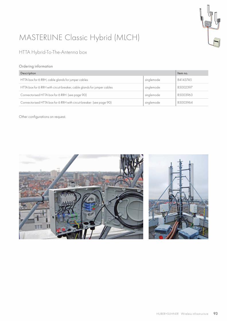
93HUBER+SUHNER Wireless infrastructure
HTTA Hybrid-To-The-Antenna box
Ordering information
Description Item no.
HTTA box for 6 RRH, cable glands for jumper cables singlemode 84143745
HTTA box for 6 RRH with circuit breaker, cable glands for jumper cables singlemode 85002397
Connectorised HTTA box for 6 RRH (see page 90) singlemode 85003963
Connectorised HTTA box for 6 RRH with circuit breaker (see page 90) singlemode 85003964
Other configurations on request.
MASTERLINE Classic Hybrid (MLCH)
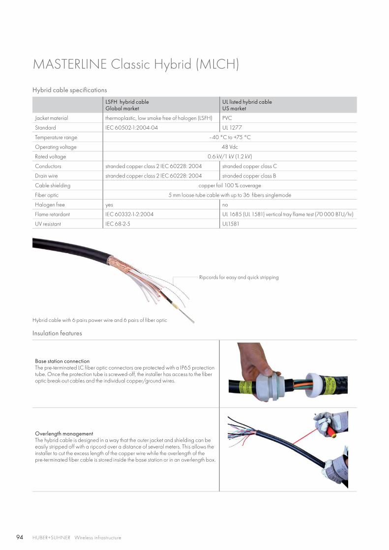
94 HUBER+SUHNER Wireless infrastructure
Hybrid cable specifications
LSFH hybrid cableGlobal market
UL listed hybrid cableUS market
Jacket material thermoplastic, low smoke free of halogen (LSFH) PVC
Standard IEC 60502-1:2004-04 UL 1277
Temperature range –40 °C to +75 °C
Operating voltage 48 Vdc
Rated voltage 0.6 kV/1 kV (1.2 kV)
Conductors stranded copper class 2 IEC 60228: 2004 stranded copper class C
Drain wire stranded copper class 2 IEC 60228: 2004 stranded copper class B
Cable shielding copper foil 100 % coverage
Fiber optic 5 mm loose-tube cable with up to 36 fibers singlemode
Halogen free yes no
Flame retardant IEC 60332-1-2:2004 UL 1685 (UL 1581) vertical tray flame test (70 000 BTU/hr)
UV resistant IEC 68-2-5 UL1581
MASTERLINE Classic Hybrid (MLCH)
Insulation features
Base station connectionThe pre-terminated LC fiber optic connectors are protected with a IP65 protection tube. Once the protection tube is screwed-off, the installer has access to the fiber optic break-out cables and the individual copper/ground wires.
Overlength managementThe hybrid cable is designed in a way that the outer jacket and shielding can be easily stripped off with a ripcord over a distance of several meters. This allows the installer to cut the excess length of the copper wire while the overlength of the pre-terminated fiber cable is stored inside the base station or in an overlength box.
Ripcords for easy and quick stripping
Hybrid cable with 6 pairs power wire and 6 pairs of fiber optic
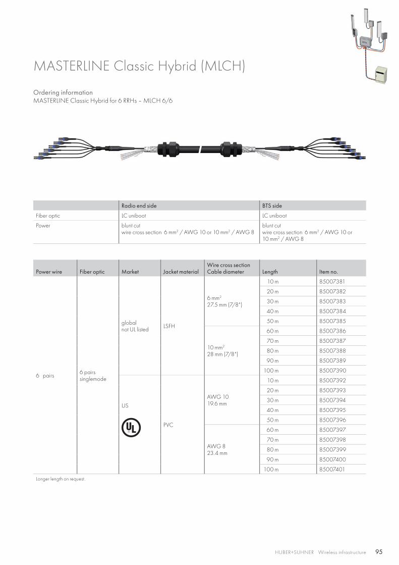
95HUBER+SUHNER Wireless infrastructure
Ordering information MASTERLINE Classic Hybrid for 6 RRHs – MLCH 6/6
MASTERLINE Classic Hybrid (MLCH)
Radio end side BTS side
Fiber optic LC uniboot LC uniboot
Power blunt cutwire cross section 6 mm2 / AWG 10 or 10 mm2 / AWG 8
blunt cutwire cross section 6 mm2 / AWG 10 or10 mm2 / AWG 8
Power wire Fiber optic Market Jacket materialWire cross sectionCable diameter Length Item no.
6 pairs 6 pairssinglemode
globalnot UL listed LSFH
6 mm2
27.5 mm (7/8")
10 m 85007381
20 m 85007382
30 m 85007383
40 m 85007384
50 m 85007385
10 mm2
28 mm (7/8")
60 m 85007386
70 m 85007387
80 m 85007388
90 m 85007389
100 m 85007390
US
PVC
AWG 1019.6 mm
10 m 85007392
20 m 85007393
30 m 85007394
40 m 85007395
50 m 85007396
AWG 823.4 mm
60 m 85007397
70 m 85007398
80 m 85007399
90 m 85007400
100 m 85007401
Longer length on request.
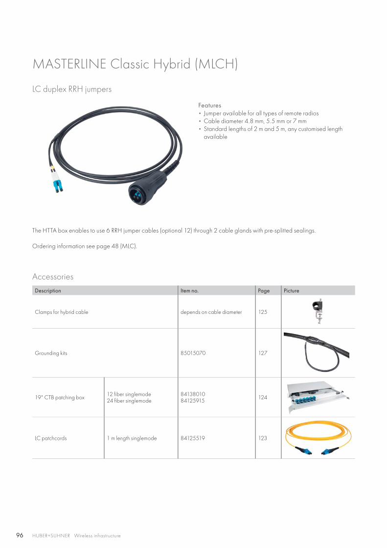
96 HUBER+SUHNER Wireless infrastructure
LC duplex RRH jumpers
Accessories
Description Item no. Page Picture
Clamps for hybrid cable depends on cable diameter 125
Grounding kits 85015070 127
19" CTB patching box 12 fiber singlemode24 fiber singlemode
8413801084125915 124
LC patchcords 1 m length singlemode 84125519 123
Features• Jumper available for all types of remote radios• Cable diameter 4.8 mm, 5.5 mm or 7 mm • Standard lengths of 2 m and 5 m, any customised length
available
The HTTA box enables to use 6 RRH jumper cables (optional 12) through 2 cable glands with pre-splitted sealings.
Ordering information see page 48 (MLC).
MASTERLINE Classic Hybrid (MLCH)
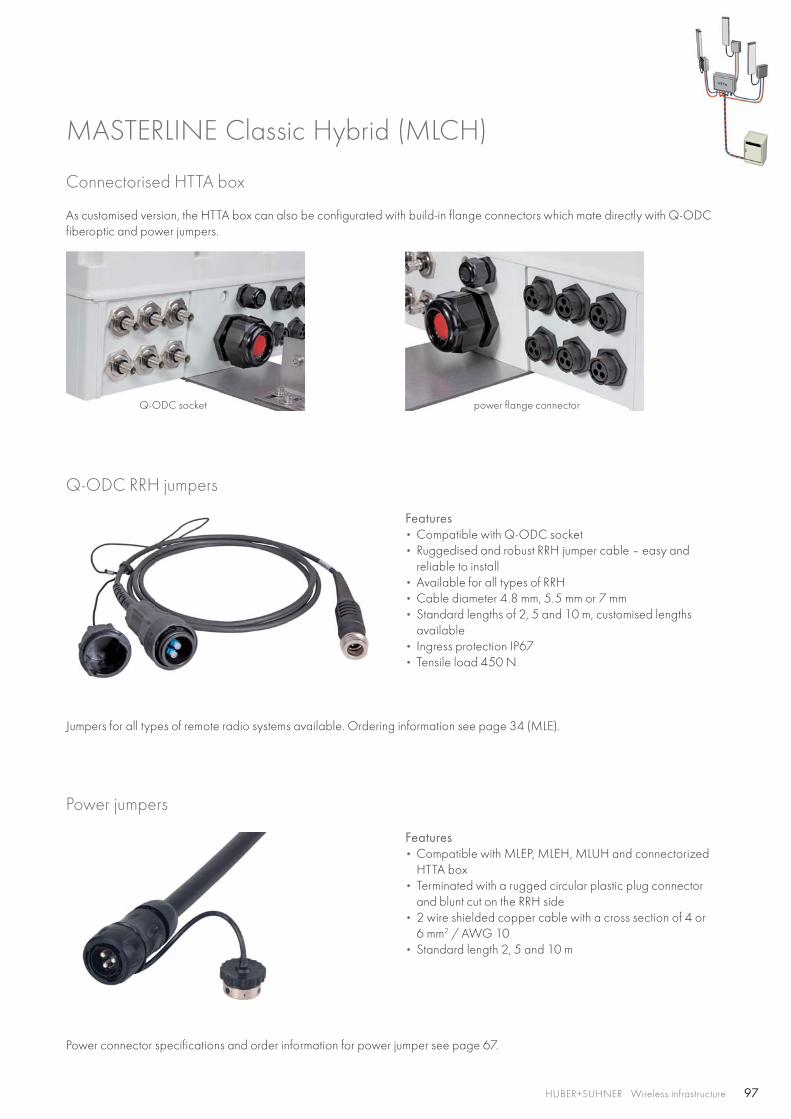
97HUBER+SUHNER Wireless infrastructure
Connectorised HTTA box
As customised version, the HTTA box can also be configurated with build-in flange connectors which mate directly with Q-ODC fiberoptic and power jumpers.
Power jumpers
Power connector specifications and order information for power jumper see page 67.
Q-ODC RRH jumpers
Features• Compatible with Q-ODC socket• Ruggedised and robust RRH jumper cable – easy and
reliable to install• Available for all types of RRH• Cable diameter 4.8 mm, 5.5 mm or 7 mm• Standard lengths of 2, 5 and 10 m, customised lengths
available• Ingress protection IP67• Tensile load 450 N
Jumpers for all types of remote radio systems available. Ordering information see page 34 (MLE).
Q-ODC socket power flange connector
MASTERLINE Classic Hybrid (MLCH)
Features• Compatible with MLEP, MLEH, MLUH and connectorized
HTTA box• Terminated with a rugged circular plastic plug connector
and blunt cut on the RRH side • 2 wire shielded copper cable with a cross section of 4 or
6 mm2 / AWG 10• Standard length 2, 5 and 10 m
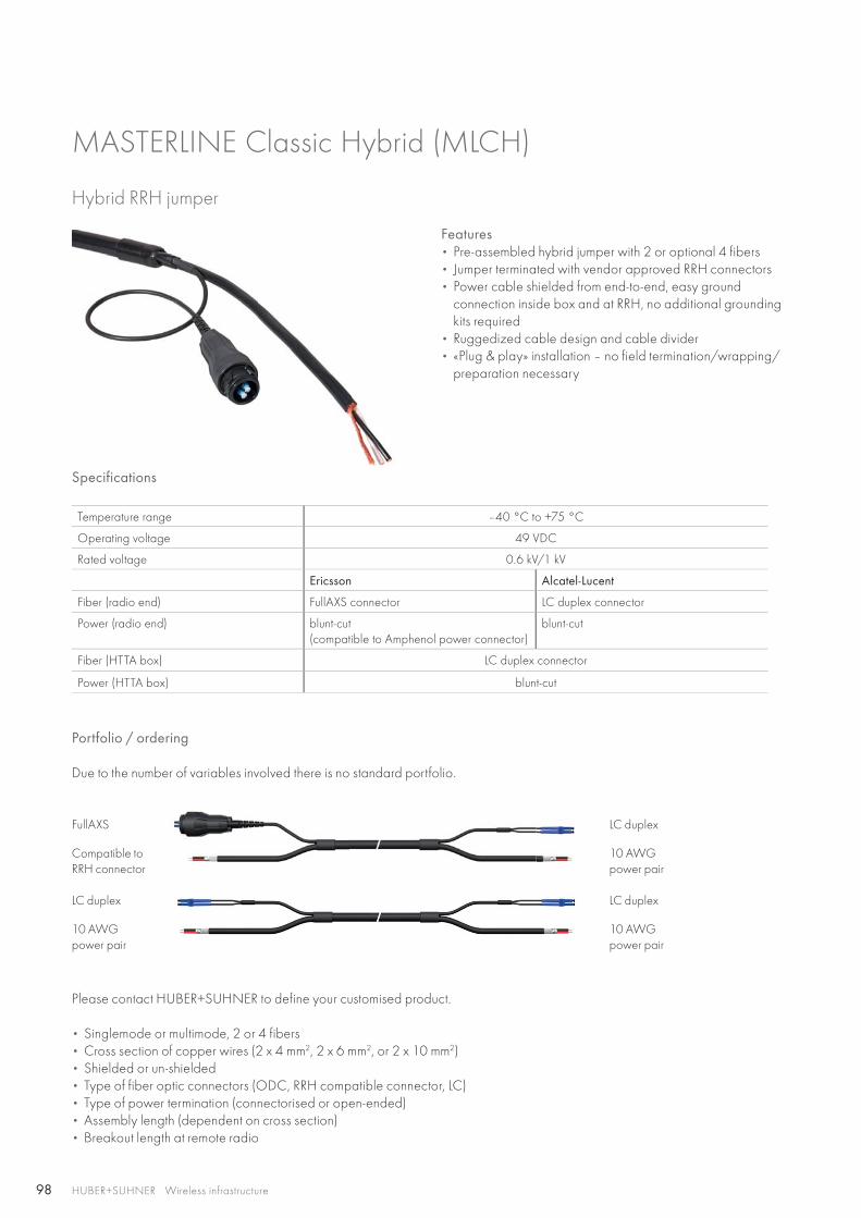
98 HUBER+SUHNER Wireless infrastructure
Hybrid RRH jumper
Features • Pre-assembled hybrid jumper with 2 or optional 4 fibers• Jumper terminated with vendor approved RRH connectors• Power cable shielded from end-to-end, easy ground
connection inside box and at RRH, no additional grounding kits required
• Ruggedized cable design and cable divider• «Plug & play» installation – no field termination/wrapping/
preparation necessary
MASTERLINE Classic Hybrid (MLCH)
Please contact HUBER+SUHNER to define your customised product.
• Singlemode or multimode, 2 or 4 fibers• Cross section of copper wires (2 x 4 mm2, 2 x 6 mm2, or 2 x 10 mm2)• Shielded or un-shielded• Type of fiber optic connectors (ODC, RRH compatible connector, LC)• Type of power termination (connectorised or open-ended)• Assembly length (dependent on cross section)• Breakout length at remote radio
Specifications
Temperature range –40 °C to +75 °C
Operating voltage 49 VDC
Rated voltage 0.6 kV/1 kV
Ericsson Alcatel-Lucent
Fiber (radio end) FullAXS connector LC duplex connector
Power (radio end) blunt-cut (compatible to Amphenol power connector)
blunt-cut
Fiber (HTTA box) LC duplex connector
Power (HTTA box) blunt-cut
Portfolio / ordering
Due to the number of variables involved there is no standard portfolio.
FullAXS
Compatible to RRH connector
LC duplex
10 AWGpower pair
LC duplex
10 AWGpower pair
LC duplex
10 AWGpower pair
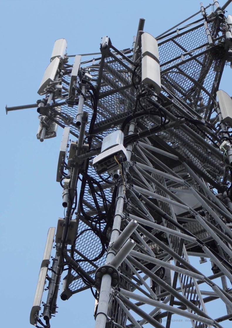
999999999999999999999999999999999999999999999999999999999999999999999HUBER+SUHNER Wireless infrastructure
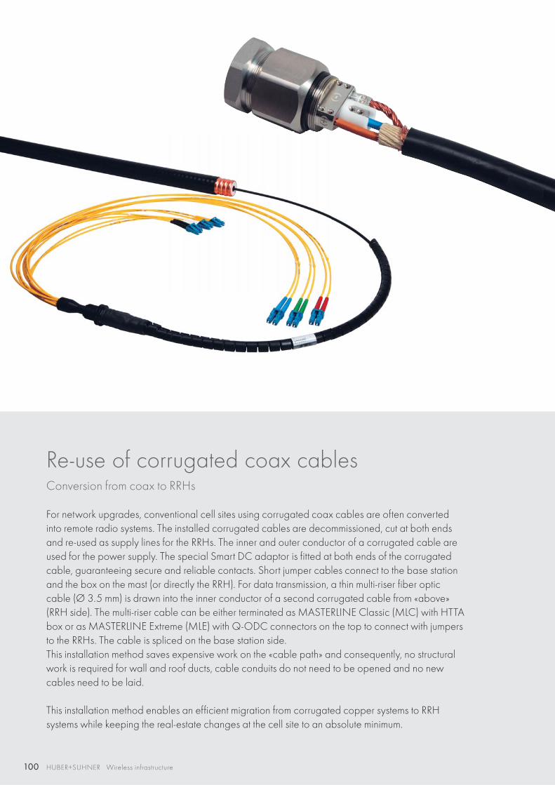
100 HUBER+SUHNER Wireless infrastructure
Re-use of corrugated coax cables Conversion from coax to RRHs
For network upgrades, conventional cell sites using corrugated coax cables are often converted into remote radio systems. The installed corrugated cables are decommissioned, cut at both ends and re-used as supply lines for the RRHs. The inner and outer conductor of a corrugated cable are used for the power supply. The special Smart DC adaptor is fitted at both ends of the corrugated cable, guaranteeing secure and reliable contacts. Short jumper cables connect to the base station and the box on the mast (or directly the RRH). For data transmission, a thin multi-riser fiber optic cable (Ø 3.5 mm) is drawn into the inner conductor of a second corrugated cable from «above» (RRH side). The multi-riser cable can be either terminated as MASTERLINE Classic (MLC) with HTTA box or as MASTERLINE Extreme (MLE) with Q-ODC connectors on the top to connect with jumpers to the RRHs. The cable is spliced on the base station side. This installation method saves expensive work on the «cable path» and consequently, no structural work is required for wall and roof ducts, cable conduits do not need to be opened and no new cables need to be laid.
This installation method enables an efficient migration from corrugated copper systems to RRH systems while keeping the real-estate changes at the cell site to an absolute minimum.
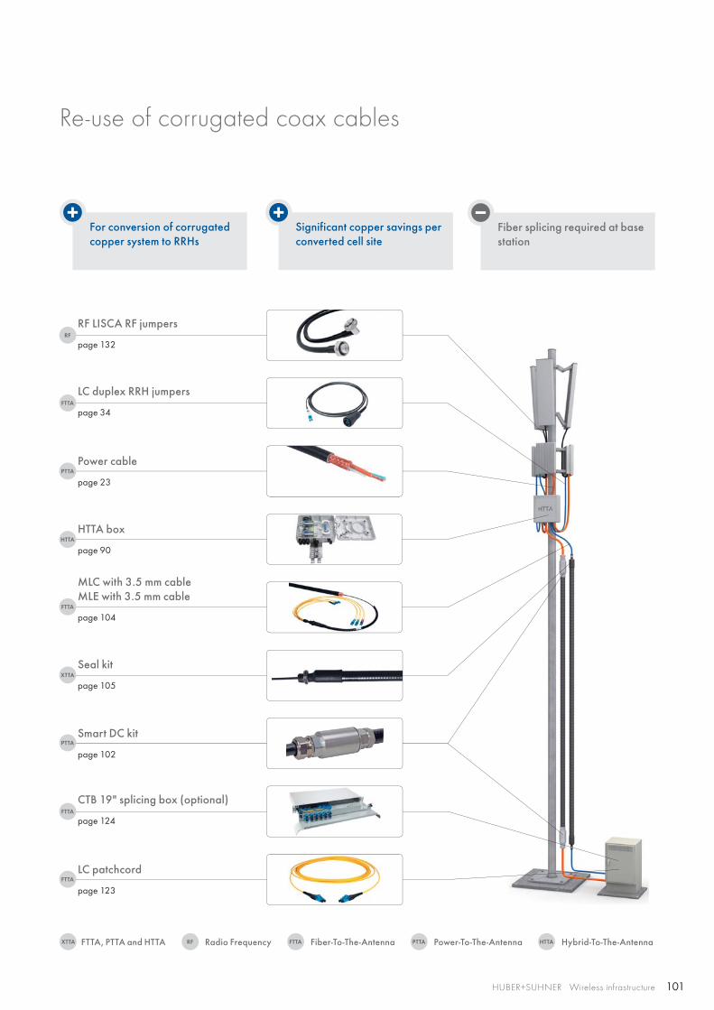
101
PTTA
FTTA
RF
HTTA
XTTA
FTTA
FTTA
PTTA
FTTA
RFXTTA FTTA PTTA HTTA
HUBER+SUHNER Wireless infrastructure
For conversion of corrugated copper system to RRHs
Significant copper savings per converted cell site
Fiber splicing required at base station
Power cable
page 23
LC duplex RRH jumpers
page 34
RF LISCA RF jumpers
page 132
HTTA box
page 90
MLC with 3.5 mm cableMLE with 3.5 mm cable
page 104
Smart DC kit
page 102
Seal kit
page 105
LC patchcord
page 123
CTB 19" splicing box (optional)
page 124
Re-use of corrugated coax cables
Radio FrequencyFTTA, PTTA and HTTA Fiber-To-The-Antenna Power-To-The-Antenna Hybrid-To-The-Antenna
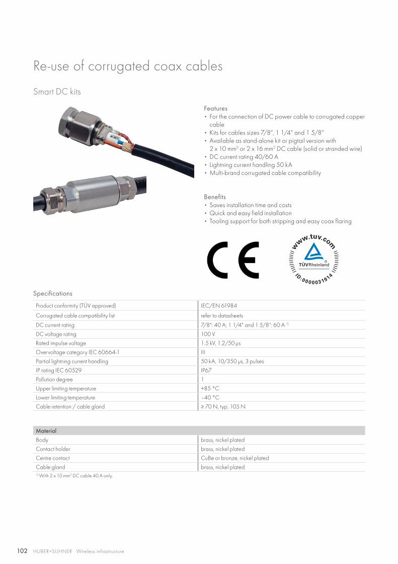
102 HUBER+SUHNER Wireless infrastructure
Smart DC kits
Features • For the connection of DC power cable to corrugated copper
cable• Kits for cables sizes 7/8", 1 1/4" and 1 5/8"• Available as stand-alone kit or pigtail version with
2 x 10 mm2 or 2 x 16 mm2 DC cable (solid or stranded wire)• DC current rating 40/60 A• Lightning current handling 50 kA• Multi-brand corrugated cable compatibility
Benefits• Saves installation time and costs• Quick and easy field installation• Tooling support for both stripping and easy coax flaring
Specifications
Product conformity (TÜV approved) IEC/EN 61984
Corrugated cable compatibility list refer to datasheets
DC current rating 7/8": 40 A; 1 1/4" and 1 5/8": 60 A 1)
DC voltage rating 100 V
Rated impulse voltage 1.5 kV, 1.2/50 μs
Overvoltage category IEC 60664-1 III
Partial lightning current handling 50 kA, 10/350 μs, 3 pulses
IP rating IEC 60529 IP67
Pollution degree 1
Upper limiting temperature +85 °C
Lower limiting temperature –40 °C
Cable retention / cable gland ≥ 70 N, typ. 105 N
Material
Body brass, nickel plated
Contact holder brass, nickel plated
Centre contact CuBe or bronze, nickel plated
Cable gland brass, nickel plated1) With 2 x 10 mm2 DC cable 40 A only.
Re-use of corrugated coax cables
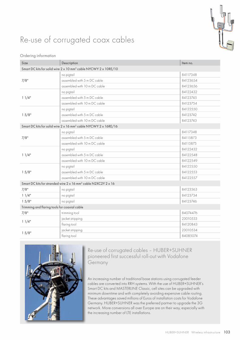
103HUBER+SUHNER Wireless infrastructure
Ordering information
Size Description Item no.
Smart DC kits for solid wire 2 x 10 mm2 cable NYCWY 2 x 10RE/10
7/8"
no pigtail 84117348
assembled with 5 m DC cable 84123654
assembled with 10 m DC cable 84123656
1 1/4"
no pigtail 84122432
assembled with 5 m DC cable 84123745
assembled with 10 m DC cable 84123754
1 5/8"
no pigtail 84122550
assembled with 5 m DC cable 84123742
assembled with 10 m DC cable 84123743
Smart DC kits for solid wire 2 x 16 mm2 cable NYCWY 2 x 16RE/16
7/8"
no pigtail 84117348
assembled with 5 m DC cable 84115873
assembled with 10 m DC cable 84115875
1 1/4"
no pigtail 84122432
assembled with 5 m DC cable 84122548
assembled with 10 m DC cable 84122549
1 5/8"
no pigtail 84122550
assembled with 5 m DC cable 84122553
assembled with 10 m DC cable 84122557
Smart DC kits for stranded wire 2 x 16 mm2 cable N2XC2Y 2 x 16
7/8" no pigtail 84123563
1 1/4" no pigtail 84123734
1 5/8" no pigtail 84123746
Trimming and flaring tools for coaxial cable
7/8" trimming tool 84074476
1 1/4"jacket stripping 23010533
flaring tool 84120843
1 5/8"jacket stripping 23010534
flaring tool 84085074
Re-use of corrugated cables – HUBER+SUHNER pioneered first successful roll-out with Vodafone Germany
An increasing number of traditional base stations using corrugated feeder cables are converted into RRH systems. With the use of HUBER+SUHNER’s Smart DC kits and MASTERLINE Classic, cell sites can be upgraded with minimum downtime and with completely avoiding expensive cable routing. These advantages saved millions of Euros of installation costs for Vodafone Germany. HUBER+SUHNER was the preferred partner to upgrade the 3G network. More conversions all over Europe are on their way, especially with the increasing number of LTE installations.
Re-use of corrugated coax cables
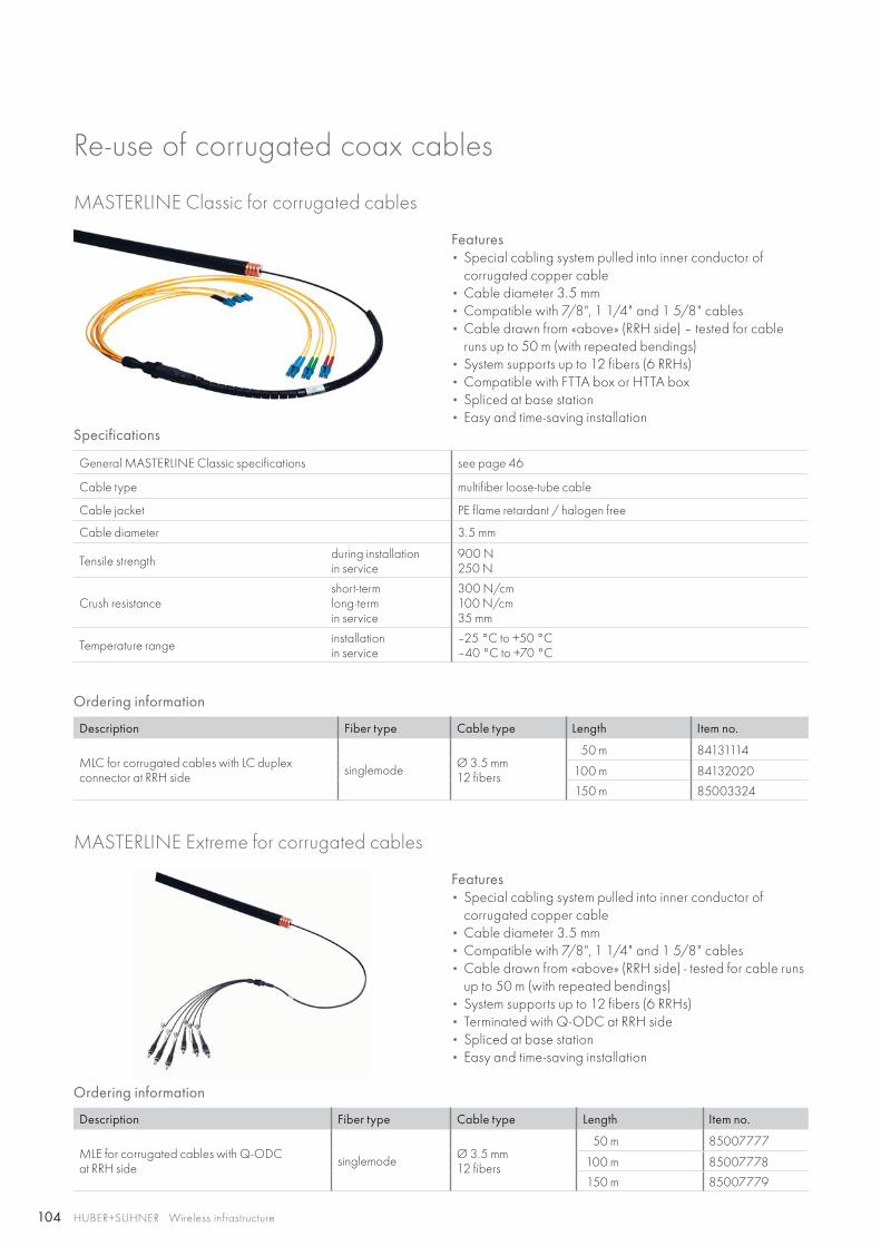
104 HUBER+SUHNER Wireless infrastructure
Re-use of corrugated coax cables
Features • Special cabling system pulled into inner conductor of
corrugated copper cable• Cable diameter 3.5 mm• Compatible with 7/8", 1 1/4" and 1 5/8" cables• Cable drawn from «above» (RRH side) – tested for cable
runs up to 50 m (with repeated bendings)• System supports up to 12 fibers (6 RRHs)• Compatible with FTTA box or HTTA box• Spliced at base station• Easy and time-saving installation
Specifications
General MASTERLINE Classic specifications see page 46
Cable type multifiber loose-tube cable
Cable jacket PE flame retardant / halogen free
Cable diameter 3.5 mm
Tensile strength during installationin service
900 N250 N
Crush resistanceshort-termlong-termin service
300 N/cm100 N/cm35 mm
Temperature range installationin service
–25 °C to +50 °C–40 °C to +70 °C
Ordering information
Description Fiber type Cable type Length Item no.
MLC for corrugated cables with LC duplex connector at RRH side singlemode Ø 3.5 mm
12 fibers
50 m 84131114
100 m 84132020
150 m 85003324
MASTERLINE Extreme for corrugated cables
MASTERLINE Classic for corrugated cables
Features • Special cabling system pulled into inner conductor of
corrugated copper cable• Cable diameter 3.5 mm• Compatible with 7/8", 1 1/4" and 1 5/8" cables• Cable drawn from «above» (RRH side) - tested for cable runs
up to 50 m (with repeated bendings)• System supports up to 12 fibers (6 RRHs)• Terminated with Q-ODC at RRH side• Spliced at base station• Easy and time-saving installation
Ordering information
Description Fiber type Cable type Length Item no.
MLE for corrugated cables with Q-ODC at RRH side singlemode Ø 3.5 mm
12 fibers
50 m 85007777
100 m 85007778
150 m 85007779
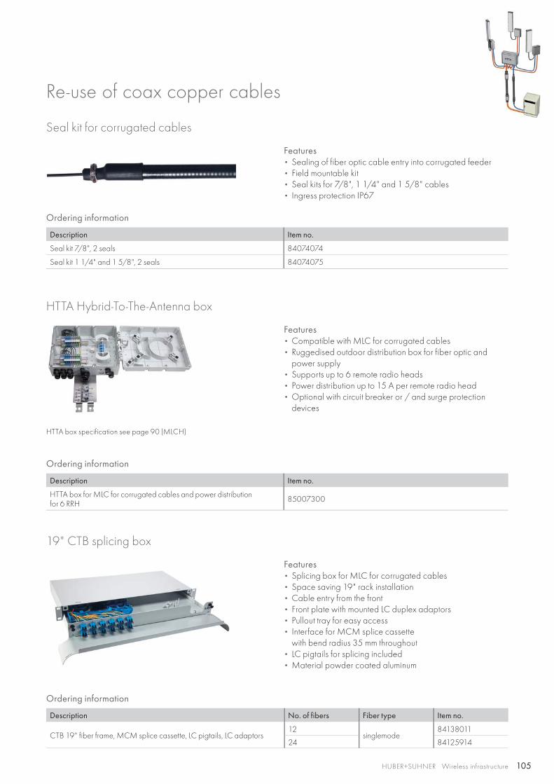
105HUBER+SUHNER Wireless infrastructure
Re-use of coax copper cables
Seal kit for corrugated cables
HTTA Hybrid-To-The-Antenna box
19" CTB splicing box
Features • Sealing of fiber optic cable entry into corrugated feeder• Field mountable kit• Seal kits for 7/8", 1 1/4" and 1 5/8" cables• Ingress protection IP67
Features • Compatible with MLC for corrugated cables• Ruggedised outdoor distribution box for fiber optic and
power supply• Supports up to 6 remote radio heads• Power distribution up to 15 A per remote radio head• Optional with circuit breaker or / and surge protection
devices
Features • Splicing box for MLC for corrugated cables• Space saving 19" rack installation• Cable entry from the front• Front plate with mounted LC duplex adaptors• Pullout tray for easy access• Interface for MCM splice cassette
with bend radius 35 mm throughout• LC pigtails for splicing included• Material powder coated aluminum
Ordering information
Description No. of fibers Fiber type Item no.
CTB 19" fiber frame, MCM splice cassette, LC pigtails, LC adaptors12
singlemode84138011
24 84125914
Ordering information
Description Item no.
Seal kit 7/8", 2 seals 84074074
Seal kit 1 1/4" and 1 5/8", 2 seals 84074075
Ordering information
Description Item no.
HTTA box for MLC for corrugated cables and power distribution for 6 RRH 85007300
HTTA box specification see page 90 (MLCH)
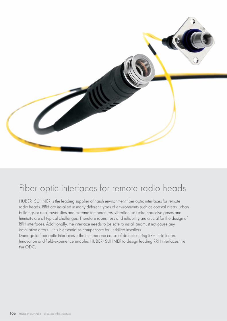
106 HUBER+SUHNER Wireless infrastructure
Fiber optic interfaces for remote radio heads HUBER+SUHNER is the leading supplier of harsh environment fiber optic interfaces for remote radio heads. RRH are installed in many different types of environments such as coastal areas, urban buildings or rural tower sites and extreme temperatures, vibration, salt mist, corrosive gases and humidity are all typical challenges. Therefore robustness and reliability are crucial for the design of RRH interfaces. Additionally, the interface needs to be safe to install andmust not cause anyinstallation errors – this is essential to compensate for unskilled installers.Damage to fiber optic interfaces is the number one cause of defects during RRH installation.Innovation and field-experience enables HUBER+SUHNER to design leading RRH interfaces like the ODC.
107HUBER+SUHNER Wireless infrastructure
Content
Q-ODC®
outdoor connector plug / socket 108
Q-ODC®-12outdoor connector plug / socket 110
ODC®-2outdoor connector plug / socket 112
ODC®-4outdoor connector plug / socket 114
Q-XCOquick-lock ruggedised SFP connector 116
FullAXSruggedised sealing system 118
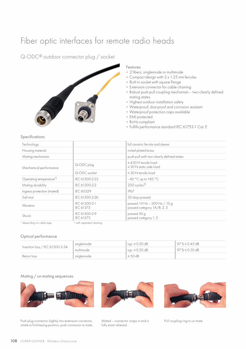
108 HUBER+SUHNER Wireless infrastructure
Features• 2 fibers, singlemode or multimode • Compact design with 2 x 1.25 mm ferrules• Built-in socket with square flange• Extension connector for cable chaining• Robust push-pull coupling mechanism – two clearly defined
mating states • Highest outdoor installation safety • Waterproof, dust proof and corrosion resistant • Waterproof protection caps available• EMI protected• RoHs compliant• Fulfills performance standard IEC 61753-1 Cat. E
Q-ODC® outdoor connector plug / socket
Specifications
Technology full ceramic ferrule and sleeve
Housing material nickel-plated brass
Mating mechanism push-pull with two clearly defined states
Mechanical performance Q-ODC plug ≤ 450 N tensile load
≤ 30 N static side load
Q-ODC socket ≤ 30 N tensile load
Operating temperature1) IEC 61300-2-22 –40 °C up to +85 °C
Mating durability IEC 61300-2-2 200 cycles2)
Ingress protection (mated) IEC 60529 IP67
Salt mist IEC 61300-2-26 30 days passed
Vibration IEC 61300-2-1IEC 61373
passed 10 Hz – 500 Hz / 10 gpassed category 1A/B, 2, 3
Shock IEC 61300-2-9IEC 61373
passed 50 gpassed category 1, 2
1) depending on cable type 2) with repeated cleaning
Optical performance
Insertion loss / IEC 61300-3-34singlemode typ. ≤ 0.20 dB 97 % ≤ 0.45 dB
multimode typ. ≤ 0.20 dB 97 % ≤ 0.50 dB
Return loss singlemode ≥ 50 dB
Fiber optic interfaces for remote radio heads
Mating / un-mating sequences
Push plug connector slightly into extension connector, rotate to find keying position, push connector to mate.
Mated – connector snaps in and is fully strain relieved.
Pull coupling ring to un-mate.
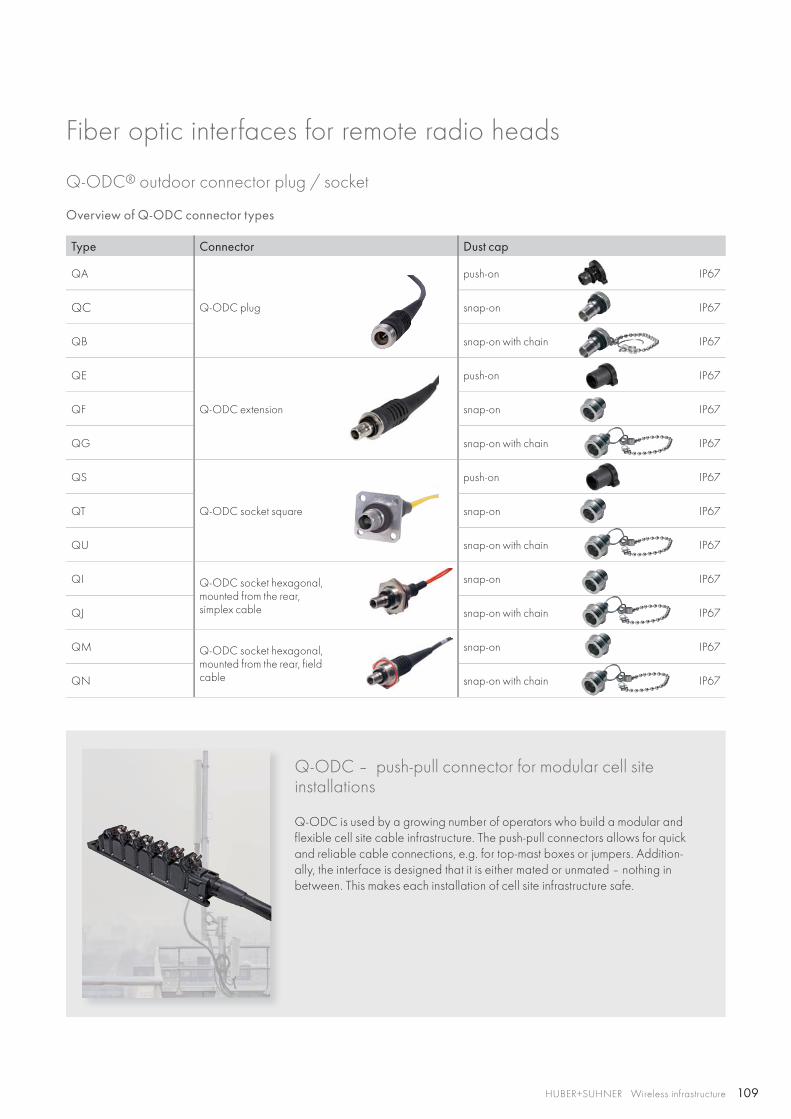
109HUBER+SUHNER Wireless infrastructure
Q-ODC® outdoor connector plug / socket
Overview of Q-ODC connector types
Type Connector Dust cap
QA
Q-ODC plug
push-on IP67
QC snap-on IP67
QB snap-on with chain IP67
QE
Q-ODC extension
push-on IP67
QF snap-on IP67
QG snap-on with chain IP67
QS
Q-ODC socket square
push-on IP67
QT snap-on IP67
QU snap-on with chain IP67
QI Q-ODC socket hexagonal, mounted from the rear, simplex cable
snap-on IP67
QJ snap-on with chain IP67
QM Q-ODC socket hexagonal, mounted from the rear, field cable
snap-on IP67
QN snap-on with chain IP67
Q-ODC – push-pull connector for modular cell site installations
Q-ODC is used by a growing number of operators who build a modular and flexible cell site cable infrastructure. The push-pull connectors allows for quick and reliable cable connections, e.g. for top-mast boxes or jumpers. Addition-ally, the interface is designed that it is either mated or unmated – nothing in between. This makes each installation of cell site infrastructure safe.
Fiber optic interfaces for remote radio heads
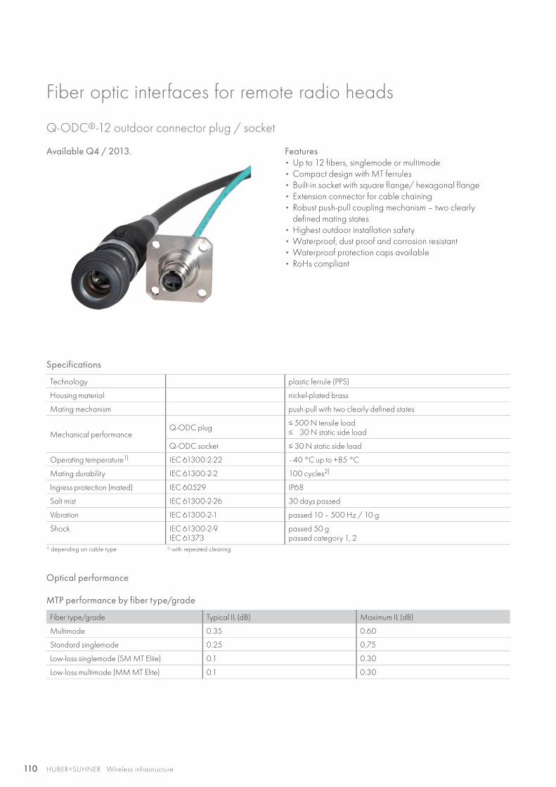
110 HUBER+SUHNER Wireless infrastructure
Fiber optic interfaces for remote radio heads
Features• Up to 12 fibers, singlemode or multimode• Compact design with MT ferrules• Built-in socket with square flange/ hexagonal flange• Extension connector for cable chaining• Robust push-pull coupling mechanism – two clearly
defined mating states• Highest outdoor installation safety• Waterproof, dust proof and corrosion resistant• Waterproof protection caps available• RoHs compliant
Q-ODC®-12 outdoor connector plug / socket
Specifications
Technology plastic ferrule (PPS)
Housing material nickel-plated brass
Mating mechanism push-pull with two clearly defined states
Mechanical performance Q-ODC plug ≤ 500 N tensile load
≤ 30 N static side load
Q-ODC socket ≤ 30 N static side load
Operating temperature1) IEC 61300-2-22 –40 °C up to +85 °C
Mating durability IEC 61300-2-2 100 cycles2)
Ingress protection (mated) IEC 60529 IP68
Salt mist IEC 61300-2-26 30 days passed
Vibration IEC 61300-2-1 passed 10 – 500 Hz / 10 g
Shock IEC 61300-2-9IEC 61373
passed 50 gpassed category 1, 2
1) depending on cable type 2) with repeated cleaning
Optical performance
MTP performance by fiber type/grade
Fiber type/grade Typical IL (dB) Maximum IL (dB)
Multimode 0.35 0.60
Standard singlemode 0.25 0.75
Low-loss singlemode (SM MT Elite) 0.1 0.30
Low-loss multimode (MM MT Elite) 0.1 0.30
Available Q4 / 2013.
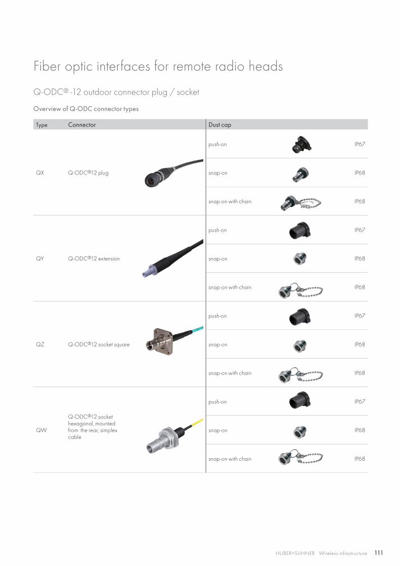
111HUBER+SUHNER Wireless infrastructure
Q-ODC® -12 outdoor connector plug / socket
Overview of Q-ODC connector types
Type Connector Dust cap
QX Q-ODC®12 plug
push-on IP67
snap-on IP68
snap-on with chain IP68
QY Q-ODC®12 extension
push-on IP67
snap-on IP68
snap-on with chain IP68
QZ Q-ODC®12 socket square
push-on IP67
snap-on IP68
snap-on with chain IP68
QW
Q-ODC®12 socket hexagonal, mounted from the rear, simplex cable
push-on IP67
snap-on IP68
snap-on with chain IP68
Fiber optic interfaces for remote radio heads
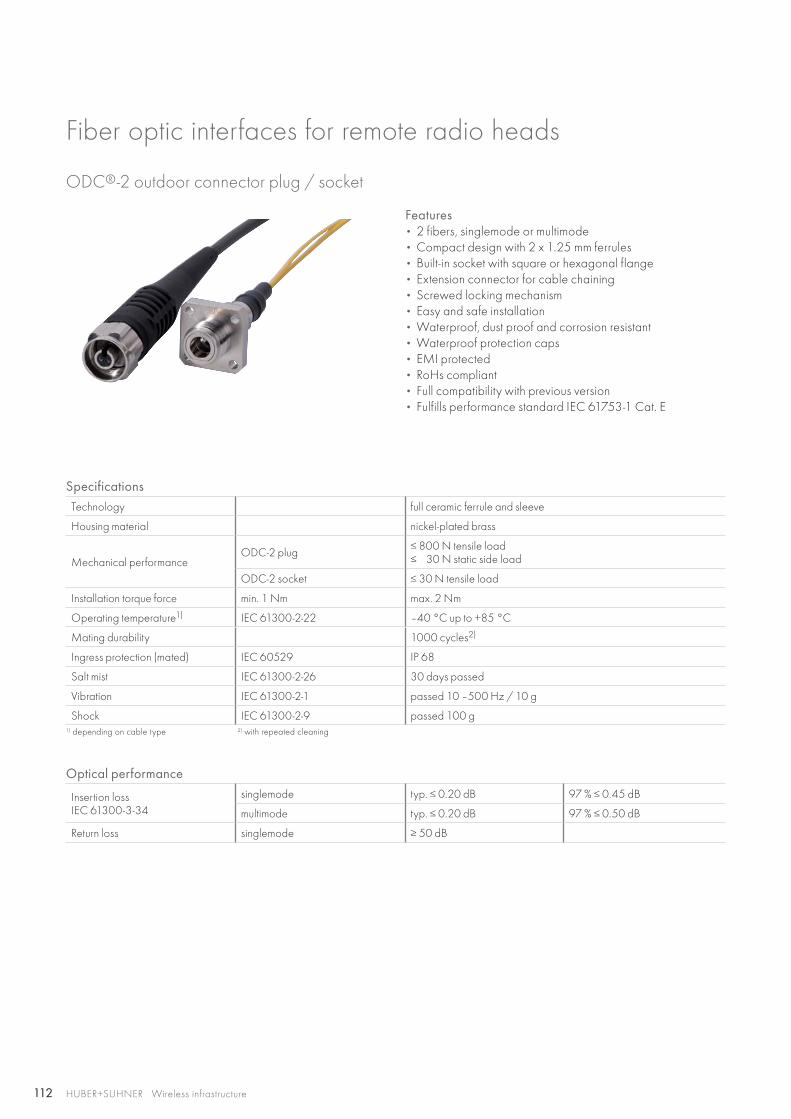
112 HUBER+SUHNER Wireless infrastructure
Features• 2 fibers, singlemode or multimode • Compact design with 2 x 1.25 mm ferrules• Built-in socket with square or hexagonal flange• Extension connector for cable chaining• Screwed locking mechanism • Easy and safe installation• Waterproof, dust proof and corrosion resistant• Waterproof protection caps• EMI protected• RoHs compliant• Full compatibility with previous version• Fulfills performance standard IEC 61753-1 Cat. E
ODC®-2 outdoor connector plug / socket
SpecificationsTechnology full ceramic ferrule and sleeve
Housing material nickel-plated brass
Mechanical performance ODC-2 plug ≤ 800 N tensile load
≤ 30 N static side load
ODC-2 socket ≤ 30 N tensile load
Installation torque force min. 1 Nm max. 2 Nm
Operating temperature1) IEC 61300-2-22 –40 °C up to +85 °C
Mating durability 1000 cycles2)
Ingress protection (mated) IEC 60529 IP 68
Salt mist IEC 61300-2-26 30 days passed
Vibration IEC 61300-2-1 passed 10 –500 Hz / 10 g
Shock IEC 61300-2-9 passed 100 g1) depending on cable type 2) with repeated cleaning
Optical performance
Insertion lossIEC 61300-3-34
singlemode typ. ≤ 0.20 dB 97 % ≤ 0.45 dB
multimode typ. ≤ 0.20 dB 97 % ≤ 0.50 dB
Return loss singlemode ≥ 50 dB
Fiber optic interfaces for remote radio heads
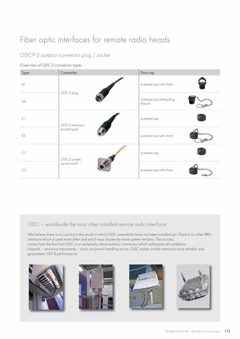
113HUBER+SUHNER Wireless infrastructure
ODC – worldwide the most often installed remote radio interface
We believe there is no country in the world in which ODC assemblies have not been installed yet. There is no other RRH interface which is used more often and which was chosen by more system vendors. The success comes from the fact that ODC is an extremely robust outdoor connector which withstands all installation hazards – and most importantly – does not permit handling errors. ODC makes mobile networks more reliable and guarantees 100 % performance.
Overview of ODC-2 connector types
Type Connector Dust cap
A1
ODC-2 plug
screwed cap with chain
A4 screwed cap with pulling feature
E1
ODC-2 extension (socket type)
screwed cap
E3 screwed cap with chain
C1
ODC-2 socket,square small
screwed cap
C3 screwed cap with chain
ODC®-2 outdoor connector plug / socket
Fiber optic interfaces for remote radio heads
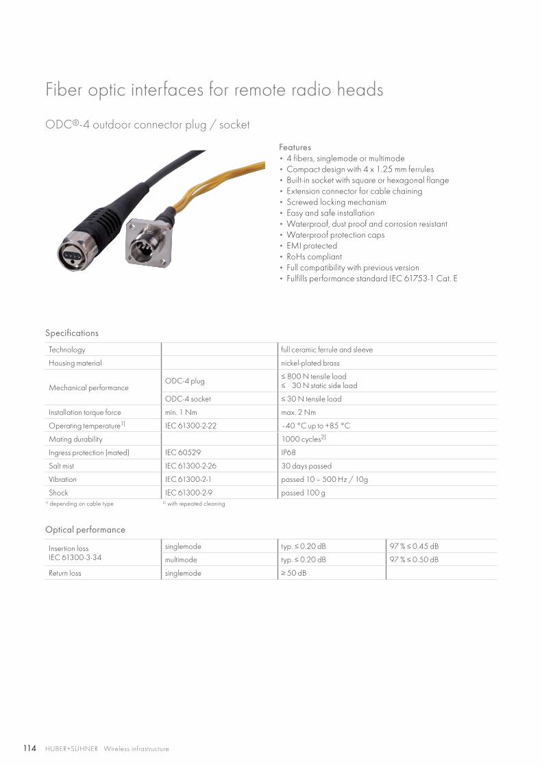
114 HUBER+SUHNER Wireless infrastructure
Features• 4 fibers, singlemode or multimode • Compact design with 4 x 1.25 mm ferrules• Built-in socket with square or hexagonal flange• Extension connector for cable chaining• Screwed locking mechanism• Easy and safe installation• Waterproof, dust proof and corrosion resistant• Waterproof protection caps• EMI protected• RoHs compliant• Full compatibility with previous version• Fulfills performance standard IEC 61753-1 Cat. E
ODC®-4 outdoor connector plug / socket
Specifications
Technology full ceramic ferrule and sleeve
Housing material nickel-plated brass
Mechanical performance ODC-4 plug ≤ 800 N tensile load
≤ 30 N static side load
ODC-4 socket ≤ 30 N tensile load
Installation torque force min. 1 Nm max. 2 Nm
Operating temperature1) IEC 61300-2-22 –40 °C up to +85 °C
Mating durability 1000 cycles2)
Ingress protection (mated) IEC 60529 IP68
Salt mist IEC 61300-2-26 30 days passed
Vibration IEC 61300-2-1 passed 10 – 500 Hz / 10g
Shock IEC 61300-2-9 passed 100 g1) depending on cable type 2) with repeated cleaning
Optical performance
Insertion lossIEC 61300-3-34
singlemode typ. ≤ 0.20 dB 97 % ≤ 0.45 dB
multimode typ. ≤ 0.20 dB 97 % ≤ 0.50 dB
Return loss singlemode ≥ 50 dB
Fiber optic interfaces for remote radio heads
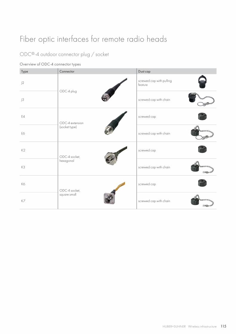
115HUBER+SUHNER Wireless infrastructure
ODC®-4 outdoor connector plug / socket
Overview of ODC-4 connector types
Type Connector Dust cap
J2
ODC-4 plug
screwed cap with pulling feature
J3 screwed cap with chain
E4
ODC-4 extension (socket type)
screwed cap
E6 screwed cap with chain
K2
ODC-4 socket,hexagonal
screwed cap
K3 screwed cap with chain
K6
ODC-4 socket,square small
screwed cap
K7 screwed cap with chain
Fiber optic interfaces for remote radio heads
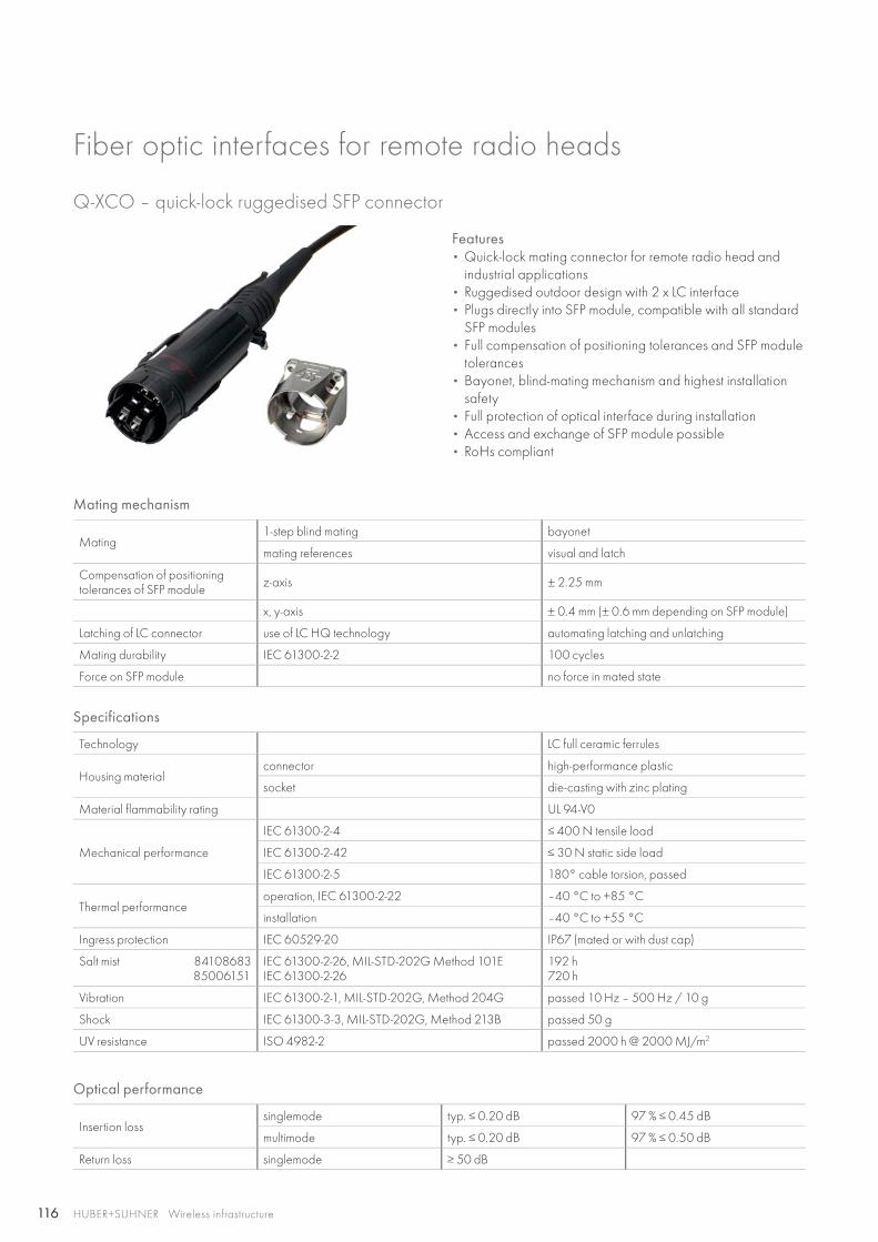
116 HUBER+SUHNER Wireless infrastructure
Q-XCO – quick-lock ruggedised SFP connector
Features• Quick-lock mating connector for remote radio head and
industrial applications• Ruggedised outdoor design with 2 x LC interface• Plugs directly into SFP module, compatible with all standard
SFP modules• Full compensation of positioning tolerances and SFP module
tolerances• Bayonet, blind-mating mechanism and highest installation
safety• Full protection of optical interface during installation• Access and exchange of SFP module possible• RoHs compliant
Mating mechanism
Mating1-step blind mating bayonet
mating references visual and latch
Compensation of positioning tolerances of SFP module z-axis ± 2.25 mm
x, y-axis ± 0.4 mm (± 0.6 mm depending on SFP module)
Latching of LC connector use of LC HQ technology automating latching and unlatching
Mating durability IEC 61300-2-2 100 cycles
Force on SFP module no force in mated state
Specifications
Technology LC full ceramic ferrules
Housing materialconnector high-performance plastic
socket die-casting with zinc plating
Material flammability rating UL 94-V0
Mechanical performance
IEC 61300-2-4 ≤ 400 N tensile load
IEC 61300-2-42 ≤ 30 N static side load
IEC 61300-2-5 180° cable torsion, passed
Thermal performanceoperation, IEC 61300-2-22 –40 °C to +85 °C
installation –40 °C to +55 °C
Ingress protection IEC 60529-20 IP67 (mated or with dust cap)
Salt mist 84108683 85006151
IEC 61300-2-26, MIL-STD-202G Method 101EIEC 61300-2-26
192 h720 h
Vibration IEC 61300-2-1, MIL-STD-202G, Method 204G passed 10 Hz – 500 Hz / 10 g
Shock IEC 61300-3-3, MIL-STD-202G, Method 213B passed 50 g
UV resistance ISO 4982-2 passed 2000 h @ 2000 MJ/m2
Optical performance
Insertion losssinglemode typ. ≤ 0.20 dB 97 % ≤ 0.45 dB
multimode typ. ≤ 0.20 dB 97 % ≤ 0.50 dB
Return loss singlemode ≥ 50 dB
Fiber optic interfaces for remote radio heads
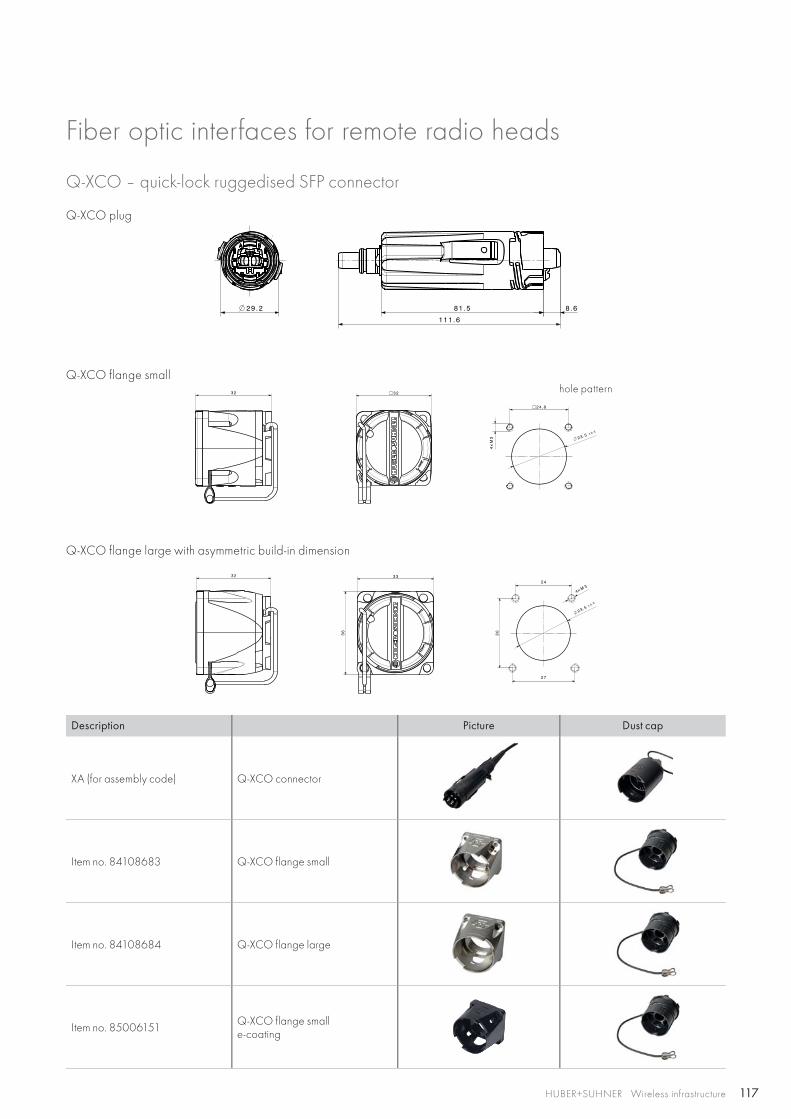
117HUBER+SUHNER Wireless infrastructure
Q-XCO – quick-lock ruggedised SFP connector
Fiber optic interfaces for remote radio heads
Q-XCO plug
Q-XCO flange smallhole pattern
Q-XCO flange large with asymmetric build-in dimension
Description Picture Dust cap
XA (for assembly code) Q-XCO connector
Item no. 84108683 Q-XCO flange small
Item no. 84108684 Q-XCO flange large
Item no. 85006151 Q-XCO flange smalle-coating
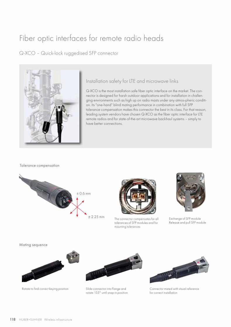
118
± 0.6 mm
± 2.25 mm
HUBER+SUHNER Wireless infrastructure
Installation safety for LTE and microwave links
Q-XCO is the most installation safe fiber optic interface on the market. The con-nector is designed for harsh outdoor applications and for installation in challen-ging environments such as high up on radio masts under any atmos-pheric conditi-on. Its "one-hand" blind mating performance in combination with full SFP tolerance compensation makes this connector the best in its class. For that reason, leading system vendors have chosen Q-XCO as the fiber optic interface for LTE remote radios and for state-of-the-art microwave backhaul systems – simply to have better connections.
Q-XCO – Quick-lock ruggedised SFP connector
Mating sequence
Slide connector into flange and rotate 155° until snap-in position
Rotate to find correct keying position
Tolerance compensation
The connector compensates for all tolerances of SFP modules and for mounting tolerances
Exchange of SFP moduleRelease and pull SFP module
Connector mated with visual reference for correct installation
Fiber optic interfaces for remote radio heads
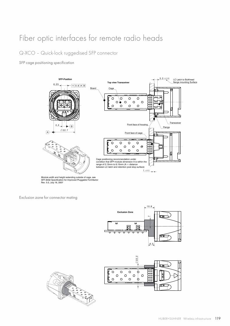
119HUBER+SUHNER Wireless infrastructure
SFP cage positioning specification
Exclusion zone for connector mating
Q-XCO – Quick-lock ruggedised SFP connector
Fiber optic interfaces for remote radio heads
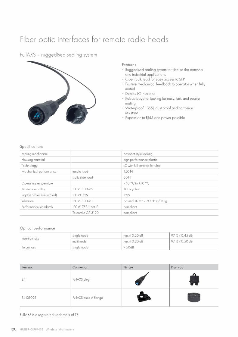
120 HUBER+SUHNER Wireless infrastructure
Features• Ruggedised sealing system for fiber-to-the-antenna
and industrial applications• Open bulkhead for easy access to SFP• Positive mechanical feedback to operator when fully
mated• Duplex LC interface• Robust bayonet locking for easy, fast, and secure
mating• Waterproof (IP65), dust proof and corrosion
resistant.• Expansion to RJ45 and power possible
FullAXS – ruggedised sealing system
Specifications
Mating mechanism bayonet style locking
Housing material high performance plastic
Technology LC with full ceramic ferrules
Mechanical performance tensile load 150 N
static side load 30 N
Operating temperature –40 °C to +70 °C
Mating durability IEC 61300-2-2 100 cycles
Ingress protection (mated) IEC 60529 IP65
Vibration IEC 61300-2-1 passed 10 Hz – 500 Hz / 10 g
Performance standards IEC 61753-1 cat. E compliant
Telcordia GR 3120 compliant
Optical performance
Insertion loss singlemode typ. ≤ 0.20 dB 97 % ≤ 0.45 dB
multimode typ. ≤ 0.20 dB 97 % ≤ 0.50 dB
Return loss singlemode ≥ 50dB
Item no. Connector Picture Dust cap
Z4 FullAXS plug
84131095 FullAXS build-in flange
.
FullAXS is a registered trademark of TE.
Fiber optic interfaces for remote radio heads
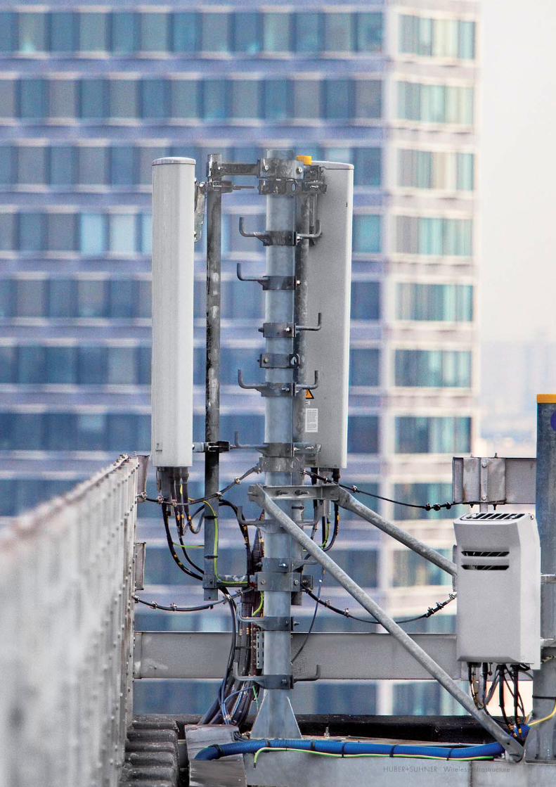
121HUBER+SUHNER Wireless infrastructure
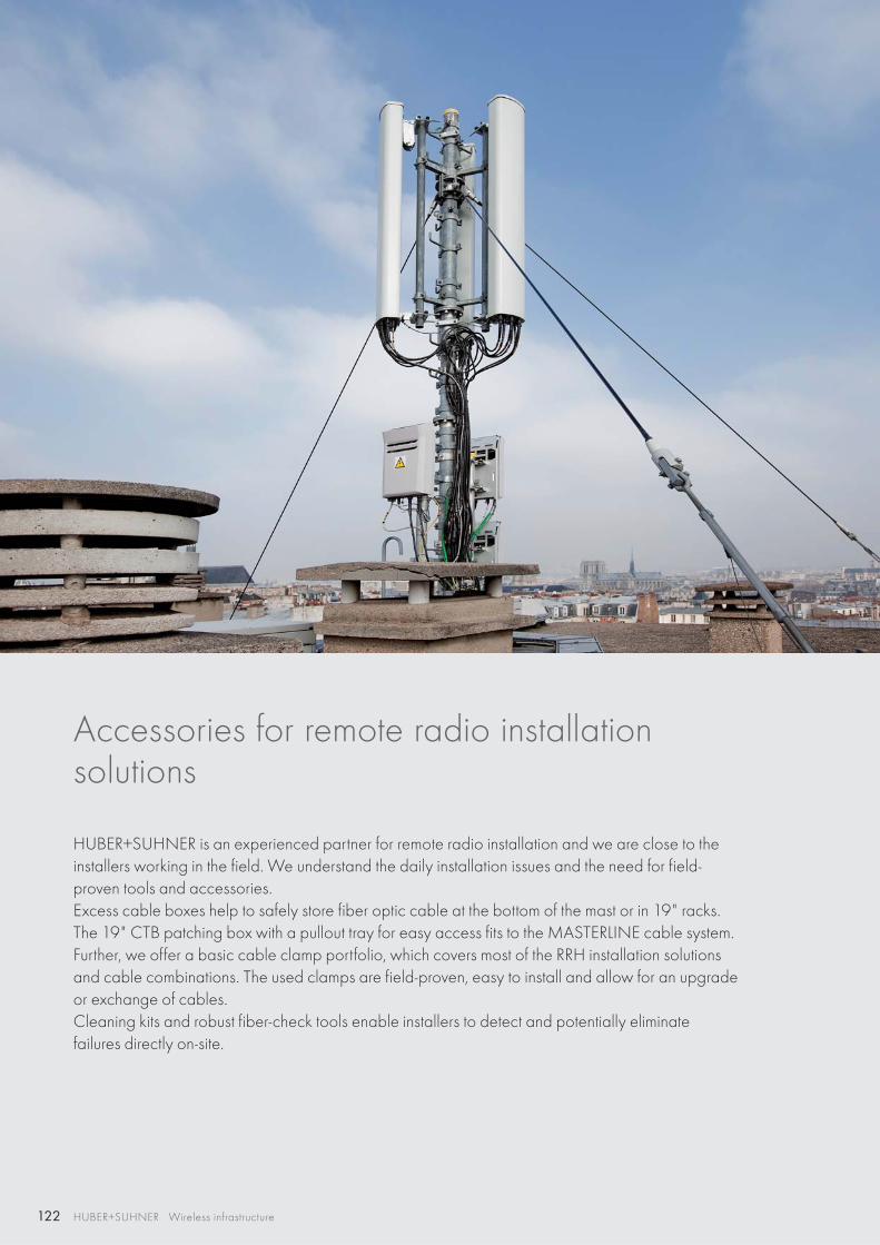
122 HUBER+SUHNER Wireless infrastructure
Accessories for remote radio installationsolutions
HUBER+SUHNER is an experienced partner for remote radio installation and we are close to the installers working in the field. We understand the daily installation issues and the need for field-proven tools and accessories. Excess cable boxes help to safely store fiber optic cable at the bottom of the mast or in 19" racks. The 19" CTB patching box with a pullout tray for easy access fits to the MASTERLINE cable system.Further, we offer a basic cable clamp portfolio, which covers most of the RRH installation solutions and cable combinations. The used clamps are field-proven, easy to install and allow for an upgrade or exchange of cables.Cleaning kits and robust fiber-check tools enable installers to detect and potentially eliminate failures directly on-site.
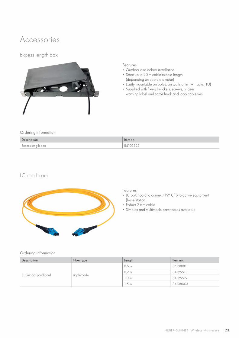
123HUBER+SUHNER Wireless infrastructure
Accessories
Excess length box
LC patchcord
Features • Outdoor and indoor installation• Store up to 20 m cable excess length
(depending on cable diameter)• Easily mountable on poles, on walls or in 19" racks (1U)• Supplied with fixing brackets, screws, a laser
warning label and some hook and loop cable ties
Features • LC patchcord to connect 19" CTB to active equipment
(base station)• Robust 2 mm cable• Simplex and multimode patchcords available
Ordering information
Description Item no.
Excess length box 84103325
Ordering information
Description Fiber type Length Item no.
LC uniboot patchcord singlemode
0.5 m 84138001
0.7 m 84125518
1.0 m 84125519
1.5 m 84138003
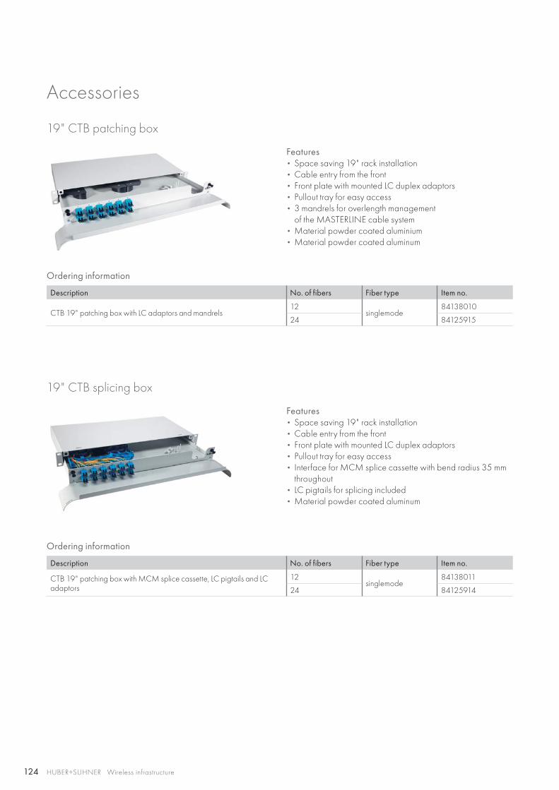
124 HUBER+SUHNER Wireless infrastructure
Accessories
19" CTB patching box
19" CTB splicing box
Features • Space saving 19" rack installation• Cable entry from the front• Front plate with mounted LC duplex adaptors• Pullout tray for easy access• 3 mandrels for overlength management
of the MASTERLINE cable system• Material powder coated aluminium• Material powder coated aluminum
Features • Space saving 19" rack installation• Cable entry from the front• Front plate with mounted LC duplex adaptors• Pullout tray for easy access• Interface for MCM splice cassette with bend radius 35 mm
throughout• LC pigtails for splicing included• Material powder coated aluminum
Ordering information
Description No. of fibers Fiber type Item no.
CTB 19" patching box with LC adaptors and mandrels12
singlemode84138010
24 84125915
Ordering information
Description No. of fibers Fiber type Item no.
CTB 19" patching box with MCM splice cassette, LC pigtails and LC adaptors
12singlemode
84138011
24 84125914
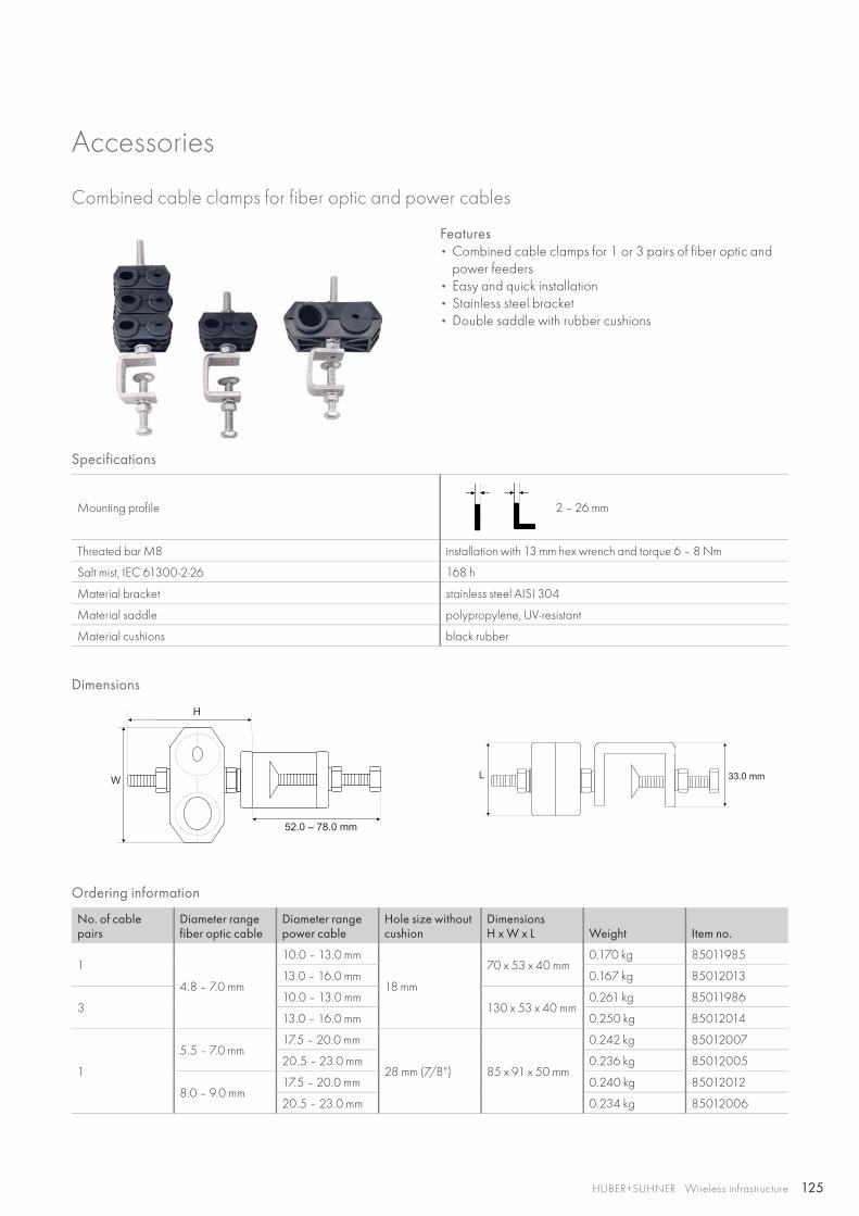
125
H
W
52.0 – 78.0 mm
L 33.0 mm
HUBER+SUHNER Wireless infrastructure
Accessories
Combined cable clamps for fiber optic and power cables
Features • Combined cable clamps for 1 or 3 pairs of fiber optic and
power feeders• Easy and quick installation• Stainless steel bracket• Double saddle with rubber cushions
Specifications
Mounting profile 2 – 26 mm
Threated bar M8 installation with 13 mm hex wrench and torque 6 – 8 Nm
Salt mist, IEC 61300-2-26 168 h
Material bracket stainless steel AISI 304
Material saddle polypropylene, UV-resistant
Material cushions black rubber
Dimensions
Ordering information
No. of cable pairs
Diameter range fiber optic cable
Diameter range power cable
Hole size without cushion
DimensionsH x W x L Weight Item no.
1
4.8 – 7.0 mm
10.0 – 13.0 mm
18 mm
70 x 53 x 40 mm0.170 kg 85011985
13.0 – 16.0 mm 0.167 kg 85012013
310.0 – 13.0 mm
130 x 53 x 40 mm0.261 kg 85011986
13.0 – 16.0 mm 0.250 kg 85012014
1
5.5 – 7.0 mm17.5 – 20.0 mm
28 mm (7/8") 85 x 91 x 50 mm
0.242 kg 85012007
20.5 – 23.0 mm 0.236 kg 85012005
8.0 – 9.0 mm17.5 – 20.0 mm 0.240 kg 85012012
20.5 – 23.0 mm 0.234 kg 85012006
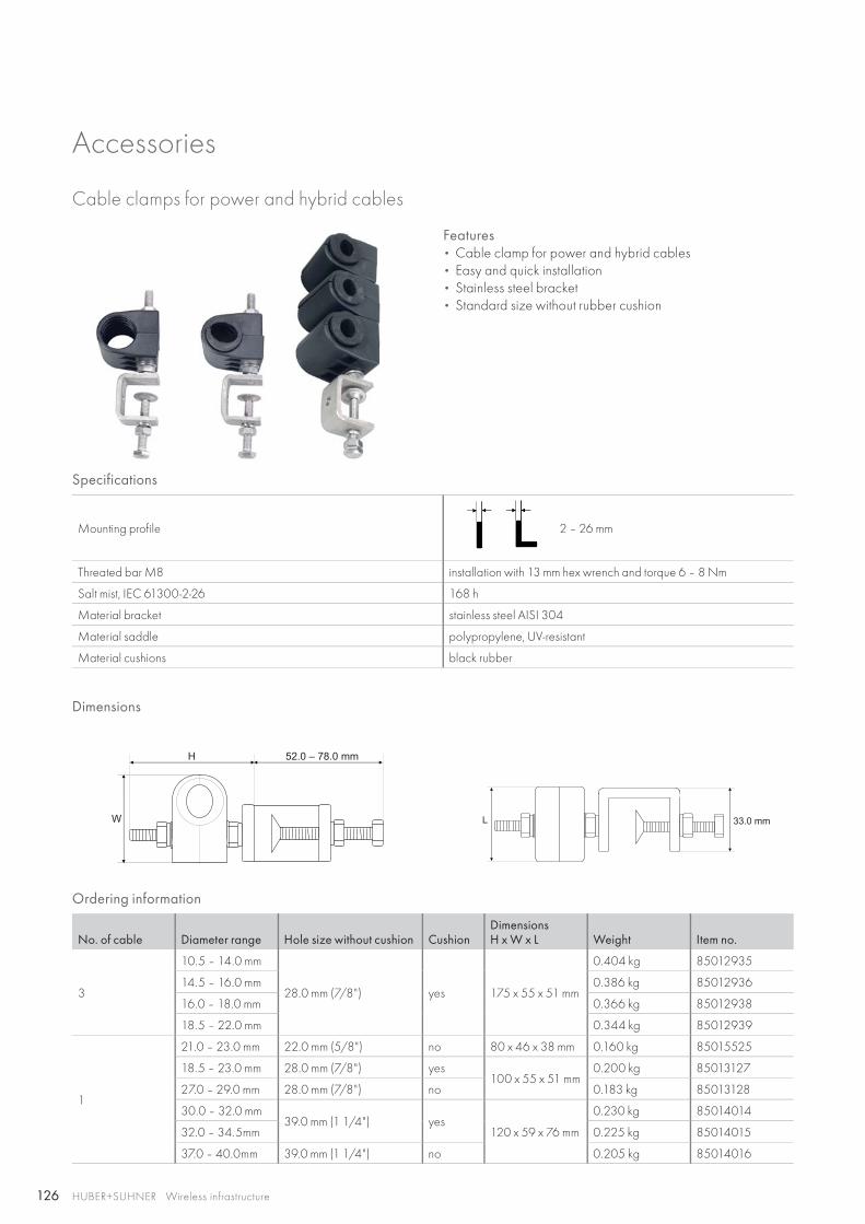
126
H 52.0 – 78.0 mm
W L 33.0 mm
HUBER+SUHNER Wireless infrastructure
Accessories
Cable clamps for power and hybrid cables
Features • Cable clamp for power and hybrid cables• Easy and quick installation• Stainless steel bracket• Standard size without rubber cushion
Specifications
Mounting profile 2 – 26 mm
Threated bar M8 installation with 13 mm hex wrench and torque 6 – 8 Nm
Salt mist, IEC 61300-2-26 168 h
Material bracket stainless steel AISI 304
Material saddle polypropylene, UV-resistant
Material cushions black rubber
Dimensions
Ordering information
No. of cable Diameter range Hole size without cushion CushionDimensionsH x W x L Weight Item no.
3
10.5 – 14.0 mm
28.0 mm (7/8") yes 175 x 55 x 51 mm
0.404 kg 85012935
14.5 – 16.0 mm 0.386 kg 85012936
16.0 – 18.0 mm 0.366 kg 85012938
18.5 – 22.0 mm 0.344 kg 85012939
1
21.0 – 23.0 mm 22.0 mm (5/8") no 80 x 46 x 38 mm 0.160 kg 85015525
18.5 – 23.0 mm 28.0 mm (7/8") yes100 x 55 x 51 mm
0.200 kg 85013127
27.0 – 29.0 mm 28.0 mm (7/8") no 0.183 kg 85013128
30.0 – 32.0 mm39.0 mm (1 1/4") yes
120 x 59 x 76 mm
0.230 kg 85014014
32.0 – 34.5mm 0.225 kg 85014015
37.0 – 40.0mm 39.0 mm (1 1/4") no 0.205 kg 85014016
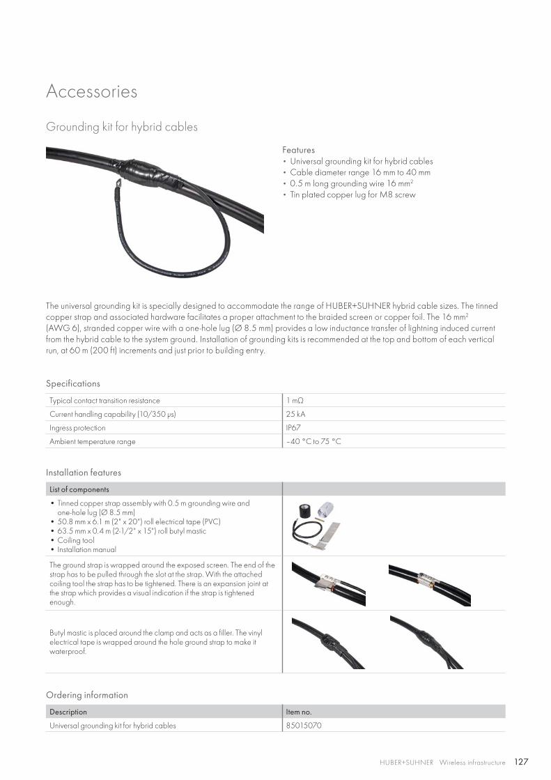
127HUBER+SUHNER Wireless infrastructure
Accessories
Grounding kit for hybrid cables
Features • Universal grounding kit for hybrid cables• Cable diameter range 16 mm to 40 mm• 0.5 m long grounding wire 16 mm2
• Tin plated copper lug for M8 screw
Specifications
Typical contact transition resistance 1 mΩ
Current handling capability (10/350 μs) 25 kA
Ingress protection IP67
Ambient temperature range –40 °C to 75 °C
Installation features
List of components
• Tinned copper strap assembly with 0.5 m grounding wire and one-hole lug (Ø 8.5 mm)
• 50.8 mm x 6.1 m (2" x 20") roll electrical tape (PVC)• 63.5 mm x 0.4 m (2-1/2" x 15") roll butyl mastic• Coiling tool• Installation manual
The ground strap is wrapped around the exposed screen. The end of the strap has to be pulled through the slot at the strap. With the attached coiling tool the strap has to be tightened. There is an expansion joint at the strap which provides a visual indication if the strap is tightened enough.
Butyl mastic is placed around the clamp and acts as a filler. The vinyl electrical tape is wrapped around the hole ground strap to make it waterproof.
The universal grounding kit is specially designed to accommodate the range of HUBER+SUHNER hybrid cable sizes. The tinned copper strap and associated hardware facilitates a proper attachment to the braided screen or copper foil. The 16 mm2
(AWG 6), stranded copper wire with a one-hole lug (Ø 8.5 mm) provides a low inductance transfer of lightning induced current from the hybrid cable to the system ground. Installation of grounding kits is recommended at the top and bottom of each vertical run, at 60 m (200 ft) increments and just prior to building entry.
Ordering information
Description Item no.
Universal grounding kit for hybrid cables 85015070
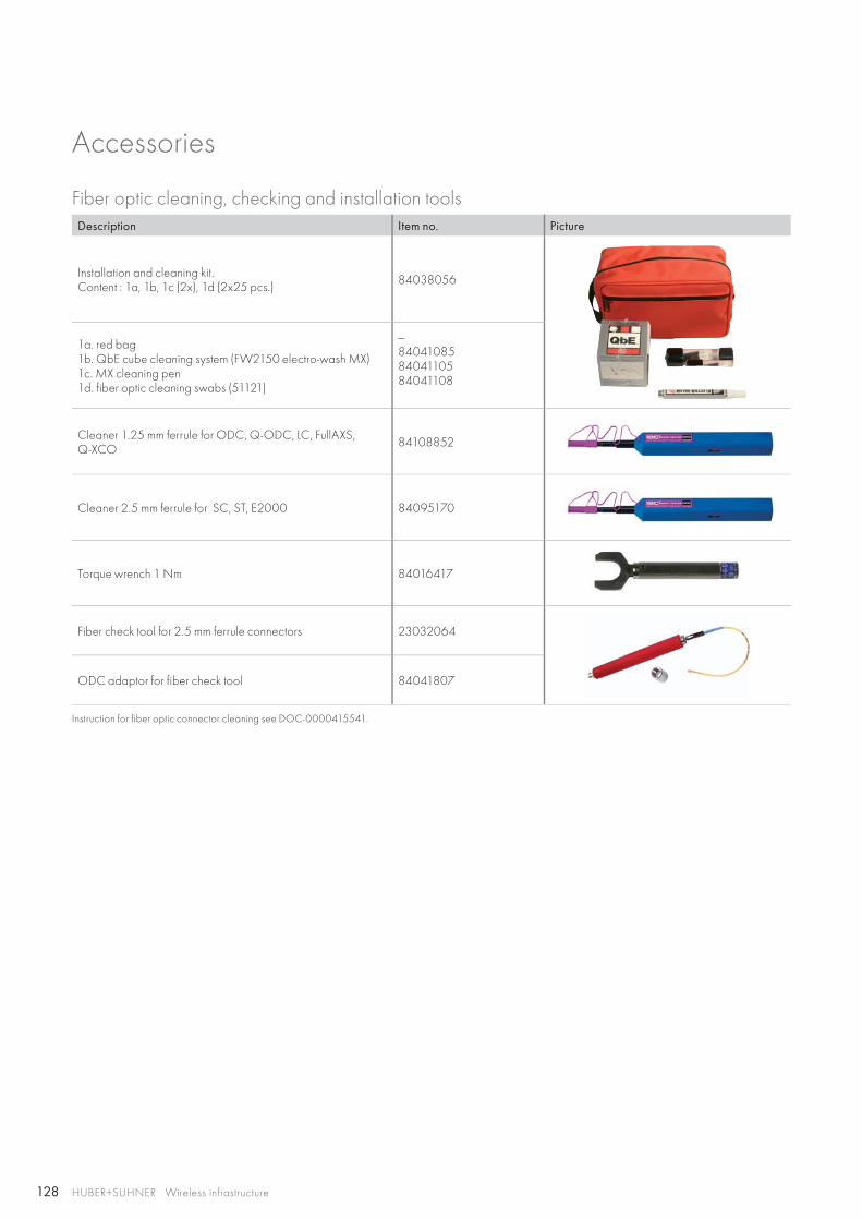
128 HUBER+SUHNER Wireless infrastructure
Accessories
Fiber optic cleaning, checking and installation toolsDescription Item no. Picture
Installation and cleaning kit.Content : 1a, 1b, 1c (2x), 1d (2x25 pcs.) 84038056
1a. red bag1b. QbE cube cleaning system (FW2150 electro-wash MX)1c. MX cleaning pen1d. fiber optic cleaning swabs (51121)
—840410858404110584041108
Cleaner 1.25 mm ferrule for ODC, Q-ODC, LC, FullAXS, Q-XCO 84108852
Cleaner 2.5 mm ferrule for SC, ST, E2000 84095170
Torque wrench 1 Nm 84016417
Fiber check tool for 2.5 mm ferrule connectors 23032064
ODC adaptor for fiber check tool 84041807
Instruction for fiber optic connector cleaning see DOC-0000415541.
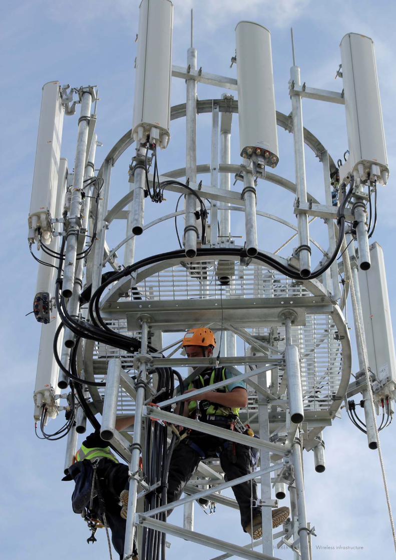
129HUBER+SUHNER Wireless infrastructure
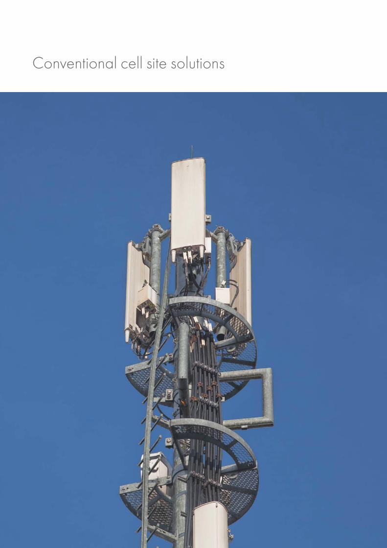
Conventional cell site solutions
131HUBER+SUHNER Wireless infrastructure
Content
LISCA – RF jumpers 132
SUCOFEED corrugated cables 138
SUCOFEED aluminium corrugated cables 147
QUICK-FIT coaxial connectors 150
HUBER+SUHNER ECO connectors 154
Cable stripping tools 158
Lightning protectors 162
Accessories 174
Power splitters 180
GPS antennas 184
PIM test kit 186
RF Feederline components selection guide 190
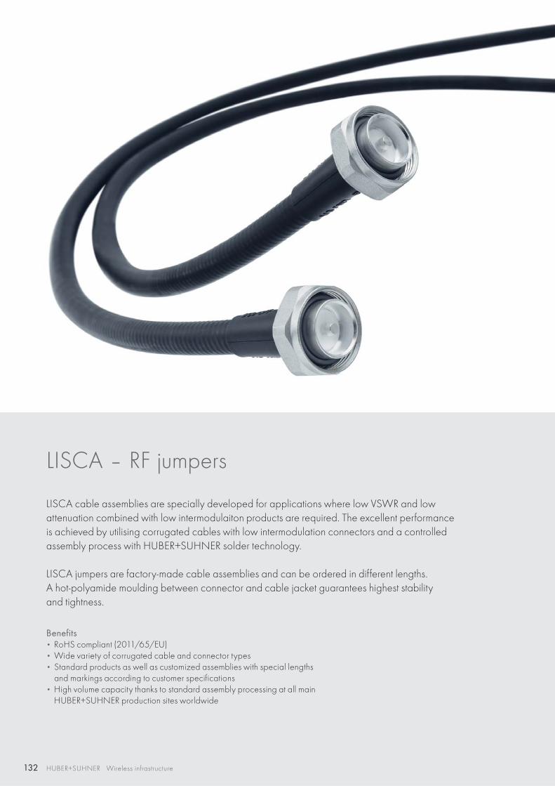
132 HUBER+SUHNER Wireless infrastructure
LISCA – RF jumpers
LISCA cable assemblies are specially developed for applications where low VSWR and low attenuation combined with low inter modulaiton products are required. The excellent performance is achieved by utilising corrugated cables with low intermodulation connectors and a controlled assembly process with HUBER+SUHNER solder technology.
LISCA jumpers are factory-made cable assemblies and can be ordered in different lengths. A hot-polyamide moulding between connector and cable jacket guarantees highest stability and tightness.
Benefits • RoHS compliant (2011/65/EU)• Wide variety of corrugated cable and connector types• Standard products as well as customized assemblies with special lengths
and markings according to customer specifications• High volume capacity thanks to standard assembly processing at all main
HUBER+SUHNER production sites worldwide
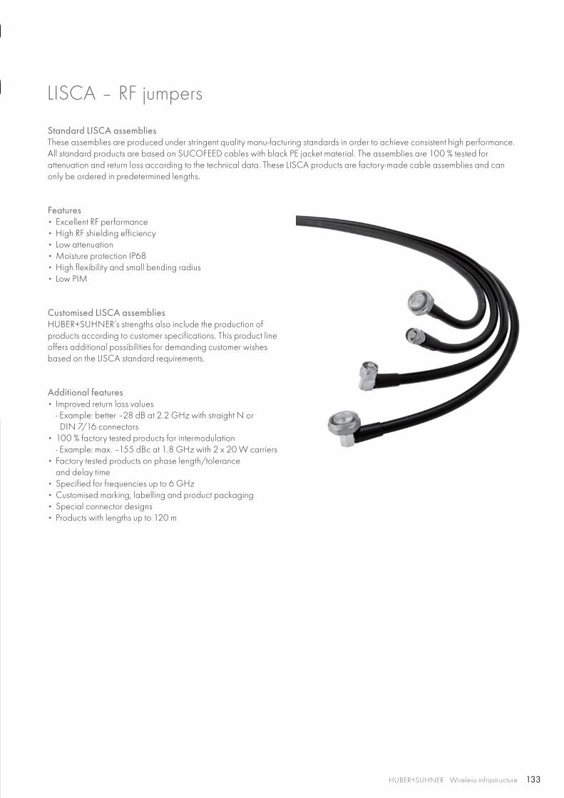
133HUBER+SUHNER Wireless infrastructure
LISCA – RF jumpers
Standard LISCA assembliesThese assemblies are produced under stringent quality manu-facturing standards in order to achieve consistent high performance. All standard products are based on SUCOFEED cables with black PE jacket material. The assemblies are 100 % tested forattenuation and return loss according to the technical data. These LISCA products are factory-made cable assemblies and can only be ordered in predetermined lengths.
Features • Excellent RF performance• High RF shielding efficiency • Low attenuation• Moisture protection IP68• High flexibility and small bending radius• Low PIM
Customised LISCA assembliesHUBER+SUHNER’s strengths also include the production of products according to customer specifications. This product line offers additional possibilities for demanding customer wishes based on the LISCA standard requirements.
Additional features• Improved return loss values
- Example: better –28 dB at 2.2 GHz with straight N or DIN 7/16 connectors
• 100 % factory tested products for intermodulation- Example: max. –155 dBc at 1.8 GHz with 2 x 20 W carriers
• Factory tested products on phase length/tolerance and delay time
• Specified for frequencies up to 6 GHz• Customised marking, labelling and product packaging • Special connector designs• Products with lengths up to 120 m
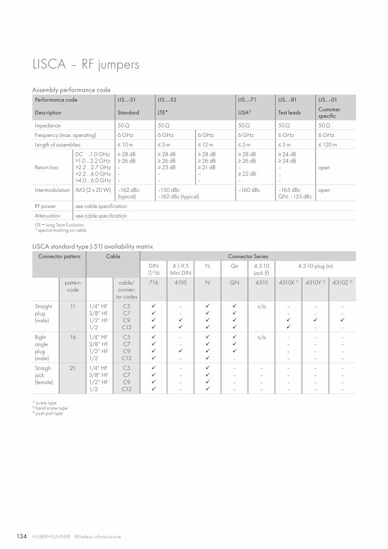
134 HUBER+SUHNER Wireless infrastructure
LISCA – RF jumpers
Assembly performance codePerformance code LIS...-51 LIS...-52 LIS...-71 LIS…-81 LIS…-01
Description Standard LTE* USA1) Test leads Customer specific
Impedance 50 Ω 50 Ω 50 Ω 50 Ω 50 Ω
Frequency (max. operating) 6 GHz 6 GHz 6 GHz 6 GHz 6 GHz 6 GHz
Length of assemblies ≤ 10 m ≤ 5 m ≤ 12 m ≤ 5 m ≤ 5 m ≤ 120 m
Return loss
DC ..1.0 GHz>1.0 .. 2.2 GHz>2.2 .. 2.7 GHz>2.2 .. 4.0 GHz>4.0 .. 6.0 GHz
≥ 28 dB≥ 26 dB–––
≥ 28 dB≥ 26 dB≥ 23 dB––
≥ 28 dB≥ 26 dB≥ 21 dB––
≥ 28 dB≥ 26 dB–≥ 22 dB–
≥ 24 dB≥ 24 dB–––
open
Intermodulation IM3 (2 x 20 W) –162 dBc (typical)
–150 dBc–162 dBc (typical)
–160 dBc –165 dBc QN: –155 dBc
open
RF power see cable specification
Attenuation see cable specification
LTE = Long Term Evolution1) special marking on cable
LISCA standard type (-51) availability matrixConnector pattern Cable Connector Series
DIN 7/16
4.1-9.5 Mini DIN
N Qn 4.3-10 jack (f)
4.3-10 plug (m)
pattern code
cable/ connec-
tor codes
716 4195 N QN 4310 4310X 1) 4310Y 2) 4310Z 3)
Straight plug (male)
11 1/4" HF3/8" HF1/2" HF1/2
C5C7C9C12
––
n/a ––
–––
–––
Right angle plug (male)
16 1/4" HF3/8" HF1/2" HF1/2
C5C7C9C12
–––
–
n/a ––––
––––
––––
Straigh jack (female)
21 1/4" HF3/8" HF1/2" HF1/2
C5C7C9C12
––––
––––
––––
––––
––––
––––
1) screw type2) hand screw type3) push-pull type
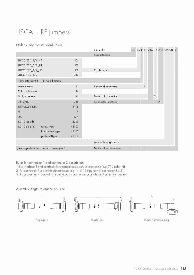
135HUBER+SUHNER Wireless infrastructure
Assembly length: tolerance +/– 1 %
Plug to plug Plug to jack Plug to right angle plug
Order number for standard LISCA Example: LIS - C9 F - 11 716 - 16 716 - 02000 - 51
Product name
SUCOFEED_1/4_HF C5
SUCOFEED_3/8_HF C7
SUCOFEED_1/2_HF C9 Cable type
SUCOFEED_1/2 C12
Flame retardant: F PE: no indication
Straight male 11 Pattern of connector 1
Right angle male 16
Straight female 21 Pattern of connector 2
DIN 7/16 716 Connector interface 1 2
4.1-9.5 Mini DIN 4195
N N
QN QN
4.3-10 jack (f) 4310
4.3-10 plug (m) screw type 4310X
hand screw type 4310Y
push-pull type 4310Z
Assembly length in mm
Jumper performance code example: 51 Technical performance
Rules for connector 1 and connector 2 description1. For interface 1 and interface 2: numerical code before letter code (e.g. 716 befor N).2. For connector 1 use lower pattern code (e.g. 11 or 16 if pattern of connector 2 is 21).3. If both connectors are of right angle, additional information about alignment is required.
LISCA – RF jumpers
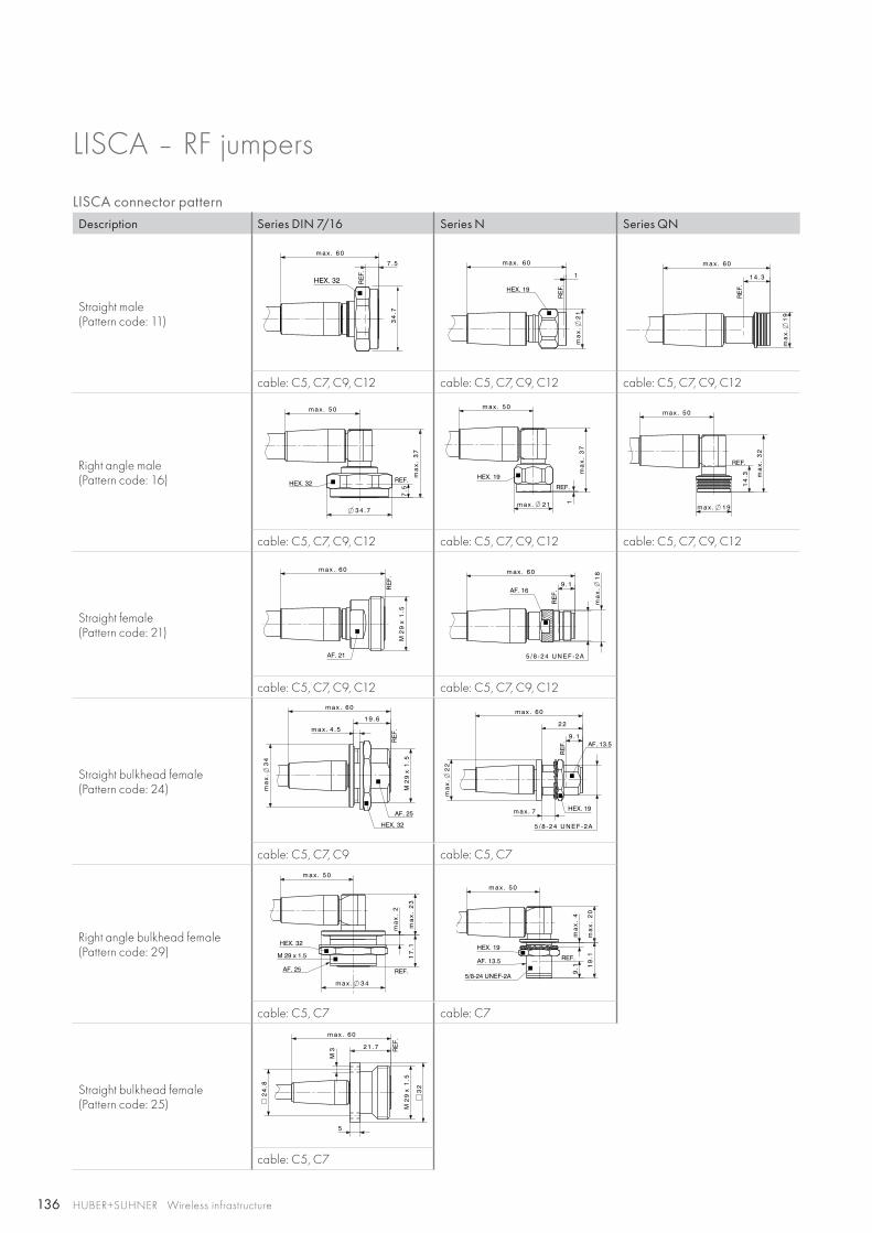
136 HUBER+SUHNER Wireless infrastructure
LISCA – RF jumpers
LISCA connector patternDescription Series DIN 7/16 Series N Series QN
Straight male(Pattern code: 11)
cable: C5, C7, C9, C12 cable: C5, C7, C9, C12 cable: C5, C7, C9, C12
Right angle male(Pattern code: 16)
cable: C5, C7, C9, C12 cable: C5, C7, C9, C12 cable: C5, C7, C9, C12
Straight female(Pattern code: 21)
cable: C5, C7, C9, C12 cable: C5, C7, C9, C12
Straight bulkhead female(Pattern code: 24)
cable: C5, C7, C9 cable: C5, C7
Right angle bulkhead female(Pattern code: 29)
cable: C5, C7 cable: C7
Straight bulkhead female(Pattern code: 25)
cable: C5, C7
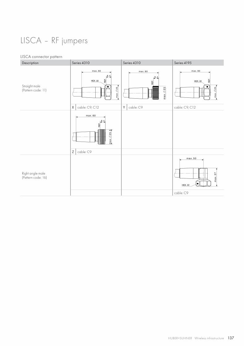
137HUBER+SUHNER Wireless infrastructure
LISCA – RF jumpers
LISCA connector patternDescription Series 4310 Series 4310 Series 4195
Straight male(Pattern code: 11)
8 . 4
m a x . 6 0
25
ma
x.
RE
F.
HEX. 22
8 . 4
m a x . 6 0
23
ma
x.
RE
F. HEX. 22
m a x . 6 0
25
ma
x.
RE
F.
X cable: C9, C12 Y cable: C9 cable: C9, C12
RE
F.
8 . 4
m a x . 6 0
25
.5m
ax.
Z cable: C9
Right angle male(Pattern code: 16)
HEX. 22
m a x . 5 0
ma
x.3
7
cable: C9
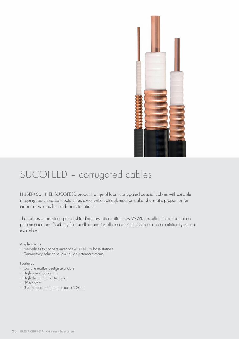
138 HUBER+SUHNER Wireless infrastructure
SUCOFEED – corrugated cables
HUBER+SUHNER SUCOFEED product range of foam corrugated coaxial cables with suitable stripping tools and connectors has excellent electrical, mechanical and climatic properties for indoor as well as for outdoor installations.
The cables guarantee optimal shielding, low attenuation, low VSWR, excellent intermodulation performance and flexibility for handling and installation on sites. Copper and aluminium types are available.
Applications • Feederlines to connect antennas with cellular base stations• Connectivity solution for distributed antenna systems
Features • Low attenuation design available• High power capability• High shielding effectiveness• UV-resistant• Guaranteed performance up to 3 GHz
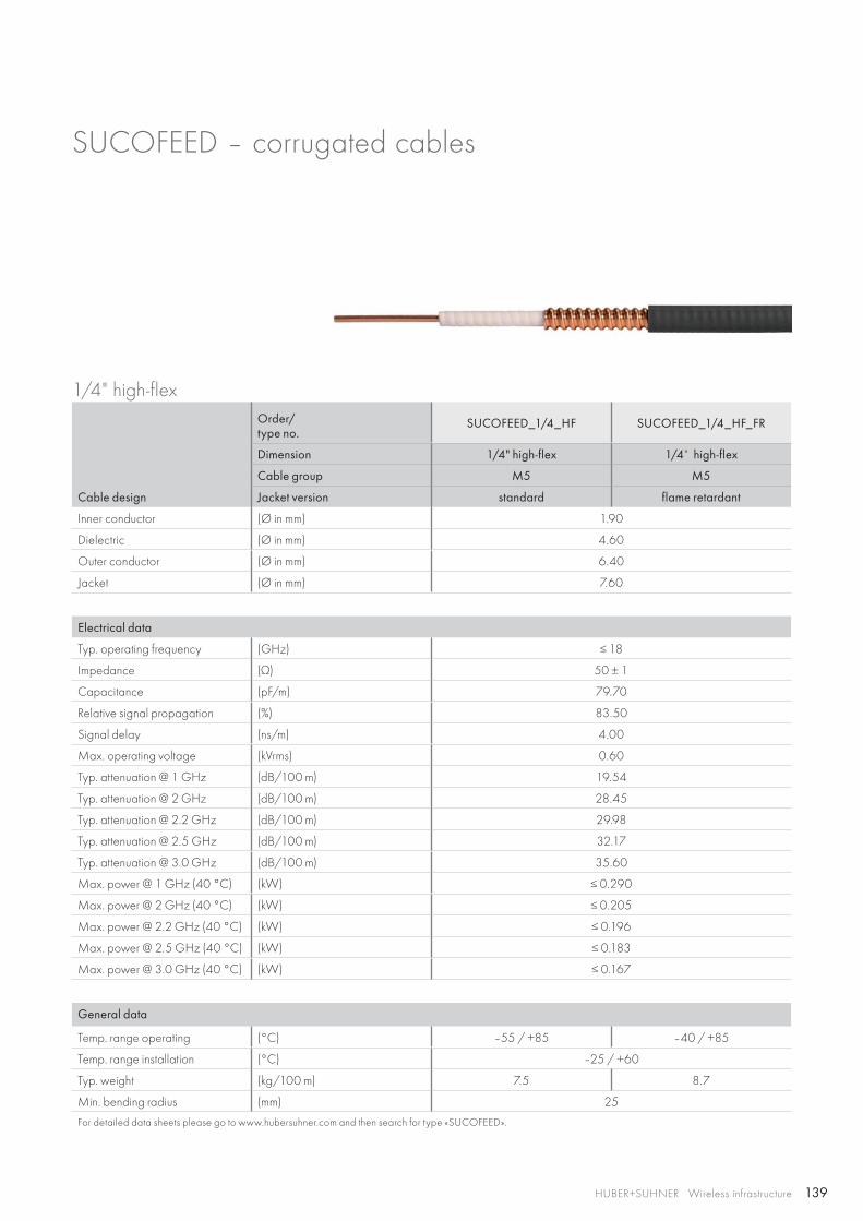
139HUBER+SUHNER Wireless infrastructure
SUCOFEED – corrugated cables
1/4" high-flex
Cable design
Order/type no.
SUCOFEED_1/4_HF SUCOFEED_1/4_HF_FR
Dimension 1/4" high-flex 1/4" high-flex
Cable group M5 M5
Jacket version standard flame retardant
Inner conductor (Ø in mm) 1.90
Dielectric (Ø in mm) 4.60
Outer conductor (Ø in mm) 6.40
Jacket (Ø in mm) 7.60
Electrical data
Typ. operating frequency (GHz) ≤ 18
Impedance (Ω) 50 ± 1
Capacitance (pF/m) 79.70
Relative signal propagation (%) 83.50
Signal delay (ns/m) 4.00
Max. operating voltage (kVrms) 0.60
Typ. attenuation @ 1 GHz (dB/100 m) 19.54
Typ. attenuation @ 2 GHz (dB/100 m) 28.45
Typ. attenuation @ 2.2 GHz (dB/100 m) 29.98
Typ. attenuation @ 2.5 GHz (dB/100 m) 32.17
Typ. attenuation @ 3.0 GHz (dB/100 m) 35.60
Max. power @ 1 GHz (40 °C) (kW) ≤ 0.290
Max. power @ 2 GHz (40 °C) (kW) ≤ 0.205
Max. power @ 2.2 GHz (40 °C) (kW) ≤ 0.196
Max. power @ 2.5 GHz (40 °C) (kW) ≤ 0.183
Max. power @ 3.0 GHz (40 °C) (kW) ≤ 0.167
General data
Temp. range operating (°C) –55 / +85 –40 / +85
Temp. range installation (°C) –25 / +60
Typ. weight (kg/100 m) 7.5 8.7
Min. bending radius (mm) 25
For detailed data sheets please go to www.hubersuhner.com and then search for type «SUCOFEED».
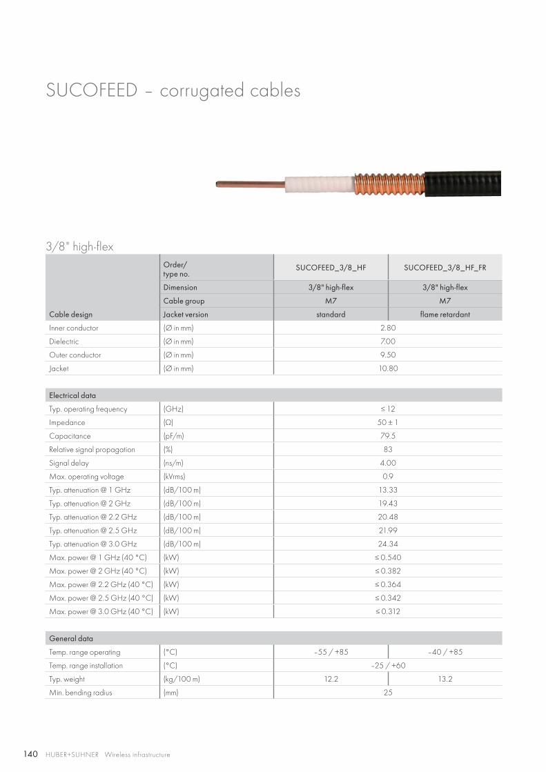
140 HUBER+SUHNER Wireless infrastructure
SUCOFEED – corrugated cables
3/8" high-flex
Cable design
Order/type no.
SUCOFEED_3/8_HF SUCOFEED_3/8_HF_FR
Dimension 3/8" high-flex 3/8" high-flex
Cable group M7 M7
Jacket version standard flame retardant
Inner conductor (Ø in mm) 2.80
Dielectric (Ø in mm) 7.00
Outer conductor (Ø in mm) 9.50
Jacket (Ø in mm) 10.80
Electrical data
Typ. operating frequency (GHz) ≤ 12
Impedance (Ω) 50 ± 1
Capacitance (pF/m) 79.5
Relative signal propagation (%) 83
Signal delay (ns/m) 4.00
Max. operating voltage (kVrms) 0.9
Typ. attenuation @ 1 GHz (dB/100 m) 13.33
Typ. attenuation @ 2 GHz (dB/100 m) 19.43
Typ. attenuation @ 2.2 GHz (dB/100 m) 20.48
Typ. attenuation @ 2.5 GHz (dB/100 m) 21.99
Typ. attenuation @ 3.0 GHz (dB/100 m) 24.34
Max. power @ 1 GHz (40 °C) (kW) ≤ 0.540
Max. power @ 2 GHz (40 °C) (kW) ≤ 0.382
Max. power @ 2.2 GHz (40 °C) (kW) ≤ 0.364
Max. power @ 2.5 GHz (40 °C) (kW) ≤ 0.342
Max. power @ 3.0 GHz (40 °C) (kW) ≤ 0.312
General data
Temp. range operating (°C) –55 / +85 –40 / +85
Temp. range installation (°C) –25 / +60
Typ. weight (kg/100 m) 12.2 13.2
Min. bending radius (mm) 25
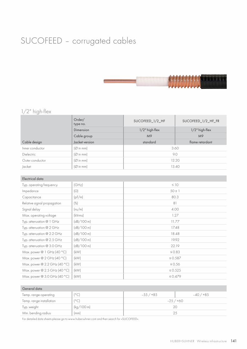
141HUBER+SUHNER Wireless infrastructure
SUCOFEED – corrugated cables
1/2" high-flex
Cable design
Order/type no.
SUCOFEED_1/2_HF SUCOFEED_1/2_HF_FR
Dimension 1/2" high-flex 1/2" high-flex
Cable group M9 M9
Jacket version standard flame retardant
Inner conductor (Ø in mm) 3.60
Dielectric (Ø in mm) 9.0
Outer conductor (Ø in mm) 12.20
Jacket (Ø in mm) 13.40
Electrical data
Typ. operating frequency (GHz) ≤ 10
Impedance (Ω) 50 ± 1
Capacitance (pF/m) 80.3
Relative signal propagation (%) 81
Signal delay (ns/m) 4.00
Max. operating voltage (kVrms) 1.27
Typ. attenuation @ 1 GHz (dB/100 m) 11.77
Typ. attenuation @ 2 GHz (dB/100 m) 17.48
Typ. attenuation @ 2.2 GHz (dB/100 m) 18.48
Typ. attenuation @ 2.5 GHz (dB/100 m) 19.92
Typ. attenuation @ 3.0 GHz (dB/100 m) 22.19
Max. power @ 1 GHz (40 °C) (kW) ≤ 0.83
Max. power @ 2 GHz (40 °C) (kW) ≤ 0.587
Max. power @ 2.2 GHz (40 °C) (kW) ≤ 0.56
Max. power @ 2.5 GHz (40 °C) (kW) ≤ 0.525
Max. power @ 3.0 GHz (40 °C) (kW) ≤ 0.479
General data
Temp. range operating (°C) –55 / +85 –40 / +85
Temp. range installation (°C) –25 / +60
Typ. weight (kg/100 m) 20
Min. bending radius (mm) 25
For detailed data sheets please go to www.hubersuhner.com and then search for «SUCOFEED».
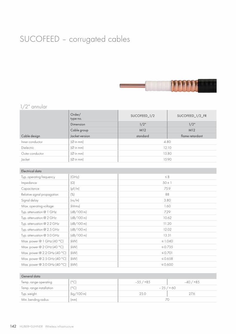
142 HUBER+SUHNER Wireless infrastructure
SUCOFEED – corrugated cables
1/2" annular
Cable design
Order/type no.
SUCOFEED_1/2 SUCOFEED_1/2_FR
Dimension 1/2" 1/2"
Cable group M12 M12
Jacket version standard flame retardant
Inner conductor (Ø in mm) 4.80
Dielectric (Ø in mm) 12.10
Outer conductor (Ø in mm) 13.80
Jacket (Ø in mm) 15.90
Electrical data
Typ. operating frequency (GHz) ≤ 8
Impedance (Ω) 50 ± 1
Capacitance (pF/m) 75.9
Relative signal propagation (%) 88
Signal delay (ns/m) 3.80
Max. operating voltage (kVrms) 1.60
Typ. attenuation @ 1 GHz (dB/100 m) 7.29
Typ. attenuation @ 2 GHz (dB/100 m) 10.62
Typ. attenuation @ 2.2 GHz (dB/100 m) 11.20
Typ. attenuation @ 2.5 GHz (dB/100 m) 12.02
Typ. attenuation @ 3.0 GHz (dB/100 m) 13.31
Max. power @ 1 GHz (40 °C) (kW) ≤ 1.040
Max. power @ 2 GHz (40 °C) (kW) ≤ 0.735
Max. power @ 2.2 GHz (40 °C) (kW) ≤ 0.701
Max. power @ 2.5 GHz (40 °C) (kW) ≤ 0.658
Max. power @ 3.0 GHz (40 °C) (kW) ≤ 0.600
General data
Temp. range operating (°C) –55 / +85 –40 / +85
Temp. range installation (°C) – 25 / + 60
Typ. weight (kg/100 m) 25.0 27.6
Min. bending radius (mm) 70
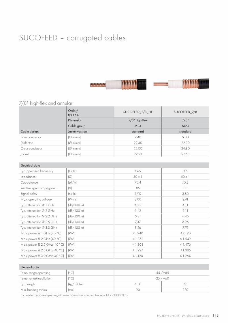
143HUBER+SUHNER Wireless infrastructure
SUCOFEED – corrugated cables
7/8" high-flex and annular
Cable design
Order/type no.
SUCOFEED_7/8_HF SUCOFEED_7/8
Dimension 7/8" high-flex 7/8"
Cable group M24 M23
Jacket version standard standard
Inner conductor (Ø in mm) 9.40 9.00
Dielectric (Ø in mm) 22.40 22.30
Outer conductor (Ø in mm) 25.00 24.80
Jacket (Ø in mm) 27.50 27.60
Electrical data
Typ. operating frequency (GHz) ≤ 4.9 ≤ 5
Impedance (Ω) 50 ± 1 50 ± 1
Capacitance (pF/m) 75.4 75.8
Relative signal propagation (%) 85 88
Signal delay (ns/m) 3.90 3.80
Max. operating voltage (kVrms) 3.00 2.91
Typ. attenuation @ 1 GHz (dB/100 m) 4.25 4.11
Typ. attenuation @ 2 GHz (dB/100 m) 6.42 6.11
Typ. attenuation @ 2.2 GHz (dB/100 m) 6.81 6.46
Typ. attenuation @ 2.5 GHz (dB/100 m) 7.37 6.96
Typ. attenuation @ 3.0 GHz (dB/100 m) 8.26 7.76
Max. power @ 1 GHz (40 °C) (kW) ≤ 1.940 ≤ 2.190
Max. power @ 2 GHz (40 °C) (kW) ≤ 1.372 ≤ 1.549
Max. power @ 2.2 GHz (40 °C) (kW) ≤ 1.308 ≤ 1.476
Max. power @ 2.5 GHz (40 °C) (kW) ≤ 1.227 ≤ 1.385
Max. power @ 3.0 GHz (40 °C) (kW) ≤ 1.120 ≤ 1.264
General data
Temp. range operating (°C) –55 / +85
Temp. range installation (°C) –25 / +60
Typ. weight (kg/100 m) 48.0 53
Min. bending radius (mm) 90 120
For detailed data sheets please go to www.hubersuhner.com and then search for «SUCOFEED».
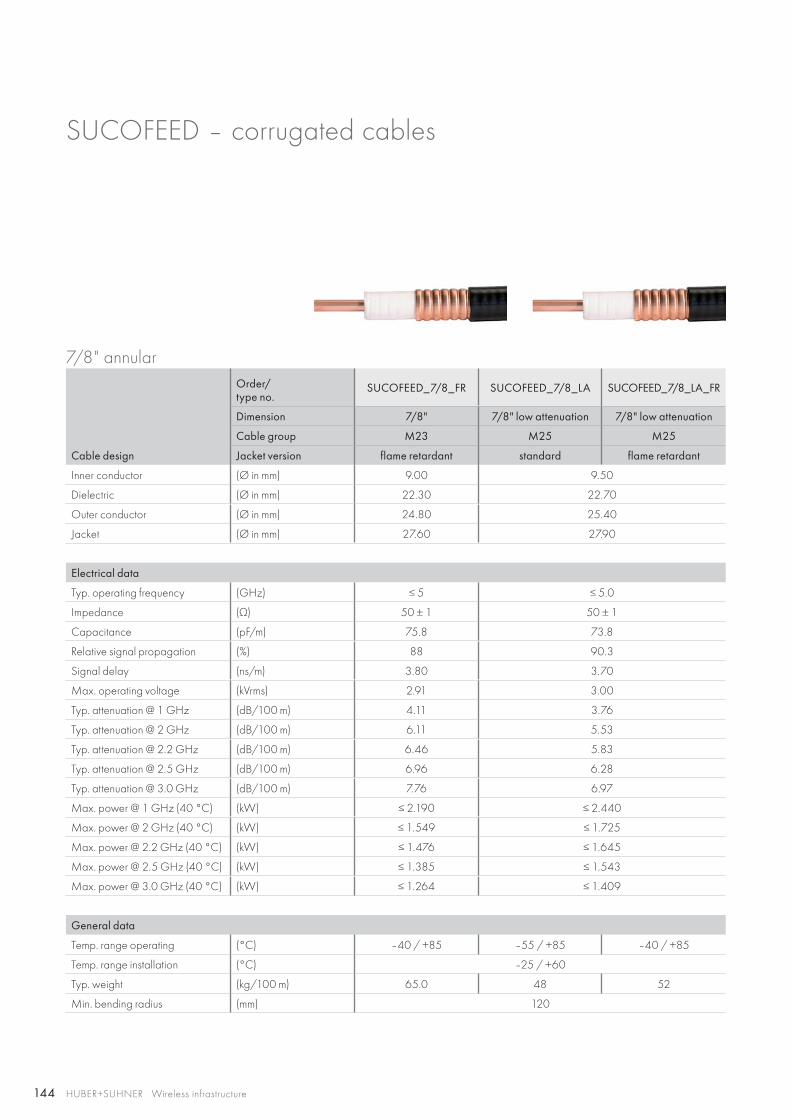
144 HUBER+SUHNER Wireless infrastructure
SUCOFEED – corrugated cables
7/8" annular
Cable design
Order/type no.
SUCOFEED_7/8_FR SUCOFEED_7/8_LA SUCOFEED_7/8_LA_FR
Dimension 7/8" 7/8" low attenuation 7/8" low attenuation
Cable group M23 M25 M25
Jacket version flame retardant standard flame retardant
Inner conductor (Ø in mm) 9.00 9.50
Dielectric (Ø in mm) 22.30 22.70
Outer conductor (Ø in mm) 24.80 25.40
Jacket (Ø in mm) 27.60 27.90
Electrical data
Typ. operating frequency (GHz) ≤ 5 ≤ 5.0
Impedance (Ω) 50 ± 1 50 ± 1
Capacitance (pF/m) 75.8 73.8
Relative signal propagation (%) 88 90.3
Signal delay (ns/m) 3.80 3.70
Max. operating voltage (kVrms) 2.91 3.00
Typ. attenuation @ 1 GHz (dB/100 m) 4.11 3.76
Typ. attenuation @ 2 GHz (dB/100 m) 6.11 5.53
Typ. attenuation @ 2.2 GHz (dB/100 m) 6.46 5.83
Typ. attenuation @ 2.5 GHz (dB/100 m) 6.96 6.28
Typ. attenuation @ 3.0 GHz (dB/100 m) 7.76 6.97
Max. power @ 1 GHz (40 °C) (kW) ≤ 2.190 ≤ 2.440
Max. power @ 2 GHz (40 °C) (kW) ≤ 1.549 ≤ 1.725
Max. power @ 2.2 GHz (40 °C) (kW) ≤ 1.476 ≤ 1.645
Max. power @ 2.5 GHz (40 °C) (kW) ≤ 1.385 ≤ 1.543
Max. power @ 3.0 GHz (40 °C) (kW) ≤ 1.264 ≤ 1.409
General data
Temp. range operating (°C) –40 / +85 –55 / +85 –40 / +85
Temp. range installation (°C) –25 / +60
Typ. weight (kg/100 m) 65.0 48 52
Min. bending radius (mm) 120
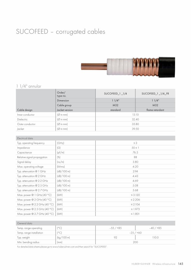
145HUBER+SUHNER Wireless infrastructure
SUCOFEED – corrugated cables
1 1/4" annular
Cable design
Order/type no.
SUCOFEED_1 _1/4 SUCOFEED_1 _1/4_FR
Dimension 1 1/4" 1 1/4"
Cable group M32 M32
Jacket version standard flame retardant
Inner conductor (Ø in mm) 13.10
Dielectric (Ø in mm) 32.40
Outer conductor (Ø in mm) 35.80
Jacket (Ø in mm) 39.50
Electrical data
Typ. operating frequency (GHz) ≤ 3
Impedance (Ω) 50 ± 1
Capacitance (pF/m) 76.5
Relative signal propagation (%) 88
Signal delay (ns/m) 3.80
Max. operating voltage (kVrms) 4.20
Typ. attenuation @ 1 GHz (dB/100 m) 2.94
Typ. attenuation @ 2 GHz (dB/100 m) 4.43
Typ. attenuation @ 2.2 GHz (dB/100 m) 4.69
Typ. attenuation @ 2.5 GHz (dB/100 m) 5.08
Typ. attenuation @ 2.7 GHz (dB/100 m) 5.68
Max. power @ 1 GHz (40 °C) (kW) ≤ 3.120
Max. power @ 2 GHz (40 °C) (kW) ≤ 2.206
Max. power @ 2.2 GHz (40 °C) (kW) ≤ 2.104
Max. power @ 2.5 GHz (40 °C) (kW) ≤ 1.973
Max. power @ 2.7 GHz (40 °C) (kW) ≤ 1.801
General data
Temp. range operating (°C) –55 / +85 –40 / +85
Temp. range installation (°C) –25 / +60
Typ. weight (kg/100 m) 92 110.0
Min. bending radius (mm) 200
For detailed data sheets please go to www.hubersuhner.com and then search for “SUCOFEED”.
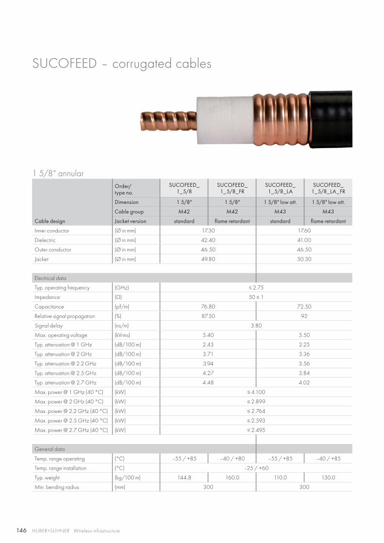
146 HUBER+SUHNER Wireless infrastructure
SUCOFEED – corrugated cables
1 5/8" annular
Cable design
Order/type no.
SUCOFEED_1_5/8
SUCOFEED_1_5/8_FR
SUCOFEED_1_5/8_LA
SUCOFEED_1_5/8_LA_FR
Dimension 1 5/8" 1 5/8" 1 5/8" low att. 1 5/8" low att.
Cable group M42 M42 M43 M43
Jacket version standard flame retardant standard flame retardant
Inner conductor (Ø in mm) 17.30 17.60
Dielectric (Ø in mm) 42.40 41.00
Outer conductor (Ø in mm) 46.50 46.50
Jacket (Ø in mm) 49.80 50.30
Electrical data
Typ. operating frequency (GHz) ≤ 2.75
Impedance (Ω) 50 ± 1
Capacitance (pF/m) 76.80 72.50
Relative signal propagation (%) 87.50 92
Signal delay (ns/m) 3.80
Max. operating voltage (kVrms) 5.40 5.50
Typ. attenuation @ 1 GHz (dB/100 m) 2.43 2.25
Typ. attenuation @ 2 GHz (dB/100 m) 3.71 3.36
Typ. attenuation @ 2.2 GHz (dB/100 m) 3.94 3.56
Typ. attenuation @ 2.5 GHz (dB/100 m) 4.27 3.84
Typ. attenuation @ 2.7 GHz (dB/100 m) 4.48 4.02
Max. power @ 1 GHz (40 °C) (kW) ≤ 4.100
Max. power @ 2 GHz (40 °C) (kW) ≤ 2.899
Max. power @ 2.2 GHz (40 °C) (kW) ≤ 2.764
Max. power @ 2.5 GHz (40 °C) (kW) ≤ 2.593
Max. power @ 2.7 GHz (40 °C) (kW) ≤ 2.495
General data
Temp. range operating (°C) –55 / +85 –40 / +80 –55 / +85 –40 / +85
Temp. range installation (°C) –25 / +60
Typ. weight (kg/100 m) 144.8 160.0 110.0 130.0
Min. bending radius (mm) 300 300
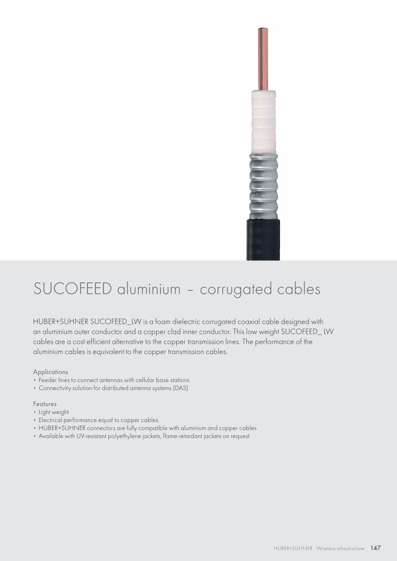
147HUBER+SUHNER Wireless infrastructure
SUCOFEED aluminium – corrugated cables
HUBER+SUHNER SUCOFEED_LW is a foam dielectric corrugated coaxial cable designed with an aluminium outer conductor and a copper clad inner conductor. This low weight SUCOFEED_ LW cables are a cost efficient alternative to the copper transmission lines. The performance of the aluminium cables is equivalent to the copper transmission cables.
Applications• Feeder lines to connect antennas with cellular base stations• Connectivity solution for distributed antenna systems (DAS)
Features• Light weight• Electrical performance equal to copper cables• HUBER+SUHNER connectors are fully compatible with aluminium and copper cables • Available with UV-resistant polyethylene jackets, flame-retardant jackets on request
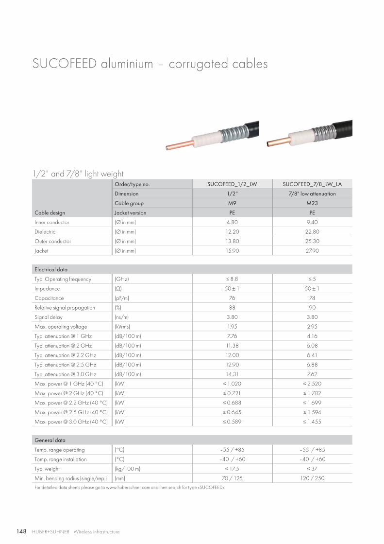
148 HUBER+SUHNER Wireless infrastructure
SUCOFEED aluminium – corrugated cables
1/2" and 7/8" light weight
Cable design
Order/type no. SUCOFEED_1/2_LW SUCOFEED_7/8_LW_LA
Dimension 1/2" 7/8" low attenuation
Cable group M9 M23
Jacket version PE PE
Inner conductor (Ø in mm) 4.80 9.40
Dielectric (Ø in mm) 12.20 22.80
Outer conductor (Ø in mm) 13.80 25.30
Jacket (Ø in mm) 15.90 27.90
Electrical data
Typ. Operating frequency (GHz) ≤ 8.8 ≤ 5
Impedance (Ω) 50 ± 1 50 ± 1
Capacitance (pF/m) 76 74
Relative signal propagation (%) 88 90
Signal delay (ns/m) 3.80 3.80
Max. operating voltage (kVrms) 1.95 2.95
Typ. attenuation @ 1 GHz (dB/100 m) 7.76 4.16
Typ. attenuation @ 2 GHz (dB/100 m) 11.38 6.08
Typ. attenuation @ 2.2 GHz (dB/100 m) 12.00 6.41
Typ. attenuation @ 2.5 GHz (dB/100 m) 12.90 6.88
Typ. attenuation @ 3.0 GHz (dB/100 m) 14.31 7.62
Max. power @ 1 GHz (40 °C) (kW) ≤ 1.020 ≤ 2.520
Max. power @ 2 GHz (40 °C) (kW) ≤ 0.721 ≤ 1.782
Max. power @ 2.2 GHz (40 °C) (kW) ≤ 0.688 ≤ 1.699
Max. power @ 2.5 GHz (40 °C) (kW) ≤ 0.645 ≤ 1.594
Max. power @ 3.0 GHz (40 °C) (kW) ≤ 0.589 ≤ 1.455
General data
Temp. range operating (°C) –55 / +85 –55 / +85
Tamp. range installation (°C) –40 / +60 –40 / +60
Typ. weight (kg/100 m) ≤ 17.5 ≤ 37
Min. bending radius (single/rep.) (mm) 70 / 125 120 / 250
For detailed data sheets please go to www.hubersuhner.com and then search for type «SUCOFEED»
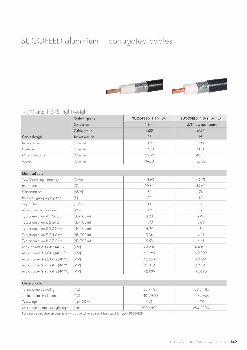
149HUBER+SUHNER Wireless infrastructure
SUCOFEED aluminium – corrugated cables
1-1/4" and 1 5/8" light weight
Cable design
Order/type no. SUCOFEED_1-1/4_LW SUCOFEED_1-5/8_LW_LA
Dimension 1-1/4" 1-5/8" low attenuation
Cable group M32 M43
Jacket version PE PE
Inner conductor (Ø in mm) 13.10 17.60
Dielectric (Ø in mm) 32.00 41.50
Outer conductor (Ø in mm) 36.00 46.50
Jacket (Ø in mm) 39.20 50.30
Electrical data
Typ. Operating frequency (GHz) ≤ 3.60 ≤ 2.75
Impedance (Ω) 50 ± 1 50 ± 1
Capacitance (pF/m) 75 74
Relative signal propagation (%) 88 89
Signal delay (ns/m) 3.8 3.8
Max. operating voltage (kVrms) 4.2 5.6
Typ. attenuation @ 1 GHz (dB/100 m) 3.20 2.48
Typ. attenuation @ 2 GHz (dB/100 m) 4.70 3.69
Typ. attenuation @ 2.2 GHz (dB/100 m) 4.97 3.91
Typ. attenuation @ 2.5 GHz (dB/100 m) 5.34 4.21
Typ. attenuation @ 2.7 GHz (dB/100 m) 5.58 4.41
Max. power @ 1 GHz (40 °C) (kW) ≤ 3.350 ≤ 4.100
Max. power @ 2 GHz (40 °C) (kW) ≤ 2.369 ≤ 2.899
Max. power @ 2.2 GHz (40 °C) (kW) ≤ 2.259 ≤ 2.764
Max. power @ 2.5 GHz (40 °C) (kW) ≤ 2.119 ≤ 2.593
Max. power @ 2.7 GHz (40 °C) (kW) ≤ 2.039 ≤ 2.690
General data
Temp. range operating (°C) –55 / +85 –55 / +85
Tamp. range installation (°C) –40 / +60 –40 / +60
Typ. weight (kg/100 m) ≤ 65 ≤ 99
Min. bending radius (single/rep.) (mm) 200 / 400 280 / 500
For detailed data sheets please go to www.hubersuhner.com and then search for type «SUCOFEED»
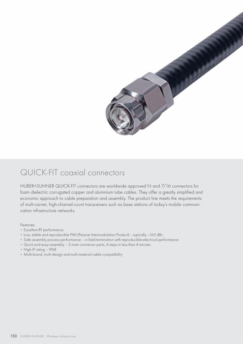
150 HUBER+SUHNER Wireless infrastructure
QUICK-FIT coaxial connectors HUBER+SUHNER QUICK-FIT connectors are worldwide approved N and 7/16 connectors for foam dielectric corrugated copper and aluminium tube cables. They offer a greatly simplified and economic approach to cable preparation and assembly. The product line meets the requirements of multi-carrier, high-channel-count transceivers such as base stations of today’s mobile communi-cation infrastructure networks.
Features • Excellent RF performance• Low, stable and reproducible PIM (Passive Intermodulation Product) – typically –165 dBc• Safe assembly process performance – in-field termination with reproducible electrical performance• Quick and easy assembly – 2 main connector parts, 4 steps in less than 4 minutes• High IP rating – IP68• Multi-brand, multi-design and multi-material cable compatibility
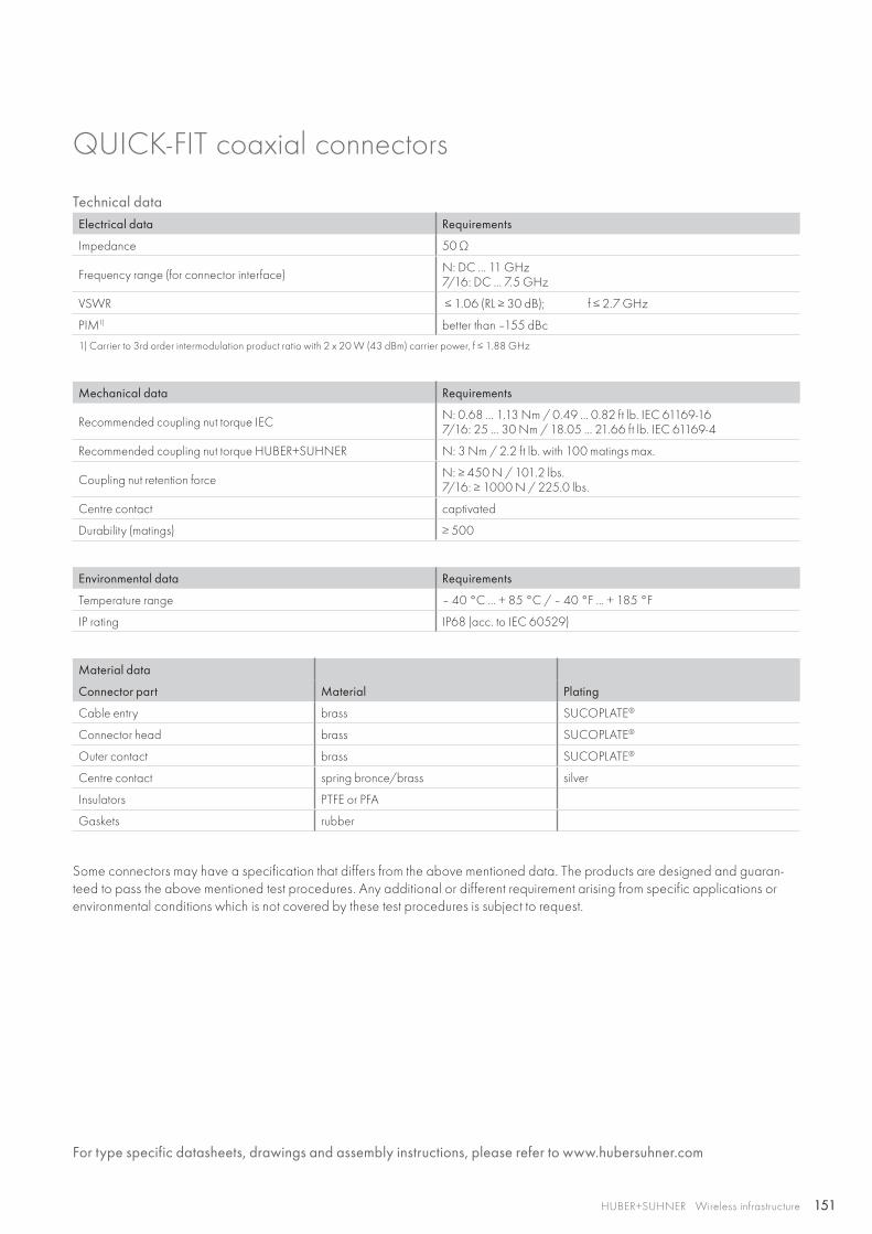
151HUBER+SUHNER Wireless infrastructure
QUICK-FIT coaxial connectors
Technical dataElectrical data Requirements
Impedance 50 Ω
Frequency range (for connector interface) N: DC ... 11 GHz7/16: DC ... 7.5 GHz
VSWR ≤ 1.06 (RL ≥ 30 dB); f ≤ 2.7 GHz
PIM1) better than –155 dBc
1) Carrier to 3rd order intermodulation product ratio with 2 x 20 W (43 dBm) carrier power, f ≤ 1.88 GHz
Mechanical data Requirements
Recommended coupling nut torque IEC N: 0.68 ... 1.13 Nm / 0.49 ... 0.82 ft lb. IEC 61169-167/16: 25 ... 30 Nm / 18.05 ... 21.66 ft lb. IEC 61169-4
Recommended coupling nut torque HUBER+SUHNER N: 3 Nm / 2.2 ft lb. with 100 matings max.
Coupling nut retention force N: ≥ 450 N / 101.2 lbs.7/16: ≥ 1000 N / 225.0 lbs.
Centre contact captivated
Durability (matings) ≥ 500
Environmental data Requirements
Temperature range – 40 °C ... + 85 °C / – 40 °F ... + 185 °F
IP rating IP68 (acc. to IEC 60529)
Material data
Connector part Material Plating
Cable entry brass SUCOPLATE®
Connector head brass SUCOPLATE®
Outer contact brass SUCOPLATE®
Centre contact spring bronce/brass silver
Insulators PTFE or PFA
Gaskets rubber
Some connectors may have a specification that differs from the above mentioned data. The products are designed and guaran-teed to pass the above mentioned test procedures. Any additional or different requirement arising from specific applications or environmental conditions which is not covered by these test procedures is subject to request.
For type specific datasheets, drawings and assembly instructions, please refer to www.hubersuhner.com
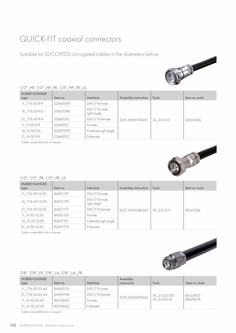
152 HUBER+SUHNER Wireless infrastructure
1/2"_HF, 1/2"_HF_FR, 1/2"_HF_FR_ULHUBER+SUHNER type Item no. Interface Assembly instruction Tools Item no. tools
11_716-50-9-9 22660309 DIN 7/16 male
DOC-0000179418 74_Z-0-9-15 23001006
16_716-50-9-5 23007298 DIN 7/16 maleright angle
21_716-50-9-9 22660310 DIN 7/16 female
11_N-50-9-9 22660311 N male
16_N-50-9-6 23007299 N female right angle
21_N-50-9-9 22660312 N female
Cable compatibility list on request.
1/2", 1/2"_FR, 1/2"_FR_ULHUBER+SUHNER type Item no. Interface Assembly instruction Tools Item no. tools
11_716-50-12-50 84201175 DIN 7/16 male
DOC-0000386367 74_Z-0-12-11 84147226
16_716-50-12-50 84201179 DIN 7/16 maleright angle
21_716-50-12-50 84201177 DIN 7/16 female
11_N-50-12-50 84201169 N male
16_N-50-12-50 84201181 N female right angle
21_N-50-12-50 84201173 N female
Cable compatibility list on request.
7/8", 7/8"_FR, 7/8"_LA, 7/8"_LA_FRHUBER+SUHNER type Item no. Interface
Assemblyinstruction Tools Item no. tools
11_716-50-23-44 84069135 DIN 7/16 male
DOC-0000295365 74_Z-0-23-100 74_Z-0-23-18
8413392384074476
21_716-50-23-44 84069194 DIN 7/16 female
11_N-50-23-43 84124063 N male
21_N-50-23-43 84124062 N female
Cable compatibility list on request.
QUICK-FIT coaxial connectors
Suitable for SUCOFEED corrugated cables in the diameters below
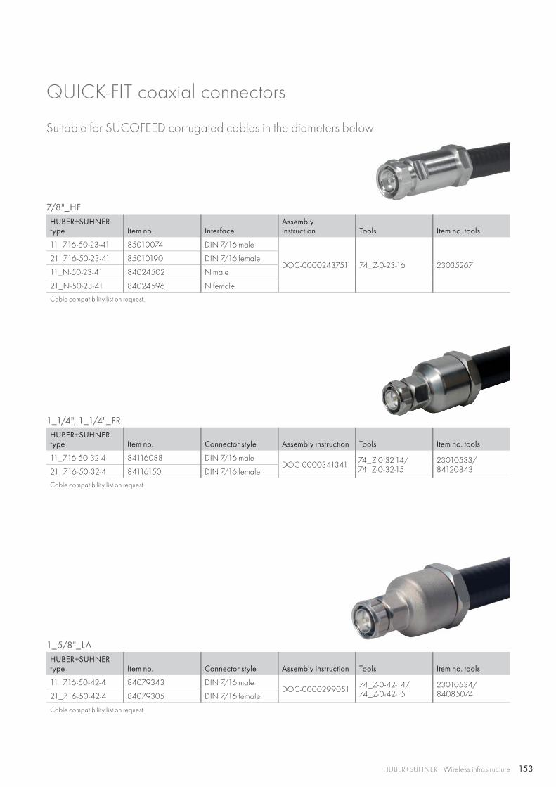
153HUBER+SUHNER Wireless infrastructure
7/8"_HFHUBER+SUHNER type Item no. Interface
Assemblyinstruction Tools Item no. tools
11_716-50-23-41 85010074 DIN 7/16 male
DOC-0000243751 74_Z-0-23-16 2303526721_716-50-23-41 85010190 DIN 7/16 female
11_N-50-23-41 84024502 N male
21_N-50-23-41 84024596 N female
Cable compatibility list on request.
1_1/4", 1_1/4"_FRHUBER+SUHNER type Item no. Connector style Assembly instruction Tools Item no. tools
11_716-50-32-4 84116088 DIN 7/16 maleDOC-0000341341 74_Z-0-32-14/
74_Z-0-32-1523010533/ 8412084321_716-50-32-4 84116150 DIN 7/16 female
Cable compatibility list on request.
1_5/8"_LAHUBER+SUHNER type Item no. Connector style Assembly instruction Tools Item no. tools
11_716-50-42-4 84079343 DIN 7/16 maleDOC-0000299051 74_Z-0-42-14/
74_Z-0-42-1523010534/ 8408507421_716-50-42-4 84079305 DIN 7/16 female
Cable compatibility list on request.
QUICK-FIT coaxial connectors
Suitable for SUCOFEED corrugated cables in the diameters below
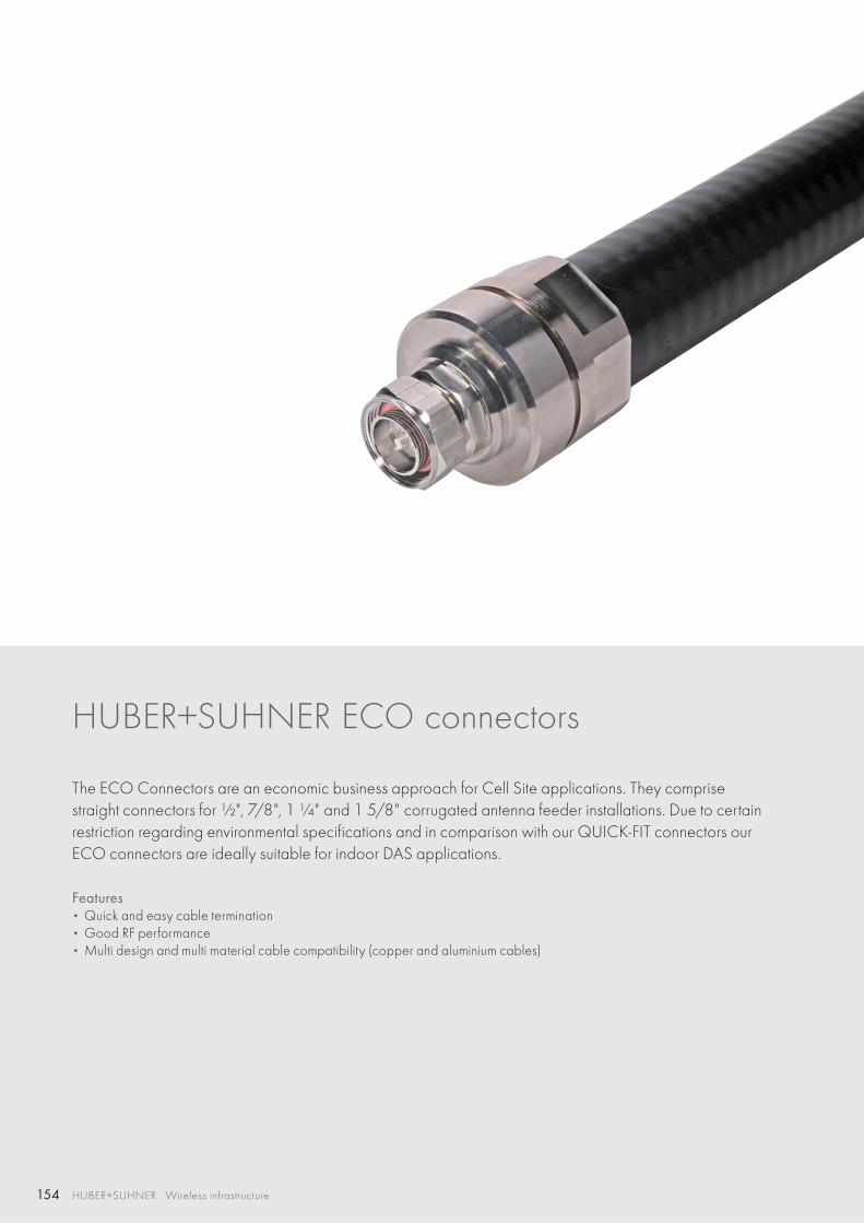
154 HUBER+SUHNER Wireless infrastructure
HUBER+SUHNER ECO connectors
The ECO Connectors are an economic business approach for Cell Site applications. They comprise straight connectors for ½", 7/8", 1 ¼" and 1 5/8" corrugated antenna feeder installations. Due to certain restriction regarding environmental specifications and in comparison with our QUICK-FIT connectors our ECO connectors are ideally suitable for indoor DAS applications.
Features• Quick and easy cable termination• Good RF performance• Multi design and multi material cable compatibility (copper and aluminium cables)
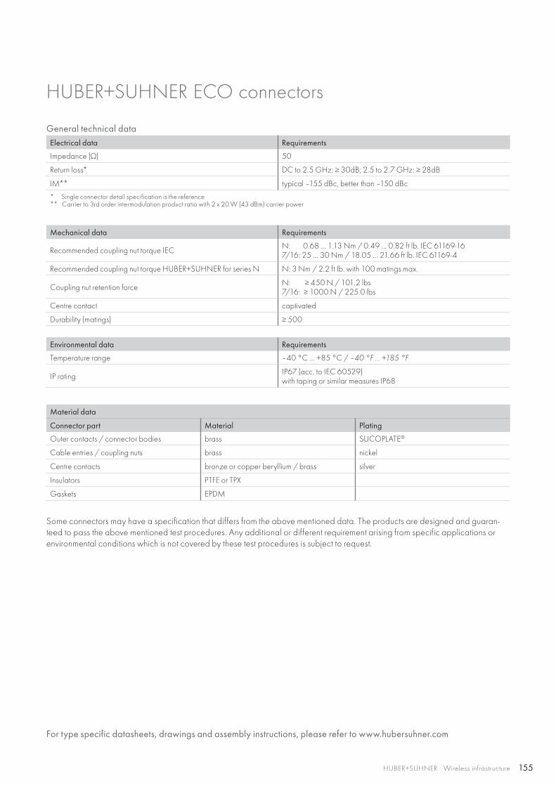
155HUBER+SUHNER Wireless infrastructure
HUBER+SUHNER ECO connectors
General technical dataElectrical data Requirements
Impedance (Ω) 50
Return loss* DC to 2.5 GHz: ≥ 30dB; 2.5 to 2.7 GHz: ≥ 28dB
IM** typical –155 dBc, better than –150 dBc
* Single connector detail specification is the reference** Carrier to 3rd order intermodulation product ratio with 2 x 20 W (43 dBm) carrier power
Mechanical data Requirements
Recommended coupling nut torque IEC N: 0.68 … 1.13 Nm / 0.49 … 0.82 ft lb. IEC 61169-167/16: 25 … 30 Nm / 18.05 … 21.66 ft lb. IEC 61169-4
Recommended coupling nut torque HUBER+SUHNER for series N N: 3 Nm / 2.2 ft Ib. with 100 matings max.
Coupling nut retention force N: ≥ 450 N / 101.2 lbs7/16: ≥ 1000 N / 225.0 lbs
Centre contact captivated
Durability (matings) ≥ 500
Environmental data Requirements
Temperature range –40 °C … +85 °C / –40 °F … +185 °F
IP rating IP67 (acc. to IEC 60529)with taping or similar measures IP68
Material data
Connector part Material Plating
Outer contacts / connector bodies brass SUCOPLATE®
Cable entries / coupling nuts brass nickel
Centre contacts bronze or copper beryllium / brass silver
Insulators PTFE or TPX
Gaskets EPDM
Some connectors may have a specification that differs from the above mentioned data. The products are designed and guaran-teed to pass the above mentioned test procedures. Any additional or different requirement arising from specific applications or environmental conditions which is not covered by these test procedures is subject to request.
For type specific datasheets, drawings and assembly instructions, please refer to www.hubersuhner.com
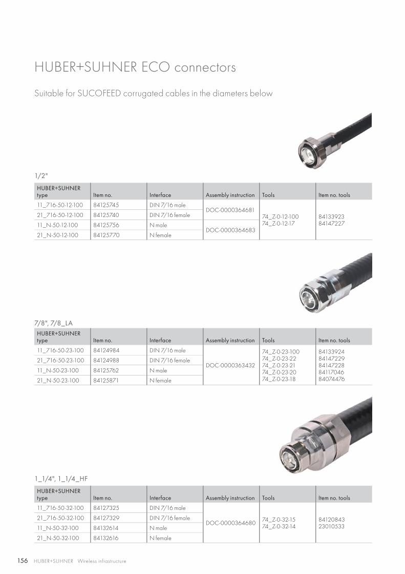
156 HUBER+SUHNER Wireless infrastructure
Suitable for SUCOFEED corrugated cables in the diameters below
1/2"
HUBER+SUHNER type Item no. Interface Assembly instruction Tools Item no. tools
11_716-50-12-100 84125745 DIN 7/16 maleDOC-0000364681
74_Z-0-12-100 74_Z-0-12-17
8413392384147227
21_716-50-12-100 84125740 DIN 7/16 female
11_N-50-12-100 84125756 N maleDOC-0000364683
21_N-50-12-100 84125770 N female
7/8", 7/8_LAHUBER+SUHNER type Item no. Interface Assembly instruction Tools Item no. tools
11_716-50-23-100 84124984 DIN 7/16 male
DOC-0000363432
74_Z-0-23-100 74_Z-0-23-22 74_Z-0-23-21 74_Z-0-23-2074_Z-0-23-18
8413392484147229841472288411704684074476
21_716-50-23-100 84124988 DIN 7/16 female
11_N-50-23-100 84125762 N male
21_N-50-23-100 84125871 N female
1_1/4", 1_1/4_HF
HUBER+SUHNER type Item no. Interface Assembly instruction Tools Item no. tools
11_716-50-32-100 84127325 DIN 7/16 male
DOC-0000364680 74_Z-0-32-15 74_Z-0-32-14
8412084323010533
21_716-50-32-100 84127329 DIN 7/16 female
11_N-50-32-100 84132614 N male
21_N-50-32-100 84132616 N female
HUBER+SUHNER ECO connectors
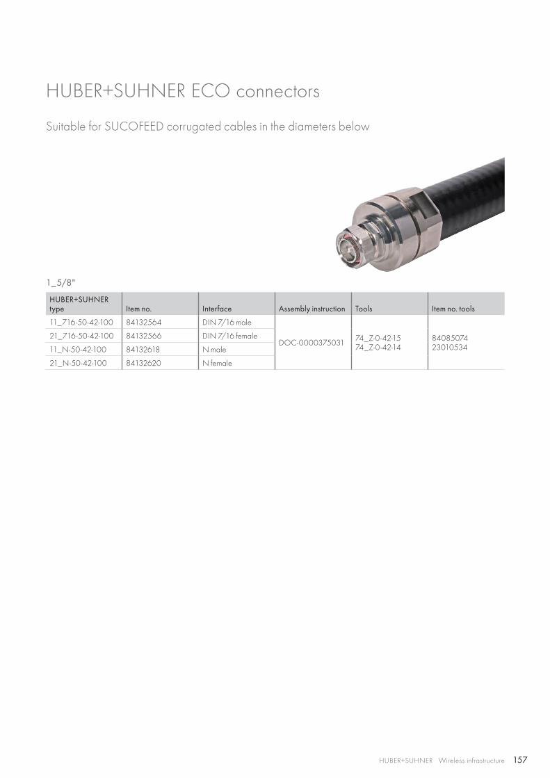
157HUBER+SUHNER Wireless infrastructure
1_5/8"
HUBER+SUHNER type Item no. Interface Assembly instruction Tools Item no. tools
11_716-50-42-100 84132564 DIN 7/16 male
DOC-0000375031 74_Z-0-42-15 74_Z-0-42-14
8408507423010534
21_716-50-42-100 84132566 DIN 7/16 female
11_N-50-42-100 84132618 N male
21_N-50-42-100 84132620 N female
HUBER+SUHNER ECO connectors
Suitable for SUCOFEED corrugated cables in the diameters below
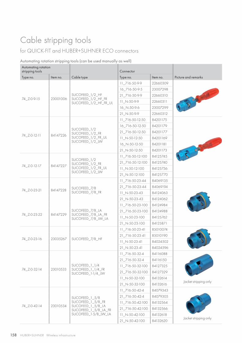
158 HUBER+SUHNER Wireless infrastructure
Cable stripping tools
Automating rotation stripping tools (can be used manually as well)Automating rotationstripping tools
Cable type
Connector
Picture and remarksType no. Item no. Type no. Item no.
74_Z-0-9-15 23001006SUCOFEED_1/2_HFSUCOFEED_1/2_HF_FRSUCOFEED_1/2_HF_FR_UL
11_716-50-9-9 22660309
16_716-50-9-5 23007298
21_716-50-9-9 22660310
11_N-50-9-9 22660311
16_N-50-9-6 23007299
21_N-50-9-9 22660312
74_Z-0-12-11 84147226
SUCOFEED_1/2SUCOFEED_1/2_FRSUCOFEED_1/2_FR_ULSUCOFEED_1/2_LW
11_716-50-12-50 84201175
16_716-50-12-50 84201179
21_716-50-12-50 84201177
11_N-50-12-50 84201169
16_N-50-12-50 84201181
21_N-50-12-50 84201173
74_Z-0-12-17 84147227
SUCOFEED_1/2SUCOFEED_1/2_FRSUCOFEED_1/2_FR_ULSUCOFEED_1/2_LW
11_716-50-12-100 84125745
21_716-50-12-100 84125740
11_N-50-12-100 84125756
21_N-50-12-100 84125770
74_Z-0-23-21 84147228 SUCOFEED_7/8SUCOFEED_7/8_FR
11_716-50-23-44 84069135
21_716-50-23-44 84069194
11_N-50-23-43 84124063
21_N-50-23-43 84124062
74_Z-0-23-22 84147229SUCOFEED_7/8_LASUCOFEED_7/8_LA_FRSUCOFEED_7/8_LW_LA
11_716-50-23-100 84124984
21_716-50-23-100 84124988
11_N-50-23-100 84125762
21_N-50-23-100 84125871
74_Z-0-23-16 23035267 SUCOFEED_7/8_HF
11_716-50-23-41 85010074
21_716-50-23-41 85010190
11_N-50-23-41 84024502
21_N-50-23-41 84024596
74_Z-0-32-14 23010533SUCOFEED_1_1/4SUCOFEED_1_1/4_FRSUCOFEED_1-1/4_LW
11_716-50-32-4 84116088
Jacket stripping only
21_716-50-32-4 84116150
11_716-50-32-100 84127325
21_716-50-32-100 84127329
11_N-50-32-100 84132614
21_N-50-32-100 84132616
74_Z-0-42-14 23010534
SUCOFEED_1_5/8SUCOFEED_1_5/8_FRSUCOFEED_1_5/8_LASUCOFEED_1_5/8_LA_FRSUCOFEED_1-5/8_LW_LA
11_716-50-42-4 84079343
Jacket stripping only
21_716-50-42-4 84079305
11_716-50-42-100 84132564
21_716-50-42-100 84132566
11_N-50-42-100 84132618
21_N-50-42-100 84132620
for QUICK-FIT and HUBER+SUHNER ECO connectors
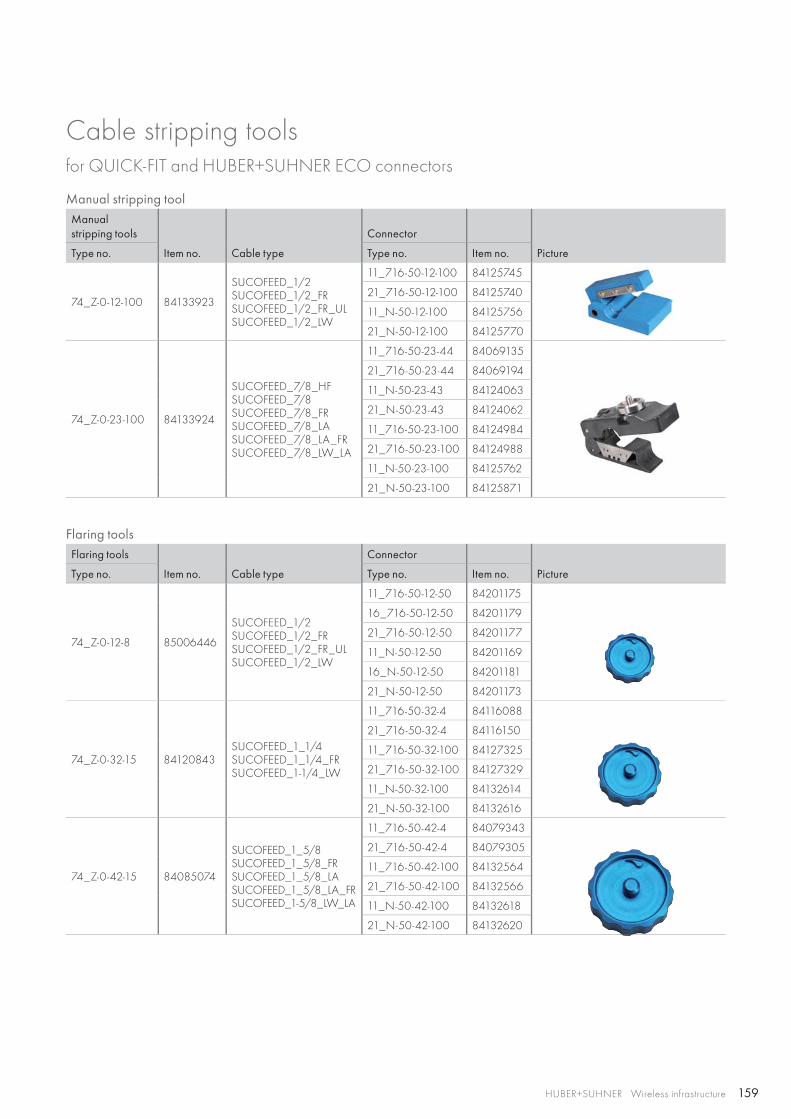
159HUBER+SUHNER Wireless infrastructure
Manual stripping toolManual stripping tools
Item no. Cable type
Connector
PictureType no. Type no. Item no.
74_Z-0-12-100 84133923
SUCOFEED_1/2SUCOFEED_1/2_FRSUCOFEED_1/2_FR_ULSUCOFEED_1/2_LW
11_716-50-12-100 84125745
21_716-50-12-100 84125740
11_N-50-12-100 84125756
21_N-50-12-100 84125770
74_Z-0-23-100 84133924
SUCOFEED_7/8_HFSUCOFEED_7/8SUCOFEED_7/8_FRSUCOFEED_7/8_LASUCOFEED_7/8_LA_FRSUCOFEED_7/8_LW_LA
11_716-50-23-44 84069135
21_716-50-23-44 84069194
11_N-50-23-43 84124063
21_N-50-23-43 84124062
11_716-50-23-100 84124984
21_716-50-23-100 84124988
11_N-50-23-100 84125762
21_N-50-23-100 84125871
Flaring toolsFlaring tools
Item no. Cable type
Connector
PictureType no. Type no. Item no.
74_Z-0-12-8 85006446
SUCOFEED_1/2SUCOFEED_1/2_FRSUCOFEED_1/2_FR_ULSUCOFEED_1/2_LW
11_716-50-12-50 84201175
16_716-50-12-50 84201179
21_716-50-12-50 84201177
11_N-50-12-50 84201169
16_N-50-12-50 84201181
21_N-50-12-50 84201173
74_Z-0-32-15 84120843SUCOFEED_1_1/4SUCOFEED_1_1/4_FRSUCOFEED_1-1/4_LW
11_716-50-32-4 84116088
21_716-50-32-4 84116150
11_716-50-32-100 84127325
21_716-50-32-100 84127329
11_N-50-32-100 84132614
21_N-50-32-100 84132616
74_Z-0-42-15 84085074
SUCOFEED_1_5/8SUCOFEED_1_5/8_FRSUCOFEED_1_5/8_LASUCOFEED_1_5/8_LA_FRSUCOFEED_1-5/8_LW_LA
11_716-50-42-4 84079343
21_716-50-42-4 84079305
11_716-50-42-100 84132564
21_716-50-42-100 84132566
11_N-50-42-100 84132618
21_N-50-42-100 84132620
Cable stripping toolsfor QUICK-FIT and HUBER+SUHNER ECO connectors
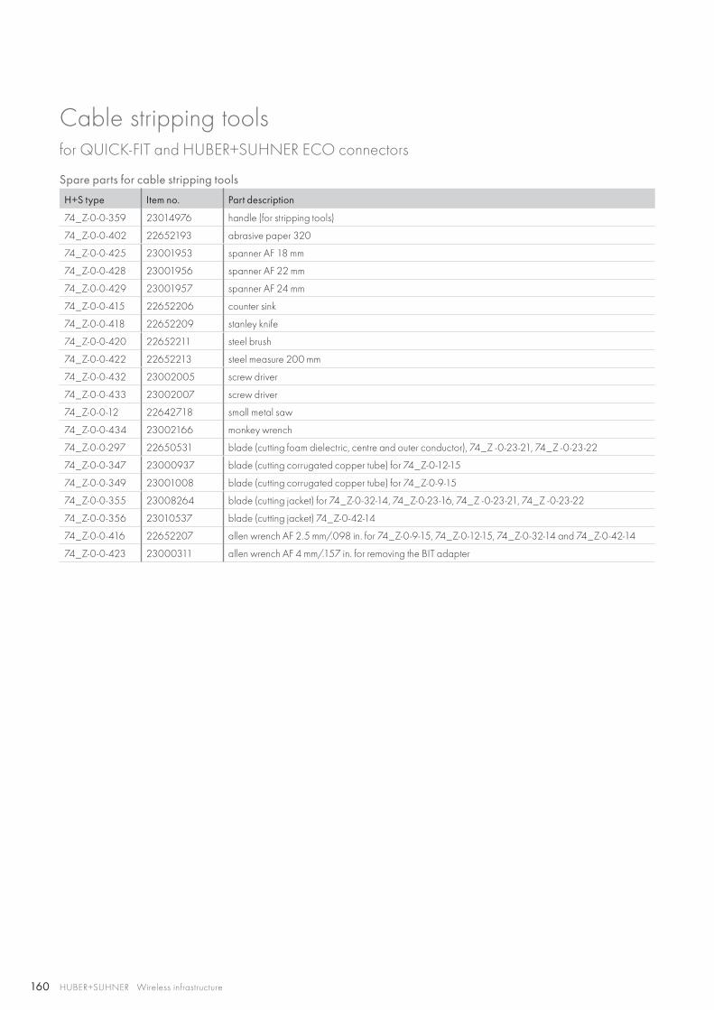
160 HUBER+SUHNER Wireless infrastructure
Cable stripping toolsfor QUICK-FIT and HUBER+SUHNER ECO connectors
Spare parts for cable stripping tools
H+S type Item no. Part description
74_Z-0-0-359 23014976 handle (for stripping tools)
74_Z-0-0-402 22652193 abrasive paper 320
74_Z-0-0-425 23001953 spanner AF 18 mm
74_Z-0-0-428 23001956 spanner AF 22 mm
74_Z-0-0-429 23001957 spanner AF 24 mm
74_Z-0-0-415 22652206 counter sink
74_Z-0-0-418 22652209 stanley knife
74_Z-0-0-420 22652211 steel brush
74_Z-0-0-422 22652213 steel measure 200 mm
74_Z-0-0-432 23002005 screw driver
74_Z-0-0-433 23002007 screw driver
74_Z-0-0-12 22642718 small metal saw
74_Z-0-0-434 23002166 monkey wrench
74_Z-0-0-297 22650531 blade (cutting foam dielectric, centre and outer conductor), 74_Z -0-23-21, 74_Z -0-23-22
74_Z-0-0-347 23000937 blade (cutting corrugated copper tube) for 74_Z-0-12-15
74_Z-0-0-349 23001008 blade (cutting corrugated copper tube) for 74_Z-0-9-15
74_Z-0-0-355 23008264 blade (cutting jacket) for 74_Z-0-32-14, 74_Z-0-23-16, 74_Z -0-23-21, 74_Z -0-23-22
74_Z-0-0-356 23010537 blade (cutting jacket) 74_Z-0-42-14
74_Z-0-0-416 22652207 allen wrench AF 2.5 mm/.098 in. for 74_Z-0-9-15, 74_Z-0-12-15, 74_Z-0-32-14 and 74_Z-0-42-14
74_Z-0-0-423 23000311 allen wrench AF 4 mm/.157 in. for removing the BIT adapter
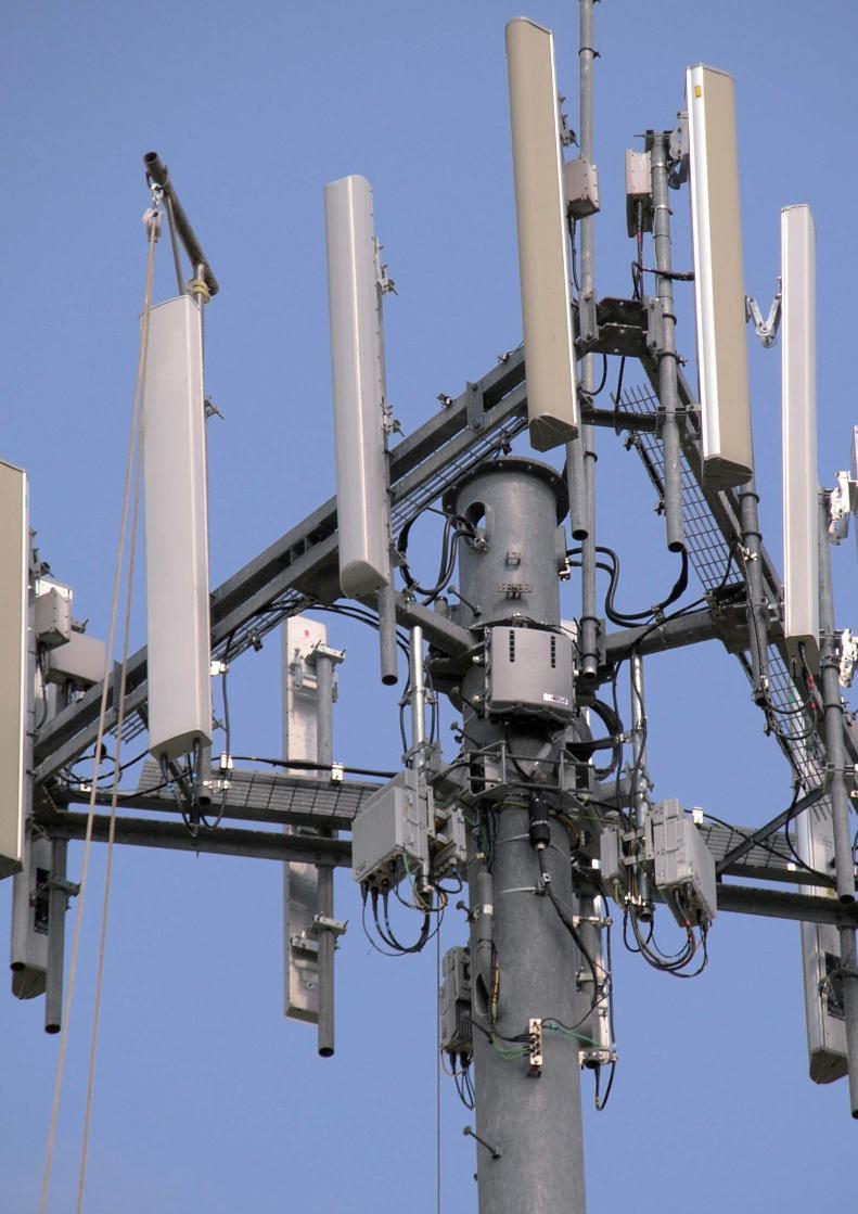
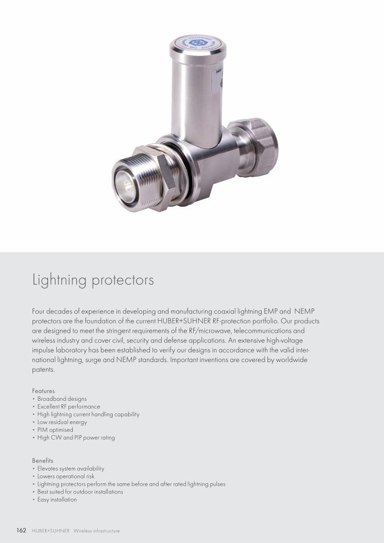
162 HUBER+SUHNER Wireless infrastructure
Lightning protectors
Four decades of experience in developing and manufacturing coaxial lightning EMP and NEMP protectors are the foundation of the current HUBER+SUHNER RF-protection portfolio. Our products are designed to meet the stringent requirements of the RF/microwave, telecommunications and wireless industry and cover civil, security and defense applications. An extensive high-voltage impulse laboratory has been established to verify our designs in accordance with the valid inter-national lightning, surge and NEMP standards. Important inventions are covered by worldwide patents.
Features • Broadband designs• Excellent RF performance• High lightning current handling capability• Low residual energy• PIM optimised• High CW and PIP power rating
Benefits • Elevates system availability• Lowers operational risk• Lightning protectors perform the same before and after rated lightning pulses• Best suited for outdoor installations• Easy installation
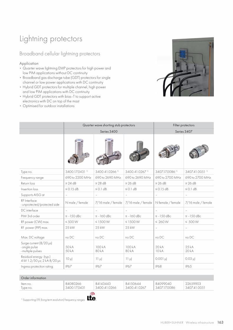
163HUBER+SUHNER Wireless infrastructure
Lightning protectors
Broadband cellular lightning protectors
Application• Quarter wave lightning EMP protectors for high power and
low PIM applications without DC continuity• Broadband gas discharge tube (GDT) protectors for single
channel or low power applications with DC continuity• Hybrid GDT protectors for multiple channel, high power
and low PIM applications with DC continuity• Hybrid GDT protectors with bias–T to support active
electronics with DC on top of the mast• Optimised for outdoor installations
Quarter wave shorting stub protectors Filter protectors
Series 3400 Series 3407
Type no. 3400.17.0431 1) 3400.41.0266 1) 3400.41.0267 1) 3407.17.0086 1) 3407.41.0051 1)
Frequency range 690 to 2200 MHz 690 to 2690 MHz 690 to 2690 MHz 690 to 2700 MHz 690 to 2700 MHz
Return loss ≥ 24 dB ≥ 28 dB ≥ 26 dB ≥ 26 dB ≥ 26 dB
Insertion loss ≤ 0.15 dB ≤ 0.1 dB ≤ 0.1 dB ≤ 0.15 dB ≤ 0.1 dB
Supports AISG at – – – – –
RF Interface- unprotected/protected side N male / female 7/16 male / female 7/16 male / female N female / female 7/16 male / female
DC interface – – – – –
PIM 3rd order ≤ –150 dBc ≤ –160 dBc ≤ –160 dBc ≤ –150 dBc ≤ –150 dBc
RF power (CW) max. ≤ 500 W ≤ 1500 W ≤ 1500 W ≤ 260 W ≤ 500 W
RF power (PIP) max. 25 kW 25 kW 25 kW – –
Max. DC voltage no DC no DC no DC no DC no DC
Surge current (8/20 μs)- single pulse- multiple pulses
50 kA50 kA
100 kA80 kA
100 kA80 kA
20 kA10 kA
25 kA20 kA
Residual energy (typ.) 4 kV 1.2/50 μs; 2 kA 8/20 μs 10 μJ 11 μJ 11 μJ 0.001 μJ 0.03 μJ
Ingress protection rating IP67 IP67 IP67 IP68 IP65
Order information
Item no.Type no.
840802663400.17.0431
841434433400.41.0266
841506443400.41.0267
840990403407.17.0086
226599033407.41.0051
1) Supporting LTE (long term evolution) frequency ranges
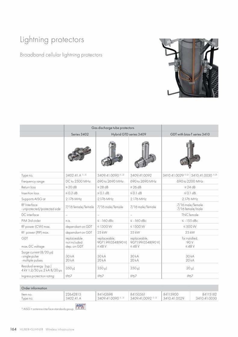
164 HUBER+SUHNER Wireless infrastructure
Broadband cellular lightning protectors
Gas discharge tube protectors
Series 3402 Hybrid GTD series 3409 GDT with bias-T series 3410
Type no. 3402.41.A 1) , 2) 3409.41.0090 1) , 2) 3409.41.0092 3410.41.0029 1) ,2) 3410.41.0030 1) ,2)
Frequency range DC to 2500 MHz 690 to 2690 MHz 690 to 2690 MHz 690 to 2200 MHz
Return loss ≥ 20 dB ≥ 28 dB ≥ 26 dB ≥ 24 dB
Insertion loss ≤ 0.2 dB ≤ 0.1 dB ≤ 0.1 dB ≤ 0.1 dB
Supports AISG at 2.176 MHz 2.176 MHz 2.176 MHz 2.176 MHz
RF Interface- unprotected/protected side 7/16 female/female 7/16 male/female 7/16 male/female 7/16 male/female
7/16 female/male
DC interface – – – TNC female
PIM 3rd order n.a. ≤ –160 dBc ≤ –160 dBc ≤ –155 dBc
RF power (CW) max. dependant on GDT ≤ 1500 W ≤ 1500 W ≤ 500 W
RF power (PIP) max. dependant on GDT 25 kW 25 kW 25 kW
GDT
max. DC voltage
replaceable not includeddep. on GDT
replaceable, 9071.99.0548(90 V)≤ 48 V
replaceable, 9071.99.0548(90 V)≤ 48 V
fix installed, 90 V≤ 48 V
Surge current (8/20 μs)- single pulse- multiple pulses
30 kA20 kA
30 kA20 kA
30 kA20 kA
30 kA20 kA
Residual energy (typ.)4 kV 1.2/50 μs; 2 kA 8/20 μs 350 μJ 350 μJ 350 μJ 20 μJ
Ingress protection rating IP67 IP67 IP67 IP67
Order information
Item no.Type no.
226428133402.41.A
841426983409.41.0090 1) , 2)
841505613409.41.0092 1) , 2)
841159003410.41.0029
841151823410.41.0030
2) AISG = antenna interface standards group
Lightning protectors
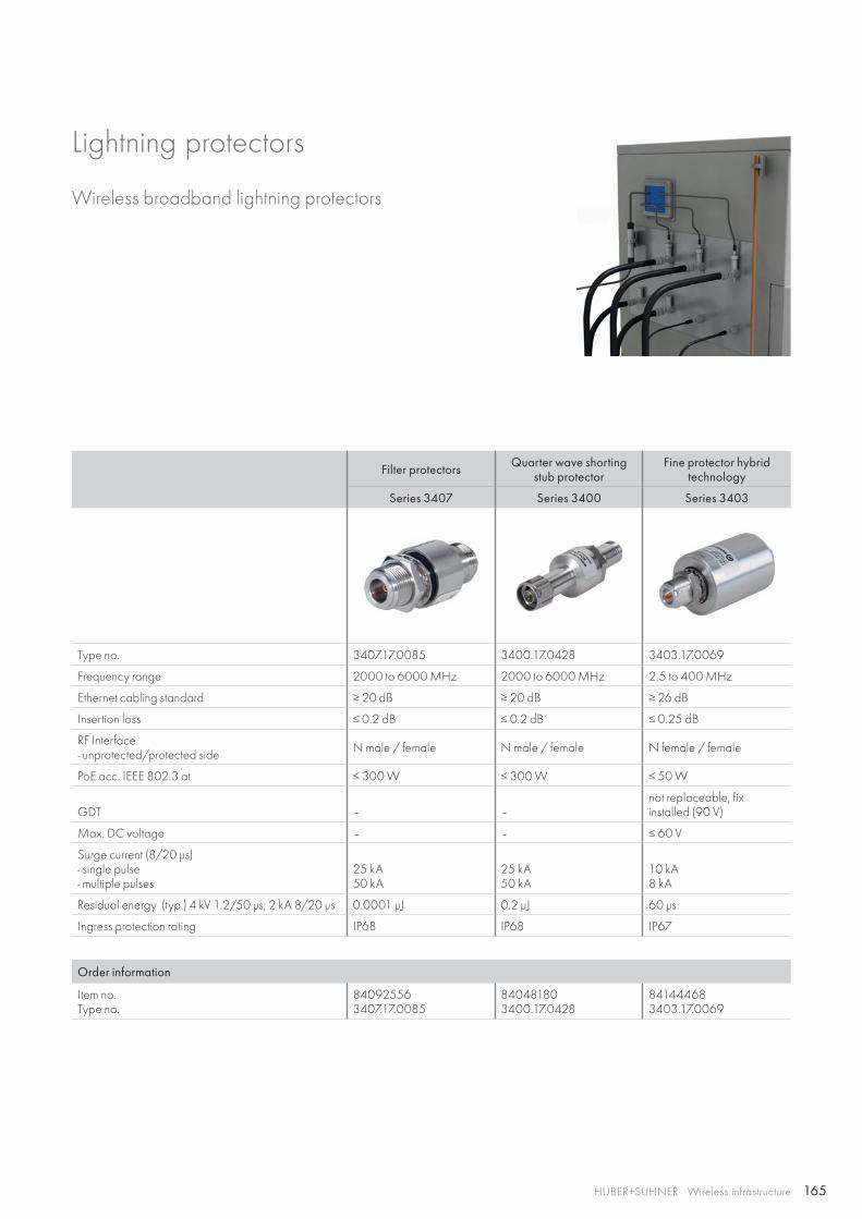
165HUBER+SUHNER Wireless infrastructure
Filter protectors Quarter wave shorting stub protector
Fine protector hybrid technology
Series 3407 Series 3400 Series 3403
Type no. 3407.17.0085 3400.17.0428 3403.17.0069
Frequency range 2000 to 6000 MHz 2000 to 6000 MHz 2.5 to 400 MHz
Ethernet cabling standard ≥ 20 dB ≥ 20 dB ≥ 26 dB
Insertion loss ≤ 0.2 dB ≤ 0.2 dB ≤ 0.25 dB
RF Interface- unprotected/protected side N male / female N male / female N female / female
PoE acc. IEEE 802.3 at ≤ 300 W ≤ 300 W ≤ 50 W
GDT – –not replaceable, fix installed (90 V)
Max. DC voltage – – ≤ 60 V
Surge current (8/20 μs)- single pulse- multiple pulses
25 kA50 kA
25 kA50 kA
10 kA8 kA
Residual energy (typ.) 4 kV 1.2/50 μs; 2 kA 8/20 μs 0.0001 μJ 0.2 μJ 60 μs
Ingress protection rating IP68 IP68 IP67
Order information
Item no.Type no.
840925563407.17.0085
840481803400.17.0428
841444683403.17.0069
Lightning protectors
Wireless broadband lightning protectors
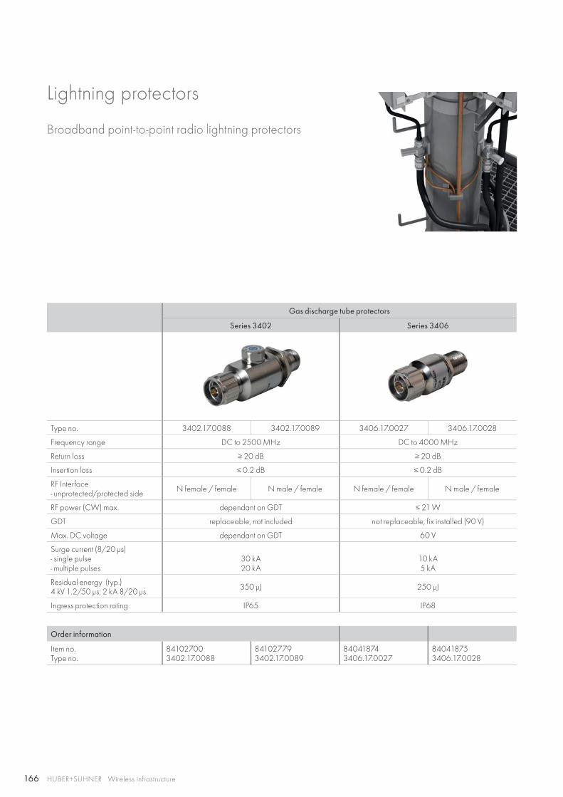
166 HUBER+SUHNER Wireless infrastructure
Gas discharge tube protectors
Series 3402 Series 3406
Type no. 3402.17.0088 3402.17.0089 3406.17.0027 3406.17.0028
Frequency range DC to 2500 MHz DC to 4000 MHz
Return loss ≥ 20 dB ≥ 20 dB
Insertion loss ≤ 0.2 dB ≤ 0.2 dB
RF Interface- unprotected/protected side N female / female N male / female N female / female N male / female
RF power (CW) max. dependant on GDT ≤ 21 W
GDT replaceable, not included not replaceable, fix installed (90 V)
Max. DC voltage dependant on GDT 60 V
Surge current (8/20 μs)- single pulse- multiple pulses
30 kA20 kA
10 kA5 kA
Residual energy (typ.)4 kV 1.2/50 μs; 2 kA 8/20 μs 350 μJ 250 μJ
Ingress protection rating IP65 IP68
Order information
Item no.Type no.
841027003402.17.0088
841027793402.17.0089
840418743406.17.0027
840418753406.17.0028
Broadband point-to-point radio lightning protectors
Lightning protectors
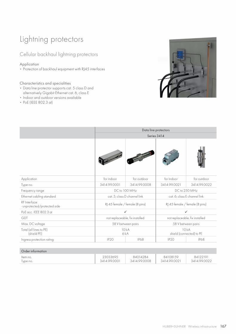
167HUBER+SUHNER Wireless infrastructure
Data line protectors
Series 3414
Application for indoor for outdoor for indoor for outdoor
Type no. 3414.99.0001 3414.99.0008 3414.99.0021 3414.99.0022
Frequency range DC to 100 MHz DC to 250 MHz
Ethernet cabling standard cat. 5; class D channel link cat. 6; class E channel link
RF Interface- unprotected/protected side RJ 45 female / female (8 pins) RJ 45 female / female (8 pins)
PoE acc. IEEE 802.3 at
GDT not replaceable, fix installed not replaceable, fix installed
Max. DC voltage 58 V between pairs 58 V between pairs
Total (all lines to PE) (shield PE)
10 kA6 kA
10 kAshield (connected) to PE
Ingress protection rating IP20 IP68 IP20 IP68
Order information
Item no.Type no.
230336953414.99.0001
840142843414.99.0008
841081593414.99.0021
841221913414.99.0022
Lightning protectors
Cellular backhaul lightning protectors
Application• Protection of backhaul equipment with RJ45 interfaces
Characteristics and specialities• Data line protector supports cat. 5 class D and
alternatively Gigabit Ethernet cat. 6, class E• Indoor and outdoor versions available• PoE (IEEE 802.3 at)
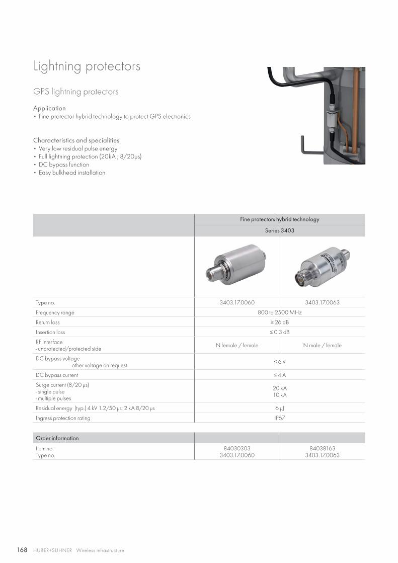
168 HUBER+SUHNER Wireless infrastructure
Lightning protectors
GPS lightning protectors
Fine protectors hybrid technology
Series 3403
Type no. 3403.17.0060 3403.17.0063
Frequency range 800 to 2500 MHz
Return loss ≥ 26 dB
Insertion loss ≤ 0.3 dB
RF Interface- unprotected/protected side N female / female N male / female
DC bypass voltage other voltage on request ≤ 6 V
DC bypass current ≤ 4 A
Surge current (8/20 μs)- single pulse- multiple pulses
20 kA10 kA
Residual energy (typ.) 4 kV 1.2/50 μs; 2 kA 8/20 μs 6 μJ
Ingress protection rating IP67
Order information
Item no.Type no.
840303033403.17.0060
840381633403.17.0063
Application• Fine protector hybrid technology to protect GPS electronics
Characteristics and specialities• Very low residual pulse energy• Full lightning protection (20kA ; 8/20μs)• DC bypass function• Easy bulkhead installation
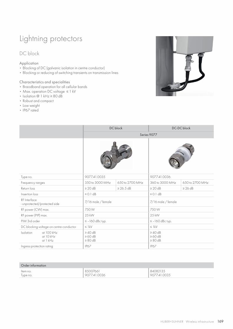
169HUBER+SUHNER Wireless infrastructure
DC block
DC block DC-DC block
Series 9077
Type no. 9077.41.0035 9077.41.0036
Frequency ranges 350 to 3000 MHz 650 to 2700 MHz 360 to 3000 MHz 650 to 2700 MHz
Return loss ≥ 20 dB ≥ 26.5 dB ≥ 20 dB ≥ 26 dB
Insertion loss ≤ 0.1 dB ≤ 0.1 dB
RF Interface- unprotected/protected side 7/16 male / female 7/16 male / female
RF power (CW) max. 750 W 750 W
RF power (PIP) max. 25 kW 25 kW
PIM 3rd order ≤ –160 dBc typ. ≤ –160 dBc typ.
DC blocking voltage on centre conductor ≤ 1kV ≤ 1kV
Isolation at 100 kHz at 10 kHz at 1 kHz
≥ 40 dB≥ 60 dB≥ 80 dB
≥ 40 dB≥ 60 dB≥ 80 dB
Ingress protection rating IP67 IP67
Order information
Item no.Type no.
850076619077.41.0036
840821359077.41.0035
Application• Blocking of DC (galvanic isolation in centre conductor)• Blocking or reducing of switching transients on transmission lines
Characteristics and specialities• Braodband operation for all cellular bands• Max. operation DC voltage ≤ 1 kV• Isolation @ 1 kHz ≥ 80 dB• Robust and compact• Low weight• IP67 rated
Lightning protectors
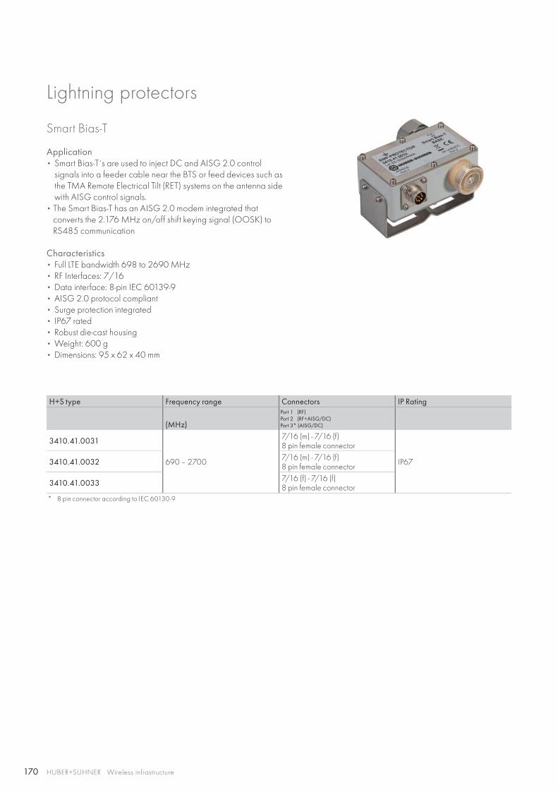
170 HUBER+SUHNER Wireless infrastructure
Smart Bias-T
Application• Smart Bias-T́ s are used to inject DC and AISG 2.0 control
signals into a feeder cable near the BTS or feed devices such as the TMA Remote Electrical Tilt (RET) systems on the antenna side with AISG control signals.
• The Smart Bias-T has an AISG 2.0 modem integrated that converts the 2.176 MHz on/off shift keying signal (OOSK) to RS485 communication
Characteristics• Full LTE bandwidth 698 to 2690 MHz• RF Interfaces: 7/16• Data interface: 8-pin IEC 60139-9• AISG 2.0 protocol compliant• Surge protection integrated• IP67 rated• Robust die-cast housing• Weight: 600 g• Dimensions: 95 x 62 x 40 mm
Lightning protectors
H+S type Frequency range Connectors IP Rating
(MHz)
Port 1 (RF)Port 2 (RF+AISG/DC)Port 3* (AISG/DC)
3410.41.0031
690 – 2700
7/16 (m) - 7/16 (f)8 pin female connector
IP67 3410.41.0032 7/16 (m) - 7/16 (f)8 pin female connector
3410.41.0033 7/16 (f) - 7/16 (f)8 pin female connector
* 8 pin connector according to IEC 60130-9
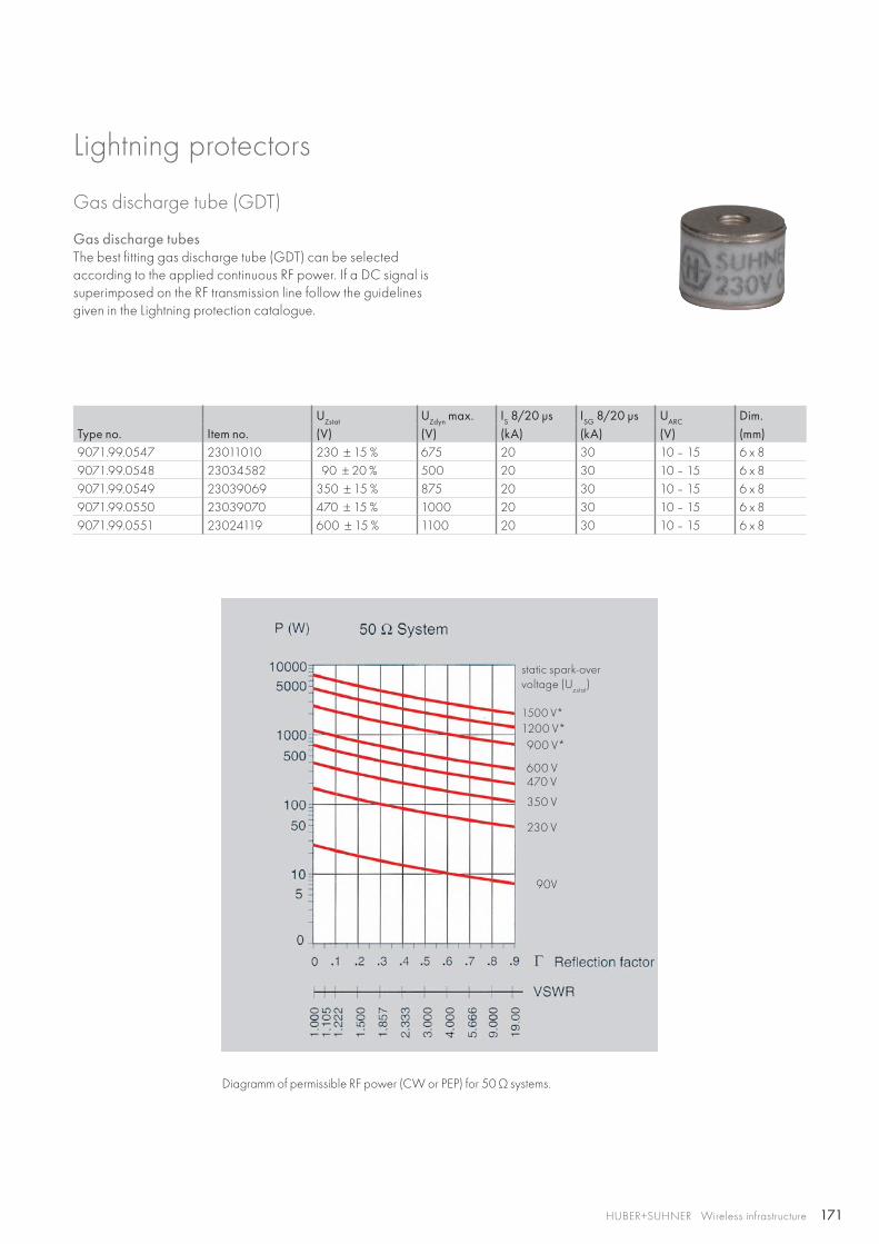
171HUBER+SUHNER Wireless infrastructure
Gas discharge tube (GDT)
Type no. Item no.UZstat UZdyn max. IS 8/20 μs ISG 8/20 μs UARC Dim.(V) (V) (kA) (kA) (V) (mm)
9071.99.0547 23011010 230 ± 15 % 675 20 30 10 – 15 6 x 89071.99.0548 23034582 90 ± 20 % 500 20 30 10 – 15 6 x 89071.99.0549 23039069 350 ± 15 % 875 20 30 10 – 15 6 x 89071.99.0550 23039070 470 ± 15 % 1000 20 30 10 – 15 6 x 89071.99.0551 23024119 600 ± 15 % 1100 20 30 10 – 15 6 x 8
Gas discharge tubesThe best fitting gas discharge tube (GDT) can be selected according to the applied continuous RF power. If a DC signal is superimposed on the RF transmission line follow the guidelines given in the Lightning protection catalogue.
1500 V*
static spark-overvoltage (U
zstat)
350 V
470 V600 V
900 V*1200 V*
90V
230 V
Diagramm of permissible RF power (CW or PEP) for 50 Ω systems.
Lightning protectors
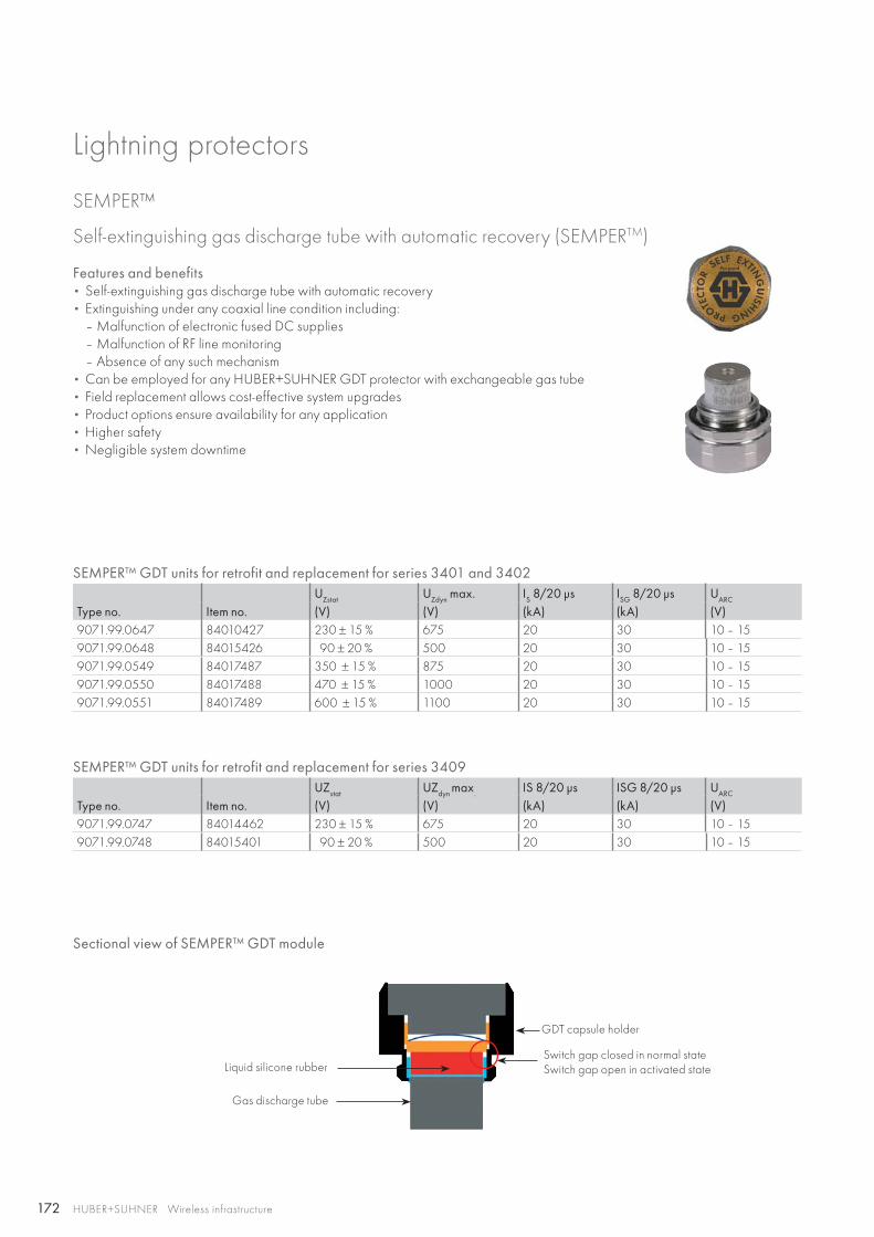
172 HUBER+SUHNER Wireless infrastructure
Features and benefits• Self-extinguishing gas discharge tube with automatic recovery• Extinguishing under any coaxial line condition including:
– Malfunction of electronic fused DC supplies– Malfunction of RF line monitoring– Absence of any such mechanism
• Can be employed for any HUBER+SUHNER GDT protector with exchangeable gas tube• Field replacement allows cost-effective system upgrades• Product options ensure availability for any application• Higher safety• Negligible system downtime
SEMPER™ GDT units for retrofit and replacement for series 3401 and 3402
Type no. Item no.UZstat UZdyn max. IS 8/20 μs ISG 8/20 μs UARC
(V) (V) (kA) (kA) (V)9071.99.0647 84010427 230 ± 15 % 675 20 30 10 – 159071.99.0648 84015426 90 ± 20 % 500 20 30 10 – 159071.99.0549 84017487 350 ± 15 % 875 20 30 10 – 159071.99.0550 84017488 470 ± 15 % 1000 20 30 10 – 159071.99.0551 84017489 600 ± 15 % 1100 20 30 10 – 15
SEMPER™ GDT units for retrofit and replacement for series 3409
Type no. Item no.UZstat UZdyn max. IS 8/20 μs ISG 8/20 μs UARC
(V) (V) (kA) (kA) (V)9071.99.0747 84014462 230 ± 15 % 675 20 30 10 – 159071.99.0748 84015401 90 ± 20 % 500 20 30 10 – 15
SEMPER™
GDT capsule holder
Switch gap closed in normal stateSwitch gap open in activated stateLiquid silicone rubber
Gas discharge tube
Sectional view of SEMPER™ GDT module
Self-extinguishing gas discharge tube with automatic recovery (SEMPERTM)
Lightning protectors
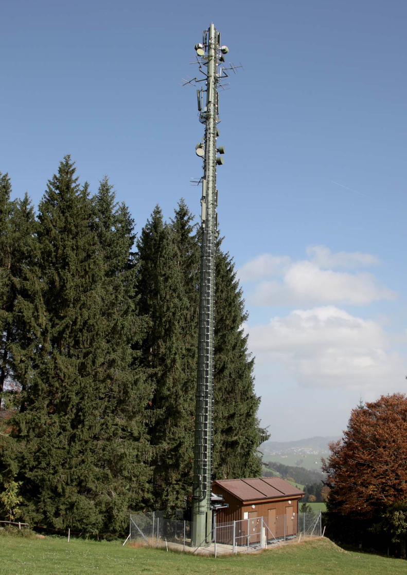
173HUBER+SUHNER Wireless infrastructure
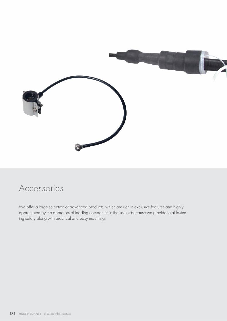
174 HUBER+SUHNER Wireless infrastructure
Accessories
We offer a large selection of advanced products, which are rich in exclusive features and highly appreciated by the operators of leading companies in the sector because we provide total fasten-ing safety along with practical and easy mounting.
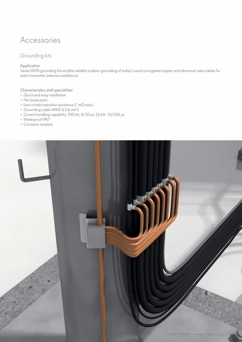
175HUBER+SUHNER Wireless infrastructure
Grounding kits
ApplicationSeries 9076 grounding kits enable reliable outdoor grounding of today’s usual corrugated copper and aluminium tube cables for radio transmitter antenna installations.
Characteristics and specialities • Quick and easy installation• No loose parts• Low contact transition resistance (1 mΩ max.)• Grounding cable AWG 6 (16 mm2)• Current handling capability 100 kA, 8/20 μs; 25 kA, 10/350 μs• Waterproof IP67• Corrosion resistant
Accessories
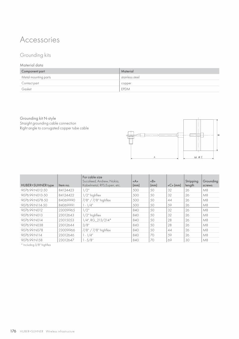
176 HUBER+SUHNER Wireless infrastructure
Material dataComponent part Material
Metal mounting parts stainless steel
Contact part copper
Gasket EPDM
Grounding kit N-styleStraight grounding cable connectionRight angle to corrugated copper tube cable
HUBER+SUHNER type Item no.
For cable sizeSucofeed, Andrew, Nokia, Kabelmetal, RFS,Eupen, etc.
«A»(mm)
«B»(mm) «C» (mm)
Stripping length
Grounding screws
9076.99.N012-50 84124423 1/2" 500 50 32 26 M89076.99.N013-50 84124422 1/2" highflex 500 50 32 26 M89076.99.N078-50 84069990 7/8" / 7/8" highflex 500 50 44 26 M89076.99.N114-50 84069991 1 - 1/4" 500 50 59 26 M89076.99.N012 23009965 1/2" 840 50 32 26 M89076.99.N013 23012643 1/2" highflex 840 50 32 26 M89076.99.N014 23015053 1/4", RG_213/214* 840 50 28 26 M89076.99.N038 23012644 3/8" 840 50 28 26 M89076.99.N078 23009966 7/8" / 7/8" highflex 840 50 44 26 M89076.99.N114 23012646 1 - 1/4" 840 70 59 26 M89076.99.N158 23012647 1 - 5/8" 840 70 69 30 M8* Including 3/8" highflex
Accessories
Grounding kits
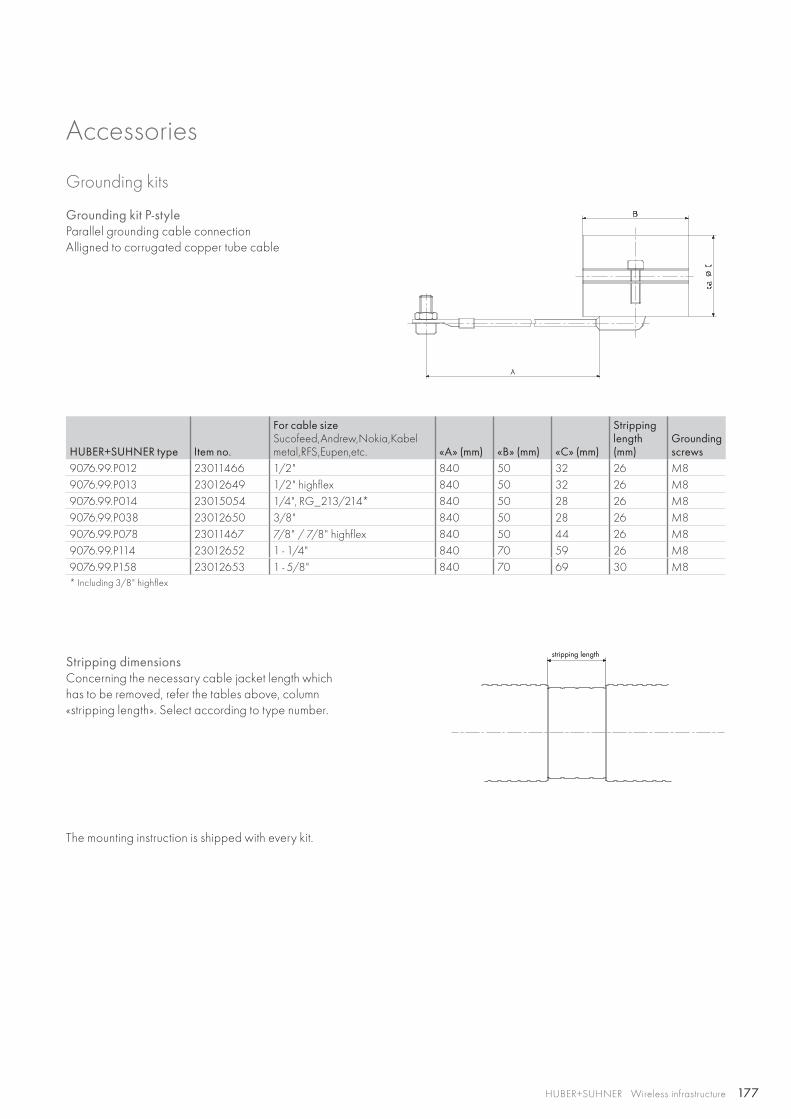
177
stripping length
HUBER+SUHNER Wireless infrastructure
Grounding kit P-styleParallel grounding cable connectionAlligned to corrugated copper tube cable
HUBER+SUHNER type Item no.
For cable sizeSucofeed,Andrew,Nokia,Kabel metal,RFS,Eupen,etc. «A» (mm) «B» (mm) «C» (mm)
Stripping length (mm)
Grounding screws
9076.99.P012 23011466 1/2" 840 50 32 26 M89076.99.P013 23012649 1/2" highflex 840 50 32 26 M89076.99.P014 23015054 1/4", RG_213/214* 840 50 28 26 M89076.99.P038 23012650 3/8" 840 50 28 26 M89076.99.P078 23011467 7/8" / 7/8" highflex 840 50 44 26 M89076.99.P114 23012652 1 - 1/4" 840 70 59 26 M89076.99.P158 23012653 1 - 5/8" 840 70 69 30 M8* Including 3/8" highflex
Stripping dimensionsConcerning the necessary cable jacket length whichhas to be removed, refer the tables above, column «stripping length». Select according to type number.
The mounting instruction is shipped with every kit.
Accessories
Grounding kits
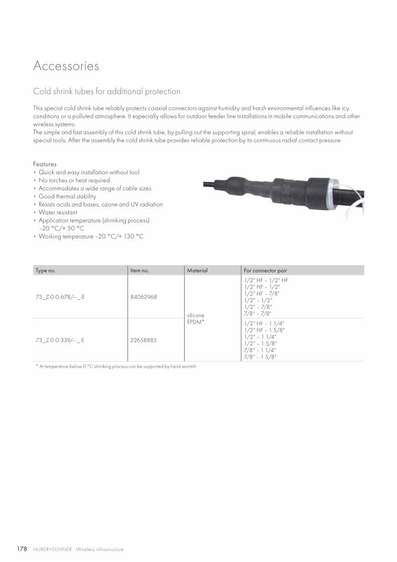
178 HUBER+SUHNER Wireless infrastructure
Cold shrink tubes for additional protection
Type no. Item no. Material For connector pair
73_Z-0-0-678/-- -_-E 84062968
siliconeEPDM*
1/2" HF – 1/2" HF1/2" HF – 1/2"1/2" HF – 7/8"1/2" – 1/2"1/2" – 7/8"7/8" – 7/8"
73_Z-0-0-339/-- -_-E 22658885
1/2" HF – 1 1/4"1/2" HF – 1 5/8"1/2" – 1 1/4"1/2" – 1 5/8"7/8" – 1 1/4"7/8" – 1 5/8"
* At temperature below 0 °C shrinking process can be supported by hand warmth.
This special cold shrink tube reliably protects coaxial connectors against humidity and harsh environmental influences like icy conditions or a polluted atmosphere. It especially allows for outdoor feeder line installations in mobile communications and other wireless systems.The simple and fast assembly of this cold shrink tube, by pulling out the supporting spiral, enables a reliable installation without special tools. After the assembly the cold shrink tube provides reliable protection by its continuous radial contact pressure.
Features • Quick and easy installation without tool• No torches or heat required• Accommodates a wide range of cable sizes• Good thermal stability• Resists acids and bases, ozone and UV radiation• Water resistant• Application temperature (shrinking process)
–20 °C/+ 50 °C• Working temperature –20 °C/+ 130 °C
Accessories
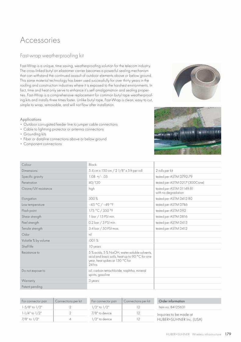
179HUBER+SUHNER Wireless infrastructure
Inquiries to be made atHUBER+SUHNER Inc. (USA)
Fast-wrap weatherproofing kit
Fast-Wrap is a unique, time saving, weatherproofing solution for the telecom industry. The cross-linked butyl on elastomer carrier becomes a powerful sealing mechanism that can withstand the continued assault of outdoor elements above or below ground. This same material technology has been used successfully for over thirty years in the roofing and construction industries where it is exposed to the harshest environments. In fact, time and heat only serve to enhance it’s self amalgamation and sealing proper-ties. Fast-Wrap is a comprehensive replacement for common butyl tape weatherproof-ing kits and installs three times faster. Unlike butyl tape, Fast-Wrap is clean, easy to cut, simple to wrap, removable, and will not flow after installation.
Applications • Outdoor corrugated feeder line to jumper cable connections • Cable to lightning protector or antenna connections• Grounding kits• Fiber or dataline connections above or below ground• Component connections
Colour Black
Dimensions 5.4 cm x 150 cm / 2 1/8" x 5 ft per roll 2 rolls per kit
Specific gravity 1.08 +/– .05 tested per ASTM D792-79
Penetration 40/120 tested per ASTM D217 (300Cone)
Ozone/UV resistance high tested per ASTM D1149-81with no degradation
Elongation 300 % tested per ASTM D412-80
Low temperature –45 °C / –49 °F tested per ASTM D746
Flash point 175 °C / 350 °F tested per ASTM D92
Shear strength 1 bar / 15 PSI min. tested per ASTM D816
Peel strength 0.2 bar / 3 PSI min. tested per ASTM D413
Tensile strength 3.4 bar / 50 PSI max. tested per ASTM D412
Odor nil
Volatile % by volume .001 %
Shelf life 10 years
Resistance to 5 % acids, 5 % NaOH, water soluble solvents, acid and basic soils, heat up to 90 °C for one year, heat spikes at 130 °C for24 hrs
Do not expose to oil, carbon tetrachloride, naphtha, mineral spirits, gasoline
Warranty 3 years
Patent pending
For connector pair Connections per kit
1-5/8" to 1/2" 2
1-1/4" to 1/2" 2
7/8" to 1/2" 4
Accessories
For connector pair Connections per kit
1/2" to 1/2" 12
7/8" to device 12
1/2" to device 12
Order information
Item no. 84125631
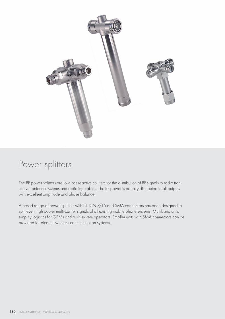
180 HUBER+SUHNER Wireless infrastructure
Power splitters
The RF power splitters are low loss reactive splitters for the distribution of RF signals to radio tran-sceiver antenna systems and radiating cables. The RF power is equally distributed to all outputs with excellent amplitude and phase balance.
A broad range of power splitters with N, DIN 7/16 and SMA connectors has been designed to split even high power multi-carrier signals of all existing mobile phone systems. Multiband units simplify logistics for OEMs and multi-system operators. Smaller units with SMA connectors can be provided for picocell wireless communication systems.
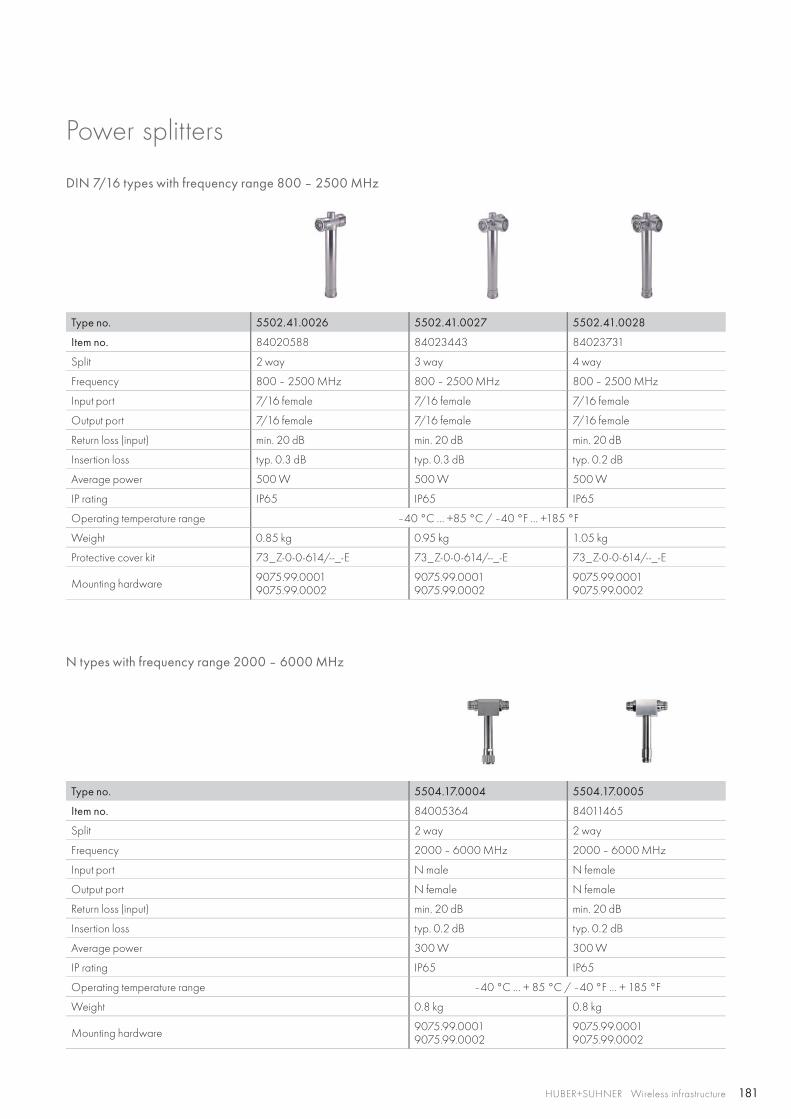
181HUBER+SUHNER Wireless infrastructure
Power splitters
DIN 7/16 types with frequency range 800 – 2500 MHz
Type no. 5502.41.0026 5502.41.0027 5502.41.0028
Item no. 84020588 84023443 84023731
Split 2 way 3 way 4 way
Frequency 800 – 2500 MHz 800 – 2500 MHz 800 – 2500 MHz
Input port 7/16 female 7/16 female 7/16 female
Output port 7/16 female 7/16 female 7/16 female
Return loss (input) min. 20 dB min. 20 dB min. 20 dB
Insertion loss typ. 0.3 dB typ. 0.3 dB typ. 0.2 dB
Average power 500 W 500 W 500 W
IP rating IP65 IP65 IP65
Operating temperature range –40 °C … +85 °C / –40 °F … +185 °F
Weight 0.85 kg 0.95 kg 1.05 kg
Protective cover kit 73_Z-0-0-614/--_-E 73_Z-0-0-614/--_-E 73_Z-0-0-614/--_-E
Mounting hardware 9075.99.0001 9075.99.0002
9075.99.0001 9075.99.0002
9075.99.0001 9075.99.0002
Type no. 5504.17.0004 5504.17.0005
Item no. 84005364 84011465
Split 2 way 2 way
Frequency 2000 – 6000 MHz 2000 – 6000 MHz
Input port N male N female
Output port N female N female
Return loss (input) min. 20 dB min. 20 dB
Insertion loss typ. 0.2 dB typ. 0.2 dB
Average power 300 W 300 W
IP rating IP65 IP65
Operating temperature range –40 °C … + 85 °C / –40 °F … + 185 °F
Weight 0.8 kg 0.8 kg
Mounting hardware 9075.99.0001 9075.99.0002
9075.99.0001 9075.99.0002
N types with frequency range 2000 – 6000 MHz

182 HUBER+SUHNER Wireless infrastructure
Protective cover kitThe protective cover kit provides additonal protection for RF power splitters exposed to harsh environmental conditions. Important: The installation of the protective cover kit requires right angle adaptors on all output ports. As the power splitters are supplied with straight connector shapes (female) only, you will have to use either jumpers with right angle interfaces (male) or separately ordering right angle adaptors as listed below.
Power splitters – accessories
Type no. Item no. Weight (kg)
73_Z-0-0-614/-- -_-E 84072501 0.4334
The protective cover kit includes the protective cover with screw M8x1 and screw fixation cord and rubber bellows with hose clamp.
Type no. 53_N-50-0-4/133_UE 53_716-50-0-1/003_-E
Item no. 22658908 22641259
Shape right angle adaptor right angle adaptor
Connector series N 7/16
Connector gender plug/jack [m/f] plug/jack [m/f]
Right angle adaptors to be ordered separately 1 adaptor required per output port
Type no. Item no. For mast diameter Weight (kg)
9075.99.0001 22648739 40 – 50 mm 0.35
9075.99.0002 22648738 50 – 360 mm 0.45
One set consists of a complete bracket plus two steel hose clamps adjusted to the selected mast diameter.
This mounting hardware allows you to fix RF power splitters on masts of 40 to 360 mm diameter by means of non corrosive steel hose clamps. It can be used for wall mounting (2 x 8.0 mm diameter holes) too.
Mounting hardware
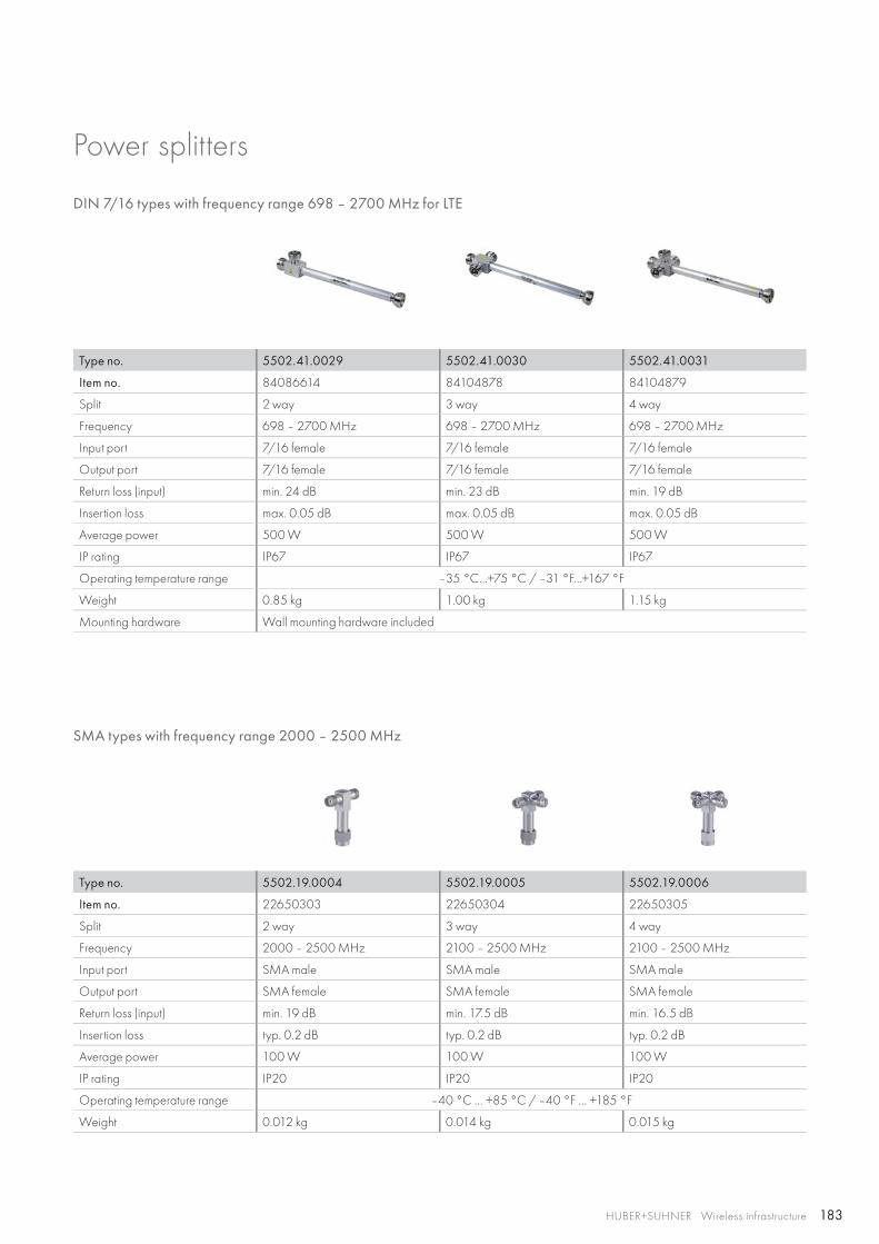
183HUBER+SUHNER Wireless infrastructure
Type no. 5502.19.0004 5502.19.0005 5502.19.0006
Item no. 22650303 22650304 22650305
Split 2 way 3 way 4 way
Frequency 2000 – 2500 MHz 2100 – 2500 MHz 2100 – 2500 MHz
Input port SMA male SMA male SMA male
Output port SMA female SMA female SMA female
Return loss (input) min. 19 dB min. 17.5 dB min. 16.5 dB
Insertion loss typ. 0.2 dB typ. 0.2 dB typ. 0.2 dB
Average power 100 W 100 W 100 W
IP rating IP20 IP20 IP20
Operating temperature range –40 °C … +85 °C / –40 °F … +185 °F
Weight 0.012 kg 0.014 kg 0.015 kg
SMA types with frequency range 2000 – 2500 MHz
Power splitters
DIN 7/16 types with frequency range 698 – 2700 MHz for LTE
Type no. 5502.41.0029 5502.41.0030 5502.41.0031
Item no. 84086614 84104878 84104879
Split 2 way 3 way 4 way
Frequency 698 – 2700 MHz 698 – 2700 MHz 698 – 2700 MHz
Input port 7/16 female 7/16 female 7/16 female
Output port 7/16 female 7/16 female 7/16 female
Return loss (input) min. 24 dB min. 23 dB min. 19 dB
Insertion loss max. 0.05 dB max. 0.05 dB max. 0.05 dB
Average power 500 W 500 W 500 W
IP rating IP67 IP67 IP67
Operating temperature range –35 °C…+75 °C / –31 °F…+167 °F
Weight 0.85 kg 1.00 kg 1.15 kg
Mounting hardware Wall mounting hardware included
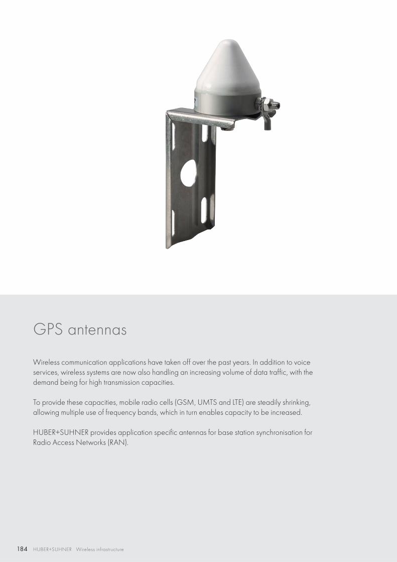
184 HUBER+SUHNER Wireless infrastructure
GPS antennas
Wireless communication applications have taken off over the past years. In addition to voice services, wireless systems are now also handling an increasing volume of data traffic, with the demand being for high transmission capacities.
To provide these capacities, mobile radio cells (GSM, UMTS and LTE) are steadily shrinking, allowing multiple use of frequency bands, which in turn enables capacity to be increased.
HUBER+SUHNER provides application specific antennas for base station synchronisation for Radio Access Networks (RAN).
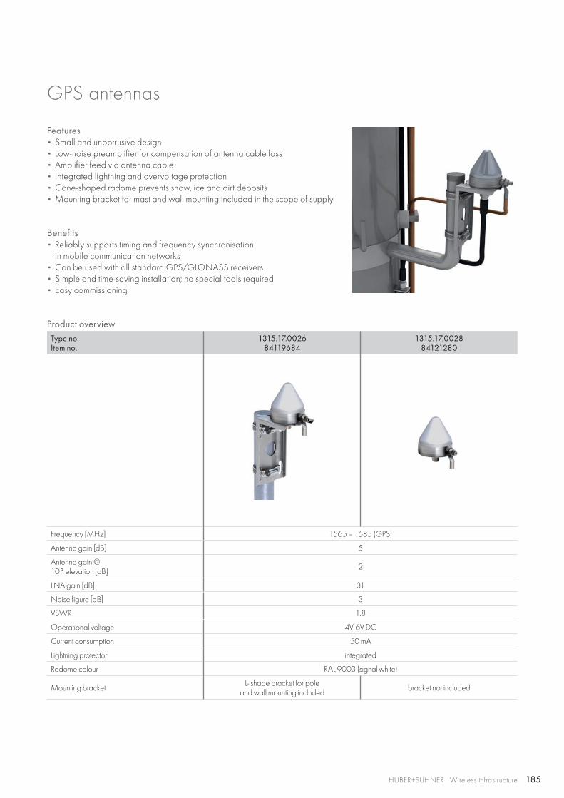
185HUBER+SUHNER Wireless infrastructure
GPS antennas
Features• Small and unobtrusive design• Low-noise preamplifier for compensation of antenna cable loss• Amplifier feed via antenna cable • Integrated lightning and overvoltage protection• Cone-shaped radome prevents snow, ice and dirt deposits• Mounting bracket for mast and wall mounting included in the scope of supply
Benefits• Reliably supports timing and frequency synchronisation
in mobile communication networks• Can be used with all standard GPS/GLONASS receivers• Simple and time-saving installation; no special tools required• Easy commissioning
Product overviewType no.Item no.
1315.17.0026 84119684
1315.17.0028 84121280
Frequency [MHz] 1565 – 1585 (GPS)
Antenna gain [dB] 5
Antenna gain @10° elevation [dB] 2
LNA gain [dB] 31
Noise figure [dB] 3
VSWR 1.8
Operational voltage 4V-6V DC
Current consumption 50 mA
Lightning protector integrated
Radome colour RAL 9003 (signal white)
Mounting bracket L- shape bracket for pole and wall mounting included bracket not included
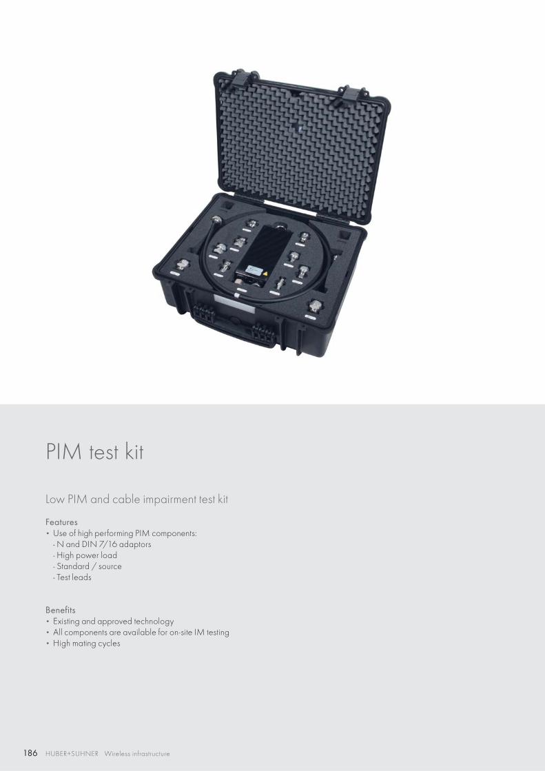
186 HUBER+SUHNER Wireless infrastructure
PIM test kit
Low PIM and cable impairment test kit
Features • Use of high performing PIM components:
- N and DIN 7/16 adaptors- High power load- Standard / source- Test leads
Benefits • Existing and approved technology• All components are available for on-site IM testing• High mating cycles
187HUBER+SUHNER Wireless infrastructure
PIM test kit
Technical data
Electrical
Impedance 50 Ω
Frequency range 690 MHz to 2700 MHz
RF CW power 50 W
Environmental
Operating temperature 0 °C up to +40 °C
RoHS 2011/65/EC compliant
Mechanical
Number of matings 500 with max. torque of 30 Nm for DIN 7/16 or max. torque of 1 Nm for N interfaces, increased torque may reduce the number of matings significantly
Material
Piece part Material Surface Plating
Body brass tri-metal plating
Centre contact female copper beryllium alloy gold plating / silver plating / tri-metal plating
Centre contact male brass gold plating / silver plating / tri-metal plating
Case dimensions 520 x 435 x 230 mm (20.5 x 17 x 9 in.)
Weight 10.3 kg (22.7 lbs.)
Order information
Low PIM and cable impairment test kit, item no. 84131152
Low PIM and cable impairment test kit
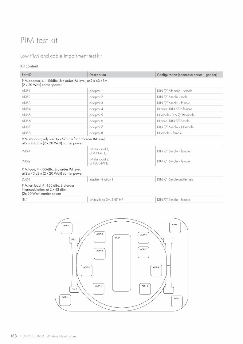
188
spare
IMS-2IMS-1
spare
ADP-6ADP-2
ADP-7ADP-3
ADP-4 ADP-8
ADP-1 ADP-5
ITL-1
ITL-1
LOD-1
HUBER+SUHNER Wireless infrastructure
Kit content
Part ID Description Configuration (connector series – gender)
PIM adaptor, ≤ –155dBc, 3rd order IM level, at 2 x 43 dBm (2 x 20 Watt) carrier power
ADP-1 adaptor 1 DIN 7/16 female – female
ADP-2 adaptor 2 DIN 7/16 male – male
ADP-3 adaptor 3 DIN 7/16 male – female
ADP-4 adaptor 4 N male - DIN 7/16 female
ADP-5 adaptor 5 N female - DIN 7/16 female
ADP-6 adaptor 6 N male - DIN 7/16 male
ADP-7 adaptor 7 DIN 7/16 male – N female
ADP-8 adaptor 8 N female – female
PIM standard, adjusted to –57 dBm for 3rd order IM level, at 2 x 43 dBm (2 x 20 Watt) carrier power
IMS-1 IM standard 1, at 900 MHz DIN 7/16 male – female
IMS-2 IM standard 2, at 1800 MHz DIN 7/16 male – female
PIM load, ≤ –155dBc, 3rd order IM level,at 2 x 43 dBm (2 x 20 Watt) carrier power
LOD-1 load termination 1 DIN 7/16 male and female
PIM test lead, ≤ –155 dBc, 3rd orderintermodulation, at 2 x 43 dBm(2x 20 Watt) carrier power
ITL-1 IM test lead 3m, 3/8" HF DIN 7/16 male – female
PIM test kit
Low PIM and cable impairment test kit
189HUBER+SUHNER Wireless infrastructure
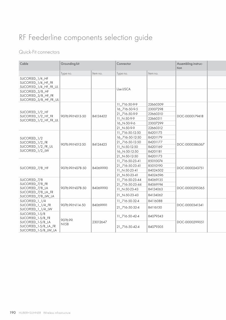
190 HUBER+SUHNER Wireless infrastructure
RF Feederline components selection guide
Quick-Fit connectors
Cable Grounding kit Connector Assembling instruc-tion
Type no. Item no. Type no. Item no.
SUCOFEED_1/4_HFSUCOFEED_1/4_HF_FRSUCOFEED_1/4_HF_FR_UL
Use LISCASUCOFEED_3/8_HFSUCOFEED_3/8_HF_FRSUCOFEED_3/8_HF_FR_UL
SUCOFEED_1/2_HFSUCOFEED_1/2_HF_FRSUCOFEED_1/2_HF_FR_UL
9076.99.N013-50 84124422
11_716-50-9-9 22660309
DOC-0000179418
16_716-50-9-5 2300729821_716-50-9-9 2266031011_N-50-9-9 2266031116_N-50-9-6 2300729921_N-50-9-9 22660312
SUCOFEED_1/2SUCOFEED_1/2_FRSUCOFEED_1/2_FR_ULSUCOFEED_1/2_LW
9076.99.N012-50 84124423
11_716-50-12-50 84201175
DOC-0000386367
16_716-50-12-50 8420117921_716-50-12-50 8420117711_N-50-12-50 8420116916_N-50-12-50 8420118121_N-50-12-50 84201173
SUCOFEED_7/8_HF 9076.99.N078-50 84069990
11_716-50-23-41 85010074
DOC-000024375121_716-50-23-41 8501019011_N-50-23-41 8402450221_N-50-23-41 84024596
SUCOFEED_7/8SUCOFEED_7/8_FRSUCOFEED_7/8_LASUCOFEED_7/8_LA_FRSUCOFEED_7/8_LW_LA
9076.99.N078-50 84069990
11_716-50-23-44 84069135
DOC-000029536521_716-50-23-44 8406919411_N-50-23-43 84124063
21_N-50-23-43 84124062
SUCOFEED_1_1/4SUCOFEED_1_1/4_FRSUCOFEED_1_1/4_LW
9076.99.N114-50 8406999111_716-50-32-4 84116088
DOC-000034134121_716-50-32-4 84116150
SUCOFEED_1-5/8SUCOFEED_1-5/8_FRSUCOFEED_1-5/8_LASUCOFEED_1-5/8_LA_FRSUCOFEED_1-5/8_LW_LA
9076.99.N158
23012647
11_716-50-42-4 84079343
DOC-000029905121_716-50-42-4 84079305
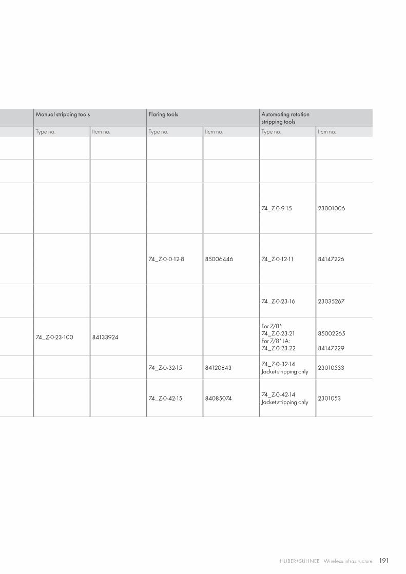
191HUBER+SUHNER Wireless infrastructure
Manual stripping tools Flaring tools Automating rotation stripping tools
Type no. Item no. Type no. Item no. Type no. Item no.
74_Z-0-9-15 23001006
74_Z-0-0-12-8 85006446 74_Z-0-12-11 84147226
74_Z-0-23-16 23035267
74_Z-0-23-100 84133924
For 7/8":74_Z-0-23-21For 7/8" LA:74_Z-0-23-22
85002265
84147229
74_Z-0-32-15 8412084374_Z-0-32-14Jacket stripping only
23010533
74_Z-0-42-15 8408507474_Z-0-42-14Jacket stripping only
2301053
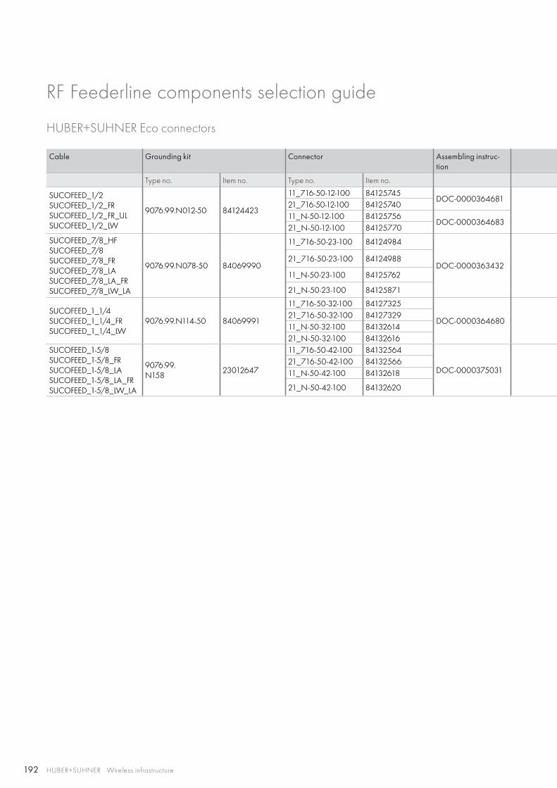
192 HUBER+SUHNER Wireless infrastructure
RF Feederline components selection guide
HUBER+SUHNER Eco connectors
Cable Grounding kit Connector Assembling instruc-tion
Type no. Item no. Type no. Item no.
SUCOFEED_1/2SUCOFEED_1/2_FRSUCOFEED_1/2_FR_ULSUCOFEED_1/2_LW
9076.99.N012-50 84124423
11_716-50-12-100 84125745DOC-0000364681
21_716-50-12-100 8412574011_N-50-12-100 84125756
DOC-000036468321_N-50-12-100 84125770
SUCOFEED_7/8_HFSUCOFEED_7/8SUCOFEED_7/8_FRSUCOFEED_7/8_LASUCOFEED_7/8_LA_FRSUCOFEED_7/8_LW_LA
9076.99.N078-50 84069990
11_716-50-23-100 84124984
DOC-000036343221_716-50-23-100 84124988
11_N-50-23-100 84125762
21_N-50-23-100 84125871
SUCOFEED_1_1/4SUCOFEED_1_1/4_FRSUCOFEED_1_1/4_LW
9076.99.N114-50 84069991
11_716-50-32-100 84127325
DOC-000036468021_716-50-32-100 8412732911_N-50-32-100 8413261421_N-50-32-100 84132616
SUCOFEED_1-5/8SUCOFEED_1-5/8_FRSUCOFEED_1-5/8_LASUCOFEED_1-5/8_LA_FRSUCOFEED_1-5/8_LW_LA
9076.99.N158
23012647
11_716-50-42-100 84132564
DOC-000037503121_716-50-42-100 8413256611_N-50-42-100 84132618
21_N-50-42-100 84132620
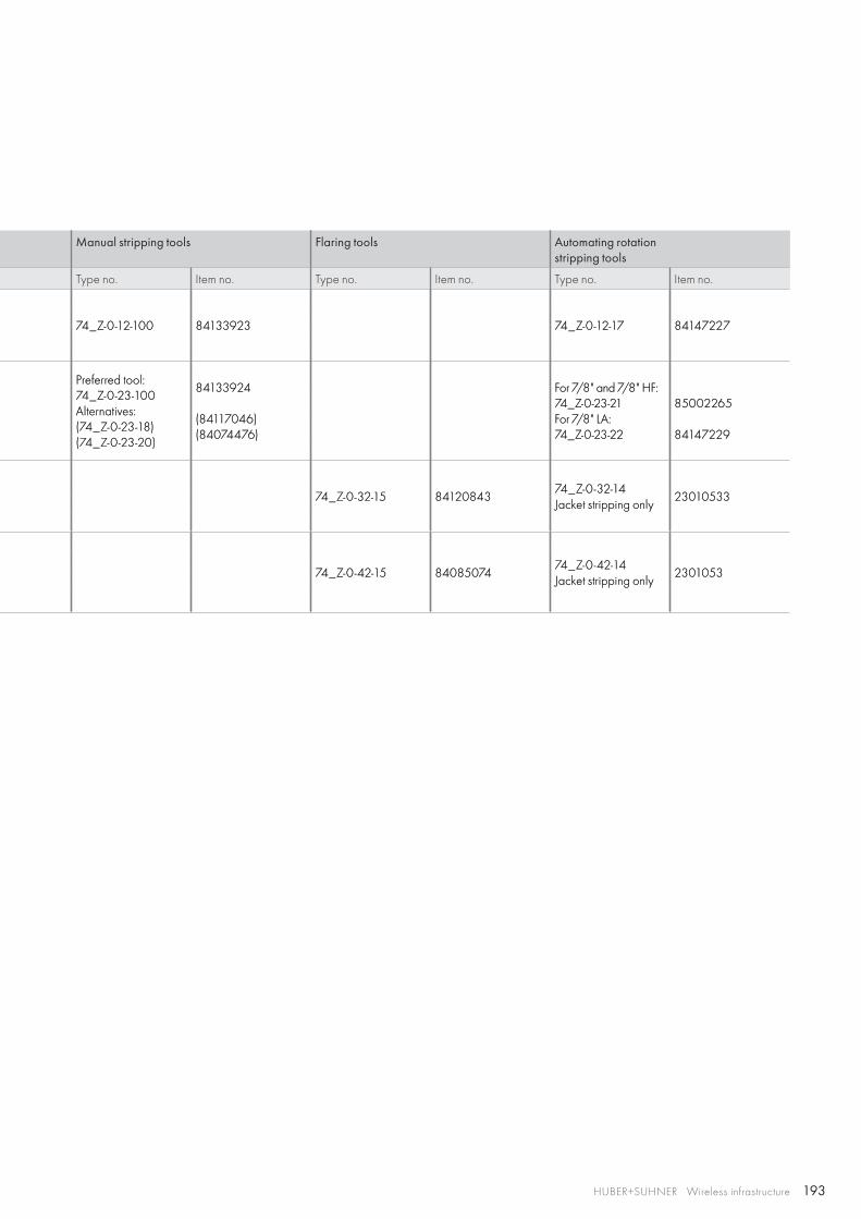
193HUBER+SUHNER Wireless infrastructure
Manual stripping tools Flaring tools Automating rotation stripping tools
Type no. Item no. Type no. Item no. Type no. Item no.
74_Z-0-12-100 84133923 74_Z-0-12-17 84147227
Preferred tool:74_Z-0-23-100Alternatives:(74_Z-0-23-18)(74_Z-0-23-20)
84133924
(84117046)(84074476)
For 7/8" and 7/8" HF:74_Z-0-23-21For 7/8" LA:74_Z-0-23-22
85002265
84147229
74_Z-0-32-15 8412084374_Z-0-32-14Jacket stripping only
23010533
74_Z-0-42-15 8408507474_Z-0-42-14Jacket stripping only
2301053
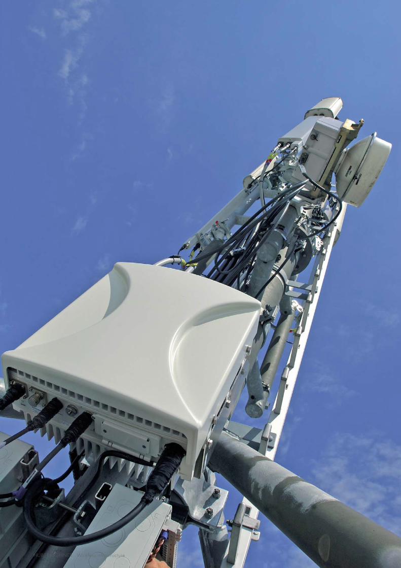
194 HUBER+SUHNER Wireless infrastructure
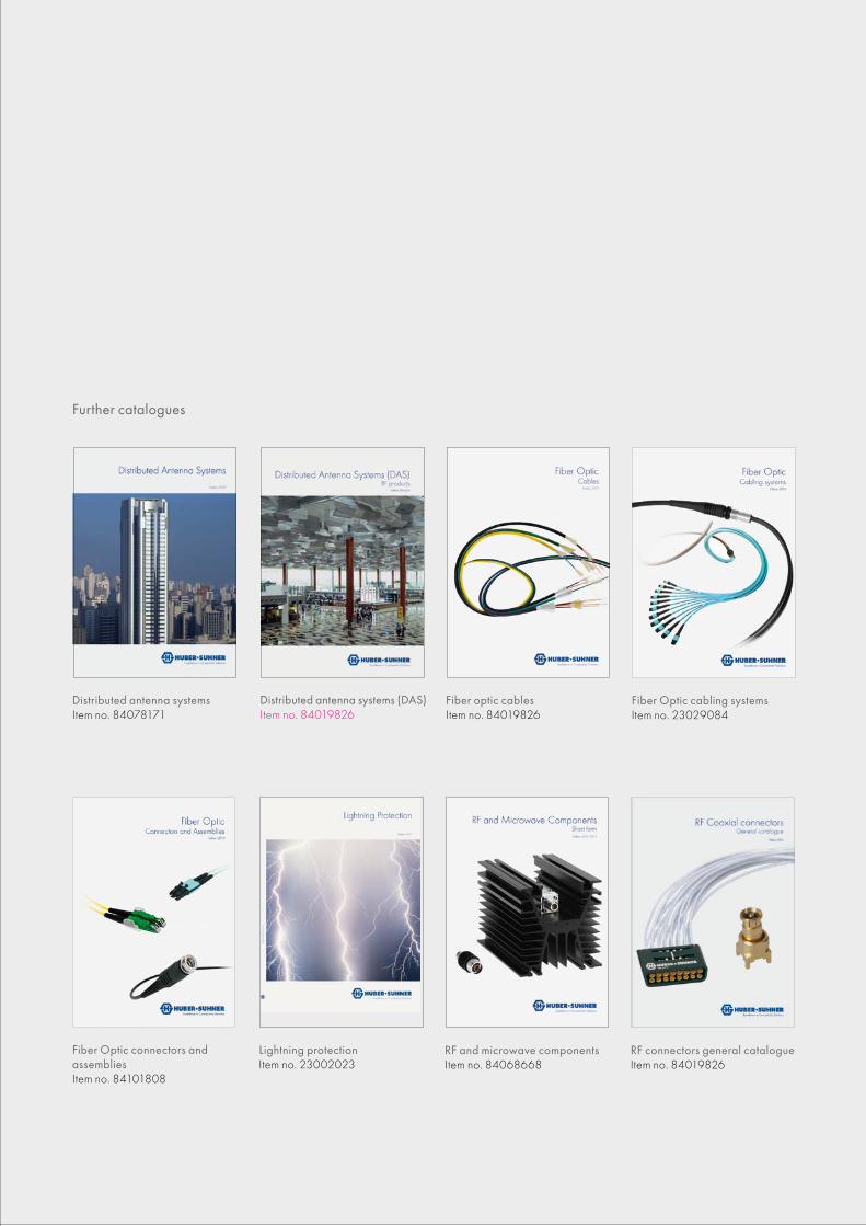
Count on proven wireless technology
Distributed antenna systems Item no. 84078171
Fiber optic cables Item no. 84019826
Fiber Optic cabling systems Item no. 23029084
Lightning protection Item no. 23002023
RF connectors general catalogue Item no. 84019826
RF and microwave components Item no. 84068668
Further catalogues
Fiber Optic connectors and assemblies Item no. 84101808
Distributed antenna systems (DAS) Item no. 84019826
Wireless infrastructureSolutions for remote radios and cell sites
HUBER+SUHNER AG Fiber Optics Division Degersheimerstrasse 14 9100 Herisau Switzerland Phone +41 71 353 4111 Fax +41 71 353 4444 hubersuhner.com
841
26
95
3_R
ev. E
/01
.201
4
HUBER+SUHNER is certified according to EN(AS) 9100, ISO 9001, ISO 14001, ISO/TS 16949 and IRIS.
WaiverFact and figures herein are for information only and do not represent any warranty of any kind.