Embed Size (px)
Citation preview
© 2011 SHYAM | Company Confidential 1/10
RM-24/58
Carrier Grade Radios Modems
Quick Start Guide
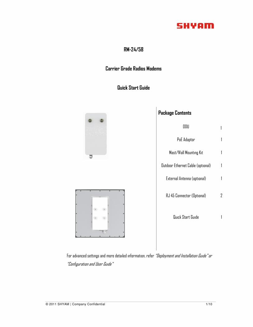
Package Contents
ODU 1
PoE Adaptor 1
Mast/Wall Mounting Kit 1
Outdoor Ethernet Cable (optional) 1
External Antenna (optional) 1
RJ 45 Connector (Optional) 2
Quick Start Guide 1
For advanced settings and more detailed information, refer “Deployment and Installation Guide” or
“Configuration and User Guide”
© 2012 SHYAM | Company Confidential Page 2/10
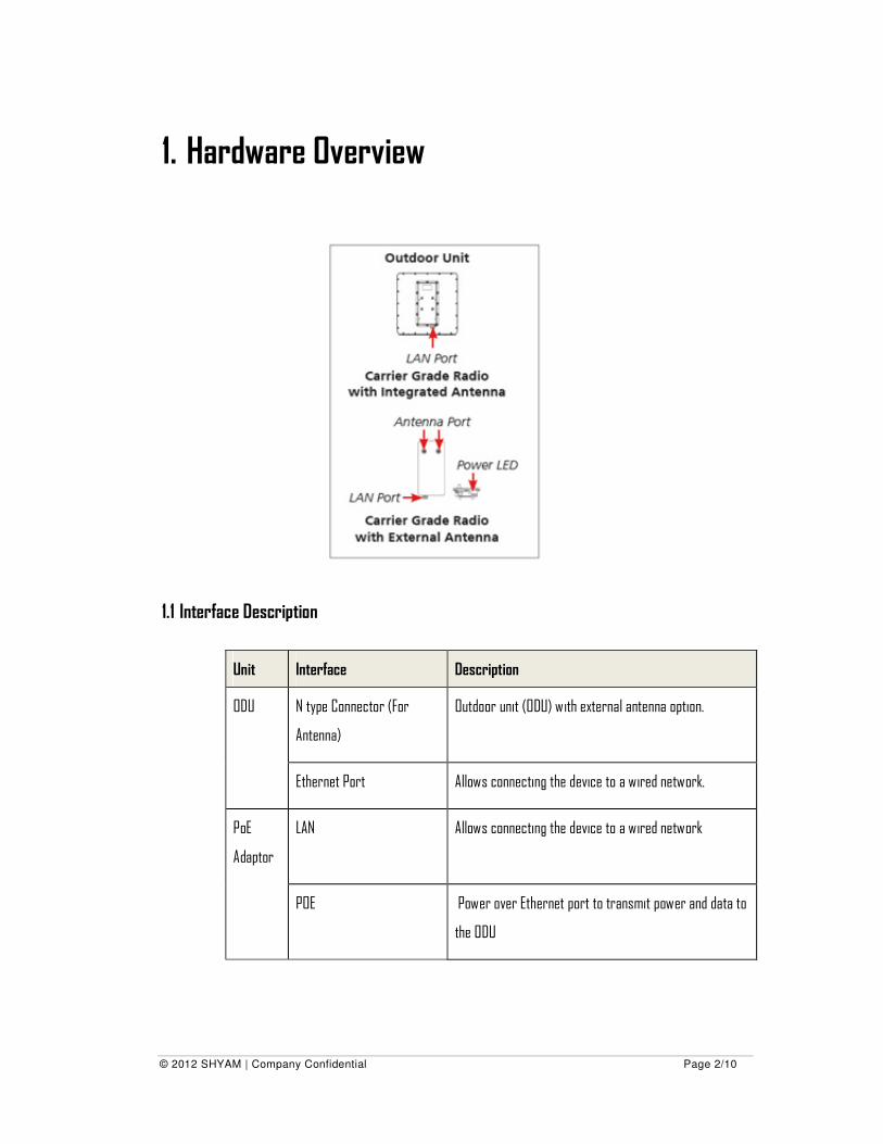
1. Hardware Overview
1.1 Interface Description
Unit Interface Description
ODU N type Connector (For
Antenna)
Outdoor unit (ODU) with external antenna option.
Ethernet Port Allows connecting the device to a wired network.
PoE
Adaptor
LAN Allows connecting the device to a wired network
POE Power over Ethernet port to transmit power and data to
the ODU
© 2012 SHYAM | Company Confidential Page 3/10
1.2 Caution and Warnings
• Internal settings, adjustment, maintenance, and repairs should be performed only by a
skilled technician who is aware of the hazards involved.
• Do not tightly secure the ODU to its mounting brackets until the alignment process of the
antenna is complete.
• Before installing an ODU, ensure that it is disconnected from power.
• Check that there are no direct obstructions or interferences in front of Antenna.
• Supply the appropriate AC/DC power to the equipment. Incorrect AC/DC power settings
can damage the equipment and may cause injury to the user.
• Avoid standing in front of a live ODU. This radio requires clear LOS (line-of-sight) for
operation.
• Make sure that both master and slave sites are assigned different IP addresses before
they are installed.
• Do not connect or disconnect the cables during the period of lightning.
• ODU’s must be attached to a properly grounded structure and installed masts must be
grounded to provide protection against lightning.
© 2012 SHYAM | Company Confidential
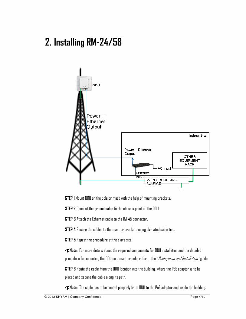
2. Installing RM-
STEP 1 Mount ODU on the pole or
STEP 2 Connect the ground cable to the chassis point on the ODU.
STEP 3 Attach the Ethernet
STEP 4 Secure the cables to the mast or brackets using UV
STEP 5 Repeat the procedure at the slave site.
����Note: For more details about the required components for ODU installation and the detailed
procedure for mounting the ODU on a mast or
STEP 6 Route the cable from the ODU location into the building
placed and secure the cable along its path.
����Note: The cable has to be routed properly from ODU to the PoE
SHYAM | Company Confidential
-24/58
Mount ODU on the pole or mast with the help of mounting brackets.
Connect the ground cable to the chassis point on the ODU.
Attach the Ethernet cable to the RJ-45 connector.
Secure the cables to the mast or brackets using UV-rated cable ties.
Repeat the procedure at the slave site.
For more details about the required components for ODU installation and the detailed
for mounting the ODU on a mast or pole, refer to the “Deployment and Installation
Route the cable from the ODU location into the building, where the PoE adaptor
and secure the cable along its path.
The cable has to be routed properly from ODU to the PoE adaptor and inside the building.
Page 4/10
For more details about the required components for ODU installation and the detailed
Deployment and Installation” guide.
adaptor is to be
and inside the building.
© 2012 SHYAM | Company Confidential Page 5/10
STEP 7 Place the PoE adaptor near to other user equipment (such as Switch/Router).
STEP 8: Connect the ODU cable to the appropriate RJ-45 connector on the POE designated port of
PoE adaptor.
����Note: The Cat5e Shielded Ethernet cable from PoE adaptor to the ODU should be less than 100
meters in length.
STEP 10 Connect power to the PoE adaptor.
����Note: AC power is supplied to the PoE adaptor through a standard 3-prong plug using 1.5m (5 ft)
standard power cable.
Aligning the Master and Slave ODU
STEP 1 Verify normal operation of the PoE adaptor by the LED indications on the ODU.
STEP 2 The Radio Modem operates in a pair of two Radio Modems with the same configuration, one
as a master and another as a slave. Both the units are installed on the top of a tower/pole or a wall.
STEP 3 Align the master ODU in the direction of the slave ODU and vice-versa.
Perform the following steps to align both master and slave Radio Modems:
• Adjust the Azimuth and elevation of the Radio Modem(s) to get the desired orientation and
tighten the nuts.
• Turn the slave Radio Modem slowly towards the master, listening to the beep sequence
until optimal alignment is achieved.
Frequency of beep confirms the link quality. The signal strength improves with the increase in the
beep frequency. After approximately 40 seconds, the Radio Modem starts beeping, indicating its
normal operation.
The indication of signal strength is done during the first 30 minutes (software configurable) after
bootup or since value was changed whichever happens later. This is applicable for both the master
and slave Radio Modem(s).
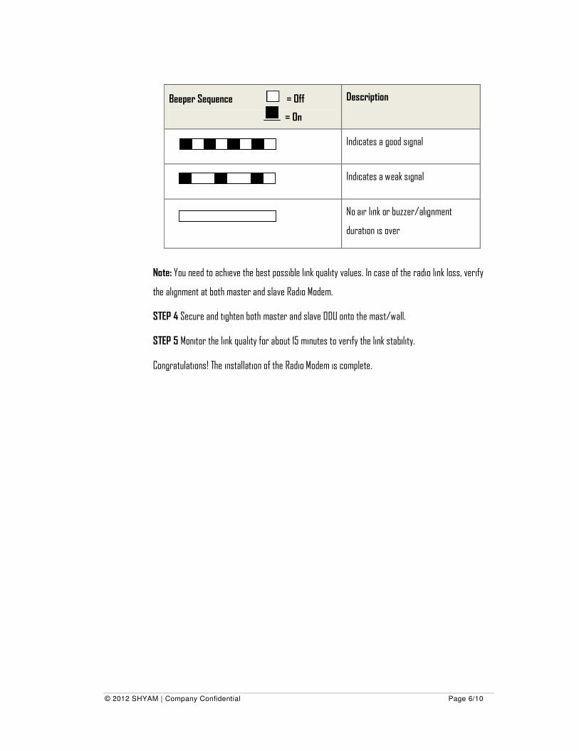
The following table shows you the different beeper sequences and the signals.
© 2012 SHYAM | Company Confidential Page 6/10
Beeper Sequence = Off
= On
Description
Indicates a good signal
Indicates a weak signal
No air link or buzzer/alignment
duration is over
Note: You need to achieve the best possible link quality values. In case of the radio link loss, verify
the alignment at both master and slave Radio Modem.
STEP 4 Secure and tighten both master and slave ODU onto the mast/wall.
STEP 5 Monitor the link quality for about 15 minutes to verify the link stability.
Congratulations! The installation of the Radio Modem is complete.
© 2012 SHYAM | Company Confidential Page 7/10
3. Configuring RM-24/58
STEP 1 Use desktop with Internet explorer or Firefox web browser for configuration the Radio
Modem. Recommended browsers are IE 8 or above and Firefox 3.6.23.
STEP 2 Connect the desktop to the LAN port of the PoE adaptor.
STEP 3 Configure the IP of your desktop in the same domain (Default IP of Radio Modem: 192.168.0.1
(for master), 192.168.0.2 (for slave))
STEP 4 Open the web browser and type the URL http://192.168.0.1 (master) or http://192.168.0.2
(for slave) and press enter. Login dialog box will appear, provide user name as admin and password
as public.
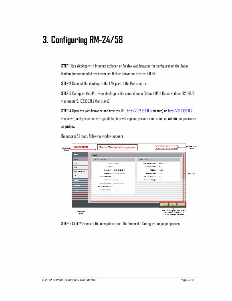
On successful login, following window appears.
STEP 5 Click Wireless in the navigation pane. The General – Configuration page appears.
© 2012 SHYAM | Company Confidential Page 8/10
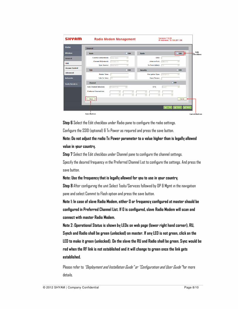
Step 6 Select the Edit checkbox under Radio pane to configure the radio settings.
Configure the SSID (optional) & Tx Power as required and press the save button.
Note: Do not adjust the radio Tx Power parameter to a value higher than is legally allowed
value in your country.
Step 7 Select the Edit checkbox under Channel pane to configure the channel settings.
Specify the desired frequency in the Preferred Channel List to configure the settings. And press the
save button.
Note: Use the frequency that is legally allowed for you to use in your country.
Step 8 After configuring the unit Select Tools/Services followed by OP & Mgmt in the navigation
pane and select Commit to Flash option and press the save button.
Note 1: In case of slave Radio Modem, either 0 or frequency configured at master should be
configured in Preferred Channel List. If 0 is configured, slave Radio Modem will scan and
connect with master Radio Modem.
Note 2: Operational Status is shown by LEDs on web page (lower right hand corner), RU,
Synch and Radio shall be green (unlocked) on master. If any LED is not green, click on the
LED to make it green (unlocked). On the slave the RU and Radio shall be green. Sync would be
red when the RF link is not established and it will change to green once the link gets
established.
Please refer to “Deployment and Installation Guide” or “Configuration and User Guide” for more
details.
© 2012 SHYAM | Company Confidential Page 9/10
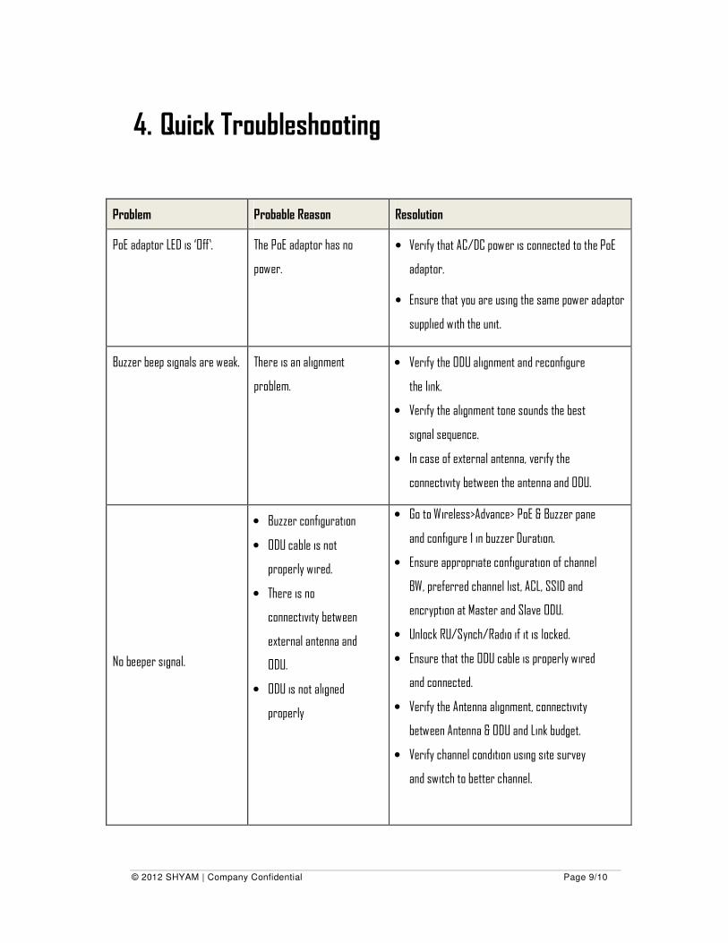
4. Quick Troubleshooting
Problem Probable Reason Resolution
PoE adaptor LED is ‘Off’. The PoE adaptor has no
power.
• Verify that AC/DC power is connected to the PoE
adaptor.
• Ensure that you are using the same power adaptor
supplied with the unit.
Buzzer beep signals are weak. There is an alignment
problem.
• Verify the ODU alignment and reconfigure
the link.
• Verify the alignment tone sounds the best
signal sequence.
• In case of external antenna, verify the
connectivity between the antenna and ODU.
No beeper signal.
• Buzzer configuration
• ODU cable is not
properly wired.
• There is no
connectivity between
external antenna and
ODU.
• ODU is not aligned
properly
• Go to Wireless>Advance> PoE & Buzzer pane
and configure 1 in buzzer Duration.
• Ensure appropriate configuration of channel
BW, preferred channel list, ACL, SSID and
encryption at Master and Slave ODU.
• Unlock RU/Synch/Radio if it is locked.
• Ensure that the ODU cable is properly wired
and connected.
• Verify the Antenna alignment, connectivity
between Antenna & ODU and Link budget.
• Verify channel condition using site survey
and switch to better channel.
© 2012 SHYAM | Company Confidential Page 10/10
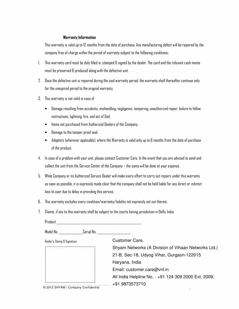
Warranty Information
This warranty is valid up to 12 months from the date of purchase. Any manufacturing defect will be repaired by the
company free of charge within the period of warranty subject to the following conditions:
1. This warranty card must be duly filled in, stamped & signed by the dealer. The card and the relevant cash memo
must be preserved & produced along with the defective unit.
2. Once the defective unit is repaired during the said warranty period, the warranty shall thereafter continue only
for the unexpired period to the original warranty.
3. This warranty is not valid in case of
• Damage resulting from accidents, mishandling, negligence, tampering, unauthorized repair, failure to follow
instructions, lightning, fire, and act of God.
• Items not purchased from Authorized Dealers of the Company.
• Damage to the tamper proof seal.
• Adaptors (wherever applicable), where the Warranty is valid only up to 6 months from the date of purchase
of the product.
4. In case of a problem with your unit, please contact Customer Care. In the event that you are advised to send and
collect the unit from the Service Center of the Company – the same will be done at your expense.
5. While Company or its Authorized Service Dealer will make every effort to carry out repairs under this warranty
as soon as possible, it is expressly made clear that the company shall not be held liable for any direct or indirect
loss to user due to delay in providing this service.
6. This warranty excludes every condition/warranty/liability not expressly set out therein.
7. Claims, if any to this warranty shall be subject to the courts having jurisdiction in Delhi, India.
Product _____________________________________________________
Model No. _______________Serial No. _____________________
Dealer’s Stamp & Signature
Customer Care,
Shyam Networks (A Division of Vihaan Networks Ltd.)
21-B, Sec-18, Udyog Vihar, Gurgaon-122015
Haryana, India
Email: [email protected]
All India Helpline No. - +91 124 309 2000 Ext. 2009,
+91 9873573710


