Embed Size (px)
Citation preview
The University of Southern Mississippi The University of Southern Mississippi
The Aquila Digital Community The Aquila Digital Community
Master's Theses
Spring 5-2013
Wireless Cooperative Communication and Networking Wireless Cooperative Communication and Networking
Yi Zhu University of Southern Mississippi
Follow this and additional works at: https://aquila.usm.edu/masters_theses
Recommended Citation Recommended Citation Zhu, Yi, "Wireless Cooperative Communication and Networking" (2013). Master's Theses. 520. https://aquila.usm.edu/masters_theses/520
This Masters Thesis is brought to you for free and open access by The Aquila Digital Community. It has been accepted for inclusion in Master's Theses by an authorized administrator of The Aquila Digital Community. For more information, please contact [email protected].
The Umversity of Southern MissiSSippi
WIRELESS COOPERATIVE COMMUNICATION AND NETWORKING
by
YiZhu
A Thesis Submitted to the Graduate School
of The University of Southern Mississippi m Partial Fulfillment of the Reqmrements
for the Degree of Master of Science
May 2013

ABSTRACT
WIRELESS COOPERATIVE COMMUNICATION AND NETWORKING
by Yi Zhu
May 2013
Cooperative comrnumcat10n can achieve diversity gain and mcrease the channel capacity
This paper proposes a novel cooperative scheme called Cooperative Step-Wise Demodu
lation, which utilizes low level demodulatiOn to demodulate high level modulated signal
cooperatively Th1s paper focuses cooperative scheme in multi-hop w1reless networks. The
bit error rate probabihty 1s analyzed. The comparison among the proposed scheme and the
conventional scheme 1s made through simulation and soft-define rad1o based experiments.
Results show that the proposed scheme has great potential in the performance 1mprovement
of cooperative commumcatwn.
11

ACKNOWLEDGMENTS
I would like to express my deep appreciatiOn to my advisor Dr. Shaoen Wu, for
introducing me to this exciting and challenging thesis,for his constant encoragement and
acdemic advice. He has been extremely helpful to me. I would also like to thank my
graduate committee members, Dr. Zhaoxian Zhou and Dr. Jonathan Sun for their reviewmg
and advice throughout the duration of this thesis.
Ill
TABLE OF CONTENTS
ABSTRACT ti
ACKNOWLEDGMENTS Ill
LIST OF ILLUSTRATIONS v
I INTRODUCTION 1
II RELATED WORK 3
III SYSTEM MODEL 5
IV COOPERATIVE STEP-WISE RELAYING AND COMBINING 7 4.1 16-QAMCSRC 7 4.2 Extanded CSRC 9
v BIT ERROR PROBABILITY OF CSRC 11
VI PERFORMANCE EVALUATION 14 6.1 Experiment Settings 14 6.2 Stmulation Results 15
VII SDR EXPERIMENTS 18
vm CONCLUSION 20
BffiLIOGRAPHY 21
IV
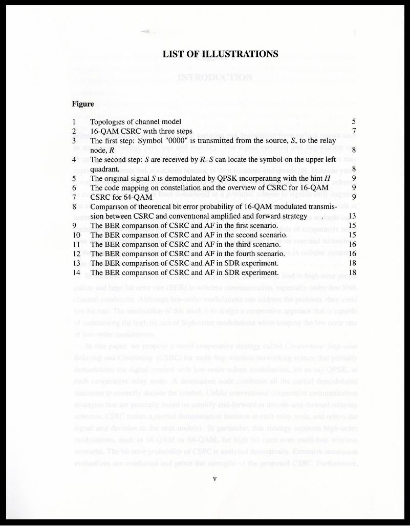
LIST OF ILLUSTRATIONS
Figure
Topologies of channel model 5 2 16-QAM CSRC with three steps 7 3 The first step: Symbol "0000" IS transmitted from the source, S, to the relay
node, R 8 4 The second step: S are received by R. Scan locate the symbol on the upper left
quadrant. 8 5 The ongmal signal S IS demodulated by QPSK mcorperatmg with the hint H 9 6 The code mapping on constellation and the overview of CSRC for 16-QAM 9 7 CSRC for 64-QAM 9 8 Comparison of theoretical bit error probability of 16-QAM modulated transmis-
sion between CSRC and conventiOnal amplified and forward strategy 13 9 The BER comparison of CSRC and AF in the first scenario. 15 10 The BER companson of CSRC and AF in the second scenario. 15 11 The BER companson of CSRC and AF in the third scenano. 16 12 The BER comparison of CSRC and AF in the fourth scenario. 16 13 The BER comparison of CSRC and AF in SDR experiment. 18 14 The BER companson ofCSRC and AF in SDR experiment. 18
v
Chapter I
INTRODUCTION
Wireless communication suffers signal variation and degradation from variOus causes such
as multi-path fading, path loss and mobility The signal variation and degradation can
be lllitlgated by explOiting user diversity unique in wueless networking where users may
expenence different hnk conditions because of their locatiOns and speeds [8] In recent years,
novel opportumsuc technologies of cooperatiOn among wireless mobile termmals, referred
as cooperative relay, have been considered as a potential scheme to significantly Improve
the commumcation system performance by cooperatively relaying the received signals at
mtermediate nodes to the destination m order to constitute a distributed virtual multiple mput
multiple output (MIMO) system [2, 3, 9] Because of various gains of cooperative relay
over the conventional smgle-path transmission, It IS expected to be an essential technology
to the next generatiOn wireless networks. In particular, relay station in cellular system IS
able to increase energy efficiency and extend cell coverage[20]
In wireless communicatiOn, normally, high-order modulations lead to high error propa
gation and large bit error rate (BER) in wireless communication, especially under low SNR
channel conditiOns. Although low-order modulations can address the problem, they y1eld
low bit rate. The motivation of this work is to design a cooperative approach that is capable
of mamtruning the high bit rate of high-order modulations while keeping the low error rate
of low-order modulatiOns.
In this paper, we propose a novel cooperative strategy called Cooperative Step-wise
Relaying and Combining (CSRC) for multi-hop wireless networkmg system that partially
demodulates the signal symbol with low-order robust modulatiOns, let us say QPSK, at
each cooperative relay node. A destmatwn node combmes all the partial demodulated
outcomes to correctly decode the symbol. Unlike conventional cooperative commumcatlon
strategies that are generally based on amphfy-and-forward or decode-and-forward relaymg
schemes, CSRC makes a partial demodulation deciSion at each relay node, and relays the
signal and decision to the next node(s). In particular, th1s strategy supports high-order
modulations, such as 16-QAM or 64-QAM, for high b1t rates over multi-hop wireless
networks. The b1t error probability of CSRC is analyzed theoretically Extensive SimulatiOn
evaluatiOns are conducted and prove the strengths of the proposed CSRC Furthermore,
2
the compansons of performance between proposed scheme and conventional scheme are
conducted on a soft-define radio (SDR) testbed. The results of both Simulation results and
SDR testbed experiments show the great potentials of CSRC in improving the commumcat10n
performance.
In the rest of this paper, the related cooperative relay work IS reviewed in Section II and
the system is modeled m SectiOn III. Then, Section IV presents the proposed Cooperative
Step- Wise Relaying and Combining In Section V, the bit error probability of CSRC IS
analyzed. The simulatiOn experiments are demonstrated in SectiOn VI. In Section VII, the
results of SDR testbed expenments are demonstrated. Finally, SectiOn VIII concludes this
work.
3
Chapterll
RELATED WORK
There are two fundamental components m cooperative communication. relaymg and com
bining. The typtcal approach for cooperative communication IS to relay the received stgnal
at mtermedtate nodes and finally combme the recetved stgnals at the destmation node.
Dtfferent in how the information is processed m the relaying, vanous schemes have been
proposed in the literature, mcluding amplify-and-forward [13], demodulate-and-forward [7],
decode-and-forward [13, 4] and soft decode-and-forward [10] In amplify-and-forward (AF),
a relay node amplifies the received stgnals and forwards the scaled signal to the destinatiOn.
In demodulate-and-forward, a relay node demodulates the received signals and forwards
regenerated signals to the destination. In decode-and-forward (DF), a re lay node decodes
the received stgnals, re-encodes and forwards the regenerated signals to the destmation. It
has been remarked that AF is low-complexity and sigmficantly saves transrrussion power.
However, compared to DF, AF has two main drawbacks. One IS that it does not have coding
gams and the other IS that it will also amplify and forward noises. DF has the advantages of
regeneratmg the signal, and correcting errors at the relay Nevertheless, when the capability
of error correctmg m the decoding is not strong enough to correct all errors, the errors will
be propagated throughout commumcatwn network.
Azarian, Gamal and Schmter investigated the dtverstty-multiplexing tradeoff of relay
protocols [14] Coding schemes such as distributed Turbo codes [22, 19] have been also
studied to explOit the cooperative dtverstty for DF m relay channels. Recently, Low Density
Panty Check (LDPC) codes were investigated for half-duplex relay channels [ 1, 12] In the
case that the channel between the source and relay IS not reliable enough to guarantee error
free decoded btts at the relay, avoiding error propagation at the relay becomes challenging.
To address this challenge, relay schemes that attempt to combme the benefit of DF and AF
were proposed, such as the soft decode-and-forward protocols [ 10, 22] In soft decode-and
forward, the soft information in decodmg the source stgnal is used to form a soft stgnal
at the relay based on the log-likelihood ratios. Then, the soft signal IS transrrutted to the
destinatiOn node with relaymg schemes of AF, Estimate-and-Forward [ 15] and Decode
Estimate-Forward [1 8] , whtch use the mmtmum mean square error estimatiOn (MMSE) to
opt1m1ze SNR.
4
In cooperative commumcation, the source and relay Signals are finally combined at the
destmatwn. A possible combmmg techmque IS the well-known Maximum-ratio-combining
(MRC). However, it IS suboptimal and does not achieve full diversity [11] Senous perfor
mance degradatiOn of MRC can be caused by the error propagation at the relays. Another
Important challenge is that MRC incurs high computatiOnal complexity at the destmatwn,
especially when high-order modulations are employed. Wang, et al. proposed Cooperative
Maximum Ratio Combining (C-MRC) to achieve full diversity with DF relaying schemes by
expl01tmg the knowledge of the mstantaneous bit-error probability of the source-relay hnk
at the destination [21]
All of the relay protocols that have been discussed above suffer from the problem of
low spectrum efficiency Specifically, their spectrum efficiency is half of that of direct
transmission. To Improve the spectrum efficiency, two-way relaying is proposed [5, 17]
The packets from two ends are combined at the relay node. The combined packets are
relayed to two ends. Finally, there two can extracts the packets they need by subtractmg the
packets they have sent. In three terminal and TDMA setting, two-way relaying need two
slots instead of four for one-way relay

5
Chapter ill
SYSTEM MODEL
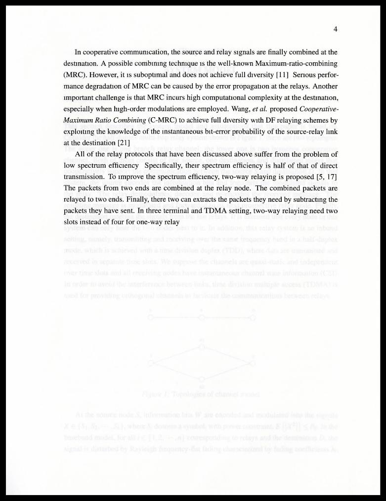
This section describes the system model and assumptions that this paper IS based on.
Consider the half-duplex multi-hop relay system shown in Figure 1, there are two topologies.
The upper one is one branch relay channel, the lower one IS two branches cooperative
channel. Both of them consist of one source, one destmatwn, and distributed relays that
cooperatively support the commumcation between the sourceS and destination D In this
system, the source encodes the mformatwn bits and transrruts the modulated signals to
the relay The relay demodulates, decodes and re-encodes the received message. The
resulting message is modulated and forwarded to its next prospectlve relay node. Finally,
the destmatwn receives the signals from the last relays. It is assumed that every node m this
system can only hear the two nodes next to it. In addltwn, this relay system is an inband
setting, namely, transrruttmg and receiving over the same frequency band in a half-duplex
mode, which IS achieved with a time division duplex (TOO), where data are transmitted and
received in separate time slots. We suppose the channels are quasi-static and mdependent
over time slots and all receiving nodes have instantaneous channel state mformat10n (CSI)
In order to avoid the mterference between links, time division multiple access (TDMA) is
used for providmg orthogonal channels to facilitate the commurucations between relays.
R D
o~------~or------~0
Rl
R2
Figure I Topologies of channel model
At the source node S, mformatwn bits W are encoded and modulated mto the signals
X E {St ,S2 , , Sk}, where S; denotes a symbol, With power constraint, E [IX2IJ < Po In the
baseband model, for all i E { 1, 2, , n} correspondmg to relays and the destmation D, the
Signal Is disturbed by Rayleigh frequency-flat fadmg charactenzed by fadmg coefficients h;,
6
which are constant complex scalars known to the relays. Z; "" N (O, cr;) captures the additive
white Gaussian nmse (AWGN) perceived by nodes, where N (O, cr;) denotes symmetric
complex Gaussian distributiOn with zero mean and variance cr; P; denotes the transnut
power and g; denotes the path loss. The overall channel gain IS modeled as G; J P; g; h;
The signals forwarded by relays are denoted by X; for all i E { 1, 2, , n} The received
signals at relays and the destmation D can be wntten as.
7
Chapter IV
COOPERATIVE STEP-WISE RELAYING AND COMBINING
In this section, we explam how the proposed Cooperative Step-wise Relaying and Combining
(CSRC) works. CSRC works on multi-hop relay channels. High data rate transmission
achteved by htgh order modulation, such as 16-QAM or 64-QAM, can result m performance
degradatiOn in the case of low channel SNR. Our approach solves th1s problem by makmg
detection with low-order modulatiOns, e.g. QPSK, at each relay node, and forwarding the
detection to the next relay The detection results are gathered on the destmatton to make
the final demodulation and decode the information btts. To facilitate the explanation, CSRC
for 16-QAM modulation m one branch relay channelts elaborated as an example to show
how it works. Extensively, CSRC for 64-QAM m both of one branch relay channel and two
branches relay channel are illustrated in the followmg.
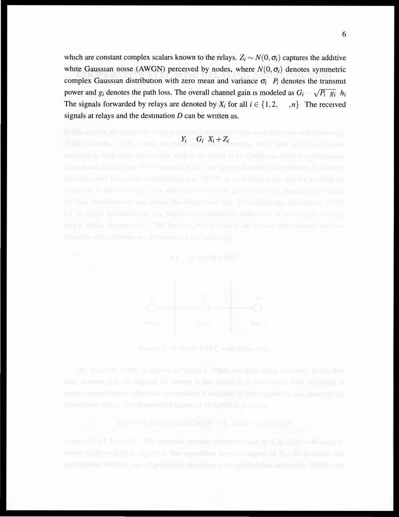
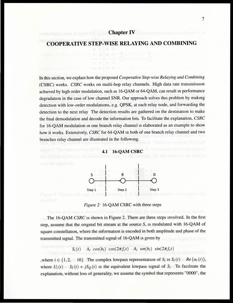
4.1 16-QAM CSRC
S R D
Of-------+--------"•Or--1----~·0
Step 1 Step 2 Step 3
Figure 2· 16-QAM CSRC with three steps
The 16-QAM CSRC ts shown in Figure 2. There are three steps mvolved. In the first
step, assume that the ongmal bit stream at the sourceS, 1s modulated with 16-QAM of
square constellatiOn, where the mformat10n is encoded in both amplitude and phase of the
transmitted stgnal. The transmitted stgnal of 16-QAM 1s gtven by
S; (t ) A; cos(b;) cos(2n f ct ) A; sm(b;) sin(27rfct )
,where i E { 1, 2, 16} The complex lowpass representatiOn of S; IS S; (t ) Re{u; (t)},
where U; (t) sf (t ) + jSQ (t) IS the equivalent lowpass stgnal of S; To facthtate the
explanation, without loss of generality, we assume the symbol that represents "0000", the
8
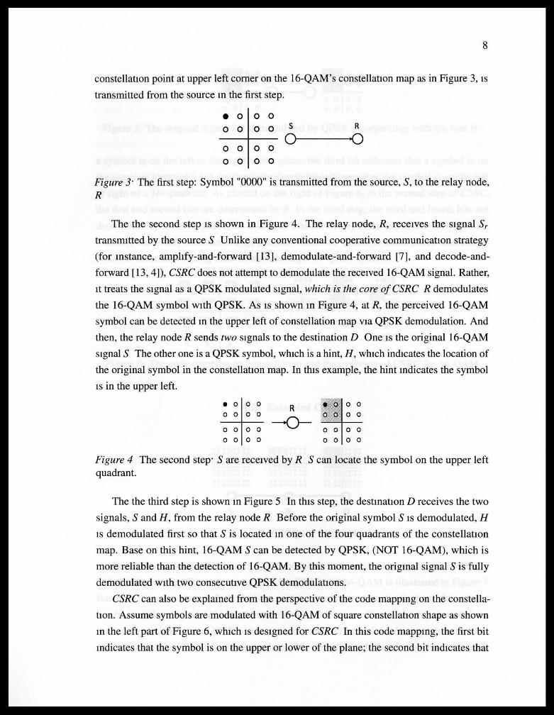
constellatiOn point at upper left corner on the 16-QAM's constellatiOn map as in Figure 3, IS
transmitted from the source m the first step.
• 0 0 0
0 0 0 0 s R
0 0 0 0 o---o
0 0 0 0
Figure 3· The first step: Symbol "0000" is transmitted from the source, S, to the relay node, R
The the second step IS shown in Figure 4. The relay node, R, receives the Signal Sr
transmitted by the sourceS Unlike any conventional cooperative communicatiOn strategy
(for mstance, amplify-and-forward [13], demodulate-and-forward [7], and decode-and
forward [13, 4]), CSRC does not attempt to demodulate the received 16-QAM signal. Rather,
1t treats the signal as a QPSK modulated signal, which is the core of CSRC R demodulates
the 16-QAM symbol With QPSK. As IS shown m Figure 4, at R, the perceived 16-QAM
symbol can be detected m the upper left of constellation map vta QPSK demodulation. And
then, the relay node R sends two signals to the destination D One IS the original 16-QAM
signalS The other one is a QPSK symbol, whtch is a hint, H, which indicates the location of
the original symbol in the constellatiOn map. In this example, the hint mdicates the symbol
IS in the upper left. -• 0 0 0 R • 0 0 0
0 0 0 0 --()-
0 0 0 0
0 0 0 0 0 0 0 0
0 0 0 0 0 0 0 0
Figure 4 The second step· S are received by R S can locate the symbol on the upper left quadrant.
The the third step is shown m Figure 5 In this step, the destmatiOn D receives the two
signals, S and H, from the relay node R Before the original symbol S IS demodulated, H
IS demodulated first so that S is located m one of the four quadrants of the constellation
map. Base on this hint, 16-QAM Scan be detected by QPSK, (NOT 16-QAM), which is
more reliable than the detection of 16-QAM. By this moment, the origmal signal S is fully
demodulated with two consecutive QPSK demodulatiOns.
CSRC can also be explamed from the perspective of the code mappmg on the constella
tiOn. Assume symbols are modulated with 16-QAM of square constellatiOn shape as shown
m the left part of Figure 6, which IS designed for CSRC In this code mappmg, the first bit
mdicates that the symbol is on the upper or lower of the plane; the second bit indicates that
9
eooo lllo o o ooooR 0 0f0oo
oooo0--()oooo 0 0 0 0 0 0 0 0
Figure 5 The ongmal signal S is demodulated by QPSK incorperating with the hmt H
a symbol is on the left or the nght of the plane, the third bit mdicates that a symbol is on
the upper or lower of a 114 quadrant; the fourth bit mdicates that the symbol is on the left
or nght of a 1/4 quadrant. As plotted on the right of Figure 6, in the second step of CSRC,
the first and second bits are determmed by R. In the third step, the thud and fourth bits are
determined by the destination, D It is clear that each relay node determmes only two bit.
Namely, each relay conducted a QPSK demodulatiOn, which is much more tolerant to
channel noise and fading than demodulating a 16-QAM symbol.
()()(}() 0001 0100 0101 0 00 0 [Q]]oo ~~ 0 0 0 0 • 0 0 0 • o 0 0 0 0
0 0 0 0 00 0 0 0 0 0010 0011 0110 Oll1
0 0 0 0 0 0 0 0 0 0 0 0 0 0 0 0
0 0 0 0 0 0 0 0 0 0 0 0
1000 1001 l lCJO 1101 0 0 0 0 0 0 0
1010 lOll lll O l l l1 s R D 0 0 0 0
Figure 6· The code mapping on constellation and the overview of CSRC for 16-QAM
4.2 Extanded CSRC
• 0 0 0 0 0 0 0 • 0 0 0 0 0 0 0 .00 00 0 0 0 0 0 0 0 0 0 0 0 0 0 0 0 0 0 0 0 0
0 0 0 0 0 0 0 0 0 0 00 0 0 0 0 0 0 0 0 0 0 0 0 0 0 0 0 00 0 0 0 0 0 0 0 0 0 0
0 0 0 0 00 0 0 0 0 0 0 0 0 0 0 0 0 0 0 0 0 0 0 0 0 00 0 0 0 0 0 0 0 0 0 0 0 0 0 0 0 0 0 0 0 0
0 0 0 0 0 0 0 0 0 0 0 0 0 0 0 0 0 0 0 Q 0 0 0 0 0 0 0 0 00 0 0 0 0 0 0 0 0 0 0 00 0 0 0 0 0 0
0 0 0 s R D
Figure 7 CSRC for 64-QAM
In addition to apply CSRC for 16-QAM modulation, it can also be used for 64-QAM and
256-QAM symbols. The enure procedure for CSRC With 64-QAM is Illustrated m Figure 7
Based on the same three-node model (one source, one relay and one destmation), data stream
can be modulated by 64-QAM and transmltted by the source. Then, the relay demodulates
the received signal with QPSK to locate the symbol in one of the four quadrants of the
constellatiOn map. Th1s locatiOn IS modulated by QPSK and forwarded to the destmatwn
10
with the ongmal 64-QAM signals. On the destmat10n side, the original 64-QAM signal
IS demodulated by 16-QAM in concert with the QPSK location hint. For CSRC with 256-
QAM, the relay demodulates the signal by 64-QAM. The resulted, as a hint, IS forwarded
With the onginal 256-QAM signal. The destinatiOn demodulates the original s1gnal by
64-QAM mcorporatmg the 64-QAM hmt. CSRC is also able to adopt to two branches
network topology in lower parts of Figure 1 It can be in cooperative manner by transmitting
Identical signal usmg CSRC in both branches and combming the received signals from both
branches at the destinatiOn.
11
Chapter V
BIT ERROR PROBABILITY OF CSRC
In thts section, the bit error probability of CSRC for 16-QAM in AWGN channel is analyzed
to show the improvement of performance on detection. CSRC achieves low error of detectiOn
by partially demodulatmg the signal symbol wtth QPSK, whtch is the more reliable, at each
cooperative relay node. Assume that all channels have the same SNR, Yo The probability of
error of QPSK wtth coherent detectiOn and perfect recovery of the earner frequency and
phase ts
Po Q(~) ,where Q (x) ts defined as the probabtlity that a Gaussian random vanable X wtth mean 0
and vartance 1 is greater than x. Q (x) P (X > x) fxoo Jke-xl 12dx. AWGN channel can
be represented by Binary Symmetric Channel [16] The channel transition matnx IS
T [I Po Po ]
Po l Po
The element in the first row and the first column ts the probabthty of sending btt 0 and
receivmg bit 0. The element in the first row and the second column ts the probability of
sending bit 0 and receivmg btt I. In CSRC for I6-QAM, each relay detects two bits. In
addition, the transmission error probability for each bit ts not always the same, because they
are detected at dtfferent nodes. The error probabilities for each bit are discussed separately
and followed by the bit error probability for CSRC in the following.
For the first two bits, denoted as Pt and Pz, they are detected at R, transmitted to D, and
finally demodulated by D Due to the assumptiOn that SNR of all channels are Identical,
the channel transition matrixes of the channel between S and R and the channel between R
and D are identical. Therefore, the transitiOn matnx for the transmission of the two bits by
CSRC strategy, denoted as T12, ts
T12 = T T
_ [PJ + ( l - 2Po (1
Po)2 2Po ( l Po) PJ+(l
Thereby, the error probability of the first two bits IS
Pt Pz 2Po ( 1 Po)
Po ) J Po)2
12
For the last two bits, denoted as P3 and P4, the detection depends on the previous
detection of the first two bits. To assure the correctiOn of the detectiOn, the first two bits
must be received and demodulated correctly at D in order to locate the regton of the stgnal
m the constellatiOn map. In other words, the detectiOn of QPSK hint must be right. The
probability of QPSK symbol error 1s
The transition matrix for the transmission of the two b1ts by CSRC strategy, denoted as T34,
IS
[( I ( 1
Ps) ( 1 Po )+ Ps Po ( 1 Ps) Po + Ps ( 1 Po) ( 1
Ps) Po + Ps (1 Po)] Ps) ( I Po) + Ps Po
Thus, the error probability of the last two bits is
The symbol error probability of CSRC strategy is
4
Psymbot = 1 n ( 1 ?j ) i= l
The b1t error probability can be approximated by
, where M is the order of the modulatiOn. In this example, 16-QAM is used so that M equals
to 4.
To consider the b1t error probability of CSRC m two branches case m Figure /reffl , the
additional effect of combmg at the destmatwn must be analyzed. Suppose MRC servers
as the combing technique, which maximtzed the SNR with respect to the weights on each
branch. The SNR of the result of MRC equals to the sum of SNR of each branch. In our
analysts, Yd denotes the SNR after MRC at the destmat10n, y1 denotes the SNR of the upper
branch, 'Y2 denotes the SNR of the lower branch. The SNR after MRC at the destmation IS
Yd y1 + 'Y2 The transitiOn matrix of relay-destmatwn chennal is modified by Yd To get
transitiOn matnx of relay-destmation chennal, we define
Po' Q ( J2r;) ,and
T' [l Po'
Po'
The transition matnx for the transmission of the first two bits, denoted as Td, is
The transition matrix for the transmiSSion of the last two bits, denoted as T341
, is
Ps ] T' l Ps
13
Usmg these two transition matnxes by the same way as what IS formulated for one branch
case, we can get the bit error probability for the two branches case.
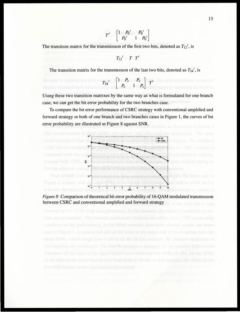
To compare the bit error performance of CSRC strategy with conventional amplified and
forward strategy m both of one branch and two branches cases in Figure l , the curves of bit
error probability are Illustrated m Figure 8 agamst SNR.
Figure 8· Comparison of theoretical bit error probability of 16-QAM modulated transmiSSion between CSRC and conventiOnal amplified and forward strategy
14
Chapter VI
PERFORMANCE EVALUATION
In order to evaluate the performance of the proposed CSRC, th1s section presents numencal
results obtamed with Monte Carlo simulations. The performance 1s measured m blt error
rate (BER) upon SNR. The simulations are based on AWGN channels m different scenarios.
The performance with AWGN channels can be cons1dered as the upper bound.
6.1 Experiment Settings
In the simulatwn experiments, we consider two channel models, as illustrated m Figure 1
One model cons1st of three nodes. one source, one relay and one destinatwn. The other
model cons1sts of four nodes. one source, two relay nodes and one destmation. We simulated
CSRC for two modulatwns. 16-QAM and 64-QAM. The performance of CSRC schemes is
compared with the conventiOnal cooperative schemes of amplified-and-forward relaying,
because both CSRC and the conventwnal methods do not have the error control coding so
that the effect of coding gam can be ehrninated to ensure fau compar1sons.
Four scenanos are considered. In the first scenario, three-node model, the upper case m
Figure 1, is used, w1th the same SNRs in two links, which range from OdB to I OdB In th1s
scenano, the channel condiuons of two lmks are symmetric. The performance 1s measured
from poor to good channel conditwns. In the second scenano, the SNR of the hnk between
the destmation and the relay var1es from 0 dB to 10 dB, but the SNR of the other link is kept
constant as low (5 dB 1s set in experiments). In tlus scenano, the channel conditions of two
links are asymmetric. Th1s scenario particularly evaluates the effect of low SNR source-relay
condition on the performance. In the third scenario, four-node channel model, the lower
case m Figure 1, 1s cons1dered and all the links m the upper and lower branches have the
same SNRs, wh1ch range from 0 dB to 10 dB In this scenano, the channel cond1t10ns of
two branches are symmetric. The fourth scenarw is des1gned for asymmetric links m two
branches. all the links of the upper branch have relauvely low SNRs (5 dB), but the SNRs
of the links m the lower branch vary from 0 dB to I 0 dB In th1s scenano, the effect of one
low SNR branch on the performance is revealed.
15
6.2 Simulation Results
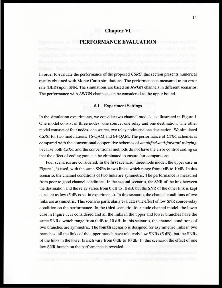
Figure 9 shows the BER performance of the proposed CSRC and the conventional amplified
and-forward (AF) cooperative strategy m the first scenario, where x-axis refers to the SNR
on each hnk. The simulation result shows the strengths of the proposed strategy m improvmg
the performance. In Figure 9, we observe that CSRC outperforms the conventional AF
strategy Specifically, It improves the BER around 2 to 3 dB over the conventional AF
strategy The performance gap between two strategies for 64-QAM is larger than for 16-
QAM, which mdicates that the performance gam of CSRC becomes greater when higher
order modulation is employed to achieve high data rate. This IS because higher order
modulation leads to larger errors and gives more space for CSRC to improve.
10° ~---·--···r·-·----,···-·.-·-·--"'-:-·:-···-··--r--:--:-y-···-·--·-..,-·--·;··---.,.-. ..,..-----·-·r - ····-··-,:..,.··--·-··
: == ·---·-------·-- --·--- · - --·-- -- --- - ----
s SNIO{cll)
10
Figure 9· The BER comparison of CSRC and AF in the first scenariO.
, .. ~·~-~~-..--- ---,--·~~~ j
E::: ~=~'•-·<-.:i'·--•---. -- - -o-
1 - - - .... __ .---·--- -o---e----
to· ' -
l I
~ , .... l iii ~
.J .-::-...,..,...,.,..,..,..,-~ r
--- --- "G .. .... 'Q.. ..
to ... o'--~-.._____._ _ _._~,-~--'---"---'---l,o
SNM{cll)
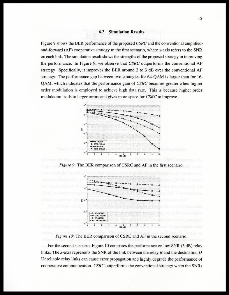
Figure 1 O· The BER comparison of CSRC and AF in the second scenario.
For the second scenano, Figure 10 compares the performance on low SNR (5 dB) relay
hnks. The x-axis represents the SNR of the hnk between the relay R and the destination D
Unreliable relay links can cause error propagatiOn and highly degrade the performance of
cooperative commumcatlon. CSRC outperforms the conventional strategy when the SNRs
to• ...---.......... --......----.-----.-----.
10 .....
...... Af'-16QAM to·• --CSRC- t6QAM
' •8•1\f-~AM -•· CSRC~
to·•L.=:===:.:==~..._--~--~--~ 0 6 10
SNR td8J
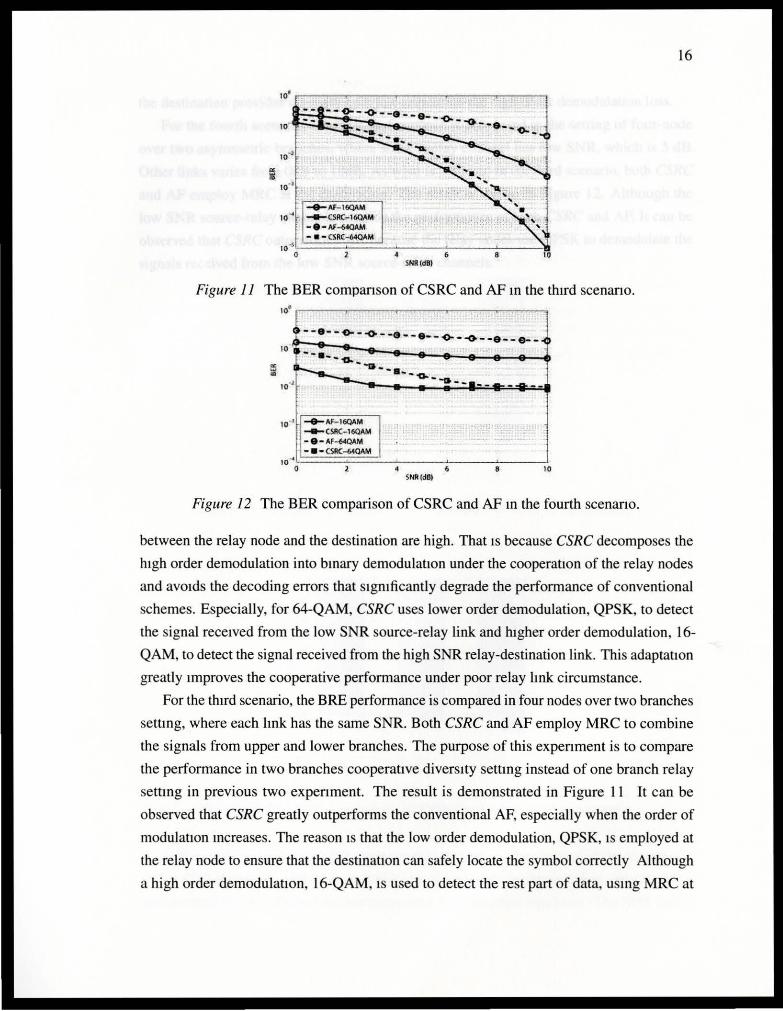
Figure II The BER companson of CSRC and AF m the third scenario.
ffi "'
--·- -«>---o- - -e- -•--~- -o-·--e-- e--10~~~~~~~----------.. ~~~--I T --•---a. -'"11--· -- -o. --G--
to" ..,.._Af'-160AM --CSAC- 16QAM ·8-AF~AM
-.-CSRc.-64QAM to ... t.==========-~---'---~--_j
0 l 10 SNR (dBl
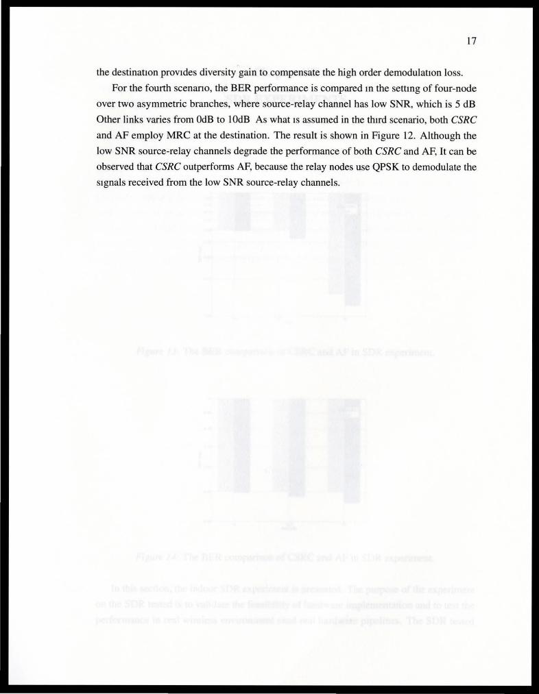
Figure 12 The BER comparison of CSRC and AF m the fourth scenano.
16
between the relay node and the destination are high. That IS because CSRC decomposes the
h1gh order demodulation into bmary demodulatiOn under the cooperatiOn of the relay nodes
and av01ds the decoding errors that Sigmficantly degrade the performance of conventional
schemes. Especially, for 64-QAM, CSRC uses lower order demodulation, QPSK, to detect
the signal rece1ved from the low SNR source-relay link and higher order demodulation, 16-
QAM, to detect the signal received from the high SNR relay-destination link. This adaptation
greatly Improves the cooperative performance under poor relay hnk circumstance.
For the th1rd scenario, the BRE performance is compared in four nodes over two branches
settmg, where each hnk has the same SNR. Both CSRC and AF employ MRC to combine
the signals from upper and lower branches. The purpose of this expenment is to compare
the performance in two branches cooperative divers1ty settmg instead of one branch relay
settmg in previous two expenment. The result is demonstrated in Figure 11 It can be
observed that CSRC greatly outperforms the conventional AF, especially when the order of
modulation mcreases. The reason IS that the low order demodulation, QPSK, 1s employed at
the relay node to ensure that the destinatiOn can safely locate the symbol correctly Although
a high order demodulatiOn, 16-QAM, 1s used to detect the rest part of data, usmg MRC at
17
the destinatiOn provides diversity gain to compensate the high order demodulatiOn loss.
For the fourth scenano, the BER performance is compared m the settmg of four-node
over two asymmetric branches, where source-relay channel has low SNR, which is 5 dB
Other links varies from OdB to l OdB As what IS assumed in the third scenario, both CSRC
and AF employ MRC at the destination. The result is shown in Figure 12. Although the
low SNR source-relay channels degrade the performance of both CSRC and AF, It can be
observed that CSRC outperforms AF, because the relay nodes use QPSK to demodulate the
Signals received from the low SNR source-relay channels.
18
Chapter VII
SDR EXPERIMENTS
-1 00>'---1J,-0 ---~1u~-----1..,.., _ _J
SNR
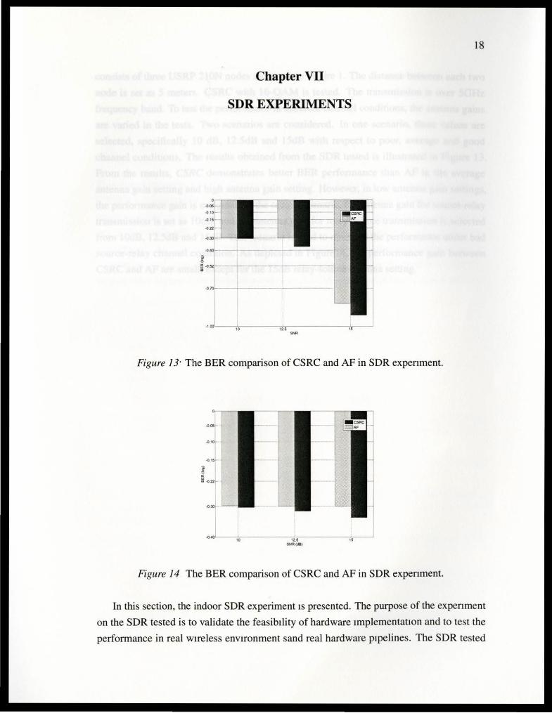
Figure 1 3· The BER comparison of CSRC and AF in SDR expenment.
10 , . SNR (dB)
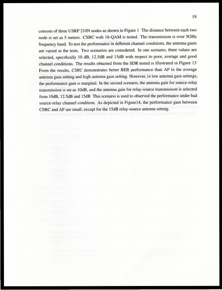
Figure 14 The BER comparison of CSRC and AF in SDR expenment.
In this section, the indoor SDR experiment IS presented. The purpose of the expenment
on the SDR tested is to validate the feasibility of hardware ImplementatiOn and to test the
performance in real wireless environment sand real hardware pipelines. The SDR tested
19
consists of three USRP 21 ON nodes as shown in Figure 1 The distance between each two
node IS set as 5 meters. CSRC w1th 16-QAM is tested. The transmission IS over 50Hz
frequency band. To test the performance in different channel conditions, the antenna gams
are vaned m the tests. Two scenarios are considered. In one scenano, three values are
selected, specifically 10 dB, 12.5dB and 15dB w1th respect to poor, average and good
channel conditions. The results obtamed from the SDR tested IS illustrated m Figure 13
From the results, CSRC demonstrates better BER performance than AF in the average
antenna gam setting and h1gh antenna gam setting. However, in low antenna gam settmgs,
the performance gam IS marginal. In the second scenano, the antenna gain for source-relay
transmission 1s set as lOdB, and the antenna gain for relay-source transmiSSIOn is selected
from IOdB, 12.5dB and 15dB Th1s scenariO is used to observed the performance under bad
source-relay channel condition. As depicted in Figurel4, the performance gam between
CSRC and AF are small, except for the 15dB relay-source antenna settmg.
20
Chaptervm
CONCLUSION
This paper proposes a novel Cooperative Step-Wise Relaying and Combining strategy
(CSRC) for cooperative communicatiOn w1th h1gh order modulation. CSRC supports high
order modulation to achieve high b1t rate transrrussion while mamtammg low bit error
rate performance with low order demodulation detectwns at cooperative relay nodes. The
strengths of CSRC are confirmed with theoretical analysis of bit error probability, extensive
simulatiOns and open source SDR testbed experiments. CSRC can be further extended to
support other higher-order modulations such as 256-QAM over multi-hop wireless networks.
21
BffiLIOGRAPHY
[I] A. Chakrabarti, A. de Baynast, A. Sabharwal and B Aazhang. Low density parity check codes for the relay channel. IEEE Journal on Selected Areas in Communications, 25(2):280-291 ,
2007
[2] A. Sendonaris, E. Erkip, and B Aazhang. User cooperation diversity, part I. System descnption. IEEE Transaction on Communications, 51(1)"1927IC1938, 2003.
[3] A. Sendonaris, E. Erkip, and B . Aazhang. User cooperation diversity, part II. Implementation aspects and performance analysis. IEEE Transaction On Communications, 51 ( l ): 1939fC 1948, 2003.
[4] A. Stefanov and E. Erkip. Cooperative coding for wireless networks. IEEE Transaction On Communications, 52(9), 2004.
[5] B Rankov and A. Wittneben. Spectral efficient protocols for half-duplex fading relay channels. IEEE J. Select. Areas Commun., 25:379-.389, 2007
[6] M. J Berger. Stability of interfaces with mesh refinement. Paper 83-42, I CASE, NASA Langley Research Center, Hampton, August 1983.
[7] D. Chen and J N Laneman. Modulation and demodulation for cooperative diversity in wireless systems. IEEE Transactions on Wireless Communications, 2005
[8] D. Tse and P Viswanath. Fundamentals of Wireless Communication. Cambridge.
[9] G JYamer, M. Gastpar and P Gupta. Cooperative strategies and capacity the mdependent and tdentically dtstributed theorems for relay networks. IEEE Transaction on Information Theory, 51 3037- 3063, 2005
[I 0] H. H. Sneessens and L. Vandendorpe. Soft decode and forward improves cooperattve commumcations. 3G 2005ql6th lEE International Conference on 3G and Beyond, 2005
[ 11] J Adeane, M. R. D Rodrigues, and I. J Wassell. Characterisation of the performance of cooperative networks in ricean fadmg channels. 12th Int. Conf Telecommun., Cape Town, South Africa, 2005
[12] J Hu and T M. Duman. Low density parity check codes for the relay channel. IEEE Transactions on Communications, 6(9):3384IC3394, 2007
[ 13] J Laneman, D Tse and G Womell. Cooperative diversity in wireless networks. Efficient protocols and outage behaviour. IEEE Transactions on Information Theory, 50(12):3062-3080, 2004.
[ 14] K. Azarian, H. El Gamal, and P Schniter On the achievable diverstty-multiplexmg tradeoff in half-duplex cooperattve channels. IEEE Transactions on Information Theory, 5 1 (12):552IC572, 2005
22
[15] K. Gomadam and S. A. Jafar Optimal relay functtonality for snr maximization in memoryless relay networks. IEEE Journal on Selected Areas in Communications, 25(2) .39~0 I, 2007
[16] M.C. Thomas and A.T Joy Elements of Information Theory (second edition) WILEY.
[ 17] P Popovskt and H. Yomo. Wireless network coding by amplify-and-forward for bi-directional traffic flows. IEEE Commun. Lett., 11 16-18, 2007
[18] P Weitkemper, D Wlzbben, V Klzhn and K. D. Kammeyer Soft mformation relaying for wireless networks with error-prone source-relay link. Proceedings of 7th International lTG Conference on Source and Channel Coding, 2008.
[ 19] R. Thobaben. On distributed codes with noisy relays. In Proceedings of Asilomar Conference on Signals, Systems and Computers, pages 26-29, 2008.
[20] T Tran, Y Shin and 0. Shin. Overview of enablmg technologies for 3gpp lte-advanced. EURASIP Journal on Wireless Communications and Networking, 2012.54.
[2 1] T Wang, A. Cano, G Giannakis and N Laneman. High performance cooperative demodulation with decode-and-forward relays. IEEE Transactions on Wireless Communications, 55(7): 1427-1438,2007
[22] Y Li, B. Yucetic, T.F. Wong, and M. Dohler Distributed turbo coding with soft information relaying in multihop relay networks. IEEE Journal on Selected Areas in Communications, 24(1 1):2040 fc 2050, 2oo6.


