Embed Size (px)
Citation preview
1
WBID Wireless Battery Identification Device
Installation and Configuration Manual
Revision 3.3.1 8/2/2021
2
Contents Introduction .................................................................................................................................................. 3
Installation and Setup ................................................................................................................................... 4
Planning Your Installation .......................................................................................................................... 4
Mechanical and Electrical Installation ....................................................................................................... 5
Connecting, Calibration and Setup ............................................................................................................ 9
Basic Settings ....................................................................................................................................... 11
Multifunction IO Settings ..................................................................................................................... 13
Calibration ............................................................................................................................................ 15
Erase and Start Logging........................................................................................................................ 15
Firmware Updates ................................................................................................................................... 17
Reviewing 30 Day Summary Data ............................................................................................................... 19
WID Connection ....................................................................................................................................... 19
Heading Columns ..................................................................................................................................... 21
Summary Group....................................................................................................................................... 22
Lifetime Group ......................................................................................................................................... 23
Information Group ................................................................................................................................... 24
Custom Group.......................................................................................................................................... 24
Exporting 30 Day Summary Data to Excel ............................................................................................... 25
The Real-Time Values Screen ...................................................................................................................... 26
Retrieving and Analyzing Detail Logs from the WBID ................................................................................. 28
Generating Event Grids and Graphs from 5 Minute Data ....................................................................... 31
Graph Page 1 ........................................................................................................................................ 36
Graph Page 2 ........................................................................................................................................ 37
Graph Page 3 ........................................................................................................................................ 38
Appendix I Installing WBID Sensors ............................................................................................................ 40
Appendix II Installing LED Module .............................................................................................................. 42
Appendix III Accessories and Part Numbers ............................................................................................... 43
Appendix IV Installing and Using the Site Probe ......................................................................................... 44
Appendix V Updating WID firmware ........................................................................................................... 47
3
Introduction
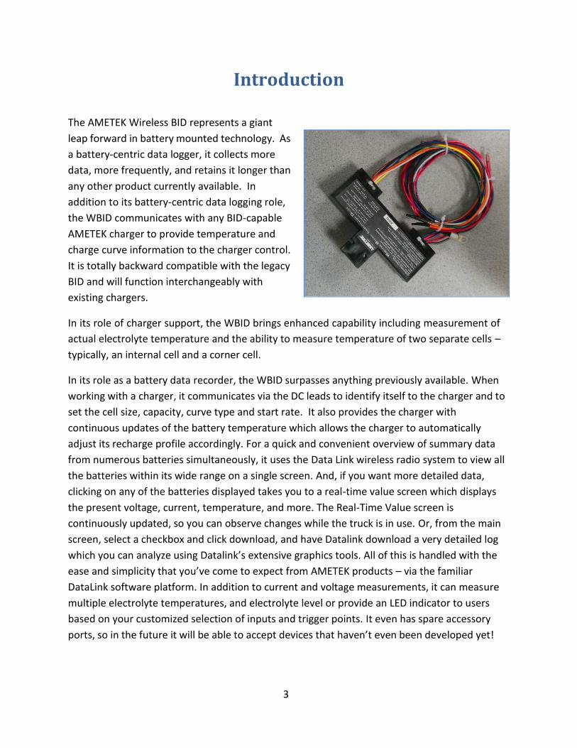
The AMETEK Wireless BID represents a giant
leap forward in battery mounted technology. As
a battery-centric data logger, it collects more
data, more frequently, and retains it longer than
any other product currently available. In
addition to its battery-centric data logging role,
the WBID communicates with any BID-capable
AMETEK charger to provide temperature and
charge curve information to the charger control.
It is totally backward compatible with the legacy
BID and will function interchangeably with
existing chargers.
In its role of charger support, the WBID brings enhanced capability including measurement of
actual electrolyte temperature and the ability to measure temperature of two separate cells –
typically, an internal cell and a corner cell.
In its role as a battery data recorder, the WBID surpasses anything previously available. When
working with a charger, it communicates via the DC leads to identify itself to the charger and to
set the cell size, capacity, curve type and start rate. It also provides the charger with
continuous updates of the battery temperature which allows the charger to automatically
adjust its recharge profile accordingly. For a quick and convenient overview of summary data
from numerous batteries simultaneously, it uses the Data Link wireless radio system to view all
the batteries within its wide range on a single screen. And, if you want more detailed data,
clicking on any of the batteries displayed takes you to a real-time value screen which displays
the present voltage, current, temperature, and more. The Real-Time Value screen is
continuously updated, so you can observe changes while the truck is in use. Or, from the main
screen, select a checkbox and click download, and have Datalink download a very detailed log
which you can analyze using Datalink’s extensive graphics tools. All of this is handled with the
ease and simplicity that you’ve come to expect from AMETEK products – via the familiar
DataLink software platform. In addition to current and voltage measurements, it can measure
multiple electrolyte temperatures, and electrolyte level or provide an LED indicator to users
based on your customized selection of inputs and trigger points. It even has spare accessory
ports, so in the future it will be able to accept devices that haven’t even been developed yet!
4
Installation and Setup
Planning Your Installation
The first step in planning your WBID installation is to select what options you wish to install.
WBID Module. The basic module includes power and current sensing connections which enable
it to sense and record the entire electrical history of the battery for the entire life of the
battery. To enable that functionality, you will need only to make the proper connections on the
battery and configure the parameters in the module. We’ll get to that in detail shortly.
Optional Devices. In all but the simplest installations, it is highly beneficial to include some key
external sensors in your installation.
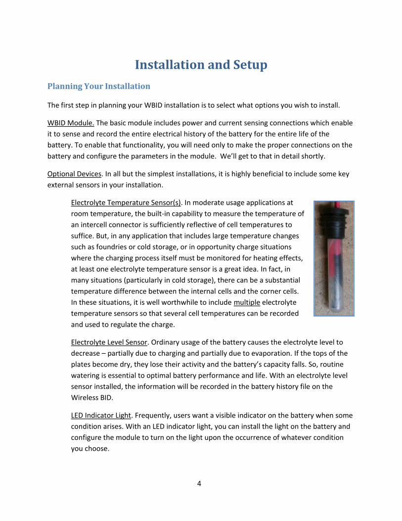
Electrolyte Temperature Sensor(s). In moderate usage applications at
room temperature, the built-in capability to measure the temperature of
an intercell connector is sufficiently reflective of cell temperatures to
suffice. But, in any application that includes large temperature changes
such as foundries or cold storage, or in opportunity charge situations
where the charging process itself must be monitored for heating effects,
at least one electrolyte temperature sensor is a great idea. In fact, in
many situations (particularly in cold storage), there can be a substantial
temperature difference between the internal cells and the corner cells.
In these situations, it is well worthwhile to include multiple electrolyte
temperature sensors so that several cell temperatures can be recorded
and used to regulate the charge.
Electrolyte Level Sensor. Ordinary usage of the battery causes the electrolyte level to
decrease – partially due to charging and partially due to evaporation. If the tops of the
plates become dry, they lose their activity and the battery’s capacity falls. So, routine
watering is essential to optimal battery performance and life. With an electrolyte level
sensor installed, the information will be recorded in the battery history file on the
Wireless BID.
LED Indicator Light. Frequently, users want a visible indicator on the battery when some
condition arises. With an LED indicator light, you can install the light on the battery and
configure the module to turn on the light upon the occurrence of whatever condition
you choose.
5
Mechanical and Electrical Installation
WARNING: Use extreme caution when working with batteries. The possibility of shock, fire, and explosion exists. Batteries produce explosive gases. Keep sparks, flame, and cigarettes away. Ventilate when working in an enclosed area. Always shield eyes when working near batteries. Facemask and gloves are recommended during WBID installation. AVERTISSEMENT : Soyez extrêmement prudent lorsque vous travaillez avec des batteries. Il existe un risque de choc, d'incendie et d'explosion. Les batteries produisent des gaz explosifs. Tenez à l'écart les étincelles, les flammes et les cigarettes. Aérez lorsque vous travaillez dans un endroit fermé. Protégez toujours vos yeux lorsque vous travaillez à proximité de batteries. Le port d'un Le port d'un masque et de gants est recommandé lors de l'installation du WBID.
WARNING: Do not lay tools on top of the battery as they may conduct electricity. AVERTISSEMENT : Ne posez pas d'outils sur la batterie car ils peuvent conduire l'électricité.
These instructions cover mechanical and electrical installation of the AMETEK WBID. The following tools will be required for the installation:
• Portable power drill
• 3/16” drill bit with suitable stop to limit drill depth to ½”
• #2 Phillips screwdriver
• Diagonal cutting pliers (side cutters)
• Wood or rubber mallet Note: If you will be installing any sensors or other optional devices, be sure to check the instructions packed with the device(s) for any additional tool requirements. Accessory instructions are also included in the appendices of this document.
Installation:
1. Carefully unpack the WBID from its shipping carton, and neatly lay out the parts. Some of the wires will have their terminations sealed in heat shrink tubing. DO NOT REMOVE THE HEAT SHRINK AT THIS TIME. Check the parts against the following material list:
a. WBID Module b. Qty 1: No-Ox-ID A Special grease, 0.25 oz c. Qty 5: 6-32 1/4” screws d. Qty 2: 6-32 3/4” screws e. Qty 7: #6 flat washer f. Qty 7: Brass inserts g. Qty 8: Polypropylene cable ties
2. Move the battery to a clean, well-lit area. 3. The battery must be clean and free of corrosion for proper operation of the WBID.
6
WARNING: drilling can cause sparks that can ignite flammable gas. Please use caution with batteries that have recently been under charge or in areas with flammable gas or material.
AVERTISSEMENT : Le perçage peut provoquer des étincelles susceptibles d'enflammer un gaz inflammable. Soyez prudent avec les batteries qui ont été récemment chargées ou dans les zones où se trouvent des gaz ou des matériaux inflammables.
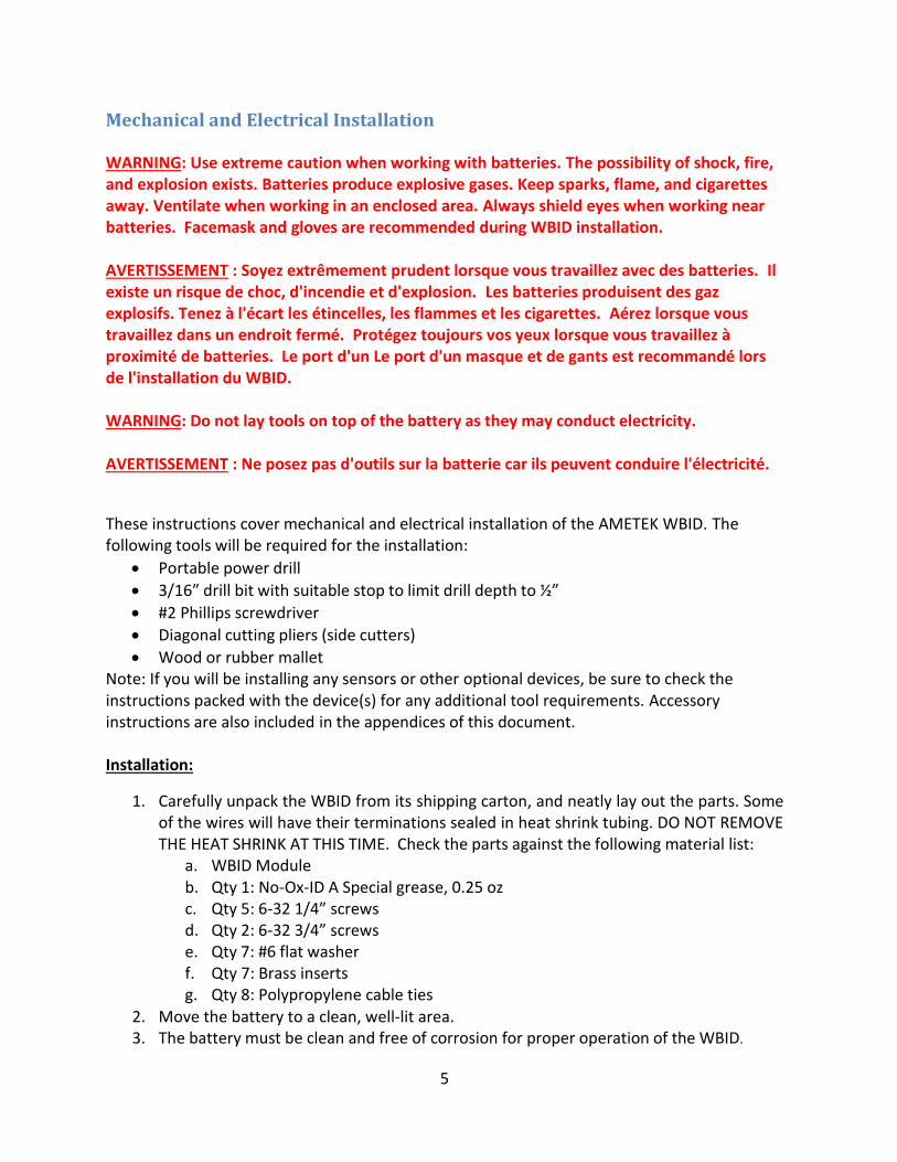
4. Using a 3/16” drill and a suitable stop to limit the depth of the hole to ½”, drill 7 holes for the provided inserts. These holes must be at least 3/8” deep to assure proper seating of the components.
a. In the center of the battery negative post b. In the center of the battery positive post c. In the positive post of the cell closest to the negative battery terminal (most
negative cell)
d. In the negative post of the second cell from the negative terminal e. In the positive post of the second cell from the negative terminal f. Two holes in the intercell connector where the module is to be mounted.
Typically, this will be toward the center of the battery as that gives the module maximum mechanical protection. Before removing the connector cover, place the module in its planned location on top of the connector cover and scribe a line around it. Then remove the connector cover and cut out along the line so that after mounting, the module will make direct contact with the connector. Now, with the connector cover back in place, use the module as a template for drilling the holes. When drilling the intercell, be careful to limit the depth so as not to damage a cell cover.
5. Place an insert into each one of the 7 holes and tap it gently with a wooden or rubber mallet until it is flush with the surface. It is especially critical that the module mounting inserts be flush so that the bottom of the module is tight against the intercell connector.
7
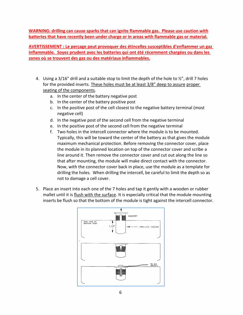
6. Pre-grease the two 6-32 x ¾” machine screws with NO-OX-ID A and attach the WBID to the intercell connector using the two holes drilled in step 4f and using two #6 flat washers as shown above.
7. Apply NO-OX-ID A corrosion inhibitor on all 5 of the remaining inserts prior to connecting the harness to the battery.
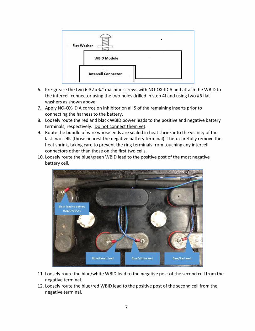
8. Loosely route the red and black WBID power leads to the positive and negative battery terminals, respectively. Do not connect them yet.
9. Route the bundle of wire whose ends are sealed in heat shrink into the vicinity of the last two cells (those nearest the negative battery terminal). Then. carefully remove the heat shrink, taking care to prevent the ring terminals from touching any intercell connectors other than those on the first two cells.
10. Loosely route the blue/green WBID lead to the positive post of the most negative battery cell.
11. Loosely route the blue/white WBID lead to the negative post of the second cell from the negative terminal.
12. Loosely route the blue/red WBID lead to the positive post of the second cell from the negative terminal.
8
13. Plan the electrical installation of any optional devices. The WBID includes a cluster of six color coded wires (Green, Yellow, Blue, White, Brown and Orange) that form its accessory ports. Select which of the wires will be connected to which of the sensors and make a note of it. The sensors and indicators have their own installation instructions detailing mechanical installation that come packed with the devices. They are also included in the appendix to this document.
14. Using a 6-32 x ¼” machine screw and provided washer, connect the black power lead to battery negative.
NOTE: Double check the following two connections: verify ~2V from the black WBID lead to the planned connections for the blue/green and blue/white WBID leads.
15. Using a 6-32 x ¼” machine screw and provided washer, connect the blue/green lead to the positive post of the most negative cell.
16. Using a 6-32 x ¼” machine screw and provided washer, connect the blue/white lead to the negative post of the second cell from the negative terminal.
NOTE: Double check the following connection: verify ~4V from the black WBID lead to the planned connection for the blue/red WBID lead.
17. Using a 6-32 x ¼” machine screw and provided washer, connect the blue/red lead to the positive post of the second cell from the negative terminal.
18. Using a 6-32 x ¼” machine screw and provided washer, connect the red power lead to the positive battery terminal.
19. Verify that the red LED on the WBID is flashing approximately 1x/sec, indicating that the module is operating but not setup and calibrated. It may take more than 30 seconds for the startup process to be completed and the LEDs to settle into this pattern.
20. Coat all exposed metal connections/screw heads with NO-OX-ID A. 21. Replace the terminal covers. Modify the intercell covers if needed and replace those as
well. Tie down all wiring with the provided wire ties. If for any reason other wire ties are used, make sure they are the polypropylene type. (Most wire ties are nylon which deteriorates quickly in contact with battery acid.)
22. If the battery has a cover, verify that it closes with no interference. If there is no cover, verify that the battery goes into the truck with no issues.
The WBID must be calibrated and configured to your battery before connecting it to a charger.
DataLink includes screens that make this quick and easy using a laptop computer and an
AMETEK Wireless Interface Device (WID). The following section shows how to access these
pages and perform the necessary steps using Datalink 3.3.0 or later.
9
Connecting, Calibration and Setup
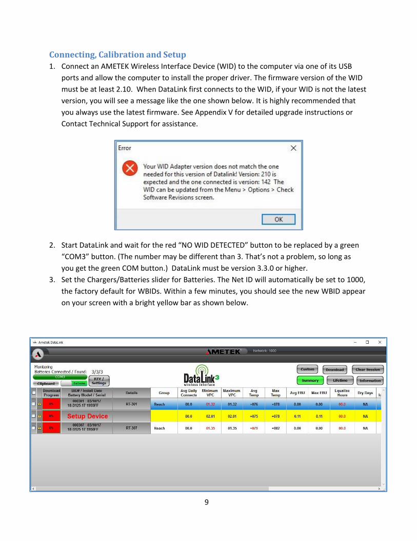
1. Connect an AMETEK Wireless Interface Device (WID) to the computer via one of its USB
ports and allow the computer to install the proper driver. The firmware version of the WID
must be at least 2.10. When DataLink first connects to the WID, if your WID is not the latest
version, you will see a message like the one shown below. It is highly recommended that
you always use the latest firmware. See Appendix V for detailed upgrade instructions or
Contact Technical Support for assistance.
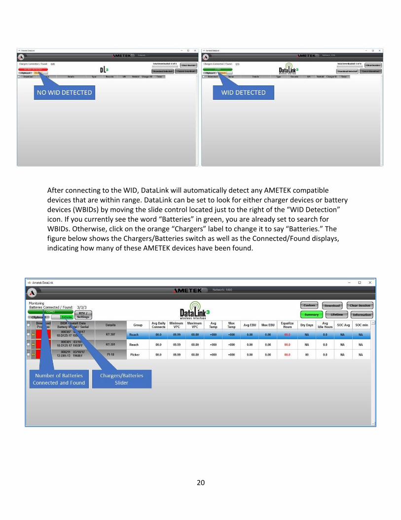
2. Start DataLink and wait for the red “NO WID DETECTED” button to be replaced by a green
“COM3” button. (The number may be different than 3. That’s not a problem, so long as
you get the green COM button.) DataLink must be version 3.3.0 or higher.
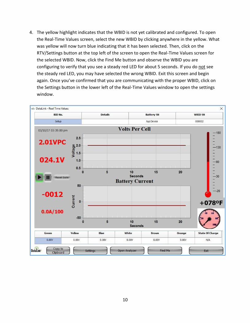
3. Set the Chargers/Batteries slider for Batteries. The Net ID will automatically be set to 1000,
the factory default for WBIDs. Within a few minutes, you should see the new WBID appear
on your screen with a bright yellow bar as shown below.
10
4. The yellow highlight indicates that the WBID is not yet calibrated and configured. To open
the Real-Time Values screen, select the new WBID by clicking anywhere in the yellow. What
was yellow will now turn blue indicating that it has been selected. Then, click on the
RTV/Settings button at the top left of the screen to open the Real-Time Values screen for
the selected WBID. Now, click the Find Me button and observe the WBID you are
configuring to verify that you see a steady red LED for about 5 seconds. If you do not see
the steady red LED, you may have selected the wrong WBID. Exit this screen and begin
again. Once you’ve confirmed that you are communicating with the proper WBID, click on
the Settings button in the lower left of the Real-Time Values window to open the settings
window.
11
Basic Settings
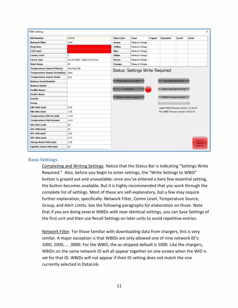
Completing and Writing Settings. Notice that the Status Bar is indicating “Settings Write
Required.” Also, before you begin to enter settings, the “Write Settings to WBID”
button is grayed out and unavailable; once you’ve entered a bare few essential setting,
the button becomes available. But it is highly recommended that you work through the
complete list of settings. Most of these are self-explanatory, but a few may require
further explanation, specifically: Network Filter, Comm Level, Temperature Source,
Group, and Alert Limits. See the following paragraphs for elaboration on those. Note
that if you are doing several WBIDs with near identical settings, you can Save Settings of
the first unit and then use Recall Settings on later units to avoid repetitive entries.
Network Filter. For those familiar with downloading data from chargers, this is very
similar. A major exception is that WBIDs are only allowed one of nine network ID’s:
1000, 2000, … ,9000. For the WBID, the as-shipped default is 1000. Like the chargers,
WBIDs on the same network ID will all appear together on one screen when the WID is
set for that ID. WBIDs will not appear if their ID setting does not match the one
currently selected in DataLink.

12
Comm Level. This is optimizing charger communications for the type of charger in use.
The as-shipped default is 0, and it should remain at 0 unless directed by AMETEK
Technical Services to use a different setting.
Temperature Source. The temperature source settings define how the WBID will report
temperature to the charger. There will always be a Primary source, and the default
primary will be the sensor embedded in the module and in intimate contact with the
intercell connector on which it is mounted. If you have installed one or more
temperature sensors in cells, there are more options. Most people will leave the
internal as primary and make the cell sensor be secondary. Then, the next setting tells
the WBID how to combine the two readings so that it can send a single temperature to
the charger. The options are to send the average, the maximum, or the minimum
temperature. The default is average, but in particularly hot or cold applications, some
users prefer maximum or minimum.
Group. This is basically a convenience setting that allows you to group batteries within
the same network according to categories you create. Since the 30-day summary grid
can be sorted on the Group field, you can then organize them with the click of a mouse.
For example, if area 1 includes both pallet jacks and reach trucks, you could create
groups called “pallet” and “reach”. Then, once the summary grid appears on your
screen, you can just click on the “Group” header to sort the grid so that all the pallet
jacks are together, and all the reach trucks are together.
Alert Limits. The limits toward the bottom of the settings area define the conditions
that will create an Alert when this battery’s summary data is displayed in the 30-day
Summary Battery Grid. Alerts will be highlighted in red on the Summary Grid. Default
settings are loaded when you receive your WBID, but they can be customized to the
working conditions for this specific battery at this specific site.
Once you’ve entered all the settings, click on the “Write Settings to WBID” button. The
settings entry grid will go blank, and Status will briefly say Writing Settings, then Getting
Settings, as it reads your entries back from the WBID to verify, and finally the grid will be
filled in with the settings and the Calibrate button becomes available. The Status Bar
now indicates “Calibration Required.”
13
Multifunction IO Settings
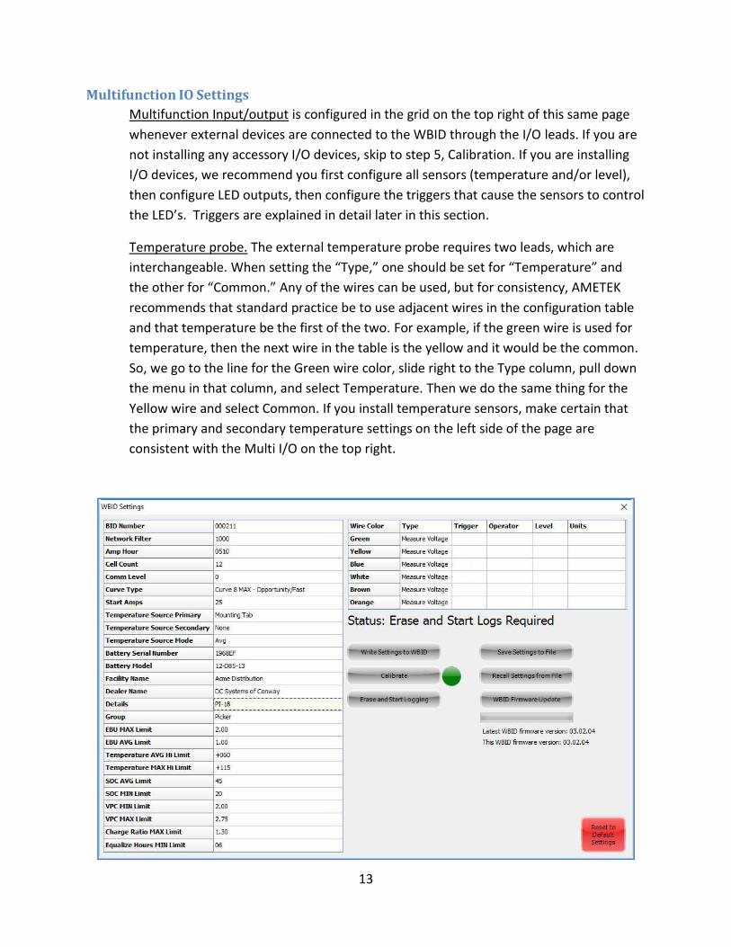
Multifunction Input/output is configured in the grid on the top right of this same page
whenever external devices are connected to the WBID through the I/O leads. If you are
not installing any accessory I/O devices, skip to step 5, Calibration. If you are installing
I/O devices, we recommend you first configure all sensors (temperature and/or level),
then configure LED outputs, then configure the triggers that cause the sensors to control
the LED’s. Triggers are explained in detail later in this section.
Temperature probe. The external temperature probe requires two leads, which are
interchangeable. When setting the “Type,” one should be set for “Temperature” and
the other for “Common.” Any of the wires can be used, but for consistency, AMETEK
recommends that standard practice be to use adjacent wires in the configuration table
and that temperature be the first of the two. For example, if the green wire is used for
temperature, then the next wire in the table is the yellow and it would be the common.
So, we go to the line for the Green wire color, slide right to the Type column, pull down
the menu in that column, and select Temperature. Then we do the same thing for the
Yellow wire and select Common. If you install temperature sensors, make certain that
the primary and secondary temperature settings on the left side of the page are
consistent with the Multi I/O on the top right.

14
Electrolyte Level Sensor. The electrolyte level sensor requires only a single wire, and it
can be any of the wires. Again, for consistency, AMETEK recommends that you work
down the table, so continuing the example above, we’ve already used the green and
yellow wires for temperature, so the next available wire is the blue. We go to the Blue
Wire line, pull down the menu, and select Level.
LED indicator. The LED indicator requires two wires and can be set to trigger on a wide
variety of conditions, such as high or low temperature, high or low electrolyte, and high
or low battery voltage. Unlike the temperature sensor, it does matter which wire is
which, because the LED can be made to illuminate in either red or green. Suppose that
you connect the LED green wire to the white WBID lead and the LED red to the brown.
Now, when you set the trigger on the white lead, the green LED will illuminate because
it is the green LED wire that is connected to that lead. If you set the trigger on the
brown LED, then the red LED would illuminate because the red LED wire is connected to
that lead.
Trigger Settings. If you’ve installed an LED, then you will need to configure the trigger
variable and condition. LED’s can be made to trigger on any of the sensors or on battery
voltage or current.
To trigger on temperature. Go to the LED line (White wire in this case) and set the
Trigger Channel for the wire set as Temperature. (In this case, green) Now, let’s
suppose that I want the LED to turn on if the temperature is greater than 125 degrees F.
I set the remaining values to “Greater than” and 125. Now the Status bar says, “Settings
Write Required,” so we click the “Write Settings to WBID” button. The status bar will
change to tell us first that it is writing and then that it is reading (though that may be
very fast). Finally, it will either revert to “Logging” if this is a change to a previously
installed WBID or it will say “Calibration Required” if it is a new installation.
To trigger on level, set Trigger channel to the Level line (Blue in this case). The level
sensor can have either of two values: 0 or 1. A value of zero indicates the level is below
the sensor, while a 1 indicates it is above the tip of the sensor. To trigger the LED on low
level, set Operator to Equal to 0. To trigger on high level (i.e., above the probe tip) set
Operator to Equal to 0. No need to remember these as they are noted in the far-right
column of the multi-IO setup grid on your screen.
To trigger on battery voltage or current, set the Trigger Channel to either voltage or
current in the pull-down menu on the LED ON line. So, continuing with the example
started earlier, let’s suppose that you didn’t want temperature to trigger the LED, but
rather wanted it to turn on if the battery voltage ever went below 1.97 vpc. Starting
15
with the setup shown, we go to the LED On line and open the pull-down menu on its
trigger channel. We select Voltage from the pull down and then Less Than 1.97. Now, if
the voltage goes below 1.97 volts per cell, the LED will illuminate, and when it rises back
above 1.97, the LED will extinguish.
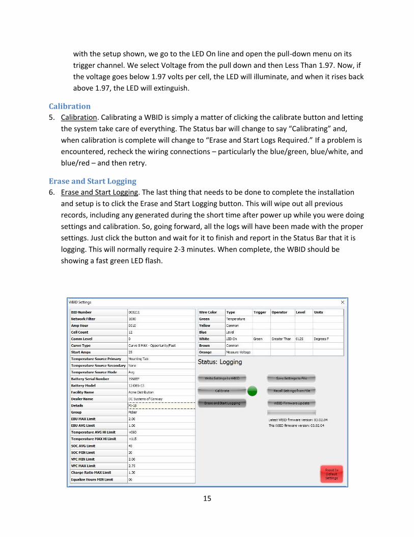
Calibration
5. Calibration. Calibrating a WBID is simply a matter of clicking the calibrate button and letting
the system take care of everything. The Status bar will change to say “Calibrating” and,
when calibration is complete will change to “Erase and Start Logs Required.” If a problem is
encountered, recheck the wiring connections – particularly the blue/green, blue/white, and
blue/red – and then retry.
Erase and Start Logging
6. Erase and Start Logging. The last thing that needs to be done to complete the installation
and setup is to click the Erase and Start Logging button. This will wipe out all previous
records, including any generated during the short time after power up while you were doing
settings and calibration. So, going forward, all the logs will have been made with the proper
settings. Just click the button and wait for it to finish and report in the Status Bar that it is
logging. This will normally require 2-3 minutes. When complete, the WBID should be
showing a fast green LED flash.

16
This completes the installation, configuration, and calibration of the
AMETEK Wireless BID. The WBID is now collecting and logging data. In
the next section, we will explain the various ways to access and analyze
that data.
17
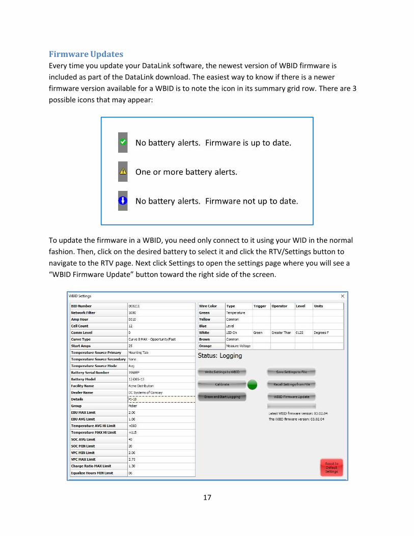
Firmware Updates
Every time you update your DataLink software, the newest version of WBID firmware is
included as part of the DataLink download. The easiest way to know if there is a newer
firmware version available for a WBID is to note the icon in its summary grid row. There are 3
possible icons that may appear:
To update the firmware in a WBID, you need only connect to it using your WID in the normal
fashion. Then, click on the desired battery to select it and click the RTV/Settings button to
navigate to the RTV page. Next click Settings to open the settings page where you will see a
“WBID Firmware Update” button toward the right side of the screen.

18
Click the WBID Firmware Update button, and DataLink will automatically update the firmware
in the WBID. The progress bar below the button will slowly turn green as the update
progresses. The process takes about 5-10 minutes, so you should be sure that you can keep the
WBID within range for that long before you start. When the update is complete, the WBID will
restart, and normal communication will resume. No historical data is lost, and data collection is
interrupted only during the 5-10 minutes of the update.
19
Reviewing 30 Day Summary Data
The WBID delivers 30-day summary data wirelessly to your computer. By installing AMETEK’s
DataLink 3 software (revision 3.3.0 or above) and connecting a WID device (version 2.10 or
above) to your USB port, you can access every WBID in your facility from hundreds of feet
away. In this section, we will cover the fleet-wide, 30-day view using the WID, and in the next
section, we will discuss how to download and analyze detailed historical data for a specific
battery from an individual WBID.
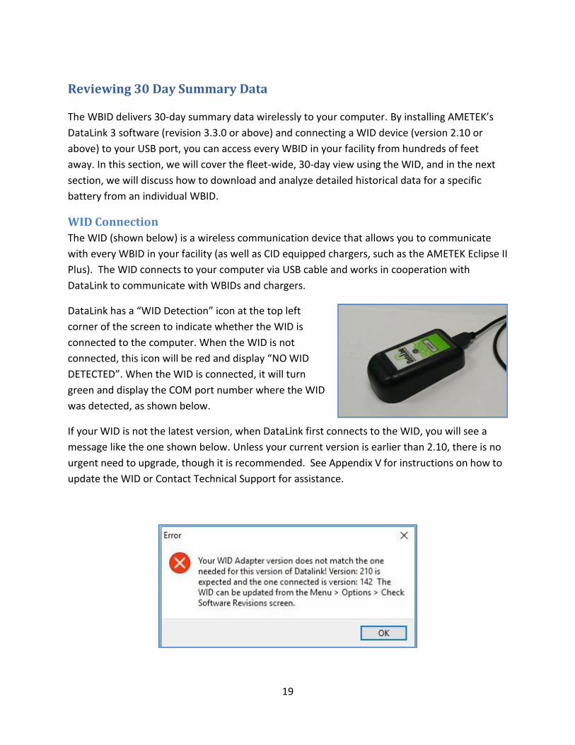
WID Connection
The WID (shown below) is a wireless communication device that allows you to communicate
with every WBID in your facility (as well as CID equipped chargers, such as the AMETEK Eclipse II
Plus). The WID connects to your computer via USB cable and works in cooperation with
DataLink to communicate with WBIDs and chargers.
DataLink has a “WID Detection” icon at the top left
corner of the screen to indicate whether the WID is
connected to the computer. When the WID is not
connected, this icon will be red and display “NO WID
DETECTED”. When the WID is connected, it will turn
green and display the COM port number where the WID
was detected, as shown below.
If your WID is not the latest version, when DataLink first connects to the WID, you will see a
message like the one shown below. Unless your current version is earlier than 2.10, there is no
urgent need to upgrade, though it is recommended. See Appendix V for instructions on how to
update the WID or Contact Technical Support for assistance.
20
After connecting to the WID, DataLink will automatically detect any AMETEK compatible devices that are within range. DataLink can be set to look for either charger devices or battery devices (WBIDs) by moving the slide control located just to the right of the “WID Detection” icon. If you currently see the word “Batteries” in green, you are already set to search for WBIDs. Otherwise, click on the orange “Chargers” label to change it to say “Batteries.” The figure below shows the Chargers/Batteries switch as well as the Connected/Found displays, indicating how many of these AMETEK devices have been found.
21
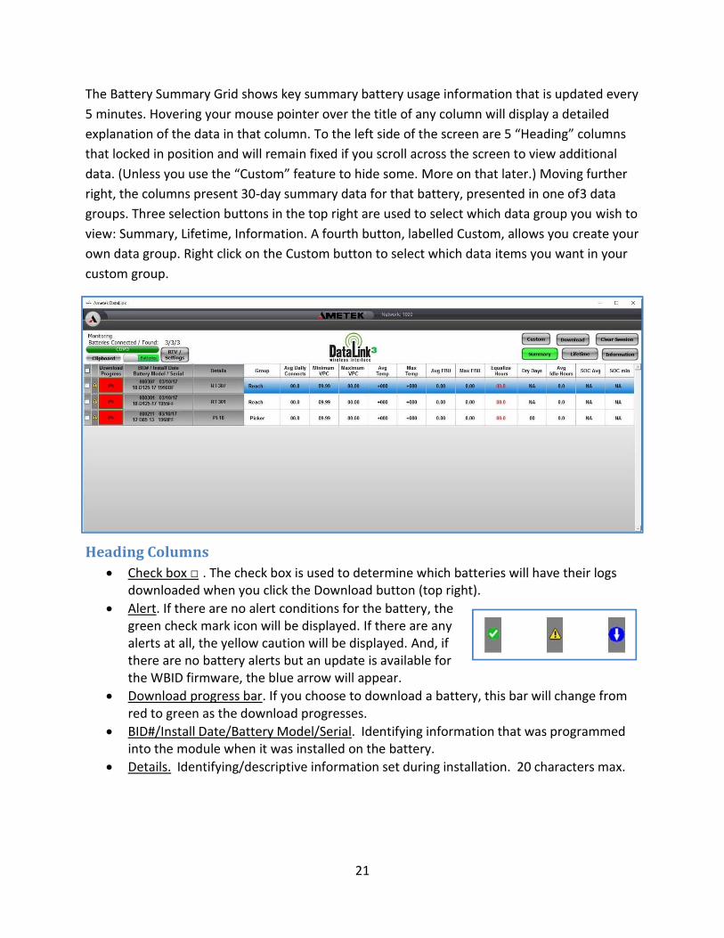
The Battery Summary Grid shows key summary battery usage information that is updated every
5 minutes. Hovering your mouse pointer over the title of any column will display a detailed
explanation of the data in that column. To the left side of the screen are 5 “Heading” columns
that locked in position and will remain fixed if you scroll across the screen to view additional
data. (Unless you use the “Custom” feature to hide some. More on that later.) Moving further
right, the columns present 30-day summary data for that battery, presented in one of 3 data
groups. Three selection buttons in the top right are used to select which data group you wish to
view: Summary, Lifetime, Information. A fourth button, labelled Custom, allows you create your
own data group. Right click on the Custom button to select which data items you want in your
custom group.
Heading Columns
• Check box □ . The check box is used to determine which batteries will have their logs downloaded when you click the Download button (top right).
• Alert. If there are no alert conditions for the battery, the green check mark icon will be displayed. If there are any alerts at all, the yellow caution will be displayed. And, if there are no battery alerts but an update is available for the WBID firmware, the blue arrow will appear.
• Download progress bar. If you choose to download a battery, this bar will change from red to green as the download progresses.
• BID#/Install Date/Battery Model/Serial. Identifying information that was programmed into the module when it was installed on the battery.
• Details. Identifying/descriptive information set during installation. 20 characters max.

22
Summary Group
All Summary information is based on what has happened during the last 30 days.
• Group. Set by the installer to identify this battery as a member of an operating group, e.g., “Reach” or “Pallet.” 10 characters max. Like all the other fields, this one can be sorted just by clicking the header, allowing the summary grid to be readily sorted by group ID.
• Avg Daily Connects. The average number of times per day that the battery was connected to a charger and a charge was initiated.
• Minimum VPC. The lowest 5-minute average volts per cell the battery reached during the last 30 days.
• Maximum VPC. The highest 5-minute average volts per cell the battery reached during the last 30 days.
• Avg Temp. The average temperature during the last 30 days.
• Max Temp. The maximum temperature during the last 30 days. • Avg EBU. The average Equivalent Battery Units discharged per day, during the last 30
days.
• Max EBU. The maximum Equivalent Battery Units discharged per day during the last 30 days.
• Equalize Hours. The average number of hours per week of Equalize time. Note that the module does not “know” when the charger is in EQ mode, so this is an estimate based on hours above 2.5 vpc beyond the basic 3 hours of a typical recharge.
• Dry Days. Number of days during the last 30 that the level sensor indicated low electrolyte.
• Avg Idle Hours. The average number of hours per day that the battery was neither charging nor discharging, i.e., not in use, but also not being charged.
• SOC Avg. The average estimated state of charge during the last 30 days.
• SOC min. The minimum estimated state of charge during the last 30 days.
23
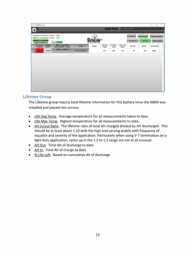
Lifetime Group
The Lifetime group reports total lifetime information for this battery since the WBID was
installed and placed into service.
• Life Avg Temp. Average temperature for all measurements taken to date.
• Life Max Temp. Highest temperature for all measurements to date.
• AH in/out Ratio. The lifetime ratio of total AH charged divided by AH discharged. This should be at least about 1.10 with the high end varying widely with frequency of equalize and severity of the application. Particularly when using V-T termination on a light duty application, ratios up in the 1.2 to 1.3 range are not at all unusual.
• AH Out. Total AH of discharge to date.
• AH In. Total Ah of charge to date.
• % Life Left. Based on cumulative Ah of discharge.
24
Information Group
The Information group presents key information regarding the WBID, its status, and its
firmware. It is primarily of interest for diagnostic purposes rather than routine battery
monitoring.
• S/N. Serial number of the WBID.
• Calibrated. Whether this WBID was calibrated after it was installed.
• Cells/Amp Hours. The battery settings stored in the WBID. For the WBID to function
properly, they MUST match the ratings of the battery.
• Avg Days. This number is the number of days included in the “30 day” summary
currently being presented. The only time it should ever be other than 30 is during the
first 30 days after installation or after a hard reset of the module. (e.g., a power cycle
or a “Reset to Defaults” by the user from the Settings screen)
• ARM Version. Revision level of the currently installed WBID firmware.
• NetAdd. This is NOT the same as the Net ID that is user determined. It is a parameter
defining how the WBID has connected with your WID and is primarily of technical and
troubleshooting importance.
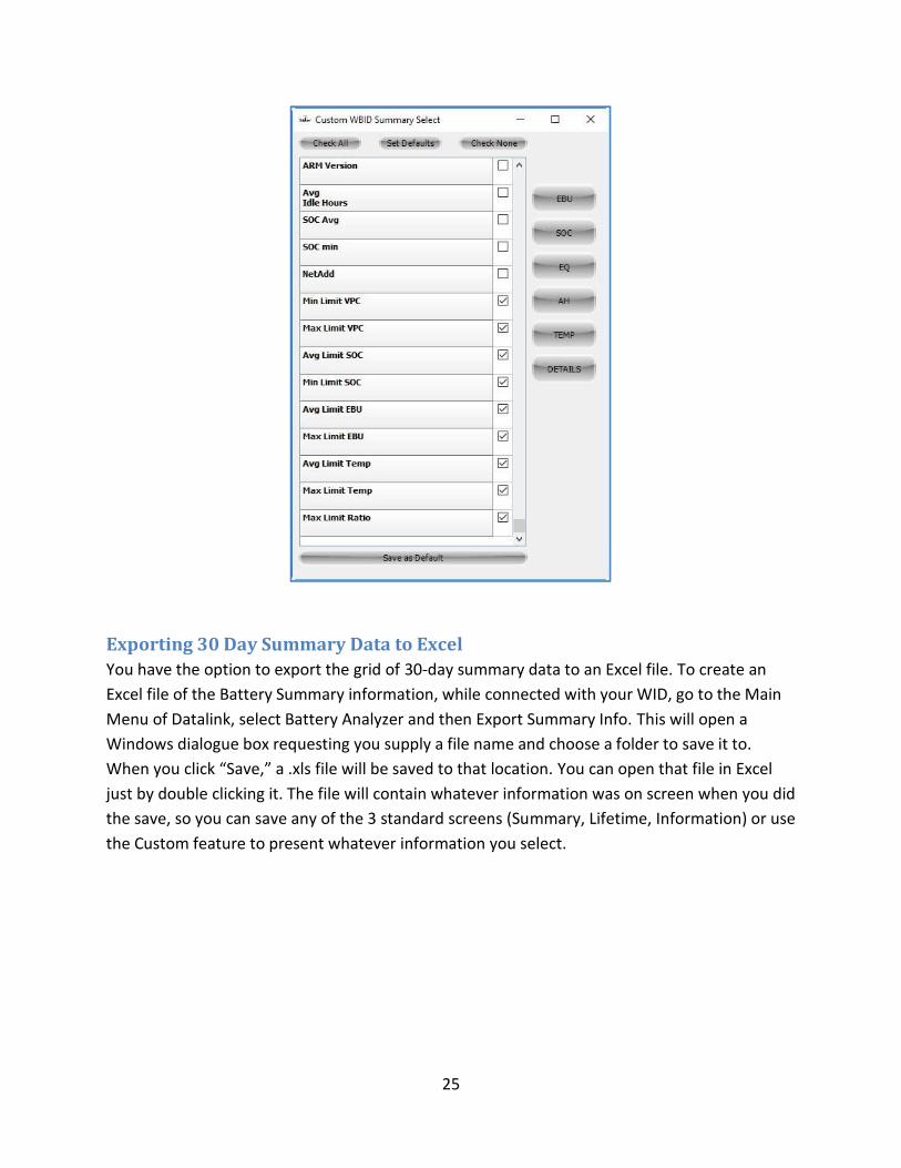
Custom Group
The Custom button allows you to create your own information groups so that you can look at
the data you want and only the data you want. To create a custom information group, right
click the Custom button, bringing up a menu of information items with a check box next to
each. Then just check the items you want included in your custom group. Toward the bottom
of the main list, you will see that the alarm limits are included here so that if you want to check
the settings for all the WBIDs you’re looking at without navigating into the Settings sheet for
each, you can just check the ones you want to see, and they will be included in the screen
display. To the right of the main list, you will see buttons that will check boxes by group. So,
for example, if you click the EBU button, it will check all the boxes related to EBU. This is just a
convenience to save you going through the items one by one – you can do it either way. At the
top of this screen, you will see buttons that can clear all boxes, check all the boxes, or return
you to the default settings. At the very bottom of the screen, is a button labelled “Save as
Default.” Clicking this button will store the settings you have at that moment and make them
your default going forward. So, no matter what changes you might make in the course of a
work session, when you open DataLink the next time, it will open with these default settings.
To exit this menu, just click on the X in the upper right-hand corner. To display the custom
information group, left click the Custom button.
25
Exporting 30 Day Summary Data to Excel
You have the option to export the grid of 30-day summary data to an Excel file. To create an
Excel file of the Battery Summary information, while connected with your WID, go to the Main
Menu of Datalink, select Battery Analyzer and then Export Summary Info. This will open a
Windows dialogue box requesting you supply a file name and choose a folder to save it to.
When you click “Save,” a .xls file will be saved to that location. You can open that file in Excel
just by double clicking it. The file will contain whatever information was on screen when you did
the save, so you can save any of the 3 standard screens (Summary, Lifetime, Information) or use
the Custom feature to present whatever information you select.
26
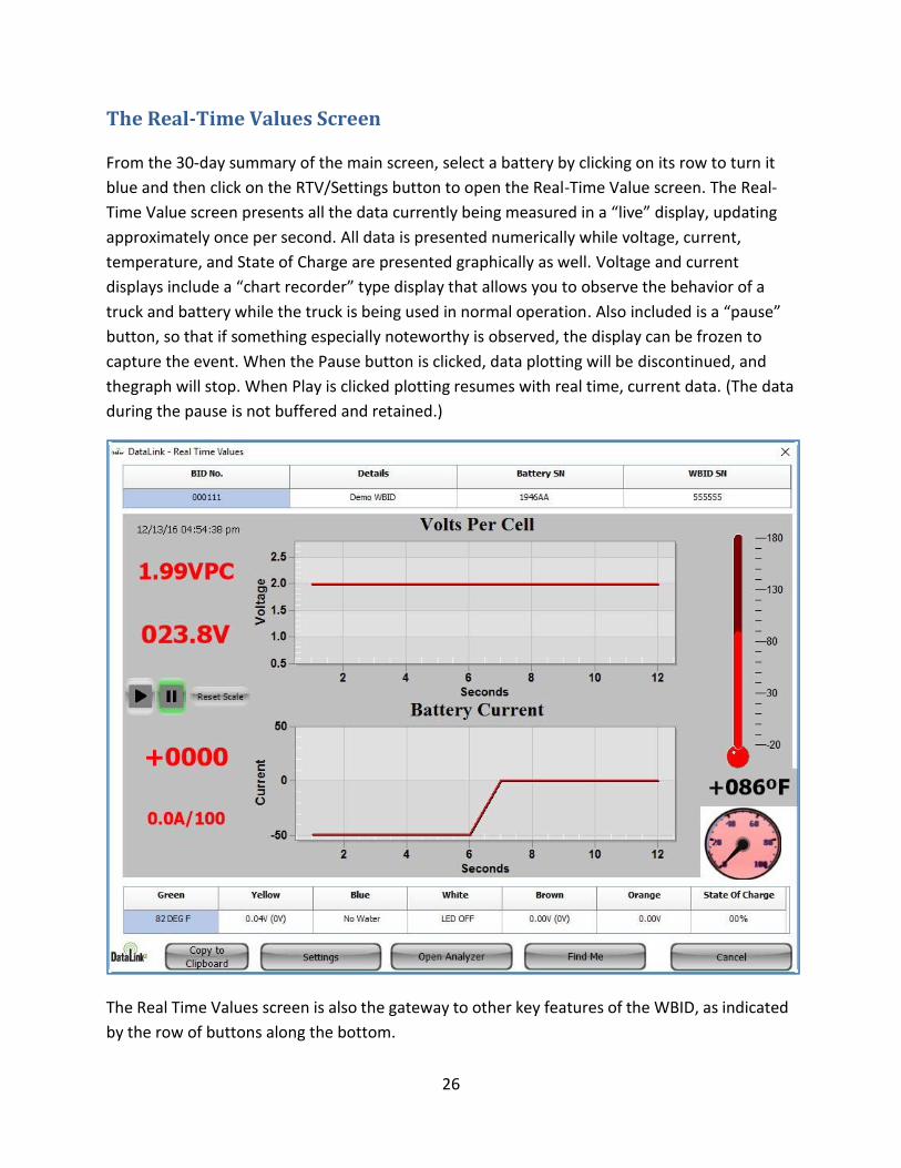
The Real-Time Values Screen
From the 30-day summary of the main screen, select a battery by clicking on its row to turn it
blue and then click on the RTV/Settings button to open the Real-Time Value screen. The Real-
Time Value screen presents all the data currently being measured in a “live” display, updating
approximately once per second. All data is presented numerically while voltage, current,
temperature, and State of Charge are presented graphically as well. Voltage and current
displays include a “chart recorder” type display that allows you to observe the behavior of a
truck and battery while the truck is being used in normal operation. Also included is a “pause”
button, so that if something especially noteworthy is observed, the display can be frozen to
capture the event. When the Pause button is clicked, data plotting will be discontinued, and
the graph will stop. When Play is clicked plotting resumes with real time, current data. (The data
during the pause is not buffered and retained.)
The Real Time Values screen is also the gateway to other key features of the WBID, as indicated
by the row of buttons along the bottom.

27
1. Copy to Clipboard. Puts a copy of the entire Real Time Values page on the Windows
clipboard from which you can paste it into PowerPoint, Word, or anywhere else.
This can be very useful when you’ve captured something while watching RTV during
normal operation, and you want to incorporate it in a report to the client.
2. Settings. This opens the path to the Settings menu from which you set all the
information stored on the WBID, e.g., BID number, curve type, start rate, Details,
etc. The Settings menu is also where you go to do a firmware update of the WBID.
See Connecting, Calibration, and Setup for more on this.
3. Open Analyzer. Opens the battery analyzer to the folder where the most recent
download for this battery is saved – provided it was saved there in this session.
4. Find Me. The Find Me button is useful for occasions where you want to verify that
this is really the module that you think it is … but you cannot easily see the module
to read its SN. Clicking Find Me will cause the fast-green LED of the connected
module to extinguish and a steady red to illuminate – for about 5 seconds. These
are bright enough that you can easily see the change even when looking into the end
of a reach truck battery compartment. It is strongly recommended that you always
do a Find Me to verify your connection before any Settings changes.
5. Cancel. Takes you back to the 30-day summary grid.
28
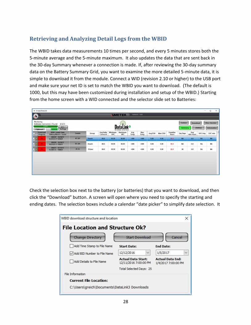
Retrieving and Analyzing Detail Logs from the WBID
The WBID takes data measurements 10 times per second, and every 5 minutes stores both the
5-minute average and the 5-minute maximum. It also updates the data that are sent back in
the 30-day Summary whenever a connection is made. If, after reviewing the 30-day summary
data on the Battery Summary Grid, you want to examine the more detailed 5-minute data, it is
simple to download it from the module. Connect a WID (revision 2.10 or higher) to the USB port
and make sure your net ID is set to match the WBID you want to download. (The default is
1000, but this may have been customized during installation and setup of the WBID.) Starting
from the home screen with a WID connected and the selector slide set to Batteries:
Check the selection box next to the battery (or batteries) that you want to download, and then
click the “Download” button. A screen will open where you need to specify the starting and
ending dates. The selection boxes include a calendar “date picker” to simplify date selection. It
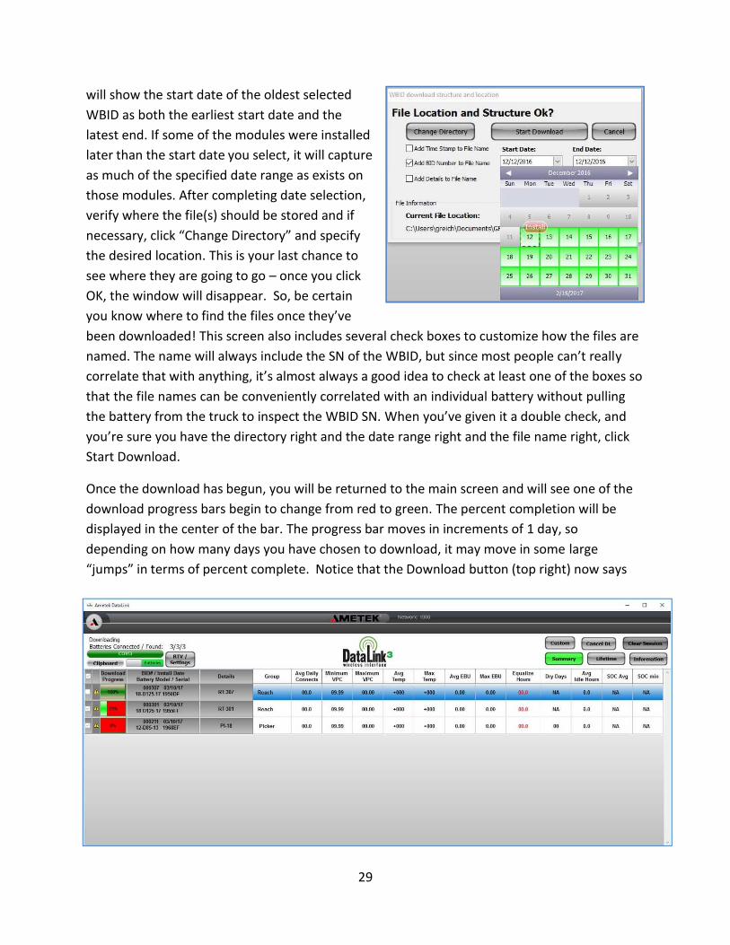
29
will show the start date of the oldest selected
WBID as both the earliest start date and the
latest end. If some of the modules were installed
later than the start date you select, it will capture
as much of the specified date range as exists on
those modules. After completing date selection,
verify where the file(s) should be stored and if
necessary, click “Change Directory” and specify
the desired location. This is your last chance to
see where they are going to go – once you click
OK, the window will disappear. So, be certain
you know where to find the files once they’ve
been downloaded! This screen also includes several check boxes to customize how the files are
named. The name will always include the SN of the WBID, but since most people can’t really
correlate that with anything, it’s almost always a good idea to check at least one of the boxes so
that the file names can be conveniently correlated with an individual battery without pulling
the battery from the truck to inspect the WBID SN. When you’ve given it a double check, and
you’re sure you have the directory right and the date range right and the file name right, click
Start Download.
Once the download has begun, you will be returned to the main screen and will see one of the
download progress bars begin to change from red to green. The percent completion will be
displayed in the center of the bar. The progress bar moves in increments of 1 day, so
depending on how many days you have chosen to download, it may move in some large
“jumps” in terms of percent complete. Notice that the Download button (top right) now says

30
Cancel DL. Clicking this will cause DataLink to complete the day of data currently in progress
and terminate the process. When the batch download has completed, the status message on
the top left (above the COM button) will revert from saying “Downloading” to say
“Monitoring.”
31
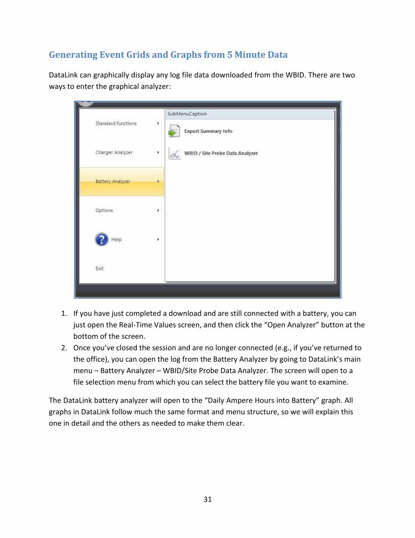
Generating Event Grids and Graphs from 5 Minute Data
DataLink can graphically display any log file data downloaded from the WBID. There are two
ways to enter the graphical analyzer:
1. If you have just completed a download and are still connected with a battery, you can
just open the Real-Time Values screen, and then click the “Open Analyzer” button at the
bottom of the screen.
2. Once you’ve closed the session and are no longer connected (e.g., if you’ve returned to
the office), you can open the log from the Battery Analyzer by going to DataLink’s main
menu – Battery Analyzer – WBID/Site Probe Data Analyzer. The screen will open to a
file selection menu from which you can select the battery file you want to examine.
The DataLink battery analyzer will open to the “Daily Ampere Hours into Battery” graph. All
graphs in DataLink follow much the same format and menu structure, so we will explain this
one in detail and the others as needed to make them clear.
32
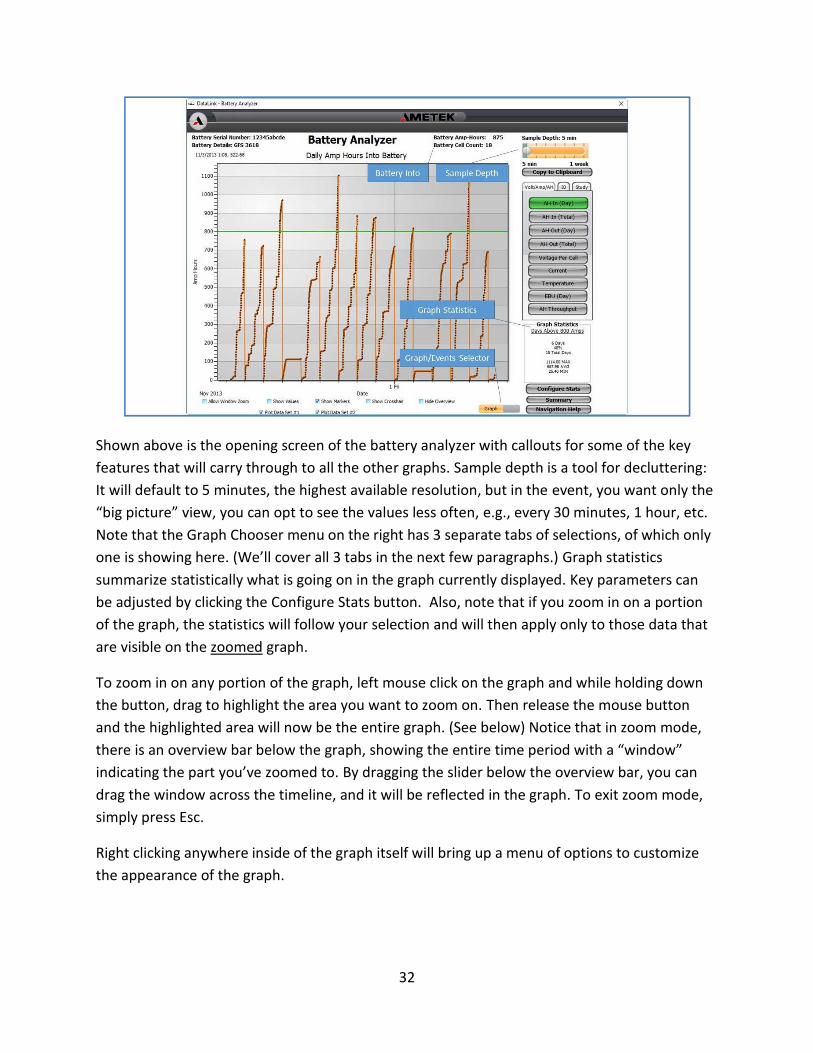
Shown above is the opening screen of the battery analyzer with callouts for some of the key
features that will carry through to all the other graphs. Sample depth is a tool for decluttering:
It will default to 5 minutes, the highest available resolution, but in the event, you want only the
“big picture” view, you can opt to see the values less often, e.g., every 30 minutes, 1 hour, etc.
Note that the Graph Chooser menu on the right has 3 separate tabs of selections, of which only
one is showing here. (We’ll cover all 3 tabs in the next few paragraphs.) Graph statistics
summarize statistically what is going on in the graph currently displayed. Key parameters can
be adjusted by clicking the Configure Stats button. Also, note that if you zoom in on a portion
of the graph, the statistics will follow your selection and will then apply only to those data that
are visible on the zoomed graph.
To zoom in on any portion of the graph, left mouse click on the graph and while holding down
the button, drag to highlight the area you want to zoom on. Then release the mouse button
and the highlighted area will now be the entire graph. (See below) Notice that in zoom mode,
there is an overview bar below the graph, showing the entire time period with a “window”
indicating the part you’ve zoomed to. By dragging the slider below the overview bar, you can
drag the window across the timeline, and it will be reflected in the graph. To exit zoom mode,
simply press Esc.
Right clicking anywhere inside of the graph itself will bring up a menu of options to customize
the appearance of the graph.
33
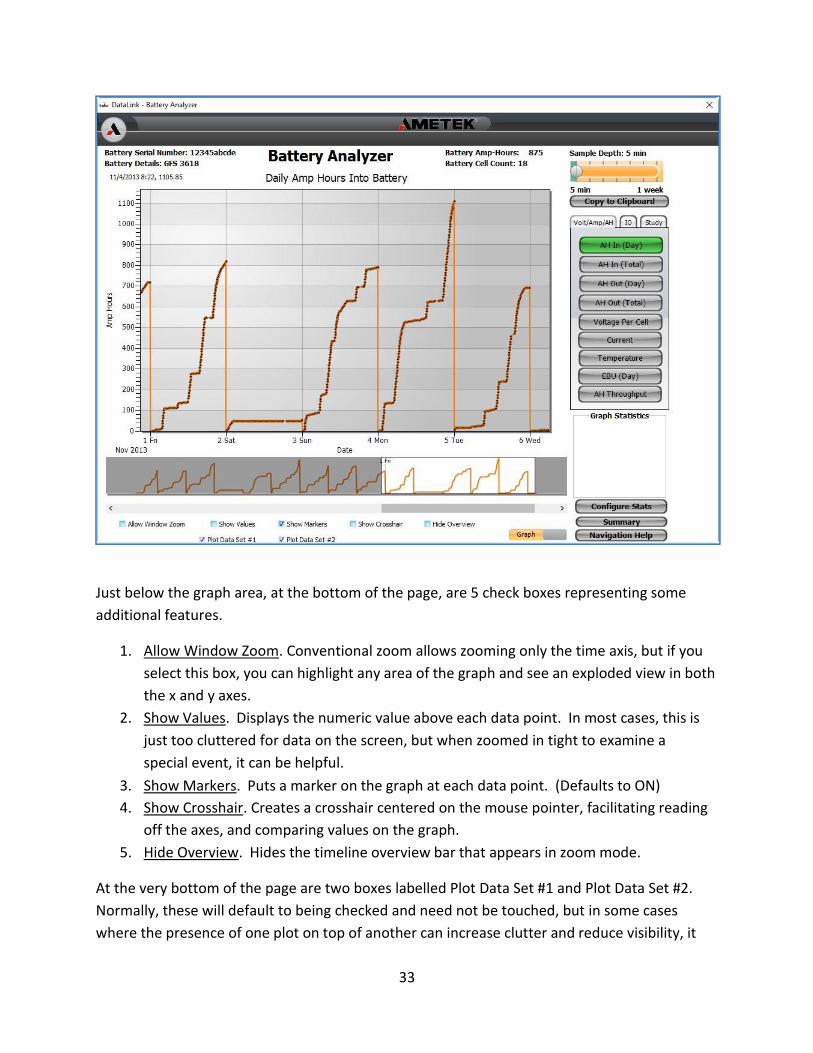
Just below the graph area, at the bottom of the page, are 5 check boxes representing some
additional features.
1. Allow Window Zoom. Conventional zoom allows zooming only the time axis, but if you
select this box, you can highlight any area of the graph and see an exploded view in both
the x and y axes.
2. Show Values. Displays the numeric value above each data point. In most cases, this is
just too cluttered for data on the screen, but when zoomed in tight to examine a
special event, it can be helpful.
3. Show Markers. Puts a marker on the graph at each data point. (Defaults to ON)
4. Show Crosshair. Creates a crosshair centered on the mouse pointer, facilitating reading
off the axes, and comparing values on the graph.
5. Hide Overview. Hides the timeline overview bar that appears in zoom mode.
At the very bottom of the page are two boxes labelled Plot Data Set #1 and Plot Data Set #2.
Normally, these will default to being checked and need not be touched, but in some cases
where the presence of one plot on top of another can increase clutter and reduce visibility, it

34
can be useful to uncheck one or the other of these boxes. If you choose to turn off one of the
plots, it may also be useful to uncheck the Show Markers box, as hiding a plot does not, by
itself, hide its markers.
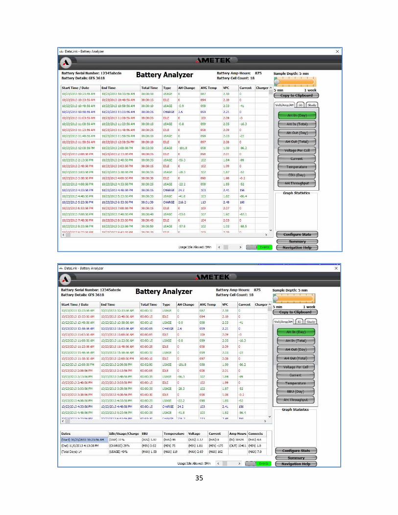
Finally, the Graph/Events selector slide allows you to see the data either graphically or as a
table of events. Sliding this selector to the left brings up the screen shown in the next figure – a
data grid listing all charge, usage, and idle events for the period. A critical control on this page
is the Usage Idle Allowed slider at the bottom. This dictates how long the battery must be idle
during a Usage period before the Usage event is considered ended and an Idle event initiated.
Typically, this would be set for approximately 10-15 minutes. Once on the Events grid, clicking
on the Summary button will overlay summary statistics for the complete file of data. Clicking a
second time will hide them so more events are visible. In the Events grid itself, double clicking
on an individual event will open the graph view of that event. Highlighting a series of events
and then changing to graph view will take you to a graph that has already zoomed in on the
events you highlighted. Changing the zoom on the graph will move the event highlighting to
match; they are linked together and will remain in sync as you work back and forth.
Once you are in graph view, you can use the Graph Chooser menu to examine any parameter
and then click the slider to return to Event Grid exactly where you left off. At the lower right of
these screens is a button labelled Navigation Help which will provide more detail on using the
event grid and graphics views.
35

36
All available graphs share the same layout and features.
Graph Page 1
Page 1 is the Volt/Amp/Ah page. It includes 9 different graphs and focuses on day-to-
day charges and discharges as well as temperature.
1. AH In (Day) – Daily ampere hours of charge. Resets to zero at the beginning of each day.
2. AH In (Total) – Cumulative ampere hours of charge
3. AH Out (Day) – Daily ampere hours of discharge. Resets to zero at the beginning of each
day. Provides insight into when, throughout the day, power is being used most rapidly.
4. AH Out (Total) – cumulative ampere hours of discharge
5. Voltage Per Cell – a continuous graph of peak and 5-minute average volts per cell
6. Current – a continuous graph of peak and 5-minute average current, both discharging
and charging
7. Temperature – a continuous graph of 5-minute average temperature
8. EBU(Day) – a graph of Equivalent Battery Usage for each day. The graph displays the
pattern of usage throughout each day and then resets to zero at the start of the next
day.
9. AH Throughput – cumulative net Ah throughput, increasing with charge and decreasing
with discharge, i.e., charge Ah minus discharge Ah. Another way to think of this is
lifetime Ah of overcharge.
37
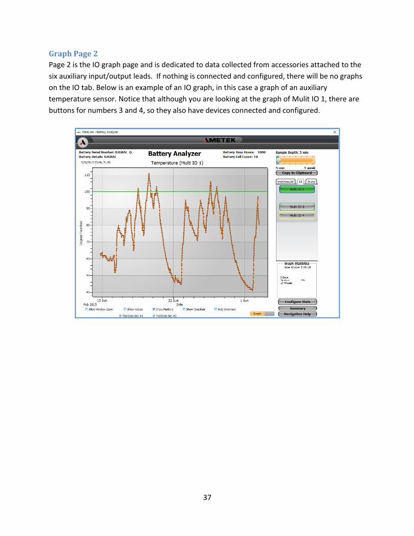
Graph Page 2
Page 2 is the IO graph page and is dedicated to data collected from accessories attached to the
six auxiliary input/output leads. If nothing is connected and configured, there will be no graphs
on the IO tab. Below is an example of an IO graph, in this case a graph of an auxiliary
temperature sensor. Notice that although you are looking at the graph of Mulit IO 1, there are
buttons for numbers 3 and 4, so they also have devices connected and configured.

38
Graph Page 3
Page 3 is the Study tab and is focused primarily on charge scheduling, i.e., how much time is
usage, how much is idle, and how much is charge. This section is most useful in analyzing data
from a power study, although it can be highly beneficial when evaluating an ongoing operation
and comparing present conditions vs. initial startup to determine whether there is still enough
charge time available and whether all available opportunities are being used. In addition, the
Study tab includes a model called SOC Predictor which allows modelling an operation with its
existing, measured load profile against a proposed charge regime. With the load drawn from
the actual data and charge currents and conditions input from slide controls, the SOC predictor
will generate a graph of the State of Charge vs time that would be produced. These are the
graphs of Tab 3:
1. Charger Status
2. Connects Per Day
3. Charge Times
4. In Use Times
5. Idle Times
6. Idle + Charge Times
7. Charge/Idle/Usage Times
8. AVG Current Draw
9. Predicted SOC
A few special points of clarification are appropriate regarding these graphs.
1. The terms “usage” and “charge” are obvious enough, but “idle” can be confusing. In this
case, “idle time” is time when the battery is neither being used nor being charged. So,
to see all the charge opportunities, you need to consider idle time plus charge time.
2. Charger Status – Shows the type of charge termination on each recharge of this battery.
3. Connects per Day is self-explanatory and should correlate with the number of available
opportunities at that site.
4. Items 3-6 all show exactly when those events are occurring in the form of a green line
that is high during the event. These can be great to examine in detail when the battery
is being used and charged during a limited work period.
5. The Charge/Idle/Usage graph is a summary of all 3 types of activity over the entire
period. It contains a lot of information, and can be initially overwhelming, but once you
study the legend, it’s a powerful overview.
6. Average Current Draw, as noted on the graph, reflects how hard the battery is being
worked when it is being worked. Since it counts only time when discharge is occurring,
it is not sensitive to how long the battery is being used, only how hard.

39
7. As noted above, Predicted SOC is not merely a graph but a modeling tool. If
Charge/Idle/Usage sums up what is currently happening, Predicted SOC predicts what
would happen if you kept the same customer load and usage profile and charged in
accordance with the settings you select using the slide controls. This one tool will tell
you whether opportunity or fast charge is possible in this application and what it will
take to make it work.

40
Appendix I Installing WBID Sensors
Installation Instructions for WBID Sensors
WARNING: Use extreme caution when working with batteries. The possibility of shock, fire,
and explosion exists. Batteries produce explosive gases. Keep sparks, flame, and cigarettes
away. Ventilate when working in an enclosed area. Always shield eyes when working near
batteries. Facemask and gloves are recommended during WBID installation
AVERTISSEMENT : Soyez extrêmement prudent lorsque vous travaillez avec des batteries. Il
existe un risque de choc, d'incendie et d'explosion. Les batteries produisent des gaz
explosifs. Tenez à l'écart les étincelles, les flammes et les cigarettes. Aérez lorsque vous
travaillez dans un endroit fermé. Protégez toujours vos yeux lorsque vous travaillez à
proximité de batteries. Le port d'un Le port d'un masque et de gants est recommandé lors
de l'installation du WBID.
WARNING: Do not lay tools on top of the battery as they may conduct electricity.
AVERTISSEMENT : Ne posez pas d'outils sur la batterie car ils peuvent conduire l'électricité.
These instructions cover mechanical and electrical installation of the temperature sensor
(AMETEK Part Number 198823) and/or electrolyte level sensor (AMETEK Part Number
198848) for the AMETEK Wireless Battery Identification Device (WBID). The following tools
will be required for the installation:
• Portable power drill
• Sensor hole drill bit (AMETEK Part Number: 198894)
• Universal crimping tool (e.g., Klein Tools J1005 Insulated Crimper, 22-10 AWG, 9-3/4 in.)
• Wire cutting pliers
• Wire stripper
• Heat gun
Installation:
1. Carefully unpack the sensor from its shipping carton, and neatly lay out the parts. Check
the parts against the following material list:
a. WBID Sensor (level or temperature) b. Heat shrinkable butt splice(s) (Quantity 2 for temperature sensor and 1 for level
sensor)

41
2. Move the battery to a clean, well-lit area.
3. The battery must be clean and free of corrosion for proper operation of the WBID.
WARNING: drilling can cause sparks that can ignite flammable gas. Please use caution with batteries that have recently been under charge or in areas with flammable gas or material. AVERTISSEMENT : Le perçage peut provoquer des étincelles susceptibles d'enflammer un gaz inflammable. Soyez prudent avec les batteries qui ont été récemment chargées ou dans les zones où se trouvent des gaz ou des matériaux inflammables.
4. Using the sensor hole drill, make a hole in the battery jar that is clear of any other
accessory or cell cap. Make certain that you are not directly above either of the cell
straps that join the plate lugs to the posts as that would interfere with full insertion of
the sensor. The level sensor should be installed at least 6 cells from the most negative
cell for proper operation.
5. Route the sensor wires to the WBID. With your cutting pliers, trim off any excess sensor
lead that is not required to reach the WBID connections. On the level sensor, there is a
section covered by heat shrink tubing – do not remove this section!
6. Temperature sensors require two leads each, while level requires only one. It is
recommended that the green and yellow leads be used for the first temperature sensor,
blue and white for second, and the orange or brown for the level sensor. After
completing the mechanical and electrical installation, the WBID must be configured in
software to properly read the new sensor.
7. Cut the protective cap from the WBID accessory leads to be used for the sensor, and
then strip ¼ inch of the insulation. Strip ¼ inch of the sensor leads as well.
8. Using the provided butt splices, crimp the sensor leads to the WBID connections and use
a heat gun to shrink the splice to protect against contamination and corrosion.
9. Secure these leads to the top of the battery along with the other WBID leads using the
provided polypropylene wire ties.
10. See the WBID owner’s manual for guidance in configuring the WBID to read and log the
data from the newly installed sensor. Note: Sensors will not function unless the WBID
has been properly configured to reflect the electrical connection of the sensors.

42
Appendix II Installing LED Module Installation Instructions WBID LED Module
1. Check that all parts are included with your kit:
a. 2 heat shrinkable butt splices (Reference) b. 2 brass inserts (191727-002) c. 2 6-32 x ¼’ phillips screws (192071-002) d. 2 #6 stainless flat washers (402524-004) e. 2 cable ties (191849-001) f. 1 LED module assembly (198837)
2. Move the battery to a clean well-ventilated area. 3. Mount the LED module in the desired place on the battery. It is assumed that an intercell
connector will be used. a. Use a 3/16” drill bit, make 2 holes approximately 1/2 “deep and 1 3/8” apart. b. Place an insert above each hole and tap lightly with a wooded or rubber mallet until the
insert is flush with the top of the hole. c. Secure the LED module with the included #6 screws and washers.
**Other mounting methods and placements may be used. Be sure to keep the LED module
clear from being impacted or constantly being exposed to battery fluids.
4. Using the 2 heat shrinkable butt splices, make the electrical connections to the WBID I/O wiring. a. See the WBID manual for additional connection information. b. Using a heat gun, seal the butt spliced connections. c. Tie the 2 module wires to a secure place on the battery.
Warning: USE EXTREME CAUTION WHEN WORKING WITH BATTERIES. THE
POSSIBILITY OF SHOCK, FIRE AND EXPLOSION EXISTS. BATTERIES
PRODUCE EXPLOSIVE GASES. KEEP SPARKS, FLAME AND CIGARETTES
AWAY. VENTILATE WHEN WORKING IN AN ENCLOSED AREA. ALWAYS
SHIELD EYES WHEN WORKING NEAR BATTERIES. FACEMASK AND GLOVES
ARE RECOMMENDED.
AVERTISSEMENT : Soyez extrêmement prudent lorsque vous travaillez
avec des batteries. Il existe un risque de choc, d'incendie et
d'explosion. Les batteries produisent des gaz explosifs. Tenez à l'écart les
étincelles, les flammes et les cigarettes. Aérez lorsque vous travaillez
dans un endroit fermé. Protégez toujours vos yeux lorsque vous travaillez
à proximité de batteries. Le port d'un masque et de gants est
recommandé.

43
Appendix III Accessories and Part Numbers
198900 WBID Kit (12-40 Cell)
198901 Site Probe Kit (12-40 Cell)
198823 Electrolyte Temperature Kit
198848 Electrolyte Level Kit
198853 Remote LED Kit
198894 Sensor Installation Kit: Battery jar drill bit
198893 Repair Kit: each color of wire and several heat shrinkable splices
191897 Installation drill bit (3/16”) and NO-OX-ID grease

44
Appendix IV Installing and Using the Site Probe
Introduction:
These instructions cover mechanical and electrical installation of the AMETEK Site Probe. The
Site Probe is a battery monitoring device that connects between a truck and its battery to
measure the truck’s power requirements. After recording data for a time, the data can be
wirelessly uploaded to a computer where usage can be analyzed, and opportunity charge
systems can be designed using computer models built into Datalink. The Site Probe connects
through a short cable designed to go inline between the truck and battery and is supplied with
SB350 gray connectors. Once connected, the Site Probe detects battery current and voltage and
logs this data as well as other critical information including amp hours in and out of the battery,
idle and usage times, and EBU. Logged data is not volatile and will be retained when the
battery is disconnected and even after the Probe has been removed from the truck.
Installation Steps:
To start using the Site Probe, connect it between the truck and battery. Depending on the installation, this may require changing the connector shells to be compatible. Pay close
attention to orientation of the site probe. One end of the device has a green LED; this is the
end that should be connected to the truck. The orientation is critical to recording the current
flow with correct polarity so that subsequent data analysis is simple and straightforward. In
many applications, the device can be free hanging or strapped to the outside of the truck during
WARNING: Use extreme caution when working with batteries. The possibility of shock, fire,
and explosion exists. Batteries produce explosive gases. Keep sparks, flame, and cigarettes
away. Ventilate when working in an enclosed area. Always shield eyes when working near
batteries. Facemask and gloves are recommended during Site Probe installation.
AVERTISSEMENT : Soyez extrêmement prudent lorsque vous travaillez avec des batteries. Il
existe un risque de choc, d'incendie et d'explosion. Les batteries produisent des gaz explosifs.
Tenez à l'écart les étincelles, les flammes et les cigarettes. Aérez lorsque vous travaillez dans
un endroit fermé. Protégez toujours vos yeux lorsque vous travaillez à proximité de
batteries. Le port d'un masque et de gants est recommandé.
WARNING: Do not lay tools on top of the battery as they may conduct electricity.
AVERTISSEMENT : Ne posez pas d'outils sur la batterie car ils peuvent conduire l'électricité.
45
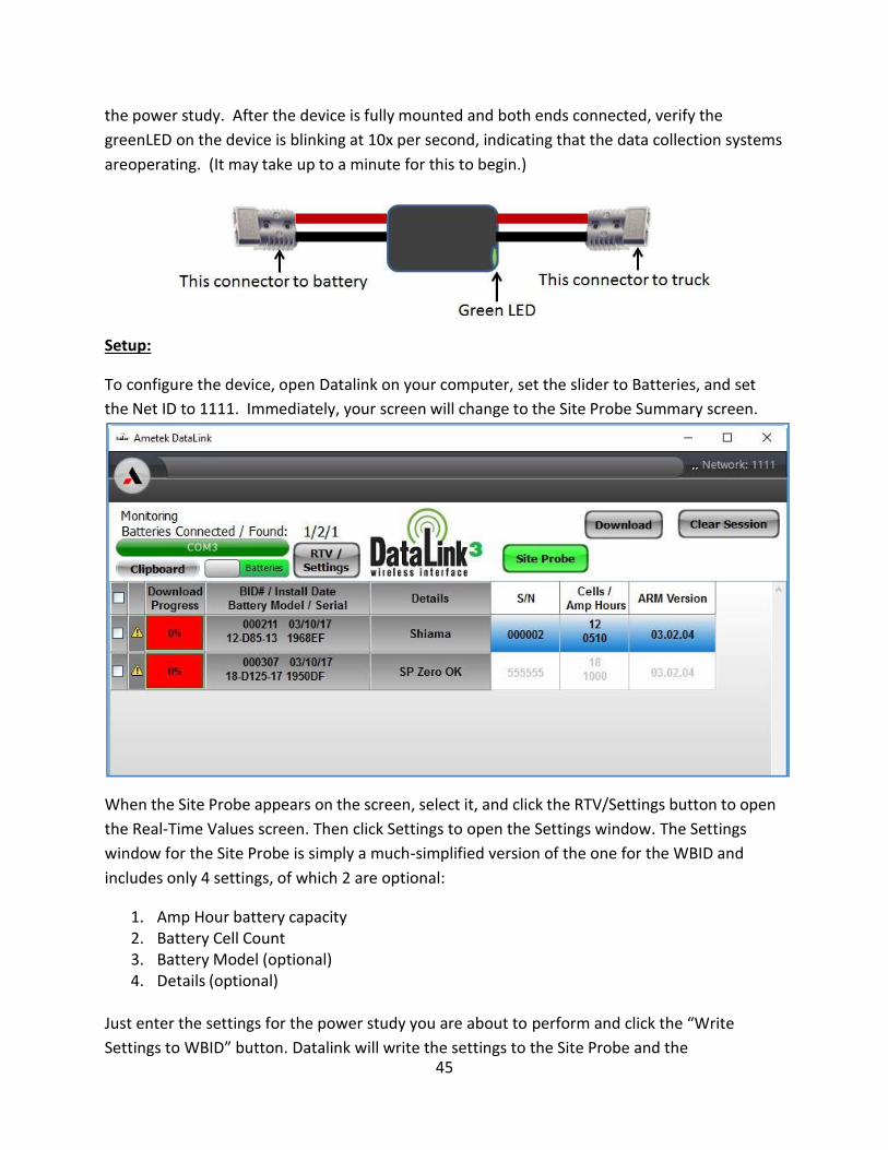
the power study. After the device is fully mounted and both ends connected, verify the
greenLED on the device is blinking at 10x per second, indicating that the data collection systems
are operating. (It may take up to a minute for this to begin.)
Setup:
To configure the device, open Datalink on your computer, set the slider to Batteries, and set
the Net ID to 1111. Immediately, your screen will change to the Site Probe Summary screen.
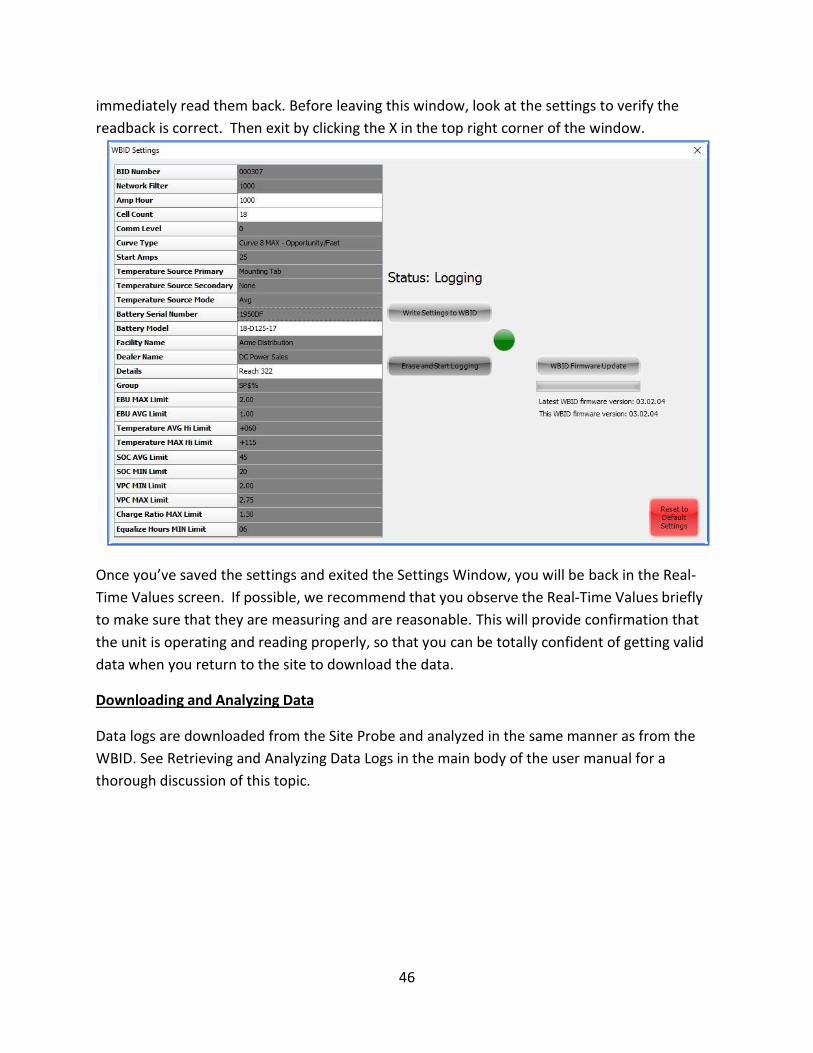
When the Site Probe appears on the screen, select it, and click the RTV/Settings button to open
the Real-Time Values screen. Then click Settings to open the Settings window. The Settings
window for the Site Probe is simply a much-simplified version of the one for the WBID and
includes only 4 settings, of which 2 are optional:
1. Amp Hour battery capacity 2. Battery Cell Count 3. Battery Model (optional) 4. Details (optional)
Just enter the settings for the power study you are about to perform and click the “Write
Settings to WBID” button. Datalink will write the settings to the Site Probe and the
46
immediately read them back. Before leaving this window, look at the settings to verify the
readback is correct. Then exit by clicking the X in the top right corner of the window.
Once you’ve saved the settings and exited the Settings Window, you will be back in the Real-
Time Values screen. If possible, we recommend that you observe the Real-Time Values briefly
to make sure that they are measuring and are reasonable. This will provide confirmation that
the unit is operating and reading properly, so that you can be totally confident of getting valid
data when you return to the site to download the data.
Downloading and Analyzing Data
Data logs are downloaded from the Site Probe and analyzed in the same manner as from the
WBID. See Retrieving and Analyzing Data Logs in the main body of the user manual for a
thorough discussion of this topic.
47
Appendix V Updating WID firmware Introduction
The Datalink installer always includes the latest firmware for your WID as well as the
program to install it. If the firmware in your WID is out of date, Datalink will inform you
when it first connects to the WID. In many cases, you can operate without immediately
updating and not experience any difficulties, but updates occur for a reason, so AMETEK
recommends that you always install the latest firmware at your earliest convenience or if
you are experiencing difficulties.
Installing New WID Firmware
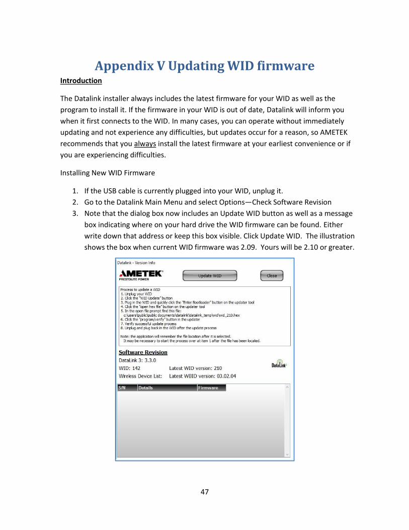
1. If the USB cable is currently plugged into your WID, unplug it.
2. Go to the Datalink Main Menu and select Options—Check Software Revision
3. Note that the dialog box now includes an Update WID button as well as a message
box indicating where on your hard drive the WID firmware can be found. Either
write down that address or keep this box visible. Click Update WID. The illustration
shows the box when current WID firmware was 2.09. Yours will be 2.10 or greater.
48
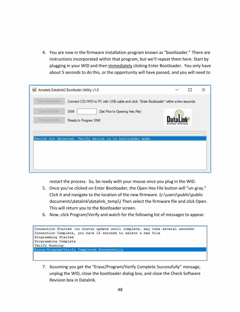
4. You are now in the firmware installation program known as “bootloader.” There are
instructions incorporated within that program, but we’ll repeat them here. Start by
plugging in your WID and then immediately clicking Enter Bootloader. You only have
about 5 seconds to do this, or the opportunity will have passed, and you will need to
restart the process. So, be ready with your mouse once you plug in the WID.
5. Once you’ve clicked on Enter Bootloader, the Open Hex File button will “un-gray.”
Click it and navigate to the location of the new firmware. (c:\users\public\public
documents\datalink\datalink_temp\) Then select the firmware file and click Open.
This will return you to the Bootloader screen.
6. Now, click Program/Verify and watch for the following list of messages to appear.
7. Assuming you get the “Erase/Program/Verify Complete Successfully” message,
unplug the WID, close the bootloader dialog box, and close the Check Software
Revision box in Datalink.

49
8. Reconnect the WID and wait for the green Datalink Com button indicating it is
connected to Datalink.
9. Now, reopen the Check Software Revision box and verify that you now have the
latest revision of firmware installed in your WID.


