Embed Size (px)
Citation preview
TOYO INTELLIGENT INVERTER VF66B (DC motor drive)
Operating Manual
1
Preface Thank you very much for choosing our product. This manual describes how to handle a main unit of TOYO VF66B (DC motor drive). It provides instructions for using VF66B (DC motor drive), such as how to install, wire, and operate it correctly as well as handling methods of its protection operation. Before operating VF66B (DC motor drive), be sure to carefully read this manual. In addition to the standard functions, TOYO VF66B (DC motor drive) provides many other features. You can build an optimal system for different applications by using its various functions. In such a case, preferentially use the values described in the dedicated "Instruction Manual" and "Test Report" for the function. When delivering any of your products with VF66B (DC motor drive) built in, consider that this manual can be distributed to end users. Also, when changing our factory default initialized data (hereinafter referred to as Initialized data) for setting parameters of VF66B (DC motor drive), make sure that end users can be informed about the changed contents of the Initialized data.
2
Be Sure To Read This Before Use Safety Notice
To use VF66B (DC motor drive) correctly, be sure to completely read this manual and all other attached documents before installation, operation, maintenance, and inspection. You need to have a good knowledge of equipment, safety information, and all notices before using VF66B (DC motor drive). In this manual, safety notices are ranked as "Danger", "Warning", and "Caution".
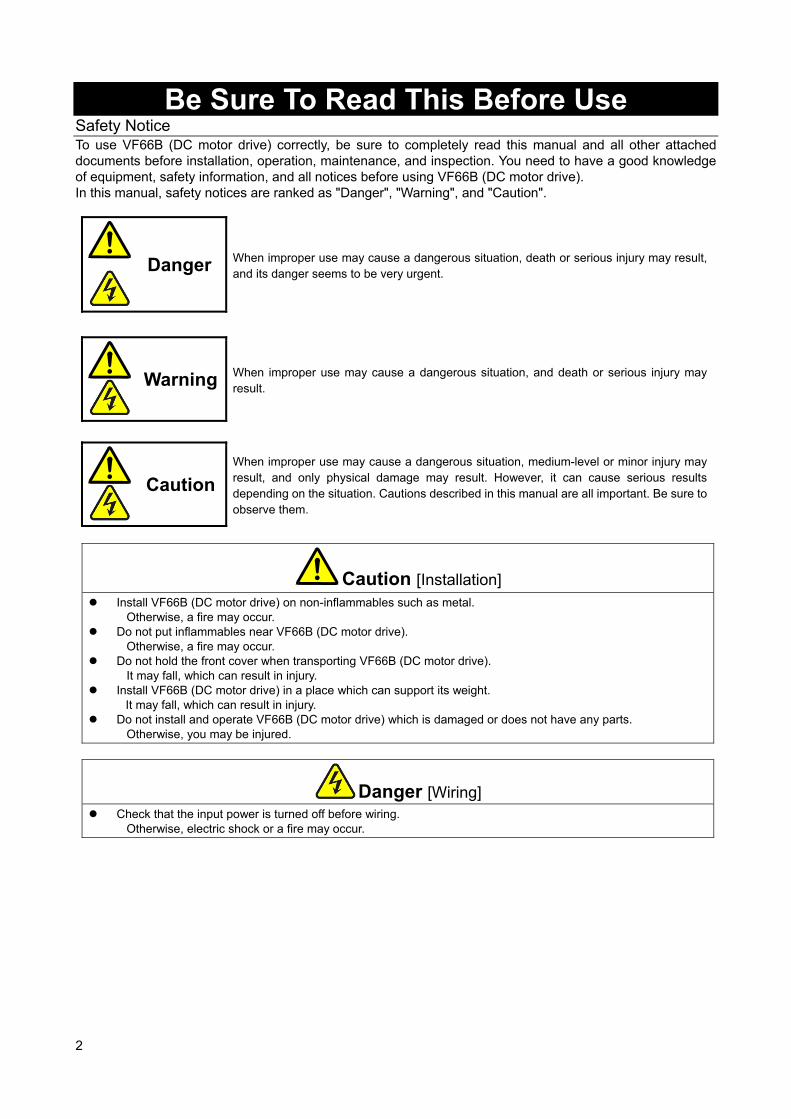
Danger When improper use may cause a dangerous situation, death or serious injury may result, and its danger seems to be very urgent.
Warning When improper use may cause a dangerous situation, and death or serious injury may
result.
Caution
When improper use may cause a dangerous situation, medium-level or minor injury may result, and only physical damage may result. However, it can cause serious results depending on the situation. Cautions described in this manual are all important. Be sure to observe them.
Caution [Installation] Install VF66B (DC motor drive) on non-inflammables such as metal.
Otherwise, a fire may occur. Do not put inflammables near VF66B (DC motor drive).
Otherwise, a fire may occur. Do not hold the front cover when transporting VF66B (DC motor drive).
It may fall, which can result in injury. Install VF66B (DC motor drive) in a place which can support its weight.
It may fall, which can result in injury. Do not install and operate VF66B (DC motor drive) which is damaged or does not have any parts.
Otherwise, you may be injured.
Danger [Wiring] Check that the input power is turned off before wiring.
Otherwise, electric shock or a fire may occur.
3
Warning [Wiring] Be sure to connect a ground wire.
Otherwise, electric shock or a fire may occur. Electrical engineering technicians should connect wires.
Otherwise, electric shock or a fire may occur. Be sure to install VF66B (DC motor drive) before wiring.
Otherwise, electric shock or a fire may occur. For ground fault protection, connect the leakage guard relay or ground fault interrupter exclusive for VF66B (DC
motor drive) to the inputs (R/L1, S/L2, T/L3) of VF66B (DC motor drive). Otherwise, electric shock or a fire may occur.
Warning [Wiring] Do not connect the alternating-current power supply to the output terminals (P/N).
Otherwise, injury or a fire may occur. Check that the rated voltage of the product and the voltage of the alternating-current power supply match with
each other. Otherwise, injury or a fire may occur.
Do not directly connect a resistor between direct-current terminals 1/ 2 and or 1 and 2. Otherwise, a fire may occur.
Warning [Operation] Be sure to install the front cover before turning on the input power. Do not remove the front cover during
energization. Otherwise, it can result in a risk of electric shock.
Do not use the switches with wet hands. Otherwise, it can result in a risk of electric shock.
Do not touch the VF66B (DC motor drive) terminals while VF66B (DC motor drive) is energized, even during stop.
Otherwise, it can result in a risk of electric shock.
Warning [Operation]
The stop button is available only when functions have been set. Provide an emergency stop button separately. Otherwise, you may be injured.
When alarm reset is performed with operation signals input, VF66B (DC motor drive) suddenly restarts. Check that signals are turned off, and then perform alarm reset.
Otherwise, you may be injured.
Caution [Operation] Do not touch a heat sink and a discharge resistor because they reach high temperatures.
Otherwise, you may get burned. You can set a wide range of operation from high speed to low speed with VF66B (DC motor drive). Before
operation, check the permitted range of the motor and machinery sufficiently. Otherwise, you may be injured.
Provide a holding brake separately if necessary. Otherwise, you may be injured.
4
Warning [Maintenance and inspection, and replacement of parts] Before inspection, turn off the input power after checking that the motor is stopped, and then wait for over ten
minutes. Also, check that direct-current voltage between 1 and or 2 and is less than or equal to 30 V.
Otherwise, electric shock, injury, or a fire may occur. Check that the rated voltage of the product and the voltage of the alternating-current power supply match with
each other. Otherwise, injury, electric shock, or part damage may occur.
Do not perform maintenance and inspection or replace parts except qualified persons. Use a tool for insulation for maintenance and inspection.
Otherwise, electric shock or injury may occur.
Warning [Others] Never modify VF66B (DC motor drive).
Otherwise, electric shock or injury may occur.
Caution [General notice]To provide detailed explanation, all figures described in this manual are sometimes drawn with the cover or a safety shield removed. To operate VF66B (DC motor drive), be sure to set the specified cover or shield to its original position and to follow the procedure described in this manual. These safety notices and specifications in this manual are subject to change without notice.
5
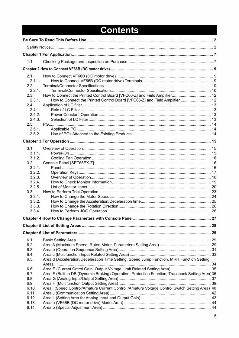
Contents Be Sure To Read This Before Use .................................................................................................................. 2
Safety Notice .................................................................................................................................................. 2
Chapter 1 For Application ............................................................................................................................... 7
1.1. Checking Package and Inspection on Purchase ............................................................................. 7
Chapter 2 How to Connect VF66B (DC motor drive) ............................................................................................. 9
2.1. How to Connect VF66B (DC motor drive) ....................................................................................... 9 2.1.1. How to Connect VF66B (DC motor drive) Terminals ................................................................ 9
2.2. Terminal/Connector Specifications ................................................................................................ 10 2.2.1. Terminal/Connector Specifications ......................................................................................... 10
2.3. How to Connect the Printed Control Board [VFC66-Z] and Field Amplifier ................................... 12 2.3.1. How to Connect the Printed Control Board [VFC66-Z] and Field Amplifier ........................... 12
2.4. Application of LC filter.................................................................................................................... 13 2.4.1. Role of LC Filter ..................................................................................................................... 13 2.4.2. Power Constant Operation ..................................................................................................... 13 2.4.3. Selection of LC Filter .............................................................................................................. 13
2.5. PG.................................................................................................................................................. 14 2.5.1. Applicable PG ......................................................................................................................... 14 2.5.2. Use of PGs Attached to the Existing Products ....................................................................... 14
Chapter 3 For Operation ............................................................................................................................... 15
3.1. Overview of Operation ................................................................................................................... 15 3.1.1. Power-On ............................................................................................................................... 15 3.1.2. Cooling Fan Operation ........................................................................................................... 16
3.2. Console Panel [SET66EX-Z] ......................................................................................................... 16 3.2.1. Panel ...................................................................................................................................... 16 3.2.2. Operation Keys ....................................................................................................................... 17 3.2.3. Overview of Operation ............................................................................................................ 18 3.2.4. How to Check Monitor Information ......................................................................................... 19 3.2.5. List of Monitor Items ............................................................................................................... 20
3.3. How to Perform Trial Operation ..................................................................................................... 23 3.3.1. How to Change the Motor Speed ........................................................................................... 24 3.3.2. How to Change the Acceleration/Deceleration time ............................................................... 25 3.3.3. How to Change the Rotation Direction ................................................................................... 26 3.3.4. How to Perform JOG Operation ............................................................................................. 26
Chapter 4 How to Change Parameters with Console Panel ...................................................................... 27
Chapter 5 List of Setting Areas .................................................................................................................... 28
Chapter 6 List of Parameters ........................................................................................................................ 29
6.1. Basic Setting Area ......................................................................................................................... 29 6.2. Area A (Maximum Speed, Rated Motor, Parameters Setting Area) .............................................. 29 6.3. Area b (Operation Sequence Setting Area) ................................................................................... 31 6.4. Area c (Multifunction Input Related Setting Area) ......................................................................... 33 6.5. Area d (Acceleration/Deceleration Time Setting, Speed Jump Function, MRH Function Setting
Area) .............................................................................................................................................. 34 6.6. Area E (Current Cotrol Gain, Output Voltage Limit Related Setting Area) .................................... 35 6.7. Area F (Built-in DB (Dynamic Braking) Operation, Protection Function, Traceback Setting Area) 36 6.8. Area G (Analog Input/Output Setting Area) ................................................................................... 37 6.9. Area H (Multifunction Output Setting Area) ................................................................................... 39 6.10. Area i (Speed Control/Amature Current Control /Amature Voltage Control Switch Setting Area) 40 6.11. Area J (Communication Setting Area) ........................................................................................... 42 6.12. Area L (Setting Area for Analog Input and Output Gain) ............................................................... 43 6.13. Area n (VF66B (DC motor drive) Model Area) .............................................................................. 44 6.14. Area o (Special Adjustment Area) ................................................................................................. 44
6
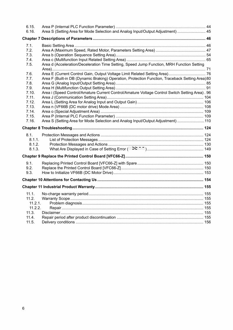
6.15. Area P (Internal PLC Function Parameter) ................................................................................... 44 6.16. Area S (Setting Area for Mode Selection and Analog Input/Output Adjustment) .......................... 45
Chapter 7 Descriptions of Parameters ........................................................................................................ 46
7.1. Basic Setting Area ......................................................................................................................... 46 7.2. Area A (Maximum Speed, Rated Motor, Parameters Setting Area) .............................................. 47 7.3. Area b (Operation Sequence Setting Area) ................................................................................... 54 7.4. Area c (Multifunction Input Related Setting Area) ......................................................................... 65 7.5. Area d (Acceleration/Deceleration Time Setting, Speed Jump Function, MRH Function Setting
Area) .............................................................................................................................................. 71 7.6. Area E (Current Control Gain, Output Voltage Limit Related Setting Area) .................................. 76 7.7. Area F (Built-in DB (Dynamic Braking) Operation, Protection Function, Traceback Setting Area) 80 7.8. Area G (Analog Input/Output Setting Area) ................................................................................... 85 7.9. Area H (Multifunction Output Setting Area) ................................................................................... 91 7.10. Area i (Speed Control/Amature Current Control/Amature Voltage Control Switch Setting Area) . 96 7.11. Area J (Communication Setting Area) ......................................................................................... 104 7.12. Area L (Setting Area for Analog Input and Output Gain) ............................................................. 106 7.13. Area n (VF66B (DC motor drive) Mode Area) ............................................................................. 108 7.14. Area o (Special Adjustment Area) ............................................................................................... 109 7.15. Area P (Internal PLC Function Parameter) ................................................................................. 109 7.16. Area S (Setting Area for Mode Selection and Analog Input/Output Adjustment) ......................... 110
Chapter 8 Troubleshooting ......................................................................................................................... 124
8.1. Protection Messages and Actions ............................................................................................... 124 8.1.1. List of Protection Messages ................................................................................................. 124 8.1.2. Protection Messages and Actions ........................................................................................ 130 8.1.3. What Are Displayed in Case of Setting Error ( ) .................................................... 149
Chapter 9 Replace the Printed Control Board [VFC66-Z] ........................................................................ 150
9.1. Replacing Printed Control Board [VFC66-Z] with Spare ............................................................. 150 9.2. Replace the Printed Control Board [VFC66-Z] ............................................................................ 150 9.3. How to Initialize VF66B (DC Motor Drive) ................................................................................... 153
Chapter 10 Attentions for Contacting Us .................................................................................................. 154
Chapter 11 Industrial Product Warranty .................................................................................................... 155
11.1. No-charge warranty period .......................................................................................................... 155 11.2. Warranty Scope ........................................................................................................................... 155
11.2.1. Problem diagnosis ................................................................................................................ 155 11.2.2. Repair ................................................................................................................................... 155
11.3. Disclaimer .................................................................................................................................... 155 11.4. Repair period after product discontinuation ................................................................................ 155 11.5. Delivery conditions ...................................................................................................................... 156
7
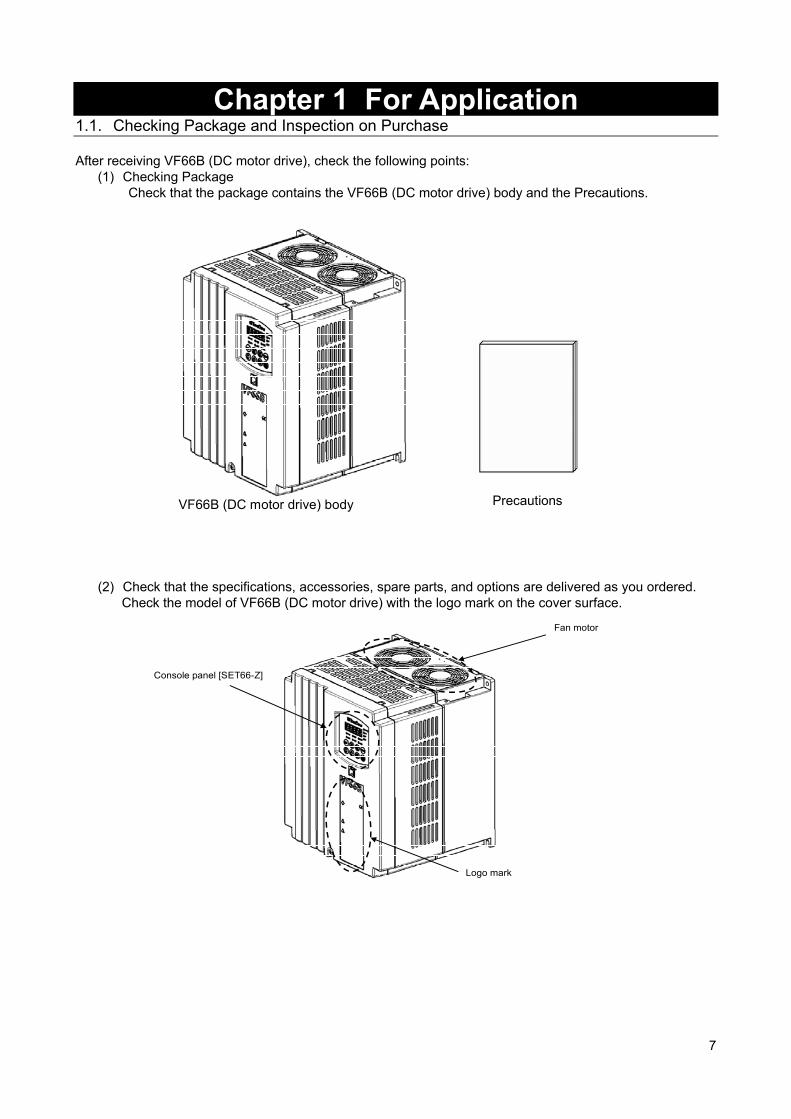
Chapter 1 For Application 1.1. Checking Package and Inspection on Purchase After receiving VF66B (DC motor drive), check the following points:
(1) Checking Package Check that the package contains the VF66B (DC motor drive) body and the Precautions.
VF66B (DC motor drive) body Precautions
(2) Check that the specifications, accessories, spare parts, and options are delivered as you ordered.
Check the model of VF66B (DC motor drive) with the logo mark on the cover surface.
Logo mark
Fan motor
Console panel [SET66-Z]

8
Example of model display on the cover surface
VF66B DCM Drive
VF66B-7R544 TYPE VF66B-7R544-W**
APPL. QA*
INPUT 3Φ380~460V 50/60Hz
OUTPUT DC440V 17.0A
WEIGHT 5.5 kg
SER. No. QC 123456789-001
! DANGER ・・・・・・・・・・・・・・・
・・・・・・・・・・・・・・・
・・・・・・・・・・・・・・・
! CAUTION ・・・・・・・・・・・・・・・
・・・・・・・・・・・・・・・
! DANGER ・・・・・・・・・・・・・・・
・・・・・・・・・・・・・・・
・・・・・・・・・・・・・・・
Model (VF66B (DC motor drive))
Output voltage/current
Input power supply voltage specifications
Model: VF66B-7R544-W1
Voltage class 22: this indicates 200 V class 44: this indicates 400 V class
Type Applied symbol
Serial
Weight
(3) Check that nothing is broken during transport. (4) Check that screws, etc. are not loose or removed.
If you have any problem, contact us or the distributor.
Caution [Safety notice]To use VF66B (DC motor drive) correctly, read this manual completely. TOYO VF66B (DC motor drive) is not designed and produced for the purpose of being used for a device or system under a situation where human life may be threatened. Do not use this TOYO VF66B (DC motor drive) for special purposes such as riding, medical, aerospace, nuclear power control, and a submarine repeater or system. VF66B (DC motor drive) is produced under the strict quality control. However, when VF66B (DC motor drive) is applied to an important facility where its failure might threaten human life or cause expected serious losses, you should install any safety devices to prevent serious accidents. When using VF66B (DC motor drive) for load other than a DC motor, consult with us. This product requires electrical work. Electrical engineering technicians should do it.
9
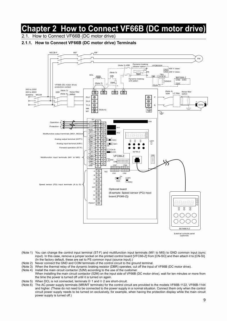
Chapter 2 How to Connect VF66B (DC motor drive) 2.1. How to Connect VF66B (DC motor drive)
2.1.1. How to Connect VF66B (DC motor drive) Terminals
TB2
SW2SW4
ON
CN1 CN2
Optional board
(Example: Speed sensor (PG) input
board [PG66-Z])
A
B
G
G
U/Z
V
W
G
PGOUT
ON
(Note 3)
DCL 49B
DBR
Noise filter option
Noise filter option
52M
MCCB 52M (Note 4)
200 to 220V
400 to 460V
50/60Hz
86F 49F MCCB-F
FM
49B
DBR
Dynamic braking resistor option
Dynamic braking unit option
External console panel (optional)
(Note 3)
(Note 3)
(Note 4)
(Note 5)
(Note 6)
B -
R/L1
S/L2
T/L3
MR
MT
P
N
+ 1 + 2
TB1
CN-SO
CN-SI
RY1
CN3
SW2
SW1
CN4
LED1
52MA
86Aa
86Ab
P
COM
GND
+10
PS
PS
MI3
GND
GND
52MA
86A
MO1
MO2
AOT1
AIN1
ST-F
MI1
MI2
MI4
MI5
CN5
3 1
ON
RY2
CN6
SET66-Z
CN7 CN4
VFC66-Z
SET66EX-Z
Operation
Protection
Multifunction output terminals (MO1, MO2)
Analog output terminal (AOT1)
Analog input terminal (AIN1)
Forward operation (ST-F)
Multifunction input terminals (MI1 to MI5)
Speed sensor (PG) input terminals (A to G)
DCM
AF
LC filter
P
PR
N
400 V class:
200 V class:
VFDB2009
52MAX
CN3 CN2
1 4 8 9 TB2
CN6
CN1
CN2 CN3 DBIF2009-Z
(Note 7)VF66B (DC motor drive) protection contact
(Note 1) You can change the control input terminal (ST-F) and multifunction input terminals (MI1 to MI5) to GND common input (sync input). In this case, remove a jumper socket on the printed control board [VFC66-Z] from [CN-SO] and then attach it to [CN-SI]. (In the factory default, these are set to PS common input (source input).)
(Note 2) Never connect the GND and COM terminals of the control circuit to the ground terminal. (Note 3) When the thermal relay of the dynamic braking resistor (DBR) operates, cut off the input of VF66B (DC motor drive). (Note 4) Install the main circuit contactor (52M) according to the use of the customer.
When installing the main circuit contactor (52M) on the input side of VF66B (DC motor drive), wait for ten minutes or more from the time the power is turned off until it is turned on again.
(Note 5) When DCL is not connected, terminals 1 and 2 are short-circuit. (Note 6) The AC power supply terminals (MR/MT terminals) for the control circuit are provided to the models VF66B-1122, VF66B-1144
and higher. (These do not need to be connected to the power supply in a normal situation. Connect them only when the control circuit power supply needs to be turned on exclusively, for example, when having the protection display while the main circuit power supply is turned off.)
10
(Note 7) Use DBIF2009-Z when communicating with the printed control board [VFC66-Z] and the dynamic braking (DB) optional unit [VFDB2009]. For more information, refer to the separate document "VFDB2009 Operation Manual."
CAUTION [Installation of SET66EX-Z (external console panel)]
Before installing SET66EX-Z (external console panel), be sure to take any measures against static electricity. Otherwise, circuits inside VF66B (DC motor drive) may be damaged.
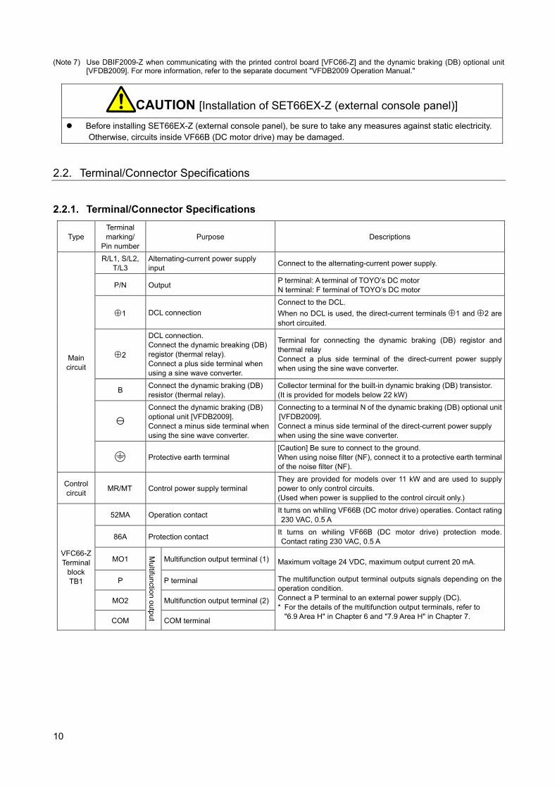
2.2. Terminal/Connector Specifications 2.2.1. Terminal/Connector Specifications
Type Terminal marking/
Pin number Purpose Descriptions
Main circuit
R/L1, S/L2, T/L3
Alternating-current power supply input
Connect to the alternating-current power supply.
P/N Output P terminal: A terminal of TOYO’s DC motor N terminal: F terminal of TOYO’s DC motor
1 DCL connection
Connect to the DCL.
When no DCL is used, the direct-current terminals 1 and 2 are short circuited.
2
DCL connection. Connect the dynamic breaking (DB) registor (thermal relay). Connect a plus side terminal when using a sine wave converter.
Terminal for connecting the dynamic braking (DB) registor and thermal relay Connect a plus side terminal of the direct-current power supply when using the sine wave converter.
B Connect the dynamic braking (DB) resistor (thermal relay).
Collector terminal for the built-in dynamic braking (DB) transistor. (It is provided for models below 22 kW)
Connect the dynamic braking (DB) optional unit [VFDB2009]. Connect a minus side terminal when using the sine wave converter.
Connecting to a terminal N of the dynamic braking (DB) optional unit [VFDB2009]. Connect a minus side terminal of the direct-current power supply when using the sine wave converter.
Protective earth terminal [Caution] Be sure to connect to the ground. When using noise filter (NF), connect it to a protective earth terminal of the noise filter (NF).
Control circuit
MR/MT Control power supply terminal They are provided for models over 11 kW and are used to supply power to only control circuits. (Used when power is supplied to the control circuit only.)
VFC66-Z Terminal
block TB1
52MA Operation contact It turns on whiling VF66B (DC motor drive) operaties. Contact rating 230 VAC, 0.5 A
86A Protection contact It turns on whiling VF66B (DC motor drive) protection mode. Contact rating 230 VAC, 0.5 A
MO1
Multifunction output
Multifunction output terminal (1) Maximum voltage 24 VDC, maximum output current 20 mA.
The multifunction output terminal outputs signals depending on the operation condition. Connect a P terminal to an external power supply (DC). * For the details of the multifunction output terminals, refer to
"6.9 Area H" in Chapter 6 and "7.9 Area H" in Chapter 7.
P P terminal
MO2 Multifunction output terminal (2)
COM COM terminal
11
Type Terminal marking/
Pin number Purpose Descriptions
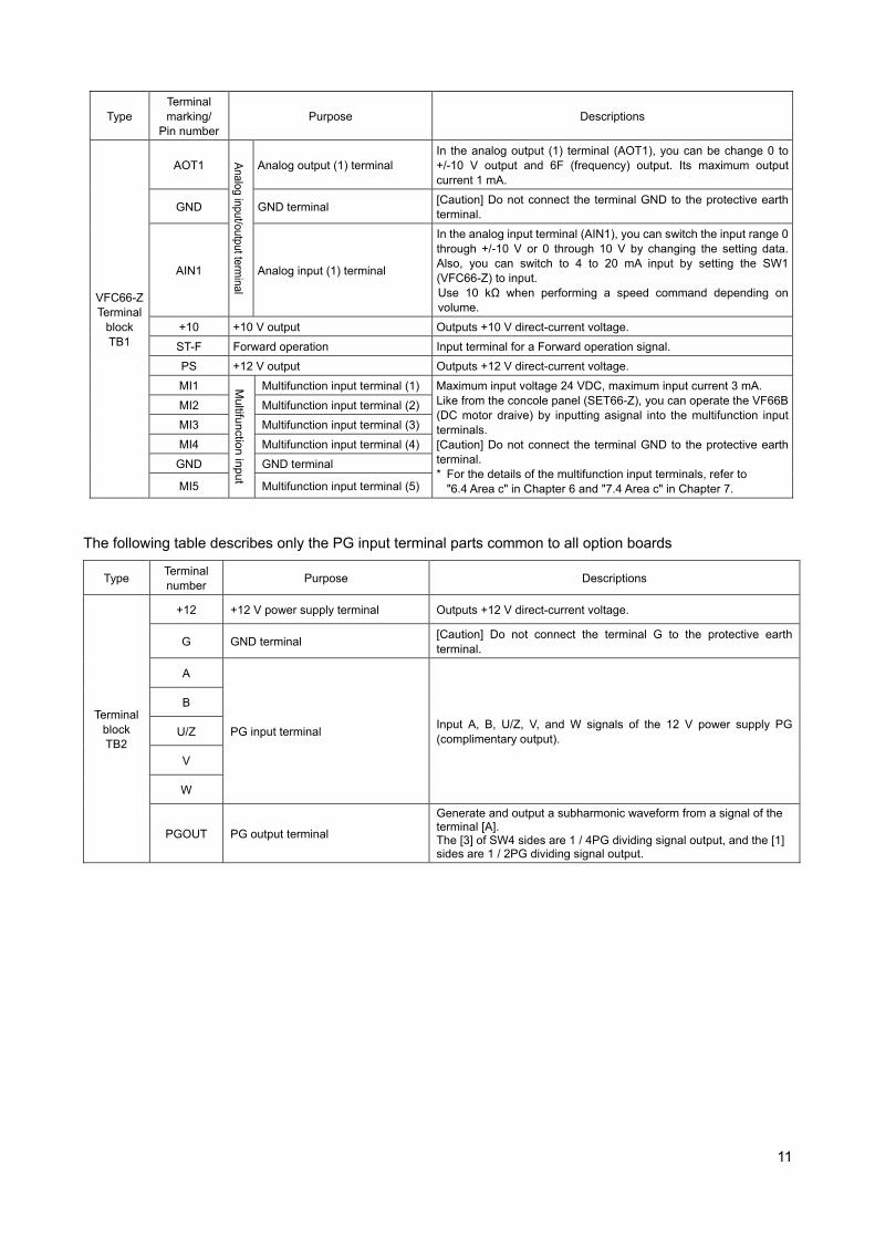
VFC66-Z Terminal
block TB1
AOT1
Analog input/output term
inal
Analog output (1) terminal In the analog output (1) terminal (AOT1), you can be change 0 to +/-10 V output and 6F (frequency) output. Its maximum output current 1 mA.
GND GND terminal [Caution] Do not connect the terminal GND to the protective earth terminal.
AIN1 Analog input (1) terminal
In the analog input terminal (AIN1), you can switch the input range 0 through +/-10 V or 0 through 10 V by changing the setting data. Also, you can switch to 4 to 20 mA input by setting the SW1 (VFC66-Z) to input. Use 10 kΩ when performing a speed command depending on volume.
+10 +10 V output Outputs +10 V direct-current voltage.
ST-F Forward operation Input terminal for a Forward operation signal.
PS +12 V output Outputs +12 V direct-current voltage.
MI1 Multifunction input
Multifunction input terminal (1) Maximum input voltage 24 VDC, maximum input current 3 mA. Like from the concole panel (SET66-Z), you can operate the VF66B (DC motor draive) by inputting asignal into the multifunction input terminals. [Caution] Do not connect the terminal GND to the protective earth terminal. * For the details of the multifunction input terminals, refer to
"6.4 Area c" in Chapter 6 and "7.4 Area c" in Chapter 7.
MI2 Multifunction input terminal (2)
MI3 Multifunction input terminal (3)
MI4 Multifunction input terminal (4)
GND GND terminal
MI5 Multifunction input terminal (5)
The following table describes only the PG input terminal parts common to all option boards
Type Terminal number
Purpose Descriptions
Terminal block TB2
+12 +12 V power supply terminal Outputs +12 V direct-current voltage.
G GND terminal [Caution] Do not connect the terminal G to the protective earth terminal.
A
PG input terminal Input A, B, U/Z, V, and W signals of the 12 V power supply PG (complimentary output).
B
U/Z
V
W
PGOUT PG output terminal
Generate and output a subharmonic waveform from a signal of the terminal [A]. The [3] of SW4 sides are 1 / 4PG dividing signal output, and the [1] sides are 1 / 2PG dividing signal output.
12
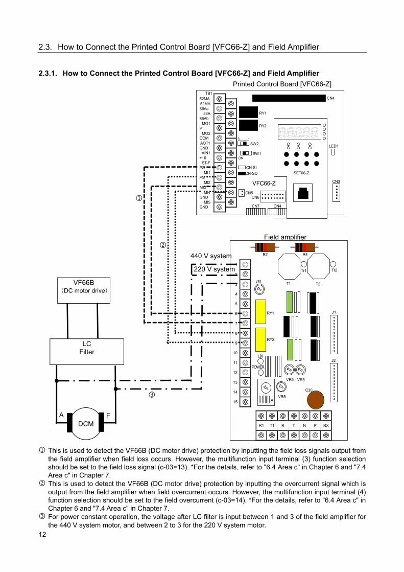
2.3. How to Connect the Printed Control Board [VFC66-Z] and Field Amplifier 2.3.1. How to Connect the Printed Control Board [VFC66-Z] and Field Amplifier
TB1
CN-SO
CN-SI
RY1
CN3
SW2
SW1
CN4
LED1
52MA
86Aa
86Ab
P
COM
GND
+10
PS
PS
MI3
GND
GND
52MA
86A
MO1
MO2
AOT1
AIN1
ST-F
MI1
MI2
MI4
MI5
CN5
3 1
ON
RY2
CN6
SET66-Z
CN7 CN4
VFC66-Z
RY1 J1
VR5
POWER
RY2
1
2
3
4
5
6
7
8
9
10
11
12
13
14
15
LD1
VR1
VR5 VR5
C30
J2
T1 T2
Tr1 Tr2
R2 R4
R1 T1 R T N P RX
A
This is used to detect the VF66B (DC motor drive) protection by inputting the field loss signals output from the field amplifier when field loss occurs. However, the multifunction input terminal (3) function selection should be set to the field loss signal (c-03=13). *For the details, refer to "6.4 Area c" in Chapter 6 and "7.4 Area c" in Chapter 7.
This is used to detect the VF66B (DC motor drive) protection by inputting the overcurrent signal which is output from the field amplifier when field overcurrent occurs. However, the multifunction input terminal (4) function selection should be set to the field overcurrent (c-03=14). *For the details, refer to "6.4 Area c" in Chapter 6 and "7.4 Area c" in Chapter 7.
For power constant operation, the voltage after LC filter is input between 1 and 3 of the field amplifier for the 440 V system motor, and between 2 to 3 for the 220 V system motor.
Field amplifier
Printed Control Board [VFC66-Z]
DCM
LC Filter
VF66B (DC motor drive)
440 V system
220 V system
A F

13
2.4. Application of LC filter 2.4.1. Role of LC Filter
LC filter reduces the load applied to the DC motor by smoothing the PWM control waveform (average voltage control of the pulse width modulation by using square wave) which is output from VF66B (DC motor drive) and reducing the peak voltage applied to the DC motor. Because the application of LC filter varies depending on the structure of DC motor and the deterioration state of insulation, please contact us. 2.4.2. Power Constant Operation
When performing the power constant operation, please install the specified LC filter between the output of VF66B (DC motor drive) and the DC motor. Input the voltage after LC filter to the field amplifier for weaker field control. For how to connect the voltage input to the field amplifier, refer to "2.3 How to Connect the Printed Control Board [VFC66-Z] and Field Amplifier" in Chapter 2. 2.4.3. Selection of LC Filter
Following L (DC reactor) and C (film capacitor) are provided. Select the number of LC filters depending on the current of DC motor and apply them in parallel.
L1 (DC reactor) 3 mH 115 A L2 (DC reactor) 15 mH 25 A C (Film capacitor) 400 μF 800 V
Selection example For DC motor, 200 kW, 440 V, 489 A, 1150 min-1:
DC motor current/DC reactor rated current = 489/115 =4.25 By rounding up the first decimal number, you get "5." Therefore, apply 5 pieces of L and 5 pieces of C in parallel.
The following table indicates the resonance frequencies.
L C Resonance frequencies
L1 3 mH 400 μF 145 Hz
L2 15 mH 400 μF 65 Hz
L2 15 mH 2 parallel (7.5 mH) 400 μF 92 Hz
L2 15 mH 3 parallel ( 5 mH) 400 μF 112 Hz
VF66B (DC motor
drive)
N
P LC filter
M
3 mH,115 A
400 μF, 800 V
200 kW, 489 A
Field amplifier
14
2.5. PG 2.5.1. Applicable PG
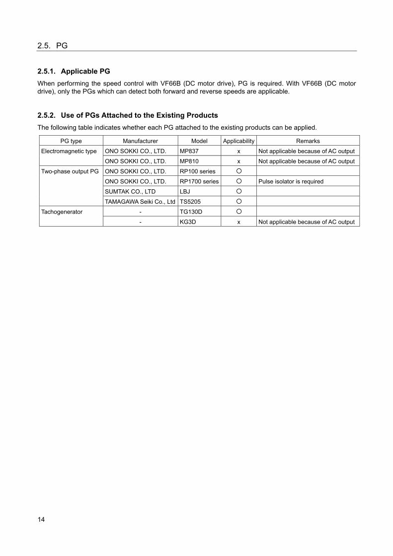
When performing the speed control with VF66B (DC motor drive), PG is required. With VF66B (DC motor drive), only the PGs which can detect both forward and reverse speeds are applicable. 2.5.2. Use of PGs Attached to the Existing Products
The following table indicates whether each PG attached to the existing products can be applied.
PG type Manufacturer Model Applicability Remarks
Electromagnetic type ONO SOKKI CO., LTD. MP837 x Not applicable because of AC output
ONO SOKKI CO., LTD. MP810 x Not applicable because of AC output
Two-phase output PG ONO SOKKI CO., LTD. RP100 series
ONO SOKKI CO., LTD. RP1700 series Pulse isolator is required
SUMTAK CO., LTD LBJ
TAMAGAWA Seiki Co., Ltd TS5205
Tachogenerator - TG130D
- KG3D x Not applicable because of AC output
15
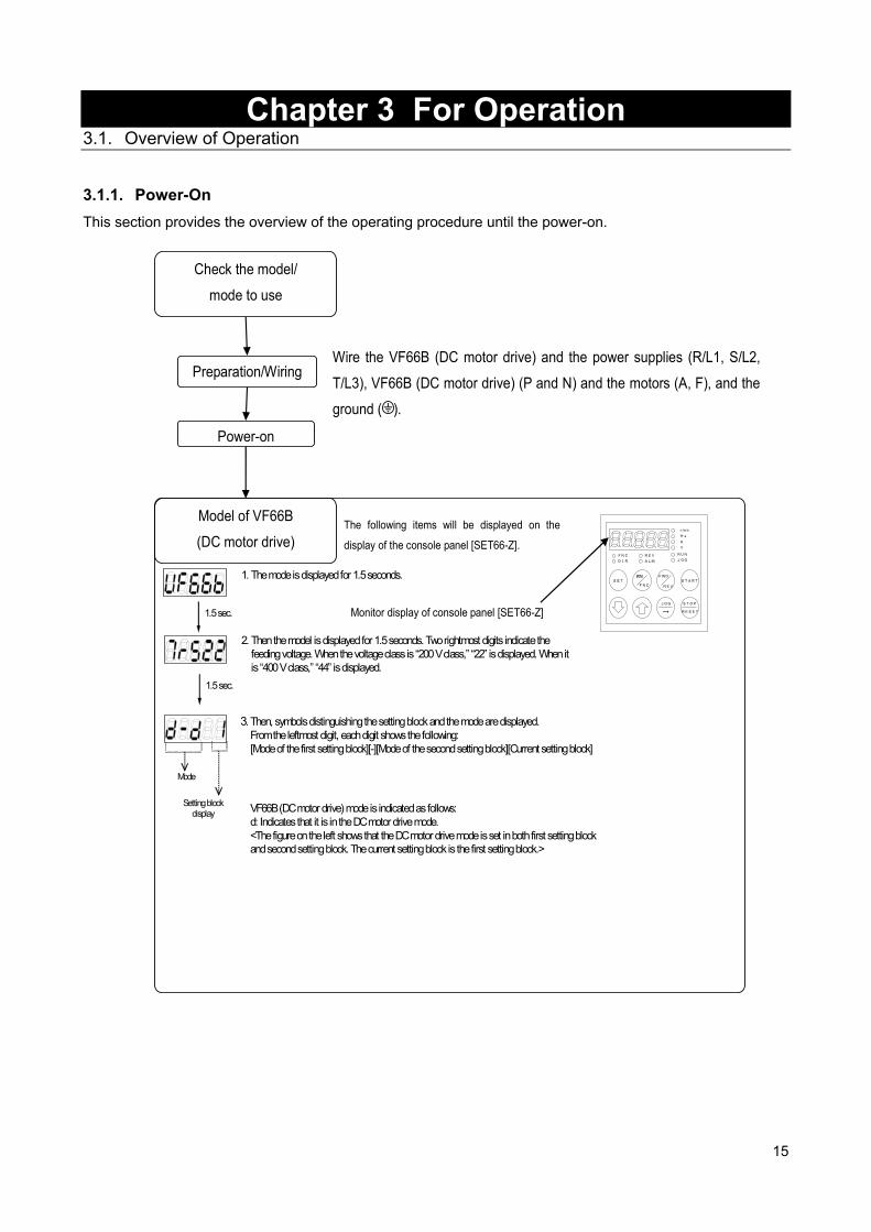
Chapter 3 For Operation 3.1. Overview of Operation 3.1.1. Power-On
This section provides the overview of the operating procedure until the power-on.
Preparation/Wiring
Check the model/
mode to use
Power-on
Model of VF66B
(DC motor drive)
Wire the VF66B (DC motor drive) and the power supplies (R/L1, S/L2,
T/L3), VF66B (DC motor drive) (P and N) and the motors (A, F), and the
ground ( ).
Monitor display of console panel [SET66-Z]
The following items will be displayed on the
display of the console panel [SET66-Z].
1.5 sec.
2. Then the model is displayed for 1.5 seconds. Two rightmost digits indicate the feeding voltage. When the voltage class is “200 V class,” “22” is displayed. When it is “400 V class,” “44” is displayed.
1. The mode is displayed for 1.5 seconds.
1.5 sec.
Mode
Setting block display
3. Then, symbols distinguishing the setting block and the mode are displayed. From the leftmost digit, each digit shows the following: [Mode of the first setting block][-][Mode of the second setting block][Current setting block]
VF66B (DC motor drive) mode is indicated as follows: d: Indicates that it is in the DC motor drive mode. <The figure on the left shows that the DC motor drive mode is set in both first setting block and second setting block. The current setting block is the first setting block.>
r/min
Hz
A
V
FNC
DIR
REV
ALM
RUN
JOG
FNC
RESET
FWD
JOG
START
STOP
REV
MONI SET
→
16
3.1.2. Cooling Fan Operation
When VF66B (DC motor drive) is turned on, the cooling fan installed on it also starts at the same time. It behaves as follows. Please keep this in mind.
State of VF66B (DC motor drive) Cooling Fan operation
Power-on It operates for five minutes after power-on and then stops. However, when VF66B (DC motor drive) is operated within five minutes after power-on, the cooling fan stops in one minute after VF66B (DC motor drive) stops.
Running It always operates.
Stop After VF66B (DC motor drive) stops, it operates for one minute and then stops.
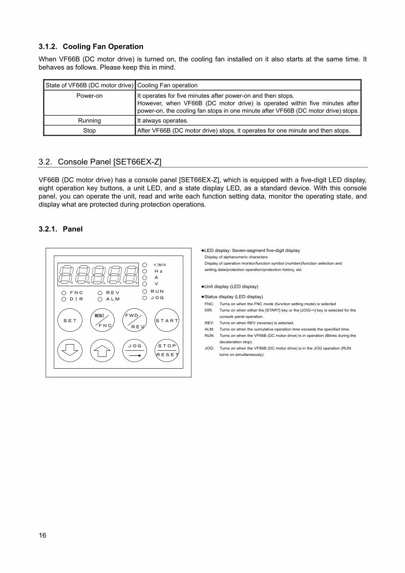
3.2. Console Panel [SET66EX-Z] VF66B (DC motor drive) has a console panel [SET66EX-Z], which is equipped with a five-digit LED display, eight operation key buttons, a unit LED, and a state display LED, as a standard device. With this console panel, you can operate the unit, read and write each function setting data, monitor the operating state, and display what are protected during protection operations. 3.2.1. Panel
r/min
Hz
A
V
FNC
DIR
REV
ALM
RUN
JOG
FNC
RESET
FWD
JOG
START
STOP
REV
MONI SET
LED display: Seven-segment five-digit display Display of alphanumeric characters
Display of operation monitor/function symbol (number)/function selection and
setting data/protection operation/protection history, etc.
Unit display (LED display)
Status display (LED display) FNC: Turns on when the FNC mode (function setting mode) is selected
DIR: Turns on when either the [START] key or the [JOG/->] key is selected for the
console panel operation.
REV: Turns on when REV (reverse) is selected.
ALM: Turns on when the cumulative operation time exceeds the specified time.
RUN: Turns on when the VF66B (DC motor drive) is in operation (Blinks during the
deceleration stop).
JOG: Turns on when the VF66B (DC motor drive) is in the JOG operation (RUN
turns on simultaneously).

17
3.2.2. Operation Keys
START
FWD
REV
SET
FNC
MONI
RESET
STOP
JOG
<In FNC (function setting) mode> · Confirms the selection of setting number. · Writes the setting data.
<In MONI (monitor) mode> · Switches the monitor items.
<During protection operation> · Reads out the one-point traceback data.
Switches MONI mode and FNC mode. <In FNC (function setting) mode> · Switches to MONI mode.
<In MONI (monitor) mode> · Switches to FNC mode.
<In FNC (function setting) mode> · Moves the operation digit (flashing digit) one digit to
left.
<In MONI (monitor) mode> · Switches the forward rotation/reverse rotation when
the [START] or the [JOG/->] is active on the console panel. When the reverse rotation command selection is active, REV (LED) turns on
<In MONI (monitor) mode> · Starts operating the VF66B (DC motor drive) when the
console panel is selected in the operation commanding place selection.
<FNC (function setting) mode> · Increases the number indicated in the selected digit by
+1 when setting the setting number and setting data. (Numbers change in this order: “0” -> “1” -> …. -> “9” -> “- (minus)” -> “0”)
<In MONI (monitor) mode> · Switches the monitor items.(For the details, refer to
Chapter 3 “3.2.4 How to Check Monitor Information.”)
<In FNC (function setting) mode> · Increases the number indicated in the selected digit by
-1 when setting the setting number and setting data. (Numbers change in this order: “0” -> “- (minus)” -> “9” -> … -> “1” -> “0”)
<In MONI (monitor) mode> · Switches the monitor items.(For the details, refer to
Chapter 3 “3.2.4 How to Check Monitor Information.”)
<In FNC (function setting) mode> · Moves the operation digit (flashing digit) one digit to
right.
<In MONI (monitor) mode> · Starts operating the VF66B (DC motor drive) when
console panel is selected in the JOG commanding place selection.
Stops the VF66B (DC motor drive) while operating with the [START] key on the console panel. Resets the protection operation during the protection operation.
18
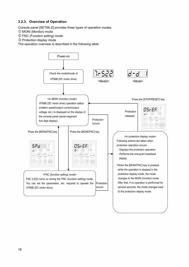
3.2.3. Overview of Operation
Console panel [SET66-Z] provides three types of operation modes. MONI (Monitor) mode FNC (Function setting) mode Protection display mode The operation overview is described in the following table.
Power-on
Check the model/mode of
VF66B (DC motor drive)
<In MONI (monitor) mode>
VF66B (DC motor drive) operation status
(rotation speed/output current/output
voltage, etc.) is displayed on the display of
the console panel (seven-segment
five-digit display).
<Model> <Mode>
r/min
Hz
A
V
FNC
DIR
REV
ALM
RUN
JOG
FNC
RESET
FWD
JOG
START
STOP
REV
MONI SET
→
r/min
Hz
A
V
FNC
DIR
REV
ALM
RUN
JOG
FNC
RESET
FWD
JOG
START
STOP
REV
MONI SET
→
Press the [MONI/FNC] key Press the [MONI/FNC] key
<In protection display mode>
Following actions are taken when
protection operation occurs:
- Displays the protection operation
- Performs the one-point traceback
display
*When the [MONI/FNC] key is pressed
while the operation is stopped in the
protection display mode, the mode
changes to the MONI (monitor) mode.
After that, if no operation is performed for
several seconds, the mode changes back
to the protection display mode.
<FNC (function setting) mode>
FNC (LED) turns on during the FNC (function setting) mode.
You can set the parameters, etc. required to operate the
VF66B (DC motor drive).
Protection occurs
Protection occurs
r/min
Hz
A
V
FNC
DIR
REV
ALM
RUN
JOG
FNC
RESET
FWD
JOG
START
STOP
REV
MONI SET
→
Protection
released
Press the [STOP/RESET] key
19
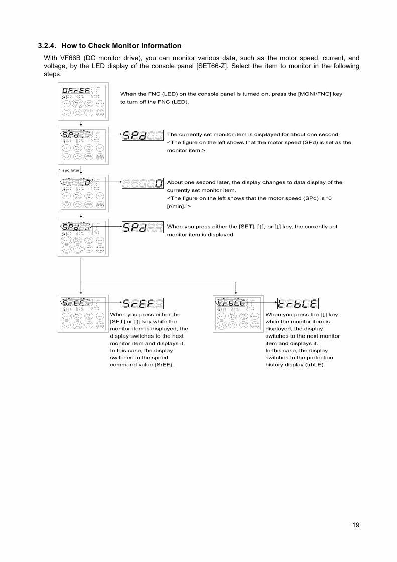
3.2.4. How to Check Monitor Information
With VF66B (DC monitor drive), you can monitor various data, such as the motor speed, current, and voltage, by the LED display of the console panel [SET66-Z]. Select the item to monitor in the following steps.
r/min
Hz
A
V
FNC
DIR
REV
ALM
RUN
JOG
FNC
RESET
FWD
JOG
START
STOP
REV
MONI SET
→
When the FNC (LED) on the console panel is turned on, press the [MONI/FNC] key
to turn off the FNC (LED).
r/min
Hz
A
V
FNC
DIR
REV
ALM
RUN
JOG
FNC
RESET
FWD
JOG
START
STOP
REV
MONI SET
→
The currently set monitor item is displayed for about one second.
<The figure on the left shows that the motor speed (SPd) is set as the
monitor item.>
r/min
Hz
A
V
FNC
DIR
REV
ALM
RUN
JOG
FNC
RESET
FWD
JOG
START
STOP
REV
MONI SET
→
About one second later, the display changes to data display of the
currently set monitor item.
<The figure on the left shows that the motor speed (SPd) is “0
[r/min].”>
1 sec later
r/min
Hz
A
V
FNC
DIR
REV
ALM
RUN
JOG
FNC
RESET
FWD
JOG
START
STOP
REV
MONI SET
→
When you press either the [SET], [↑], or [↓] key, the currently set
monitor item is displayed.
r/min
Hz
A
V
FNC
DIR
REV
ALM
RUN
JOG
FNC
RESET
FWD
JOG
START
STOP
REV
MONI SET
→
When you press either the
[SET] or [↑] key while the
monitor item is displayed, the
display switches to the next
monitor item and displays it.
In this case, the display
switches to the speed
command value (SrEF).
r/min
Hz
A
V
FNC
DIR
REV
ALM
RUN
JOG
FNC
RESET
FWD
JOG
START
STOP
REV
MONI SET
→
When you press the [↓] key
while the monitor item is
displayed, the display
switches to the next monitor
item and displays it.
In this case, the display
switches to the protection
history display (trbLE).
20
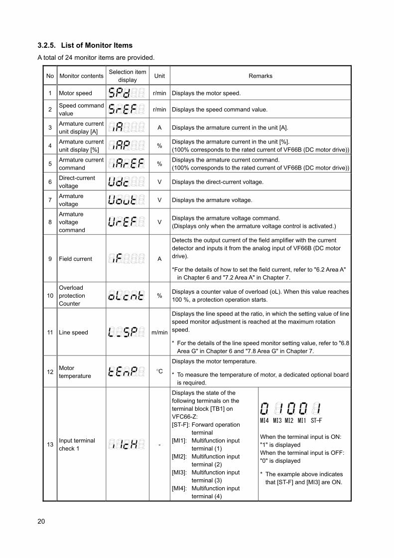
3.2.5. List of Monitor Items
A total of 24 monitor items are provided.
No Monitor contents Selection item
display Unit Remarks
1 Motor speed
r/min Displays the motor speed.
2 Speed command value
r/min Displays the speed command value.
3 Armature current unit display [A]
A Displays the armature current in the unit [A].
4 Armature current unit display [%]
%
Displays the armature current in the unit [%]. (100% corresponds to the rated current of VF66B (DC motor drive))
5 Armature current command
%
Displays the armature current command. (100% corresponds to the rated current of VF66B (DC motor drive))
6 Direct-current voltage
V Displays the direct-current voltage.
7 Armature voltage
V Displays the armature voltage.
8 Armature voltage command
V
Displays the armature voltage command. (Displays only when the armature voltage control is activated.)
9 Field current
A
Detects the output current of the field amplifier with the current detector and inputs it from the analog input of VF66B (DC motor drive).
*For the details of how to set the field current, refer to "6.2 Area A" in Chapter 6 and "7.2 Area A" in Chapter 7.
10 Overload protection Counter
%
Displays a counter value of overload (oL). When this value reaches 100 %, a protection operation starts.
11 Line speed
m/min
Displays the line speed at the ratio, in which the setting value of line speed monitor adjustment is reached at the maximum rotation speed.
* For the details of the line speed monitor setting value, refer to "6.8 Area G" in Chapter 6 and "7.8 Area G" in Chapter 7.
12 Motor temperature
°C
Displays the motor temperature.
* To measure the temperature of motor, a dedicated optional board is required.
13 Input terminal check 1
-
Displays the state of the following terminals on the terminal block [TB1] on VFC66-Z: [ST-F]: Forward operation
terminal [MI1]: Multifunction input
terminal (1) [MI2]: Multifunction input
terminal (2) [MI3]: Multifunction input
terminal (3) [MI4]: Multifunction input
terminal (4)
ST-F MI1 MI2 MI3 MI4
When the terminal input is ON: "1" is displayed When the terminal input is OFF: "0" is displayed
* The example above indicates that [ST-F] and [MI3] are ON.
21
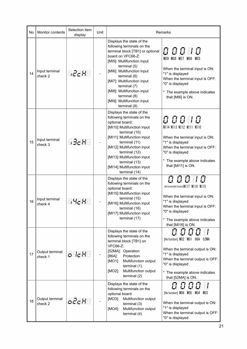
No Monitor contents Selection item
display Unit Remarks
14 Input terminal check 2
-
Displays the state of the following terminals on the terminal block [TB1] or optional board on VFC66-Z: [MI5]: Multifunction input
terminal (5) [MI6]: Multifunction input
terminal (6) [MI7]: Multifunction input
terminal (7) [MI8]: Multifunction input
terminal (8) [MI9]: Multifunction input
terminal (9)
MI5 MI6 MI7 MI8 MI9
When the terminal input is ON: "1" is displayed When the terminal input is OFF: "0" is displayed
* The example above indicates that [MI6] is ON.
15 Input terminal check 3
-
Displays the state of the following terminals on the optional board: [MI10]: Multifunction input
terminal (10) [MI11]: Multifunction input
terminal (11) [MI12]: Multifunction input
terminal (12) [MI13]: Multifunction input
terminal (13) [MI14]: Multifunction input
terminal (14)
MI10 MI11 MI12 MI13 MI14
When the terminal input is ON: "1" is displayed When the terminal input is OFF: "0" is displayed
* The example above indicates that [MI11] is ON.
16 Input terminal check 4
-
Displays the state of the following terminals on the optional board: [MI15]: Multifunction input
terminal (15) [MI16]: Multifunction input
terminal (16) [MI17]: Multifunction input
terminal (17)
MI15 MI16 MI17 [No function] [No function]
When the terminal input is ON: "1" is displayed When the terminal input is OFF: "0" is displayed
* The example above indicates that [MI16] is ON.
17 Output terminal check 1
-
Displays the state of the following terminals on the terminal block [TB1] on VFC66-Z: [52MA]: Operation [86A]: Protection [MO1]: Multifunction output
terminal (1) [MO2]: Multifunction output
terminal (2)
52MA86A MO1 MO2 [No function]
When the terminal output is ON: "1" is displayed When the terminal output is OFF: "0" is displayed
* The example above indicates that [52MA] is ON.
18 Output terminal check 2
-
Displays the state of the following terminals on the optional board: [MO3]: Multifunction output
terminal (3) [MO4]: Multifunction output
terminal (4)
MO3 MO4 MO5 MO6 [No function]
When the terminal output is ON: "1" is displayed When the terminal output is OFF: "0" is displayed
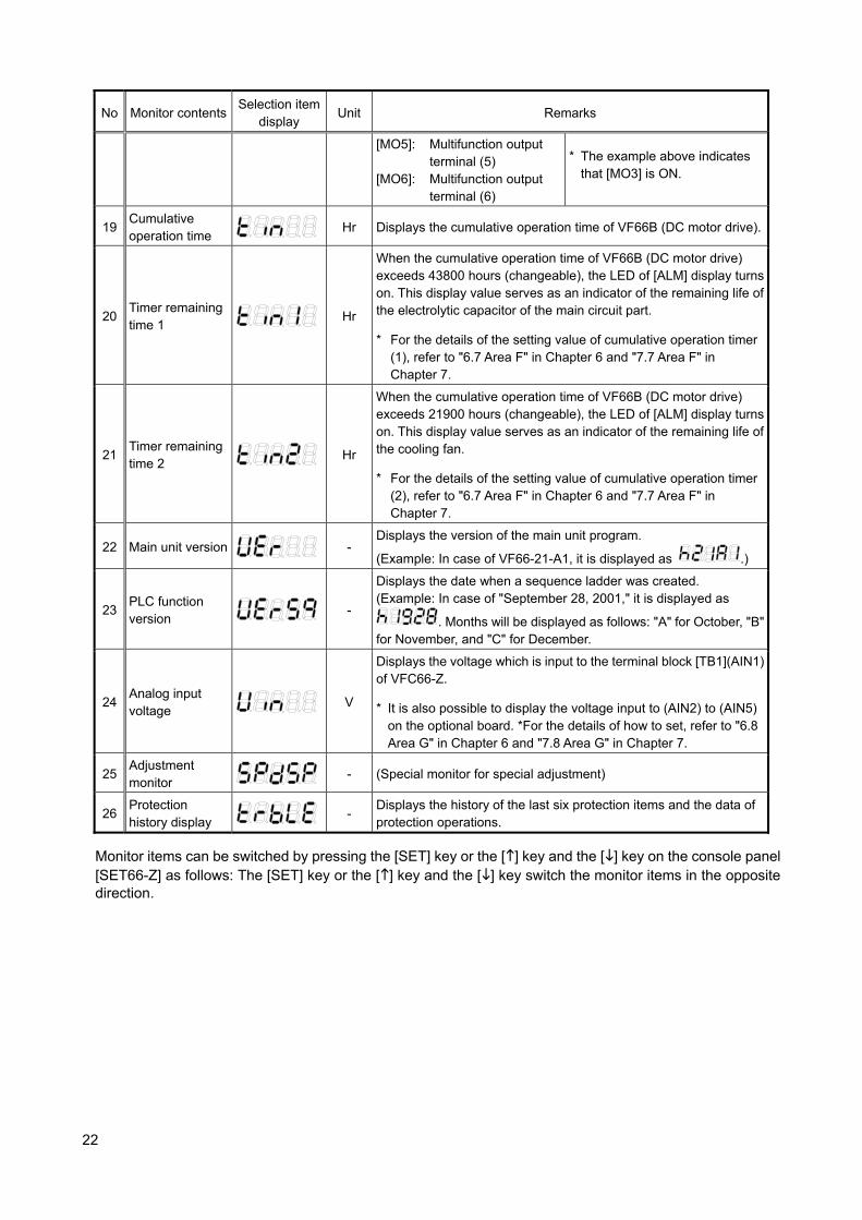
22
No Monitor contents Selection item
display Unit Remarks
[MO5]: Multifunction output terminal (5)
[MO6]: Multifunction output terminal (6)
* The example above indicates that [MO3] is ON.
19 Cumulative operation time
Hr Displays the cumulative operation time of VF66B (DC motor drive).
20 Timer remaining time 1
Hr
When the cumulative operation time of VF66B (DC motor drive) exceeds 43800 hours (changeable), the LED of [ALM] display turns on. This display value serves as an indicator of the remaining life of the electrolytic capacitor of the main circuit part.
* For the details of the setting value of cumulative operation timer (1), refer to "6.7 Area F" in Chapter 6 and "7.7 Area F" in Chapter 7.
21 Timer remaining time 2
Hr
When the cumulative operation time of VF66B (DC motor drive) exceeds 21900 hours (changeable), the LED of [ALM] display turns on. This display value serves as an indicator of the remaining life of the cooling fan.
* For the details of the setting value of cumulative operation timer (2), refer to "6.7 Area F" in Chapter 6 and "7.7 Area F" in Chapter 7.
22 Main unit version
- Displays the version of the main unit program.
(Example: In case of VF66-21-A1, it is displayed as
.)
23 PLC function version
-
Displays the date when a sequence ladder was created. (Example: In case of "September 28, 2001," it is displayed as
. Months will be displayed as follows: "A" for October, "B"for November, and "C" for December.
24 Analog input voltage
V
Displays the voltage which is input to the terminal block [TB1](AIN1) of VFC66-Z.
* It is also possible to display the voltage input to (AIN2) to (AIN5) on the optional board. *For the details of how to set, refer to "6.8 Area G" in Chapter 6 and "7.8 Area G" in Chapter 7.
25 Adjustment monitor
- (Special monitor for special adjustment)
26 Protection history display
- Displays the history of the last six protection items and the data of protection operations.
Monitor items can be switched by pressing the [SET] key or the [] key and the [] key on the console panel [SET66-Z] as follows: The [SET] key or the [] key and the [] key switch the monitor items in the opposite direction.

23
3.3. How to Perform Trial Operation In the trial operation, perform the trial operation only with the motor first and check that it operates properly. Only after that, connect it to the unit. This section describes how to perform the trial operation by using the console panel [SET66-Z].
Preparation/Wiring
Check capacity/voltage to use
Power-on
Check the model/mode of
VF66B (DC motor drive)
Set the speed command,
acceleration/deceleration time, etc.
Operation/Stop
Perform wiring between VF66B (DC motor drive) and power supplies (R/L1, S/L2,
T/L3), outputs (P and N) and motors (A and F), and the ground ( ).
<Model> <Mode>
r/min
Hz
A
V
FNC
DIR
REV
ALM
RUN
JOG
FNC
RESET
FWD
JOG
START
STOP
REV
MONI SET
→
Press the [MONI/FNC] key on the console panel
[SET66-Z] to turn on FNC (LED). Set “0. SrEF” (speed
command)/”3. Acc1” (acceleration time), etc. For the
details, refer to Chapter 3 “3.3.1 How to Change the
Motor Speed” and the subsequent sections.
Set motor constant
Select the operation commanding place
Setting change
Press the [MONI/FNC] key on the console panel
[SET66-Z] to turn off FNC (LED). When you press the
[START] key, the operation starts with the speed
command (0. SrEF), acceleration time (3. Acc1), etc. as
they were set. When you press the [STOP/RESET] key,
the operation stops.
Set the constant in the parameter to the motors required for operation.
r/min
Hz
A
V
FNC
DIR
REV
ALM
RUN
JOG
FNC
RESET
FWD
JOG
START
STOP
REV
MONI SET
→
Set the operation commanding place for the operation command, speed
command, etc. to the console panel [SET66-Z]. Set as follows.
Area b *In the default setting (factory default data), they are as follows.
Display Contents Setting value
b-09 Command input when coupled Set to 1 (console)
b-10 Speed command input selection Set to 0 (interlocked)
b-11 Operation command input selection Set to 0 (interlocked)
b-12 JOG command input selection Set to 0 (interlocked)
24
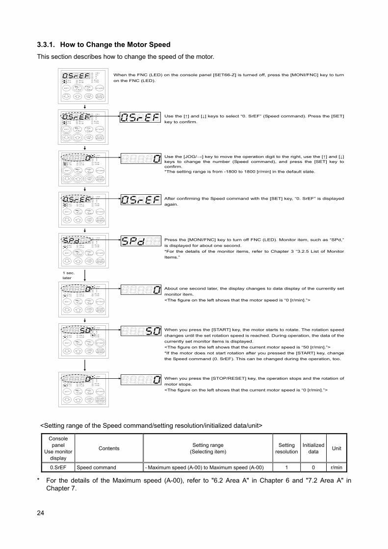
3.3.1. How to Change the Motor Speed
This section describes how to change the speed of the motor.
r/min
Hz
A
V
FNC
DIR
REV
ALM
RUN
JOG
FNC
RESET
FWD
JOG
START
STOP
REV
MONI SET
→
Press the [MONI/FNC] key to turn off FNC (LED). Monitor item, such as “SPd,”
is displayed for about one second.
*For the details of the monitor items, refer to Chapter 3 “3.2.5 List of Monitor
Items.”
r/min
Hz
A
V
FNC
DIR
REV
ALM
RUN
JOG
FNC
RESET
FWD
JOG
START
STOP
REV
MONI SET
→
1 sec.
later
About one second later, the display changes to data display of the currently set
monitor item.
<The figure on the left shows that the motor speed is “0 [r/min].”>
r/min
Hz
A
V
FNC
DIR
REV
ALM
RUN
JOG
FNC
RESET
FWD
JOG
START
STOP
REV
MONI SET
→
When you press the [START] key, the motor starts to rotate. The rotation speed
changes until the set rotation speed is reached. During operation, the data of the
currently set monitor items is displayed.
<The figure on the left shows that the current motor speed is “50 [r/min].”>
*If the motor does not start rotation after you pressed the [START] key, change
the Speed command (0. SrEF). This can be changed during the operation, too.
r/min
Hz
A
V
FNC
DIR
REV
ALM
RUN
JOG
FNC
RESET
FWD
JOG
START
STOP
REV
MONI SET
→
When you press the [STOP/RESET] key, the operation stops and the rotation of
motor stops.
<The figure on the left shows that the current motor speed is “0 [r/min].”>
r/min
Hz
A
V
FNC
DIR
REV
ALM
RUN
JOG
FNC
RESET
FWD
JOG
START
STOP
REV
MONI SET
→
When the FNC (LED) on the console panel [SET66-Z] is turned off, press the [MONI/FNC] key to turn
on the FNC (LED).
r/min
Hz
A
V
FNC
DIR
REV
ALM
RUN
JOG
FNC
RESET
FWD
JOG
START
STOP
REV
MONI SET
→
Use the [↑] and [↓] keys to select “0. SrEF” (Speed command). Press the [SET]
key to confirm.
r/min
Hz
A
V
FNC
DIR
REV
ALM
RUN
JOG
FNC
RESET
FWD
JOG
START
STOP
REV
MONI SET
→
Use the [JOG/→] key to move the operation digit to the right, use the [↑] and [↓] keys to change the number (Speed command), and press the [SET] key to confirm. *The setting range is from -1800 to 1800 [r/min] in the default state.
r/min
Hz
A
V
FNC
DIR
REV
ALM
RUN
JOG
FNC
RESET
FWD
JOG
START
STOP
REV
MONI SET
→
After confirming the Speed command with the [SET] key, “0. SrEF” is displayed
again.
<Setting range of the Speed command/setting resolution/initialized data/unit>
Console panel
Use monitor display
Contents Setting range
(Selecting item) Setting
resolution Initialized
data Unit
0.SrEF Speed command - Maximum speed (A-00) to Maximum speed (A-00) 1 0 r/min
* For the details of the Maximum speed (A-00), refer to "6.2 Area A" in Chapter 6 and "7.2 Area A" in Chapter 7.
25
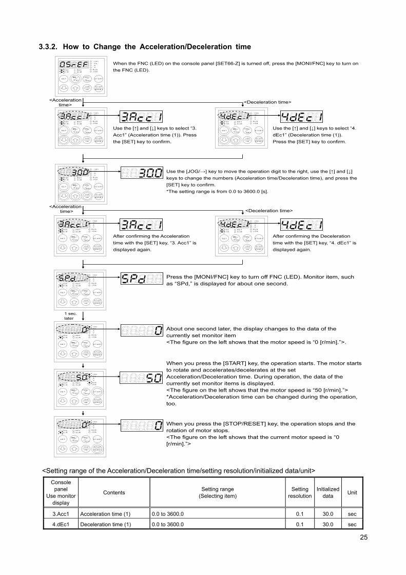
3.3.2. How to Change the Acceleration/Deceleration time
r/min
Hz
A
V
FNC
DIR
REV
ALM
RUN
JOG
FNC
RESET
FWD
JOG
START
STOP
REV
MONI SET
→
When the FNC (LED) on the console panel [SET66-Z] is turned off, press the [MONI/FNC] key to turn on
the FNC (LED).
r/min
Hz
A
V
FNC
DIR
REV
ALM
RUN
JOG
FNC
RESET
FWD
JOG
START
STOP
REV
MONI SET
→
Use the [↑] and [↓] keys to select “3.
Acc1” (Acceleration time (1)). Press
the [SET] key to confirm.
r/min
Hz
A
V
FNC
DIR
REV
ALM
RUN
JOG
FNC
RESET
FWD
JOG
START
STOP
REV
MONI SET
→
Use the [↑] and [↓] keys to select “4.
dEc1” (Deceleration time (1)).
Press the [SET] key to confirm.
<Acceleration time>
<Deceleration time>
r/min
Hz
A
V
FNC
DIR
REV
ALM
RUN
JOG
FNC
RESET
FWD
JOG
START
STOP
REV
MONI SET
→
Use the [JOG/→] key to move the operation digit to the right, use the [↑] and [↓]
keys to change the numbers (Acceleration time/Deceleration time), and press the
[SET] key to confirm.
*The setting range is from 0.0 to 3600.0 [s].
r/min
Hz
A
V
FNC
DIR
REV
ALM
RUN
JOG
FNC
RESET
FWD
JOG
START
STOP
REV
MONI SET
→
After confirming the Acceleration
time with the [SET] key, “3. Acc1” is
displayed again.
r/min
Hz
A
V
FNC
DIR
REV
ALM
RUN
JOG
FNC
RESET
FWD
JOG
START
STOP
REV
MONI SET
→
<Acceleration time> <Deceleration time>
After confirming the Deceleration
time with the [SET] key, “4. dEc1” is
displayed again.
r/min
Hz
A
V
FNC
DIR
REV
ALM
RUN
JOG
FNC
RESET
FWD
JOG
START
STOP
REV
MONI SET
→
Press the [MONI/FNC] key to turn off FNC (LED). Monitor item, such as “SPd,” is displayed for about one second.
r/min
Hz
A
V
FNC
DIR
REV
ALM
RUN
JOG
FNC
RESET
FWD
JOG
START
STOP
REV
MONI SET
→
1 sec. later
About one second later, the display changes to the data of the currently set monitor item <The figure on the left shows that the motor speed is “0 [r/min].”>.
r/min
Hz
A
V
FNC
DIR
REV
ALM
RUN
JOG
FNC
RESET
FWD
JOG
START
STOP
REV
MONI SET
→
When you press the [START] key, the operation starts. The motor starts to rotate and accelerates/decelerates at the set Acceleration/Deceleration time. During operation, the data of the currently set monitor items is displayed. <The figure on the left shows that the motor speed is “50 [r/min].”> *Acceleration/Deceleration time can be changed during the operation, too.
r/min
Hz
A
V
FNC
DIR
REV
ALM
RUN
JOG
FNC
RESET
FWD
JOG
START
STOP
REV
MONI SET
→
When you press the [STOP/RESET] key, the operation stops and the rotation of motor stops. <The figure on the left shows that the current motor speed is “0 [r/min].”>
<Setting range of the Acceleration/Deceleration time/setting resolution/initialized data/unit>
Console panel
Use monitor display
Contents Setting range
(Selecting item) Setting
resolution Initialized
data Unit
3.Acc1 Acceleration time (1) 0.0 to 3600.0 0.1 30.0 sec
4.dEc1 Deceleration time (1) 0.0 to 3600.0 0.1 30.0 sec
26
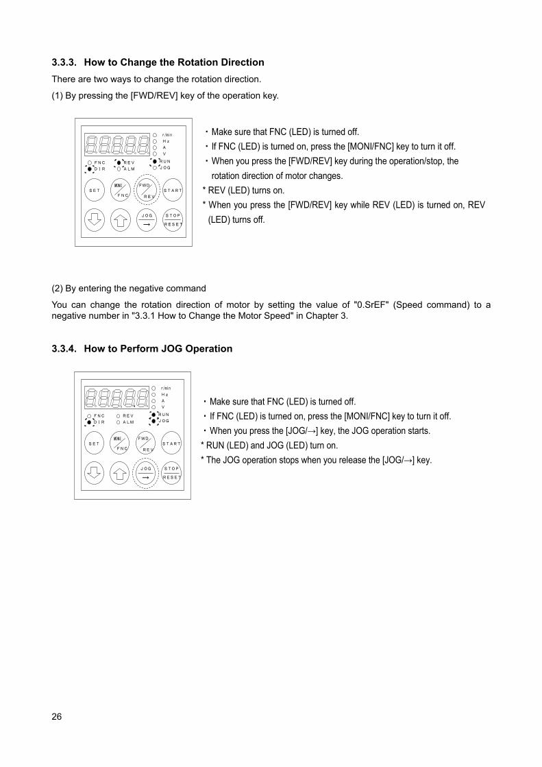
3.3.3. How to Change the Rotation Direction
There are two ways to change the rotation direction.
(1) By pressing the [FWD/REV] key of the operation key.
r/min
Hz
A
V
FNC
DIR
REV
ALM
RUN
JOG
FNC
RESET
FWD
JOG
START
STOP
REV
MONI SET
→
・ Make sure that FNC (LED) is turned off.
・ If FNC (LED) is turned on, press the [MONI/FNC] key to turn it off.
・ When you press the [FWD/REV] key during the operation/stop, the
rotation direction of motor changes.
* REV (LED) turns on.
* When you press the [FWD/REV] key while REV (LED) is turned on, REV
(LED) turns off.
(2) By entering the negative command
You can change the rotation direction of motor by setting the value of "0.SrEF" (Speed command) to a negative number in "3.3.1 How to Change the Motor Speed" in Chapter 3. 3.3.4. How to Perform JOG Operation
r/min
Hz
A
V
FNC
DIR
REV
ALM
RUN
JOG
FNC
RESET
FWD
JOG
START
STOP
REV
MONI SET
→
・ Make sure that FNC (LED) is turned off.
・ If FNC (LED) is turned on, press the [MONI/FNC] key to turn it off.
・ When you press the [JOG/→] key, the JOG operation starts.
* RUN (LED) and JOG (LED) turn on.
* The JOG operation stops when you release the [JOG/→] key.
27
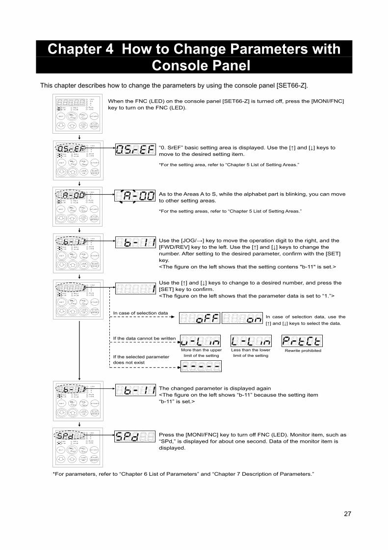
Chapter 4 How to Change Parameters with Console Panel
This chapter describes how to change the parameters by using the console panel [SET66-Z].
r/min
Hz
A
V
FNC
DIR
REV
ALM
RUN
JOG
FNC
RESET
FWD
JOG
START
STOP
REV
MONI SET
→
When the FNC (LED) on the console panel [SET66-Z] is turned off, press the [MONI/FNC] key to turn on the FNC (LED).
r/min
Hz
A
V
FNC
DIR
REV
ALM
RUN
JOG
FNC
RESET
FWD
JOG
START
STOP
REV
MONI SET
→
“0. SrEF” basic setting area is displayed. Use the [↑] and [↓] keys to move to the desired setting item.
r/min
Hz
A
V
FNC
DIR
REV
ALM
RUN
JOG
FNC
RESET
FWD
JOG
START
STOP
REV
MONI SET
→
Use the [JOG/→] key to move the operation digit to the right, and the [FWD/REV] key to the left. Use the [↑] and [↓] keys to change the number. After setting to the desired parameter, confirm with the [SET] key. <The figure on the left shows that the setting contens "b-11" is set.>
r/min
Hz
A
V
FNC
DIR
REV
ALM
RUN
JOG
FNC
RESET
FWD
JOG
START
STOP
REV
MONI SET
→
Use the [↑] and [↓] keys to change to a desired number, and press the [SET] key to confirm. <The figure on the left shows that the parameter data is set to “1.”>
r/min
Hz
A
V
FNC
DIR
REV
ALM
RUN
JOG
FNC
RESET
FWD
JOG
START
STOP
REV
MONI SET
→
The changed parameter is displayed again <The figure on the left shows “b-11” because the setting item “b-11” is set.>
Press the [MONI/FNC] key to turn off FNC (LED). Monitor item, such as “SPd,” is displayed for about one second. Data of the monitor item is displayed.
r/min
Hz
A
V
FNC
DIR
REV
ALM
RUN
JOG
FNC
RESET
FWD
JOG
START
STOP
REV
MONI SET
→
r/min
Hz
A
V
FNC
DIR
REV
ALM
RUN
JOG
FNC
RESET
FWD
JOG
START
STOP
REV
MONI SET
→
As to the Areas A to S, while the alphabet part is blinking, you can move to other setting areas.
*For parameters, refer to “Chapter 6 List of Parameters” and “Chapter 7 Description of Parameters.”
*For the setting area, refer to “Chapter 5 List of Setting Areas.”
*For the setting areas, refer to “Chapter 5 List of Setting Areas.”
In case of selection data, use the
[↑] and [↓] keys to select the data.
In case of selection data
If the data cannot be written
If the selected parameter does not exist
Less than the lower
limit of the setting
More than the upper
limit of the setting Rewrite prohibited

28
Chapter 5 List of Setting Areas VF66B (DC motor drive) provides the total of 16 areas: "basic setting area" through "area S." The following table indicates the setting area and main contents of each setting.
Setting area Console panel Monitor display
Main contents
Basic setting area
Speed command
Forward JOG speed
Reverse JOG speed
Acceleration time (1)
Deceleration time (1)
Acceleration time (2)
Deceleration time (2)
Speed control proportion gain (1)
Speed control integral time constant (1)
System inertial moment (1)
Area A
Maximum speed Rated motor/motor's constant
Area b
Operation command input selection Analog input (1) characteristics selection Analog output (1) characteristics selection
Area c
Multifunction input place selection
Area d
Acceleration time, JOG acceleration time selection
Area E
Current control gain Output voltage limit
Area F
Protection function related Cumulative operation timer
Area G
Analog input (2) characteristics selection Analog output (2) characteristics selection
Area H
Multifunction output place selection
Area i
Speed control/Armature current control/Armature voltage control switching
Area J
Communication options
Area L
Direct-current voltage adjustment gain Analog input/output adjustment gain
Area n
VF66B (DC motor drive) model
Area P
Parameters used in the internal PLC function
Area S
Initialized Cumulative operation timer clear
29
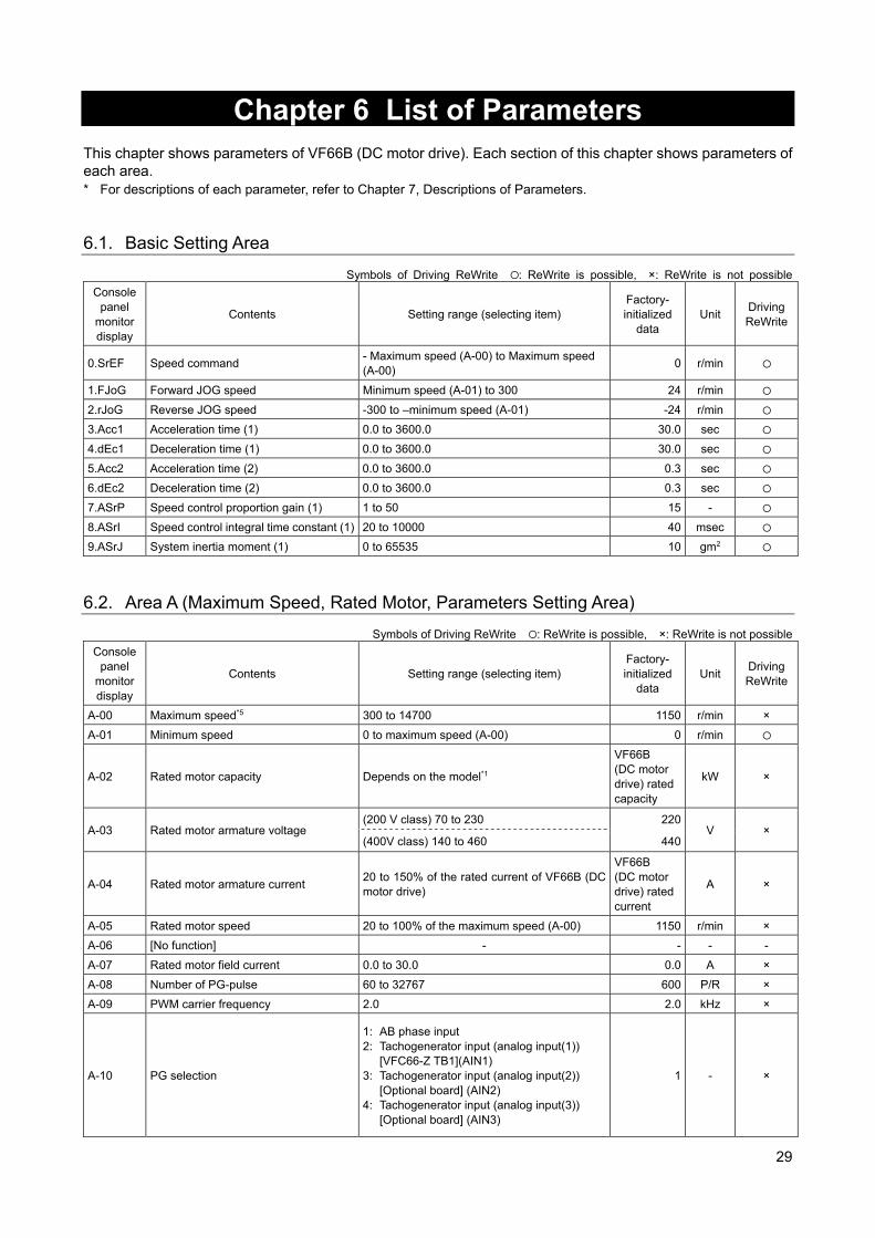
Chapter 6 List of Parameters
This chapter shows parameters of VF66B (DC motor drive). Each section of this chapter shows parameters of each area. * For descriptions of each parameter, refer to Chapter 7, Descriptions of Parameters. 6.1. Basic Setting Area
Symbols of Driving ReWrite : ReWrite is possible, ×: ReWrite is not possible
Console panel
monitor display
Contents Setting range (selecting item) Factory- initialized
data Unit
Driving ReWrite
0.SrEF Speed command - Maximum speed (A-00) to Maximum speed (A-00)
0 r/min
1.FJoG Forward JOG speed Minimum speed (A-01) to 300 24 r/min
2.rJoG Reverse JOG speed -300 to –minimum speed (A-01) -24 r/min
3.Acc1 Acceleration time (1) 0.0 to 3600.0 30.0 sec
4.dEc1 Deceleration time (1) 0.0 to 3600.0 30.0 sec
5.Acc2 Acceleration time (2) 0.0 to 3600.0 0.3 sec
6.dEc2 Deceleration time (2) 0.0 to 3600.0 0.3 sec
7.ASrP Speed control proportion gain (1) 1 to 50 15 -
8.ASrI Speed control integral time constant (1) 20 to 10000 40 msec
9.ASrJ System inertia moment (1) 0 to 65535 10 gm2
6.2. Area A (Maximum Speed, Rated Motor, Parameters Setting Area)
Symbols of Driving ReWrite : ReWrite is possible, ×: ReWrite is not possible
Console panel
monitor display
Contents Setting range (selecting item) Factory- initialized
data Unit
Driving ReWrite
A-00 Maximum speed*5 300 to 14700 1150 r/min ×
A-01 Minimum speed 0 to maximum speed (A-00) 0 r/min
A-02 Rated motor capacity Depends on the model*1
VF66B (DC motor drive) rated capacity
kW ×
A-03 Rated motor armature voltage (200 V class) 70 to 230 220
V × (400V class) 140 to 460 440
A-04 Rated motor armature current 20 to 150% of the rated current of VF66B (DC motor drive)
VF66B (DC motor drive) rated current
A ×
A-05 Rated motor speed 20 to 100% of the maximum speed (A-00) 1150 r/min ×
A-06 [No function] - - - -
A-07 Rated motor field current 0.0 to 30.0 0.0 A ×
A-08 Number of PG-pulse 60 to 32767 600 P/R ×
A-09 PWM carrier frequency 2.0 2.0 kHz ×
A-10 PG selection
1: AB phase input 2: Tachogenerator input (analog input(1))
[VFC66-Z TB1](AIN1) 3: Tachogenerator input (analog input(2))
[Optional board] (AIN2) 4: Tachogenerator input (analog input(3))
[Optional board] (AIN3)
1 - ×
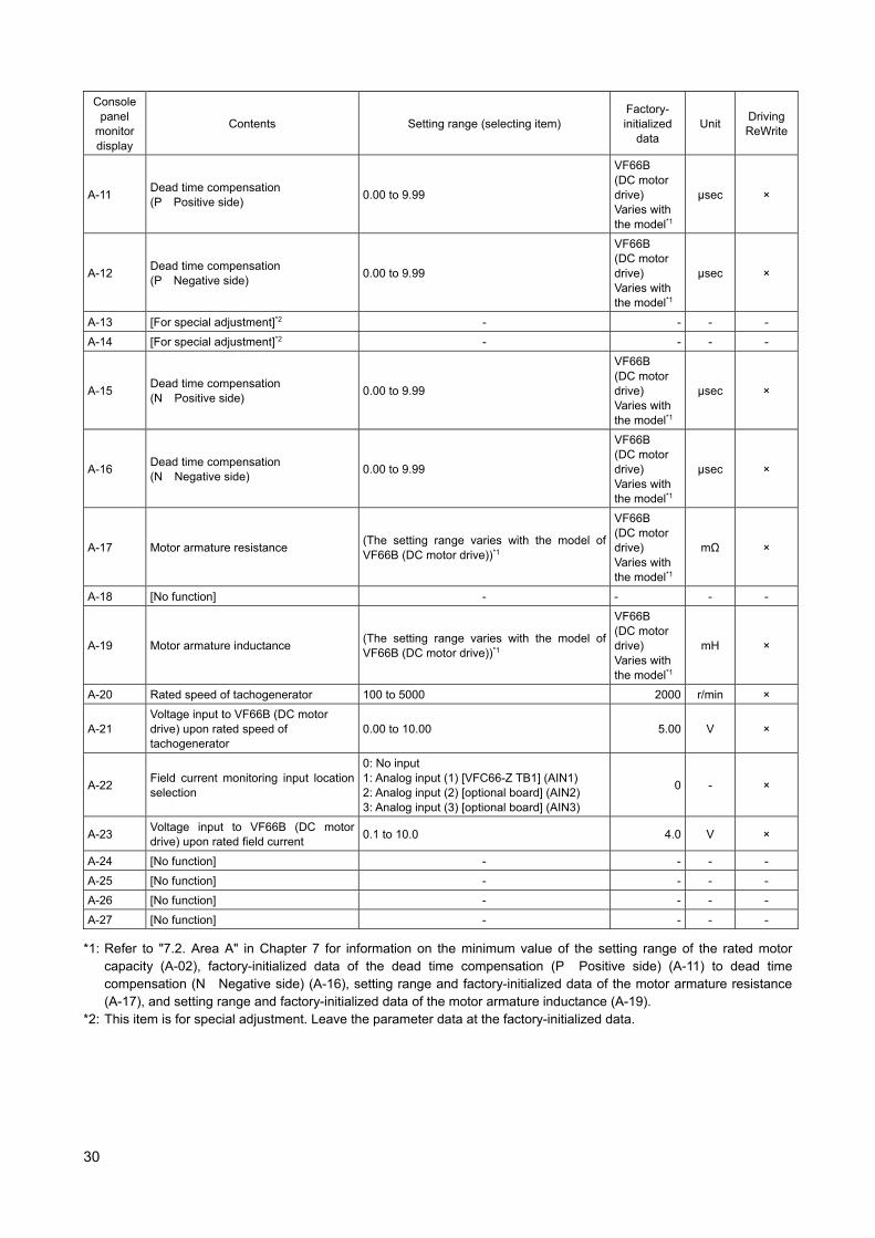
30
Console panel
monitor display
Contents Setting range (selecting item) Factory- initialized
data Unit
Driving ReWrite
A-11 Dead time compensation (P Positive side)
0.00 to 9.99
VF66B (DC motor drive) Varies with the model*1
μsec ×
A-12 Dead time compensation (P Negative side)
0.00 to 9.99
VF66B (DC motor drive) Varies with the model*1
μsec ×
A-13 [For special adjustment]*2 - - - -
A-14 [For special adjustment]*2 - - - -
A-15 Dead time compensation (N Positive side)
0.00 to 9.99
VF66B (DC motor drive) Varies with the model*1
μsec ×
A-16 Dead time compensation (N Negative side)
0.00 to 9.99
VF66B (DC motor drive) Varies with the model*1
μsec ×
A-17 Motor armature resistance (The setting range varies with the model of VF66B (DC motor drive))*1
VF66B (DC motor drive) Varies with the model*1
mΩ ×
A-18 [No function] - - - -
A-19 Motor armature inductance (The setting range varies with the model of VF66B (DC motor drive))*1
VF66B (DC motor drive) Varies with the model*1
mH ×
A-20 Rated speed of tachogenerator 100 to 5000 2000 r/min ×
A-21 Voltage input to VF66B (DC motor drive) upon rated speed of tachogenerator
0.00 to 10.00 5.00 V ×
A-22 Field current monitoring input location selection
0: No input 1: Analog input (1) [VFC66-Z TB1] (AIN1) 2: Analog input (2) [optional board] (AIN2) 3: Analog input (3) [optional board] (AIN3)
0 - ×
A-23 Voltage input to VF66B (DC motor drive) upon rated field current
0.1 to 10.0 4.0 V ×
A-24 [No function] - - - -
A-25 [No function] - - - -
A-26 [No function] - - - -
A-27 [No function] - - - -
*1: Refer to "7.2. Area A" in Chapter 7 for information on the minimum value of the setting range of the rated motor capacity (A-02), factory-initialized data of the dead time compensation (P Positive side) (A-11) to dead time compensation (N Negative side) (A-16), setting range and factory-initialized data of the motor armature resistance (A-17), and setting range and factory-initialized data of the motor armature inductance (A-19).
*2: This item is for special adjustment. Leave the parameter data at the factory-initialized data.
31
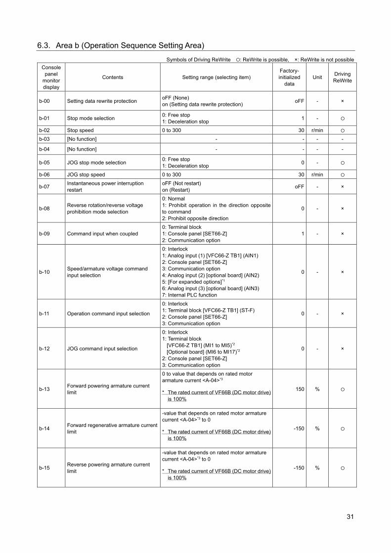
6.3. Area b (Operation Sequence Setting Area)
Symbols of Driving ReWrite : ReWrite is possible, ×: ReWrite is not possible
Console panel
monitor display
Contents Setting range (selecting item) Factory- initialized
data Unit
Driving ReWrite
b-00 Setting data rewrite protection oFF (None) on (Setting data rewrite protection)
oFF - ×
b-01 Stop mode selection 0: Free stop 1: Deceleration stop
1 -
b-02 Stop speed 0 to 300 30 r/min
b-03 [No function] - - - -
b-04 [No function] - - - -
b-05 JOG stop mode selection 0: Free stop 1: Deceleration stop
0 -
b-06 JOG stop speed 0 to 300 30 r/min
b-07 Instantaneous power interruption restart
oFF (Not restart) on (Restart)
oFF - ×
b-08 Reverse rotation/reverse voltage prohibition mode selection
0: Normal 1: Prohibit operation in the direction opposite to command 2: Prohibit opposite direction
0 - ×
b-09 Command input when coupled 0: Terminal block 1: Console panel [SET66-Z] 2: Communication option
1 - ×
b-10 Speed/armature voltage command input selection
0: Interlock 1: Analog input (1) [VFC66-Z TB1] (AIN1) 2: Console panel [SET66-Z] 3: Communication option 4: Analog input (2) [optional board] (AIN2) 5: [For expanded options]*1 6: Analog input (3) [optional board] (AIN3) 7: Internal PLC function
0 - ×
b-11 Operation command input selection
0: Interlock 1: Terminal block [VFC66-Z TB1] (ST-F) 2: Console panel [SET66-Z] 3: Communication option
0 - ×
b-12 JOG command input selection
0: Interlock 1: Terminal block
[VFC66-Z TB1] (MI1 to MI5)*2
[Optional board] (MI6 to MI17)*2 2: Console panel [SET66-Z] 3: Communication option
0 - ×
b-13 Forward powering armature current limit
0 to value that depends on rated motor armature current <A-04>*3
* The rated current of VF66B (DC motor drive) is 100%
150 %
b-14 Forward regenerative armature current limit
-value that depends on rated motor armature current <A-04>*3 to 0
* The rated current of VF66B (DC motor drive) is 100%
-150 %
b-15 Reverse powering armature current limit
-value that depends on rated motor armature current <A-04>*3 to 0
* The rated current of VF66B (DC motor drive) is 100%
-150 %
32
Console panel
monitor display
Contents Setting range (selecting item) Factory- initialized
data Unit
Driving ReWrite
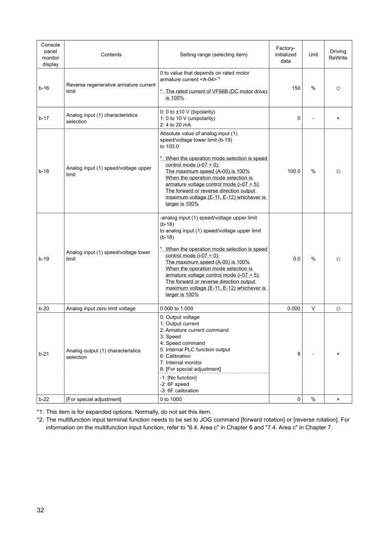
b-16 Reverse regenerative armature current limit
0 to value that depends on rated motor armature current <A-04>*3
* The rated current of VF66B (DC motor drive) is 100%
150 %
b-17 Analog input (1) characteristics selection
0: 0 to ±10 V (bipolarity) 1: 0 to 10 V (unipolarity) 2: 4 to 20 mA
0 - ×
b-18 Analog input (1) speed/voltage upper limit
Absolute value of analog input (1) speed/voltage lower limit (b-19) to 100.0
* When the operation mode selection is speed control mode (i-07 = 0): The maximum speed (A-00) is 100% When the operation mode selection is armature voltage control mode (i-07 = 5): The forward or reverse direction output maximum voltage (E-11, E-12) whichever is larger is 100%
100.0 %
b-19 Analog input (1) speed/voltage lower limit
-analog input (1) speed/voltage upper limit (b-18) to analog input (1) speed/voltage upper limit (b-18)
* When the operation mode selection is speed control mode (i-07 = 0): The maximum speed (A-00) is 100% When the operation mode selection is armature voltage control mode (i-07 = 5): The forward or reverse direction output maximum voltage (E-11, E-12) whichever is larger is 100%
0.0 %
b-20 Analog input zero limit voltage 0.000 to 1.000 0.000 V
b-21 Analog output (1) characteristics selection
0: Output voltage 1: Output current 2: Armature current command 3: Speed 4: Speed command 5: Internal PLC function output 6: Calibration 7: Internal monitor 8: [For special adjustment]
8 - ×
-1: [No function] -2: 6F speed -3: 6F calibration
b-22 [For special adjustment] 0 to 1000 0 % ×
*1: This item is for expanded options. Normally, do not set this item. *2: The multifunction input terminal function needs to be set to JOG command [forward rotation] or [reverse rotation]. For
information on the multifunction input function, refer to "6.4. Area c" in Chapter 6 and "7.4. Area c" in Chapter 7.
33
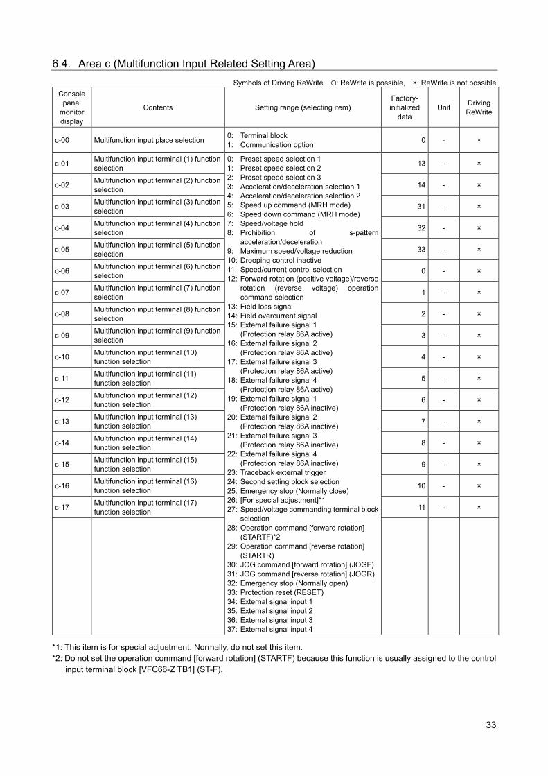
6.4. Area c (Multifunction Input Related Setting Area)
Symbols of Driving ReWrite : ReWrite is possible, ×: ReWrite is not possible
Console panel
monitor display
Contents Setting range (selecting item) Factory- initialized
data Unit
Driving ReWrite
c-00 Multifunction input place selection 0: Terminal block 1: Communication option
0 - ×
c-01 Multifunction input terminal (1) function selection
0: Preset speed selection 1 1: Preset speed selection 2 2: Preset speed selection 3 3: Acceleration/deceleration selection 1 4: Acceleration/deceleration selection 2 5: Speed up command (MRH mode) 6: Speed down command (MRH mode) 7: Speed/voltage hold 8: Prohibition of s-pattern
acceleration/deceleration 9: Maximum speed/voltage reduction 10: Drooping control inactive 11: Speed/current control selection 12: Forward rotation (positive voltage)/reverse
rotation (reverse voltage) operation command selection
13: Field loss signal 14: Field overcurrent signal 15: External failure signal 1
(Protection relay 86A active) 16: External failure signal 2
(Protection relay 86A active) 17: External failure signal 3
(Protection relay 86A active) 18: External failure signal 4
(Protection relay 86A active) 19: External failure signal 1
(Protection relay 86A inactive) 20: External failure signal 2
(Protection relay 86A inactive) 21: External failure signal 3
(Protection relay 86A inactive) 22: External failure signal 4
(Protection relay 86A inactive) 23: Traceback external trigger 24: Second setting block selection 25: Emergency stop (Normally close) 26: [For special adjustment]*1 27: Speed/voltage commanding terminal block
selection 28: Operation command [forward rotation]
(STARTF)*2 29: Operation command [reverse rotation]
(STARTR) 30: JOG command [forward rotation] (JOGF)31: JOG command [reverse rotation] (JOGR)32: Emergency stop (Normally open) 33: Protection reset (RESET) 34: External signal input 1 35: External signal input 2 36: External signal input 3 37: External signal input 4
13 - ×
c-02 Multifunction input terminal (2) function selection
14 - ×
c-03 Multifunction input terminal (3) function selection
31 - ×
c-04 Multifunction input terminal (4) function selection
32 - ×
c-05 Multifunction input terminal (5) function selection
33 - ×
c-06 Multifunction input terminal (6) function selection
0 - ×
c-07 Multifunction input terminal (7) function selection
1 - ×
c-08 Multifunction input terminal (8) function selection
2 - ×
c-09 Multifunction input terminal (9) function selection
3 - ×
c-10 Multifunction input terminal (10) function selection
4 - ×
c-11 Multifunction input terminal (11) function selection
5 - ×
c-12 Multifunction input terminal (12) function selection
6 - ×
c-13 Multifunction input terminal (13) function selection
7 - ×
c-14 Multifunction input terminal (14) function selection
8 - ×
c-15 Multifunction input terminal (15) function selection
9 - ×
c-16 Multifunction input terminal (16) function selection
10 - ×
c-17 Multifunction input terminal (17) function selection
11 - ×
*1: This item is for special adjustment. Normally, do not set this item. *2: Do not set the operation command [forward rotation] (STARTF) because this function is usually assigned to the control
input terminal block [VFC66-Z TB1] (ST-F).
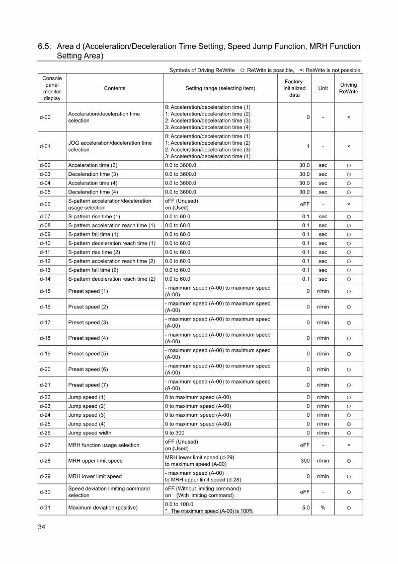
34
6.5. Area d (Acceleration/Deceleration Time Setting, Speed Jump Function, MRH Function Setting Area)
Symbols of Driving ReWrite : ReWrite is possible, ×: ReWrite is not possible
Console panel
monitor display
Contents Setting range (selecting item) Factory- initialized
data Unit
Driving ReWrite
d-00 Acceleration/deceleration time selection
0: Acceleration/deceleration time (1) 1: Acceleration/deceleration time (2) 2: Acceleration/deceleration time (3) 3: Acceleration/deceleration time (4)
0 - ×
d-01 JOG acceleration/deceleration time selection
0: Acceleration/deceleration time (1) 1: Acceleration/deceleration time (2) 2: Acceleration/deceleration time (3) 3: Acceleration/deceleration time (4)
1 - ×
d-02 Acceleration time (3) 0.0 to 3600.0 30.0 sec
d-03 Deceleration time (3) 0.0 to 3600.0 30.0 sec
d-04 Acceleration time (4) 0.0 to 3600.0 30.0 sec
d-05 Deceleration time (4) 0.0 to 3600.0 30.0 sec
d-06 S-pattern acceleration/deceleration usage selection
oFF (Unused) on (Used)
oFF - ×
d-07 S-pattern rise time (1) 0.0 to 60.0 0.1 sec
d-08 S-pattern acceleration reach time (1) 0.0 to 60.0 0.1 sec
d-09 S-pattern fall time (1) 0.0 to 60.0 0.1 sec
d-10 S-pattern deceleration reach time (1) 0.0 to 60.0 0.1 sec
d-11 S-pattern rise time (2) 0.0 to 60.0 0.1 sec
d-12 S-pattern acceleration reach time (2) 0.0 to 60.0 0.1 sec
d-13 S-pattern fall time (2) 0.0 to 60.0 0.1 sec
d-14 S-pattern deceleration reach time (2) 0.0 to 60.0 0.1 sec
d-15 Preset speed (1) - maximum speed (A-00) to maximum speed (A-00)
0 r/min
d-16 Preset speed (2) - maximum speed (A-00) to maximum speed (A-00)
0 r/min
d-17 Preset speed (3) - maximum speed (A-00) to maximum speed (A-00)
0 r/min
d-18 Preset speed (4) - maximum speed (A-00) to maximum speed (A-00)
0 r/min
d-19 Preset speed (5) - maximum speed (A-00) to maximum speed (A-00)
0 r/min
d-20 Preset speed (6) - maximum speed (A-00) to maximum speed (A-00)
0 r/min
d-21 Preset speed (7) - maximum speed (A-00) to maximum speed (A-00)
0 r/min
d-22 Jump speed (1) 0 to maximum speed (A-00) 0 r/min
d-23 Jump speed (2) 0 to maximum speed (A-00) 0 r/min
d-24 Jump speed (3) 0 to maximum speed (A-00) 0 r/min
d-25 Jump speed (4) 0 to maximum speed (A-00) 0 r/min
d-26 Jump speed width 0 to 300 0 r/min
d-27 MRH function usage selection oFF (Unused) on (Used)
oFF - ×
d-28 MRH upper limit speed MRH lower limit speed (d-29) to maximum speed (A-00)
300 r/min
d-29 MRH lower limit speed - maximum speed (A-00) to MRH upper limit speed (d-28)
0 r/min
d-30 Speed deviation limiting command selection
oFF (Without limiting command) on (With limiting command)
oFF -
d-31 Maximum deviation (positive) 0.0 to 100.0 * The maximum speed (A-00) is 100%
5.0 %
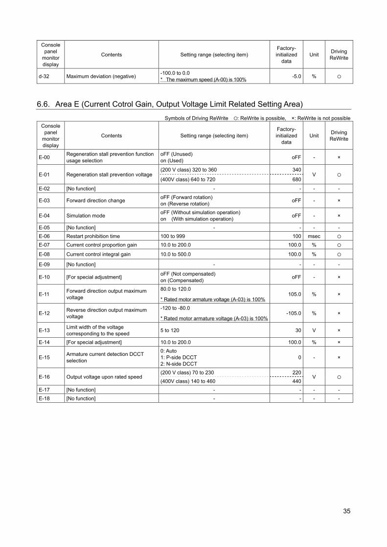
35
Console panel
monitor display
Contents Setting range (selecting item) Factory- initialized
data Unit
Driving ReWrite
d-32 Maximum deviation (negative) -100.0 to 0.0 * The maximum speed (A-00) is 100%
-5.0 %
6.6. Area E (Current Cotrol Gain, Output Voltage Limit Related Setting Area)
Symbols of Driving ReWrite : ReWrite is possible, ×: ReWrite is not possible
Console panel
monitor display
Contents Setting range (selecting item) Factory- initialized
data Unit
Driving ReWrite
E-00 Regeneration stall prevention function usage selection
oFF (Unused) on (Used)
oFF - ×
E-01 Regeneration stall prevention voltage (200 V class) 320 to 360 340
V (400V class) 640 to 720 680
E-02 [No function] - - - -
E-03 Forward direction change oFF (Forward rotation) on (Reverse rotation)
oFF - ×
E-04 Simulation mode oFF (Without simulation operation) on (With simulation operation)
oFF - ×
E-05 [No function] - - - -
E-06 Restart prohibition time 100 to 999 100 msec
E-07 Current control proportion gain 10.0 to 200.0 100.0 %
E-08 Current control integral gain 10.0 to 500.0 100.0 %
E-09 [No function] - - - -
E-10 [For special adjustment] oFF (Not compensated) on (Compensated)
oFF - ×
E-11 Forward direction output maximum voltage
80.0 to 120.0
* Rated motor armature voltage (A-03) is 100%105.0 % ×
E-12 Reverse direction output maximum voltage
-120 to -80.0
* Rated motor armature voltage (A-03) is 100%-105.0 % ×
E-13 Limit width of the voltage corresponding to the speed
5 to 120 30 V ×
E-14 [For special adjustment] 10.0 to 200.0 100.0 % ×
E-15 Armature current detection DCCT selection
0: Auto 1: P-side DCCT 2: N-side DCCT
0 - ×
E-16 Output voltage upon rated speed (200 V class) 70 to 230 220
V (400V class) 140 to 460 440
E-17 [No function] - - - -
E-18 [No function] - - - -
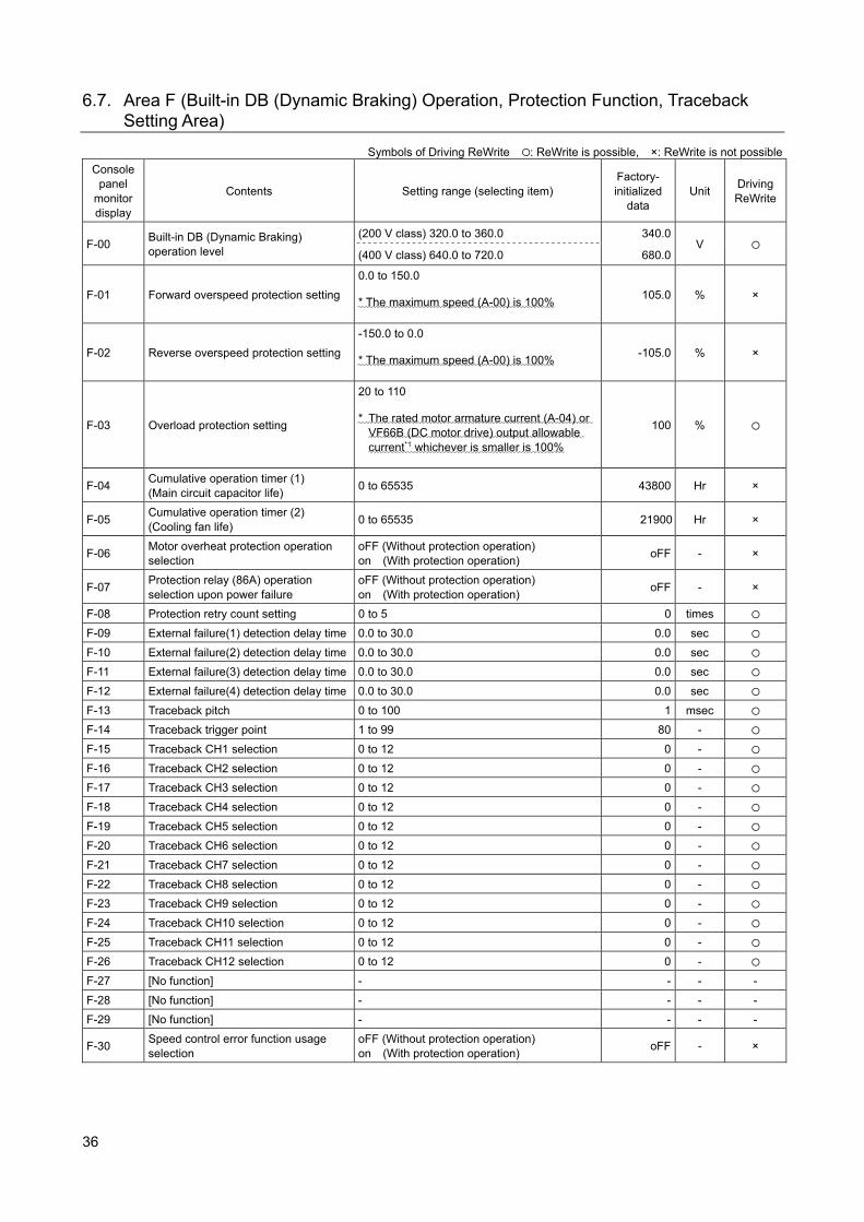
36
6.7. Area F (Built-in DB (Dynamic Braking) Operation, Protection Function, Traceback Setting Area)
Symbols of Driving ReWrite : ReWrite is possible, ×: ReWrite is not possible
Console panel
monitor display
Contents Setting range (selecting item) Factory- initialized
data Unit
Driving ReWrite
F-00 Built-in DB (Dynamic Braking) operation level
(200 V class) 320.0 to 360.0 340.0 V
(400 V class) 640.0 to 720.0 680.0
F-01 Forward overspeed protection setting
0.0 to 150.0
* The maximum speed (A-00) is 100% 105.0 % ×
F-02 Reverse overspeed protection setting
-150.0 to 0.0
* The maximum speed (A-00) is 100% -105.0 % ×
F-03 Overload protection setting
20 to 110
* The rated motor armature current (A-04) or VF66B (DC motor drive) output allowable current*1 whichever is smaller is 100%
100 %
F-04 Cumulative operation timer (1) (Main circuit capacitor life)
0 to 65535 43800 Hr ×
F-05 Cumulative operation timer (2) (Cooling fan life)
0 to 65535 21900 Hr ×
F-06 Motor overheat protection operation selection
oFF (Without protection operation) on (With protection operation)
oFF - ×
F-07 Protection relay (86A) operation selection upon power failure
oFF (Without protection operation) on (With protection operation)
oFF - ×
F-08 Protection retry count setting 0 to 5 0 times
F-09 External failure(1) detection delay time 0.0 to 30.0 0.0 sec
F-10 External failure(2) detection delay time 0.0 to 30.0 0.0 sec
F-11 External failure(3) detection delay time 0.0 to 30.0 0.0 sec
F-12 External failure(4) detection delay time 0.0 to 30.0 0.0 sec
F-13 Traceback pitch 0 to 100 1 msec
F-14 Traceback trigger point 1 to 99 80 -
F-15 Traceback CH1 selection 0 to 12 0 -
F-16 Traceback CH2 selection 0 to 12 0 -
F-17 Traceback CH3 selection 0 to 12 0 -
F-18 Traceback CH4 selection 0 to 12 0 -
F-19 Traceback CH5 selection 0 to 12 0 -
F-20 Traceback CH6 selection 0 to 12 0 -
F-21 Traceback CH7 selection 0 to 12 0 -
F-22 Traceback CH8 selection 0 to 12 0 -
F-23 Traceback CH9 selection 0 to 12 0 -
F-24 Traceback CH10 selection 0 to 12 0 -
F-25 Traceback CH11 selection 0 to 12 0 -
F-26 Traceback CH12 selection 0 to 12 0 -
F-27 [No function] - - - -
F-28 [No function] - - - -
F-29 [No function] - - - -
F-30 Speed control error function usage selection
oFF (Without protection operation) on (With protection operation)
oFF - ×
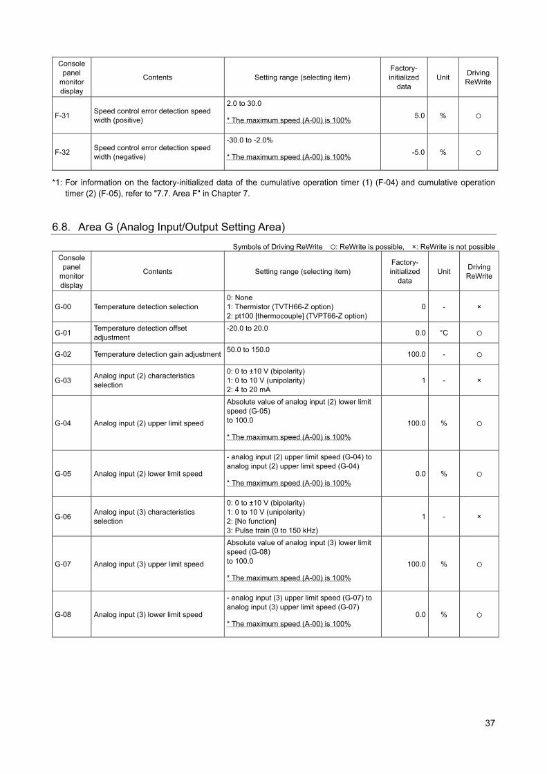
37
Console panel
monitor display
Contents Setting range (selecting item) Factory- initialized
data Unit
Driving ReWrite
F-31 Speed control error detection speed width (positive)
2.0 to 30.0
* The maximum speed (A-00) is 100% 5.0 %
F-32 Speed control error detection speed width (negative)
-30.0 to -2.0%
* The maximum speed (A-00) is 100% -5.0 %
*1: For information on the factory-initialized data of the cumulative operation timer (1) (F-04) and cumulative operation timer (2) (F-05), refer to "7.7. Area F" in Chapter 7.
6.8. Area G (Analog Input/Output Setting Area)
Symbols of Driving ReWrite : ReWrite is possible, ×: ReWrite is not possible
Console panel
monitor display
Contents Setting range (selecting item) Factory- initialized
data Unit
Driving ReWrite
G-00 Temperature detection selection 0: None 1: Thermistor (TVTH66-Z option) 2: pt100 [thermocouple] (TVPT66-Z option)
0 - ×
G-01 Temperature detection offset adjustment
-20.0 to 20.0 0.0 °C
G-02 Temperature detection gain adjustment 50.0 to 150.0
100.0 -
G-03 Analog input (2) characteristics selection
0: 0 to ±10 V (bipolarity) 1: 0 to 10 V (unipolarity) 2: 4 to 20 mA
1 - ×
G-04 Analog input (2) upper limit speed
Absolute value of analog input (2) lower limit speed (G-05) to 100.0
* The maximum speed (A-00) is 100%
100.0 %
G-05 Analog input (2) lower limit speed
- analog input (2) upper limit speed (G-04) to analog input (2) upper limit speed (G-04)
* The maximum speed (A-00) is 100% 0.0 %
G-06 Analog input (3) characteristics selection
0: 0 to ±10 V (bipolarity) 1: 0 to 10 V (unipolarity) 2: [No function] 3: Pulse train (0 to 150 kHz)
1 - ×
G-07 Analog input (3) upper limit speed
Absolute value of analog input (3) lower limit speed (G-08) to 100.0
* The maximum speed (A-00) is 100%
100.0 %
G-08 Analog input (3) lower limit speed
- analog input (3) upper limit speed (G-07) to analog input (3) upper limit speed (G-07)
* The maximum speed (A-00) is 100% 0.0 %
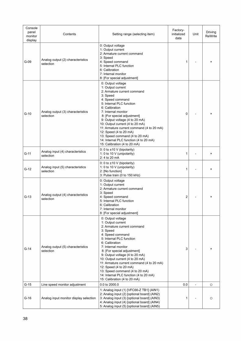
38
Console panel
monitor display
Contents Setting range (selecting item) Factory- initialized
data Unit
Driving ReWrite
G-09 Analog output (2) characteristics selection
0: Output voltage 1: Output current 2: Armature current command 3: Speed 4: Speed command 5: Internal PLC function 6: Calibration 7: Internal monitor 8: [For special adjustment]
1 - ×
G-10 Analog output (3) characteristics selection
0: Output voltage 1: Output current 2: Armature current command 3: Speed 4: Speed command 5: Internal PLC function 6: Calibration 7: Internal monitor 8: [For special adjustment] 9: Output voltage (4 to 20 mA)
10: Output current (4 to 20 mA) 11: Armature current command (4 to 20 mA) 12: Speed (4 to 20 mA) 13: Speed command (4 to 20 mA) 14: Internal PLC function (4 to 20 mA) 15: Calibration (4 to 20 mA)
0 - ×
G-11 Analog input (4) characteristics selection
0: 0 to ±10 V (bipolarity) 1: 0 to 10 V (unipolarity) 2: 4 to 20 mA
1 - ×
G-12 Analog input (5) characteristics selection
0: 0 to ±10 V (bipolarity) 1: 0 to 10 V (unipolarity) 2: [No function] 3: Pulse train (0 to 150 kHz)
1 - ×
G-13 Analog output (4) characteristics selection
0: Output voltage 1: Output current 2: Armature current command 3: Speed 4: Speed command 5: Internal PLC function 6: Calibration 7: Internal monitor 8: [For special adjustment]
2 - ×
G-14 Analog output (5) characteristics selection
0: Output voltage 1: Output current 2: Armature current command 3: Speed 4: Speed command 5: Internal PLC function 6: Calibration 7: Internal monitor 8: [For special adjustment] 9: Output voltage (4 to 20 mA)
10: Output current (4 to 20 mA) 11: Armature current command (4 to 20 mA) 12: Speed (4 to 20 mA) 13: Speed command (4 to 20 mA) 14: Internal PLC function (4 to 20 mA) 15: Calibration (4 to 20 mA)
3 - ×
G-15 Line speed monitor adjustment 0.0 to 2000.0 0.0 -
G-16 Analog input monitor display selection
1: Analog input (1) [VFC66-Z TB1] (AIN1) 2: Analog input (2) [optional board] (AIN2) 3: Analog input (3) [optional board] (AIN3) 4: Analog input (4) [optional board] (AIN4) 5: Analog input (5) [optional board] (AIN5)
1 -
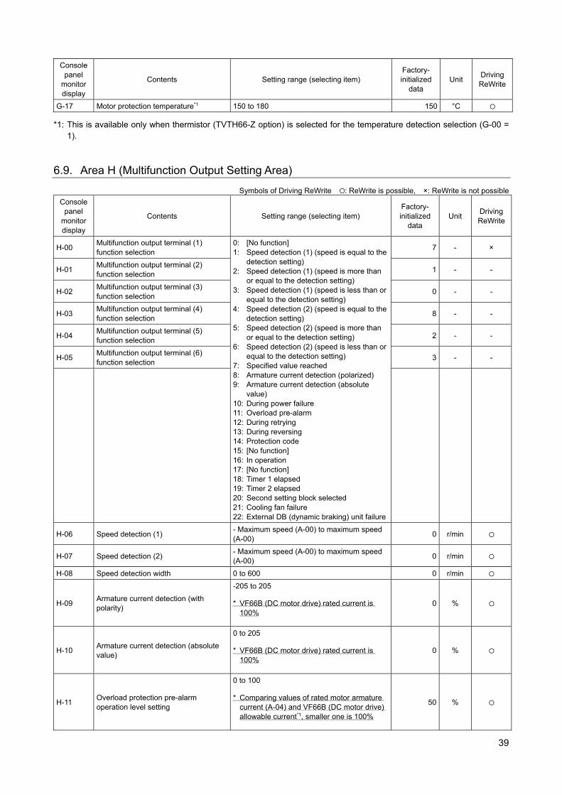
39
Console panel
monitor display
Contents Setting range (selecting item) Factory- initialized
data Unit
Driving ReWrite
G-17 Motor protection temperature*1 150 to 180 150 °C
*1: This is available only when thermistor (TVTH66-Z option) is selected for the temperature detection selection (G-00 = 1).
6.9. Area H (Multifunction Output Setting Area)
Symbols of Driving ReWrite : ReWrite is possible, ×: ReWrite is not possible
Console panel
monitor display
Contents Setting range (selecting item) Factory- initialized
data Unit
Driving ReWrite
H-00 Multifunction output terminal (1) function selection
0: [No function] 1: Speed detection (1) (speed is equal to the
detection setting) 2: Speed detection (1) (speed is more than
or equal to the detection setting) 3: Speed detection (1) (speed is less than or
equal to the detection setting) 4: Speed detection (2) (speed is equal to the
detection setting) 5: Speed detection (2) (speed is more than
or equal to the detection setting) 6: Speed detection (2) (speed is less than or
equal to the detection setting) 7: Specified value reached 8: Armature current detection (polarized) 9: Armature current detection (absolute
value) 10: During power failure 11: Overload pre-alarm 12: During retrying 13: During reversing 14: Protection code 15: [No function] 16: In operation 17: [No function] 18: Timer 1 elapsed 19: Timer 2 elapsed 20: Second setting block selected 21: Cooling fan failure 22: External DB (dynamic braking) unit failure
7 - ×
H-01 Multifunction output terminal (2) function selection
1 - -
H-02 Multifunction output terminal (3) function selection
0 - -
H-03 Multifunction output terminal (4) function selection
8 - -
H-04 Multifunction output terminal (5) function selection
2 - -
H-05 Multifunction output terminal (6) function selection
3 - -
H-06 Speed detection (1) - Maximum speed (A-00) to maximum speed (A-00)
0 r/min
H-07 Speed detection (2) - Maximum speed (A-00) to maximum speed (A-00)
0 r/min
H-08 Speed detection width 0 to 600 0 r/min
H-09 Armature current detection (with polarity)
-205 to 205
* VF66B (DC motor drive) rated current is 100%
0 %
H-10 Armature current detection (absolute value)
0 to 205
* VF66B (DC motor drive) rated current is 100%
0 %
H-11 Overload protection pre-alarm operation level setting
0 to 100
* Comparing values of rated motor armature current (A-04) and VF66B (DC motor drive) allowable current*1, smaller one is 100%
50 %
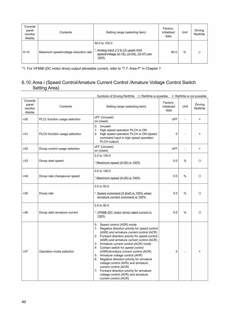
40
Console panel
monitor display
Contents Setting range (selecting item) Factory- initialized
data Unit
Driving ReWrite
H-12 Maximum speed/voltage reduction rate
50.0 to 100.0
* Analog input (1) to (3) upper limit speed/voltage (b-18), (G-04), (G-07) are 100%
90.0 %
*1: For VF66B (DC motor drive) output allowable current, refer to "7.7. Area F" in Chapter 7. 6.10. Area i (Speed Control/Amature Current Control /Amature Voltage Control Switch
Setting Area)
Symbols of Driving ReWrite : ReWrite is possible, ×: ReWrite is not possible
Console panel
monitor display
Contents Setting range (selecting item) Factory- initialized
data Unit
Driving ReWrite
i-00 PLCL function usage selection oFF (Unused) on (Used)
oFF - ×
i-01 PLCH function usage selection
0: Unused 1: High speed operation PLCH is ON 2: High speed operation PLCH is ON (speed
command input is high speed operation PLCH output)
0 - ×
i-02 Droop control usage selection oFF (Unused) on (Used)
oFF - ×
i-03 Droop start speed
0.0 to 100.0
* Maximum speed (A-00) is 100% 0.0 %
i-04 Droop rate changeover speed
0.0 to 100.0
* Maximum speed (A-00) is 100% 0.0 %
i-05 Droop rate
0.0 to 50.0
* Speed command (0.Sref) is 100% when armature current command is 100%
0.0 %
i-06 Droop start armature current
0.0 to 90.0
* VF66B (DC motor drive) rated current is 100%
0.0 %
i-07 Operation mode selection
0: Speed control (ASR) mode 1: Negative direction priority for speed control
(ASR) and armature current control (ACR)2: Forward direction priority for speed control
(ASR) and armature current control (ACR)3: Armature current control (ACR) mode 4: Contact switch for speed control
(ASR)/armature current control (ACR) 5: Armature voltage control (AVR) 6: Negative direction priority for armature
voltage control (AVR) and armature current control (ACR)
7: Forward direction priority for armature voltage control (AVR) and armature current control (ACR)
0 - ×
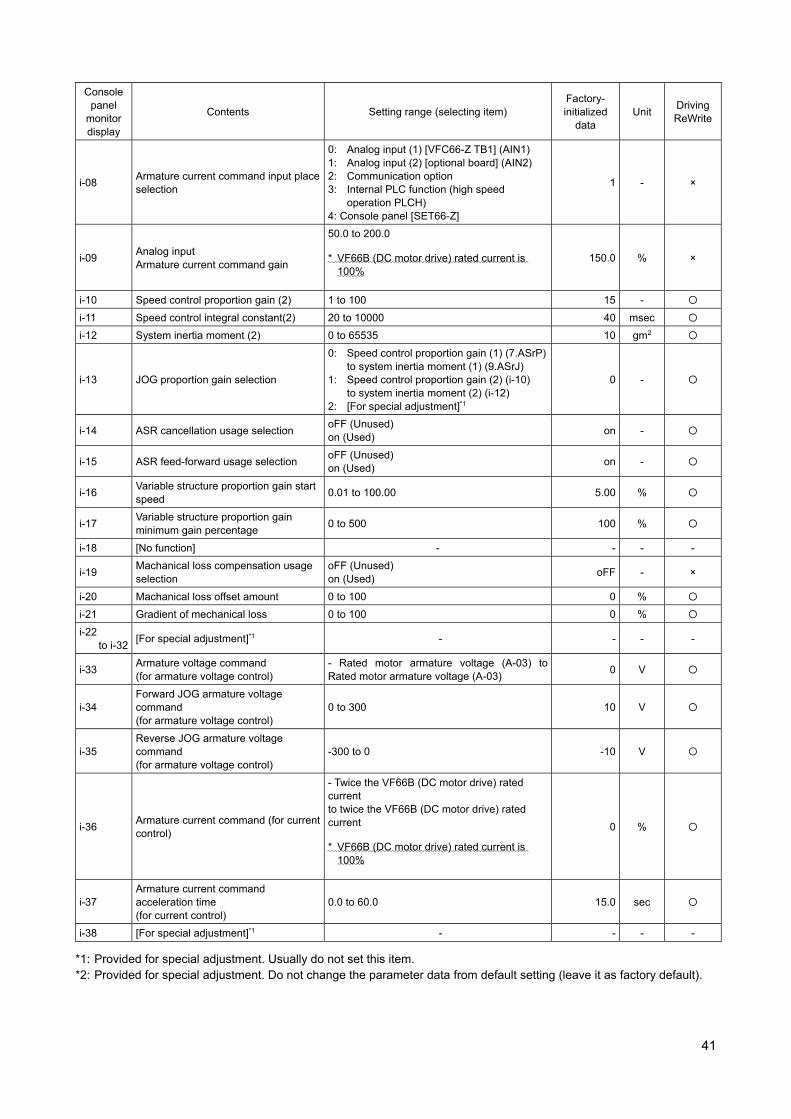
41
Console panel
monitor display
Contents Setting range (selecting item) Factory- initialized
data Unit
Driving ReWrite
i-08 Armature current command input place selection
0: Analog input (1) [VFC66-Z TB1] (AIN1) 1: Analog input (2) [optional board] (AIN2) 2: Communication option 3: Internal PLC function (high speed
operation PLCH) 4: Console panel [SET66-Z]
1 - ×
i-09 Analog input Armature current command gain
50.0 to 200.0
* VF66B (DC motor drive) rated current is 100%
150.0 % ×
i-10 Speed control proportion gain (2) 1 to 100 15 -
i-11 Speed control integral constant(2) 20 to 10000 40 msec
i-12 System inertia moment (2) 0 to 65535 10 gm2
i-13 JOG proportion gain selection
0: Speed control proportion gain (1) (7.ASrP) to system inertia moment (1) (9.ASrJ)
1: Speed control proportion gain (2) (i-10) to system inertia moment (2) (i-12)
2: [For special adjustment]*1
0 -
i-14 ASR cancellation usage selection oFF (Unused) on (Used)
on -
i-15 ASR feed-forward usage selection oFF (Unused) on (Used)
on -
i-16 Variable structure proportion gain start speed
0.01 to 100.00 5.00 %
i-17 Variable structure proportion gain minimum gain percentage
0 to 500 100 %
i-18 [No function] - - - -
i-19 Machanical loss compensation usage selection
oFF (Unused) on (Used)
oFF - ×
i-20 Machanical loss offset amount 0 to 100 0 %
i-21 Gradient of mechanical loss 0 to 100 0 %
i-22 to i-32
[For special adjustment]*1 - - - -
i-33 Armature voltage command (for armature voltage control)
- Rated motor armature voltage (A-03) to Rated motor armature voltage (A-03)
0 V
i-34 Forward JOG armature voltage command (for armature voltage control)
0 to 300 10 V
i-35 Reverse JOG armature voltage command (for armature voltage control)
-300 to 0 -10 V
i-36 Armature current command (for current control)
- Twice the VF66B (DC motor drive) rated current to twice the VF66B (DC motor drive) rated current
* VF66B (DC motor drive) rated current is 100%
0 %
i-37 Armature current command acceleration time (for current control)
0.0 to 60.0 15.0 sec
i-38 [For special adjustment]*1 - - - -
*1: Provided for special adjustment. Usually do not set this item. *2: Provided for special adjustment. Do not change the parameter data from default setting (leave it as factory default).

42
6.11. Area J (Communication Setting Area)
Symbols of Driving ReWrite : ReWrite is possible, ×: ReWrite is not possible
Console panel
monitor display
Contents Setting range (selecting item) Factory- initialized
data Unit
Driving ReWrite
J-00 Digital communication option selection
0:OFF 1: OPCN66-Z 2: [For special adjustment]*2 3: [For special adjustment]*2 4: [For special adjustment]*2 5: IO66-Z 6: [For special adjustment]*2 7: CC66-Z
0 - ×
J-01 CC66-Z baud rate
0: 156 kbps 1: 625 kbps 2: 2.5 Mbps 3: 5 Mbps 4: 10 Mbps 5: 10 Mbps
4 -
J-02 OPCN66-Z baud rate
0: 125 kbps 1: 250 kbps 2: 500 kbps 3: 1 Mbps 4: [For special adjustment]*2
3 - ×
J-03 [For special adjustment]*1 - - - -
J-04 OPCN66-Z input 3 to 19 14 - ×
J-05 OPCN66-Z output 2 to 12 6 - ×
J-06 [For special adjustment]*1 - - - -
J-07
OPCN66-Z transmission wait time selection
125kbps 250kbps 500 kbps/1 Mbps
0 - ×
0: 1: 2: 3: 4: 5: 6:
200 μs 200 μs 200 μs 200 μs 200 μs 200 μs 200 μs
200 μs 200 μs 200 μs 200 μs 150 μs 100 μs 100 μs
200 μs 200 μs 200 μs 200 μs 150 μs 100 μs 50 μs
CC66-Z CC-Link version/number of occupied stations selection
Version Number of occupied stations
0: 1: 2: 3: 4: 5: 6:
1.1 1.1 1.1 1.1 2.0 (double) 2.0 (4 times) 2.0 (8 times)
One Two Three Four One One One
J-08 [For special adjustment]*1 - - - -
J-09 [For special adjustment]*1 - - - -
J-10 [For special adjustment]*1 - - - -
J-11 [For special adjustment]*1 - - - -
J-12 [For special adjustment]*1 - - - -
J-13 High speed response input selection 0: Communication option 1: Analog input (2) [optional board] (AIN2)
0 - ×
J-14 Date/Time data selection from communication
0: Without date/time data 1: With date/time data
0 - ×
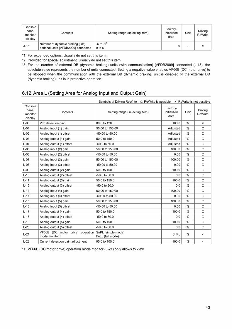
43
Console panel
monitor display
Contents Setting range (selecting item) Factory- initialized
data Unit
Driving ReWrite
J-15 Number of dynamic braking (DB) optional units [VFDB2009] connected
-6 to -13 0 to 6
0 - ×
*1: For expanded options. Usually do not set this item. *2: Provided for special adjustment. Usually do not set this item. *3: For the number of external DB (dynamic braking) units (with communication) [VFDB2009] connected (J-15), the
absolute value represents the number of units connected. Setting a negative value enables VF66B (DC motor drive) to be stopped when the communication with the external DB (dynamic braking) unit is disabled or the external DB (dynamic braking) unit is in protective operation.
6.12. Area L (Setting Area for Analog Input and Output Gain)
Symbols of Driving ReWrite : ReWrite is possible, ×: ReWrite is not possible
Console panel
monitor display
Contents Setting range (selecting item) Factory- initialized
data Unit
Driving ReWrite
L-00 Vdc detection gain 80.0 to 120.0 100.0 % ×
L-01 Analog input (1) gain 50.00 to 150.00 Adjusted %
L-02 Analog input (1) offset -50.00 to 50.00 Adjusted %
L-03 Analog output (1) gain 50.0 to 150.0 Adjusted %
L-04 Analog output (1) offset -50.0 to 50.0 Adjusted %
L-05 Analog input (2) gain 50.00 to 150.00 100.00 %
L-06 Analog input (2) offset -50.00 to 50.00 0.00 %
L-07 Analog input (3) gain 50.00 to 150.00 100.00 %
L-08 Analog input (3) offset -50.00 to 50.00 0.00 %
L-09 Analog output (2) gain 50.0 to 150.0 100.0 %
L-10 Analog output (2) offset -50.0 to 50.0 0.0 %
L-11 Analog output (3) gain 50.0 to 150.0 100.0 %
L-12 Analog output (3) offset -50.0 to 50.0 0.0 %
L-13 Analog input (4) gain 50.00 to 150.00 100.00 %
L-14 Analog input (4) offset -50.00 to 50.00 0.00 %
L-15 Analog input (5) gain 50.00 to 150.00 100.00 %
L-16 Analog input (5) offset -50.00 to 50.00 0.00 %
L-17 Analog output (4) gain 50.0 to 150.0 100.0 %
L-18 Analog output (4) offset -50.0 to 50.0 0.0 %
L-19 Analog output (5) gain 50.0 to 150.0 100.0 %
L-20 Analog output (5) offset -50.0 to 50.0 0.0 %
L-21 VF66B (DC motor drive) operation mode monitor*1
SnPL (simple mode) FuLL (full mode)
SnPL % ×
L-22 Current detection gain adjustment 95.0 to 105.0 100.0 % ×
*1: VF66B (DC motor drive) operation mode monitor (L-21) only allows to view.
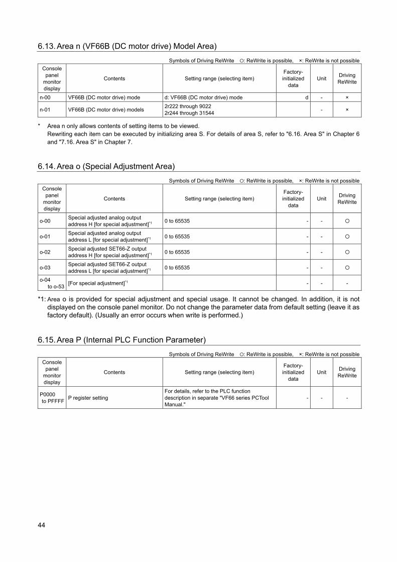
44
6.13. Area n (VF66B (DC motor drive) Model Area)
Symbols of Driving ReWrite : ReWrite is possible, ×: ReWrite is not possible
Console panel
monitor display
Contents Setting range (selecting item) Factory- initialized
data Unit
Driving ReWrite
n-00 VF66B (DC motor drive) mode d: VF66B (DC motor drive) mode d - ×
n-01 VF66B (DC motor drive) models 2r222 through 9022 2r244 through 31544
- ×
* Area n only allows contents of setting items to be viewed. Rewriting each item can be executed by initializing area S. For details of area S, refer to "6.16. Area S" in Chapter 6 and "7.16. Area S" in Chapter 7.
6.14. Area o (Special Adjustment Area)
Symbols of Driving ReWrite : ReWrite is possible, ×: ReWrite is not possible
Console panel
monitor display
Contents Setting range (selecting item) Factory- initialized
data Unit
Driving ReWrite
o-00 Special adjusted analog output address H [for special adjustment]*1
0 to 65535 - -
o-01 Special adjusted analog output address L [for special adjustment]*1 0 to 65535 - -
o-02 Special adjusted SET66-Z output address H [for special adjustment]*1
0 to 65535 - -
o-03 Special adjusted SET66-Z output address L [for special adjustment]*1
0 to 65535 - -
o-04 to o-53
[For special adjustment]*1 - - -
*1: Area o is provided for special adjustment and special usage. It cannot be changed. In addition, it is not displayed on the console panel monitor. Do not change the parameter data from default setting (leave it as factory default). (Usually an error occurs when write is performed.)
6.15. Area P (Internal PLC Function Parameter)
Symbols of Driving ReWrite : ReWrite is possible, ×: ReWrite is not possible
Console panel
monitor display
Contents Setting range (selecting item) Factory- initialized
data Unit
Driving ReWrite
P0000 to PFFFF
P register setting For details, refer to the PLC function description in separate "VF66 series PCTool Manual."
- - -
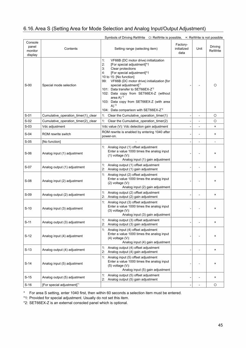
45
6.16. Area S (Setting Area for Mode Selection and Analog Input/Output Adjustment)
Symbols of Driving ReWrite : ReWrite is possible, ×: ReWrite is not possible
Console panel
monitor display
Contents Setting range (selecting item) Factory- initialized
data Unit
Driving ReWrite
S-00 Special mode selection
1: VF66B (DC motor drive) initialization 2: [For special adjustment]*1 3: Clear protections 4: [For special adjustment]*1 10 to 15: [No function] 99: VF66B (DC motor drive) initialization [for
special adjustment]*1 101: Data transfer to SET66EX-Z*2 102: Data copy from SET66EX-Z (without
area A) *2 103: Data copy from SET66EX-Z (with area
A) *2 104: Data comparison with SET66EX-Z*2
- -
S-01 Cumulative_operation_timer(1)_clear 1: Clear the Cumulative_operation_timer(1) - -
S-02 Cumulative_operation_timer(2)_clear 1: Clear the Cumulative_operation_timer(2) - -
S-03 Vdc adjustment Vdc value (V): Vdc detection gain adjustment - - ×
S-04 ROM rewrite switch ROM rewrite is enabled by entering 1040 after power-on.
- - ×
S-05 [No function] - - - -
S-06 Analog input (1) adjustment
1: Analog input (1) offset adjustment Enter a value 1000 times the analog input (1) voltage (V):
Analog input (1) gain adjustment
- - ×
S-07 Analog output (1) adjustment 1: Analog output (1) offset adjustment 2: Analog output (1) gain adjustment
- - ×
S-08 Analog input (2) adjustment
1: Analog input (2) offset adjustment Enter a value 1000 times the analog input (2) voltage (V):
Analog input (2) gain adjustment
- - ×
S-09 Analog output (2) adjustment 1: Analog output (2) offset adjustment 2: Analog output (2) gain adjustment
- - ×
S-10 Analog input (3) adjustment
1: Analog input (3) offset adjustment Enter a value 1000 times the analog input (3) voltage (V):
Analog input (3) gain adjustment
- - ×
S-11 Analog output (3) adjustment 1: Analog output (3) offset adjustment 2: Analog output (3) gain adjustment
- - ×
S-12 Analog input (4) adjustment
1: Analog input (4) offset adjustment Enter a value 1000 times the analog input (4) voltage (V):
Analog input (4) gain adjustment
- - ×
S-13 Analog output (4) adjustment 1: Analog output (4) offset adjustment 2: Analog output (4) gain adjustment
- - ×
S-14 Analog input (5) adjustment
1: Analog input (5) offset adjustment Enter a value 1000 times the analog input (5) voltage (V):
Analog input (5) gain adjustment
- - ×
S-15 Analog output (5) adjustment 1: Analog output (5) offset adjustment 2: Analog output (5) gain adjustment
- - ×
S-16 [For special adjustment]*1 - -
* For area S setting, enter 1040 first, then within 60 seconds a selection item must be entered. *1: Provided for special adjustment. Usually do not set this item. *2: SET66EX-Z is an external consoled panel which is optional.
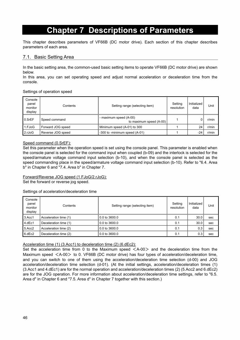
46
Chapter 7 Descriptions of Parameters
This chapter describes parameters of VF66B (DC motor drive). Each section of this chapter describes parameters of each area. 7.1. Basic Setting Area In the basic setting area, the common-used basic setting items to operate VF66B (DC motor drive) are shown below. In this area, you can set operating speed and adjust normal acceleration or deceleration time from the console. Settings of operation speed
Console panel
monitor display
Contents Setting range (selecting item) Setting
resolution Initialized
data Unit
0.SrEF Speed command - maximum speed (A-00)
to maximum speed (A-00)1 0 r/min
1.FJoG Forward JOG speed Minimum speed (A-01) to 300 1 24 r/min
2.rJoG Reverse JOG speed -300 to -minimum speed (A-01) 1 -24 r/min
Speed command (0.SrEF): Set this parameter when the operation speed is set using the console panel. This parameter is enabled when the console panel is selected for the command input when coupled (b-09) and the interlock is selected for the speed/armature voltage command input selection (b-10), and when the console panel is selected as the speed commanding place in the speed/armature voltage command input selection (b-10). Refer to "6.4. Area b" in Chapter 6 and "7.4. Area b" in Chapter 7. Forward/Reverse JOG speed (1.FJoG/2.rJoG): Set the forward or reverse jog speed. Settings of acceleration/deceleration time
Console panel
monitor display
Contents Setting range (selecting item) Setting
resolution Initialized
data Unit
3.Acc1 Acceleration time (1) 0.0 to 3600.0 0.1 30.0 sec
4.dEc1 Deceleration time (1) 0.0 to 3600.0 0.1 30.0 sec
5.Acc2 Acceleration time (2) 0.0 to 3600.0 0.1 0.3 sec
6.dEc2 Deceleration time (2) 0.0 to 3600.0 0.1 0.3 sec
Acceleration time (1) (3.Acc1) to deceleration time (2) (6.dEc2): Set the acceleration time from 0 to the Maximum speed <A-00> and the deceleration time from the Maximum speed <A-00> to 0. VF66B (DC motor drive) has four types of acceleration/deceleration time, and you can switch to one of them using the acceleration/deceleration time selection (d-00) and JOG acceleration/deceleration time selection (d-01). (At the initial settings, acceleration/deceleration times (1) (3.Acc1 and 4.dEc1) are for the normal operation and acceleration/deceleration times (2) (5.Acc2 and 6.dEc2) are for the JOG operation. For more information about acceleration/deceleration time settings, refer to "6.5. Area d" in Chapter 6 and "7.5. Area d" in Chapter 7 together with this section.)
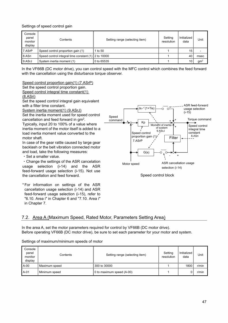
47
Settings of speed control gain
Console panel
monitor display
Contents Setting range (selecting item) Setting
resolution Initialized
data Unit
7.ASrP Speed control proportion gain (1) 1 to 50 1 15 -
8.ASri Speed control integral time constant (1) 2 to 10000 1 40 msec
9.ASrJ System inertia moment (1) 0 to 65535 1 10 gm2
In the VF66B (DC motor drive), you can control speed with the MFC control which combines the feed forward with the cancellation using the disturbance torque observer. Speed control proportion gain(1) (7.ASrP) Set the speed control proportion gain. Speed control integral time constant(1) (8.ASri) Set the speed control integral gain equivalent with a filter time constant. System inertia moment(1) (9.ASrJ) Set the inertia moment used for speed control cancellation and feed forward in gm2. Typically, input 20 to 100% of a value where inertia moment of the motor itself is added to a load inertia moment value converted to the motor shaft. In case of the gear rattle caused by large gear backlash or the belt vibration connected motor and load, take the following measures: ・Set a smaller value. ・Change the settings of the ASR cancelation usage selection (i-14) and the ASR feed-forward usage selection (i-15). Not use the cancellation and feed forward.
* For information on settings of the ASR cancellation usage selection (i-14) and ASR feed-forward usage selection (i-15), refer to "6.10. Area i" in Chapter 6 and "7.10. Area i" in Chapter 7.
Speed control block
7.2. Area A (Maximum Speed, Rated Motor, Parameters Setting Area) In the area A, set the motor parameters required for control by VF66B (DC motor drive). Before operating VF66B (DC motor drive), be sure to set each parameter for your motor and system. Settings of maximum/minimum speeds of motor
Console panel
monitor display
Contents Setting range (selecting item) Setting
resolution Initialized
data Unit
A-00 Maximum speed 300 to 30000 1 1800 r/min
A-01 Minimum speed 0 to maximum speed (A-00) 1 0 r/min
Speed command
Kp
Filter
Motor speed
G(s)
Js/(1+Tis)
+ + +
+-
+
-
Torque command
Speed control integral time constant
8.ASriSpeed control proportion gain (1)
7.ASrP
Moment of inertia of system 9.ASrJ
ASR cancellation usage
selection (i-14)
ASR feed-forward usage selection (i-15)
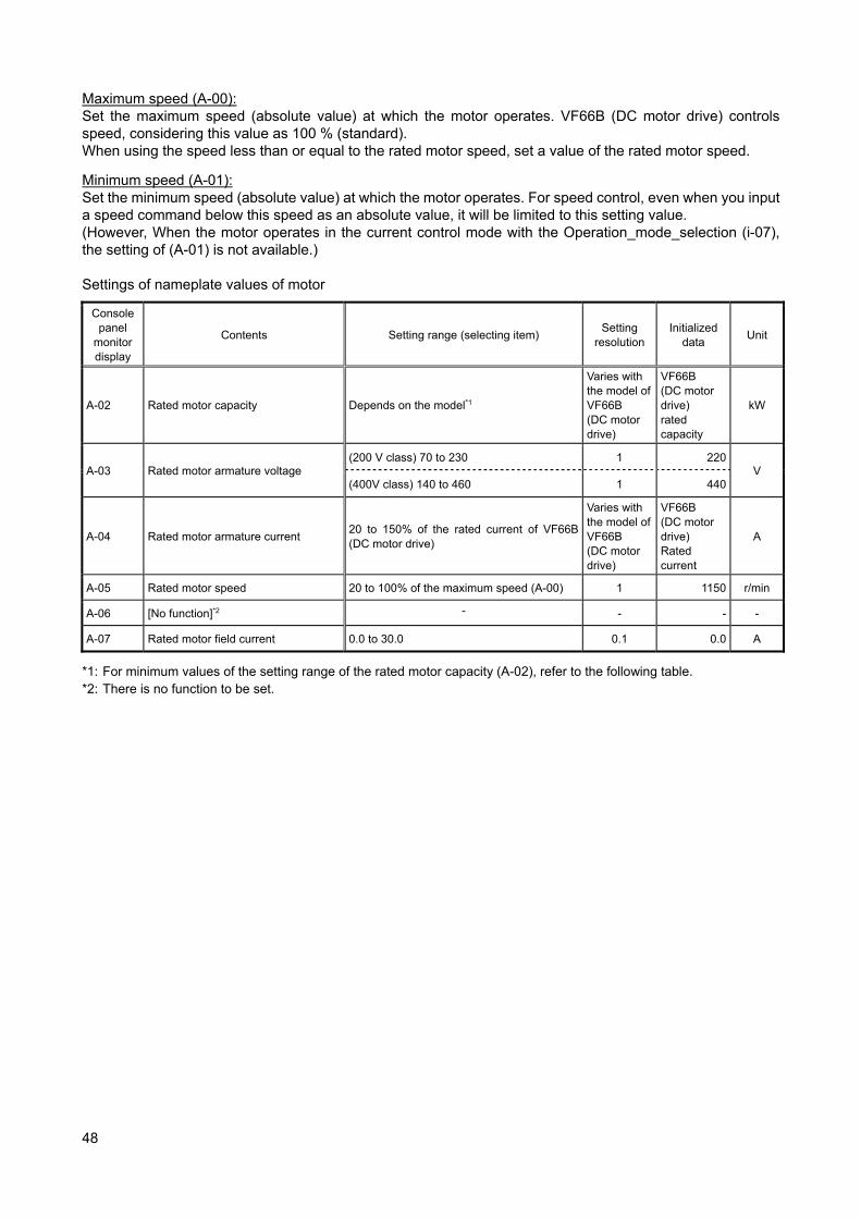
48
Maximum speed (A-00): Set the maximum speed (absolute value) at which the motor operates. VF66B (DC motor drive) controls speed, considering this value as 100 % (standard). When using the speed less than or equal to the rated motor speed, set a value of the rated motor speed.
Minimum speed (A-01): Set the minimum speed (absolute value) at which the motor operates. For speed control, even when you input a speed command below this speed as an absolute value, it will be limited to this setting value. (However, When the motor operates in the current control mode with the Operation_mode_selection (i-07), the setting of (A-01) is not available.) Settings of nameplate values of motor
Console panel
monitor display
Contents Setting range (selecting item) Setting
resolution Initialized
data Unit
A-02 Rated motor capacity Depends on the model*1
Varies with the model of VF66B (DC motor drive)
VF66B (DC motor drive) rated capacity
kW
A-03 Rated motor armature voltage (200 V class) 70 to 230 1 220
V (400V class) 140 to 460 1 440
A-04 Rated motor armature current 20 to 150% of the rated current of VF66B (DC motor drive)
Varies with the model of VF66B (DC motor drive)
VF66B (DC motor drive) Rated current
A
A-05 Rated motor speed 20 to 100% of the maximum speed (A-00) 1 1150 r/min
A-06 [No function]*2 - - - -
A-07 Rated motor field current 0.0 to 30.0 0.1 0.0 A
*1: For minimum values of the setting range of the rated motor capacity (A-02), refer to the following table. *2: There is no function to be set.
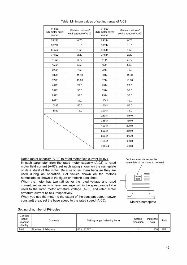
49
Table: Minimum values of setting range of A-02
VF66B (DC motor drive)
model
Minimum value of setting range of A-02
VF66B (DC motor drive)
model
Minimum value of setting range of A-02
2R222 0.75 2R244 0.75
3R722 1.10 3R744 1.10
5R522 1.50 5R544 1.50
7R522 2.20 7R544 2.20
1122 3.70 1144 3.70
1522 5.50 1544 5.50
2222 7.50 2244 7.50
3022 11.00 3044 11.00
3722 15.00 3744 15.00
4522 22.0 4544 22.0
5522 30.0 5544 30.0
7522 37.0 7544 37.0
9022 45.0 11044 45.0
15022 55.0 16044 55.0
18022 75.0 20044 75.0
25044 110.0
31544 160.0
40044 200.0
50044 250.0
60044 315.0
75044 400.0
100044 500.0
Rated motor capacity (A-02) to rated motor field current (A-07): In each parameter from the rated motor capacity (A-02) to rated motor field current (A-07), set each rating shown on the nameplate or data sheet of the motor. Be sure to set them because they are used during an operation. Set values shown on the motor's nameplate as shown in the figure or motor's data sheet. When the motor has two ratings for the rated voltage and rated current, set values whichever are larger within the speed range to be used to the rated motor armature voltage (A-03) and rated motor armature current (A-04), respectively. When you use the motor to the extent of the constant output (power constant) area, set the base speed to the rated speed (A-05). Motor's nameplate
Setting of number of PG-pulse
Console panel
monitor display
Contents Setting range (selecting item) Setting
resolution Initialized
data Unit
A-08 Number of PG-pulse 60 to 32767 1 600 P/R
Name- plate
Set the values shown on the nameplate of the motor to be used.
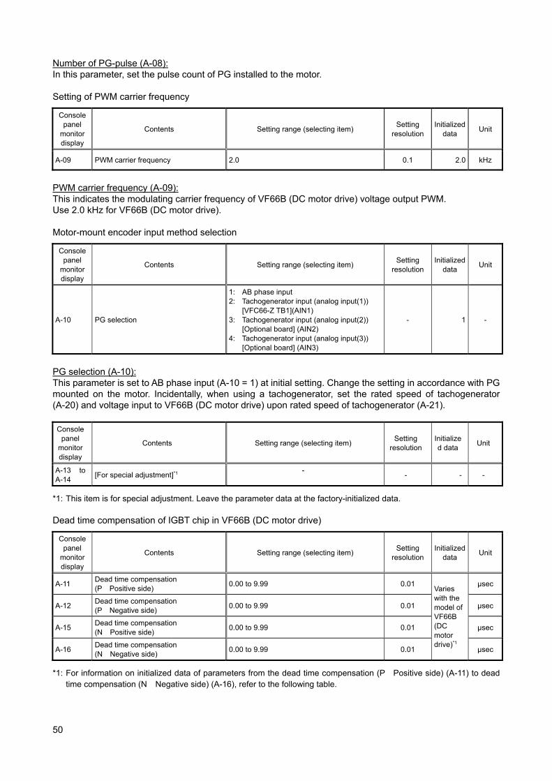
50
Number of PG-pulse (A-08): In this parameter, set the pulse count of PG installed to the motor. Setting of PWM carrier frequency
Console panel
monitor display
Contents Setting range (selecting item) Setting
resolution Initialized
data Unit
A-09 PWM carrier frequency 2.0 0.1 2.0 kHz
PWM carrier frequency (A-09): This indicates the modulating carrier frequency of VF66B (DC motor drive) voltage output PWM. Use 2.0 kHz for VF66B (DC motor drive). Motor-mount encoder input method selection
Console panel
monitor display
Contents Setting range (selecting item) Setting
resolution Initialized
data Unit
A-10 PG selection
1: AB phase input 2: Tachogenerator input (analog input(1))
[VFC66-Z TB1](AIN1) 3: Tachogenerator input (analog input(2))
[Optional board] (AIN2) 4: Tachogenerator input (analog input(3))
[Optional board] (AIN3)
- 1 -
PG selection (A-10): This parameter is set to AB phase input (A-10 = 1) at initial setting. Change the setting in accordance with PG mounted on the motor. Incidentally, when using a tachogenerator, set the rated speed of tachogenerator (A-20) and voltage input to VF66B (DC motor drive) upon rated speed of tachogenerator (A-21).
Console panel
monitor display
Contents Setting range (selecting item) Setting
resolution Initialized data
Unit
A-13 to A-14
[For special adjustment]*1 -
- - -
*1: This item is for special adjustment. Leave the parameter data at the factory-initialized data. Dead time compensation of IGBT chip in VF66B (DC motor drive)
Console panel
monitor display
Contents Setting range (selecting item) Setting
resolution Initialized
data Unit
A-11 Dead time compensation (P Positive side)
0.00 to 9.99 0.01 Varies with the model of VF66B (DC motor drive)*1
μsec
A-12 Dead time compensation (P Negative side)
0.00 to 9.99 0.01 μsec
A-15 Dead time compensation (N Positive side)
0.00 to 9.99 0.01 μsec
A-16 Dead time compensation (N Negative side)
0.00 to 9.99 0.01 μsec
*1: For information on initialized data of parameters from the dead time compensation (P Positive side) (A-11) to dead time compensation (N Negative side) (A-16), refer to the following table.
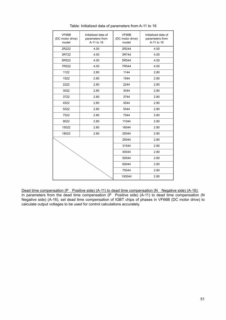
51
Table: Initialized data of parameters from A-11 to 16
VF66B (DC motor drive)
model
Initialized data of parameters from
A-11 to 16
VF66B (DC motor drive)
model
Initialized data of parameters from
A-11 to 16
2R222 4.00 2R244 4.00
3R722 4.00 3R744 4.00
5R522 4.00 5R544 4.00
7R522 4.00 7R544 4.00
1122 2.80 1144 2.80
1522 2.80 1544 2.80
2222 2.80 2244 2.80
3022 2.80 3044 2.80
3722 2.80 3744 2.80
4522 2.80 4544 2.80
5522 2.80 5544 2.80
7522 2.80 7544 2.80
9022 2.80 11044 2.80
15022 2.80 16044 2.80
18022 2.80 20044 2.80
25044 2.80
31544 2.80
40044 2.80
50044 2.80
60044 2.80
75044 2.80
100044 2.80
Dead time compensation (P Positive side) (A-11) to dead time compensation (N Negative side) (A-16): In parameters from the dead time compensation (P Positive side) (A-11) to dead time compensation (N Negative side) (A-16), set dead time compensation of IGBT chips of phases in VF66B (DC motor drive) to calculate output voltages to be used for control calculations accurately.
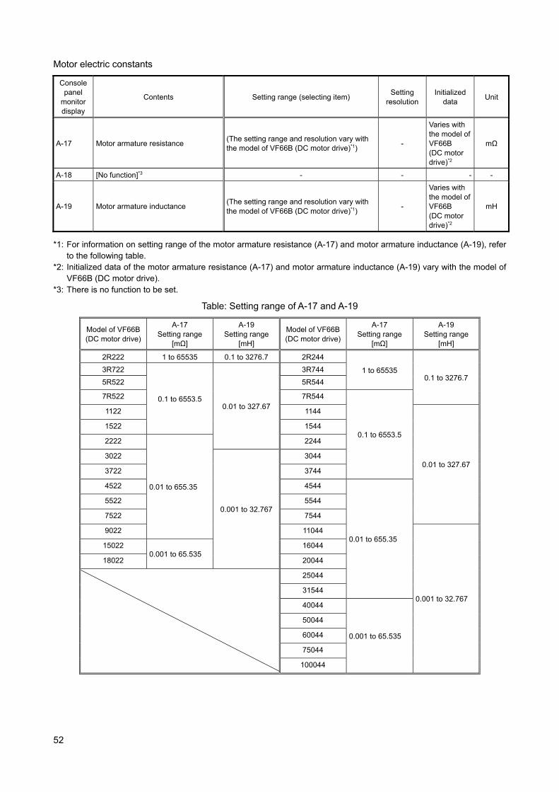
52
Motor electric constants
Console panel
monitor display
Contents Setting range (selecting item) Setting
resolution Initialized
data Unit
A-17 Motor armature resistance (The setting range and resolution vary with the model of VF66B (DC motor drive)*1)
-
Varies with the model of VF66B (DC motor drive)*2
mΩ
A-18 [No function]*3 - - - -
A-19 Motor armature inductance (The setting range and resolution vary with the model of VF66B (DC motor drive)*1)
-
Varies with the model of VF66B (DC motor drive)*2
mH
*1: For information on setting range of the motor armature resistance (A-17) and motor armature inductance (A-19), refer to the following table.
*2: Initialized data of the motor armature resistance (A-17) and motor armature inductance (A-19) vary with the model of VF66B (DC motor drive).
*3: There is no function to be set.
Table: Setting range of A-17 and A-19
Model of VF66B (DC motor drive)
A-17 Setting range
[mΩ]
A-19 Setting range
[mH]
Model of VF66B (DC motor drive)
A-17 Setting range
[mΩ]
A-19 Setting range
[mH]
2R222 1 to 65535 0.1 to 3276.7 2R244
1 to 65535 0.1 to 3276.7
3R722
0.1 to 6553.5 0.01 to 327.67
3R744
5R522 5R544
7R522 7R544
0.1 to 6553.5
1122 1144
0.01 to 327.67
1522 1544
2222
0.01 to 655.35
2244
3022
0.001 to 32.767
3044
3722 3744
4522 4544
0.01 to 655.35
5522 5544
7522 7544
9022 11044
0.001 to 32.767
15022 0.001 to 65.535
16044
18022 20044
25044
31544
40044
0.001 to 65.535
50044
60044
75044
100044
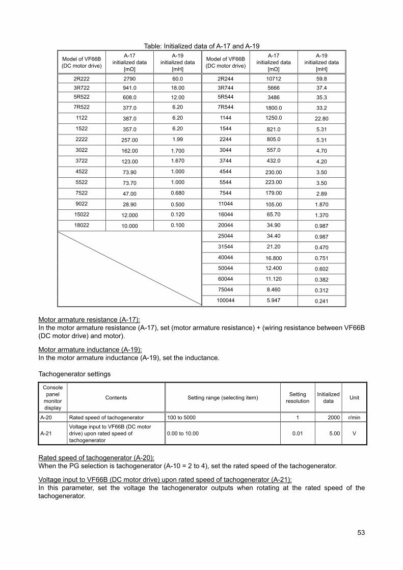
53
Table: Initialized data of A-17 and A-19
Model of VF66B (DC motor drive)
A-17 initialized data
[mΩ]
A-19 initialized data
[mH]
Model of VF66B (DC motor drive)
A-17 initialized data
[mΩ]
A-19 initialized data
[mH]
2R222 2790 60.0 2R244 10712 59.8
3R722 941.0 18.00 3R744 5666 37.4
5R522 608.0 12.00 5R544 3486 35.3
7R522 377.0 6.20 7R544 1800.0 33.2
1122 387.0 6.20 1144 1250.0 22.80
1522 357.0 6.20 1544 821.0 5.31
2222 257.00 1.99 2244 805.0 5.31
3022 162.00 1.700 3044 557.0 4.70
3722 123.00 1.670 3744 432.0 4.20
4522 73.90 1.000 4544 230.00 3.50
5522 73.70 1.000 5544 223.00 3.50
7522 47.00 0.680 7544 179.00 2.89
9022 28.90 0.500 11044 105.00 1.870
15022 12.000 0.120 16044 65.70 1.370
18022 10.000 0.100 20044 34.90 0.987
25044 34.40 0.987
31544 21.20 0.470
40044 16.800 0.751
50044 12.400 0.602
60044 11.120 0.382
75044 8.460 0.312
100044 5.947 0.241
Motor armature resistance (A-17): In the motor armature resistance (A-17), set (motor armature resistance) + (wiring resistance between VF66B (DC motor drive) and motor).
Motor armature inductance (A-19): In the motor armature inductance (A-19), set the inductance. Tachogenerator settings
Console panel
monitor display
Contents Setting range (selecting item) Setting
resolution Initialized
data Unit
A-20 Rated speed of tachogenerator 100 to 5000 1 2000 r/min
A-21 Voltage input to VF66B (DC motor drive) upon rated speed of tachogenerator
0.00 to 10.00 0.01 5.00 V
Rated speed of tachogenerator (A-20): When the PG selection is tachogenerator (A-10 = 2 to 4), set the rated speed of the tachogenerator.
Voltage input to VF66B (DC motor drive) upon rated speed of tachogenerator (A-21): In this parameter, set the voltage the tachogenerator outputs when rotating at the rated speed of the tachogenerator.
54
Field current monitor settings
Console panel
monitor display
Contents Setting range (selecting item) Setting
resolution Initialized
data Unit
A-22 Field current monitoring input location selection
0: No input 1: Analog input (1)
[VFC66-Z TB1](AIN1) 2: Analog input (2)
[Optional board] (AIN2) 3: Analog input (3)
[Optional board] (AIN3)
- 0 -
A-23 Voltage input to VF66B (DC motor drive) upon rated field current
0.1 to 10.0 0.1 4.0 V
Field current monitoring input location selection (A-22): The field current output by the field amplifier is input to VF66B (DC motor drive) using DCCT, allowing to display the magnitude of the field current on the monitor of the console panel. In this parameter, set the location of VF66B (DC motor drive) to input the voltage that is output by DCCT to carry out the process described above.
Voltage input to VF66B (DC motor drive) upon rated field current (A-23): In this parameter, set the voltage (voltage to be input to VF66B (DC motor drive)) output by DCCT when the field amplifier is outputting the rated field current.
Console panel
monitor display
Contents Setting range (selecting item) Setting
resolution Initialized
data Unit
A-24 to A-27
[No function]*1 - - - -
*1: There is no function to be set. 7.3. Area b (Operation Sequence Setting Area) Parameter data write protection setting
Console panel
monitor display
Contents Setting range (selecting item) Setting
resolution Initialized
data Unit
b-00 Setting data rewrite protection oFF (None) on (Setting data rewrite protection)
- oFF -
Setting data rewrite protection (b-00): When (b-00) is set to "ON," you cannot change data from the console or in other ways. When you want to change the setting value of the parameter, select this as "OFF." *When you try to rewrite data with (b-00) set to "ON,"
appears in the seven-segment display on the console.

55
Selection of stop mode
Console panel
monitor display
Contents Setting range (selecting item) Setting
resolution Initialized
data Unit
b-01 Stop mode selection 0: Free stop 1: Deceleration stop
- 1 -
b-02 Stop speed 0 to 300 1 30 r/min
b-03 [No function]*1 - - - -
b-04 [No function]*1 - - - -
b-05 JOG stop mode selection 0: Free stop 1: Deceleration stop
- 0 -
b-06 JOG stop speed 0 to 300 1 30 r/min
*1: There is no function to be set.
Stop mode selection (b-01), JOG stop mode selection (b-05): In the Stop mode selection (b-01) and the JOG stop mode selection (b-05), select a behavior when turning off an operation or jog command. When the Operation mode selection (i-07) is not "0" (speed control mode), free stop always occurs regardless of the settings of (b-01) and (b-05).
Stop speed (b-02), JOG stop speed (b-06): In the stop speed (b-02) and JOG stop speed (b-06), set speeds for stopping an operation or JOG operation.
Free stop Deceleration stop
Turning off an operation or JOG command will cause VF66B (DC motor drive) to stop voltage output.
VF66B (DC motor drive) gradually decelerates according to the deceleration time until it reaches the settings of the Stop speed (b-02) and the JOG stop speed (b-06), and then it stops voltage output.
Operation/JOG command
Motor speed
Output current
Free run
Operation/JOG command
Motor speed
Output current
b-02/b-06
Caution [About free run] Note that a DC motor generates a voltage proportional to the speed even in a free run state due to the field current. When you want to shut down the output voltage immediately after turning off the operation in a case where the power constant area is used, insert an output MC (electromagnetic contactor) between the motor and VF66B (DC motor drive) and operate this MC through the 52MA relay of VF66B (DC motor drive).
56
Instantaneous power interruption restart behavior setting
Console panel
monitor display
Contents Setting range (selecting item) Setting
resolution Initialized
data Unit
b-07 Instantaneous power interruption restart
oFF (Not restart) on (Restart)
- oFF -
Instantaneous power interruption restart (b-07): Instantaneous power interruption means that direct current voltage becomes the specified value or less and then returns to the specified value or more without control power failure. Select whether or not restarting VF66B (DC motor drive) after restoring power when instantaneous power interruption occurs and the operation is temporarily stopped.
oFF: VF66B (DC motor drive) does not restart even after the power is restored. (It remains to be stopped.) To restart it, you need to turn off the operation or JOG command and turn it on.
on: VF66B (DC motor drive) automatically restarts after the power is restored.However, when it operates from the contact signal or the digital communication option command, the operation command to the inverter should be kept "ON." (After the inverter stops, when you cannot restart it with the operation command kept "ON," the startup stall protection (
) will operate.)
Warning [About instantaneous power interruption restart] When the instantaneous power interruption restart (b-07) is set to on, the motor automatically restarts after
detecting instantaneous power interruption and restoring power. Therefore, do not come close to the motor while instantaneous power interruption is being detected. Otherwise, you may be injured.
Reverse rotation prohibition mode setting
Console panel
monitor display
Contents Setting range (selecting item) Setting
resolution Initialized
data Unit
b-08 Reverse rotation/reverse voltage prohibition mode selection
0: Normal 1: Prohibit operation in the direction opposite
to command 2: Prohibit opposite direction
- 0 -
Reverse rotation/reverse voltage prohibition mode selection (b-08): This parameter prohibits reverse rotation/reverse voltage operation. ・Normal (b-08 = 0): This is a normal operation. There is no limit on both the forward and reverse operations.
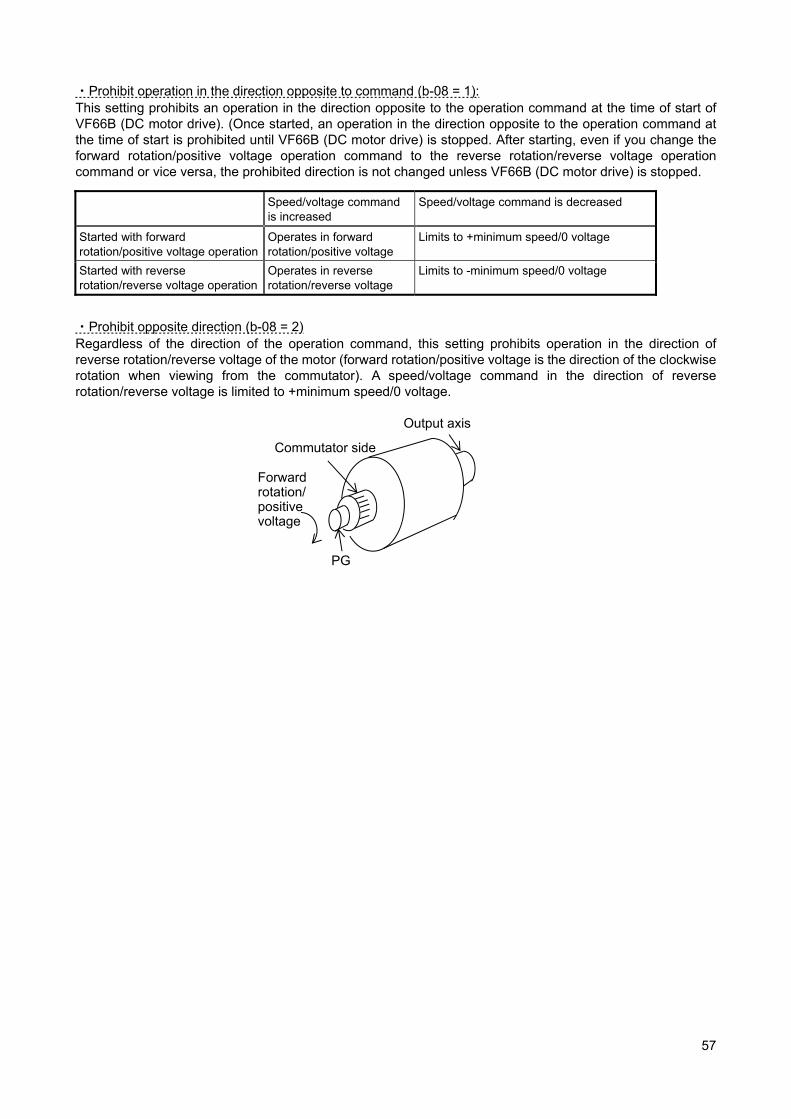
57
・Prohibit operation in the direction opposite to command (b-08 = 1): This setting prohibits an operation in the direction opposite to the operation command at the time of start of VF66B (DC motor drive). (Once started, an operation in the direction opposite to the operation command at the time of start is prohibited until VF66B (DC motor drive) is stopped. After starting, even if you change the forward rotation/positive voltage operation command to the reverse rotation/reverse voltage operation command or vice versa, the prohibited direction is not changed unless VF66B (DC motor drive) is stopped.
Speed/voltage command is increased
Speed/voltage command is decreased
Started with forward rotation/positive voltage operation
Operates in forward rotation/positive voltage
Limits to +minimum speed/0 voltage
Started with reverse rotation/reverse voltage operation
Operates in reverse rotation/reverse voltage
Limits to -minimum speed/0 voltage
・Prohibit opposite direction (b-08 = 2) Regardless of the direction of the operation command, this setting prohibits operation in the direction of reverse rotation/reverse voltage of the motor (forward rotation/positive voltage is the direction of the clockwise rotation when viewing from the commutator). A speed/voltage command in the direction of reverse rotation/reverse voltage is limited to +minimum speed/0 voltage.
Commutator side
Output axis
PG
Forward rotation/ positive voltage
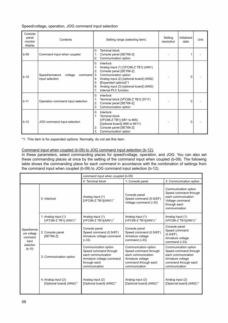
58
Speed/voltage, operation, JOG command input selection
Console panel
monitor display
Contents Setting range (selecting item) Setting
resolution Initialized
data Unit
b-09 Command input when coupled 0: Terminal block 1: Console panel [SET66-Z] 2: Communication option
- 1 -
b-10 Speed/armature voltage command input selection
0: Interlock 1: Analog input (1) [VFC66-Z TB1] (AIN1) 2: Console panel [SET66-Z] 3: Communication option 4: Analog input (2) [optional board] (AIN2) 5: [Expanded options]*1 6: Analog input (3) [optional board] (AIN3) 7: Internal PLC function
- 0 -
b-11 Operation command input selection
0: Interlock 1: Terminal block [VFC66-Z TB1] (ST-F) 2: Console panel [SET66-Z] 3: Communication option
- 0 -
b-12 JOG command input selection
0: Interlock 1: Terminal block
[VFC66-Z TB1] (MI1 to MI5) [Optional board] (MI6 to MI17)
2: Console panel [SET66-Z] 3: Communication option
- 0 -
*1: This item is for expanded options. Normally, do not set this item.
Command input when coupled (b-09) to JOG command input selection (b-12): In these parameters, select commanding places for speed/voltage, operation, and JOG. You can also set these commanding places at once by the setting of the command input when coupled (b-09). The following table shows the commanding place for each command in accordance with the combination of settings from the command input when coupled (b-09) to JOG command input selection (b-12).
command input when coupled (b-09)
0: Terminal block 1: Console panel 2: Communication option
Speed/armature voltage command
input selection
(b-10)
0: Interlock Analog input (1) [VFC66-Z TB1](AIN1)*1
Console panel Speed command (0.SrEF)Voltage command (i-33)
Communication option Speed command through each communication Voltage command through each communication
1: Analog input (1) [VFC66-Z TB1] (AIN1)*1
Analog input (1) [VFC66-Z TB1](AIN1)*1
Analog input (1) [VFC66-Z TB1](AIN1)*1
Analog input (1) [VFC66-Z TB1](AIN1)*1
2: Console panel [SET66-Z]
Console panel Speed command (0.SrEF) Armature voltage command (i-33)
Console panel Speed command (0.SrEF)Armature voltage command (i-33)
Console panel Speed command (0.SrEF) Armature voltage command (i-33)
3: Communication option
Communication option Speed command through each communication Armature voltage command through each communication
Communication option Speed command through each communication Armature voltage command through each communication
Communication option Speed command through each communication Armature voltage command through each communication
4: Analog input (2) [Optional board] (AIN2)*2
Analog input (2) [Optional board] (AIN2)*2
Analog input (2) [Optional board] (AIN2)*2
Analog input (2) [Optional board] (AIN2)*2
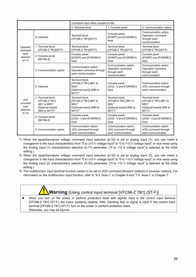
59
command input when coupled (b-09)
0: Terminal block 1: Console panel 2: Communication option
Operation command
input selection
(b-11)
0: Interlock Terminal block [VFC66-Z TB1](ST-F)
Console panel [START] and [FOR/REV] keys
Communication option Operation command through each communication
1: Terminal block [VFC66-Z TB1](ST-F)
Terminal block [VFC66-Z TB1](ST-F)
Terminal block [VFC66-Z TB1](ST-F)
Terminal block [VFC66-Z TB1](ST-F)
2: Console panel [SET66-Z]
Console panel [START] and [FOR/REV] keys
Console panel [START] and [FOR/REV] keys
Console panel [START] and [FOR/REV] keys
3: Communication option Communication option Operation command through each communication
Communication option Operation command through each communication
Communication option Operation command through each communication
JOG command
input selection
(b-12)
0: Interlock
Terminal block [VFC66-Z TB1] (MI1 to MI5)*3
[Optional board] (MI6 to MI17)*3
Console panel [JOG/→] and [FOR/REV] keys
Communication option JOG command through each communication
1: Terminal block [VFC66-Z TB1] (MI1 to MI5)*3 [Optional board] (MI6 to MI17)*3
Terminal block [VFC66-Z TB1] (MI1 to MI5)*3
[Optional board] (MI6 to MI17)*3
Terminal block [VFC66-Z TB1] (MI1 to MI5)*3
[Optional board] (MI6 to MI17)*3
Terminal block [VFC66-Z TB1] (MI1 to MI5)*3
[Optional board] (MI6 to MI17)*3
2: Console panel [SET66-Z]
Console panel [JOG/→] and [FOR/REV] keys
Console panel [JOG/→] and [FOR/REV] keys
Console panel [JOG/→] and [FOR/REV] keys
3: Communication option Communication option JOG command through each communication
Communication option JOG command through each communication
Communication option JOG command through each communication
*1: When the speed/armature voltage command input selection (b-10) is set to analog input (1), you can make a changeover in the input characteristics from "0 to ±10 V voltage input" to "0 to +10 V voltage input" or vice versa using the Analog input (1) characteristics selection (b-17) parameter. ("0 to +10 V voltage input" is selected as the initial setting.)
*2: When the speed/armature voltage command input selection (b-10) is set to analog input (2), you can make a changeover in the input characteristics from "0 to ±10 V voltage input" to "0 to +10 V voltage input" or vice versa using the Analog input (2) characteristics selection (G-03) parameter. ("0 to +10 V voltage input" is selected as the initial setting.)
*3: The multifunction input terminal function needs to be set to JOG command [forward rotation] or [reverse rotation]. For information on the multifunction input function, refer to "6.4. Area c" in Chapter 6 and "7.4. Area c" in Chapter 7.
Warning [Using control input terminal [VFC66-Z TB1] (ST-F)] When you turn on the power or perform protection reset with signals input in the control input terminal
[VFC66-Z TB1] (ST-F), the motor suddenly restarts. After checking that no signal is input in the control input terminal [VFC66-Z TB1] (ST-F), turn on the power or perform protection reset. Otherwise, you may be injured.

60
Settings of current limiter
Console panel
monitor display
Contents Setting range (selecting item) Setting
resolution Initialized
data Unit
b-13 Forward powering armature current limit
0 to value that depends on rated motor armature current <A-04>*1
1 150 %
b-14 Forward regenerative armature current limit
-value that depends on rated motor armature current <A-04>*1 to 0
1 -150 %
b-15 Reverse powering armature current limit
-value that depends on rated motor armature current <A-04>*1 to 0
1 -150 %
b-16 Reverse regenerative armature current limit
0 to value that depends on rated motor armature current <A-04>*1
1 150 %
*1: The maximum (minimum) value of the armature current limit varies with the model of VF66B (DC motor drive) ・For models less than 7522, 7544 The value is calculated by 200 x (rated current of VF66B (DC motor drive)/rated motor armature current (A-04). If the calculated value exceeds 200%, the maximum (minimum) value is 200%.
・For models greater than or equal to 7522, 7544 The value is calculated by 150 x (rated current of VF66B (DC motor drive)/rated motor armature current (A-04). If the calculated value exceeds 200%, the maximum (minimum) value is 200%.
Forward powering armature current limit (b-13) to reverse regenerative armature current limit (b-16): In these parameters, set armature current limits of power running and regeneration for each of forward rotation and reverse rotation. When an armature current command exceeds any of these values, it is limited to these setting values. Incidentally, the rated current of VF66B (DC motor drive) is 100%. Analog speed/voltage command characteristics settings (analog input (1) [VFC66-Z TB1] (AIN1))
Console panel
monitor display
Contents Setting range (selecting item) Setting
resolution Initialized
data Unit
b-17 Analog input (1) characteristics selection
0: 0 to ±10 V (bipolarity) 1: 0 to 10 V (unipolarity) 2: 4 to 20 mA
- 1 -
b-18 Analog input (1) speed/voltage upper limit
Absolute value of analog input (1) speed/voltage lower limit (b-19)
to 100.00.1 100.0 %
b-19 Analog input (1) speed/voltage lower limit
-analog input (1) speed/voltage upper limit (b-18)
to analog input (1) speed/voltage upper limit (b-18)
0.1 0.0 %
Analog input (1) characteristics selection (b-17): In this parameter, select the type of input characteristics of analog input (1) of [VFC66-Z TB1] (AIN1). Analog input (1) speed/voltage upper limit (b-18), analog input (1) speed/voltage lower limit (b-19): Settings for the analog input (1) speed/voltage upper limit (b-18) and analog input (1) speed/voltage lower limit (b-19) vary depending on the operation mode selection (i-07). ・When the operation mode selection is speed control mode (i-07 = 0) Set the ratio to the maximum speed (A-00).
・When the operation mode selection is armature voltage control mode (i-07 = 5) Set the ratio to the forward direction output maximum voltage (E-11) or reverse direction output maximum voltage (E-12) whichever its absolute value is larger.
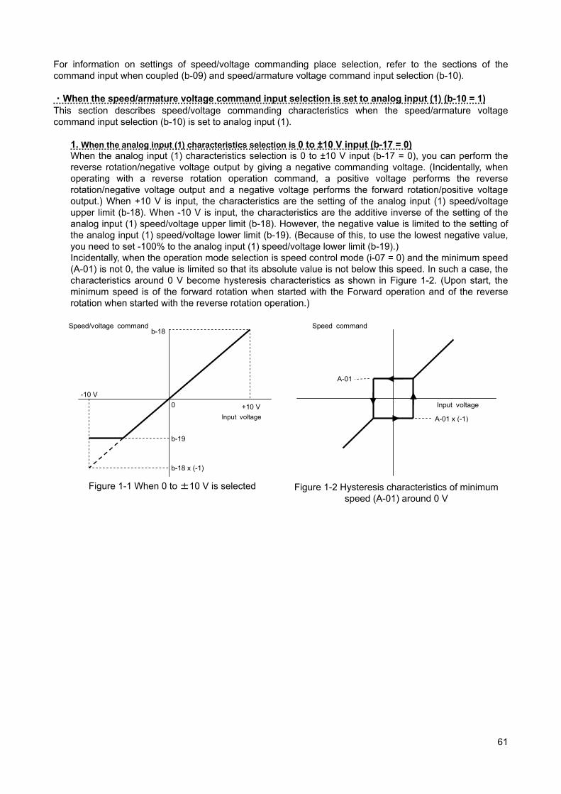
61
For information on settings of speed/voltage commanding place selection, refer to the sections of the command input when coupled (b-09) and speed/armature voltage command input selection (b-10). ・When the speed/armature voltage command input selection is set to analog input (1) (b-10 = 1) This section describes speed/voltage commanding characteristics when the speed/armature voltage command input selection (b-10) is set to analog input (1).
1. When the analog input (1) characteristics selection is 0 to ±10 V input (b-17 = 0) When the analog input (1) characteristics selection is 0 to ±10 V input (b-17 = 0), you can perform the reverse rotation/negative voltage output by giving a negative commanding voltage. (Incidentally, when operating with a reverse rotation operation command, a positive voltage performs the reverse rotation/negative voltage output and a negative voltage performs the forward rotation/positive voltage output.) When +10 V is input, the characteristics are the setting of the analog input (1) speed/voltage upper limit (b-18). When -10 V is input, the characteristics are the additive inverse of the setting of the analog input (1) speed/voltage upper limit (b-18). However, the negative value is limited to the setting of the analog input (1) speed/voltage lower limit (b-19). (Because of this, to use the lowest negative value, you need to set -100% to the analog input (1) speed/voltage lower limit (b-19).) Incidentally, when the operation mode selection is speed control mode (i-07 = 0) and the minimum speed (A-01) is not 0, the value is limited so that its absolute value is not below this speed. In such a case, the characteristics around 0 V become hysteresis characteristics as shown in Figure 1-2. (Upon start, the minimum speed is of the forward rotation when started with the Forward operation and of the reverse rotation when started with the reverse rotation operation.)
Input voltage
+10 V
-10 V
Speed/voltage command b-18
b-19
0
b-18 x (-1)
Figure 1-1 When 0 to ±10 V is selected
Speed command
A-01
A-01 x (-1)
Input voltage
Figure 1-2 Hysteresis characteristics of minimum speed (A-01) around 0 V

62
2. When the analog input (1) characteristics selection is 0 to +10V input (b-17 = 1) When 0V is input, the characteristics are the setting of the analog input (1) speed/voltage lower limit (b-19). When +10V is input, the characteristics are the setting of the analog input (1) speed/voltage upper limit (b-18) (Figure 2-1). However, those are effective for positive voltages only. Negative voltages are limited to the analog input (1) speed/voltage lower limit (b-19) (or 0 when a negative value is set to the analog input (1) speed/voltage lower limit (b-19)) (Figure 2-2). Incidentally, when the operation mode selection is speed control mode (i-07 = 0) and the minimum speed (A-01) is not 0, the value is limited so that its absolute value is not below this speed. Since the speed command is for the forward rotation only, use the reverse rotation operation command to perform the reverse rotation.
b-19
b-18
+10 V0V
Input voltage
Speed/voltage command
Figure 2-1 When 0 to +10V is selected (Analog input (1) speed/voltage lower limit (b-19) is 0
or more)
b-19
b-18
+10 V0V
Input voltage
Speed/voltage command
Figure 2-2 When 0 to +10V is selected (Analog input (1) speed/voltage lower limit (b-19)
is less than 0)
3. When the analog input (1) characteristics selection is 4 to 20 mA input (b-17 = 2) When 4 mA is input, the characteristics are the setting of the analog input (1) speed/voltage lower limit (b-19). When 20 mA is input, the characteristics are the setting of the analog input (1) speed/voltage upper limit (b-18) (Figure 3-1). However, those are effective for positive currents only. When a negative current is input, it is limited to the analog input (1) speed/voltage lower limit (b-19) (or 0 when a negative value is set to the analog input (1) speed/voltage lower limit (b-19)) (Figure 3-2). Incidentally, when the operation mode selection is speed control mode (i-07 = 0) and the minimum speed (A-01) is not 0, the value is limited so that its absolute value is not below this speed. Since the speed command is for the forward rotation only, use the reverse rotation operation command to perform the reverse rotation.
b-19
b-18
20 mA4 mA
Input current
Speed/voltage command
Figure 3-1 When 4 to 20 mA is selected
(when b-19 is 0 or more)
b-19
b-18
20 mA
4 mA
Input current
Speed/voltage command
Figure 3-2 When 4 to 20 mA is selected
(when b-19 is less than 0)
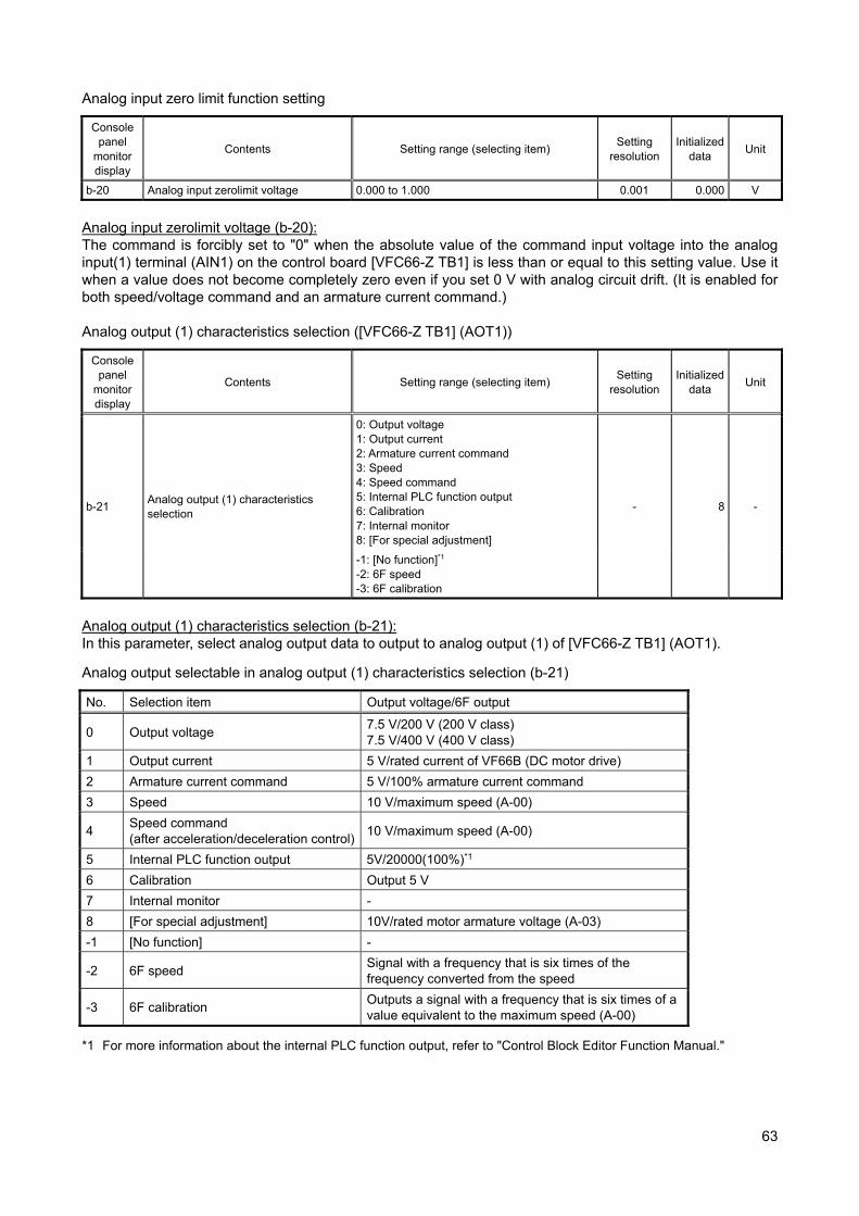
63
Analog input zero limit function setting
Console panel
monitor display
Contents Setting range (selecting item) Setting
resolution Initialized
data Unit
b-20 Analog input zerolimit voltage 0.000 to 1.000 0.001 0.000 V
Analog input zerolimit voltage (b-20): The command is forcibly set to "0" when the absolute value of the command input voltage into the analog input(1) terminal (AIN1) on the control board [VFC66-Z TB1] is less than or equal to this setting value. Use it when a value does not become completely zero even if you set 0 V with analog circuit drift. (It is enabled for both speed/voltage command and an armature current command.) Analog output (1) characteristics selection ([VFC66-Z TB1] (AOT1))
Console panel
monitor display
Contents Setting range (selecting item) Setting
resolution Initialized
data Unit
b-21 Analog output (1) characteristics selection
0: Output voltage 1: Output current 2: Armature current command 3: Speed 4: Speed command 5: Internal PLC function output 6: Calibration 7: Internal monitor 8: [For special adjustment]
- 8 -
-1: [No function]*1 -2: 6F speed -3: 6F calibration
Analog output (1) characteristics selection (b-21): In this parameter, select analog output data to output to analog output (1) of [VFC66-Z TB1] (AOT1).
Analog output selectable in analog output (1) characteristics selection (b-21)
No. Selection item Output voltage/6F output
0 Output voltage 7.5 V/200 V (200 V class) 7.5 V/400 V (400 V class)
1 Output current 5 V/rated current of VF66B (DC motor drive)
2 Armature current command 5 V/100% armature current command
3 Speed 10 V/maximum speed (A-00)
4 Speed command (after acceleration/deceleration control)
10 V/maximum speed (A-00)
5 Internal PLC function output 5V/20000(100%)*1
6 Calibration Output 5 V
7 Internal monitor -
8 [For special adjustment] 10V/rated motor armature voltage (A-03)
-1 [No function] -
-2 6F speed Signal with a frequency that is six times of the frequency converted from the speed
-3 6F calibration Outputs a signal with a frequency that is six times of a value equivalent to the maximum speed (A-00)
*1 For more information about the internal PLC function output, refer to "Control Block Editor Function Manual."
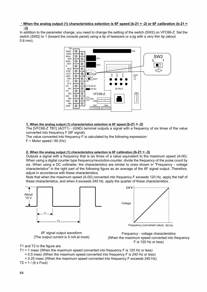
64
・When the analog output (1) characteristics selection is 6F speed (b-21 = -2) or 6F calibration (b-21 = -3)
In addition to the parameter change, you need to change the setting of the switch (SW2) on VFC66-Z. Set the switch (SW2) to 1 (toward the console panel) using a tip of tweezers or a jig with a very thin tip (about 0.8 mm).
TB1
CN-SO
CN-SI
RY1
CN3
SW2
SW1
CN4
LED1
52MA
86Aa
86Ab
P
COM
GND
+10
PS
PS
MI3
GND
GND
52MA
86A
MO1
MO2
AOT1
AIN1
ST-F
MI1
MI2
MI4
MI5
CN5
3 1
ON
RY2
CN6
SET66-Z
CN7 CN4
VFC66-Z
1. When the analog output (1) characteristics selection is 6F speed (b-21 = -2) The [VFC66-Z TB1] (AOT1) - (GND) terminal outputs a signal with a frequency of six times of the value converted into frequency F (6F signal). The value converted into frequency F is calculated by the following expression: F = Motor speed / 60 (Hz)
2. When the analog output (1) characteristics selection is 6F calibration (b-21 = -3) Outputs a signal with a frequency that is six times of a value equivalent to the maximum speed (A-00). When using a digital counter type frequency/revolution-counter, divide the frequency of the pulse count by six. When using a DC voltmeter, the characteristics are similar to ones shown in "Frequency - voltage characteristics" in the right part of the following figure as an average of the 6F signal output. Therefore, adjust in accordance with these characteristics. Note that when the maximum speed (A-00) converted into frequency F exceeds 120 Hz, apply the half of these characteristics, and when it exceeds 240 Hz, apply the quarter of these characteristics.
6F signal output waveform (The output current is 5 mA at most)
Frequency - voltage characteristics
(When the maximum speed converted into frequency F is 120 Hz or less)
T1 and T2 in the figure are T1 = 1 msec (When the maximum speed converted into frequency F is 120 Hz or less)
= 0.5 msec (When the maximum speed converted into frequency F is 240 Hz or less) = 0.25 msec (When the maximum speed converted into frequency F exceeds 240 Hz)
T2 = 1 / (6 x Fout)
T2
T1
About 10 V
3.6 V
60 HzFrequency (converted value)
Voltage
SW2 3 1
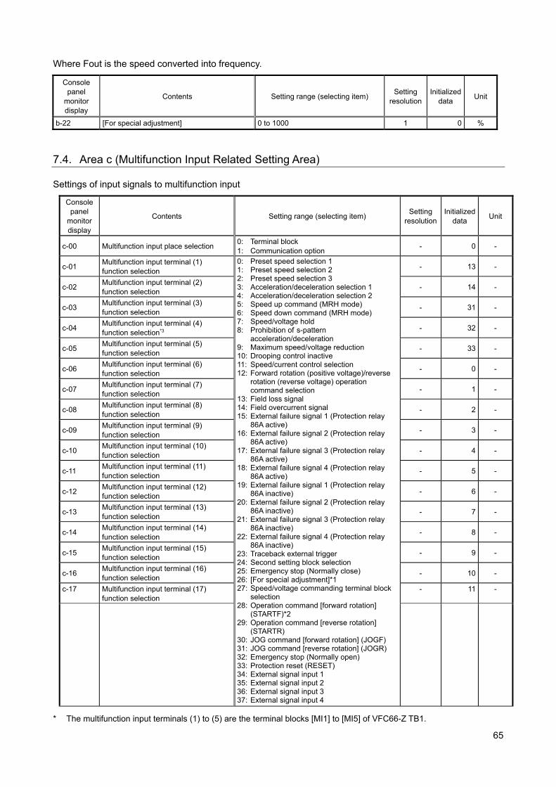
65
Where Fout is the speed converted into frequency.
Console panel
monitor display
Contents Setting range (selecting item) Setting
resolution Initialized
data Unit
b-22 [For special adjustment] 0 to 1000 1 0 %
7.4. Area c (Multifunction Input Related Setting Area) Settings of input signals to multifunction input
* The multifunction input terminals (1) to (5) are the terminal blocks [MI1] to [MI5] of VFC66-Z TB1.
Console panel
monitor display
Contents Setting range (selecting item) Setting
resolution Initialized
data Unit
c-00 Multifunction input place selection 0: Terminal block 1: Communication option
- 0 -
c-01 Multifunction input terminal (1) function selection
0: Preset speed selection 1 1: Preset speed selection 2 2: Preset speed selection 3 3: Acceleration/deceleration selection 1 4: Acceleration/deceleration selection 2 5: Speed up command (MRH mode) 6: Speed down command (MRH mode) 7: Speed/voltage hold 8: Prohibition of s-pattern
acceleration/deceleration 9: Maximum speed/voltage reduction 10: Drooping control inactive 11: Speed/current control selection 12: Forward rotation (positive voltage)/reverse
rotation (reverse voltage) operation command selection
13: Field loss signal 14: Field overcurrent signal 15: External failure signal 1 (Protection relay
86A active) 16: External failure signal 2 (Protection relay
86A active) 17: External failure signal 3 (Protection relay
86A active) 18: External failure signal 4 (Protection relay
86A active) 19: External failure signal 1 (Protection relay
86A inactive) 20: External failure signal 2 (Protection relay
86A inactive) 21: External failure signal 3 (Protection relay
86A inactive) 22: External failure signal 4 (Protection relay
86A inactive) 23: Traceback external trigger 24: Second setting block selection 25: Emergency stop (Normally close) 26: [For special adjustment]*1 27: Speed/voltage commanding terminal block
selection 28: Operation command [forward rotation]
(STARTF)*2 29: Operation command [reverse rotation]
(STARTR) 30: JOG command [forward rotation] (JOGF) 31: JOG command [reverse rotation] (JOGR) 32: Emergency stop (Normally open) 33: Protection reset (RESET) 34: External signal input 1 35: External signal input 2 36: External signal input 3 37: External signal input 4
- 13 -
c-02 Multifunction input terminal (2) function selection
- 14 -
c-03 Multifunction input terminal (3) function selection
- 31 -
c-04 Multifunction input terminal (4) function selection*3
- 32 -
c-05 Multifunction input terminal (5) function selection
- 33 -
c-06 Multifunction input terminal (6) function selection
- 0 -
c-07 Multifunction input terminal (7) function selection
- 1 -
c-08 Multifunction input terminal (8) function selection
- 2 -
c-09 Multifunction input terminal (9) function selection
- 3 -
c-10 Multifunction input terminal (10) function selection
- 4 -
c-11 Multifunction input terminal (11) function selection
- 5 -
c-12 Multifunction input terminal (12) function selection
- 6 -
c-13 Multifunction input terminal (13) function selection
- 7 -
c-14 Multifunction input terminal (14) function selection
- 8 -
c-15 Multifunction input terminal (15) function selection
- 9 -
c-16 Multifunction input terminal (16) function selection
- 10 -
c-17 Multifunction input terminal (17) function selection
- 11 -
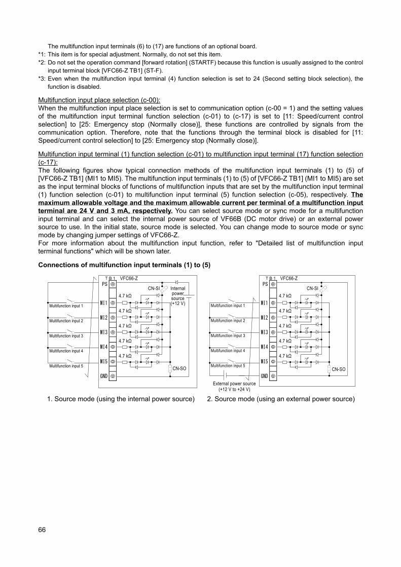
66
The multifunction input terminals (6) to (17) are functions of an optional board. *1: This item is for special adjustment. Normally, do not set this item. *2: Do not set the operation command [forward rotation] (STARTF) because this function is usually assigned to the control
input terminal block [VFC66-Z TB1] (ST-F). *3: Even when the multifunction input terminal (4) function selection is set to 24 (Second setting block selection), the
function is disabled.
Multifunction input place selection (c-00): When the multifunction input place selection is set to communication option (c-00 = 1) and the setting values of the multifunction input terminal function selection (c-01) to (c-17) is set to [11: Speed/current control selection] to [25: Emergency stop (Normally close)], these functions are controlled by signals from the communication option. Therefore, note that the functions through the terminal block is disabled for [11: Speed/current control selection] to [25: Emergency stop (Normally close)].
Multifunction input terminal (1) function selection (c-01) to multifunction input terminal (17) function selection (c-17): The following figures show typical connection methods of the multifunction input terminals (1) to (5) of [VFC66-Z TB1] (MI1 to MI5). The multifunction input terminals (1) to (5) of [VFC66-Z TB1] (MI1 to MI5) are set as the input terminal blocks of functions of multifunction inputs that are set by the multifunction input terminal (1) function selection (c-01) to multifunction input terminal (5) function selection (c-05), respectively. The maximum allowable voltage and the maximum allowable current per terminal of a multifunction input terminal are 24 V and 3 mA, respectively. You can select source mode or sync mode for a multifunction input terminal and can select the internal power source of VF66B (DC motor drive) or an external power source to use. In the initial state, source mode is selected. You can change mode to source mode or sync mode by changing jumper settings of VFC66-Z. For more information about the multifunction input function, refer to "Detailed list of multifunction input terminal functions" which will be shown later.
Connections of multifunction input terminals (1) to (5)
PS
MI1
MI2
MI3
MI4
MI5
GND
Multifunction input 1
Multifunction input 2
Multifunction input 3
Multifunction input 4
Multifunction input 5
4.7 kΩ
4.7 kΩ
4.7 kΩ
4.7 kΩ
4.7 kΩ
CN-SI
CN-SO
VFC66-Z TB1
Internal power source (+12 V)
1. Source mode (using the internal power source)
PS
MI1
MI2
MI3
MI4
MI5
GND
Multifunction input 1
Multifunction input 2
Multifunction input 3
Multifunction input 4
Multifunction input 5
4.7 kΩ
4.7 kΩ
4.7 kΩ
4.7 kΩ
4.7 kΩ
CN-SI
CN-SO
VFC66-Z TB1
External power source (+12 V to +24 V)
2. Source mode (using an external power source)

67
PS
MI1
MI2
MI3
MI4
MI5
GND
Multifunction input 1
Multifunction input 2
Multifunction input 3
Multifunction input 4
Multifunction input 5
4.7 kΩ
4.7 kΩ
4.7 kΩ
4.7 kΩ
4.7 kΩ
CN-SI
CN-SO
VFC66-Z TB1
Internal power source (+12 V)
3. Sync mode (using the internal power source)
PS
MI1
MI2
MI3
MI4
MI5
GND
Multifunction input 1
Multifunction input 2
Multifunction input 3
Multifunction input 4
Multifunction input 5
4.7 kΩ
4.7 kΩ
4.7 kΩ
4.7 kΩ
4.7 kΩ
CN-SI
CN-SO
VFC66-Z TB1
External power source
(+12 V to +24 V)
4. Sync mode (using an external power source)
Warning [Safety notice] Be sure to turn off VF66B (DC motor drive) before connecting terminals.
It may result in a risk of electric shock. Close the front cover before turning on the power.
It may result in a risk of electric shock. Be sure to turn off VF66B (DC motor drive) before handling the jumper.
It mayw result in a risk of electric shock, injury, failure, or malfunction.
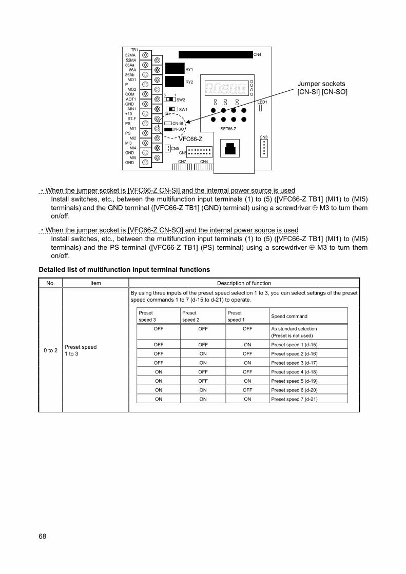
68
TB1
CN-SO
CN-SI
RY1
CN3
SW2
SW1
CN4
LED1
52MA
86Aa
86Ab
P
COM
GND
+10
PS
PS
MI3
GND
GND
52MA
86A
MO1
MO2
AOT1
AIN1
ST-F
MI1
MI2
MI4
MI5
CN5
3 1
ON
RY2
CN6
SET66-Z
CN7 CN4
VFC66-Z
・When the jumper socket is [VFC66-Z CN-SI] and the internal power source is used Install switches, etc., between the multifunction input terminals (1) to (5) ([VFC66-Z TB1] (MI1) to (MI5) terminals) and the GND terminal ([VFC66-Z TB1] (GND) terminal) using a screwdriver M3 to turn them on/off.
・When the jumper socket is [VFC66-Z CN-SO] and the internal power source is used Install switches, etc., between the multifunction input terminals (1) to (5) ([VFC66-Z TB1] (MI1) to (MI5) terminals) and the PS terminal ([VFC66-Z TB1] (PS) terminal) using a screwdriver M3 to turn them on/off.
Detailed list of multifunction input terminal functions
No. Item Description of function
0 to 2 Preset speed 1 to 3
By using three inputs of the preset speed selection 1 to 3, you can select settings of the preset speed commands 1 to 7 (d-15 to d-21) to operate.
Preset
speed 3
Preset
speed 2
Preset
speed 1 Speed command
OFF OFF OFF As standard selection
(Preset is not used)
OFF OFF ON Preset speed 1 (d-15)
OFF ON OFF Preset speed 2 (d-16)
OFF ON ON Preset speed 3 (d-17)
ON OFF OFF Preset speed 4 (d-18)
ON OFF ON Preset speed 5 (d-19)
ON ON OFF Preset speed 6 (d-20)
ON ON ON Preset speed 7 (d-21)
Jumper sockets [CN-SI] [CN-SO]
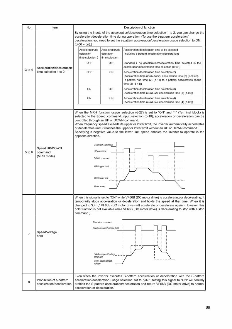
69
No. Item Description of function
3 to 4 Acceleration/deceleration time selection 1 to 2
By using the inputs of the acceleration/deceleration time selection 1 to 2, you can change the acceleration/deceleration time during operation. (To use the s-pattern acceleration/ deceleration, you need to set the s-pattern acceleration/deceleration usage selection to ON (d-06 = on).)
Acceleration/de
celeration
time selection 2
Acceleration/de
celeration
time selection 1
Acceleration/deceleration time to be selected
(including s-pattern acceleration/deceleration)
OFF OFF Standard (The acceleration/deceleration time selected in the
acceleration/deceleration time selection (d-00))
OFF ON Acceleration/deceleration time selection (2)
(Acceleration time (2) (5.Acc2), deceleration time (2) (6.dEc2),
s-pattern rise time (2) (d-11) to s-pattern deceleration reach
time (2) (d-14))
ON OFF Acceleration/deceleration time selection (3)
(Acceleration time (3) (d-02), deceleration time (3) (d-03))
ON ON Acceleration/deceleration time selection (4)
(Acceleration time (4) (d-04), deceleration time (4) (d-05))
5 to 6 Speed UP/DOWN command (MRH mode)
When the MRH_function_usage_selection (d-27) is set to "ON" and "1" (Terminal block) is selected to the Speed_command_input_selection (b-10), acceleration or deceleration can be controlled through an UP or DOWN command. When frequency/speed exceeds its upper or lower limit, the inverter automatically accelerates or decelerates until it reaches the upper or lower limit without an UP or DOWN command. Specifying a negative value to the lower limit speed enables the inverter to operate in the opposite direction.
Operation command
UP command
DOWN command
Motor speed
MRH lower limit
MRH upper limit
7 Speed/voltage hold
When this signal is set to "ON" while VF66B (DC motor drive) is accelerating or decelerating, it temporarily stops acceleration or deceleration and holds the speed at that time. When it is changed to "OFF," VF66B (DC motor drive) will accelerate or decelerate again. (However, this hold function is not available while VF66B (DC motor drive) is decelerating to stop with a stop command.)
Operation command
Rotation speed/voltage hold
Motor speed/output voltage
Rotation speed/voltage command
8 Prohibition of s-pattern acceleration/deceleration
Even when the inverter executes S-pattern acceleration or deceleration with the S-patternacceleration/deceleration usage selection set to "ON," setting this signal to "ON" will forcibly prohibit the S-pattern acceleration/deceleration and return VF66B (DC motor drive) to normal acceleration or deceleration.
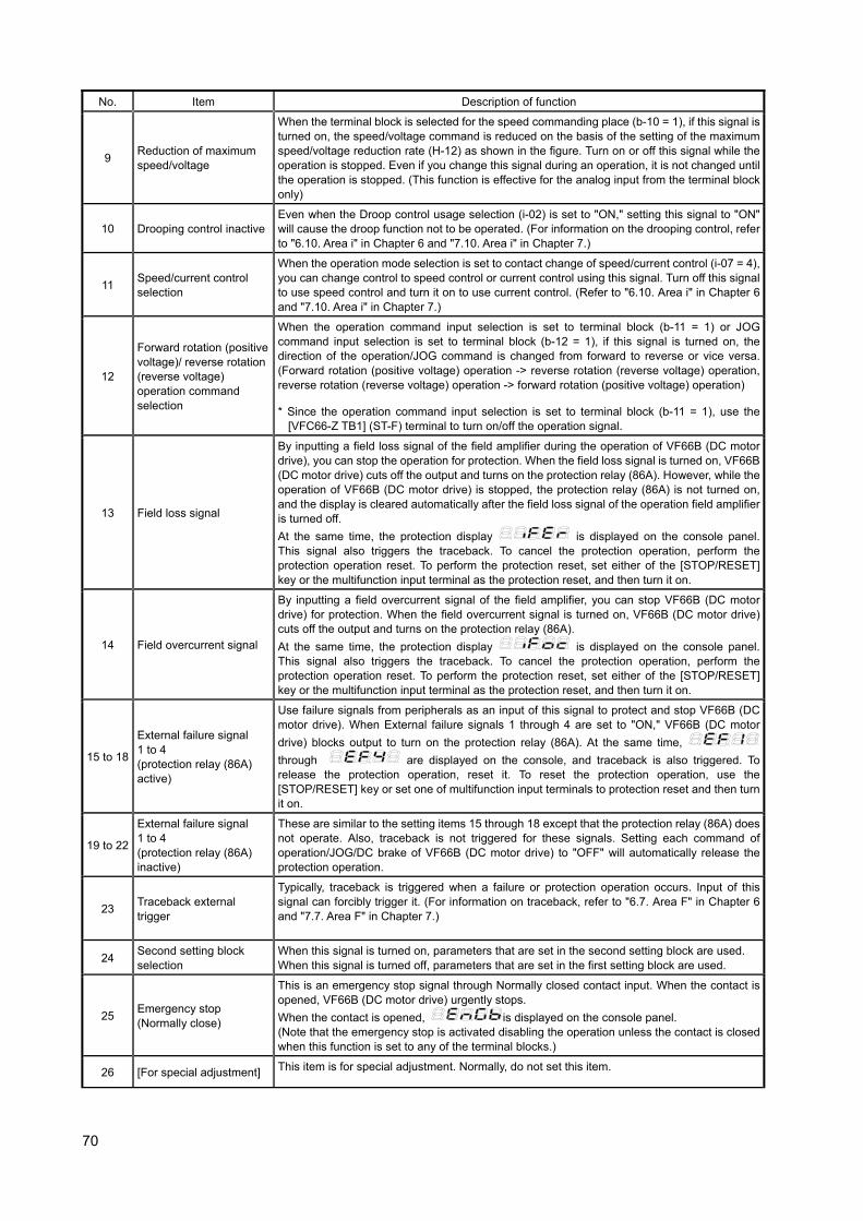
70
No. Item Description of function
9 Reduction of maximum speed/voltage
When the terminal block is selected for the speed commanding place (b-10 = 1), if this signal is turned on, the speed/voltage command is reduced on the basis of the setting of the maximum speed/voltage reduction rate (H-12) as shown in the figure. Turn on or off this signal while the operation is stopped. Even if you change this signal during an operation, it is not changed until the operation is stopped. (This function is effective for the analog input from the terminal block only)
10 Drooping control inactiveEven when the Droop control usage selection (i-02) is set to "ON," setting this signal to "ON" will cause the droop function not to be operated. (For information on the drooping control, refer to "6.10. Area i" in Chapter 6 and "7.10. Area i" in Chapter 7.)
11 Speed/current control selection
When the operation mode selection is set to contact change of speed/current control (i-07 = 4), you can change control to speed control or current control using this signal. Turn off this signal to use speed control and turn it on to use current control. (Refer to "6.10. Area i" in Chapter 6 and "7.10. Area i" in Chapter 7.)
12
Forward rotation (positive voltage)/ reverse rotation (reverse voltage) operation command selection
When the operation command input selection is set to terminal block (b-11 = 1) or JOG command input selection is set to terminal block (b-12 = 1), if this signal is turned on, the direction of the operation/JOG command is changed from forward to reverse or vice versa. (Forward rotation (positive voltage) operation -> reverse rotation (reverse voltage) operation, reverse rotation (reverse voltage) operation -> forward rotation (positive voltage) operation)
* Since the operation command input selection is set to terminal block (b-11 = 1), use the [VFC66-Z TB1] (ST-F) terminal to turn on/off the operation signal.
13 Field loss signal
By inputting a field loss signal of the field amplifier during the operation of VF66B (DC motor drive), you can stop the operation for protection. When the field loss signal is turned on, VF66B (DC motor drive) cuts off the output and turns on the protection relay (86A). However, while the operation of VF66B (DC motor drive) is stopped, the protection relay (86A) is not turned on, and the display is cleared automatically after the field loss signal of the operation field amplifier is turned off.
At the same time, the protection display
is displayed on the console panel. This signal also triggers the traceback. To cancel the protection operation, perform the protection operation reset. To perform the protection reset, set either of the [STOP/RESET] key or the multifunction input terminal as the protection reset, and then turn it on.
14 Field overcurrent signal
By inputting a field overcurrent signal of the field amplifier, you can stop VF66B (DC motor drive) for protection. When the field overcurrent signal is turned on, VF66B (DC motor drive) cuts off the output and turns on the protection relay (86A).
At the same time, the protection display
is displayed on the console panel. This signal also triggers the traceback. To cancel the protection operation, perform the protection operation reset. To perform the protection reset, set either of the [STOP/RESET] key or the multifunction input terminal as the protection reset, and then turn it on.
15 to 18
External failure signal 1 to 4 (protection relay (86A) active)
Use failure signals from peripherals as an input of this signal to protect and stop VF66B (DC motor drive). When External failure signals 1 through 4 are set to "ON," VF66B (DC motor
drive) blocks output to turn on the protection relay (86A). At the same time,
through
are displayed on the console, and traceback is also triggered. To release the protection operation, reset it. To reset the protection operation, use the [STOP/RESET] key or set one of multifunction input terminals to protection reset and then turn it on.
19 to 22
External failure signal 1 to 4 (protection relay (86A) inactive)
These are similar to the setting items 15 through 18 except that the protection relay (86A) does not operate. Also, traceback is not triggered for these signals. Setting each command of operation/JOG/DC brake of VF66B (DC motor drive) to "OFF" will automatically release the protection operation.
23 Traceback external trigger
Typically, traceback is triggered when a failure or protection operation occurs. Input of this signal can forcibly trigger it. (For information on traceback, refer to "6.7. Area F" in Chapter 6 and "7.7. Area F" in Chapter 7.)
24 Second setting block selection
When this signal is turned on, parameters that are set in the second setting block are used. When this signal is turned off, parameters that are set in the first setting block are used.
25 Emergency stop (Normally close)
This is an emergency stop signal through Normally closed contact input. When the contact is opened, VF66B (DC motor drive) urgently stops.
When the contact is opened,
is displayed on the console panel. (Note that the emergency stop is activated disabling the operation unless the contact is closed when this function is set to any of the terminal blocks.)
26 [For special adjustment] This item is for special adjustment. Normally, do not set this item.
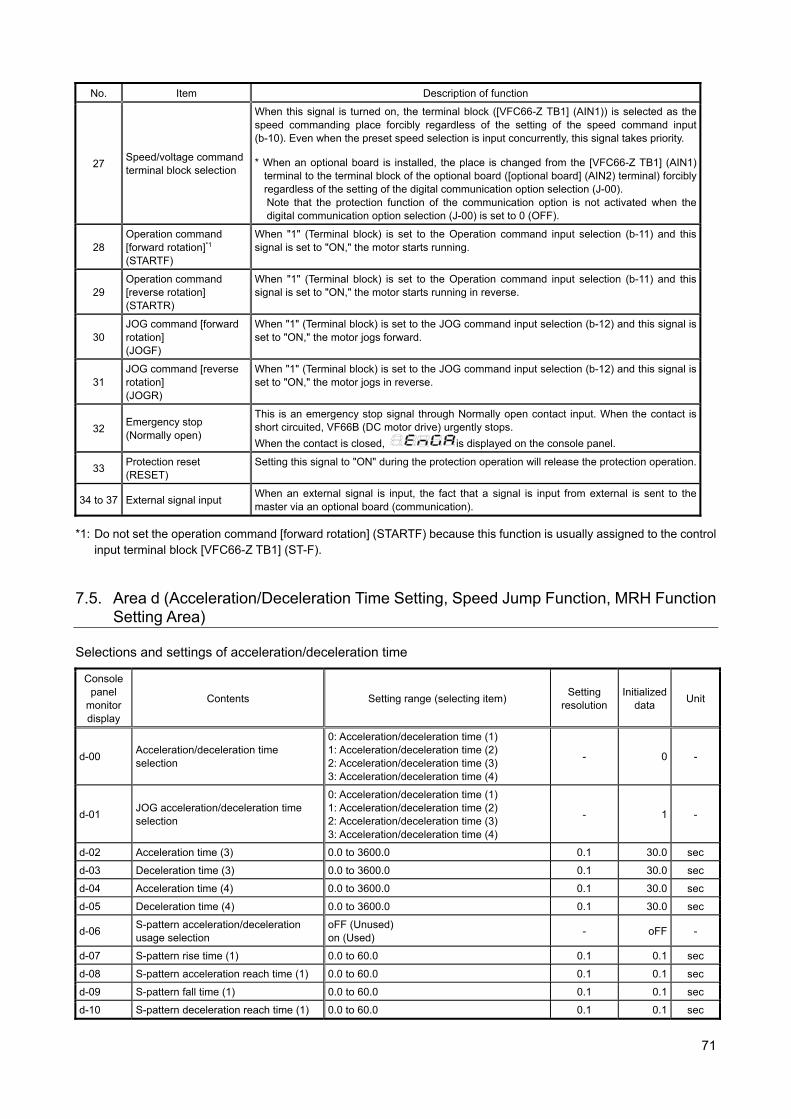
71
No. Item Description of function
27 Speed/voltage commandterminal block selection
When this signal is turned on, the terminal block ([VFC66-Z TB1] (AIN1)) is selected as the speed commanding place forcibly regardless of the setting of the speed command input(b-10). Even when the preset speed selection is input concurrently, this signal takes priority.
* When an optional board is installed, the place is changed from the [VFC66-Z TB1] (AIN1) terminal to the terminal block of the optional board ([optional board] (AIN2) terminal) forcibly regardless of the setting of the digital communication option selection (J-00). Note that the protection function of the communication option is not activated when the digital communication option selection (J-00) is set to 0 (OFF).
28 Operation command [forward rotation]*1 (STARTF)
When "1" (Terminal block) is set to the Operation command input selection (b-11) and this signal is set to "ON," the motor starts running.
29 Operation command [reverse rotation] (STARTR)
When "1" (Terminal block) is set to the Operation command input selection (b-11) and this signal is set to "ON," the motor starts running in reverse.
30 JOG command [forward rotation] (JOGF)
When "1" (Terminal block) is set to the JOG command input selection (b-12) and this signal is set to "ON," the motor jogs forward.
31 JOG command [reverse rotation] (JOGR)
When "1" (Terminal block) is set to the JOG command input selection (b-12) and this signal is set to "ON," the motor jogs in reverse.
32 Emergency stop (Normally open)
This is an emergency stop signal through Normally open contact input. When the contact is short circuited, VF66B (DC motor drive) urgently stops.
When the contact is closed,
is displayed on the console panel.
33 Protection reset (RESET)
Setting this signal to "ON" during the protection operation will release the protection operation.
34 to 37 External signal input When an external signal is input, the fact that a signal is input from external is sent to the master via an optional board (communication).
*1: Do not set the operation command [forward rotation] (STARTF) because this function is usually assigned to the control input terminal block [VFC66-Z TB1] (ST-F).
7.5. Area d (Acceleration/Deceleration Time Setting, Speed Jump Function, MRH Function
Setting Area) Selections and settings of acceleration/deceleration time
Console panel
monitor display
Contents Setting range (selecting item) Setting
resolution Initialized
data Unit
d-00 Acceleration/deceleration time selection
0: Acceleration/deceleration time (1) 1: Acceleration/deceleration time (2) 2: Acceleration/deceleration time (3) 3: Acceleration/deceleration time (4)
- 0 -
d-01 JOG acceleration/deceleration time selection
0: Acceleration/deceleration time (1) 1: Acceleration/deceleration time (2) 2: Acceleration/deceleration time (3) 3: Acceleration/deceleration time (4)
- 1 -
d-02 Acceleration time (3) 0.0 to 3600.0 0.1 30.0 sec
d-03 Deceleration time (3) 0.0 to 3600.0 0.1 30.0 sec
d-04 Acceleration time (4) 0.0 to 3600.0 0.1 30.0 sec
d-05 Deceleration time (4) 0.0 to 3600.0 0.1 30.0 sec
d-06 S-pattern acceleration/deceleration usage selection
oFF (Unused) on (Used)
- oFF -
d-07 S-pattern rise time (1) 0.0 to 60.0 0.1 0.1 sec
d-08 S-pattern acceleration reach time (1) 0.0 to 60.0 0.1 0.1 sec
d-09 S-pattern fall time (1) 0.0 to 60.0 0.1 0.1 sec
d-10 S-pattern deceleration reach time (1) 0.0 to 60.0 0.1 0.1 sec
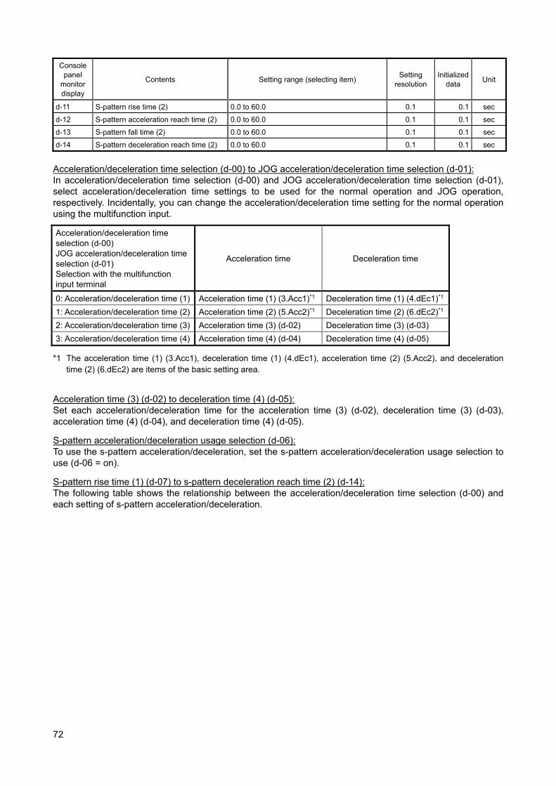
72
Console panel
monitor display
Contents Setting range (selecting item) Setting
resolution Initialized
data Unit
d-11 S-pattern rise time (2) 0.0 to 60.0 0.1 0.1 sec
d-12 S-pattern acceleration reach time (2) 0.0 to 60.0 0.1 0.1 sec
d-13 S-pattern fall time (2) 0.0 to 60.0 0.1 0.1 sec
d-14 S-pattern deceleration reach time (2) 0.0 to 60.0 0.1 0.1 sec
Acceleration/deceleration time selection (d-00) to JOG acceleration/deceleration time selection (d-01): In acceleration/deceleration time selection (d-00) and JOG acceleration/deceleration time selection (d-01), select acceleration/deceleration time settings to be used for the normal operation and JOG operation, respectively. Incidentally, you can change the acceleration/deceleration time setting for the normal operation using the multifunction input.
Acceleration/deceleration time selection (d-00) JOG acceleration/deceleration time selection (d-01) Selection with the multifunction input terminal
Acceleration time Deceleration time
0: Acceleration/deceleration time (1) Acceleration time (1) (3.Acc1)*1 Deceleration time (1) (4.dEc1)*1
1: Acceleration/deceleration time (2) Acceleration time (2) (5.Acc2)*1 Deceleration time (2) (6.dEc2)*1
2: Acceleration/deceleration time (3) Acceleration time (3) (d-02) Deceleration time (3) (d-03)
3: Acceleration/deceleration time (4) Acceleration time (4) (d-04) Deceleration time (4) (d-05)
*1 The acceleration time (1) (3.Acc1), deceleration time (1) (4.dEc1), acceleration time (2) (5.Acc2), and deceleration time (2) (6.dEc2) are items of the basic setting area.
Acceleration time (3) (d-02) to deceleration time (4) (d-05): Set each acceleration/deceleration time for the acceleration time (3) (d-02), deceleration time (3) (d-03), acceleration time (4) (d-04), and deceleration time (4) (d-05).
S-pattern acceleration/deceleration usage selection (d-06): To use the s-pattern acceleration/deceleration, set the s-pattern acceleration/deceleration usage selection to use (d-06 = on).
S-pattern rise time (1) (d-07) to s-pattern deceleration reach time (2) (d-14): The following table shows the relationship between the acceleration/deceleration time selection (d-00) and each setting of s-pattern acceleration/deceleration.
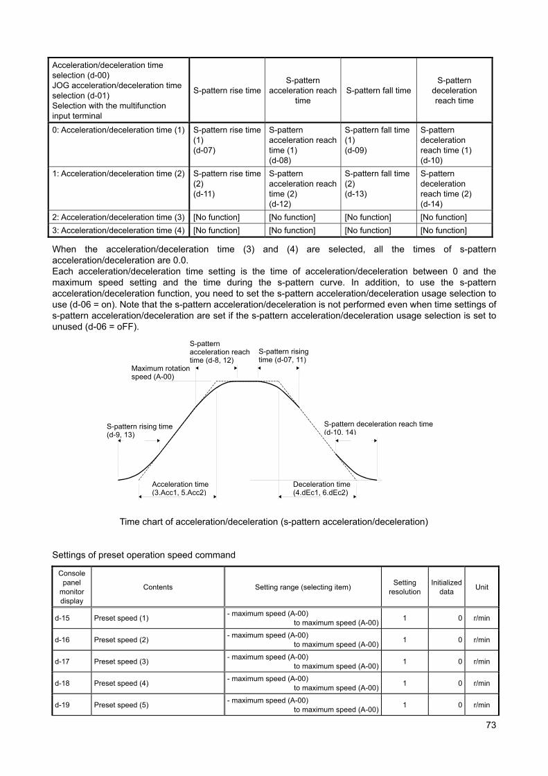
73
Acceleration/deceleration time selection (d-00) JOG acceleration/deceleration time selection (d-01) Selection with the multifunction input terminal
S-pattern rise timeS-pattern
acceleration reach time
S-pattern fall time S-pattern
deceleration reach time
0: Acceleration/deceleration time (1) S-pattern rise time (1) (d-07)
S-pattern acceleration reach time (1) (d-08)
S-pattern fall time (1) (d-09)
S-pattern deceleration reach time (1) (d-10)
1: Acceleration/deceleration time (2) S-pattern rise time (2) (d-11)
S-pattern acceleration reach time (2) (d-12)
S-pattern fall time (2) (d-13)
S-pattern deceleration reach time (2) (d-14)
2: Acceleration/deceleration time (3) [No function] [No function] [No function] [No function]
3: Acceleration/deceleration time (4) [No function] [No function] [No function] [No function]
When the acceleration/deceleration time (3) and (4) are selected, all the times of s-pattern acceleration/deceleration are 0.0. Each acceleration/deceleration time setting is the time of acceleration/deceleration between 0 and the maximum speed setting and the time during the s-pattern curve. In addition, to use the s-pattern acceleration/deceleration function, you need to set the s-pattern acceleration/deceleration usage selection to use (d-06 = on). Note that the s-pattern acceleration/deceleration is not performed even when time settings of s-pattern acceleration/deceleration are set if the s-pattern acceleration/deceleration usage selection is set to unused (d-06 = oFF).
Time chart of acceleration/deceleration (s-pattern acceleration/deceleration) Settings of preset operation speed command
Console panel
monitor display
Contents Setting range (selecting item) Setting
resolution Initialized
data Unit
d-15 Preset speed (1) - maximum speed (A-00)
to maximum speed (A-00)1 0 r/min
d-16 Preset speed (2) - maximum speed (A-00)
to maximum speed (A-00)1 0 r/min
d-17 Preset speed (3) - maximum speed (A-00)
to maximum speed (A-00)1 0 r/min
d-18 Preset speed (4) - maximum speed (A-00)
to maximum speed (A-00)1 0 r/min
d-19 Preset speed (5) - maximum speed (A-00)
to maximum speed (A-00)1 0 r/min
S-pattern rising time (d-9, 13)
S-pattern acceleration reach time (d-8, 12)
Acceleration time (3.Acc1, 5.Acc2)
Deceleration time (4.dEc1, 6.dEc2)
S-pattern rising time (d-07, 11)
S-pattern deceleration reach time (d-10, 14)
Maximum rotation speed (A-00)
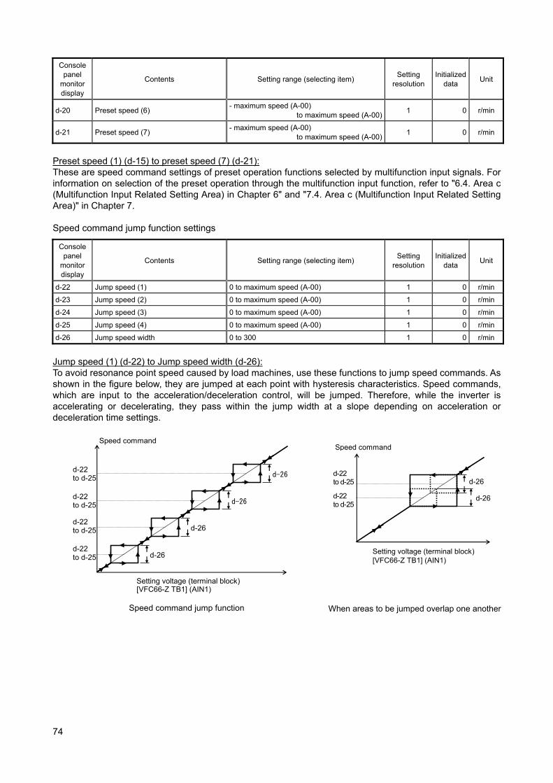
74
Console panel
monitor display
Contents Setting range (selecting item) Setting
resolution Initialized
data Unit
d-20 Preset speed (6) - maximum speed (A-00)
to maximum speed (A-00)1 0 r/min
d-21 Preset speed (7) - maximum speed (A-00)
to maximum speed (A-00)1 0 r/min
Preset speed (1) (d-15) to preset speed (7) (d-21): These are speed command settings of preset operation functions selected by multifunction input signals. For information on selection of the preset operation through the multifunction input function, refer to "6.4. Area c (Multifunction Input Related Setting Area) in Chapter 6" and "7.4. Area c (Multifunction Input Related Setting Area)" in Chapter 7. Speed command jump function settings
Console panel
monitor display
Contents Setting range (selecting item) Setting
resolution Initialized
data Unit
d-22 Jump speed (1) 0 to maximum speed (A-00) 1 0 r/min
d-23 Jump speed (2) 0 to maximum speed (A-00) 1 0 r/min
d-24 Jump speed (3) 0 to maximum speed (A-00) 1 0 r/min
d-25 Jump speed (4) 0 to maximum speed (A-00) 1 0 r/min
d-26 Jump speed width 0 to 300 1 0 r/min
Jump speed (1) (d-22) to Jump speed width (d-26): To avoid resonance point speed caused by load machines, use these functions to jump speed commands. As shown in the figure below, they are jumped at each point with hysteresis characteristics. Speed commands, which are input to the acceleration/deceleration control, will be jumped. Therefore, while the inverter is accelerating or decelerating, they pass within the jump width at a slope depending on acceleration or deceleration time settings.
Speed command
Setting voltage (terminal block)[VFC66-Z TB1] (AIN1)
d-26
d-26
d-26
d-26
d-22 to d-25
d-22 to d-25
d-22 to d-25
d-22 to d-25
Speed command jump function
Speed command
Setting voltage (terminal block) [VFC66-Z TB1] (AIN1)
d-26
d-26d-22 to d-25
d-22 to d-25
When areas to be jumped overlap one another
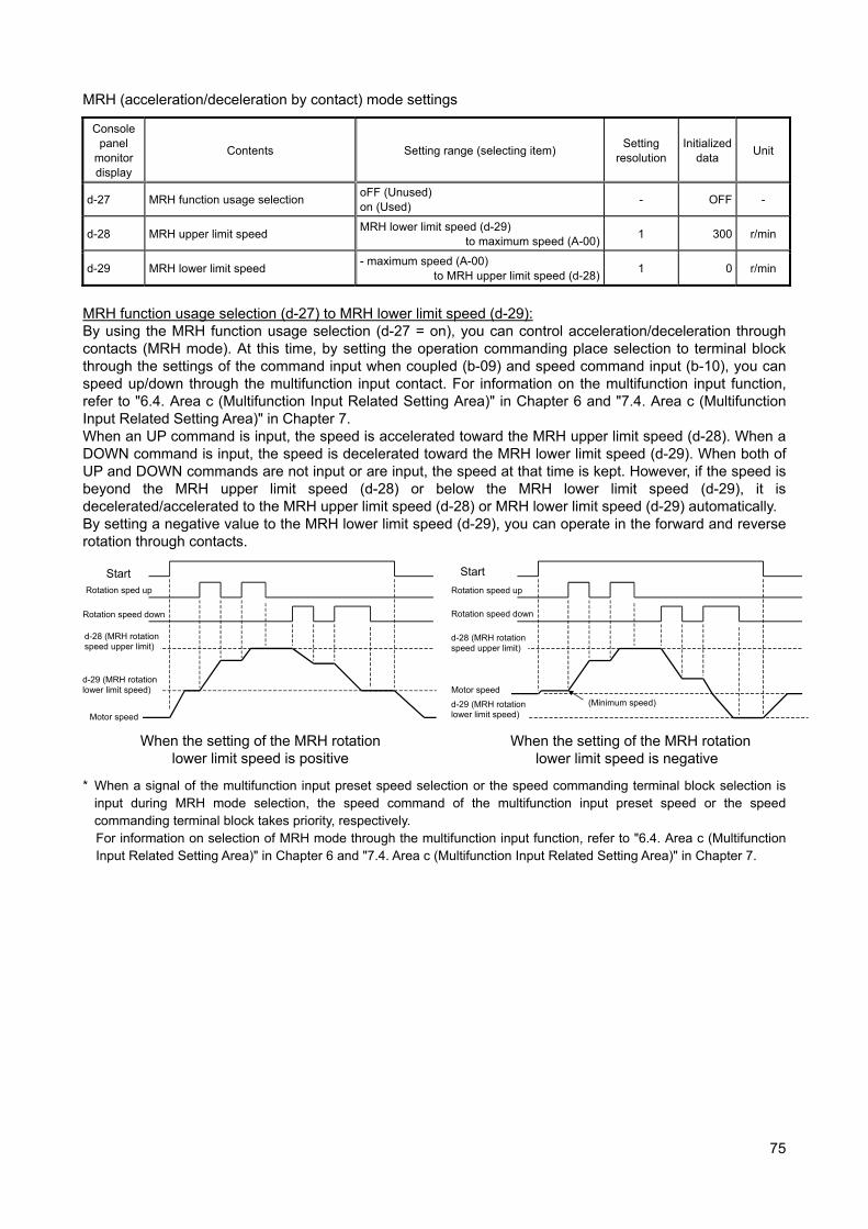
75
MRH (acceleration/deceleration by contact) mode settings
Console panel
monitor display
Contents Setting range (selecting item) Setting
resolution Initialized
data Unit
d-27 MRH function usage selection oFF (Unused) on (Used)
- OFF -
d-28 MRH upper limit speed MRH lower limit speed (d-29)
to maximum speed (A-00)1 300 r/min
d-29 MRH lower limit speed - maximum speed (A-00)
to MRH upper limit speed (d-28)1 0 r/min
MRH function usage selection (d-27) to MRH lower limit speed (d-29): By using the MRH function usage selection (d-27 = on), you can control acceleration/deceleration through contacts (MRH mode). At this time, by setting the operation commanding place selection to terminal block through the settings of the command input when coupled (b-09) and speed command input (b-10), you can speed up/down through the multifunction input contact. For information on the multifunction input function, refer to "6.4. Area c (Multifunction Input Related Setting Area)" in Chapter 6 and "7.4. Area c (Multifunction Input Related Setting Area)" in Chapter 7. When an UP command is input, the speed is accelerated toward the MRH upper limit speed (d-28). When a DOWN command is input, the speed is decelerated toward the MRH lower limit speed (d-29). When both of UP and DOWN commands are not input or are input, the speed at that time is kept. However, if the speed is beyond the MRH upper limit speed (d-28) or below the MRH lower limit speed (d-29), it is decelerated/accelerated to the MRH upper limit speed (d-28) or MRH lower limit speed (d-29) automatically. By setting a negative value to the MRH lower limit speed (d-29), you can operate in the forward and reverse rotation through contacts.
When the setting of the MRH rotation lower limit speed is positive
When the setting of the MRH rotation lower limit speed is negative
* When a signal of the multifunction input preset speed selection or the speed commanding terminal block selection is input during MRH mode selection, the speed command of the multifunction input preset speed or the speed commanding terminal block takes priority, respectively. For information on selection of MRH mode through the multifunction input function, refer to "6.4. Area c (Multifunction Input Related Setting Area)" in Chapter 6 and "7.4. Area c (Multifunction Input Related Setting Area)" in Chapter 7.
Start Rotation sped up
Rotation speed down
Motor speed
d-28 (MRH rotation speed upper limit)
Start
Rotation speed up
Rotation speed down
Motor speed
(Minimum speed)
d-29 (MRH rotation lower limit speed)
d-29 (MRH rotation lower limit speed)
d-28 (MRH rotation speed upper limit)
76
Settings of speed deviation limit function upon acceleration/deceleration
Console panel
monitor display
Contents Setting range (selecting item) Setting
resolution Initialized
data Unit
d-30 Speed deviation limiting command selection
oFF (Without limiting command) on (With limiting command)
- OFF -
d-31 Maximum deviation (positive) 0.0 to 100.0 0.1 5.0 %
d-32 Maximum deviation (negative) -100.0 to 0.0 0.1 -5.0 %
Speed deviation limiting command selection (d-30) to maximum deviation (negative) (d-32): When the speed deviation limiting command selection is set to use (d-30 = on), the outputs of the speed and the acceleration/deceleration control are limited to the deviations of the maximum deviation (positive) (d-31) and maximum deviation (negative) (d-32). This function prevents an abrupt acceleration due to a sudden change in the load or power source voltage when the load is lightened suddenly or a similar situation arises in a state where the speed is reduced due to the torque limit during a speed control operation, allowing to restore the speed with the slope that is set with the acceleration/deceleration time. (Note that the acceleration/deceleration are restricted if you set a too small deviation.) Incidentally, the settings of the maximum deviation (positive) (d-31) and maximum deviation (negative) (d-32) become the maximum speed (A-00) when they are set to 100%. 7.6. Area E (Current Control Gain, Output Voltage Limit Related Setting Area) Regeneration stall prevention function settings
Console panel
monitor display
Contents Setting range (selecting item) Setting
resolution Initialized
data Unit
E-00 Regeneration stall prevention function usage selection
oFF (Unused) on (Used)
- oFF -
E-01 Regeneration stall prevention voltage (200 V class) 320 to 360 1 340
V (400V class) 640 to 720 1 680
Regeneration stall prevention function usage selection (E-00), regeneration stall prevention voltage (E-01): When the DC voltage rises beyond the regeneration stall prevention voltage, this function limits the torque command toward regeneration (in the negative direction for forward rotation, and in the forward direction for reverse rotation) to zero and stops deceleration when decelerating to prevent the protective detection by the VF66B (DC motor drive) input overvoltage protection (oV_i) action. During deceleration, these functions can temporarily stop the deceleration to prevent the inverter from tripping due to an overvoltage (oV) protection operation.
Console panel
monitor display
Contents Setting range (selecting item) Setting
resolution Initialized
data Unit
E-02 [No function]*1 - - - -
*1: There is no function to be set.

77
Motor rotation direction changeover setting
Console panel
monitor display
Contents Setting range (selecting item) Setting
resolution Initialized
data Unit
E-03 Forward direction change oFF (Forward rotation) on (Reverse rotation)
- oFF -
Forward direction change (E-03): By setting the forward direction change to reverse rotation (E-03 = on), you can reverse the direction of the rotation of the motor without changing the input wiring. When the reverse rotation prohibition mode setting is set to prohibit opposite direction (b-08 = 2) while the forward direction change is reverse rotation (E-03 = on), the forward rotation is prohibited.
Simulation mode setting
Console panel
monitor display
Contents Setting range (selecting item) Setting
resolution Initialized
data Unit
E-04 Simulation mode oFF (Without simulation operation) on (With simulation operation) - oFF -
Simulation mode (E-04): By setting the simulation mode to simulation operation (E-04 = on), you can put VF66B (DC motor drive) to simulation mode. In simulation mode, VF66B (DC motor drive) simulates operation mode without outputting voltages. Since VF66B (DC motor drive) does not output anything during operation in simulation mode, you can check the sequence connected to VF66B (DC motor drive) without operating the motor connected to VF66B (DC motor drive).
Console panel
monitor display
Contents Setting range (selecting item) Setting
resolution Initialized
data Unit
E-05 [No function]*1 - - - -
*1: There is no function to be set. Restart prohibition time
Console panel
monitor display
Contents Setting range (selecting item) Setting
resolution Initialized
data Unit
E-06 Restart prohibition time 100 to 999 1 100 msec
Restart prohibition time (E-06): Select the amount of time VF66B (DC motor drive) is prohibited from restarting. Normally, do not change its Initialized data. Current control gain adjustments
Console panel
monitor display
Contents Setting range (selecting item) Setting
resolution Initialized
data Unit
E-07 Current control proportion gain 10.0 to 200.0 0.1 100.0 %
E-08 Current control integral gain 10.0 to 500.0 0.1 100.0 %
Current control proportion gain (E-07), current control integral gain (E-08):
These functions adjust current control gain. Normally, do not change its Initialized data.
78
Console
panel monitor display
Contents Setting range (selecting item) Setting
resolution Initialized
data Unit
E-09 [No function]*1 - - - -
*1: There is no function to be set.
Console panel
monitor display
Contents Setting range (selecting item) Setting
resolution Initialized
data Unit
E-10 [For special adjustment] oFF (Not compensated) on (Compensated)
- oFF -
Maximum output voltage settings
Console panel
monitor display
Contents Setting range (selecting item) Setting
resolution Initialized
data Unit
E-11 Forward direction output maximum voltage
80.0 to 120.0 0.1 105.0 %
E-12 Reverse direction output maximum voltage
-120.0 to -80.0 0.1 -105.0 %
Forward direction output maximum voltage (E-11), reverse direction output maximum voltage (E-12): In these parameters, set the maximum voltages VF66B (DC motor drive) can output. When a voltage command is larger than these setting values, the voltage command is limited to one of the setting values. When voltage commands are limited to the setting value for 500 ms continuously, protective detection is performed by VF66B (DC motor drive) output overvoltage protection (oV_o) operation. Incidentally, the forward direction output maximum voltage (E-11) and reverse direction output maximum voltage (E-12) become the rated motor armature voltage (A-03) when they are set to 100%. Setting of limit width of the voltage corresponding to the speed
Console panel
monitor display
Contents Setting range (selecting item) Setting
resolution Initialized
data Unit
E-13 Limit width of the voltage corresponding to the speed
5 to 120 1 30 V
Limit width of the voltage corresponding to the speed (E-13): When the operation mode selection is speed control (ASR) mode, speed control (ASR) and armature current control (ACR) with priority to reverse direction, or speed control (ASR) and armature current control (ACR) with priority to forward direction (i-07 = 0 to 2), this function compares the voltage equivalent to the speed detected by PG mounted on the motor with the armature voltage command, and when the armature voltage command exceeds the value calculated by adding the voltage equivalent to the speed and the limit width of the voltage corresponding to the speed (E-13), this function limits the armature voltage command to the value calculated by adding the voltage equivalent to the speed and the limit width of the voltage corresponding to the speed (E-13). When armature voltage commands are limited to the value calculated by adding the voltage equivalent to the speed and the limit width of the voltage corresponding to the speed (E-13) for 100 ms continuously, protective detection is performed by PG error protection (PEr) operation.
79
Console panel
monitor display
Contents Setting range (selecting item) Setting
resolution Initialized
data Unit
E-14 [For special adjustment] 10.0 to 200.0 0.1 100.0 %
Armature current detection DCCT selection setting
Console panel
monitor display
Contents Setting range (selecting item) Setting
resolution Initialized
data Unit
E-15 Armature current detection DCCT selection
0: Auto 1: P-side DCCT 2: N-side DCCT
- 0 -
Armature current detection DCCT selection (E-15): In this parameter, set the DCCT to detect the armature current. When the armature current detection DCCT selection is set to auto (E-15 = 0), this function selects a DCCT among DCCTs on the P side and N side whichever its deviation from the armature current command is smaller.
Output voltage upon rated speed
Console panel
monitor display
Contents Setting range (selecting item) Setting
resolution Initialized
data Unit
E-16 Output voltage upon rated speed (200 V class) 70 to 230 1 220 V
(400V class) 140 to 460 1 440 V
Output voltage upon rated speed (E-16): In this parameter, set the voltage to be output upon the rated speed viewing the output voltage (Vout) on the console panel (SET66-Z). This setting is used as the reference voltage for the voltage corresponding to the speed that is used for the PG error protection (PEr) detection.
Console panel
monitor display
Contents Setting range (selecting item) Setting
resolution Initialized
data Unit
E-17 to 18 [No function]*1 - - - -
*1: There is no function to be set.

80
7.7. Area F (Built-in DB (Dynamic Braking) Operation, Protection Function, Traceback Setting Area)
Built-in DB (Dynamic Braking) operation level setting
Console panel
monitor display
Contents Setting range (selecting item) Setting
resolution Initialized
data Unit
F-00 Built-in DB (Dynamic Braking) operation level
(200 V class) 320.0 to 360.0 0.1 340.0 V
(400V class) 640.0 to 720.0 0.1 680.0 V
Built-in DB (Dynamic Braking) operation level (F-00): A transistor for DB (Dynamic Braking) is incorporated in VF66B-2R222 to 2222 (200 V class) and VF66B-2R244 to 2244 (400 V class) allowing to perform the dynamic braking by connecting a DB (Dynamic Braking) resistor and thermal relay between main circuit terminal blocks [+2] and [B] using a screwdriver or one of six point box-end wrenches M4 to M12. In the built-in DB (Dynamic Braking) operation level (F-00) setting, set the operation level of this built-in DB (Dynamic Braking) transistor. When the DC voltage rises beyond this setting, the built-in DB (Dynamic Braking) transistor is turned on. When the DC voltage falls below this setting, the built-in DB (Dynamic Braking) transistor is turned off. Usually, leave this setting at the initial value. When the power source voltage is high causing the built-in DB (Dynamic Braking) transistor to be turned on even in other than brake mode, set a higher value.
* When using this function in combination with a sine wave converter (VF61R, VF64R), set this setting to 360 V (200 V class) or 720 V (400 V class).
Over speed protection settings
Console panel
monitor display
Contents Setting range (selecting item) Setting
resolution Initialized
data Unit
F-01 Forward overspeed protection setting 0.0 to 150.0 0.1 105.0 %
F-02 Reverse overspeed protection setting -150.0 to 0.0 0.1 -105.0 %
Forward overspeed protection setting (F-01), reverse overspeed protection setting (F-02): In these parameters, set the ratio to the maximum speed (%). When the motor speed exceeds the forward overspeed protection setting (F-01) or reverse overspeed protection setting (F-02), the overspeed protection function (oS) activates to perform protective detection. Set for forward and reverse individually. (When you change the maximum speed (A-00), also change these settings.) Incidentally, these settings become the maximum speed (A-00) when set to 100%.
Warning [Overspeed protection setting] In the forward overspeed protection setting (F-01) and reverse overspeed protection setting (F-02),
do not set a value significantly exceeding the rated motor speed. It may result in a risk of serious accidents.
Overload protection setting
Console panel
monitor display
Contents Setting range (selecting item) Setting
resolution Initialized
data Unit
F-03 Overload protection setting 20 to 110 1 100 %
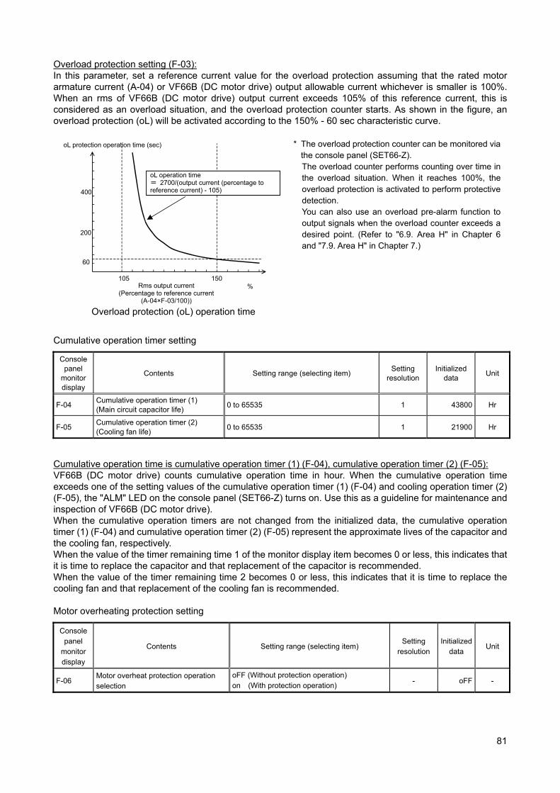
81
Overload protection setting (F-03): In this parameter, set a reference current value for the overload protection assuming that the rated motor armature current (A-04) or VF66B (DC motor drive) output allowable current whichever is smaller is 100%. When an rms of VF66B (DC motor drive) output current exceeds 105% of this reference current, this is considered as an overload situation, and the overload protection counter starts. As shown in the figure, an overload protection (oL) will be activated according to the 150% - 60 sec characteristic curve.
Overload protection (oL) operation time
* The overload protection counter can be monitored via the console panel (SET66-Z). The overload counter performs counting over time in the overload situation. When it reaches 100%, the overload protection is activated to perform protective detection. You can also use an overload pre-alarm function to output signals when the overload counter exceeds a desired point. (Refer to "6.9. Area H" in Chapter 6 and "7.9. Area H" in Chapter 7.)
Cumulative operation timer setting
Console panel
monitor display
Contents Setting range (selecting item) Setting
resolution Initialized
data Unit
F-04 Cumulative operation timer (1) (Main circuit capacitor life)
0 to 65535 1 43800 Hr
F-05 Cumulative operation timer (2) (Cooling fan life)
0 to 65535 1 21900 Hr
Cumulative operation time is cumulative operation timer (1) (F-04), cumulative operation timer (2) (F-05): VF66B (DC motor drive) counts cumulative operation time in hour. When the cumulative operation time exceeds one of the setting values of the cumulative operation timer (1) (F-04) and cooling operation timer (2) (F-05), the "ALM" LED on the console panel (SET66-Z) turns on. Use this as a guideline for maintenance and inspection of VF66B (DC motor drive). When the cumulative operation timers are not changed from the initialized data, the cumulative operation timer (1) (F-04) and cumulative operation timer (2) (F-05) represent the approximate lives of the capacitor and the cooling fan, respectively. When the value of the timer remaining time 1 of the monitor display item becomes 0 or less, this indicates that it is time to replace the capacitor and that replacement of the capacitor is recommended. When the value of the timer remaining time 2 becomes 0 or less, this indicates that it is time to replace the cooling fan and that replacement of the cooling fan is recommended. Motor overheating protection setting
Console panel
monitor display
Contents Setting range (selecting item) Setting
resolution Initialized
data Unit
F-06 Motor overheat protection operation selection
oFF (Without protection operation) on (With protection operation)
- oFF -
oL protection operation time (sec)
Rms output current (Percentage to reference current
(A-04×F-03/100))
105 150
60
200
400
oL operation time = 2700/(output current (percentage to reference current) - 105)
%
82
Motor overheat protection operation selection (F-06): Select whether motor overheat protection is enabled or not. Using this function requires <TVPT66-Z> or <TVTH66-Z> and the motor temperature sensor. When <F-06> is set to "ON," the inverter trips in the following conditions: ・Motor temperature exceeds a setting of the Motor_protect_temperature <G-17>. Setting of protection relay (86A) operation upon power failure
Console panel
monitor display
Contents Setting range (selecting item) Setting
resolution Initialized
data Unit
F-07 Protection_relay(86A)_operation_selection_upon_power_failure
oFF (Without protection operation) on (With protection operation)
- oFF -
Protection relay (86A) operation selection upon power failure (F-07): Select a protection relay (86A) operation when VF66B (DC motor drive) detects power failure.
・When the protection relay (86A) operation selection upon power failure is set to protection relay inactive (F-07 = oFF) Even if VF66B (DC motor drive) detects power failure, a protection relay (86A) will not be activated. An operation command (or JOG command, DC brake command) is only set to "OFF" after the power is restored, and power failure is reset. When the Instantaneous power interruption restart (b-07) is set to "ON," after the power is restored, power failure is automatically reset to restart VF66B (DC motor drive).
・When the protection relay (86A) operation selection upon power failure is set to protection relay active (F-07 = on) When VF66B (DC motor drive) detects power failure, the protection relay (86A) will be activated and VF66B (DC motor drive) will trip. In this case, like other protection operations, you should perform protection reset using reset terminals or the [STOP/RESET] key. Even when the Instantaneous power interruption restart (b-07) is set to "ON," VF66B (DC motor drive) does not automatically restart.
Warning [About instantaneous power interruption restart] If the Instantaneous power interruption restart (b-07) is set to "ON," the motor automatically restarts when the
power is restored after instantaneous power interruption is detected. Therefore, do not come close to the motor while instantaneous power interruption is being detected. Otherwise, you may be injured.
Protection retry function setting
Console panel
monitor display
Contents Setting range (selecting item) Setting
resolution Initialized
data Unit
F-08 Protection retry count setting 0 to 5 1 0 times

83
Protection retry count setting (F-08): When a protection operation occurs, this function executes "auto protection reset" and "auto restart" the number of times which is specified in the Protection retry count setting (F-08). It executes auto reset in one second after the protection operation occurs, and then it executes auto restart. When another protection operation occurs within ten seconds after restart, the inverter increases a value of the retry counter by one. When the value is below a setting value of the Protection retry count setting (F-08), VF66B (DC motor drive) resets the protection operation again to restart. When a protection operation does not occur in ten seconds after auto restart, VF66B (DC motor drive) considers it as a successful retry and clears the retry counter.
* The protection retry is available for protection operations of overvoltage, overspeed, power failure (when 86A is turned on), external failure (protection relay 86A activated), and option error only. The retry against other protections is prohibited for safety reasons.
External failure detection delay time setting
Console panel
monitor display
Contents Setting range (selecting item) Setting
resolution Initialized
data Unit
F-09 External failure(1) detection delay time 0.0 to 30.0 0.1 0.0 sec
F-10 External failure(2) detection delay time 0.0 to 30.0 0.1 0.0 sec
F-11 External failure(3) detection delay time 0.0 to 30.0 0.1 0.0 sec
F-12 External failure(4) detection delay time 0.0 to 30.0 0.1 0.0 sec
External failure 1 detection delay time (F-09) to external failure 4 detection delay time (F-12): Time required to detect external failure signals can be delayed during the amount of time specified in the External failure(1) through (4) detection delay time ((F-09) through (F-12)). These are used to adjust detection sensitivity of external failure signals. Traceback function settings
Console panel
monitor display
Contents Setting range (selecting item) Setting
resolution Initialized
data Unit
F-13 Traceback pitch 0 to 100 1 1 msec
F-14 Traceback trigger point 1 to 99 1 80 -
F-15 Traceback CH1 selection 0 to 12 1 0 -
F-16 Traceback CH2 selection 0 to 12 1 0 -
F-17 Traceback CH3 selection 0 to 12 1 0 -
F-18 Traceback CH4 selection 0 to 12 1 0 -
F-19 Traceback CH5 selection 0 to 12 1 0 -
F-20 Traceback CH6 selection 0 to 12 1 0 -
F-21 Traceback CH7 selection 0 to 12 1 0 -
F-22 Traceback CH8 selection 0 to 12 1 0 -
F-23 Traceback CH9 selection 0 to 12 1 0 -
F-24 Traceback CH10 selection 0 to 12 1 0 -
F-25 Traceback CH11 selection 0 to 12 1 0 -
F-26 Traceback CH12 selection 0 to 12 1 0 -
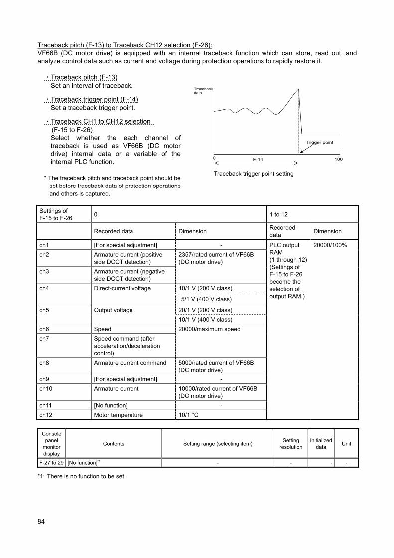
84
Traceback pitch (F-13) to Traceback CH12 selection (F-26): VF66B (DC motor drive) is equipped with an internal traceback function which can store, read out, and analyze control data such as current and voltage during protection operations to rapidly restore it. ・Traceback pitch (F-13)
Set an interval of traceback.
・Traceback trigger point (F-14) Set a traceback trigger point.
・Traceback CH1 to CH12 selection (F-15 to F-26) Select whether the each channel of traceback is used as VF66B (DC motor drive) internal data or a variable of the internal PLC function.
* The traceback pitch and traceback point should be
set before traceback data of protection operations and others is captured.
Traceback data
F-14
Trigger point
0 100
Traceback trigger point setting
Settings of F-15 to F-26
0 1 to 12
Recorded data Dimension Recorded data
Dimension
ch1 [For special adjustment] - PLC output RAM (1 through 12) (Settings of F-15 to F-26 become the selection of output RAM.)
20000/100%
ch2 Armature current (positive side DCCT detection)
2357/rated current of VF66B (DC motor drive)
ch3 Armature current (negative side DCCT detection)
ch4 Direct-current voltage 10/1 V (200 V class)
5/1 V (400 V class)
ch5 Output voltage 20/1 V (200 V class)
10/1 V (400 V class)
ch6 Speed 20000/maximum speed
ch7 Speed command (after acceleration/deceleration control)
ch8 Armature current command 5000/rated current of VF66B (DC motor drive)
ch9 [For special adjustment] -
ch10 Armature current 10000/rated current of VF66B (DC motor drive)
ch11 [No function] -
ch12 Motor temperature 10/1 °C
Console
panel monitor display
Contents Setting range (selecting item) Setting
resolution Initialized
data Unit
F-27 to 29 [No function]*1 - - - -
*1: There is no function to be set.
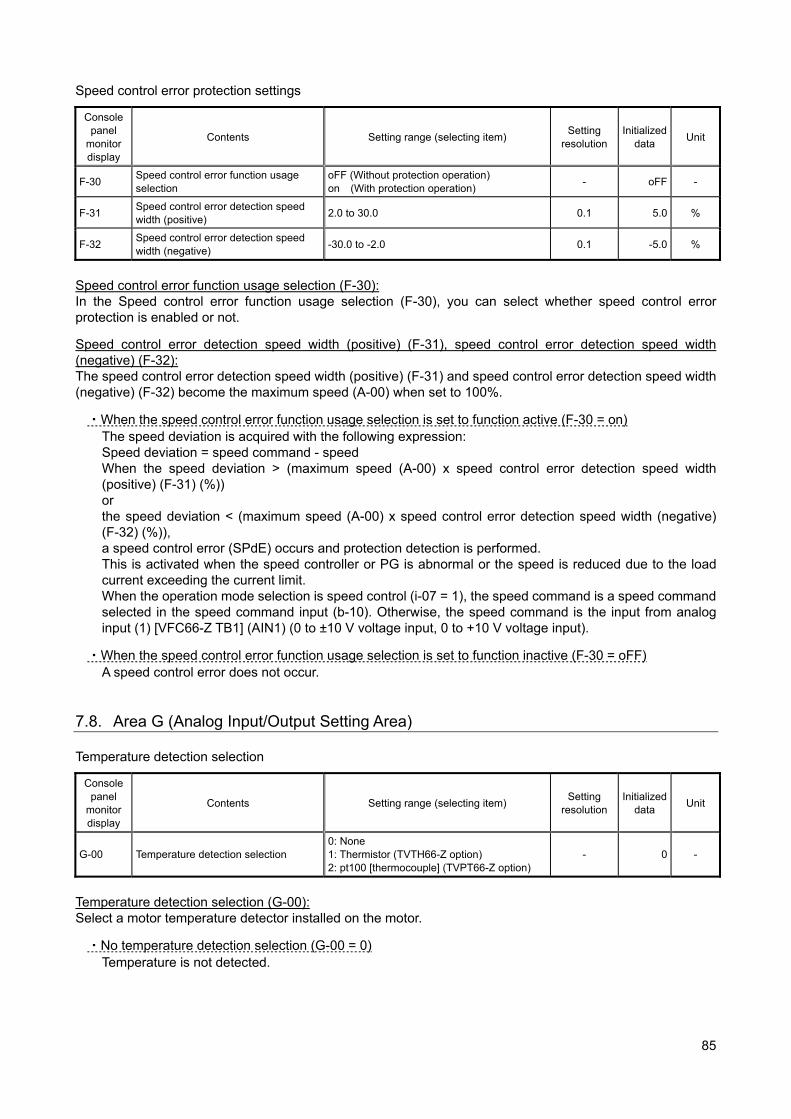
85
Speed control error protection settings
Console panel
monitor display
Contents Setting range (selecting item) Setting
resolution Initialized
data Unit
F-30 Speed control error function usage selection
oFF (Without protection operation) on (With protection operation)
- oFF -
F-31 Speed control error detection speed width (positive)
2.0 to 30.0 0.1 5.0 %
F-32 Speed control error detection speed width (negative)
-30.0 to -2.0 0.1 -5.0 %
Speed control error function usage selection (F-30): In the Speed control error function usage selection (F-30), you can select whether speed control error protection is enabled or not.
Speed control error detection speed width (positive) (F-31), speed control error detection speed width (negative) (F-32): The speed control error detection speed width (positive) (F-31) and speed control error detection speed width (negative) (F-32) become the maximum speed (A-00) when set to 100%.
・When the speed control error function usage selection is set to function active (F-30 = on) The speed deviation is acquired with the following expression: Speed deviation = speed command - speed When the speed deviation > (maximum speed (A-00) x speed control error detection speed width (positive) (F-31) (%)) or the speed deviation < (maximum speed (A-00) x speed control error detection speed width (negative) (F-32) (%)), a speed control error (SPdE) occurs and protection detection is performed. This is activated when the speed controller or PG is abnormal or the speed is reduced due to the load current exceeding the current limit. When the operation mode selection is speed control (i-07 = 1), the speed command is a speed command selected in the speed command input (b-10). Otherwise, the speed command is the input from analog input (1) [VFC66-Z TB1] (AIN1) (0 to ±10 V voltage input, 0 to +10 V voltage input).
・When the speed control error function usage selection is set to function inactive (F-30 = oFF) A speed control error does not occur.
7.8. Area G (Analog Input/Output Setting Area) Temperature detection selection
Console panel
monitor display
Contents Setting range (selecting item) Setting
resolution Initialized
data Unit
G-00 Temperature detection selection 0: None 1: Thermistor (TVTH66-Z option) 2: pt100 [thermocouple] (TVPT66-Z option)
- 0 -
Temperature detection selection (G-00): Select a motor temperature detector installed on the motor.
・No temperature detection selection (G-00 = 0) Temperature is not detected.
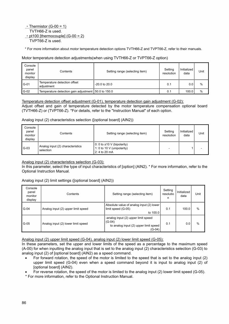
86
・Thermistor (G-00 = 1) TVTH66-Z is used.
・pt100 [thermocouple] (G-00 = 2) TVPT66-Z is used.
* For more information about motor temperature detection options TVTH66-Z and TVPT66-Z, refer to their manuals. Motor temperature detection adjustments(when using TVTH66-Z or TVPT66-Z option)
Console panel
monitor display
Contents Setting range (selecting item) Setting
resolution Initialized
data Unit
G-01 Temperature detection offset adjustment
-20.0 to 20.0 0.1 0.0 %
G-02 Temperature detection gain adjustment 50.0 to 150.0 0.1 100.0 %
Temperature detection offset adjustment (G-01), temperature detection gain adjustment (G-02): Adjust offset and gain of temperature detected by the motor temperature compensation optional board (TVTH66-Z) or (TVPT66-Z). *For details, refer to the "Instruction Manual" of each option. Analog input (2) characteristics selection ([optional board] (AIN2))
Console panel
monitor display
Contents Setting range (selecting item) Setting
resolution Initialized
data Unit
G-03 Analog input (2) characteristics selection
0: 0 to ±10 V (bipolarity) 1: 0 to 10 V (unipolarity) 2: 4 to 20 mA
- 1 -
Analog input (2) characteristics selection (G-03): In this parameter, select the type of input characteristics of [option] (AIN2). * For more information, refer to the Optional Instruction Manual. Analog input (2) limit settings ([optional board] (AIN2))
Console panel
monitor display
Contents Setting range (selecting item) Setting
resolution
Initialized data
Unit
G-04 Analog input (2) upper limit speed Absolute value of analog input (2) lower limit speed (G-05)
to 100.00.1 100.0 %
G-05 Analog input (2) lower limit speed
-analog input (2) upper limit speed (G-04)
to analog input (2) upper limit speed (G-04)
0.1 0.0 %
Analog input (2) upper limit speed (G-04), analog input (2) lower limit speed (G-05): In these parameters, set the upper and lower limits of the speed as a percentage to the maximum speed (A-00) for when inputting the analog input that is set to the analog input (2) characteristics selection (G-03) to analog input (2) of [optional board] (AIN2) as a speed command. For forward rotation, the speed of the motor is limited to the speed that is set to the analog input (2)
upper limit speed (G-04) even when a speed command beyond it is input to analog input (2) of [optional board] (AIN2).
For reverse rotation, the speed of the motor is limited to the analog input (2) lower limit speed (G-05). * For more information, refer to the Optional Instruction Manual.
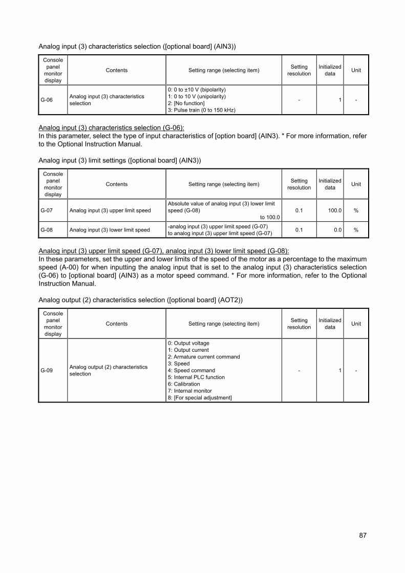
87
Analog input (3) characteristics selection ([optional board] (AIN3))
Console panel
monitor display
Contents Setting range (selecting item) Setting
resolution Initialized
data Unit
G-06 Analog input (3) characteristics selection
0: 0 to ±10 V (bipolarity) 1: 0 to 10 V (unipolarity) 2: [No function] 3: Pulse train (0 to 150 kHz)
- 1 -
Analog input (3) characteristics selection (G-06): In this parameter, select the type of input characteristics of [option board] (AIN3). * For more information, refer to the Optional Instruction Manual. Analog input (3) limit settings ([optional board] (AIN3))
Console panel
monitor display
Contents Setting range (selecting item) Setting
resolution Initialized
data Unit
G-07 Analog input (3) upper limit speed Absolute value of analog input (3) lower limit speed (G-08)
to 100.00.1 100.0 %
G-08 Analog input (3) lower limit speed -analog input (3) upper limit speed (G-07) to analog input (3) upper limit speed (G-07)
0.1 0.0 %
Analog input (3) upper limit speed (G-07), analog input (3) lower limit speed (G-08): In these parameters, set the upper and lower limits of the speed of the motor as a percentage to the maximum speed (A-00) for when inputting the analog input that is set to the analog input (3) characteristics selection (G-06) to [optional board] (AIN3) as a motor speed command. * For more information, refer to the Optional Instruction Manual. Analog output (2) characteristics selection ([optional board] (AOT2))
Console panel
monitor display
Contents Setting range (selecting item) Setting
resolution Initialized
data Unit
G-09 Analog output (2) characteristics selection
0: Output voltage 1: Output current 2: Armature current command 3: Speed 4: Speed command 5: Internal PLC function 6: Calibration 7: Internal monitor 8: [For special adjustment]
- 1 -
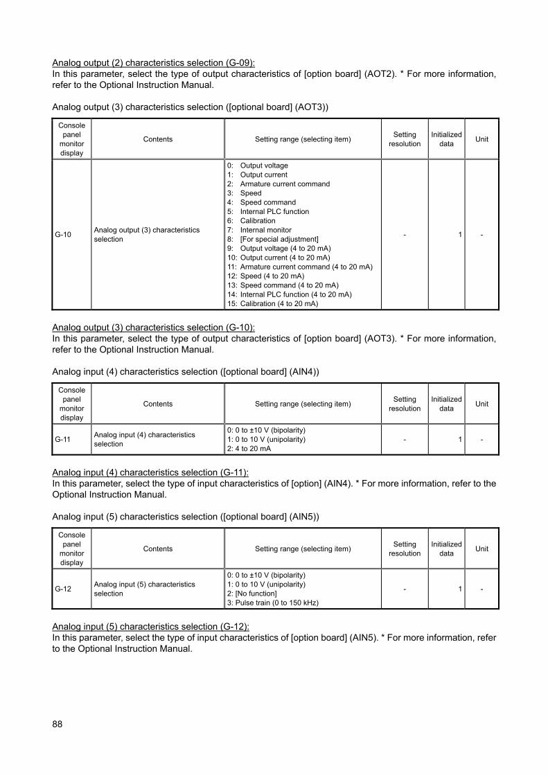
88
Analog output (2) characteristics selection (G-09): In this parameter, select the type of output characteristics of [option board] (AOT2). * For more information, refer to the Optional Instruction Manual. Analog output (3) characteristics selection ([optional board] (AOT3))
Console panel
monitor display
Contents Setting range (selecting item) Setting
resolution Initialized
data Unit
G-10 Analog output (3) characteristics selection
0: Output voltage 1: Output current 2: Armature current command 3: Speed 4: Speed command 5: Internal PLC function 6: Calibration 7: Internal monitor 8: [For special adjustment] 9: Output voltage (4 to 20 mA) 10: Output current (4 to 20 mA) 11: Armature current command (4 to 20 mA) 12: Speed (4 to 20 mA) 13: Speed command (4 to 20 mA) 14: Internal PLC function (4 to 20 mA) 15: Calibration (4 to 20 mA)
- 1 -
Analog output (3) characteristics selection (G-10): In this parameter, select the type of output characteristics of [option board] (AOT3). * For more information, refer to the Optional Instruction Manual. Analog input (4) characteristics selection ([optional board] (AIN4))
Console panel
monitor display
Contents Setting range (selecting item) Setting
resolution Initialized
data Unit
G-11 Analog input (4) characteristics selection
0: 0 to ±10 V (bipolarity) 1: 0 to 10 V (unipolarity) 2: 4 to 20 mA
- 1 -
Analog input (4) characteristics selection (G-11): In this parameter, select the type of input characteristics of [option] (AIN4). * For more information, refer to the Optional Instruction Manual. Analog input (5) characteristics selection ([optional board] (AIN5))
Console panel
monitor display
Contents Setting range (selecting item) Setting
resolution Initialized
data Unit
G-12 Analog input (5) characteristics selection
0: 0 to ±10 V (bipolarity) 1: 0 to 10 V (unipolarity) 2: [No function] 3: Pulse train (0 to 150 kHz)
- 1 -
Analog input (5) characteristics selection (G-12): In this parameter, select the type of input characteristics of [option board] (AIN5). * For more information, refer to the Optional Instruction Manual.
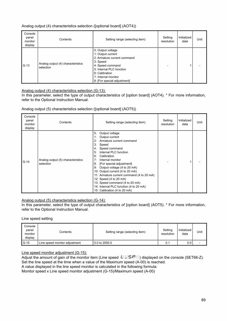
89
Analog output (4) characteristics selection ([optional board] (AOT4))
Console panel
monitor display
Contents Setting range (selecting item) Setting
resolution Initialized
data Unit
G-13 Analog output (4) characteristics selection
0: Output voltage 1: Output current 2: Armature current command 3: Speed 4: Speed command 5: Internal PLC function 6: Calibration 7: Internal monitor 8: [For special adjustment]
- 1 -
Analog output (4) characteristics selection (G-13): In this parameter, select the type of output characteristics of [option board] (AOT4). * For more information, refer to the Optional Instruction Manual. Analog output (5) characteristics selection ([optional board] (AOT5))
Console panel
monitor display
Contents Setting range (selecting item) Setting
resolution Initialized
data Unit
G-14 Analog output (5) characteristics selection
0: Output voltage 1: Output current 2: Armature current command 3: Speed 4: Speed command 5: Internal PLC function 6: Calibration 7: Internal monitor 8: [For special adjustment] 9: Output voltage (4 to 20 mA) 10: Output current (4 to 20 mA) 11: Armature current command (4 to 20 mA) 12: Speed (4 to 20 mA) 13: Speed command (4 to 20 mA) 14: Internal PLC function (4 to 20 mA) 15: Calibration (4 to 20 mA)
- 1 -
Analog output (5) characteristics selection (G-14): In this parameter, select the type of output characteristics of [option board] (AOT5). * For more information, refer to the Optional Instruction Manual. Line speed setting
Console panel
monitor display
Contents Setting range (selecting item) Setting
resolution Initialized
data Unit
G-15 Line speed monitor adjustment 0.0 to 2000.0 0.1 0.0 -
Line speed monitor adjustment (G-15): Adjust the amount of gain of the monitor item (Line speed
) displayed on the console (SET66-Z). Set the line speed at the time when a value of the Maximum speed (A-00) is reached. A value displayed in the line speed monitor is calculated in the following formula: Monitor speed x Line speed monitor adjustment (G-15)/Maximum speed (A-00)
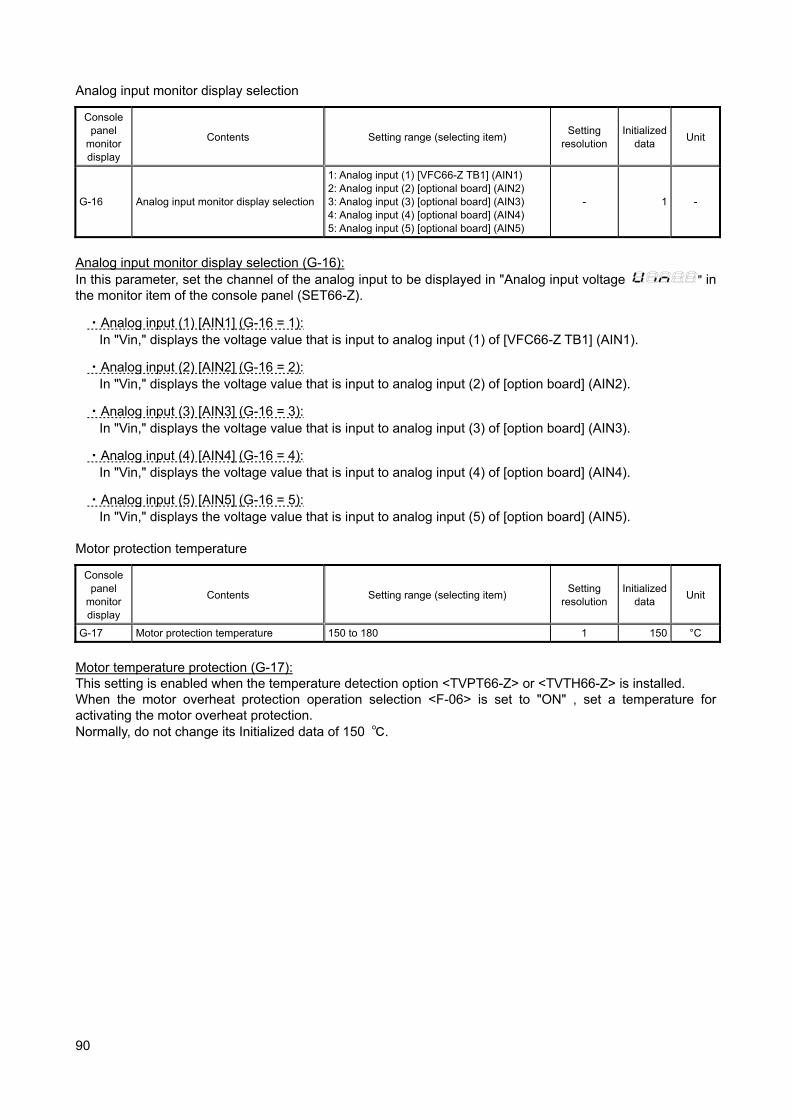
90
Analog input monitor display selection
Console panel
monitor display
Contents Setting range (selecting item) Setting
resolution Initialized
data Unit
G-16 Analog input monitor display selection
1: Analog input (1) [VFC66-Z TB1] (AIN1) 2: Analog input (2) [optional board] (AIN2) 3: Analog input (3) [optional board] (AIN3) 4: Analog input (4) [optional board] (AIN4) 5: Analog input (5) [optional board] (AIN5)
- 1 -
Analog input monitor display selection (G-16): In this parameter, set the channel of the analog input to be displayed in "Analog input voltage
" in the monitor item of the console panel (SET66-Z).
・Analog input (1) [AIN1] (G-16 = 1): In "Vin," displays the voltage value that is input to analog input (1) of [VFC66-Z TB1] (AIN1).
・Analog input (2) [AIN2] (G-16 = 2): In "Vin," displays the voltage value that is input to analog input (2) of [option board] (AIN2).
・Analog input (3) [AIN3] (G-16 = 3): In "Vin," displays the voltage value that is input to analog input (3) of [option board] (AIN3).
・Analog input (4) [AIN4] (G-16 = 4): In "Vin," displays the voltage value that is input to analog input (4) of [option board] (AIN4).
・Analog input (5) [AIN5] (G-16 = 5): In "Vin," displays the voltage value that is input to analog input (5) of [option board] (AIN5).
Motor protection temperature
Console panel
monitor display
Contents Setting range (selecting item) Setting
resolution Initialized
data Unit
G-17 Motor protection temperature 150 to 180 1 150 °C
Motor temperature protection (G-17): This setting is enabled when the temperature detection option <TVPT66-Z> or <TVTH66-Z> is installed. When the motor overheat protection operation selection <F-06> is set to "ON" , set a temperature for activating the motor overheat protection. Normally, do not change its Initialized data of 150 .
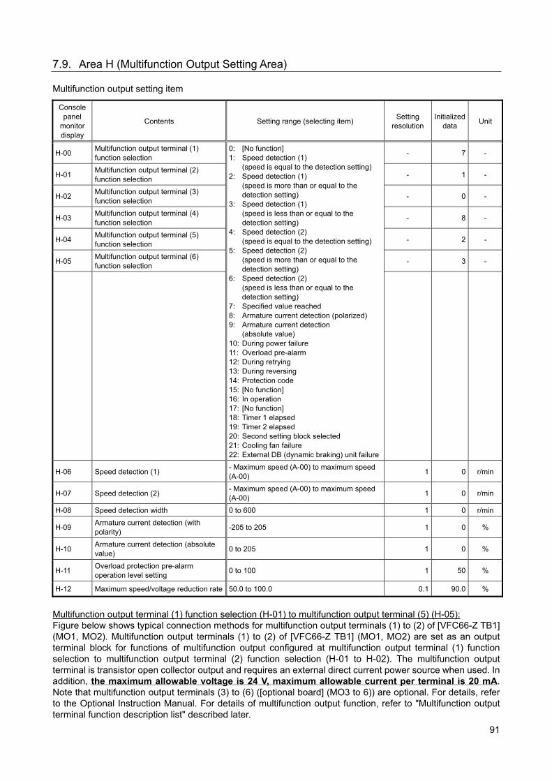
91
7.9. Area H (Multifunction Output Setting Area) Multifunction output setting item
Console panel
monitor display
Contents Setting range (selecting item) Setting
resolution Initialized
data Unit
H-00 Multifunction output terminal (1) function selection
0: [No function] 1: Speed detection (1)
(speed is equal to the detection setting) 2: Speed detection (1)
(speed is more than or equal to the detection setting)
3: Speed detection (1) (speed is less than or equal to the detection setting)
4: Speed detection (2) (speed is equal to the detection setting)
5: Speed detection (2) (speed is more than or equal to the detection setting)
6: Speed detection (2) (speed is less than or equal to the detection setting)
7: Specified value reached 8: Armature current detection (polarized) 9: Armature current detection
(absolute value) 10: During power failure 11: Overload pre-alarm 12: During retrying 13: During reversing 14: Protection code 15: [No function] 16: In operation 17: [No function] 18: Timer 1 elapsed 19: Timer 2 elapsed 20: Second setting block selected 21: Cooling fan failure 22: External DB (dynamic braking) unit failure
- 7 -
H-01 Multifunction output terminal (2) function selection
- 1 -
H-02 Multifunction output terminal (3) function selection
- 0 -
H-03 Multifunction output terminal (4) function selection
- 8 -
H-04 Multifunction output terminal (5) function selection
- 2 -
H-05 Multifunction output terminal (6) function selection
- 3 -
H-06 Speed detection (1) - Maximum speed (A-00) to maximum speed (A-00)
1 0 r/min
H-07 Speed detection (2) - Maximum speed (A-00) to maximum speed (A-00)
1 0 r/min
H-08 Speed detection width 0 to 600 1 0 r/min
H-09 Armature current detection (with polarity)
-205 to 205 1 0 %
H-10 Armature current detection (absolute value)
0 to 205 1 0 %
H-11 Overload protection pre-alarm operation level setting
0 to 100 1 50 %
H-12 Maximum speed/voltage reduction rate 50.0 to 100.0 0.1 90.0 %
Multifunction output terminal (1) function selection (H-01) to multifunction output terminal (5) (H-05): Figure below shows typical connection methods for multifunction output terminals (1) to (2) of [VFC66-Z TB1] (MO1, MO2). Multifunction output terminals (1) to (2) of [VFC66-Z TB1] (MO1, MO2) are set as an output terminal block for functions of multifunction output configured at multifunction output terminal (1) function selection to multifunction output terminal (2) function selection (H-01 to H-02). The multifunction output terminal is transistor open collector output and requires an external direct current power source when used. In addition, the maximum allowable voltage is 24 V, maximum allowable current per terminal is 20 mA. Note that multifunction output terminals (3) to (6) ([optional board] (MO3 to 6)) are optional. For details, refer to the Optional Instruction Manual. For details of multifunction output function, refer to "Multifunction output terminal function description list" described later.
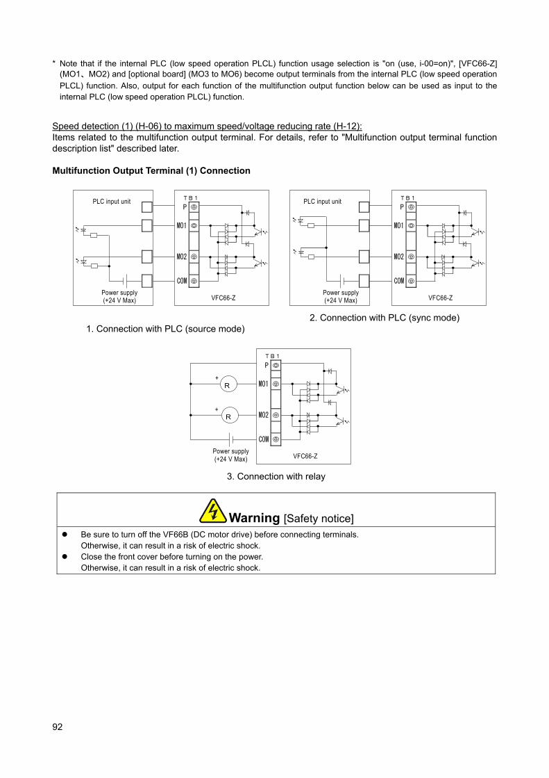
92
* Note that if the internal PLC (low speed operation PLCL) function usage selection is "on (use, i-00=on)", [VFC66-Z] (MO1、MO2) and [optional board] (MO3 to MO6) become output terminals from the internal PLC (low speed operation
PLCL) function. Also, output for each function of the multifunction output function below can be used as input to the internal PLC (low speed operation PLCL) function.
Speed detection (1) (H-06) to maximum speed/voltage reducing rate (H-12): Items related to the multifunction output terminal. For details, refer to "Multifunction output terminal function description list" described later. Multifunction Output Terminal (1) Connection
P
MO1
MO2
COM
VFC66-Z
TB1
Power supply (+24 V Max)
PLC input unit
1. Connection with PLC (source mode)
P
MO1
MO2
COM
VFC66-Z
TB1
Power supply (+24 V Max)
PLC input unit
2. Connection with PLC (sync mode)
P
MO1
MO2
COM
VFC66-Z
TB1
Power supply (+24 V Max)
R
R
+
+
3. Connection with relay
Warning [Safety notice] Be sure to turn off the VF66B (DC motor drive) before connecting terminals.
Otherwise, it can result in a risk of electric shock. Close the front cover before turning on the power.
Otherwise, it can result in a risk of electric shock.
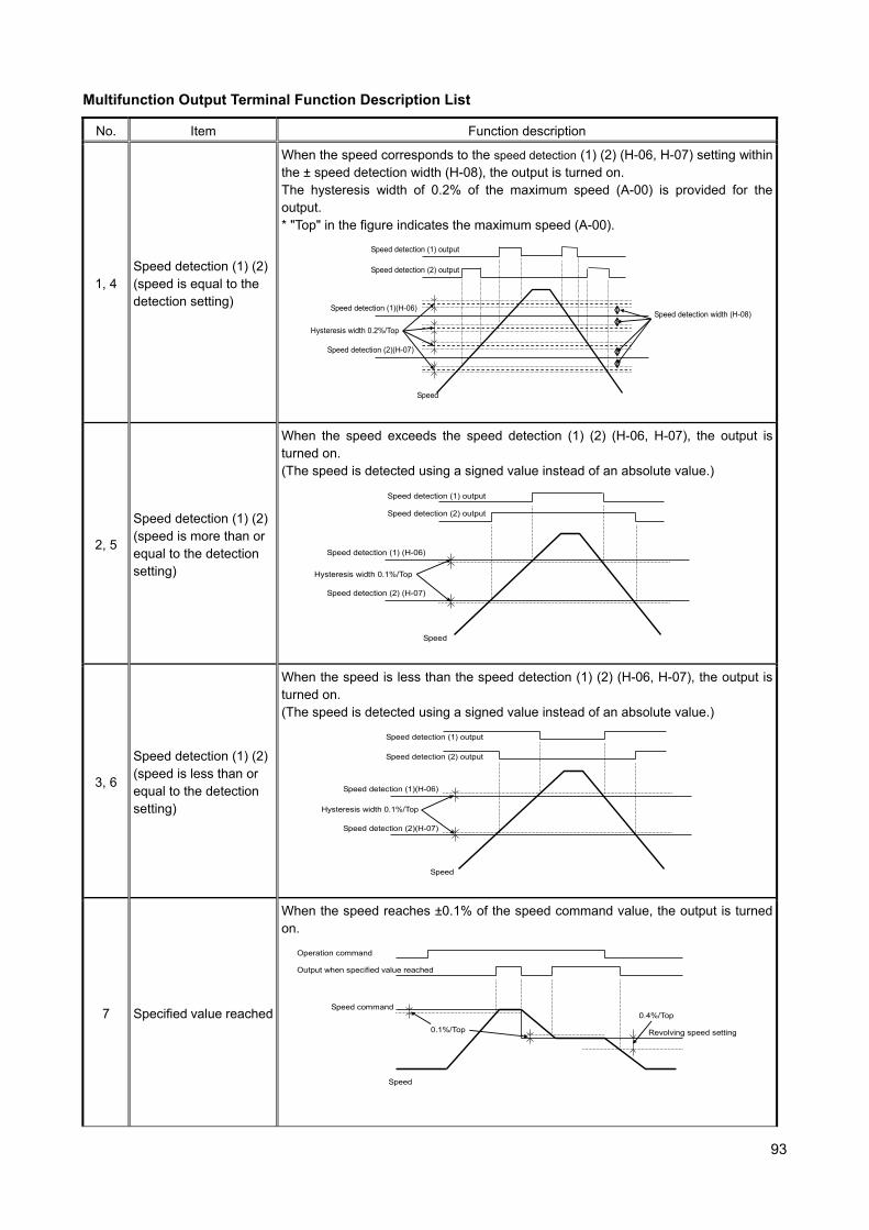
93
Multifunction Output Terminal Function Description List
No. Item Function description
1, 4 Speed detection (1) (2)(speed is equal to the detection setting)
When the speed corresponds to the speed detection (1) (2) (H-06, H-07) setting within the ± speed detection width (H-08), the output is turned on. The hysteresis width of 0.2% of the maximum speed (A-00) is provided for the output. * "Top" in the figure indicates the maximum speed (A-00).
Speed detection (1) output
Speed
Speed detection (1)(H-06)Speed detection width (H-08)
Hysteresis width 0.2%/Top
Speed detection (2)(H-07)
Speed detection (2) output
2, 5
Speed detection (1) (2)(speed is more than or equal to the detection setting)
When the speed exceeds the speed detection (1) (2) (H-06, H-07), the output is turned on. (The speed is detected using a signed value instead of an absolute value.)
Speed detection (1) output
Speed
Speed detection (1) (H-06)
Hysteresis width 0.1%/Top
Speed detection (2) (H-07)
Speed detection (2) output
3, 6
Speed detection (1) (2)(speed is less than or equal to the detection setting)
When the speed is less than the speed detection (1) (2) (H-06, H-07), the output is turned on. (The speed is detected using a signed value instead of an absolute value.)
Speed detection (1) output
Speed
Speed detection (1)(H-06)
Hysteresis width 0.1%/Top
Speed detection (2)(H-07)
Speed detection (2) output
7 Specified value reached
When the speed reaches ±0.1% of the speed command value, the output is turned on.
Operation command
Speed
0.1%/Top
Speed command
Output when specified value reached
Revolving speed setting
0.4%/Top
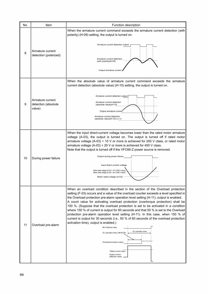
94
No. Item Function description
8 Armature current detection (polarized)
When the armature current command exceeds the armature current detection (with polarity) (H-09) setting, the output is turned on.
Output armature current
Armature current detection(with polarity)(H-09)
Armature current detection output
9 Armature current detection (absolute value)
When the absolute value of armature current command exceeds the armature current detection (absolute value) (H-10) setting, the output is turned on.
Output armature current
Armature current detection(absolute value)(H-10)
Armature current detection output
Armature current detection (absolute value)(H-10) x (-1)
10 During power failure
When the input direct-current voltage becomes lower than the rated motor armature voltage (A-03), the output is turned on. The output is turned off if rated motor armature voltage (A-03) + 10 V or more is achieved for 200 V class, or rated motor armature voltage (A-03) + 20 V or more is achieved for 400 V class. Note that the output is turned off if the VFC66-Z power source is removed.
Input direct current voltage
Motor rated voltage (A-03) + 10 V (200 V class) Motor rated voltage (A-03) + 20 V (400 V class)
Output during power failure
Motor rated voltage (A-03)
11 Overload pre-alarm
When an overload condition described in the section of the Overload protection setting (F-03) occurs and a value of the overload counter exceeds a level specified in the Overload protection pre-alarm operation level setting (H-11), output is enabled. A count value for activating overload protection (overtorque protection) shall be 100 %. (Suppose that the overload protection is set to be activated in a condition where 150 % of current is output for 60 seconds and that 50 % is set to the Overload protection pre-alarm operation level setting (H-11). In this case, when 150 % of current is output for 30 seconds (i.e., 50 % of 60 seconds of the overload protection activation time), output is enabled.)
Output current (effective value)
86 A (failure) relay
Rated current value
Overload pre-alarm output
OL activation timeOL activation time x H-11/100

95
No. Item Function description
12 During retrying
For ten seconds after the protection retry operation, output is enabled. For details of protection operation retry, refer to "6.7. Area F" in Chapter 6 and "7.7. Area F" in Chapter 7.
13 During reversing When the motor is running in reverse, output is enabled. (The hysteresis of 12 r/min is provided in the vicinity of 0 speed to prevent chattering.)
14 Protection operation code
When a failure occurs or a protection operation is activated, this function uses four multifunction output terminals to output a code corresponding to the activated protection. (Unlike other functions, this function requires four multifunction output terminals and you should set "Protection operation code" to all of them.) The list below shows output codes. <Output code list>
Contents MO1 MO2 MO3 MO4 Contents MO1 MO2 MO3 MO4
Overcurrent protection
ON OFF OFF OFFSpeed control error
ON ON ON OFF
IGBT protection operation
OFF ON OFF OFF PG error ON ON ON OFF
GAC abnormality
OFF ON OFF OFFMemory abnormality
OFF OFF OFF ON
Inverter overheat protection
OFF ON OFF OFFOptional error
OFF OFF OFF ON
Charging resistance overheat protection
OFF ON OFF OFFCPU abnormality handling
OFF OFF OFF ON
VF66B (DC motor drive) input direct current overvoltage
ON ON OFF OFFCommunication timeout error
ON OFF OFF ON
VF66B (DC motor drive) output direct current overvoltage
ON ON OFF OFFInsufficient voltage
OFF ON OFF ON
Overload protection
OFF OFF ON OFF Setting error ON ON OFF ON
Loss of field system
ON OFF ON OFFExternal failure 1
OFF OFF ON ON
Field system overcurrent
ON OFF ON OFFExternal failure 2
ON OFF ON ON
Motor overheat protection
OFF OFF ON OFFExternal failure 3
OFF ON ON ON
Start traffic OFF ON ON OFFExternal failure 4
ON ON ON ON
Overspeed protection
ON ON ON OFF
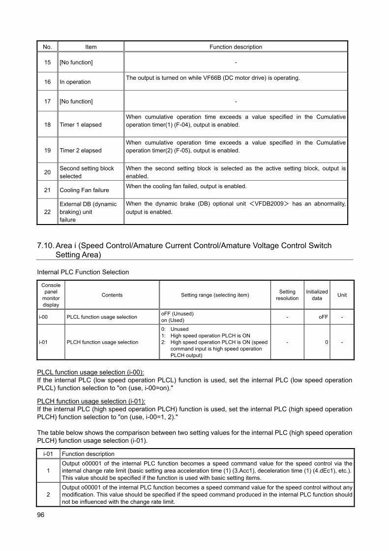
96
No. Item Function description
15 [No function] -
16 In operation The output is turned on while VF66B (DC motor drive) is operating.
17 [No function] -
18 Timer 1 elapsed When cumulative operation time exceeds a value specified in the Cumulative operation timer(1) (F-04), output is enabled.
19 Timer 2 elapsed When cumulative operation time exceeds a value specified in the Cumulative operation timer(2) (F-05), output is enabled.
20 Second setting block selected
When the second setting block is selected as the active setting block, output is enabled.
21 Cooling Fan failure When the cooling fan failed, output is enabled.
22 External DB (dynamic braking) unit failure
When the dynamic brake (DB) optional unit <VFDB2009> has an abnormality,
output is enabled.
7.10. Area i (Speed Control/Amature Current Control/Amature Voltage Control Switch
Setting Area) Internal PLC Function Selection
Console panel
monitor display
Contents Setting range (selecting item) Setting
resolution Initialized
data Unit
i-00 PLCL function usage selection oFF (Unused) on (Used)
- oFF -
i-01 PLCH function usage selection
0: Unused 1: High speed operation PLCH is ON 2: High speed operation PLCH is ON (speed
command input is high speed operation PLCH output)
- 0 -
PLCL function usage selection (i-00): If the internal PLC (low speed operation PLCL) function is used, set the internal PLC (low speed operation PLCL) function selection to "on (use, i-00=on)."
PLCH function usage selection (i-01): If the internal PLC (high speed operation PLCH) function is used, set the internal PLC (high speed operation PLCH) function selection to "on (use, i-00=1, 2)." The table below shows the comparison between two setting values for the internal PLC (high speed operation PLCH) function usage selection (i-01).
i-01 Function description
1 Output o00001 of the internal PLC function becomes a speed command value for the speed control via the internal change rate limit (basic setting area acceleration time (1) (3.Acc1), deceleration time (1) (4.dEc1), etc.).This value should be specified if the function is used with basic setting items.
2 Output o00001 of the internal PLC function becomes a speed command value for the speed control without any modification. This value should be specified if the speed command produced in the internal PLC function should not be influenced with the change rate limit.
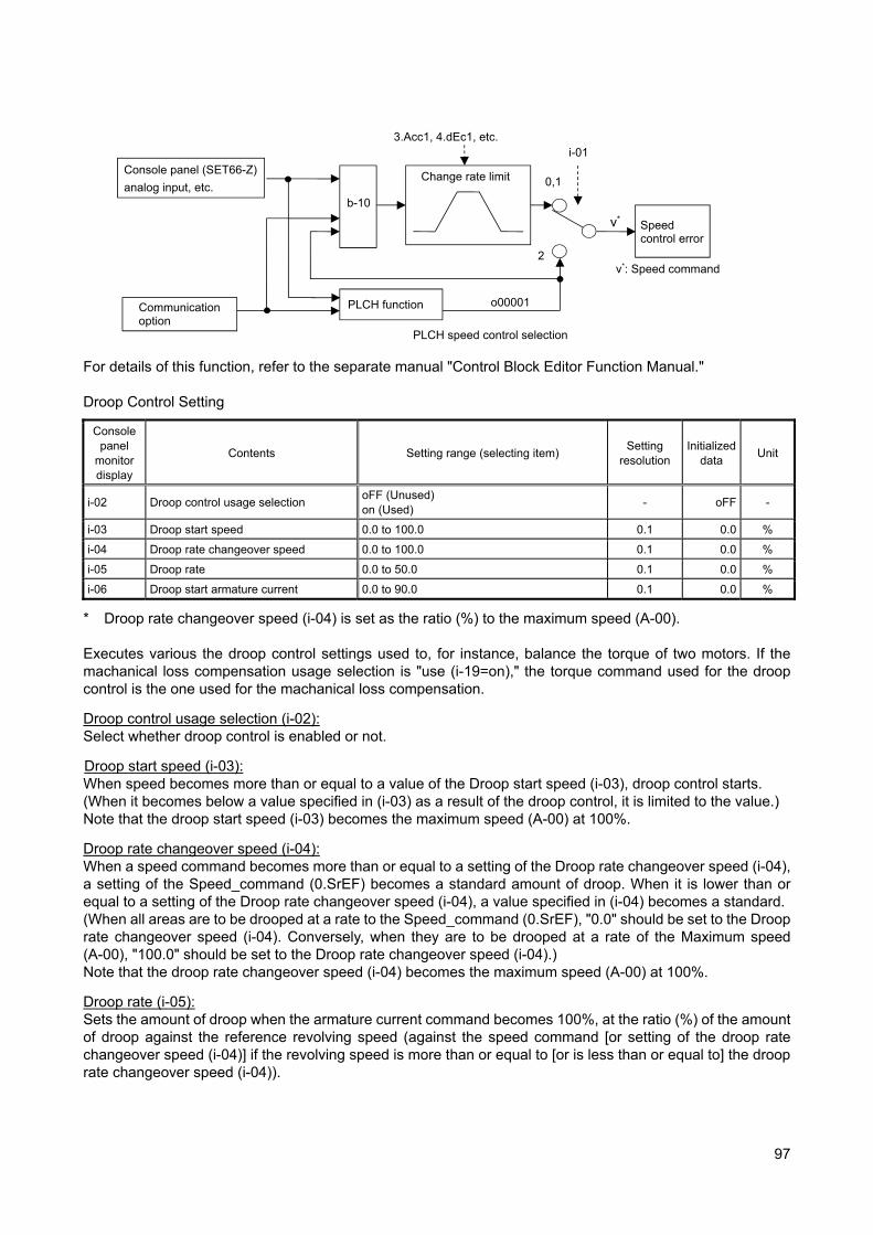
97
For details of this function, refer to the separate manual "Control Block Editor Function Manual." Droop Control Setting
Console panel
monitor display
Contents Setting range (selecting item) Setting
resolution Initialized
data Unit
i-02 Droop control usage selection oFF (Unused) on (Used)
- oFF -
i-03 Droop start speed 0.0 to 100.0 0.1 0.0 %
i-04 Droop rate changeover speed 0.0 to 100.0 0.1 0.0 %
i-05 Droop rate 0.0 to 50.0 0.1 0.0 %
i-06 Droop start armature current 0.0 to 90.0 0.1 0.0 %
* Droop rate changeover speed (i-04) is set as the ratio (%) to the maximum speed (A-00). Executes various the droop control settings used to, for instance, balance the torque of two motors. If the machanical loss compensation usage selection is "use (i-19=on)," the torque command used for the droop control is the one used for the machanical loss compensation.
Droop control usage selection (i-02): Select whether droop control is enabled or not.
Droop start speed (i-03): When speed becomes more than or equal to a value of the Droop start speed (i-03), droop control starts. (When it becomes below a value specified in (i-03) as a result of the droop control, it is limited to the value.) Note that the droop start speed (i-03) becomes the maximum speed (A-00) at 100%.
Droop rate changeover speed (i-04): When a speed command becomes more than or equal to a setting of the Droop rate changeover speed (i-04), a setting of the Speed_command (0.SrEF) becomes a standard amount of droop. When it is lower than or equal to a setting of the Droop rate changeover speed (i-04), a value specified in (i-04) becomes a standard. (When all areas are to be drooped at a rate to the Speed_command (0.SrEF), "0.0" should be set to the Droop rate changeover speed (i-04). Conversely, when they are to be drooped at a rate of the Maximum speed (A-00), "100.0" should be set to the Droop rate changeover speed (i-04).) Note that the droop rate changeover speed (i-04) becomes the maximum speed (A-00) at 100%.
Droop rate (i-05): Sets the amount of droop when the armature current command becomes 100%, at the ratio (%) of the amount of droop against the reference revolving speed (against the speed command [or setting of the droop rate changeover speed (i-04)] if the revolving speed is more than or equal to [or is less than or equal to] the droop rate changeover speed (i-04)).
Console panel (SET66-Z)
analog input, etc.
b-10
3.Acc1, 4.dEc1, etc.
Speed control error
Change rate limit
Communication option
PLCH function
PLCH speed control selection
i-01
0,1
2
o00001
v*: Speed command
v*
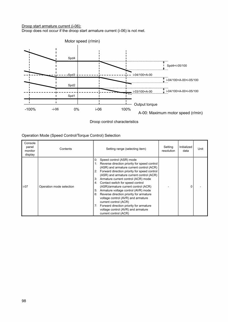
98
Droop start armature current (i-06): Droop does not occur if the droop start armature current (i-06) is not met.
100%-100% 0% Output torque
i-06
i-04/100×A-00
i-03/100×A-00
Spd4
Spd3
Spd2
Spd1
Spd4×i-05/100
i-04/100×A-00×i-05/100
i-04/100×A-00×i-05/100
A-00: Maximum motor speed (r/min) -i-06
Motor speed (r/min)
Droop control characteristics Operation Mode (Speed Control/Torque Control) Selection
Console panel
monitor display
Contents Setting range (selecting item) Setting
resolution Initialized
data Unit
i-07 Operation mode selection
0: Speed control (ASR) mode 1: Reverse direction priority for speed control
(ASR) and armature current control (ACR)2: Forward direction priority for speed control
(ASR) and armature current control (ACR)3: Armature current control (ACR) mode 4: Contact switch for speed control
(ASR)/armature current control (ACR) 5: Armature voltage control (AVR) mode 6: Reverse direction priority for armature
voltage control (AVR) and armature current control (ACR)
7: Forward direction priority for armature voltage control (AVR) and armature current control (ACR)
- 0 -
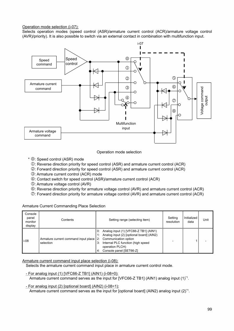
99
Operation mode selection (i-07): Selects operation modes (speed control (ASR)/armature current control (ACR)/armature voltage control (AVR)/priority). It is also possible to switch via an external contact in combination with multifunction input.
Operation mode selection
* : Speed control (ASR) mode : Reverse direction priority for speed control (ASR) and armature current control (ACR) : Forward direction priority for speed control (ASR) and armature current control (ACR) : Armature current control (ACR) mode : Contact switch for speed control (ASR)/armature current control (ACR) : Armature voltage control (AVR) : Reverse direction priority for armature voltage control (AVR) and armature current control (ACR) : Forward direction priority for armature voltage control (AVR) and armature current control (ACR)
Armature Current Commanding Place Selection
Console panel
monitor display
Contents Setting range (selecting item) Setting
resolution Initialized
data Unit
i-08 Armature current command input place selection
0: Analog input (1) [VFC66-Z TB1] (AIN1) 1: Analog input (2) [optional board] (AIN2) 2: Communication option 3: Internal PLC function (high speed
operation PLCH) 4: Console panel [SET66-Z]
- 1 -
Armature current command input place selection (i-08):
Selects the armature current command input place in armature current control mode.
- For analog input (1) [VFC66-Z TB1] (AIN1) (i-08=0): Armature current command serves as the input for [VFC66-Z TB1] (AIN1) analog input (1)*1.
- For analog input (2) [optional board] (AIN2) (i-08=1): Armature current command serves as the input for [optional board] (AIN2) analog input (2)*1.
Speed command
Speed control
Armature current command
Armature voltage command
Vol
tage
com
man
d ou
tput
i-07
Multifunction input
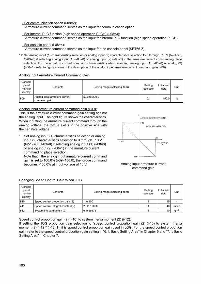
100
- For communication option (i-08=2): Armature current command serves as the input for communication option.
- For internal PLC function (high speed operation PLCH) (i-08=3): Armature current command serves as the input for internal PLC function (high speed operation PLCH).
- For console panel (i-08=4): Armature current command serves as the input for the console panel [SET66-Z].
*1: Set analog input (1) characteristics selection or analog input (2) characteristics selection to 0 through ±10 V (b2-17=0, G-03=0) if selecting analog input (1) (i-08=0) or analog input (2) (i-08=1) in the armature current commanding place selection. For the armature current command characteristics when selecting analog input (1) (i-08=0) or analog (2) (i-08=1), refer to figure shown in the description of the analog input armature current command gain (i-09).
Analog Input Armature Current Command Gain
Console panel
monitor display
Contents Setting range (selecting item) Setting
resolution Initialized
data Unit
i-09 Analog input armature current command gain
50.0 to 200.0 0.1 150.0 %
Analog input armature current command gain (i-09): This is the armature current command gain setting against the analog input. The right figure shows the characteristics.When inputting the armature current command through the analog voltage, the torque exists in the positive side with the negative voltage.
* Set analog input (1) characteristics selection or analog input (2) characteristics selection to 0 through ±10 V (b2-17=0, G-03=0) if selecting analog input (1) (i-08=0) or analog input (2) (i-08=1) in the armature current commanding place selection. Note that if the analog input armature current command gain is set to 100.0% (i-09=100.0), the torque command becomes -100.0% at input voltage of 10 V.
(i-09)
-(i-09)
10V
-10V Input voltage [V]
Armature current command [%]
(i-09): 50.0 to 200.0 [%]
Analog input armature current
command gain Changing Speed Control Gain When JOG
Console panel
monitor display
Contents Setting range (selecting item) Setting
resolution Initialized
data Unit
i-10 Speed control proportion gain (2) 1 to 100 1 15 -
i-11 Speed control integral constant(2) 20 to 10000 1 40 msec
i-12 System inertia moment (2) 0 to 65535 1 10 gm2
Speed control proportion gain (2) (i-10) to system inertia moment (2) (i-12): If setting the JOG proportion gain selection to "speed control proportion gain (2) (i-10) to system inertia moment (2) (i-12)" (i-13=1), it is speed control proportion gain used in JOG. For the speed control proportion gain, refer to the speed control proportion gain setting in "6.1. Basic Setting Area" in Chapter 6 and "7.1. Basic Setting Area" in Chapter 7.

101
JOG Proportion Gain Selection
Console panel
monitor display
Contents Setting range (selecting item) Setting
resolution Initialized
data Unit
i-13 JOG proportion gain selection
0: Speed control proportion gain (1) (7.ASrP)to system inertia moment (1) (9.ASrJ)
1: Speed control proportion gain (2) (i-10) to system inertia moment (2) (i-12)
2: [For special adjustment]*1
1 15 -
*1: Provided for special adjustment. Usually do not set this item. JOG proportion gain selection (i-13): Set proportion gain, time constant, and inertia moment used for JOG operation.
- For speed control proportion gain (1) (7.ASrP) to system inertia moment (1) (i-13=0) Setting values of the Speed control proportion gain(1) (7.ASrP), Speed control integral time constant(1) (8.ASrI), and System inertia moment(1) (9.ASrJ) are used.
- For speed control proportion gain (2) (i-10) to system inertia moment (2) (i-12) (i-13=1) Setting values of speed control proportion gain (2) (i-10), speed control integral constant (2) (i-11), and system inertia moment (i-12) are used in JOG.
Speed Control (ASR) Selection
Console panel
monitor display
Contents Setting range (selecting item) Setting
resolution Initialized
data Unit
i-14 ASR cancellation usage selection oFF (Unused) on (Used)
- on -
i-15 ASR feed-forward usage selection oFF (Unused) on (Used)
- on -
ASR cancellation usage selection (i-14), ASR feed-forward usage selection (i-15): For VF66B (DC motor drive), the robust speed control (MFC control) is configured in combination with cancellation and feed-forward using the disturbance observer. These cancellation and feed-forward can be switched between used/unused through ASR cancellation usage selection and ASR feed-forward usage selection (i-14=on/oFF, i-15=on/oFF). If both ASR cancellation usage selection and ASR feed-forward usage selection are set to unused (i-14=oFF and i-15=oFF), the function is equivalent to conventional PI control. For details, refer to "6.1. Basic Setting Area" in Chapter 6 and "7.1. Basic Setting Area" in Chapter 7. Variable Structure Proportion Gain Adjustment
Console panel
monitor display
Contents Setting range (selecting item) Setting
resolution Initialized
data Unit
i-16 Variable structure proportion gain start speed
0.01 to 100.00 0.01 5.00 %
i-17 Variable structure proportion gain minimum gain percentage
0 to 500 1 100 %
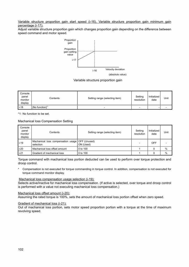
102
Variable structure proportion gain start speed (i-16), Variable structure proportion gain minimum gain percentage (i-17): Adjust variable structure proportion gain which changes proportion gain depending on the difference between speed command and motor speed.
(absolute value)
Variable structure proportion gain
i-16 Velocity deviation
Proportion gain
Proportion gain setting
value
i-17
Console
panel monitor display
Contents Setting range (selecting item) Setting
resolution Initialized
data Unit
i-18 [No function]*1 - - - -
*1: No function to be set. Machanical loss Compensation Setting
Console panel
monitor display
Contents Setting range (selecting item) Setting
resolution Initialized
data Unit
i-19 Machanical loss compensation usage selection
OFF (Unused) ON (Used)
- OFF -
i-20 Machanical loss offset amount 0 to 100 1 0 %
i-21 Gradient of mechanical loss 0 to 100 1 0 %
Torque command with machanical loss portion deducted can be used to perform over torque protection and droop control.
* Compensation is not executed for torque commanding in torque control. In addition, compensation is not executed for torque command monitor display.
Machanical loss compensation usage selection (i-19): Selects active/inactive for machanical loss compensation. (If active is selected, over torque and droop control is performed with a value not executing machanical loss compensation.)
Machanical loss offset amount (i-20): Assuming the rated torque is 100%, sets the amount of machanical loss portion offset when zero speed.
Gradient of mechanical loss (i-21): Out of machanical loss portion, sets motor speed proportion portion with a torque at the time of maximum revolving speed.

103
Machanical loss compensation
Console panel
monitor display
Contents Setting range (selecting item) Setting
resolution Initialized
data Unit
i-22 to i-32
[For special adjustment]*1 -
- - -
*1: Provided for special adjustment. Do not change the parameter data from default setting (leave it as factory initialized data).
Armature Voltage Command Setting
Console panel
monitor display
Contents Setting range (selecting item) Setting
resolution Initialized
data Unit
i-33 Armature voltage command value (for armature voltage control)
- Rated motor armature voltage (A-03) to Rated motor armature voltage (A-03)
1 0 V
i-34 Forward JOG armature voltage command (for armature voltage control)
0 to 100 1 0 %
i-35 Reverse JOG armature voltage command (for armature voltage control)
0 to 100 1 0 %
Armature voltage command value (for armature voltage control) (i-33): Setting used to specify an armature voltage command value on the console panel for armature voltage control. It is enabled when selecting the console panel as a command input when coupled (b-09) and specifying interlock for speed/armature voltage command input selection (b-10), and when selecting the console panel as a speed commanding place in speed/armature voltage command input selection (b-10). Refer to "6.3. Area b" in Chapter 6 and "7.3. Area b" in Chapter 7.
Positive JOG armature voltage command value (for armature voltage control) (i-34)/Negative JOG armature voltage command value (for armature voltage control) (i-35) Sets positive JOG armature voltage command and negative JOG armature voltage command values for armature voltage control.
Torque for machanical loss (%)
Revolving speed
-A-00 0
Motor speed (r/min)
Motor speed
ON
0
OFF
To over torque protection function, droop control function
Torque command after machine loss compensation
Torque command
+
A-00
i-20
i-21
i-19
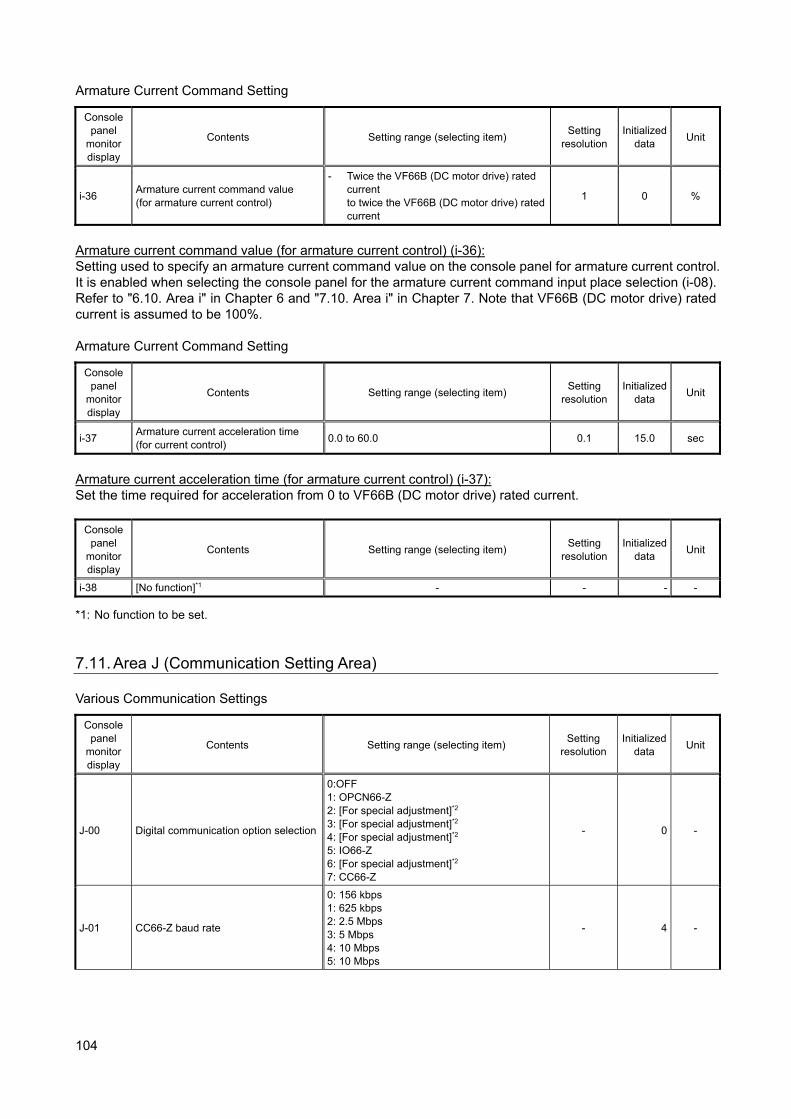
104
Armature Current Command Setting
Console panel
monitor display
Contents Setting range (selecting item) Setting
resolution Initialized
data Unit
i-36 Armature current command value (for armature current control)
- Twice the VF66B (DC motor drive) rated current to twice the VF66B (DC motor drive) rated current
1 0 %
Armature current command value (for armature current control) (i-36): Setting used to specify an armature current command value on the console panel for armature current control. It is enabled when selecting the console panel for the armature current command input place selection (i-08). Refer to "6.10. Area i" in Chapter 6 and "7.10. Area i" in Chapter 7. Note that VF66B (DC motor drive) rated current is assumed to be 100%. Armature Current Command Setting
Console panel
monitor display
Contents Setting range (selecting item) Setting
resolution Initialized
data Unit
i-37 Armature current acceleration time (for current control)
0.0 to 60.0 0.1 15.0 sec
Armature current acceleration time (for armature current control) (i-37): Set the time required for acceleration from 0 to VF66B (DC motor drive) rated current.
Console panel
monitor display
Contents Setting range (selecting item) Setting
resolution Initialized
data Unit
i-38 [No function]*1 - - - -
*1: No function to be set. 7.11. Area J (Communication Setting Area) Various Communication Settings
Console panel
monitor display
Contents Setting range (selecting item) Setting
resolution Initialized
data Unit
J-00 Digital communication option selection
0:OFF 1: OPCN66-Z 2: [For special adjustment]*2 3: [For special adjustment]*2 4: [For special adjustment]*2 5: IO66-Z 6: [For special adjustment]*2 7: CC66-Z
- 0 -
J-01 CC66-Z baud rate
0: 156 kbps 1: 625 kbps 2: 2.5 Mbps 3: 5 Mbps 4: 10 Mbps 5: 10 Mbps
- 4 -
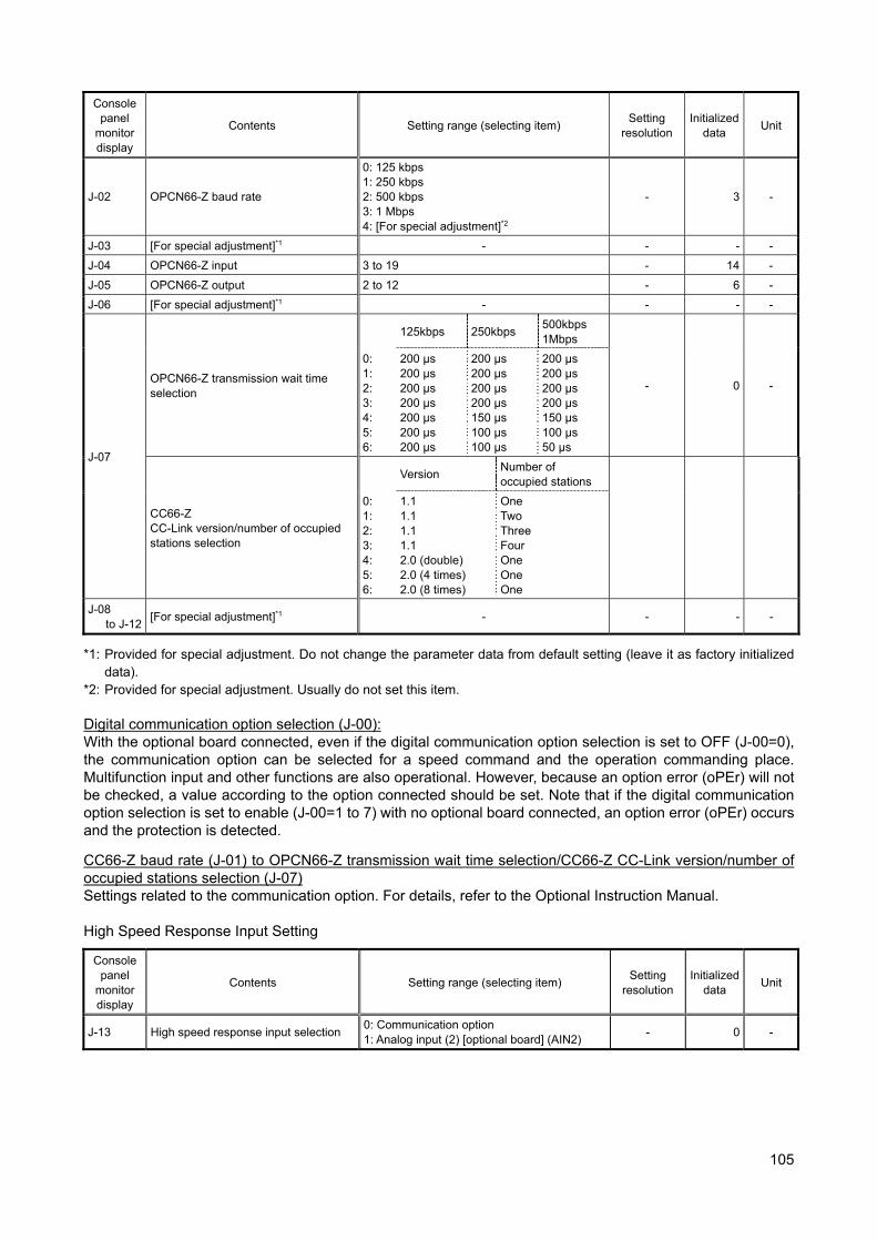
105
Console panel
monitor display
Contents Setting range (selecting item) Setting
resolution Initialized
data Unit
J-02 OPCN66-Z baud rate
0: 125 kbps 1: 250 kbps 2: 500 kbps 3: 1 Mbps 4: [For special adjustment]*2
- 3 -
J-03 [For special adjustment]*1 - - - -
J-04 OPCN66-Z input 3 to 19 - 14 -
J-05 OPCN66-Z output 2 to 12 - 6 -
J-06 [For special adjustment]*1 - - - -
J-07
OPCN66-Z transmission wait time selection
125kbps 250kbps 500kbps 1Mbps
- 0 -
0: 1: 2: 3: 4: 5: 6:
200 μs 200 μs 200 μs 200 μs 200 μs 200 μs 200 μs
200 μs 200 μs 200 μs 200 μs 150 μs 100 μs 100 μs
200 μs 200 μs 200 μs 200 μs 150 μs 100 μs 50 μs
CC66-Z CC-Link version/number of occupied stations selection
Version Number of occupied stations
0: 1: 2: 3: 4: 5: 6:
1.1 1.1 1.1 1.1 2.0 (double) 2.0 (4 times) 2.0 (8 times)
One Two Three Four One One One
J-08 to J-12
[For special adjustment]*1 - - - -
*1: Provided for special adjustment. Do not change the parameter data from default setting (leave it as factory initialized data).
*2: Provided for special adjustment. Usually do not set this item. Digital communication option selection (J-00): With the optional board connected, even if the digital communication option selection is set to OFF (J-00=0), the communication option can be selected for a speed command and the operation commanding place. Multifunction input and other functions are also operational. However, because an option error (oPEr) will not be checked, a value according to the option connected should be set. Note that if the digital communication option selection is set to enable (J-00=1 to 7) with no optional board connected, an option error (oPEr) occurs and the protection is detected.
CC66-Z baud rate (J-01) to OPCN66-Z transmission wait time selection/CC66-Z CC-Link version/number of occupied stations selection (J-07) Settings related to the communication option. For details, refer to the Optional Instruction Manual. High Speed Response Input Setting
Console panel
monitor display
Contents Setting range (selecting item) Setting
resolution Initialized
data Unit
J-13 High speed response input selection 0: Communication option 1: Analog input (2) [optional board] (AIN2)
- 0 -
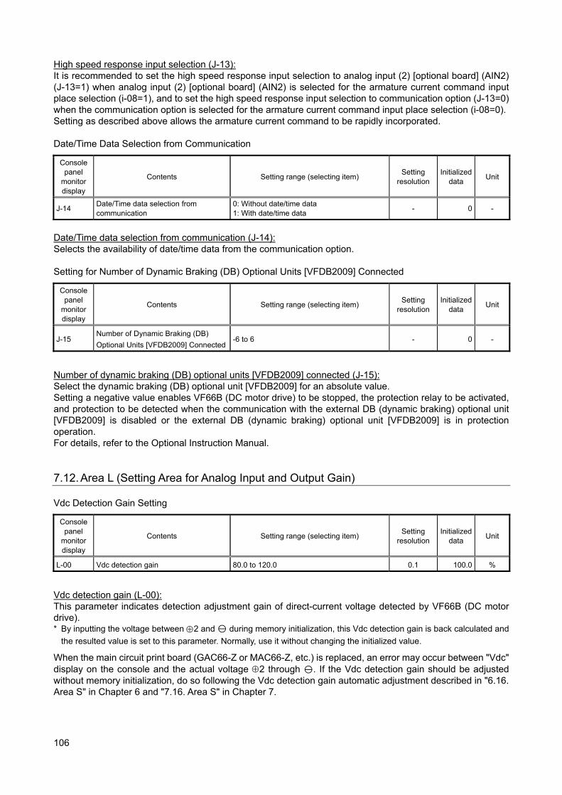
106
High speed response input selection (J-13): It is recommended to set the high speed response input selection to analog input (2) [optional board] (AIN2) (J-13=1) when analog input (2) [optional board] (AIN2) is selected for the armature current command input place selection (i-08=1), and to set the high speed response input selection to communication option (J-13=0) when the communication option is selected for the armature current command input place selection (i-08=0). Setting as described above allows the armature current command to be rapidly incorporated. Date/Time Data Selection from Communication
Console panel
monitor display
Contents Setting range (selecting item) Setting
resolution Initialized
data Unit
J-14 Date/Time data selection from communication
0: Without date/time data 1: With date/time data
- 0 -
Date/Time data selection from communication (J-14): Selects the availability of date/time data from the communication option. Setting for Number of Dynamic Braking (DB) Optional Units [VFDB2009] Connected
Console panel
monitor display
Contents Setting range (selecting item) Setting
resolution Initialized
data Unit
J-15 Number of Dynamic Braking (DB)
Optional Units [VFDB2009] Connected -6 to 6 - 0 -
Number of dynamic braking (DB) optional units [VFDB2009] connected (J-15): Select the dynamic braking (DB) optional unit [VFDB2009] for an absolute value. Setting a negative value enables VF66B (DC motor drive) to be stopped, the protection relay to be activated, and protection to be detected when the communication with the external DB (dynamic braking) optional unit [VFDB2009] is disabled or the external DB (dynamic braking) optional unit [VFDB2009] is in protection operation. For details, refer to the Optional Instruction Manual. 7.12. Area L (Setting Area for Analog Input and Output Gain) Vdc Detection Gain Setting
Console panel
monitor display
Contents Setting range (selecting item) Setting
resolution Initialized
data Unit
L-00 Vdc detection gain 80.0 to 120.0 0.1 100.0 %
Vdc detection gain (L-00): This parameter indicates detection adjustment gain of direct-current voltage detected by VF66B (DC motor drive). * By inputting the voltage between 2 and during memory initialization, this Vdc detection gain is back calculated and
the resulted value is set to this parameter. Normally, use it without changing the initialized value.
When the main circuit print board (GAC66-Z or MAC66-Z, etc.) is replaced, an error may occur between "Vdc" display on the console and the actual voltage 2 through . If the Vdc detection gain should be adjusted without memory initialization, do so following the Vdc detection gain automatic adjustment described in "6.16. Area S" in Chapter 6 and "7.16. Area S" in Chapter 7.
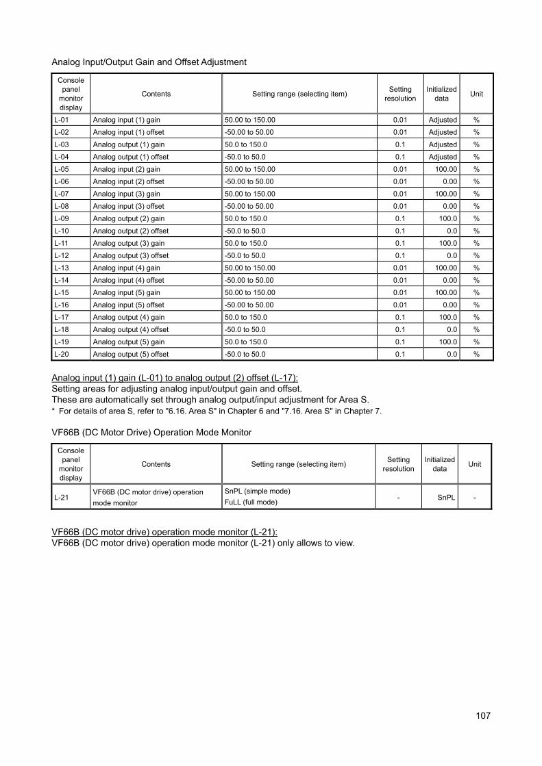
107
Analog Input/Output Gain and Offset Adjustment
Console panel
monitor display
Contents Setting range (selecting item) Setting
resolution Initialized
data Unit
L-01 Analog input (1) gain 50.00 to 150.00 0.01 Adjusted %
L-02 Analog input (1) offset -50.00 to 50.00 0.01 Adjusted %
L-03 Analog output (1) gain 50.0 to 150.0 0.1 Adjusted %
L-04 Analog output (1) offset -50.0 to 50.0 0.1 Adjusted %
L-05 Analog input (2) gain 50.00 to 150.00 0.01 100.00 %
L-06 Analog input (2) offset -50.00 to 50.00 0.01 0.00 %
L-07 Analog input (3) gain 50.00 to 150.00 0.01 100.00 %
L-08 Analog input (3) offset -50.00 to 50.00 0.01 0.00 %
L-09 Analog output (2) gain 50.0 to 150.0 0.1 100.0 %
L-10 Analog output (2) offset -50.0 to 50.0 0.1 0.0 %
L-11 Analog output (3) gain 50.0 to 150.0 0.1 100.0 %
L-12 Analog output (3) offset -50.0 to 50.0 0.1 0.0 %
L-13 Analog input (4) gain 50.00 to 150.00 0.01 100.00 %
L-14 Analog input (4) offset -50.00 to 50.00 0.01 0.00 %
L-15 Analog input (5) gain 50.00 to 150.00 0.01 100.00 %
L-16 Analog input (5) offset -50.00 to 50.00 0.01 0.00 %
L-17 Analog output (4) gain 50.0 to 150.0 0.1 100.0 %
L-18 Analog output (4) offset -50.0 to 50.0 0.1 0.0 %
L-19 Analog output (5) gain 50.0 to 150.0 0.1 100.0 %
L-20 Analog output (5) offset -50.0 to 50.0 0.1 0.0 %
Analog input (1) gain (L-01) to analog output (2) offset (L-17): Setting areas for adjusting analog input/output gain and offset. These are automatically set through analog output/input adjustment for Area S. * For details of area S, refer to "6.16. Area S" in Chapter 6 and "7.16. Area S" in Chapter 7. VF66B (DC Motor Drive) Operation Mode Monitor
Console panel
monitor display
Contents Setting range (selecting item) Setting
resolution Initialized
data Unit
L-21 VF66B (DC motor drive) operation
mode monitor
SnPL (simple mode)
FuLL (full mode) - SnPL -
VF66B (DC motor drive) operation mode monitor (L-21): VF66B (DC motor drive) operation mode monitor (L-21) only allows to view.
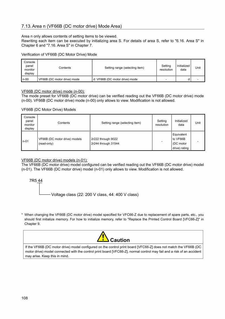
108
7.13. Area n (VF66B (DC motor drive) Mode Area) Area n only allows contents of setting items to be viewed. Rewriting each item can be executed by initializing area S. For details of area S, refer to "6.16. Area S" in Chapter 6 and "7.16. Area S" in Chapter 7. Verification of VF66B (DC Motor Drive) Mode
Console panel
monitor display
Contents Setting range (selecting item) Setting
resolution Initialized
data Unit
n-00 VF66B (DC motor drive) mode d: VF66B (DC motor drive) mode - d -
VF66B (DC motor drive) mode (n-00): The mode preset for VF66B (DC motor drive) can be verified reading out the VF66B (DC motor drive) mode (n-00). VF66B (DC motor drive) mode (n-00) only allows to view. Modification is not allowed. VF66B (DC Motor Drive) Models
Console panel
monitor display
Contents Setting range (selecting item) Setting
resolution Initialized
data Unit
n-01 VF66B (DC motor drive) models
(read-only)
2r222 through 9022
2r244 through 31544 -
Equivalent
to VF66B
(DC motor
drive) rating
-
VF66B (DC motor drive) models (n-01): The VF66B (DC motor drive) model configured can be verified reading out the VF66B (DC motor drive) model (n-01). The VF66B (DC motor drive) model (n-01) only allows to view. Modification is not allowed.
7R5 44
Voltage class (22: 200 V class, 44: 400 V class)
* When changing the VF66B (DC motor drive) model specified for VFC66-Z due to replacement of spare parts, etc., you
should first initialize memory. For how to initialize memory, refer to "Replace the Printed Control Board [VFC66-Z]" in Chapter 9.
CautionIf the VF66B (DC motor drive) model configured on the control print board [VFC66-Z] does not match the VF66B (DC motor drive) model connected with the control print board [VFC66-Z], normal control may fail and a risk of an accident may arise. Keep this in mind.
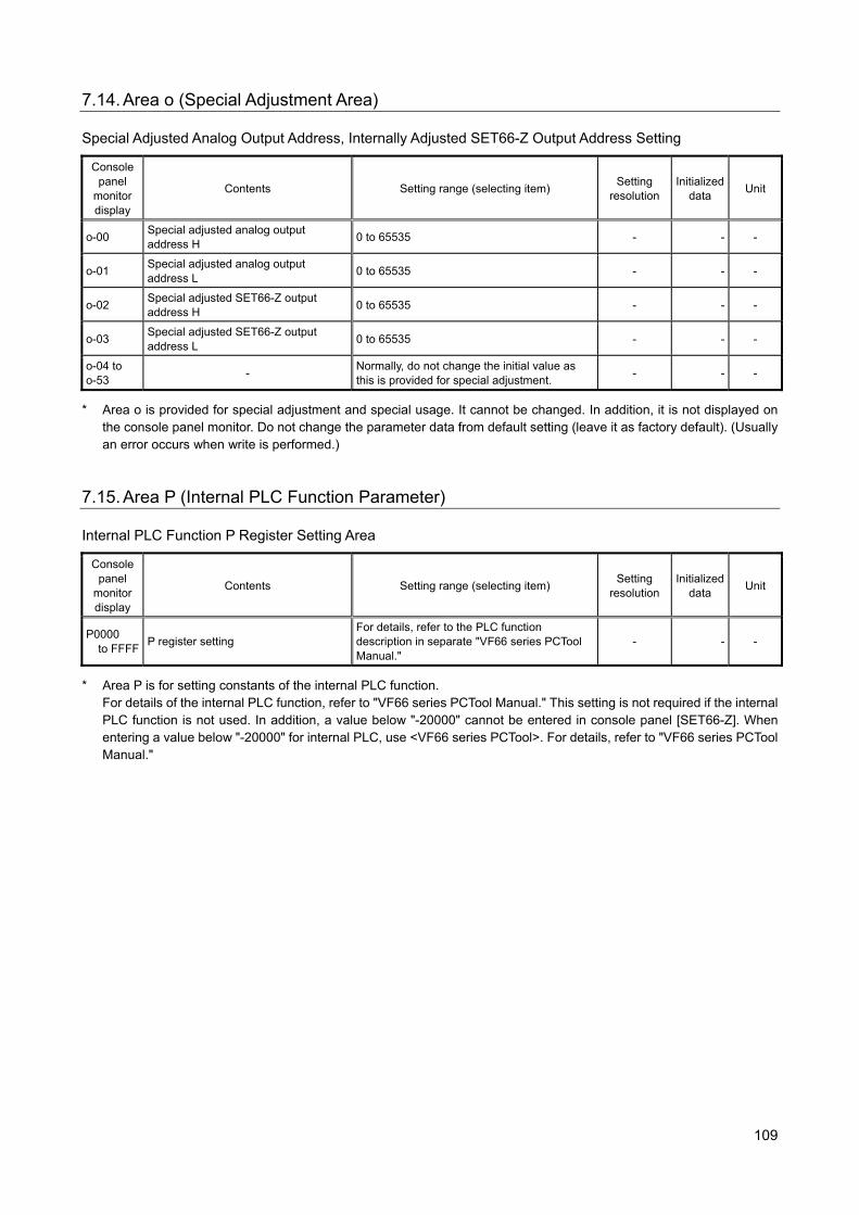
109
7.14. Area o (Special Adjustment Area) Special Adjusted Analog Output Address, Internally Adjusted SET66-Z Output Address Setting
Console panel
monitor display
Contents Setting range (selecting item) Setting
resolution Initialized
data Unit
o-00 Special adjusted analog output address H
0 to 65535 - - -
o-01 Special adjusted analog output address L
0 to 65535 - - -
o-02 Special adjusted SET66-Z output address H
0 to 65535 - - -
o-03 Special adjusted SET66-Z output address L
0 to 65535 - - -
o-04 to o-53
- Normally, do not change the initial value as this is provided for special adjustment.
- - -
* Area o is provided for special adjustment and special usage. It cannot be changed. In addition, it is not displayed on the console panel monitor. Do not change the parameter data from default setting (leave it as factory default). (Usually an error occurs when write is performed.)
7.15. Area P (Internal PLC Function Parameter) Internal PLC Function P Register Setting Area
Console panel
monitor display
Contents Setting range (selecting item) Setting
resolution Initialized
data Unit
P0000 to FFFF
P register setting For details, refer to the PLC function description in separate "VF66 series PCTool Manual."
- - -
* Area P is for setting constants of the internal PLC function. For details of the internal PLC function, refer to "VF66 series PCTool Manual." This setting is not required if the internal PLC function is not used. In addition, a value below "-20000" cannot be entered in console panel [SET66-Z]. When entering a value below "-20000" for internal PLC, use <VF66 series PCTool>. For details, refer to "VF66 series PCTool Manual."
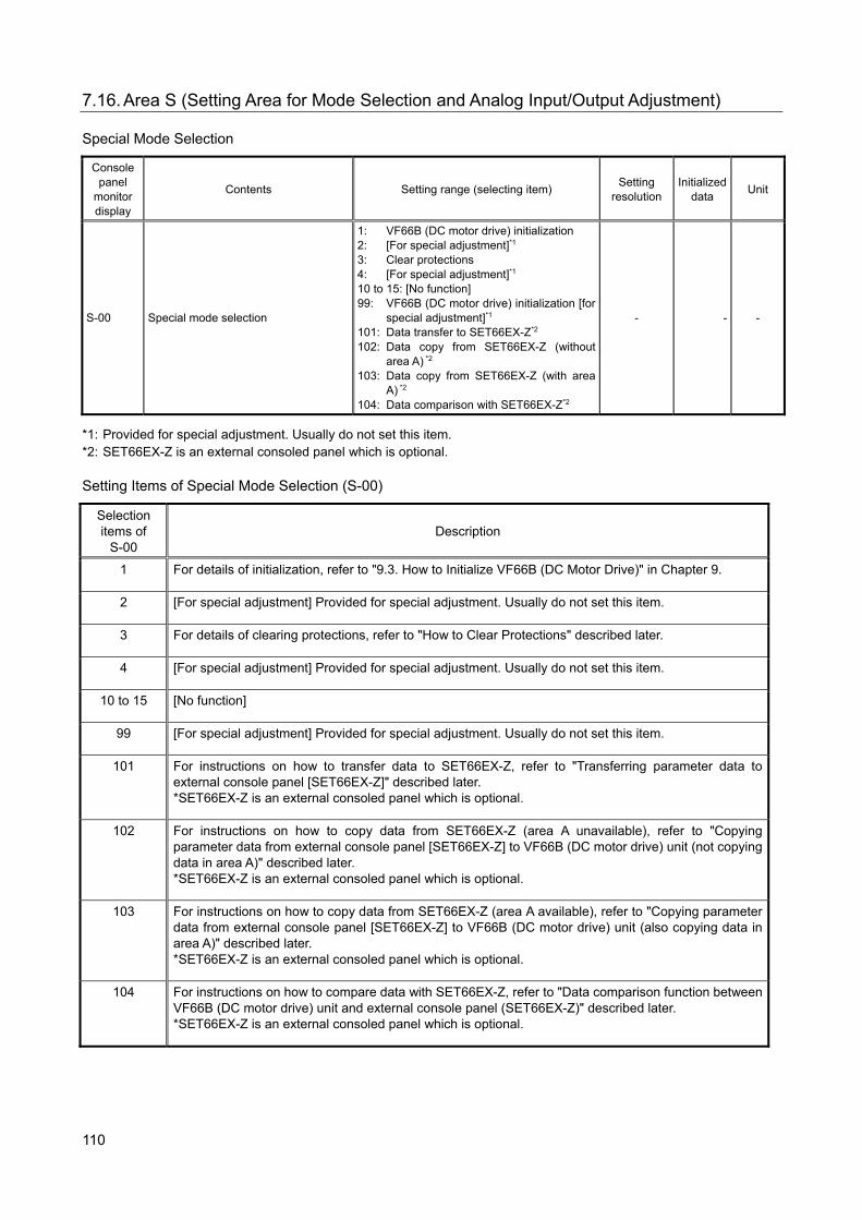
110
7.16. Area S (Setting Area for Mode Selection and Analog Input/Output Adjustment) Special Mode Selection
Console panel
monitor display
Contents Setting range (selecting item) Setting
resolution Initialized
data Unit
S-00 Special mode selection
1: VF66B (DC motor drive) initialization 2: [For special adjustment]*1 3: Clear protections 4: [For special adjustment]*1 10 to 15: [No function] 99: VF66B (DC motor drive) initialization [for
special adjustment]*1 101: Data transfer to SET66EX-Z*2 102: Data copy from SET66EX-Z (without
area A) *2 103: Data copy from SET66EX-Z (with area
A) *2 104: Data comparison with SET66EX-Z*2
- - -
*1: Provided for special adjustment. Usually do not set this item. *2: SET66EX-Z is an external consoled panel which is optional. Setting Items of Special Mode Selection (S-00)
Selection items of
S-00 Description
1 For details of initialization, refer to "9.3. How to Initialize VF66B (DC Motor Drive)" in Chapter 9.
2 [For special adjustment] Provided for special adjustment. Usually do not set this item.
3 For details of clearing protections, refer to "How to Clear Protections" described later.
4 [For special adjustment] Provided for special adjustment. Usually do not set this item.
10 to 15 [No function]
99 [For special adjustment] Provided for special adjustment. Usually do not set this item.
101 For instructions on how to transfer data to SET66EX-Z, refer to "Transferring parameter data to external console panel [SET66EX-Z]" described later. *SET66EX-Z is an external consoled panel which is optional.
102 For instructions on how to copy data from SET66EX-Z (area A unavailable), refer to "Copying parameter data from external console panel [SET66EX-Z] to VF66B (DC motor drive) unit (not copying data in area A)" described later. *SET66EX-Z is an external consoled panel which is optional.
103 For instructions on how to copy data from SET66EX-Z (area A available), refer to "Copying parameter data from external console panel [SET66EX-Z] to VF66B (DC motor drive) unit (also copying data in area A)" described later. *SET66EX-Z is an external consoled panel which is optional.
104 For instructions on how to compare data with SET66EX-Z, refer to "Data comparison function between VF66B (DC motor drive) unit and external console panel (SET66EX-Z)" described later. *SET66EX-Z is an external consoled panel which is optional.
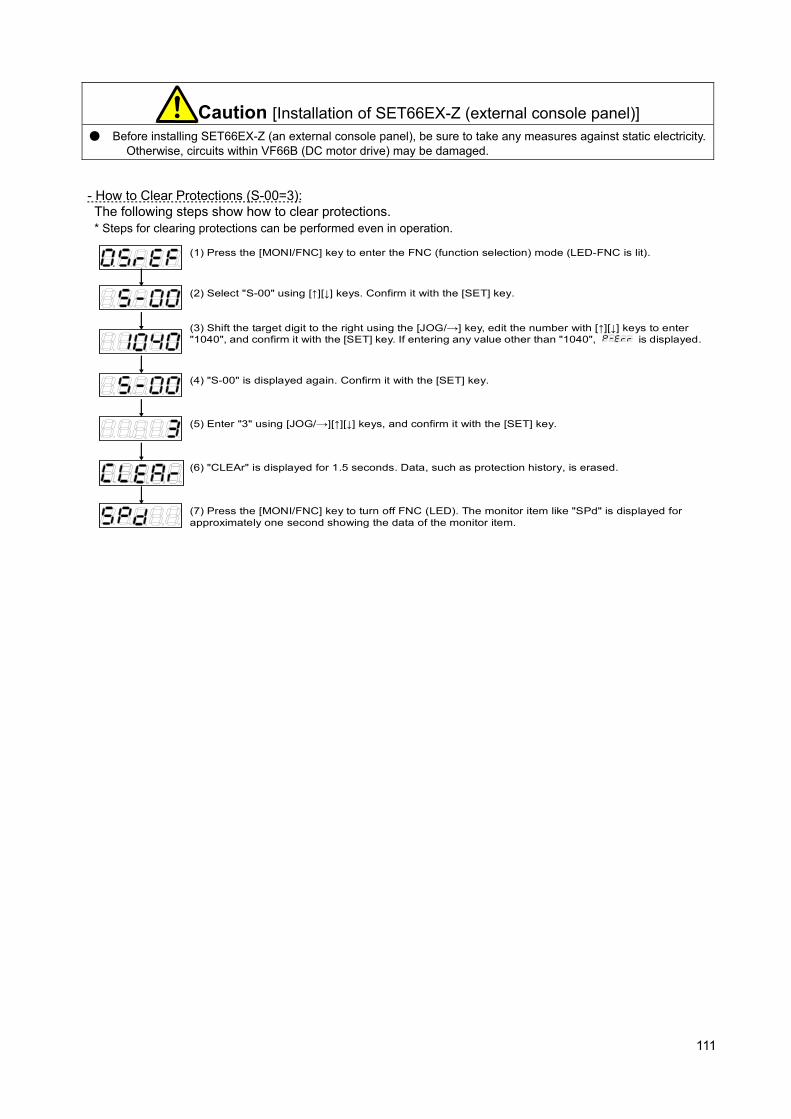
111
Caution [Installation of SET66EX-Z (external console panel)] Before installing SET66EX-Z (an external console panel), be sure to take any measures against static electricity.
Otherwise, circuits within VF66B (DC motor drive) may be damaged.
- How to Clear Protections (S-00=3): The following steps show how to clear protections. * Steps for clearing protections can be performed even in operation.
(1) Press the [MONI/FNC] key to enter the FNC (function selection) mode (LED-FNC is lit).
(2) Select "S-00" using [↑][↓] keys. Confirm it with the [SET] key.
(3) Shift the target digit to the right using the [JOG/→] key, edit the number with [↑][↓] keys to enter "1040", and confirm it with the [SET] key. If entering any value other than "1040",
is displayed.
(4) "S-00" is displayed again. Confirm it with the [SET] key.
(5) Enter "3" using [JOG/→][↑][↓] keys, and confirm it with the [SET] key.
(7) Press the [MONI/FNC] key to turn off FNC (LED). The monitor item like "SPd" is displayed for approximately one second showing the data of the monitor item.
(6) "CLEAr" is displayed for 1.5 seconds. Data, such as protection history, is erased.

112
- Transferring parameter data to external console panel [SET66EX-Z] (S-00=101): The following steps show how to transfer parameter data to the VF66B (DC motor drive) unit and the external console panel [SET66EX-Z].
Connect the VF66B (DC motor drive) unit to the optional external console panel [SET66EX-Z].
Press the [MONI/FNC] key to enter the FNC (function selection) mode (LED-FNC is lit).
Select "S-00" using [↑][↓] keys ("S" starts flashing). Confirm it with the [SET] key.
Shift the target digit to the right using the [JOG/→] key, edit the number with [↑][↓] keys to enter "1040".
"S-00" is displayed again. Confirm it with the [SET] key.
Edit the number with [JOG/→][↑][↓] keys to enter "101", and confirm it with the [SET] key.
"VtoS" and "SurE" flash alternately. Subsequently confirm it with the [SET] key. *If communication with the external console panel [SET66EX-Z] is disabled, there is no response.
"VtoS" is displayed. Data is transferred from the VF66B (DC motor drive) unit to the external console panel [SET66EX-Z].
"End" is displayed when the transfer is successfully completed.
Mode is displayed. After a few seconds the display returns to the monitor item.
* If normal communication fails during the data transfer, it is aborted with mode displayed, or
flashes for 10 seconds and then the transfer is aborted.
↓
To resume the transfer, wait until mode is displayed after interruption and the display returns to the monitor
item. Follow the same procedure from the beginning.
* When connecting the external console panel [SET66EX-Z] to the VF66B (DC motor drive) unit, the console panel [SET66-Z] located on the VF66B (DC motor drive) unit becomes unavailable.
External console panel [SET66EX-Z]
VF66B (DC motor drive) unit
VF66B
・・・
・・・
・・・
・・・
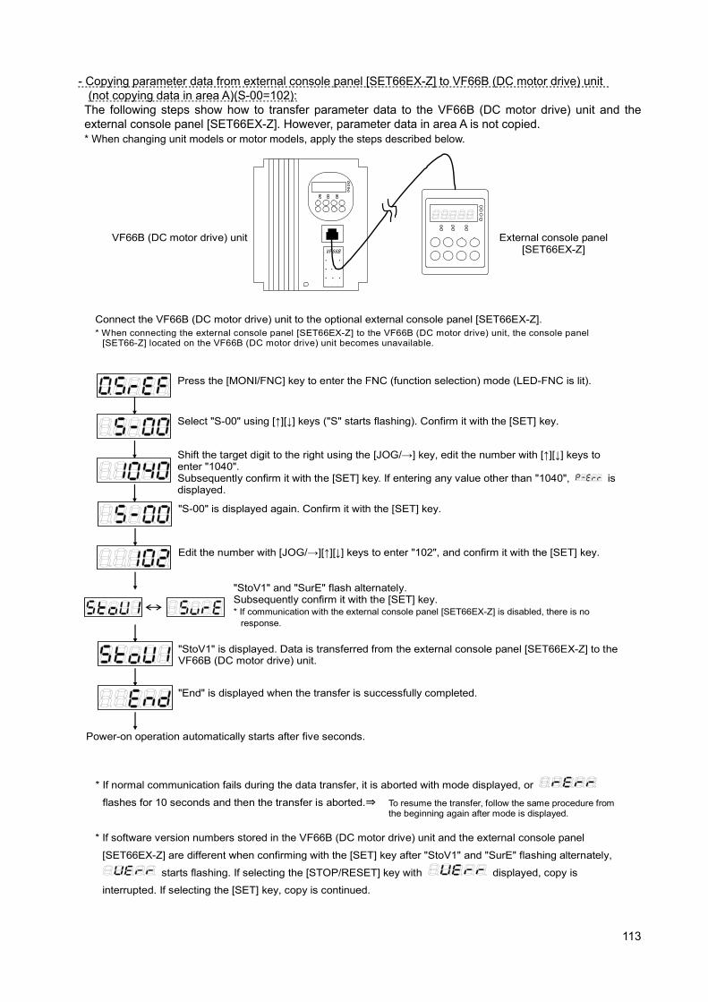
113
- Copying parameter data from external console panel [SET66EX-Z] to VF66B (DC motor drive) unit (not copying data in area A)(S-00=102):
The following steps show how to transfer parameter data to the VF66B (DC motor drive) unit and the external console panel [SET66EX-Z]. However, parameter data in area A is not copied. * When changing unit models or motor models, apply the steps described below.
Connect the VF66B (DC motor drive) unit to the optional external console panel [SET66EX-Z].
Press the [MONI/FNC] key to enter the FNC (function selection) mode (LED-FNC is lit).
Select "S-00" using [↑][↓] keys ("S" starts flashing). Confirm it with the [SET] key.
Shift the target digit to the right using the [JOG/→] key, edit the number with [↑][↓] keys to enter "1040". Subsequently confirm it with the [SET] key. If entering any value other than "1040",
is displayed.
"S-00" is displayed again. Confirm it with the [SET] key.
Edit the number with [JOG/→][↑][↓] keys to enter "102", and confirm it with the [SET] key.
"StoV1" and "SurE" flash alternately. Subsequently confirm it with the [SET] key. * If communication with the external console panel [SET66EX-Z] is disabled, there is no
response.
"StoV1" is displayed. Data is transferred from the external console panel [SET66EX-Z] to the VF66B (DC motor drive) unit.
"End" is displayed when the transfer is successfully completed.
Power-on operation automatically starts after five seconds.
* If normal communication fails during the data transfer, it is aborted with mode displayed, or
flashes for 10 seconds and then the transfer is aborted.⇒ To resume the transfer, follow the same procedure from the beginning again after mode is displayed.
* If software version numbers stored in the VF66B (DC motor drive) unit and the external console panel
[SET66EX-Z] are different when confirming with the [SET] key after "StoV1" and "SurE" flashing alternately,
starts flashing. If selecting the [STOP/RESET] key with
displayed, copy is
interrupted. If selecting the [SET] key, copy is continued.
* When connecting the external console panel [SET66EX-Z] to the VF66B (DC motor drive) unit, the console panel [SET66-Z] located on the VF66B (DC motor drive) unit becomes unavailable.
External console panel [SET66EX-Z]
VF66B (DC motor drive) unit
VF66B
・ ・ ・
・・・
・ ・ ・
・・・

114
- Copying parameter data from external console panel [SET66EX-Z] to VF66B (DC motor drive) unit (also copying data in area A) (S-00=103): The following steps show how to transfer parameter data to the VF66B (DC motor drive) unit and the external console panel [SET66EX-Z]. Parameter data in area A is also copied. * If both the unit model and motor model are identical, apply the steps described below.
Connect the VF66B (DC motor drive) unit to the optional external console panel [SET66EX-Z].
Press the [MONI/FNC] key to enter the FNC (function selection) mode (LED-FNC is lit).
Select "S-00" using [↑][↓] keys ("S" starts flashing). Confirm it with the [SET] key.
Shift the target digit to the right using the [JOG/→] key, edit the number with [↑][↓] keys to enter "1040". Subsequently confirm it with the [SET] key. If entering any value other than "1040",
is displayed.
"S-00" is displayed again. Confirm it with the [SET] key.
Edit the number with [JOG/→][↑][↓] keys to enter "102", and confirm it with the [SET] key.
"StoV1" and "SurE" flash alternately. Subsequently confirm it with the [SET] key. * If communication with the external console panel [SET66EX-Z] is disabled, there is no
response.
"StoV1" is displayed. Data is transferred from the external console panel [SET66EX-Z] to the VF66B (DC motor drive) unit.
"End" is displayed when the transfer is successfully completed.
Power-on operation automatically starts after five seconds.
* If normal communication fails during the data transfer, it is aborted with mode displayed, or
flashes for 10 seconds and then the transfer is aborted.⇒ To resume the transfer, follow the same procedure from the beginning again after mode is displayed.
* If software version numbers stored in the VF66B (DC motor drive) unit and the external console panel
[SET66EX-Z] are different when confirming with the [SET] key after "StoV1" and "SurE" flashing alternately,
starts flashing. If selecting the [STOP/RESET] key with
displayed, copy is
interrupted. If selecting the [SET] key, copy is continued.
* When connecting the external console panel [SET66EX-Z] to the VF66B (DC motor drive) unit, the console panel [SET66-Z] located on the VF66B (DC motor drive) unit becomes unavailable.
External console panel [SET66EX-Z]
VF66B (DC motor drive) unit
VF66B
・ ・ ・
・・・
・ ・ ・
・・・
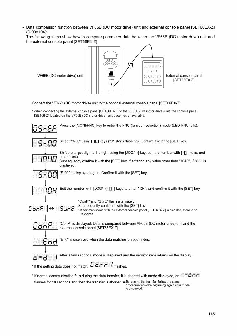
115
- Data comparison function between VF66B (DC motor drive) unit and external console panel [SET66EX-Z] (S-00=104): The following steps show how to compare parameter data between the VF66B (DC motor drive) unit and the external console panel [SET66EX-Z].
Connect the VF66B (DC motor drive) unit to the optional external console panel [SET66EX-Z].
Press the [MONI/FNC] key to enter the FNC (function selection) mode (LED-FNC is lit).
Select "S-00" using [↑][↓] keys ("S" starts flashing). Confirm it with the [SET] key.
Shift the target digit to the right using the [JOG/→] key, edit the number with [↑][↓] keys, and enter "1040." Subsequently confirm it with the [SET] key. If entering any value other than "1040",
is displayed.
"S-00" is displayed again. Confirm it with the [SET] key.
Edit the number with [JOG/→][↑][↓] keys to enter "104", and confirm it with the [SET] key.
"ConP" and "SurE" flash alternately. Subsequently confirm it with the [SET] key. * If communication with the external console panel [SET66EX-Z] is disabled, there is no
response.
"ConP" is displayed. Data is compared between VF66B (DC motor drive) unit and the external console panel [SET66EX-Z].
"End" is displayed when the data matches on both sides.
* If the setting data does not match,
flashes.
After a few seconds, mode is displayed and the monitor item returns on the display.
* If normal communication fails during the data transfer, it is aborted with mode displayed, or
flashes for 10 seconds and then the transfer is aborted.⇒ To resume the transfer, follow the same procedure from the beginning again after mode is displayed.
* When connecting the external console panel [SET66EX-Z] to the VF66B (DC motor drive) unit, the console panel [SET66-Z] located on the VF66B (DC motor drive) unit becomes unavailable.
External console panel [SET66EX-Z]
VF66B (DC motor drive) unit
VF66B
・・・
・・・
・・・
・・・
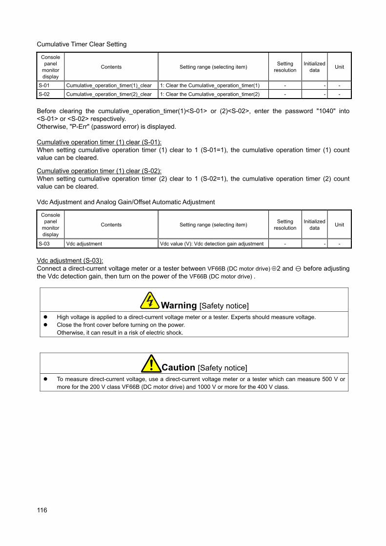
116
Cumulative Timer Clear Setting
Console panel
monitor display
Contents Setting range (selecting item) Setting
resolution Initialized
data Unit
S-01 Cumulative_operation_timer(1)_clear 1: Clear the Cumulative_operation_timer(1) - - -
S-02 Cumulative_operation_timer(2)_clear 1: Clear the Cumulative_operation_timer(2) - - -
Before clearing the cumulative_operation_timer(1)<S-01> or (2)<S-02>, enter the password "1040" into <S-01> or <S-02> respectively. Otherwise, "P-Err" (password error) is displayed. Cumulative operation timer (1) clear (S-01): When setting cumulative operation timer (1) clear to 1 (S-01=1), the cumulative operation timer (1) count value can be cleared.
Cumulative operation timer (1) clear (S-02): When setting cumulative operation timer (2) clear to 1 (S-02=1), the cumulative operation timer (2) count value can be cleared. Vdc Adjustment and Analog Gain/Offset Automatic Adjustment
Console panel
monitor display
Contents Setting range (selecting item) Setting
resolution Initialized
data Unit
S-03 Vdc adjustment Vdc value (V): Vdc detection gain adjustment - - -
Vdc adjustment (S-03): Connect a direct-current voltage meter or a tester between VF66B (DC motor drive) 2 and before adjusting the Vdc detection gain, then turn on the power of the VF66B (DC motor drive) .
Warning [Safety notice] High voltage is applied to a direct-current voltage meter or a tester. Experts should measure voltage. Close the front cover before turning on the power.
Otherwise, it can result in a risk of electric shock.
Caution [Safety notice] To measure direct-current voltage, use a direct-current voltage meter or a tester which can measure 500 V or
more for the 200 V class VF66B (DC motor drive) and 1000 V or more for the 400 V class.
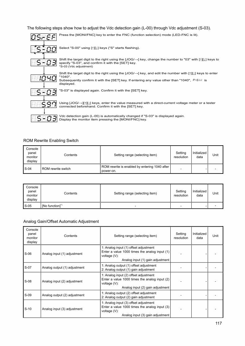
117
The following steps show how to adjust the Vdc detection gain (L-00) through Vdc adjustment (S-03).
Press the [MONI/FNC] key to enter the FNC (function selection) mode (LED-FNC is lit).
Select "S-00" using [↑][↓] keys ("S" starts flashing).
Shift the target digit to the right using the [JOG/→] key, and edit the number with [↑][↓] keys to enter "1040". Subsequently confirm it with the [SET] key. If entering any value other than "1040",
is displayed.
"S-03" is displayed again. Confirm it with the [SET] key.
Using [JOG/→][↑][↓] keys, enter the value measured with a direct-current voltage meter or a tester connected beforehand. Confirm it with the [SET] key.
Shift the target digit to the right using the [JOG/→] key, change the number to "03" with [↑][↓] keys to specify "S-03", and confirm it with the [SET] key. *S-03 (Vdc adjustment)
Vdc detection gain (L-00) is automatically changed if "S-03" is displayed again. Display the monitor item pressing the [MONI/FNC] key.
ROM Rewrite Enabling Switch
Console panel
monitor display
Contents Setting range (selecting item) Setting
resolution Initialized
data Unit
S-04 ROM rewrite switch ROM rewrite is enabled by entering 1040 after power-on.
- - -
Console panel
monitor display
Contents Setting range (selecting item) Setting
resolution Initialized
data Unit
S-05 [No function]*1 - - - -
Analog Gain/Offset Automatic Adjustment
Console panel
monitor display
Contents Setting range (selecting item) Setting
resolution Initialized
data Unit
S-06 Analog input (1) adjustment
1: Analog input (1) offset adjustment Enter a value 1000 times the analog input (1) voltage (V):
Analog input (1) gain adjustment
- - -
S-07 Analog output (1) adjustment 1: Analog output (1) offset adjustment 2: Analog output (1) gain adjustment
- - -
S-08 Analog input (2) adjustment
1: Analog input (2) offset adjustment Enter a value 1000 times the analog input (2) voltage (V):
Analog input (2) gain adjustment
- - -
S-09 Analog output (2) adjustment 1: Analog output (2) offset adjustment 2: Analog output (2) gain adjustment
- - -
S-10 Analog input (3) adjustment
1: Analog input (3) offset adjustment Enter a value 1000 times the analog input (3) voltage (V):
Analog input (3) gain adjustment
- - -
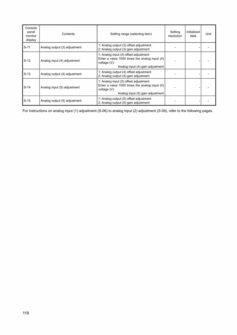
118
Console panel
monitor display
Contents Setting range (selecting item) Setting
resolution Initialized
data Unit
S-11 Analog output (3) adjustment 1: Analog output (3) offset adjustment 2: Analog output (3) gain adjustment
- - -
S-12 Analog input (4) adjustment
1: Analog input (4) offset adjustment Enter a value 1000 times the analog input (4) voltage (V):
Analog input (4) gain adjustment
- - -
S-13 Analog output (4) adjustment 1: Analog output (4) offset adjustment 2: Analog output (4) gain adjustment
- - -
S-14 Analog input (5) adjustment
1: Analog input (5) offset adjustment Enter a value 1000 times the analog input (5) voltage (V):
Analog input (5) gain adjustment
- - -
S-15 Analog output (5) adjustment 1: Analog output (5) offset adjustment 2: Analog output (5) gain adjustment
- - -
For instructions on analog input (1) adjustment (S-06) to analog input (2) adjustment (S-09), refer to the following pages.

119
Analog input (1) adjustment (S-06): The following steps show how to adjust analog input (1) gain (L-01) and analog input (1) offset (L-02) through analog input (1) adjustment (S-06).
Control print board [VFC66-Z]
terminal block [TB1]
Press the [MONI/FNC] key to enter the FNC (function selection) mode (LED-FNC is lit).
With [↑][↓] keys, select "b-00" ("b" starts flashing).
Shift the target digit to the right using the [JOG/→] key, edit the number with [↑][↓] keys to enter "0".
Edit the number with [JOG/→] [↑][↓] keys to enter "1040", and confirm it with the [SET] key. If entering any value other than "1040",
is displayed.
Shift the target digit to the right using the [JOG/→] key, change the number to "17" with [↑][↓] keys to specify "b-17", and confirm it with the [SET] key.
Turn off VF66B (DC motor drive), open the front cover, and cause short circuit between (AIN1) and (GND) terminals of the terminal block [TB1] on the control print board [VFC66-Z] using the Phillips screwdriver (M3).
Warning [Short circuiting on terminals]
Be sure to turn off VF66B (DC motor drive) before short-circuiting the terminals. Otherwise, it can result in a risk of electric shock.
After power-on, press the [MONI/FNC] key to enter the FNC (function selection) mode (LED-FNC is lit). Select "S-06" using [JOG/→] [↑][↓] keys. Confirm it with the [SET] key.
"S-06" is displayed again. Confirm it with the [SET] key.
Enter "1" using [JOG/→] [↑][↓] keys, and confirm it with the [SET] key.
Turn off VF66B (DC motor drive), open the front cover, and remove the wiring installed between (AIN1) and (GND) terminals of the terminal block [TB1] on the control print board [VFC66-Z] using the Phillips screwdriver (M3). Next, cause short circuit between (AIN1) and (+10) terminals of the terminal block [TB1] on the control print board [VFC66-Z] using the Phillips screwdriver (M3).
Control print board [VFC66-Z] terminal block [TB1]
- After power-on, press the [MONI/FNC] key to enter FNC (function selection) mode (LED-FNC is lit), and then select "S-06" using [JOG/→] [↑][↓] keys. Confirm it with the [SET] key.
- Edit the number with [JOG/→] [↑][↓] keys to enter "1040", and confirm it with the [SET] key. If entering any value other than "1040",
is displayed. - "S-06" is displayed again. Confirm it with the [SET] key.
When "S-06" is displayed again, analog input (1) gain (L-01) and analog input (1) offset (L-02) are automatically changed. Press the [MONI/FNC] key to display the monitor item.
Caution [Measuring voltage between terminals]
Sufficient care must be taken not to touch electrical wires and terminals when measuring the voltage between terminals.
Otherwise, it can result in a risk of electric shock.
After adjustment, turn off VF66B (DC motor drive), open the front cover, and remove the wiring installed between (AIN1) and (+10) terminals of the terminal block [TB1] on the control print board [VFC66-Z] using the Phillips screwdriver (M3).
Warning [Short circuiting on terminals]
Be sure to turn off VF66B (DC motor drive) before short-circuiting the terminals. Otherwise, it can result in a risk of electric shock.
AOT1
GND
AIN1
+10
AOT1
GND
AIN1
+10
Measure the voltage between [AIN1] and [GND] terminals with a tester or other meters. Enter a value 1000 times the measured value. If the voltage cannot be measured, enter "9930" even though the precision decreases.
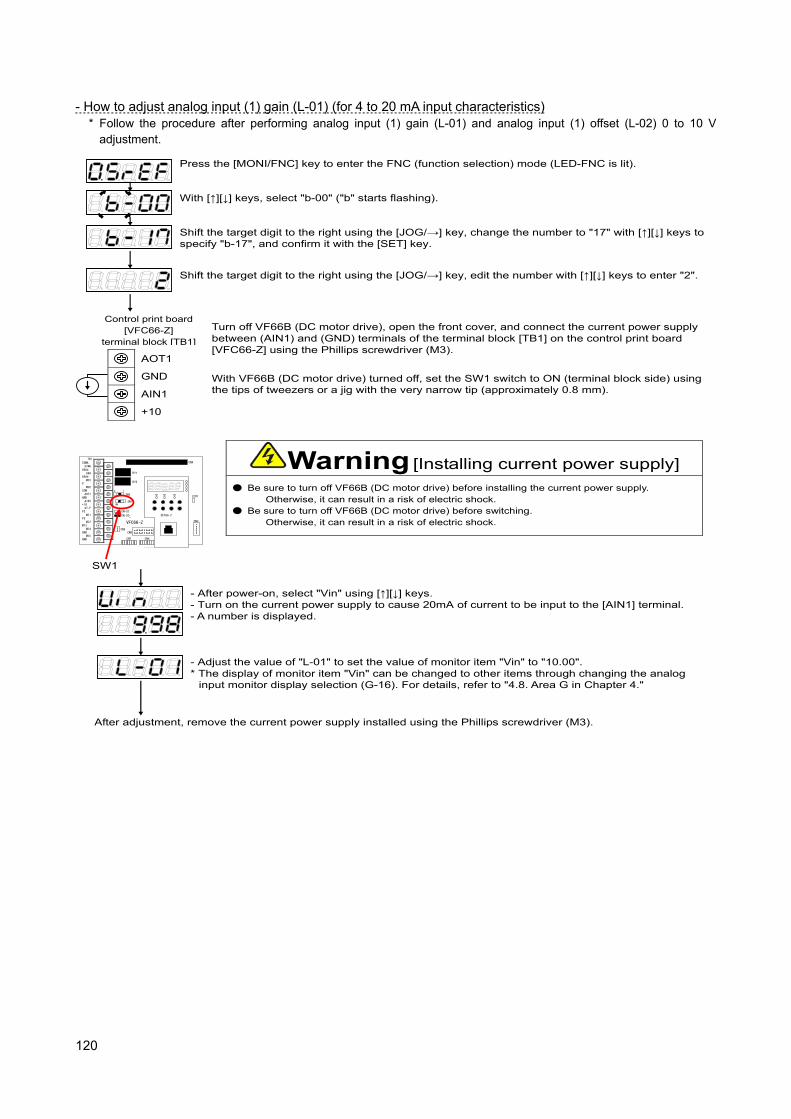
120
- How to adjust analog input (1) gain (L-01) (for 4 to 20 mA input characteristics)
* Follow the procedure after performing analog input (1) gain (L-01) and analog input (1) offset (L-02) 0 to 10 V adjustment.
Press the [MONI/FNC] key to enter the FNC (function selection) mode (LED-FNC is lit).
With [↑][↓] keys, select "b-00" ("b" starts flashing).
Shift the target digit to the right using the [JOG/→] key, edit the number with [↑][↓] keys to enter "2".
Shift the target digit to the right using the [JOG/→] key, change the number to "17" with [↑][↓] keys to specify "b-17", and confirm it with the [SET] key.
Turn off VF66B (DC motor drive), open the front cover, and connect the current power supply between (AIN1) and (GND) terminals of the terminal block [TB1] on the control print board [VFC66-Z] using the Phillips screwdriver (M3).
Warning [Installing current power supply]
Be sure to turn off VF66B (DC motor drive) before installing the current power supply. Otherwise, it can result in a risk of electric shock.
Be sure to turn off VF66B (DC motor drive) before switching. Otherwise, it can result in a risk of electric shock.
Control print board [VFC66-Z]
terminal block [TB1]
- After power-on, select "Vin" using [↑][↓] keys. - Turn on the current power supply to cause 20mA of current to be input to the [AIN1] terminal. - A number is displayed.
With VF66B (DC motor drive) turned off, set the SW1 switch to ON (terminal block side) using the tips of tweezers or a jig with the very narrow tip (approximately 0.8 mm).
- Adjust the value of "L-01" to set the value of monitor item "Vin" to "10.00". * The display of monitor item "Vin" can be changed to other items through changing the analog
input monitor display selection (G-16). For details, refer to "4.8. Area G in Chapter 4."
After adjustment, remove the current power supply installed using the Phillips screwdriver (M3).
TB1
CN-SO
CN-SI
RY1
CN3
SW2
SW1
CN4
LED1
52MA
86Aa
86Ab
P
COM
GND
+10
PS
PS
MI3
GND
GND
52MA
86A
MO1
MO2
AOT1
AIN1
ST-F
MI1
MI2
MI4
MI5
CN5
3 1
ON
RY2
CN6
SET66-Z
CN7 CN4
VFC66-Z
SW1
AOT1
GND
AIN1
+10
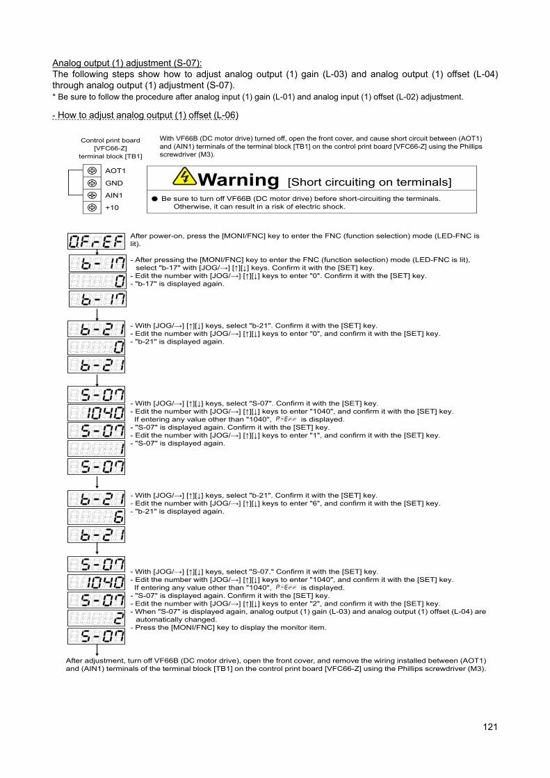
121
Analog output (1) adjustment (S-07): The following steps show how to adjust analog output (1) gain (L-03) and analog output (1) offset (L-04) through analog output (1) adjustment (S-07). * Be sure to follow the procedure after analog input (1) gain (L-01) and analog input (1) offset (L-02) adjustment.
- How to adjust analog output (1) offset (L-06)
After power-on, press the [MONI/FNC] key to enter the FNC (function selection) mode (LED-FNC is lit).
- With [JOG/→] [↑][↓] keys, select "S-07". Confirm it with the [SET] key. - Edit the number with [JOG/→] [↑][↓] keys to enter "1040", and confirm it with the [SET] key. If entering any value other than "1040",
is displayed. - "S-07" is displayed again. Confirm it with the [SET] key. - Edit the number with [JOG/→] [↑][↓] keys to enter "1", and confirm it with the [SET] key. - "S-07" is displayed again.
With VF66B (DC motor drive) turned off, open the front cover, and cause short circuit between (AOT1) and (AIN1) terminals of the terminal block [TB1] on the control print board [VFC66-Z] using the Phillips screwdriver (M3).
Warning [Short circuiting on terminals]
Be sure to turn off VF66B (DC motor drive) before short-circuiting the terminals. Otherwise, it can result in a risk of electric shock.
Control print board [VFC66-Z]
terminal block [TB1]
- After pressing the [MONI/FNC] key to enter the FNC (function selection) mode (LED-FNC is lit), select "b-17" with [JOG/→] [↑][↓] keys. Confirm it with the [SET] key.
- Edit the number with [JOG/→] [↑][↓] keys to enter "0". Confirm it with the [SET] key. - "b-17" is displayed again.
- With [JOG/→] [↑][↓] keys, select "b-21". Confirm it with the [SET] key. - Edit the number with [JOG/→] [↑][↓] keys to enter "0", and confirm it with the [SET] key. - "b-21" is displayed again.
- With [JOG/→] [↑][↓] keys, select "b-21". Confirm it with the [SET] key. - Edit the number with [JOG/→] [↑][↓] keys to enter "6", and confirm it with the [SET] key. - "b-21" is displayed again.
- With [JOG/→] [↑][↓] keys, select "S-07." Confirm it with the [SET] key. - Edit the number with [JOG/→] [↑][↓] keys to enter "1040", and confirm it with the [SET] key. If entering any value other than "1040",
is displayed. - "S-07" is displayed again. Confirm it with the [SET] key. - Edit the number with [JOG/→] [↑][↓] keys to enter "2", and confirm it with the [SET] key. - When "S-07" is displayed again, analog output (1) gain (L-03) and analog output (1) offset (L-04) are
automatically changed. - Press the [MONI/FNC] key to display the monitor item.
After adjustment, turn off VF66B (DC motor drive), open the front cover, and remove the wiring installed between (AOT1) and (AIN1) terminals of the terminal block [TB1] on the control print board [VFC66-Z] using the Phillips screwdriver (M3).
AOT1
GND
AIN1
+10
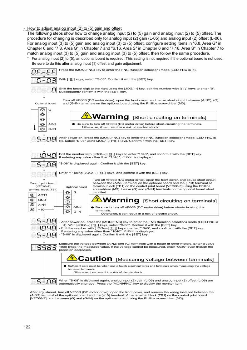
122
- How to adjust analog input (2) to (5) gain and offset The following steps show how to change analog input (2) to (5) gain and analog input (2) to (5) offset. The procedure for changing is described only for analog input (2) gain (L-05) and analog input (2) offset (L-06). For analog input (3) to (5) gain and analog input (3) to (5) offset, configure setting items in "6.8. Area G" in Chapter 6 and "7.8. Area G" in Chapter 7 and "6.16. Area S" in Chapter 6 and "7.16. Area S" in Chapter 7 to match analog input (3) to (5) gain and analog input (3) to (5) offset, then follow the same procedure. * For analog input (2) to (5), an optional board is required. This setting is not required if the optional board is not used.
Be sure to do this after analog input (1) offset and gain adjustment.
AOT1
GND
AIN1
+10
Press the [MONI/FNC] key to enter the FNC (function selection) mode (LED-FNC is lit).
With [↑][↓] keys, select "G-03". Confirm it with the [SET] key.
Edit the number with [JOG/→] [↑][↓] keys to enter "1040", and confirm it with the [SET] key. If entering any value other than "1040",
is displayed.
Shift the target digit to the right using the [JOG/→] key, edit the number with [↑][↓] keys to enter "0". Subsequently confirm it with the [SET] key.
Turn off VF66B (DC motor drive), open the front cover, and cause short circuit between (AIN2), (G), and (G-IN) terminals on the optional board using the Phillips screwdriver (M3).
Warning [Short circuiting on terminals]
Be sure to turn off VF66B (DC motor drive) before short-circuiting the terminals. Otherwise, it can result in a risk of electric shock.
After power-on, press the [MONI/FNC] key to enter the FNC (function selection) mode (LED-FNC is lit). Select "S-08" using [JOG/→] [↑][↓] keys. Confirm it with the [SET] key.
"S-08" is displayed again. Confirm it with the [SET] key.
Enter "1" using [JOG/→] [↑][↓] keys, and confirm it with the [SET] key.
Turn off VF66B (DC motor drive), open the front cover, and cause short circuit between the (AIN2) terminal on the optional board and the (+10) terminal of terminal block [TB1] on the control print board [VFC66-Z] using the Phillips screwdriver (M3). Leave (G) and (G-IN) terminals on the optional board short circuited.
- After power-on, press the [MONI/FNC] key to enter the FNC (function selection) mode (LED-FNC is lit). With [JOG/→] [↑][↓] keys, select "S-08". Confirm it with the [SET] key.
- Edit the number with [JOG/→] [↑][↓] keys to enter "1040", and confirm it with the [SET] key. If entering any value other than "1040",
is displayed. - "S-08" is displayed again. Confirm it with the [SET] key.
When "S-08" is displayed again, analog input (2) gain (L-05) and analog input (2) offset (L-06) are automatically changed. Press the [MONI/FNC] key to display the monitor item.
Measure the voltage between (AIN2) and (G) terminals with a tester or other meters. Enter a value 1000 times the measured value. If the voltage cannot be measured, enter "9930" even though the precision decreases.
Caution [Measuring voltage between terminals]
Sufficient care must be taken not to touch electrical wires and terminals when measuring the voltage between terminals.
Otherwise, it can result in a risk of electric shock.
Optional board
Control print board [VFC66-Z]
terminal block [TB1] Optional board
After adjustment, turn off VF66B (DC motor drive), open the front cover, and remove the wiring installed between the (AIN2) terminal of the optional board and the (+10) terminal of the terminal block [TB1] on the control print board [VFC66-Z], and between (G) and (G-IN) on the optional board using the Phillips screwdriver (M3).
G
AIN2
G-IN
・・・・・・・・
・・
G
AIN2
G-IN
・・・・・・・・
・・
Warning [Short circuiting on terminals]
Be sure to turn off VF66B (DC motor drive) before short-circuiting the terminals.
Otherwise, it can result in a risk of electric shock.
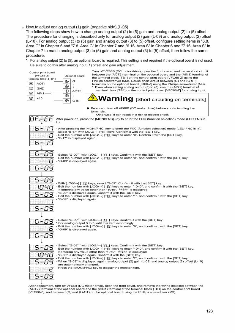
123
- How to adjust analog output (1) gain (negative side) (L-05) The following steps show how to change analog output (2) to (5) gain and analog output (2) to (5) offset. The procedure for changing is described only for analog output (2) gain (L-09) and analog output (2) offset (L-10). For analog output (3) to (5) gain and analog output (3) to (5) offset, configure setting items in "6.8. Area G" in Chapter 6 and "7.8. Area G" in Chapter 7 and "6.16. Area S" in Chapter 6 and "7.16. Area S" in Chapter 7 to match analog output (3) to (5) gain and analog output (3) to (5) offset, then follow the same procedure. * For analog output (2) to (5), an optional board is required. This setting is not required if the optional board is not used.
Be sure to do this after analog input (1) offset and gain adjustment.
AOT1
GND
AIN1
+10
Turn off VF66B (DC motor drive), open the front cover, and cause short circuit between the (AOT2) terminal on the optional board and the (AIN1) terminal of the terminal block [TB1] on the control print board [VFC66-Z] using the Phillips screwdriver (M3). Cause short circuit between (G) and (G-0T) terminals on the optional board [IO66-Z] using the Phillips screwdriver (M3). * Even when setting analog output (3) to (5), use the (AIN1) terminal of
terminal block [TB1] on the control print board [VFC66-Z] for analog input.
Control print board [VFC66-Z]
terminal block [TB1] Optional board
After power-on, press the [MONI/FNC] key to enter the FNC (function selection) mode (LED-FNC is lit).
- With [JOG/→] [↑][↓] keys, select "S-09". Confirm it with the [SET] key. - Edit the number with [JOG/→] [↑][↓] keys to enter "1040", and confirm it with the [SET] key.
If entering any value other than "1040",
is displayed. - "S-09" is displayed again. Confirm it with the [SET] key. - Edit the number with [JOG/→] [↑][↓] keys to enter "1", and confirm it with the [SET] key. - "S-09" is displayed again.
- After pressing the [MONI/FNC] key to enter the FNC (function selection) mode (LED-FNC is lit), select "b-17" with [JOG/→] [↑][↓] keys. Confirm it with the [SET] key.
- Edit the number with [JOG/→] [↑][↓] keys to enter "0". Confirm it with the [SET] key. - "b-17" is displayed again.
- Select "G-09"*1 with [JOG/→] [↑][↓] keys. Confirm it with the [SET] key. - Edit the number with [JOG/→] [↑][↓] keys to enter "0", and confirm it with the [SET] key. - "G-09" is displayed again.
- Select "G-09"*1 with [JOG/→] [↑][↓] keys. Confirm it with the [SET] key. * For analog output 3 to 5, edit this item accordingly. - Edit the number with [JOG/→] [↑][↓] keys to enter "6", and confirm it with the [SET] key. - "G-09" is displayed again.
- Select "G-09"*2 with [JOG/→] [↑][↓] keys. Confirm it with the [SET] key. - Edit the number with [JOG/→] [↑][↓] keys to enter "1040", and confirm it with the [SET] key. If entering any value other than "1040",
is displayed. - "S-09" is displayed again. Confirm it with the [SET] key. - Edit the number with [JOG/→] [↑][↓] keys to enter "2", and confirm it with the [SET] key. - When "S-09" is displayed again, analog output (2) gain (L-09) and analog output (2) offset (L-10)
are automatically changed. - Press the [MONI/FNC] key to display the monitor item.
After adjustment, turn off VF66B (DC motor drive), open the front cover, and remove the wiring installed between the (AOT2) terminal of the optional board and the (AIN1) terminal of the terminal block [TB1] on the control print board [VFC66-Z], and between (G) and (G-OT) on the optional board using the Phillips screwdriver (M3).
G
AOT2
G-IN
・・・
・・・ Warning [Short circuiting on terminals]
Be sure to turn off VF66B (DC motor drive) before short-circuiting the terminals.
Otherwise, it can result in a risk of electric shock.
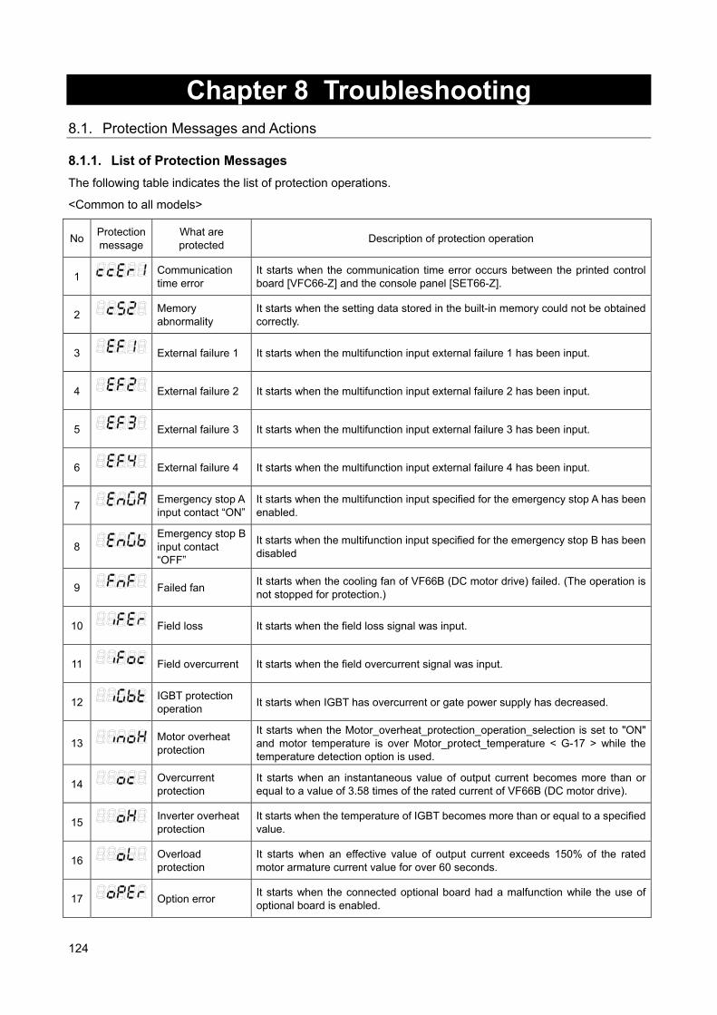
124
Chapter 8 Troubleshooting 8.1. Protection Messages and Actions 8.1.1. List of Protection Messages
The following table indicates the list of protection operations.
<Common to all models>
No Protection message
What are protected
Description of protection operation
1
Communication time error
It starts when the communication time error occurs between the printed control board [VFC66-Z] and the console panel [SET66-Z].
2
Memory abnormality
It starts when the setting data stored in the built-in memory could not be obtained correctly.
3
External failure 1 It starts when the multifunction input external failure 1 has been input.
4
External failure 2 It starts when the multifunction input external failure 2 has been input.
5
External failure 3 It starts when the multifunction input external failure 3 has been input.
6
External failure 4 It starts when the multifunction input external failure 4 has been input.
7
Emergency stop A input contact “ON”
It starts when the multifunction input specified for the emergency stop A has been enabled.
8
Emergency stop B input contact “OFF”
It starts when the multifunction input specified for the emergency stop B has been disabled
9
Failed fan
It starts when the cooling fan of VF66B (DC motor drive) failed. (The operation is not stopped for protection.)
10
Field loss It starts when the field loss signal was input.
11
Field overcurrent It starts when the field overcurrent signal was input.
12
IGBT protection operation
It starts when IGBT has overcurrent or gate power supply has decreased.
13
Motor overheat protection
It starts when the Motor_overheat_protection_operation_selection is set to "ON" and motor temperature is over Motor_protect_temperature < G-17 > while the temperature detection option is used.
14
Overcurrent protection
It starts when an instantaneous value of output current becomes more than or equal to a value of 3.58 times of the rated current of VF66B (DC motor drive).
15
Inverter overheat protection
It starts when the temperature of IGBT becomes more than or equal to a specified value.
16
Overload protection
It starts when an effective value of output current exceeds 150% of the rated motor armature current value for over 60 seconds.
17
Option error
It starts when the connected optional board had a malfunction while the use of optional board is enabled.
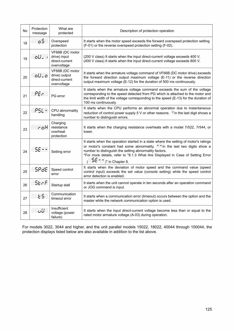
125
No Protection message
What are protected
Description of protection operation
18
Overspeed protection
It starts when the motor speed exceeds the forward overspeed protection setting (F-01) or the reverse overspeed protection setting (F-02).
19
VF66B (DC motor drive) input direct-current overvoltage
(200 V class) It starts when the input direct-current voltage exceeds 400 V. (400 V class) It starts when the input direct-current voltage exceeds 800 V.
20
VF66B (DC motor drive) output direct-current overvoltage
It starts when the armature voltage command of VF66B (DC motor drive) exceeds the forward direction output maximum voltage (E-11) or the reverse direction output maximum voltage (E-12) for the duration of 500 ms continuously.
21
PG error
It starts when the armature voltage command exceeds the sum of the voltage corresponding to the speed detected from PG which is attached to the motor and the limit width of the voltage corresponding to the speed (E-13) for the duration of 100 ms continuously.
22
CPU abnormality handling
It starts when the CPU performs an abnormal operation due to instantaneous reduction of control power supply 5 V or other reasons.
in the last digit shows a number to distinguish errors.
23
Charging resistance overheat protection
It starts when the charging resistance overheats with a model 7r522, 7r544, or lower.
24
Setting error
It starts when the operation started in a state where the setting of motor's ratings or motor's constant had some abnormality.
in the last two digits show a number to distinguish the setting abnormality factors. *For more details, refer to "8.1.3 What Are Displayed in Case of Setting Error
( )" in Chapter 8.
25
Speed control error
It starts when the deviation of motor speed and the command value (speed control input) exceeds the set value (console setting) while the speed control error detection is enabled.
26
Startup stall
It starts when the unit cannot operate in ten seconds after an operation command or JOG command is input.
27
Communication timeout error
It starts when a communication error (timeout) occurs between the option and the master while the network communication option is used.
28
Insufficient voltage (power failure)
It starts when the input direct-current voltage become less than or equal to the rated motor armature voltage (A-03) during operation.
For models 3022, 3044 and higher, and the unit parallel models 15022, 18022, 40044 through 100044, the protection displays listed below are also available in addition to the list above.
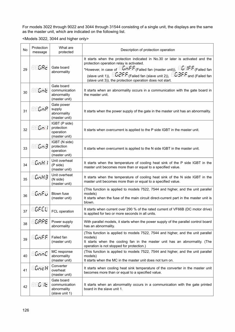
126
For models 3022 through 9022 and 3044 through 31544 consisting of a single unit, the displays are the same as the master unit, which are indicated on the following list.
<Models 3022, 3044 and higher only>
No Protection message
What are protected
Description of protection operation
29
Gate board abnormality
It starts when the protection indicated in No.30 or later is activated and the protection operation relay is activated.
*However, in case of
(Failed fan (master unit)),
(Failed fan
(slave unit 1)),
(Failed fan (slave unit 2)),
and (Failed fan (slave unit 3)), the protection operation does not start.
30
Gate board communication abnormality (master unit)
It starts when an abnormality occurs in a communication with the gate board in the master unit.
31
Gate power supply abnormality (master unit)
It starts when the power supply of the gate in the master unit has an abnormality.
32
IGBT (P side) protection operation (master unit)
It starts when overcurrent is applied to the P side IGBT in the master unit.
33
IGBT (N side) protection operation (master unit)
It starts when overcurrent is applied to the N side IGBT in the master unit.
34
Unit overheat (P side) (master unit)
It starts when the temperature of cooling heat sink of the P side IGBT in the master unit becomes more than or equal to a specified value.
35
Unit overheat (N side) (master unit)
It starts when the temperature of cooling heat sink of the N side IGBT in the master unit becomes more than or equal to a specified value.
36
Blown fuse (master unit)
(This function is applied to models 7522, 7544 and higher, and the unit parallel models) It starts when the fuse of the main circuit direct-current part in the master unit is blown.
37
FCL operation
It starts when current over 290 % of the rated current of VF66B (DC motor drive) is applied for two or more seconds in all units.
38
Power supply abnormality
With parallel models, it starts when the power supply of the parallel control board has an abnormality.
39
Failed fan (master unit)
(This function is applied to models 7522, 7544 and higher, and the unit parallel models) It starts when the cooling fan in the master unit has an abnormality. (The operation is not stopped for protection.)
40
MC response abnormality (master unit)
(This function is applied to models 7522, 7544 and higher, and the unit parallel models) It starts when the MC in the master unit does not turn on.
41
Converter overheat (master unit)
It starts when cooling heat sink temperature of the converter in the master unit becomes more than or equal to a specified value.
42
Gate board communication abnormality (slave unit 1)
It starts when an abnormality occurs in a communication with the gate printed board in the slave unit 1.
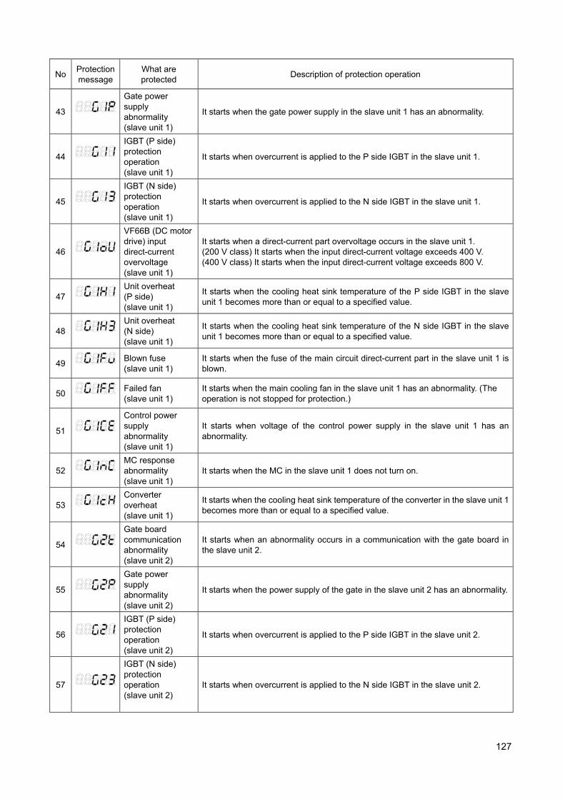
127
No Protection message
What are protected
Description of protection operation
43
Gate power supply abnormality (slave unit 1)
It starts when the gate power supply in the slave unit 1 has an abnormality.
44
IGBT (P side) protection operation (slave unit 1)
It starts when overcurrent is applied to the P side IGBT in the slave unit 1.
45
IGBT (N side) protection operation (slave unit 1)
It starts when overcurrent is applied to the N side IGBT in the slave unit 1.
46
VF66B (DC motor drive) input direct-current overvoltage (slave unit 1)
It starts when a direct-current part overvoltage occurs in the slave unit 1. (200 V class) It starts when the input direct-current voltage exceeds 400 V. (400 V class) It starts when the input direct-current voltage exceeds 800 V.
47
Unit overheat (P side) (slave unit 1)
It starts when the cooling heat sink temperature of the P side IGBT in the slave unit 1 becomes more than or equal to a specified value.
48
Unit overheat (N side) (slave unit 1)
It starts when the cooling heat sink temperature of the N side IGBT in the slave unit 1 becomes more than or equal to a specified value.
49
Blown fuse (slave unit 1)
It starts when the fuse of the main circuit direct-current part in the slave unit 1 is blown.
50
Failed fan (slave unit 1)
It starts when the main cooling fan in the slave unit 1 has an abnormality. (The operation is not stopped for protection.)
51
Control power supply abnormality (slave unit 1)
It starts when voltage of the control power supply in the slave unit 1 has an abnormality.
52
MC response abnormality (slave unit 1)
It starts when the MC in the slave unit 1 does not turn on.
53
Converter overheat (slave unit 1)
It starts when the cooling heat sink temperature of the converter in the slave unit 1 becomes more than or equal to a specified value.
54
Gate board communication abnormality (slave unit 2)
It starts when an abnormality occurs in a communication with the gate board in the slave unit 2.
55
Gate power supply abnormality (slave unit 2)
It starts when the power supply of the gate in the slave unit 2 has an abnormality.
56
IGBT (P side) protection operation (slave unit 2)
It starts when overcurrent is applied to the P side IGBT in the slave unit 2.
57
IGBT (N side) protection operation (slave unit 2)
It starts when overcurrent is applied to the N side IGBT in the slave unit 2.
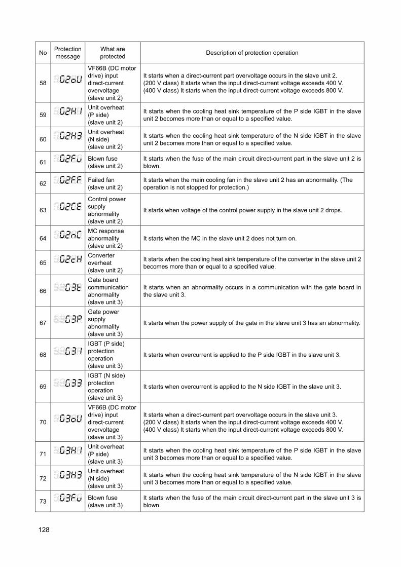
128
No Protection message
What are protected
Description of protection operation
58
VF66B (DC motor drive) input direct-current overvoltage (slave unit 2)
It starts when a direct-current part overvoltage occurs in the slave unit 2. (200 V class) It starts when the input direct-current voltage exceeds 400 V. (400 V class) It starts when the input direct-current voltage exceeds 800 V.
59
Unit overheat (P side) (slave unit 2)
It starts when the cooling heat sink temperature of the P side IGBT in the slave unit 2 becomes more than or equal to a specified value.
60
Unit overheat (N side) (slave unit 2)
It starts when the cooling heat sink temperature of the N side IGBT in the slave unit 2 becomes more than or equal to a specified value.
61
Blown fuse (slave unit 2)
It starts when the fuse of the main circuit direct-current part in the slave unit 2 is blown.
62
Failed fan (slave unit 2)
It starts when the main cooling fan in the slave unit 2 has an abnormality. (The operation is not stopped for protection.)
63
Control power supply abnormality (slave unit 2)
It starts when voltage of the control power supply in the slave unit 2 drops.
64
MC response abnormality (slave unit 2)
It starts when the MC in the slave unit 2 does not turn on.
65
Converter overheat (slave unit 2)
It starts when the cooling heat sink temperature of the converter in the slave unit 2 becomes more than or equal to a specified value.
66
Gate board communication abnormality (slave unit 3)
It starts when an abnormality occurs in a communication with the gate board in the slave unit 3.
67
Gate power supply abnormality (slave unit 3)
It starts when the power supply of the gate in the slave unit 3 has an abnormality.
68
IGBT (P side) protection operation (slave unit 3)
It starts when overcurrent is applied to the P side IGBT in the slave unit 3.
69
IGBT (N side) protection operation (slave unit 3)
It starts when overcurrent is applied to the N side IGBT in the slave unit 3.
70
VF66B (DC motor drive) input direct-current overvoltage (slave unit 3)
It starts when a direct-current part overvoltage occurs in the slave unit 3. (200 V class) It starts when the input direct-current voltage exceeds 400 V. (400 V class) It starts when the input direct-current voltage exceeds 800 V.
71
Unit overheat (P side) (slave unit 3)
It starts when the cooling heat sink temperature of the P side IGBT in the slave unit 3 becomes more than or equal to a specified value.
72
Unit overheat (N side) (slave unit 3)
It starts when the cooling heat sink temperature of the N side IGBT in the slave unit 3 becomes more than or equal to a specified value.
73
Blown fuse (slave unit 3)
It starts when the fuse of the main circuit direct-current part in the slave unit 3 is blown.
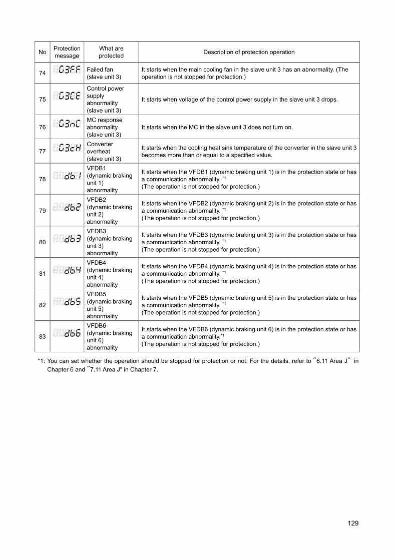
129
No Protection message
What are protected
Description of protection operation
74
Failed fan (slave unit 3)
It starts when the main cooling fan in the slave unit 3 has an abnormality. (The operation is not stopped for protection.)
75
Control power supply abnormality (slave unit 3)
It starts when voltage of the control power supply in the slave unit 3 drops.
76
MC response abnormality (slave unit 3)
It starts when the MC in the slave unit 3 does not turn on.
77
Converter overheat (slave unit 3)
It starts when the cooling heat sink temperature of the converter in the slave unit 3 becomes more than or equal to a specified value.
78
VFDB1 (dynamic braking unit 1) abnormality
It starts when the VFDB1 (dynamic braking unit 1) is in the protection state or has a communication abnormality. *1 (The operation is not stopped for protection.)
79
VFDB2 (dynamic braking unit 2) abnormality
It starts when the VFDB2 (dynamic braking unit 2) is in the protection state or has a communication abnormality. *1 (The operation is not stopped for protection.)
80
VFDB3 (dynamic braking unit 3) abnormality
It starts when the VFDB3 (dynamic braking unit 3) is in the protection state or has a communication abnormality. *1 (The operation is not stopped for protection.)
81
VFDB4 (dynamic braking unit 4) abnormality
It starts when the VFDB4 (dynamic braking unit 4) is in the protection state or has a communication abnormality. *1 (The operation is not stopped for protection.)
82
VFDB5 (dynamic braking unit 5) abnormality
It starts when the VFDB5 (dynamic braking unit 5) is in the protection state or has a communication abnormality. *1 (The operation is not stopped for protection.)
83
VFDB6 (dynamic braking unit 6) abnormality
It starts when the VFDB6 (dynamic braking unit 6) is in the protection state or has a communication abnormality.*1 (The operation is not stopped for protection.)
*1: You can set whether the operation should be stopped for protection or not. For the details, refer to "6.11 Area J" in
Chapter 6 and "7.11 Area J" in Chapter 7.
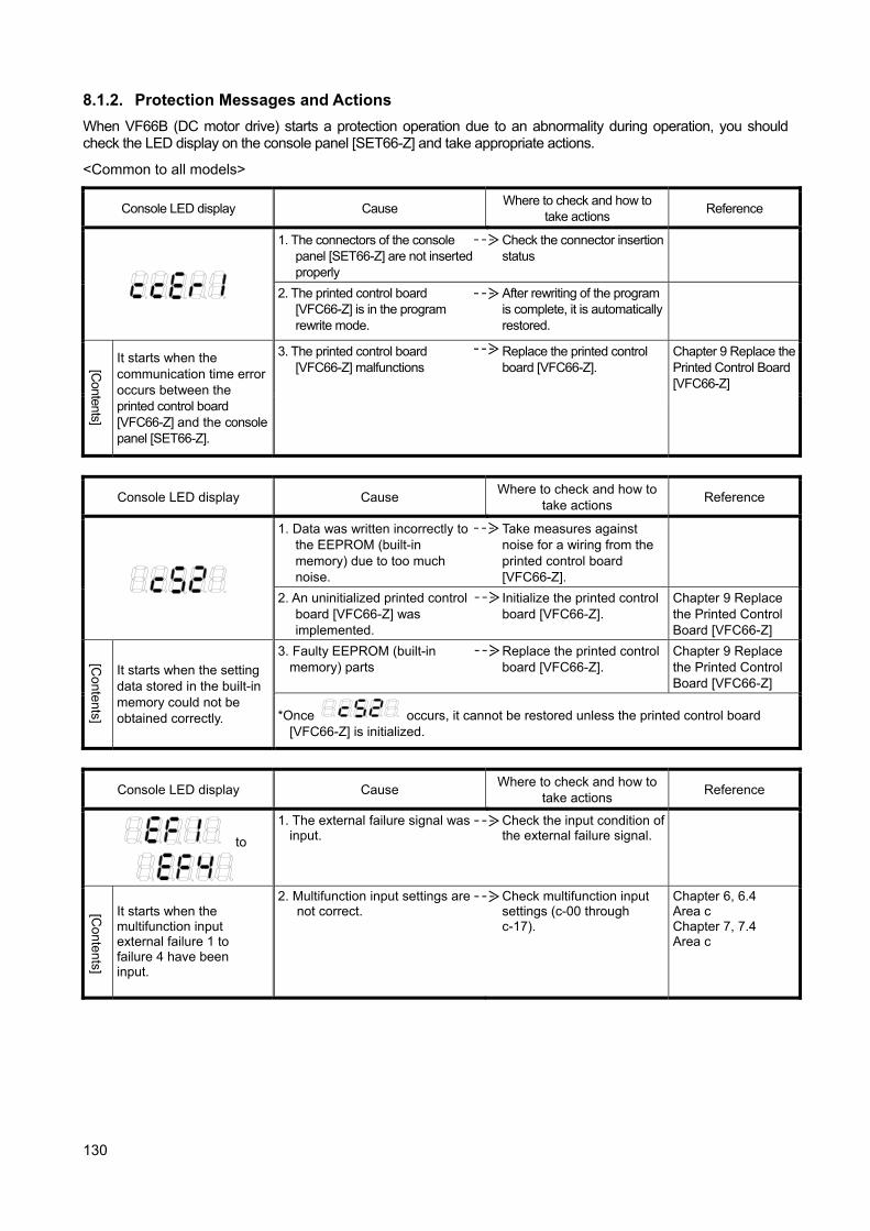
130
8.1.2. Protection Messages and Actions
When VF66B (DC motor drive) starts a protection operation due to an abnormality during operation, you should check the LED display on the console panel [SET66-Z] and take appropriate actions.
<Common to all models>
Console LED display Cause Where to check and how to
take actions Reference
1. The connectors of the console panel [SET66-Z] are not inserted properly
Check the connector insertion status
2. The printed control board [VFC66-Z] is in the program rewrite mode.
After rewriting of the program is complete, it is automatically restored.
[Contents]
It starts when the communication time error occurs between the printed control board [VFC66-Z] and the console panel [SET66-Z].
3. The printed control board [VFC66-Z] malfunctions
Replace the printed control board [VFC66-Z].
Chapter 9 Replace the Printed Control Board [VFC66-Z]
Console LED display Cause Where to check and how to
take actions Reference
1. Data was written incorrectly to the EEPROM (built-in memory) due to too much noise.
Take measures against noise for a wiring from the printed control board [VFC66-Z].
2. An uninitialized printed control board [VFC66-Z] was implemented.
Initialize the printed control board [VFC66-Z].
Chapter 9 Replace the Printed Control Board [VFC66-Z]
[Contents]
It starts when the setting data stored in the built-in memory could not be obtained correctly.
3. Faulty EEPROM (built-in memory) parts
Replace the printed control board [VFC66-Z].
Chapter 9 Replace the Printed Control Board [VFC66-Z]
*Once occurs, it cannot be restored unless the printed control board [VFC66-Z] is initialized.
Console LED display Cause Where to check and how to
take actions Reference
to
1. The external failure signal was input.
Check the input condition of the external failure signal.
[Contents]
It starts when the multifunction input external failure 1 to failure 4 have been input.
2. Multifunction input settings are not correct.
Check multifunction input settings (c-00 through c-17).
Chapter 6, 6.4 Area c Chapter 7, 7.4 Area c
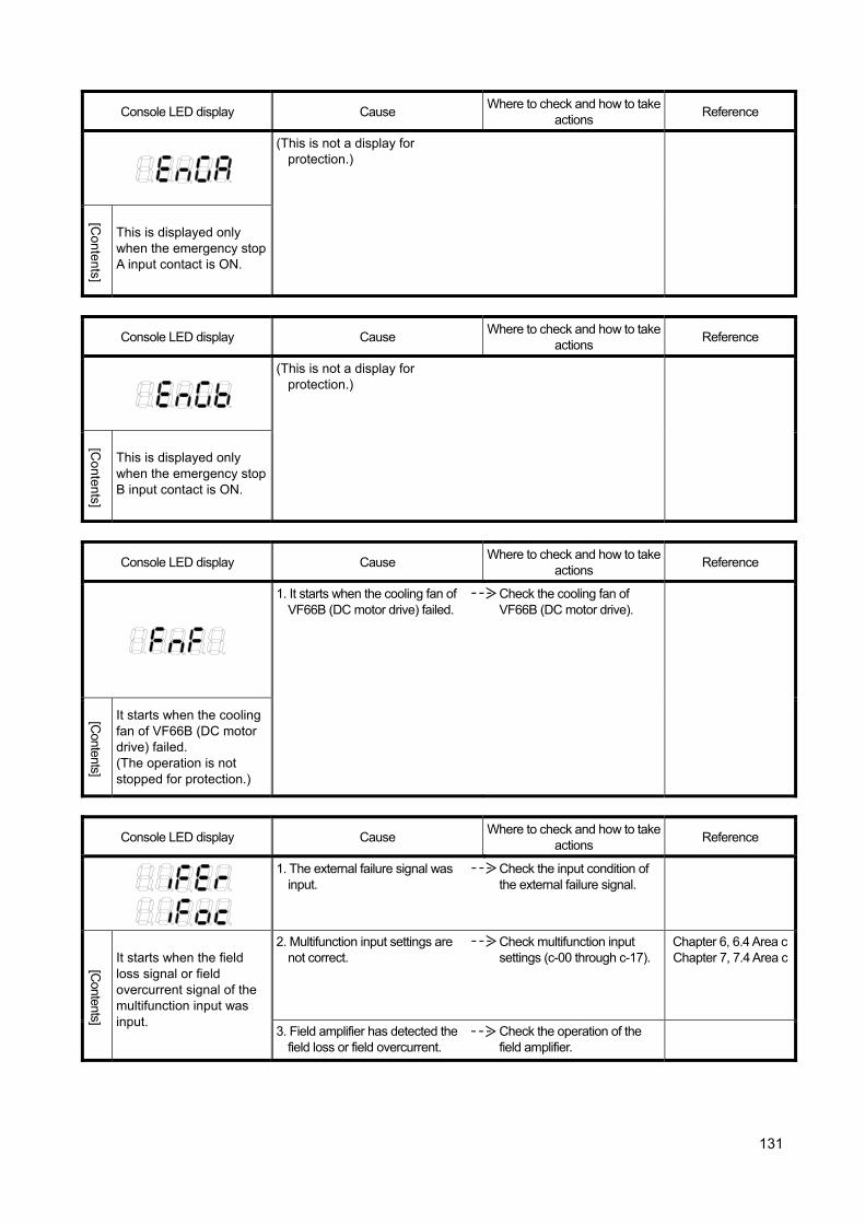
131
Console LED display Cause Where to check and how to take
actions Reference
(This is not a display for protection.)
[Contents]
This is displayed only when the emergency stop A input contact is ON.
Console LED display Cause Where to check and how to take
actions Reference
(This is not a display for protection.)
[Contents]
This is displayed only when the emergency stop B input contact is ON.
Console LED display Cause Where to check and how to take
actions Reference
1. It starts when the cooling fan of VF66B (DC motor drive) failed.
Check the cooling fan of VF66B (DC motor drive).
[Contents]
It starts when the cooling fan of VF66B (DC motor drive) failed. (The operation is not stopped for protection.)
Console LED display Cause Where to check and how to take
actions Reference
1. The external failure signal was input.
Check the input condition of the external failure signal.
[Contents]
It starts when the field loss signal or field overcurrent signal of the multifunction input was input.
2. Multifunction input settings are not correct.
Check multifunction input settings (c-00 through c-17).
Chapter 6, 6.4 Area cChapter 7, 7.4 Area c
3. Field amplifier has detected the field loss or field overcurrent.
Check the operation of the field amplifier.

132
Console LED display Cause Where to check and how to take
actions Reference
1. Ambient temperature becomes high.
・ Check the installation environment.
・ Check whether temperature inside the control panel rises or not.
2. The cooling space of the unit is not enough.
Keep enough cooling space.
3. The installation direction of the unit is not correct.
Install the unit in the correct direction.
4. The output electrical wire was grounded or short circuited.
Check the output wiring. Chapter 2, 2.1 How to Connect VF66B (DC motor drive)
5. DCL is not connected. Connect DCL. Chapter 2, 2.1 How to Connect VF66B (DC motor drive)
[Contents]
The protection operation of the IPM module in the unit occurs. ・Overcurrent was
applied to the IGBT element.
・The gate power supply voltage of IGBT has dropped.
・Fins for IPM module and the input rectification diode module overheat.
6. IGBT (IPM) is damaged. Check whether IGBT (IPM) works properly or not (continuity check).
7. The cooling fan fails.
Replace the cooling fan.
8. The wind of the cooling fan blows in the reverse direction.
Install the cooling fan so that the wind blows in the correct direction.
9. The main circuit printed board [GAC66-Z or MAC66-Z] malfunctions
Replace the main circuit printed board [GAC66-Z or MAC66-Z].
Console LED display Cause Where to check and how to
take actions Reference
1. The cooling fan of the motor fails.
Replace the cooling fan of the motor.
2. Ambient temperature of the motor is high.
Check the installation environment of the motor.
[Contents]
It starts when the Motor_overheat_protection_operation_selection is set to "ON" and motor temperature is over Motor_protect_temperature < G-17 > while the temperature detection option is used.
3. The motor temperature detection wiring is disconnected, or noise is penetrating.
・Check the motor temperature detection wiring.
・Take measures against noise.
4. The adjustment of the temperature detection offset adjustment (G-01) and the temperature detection gain adjustment (G-02) are not correct.
Readjust the temperature detection offset adjustment (G-01) and the temperature detection gain adjustment (G-02).
Chapter 6, 6.8 Area G Chapter 7, 7.8 Area G
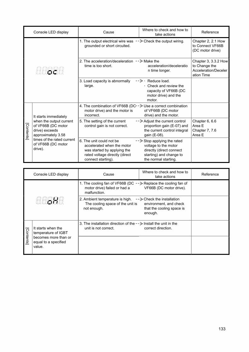
133
Console LED display Cause Where to check and how to
take actions Reference
1. The output electrical wire was grounded or short circuited.
Check the output wiring. Chapter 2, 2.1 How to Connect VF66B (DC motor drive)
2. The acceleration/deceleration time is too short.
Make the acceleration/deceleration time longer.
Chapter 3, 3.3.2 How to Change the Acceleration/Deceleration Time
3. Load capacity is abnormally large.
・ Reduce load. ・ Check and review the
capacity of VF66B (DC motor drive) and the motor.
[Contents]
It starts immediately when the output current of VF66B (DC motor drive) exceeds approximately 3.58 times of the rated current of VF66B (DC motor drive).
4. The combination of VF66B (DC motor drive) and the motor is incorrect.
Use a correct combination of VF66B (DC motor drive) and the motor.
5. The setting of the current control gain is not correct.
Adjust the current control proportion gain (E-07) and the current control integral gain (E-08).
Chapter 6, 6.6 Area E Chapter 7, 7.6 Area E
6. The unit could not be accelerated when the motor was started by applying the rated voltage directly (direct connect starting).
Stop applying the rated voltage to the motor directly (direct connect starting) and change to the normal starting.
Console LED display Cause Where to check and how to
take actions Reference
1. The cooling fan of VF66B (DC motor drive) failed or had a malfunction.
Replace the cooling fan of VF66B (DC motor drive).
2. Ambient temperature is high. The cooling space of the unit is not enough.
Check the installation environment, and check that the cooling space is enough.
[Contents]
It starts when the temperature of IGBT becomes more than or equal to a specified value.
3. The installation direction of the unit is not correct.
Install the unit in the correct direction.

134
Console LED display Cause Where to check and how to
take actions Reference
1. Capacity of VF66B (DC motor drive) and the motor is too small.
・ Reduce load. ・ Check and review the
capacity of VF66B (DC motor drive) and the motor.
[Contents]
It starts when current equivalent to 150% of the rated motor armature current is applied to VF66B (CD motor drive) output for a minute.
2. A value of the overload protection setting (F-03) for the overload protection is not correct.
Check and review the setting value of the overload protection setting (F-03).
Chapter 6, 6.7 Area F Chapter 7, 7.7 Area F
3. Load capacity is abnormally large.
Use the overload protection pre-alarm operation level setting (H-11).
Chapter 6, 6.9 Area H Chapter 7, 7.9 Area H
Console LED display Cause Where to check and how to
take actions Reference
1. The digital communication option selection (J-00) is set to "ON" without the communication optional printed board connected.
Set the digital communication option usage selection (J-00) to "OFF."
Chapter 6, 6.11 Area J Chapter 7, 7.11 Area J
2. Communication optional printed board malfunctions.
Replace the communication optional printed board.
Optional Instruction Manual
[Contents]
It starts when the communicationoptional printed board has a malfunction or a loose connection.
3. Communication optional printed board is not connected properly.
Check the connection with the communication optional printed board and the connector insertion status.
Optional Instruction Manual
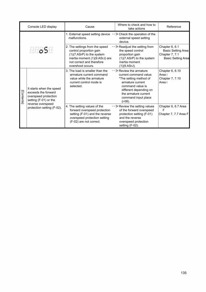
135
Console LED display Cause Where to check and how to
take actions Reference
1. External speed setting device malfunctions.
Check the operation of the external speed setting device.
2. The settings from the speed control proportion gain (1)(7.ASrP) to the system inertia moment (1)(9.ASrJ) are not correct and therefore overshoot occurs.
Readjust the setting from the speed control proportion gain (1)(7.ASrP) to the system inertia moment (1)(9.ASrJ).
Chapter 6, 6.1 Basic Setting Area
Chapter 7, 7.1 Basic Setting Area
[Contents]
It starts when the speed exceeds the forward overspeed protection setting (F-01) or the reverse overspeed protection setting (F-02).
3. The load is smaller than the armature current command value while the armature current control mode is selected.
Review the armature current command value. *The setting method of
armature current command value is different depending on the armature current command input place (i-08).
Chapter 6, 6.10 Area i Chapter 7, 7.10 Area i
4. The setting values of the forward overspeed protection setting (F-01) and the reverse overspeed protection setting (F-02) are not correct.
Review the setting values of the forward overspeed protection setting (F-01) and the reverse overspeed protection setting (F-02).
Chapter 6, 6.7 Area F
Chapter 7, 7.7 Area F
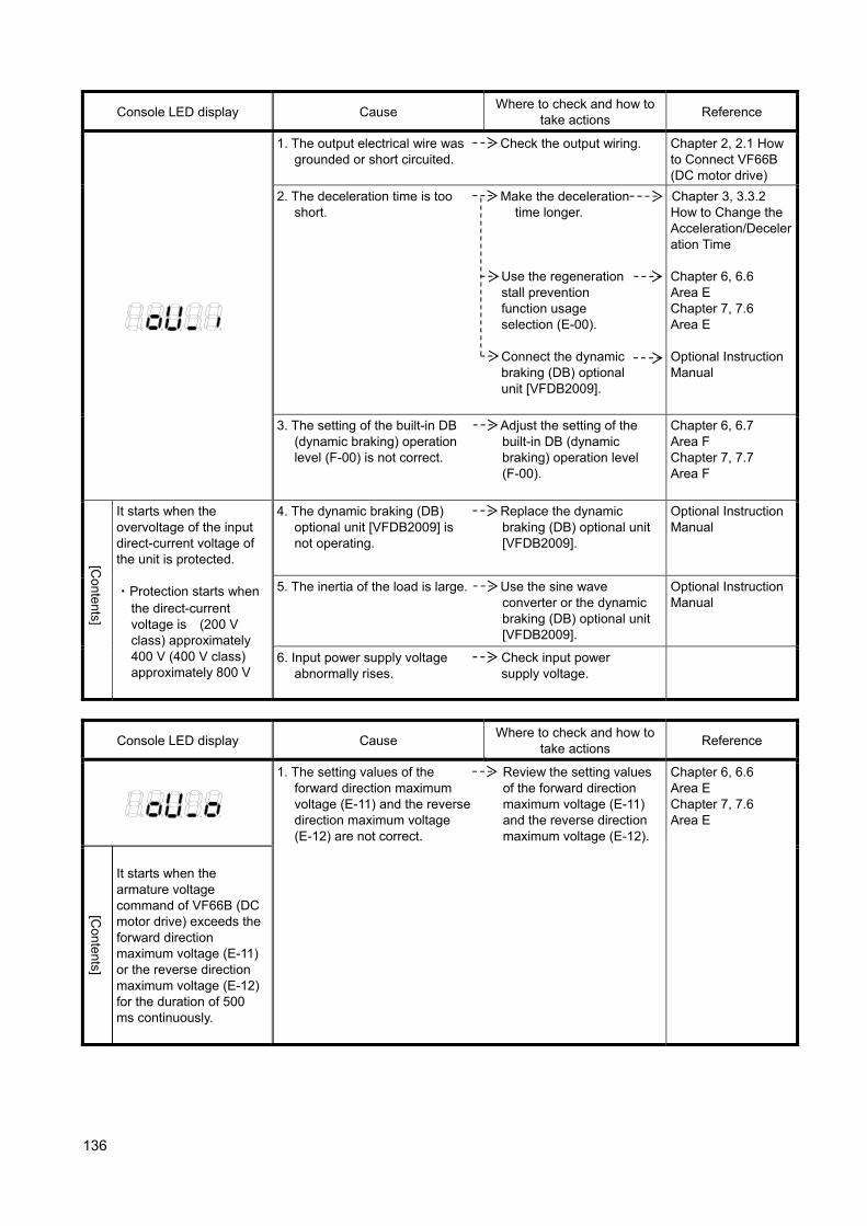
136
Console LED display Cause Where to check and how to
take actions Reference
1. The output electrical wire was grounded or short circuited.
Check the output wiring. Chapter 2, 2.1 How to Connect VF66B (DC motor drive)
2. The deceleration time is too short.
Make the deceleration time longer.
Use the regeneration stall prevention function usage selection (E-00).
Connect the dynamic braking (DB) optional unit [VFDB2009].
Chapter 3, 3.3.2 How to Change the Acceleration/Deceleration Time
Chapter 6, 6.6 Area E Chapter 7, 7.6 Area E Optional Instruction Manual
3. The setting of the built-in DB (dynamic braking) operation level (F-00) is not correct.
Adjust the setting of the built-in DB (dynamic braking) operation level (F-00).
Chapter 6, 6.7 Area F Chapter 7, 7.7 Area F
[Contents]
It starts when the overvoltage of the input direct-current voltage of the unit is protected. ・Protection starts when
the direct-current voltage is (200 V class) approximately 400 V (400 V class) approximately 800 V
4. The dynamic braking (DB) optional unit [VFDB2009] is not operating.
Replace the dynamic braking (DB) optional unit [VFDB2009].
Optional Instruction Manual
5. The inertia of the load is large. Use the sine wave converter or the dynamic braking (DB) optional unit [VFDB2009].
Optional Instruction Manual
6. Input power supply voltage abnormally rises.
Check input power supply voltage.
Console LED display Cause Where to check and how to
take actions Reference
1. The setting values of the forward direction maximum voltage (E-11) and the reverse direction maximum voltage (E-12) are not correct.
Review the setting values of the forward direction maximum voltage (E-11) and the reverse direction maximum voltage (E-12).
Chapter 6, 6.6 Area E Chapter 7, 7.6 Area E
[Contents]
It starts when the armature voltage command of VF66B (DC motor drive) exceeds the forward direction maximum voltage (E-11) or the reverse direction maximum voltage (E-12) for the duration of 500 ms continuously.
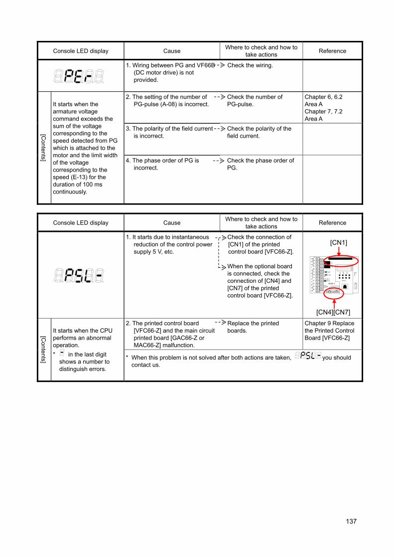
137
Console LED display Cause Where to check and how to
take actions Reference
1. Wiring between PG and VF66B (DC motor drive) is not provided.
Check the wiring.
[Contents]
It starts when the armature voltage command exceeds the sum of the voltage corresponding to the speed detected from PG which is attached to the motor and the limit width of the voltage corresponding to the speed (E-13) for the duration of 100 ms continuously.
2. The setting of the number of PG-pulse (A-08) is incorrect.
Check the number of PG-pulse.
Chapter 6, 6.2 Area A Chapter 7, 7.2 Area A
3. The polarity of the field current is incorrect.
Check the polarity of the field current.
4. The phase order of PG is incorrect.
Check the phase order of PG.
Console LED display Cause Where to check and how to
take actions Reference
1. It starts due to instantaneous reduction of the control power supply 5 V, etc.
Check the connection of [CN1] of the printed control board [VFC66-Z]. When the optional board is connected, check the connection of [CN4] and [CN7] of the printed control board [VFC66-Z].
TB1
CN-SO
CN-SI
RY1
CN3
SW2
SW1
CN4
LED1
52MA
86Aa
86Ab
P
COM
GND
+10
PS
PS
MI3
GND
GND
52MA
86A
MO1
MO2
AOT1
AIN1
ST-F
MI1
MI2
MI4
MI5
CN5
3 1
ON
RY2
CN6
SET66-Z
CN7 CN4
VFC66-Z
[Contents]
It starts when the CPU performs an abnormal operation.
* in the last digit shows a number to distinguish errors.
2. The printed control board [VFC66-Z] and the main circuit printed board [GAC66-Z or MAC66-Z] malfunction.
Replace the printed boards.
Chapter 9 Replace the Printed Control Board [VFC66-Z]
* When this problem is not solved after both actions are taken, you should contact us.
[CN4][CN7]
[CN1]
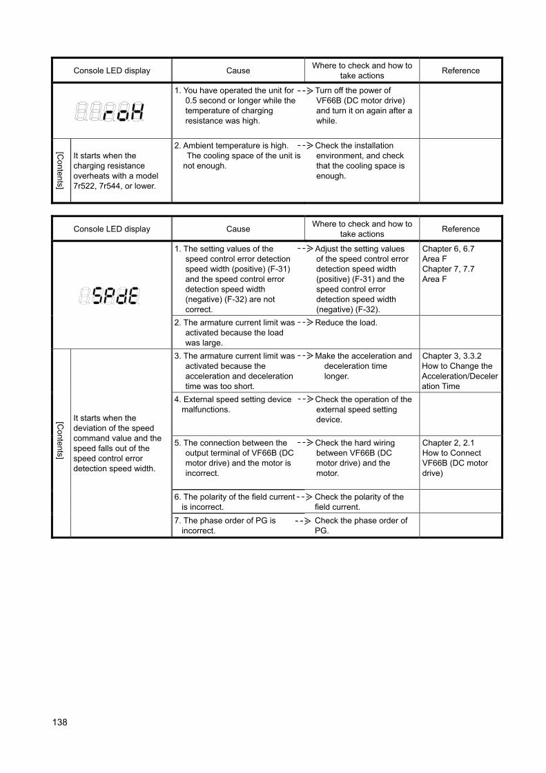
138
Console LED display Cause Where to check and how to
take actions Reference
1. You have operated the unit for 0.5 second or longer while the temperature of charging resistance was high.
Turn off the power of VF66B (DC motor drive) and turn it on again after a while.
[Contents]
It starts when the charging resistance overheats with a model 7r522, 7r544, or lower.
2. Ambient temperature is high. The cooling space of the unit is not enough.
Check the installation environment, and check that the cooling space is enough.
Console LED display Cause Where to check and how to
take actions Reference
1. The setting values of the speed control error detection speed width (positive) (F-31) and the speed control error detection speed width (negative) (F-32) are not correct.
Adjust the setting values of the speed control error detection speed width (positive) (F-31) and the speed control error detection speed width (negative) (F-32).
Chapter 6, 6.7 Area F Chapter 7, 7.7 Area F
2. The armature current limit was activated because the load was large.
Reduce the load.
[Contents]
It starts when the deviation of the speed command value and the speed falls out of the speed control error detection speed width.
3. The armature current limit was activated because the acceleration and deceleration time was too short.
Make the acceleration and deceleration time longer.
Chapter 3, 3.3.2 How to Change the Acceleration/Deceleration Time
4. External speed setting device malfunctions.
Check the operation of the external speed setting device.
5. The connection between the output terminal of VF66B (DC motor drive) and the motor is incorrect.
Check the hard wiring between VF66B (DC motor drive) and the motor.
Chapter 2, 2.1 How to Connect VF66B (DC motor drive)
6. The polarity of the field current is incorrect.
Check the polarity of the field current.
7. The phase order of PG is incorrect.
Check the phase order of PG.
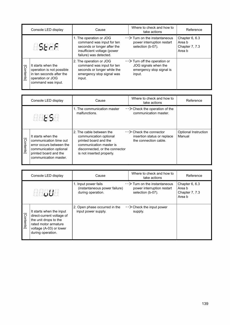
139
Console LED display Cause Where to check and how to
take actions Reference
1. The operation or JOG command was input for ten seconds or longer after the insufficient voltage (power failure) was detected.
Turn on the instantaneous power interruption restart selection (b-07).
Chapter 6, 6.3 Area b Chapter 7, 7.3 Area b
[Contents]
It starts when the operation is not possible in ten seconds after the operation or JOG command was input.
2. The operation or JOG command was input for ten seconds or longer while the emergency stop signal was input.
Turn off the operation or JOG signals when the emergency stop signal is input.
Console LED display Cause Where to check and how to
take actions Reference
1. The communication master malfunctions.
Check the operation of the communication master.
[Contents]
It starts when the communication time out error occurs between the communication optional printed board and the communication master.
2. The cable between the communication optional printed board and the communication master is disconnected, or the connector is not inserted properly.
Check the connector insertion status or replace the connection cable.
Optional Instruction Manual
Console LED display Cause Where to check and how to
take actions Reference
1. Input power fails (instantaneous power failure) during operation.
Turn on the instantaneous power interruption restart selection (b-07).
Chapter 6, 6.3 Area b Chapter 7, 7.3 Area b
[Contents]
It starts when the input direct-current voltage of the unit drops to the rated motor armature voltage (A-03) or lower during operation.
2. Open phase occurred in the input power supply.
Check the input power supply.

140
<Models 3022, 3044 and higher, and the unit parallel models>
For models 3022 through 9022 and 3044 through 31544 consisting of a single unit, the displays are the same as the master unit, which is indicated in the following list. Parallel models are 15022, 18022, and 40044 through 100044.
Console LED display Cause Where to check and how to
take actions Reference
1. The protection indicated in No.30 or later is activated.
Clear the protection operation indicated in No.30 or later.
Chapter 8, 8.1.1 List of Protection Messages
[Contents]
It starts when the protection indicated in No.30 or later is activated and the protection operation relay is activated. *However,
in case of (Failed fan (master unit)),
(Failed fan
(slave unit 1)),
(Failed fan (slave unit 2)),
and (Failed fan (slave unit 3)), it does not start.
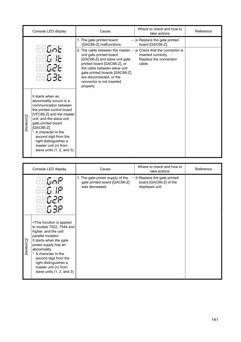
141
Console LED display Cause Where to check and how to
take actions Reference
1. The gate printed board [GAC66-Z] malfunctions.
Replace the gate printed board [GAC66-Z].
2. The cable between the master unit gate printed board [GAC66-Z] and slave unit gate printed board [GAC66-Z], or the cable between slave unit gate printed boards [GAC66-Z] are disconnected, or the connector is not inserted properly.
Check that the connector is inserted correctly. Replace the connection cable.
[Contents]
It starts when an abnormality occurs in a communication between the printed control board [VFC66-Z] and the master unit, and the slave unit gate printed board [GAC66-Z]. * A character in the
second digit from the right distinguishes a master unit (n) from slave units (1, 2, and 3).
Console LED display Cause Where to check and how to
take actions Reference
1. The gate power supply of the gate printed board [GAC66-Z] was decreased.
Replace the gate printed board [GAC66-Z] of the displayed unit.
[Contents]
<This function is applied to models 7522, 7544 and higher, and the unit parallel models> It starts when the gate power supply has an abnormality. * A character in the
second digit from the right distinguishes a master unit (n) from slave units (1, 2, and 3).
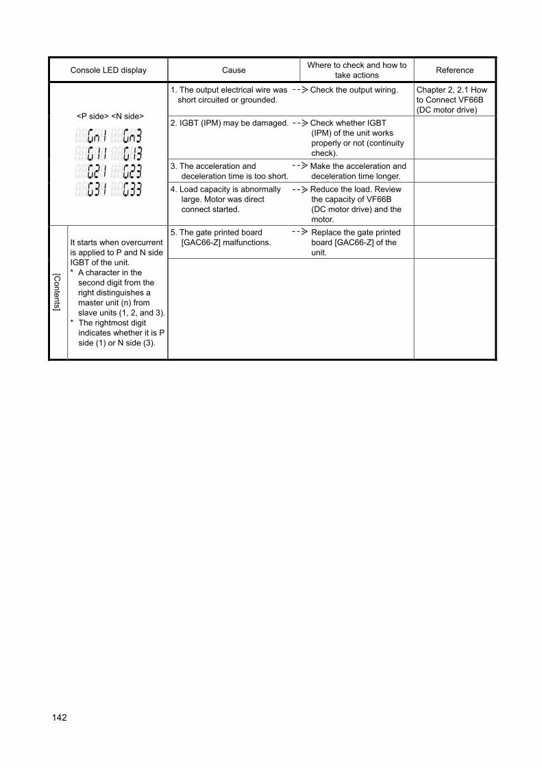
142
Console LED display Cause Where to check and how to
take actions Reference
<P side> <N side>
1. The output electrical wire was short circuited or grounded.
Check the output wiring. Chapter 2, 2.1 How to Connect VF66B (DC motor drive)
2. IGBT (IPM) may be damaged. Check whether IGBT (IPM) of the unit works properly or not (continuity check).
3. The acceleration and deceleration time is too short.
Make the acceleration and deceleration time longer.
4. Load capacity is abnormally large. Motor was direct connect started.
Reduce the load. Review the capacity of VF66B (DC motor drive) and the motor.
[Contents]
It starts when overcurrent is applied to P and N side IGBT of the unit. * A character in the
second digit from the right distinguishes a master unit (n) from slave units (1, 2, and 3).
* The rightmost digit indicates whether it is P side (1) or N side (3).
5. The gate printed board [GAC66-Z] malfunctions.
Replace the gate printed board [GAC66-Z] of the unit.
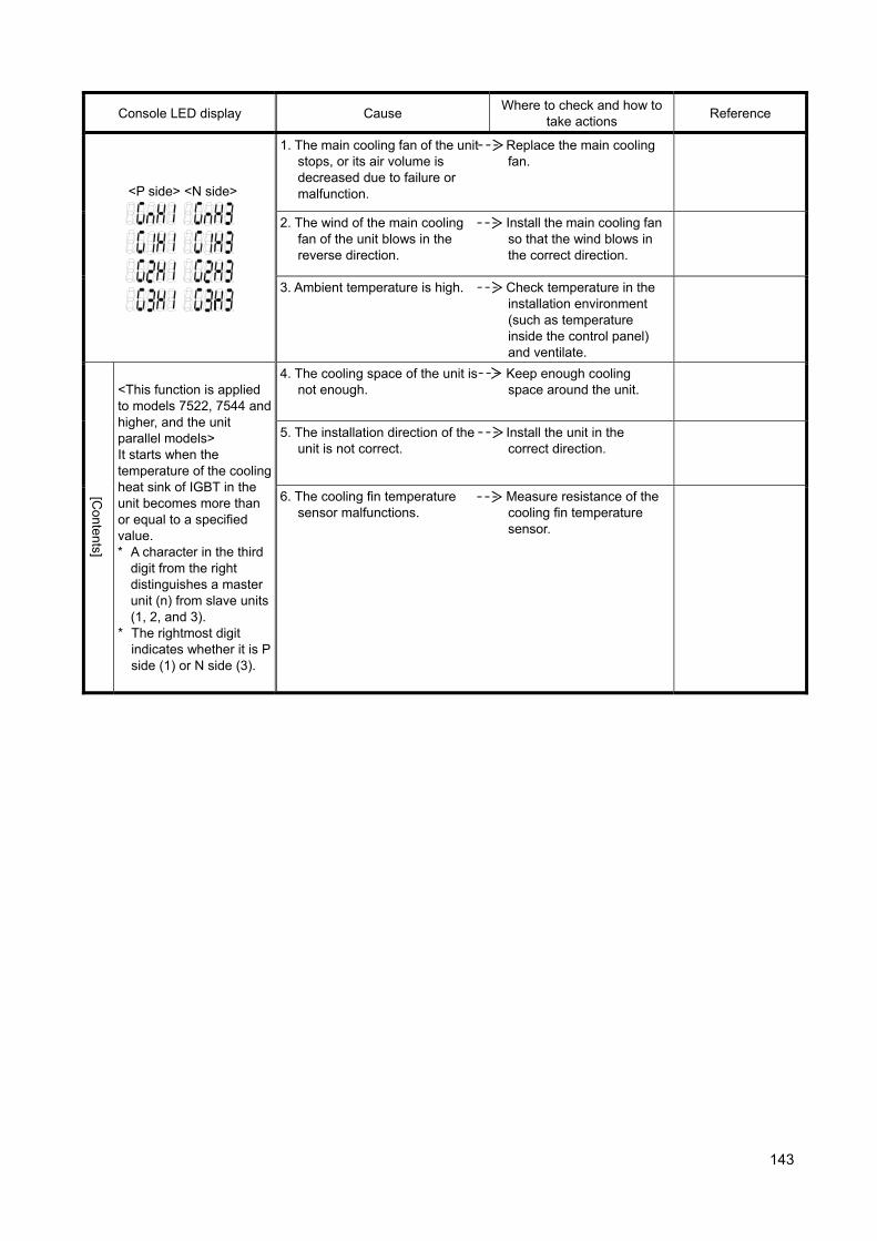
143
Console LED display Cause Where to check and how to
take actions Reference
<P side> <N side>
1. The main cooling fan of the unit stops, or its air volume is decreased due to failure or malfunction.
Replace the main cooling fan.
2. The wind of the main cooling fan of the unit blows in the reverse direction.
Install the main cooling fan so that the wind blows in the correct direction.
3. Ambient temperature is high. Check temperature in the installation environment (such as temperature inside the control panel) and ventilate.
[Contents]
<This function is applied to models 7522, 7544 and higher, and the unit parallel models> It starts when the temperature of the cooling heat sink of IGBT in the unit becomes more than or equal to a specified value. * A character in the third
digit from the right distinguishes a master unit (n) from slave units (1, 2, and 3).
* The rightmost digit indicates whether it is P side (1) or N side (3).
4. The cooling space of the unit is not enough.
Keep enough cooling space around the unit.
5. The installation direction of the unit is not correct.
Install the unit in the correct direction.
6. The cooling fin temperature sensor malfunctions.
Measure resistance of the cooling fin temperature sensor.
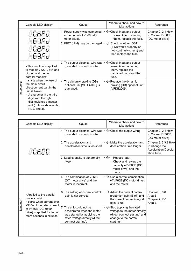
144
Console LED display Cause Where to check and how to
take actions Reference
1. Power supply was connected to the output of VF66B (DC motor drive).
Check input and output wires. After correcting them, replace the fuse.
Chapter 2, 2.1 How to Connect VF66B (DC motor drive)
2. IGBT (IPM) may be damaged. Check whether IGBT (IPM) works properly or not (continuity check) and then replace the fuse.
[Contents]
<This function is applied to models 7522, 7544 and higher, and the unit parallel models> It starts when the fuse of the main circuit direct-current part in the unit is blown. * A character in the third
digit from the right distinguishes a master unit (n) from slave units (1, 2, and 3).
3. The output electrical wire was grounded or short circuited.
Check input and output wires. After correcting them, replace the damaged parts and the fuse.
4. The dynamic braking (DB) optional unit [VFDB2009] is damaged.
Replace the dynamic braking (DB) optional unit [VFDB2009].
Console LED display Cause Where to check and how to
take actions Reference
1. The output electrical wire was grounded or short circuited.
Check the output wiring. Chapter 2, 2.1 How to Connect VF66B (DC motor drive)
2. The acceleration and deceleration time is too short.
Make the acceleration and deceleration time longer.
Chapter 3, 3.3.2 How to Change the Acceleration/Deceleration Time
3. Load capacity is abnormally large.
・ Reduce load. ・ Check and review the
capacity of VF66B (DC motor drive) and the motor.
[Contents]
<Applied to the parallel models only> It starts when current over 290 % of the rated current of VF66B (DC motor drive) is applied for two or more seconds in all units.
4. The combination of VF66B (DC motor drive) and the motor is incorrect.
Use a correct combination of VF66B (DC motor drive) and the motor.
6. The setting of current control gain is not correct.
Adjust the current control proportion gain (E-07) and the current control integral gain (E-08).
Chapter 6, 6.6 Area E Chapter 7, 7.6 Area E
7. The unit could not be accelerated when the motor was started by applying the rated voltage directly (direct connect starting).
Stop applying the rated voltage to the motor directly (direct connect starting) and change to the normal starting.
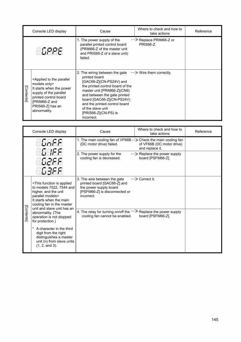
145
Console LED display Cause Where to check and how to
take actions Reference
1. The power supply of the parallel printed control board (PRIM66-Z of the master unit and PRIS66-Z of a slave unit) failed.
Replace PRIM66-Z or PRIS66-Z.
[Contents]
<Applied to the parallel models only> It starts when the power supply of the parallel printed control board [PRIM66-Z and PRIS66-Z] has an abnormality.
2. The wiring between the gate printed board [GAC66-Z](CN-PS24V) and the printed control board of the master unit [PRIM66-Z](CN9) and between the gate printed board [GAC66-Z](CN-PS24V) and the printed control board of the slave unit [PRIS66-Z](CN-PS) is incorrect.
Wire them correctly.
Console LED display Cause Where to check and how to
take actions Reference
1. The main cooling fan of VF66B (DC motor drive) failed.
Check the main cooling fan of VF66B (DC motor drive) and replace it.
2. The power supply for the cooling fan is decreased.
Replace the power supply board [PSFM66-Z].
[Contents]
<This function is applied to models 7522, 7544 and higher, and the unit parallel models> It starts when the main cooling fan in the master unit and slave unit has an abnormality. (The operation is not stopped for protection.)
* A character in the third digit from the right distinguishes a master unit (n) from slave units (1, 2, and 3).
3. The wire between the gate printed board [GAC66-Z] and the power supply board [PSFM66-Z] is disconnected or incorrect.
Correct it.
4. The relay for turning on/off the cooling fan cannot be enabled.
Replace the power supply board [PSFM66-Z].

146
Console LED display Cause Where to check and how to
take actions Reference
1. The gate printed board [GAC66-Z] malfunctions.
Replace the gate printed board [GAC66-Z] of the displayed slave unit.
[Contents]
<Applied to the parallel models only> It starts when voltage of the control power supply in the slave unit drops. *A character in the third
digit from the right distinguishes the slave units (1, 2, and 3).
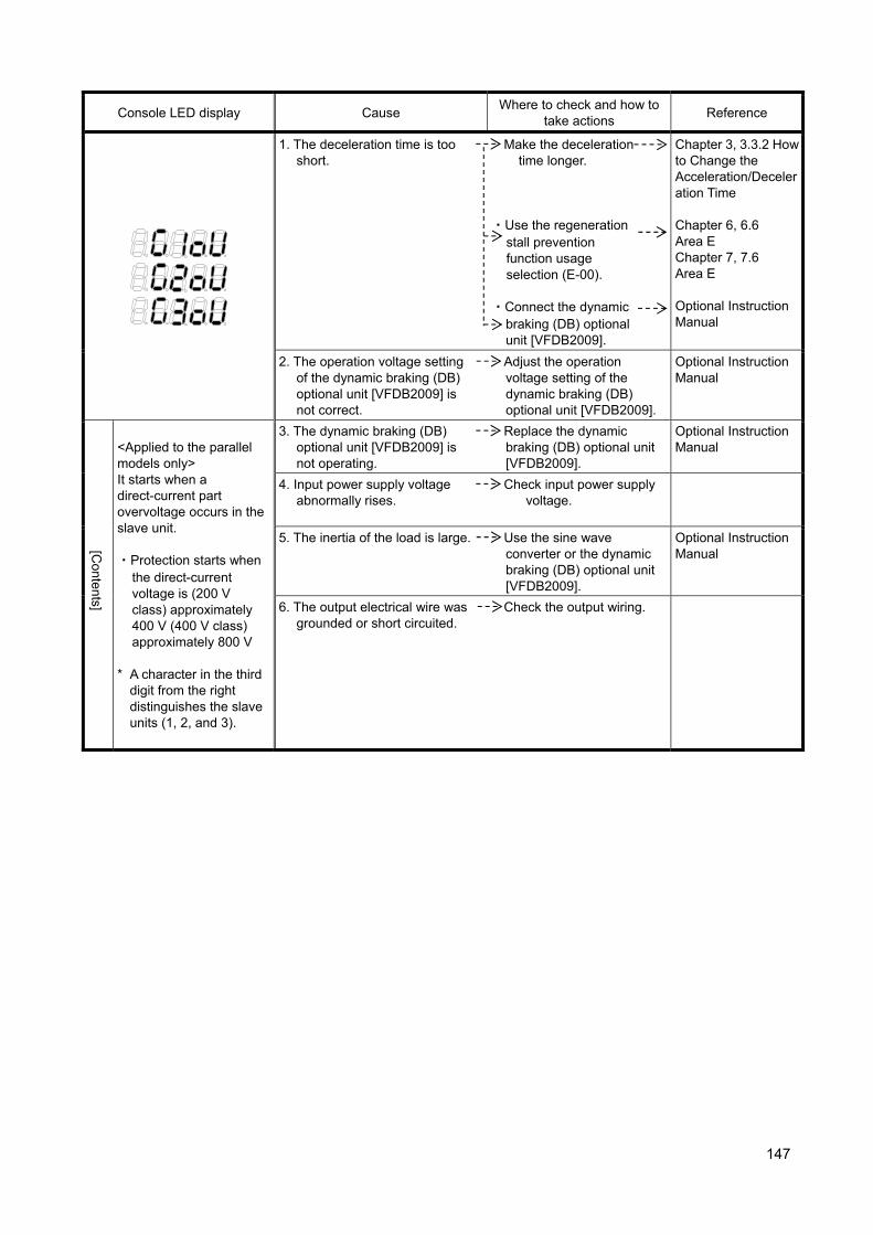
147
Console LED display Cause Where to check and how to
take actions Reference
1. The deceleration time is too short.
Make the deceleration time longer.
・Use the regeneration
stall prevention function usage selection (E-00).
・Connect the dynamic
braking (DB) optional unit [VFDB2009].
Chapter 3, 3.3.2 How to Change the Acceleration/Deceleration Time
Chapter 6, 6.6 Area E Chapter 7, 7.6 Area E Optional Instruction Manual
2. The operation voltage setting of the dynamic braking (DB) optional unit [VFDB2009] is not correct.
Adjust the operation voltage setting of the dynamic braking (DB) optional unit [VFDB2009].
Optional Instruction Manual
[Contents]
<Applied to the parallel models only> It starts when a direct-current part overvoltage occurs in the slave unit. ・Protection starts when
the direct-current voltage is (200 V class) approximately 400 V (400 V class) approximately 800 V
* A character in the third
digit from the right distinguishes the slave units (1, 2, and 3).
3. The dynamic braking (DB) optional unit [VFDB2009] is not operating.
Replace the dynamic braking (DB) optional unit [VFDB2009].
Optional Instruction Manual
4. Input power supply voltage abnormally rises.
Check input power supply voltage.
5. The inertia of the load is large. Use the sine wave converter or the dynamic braking (DB) optional unit [VFDB2009].
Optional Instruction Manual
6. The output electrical wire was grounded or short circuited.
Check the output wiring.
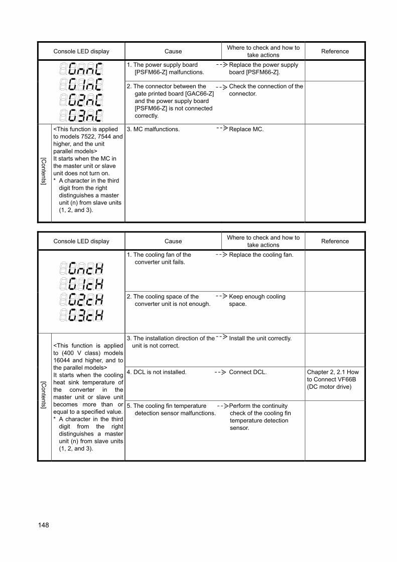
148
Console LED display Cause Where to check and how to
take actions Reference
1. The power supply board [PSFM66-Z] malfunctions.
Replace the power supply board [PSFM66-Z].
2. The connector between the gate printed board [GAC66-Z] and the power supply board [PSFM66-Z] is not connected correctly.
Check the connection of the connector.
[Contents]
<This function is applied to models 7522, 7544 and higher, and the unit parallel models> It starts when the MC in the master unit or slave unit does not turn on. * A character in the third
digit from the right distinguishes a master unit (n) from slave units (1, 2, and 3).
3. MC malfunctions. Replace MC.
Console LED display Cause Where to check and how to
take actions Reference
1. The cooling fan of the converter unit fails.
Replace the cooling fan.
2. The cooling space of the converter unit is not enough.
Keep enough cooling space.
[Contents]
<This function is applied to (400 V class) models 16044 and higher, and to the parallel models> It starts when the cooling heat sink temperature of the converter in the master unit or slave unit becomes more than or equal to a specified value.* A character in the third
digit from the right distinguishes a master unit (n) from slave units (1, 2, and 3).
3. The installation direction of the unit is not correct.
Install the unit correctly.
4. DCL is not installed. Connect DCL. Chapter 2, 2.1 How to Connect VF66B (DC motor drive)
5. The cooling fin temperature detection sensor malfunctions.
Perform the continuity check of the cooling fin temperature detection sensor.
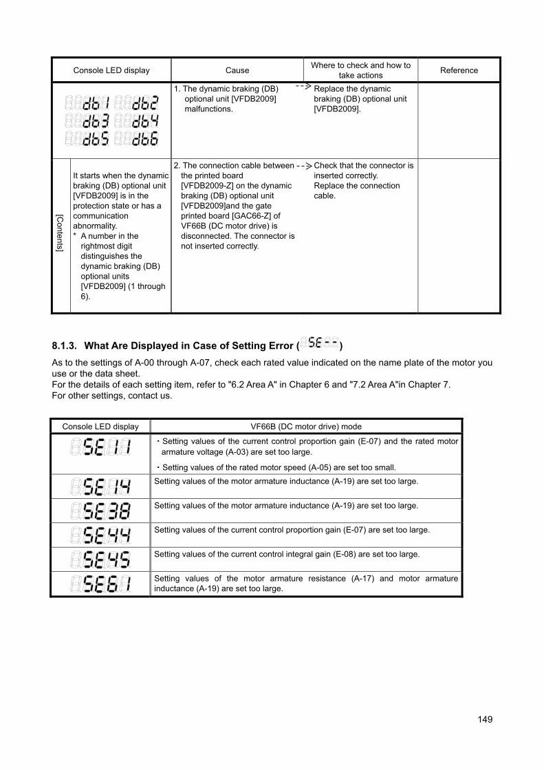
149
Console LED display Cause Where to check and how to
take actions Reference
1. The dynamic braking (DB) optional unit [VFDB2009] malfunctions.
Replace the dynamic braking (DB) optional unit [VFDB2009].
[Contents]
It starts when the dynamic braking (DB) optional unit [VFDB2009] is in the protection state or has a communication abnormality. * A number in the
rightmost digit distinguishes the dynamic braking (DB) optional units [VFDB2009] (1 through 6).
2. The connection cable between the printed board [VFDB2009-Z] on the dynamic braking (DB) optional unit [VFDB2009]and the gate printed board [GAC66-Z] of VF66B (DC motor drive) is disconnected. The connector is not inserted correctly.
Check that the connector is inserted correctly. Replace the connection cable.
8.1.3. What Are Displayed in Case of Setting Error ( )
As to the settings of A-00 through A-07, check each rated value indicated on the name plate of the motor you use or the data sheet. For the details of each setting item, refer to "6.2 Area A" in Chapter 6 and "7.2 Area A"in Chapter 7. For other settings, contact us.
Console LED display VF66B (DC motor drive) mode
・Setting values of the current control proportion gain (E-07) and the rated motor armature voltage (A-03) are set too large.
・Setting values of the rated motor speed (A-05) are set too small.
Setting values of the motor armature inductance (A-19) are set too large.
Setting values of the motor armature inductance (A-19) are set too large.
Setting values of the current control proportion gain (E-07) are set too large.
Setting values of the current control integral gain (E-08) are set too large.
Setting values of the motor armature resistance (A-17) and motor armature inductance (A-19) are set too large.
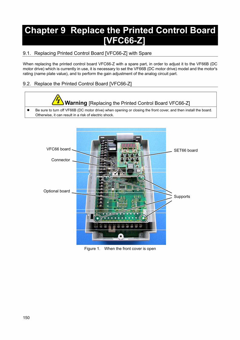
150
Chapter 9 Replace the Printed Control Board [VFC66-Z]
9.1. Replacing Printed Control Board [VFC66-Z] with Spare When replacing the printed control board VFC66-Z with a spare part, in order to adjust it to the VF66B (DC motor drive) which is currently in use, it is necessary to set the VF66B (DC motor drive) model and the motor's rating (name plate value), and to perform the gain adjustment of the analog circuit part.
9.2. Replace the Printed Control Board [VFC66-Z]
Warning [Replacing the Printed Control Board VFC66-Z] Be sure to turn off VF66B (DC motor drive) when opening or closing the front cover, and then install the board.
Otherwise, it can result in a risk of electric shock.
Figure 1. When the front cover is open
VFC66 board
Connector
Optional board
SET66 board
Supports
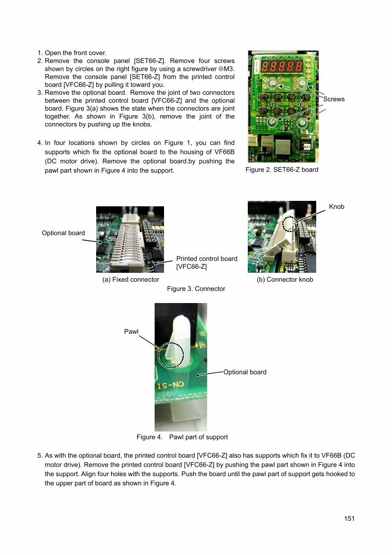
151
1. Open the front cover. 2. Remove the console panel [SET66-Z]. Remove four screws
shown by circles on the right figure by using a screwdriver M3. Remove the console panel [SET66-Z] from the printed control board [VFC66-Z] by pulling it toward you.
3. Remove the optional board. Remove the joint of two connectors between the printed control board [VFC66-Z] and the optional board. Figure 3(a) shows the state when the connectors are joint together. As shown in Figure 3(b), remove the joint of the connectors by pushing up the knobs.
4. In four locations shown by circles on Figure 1, you can find
supports which fix the optional board to the housing of VF66B
(DC motor drive). Remove the optional board.by pushing the
pawl part shown in Figure 4 into the support.
Figure 2. SET66-Z board
つまみ
オプション基板
VFC66基板
(a) Fixed connector (b) Connector knob
Figure 3. Connector
爪
オプション基板
Figure 4. Pawl part of support
5. As with the optional board, the printed control board [VFC66-Z] also has supports which fix it to VF66B (DC
motor drive). Remove the printed control board [VFC66-Z] by pushing the pawl part shown in Figure 4 into
the support. Align four holes with the supports. Push the board until the pawl part of support gets hooked to
the upper part of board as shown in Figure 4.
Screws
Printed control board[VFC66-Z]
Optional board
Knob
Pawl
Optional board
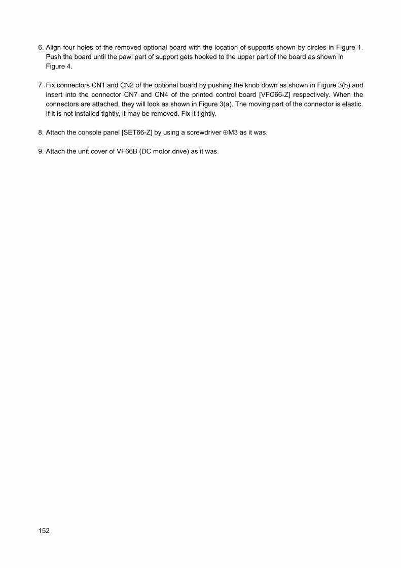
152
6. Align four holes of the removed optional board with the location of supports shown by circles in Figure 1.
Push the board until the pawl part of support gets hooked to the upper part of the board as shown in
Figure 4.
7. Fix connectors CN1 and CN2 of the optional board by pushing the knob down as shown in Figure 3(b) and
insert into the connector CN7 and CN4 of the printed control board [VFC66-Z] respectively. When the
connectors are attached, they will look as shown in Figure 3(a). The moving part of the connector is elastic.
If it is not installed tightly, it may be removed. Fix it tightly.
8. Attach the console panel [SET66-Z] by using a screwdriver M3 as it was.
9. Attach the unit cover of VF66B (DC motor drive) as it was.
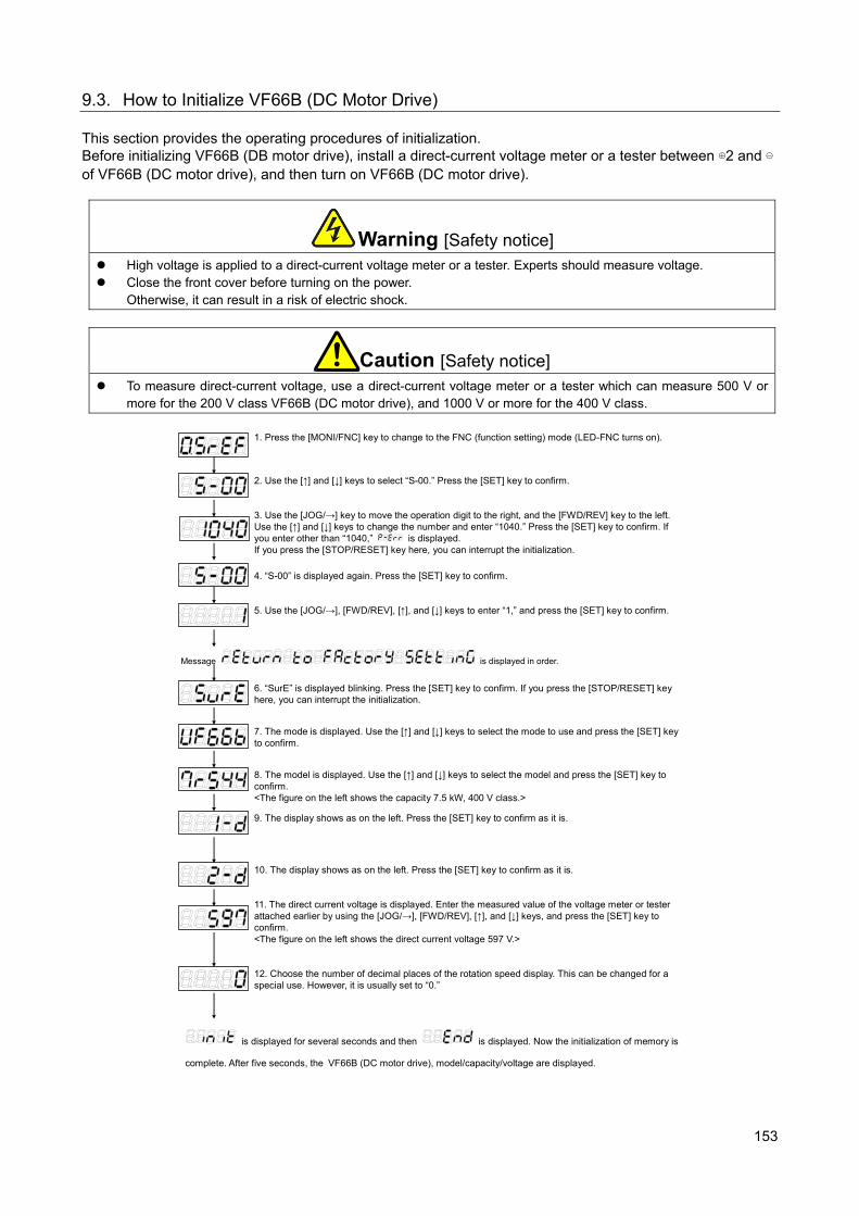
153
9.3. How to Initialize VF66B (DC Motor Drive) This section provides the operating procedures of initialization. Before initializing VF66B (DB motor drive), install a direct-current voltage meter or a tester between ⊕2 and ⊖ of VF66B (DC motor drive), and then turn on VF66B (DC motor drive).
Warning [Safety notice] High voltage is applied to a direct-current voltage meter or a tester. Experts should measure voltage. Close the front cover before turning on the power.
Otherwise, it can result in a risk of electric shock.
Caution [Safety notice] To measure direct-current voltage, use a direct-current voltage meter or a tester which can measure 500 V or
more for the 200 V class VF66B (DC motor drive), and 1000 V or more for the 400 V class.
1. Press the [MONI/FNC] key to change to the FNC (function setting) mode (LED-FNC turns on).
2. Use the [↑] and [↓] keys to select “S-00.” Press the [SET] key to confirm.
3. Use the [JOG/→] key to move the operation digit to the right, and the [FWD/REV] key to the left. Use the [↑] and [↓] keys to change the number and enter “1040.” Press the [SET] key to confirm. If you enter other than “1040,”
is displayed. If you press the [STOP/RESET] key here, you can interrupt the initialization.
4. “S-00” is displayed again. Press the [SET] key to confirm.
5. Use the [JOG/→], [FWD/REV], [↑], and [↓] keys to enter “1,” and press the [SET] key to confirm.
Message is displayed in order.
6. “SurE” is displayed blinking. Press the [SET] key to confirm. If you press the [STOP/RESET] key here, you can interrupt the initialization.
7. The mode is displayed. Use the [↑] and [↓] keys to select the mode to use and press the [SET] key to confirm.
8. The model is displayed. Use the [↑] and [↓] keys to select the model and press the [SET] key to confirm. <The figure on the left shows the capacity 7.5 kW, 400 V class.>
9. The display shows as on the left. Press the [SET] key to confirm as it is.
10. The display shows as on the left. Press the [SET] key to confirm as it is.
11. The direct current voltage is displayed. Enter the measured value of the voltage meter or tester attached earlier by using the [JOG/→], [FWD/REV], [↑], and [↓] keys, and press the [SET] key to confirm. <The figure on the left shows the direct current voltage 597 V.>
is displayed for several seconds and then
is displayed. Now the initialization of memory is
complete. After five seconds, the VF66B (DC motor drive), model/capacity/voltage are displayed.
12. Choose the number of decimal places of the rotation speed display. This can be changed for a special use. However, it is usually set to “0.”
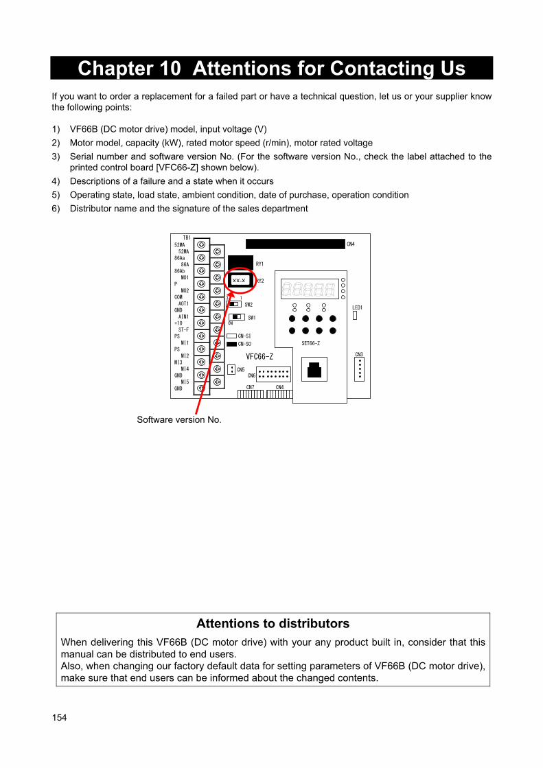
154
Chapter 10 Attentions for Contacting Us If you want to order a replacement for a failed part or have a technical question, let us or your supplier know the following points: 1) VF66B (DC motor drive) model, input voltage (V)
2) Motor model, capacity (kW), rated motor speed (r/min), motor rated voltage
3) Serial number and software version No. (For the software version No., check the label attached to the printed control board [VFC66-Z] shown below).
4) Descriptions of a failure and a state when it occurs
5) Operating state, load state, ambient condition, date of purchase, operation condition
6) Distributor name and the signature of the sales department
TB1
CN-SO
CN-SI
RY1
CN3
SW2
SW1
CN4
LED1
52MA
86Aa
86Ab
P
COM
GND
+10
PS
PS
MI3
GND
GND
52MA
86A
MO1
MO2
AOT1
AIN1
ST-F
MI1
MI2
MI4
MI5
CN5
3 1
ON
RY2
CN6
SET66-Z
CN7 CN4
VFC66-Z
Attentions to distributors
When delivering this VF66B (DC motor drive) with your any product built in, consider that this manual can be distributed to end users. Also, when changing our factory default data for setting parameters of VF66B (DC motor drive), make sure that end users can be informed about the changed contents.
XX-X
Software version No.
155
Chapter 11 Industrial Product Warranty 11.1. No-charge warranty period The free of charge warranty period shall be "less than 1 year after installation in your company or your customers" or "less than 18 months after shipment from the factory or storage warehouse," whichever comes first. In the case of repair, overhaul or other maintenance by Toyo Denki or a company designated by Toyo Denki, the warranty period for the parts concerned shall be for one year from the date of acceptance inspection. 11.2. Warranty Scope 11.2.1. Problem diagnosis
As a general rule, initial diagnosis in the event of product failure should be performed by your company. However, if you request initial problem diagnosis, it can be performed on your behalf by Toyo Denki or a member of our service network. Please note that if Toyo Denki is not responsible for the cause of the failure, a fee will be charged for the initial diagnosis. 11.2.2. Repair
Repair, part replacement, and onsite repair shall be provided free of charge. However, this shall not apply in the following cases: 1. When the problem is a result of improper product handling, conditions, environment, usage method, etc.,
by you or your customer.
2. When the problem was caused by a system designed by you or your customer.
3. When the problem was caused by deficiencies in a program created by you or your customer.
4. When the problem originated in something other than the delivered product.
5. When the problem was caused by modification performed without the prior approval of Toyo Denki.
6. When the problem was caused by repair or modification performed by someone other than Toyo Denki or a company designated by Toyo Denki.
7. When the problem was caused by a force majeure such as a natural disaster, fire, or accident.
8. Other cases where Toyo Denki is not responsible for the cause of the problem.
9. The no-charge warranty period has expired. 11.3. Disclaimer Irrespective of whether the no-charge warranty period is in effect, this warranty shall not compensate you or yourcustomer for any damages that are not the responsibility of Toyo Denki, or for any lost opportunity, lost profit, secondary damages, or accident due to the failure of the Toyo Denki product concerned. Moreover, compensation shall not be provided relating to articles other than the Toyo Denki product concerned. 11.4. Repair period after product discontinuation Once the product has gone out of production, Toyo Denki will continue to provide repair service for the product for a period of seven years. However, please note that the procurement of electronic components for the product may become difficult during that time, and repair may not be possible.
156
11.5. Delivery conditions In the case of standard products ordered without test operation and adjustment, delivery shall take place upon product arrival at your company, and Toyo Denki shall not be responsible for onsite test operation and adjustments. All Rights The copyright of this manual belongs to Toyo Denki. Duplicating all or part of contents of this manual without obtaining permission from the right holder is prohibited under the Copyright Act. All rights of company names and product names described in this manual belong to their respective owners.

https://www.toyodenki.co.jp/en/ HEAD OFFICE: Tokyo Tatemono Yaesu Bldg, 1-4-16 Yaesu, Chuo-ku, Tokyo, Japan ZIP CODE 103-0028 TEL: +81-3-5202-8132 - 6 FAX: +81-3-5202-8150
In addition, the contents of this the "operation manual" may be changed without a preliminary announcement by specification
change of a product etc. Please understand that it may differ from the contents of the "operation manual" enclosed by the
model of purchase, and the contents of the "operation manual" posted on our homepage.
Please have a look from our homepage about the newest "operation manual".
Contents of this manual are subject to change without notice.
TIM078[A]_20180717