Embed Size (px)
Citation preview
Verifying Industrial Hybrid Systems
with MathSAT 1
Gilles Audemarda, Marco Bozzanob, Alessandro Cimattib andRoberto Sebastianic,2
a Centre de Recherche en Informatique de LensIUT de Lens, Rue de l’universite, SP16, F 62307 Lens Cedex
b ITC-IRST,Via Sommarive 18, 38050 Povo, Trento, Italy{bozzano,cimatti}@itc.it
c DIT, Universita di Trento, Via Sommarive 14, 38050 Povo, Trento, [email protected]
Abstract
Industrial systems of practical relevance can be often characterized in terms of discrete controlvariables and real-valued physical variables, and can therefore be modeled as hybrid automata.Unfortunately, continuity of the physical behaviour over time, or triangular constraints, must oftenbe assumed, which yield an undecidable class of hybrid automata.In this paper, we propose a technique for bounded reachability of linear hybrid automata, basedon the reduction of a bounded reachability problem to a MathSAT problem, i.e. satisfiabilityof a boolean combination of propositional variables and mathematical constraints. The MathSATsolver can be used to check the existence (or absence) of paths of bounded length.The approach is very similar in spirit to SAT-based bounded model checking; furthermore, theability to reason directly about real variables gives computational leverage over discretization-based methods. Despite the undecidability of the general problem, the proposed method is able toprovide valuable information on large designs of practical relevance.
Keywords: Formal Verification, Hybrid Systems, SAT
1 This work has been sponsored by the CALCULEMUS! IHP-RTN EC project, contractcode HPRN-CT-2000-00102, and has thus benefited of the financial contribution of theCommission through the IHP programme. It has also been partly supported by ESACS,an European sponsored project, contract no. G4RD-CT-2000-00361, and by a grant fromIntel Corporation.2 Sponsored by a MIUR COFIN02 project, code 2002097822 003.
Electronic Notes in Theoretical Computer Science 119 (2005) 17–32
1571-0661/$ – see front matter © 2005 Elsevier B.V. All rights reserved.
www.elsevier.com/locate/entcs
doi:10.1016/j.entcs.2004.12.022
1 Introduction
Many systems and plants of industrial relevance (e.g., engines, turbines) aredefined in terms of discrete control variables and physical real-valued variables(e.g., speed, pressure), and can be naturally modeled as hybrid automata: de-pending on a discrete state (e.g., “nominal”, “increasing”), different equationsdescribe the behaviour of the physical variable (e.g., speed). Frequently, thedynamics of physical variables is continuous: i.e., transitions from a discretestate to another should not necessarily yield a discontinuity in the physicaldimension. For instance, in the transition from “increasing” to “decreasing”,the velocity should not change its value (but only its derivative). Furthermore,the evolution can depend on the comparison between the values of physicalvariables. Unfortunately, either imposing continuity or allowing for compar-isons between variables (also known as triangular constraints) result in a classof hybrid automata where even reachability is undecidable [12]. Yet, it is veryimportant to be able to develop tools that allow to formally validate suchdesigns, that often implement critical functionalities (e.g., control systems foravionics).
In this paper, we address the problem of verifying hybrid automata withcontinuous variables and triangular constraints. We propose a formal verifica-tion method for bounded reachability. The approach is based on the encodingof a bounded reachability problem into a MathSAT problem, i.e. the problemof checking the satisfiability of a boolean combination of propositional vari-ables and mathematical constraints over real variables. The approach is madepractical by the use of the efficient MathSAT solver [1], that extends and inte-grates state-of-the-art techniques for propositional satisfiability (SAT) with aset of mathematical reasoners. The approach presented in this paper is largelysimilar to bounded model checking [4], and enhances the method presentedin [3], limited to timed systems, to dealing with real variables with arbitrarylinear dynamics.
The proposed technique is clearly incomplete, and currently limited to thecase of linear dynamics. Despite these facts, however, it allows us to representand to analyze interesting systems from real-world applications [6,5], providinguseful information, especially oriented to debugging and goal-directed simula-tion. An experimental analysis shows that our techniques is competitive withstate of the art verification tools such as HyTech, and with methods based onthe discretization of real variables.
G. Audemard et al. / Electronic Notes in Theoretical Computer Science 119 (2005) 17–3218

VALVE
Computer
Computer
GBX MEPTO
ATSM
UTIL
GBX MEPTO
ATSM
UTIL
GBX: GearboxME: Main EnginePTO: Power Take Off ShaftUTIL: Utilities
ATSM: Air Turbine Starter Motor
Fig. 1. SPS schematic view
Outline of the paper
The rest of the paper is structured as follows. In Section 2 we illustratea motivating example for our approach; in Section 3 we give a short andinformal introduction to our model of hybrid systems; in Section 4 we give abrief overview of SAT-based bounded model checking and we discuss in moredetail our encoding of hybrid systems into MathSAT; in Section 5 we discusssome experiments, and finally in Section 6 and 7 we discuss related work anddraw some conclusions.
2 A Motivating Example: The Secondary Power Sys-tem
Throughout the paper, we use a running example to motivate and illustrate themain concepts we present. Specifically, we discuss the modeling and analysis ofa real-world safety-critical system, namely the Secondary Power System (SPS).It is an industrial case study which has been and is being investigated withinESACS (Enhanced Safety Analysis for Complex Systems), a European-Union-sponsored project in the avionics sector, whose goal is to define a methodologyto improve the safety analysis practice for complex systems development [6,5].
The SPS drives the hydraulic and electrical utilities of an aircraft. It is anexample of safety-critical system with embedded hardware and software com-ponents. The hardware subsystems comprise (electro)-mechanical components(e.g., control valves, relays, shafts, gearboxes, freewheels) and electronic trans-ducers (e.g., speed and pressure sensors), whereas the software component isgiven by embedded controllers (SPS computers).
G. Audemard et al. / Electronic Notes in Theoretical Computer Science 119 (2005) 17–32 19
�
�
�
�
�
�
�
�
�
�
�
��
�
�
�
�
�
�
�
��������
grippage
flameout
sp me’=
sp me’=
sp me≥ sm1sp me≤ sm2
sp me-k1(∆t)
sp me-k2(∆t)
sp me≥ sm3sp me≤ sm2
sp me= sm3
sp me≤ sm2
sp me≥ sm4
sp me= sm4sp me= sm4
speed sm4
speed sm3
sp me= sm3
no fail
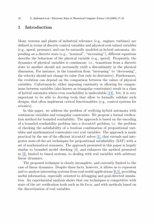
Fig. 2. SPS: main engine automaton (ME)
The SPS drives the utilities of both the left and right hand side of theaircraft. To ensure the basic safety requirement, i.e. no single failures shallcause the total loss of the SPS utilities, the architecture of the system includestwo basic redundancies: there are two independent and perfectly symmetriclines, whose purpose is to drive the left and the right hand side utilities,respectively; for each side, the mechanical drive of the relevant utilities (normalmode) is redounded by a pneumatic drive (cross-bleed mode) in case of failureof one of the components in the mechanical line.
Figure 1 shows a simplified schematic view of the SPS. The SPS normaloperation consists in transmitting the mechanical power from the engines tothe relevant hydraulic and electrical generators. Specifically, the mechanicalpower of the main engine (ME) is transmitted via the Power Take Off Shaft(PTO) to a gearbox (GBX) which feeds the utilities. A component may faildue to abnormal operational conditions or ruptures. As an example, flame-out and grippage are two possible failure modes of the main engine. To ensuresafety of in-flight operation, in case of an engine failure the SPS computers au-tomatically initiate a cross-bleed procedure consisting in driving the hydraulicand electrical generators by means of an air turbine motor (ATSM), usingbled air from a valve (VALVE), which is in turn fed by the mechanical powercoming from the opposite engine. Correct functioning of the cross-bleed pro-cedure is an example of one safety requirement of the SPS. Some experimentalresults about this will be presented in Section 5.
3 Modeling Hybrid Automata
In this section we briefly present and exemplify our model of hybrid systems.The model is inspired by the linear and rectangular hybrid automata modelspresented in [10,11]. Informally, a hybrid system can be seen as the parallel
G. Audemard et al. / Electronic Notes in Theoretical Computer Science 119 (2005) 17–3220
�
�
�
�
�
�
�
��
�
�
�
�
�
�
�
open?
close?opened closed
stuck open stuck closed
p valve=0
p valve=0
p valve≥ p1p valve≤ p2
p valve≥ p1
p valve≤ p2
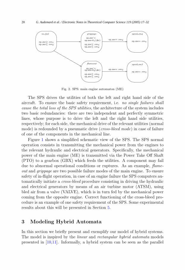
Fig. 3. SPS: valve automaton (VALVE)
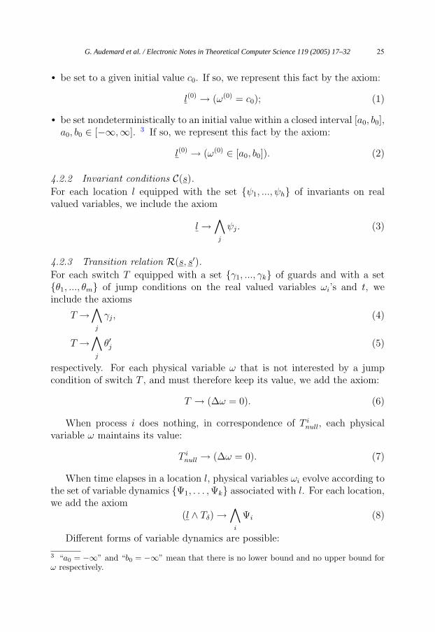
composition of a collection of hybrid automata, which can communicate ei-ther by explicit synchronization on some channel, or implicitly by means ofshared variables. Each automaton models both discrete events (e.g., failure ofa component) and continuous activities of analog variables (e.g., time, com-ponent speed). At any given instant of time, the state of a hybrid automatonis defined by a control location (discrete state) and the values of all the ana-log variables (continuous state). The state can change either because of aninstantaneous discrete transition, which changes the control location and mayalso affect the values of the analog variables (e.g., re-initialization is possible)or because of a time elapse (continuous) transition, which changes only thevalues of the analog variables according to some specified law. Hybrid systemscan be seen as an extension of the timed systems model of [3], in which theonly analog variables are clocks. In the following, by elementary linear ex-pression we mean an equality and/or (non-strict) inequality over linear terms(i.e., linear combinations of real-valued variables with rational coefficients).
Figure 2 and 3 depict two examples of hybrid automata, modeling themain engine (ME) and the valve (VALVE) components of the SPS. A hybridautomaton consists of the following components:
Locations A finite set of locations, encoding the discrete states of the hybridautomaton. The automaton in Figure 2 has five locations, drawn as circles,which model the discrete state of the ME of the SPS. Location no fail mod-els the default behaviour of the engine; locations grippage and flameoutmodel two different faulty states; locations speed sm4 and speed sm3 modelstates in which the speed of the engine has the constant value sm4 and sm3.
Analog Variables A finite vector of real-valued data variables (w1, . . . , wn).The sp me variable in Figure 2 encodes the speed of the ME. Clock variablesof [3] may be seen as a particular case of real-valued variables. Primed
G. Audemard et al. / Electronic Notes in Theoretical Computer Science 119 (2005) 17–32 21
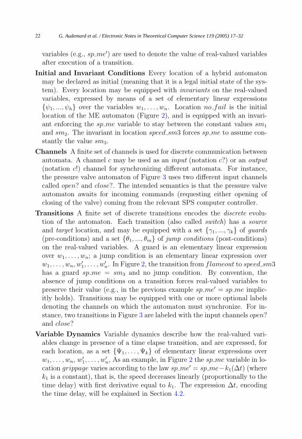
variables (e.g., sp me′) are used to denote the value of real-valued variablesafter execution of a transition.
Initial and Invariant Conditions Every location of a hybrid automatonmay be declared as initial (meaning that it is a legal initial state of the sys-tem). Every location may be equipped with invariants on the real-valuedvariables, expressed by means of a set of elementary linear expressions{ψ1, ..., ψh} over the variables w1, . . . , wn. Location no fail is the initiallocation of the ME automaton (Figure 2), and is equipped with an invari-ant enforcing the sp me variable to stay between the constant values sm1
and sm2. The invariant in location speed sm3 forces sp me to assume con-stantly the value sm3.
Channels A finite set of channels is used for discrete communication betweenautomata. A channel c may be used as an input (notation c?) or an output(notation c!) channel for synchronizing different automata. For instance,the pressure valve automaton of Figure 3 uses two different input channelscalled open? and close?. The intended semantics is that the pressure valveautomaton awaits for incoming commands (requesting either opening ofclosing of the valve) coming from the relevant SPS computer controller.
Transitions A finite set of discrete transitions encodes the discrete evolu-tion of the automaton. Each transition (also called switch) has a sourceand target location, and may be equipped with a set {γ1, ..., γk} of guards(pre-conditions) and a set {θ1, ..., θm} of jump conditions (post-conditions)on the real-valued variables. A guard is an elementary linear expressionover w1, . . . , wn; a jump condition is an elementary linear expression overw1, . . . , wn, w′
1, . . . , w′n. In Figure 2, the transition from flameout to speed sm3
has a guard sp me = sm3 and no jump condition. By convention, theabsence of jump conditions on a transition forces real-valued variables topreserve their value (e.g., in the previous example sp me′ = sp me implic-itly holds). Transitions may be equipped with one or more optional labelsdenoting the channels on which the automaton must synchronize. For in-stance, two transitions in Figure 3 are labeled with the input channels open?and close?
Variable Dynamics Variable dynamics describe how the real-valued vari-ables change in presence of a time elapse transition, and are expressed, foreach location, as a set {Ψ1, . . . , Ψk} of elementary linear expressions overw1, . . . , wn, w′
1, . . . , w′n, As an example, in Figure 2 the sp me variable in lo-
cation grippage varies according to the law sp me′ = sp me−k1(∆t) (wherek1 is a constant), that is, the speed decreases linearly (proportionally to thetime delay) with first derivative equal to k1. The expression ∆t, encodingthe time delay, will be explained in Section 4.2.
G. Audemard et al. / Electronic Notes in Theoretical Computer Science 119 (2005) 17–3222

The hybrid automata presented here do not fall into the rectangular automataclass described in [10], since re-initialization of variables is not enforced, andtriangular constraints are possible. As a consequence, even the problem ofreachability for this class of automata is undecidable [12].
4 Bounded Model Checking for Hybrid Systems
In this section we give a very short overview of SAT based model checking, andwe discuss the encoding of our model of hybrid systems, informally describedin Section 3, into MathSAT.
4.1 SAT Based Bounded Model Checking
Bounded Model Checking (BMC) is a recent approach to symbolic modelchecking [4]. Given a Kripke structure M , and an LTL formula f , the ideais to check whether f is true in M by looking for a counterexample (i.e., awitness to the violation of f) that can be presented within a bound of k steps.Given k, the problem is reduced to the satisfiability of a propositional formula[[M,¬f ]]k. For instance, for a property of the form f := Gp(s), where p(s) isa boolean formula in the boolean variables s, then
[[M,¬f ]]k = I(s(0)) ∧k∧
i=0
C(s(i)) ∧k−1∧
i=0
R(s(i), s(i+1)) ∧k∨
i=0
¬p(s(i)),
where I(s(0)) is a representation of the initial conditions, C(s(i)) is a representa-tion of the invariant conditions at step i, and R(s(i), s(i+1)) is a representationof the transition relation from step i to step i + 1. If [[M,¬f ]]k is satisfiable,the propositional model provides a counterexaple of k steps to f . If [[M,¬f ]]kis unsatisfiable, then nothing can be said about the existence of counterexam-ples to M |= f with higher bound. The typical technique is to generate andsolve [[M,¬f ]]k for increasing values of k, until either a counter-example isfound, or a given time-out is reached.
BMC is being increasingly accepted as practical technique, effective inparticular in the process of falsification, i.e. bug finding. The technique relieson the use of efficient SAT solvers (e.g., based on DPLL procedures [8]) forchecking the propositional satisfiability of [[M,¬f ]]k. As shown in [7], BMCavoids the blow-up in memory that can occur with model checking based onBinary Decision Diagrams, and is therefore able to tackle much larger circuits.
G. Audemard et al. / Electronic Notes in Theoretical Computer Science 119 (2005) 17–32 23

4.2 The encoding
Our approach to the verification of hybrid automata is a generalization ofBMC for timed systems, as proposed in [3]. The approach reduces a BMCproblem for timed systems to the problem of deciding the satisfiability ofmath-formulas, i.e. boolean combinations of boolean variables and linear(in)equalities over real variables, representing absolute time and clocks. Theresulting math-formulas are tackled with MathSAT [2,1], a solver combiningan efficient DPLL procedure with mathematical constraint solvers of increasingdeductive power.
In the encoding for timed automata, boolean variables are used to encodethe discrete part of the system, while linear constraints on real variables en-code the timed part. In particular, each location l is represented by a bitwiseencoding l, so that li holds if and only if the system is in the location li;each synchronization event (channel, shared variable) is represented by a cor-responding boolean variables; each switch is represented by a single booleanvariable (say, T ) which holds if and only if the system executes the correspond-ing switch; a boolean variable Tδ, representing a continuous transition, holdsif and only if time elapses by some δ > 0; finally, for each process Pi, we intro-duce a boolean variable T i
null, that holds if and only if process Pi does nothing.In order to deal with time, we introduce a real valued variable t representingabsolute time, and, for each clock x, a real valued variable ox representingthe difference with respect to absolute time. All mathematical constraintsrequired in the encoding are in the form v1 − v2 �� c, ��∈ {≤,≥, =, >, <} v1
and v2 being real variables representing either absolute time or clock values.The reader can refer to [3] for details.
We tackle the case of hybrid automata by considering that it is an extensionof the case of timed automata. The encoding for the timed case is extendedby introducing a set of real variables ωi’s, representing physical entities. Tosimplify the notation, in the following we write: “∆t” for the difference t′ − tbetween absolute time in the next and in the current state; “∆ω” for “ω′−ω”,so that, e.g., we write “c · ∆t...” for “c · t′ − c · t...”; “∆ω = 0” for “ω′ = ω”,“∆ω ≤ ...” for “ω′ ≤ ω + ...”. We also write “(w ∈ [t1, t2])” for “(w ≥t1)∧ (w ≤ t2)”, where t1 and t2 are linear terms. If ψ is a formula, ψ′ denotesthe formula obtained by substituting in ψ each propositional variable pj withp′j, and each real variable vi with v′
i.
4.2.1 Initial conditions I(s(0)).
At step 0, in an initial location l, ω can either:
G. Audemard et al. / Electronic Notes in Theoretical Computer Science 119 (2005) 17–3224
• be set to a given initial value c0. If so, we represent this fact by the axiom:
l(0) → (ω(0) = c0); (1)
• be set nondeterministically to an initial value within a closed interval [a0, b0],a0, b0 ∈ [−∞,∞]. 3 If so, we represent this fact by the axiom:
l(0) → (ω(0) ∈ [a0, b0]). (2)
4.2.2 Invariant conditions C(s).
For each location l equipped with the set {ψ1, ..., ψh} of invariants on realvalued variables, we include the axiom
l →∧
j
ψj. (3)
4.2.3 Transition relation R(s, s′).For each switch T equipped with a set {γ1, ..., γk} of guards and with a set{θ1, ..., θm} of jump conditions on the real valued variables ωi’s and t, weinclude the axioms
T →∧
j
γj, (4)
T →∧
j
θ′j (5)
respectively. For each physical variable ω that is not interested by a jumpcondition of switch T , and must therefore keep its value, we add the axiom:
T → (∆ω = 0). (6)
When process i does nothing, in correspondence of T inull, each physical
variable ω maintains its value:
T inull → (∆ω = 0). (7)
When time elapses in a location l, physical variables ωi evolve according tothe set of variable dynamics {Ψ1, . . . , Ψk} associated with l. For each location,we add the axiom
(l ∧ Tδ) →∧
i
Ψi (8)
Different forms of variable dynamics are possible:
3 “a0 = −∞” and “b0 = −∞” mean that there is no lower bound and no upper bound forω respectively.
G. Audemard et al. / Electronic Notes in Theoretical Computer Science 119 (2005) 17–32 25
• ω maintains its value under a dynamic of the form:
(l ∧ Tδ) → (∆ω = 0); (9)
• ω may evolve deterministically according to a linear function:
(l ∧ Tδ) → (∆ω = c · ∆t) (10)
c being a constant.
• ω may evolve nondeterministically within two linear functions:
ω′ ∈ [b1ω + c1 · ∆t − a1, b2ω + c2 · ∆t + a2], (11)
a1, a2 ≥ 0, b1, b2 ∈ {0, 1}, c1, c2 ∈ (−∞,∞). (12)
If a1 = a2 = 0, then (11) encodes a triangular constraint. If b1 = b2 = 0and c1 = c2 = 0, then (11) encodes a rectangular constraint.
• in the general case, the evolution of the variables can be nondeterministicwithin the space described by the linear inequalities {Ψ1, . . . , Ψk}, as inequation 8.
The encoding of properties basically follows the encoding in [3]. Our ap-proach is bounded complete, in the following sense: if there exists a trace oflength k, then the encoding of length k is satisfiable, and can be found byrunning MathSAT on it. The undecidability of the class of hybrid automatawe are dealing with tells us that it is in general impossible to decide if acounterexample might be found with bigger k, or if the problem is unsolvable.
5 Experimental Evaluation
We evaluated the potential of the approach by tackling an example of hybridsystems of industrial relevance, i.e. the model of the SPS. The bounded reach-ability method described in Section 4 can be used both for model debugging(i.e., bug hunting) and for simulation of hybrid systems. In the following weprovide some hints about the use of our methodology by showing some experi-mental results. For illustration purposes, we will discuss a simplified one-sidedmodel of the SPS case study, including one instance of the ME, GBX, VALVE,ATSM, PTO and SPS computer components of Figure 1. Under this abstrac-tion, the analogous components of the opposite side of the system are assumedto be correctly working. An example of property to be checked is given by(the negation of) the following formula:
(! GBX.loc broken & ! GBX.loc grippage & ! VALVE.loc stuck closed &
! ATSM.loc broken & ! PTO.loc fused) U GBX.sp gbx <= sg1 (P1)
This is a typical safety property expressed via the LTL until operator.The intended semantics is whether there exists a path such that no failures of
G. Audemard et al. / Electronic Notes in Theoretical Computer Science 119 (2005) 17–3226

Time T0 :
Locations : no fail, gbx pto driven, atsm idle, sps ok, closedAnalog Variables : sp me = sm2, sp gbx = sg2, sp atsm = 0Discrete Trans : me grippageSynchronizations : none
Time T1 :
Locations : grippage, gbx pto driven, atsm idle, sps ok, closedAnalog Variables : sp me = sm5, sp gbx = sg3, sp atsm = 0Discrete Trans : atsm inc a, sps inc a, valve openSynchronizations : SPS and ATSM on inc a, SPS and VALVE on open
Time T2 :
Locations : grippage, gbx pto driven, atsm inc a, sps inc a, openAnalog Variables : sp me = sm6, sp gbx = sg4, sp atsm = sa2
Discrete Trans : atsm inc a inc b, sps inc a inc bSynchronizations : SPS and ATSM on inc b
Time T3 :
Locations : grippage, gbx pto driven, atsm inc b, sps inc b, openAnalog Variables : sp me = sm7, sp gbx = sg1, sp atsm = sa3
Fig. 4. An example of MathSAT trace
the GBX, VALVE, ATSM and PTO components happen along the path, andfinally the speed of the gearbox (GBX component) drops below the constantvalue sg1. The negation of the above property can be seen as a safety propertyto be verified by the system (i.e., in presence of failures due only to the mainengine, the gearbox speed cannot drop below sg1). The rationale behind thisproperty is that the cross-bleed procedure initiated by the SPS computer (seeSection 2) is able to recover from an engine failure by using power comingfrom the opposite engine (which is assumed to be working in this one-sidedmodel).
The property may or may not hold depending on the value chosen for theconstant sg1. In particular, if the value chosen for sg1 exceeds a given thresh-old, the property is falsified by MathSAT (this means that the cross-bleedprocedure is not able to prevent the gearbox speed to drop below that par-ticular value). In this case, MathSAT generates an output trace showing anexecution of the system which leads to the violation. The trace includes infor-mation on the discrete transitions and the time elapse transitions taken by theautomata, the exact time delays and time points at which the transitions takeplace, and the synchronization channels between different automata. If thevalue of the constant sg1 is chosen below a suitable threshold, property (P1)holds, and therefore MathSAT correctly does not find any counterexample.Regarding the choice of the constant sg1, see the discussion in Section 7.
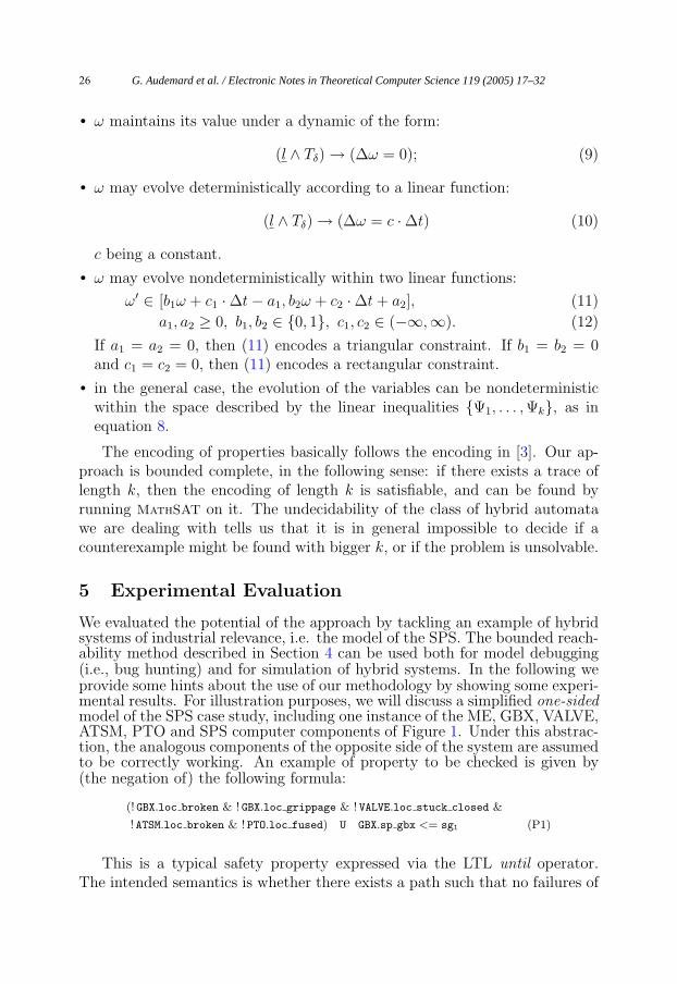
The trace generated by MathSAT is schematically shown in Figure 4.For each time instant, the trace shows the current locations of the ME,GBX, ATSM, and VALVE automata, the current values of the sp me, sp gbx,
G. Audemard et al. / Electronic Notes in Theoretical Computer Science 119 (2005) 17–32 27
�
�
�
�
�
�
�
�
�
�
�
�sps ok
open!
sp gbx-sp atsmsp gbx ≥ sg2
≥ c1
sp gbx - sp atsm ≤ c1sp gbx ≤ sg2
sps inc a sps inc b
inc a! inc b!
Fig. 5. SPS computer automaton (fragment)
sp atsm analog variables, the discrete transitions which take place at that timeinstant, and the synchronizations channels. For a better understanding of thetrace, in Figure 5 we show a simplified version of the SPS computer automaton(only the part relevant to the simulation is shown). Notice that this automatonshows as example of triangular constraint, i.e. sp gbx − sp atsm ≤ c1 [≥ c1],and of communication with shared variables (variables sp gbx and sp atsmmodel, respectively, the speed of the GBX and ATSM components).
The simulation begins at time T0, when an engine grippage takes place.Both the engine and the gearbox speeds begin to decrease. At time T1, theSPS computer detects a gearbox low speed condition, and therefore issues theopening of the valve (the VALVE and SPS computer automata synchronizeon the open channel); as a result, the ATSM begins to increase its speed (SPSand ATSM synchronize on the inc a channel). At time T2, the SPS computerissues a change in the ATSM dynamics (SPS and ATSM synchronize on inc b).The simulation stops at time T3, when the gearbox speed reaches the valuesg1.
The same approach can be used for guided simulation. To give an example,we consider the following formula:
(! ME.loc eng flameout & ! GBX.loc broken & ! GBX.loc grippage &
! VALVE.loc stuck closed & ! ATSM.loc broken & ! PTO.loc fused)
U GBX.sp atsm >= sa1 (P2)
It is a variation of the previous reachability property, here we require thatat the end of the path the speed of the ATSM component is greater than theconstant value sa1. Furthermore, by explicitly ruling out an engine flameout,we limit the possible failure modes of the main engine to grippage. As ex-plained in Section 2, in presence of an engine failure, the ATSM component isresponsible of carrying out the cross-bleed procedure, which consists in driv-ing the gearbox with the pneumatic power coming from the valve. Correctfunctioning of the cross-bleed procedure requires the ATSM (which is initiallyidle) to start and bring up the gearbox speed. Using MathSAT, we are ableto reconstruct a trace corresponding to the above property, which illustrateshow the cross-bleed procedure is carried out. It is possible to tune the abovesimulation and perform further ones by adding further constraints on the traceto look for.
G. Audemard et al. / Electronic Notes in Theoretical Computer Science 119 (2005) 17–3228
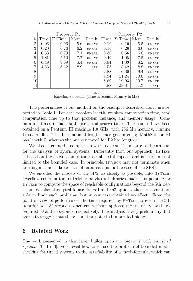
Property P1 Property P2k Time Σ Time Mem. Result Time Σ Time Mem. Result2 0.06 0.06 5.6 UNSAT 0.10 0.10 5.5 UNSAT
3 0.20 0.26 6.2 UNSAT 0.16 0.26 6.0 UNSAT
4 0.53 0.79 7.1 UNSAT 0.30 0.56 6.8 UNSAT
5 1.81 2.60 7.7 UNSAT 0.49 1.05 7.5 UNSAT
6 6.49 9.09 8.4 UNSAT 0.84 1.89 8.2 UNSAT
7 4.53 13.62 8.9 SAT 1.53 3.42 8.8 UNSAT
8 2.88 6.30 9.4 UNSAT
9 4.94 11.24 10.0 UNSAT
10 8.69 19.93 10.7 UNSAT
11 8.88 28.81 11.3 SAT
Table 1Experimental results (Time in seconds, Memory in MB)
The performance of our method on the examples described above are re-ported in Table 1. For each problem length, we show computation time, totalcomputation time up to that problem instance, and memory usage. Com-putation times include both parse and search time. The results have beenobtained on a Pentium III machine 1.0 GHz, with 256 Mb memory, runningLinux Redhat 7.1. The minimal length trace generated by MathSat for P1has length 7, whereas the one generated for P2 has length 11.
We also attempted a comparison with HyTech [11], a state-of-the-art toolfor the analysis of hybrid systems. Differently from our approach, HyTech
is based on the calculation of the reachable state space, and is therefore notlimited to the bounded case. In principle, HyTech may not terminate whentackling an undecidable class of automata (as in the case of the SPS).
We encoded the models of the SPS, as closely as possible, into HyTech.Overflow errors in the underlying polyhedral libraries made it impossible forHyTech to compute the space of reachable configurations beyond the 5th iter-ation. We also attempted to use the -o1 and -o2 options, that are sometimesable to limit such problems, but in our case obtained no effect. From thepoint of view of performance, the time required by HyTech to reach the 5thiteration was 32 seconds, when run without options; the use of -o1 and -o2
required 50 and 86 seconds, respectively. The analysis is very preliminary, butseems to suggest that there is a clear potential in our techniques.
6 Related Work
The work presented in this paper builds upon our previous work on timedsystems [3]. In [3], we showed how to reduce the problem of bounded modelchecking for timed systems to the satisfiability of a math-formula, which can
G. Audemard et al. / Electronic Notes in Theoretical Computer Science 119 (2005) 17–32 29
then be checked by a SAT-solver. We also presented the MathSat solver [2,1],an efficient SAT-solver which is based on the integration of SAT techniques [4]with some specialized decision procedures for linear mathematical constraints.A work related to ours, but still limited to timed systems, is [17]. In the presentwork, as explained in Section 4.2, we have extended the encoding in order todeal with hybrid systems.
Our model for hybrid systems is closely related with the linear and rectan-gular hybrid automata models presented in [10,13], the main difference being inthe definition of the dynamics of the real-valued variables. In [10], the dynam-ics (called flow conditions) of the real-valued variables are defined by meansof linear constraints over the first derivatives of such variables, whereas in ourmodel dynamics can be characterized by means of linear functions of the timedelay, which directly constrain the behaviour of the variables. This approachis analogous to restricting the flows of the real-valued variables to stay insidea rectangular region, as in the rectangular automata model of [10]. In fact, asnoted in [12], under the hypothesis of working with convex linear constraints,requiring the flow to be inside a rectangular region amounts to requiring theexistence of a smooth function inside the corresponding piecewise-linear enve-lope.
The model of hybrid I/O automata presented in [14] is general enoughto accommodate our model of hybrid automata. Discrete and continuouscommunication are achieved by means of, respectively, shared actions andshared variables. However, discrete events are not allowed to change the valueof shared variables, as in our case.
As an alternative approach to the verification of hybrid systems, we cite[15], where the CheckMate tool is presented. CheckMate performs verificationof hybrid systems using finite-state approximations called quotient transitionsystems. Although this approach is not restricted to linear hybrid automata,the verification analysis may be inconclusive, in which case a refinement of thecurrent approximation may be attempted. An analysis of the current trendsin model checking of hybrid systems can be found in [16].
This line of research has been carried on inside the ESACS [6] project(see http://www.esacs.org), an European-Union-sponsored project whosemain goals are to define a methodology and a shared environment to improvethe safety analysis practice for complex systems development. The SecondaryPower System [5] is one of the case-studies investigated in ESACS. One of themain motivations for our research is the realization that the use of traditionalfinite-state model checking, based on the discretization of real variables, has avery hard time in dealing with the complexity of hybrid systems [5]. In fact,the results may depend on the step of discretization, and the state explosion
G. Audemard et al. / Electronic Notes in Theoretical Computer Science 119 (2005) 17–3230
problem makes such an approach infeasible in practice.
7 Conclusions and Future Work
In this paper, we have addressed the problem of verification of industrialsystems that are naturally modeled as linear hybrid automata. The approachis an enhancement of the bounded model checking approach for timed systemsproposed in [3] to the case of linear hybrid automata. Efficiency is gainedby the use of the MathSAT solver. The main limitations are given by theundecidability of the analyzed class, and the constraints on the linearity ofreal variables dynamics. Despite this, however, the approach allows us tomodel and analyze systems of practical relevance, that HyTech is currentlyunable to deal with.
In the future, we will provide a more thorough experimental evaluation,by enlarging both the set of tools we compare with (some of them are citedin Section 6), and the set of case studies to analyze. Regarding the SPS ex-ample, we plan to experiment with more complex models, at different levelsof granularity and abstraction (e.g., a two-sided model of the system). Wewill investigate how to optimize the MathSAT solver on these specific prob-lems (e.g., by constraining the splitting variables in the style of [9,18]), andwill experiment with different encodings. As a first step towards bridgingthe gap between bounded model checking and unbounded verification, induc-tive reasoning techniques to prove invariant properties will be investigated.An important point we plan to address in the near future is concerned withparametric analysis, which is currently supported in HyTech. To exemplify,parametric analysis would allow us to replace the constant value sg1 in prop-erty (P1) (see Section 5) with a parameter α in order to find out constraintson the parameter for which the property does or does not hold. Finally, in thefuture we plan to extend the framework to properties expressed in full LTL.
References
[1] Gilles Audemard, Piergiorgio Bertoli, Alessandro Cimatti, Artur Korni�lowicz, and RobertoSebastiani. A SAT Based Approach for Solving Formulas over Boolean and LinearMathematical Propositions. In Andrei Voronkov, editor, CADE-18: Conference on AutomatedDeduction, volume 2392 of LNAI, pages 195–210, Copenhagen, Denmark, 2002. Springer.
[2] Gilles Audemard, Piergiorgio Bertoli, Alessandro Cimatti, Artur Korni�lowicz, and RobertoSebastiani. Integrating Boolean and Mathematical Solving: Foundations, Basic Algorithmsand Requirements. In Jacques Calmet, Bernard Benhamou, Olga Caprotti, Laurent Henocque,and Volker Sorge, editors, CALCULEMUS-2002: Symposium on the Integration of SymbolicComputation and Mechanized Reasoning, volume 2385 of LNAI, pages 231–245, Marseille,France, 2002. Springer.
G. Audemard et al. / Electronic Notes in Theoretical Computer Science 119 (2005) 17–32 31
[3] Gilles Audemard, Alessandro Cimatti, Artur Korni�lowicz, and Roberto Sebastiani. BoundedModel Checking for Timed Systems. In Doron A. Peled and Moshe Y. Vardi, editors, FORTE2002: Conference on Formal Techniques for Networked and Distributed Systems, volume 2529of LNCS, Houston, Texas, November 2002. Springer.
[4] A. Biere, A. Cimatti, E.M. Clarke, and Y. Zhu. Symbolic Model Checking without BDDs.In R. Cleaveland, editor, Proc. 5th International Conference on Tools and Algorithms forConstruction and Analysis of Systems (TACAS’99), volume 1579 of LNCS, pages 193–207.Springer-Verlag, 1999.
[5] M. Bozzano, A. Cavallo, M. Cifaldi, L. Valacca, and A. Villafiorita. Improving SafetyAssessment of Complex Systems: An industrial case study. In Proc. Formal Methods Europe(FME 2003), volume 2805 of LNCS, pages 208–222, 2003.
[6] M. Bozzano, A. Villafiorita, O. Akerlund, P. Bieber, C. Bougnol, E. Bode, M. Bretschneider,A. Cavallo, C. Castel, M. Cifaldi, A. Cimatti, A. Griffault, C. Kehren, B. Lawrence, A. Ludtke,S. Metge, C. Papadopoulos, R. Passarello, T. Peikenkamp, P. Persson, C. Seguin, L. Trotta,L. Valacca, and G. Zacco. ESACS: An Integrated Methodology for Design and Safety Analysisof Complex Systems. In European Safety and Reliability Conference (ESREL’03), pages 237–245. Balkema Publisher, 2003.
[7] F. Copty, L. Fix, E. Giunchiglia, G. Kamhi, A. Tacchella, and M. Vardi. Benefits of BoundedModel Checking at an Industrial Setting. In Proc. CAV’2001, LNCS. Springer, 2001.
[8] M. Davis, G. Longemann, and D. Loveland. A machine program for theorem proving. Journalof the ACM, 5(7), 1962.
[9] E. Giunchiglia, A. Massarotto, and R. Sebastiani. Act, and the Rest Will Follow: ExploitingDeterminism in Planning as Satisfiability. In Proc. AAAI’98, pages 948–953, 1998.
[10] T.A. Henzinger. The Theory of Hybrid Automata. In Proceedings 11th Annual InternationalSymposium on Logic in Computer Science (LICS’96), pages 278–292, New Brunswick, NewJersey, 1996. IEEE Computer Society Press.
[11] T.A. Henzinger, P.-H. Ho, and H. Wong-Toi. HyTech: A Model Checker for Hybrid Systems.Software Tools for Technology Transfer, 1:110–122, 1997.
[12] T.A. Henzinger, P.W. Kopke, A. Puri, and P. Varaiya. What’s Decidable About HybridAutomata? Journal of Computer and System Sciences, 57:94–124, 1998.
[13] T.A. Henzinger and R. Majumdar. Symbolic Model Checking for Rectangular Hybrid Systems.In S. Graf and M. I. Schwartzbach, editors, Proceedings 6th International Conference on Toolsand Algorithms for Construction and Analysis of Systems (TACAS’00), volume 1785 of LNCS,pages 142–156, Berlin, Germany, 2000. Springer-Verlag.
[14] N. Lynch, R. Segala, and F. Vaandrager. Hybrid I/O Automata. Information andComputation, 2003. To appear.
[15] B.I. Silva, K. Richeson, B.H. Krogh, and A. Chutinan. Modeling and verification of hybriddynamical system using CheckMate. In Proc. ADPM 2000, Automation of mixed processes:Hybrid Dynamic Systems. Shaker Verlag, 2000.
[16] B.I. Silva, O. Stursberg, B.H. Krogh, and S. Engell. An assessment of the Current Status ofAlgorithmic Approaches to the Verification of Hybrid Systems. In Proc. 40th Conference onDecision and Control, 2001.
[17] M. Sorea. Bounded Model Checking for Timed Automata. In Proceedings 3rd Workshop onModels for Time-Critical Systems (MTCS’02), Brno, Czech Republic, 2002.
[18] Ofer Strichman. Tuning SAT checkers for bounded model checking. In Proc. CAV00, volume1855 of LNCS, pages 480–494, Berlin, 2000. Springer.
G. Audemard et al. / Electronic Notes in Theoretical Computer Science 119 (2005) 17–3232


