Embed Size (px)
Citation preview
UTA220/UTA220k Terminal Adapter
User Guide
Motorola ING, Inc. Part No. T0123 A20 Cabot Blvd August 1998Mansfield, MA 02048-1193 © 1998 Motorola
ii
COPYRIGHT
Copyright 1998 by Motorola, Inc.
Published by Motorola, who reserves the right to make improvements in the productsdescribed in this manual as well as to revise this publication at any time and without noticeto any person of such revision or change.
All rights reserved. No part of this publication may be reproduced, transcribed, stored inan electronic retrieval system, translated into any language or computer language, or betransmitted in any form whatsoever without the prior written consent of the publisher. Foradditional information contact
Motorola20 Cabot Blvd.Mansfield, MA 02048(508) 261-4000
NOTICE
All titles, versions, trademarks, claims of compatibility, etc., of hardware and softwareproducts mentioned herein are the sole property and responsibility of the respective vendors.Motorola makes no endorsement of any particular product for any purpose, nor claimsresponsibility for its operation and accuracy.
UPDATES
Updates to the products and the manual are obtainable at participating Motorola dealers anddistributors, or directly from Motorola on the same terms and conditions as those offeredby Motorola to its registered customers as verified by the completion and return of theregistration form to Motorola.
STATEMENT OF APPLICATION
This manual is written for users of the Motorola UTA220/UTA220k terminal adapter.Please read the appropriate chapters before installing, changing any option, or operating theunit.
FCC REQUIREMENTS
WARNINGThis equipment uses, generates, and can radiate radiofrequency energy interfering with radio communicationsif not installed and used according to the instructionmanual. It has been tested and complies with the limits fora Class A computing device according to FCC Rules, Part15. Operation of this equipment in a residential area maycause interference. If it does, you must correct the causeof the interference.
Changes or modifications to this unit not expresslyapproved by the party responsible for compliance couldvoid the user’s authority to operate this equipment.
SHIELDED CABLESShielded DTE cables should be used with this unit toensure compliance with Class A limits.
SPECIAL REQUIREMENTS FOR CANADA
Certain requirements exist for data communication products manufactured for use inCanada. Principle among these requirements is the application of the IC stamp as describedbelow. However, certain data communication products do not require the IC stamp noradherence to IC requirements. If this is the case the IC stamp will not be affixed to the rearpanel of standalone units nor packaged with units designed for insertion in user equipment.
Industry Canada (IC) Requirements
IC stamps are affixed to the rear of each standalone unit sold in Canada. Card units whichare installed in the user’s equipment are shipped with a stamp included. The user shouldplace the stamp on the outside of his equipment as close as possible to the telephone lineconnector. This stamp has the certification number for that particular unit. The numbersare different for each model.
The Industry Canada label identifies certified equipment. This certification means that theequipment meets certain telecommunications network protective, operational, and safetyrequirements. IC does not guarantee the equipment will operate to the user’s satisfaction.
Before installing this equipment, users should ensure that it is permissible to be connectedto the facilities of the local telecommunications company. The equipment must also beinstalled using an acceptable method of connection. In some cases, the company’s insidewiring associated with a single line individual service may be extended by means of acertified connector assembly (telephone extension cord). The customer should be awarethat compliance with the above conditions may not prevent degradation of service in somesituations.
iii
limitest sur le
Repairs to certified equipment should be made by an authorized Canadian maintenancefacility designated by the supplier. Any repairs or alterations made by the user to thisequipment, or equipment malfunctions, may give the telecommunications company causeto request the user to disconnect the equipment. For their own protection users should ensurethat the electrical ground connections of the power utility, telephone lines and internalmetallic water pipe system, if present, are connected together. This precaution may beparticularly important in rural areas.
CAUTIONUsers should not attempt to make installation connectionsthemselves, but should contact the appropriate electricinspection authority or electrician.
Load Number
The Load Number (LN) assigned to each terminal device denotes the percentage of the totalload to be connected to a telephone loop which is used by the device, to prevent overloading.The termination on a loop may consist of any combination of devices subject only to therequirement that the total of the Load Numbers of all the devices does not exceed 100.
Canadian Emission Requirements
This digital apparatus does not exceed the Class A limits for radio noise emissions fromdigital apparatus set out in the Radio Interference Regulations of the Industry Canada (IC).
Le présent appareil numérique n'emet pas de bruits radioélectriques dépassant lesapplicables aux appareils numériques de la class A prescriptes dans le Règlemenbrouillage radioélectrique édicté par Industrie et Canada.
iv

Preface
PREFACE AND STATEMENT OF APPLICATION
This manual is written for users of the UDS UTA220/UTA220k terminal adapter. Please read the appropriate chapters before installing, changing any option, or operating the unit.
v

Preface
vi
Contents
Motorola Information Systems Group Customer Information
Chapter 1. Introduction
FEATURES .............................................................................................................. 1-1Compatibility ....................................................................................................... 1-1Other Features ...................................................................................................... 1-1
OPERATION ............................................................................................................ 1-2PHYSICAL DESCRIPTION .................................................................................... 1-2
LED Description .................................................................................................. 1-4FUNCTIONAL ........................................................................................................ 1-4
Chapter 2. Installation
RECEIPT INSPECTION .......................................................................................... 2-1SITE PREPARATION .............................................................................................. 2-1INSTALLATION ...................................................................................................... 2-2
Power Connection ................................................................................................ 2-2ISDN Connection ................................................................................................ 2-2
DTE Connection ....................................................................................................... 2-3DTE INTERFACE SPECIFICATIONS ................................................................... 2-3
Chapter 3. Getting Started
SWITCHES AND STRAPS ..................................................................................... 3-1Cover Removal .................................................................................................... 3-1
SWITCH AND STRAP SETTINGS......................................................................... 3-2Signal Ground ...................................................................................................... 3-2V.35/EIA-232 Interface ....................................................................................... 3-3 Interface Card Removal ...................................................................................... 3-4DIP Switch Options ............................................................................................. 3-5
CENTRAL OFFICE SWITCH ................................................................................ 3-6SETUP....................................................................................................................... 3-6
Chapter 4. ISDN
ISDN BASICS .......................................................................................................... 4-1ISDN Standards .................................................................................................... 4-1National ISDN...................................................................................................... 4-1Basic Rate Interface ............................................................................................. 4-2Terminal Adapters ............................................................................................... 4-2ISDN Basic Rate Interface Points ........................................................................ 4-2ISDN Service ....................................................................................................... 4-3ISDN SWITCHES ............................................................................................... 4-3ISDN ADDRESSES AND IDENTIFIERS ......................................................... 4-5ISDN CHANNELS ............................................................................................. 4-6B-Channel Data Service ...................................................................................... 4-6B-Channel Data Protocols .................................................................................... 4-7D-Channel Signaling Protocols ........................................................................... 4-7Layer One ............................................................................................................. 4-7Layer Two............................................................................................................. 4-8Layer Three ......................................................................................................... 4-8
vii
Contents (continued)
Chapter 5. LCD Operation
LCD MENUS ........................................................................................................... 5-1Main Menus ......................................................................................................... 5-1Submenus ............................................................................................................ 5-1
LCD OPERATION ................................................................................................... 5-1Menu Traversal..................................................................................................... 5-1
Chapter 6. V.25 bis Dialer Operation
SELECTING V.25bis .......................................................................................... 6-1OPERATION IN V.25 bis MODE............................................................................. 6-1V.25 bis MESSAGE FRAMES ................................................................................. 6-1DTE INTERFACE PINS .......................................................................................... 6-2
DTR Pin Operation............................................................................................... 6-2DCD Pin Operation ............................................................................................. 6-2CTS Pin Operation .............................................................................................. 6-3DSR Pin Operation .............................................................................................. 6-3
COMMAND PROCEDURES .................................................................................. 6-3COMMANDS ........................................................................................................... 6-3
Dial Command: CRN xx..x ................................................................................ 6-3Connect Incoming Calls: CIC ............................................................................. 6-4
INDICATION MESSAGES ..................................................................................... 6-4Call Connect Indication: CNX ............................................................................ 6-4Incoming Call Indication: INC ............................................................................ 6-5Response Messages ............................................................................................. 6-5
Chapter 7. EIA-366 Dialer Operation
CONFIGURATION ................................................................................................. 7-1OPERATION ............................................................................................................ 7-1INTERFACE SIGNAL DEFINITIONS ................................................................... 7-2
Power Indication (PWI) ....................................................................................... 7-2Call Request (CRQ) ............................................................................................. 7-2Data Line Occupied (DLO) ................................................................................. 7-2Distant Station Connected (DSC)......................................................................... 7-2Digit Signal Circuits (NB1-NB8)......................................................................... 7-2Digit Present (DPR).............................................................................................. 7-3Present Next Digit (PND) .................................................................................... 7-3Abandon Call and Retry (ACR) .......................................................................... 7-4
EXAMPLE DIAL SEQUENCE................................................................................ 7-4
Chapter 8. AT Command Operation
AT COMMAND STATEMENT ............................................................................... 8-1AT Command Mode ............................................................................................. 8-1ESCAPE SEQUENCE: + + + ............................................................................. 8-1CREATING A COMMAND STATEMENT: AT ................................................. 8-2COMMAND STATEMENT GUIDELINES ....................................................... 8-2MONITOR DISPLAY.......................................................................................... 8-2DTE CHARACTER ECHO: E ............................................................................ 8-2COMMAND STATEMENT BUFFER ................................................................ 8-2
viii
Contents (continued)
Chapter 8. AT Command Operation (Continued)
BACKSPACE KEY .................................................................................................. 8-3REPEATING A COMMAND: A/ ....................................................................... 8-3
NUMBERED COMMANDS ................................................................................... 8-3GROUP COMMANDS ....................................................................................... 8-3COMMAND SCOPE ........................................................................................... 8-4Supervisor Command Mode ................................................................................ 8-4
Chapter 9. Rate Adaption
RATE ADAPTION ................................................................................................... 9-1T-LINK...................................................................................................................... 9-1
Flow Control and Pin Options ............................................................................. 9-2T-Link Options .................................................................................................... 9-2V.120..................................................................................................................... 9-3V.120 Options ...................................................................................................... 9-3
Chapter 10. BONDING
BONDING ON THE UTA220 ................................................................................. 10-1PLACING A BONDING CALL .............................................................................. 10-2DISCONNECTING A BONDING CALL ............................................................... 10-2
Chapter 11. Synchronous Operation
SYNCHRONOUS MODES ..................................................................................... 11-1Synchronous Mode 1: Sync Pause Mode ............................................................ 11-1Synchronous Mode 2: Dial Stored Number Mode .............................................. 11-1
Chapter 12. D-Channel X.25
FUNCTIONAL DESCRIPTION .............................................................................. 12-1X.25 ..................................................................................................................... 12-1PAD ..................................................................................................................... 12-1
ESTABLISHING AN X.25 SESSION ..................................................................... 12-2Initialize the PAD ................................................................................................. 12-2ATDD Command.................................................................................................. 12-2AT@P1=P or AT@P1=D Command ................................................................... 12-2Establishing an X.25 Virtual Connection ............................................................ 12-3Escaping to PAD Command Mode ...................................................................... 12-4Escaping to AT Command Mode ......................................................................... 12-4Disconnecting the X.25 Virtual Connection ........................................................ 12-4
COMMON APPARENT PROBLEMS .................................................................... 12-5Parameter 1 Changed ........................................................................................... 12-5Parameter 2 Changed ........................................................................................... 12-5Parameter 5 Changed ........................................................................................... 12-5Parameter 6 Changed ........................................................................................... 12-5Parameter 20 Changed.......................................................................................... 12-5
PAD COMMAND SET ............................................................................................ 12-5PAD Command Format ....................................................................................... 12-5
ix
Contents (continued)
Chapter 12. D-Channel X.25 (Continued)
Issuing PAD Commands ...................................................................................... 12-6Status: STAT......................................................................................................... 12-6Clear: CLR ........................................................................................................... 12-6RESET ................................................................................................................. 12-6Interrupt: INT ....................................................................................................... 12-7SET....................................................................................................................... 12-7Read: PAR? .......................................................................................................... 12-8Set and Read: SET? ............................................................................................. 12-8Remote Read: RPAR? ......................................................................................... 12-8Remote Set and Read: RSET? ............................................................................. 12-9Profile Read/Save: PROF .................................................................................... 12-9PAD Select ........................................................................................................... 12-10
FACILITIES ............................................................................................................. 12-11Reverse Charging: R ............................................................................................ 12-11Network User Identification (NUI) ..................................................................... 12-11Closed User Group (CUG) .................................................................................. 12-11Recognized Private Operating Agency ............................................................... 12-12Flow Control Parameter Negotiation ................................................................... 12-12
PAD SERVICE SIGNALS ....................................................................................... 12-14PAD Reset Service Signals .................................................................................. 12-15Pad Clear Service Signals .................................................................................... 12-15
X.3 PARAMETERS AND VALUES ....................................................................... 12-16Saving the X.3 Parameter Configuration ............................................................. 12-16Parameter 1: Pad Recall Character ...................................................................... 12-19Parameter 2: Echo ................................................................................................ 12-20Parameter 3: Selection of Data Forwarding Characters ...................................... 12-20Parameter 4: Selection of Idle Timer Delay ....................................................... 12-21Parameter 5: Ancillary Device Control ............................................................... 12-22Parameter 6: Control of PAD Service Signals ..................................................... 12-22Parameter 7: Action of PAD on Break from DTE .............................................. 12-23Parameter 8: Discard Output .............................................................................. 12-24Parameter 9: Padding after Carriage Return........................................................ 12-24Parameter 10: Line Folding .................................................................................. 12-25Parameter 11: Binary Speed of Local DTE ....................................................... 12-25Parameter 12: Flow Control of PAD by Local DTE .......................................... 12-26Parameter 13: Line Feed Insertion after Carriage Return ................................... 12-26Parameter 14: Padding after Line Feed .............................................................. 12-27Parameter 15: Editing .......................................................................................... 12-28Parameter 16: Character Delete .......................................................................... 12-28Parameter 17: Line Delete .................................................................................... 12-29Parameter 18: Line Display .................................................................................. 12-30Parameter 19: Editing PAD Service Signals ....................................................... 12-31Parameter 20: Echo Mask .................................................................................... 12-32Parameter 21: Parity Treatment ........................................................................... 12-32Parameter 22: Page Wait ..................................................................................... 12-33
x
Contents (continued)
Chapter 13. Softload
TA SOFTWARE ARCHITECTURE ........................................................................ 13-1Software Sets ....................................................................................................... 13-1Software Format .................................................................................................. 13-1TA Power-Up Sequence ...................................................................................... 13-2
SOFTLOAD OPERATION ...................................................................................... 13-3Set/Display Softload Password: %P1 .................................................................. 13-3Request Softload Product Version Information: $Q ............................................ 13-4Initiate Software Download: $Y=x ..................................................................... 13-5Copy Active Flash: $Y2=x ................................................................................. 13-6S59 SOFTLOAD ................................................................................................. 13-6Swap to Alternate Software: $T=x ...................................................................... 13-8
TYPICAL LOCAL SOFTLOAD SESSION ............................................................ 13-8
Chapter 14. Diagnostics
COMMUNICATION DIAGNOSTICS .................................................................... 14-1GLOBAL TESTS ..................................................................................................... 14-1
2B+D Loopback ................................................................................................... 14-1PORT TESTS ...................................................................................................... 14-2Local Terminal Loopback .................................................................................... 14-2Local Loopback Test ........................................................................................... 14-2Digital Loopback Test ......................................................................................... 14-3Bilateral Loopback Test ....................................................................................... 14-5
DIAGNOSTIC STATUS DISPLAY ......................................................................... 14-6Front Panel Keypad Test ..................................................................................... 14-6View Product Information ................................................................................... 14-6View Diagnostic Code ......................................................................................... 14-6
Chapter 15. Maintenance
FUSE ........................................................................................................................ 15-1MAINTENANCE...................................................................................................... 15-1
Appendix A. Specifications
ISDN Line Type .................................................................................................. A-1Connection Types ............................................................................................... A-1DTE Data Rates ................................................................................................... A-1DCE Data Rates ................................................................................................... A-1Data Rate Adaption Protocols ............................................................................. A-1DTE Available Interfaces .................................................................................... A-1Switch Compatibility............................................................................................ A-1Supplementary Services ....................................................................................... A-2Dimensions .......................................................................................................... A-2Environmental ..................................................................................................... A-2Power Requirements ............................................................................................ A-2Power Consumption ............................................................................................ A-2
xi
Contents (continued)
Appendix B. Factory Default Settings
Appendix C. AT Command Set
Appendix D. Interfaces
ISDN INTERFACE .................................................................................................. D-1INTERFACES .......................................................................................................... D-1EIA-366A Requirements .......................................................................................... D-5DTE INTERFACE PIN DESCRIPTIONS ............................................................... D-6
Transmit Data ...................................................................................................... D-6Receive Data ........................................................................................................ D-6Request to Send .................................................................................................... D-6Clear to Send ....................................................................................................... D-6Data Set Ready .................................................................................................... D-6Signal Ground ...................................................................................................... D-6Data Carrier Detect .............................................................................................. D-6Transmit Clock .................................................................................................... D-6Receive Clock ...................................................................................................... D-7Data Terminal Ready ........................................................................................... D-7Ring Indicator ...................................................................................................... D-7
Appendix E. Network Option Values
Appendix F. ASCII and EBCDIC Characters
Appendix G. Abbreviations and Acronyms
Appendix H. Status and Connection Messages
Appendix I. 128K Clear Channel Leased-Line Service
Configuring D- and B-Channels ............................................................................... I-1Configuring the Port and Protocol ............................................................................ I-2
Return Procedures
Index
xii
by
age
zed r
elf-
.
mail, you ne in ave.
Motorola Information Systems GroupCustomer Information
IntroductionU.S.A. customers who have questions about Motorola Information Systems Group (ISG) products or services should refer to the following sections. Non-U.S.A. customers should contact their local Motorola Information Systems Group subsidiary office or distributor. For a listing of our Sales and Service Offices, visit our Web site at: http://www.mot.com/MIMS/ISG/.
For Questions About Your Product Shipment
If you have questions about whether your shipment is complete or about its condition upon receipt, please call your nearest Motorola Information Systems Group representative, or Customer Administration at (508) 261-4000, Extension 4745.
For Technical Assistance or to Schedule Service
Call your local Salesperson to request that a Network Services Specialist work with you to develop an implementation and/or staging quote.
For service, if your unit is under warranty and/or you have a service contract:
Call (800) 544-0062 for assistance. When you call for assistance, please have the unit’s Model Number and Serial Number ready.
If you do not have a service contract, and your unit is no longer under warranty:
You can purchase a service contract or arrange for Time and Material services calling (800) 544-0062 for assistance.
To Access the Motorola ISG Internet Web Pages
Additional company and product information can be found on our Internet Web pat:
http://www.mot.com/MIMS/ISG/
For Sales-Related Issues
Please call your local Motorola Information Systems Group sales office, authoridistributor, or the Sales Assistance Center at (800) 446-0144. For a listing of ousales offices, visit our Web site at: http://www.mot.com/MIMS/ISG/.
For Information on Product Training
For information on classroom training, customized on-site training, or to order sstudy training materials, call the Sales Assistance Center at (800) 446-0144.
For Questions About Billing
If you have a question regarding billing, call 1-800-446-0144 and select option 2
For Comments About the Manual
To help us improve our product documentation, please complete and return by or fax to (508) 339-6814, the prepaid comment card at the end of this guide. If prefer, simply include your name, company, and telephone number and someothe documentation group will contact you to discuss any comments you might h
Motorola Information Systems Group Customer Information xiii
To Order Additional Motorola ISG User Documentation
If you would like to order additional copies of Motorola Information Systems Group user documentation, call (508) 261-5933.
xiv Motorola Information Systems Group Customer Information
Customer Response Card
Motorola would like your help in improving its product documentation. Please complete and return this card (by mail or fax to (508) 339-6814; Attention: Product Documentaton), to provide your feedback.
To discuss comments with a member of the Motorola documentation group, provide telephone information at the bottom of this page. Thank you for your help.
Name _________________________________________________________________________
Company Name _________________________________________________________________
Address _______________________________________________________________________
_______________________________________________________________________
_______________________________________________________________________
Document Title: UTA220/UTA220k User’s Guide
Part Number: T0123, Rev A
Please rate this document for usability:
What did you like about the document? ______________________________________________
______________________________________________________________________________
______________________________________________________________________________
______________________________________________________________________________
______________________________________________________________________________
What information, if any, is missing from the document? _________________________________
______________________________________________________________________________
______________________________________________________________________________
______________________________________________________________________________
______________________________________________________________________________
Please identify any sections/concepts that are unclear or explained inadequately.
______________________________________________________________________________
______________________________________________________________________________
______________________________________________________________________________
______________________________________________________________________________
Additional comments/suggestions. __________________________________________________
______________________________________________________________________________
______________________________________________________________________________
______________________________________________________________________________
______________________________________________________________________________
Telephone ________________________ Ext. _________________ Best time to call __________
Excellent Good Average Below Average Poor
Cut
Her
e
FOLD HERE
DO NOT TEAR – FOLD HERE AND STAPLE
BUSINESS REPLY MAILFIRST CLASS PERMIT NO. 39783 MANSFIELD, MA
POSTAGE WILL BE PAID BY ADDRESSEE
Motorola University East M2-3020 Cabot BoulevardMansfield, Massachusetts 02048-1193USA
NO POSTAGENECESSARY
IF MAILEDIN THE
UNITED STATES
Introduction
l ve
g
d
Chapter 1Introduction
The Motorola UTA220 terminal adapter connects existing Data Terminal Equipment (DTE) to the Integrated Services Digital Network (ISDN). The UTA220 uses the ISDN Basic Rate Interface which consists of two bearer (B) channels for data and one delta (D) channel for signaling.
The UTA220 has two DTE port connectors. In addition, the UTA220 can be ordered with two additional DTE port connectors for EIA-232 asynchronous use or EIA-366 dialing. Each DTE has access to the 56 kbps/64 kbps ISDN B channels. The UTA220 functions similarly to two standard modems in this mode.
FEATURESThe UTA220 allows maximum freedom in designing a communications network. The UTA220 includes the following features:
Compatibility • Compatible with Northern Telecom DMS100 ISDN centra
office switches running software versions BCS-29 and abo• Compatible with AT&T 5ESS ISDN central office switches
running generic programs 5E4.2 or above for TYPE A terminals
• Compatible with central office switches running the signalinstandard National ISDN 1 (NI1)
Note: The UTA220 does not support electronic key telephone service (EKTS) or supplementary data services.
Other Features• LCD option selection and operation control• Nonvolatile storage of 10 dial strings per port • Two sets of operating configurations saved in nonvolatile
memory• 56 kbps/64 kbps synchronous operation• 112 kbps/128 kbps synchronous operation using the
BONDING protocol• V.25 bis HDLC or BISYNC call control• EIA-366 call control on the optional upper ports• Optional front panel UTA220 numeric keypad for dialing an
entering options• Integral autodialing with AT command set
UTA220/UTA220k 1-1
Introduction
ee s;
d
er
it ther rs.
N h, ith ted
OPERATIONNonvolatile memory holds two sets of user defined operating configurations. Options and functions are selected from the front panel or by AT commands. A menu driven 32-character liquid crystal display (LCD) provides command feedback as well as real time displays. UTA220 operation is monitored by six light emitting diodes (LEDs) on the front panel.
The UTA220 and UTA220 have four methods of operation. • The UTA220 is programmed from the front panel using thr
push buttons, YES, NO, and HOME. The UTA220 has anumeric keypad that includes the additional function keyCALL / HANGUP and ENTER;
• V.25 bis dialer functions and AT commands are performeon the EIA-232 or V.35 interfaces.
• EIA-366 dialer functions are performed on the optional uppports.
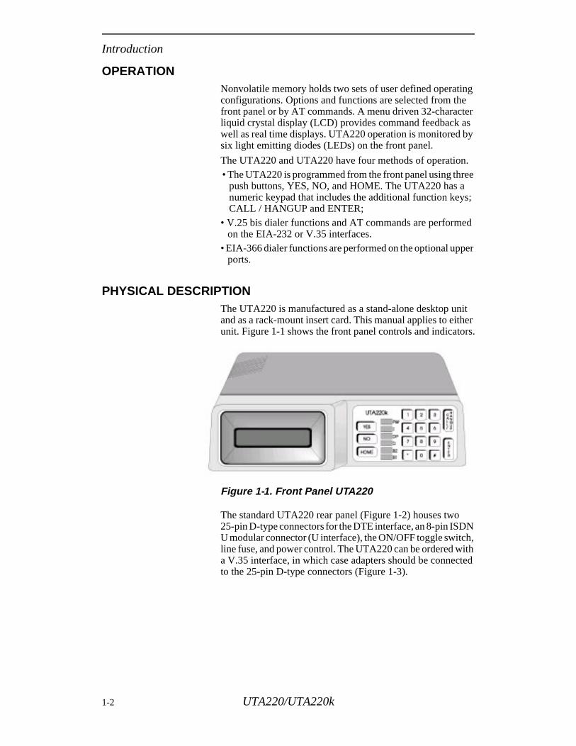
PHYSICAL DESCRIPTIONThe UTA220 is manufactured as a stand-alone desktop unand as a rack-mount insert card. This manual applies to eiunit. Figure 1-1 shows the front panel controls and indicato
Figure 1-1. Front Panel UTA220
The standard UTA220 rear panel (Figure 1-2) houses two25-pin D-type connectors for the DTE interface, an 8-pin ISDU modular connector (U interface), the ON/OFF toggle switcline fuse, and power control. The UTA220 can be ordered wa V.35 interface, in which case adapters should be connecto the 25-pin D-type connectors (Figure 1-3).
1-2 UTA220/UTA220k
Introduction
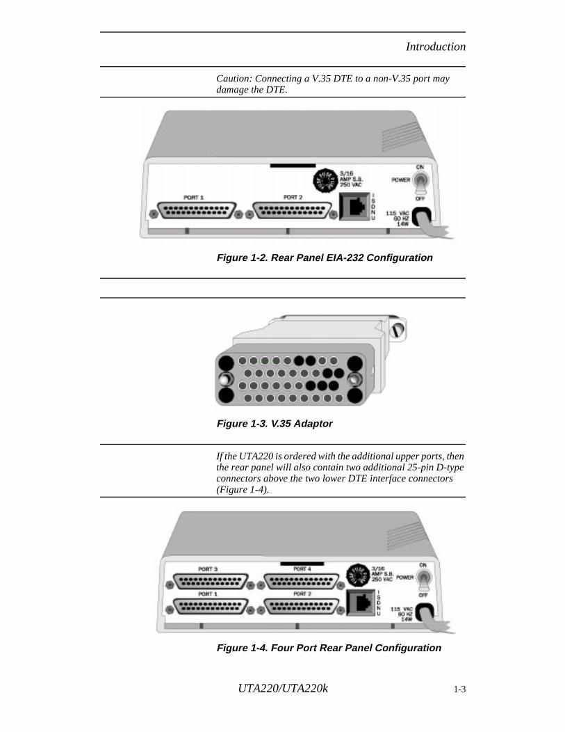
Caution: Connecting a V.35 DTE to a non-V.35 port may damage the DTE.
Figure 1-2. Rear Panel EIA-232 Configuration
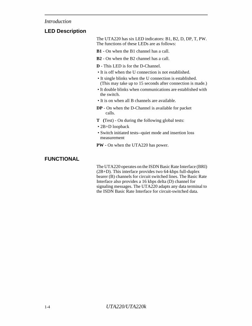
Figure 1-3. V.35 Adaptor
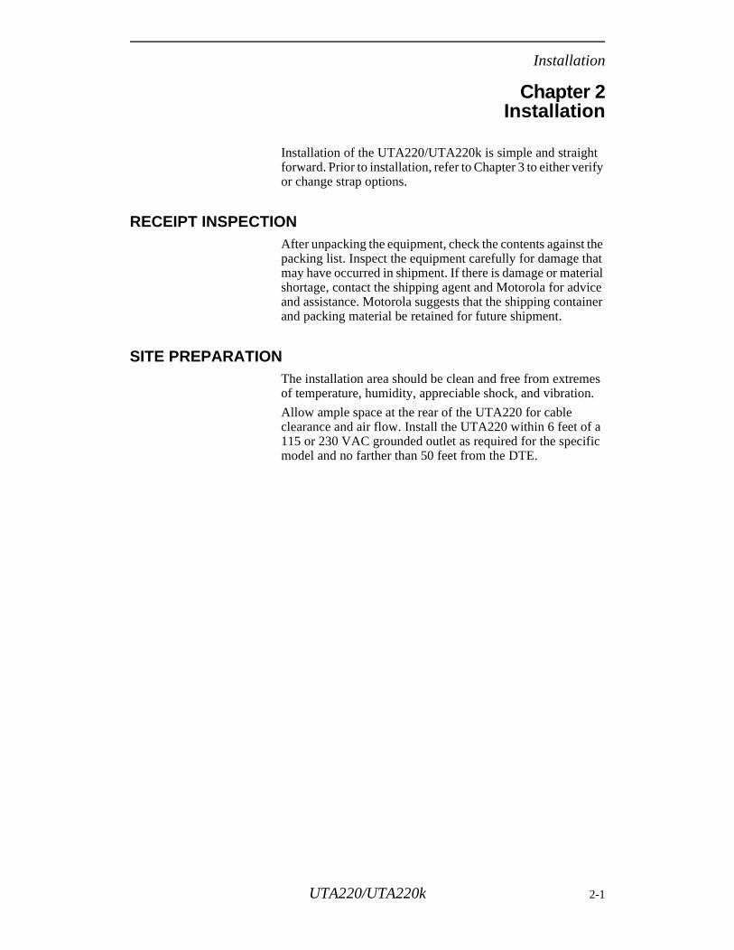
If the UTA220 is ordered with the additional upper ports, then the rear panel will also contain two additional 25-pin D-type connectors above the two lower DTE interface connectors (Figure 1-4).
Figure 1-4. Four Port Rear Panel Configuration
UTA220/UTA220k 1-3
Introduction
e.)ith
I)
te
l to
LED Description The UTA220 has six LED indicators: B1, B2, D, DP, T, PW. The functions of these LEDs are as follows:
B1 - On when the B1 channel has a call.
B2 - On when the B2 channel has a call.
D - This LED is for the D-Channel. • It is off when the U connection is not established. • It single blinks when the U connection is established.
(This may take up to 15 seconds after connection is mad • It double blinks when communications are established w
the switch. • It is on when all B channels are available.
DP - On when the D-Channel is available for packet calls.
T (Test) - On during the following global tests: • 2B+D loopback • Switch initiated tests--quiet mode and insertion loss
measurement
PW - On when the UTA220 has power.
FUNCTIONALThe UTA220 operates on the ISDN Basic Rate Interface (BR(2B+D). This interface provides two 64-kbps full-duplex bearer (B) channels for circuit switched lines. The Basic RaInterface also provides a 16 kbps delta (D) channel for signaling messages. The UTA220 adapts any data terminathe ISDN Basic Rate Interface for circuit-switched data.
1-4 UTA220/UTA220k
Installation
Chapter 2Installation
Installation of the UTA220/UTA220k is simple and straight forward. Prior to installation, refer to Chapter 3 to either verify or change strap options.
RECEIPT INSPECTIONAfter unpacking the equipment, check the contents against the packing list. Inspect the equipment carefully for damage that may have occurred in shipment. If there is damage or material shortage, contact the shipping agent and Motorola for advice and assistance. Motorola suggests that the shipping container and packing material be retained for future shipment.
SITE PREPARATIONThe installation area should be clean and free from extremes of temperature, humidity, appreciable shock, and vibration.
Allow ample space at the rear of the UTA220 for cable clearance and air flow. Install the UTA220 within 6 feet of a 115 or 230 VAC grounded outlet as required for the specific model and no farther than 50 feet from the DTE.
UTA220/UTA220k 2-1
Installation
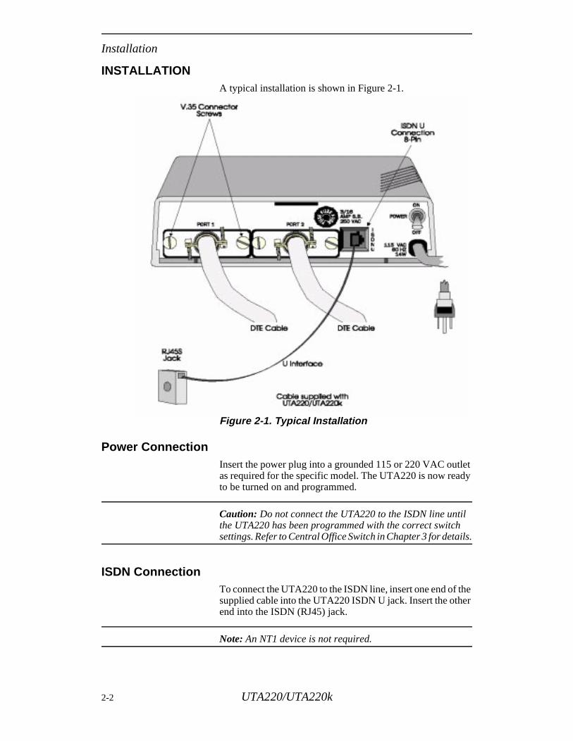
INSTALLATION A typical installation is shown in Figure 2-1.
Figure 2-1. Typical Installation
Power ConnectionInsert the power plug into a grounded 115 or 220 VAC outlet as required for the specific model. The UTA220 is now ready to be turned on and programmed.
Caution: Do not connect the UTA220 to the ISDN line until the UTA220 has been programmed with the correct switch settings. Refer to Central Office Switch in Chapter 3 for details.
ISDN ConnectionTo connect the UTA220 to the ISDN line, insert one end of the supplied cable into the UTA220 ISDN U jack. Insert the other end into the ISDN (RJ45) jack.
Note: An NT1 device is not required.
2-2 UTA220/UTA220k
Installation
DTE ConnectionInsert each DTE cable into a DTE connector. Insert the opposite end into the DTE. Secure the connect screws to complete the connection.
DTE INTERFACE SPECIFICATIONSThe DTE interface to the UTA220 is through an EIA-232 D/E 25-pin D-type connector. The UTA220 can also be configured for V.35 operation. It is also available with V.35 interfaces and with two additional ports for EIA-366 dialing, or EIA-232C operation.
UTA220/UTA220k 2-3

Installation
2-4 UTA220/UTA220k
Getting Started
s
ium ts. y ith ith
Chapter 3Getting Started
This chapter provides instructions for setting switches and straps plus a quick programming setup for the DMS100 or the 5ESS central office switch or switches running National ISDN 1 (NI1).
Caution: Do not connect the UTA220 to the ISDN line until the UTA220 has been programmed for the correct switch, switch version, Terminal Endpoint Identifier (TEI) numbers, and Service Profile Identifiers (SPIDs). These are provided by the telephone company at subscription time. Use of numbers other than those assigned or failure to program these numbers in the UTA220 can result in error conditions between the central office switch and the terminal adapter.
SWITCHES AND STRAPSThe unit is factory configured to current industry standards. Because of different environments, some terminal adapters may require strap or switch changes. This section describes the strap and switch options and how to use them.
Caution: Electrostatic discharge (ESD) can damage electronic components.
Cover RemovalTo select or inspect the strap option, first remove the unit’cover.
Warning: Do not remove the cover unless both the power cord and ISDN line are unplugged.
Place the UTA220 on its side on a flat surface. Insert a medsize flat screwdriver blade in one of the bottom rear latch sloDO NOT PUSH the screwdriver. Lightly pry the handle awato disengage the lock prong from the lock clip as shown inFigure 3-1. Assist by pushing the cover from the chassis wyour fingers on the unit rear edges. Repeat this procedure wthe remaining three latch slots.
UTA220/UTA220k 3-1
Getting Started
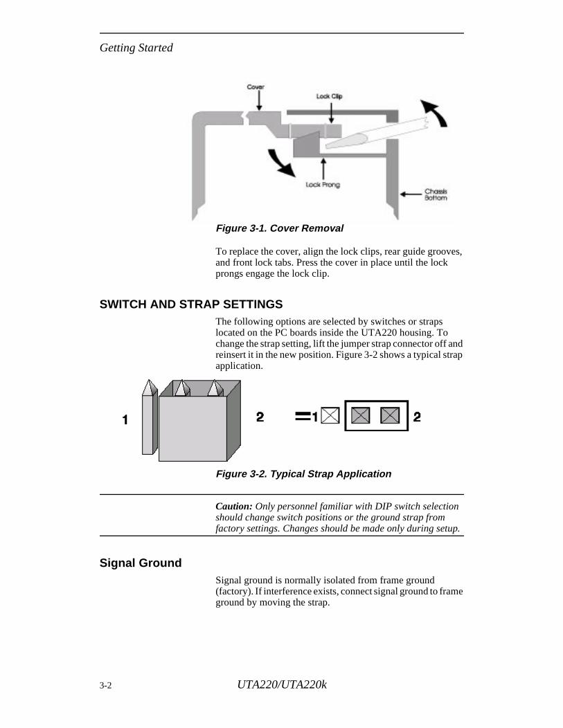
Figure 3-1. Cover Removal
To replace the cover, align the lock clips, rear guide grooves, and front lock tabs. Press the cover in place until the lock prongs engage the lock clip.
SWITCH AND STRAP SETTINGSThe following options are selected by switches or straps located on the PC boards inside the UTA220 housing. To change the strap setting, lift the jumper strap connector off and reinsert it in the new position. Figure 3-2 shows a typical strap application.
Figure 3-2. Typical Strap Application
Caution: Only personnel familiar with DIP switch selection should change switch positions or the ground strap from factory settings. Changes should be made only during setup.
Signal GroundSignal ground is normally isolated from frame ground (factory). If interference exists, connect signal ground to frame ground by moving the strap.
3-2 UTA220/UTA220k
Getting Started
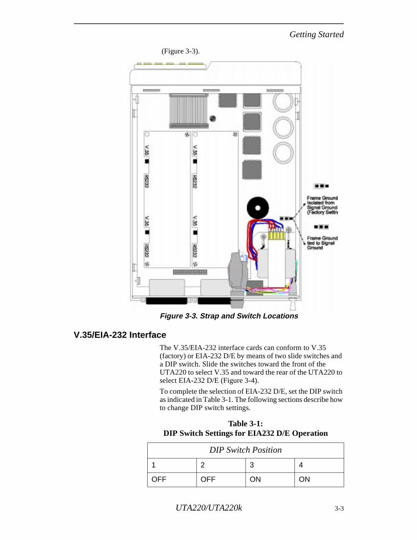
(Figure 3-3).
Figure 3-3. Strap and Switch Locations
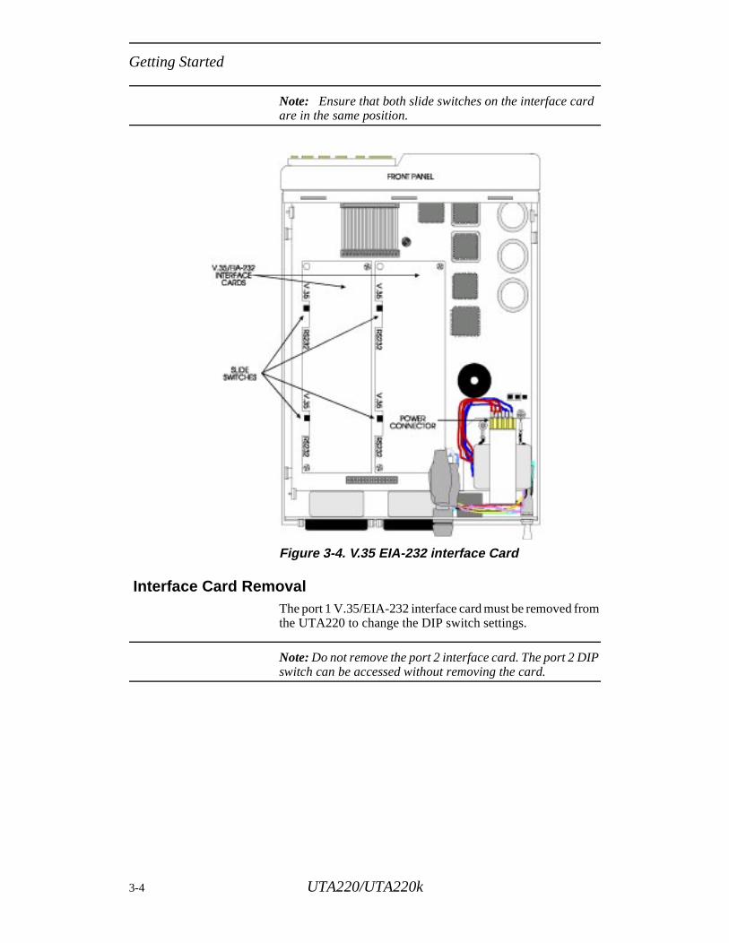
V.35/EIA-232 Interface The V.35/EIA-232 interface cards can conform to V.35 (factory) or EIA-232 D/E by means of two slide switches and a DIP switch. Slide the switches toward the front of the UTA220 to select V.35 and toward the rear of the UTA220 to select EIA-232 D/E (Figure 3-4).
To complete the selection of EIA-232 D/E, set the DIP switch as indicated in Table 3-1. The following sections describe how to change DIP switch settings.
Table 3-1: DIP Switch Settings for EIA232 D/E Operation
DIP Switch Position
1 2 3 4
OFF OFF ON ON
UTA220/UTA220k 3-3
Getting Started
Note: Ensure that both slide switches on the interface card are in the same position.
Figure 3-4. V.35 EIA-232 interface Card
Interface Card RemovalThe port 1 V.35/EIA-232 interface card must be removed from the UTA220 to change the DIP switch settings.
Note: Do not remove the port 2 interface card. The port 2 DIP switch can be accessed without removing the card.
3-4 UTA220/UTA220k
Getting Started
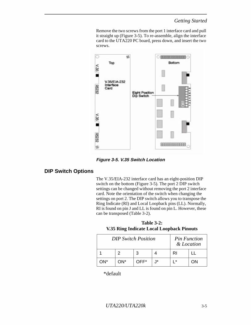
Remove the two screws from the port 1 interface card and pull it straight up (Figure 3-5). To re-assemble, align the interface card to the UTA220 PC board, press down, and insert the two screws.
Figure 3-5. V.35 Switch Location
DIP Switch OptionsThe V.35/EIA-232 interface card has an eight-position DIP switch on the bottom (Figure 3-5). The port 2 DIP switch settings can be changed without removing the port 2 interface card. Note the orientation of the switch when changing the settings on port 2. The DIP switch allows you to transpose the Ring Indicate (RI) and Local Loopback pins (LL). Normally, RI is found on pin J and LL is found on pin L. However, these can be transposed (Table 3-2).
*default
Table 3-2: V.35 Ring Indicate Local Loopback Pinouts
DIP Switch Position Pin Function & Location
1 2 3 4 RI LL
ON* ON* OFF* J* L* ON
UTA220/UTA220k 3-5
Getting Started
,
l
is
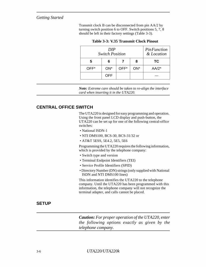
Transmit clock B can be disconnected from pin AA/2 by turning switch position 6 to OFF. Switch positions 5, 7, 8 should be left in their factory settings (Table 3-3).
Note: Extreme care should be taken to re-align the interface card when inserting it in the UTA220.
CENTRAL OFFICE SWITCHThe UTA220 is designed for easy programming and operation. Using the front panel LCD display and push-button, the UTA220 can be set up for one of the following central-office switches: • National ISDN-1 • NTI DMS100, BCS-30, BCS-31/32 or • AT&T 5ESS, 5E4.2, 5E5, 5E6
Programming the UTA220 requires the following informationwhich is provided by the telephone company: • Switch type and version • Terminal Endpoint Identifiers (TEI) • Service Profile Identifiers (SPID) • Directory Number (DN) strings (only supplied with Nationa
ISDN and NTI DMS100 lines)
This information identifies the UTA220 to the telephone company. Until the UTA220 has been programmed with thinformation, the telephone company will not recognize theterminal adapter, and calls cannot be placed.
SETUP
Caution: For proper operation of the UTA220, enterthe following options exactly as given by thetelephone company.
Table 3-3: V.35 Transmit Clock Pinout
DIPSwitch Position
Pin Function & Location
5 6 7 8 TC
OFF* ON* OFF* ON* AA/2*
OFF ---
3-6 UTA220/UTA220k
Getting Started
Setup Step 1
Plug the UTA220 into the power outlet. Turn the power switch on the rear panel ON.
Note: Do not connect the UTA220 to the ISDN line until the UTA220 has been properly programmed.
The LCD displays the banner:ISDN TERMINAL ADAPTER
Setup Step 2
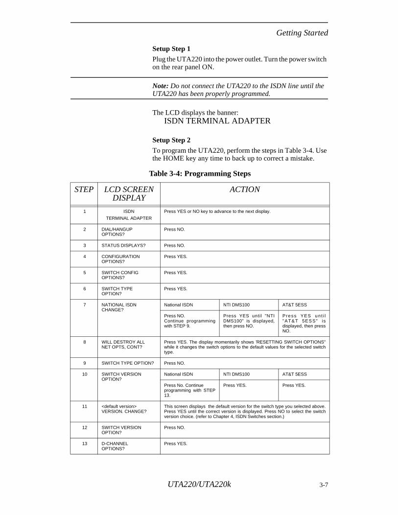
To program the UTA220, perform the steps in Table 3-4. Use the HOME key any time to back up to correct a mistake.
Table 3-4: Programming Steps
STEP LCD SCREEN DISPLAY
ACTION
1 ISDN
TERMINAL ADAPTER
Press YES or NO key to advance to the next display.
2 DIAL/HANGUPOPTIONS?
Press NO.
3 STATUS DISPLAYS? Press NO.
4 CONFIGURATIONOPTIONS?
Press YES.
5 SWITCH CONFIGOPTIONS?
Press YES.
6 SWITCH TYPE OPTION?
Press YES.
7 NATIONAL ISDNCHANGE?
National ISDN NTI DMS100 AT&T 5ESS
Press NO.Continue programmingwith STEP 9.
Press YES until "NTIDMS100" is displayed,then press NO.
Press YES unt i l"AT&T 5ES S" i sdisplayed, then pressNO.
8 WILL DESTROY ALLNET OPTS, CONT?
Press YES. The display momentarily shows ’RESETTING SWITCH OPTIONS"while it changes the switch options to the default values for the selected switchtype.
9 SWITCH TYPE OPTION? Press NO.
10 SWITCH VERSIONOPTION?
National ISDN NTI DMS100 AT&T 5ESS
Press No. Continueprogramming with STEP13.
Press YES. Press YES.
11 <default version>VERSION. CHANGE?
This screen displays the default version for the switch type you selected above.Press YES until the correct version is displayed. Press NO to select the switchversion choice. (refer to Chapter 4, ISDN Switches section.)
12 SWITCH VERSIONOPTION?
Press NO.
13 D-CHANNELOPTIONS?
Press YES.
UTA220/UTA220k 3-7
Getting Started
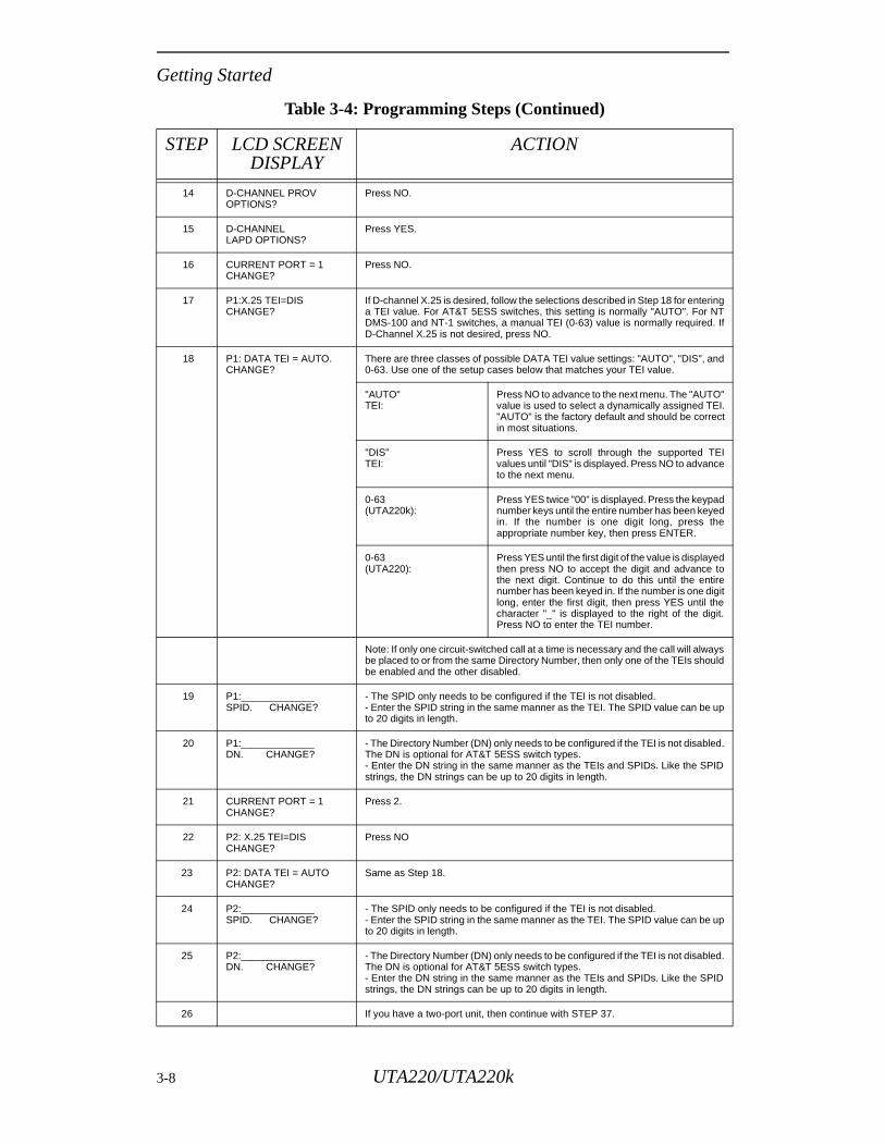
14 D-CHANNEL PROVOPTIONS?
Press NO.
15 D-CHANNELLAPD OPTIONS?
Press YES.
16 CURRENT PORT = 1CHANGE?
Press NO.
17 P1:X.25 TEI=DIS CHANGE?
If D-channel X.25 is desired, follow the selections described in Step 18 for enteringa TEI value. For AT&T 5ESS switches, this setting is normally "AUTO". For NTDMS-100 and NT-1 switches, a manual TEI (0-63) value is normally required. IfD-Channel X.25 is not desired, press NO.
18 P1: DATA TEI = AUTO.CHANGE?
There are three classes of possible DATA TEI value settings: "AUTO", "DIS", and0-63. Use one of the setup cases below that matches your TEI value.
"AUTO"TEI:
Press NO to advance to the next menu. The "AUTO"value is used to select a dynamically assigned TEI."AUTO" is the factory default and should be correctin most situations.
"DIS"TEI:
Press YES to scroll through the supported TEIvalues until "DIS" is displayed. Press NO to advanceto the next menu.
0-63(UTA220k):
Press YES twice "00" is displayed. Press the keypadnumber keys until the entire number has been keyedin. If the number is one digit long, press theappropriate number key, then press ENTER.
0-63(UTA220):
Press YES until the first digit of the value is displayedthen press NO to accept the digit and advance tothe next digit. Continue to do this until the entirenumber has been keyed in. If the number is one digitlong, enter the first digit, then press YES until thecharacter "_" is displayed to the right of the digit.Press NO to enter the TEI number.
Note: If only one circuit-switched call at a time is necessary and the call will alwaysbe placed to or from the same Directory Number, then only one of the TEIs shouldbe enabled and the other disabled.
19 P1:_____________SPID. CHANGE?
- The SPID only needs to be configured if the TEI is not disabled.- Enter the SPID string in the same manner as the TEI. The SPID value can be upto 20 digits in length.
20 P1:_____________DN. CHANGE?
- The Directory Number (DN) only needs to be configured if the TEI is not disabled.The DN is optional for AT&T 5ESS switch types.- Enter the DN string in the same manner as the TEIs and SPIDs. Like the SPIDstrings, the DN strings can be up to 20 digits in length.
21 CURRENT PORT = 1CHANGE?
Press 2.
22 P2: X.25 TEI=DIS CHANGE?
Press NO
23 P2: DATA TEI = AUTOCHANGE?
Same as Step 18.
24 P2:_____________SPID. CHANGE?
- The SPID only needs to be configured if the TEI is not disabled.- Enter the SPID string in the same manner as the TEI. The SPID value can be upto 20 digits in length.
25 P2:_____________DN. CHANGE?
- The Directory Number (DN) only needs to be configured if the TEI is not disabled.The DN is optional for AT&T 5ESS switch types.- Enter the DN string in the same manner as the TEIs and SPIDs. Like the SPIDstrings, the DN strings can be up to 20 digits in length.
26 If you have a two-port unit, then continue with STEP 37.
Table 3-4: Programming Steps (Continued)
STEP LCD SCREEN DISPLAY
ACTION
3-8 UTA220/UTA220k

Getting Started
Note: Some LCD screen displays require different actions depending on the telephone company’s switch type.
Setup Step 3
Insert the ISDN line into the ISDN U jack located on the rear panel.
27 CURRENT PORT = 2CHANGE?
Press 3.
28 P3 : X .25 TEI=D ISCHANGE?
Press NO
29 P3: DATA TEI = DIS.CHANGE?
Same as Step 18.
30 P3:_____________SPID. CHANGE?
- The SPID only needs to be configured if the TEI is not disabled.- Enter the SPID string in the same manner as the TEI. The SPID value can be upto 20 digits in length.
31 P3:_____________DN. CHANGE?
- The Directory Number (DN) only needs to be configured if the TEI is not disabled.The DN is optional for AT&T 5ESS switch types.- Enter the DN string in the same manner as the TEIs and SPIDs. Like the SPIDstrings, the DN strings can be up to 20 digits in length.
32 CURRENT PORT = 3CHANGE?
Press 4.
33 P4: X.25 TEI=DISCHANGE?
Press NO
34 P4: TEI = DIS.CHANGE?
Same as Step 18.
35 P4:_____________SPID. CHANGE?
- The SPID only needs to be configured if the TEI is not disabled.- Enter the SPID string in the same manner as the TEI. The SPID value can be upto 20 digits in length.
36 P4:_____________DN. CHANGE?
- The Directory Number (DN) only needs to be configured if the TEI is not disabled.The DN is optional for AT&T 5ESS switch types.- Enter the DN string in the same manner as the TEIs and SPIDs. Like the SPIDstrings, the DN strings can be up to 20 digits in length.
37 CURRENT PORT = 4CHANGE?
Press HOME.
38 D-CHANNEL LAPD
OPTIONS?
Press NO.
39 D-CHANNEL PROVISIONX.25 OPTIONS?
Press NO.
40 D-CHANNEL OPTIONS? Press NO.
41 MULTIFRAME SYNC =__________CHANGE?
Press NO.
42 FRONT PANEL LOCKOPTION?
Press NO.
43 SAVE SWITCH ANDGLOBL TO NONVOL?
Press YES to save the switch configuration. The display momentarily shows"SAVING" while it is saving the options to nonvolatile memory.
44 RESTART NETWORKLINK?
Plug telephone cable into ISDN U jack on rear of unit, then press YES.
Table 3-4: Programming Steps (Continued)
STEP LCD SCREEN DISPLAY
ACTION
UTA220/UTA220k 3-9

Getting Started
3-10 UTA220/UTA220k
ISDN
Chapter 4ISDN
This chapter provides information to help you set up and use your Terminal Adaptor (TA). For users unfamiliar with TAs, some fundamental Integrated Services Digital Network (ISDN) concepts are presented first. If you are already familiar with ISDN you may skip over this section, but the ISDN Switches and the ISDN Addresses and Identifiers sections contain information pertinent to the switch configuration of the TA and should be reviewed.
ISDN BASICSISDN is a global system that provides a variety of high-speed digital telecommunication services including voice, data, images, and video, integrated on one network. As ISDN evolves it will provide the same types of services as the existing analog networks (voice and low-speed data), plus new services made possible by recent advances in computers and digital data communications.
ISDN is based on standards that define the interfaces between the network and the equipment connected to it. This standardization permits communication between ISDN systems and equipment manufactured by different vendors world wide.
ISDN StandardsISDN standards are set by the International Consultative Committee for Telegraph and Telephone (CCITT), an organization that establishes communications recommendations under the auspices of the United Nations.
Because ISDN technology advances faster than the CCITT can establish standards, a number of de-facto standards have been developed by manufacturers of telephone equipment. While these set the precedence for CCITT standards eventually agreed to, there are enough differences that those who set up ISDN equipment (such as TAs) must be aware of them.
National ISDNThe U.S.A. and Canada have an ISDN standard for North America called National ISDN. The first version of this standard, National ISDN One (NI-1), is being adopted by equipment manufacturers and network providers. When fully deployed, NI-1 will make understanding and configuring ISDN equipment easier and more efficient.
UTA220/UTA220k 4-1
ISDN
the e.
o
Basic Rate InterfaceSeveral types of ISDN network services are available. The most common is Basic Rate Interface (BRI). BRI provides two B-channels (bearer channels) and one D-channel (used to place and release calls on the network).
B-channels, which operate at 64 kbps full-duplex, carry end-to-end data between network terminals. B-channels can be either circuit-switched (dial-up), allowing each call to be placed to different endpoints, or permanently connected (nailed) to a single endpoint. In some applications, B-channels can also be used to carry packet-switched data, where each frame of data can dynamically be sent to different network users. The TA does not support packet-switching on a B-channel.
The D-channel is primarily a control channel between the network and the terminal device (such as a TA).
Terminal AdaptersTerminal adapters attach standard data terminals and voice telephones to the ISDN, allowing them to send and receive calls and data via the ISDN. Some terminal adapters (but not the UTA220) support voice service, allowing a standard (analog) telephone set to be connected to the ISDN.
The UTA220 operates on the ISDN BRI. It provides circuit-switched data communications using circuit-switched B-channels for data, and uses the D-channel for signaling only.
ISDN Basic Rate Interface PointsBRI points and the associated devices found on customer premises are shown in Figure 4-1. The boxes in the diagram represent devices, and the vertical lines represent defined interface points. There are two types of DTEs represented in the diagram: • TE1 devices have a built in ISDN interface. • TE2 devices do not have a built in ISDN interface, and
require a TA to interface with the ISDN.
The data terminal devices (DTEs) are located in the left of diagram. The TA is connected to the ISDN at the U interfacAn NT1 device is not required; the NT1 function is built intthe UTA220.
4-2 UTA220/UTA220k
ISDN
for
e
nd re
h
ns. d
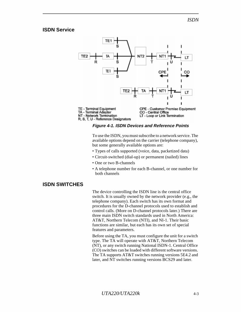
ISDN Service
Figure 4-1. ISDN Devices and Reference Points
To use the ISDN, you must subscribe to a network service. The available options depend on the carrier (telephone company), but some generally available options are:• Types of calls supported (voice, data, packetized data)• Circuit-switched (dial-up) or permanent (nailed) lines• One or two B-channels• A telephone number for each B-channel, or one number
both channels
ISDN SWITCHESThe device controlling the ISDN line is the central office switch. It is usually owned by the network provider (e.g., thtelephone company). Each switch has its own format and procedures for the D-channel protocols used to establish acontrol calls. (More on D-channel protocols later.) There athree main ISDN switch standards used in North America:AT&T, Northern Telecom (NTI), and NI-1. Their basic functions are similar, but each has its own set of special features and parameters.
Before using the TA, you must configure the unit for a switctype. The TA will operate with AT&T, Northern Telecom (NT), or any switch running National ISDN-1. Central Office(CO) switches can be loaded with different software versioThe TA supports AT&T switches running versions 5E4.2 anlater, and NT switches running versions BCS29 and later.
UTA220/UTA220k 4-3
ISDN
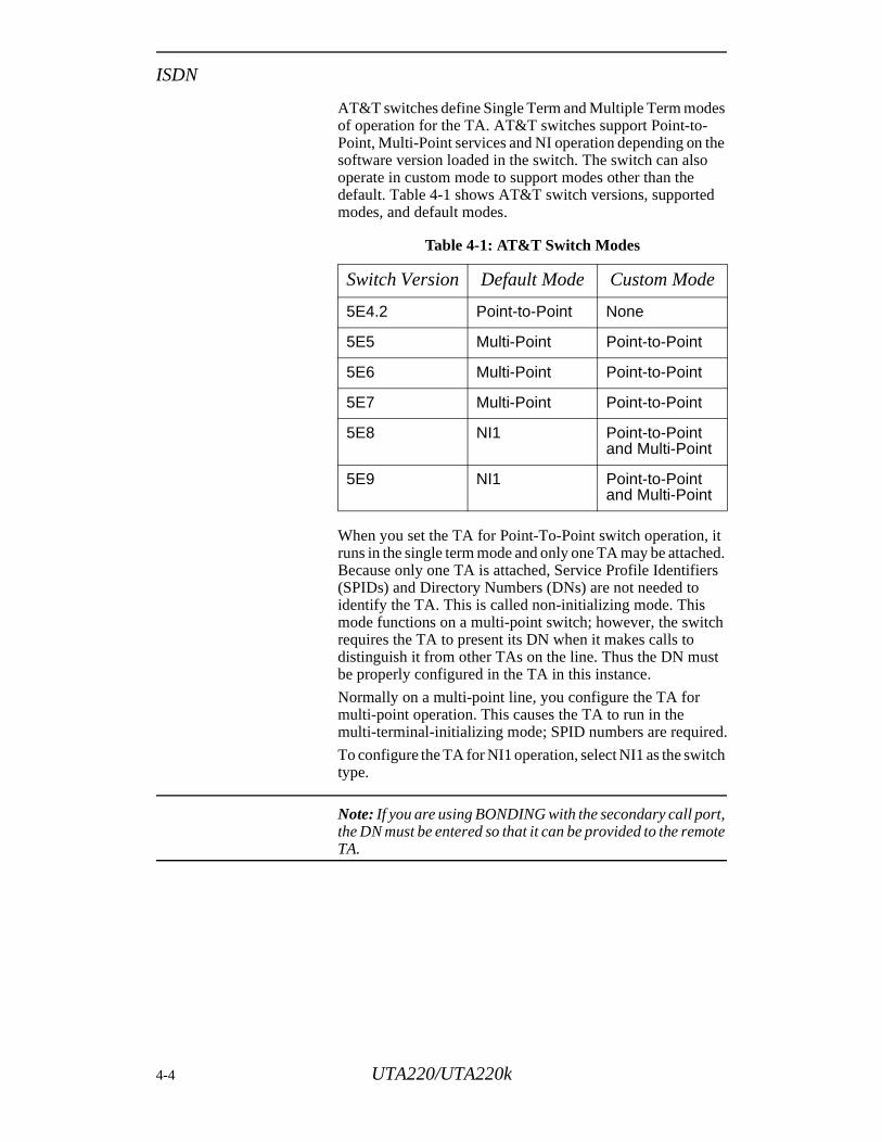
AT&T switches define Single Term and Multiple Term modes of operation for the TA. AT&T switches support Point-to-Point, Multi-Point services and NI operation depending on the software version loaded in the switch. The switch can also operate in custom mode to support modes other than the default. Table 4-1 shows AT&T switch versions, supported modes, and default modes.
When you set the TA for Point-To-Point switch operation, it runs in the single term mode and only one TA may be attached. Because only one TA is attached, Service Profile Identifiers (SPIDs) and Directory Numbers (DNs) are not needed to identify the TA. This is called non-initializing mode. This mode functions on a multi-point switch; however, the switch requires the TA to present its DN when it makes calls to distinguish it from other TAs on the line. Thus the DN must be properly configured in the TA in this instance.
Normally on a multi-point line, you configure the TA for multi-point operation. This causes the TA to run in the multi-terminal-initializing mode; SPID numbers are required.
To configure the TA for NI1 operation, select NI1 as the switch type.
Note: If you are using BONDING with the secondary call port, the DN must be entered so that it can be provided to the remote TA.
Table 4-1: AT&T Switch Modes
Switch Version Default Mode Custom Mode
5E4.2 Point-to-Point None
5E5 Multi-Point Point-to-Point
5E6 Multi-Point Point-to-Point
5E7 Multi-Point Point-to-Point
5E8 NI1 Point-to-Point and Multi-Point
5E9 NI1 Point-to-Point and Multi-Point
4-4 UTA220/UTA220k
ISDN
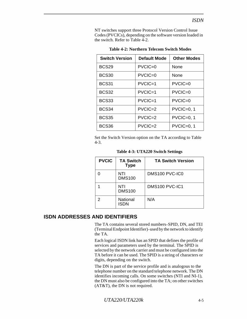
NT switches support three Protocol Version Control Issue Codes (PVCICs), depending on the software version loaded in the switch. Refer to Table 4-2.
Set the Switch Version option on the TA according to Table 4-3.
ISDN ADDRESSES AND IDENTIFIERSThe TA contains several stored numbers–SPID, DN, and TEI (Terminal Endpoint Identifier)–used by the network to identify the TA.
Each logical ISDN link has an SPID that defines the profile of services and parameters used by the terminal. The SPID is selected by the network carrier and must be configured into the TA before it can be used. The SPID is a string of characters or digits, depending on the switch.
The DN is part of the service profile and is analogous to the telephone number on the standard telephone network. The DN identifies incoming calls. On some switches (NTI and NI-1), the DN must also be configured into the TA; on other switches (AT&T), the DN is not required.
Table 4-2: Northern Telecom Switch Modes
Switch Version Default Mode Other Modes
BCS29 PVCIC=0 None
BCS30 PVCIC=0 None
BCS31 PVCIC=1 PVCIC=0
BCS32 PVCIC=1 PVCIC=0
BCS33 PVCIC=1 PVCIC=0
BCS34 PVCIC=2 PVCIC=0, 1
BCS35 PVCIC=2 PVCIC=0, 1
BCS36 PVCIC=2 PVCIC=0, 1
Table 4-3: UTA220 Switch Settings
PVCIC TA Switch Type
TA Switch Version
0 NTI DMS100
DMS100 PVC-IC0
1 NTI DMS100
DMS100 PVC-IC1
2 National ISDN
N/A
UTA220/UTA220k 4-5
ISDN
ust
The TEI is used to identify the terminal device. In most applications, the network switch automatically assigns a TEI to the TA when the connection is established; otherwise, you must enter the TEI before connecting to the network.
If your switch permits it, the UTA220 allows you to use one SPID and one TEI on simultaneous calls. AT&T switches allow two calls per SPID. With this support you can configure two or more ports to share a DN.
Note: To use this feature, configure each port with the same SPID and DN, enable one port’s TEI, and disable the TEI on the remaining port(s).
The UTA220 also allows you to use multiple DNs on the same SPID if your switch supports it. NT switches support up to four DNs per SPID.
Note: To use this feature, configure both ports with the same SPID and different DNs, then enable one port’s TEI and disable the other’s.
ISDN CHANNELSAs previously mentioned, there are three channels available on the ISDN Basic Rate Interface: two 64 Kbps B-channels and one 16 Kbps D-channel. The B-channels are the primary means of carrying user information, whether voice or data. Voice data must be sent on a B-channel. The B-channel also provides the most efficient path for data communications, since it has four times the data capacity of the D-channel.
The D-channel is the control channel between the TA and the network switch. It is used mainly for exchanging signaling messages with the switch, to perform functions like setting up and releasing calls.
Note: The UTA220 supports only data calls.
B-Channel Data Service When a B-channel data call is placed, the switch allocates a free B-channel between the TA and the remote DCE (e.g., the TA at the other end of the ISDN link). This B-channel acts like a bit-pipe between two network users, operating synchronously at 64 Kbps. In most cases, the ISDN network does not know about the format of the data sent on the B-channels.
There are several ways to use the B-channel to pass data. In the “clear channel” mode, data from the DTE goes directlyonto the B-channel. However, to use this mode, your DTE malso operate synchronously at 56 or 64 kbps.
4-6 UTA220/UTA220k
ISDN
e
d r re . g
h
can
of is a is TE
oth se
us
ly,
he al
he
s.
ed es
30.
B-Channel Data ProtocolsTo allow greater flexibility for your DTE, there are three rate adaption protocols available for use on the B-channel: TLink, V.120, and Bonding. These protocols allow your DTE to operate both synchronously and asynchronously, and at a different speed than the B-channel. • TLink is a Northern Telecom proprietary rate adaption
protocol. It supports synchronous and asynchronous ratadaption at a variety of speeds.
• V.120 is a CCITT protocol that supports synchronous anasynchronous rate adaption, and also provides link-layeerror control. Although errors on a digital network are morare than on an analog telephone line, they are possibleV.120 provides an end-to-end protocol for detecting andcorrecting any such errors. V.120 also performs bufferinand can thus support flow control to and from the DTE.
• BONDING is a new protocol standard from the BandwidtON Demand INteroperability Group. It combines the bandwidth of several 56 kbps or 64 kbps channels, and bond from 2 to 31 channels at once, if the channels are available. The high speed data, which must be a multiple56 kbps or 64 kbps, comes in on the DTE interface and split to the various channels. On the opposite end the datrecombined into the original data stream and sent to the Dinterface.
To use a rate adaption protocol, the DCEs (e.g., TAs) at bends of the link must support it and must be configured to uit. In general, since it is more flexible and supports error control, V.120 should be used for most applications, and thit is the default protocol in the UTA220.
D-Channel Signaling ProtocolsThe D-channel conveys signaling information and, optionalpacket-switched data, to the network switch. This data is passed in message blocks defined by the ISDN signaling protocols. These protocols vary somewhat depending on tnetwork switch installed at the telephone company's centroffice. As mentioned earlier, several de-facto protocol standards, are used for the D-channel signaling between tTA and the switch.
The TA signaling protocols function on three protocol layerEach of these layers is described below.
Layer OneThe physical layer includes components and interfaces needto provide a physical communications path. All ISDN switchuse the same physical layer protocols for the Basic Rate Interface, which are based on CCITT Recommendation I.4
UTA220/UTA220k 4-7
ISDN
Layer TwoThe data link layer ensures error-free transmission of D-channel messages between the terminal and the network switch. The link layer in effect provides a virtual error-free connection for the next higher protocol layer to use. The LAPD protocol is the error detection and correction mechanism for layer two. Layer two protocols are based on CCITT recommendation Q.921, and are almost identical. Minor differences do exist, however, primarily in how the protocols respond to certain very unlikely error conditions.
Layer ThreeThe network layer consists of signaling messages passed between the terminal and the network, using the data link layer. These messages communicate call setup (dialing) and release messages from the TA, call progress information from the network, and messages concerning special call-related features. Layer three of the D-channel can also be used to exchange packetized data using X.25, if the TA and the switch are set up to allow it.
All layer three protocols are based on CCITT Recommendation Q.931. However, the protocol used depends on the brand and version of the network switch. There are differences in the exact procedures used by each switch to set up and release calls. In addition, because switches are manufactured by competing companies, each switch offers a different set of extra features. These features are called supplementary services.
Unfortunately, each vendor implements these features differently. Also, there are different versions of each of the switches, each of which implements a different set of features. As a result, you must configure your TA for the particular switch type and version so that the TA can use the correct signaling protocol for that switch. The switch type and version are two of the most important network parameters in the TA.
4-8 UTA220/UTA220k
LCD Operation
rt
rk
s
g
N s u
ME.
a
Chapter 5LCD Operation
The UTA220 has an easy-to-use front panel with a Liquid Crystal Display (LCD). You can monitor TA status, perform operations, and program the TA without using a terminal or computer.
LCD MENUSThe LCD menus are arranged in multiple levels. Menu headers may to more menu headers, options screens or action screens. When the NO key is pressed while a menu header is displayed, the LCD advances to the next menu header. When the YES key is pressed, the menu descends one level in the menus.
Main MenusThe Main Menu headers are:• DIAL/HANGUP OPTIONS? - to dial manually or to dial
previously stored telephone numbers and to hang up.• STATUS DISPLAYS? - to view the status of each data po
call.• CONFIGURATIONS OPTIONS? - to program switch and
port options.• CONFIGURATION LOAD/SAVE OPTIONS? - to save the
switch and port configuration settings or to retrieve the factory settings or stored settings.
• DIAGNOSTIC OPTIONS? - to run tests, restart the netwoand view product information.
SubmenusA menu includes menu headers, action screens, or optionscreens. Action screens let you perform an action, such adialing. Option screens show settings and allow changes. Options may be set from multiple choice lists or by enterindata.
LCD OPERATION
Menu TraversalAfter power-up, the LCD displays the sign-on banner: ISDTERMINAL ADAPTER. To enter the Main Menu level, presthe YES or NO key. Whenever the LCD is on the Main Menlevel, the sign-on banner can be displayed by pressing HO
In general, pressing NO moves the display vertically downcolumn (Table 5-1) and pressing YES moves the display horizontally across the columns (one level deeper).
UTA220/UTA220k 5-1
LCD Operation
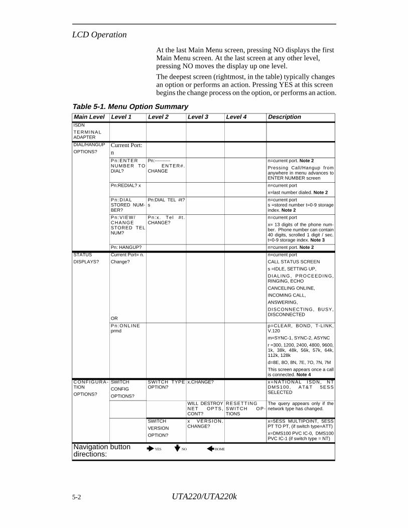
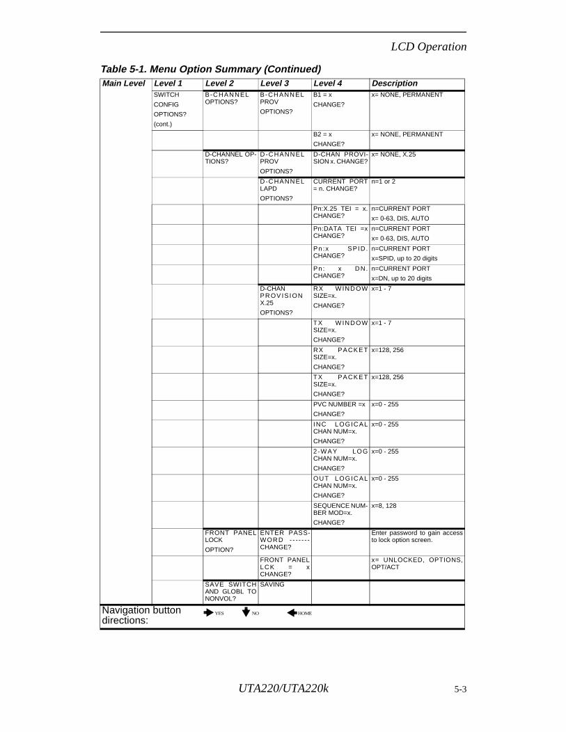
At the last Main Menu screen, pressing NO displays the first Main Menu screen. At the last screen at any other level, pressing NO moves the display up one level.
The deepest screen (rightmost, in the table) typically changes an option or performs an action. Pressing YES at this screen begins the change process on the option, or performs an action.
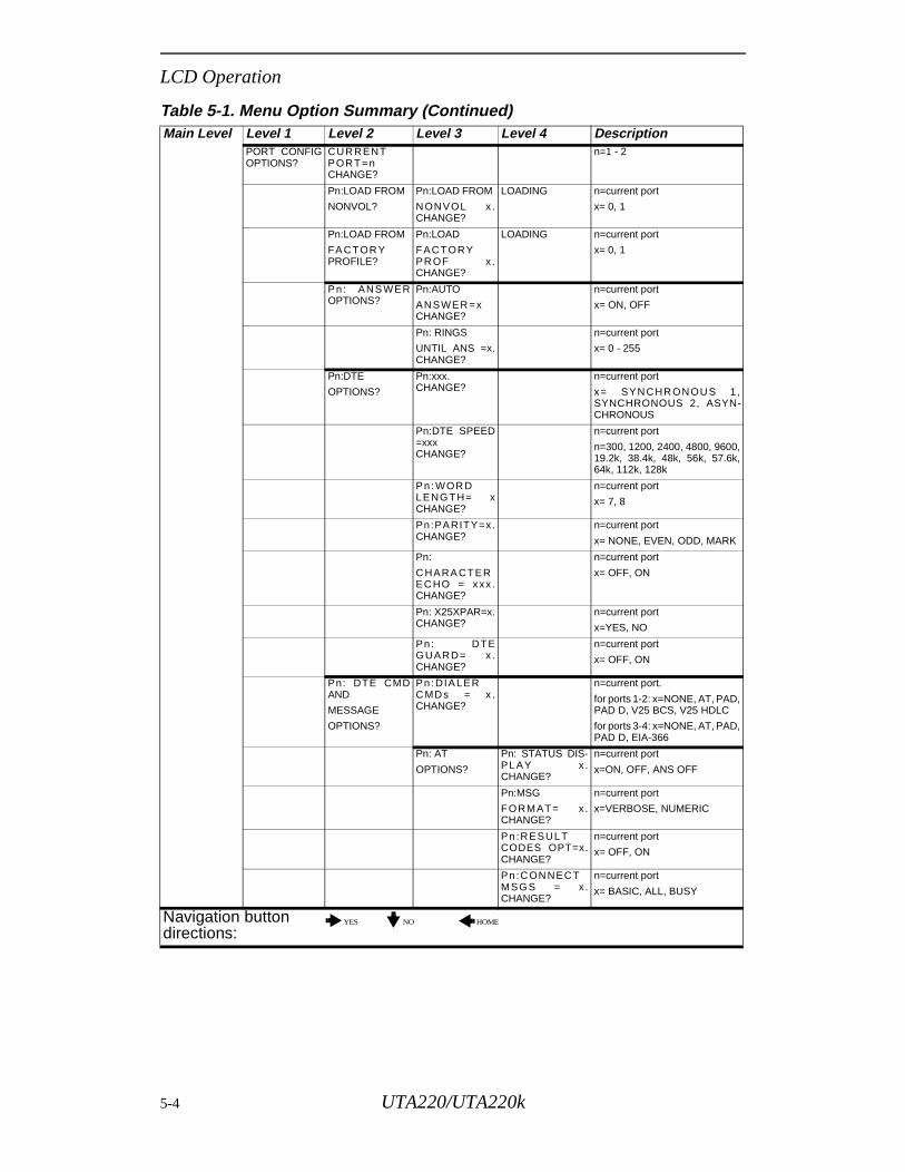
Table 5-1. Menu Option Summary Main Level Level 1 Level 2 Level 3 Level 4 DescriptionISDN
TER MINA LADAPTER
DIAL/HANGUP
OPTIONS? Current Port: nPn:ENTERNUMBER TODIAL?
Pn:---------- EN TER#.CHANGE
n=current port. Note 2
Pressing Call/Hangup fromanywhere in menu advances toENTER NUMBER screen
Pn:REDIAL? x n=current port
x=last number dialed. Note 2
Pn:DIALSTORED NUM-BER?
Pn:DIAL TEL #t?s
n=current ports =stored number t=0-9 storageindex. Note 2
Pn:V IEW/CHAN GESTORED TELNUM?
Pn:x . Te l # t .CHANGE?
n=current port
x= 13 digits of the phone num-ber. Phone number can contain40 digits, scrolled 1 digit / sec.t=0-9 storage index. Note 3
Pn: HANGUP? n=current port. Note 2
STATUS
DISPLAYS?
Current Port= n.
Change?
OR
n=current port
CALL STATUS SCREEN
s =IDLE, SETTING UP,
D IALING, PROCEED ING,RINGING, ECHO
CANCELING ONLINE,
INCOMING CALL,
ANSWERING,
DISCONNECTING, BUSY,DISCONNECTED
Pn:ONL INEprmd
p=CLEAR, BOND, T-LINK,V.120
m=SYNC-1, SYNC-2, ASYNC
r =300, 1200, 2400, 4800, 9600,1k, 38k, 48k, 56k, 57k, 64k,112k, 128k
d=8E, 8O, 8N, 7E, 7O, 7N, 7M
This screen appears once a callis connected. Note 4
C ON FIGURA -TION
OPTIONS?
SWITCH
CONFIG
OPTIONS?
SWITCH TYPEOPTION?
x.CHANGE? x=NATIONAL ISDN , NTDMS100 , A T& T 5ESSSELECTED
WILL DESTROYN ET OP TS ,CONT?
RE SETTINGSW ITCH OP-TIONS
The query appears only if thenetwork type has changed.
SWITCH
VERSION
OPTION?
x VERSION.CHANGE?
x=5ESS MULTIPOINT, 5ESSPT TO PT, (if switch type=ATT)
x=DMS100 PVC IC-0, DMS100PVC IC-1 (if switch type = NT)
Navigation button directions:
YES NO HOME
5-2 UTA220/UTA220k
LCD Operation
SWITCH
CONFIG
OPTIONS?
(cont.)
B -C HAN NELOPTIONS?
B-CH ANN ELPROV
OPTIONS?
B1 = x
CHANGE?
x= NONE, PERMANENT
B2 = x
CHANGE?
x= NONE, PERMANENT
D-CHANNEL OP-TIONS?
D -C HANN ELPROV
OPTIONS?
D-CHAN PROVI-SION x. CHANGE?
x= NONE, X.25
D -C HANN ELLAPD
OPTIONS?
CURRENT PORT= n. CHANGE?
n=1 or 2
Pn:X.25 TEI = x.CHANGE?
n=CURRENT PORT
x= 0-63, DIS, AUTO
Pn:DATA TEI =xCHANGE?
n=CURRENT PORT
x= 0-63, DIS, AUTO
Pn:x SPID.CHANGE?
n=CURRENT PORT
x=SPID, up to 20 digits
Pn : x D N.CHANGE?
n=CURRENT PORT
x=DN, up to 20 digits
D-CHAN PR OV ISIONX.25
OPTIONS?
RX W IND OWSIZE=x.
CHANGE?
x=1 - 7
TX W IND OWSIZE=x.
CHANGE?
x=1 - 7
RX PACK ETSIZE=x.
CHANGE?
x=128, 256
TX PACK ETSIZE=x.
CHANGE?
x=128, 256
PVC NUMBER =x
CHANGE?
x=0 - 255
INC LOGIC ALCHAN NUM=x.
CHANGE?
x=0 - 255
2 -W AY LOGCHAN NUM=x.
CHANGE?
x=0 - 255
OUT LOGICALCHAN NUM=x.
CHANGE?
x=0 - 255
SEQUENCE NUM-BER MOD=x.
CHANGE?
x=8, 128
FRONT PANELLOCK
OPTION?
ENTER PASS-W OR D - - - - - - -CHANGE?
Enter password to gain accessto lock option screen.
FRONT PANELLCK = xCHANGE?
x= UNLOCKED, OPTIONS,OPT/ACT
SAVE SWITCHAND GLOBL TONONVOL?
SAVING
Table 5-1. Menu Option Summary (Continued) Main Level Level 1 Level 2 Level 3 Level 4 Description
Navigation button directions:
YES NO HOME
UTA220/UTA220k 5-3
LCD Operation
PORT CONFIGOPTIONS?
CUR RENTPOR T=nCHANGE?
n=1 - 2
Pn:LOAD FROM
NONVOL?
Pn:LOAD FROM
NONVOL x .CHANGE?
LOADING n=current port
x= 0, 1
Pn:LOAD FROM
FA CTOR YPROFILE?
Pn:LOAD
FAC TORYPR OF x .CHANGE?
LOADING n=current port
x= 0, 1
Pn: ANS WEROPTIONS?
Pn:AUTO
AN SWER =xCHANGE?
n=current port
x= ON, OFF
Pn: RINGS
UNTIL ANS =x.CHANGE?
n=current port
x= 0 - 255
Pn:DTE
OPTIONS?
Pn:xxx. CHANGE?
n=current port
x= SYN CHR ON OU S 1 ,SYNCHRONOUS 2, ASYN-CHRONOUS
Pn:DTE SPEED=xxx CHANGE?
n=current port
n=300, 1200, 2400, 4800, 9600,19.2k, 38.4k, 48k, 56k, 57.6k,64k, 112k, 128k
Pn :WOR DLENGTH= xCHANGE?
n=current port
x= 7, 8
Pn:PARITY=x.CHANGE?
n=current port
x= NONE, EVEN, ODD, MARK
Pn:
C HARA CTEREC HO = xxx .CHANGE?
n=current port
x= OFF, ON
Pn: X25XPAR=x.CHANGE?
n=current port
x=YES, NO
Pn : DTEGUAR D= x .CHANGE?
n=current port
x= OFF, ON
Pn: DTE CMDAND
MESSAGE
OPTIONS?
Pn :DIA LERCMDs = x .CHANGE?
n=current port.
for ports 1-2: x=NONE, AT, PAD,PAD D, V25 BCS, V25 HDLC
for ports 3-4: x=NONE, AT, PAD,PAD D, EIA-366
Pn: AT
OPTIONS?
Pn: STATUS DIS-PLAY x .CHANGE?
n=current port
x=ON, OFF, ANS OFF
Pn:MSG
FORMAT= x .CHANGE?
n=current port
x=VERBOSE, NUMERIC
Pn :R ESULTCODES OPT=x.CHANGE?
n=current port
x= OFF, ON
Pn :C ON NEC TMSGS = x .CHANGE?
n=current port
x= BASIC, ALL, BUSY
Table 5-1. Menu Option Summary (Continued) Main Level Level 1 Level 2 Level 3 Level 4 Description
Navigation button directions:
YES NO HOME
5-4 UTA220/UTA220k
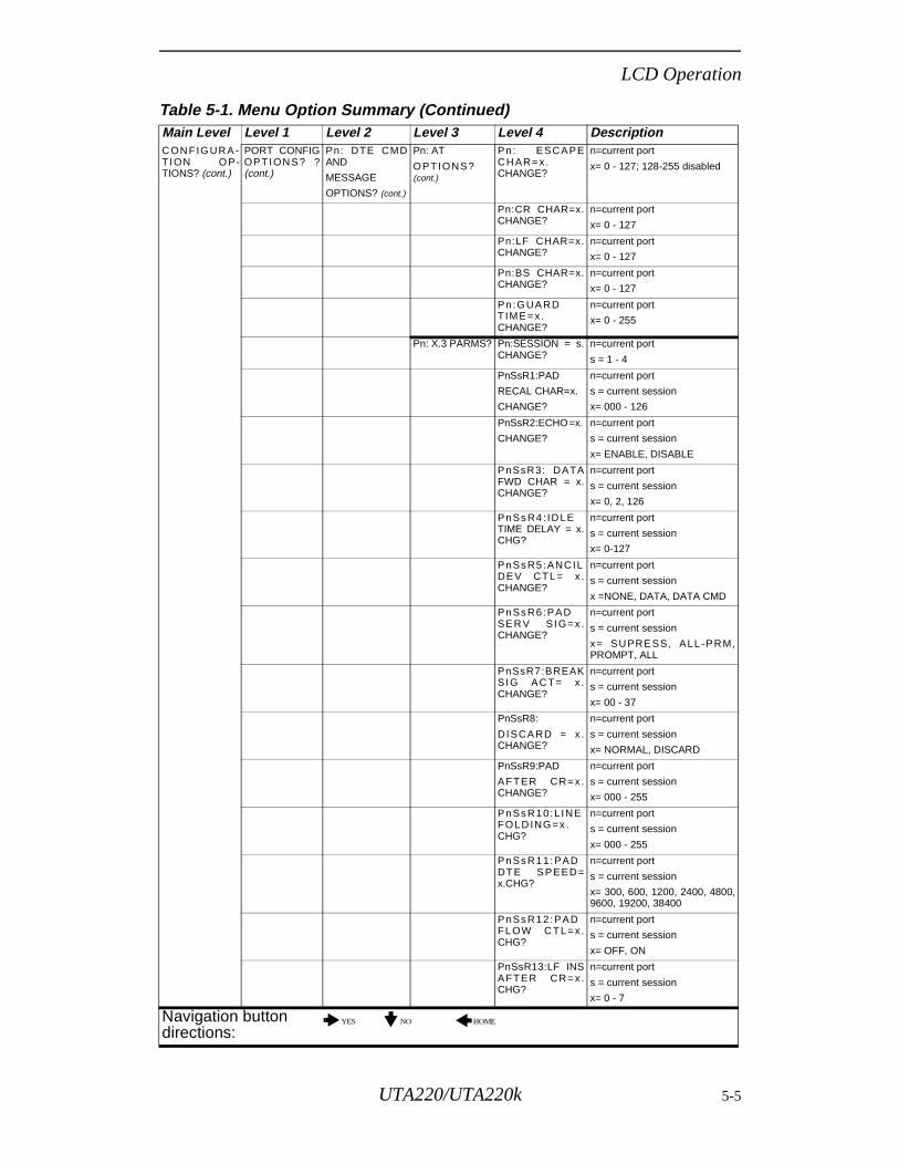
LCD Operation
C ON FIGURA -T ION OP-TIONS? (cont.)
PORT CONFIGOPTION S? ?(cont.)
Pn: DTE CMDAND
MESSAGE
OPTIONS? (cont.)
Pn: AT
OPTIONS?(cont.)
Pn : ESCAPECH AR= x.CHANGE?
n=current port
x= 0 - 127; 128-255 disabled
Pn:CR CHAR=x.CHANGE?
n=current port
x= 0 - 127
Pn:LF CHAR=x.CHANGE?
n=current port
x= 0 - 127
Pn:BS CHAR=x.CHANGE?
n=current port
x= 0 - 127
Pn :GUA RDTIME= x.CHANGE?
n=current port
x= 0 - 255
Pn: X.3 PARMS? Pn:SESSION = s.CHANGE?
n=current port
s = 1 - 4
PnSsR1:PAD
RECAL CHAR=x.
CHANGE?
n=current port
s = current session
x= 000 - 126
PnSsR2:ECHO =x.
CHANGE?
n=current port
s = current session
x= ENABLE, DISABLE
PnSsR3: DATAFWD CHAR = x.CHANGE?
n=current port
s = current session
x= 0, 2, 126
PnSsR4 : ID LETIME DELAY = x.CHG?
n=current port
s = current session
x= 0-127
PnSsR5 :ANC ILDE V CTL= x .CHANGE?
n=current port
s = current session
x =NONE, DATA, DATA CMD
PnSsR6 :PADSER V SIG= x .CHANGE?
n=current port
s = current session
x= SUPRESS, ALL -PRM,PROMPT, ALL
PnSsR7:BREAKSIG AC T= x .CHANGE?
n=current port
s = current session
x= 00 - 37
PnSsR8:
DISCA RD = x .CHANGE?
n=current port
s = current session
x= NORMAL, DISCARD
PnSsR9:PAD
AFTER CR= x.CHANGE?
n=current port
s = current session
x= 000 - 255
PnSsR10:L INEFOLD ING=x .CHG?
n=current port
s = current session
x= 000 - 255
PnSsR11:PADDTE S PEED=x.CHG?
n=current port
s = current session
x= 300, 600, 1200, 2400, 4800,9600, 19200, 38400
PnSsR12:PADFLOW C TL= x.CHG?
n=current port
s = current session
x= OFF, ON
PnSsR13:LF INSAFTER CR= x.CHG?
n=current port
s = current session
x= 0 - 7
Table 5-1. Menu Option Summary (Continued) Main Level Level 1 Level 2 Level 3 Level 4 Description
Navigation button directions:
YES NO HOME
UTA220/UTA220k 5-5
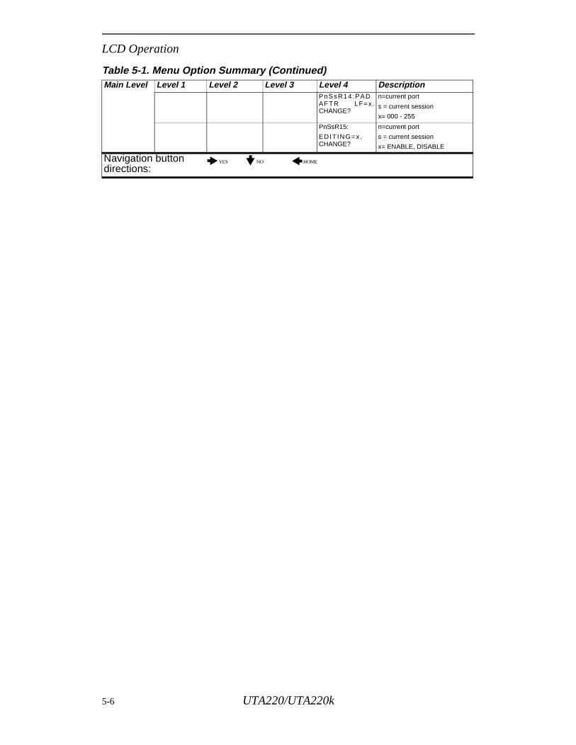
LCD Operation
PnSsR14:PADAFTR LF= x.CHANGE?
n=current port
s = current session
x= 000 - 255
PnSsR15:
ED IT IN G= x.CHANGE?
n=current port
s = current session
x= ENABLE, DISABLE
Table 5-1. Menu Option Summary (Continued) Main Level Level 1 Level 2 Level 3 Level 4 Description
Navigation button directions:
YES NO HOME
5-6 UTA220/UTA220k
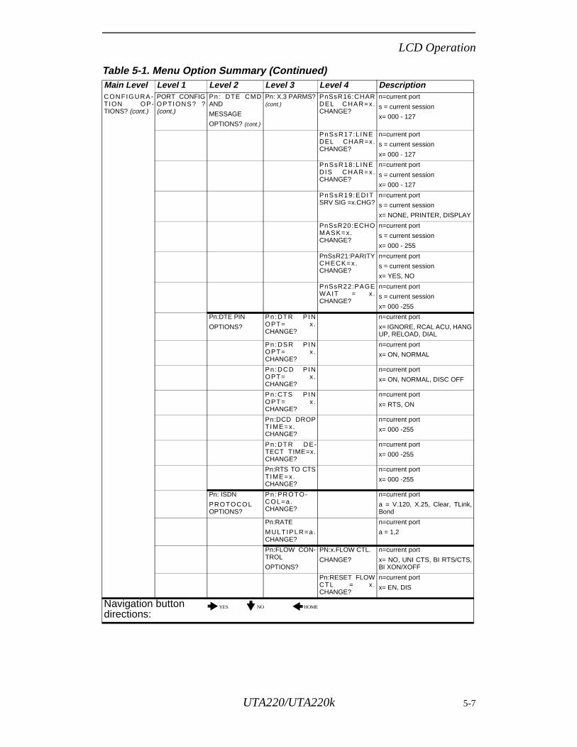
LCD Operation
C ON FIGURA -T ION OP-TIONS? (cont.)
PORT CONFIGOPTION S? ?(cont.)
Pn: DTE CMDAND
MESSAGE
OPTIONS? (cont.)
Pn: X.3 PARMS?(cont.)
PnSsR16:CHARDE L C HAR= x.CHANGE?
n=current port
s = current session
x= 000 - 127
PnSsR17:L INEDEL CHAR=x.CHANGE?
n=current port
s = current session
x= 000 - 127
PnSsR18:L INEDIS C HAR= x.CHANGE?
n=current port
s = current session
x= 000 - 127
PnSsR19:EDITSRV SIG =x.CHG?
n=current port
s = current session
x= NONE, PRINTER, DISPLAY
PnSsR20:ECHOMASK= x.CHANGE?
n=current port
s = current session
x= 000 - 255
PnSsR21:PARITYCH ECK= x.CHANGE?
n=current port
s = current session
x= YES, NO
PnSsR22:PAGEWA IT = x .CHANGE?
n=current port
s = current session
x= 000 -255
Pn:DTE PIN
OPTIONS?
Pn :DTR PINOPT= x .CHANGE?
n=current port
x= IGNORE, RCAL ACU, HANGUP, RELOAD, DIAL
Pn :DSR PINOPT= x .CHANGE?
n=current port
x= ON, NORMAL
Pn :DCD PINOPT= x .CHANGE?
n=current port
x= ON, NORMAL, DISC OFF
Pn :CTS P INOPT= x .CHANGE?
n=current port
x= RTS, ON
Pn:DCD DROPTIME =x.CHANGE?
n=current port
x= 000 -255
Pn :DTR D E-TECT TIME=x.CHANGE?
n=current port
x= 000 -255
Pn:RTS TO CTSTIME =x.CHANGE?
n=current port
x= 000 -255
Pn: ISDN
PROTOCOLOPTIONS?
Pn :PROTO-C OL=a .CHANGE?
n=current port
a = V.120, X.25, Clear, TLink,Bond
Pn:RATE
MULTIP LR =a .CHANGE?
n=current port
a = 1,2
Pn:FLOW CON-TROL
OPTIONS?
PN:x.FLOW CTL.
CHANGE?
n=current port
x= NO, UNI CTS, BI RTS/CTS,BI XON/XOFF
Pn:RESET FLOWCTL = x .CHANGE?
n=current port
x= EN, DIS
Table 5-1. Menu Option Summary (Continued) Main Level Level 1 Level 2 Level 3 Level 4 Description
Navigation button directions:
YES NO HOME
UTA220/UTA220k 5-7
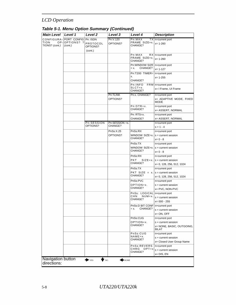
LCD Operation
C ON FIGURA -T ION OP-TIONS? (cont.)
PORT CONFIGOPTION S? ?(cont.)
Pn: ISDN
PROTOCOLOPTIONS?
(cont.)
Pn:V.120
OPTIONS?
Pn :MAX TXFRAME SIZE=x.CHANGE?
n=current port
x= 1-260
Pn :MAX RXFRAME SIZE=x.CHANGE?
n=current port
x= 1-260
Pn:WINDOW SIZE= x. CHANGE?
n=current port
x= 1-127
Pn:T200 TIMER=x.
CHANGE?
n=current port
x= 1-255
Pn : INFO FR MSLCT=x .CHANGE?
n=current port
x= I Frame, UI Frame
Pn:TLINK
OPTIONS?
Pn:x. CHANGE? n=current port
x= ADAPTIVE MODE, FIXEDMODE
Pn:D TR=x .CHANGE?
n=current port
x= ASSERT, NORMAL
Pn: RTS=x.
CHANGE?
n=current port
x= ASSERT, NORMAL
Pn:SESSIONOPTIONS?
Pn:SESSION =s.CHANGE?
n=current port
s = 1 - 4
PnSs:X.25
OPTIONS?
PnSs:RX
WINDOW SIZE=x.CHANGE?
n=current port
s = current session
x= 0 - 8
PnSs:TX
WINDOW SIZE=x.CHANGE?
n=current port
s = current session
x= 0 - 8
PnSs:RX
PKT S IZE= x.CHANGE?
n=current port
s = current session
x= 0, 128, 256, 512, 1024
PnSs:TX
PKT SIZE = x.CHANGE?
n=current port
s = current session
x= 0, 128, 256, 512, 1024
PnSs:PVC
OPTION=x .CHANGE?
n=current port
s = current session
x= PVC, NON-PVC
PnSs: LOGICALCH N NU M= x.CHANGE?
n=current port
s = current session
x= 000 - 255
PnSs:D BIT CONF= x. CHANGE?
n=current port
s = current session
x= ON, OFF
PnSs:CUG
OPTION=x .CHANGE?
n=current port
s = current session
x= NONE, BASIC, OUTGOING,BILAT
PnSs :CU GNA ME =x.CHANGE?
n=current port
s = current session
x= Closed User Group Name
PnSs :REV ERSCH RG OPT=xCHANGE?
n=current port
s = current session
x= DIS, EN
Table 5-1. Menu Option Summary (Continued) Main Level Level 1 Level 2 Level 3 Level 4 Description
Navigation button directions:
YES NO HOME
5-8 UTA220/UTA220k
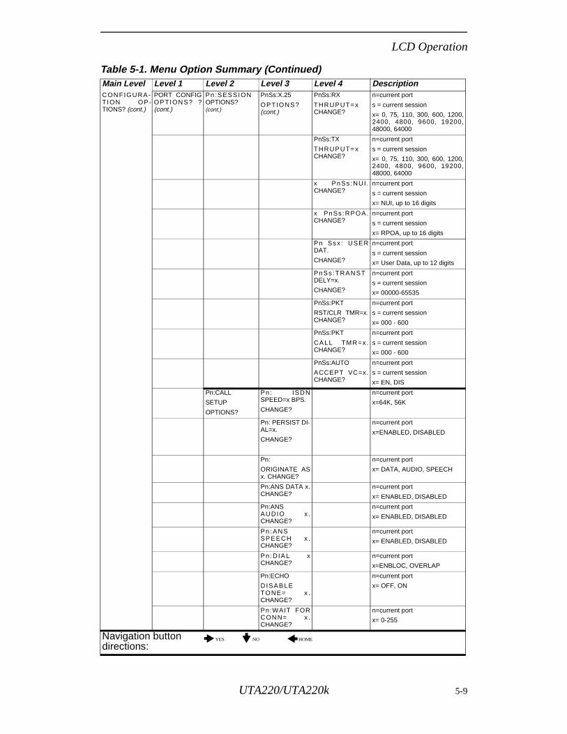
LCD Operation
C ON FIGURA -T ION OP-TIONS? (cont.)
PORT CONFIGOPTION S? ?(cont.)
Pn:SESSIONOPTIONS? (cont.)
PnSs:X.25
OPTIONS?(cont.)
PnSs:RX
THR UPU T= xCHANGE?
n=current port
s = current session
x= 0, 75, 110, 300, 600, 1200,2400, 4800, 9600, 19200,48000, 64000
PnSs:TX
THR UPU T= xCHANGE?
n=current port
s = current session
x= 0, 75, 110, 300, 600, 1200,2400, 4800, 9600, 19200,48000, 64000
x PnSs :NU I .CHANGE?
n=current port
s = current session
x= NUI, up to 16 digits
x PnSs :RPOA.CHANGE?
n=current port
s = current session
x= RPOA, up to 16 digits
Pn Ssx : USERDAT.
CHANGE?
n=current port
s = current session
x= User Data, up to 12 digits
PnSs :TRAN STDELY=x.
CHANGE?
n=current port
s = current session
x= 00000-65535
PnSs:PKT
RST/CLR TMR=x.CHANGE?
n=current port
s = current session
x= 000 - 600
PnSs:PKT
CA LL TMR= x.CHANGE?
n=current port
s = current session
x= 000 - 600
PnSs:AUTO
ACCEPT VC=x.CHANGE?
n=current port
s = current session
x= EN, DIS
Pn:CALL
SETUP
OPTIONS?
Pn : ISD NSPEED=x BPS.
CHANGE?
n=current port
x=64K, 56K
Pn: PERSIST DI-AL=x.
CHANGE?
n=current port
x=ENABLED, DISABLED
Pn:
ORIGINATE ASx. CHANGE?
n=current port
x= DATA, AUDIO, SPEECH
Pn:ANS DATA x.CHANGE?
n=current port
x= ENABLED, DISABLED
Pn:ANS AU DIO x .CHANGE?
n=current port
x= ENABLED, DISABLED
Pn :ANSSP EECH x .CHANGE?
n=current port
x= ENABLED, DISABLED
Pn :DIA L xCHANGE?
n=current port
x=ENBLOC, OVERLAP
Pn:ECHO
D ISAB LETONE= x .CHANGE?
n=current port
x= OFF, ON
Pn:WAIT FORCONN= x .CHANGE?
n=current port
x= 0-255
Table 5-1. Menu Option Summary (Continued) Main Level Level 1 Level 2 Level 3 Level 4 Description
Navigation button directions:
YES NO HOME
UTA220/UTA220k 5-9
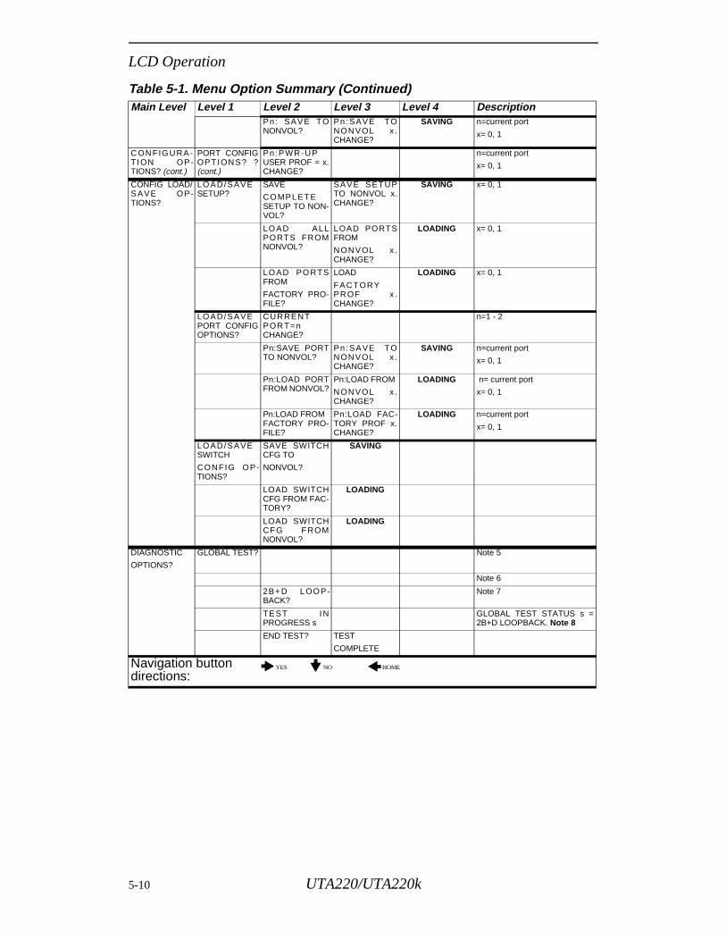
LCD Operation
Pn: SAVE TONONVOL?
Pn :SAVE TONONVOL x .CHANGE?
SAVING n=current port
x= 0, 1
C ON FIGURA -T ION OP-TIONS? (cont.)
PORT CONFIGOPTION S? ?(cont.)
Pn:PWR -U PUSER PROF = x.CHANGE?
n=current port
x= 0, 1
CONFIG LOAD/S AVE OP-TIONS?
LOAD/SAVESETUP?
SAVE
COMPLETESETUP TO NON-VOL?
SAVE SETUPTO NONVOL x.CHANGE?
SAVING x= 0, 1
LOAD ALLPORTS FROMNONVOL?
LOAD PORTSFROM
NONVOL x .CHANGE?
LOADING x= 0, 1
LOAD PORTSFROM
FACTORY PRO-FILE?
LOAD
FAC TORYPR OF x .CHANGE?
LOADING x= 0, 1
LOAD/SAVEPORT CONFIGOPTIONS?
CUR RENTPOR T=nCHANGE?
n=1 - 2
Pn:SAVE PORTTO NONVOL?
Pn :SAVE TONONVOL x .CHANGE?
SAVING n=current port
x= 0, 1
Pn:LOAD PORTFROM NONVOL?
Pn:LOAD FROM
NONVOL x .CHANGE?
LOADING n= current port
x= 0, 1
Pn:LOAD FROMFACTORY PRO-FILE?
Pn:LOAD FAC-TORY PROF x.CHANGE?
LOADING n=current port
x= 0, 1
LOAD/SAVESWITCH
CONFIG OP-TIONS?
SAVE SWITCHCFG TO
NONVOL?
SAVING
LOAD SWITCHCFG FROM FAC-TORY?
LOADING
LOAD SWITCHCFG FROMNONVOL?
LOADING
DIAGNOSTIC
OPTIONS?
GLOBAL TEST? Note 5
Note 6
2B+ D LOOP-BACK?
Note 7
TE ST INPROGRESS s
GLOBAL TEST STATUS s =2B+D LOOPBACK. Note 8
END TEST? TEST
COMPLETE
Table 5-1. Menu Option Summary (Continued) Main Level Level 1 Level 2 Level 3 Level 4 Description
Navigation button directions:
YES NO HOME
5-10 UTA220/UTA220k
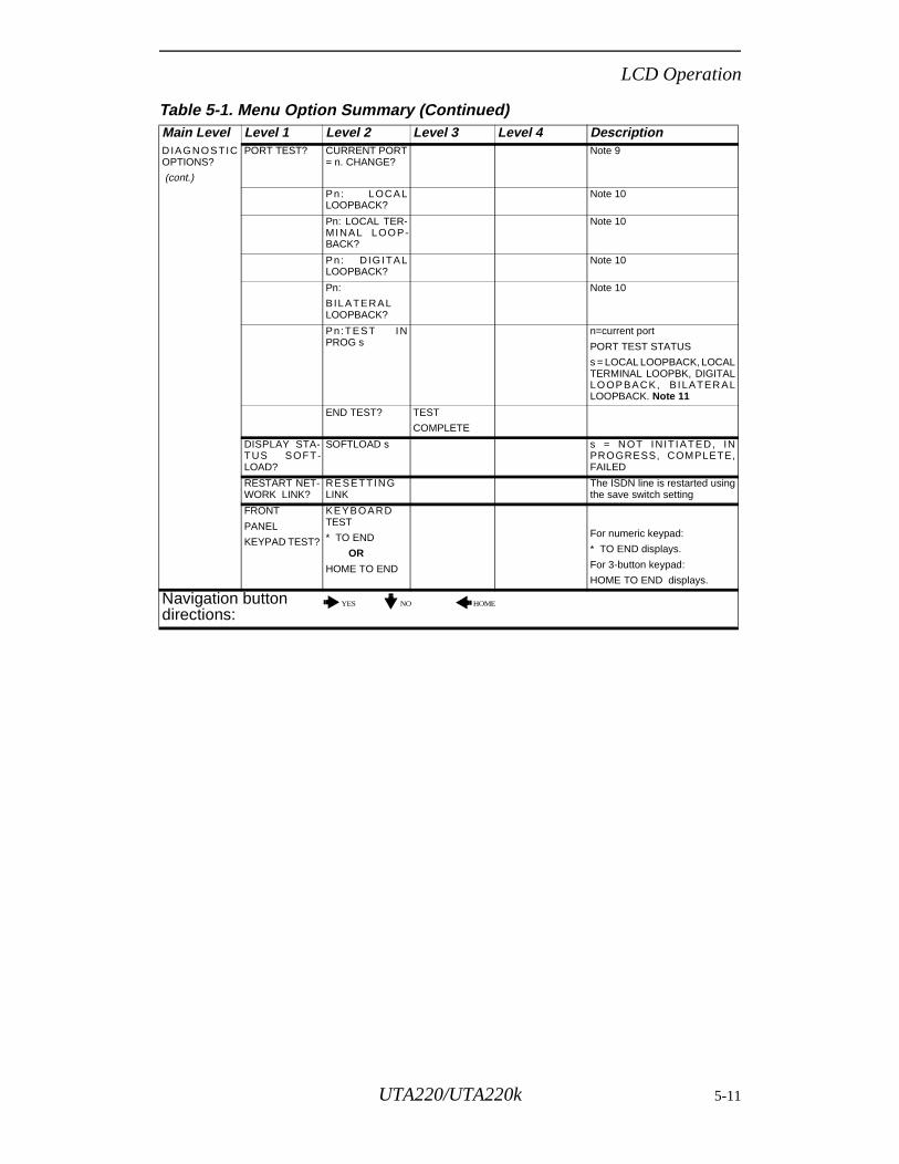
LCD Operation
D IAGNOSTICOPTIONS?
(cont.)
PORT TEST? CURRENT PORT= n. CHANGE?
Note 9
Pn: LOCA LLOOPBACK?
Note 10
Pn: LOCAL TER-MINAL LOOP-BACK?
Note 10
Pn: D IG ITA LLOOPBACK?
Note 10
Pn:
B ILATERALLOOPBACK?
Note 10
Pn:TEST INPROG s
n=current port
PORT TEST STATUS
s = LOCAL LOOPBACK, LOCALTERMINAL LOOPBK, DIGITALLOOP BACK, B ILATER ALLOOPBACK. Note 11
END TEST? TEST
COMPLETE
DISPLAY STA-TUS SOFT-LOAD?
SOFTLOAD s s = NOT INIT IATED, INPROGRESS, COMPLETE,FAILED
RESTART NET-WORK LINK?
RESETTINGLINK
The ISDN line is restarted usingthe save switch setting
FRONT
PANEL
KEYPAD TEST?
KEYBOARDTEST
* TO END
OR
HOME TO END
For numeric keypad:
* TO END displays.
For 3-button keypad:
HOME TO END displays.
Table 5-1. Menu Option Summary (Continued) Main Level Level 1 Level 2 Level 3 Level 4 Description
Navigation button directions:
YES NO HOME
UTA220/UTA220k 5-11
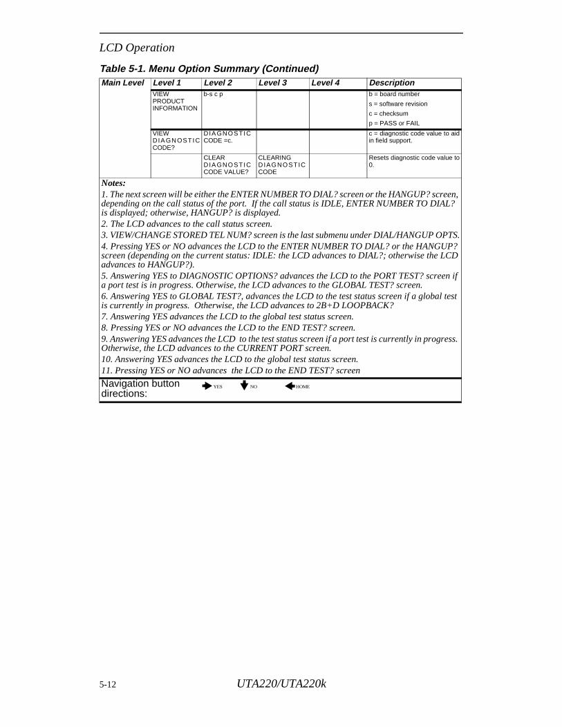
LCD Operation
VIEW PRODUCT INFORMATION
b-s c p b = board number
s = software revision
c = checksum
p = PASS or FAIL
VIEW DIA GN OSTICCODE?
DIA GNOSTICCODE =c.
c = diagnostic code value to aidin field support.
CLEAR DIA GNOSTICCODE VALUE?
CLEARING D IAGNOSTICCODE
Resets diagnostic code value to0.
Notes: 1. The next screen will be either the ENTER NUMBER TO DIAL? screen or the HANGUP? screen, depending on the call status of the port. If the call status is IDLE, ENTER NUMBER TO DIAL? is displayed; otherwise, HANGUP? is displayed.2. The LCD advances to the call status screen.3. VIEW/CHANGE STORED TEL NUM? screen is the last submenu under DIAL/HANGUP OPTS.4. Pressing YES or NO advances the LCD to the ENTER NUMBER TO DIAL? or the HANGUP? screen (depending on the current status: IDLE: the LCD advances to DIAL?; otherwise the LCD advances to HANGUP?).5. Answering YES to DIAGNOSTIC OPTIONS? advances the LCD to the PORT TEST? screen if a port test is in progress. Otherwise, the LCD advances to the GLOBAL TEST? screen.6. Answering YES to GLOBAL TEST?, advances the LCD to the test status screen if a global test is currently in progress. Otherwise, the LCD advances to 2B+D LOOPBACK?7. Answering YES advances the LCD to the global test status screen.8. Pressing YES or NO advances the LCD to the END TEST? screen.9. Answering YES advances the LCD to the test status screen if a port test is currently in progress. Otherwise, the LCD advances to the CURRENT PORT screen.10. Answering YES advances the LCD to the global test status screen.11. Pressing YES or NO advances the LCD to the END TEST? screen
Table 5-1. Menu Option Summary (Continued) Main Level Level 1 Level 2 Level 3 Level 4 Description
Navigation button directions:
YES NO HOME
5-12 UTA220/UTA220k
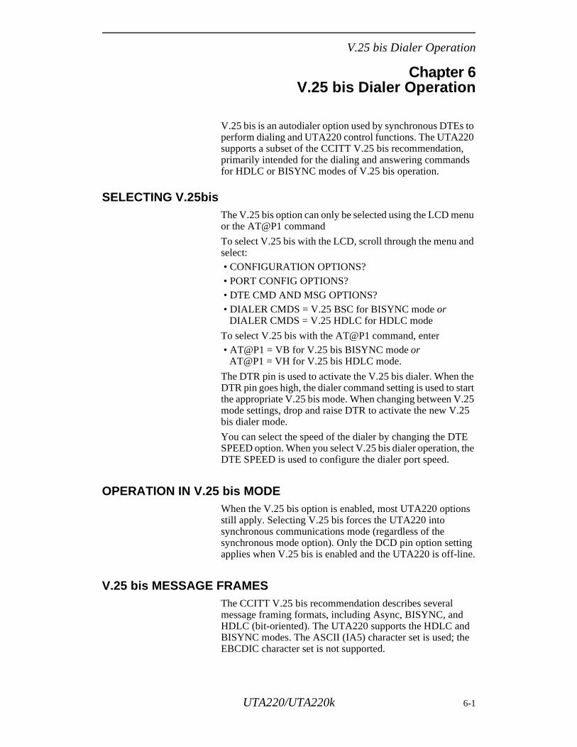
V.25 bis Dialer Operation
he tart .25 5
E the
s
g e.
e
Chapter 6V.25 bis Dialer Operation
V.25 bis is an autodialer option used by synchronous DTEs to perform dialing and UTA220 control functions. The UTA220 supports a subset of the CCITT V.25 bis recommendation, primarily intended for the dialing and answering commands for HDLC or BISYNC modes of V.25 bis operation.
SELECTING V.25bis The V.25 bis option can only be selected using the LCD menu or the AT@P1 command
To select V.25 bis with the LCD, scroll through the menu and select: • CONFIGURATION OPTIONS? • PORT CONFIG OPTIONS? • DTE CMD AND MSG OPTIONS? • DIALER CMDS = V.25 BSC for BISYNC mode or
DIALER CMDS = V.25 HDLC for HDLC mode
To select V.25 bis with the AT@P1 command, enter • AT@P1 = VB for V.25 bis BISYNC mode or
AT@P1 = VH for V.25 bis HDLC mode.
The DTR pin is used to activate the V.25 bis dialer. When tDTR pin goes high, the dialer command setting is used to sthe appropriate V.25 bis mode. When changing between Vmode settings, drop and raise DTR to activate the new V.2bis dialer mode.
You can select the speed of the dialer by changing the DTSPEED option. When you select V.25 bis dialer operation, DTE SPEED is used to configure the dialer port speed.
OPERATION IN V.25 bis MODEWhen the V.25 bis option is enabled, most UTA220 optionstill apply. Selecting V.25 bis forces the UTA220 into synchronous communications mode (regardless of the synchronous mode option). Only the DCD pin option settinapplies when V.25 bis is enabled and the UTA220 is off-lin
V.25 bis MESSAGE FRAMESThe CCITT V.25 bis recommendation describes several message framing formats, including Async, BISYNC, and HDLC (bit-oriented). The UTA220 supports the HDLC andBISYNC modes. The ASCII (IA5) character set is used; thEBCDIC character set is not supported.
UTA220/UTA220k 6-1
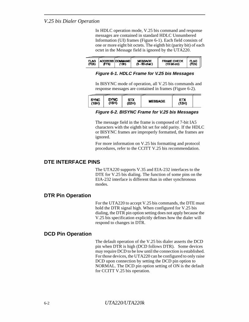
V.25 bis Dialer Operation
In HDLC operation mode, V.25 bis command and response messages are contained in standard HDLC Unnumbered Information (UI) frames (Figure 6-1). Each field consists of one or more eight bit octets. The eighth bit (parity bit) of each octet in the Message field is ignored by the UTA220.
Figure 6-1. HDLC Frame for V.25 bis Messages
In BISYNC mode of operation, all V.25 bis commands and response messages are contained in frames (Figure 6-2).
Figure 6-2. BISYNC Frame for V.25 bis Messages
The message field in the frame is composed of 7-bit IA5 characters with the eighth bit set for odd parity. If the HDLC or BISYNC frames are improperly formatted, the frames are ignored.
For more information on V.25 bis formatting and protocol procedures, refer to the CCITT V.25 bis recommendation.
DTE INTERFACE PINSThe UTA220 supports V.35 and EIA-232 interfaces to the DTE for V.25 bis dialing. The function of some pins on the EIA-232 interface is different than in other synchronous modes.
DTR Pin OperationFor the UTA220 to accept V.25 bis commands, the DTE must hold the DTR signal high. When configured for V.25 bis dialing, the DTR pin option setting does not apply because the V.25 bis specification explicitly defines how the dialer will respond to changes in DTR.
DCD Pin OperationThe default operation of the V.25 bis dialer asserts the DCD pin when DTR is high (DCD follows DTR). Some devices may require DCD to be low until the connection is established. For those devices, the UTA220 can be configured to only raise DCD upon connection by setting the DCD pin option to NORMAL. The DCD pin option setting of ON is the default for CCITT V.25 bis operation.
6-2 UTA220/UTA220k
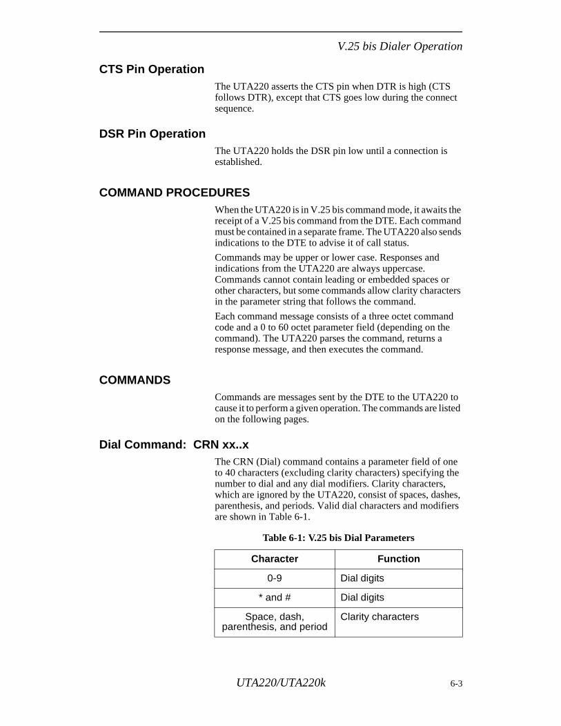
V.25 bis Dialer Operation
CTS Pin OperationThe UTA220 asserts the CTS pin when DTR is high (CTS follows DTR), except that CTS goes low during the connect sequence.
DSR Pin OperationThe UTA220 holds the DSR pin low until a connection is established.
COMMAND PROCEDURESWhen the UTA220 is in V.25 bis command mode, it awaits the receipt of a V.25 bis command from the DTE. Each command must be contained in a separate frame. The UTA220 also sends indications to the DTE to advise it of call status.
Commands may be upper or lower case. Responses and indications from the UTA220 are always uppercase. Commands cannot contain leading or embedded spaces or other characters, but some commands allow clarity characters in the parameter string that follows the command.
Each command message consists of a three octet command code and a 0 to 60 octet parameter field (depending on the command). The UTA220 parses the command, returns a response message, and then executes the command.
COMMANDSCommands are messages sent by the DTE to the UTA220 to cause it to perform a given operation. The commands are listed on the following pages.
Dial Command: CRN xx..xThe CRN (Dial) command contains a parameter field of one to 40 characters (excluding clarity characters) specifying the number to dial and any dial modifiers. Clarity characters, which are ignored by the UTA220, consist of spaces, dashes, parenthesis, and periods. Valid dial characters and modifiers are shown in Table 6-1.
Table 6-1: V.25 bis Dial Parameters
Character Function
0-9 Dial digits
* and # Dial digits
Space, dash, parenthesis, and period
Clarity characters
UTA220/UTA220k 6-3
V.25 bis Dialer Operation
After dialing, the UTA220 attempts to establish a synchronous connection with the remote UTA220. As in other synchronous modes, flow control and buffering are not used when V.25 bis is enabled. When the call begins the connection sequence, the UTA220 sends a Call Connect Indication (CNX) message. Upon connection, the UTA220 raises the DSR pin and enters the on-line data mode.
Examples of valid dial commands are:
CRN 12055550123CRN 1 (205) 555-0123 CRN 9 1-205-555-0123
Responses to the dial command are:
VAL INVCU INVMS INVPS INVPV CFICFIDT CFIET CFIRT CFIAB
Refer to Table 2 for a description of these response messages.
Connect Incoming Calls: CICThis command forces the UTA220 to answer an incoming call if the port on which the call is received is configured for manual answer (the auto-answer option is set to off). No parameters are allowed. The DTE typically issues this command after receiving an INC indication from the UTA220.
Responses to the CIC command are:
VALINV INVMS INVPS
INDICATION MESSAGES Indication messages are unsolicited messages sent by the UTA220 to indicate a special condition, such as an incoming call. These messages are described below.
Call Connect Indication: CNXThe UTA220 sends this message to the DTE to indicate that an incoming or outgoing call is physically connected end-to-end. The call connection sequence is then started. The DTE should not begin sending data until the call connection sequence is completed, which the UTA220 indicates by raising the DSR pin.
6-4 UTA220/UTA220k
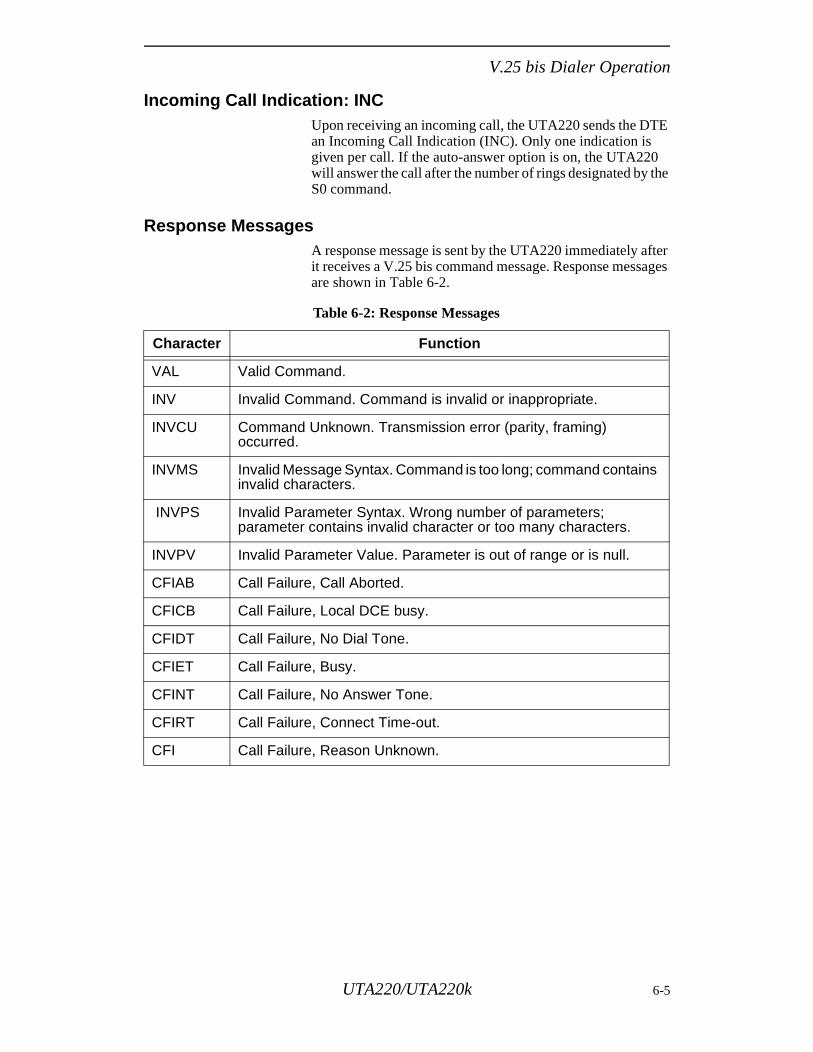
V.25 bis Dialer Operation
Incoming Call Indication: INCUpon receiving an incoming call, the UTA220 sends the DTE an Incoming Call Indication (INC). Only one indication is given per call. If the auto-answer option is on, the UTA220 will answer the call after the number of rings designated by the S0 command.
Response MessagesA response message is sent by the UTA220 immediately after it receives a V.25 bis command message. Response messages are shown in Table 6-2.
Table 6-2: Response Messages
Character Function
VAL Valid Command.
INV Invalid Command. Command is invalid or inappropriate.
INVCU Command Unknown. Transmission error (parity, framing) occurred.
INVMS Invalid Message Syntax. Command is too long; command contains invalid characters.
INVPS Invalid Parameter Syntax. Wrong number of parameters; parameter contains invalid character or too many characters.
INVPV Invalid Parameter Value. Parameter is out of range or is null.
CFIAB Call Failure, Call Aborted.
CFICB Call Failure, Local DCE busy.
CFIDT Call Failure, No Dial Tone.
CFIET Call Failure, Busy.
CFINT Call Failure, No Answer Tone.
CFIRT Call Failure, Connect Time-out.
CFI Call Failure, Reason Unknown.
UTA220/UTA220k 6-5

V.25 bis Dialer Operation
6-6 UTA220/UTA220k
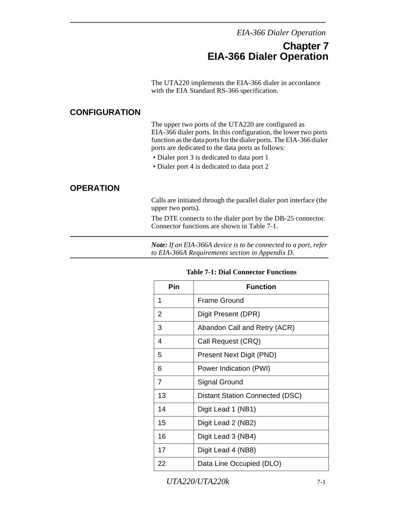
EIA-366 Dialer Operation
he
r.
Chapter 7EIA-366 Dialer Operation
The UTA220 implements the EIA-366 dialer in accordance with the EIA Standard RS-366 specification.
CONFIGURATIONThe upper two ports of the UTA220 are configured as EIA-366 dialer ports. In this configuration, the lower two ports function as the data ports for the dialer ports. The EIA-366 dialer ports are dedicated to the data ports as follows: • Dialer port 3 is dedicated to data port 1 • Dialer port 4 is dedicated to data port 2
OPERATIONCalls are initiated through the parallel dialer port interface (tupper two ports).
The DTE connects to the dialer port by the DB-25 connectoConnector functions are shown in Table 7-1.
Note: If an EIA-366A device is to be connected to a port, refer to EIA-366A Requirements section in Appendix D.
Table 7-1: Dial Connector Functions
Pin Function
1 Frame Ground
2 Digit Present (DPR)
3 Abandon Call and Retry (ACR)
4 Call Request (CRQ)
5 Present Next Digit (PND)
6 Power Indication (PWI)
7 Signal Ground
13 Distant Station Connected (DSC)
14 Digit Lead 1 (NB1)
15 Digit Lead 2 (NB2)
16 Digit Lead 3 (NB4)
17 Digit Lead 4 (NB8)
22 Data Line Occupied (DLO)
UTA220/UTA220k 7-1
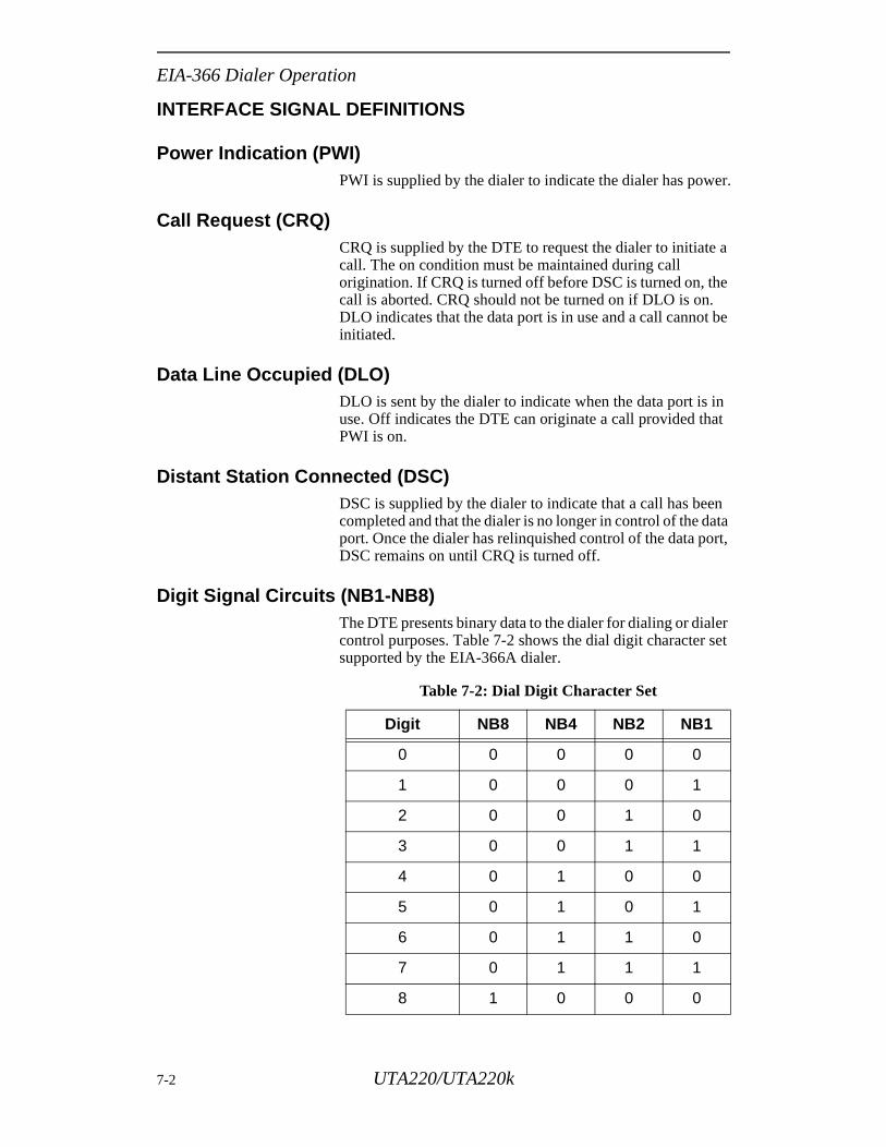
EIA-366 Dialer Operation
INTERFACE SIGNAL DEFINITIONS
Power Indication (PWI)PWI is supplied by the dialer to indicate the dialer has power.
Call Request (CRQ)CRQ is supplied by the DTE to request the dialer to initiate a call. The on condition must be maintained during call origination. If CRQ is turned off before DSC is turned on, the call is aborted. CRQ should not be turned on if DLO is on. DLO indicates that the data port is in use and a call cannot be initiated.
Data Line Occupied (DLO)DLO is sent by the dialer to indicate when the data port is in use. Off indicates the DTE can originate a call provided that PWI is on.
Distant Station Connected (DSC)DSC is supplied by the dialer to indicate that a call has been completed and that the dialer is no longer in control of the data port. Once the dialer has relinquished control of the data port, DSC remains on until CRQ is turned off.
Digit Signal Circuits (NB1-NB8)The DTE presents binary data to the dialer for dialing or dialer control purposes. Table 7-2 shows the dial digit character set supported by the EIA-366A dialer.
Table 7-2: Dial Digit Character Set
Digit NB8 NB4 NB2 NB1
0 0 0 0 0
1 0 0 0 1
2 0 0 1 0
3 0 0 1 1
4 0 1 0 0
5 0 1 0 1
6 0 1 1 0
7 0 1 1 1
8 1 0 0 0
7-2 UTA220/UTA220k
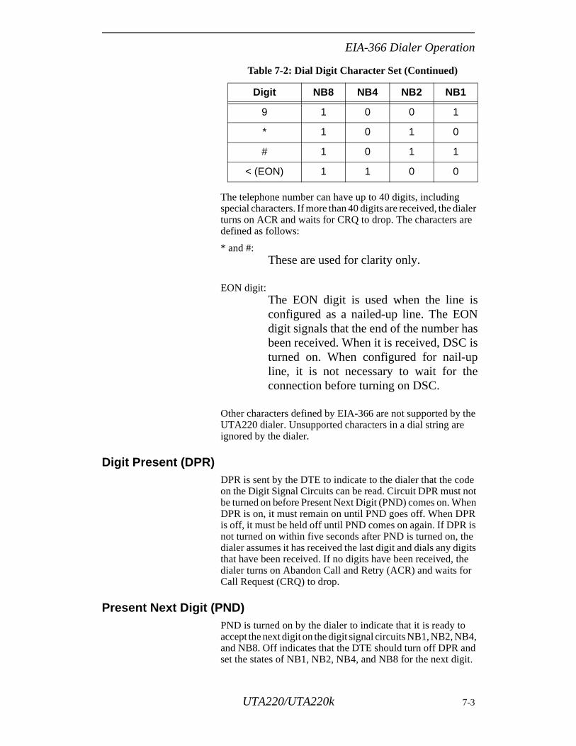
EIA-366 Dialer Operation
The telephone number can have up to 40 digits, including special characters. If more than 40 digits are received, the dialer turns on ACR and waits for CRQ to drop. The characters are defined as follows:
* and #:These are used for clarity only.
EON digit:The EON digit is used when the line isconfigured as a nailed-up line. The EONdigit signals that the end of the number hasbeen received. When it is received, DSC isturned on. When configured for nail-upline, it is not necessary to wait for theconnection before turning on DSC.
Other characters defined by EIA-366 are not supported by the UTA220 dialer. Unsupported characters in a dial string are ignored by the dialer.
Digit Present (DPR)DPR is sent by the DTE to indicate to the dialer that the code on the Digit Signal Circuits can be read. Circuit DPR must not be turned on before Present Next Digit (PND) comes on. When DPR is on, it must remain on until PND goes off. When DPR is off, it must be held off until PND comes on again. If DPR is not turned on within five seconds after PND is turned on, the dialer assumes it has received the last digit and dials any digits that have been received. If no digits have been received, the dialer turns on Abandon Call and Retry (ACR) and waits for Call Request (CRQ) to drop.
Present Next Digit (PND)PND is turned on by the dialer to indicate that it is ready to accept the next digit on the digit signal circuits NB1, NB2, NB4, and NB8. Off indicates that the DTE should turn off DPR and set the states of NB1, NB2, NB4, and NB8 for the next digit.
9 1 0 0 1
* 1 0 1 0
# 1 0 1 1
< (EON) 1 1 0 0
Table 7-2: Dial Digit Character Set (Continued)
Digit NB8 NB4 NB2 NB1
UTA220/UTA220k 7-3
EIA-366 Dialer Operation
ce
on
, ns
nds
er
ll
C)
y
itch,
Abandon Call and Retry (ACR)ACR is supplied by the dialer to indicate that the call cannot be successfully established. The on condition instructs the DTE to abandon the call by dropping the call later. ACR remains on until CRQ is turned off.
EXAMPLE DIAL SEQUENCEThe following is an example of the sequence of events that occur when a call is initiated using the EIA-366A dialer port.• Data Line Occupied (DLO) must be off for the dial sequen
to begin.• The DTE turns on Call Request (CRQ) to initiate dialing.• When CRQ is turned on, the dialer port turns on DLO to
indicate that the data port is now in use. The dialer turnsPresent Next Digit (PND) to request a dial digit from the DTE.
• The DTE sets the digit signal circuit bits (NB1, NB2, NB4and NB8) to the correct value for the first dial digit, then turon Digit Present (DPR).
• When DPR turns on, the dialer reads the digit and respowith another PND.
• The PND/DPR sequence continues until either EON is received or five seconds expires without receiving anothdigit (DPR is not turned on to present another digit).
• When all the digits are received, the dialer initiates the caon the data port to which the dialer is dedicated.
• When the call is connected, Distant Station Connected (DSis turned on by the dialer port. If the call cannot completesuccessfully, Abandon Call and Retry (ACR) is turned onuntil CRQ is turned off.
• The call can be terminated before the call is connected bturning CRQ off.
• Once the call is completed, the call can be terminated bynormal disconnect methods such as disconnect by the swthe front panel, or DTR disconnect.
7-4 UTA220/UTA220k
AT Command Operation
Chapter 8AT Command Operation
This chapter provides information on how to use AT commands to operate and configure the TA via a data port.
The UTA220 AT command set is shown in Appendix C.
AT COMMAND STATEMENTThe TA communicates with a DTE asynchronously whenever the corresponding DTE port is configured for AT command mode. When the TA is powered up, any DTE port configured for AT commands enters command mode. AT commands can then be used to configure and control the TA. The command statement is typed using the DTE keyboard and temporarily resides in a section of memory called a buffer.
The command statement must be written in a specific form so the TA recognizes and follows the instruction. The command statement begins with the letters AT and is followed by one or more commands, which can each consist of a sequence of keyboard symbols, such as & and %, letters, numbers, and is followed by a return or end-of-line character.
AT Command ModeAT commands can only be issued when the DTE port is configured for AT command mode. Normally, the DTE port is in AT command mode whenever it is off-line. After the TA establishes a connection with another TA and goes into on-line data mode, characters sent to the TA by the DTE are interpreted as data (not as commands) and are transmitted to the remote TA.
If the DTE port is configured for DIALER CMDS = NONE, AT commands are not accepted in any mode.
ESCAPE SEQUENCE: + + +If the TA is in asynchronous data mode, the escape sequence can be sent to return the TA to the command mode and remain on-line. The escape sequence consists of a pause (normally 1 second), three escape characters, and then another pause. The default escape sequence characters are: + + +.
The escape sequence character is set by the S2 command and can be changed. The escape sequence can also be disabled to prevent false escapes into command mode.
After entering the escape sequence, the TA returns to AT command mode, but does not hang up or break the connection with the remote TA. AT commands can now be entered to the TA. The ATO command returns the TA to the data mode.
UTA220/UTA220k 8-1
AT Command Operation
nd
he
r by
cter AT
ly:
ter.
al s on.
ry end-end -
CREATING A COMMAND STATEMENT: ATTo create a command statement, use the following steps:
1. Type AT, the attention code telling the unit a command statement follows.
2. Type the command.
3. Press the return key to “Enter” or send the command statement to the TA.
An example of a command statement using the dial comma(D) follows.
ATD555-1212
This statement can be read as: Attention: dial 555-1212.
Another example: Enter ATZ. This means “Attention: reset tTA and reload current configuration with stored values.”
After entering a command line the TA returns a response message indicating whether the command was accepted, ogiving the data requested by the command line.
The AT command also sets some of the TA’s DTE data parameters, such as DTE speed, parity, and bits per charato match the DTE. This process is repeated each time theprefix is typed.
COMMAND STATEMENT GUIDELINESWhen typing command statements, the following rules app• Return must be pressed to execute (Enter) a command.• The command buffer can hold 128 characters including
spaces.• Use the backspace or delete key to erase the last charac
MONITOR DISPLAY As commands are typed they normally appear on the DTEmonitor. This is called local character echo.
DTE CHARACTER ECHO: ETo determine if echo is set properly, type AT. If the termindisplays AT, echo is set correctly. If it displays AATT, thenecho should be disabled by typing ATE. If the terminal doenot display the AT at all, echo should be enabled by typingATE1. The echo option only affects command mode operati
COMMAND STATEMENT BUFFERThe TA temporarily stores up to 128 characters in a memobuffer. If more than 128 characters are entered before the of-line characters, the TA ceases to echo and waits for the of line character. To correct this condition, retype the command using 128 characters or less.
8-2 UTA220/UTA220k
AT Command Operation
nd
is the
The characters the AT command interpreter uses as end-of-line, line feed, and backspace are set respectively by the S3, S4, and S5 commands and can be changed.
The punctuation used in telephone numbers takes up space in the buffer, as do blank characters used as spaces to help increase readability.
BACKSPACE KEYUse the backspace key to change the command statement or correct errors. The backspace key allows the cursor to be moved back to the character(s) in error. The command can then be retyped from that point.
Example: ATD5551211 has been typed. To change the last 1 to 2, press the backspace key once, type 2, and press return to execute the command.
REPEATING A COMMAND: A/This command tells the TA to repeat the last command stored in its buffer. The command is automatically executed without any need to retype the command or press the return key.
Example: The ATD5551212 command has been executed, and the phone is busy. To repeat the instruction type A/, but do not use AT before this command, as AT would empty the buffer and there would be no command to repeat.
NUMBERED COMMANDSSeries of commands starting with the same letter are distinguished by a number following the letter.
For example, the E0 command selects echo off, and E1 selects echo on.
GROUP COMMANDSA group of commands can be typed in a single statement. Pressing the RETURN key sends the entire command string to the TA, which executes each command, in the order it appears in the command statement, from left to right.
For example, the command statement ATQ0V0D5551212 means:• AT Attention• Q Allow status messages to be sent• V Select status• D Dial 555-1212
The TA executes the AT command followed by the Q, V, aD commands. The TA returns the status message corresponding to the last command on the line. If an errorencountered in a command line, subsequent commands online are ignored.
UTA220/UTA220k 8-3
AT Command Operation
or ne er
ere ich rt
ants
re d.
her he s re
Some commands use special formats or have special rules concerning their use. For example, the dial D command initiates the dial process so no other commands, only dial modifiers, can follow the D command.
COMMAND SCOPEThe scope of a command refers to the extent of its effect on the TA. AT commands have a scope of Global, Channel, or Port.
Global commands affect the operating characteristics of the TA as a whole, potentially disrupting operation on all of the ports and channels. Thus, a global command should be used with caution (or not at all) if there are currently active calls on any port.
Channel commands affect only the operation of the B1, B2, or D-Channels of the TA. These commands should be used with caution if there are active calls on any port.
Port commands affect only the operation of the particular DTE port in use. If the user is issuing a port command via DTE port 1, then only DTE port 1 characteristics are affected. This rule does not apply if the user has entered Supervisor Command Mode (explained in the next section).
Supervisor Command ModeThe UTA220 is equipped with a feature called “AT SupervisCommand Mode.” This allows AT commands issued from oDTE port to be executed as if they were coming from anothDTE port. This includes call placement and call control.
To enter supervisor command mode, AT>Cn is entered, whn is the port to control. AT>C? can be entered to display whport is being controlled. To return to control of the DTE poto which you are connected, enter AT>C0 or AT>C.
For example, a user may be connected to DTE port 3 and wto control DTE port 1. The user enters AT>C1 at the DTE console. Now the user may operate as if he or she were connected to DTE port 1. All port commands issued from heon will affect DTE port 1 until the AT>C command is entere
In supervisor command mode, when a call is placed for anotDTE port, the controlled port enters the on-line mode while tsupervisor port is still off-line. The supervisory port still hafull control of the controlled DTE port. Connect messages adirected to the supervisor port in addition to the port beingcontrolled.
Caution: There is no mechanism to prevent a DTE port from being controlled by another DTE port. A DTE port can be controlled by more than one other DTE port.
8-4 UTA220/UTA220k
Rate Adaption
is eed e t a
nd
the m
r t is
d
Chapter 9Rate Adaption
To allow greater flexibility for your DTE, three rate adaption protocols are available for use on the B-channel: T-Link, V.120, and Bonding (see Chapter 10 for a description of Bonding). These protocols allow your DTE to operate both synchronously and asynchronously, and at a different speed than the B-channel.
RATE ADAPTIONWhen a data call is placed, the TA tries to establish physical data connection on the ISDN B-channel. The B-channel is a digital channel that can transfer data at 56 or 64 kbps, depending on the path the network chooses when routing the call.
A rate adaption protocol is necessary if the user’s DTE rateother than 56 or 64 kbps. The protocol adapts the lower spof the DTE to the higher speed of the ISDN B-channel. ThLCD menu or the AT%A2 command can be used to selecrate adaption protocol.
This chapter discusses two rate adaption protocols: TLink aV.120. • T-Link does not guarantee error free data; it only adapts
lower DTE speed to the higher ISDN speed to a maximuof 19.2 kbps asynchronous and 64 kbps synchronous.
• V.120 is an error-controlling protocol that guarantees errofree data transfer at speeds up to 128 kbps. (Throughpulimited by the B-Channel to about 70 kbps.)
T-LINKT-Link is a Northern Telecom proprietary rate adaption protocol. It supports synchronous and asynchronous rate adaption at a variety of speeds.
To select T-Link with the LCD, scroll through the menu anselect: • CONFIGURATION OPTIONS? • PORT CONFIG OPTIONS? • PROTOCOL OPTIONS? • PROTOCOL = T-LINK
To select T-Link with the AT%A2 command, enter AT%A2=1.
UTA220/UTA220k 9-1
Rate Adaption
h be eed
the
t ns
ped
r
he e
TA
pin
in
When using a rate adaption protocol, both the calling and called units must use the same protocol. Also, unless the TA is configured for T-Link “adaptive mode,” the DTEs on botends must be set to the same DTE speed before data cantransferred. In the adaptive mode, the TA can adjust its spautomatically to match the remote unit. To use this mode,however, the DTE must also be able to change its speed according to the connect speed of the TA, as indicated by rate in the connect message.
Flow Control and Pin OptionsWhen using T-Link the flow control option for the DTE poris overridden. In addition the RTS, CTS, and DTR pin optioare overridden. The T-Link protocol itself defines the way these pins are handled.
T-Link transmits the state of the RTS pin to the remote TAwhere it is transmitted back as the CTS state. DTR is mapto the remote end as DSR, but it is not looped back.
T-Link OptionsFixed/Adaptive:• In fixed mode, the TA will not negotiate setup. If the othe
TA is not set to the same speed the negotiation will fail.• In adaptive mode, the called TA will be asked to adapt to t
originator’s parameters. If the called TA is set for fixed modand its parameters don't match the originator’s, the called will request that the originator adapt to it.
RTS Assert/Normal:• In RTS assert mode, T-Link operates as if RTS is always
asserted• In RTS normal mode, T-Link passes the state of the RTS
to the remote TA
DTR Assert/Normal:• In DTR assert mode, T-Link operates as if DTR is always
asserted• In DTR normal mode, T-Link passes the state of the DTR p
to the remote TA
9-2 UTA220/UTA220k
Rate Adaption
2.
t
re ly
t d
V.120V.120 is a CCITT protocol that supports synchronous and asynchronous rate adaption, and also provides link-layer error control. Although errors on a digital network are rarer than on an analog telephone line, they are possible. V.120 provides an end-to-end protocol for detecting and correcting any such errors. V.120 also performs buffering and can thus support flow control to and from the DTE.
To select V.120 with the LCD, scroll through the menu and select: • CONFIGURATION OPTIONS? • PORT CONFIG OPTIONS? • PROTOCOL OPTIONS? • PROTOCOL = V.120
To select V.120 with the AT%A2 command, enter AT%A2=
V.120 OptionsMaximum Transmit Frame Size is the maximum size a framecan be for transmitting. The transmit frame size affects thestore-and-forward delay.
Maximum Receive Frame Size is the maximum size frame thais accepted by the TA. Larger frames are rejected.
Window Size is the number of frames that can be sent befoan acknowledgment is received. This parameter is normalnot changed.
T200 Timer is the length of time to wait for acknowledgmenof a sent frame. If this timer expires, V.120 attempts to senthe frame again.
UTA220/UTA220k 9-3

Rate Adaption
9-4 UTA220/UTA220k
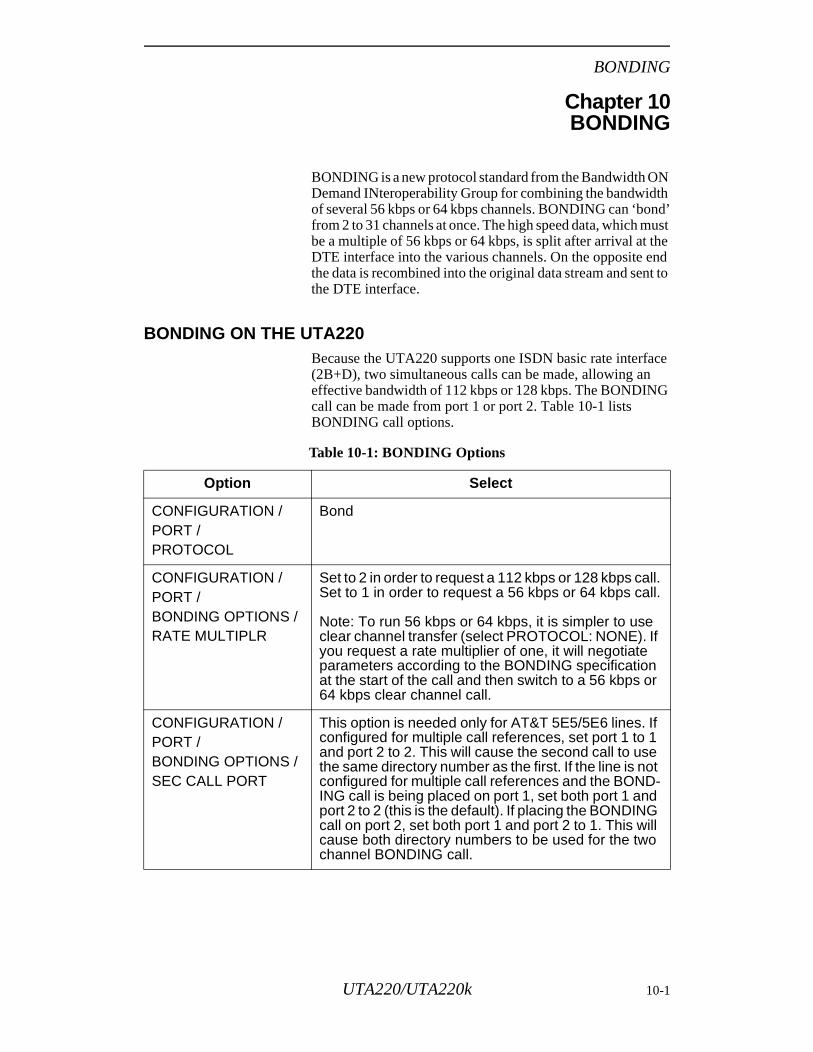
BONDING
Chapter 10BONDING
BONDING is a new protocol standard from the Bandwidth ON Demand INteroperability Group for combining the bandwidth of several 56 kbps or 64 kbps channels. BONDING can ‘bond’ from 2 to 31 channels at once. The high speed data, which must be a multiple of 56 kbps or 64 kbps, is split after arrival at the DTE interface into the various channels. On the opposite end the data is recombined into the original data stream and sent to the DTE interface.
BONDING ON THE UTA220Because the UTA220 supports one ISDN basic rate interface (2B+D), two simultaneous calls can be made, allowing an effective bandwidth of 112 kbps or 128 kbps. The BONDING call can be made from port 1 or port 2. Table 10-1 lists BONDING call options.
Table 10-1: BONDING Options
Option Select
CONFIGURATION / PORT / PROTOCOL
Bond
CONFIGURATION /PORT / BONDING OPTIONS /RATE MULTIPLR
Set to 2 in order to request a 112 kbps or 128 kbps call.Set to 1 in order to request a 56 kbps or 64 kbps call.
Note: To run 56 kbps or 64 kbps, it is simpler to use clear channel transfer (select PROTOCOL: NONE). If you request a rate multiplier of one, it will negotiate parameters according to the BONDING specification at the start of the call and then switch to a 56 kbps or 64 kbps clear channel call.
CONFIGURATION /PORT / BONDING OPTIONS /SEC CALL PORT
This option is needed only for AT&T 5E5/5E6 lines. If configured for multiple call references, set port 1 to 1 and port 2 to 2. This will cause the second call to use the same directory number as the first. If the line is not configured for multiple call references and the BOND-ING call is being placed on port 1, set both port 1 and port 2 to 2 (this is the default). If placing the BONDING call on port 2, set both port 1 and port 2 to 1. This will cause both directory numbers to be used for the two channel BONDING call.
UTA220/UTA220k 10-1
BONDING
PLACING A BONDING CALLYou can place a call from port 1 or port 2 using any normal means. The answering party must be set to run BONDING or the call will disconnect shortly after connection. If you specify a rate multiplier of 2 and the answering party indicates it will support 2 or more channels for BONDING, the answering side will pass the directory number for the second call in the negotiation. The second call is made automatically. You can tell this call is being made by the flashing LED on the second B-channel. If delay equalization between the channels is obtained, data mode is entered. The front panel indicates the BONDING connection, the B-channel line speed (56 or 64 kbps), and the DTE speed (56, 64, 112, or 128 kbps). The B-channel LEDs remain on when data mode has been entered.
Note: When a rate multiple of 2 is negotiated, both B-channels are used. The remaining ports are prevented from making circuit switched calls for the duration of the BONDING call.
If the rate multiple is set to 1 on either the originator or answerer, the second call will not be made and data mode will be entered immediately after negotiation. The second call will not be made and data mode will be entered immediately after negotiation. The screen will indicate the speed the call connected at.
The Directory Numbers configured in the D-channel setup tell the origination side what the second Directory Number is. If you are using a point-to-point line with only one Directory Number, on answering a BONDING call that is requesting two channels, this directory number will be sent to the origination side, which is the same number as the first one dialed. This is because a point-to-point line can receive two calls using the same Directory Number. AT&T 5E5/5E6 can also be configured to receive two calls using the same Directory Number. To use this capability, change port 1’s SEC CALL PORT (located under BONDING OPTIONS in CONFIGURATION / PORT) to 1 and set port 2’s SEC CALL PORT to 2.
DISCONNECTING A BONDING CALLDisconnecting by any normal means disconnects all BONDING channels. If either channel is disconnected by the switch, the entire call is disconnected by the UTA220. The disconnection can be validated by the LCD screen indicating DISCONNECTED and the B1 and B2 LEDs being off.
10-2 UTA220/UTA220k
Synchronous Operation
ate me
rn
be n
of ct
er, r
be ous
on
e
the
g
Chapter 11Synchronous Operation
SYNCHRONOUS MODESThe UTA220 supports two synchronous modes. Operation in each of these modes is described below.
Synchronous Mode 1: Sync Pause ModeWhen a telephone connection is made, the UTA220 delays for 5 seconds (configurable with the S25 command ’0’) before monitoring DTR.
This delay serves two purposes. If separate dialing and communication terminals are used, this allows the terminal operator to switch the EIA-232 cable between the two. If separdialing and communications software is being used on the saterminal, the delay allows time for the dialing software to complete and the communications software to initialize and tuDTR on.
After the UTA220 connects, the DSR, CD, and CTS pins will high. This can be used by the DTE as an indication that it cabegin sending synchronous data to the UTA220.
The UTA220 disconnects if it detects an on-to-off transition the DTR pin when &D0 is not in effect, or it receives a disconnemessage from the switch. After a disconnect, the UTA220 returns to the off-line state. If the UTA220 is set to auto answit will only answer when DTR is on or &D0 is in effect. If youdo not want the UTA220 to answer, DTR must remain low foat least 8 seconds after the ringing ends.
Synchronous Mode 2: Dial Stored Number ModeThe UTA220 will automatically dial the telephone number stored in directory entry number 0 when it detects and off-to-on transition of the DTR pin.
Once the UTA220 connects, the DSR, CD, and CTS pins willhigh to indicate to the DTE that it can begin sending synchrondata.
The UTA220 disconnects upon detecting an on-to-off transitiof the DTR pin when &D0 is not in effect, or receiving a disconnect message from the switch. After disconnecting, thUTA220 hangs up and returns to the off-line state.
If the UTA220 is set to auto answer, it will only answer whenDTR is on or &D0 is in effect. If you do not want the UTA220to answer, DTR must remain low for at least 8 seconds afterringing ends. After that time, DTR going high will cause the UTA220 to originate a call. If DTR goes high during the ringinprocess, but before the required ring count is reached, the UTA220 will not originate a call.
UTA220/UTA220k 11-1

Synchronous Operation
11-2 UTA220/UTA220k
D-Channel X.25
nd rts
ng.
ns
s:D ata
ost ys
rmit us
n
Chapter 12D-Channel X.25
The TA provides the 1984 CCITT specified X.25 protocol for the D-channel with a Packet Assembler/ Disassembler (PAD) interface for asynchronous data terminals. The X.25 protocol supports the following X.25 parameters: • Single channel operation • Modulo 8 • Transmit packet size maximum of 256 byte • Receive packet size maximum of 256 bytes • Link level window size maximum of 7 • Packet level window size maximum of 7
FUNCTIONAL DESCRIPTION
X.25X.25 is a synchronous error-correcting protocol for data transmission over public and private networks. The X.25 protocol is subdivided into three layers: physical, data link, apacket (or network). Each layer is responsible for specific paof the data transmission, error checking, and error correctiData is transmitted in packets that contain additional information to facilitate the error checking and correcting.
PADThe PAD acts as an intermediary between the local user'sasynchronous terminal and the X.25 protocol. PAD functioare specified by CCITT X.3, X.28, and X.29 recommendations. These recommendations are as follow• X.3 defines 22 PAD parameters that govern how the PA
operates. These parameters specify how and when the dfrom the asynchronous DTE is forwarded to the remote h(assembly) and how the data from the remote host displato the asynchronous terminal (disassembly).
• X.28 defines the PAD commands and responses that pecommunication with the X.25 protocol via an asynchronoterminal.
• X.29 defines supervisory packets used for communicatiobetween the local PAD and the remote host's PAD.
UTA220/UTA220k 12-1
D-Channel X.25
ot for the
e of
d s to
the
l e p,
ESTABLISHING AN X.25 SESSIONBefore using the TA for X.25 communications on the D-channel, the user must subscribe to the ISDN D-packet service. If the user is subscribed to the D-packet service, a connection is automatically established between the TA and the ISDN packet handler when the TA is first powered up. This is known as the D-channel X.25 link connection. Once the TA is connected to the ISDN packet handler, the X.25 PAD is used to make an X.25 virtual connection to a specific remote host or device. The connection is called “virtual” because it is na direct physical connection; a transmission path is createdeach call and held until communications are completed andconnection is disconnected.
The following explains how an X.25 virtual connection (session) is established and disconnected, as well as somthe activities performed during the X.25 session.
Initialize the PADWhen the TA is first powered up, the TA is in the AT commanmode. There are three AT commands that the TA supportinitialize the PAD:
ATDD
AT@P1 = P
AT@P1 = D
Once the PAD is initialized, the PAD prompt character * displays and the PAD is in the PAD command mode.
ATDD CommandThe ATDD command is valid for initializing the PAD onlywhen the D-channel X.25 link is established. If the ATDD command is entered when the D-channel X.25 link is not established, the TA responds with ERROR and remains in AT command mode.
AT@P1=P or AT@P1=D Command The AT@P1=P or AT@P1=D command initializes the PADautomatically when the TA is powered up. If the D-channeX.25 link is not established when the TA is powered up, thPAD is initialized to the PAD command mode. Likewise, ifthe D-channel link is connected when the TA is powered uthe PAD is initialized to the PAD command mode, just as though an ATDD had been executed.
12-2 UTA220/UTA220k
D-Channel X.25
D can
D s
he
tual
e all
nge
Note: The AT@P1=P and AT@P1=D commands do not take effect until the TA power is cycled or the TA is restarted. The AT&W command must be executed to save all port parameters.
Establishing an X.25 Virtual ConnectionThere are three modes of operation for the PAD: • Command mode • Connect-in-progress mode • Data transfer mode
Initially, the PAD is in the PAD command mode where PAcommands can be executed and an X.25 virtual connectionbe established if the D-channel X.25 link is connected.
An X.25 virtual call can be established by initiating the PAselect command containing the desired requested facilitieand/or Network User Address (NUA).
Refer to the PAD COMMAND SET section for the rules governing the format of the PAD select command. The facilities permit the user to request special services from tISDN network at call-setup time. The NUA informs the ISDNpacket handler of the remote location address the user is requesting for connection through the ISDN network.
Example: R-12345678
This command requests reverse charging and directs the vircall to the NUA 12345678.
During establishment of the X.25 virtual call connection, thPAD is in the connect-in-progress mode. When the virtual cis established, the following message displays:
COM
The PAD is now in the data transfer mode and data exchacan begin.
Note: Data is transmitted through the PAD that is packeting the data. Echo of PAD data and PAD commands is performed locally by the PAD.
UTA220/UTA220k 12-3
D-Channel X.25
Escaping to PAD Command ModeWhen in data transfer mode or connect-in-progress mode, it is possible to escape to the PAD command mode to execute a PAD command. To escape to the PAD command mode issue the PAD recall character as specified by X.3 parameter 1. The default PAD recall character for the TA is DLE (Ctrl P).
Once in the PAD command mode, the PAD prompt character * displays and only one PAD command may be executed. Upon execution of the PAD command, the PAD returns either to the previous mode of the PAD (i.e., data transfer) or to the final mode required by the execution of the PAD command (i.e., after execution of the PAD clear command, the final mode is the PAD command mode).
Escaping to AT Command ModeTo escape to the AT command mode from PAD data or command mode, enter the AT escape command (+ + +). This temporarily suspends PAD operations and follows standard is AT command function operation. To return to PAD operation enter:
ATDD
To end the call and exit the PAD enter:ATH
To save the port and current session configuration, including the current PAD parameter configuration, to nonvolatile memory enter:
AT&W
Disconnecting the X.25 Virtual Connection The X.25 virtual call connection is disconnected by issuing the PAD Clear command while in the PAD command mode.
Example: *CLR
This disconnects the virtual call but leaves the terminal adapter on-line and in the PAD command mode.
When the virtual call is disconnected, the PAD Clear Confirmed response and PAD prompt character are displayed:
CLR CONF*
The PAD is now in the PAD command mode where another X.25 virtual connection can be established via the PAD Select command.
12-4 UTA220/UTA220k
D-Channel X.25
COMMON APPARENT PROBLEMSDuring a session the X.25 network or remote PAD can alter the current values of the X.3 parameters resulting in common apparent problems.
Parameter 1 ChangedPAD recall using the character DLE (Ctrl P) is no longer possible.
Parameter 2 ChangedCharacters are no longer echoed when in the PAD command mode.
Parameter 5 ChangedFlow control characters are sent to the DTE by the PAD during the PAD command mode.
Parameter 6 Changed The PAD prompt no longer appears when in the PAD command mode.
Parameter 20 ChangedEditing characters are echoed.
PAD COMMAND SETThe X.25 PAD serves as an asynchronous interface through which the X.25 protocol and PAD operation can be controlled. PAD commands are specified in X.28 by CCITT which allow for communication directly with the PAD. Some of the X.28 PAD commands control the X.25 protocol operation such as call setup, call clearing, etc. The rest of the PAD commands provide access to the X.3 PAD parameters for PAD operation control (refer to the X.3 Parameters and Values section).
PAD Command FormatThe format of each PAD command is described in the section below. The PAD accepts either upper or lowercase characters for the PAD command characters. Any spaces inserted in the PAD command are ignored except for spaces in the call user data of the PAD select command (see PAD select command). A PAD command line can contain up to 128 characters. Multiple PAD commands are not permitted on a command line.
UTA220/UTA220k 12-5
D-Channel X.25
Issuing PAD CommandsPAD commands are accepted by the PAD only when it is in PAD command mode (when a PAD prompt character * displays at the beginning of the command line). As each PAD command character is typed, the character is echoed to the local DTE device for display, unless echoing is disabled by X.3 parameter 2.
Each PAD command is input to the PAD by typing the PAD command delimiter character (a carriage return or + character) at the end of the command line. The PAD commands can be edited, unless editing is disabled by X.3 parameter 15, any time before the command is input to the PAD. Once the PAD has executed the command, a response, called a PAD service signal, is returned to the DTE to inform the user of the result of the command execution.
Note: An incorrect PAD format will cause an ERR response.
Status: STATThis command requests the virtual call status of the local DTE.
Response:
ENGAGED - Indicates the local DTE is currently engaged in a virtual call.
FREE - Indicates the local DTE is not engaged in a virtual call.
Clear: CLRThe clear command disconnects the virtual call connection.
Response:
CLR CONF - Confirms that the clear command was accepted by the packet handler and the current virtual call was disconnected.
CLR ERR - Indicates that the clear command was in error because a virtual call was not established, or that the PAD is in an unknown mode and cannot accept the clear command.
CLR DER - Indicates that the remote end is no longer responding because no response to the clear or additional retransmission of the clear was received.
RESETThis command resets the current virtual call. When resetting the call, the packet sequence counters P(r) and P(s) and the packet window are reset to 0. Outstanding data or data stored from the local DTE is discarded. The reset returns the current virtual call to a known mode (the same mode the virtual call was in when it was first established). This command is only valid when a virtual call is connected.
12-6 UTA220/UTA220k
D-Channel X.25
Note: The CR LF characters indicate a carriage return and line feed response and are not actually displayed.
Response:
CR LF - Indicates the reset of the virtual call is complete.
ERR - Indicates a reset command error caused by either a virtual call not being established or the PAD being in a mode unknown to the user.
Interrupt: INTThis command initiates the transmission of an interrupt packet to the remote DTE. This command is only valid when a call is connected.
Response:
CR LF - Indicates that the interrupt packet was transmitted.
ERR - Indicates an interrupt command error caused by a virtual call not being established or the PAD being in a mode unknown to the user.
SETThis command sets or changes the value of one or more X.3 parameters.
A colon must be placed between the parameter and its corresponding value. If more than one parameter is requested to be set or changed, a comma must delimit the value and the next parameter.
SET <parameter>:<value>,<parameter>:<value>,...
Note: Refer to Table 6 for a list of X.3 parameters and their corresponding default values.
Response:
CR LF - Indicates that the parameter specified in the set command is set to its corresponding specified value.
PAR <parameter>: INV - Indicates that the specified parameter is incorrect or cannot be changed because it is a READ ONLY parameter (i.e., parameter 11 is a READ ONLY parameter), or the value specified in the set command is an invalid value for the specified parameter.
UTA220/UTA220k 12-7
D-Channel X.25
Read: PAR?This command requests a display of the current values of the specified X.3 parameter(s).
If more than one parameter is specified, each must be delimited by a comma. If none are specified, all parameters (1 - 22) and their corresponding values are displayed.
PAR? <parameter>,<parameter>,...
or
PAR?
Response:
PAR <parameter>:<value>,<parameter>: <value>, ... - Lists each parameter specified by the read command and the corresponding value.
PAR <parameter>: INV - Indicates the invalid parameter specified in the read command.
Set and Read: SET?These commands request the setting or changing of the current values of the specified X.3 parameters and display the values after the setting or changing.
A colon must be placed between the specified parameter and its corresponding specified value. If more than one parameter is requested to be set or changed, a comma must delimit the value and the next parameter reference.
SET? <parameter>:<value>, <parameter>:<value,.>...
Response:
PAR <parameter>: <value>, <parameter>: <value>... - Lists each parameter specified by the set and read command and the corresponding value.
PAR <parameter>: INV - Indicates the specified parameter is incorrect or cannot be changed because it is a READ ONLY parameter, or the value specified in the set and read command is an invalid value for the specified parameter.
Remote Read: RPAR?The read command requests a display of the current values of the specified X.3 parameter(s) from the remote PAD. This is only valid if an X.25 call is active.
If more than one parameter is specified, each must be delimited by a comma (,). If none are specified, all parameters (1-22) and their corresponding values are displayed.
12-8 UTA220/UTA220k
D-Channel X.25
RPAR? <parameter>,<parameter>,...
or
RPAR?
Response:
PAR <parameter>:<value>,<parameter>:<value>,... - Lists each parameter specified by the read command and the corresponding value.
PAR <parameter>: INV - Indicates the invalid parameter specified in the read command.
Remote Set and Read: RSET?These commands request, from a remote PAD, the setting or changing of the current values of the specified X.3 parameters and display the values after the setting or changing from the remote PAD. This is only valid if an X.25 call is active.
A colon must be placed between the specified parameter and its corresponding specified value. If more than one parameter is requested to be set or changed, a comma must delimit the value and the next parameter reference.
RSET? <parameter>:<value>,<parameter>:<value>,...
Response:
PAR <parameter>:<value>,<parameter>:<value>,...-- Lists each parameter specified by the set and read command and the corresponding value.
PAR <parameter>: INV--Indicates the specified parameter is incorrect or cannot be changed because it is a READ ONLY parameter (i.e., parameter 11 is a READ ONLY parameter), or the value specified in the set and read command is an invalid value for the specified parameter.
Profile Read/Save: PROFThese commands allow the user to load a saved, default, or standard set of X.3 parameters from non-volatile memory or save the X.3 parameters to one of two user profiles in non-volatile memory. The PROF command syntax is as follows:
PROF 90, PROF SIM: Will load the CCITT simple standard profile.
PROF 91, PROF TRA: Will load the CCITT transparent standard profile.
PROF NVM #(0,1): Will load from one of two specified non-volatile memories a profile stored by the user.
PROF SAV #(0,1): Will store the current X.3 profile into one of two non-volatile memories as specified.
PROF DEF: Will load the factory default X.3 profile.
UTA220/UTA220k 12-9
D-Channel X.25
ot
e
x son
PAD SelectThis command establishes an X.25 virtual call connection through the ISDN packet handler to a remote host or device. The contents of the PAD select command determine the contents of the X.25 Call Request packet. The format can be in any of following three forms:
<facility request block> - <address block> <calluser data>
<facility request block> - <call user data>
<address block> <call user data>
The facility request block permits the user to request special services from the ISDN network. If more than one facility is specified, a comma must separate each facility. The end of the facility request block must be followed by the hyphen character.
The address block specifies the called Network User Address (NUA). The address cannot exceed 15 characters in length. Abbreviated or multiple addresses are not supported.
The call user data field cannot exceed 12 characters in length (including spaces) and must be preceded by either the P or D character. Carriage returns and the + character are not considered part of the user data field because they are treated as PAD command delimiters.
Response:
COM - Indicates the virtual call is established.
ERR - Indicates the PAD is in an unknown mode that cannot allow the PAD select command, the PAD has been initialized in the off-line mode (i.e., no virtual call connection has been established), or the PAD select command is invalid due to a format error. Some PAD select format errors are as follows:• The facilities block is not followed by the - character.• The CUG facility is requested and two decimal digits are n
specified.• The RPOA facility is requested and four decimal digits ar
not specified.• The address block length exceeded 15 characters.• The call user data block is not preceded by the P or D
character.• The call user data block length exceeded 12 characters.• An invalid facility is requested as the first facility in the
facility request block.
CLR xxx - Indicates the attempted call has cleared. The xxis the ASCII character cause code which specifies the reathe call attempt cleared (see PAD Clear Service Signals).
12-10 UTA220/UTA220k
D-Channel X.25
ll ility ce
e
to for ces re
til nd
. ata alid
by ted der
l
FACILITIESThe following facilities and corresponding code formats are supported by the TA.
Reverse Charging: RReverse Charging is a facility analogous to “collect” calls. Aconnect charges are charged to the remote DTE. This facworks in conjunction with the Reverse Charging Acceptanfacility. If the remote DTE does not subscribe to Reverse Charging Acceptance, the local DTE's call with the reversecharging request is cleared.
Format: R
Network User Identification (NUI) This facility provides a way for the user to be identified by thnetwork for the purpose of billing, security, or network management.
Format: N <NUI string>
A character string of up to 16 decimal characters from 33 126 of the ASCII character table (see Appendix F) except characters 43 to 45 (hyphen, comma, and plus sign). Spacan be included in the specification of the NUI string but adiscarded by the PAD.
Echo to the local DTE is turned off upon entering the N una comma or hyphen is entered. The comma signifies the eof the NUI string and indicates that more facilities are to follow. The hyphen signifies the ending of the facility blockThe P or D designator used for the beginning of the user dcall does not end the NUI string because it is considered a vNUI string character.
Closed User Group (CUG)The Closed User Group (CUG) facility permits users to essentially establish a private network on a public network restricting communications to only those who are designato be in the group. Access by anyone outside the group isdenied. The CUG number is assigned by the network proviat subscription time.
Format: G <xx>
<xx>: two decimal digits ranging from 00 - 99. If two decimadigits are not specified, the response ERR displays.
UTA220/UTA220k 12-11
D-Channel X.25
e
s
nel
Recognized Private Operating AgencyThe Recognized Private Operating Agency (RPOA) facility permits the user to specify the particular international gateway to be used when initiating an international virtual call.
Format: T <xxxx>
<xxxx>: four decimal digits
If four decimal digits are not specified, the response ERR displays.
Flow Control Parameter NegotiationThis facility permits the negotiation on a per-call basis of the packet and window sizes (flow control parameters) for each direction of transmission. The packet size designates the maximum data field length of the data packets. The window size designates the number of data packets that may be sent before acknowledgment of the received packets (i.e., permission to transmit more data packets) is received. Window sizes do not have to be the same at both ends of the virtual connection.
The TA cannot initiate negotiation of this facility, but will respond to negotiation from the network. The packet window size is changed by using the AT command !X0 (receive window size), !X1 (transmit window size) for the D-Channel or %D0 (receive window size), %D1 (transmit size) for an X.25 configured port (see AT commands).
If the window size is not the default value of two, the specified window size value is requested in the call request packet when the virtual call is being established. The default packet size supported by the TA is 128 bytes and can be changed using the AT commands !X2 (receive packet size), !X3 (transmit packet size), for the D-Channel or %D2 (receive packet size), %D3 (transmit packet size) for an X.25 configured port.
To allow maximum flexibility, the user may configure various parameters, such as packet size, window size, call type/LCN ranges, and packet modulus, for the D-Channel, Port, or Session (session not yet implemented) differently for each X.25 call.
The rules to determine the parameters used areas follows:• If a session parameter (window or packet) is non-zero, th
session parameter is used.• If the session parameter is zero and the port parameter i
non-zero, the port parameter is used.• If the session and port parameters are zero, the D-Chan
parameter is used.
12-12 UTA220/UTA220k

D-Channel X.25
*Acknowledgment PAD service signal is transmitted to the local DTE as a carriage return and a line feed.
Table 12-1: PAD Command Set Summary
Command Description Response
STAT Requests virtual call status of the DTE
ENGAGED or FREE
CLR Disconnects the current virtual call
CLR CONF, CLR ERR, or CLR DER
RESET Resets the current virtual call Acknowledgment PAD service signal or ERR *
INT Transmits an interrupt packet Acknowledgment PAD service signal or ERR *
SET Sets or changes the value of one or more of the current parameters
Acknowledgment PAD service signal or ERR or PAR (list of specified parameters and INV) *
PAR? Requests display of the current values of the specified parameters
PAR (list of specified parameters with their current values or INV)
SET? Requests the setting or changing of the current values of the specified parameters and display the values after the setting or changing
PAR (list of specified parameters with their current values or INV) or ERR
RPAR? Requests the display from the remote PAD of the current values of the specified parameters
PAR (list of specified parameters with their current values or INV)
RSET? Requests the setting or changing from the remote PAD of the current values of the specified parameters and displays the values after the setting or changing
PAR (list of specified parameters with their current values or INV) or ERR
PROF Loads or Stores the current X.3 profile
Acknowledgment PAD service signal or ERR*
PAD Select Command
Sets up and establishes a virtual call
COMM, ERR, or CLR xxx (see PAD Clear Service Signals)
UTA220/UTA220k 12-13
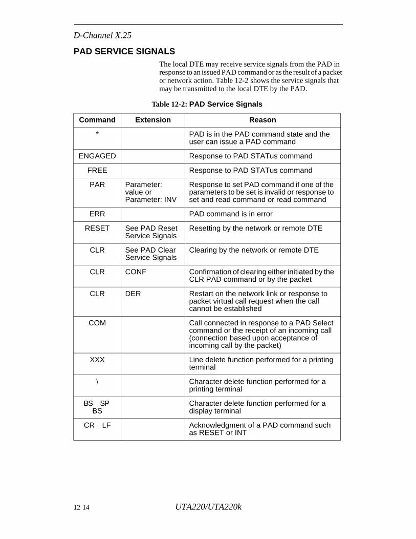
D-Channel X.25
PAD SERVICE SIGNALSThe local DTE may receive service signals from the PAD in response to an issued PAD command or as the result of a packet or network action. Table 12-2 shows the service signals that may be transmitted to the local DTE by the PAD.
Table 12-2: PAD Service Signals
Command Extension Reason
* PAD is in the PAD command state and the user can issue a PAD command
ENGAGED Response to PAD STATus command
FREE Response to PAD STATus command
PAR Parameter: value orParameter: INV
Response to set PAD command if one of the parameters to be set is invalid or response to set and read command or read command
ERR PAD command is in error
RESET See PAD Reset Service Signals
Resetting by the network or remote DTE
CLR See PAD Clear Service Signals
Clearing by the network or remote DTE
CLR CONF Confirmation of clearing either initiated by the CLR PAD command or by the packet
CLR DER Restart on the network link or response to packet virtual call request when the call cannot be established
COM Call connected in response to a PAD Select command or the receipt of an incoming call (connection based upon acceptance of incoming call by the packet)
XXX Line delete function performed for a printing terminal
\ Character delete function performed for a printing terminal
BS SPBS
Character delete function performed for a display terminal
CR LF Acknowledgment of a PAD command such as RESET or INT
12-14 UTA220/UTA220k
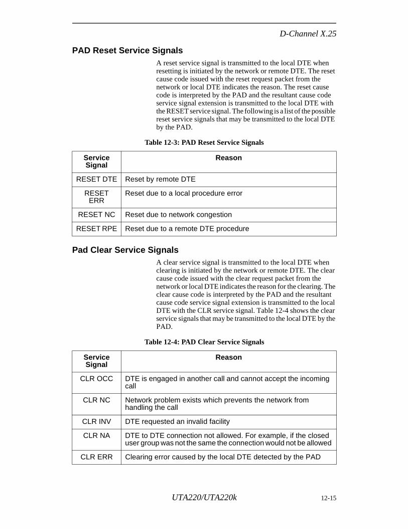
D-Channel X.25
PAD Reset Service SignalsA reset service signal is transmitted to the local DTE when resetting is initiated by the network or remote DTE. The reset cause code issued with the reset request packet from the network or local DTE indicates the reason. The reset cause code is interpreted by the PAD and the resultant cause code service signal extension is transmitted to the local DTE with the RESET service signal. The following is a list of the possible reset service signals that may be transmitted to the local DTE by the PAD.
Pad Clear Service SignalsA clear service signal is transmitted to the local DTE when clearing is initiated by the network or remote DTE. The clear cause code issued with the clear request packet from the network or local DTE indicates the reason for the clearing. The clear cause code is interpreted by the PAD and the resultant cause code service signal extension is transmitted to the local DTE with the CLR service signal. Table 12-4 shows the clear service signals that may be transmitted to the local DTE by the PAD.
Table 12-3: PAD Reset Service Signals
ServiceSignal
Reason
RESET DTE Reset by remote DTE
RESET ERR
Reset due to a local procedure error
RESET NC Reset due to network congestion
RESET RPE Reset due to a remote DTE procedure
Table 12-4: PAD Clear Service Signals
ServiceSignal
Reason
CLR OCC DTE is engaged in another call and cannot accept the incoming call
CLR NC Network problem exists which prevents the network from handling the call
CLR INV DTE requested an invalid facility
CLR NA DTE to DTE connection not allowed. For example, if the closed user group was not the same the connection would not be allowed
CLR ERR Clearing error caused by the local DTE detected by the PAD
UTA220/UTA220k 12-15
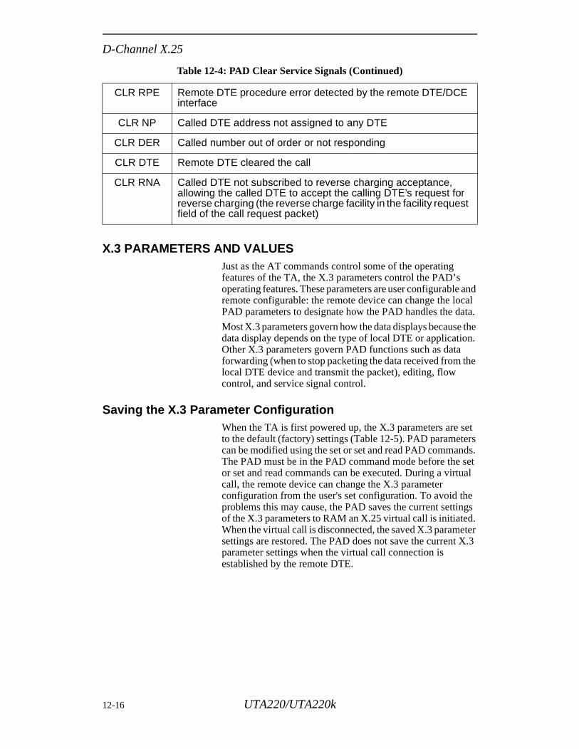
D-Channel X.25
and cal ata.
the n.
the
et ers
ds. set ual
e ngs . ter
X.3
X.3 PARAMETERS AND VALUESJust as the AT commands control some of the operating features of the TA, the X.3 parameters control the PAD’s operating features. These parameters are user configurableremote configurable: the remote device can change the loPAD parameters to designate how the PAD handles the d
Most X.3 parameters govern how the data displays becausedata display depends on the type of local DTE or applicatioOther X.3 parameters govern PAD functions such as dataforwarding (when to stop packeting the data received from local DTE device and transmit the packet), editing, flow control, and service signal control.
Saving the X.3 Parameter ConfigurationWhen the TA is first powered up, the X.3 parameters are sto the default (factory) settings (Table 12-5). PAD parametcan be modified using the set or set and read PAD commanThe PAD must be in the PAD command mode before the or set and read commands can be executed. During a virtcall, the remote device can change the X.3 parameter configuration from the user's set configuration. To avoid thproblems this may cause, the PAD saves the current settiof the X.3 parameters to RAM an X.25 virtual call is initiatedWhen the virtual call is disconnected, the saved X.3 paramesettings are restored. The PAD does not save the current parameter settings when the virtual call connection is established by the remote DTE.
CLR RPE Remote DTE procedure error detected by the remote DTE/DCE interface
CLR NP Called DTE address not assigned to any DTE
CLR DER Called number out of order or not responding
CLR DTE Remote DTE cleared the call
CLR RNA Called DTE not subscribed to reverse charging acceptance, allowing the called DTE to accept the calling DTE’s request for reverse charging (the reverse charge facility in the facility request field of the call request packet)
Table 12-4: PAD Clear Service Signals (Continued)
12-16 UTA220/UTA220k
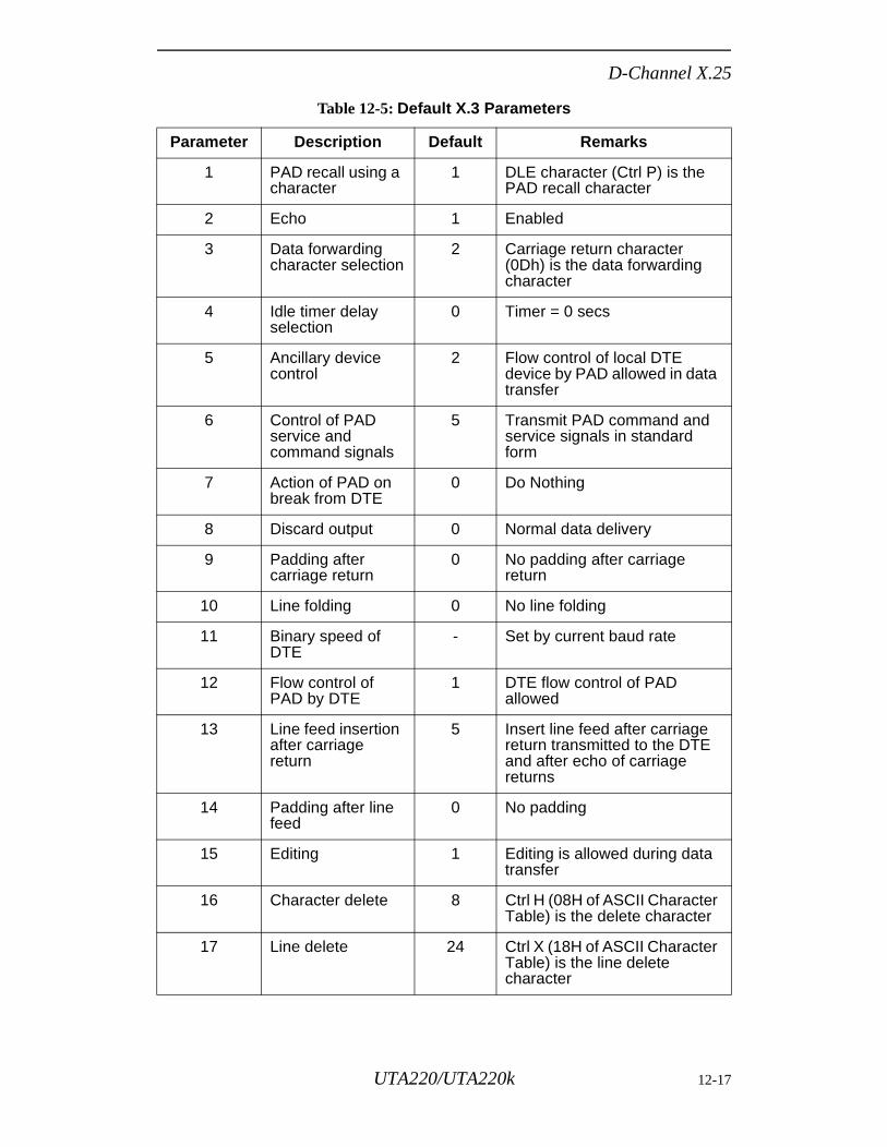
D-Channel X.25
Table 12-5: Default X.3 Parameters
Parameter Description Default Remarks
1 PAD recall using a character
1 DLE character (Ctrl P) is the PAD recall character
2 Echo 1 Enabled
3 Data forwarding character selection
2 Carriage return character (0Dh) is the data forwarding character
4 Idle timer delay selection
0 Timer = 0 secs
5 Ancillary device control
2 Flow control of local DTE device by PAD allowed in data transfer
6 Control of PAD service and command signals
5 Transmit PAD command and service signals in standard form
7 Action of PAD on break from DTE
0 Do Nothing
8 Discard output 0 Normal data delivery
9 Padding after carriage return
0 No padding after carriage return
10 Line folding 0 No line folding
11 Binary speed of DTE
- Set by current baud rate
12 Flow control of PAD by DTE
1 DTE flow control of PAD allowed
13 Line feed insertion after carriage return
5 Insert line feed after carriage return transmitted to the DTE and after echo of carriage returns
14 Padding after line feed
0 No padding
15 Editing 1 Editing is allowed during data transfer
16 Character delete 8 Ctrl H (08H of ASCII Character Table) is the delete character
17 Line delete 24 Ctrl X (18H of ASCII Character Table) is the line delete character
UTA220/UTA220k 12-17
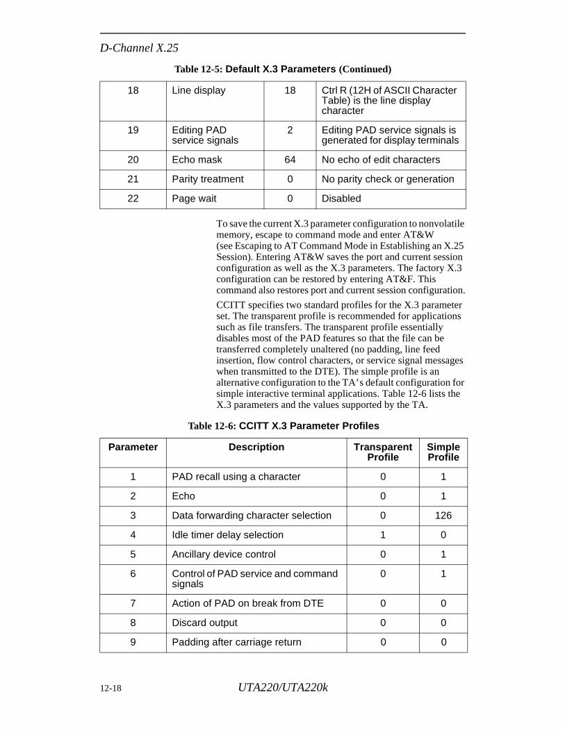
D-Channel X.25
To save the current X.3 parameter configuration to nonvolatile memory, escape to command mode and enter AT&W (see Escaping to AT Command Mode in Establishing an X.25 Session). Entering AT&W saves the port and current session configuration as well as the X.3 parameters. The factory X.3 configuration can be restored by entering AT&F. This command also restores port and current session configuration.
CCITT specifies two standard profiles for the X.3 parameter set. The transparent profile is recommended for applications such as file transfers. The transparent profile essentially disables most of the PAD features so that the file can be transferred completely unaltered (no padding, line feed insertion, flow control characters, or service signal messages when transmitted to the DTE). The simple profile is an alternative configuration to the TA’ s default configuration for simple interactive terminal applications. Table 12-6 lists the X.3 parameters and the values supported by the TA.
18 Line display 18 Ctrl R (12H of ASCII Character Table) is the line display character
19 Editing PAD service signals
2 Editing PAD service signals is generated for display terminals
20 Echo mask 64 No echo of edit characters
21 Parity treatment 0 No parity check or generation
22 Page wait 0 Disabled
Table 12-6: CCITT X.3 Parameter Profiles
Parameter Description Transparent Profile
SimpleProfile
1 PAD recall using a character 0 1
2 Echo 0 1
3 Data forwarding character selection 0 126
4 Idle timer delay selection 1 0
5 Ancillary device control 0 1
6 Control of PAD service and command signals
0 1
7 Action of PAD on break from DTE 0 0
8 Discard output 0 0
9 Padding after carriage return 0 0
Table 12-5: Default X.3 Parameters (Continued)
12-18 UTA220/UTA220k
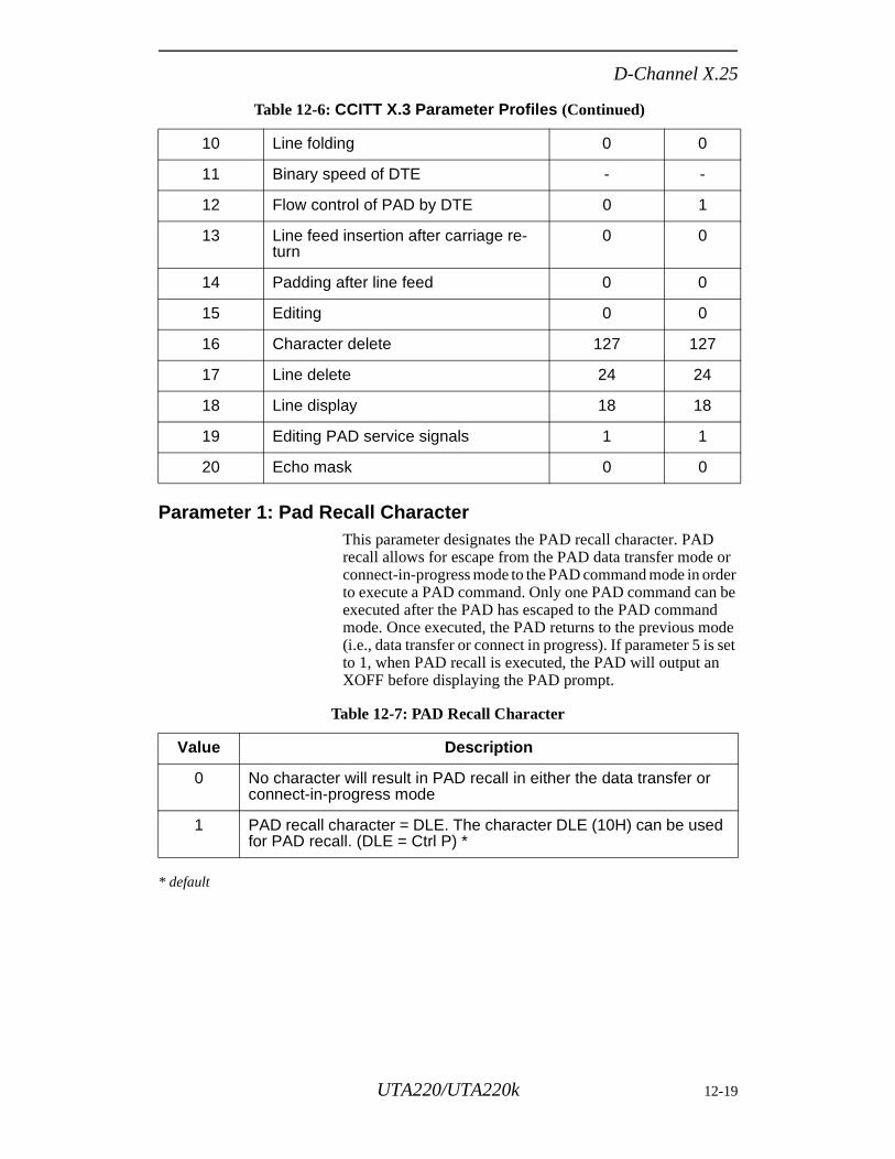
D-Channel X.25
Parameter 1: Pad Recall Character This parameter designates the PAD recall character. PAD recall allows for escape from the PAD data transfer mode or connect-in-progress mode to the PAD command mode in order to execute a PAD command. Only one PAD command can be executed after the PAD has escaped to the PAD command mode. Once executed, the PAD returns to the previous mode (i.e., data transfer or connect in progress). If parameter 5 is set to 1, when PAD recall is executed, the PAD will output an XOFF before displaying the PAD prompt.
* default
10 Line folding 0 0
11 Binary speed of DTE - -
12 Flow control of PAD by DTE 0 1
13 Line feed insertion after carriage re-turn
0 0
14 Padding after line feed 0 0
15 Editing 0 0
16 Character delete 127 127
17 Line delete 24 24
18 Line display 18 18
19 Editing PAD service signals 1 1
20 Echo mask 0 0
Table 12-7: PAD Recall Character
Value Description
0 No character will result in PAD recall in either the data transfer or connect-in-progress mode
1 PAD recall character = DLE. The character DLE (10H) can be used for PAD recall. (DLE = Ctrl P) *
Table 12-6: CCITT X.3 Parameter Profiles (Continued)
UTA220/UTA220k 12-19
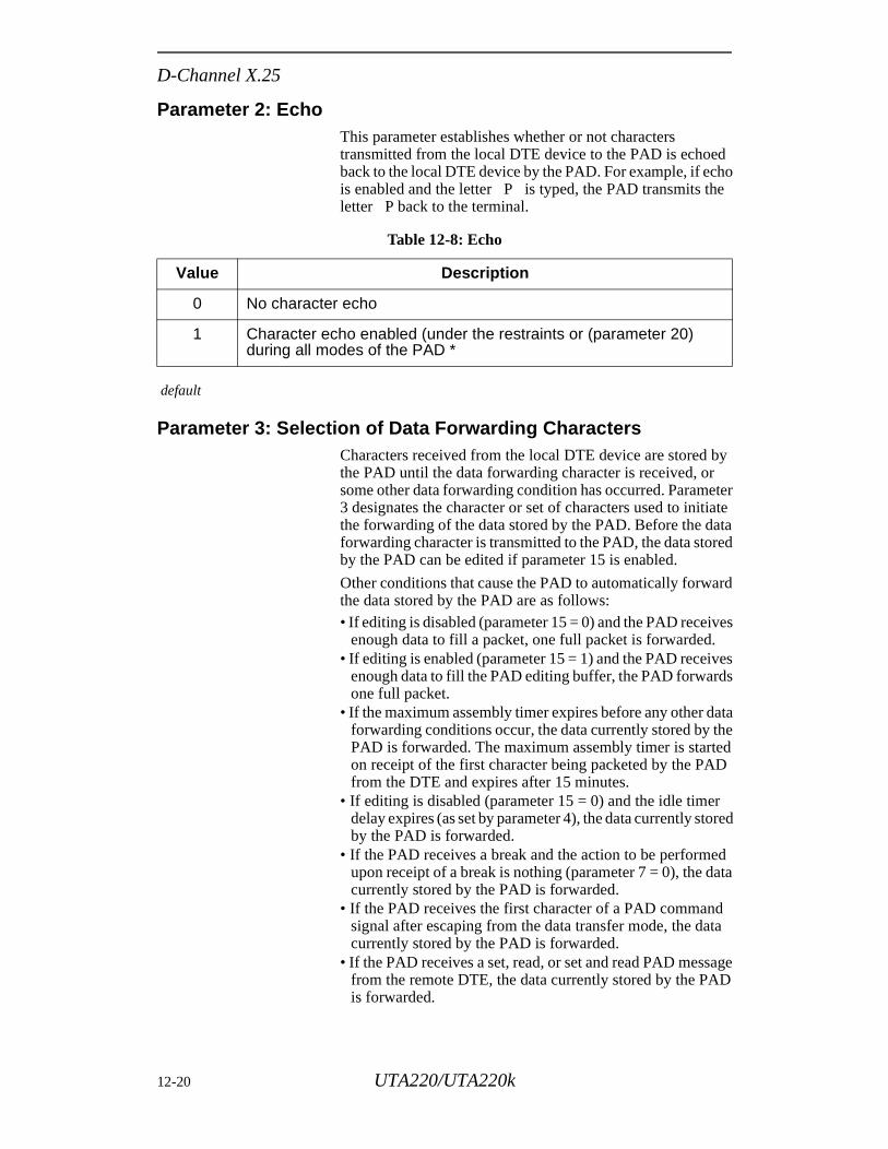
D-Channel X.25
es
ves s
ata he ed D
r ored
ed ata
d ta
age D
Parameter 2: EchoThis parameter establishes whether or not characters transmitted from the local DTE device to the PAD is echoed back to the local DTE device by the PAD. For example, if echo is enabled and the letter P is typed, the PAD transmits the letter P back to the terminal.
default
Parameter 3: Selection of Data Forwarding CharactersCharacters received from the local DTE device are stored by the PAD until the data forwarding character is received, or some other data forwarding condition has occurred. Parameter 3 designates the character or set of characters used to initiate the forwarding of the data stored by the PAD. Before the data forwarding character is transmitted to the PAD, the data stored by the PAD can be edited if parameter 15 is enabled.
Other conditions that cause the PAD to automatically forward the data stored by the PAD are as follows:• If editing is disabled (parameter 15 = 0) and the PAD receiv
enough data to fill a packet, one full packet is forwarded.• If editing is enabled (parameter 15 = 1) and the PAD recei
enough data to fill the PAD editing buffer, the PAD forwardone full packet.
• If the maximum assembly timer expires before any other dforwarding conditions occur, the data currently stored by tPAD is forwarded. The maximum assembly timer is starton receipt of the first character being packeted by the PAfrom the DTE and expires after 15 minutes.
• If editing is disabled (parameter 15 = 0) and the idle timedelay expires (as set by parameter 4), the data currently stby the PAD is forwarded.
• If the PAD receives a break and the action to be performupon receipt of a break is nothing (parameter 7 = 0), the dcurrently stored by the PAD is forwarded.
• If the PAD receives the first character of a PAD commansignal after escaping from the data transfer mode, the dacurrently stored by the PAD is forwarded.
• If the PAD receives a set, read, or set and read PAD messfrom the remote DTE, the data currently stored by the PAis forwarded.
Table 12-8: Echo
Value Description
0 No character echo
1 Character echo enabled (under the restraints or (parameter 20) during all modes of the PAD *
12-20 UTA220/UTA220k
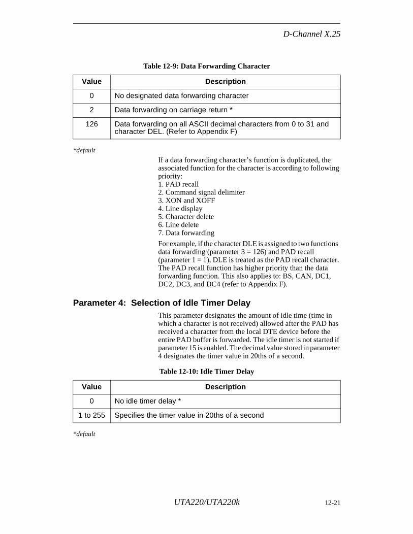
D-Channel X.25
ng
ns
ter.
as if eter
*default
If a data forwarding character’s function is duplicated, the associated function for the character is according to followipriority:1. PAD recall2. Command signal delimiter3. XON and XOFF 4. Line display5. Character delete6. Line delete7. Data forwarding
For example, if the character DLE is assigned to two functiodata forwarding (parameter 3 = 126) and PAD recall (parameter 1 = 1), DLE is treated as the PAD recall characThe PAD recall function has higher priority than the data forwarding function. This also applies to: BS, CAN, DC1, DC2, DC3, and DC4 (refer to Appendix F).
Parameter 4: Selection of Idle Timer Delay This parameter designates the amount of idle time (time inwhich a character is not received) allowed after the PAD hreceived a character from the local DTE device before theentire PAD buffer is forwarded. The idle timer is not startedparameter 15 is enabled. The decimal value stored in param4 designates the timer value in 20ths of a second.
*default
Table 12-9: Data Forwarding Character
Value Description
0 No designated data forwarding character
2 Data forwarding on carriage return *
126 Data forwarding on all ASCII decimal characters from 0 to 31 and character DEL. (Refer to Appendix F)
Table 12-10: Idle Timer Delay
Value Description
0 No idle timer delay *
1 to 255 Specifies the timer value in 20ths of a second
UTA220/UTA220k 12-21
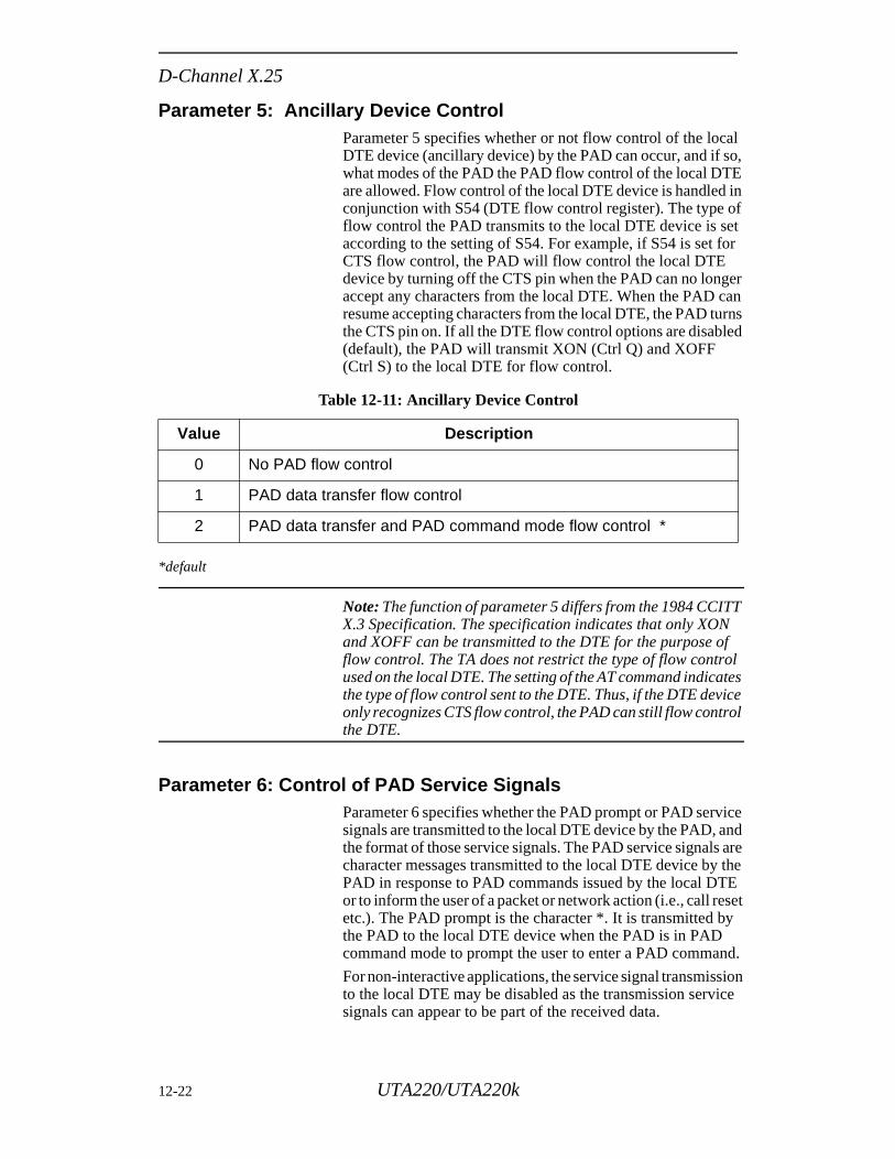
D-Channel X.25
Parameter 5: Ancillary Device ControlParameter 5 specifies whether or not flow control of the local DTE device (ancillary device) by the PAD can occur, and if so, what modes of the PAD the PAD flow control of the local DTE are allowed. Flow control of the local DTE device is handled in conjunction with S54 (DTE flow control register). The type of flow control the PAD transmits to the local DTE device is set according to the setting of S54. For example, if S54 is set for CTS flow control, the PAD will flow control the local DTE device by turning off the CTS pin when the PAD can no longer accept any characters from the local DTE. When the PAD can resume accepting characters from the local DTE, the PAD turns the CTS pin on. If all the DTE flow control options are disabled (default), the PAD will transmit XON (Ctrl Q) and XOFF (Ctrl S) to the local DTE for flow control.
*default
Note: The function of parameter 5 differs from the 1984 CCITT X.3 Specification. The specification indicates that only XON and XOFF can be transmitted to the DTE for the purpose of flow control. The TA does not restrict the type of flow control used on the local DTE. The setting of the AT command indicates the type of flow control sent to the DTE. Thus, if the DTE device only recognizes CTS flow control, the PAD can still flow control the DTE.
Parameter 6: Control of PAD Service SignalsParameter 6 specifies whether the PAD prompt or PAD service signals are transmitted to the local DTE device by the PAD, and the format of those service signals. The PAD service signals are character messages transmitted to the local DTE device by the PAD in response to PAD commands issued by the local DTE or to inform the user of a packet or network action (i.e., call reset etc.). The PAD prompt is the character *. It is transmitted by the PAD to the local DTE device when the PAD is in PAD command mode to prompt the user to enter a PAD command.
For non-interactive applications, the service signal transmission to the local DTE may be disabled as the transmission service signals can appear to be part of the received data.
Table 12-11: Ancillary Device Control
Value Description
0 No PAD flow control
1 PAD data transfer flow control
2 PAD data transfer and PAD command mode flow control *
12-22 UTA220/UTA220k
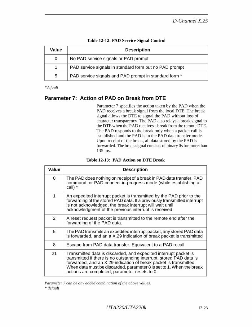
D-Channel X.25
*default
Parameter 7: Action of PAD on Break from DTEParameter 7 specifies the action taken by the PAD when the PAD receives a break signal from the local DTE. The break signal allows the DTE to signal the PAD without loss of character transparency. The PAD also relays a break signal to the DTE when the PAD receives a break from the remote DTE. The PAD responds to the break only when a packet call is established and the PAD is in the PAD data transfer mode. Upon receipt of the break, all data stored by the PAD is forwarded. The break signal consists of binary 0s for more than 135 ms.
Parameter 7 can be any added combination of the above values.* default
Table 12-12: PAD Service Signal Control
Value Description
0 No PAD service signals or PAD prompt
1 PAD service signals in standard form but no PAD prompt
5 PAD service signals and PAD prompt in standard form *
Table 12-13: PAD Action on DTE Break
Value Description
0 The PAD does nothing on receipt of a break in PAD data transfer, PAD command, or PAD connect-in-progress mode (while establishing a call) *
1 An expedited interrupt packet is transmitted by the PAD prior to the forwarding of the stored PAD data. If a previously transmitted interrupt is not acknowledged, the break interrupt will wait until acknowledgment of the previous interrupt is received.
2 A reset request packet is transmitted to the remote end after the forwarding of the PAD data.
5 The PAD transmits an expedited interrupt packet, any stored PAD data is forwarded, and an a X.29 indication of break packet is transmitted
8 Escape from PAD data transfer. Equivalent to a PAD recall
21 Transmitted data is discarded, and expedited interrupt packet is transmitted if there is no outstanding interrupt, stored PAD data is forwarded, and an X.29 indication of break packet is transmitted. When data must be discarded, parameter 8 is set to 1. When the break actions are completed, parameter resets to 0.
UTA220/UTA220k 12-23
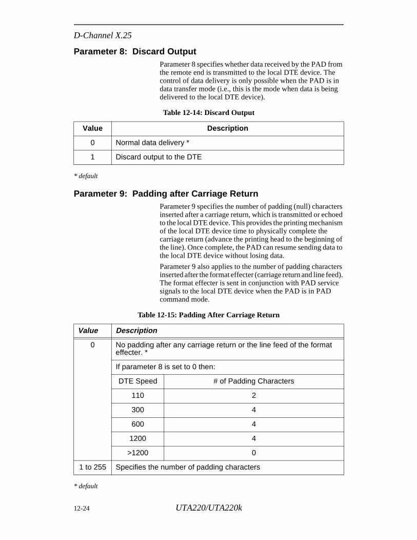
D-Channel X.25
Parameter 8: Discard OutputParameter 8 specifies whether data received by the PAD from the remote end is transmitted to the local DTE device. The control of data delivery is only possible when the PAD is in data transfer mode (i.e., this is the mode when data is being delivered to the local DTE device).
* default
Parameter 9: Padding after Carriage Return Parameter 9 specifies the number of padding (null) characters inserted after a carriage return, which is transmitted or echoed to the local DTE device. This provides the printing mechanism of the local DTE device time to physically complete the carriage return (advance the printing head to the beginning of the line). Once complete, the PAD can resume sending data to the local DTE device without losing data.
Parameter 9 also applies to the number of padding characters inserted after the format effecter (carriage return and line feed). The format effecter is sent in conjunction with PAD service signals to the local DTE device when the PAD is in PAD command mode.
* default
Table 12-14: Discard Output
Value Description
0 Normal data delivery *
1 Discard output to the DTE
Table 12-15: Padding After Carriage Return
Value Description
0 No padding after any carriage return or the line feed of the format effecter. *
If parameter 8 is set to 0 then:
DTE Speed # of Padding Characters
110 2
300 4
600 4
1200 4
>1200 0
1 to 255 Specifies the number of padding characters
12-24 UTA220/UTA220k
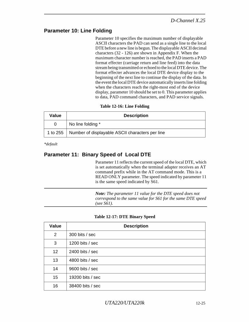
D-Channel X.25
Parameter 10: Line Folding Parameter 10 specifies the maximum number of displayable ASCII characters the PAD can send as a single line to the local DTE before a new line is begun. The displayable ASCII decimal characters (32 - 126) are shown in Appendix F. When the maximum character number is reached, the PAD inserts a PAD format effecter (carriage return and line feed) into the data stream being transmitted or echoed to the local DTE device. The format effecter advances the local DTE device display to the beginning of the next line to continue the display of the data. In the event the local DTE device automatically inserts line folding when the characters reach the right-most end of the device display, parameter 10 should be set to 0. This parameter applies to data, PAD command characters, and PAD service signals.
*default
Parameter 11: Binary Speed of Local DTEParameter 11 reflects the current speed of the local DTE, which is set automatically when the terminal adapter receives an AT command prefix while in the AT command mode. This is a READ ONLY parameter. The speed indicated by parameter 11 is the same speed indicated by S61.
Note: The parameter 11 value for the DTE speed does not correspond to the same value for S61 for the same DTE speed (see S61).
Table 12-16: Line Folding
Value Description
0 No line folding *
1 to 255 Number of displayable ASCII characters per line
Table 12-17: DTE Binary Speed
Value Description
2 300 bits / sec
3 1200 bits / sec
12 2400 bits / sec
13 4800 bits / sec
14 9600 bits / sec
15 19200 bits / sec
16 38400 bits / sec
UTA220/UTA220k 12-25
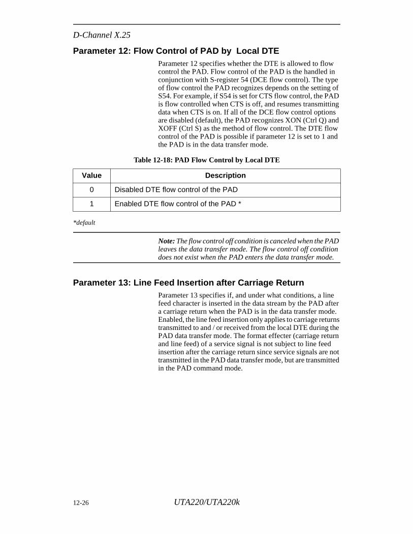
D-Channel X.25
Parameter 12: Flow Control of PAD by Local DTEParameter 12 specifies whether the DTE is allowed to flow control the PAD. Flow control of the PAD is the handled in conjunction with S-register 54 (DCE flow control). The type of flow control the PAD recognizes depends on the setting of S54. For example, if S54 is set for CTS flow control, the PAD is flow controlled when CTS is off, and resumes transmitting data when CTS is on. If all of the DCE flow control options are disabled (default), the PAD recognizes XON (Ctrl Q) and XOFF (Ctrl S) as the method of flow control. The DTE flow control of the PAD is possible if parameter 12 is set to 1 and the PAD is in the data transfer mode.
*default
Note: The flow control off condition is canceled when the PAD leaves the data transfer mode. The flow control off condition does not exist when the PAD enters the data transfer mode.
Parameter 13: Line Feed Insertion after Carriage ReturnParameter 13 specifies if, and under what conditions, a line feed character is inserted in the data stream by the PAD after a carriage return when the PAD is in the data transfer mode. Enabled, the line feed insertion only applies to carriage returns transmitted to and / or received from the local DTE during the PAD data transfer mode. The format effecter (carriage return and line feed) of a service signal is not subject to line feed insertion after the carriage return since service signals are not transmitted in the PAD data transfer mode, but are transmitted in the PAD command mode.
Table 12-18: PAD Flow Control by Local DTE
Value Description
0 Disabled DTE flow control of the PAD
1 Enabled DTE flow control of the PAD *
12-26 UTA220/UTA220k
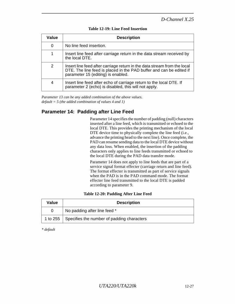
D-Channel X.25
Parameter 13 can be any added combination of the above values.default = 5 (the added combination of values 4 and 1)
Parameter 14: Padding after Line FeedParameter 14 specifies the number of padding (null) characters inserted after a line feed, which is transmitted or echoed to the local DTE. This provides the printing mechanism of the local DTE device time to physically complete the line feed (i.e., advance the printing head to the next line). Once complete, the PAD can resume sending data to the local DTE device without any data loss. When enabled, the insertion of the padding characters only applies to line feeds transmitted or echoed to the local DTE during the PAD data transfer mode.
Parameter 14 does not apply to line feeds that are part of a service signal format effecter (carriage return and line feed). The format effecter is transmitted as part of service signals when the PAD is in the PAD command mode. The format effecter line feed transmitted to the local DTE is padded according to parameter 9.
* default
Table 12-19: Line Feed Insertion
Value Description
0 No line feed insertion.
1 Insert line feed after carriage return in the data stream received by the local DTE.
2 Insert line feed after carriage return in the data stream from the local DTE. The line feed is placed in the PAD buffer and can be edited if parameter 15 (editing) is enabled.
4 Insert line feed after echo of carriage return to the local DTE. If parameter 2 (echo) is disabled, this will not apply.
Table 12-20: Padding After Line Feed
Value Description
0 No padding after line feed *
1 to 255 Specifies the number of padding characters
UTA220/UTA220k 12-27
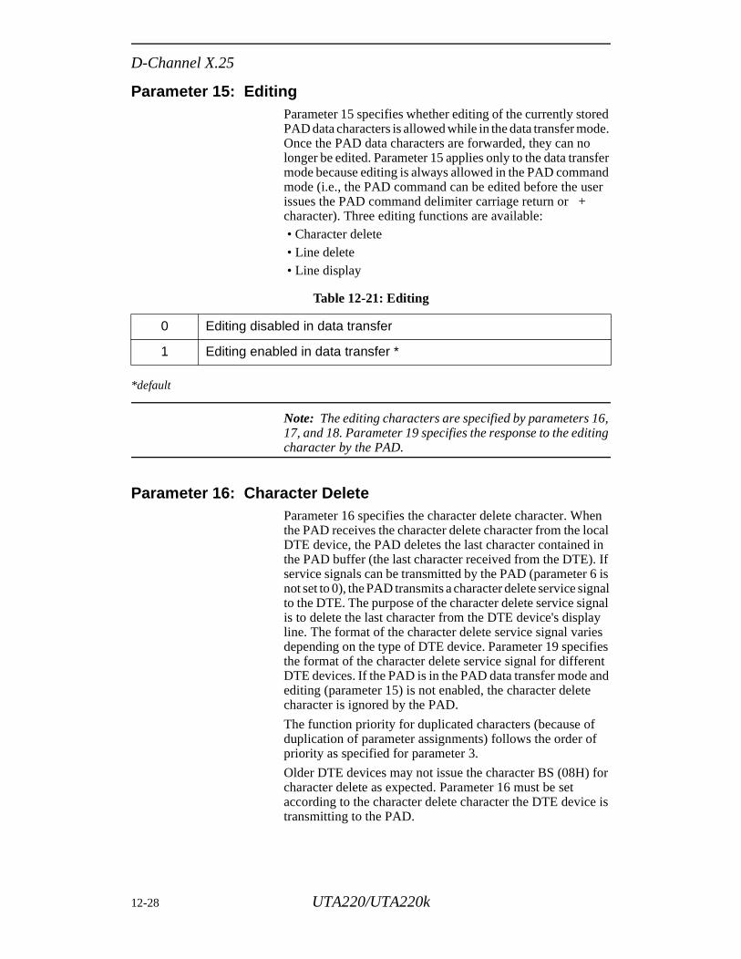
D-Channel X.25
en cal
in If 6 is gnal nal y
es fies nt nd
f
for
e is
Parameter 15: EditingParameter 15 specifies whether editing of the currently stored PAD data characters is allowed while in the data transfer mode. Once the PAD data characters are forwarded, they can no longer be edited. Parameter 15 applies only to the data transfer mode because editing is always allowed in the PAD command mode (i.e., the PAD command can be edited before the user issues the PAD command delimiter carriage return or + character). Three editing functions are available: • Character delete • Line delete • Line display
*default
Note: The editing characters are specified by parameters 16, 17, and 18. Parameter 19 specifies the response to the editing character by the PAD.
Parameter 16: Character DeleteParameter 16 specifies the character delete character. Whthe PAD receives the character delete character from the loDTE device, the PAD deletes the last character containedthe PAD buffer (the last character received from the DTE).service signals can be transmitted by the PAD (parameter not set to 0), the PAD transmits a character delete service sito the DTE. The purpose of the character delete service sigis to delete the last character from the DTE device's displaline. The format of the character delete service signal varidepending on the type of DTE device. Parameter 19 specithe format of the character delete service signal for differeDTE devices. If the PAD is in the PAD data transfer mode aediting (parameter 15) is not enabled, the character deletecharacter is ignored by the PAD.
The function priority for duplicated characters (because ofduplication of parameter assignments) follows the order opriority as specified for parameter 3.
Older DTE devices may not issue the character BS (08H) character delete as expected. Parameter 16 must be set according to the character delete character the DTE devictransmitting to the PAD.
Table 12-21: Editing
0 Editing disabled in data transfer
1 Editing enabled in data transfer *
12-28 UTA220/UTA220k
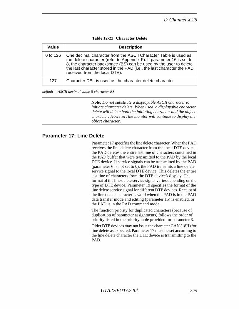
D-Channel X.25
default = ASCII decimal value 8 character BS
Note: Do not substitute a displayable ASCII character to initiate character delete. When used, a displayable character delete will delete both the initiating character and the object character. However, the monitor will continue to display the object character.
Parameter 17: Line DeleteParameter 17 specifies the line delete character. When the PAD receives the line delete character from the local DTE device, the PAD deletes the entire last line of characters contained in the PAD buffer that were transmitted to the PAD by the local DTE device. If service signals can be transmitted by the PAD (parameter 6 is not set to 0), the PAD transmits a line delete service signal to the local DTE device. This deletes the entire last line of characters from the DTE device’s display. The format of the line delete service signal varies depending on the type of DTE device. Parameter 19 specifies the format of the line delete service signal for different DTE devices. Receipt of the line delete character is valid when the PAD is in the PAD data transfer mode and editing (parameter 15) is enabled, or the PAD is in the PAD command mode.
The function priority for duplicated characters (because of duplication of parameter assignments) follows the order of priority listed in the priority table provided for parameter 3.
Older DTE devices may not issue the character CAN (18H) for line delete as expected. Parameter 17 must be set according to the line delete character the DTE device is transmitting to the PAD.
Table 12-22: Character Delete
Value Description
0 to 126 One decimal character from the ASCII Character Table is used as the delete character (refer to Appendix F). If parameter 16 is set to 8, the character backspace (BS) can be used by the user to delete the last character stored in the PAD (i.e., the last character the PAD received from the local DTE).
127 Character DEL is used as the character delete character
UTA220/UTA220k 12-29
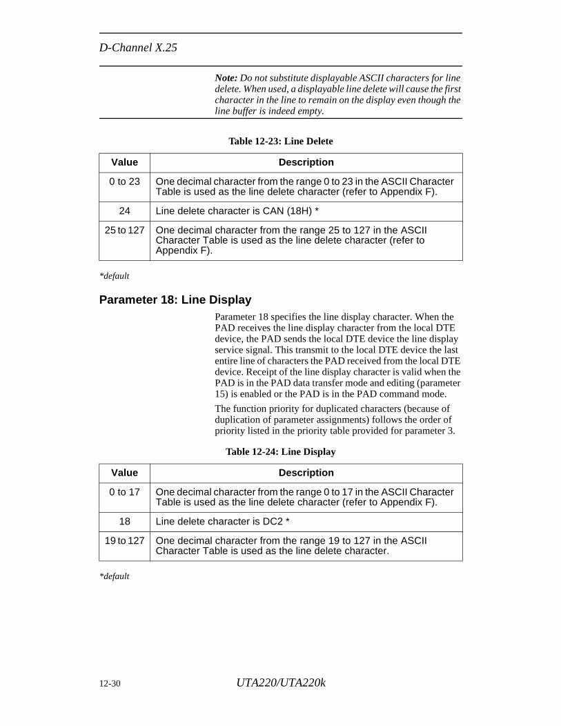
D-Channel X.25
Note: Do not substitute displayable ASCII characters for line delete. When used, a displayable line delete will cause the first character in the line to remain on the display even though the line buffer is indeed empty.
*default
Parameter 18: Line Display Parameter 18 specifies the line display character. When the PAD receives the line display character from the local DTE device, the PAD sends the local DTE device the line display service signal. This transmit to the local DTE device the last entire line of characters the PAD received from the local DTE device. Receipt of the line display character is valid when the PAD is in the PAD data transfer mode and editing (parameter 15) is enabled or the PAD is in the PAD command mode.
The function priority for duplicated characters (because of duplication of parameter assignments) follows the order of priority listed in the priority table provided for parameter 3.
*default
Table 12-23: Line Delete
Value Description
0 to 23 One decimal character from the range 0 to 23 in the ASCII Character Table is used as the line delete character (refer to Appendix F).
24 Line delete character is CAN (18H) *
25 to 127 One decimal character from the range 25 to 127 in the ASCII Character Table is used as the line delete character (refer to Appendix F).
Table 12-24: Line Display
Value Description
0 to 17 One decimal character from the range 0 to 17 in the ASCII Character Table is used as the line delete character (refer to Appendix F).
18 Line delete character is DC2 *
19 to 127 One decimal character from the range 19 to 127 in the ASCII Character Table is used as the line delete character.
12-30 UTA220/UTA220k
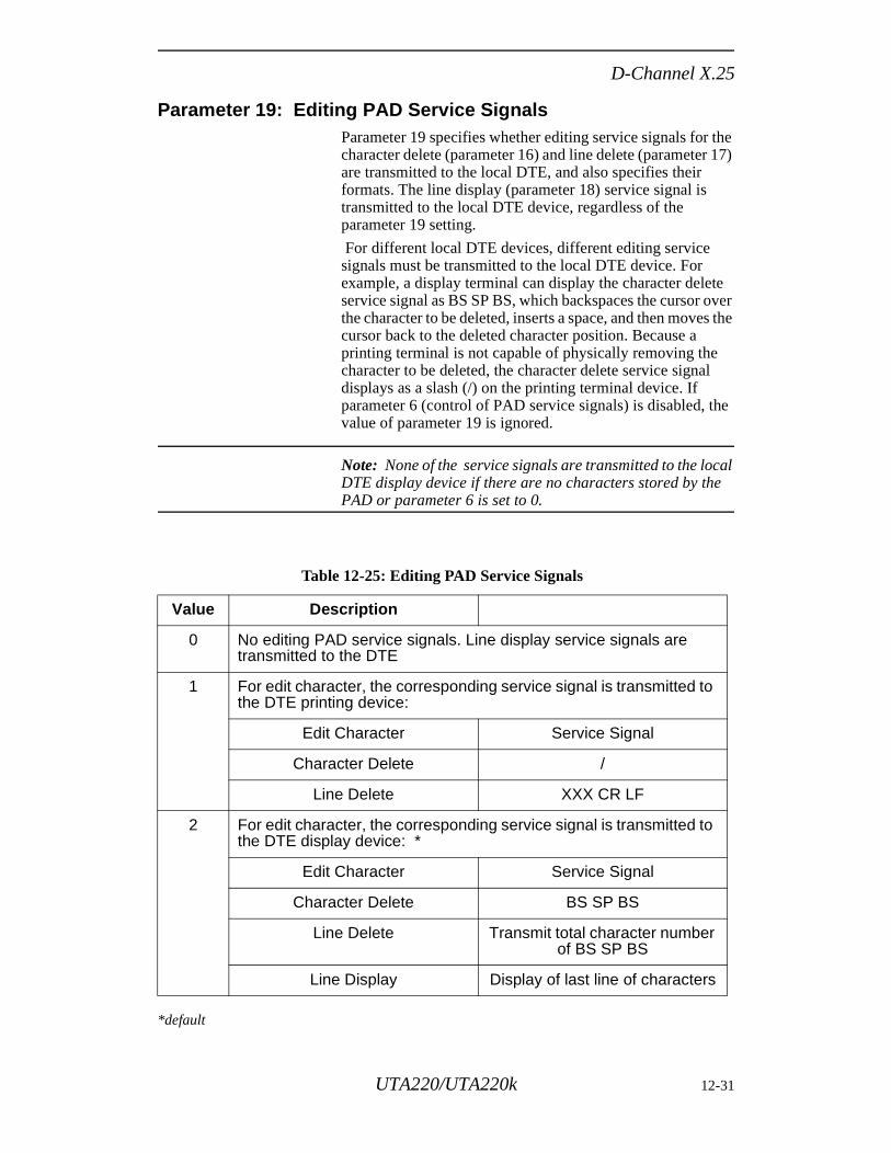
D-Channel X.25
Parameter 19: Editing PAD Service Signals Parameter 19 specifies whether editing service signals for the character delete (parameter 16) and line delete (parameter 17) are transmitted to the local DTE, and also specifies their formats. The line display (parameter 18) service signal is transmitted to the local DTE device, regardless of the parameter 19 setting.
For different local DTE devices, different editing service signals must be transmitted to the local DTE device. For example, a display terminal can display the character delete service signal as BS SP BS, which backspaces the cursor over the character to be deleted, inserts a space, and then moves the cursor back to the deleted character position. Because a printing terminal is not capable of physically removing the character to be deleted, the character delete service signal displays as a slash (/) on the printing terminal device. If parameter 6 (control of PAD service signals) is disabled, the value of parameter 19 is ignored.
Note: None of the service signals are transmitted to the local DTE display device if there are no characters stored by the PAD or parameter 6 is set to 0.
*default
Table 12-25: Editing PAD Service Signals
Value Description
0 No editing PAD service signals. Line display service signals are transmitted to the DTE
1 For edit character, the corresponding service signal is transmitted to the DTE printing device:
Edit Character Service Signal
Character Delete /
Line Delete XXX CR LF
2 For edit character, the corresponding service signal is transmitted to the DTE display device: *
Edit Character Service Signal
Character Delete BS SP BS
Line Delete Transmit total character number of BS SP BS
Line Display Display of last line of characters
UTA220/UTA220k 12-31
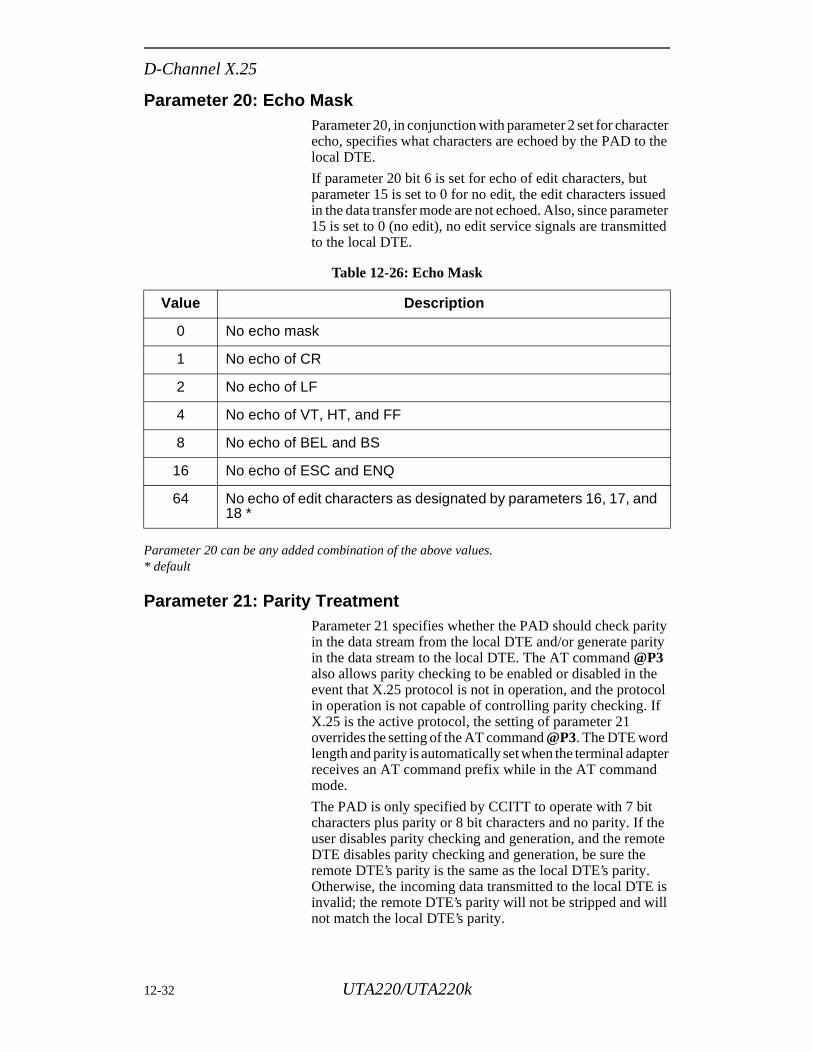
D-Channel X.25
Parameter 20: Echo Mask Parameter 20, in conjunction with parameter 2 set for character echo, specifies what characters are echoed by the PAD to the local DTE.
If parameter 20 bit 6 is set for echo of edit characters, but parameter 15 is set to 0 for no edit, the edit characters issued in the data transfer mode are not echoed. Also, since parameter 15 is set to 0 (no edit), no edit service signals are transmitted to the local DTE.
Parameter 20 can be any added combination of the above values.* default
Parameter 21: Parity TreatmentParameter 21 specifies whether the PAD should check parity in the data stream from the local DTE and/or generate parity in the data stream to the local DTE. The AT command @P3 also allows parity checking to be enabled or disabled in the event that X.25 protocol is not in operation, and the protocol in operation is not capable of controlling parity checking. If X.25 is the active protocol, the setting of parameter 21 overrides the setting of the AT command @P3. The DTE word length and parity is automatically set when the terminal adapter receives an AT command prefix while in the AT command mode.
The PAD is only specified by CCITT to operate with 7 bit characters plus parity or 8 bit characters and no parity. If the user disables parity checking and generation, and the remote DTE disables parity checking and generation, be sure the remote DTE’s parity is the same as the local DTE’s parity. Otherwise, the incoming data transmitted to the local DTE is invalid; the remote DTE’s parity will not be stripped and will not match the local DTE’s parity.
Table 12-26: Echo Mask
Value Description
0 No echo mask
1 No echo of CR
2 No echo of LF
4 No echo of VT, HT, and FF
8 No echo of BEL and BS
16 No echo of ESC and ENQ
64 No echo of edit characters as designated by parameters 16, 17, and 18 *
12-32 UTA220/UTA220k
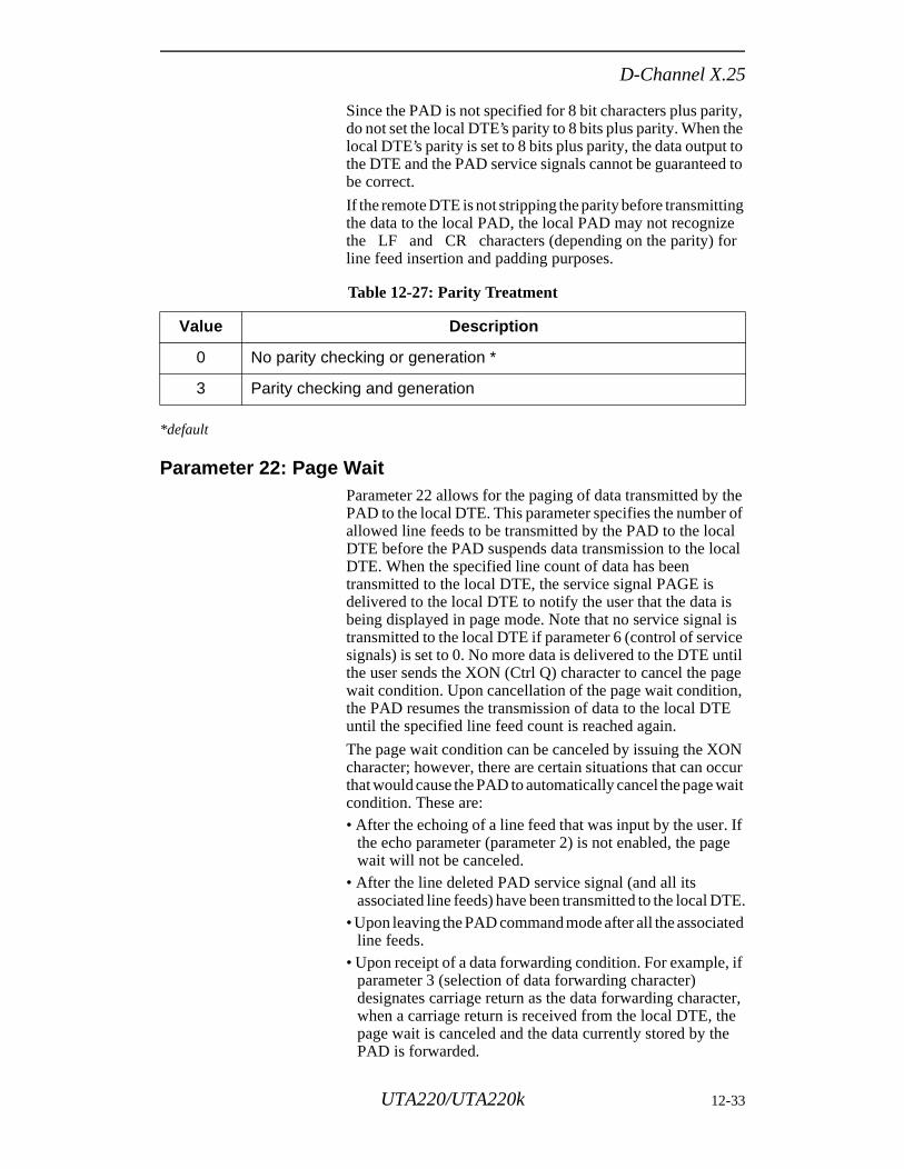
D-Channel X.25
. If ge
TE.ted
if
ter, e e
Since the PAD is not specified for 8 bit characters plus parity, do not set the local DTE’s parity to 8 bits plus parity. When the local DTE’s parity is set to 8 bits plus parity, the data output to the DTE and the PAD service signals cannot be guaranteed to be correct.
If the remote DTE is not stripping the parity before transmitting the data to the local PAD, the local PAD may not recognize the LF and CR characters (depending on the parity) for line feed insertion and padding purposes.
*default
Parameter 22: Page WaitParameter 22 allows for the paging of data transmitted by the PAD to the local DTE. This parameter specifies the number of allowed line feeds to be transmitted by the PAD to the local DTE before the PAD suspends data transmission to the local DTE. When the specified line count of data has been transmitted to the local DTE, the service signal PAGE is delivered to the local DTE to notify the user that the data is being displayed in page mode. Note that no service signal is transmitted to the local DTE if parameter 6 (control of service signals) is set to 0. No more data is delivered to the DTE until the user sends the XON (Ctrl Q) character to cancel the page wait condition. Upon cancellation of the page wait condition, the PAD resumes the transmission of data to the local DTE until the specified line feed count is reached again.
The page wait condition can be canceled by issuing the XON character; however, there are certain situations that can occur that would cause the PAD to automatically cancel the page wait condition. These are:• After the echoing of a line feed that was input by the user
the echo parameter (parameter 2) is not enabled, the pawait will not be canceled.
• After the line deleted PAD service signal (and all its associated line feeds) have been transmitted to the local D
• Upon leaving the PAD command mode after all the associaline feeds.
• Upon receipt of a data forwarding condition. For example,parameter 3 (selection of data forwarding character) designates carriage return as the data forwarding characwhen a carriage return is received from the local DTE, thpage wait is canceled and the data currently stored by thPAD is forwarded.
Table 12-27: Parity Treatment
Value Description
0 No parity checking or generation *
3 Parity checking and generation
UTA220/UTA220k 12-33
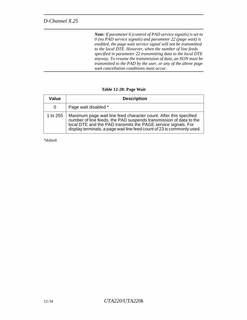
D-Channel X.25
Note: If parameter 6 (control of PAD service signals) is set to 0 (no PAD service signals) and parameter 22 (page wait) is enabled, the page wait service signal will not be transmitted to the local DTE. However, when the number of line feeds specified in parameter 22 transmitting data to the local DTE anyway. To resume the transmission of data, an XON must be transmitted to the PAD by the user, or any of the above page wait cancellation conditions must occur.
*default
Table 12-28: Page Wait
Value Description
0 Page wait disabled *
1 to 255 Maximum page wait line feed character count. After this specified number of line feeds, the PAD suspends transmission of data to the local DTE and the PAD transmits the PAGE service signals. For display terminals, a page wait line feed count of 23 is commonly used.
12-34 UTA220/UTA220k
Softload
l
and
any and
ted
urs
t
a
Chapter 13Softload
The optional softload feature lets you download new software into the TA through the local DTE port. The new software is stored in nonvolatile flash-programmable read-only memory devices (PROMS) and is retained even when the unit is powered down. This allows software updates and new features to be added to the TA without physically removing the unit from service.
The new software files are downloaded into the TA from the customer’s host computer using the YModem-G file transfer protocol. Password protection prevents unauthorized software changes.
Note: If the softload feature is not present, the %P1, $Q, $Y=x, $Y2=x, and $T=x commands will return an ERROR message.
The softload feature does not interfere with normal TA operation, except for the swap command. While the softload is in progress the TA remains fully operational.
TA SOFTWARE ARCHITECTUREThe concepts of sets of software and how the TA’s CentraProcessing Unit (CPU) use them are described below.
Software SetsThe TA has two sets of operational software: the active set the alternate set. The TA operates from the active set andperforms software downloads into the alternate set.
A swap command allows the user to swap software sets attime. The active software becomes the alternate software, vice versa. This swap also allows the unit to return to its previous version of software. The active software set selecis stored in a separate nonvolatile memory location and isretained even after powering down the unit.
Swaps to invalid software are prevented. If a power-up occin an invalid set of software, the TA automatically swaps tothe alternate set of software.
Software FormatUpdated software for the TA is provided on a standard PC-compatible 5.25” high-density floppy diskette. The hoscomputer can be a PC on any other system capable of reading PC-formatted floppy disks and transferring files viYModem-G.
UTA220/UTA220k 13-1
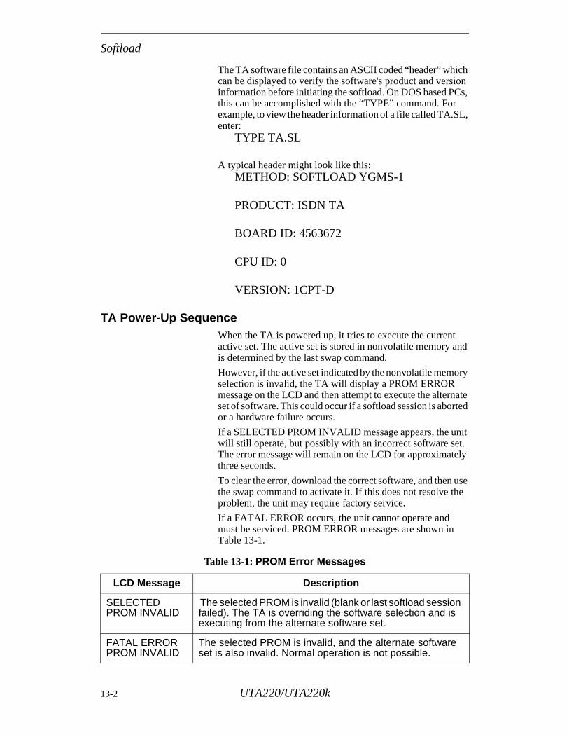
Softload
h ion s,
L,
nd
ry
nate ted
it t. ly
use e
The TA software file contains an ASCII coded “header” whiccan be displayed to verify the software's product and versinformation before initiating the softload. On DOS based PCthis can be accomplished with the “TYPE” command. For example, to view the header information of a file called TA.Senter:
TYPE TA.SL
A typical header might look like this:METHOD: SOFTLOAD YGMS-1
PRODUCT: ISDN TA
BOARD ID: 4563672
CPU ID: 0
VERSION: 1CPT-D
TA Power-Up SequenceWhen the TA is powered up, it tries to execute the currentactive set. The active set is stored in nonvolatile memory ais determined by the last swap command.
However, if the active set indicated by the nonvolatile memoselection is invalid, the TA will display a PROM ERROR message on the LCD and then attempt to execute the alterset of software. This could occur if a softload session is aboror a hardware failure occurs.
If a SELECTED PROM INVALID message appears, the unwill still operate, but possibly with an incorrect software seThe error message will remain on the LCD for approximatethree seconds.
To clear the error, download the correct software, and then the swap command to activate it. If this does not resolve thproblem, the unit may require factory service.
If a FATAL ERROR occurs, the unit cannot operate and must be serviced. PROM ERROR messages are shown inTable 13-1.
Table 13-1: PROM Error Messages
LCD Message Description
SELECTED PROM INVALID
The selected PROM is invalid (blank or last softload session failed). The TA is overriding the software selection and is executing from the alternate software set.
FATAL ERROR PROM INVALID
The selected PROM is invalid, and the alternate software set is also invalid. Normal operation is not possible.
13-2 UTA220/UTA220k
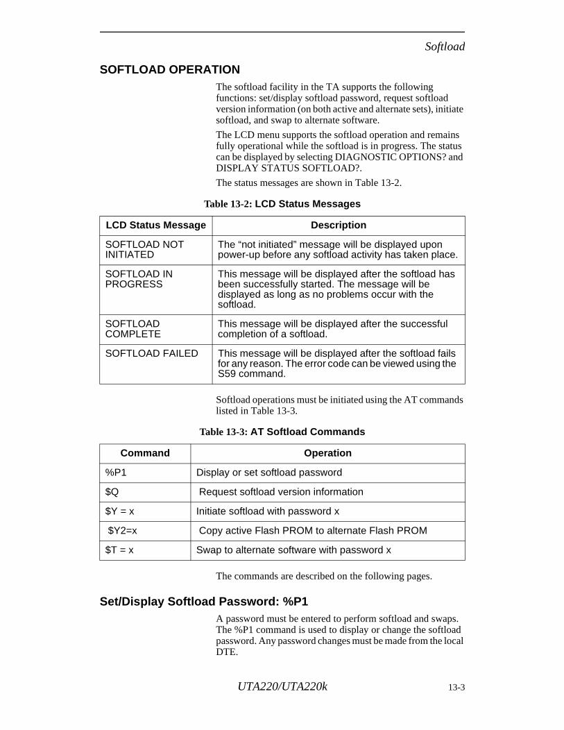
Softload
SOFTLOAD OPERATIONThe softload facility in the TA supports the following functions: set/display softload password, request softload version information (on both active and alternate sets), initiate softload, and swap to alternate software.
The LCD menu supports the softload operation and remains fully operational while the softload is in progress. The status can be displayed by selecting DIAGNOSTIC OPTIONS? and DISPLAY STATUS SOFTLOAD?.
The status messages are shown in Table 13-2.
Softload operations must be initiated using the AT commands listed in Table 13-3.
The commands are described on the following pages.
Set/Display Softload Password: %P1A password must be entered to perform softload and swaps. The %P1 command is used to display or change the softload password. Any password changes must be made from the local DTE.
Table 13-2: LCD Status Messages
LCD Status Message Description
SOFTLOAD NOT INITIATED
The “not initiated” message will be displayed upon power-up before any softload activity has taken place.
SOFTLOAD IN PROGRESS
This message will be displayed after the softload has been successfully started. The message will be displayed as long as no problems occur with the softload.
SOFTLOAD COMPLETE
This message will be displayed after the successful completion of a softload.
SOFTLOAD FAILED This message will be displayed after the softload fails for any reason. The error code can be viewed using the S59 command.
Table 13-3: AT Softload Commands
Command Operation
%P1 Display or set softload password
$Q Request softload version information
$Y = x Initiate softload with password x
$Y2=x Copy active Flash PROM to alternate Flash PROM
$T = x Swap to alternate software with password x
UTA220/UTA220k 13-3
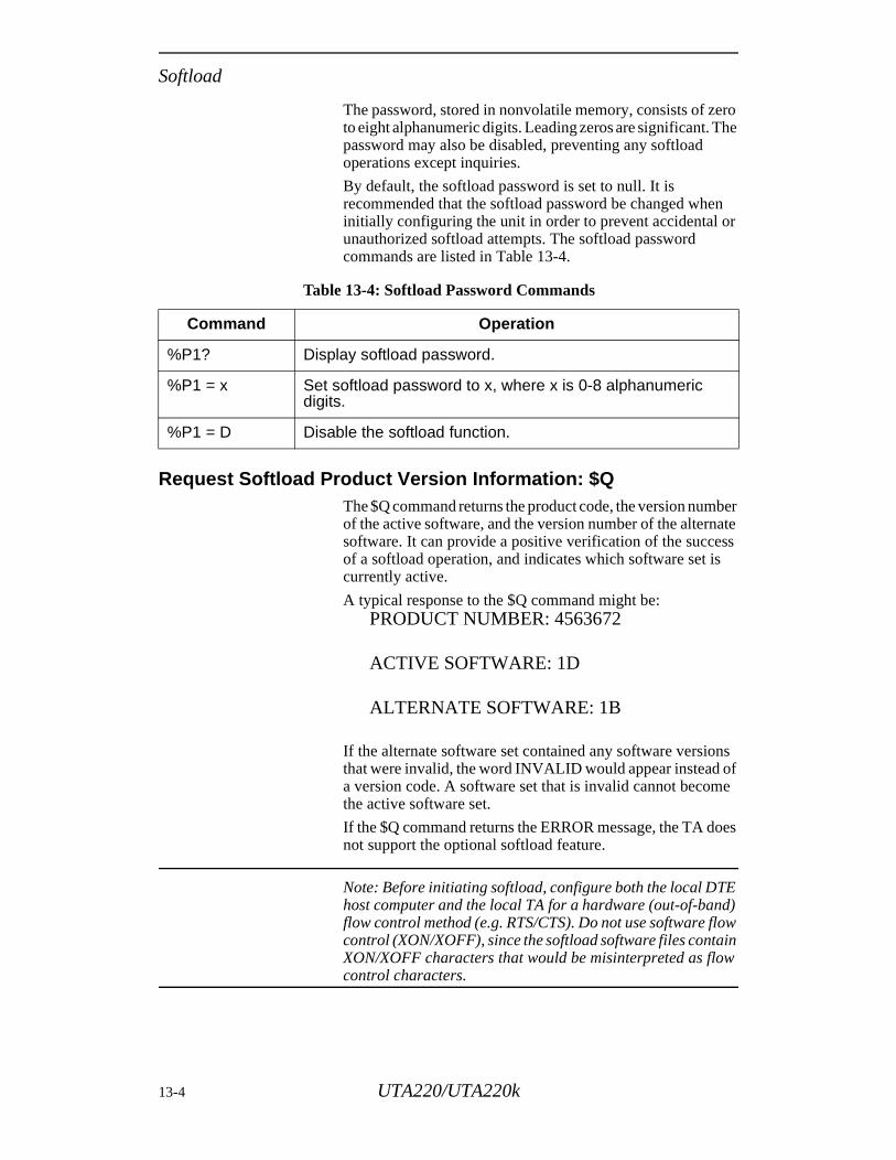
Softload
The password, stored in nonvolatile memory, consists of zero to eight alphanumeric digits. Leading zeros are significant. The password may also be disabled, preventing any softload operations except inquiries.
By default, the softload password is set to null. It is recommended that the softload password be changed when initially configuring the unit in order to prevent accidental or unauthorized softload attempts. The softload password commands are listed in Table 13-4.
Request Softload Product Version Information: $QThe $Q command returns the product code, the version number of the active software, and the version number of the alternate software. It can provide a positive verification of the success of a softload operation, and indicates which software set is currently active.
A typical response to the $Q command might be:PRODUCT NUMBER: 4563672
ACTIVE SOFTWARE: 1D
ALTERNATE SOFTWARE: 1B
If the alternate software set contained any software versions that were invalid, the word INVALID would appear instead of a version code. A software set that is invalid cannot become the active software set.
If the $Q command returns the ERROR message, the TA does not support the optional softload feature.
Note: Before initiating softload, configure both the local DTE host computer and the local TA for a hardware (out-of-band) flow control method (e.g. RTS/CTS). Do not use software flow control (XON/XOFF), since the softload software files contain XON/XOFF characters that would be misinterpreted as flow control characters.
Table 13-4: Softload Password Commands
Command Operation
%P1? Display softload password.
%P1 = x Set softload password to x, where x is 0-8 alphanumeric digits.
%P1 = D Disable the softload function.
13-4 UTA220/UTA220k
Softload
Initiate Software Download: $Y=xThe $Y command initiates a softload into the alternate software set. This command requires the softload password previously set by the %P1 command. If the password does not match the unit’s stored password, the TA will return an ERROR message.
If the password matches, the TA begins by displaying the softload method ID. This ID code must match the softload method ID of the new software to be loaded.
After displaying the method ID, the TA begins erasing the Flash memory devices for the alternate software set. If the erasure is successful, the TA returns a READY message and enters the YModem-G receive mode.
At this point, the TA is ready to accept a softload using the YModem-G file transfer protocol. The TA sends the YModem-G initiation character (G) until the DTE begins sending YModem-G frames. If no frames are received within two minutes, the TA will time out, send an ERROR message, and return to the AT command mode.
The YModem-G transfer should send one file. During the transfer, the TA may issue flow control requests to pace the DTE’s sending of data.
After the file has been transferred, the TA verifies that the file has been received and programmed correctly. The TA then sends a response code (OK or ERROR) to the DTE indicating the success or failure of the entire softload.
If an error occurs during the transfer, or if the host fails to respond to the YModem-G initiation requests, the TA returns with an ERROR message. In this case, the alternate software is marked as INVALID to prevent a swap attempt.
If an error occurs during the softload, the TA attempts to cancel the YModem-G transfer by sending a series of ASCII CAN characters (18 hex). It then returns to the AT command mode, echoing any characters received from the DTE. Depending upon when the host recognizes the cancel sequence, the host may begin to display the echoed softload characters on its screen. The DTE may also abort the transfer by sending 2 or more CAN characters between YModem-G frames.
An example of a typical softload session is provided at the end of this chapter.
UTA220/UTA220k 13-5
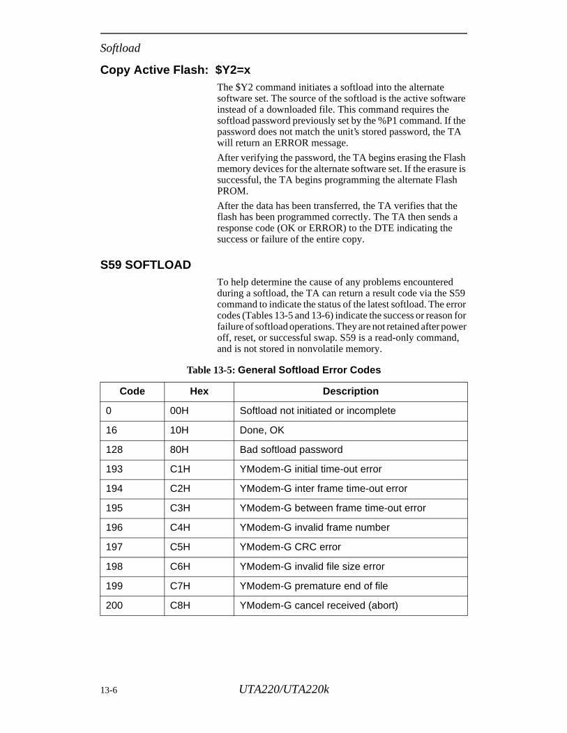
Softload
Copy Active Flash: $Y2=xThe $Y2 command initiates a softload into the alternate software set. The source of the softload is the active software instead of a downloaded file. This command requires the softload password previously set by the %P1 command. If the password does not match the unit’s stored password, the TA will return an ERROR message.
After verifying the password, the TA begins erasing the Flash memory devices for the alternate software set. If the erasure is successful, the TA begins programming the alternate Flash PROM.
After the data has been transferred, the TA verifies that the flash has been programmed correctly. The TA then sends a response code (OK or ERROR) to the DTE indicating the success or failure of the entire copy.
S59 SOFTLOADTo help determine the cause of any problems encountered during a softload, the TA can return a result code via the S59 command to indicate the status of the latest softload. The error codes (Tables 13-5 and 13-6) indicate the success or reason for failure of softload operations. They are not retained after power off, reset, or successful swap. S59 is a read-only command, and is not stored in nonvolatile memory.
Table 13-5: General Softload Error Codes
Code Hex Description
0 00H Softload not initiated or incomplete
16 10H Done, OK
128 80H Bad softload password
193 C1H YModem-G initial time-out error
194 C2H YModem-G inter frame time-out error
195 C3H YModem-G between frame time-out error
196 C4H YModem-G invalid frame number
197 C5H YModem-G CRC error
198 C6H YModem-G invalid file size error
199 C7H YModem-G premature end of file
200 C8H YModem-G cancel received (abort)
13-6 UTA220/UTA220k
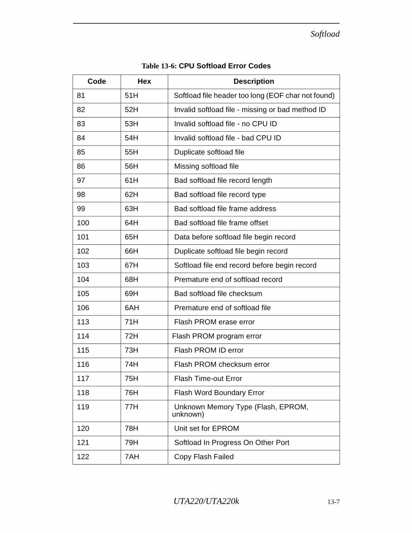
Softload
Table 13-6: CPU Softload Error Codes
Code Hex Description
81 51H Softload file header too long (EOF char not found)
82 52H Invalid softload file - missing or bad method ID
83 53H Invalid softload file - no CPU ID
84 54H Invalid softload file - bad CPU ID
85 55H Duplicate softload file
86 56H Missing softload file
97 61H Bad softload file record length
98 62H Bad softload file record type
99 63H Bad softload file frame address
100 64H Bad softload file frame offset
101 65H Data before softload file begin record
102 66H Duplicate softload file begin record
103 67H Softload file end record before begin record
104 68H Premature end of softload record
105 69H Bad softload file checksum
106 6AH Premature end of softload file
113 71H Flash PROM erase error
114 72H Flash PROM program error
115 73H Flash PROM ID error
116 74H Flash PROM checksum error
117 75H Flash Time-out Error
118 76H Flash Word Boundary Error
119 77H Unknown Memory Type (Flash, EPROM, unknown)
120 78H Unit set for EPROM
121 79H Softload In Progress On Other Port
122 7AH Copy Flash Failed
UTA220/UTA220k 13-7
Softload
l.
um
e R
and ds. reset ful,
lly ry.
ion
s
ile
e ly,
Swap to Alternate Software: $T=xThe $T command initiates a swap to the alternate set of software. If successful, the alternate software becomes the active software, and vice versa. The TA will automatically perform a reset to reinitialize the new software after the swap.
A softload password must be provided with the $T command. If the password does not match the unit’s stored password, the TA will return an ERROR message.
Before the TA attempts the swap, it first verifies that the alternate set of software is valid. An extensive set of tests must be passed during and after softloading. In order for the TA to allow a software swap the following conditions must be met:• The previous software load was complete and successfu• The software is loaded in the correct format.• The software is for the correct product.• The software version information is correct.• The checksum of the software matches its stored checks
value.
If any of the above conditions is not met, then the alternatsoftware is marked as invalid and the TA returns the ERROmessage. If all verification checks pass, it returns OK andproceeds with the swap. The swap forces the TA to reset reinitialize with the new software; this takes about 10 seconNote that the OK message is returned before the swap and are performed; to verify that the swap was actually successuse the $Q command to request the software version.
When the swap command is executed, the TA automaticastores the selection of active software in nonvolatile memo
Note: Depending upon the changes implemented in the software, one or more parameters in the TA’s stored profile may be reset following a swap command.
TYPICAL LOCAL SOFTLOAD SESSIONThe following example demonstrates a typical softload sessform a local host. The host computer in this example is a PC-compatible computer running a typical communicationpackage.
The steps in performing a softload transfer and swap are:
1. Check the distribution floppy diskette that contains the fto be downloaded. There should be a file called README.TXT that describes the software contained on thfloppy and gives the name of the actual softload file. Normalsoftload files for the UTA220 are named UTA220.SL.
13-8 UTA220/UTA220k
Softload
st.
d
AT
e
TA e es
d
d sh
be
to .
t ely
pt, nter
he the
2. To be sure that the software in the file is correct, display the file on the host computer (be careful not to modify it). At the top of each file is a header (ASCII format) containing the product and version information for the softload file. If the host is a PC-compatible, the easiest way to do this is to enter: TYPE filename where filename is the name of the softload file to display.
3. Load the file to be downloaded to the TA onto the host computer hard disk before downloading (this significantly decreases the download time).
4. Connect the PC to any of the TA’s DTE port(s). Begin executing the communications software package on the ho
5. Configure the host software for: 19200 bps full-duplex asynchronous operation, 8-bit characters with no parity, anRTS/CTS flow control of the DTE.
6. Using the terminal emulation mode on the host, send an command to the TA. The TA should respond with OK.
7. Configure the TA for RTS/CTS flow control, using either thkeypad on the front panel or the AT&K3 command.
8. Check the version numbers of the current software on theto verify that it is to be downloaded into the correct alternatset. Enter AT$Q. The TA should respond with the version codfor both the active and alternate set.
9. Initiate Softload. Enter the AT$Y=x (where x is the softloapassword). The TA responds with either ERROR (if the password is invalid) or the softload method banner (SOFTLOAD YGMS-1). This banner identifies the downloamethod and file format. The TA then begins to erase the Flamemory for the alternate set so that the new software can downloaded.
10. When the erase is complete, the TA returns YModem-Ginitiation characters (G). This indicates that the TA is readyreceive the YModem-G frames containing the new software
11. Initiate the YModem-G file upload mode on the host computer. Upload only the “.SL” file to the TA; do not attempto send any other type of file. The transfer takes approximat3.5 minutes at 19200 bps.
12. If any errors are encountered during the file transfer attemset the host back up for the terminal emulation mode and eATS59? to display the softload error code.
13. After the YModem-G file transfer is complete, the TA verifies the new software. This takes about 10 seconds. If tsoftware has been transferred and programmed correctly, TA returns an OK message to the DTE; otherwise it returnsERROR.
UTA220/UTA220k 13-9
Softload
14. After successful completion of the softload, the alternate memory now contains the new downloaded software. To verify this, return to the terminal emulation mode on the host and enter AT$Q to display the software version codes. The code of the alternate software set should match the code contained in the header of the downloaded file.
15. The user can swap and operate using the new alternate software now or at a later time. To perform the swap, enter AT$T=x where x is the softload password. The TA returns either OK (indicating a swap is imminent) or ERROR (indicating a bad password or invalid alternate software set). The TA resets and reinitializes after implementing the swap.
16. To verify that the swap has occurred, enter AT$Q.
13-10 UTA220/UTA220k
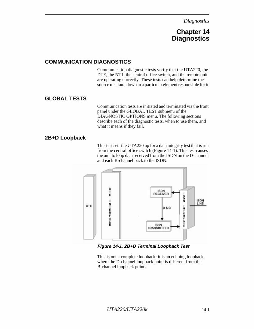
Diagnostics
Chapter 14Diagnostics
COMMUNICATION DIAGNOSTICSCommunication diagnostic tests verify that the UTA220, the DTE, the NT1, the central office switch, and the remote unit are operating correctly. These tests can help determine the source of a fault down to a particular element responsible for it.
GLOBAL TESTSCommunication tests are initiated and terminated via the front panel under the GLOBAL TEST submenu of the DIAGNOSTIC OPTIONS menu. The following sections describe each of the diagnostic tests, when to use them, and what it means if they fail.
2B+D LoopbackThis test sets the UTA220 up for a data integrity test that is run from the central office switch (Figure 14-1). This test causes the unit to loop data received from the ISDN on the D-channel and each B-channel back to the ISDN.
Figure 14-1. 2B+D Terminal Loopback Test
This is not a complete loopback; it is an echoing loopback where the D-channel loopback point is different from the B-channel loopback points.
UTA220/UTA220k 14-1
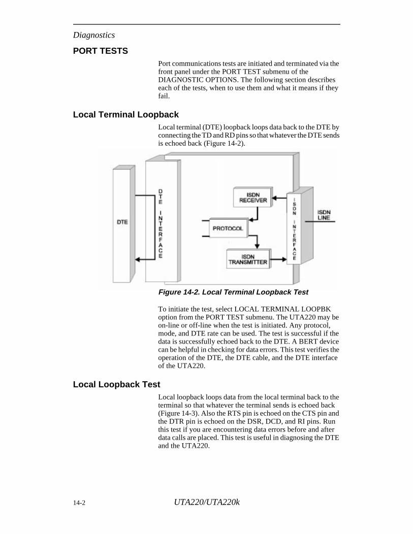
Diagnostics
PORT TESTSPort communications tests are initiated and terminated via the front panel under the PORT TEST submenu of the DIAGNOSTIC OPTIONS. The following section describes each of the tests, when to use them and what it means if they fail.
Local Terminal LoopbackLocal terminal (DTE) loopback loops data back to the DTE by connecting the TD and RD pins so that whatever the DTE sends is echoed back (Figure 14-2).
Figure 14-2. Local Terminal Loopback Test
To initiate the test, select LOCAL TERMINAL LOOPBK option from the PORT TEST submenu. The UTA220 may be on-line or off-line when the test is initiated. Any protocol, mode, and DTE rate can be used. The test is successful if the data is successfully echoed back to the DTE. A BERT device can be helpful in checking for data errors. This test verifies the operation of the DTE, the DTE cable, and the DTE interface of the UTA220.
Local Loopback Test Local loopback loops data from the local terminal back to the terminal so that whatever the terminal sends is echoed back (Figure 14-3). Also the RTS pin is echoed on the CTS pin and the DTR pin is echoed on the DSR, DCD, and RI pins. Run this test if you are encountering data errors before and after data calls are placed. This test is useful in diagnosing the DTE and the UTA220.
14-2 UTA220/UTA220k

Diagnostics
Figure 14-3. Local Loopback Test
To initiate the test, select the LOCAL LOOP option from the PORT TEST submenu. The UTA220 may be on-line or off-line when the test is initiated. Any protocol, mode, and DTE rate may be used. Data from the local DTE will be echoed back to the sender and the CTS pin follows the RTS pin and the DSR, DCD and RI pins follow the DTR pin. The DTE portion of the test verifies the operation of the DTE, the DTE cable the DTE interface in the UTA220 and of the data buffers in the UTA220. The test is successful if the data is successfully echoed back to the sender. A BERT device can be helpful in checking for data errors.
Digital Loopback TestDigital loopback loops the ISDN B-Channel data normally sent to the local DTE (Figure 14-4). Any B-Channel data received by the UTA220 is processed by the rate-adaptation protocol, and then echoed back out the B-channel to the sending unit. This test is useful in diagnosing the DTE, UTA220, switch ISDN line, and remote unit. Run this test if you encounter data errors after a call is placed successfully.
UTA220/UTA220k 14-3
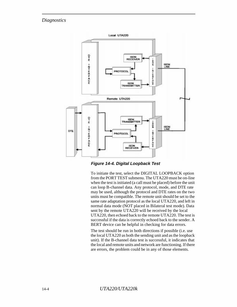
Diagnostics
Figure 14-4. Digital Loopback Test
To initiate the test, select the DIGITAL LOOPBACK option from the PORT TEST submenu. The UTA220 must be on-line when the test is initiated (a call must be placed) before the unit can loop B-channel data. Any protocol, mode, and DTE rate may be used, although the protocol and DTE rates on the two units must be compatible. The remote unit should be set to the same rate adaptation protocol as the local UTA220, and left in normal data mode (NOT placed in Bilateral test mode). Data sent by the remote UTA220 will be received by the local UTA220, then echoed back to the remote UTA220. The test is successful if the data is correctly echoed back to the sender. A BERT device can be helpful in checking for data errors.
The test should be run in both directions if possible (i.e. use the local UTA220 as both the sending unit and as the loopback unit). If the B-channel data test is successful, it indicates that the local and remote units and network are functioning. If there are errors, the problem could be in any of those elements.
14-4 UTA220/UTA220k
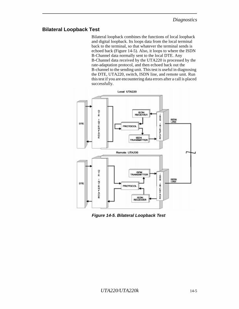
Diagnostics
Bilateral Loopback Test Bilateral loopback combines the functions of local loopback and digital loopback. Its loops data from the local terminal back to the terminal, so that whatever the terminal sends is echoed back (Figure 14-5). Also, it loops to where the ISDN B-Channel data normally sent to the local DTE. Any B-Channel data received by the UTA220 is processed by the rate-adaptation protocol, and then echoed back out the B-channel to the sending unit. This test is useful in diagnosing the DTE, UTA220, switch, ISDN line, and remote unit. Run this test if you are encountering data errors after a call is placed successfully.
Figure 14-5. Bilateral Loopback Test
UTA220/UTA220k 14-5
Diagnostics
To initiate the test, select the BILATERAL LOOPBACK option from the PORT TEST submenu. The UTA220 can be on-line or off-line when the test is initiated but a call must be placed before the unit can loop B-channel data. Any protocol, mode, and DTE rate can be used, however, the protocol and DTE rates on the two units must be compatible. The remote unit should be set to the same rate adaptation protocol as the local UTA220 and left in normal data mode (NOT placed in Bilateral test mode). Data sent by the remote UTA220 will be received by the local UTA220 then echoed back to the remote UTA220. The test is successful if the data is successfully echoed back to the sender. A BERT device can be helpful in checking for data errors.Also, data from the local DTE will be echoed back to the DTE. The DTE portion of the test verifies the operation of the DTE, the DTE cable, the DTE interface to the UTA220, and the data buffers in the UTA220.
The test should be run in both directions if possible (i.e., use the local UTA220 as both the sending unit and as the loopback unit). If the B-channel data test is successful, it indicates that the local and remote units and the network are functioning. If there are errors, the problem could be in any of those elements.
DIAGNOSTIC STATUS DISPLAYThe UTA220 LCD can display a status screen that provides diagnostic information concerning the state of the UTA220 and the link. The status displays are found under the DIAGNOSTIC OPTIONS menu and are described below.
Front Panel Keypad TestThis test allows you to verify the functioning of the front panel buttons. After this test is begun, press each key. The key legend will be displayed on the LCD when the key is pressed. The * (UTA220k) or “HOME” (UTA220) key ends the test.
View Product InformationDisplays software checksum, self-check status, PC boardnumber and the software revision code.
View Diagnostic Code This display is for factory use.
14-6 UTA220/UTA220k
Maintenance
Chapter 15Maintenance
Warning: Disconnect power before performing maintenance. Although dangerous voltage levels are not exposed, disconnecting power will ensure no electric shock hazard is present.
The unit contains no internal electronic components that can be serviced or replaced by the user. Repairs should not be attempted by the user.
FUSEIf a fuse fails, replace it with one of equal rating. Repeated failure indicates a more serious problem.
MAINTENANCEThe unit provides maintenance free service. Periodically it is necessary to remove dust that has collected on internal components. Remove dust with a soft bristle brush and low pressure air or vacuum. Before attempting diagnostic tests, check that all connectors and plugs are firmly inserted. The test procedures will identify the faulty component in a bad communications link.
If the unit appears faulty, contact your Motorola representative. Do not return the unit without prior instructions.
UTA220/UTA220k 15-1

Maintenance
15-2 UTA220/UTA220k
Specifications
Appendix ASpecifications
ISDN Line Type
ISDN Basic Rate Interface
Connection Types
Circuit-switched (dial-up)
DTE Data Rates
300, 1200, 2400, 4800, 9600, 19.2k, 38.4k, 48k, 56k, 57.6k,64k, 112k, 115.2k, 128k
DCE Data Rates
B-channel: 56 kbps or 64 kbpsD-channel: 16 kbps
Data Rate Adaption Protocols
Clear ChannelBONDINGV.120T-Link
DTE Available Interfaces
EIA-232 (V.24), CCITT V.35, EIA-366A
Switch Compatibility
Northern Telecom DMS100 - Central office switch runningsoftware version BCS-29 or above
Layer 1 (physical): Conforms to CCITT I.430
Layer 2 (Link): Conforms to Northern Telecom specificationNIS 208-4, Issue 1.1 section C, based on CCITTRecommendation Q.921
Layer 3 (Signaling): For BCS-29 and BCS-30, conforms toNIS 208-4, Issue 1.1, sections D-H. For BCS-31, -32, and -33conforms to NIS 208-5, Issue 1.1 Section D-H. These arebased on CCITT Recommendation Q.931. For BCS-34,conforms to National ISDN-1.
AT&T 5ESS - Central office switch running generic program5E4.2, or above for type A terminal
Layer 1 (physical): Conforms to CCITT I.430
UTA220/UTA220k A-1
Specifications
acls
Layer 2 (Link): Conforms to AT&T specification 5D5-900-311, December 1987, Part III, based on CCITT Recommendation Q.921
Layer 3 (Signaling): For 5E4.2, conforms to 5D5-900-301,Issue 1.04, September 1987, Parts IV - VI. For 5E5, conformsto 5D5-900-311, Issue 1.00, December 1987, Parts IV - VII.For 5E6 and 5E7, conforms to 5D5-900-321, Issue 1.02,September 1990, Parts IV - VII. These are based on CCITTRecommendation Q.931. For 5E8, conforms to NationalISDN-1.
US National ISDN One - Central office switches, as describedin Bellcore Special Report SR-NWT-001953, Issue 1, June1991, and Revision 1, December 1991
Supplementary Services
The UTA220 does not support any supplementary dataservices, nor does it support Electronic Key Telephone Service(EKTS).
Dimensions
Width 6.95 inches (17.65 cm)Height 2.22 inches (5.69 cm)Depth 9.98 inches (25.35 cm)
Environmental
0° to + 50° C
95% relative humidity, noncondensing
Power Requirements
115 Vac <Insert equation here> 10%, 60 Hz; or 230 V<Insert equation here> 10%, 50/60 Hz for applicable mode
Power Consumption
6 watts nominal
A-2 UTA220/UTA220k
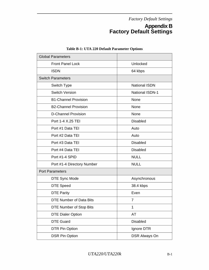
Factory Default Settings
Appendix BFactory Default Settings
Table B-1: UTA 220 Default Parameter Options
Global Parameters
Front Panel Lock Unlocked
ISDN 64 kbps
Switch Parameters
Switch Type National ISDN
Switch Version National ISDN-1
B1-Channel Provision None
B2-Channel Provision None
D-Channel Provision None
Port 1-4 X.25 TEI Disabled
Port #1 Data TEI Auto
Port #2 Data TEI Auto
Port #3 Data TEI Disabled
Port #4 Data TEI Disabled
Port #1-4 SPID NULL
Port #1-4 Directory Number NULL
Port Parameters
DTE Sync Mode Asynchronous
DTE Speed 38.4 kbps
DTE Parity Even
DTE Number of Data Bits 7
DTE Number of Stop Bits 1
DTE Dialer Option AT
DTE Guard Disabled
DTR Pin Option Ignore DTR
DSR Pin Option DSR Always On
UTA220/UTA220k B-1
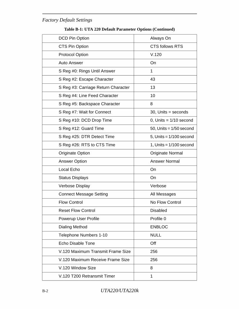
Factory Default Settings
DCD Pin Option Always On
CTS Pin Option CTS follows RTS
Protocol Option V.120
Auto Answer On
S Reg #0: Rings Until Answer 1
S Reg #2: Escape Character 43
S Reg #3: Carriage Return Character 13
S Reg #4: Line Feed Character 10
S Reg #5: Backspace Character 8
S Reg #7: Wait for Connect 30, Units = seconds
S Reg #10: DCD Drop Time 0, Units = 1/10 second
S Reg #12: Guard Time 50, Units = 1/50 second
S Reg #25: DTR Detect Time 5, Units = 1/100 second
S Reg #26: RTS to CTS Time 1, Units = 1/100 second
Originate Option Originate Normal
Answer Option Answer Normal
Local Echo On
Status Displays On
Verbose Display Verbose
Connect Message Setting All Messages
Flow Control No Flow Control
Reset Flow Control Disabled
Powerup User Profile Profile 0
Dialing Method ENBLOC
Telephone Numbers 1-10 NULL
Echo Disable Tone Off
V.120 Maximum Transmit Frame Size 256
V.120 Maximum Receive Frame Size 256
V.120 Window Size 8
V.120 T200 Retransmit Timer 1
Table B-1: UTA 220 Default Parameter Options (Continued)
B-2 UTA220/UTA220k
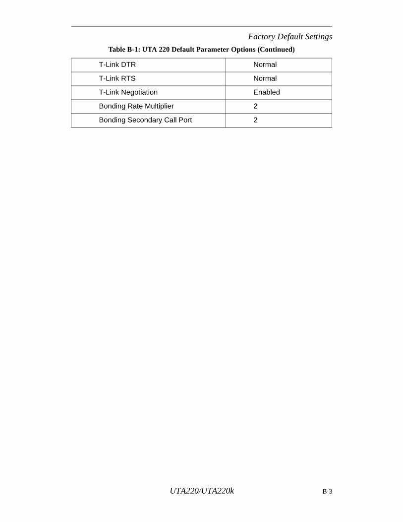
Factory Default Settings
T-Link DTR Normal
T-Link RTS Normal
T-Link Negotiation Enabled
Bonding Rate Multiplier 2
Bonding Secondary Call Port 2
Table B-1: UTA 220 Default Parameter Options (Continued)
UTA220/UTA220k B-3

Factory Default Settings
B-4 UTA220/UTA220k
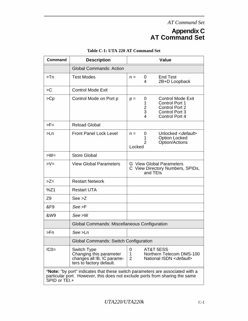
AT Command Set
Appendix CAT Command Set
Table C-1: UTA 220 AT Command Set
Command Description Value
Global Commands: Action
>Tn Test Modes n = 0 End Test4 2B+D Loopback
>C Control Mode Exit
>Cp Control Mode on Port p p = 0 Control Mode Exit1 Control Port 12 Control Port 23 Control Port 34 Control Port 4
>F= Reload Global
>Ln Front Panel Lock Level n = 0 Unlocked <default>1 Option Locked2 Option/Actions
Locked
>W= Store Global
>V= View Global Parameters G View Global ParametersC View Directory Numbers, SPIDs,
and TEIs
>Z= Restart Network
%Z1 Restart UTA
Z9 See >Z
&F9 See >F
&W9 See >W
Global Commands: Miscellaneous Configuration
>Fn See >Ln
Global Commands: Switch Configuration
!C0= Switch TypeChanging this parameter changes all !B, !C parame-ters to factory default.
0 AT&T 5ESS1 Northern Telecom DMS-1002 National ISDN <default>
*Note: "by port" indicates that these switch parameters are associated with a particular port. However, this does not exclude ports from sharing the same SPID or TEI.+
UTA220/UTA220k C-1
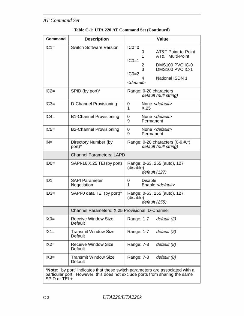
AT Command Set
!C1= Switch Software Version !C0=00 AT&T Point-to-Point1 AT&T Multi-Point
!C0=12 DMS100 PVC IC-03 DMS100 PVC IC-1
!C0=24 National ISDN 1
<default>
!C2= SPID (by port)* Range: 0-20 charactersdefault (null string)
!C3= D-Channel Provisioning 0 None <default>1 X.25
!C4= B1-Channel Provisioning 0 None <default>9 Permanent
!C5= B2-Channel Provisioning 0 None <default>9 Permanent
!N= Directory Number (by port)*
Range: 0-20 characters (0-9,#,*)default (null string)
Channel Parameters: LAPD
!D0= SAPI-16 X.25 TEI (by port) Range: 0-63, 255 (auto), 127 (disable)
default (127)
!D1 SAPI Parameter Negotiation
0 Disable1 Enable <default>
!D3= SAPI-0 data TEI (by port)* Range: 0-63, 255 (auto), 127 (disable)
default (255)
Channel Parameters: X.25 Provisional D-Channel
!X0= Receive Window Size Default
Range: 1-7 default (2)
!X1= Transmit Window Size Default
Range: 1-7 default (2)
!X2= Receive Window Size Default
Range: 7-8 default (8)
!X3= Transmit Window Size Default
Range: 7-8 default (8)
Table C-1: UTA 220 AT Command Set (Continued)
Command Description Value
*Note: "by port" indicates that these switch parameters are associated with a particular port. However, this does not exclude ports from sharing the same SPID or TEI.+
C-2 UTA220/UTA220k
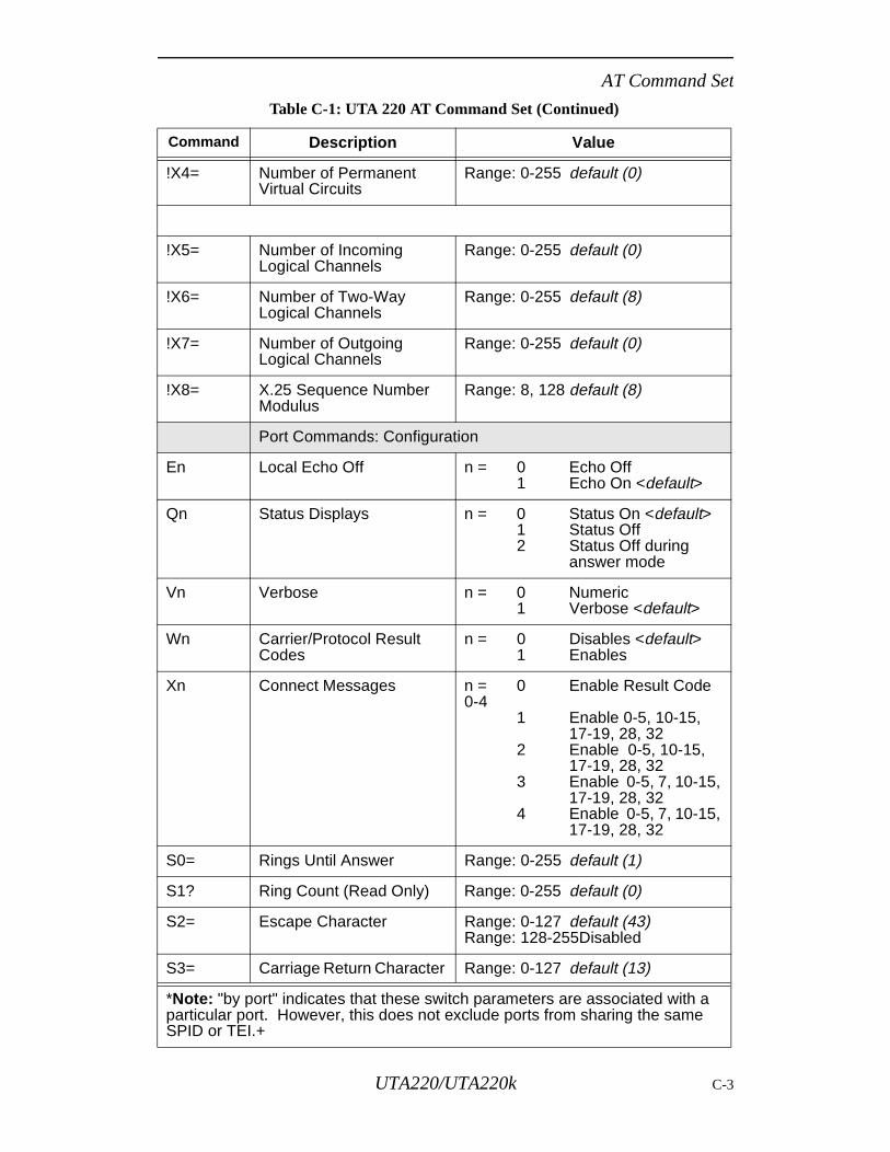
AT Command Set
!X4= Number of Permanent Virtual Circuits
Range: 0-255 default (0)
!X5= Number of Incoming Logical Channels
Range: 0-255 default (0)
!X6= Number of Two-Way Logical Channels
Range: 0-255 default (8)
!X7= Number of Outgoing Logical Channels
Range: 0-255 default (0)
!X8= X.25 Sequence Number Modulus
Range: 8, 128 default (8)
Port Commands: Configuration
En Local Echo Off n = 0 Echo Off1 Echo On <default>
Qn Status Displays n = 0 Status On <default>1 Status Off2 Status Off during
answer mode
Vn Verbose n = 0 Numeric1 Verbose <default>
Wn Carrier/Protocol ResultCodes
n = 0 Disables <default>1 Enables
Xn Connect Messages n = 0 Enable Result Code 0-4
1 Enable 0-5, 10-15, 17-19, 28, 32
2 Enable 0-5, 10-15, 17-19, 28, 32
3 Enable 0-5, 7, 10-15,17-19, 28, 32
4 Enable 0-5, 7, 10-15,17-19, 28, 32
S0= Rings Until Answer Range: 0-255 default (1)
S1? Ring Count (Read Only) Range: 0-255 default (0)
S2= Escape Character Range: 0-127 default (43)Range: 128-255Disabled
S3= Carriage Return Character Range: 0-127 default (13)
Table C-1: UTA 220 AT Command Set (Continued)
Command Description Value
*Note: "by port" indicates that these switch parameters are associated with a particular port. However, this does not exclude ports from sharing the same SPID or TEI.+
UTA220/UTA220k C-3
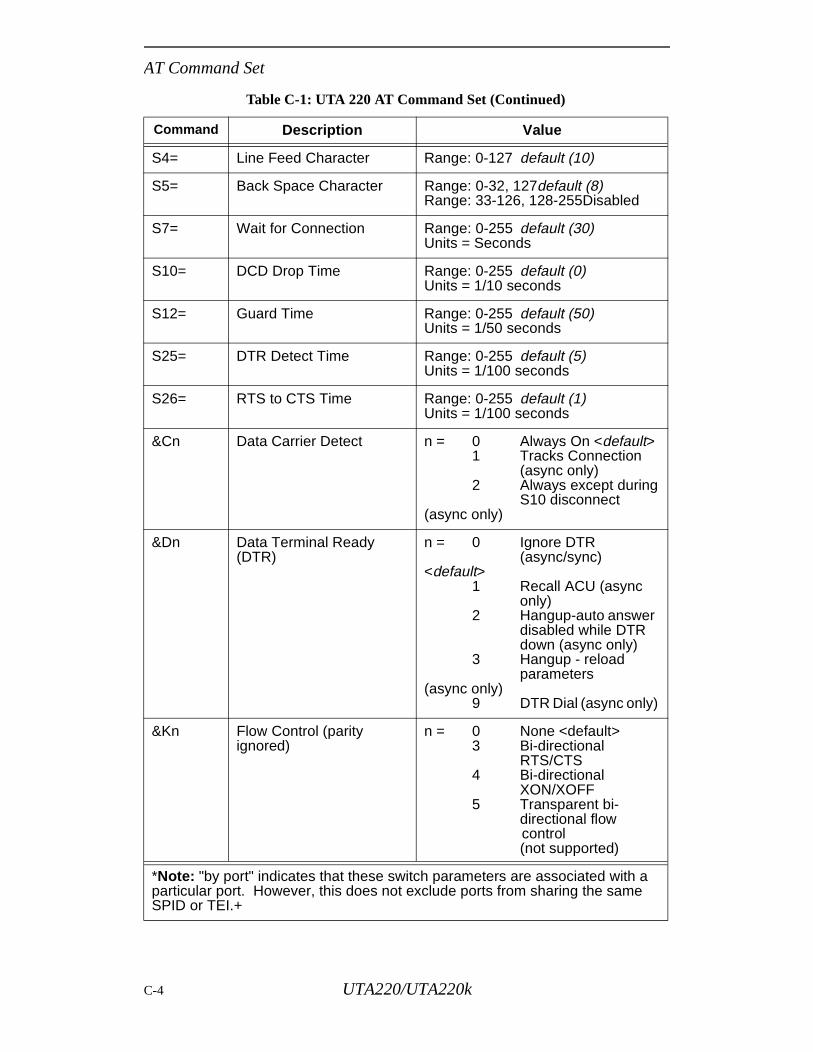
AT Command Set
S4= Line Feed Character Range: 0-127 default (10)
S5= Back Space Character Range: 0-32, 127default (8)Range: 33-126, 128-255Disabled
S7= Wait for Connection Range: 0-255 default (30)Units = Seconds
S10= DCD Drop Time Range: 0-255 default (0)Units = 1/10 seconds
S12= Guard Time Range: 0-255 default (50)Units = 1/50 seconds
S25= DTR Detect Time Range: 0-255 default (5)Units = 1/100 seconds
S26= RTS to CTS Time Range: 0-255 default (1)Units = 1/100 seconds
&Cn Data Carrier Detect n = 0 Always On <default>1 Tracks Connection
(async only)2 Always except during
S10 disconnect (async only)
&Dn Data Terminal Ready (DTR)
n = 0 Ignore DTR(async/sync)
<default>1 Recall ACU (async
only)2 Hangup-auto answer
disabled while DTR down (async only)
3 Hangup - reload parameters
(async only)9 DTR Dial (async only)
&Kn Flow Control (parity ignored)
n = 0 None <default>3 Bi-directional
RTS/CTS4 Bi-directional
XON/XOFF5 Transparent bi-
directional flow control
(not supported)
Table C-1: UTA 220 AT Command Set (Continued)
Command Description Value
*Note: "by port" indicates that these switch parameters are associated with a particular port. However, this does not exclude ports from sharing the same SPID or TEI.+
C-4 UTA220/UTA220k
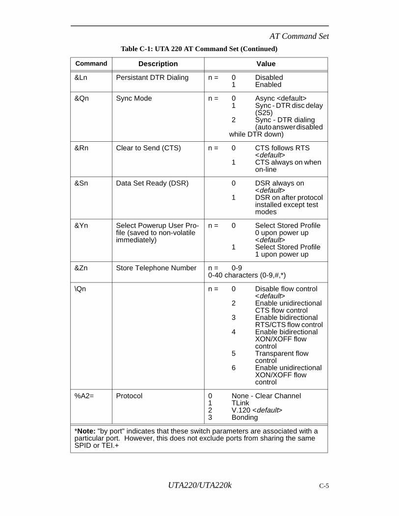
AT Command Set
&Ln Persistant DTR Dialing n = 0 Disabled1 Enabled
&Qn Sync Mode n = 0 Async <default>1 Sync - DTR disc delay
(S25)2 Sync - DTR dialing
(auto answer disabled while DTR down)
&Rn Clear to Send (CTS) n = 0 CTS follows RTS<default>
1 CTS always on when on-line
&Sn Data Set Ready (DSR) 0 DSR always on<default>
1 DSR on after protocolinstalled except testmodes
&Yn Select Powerup User Pro-file (saved to non-volatile immediately)
n = 0 Select Stored Profile0 upon power up<default>
1 Select Stored Profile1 upon power up
&Zn Store Telephone Number n = 0-90-40 characters (0-9,#,*)
\Qn n = 0 Disable flow control<default>
2 Enable unidirectionalCTS flow control
3 Enable bidirectionalRTS/CTS flow control
4 Enable bidirectionalXON/XOFF flowcontrol
5 Transparent flowcontrol
6 Enable unidirectionalXON/XOFF flow control
%A2= Protocol 0 None - Clear Channel1 TLink2 V.120 <default>3 Bonding
Table C-1: UTA 220 AT Command Set (Continued)
Command Description Value
*Note: "by port" indicates that these switch parameters are associated with a particular port. However, this does not exclude ports from sharing the same SPID or TEI.+
UTA220/UTA220k C-5
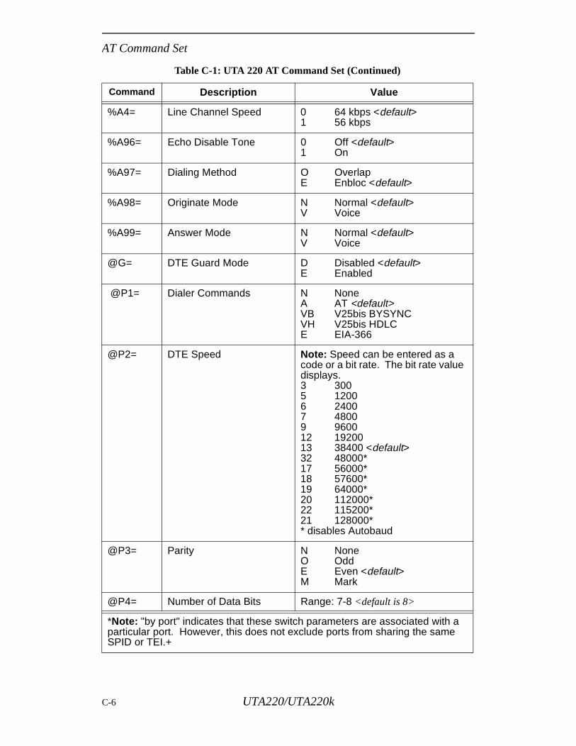
AT Command Set
%A4= Line Channel Speed 0 64 kbps <default>1 56 kbps
%A96= Echo Disable Tone 0 Off <default>1 On
%A97= Dialing Method O OverlapE Enbloc <default>
%A98= Originate Mode N Normal <default>V Voice
%A99= Answer Mode N Normal <default>V Voice
@G= DTE Guard Mode D Disabled <default>E Enabled
@P1= Dialer Commands N NoneA AT <default>VB V25bis BYSYNCVH V25bis HDLCE EIA-366
@P2= DTE Speed Note: Speed can be entered as a code or a bit rate. The bit rate value displays.3 3005 12006 24007 48009 960012 1920013 38400 <default>32 48000*17 56000*18 57600*19 64000*20 112000*22 115200*21 128000** disables Autobaud
@P3= Parity N NoneO OddE Even <default>M Mark
@P4= Number of Data Bits Range: 7-8 <default is 8>
Table C-1: UTA 220 AT Command Set (Continued)
Command Description Value
*Note: "by port" indicates that these switch parameters are associated with a particular port. However, this does not exclude ports from sharing the same SPID or TEI.+
C-6 UTA220/UTA220k
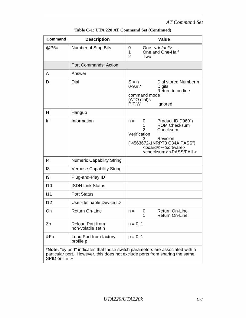
AT Command Set
@P6= Number of Stop Bits 0 One <default>1 One and One-Half2 Two
Port Commands: Action
A Answer
D Dial S = n Dial stored Number n0-9,#,* Digits; Return to on-line command mode (ATO dial)sP,T,W Ignored
H Hangup
In Information n = 0 Product ID ("960")1 ROM Checksum2 Checksum
Verification3 Revision
("4563672-1NRPT3 C34A PASS")<board#>-<software><checksum> <PASS/FAIL>
I4 Numeric Capability String
I8 Verbose Capability String
I9 Plug-and-Play ID
I10 ISDN Link Status
I11 Port Status
I12 User-definable Device ID
On Return On-Line n = 0 Return On-Line1 Return On-Line
Zn Reload Port from non-volatile set n
n = 0, 1
&Fp Load Port from factory profile p
p = 0, 1
Table C-1: UTA 220 AT Command Set (Continued)
Command Description Value
*Note: "by port" indicates that these switch parameters are associated with a particular port. However, this does not exclude ports from sharing the same SPID or TEI.+
UTA220/UTA220k C-7

AT Command Set
&Tn Test Modes n = 0 End Test1 Local Loop-
back3 Digital Loop-
back9 Local Ter -
minal Loopback8 Bilateral
Loopback
&V= View Parameters E Port V.120T Port TLinkZ Stored Telephone Numbers
&Wn Store port to non-volatile set n
n = 0, 1
Port Commands: V.120 (B-Channel only)
%E0= Maximum Transmit Frame Size
Range: 1-260 default (260)
%E1= Maximum Receive Frame Size
Range: 1-260 default (260)
%E2= Window Size Range: 1-127 default (8)
%E3= T200 Transmission timer Range: 1-255 default (5)
%E7= Protocol Option 0 Transparent to all bits (SYNC/
ASYNC) according to &Q1 Use protocols (SDLC) <default>
%E9= Information FrameSelection
0 Use I Frames <default>1 Use UI Frames
Port Commands: TLink (B-Channel Only)
@T0= Echo E EnabledD Disabled <default>
@T1= DTR A AssertN Normal <default>
@T2= RTS A AssertN Normal <default>
@T3= Negotiation E Enabled <default>D Disabled
Table C-1: UTA 220 AT Command Set (Continued)
Command Description Value
*Note: "by port" indicates that these switch parameters are associated with a particular port. However, this does not exclude ports from sharing the same SPID or TEI.+
C-8 UTA220/UTA220k
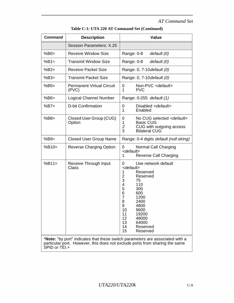
AT Command Set
Session Parameters: X.25
%B0= Receive Window Size Range: 0-8 default (0)
%B1= Transmit Window Size Range: 0-8 default (0)
%B2= Receive Packet Size Range: 0, 7-10default (0)
%B3= Transmit Packet Size Range: 0, 7-10default (0)
%B5= Permanent Virtual Circuit (PVC)
0 Non-PVC <default>1 PVC
%B6= Logical Channel Number Range: 0-255 default (1)
%B7= D-bit Confirmation 0 Disabled <default>1 Enabled
%B8= Closed User Group (CUG) Option
0 No CUG selected <default>1 Basic CUG2 CUG with outgoing access3 Bilateral CUG
%B9= Closed User Group Name Range: 0-4 digits default (null string)
%B10= Reverse Charging Option 0 Normal Call Charging <default>1 Reverse Call Charging
%B11= Receive Through Input Class
0 Use network default <default>1 Reserved2 Reserved3 754 1105 3006 6007 12008 24009 480010 960011 1920012 4800013 6400014 Reserved15 Reserved
Table C-1: UTA 220 AT Command Set (Continued)
Command Description Value
*Note: "by port" indicates that these switch parameters are associated with a particular port. However, this does not exclude ports from sharing the same SPID or TEI.+
UTA220/UTA220k C-9
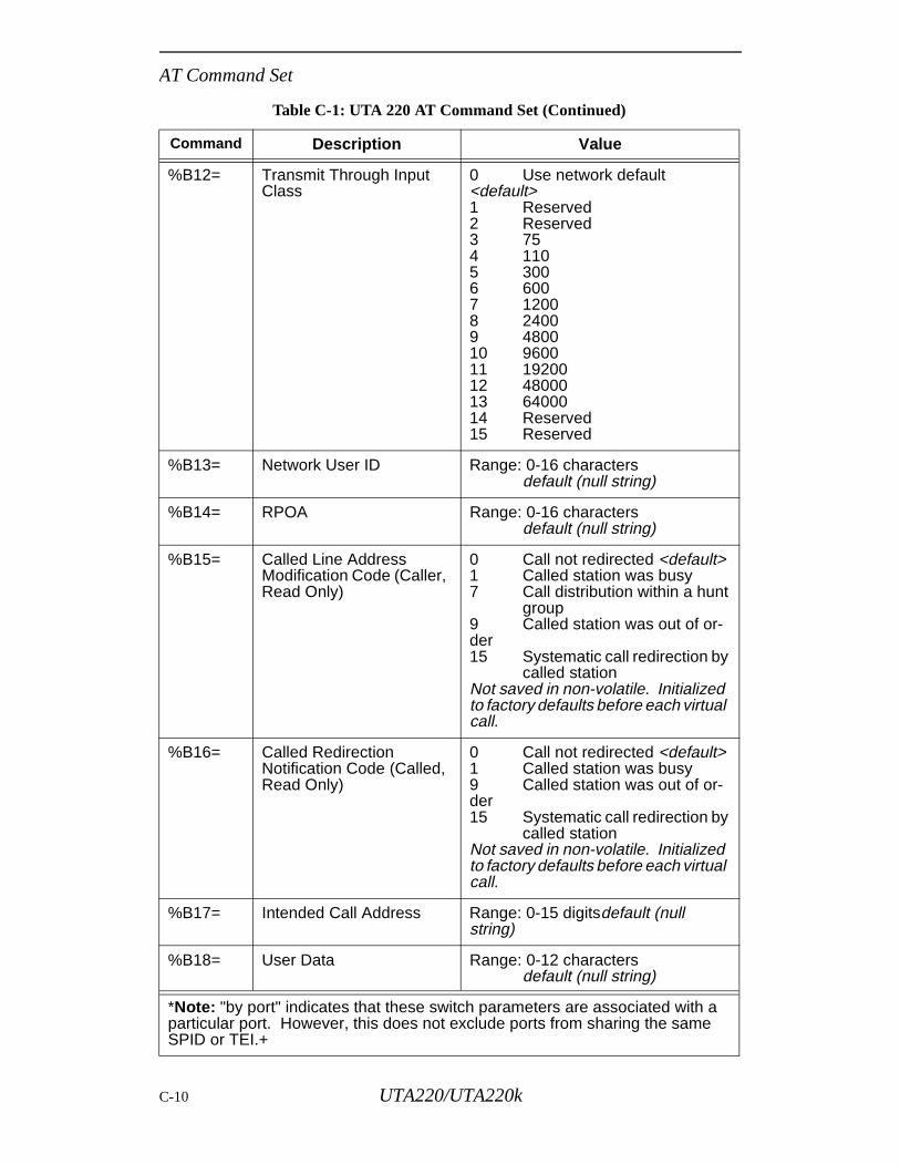
AT Command Set
%B12= Transmit Through Input Class
0 Use network default <default>1 Reserved2 Reserved3 754 1105 3006 6007 12008 24009 480010 960011 1920012 4800013 6400014 Reserved15 Reserved
%B13= Network User ID Range: 0-16 charactersdefault (null string)
%B14= RPOA Range: 0-16 charactersdefault (null string)
%B15= Called Line Address Modification Code (Caller, Read Only)
0 Call not redirected <default>1 Called station was busy7 Call distribution within a hunt
group9 Called station was out of or-der15 Systematic call redirection by
called stationNot saved in non-volatile. Initialized to factory defaults before each virtual call.
%B16= Called Redirection Notification Code (Called, Read Only)
0 Call not redirected <default>1 Called station was busy9 Called station was out of or-der15 Systematic call redirection by
called stationNot saved in non-volatile. Initialized to factory defaults before each virtual call.
%B17= Intended Call Address Range: 0-15 digitsdefault (null string)
%B18= User Data Range: 0-12 charactersdefault (null string)
Table C-1: UTA 220 AT Command Set (Continued)
Command Description Value
*Note: "by port" indicates that these switch parameters are associated with a particular port. However, this does not exclude ports from sharing the same SPID or TEI.+
C-10 UTA220/UTA220k
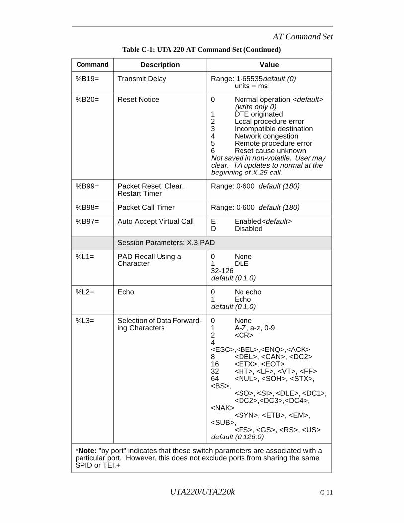
AT Command Set
%B19= Transmit Delay Range: 1-65535default (0)units = ms
%B20= Reset Notice 0 Normal operation <default>(write only 0)
1 DTE originated2 Local procedure error3 Incompatible destination4 Network congestion5 Remote procedure error6 Reset cause unknownNot saved in non-volatile. User may clear. TA updates to normal at the beginning of X.25 call.
%B99= Packet Reset, Clear, Restart Timer
Range: 0-600 default (180)
%B98= Packet Call Timer Range: 0-600 default (180)
%B97= Auto Accept Virtual Call E Enabled<default>D Disabled
Session Parameters: X.3 PAD
%L1= PAD Recall Using a Character
0 None1 DLE 32-126default (0,1,0)
%L2= Echo 0 No echo1 Echodefault (0,1,0)
%L3= Selection of Data Forward-ing Characters
0 None1 A-Z, a-z, 0-92 <CR>4<ESC>,<BEL>,<ENQ>,<ACK>8 <DEL>, <CAN>, <DC2>16 <ETX>, <EOT>32 <HT>, <LF>, <VT>, <FF>64 <NUL>, <SOH>, <STX>, <BS>,
<SO>, <SI>, <DLE>, <DC1>,<DC2>,<DC3>,<DC4>,
<NAK><SYN>, <ETB>, <EM>,
<SUB>,<FS>, <GS>, <RS>, <US>
default (0,126,0)
Table C-1: UTA 220 AT Command Set (Continued)
Command Description Value
*Note: "by port" indicates that these switch parameters are associated with a particular port. However, this does not exclude ports from sharing the same SPID or TEI.+
UTA220/UTA220k C-11
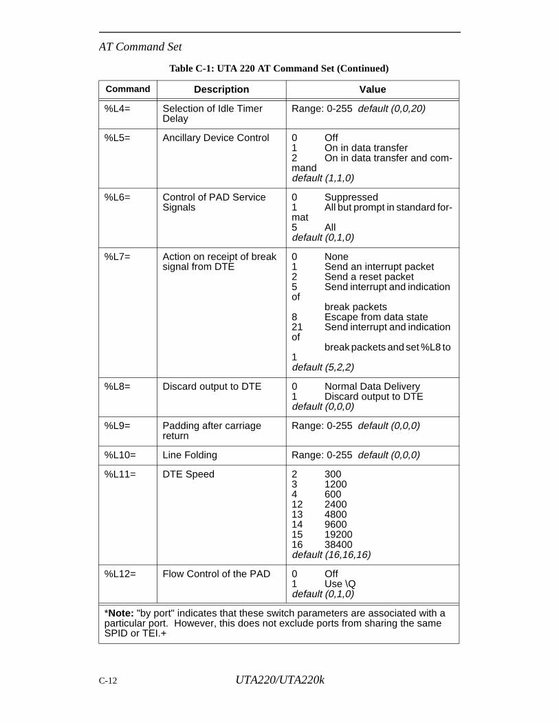
AT Command Set
%L4= Selection of Idle Timer Delay
Range: 0-255 default (0,0,20)
%L5= Ancillary Device Control 0 Off1 On in data transfer2 On in data transfer and com-manddefault (1,1,0)
%L6= Control of PAD Service Signals
0 Suppressed1 All but prompt in standard for-mat5 Alldefault (0,1,0)
%L7= Action on receipt of break signal from DTE
0 None1 Send an interrupt packet2 Send a reset packet5 Send interrupt and indication of
break packets8 Escape from data state21 Send interrupt and indication of
break packets and set %L8 to 1default (5,2,2)
%L8= Discard output to DTE 0 Normal Data Delivery1 Discard output to DTEdefault (0,0,0)
%L9= Padding after carriage return
Range: 0-255 default (0,0,0)
%L10= Line Folding Range: 0-255 default (0,0,0)
%L11= DTE Speed 2 3003 12004 60012 240013 480014 960015 1920016 38400default (16,16,16)
%L12= Flow Control of the PAD 0 Off1 Use \Qdefault (0,1,0)
Table C-1: UTA 220 AT Command Set (Continued)
Command Description Value
*Note: "by port" indicates that these switch parameters are associated with a particular port. However, this does not exclude ports from sharing the same SPID or TEI.+
C-12 UTA220/UTA220k
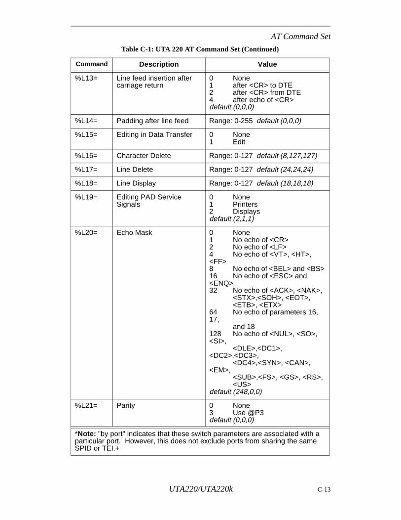
AT Command Set
%L13= Line feed insertion after carriage return
0 None1 after <CR> to DTE2 after <CR> from DTE4 after echo of <CR>default (0,0,0)
%L14= Padding after line feed Range: 0-255 default (0,0,0)
%L15= Editing in Data Transfer 0 None1 Edit
%L16= Character Delete Range: 0-127 default (8,127,127)
%L17= Line Delete Range: 0-127 default (24,24,24)
%L18= Line Display Range: 0-127 default (18,18,18)
%L19= Editing PAD Service Signals
0 None1 Printers2 Displaysdefault (2,1,1)
%L20= Echo Mask 0 None1 No echo of <CR>2 No echo of <LF>4 No echo of <VT>, <HT>, <FF>8 No echo of <BEL> and <BS>16 No echo of <ESC> and <ENQ>32 No echo of <ACK>, <NAK>,
<STX>,<SOH>, <EOT>,<ETB>, <ETX>
64 No echo of parameters 16, 17,
and 18128 No echo of <NUL>, <SO>, <SI>,
<DLE>,<DC1>, <DC2>,<DC3>,
<DC4>,<SYN>, <CAN>, <EM>,
<SUB>,<FS>, <GS>, <RS>,<US>
default (248,0,0)
%L21= Parity 0 None3 Use @P3default (0,0,0)
Table C-1: UTA 220 AT Command Set (Continued)
Command Description Value
*Note: "by port" indicates that these switch parameters are associated with a particular port. However, this does not exclude ports from sharing the same SPID or TEI.+
UTA220/UTA220k C-13
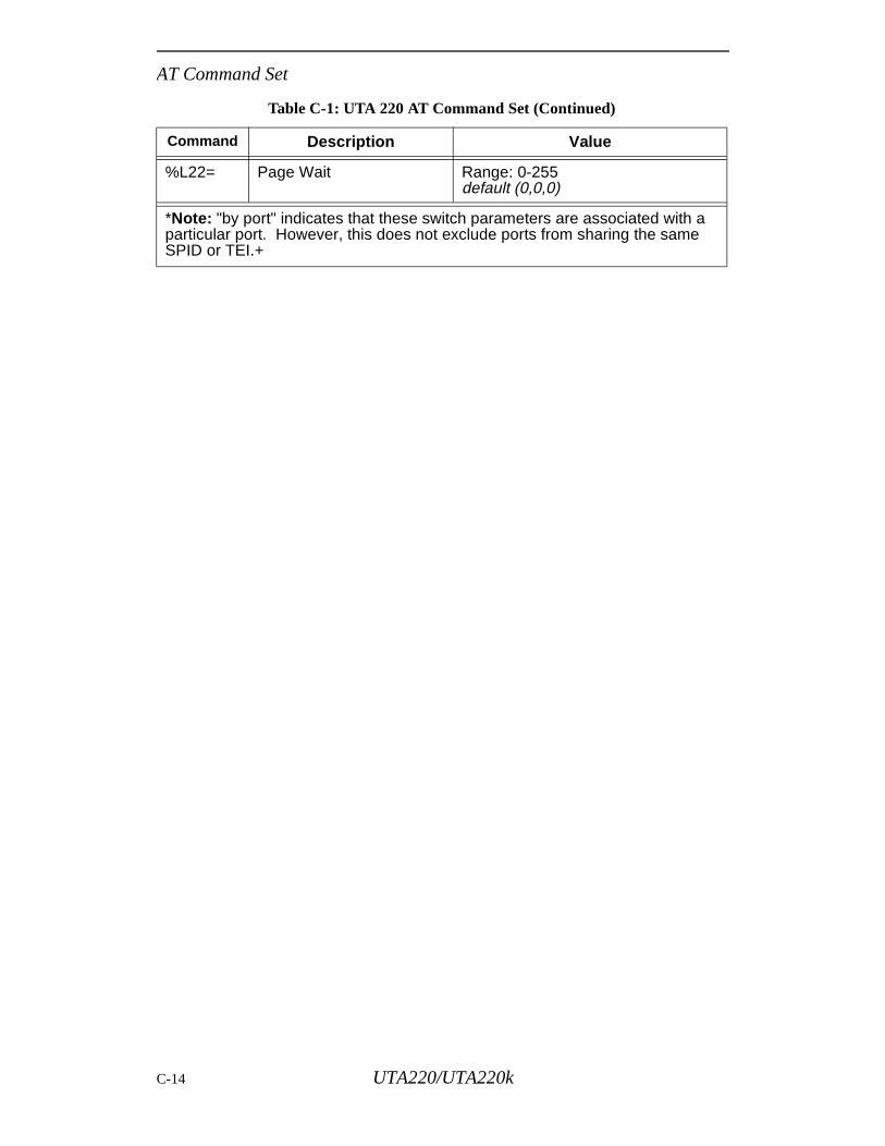
AT Command Set
%L22= Page Wait Range: 0-255default (0,0,0)
Table C-1: UTA 220 AT Command Set (Continued)
Command Description Value
*Note: "by port" indicates that these switch parameters are associated with a particular port. However, this does not exclude ports from sharing the same SPID or TEI.+
C-14 UTA220/UTA220k
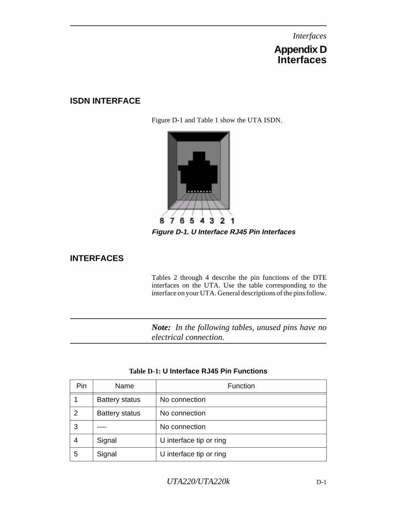
Interfaces
Appendix DInterfaces
ISDN INTERFACE
Figure D-1 and Table 1 show the UTA ISDN.
Figure D-1. U Interface RJ45 Pin Interfaces
INTERFACES
Tables 2 through 4 describe the pin functions of the DTEinterfaces on the UTA. Use the table corresponding to theinterface on your UTA. General descriptions of the pins follow.
Note: In the following tables, unused pins have noelectrical connection.
Table D-1: U Interface RJ45 Pin Functions
Pin Name Function
1 Battery status No connection
2 Battery status No connection
3 ---- No connection
4 Signal U interface tip or ring
5 Signal U interface tip or ring
UTA220/UTA220k D-1
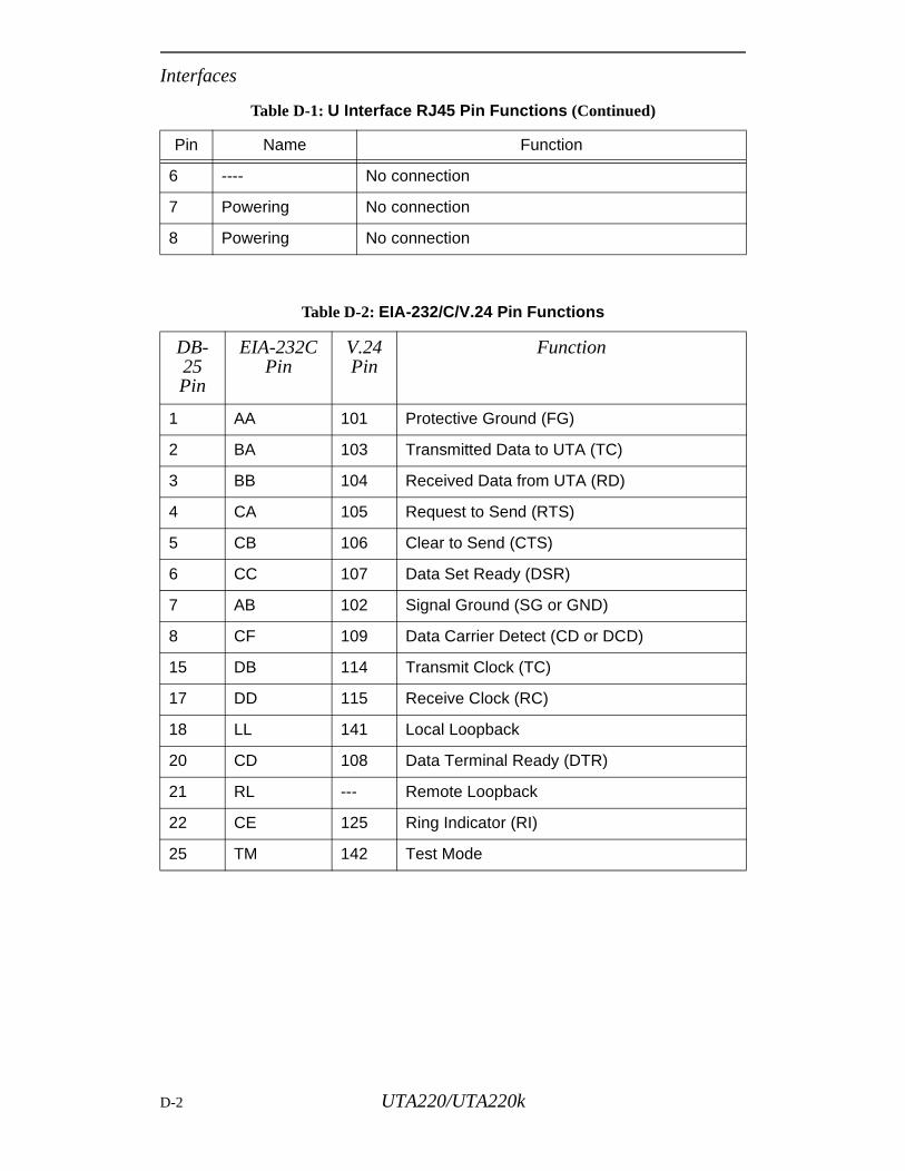
Interfaces
6 ---- No connection
7 Powering No connection
8 Powering No connection
Table D-2: EIA-232/C/V.24 Pin Functions
DB-25Pin
EIA-232CPin
V.24Pin
Function
1 AA 101 Protective Ground (FG)
2 BA 103 Transmitted Data to UTA (TC)
3 BB 104 Received Data from UTA (RD)
4 CA 105 Request to Send (RTS)
5 CB 106 Clear to Send (CTS)
6 CC 107 Data Set Ready (DSR)
7 AB 102 Signal Ground (SG or GND)
8 CF 109 Data Carrier Detect (CD or DCD)
15 DB 114 Transmit Clock (TC)
17 DD 115 Receive Clock (RC)
18 LL 141 Local Loopback
20 CD 108 Data Terminal Ready (DTR)
21 RL --- Remote Loopback
22 CE 125 Ring Indicator (RI)
25 TM 142 Test Mode
Table D-1: U Interface RJ45 Pin Functions (Continued)
Pin Name Function
D-2 UTA220/UTA220k
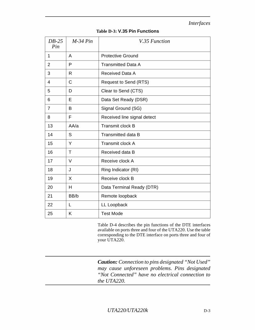
Interfaces
”tedo
Table D-4 describes the pin functions of the DTE interfacesavailable on ports three and four of the UTA220. Use the tablecorresponding to the DTE interface on ports three and four ofyour UTA220.
Caution: Connection to pins designated “Not Usedmay cause unforeseen problems. Pins designa“Not Connected” have no electrical connection tthe UTA220.
Table D-3: V.35 Pin Functions
DB-25Pin
M-34 Pin V.35 Function
1 A Protective Ground
2 P Transmitted Data A
3 R Received Data A
4 C Request to Send (RTS)
5 D Clear to Send (CTS)
6 E Data Set Ready (DSR)
7 B Signal Ground (SG)
8 F Received line signal detect
13 AA/a Transmit clock B
14 S Transmitted data B
15 Y Transmit clock A
16 T Received data B
17 V Receive clock A
18 J Ring Indicator (RI)
19 X Receive clock B
20 H Data Terminal Ready (DTR)
21 BB/b Remote loopback
22 L LL Loopback
25 K Test Mode
UTA220/UTA220k D-3
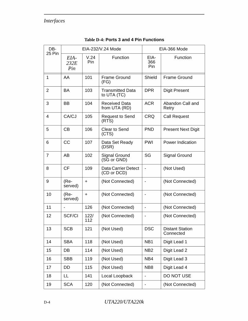
Interfaces
Table D-4: Ports 3 and 4 Pin Functions
DB-25 Pin
EIA-232/V.24 Mode EIA-366 Mode
EIA-232EPin
V.24 Pin
Function EIA-366Pin
Function
1 AA 101 Frame Ground (FG)
Shield Frame Ground
2 BA 103 Transmitted Data to UTA (TC)
DPR Digit Present
3 BB 104 Received Data from UTA (RD)
ACR Abandon Call and Retry
4 CA/CJ 105 Request to Send (RTS)
CRQ Call Request
5 CB 106 Clear to Send (CTS)
PND Present Next Digit
6 CC 107 Data Set Ready (DSR)
PWI Power Indication
7 AB 102 Signal Ground(SG or GND)
SG Signal Ground
8 CF 109 Data Carrier Detect(CD or DCD)
- (Not Used)
9 (Re-served)
+ (Not Connected) - (Not Connected)
10 (Re-served)
+ (Not Connected) - (Not Connected)
11 - 126 (Not Connected) - (Not Connected)
12 SCF/CI 122/112
(Not Connected) - (Not Connected)
13 SCB 121 (Not Used) DSC Distant Station Connected
14 SBA 118 (Not Used) NB1 Digit Lead 1
15 DB 114 (Not Used) NB2 Digit Lead 2
16 SBB 119 (Not Used) NB4 Digit Lead 3
17 DD 115 (Not Used) NB8 Digit Lead 4
18 LL 141 Local Loopback - DO NOT USE
19 SCA 120 (Not Connected) - (Not Connected)
D-4 UTA220/UTA220k
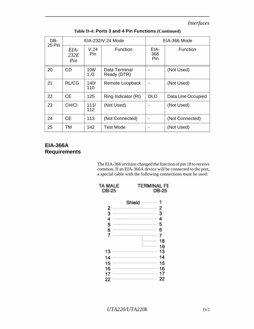
Interfaces
EIA-366A Requirements
The EIA-366 revision changed the function of pin 18 to receivecommon. If an EIA-366A device will be connected to the port,a special cable with the following connections must be used:
20 CD 108/1,/2
Data Terminal Ready (DTR)
- (Not Used)
21 RL/CG 140/110
Remote Loopback - (Not Used)
22 CE 125 Ring Indicator (RI) DLO Data Line Occupied
23 CH/CI 111/112
(Not Used) - (Not Used)
24 CE 113 (Not Connected) - (Not Connected)
25 TM 142 Test Mode - (Not Used)
Table D-4: Ports 3 and 4 Pin Functions (Continued)
DB-25 Pin
EIA-232/V.24 Mode EIA-366 Mode
EIA-232EPin
V.24 Pin
Function EIA-366Pin
Function
UTA220/UTA220k D-5
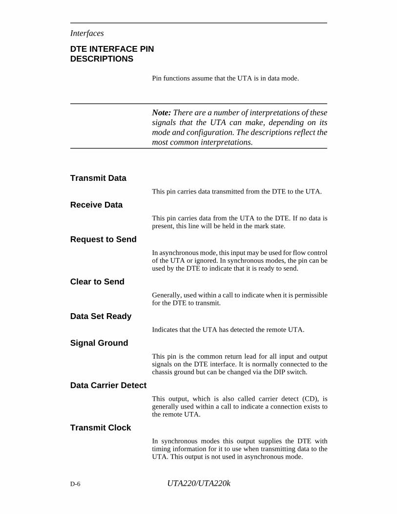
Interfaces
DTE INTERFACE PIN DESCRIPTIONS
Pin functions assume that the UTA is in data mode.
Note: There are a number of interpretations of thesesignals that the UTA can make, depending on itsmode and configuration. The descriptions reflect themost common interpretations.
Transmit Data
This pin carries data transmitted from the DTE to the UTA.
Receive Data
This pin carries data from the UTA to the DTE. If no data ispresent, this line will be held in the mark state.
Request to Send
In asynchronous mode, this input may be used for flow controlof the UTA or ignored. In synchronous modes, the pin can beused by the DTE to indicate that it is ready to send.
Clear to Send
Generally, used within a call to indicate when it is permissiblefor the DTE to transmit.
Data Set Ready
Indicates that the UTA has detected the remote UTA.
Signal Ground
This pin is the common return lead for all input and outputsignals on the DTE interface. It is normally connected to thechassis ground but can be changed via the DIP switch.
Data Carrier Detect
This output, which is also called carrier detect (CD), isgenerally used within a call to indicate a connection exists tothe remote UTA.
Transmit Clock
In synchronous modes this output supplies the DTE withtiming information for it to use when transmitting data to theUTA. This output is not used in asynchronous mode.
D-6 UTA220/UTA220k
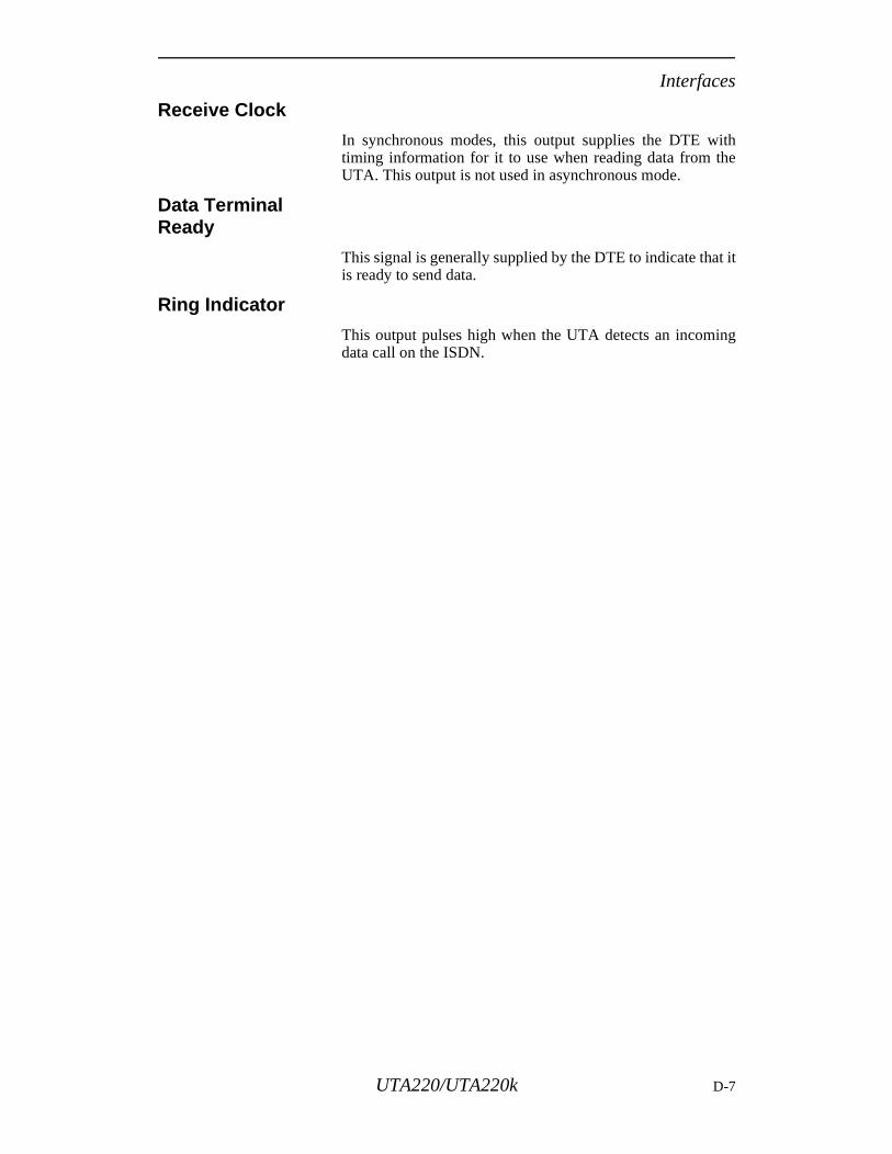
Interfaces
Receive Clock
In synchronous modes, this output supplies the DTE withtiming information for it to use when reading data from theUTA. This output is not used in asynchronous mode.
Data Terminal Ready
This signal is generally supplied by the DTE to indicate that itis ready to send data.
Ring Indicator
This output pulses high when the UTA detects an incomingdata call on the ISDN.
UTA220/UTA220k D-7

Interfaces
D-8 UTA220/UTA220k
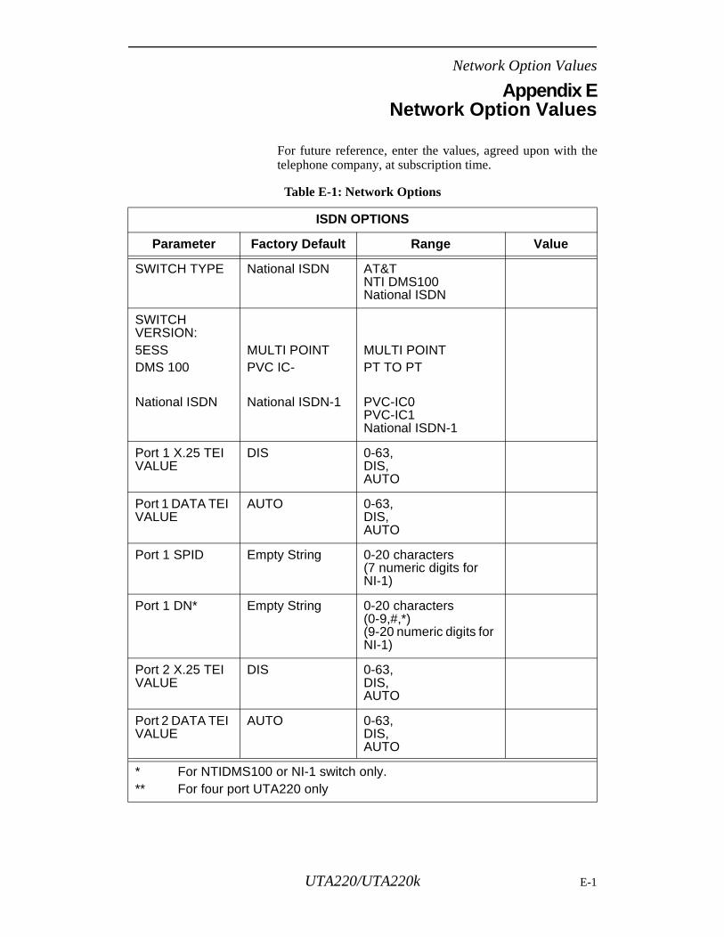
Network Option Values
Appendix ENetwork Option Values
For future reference, enter the values, agreed upon with thetelephone company, at subscription time.
Table E-1: Network Options
ISDN OPTIONS
Parameter Factory Default Range Value
SWITCH TYPE National ISDN AT&TNTI DMS100National ISDN
SWITCH VERSION:5ESSDMS 100
National ISDN
MULTI POINTPVC IC-
National ISDN-1
MULTI POINTPT TO PT
PVC-IC0PVC-IC1National ISDN-1
Port 1 X.25 TEI VALUE
DIS 0-63,DIS,AUTO
Port 1 DATA TEI VALUE
AUTO 0-63,DIS,AUTO
Port 1 SPID Empty String 0-20 characters(7 numeric digits for NI-1)
Port 1 DN* Empty String 0-20 characters (0-9,#,*)(9-20 numeric digits for NI-1)
Port 2 X.25 TEI VALUE
DIS 0-63,DIS,AUTO
Port 2 DATA TEI VALUE
AUTO 0-63,DIS,AUTO
* For NTIDMS100 or NI-1 switch only.** For four port UTA220 only
UTA220/UTA220k E-1
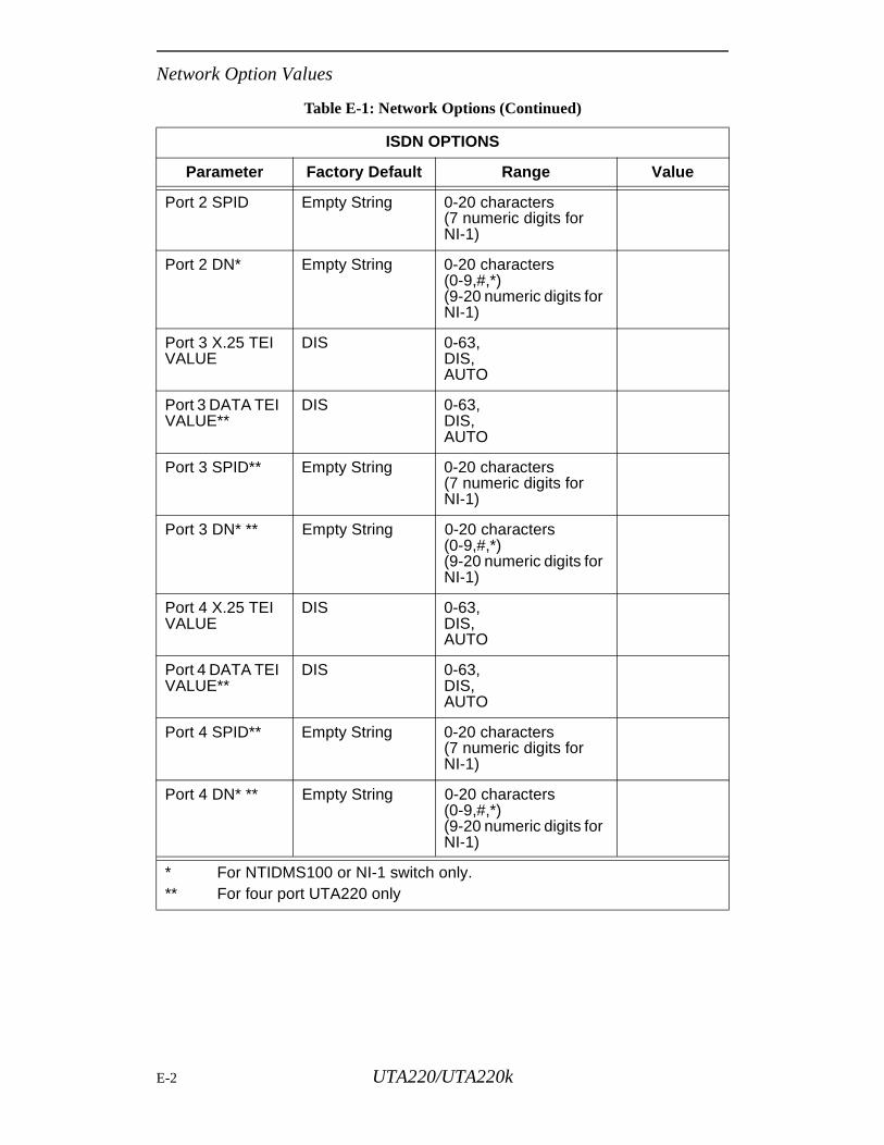
Network Option Values
Port 2 SPID Empty String 0-20 characters (7 numeric digits for NI-1)
Port 2 DN* Empty String 0-20 characters (0-9,#,*)(9-20 numeric digits for NI-1)
Port 3 X.25 TEI VALUE
DIS 0-63,DIS,AUTO
Port 3 DATA TEI VALUE**
DIS 0-63,DIS,AUTO
Port 3 SPID** Empty String 0-20 characters (7 numeric digits for NI-1)
Port 3 DN* ** Empty String 0-20 characters (0-9,#,*)(9-20 numeric digits for NI-1)
Port 4 X.25 TEI VALUE
DIS 0-63,DIS,AUTO
Port 4 DATA TEI VALUE**
DIS 0-63,DIS,AUTO
Port 4 SPID** Empty String 0-20 characters (7 numeric digits for NI-1)
Port 4 DN* ** Empty String 0-20 characters (0-9,#,*)(9-20 numeric digits for NI-1)
Table E-1: Network Options (Continued)
ISDN OPTIONS
Parameter Factory Default Range Value
* For NTIDMS100 or NI-1 switch only.** For four port UTA220 only
E-2 UTA220/UTA220k

ASCII and EBCDIC Characters
Appendix FASCII and EBCDIC Characters
Hexadecimal equivalents of binary and decimal numbers areas follows:
Hexadecimal Examples:
The following chart lists the ASCII decimal, hexadecimal,equivalent character values, and EBCDIC characters. Thetable only goes as high as available keyboard symbols. Controlkeys are shown in the right column of the first table.
Binary Decimal Hexadecimal
0000 0 0
0001 1 1
0010 2 2
0011 3 3
0100 4 4
0101 5 5
0110 6 6
0111 7 7
1000 8 8
1001 9 9
1010 10 A
1011 11 B
1100 12 C
1101 13 D
1110 14 E
1111 15 F
ASCII Symbol
Decimal Hex EBCDIC Control Key
(NUL) 0 00 NU (null) @
(SOH) 1 01 SH (start of header) A
(STX) 2 02 SX (start of text) B
(ETX) 3 03 EX (end of text) C
(EOT) 4 04 PF D
(ENQ) 5 05 HT (horizontal tab) E
(ACK) 6 06 LC (lower case) F
(BEL) 7 07 delete G
(BS) 8 08 -- H
(HT) 9 09 -- I
010110011110
101111010010
=5B hex=9D hex=E2 hex
UTA220/UTA220k F-1
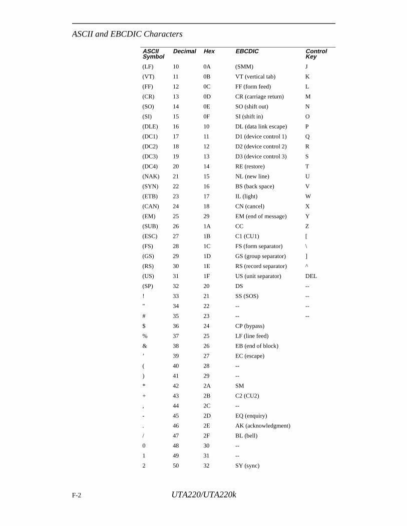
ASCII and EBCDIC Characters
(LF) 10 0A (SMM) J
(VT) 11 0B VT (vertical tab) K
(FF) 12 0C FF (form feed) L
(CR) 13 0D CR (carriage return) M
(SO) 14 0E SO (shift out) N
(SI) 15 0F SI (shift in) O
(DLE) 16 10 DL (data link escape) P
(DC1) 17 11 D1 (device control 1) Q
(DC2) 18 12 D2 (device control 2) R
(DC3) 19 13 D3 (device control 3) S
(DC4) 20 14 RE (restore) T
(NAK) 21 15 NL (new line) U
(SYN) 22 16 BS (back space) V
(ETB) 23 17 IL (light) W
(CAN) 24 18 CN (cancel) X
(EM) 25 29 EM (end of message) Y
(SUB) 26 1A CC Z
(ESC) 27 1B C1 (CU1) [
(FS) 28 1C FS (form separator) \
(GS) 29 1D GS (group separator) ]
(RS) 30 1E RS (record separator) ^
(US) 31 1F US (unit separator) DEL
(SP) 32 20 DS --
! 33 21 SS (SOS) --
" 34 22 -- --
# 35 23 -- --
$ 36 24 CP (bypass)
% 37 25 LF (line feed)
& 38 26 EB (end of block)
’ 39 27 EC (escape)
( 40 28 --
) 41 29 --
* 42 2A SM
+ 43 2B C2 (CU2)
, 44 2C --
- 45 2D EQ (enquiry)
. 46 2E AK (acknowledgment)
/ 47 2F BL (bell)
0 48 30 --
1 49 31 --
2 50 32 SY (sync)
ASCII Symbol
Decimal Hex EBCDIC Control Key
F-2 UTA220/UTA220k
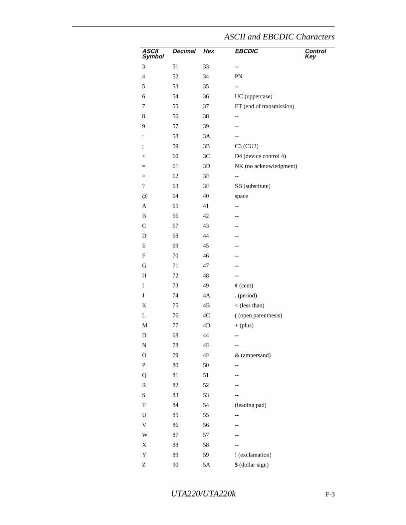
ASCII and EBCDIC Characters
3 51 33 --
4 52 34 PN
5 53 35 --
6 54 36 UC (uppercase)
7 55 37 ET (end of transmission)
8 56 38 --
9 57 39 --
: 58 3A --
; 59 3B C3 (CU3)
< 60 3C D4 (device control 4)
= 61 3D NK (no acknowledgment)
> 62 3E --
? 63 3F SB (substitute)
@ 64 40 space
A 65 41 --
B 66 42 --
C 67 43 --
D 68 44 --
E 69 45 --
F 70 46 --
G 71 47 --
H 72 48 --
I 73 49 ¢ (cent)
J 74 4A . (period)
K 75 4B < (less than)
L 76 4C ( (open parenthesis)
M 77 4D + (plus)
D 68 44 --
N 78 4E --
O 79 4F & (ampersand)
P 80 50 --
Q 81 51 --
R 82 52 --
S 83 53 --
T 84 54 (leading pad)
U 85 55 --
V 86 56 --
W 87 57 --
X 88 58 --
Y 89 59 ! (exclamation)
Z 90 5A $ (dollar sign)
ASCII Symbol
Decimal Hex EBCDIC Control Key
UTA220/UTA220k F-3
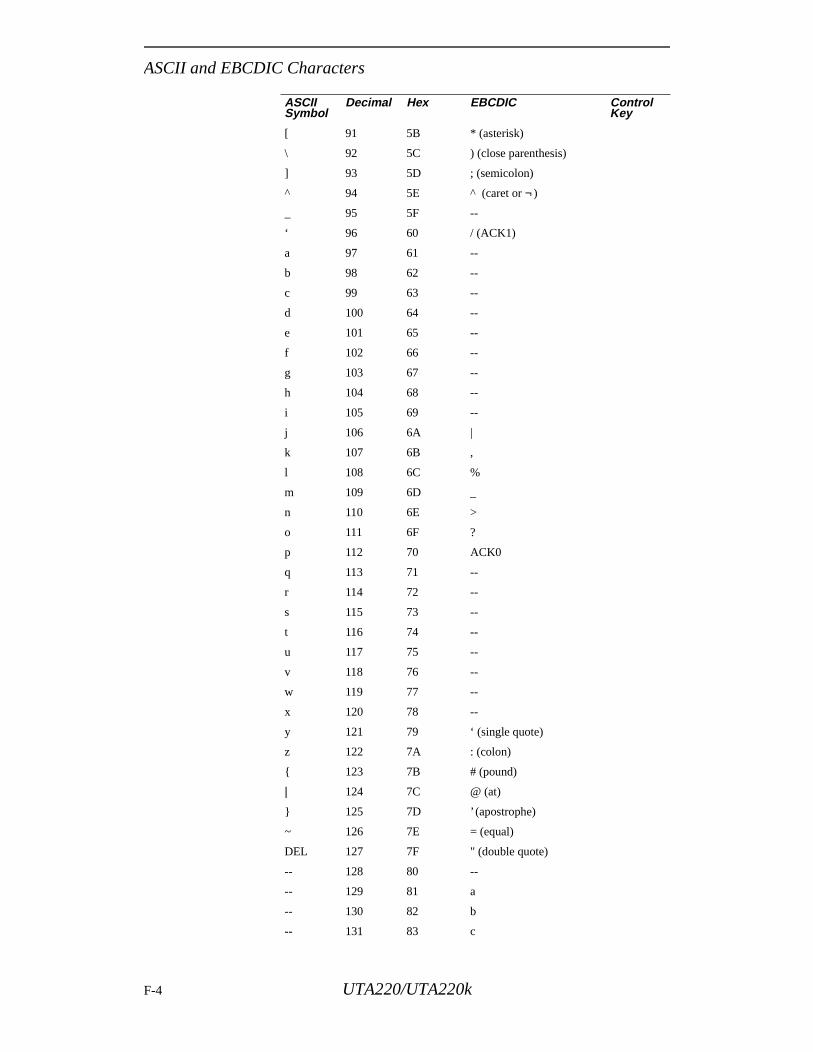
ASCII and EBCDIC Characters
[ 91 5B * (asterisk)
\ 92 5C ) (close parenthesis)
] 93 5D ; (semicolon)
^ 94 5E ^ (caret or ¬)
_ 95 5F --
‘ 96 60 / (ACK1)
a 97 61 --
b 98 62 --
c 99 63 --
d 100 64 --
e 101 65 --
f 102 66 --
g 103 67 --
h 104 68 --
i 105 69 --
j 106 6A |
k 107 6B ,
l 108 6C %
m 109 6D _
n 110 6E >
o 111 6F ?
p 112 70 ACK0
q 113 71 --
r 114 72 --
s 115 73 --
t 116 74 --
u 117 75 --
v 118 76 --
w 119 77 --
x 120 78 --
y 121 79 ‘ (single quote)
z 122 7A : (colon)
{ 123 7B # (pound)
| 124 7C @ (at)
} 125 7D ’ (apostrophe)
~ 126 7E = (equal)
DEL 127 7F " (double quote)
-- 128 80 --
-- 129 81 a
-- 130 82 b
-- 131 83 c
ASCII Symbol
Decimal Hex EBCDIC Control Key
F-4 UTA220/UTA220k

ASCII and EBCDIC Characters
-- 132 84 d
-- 133 85 e
-- 134 86 f
-- 135 87 g
-- 136 88 h
-- 137 89 i
-- 138 8A --
-- 139 8B --
-- 140 8C ≤ (less than or equal)
-- 141 8D (
-- 142 8E +
-- 143 8F --
-- 144 90 --
-- 145 91 j
146
147 93 l
148 94 m
149 95 n
150 96 o
151 97 p
152 98 q
153 99 r
154 9A --
155 9B --
156 9C x
157 9D )
158 9E ±
159 9F --
160 A0 --
161 A1 ~
162 A2 s
163 A3 t
164 A4 u
165 A5 v
166 A6 w
167 A7 x
168 A8 y
169 A9 z
170 AA --
171 AB
172 AC
ASCII Symbol
Decimal Hex EBCDIC Control Key
UTA220/UTA220k F-5
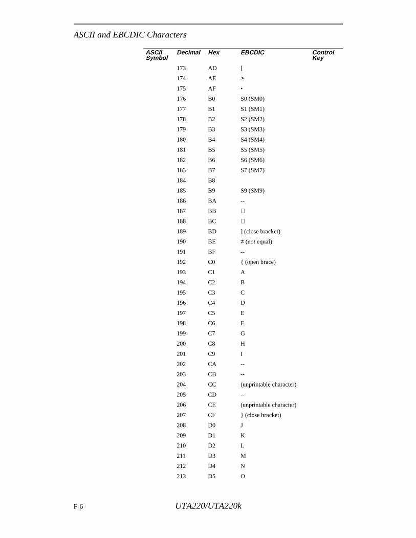
ASCII and EBCDIC Characters
173 AD [
174 AE ≥
175 AF •
176 B0 S0 (SM0)
177 B1 S1 (SM1)
178 B2 S2 (SM2)
179 B3 S3 (SM3)
180 B4 S4 (SM4)
181 B5 S5 (SM5)
182 B6 S6 (SM6)
183 B7 S7 (SM7)
184 B8
185 B9 S9 (SM9)
186 BA --
187 BB
188 BC
189 BD ] (close bracket)
190 BE ≠ (not equal)
191 BF --
192 C0 { (open brace)
193 C1 A
194 C2 B
195 C3 C
196 C4 D
197 C5 E
198 C6 F
199 C7 G
200 C8 H
201 C9 I
202 CA --
203 CB --
204 CC (unprintable character)
205 CD --
206 CE (unprintable character)
207 CF } (close bracket)
208 D0 J
209 D1 K
210 D2 L
211 D3 M
212 D4 N
213 D5 O
ASCII Symbol
Decimal Hex EBCDIC Control Key
F-6 UTA220/UTA220k
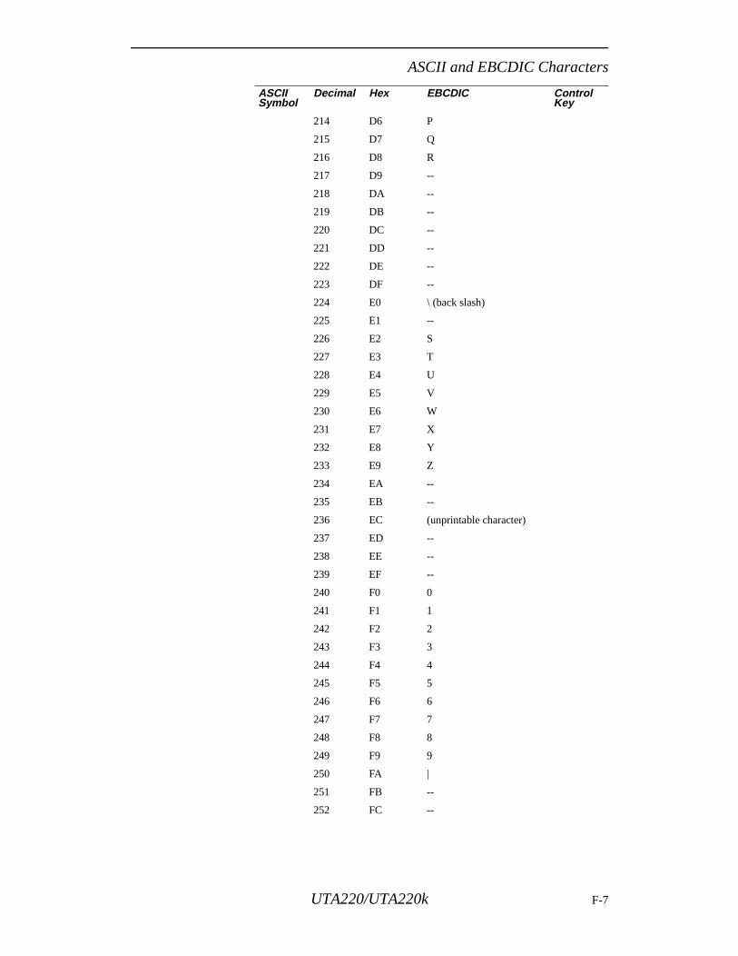
ASCII and EBCDIC Characters
214 D6 P
215 D7 Q
216 D8 R
217 D9 --
218 DA --
219 DB --
220 DC --
221 DD --
222 DE --
223 DF --
224 E0 \ (back slash)
225 E1 --
226 E2 S
227 E3 T
228 E4 U
229 E5 V
230 E6 W
231 E7 X
232 E8 Y
233 E9 Z
234 EA --
235 EB --
236 EC (unprintable character)
237 ED --
238 EE --
239 EF --
240 F0 0
241 F1 1
242 F2 2
243 F3 3
244 F4 4
245 F5 5
246 F6 6
247 F7 7
248 F8 8
249 F9 9
250 FA |
251 FB --
252 FC --
ASCII Symbol
Decimal Hex EBCDIC Control Key
UTA220/UTA220k F-7
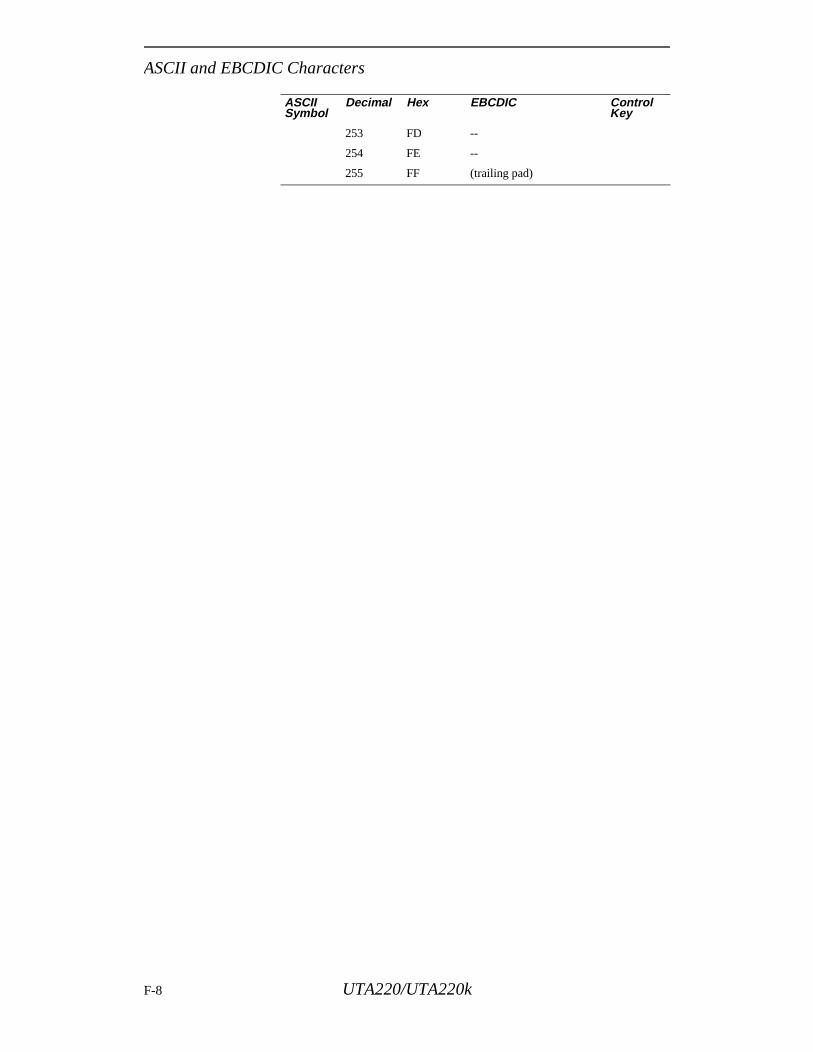
ASCII and EBCDIC Characters
253 FD --
254 FE --
255 FF (trailing pad)
ASCII Symbol
Decimal Hex EBCDIC Control Key
F-8 UTA220/UTA220k
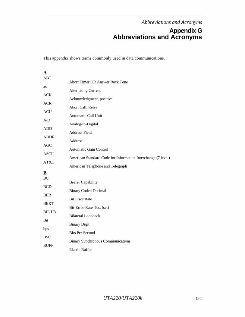
Abbreviations and Acronyms
Appendix GAbbreviations and Acronyms
This appendix shows terms commonly used in data communications.
AABT
Abort Timer OR Answer Back Toneac
Alternating CurrentACK
Acknowledgment, positiveACR
Abort Call, RetryACU
Automatic Call UnitA/D
Analog-to-DigitalADD
Address FieldADDR
AddressAGC
Automatic Gain ControlASCII
American Standard Code for Information Interchange (7 level)AT&T
American Telephone and Telegraph
BBC
Bearer CapabilityBCD
Binary Coded DecimalBER
Bit Error RateBERT
Bit-Error-Rate-Test (set)BIL LB
Bilateral LoopbackBit
Binary Digitbps
Bits Per SecondBSC
Binary Synchronous CommunicationsBUFF
Elastic Buffer
UTA220/UTA220k G-1
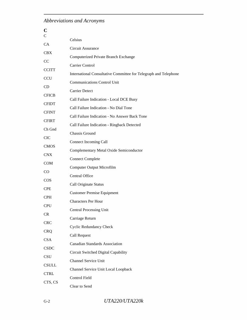
Abbreviations and Acronyms
CC
CelsiusCA
Circuit AssuranceCBX
Computerized Private Branch ExchangeCC
Carrier ControlCCITT
International Consultative Committee for Telegraph and TelephoneCCU
Communications Control UnitCD
Carrier DetectCFICB
Call Failure Indication - Local DCE BusyCFIDT
Call Failure Indication - No Dial ToneCFINT
Call Failure Indication - No Answer Back Tone CFIRT
Call Failure Indication - Ringback DetectedCh Gnd
Chassis GroundCIC
Connect Incoming CallCMOS
Complementary Metal Oxide SemiconductorCNX
Connect CompleteCOM
Computer Output MicrofilmCO
Central OfficeCOS
Call Originate StatusCPE
Customer Premise EquipmentCPH
Characters Per HourCPU
Central Processing UnitCR
Carriage ReturnCRC
Cyclic Redundancy CheckCRQ
Call RequestCSA
Canadian Standards AssociationCSDC
Circuit Switched Digital CapabilityCSU
Channel Service UnitCSULL
Channel Service Unit Local LoopbackCTRL
Control FieldCTS, CS
Clear to Send
G-2 UTA220/UTA220k
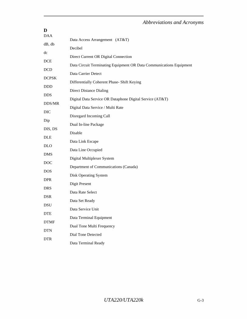
Abbreviations and Acronyms
DDAA
Data Access Arrangement (AT&T)dB, db
Decibeldc
Direct Current OR Digital ConnectionDCE
Data Circuit Terminating Equipment OR Data Communications EquipmentDCD
Data Carrier DetectDCPSK
Differentially Coherent Phase- Shift KeyingDDD
Direct Distance DialingDDS
Digital Data Service OR Dataphone Digital Service (AT&T)DDS/MR
Digital Data Service / Multi RateDIC
Disregard Incoming CallDip
Dual In-line PackageDIS, DS
DisableDLE
Data Link EscapeDLO
Data Line OccupiedDMS
Digital Multiplexer SystemDOC
Department of Communications (Canada)DOS
Disk Operating SystemDPR
Digit PresentDRS
Data Rate SelectDSR
Data Set ReadyDSU
Data Service UnitDTE
Data Terminal EquipmentDTMF
Dual Tone Multi FrequencyDTN
Dial Tone DetectedDTR
Data Terminal Ready
UTA220/UTA220k G-3

Abbreviations and Acronyms
EEBCDIC
Extended Binary Coded Decimal Interchange Code (8 level)EIA
Electronic Industries AssociationEIA-232C EIA-232D
Interface between DTE and Data Interchange Communication Equipment employing serial binary data
ENEnabled
ENQEnquiry
EOAEnd of Address
EOMEnd of Message
EONEnd of Number
EOTEnd of Text OR End of Transmission
EPROMErasable Programmable Read Only Memory
ERError
ESCEscape (key)
ETBEnd of Block
ETCExternal Transmit Clock
ETXEnd of Text
EXTExternal
FFA
Feature ActivatorFB
FallbackFCC
Federal Communications CommissionFDM
Frequency Division ModulationFDX
Full-Duplex TransmissionFF
Form FeedFGND
Frame GroundFL
FlagFLL
Fixed loss loopFM
Frequency ModulationFox message
Test message (The quick brown fox jumps over the lazy dog) 0123456789FSK
Frequency-Shift KeyingFX
Foreign Exchange
G-4 UTA220/UTA220k

Abbreviations and Acronyms
HHDLC
High Level Data Link ControlHDX
Half-Duplex TransmissionHz
Hertz (cycles per second)
IINC
Incoming Call INV
InvalidINVCU
Invalid Command - Command UnknownINVMS
Invalid Command - Message Syntax ErrorINVPS
Invalid Command - Parameter Syntax ErrorINVPV
Invalid Command - Parameter Value ErrorI/O
Input / OutputIS
International StandardISDN
Integrated Services Digital Network
KKBD
Keyboardkbps
Kilobits Per Second
LLAL
Local Analog LoopbackLAPD
Link Access Protocol - D ChannelLAPM
Link Access Protocol for ModemsLB OPTS
Loopback OptionsLCD
Liquid Crystal Display OR Line Current DisconnectLDL
Local Digital LoopbackLDM
Limited-Distance ModemLED
Light Emitting DiodeLF
Line FeedLINK
Analog Telephone Line ConnectionLL
Local LoopbackLO
Line OccupancyLRC
Longitudinal Redundancy Check
UTA220/UTA220k G-5
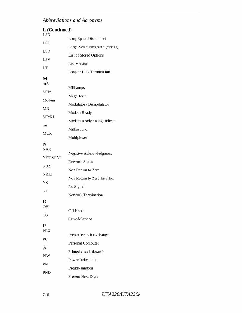
Abbreviations and Acronyms
L (Continued)LSD
Long Space DisconnectLSI
Large-Scale Integrated (circuit)LSO
List of Stored OptionsLSV
List VersionLT
Loop or Link Termination
MmA
MilliampsMHz
MegaHertzModem
Modulator / DemodulatorMR
Modem ReadyMR/RI
Modem Ready / Ring Indicatems
MillisecondMUX
Multiplexer
NNAK
Negative AcknowledgmentNET STAT
Network StatusNRZ
Non Return to ZeroNRZI
Non Return to Zero InvertedNS
No SignalNT
Network Termination
OOH
Off HookOS
Out-of-Service
PPBX
Private Branch ExchangePC
Personal Computerpc
Printed circuit (board)PIW
Power IndicationPN
Pseudo randomPND
Present Next Digit
G-6 UTA220/UTA220k
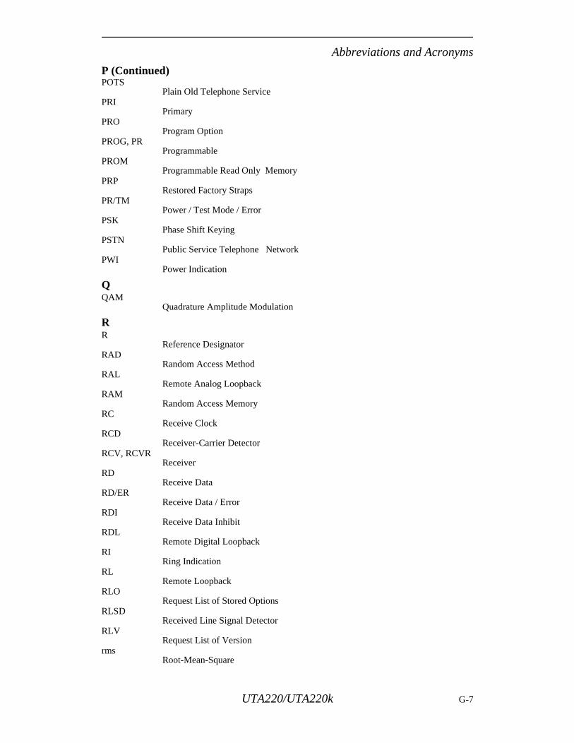
Abbreviations and Acronyms
P (Continued)POTS
Plain Old Telephone ServicePRI
PrimaryPRO
Program OptionPROG, PR
ProgrammablePROM
Programmable Read Only MemoryPRP
Restored Factory StrapsPR/TM
Power / Test Mode / ErrorPSK
Phase Shift KeyingPSTN
Public Service Telephone NetworkPWI
Power Indication
QQAM
Quadrature Amplitude Modulation
RR
Reference DesignatorRAD
Random Access MethodRAL
Remote Analog LoopbackRAM
Random Access MemoryRC
Receive ClockRCD
Receiver-Carrier DetectorRCV, RCVR
ReceiverRD
Receive DataRD/ER
Receive Data / ErrorRDI
Receive Data InhibitRDL
Remote Digital LoopbackRI
Ring IndicationRL
Remote LoopbackRLO
Request List of Stored OptionsRLSD
Received Line Signal DetectorRLV
Request List of Versionrms
Root-Mean-Square
UTA220/UTA220k G-7
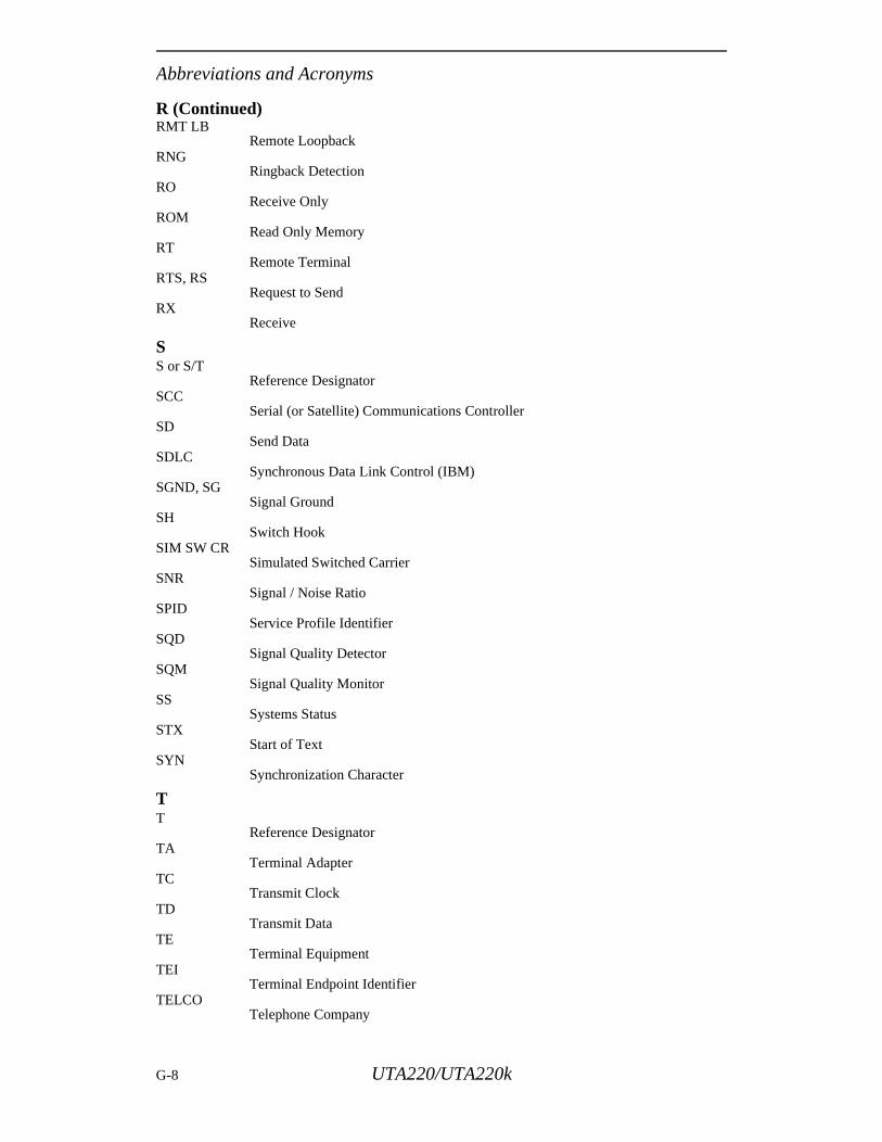
Abbreviations and Acronyms
R (Continued)RMT LB
Remote LoopbackRNG
Ringback DetectionRO
Receive OnlyROM
Read Only MemoryRT
Remote TerminalRTS, RS
Request to SendRX
Receive
SS or S/T
Reference DesignatorSCC
Serial (or Satellite) Communications ControllerSD
Send DataSDLC
Synchronous Data Link Control (IBM)SGND, SG
Signal GroundSH
Switch HookSIM SW CR
Simulated Switched CarrierSNR
Signal / Noise RatioSPID
Service Profile IdentifierSQD
Signal Quality DetectorSQM
Signal Quality MonitorSS
Systems StatusSTX
Start of TextSYN
Synchronization Character
TT
Reference DesignatorTA
Terminal AdapterTC
Transmit ClockTD
Transmit DataTE
Terminal EquipmentTEI
Terminal Endpoint Identifier TELCO
Telephone Company
G-8 UTA220/UTA220k
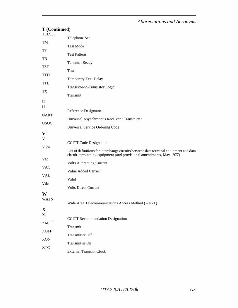
Abbreviations and Acronyms
T (Continued)TELSET
Telephone SetTM
Test ModeTP
Test PatternTR
Terminal ReadyTST
TestTTD
Temporary Text DelayTTL
Transistor-to-Transistor LogicTX
Transmit
UU
Reference DesignatorUART
Universal Asynchronous Receiver / TransmitterUSOC
Universal Service Ordering Code
VV.
CCITT Code DesignationV.24
List of definitions for interchange circuits between data terminal equipment and data circuit-terminating equipment (and provisional amendments, May 1977)
VacVolts Alternating Current
VACValue Added Carrier
VALValid
VdcVolts Direct Current
WWATS
Wide Area Telecommunications Access Method (AT&T)
XX.
CCITT Recommendation DesignationXMIT
TransmitXOFF
Transmitter OffXON
Transmitter OnXTC
External Transmit Clock
UTA220/UTA220k G-9

Abbreviations and Acronyms
G-10 UTA220/UTA220k
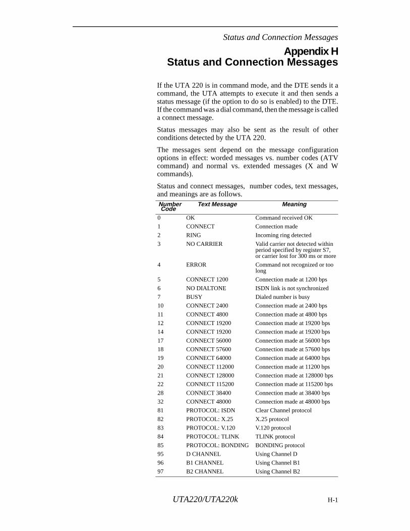
Status and Connection Messages
Appendix HStatus and Connection Messages
If the UTA 220 is in command mode, and the DTE sends it acommand, the UTA attempts to execute it and then sends astatus message (if the option to do so is enabled) to the DTE.If the command was a dial command, then the message is calleda connect message.
Status messages may also be sent as the result of otherconditions detected by the UTA 220.
The messages sent depend on the message configurationoptions in effect: worded messages vs. number codes (ATVcommand) and normal vs. extended messages (X and Wcommands).
Status and connect messages, number codes, text messages,and meanings are as follows. Number Code
Text Message Meaning
0 OK Command received OK
1 CONNECT Connection made
2 RING Incoming ring detected
3 NO CARRIER Valid carrier not detected within period specified by register S7, or carrier lost for 300 ms or more
4 ERROR Command not recognized or too long
5 CONNECT 1200 Connection made at 1200 bps
6 NO DIALTONE ISDN link is not synchronized
7 BUSY Dialed number is busy
10 CONNECT 2400 Connection made at 2400 bps
11 CONNECT 4800 Connection made at 4800 bps
12 CONNECT 19200 Connection made at 19200 bps
14 CONNECT 19200 Connection made at 19200 bps
17 CONNECT 56000 Connection made at 56000 bps
18 CONNECT 57600 Connection made at 57600 bps
19 CONNECT 64000 Connection made at 64000 bps
20 CONNECT 112000 Connection made at 11200 bps
21 CONNECT 128000 Connection made at 128000 bps
22 CONNECT 115200 Connection made at 115200 bps
28 CONNECT 38400 Connection made at 38400 bps
32 CONNECT 48000 Connection made at 48000 bps
81 PROTOCOL: ISDN Clear Channel protocol
82 PROTOCOL: X.25 X.25 protocol
83 PROTOCOL: V.120 V.120 protocol
84 PROTOCOL: TLINK TLINK protocol
85 PROTOCOL: BONDING BONDING protocol
95 D CHANNEL Using Channel D
96 B1 CHANNEL Using Channel B1
97 B2 CHANNEL Using Channel B2
UTA220/UTA220k H-1

Status and Connection Messages
H-2 UTA220/UTA220k
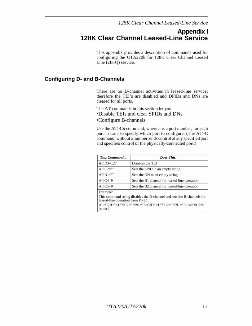
128K Clear Channel Leased-Line Service
are
for
Appendix I128K Clear Channel Leased-Line Service
This appendix provides a description of commands used forconfiguring the UTA220k for 128K Clear Channel LeasedLine (2B1Q) service.
Configuring D- and B-Channels
There are no D-channel activities in leased-line service;therefore the TEI’s are disabled and DPIDs and DNs cleared for all ports.
The AT commands in this section let you:•Disable TEIs and clear SPIDs and DNs•Configure B-channels
Use the AT>Cn command, where n is a port number, for eachport in turn, to specify which port to configure. (The AT>Ccommand, without a number, ends control of any specified portand specifies control of the physically-connected port.)
This Command... Does This:
AT!D3=127 Disables the TEI
AT!C2=”” Sets the SPID to an empty string
AT!N1=”” Sets the DN to an empty string
AT!C4=9 Sets the B1 channel for leased-line operation
AT!C5=9 Sets the B2 channel for leased-line operation
Example:This command string disables the D-channel and sets the B-channelsleased-line operation from Port 1.AT>C2!D3=127!C2=””!N1=””>C!D3=127!C2=””!N1=””!C4=9!C5=9 [enter]
UTA220/UTA220k I-1
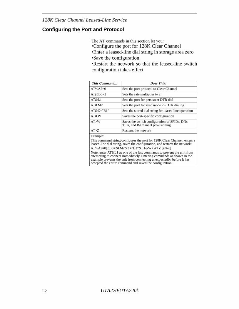
128K Clear Channel Leased-Line Service
ro
tch
s a :
Configuring the Port and Protocol
The AT commands in this section let you:•Configure the port for 128K Clear Channel•Enter a leased-line dial string in storage area ze•Save the configuration•Restart the network so that the leased-line swiconfiguration takes effect
This Command... Does This:
AT%A2=0 Sets the port protocol to Clear Channel
AT@B0=2 Sets the rate multiplier to 2
AT&L1 Sets the port for persistent DTR dial
AT&M2 Sets the port for sync mode 2 - DTR dialing
AT&Z=”B1” Sets the stored dial string for leased line operation
AT&W Saves the port-specific configuration
AT>W Saves the switch configuration of SPIDs, DNs, TEIs, and B-Channel provisioning
AT>Z Restarts the network
Example:This command string configures the port for 128K Clear Channel, enterleased-line dial string, saves the configuration, and restarts the networkAT%A2=0@B0=2&M2&Z=”B1”&L1&W>W>Z [enter]Note: enter AT&L1 as one of the last commands to prevent the unit fromattempting to connect immediately. Entering commands as shown in theexample prevents the unit from connecting unexpectedly, before it has accepted the entire command and saved the configuration.
I-2 UTA220/UTA220k
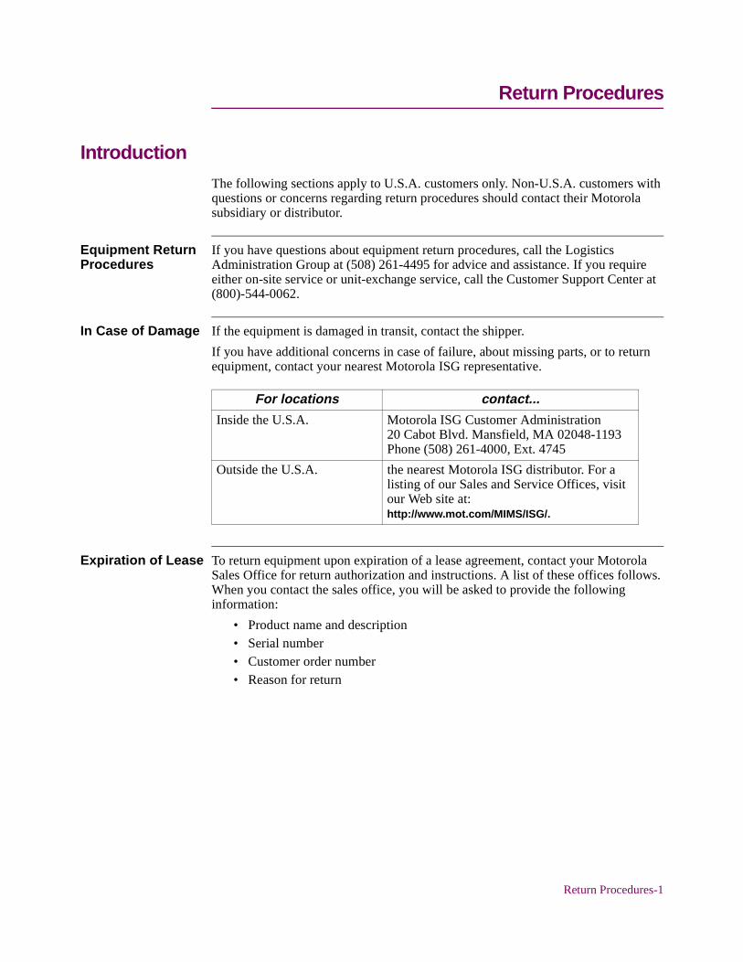
Return Procedures
IntroductionThe following sections apply to U.S.A. customers only. Non-U.S.A. customers with questions or concerns regarding return procedures should contact their Motorola subsidiary or distributor.
Equipment Return Procedures
If you have questions about equipment return procedures, call the Logistics Administration Group at (508) 261-4495 for advice and assistance. If you require either on-site service or unit-exchange service, call the Customer Support Center at (800)-544-0062.
In Case of Damage If the equipment is damaged in transit, contact the shipper.
If you have additional concerns in case of failure, about missing parts, or to return equipment, contact your nearest Motorola ISG representative.
Expiration of Lease To return equipment upon expiration of a lease agreement, contact your Motorola Sales Office for return authorization and instructions. A list of these offices follows. When you contact the sales office, you will be asked to provide the following information:
• Product name and description• Serial number• Customer order number• Reason for return
For locations contact...
Inside the U.S.A. Motorola ISG Customer Administration20 Cabot Blvd. Mansfield, MA 02048-1193Phone (508) 261-4000, Ext. 4745
Outside the U.S.A. the nearest Motorola ISG distributor. For a listing of our Sales and Service Offices, visit our Web site at:http://www.mot.com/MIMS/ISG/.
Return Procedures-1
r any g.
e ty to ring
tion
Factory Repair To return equipment for factory repair, call the Logistics Administration Group at (508) 261-4495, for return authorization and instructions. When you call, you will be given a Return Material Authorization (RMA) control number. Mark this number clearly on the shipping container for ease of identification and faster service. The RMA control number provides a convenient tracking reference for both parties. Please have the following information available for each piece of equipment you return:
• Product name and description• Serial number• Failure symptoms
Packaging Guidelines for Equipment Return
Data communications equipment or parts that are to be returned to Motorola foreason must be properly packaged to prevent damage in shipment and handlin
If the original packing material and shipping container are available, reuse thesitems to return equipment. If these items are not available, it is your responsibilipackage the contents in a manner that protects the equipment from damage dunormal shipping and handling. Responsibility for damage to equipment during transit must be resolved between you and the carrier. The Logistics Administragroup can provide you with specific packaging instructions upon request.
Return Procedures-2
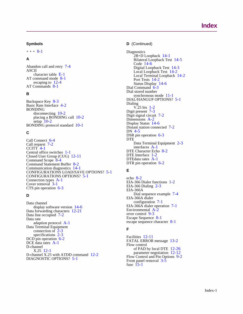
Index
Symbols
+ + + 8-1
A
Abandon call and retry 7-4ASCII
character table E-1AT command mode 8-1
escaping to 12-4AT Commands 8-1
B
Backspace Key 8-3Basic Rate Interface 4-2BONDING
disconnecting 10-2placing a BONDING call 10-2setup 10-2
BONDING protocol standard 10-1
C
Call Connect 6-4Call request 7-2CCITT 4-1Central office switches 1-1Closed User Group (CUG) 12-11Command Scope 8-4Command Statement Buffer 8-2Communication diagnostics 14-1CONFIGURATIONS LOAD/SAVE OPTIONS? 5-1CONFIGURATIONS OPTIONS? 5-1Connection types A-1Cover removal 3-1CTS pin operation 6-3
D
Data channeldisplay software version 14-6
Data forwarding characters 12-21Data line occupied 7-2Data rate
adaption protocol A-1Data Terminal Equipment
connection of 2-3specifications 2-3
DCD pin operation 6-2DCE data rates A-1D-channel
X.25 12-1D-channel X.25 with ATDD command 12-2DIAGNOSTIC OPTIONS? 5-1
D (Continued)
Diagnostics2B+D Loopback 14-1Bilateral Loopback Test 14-5Code 14-6Digital Loopback Test 14-3Local Loopback Test 14-2Local Terminal Loopback 14-2Port Tests 14-2Status Display 14-6
Dial Command 6-3Dial stored number
synchronous mode 11-1DIAL/HANGUP OPTIONS? 5-1Dialing
V.25 bis 1-2Digit present 7-3Digit signal circuit 7-2Dimensions A-2Display Status 14-6Distant station connected 7-2DN 4-5DSR pin operation 6-3DTE
Data Terminal Equipment 2-3interfaces A-1
DTE Character Echo 8-2DTE Interface 1-2DTEdata rates A-1DTR pin operation 6-2
E
echo 8-2EIA-366 Dialer functions 1-2EIA-366 Dialing 2-3EIA-366A
Dial sequence example 7-4EIA-366A dialer
configuration 7-1EIA-366A dialer operation 7-1Environmental A-2error control 9-3Escape Sequence 8-1escape sequence character 8-1
F
Facilities 12-11FATAL ERROR message 13-2Flow control
of PAD by local DTE 12-26parameter negotiation 12-12
Flow Control and Pin Options 9-2Front panel removal 3-5fuse 15-1
Index-1
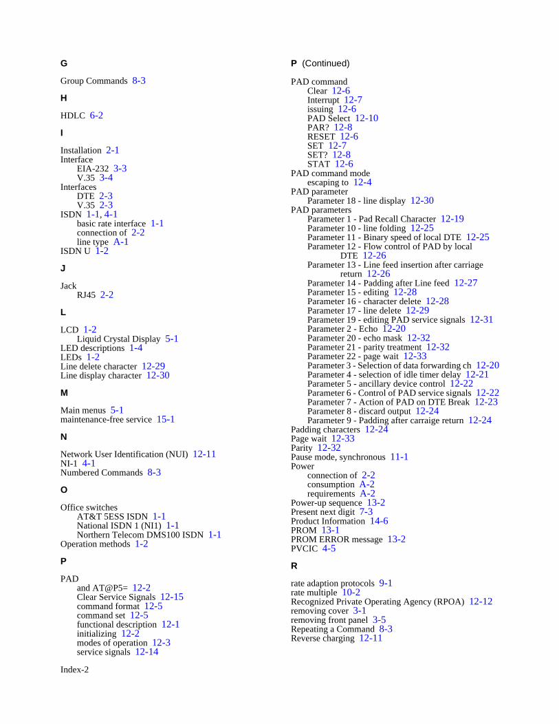
G
Group Commands 8-3
H
HDLC 6-2
I
Installation 2-1Interface
EIA-232 3-3V.35 3-4
InterfacesDTE 2-3V.35 2-3
ISDN 1-1, 4-1basic rate interface 1-1connection of 2-2line type A-1
ISDN U 1-2
J
JackRJ45 2-2
L
LCD 1-2Liquid Crystal Display 5-1
LED descriptions 1-4LEDs 1-2Line delete character 12-29Line display character 12-30
M
Main menus 5-1maintenance-free service 15-1
N
Network User Identification (NUI) 12-11NI-1 4-1Numbered Commands 8-3
O
Office switchesAT&T 5ESS ISDN 1-1National ISDN 1 (NI1) 1-1Northern Telecom DMS100 ISDN 1-1
Operation methods 1-2
P
PADand AT@P5= 12-2Clear Service Signals 12-15command format 12-5command set 12-5functional description 12-1initializing 12-2modes of operation 12-3service signals 12-14
P (Continued)
PAD commandClear 12-6Interrupt 12-7issuing 12-6PAD Select 12-10PAR? 12-8RESET 12-6SET 12-7SET? 12-8STAT 12-6
PAD command modeescaping to 12-4
PAD parameterParameter 18 - line display 12-30
PAD parametersParameter 1 - Pad Recall Character 12-19Parameter 10 - line folding 12-25Parameter 11 - Binary speed of local DTE 12-25Parameter 12 - Flow control of PAD by local
DTE 12-26Parameter 13 - Line feed insertion after carriage
return 12-26Parameter 14 - Padding after Line feed 12-27Parameter 15 - editing 12-28Parameter 16 - character delete 12-28Parameter 17 - line delete 12-29Parameter 19 - editing PAD service signals 12-31Parameter 2 - Echo 12-20Parameter 20 - echo mask 12-32Parameter 21 - parity treatment 12-32Parameter 22 - page wait 12-33Parameter 3 - Selection of data forwarding ch 12-20Parameter 4 - selection of idle timer delay 12-21Parameter 5 - ancillary device control 12-22Parameter 6 - Control of PAD service signals 12-22Parameter 7 - Action of PAD on DTE Break 12-23Parameter 8 - discard output 12-24Parameter 9 - Padding after carraige return 12-24
Padding characters 12-24Page wait 12-33Parity 12-32Pause mode, synchronous 11-1Power
connection of 2-2consumption A-2requirements A-2
Power-up sequence 13-2Present next digit 7-3Product Information 14-6PROM 13-1PROM ERROR message 13-2PVCIC 4-5
R
rate adaption protocols 9-1rate multiple 10-2Recognized Private Operating Agency (RPOA) 12-12removing cover 3-1removing front panel 3-5Repeating a Command 8-3Reverse charging 12-11
Index-2
S
SELECTED PROM INVALID message 13-2Service signals 12-31Setup 3-6Slide switch 3-3Softload Commands 13-3SOFTLOAD COMPLETE 13-3SOFTLOAD FAILED 13-3SOFTLOAD IN PROGRESS 13-3SOFTLOAD NOT INITIATED 13-3software updates 13-1software version 13-2Specifications A-1, B-1, D-1SPID 4-5STATUS DISPLAYS? 5-1Supervisor Command Mode 8-4supervisor command mode 8-4Supplementary services A-2Switch compatibility A-1Switches
Programming 3-6symbols 8-1
T
TEI 4-5Terminal adapters 4-2Terminal Endpoint Identifier 4-5T-Link 9-1T-Link Options 9-2Troubleshooting 14-1
V
V.120 9-3V.25 bis 6-1V.35 switch options 3-5
X
X.2functional description 12-1
X.25 sessionestablishing 12-2
X.25 virtual connectiondisconnecting 12-4establishing 12-3
X.3 parameter configurationsaving 12-16
Index-3
WARRANTY
Motorola warrants that equipment manufactured and sold by us is free from defects inmaterial and workmanship. Under this warranty, our obligation is limited to repairing orreplacing any equipment or parts (not already carrying a separate warranty of their supplier)proved to be defective by our inspection within two years after sale to their originalpurchaser. This warranty shall not apply to equipment or parts thereof which are normallyconsumed in operation, or to any equipment which shall have been repaired or alteredoutside our plant in any way, so as to, in the judgment of Motorola, affect its stability orreliability, nor which has been operated in a manner exceeding its specifications, nor whichhas been altered, defaced, or has had the serial number removed. Motorola does not assumeany liability for consequential damages and, in any event, our liability shall not exceed theoriginal purchase price.
The foregoing constitutes the sole and exclusive remedy of the Buyer and exclusive liabilityof Motorola AND IS IN LIEU OF ANY AND ALL OTHER WARRANTIES EXPRESSEDOR IMPLIED OR STATUTORY AS TO MERCHANTABILITY, FITNESS FOR PUR-POSE SOLD, DESCRIPTION, QUALITY, PRODUCTIVENESS OR ANY OTHERMATTER. Without limiting the foregoing, in no event shall Motorola be liable for the lossof use or profit or other collateral, special or consequential damages.
WARRANTY REGISTRATION CARD
The information you supply us on the form below is extremely valuable for warrantyprotection, product alerts and new product updates. It also helps us understand how youare using our product and where you heard about us so that we may better serve you in thefuture. Please take a few minutes to complete the form and return it to Motorola.
Thank you for buying Motorola Products.
( )NAME TITLE PHONE
COMPANY STREET
CITY STATE ZIP
UTA220/UTA220k PRODUCT MODEL SERIAL #
$PLACE OF PURCHASE PRICE PAID DATE OF PURCHASE TODAY’S DATE
INTENDED APPLICATION(S) INDUSTRY REPRESENTED (Bank, Hospital, etc)
I learned about this product through: Magazines I regularly read:
Salesman Business Week MIS Week
A friend Byte Network World
Trade show Communications Week PC Magazine
Direct mail ComputerWorld PC Week
Retail store Data Communications PC World
Magazine: _____________ Fortune Wall Street Journal
Other: _______________ Info World Other: _______
What other Motorola product(s) would you be interested in?
High Speed Modems Rack Assemblies International Modems
Medium Speed Modems Custom Modems Micro-to-Mainframe Modems
Low Speed Modems Multiplexers Digital Products
Did the shipping container and equipment arrive in good condition?
YES NO
Did you receive the specified accessories?
YES NO
If you prefer not to be added to our mailing list for future product information, please check.
Mailing Address: Motorola, 20 Cabot Blvd., Mansfield, MA 02048
Attention: Transmission Products Group.


