Embed Size (px)
Citation preview
PWE Geolog 6.7.1 Adapter Version 2.2.0
Adapter Profile Rev. 1
© 2004-2012 Petris Technology, Inc.
PetrisWINDS is a registered trademark of Petris Technology, Inc.
Portions of this software are covered under US Patent No. 6,792,431. Other patents pending.

ii PWE Geolog 6.7.1 Adapter 2.2.0 Adapter Profile, r.1 Copyright © 2004-2012 Petris Technology, Inc.
Copyrights
Copyright © 2004-2012 Petris Technology, Inc. All rights reserved. The contents of this document and of the
software it describes are the property of Petris Technology, Inc., and are copyrighted. No part of this document may be copied, distributed, transmitted, transcribed, stored in a retrieval system, disclosed to third parties, or translated
into any language, in any form, or by any means, electronic, magnetic, manual, or otherwise, without the express
written consent of Petris Technology, Inc.
Trademarks
PetrisWINDS® Enterprise is a registered trademark of Petris Technology, Inc., in the United States and other
countries. Other parties’ trademarks or service marks are the property of their respective owners, and should be
treated as such.
Disclaimer
The instructions and descriptions contained in this document are accurate as of the document’s first printing.
Succeeding products and documents are subject to change without notice. Petris Technology, Inc., assumes no
liability for damages incurred directly or indirectly from errors or omissions in this document, or from discrepancies
between the product and this document. Any parameters that the customer uses beyond those indicated in this
document may have unpredictable results.
Petris Technology, Inc.
Visit our websites at www.petris.com for more information regarding product sales and technical support.
Attributions and Third Party Software
Certain third party code has been bundled with, or embedded in, this software. The licensors of this third party code,
and the terms and conditions of their respective licenses, may be found in the Docs/Third_Party.pdf file located
under the root directory of where the Adapter was installed ($ADAPTER_HOME/docs/Third_Party.pdf).
Last Revision
September 5, 2012
1. CONTENTS
PWE Geolog 6.7.1 Adapter 2.2.0 Adapter Profile, r.1 iii Copyright © 2004-2012 Petris Technology, Inc.
1. ABOUT THIS DOCUMENT.......................................................................................................... 1
1.1 PURPOSE ........................................................................................................................................ 1
2. DATA TYPES AND DATA STRUCTURE ................................................................................... 3
2.1 OVERVIEW OF DATA TYPES .......................................................................................................... 3 2.2 DATA TYPES SUPPORTED BY THIS ADAPTER ................................................................................ 3 2.3 DATA TYPE MAPPINGS .................................................................................................................. 3 2.4 MAPPING SET NAMES TO DATA TYPES ......................................................................................... 4 2.5 SET DEPTH UNITS AND LOG UNITS ............................................................................................... 4 2.5.1. GEOLOG UNITS ........................................................................................................................... 4 2.5.2. GEOLOG ADAPTER HANDLING OF UNITS ..................................................................................... 4
3. PRIMARY KEYS AND PROXIES ................................................................................................ 7
3.1 PRIMARY KEYS .............................................................................................................................. 7
4. TRANSFER OPTIONS .................................................................................................................. 9
4.1 WELL OPTIONS.......................................................................................................................... 9 4.2 MATCHING WELL BY ALTERNATIVE WELL KEYS .......................................................................... 9 4.2.1. ACTIVATING ALTERNATIVE WELL KEY MATCHING ..................................................................... 10
5. RULES .......................................................................................................................................... 11
5.1 INSERTION RULES ....................................................................................................................... 11 5.1.1. INSERTION RULES (WELL, LOG AND LOG CURVES) .............................................................. 11 5.1.2. CORES ..................................................................................................................................... 12 5.2 IMPORTANT BEHAVIORS OF THE APPLICATION .......................................................................... 14
6. SET CONSTANTS ....................................................................................................................... 15
6.1 INSERT BEHAVIOR (SETS AND CURVES) ....................................................................................... 15 6.2 SET CONSTANTS .......................................................................................................................... 15 6.3 DATA FLOW ................................................................................................................................. 16 6.4 HOW TO TRANSFER SET CONSTANTS .......................................................................................... 18
CONTENTS
iv PWE Geolog 6.7.1 Adapter 2.2.0 Adapter Profile, r.1 Copyright © 2004-2012 Petris Technology, Inc.
Revision History
Rev. Date Of Issue Author Scope
01 05-Sep-2012 Carol Langland Changed document version for consistency; Added information regarding
third-party licensing.
00 27-Jun-2012 Carol Langland Initial Creation based on version 2.1;
Added known limitation about curve
versioning; Added information on core interval behavior.
Adapter Profile Conventions
Names belonging to features of the interface are written in Bold Type or are identified by
‘Single Quotes’.
Any text that must be entered by the user, whether in the application or in another context
such as a DOS prompt or terminal window, appears in Courier font.
Do to frequent product updates, screenshots in this guide are intended to be examples and
may not accurately represent your installation.

11
PWE Geolog 6.7.1 Adapter 2.2.0 Adapter Profile, r.1 1 Copyright © 2004-2012 Petris Technology, Inc.
1. ABOUT THIS DOCUMENT
1.1 Purpose
This Adapter Profile has been compiled in order to provide a more complete understanding of
the adapter, its requirements, and its functionality and limitations.
This document is intended for use in either of the following:
As part of requirements documentation by programmers, or
As a general technical reference by high-level users or administrators.
The material is presented in the following general order:
Data structures supported
Options provided during PetrisWINDS® Enterprise (“WINDS”) transfers
Rules discussion
Set Constants
For a fuller understanding of adapters in general, read the PetrisWINDS®
Enterprise Adapter
Developer’s Guide.

22
PWE Geolog 6.7.1 Adapter 2.2.0 Adapter Profile, r.1 3 Copyright © 2004-2012 Petris Technology, Inc.
2. DATA TYPES AND DATA STRUCTURE
2.1 Overview of Data Types
Every adapter supports data types that are native to its target application. However, all the data
types of the target application may not be supported. This may be for any of several reasons:
Some data types simply are not used by customers, thus their priority for completion
is lower than more significant data types.
Applications themselves evolve over time, introducing new data types. The adapter
may simply not yet be scheduled for expansion to encompass the new data type.
Some data types are quite complex, and require customer-specific input. Petris can work with
each customer to develop the necessary custom solutions.
2.2 Data Types Supported by This Adapter
This adapter has a multi-tier data structure. This means that starting with the top parent type
(WELL), there are two children layers (or sub-types) below the parent WELL. In Geolog
terminology, those layers are SET (log) and LOG (curve).
For more information regarding attribute details for each supported data type refer to the attribute
spreadsheet provided with the documentation for this adapter.
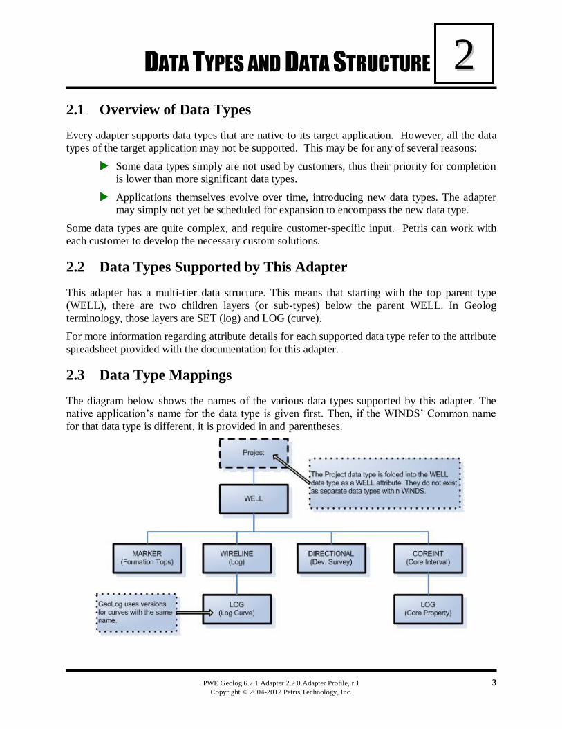
2.3 Data Type Mappings
The diagram below shows the names of the various data types supported by this adapter. The
native application’s name for the data type is given first. Then, if the WINDS’ Common name
for that data type is different, it is provided in and parentheses.
CHAPTER 2: DATA TYPES AND DATA STRUCTURE
4 PWE Geolog 6.7.1 Adapter 2.2.0 Adapter Profile, r.1 Copyright © 2004-2012 Petris Technology, Inc.
2.4 Mapping Set Names to Data Types
Since Geolog stores everything as SETs, the adapter needs a way to map which SETs to use for
each type of Data Type. This is done in a file called EXISTING_DATATYPE_NAME.txt
located in $ADAPTER_HOME/bin directory. When the adapter is processing a well it will find
all the SETs that it has and use this file to determine what type of data it is related to. If the SET
name is not configured in this file then it will be ignored when the well is spidered. If a SET
name is sent to the adapter for insert and the name is not configured for that Data Type, then the
set name will be pre-pended with the first SET name that is configured for that Data Type.
i.e., if a curve is transferred with the SET name (log name) of EXPL, in the below example the
adapter will create the SET as WIRE_EXPL.
WIRELINE =
{"WIRE","WELLOG","COMPOSITE","DEPTH_MATCH","EDIT","ENV","MWD","MUD_LOG"
,"FLUID","RUN","RUN1","RUN2","FALMD","SPLICED","REFERENCE","UNKNOWN"}
To map SET names to the Data Type, you simply add then to the corresponding line. For
example:
WIRELINE = {"WIRE","EXPL",
"WELLOG","COMPOSITE","DEPTH_MATCH","EDIT","ENV","MWD","MUD_LOG","FLUID"
,"RUN","RUN1","RUN2","FALMD","SPLICED","REFERENCE","UNKNOWN"}
Now any SETs called EXPL will be treated by the adapter during a spider as a SET for Curves
and if the SET name is sent to the adapter on a transfer, it will use the SET name as is.
“ABC will match and string containing “ABC”; “ABCDxyz021ST”, xABC67”, so there is no
need to enter “ABC1”, “ABC2” if “ABC is already entered.
2.5 Set Depth Units and Log Units
2.5.1. Geolog Units
The default units in Geolog are imperial (e.g. feet for length), but you may set it to metric
(e.g. meters for length) or a mixture of the two (mixed). This is done by setting the
environment variable PG_UNIT_SYSTEM to “metric” or “mixed”.
By default, when data is loaded, it is converted into preferred units by the Geolog
application, not by the adapter. If you do not wish to convert, set the environment
variable PG_UNIT_CONVERT to “no”.
2.5.2. Geolog Adapter Handling of Units
a. Based on what the Geolog application expects, the style sheet must ensure that
correct units are supplied to the geolog adapter. For the metric system, all length
units should be converted to “METRES” (not “METERS”).
b. There are two related units, one is depth unit (SET_UNITS), the other is curve
unit. If the incoming XML does not supply a unit for depth (refunit,
SET_UNITS), the adapter will assume that the unit is FEET. For log curves
(logunit, LOG_UNITS), if the unit is missing, the adapter will set it to “NONE”.
CHAPTER 2: DATA TYPES AND DATA STRUCTURE
PWE Geolog 6.7.1 Adapter 2.2.0 Adapter Profile, r.1 5
Copyright © 2004-2012 Petris Technology, Inc.
For incoming data not supplying a unit at all (null unit), it would be best to set it up in the
C2N style sheet to convert to whatever default the user wishes.
c. The Geolog adapter expects the SET_UNITS at the SET level. Because the
majority of data sources provide this information at curve level, the supplied C2N
style sheet will extract SET_UNITS from depth unit in the curve (LOG, in Geolog
term) level instead of using the depth unit from the log (SET, in Geolog term).

33
PWE Geolog 6.7.1 Adapter 2.2.0 Adapter Profile, r.1 7 Copyright © 2004-2012 Petris Technology, Inc.
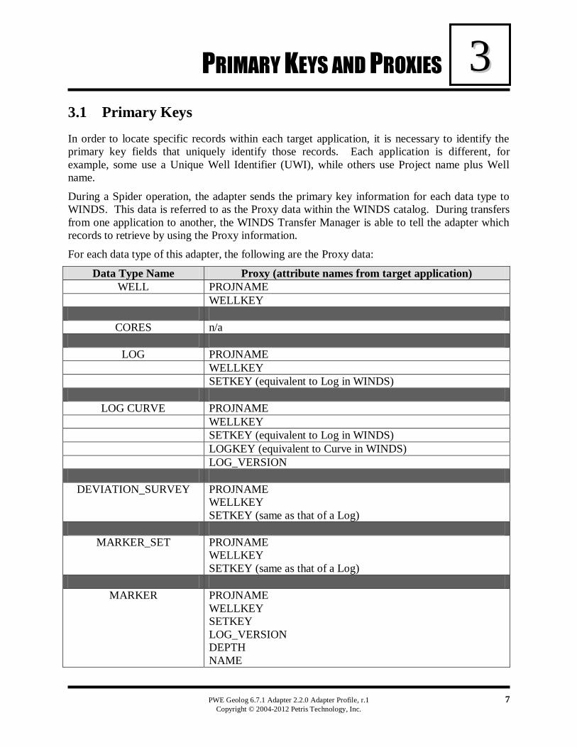
3. PRIMARY KEYS AND PROXIES
3.1 Primary Keys
In order to locate specific records within each target application, it is necessary to identify the
primary key fields that uniquely identify those records. Each application is different, for
example, some use a Unique Well Identifier (UWI), while others use Project name plus Well
name.
During a Spider operation, the adapter sends the primary key information for each data type to
WINDS. This data is referred to as the Proxy data within the WINDS catalog. During transfers
from one application to another, the WINDS Transfer Manager is able to tell the adapter which
records to retrieve by using the Proxy information.
For each data type of this adapter, the following are the Proxy data:
Data Type Name Proxy (attribute names from target application)
WELL PROJNAME
WELLKEY
CORES n/a
LOG PROJNAME
WELLKEY
SETKEY (equivalent to Log in WINDS)
LOG CURVE PROJNAME
WELLKEY
SETKEY (equivalent to Log in WINDS)
LOGKEY (equivalent to Curve in WINDS)
LOG_VERSION
DEVIATION_SURVEY PROJNAME
WELLKEY
SETKEY (same as that of a Log)
MARKER_SET PROJNAME
WELLKEY
SETKEY (same as that of a Log)
MARKER PROJNAME
WELLKEY
SETKEY
LOG_VERSION
DEPTH
NAME

CHAPTER 3: PRIMARY KEYS AND PROXIES
8 PWE Geolog 6.7.1 Adapter 2.2.0 Adapter Profile, r.1 Copyright © 2004-2012 Petris Technology, Inc.
CORE INTERVAL (log) (same keys as for LOG)
CORE SETS (log) (same keys as for LOG)
CORE DATA (curve) (same keys as for Log Curve)
44
PWE Geolog 6.7.1 Adapter 2.2.0 Adapter Profile, r.1 9 Copyright © 2004-2012 Petris Technology, Inc.
4. TRANSFER OPTIONS
The WINDS/Geolog transfer options, in combination with basic rules built into the adapter
program, cause specific actions to be performed by the Geolog adapter. The purpose of this
chapter is to describe those transfer options that are selectable by the user, and give a brief
insight into the resulting logic flow within the adapter.
After selecting a destination project, the following options are available to the user:
4.1 WELL OPTIONS
As presently implemented, following is a description of how the Geolog adapter interprets the
WELL option sent by Winds. Important to this explanation is knowing that:
The well name is the primary key for well insertions.
De-selecting the “Create” function does not automatically allow the “Overwrite”
(update) function. The user is given independent control over each function, as
described below.
1. If the "Create New Well" is checked, the user is giving the adapter permission to try to
insert the incoming well if there is no matching well name already in the Geolog system.
In this scenario:
a. If the incoming well has a well name that is not already in the system, then the
adapter will use the well name in the incoming data to insert the well.
b. If the incoming well does not have a well name, then the adapter will abort
the insertion.
2. If the "Create New Well" is Not checked, the user is preventing the adapter from
inserting any new wells. This means that if the incoming well’s well name is not already
in the Geolog system, the adapter will not attempt to insert it. (See Overwrite option
below for updating procedures.)
a. If this option is unchecked, the adapter has no insertion actions to perform.
3. If the "Overwrite Existing Well" is checked, the user is giving the adapter permission to
update existing well headers.
a. If the incoming well has a well name matching an existing well name, then the
adapter will attempt to update the well header in Geolog.
b. If the well name does not exist already, the adapter takes no action on this option.
(See section above for inserting new wells.)
If the "Overwrite Existing Well" is Not checked, the user is not giving the adapter permission to
update existing well headers. Regardless of the incoming well’s well name, the adapter will take
no action on this option.
4.2 Matching well by alternative well keys
When inserting data into the database, we normally find a well by well name. However, in some
cases, the well name may not be unique across different databases. For example, well “ABC” in
Recall may be called well “XYZ” in Geolog. When we transfer the data from Recall to Geolog,
CHAPTER 4: TRANSFER OPTIONS
10 PWE Geolog 6.7.1 Adapter 2.2.0 Adapter Profile, r.1 Copyright © 2004-2012 Petris Technology, Inc.
a new well (“ABC”) will be created even though the well already exists in Geolog as “XYZ”,
causing confusion.
The Geolog adapter now offers a solution to avoid this problem by matching the well with an
alternative well key.
1. When inserting data, it will first try to match by well name as previously stated. If a well
is found to exist in the database, it will return, just as before.
2. If match by well name does not yield a well, it will try to match by the alternative well
key.
3. The matching by alternative well key is optional.
4. Currently acceptable alternative well keys are API_NUMBER and UNIQUE_WELL_ID. Only
one alternative well key may be used.
5. This process only affects transfer (inserting data) and does not affect other functions like
spider or view original.
Caution Because of the limitations of Geolog API, there may be a performance issue
associated with matching well by alternative well key when there are a large number of wells in
a project. Thus it is advised that this feature not be activated if it is not needed.
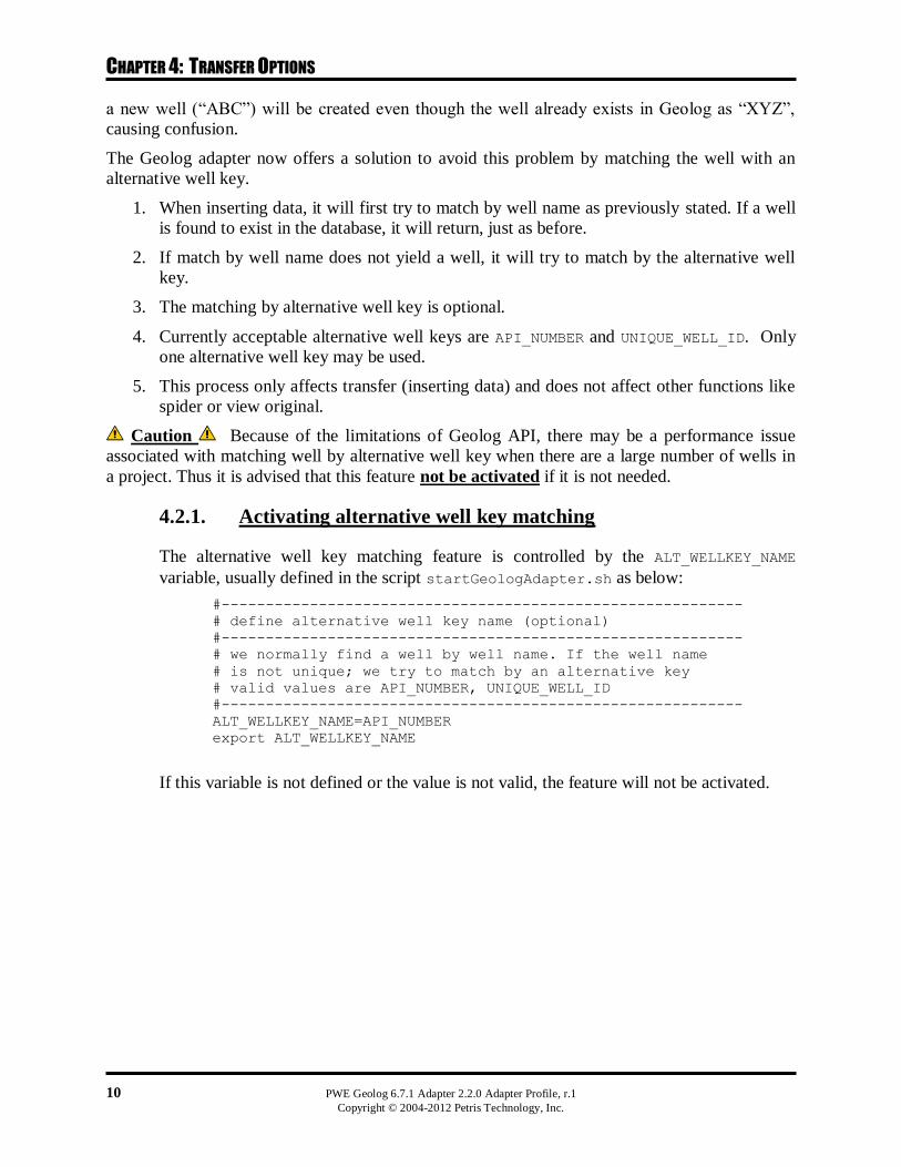
4.2.1. Activating alternative well key matching
The alternative well key matching feature is controlled by the ALT_WELLKEY_NAME
variable, usually defined in the script startGeologAdapter.sh as below:
#-----------------------------------------------------------
# define alternative well key name (optional)
#-----------------------------------------------------------
# we normally find a well by well name. If the well name
# is not unique; we try to match by an alternative key
# valid values are API_NUMBER, UNIQUE_WELL_ID
#-----------------------------------------------------------
ALT_WELLKEY_NAME=API_NUMBER
export ALT_WELLKEY_NAME
If this variable is not defined or the value is not valid, the feature will not be activated.
PWE Geolog 6.7.1 Adapter 2.2.0 Adapter Profile, r.1 11 Copyright © 2004-2012 Petris Technology, Inc.
55 5. RULES
5.1 Insertion Rules
5.1.1. Insertion Rules (WELL, LOG and LOG CURVES)
1. Project name, Well, Log (Set), and Curve (Log) names are required.
2. The API number must contain a value. It cannot be empty.
3. Empty Sets cannot be inserted – each Set must have at least one curve.
4. SET naming (“Logs” in WINDS terminology)
a. Note – in the following discussion, the term “Log” refers to the WINDS type of
Log data type, not the Geolog log (which is the WINDS curve type).
b. Geolog does not have the concept of specific named data types at the Well Log
level. Instead it has an entity called a ‘SET’. As such, Geolog does not provide an
attribute or flag to signify which sets are Well Logs versus any other data type.
c. Thus, in order to distinguish one type of Set from another, it is necessary to
artificially name the Sets (Logs). Thus, every inserted Log name is given the
prefix “WIRE_” by the adapter, unless it is already has that prefix.
d. Maximum length of the Set name is 16 characters, including the prefix (WIRE_,
DIRECTIONAL_ etc.).
5. Curves (“Logs” in Geolog terminology)
a. Versioning - When a curve is inserted into Geolog, if that curve name already
exists for the same Set, then the Geolog application creates a new curve with the
next version number. It will not overwrite existing curves, unless the version
number is explicitly specified.
If Unit Conversion is turned on (via the PG_UNIT_CONVERT setting)
and the incoming curve unit does not match the project curve unit
setting, curve versioning will fail and a new set will be created. You
may turn Unit Conversion off to avoid this problem (see the Geolog
Units section) or ensure your incoming units match your destination’s
project units.
b. Curves can be periodic (equal depth or time between points) or aperiodic.
c. Empty curves, or curves with a single point with a value of -999 will be ignored
by the adapter.
Some interesting situations: (uses Geolog terminology)
Case I:
If we insert GR log into an existing set WIRE_GR having not previous GR log, the API
will present this as GR_1 because Geolog automatically appends numeric version to the
name to create log versions.
Case II:
If we insert GR Log into the existing set WIRE_GR having log with name GR_1 and
GR_3, then new log added would have the name GR_4.
Case III:
CHAPTER 5: RULES
12 PWE Geolog 6.7.1 Adapter 2.2.0 Adapter Profile, r.1 Copyright © 2004-2012 Petris Technology, Inc.
If we insert Log name GR_3 (note the “_3”) in set WIRE_GR having existing log with
name GR_3, then it will replace the already existing GR_3 log with this new GR_3 log
because GR_3 refers explicitly to the GR log with version no 3. This is not a normal case
since it is contrary to Geolog’s own rules, which will create a new version during editing,
rather than actually changing a log curve. Normally, log/curve names do not contain this
type of suffix.
5.1.2. CORES
General background:
The rock material of a well borehole is typically collected via multiple coring jobs. Each coring
job covers a specified section of the wellbore – this section may be called a “Core Interval”.
Each Core Interval is delineated by a top depth and a bottom depth. It should be noted that actual
recovered material may not span the entire Core Interval range – some material may be lost
during the coring process.
The acquired material of a Core Interval is typically sent to a laboratory for analysis. The result
of the analysis is a set of measured properties (like porosity) along the material’s length.
Thus, “Core Properties” represent the set of values resulting from the analysis measurements. In
a core data matrix (with depth on the Y-axis), properties are the column arrays at varying depths,
and can be visualized as curves. One lab analysis will usually produce one set of measured
properties, such as porosity, permeability, etc.
Since a given core interval can be analyzed multiple times, there can be multiple sets of
measurements (property curves) for that interval. Each analysis is essentially producing a new set
of data for each property curve (such as porosity).
In summary, a Core Interval is the result of a core acquisition activity at the well location. Core
Properties are the measured data that result from an analysis activity at a later time.
For additional information, also see the “Core Data Implementation” document from Petris.
Assumptions
1. If a Core Interval is selected for viewing, the Core Interval plus all of its property data
(multiple curves) will be extracted for viewing.
2. A Core Interval will always be transferred with all of its property data. Individual
property curves cannot be selected for transfer.
Extraction rules (general)
1. Each Core Interval (header) must include a top depth and a bottom depth.
a. If either depth is missing from the native data structure, then those values should
be derived from the minimum and maximum depths of the core samples or
properties, or by some other reasonable method, if possible.
b. Then if either depth is still missing, the Core Interval should not be extracted.
2. Every property value must have an associated depth. Otherwise that value should not be
extracted.
3. Extracted data:
a. During extractions, a request to extract a core interval will always extract that
core interval, its direct attributes, plus its entire set of property data.
b. A single property curve must be extractable (for viewing), with its parent Interval.
CHAPTER 5: RULES
PWE Geolog 6.7.1 Adapter 2.2.0 Adapter Profile, r.1 13
Copyright © 2004-2012 Petris Technology, Inc.
c. If there is no property data, the adapter is permitted to extract the Core Interval
alone, if the adapter’s local rules permit it.
Insertion and Update Rules (General)
Note: The following are general insertion rules. It is recognized that there may be specific cases
for each datasource that require additional restrictions.
1. Each incoming Core Interval (header) must have a top depth and a bottom depth.
a. If either depth is missing, the Core Interval should not be inserted, and
appropriate error message should be displayed and/or logged.
b. Top depth must be less than base depth. Otherwise, the Core Interval should not
be inserted, and appropriate error message should be displayed and/or logged.
2. Insertion of Core Intervals will be based on the top depth and bottom depth.
a. Assume a Core Interval is stored already, and then a second Core Interval needs
to be inserted:
i. If the top depth and bottom depth are exactly the same, then the existing
Core Interval is updated. A new instance of that interval will not be created.
ii. If the intervals do NOT overlap, then the new Core Interval is inserted as a
separate interval.
iii. If the intervals overlap, but the top and bottom depths of both intervals do
not exactly match, then the incoming Core Interval will be discarded and
an error message displayed. (However, the core properties may be saved.
See rules for core properties below.)
b. Insertion data will normally include both the Core Interval and the related
properties. But if a Core Interval is received that has no property data, then the
adapter is permitted to insert the Core Interval without the properties, if an adapter’s
local rules allow it.
3. Insertion of Core Properties
A fundamental premise regarding Core Properties is that there is no way to
universally and uniquely identify a given set of properties. For example, Set #1 in one
application may have nothing to do with Set #1 in another application. Thus, the
general assumption is that incoming data has resulted from a new analysis (or
process). Therefore, core property data is always inserted as a new object (possibly
with a new identifying label), and existing core property data is never updated by an
adapter.
a. When a set of measurements is received, it should be inserted as a new set (or
version if necessary). There should be no attempt to update an existing set. The
internally-assigned Set number will be the next available Set number, which is not
guaranteed to be the same Set number as that of the incoming data.
b. A core sample or property cannot be inserted without a parent Core Interval
c. If an incoming interval is wholly contained by an existing interval, then the core
properties of the incoming interval should be saved with the existing interval’s
data. “Wholly contained” means that the incoming top depth is greater than or

CHAPTER 5: RULES
14 PWE Geolog 6.7.1 Adapter 2.2.0 Adapter Profile, r.1 Copyright © 2004-2012 Petris Technology, Inc.
equal to the existing top depth, and the incoming bottom depth is less than or
equal to the existing top depth.
Insertion and Update Rules (Specifics)
Empty property arrays may have to be created in order to satisfy requirements to have
properties in a given Core Interval depth range. These empty property arrays are not
reported to PWE during insertions or spider operations.
Core Interval Behavior
The Geolog Adapter uses the USE_COREINIT_SET variable to determine how it
interprets core intervals. By default, this variable is set to “no” which means all cores will
use a core interval of 1 and belong to the same interval.
If set to “yes”, the Geolog project must have a set named COREINT that defines the core
intervals. In addition, a corresponding log named CORE_NUM must be present in the
CORE set. This CORE_NUM log should define the interval for every elementin the core
property array. If this variable is set to yes and both requirements have not been met in
the Geolog project, no CORE data will be spidered.
This variable may be found in the StartGeologAdapter.sh script located in the
<ADAPTER_HOME>/bin directory.
5.2 Important Behaviors of the Application
1. Curves of the same name (without an explicit version number) are assigned new version
numbers of that curve by the application itself. Editing a curve within Geolog
automatically generates a new version.
2. When a curve is inserted, the Log_Min and Log_Max values are always recomputed by
Geolog. The inserted values are ignored.
3. Geolog limits Well names to 32 characters.
4. Geolog limits curve names to 75 characters.
5. Referencing a log (curve) by name only, without a version, will access the latest version
of the log (curve).

PWE Geolog 6.7.1 Adapter 2.2.0 Adapter Profile, r.1 15 Copyright © 2004-2012 Petris Technology, Inc.
66 6. SET CONSTANTS
The Geolog adapter has been modified to enable the extraction, insertion and display of Set
constants. The object hierarchy and terminology in Geolog is different than most other log
adapters in what they call the objects. In Most models you have well as the top data object. You
have logs as children of the well; Logs are containers for curves that share the parameters of the
log. In Geolog you have differing names for the objects. This difference in semantics is
summarized as follows:
Geolog Openworks
WELL WELL
SET LOG
LOG CURVE
6.1 Insert behavior (sets and curves)
When transferring curves into Geolog the following sequence of events occur:
1. Check to see if a set with the same name, sample rate, interpolation ,top depth and bottom
depth as the incoming curve already exists..if so insert the curve in this set.
2. If a set already exists with the same name, but differing values for any of the other
attributes….an new version of the set is created and the curve inserted in the new set.
3. If the set does not exist…create it and insert the curve.
4. If a curve with the same name already exists in the Set…the curve is versioned and added
to the set.
Only the well has overwrite priveldge..not the set. If you transfer one curve from a set, then add
set constants and transfer another curve….the curve will be added, but the set will not be updated
to reflect the new constants. Once it is created it is not added to.
6.2 Set Constants
Set constants can functionally be thought of as attributes of the set. In Geolog when adding
constants to a set, you can select from a predefined list of constant values, or create a unique one
of your own.
CHAPTER 6: SET CONSTANTS
16 PWE Geolog 6.7.1 Adapter 2.2.0 Adapter Profile, r.1 Copyright © 2004-2012 Petris Technology, Inc.
6.3 Data Flow
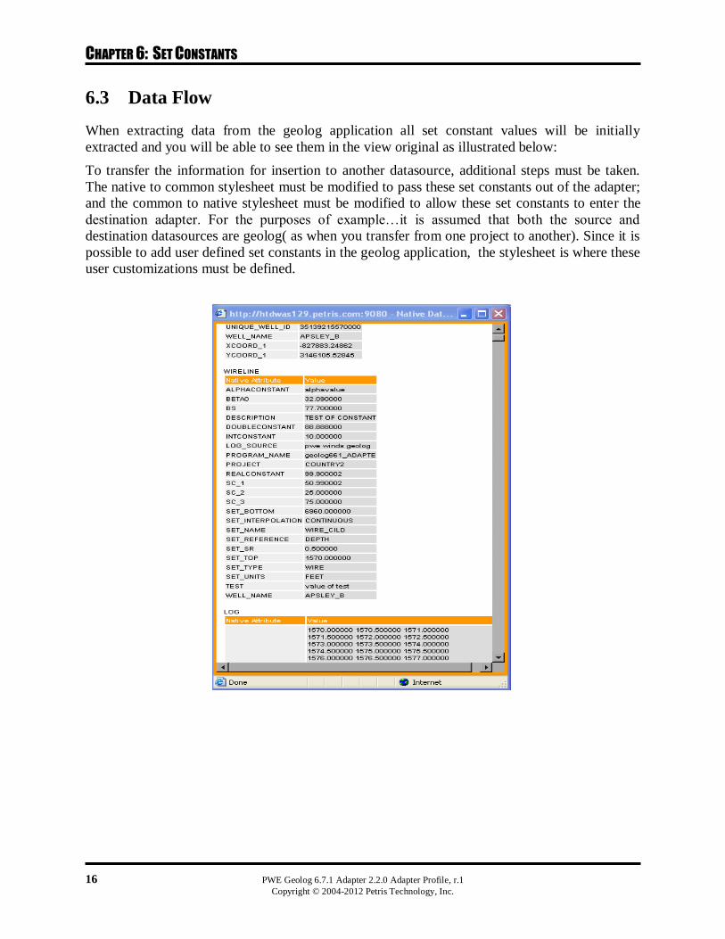
When extracting data from the geolog application all set constant values will be initially
extracted and you will be able to see them in the view original as illustrated below:
To transfer the information for insertion to another datasource, additional steps must be taken.
The native to common stylesheet must be modified to pass these set constants out of the adapter;
and the common to native stylesheet must be modified to allow these set constants to enter the
destination adapter. For the purposes of example…it is assumed that both the source and
destination datasources are geolog( as when you transfer from one project to another). Since it is
possible to add user defined set constants in the geolog application, the stylesheet is where these
user customizations must be defined.
CHAPTER 6: SET CONSTANTS
PWE Geolog 6.7.1 Adapter 2.2.0 Adapter Profile, r.1 17
Copyright © 2004-2012 Petris Technology, Inc.
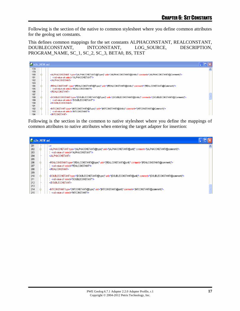
Following is the section of the native to common stylesheet where you define common attributes
for the geolog set constants.
This defines common mappings for the set constants ALPHACONSTANT, REALCONSTANT,
DOUBLECONSTANT, INTCONSTANT, LOG_SOURCE, DESCRIPTION,
PROGRAM_NAME, SC_1, SC_2, SC_3, BETA0, BS, TEST
Following is the section in the common to native stylesheet where you define the mappings of
common attributes to native attributes when entering the target adapter for insertion:

CHAPTER 6: SET CONSTANTS
18 PWE Geolog 6.7.1 Adapter 2.2.0 Adapter Profile, r.1 Copyright © 2004-2012 Petris Technology, Inc.
6.4 How to Transfer Set Constants
This is an example of transfer of a curve (along with set constants) from one geolog project to
another. Here we are working with the WIRE_CILD set of the well ASHLEY_B in the project
COUNTRY2. We will transfer it to the project BP_TEST6. Note when a curve is selected for
transfer the parent objects SET and WELL are transferred to contain it.
Begin by logging in to the PetrisWINDS® Enterprise application. On the New Search screen
select Geolog6.6 from the DataSource list box and the Datatype Log. In the Basic Search
console enter COUNTRY2 as the Well Project and click Find.
From the results listing, select the ASHLEY_B and click Add to Cart.
Once ASAHLEY_B has been added to the cart select Transfer.
CHAPTER 6: SET CONSTANTS
PWE Geolog 6.7.1 Adapter 2.2.0 Adapter Profile, r.1 19
Copyright © 2004-2012 Petris Technology, Inc.
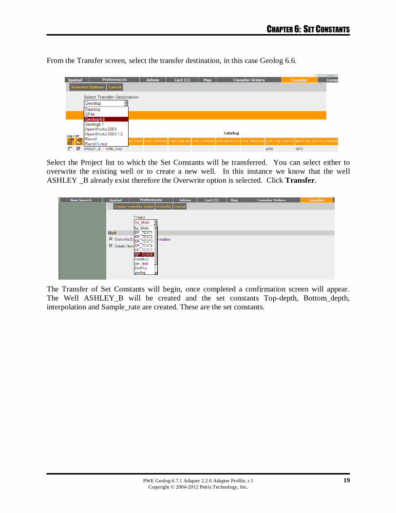
From the Transfer screen, select the transfer destination, in this case Geolog 6.6.
Select the Project list to which the Set Constants will be transferred. You can select either to
overwrite the existing well or to create a new well. In this instance we know that the well
ASHLEY _B already exist therefore the Overwrite option is selected. Click Transfer.
The Transfer of Set Constants will begin, once completed a confirmation screen will appear.
The Well ASHLEY_B will be created and the set constants Top-depth, Bottom_depth,
interpolation and Sample_rate are created. These are the set constants.


