Embed Size (px)
Citation preview

Upgrade systemsE-Series SystemsNetAppJuly 27, 2022
This PDF was generated from https://docs.netapp.com/us-en/e-series/upgrade-controllers/index.html onJuly 27, 2022. Always check docs.netapp.com for the latest.

Table of Contents
Upgrade systems . . . . . . . . . . . . . . . . . . . . . . . . . . . . . . . . . . . . . . . . . . . . . . . . . . . . . . . . . . . . . . . . . . . . . . . . . 1
Controllers . . . . . . . . . . . . . . . . . . . . . . . . . . . . . . . . . . . . . . . . . . . . . . . . . . . . . . . . . . . . . . . . . . . . . . . . . . . . 1
SANtricity OS . . . . . . . . . . . . . . . . . . . . . . . . . . . . . . . . . . . . . . . . . . . . . . . . . . . . . . . . . . . . . . . . . . . . . . . . . 20
Upgrade systems
Controllers
Upgrade controllers overview
You can upgrade your storage array through the replacement of existing controllers.
Controller components
A controller consists of a board, firmware, and software. It controls the drives, and also implements the
management software functions.
When to use this procedure
You typically use this procedure when you want to upgrade all controllers to a different model or platform. This
procedure involves replacing all controllers in a controller-drive tray.
You might also use this procedure in the following situations:
• When all controllers in a controller-drive tray encounter hardware failures and are no longer functional.
• To upgrade the dual inline memory modules (DIMMs) in your controller-drive tray by replacing both
controllers with the same model of controllers, but with different DIMMs.
The HIC upgrade scenarios are not covered within this procedure. Instead, refer to the HIC add,
upgrade and replacement procedures for your E-Series system.
Upgrade considerations
Before you upgrade controllers, review the following considerations.
Hardware and firmware requirements
• Duplex and simplex controller upgrades
For duplex controller-drive trays, you replace both controllers. For simplex controller-drive trays, you
replace the one controller. In both cases, you must power off the controller-drive tray. As a result, you
cannot access data on the storage array until you successfully complete the replacement.
• Trays and shelves
Storage arrays with an E2800 or E5700 controller shelf are typically managed with the SANtricity System
Manager user interface. You might also use the SANtricity Storage Manager interface to manage E2800 or
E5700 controller shelves. All other controller-drive trays referenced in this procedure use SANtricity
Storage Manager.
• Controller batteries
A new controller is shipped without a battery installed. When possible, you should remove the battery from
your old controller and then install that battery in the new controller. However, for some controller upgrades,
the battery from the old controller is not compatible with the new controller. In those cases, you must order
1

a battery along with your new controller, and have that battery available before you begin these tasks.
• Vendor Identification
Some controller upgrades result in the Vendor ID in SCSI Inquiry Data changing from LSI to NETAPP.
When the Vendor ID changes from LSI to NETAPP, additional steps are required on the Windows,
VMware, and AIX operating systems to reclaim devices. Steps for these operating systems are included in
this upgrade procedure.
• Synchronous Mirroring and Asynchronous Mirroring
If your storage array participates in Synchronous Mirroring, only iSCSI or Fibre Channel connections are
supported between the primary site and the remote site. If the host interface card (HIC) configuration in
your new controllers does not include iSCSI or Fibre Channel connections, Synchronous Mirroring will not
be supported.
For Asynchronous Mirroring, the local storage array and remote storage array can run different versions of
firmware. The minimum firmware version supported is SANtricity firmware version 7.84.
• Storage object limits
If you change your controllers from 5x00 models to 2x00 models, your new storage array configuration will
support lower numbers of some storage objects (for example, volumes) in the storage management
software than your old configuration. You must make sure that your old configuration does not exceed the
storage object limits. See Hardware Universe for more information.
Upgrade to newer models
If you are replacing the controllers to upgrade to a new model, keep in mind that your current storage array
might have premium features installed that the new model cannot support. For example, E2700 controllers do
not support the legacy Snapshots premium feature.
If you replace E2600 controllers with E2700 controllers, and your storage array was using the legacy
Snapshots feature, you must disable that feature and delete or convert all volumes (that is, snapshots,
repositories) associated with that feature before you replace the controllers. You can convert legacy Snapshots
to the updated Snapshots feature. Before you upgrade a controller-drive tray, you should disable any premium
features used on your storage array that are not supported on the new controllers.
Upgrade compatibility
Review the supported upgrade paths for each storage array model.
From E2x00 to E2x00
• Battery: Reuse the old battery.
• Vendor ID: Additional steps required.
• Feature support: Legacy snapshots are not supported on the E2700.
• SAS-2 shelves: E2800 controllers must not be placed into SAS-2 shelves.
From E2x00 to E5x00
• Battery: Order a new battery.
2

• Vendor ID: Additional steps are required when upgrading from E2600 to E5500 or E5600, or when
upgrading from E2700 to E5400.
• Feature support:
◦ Legacy snapshots are not supported on the E5500 or E5600.
◦ Legacy remote volume mirroring (RVM) is not supported on the E5500 or E5600 with iSCSI HICs.
◦ Data Assurance is not supported on the E5500 or E5600 with iSCSI HICs.
◦ E5700 controllers must not be placed into SAS-2 shelves.
• SAS-3 shelves: E5400, E5500, and E5600 controllers must not be placed into SAS-3 shelves.
From E5x00 to E2x00
• Battery: Order a new battery.
• Vendor ID: Additional steps are required when upgrading from E5500 or E5600 to E2600, or when
upgrading from E5400 to E2700.
• Feature support: Legacy snapshots are not supported on the E2700.
• SAS-3 shelves: E5400, E5500, and E5600 controllers must not be placed into SAS-3 shelves.
From E5x00 to E5x00
• Battery: Reuse the old battery.
• Vendor ID: Additional steps required when upgrading from E5400 to E5500 or E5600.
• Feature support:
◦ Legacy snapshots are not supported on the E5500 or E5600.
◦ Legacy remote volume mirroring (RVM) is not supported on the E5400 or E5500 with iSCSI HICs.
◦ Data Assurance is not supported on the E5400 or E5500 with iSCSI HICs.
◦ E5700 controllers must not be placed into SAS-2 shelves.
• SAS-3 shelves: E5400, E5500, and E5600 controllers must not be placed into SAS-3 shelves.
From EF5x0 to EF5x0
• Battery: Reuse the old battery.
• Vendor ID: Additional steps required when upgrading from EF540 to EF550 or EF560.
• Feature support:
◦ No Legacy Snapshots for EF550/EF560.
◦ No Data Assurance for EF550/EF560 with iSCSI.
◦ EF570 controllers must not be placed into SAS-3 shelves.
• SAS-3 shelves: EF540, EF550, and EF560 controllers must not be placed into SAS-3 shelves.
SAS enclosures
The E5700 supports DE5600 and DE6600 SAS-2 enclosures via head upgrade. When a E5700 controller is
installed in SAS-2 enclosures, support for base host ports is disabled.
3

SAS-2 shelves SAS-3 shelves
SAS-2 shelves include the following models:
• DE1600, DE5600, and DE6600 drive trays
• E5400, E5500, and E5600 controller-drive trays
• EF540, EF550 and EF560 flash arrays
• E2600 and E2700 controller-drive trays
SAS-3 shelves include the following models:
• E2800 controller shelves
• E5700 controller shelves
• DE212C, DE224C, DE460C drive shelves
SAS-2 to SAS-3 investment protection
You can reconfigure your SAS-2 system to be used behind a new SAS-3 controller shelf
(E57XX/EF570/E28XX).
This procedure requires a Feature Product Variance Request (FPVR). To file an FPVR, contact
your sales team.
Prepare to upgrade controllers
Prepare to upgrade controllers by saving the Drive Security key (if used), recording the
serial number, gathering support data, disabling certain features (if used), and taking the
controller offline.
Gathering support data can temporarily impact performance on your storage array.
Steps
1. Make sure that the existing storage array is updated to the latest released operating system (controller
firmware) version available for your current controllers. From SANtricity System Manager, go to Support ›Upgrade Center to view your software and firmware inventory.
If you are upgrading to controllers that support SANtricity OS version 8.50, you must install
the latest versions of SANtricity OS and the latest NVSRAM after you install and power on
the new controllers. If you do not perform this upgrade, you might not be able to configure
the storage array for Automatic Load Balancing (ALB).
2. If you are performing a complete controller replacement and are also using the Drive Security feature,
complete the appropriate steps for your security type (internal or external) and drive state in the following
table.
Drive Security is a storage array feature that provides an extra layer of security with either
Full Disk Encryption (FDE) drives or Federal Information Processing Standard (FIPS) drives.
When these drives are used with the Drive Security feature, they require a security key for
access to their data.
4

Security type and context Steps
Internal key management, one or more drives
locked
a. Export the internal security key file to a known
location on the management client (the system
with a browser used for accessing System
Manager). Use the export storageArray
securityKey CLI command. You must provide
the pass phrase associated with the security
key and specify the location where you want to
save the command. For information about using
this command, see the Command Line
Reference.
b. Know the pass phrase associated with the
internal security key.
External key management, all drives locked, you
are able to transition to internal key management
temporarily for the controller replacement
(recommended).
Perform the following steps, in order:
a. Record the External KMS server address and
port number. From System Manager, go to
Settings › System › Security Key
Management › View/Edit Key Management
Server Settings.
b. Ensure that the client and server certificates are
available on your local host so the storage array
and key management server can authenticate
each other after the controller replacement is
finished. Use the save storageArray
keyManagementCertificate CLI command
to save the certificates. Be sure to run the
command twice, once with the
certificateType parameter set to client,
and the other with the parameter set to server.
For information about using this command, see
the Command Line Reference.
c. Transition to internal key management by
running the disable storageArray
externalKeyManagement CLI command.
d. Export the internal security key file to a known
location on the management client (the system
with a browser used for accessing System
Manager). Use the export storageArray
securityKey CLI command. You must provide
the pass phrase associated with the security
key and specify the location where you want to
save the command. For information about using
this command, see the Command Line
Reference.
e. Know the pass phrase associated with the
internal security key.
5

Security type and context Steps
External key management, all drives locked, you
are not able to transition to internal key
management temporarily for the controller
replacement.
Perform the following steps, in order:
a. Record the External KMS server address and
port number. From System Manager, go to
Settings › System › Security Key
Management › View/Edit Key Management
Server Settings.
b. Ensure that the client and server certificates are
available on your local host so the storage array
and key management server can authenticate
each other after the controller replacement is
finished. Use the save storageArray
keyManagementCertificate CLI command
to save the certificates. Be sure to run the
command twice, once with the
certificateType parameter set to client,
and the other with the parameter set to server.
For information about using this command, see
the Command Line Reference.
External key management, partial drives locked No additional steps are necessary.
Your storage array must be in an optimal state to retrieve client and server certificates. If the
certificates are not retrievable, then a new CSR must be created and signed and the server
certificate downloaded from the EKMS.
1. Record the serial number for your storage array:
a. From System Manager, select Support › Support Center › Support Resources tab.
b. Scroll down to Launch detailed storage array information, and then select Storage Array Profile.
The Report appears on your screen.
c. To locate the chassis serial number under the storage array profile, type serial number in the Find text
box, and then click Find.
All matching terms are highlighted. To scroll through all the results one at a time, continue to click Find.
d. Make a record of the Chassis Serial Number.
You need this serial number to perform the steps in Complete controller upgrade.
2. Gather support data about your storage array by using either the GUI or the CLI:
◦ Use either System Manager or the Array Management Window in Storage Manager to collect and save
a support bundle of your storage array.
▪ From System Manager, select Support › Support Center › Diagnostics tab. Then select Collect
Support Data and click Collect.
▪ From the Array Management Window toolbar, select Monitor › Health › Collect Support Data
6

Manually. Then enter a name and specify a location on your system where you want to store the
support bundle.
The file is saved in the Downloads folder for your browser with the name support-data.7z.
If your shelf contains drawers, the diagnostics data for that shelf is archived in a separate zipped
file named tray-component-state-capture.7z.
◦ Use the CLI to run the save storageArray supportData command to gather comprehensive
support data about the storage array.
3. Ensure that no I/O operations are occurring between the storage array and all connected hosts:
a. Stop all processes that involve the LUNs mapped from the storage to the hosts.
b. Ensure that no applications are writing data to any LUNs mapped from the storage to the hosts.
c. Unmount all file systems associated with volumes on the array.
The exact steps to stop host I/O operations depend on the host operating system and
the configuration, which are beyond the scope of these instructions. If you are not sure
how to stop host I/O operations in your environment, consider shutting down the host.
Possible data loss — If you continue this procedure while I/O operations are occurring,
you might lose data.
4. If the storage array participates in a mirroring relationship, stop all host I/O operations on the secondary
storage array.
5. If you are using asynchronous or synchronous mirroring, delete any mirrored pairs and deactivate any
mirroring relationships through the System Manager or the Array Management window.
6. If there is a thin provisioned volume that is reported to the host as a thin volume and the old array is
running firmware (8.25 firmware or above) that supports the UNMAP feature, disable Write Back Caching
for all thin volumes:
a. From System Manager, select Storage › Volumes.
b. Select any volume, and then select More › Change cache settings.
The Change Cache Setting dialog box appears. All volumes on the storage array appear in this dialog
box.
c. Select the Basic tab and change the settings for read caching and write caching.
d. Click Save.
e. Wait five minutes to allow any data in cache memory to be flushed to disk.
7. If the Security Assertion Markup Language (SAML) is enabled on the controller, contact technical support
to disable the SAML authentication.
After SAML is enabled, you cannot disable it through the SANtricity System Manager
interface. To disable the SAML configuration, contact technical support for assistance.
8. Wait for all operations in progress to complete before continuing to the next step.
a. From System Manager’s Home page, select View Operations in Progress.
7

b. Make sure all operations shown on the Operations in Progress window are complete before
continuing.
9. Turn off power to the controller-drive tray.
Wait for all of the LEDs on the controller-drive tray to go dark.
10. Turn off power to each drive tray that is connected to the controller-drive tray.
Wait two minutes for all of the drives to spin down.
What’s next?
Go to Remove controllers.
Remove controllers
After preparing for the upgrade, you can remove the controllers, and if necessary, remove
the battery.
Step 1: Remove controller
Remove the controller canister so you can upgrade it with a new one. You must disconnect all cables and
remove any SFP transceivers. Then, you can slide the controller canister out of the controller shelf.
What you’ll need
• An ESD wristband or take other antistatic precautions.
• Labels to identify each cable that is connected to the controller canister.
About this task
Perform the following steps for each controller in the controller-drive tray.
If you are upgrading controllers in a duplex controller-drive tray, repeat all steps to remove the second
controller canister.
Steps
1. Put on an ESD wristband or take other antistatic precautions.
2. Label each cable that is attached to the old controller canister. Depending on the HIC configuration, you
might be able to reconnect some cables after you replace the controller canister.
3. Disconnect all of the interface and Ethernet cables from the old controller canister.
If fiber-optic cables are present, you can use the two release levers to partially remove the controller
canister. Opening these release levers makes it easier to press down the fiber-optic cable release tab.
To prevent degraded performance, do not twist, fold, pinch, or step on the cables.
4. If the old controller canister contains a Fibre Channel HIC or an InfiniBand HIC, remove the small form-
factor pluggable (SFP+) transceivers (for Fibre Channel) or quad SFP (QSFP+) transceivers (for
InfiniBand) from the HIC, and save them for possible reuse.
5. Remove controller A.
a. Unlock and rotate the release handles out to release the controller canister.
8

b. Using the release handles and your hands, pull the controller canister out of the controller-drive tray.
The following figure is an example of the general location for the release handles on controller models.
Controller shelves and controller-drive trays have a similar configuration for the release handles.
(1) Controller canister
(2) Cam handle
6. Set the old controller canister on a flat, static-free surface near the controller-drive tray with the release
levers up. Position the controller canister so that you can access the top cover.
7. (Conditional) If you are upgrading controllers in a duplex controller-drive tray, repeat all steps to remove the
second controller canister.
If you intend to use the battery from the old controller in the new controller, go to the next part of the section;
otherwise go to Install new controllers.
Step 2: Remove battery
Remove the battery only if you intend to use the battery from the old controller canister in the new controller
canister.
Steps
1. Press down on both of the top cover latch buttons on the old controller canister, and slide the top cover to
the rear of the canister.
2. Perform one of the following options, depending on your model of controller-drive tray, to release the old
battery:
◦ For the E2600 or the E2700 controller-drive tray, unscrew the thumb screw that secures the battery to
9

the controller canister.
◦ For the E5400, EF540, E5500, EF550, E5600, or EF600 controller-drive tray, release the tab that
secures the battery to the controller canister.
3. Remove the battery by sliding it towards the rear of the old controller canister.
What’s next?
Go to Install new controllers.
Install new controllers
After you have removed the old controllers, you can install new controllers in the
controller-drive tray.
About this task
Perform the following steps for each controller in the controller-drive tray. If you are upgrading controllers in a
duplex controller-drive tray, repeat all steps to install the second controller canister.
What you’ll need
• An ESD wristband or take other antistatic precautions.
• A battery from the original controller canister or a new battery that you ordered.
• The new controller canister.
Step 1: Install battery
Install the battery that you removed from the original controller canister or a new battery that you ordered.
Steps
1. Unpack the new controller canister, and set it on a flat, static-free surface so that the removable cover
faces up.
2. Press down on the cover button, and slide the cover off.
3. Orient the controller canister so that the slot for the battery faces toward you.
4. Depending on your controller model, do one of the following:
◦ For E2600 or E2700 controller models:
a. Insert the battery circuit board by sliding it towards the front of the new controller canister.
b. Tighten the thumbscrew to secure the battery circuit board in the new controller canister card.
c. Reinstall the top cover on the new controller canister by sliding it forward until the top latch covers
click.
When the latch clicks into place, the bottom of the latch hooks into a metal slot on the chassis.
◦ For other controller models:
a. Insert the battery into the new controller canister.
Slide the battery into the canister, making sure it stays below the rivets on the wall of the new
canister.
b. Keeping the locking handle at a 45-degree angle, align the connectors at the bottom of the battery
with the connectors on the canister.
10

c. Push the battery down until you hear it click, and move the locking handle up to secure the
controller battery to the controller canister.
To make sure that the controller battery is seated correctly in an E5XX controller-
drive tray, you might need to slide it out and insert it again. It is secure when you
hear it click into place, and when the locking handle does not move out of its upright
position when you wiggle it.
d. Reinstall the top cover on the new controller canister by sliding it forward until the top latch covers
click.
When the latch clicks into place, the bottom of the latch hooks into a metal slot on the chassis.
5. Turn the controller canister over to confirm that the battery is installed correctly.
Step 2: Install new controller canister
Install the new controller canister into the controller shelf.
Steps
1. Slide the new controller canister all the way into the controller-drive tray. Rotate the release levers towards
the center of the controller canister to lock it into place.
2. If your new controller canister has a Fibre Channel HIC or an InfiniBand HIC, install the SFP+ transceivers
(Fibre Channel) or QSFP+ transceiver (InfiniBand) into the controller canister and reconnect the host
cables.
Depending on the HICs involved in your upgrade, you might be able to reuse SFP+ transceiver or QSFP+
transceivers that you removed from your old controller canister.
3. Reconnect all of the cables between the controller-drive tray and the drive trays.
If the drive cabling configuration is the same as it was with your old controllers, use the labels that you
attached to the cables to reconnect the cables correctly.
If you are upgrading to E2700 controllers from an earlier model, the drive cabling
configuration might be different from the configuration used for the old controllers.
What’s next?
If you are upgrading E2800 and E5700 controllers and the Drive Security feature is enabled, go to Unlock
drives. Otherwise, go to Complete controller upgrade.
Unlock drives
If you are upgrading E2800 and E5700 controllers, the Drive Security feature for these
controllers result in the locking of drives whether partially, externally, or internally. If the
Drive Security feature is enabled, you must manually unlock these drives.
Follow the appropriate procedure for:
• Internal key management
• External key management
11

Internal key management
Follow these steps for internal key management when all drives are locked.
About this task
The newly swapped controllers will lock down with seven-segment display code of L5. This lock down occurs
when no drives in the storage array are able to perform autocode synchronization (ACS). ACS resumes and
updates the new controllers after the security key is imported.
If you are not using management port 1, try with other default IP addresses:
Ctrl A port 1: 192.168.128.101
Ctrl A port 2: 192.168.128.102
Ctrl B port 1: 192.168.129.101
Ctrl B port 2: 192.168.129.102
Steps
1. Install the SANtricity client to a laptop or PC to be used in step 2 to connect directly to the array controller.
2. Connect the laptop or PC to controller A management port 1 directly via an RJ45 ethernet cable. This step
might also require the laptop IP address be set to the same subnet.
3. Using the IP address 192.168.128.101 with username admin and the password blank, import the internal
key using the import storageArray securityKey file CLI command, with the security key saved
from Prepare to upgrade controllers. For information about using this command, see the Command Line
Reference.
Example: SMcli 192.168.128.101 -u admin -c "import storageArray securityKey
file=\"Directory&FileName\" passPhrase=\"passPhraseString\";"
Controllers will continue with the autocode synchronization process from the drives and reboot. After reboot the
controllers will be accessible through the original IP configuration.
External key management
Follow these steps for external key management when all drives are locked.
About this task
The newly swapped controllers will lock down with seven-segment display code of L5. This lock down occurs
when no drives in the storage array are able to perform autocode synchronization (ACS). ACS resumes and
updates the new controllers after the security key is imported.
Your storage array must be in an optimal state to retrieve client and server certificates. If the
certificates are not retrievable, then a new CSR must be created and signed and the server
certificate downloaded from the EKMS.
Steps
1. Install the SANtricity client to a laptop or PC to be used in step 2 to connect directly to the array controller.
2. Connect the laptop or PC to controller A management port 1 directly via an RJ45 ethernet cable. You might
also need to set the laptop IP address to the same subnet.
3. Using default IP address 192.168.128.101 with username admin and the password blank, set up the
external key management server using the set storageArray externalKeyManagement CLI
command and provide the serverAddress and serverPort saved from Prepare to upgrade controllers.
12

For information about using this command, see the Command Line Reference.
Example: SMcli 192.168.128.101 -u admin -c "set storageArray
externalKeyManagement serverAddress=<ServerIPAddress>
serverPort=<serverPort>;"
4. Using the default IP address 192.168.128.101 with the username admin and the password remaining
blank, download the certificates using the storageArray keyManagementCertificate CLI
command: once for the client certificate and a second time for the server certificate. For information about
using this command, see the Command Line Reference.
Example A: SMcli 192.168.128.101 -u admin -c "download storageArray
keyManagementCertificate certificateType=client file=\"Directory&FileName\";"
Example B: SMcli 192.168.128.101 -u admin -c "download storageArray
keyManagementCertificate certificateType=server file=\"Directory&FileName\";"
5. Using the security key saved from Prepare to upgrade controllers, import the external key to IP address
192.168.128.101 with the username admin and the password remaining blank. For information about
using this command, see the Command Line Reference.
Example: SMcli 192.168.128.101 -u admin -c "import storageArray securityKey
file=\"Directory&FileName\" passPhrase=\"passPhraseString\";"
Controllers will continue with the autocode synchronization process from the drives and reboot. After reboot the
controllers will be accessible through the original IP configuration.
Complete controller upgrade
Complete the controller upgrade by powering on the controller shelf and validating the
controller software version. Then, you can collect support data and resume operations.
If you are upgrading controllers in a duplex controller-drive tray, repeat all steps to complete the upgrade for
the second controller.
Step 1: Power on controller
You must power on the controller shelf to confirm that it is working correctly.
Steps
1. Turn on the power switch on the rear of each drive tray that is connected to the controller-drive tray.
2. Wait two minutes for the drives to spin up.
3. Turn on the power switch on the rear of the controller-drive tray.
4. Wait three minutes for the power-up process to complete.
5. If you are performing a complete controller replacement for either E2800 or E5700 controllers, proceed to
one of the following procedures based on your drive security scenario.
13

Complete controller replacement type Procedure and prerequisites
All unsecured drives, neither External or Internal
Key Management
Proceed to the next step.
Mix of secured and unsecured drives, Internal Key
Management
You first must create an internal security key and
then import the security key manually to unlock the
secured drives. After the drives are unlocked, you
can access the drives.
a. Create internal security key
b. Controller swap with internal key management
and one or more drives secured
All secured drives, Internal Key Management Controller swap with internal key management and
one or more drives secured
Mix of secured and unsecured drives, External Key
Management
Proceed to the next step.
After performing the controller replacement, the
controllers will automatically resynchronize with the
External Key Management Server and the drives
will unlock and be accessible.
If you receive a seven-segment
display lock-down code of L5 after
performing a controller replacement
of mixed secured drives with internal
key management, contact technical
support.
All secured drives, External Key Management, you
have temporarily switched back to Internal Key
Management for the controller replacement
procedure
You must first unlock the secured drives using the
Internal Key Management procedure. After the
drives are unlocked, then you transition back to
External Key Management by creating a new
external security key for the storage array.
a. Controller swap with internal key management
and one or more drives secured
b. Create external security key
All secured drives, External Key Management, you
have not temporarily switched to Internal Key
Management for the controller replacement
procedure
Controller swap with external key management and
all drives secured
Step 2: Check status of controllers and trays
You can use the LEDs and the storage management software to check the status of your controllers and trays.
14

Steps
1. Look at the LEDs on controller A to make sure that it is booting correctly.
The Host Link Service Action Required LEDs turn green during the reboot. The seven-segment display
shows the sequence OS+ Sd+ blank- to indicate that the controller is performing Start-of-day (SOD)
processing.
After the controller successfully completes rebooting, the seven-segment display shows the tray ID
matching the seven-segment display on the second controller. You can then discover the new controller
canister by using the storage management software.
2. If any of the controller-drive tray’s Service Action Required LEDs are on, or if the Controller Service Action
Required LED is on:
a. Check that the controller canister has been installed correctly and that all of the cables are correctly
seated. Reinstall the controller canister, if necessary.
b. Check the controller-drive tray’s Service Action Required LEDs and the Controller Service Action
Required LED again. If the problem is not corrected, contact technical support.
3. For a duplex configuration, repeat step 1 through step 2 for controller B.
4. Using the LEDs and the storage management software, check the status of all of the trays in the storage
array. If any component has a Needs Attention status, use the Recovery Guru to troubleshoot. If the
problem is not resolved, contact technical support.
Step 3: Validate controller software version
You must ensure that your new controllers are running with the correct operating system (controller firmware)
level and NVSRAM.
Steps
1. Do one of the following:
◦ If you are upgrading to controllers that do not support SANtricity 11.30 and controller firmware 8.30,
make sure that the version running on the new controllers matches the version that was last running on
the original controllers. Normally, this will be the most recent release supported by the old controllers. If
necessary, install the appropriate version on the new controllers.
◦ If you are upgrading to controllers that run SANtricity 11.30 and controller firmware 8.30, download and
install the latest NVSRAM after you power on the new controllers.
2. If your controller upgrade involves a protocol change (for example, Fibre Channel to iSCSI), and you
already have hosts defined for your storage array, associate the new host ports with your hosts:
a. From System Manager, select Storage › Hosts.
b. Select the host to which the ports will be associated, and then click View/Edit Settings.
A dialog box appears that shows the current host settings.
c. Click the Host Ports tab.
The dialog box shows the current host port identifiers.
d. To update the host port identifier information associated with each host, replace the host port IDs from
the old host adapters with the new host port IDs for the new host adapter.
e. Repeat step d for each host.
15
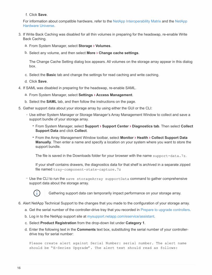
f. Click Save.
For information about compatible hardware, refer to the NetApp Interoperability Matrix and the NetApp
Hardware Universe.
3. If Write Back Caching was disabled for all thin volumes in preparing for the headswap, re-enable Write
Back Caching.
a. From System Manager, select Storage › Volumes.
b. Select any volume, and then select More › Change cache settings.
The Change Cache Setting dialog box appears. All volumes on the storage array appear in this dialog
box.
c. Select the Basic tab and change the settings for read caching and write caching.
d. Click Save.
4. If SAML was disabled in preparing for the headswap, re-enable SAML.
a. From System Manager, select Settings › Access Management.
b. Select the SAML tab, and then follow the instructions on the page.
5. Gather support data about your storage array by using either the GUI or the CLI:
◦ Use either System Manager or Storage Manager’s Array Management Window to collect and save a
support bundle of your storage array.
▪ From System Manager, select Support › Support Center › Diagnostics tab. Then select Collect
Support Data and click Collect.
▪ From the Array Management Window toolbar, select Monitor › Health › Collect Support Data
Manually. Then enter a name and specify a location on your system where you want to store the
support bundle.
The file is saved in the Downloads folder for your browser with the name support-data.7z.
If your shelf contains drawers, the diagnostics data for that shelf is archived in a separate zipped
file named tray-component-state-capture.7z
◦ Use the CLI to run the save storageArray supportData command to gather comprehensive
support data about the storage array.
Gathering support data can temporarily impact performance on your storage array.
6. Alert NetApp Technical Support to the changes that you made to the configuration of your storage array.
a. Get the serial number of the controller-drive tray that you recorded in Prepare to upgrade controllers.
b. Log in to the NetApp support site at mysupport.netapp.com/eservice/assistant.
c. Select Product Registration from the drop-down list under Category 1.
d. Enter the following text in the Comments text box, substituting the serial number of your controller-
drive tray for serial number:
Please create alert against Serial Number: serial number. The alert name
should be “E-Series Upgrade”. The alert text should read as follows:
16

“Attention: The controllers in this system have been upgraded from the
original configuration. Verify the controller configuration before ordering
replacement controllers and notify dispatch that the system has been
upgraded.”
e. Click the Submit button at the bottom of the form.
What’s next?
If your controller upgrade results in changing the vendor ID from LSI to NETAPP, go to Remount volumes after
changing the vendor from LSI to NETAPP; otherwise, your controller upgrade is complete and you can resume
normal operations.
Remount volumes after changing the vendor from LSI to NETAPP
If your controller upgrade results in changing the vendor ID from LSI to NETAPP, follow
the appropriate procedure for your host type:
• Remount volumes on an AIX host
• Remount volumes on a VMware host
• Remount volumes on a Windows host
Remount volumes on an AIX host
After you replace the controllers, you might observe that the host shows the new volumes on the storage array,
but also shows the original volumes as failed.
Step
If failed volumes appear, run the cfgmgr command.
Remount volumes on a VMware host
After you replace the controllers, you might observe the following conditions:
• VMware shows new paths for the volumes on the storage array, but also shows the original paths as dead
paths.
• The hosts still list the volumes on the storage array as having LSI vendor IDs. This might occur when the
volumes were claimed by the LSI rule at the start and so continue to use the same LSI rule when the
volumes come back on line.
• The Display Name does not reflect the change from LSI to NetApp. This might occur because the display
name became free test after initial discovery. In this case, you can change the Display Name manually.
Steps
1. Perform a rescan on each host.
2. Halt all host I/O operations to this subsystem.
3. Reclaim the volumes under NetApp rule.
a. Run the esxcli storage core device list command. Check the output from the command to
identify volumes whose names have the form aa.xxxx.
b. Run the command do esxcli storage core claiming reclaim -d naa.xxxxx to change
the LSI vendor ID to NetApp.
17

Remount volumes on a Windows host
After you replace the controllers, you must remount volumes on a Windows host to enable attached hosts to
perform I/O operations with the volumes located on the upgraded storage array.
Steps
1. In the Device Manager, select Show Hidden Devices.
2. For each NETAPP SCSI Disk Device listed in the Device Manager, right-click on the entry, and select
Uninstall.
If Windows displays a dialog box with a message indicating that you should reboot the host, finish
uninstalling all of the volumes before you scan for hardware and reboot.
3. Right-click in the Device Manager, and then select Scan for Hardware Changes.
4. Reboot the host.
Reconfigure a SAS-2 system behind a new SAS-3 controller shelf
If necessary, you can reconfigure your SAS-2 system to be used behind a new SAS-3
controller shelf.
Approved SAS-2 arrays include the E2700, E550/EF5500, and E5600/EF560. Approved SAS-2 drive shelves
include the DE1600, DE5600, and DE6600. Approved SAS-3 arrays include the E2800 and E5700/EF570.
Approved SAS-3 drive shelves include DE212C, DE224C, and DE460C.
About this task
In this procedure, you convert the controller shelf in an approved SAS-2 array to a drive shelf, and then place
that shelf behind a new approved SAS-3 array and drive shelves, without data preservation.
Before you begin
Due to the complexity of this procedure, the following is required:
• You must have a Feature Product Variance Request (FPVR). To file an FPVR, contact NetApp Professional
Services.
Failure to acquire an FPVR before attempting this procedure can result in drive failure and
controller lock down.
• If you are able to back up your data, you can perform this procedure without assistance from NetApp
Professional Services.
• If you cannot back up your data, contact NetApp Professional Services for assistance with this procedure.
• Make sure both of your arrays are prepared for the procedure:
◦ Existing array: Existing array with SANtricity OS 8.25 or later that is powered up.
◦ New array: New array unpacked and powered down.
• Record the serial number from the SAS-2 controller shelf that you will be converting to a drive shelf.
Step 1: Power down the controllers (non-data preservation)
All operations must be shut down before you can power down the controllers.
18

Steps
1. If the existing SAS-2 array is still accessible, delete all volume groups, power down both controllers, and
remove all cables.
2. Record the serial number from the SAS-2 controller shelf that you will be converting to a drive shelf.
3. If drive security is in use for the existing array, ensure that the security key is available.
Step 2: Install the controllers (non-data preservation)
Upon successful shut down, you can replace the controllers in the array.
Steps
1. Replace both controllers in the existing array with IOMs or ESMs.
2. If possible, use the host cables and network cables from the existing array and connect them to the
controllers in the new array.
Depending on the host connections of your new array, different cables may be required.
3. Cable the drive shelves behind the controllers in the new array.
The existing controller-drive tray and any attached drive trays become drive shelves and can be cabled to
the controllers in the new array.
Connecting SAS-2 to SAS-3 requires SAS HD to mini SAS cables. For more detailed cabling
information for your particular controller and expansion shelf configuration, refer to Cabling
or the E-Series Hardware Cabling Guide.
Step 3: Power on the controllers (non-data preservation)
After installation is complete, power on the controllers and submit your configuration changes to NetApp
Technical Support.
Steps
1. Power up the new array including any attached drive shelves.
2. Configure the management port and the IP addresses by installing the SANtricity Quick Connect utility.
3. If drive security was in use on the existing array, import the security key.
4. If you were unable to delete the volume groups from your existing array before performing this procedure,
you must set all foreign drives to appear as native. For detailed information on how to set drives to native,
refer to the SANtricity Online Help.
5. Send your configuration changes to NetApp Technical Support.
a. Get the serial number of the old controller-drive tray that you recorded in Step 2.
b. Log in to the NetApp Support Site.
c. From the drop-down list under Feedback Category, select Installed products > Decommission
Request.
d. Select Create Case. Enter the following text in the Comments text box, substituting the serial number
of your controller-drive tray for serial number:
Please decommission this serial number as the entitlement has been moved to
19

another serial number in the system. Please reference this in the SN notes.
e. Select Submit.
The completed SAS-2 to SAS-3 configuration changes are submitted to NetApp Technical Support.
SANtricity OS
Overview of upgrading the SANtricity OS
You can upgrade your operating system and system hardware components to the latest
version of SANtricity software and firmware.
These upgrade procedures include separate instructions for the following:
• Single controller — Includes procedures for upgrading the storage array’s software and, optionally, the IOM
firmware and the nonvolatile static random access memory (NVSRAM).
• Multiple controllers — Includes procedures for upgrading SANtricity OS software on multiple storage arrays
of the same type.
• Drive — Includes instructions for upgrading the drive’s firmware.
Before you begin the upgrade, be sure to review the Upgrade considerations.
Upgrade considerations
To ensure a successful upgrade, review the following upgrade considerations.
Controller upgrades (single or multiple)
Review these key considerations before upgrading controllers.
Current versions
You can view the current versions of your software and firmware, as follows:
• For a single controller, use the SANtricity System Manager interface. Go to Support › Upgrade Center,
and then click the link for Software and Firmware Inventory.
• For multiple controllers, use the SANtricity Unified Manager interface. Go to the Manage page for
discovered storage arrays. The versions are shown in the SANtricity OS Software column. The controller
firmware and NVSRAM information is available in a pop-up dialog box when you click on the SANtricity OS
version in each row.
Components included in the upgrade
The following components are included in the SANtricity OS upgrade process:
• System Manager — System Manager is the software that manages the storage array.
• Controller firmware — Controller firmware manages the I/O between hosts and volumes.
• IOM firmware — The I/O module (IOM) firmware manages the connection between a controller and a drive
shelf. It also monitors the status of the components.
20

• Supervisor software — Supervisor software is the virtual machine on a controller in which the software
runs.
Components to upgrade separately
The following components must be upgraded separately:
• Controller NVSRAM — Controller NVSRAM is a controller file that specifies the default settings for the
controllers. Instructions for upgrading the NVSRAM are included with the instructions for upgrading the
controllers.
• Drive firmware — See Upgrade drive firmware for separate instructions.
• Multipath/failover driver — As part of the upgrade process, the host’s multipath/failover driver might also
need to be upgraded so the host can interact with the controllers correctly. If hosts running operating
systems other than Microsoft Windows have I/O connections to your storage system, upgrade the multipath
drivers for those hosts. For compatibility information, refer to the NetApp Interoperability Matrix. For
upgrade instructions, refer to the Linux express configuration, Windows express configuration, or VMware
express configuration.
• SANtricity Unified Manager — Unified Manager is the software that manages multiple storage systems,
including the E2800, E5700, EF300, and EF600 models. Unified Manager is part of the SANtricity Web
Services Proxy, which is a RESTful API server installed separately on a host system to manage hundreds
of new and legacy NetApp E-Series storage systems. For more information, see SANtricity Web Services
Proxy overview.
• Utilities — Other management utilities require separate upgrades, such as the SANtricity Windows Host
Utility, the SANtricity Linux Host Utility, and SANtricity Windows DSM. For more information about these
utilities, refer to the Linux express configuration, Windows express configuration, or VMware express
configuration.
• Legacy systems — If your storage system is part of a storage network that includes older storage
systems, you might need to use the legacy SANtricity Storage Manager Enterprise Management Window
(EMW) to provide an enterprise view of all of your storage systems. In this case, check to see if there is a
newer maintenance release of SANtricity Storage Manager.
Dual controllers and I/O processing
If a storage array contains two controllers and you have a multipath driver installed, the storage array can
continue to process I/O while the upgrade occurs. During the upgrade, the following process occurs:
1. Controller A fails over all its LUNs to controller B.
2. Upgrade occurs on controller A.
3. Controller A takes back its LUNs and all of controller B’s LUNs.
4. Upgrade occurs on controller B.
After the upgrade completes, you might need to manually redistribute volumes between the controllers to
ensure volumes return to the correct owning controller.
Health check
A health check runs as part of the upgrade process. This health check assesses all storage array components
to make sure the upgrade can proceed. The following conditions might prevent the upgrade:
• Failed assigned drives
21

• Hot spares in use
• Incomplete volume groups
• Exclusive operations running
• Missing volumes
• Controller in non-optimal status
• Excess number of event log events
• Configuration database validation failure
• Drives with old versions of DACstore
You also can run the pre-upgrade health check separately without doing an upgrade.
Immediate or staged upgrade
You can activate the upgrade immediately or stage it for a later time. You might choose to activate later for
these reasons:
• Time of day — Activating the software can take a long time, so you might want to wait until I/O loads are
lighter. Depending on the I/O load and cache size, a controller upgrade can typically take between 15 to 25
minutes to complete. The controllers reboot and fail over during activation so performance might be lower
than usual until the upgrade completes.
• Type of package — You might want to test the new software and firmware on one storage array before
upgrading the files on other storage arrays.
Drive firmware upgrade
Review these key considerations before upgrading your drive firmware.
Drive compatibility
Each drive firmware file contains information about the drive type on which the firmware runs. You can
download the specified firmware file only to a compatible drive. System Manager automatically checks
compatibility during the upgrade process.
Drive upgrade methods
There are two types of drive firmware upgrade methods: online and offline.
22

Online upgrade Offline upgrade
During an online upgrade, drives are upgraded
sequentially, one at a time. The storage array
continues processing I/O while the upgrade occurs.
You do not have to stop I/O. If a drive can do an
online upgrade, the online method is used
automatically.
Drives that can do an online upgrade include the
following:
• Drives in an Optimal pool
• Drives in an Optimal redundant volume group
(RAID 1, RAID 5, and RAID 6)
• Unassigned drives
• Standby hot spare drives
Doing an online drive firmware upgrade can take
several hours exposing the storage array to potential
volume failures. Volume failure could occur in these
cases:
• In a RAID 1 or RAID 5 volume group, one drive
fails while a different drive in the volume group is
being upgraded.
• In a RAID 6 pool or volume group, two drives fail
while a different drive in the pool or volume group
is being upgraded.
During an offline upgrade, all drives of the same drive
type are upgraded at the same time. This method
requires stopping I/O activity to the volumes
associated with the selected drives. Because multiple
drives can be upgraded concurrently (in parallel), the
overall downtime is significantly reduced. If a drive
can do only an offline upgrade, the offline method is
used automatically.
The following drives MUST use the offline method:
• Drives in a non-redundant volume group (RAID 0)
• Drives in a non-optimal pool or volume group
• Drives in SSD cache
Upgrade software and firmware for a single controller
You can upgrade a single controller, which ensures that you have all the latest features
and fixes.
This process involves upgrading the storage array’s software and, optionally, the IOM firmware and the
nonvolatile static random access memory (NVSRAM).
Before you begin
• Review Upgrade considerations.
• Determine if you want to upgrade the controller NVSRAM file at the same time as the OS firmware.
Normally, you should upgrade all components at the same time. However, you might decide not to upgrade
the controller NVSRAM file if your file has either been patched or is a custom version and you do not want
to overwrite it.
• Determine if you want to upgrade your IOM firmware.
Normally, you should upgrade all components at the same time. However, you might decide not to upgrade
the IOM firmware if you do not want to upgrade it as part of the SANtricity OS software upgrade or if
technical support has instructed you to downgrade your IOM firmware (you can only downgrade firmware
23

by using the command line interface).
• Decide if you want to activate your OS upgrade now or later.
Reasons for activating later might include:
◦ Time of day – Activating the software and firmware can take a long time, so you might want to wait
until I/O loads are lighter. The controllers fail over during activation so performance might be lower than
usual until the upgrade completes.
◦ Type of package – You might want to test the new software and firmware on one storage array before
upgrading the files on other storage arrays.
Step 1: Download software files from support site
In this step, you go to the NetApp Support site to save the new downloadable package (DLP) software files to
your management host system.
The time required for the upgrade depends on your storage array configuration and the components that you
are upgrading.
Steps
1. If your storage array contains only one controller or you do not have a multipath driver installed, stop I/O
activity to the storage array to prevent application errors. If your storage array has two controllers and you
have a multipath driver installed, you do not need to stop I/O activity.
If you are upgrading SANtricity OS on a StorageGRID appliance (for example, SG5612 or
SG5760), you need to stop I/O activity by placing the appliance into maintenance mode
before continuing with this procedure, or data could be lost. For detailed steps, see the
installation and maintenance instructions for your StorageGRID appliance.
2. From the System Manager interface, select Support › Upgrade Center.
3. In the area labeled "SANtricity OS Software upgrade," click NetApp SANtricity OS Downloads to open
the NetApp Support site.
4. From the Downloads page, select E-Series SANtricity OS Controller Software.
Digitally signed firmware is required in version 8.42 and above. If you attempt to download
unsigned firmware, an error is displayed and the download is aborted.
5. Follow the on-screen instructions to download the most recent OS software for your controller model. If you
also want to upgrade the NVSRAM, download the NVSRAM file for a single controller.
Step 2: Transfer software files to the controllers
In this step, you transfer the software files to your controller so you can begin the upgrade process. The
components are copied from the management client to the controllers and placed in a staging area in flash
memory.
Risk of data loss or risk of damage to the storage array — Do not make changes to the
storage array while the upgrade is occurring. Maintain power to the storage array.
Steps
24

1. (Optional). If you are planning to perform an upgrade during a specific maintenance window, you might
want to run a pre-upgrade health check to determine if there are any major storage array problems in
advance. If this is the case, select pre-upgrade health check from the Upgrade Center in System
Manager (Support › Upgrade Center), and follow any on-screen instructions. Otherwise, you can skip this
step, because a health check is part of the upgrade process.
2. If you do NOT want to upgrade the IOM firmware at this time, click Suspend IOM Auto-Synchronization
and follow the instructions in the dialog box.
If you have a storage array with a single controller, the IOM firmware is not upgraded.
3. From the Upgrade Center in System Manager, click Begin Upgrade from "SANtricity OS Software
upgrade."
The Upgrade SANtricity OS Software dialog appears.
4. Select one or more files to begin the upgrade process:
a. Select the SANtricity OS Software file by clicking Browse and navigating to the OS software file you
downloaded from the Support site.
b. Select the Controller NVSRAM file by clicking Browse and navigating to the NVSRAM file that you
downloaded from the Support site. Controller NVSRAM files have a filename similar to N2800-
830000-000.dlp.
These actions occur:
◦ By default, only the files that are compatible with the current storage array configuration appear.
◦ When you select a file for upgrade, the file’s name and size appear.
5. (Optional) If you selected a SANtricity OS Software file to upgrade, you can transfer the files to the
controller without activating them by selecting the Transfer files now, but do not upgrade (activate
upgrade later) check box.
6. Click Start, and confirm that you want to perform the operation.
You can cancel the operation during the pre-upgrade health check, but not during transferring or activating.
7. (Optional) To see a list of what was upgraded, click Save Log.
The file is saved in the Downloads folder for your browser with the name, drive_upgrade_log-
timestamp.txt.
If you have already activated your software files, go to Step 4: Complete software and firmware upgrade;
otherwise, go to Step 3: Activate software files.
Step 3: Activate software files
Follow this step only if you have software or firmware that has been transferred but not activated. To check this
state, look for a notification in the Notifications area of the System Manager Home page or in the Upgrade
Center page.
When you perform the activation operation, the current software and firmware is replaced with the new
software and firmware. You cannot stop the activation process after it starts.
Steps
25

1. From the System Manager interface, select Support › Upgrade Center.
2. In the area labeled "SANtricity OS Software upgrade," click Activate, and confirm that you want to perform
the operation.
3. (Optional) To see a list of what was upgraded, click Save Log.
The file is saved in the Downloads folder for your browser with the name, drive_upgrade_log-
timestamp.txt.
Step 4: Complete software and firmware upgrade
Complete the software and firmware upgrade by verifying the versions in the Software and Firmware Inventory
dialog box.
Before you begin
• You must have activated your software or firmware.
Steps
1. From System Manager, verify that all components appear on the Hardware page.
2. Verify the new software and firmware versions by checking the Software and Firmware Inventory dialog
box (go to Support › Upgrade Center, and then click the link for Software and Firmware Inventory).
3. If you upgraded controller NVSRAM, any custom settings that you have applied to the existing NVSRAM
are lost during the process of activation. You need to apply the custom settings to the NVSRAM again after
the process of activation is complete.
4. If any of the following errors occur during the upgrade procedure, take the appropriate recommended
action.
If you encounter this firmware download error… Then do the following…
Failed assigned drives One reason for the failure might be that the drive
does not have the appropriate signature. Make sure
that the affected drive is an authorized drive.
Contact technical support for more information.
When replacing a drive, make sure that the
replacement drive has a capacity equal to or greater
than the failed drive you are replacing.
You can replace the failed drive while the storage
array is receiving I/O.
Check storage array • Make sure that an IP address has been
assigned to each controller.
• Make sure that all cables connected to the
controller are not damaged.
• Make sure that all cables are tightly connected.
26

If you encounter this firmware download error… Then do the following…
Integrated hot spare drives This error condition must be corrected before you
can upgrade the firmware. Launch System Manager
and use the Recovery Guru to resolve the problem.
Incomplete volume groups If one or more volume groups or disk pools are
incomplete, you must correct this error condition
before you can upgrade the firmware. Launch
System Manager and use the Recovery Guru to
resolve the problem.
Exclusive operations (other than background
media/parity scan) currently running on any volume
groups
If one or more exclusive operations are in progress,
the operations must complete before the firmware
can be upgraded. Use System Manager to monitor
the progress of the operations.
Missing volumes You must correct the missing volume condition
before the firmware can be upgraded. Launch
System Manager and use the Recovery Guru to
resolve the problem.
Either controller in a state other than Optimal One of the storage array controllers needs attention.
This condition must be corrected before the
firmware can be upgraded. Launch System
Manager and use the Recovery Guru to resolve the
problem.
Mismatched Storage Partition information between
Controller Object Graphs
An error occurred while validating the data on the
controllers. Contact technical support to resolve this
issue.
SPM Verify Database Controller check fails A storage partitions mapping database error
occurred on a controller. Contact technical support
to resolve this issue.
Configuration Database Validation (if supported by
the storage array’s controller version)
A configuration database error occurred on a
controller. Contact technical support to resolve this
issue.
MEL Related Checks Contact technical support to resolve this issue.
More than 10 DDE Informational or Critical MEL
events were reported in the last 7 days
Contact technical support to resolve this issue.
More than 2 Page 2C Critical MEL Events were
reported in the last 7 days
Contact technical support to resolve this issue.
27
If you encounter this firmware download error… Then do the following…
More than 2 Degraded Drive Channel Critical MEL
events were reported in the last 7 days
Contact technical support to resolve this issue.
More than 4 critical MEL entries in the last 7 days Contact technical support to resolve this issue.
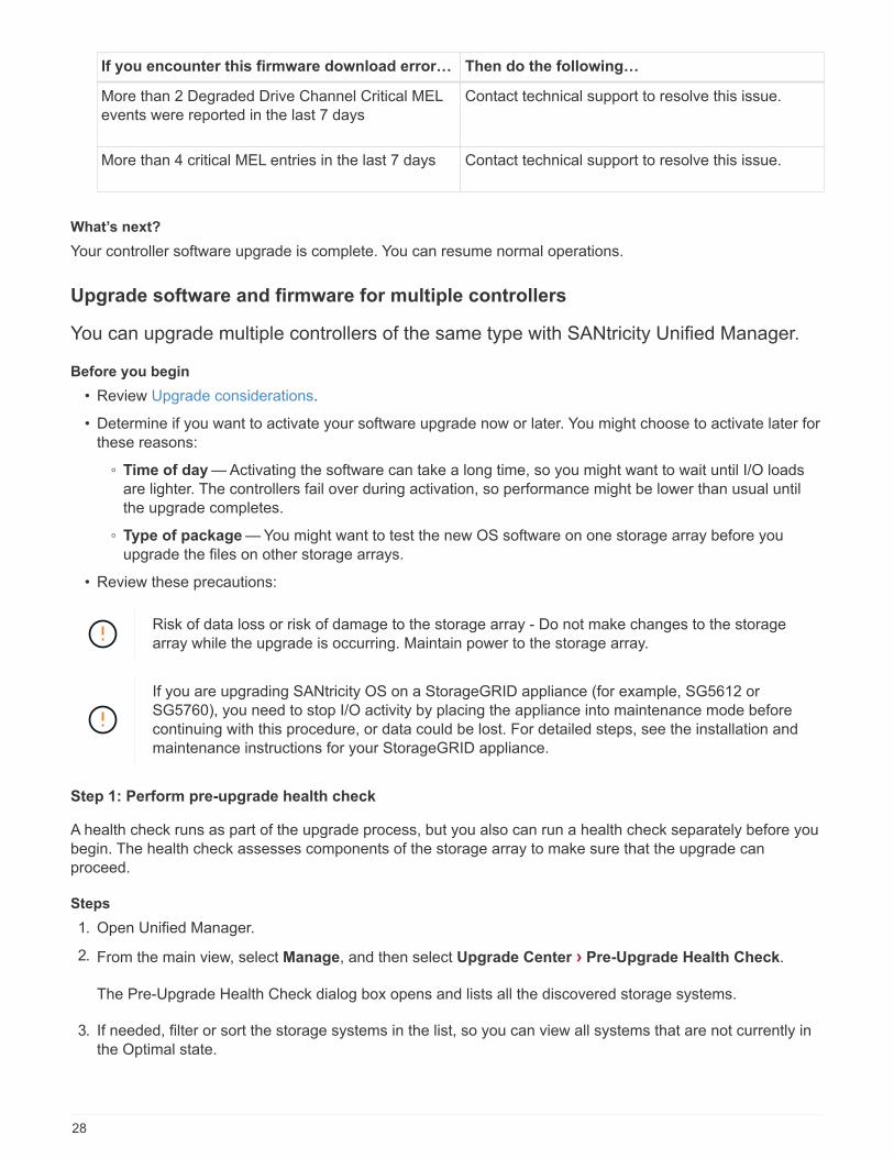
What’s next?
Your controller software upgrade is complete. You can resume normal operations.
Upgrade software and firmware for multiple controllers
You can upgrade multiple controllers of the same type with SANtricity Unified Manager.
Before you begin
• Review Upgrade considerations.
• Determine if you want to activate your software upgrade now or later. You might choose to activate later for
these reasons:
◦ Time of day — Activating the software can take a long time, so you might want to wait until I/O loads
are lighter. The controllers fail over during activation, so performance might be lower than usual until
the upgrade completes.
◦ Type of package — You might want to test the new OS software on one storage array before you
upgrade the files on other storage arrays.
• Review these precautions:
Risk of data loss or risk of damage to the storage array - Do not make changes to the storage
array while the upgrade is occurring. Maintain power to the storage array.
If you are upgrading SANtricity OS on a StorageGRID appliance (for example, SG5612 or
SG5760), you need to stop I/O activity by placing the appliance into maintenance mode before
continuing with this procedure, or data could be lost. For detailed steps, see the installation and
maintenance instructions for your StorageGRID appliance.
Step 1: Perform pre-upgrade health check
A health check runs as part of the upgrade process, but you also can run a health check separately before you
begin. The health check assesses components of the storage array to make sure that the upgrade can
proceed.
Steps
1. Open Unified Manager.
2. From the main view, select Manage, and then select Upgrade Center › Pre-Upgrade Health Check.
The Pre-Upgrade Health Check dialog box opens and lists all the discovered storage systems.
3. If needed, filter or sort the storage systems in the list, so you can view all systems that are not currently in
the Optimal state.
28

4. Select the check boxes for the storage systems that you want to run through the health check.
5. Click Start.
The progress is shown in the dialog box while the health check is performed.
6. When the health check completes, you can click on the ellipses (…) to the right of each row to view more
information and perform other tasks.
If any arrays fail the health check, you can skip that particular array and continue the
upgrade for the others, or you can stop the entire process and troubleshoot the arrays that
did not pass.
Step 2: Download software files from support site
In this step, you go to the NetApp Support site to save the new downloadable package (DLP) software files to
your management host system.
Steps
1. If your storage array contains only one controller or a multipath driver is not in use, stop I/O activity to the
storage array to prevent application errors. If your storage array has two controllers and you have a
multipath driver installed, you do not need to stop I/O activity.
2. From Unified Manager’s main view, select Manage, and then select one or more storage arrays that you
want to upgrade.
3. Select Upgrade Center › Upgrade SANtricity OS Software.
The Upgrade SANtricity OS software page appears.
4. Download the latest SANtricity OS software package from the NetApp support site to your local machine.
a. Click Add new file to software repository.
b. Click the link for finding the latest SANtricity OS Downloads.
c. Click the Download Latest Release link.
d. Follow the remaining instructions to download the SANtricity OS file and the NVSRAM file to your local
machine.
Digitally signed firmware is required in version 8.42 and above. If you attempt to download
unsigned firmware, an error is displayed and the download is aborted.
Step 3: Transfer software files to the controllers
You load the SANtricity OS software file and the NVSRAM file into the repository so it is accessible to the
Unified Manager Upgrade Center.
Risk of data loss or risk of damage to the storage array - Do not make changes to the storage
array while the upgrade is occurring. Maintain power to the storage array.
Steps
1. From Unified Manager’s main view, select Manage, and then select one or more storage arrays that you
want to upgrade.
29

2. Select Upgrade Center › Upgrade SANtricity OS Software.
The Upgrade SANtricity OS software page appears.
3. Download the latest SANtricity OS software package from the NetApp support site to your local machine.
a. Click Add new file to software repository.
b. Click the link for finding the latest SANtricity OS Downloads.
c. Click the Download Latest Release link.
d. Follow the remaining instructions to download the SANtricity OS file and the NVSRAM file to your local
machine.
Digitally signed firmware is required in version 8.42 and above. If you attempt to download
unsigned firmware, an error is displayed and the download is aborted.
4. Select the OS software file and the NVSRAM file that you want to use to upgrade the controllers:
a. From the Select a SANtricity OS software file drop-down, select the OS file that you downloaded to
your local machine.
If there are multiple files available, the files are sorted from newest date to oldest date.
The software repository lists all software files associated with the Web Services Proxy. If
you do not see the file that you want to use, you can click the link, Add new file to
software repository, to browse to the location where the OS file that you want to add
resides.
b. From the Select an NVSRAM file drop-down, select the controller file that you want to use.
If there are multiple files, the files are sorted from newest date to oldest date.
5. In the Compatible Storage Array table, review the storage arrays that are compatible with the OS software
file that you selected, and then select the arrays you want to upgrade.
◦ The storage arrays that you selected in the Manage view and that are compatible with the selected
firmware file are selected by default in the Compatible Storage Array table.
◦ The storage arrays that cannot be updated with the selected firmware file are not selectable in the
Compatible Storage Array table as indicated by the status Incompatible.
6. (Optional) To transfer the software file to the storage arrays without activating them, select the Transfer the
OS software to the storage arrays, mark it as staged, and activate at a later time check box.
7. Click Start.
8. Depending on whether you chose to activate now or later, do one of the following:
◦ Type TRANSFER to confirm that you want to transfer the proposed OS software versions on the arrays
you selected to upgrade, and then click Transfer.
To activate the transferred software, select Upgrade Center › Activate Staged OS Software.
◦ Type UPGRADE to confirm that you want to transfer and activate the proposed OS software versions
on the arrays you selected to upgrade, and then click Upgrade.
The system transfers the software file to each storage array you selected to upgrade and then activates
30

that file by initiating a reboot.
The following actions occur during the upgrade operation:
◦ A pre-upgrade health check runs as part of the upgrade process. The pre-upgrade health check
assesses all storage array components to make sure that the upgrade can proceed.
◦ If any health check fails for a storage array, the upgrade stops. You can click the ellipsis (…) and select
Save Log to review the errors. You can also choose to override the health check error and then click
Continue to proceed with the upgrade.
◦ You can cancel the upgrade operation after the pre-upgrade health check.
9. (Optional) Once the upgrade has completed, you can see a list of what was upgraded for a specific storage
array by clicking the ellipsis (…) and then selecting Save Log.
The file is saved in the Downloads folder for your browser with the nameupgrade_log-<date>.json.
Step 4: Activate staged software files (optional)
You can choose to activate the software file immediately or wait until a more convenient time. This procedure
assumes you chose to activate the software file at a later time.
You cannot stop the activation process after it starts.
Steps
1. From Unified Manager’s main view, select Manage. If necessary, click the Status column to sort all storage
arrays with a status of "OS Upgrade (awaiting activation)."
2. Select one or more storage arrays that you want to activate software for, and then select Upgrade Center ›Activate Staged OS Software.
The following actions occur during the upgrade operation:
◦ A pre-upgrade health check runs as part of the activate process. The pre-upgrade health check
assesses all storage array components to make sure that the activation can proceed.
◦ If any health check fails for a storage array, the activation stops. You can click the ellipsis (…) and
select Save Log to review the errors. You can also choose to override the health check error and then
click Continue to proceed with the activation.
◦ You can cancel the activate operation after the pre-upgrade health check. On successful completion of
the pre-upgrade health check, activation occurs. The time it takes to activate depends on your storage
array configuration and the components that you are activating.
3. (Optional) After the activation is complete, you can see a list of what was activated for a specific storage
array by clicking the ellipsis (…) and then selecting Save Log.
The file is saved in the Downloads folder for your browser with the name activate_log-<date>.json.
What’s next?
Your controller software upgrade is complete. You can resume normal operations.
Upgrade drive firmware
Follow this procedure to upgrade your drives' firmware, which ensures you have all the
31

latest features and fixes.
Step 1: Download drive firmware files
In this step, you go to the NetApp Support site to download the drive firmware files to your management client.
Steps
1. In SANtricity System Manager, select Support › Upgrade Center.
2. Under Drive Firmware upgrade, click NetApp Support and log in to the NetApp Support site.
3. From the Support site, click the Downloads tab, and then select Disk Drive & Firmware Matrix.
4. Select E-Series and EF-Series Disk Firmware.
5. Follow the on-screen instructions to download the files.
Step 2: Begin drive firmware upgrade
In this step, you upgrade the drives' firmware.
Before you begin
• Back up your data using disk-to-disk backup, volume copy (to a volume group not affected by the planned
firmware upgrade), or a remote mirror.
• Make sure the storage array has an Optimal status.
• Make sure all drives have an Optimal status.
• Make sure no configuration changes are running on the storage array.
• Understand that if the drives are capable of only an offline upgrade, I/O activity to all volumes associated
with the drives is stopped.
Steps
1. From the System Manager Upgrade Center (Support › Upgrade Center), click Begin Upgrade from the
"Drive Firmware upgrade" section.
A dialog box appears, which lists the drive firmware files currently in use.
2. Extract (unzip) the files you downloaded from the Support site.
3. Click Browse, and select the new drive firmware files that you downloaded from the Support site.
Drive firmware files have a filename similar to D_HUC101212CSS600_30602291_MS01_2800_0002 with
the extension of .dlp.
You can select up to four drive firmware files, one at a time. If more than one drive firmware file is
compatible with the same drive, you get a file conflict error. Decide which drive firmware file you want to
use for the upgrade and remove the other one.
4. Click Next.
The Select Drives dialog box appears, which lists the drives that you can upgrade with the selected files.
Only drives that are compatible appear.
The selected firmware for the drive appears in the Proposed Firmware information area. If you must
change the firmware, click Back to return to the previous dialog.
32
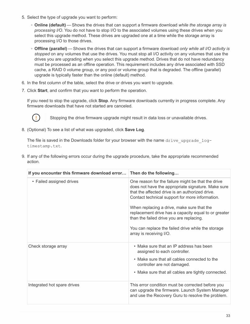
5. Select the type of upgrade you want to perform:
◦ Online (default) — Shows the drives that can support a firmware download while the storage array is
processing I/O. You do not have to stop I/O to the associated volumes using these drives when you
select this upgrade method. These drives are upgraded one at a time while the storage array is
processing I/O to those drives.
◦ Offline (parallel) — Shows the drives that can support a firmware download only while all I/O activity is
stopped on any volumes that use the drives. You must stop all I/O activity on any volumes that use the
drives you are upgrading when you select this upgrade method. Drives that do not have redundancy
must be processed as an offline operation. This requirement includes any drive associated with SSD
cache, a RAID 0 volume group, or any pool or volume group that is degraded. The offline (parallel)
upgrade is typically faster than the online (default) method.
6. In the first column of the table, select the drive or drives you want to upgrade.
7. Click Start, and confirm that you want to perform the operation.
If you need to stop the upgrade, click Stop. Any firmware downloads currently in progress complete. Any
firmware downloads that have not started are canceled.
Stopping the drive firmware upgrade might result in data loss or unavailable drives.
8. (Optional) To see a list of what was upgraded, click Save Log.
The file is saved in the Downloads folder for your browser with the name drive_upgrade_log-
timestamp.txt.
9. If any of the following errors occur during the upgrade procedure, take the appropriate recommended
action.
If you encounter this firmware download error… Then do the following…
• Failed assigned drives One reason for the failure might be that the drive
does not have the appropriate signature. Make sure
that the affected drive is an authorized drive.
Contact technical support for more information.
When replacing a drive, make sure that the
replacement drive has a capacity equal to or greater
than the failed drive you are replacing.
You can replace the failed drive while the storage
array is receiving I/O.
Check storage array • Make sure that an IP address has been
assigned to each controller.
• Make sure that all cables connected to the
controller are not damaged.
• Make sure that all cables are tightly connected.
Integrated hot spare drives This error condition must be corrected before you
can upgrade the firmware. Launch System Manager
and use the Recovery Guru to resolve the problem.
33

If you encounter this firmware download error… Then do the following…
Incomplete volume groups If one or more volume groups or disk pools are
incomplete, you must correct this error condition
before you can upgrade the firmware. Launch
System Manager and use the Recovery Guru to
resolve the problem.
Exclusive operations (other than background
media/parity scan) currently running on any volume
groups
If one or more exclusive operations are in progress,
the operations must complete before the firmware
can be upgraded. Use System Manager to monitor
the progress of the operations.
Missing volumes You must correct the missing volume condition
before the firmware can be upgraded. Launch
System Manager and use the Recovery Guru to
resolve the problem.
Either controller in a state other than Optimal One of the storage array controllers needs attention.
This condition must be corrected before the
firmware can be upgraded. Launch System
Manager and use the Recovery Guru to resolve the
problem.
Mismatched Storage Partition information between
Controller Object Graphs
An error occurred while validating the data on the
controllers. Contact technical support to resolve this
issue.
SPM Verify Database Controller check fails A storage partitions mapping database error
occurred on a controller. Contact technical support
to resolve this issue.
Configuration Database Validation (if supported by
the storage array’s controller version)
A configuration database error occurred on a
controller. Contact technical support to resolve this
issue.
MEL Related Checks Contact technical support to resolve this issue.
More than 10 DDE Informational or Critical MEL
events were reported in the last 7 days
Contact technical support to resolve this issue.
More than 2 Page 2C Critical MEL Events were
reported in the last 7 days
Contact technical support to resolve this issue.
More than 2 Degraded Drive Channel Critical MEL
events were reported in the last 7 days
Contact technical support to resolve this issue.
More than 4 critical MEL entries in the last 7 days Contact technical support to resolve this issue.
34

What’s next?
Your drive firmware upgrade is complete. You can resume normal operations.
35

Copyright Information
Copyright © 2022 NetApp, Inc. All rights reserved. Printed in the U.S. No part of this document covered by
copyright may be reproduced in any form or by any means-graphic, electronic, or mechanical, including
photocopying, recording, taping, or storage in an electronic retrieval system- without prior written permission of
the copyright owner.
Software derived from copyrighted NetApp material is subject to the following license and disclaimer:
THIS SOFTWARE IS PROVIDED BY NETAPP “AS IS” AND WITHOUT ANY EXPRESS OR IMPLIED
WARRANTIES, INCLUDING, BUT NOT LIMITED TO, THE IMPLIED WARRANTIES OF MERCHANTABILITY
AND FITNESS FOR A PARTICULAR PURPOSE, WHICH ARE HEREBY DISCLAIMED. IN NO EVENT SHALL
NETAPP BE LIABLE FOR ANY DIRECT, INDIRECT, INCIDENTAL, SPECIAL, EXEMPLARY, OR
CONSEQUENTIAL DAMAGES (INCLUDING, BUT NOT LIMITED TO, PROCUREMENT OF SUBSTITUTE
GOODS OR SERVICES; LOSS OF USE, DATA, OR PROFITS; OR BUSINESS INTERRUPTION) HOWEVER
CAUSED AND ON ANY THEORY OF LIABILITY, WHETHER IN CONTRACT, STRICT LIABILITY, OR TORT
(INCLUDING NEGLIGENCE OR OTHERWISE) ARISING IN ANY WAY OUT OF THE USE OF THIS
SOFTWARE, EVEN IF ADVISED OF THE POSSIBILITY OF SUCH DAMAGE.
NetApp reserves the right to change any products described herein at any time, and without notice. NetApp
assumes no responsibility or liability arising from the use of products described herein, except as expressly
agreed to in writing by NetApp. The use or purchase of this product does not convey a license under any
patent rights, trademark rights, or any other intellectual property rights of NetApp.
The product described in this manual may be protected by one or more U.S. patents, foreign patents, or
pending applications.
RESTRICTED RIGHTS LEGEND: Use, duplication, or disclosure by the government is subject to restrictions
as set forth in subparagraph (c)(1)(ii) of the Rights in Technical Data and Computer Software clause at DFARS
252.277-7103 (October 1988) and FAR 52-227-19 (June 1987).
Trademark Information
NETAPP, the NETAPP logo, and the marks listed at http://www.netapp.com/TM are trademarks of NetApp, Inc.
Other company and product names may be trademarks of their respective owners.
36


