Embed Size (px)
Citation preview
User’sManual
UP55AProgram ControllerUser’s Manual
IM 05P02C41-01EN
IM 05P02C41-01EN5th Edition
Functional
Enhancement

Product RegistrationThank you for purchasing YOKOGAWA products.
YOKOGAWA provides registered users with a variety of information and services.Please allow us to serve you best by completing the product registration form accessible from our homepage.
http://www.yokogawa.com/ns/reg/

iIM 05P02C41-01EN
5th Edition : Mar. 2016 (YK)All Rights Reserved, Copyright © 2010 Yokogawa Electric Corporation
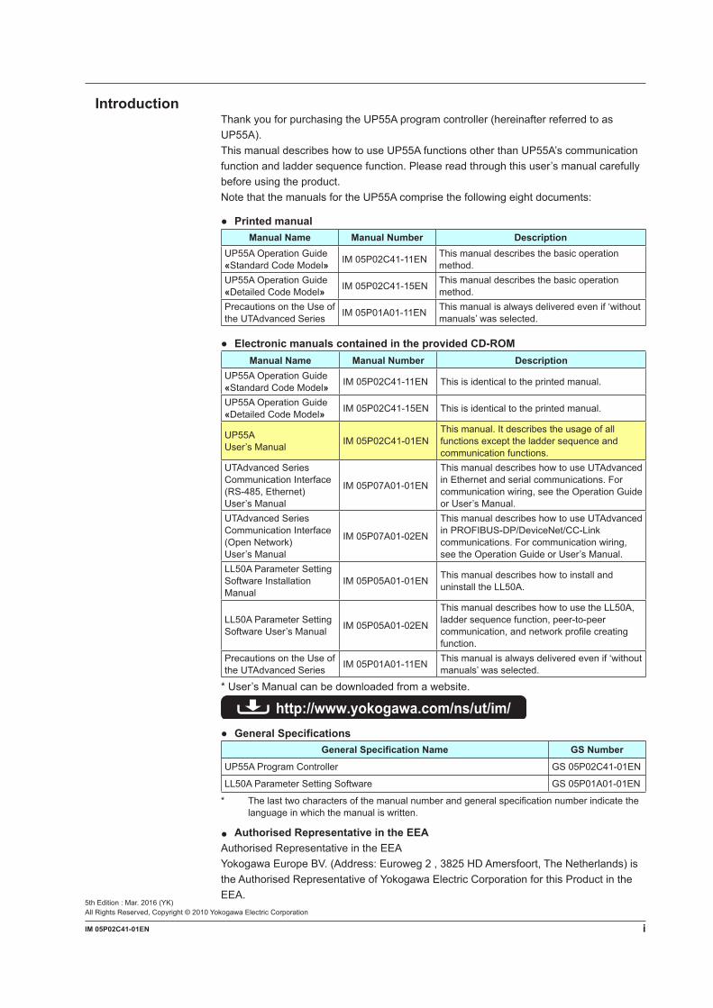
IntroductionThank you for purchasing the UP55A program controller (hereinafter referred to as UP55A).This manual describes how to use UP55A functions other than UP55A’s communication function and ladder sequence function. Please read through this user’s manual carefully before using the product.Note that the manuals for the UP55A comprise the following eight documents:
PrintedmanualManual Name Manual Number Description
UP55A Operation Guide«Standard Code Model» IM 05P02C41-11EN This manual describes the basic operation
method.UP55A Operation Guide«Detailed Code Model» IM 05P02C41-15EN This manual describes the basic operation
method.Precautions on the Use of the UTAdvanced Series IM 05P01A01-11EN This manual is always delivered even if ‘without
manuals’ was selected.
ElectronicmanualscontainedintheprovidedCD-ROMManual Name Manual Number Description
UP55A Operation Guide«Standard Code Model» IM 05P02C41-11EN This is identical to the printed manual.
UP55A Operation Guide«Detailed Code Model» IM 05P02C41-15EN This is identical to the printed manual.
UP55AUser’s Manual IM 05P02C41-01EN
This manual. It describes the usage of all functions except the ladder sequence and communication functions.
UTAdvanced Series Communication Interface (RS-485, Ethernet) User’s Manual
IM 05P07A01-01EN
This manual describes how to use UTAdvanced in Ethernet and serial communications. For communication wiring, see the Operation Guide or User’s Manual.
UTAdvanced Series Communication Interface (Open Network) User’s Manual
IM 05P07A01-02EN
This manual describes how to use UTAdvanced in PROFIBUS-DP/DeviceNet/CC-Link communications. For communication wiring, see the Operation Guide or User’s Manual.
LL50A Parameter Setting Software Installation Manual
IM 05P05A01-01EN This manual describes how to install and uninstall the LL50A.
LL50A Parameter Setting Software User’s Manual IM 05P05A01-02EN
This manual describes how to use the LL50A, ladder sequence function, peer-to-peer communication, and network profile creating function.
Precautions on the Use of the UTAdvanced Series IM 05P01A01-11EN This manual is always delivered even if ‘without
manuals’ was selected.
* User’s Manual can be downloaded from a website.
http://www.yokogawa.com/ns/ut/im/ GeneralSpecifications
GeneralSpecificationName GSNumber
UP55A Program Controller GS 05P02C41-01EN
LL50A Parameter Setting Software GS 05P01A01-01EN
* The last two characters of the manual number and general specification number indicate the language in which the manual is written.
AuthorisedRepresentativeintheEEAAuthorised Representative in the EEAYokogawa Europe BV. (Address: Euroweg 2 , 3825 HD Amersfoort, The Netherlands) is the Authorised Representative of Yokogawa Electric Corporation for this Product in the EEA.
ii IM 05P02C41-01EN
Target ReadersThis guide is intended for the following personnel; Engineersresponsibleforinstallation,wiring,andmaintenanceoftheequipment. Personnelresponsiblefornormaldailyoperationoftheequipment.
Notice Thecontentsofthismanualaresubjecttochangewithoutnoticeasaresultof
continuing improvements to the instrument’s performance and functions. Everyefforthasbeenmadetoensureaccuracyinthepreparationofthismanual.
Should any errors or omissions come to your attention, however, please inform YokogawaElectric’ssalesofficeorsalesrepresentative.
Undernocircumstancesmaythecontentsofthismanual,inpartorinwhole,betranscribed or copied without our permission.
Trademarks Ourproductnamesorbrandnamesmentionedinthismanualarethetrademarksor
registered trademarks of Yokogawa Electric Corporation (hereinafter referred to as YOKOGAWA).
Microsoft,MS-DOS,Windows,WindowsXP,WindowsVista,andWindows7areeither registered trademarks or trademarks of Microsoft Corporation in the United States and/or other countries.
Adobe,Acrobat,andPostscriptareeitherregisteredtrademarksortrademarksofAdobe Systems Incorporated.
EthernetisaregisteredtrademarkofXEROXCorporationintheUnitedStates. ModbusisaregisteredtrademarkofSchneiderElectric. PROFIBUS-DPisaregisteredtrademarkofPROFIBUSUserOrganization. DeviceNetisaregisteredtrademarkofOpenDeviceNetVenderAssociation,Inc. CC-LinkisaregisteredtrademarkofCC-LinkPartnerAssociation(CLPA.) WedonotusetheTMor®marktoindicatethesetrademarksorregistered
trademarks in this user’s manual. Allotherproductnamesmentionedinthisuser’smanualaretrademarksorregistered
trademarks of their respective companies.
SafetyPrecautionsThis instrument is a product of Installation Category II of IEC/EN/CSA/UL61010-1, IEC/EN61010-2-201, IEC/EN61010-2-030 Safety Standards and Class A of EN61326-1, EN55011 (EMC Standards).
CAUTIONThis instrument is an EMC class A product. In a domestic environment, this product may cause radio interference in which case the user needs to take adequate measures.
The instrument is a product rated Measurement Category O (other). * Measurement Category O (other) This category applies to electric equipment that measures a circuit connected to a
low-voltage facility and receives power from stationary equipment such as electric switchboards.
To use the instrument properly and safely, observe the safety precautions described in this user’s manual when operating it. Use of the instrument in a manner not prescribed herein may compromise protection features inherent in the device. We assume no liability for or warranty on a fault caused by users’ failure to observe these instructions.This instrument is designed to be used within the scope of Measurement Category O (other) and is dedicated for indoor use.
iiiIM 05P02C41-01EN
Notes on the User’s Manual• This user’s manual should be readily accessible to the end users so it can be referred
to easily. It should be kept in a safe place.• Read the information contained in this manual thoroughly before operating the
product.• The purpose of this user’s manual is not to warrant that the product is well suited to
any particular purpose, but rather to describe the functional details of the product.
Safety,Protection,andModificationoftheProductThe following symbols are used in the product and user’s manuals to indicate safety precautions:
AC
AC/DC
“Handle with Care” (This symbol is attached to the part(s) of the product to indicate that the user’s manual should be referred to in order to protect the operator and the instrument from harm.)
The equipment wholly protected by double insulation or reinforced insulation.
Functional grounding terminal (Do not use this terminal as a protective grounding terminal.)
• In order to protect the system controlled by this product and the product itself, and to ensure safe operation, observe the safety precautions described in this user’s manual. Use of the instrument in a manner not prescribed herein may compromise the product’s functions and the protection features inherent in the device. We assume no liability for safety, or responsibility for the product’s quality, performance or functionality should users fail to observe these instructions when operating the product.
• Installation of protection and/or safety circuits with respect to a lightning protector; protective equipment for the system controlled by the product and the product itself; foolproof or failsafe design of a process or line using the system controlled by the product or the product itself; and/or the design and installation of other protective and safety circuits are to be appropriately implemented as the customer deems necessary.
• Be sure to use the spare parts approved by YOKOGAWA when replacing parts or consumables.• This product is not designed or manufactured to be used in critical applications that
directly affect or threaten human lives. Such applications include nuclear power equipment, devices using radioactivity, railway facilities, aviation equipment, air navigation facilities, aviation facilities, and medical equipment. If so used, it is the user’s responsibility to include in the system additional equipment and devices that ensure personnel safety.
• Modificationoftheproductisstrictlyprohibited.• This product is intended to be handled by skilled/trained personnel for electric devices.• ThisproductisULRecognizedComponent.InordertocomplywithULstandards,
end-products are necessary to be designed by those who have knowledge of the requirements.
WARNING PowerSupply Ensure that the instrument’s supply voltage matches the voltage of the power
supply before turning ON the power. DoNotUseinanExplosiveAtmosphere Do not operate the instrument in locations with combustible or explosive gases
orsteam.Operationinsuchenvironmentsconstitutesanextremesafetyhazard.Use of the instrument in environments with high concentrations of corrosive gas (H2S, SOX, etc.) for extended periods of time may cause a failure.
iv IM 05P02C41-01EN
DoNotRemoveInternalUnit The internal unit should not be removed by anyone other than YOKOGAWA’s
service personnel. There are dangerous high voltage parts inside. Additionally, do not replace the fuse by yourself.
DamagetotheProtectiveConstruction Operation of the instrument in a manner not specified in this user’s manual may
damage its protective construction.
Warning and Disclaimer• YOKOGAWA makes no warranties regarding the product except those stated in the
WARRANTY that is provided separately.• The product is provided on an “as is” basis. YOKOGAWA assumes no liability to any
person or entity for any loss or damage, direct or indirect, arising from the use of the product or from any unpredictable defect of the product.
NotesonSoftware• YOKOGAWA makes no warranties, either expressed or implied, with respect to the
software’smerchantabilityorsuitabilityforanyparticularpurpose,exceptasspecifiedin the terms of the separately provided warranty.
• Thissoftwaremaybeusedononespecificmachineonly.• To use the software on another machine, the software must be purchased again
separately.• It is strictly prohibited to reproduce the product except for backup purposes.• Store the software CD-ROM (the original medium) in a safe place.• All reverse-engineering operations, such as reverse compilation or the reverse
assembly of the product are strictly prohibited.• No part of the product’s software may be transferred, converted, or sublet for use by
any third party, without prior written consent from YOKOGAWA.
HandlingPrecautionsfortheMainUnit• The instrument comprises many plastic components. To clean it, wipe it with a soft,
drycloth.Donotuseorganicsolventssuchasbenzeneorthinnerforcleaning,asdiscoloration or deformation may result.
• Keepelectricallychargedobjectsawayfromthesignalterminals.Notdoingsomaycause the instrument to fail.
• Do not apply volatile chemicals to the display area, operation keys, etc. Do not leave the instrument in contact with rubber or PVC products for extended periods. Doing so may result in failure.
• If the equipment emits smoke or abnormal smells or makes unusual noises, turn OFF the instrument’s power immediately and unplug the device. In such an event, contact your sales representative.
vIM 05P02C41-01EN
CheckingtheContentsofthePackageUnpack the box and check the contents before using the product. If the product is different from that which you have ordered, if any parts or accessories are missing, or if the product appears to be damaged, contact your sales representative.
UP55A Main UnitThe UP55A main units have nameplates affixed to the side of the case.Check the model and suffix codes inscribed on the nameplate to confirm that the product received is that which was ordered.
No. (Instrument number)When contacting your sales representative, inform them of this number, too.
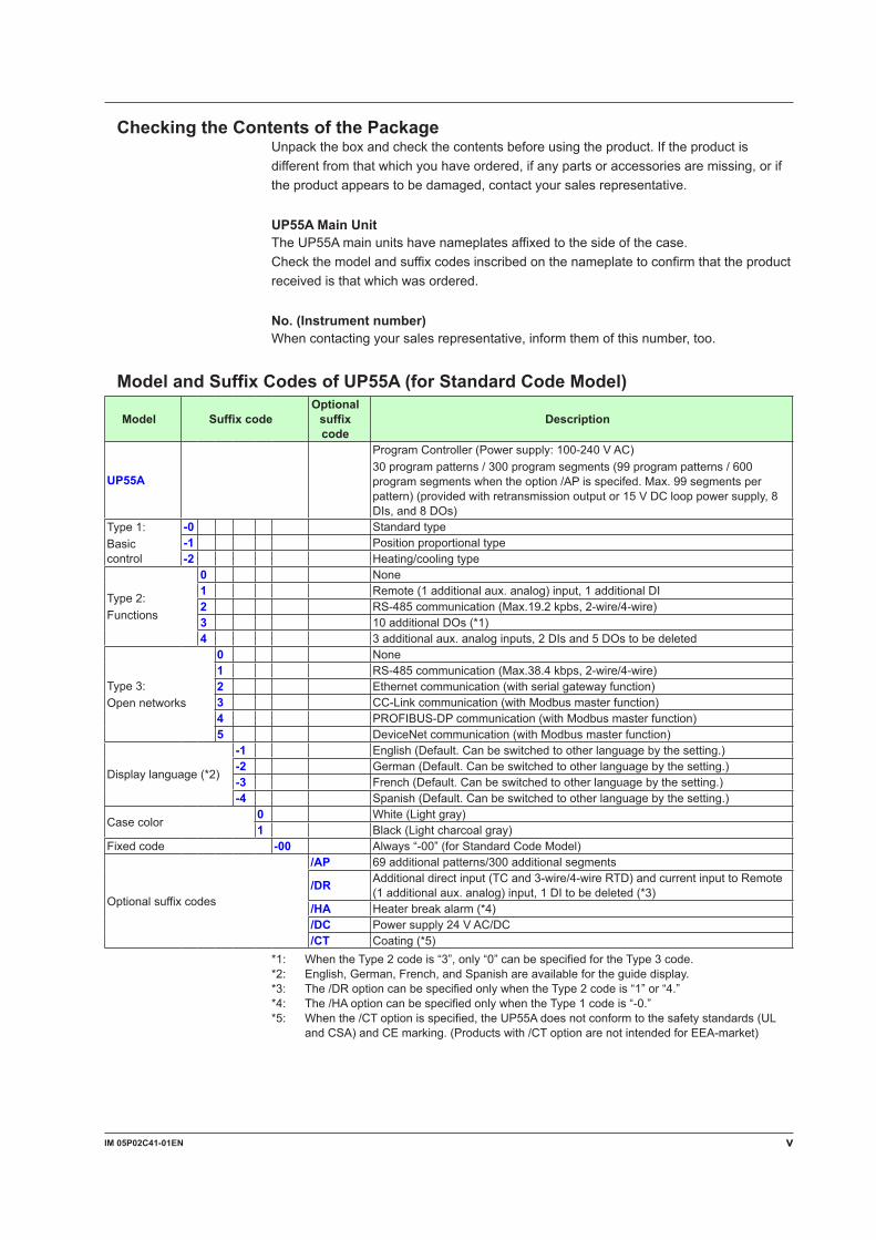
ModelandSuffixCodesofUP55A(forStandardCodeModel)
Model SuffixcodeOptionalsuffixcode
Description
UP55A
Program Controller (Power supply: 100-240 V AC)30 program patterns / 300 program segments (99 program patterns / 600 program segments when the option /AP is specifed. Max. 99 segments per pattern) (provided with retransmission output or 15 V DC loop power supply, 8 DIs, and 8 DOs)
Type 1: Basic control
-0 Standard type-1 Position proportional type-2 Heating/cooling type
Type 2:Functions
0 None1 Remote (1 additional aux. analog) input, 1 additional DI2 RS-485 communication (Max.19.2 kpbs, 2-wire/4-wire)3 10 additional DOs (*1)4 3 additional aux. analog inputs, 2 DIs and 5 DOs to be deleted
Type 3:Open networks
0 None1 RS-485 communication (Max.38.4 kbps, 2-wire/4-wire)2 Ethernet communication (with serial gateway function)3 CC-Link communication (with Modbus master function)4 PROFIBUS-DP communication (with Modbus master function)5 DeviceNet communication (with Modbus master function)
Display language (*2)
-1 English (Default. Can be switched to other language by the setting.)-2 German (Default. Can be switched to other language by the setting.)-3 French (Default. Can be switched to other language by the setting.)-4 Spanish (Default. Can be switched to other language by the setting.)
Case color0 White (Light gray)1 Black (Light charcoal gray)
Fixed code -00 Always “-00” (for Standard Code Model)
Optional suffix codes
/AP 69 additional patterns/300 additional segments
/DR Additional direct input (TC and 3-wire/4-wire RTD) and current input to Remote (1 additional aux. analog) input, 1 DI to be deleted (*3)
/HA Heater break alarm (*4)/DC Power supply 24 V AC/DC/CT Coating (*5)
*1: When the Type 2 code is “3”, only “0” can be specified for the Type 3 code.*2: English, German, French, and Spanish are available for the guide display.*3: The /DR option can be specified only when the Type 2 code is “1” or “4.”*4: The /HA option can be specified only when the Type 1 code is “-0.”*5: When the /CT option is specified, the UP55A does not conform to the safety standards (UL
and CSA) and CE marking. (Products with /CT option are not intended for EEA-market)
vi IM 05P02C41-01EN
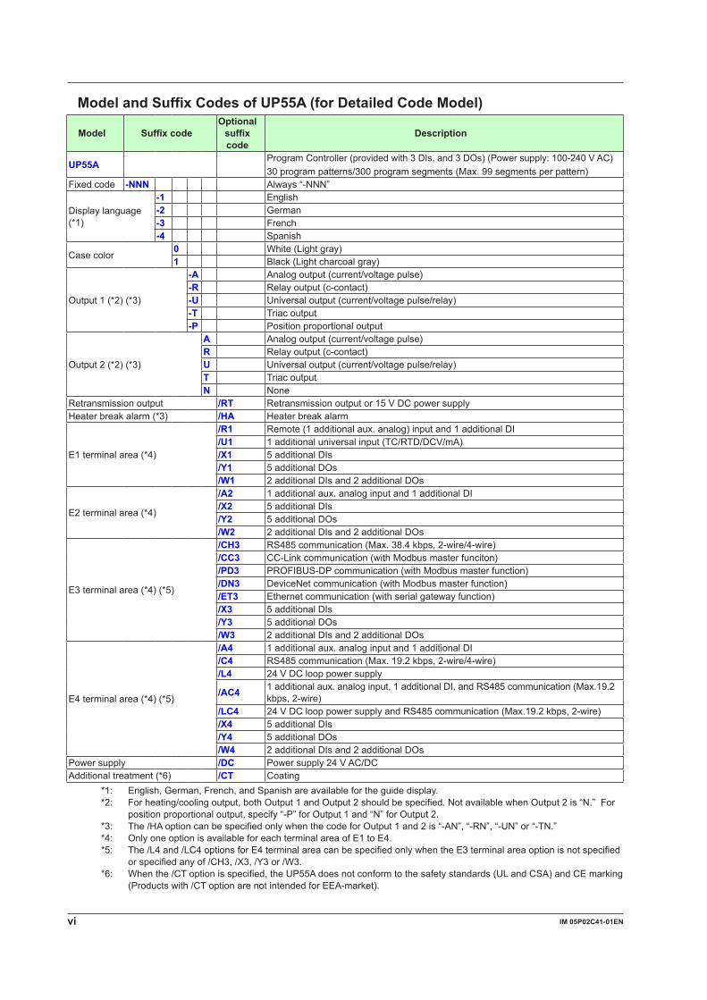
ModelandSuffixCodesofUP55A(forDetailedCodeModel)
Model SuffixcodeOptionalsuffixcode
Description
UP55AProgram Controller (provided with 3 DIs, and 3 DOs) (Power supply: 100-240 V AC)30 program patterns/300 program segments (Max. 99 segments per pattern)
Fixed code -NNN Always “-NNN”
Display language (*1)
-1 English-2 German-3 French-4 Spanish
Case color0 White (Light gray)1 Black (Light charcoal gray)
Output 1 (*2) (*3)
-A Analog output (current/voltage pulse)-R Relay output (c-contact)-U Universal output (current/voltage pulse/relay)-T Triac output-P Position proportional output
Output 2 (*2) (*3)
A Analog output (current/voltage pulse)R Relay output (c-contact)U Universal output (current/voltage pulse/relay)T Triac outputN None
Retransmission output /RT Retransmission output or 15 V DC power supplyHeater break alarm (*3) /HA Heater break alarm
E1 terminal area (*4)
/R1 Remote (1 additional aux. analog) input and 1 additional DI/U1 1 additional universal input (TC/RTD/DCV/mA)/X1 5 additional DIs/Y1 5 additional DOs/W1 2 additional DIs and 2 additional DOs
E2 terminal area (*4)
/A2 1 additional aux. analog input and 1 additional DI/X2 5 additional DIs/Y2 5 additional DOs/W2 2 additional DIs and 2 additional DOs
E3 terminal area (*4) (*5)
/CH3 RS485 communication (Max. 38.4 kbps, 2-wire/4-wire)/CC3 CC-Link communication (with Modbus master funciton)/PD3 PROFIBUS-DP communication (with Modbus master function)/DN3 DeviceNet communication (with Modbus master function)/ET3 Ethernet communication (with serial gateway function)/X3 5 additional DIs/Y3 5 additional DOs/W3 2 additional DIs and 2 additional DOs
E4 terminal area (*4) (*5)
/A4 1 additional aux. analog input and 1 additional DI/C4 RS485 communication (Max. 19.2 kbps, 2-wire/4-wire)/L4 24 V DC loop power supply
/AC4 1 additional aux. analog input, 1 additional DI, and RS485 communication (Max.19.2 kbps, 2-wire)
/LC4 24 V DC loop power supply and RS485 communication (Max.19.2 kbps, 2-wire)/X4 5 additional DIs/Y4 5 additional DOs/W4 2 additional DIs and 2 additional DOs
Power supply /DC Power supply 24 V AC/DCAdditional treatment (*6) /CT Coating
*1: English, German, French, and Spanish are available for the guide display.*2: For heating/cooling output, both Output 1 and Output 2 should be specified. Not available when Output 2 is “N.” For
position proportional output, specify “-P” for Output 1 and “N” for Output 2.*3: The /HA option can be specified only when the code for Output 1 and 2 is “-AN”, “-RN”, “-UN” or “-TN.”*4: Only one option is available for each terminal area of E1 to E4.*5: The /L4 and /LC4 options for E4 terminal area can be specified only when the E3 terminal area option is not specified
orspecifiedanyof/CH3,/X3,/Y3or/W3.*6: When the /CT option is specified, the UP55A does not conform to the safety standards (UL and CSA) and CE marking
(Products with /CT option are not intended for EEA-market).
viiIM 05P02C41-01EN
Coating Treatment(1) HumiSeal coating treatment Apply HumiSeal coating to the printed circuit board assembly. Do not apply HumiSeal coating to the following parts: connector, gold-plated contact
area, relay part, RJC device, and in the vicinity of the push switch/LED lamp.(2) Apply terminal coating to the gold-plated contact area on the printed circuit board.
Notes Therearetwotreatmentsasdescribedabove,butwedonotguaranteetheireffectiveness.
We do not supply any test data on these treatments. Donotapplyanytreatmenttothescrewterminalareaonthebacksideoftheinstrument.
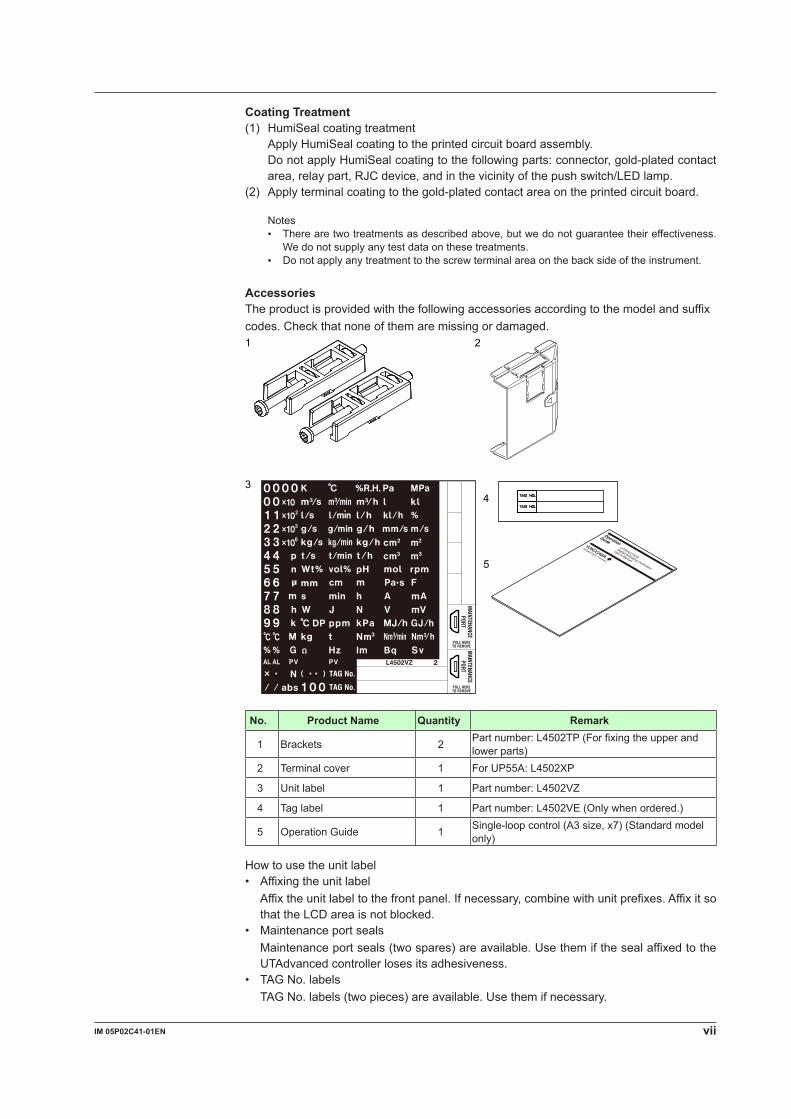
AccessoriesThe product is provided with the following accessories according to the model and suffix codes. Check that none of them are missing or damaged.
1 2
3
5
4
No. Product Name Quantity Remark
1 Brackets 2 Part number: L4502TP (For fixing the upper and lower parts)
2 Terminal cover 1 ForUP55A:L4502XP
3 Unit label 1 Part number: L4502VZ
4 Tag label 1 Part number: L4502VE (Only when ordered.)
5 Operation Guide 1 Single-loopcontrol(A3size,x7)(Standardmodelonly)
How to use the unit label• Affixing the unit label Affix the unit label to the front panel. If necessary, combine with unit prefixes. Affix it so
that the LCD area is not blocked.• Maintenance port seals Maintenance port seals (two spares) are available. Use them if the seal affixed to the
UTAdvanced controller loses its adhesiveness.• TAG No. labels TAG No. labels (two pieces) are available. Use them if necessary.
viii IM 05P02C41-01EN
Accessory(soldseparately)The following lists an accessory sold separately.
• LL50A Parameter Setting SoftwareModel Suffixcode Description
LL50A -00 Parameter Setting Software
• External Precision Resistor
Model Suffixcode Description
X010 See the General Specifications (*) Resistance Module
*: Necessary to input the current signal to the voltage input terminal.
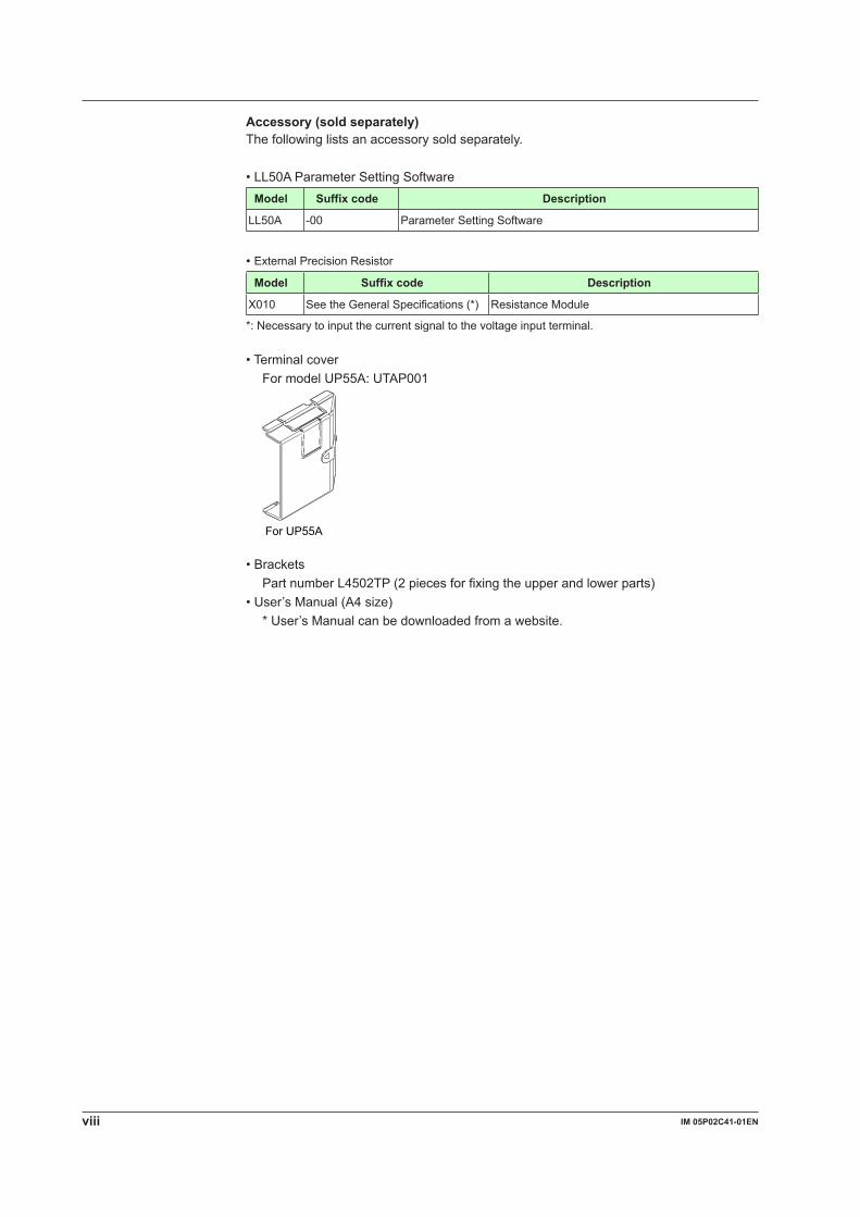
• Terminal cover For model UP55A: UTAP001
For UP55A
TAG NO.
TAG NO.
• Brackets Part number L4502TP (2 pieces for fixing the upper and lower parts)•User’sManual(A4size) * User’s Manual can be downloaded from a website.
ixIM 05P02C41-01EN
SymbolsUsedinThisManual
Thissymbolisusedontheinstrument.Itindicatesthepossibilityofinjurytotheuserordamage to the instrument, and signifies that the user must refer to the user’s manual for special instructions. The same symbol is used in the user’s manual on pages that the user needs to refer to, together with the term “WARNING” or “CAUTION.”
WARNINGCallsattentiontoactionsorconditionsthatcouldcauseseriousorfatalinjurytotheuser,and indicates precautions that should be taken to prevent such occurrences.
CAUTIONCallsattentiontoactionsorconditionsthatcouldcauseinjurytotheuserordamagetothe instrument or property and indicates precautions that should be taken to prevent such occurrences.
NoteIdentifies important information required to operate the instrument.
Indicates related operations or explanations for the user’s reference.
[ ]Indicates a character string displayed on the display.
SettingDisplayIndicates a setting display and describes the keystrokes required to display the relevant setting display.
SettingDetailsProvides the descriptions of settings.
DescriptionDescribes restrictions etc. regarding a relevant operation.
x IM 05P02C41-01EN
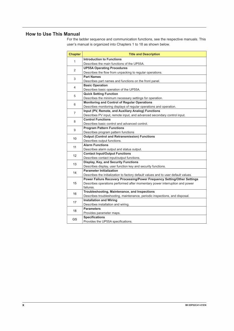
HowtoUseThisManualFor the ladder sequence and communication functions, see the respective manuals. This user’smanualisorganizedintoChapters1to18asshownbelow.
Chapter Title and Description
1Introduction to FunctionsDescribes the main functions of the UP55A.
2UP55AOperatingProceduresDescribes the flow from unpacking to regular operations.
3Part NamesDescribes part names and functions on the front panel.
4BasicOperationDescribes basic operation of the UP55A.
5QuickSettingFunctionDescribes the minimum necessary settings for operation.
6MonitoringandControlofRegularOperationsDescribes monitoring displays of regular operations and operation.
7Input(PV,Remote,andAuxiliaryAnalog)FunctionsDescribes PV input, remote input, and advanced secondary control input.
8Control FunctionsDescribes basic control and advanced control.
9Program Pattern FunctionsDescribes program pattern functions
10Output(ControlandRetransmission)FunctionsDescribes output functions.
11Alarm FunctionsDescribes alarm output and status output.
12ContactInput/OutputFunctionsDescribes contact input/output functions.
13Display,Key,andSecurityFunctionsDescribes display, user function key and security functions.
14Parameter InitializationDescribestheinitializationtofactorydefaultvaluesandtouserdefaultvalues.
15PowerFailureRecoveryProcessing/PowerFrequencySetting/OtherSettingsDescribes operations performed after momentary power interruption and power failures.
16Troubleshooting,Maintenance,andInspectionsDescribes troubleshooting, maintenance, periodic inspections, and disposal.
17Installation and WiringDescribes installation and wiring.
18ParametersProvides parameter maps.
GSSpecificationsProvides the UP55A specifications.
xiIM 05P02C41-01EN
1
2
3
4
5
6
7
8
9
10
11
12
13
14
15
16
17
18
App
Index
Contents
Introduction ............................................................................................................................iTarget Readers ..................................................................................................................... iiNotice ............................................................................................................................... iiTrademarks .......................................................................................................................... iiSafety Precautions ............................................................................................................... iiHandling Precautions for the Main Unit ............................................................................... ivChecking the Contents of the Package ................................................................................vModel and Suffix Codes of UP55A (for Standard model) .....................................................vModel and Suffix Codes of UP55A (for Detailed model) ..................................................... viSymbols Used in This Manual ............................................................................................. ixHow to Use This Manual ......................................................................................................x
Chapter1IntroductiontoFunctions1.1 Quick Setting Function ..................................................................................................... 1-11.2 Input/Output Function ....................................................................................................... 1-21.3 Control Functions ............................................................................................................. 1-41.4 Program Pattern Functions .............................................................................................. 1-71.5 Display and Key Functions ............................................................................................... 1-81.6 Ladder Sequence Function .............................................................................................. 1-91.7 Communication Functions .............................................................................................. 1-101.8 Definition of Main Symbols and Terms ........................................................................... 1-14
Chapter2UP55AOperatingProcedures2.1 UP55A Operating Procedures .......................................................................................... 2-1
Chapter 3 Part Names3.1 Names and Functions of Display Parts ............................................................................ 3-13.2 Names and Functions of Keys ......................................................................................... 3-43.3 List of Display Symbols .................................................................................................... 3-73.4 Brief Description of Setting Details (Parameters) .............................................................. 3-9
Chapter4BasicOperation4.1 Overview of Display Switch and Operation Keys ................................................................... 4-14.2 How to Set Parameters .................................................................................................... 4-5
Chapter5QuickSettingFunction5.1 Setting Using Quick Setting Function .............................................................................. 5-15.2 Restarting Quick Setting Function .................................................................................... 5-6
Chapter6MonitoringandControlofRegularOperations6.1 Monitoring and Control of Operation Displays .................................................................. 6-1
6.1.1 Operation Display Transitions in Single-loop Control, Cascade Primary-loop Control, Loop Control with PV switching, and Loop Control with PV auto-selector ................ 6-1Standard Type .....................................................................................................................6-2Position Proportional Type ...................................................................................................6-4Heating/cooling Type ...........................................................................................................6-6
6.1.2 Operation Display Transitions in Cascade Control ............................................. 6-8Standard Type .....................................................................................................................6-8Position Proportional Type .................................................................................................6-12Heating/cooling Type .........................................................................................................6-16
6.1.3 Details of the Operation Display ....................................................................... 6-20
xii IM 05P02C41-01EN
6.2 Performing and Canceling Auto-tuning ........................................................................... 6-266.3 AdjustingPIDManually .................................................................................................. 6-296.4 Setting Alarm Setpoint .................................................................................................... 6-346.5 Selecting Program Pattern Number (PTNO.) ................................................................. 6-356.6 Switching Operation Modes ........................................................................................... 6-36
6.6.1 Operation Display Switching Diagram .............................................................. 6-366.6.2 Switching to PROG Operation .......................................................................... 6-37
Selecting by RUN Key .......................................................................................................6-37Selecting by Operation Mode Parameter ...........................................................................6-37
6.6.3 Switching to RESET Operation ......................................................................... 6-38Selecting by RST Key ........................................................................................................6-38Selecting by Operation Mode Parameter ...........................................................................6-38
6.6.4 Enabling/Disabling Hold Mode of Program Operation ...................................... 6-40Selecting by MODE Key ....................................................................................................6-40Selecting by Operation Mode Parameter ...........................................................................6-40Hold Operation in Soak Segment ......................................................................................6-41Hold Operation in Ramp Segment .....................................................................................6-41
6.6.5 Excuting Advance ............................................................................................. 6-42Selecting by MODE Key ....................................................................................................6-42Selecting by Operation Mode Parameter ...........................................................................6-42
6.6.6 Switching between AUTO and MAN ................................................................. 6-44Selecting by MODE Key ....................................................................................................6-44Selecting by Operation Mode Parameter ...........................................................................6-44
6.6.7 Switching to Local Operation ............................................................................ 6-46Selecting by MODE Key ....................................................................................................6-46Selecting by Operation Mode Parameter ...........................................................................6-46
6.6.8 Switching to Remote Operation ........................................................................ 6-47Selecting by MODE Key ....................................................................................................6-47Selecting by Operation Mode Parameter ...........................................................................6-47
6.6.9 Switching between Local (LSP) and Cascade .................................................. 6-48Selecting by MODE Key ....................................................................................................6-48Selecting by Operation Mode Parameter ...........................................................................6-48
6.7 Selecting Start-of-program Pattern Number ................................................................... 6-49Selecting by MODE Key ....................................................................................................6-49Selecting by Operation Mode Parameter ...........................................................................6-49
6.8 Fast-forwarding Program Pattern ................................................................................... 6-51Performing by MODE Key .................................................................................................6-51Performing by Operation Mode Parameter ........................................................................6-51
6.9 Changing SP, TSP, or Remaining Segment-time (R.TIM) in HOLD-mode ..................... 6-52Changing SP in HOLD Operation ......................................................................................6-52Changing TSP in HOLD Operation ....................................................................................6-53Changing R.TIM in HOLD Operation .................................................................................6-53Modifying Target Setpoint in Soak Segment ......................................................................6-55Modifying Target Setpoint in Ramp Segment ....................................................................6-55Modifying Final Target Setpoint (TSP) in Soak Segment ...................................................6-56Modifying Final Target Setpoint (TSP) in Ramp Segment .................................................6-56Decreasing Segment-time in Soak Segment .....................................................................6-57Increasing Segment-time in Soak Segment ......................................................................6-58Decreasing Segment-time in Ramp Segment ...................................................................6-59Increasing Segment-time in Ramp Segment .....................................................................6-59
6.10 Changing Program Pattern during Program Operation ........................................................................ 6-606.11 Manipulating Control Output during Manual Operation ........................................................................ 6-616.12 Releasing On-State (Latch) of Alarm Output .................................................................. 6-63
Contents
xiiiIM 05P02C41-01EN
1
2
3
4
5
6
7
8
9
10
11
12
13
14
15
16
17
18
App
Index
Chapter7Input(PV,Remote,andAuxiliaryAnalog)Functions7.1 Setting Functions of PV Input, Remote Input, and Auxiliary Analog Input ........................ 7-1
7.1.1 Setting Input Type, Unit, Range, Scale, and Decimal Point Position .................. 7-17.1.2 Setting Burnout Detection for Input ..................................................................... 7-57.1.3 Setting Reference Junction Compensation (RJC) or External Reference
Junction Compensation (ERJC) ......................................................................... 7-67.1.4 Correcting Input Value ........................................................................................ 7-7
(1) Setting Bias and Filter ....................................................................................................7-7(2) Setting Square Root Extraction and Low Signal Cutoff Point .........................................7-9(3)Setting10-segmentLinearizer ......................................................................................7-10
7.1.5 Setting Ratio bias/filter ...................................................................................... 7-127.2 Setting Input Sampling Period (Control Period) ............................................................. 7-137.3 Using 4-wire RTD as PV Input........................................................................................ 7-147.4 Using Larger, Smaller, Average, or Difference of Two to Four Inputs as PV ................. 7-157.5 Setting Remote Input Method ......................................................................................... 7-167.6 AdjustingPVRangeforLoopControlwithPVSwitchingorLoopControlwithPV
Auto-selector ....................................................................................................................... 7-177.7 Setting PV Switching Methods of Loop Control with PV Switching ................................ 7-18
Chapter 8 Control Functions8.1 Setting Control Mode (CTLM) .......................................................................................... 8-1
8.1.1 Single-loop Control, Single-loop Heating/cooling Control, and Single-loop Position Proportional Control .............................................................................. 8-1n Single-loop Control Function Block Diagram ...................................................................8-2n Single-loop Heating/cooling Control Function Block Diagram .........................................8-4n Single-loop Position Proportional Control Function Block Diagram .................................8-6
8.1.2 Cascade Primary-loop Control ............................................................................ 8-9n Cascade Primary-loop Control Function Block Diagram ................................................8-10
8.1.3 Cascade Control, Cascade Heating/cooling Control, and Cascade Position Proportional Control .......................................................................................... 8-13n Cascade Control Function Block Diagram .....................................................................8-15n Cascade Heating/cooling Control Function Block Diagram ...........................................8-16n Cascade Position Proportional Control Function Block Diagram ...................................8-19
8.1.4 Loop Control with PV Switching, Heating/cooling Loop Control with PV Switching, and Position Proportional Loop Control with PV Switching ....... 8-21n Loop Control with PV Switching Function Block Diagram ..............................................8-22n Heating/cooling Loop Control with PV Switching Function Block Diagram ....................8-25n Position Proportional Loop Control with PV Switching Function Block Diagram ...........8-27
8.1.5 Loop Control with PV Auto-selector, Heating/cooling Loop Control with PV Auto-selector, and Position Proportional Loop Control with PV Auto-selector .. 8-29n Loop Control with PV Auto-selector (2 inputs) Function Block Diagram ........................8-31n Heating/cooling Loop Control with PV Auto-selector (2 inputs) Function Block Diagram ..8-33n Position Proportional Loop Control with PV Auto-selector (2 inputs) Function Block Diagram .8-35n Loop Control with PV Auto-selector (4 inputs) Function Block Diagram ........................8-36n Heating/cooling Loop Control with PV Auto-selector (4 inputs) Function Block Diagram .8-39n Position Proportional Loop Control with PV Auto-selector (4 inputs) Function Block Diagram .8-41
8.2 Setting Control Type (CNT) ............................................................................................ 8-428.2.1 PID Control ....................................................................................................... 8-438.2.2 ON/OFF Control (1 point of hysteresis / 2 points of hysteresis) ....................... 8-448.2.3 Heating/cooling Control .................................................................................... 8-468.2.4 PD Control (Stable Control in Which a Setpoint is not Exceeded) ................... 8-51
8.3 Setting PID Control Mode (ALG) .................................................................................... 8-528.4 Switching PID ................................................................................................................. 8-54
Contents
xiv IM 05P02C41-01EN
8.4.1 Switching PID According to Target Setpoint Number (SPNO) .......................... 8-548.4.2 Switching PID According to PV ......................................................................... 8-558.4.3 Switching PID According to SP ......................................................................... 8-568.4.4 Switching PID According to Target SP .............................................................. 8-588.4.5 Switching PID According to Deviation (Reference Deviation) ........................... 8-608.4.6 Setting Hysteresis at Time of PID Switch ......................................................... 8-618.4.7 Switching PID Irrespective of Operation Mode ................................................. 8-618.4.8 Switching PID by Contact Input ........................................................................ 8-61
8.5 Suppressing Overshoot (Super Function) ...................................................................... 8-628.6 Suppressing Hunting (Super2 Function) ........................................................................ 8-648.7 Suppressing Integral Action (Anti-reset Wind-up) .................................................................. 8-668.8 Performing Non-linear PID Control ................................................................................. 8-678.9 AdjustingAuto-tuningOperation .................................................................................... 8-688.10 Setting SP Limiter ........................................................................................................... 8-698.11 Setting Program Time Unit ............................................................................................. 8-708.12 Forcing Local Setpoint (LSP) to Track Program Setpoint or Remote Setpoint (SP Tracking) . 8-718.13 Setting Controller Action at Power ON (Restart Mode) ......................................................................8-728.14 Setting Time between Powering on Controller and Starting Control (Restart Timer) ..... 8-73
Chapter 9 Program Pattern Functions9.1 Setting the Setting Method of Program Pattern ................................................................ 9-1
9.1.1 Setting the Program Pattern Using the Segment Time ....................................... 9-29.1.2 Setting the Program Pattern using the Ramp-rate and Segment Time .............. 9-39.1.3 Setting the Program Time Unit ............................................................................ 9-5
9.2 PID Selection Method ....................................................................................................... 9-69.2.1 Segment PID Selection ....................................................................................... 9-69.2.2 Zone PID Selection ............................................................................................. 9-79.2.3 Local PID Selection ............................................................................................ 9-7
9.3 Setting the Program Starting Conditions (STC) ............................................................... 9-89.3.1 Starting operation at starting target setpoint (SSP) (STC=SSP) ........................ 9-89.3.2 Ramp-prioritizedPVstart(STC=RAMP) ............................................................. 9-99.3.3 Time-prioritizedPVstart(STC=TIME) .............................................................. 9-139.3.4 Starting operation at local target setpoint (STC=LSP) ...................................... 9-159.3.5 Starting operation at remote setpoint (STC=RSP)............................................ 9-17
9.4 Setting the Wait Functions ................................................................................................. 9-189.4.1 Program Wait at Segment End ......................................................................... 9-189.4.2 Program Wait in the Middle of a Segment ........................................................ 9-21
9.5 Setting the Segment Repetition ..........................................................................................................9-229.6 Operation with Linked Program Patterns ....................................................................... 9-239.7 Setting Event Functions ......................................................................................................................9-26
9.7.1 PV Event ........................................................................................................... 9-279.7.2 Time Event ........................................................................................................ 9-289.7.3 Local Event ....................................................................................................... 9-30
9.8 Setting the Operation in Segment Switching ......................................................................................9-319.8.1 Switching for continuation (JC=CONT) ............................................................. 9-319.8.2 Hold-on switching (JC=HOLD) .......................................................................... 9-339.8.3 Local-mode switching (JC=LOCAL) .................................................................. 9-359.8.4 Remote-mode switching (JC=REM) ................................................................. 9-379.8.5 Segment switching (the controller switches to a local setpoint when
the segment is completed after release) (JC=W.SL1 to W.SL5)....................... 9-399.8.6 Segment switching (the controller switches to a remote setpoint when
the segment is completed after release) (JC=W.SR1 to W.SR5) ..................... 9-40
Contents
xvIM 05P02C41-01EN
1
2
3
4
5
6
7
8
9
10
11
12
13
14
15
16
17
18
App
Index
9.9 Setting Program Pattern-2 Retransmission ........................................................................................9-419.10 Setting Starting time of program operation .........................................................................................9-429.11 Setting the Program Pattern Number Clearance ............................................................ 9-439.12 Program Pattern End Signal ...............................................................................................................9-449.13 Editing the Prgram Pattern ............................................................................................. 9-45
9.13.1 Checking the Number of Remaining Segments ................................................ 9-459.13.2 Checking the Number of Segments in specified pattern ................................... 9-459.13.3 Copying a Program Pattern .............................................................................. 9-469.13.4 Adding and Deleting Segment in Program Patterns ......................................... 9-469.13.5 Deleting the Program Pattern ........................................................................... 9-479.13.6 List of the Error Code ........................................................................................ 9-47
9.14 SynchronizedProgramPatternOperation ..................................................................... 9-489.14.1 SynchronizedOperationDuringSwitchingBetweenSegments ....................... 9-489.14.2 SynchronizedOperationofProgramPatternProgression ................................ 9-51
Chapter10Output(ControlandRetransmission)Functions10.1 Setting Control Output Type ........................................................................................... 10-110.2 Setting Control Output Cycle Time ................................................................................. 10-510.3 Setting Limiter to Control Output .................................................................................... 10-610.4 Disabling Output Limiter in MAN mode .......................................................................... 10-710.5 Setting Velocity Limiter to Control Output ....................................................................... 10-810.6 Reducing 4-20 mA Current Output to 0 mA (Tight Shut Function) ................................. 10-910.7 Setting ON/OFF Control Hysteresis ............................................................................. 10-1010.8 Canceling Offset of PV and SP (Manual Reset) ........................................................... 10-1210.9 Setting Hysteresis and Dead Band for Heating/cooling Control Output ....................... 10-1310.10 Setting Hysteresis and Dead Band for Position Proportional Control Output ............... 10-1510.11 Setting Retransmission Output Terminal, Type, and Scales ......................................... 10-1610.12 Setting Preset Output Value ......................................................................................... 10-19
10.12.1 Setting Output Value in RESET Mode (Preset Output) ................................... 10-1910.12.2 Setting Output Value When Switched to MAN Mode (Manual Preset Output) ......... 10-2010.12.3 Setting Output Value When Error Occurs (Input Error Preset Output)............ 10-21
10.13 Setting10-segmentLinearizerforOutput .................................................................... 10-2210.14 Changing Current Output Range .................................................................................. 10-2410.15 Setting Split Computation Output Function .................................................................. 10-2510.16 AdjustingMotor-operatedValvePosition(PositionProportionalOutput) ..................... 10-27
10.16.1 Setting Valve Operation Mode ........................................................................ 10-2810.16.2 AdjustingValvePositionAutomatically ........................................................... 10-2810.16.3 AdjustingValvePositionManually .................................................................. 10-2910.16.4 Setting Valve Traveling Time (Estimating Type) .............................................. 10-3010.16.5 Selecting Feedback Input (Resistor/Current) .................................................. 10-30
10.17 Using 15 V DC Loop Power Supply ............................................................................. 10-31
Chapter11AlarmFunctions11.1 Setting Alarm Type ..........................................................................................................11-111.2 Setting Number of Alarm Groups to Use .......................................................................11-1711.3 Setting Hysteresis to Alarm Operation ..........................................................................11-1811.4 Delaying Alarm Output (Alarm Delay Timer) .................................................................11-1911.5 Setting Alarm Output to Control Relay Terminal ............................................................11-2011.6 Setting Alarm Action According to Operation Mode .......................................................11-2111.7 Setting Heater Break Alarm ...........................................................................................11-22
Chapter12ContactInput/OutputFunctions12.1 Setting Contact Input Function ....................................................................................... 12-1
Contents
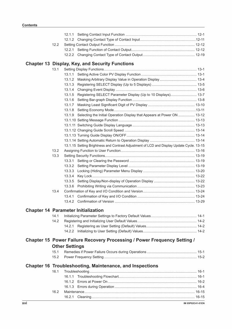
xvi IM 05P02C41-01EN
12.1.1 Setting Contact Input Function ......................................................................... 12-112.1.2 Changing Contact Type of Contact Input .........................................................12-11
12.2 Setting Contact Output Function .................................................................................. 12-1212.2.1 Setting Function of Contact Output ................................................................. 12-1212.2.2 Changing Contact Type of Contact Output ..................................................... 12-19
Chapter13Display,Key,andSecurityFunctions13.1 Setting Display Functions ............................................................................................... 13-1
13.1.1 Setting Active Color PV Display Function ......................................................... 13-113.1.2 Masking Arbitrary Display Value in Operation Display ...................................... 13-413.1.3 Registering SELECT Display (Up to 5 Displays) .............................................. 13-513.1.4 Changing Event Display ................................................................................... 13-613.1.5 Registering SELECT Parameter Display (Up to 10 Displays)........................... 13-713.1.6 Setting Bar-graph Display Function .................................................................. 13-813.1.7 Masking Least Significant Digit of PV Display ................................................ 13-1013.1.8 Setting Economy Mode ....................................................................................13-1113.1.9 Selecting the Initial Operation Display that Appears at Power ON ................. 13-1213.1.10 Setting Message Function .............................................................................. 13-1313.1.11 Switching Guide Display Language ................................................................ 13-1313.1.12 Changing Guide Scroll Speed ........................................................................ 13-1413.1.13 Turning Guide Display ON/OFF ...................................................................... 13-1413.1.14 Setting Automatic Return to Operation Display .............................................. 13-1413.1.15 SettingBrightnessandContrastAdjustmentofLCDandDisplayUpdateCycle . 13-15
13.2 Assigning Function to User Function ............................................................................ 13-1613.3 Setting Security Functions ............................................................................................ 13-19
13.3.1 Setting or Clearing the Password ................................................................... 13-1913.3.2 Setting Parameter Display Level .................................................................... 13-1913.3.3 Locking (Hiding) Parameter Menu Display ..................................................... 13-2013.3.4 Key Lock ......................................................................................................... 13-2213.3.5 Setting Display/Non-display of Operation Display .......................................... 13-2213.3.6 Prohibiting Writing via Communication ........................................................... 13-23
13.4 Confirmation of Key and I/O Condition and Version ..................................................... 13-2413.4.1 Confirmation of Key and I/O Condition ........................................................... 13-2413.4.2 Confirmation of Version .................................................................................. 13-29
Chapter14ParameterInitialization14.1 InitializingParameterSettingstoFactoryDefaultValues ............................................... 14-114.2 RegisteringandInitializingUserDefaultValues ............................................................. 14-2
14.2.1 Registering as User Setting (Default) Values.................................................... 14-214.2.2 InitializingtoUserSetting(Default)Values ....................................................... 14-2
Chapter15PowerFailureRecoveryProcessing/PowerFrequencySetting / OtherSettings15.1 Remedies if Power Failure Occurs during Operations ................................................... 15-115.2 Power Frequency Setting ............................................................................................... 15-2
Chapter16Troubleshooting,Maintenance,andInspections16.1 Troubleshooting .............................................................................................................. 16-1
16.1.1 Troubleshooting Flowchart ................................................................................ 16-116.1.2 Errors at Power On ........................................................................................... 16-216.1.3 Errors during Operation .................................................................................... 16-4
16.2 Maintenance ................................................................................................................. 16-1516.2.1 Cleaning .......................................................................................................... 16-15
Contents
xviiIM 05P02C41-01EN
1
2
3
4
5
6
7
8
9
10
11
12
13
14
15
16
17
18
App
Index
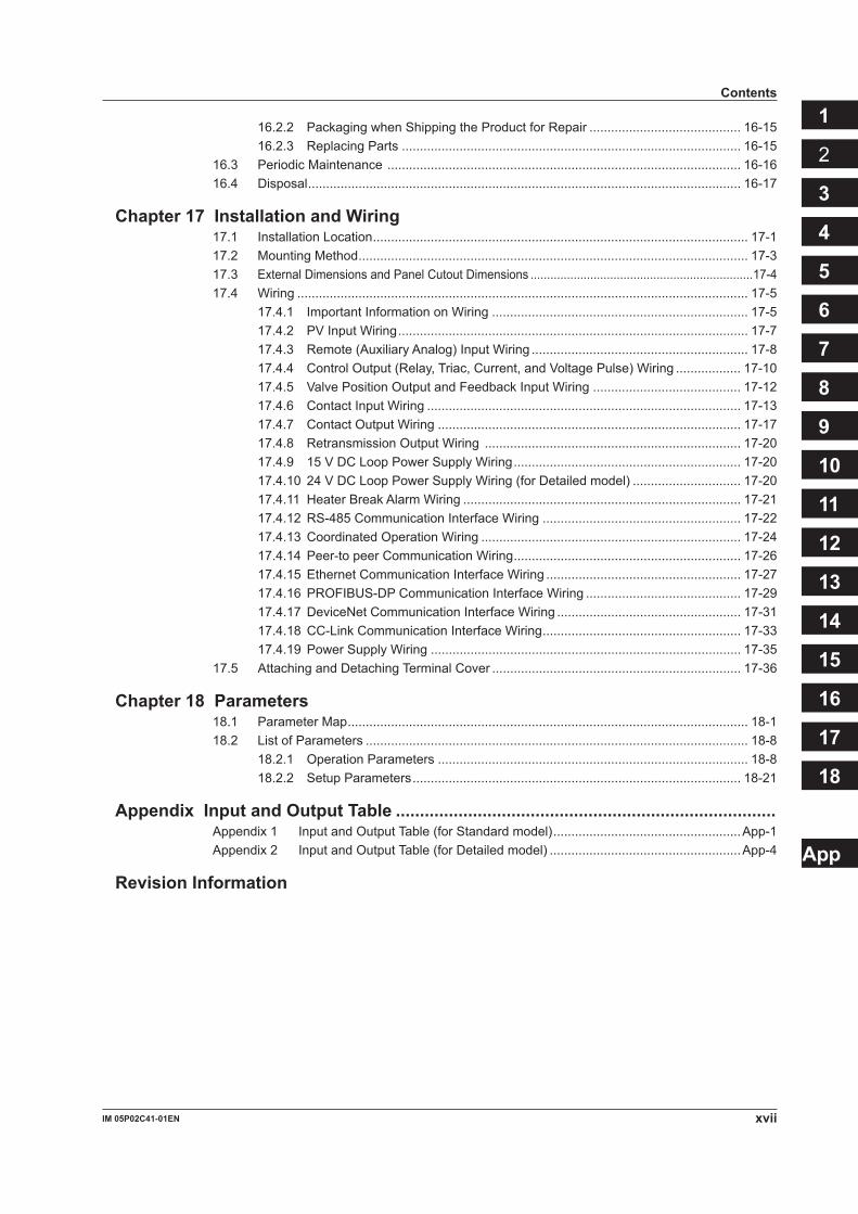
16.2.2 Packaging when Shipping the Product for Repair .......................................... 16-1516.2.3 Replacing Parts .............................................................................................. 16-15
16.3 Periodic Maintenance .................................................................................................. 16-1616.4 Disposal ........................................................................................................................ 16-17
Chapter17InstallationandWiring17.1 Installation Location ........................................................................................................ 17-117.2 Mounting Method ............................................................................................................ 17-317.3 External Dimensions and Panel Cutout Dimensions ...................................................................17-417.4 Wiring ............................................................................................................................. 17-5
17.4.1 Important Information on Wiring ....................................................................... 17-517.4.2 PV Input Wiring ................................................................................................. 17-717.4.3 Remote (Auxiliary Analog) Input Wiring ............................................................ 17-817.4.4 Control Output (Relay, Triac, Current, and Voltage Pulse) Wiring .................. 17-1017.4.5 Valve Position Output and Feedback Input Wiring ......................................... 17-1217.4.6 Contact Input Wiring ....................................................................................... 17-1317.4.7 Contact Output Wiring .................................................................................... 17-1717.4.8 Retransmission Output Wiring ....................................................................... 17-2017.4.9 15 V DC Loop Power Supply Wiring ............................................................... 17-2017.4.10 24 V DC Loop Power Supply Wiring (for Detailed model) .............................. 17-2017.4.11 Heater Break Alarm Wiring ............................................................................. 17-2117.4.12 RS-485 Communication Interface Wiring ....................................................... 17-2217.4.13 Coordinated Operation Wiring ........................................................................ 17-2417.4.14 Peer-to peer Communication Wiring ............................................................... 17-2617.4.15 Ethernet Communication Interface Wiring ...................................................... 17-2717.4.16 PROFIBUS-DP Communication Interface Wiring ........................................... 17-2917.4.17 DeviceNet Communication Interface Wiring ................................................... 17-3117.4.18 CC-Link Communication Interface Wiring ....................................................... 17-3317.4.19 Power Supply Wiring ...................................................................................... 17-35
17.5 Attaching and Detaching Terminal Cover ..................................................................... 17-36
Chapter18Parameters18.1 Parameter Map ............................................................................................................... 18-118.2 List of Parameters .......................................................................................................... 18-8
18.2.1 Operation Parameters ...................................................................................... 18-818.2.2 Setup Parameters ........................................................................................... 18-21
AppendixInputandOutputTable ...............................................................................Appendix 1 Input and Output Table (for Standard model) ....................................................App-1Appendix 2 Input and Output Table (for Detailed model) .....................................................App-4
RevisionInformation
Contents

Blank Page
1-1IM 05P02C41-01EN
Introduction to Functions
11.1 QuickSettingFunction
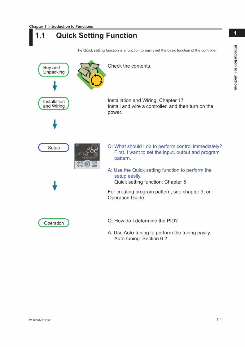
The Quick setting function is a function to easily set the basic function of the controller.
Buy andUnpacking
Installationand Wiring
Setup
Operation
Check the contents.
Installation and Wiring: Chapter 17Install and wire a controller, and then turn on the power.
Q: What should I do to perform control immediately?First, I want to set the input, output and program pattern.
A: Use the Quick setting function to perform the setup easily. Quick setting function: Chapter 5
For creating program pattern, see chapter 9, or Operation Guide.
Q: How do I determine the PID?
A: Use Auto-tuning to perform the tuning easily. Auto-tuning: Section 6.2
Chapter1IntroductiontoFunctions
1-2 IM 05P02C41-01EN
1.2 Input/OutputFunction
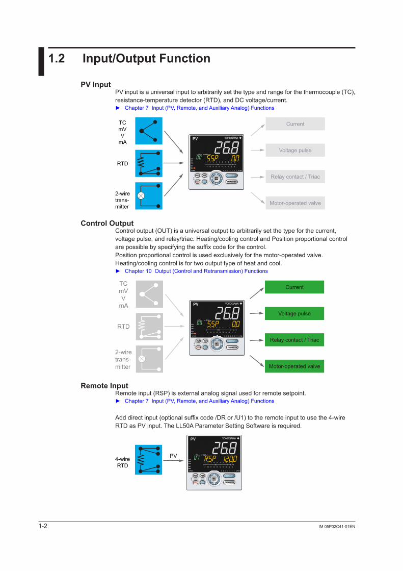
PV InputPV input is a universal input to arbitrarily set the type and range for the thermocouple (TC), resistance-temperature detector (RTD), and DC voltage/current. Chapter7Input(PV,Remote,andAuxiliaryAnalog)Functions
Current
Voltage pulse
Relay contact / Triac
Motor-operated valve
TCmVV
mA
RTD
2-wiretrans-mitter
ControlOutputControl output (OUT) is a universal output to arbitrarily set the type for the current, voltage pulse, and relay/triac. Heating/cooling control and Position proportional control are possible by specifying the suffix code for the control.Position proportional control is used exclusively for the motor-operated valve.Heating/cooling control is for two output type of heat and cool. Chapter10Output(ControlandRetransmission)Functions
Current
Voltage pulse
Relay contact / Triac
Motor-operated valve
TCmVV
mA
RTD
2-wiretrans-mitter
Remote InputRemote input (RSP) is external analog signal used for remote setpoint. Chapter7Input(PV,Remote,andAuxiliaryAnalog)Functions
Add direct input (optional suffix code /DR or /U1) to the remote input to use the 4-wire RTD as PV input. The LL50A Parameter Setting Software is required.
4-wireRTD
PV
1-3IM 05P02C41-01EN
Introduction to Functions
1AuxiliaryAnalogInputTwo auxiliary analog inputs can be used separately from PV input (PV) and remote input (RSP). Chapter7Input(PV,Remote,andAuxiliaryAnalog)Functions
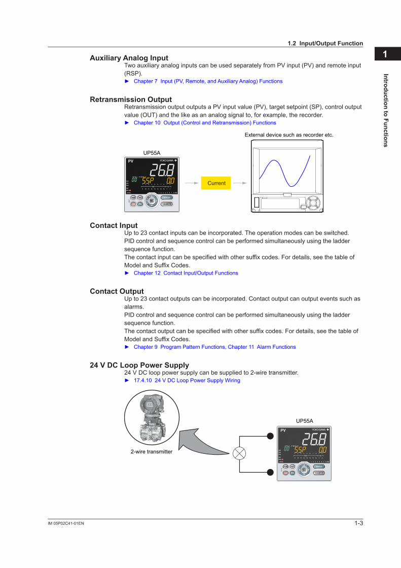
RetransmissionOutputRetransmission output outputs a PV input value (PV), target setpoint (SP), control output value (OUT) and the like as an analog signal to, for example, the recorder. Chapter10Output(ControlandRetransmission)Functions
Current
External device such as recorder etc.
UP55A
Contact InputUp to 23 contact inputs can be incorporated. The operation modes can be switched. PID control and sequence control can be performed simultaneously using the ladder sequence function.The contact input can be specified with other suffix codes. For details, see the table of Model and Suffix Codes. Chapter12ContactInput/OutputFunctions
ContactOutputUp to 23 contact outputs can be incorporated. Contact output can output events such as alarms.PID control and sequence control can be performed simultaneously using the ladder sequence function.The contact output can be specified with other suffix codes. For details, see the table of Model and Suffix Codes. Chapter9ProgramPatternFunctions,Chapter 11 Alarm Functions
24VDCLoopPowerSupply24 V DC loop power supply can be supplied to 2-wire transmitter. 17.4.1024VDCLoopPowerSupplyWiring
2-wire transmitter
UP55A
1.2Input/OutputFunction
1-4 IM 05P02C41-01EN
1.3 ControlFunctions
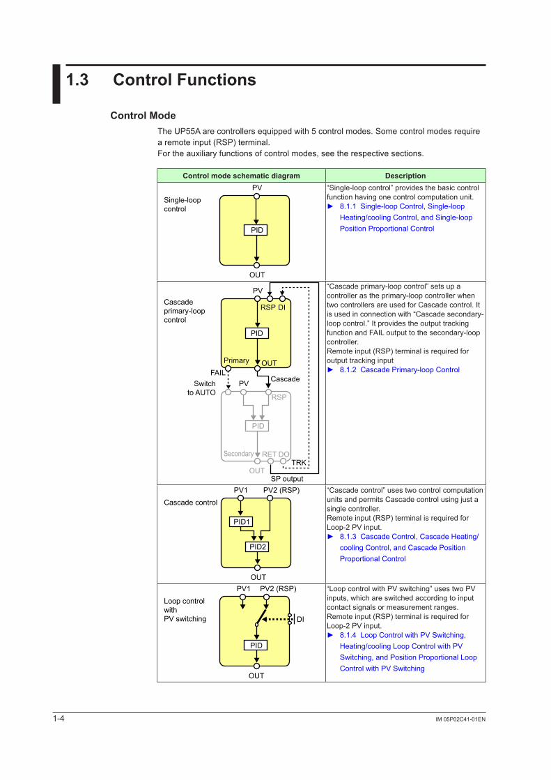
Control ModeThe UP55A are controllers equipped with 5 control modes. Some control modes require a remote input (RSP) terminal.For the auxiliary functions of control modes, see the respective sections.
Control mode schematic diagram Description
Single-loopcontrol
PV
OUT
PID
“Single-loop control” provides the basic control function having one control computation unit. 8.1.1Single-loopControl,Single-loop
Heating/cooling Control, and Single-loop Position Proportional Control
Cascadeprimary-loopcontrol
PVSwitchto AUTO
FAIL
TRK
SP output
PV
Cascade
RSP
OUT
DI
OUT
PID
RSP
RET DO
Primary
Secondary
PID
“Cascade primary-loop control” sets up a controller as the primary-loop controller when two controllers are used for Cascade control. It is used in connection with “Cascade secondary-loop control.” It provides the output tracking function and FAIL output to the secondary-loop controller.Remote input (RSP) terminal is required for output tracking input 8.1.2CascadePrimary-loopControl
Cascade controlPV1
OUT
PV2 (RSP)
PID1
PID2
“Cascade control” uses two control computation unitsandpermitsCascadecontrolusingjustasingle controller.Remote input (RSP) terminal is required for Loop-2 PV input. 8.1.3 Cascade Control, Cascade Heating/
cooling Control, and Cascade Position Proportional Control
Loop controlwithPV switching
PV1 PV2 (RSP)
OUT
DI
PID
“Loop control with PV switching” uses two PV inputs, which are switched according to input contact signals or measurement ranges.Remote input (RSP) terminal is required for Loop-2 PV input. 8.1.4 Loop Control with PV Switching,
Heating/cooling Loop Control with PV Switching, and Position Proportional Loop Control with PV Switching
1-5IM 05P02C41-01EN
Introduction to Functions
11.3ControlFunctions
Control mode schematic diagram Description
Loop controlwithPV auto-selector
PV1PV2(RSP)
PV3(AIN2)
PV4(AIN4)
OUT
PID
SELECT
“Loop control with PV auto-selector” automatically selects or calculates the max. value, the min. value, the average, or difference (of PV1 and PV2) of two to four PV inputs.Remote input (RSP) terminal and auxiliary analog input terminal are required for the inputs 2, 3, and 4. 8.1.5LoopControlwithPVAuto-selector,
Heating/cooling Loop Control with PV Auto-selector, and Position Proportional Loop Control with PV Auto-selector
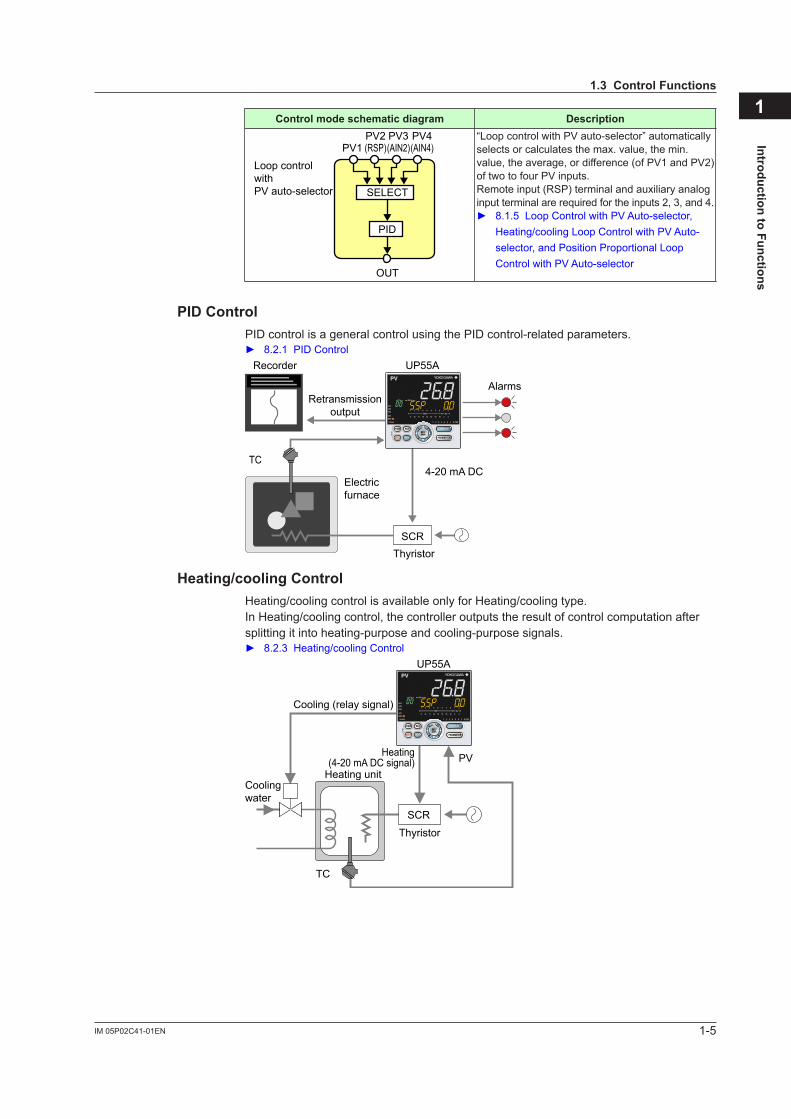
PID ControlPID control is a general control using the PID control-related parameters. 8.2.1PIDControl
AlarmsRetransmission
output
Electricfurnace
UP55A
4-20 mA DC
ThyristorSCR
Recorder
TC
Heating/cooling ControlHeating/cooling control is available only for Heating/cooling type.In Heating/cooling control, the controller outputs the result of control computation after splitting it into heating-purpose and cooling-purpose signals. 8.2.3Heating/coolingControl
UP55A
Cooling (relay signal)
Heating(4-20 mA DC signal)
TC
Heating unitCoolingwater
PV
Thyristor
SCR
1-6 IM 05P02C41-01EN
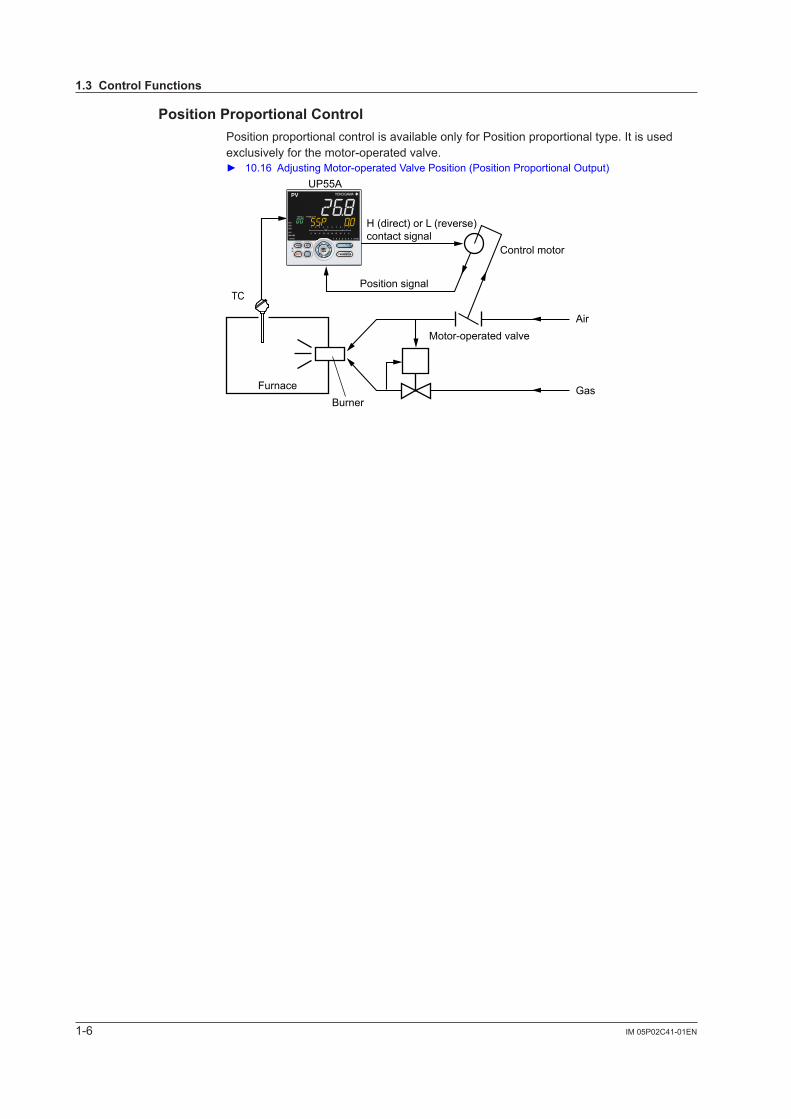
Position Proportional ControlPosition proportional control is available only for Position proportional type. It is used exclusively for the motor-operated valve. 10.16AdjustingMotor-operatedValvePosition(PositionProportionalOutput)
TC
Furnace
UP55A
Burner
Air
Gas
Motor-operated valve
Control motor
Position signal
H (direct) or L (reverse)contact signal
1.3ControlFunctions
1-7IM 05P02C41-01EN
Introduction to Functions
11.4 ProgramPatternFunctions
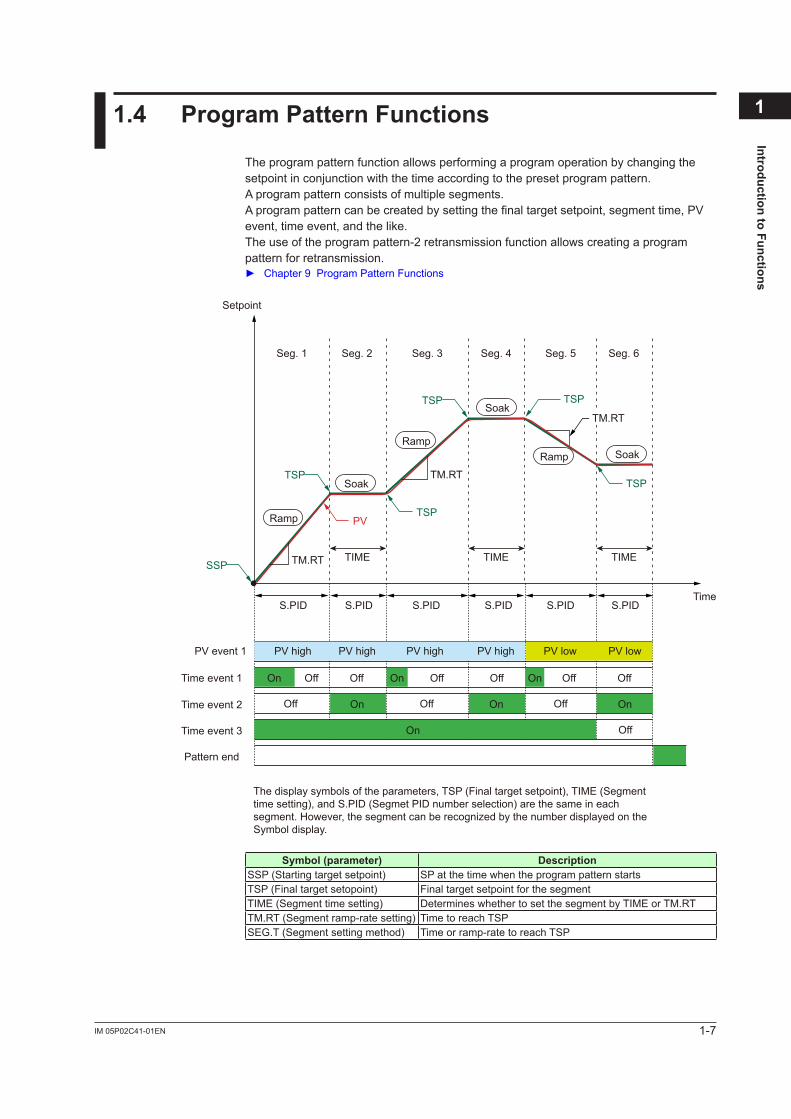
The program pattern function allows performing a program operation by changing the setpointinconjunctionwiththetimeaccordingtothepresetprogrampattern.A program pattern consists of multiple segments.A program pattern can be created by setting the final target setpoint, segment time, PV event, time event, and the like.The use of the program pattern-2 retransmission function allows creating a program pattern for retransmission. Chapter 9 Program Pattern Functions
Seg. 1 Seg. 2 Seg. 3 Seg. 4 Seg. 5 Seg. 6
S.PID
TIME
S.PIDS.PID
PV event 1
Time event 1
Time event 2
S.PID S.PID S.PIDTime
Setpoint
TSPPV
TSP
TSP
TM.RT
TM.RT
The display symbols of the parameters, TSP (Final target setpoint), TIME (Segment time setting), and S.PID (Segmet PID number selection) are the same in each segment. However, the segment can be recognized by the number displayed on the Symbol display.
TSP
SSP
TSP
Ramp
RampRamp
Soak
Soak
Soak
PV high PV high
On
On
On
On On
オン
OnOff
Off Off Off
Off
Off Off Off Off OffOn
PV high PV high PV low PV low
Time event 3
Pattern end
TM.RT TIME TIME
Symbol(parameter) DescriptionSSP (Starting target setpoint) SP at the time when the program pattern startsTSP (Final target setopoint) Final target setpoint for the segmentTIME (Segment time setting) Determines whether to set the segment by TIME or TM.RTTM.RT (Segment ramp-rate setting) Time to reach TSPSEG.T (Segment setting method) Time or ramp-rate to reach TSP
1-8 IM 05P02C41-01EN
1.5 DisplayandKeyFunctions
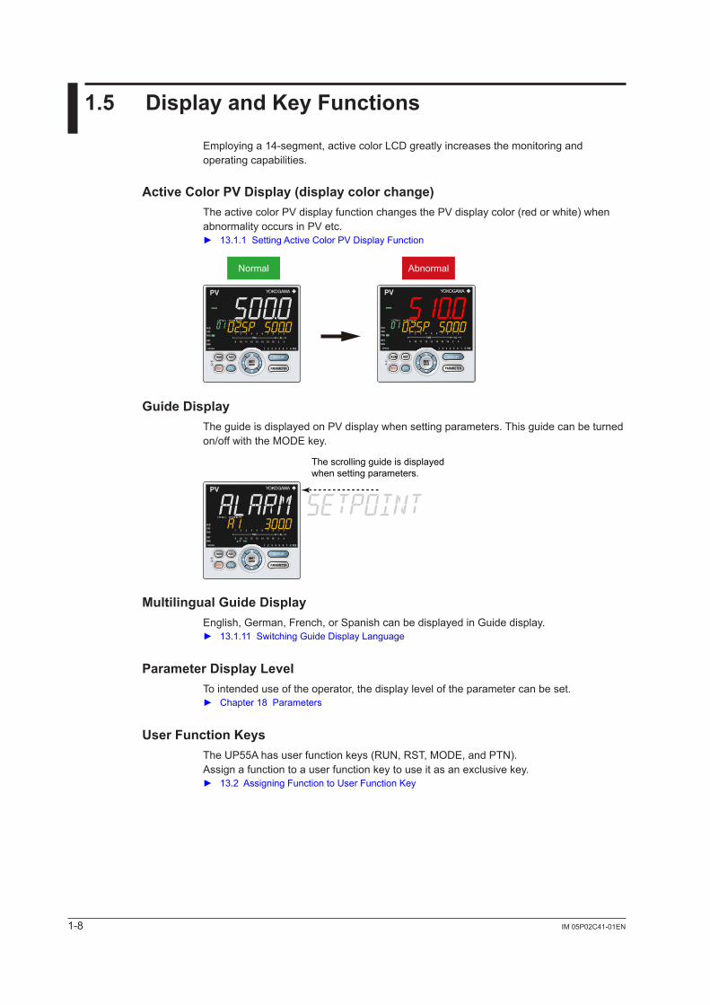
Employing a 14-segment, active color LCD greatly increases the monitoring and operating capabilities.
ActiveColorPVDisplay(displaycolorchange)The active color PV display function changes the PV display color (red or white) when abnormality occurs in PV etc. 13.1.1SettingActiveColorPVDisplayFunction
Normal Abnormal
GuideDisplayThe guide is displayed on PV display when setting parameters. This guide can be turned on/off with the MODE key.
The scrolling guide is displayed when setting parameters.
MultilingualGuideDisplayEnglish, German, French, or Spanish can be displayed in Guide display. 13.1.11SwitchingGuideDisplayLanguage
ParameterDisplayLevelTo intended use of the operator, the display level of the parameter can be set. Chapter18Parameters
UserFunctionKeysThe UP55A has user function keys (RUN, RST, MODE, and PTN).Assign a function to a user function key to use it as an exclusive key. 13.2AssigningFunctiontoUserFunctionKey
1-9IM 05P02C41-01EN
Introduction to Functions
11.6 LadderSequenceFunction
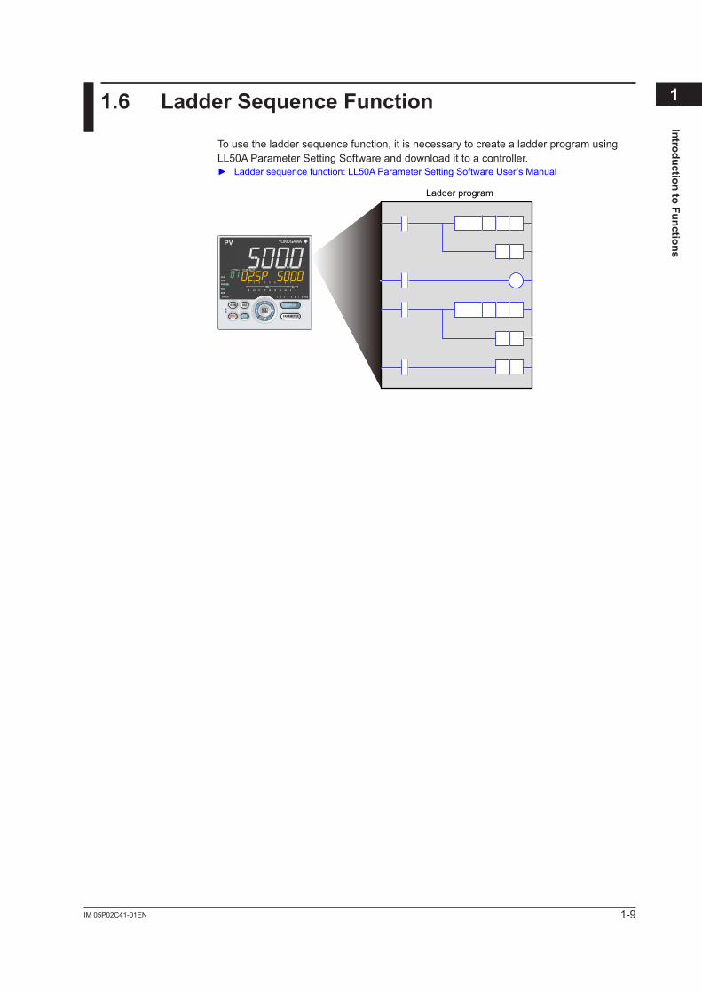
To use the ladder sequence function, it is necessary to create a ladder program using LL50A Parameter Setting Software and download it to a controller. Laddersequencefunction:LL50AParameterSettingSoftwareUser’sManual
Ladder program
1-10 IM 05P02C41-01EN
1.7 CommunicationFunctions
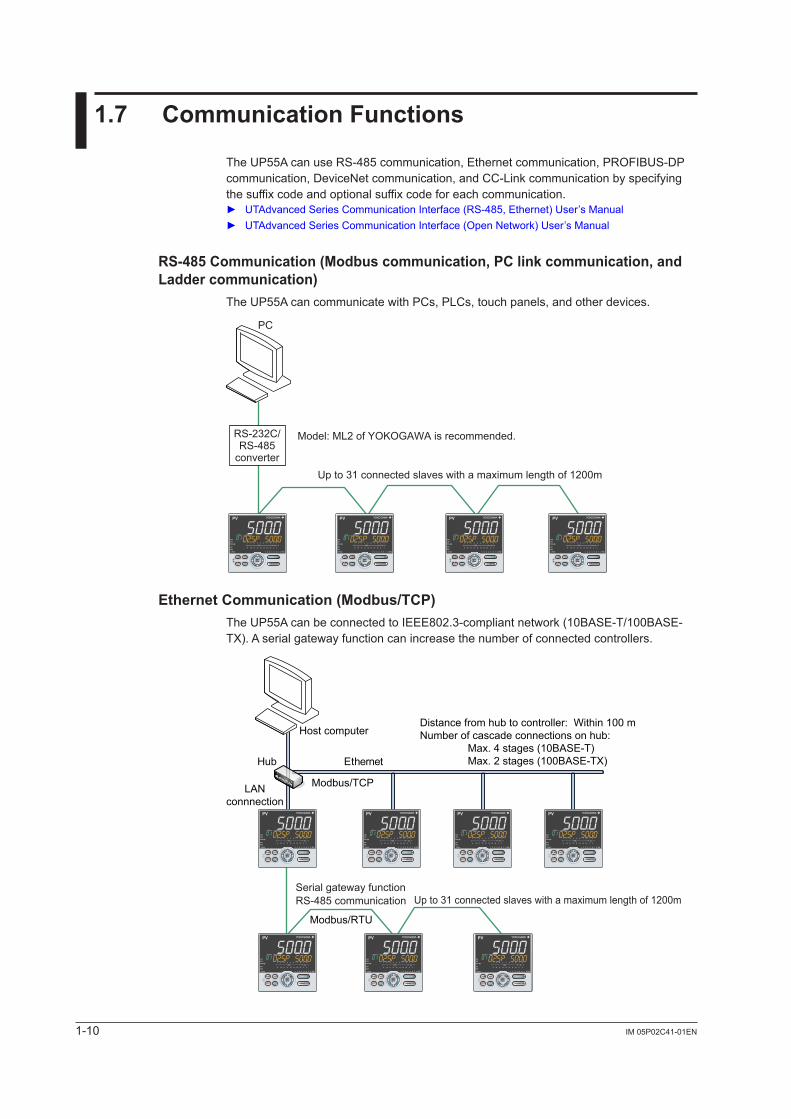
The UP55A can use RS-485 communication, Ethernet communication, PROFIBUS-DP communication, DeviceNet communication, and CC-Link communication by specifying the suffix code and optional suffix code for each communication. UTAdvancedSeriesCommunicationInterface(RS-485,Ethernet)User’sManual UTAdvanced Series Communication Interface (Open Network) User’s Manual
RS-485Communication(Modbuscommunication,PClinkcommunication,andLadder communication)
The UP55A can communicate with PCs, PLCs, touch panels, and other devices.
Up to 31 connected slaves with a maximum length of 1200m
Model: ML2 of YOKOGAWA is recommended.RS-232C/RS-485
converter
PC
Ethernet Communication (Modbus/TCP)The UP55A can be connected to IEEE802.3-compliant network (10BASE-T/100BASE-TX).Aserialgatewayfunctioncanincreasethenumberofconnectedcontrollers.
Ethernet
Modbus/RTU
Modbus/TCP
Host computer
Hub
LANconnnection
Distance from hub to controller: Within 100 mNumber of cascade connections on hub: Max. 4 stages (10BASE-T) Max. 2 stages (100BASE-TX)
RS-485 communicationSerial gateway function
Up to 31 connected slaves with a maximum length of 1200m
1-11IM 05P02C41-01EN
Introduction to Functions
11.7CommunicationFunctions
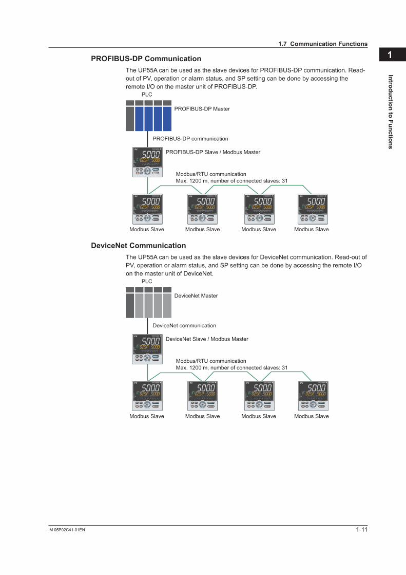
PROFIBUS-DPCommunicationThe UP55A can be used as the slave devices for PROFIBUS-DP communication. Read-out of PV, operation or alarm status, and SP setting can be done by accessing the remote I/O on the master unit of PROFIBUS-DP.
Max. 1200 m, number of connected slaves: 31
PLC
PROFIBUS-DP communication
PROFIBUS-DP Master
PROFIBUS-DP Slave / Modbus Master
Modbus Slave Modbus Slave Modbus Slave Modbus Slave
Modbus/RTU communication
DeviceNetCommunicationThe UP55A can be used as the slave devices for DeviceNet communication. Read-out of PV, operation or alarm status, and SP setting can be done by accessing the remote I/O on the master unit of DeviceNet.
Max. 1200 m, number of connected slaves: 31
PLC
DeviceNet communication
DeviceNet Master
DeviceNet Slave / Modbus Master
Modbus Slave Modbus Slave Modbus Slave Modbus Slave
Modbus/RTU communication
1-12 IM 05P02C41-01EN
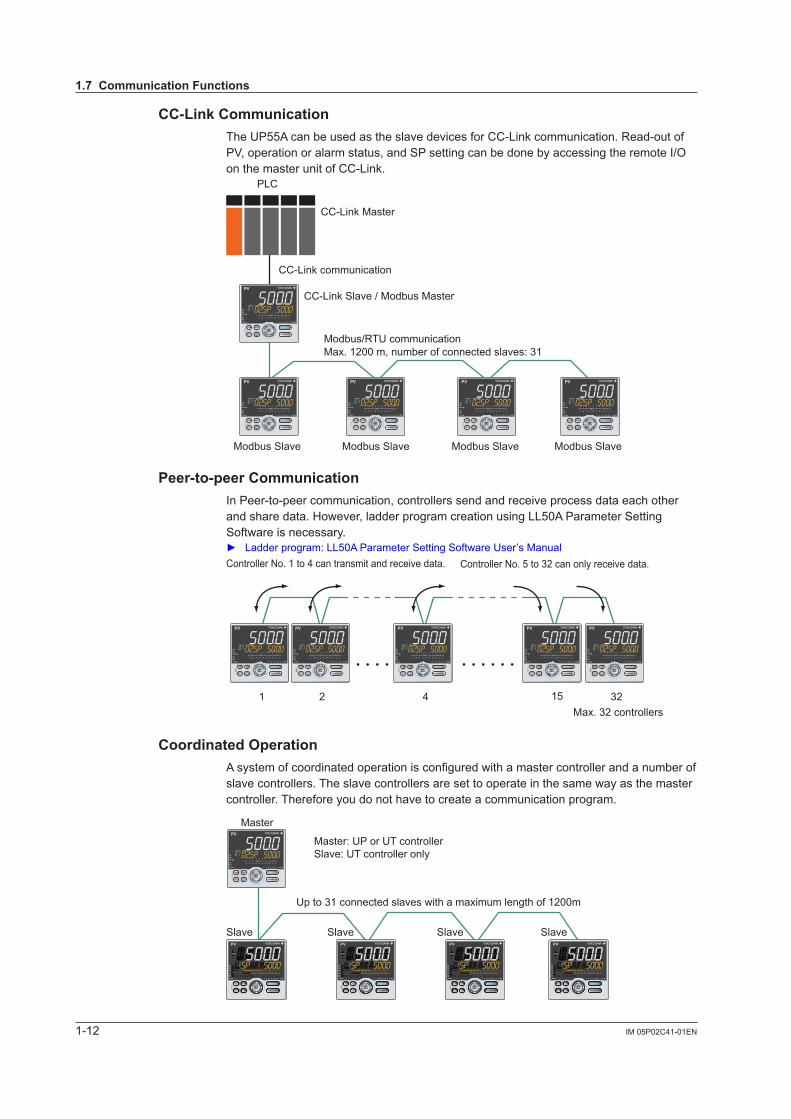
CC-LinkCommunicationThe UP55A can be used as the slave devices for CC-Link communication. Read-out of PV, operation or alarm status, and SP setting can be done by accessing the remote I/O on the master unit of CC-Link.
Max. 1200 m, number of connected slaves: 31
PLC
CC-Link communication
CC-Link Master
CC-Link Slave / Modbus Master
Modbus Slave Modbus Slave Modbus Slave Modbus Slave
Modbus/RTU communication
Peer-to-peerCommunicationIn Peer-to-peer communication, controllers send and receive process data each other and share data. However, ladder program creation using LL50A Parameter Setting Software is necessary. Ladderprogram:LL50AParameterSettingSoftwareUser’sManual
1 2 4 15 32
Controller No. 5 to 32 can only receive data.Controller No. 1 to 4 can transmit and receive data.
• • • • • • • • • •
Max. 32 controllers
CoordinatedOperationA system of coordinated operation is configured with a master controller and a number of slave controllers. The slave controllers are set to operate in the same way as the master controller. Therefore you do not have to create a communication program.
Master
Slave Slave Slave Slave
Up to 31 connected slaves with a maximum length of 1200m
Master: UP or UT controllerSlave: UT controller only
1.7CommunicationFunctions
1-13IM 05P02C41-01EN
Introduction to Functions
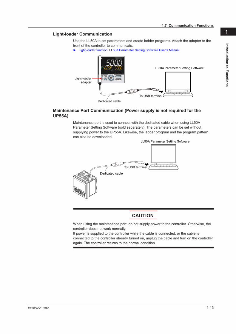
1Light-loaderCommunicationUse the LL50A to set parameters and create ladder programs. Attach the adapter to the front of the controller to communicate. Light-loaderfunction:LL50AParameterSettingSoftwareUser’sManual
Light-loaderadapter
Dedicated cable
LL50A Parameter Setting Software
To USB terminal
MaintenancePortCommunication(PowersupplyisnotrequiredfortheUP55A)
Maintenance port is used to connect with the dedicated cable when using LL50A Parameter Setting Software (sold separately). The parameters can be set without supplying power to the UP55A. Likewise, the ladder program and the program pattern can also be downloaded.
Dedicated cable
LL50A Parameter Setting Software
To USB terminal
CAUTIONWhen using the maintenance port, do not supply power to the controller. Otherwise, the controller does not work normally. If power is supplied to the controller while the cable is connected, or the cable is connected to the controller already turned on, unplug the cable and turn on the controller again. The controller returns to the normal condition.
1.7CommunicationFunctions
1-14 IM 05P02C41-01EN
1.8 DefinitionofMainSymbolsandTerms
MainSymbolPV: Measured input valueSP: Target setpointOUT: Control output valueRSP: Remote setpoint
PRG, PROGRAM: Start of Program operationRST, RESET: Stop of Program operationLOC, LOCAL: Start of Local operationREM, REMOTE: Start of Remote operationHLD, HOLD: Pause of program operationADV, ADVANCE: Advance of segmentA/M: AUTO/MANAUTO: AutomaticMAN: ManualLSP/CAS: Local(LSP)/cascade in Cascade controlCAS, CASCADE: Cascade operation
E1, E2, E3, and E4: Terminal areas 17.4Wiring
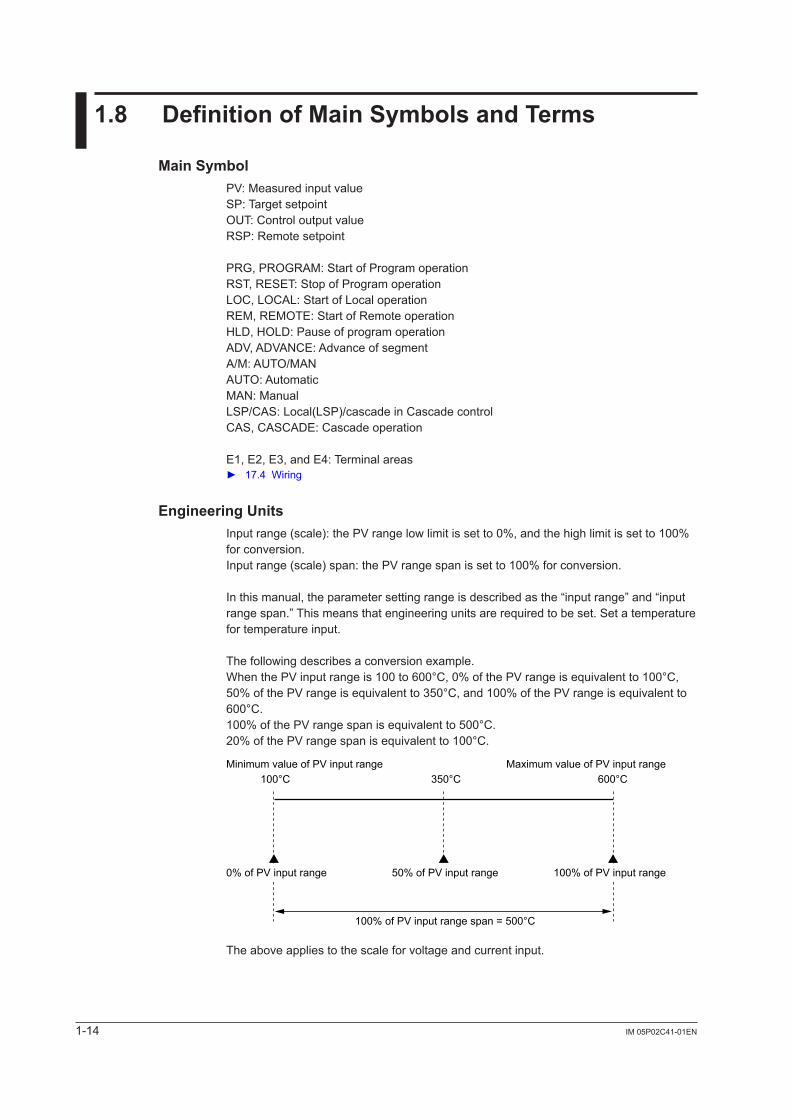
Engineering UnitsInput range (scale): the PV range low limit is set to 0%, and the high limit is set to 100% for conversion.Input range (scale) span: the PV range span is set to 100% for conversion.
In this manual, the parameter setting range is described as the “input range” and “input range span.” This means that engineering units are required to be set. Set a temperature for temperature input.
The following describes a conversion example.When the PV input range is 100 to 600°C, 0% of the PV range is equivalent to 100°C, 50% of the PV range is equivalent to 350°C, and 100% of the PV range is equivalent to 600°C.100% of the PV range span is equivalent to 500°C.20% of the PV range span is equivalent to 100°C.
Minimum value of PV input range Maximum value of PV input range100°C 600°C350°C
50% of PV input range
100% of PV input range span = 500°C
0% of PV input range 100% of PV input range
The above applies to the scale for voltage and current input.
2-1IM 05P02C41-01EN
UP55A O
perating Procedures
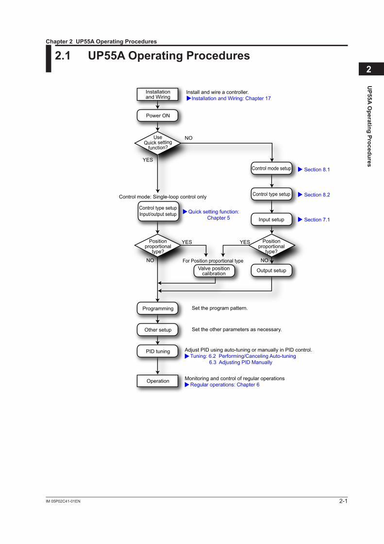
22.1 UP55AOperatingProcedures
Install and wire a controller. Installation and Wiring: Chapter 17
Quick setting function: Chapter 5
Monitoring and control of regular operations Regular operations: Chapter 6
Section 8.1
Section 8.2
Section 7.1
Adjust PID using auto-tuning or manually in PID control. Tuning: 6.2 Performing/Canceling Auto-tuning 6.3 Adjusting PID Manually
Other setup
Operation
NO
NO NO
YES
YES YES
Control mode: Single-loop control only
Set the other parameters as necessary.
Programming Set the program pattern.
PID tuning
Input setup
Output setup
Installationand Wiring
Power ON
Control mode setup
Control type setup
Control type setupInput/output setup
Valve positioncalibration
UseQuick setting
function?
Positionproportional
type?
Positionproportional
type?
For Position proportional type
Chapter2UP55AOperatingProcedures

Blank Page
3-1IM 05P02C41-01EN
Part Nam
es
3
3.1 NamesandFunctionsofDisplayParts
See the next page.
Chapter 3 Part Names
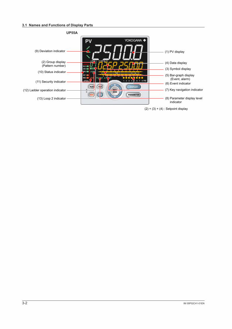
3-2 IM 05P02C41-01EN
UP55A
(1) PV display(9) Deviation indicator
(2) Group display(Pattern number)
(10) Status indicator
(11) Security indicator
(12) Ladder operation indicator
(13) Loop 2 indicator
(4) Data display
(2) + (3) + (4) : Setpoint display
(3) Symbol display
(5) Bar-graph display (Event, alarm)(6) Event indicator
(7) Key navigation indicator
(8) Parameter display level indicator
3.1NamesandFunctionsofDisplayParts
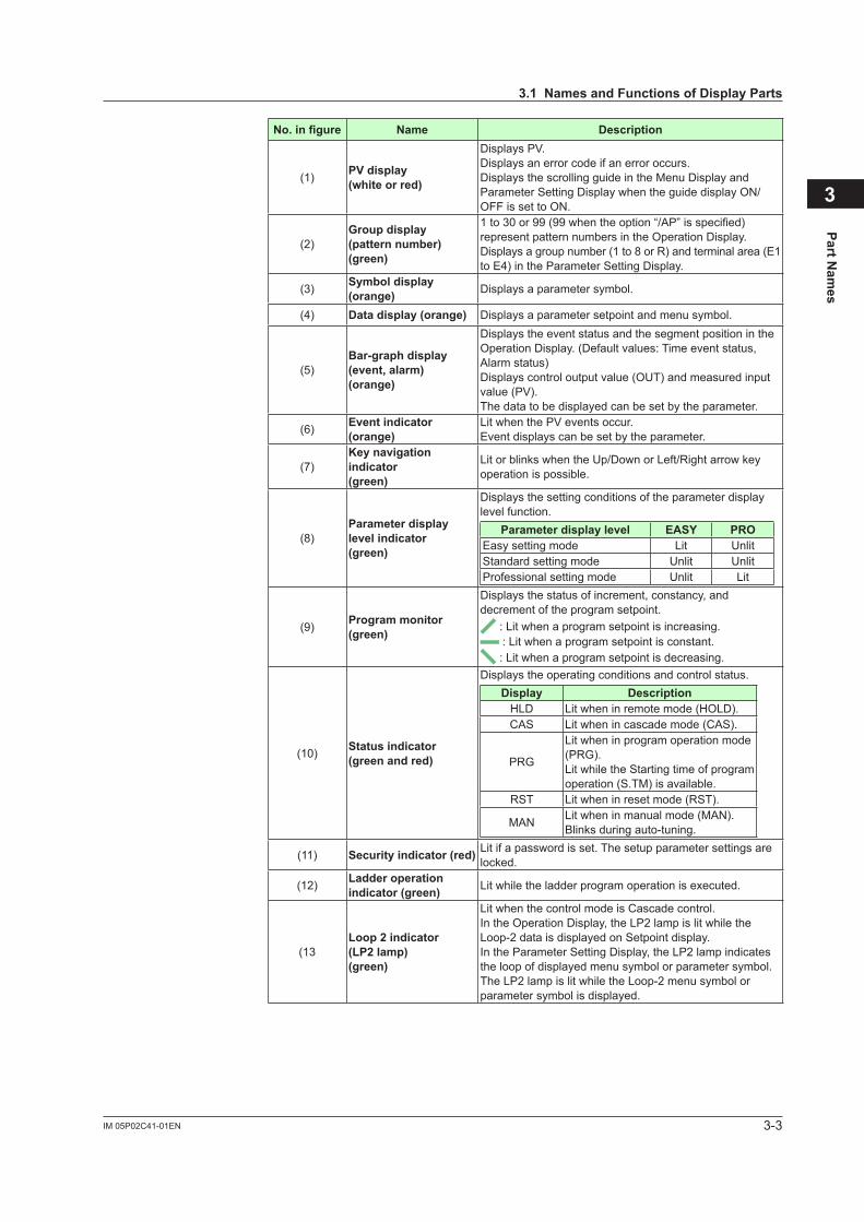
3-3IM 05P02C41-01EN
Part Nam
es
3
No.infigure Name Description
(1) PVdisplay(whiteorred)
Displays PV.Displays an error code if an error occurs.Displays the scrolling guide in the Menu Display and Parameter Setting Display when the guide display ON/OFF is set to ON.
(2)Groupdisplay (pattern number)(green)
1to30or99(99whentheoption“/AP”isspecified)represent pattern numbers in the Operation Display.Displays a group number (1 to 8 or R) and terminal area (E1 to E4) in the Parameter Setting Display.
(3) Symboldisplay(orange) Displays a parameter symbol.
(4) Datadisplay(orange) Displays a parameter setpoint and menu symbol.
(5)Bar-graphdisplay (event,alarm)(orange)
Displays the event status and the segment position in the Operation Display. (Default values: Time event status, Alarm status)Displays control output value (OUT) and measured input value (PV).The data to be displayed can be set by the parameter.
(6) Eventindicator(orange)
Lit when the PV events occur.Event displays can be set by the parameter.
(7)Keynavigationindicator (green)
Lit or blinks when the Up/Down or Left/Right arrow key operation is possible.
(8)Parameterdisplaylevelindicator(green)
Displays the setting conditions of the parameter display level function.
Parameterdisplaylevel EASY PROEasy setting mode Lit UnlitStandard setting mode Unlit UnlitProfessional setting mode Unlit Lit
(9) Program monitor(green)
Displays the status of increment, constancy, and decrement of the program setpoint.
: Lit when a program setpoint is increasing. : Lit when a program setpoint is constant. : Lit when a program setpoint is decreasing.
(10) Statusindicator(green and red)
Displays the operating conditions and control status.Display Description
HLD Lit when in remote mode (HOLD).CAS Lit when in cascade mode (CAS).
PRG
Lit when in program operation mode (PRG).Lit while the Starting time of program operation (S.TM) is available.
RST Lit when in reset mode (RST).
MAN Lit when in manual mode (MAN).Blinks during auto-tuning.
(11) Securityindicator(red) Lit if a password is set. The setup parameter settings are locked.
(12) Ladder operation indicator (green) Lit while the ladder program operation is executed.
(13Loop2indicator(LP2lamp)(green)
Lit when the control mode is Cascade control.In the Operation Display, the LP2 lamp is lit while the Loop-2 data is displayed on Setpoint display.In the Parameter Setting Display, the LP2 lamp indicates the loop of displayed menu symbol or parameter symbol. The LP2 lamp is lit while the Loop-2 menu symbol or parameter symbol is displayed.
3.1NamesandFunctionsofDisplayParts
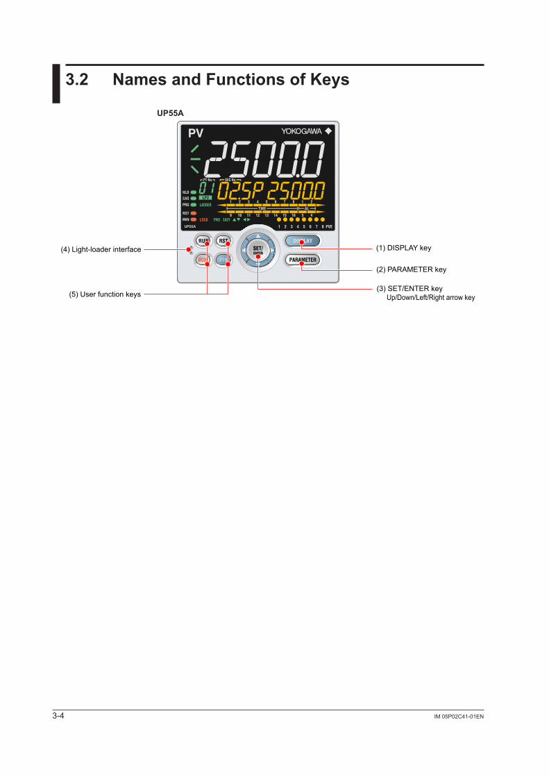
3-4 IM 05P02C41-01EN
3.2 NamesandFunctionsofKeys
UP55A
(4) Light-loader interface
(5) User function keys
(1) DISPLAY key
(2) PARAMETER key
(3) SET/ENTER key Up/Down/Left/Right arrow keys
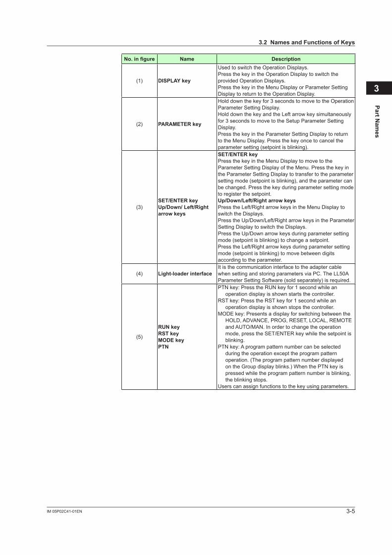
3-5IM 05P02C41-01EN
Part Nam
es
3
3.2NamesandFunctionsofKeys
No.infigure Name Description
(1) DISPLAYkey
Used to switch the Operation Displays.Press the key in the Operation Display to switch the provided Operation Displays.Press the key in the Menu Display or Parameter Setting Display to return to the Operation Display.
(2) PARAMETERkey
Hold down the key for 3 seconds to move to the Operation Parameter Setting Display.Hold down the key and the Left arrow key simultaneously for 3 seconds to move to the Setup Parameter Setting Display.Press the key in the Parameter Setting Display to return to the Menu Display. Press the key once to cancel the parameter setting (setpoint is blinking).
(3)SET/ENTERkeyUp/Down/Left/Rightarrowkeys
SET/ENTERkeyPress the key in the Menu Display to move to the Parameter Setting Display of the Menu. Press the key in the Parameter Setting Display to transfer to the parameter setting mode (setpoint is blinking), and the parameter can be changed. Press the key during parameter setting mode to register the setpoint.Up/Down/Left/RightarrowkeysPress the Left/Right arrow keys in the Menu Display to switch the Displays.Press the Up/Down/Left/Right arrow keys in the ParameterSetting Display to switch the Displays.Press the Up/Down arrow keys during parameter setting mode (setpoint is blinking) to change a setpoint.Press the Left/Right arrow keys during parameter setting mode (setpoint is blinking) to move between digits according to the parameter.
(4) Light-loaderinterfaceIt is the communication interface to the adapter cable when setting and storing parameters via PC. The LL50A Parameter Setting Software (sold separately) is required.
(5)
RUNkeyRSTkeyMODEkeyPTN
PTN key: Press the RUN key for 1 second while an operation display is shown starts the controller.
RST key: Press the RST key for 1 second while an operation display is shown stops the controller.
MODE key: Presents a display for switching between the HOLD, ADVANCE, PROG, RESET, LOCAL, REMOTE and AUTO/MAN. In order to change the operation mode, press the SET/ENTER key while the setpoint is blinking.
PTN key: A program pattern number can be selected during the operation except the program pattern operation. (The program pattern number displayed on the Group display blinks.) When the PTN key is pressed while the program pattern number is blinking, the blinking stops.
Users can assign functions to the key using parameters.
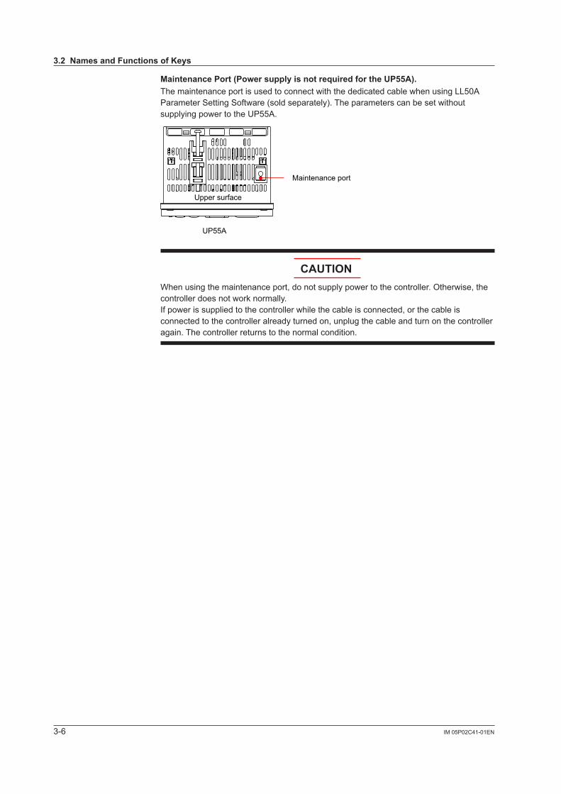
3-6 IM 05P02C41-01EN
MaintenancePort(PowersupplyisnotrequiredfortheUP55A).The maintenance port is used to connect with the dedicated cable when using LL50A Parameter Setting Software (sold separately). The parameters can be set without supplying power to the UP55A.
Maintenance port
UP55A
Upper surface
CAUTIONWhen using the maintenance port, do not supply power to the controller. Otherwise, the controller does not work normally. If power is supplied to the controller while the cable is connected, or the cable is connected to the controller already turned on, unplug the cable and turn on the controller again. The controller returns to the normal condition.
3.2NamesandFunctionsofKeys
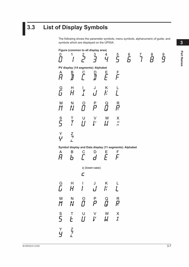
3-7IM 05P02C41-01EN
Part Nam
es
3
3.3 ListofDisplaySymbols
The following shows the parameter symbols, menu symbols, alphanumeric of guide, and symbols which are displayed on the UP55A.
Figure(commontoalldisplayarea)
0 1 2 3 4 5 6 7 8 9
PVdisplay(14segments):Alphabet
A B C D E F
G H I J K L
M N O P Q R
S T U V W X
Y Z
SymboldisplayandDatadisplay(11segments):Alphabet
c (lower-case)
A B C D E F
G H I J K L
M N O P Q R
S T U V W X
Y Z
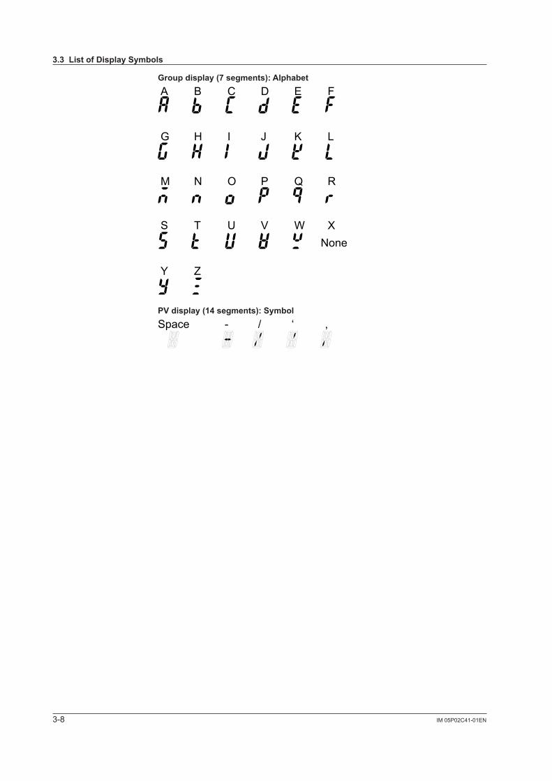
3-8 IM 05P02C41-01EN
Groupdisplay(7segments):Alphabet
A B C D E F
G H I J K L
M N O P Q R
S T U V W X
Y Z
None
PVdisplay(14segments):Symbol
Space - / ‘ ,
3.3ListofDisplaySymbols

3-9IM 05P02C41-01EN
Part Nam
es
3
3.4 BriefDescriptionofSettingDetails(Parameters)
This manual describes the Setting Details as follows in addition to the functional Description.
SettingDetails
(DisplayExample)Parameter symbol Name Display
level Settingrange Menusymbol
A1toA8 Alarm-1 to -8 setpoint EASY
Set a display value of setpoint of PV alarm, SP alarm, deviation alarm, output alarm, or velocity alarm.-19999 to 30000 (Set a value within the input range.)Decimal point position depends on the input type
AL
(1) Parameter symbol: Symbol displayed on Symbol display on the front panel.
(2) Name: Parameter name
(3) Display level: Indicates the parameter display level.
(4) Setting range: Parameter setting range
(5) Menu symbol: Indicates the menu to which the parameter belongs.: Operation parameter: Setup parameter
ParameterDisplayLevelDisplaylevel Description
EASY Easy setting mode: The minimum necessary parameters are displayed.
Corresponding parameters are displayed in all modes.
STD
Standard setting mode: The wider range of parameters than those shown in Easy setting mode are displayed.
Corresponding parameters are displayed only in Standard setting mode and Professional setting mode.Parameter display level indicators "EASY" and "PRO" are unlit in Standard setting mode.*: "STD" is the symbol used in this manual only.
PRO Professional setting mode: All parameters are displayed.
Corresponding parameters are displayed only in Professional setting mode.
NoteFor more intelligible display operation of parameters and the references, see Chapter 18, "Parameter Map."

Blank Page
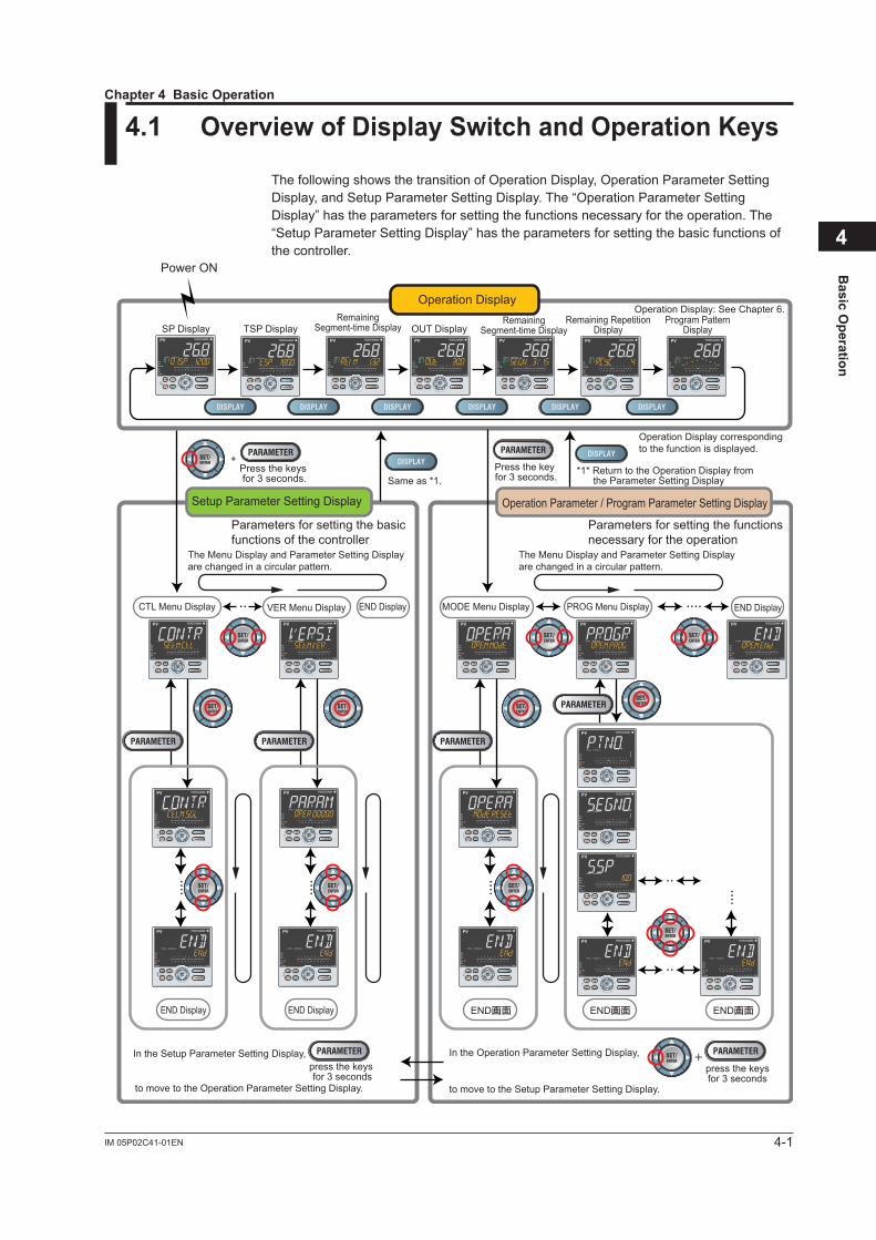
4-1IM 05P02C41-01EN
Basic O
peration
4
4.1 OverviewofDisplaySwitchandOperationKeys
The following shows the transition of Operation Display, Operation Parameter Setting Display, and Setup Parameter Setting Display. The “Operation Parameter Setting Display” has the parameters for setting the functions necessary for the operation. The “Setup Parameter Setting Display” has the parameters for setting the basic functions of the controller.
MODE Menu Display PROG Menu DisplayVER Menu Display
SP Display TSP Display
Power ON
OUT Display
Operation Display: See Chapter 6.
*1* Return to the Operation Display from the Parameter Setting Display
The Menu Display and Parameter Setting Display are changed in a circular pattern.
The Menu Display and Parameter Setting Display are changed in a circular pattern.
Same as *1.Press the keys for 3 seconds.
Press the key for 3 seconds.
+
CTL Menu Display END DisplayEND Display
END DisplayEND Display
press the keysfor 3 seconds
In the Setup Parameter Setting Display, In the Operation Parameter Setting Display,
to move to the Operation Parameter Setting Display. to move to the Setup Parameter Setting Display.
press the keys for 3 seconds
Parameters for setting the basicfunctions of the controller
Parameters for setting the functionsnecessary for the operation
・・ ・・・・
・・
・・
Operation Parameter / Program Parameter Setting Display
END画面 END画面 END画面
+
・・・・
・・・・
・・・・ ・・・・
Operation Display
Setup Parameter Setting Display
Operation Display corresponding to the function is displayed.
Remaining Segment-time Display
Remaining Segment-time Display
Remaining Repetition Display
Program Pattern Display
Chapter4BasicOperation
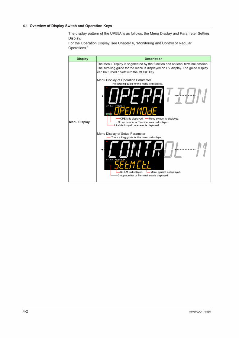
4-2 IM 05P02C41-01EN
The display pattern of the UP55A is as follows; the Menu Display and Parameter Setting Display.For the Operation Display, see Chapter 6, “Monitoring and Control of Regular Operations.”
Display Description
MenuDisplay
The Menu Display is segmented by the function and optional terminal position.The scrolling guide for the menu is displayed on PV display. The guide display can be turned on/off with the MODE key.
Menu Display of Operation ParameterThe scrolling guide for the menu is displayed.
Group number or Terminal area is displayed.Lit while Loop-2 parameter is displayed.
OPE.M is displayed. Menu symbol is displayed.
Menu Display of Setup ParameterThe scrolling guide for the menu is displayed.
Group number or Terminal area is displayed.SET.M is displayed. Menu symbol is displayed.
4.1OverviewofDisplaySwitchandOperationKeys
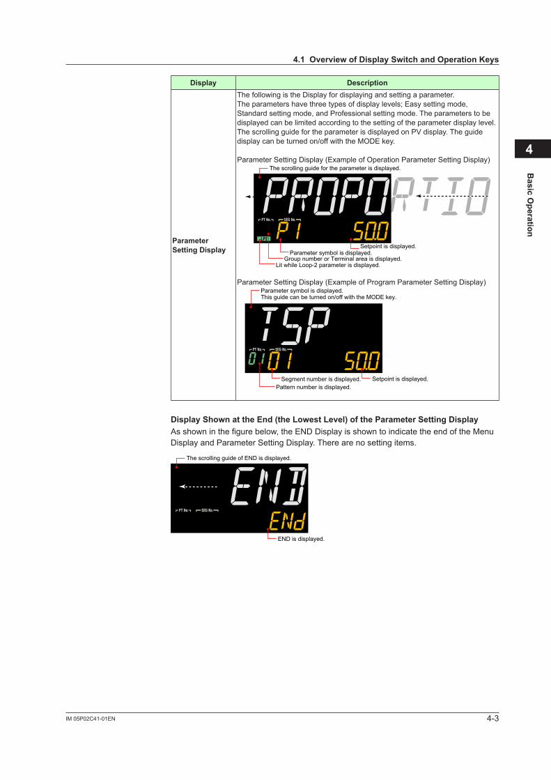
4-3IM 05P02C41-01EN
Basic O
peration
4
Display Description
Parameter SettingDisplay
The following is the Display for displaying and setting a parameter.The parameters have three types of display levels; Easy setting mode, Standard setting mode, and Professional setting mode. The parameters to be displayed can be limited according to the setting of the parameter display level.The scrolling guide for the parameter is displayed on PV display. The guide display can be turned on/off with the MODE key.
Parameter Setting Display (Example of Operation Parameter Setting Display)The scrolling guide for the parameter is displayed.
Group number or Terminal area is displayed.Lit while Loop-2 parameter is displayed.
Setpoint is displayed.Parameter symbol is displayed.
Parameter Setting Display (Example of Program Parameter Setting Display)Parameter symbol is displayed.This guide can be turned on/off with the MODE key.
Segment number is displayed.Pattern number is displayed.
Setpoint is displayed.
DisplayShownattheEnd(theLowestLevel)oftheParameterSettingDisplayAs shown in the figure below, the END Display is shown to indicate the end of the Menu Display and Parameter Setting Display. There are no setting items.
END is displayed.
The scrolling guide of END is displayed.
4.1OverviewofDisplaySwitchandOperationKeys
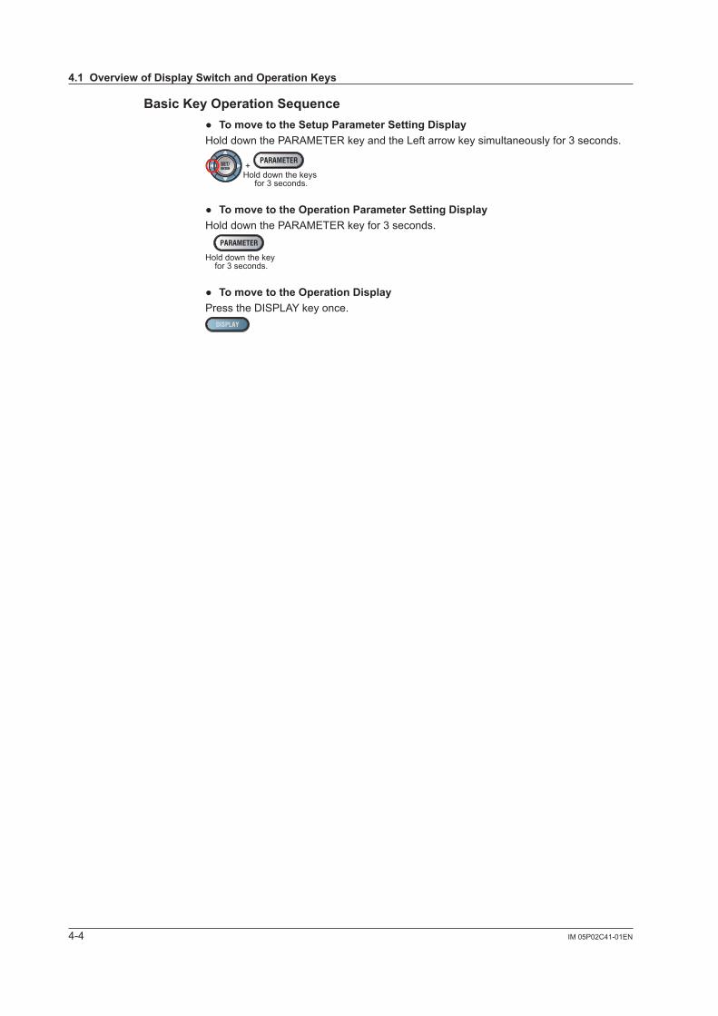
4-4 IM 05P02C41-01EN
BasicKeyOperationSequence TomovetotheSetupParameterSettingDisplayHold down the PARAMETER key and the Left arrow key simultaneously for 3 seconds.
Hold down the keys for 3 seconds.
+
TomovetotheOperationParameterSettingDisplayHold down the PARAMETER key for 3 seconds.
Hold down the key for 3 seconds.
TomovetotheOperationDisplayPress the DISPLAY key once.
4.1OverviewofDisplaySwitchandOperationKeys
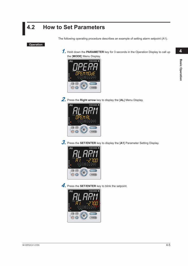
4-5IM 05P02C41-01EN
Basic O
peration
4
4.2 HowtoSetParameters
The following operating procedure describes an example of setting alarm setpoint (A1).
Operation
1. Hold down the PARAMETER key for 3 seconds in the Operation Display to call up the [MODE] Menu Display.
2. Press the Rightarrow key to display the [AL] Menu Display.
3. Press the SET/ENTER key to display the [A1] Parameter Setting Display.
4. Press the SET/ENTER key to blink the setpoint.
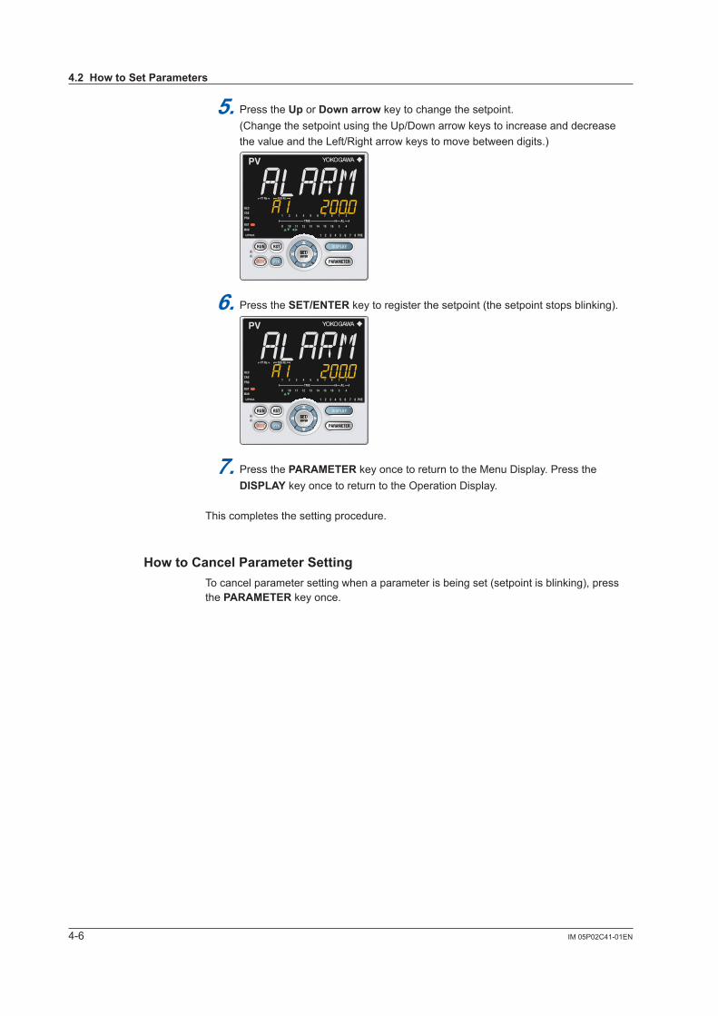
4-6 IM 05P02C41-01EN
5. Press the Up orDownarrow key to change the setpoint. (Change the setpoint using the Up/Down arrow keys to increase and decrease the value and the Left/Right arrow keys to move between digits.)
6. Press the SET/ENTER key to register the setpoint (the setpoint stops blinking).
7. Press the PARAMETER key once to return to the Menu Display. Press the DISPLAY key once to return to the Operation Display.
This completes the setting procedure.
HowtoCancelParameterSettingTo cancel parameter setting when a parameter is being set (setpoint is blinking), press the PARAMETER key once.
4.2HowtoSetParameters
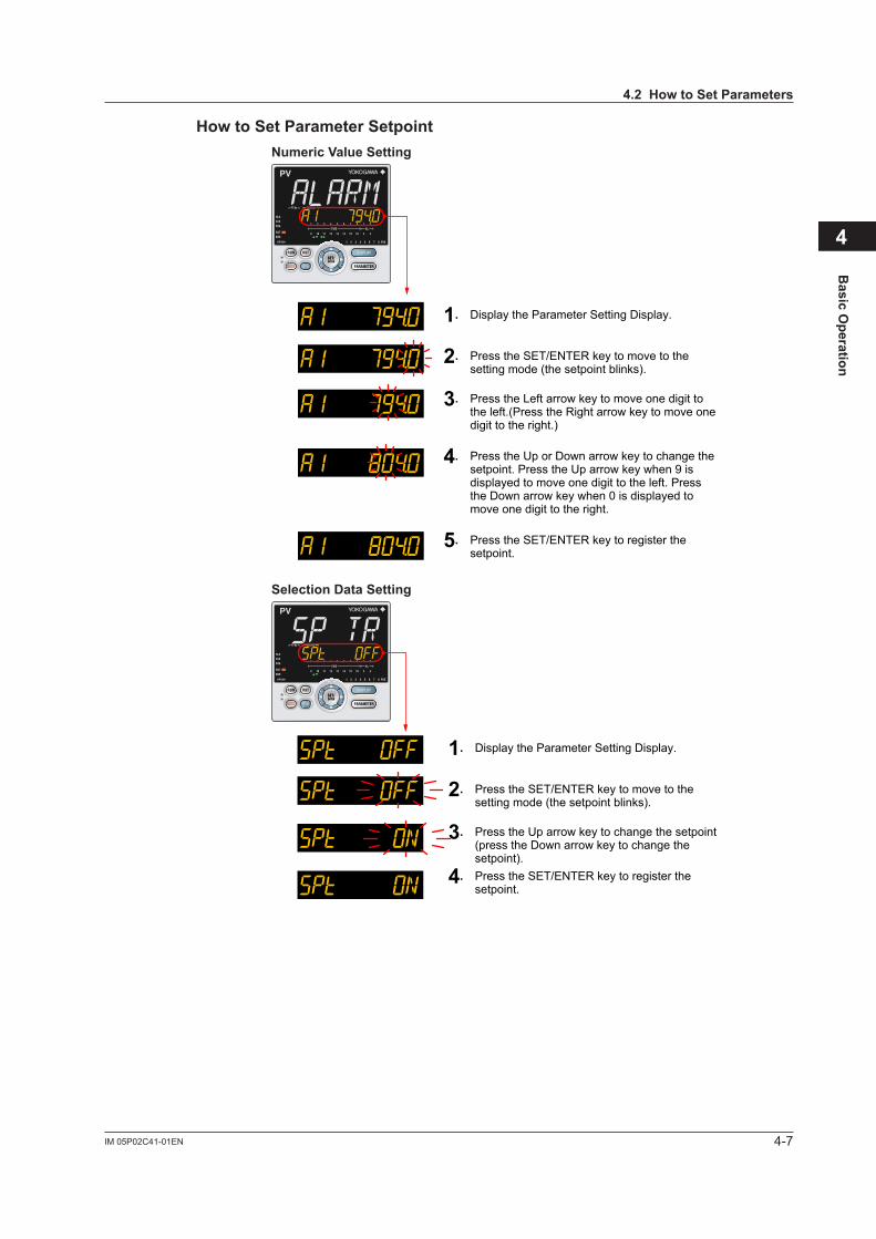
4-7IM 05P02C41-01EN
Basic O
peration
4
4.2HowtoSetParameters
HowtoSetParameterSetpointNumericValueSetting
1. Display the Parameter Setting Display.
2. Press the SET/ENTER key to move to the setting mode (the setpoint blinks).
3. Press the Left arrow key to move one digit to the left.(Press the Right arrow key to move one digit to the right.)
4. Press the Up or Down arrow key to change the setpoint. Press the Up arrow key when 9 is displayed to move one digit to the left. Press the Down arrow key when 0 is displayed to move one digit to the right.
5. Press the SET/ENTER key to register the setpoint.
SelectionDataSetting
1. Display the Parameter Setting Display.
2. Press the SET/ENTER key to move to the setting mode (the setpoint blinks).
3. Press the Up arrow key to change the setpoint (press the Down arrow key to change the setpoint).
4. Press the SET/ENTER key to register the setpoint.
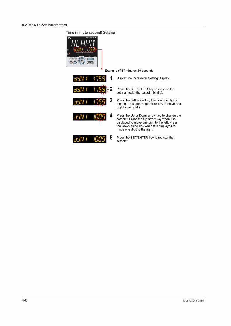
4-8 IM 05P02C41-01EN
Time(minute.second)Setting
Example of 17 minutes 59 seconds
1. Display the Parameter Setting Display.
2. Press the SET/ENTER key to move to the setting mode (the setpoint blinks).
3. Press the Left arrow key to move one digit to the left.(press the Right arrow key to move one digit to the right.)
4. Press the Up or Down arrow key to change the setpoint. Press the Up arrow key when 5 is displayed to move one digit to the left. Press the Down arrow key when 0 is displayed to move one digit to the right.
5. Press the SET/ENTER key to register the setpoint.
4.2HowtoSetParameters
5-1IM 05P02C41-01EN
Quick Setting Function
5
5.1 SettingUsingQuickSettingFunction
Description
The Quick setting function is a function to easily set the basic function of the controller.The Quick setting function starts when the power is turned on after wiring.
The Quick setting function can be used only when the control mode is Single-loop control. In other control modes, set the functions without using the Quick setting function.
The following lists the items to set using the Quick setting function.(1) Control type (PID control, Heating/cooling control, etc.)(2) Input function (PV input, range, scale (at voltage/current input), etc.)(3) Output function (control output type and cycle time)
Chapter5QuickSettingFunction
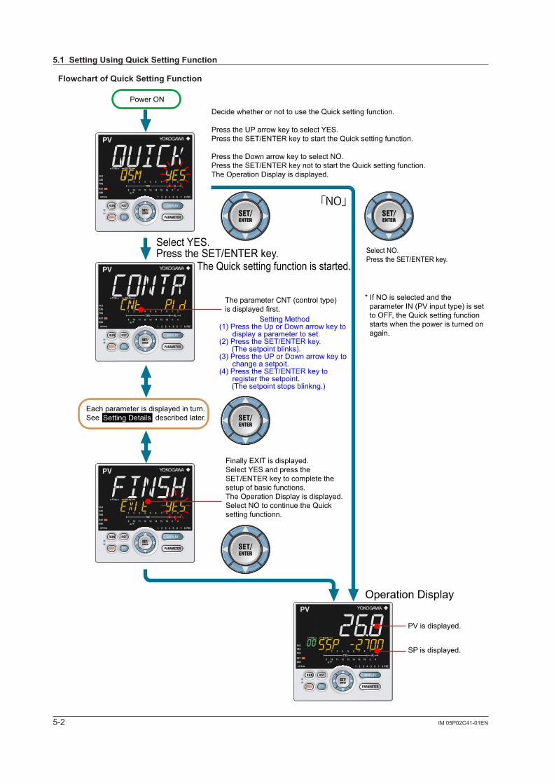
5-2 IM 05P02C41-01EN
FlowchartofQuickSettingFunction
Decide whether or not to use the Quick setting function.
Press the UP arrow key to select YES.Press the SET/ENTER key to start the Quick setting function.
Press the Down arrow key to select NO.Press the SET/ENTER key not to start the Quick setting function.The Operation Display is displayed.
Select YES.Press the SET/ENTER key.
The Quick setting function is started.
Each parameter is displayed in turn.See described later.
Select NO.Press the SET/ENTER key.
Operation Display
Power ON
The parameter CNT (control type) is displayed first.
PV is displayed.
SP is displayed.
Finally EXIT is displayed. Select YES and press the SET/ENTER key to complete the setup of basic functions.The Operation Display is displayed.Select NO to continue the Quick setting functionn.
Setting Method(1) Press the Up or Down arrow key to
display a parameter to set.(2) Press the SET/ENTER key. (The setpoint blinks).(3) Press the UP or Down arrow key to
change a setpoit.(4) Press the SET/ENTER key to
register the setpoint. (The setpoint stops blinkng.)
Setting Details
* If NO is selected and the parameter IN (PV input type) is set to OFF, the Quick setting function starts when the power is turned on again.
「NO」
5.1SettingUsingQuickSettingFunction
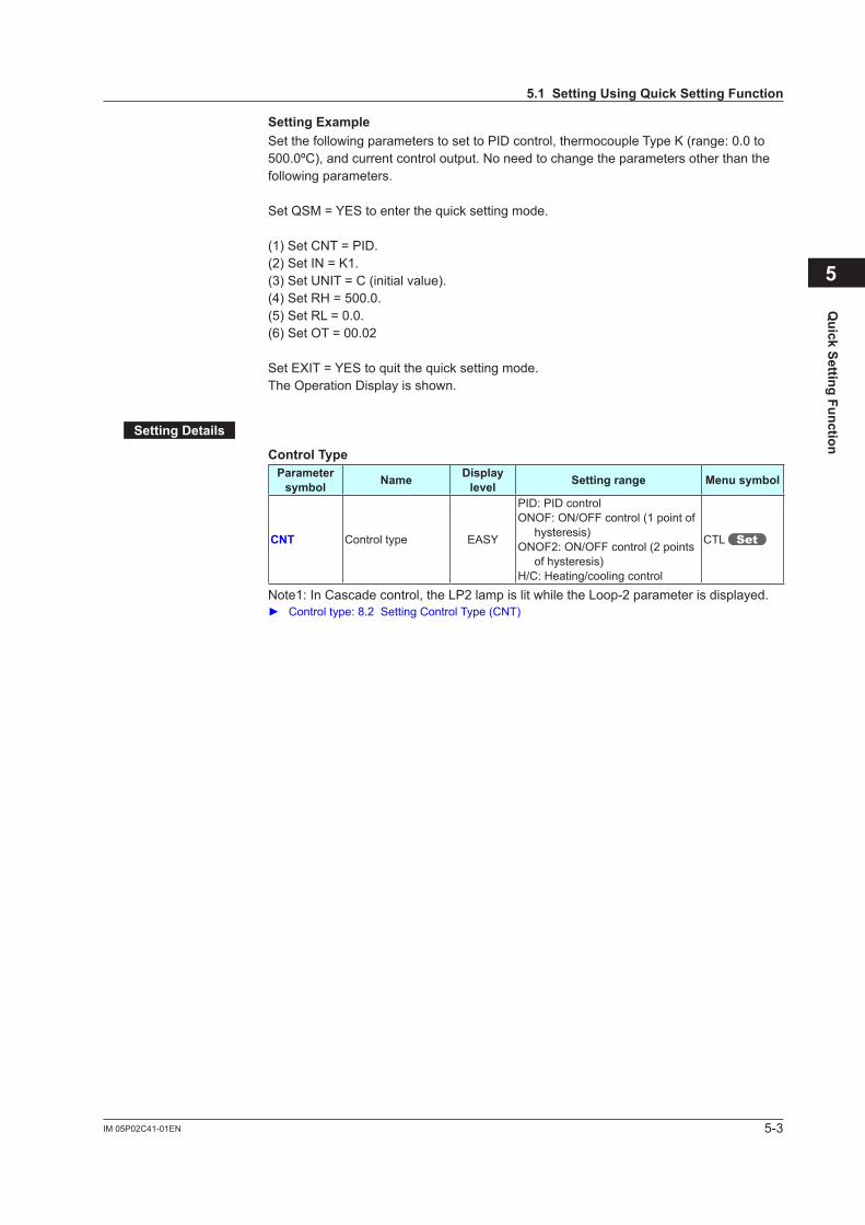
5-3IM 05P02C41-01EN
Quick Setting Function
5
SettingExampleSet the following parameters to set to PID control, thermocouple Type K (range: 0.0 to 500.0ºC), and current control output. No need to change the parameters other than the following parameters.
Set QSM = YES to enter the quick setting mode.
(1) Set CNT = PID.(2) Set IN = K1.(3) Set UNIT = C (initial value).(4) Set RH = 500.0.(5) Set RL = 0.0.(6) Set OT = 00.02
SetEXIT=YEStoquitthequicksettingmode.The Operation Display is shown.
SettingDetails
ControlTypeParameter symbol Name Display
level Settingrange Menusymbol
CNT Control type EASY
PID: PID controlONOF: ON/OFF control (1 point of
hysteresis)ONOF2: ON/OFF control (2 points
of hysteresis)H/C: Heating/cooling control
CTL
Note1: In Cascade control, the LP2 lamp is lit while the Loop-2 parameter is displayed. Controltype:8.2SettingControlType(CNT)
5.1SettingUsingQuickSettingFunction

5-4 IM 05P02C41-01EN
Input FunctionParameter symbol Name Display
level Settingrange Menusymbol
IN PV input type EASY
OFF: DisableK1: -270.0 to 1370.0 ºC / -450.0 to 2500.0 ºFK2: -270.0 to 1000.0 ºC / -450.0 to 2300.0 ºFK3: -200.0 to 500.0 ºC / -200.0 to 1000.0 ºFJ: -200.0 to 1200.0 ºC / -300.0 to 2300.0 ºFT1: -270.0 to 400.0 ºC / -450.0 to 750.0 ºFT2: 0.0 to 400.0 ºC / -200.0 to 750.0 ºFB: 0.0 to 1800.0 ºC / 32 to 3300 ºFS: 0.0 to 1700.0 ºC / 32 to 3100 ºFR: 0.0 to 1700.0 ºC / 32 to 3100 ºFN: -200.0 to 1300.0 ºC / -300.0 to 2400.0 ºFE: -270.0 to 1000.0 ºC / -450.0 to 1800.0 ºFL: -200.0 to 900.0 ºC / -300.0 to 1600.0 ºFU1: -200.0 to 400.0 ºC / -300.0 to 750.0 ºFU2: 0.0 to 400.0 ºC / -200.0 to 1000.0 ºFW: 0.0 to 2300.0 ºC / 32 to 4200 ºFPL2: 0.0 to 1390.0 ºC / 32.0 to 2500.0 ºFP2040: 0.0 to 1900.0 ºC / 32 to 3400 ºFWRE: 0.0 to 2000.0 ºC / 32 to 3600 ºFJPT1: -200.0 to 500.0 ºC / -300.0 to 1000.0 ºFJPT2: -150.0 to 150.0 ºC / -200.0 to 300.0 ºFPT1: -200.0 to 850.0 ºC / -300.0 to 1560.0 ºFPT2: -200.0 to 500.0 ºC / -300.0 to 1000.0 ºFPT3: -150.00 to 150.00 ºC / -200.0 to 300.0 ºF0.4-2V: 0.400 to 2.000 V1-5V: 1.000 to 5.000 V4-20: 4.00 to 20.00 mA0-2V: 0.000 to 2.000 V0-10V: 0.00 to 10.00 V0-20 : 0.00 to 20.00 mA-1020: -10.00 to 20.00 mV0-100: 0.0 to 100.0 mV
PV
UNIT PV input unit EASY
-: No unitC: Degree Celsius-: No unit- -: No unit- - -: No unitF: Degree Fahrenheit
RH Maximum value of PV input range EASY Depends on the input type.
- For temperature input - Set the temperature range that
is actually controlled. (RL<RH)- For voltage / current input - Set the range of a voltage /
current signal that is applied. The scale across which the
voltage / current signal is actually controlled should be set using the maximum value of input scale (SH) and minimum value of input scale (SL). (Input is always 0% when RL=RH.)
RL Minimum value of PV input range EASY
Note1: W:W-5% Re/W-26% Re(Hoskins Mfg. Co.). ASTM E988 WRE: W97Re3-W75Re25
5.1SettingUsingQuickSettingFunction
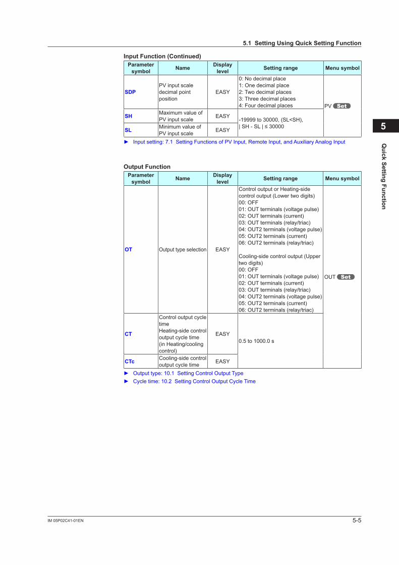
5-5IM 05P02C41-01EN
Quick Setting Function
5
5.1SettingUsingQuickSettingFunction
Input Function (Continued)Parameter symbol Name Display
level Settingrange Menusymbol
SDPPV input scale decimal point position
EASY
0: No decimal place1: One decimal place2: Two decimal places3: Three decimal places4: Four decimal places PV
SH Maximum value of PV input scale EASY
-19999 to 30000, (SL<SH),|SH-SL|≤30000SL Minimum value of
PV input scale EASY
Inputsetting:7.1SettingFunctionsofPVInput,RemoteInput,andAuxiliaryAnalogInput
OutputFunctionParameter symbol Name Display
level Settingrange Menusymbol
OT Output type selection EASY
Control output or Heating-side control output (Lower two digits)00: OFF01: OUT terminals (voltage pulse)02: OUT terminals (current)03: OUT terminals (relay/triac)04: OUT2 terminals (voltage pulse)05: OUT2 terminals (current)06: OUT2 terminals (relay/triac)
Cooling-side control output (Upper two digits)00: OFF01: OUT terminals (voltage pulse)02: OUT terminals (current)03: OUT terminals (relay/triac)04: OUT2 terminals (voltage pulse)05: OUT2 terminals (current)06: OUT2 terminals (relay/triac)
OUT
CT
Control output cycle timeHeating-side control output cycle time (in Heating/cooling control)
EASY0.5 to 1000.0 s
CTc Cooling-side control output cycle time EASY
Outputtype:10.1SettingControlOutputType Cycletime:10.2SettingControlOutputCycleTime
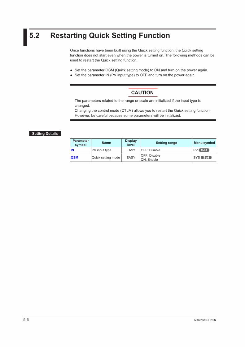
5-6 IM 05P02C41-01EN
5.2 RestartingQuickSettingFunction
Once functions have been built using the Quick setting function, the Quick setting function does not start even when the power is turned on. The following methods can be used to restart the Quick setting function.
SettheparameterQSM(Quicksettingmode)toONandturnonthepoweragain. SettheparameterIN(PVinputtype)toOFFandturnonthepoweragain.
CAUTIONTheparametersrelatedtotherangeorscaleareinitializediftheinputtypeischanged.Changing the control mode (CTLM) allows you to restart the Quick setting function. However,becarefulbecausesomeparameterswillbeinitialized.
SettingDetails
Parameter symbol Name Display
level Settingrange Menusymbol
IN PV input type EASY OFF: Disable PV
QSM Quick setting mode EASY OFF: DisableON: Enable SYS
6-1IM 05P02C41-01EN
Monitoring and C
ontrol of Regular O
perations
6
6.1 MonitoringandControlofOperationDisplays
6.1.1 OperationDisplayTransitionsinSingle-loopControl,CascadePrimary-loopControl,LoopControlwithPVswitching,andLoopControlwithPVauto-selector
Display/Non-display of Operation Display: 13.3.5 Setting Display/Non-display of Operation Display Registration of SELECT Display: 13.1.3 Registering SELECT Display (Up to 5 displays)
See the next page.
Chapter6MonitoringandControlofRegularOperations
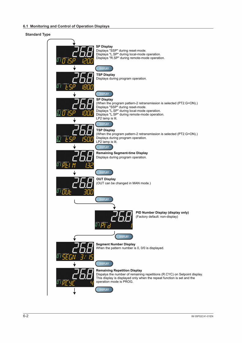
6-2 IM 05P02C41-01EN
StandardType
TSP Display
Remaining Segment-time Display
Segment Number Display
Remaining Repetition Display
Program Pattern Displayprogram pattern (overview)
Can be changed by parameter PTSL.
Soak and ramp display
(Factory default: non-display)Alarm-5 to -8 Status Display (display only)
Displays "SSP" during reset-mode.Displays "L.SP" during local-mode operation.Displays "R.SP" during remote-mode operation.
Displays during program operation.
(When the program pattern-2 retransmission is selected (PT2.G=ON).)Displays "SSP" during reset-mode.Displays "L.SP" during local-mode operation.Displays "L.SP" during remote-mode operation.LP2 lamp is lit.
SP Display
TSP Display (When the program pattern-2 retransmission is selected (PT2.G=ON).)Displays during program operation.LP2 lamp is lit.
Displays during program operation.
When the pattern number is 0, 0/0 is displayed.
Dispalys the number of remaining repetitions (R.CYC) on Setpoint display.This display is displayed only when the repeat function is set and the operation mode is PROG.
When pattern number is 0, pattern is not displayed.
0: On, 1: OnEx.: Alarm 5: Off, Alarm 6: On, Alarm 7: On, Alarm 8: Off
SP Display
OUT Display
PID Number Display (display only)(Factory default: non-display)
Heater Break Alarm-1 Current Display (display only)(Only for Heater break alarm option)
Heater Break Alarm-2 Current Display (display only)(Only for Heater break alarm option)
SELECT Displays 1 to 5(Displayed only when SELECT Display is registered.(The figure on the left is the example of the parameter A1 (alarm-1 setpoint).)
Analog Input Displays (display only)(Factory default: non-display)PV: PV analog input,RSP: RSP analog input (E1-terminal area),AIN2: AIN2 analog input (E2-terminal area),AIN4: AIN4 analog input (E4-terminal area)
(Only for each aux. analog input)
(OUT can be changed in MAN mode.)
6.1MonitoringandControlofOperationDisplays
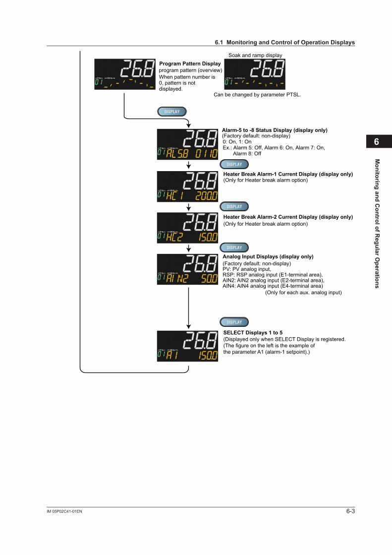
6-3IM 05P02C41-01EN
Monitoring and C
ontrol of Regular O
perations
6
TSP Display
Remaining Segment-time Display
Segment Number Display
Remaining Repetition Display
Program Pattern Displayprogram pattern (overview)
Can be changed by parameter PTSL.
Soak and ramp display
(Factory default: non-display)Alarm-5 to -8 Status Display (display only)
Displays "SSP" during reset-mode.Displays "L.SP" during local-mode operation.Displays "R.SP" during remote-mode operation.
Displays during program operation.
(When the program pattern-2 retransmission is selected (PT2.G=ON).)Displays "SSP" during reset-mode.Displays "L.SP" during local-mode operation.Displays "L.SP" during remote-mode operation.LP2 lamp is lit.
SP Display
TSP Display (When the program pattern-2 retransmission is selected (PT2.G=ON).)Displays during program operation.LP2 lamp is lit.
Displays during program operation.
When the pattern number is 0, 0/0 is displayed.
Dispalys the number of remaining repetitions (R.CYC) on Setpoint display.This display is displayed only when the repeat function is set and the operation mode is PROG.
When pattern number is 0, pattern is not displayed.
0: On, 1: OnEx.: Alarm 5: Off, Alarm 6: On, Alarm 7: On, Alarm 8: Off
SP Display
OUT Display
PID Number Display (display only)(Factory default: non-display)
Heater Break Alarm-1 Current Display (display only)(Only for Heater break alarm option)
Heater Break Alarm-2 Current Display (display only)(Only for Heater break alarm option)
SELECT Displays 1 to 5(Displayed only when SELECT Display is registered.(The figure on the left is the example of the parameter A1 (alarm-1 setpoint).)
Analog Input Displays (display only)(Factory default: non-display)PV: PV analog input,RSP: RSP analog input (E1-terminal area),AIN2: AIN2 analog input (E2-terminal area),AIN4: AIN4 analog input (E4-terminal area)
(Only for each aux. analog input)
(OUT can be changed in MAN mode.)
6.1MonitoringandControlofOperationDisplays
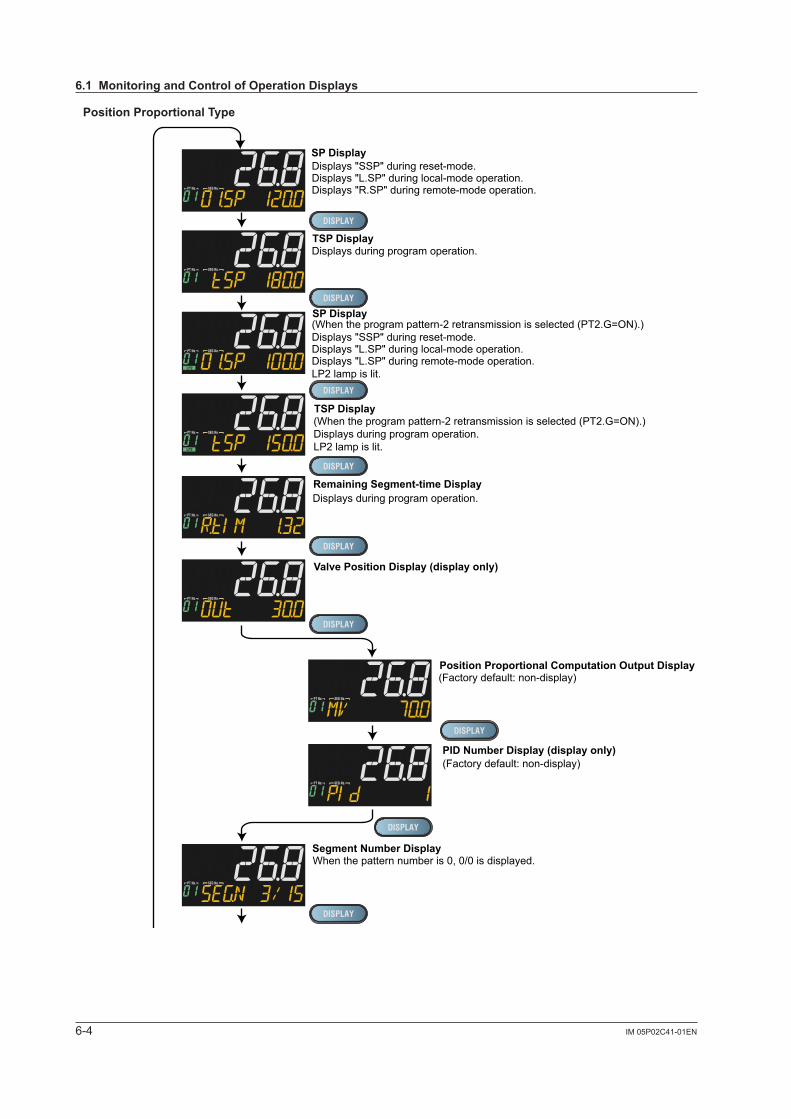
6-4 IM 05P02C41-01EN
PositionProportionalType
TSP Display
Remaining Segment-time Display
Segment Number Display
Remaining Repetition Display
Program Pattern Displayprogram pattern (overview)
Can be changed by parameter PTSL.
Soak and ramp display
(Factory default: non-display)Alarm-5 to -8 Status Display (display only)
Displays "SSP" during reset-mode.Displays "L.SP" during local-mode operation.Displays "R.SP" during remote-mode operation.
Displays during program operation.
(When the program pattern-2 retransmission is selected (PT2.G=ON).)Displays "SSP" during reset-mode.Displays "L.SP" during local-mode operation.Displays "L.SP" during remote-mode operation.LP2 lamp is lit.
SP Display
TSP Display (When the program pattern-2 retransmission is selected (PT2.G=ON).)Displays during program operation.LP2 lamp is lit.
Displays during program operation.
When the pattern number is 0, 0/0 is displayed.
When pattern number is 0, pattern is not displayed.
0: On, 1: OnEx.: Alarm 5: Off, Alarm 6: On, Alarm 7: On, Alarm 8: Off
SP Display
PID Number Display (display only)(Factory default: non-display)
SELECT Displays 1 to 5(Displayed only when SELECT Display is registered.(The figure on the left is the example of the parameter A1 (alarm-1 setpoint).)
Analog Input Displays (display only)(Factory default: non-display)PV: PV analog input,RSP: RSP analog input (E1-terminal area),AIN2: AIN2 analog input (E2-terminal area),AIN4: AIN4 analog input (E4-terminal area)
(Only for each aux. analog input)
(Factory default: non-display)Position Proportional Computation Output Display
Valve Position Display (display only)
Dispalys the number of remaining repetitions (R.CYC) on Setpoint display.This display is displayed only when the repeat function is set and the operation mode is PROG.
6.1MonitoringandControlofOperationDisplays
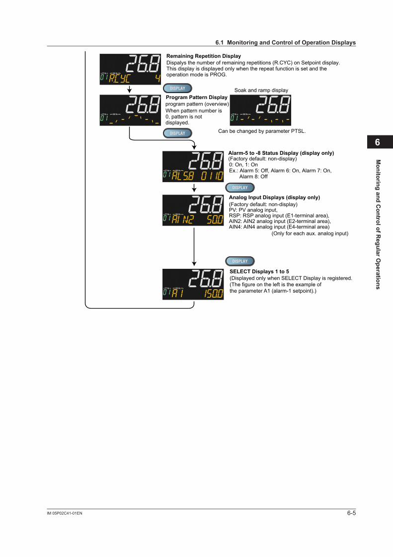
6-5IM 05P02C41-01EN
Monitoring and C
ontrol of Regular O
perations
6
TSP Display
Remaining Segment-time Display
Segment Number Display
Remaining Repetition Display
Program Pattern Displayprogram pattern (overview)
Can be changed by parameter PTSL.
Soak and ramp display
(Factory default: non-display)Alarm-5 to -8 Status Display (display only)
Displays "SSP" during reset-mode.Displays "L.SP" during local-mode operation.Displays "R.SP" during remote-mode operation.
Displays during program operation.
(When the program pattern-2 retransmission is selected (PT2.G=ON).)Displays "SSP" during reset-mode.Displays "L.SP" during local-mode operation.Displays "L.SP" during remote-mode operation.LP2 lamp is lit.
SP Display
TSP Display (When the program pattern-2 retransmission is selected (PT2.G=ON).)Displays during program operation.LP2 lamp is lit.
Displays during program operation.
When the pattern number is 0, 0/0 is displayed.
When pattern number is 0, pattern is not displayed.
0: On, 1: OnEx.: Alarm 5: Off, Alarm 6: On, Alarm 7: On, Alarm 8: Off
SP Display
PID Number Display (display only)(Factory default: non-display)
SELECT Displays 1 to 5(Displayed only when SELECT Display is registered.(The figure on the left is the example of the parameter A1 (alarm-1 setpoint).)
Analog Input Displays (display only)(Factory default: non-display)PV: PV analog input,RSP: RSP analog input (E1-terminal area),AIN2: AIN2 analog input (E2-terminal area),AIN4: AIN4 analog input (E4-terminal area)
(Only for each aux. analog input)
(Factory default: non-display)Position Proportional Computation Output Display
Valve Position Display (display only)
Dispalys the number of remaining repetitions (R.CYC) on Setpoint display.This display is displayed only when the repeat function is set and the operation mode is PROG.
6.1MonitoringandControlofOperationDisplays
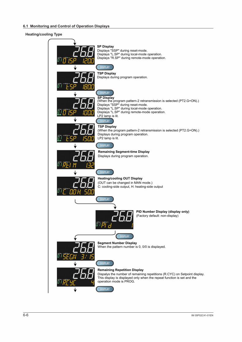
6-6 IM 05P02C41-01EN
Heating/coolingType
TSP Display
Remaining Segment-time Display
Segment Number Display
Remaining Repetition Display
Program Pattern Displayprogram pattern (overview)
Can be changed by parameter PTSL.
Soak and ramp display
(Factory default: non-display)Alarm-5 to -8 Status Display (display only)
Displays "SSP" during reset-mode.Displays "L.SP" during local-mode operation.Displays "R.SP" during remote-mode operation.
Displays during program operation.
(When the program pattern-2 retransmission is selected (PT2.G=ON).)Displays "SSP" during reset-mode.Displays "L.SP" during local-mode operation.Displays "L.SP" during remote-mode operation.LP2 lamp is lit.
SP Display
TSP Display (When the program pattern-2 retransmission is selected (PT2.G=ON).)Displays during program operation.LP2 lamp is lit.
Displays during program operation.
When the pattern number is 0, 0/0 is displayed.
When pattern number is 0, pattern is not displayed.
0: On, 1: OnEx.: Alarm 5: Off, Alarm 6: On, Alarm 7: On, Alarm 8: Off
SP Display
PID Number Display (display only)(Factory default: non-display)
SELECT Displays 1 to 5(Displayed only when SELECT Display is registered.(The figure on the left is the example of the parameter A1 (alarm-1 setpoint).)
Analog Input Displays (display only)(Factory default: non-display)PV: PV analog input,RSP: RSP analog input (E1-terminal area),AIN2: AIN2 analog input (E2-terminal area),AIN4: AIN4 analog input (E4-terminal area)
(Only for each aux. analog input)
(OUT can be changed in MAN mode.)C: cooling-side output, H: heating-side output
Heating/cooling OUT Display
Dispalys the number of remaining repetitions (R.CYC) on Setpoint display.This display is displayed only when the repeat function is set and the operation mode is PROG.
6.1MonitoringandControlofOperationDisplays
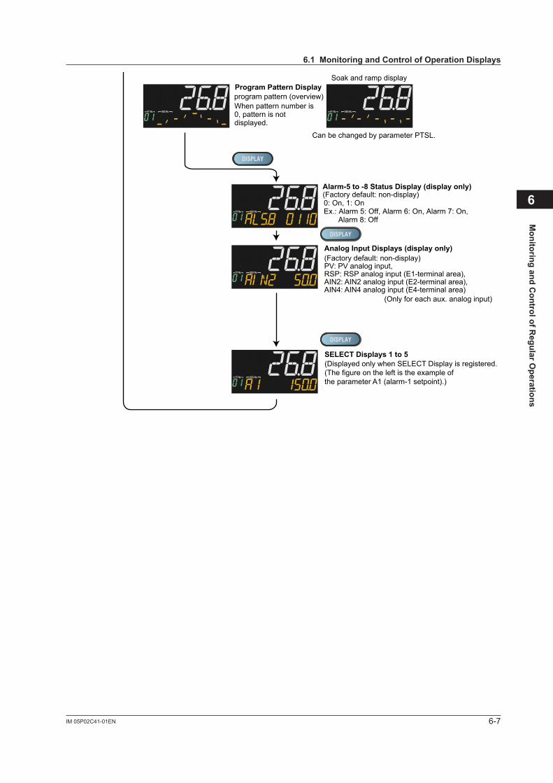
6-7IM 05P02C41-01EN
Monitoring and C
ontrol of Regular O
perations
6
TSP Display
Remaining Segment-time Display
Segment Number Display
Remaining Repetition Display
Program Pattern Displayprogram pattern (overview)
Can be changed by parameter PTSL.
Soak and ramp display
(Factory default: non-display)Alarm-5 to -8 Status Display (display only)
Displays "SSP" during reset-mode.Displays "L.SP" during local-mode operation.Displays "R.SP" during remote-mode operation.
Displays during program operation.
(When the program pattern-2 retransmission is selected (PT2.G=ON).)Displays "SSP" during reset-mode.Displays "L.SP" during local-mode operation.Displays "L.SP" during remote-mode operation.LP2 lamp is lit.
SP Display
TSP Display (When the program pattern-2 retransmission is selected (PT2.G=ON).)Displays during program operation.LP2 lamp is lit.
Displays during program operation.
When the pattern number is 0, 0/0 is displayed.
When pattern number is 0, pattern is not displayed.
0: On, 1: OnEx.: Alarm 5: Off, Alarm 6: On, Alarm 7: On, Alarm 8: Off
SP Display
PID Number Display (display only)(Factory default: non-display)
SELECT Displays 1 to 5(Displayed only when SELECT Display is registered.(The figure on the left is the example of the parameter A1 (alarm-1 setpoint).)
Analog Input Displays (display only)(Factory default: non-display)PV: PV analog input,RSP: RSP analog input (E1-terminal area),AIN2: AIN2 analog input (E2-terminal area),AIN4: AIN4 analog input (E4-terminal area)
(Only for each aux. analog input)
(OUT can be changed in MAN mode.)C: cooling-side output, H: heating-side output
Heating/cooling OUT Display
Dispalys the number of remaining repetitions (R.CYC) on Setpoint display.This display is displayed only when the repeat function is set and the operation mode is PROG.
6.1MonitoringandControlofOperationDisplays

6-8 IM 05P02C41-01EN
6.1.2 OperationDisplayTransitionsinCascadeControl Display/non-display of Operation Display: 13.3.5 Setting Display/Non-Display of Operation Display Registration of SELECT Display: 13.1.3 Registering SELECT Display (Up to 5 Displays)
StandardType
When the operation mode is Cascade (CAS):
TSP Display
Remaining Segment-time Display
Segment Number Display
Remaining Repetition Display
Program Pattern Displayprogram pattern (overview)
Can be changed by parameter PTSL.
Soak and ramp display
(Factory default: non-display)Loop-1 Alarm-5 to -8 Status Display (display only)
PV display: Loop-1 PVDisplays "SSP" during reset-mode.Displays "L.SP" during local-mode operation.Displays "R.SP" during remote-mode operation.
Displays during program operation.
Displays during program operation.
When the pattern number is 0, 0/0 is displayed.
When pattern number is 0, pattern is not displayed.
0: On, 1: OnEx.: Alarm 5: Off, Alarm 6: On, Alarm 7: On, Alarm 8: Off
(Factory default: non-display) LP2 lamp is lit.Loop-2 Alarm-5 to -8 Status Display (display only)
0: On, 1: OnEx.: Alarm 5: Off, Alarm 6: On, Alarm 7: On, Alarm 8: On
Loop-1 SP Display
Loop-2 OUT Display (display only)
Heater Break Alarm-1 Current Display (display only)(Only for Heater break alarm option)PV display: Loop-1 PV
Heater Break Alarm-2 Current Display (display only)(Only for Heater break alarm option)PV display: Loop-1 PV
SELECT Displays 1 to 5(Displayed only when SELECT Display is registered.(The figure on the left is the example of the parameter A1 (alarm-1 setpoint).)
Analog Input Displays (display only)(Factory default: non-display)PV: PV analog input,RSP: RSP analog input (E1-terminal area),AIN2: AIN2 analog input (E2-terminal area),AIN4: AIN4 analog input (E4-terminal area)
(Only for each aux. analog input)
PV display: Loop-1 PVLP2 lamp is lit.
Loop-1 PID Number Display (display only)(Factory default: non-display)PV display: Loop-1 PV
Loop-2 PID Number Display (display only)(Factory default: non-display)PV display: Loop-1 PVLP2 lamp is lit.
Loop-1 OUT Display (display only)(Factory default: non-display)PV display: Loop-1 PVSetpoint display: Loop-1 OUT
Loop-1/Loop-2 PV Display (display only)PV display: Loop-1 PVSetpoint display: Loop-2 PVLP2 lamp is lit.
Dispalys the number of remaining repetitions (R.CYC) on Setpoint display.This display is displayed only when the repeat function is set and the operation mode is PROG.
6.1MonitoringandControlofOperationDisplays
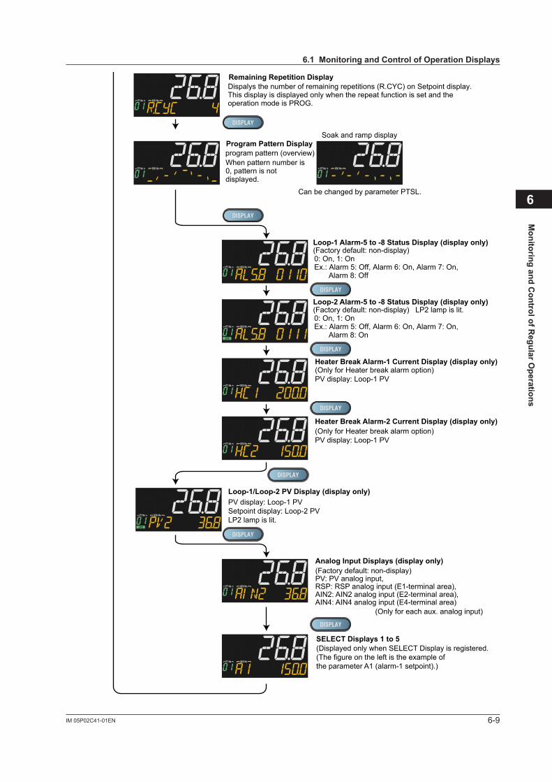
6-9IM 05P02C41-01EN
Monitoring and C
ontrol of Regular O
perations
6
TSP Display
Remaining Segment-time Display
Segment Number Display
Remaining Repetition Display
Program Pattern Displayprogram pattern (overview)
Can be changed by parameter PTSL.
Soak and ramp display
(Factory default: non-display)Loop-1 Alarm-5 to -8 Status Display (display only)
PV display: Loop-1 PVDisplays "SSP" during reset-mode.Displays "L.SP" during local-mode operation.Displays "R.SP" during remote-mode operation.
Displays during program operation.
Displays during program operation.
When the pattern number is 0, 0/0 is displayed.
When pattern number is 0, pattern is not displayed.
0: On, 1: OnEx.: Alarm 5: Off, Alarm 6: On, Alarm 7: On, Alarm 8: Off
(Factory default: non-display) LP2 lamp is lit.Loop-2 Alarm-5 to -8 Status Display (display only)
0: On, 1: OnEx.: Alarm 5: Off, Alarm 6: On, Alarm 7: On, Alarm 8: On
Loop-1 SP Display
Loop-2 OUT Display (display only)
Heater Break Alarm-1 Current Display (display only)(Only for Heater break alarm option)PV display: Loop-1 PV
Heater Break Alarm-2 Current Display (display only)(Only for Heater break alarm option)PV display: Loop-1 PV
SELECT Displays 1 to 5(Displayed only when SELECT Display is registered.(The figure on the left is the example of the parameter A1 (alarm-1 setpoint).)
Analog Input Displays (display only)(Factory default: non-display)PV: PV analog input,RSP: RSP analog input (E1-terminal area),AIN2: AIN2 analog input (E2-terminal area),AIN4: AIN4 analog input (E4-terminal area)
(Only for each aux. analog input)
PV display: Loop-1 PVLP2 lamp is lit.
Loop-1 PID Number Display (display only)(Factory default: non-display)PV display: Loop-1 PV
Loop-2 PID Number Display (display only)(Factory default: non-display)PV display: Loop-1 PVLP2 lamp is lit.
Loop-1 OUT Display (display only)(Factory default: non-display)PV display: Loop-1 PVSetpoint display: Loop-1 OUT
Loop-1/Loop-2 PV Display (display only)PV display: Loop-1 PVSetpoint display: Loop-2 PVLP2 lamp is lit.
Dispalys the number of remaining repetitions (R.CYC) on Setpoint display.This display is displayed only when the repeat function is set and the operation mode is PROG.
6.1MonitoringandControlofOperationDisplays
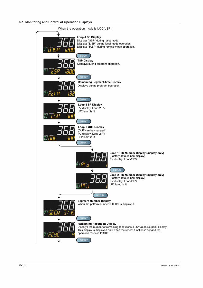
6-10 IM 05P02C41-01EN
When the operation mode is LOC(LSP):
TSP Display
Remaining Segment-time Display
Segment Number Display
Remaining Repetition Display
Program Pattern Displayprogram pattern (overview)
Can be changed by parameter PTSL.
Soak and ramp display
(Factory default: non-display)Loop-1 Alarm-5 to -8 Status Display (display only)
Displays "SSP" during reset-mode.Displays "L.SP" during local-mode operation.Displays "R.SP" during remote-mode operation.
Displays during program operation.
Displays during program operation.
When the pattern number is 0, 0/0 is displayed.
When pattern number is 0, pattern is not displayed.
0: On, 1: OnEx.: Alarm 5: Off, Alarm 6: On, Alarm 7: On, Alarm 8: Off
(Factory default: non-display) LP2 lamp is lit.Loop-2 Alarm-5 to -8 Status Display (display only)
0: On, 1: OnEx.: Alarm 5: Off, Alarm 6: On, Alarm 7: On, Alarm 8: On
Loop-1 SP Display
Loop-2 SP Display
SELECT Displays 1 to 5(Displayed only when SELECT Display is registered.(The figure on the left is the example of the parameter A1 (alarm-1 setpoint).)
Analog Input Displays (display only)(Factory default: non-display)PV: PV analog input,RSP: RSP analog input (E1-terminal area),AIN2: AIN2 analog input (E2-terminal area),AIN4: AIN4 analog input (E4-terminal area)
(Only for each aux. analog input)
PV display: Loop-2 PVLP2 lamp is lit.
Loop-2 OUT Display(OUT can be changed.) PV display: Loop-2 PVLP2 lamp is lit.
Loop-1 PID Number Display (display only)(Factory default: non-display)PV display: Loop-2 PV
Loop-2 PID Number Display (display only)(Factory default: non-display)PV display: Loop-2 PVLP2 lamp is lit.
Loop-2/Loop-1 PV Display (display only)PV display: Loop-2 PVSetpoint display: Loop-1 PV
Loop-1 PID Number Display (display only)(Factory default: non-display)PV display: Loop-2 PV
Loop-2 PID Number Display (display only)(Factory default: non-display)PV display: Loop-2 PVLP2 lamp is lit.
Dispalys the number of remaining repetitions (R.CYC) on Setpoint display.This display is displayed only when the repeat function is set and the operation mode is PROG.
6.1MonitoringandControlofOperationDisplays
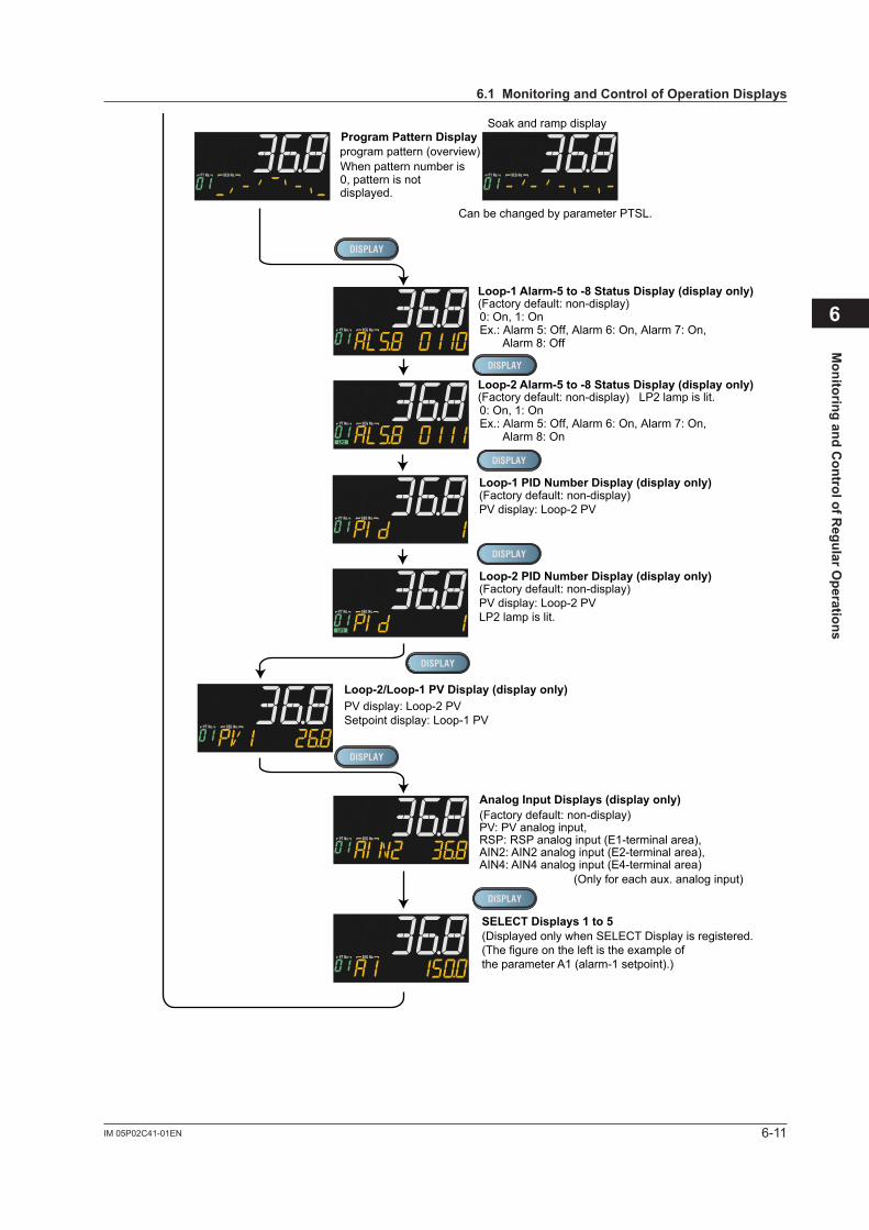
6-11IM 05P02C41-01EN
Monitoring and C
ontrol of Regular O
perations
6
TSP Display
Remaining Segment-time Display
Segment Number Display
Remaining Repetition Display
Program Pattern Displayprogram pattern (overview)
Can be changed by parameter PTSL.
Soak and ramp display
(Factory default: non-display)Loop-1 Alarm-5 to -8 Status Display (display only)
Displays "SSP" during reset-mode.Displays "L.SP" during local-mode operation.Displays "R.SP" during remote-mode operation.
Displays during program operation.
Displays during program operation.
When the pattern number is 0, 0/0 is displayed.
When pattern number is 0, pattern is not displayed.
0: On, 1: OnEx.: Alarm 5: Off, Alarm 6: On, Alarm 7: On, Alarm 8: Off
(Factory default: non-display) LP2 lamp is lit.Loop-2 Alarm-5 to -8 Status Display (display only)
0: On, 1: OnEx.: Alarm 5: Off, Alarm 6: On, Alarm 7: On, Alarm 8: On
Loop-1 SP Display
Loop-2 SP Display
SELECT Displays 1 to 5(Displayed only when SELECT Display is registered.(The figure on the left is the example of the parameter A1 (alarm-1 setpoint).)
Analog Input Displays (display only)(Factory default: non-display)PV: PV analog input,RSP: RSP analog input (E1-terminal area),AIN2: AIN2 analog input (E2-terminal area),AIN4: AIN4 analog input (E4-terminal area)
(Only for each aux. analog input)
PV display: Loop-2 PVLP2 lamp is lit.
Loop-2 OUT Display(OUT can be changed.) PV display: Loop-2 PVLP2 lamp is lit.
Loop-1 PID Number Display (display only)(Factory default: non-display)PV display: Loop-2 PV
Loop-2 PID Number Display (display only)(Factory default: non-display)PV display: Loop-2 PVLP2 lamp is lit.
Loop-2/Loop-1 PV Display (display only)PV display: Loop-2 PVSetpoint display: Loop-1 PV
Loop-1 PID Number Display (display only)(Factory default: non-display)PV display: Loop-2 PV
Loop-2 PID Number Display (display only)(Factory default: non-display)PV display: Loop-2 PVLP2 lamp is lit.
Dispalys the number of remaining repetitions (R.CYC) on Setpoint display.This display is displayed only when the repeat function is set and the operation mode is PROG.
6.1MonitoringandControlofOperationDisplays
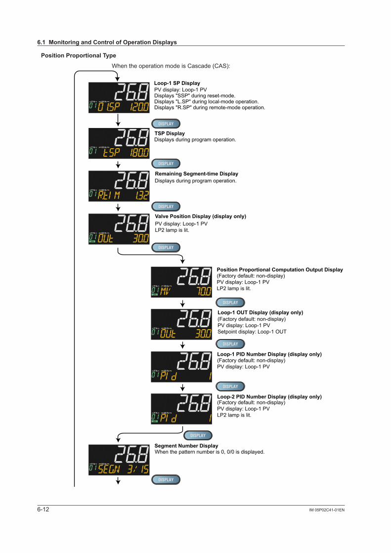
6-12 IM 05P02C41-01EN
PositionProportionalType
When the operation mode is Cascade (CAS):
TSP Display
Remaining Segment-time Display
Segment Number Display
Remaining Repetition Display
Program Pattern Displayprogram pattern (overview)
Can be changed by parameter PTSL.
Soak and ramp display
(Factory default: non-display)Loop-1 Alarm-5 to -8 Status Display (display only)
PV display: Loop-1 PVDisplays "SSP" during reset-mode.Displays "L.SP" during local-mode operation.Displays "R.SP" during remote-mode operation.
Displays during program operation.
Displays during program operation.
When the pattern number is 0, 0/0 is displayed.
When pattern number is 0, pattern is not displayed.
0: On, 1: OnEx.: Alarm 5: Off, Alarm 6: On, Alarm 7: On, Alarm 8: Off
(Factory default: non-display) LP2 lamp is lit.Loop-2 Alarm-5 to -8 Status Display (display only)
0: On, 1: OnEx.: Alarm 5: Off, Alarm 6: On, Alarm 7: On, Alarm 8: On
Loop-1 SP Display
SELECT Displays 1 to 5(Displayed only when SELECT Display is registered.(The figure on the left is the example of the parameter A1 (alarm-1 setpoint).)
Analog Input Displays (display only)(Factory default: non-display)PV: PV analog input,RSP: RSP analog input (E1-terminal area),AIN2: AIN2 analog input (E2-terminal area),AIN4: AIN4 analog input (E4-terminal area)
(Only for each aux. analog input)
Loop-2 PID Number Display (display only)
Loop-1 PID Number Display (display only)
(Factory default: non-display)PV display: Loop-1 PVLP2 lamp is lit.
(Factory default: non-display)PV display: Loop-1 PV
Loop-1 OUT Display (display only)(Factory default: non-display)PV display: Loop-1 PVSetpoint display: Loop-1 OUT
Loop-1/Loop-2 PV Display (display only)PV display: Loop-1 PVSetpoint display: Loop-2 PVLP2 lamp is lit.
PV display: Loop-1 PVLP2 lamp is lit.
Valve Position Display (display only)
Position Proportional Computation Output Display(Factory default: non-display)PV display: Loop-1 PVLP2 lamp is lit.
Dispalys the number of remaining repetitions (R.CYC) on Setpoint display.This display is displayed only when the repeat function is set and the operation mode is PROG.
6.1MonitoringandControlofOperationDisplays
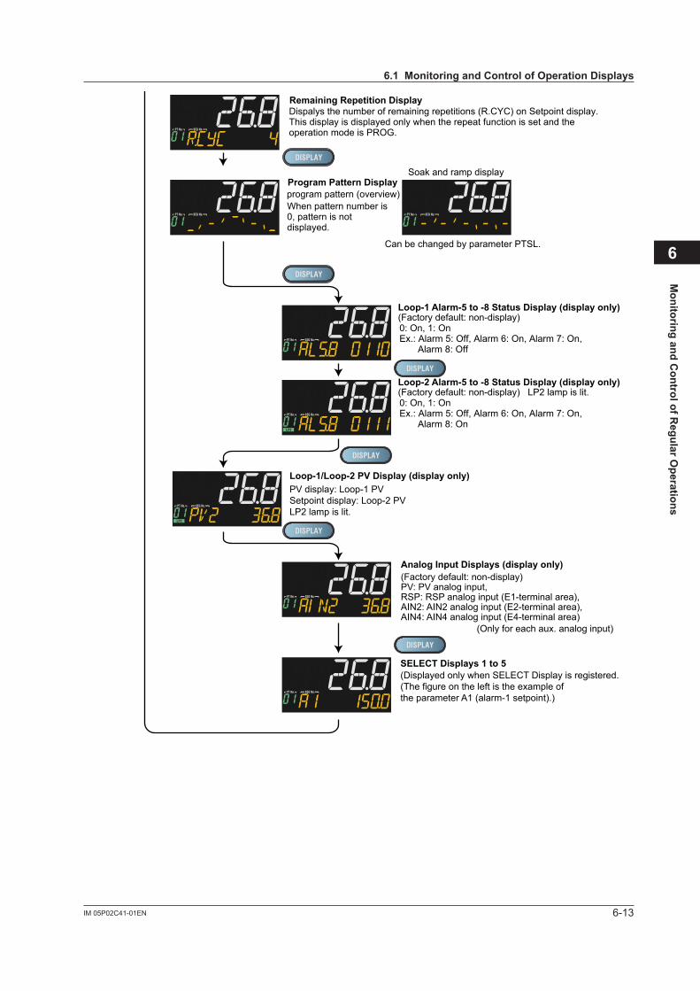
6-13IM 05P02C41-01EN
Monitoring and C
ontrol of Regular O
perations
6
TSP Display
Remaining Segment-time Display
Segment Number Display
Remaining Repetition Display
Program Pattern Displayprogram pattern (overview)
Can be changed by parameter PTSL.
Soak and ramp display
(Factory default: non-display)Loop-1 Alarm-5 to -8 Status Display (display only)
PV display: Loop-1 PVDisplays "SSP" during reset-mode.Displays "L.SP" during local-mode operation.Displays "R.SP" during remote-mode operation.
Displays during program operation.
Displays during program operation.
When the pattern number is 0, 0/0 is displayed.
When pattern number is 0, pattern is not displayed.
0: On, 1: OnEx.: Alarm 5: Off, Alarm 6: On, Alarm 7: On, Alarm 8: Off
(Factory default: non-display) LP2 lamp is lit.Loop-2 Alarm-5 to -8 Status Display (display only)
0: On, 1: OnEx.: Alarm 5: Off, Alarm 6: On, Alarm 7: On, Alarm 8: On
Loop-1 SP Display
SELECT Displays 1 to 5(Displayed only when SELECT Display is registered.(The figure on the left is the example of the parameter A1 (alarm-1 setpoint).)
Analog Input Displays (display only)(Factory default: non-display)PV: PV analog input,RSP: RSP analog input (E1-terminal area),AIN2: AIN2 analog input (E2-terminal area),AIN4: AIN4 analog input (E4-terminal area)
(Only for each aux. analog input)
Loop-2 PID Number Display (display only)
Loop-1 PID Number Display (display only)
(Factory default: non-display)PV display: Loop-1 PVLP2 lamp is lit.
(Factory default: non-display)PV display: Loop-1 PV
Loop-1 OUT Display (display only)(Factory default: non-display)PV display: Loop-1 PVSetpoint display: Loop-1 OUT
Loop-1/Loop-2 PV Display (display only)PV display: Loop-1 PVSetpoint display: Loop-2 PVLP2 lamp is lit.
PV display: Loop-1 PVLP2 lamp is lit.
Valve Position Display (display only)
Position Proportional Computation Output Display(Factory default: non-display)PV display: Loop-1 PVLP2 lamp is lit.
Dispalys the number of remaining repetitions (R.CYC) on Setpoint display.This display is displayed only when the repeat function is set and the operation mode is PROG.
6.1MonitoringandControlofOperationDisplays
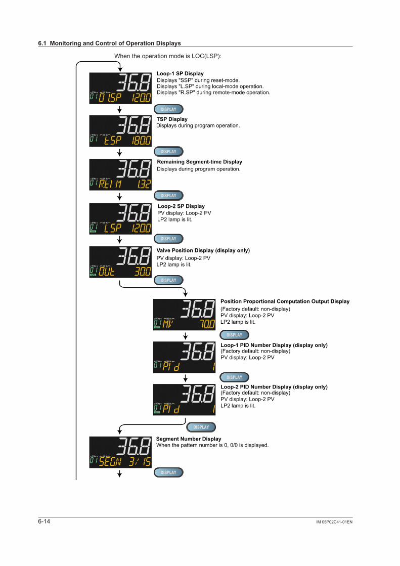
6-14 IM 05P02C41-01EN
When the operation mode is LOC(LSP):
TSP Display
Remaining Segment-time Display
Segment Number Display
Remaining Repetition Display
Program Pattern Displayprogram pattern (overview)
Can be changed by parameter PTSL.
Soak and ramp display
(Factory default: non-display)Loop-1 Alarm-5 to -8 Status Display (display only)
Displays "SSP" during reset-mode.Displays "L.SP" during local-mode operation.Displays "R.SP" during remote-mode operation.
Displays during program operation.
Displays during program operation.
When the pattern number is 0, 0/0 is displayed.
When pattern number is 0, pattern is not displayed.
0: On, 1: OnEx.: Alarm 5: Off, Alarm 6: On, Alarm 7: On, Alarm 8: Off
(Factory default: non-display) LP2 lamp is lit.Loop-2 Alarm-5 to -8 Status Display (display only)
0: On, 1: OnEx.: Alarm 5: Off, Alarm 6: On, Alarm 7: On, Alarm 8: On
Loop-1 SP Display
Loop-2 SP Display
SELECT Displays 1 to 5(Displayed only when SELECT Display is registered.(The figure on the left is the example of the parameter A1 (alarm-1 setpoint).)
Analog Input Displays (display only)(Factory default: non-display)PV: PV analog input,RSP: RSP analog input (E1-terminal area),AIN2: AIN2 analog input (E2-terminal area),AIN4: AIN4 analog input (E4-terminal area)
(Only for each aux. analog input)
PV display: Loop-2 PVLP2 lamp is lit.
Loop-1 PID Number Display (display only)(Factory default: non-display)PV display: Loop-2 PV
Loop-2 PID Number Display (display only)(Factory default: non-display)PV display: Loop-2 PVLP2 lamp is lit.
Loop-2/Loop-1 PV Display (display only)PV display: Loop-2 PVSetpoint display: Loop-1 PV
Position Proportional Computation Output Display(Factory default: non-display)PV display: Loop-2 PVLP2 lamp is lit.
Valve Position Display (display only)PV display: Loop-2 PVLP2 lamp is lit.
Dispalys the number of remaining repetitions (R.CYC) on Setpoint display.This display is displayed only when the repeat function is set and the operation mode is PROG.
6.1MonitoringandControlofOperationDisplays
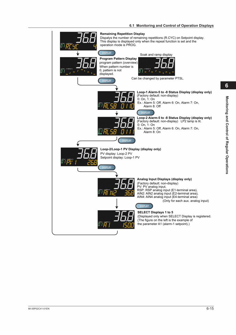
6-15IM 05P02C41-01EN
Monitoring and C
ontrol of Regular O
perations
6
TSP Display
Remaining Segment-time Display
Segment Number Display
Remaining Repetition Display
Program Pattern Displayprogram pattern (overview)
Can be changed by parameter PTSL.
Soak and ramp display
(Factory default: non-display)Loop-1 Alarm-5 to -8 Status Display (display only)
Displays "SSP" during reset-mode.Displays "L.SP" during local-mode operation.Displays "R.SP" during remote-mode operation.
Displays during program operation.
Displays during program operation.
When the pattern number is 0, 0/0 is displayed.
When pattern number is 0, pattern is not displayed.
0: On, 1: OnEx.: Alarm 5: Off, Alarm 6: On, Alarm 7: On, Alarm 8: Off
(Factory default: non-display) LP2 lamp is lit.Loop-2 Alarm-5 to -8 Status Display (display only)
0: On, 1: OnEx.: Alarm 5: Off, Alarm 6: On, Alarm 7: On, Alarm 8: On
Loop-1 SP Display
Loop-2 SP Display
SELECT Displays 1 to 5(Displayed only when SELECT Display is registered.(The figure on the left is the example of the parameter A1 (alarm-1 setpoint).)
Analog Input Displays (display only)(Factory default: non-display)PV: PV analog input,RSP: RSP analog input (E1-terminal area),AIN2: AIN2 analog input (E2-terminal area),AIN4: AIN4 analog input (E4-terminal area)
(Only for each aux. analog input)
PV display: Loop-2 PVLP2 lamp is lit.
Loop-1 PID Number Display (display only)(Factory default: non-display)PV display: Loop-2 PV
Loop-2 PID Number Display (display only)(Factory default: non-display)PV display: Loop-2 PVLP2 lamp is lit.
Loop-2/Loop-1 PV Display (display only)PV display: Loop-2 PVSetpoint display: Loop-1 PV
Position Proportional Computation Output Display(Factory default: non-display)PV display: Loop-2 PVLP2 lamp is lit.
Valve Position Display (display only)PV display: Loop-2 PVLP2 lamp is lit.
Dispalys the number of remaining repetitions (R.CYC) on Setpoint display.This display is displayed only when the repeat function is set and the operation mode is PROG.
6.1MonitoringandControlofOperationDisplays
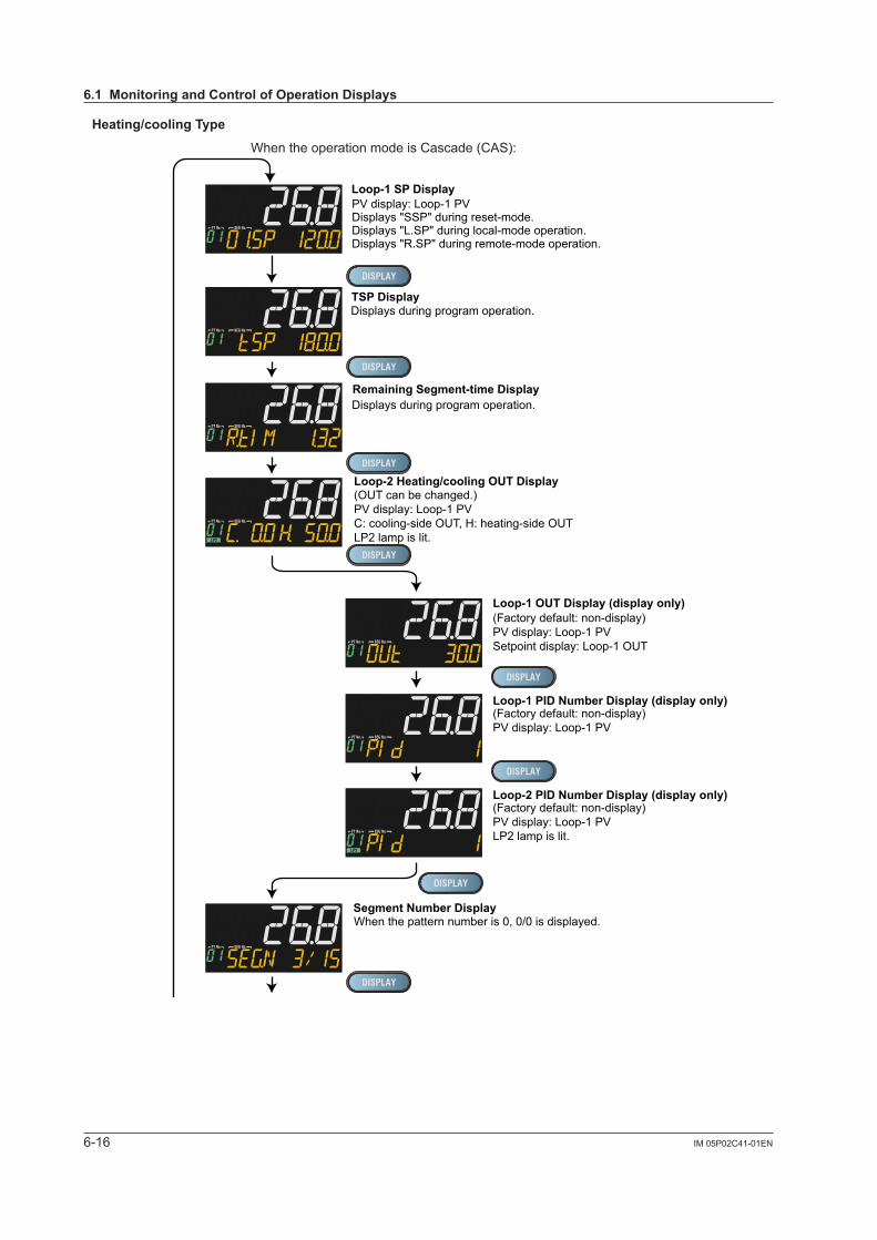
6-16 IM 05P02C41-01EN
Heating/coolingType
When the operation mode is Cascade (CAS):
TSP Display
Remaining Segment-time Display
Segment Number Display
Remaining Repetition Display
Program Pattern Displayprogram pattern (overview)
Can be changed by parameter PTSL.
Soak and ramp display
(Factory default: non-display)Loop-1 Alarm-5 to -8 Status Display (display only)
PV display: Loop-1 PVDisplays "SSP" during reset-mode.Displays "L.SP" during local-mode operation.Displays "R.SP" during remote-mode operation.
Displays during program operation.
Displays during program operation.
When the pattern number is 0, 0/0 is displayed.
When pattern number is 0, pattern is not displayed.
0: On, 1: OnEx.: Alarm 5: Off, Alarm 6: On, Alarm 7: On, Alarm 8: On
(Factory default: non-display) LP2 lamp is lit.Loop-2 Alarm-5 to -8 Status Display (display only)
0: On, 1: OnEx.: Alarm 5: Off, Alarm 6: On, Alarm 7: On, Alarm 8: On
Loop-1 SP Display
SELECT Displays 1 to 5(Displayed only when SELECT Display is registered.(The figure on the left is the example of the parameter A1 (alarm-1 setpoint).)
Analog Input Displays (display only)(Factory default: non-display)PV: PV analog input,RSP: RSP analog input (E1-terminal area),AIN2: AIN2 analog input (E2-terminal area),AIN4: AIN4 analog input (E4-terminal area)
(Only for each aux. analog input)
Loop-1 PID Number Display (display only)(Factory default: non-display)PV display: Loop-1 PV
Loop-2 PID Number Display (display only)(Factory default: non-display)PV display: Loop-1 PVLP2 lamp is lit.
Loop-1 OUT Display (display only)(Factory default: non-display)PV display: Loop-1 PVSetpoint display: Loop-1 OUT
Loop-1/Loop-2 PV Display (display only)PV display: Loop-1 PVSetpoint display: Loop-2 PVLP2 lamp is lit.
Loop-2 Heating/cooling OUT Display(OUT can be changed.)PV display: Loop-1 PVC: cooling-side OUT, H: heating-side OUTLP2 lamp is lit.
Dispalys the number of remaining repetitions (R.CYC) on Setpoint display.This display is displayed only when the repeat function is set and the operation mode is PROG.
6.1MonitoringandControlofOperationDisplays
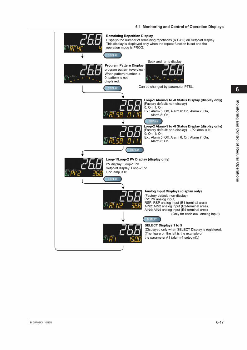
6-17IM 05P02C41-01EN
Monitoring and C
ontrol of Regular O
perations
6
TSP Display
Remaining Segment-time Display
Segment Number Display
Remaining Repetition Display
Program Pattern Displayprogram pattern (overview)
Can be changed by parameter PTSL.
Soak and ramp display
(Factory default: non-display)Loop-1 Alarm-5 to -8 Status Display (display only)
PV display: Loop-1 PVDisplays "SSP" during reset-mode.Displays "L.SP" during local-mode operation.Displays "R.SP" during remote-mode operation.
Displays during program operation.
Displays during program operation.
When the pattern number is 0, 0/0 is displayed.
When pattern number is 0, pattern is not displayed.
0: On, 1: OnEx.: Alarm 5: Off, Alarm 6: On, Alarm 7: On, Alarm 8: On
(Factory default: non-display) LP2 lamp is lit.Loop-2 Alarm-5 to -8 Status Display (display only)
0: On, 1: OnEx.: Alarm 5: Off, Alarm 6: On, Alarm 7: On, Alarm 8: On
Loop-1 SP Display
SELECT Displays 1 to 5(Displayed only when SELECT Display is registered.(The figure on the left is the example of the parameter A1 (alarm-1 setpoint).)
Analog Input Displays (display only)(Factory default: non-display)PV: PV analog input,RSP: RSP analog input (E1-terminal area),AIN2: AIN2 analog input (E2-terminal area),AIN4: AIN4 analog input (E4-terminal area)
(Only for each aux. analog input)
Loop-1 PID Number Display (display only)(Factory default: non-display)PV display: Loop-1 PV
Loop-2 PID Number Display (display only)(Factory default: non-display)PV display: Loop-1 PVLP2 lamp is lit.
Loop-1 OUT Display (display only)(Factory default: non-display)PV display: Loop-1 PVSetpoint display: Loop-1 OUT
Loop-1/Loop-2 PV Display (display only)PV display: Loop-1 PVSetpoint display: Loop-2 PVLP2 lamp is lit.
Loop-2 Heating/cooling OUT Display(OUT can be changed.)PV display: Loop-1 PVC: cooling-side OUT, H: heating-side OUTLP2 lamp is lit.
Dispalys the number of remaining repetitions (R.CYC) on Setpoint display.This display is displayed only when the repeat function is set and the operation mode is PROG.
6.1MonitoringandControlofOperationDisplays
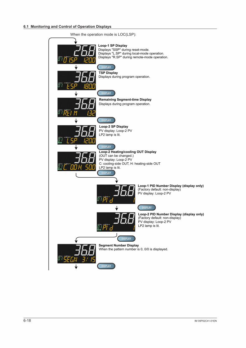
6-18 IM 05P02C41-01EN
When the operation mode is LOC(LSP):
TSP Display
Remaining Segment-time Display
Segment Number Display
Remaining Repetition Display
Program Pattern Displayprogram pattern (overview)
Can be changed by parameter PTSL.
Soak and ramp display
(Factory default: non-display)Loop-1 Alarm-5 to -8 Status Display (display only)
Displays "SSP" during reset-mode.Displays "L.SP" during local-mode operation.Displays "R.SP" during remote-mode operation.
Displays during program operation.
Displays during program operation.
When the pattern number is 0, 0/0 is displayed.
When pattern number is 0, pattern is not displayed.
0: On, 1: OnEx.: Alarm 5: Off, Alarm 6: On, Alarm 7: On, Alarm 8: Off
(Factory default: non-display) LP2 lamp is lit.Loop-2 Alarm-5 to -8 Status Display (display only)
0: On, 1: OnEx.: Alarm 5: Off, Alarm 6: On, Alarm 7: On, Alarm 8: On
Loop-1 SP Display
Loop-2 SP Display
SELECT Displays 1 to 5(Displayed only when SELECT Display is registered.(The figure on the left is the example of the parameter A1 (alarm-1 setpoint).)
Analog Input Displays (display only)(Factory default: non-display)PV: PV analog input,RSP: RSP analog input (E1-terminal area),AIN2: AIN2 analog input (E2-terminal area),AIN4: AIN4 analog input (E4-terminal area)
(Only for each aux. analog input)
PV display: Loop-2 PVLP2 lamp is lit.
Loop-1 PID Number Display (display only)(Factory default: non-display)PV display: Loop-2 PV
Loop-2 PID Number Display (display only)(Factory default: non-display)PV display: Loop-2 PVLP2 lamp is lit.
Loop-2/Loop-1 PV Display (display only)PV display: Loop-2 PVSetpoint display: Loop-1 PV
Loop-2 Heating/cooling OUT Display(OUT can be changed.)PV display: Loop-2 PVC: cooling-side OUT, H: heating-side OUTLP2 lamp is lit.
Dispalys the number of remaining repetitions (R.CYC) on Setpoint display.This display is displayed only when the repeat function is set and the operation mode is PROG.
6.1MonitoringandControlofOperationDisplays
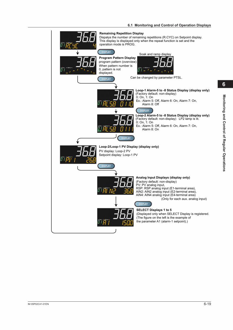
6-19IM 05P02C41-01EN
Monitoring and C
ontrol of Regular O
perations
6
TSP Display
Remaining Segment-time Display
Segment Number Display
Remaining Repetition Display
Program Pattern Displayprogram pattern (overview)
Can be changed by parameter PTSL.
Soak and ramp display
(Factory default: non-display)Loop-1 Alarm-5 to -8 Status Display (display only)
Displays "SSP" during reset-mode.Displays "L.SP" during local-mode operation.Displays "R.SP" during remote-mode operation.
Displays during program operation.
Displays during program operation.
When the pattern number is 0, 0/0 is displayed.
When pattern number is 0, pattern is not displayed.
0: On, 1: OnEx.: Alarm 5: Off, Alarm 6: On, Alarm 7: On, Alarm 8: Off
(Factory default: non-display) LP2 lamp is lit.Loop-2 Alarm-5 to -8 Status Display (display only)
0: On, 1: OnEx.: Alarm 5: Off, Alarm 6: On, Alarm 7: On, Alarm 8: On
Loop-1 SP Display
Loop-2 SP Display
SELECT Displays 1 to 5(Displayed only when SELECT Display is registered.(The figure on the left is the example of the parameter A1 (alarm-1 setpoint).)
Analog Input Displays (display only)(Factory default: non-display)PV: PV analog input,RSP: RSP analog input (E1-terminal area),AIN2: AIN2 analog input (E2-terminal area),AIN4: AIN4 analog input (E4-terminal area)
(Only for each aux. analog input)
PV display: Loop-2 PVLP2 lamp is lit.
Loop-1 PID Number Display (display only)(Factory default: non-display)PV display: Loop-2 PV
Loop-2 PID Number Display (display only)(Factory default: non-display)PV display: Loop-2 PVLP2 lamp is lit.
Loop-2/Loop-1 PV Display (display only)PV display: Loop-2 PVSetpoint display: Loop-1 PV
Loop-2 Heating/cooling OUT Display(OUT can be changed.)PV display: Loop-2 PVC: cooling-side OUT, H: heating-side OUTLP2 lamp is lit.
Dispalys the number of remaining repetitions (R.CYC) on Setpoint display.This display is displayed only when the repeat function is set and the operation mode is PROG.
6.1MonitoringandControlofOperationDisplays
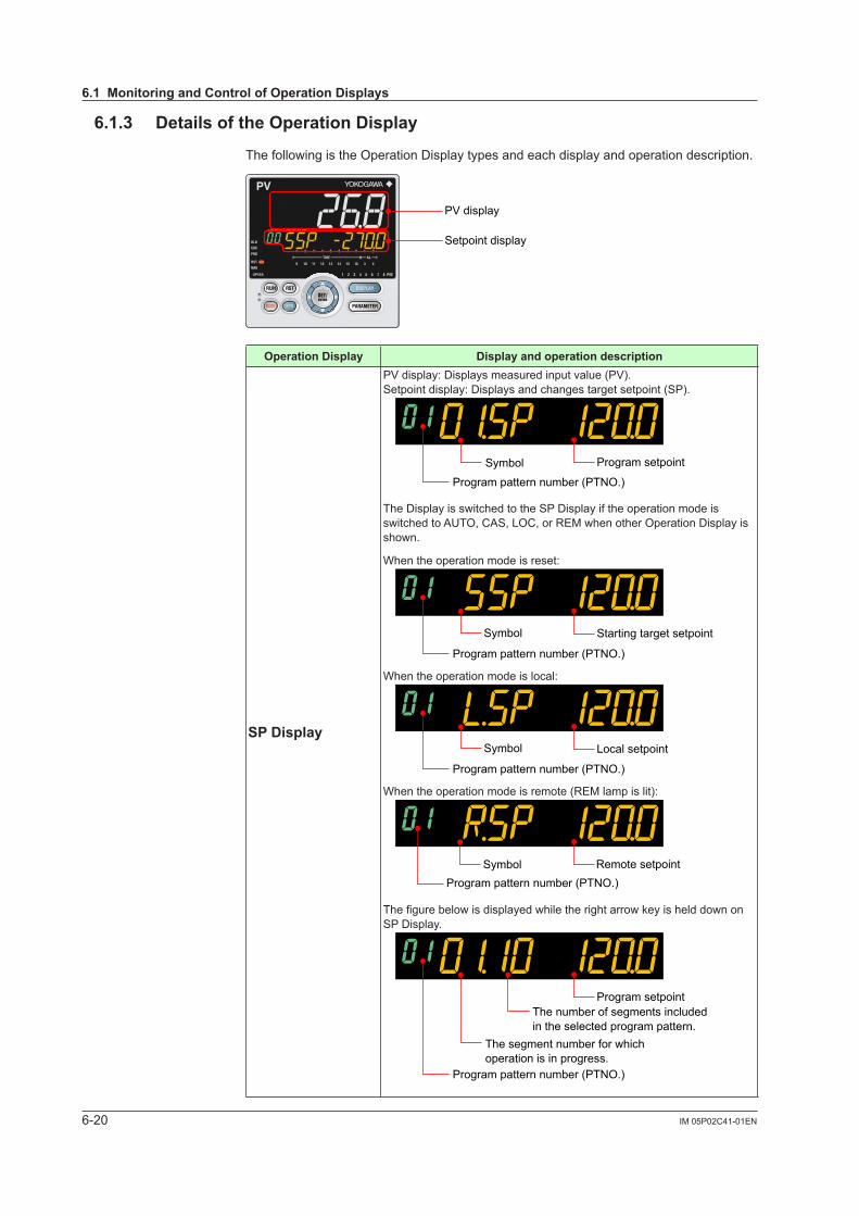
6-20 IM 05P02C41-01EN
6.1.3 DetailsoftheOperationDisplay
The following is the Operation Display types and each display and operation description.
PV display
Setpoint display
OperationDisplay Displayandoperationdescription
SPDisplay
PV display: Displays measured input value (PV).Setpoint display: Displays and changes target setpoint (SP).
Symbol Program setpoint
Program pattern number (PTNO.)
The Display is switched to the SP Display if the operation mode is switched to AUTO, CAS, LOC, or REM when other Operation Display is shown.
When the operation mode is reset:
Starting target setpointSymbol
Program pattern number (PTNO.)
When the operation mode is local:
Local setpointSymbol
Program pattern number (PTNO.)
When the operation mode is remote (REM lamp is lit):
Program pattern number (PTNO.)Remote setpointSymbol
ThefigurebelowisdisplayedwhiletherightarrowkeyishelddownonSP Display.
Program setpointThe number of segments included in the selected program pattern.
The segment number for which operation is in progress.
Program pattern number (PTNO.)
6.1MonitoringandControlofOperationDisplays
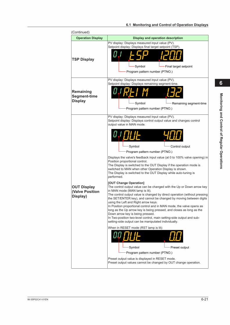
6-21IM 05P02C41-01EN
Monitoring and C
ontrol of Regular O
perations
6
(Continued)OperationDisplay Displayandoperationdescription
TSPDisplay
PV display: Displays measured input value (PV).Setpointdisplay:Displaysfinaltargetsetpoint(TSP).
Program pattern number (PTNO.)
Final target setpointSymbol
Remaining Segment-timeDisplay
PV display: Displays measured input value (PV).Setpoint display: Displays remaining segment-time.
Program pattern number (PTNO.)Remaining segment-timeSymbol
OUTDisplay(ValvePositionDisplay)
PV display: Displays measured input value (PV).Setpoint display: Displays control output value and changes control output value in MAN mode.
Program pattern number (PTNO.)
Control outputSymbol
Displays the valve's feedback input value (at 0 to 100% valve opening) in Position proportional control.The Display is switched to the OUT Display if the operation mode is switched to MAN when other Operation Display is shown.The Display is switched to the OUT Display while auto-tuning is performed.
[OUTChangeOperation]The control output value can be changed with the Up or Down arrow key in MAN mode (MAN lamp is lit).The control output value is changed by direct operation (without pressing the SET/ENTER key), and cannot be changed by moving between digits using the Left and Right arrow keys.In Position proportional control and in MAN mode, the valve opens as long as the Up arrow key is being pressed, and closes as long as the Down arrow key is being pressed.In Two-position two-level control, main setting-side output and sub-setting-side output can be manipulated individually.
When in RESET mode (RST lamp is lit):
Program pattern number (PTNO.)
Preset outputSymbol
Preset output value is displayed in RESET mode.Preset output values cannot be changed by OUT change operation.
6.1MonitoringandControlofOperationDisplays
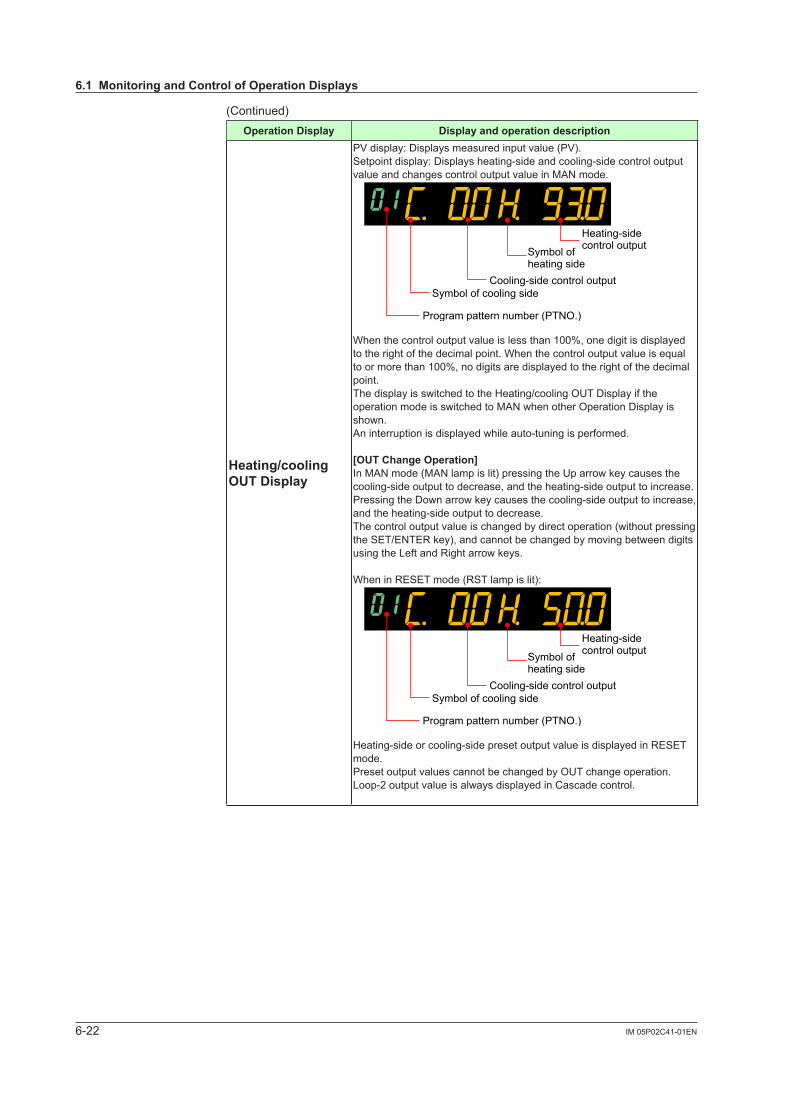
6-22 IM 05P02C41-01EN
(Continued)OperationDisplay Displayandoperationdescription
Heating/cooling OUTDisplay
PV display: Displays measured input value (PV).Setpoint display: Displays heating-side and cooling-side control output value and changes control output value in MAN mode.
Symbol of cooling side
Symbol ofheating side
Heating-sidecontrol output
Cooling-side control output
Program pattern number (PTNO.)
When the control output value is less than 100%, one digit is displayed to the right of the decimal point. When the control output value is equal to or more than 100%, no digits are displayed to the right of the decimal point.The display is switched to the Heating/cooling OUT Display if the operation mode is switched to MAN when other Operation Display is shown.An interruption is displayed while auto-tuning is performed.
[OUTChangeOperation]In MAN mode (MAN lamp is lit) pressing the Up arrow key causes the cooling-side output to decrease, and the heating-side output to increase. Pressing the Down arrow key causes the cooling-side output to increase, and the heating-side output to decrease.The control output value is changed by direct operation (without pressing the SET/ENTER key), and cannot be changed by moving between digits using the Left and Right arrow keys.
When in RESET mode (RST lamp is lit):
Symbol of cooling side
Symbol ofheating side
Heating-sidecontrol output
Cooling-side control output
Program pattern number (PTNO.)
Heating-side or cooling-side preset output value is displayed in RESET mode.Preset output values cannot be changed by OUT change operation.Loop-2 output value is always displayed in Cascade control.
6.1MonitoringandControlofOperationDisplays
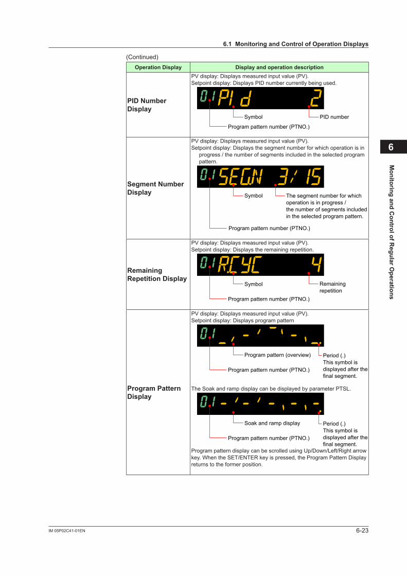
6-23IM 05P02C41-01EN
Monitoring and C
ontrol of Regular O
perations
6
(Continued)OperationDisplay Displayandoperationdescription
PID Number Display
PV display: Displays measured input value (PV).Setpoint display: Displays PID number currently being used.
Symbol PID number
Program pattern number (PTNO.)
SegmentNumberDisplay
PV display: Displays measured input value (PV).Setpoint display: Displays the segment number for which operation is in
progress / the number of segments included in the selected program pattern.
The segment number for which operation is in progress /the number of segments included in the selected program pattern.
Program pattern number (PTNO.)
Symbol
Remaining RepetitionDisplay
PV display: Displays measured input value (PV).Setpoint display: Displays the remaining repetition.
Remaining repetition
Program pattern number (PTNO.)
Symbol
Program Pattern Display
PV display: Displays measured input value (PV).Setpoint display: Displays program pattern
Period (.)This symbol is displayed after the final segment.
Program pattern number (PTNO.)
Program pattern (overview)
The Soak and ramp display can be displayed by parameter PTSL.
Period (.)This symbol is displayed after the final segment.
Program pattern number (PTNO.)
Soak and ramp display
Program pattern display can be scrolled using Up/Down/Left/Right arrow key. When the SET/ENTER key is pressed, the Program Pattern Display returns to the former position.
6.1MonitoringandControlofOperationDisplays
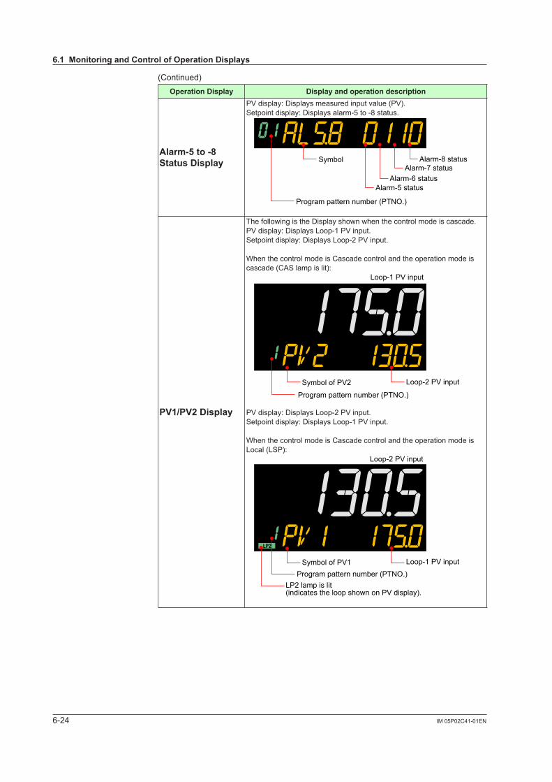
6-24 IM 05P02C41-01EN
(Continued)OperationDisplay Displayandoperationdescription
Alarm-5to-8StatusDisplay
PV display: Displays measured input value (PV).Setpoint display: Displays alarm-5 to -8 status.
Alarm-8 statusAlarm-7 status
Alarm-6 statusAlarm-5 status
Program pattern number (PTNO.)
Symbol
PV1/PV2Display
The following is the Display shown when the control mode is cascade.PV display: Displays Loop-1 PV input.Setpoint display: Displays Loop-2 PV input.
When the control mode is Cascade control and the operation mode is cascade (CAS lamp is lit):
Symbol of PV2 Loop-2 PV input
Loop-1 PV input
Program pattern number (PTNO.)
PV display: Displays Loop-2 PV input.Setpoint display: Displays Loop-1 PV input.
When the control mode is Cascade control and the operation mode is Local (LSP):
Symbol of PV1 Loop-1 PV input
LP2 lamp is lit(indicates the loop shown on PV display).
Loop-2 PV input
Program pattern number (PTNO.)
6.1MonitoringandControlofOperationDisplays
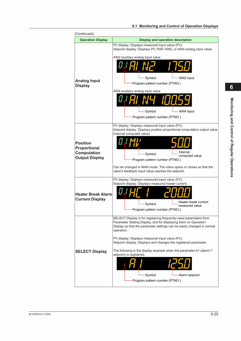
6-25IM 05P02C41-01EN
Monitoring and C
ontrol of Regular O
perations
6
(Continued)OperationDisplay Displayandoperationdescription
Analog Input Display
PV display: Displays measured input value (PV).Setpoint display: Displays PV, RSP, AIN2, or AIN4 analog input value.
AIN2 auxiliary analog input value
AIN2 inputSymbol
Program pattern number (PTNO.)
AIN4 auxiliary analog input value
AIN4 inputSymbol
Program pattern number (PTNO.)
Position Proportional Computation OutputDisplay
PV display: Displays measured input value (PV).Setpoint display: Displays position proportional computation output value (internal computed value).
Internalcomputed valueSymbol
Program pattern number (PTNO.)
Can be changed in MAN mode. The valve opens or closes so that the valve’s feedback input value reaches the setpoint.
Heater Break Alarm CurrentDisplay
PV display: Displays measured input value (PV).Setpoint display: Displays measured heater current.
Heater break current measured valueSymbol
Program pattern number (PTNO.)
SELECTDisplay
SELECT Display is for registering frequently-used parameters from Parameter Setting Display, and for displaying them on Operation Display so that the parameter settings can be easily changed in normal operation.
PV display: Displays measured input value (PV).Setpoint display: Displays and changes the registered parameter.
The following is the display example when the parameter A1 (alarm-1 setpoint) is registered.
Alarm setpointSymbol
Program pattern number (PTNO.)
6.1MonitoringandControlofOperationDisplays
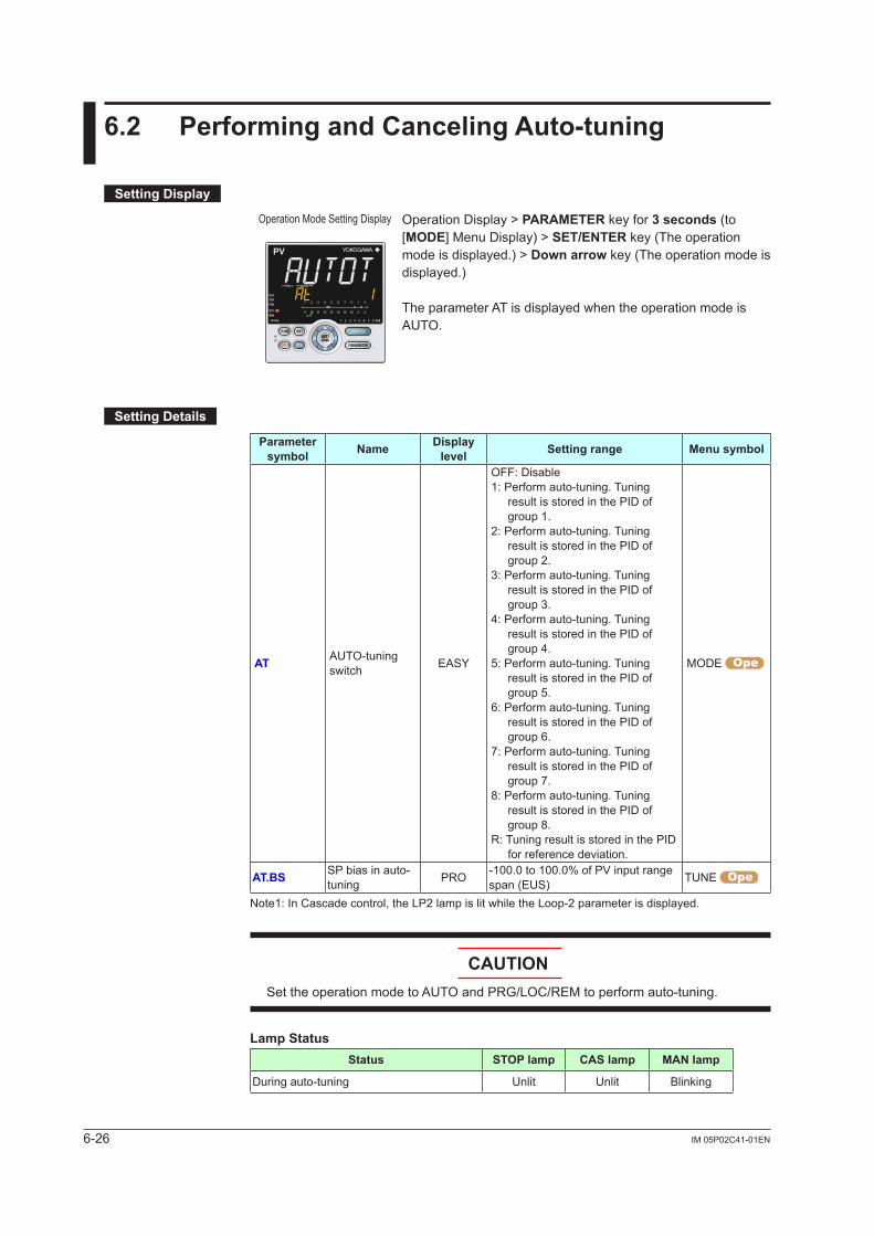
6-26 IM 05P02C41-01EN
6.2 PerformingandCancelingAuto-tuning
SettingDisplay
Operation Mode Setting Display Operation Display > PARAMETER key for 3 seconds (to [MODE] Menu Display) > SET/ENTER key (The operation mode is displayed.) > Downarrow key (The operation mode is displayed.)
The parameter AT is displayed when the operation mode is AUTO.
SettingDetails
Parameter symbol Name Display
level Settingrange Menusymbol
AT AUTO-tuning switch EASY
OFF: Disable1: Perform auto-tuning. Tuning
result is stored in the PID of group 1.
2: Perform auto-tuning. Tuning result is stored in the PID of group 2.
3: Perform auto-tuning. Tuning result is stored in the PID of group 3.
4: Perform auto-tuning. Tuning result is stored in the PID of group 4.
5: Perform auto-tuning. Tuning result is stored in the PID of group 5.
6: Perform auto-tuning. Tuning result is stored in the PID of group 6.
7: Perform auto-tuning. Tuning result is stored in the PID of group 7.
8: Perform auto-tuning. Tuning result is stored in the PID of group 8.
R: Tuning result is stored in the PID for reference deviation.
MODE
AT.BS SP bias in auto-tuning PRO -100.0 to 100.0% of PV input range
span (EUS) TUNE
Note1: In Cascade control, the LP2 lamp is lit while the Loop-2 parameter is displayed.
CAUTIONSet the operation mode to AUTO and PRG/LOC/REM to perform auto-tuning.
LampStatusStatus STOPlamp CASlamp MAN lamp
During auto-tuning Unlit Unlit Blinking
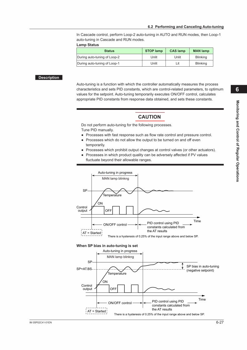
6-27IM 05P02C41-01EN
Monitoring and C
ontrol of Regular O
perations
6
In Cascade control, perform Loop-2 auto-tuning in AUTO and RUN modes, then Loop-1 auto-tuning in Cascade and RUN modes.LampStatus
Status STOPlamp CASlamp MAN lamp
During auto-tuning of Loop-2 Unlit Unlit Blinking
During auto-tuning of Loop-1 Unlit Lit Blinking
Description
Auto-tuning is a function with which the controller automatically measures the process characteristics and sets PID constants, which are control-related parameters, to optimum values for the setpoint. Auto-tuning temporarily executes ON/OFF control, calculates appropriate PID constants from response data obtained, and sets these constants.
CAUTIONDo not perform auto-tuning for the following processes.Tune PID manually. Processeswithfastresponsesuchasflowratecontrolandpressurecontrol. Processeswhichdonotallowtheoutputtobeturnedonandoffeven
temporarily. Processeswhichprohibitoutputchangesatcontrolvalves(orotheractuators). ProcessesinwhichproductqualitycanbeadverselyaffectedifPVvalues
fluctuate beyond their allowable ranges.
AT = Started
ON
OFF
TemperatureSP
Controloutput
TimeON/OFF control PID control using PID
constants calculated fromthe AT results
Auto-tuning in progress
MAN lamp blinkng
There is a hysteresis of 0.25% of the input range above and below SP.
WhenSPbiasinauto-tuningisset
AT = Started
ON
OFF
TemperatureSP+AT.BS
SP
Controloutput
TimeON/OFF control
SP bias in auto-tuning(negative setpoint)
PID control using PIDconstants calculated fromthe AT results
Auto-tuning in progress
MAN lamp blinkng
There is a hysteresis of 0.25% of the input range above and below SP.
6.2PerformingandCancelingAuto-tuning
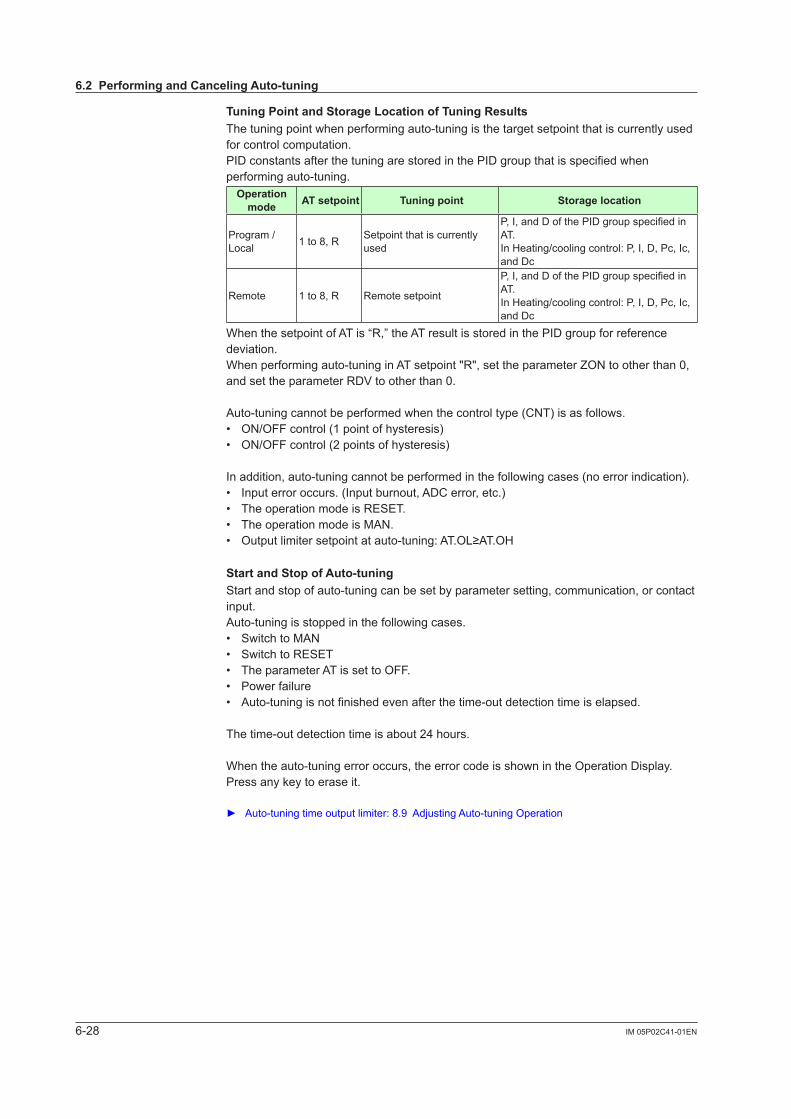
6-28 IM 05P02C41-01EN
TuningPointandStorageLocationofTuningResultsThe tuning point when performing auto-tuning is the target setpoint that is currently used for control computation.PID constants after the tuning are stored in the PID group that is specified when performing auto-tuning. Operation
mode AT setpoint Tuning point Storagelocation
Program / Local 1 to 8, R Setpoint that is currently
used
P,I,andDofthePIDgroupspecifiedinAT.In Heating/cooling control: P, I, D, Pc, Ic, and Dc
Remote 1 to 8, R Remote setpoint
P,I,andDofthePIDgroupspecifiedinAT.In Heating/cooling control: P, I, D, Pc, Ic, and Dc
When the setpoint of AT is “R,” the AT result is stored in the PID group for reference deviation.When performing auto-tuning in AT setpoint "R", set the parameter ZON to other than 0, and set the parameter RDV to other than 0.
Auto-tuning cannot be performed when the control type (CNT) is as follows.• ON/OFF control (1 point of hysteresis)• ON/OFF control (2 points of hysteresis)
In addition, auto-tuning cannot be performed in the following cases (no error indication).• Input error occurs. (Input burnout, ADC error, etc.)• The operation mode is RESET.• The operation mode is MAN.• Outputlimitersetpointatauto-tuning:AT.OL≥AT.OH
StartandStopofAuto-tuningStart and stop of auto-tuning can be set by parameter setting, communication, or contact input.Auto-tuning is stopped in the following cases.• Switch to MAN• Switch to RESET• The parameter AT is set to OFF.• Power failure• Auto-tuning is not finished even after the time-out detection time is elapsed.
The time-out detection time is about 24 hours.
When the auto-tuning error occurs, the error code is shown in the Operation Display.Press any key to erase it.
Auto-tuningtimeoutputlimiter:8.9AdjustingAuto-tuningOperation
6.2PerformingandCancelingAuto-tuning
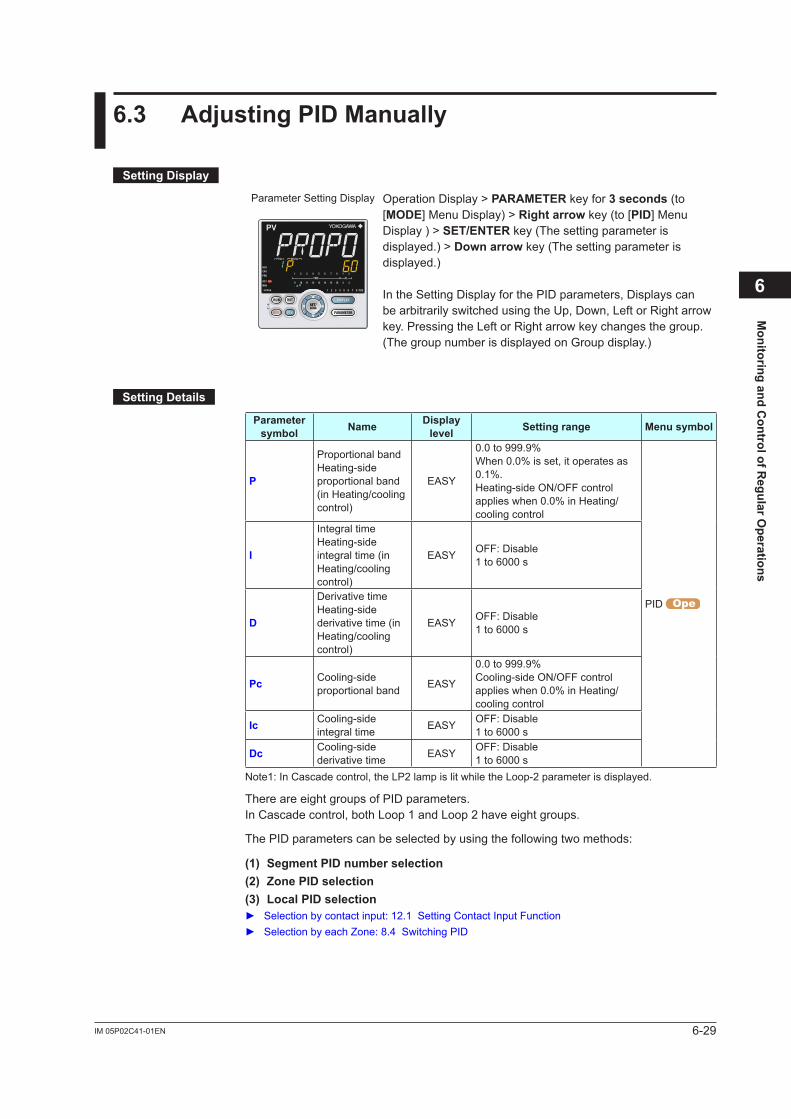
6-29IM 05P02C41-01EN
Monitoring and C
ontrol of Regular O
perations
6
6.3 AdjustingPIDManually
SettingDisplay
Parameter Setting Display Operation Display > PARAMETER key for 3 seconds (to [MODE] Menu Display) > Rightarrow key (to [PID] Menu Display ) > SET/ENTER key (The setting parameter is displayed.) > Downarrow key (The setting parameter is displayed.)
In the Setting Display for the PID parameters, Displays can be arbitrarily switched using the Up, Down, Left or Right arrow key. Pressing the Left or Right arrow key changes the group.(The group number is displayed on Group display.)
SettingDetails
Parameter symbol Name Display
level Settingrange Menusymbol
P
Proportional bandHeating-side proportional band (in Heating/cooling control)
EASY
0.0 to 999.9%When 0.0% is set, it operates as 0.1%.Heating-side ON/OFF control applies when 0.0% in Heating/cooling control
PID
I
Integral timeHeating-side integral time (in Heating/cooling control)
EASY OFF: Disable1 to 6000 s
D
Derivative timeHeating-side derivative time (in Heating/cooling control)
EASY OFF: Disable1 to 6000 s
Pc Cooling-side proportional band EASY
0.0 to 999.9%Cooling-side ON/OFF control applies when 0.0% in Heating/cooling control
Ic Cooling-side integral time EASY OFF: Disable
1 to 6000 s
Dc Cooling-side derivative time EASY OFF: Disable
1 to 6000 sNote1: In Cascade control, the LP2 lamp is lit while the Loop-2 parameter is displayed.
There are eight groups of PID parameters.In Cascade control, both Loop 1 and Loop 2 have eight groups.
The PID parameters can be selected by using the following two methods:
(1)SegmentPIDnumberselection(2)ZonePIDselection(3) Local PID selection Selection by contact input: 12.1 Setting Contact Input Function Selection by each Zone: 8.4 Switching PID
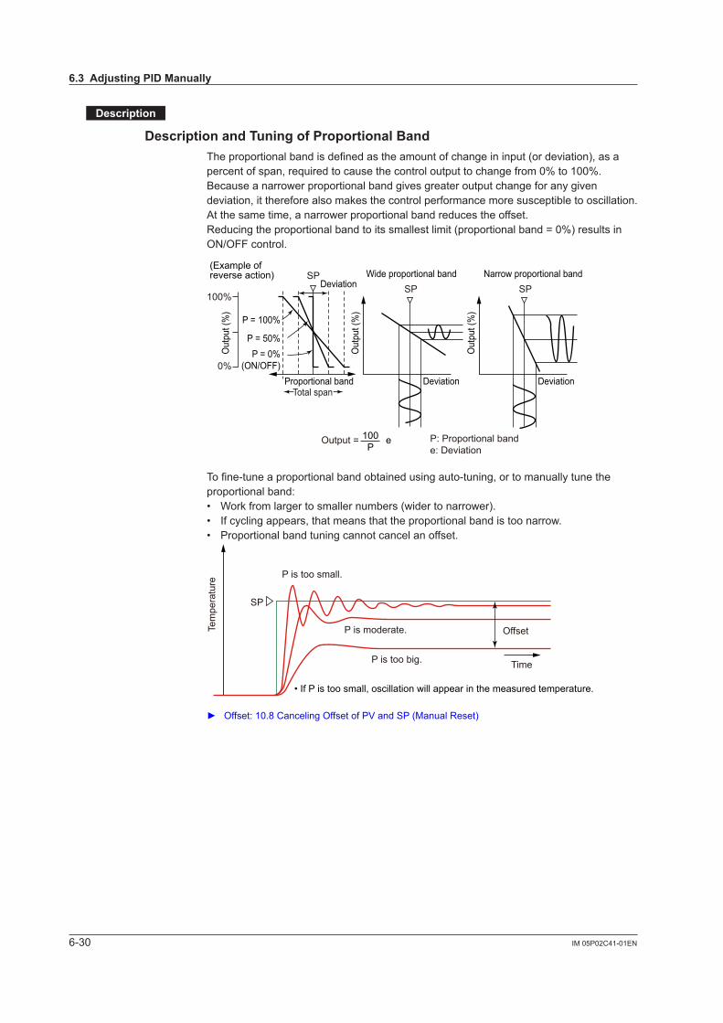
6-30 IM 05P02C41-01EN
Description
DescriptionandTuningofProportionalBandThe proportional band is defined as the amount of change in input (or deviation), as a percent of span, required to cause the control output to change from 0% to 100%.Because a narrower proportional band gives greater output change for any given deviation, it therefore also makes the control performance more susceptible to oscillation. At the same time, a narrower proportional band reduces the offset.Reducing the proportional band to its smallest limit (proportional band = 0%) results in ON/OFF control.
Output = e 100P
P: Proportional bande: Deviation
(Example ofreverse action)
100%
0%
P = 100%
SP Wide proportional band Narrow proportional bandSP SPDeviation
Deviation Deviation
P = 50%P = 0%
(ON/OFF)Proportional band
Total span
Out
put (
%)
Out
put (
%)
Out
put (
%)
To fine-tune a proportional band obtained using auto-tuning, or to manually tune the proportional band:• Work from larger to smaller numbers (wider to narrower).• If cycling appears, that means that the proportional band is too narrow.• Proportional band tuning cannot cancel an offset.
Time
SP
• If P is too small, oscillation will appear in the measured temperature.
P is too small.
Tem
pera
ture
P is too big.
P is moderate. Offset
Offset:10.8CancelingOffsetofPVandSP(ManualReset)
6.3AdjustingPIDManually
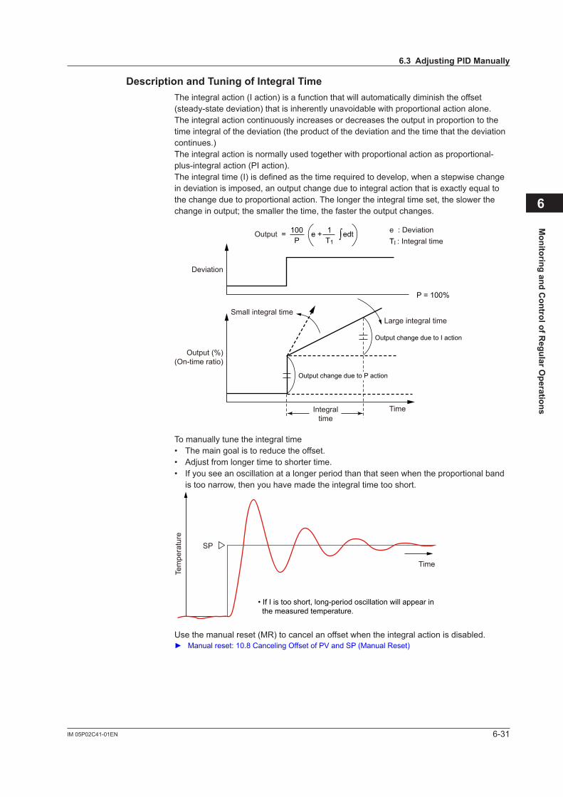
6-31IM 05P02C41-01EN
Monitoring and C
ontrol of Regular O
perations
6
DescriptionandTuningofIntegralTimeThe integral action (I action) is a function that will automatically diminish the offset (steady-state deviation) that is inherently unavoidable with proportional action alone. The integral action continuously increases or decreases the output in proportion to the time integral of the deviation (the product of the deviation and the time that the deviation continues.)The integral action is normally used together with proportional action as proportional-plus-integral action (PI action).The integral time (I) is defined as the time required to develop, when a stepwise change in deviation is imposed, an output change due to integral action that is exactly equal to the change due to proportional action. The longer the integral time set, the slower the change in output; the smaller the time, the faster the output changes.
Output = e + edt100P
1T1
e : DeviationTI : Integral time
Deviation
Output (%)(On-time ratio)
Small integral time
P = 100%
Large integral time
Output change due to I action
Output change due to P action
TimeIntegraltime
∫
To manually tune the integral time• The main goal is to reduce the offset.• Adjustfromlongertimetoshortertime.• If you see an oscillation at a longer period than that seen when the proportional band
is too narrow, then you have made the integral time too short.
SP
Tem
pera
ture
Time
• If I is too short, long-period oscillation will appear in the measured temperature.
Use the manual reset (MR) to cancel an offset when the integral action is disabled. Manualreset:10.8CancelingOffsetofPVandSP(ManualReset)
6.3AdjustingPIDManually
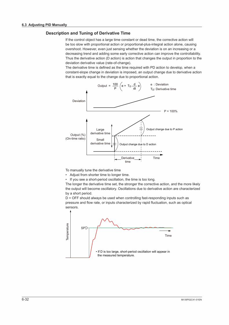
6-32 IM 05P02C41-01EN
DescriptionandTuningofDerivativeTimeIfthecontrolobjecthasalargetimeconstantordeadtime,thecorrectiveactionwillbe too slow with proportional action or proportional-plus-integral action alone, causing overshoot.However,evenjustsensingwhetherthedeviationisonanincreasingoradecreasing trend and adding some early corrective action can improve the controllability. Thus the derivative action (D action) is action that changes the output in proportion to the deviation derivative value (rate-of-change).The derivative time is defined as the time required with PD action to develop, when a constant-slope change in deviation is imposed, an output change due to derivative action that is exactly equal to the change due to proportional action.
Output = e + TD e100P
ddt
P = 100%
Output change due to P action
Output change due to D action
TimeDerivativetime
Smallderivative time
Largederivative time
e : DeviationTD: Derivative time
Deviation
Output (%)(On-time ratio)
To manually tune the derivative time• Adjustfromshortertimetolongertime.• If you see a short-period oscillation, the time is too long.The longer the derivative time set, the stronger the corrective action, and the more likely theoutputwillbecomeoscillatory.Oscillationsduetoderivativeactionarecharacterizedby a short period.D = OFF should always be used when controlling fast-responding inputs such as pressureandflowrate,orinputscharacterizedbyrapidfluctuation,suchasopticalsensors.
Time
SP
• If D is too large, short-period oscillation will appear in the measured temperature.
Tem
pera
ture
6.3AdjustingPIDManually

6-33IM 05P02C41-01EN
Monitoring and C
ontrol of Regular O
perations
6
Manual PID Tuning Procedure(1) In principle, auto-tuning must be used.(2) TunePIDparametersintheorderofP,I,andD.Adjustanumericslowlyby
observing the result, and keep notes of what the progress is.(3) Gradually reduce P from a larger value. When the PV value begins to oscillate, stop
tuning and increase the value somewhat.(4) Also gradually reduce I from a larger value. When the PV value begins to oscillate (with
long period), stop tuning and increase the value somewhat.(5) Gradually increase D from a smaller value. When the PV value begins to oscillate (with
short period), stop tuning and lower the value slightly.
ReferenceValuesforManualTuningofTemperature,Pressure,andFlowRateSettingrange(reference) Initialvaluefortuning(reference)
Pressure
P 100 to 300% 200%
I 5 to 30 s 15 s
D OFF OFF
Flow rate
P 100 to 240% 150%
I 8 to 30 s 20 s
D OFF OFF
Temperature (electric furnace)
P 1 to 20% 5%
I 180 to 600 s 240 s
D 1/4 to 1/6 of I 60 s
6.3AdjustingPIDManually
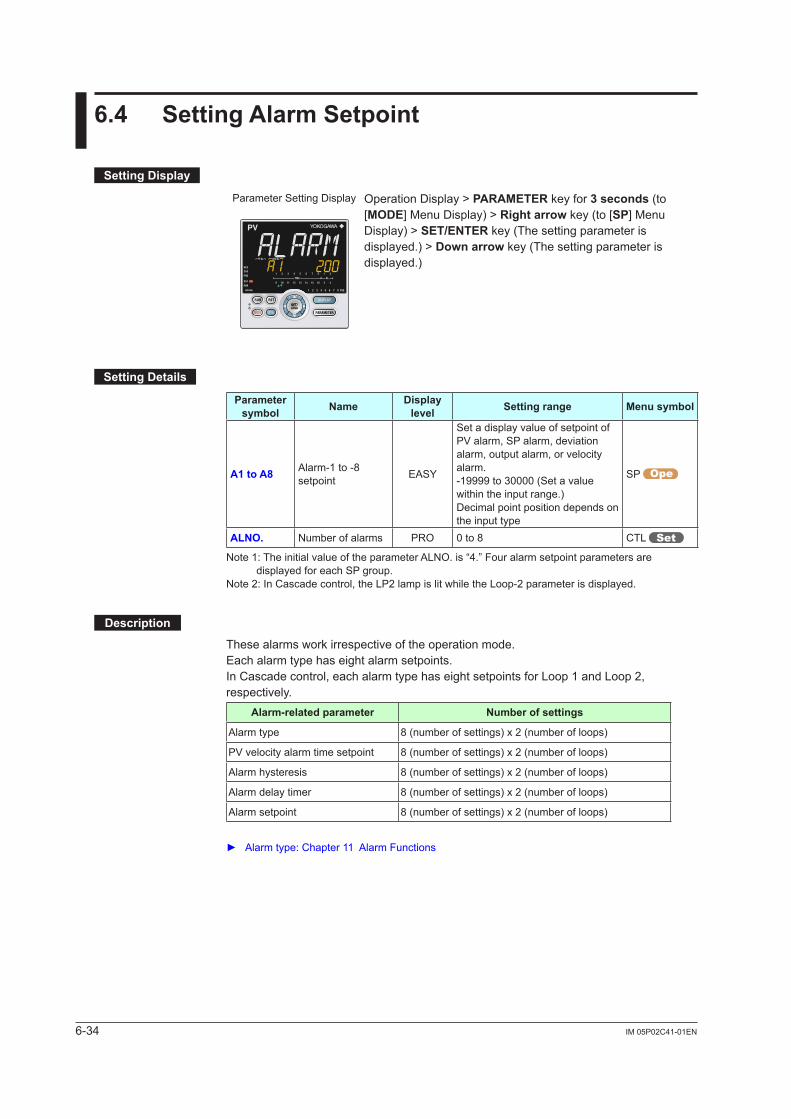
6-34 IM 05P02C41-01EN
6.4 SettingAlarmSetpoint
SettingDisplay
Parameter Setting Display Operation Display > PARAMETER key for 3 seconds (to [MODE] Menu Display) > Rightarrow key (to [SP] Menu Display) > SET/ENTER key (The setting parameter is displayed.) > Downarrow key (The setting parameter is displayed.)
SettingDetails
Parameter symbol Name Display
level Settingrange Menusymbol
A1toA8 Alarm-1 to -8 setpoint EASY
Set a display value of setpoint of PV alarm, SP alarm, deviation alarm, output alarm, or velocity alarm.-19999 to 30000 (Set a value within the input range.)Decimal point position depends on the input type
SP
ALNO. Number of alarms PRO 0 to 8 CTL
Note 1: The initial value of the parameter ALNO. is “4.” Four alarm setpoint parameters are displayed for each SP group.
Note 2: In Cascade control, the LP2 lamp is lit while the Loop-2 parameter is displayed.
Description
These alarms work irrespective of the operation mode.Each alarm type has eight alarm setpoints. In Cascade control, each alarm type has eight setpoints for Loop 1 and Loop 2, respectively.
Alarm-relatedparameter Numberofsettings
Alarm type 8 (number of settings) x 2 (number of loops)
PV velocity alarm time setpoint 8 (number of settings) x 2 (number of loops)
Alarm hysteresis 8 (number of settings) x 2 (number of loops)
Alarm delay timer 8 (number of settings) x 2 (number of loops)
Alarm setpoint 8 (number of settings) x 2 (number of loops)
Alarmtype:Chapter11AlarmFunctions
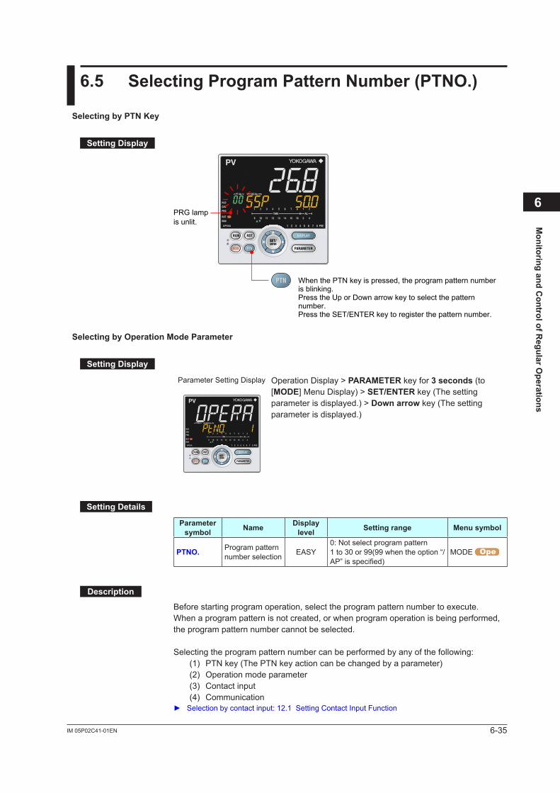
6-35IM 05P02C41-01EN
Monitoring and C
ontrol of Regular O
perations
6
6.5 SelectingProgramPatternNumber(PTNO.)
SelectingbyPTNKey
SettingDisplay
When the PTN key is pressed, the program pattern number is blinking.Press the Up or Down arrow key to select the pattern number.Press the SET/ENTER key to register the pattern number.
PRG lamp is unlit.
SelectingbyOperationModeParameter
SettingDisplay
Parameter Setting Display Operation Display > PARAMETER key for 3 seconds (to [MODE] Menu Display) > SET/ENTER key (The setting parameter is displayed.) > Downarrow key (The setting parameter is displayed.)
SettingDetails
Parameter symbol Name Display
level Settingrange Menusymbol
PTNO. Program pattern number selection EASY
0: Not select program pattern1 to 30 or 99(99 when the option “/AP”isspecified)
MODE
Description
Before starting program operation, select the program pattern number to execute.When a program pattern is not created, or when program operation is being performed, the program pattern number cannot be selected.
Selecting the program pattern number can be performed by any of the following: (1) PTN key (The PTN key action can be changed by a parameter) (2) Operation mode parameter (3) Contact input (4) Communication Selectionbycontactinput:12.1SettingContactInputFunction
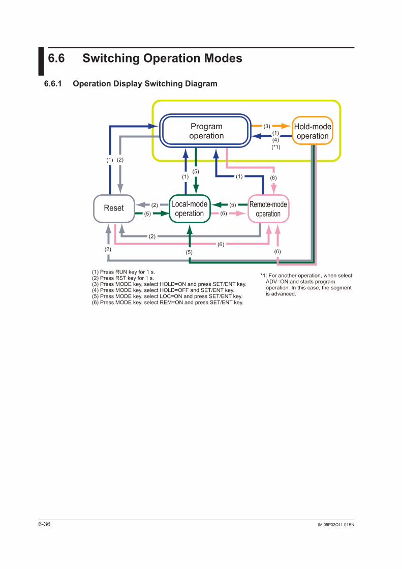
6-36 IM 05P02C41-01EN
6.6 SwitchingOperationModes
6.6.1 OperationDisplaySwitchingDiagram
*1: For another operation, when select ADV=ON and starts program operation. In this case, the segment is advanced.
(1) Press RUN key for 1 s.(2) Press RST key for 1 s.(3) Press MODE key, select HOLD=ON and press SET/ENT key.(4) Press MODE key, select HOLD=OFF and SET/ENT key.(5) Press MODE key, select LOC=ON and press SET/ENT key.(6) Press MODE key, select REM=ON and press SET/ENT key.
Reset Remote-mode operation
Local-mode operation
Program operation
Hold-mode operation
(*1)
(1)(1)
(2)
(2)
(2)
(2)
(3)
(4)(1)
(5)
(5)(5)
(5)
(6)
(6)(6)
(6)
(1)
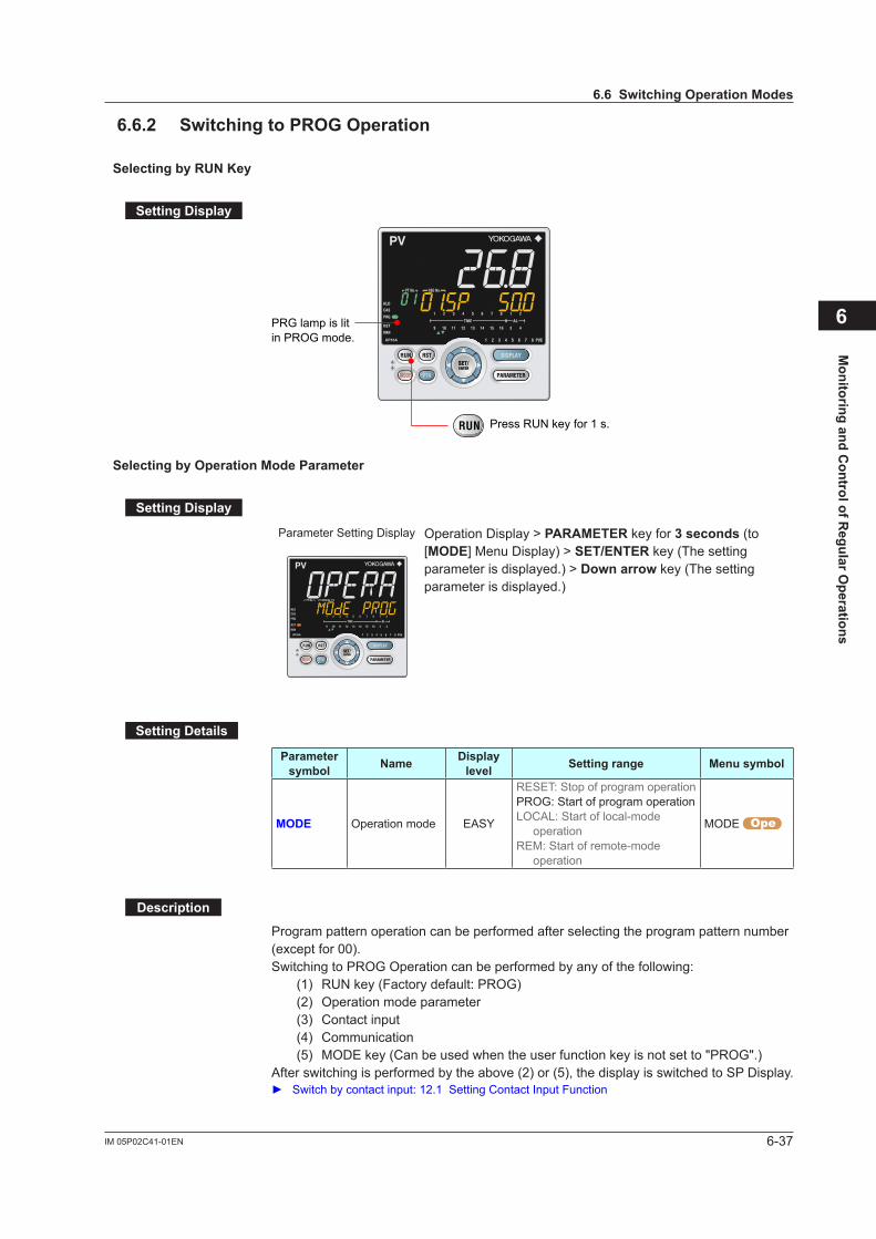
6-37IM 05P02C41-01EN
Monitoring and C
ontrol of Regular O
perations
6
6.6.2 SwitchingtoPROGOperation
SelectingbyRUNKey
SettingDisplay
Press RUN key for 1 s.
PRG lamp is lit in PROG mode.
SelectingbyOperationModeParameter
SettingDisplay
Parameter Setting Display Operation Display > PARAMETER key for 3 seconds (to [MODE] Menu Display) > SET/ENTER key (The setting parameter is displayed.) > Downarrow key (The setting parameter is displayed.)
SettingDetails
Parameter symbol Name Display
level Settingrange Menusymbol
MODE Operation mode EASY
RESET: Stop of program operationPROG: Start of program operationLOCAL: Start of local-mode
operationREM: Start of remote-mode
operation
MODE
Description
Program pattern operation can be performed after selecting the program pattern number (except for 00).Switching to PROG Operation can be performed by any of the following: (1) RUN key (Factory default: PROG) (2) Operation mode parameter (3) Contact input (4) Communication (5) MODE key (Can be used when the user function key is not set to "PROG".)After switching is performed by the above (2) or (5), the display is switched to SP Display. Switch by contact input: 12.1 Setting Contact Input Function
6.6SwitchingOperationModes
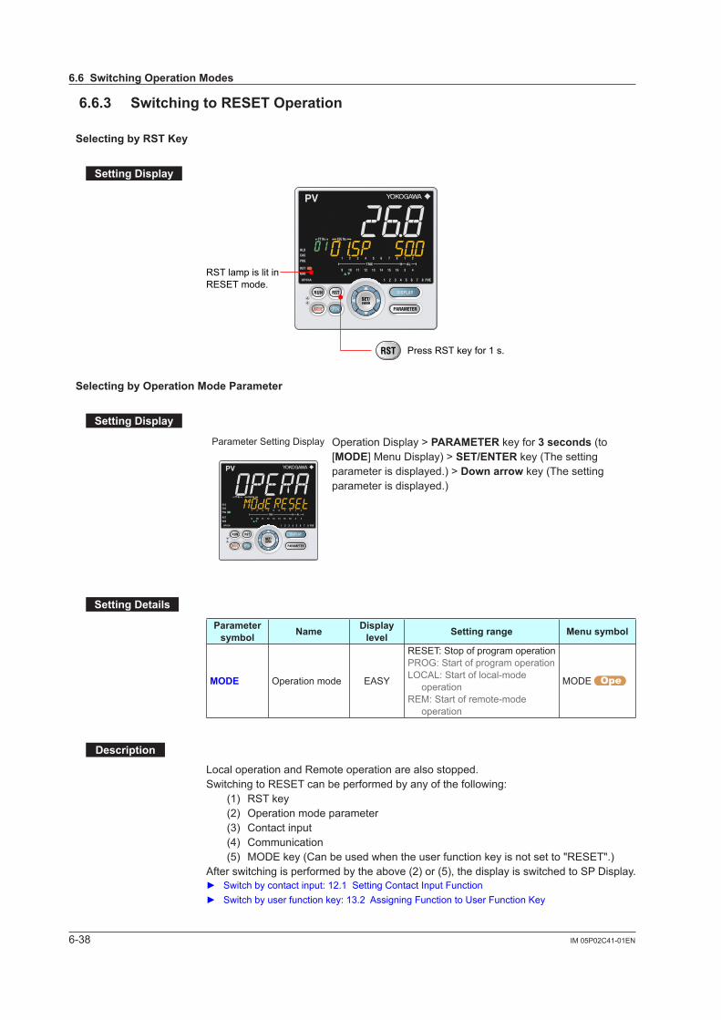
6-38 IM 05P02C41-01EN
6.6.3 SwitchingtoRESETOperation
SelectingbyRSTKey
SettingDisplay
Press RST key for 1 s.
RST lamp is lit in RESET mode.
SelectingbyOperationModeParameter
SettingDisplay
Parameter Setting Display Operation Display > PARAMETER key for 3 seconds (to [MODE] Menu Display) > SET/ENTER key (The setting parameter is displayed.) > Downarrow key (The setting parameter is displayed.)
SettingDetails
Parameter symbol Name Display
level Settingrange Menusymbol
MODE Operation mode EASY
RESET: Stop of program operationPROG: Start of program operationLOCAL: Start of local-mode
operationREM: Start of remote-mode
operation
MODE
Description
Local operation and Remote operation are also stopped.Switching to RESET can be performed by any of the following: (1) RST key (2) Operation mode parameter (3) Contact input (4) Communication (5) MODE key (Can be used when the user function key is not set to "RESET".)After switching is performed by the above (2) or (5), the display is switched to SP Display. Switchbycontactinput:12.1SettingContactInputFunction Switchbyuserfunctionkey:13.2AssigningFunctiontoUserFunctionKey
6.6SwitchingOperationModes
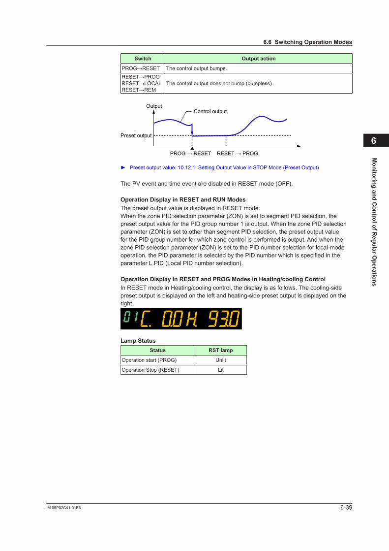
6-39IM 05P02C41-01EN
Monitoring and C
ontrol of Regular O
perations
6
Switch Outputaction
PROG→RESET The control output bumps.RESET→PROGRESET→LOCALRESET→REM
The control output does not bump (bumpless).
OutputControl output
Preset output
PROG → RESET RESET → PROG
Preset output value: 10.12.1 Setting Output Value in STOP Mode (Preset Output)
The PV event and time event are disabled in RESET mode (OFF).
OperationDisplayinRESETandRUNModesThe preset output value is displayed in RESET mode.WhenthezonePIDselectionparameter(ZON)issettosegmentPIDselection,thepresetoutputvalueforthePIDgroupnumber1isoutput.WhenthezonePIDselectionparameter (ZON) is set to other than segment PID selection, the preset output value forthePIDgroupnumberforwhichzonecontrolisperformedisoutput.AndwhenthezonePIDselectionparameter(ZON)issettothePIDnumberselectionforlocal-modeoperation, the PID parameter is selected by the PID number which is specified in the parameter L.PID (Local PID number selection).
OperationDisplayinRESETandPROGModesinHeating/coolingControlIn RESET mode in Heating/cooling control, the display is as follows. The cooling-side preset output is displayed on the left and heating-side preset output is displayed on the right.
LampStatusStatus RSTlamp
Operation start (PROG) Unlit
Operation Stop (RESET) Lit
6.6SwitchingOperationModes
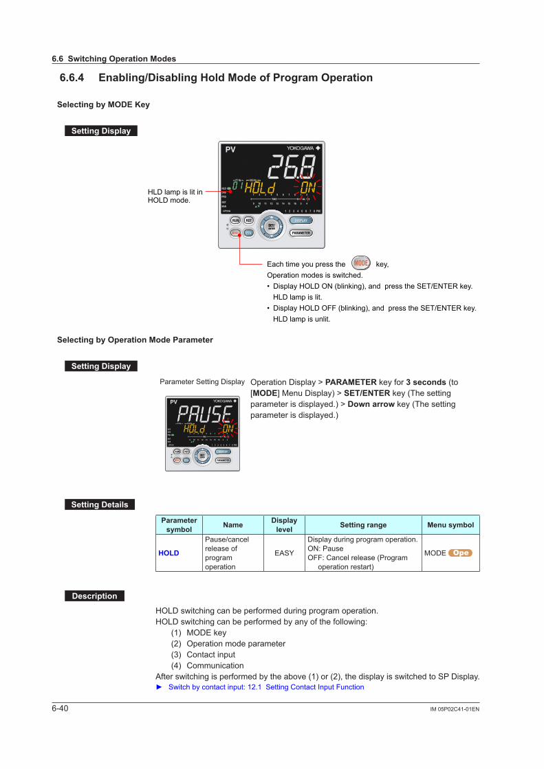
6-40 IM 05P02C41-01EN
6.6.4 Enabling/DisablingHoldModeofProgramOperation
SelectingbyMODEKey
SettingDisplay
HLD lamp is lit in HOLD mode.
Each time you press the key,Operation modes is switched.• Display HOLD ON (blinking), and press the SET/ENTER key. HLD lamp is lit.• Display HOLD OFF (blinking), and press the SET/ENTER key. HLD lamp is unlit.
SelectingbyOperationModeParameter
SettingDisplay
Parameter Setting Display Operation Display > PARAMETER key for 3 seconds (to [MODE] Menu Display) > SET/ENTER key (The setting parameter is displayed.) > Downarrow key (The setting parameter is displayed.)
SettingDetails
Parameter symbol Name Display
level Settingrange Menusymbol
HOLD
Pause/cancel release of program operation
EASY
Display during program operation.ON: PauseOFF: Cancel release (Program
operation restart)
MODE
Description
HOLD switching can be performed during program operation.HOLD switching can be performed by any of the following: (1) MODE key (2) Operation mode parameter (3) Contact input (4) CommunicationAfter switching is performed by the above (1) or (2), the display is switched to SP Display. Switchbycontactinput:12.1SettingContactInputFunction
6.6SwitchingOperationModes

6-41IM 05P02C41-01EN
Monitoring and C
ontrol of Regular O
perations
6
The hold operation function allows pausing the progress of the program pattern. The hold operation stops the segment time and the time of the time event. As a result, the segment time and the time of the time event are extended by the amount of the holding time.Releasing the hold state restarts the segment time and the time of the time event from the time when they were stopped. When the hold state is released, the action can be checked in the Deviation indicator (Program monitor display) on the front panel. Control during the hold operation is performed using the setpoint at the time when the hold operation starts. The time event keeps the state and the PV event continues the action at the time when the hold operation starts. 6.9 Changing SP, TSP, or Remaining Segment-time (R.TIM) in HOLD-mode
HoldOperationinSoakSegment
Seg.2Seg.1 Seg.3 Seg.4 Seg.5 Seg.6
Seg:Segment
Setpoint
TimeHold interval(Timer stops)
Hold interval(Timer stops)
Time eventOnOff
Time delayed by timer stops
Time delayed by timer stops
Program pattern before excuting hold operation.
HoldOperationinRampSegment
Seg.1
Seg.1 Seg.3
Seg.2
Seg.2
Seg.3
Seg.4
Seg.4
Seg.5
Seg.5
Seg.6
Seg.6
Seg:Segment
Setpoint
Time
Hold interval(Timer stops)
Hold interval
Time eventOnOff
Time delayed by timer stops
Program pattern before excuting hold operation.
Program pattern after excuting hold operation.
6.6SwitchingOperationModes

6-42 IM 05P02C41-01EN
6.6.5 ExcutingAdvance
SelectingbyMODEKey
SettingDisplay
Each time you press the key,Operation modes is switched.Display ADV ON (blinking), and press the SET/ENTER key.
SelectingbyOperationModeParameter
SettingDisplay
Parameter Setting Display Operation Display > PARAMETER key for 3 seconds (to [MODE] Menu Display) > SET/ENTER key (The setting parameter is displayed.) > Downarrow key (The setting parameter is displayed.)
SettingDetails
Parameter symbol Name Display
level Settingrange Menusymbol
ADV. Advance of segment EASY
OFF: -Display during program operation.Set as “ADV = ON” to advance from the current segment to the next segment.
MODE
Description
Advance switching can be performed during program operation.Advance switching can be performed by any of the following: (1) MODE key (2) Operation mode parameter (3) Contact input (4) CommunicationAfter switching is performed by the above (1) or (2), the display is switched to SP Display. Switch by contact input: 12.1 Setting Contact Input Function
6.6SwitchingOperationModes

6-43IM 05P02C41-01EN
Monitoring and C
ontrol of Regular O
perations
6
Executing Advance advances the program to the next segment, irrespective of the junctioncode(JC).Advance is performed as follows depending on the segment to execute and the operating state.
• When executing Advance in the last segment: The program switches to Reset operation (when JC=CONT), Local operation, or
Remoteoperationdependingonthejunctioncode(JC).
• When executing Advance in the repeat cycle end segment: The program performs a repeat operation.
• When executing Advance during the hold operation: The program releases the hold state and restarts program pattern operation from the
next segment.
Executing Advance shortens the segment time of the segment for which operation is in progress and the time of the event.
6.6SwitchingOperationModes
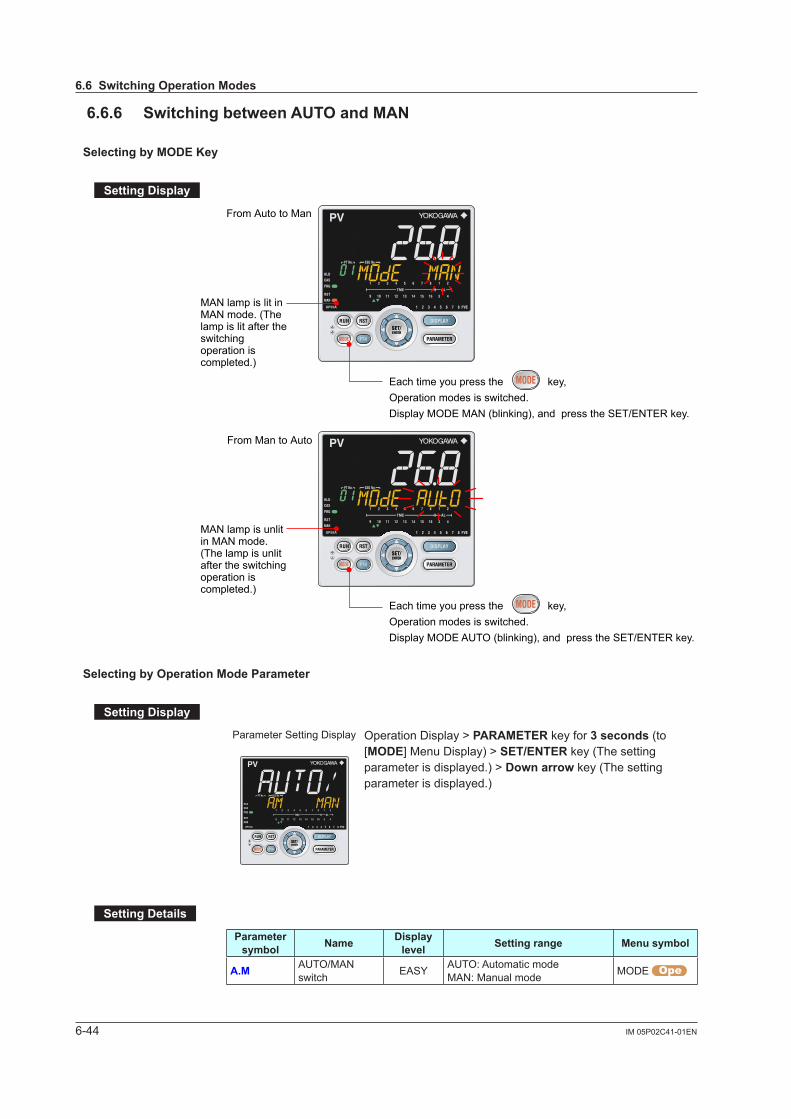
6-44 IM 05P02C41-01EN
6.6.6 SwitchingbetweenAUTOandMAN
SelectingbyMODEKey
SettingDisplay
From Auto to Man
From Man to Auto
MAN lamp is unlit in MAN mode. (The lamp is unlit after the switching operation is completed.)
MAN lamp is lit in MAN mode. (The lamp is lit after the switching operation is completed.)
Each time you press the key,Operation modes is switched.Display MODE AUTO (blinking), and press the SET/ENTER key.
Each time you press the key,Operation modes is switched.Display MODE MAN (blinking), and press the SET/ENTER key.
SelectingbyOperationModeParameter
SettingDisplay
Parameter Setting Display Operation Display > PARAMETER key for 3 seconds (to [MODE] Menu Display) > SET/ENTER key (The setting parameter is displayed.) > Downarrow key (The setting parameter is displayed.)
SettingDetails
Parameter symbol Name Display
level Settingrange Menusymbol
A.M AUTO/MAN switch EASY AUTO: Automatic mode
MAN: Manual mode MODE
6.6SwitchingOperationModes

6-45IM 05P02C41-01EN
Monitoring and C
ontrol of Regular O
perations
6
Description
AUTO/MAN switching can be performed by any of the following: (1) MODE key (2) Operation mode parameter (3) Contact input (4) Communication
When the above (1) or (2) is used to switch AUTO to MAN and MAN to AUTO, the display is switched to OUT Display and SP Display, respectively.
AUTO MAN
When the contact input (status) is ON, operation cannot be performed by keystroke or communication.When the contact input is OFF, and the setting is switched by keystroke or communication, the last switching operation is performed. Switch by contact input: 12.1 Setting Contact Input Function Switch by user function key: 13.2 Assigning Function to User Function Key
Switch Outputaction
AUTO→MAN
Holds the control output value from AUTO mode.The control output value can be bump to the manual preset output value by the setting of parameter MPO.The output value can be changed in manual mode.
MAN→AUTO The control output value does not bump (bumpless). Does not work when Integral time (I) = OFF.
Switch from AUTO to MAN, and MPON: 10.12.2 Setting Output Value When Switched to MAN Mode (Manual Preset Output)
OperationDisplayinAUTOandMANModes“OUT” is displayed on Symbol display and “Output value” is displayed on Data display in MAN mode. (The OUT Display is shown.)
SP Display is shown in AUTO mode.
OperationDisplayinAUTOandMANModesinHeating/coolingControlIn MAN mode, the Display is as follows. Symbol “C” represents the cooling side and “H” represents the heating side. The value on the right of each symbol is the output value.
LampStatusStatus MAN lamp
Automatic operation (AUTO) Unlit
Manual operation (MAN) Lit
6.6SwitchingOperationModes
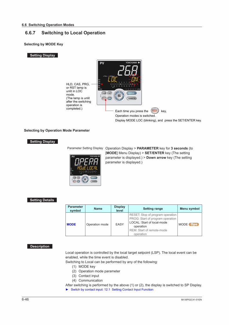
6-46 IM 05P02C41-01EN
6.6.7 SwitchingtoLocalOperation
SelectingbyMODEKey
SettingDisplay
Each time you press the key,Operation modes is switched.Display MODE LOC (blinking), and press the SET/ENTER key.
HLD, CAS, PRG, or RST lamp is unlit in LOC mode.(The lamp is unlit after the switching operation is completed.)
SelectingbyOperationModeParameter
SettingDisplay
Parameter Setting Display Operation Display > PARAMETER key for 3 seconds (to [MODE] Menu Display) > SET/ENTER key (The setting parameter is displayed.) > Downarrow key (The setting parameter is displayed.)
SettingDetails
Parameter symbol Name Display
level Settingrange Menusymbol
MODE Operation mode EASY
RESET: Stop of program operationPROG: Start of program operationLOCAL: Start of local-mode
operationREM: Start of remote-mode
operation
MODE
Description
Local operation is controlled by the local target setpoint (LSP). The local event can be enabled, while the time event is disabled.Switching to Local can be performed by any of the following: (1) MODE key (2) Operation mode parameter (3) Contact input (4) CommunicationAfter switching is performed by the above (1) or (2), the display is switched to SP Display. Switch by contact input: 12.1 Setting Contact Input Function
6.6SwitchingOperationModes
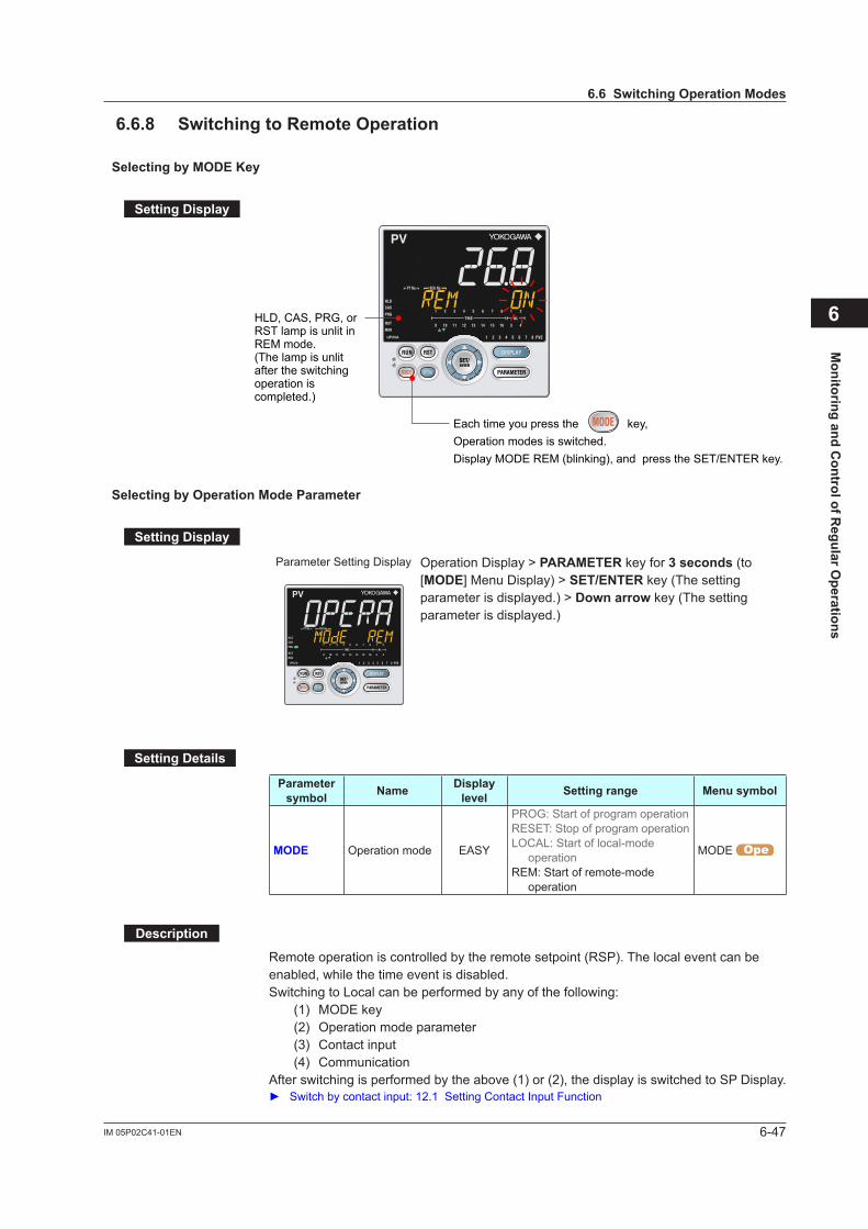
6-47IM 05P02C41-01EN
Monitoring and C
ontrol of Regular O
perations
6
6.6.8 SwitchingtoRemoteOperation
SelectingbyMODEKey
SettingDisplay
HLD, CAS, PRG, or RST lamp is unlit in REM mode.(The lamp is unlit after the switching operation is completed.)
Each time you press the key,Operation modes is switched.Display MODE REM (blinking), and press the SET/ENTER key.
SelectingbyOperationModeParameter
SettingDisplay
Parameter Setting Display Operation Display > PARAMETER key for 3 seconds (to [MODE] Menu Display) > SET/ENTER key (The setting parameter is displayed.) > Downarrow key (The setting parameter is displayed.)
SettingDetails
Parameter symbol Name Display
level Settingrange Menusymbol
MODE Operation mode EASY
PROG: Start of program operationRESET: Stop of program operationLOCAL: Start of local-mode
operationREM: Start of remote-mode
operation
MODE
Description
Remote operation is controlled by the remote setpoint (RSP). The local event can be enabled, while the time event is disabled.Switching to Local can be performed by any of the following: (1) MODE key (2) Operation mode parameter (3) Contact input (4) CommunicationAfter switching is performed by the above (1) or (2), the display is switched to SP Display. Switch by contact input: 12.1 Setting Contact Input Function
6.6SwitchingOperationModes
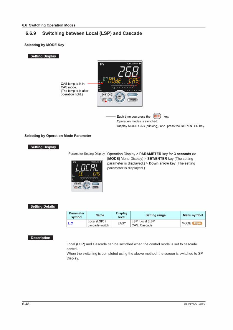
6-48 IM 05P02C41-01EN
6.6.9 SwitchingbetweenLocal(LSP)andCascade
SelectingbyMODEKey
SettingDisplay
CAS lamp is lit in CAS mode.(The lamp is lit after operation right.)
Each time you press the key,Operation modes is switched.Display MODE CAS (blinking), and press the SET/ENTER key.
SelectingbyOperationModeParameter
SettingDisplay
Parameter Setting Display Operation Display > PARAMETER key for 3 seconds (to [MODE] Menu Display) > SET/ENTER key (The setting parameter is displayed.) > Downarrow key (The setting parameter is displayed.)
SettingDetails
Parameter symbol Name Display
level Settingrange Menusymbol
L.C Local (LSP) / cascade switch EASY LSP: Local (LSP
CAS: Cascade MODE
Description
Local (LSP) and Cascade can be switched when the control mode is set to cascade control. When the switching is completed using the above method, the screen is switched to SP Display.
6.6SwitchingOperationModes
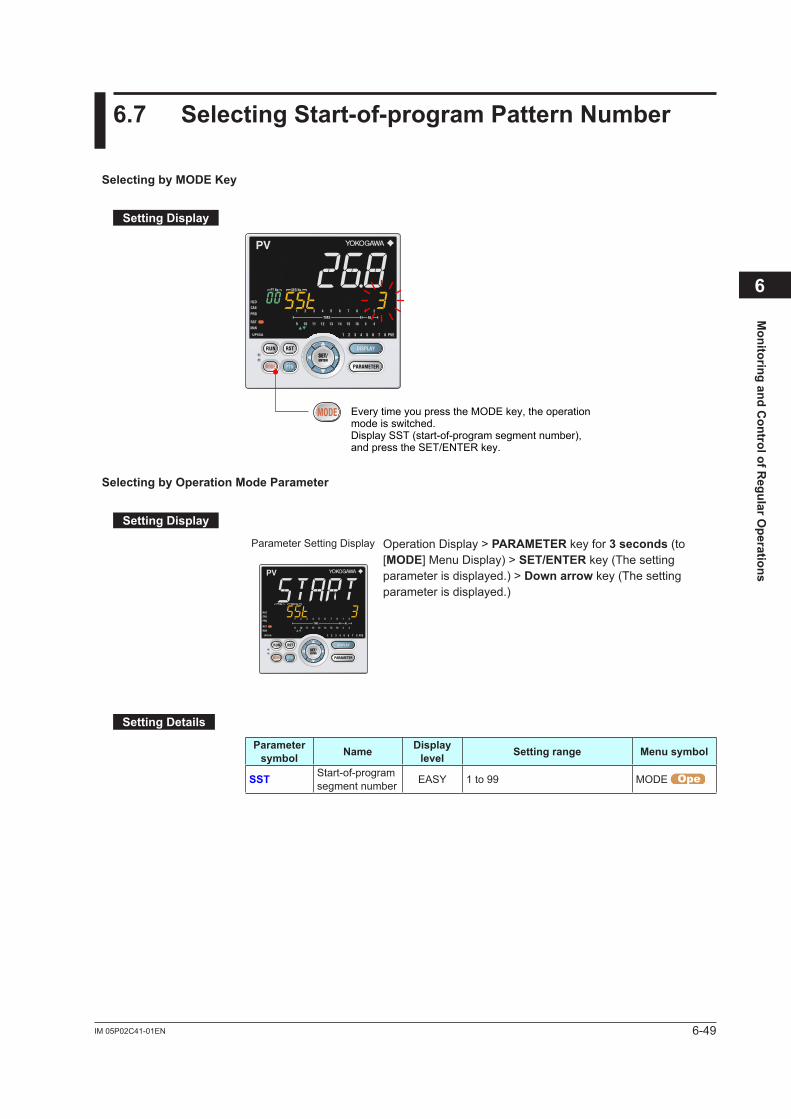
6-49IM 05P02C41-01EN
Monitoring and C
ontrol of Regular O
perations
6
6.7 SelectingStart-of-programPatternNumber
SelectingbyMODEKey
SettingDisplay
Every time you press the MODE key, the operation mode is switched. Display SST (start-of-program segment number), and press the SET/ENTER key.
SelectingbyOperationModeParameter
SettingDisplay
Parameter Setting Display Operation Display > PARAMETER key for 3 seconds (to [MODE] Menu Display) > SET/ENTER key (The setting parameter is displayed.) > Downarrow key (The setting parameter is displayed.)
SettingDetails
Parameter symbol Name Display
level Settingrange Menusymbol
SST Start-of-program segment number EASY 1 to 99 MODE

6-50 IM 05P02C41-01EN
Description
Program operation starts from the set segment number.When the operation mode is switched to reset (RST), local (LOC), or remote (REM) operation, or when power is turned on, the segment number automatically returns to 1.
B
C
AA
Setpoint
Seg.: Segment
TimeStarting program operation at Seg.3
When STC=0Start from
When STC=2
Current PVWhen STC=1
Seg.1 Seg.2 Seg.3 Seg.4 Seg.5
Start from B
6.7SelectingProgramPatternNumber
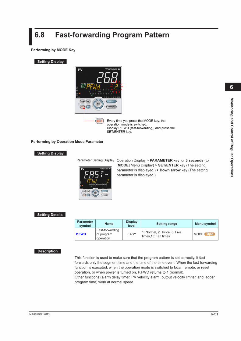
6-51IM 05P02C41-01EN
Monitoring and C
ontrol of Regular O
perations
6
6.8 Fast-forwardingProgramPattern
PerformingbyMODEKey
SettingDisplay
Every time you press the MODE key, the operation mode is switched. Display P.FWD (fast-forwarding), and press the SET/ENTER key.
PerformingbyOperationModeParameter
SettingDisplay
Parameter Setting Display Operation Display > PARAMETER key for 3 seconds (to [MODE] Menu Display) > SET/ENTER key (The setting parameter is displayed.) > Downarrow key (The setting parameter is displayed.)
SettingDetails
Parameter symbol Name Display
level Settingrange Menusymbol
P.FWDFast-forwarding of program operation
EASY 1: Normal, 2: Twice, 5: Five times,10: Ten times MODE
Description
This function is used to make sure that the program pattern is set correctly. It fast forwards only the segment time and the time of the time event. When the fast-forwarding function is executed, when the operation mode is switched to local, remote, or reset operation, or when power is turned on, P.FWD returns to 1 (normal).Other functions (alarm delay timer, PV velocity alarm, output velocity limiter, and ladder program time) work at normal speed.

6-52 IM 05P02C41-01EN
6.9 ChangingSP,TSP,orRemainingSegment-time(R.TIM)inHOLD-mode
ChangingSPinHOLDOperation
Operation
1. Display the SP Display, switch to HOLD mode. See “6.6.4 Enabling/Disabling Hold Mode of Program Operation.”
2. Press the SET/ENTER key to move to the setting mode (the setpoint blinks).
3. Press the Left arrow key to move one digit to the left. (Press the Right arrow key to move one digit to the right.)
4. Press the Up or Down arrow key to change the setpoint. Press the Up arrow key when 9 is displayed to move one digit to the left. Press the Down arrow key when 0 is displayed to move one digit to the right.
5. Press the SET/ENTER key to register the setpoint.
HLD lamp is lit
The figure right is displayed while the right arrow key is held down on SP Display.(1) The number of segments included in the selected
program pattern.(2) The segment number for which operation is in
progress.
(2) (1)
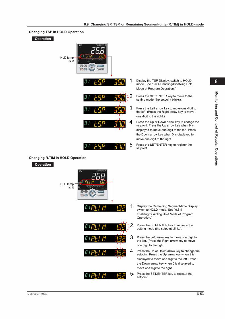
6-53IM 05P02C41-01EN
Monitoring and C
ontrol of Regular O
perations
6
ChangingTSPinHOLDOperation
Operation
1. Display the TSP Display, switch to HOLD mode. See “6.6.4 Enabling/Disabling Hold Mode of Program Operation.”
2. Press the SET/ENTER key to move to the setting mode (the setpoint blinks).
3. Press the Left arrow key to move one digit to the left. (Press the Right arrow key to move one digit to the right.)
4. Press the Up or Down arrow key to change the setpoint. Press the Up arrow key when 9 is displayed to move one digit to the left. Press the Down arrow key when 0 is displayed to move one digit to the right.
5. Press the SET/ENTER key to register the setpoint.
HLD lamp is lit
ChangingR.TIMinHOLDOperation
Operation
1. Display the Remaining Segment-time Display, switch to HOLD mode. See “6.6.4 Enabling/Disabling Hold Mode of Program Operation.”
2. Press the SET/ENTER key to move to the setting mode (the setpoint blinks).
3. Press the Left arrow key to move one digit to the left. (Press the Right arrow key to move one digit to the right.)
4. Press the Up or Down arrow key to change the setpoint. Press the Up arrow key when 9 is displayed to move one digit to the left. Press the Down arrow key when 0 is displayed to move one digit to the right.
5. Press the SET/ENTER key to register the setpoint.
HLD lamp is lit
6.9ChangingSP,TSP,orRemainingSegment-time(R.TIM)inHOLD-mode

6-54 IM 05P02C41-01EN
Description
The current setpoint (hold SP), final target setpoint (TSP), and remaining segment time can be changed during the hold operation.The value changed during the hold operation is temporary. When the program is operated again, it is operated according to the original program pattern. To operate the program using the changed value, the original program pattern needs to be changed.
The following shows conditions that can be changed during the hold operation.Segmentsettingmethod
(SEG.T)Segmenttimesetting Segmentramp-ratesetting
Segmentcondition Soak Ramp Soak RampHold SP √ √ N/A N/AFinal target setpoint √ √ N/A N/ARemaining segment-time √ √ √ N/A
√:Available,N/A:Notavialable
When the segment ramp-rate setting is selected in the segment setting method (SEG.T), the hold operation is enabled, while the hold SP and final target setpoint (TSP) cannot be changed.
6.9ChangingSP,TSP,orRemainingSegment-time(R.TIM)inHOLD-mode
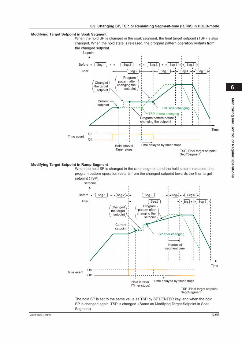
6-55IM 05P02C41-01EN
Monitoring and C
ontrol of Regular O
perations
6
ModifyingTargetSetpointinSoakSegmentWhen the hold SP is changed in the soak segment, the final target setpoint (TSP) is also changed. When the hold state is released, the program pattern operation restarts from the changed setpoint.
Seg:Segment
Setpoint
Time
Changed the target
setpoint
Hold interval(Timer stops)
Time event
TSP:Final target setpoint
OnOff
Program pattern after
changing the setpoint
Time delayed by timer stops
Program pattern before changing the setpoint
Current setpoint
Seg.1 Seg.2 Seg.3 Seg.4 Seg.5
Seg.3 Seg.4 Seg.5Seg.2
TSP before changing
TSP after changing
Before
After
ModifyingTargetSetpointinRampSegmentWhen the hold SP is changed in the ramp segment and the hold state is released, the program pattern operation restarts from the changed setpoint towards the final target setpoint (TSP).
Seg.1 Seg.2 Seg.3
Seg.3
Seg.4 Seg.5
Seg.4 Seg.5
Increased segment time
Seg:Segment
Setpoint
Time
Changed the target
setpoint
Hold interval(Timer stops)
Time event
TSP:Final target setpoint
OnOff
Program pattern after
changing the setpoint
Time delayed by timer stops
Current setpoint
SP after changing
Before
After
The hold SP is set to the same value as TSP by SET/ENTER key, and when the hold SP is changed again, TSP is changed. (Same as Modifying Target Setpoint in Soak Segment)
6.9ChangingSP,TSP,orRemainingSegment-time(R.TIM)inHOLD-mode

6-56 IM 05P02C41-01EN
ModifyingFinalTargetSetpoint(TSP)inSoakSegmentThe final target setpoint (TSP) can be changed in the soak segment.When the hold state is released, the program pattern operation restarts towards the changed final target setpoint (TSP).
Seg.1 Seg.2 Seg.3 Seg.4 Seg.5
Seg.4 Seg.5Seg.3Seg.2
Seg:Segment
Setpoint
Time
Hold interval(Timer stops)
Time event
TSP:Final target setpoint
OnOff
Program pattern after changing the setpoint
Time delayed by timer stops
Program pattern before changing the setpoint
Current setpoint
TSP after changing
TSP before changing
TSP after changing
Before
After
ModifyingFinalTargetSetpoint(TSP)inRampSegmentWhen the final target setpoint (TSP) is changed in the ramp segment and the hold state is released, the program pattern operation restarts towards the changed final target setpoint (TSP).
Seg.1
Seg.1
Seg.2
Seg.2
Seg:Segment
Setpoint
Time
Hold interval(Timer stops)
Time event
TSP:Final target setpoint
OnOff
Time delayed by timer stops
Current setpoint
TSP before changing
TSP after changing
Before
After
6.9ChangingSP,TSP,orRemainingSegment-time(R.TIM)inHOLD-mode
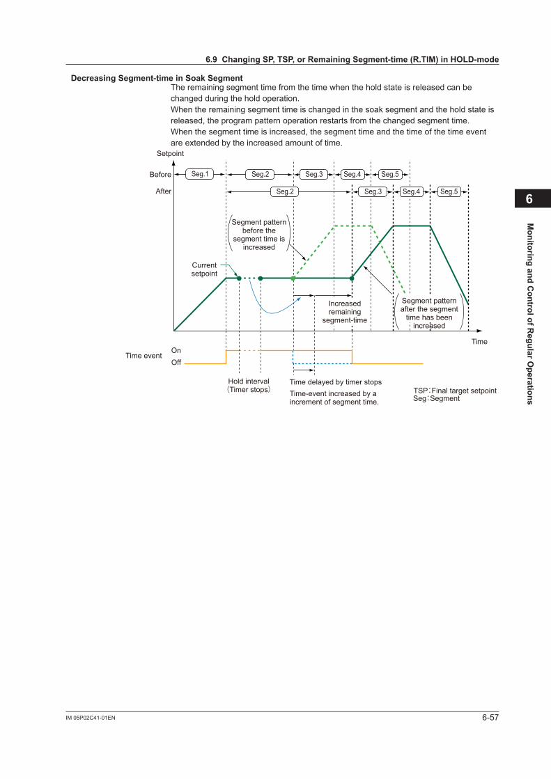
6-57IM 05P02C41-01EN
Monitoring and C
ontrol of Regular O
perations
6
DecreasingSegment-timeinSoakSegmentThe remaining segment time from the time when the hold state is released can be changed during the hold operation.When the remaining segment time is changed in the soak segment and the hold state is released, the program pattern operation restarts from the changed segment time.When the segment time is increased, the segment time and the time of the time event are extended by the increased amount of time.
Segment pattern before the
segment time is increased
Increased remaining
segment-time
Segment pattern after the segment
time has been increased
Seg.1 Seg.2
Seg.2
Seg.3 Seg.4 Seg.5
Seg.3 Seg.4 Seg.5
Time-event increased by a increment of segment time. Seg:Segment
Setpoint
Time
Hold interval(Timer stops)
Time event
TSP:Final target setpoint
OnOff
Time delayed by timer stops
Current setpoint
Before
After
6.9ChangingSP,TSP,orRemainingSegment-time(R.TIM)inHOLD-mode
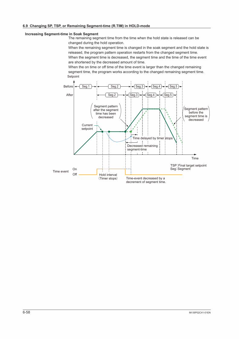
6-58 IM 05P02C41-01EN
IncreasingSegment-timeinSoakSegmentThe remaining segment time from the time when the hold state is released can be changed during the hold operation.When the remaining segment time is changed in the soak segment and the hold state is released, the program pattern operation restarts from the changed segment time.When the segment time is decreased, the segment time and the time of the time event are shortened by the decreased amount of time.When the on time or off time of the time event is larger than the changed remaining segment time, the program works according to the changed remaining segment time.
Seg.1 Seg.2
Seg.2
Seg.3
Seg.3
Seg.4
Seg.4
Seg.5
Seg.5
Segment pattern before the
segment time is decreased
Decreased remaining segment-time
Time-event decreased by a decrement of segment time.
Seg:Segment
Setpoint
Time
Hold interval(Timer stops)
Time event
TSP:Final target setpointOnOff
Current setpoint
Time delayed by timer stops
Segment pattern after the segment
time has been decreased
Before
After
6.9ChangingSP,TSP,orRemainingSegment-time(R.TIM)inHOLD-mode
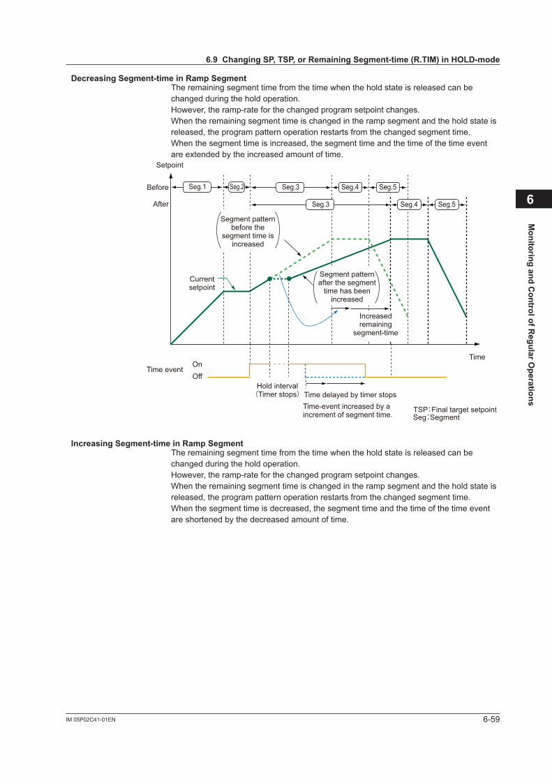
6-59IM 05P02C41-01EN
Monitoring and C
ontrol of Regular O
perations
6
DecreasingSegment-timeinRampSegmentThe remaining segment time from the time when the hold state is released can be changed during the hold operation.However, the ramp-rate for the changed program setpoint changes.When the remaining segment time is changed in the ramp segment and the hold state is released, the program pattern operation restarts from the changed segment time.When the segment time is increased, the segment time and the time of the time event are extended by the increased amount of time.
Seg.1 Seg.3 Seg.4Seg.2 Seg.5
Seg.3 Seg.4 Seg.5
Increased remaining
segment-time
Time-event increased by a increment of segment time. Seg:Segment
Setpoint
Time
Hold interval(Timer stops)
Time event
TSP:Final target setpoint
OnOff
Time delayed by timer stops
Current setpoint
Segment pattern before the
segment time is increased
Segment pattern after the segment
time has been increased
Before
After
IncreasingSegment-timeinRampSegmentThe remaining segment time from the time when the hold state is released can be changed during the hold operation.However, the ramp-rate for the changed program setpoint changes.When the remaining segment time is changed in the ramp segment and the hold state is released, the program pattern operation restarts from the changed segment time.When the segment time is decreased, the segment time and the time of the time event are shortened by the decreased amount of time.
6.9ChangingSP,TSP,orRemainingSegment-time(R.TIM)inHOLD-mode
6-60 IM 05P02C41-01EN
6.10 ChangingProgramPatternduringProgramOperation
Description
The program pattern can be changed during the program operation in Program Parameter Setting Display.Unlike changing during the hold operation, changing the program pattern in Program Parameter Setting Display saves the changed setpoint. However, even if the parameter of the segment in process is changed, it is not reflected in operation. It is reflected from the next operation. In hold mode operation, it is reflected when TSP of segment is changed.The change of the Hold-SP is reflected after release of the HOLD-mode.
Changing Hold SP: 6.9 Changing SP, TSP, or Remaining Segment-time (R.TIM) in HOLD-mode
The program pattern cannot be changed via communication during the program operation.
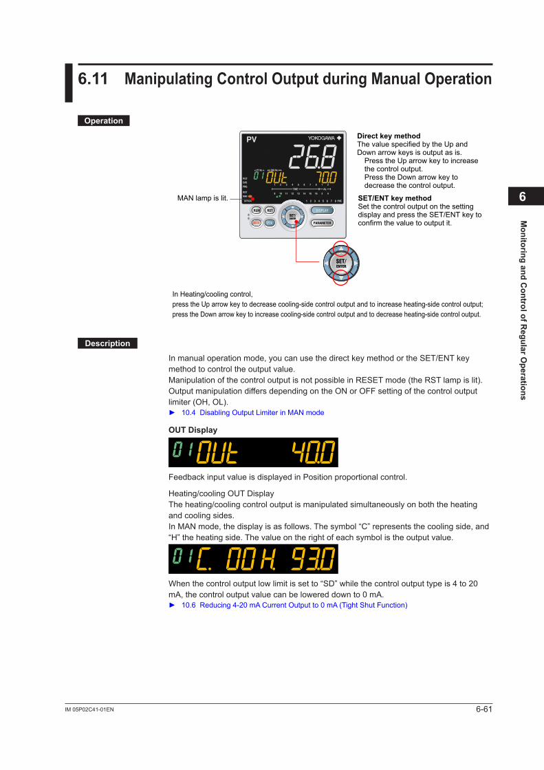
6-61IM 05P02C41-01EN
Monitoring and C
ontrol of Regular O
perations
6
6.11 ManipulatingControlOutputduringManualOperation
Operation
In Heating/cooling control,press the Up arrow key to decrease cooling-side control output and to increase heating-side control output;press the Down arrow key to increase cooling-side control output and to decrease heating-side control output.
MAN lamp is lit.
Direct key methodThe value specified by the Up and Down arrow keys is output as is.
Press the Up arrow key to increase the control output.Press the Down arrow key to decrease the control output.
SET/ENT key methodSet the control output on the setting display and press the SET/ENT key to confirm the value to output it.
Description
In manual operation mode, you can use the direct key method or the SET/ENT key method to control the output value.Manipulation of the control output is not possible in RESET mode (the RST lamp is lit). Output manipulation differs depending on the ON or OFF setting of the control output limiter (OH, OL). 10.4DisablingOutputLimiterinMANmode
OUTDisplay
Feedback input value is displayed in Position proportional control.
Heating/cooling OUT DisplayThe heating/cooling control output is manipulated simultaneously on both the heating and cooling sides.In MAN mode, the display is as follows. The symbol “C” represents the cooling side, and “H” the heating side. The value on the right of each symbol is the output value.
When the control output low limit is set to “SD” while the control output type is 4 to 20 mA, the control output value can be lowered down to 0 mA. 10.6Reducing4-20mACurrentOutputto0mA(TightShutFunction)
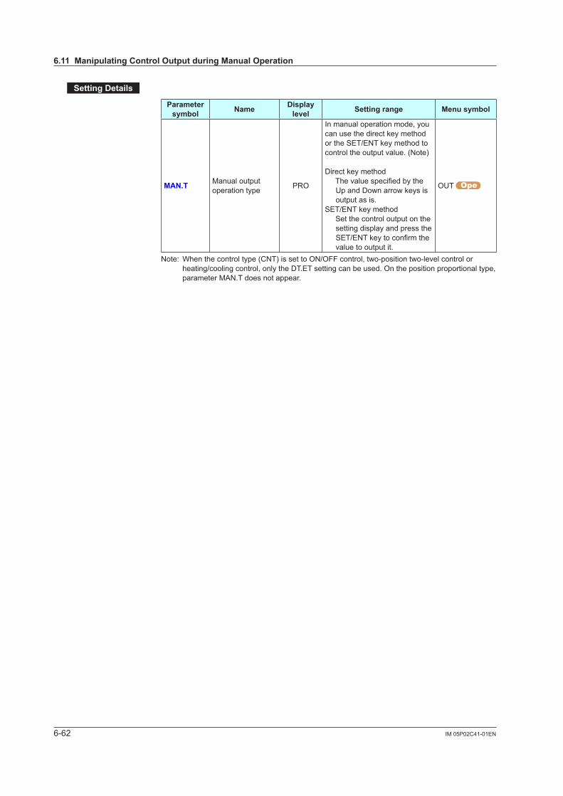
6-62 IM 05P02C41-01EN
SettingDetails
Parameter symbol Name Display
level Settingrange Menusymbol
MAN.T Manual output operation type PRO
In manual operation mode, you can use the direct key method or the SET/ENT key method to control the output value. (Note)
Direct key methodThevaluespecifiedbythe
Up and Down arrow keys is output as is.
SET/ENT key method Set the control output on the
setting display and press the SET/ENTkeytoconfirmthevalue to output it.
OUT
Note: When the control type (CNT) is set to ON/OFF control, two-position two-level control or heating/cooling control, only the DT.ET setting can be used. On the position proportional type, parameter MAN.T does not appear.
6.11ManipulatingControlOutputduringManualOperation

6-63IM 05P02C41-01EN
Monitoring and C
ontrol of Regular O
perations
6
6.12 ReleasingOn-State(Latch)ofAlarmOutput
Description
Alarm latch can be released by any of the following. (1) User function key (RUN, RST, PTN, MODE) (2) Communication (3) Contact input For the switching operation by using the above, the last switching operation is performed.
Releasing the alarm latch function releases all of the latched alarm outputs.By factory default, the function is not assigned to the user function key and contact input. Assign and use the function in accordance with the reference sections below.
Releasebyuserfunctionkey:13.2AssigningFunctiontoUserFunctionKey Releasebycontactinput:12.1SettingContactInputFunction Releaseviacommunication:UTAdvancedSeriesCommunicationInterfaceUser’sManual

Blank Page
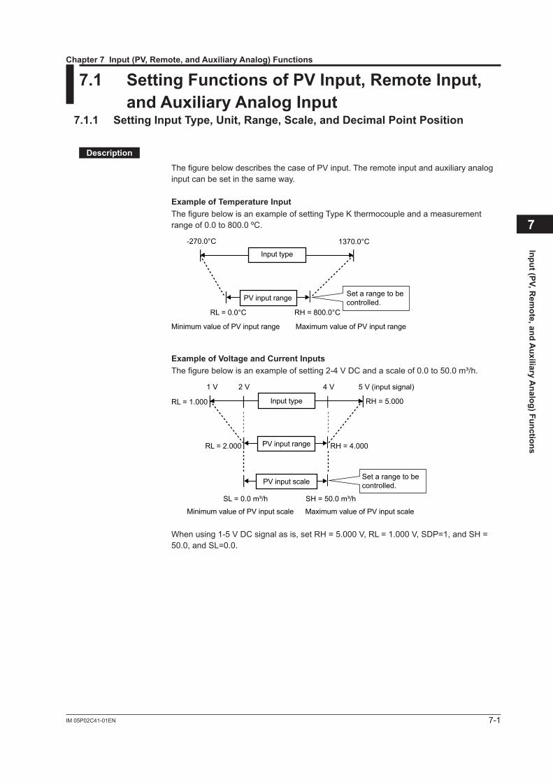
7-1IM 05P02C41-01EN
Input (PV, Rem
ote, and Auxiliary A
nalog) Functions
7
7.1 SettingFunctionsofPVInput,RemoteInput,andAuxiliaryAnalogInput
7.1.1 SettingInputType,Unit,Range,Scale,andDecimalPointPosition
Description
The figure below describes the case of PV input. The remote input and auxiliary analog input can be set in the same way.
ExampleofTemperatureInputThe figure below is an example of setting Type K thermocouple and a measurement range of 0.0 to 800.0 ºC.
Minimum value of PV input range
Input type
-270.0°C 1370.0°C
RL = 0.0°C RH = 800.0°C
Maximum value of PV input range
Set a range to becontrolled.PV input range
ExampleofVoltageandCurrentInputsThe figure below is an example of setting 2-4 V DC and a scale of 0.0 to 50.0 m³/h.
Minimum value of PV input scale
1 V 5 V (input signal)
SL = 0.0 m³/h SH = 50.0 m³/h
Maximum value of PV input scale
2 V 4 V
RL = 2.000
RL = 1.000
RH = 4.000
RH = 5.000
PV input scale
Input type
Set a range to becontrolled.
PV input range
When using 1-5 V DC signal as is, set RH = 5.000 V, RL = 1.000 V, SDP=1, and SH = 50.0, and SL=0.0.
Chapter7Input(PV,Remote,andAuxiliaryAnalog)Functions

7-2 IM 05P02C41-01EN
SettingDetails
Parameter symbol Name Display
level Settingrange Menusymbol
IN
PV input type EASY
OFF: DisableK1: -270.0 to 1370.0 ºC / -450.0 to 2500.0 ºFK2: -270.0 to 1000.0 ºC / -450.0 to 2300.0 ºFK3: -200.0 to 500.0 ºC / -200.0 to 1000.0 ºFJ: -200.0 to 1200.0 ºC / -300.0 to 2300.0 ºFT1: -270.0 to 400.0 ºC / -450.0 to 750.0 ºFT2: 0.0 to 400.0 ºC / -200.0 to 750.0 ºFB: 0.0 to 1800.0 ºC / 32 to 3300 ºFS: 0.0 to 1700.0 ºC / 32 to 3100 ºFR: 0.0 to 1700.0 ºC / 32 to 3100 ºFN: -200.0 to 1300.0 ºC / -300.0 to 2400.0 ºFE: -270.0 to 1000.0 ºC / -450.0 to 1800.0 ºFL: -200.0 to 900.0 ºC / -300.0 to 1600.0 ºFU1: -200.0 to 400.0 ºC / -300.0 to 750.0 ºFU2: 0.0 to 400.0 ºC / -200.0 to 1000.0 ºFW: 0.0 to 2300.0 ºC / 32 to 4200 ºF(Note1)PL2: 0.0 to 1390.0 ºC / 32.0 to 2500.0 ºFP2040: 0.0 to 1900.0 ºC / 32 to 3400 ºFWRE: 0.0 to 2000.0 ºC / 32 to 3600 ºFJPT1: -200.0 to 500.0 ºC / -300.0 to 1000.0 ºFJPT2: -150.0 to 150.0 ºC / -200.0 to 300.0 ºFPT1: -200.0 to 850.0 ºC / -300.0 to 1560.0 ºFPT2: -200.0 to 500.0 ºC / -300.0 to 1000.0 ºFPT3: -150.00 to 150.00 ºC / -200.0 to 300.0 ºF0.4-2V: 0.400 to 2.000 V1-5V: 1.000 to 5.000 V4-20: 4.00 to 20.00 mA0-2V: 0.000 to 2.000 V0-10V: 0.00 to 10.00 V0-20 : 0.00 to 20.00 mA-1020: -10.00 to 20.00 mV0-100: 0.0 to 100.0 mV
PV
RSP remote input type(Note2) EASY
0.4-2V: 0.400 to 2.000 V1-5V: 1.000 to 5.000 V0-2V: 0.000 to 2.000 V0-10V: 0.00 to 10.00 V0-125: 0.000 to 1.250 V
RSP
AIN2 aux. analog input type EASY AIN2
AIN4 aux. analog input type EASY AIN4
UNIT
PV input unit EASY -: No unitC: Degree Celsius-: No unit- -: No unit- - -: No unitF: Degree Fahrenheit
PV
RSP remote input unit EASY RSP AIN2 aux. analog input unit EASY AIN2
AIN4 aux. analog input unit EASY AIN4
Note1: W: W-5% Re/W-26% Re(Hoskins Mfg. Co.). ASTM E988 WRE: W97Re3-W75Re25
Note2: Standart model: For remote input with the optional suffix code /DR, RSP remote input type is same as PV input type. Detailed model: When the optional suffix code /U1 is specified, RSP remote input type is same as PV input type.
7.1SettingFunctionsofPVInput,RemoteInput,andAuxiliaryAnalogInput

7-3IM 05P02C41-01EN
Input (PV, Rem
ote, and Auxiliary A
nalog) Functions
7
(Continued)Parameter symbol Name Display
level Settingrange Menusymbol
RH(Physicalquantity)
Maximum value of PV input range EASY
Depends on the input type.- For temperature input - Set the temperature range
that is actually controlled. (RL<RH)
- For voltage / current input - Set the range of a voltage
/ current signal that is applied.
The scale across which the voltage / current signal is actually controlled should be set using the maximum value of input scale (SH) and minimum value of input scale (SL). (Input is always 0% when RL = RH.)
PV
Maximum value of RSP remote input range EASY RSP
Maximum value of AIN2 aux. analog input range EASY
Depends on the input type.Set the range of a voltage signal that is applied.The scale across which the voltage signal is actually controlled should be set using the maximum value of input scale (SH) and minimum value of input scale (SL). (Input is always 0% when RL = RH.)
AIN2
Maximum value of AIN4 aux. analog input range EASY AIN4
RL(Physicalquantity)
Minimum value of PV input range EASY
Same as RH
PV
Minimum value of RSP remote input range EASY RSP
Minimum value of AIN2 aux. analog input range EASY AIN2
Minimum value of AIN4 aux. analog input range EASY AIN4
SDP(Scaling)
PV input scale decimal point position EASY
0: No decimal place1: One decimal place2: Two decimal places3: Three decimal places4: Four decimal places
PV
RSP remote input scale decimal point position EASY RSP
AIN2 aux. analog input scale decimal point position EASY AIN2
AIN4 aux. analog input scale decimal point position EASY AIN4
SH(Scaling)
Maximum value of PV input scale EASY
-19999 to 30000, (SL<SH),|SH-SL|≤30000
PV
Maximum value of RSP remote input scale EASY RSP
Maximum value of AIN2 aux. analog input scale EASY AIN2
Maximum value of AIN4 aux. analog input scale EASY AIN4
7.1SettingFunctionsofPVInput,RemoteInput,andAuxiliaryAnalogInput
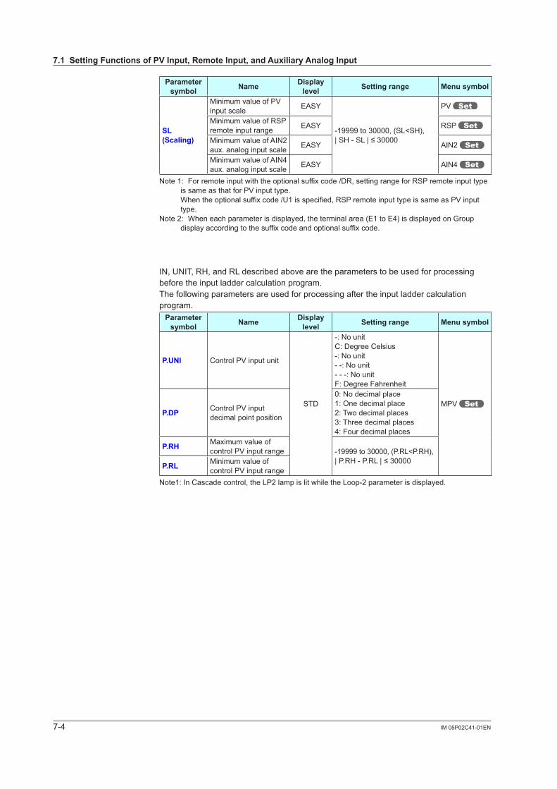
7-4 IM 05P02C41-01EN
Parameter symbol Name Display
level Settingrange Menusymbol
SL(Scaling)
Minimum value of PV input scale EASY
-19999 to 30000, (SL<SH),|SH-SL|≤30000
PV
Minimum value of RSP remote input range EASY RSP
Minimum value of AIN2 aux. analog input scale EASY AIN2
Minimum value of AIN4 aux. analog input scale EASY AIN4
Note 1: For remote input with the optional suffix code /DR, setting range for RSP remote input type is same as that for PV input type.
When the optional suffix code /U1 is specified, RSP remote input type is same as PV input type.
Note 2: When each parameter is displayed, the terminal area (E1 to E4) is displayed on Group display according to the suffix code and optional suffix code.
IN, UNIT, RH, and RL described above are the parameters to be used for processing before the input ladder calculation program.The following parameters are used for processing after the input ladder calculation program.
Parameter symbol Name Display
level Settingrange Menusymbol
P.UNI Control PV input unit
STD
-: No unitC: Degree Celsius-: No unit- -: No unit- - -: No unitF: Degree Fahrenheit
MPV P.DP Control PV input
decimal point position
0: No decimal place1: One decimal place2: Two decimal places3: Three decimal places4: Four decimal places
P.RH Maximum value of control PV input range -19999 to 30000, (P.RL<P.RH),
|P.RH-P.RL|≤30000P.RL Minimum value of control PV input range
Note1: In Cascade control, the LP2 lamp is lit while the Loop-2 parameter is displayed.
7.1SettingFunctionsofPVInput,RemoteInput,andAuxiliaryAnalogInput
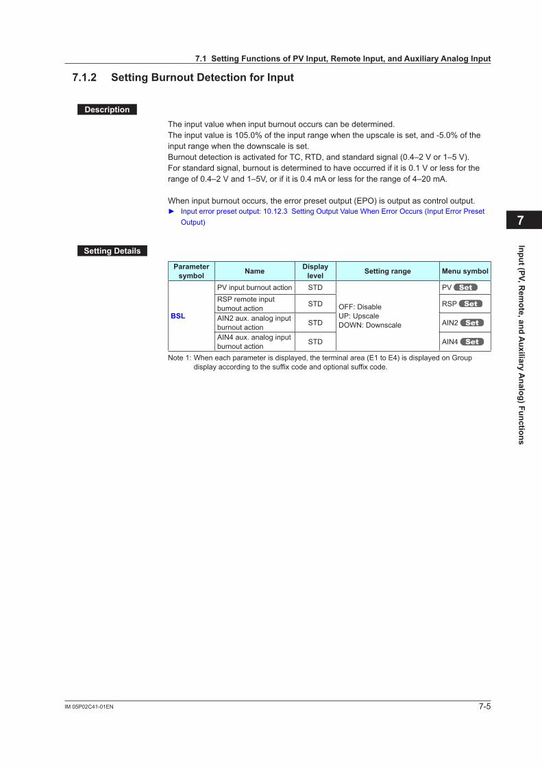
7-5IM 05P02C41-01EN
Input (PV, Rem
ote, and Auxiliary A
nalog) Functions
7
7.1.2 SettingBurnoutDetectionforInput
Description
The input value when input burnout occurs can be determined.The input value is 105.0% of the input range when the upscale is set, and -5.0% of the input range when the downscale is set.Burnout detection is activated for TC, RTD, and standard signal (0.4–2 V or 1–5 V).For standard signal, burnout is determined to have occurred if it is 0.1 V or less for the range of 0.4–2 V and 1–5V, or if it is 0.4 mA or less for the range of 4–20 mA.
When input burnout occurs, the error preset output (EPO) is output as control output. Inputerrorpresetoutput:10.12.3SettingOutputValueWhenErrorOccurs(InputErrorPreset
Output)
SettingDetails
Parameter symbol Name Display
level Settingrange Menusymbol
BSL
PV input burnout action STD
OFF: DisableUP: UpscaleDOWN: Downscale
PV RSP remote input bumout action STD RSP
AIN2 aux. analog input burnout action STD AIN2
AIN4 aux. analog input burnout action STD AIN4
Note 1: When each parameter is displayed, the terminal area (E1 to E4) is displayed on Group display according to the suffix code and optional suffix code.
7.1SettingFunctionsofPVInput,RemoteInput,andAuxiliaryAnalogInput

7-6 IM 05P02C41-01EN
7.1.3 SettingReferenceJunctionCompensation(RJC)orExternalReferenceJunctionCompensation(ERJC)
Description
ReferenceJunctionCompensation(RJC)WhenTCinputisselected,presence/absenceofinputreferencejunctioncompensationcan be set.Usually input values are compensated with the RJC function provided for the controller. However, if it is necessary to rigorously compensate the values with a device other than thefunctionofthecontroller,forexamplewithazero-compensator,theRJCfunctionofthe controller can be turned off.
ExternalReferenceJunctionCompensation(ERJC)For TC input, a temperature compensation value for external device can be set.The external RJC can be used only when RJC = OFF.
Furnace
Furnace
UP55A
UP55A
Compensating lead wire
Compensating lead wire
Terminal block
Terminal block
TC
TC
Installed in an area where ambient temperature is fixed to 25°C.
Set the temperature in the area using ERJC parameter.
Normal wiring
Example:Setting parametersRJC = OFF,ERJC = 25.0°C
SettingDetails
Parameter symbol Name Display
level Settingrange Menusymbol
RJC
PV input reference junctioncompensation PRO
OFF: RJC OFFON: RJC ON
PV
RSP remote input referencejunctioncompensation
PRO RSP
ERJC
PV input external RJC setpoint PRO
-10.0 to 60.0°CPV
RSP remote input external RJC setpoint PRO RSP
Note 1: When each parameter is displayed, the terminal area (E1 to E4) is displayed on Group display according to the suffix code and optional suffix code.
7.1SettingFunctionsofPVInput,RemoteInput,andAuxiliaryAnalogInput
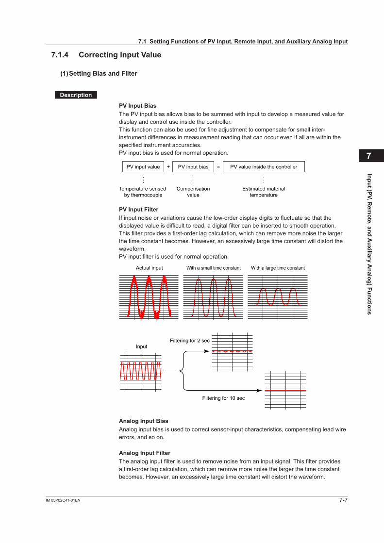
7-7IM 05P02C41-01EN
Input (PV, Rem
ote, and Auxiliary A
nalog) Functions
7.1.4 CorrectingInputValue
(1)SettingBiasandFilter
Description
PV Input BiasThe PV input bias allows bias to be summed with input to develop a measured value for display and control use inside the controller.Thisfunctioncanalsobeusedforfineadjustmenttocompensateforsmallinter-instrument differences in measurement reading that can occur even if all are within the specified instrument accuracies.PV input bias is used for normal operation.
PV input value + =PV input bias PV value inside the controller
Temperature sensed by thermocouple
Compensationvalue
Estimated materialtemperature
PV Input FilterIf input noise or variations cause the low-order display digits to fluctuate so that the displayed value is difficult to read, a digital filter can be inserted to smooth operation. This filter provides a first-order lag calculation, which can remove more noise the larger the time constant becomes. However, an excessively large time constant will distort the waveform.PV input filter is used for normal operation.
Actual input With a small time constant With a large time constant
InputFiltering for 2 sec
Filtering for 10 sec
Analog Input BiasAnalog input bias is used to correct sensor-input characteristics, compensating lead wire errors, and so on.
Analog Input FilterThe analog input filter is used to remove noise from an input signal. This filter provides a first-order lag calculation, which can remove more noise the larger the time constant becomes. However, an excessively large time constant will distort the waveform.
7
7.1SettingFunctionsofPVInput,RemoteInput,andAuxiliaryAnalogInput
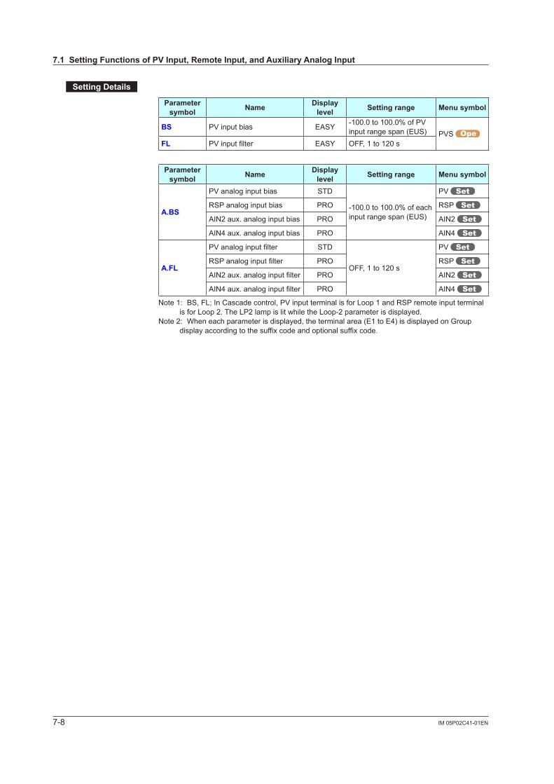
7-8 IM 05P02C41-01EN
SettingDetails
Parameter symbol Name Display
level Settingrange Menusymbol
BS PV input bias EASY -100.0 to 100.0% of PV input range span (EUS) PVS
FL PVinputfilter EASY OFF, 1 to 120 s
Parameter symbol Name Display
level Settingrange Menusymbol
A.BS
PV analog input bias STD
-100.0 to 100.0% of each input range span (EUS)
PV
RSP analog input bias PRO RSP
AIN2 aux. analog input bias PRO AIN2
AIN4 aux. analog input bias PRO AIN4
A.FL
PVanaloginputfilter STD
OFF, 1 to 120 s
PV
RSPanaloginputfilter PRO RSP
AIN2aux.analoginputfilter PRO AIN2
AIN4aux.analoginputfilter PRO AIN4
Note 1: BS, FL; In Cascade control, PV input terminal is for Loop 1 and RSP remote input terminal is for Loop 2. The LP2 lamp is lit while the Loop-2 parameter is displayed.
Note 2: When each parameter is displayed, the terminal area (E1 to E4) is displayed on Group display according to the suffix code and optional suffix code.
7.1SettingFunctionsofPVInput,RemoteInput,andAuxiliaryAnalogInput
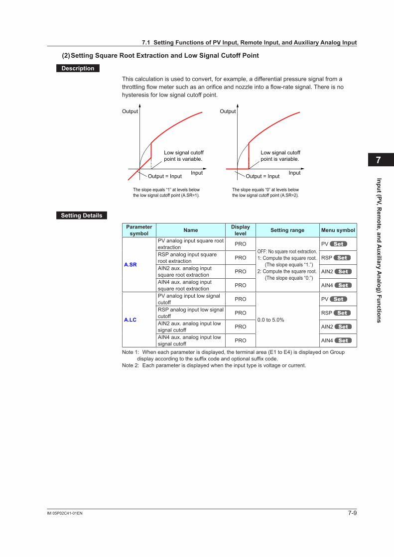
7-9IM 05P02C41-01EN
Input (PV, Rem
ote, and Auxiliary A
nalog) Functions
(2)SettingSquareRootExtractionandLowSignalCutoffPoint
Description
This calculation is used to convert, for example, a differential pressure signal from a throttlingflowmetersuchasanorificeandnozzleintoaflow-ratesignal.Thereisnohysteresis for low signal cutoff point.
Output = Input
The slope equals “1” at levels below the low signal cutoff point (A.SR=1).
The slope equals “0” at levels belowthe low signal cutoff point (A.SR=2).
Output
Input Output = Input
Output
Input
Low signal cutoff point is variable.
Low signal cutoff point is variable.
SettingDetails
Parameter symbol Name Display
level Settingrange Menusymbol
A.SR
PV analog input square root extraction PRO
OFF: No square root extraction.1: Compute the square root.
(The slope equals “1.”)2: Compute the square root.
(The slope equals “0.”)
PV
RSP analog input square root extraction PRO RSP
AIN2 aux. analog input square root extraction PRO AIN2
AIN4 aux. analog input square root extraction PRO AIN4
A.LC
PV analog input low signal cutoff PRO
0.0 to 5.0%
PV
RSP analog input low signal cutoff PRO RSP
AIN2 aux. analog input low signal cutoff PRO AIN2
AIN4 aux. analog input low signal cutoff PRO AIN4
Note 1: When each parameter is displayed, the terminal area (E1 to E4) is displayed on Group display according to the suffix code and optional suffix code.
Note 2: Each parameter is displayed when the input type is voltage or current.
7
7.1SettingFunctionsofPVInput,RemoteInput,andAuxiliaryAnalogInput
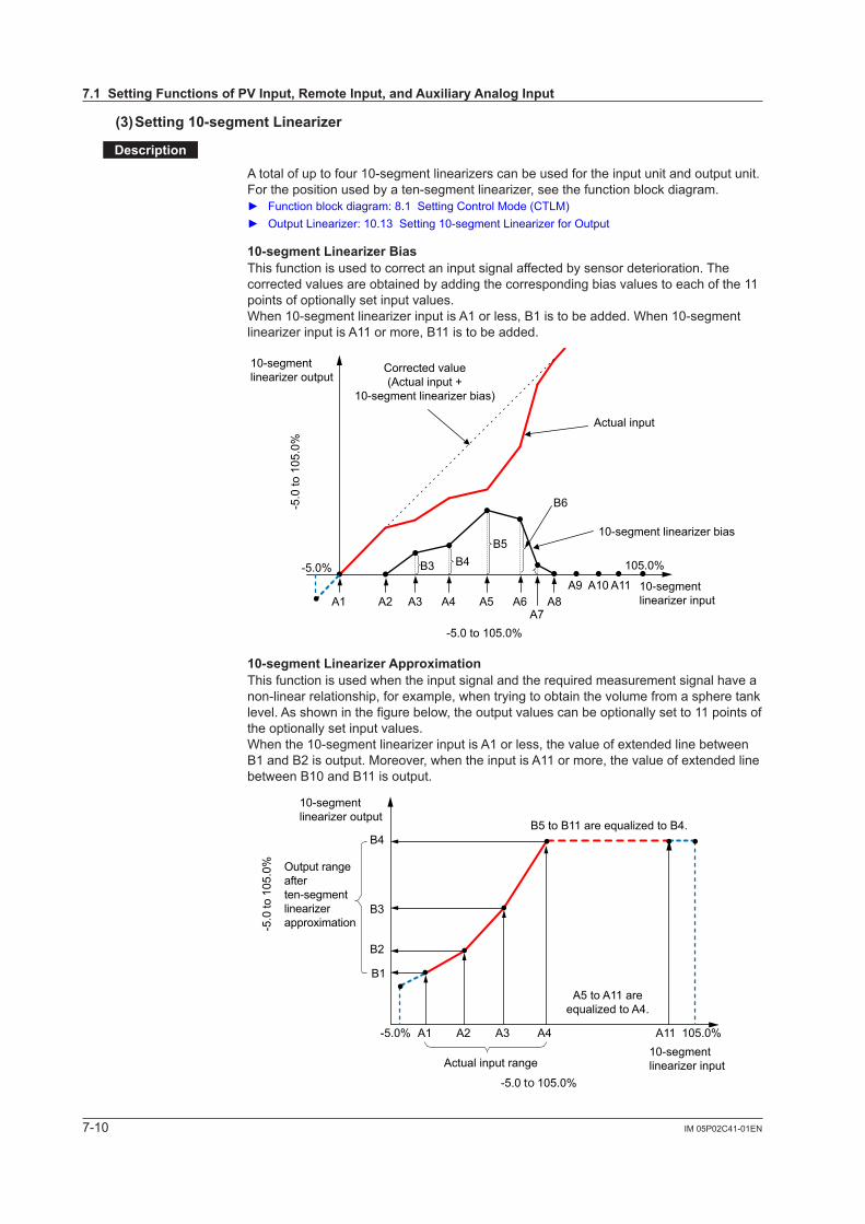
7-10 IM 05P02C41-01EN
(3)Setting10-segmentLinearizer
Description
Atotalofuptofour10-segmentlinearizerscanbeusedfortheinputunitandoutputunit.Forthepositionusedbyaten-segmentlinearizer,seethefunctionblockdiagram. Functionblockdiagram:8.1SettingControlMode(CTLM) OutputLinearizer:10.13Setting10-segmentLinearizerforOutput
10-segmentLinearizerBiasThis function is used to correct an input signal affected by sensor deterioration. The corrected values are obtained by adding the corresponding bias values to each of the 11 points of optionally set input values.When10-segmentlinearizerinputisA1orless,B1istobeadded.When10-segmentlinearizerinputisA11ormore,B11istobeadded.
A1 A2 A3 A4 A5 A6A7
A8A9 A10 A11
B3 B4B5
B6
-5.0 to 105.0%
-5.0
to 1
05.0
%
-5.0% 105.0%
Corrected value(Actual input +
10-segment linearizer bias)
10-segmentlinearizer output
Actual input
10-segment linearizer bias
10-segmentlinearizer input
10-segmentLinearizerApproximationThis function is used when the input signal and the required measurement signal have a non-linear relationship, for example, when trying to obtain the volume from a sphere tank level. As shown in the figure below, the output values can be optionally set to 11 points of the optionally set input values.Whenthe10-segmentlinearizerinputisA1orless,thevalueofextendedlinebetweenB1 and B2 is output. Moreover, when the input is A11 or more, the value of extended line between B10 and B11 is output.
-5.0 to 105.0%
-5.0
to 1
05.0
%
B1
A1 A2 A3 A4 A11 105.0%-5.0%
B2
B3
B4
Output rangeafterten-segmentlinearizerapproximation
10-segmentlinearizer output
Actual input range
B5 to B11 are equalized to B4.
A5 to A11 areequalized to A4.
10-segmentlinearizer input
7.1SettingFunctionsofPVInput,RemoteInput,andAuxiliaryAnalogInput
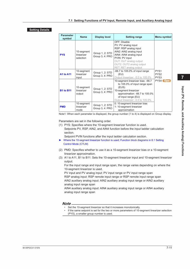
7-11IM 05P02C41-01EN
Input (PV, Rem
ote, and Auxiliary A
nalog) Functions
SettingDetails
Parameter symbol Name Displaylevel Settingrange Menusymbol
PYS10-segment linearizerselection
Group 1, 2: STDGroup 3, 4: PRO
OFF: DisablePV: PV analog inputRSP: RSP analog inputAIN2: AIN2 analog inputAIN4: AIN4 analog inputPVIN: PV inputOUT: OUT analog outputOUT2: OUT2 analog outputRET: RET analog output
PYS1PYS2PYS3PYS4
A1toA1110-segment linearizerinput
Group 1, 2: STDGroup 3, 4: PRO
-66.7 to 105.0% of input range (EU)
Outputlinearizer:-5.0to105.0%
B1toB1110-segment linearizeroutput
Group 1, 2: STDGroup 3, 4: PRO
10-segmentlinearizerbias:-66.7to 105.0% of input range span (EUS)
10-segmentlinearizerapproximation: -66.7 to 105.0% of input range (EU)
Outputlinearizer:-5.0to105.0%
PMD10-segment linearizermode
Group 1, 2: STDGroup 3, 4: PRO
0:10-segmentlinearizerbias1:10-segmentlinearizer
approximationNote1: When each parameter is displayed, the group number (1 to 4) is displayed on Group display.
Parameters are set in the following order.(1) PYS:Specifieswherethe10-segmentlinearizerfunctionisused.
Setpoints PV, RSP, AIN2, and AIN4 function before the input ladder calculation section. Setpoint PVIN functions after the input ladder calculation section.
Wherethe10-segmentlinearizerfunctionisused;Functionblockdiagramsin8.1SettingControl Mode (CTLM)
(2) PMD:Specifieswhethertouseitasa10-segmentlinearizerbiasora10-segmentlinearizerapproximation.
(3) A1toA11,B1toB11:Setsthe10-segmentlinearizerinputand10-segmentlinearizeroutput. For the input range and input range span, the range varies depending on where the 10-segmentlinearizerisused.
PV input and PV analog input: PV input range or PV input range span RSP analog input: RSP remote input range or RSP remote input range span AIN2 auxiliary analog input: AIN2 auxiliary analog input range or AIN2 auxiliary
analog input range span AIN4 auxiliary analog input: AIN4 auxiliary analog input range or AIN4 auxiliary
analog input range span
Note• Setthe10-segmentlinearizersothatitincreasesmonotonically.• Ifthesamesetpointissetforthetwoormoreparametersof10-segmentlinearizerselection
(PYS), a smaller group number is used.
7
7.1SettingFunctionsofPVInput,RemoteInput,andAuxiliaryAnalogInput
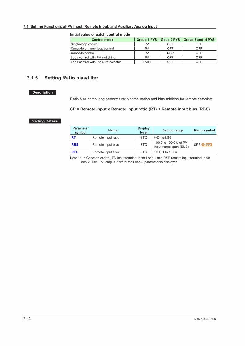
7-12 IM 05P02C41-01EN
InitialvalueofeatchcontrolmodeControl mode Group-1PYS Goup-2PYS Group-3and-4PYS
Single-loop control PV OFF OFFCascade primary-loop control PV OFF OFFCascade control PV RSP OFFLoop control with PV switching PV OFF OFFLoop control with PV auto-selector PVIN OFF OFF
7.1.5 SettingRatiobias/filter
Description
Ratio bias computing performs ratio computation and bias addition for remote setpoints.
SP=RemoteinputxRemoteinputratio(RT)+Remoteinputbias(RBS)
SettingDetails
Parameter symbol Name Display
level Settingrange Menusymbol
RT Remote input ratio STD 0.001 to 9.999
SPS RBS Remote input bias STD 100.0 to 100.0% of PV input range span (EUS)
RFL Remoteinputfilter STD OFF, 1 to 120 s
Note 1: In Cascade control, PV input terminal is for Loop 1 and RSP remote input terminal is for Loop 2. The LP2 lamp is lit while the Loop-2 parameter is displayed.
7.1SettingFunctionsofPVInput,RemoteInput,andAuxiliaryAnalogInput
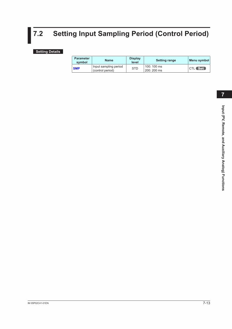
7-13IM 05P02C41-01EN
Input (PV, Rem
ote, and Auxiliary A
nalog) Functions
7.2 SettingInputSamplingPeriod(ControlPeriod)
SettingDetails
Parameter symbol Name Display
level Settingrange Menusymbol
SMP Input sampling period (control period) STD 100: 100 ms
200: 200 ms CTL
7
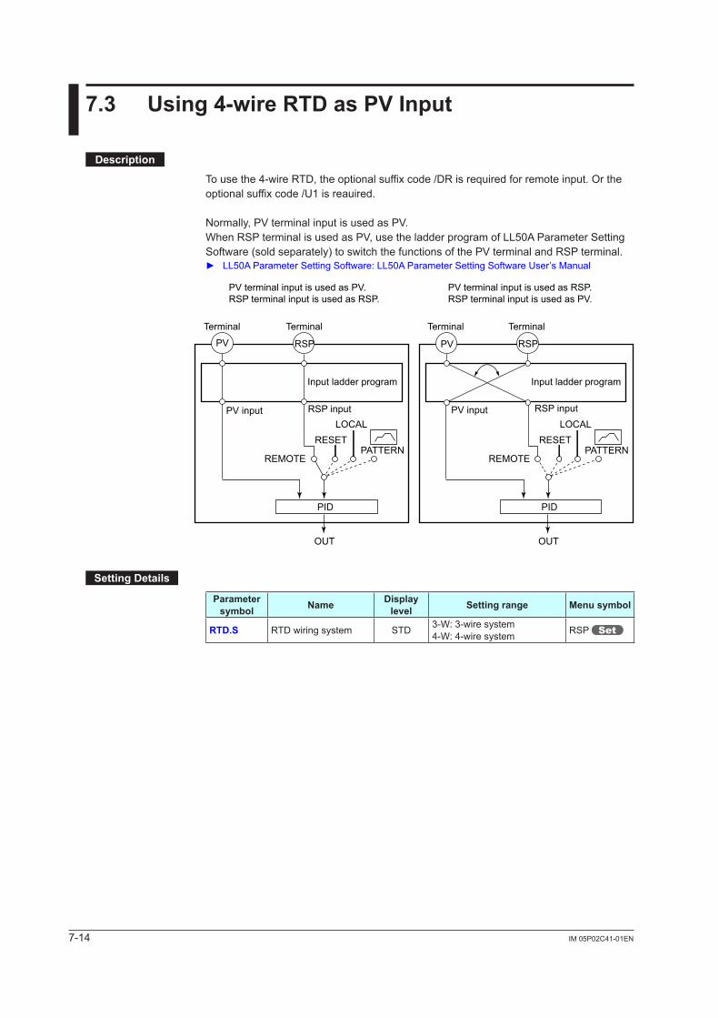
7-14 IM 05P02C41-01EN
7.3 Using4-wireRTDasPVInput
Description
To use the 4-wire RTD, the optional suffix code /DR is required for remote input. Or the optional suffix code /U1 is reauired.
Normally, PV terminal input is used as PV.When RSP terminal is used as PV, use the ladder program of LL50A Parameter Setting Software (sold separately) to switch the functions of the PV terminal and RSP terminal. LL50AParameterSettingSoftware:LL50AParameterSettingSoftwareUser’sManual
Terminal Terminal Terminal Terminal
OUT
PID
PV RSP
OUT
PID
PV RSP
Input ladder program Input ladder program
PV inputPV input RSP inputRSP input
REMOTE
RESETLOCAL
PATTERNREMOTE
RESETLOCAL
PATTERN
PV terminal input is used as PV.RSP terminal input is used as RSP.
PV terminal input is used as RSP.RSP terminal input is used as PV.
SettingDetails
Parameter symbol Name Display
level Settingrange Menusymbol
RTD.S RTD wiring system STD 3-W: 3-wire system4-W: 4-wire system RSP
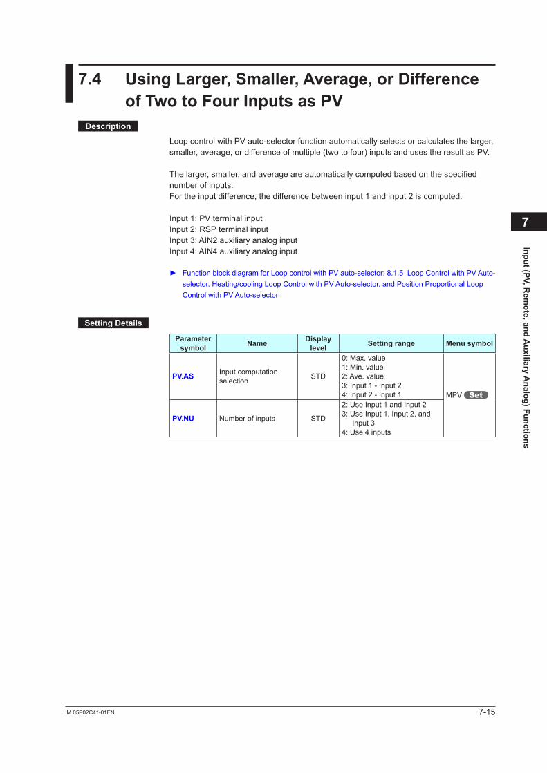
7-15IM 05P02C41-01EN
Input (PV, Rem
ote, and Auxiliary A
nalog) Functions
7.4 UsingLarger,Smaller,Average,orDifferenceofTwotoFourInputsasPV
Description
Loop control with PV auto-selector function automatically selects or calculates the larger, smaller, average, or difference of multiple (two to four) inputs and uses the result as PV.
The larger, smaller, and average are automatically computed based on the specified number of inputs.For the input difference, the difference between input 1 and input 2 is computed.
Input 1: PV terminal inputInput 2: RSP terminal inputInput 3: AIN2 auxiliary analog inputInput 4: AIN4 auxiliary analog input
FunctionblockdiagramforLoopcontrolwithPVauto-selector;8.1.5LoopControlwithPVAuto-selector, Heating/cooling Loop Control with PV Auto-selector, and Position Proportional Loop Control with PV Auto-selector
SettingDetails
Parameter symbol Name Display
level Settingrange Menusymbol
PV.AS Input computation selection STD
0: Max. value1: Min. value2: Ave. value3: Input 1 - Input 24: Input 2 - Input 1 MPV
PV.NU Number of inputs STD
2: Use Input 1 and Input 23: Use Input 1, Input 2, and
Input 34: Use 4 inputs
7
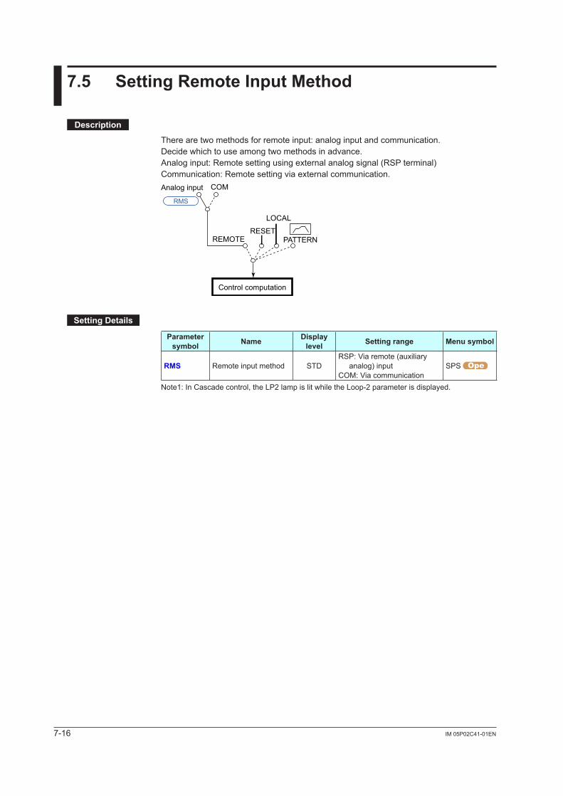
7-16 IM 05P02C41-01EN
7.5 SettingRemoteInputMethod
Description
There are two methods for remote input: analog input and communication.Decide which to use among two methods in advance.Analog input: Remote setting using external analog signal (RSP terminal)Communication: Remote setting via external communication.
COMAnalog input
LOCAL
RESETPATTERNREMOTE
Control computation
RMS
SettingDetails
Parameter symbol Name Display
level Settingrange Menusymbol
RMS Remote input method STDRSP: Via remote (auxiliary
analog) inputCOM: Via communication
SPS
Note1: In Cascade control, the LP2 lamp is lit while the Loop-2 parameter is displayed.
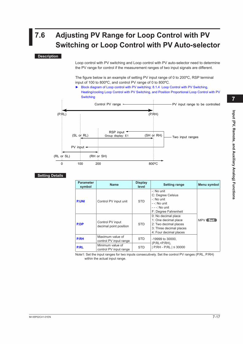
7-17IM 05P02C41-01EN
Input (PV, Rem
ote, and Auxiliary A
nalog) Functions
7.6 AdjustingPVRangeforLoopControlwithPVSwitchingorLoopControlwithPVAuto-selector
Description
Loop control with PV switching and Loop control with PV auto-selector need to determine the PV range for control if the measurement ranges of two input signals are different.
The figure below is an example of setting PV input range of 0 to 200ºC, RSP terminal input of 100 to 800ºC, and control PV range of 0 to 800ºC. BlockdiagramofLoopcontrolwithPVswitching:8.1.4LoopControlwithPVSwitching,
Heating/cooling Loop Control with PV Switching, and Position Proportional Loop Control with PV Switching
(RL or SL)
0 100 200 800ºC
(SL or RL)
(P.RL) (P.RH)
Two input ranges
Control PV range PV input range to be controlled
(SH or RH)
(RH or SH)
PV input
RSP inputGroup display: E1
SettingDetails
Parameter symbol Name Display
level Settingrange Menusymbol
P.UNI Control PV input unit STD
-: No unitC: Degree Celsius-: No unit- -: No unit- - -: No unitF: Degree Fahrenheit
MPV P.DP Control PV input
decimal point position STD
0: No decimal place1: One decimal place2: Two decimal places3: Three decimal places4: Four decimal places
P.RH Maximum value of control PV input range STD -19999 to 30000,
(P.RL<P.RH),|P.RH-P.RL|≤30000P.RL Minimum value of
control PV input range STD
Note1: Set the input ranges for two inputs consecutively. Set the control PV ranges (P.RL, P.RH) within the actual input range.
7
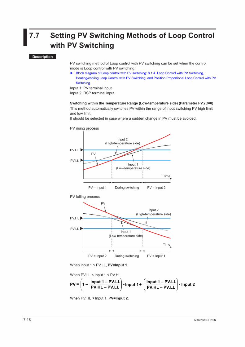
7-18 IM 05P02C41-01EN
7.7 SettingPVSwitchingMethodsofLoopControlwithPVSwitching
Description
PV switching method of Loop control with PV switching can be set when the control mode is Loop control with PV switching. BlockdiagramofLoopcontrolwithPVswitching:8.1.4LoopControlwithPVSwitching,
Heating/cooling Loop Control with PV Switching, and Position Proportional Loop Control with PV Switching
Input 1: PV terminal inputInput 2: RSP terminal input
SwitchingwithintheTemperatureRange(Low-temperatureside)(ParameterPV.2C=0)This method automatically switches PV within the range of input switching PV high limit and low limit.It should be selected in case where a sudden change in PV must be avoided.
PV rising process
PV.HL
PV.LL
Input 2(High-temperature side)
PV
Time
PV = Input 1 PV = Input 2During switching
Input 1(Low-temperature side)
PV falling process
PV.HL
PV.LL
Input 2(High-temperature side)
PV
Time
PV = Input 2 PV = Input 1During switching
Input 1(Low-temperature side)
Wheninput1≤PV.LL,PV=Input1.
When PV.LL < Input 1 < PV.HL
1 Input 1PV – + Input 2=PV.HL – PV.LLInput 1 – PV.LL Input 1 – PV.LL
PV.HL – PV.LL• •
WhenPV.HL≤Input1,PV=Input2.
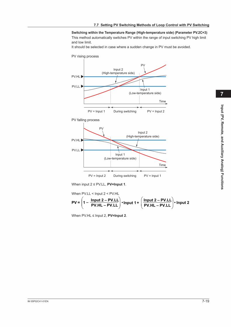
7-19IM 05P02C41-01EN
Input (PV, Rem
ote, and Auxiliary A
nalog) Functions
SwitchingwithintheTemperatureRange(High-temperatureside)(ParameterPV.2C=3)This method automatically switches PV within the range of input switching PV high limit and low limit.It should be selected in case where a sudden change in PV must be avoided.
PV rising process
PV.HL
PV.LL
Input 2(High-temperature side)
PV
Time
PV = Input 1 PV = Input 2During switching
Input 1(Low-temperature side)
PV falling process
PV.HL
PV.LL
Input 2(High-temperature side)
PV
Time
PV = Input 2 PV = Input 1During switching
Input 1(Low-temperature side)
Wheninput2≤PV.LL,PV=Input1.
When PV.LL < Input 2 < PV.HL
1 Input 1PV – + Input 2=PV.HL – PV.LLInput 2 – PV.LL Input 2 – PV.LL
PV.HL – PV.LL• •
WhenPV.HL≤Input2,PV=Input2.
7
7.7SettingPVSwitchingMethodsofLoopControlwithPVSwitching
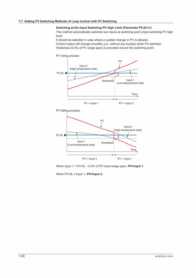
7-20 IM 05P02C41-01EN
SwitchingattheInputSwitchingPVHighLimit(ParameterPV.2C=1)This method automatically switches two inputs at switching point (input switching PV high limit)It should be selected in case where a sudden change in PV is allowed.Control output will change smoothly (i.e., without any bumps) when PV switches.Hysteresis (0.5% of PV range span) is provided around the switching point.
PV rising process
PV.HL
Input 2(High-temperature side)
PV
Input 1(Low-temperature side)
Time
Hysteresis
PV = Input 1 PV = Input 2
PV falling process
PV.HL
Input 2(High-temperature side)
PV
Input 1(Low-temperature side)
Time
Hysteresis
PV = Input 2 PV = Input 1
When input 1 < PV.HL – 0.5% of PV input range span, PV=Input1.
WhenPV.HL≤Input1,PV=Input2.
7.7SettingPVSwitchingMethodsofLoopControlwithPVSwitching
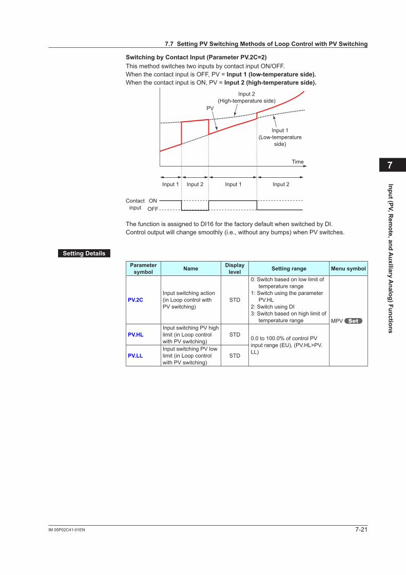
7-21IM 05P02C41-01EN
Input (PV, Rem
ote, and Auxiliary A
nalog) Functions
7
SwitchingbyContactInput(ParameterPV.2C=2)This method switches two inputs by contact input ON/OFF.When the contact input is OFF, PV = Input1(low-temperatureside).When the contact input is ON, PV = Input2(high-temperatureside).
Input 2(High-temperature side)
PV
Input 1(Low-temperature
side)
Time
Input 1 Input 1Input 2 Input 2
Contactinput
ONOFF
The function is assigned to DI16 for the factory default when switched by DI.Control output will change smoothly (i.e., without any bumps) when PV switches.
SettingDetails
Parameter symbol Name Display
level Settingrange Menusymbol
PV.2CInput switching action (in Loop control with PV switching)
STD
0: Switch based on low limit of temperature range
1: Switch using the parameter PV.HL
2: Switch using DI3: Switch based on high limit of
temperature range MPV
PV.HLInput switching PV high limit (in Loop control with PV switching)
STD0.0 to 100.0% of control PV input range (EU), (PV.HL>PV.LL)PV.LL
Input switching PV low limit (in Loop control with PV switching)
STD
7.7SettingPVSwitchingMethodsofLoopControlwithPVSwitching

Blank Page
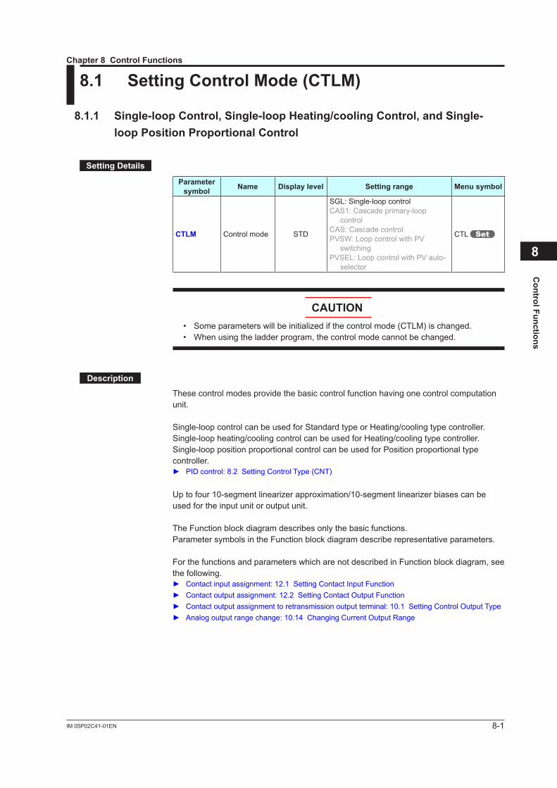
8-1IM 05P02C41-01EN
Control Functions
8
8.1 SettingControlMode(CTLM)
8.1.1 Single-loopControl,Single-loopHeating/coolingControl,andSingle-loop Position Proportional Control
SettingDetails
Parameter symbol Name Displaylevel Settingrange Menusymbol
CTLM Control mode STD
SGL: Single-loop controlCAS1: Cascade primary-loop
controlCAS: Cascade controlPVSW: Loop control with PV
switchingPVSEL: Loop control with PV auto-
selector
CTL
CAUTION• Someparameterswillbeinitializedifthecontrolmode(CTLM)ischanged.• When using the ladder program, the control mode cannot be changed.
Description
These control modes provide the basic control function having one control computation unit.
Single-loop control can be used for Standard type or Heating/cooling type controller.Single-loop heating/cooling control can be used for Heating/cooling type controller.Single-loop position proportional control can be used for Position proportional type controller. PID control: 8.2 Setting Control Type (CNT)
Uptofour10-segmentlinearizerapproximation/10-segmentlinearizerbiasescanbeused for the input unit or output unit.
The Function block diagram describes only the basic functions.Parameter symbols in the Function block diagram describe representative parameters.
For the functions and parameters which are not described in Function block diagram, see the following. Contactinputassignment:12.1SettingContactInputFunction Contactoutputassignment:12.2SettingContactOutputFunction Contactoutputassignmenttoretransmissionoutputterminal:10.1SettingControlOutputType Analogoutputrangechange:10.14ChangingCurrentOutputRange
Chapter 8 Control Functions

8-2IM
05P02C
41-01EN
nSingle-loopControlFunctionBlockDiagram
Program pattern
Local target setpointReset
COM
Anaolog input
*1
Output limiter
Manual operation
Manual preset output
Input error preset output
Preset output
RESET/RUN switch
AUTO
When sensor burnout occursNormal
MAN
RUNRESET
SP limiter
DI45PV RSP
Input type
Input unit
Input range/scale
Analog input bias
Square root extraction
Analog input filter
Input type
Input unit
Input range/scale
Analog input bias
Square root extraction
Analog input filter
10-seg. linearizer approx./bias
Remote input filter
PV input bias
PV input filterRatio bias computation
Output limiter
A.BS
A.FL
BS
FL
PMD An, Bn
10-seg. linearizer approx./bias PMD An, Bn
PMD An, Bn
CNT ALG
TSP S.PID
PTNO.
TIME RAMP
L.PIDLSP
SSP
RTRBS
REM
LOC
RMS
SPH, SPL
RFL
A.SR A.LC
UNIT
IN
RH, RL SDP SH, SL
A.BS
A.FL
10-seg. linearizer approx./bias
A.SR A.LC
UNIT
IN
RH, RL SDP SH, SL
EPOOH, OL
OH, OL OLMT
PO
MPON
OT
Equipped as standard
For optional suffix code /HAHeater break alarm
HAL2HAL1
Heater breakalarm 1
Heater breakalarm 2 Current or voltage pulseRelay Current
OUTOUT RET AL3AL2AL1
PMD
OU.H OU.L
An, Bn
Split computation
10-seg. linearizer approx./bias
RET.H RET.L
PMD An, Bn
Split computation
10-seg. linearizer approx./bias
OUT retransmission outputO1RS RET retransmission output
RTS
* After the control output terminal is specified by the parameter OT, other current output terminals can be used as retransmission output.Output terminal assignment
DI44DI43DI42DI41DI3DI2DI1 DI16
RUN
RST
Control computation
(Current when retransmission output)
Communication*1: RS-485, Ethernet, PROFIBUS-DP,
DeviceNet, CC-LinkPV input Remote inputContact inputs
Equipped as standard(for Standard model)DI16 is equipped when suffix code: Type 2 = 1 or 4.DI41 to DI45 are equipped when suffix code: Type 2 = 0, 1, or 3.
(for Standard model)Remote input can be used whensuffix code: Type 2 = 1 or 4.
Terminal Parameter Function
Analog signal Contact signal Front panel keyLegend
PV
eve
nt 1
PV
eve
nt 2
PV
eve
nt 3
Tim
e ev
ent 1
Tim
e ev
ent 2
Tim
e ev
ent 3
Tim
e ev
ent 4
DO23DO22DO21 DO24
Tim
e ev
ent 5
DO25
PV display SP display
Input ladder calculation program (signal goes to the control computation as is when without ladder program). For ladder program, see the LL50A Parameters Setting Software User’s Manual.
Output ladder calculation program (signal goes to the output as is when without ladder program). For ladder program, see the LL50A Parameter Setting Software User’s Manual.
Sta
rt of
pro
gram
ope
ratio
nw
hen
DI c
hang
es fr
om O
FF to
ON
.
Sto
p of
pro
gram
ope
ratio
nw
hen
DI c
hang
es fr
om O
FF to
ON
.
Sta
rt of
loca
l-mod
e op
erat
ion
whe
n D
I cha
nges
from
OFF
to O
N.
Sta
rt of
rem
ote-
mod
e op
erat
ion
whe
n D
I cha
nges
from
OFF
to O
N.
RST REM
A/M
LOCRUN
PV event, Time event, Alarm
Program pattern selection(Select a number during a RESET state.)
DO11 to DO15 are assinged PV event 4 to 8, and DO31 to DO35 are assinged Time event 6 to 10.
(for Detailed model)DI16 is equipped when optional suffix code /R1.DI41 to DI45 are equipped when optional suffix code /X4.
(for Detailed model) Remote input can be used whenoptional suffix code /R1.
LPS
24 V looppower supply
For optional suffix code /L4 or /LC4
8.1SettingControlM
ode(CTLM
)
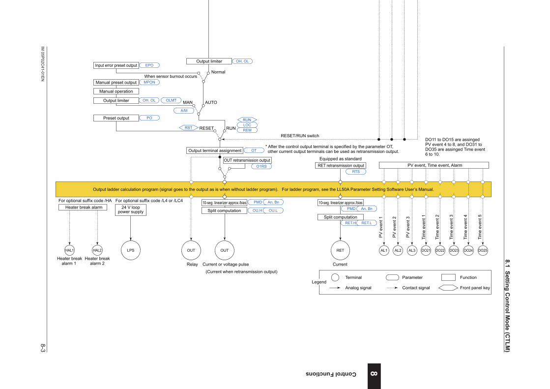
8-3IM
05P02C
41-01EN
Control Functions 8
nSingle-loopControlFunctionBlockDiagram
Program pattern
Local target setpointReset
COM
Anaolog input
*1
Output limiter
Manual operation
Manual preset output
Input error preset output
Preset output
RESET/RUN switch
AUTO
When sensor burnout occursNormal
MAN
RUNRESET
SP limiter
DI45PV RSP
Input type
Input unit
Input range/scale
Analog input bias
Square root extraction
Analog input filter
Input type
Input unit
Input range/scale
Analog input bias
Square root extraction
Analog input filter
10-seg. linearizer approx./bias
Remote input filter
PV input bias
PV input filterRatio bias computation
Output limiter
A.BS
A.FL
BS
FL
PMD An, Bn
10-seg. linearizer approx./bias PMD An, Bn
PMD An, Bn
CNT ALG
TSP S.PID
PTNO.
TIME RAMP
L.PIDLSP
SSP
RTRBS
REM
LOC
RMS
SPH, SPL
RFL
A.SR A.LC
UNIT
IN
RH, RL SDP SH, SL
A.BS
A.FL
10-seg. linearizer approx./bias
A.SR A.LC
UNIT
IN
RH, RL SDP SH, SL
EPOOH, OL
OH, OL OLMT
PO
MPON
OT
Equipped as standard
For optional suffix code /HAHeater break alarm
HAL2HAL1
Heater breakalarm 1
Heater breakalarm 2 Current or voltage pulseRelay Current
OUTOUT RET AL3AL2AL1
PMD
OU.H OU.L
An, Bn
Split computation
10-seg. linearizer approx./bias
RET.H RET.L
PMD An, Bn
Split computation
10-seg. linearizer approx./bias
OUT retransmission outputO1RS RET retransmission output
RTS
* After the control output terminal is specified by the parameter OT, other current output terminals can be used as retransmission output.Output terminal assignment
DI44DI43DI42DI41DI3DI2DI1 DI16
RUN
RST
Control computation
(Current when retransmission output)
Communication*1: RS-485, Ethernet, PROFIBUS-DP,
DeviceNet, CC-LinkPV input Remote inputContact inputs
Equipped as standard(for Standard model)DI16 is equipped when suffix code: Type 2 = 1 or 4.DI41 to DI45 are equipped when suffix code: Type 2 = 0, 1, or 3.
(for Standard model)Remote input can be used whensuffix code: Type 2 = 1 or 4.
Terminal Parameter Function
Analog signal Contact signal Front panel keyLegend
PV
eve
nt 1
PV
eve
nt 2
PV
eve
nt 3
Tim
e ev
ent 1
Tim
e ev
ent 2
Tim
e ev
ent 3
Tim
e ev
ent 4
DO23DO22DO21 DO24
Tim
e ev
ent 5
DO25
PV display SP display
Input ladder calculation program (signal goes to the control computation as is when without ladder program). For ladder program, see the LL50A Parameters Setting Software User’s Manual.
Output ladder calculation program (signal goes to the output as is when without ladder program). For ladder program, see the LL50A Parameter Setting Software User’s Manual.
Sta
rt of
pro
gram
ope
ratio
nw
hen
DI c
hang
es fr
om O
FF to
ON
.
Sto
p of
pro
gram
ope
ratio
nw
hen
DI c
hang
es fr
om O
FF to
ON
.
Sta
rt of
loca
l-mod
e op
erat
ion
whe
n D
I cha
nges
from
OFF
to O
N.
Sta
rt of
rem
ote-
mod
e op
erat
ion
whe
n D
I cha
nges
from
OFF
to O
N.
RST REM
A/M
LOCRUN
PV event, Time event, Alarm
Program pattern selection(Select a number during a RESET state.)
DO11 to DO15 are assinged PV event 4 to 8, and DO31 to DO35 are assinged Time event 6 to 10.
(for Detailed model)DI16 is equipped when optional suffix code /R1.DI41 to DI45 are equipped when optional suffix code /X4.
(for Detailed model) Remote input can be used whenoptional suffix code /R1.
LPS
24 V looppower supply
For optional suffix code /L4 or /LC4
8.1SettingControlM
ode(CTLM
)
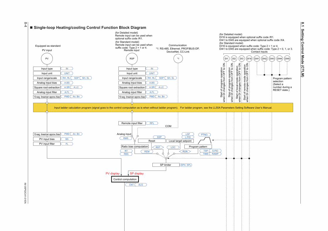
8-4IM
05P02C
41-01EN
nSingle-loopHeating/coolingControlFunctionBlockDiagram
COM
Analog input
*1
SP limiter
PV RSP
Input type
Input unit
Input range/scale
Analog input bias
Square root extraction
Analog input filter
Input type
Input unit
Input range/scale
Analog input bias
Square root extraction
Analog input filter
10-seg. linearizer approx./bias
Remote input filter
PV input bias
PV input filterRatio bias computation
A.BS
A.FL
BS
FL
PMD An, Bn
10-seg. linearizer approx./bias PMD An, Bn
PMD An, Bn
CNT ALG
RMS
SPH, SPL
RFL
A.SR A.LC
UNIT
IN
RH, RL SDP SH, SL
A.BS
A.FL
10-seg. linearizer approx./bias
A.SR A.LC
UNIT
IN
RH, RL SDP SH, SL
Control computation
Manual operation
Manual preset output
Input error preset output
Heating-side preset output
AUTO
When sensorburnout occurs
When sensorburnout occurs
Normal Normal
MAN
RUNRESET
EPOOH, OL OHc, OLc
Input error preset output EPO
POCooling-side preset output
RESETPOc
MPON
Heating/cooling computation
Heating-side output limiter Cooling-side output limiter
RUN
Current or voltage pulse
Relay Current or voltage pulse
Relay Current
OUT retransmission output OUT2 retransmission output
OT
O1RS O2RS RET retransmission outputRTS
Heating-sideoutput
Heating-sideoutput
OUTOUT
Cooling-sideoutput
Cooling-sideoutput
OUT2 OUT2 RET
* After the control output terminal is specified by the parameter OT, other current output terminals can be used as retransmission output.Output terminal assignment
PMD
OU.H OU.L OU2.H OU2.L
An, Bn PMD An, Bn
Split computation
10-seg. linearizer approx./bias
Split computation
10-seg. linearizer approx./bias
RET.H RET.L
PMD An, Bn
Split computation
10-seg. linearizer approx./bias
Equipped as standard
(Current when retransmission output) (Current when retransmission output)
PV input Remote input
Equipped as standard(for Standard model)Remote input can be used whensuffix code: Type 2 = 1 or 4.
Manual output is prioritized even if sensor burnout occurs in MAN.
Terminal Parameter Function
Analog signal Contact signal Front panel keyLegend
PV display SP display
Input ladder calculation program (signal goes to the control computation as is when without ladder program). For ladder program, see the LL50A Parameters Setting Software User’s Manual.
Communication*1: RS-485, Ethernet, PROFIBUS-DP,
DeviceNet, CC-Link
Program pattern
Local target setpointReset
TSP S.PID
PTNO.
TIME RAMP
L.PIDLSP
REM
LOC
RUN
RST
RESET/RUN switchRESET/RUN switch
DI45DI44DI43DI42DI41DI3DI2DI1 DI16
Contact inputs
(for Standard model)DI16 is equipped when suffix code: Type 2 = 1 or 4.DI41 to DI45 are equipped when suffix code: Type 2 = 0, 1, or 3.
Sta
rt of
pro
gram
ope
ratio
nw
hen
DI c
hang
es fr
om O
FF to
ON
.
Sto
p of
pro
gram
ope
ratio
nw
hen
DI c
hang
es fr
om O
FF to
ON
.
Sta
rt of
loca
l-mod
e op
erat
ion
whe
n D
I cha
nges
from
OFF
to O
N.
Sta
rt of
rem
ote-
mod
e op
erat
ion
whe
n D
I cha
nges
from
OFF
to O
N.
RST RSTREM
A/M
LOCRUN
REMLOCRUN
AL3AL2AL1
PV
eve
nt 1
PV
eve
nt 2
PV
eve
nt 3
Tim
e ev
ent 1
Tim
e ev
ent 2
Tim
e ev
ent 3
Tim
e ev
ent 4
DO23DO22DO21 DO24
Tim
e ev
ent 5
DO25
PV event, Time event, Alarm
Output ladder calculation program (signal goes to the output as is when without ladder program). For ladder program, see the LL50A Parameter Setting Software User’s Manual.
RTRBS
Program pattern selection(Select a number during a RESET state.)
DO11 to DO15 are assinged PV event 4 to 8, and DO31 to DO35 are assinged Time event 6 to 10.
(for Detailed model)Remote input can be used whenoptional suffix code /R1.
(for Detailed model)DI16 is equipped when optional suffix code /R1.DI41 to DI45 are equipped when optional suffix code /X4.
LPS
24 V looppower supply
For optional suffix code /L4 or /LC4
SSP
8.1SettingControlM
ode(CTLM
)
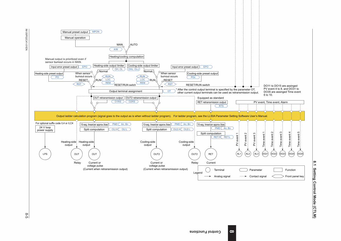
8-5IM
05P02C
41-01EN
Control Functions 8
nSingle-loopHeating/coolingControlFunctionBlockDiagram
COM
Analog input
*1
SP limiter
PV RSP
Input type
Input unit
Input range/scale
Analog input bias
Square root extraction
Analog input filter
Input type
Input unit
Input range/scale
Analog input bias
Square root extraction
Analog input filter
10-seg. linearizer approx./bias
Remote input filter
PV input bias
PV input filterRatio bias computation
A.BS
A.FL
BS
FL
PMD An, Bn
10-seg. linearizer approx./bias PMD An, Bn
PMD An, Bn
CNT ALG
RMS
SPH, SPL
RFL
A.SR A.LC
UNIT
IN
RH, RL SDP SH, SL
A.BS
A.FL
10-seg. linearizer approx./bias
A.SR A.LC
UNIT
IN
RH, RL SDP SH, SL
Control computation
Manual operation
Manual preset output
Input error preset output
Heating-side preset output
AUTO
When sensorburnout occurs
When sensorburnout occurs
Normal Normal
MAN
RUNRESET
EPOOH, OL OHc, OLc
Input error preset output EPO
POCooling-side preset output
RESETPOc
MPON
Heating/cooling computation
Heating-side output limiter Cooling-side output limiter
RUN
Current or voltage pulse
Relay Current or voltage pulse
Relay Current
OUT retransmission output OUT2 retransmission output
OT
O1RS O2RS RET retransmission outputRTS
Heating-sideoutput
Heating-sideoutput
OUTOUT
Cooling-sideoutput
Cooling-sideoutput
OUT2 OUT2 RET
* After the control output terminal is specified by the parameter OT, other current output terminals can be used as retransmission output.Output terminal assignment
PMD
OU.H OU.L OU2.H OU2.L
An, Bn PMD An, Bn
Split computation
10-seg. linearizer approx./bias
Split computation
10-seg. linearizer approx./bias
RET.H RET.L
PMD An, Bn
Split computation
10-seg. linearizer approx./bias
Equipped as standard
(Current when retransmission output) (Current when retransmission output)
PV input Remote input
Equipped as standard(for Standard model)Remote input can be used whensuffix code: Type 2 = 1 or 4.
Manual output is prioritized even if sensor burnout occurs in MAN.
Terminal Parameter Function
Analog signal Contact signal Front panel keyLegend
PV display SP display
Input ladder calculation program (signal goes to the control computation as is when without ladder program). For ladder program, see the LL50A Parameters Setting Software User’s Manual.
Communication*1: RS-485, Ethernet, PROFIBUS-DP,
DeviceNet, CC-Link
Program pattern
Local target setpointReset
TSP S.PID
PTNO.
TIME RAMP
L.PIDLSP
REM
LOC
RUN
RST
RESET/RUN switchRESET/RUN switch
DI45DI44DI43DI42DI41DI3DI2DI1 DI16
Contact inputs
(for Standard model)DI16 is equipped when suffix code: Type 2 = 1 or 4.DI41 to DI45 are equipped when suffix code: Type 2 = 0, 1, or 3.
Sta
rt of
pro
gram
ope
ratio
nw
hen
DI c
hang
es fr
om O
FF to
ON
.
Sto
p of
pro
gram
ope
ratio
nw
hen
DI c
hang
es fr
om O
FF to
ON
.
Sta
rt of
loca
l-mod
e op
erat
ion
whe
n D
I cha
nges
from
OFF
to O
N.
Sta
rt of
rem
ote-
mod
e op
erat
ion
whe
n D
I cha
nges
from
OFF
to O
N.
RST RSTREM
A/M
LOCRUN
REMLOCRUN
AL3AL2AL1
PV
eve
nt 1
PV
eve
nt 2
PV
eve
nt 3
Tim
e ev
ent 1
Tim
e ev
ent 2
Tim
e ev
ent 3
Tim
e ev
ent 4
DO23DO22DO21 DO24
Tim
e ev
ent 5
DO25
PV event, Time event, Alarm
Output ladder calculation program (signal goes to the output as is when without ladder program). For ladder program, see the LL50A Parameter Setting Software User’s Manual.
RTRBS
Program pattern selection(Select a number during a RESET state.)
DO11 to DO15 are assinged PV event 4 to 8, and DO31 to DO35 are assinged Time event 6 to 10.
(for Detailed model)Remote input can be used whenoptional suffix code /R1.
(for Detailed model)DI16 is equipped when optional suffix code /R1.DI41 to DI45 are equipped when optional suffix code /X4.
LPS
24 V looppower supply
For optional suffix code /L4 or /LC4
SSP
8.1SettingControlM
ode(CTLM
)

8-6IM
05P02C
41-01EN
nSingle-loopPositionProportionalControlFunctionBlockDiagram
COM
Analog input
*1
SP limiter
PV input Remote input
PV RSP
Input type
Input unit
Input range/scale
Analog input bias
Square root extraction
Analog input filter
Input type
Input unit
Input range/scale
Analog input bias
Square root extraction
Analog input filter
10-seg. linearizer approx./bias
Remote input filter
PV input bias
PV input filterRatio bias computation
A.BS
A.FL
BS
FL
PMD An, Bn
10-seg. linearizer approx./bias PMD An, Bn
PMD An, Bn
CNT ALG
RMS
SPH, SPL
RFL
A.SR A.LC
UNIT
IN
RH, RL SDP SH, SL
A.BS
A.FL
10-seg. linearizer approx./bias
A.SR A.LC
UNIT
IN
RH, RL SDP SH, SL
Equipped as standard(for Standard model)Remote input can be used whensuffix code: Type 2 = 1 or 4.
Control computation
Manual operation
Input error preset output
Preset output
AUTO
When sensor burnout occursNormal
MAN
RUNRESET
Output limiter
EPO
OH, OL
PO
Signal comparison
Feedback input Direct/reverse signal
Valve position slidingresistor or current
Motor-operated valve
Relay output
VALVFBIN
M
Equipped as standard Equipped as standard
Current Current
OUT RET
PMD
OU.H OU.L
An, Bn
Split computation
10-seg. linearizer approx./bias
RET.H
HYSDB PMD An, Bn
Split computation
10-seg. linearizer approx./bias
OUT retransmission outputO1RS
RET retransmission outputRTS
In Estimating-type position proportional control, the limiter function does not work on output operation. The reverse-signal relay turns on when being limited by low limit.The direct-signal relay turns on when being limited by high limit.
H relay( key)
L relay( key)
In Manual operation, the relay turns on while the or key is pressed. Output limiter does not work.
Terminal Parameter Function
Analog signal Contact signal Front panel keyLegend
PV display SP display
Position Proportional Computation Output cannot be calculated by ladder program.
Communication*1: RS-485, Ethernet, PROFIBUS-DP,
DeviceNet, CC-Link
Program pattern
Local target setpointReset
TSP S.PID
PTNO.
TIME RAMP
L.PIDLSP
REM
LOC
RUN
RST
RESET/RUN switch
DI45DI44DI43DI42DI41DI3DI2DI1 DI16
Contact inputs
(for Standard model)DI16 is equipped when suffix code: Type 2 = 1 or 4.DI41 to DI45 are equipped when suffix code: Type 2 = 0, 1, or 3.
Sta
rt of
pro
gram
ope
ratio
nw
hen
DI c
hang
es fr
om O
FF to
ON
.
Sto
p of
pro
gram
ope
ratio
nw
hen
DI c
hang
es fr
om O
FF to
ON
.
Sta
rt of
loca
l-mod
e op
erat
ion
whe
n D
I cha
nges
from
OFF
to O
N.
Sta
rt of
rem
ote-
mod
e op
erat
ion
whe
n D
I cha
nges
from
OFF
to O
N.
RSTREM
A/M
LOCRUN
AL3AL2AL1
PV
eve
nt 1
PV
eve
nt 2
PV
eve
nt 3
Tim
e ev
ent 1
Tim
e ev
ent 2
Tim
e ev
ent 3
Tim
e ev
ent 4
DO23DO22DO21 DO24
Tim
e ev
ent 5
DO25
PV event, Time event, Alarm
Output ladder calculation program (signal goes to the output as is when without ladder program). For ladder program, see the LL50A Parameter Setting Software User’s Manual.
RTRBS
Input ladder calculation program (signal goes to the control computation as is when without ladder program). For ladder program, see the LL50A Parameter Setting Software User’s Manual.
Program pattern selection(Select a number during a RESET state.)
DO11 to DO15 are assinged PV event 4 to 8, and DO31 to DO35 are assinged Time event 6 to 10.
(for Detailed model)Remote input can be used whenoptional suffix code /R1.
(for Detailed model)DI16 is equipped when optional suffix code /R1.DI41 to DI45 are equipped when optional suffix code /X4.
LPS
24 V looppower supply
For optional suffix code /L4 or /LC4
SSP
8.1SettingControlM
ode(CTLM
)
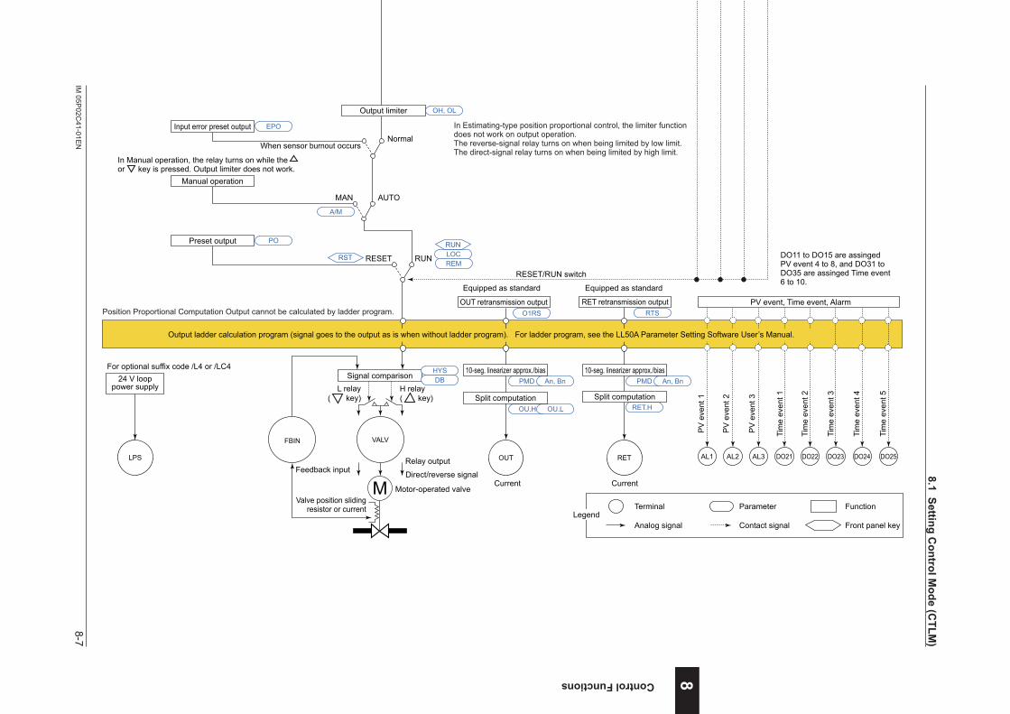
8-7IM
05P02C
41-01EN
Control Functions 8
nSingle-loopPositionProportionalControlFunctionBlockDiagram
COM
Analog input
*1
SP limiter
PV input Remote input
PV RSP
Input type
Input unit
Input range/scale
Analog input bias
Square root extraction
Analog input filter
Input type
Input unit
Input range/scale
Analog input bias
Square root extraction
Analog input filter
10-seg. linearizer approx./bias
Remote input filter
PV input bias
PV input filterRatio bias computation
A.BS
A.FL
BS
FL
PMD An, Bn
10-seg. linearizer approx./bias PMD An, Bn
PMD An, Bn
CNT ALG
RMS
SPH, SPL
RFL
A.SR A.LC
UNIT
IN
RH, RL SDP SH, SL
A.BS
A.FL
10-seg. linearizer approx./bias
A.SR A.LC
UNIT
IN
RH, RL SDP SH, SL
Equipped as standard(for Standard model)Remote input can be used whensuffix code: Type 2 = 1 or 4.
Control computation
Manual operation
Input error preset output
Preset output
AUTO
When sensor burnout occursNormal
MAN
RUNRESET
Output limiter
EPO
OH, OL
PO
Signal comparison
Feedback input Direct/reverse signal
Valve position slidingresistor or current
Motor-operated valve
Relay output
VALVFBIN
M
Equipped as standard Equipped as standard
Current Current
OUT RET
PMD
OU.H OU.L
An, Bn
Split computation
10-seg. linearizer approx./bias
RET.H
HYSDB PMD An, Bn
Split computation
10-seg. linearizer approx./bias
OUT retransmission outputO1RS
RET retransmission outputRTS
In Estimating-type position proportional control, the limiter function does not work on output operation. The reverse-signal relay turns on when being limited by low limit.The direct-signal relay turns on when being limited by high limit.
H relay( key)
L relay( key)
In Manual operation, the relay turns on while the or key is pressed. Output limiter does not work.
Terminal Parameter Function
Analog signal Contact signal Front panel keyLegend
PV display SP display
Position Proportional Computation Output cannot be calculated by ladder program.
Communication*1: RS-485, Ethernet, PROFIBUS-DP,
DeviceNet, CC-Link
Program pattern
Local target setpointReset
TSP S.PID
PTNO.
TIME RAMP
L.PIDLSP
REM
LOC
RUN
RST
RESET/RUN switch
DI45DI44DI43DI42DI41DI3DI2DI1 DI16
Contact inputs
(for Standard model)DI16 is equipped when suffix code: Type 2 = 1 or 4.DI41 to DI45 are equipped when suffix code: Type 2 = 0, 1, or 3.
Sta
rt of
pro
gram
ope
ratio
nw
hen
DI c
hang
es fr
om O
FF to
ON
.
Sto
p of
pro
gram
ope
ratio
nw
hen
DI c
hang
es fr
om O
FF to
ON
.
Sta
rt of
loca
l-mod
e op
erat
ion
whe
n D
I cha
nges
from
OFF
to O
N.
Sta
rt of
rem
ote-
mod
e op
erat
ion
whe
n D
I cha
nges
from
OFF
to O
N.
RSTREM
A/M
LOCRUN
AL3AL2AL1
PV
eve
nt 1
PV
eve
nt 2
PV
eve
nt 3
Tim
e ev
ent 1
Tim
e ev
ent 2
Tim
e ev
ent 3
Tim
e ev
ent 4
DO23DO22DO21 DO24
Tim
e ev
ent 5
DO25
PV event, Time event, Alarm
Output ladder calculation program (signal goes to the output as is when without ladder program). For ladder program, see the LL50A Parameter Setting Software User’s Manual.
RTRBS
Input ladder calculation program (signal goes to the control computation as is when without ladder program). For ladder program, see the LL50A Parameter Setting Software User’s Manual.
Program pattern selection(Select a number during a RESET state.)
DO11 to DO15 are assinged PV event 4 to 8, and DO31 to DO35 are assinged Time event 6 to 10.
(for Detailed model)Remote input can be used whenoptional suffix code /R1.
(for Detailed model)DI16 is equipped when optional suffix code /R1.DI41 to DI45 are equipped when optional suffix code /X4.
LPS
24 V looppower supply
For optional suffix code /L4 or /LC4
SSP
8.1SettingControlM
ode(CTLM
)

8-8 IM 05P02C41-01EN
Intentionally blank
8.1SettingControlMode(CTLM)
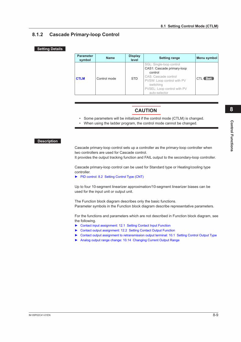
8-9IM 05P02C41-01EN
Control Functions
8.1.2 CascadePrimary-loopControl
SettingDetails
Parameter symbol Name Display
level Settingrange Menusymbol
CTLM Control mode STD
SGL: Single-loop controlCAS1: Cascade primary-loop
controlCAS: Cascade controlPVSW: Loop control with PV
switchingPVSEL: Loop control with PV
auto-selector
CTL
CAUTION• Someparameterswillbeinitializedifthecontrolmode(CTLM)ischanged.• When using the ladder program, the control mode cannot be changed.
Description
Cascade primary-loop control sets up a controller as the primary-loop controller when two controllers are used for Cascade control.It provides the output tracking function and FAIL output to the secondary-loop controller.
Cascade primary-loop control can be used for Standard type or Heating/cooling type controller. PIDcontrol:8.2SettingControlType(CNT)
Uptofour10-segmentlinearizerapproximation/10-segmentlinearizerbiasescanbeused for the input unit or output unit.
The Function block diagram describes only the basic functions.Parameter symbols in the Function block diagram describe representative parameters.
For the functions and parameters which are not described in Function block diagram, see the following. Contactinputassignment:12.1SettingContactInputFunction Contactoutputassignment:12.2SettingContactOutputFunction Contactoutputassignmenttoretransmissionoutputterminal:10.1SettingControlOutputType Analogoutputrangechange:10.14ChangingCurrentOutputRange
8
8.1SettingControlMode(CTLM)
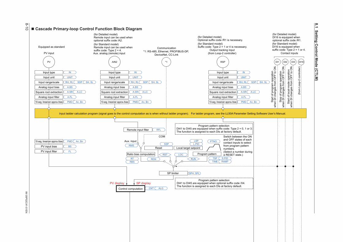
8-10IM
05P02C
41-01EN
nCascadePrimary-loopControlFunctionBlockDiagram
COM
Aux. input
*1
Output limiter
Manual operation
Manual preset output
Input error preset output
Preset output
Output tracking input
Output tracking switch (Tracking at ON)
AUTO
When sensorburnout occurs
Normal
MAN
ONOFF
RUNRESET
SP limiter
PV inputOutput tracking input
(from Loop-2 controller)
DI16PV RSP
Input type
Input unit
Input range/scale
Analog input bias
Square root extraction
Analog input filter
Input type
Input unit
Input range/scale
Analog input bias
Square root extraction
Analog input filter
Remote input filter
PV input bias
PV input filterRatio bias computation
Contact inputs
Output limiter
Output limiter
A.BS
A.FL
10-seg. linearizer approx./bias
BS
FL
CNT ALG
RMS
SPH, SPL
RFL
A.SR A.LC
UNIT
IN
RH, RL SDP SH, SL
A.BS
A.FL
A.SR A.LC
UNIT
IN
RH, RL SDP SH, SL
EPO OH, OL
OH, OL OLMT
OH, OL
PO
MPON
Equipped as standard
Equipped as standard
Current (to Loop-2 controller)
Current
OUT RET
PMD
OU.H OU.L
An, Bn
Split computation
10-seg. linearizer approx./bias
RET.H RET.L
PMD An, Bn
Split computation
10-seg. linearizer approx./bias
RET retransmission outputRTS
DI3DI2DI1
Control computation
(from
Loo
p-2
cont
rolle
r)
PMD An, Bn
10-seg. linearizer approx./bias PMD An, Bn
10-seg. linearizer approx./bias PMD An, Bn
AIN2
Input type
Input unit
Input range/scale
Analog input bias
Square root extraction
Analog input filter
A.BS
A.FL
A.SR A.LC
UNIT
IN
RH, RL SDP SH, SL
10-seg. linearizer approx./bias PMD An, Bn
(for Standard model)Suffix code: Type 2 = 1 or 4 is necessary.
(for Standard model)DI16 is equipped when suffix code: Type 2 = 1 or 4.
DI41 to DI45 are equipped when suffix code: Type 2 = 0, 1 or 3.The function is assigned to each DIs at factory default.
Terminal Parameter Function
Analog signal Contact signal Front panel keyLegend
FAIL
(to L
oop-
2 co
ntro
ller)
PV display SP display
Input ladder calculation program (signal goes to the control computation as is when without ladder program). For ladder program, see the LL50A Parameter Setting Software User’s Manual.
(for Standard model)Remote input can be used whensuffix code: Type 2 = 4.Aux. analog (remote) input
Communication*1: RS-485, Ethernet, PROFIBUS-DP,
DeviceNet, CC-Link
Program pattern
Local target setpointReset
TSP S.PID
PTNO.
TIME RAMP
L.PIDLSP
REM
LOC
RUN
RST
RESET/RUN switch
Sta
rt of
pro
gram
ope
ratio
nw
hen
DI c
hang
es fr
om O
FF to
ON
.
Sto
p of
pro
gram
ope
ratio
nw
hen
DI c
hang
es fr
om O
FF to
ON
.
Sta
rt of
loca
l-mod
e op
erat
ion
whe
n D
I cha
nges
from
OFF
to O
N.
Program pattern selection
Switch between the ON and OFF states of each contact inputs to select from program pattern numbers.(Select a number during a RESET state.)
RST REM
A/M
LOCRUN
AL3AL2AL1
PV
eve
nt 1
PV
eve
nt 2
Tim
e ev
ent 1
Tim
e ev
ent 2
Tim
e ev
ent 3
Tim
e ev
ent 4
DO23DO22DO21 DO24
Tim
e ev
ent 5
DO25
PV event, Time event, Alarm
RTRBS
Output ladder calculation program (signal goes to the output as is when without ladder program). For ladder program, see the LL50A Parameter Setting Software User’s Manual.
DO31 to DO35 are assinged Time event 6 to 10.
(for Detailed model)Optional suffix code /R1 is necessary.
(for Detailed model)DI16 is equipped when optional suffix code /R1.
(for Detailed model)Remote input can be used whenoptional suffix code /A2.
LPS
24 V looppower supply
For optional suffix code /L4 or /LC4
DI41 to DI45 are equipped when optional suffix code /X4.The function is assigned to each DIs at factory default.
Program pattern selection
SSP
8.1SettingControlM
ode(CTLM
)
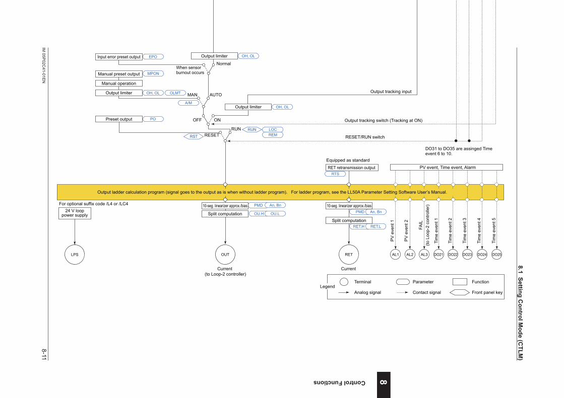
8-11IM
05P02C
41-01EN
Control Functions
nCascadePrimary-loopControlFunctionBlockDiagram
COM
Aux. input
*1
Output limiter
Manual operation
Manual preset output
Input error preset output
Preset output
Output tracking input
Output tracking switch (Tracking at ON)
AUTO
When sensorburnout occurs
Normal
MAN
ONOFF
RUNRESET
SP limiter
PV inputOutput tracking input
(from Loop-2 controller)
DI16PV RSP
Input type
Input unit
Input range/scale
Analog input bias
Square root extraction
Analog input filter
Input type
Input unit
Input range/scale
Analog input bias
Square root extraction
Analog input filter
Remote input filter
PV input bias
PV input filterRatio bias computation
Contact inputs
Output limiter
Output limiter
A.BS
A.FL
10-seg. linearizer approx./bias
BS
FL
CNT ALG
RMS
SPH, SPL
RFL
A.SR A.LC
UNIT
IN
RH, RL SDP SH, SL
A.BS
A.FL
A.SR A.LC
UNIT
IN
RH, RL SDP SH, SL
EPO OH, OL
OH, OL OLMT
OH, OL
PO
MPON
Equipped as standard
Equipped as standard
Current (to Loop-2 controller)
Current
OUT RET
PMD
OU.H OU.L
An, Bn
Split computation
10-seg. linearizer approx./bias
RET.H RET.L
PMD An, Bn
Split computation
10-seg. linearizer approx./bias
RET retransmission outputRTS
DI3DI2DI1
Control computation
(from
Loo
p-2
cont
rolle
r)
PMD An, Bn
10-seg. linearizer approx./bias PMD An, Bn
10-seg. linearizer approx./bias PMD An, Bn
AIN2
Input type
Input unit
Input range/scale
Analog input bias
Square root extraction
Analog input filter
A.BS
A.FL
A.SR A.LC
UNIT
IN
RH, RL SDP SH, SL
10-seg. linearizer approx./bias PMD An, Bn
(for Standard model)Suffix code: Type 2 = 1 or 4 is necessary.
(for Standard model)DI16 is equipped when suffix code: Type 2 = 1 or 4.
DI41 to DI45 are equipped when suffix code: Type 2 = 0, 1 or 3.The function is assigned to each DIs at factory default.
Terminal Parameter Function
Analog signal Contact signal Front panel keyLegend
FAIL
(to L
oop-
2 co
ntro
ller)
PV display SP display
Input ladder calculation program (signal goes to the control computation as is when without ladder program). For ladder program, see the LL50A Parameter Setting Software User’s Manual.
(for Standard model)Remote input can be used whensuffix code: Type 2 = 4.Aux. analog (remote) input
Communication*1: RS-485, Ethernet, PROFIBUS-DP,
DeviceNet, CC-Link
Program pattern
Local target setpointReset
TSP S.PID
PTNO.
TIME RAMP
L.PIDLSP
REM
LOC
RUN
RST
RESET/RUN switch
Sta
rt of
pro
gram
ope
ratio
nw
hen
DI c
hang
es fr
om O
FF to
ON
.
Sto
p of
pro
gram
ope
ratio
nw
hen
DI c
hang
es fr
om O
FF to
ON
.
Sta
rt of
loca
l-mod
e op
erat
ion
whe
n D
I cha
nges
from
OFF
to O
N.
Program pattern selection
Switch between the ON and OFF states of each contact inputs to select from program pattern numbers.(Select a number during a RESET state.)
RST REM
A/M
LOCRUN
AL3AL2AL1
PV
eve
nt 1
PV
eve
nt 2
Tim
e ev
ent 1
Tim
e ev
ent 2
Tim
e ev
ent 3
Tim
e ev
ent 4
DO23DO22DO21 DO24
Tim
e ev
ent 5
DO25
PV event, Time event, Alarm
RTRBS
Output ladder calculation program (signal goes to the output as is when without ladder program). For ladder program, see the LL50A Parameter Setting Software User’s Manual.
DO31 to DO35 are assinged Time event 6 to 10.
(for Detailed model)Optional suffix code /R1 is necessary.
(for Detailed model)DI16 is equipped when optional suffix code /R1.
(for Detailed model)Remote input can be used whenoptional suffix code /A2.
LPS
24 V looppower supply
For optional suffix code /L4 or /LC4
DI41 to DI45 are equipped when optional suffix code /X4.The function is assigned to each DIs at factory default.
Program pattern selection
SSP
8
8.1SettingControlM
ode(CTLM
)

8-12 IM 05P02C41-01EN
Intentionally blank
8.1SettingControlMode(CTLM)
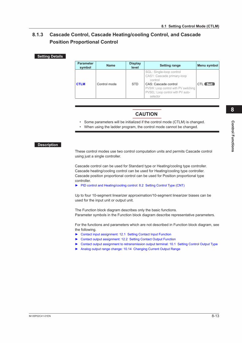
8-13IM 05P02C41-01EN
Control Functions
8.1.3 CascadeControl,CascadeHeating/coolingControl,andCascadePosition Proportional Control
SettingDetails
Parameter symbol Name Display
level Settingrange Menusymbol
CTLM Control mode STD
SGL: Single-loop controlCAS1: Cascade primary-loop
controlCAS: Cascade controlPVSW: Loop control with PV switchingPVSEL: Loop control with PV auto-
selector
CTL
CAUTION• Someparameterswillbeinitializedifthecontrolmode(CTLM)ischanged.• When using the ladder program, the control mode cannot be changed.
Description
These control modes use two control computation units and permits Cascade control usingjustasinglecontroller.
Cascade control can be used for Standard type or Heating/cooling type controller.Cascade heating/cooling control can be used for Heating/cooling type controller.Cascade position proportional control can be used for Position proportional type controller. PIDcontrolandHeating/coolingcontrol:8.2SettingControlType(CNT)
Uptofour10-segmentlinearizerapproximation/10-segmentlinearizerbiasescanbeused for the input unit or output unit.
The Function block diagram describes only the basic functions.Parameter symbols in the Function block diagram describe representative parameters.
For the functions and parameters which are not described in Function block diagram, see the following. Contactinputassignment:12.1SettingContactInputFunction Contactoutputassignment:12.2SettingContactOutputFunction Contactoutputassignmenttoretransmissionoutputterminal:10.1SettingControlOutputType Analogoutputrangechange:10.14ChangingCurrentOutputRange
8
8.1SettingControlMode(CTLM)
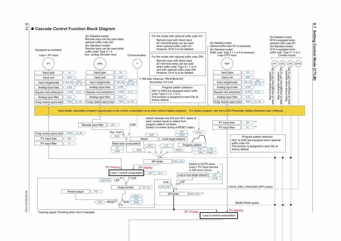
8-14IM
05P02C
41-01EN
n Cascade Control Function Block Diagram
*1
Output limiter
Manual operation
Manual preset output
Input error preset output
Preset output
When Loop-2 sensor burnout occursNormal
MAN
RUNRESET
SP limiter
DI2 DI3DI1 DI16PV RSP
Input type
Input unit
Input range/scale
Analog input bias
Square root extraction
Analog input filter
Input type
Input unit
Input range/scale
Analog input bias
Square root extraction
Analog input filter
10-seg. linearizer approx./bias
PV input bias
PV input filter
A.BS
A.FL
BS
FL
PMD An, Bn
10-seg. linearizer approx./bias PMD An, Bn
10-seg. linearizer approx./bias
PV input bias
PV input filter
BS
FL
PMD An, Bn
CNT ALG
LSP/CAS
LSP/CAS
LSPL.PID
RMS
SPH, SPL
SPH, SPL
RFL
A.SR A.LC
UNIT
IN
RH, RL SDPSH, SL
A.BS
A.FL
A.SR A.LC
UNIT
IN
RH, RL SDPSH, SL
AIN2
PMD An, Bn
A.BS
A.FL
A.SR A.LC
UNIT
IN
RH, RL SDPSH, SL
EPOOH, OL
OH, OL OLMT
PO
OT
MPON
Tracking signal (Tracking when not in Cascade)
LSPLSPCAS
CAS
CAS, AUTO
Loop-2 local target setpoint
Output limiter
OH, OL
SP limiter
RUNRESET
Remote input filter
Output limiter
Equipped as standard
For optional suffix code /HAHeater break alarm
HAL2HAL1
Heater breakalarm 1
Heater breakalarm 2 Current or
voltage pulseRelay Current
OUTOUT RET
PMD
OU.H OU.L
An, Bn
Split computation
10-seg. linearizer approx./bias
RET.H RET.L
PMD An, Bn
Split computation
10-seg. linearizer approx./bias
OUT retransmission outputO1RS RET retransmission output
RTS
Output terminal assignment
(Current when retransmission output)
CommunicationLoop-1 PV input
Equipped as standard(for Standard model)DI16 is equipped whensuffix code: Type 2 = 1 or 4.
* The LP2 lamp is lit while the Loop-2 parameter is displayed.
(for Standard model)Suffix code: Type 2 = 1 or 4 is necessary.
Loop-2 PV input Contact inputs
Switch to AUTO whenLoop-1 PV input burnoutor A/D error occurs.
RESET/RUN switch
RESET/RUN switch
** Loop-2 parameters.
**
**
****
** **
**
**
**
**
LOCAL (ON) / CASCADE (OFF) switch
Loop-2 control computation
Loop-1 control computation
COM
Aux. input
* After the control output terminal is specified by the parameter OT, other current output terminals can be used as retransmission output.
Terminal Parameter Function
Analog signal Contact signal Front panel keyLegend
PV display SP display
Input ladder calculation program (signal goes to the control computation as is when without ladder program). For ladder program, see the LL50A Parameter Setting Software User’s Manual.
PV displaySP display
(for Standard model) Remote input can be used whensuffix code: Type 2 = 4.Aux. analog (remote) input
Input type
Input unit
Input range/scale
Analog input bias
Square root extraction
Analog input filter
10-seg. linearizer approx./bias
*1: RS-485, Ethernet, PROFIBUS-DP, DeviceNet, CC-Link
For the model with optional suffix code /DR:Remote input with direct input (E1-terminal area) can be used when suffix code: Type 2 = 1 or 4, and with optional suffix code /DR.However, DI16 is to be deleted.
Switch between the ON and OFF states of each contact inputs to select from program pattern numbers.(Select a number during a RESET state.)
Program pattern
Local target setpointReset
TSP S.PID
PTNO.
TIME RAMP
L.PIDLSP
REM
LOC
RUN
RST
RST
Ratio bias computation
REMLOCRUN
Star
t of p
rogr
am o
pera
tion
when
DI c
hang
es fr
om O
FF to
ON.
Stop
of p
rogr
am o
pera
tion
when
DI c
hang
es fr
om O
FF to
ON.
Star
t of l
ocal
-mod
e op
erat
ion
when
DI c
hang
es fr
om O
FF to
ON.
Program pattern selectionDI41 to DI45 are equipped when suffix code: Type 2 = 0, 1 or 3.The function is assigned to each DIs at factory default.
RST REM
A/M
LOCRUN
AL3AL2AL1
PV
eve
nt 1
PV
eve
nt 2
PV
eve
nt 3
Tim
e ev
ent 1
Tim
e ev
ent 2
Tim
e ev
ent 3
Tim
e ev
ent 4
DO23DO22DO21 DO24
Tim
e ev
ent 5
DO25
PV event, Time event, Alarm
RTRBS
Output ladder calculation program (signal goes to the output as is when without ladder program). For ladder program, see the LL50A Parameter Setting Software User’s Manual.
DO31 to DO35 are assinged Time event 6 to 10.
Preset output PO
(for Detailed model)DI16 is equipped whenoptional suffix code /R1.(for Detailed model)
Optional suffix code /R1 is necessary.
(for Detailed model)Remote input can be used whenoptional suffix code /A2.
For the model with optional suffix code /U1:Remote input with direct input (E1-terminal area) can be used when optional suffix code /U1.However, DI16 is to be deleted.
Program pattern selectionDI41 to DI45 are equipped when optional suffix code /X4.The function is assigned to each DIs at factory default.
LPS
24 V looppower supply
For optional suffix code /L4 or /LC4
SSP
8.1SettingControlM
ode(CTLM
)

8-15IM
05P02C
41-01EN
Control Functions
n Cascade Control Function Block Diagram
*1
Output limiter
Manual operation
Manual preset output
Input error preset output
Preset output
When Loop-2 sensor burnout occursNormal
MAN
RUNRESET
SP limiter
DI2 DI3DI1 DI16PV RSP
Input type
Input unit
Input range/scale
Analog input bias
Square root extraction
Analog input filter
Input type
Input unit
Input range/scale
Analog input bias
Square root extraction
Analog input filter
10-seg. linearizer approx./bias
PV input bias
PV input filter
A.BS
A.FL
BS
FL
PMD An, Bn
10-seg. linearizer approx./bias PMD An, Bn
10-seg. linearizer approx./bias
PV input bias
PV input filter
BS
FL
PMD An, Bn
CNT ALG
LSP/CAS
LSP/CAS
LSPL.PID
RMS
SPH, SPL
SPH, SPL
RFL
A.SR A.LC
UNIT
IN
RH, RL SDPSH, SL
A.BS
A.FL
A.SR A.LC
UNIT
IN
RH, RL SDPSH, SL
AIN2
PMD An, Bn
A.BS
A.FL
A.SR A.LC
UNIT
IN
RH, RL SDPSH, SL
EPOOH, OL
OH, OL OLMT
PO
OT
MPON
Tracking signal (Tracking when not in Cascade)
LSPLSPCAS
CAS
CAS, AUTO
Loop-2 local target setpoint
Output limiter
OH, OL
SP limiter
RUNRESET
Remote input filter
Output limiter
Equipped as standard
For optional suffix code /HAHeater break alarm
HAL2HAL1
Heater breakalarm 1
Heater breakalarm 2 Current or
voltage pulseRelay Current
OUTOUT RET
PMD
OU.H OU.L
An, Bn
Split computation
10-seg. linearizer approx./bias
RET.H RET.L
PMD An, Bn
Split computation
10-seg. linearizer approx./bias
OUT retransmission outputO1RS RET retransmission output
RTS
Output terminal assignment
(Current when retransmission output)
CommunicationLoop-1 PV input
Equipped as standard(for Standard model)DI16 is equipped whensuffix code: Type 2 = 1 or 4.
* The LP2 lamp is lit while the Loop-2 parameter is displayed.
(for Standard model)Suffix code: Type 2 = 1 or 4 is necessary.
Loop-2 PV input Contact inputs
Switch to AUTO whenLoop-1 PV input burnoutor A/D error occurs.
RESET/RUN switch
RESET/RUN switch
** Loop-2 parameters.
**
**
****
** **
**
**
**
**
LOCAL (ON) / CASCADE (OFF) switch
Loop-2 control computation
Loop-1 control computation
COM
Aux. input
* After the control output terminal is specified by the parameter OT, other current output terminals can be used as retransmission output.
Terminal Parameter Function
Analog signal Contact signal Front panel keyLegend
PV display SP display
Input ladder calculation program (signal goes to the control computation as is when without ladder program). For ladder program, see the LL50A Parameter Setting Software User’s Manual.
PV displaySP display
(for Standard model) Remote input can be used whensuffix code: Type 2 = 4.Aux. analog (remote) input
Input type
Input unit
Input range/scale
Analog input bias
Square root extraction
Analog input filter
10-seg. linearizer approx./bias
*1: RS-485, Ethernet, PROFIBUS-DP, DeviceNet, CC-Link
For the model with optional suffix code /DR:Remote input with direct input (E1-terminal area) can be used when suffix code: Type 2 = 1 or 4, and with optional suffix code /DR.However, DI16 is to be deleted.
Switch between the ON and OFF states of each contact inputs to select from program pattern numbers.(Select a number during a RESET state.)
Program pattern
Local target setpointReset
TSP S.PID
PTNO.
TIME RAMP
L.PIDLSP
REM
LOC
RUN
RST
RST
Ratio bias computation
REMLOCRUN
Star
t of p
rogr
am o
pera
tion
when
DI c
hang
es fr
om O
FF to
ON.
Stop
of p
rogr
am o
pera
tion
when
DI c
hang
es fr
om O
FF to
ON.
Star
t of l
ocal
-mod
e op
erat
ion
when
DI c
hang
es fr
om O
FF to
ON.
Program pattern selectionDI41 to DI45 are equipped when suffix code: Type 2 = 0, 1 or 3.The function is assigned to each DIs at factory default.
RST REM
A/M
LOCRUN
AL3AL2AL1
PV
eve
nt 1
PV
eve
nt 2
PV
eve
nt 3
Tim
e ev
ent 1
Tim
e ev
ent 2
Tim
e ev
ent 3
Tim
e ev
ent 4
DO23DO22DO21 DO24
Tim
e ev
ent 5
DO25
PV event, Time event, Alarm
RTRBS
Output ladder calculation program (signal goes to the output as is when without ladder program). For ladder program, see the LL50A Parameter Setting Software User’s Manual.
DO31 to DO35 are assinged Time event 6 to 10.
Preset output PO
(for Detailed model)DI16 is equipped whenoptional suffix code /R1.(for Detailed model)
Optional suffix code /R1 is necessary.
(for Detailed model)Remote input can be used whenoptional suffix code /A2.
For the model with optional suffix code /U1:Remote input with direct input (E1-terminal area) can be used when optional suffix code /U1.However, DI16 is to be deleted.
Program pattern selectionDI41 to DI45 are equipped when optional suffix code /X4.The function is assigned to each DIs at factory default.
LPS
24 V looppower supply
For optional suffix code /L4 or /LC4
SSP
8
8.1SettingControlM
ode(CTLM
)
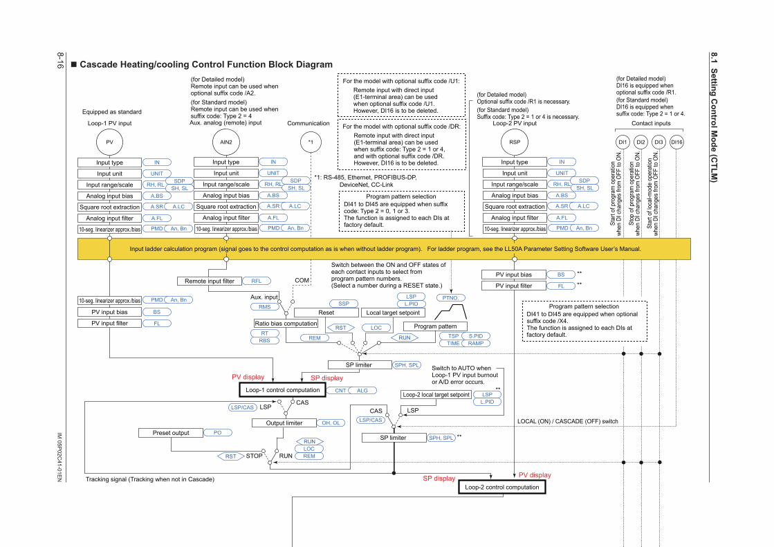
8-16IM
05P02C
41-01EN
n Cascade Heating/cooling Control Function Block Diagram
Communication
COM
Aux. input
*1
SP limiter
Loop-1 PV input
Equipped as standard
* The LP2 lamp is lit while the Loop-2 parameter is displayed.
(for Standard model)Suffix code: Type 2 = 1 or 4 is necessary.
Loop-2 PV input
DI2 DI3DI1 DI16PV RSP
Input type
Input unit
Input range/scale
Analog input bias
Square root extraction
Analog input filter
Input type
Input unit
Input range/scale
Analog input bias
Square root extraction
Analog input filter
10-seg. linearizer approx./bias
PV input bias
PV input filter Ratio bias computation
Contact inputs
A.BS
A.FL
BS
FL
PMD An, Bn
10-seg. linearizer approx./bias PMD An, Bn
10-seg. linearizer approx./bias
PV input bias
PV input filter
BS
FL
PMD An, Bn
CNT ALG
RMS
SPH, SPL
SPH, SPL
RFL
A.SR A.LC
UNIT
IN
RH, RLSDP
SH, SLA.BS
A.FL
A.SR A.LC
UNIT
IN
RH, RL SDPSH, SL
AIN2
PMD An, Bn
A.BS
A.FL
A.SR A.LC
UNIT
IN
RH, RL SDPSH, SL
Tracking signal (Tracking when not in Cascade)
LSPLSP CASCAS
Switch to AUTO whenLoop-1 PV input burnoutor A/D error occurs.
Loop-2 local target setpoint
OH, OL
SP limiter
RUNSTOP
Remote input filter
Output limiter
RESET/RUN switch
Loop-1 control computation
Loop-2 control computation
Manual operation
Manual preset output
Input error preset output
Heating-side preset output
RESET/RUN switch
Normal Normal
MAN
RUNRESET
Current or voltage pulse
Relay Current or voltage pulse
Relay Current
EPOOH, OL OHc, OLc
Input error preset output
OUT retransmission output OUT2 retransmission output
EPO
POCooling-side preset output
RESETPOc
OT
O1RS O2RS RET retransmission outputRTS
MPON
Heating-sideoutput
Heating-sideoutput
Cooling-sideoutput
Cooling-sideoutput
OUTOUT OUT2 OUT2
Heating/cooling computation
RET
* After the control output terminal is specified by the parameter OT, other current output terminals can be used as retransmission output.
Terminal Parameter Function
Analog signal Contact signal Front panel keyLegend
Heating-side output limiter Cooling-side output limiter
RUN
Output terminal assignment
PMD
OU.H OU.L OU2.H OU2.L
An, Bn PMD An, Bn
Split computation
10-seg. linearizer approx./bias
Split computation
10-seg. linearizer approx./bias
RET.H RET.L
PMD An, Bn
Split computation
10-seg. linearizer approx./bias
CAS, AUTO
Equipped as standard
(Current when retransmission output) (Current when retransmission output)
When Loop-2 sensorburnout occurs
When Loop-2 sensorburnout occurs
PV display SP display
Input ladder calculation program (signal goes to the control computation as is when without ladder program). For ladder program, see the LL50A Parameter Setting Software User’s Manual.
PV displaySP display
Manual output is prioritized even if sensor burnout occurs in MAN.
(for Standard model)Remote input can be used whensuffix code: Type 2 = 4Aux. analog (remote) input
Input type
Input unit
Input range/scale
Analog input bias
Square root extraction
Analog input filter
10-seg. linearizer approx./bias
*1: RS-485, Ethernet, PROFIBUS-DP, DeviceNet, CC-Link
For the model with optional suffix code /DR:Remote input with direct input (E1-terminal area) can be used when suffix code: Type 2 = 1 or 4, and with optional suffix code /DR.However, DI16 is to be deleted.
Program pattern selection
Switch between the ON and OFF states of each contact inputs to select from program pattern numbers.(Select a number during a RESET state.)
DI41 to DI45 are equipped when suffix code: Type 2 = 0, 1 or 3.The function is assigned to each DIs at factory default.
(for Standard model)DI16 is equipped whensuffix code: Type 2 = 1 or 4.
RTRBS
Program pattern
Local target setpointReset
TSP S.PID
PTNO.
TIME RAMP
L.PIDLSP
REM
LOC
RUN
RST
LSP/CAS
RST REMLOCRUN
LSP/CAS
LSPL.PID
Star
t of p
rogr
am o
pera
tion
when
DI c
hang
es fr
om O
FF to
ON.
Stop
of p
rogr
am o
pera
tion
when
DI c
hang
es fr
om O
FF to
ON.
Star
t of l
ocal
-mod
e op
erat
ion
when
DI c
hang
es fr
om O
FF to
ON.
RST RSTREM
A/M
LOCRUN
REMLOCRUN
AL3AL2AL1
PV
eve
nt 1
PV
eve
nt 2
PV
eve
nt 3
Tim
e ev
ent 1
Tim
e ev
ent 2
Tim
e ev
ent 3
Tim
e ev
ent 4
DO23DO22DO21 DO24
Tim
e ev
ent 5
DO25
PV event, Time event, Alarm
Output ladder calculation program (signal goes to the output as is when without ladder program). For ladder program, see the LL50A Parameter Setting Software User’s Manual.
LOCAL (ON) / CASCADE (OFF) switch
Preset output PO
DO31 to DO35 are assinged Time event 6 to 10.
(for Detailed model)Optional suffix code /R1 is necessary.
(for Detailed model)Remote input can be used whenoptional suffix code /A2.
(for Detailed model)DI16 is equipped whenoptional suffix code /R1.
For the model with optional suffix code /U1:Remote input with direct input (E1-terminal area) can be used when optional suffix code /U1.However, DI16 is to be deleted.
Program pattern selectionDI41 to DI45 are equipped when optional suffix code /X4.The function is assigned to each DIs at factory default.
LPS
24 V looppower supply
For optional suffix code /L4 or /LC4
** Loop-2 parameters.
**
**
**
**
**
**
** **
** **
SSP
8.1SettingControlM
ode(CTLM
)
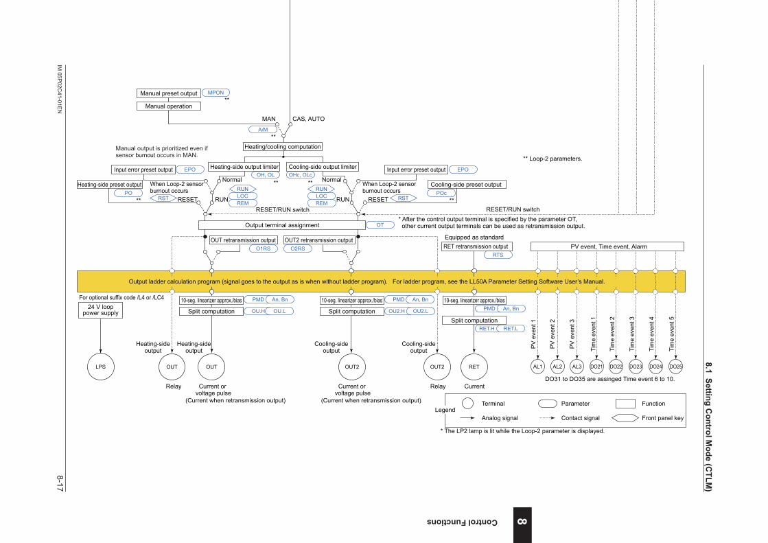
8-17IM
05P02C
41-01EN
Control Functions
n Cascade Heating/cooling Control Function Block Diagram
Communication
COM
Aux. input
*1
SP limiter
Loop-1 PV input
Equipped as standard
* The LP2 lamp is lit while the Loop-2 parameter is displayed.
(for Standard model)Suffix code: Type 2 = 1 or 4 is necessary.
Loop-2 PV input
DI2 DI3DI1 DI16PV RSP
Input type
Input unit
Input range/scale
Analog input bias
Square root extraction
Analog input filter
Input type
Input unit
Input range/scale
Analog input bias
Square root extraction
Analog input filter
10-seg. linearizer approx./bias
PV input bias
PV input filter Ratio bias computation
Contact inputs
A.BS
A.FL
BS
FL
PMD An, Bn
10-seg. linearizer approx./bias PMD An, Bn
10-seg. linearizer approx./bias
PV input bias
PV input filter
BS
FL
PMD An, Bn
CNT ALG
RMS
SPH, SPL
SPH, SPL
RFL
A.SR A.LC
UNIT
IN
RH, RLSDP
SH, SLA.BS
A.FL
A.SR A.LC
UNIT
IN
RH, RL SDPSH, SL
AIN2
PMD An, Bn
A.BS
A.FL
A.SR A.LC
UNIT
IN
RH, RL SDPSH, SL
Tracking signal (Tracking when not in Cascade)
LSPLSP CASCAS
Switch to AUTO whenLoop-1 PV input burnoutor A/D error occurs.
Loop-2 local target setpoint
OH, OL
SP limiter
RUNSTOP
Remote input filter
Output limiter
RESET/RUN switch
Loop-1 control computation
Loop-2 control computation
Manual operation
Manual preset output
Input error preset output
Heating-side preset output
RESET/RUN switch
Normal Normal
MAN
RUNRESET
Current or voltage pulse
Relay Current or voltage pulse
Relay Current
EPOOH, OL OHc, OLc
Input error preset output
OUT retransmission output OUT2 retransmission output
EPO
POCooling-side preset output
RESETPOc
OT
O1RS O2RS RET retransmission outputRTS
MPON
Heating-sideoutput
Heating-sideoutput
Cooling-sideoutput
Cooling-sideoutput
OUTOUT OUT2 OUT2
Heating/cooling computation
RET
* After the control output terminal is specified by the parameter OT, other current output terminals can be used as retransmission output.
Terminal Parameter Function
Analog signal Contact signal Front panel keyLegend
Heating-side output limiter Cooling-side output limiter
RUN
Output terminal assignment
PMD
OU.H OU.L OU2.H OU2.L
An, Bn PMD An, Bn
Split computation
10-seg. linearizer approx./bias
Split computation
10-seg. linearizer approx./bias
RET.H RET.L
PMD An, Bn
Split computation
10-seg. linearizer approx./bias
CAS, AUTO
Equipped as standard
(Current when retransmission output) (Current when retransmission output)
When Loop-2 sensorburnout occurs
When Loop-2 sensorburnout occurs
PV display SP display
Input ladder calculation program (signal goes to the control computation as is when without ladder program). For ladder program, see the LL50A Parameter Setting Software User’s Manual.
PV displaySP display
Manual output is prioritized even if sensor burnout occurs in MAN.
(for Standard model)Remote input can be used whensuffix code: Type 2 = 4Aux. analog (remote) input
Input type
Input unit
Input range/scale
Analog input bias
Square root extraction
Analog input filter
10-seg. linearizer approx./bias
*1: RS-485, Ethernet, PROFIBUS-DP, DeviceNet, CC-Link
For the model with optional suffix code /DR:Remote input with direct input (E1-terminal area) can be used when suffix code: Type 2 = 1 or 4, and with optional suffix code /DR.However, DI16 is to be deleted.
Program pattern selection
Switch between the ON and OFF states of each contact inputs to select from program pattern numbers.(Select a number during a RESET state.)
DI41 to DI45 are equipped when suffix code: Type 2 = 0, 1 or 3.The function is assigned to each DIs at factory default.
(for Standard model)DI16 is equipped whensuffix code: Type 2 = 1 or 4.
RTRBS
Program pattern
Local target setpointReset
TSP S.PID
PTNO.
TIME RAMP
L.PIDLSP
REM
LOC
RUN
RST
LSP/CAS
RST REMLOCRUN
LSP/CAS
LSPL.PID
Star
t of p
rogr
am o
pera
tion
when
DI c
hang
es fr
om O
FF to
ON.
Stop
of p
rogr
am o
pera
tion
when
DI c
hang
es fr
om O
FF to
ON.
Star
t of l
ocal
-mod
e op
erat
ion
when
DI c
hang
es fr
om O
FF to
ON.
RST RSTREM
A/M
LOCRUN
REMLOCRUN
AL3AL2AL1
PV
eve
nt 1
PV
eve
nt 2
PV
eve
nt 3
Tim
e ev
ent 1
Tim
e ev
ent 2
Tim
e ev
ent 3
Tim
e ev
ent 4
DO23DO22DO21 DO24
Tim
e ev
ent 5
DO25
PV event, Time event, Alarm
Output ladder calculation program (signal goes to the output as is when without ladder program). For ladder program, see the LL50A Parameter Setting Software User’s Manual.
LOCAL (ON) / CASCADE (OFF) switch
Preset output PO
DO31 to DO35 are assinged Time event 6 to 10.
(for Detailed model)Optional suffix code /R1 is necessary.
(for Detailed model)Remote input can be used whenoptional suffix code /A2.
(for Detailed model)DI16 is equipped whenoptional suffix code /R1.
For the model with optional suffix code /U1:Remote input with direct input (E1-terminal area) can be used when optional suffix code /U1.However, DI16 is to be deleted.
Program pattern selectionDI41 to DI45 are equipped when optional suffix code /X4.The function is assigned to each DIs at factory default.
LPS
24 V looppower supply
For optional suffix code /L4 or /LC4
** Loop-2 parameters.
**
**
**
**
**
**
** **
** **
SSP
8
8.1SettingControlM
ode(CTLM
)
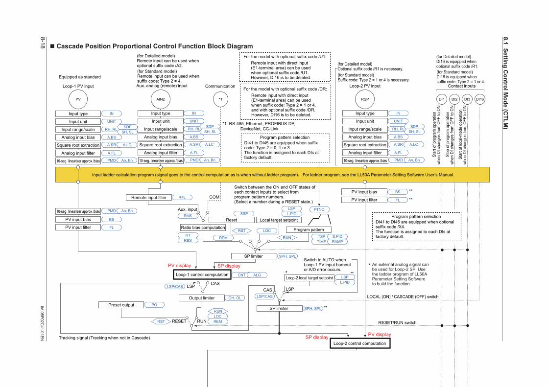
8-18IM
05P02C
41-01EN
n Cascade Position Proportional Control Function Block Diagram
Communication
COM
Aux. input
*1
SP limiter
Loop-1 PV input
Equipped as standard (for Standard model)Suffix code: Type 2 = 1 or 4 is necessary.
Loop-2 PV input
DI2 DI3DI1 DI16PV RSP
Input type
Input unit
Input range/scale
Analog input bias
Square root extraction
Analog input filter
Input type
Input unit
Input range/scale
Analog input bias
Square root extraction
Analog input filter
10-seg. linearizer approx./bias
PV input bias
PV input filter Ratio bias computation
Contact inputs
A.BS
A.FL
BS
FL
PMD An, Bn
10-seg. linearizer approx./bias PMD An, Bn
10-seg. linearizer approx./bias
PV input bias
PV input filter
BS
FL
PMD An, Bn
CNT ALG
RMS
SPH, SPL
SPH, SPL
RFL
A.SR A.LC
UNIT
IN
RH, RL SDPSH, SL
A.BS
A.FL
A.SR A.LC
UNIT
IN
RH, RL SDPSH, SL
AIN2
PMD An, Bn
A.BS
A.FL
A.SR A.LC
UNIT
IN
RH, RL SDPSH, SL
Tracking signal (Tracking when not in Cascade)
LSPLSPCAS
CAS
Switch to AUTO whenLoop-1 PV input burnoutor A/D error occurs.
Loop-2 local target setpoint
OH, OL
SP limiter
RUNRESET
Remote input filter
Output limiter
Loop-1 control computation
Manual operation
Input error preset output
Preset output
When Loop-2 sensor burnout occursNormal
MAN
RUNRESET
EPOOH, OL
PO
CAS, AUTO
Output limiter
Signal comparison
Feedback input Direct/reverse signal
Motor-operated valve
Relay output
VALVFBIN
M
Equipped as standardEquipped as standard
Current Current
OUT RET
PMD
OU.H OU.L
HYSDB An, Bn
Split computation
10-seg. linearizer approx./bias
RET.H RET.L
PMD An, Bn
Split computation
10-seg. linearizer approx./bias
OUT retransmission outputO1RS
RET retransmission outputRTS
Valve position slidingresistor or current
In Estimating-type position proportional control, the limiter function does not work on output operation. The reverse-signal relay turns on when being limited by low limit.The direct-signal relay turns on when being limited by high limit.
H relay( key)
L relay( key)
In Manual operation, the relay turns on while the or key is pressed. Output limiter does not work.
(for Standard model)DI16 is equipped whensuffix code: Type 2 = 1 or 4.
* The LP2 lamp is lit while the Loop-2 parameter is displayed.
Loop-2 control computation
Terminal Parameter Function
Analog signal Contact signal Front panel keyLegend
PV display SP display
Input ladder calculation program (signal goes to the control computation as is when without ladder program). For ladder program, see the LL50A Parameter Setting Software User’s Manual.
PV displaySP display
(for Standard model)Remote input can be used whensuffix code: Type 2 = 4.Aux. analog (remote) input
Input type
Input unit
Input range/scale
Analog input bias
Square root extraction
Analog input filter
10-seg. linearizer approx./bias
Position Proportional Computation Output cannot be calculated by ladder program.
** An external analog signal can
be used for Loop-2 SP. Use the ladder program of LL50A Parameter Setting Software to build the function.
*1: RS-485, Ethernet, PROFIBUS-DP, DeviceNet, CC-Link
For the model with optional suffix code /DR:Remote input with direct input (E1-terminal area) can be used when suffix code: Type 2 = 1 or 4, and with optional suffix code /DR.However, DI16 is to be deleted.
Program pattern selectionDI41 to DI45 are equipped when suffix code: Type 2 = 0, 1 or 3.The function is assigned to each DIs at factory default.
Program pattern
Local target setpointReset
TSP S.PID
PTNO.
TIME RAMP
L.PIDLSP
REM
LOC
RUN
RST
LSP/CAS
LSPL.PID
RST REMLOCRUN
LSP/CAS
RESET/RUN switch
RESET/RUN switch
LOCAL (ON) / CASCADE (OFF) switch
Star
t of p
rogr
am o
pera
tion
when
DI c
hang
es fr
om O
FF to
ON.
Stop
of p
rogr
am o
pera
tion
when
DI c
hang
es fr
om O
FF to
ON.
Star
t of l
ocal
-mod
e op
erat
ion
when
DI c
hang
es fr
om O
FF to
ON.
Switch between the ON and OFF states of each contact inputs to select from program pattern numbers.(Select a number during a RESET state.)
RST REM
A/M
LOCRUN
AL3AL2AL1
PV
eve
nt 1
PV
eve
nt 2
PV
eve
nt 3
Tim
e ev
ent 1
Tim
e ev
ent 2
Tim
e ev
ent 3
Tim
e ev
ent 4
DO23DO22DO21 DO24
Tim
e ev
ent 5
DO25
PV event, Time event, Alarm
Output ladder calculation program (signal goes to the output as is when without ladder program). For ladder program, see the LL50A Parameter Setting Software User’s Manual.
RTRBS
Preset output PO
DO31 to DO35 are assinged Time event 6 to 10.
(for Detailed model)Optional suffix code /R1 is necessary.
(for Detailed model)DI16 is equipped whenoptional suffix code /R1.
(for Detailed model)Remote input can be used whenoptional suffix code /A2.
For the model with optional suffix code /U1:Remote input with direct input (E1-terminal area) can be used when optional suffix code /U1.However, DI16 is to be deleted.
LPS
24 V looppower supply
For optional suffix code /L4 or /LC4
Program pattern selectionDI41 to DI45 are equipped when optional suffix code /X4.The function is assigned to each DIs at factory default.
** Loop-2 parameters.
**
**
**
**
**
**
**
SSP
8.1SettingControlM
ode(CTLM
)
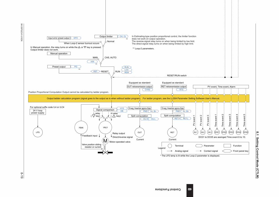
8-19IM
05P02C
41-01EN
Control Functions 8
n Cascade Position Proportional Control Function Block Diagram
Communication
COM
Aux. input
*1
SP limiter
Loop-1 PV input
Equipped as standard (for Standard model)Suffix code: Type 2 = 1 or 4 is necessary.
Loop-2 PV input
DI2 DI3DI1 DI16PV RSP
Input type
Input unit
Input range/scale
Analog input bias
Square root extraction
Analog input filter
Input type
Input unit
Input range/scale
Analog input bias
Square root extraction
Analog input filter
10-seg. linearizer approx./bias
PV input bias
PV input filter Ratio bias computation
Contact inputs
A.BS
A.FL
BS
FL
PMD An, Bn
10-seg. linearizer approx./bias PMD An, Bn
10-seg. linearizer approx./bias
PV input bias
PV input filter
BS
FL
PMD An, Bn
CNT ALG
RMS
SPH, SPL
SPH, SPL
RFL
A.SR A.LC
UNIT
IN
RH, RL SDPSH, SL
A.BS
A.FL
A.SR A.LC
UNIT
IN
RH, RL SDPSH, SL
AIN2
PMD An, Bn
A.BS
A.FL
A.SR A.LC
UNIT
IN
RH, RL SDPSH, SL
Tracking signal (Tracking when not in Cascade)
LSPLSPCAS
CAS
Switch to AUTO whenLoop-1 PV input burnoutor A/D error occurs.
Loop-2 local target setpoint
OH, OL
SP limiter
RUNRESET
Remote input filter
Output limiter
Loop-1 control computation
Manual operation
Input error preset output
Preset output
When Loop-2 sensor burnout occursNormal
MAN
RUNRESET
EPOOH, OL
PO
CAS, AUTO
Output limiter
Signal comparison
Feedback input Direct/reverse signal
Motor-operated valve
Relay output
VALVFBIN
M
Equipped as standardEquipped as standard
Current Current
OUT RET
PMD
OU.H OU.L
HYSDB An, Bn
Split computation
10-seg. linearizer approx./bias
RET.H RET.L
PMD An, Bn
Split computation
10-seg. linearizer approx./bias
OUT retransmission outputO1RS
RET retransmission outputRTS
Valve position slidingresistor or current
In Estimating-type position proportional control, the limiter function does not work on output operation. The reverse-signal relay turns on when being limited by low limit.The direct-signal relay turns on when being limited by high limit.
H relay( key)
L relay( key)
In Manual operation, the relay turns on while the or key is pressed. Output limiter does not work.
(for Standard model)DI16 is equipped whensuffix code: Type 2 = 1 or 4.
* The LP2 lamp is lit while the Loop-2 parameter is displayed.
Loop-2 control computation
Terminal Parameter Function
Analog signal Contact signal Front panel keyLegend
PV display SP display
Input ladder calculation program (signal goes to the control computation as is when without ladder program). For ladder program, see the LL50A Parameter Setting Software User’s Manual.
PV displaySP display
(for Standard model)Remote input can be used whensuffix code: Type 2 = 4.Aux. analog (remote) input
Input type
Input unit
Input range/scale
Analog input bias
Square root extraction
Analog input filter
10-seg. linearizer approx./bias
Position Proportional Computation Output cannot be calculated by ladder program.
** An external analog signal can
be used for Loop-2 SP. Use the ladder program of LL50A Parameter Setting Software to build the function.
*1: RS-485, Ethernet, PROFIBUS-DP, DeviceNet, CC-Link
For the model with optional suffix code /DR:Remote input with direct input (E1-terminal area) can be used when suffix code: Type 2 = 1 or 4, and with optional suffix code /DR.However, DI16 is to be deleted.
Program pattern selectionDI41 to DI45 are equipped when suffix code: Type 2 = 0, 1 or 3.The function is assigned to each DIs at factory default.
Program pattern
Local target setpointReset
TSP S.PID
PTNO.
TIME RAMP
L.PIDLSP
REM
LOC
RUN
RST
LSP/CAS
LSPL.PID
RST REMLOCRUN
LSP/CAS
RESET/RUN switch
RESET/RUN switch
LOCAL (ON) / CASCADE (OFF) switch
Star
t of p
rogr
am o
pera
tion
when
DI c
hang
es fr
om O
FF to
ON.
Stop
of p
rogr
am o
pera
tion
when
DI c
hang
es fr
om O
FF to
ON.
Star
t of l
ocal
-mod
e op
erat
ion
when
DI c
hang
es fr
om O
FF to
ON.
Switch between the ON and OFF states of each contact inputs to select from program pattern numbers.(Select a number during a RESET state.)
RST REM
A/M
LOCRUN
AL3AL2AL1
PV
eve
nt 1
PV
eve
nt 2
PV
eve
nt 3
Tim
e ev
ent 1
Tim
e ev
ent 2
Tim
e ev
ent 3
Tim
e ev
ent 4
DO23DO22DO21 DO24
Tim
e ev
ent 5
DO25
PV event, Time event, Alarm
Output ladder calculation program (signal goes to the output as is when without ladder program). For ladder program, see the LL50A Parameter Setting Software User’s Manual.
RTRBS
Preset output PO
DO31 to DO35 are assinged Time event 6 to 10.
(for Detailed model)Optional suffix code /R1 is necessary.
(for Detailed model)DI16 is equipped whenoptional suffix code /R1.
(for Detailed model)Remote input can be used whenoptional suffix code /A2.
For the model with optional suffix code /U1:Remote input with direct input (E1-terminal area) can be used when optional suffix code /U1.However, DI16 is to be deleted.
LPS
24 V looppower supply
For optional suffix code /L4 or /LC4
Program pattern selectionDI41 to DI45 are equipped when optional suffix code /X4.The function is assigned to each DIs at factory default.
** Loop-2 parameters.
**
**
**
**
**
**
**
SSP
8.1SettingControlM
ode(CTLM
)

8-20 IM 05P02C41-01EN
Intentionally blank
8.1SettingControlMode(CTLM)

8-21IM 05P02C41-01EN
Control Functions
8.1.4 LoopControlwithPVSwitching,Heating/coolingLoopControlwithPVSwitching,andPositionProportionalLoopControlwithPVSwitching
SettingDetails
Parameter symbol Name Display
level Settingrange Menusymbol
CTLM Control mode STD
SGL: Single-loop controlCAS1: Cascade primary-loop
controlCAS: Cascade controlPVSW: Loop control with PV
switchingPVSEL: Loop control with PV
auto-selector
CTL
CAUTION• Someparameterswillbeinitializedifthecontrolmode(CTLM)ischanged.• When using the ladder program, the control mode cannot be changed.
Description
These control modes use two PV inputs, which are switched according to input contact signals or measurement ranges.
Loop control with PV switching can be used for Standard type or Heating/cooling type controller.Heating/cooling loop control with PV switching can be used for Heating/cooling type controller.Position proportional loop control with PV switching can be used for Position proportional type controller. PIDcontrolandHeating/coolingcontrol:8.2SettingControlType(CNT)
Description about Loop control with PV switching PVrange:7.6AdjustingPVRangeforLoopControlwithPVSwitching Switchingaction:7.7SettingPVSwitchingMethodsofLoopControlwithPVSwitching
Uptofour10-segmentlinearizerapproximation/10-segmentlinearizerbiasescanbeused for the input unit or output unit.
The Function block diagram describes only the basic functions.Parameter symbols in the Function block diagram describe representative parameters.
For the functions and parameters which are not described in Function block diagram, see the following. Contactinputassignment:12.1SettingContactInputFunction Contactoutputassignment:12.2SettingContactOutputFunction Contactoutputassignmenttoretransmissionoutputterminal:10.1SettingControlOutputType Analogoutputrangechange:10.14ChangingCurrentOutputRange
8
8.1SettingControlMode(CTLM)
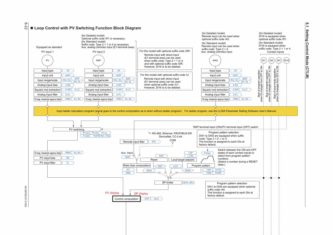
8-22IM
05P02C
41-01EN
nLoopControlwithPVSwitchingFunctionBlockDiagram
COM
Aux. input
Output limiter
Manual operation
Manual preset output
Input error preset output
Preset output
AUTO
When sensor burnout occursNormal
MAN
RUNRESET
SP limiter
PV input 1 PV input 2
DI16PV
Input type
Input unit
Input range/scale
Analog input bias
Square root extraction
Analog input filter
10-seg. linearizer approx./bias
Remote input filter
PV input bias
PV input filterRatio bias computation
PV switching
Contact inputs
Output limiter
A.BS
A.FL
BS
FL
PMD An, Bn10-seg. linearizer approx./bias PMD An, Bn
10-seg. linearizer approx./bias PMD An, Bn
PV.2C PV.HL PV.LLP.UNI P.DP P.RH, P.RL
CNT ALG
RMS
SPH, SPL
RFL
A.SR A.LC
UNIT
IN
RH, RLSDP
SH, SL
RSP
Input type
Input unit
Input range/scale
Analog input bias
Square root extraction
Analog input filter
A.BS
A.FL
A.SR A.LC
UNIT
IN
RH, RL SDPSH, SL
PMD An, Bn
AIN2
A.BS
A.FL
A.SR A.LC
UNIT
IN
RH, RL SDPSH, SL
EPOOH, OL
OH, OL OLMT
PO
MPON
Equipped as standard
OT
Equipped as standard
For optional suffix code /HAHeater break alarm
HAL2HAL1
Heater breakalarm 1
Heater breakalarm 2 Current or
voltage pulseRelay Current
OUTOUT RET
PMD
OU.H OU.L
An, Bn
Split computation
10-seg. linearizer approx./bias
RET.H RET.L
PMD An, Bn
Split computation
10-seg. linearizer approx./bias
OUT retransmission outputO1RS RET retransmission output
RTS
* After the control output terminal is specified by the parameter OT, other current output terminals can be used as retransmission output.Output terminal assignment
DI3DI1 DI2
Sensor burnout occurs when PV or RSP input burnout occurs.However, burnout is not detected if input is not connected.
Control computation
RSP terminal input (ON)/PV terminal input (OFF) switch
(Current when retransmission output)
(for Standard model)DI16 is equipped whensuffix code: Type 2 = 1 or 4.
Terminal Parameter Function
Analog signal Contact signal Front panel keyLegend
Aux. analog (remote) input (E1-terminal area)
(for Standard model)Suffix code: Type 2 = 1 or 4 is necessary.
PV display SP display
Input ladder calculation program (signal goes to the control computation as is when without ladder program). For ladder program, see the LL50A Parameter Setting Software User’s Manual.
(for Standard model)Remote input can be used whensuffix code: Type 2 = 4.Aux. analog (remote) input
10-seg. linearizer approx./bias
Input type
Input unit
Input range/scale
Analog input bias
Square root extraction
Analog input filter
*1: RS-485, Ethernet, PROFIBUS-DP, DeviceNet, CC-Link
For the model with optional suffix code /DR:Remote input with direct input (E1-terminal area) can be used when suffix code: Type 2 = 1 or 4, and with optional suffix code /DR.However, DI16 is to be deleted.
Program pattern
Local target setpointReset
TSP S.PID
PTNO.
TIME RAMP
L.PIDLSP
REM
LOC
RUN
RST
Program pattern selection
Switch between the ON and OFF states of each contact inputs to select from program pattern numbers.(Select a number during a RESET state.)
DI41 to DI45 are equipped when suffix code: Type 2 = 0, 1 or 3.The function is assigned to each DIs at factory default.
Star
t of p
rogr
am o
pera
tion
when
DI c
hang
es fr
om O
FF to
ON.
Stop
of p
rogr
am o
pera
tion
when
DI c
hang
es fr
om O
FF to
ON.
Star
t of l
ocal
-mod
e op
erat
ion
when
DI c
hang
es fr
om O
FF to
ON.
RST REM
A/M
LOCRUN
RESET/RUN switch
RTRBS
AL3AL2AL1
PV
eve
nt 1
PV
eve
nt 2
PV
eve
nt 3
Tim
e ev
ent 1
Tim
e ev
ent 2
Tim
e ev
ent 3
Tim
e ev
ent 4
DO23DO22DO21 DO24
Tim
e ev
ent 5
DO25
PV event, Time event, Alarm
Output ladder calculation program (signal goes to the output as is when without ladder program). For ladder program, see the LL50A Parameter Setting Software User’s Manual.
DO31 to DO35 are assinged Time event 6 to 10.
(for Detailed model)DI16 is equipped whenoptional suffix code /R1.
(for Detailed model)Optional suffix code /R1 is necessary.
(for Detailed model)Remote input can be used whenoptional suffix code /A2.
For the model with optional suffix code /U:Remote input with direct input (E1-terminal area) can be used when optional suffix code /U1.However, DI16 is to be deleted.
Program pattern selectionDI41 to DI45 are equipped when optional suffix code /X4.The function is assigned to each DIs at factory default.
LPS
24 V looppower supply
For optional suffix code /L4 or /LC4
SSP
8.1SettingControlM
ode(CTLM
)

8-23IM
05P02C
41-01EN
Control Functions
nLoopControlwithPVSwitchingFunctionBlockDiagram
COM
Aux. input
Output limiter
Manual operation
Manual preset output
Input error preset output
Preset output
AUTO
When sensor burnout occursNormal
MAN
RUNRESET
SP limiter
PV input 1 PV input 2
DI16PV
Input type
Input unit
Input range/scale
Analog input bias
Square root extraction
Analog input filter
10-seg. linearizer approx./bias
Remote input filter
PV input bias
PV input filterRatio bias computation
PV switching
Contact inputs
Output limiter
A.BS
A.FL
BS
FL
PMD An, Bn10-seg. linearizer approx./bias PMD An, Bn
10-seg. linearizer approx./bias PMD An, Bn
PV.2C PV.HL PV.LLP.UNI P.DP P.RH, P.RL
CNT ALG
RMS
SPH, SPL
RFL
A.SR A.LC
UNIT
IN
RH, RLSDP
SH, SL
RSP
Input type
Input unit
Input range/scale
Analog input bias
Square root extraction
Analog input filter
A.BS
A.FL
A.SR A.LC
UNIT
IN
RH, RL SDPSH, SL
PMD An, Bn
AIN2
A.BS
A.FL
A.SR A.LC
UNIT
IN
RH, RL SDPSH, SL
EPOOH, OL
OH, OL OLMT
PO
MPON
Equipped as standard
OT
Equipped as standard
For optional suffix code /HAHeater break alarm
HAL2HAL1
Heater breakalarm 1
Heater breakalarm 2 Current or
voltage pulseRelay Current
OUTOUT RET
PMD
OU.H OU.L
An, Bn
Split computation
10-seg. linearizer approx./bias
RET.H RET.L
PMD An, Bn
Split computation
10-seg. linearizer approx./bias
OUT retransmission outputO1RS RET retransmission output
RTS
* After the control output terminal is specified by the parameter OT, other current output terminals can be used as retransmission output.Output terminal assignment
DI3DI1 DI2
Sensor burnout occurs when PV or RSP input burnout occurs.However, burnout is not detected if input is not connected.
Control computation
RSP terminal input (ON)/PV terminal input (OFF) switch
(Current when retransmission output)
(for Standard model)DI16 is equipped whensuffix code: Type 2 = 1 or 4.
Terminal Parameter Function
Analog signal Contact signal Front panel keyLegend
Aux. analog (remote) input (E1-terminal area)
(for Standard model)Suffix code: Type 2 = 1 or 4 is necessary.
PV display SP display
Input ladder calculation program (signal goes to the control computation as is when without ladder program). For ladder program, see the LL50A Parameter Setting Software User’s Manual.
(for Standard model)Remote input can be used whensuffix code: Type 2 = 4.Aux. analog (remote) input
10-seg. linearizer approx./bias
Input type
Input unit
Input range/scale
Analog input bias
Square root extraction
Analog input filter
*1: RS-485, Ethernet, PROFIBUS-DP, DeviceNet, CC-Link
For the model with optional suffix code /DR:Remote input with direct input (E1-terminal area) can be used when suffix code: Type 2 = 1 or 4, and with optional suffix code /DR.However, DI16 is to be deleted.
Program pattern
Local target setpointReset
TSP S.PID
PTNO.
TIME RAMP
L.PIDLSP
REM
LOC
RUN
RST
Program pattern selection
Switch between the ON and OFF states of each contact inputs to select from program pattern numbers.(Select a number during a RESET state.)
DI41 to DI45 are equipped when suffix code: Type 2 = 0, 1 or 3.The function is assigned to each DIs at factory default.
Star
t of p
rogr
am o
pera
tion
when
DI c
hang
es fr
om O
FF to
ON.
Stop
of p
rogr
am o
pera
tion
when
DI c
hang
es fr
om O
FF to
ON.
Star
t of l
ocal
-mod
e op
erat
ion
when
DI c
hang
es fr
om O
FF to
ON.
RST REM
A/M
LOCRUN
RESET/RUN switch
RTRBS
AL3AL2AL1
PV
eve
nt 1
PV
eve
nt 2
PV
eve
nt 3
Tim
e ev
ent 1
Tim
e ev
ent 2
Tim
e ev
ent 3
Tim
e ev
ent 4
DO23DO22DO21 DO24
Tim
e ev
ent 5
DO25
PV event, Time event, Alarm
Output ladder calculation program (signal goes to the output as is when without ladder program). For ladder program, see the LL50A Parameter Setting Software User’s Manual.
DO31 to DO35 are assinged Time event 6 to 10.
(for Detailed model)DI16 is equipped whenoptional suffix code /R1.
(for Detailed model)Optional suffix code /R1 is necessary.
(for Detailed model)Remote input can be used whenoptional suffix code /A2.
For the model with optional suffix code /U:Remote input with direct input (E1-terminal area) can be used when optional suffix code /U1.However, DI16 is to be deleted.
Program pattern selectionDI41 to DI45 are equipped when optional suffix code /X4.The function is assigned to each DIs at factory default.
LPS
24 V looppower supply
For optional suffix code /L4 or /LC4
SSP
8
8.1SettingControlM
ode(CTLM
)
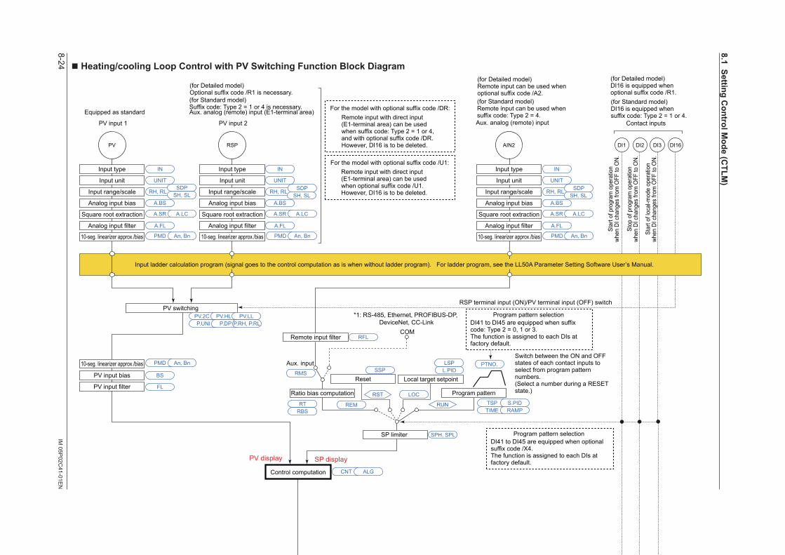
8-24IM
05P02C
41-01EN
nHeating/coolingLoopControlwithPVSwitchingFunctionBlockDiagram
COM
Aux. input
SP limiter
DI16PV
Input type
Input unit
Input range/scale
Analog input bias
Square root extraction
Analog input filter
10-seg. linearizer approx./bias
PV input bias
PV input filterRatio bias computation
PV switching
A.BS
A.FL
BS
FL
PMD An, Bn10-seg. linearizer approx./bias PMD An, Bn
10-seg. linearizer approx./bias PMD An, Bn
PV.2C PV.HL PV.LLP.UNI P.DP P.RH, P.RL
CNT ALG
RMS
SPH, SPL
RFL
A.SR A.LC
UNIT
IN
RH, RLSDP
SH, SL
RSP
Input type
Input unit
Input range/scale
Analog input bias
Square root extraction
Analog input filter
A.BS
A.FL
A.SR A.LC
UNIT
IN
RH, RL SDPSH, SL
PMD An, Bn
AIN2
A.BS
A.FL
A.SR A.LC
UNIT
IN
RH, RL SDPSH, SL
DI3DI1 DI2
Control computation
RSP terminal input (ON)/PV terminal input (OFF) switch
Manual operation
Manual preset output
Input error preset output
Heating-side preset output
AUTO
When sensorburnout occurs
Normal Normal
MAN
RUNRESET
EPOOH, OL OHc, OLc
Input error preset output
When sensorburnout occurs
EPO
POCooling-side preset output
RESETPOc
MPON
Heating/cooling computation
Heating-side output limiter Cooling-side output limiter
RUN
Current or voltage pulse
Relay Current or voltage pulse
Relay Current
OUT retransmission output OUT2 retransmission output
OT
O1RS O2RS RET retransmission outputRTS
Heating-sideoutput
Heating-sideoutput
OUTOUT
Cooling-sideoutput
Cooling-sideoutput
OUT2 OUT2 RET
* After the control output terminal is specified by the parameter OT, other current output terminals can be used as retransmission output.Output terminal assignment
PMD
OU.H OU.L OU2.H OU2.L
An, Bn PMD An, Bn
Split computation
10-seg. linearizer approx./bias
Split computation
10-seg. linearizer approx./bias
RET.H RET.L
PMD An, Bn
Split computation
10-seg. linearizer approx./bias
Equipped as standard
(Current when retransmission output) (Current when retransmission output)
PV input 1 PV input 2 Contact inputs
Equipped as standard
(for Standard model)DI16 is equipped whensuffix code: Type 2 = 1 or 4.
Terminal Parameter Function
Analog signal Contact signal Front panel keyLegend
Aux. analog (remote) input (E1-terminal area)
(for Standard model)Suffix code: Type 2 = 1 or 4 is necessary.
PV display SP display
Input ladder calculation program (signal goes to the control computation as is when without ladder program). For ladder program, see the LL50A Parameter Setting Software User’s Manual.
Manual output is prioritized even if sensor burnout occurs in MAN.
(for Standard model)Remote input can be used whensuffix code: Type 2 = 4.Aux. analog (remote) input
Remote input filter
10-seg. linearizer approx./bias
Input type
Input unit
Input range/scale
Analog input bias
Square root extraction
Analog input filter
*1: RS-485, Ethernet, PROFIBUS-DP, DeviceNet, CC-Link
For the model with optional suffix code /DR:Remote input with direct input (E1-terminal area) can be used when suffix code: Type 2 = 1 or 4, and with optional suffix code /DR.However, DI16 is to be deleted.
Program pattern
Local target setpointReset
TSP S.PID
PTNO.
TIME RAMP
L.PIDLSP
REM
LOC
RUN
RST
Program pattern selection
Switch between the ON and OFF states of each contact inputs to select from program pattern numbers.(Select a number during a RESET state.)
DI41 to DI45 are equipped when suffix code: Type 2 = 0, 1 or 3.The function is assigned to each DIs at factory default.
Star
t of p
rogr
am o
pera
tion
when
DI c
hang
es fr
om O
FF to
ON.
Stop
of p
rogr
am o
pera
tion
when
DI c
hang
es fr
om O
FF to
ON.
Star
t of l
ocal
-mod
e op
erat
ion
when
DI c
hang
es fr
om O
FF to
ON.
RESET/RUN switchRESET/RUN switchRST REM
A/M
LOCRUN
REMLOCRUN
AL3AL2AL1
PV
eve
nt 1
PV
eve
nt 2
PV
eve
nt 3
Tim
e ev
ent 1
Tim
e ev
ent 2
Tim
e ev
ent 3
Tim
e ev
ent 4
DO23DO22DO21 DO24
Tim
e ev
ent 5
DO25
PV event, Time event, Alarm
Output ladder calculation program (signal goes to the output as is when without ladder program). For ladder program, see the LL50A Parameter Setting Software User’s Manual.
RTRBS
DO31 to DO35 are assinged Time event 6 to 10.
(for Detailed model)DI16 is equipped whenoptional suffix code /R1.
(for Detailed model)Optional suffix code /R1 is necessary.
(for Detailed model)Remote input can be used whenoptional suffix code /A2.
For the model with optional suffix code /U1:Remote input with direct input (E1-terminal area) can be used when optional suffix code /U1.However, DI16 is to be deleted.
Program pattern selectionDI41 to DI45 are equipped when optional suffix code /X4.The function is assigned to each DIs at factory default.
LPS
24 V looppower supply
For optional suffix code /L4 or /LC4
SSP
8.1SettingControlM
ode(CTLM
)
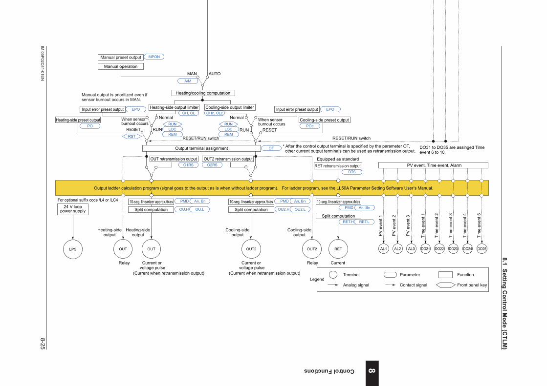
8-25IM
05P02C
41-01EN
Control Functions
nHeating/coolingLoopControlwithPVSwitchingFunctionBlockDiagram
COM
Aux. input
SP limiter
DI16PV
Input type
Input unit
Input range/scale
Analog input bias
Square root extraction
Analog input filter
10-seg. linearizer approx./bias
PV input bias
PV input filterRatio bias computation
PV switching
A.BS
A.FL
BS
FL
PMD An, Bn10-seg. linearizer approx./bias PMD An, Bn
10-seg. linearizer approx./bias PMD An, Bn
PV.2C PV.HL PV.LLP.UNI P.DP P.RH, P.RL
CNT ALG
RMS
SPH, SPL
RFL
A.SR A.LC
UNIT
IN
RH, RLSDP
SH, SL
RSP
Input type
Input unit
Input range/scale
Analog input bias
Square root extraction
Analog input filter
A.BS
A.FL
A.SR A.LC
UNIT
IN
RH, RL SDPSH, SL
PMD An, Bn
AIN2
A.BS
A.FL
A.SR A.LC
UNIT
IN
RH, RL SDPSH, SL
DI3DI1 DI2
Control computation
RSP terminal input (ON)/PV terminal input (OFF) switch
Manual operation
Manual preset output
Input error preset output
Heating-side preset output
AUTO
When sensorburnout occurs
Normal Normal
MAN
RUNRESET
EPOOH, OL OHc, OLc
Input error preset output
When sensorburnout occurs
EPO
POCooling-side preset output
RESETPOc
MPON
Heating/cooling computation
Heating-side output limiter Cooling-side output limiter
RUN
Current or voltage pulse
Relay Current or voltage pulse
Relay Current
OUT retransmission output OUT2 retransmission output
OT
O1RS O2RS RET retransmission outputRTS
Heating-sideoutput
Heating-sideoutput
OUTOUT
Cooling-sideoutput
Cooling-sideoutput
OUT2 OUT2 RET
* After the control output terminal is specified by the parameter OT, other current output terminals can be used as retransmission output.Output terminal assignment
PMD
OU.H OU.L OU2.H OU2.L
An, Bn PMD An, Bn
Split computation
10-seg. linearizer approx./bias
Split computation
10-seg. linearizer approx./bias
RET.H RET.L
PMD An, Bn
Split computation
10-seg. linearizer approx./bias
Equipped as standard
(Current when retransmission output) (Current when retransmission output)
PV input 1 PV input 2 Contact inputs
Equipped as standard
(for Standard model)DI16 is equipped whensuffix code: Type 2 = 1 or 4.
Terminal Parameter Function
Analog signal Contact signal Front panel keyLegend
Aux. analog (remote) input (E1-terminal area)
(for Standard model)Suffix code: Type 2 = 1 or 4 is necessary.
PV display SP display
Input ladder calculation program (signal goes to the control computation as is when without ladder program). For ladder program, see the LL50A Parameter Setting Software User’s Manual.
Manual output is prioritized even if sensor burnout occurs in MAN.
(for Standard model)Remote input can be used whensuffix code: Type 2 = 4.Aux. analog (remote) input
Remote input filter
10-seg. linearizer approx./bias
Input type
Input unit
Input range/scale
Analog input bias
Square root extraction
Analog input filter
*1: RS-485, Ethernet, PROFIBUS-DP, DeviceNet, CC-Link
For the model with optional suffix code /DR:Remote input with direct input (E1-terminal area) can be used when suffix code: Type 2 = 1 or 4, and with optional suffix code /DR.However, DI16 is to be deleted.
Program pattern
Local target setpointReset
TSP S.PID
PTNO.
TIME RAMP
L.PIDLSP
REM
LOC
RUN
RST
Program pattern selection
Switch between the ON and OFF states of each contact inputs to select from program pattern numbers.(Select a number during a RESET state.)
DI41 to DI45 are equipped when suffix code: Type 2 = 0, 1 or 3.The function is assigned to each DIs at factory default.
Star
t of p
rogr
am o
pera
tion
when
DI c
hang
es fr
om O
FF to
ON.
Stop
of p
rogr
am o
pera
tion
when
DI c
hang
es fr
om O
FF to
ON.
Star
t of l
ocal
-mod
e op
erat
ion
when
DI c
hang
es fr
om O
FF to
ON.
RESET/RUN switchRESET/RUN switchRST REM
A/M
LOCRUN
REMLOCRUN
AL3AL2AL1
PV
eve
nt 1
PV
eve
nt 2
PV
eve
nt 3
Tim
e ev
ent 1
Tim
e ev
ent 2
Tim
e ev
ent 3
Tim
e ev
ent 4
DO23DO22DO21 DO24
Tim
e ev
ent 5
DO25
PV event, Time event, Alarm
Output ladder calculation program (signal goes to the output as is when without ladder program). For ladder program, see the LL50A Parameter Setting Software User’s Manual.
RTRBS
DO31 to DO35 are assinged Time event 6 to 10.
(for Detailed model)DI16 is equipped whenoptional suffix code /R1.
(for Detailed model)Optional suffix code /R1 is necessary.
(for Detailed model)Remote input can be used whenoptional suffix code /A2.
For the model with optional suffix code /U1:Remote input with direct input (E1-terminal area) can be used when optional suffix code /U1.However, DI16 is to be deleted.
Program pattern selectionDI41 to DI45 are equipped when optional suffix code /X4.The function is assigned to each DIs at factory default.
LPS
24 V looppower supply
For optional suffix code /L4 or /LC4
SSP
8
8.1SettingControlM
ode(CTLM
)
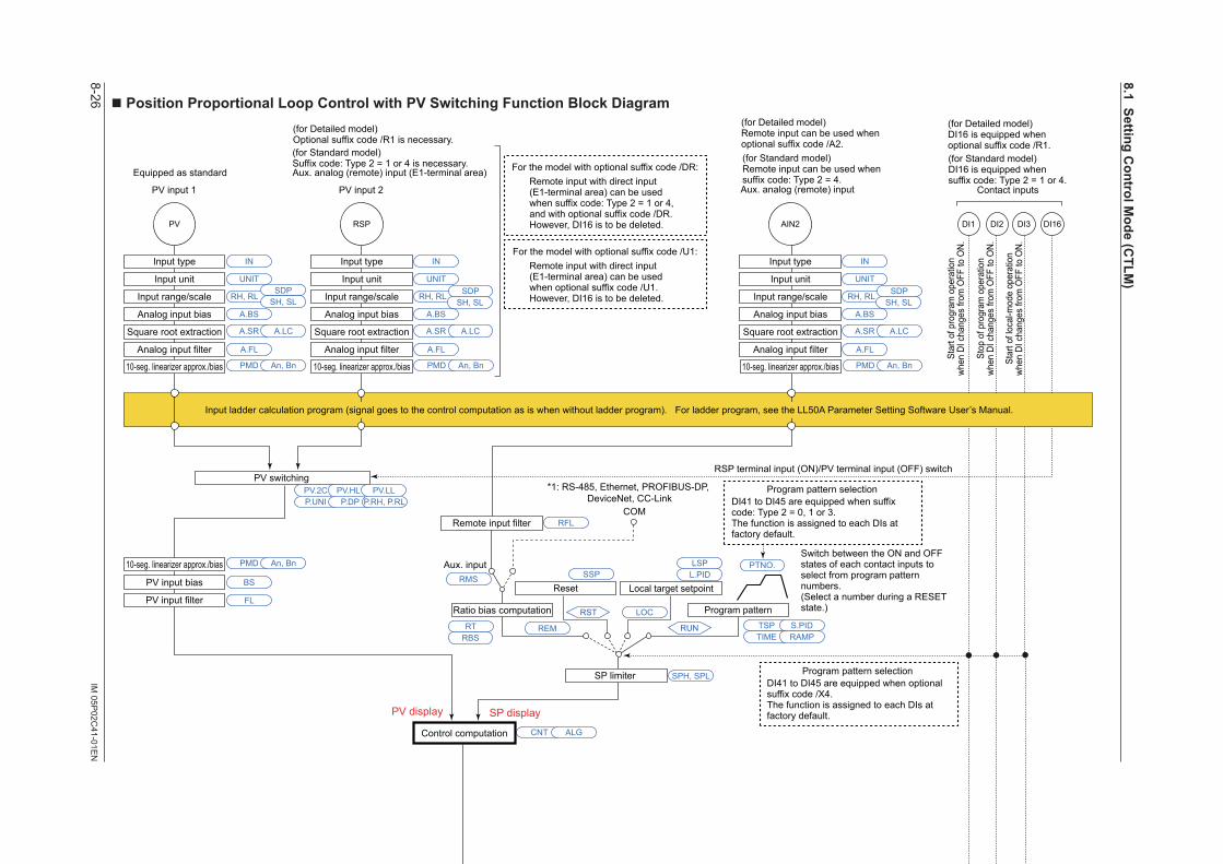
8-26IM
05P02C
41-01EN
nPositionProportionalLoopControlwithPVSwitchingFunctionBlockDiagram
COM
Aux. input
SP limiter
DI16PV
Input type
Input unit
Input range/scale
Analog input bias
Square root extraction
Analog input filter
10-seg. linearizer approx./bias
Remote input filter
PV input bias
PV input filterRatio bias computation
PV switching
A.BS
A.FL
BS
FL
PMD An, Bn10-seg. linearizer approx./bias PMD An, Bn
10-seg. linearizer approx./bias PMD An, Bn
PV.2C PV.HL PV.LLP.UNI P.DP P.RH, P.RL
CNT ALG
RMS
SPH, SPL
RFL
A.SR A.LC
UNIT
IN
RH, RLSDP
SH, SL
RSP
Input type
Input unit
Input range/scale
Analog input bias
Square root extraction
Analog input filter
A.BS
A.FL
A.SR A.LC
UNIT
IN
RH, RL SDPSH, SL
PMD An, Bn
AIN2
A.BS
A.FL
A.SR A.LC
UNIT
IN
RH, RL SDPSH, SL
DI3DI1 DI2
Control computation
RSP terminal input (ON)/PV terminal input (OFF) switch
Manual operation
Input error preset output
Preset output
AUTO
When sensor burnout occursNormal
MAN
RUNRESET
Output limiter
EPO
OH, OL
PO
Signal comparison
Feedback input Direct/reverse signal
Valve position slidingresistor or current
Motor-operated valve
Relay output
VALVFBIN
M Current Current
OUT RET
PMD
OU.H OU.L
HYSDB An, Bn
Split computation
10-seg. linearizer approx./bias
RET.H RET.L
PMD An, Bn
Split computation
10-seg. linearizer approx./bias
OUT retransmission outputO1RS
RET retransmission outputRTS
PV input 1 PV input 2
Aux. analog (remote) input (E1-terminal area)
(for Standard model)Suffix code: Type 2 = 1 or 4 is necessary.
Contact inputs
Equipped as standard(for Standard model)DI16 is equipped whensuffix code: Type 2 = 1 or 4.
Equipped as standard Equipped as standard
In Estimating-type position proportional control, the limiter function does not work on output operation. The reverse-signal relay turns on when being limited by low limit.The direct-signal relay turns on when being limited by high limit.
In Manual operation, the relay turns on while the or key is pressed. Output limiter does not work.
H relay( key)
L relay( key)
Terminal Parameter Function
Analog signal Contact signal Front panel keyLegend
PV display SP display
Input ladder calculation program (signal goes to the control computation as is when without ladder program). For ladder program, see the LL50A Parameter Setting Software User’s Manual.
(for Standard model)Remote input can be used whensuffix code: Type 2 = 4.Aux. analog (remote) input
10-seg. linearizer approx./bias
Input type
Input unit
Input range/scale
Analog input bias
Square root extraction
Analog input filter
Position Proportional Computation Output cannot be calculated by ladder program.
*1: RS-485, Ethernet, PROFIBUS-DP, DeviceNet, CC-Link
For the model with optional suffix code /DR:Remote input with direct input (E1-terminal area) can be used when suffix code: Type 2 = 1 or 4, and with optional suffix code /DR.However, DI16 is to be deleted.
Program pattern
Local target setpointReset
TSP S.PID
PTNO.
TIME RAMP
L.PIDLSP
REM
LOC
RUN
RST
RTRBS
Program pattern selection
Switch between the ON and OFF states of each contact inputs to select from program pattern numbers.(Select a number during a RESET state.)
DI41 to DI45 are equipped when suffix code: Type 2 = 0, 1 or 3.The function is assigned to each DIs at factory default.
Star
t of p
rogr
am o
pera
tion
when
DI c
hang
es fr
om O
FF to
ON.
Stop
of p
rogr
am o
pera
tion
when
DI c
hang
es fr
om O
FF to
ON.
Star
t of l
ocal
-mod
e op
erat
ion
when
DI c
hang
es fr
om O
FF to
ON.
RESET/RUN switch
RSTREM
A/M
LOCRUN
AL3AL2AL1
PV
eve
nt 1
PV
eve
nt 2
PV
eve
nt 3
Tim
e ev
ent 1
Tim
e ev
ent 2
Tim
e ev
ent 3
Tim
e ev
ent 4
DO23DO22DO21 DO24
Tim
e ev
ent 5
DO25
PV event, Time event, Alarm
Output ladder calculation program (signal goes to the output as is when without ladder program). For ladder program, see the LL50A Parameter Setting Software User’s Manual.
DO31 to DO35 are assinged Time event 6 to 10.
(for Detailed model)Optional suffix code /R1 is necessary.
(for Detailed model)DI16 is equipped whenoptional suffix code /R1.
(for Detailed model)Remote input can be used whenoptional suffix code /A2.
For the model with optional suffix code /U1:Remote input with direct input (E1-terminal area) can be used when optional suffix code /U1.However, DI16 is to be deleted.
Program pattern selectionDI41 to DI45 are equipped when optional suffix code /X4.The function is assigned to each DIs at factory default.
LPS
24 V looppower supply
For optional suffix code /L4 or /LC4
SSP
8.1SettingControlM
ode(CTLM
)
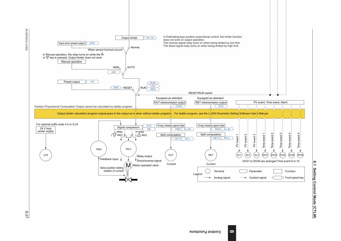
8-27IM
05P02C
41-01EN
Control Functions
nPositionProportionalLoopControlwithPVSwitchingFunctionBlockDiagram
COM
Aux. input
SP limiter
DI16PV
Input type
Input unit
Input range/scale
Analog input bias
Square root extraction
Analog input filter
10-seg. linearizer approx./bias
Remote input filter
PV input bias
PV input filterRatio bias computation
PV switching
A.BS
A.FL
BS
FL
PMD An, Bn10-seg. linearizer approx./bias PMD An, Bn
10-seg. linearizer approx./bias PMD An, Bn
PV.2C PV.HL PV.LLP.UNI P.DP P.RH, P.RL
CNT ALG
RMS
SPH, SPL
RFL
A.SR A.LC
UNIT
IN
RH, RLSDP
SH, SL
RSP
Input type
Input unit
Input range/scale
Analog input bias
Square root extraction
Analog input filter
A.BS
A.FL
A.SR A.LC
UNIT
IN
RH, RL SDPSH, SL
PMD An, Bn
AIN2
A.BS
A.FL
A.SR A.LC
UNIT
IN
RH, RL SDPSH, SL
DI3DI1 DI2
Control computation
RSP terminal input (ON)/PV terminal input (OFF) switch
Manual operation
Input error preset output
Preset output
AUTO
When sensor burnout occursNormal
MAN
RUNRESET
Output limiter
EPO
OH, OL
PO
Signal comparison
Feedback input Direct/reverse signal
Valve position slidingresistor or current
Motor-operated valve
Relay output
VALVFBIN
M Current Current
OUT RET
PMD
OU.H OU.L
HYSDB An, Bn
Split computation
10-seg. linearizer approx./bias
RET.H RET.L
PMD An, Bn
Split computation
10-seg. linearizer approx./bias
OUT retransmission outputO1RS
RET retransmission outputRTS
PV input 1 PV input 2
Aux. analog (remote) input (E1-terminal area)
(for Standard model)Suffix code: Type 2 = 1 or 4 is necessary.
Contact inputs
Equipped as standard(for Standard model)DI16 is equipped whensuffix code: Type 2 = 1 or 4.
Equipped as standard Equipped as standard
In Estimating-type position proportional control, the limiter function does not work on output operation. The reverse-signal relay turns on when being limited by low limit.The direct-signal relay turns on when being limited by high limit.
In Manual operation, the relay turns on while the or key is pressed. Output limiter does not work.
H relay( key)
L relay( key)
Terminal Parameter Function
Analog signal Contact signal Front panel keyLegend
PV display SP display
Input ladder calculation program (signal goes to the control computation as is when without ladder program). For ladder program, see the LL50A Parameter Setting Software User’s Manual.
(for Standard model)Remote input can be used whensuffix code: Type 2 = 4.Aux. analog (remote) input
10-seg. linearizer approx./bias
Input type
Input unit
Input range/scale
Analog input bias
Square root extraction
Analog input filter
Position Proportional Computation Output cannot be calculated by ladder program.
*1: RS-485, Ethernet, PROFIBUS-DP, DeviceNet, CC-Link
For the model with optional suffix code /DR:Remote input with direct input (E1-terminal area) can be used when suffix code: Type 2 = 1 or 4, and with optional suffix code /DR.However, DI16 is to be deleted.
Program pattern
Local target setpointReset
TSP S.PID
PTNO.
TIME RAMP
L.PIDLSP
REM
LOC
RUN
RST
RTRBS
Program pattern selection
Switch between the ON and OFF states of each contact inputs to select from program pattern numbers.(Select a number during a RESET state.)
DI41 to DI45 are equipped when suffix code: Type 2 = 0, 1 or 3.The function is assigned to each DIs at factory default.
Star
t of p
rogr
am o
pera
tion
when
DI c
hang
es fr
om O
FF to
ON.
Stop
of p
rogr
am o
pera
tion
when
DI c
hang
es fr
om O
FF to
ON.
Star
t of l
ocal
-mod
e op
erat
ion
when
DI c
hang
es fr
om O
FF to
ON.
RESET/RUN switch
RSTREM
A/M
LOCRUN
AL3AL2AL1
PV
eve
nt 1
PV
eve
nt 2
PV
eve
nt 3
Tim
e ev
ent 1
Tim
e ev
ent 2
Tim
e ev
ent 3
Tim
e ev
ent 4
DO23DO22DO21 DO24
Tim
e ev
ent 5
DO25
PV event, Time event, Alarm
Output ladder calculation program (signal goes to the output as is when without ladder program). For ladder program, see the LL50A Parameter Setting Software User’s Manual.
DO31 to DO35 are assinged Time event 6 to 10.
(for Detailed model)Optional suffix code /R1 is necessary.
(for Detailed model)DI16 is equipped whenoptional suffix code /R1.
(for Detailed model)Remote input can be used whenoptional suffix code /A2.
For the model with optional suffix code /U1:Remote input with direct input (E1-terminal area) can be used when optional suffix code /U1.However, DI16 is to be deleted.
Program pattern selectionDI41 to DI45 are equipped when optional suffix code /X4.The function is assigned to each DIs at factory default.
LPS
24 V looppower supply
For optional suffix code /L4 or /LC4
SSP
8
8.1SettingControlM
ode(CTLM
)

8-28 IM 05P02C41-01EN
Intentionally blank
8.1SettingControlMode(CTLM)
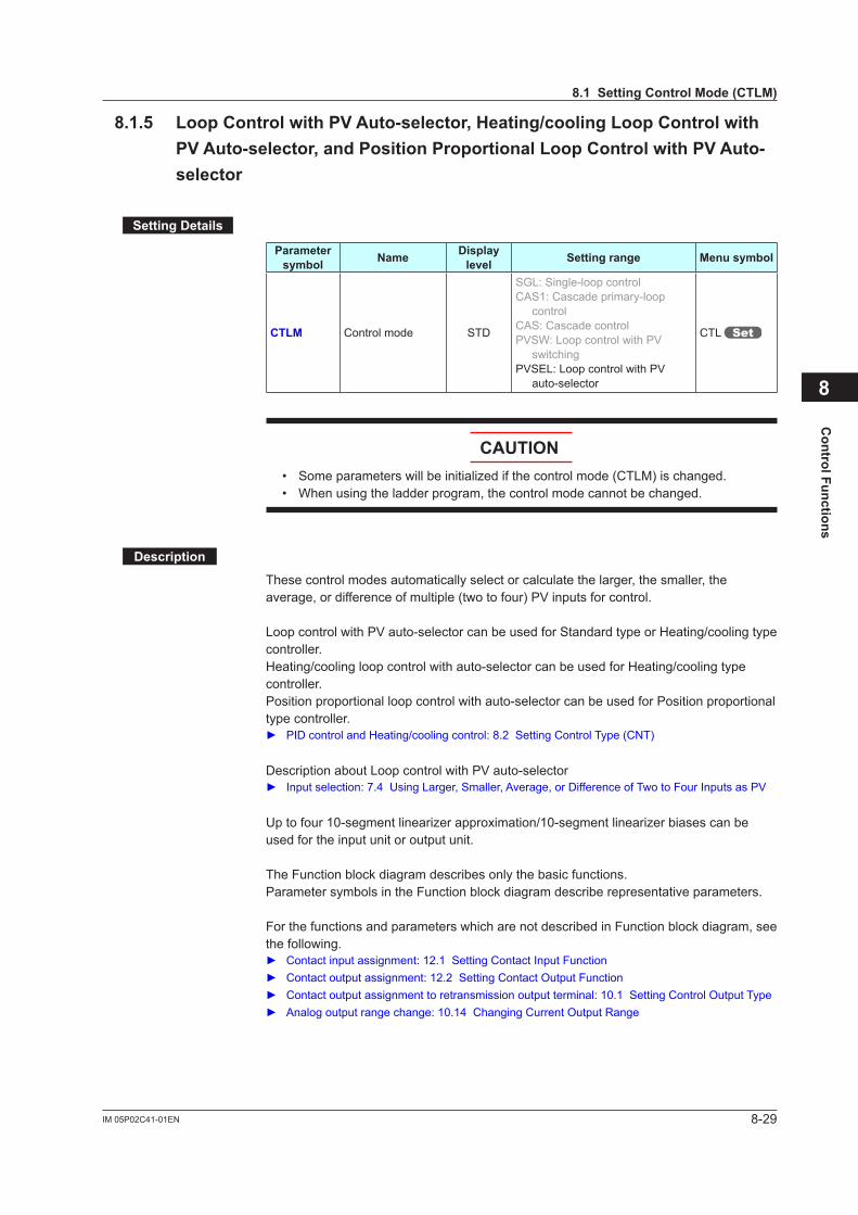
8-29IM 05P02C41-01EN
Control Functions
8.1.5 LoopControlwithPVAuto-selector,Heating/coolingLoopControlwithPVAuto-selector,andPositionProportionalLoopControlwithPVAuto-selector
SettingDetails
Parameter symbol Name Display
level Settingrange Menusymbol
CTLM Control mode STD
SGL: Single-loop controlCAS1: Cascade primary-loop
controlCAS: Cascade controlPVSW: Loop control with PV
switchingPVSEL: Loop control with PV
auto-selector
CTL
CAUTION• Someparameterswillbeinitializedifthecontrolmode(CTLM)ischanged.• When using the ladder program, the control mode cannot be changed.
Description
These control modes automatically select or calculate the larger, the smaller, the average, or difference of multiple (two to four) PV inputs for control.
Loop control with PV auto-selector can be used for Standard type or Heating/cooling type controller.Heating/cooling loop control with auto-selector can be used for Heating/cooling type controller.Position proportional loop control with auto-selector can be used for Position proportional type controller. PIDcontrolandHeating/coolingcontrol:8.2SettingControlType(CNT)
Description about Loop control with PV auto-selector Inputselection:7.4UsingLarger,Smaller,Average,orDifferenceofTwotoFourInputsasPV
Uptofour10-segmentlinearizerapproximation/10-segmentlinearizerbiasescanbeused for the input unit or output unit.
The Function block diagram describes only the basic functions.Parameter symbols in the Function block diagram describe representative parameters.
For the functions and parameters which are not described in Function block diagram, see the following. Contactinputassignment:12.1SettingContactInputFunction Contactoutputassignment:12.2SettingContactOutputFunction Contactoutputassignmenttoretransmissionoutputterminal:10.1SettingControlOutputType Analogoutputrangechange:10.14ChangingCurrentOutputRange
8
8.1SettingControlMode(CTLM)
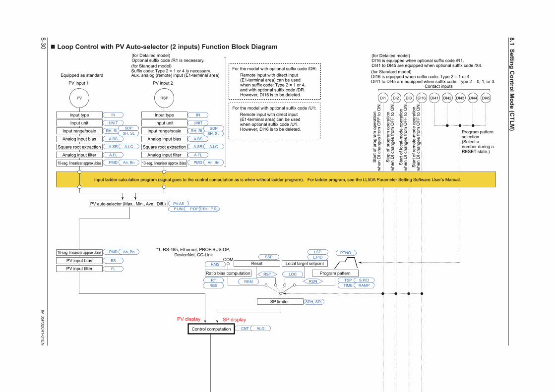
8-30IM
05P02C
41-01EN
nLoopControlwithPVAuto-selector(2inputs)FunctionBlockDiagram
COM
Output limiter
Manual operation
Manual preset output
Input error preset output
Preset output
AUTO
When sensorburnout occurs
Normal
MAN
RUNRESET
SP limiter
PV
Input type
Input unit
Input range/scale
Analog input bias
Square root extraction
Analog input filter
10-seg. linearizer approx./bias
PV input bias
PV input filterRatio bias computation
PV auto-selector (Max., Min., Ave., Diff.)
Output limiter
A.BS
A.FL
BS
FL
PMD An, Bn
10-seg. linearizer approx./bias PMD An, Bn 10-seg. linearizer approx./bias PMD An, Bn
PV.ASP.UNI P.DP P.RH, P.RL
CNT ALG
SPH, SPL
A.SR A.LC
UNIT
IN
RH, RLSDP
SH, SL
RSP
Input type
Input unit
Input range/scale
Analog input bias
Square root extraction
Analog input filter
A.BS
A.FL
A.SR A.LC
UNIT
IN
RH, RL SDPSH, SL
EPOOH, OL
OH, OL OLMT
PO
MPON
OT
Equipped as standard
For optional suffix code /HAHeater break alarm
HAL2HAL1
Heater breakalarm 1
Heater breakalarm 2 Current or
voltage pulseRelay Current
OUTOUT RET
PMD
OU.H OU.L
An, Bn
Split computation
10-seg. linearizer approx./bias
RET.H RET.L
PMD An, Bn
Split computation
10-seg. linearizer approx./bias
OUT retransmission outputO1RS RET retransmission output
RTS
Output terminal assignment
Control computation
(Current when retransmission output)
PV input 1 PV input 2
Aux. analog (remote) input (E1-terminal area)
(for Standard model)Suffix code: Type 2 = 1 or 4 is necessary.
Equipped as standard
* After the control output terminal is specified by the parameter OT, other current output terminals can be used as retransmission output.
Sensor burnout occurs when PV or RSP input burnout occurs.However, burnout is not detected if input is not conncted.
Terminal Parameter Function
Analog signal Contact signal Front panel keyLegend
PV display SP display
Input ladder calculation program (signal goes to the control computation as is when without ladder program). For ladder program, see the LL50A Parameter Setting Software User’s Manual.
RMS
*1: RS-485, Ethernet, PROFIBUS-DP, DeviceNet, CC-Link
Program pattern
Local target setpointReset
TSP S.PID
PTNO.
TIME RAMP
L.PIDLSP
REM
LOC
RUN
RSTRT
RBS
RESET/RUN switch
DI45DI44DI43DI42DI41DI3DI2DI1 DI16
Program pattern selection(Select a number during a RESET state.)
Contact inputs
(for Standard model)DI16 is equipped when suffix code: Type 2 = 1 or 4.DI41 to DI45 are equipped when suffix code: Type 2 = 0, 1, or 3.
Sta
rt of
pro
gram
ope
ratio
nw
hen
DI c
hang
es fr
om O
FF to
ON
.
Sto
p of
pro
gram
ope
ratio
nw
hen
DI c
hang
es fr
om O
FF to
ON
.
Sta
rt of
loca
l-mod
e op
erat
ion
whe
n D
I cha
nges
from
OFF
to O
N.
Sta
rt of
rem
ote-
mod
e op
erat
ion
whe
n D
I cha
nges
from
OFF
to O
N.
For the model with optional suffix code /DR:Remote input with direct input (E1-terminal area) can be used when suffix code: Type 2 = 1 or 4, and with optional suffix code /DR.However, DI16 is to be deleted.
RSTREM
A/M
LOCRUN
AL3AL2AL1
PV
eve
nt 1
PV
eve
nt 2
PV
eve
nt 3
Tim
e ev
ent 1
Tim
e ev
ent 2
Tim
e ev
ent 3
Tim
e ev
ent 4
DO23DO22DO21 DO24
Tim
e ev
ent 5
DO25
PV event, Time event, Alarm
Output ladder calculation program (signal goes to the output as is when without ladder program). For ladder program, see the LL50A Parameter Setting Software User’s Manual.
DO31 to DO35 are assinged Time event 6 to 10.
(for Detailed model)Optional suffix code /R1 is necessary.
(for Detailed model)DI16 is equipped when optional suffix code /R1.DI41 to DI45 are equipped when optional suffix code /X4.
For the model with optional suffix code /U1:Remote input with direct input (E1-terminal area) can be used when optional suffix code /U1.However, DI16 is to be deleted.
LPS
24 V looppower supply
For optional suffix code /L4 or /LC4
SSP
8.1SettingControlM
ode(CTLM
)
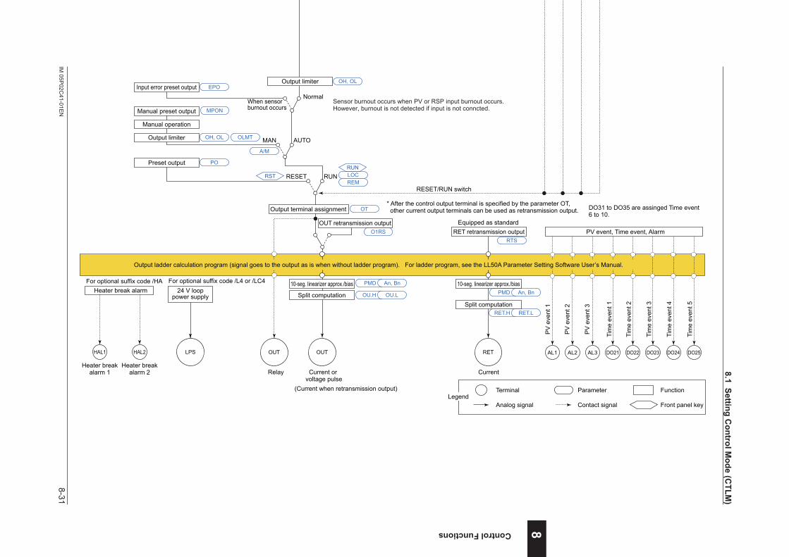
8-31IM
05P02C
41-01EN
Control Functions
nLoopControlwithPVAuto-selector(2inputs)FunctionBlockDiagram
COM
Output limiter
Manual operation
Manual preset output
Input error preset output
Preset output
AUTO
When sensorburnout occurs
Normal
MAN
RUNRESET
SP limiter
PV
Input type
Input unit
Input range/scale
Analog input bias
Square root extraction
Analog input filter
10-seg. linearizer approx./bias
PV input bias
PV input filterRatio bias computation
PV auto-selector (Max., Min., Ave., Diff.)
Output limiter
A.BS
A.FL
BS
FL
PMD An, Bn
10-seg. linearizer approx./bias PMD An, Bn 10-seg. linearizer approx./bias PMD An, Bn
PV.ASP.UNI P.DP P.RH, P.RL
CNT ALG
SPH, SPL
A.SR A.LC
UNIT
IN
RH, RLSDP
SH, SL
RSP
Input type
Input unit
Input range/scale
Analog input bias
Square root extraction
Analog input filter
A.BS
A.FL
A.SR A.LC
UNIT
IN
RH, RL SDPSH, SL
EPOOH, OL
OH, OL OLMT
PO
MPON
OT
Equipped as standard
For optional suffix code /HAHeater break alarm
HAL2HAL1
Heater breakalarm 1
Heater breakalarm 2 Current or
voltage pulseRelay Current
OUTOUT RET
PMD
OU.H OU.L
An, Bn
Split computation
10-seg. linearizer approx./bias
RET.H RET.L
PMD An, Bn
Split computation
10-seg. linearizer approx./bias
OUT retransmission outputO1RS RET retransmission output
RTS
Output terminal assignment
Control computation
(Current when retransmission output)
PV input 1 PV input 2
Aux. analog (remote) input (E1-terminal area)
(for Standard model)Suffix code: Type 2 = 1 or 4 is necessary.
Equipped as standard
* After the control output terminal is specified by the parameter OT, other current output terminals can be used as retransmission output.
Sensor burnout occurs when PV or RSP input burnout occurs.However, burnout is not detected if input is not conncted.
Terminal Parameter Function
Analog signal Contact signal Front panel keyLegend
PV display SP display
Input ladder calculation program (signal goes to the control computation as is when without ladder program). For ladder program, see the LL50A Parameter Setting Software User’s Manual.
RMS
*1: RS-485, Ethernet, PROFIBUS-DP, DeviceNet, CC-Link
Program pattern
Local target setpointReset
TSP S.PID
PTNO.
TIME RAMP
L.PIDLSP
REM
LOC
RUN
RSTRT
RBS
RESET/RUN switch
DI45DI44DI43DI42DI41DI3DI2DI1 DI16
Program pattern selection(Select a number during a RESET state.)
Contact inputs
(for Standard model)DI16 is equipped when suffix code: Type 2 = 1 or 4.DI41 to DI45 are equipped when suffix code: Type 2 = 0, 1, or 3.
Sta
rt of
pro
gram
ope
ratio
nw
hen
DI c
hang
es fr
om O
FF to
ON
.
Sto
p of
pro
gram
ope
ratio
nw
hen
DI c
hang
es fr
om O
FF to
ON
.
Sta
rt of
loca
l-mod
e op
erat
ion
whe
n D
I cha
nges
from
OFF
to O
N.
Sta
rt of
rem
ote-
mod
e op
erat
ion
whe
n D
I cha
nges
from
OFF
to O
N.
For the model with optional suffix code /DR:Remote input with direct input (E1-terminal area) can be used when suffix code: Type 2 = 1 or 4, and with optional suffix code /DR.However, DI16 is to be deleted.
RSTREM
A/M
LOCRUN
AL3AL2AL1
PV
eve
nt 1
PV
eve
nt 2
PV
eve
nt 3
Tim
e ev
ent 1
Tim
e ev
ent 2
Tim
e ev
ent 3
Tim
e ev
ent 4
DO23DO22DO21 DO24
Tim
e ev
ent 5
DO25
PV event, Time event, Alarm
Output ladder calculation program (signal goes to the output as is when without ladder program). For ladder program, see the LL50A Parameter Setting Software User’s Manual.
DO31 to DO35 are assinged Time event 6 to 10.
(for Detailed model)Optional suffix code /R1 is necessary.
(for Detailed model)DI16 is equipped when optional suffix code /R1.DI41 to DI45 are equipped when optional suffix code /X4.
For the model with optional suffix code /U1:Remote input with direct input (E1-terminal area) can be used when optional suffix code /U1.However, DI16 is to be deleted.
LPS
24 V looppower supply
For optional suffix code /L4 or /LC4
SSP
8
8.1SettingControlM
ode(CTLM
)
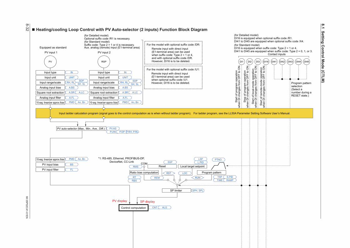
8-32IM
05P02C
41-01EN
nHeating/coolingLoopControlwithPVAuto-selector(2inputs)FunctionBlockDiagram
COM
SP limiter
PV
Input type
Input unit
Input range/scale
Analog input bias
Square root extraction
Analog input filter
10-seg. linearizer approx./bias
PV input bias
PV input filterRatio bias computation
PV auto-selector (Max., Min., Ave., Diff.)
A.BS
A.FL
BS
FL
PMD An, Bn
10-seg. linearizer approx./bias PMD An, Bn 10-seg. linearizer approx./bias PMD An, Bn
PV.ASP.UNI P.DP P.RH, P.RL
CNT ALG
SPH, SPL
A.SR A.LC
UNIT
IN
RH, RLSDP
SH, SL
RSP
Input type
Input unit
Input range/scale
Analog input bias
Square root extraction
Analog input filter
A.BS
A.FL
A.SR A.LC
UNIT
IN
RH, RL SDPSH, SL
Control computation
Manual operation
Manual preset output
Input error preset output
Heating-side preset output
AUTO
When sensorburnout occurs
Normal Normal
MAN
RUNRESET
EPOOH, OL OHc, OLc
Error preset output
When sensorburnout occurs
EPO
POCooling-side preset output
RESET
MPON
Heating/cooling computation
Heating-side output limiter Cooling-side output limiter
RUN
Relay Relay Current
OUT retransmission output OUT2 retransmission output
OT
O1RS O2RS RET retransmission outputRTS
Heating-sideoutput
Heating-sideoutput
OUTOUT
Cooling-sideoutput
Cooling-sideoutput
OUT2 OUT2 RET
Output terminal assignment
PMD
OU.H OU.L OU2.H OU2.L
An, Bn PMD An, Bn
Split computation
10-seg. linearizer approx./bias
Split computation
10-seg. linearizer approx./bias
RET.H RET.L
PMD An, Bn
Split computation
10-seg. linearizer approx./bias
Equipped as standard
PV input 1 PV input 2
Aux. analog (remote) input (E1-terminal area)
(for Standard model)Suffix code: Type 2 = 1 or 4 is necessary.
Equipped as standard
Terminal Parameter Function
Analog signal Contact signal Front panel keyLegend
* After the control output terminal is specified by the parameter OT, other current output terminals can be used as retransmission output.
Current or voltage pulse
(Current when retransmission output)
Current or voltage pulse
(Current when retransmission output)
Sensor burnout occurs when PV or RSPinput burnout occurs.However, burnout is not detected if inputis not conncted.
PV display SP display
Input ladder calculation program (signal goes to the control computation as is when without ladder program). For ladder program, see the LL50A Parameter Setting Software User’s Manual.
Manual output is prioritized even if sensor burnout occurs in MAN.
RMS
*1: RS-485, Ethernet, PROFIBUS-DP, DeviceNet, CC-Link
For the model with optional suffix code /DR:Remote input with direct input (E1-terminal area) can be used when suffix code: Type 2 = 1 or 4, and with optional suffix code /DR.However, DI16 is to be deleted.
Program pattern
Local target setpointReset
TSP S.PID
PTNO.
TIME RAMP
L.PIDLSP
REM
LOC
RUN
RST
RESET/RUN switchRESET/RUN switch
DI45DI44DI43DI42DI41DI3DI2DI1 DI16
Program pattern selection(Select a number during a RESET state.)
Contact inputs
(for Standard model)DI16 is equipped when suffix code: Type 2 = 1 or 4.DI41 to DI45 are equipped when suffix code: Type 2 = 0, 1, or 3.
Sta
rt of
pro
gram
ope
ratio
nw
hen
DI c
hang
es fr
om O
FF to
ON
.
Sto
p of
pro
gram
ope
ratio
nw
hen
DI c
hang
es fr
om O
FF to
ON
.
Sta
rt of
loca
l-mod
e op
erat
ion
whe
n D
I cha
nges
from
OFF
to O
N.
Sta
rt of
rem
ote-
mod
e op
erat
ion
whe
n D
I cha
nges
from
OFF
to O
N.
RST
RSTREM
A/M
LOCRUN
REMLOCRUN
AL3AL2AL1
PV
eve
nt 1
PV
eve
nt 2
PV
eve
nt 3
Tim
e ev
ent 1
Tim
e ev
ent 2
Tim
e ev
ent 3
Tim
e ev
ent 4
DO23DO22DO21 DO24
Tim
e ev
ent 5
DO25
PV event, Time event, Alarm
Output ladder calculation program (signal goes to the output as is when without ladder program). For ladder program, see the LL50A Parameter Setting Software User’s Manual.
RTRBS
DO31 to DO35 are assinged Time event 6 to 10.
(for Detailed model)Optional suffix code /R1 is necessary.
(for Detailed model)DI16 is equipped when optional suffix code /R1.DI41 to DI45 are equipped when optional suffix code /X4.
For the model with optional suffix code /U1:Remote input with direct input (E1-terminal area) can be used when optional suffix code /U1.However, DI16 is to be deleted.
LPS
24 V looppower supply
For optional suffix code /L4 or /LC4
SSP
8.1SettingControlM
ode(CTLM
)
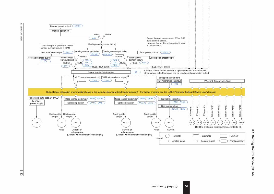
8-33IM
05P02C
41-01EN
Control Functions
nHeating/coolingLoopControlwithPVAuto-selector(2inputs)FunctionBlockDiagram
COM
SP limiter
PV
Input type
Input unit
Input range/scale
Analog input bias
Square root extraction
Analog input filter
10-seg. linearizer approx./bias
PV input bias
PV input filterRatio bias computation
PV auto-selector (Max., Min., Ave., Diff.)
A.BS
A.FL
BS
FL
PMD An, Bn
10-seg. linearizer approx./bias PMD An, Bn 10-seg. linearizer approx./bias PMD An, Bn
PV.ASP.UNI P.DP P.RH, P.RL
CNT ALG
SPH, SPL
A.SR A.LC
UNIT
IN
RH, RLSDP
SH, SL
RSP
Input type
Input unit
Input range/scale
Analog input bias
Square root extraction
Analog input filter
A.BS
A.FL
A.SR A.LC
UNIT
IN
RH, RL SDPSH, SL
Control computation
Manual operation
Manual preset output
Input error preset output
Heating-side preset output
AUTO
When sensorburnout occurs
Normal Normal
MAN
RUNRESET
EPOOH, OL OHc, OLc
Error preset output
When sensorburnout occurs
EPO
POCooling-side preset output
RESET
MPON
Heating/cooling computation
Heating-side output limiter Cooling-side output limiter
RUN
Relay Relay Current
OUT retransmission output OUT2 retransmission output
OT
O1RS O2RS RET retransmission outputRTS
Heating-sideoutput
Heating-sideoutput
OUTOUT
Cooling-sideoutput
Cooling-sideoutput
OUT2 OUT2 RET
Output terminal assignment
PMD
OU.H OU.L OU2.H OU2.L
An, Bn PMD An, Bn
Split computation
10-seg. linearizer approx./bias
Split computation
10-seg. linearizer approx./bias
RET.H RET.L
PMD An, Bn
Split computation
10-seg. linearizer approx./bias
Equipped as standard
PV input 1 PV input 2
Aux. analog (remote) input (E1-terminal area)
(for Standard model)Suffix code: Type 2 = 1 or 4 is necessary.
Equipped as standard
Terminal Parameter Function
Analog signal Contact signal Front panel keyLegend
* After the control output terminal is specified by the parameter OT, other current output terminals can be used as retransmission output.
Current or voltage pulse
(Current when retransmission output)
Current or voltage pulse
(Current when retransmission output)
Sensor burnout occurs when PV or RSPinput burnout occurs.However, burnout is not detected if inputis not conncted.
PV display SP display
Input ladder calculation program (signal goes to the control computation as is when without ladder program). For ladder program, see the LL50A Parameter Setting Software User’s Manual.
Manual output is prioritized even if sensor burnout occurs in MAN.
RMS
*1: RS-485, Ethernet, PROFIBUS-DP, DeviceNet, CC-Link
For the model with optional suffix code /DR:Remote input with direct input (E1-terminal area) can be used when suffix code: Type 2 = 1 or 4, and with optional suffix code /DR.However, DI16 is to be deleted.
Program pattern
Local target setpointReset
TSP S.PID
PTNO.
TIME RAMP
L.PIDLSP
REM
LOC
RUN
RST
RESET/RUN switchRESET/RUN switch
DI45DI44DI43DI42DI41DI3DI2DI1 DI16
Program pattern selection(Select a number during a RESET state.)
Contact inputs
(for Standard model)DI16 is equipped when suffix code: Type 2 = 1 or 4.DI41 to DI45 are equipped when suffix code: Type 2 = 0, 1, or 3.
Sta
rt of
pro
gram
ope
ratio
nw
hen
DI c
hang
es fr
om O
FF to
ON
.
Sto
p of
pro
gram
ope
ratio
nw
hen
DI c
hang
es fr
om O
FF to
ON
.
Sta
rt of
loca
l-mod
e op
erat
ion
whe
n D
I cha
nges
from
OFF
to O
N.
Sta
rt of
rem
ote-
mod
e op
erat
ion
whe
n D
I cha
nges
from
OFF
to O
N.
RST
RSTREM
A/M
LOCRUN
REMLOCRUN
AL3AL2AL1
PV
eve
nt 1
PV
eve
nt 2
PV
eve
nt 3
Tim
e ev
ent 1
Tim
e ev
ent 2
Tim
e ev
ent 3
Tim
e ev
ent 4
DO23DO22DO21 DO24
Tim
e ev
ent 5
DO25
PV event, Time event, Alarm
Output ladder calculation program (signal goes to the output as is when without ladder program). For ladder program, see the LL50A Parameter Setting Software User’s Manual.
RTRBS
DO31 to DO35 are assinged Time event 6 to 10.
(for Detailed model)Optional suffix code /R1 is necessary.
(for Detailed model)DI16 is equipped when optional suffix code /R1.DI41 to DI45 are equipped when optional suffix code /X4.
For the model with optional suffix code /U1:Remote input with direct input (E1-terminal area) can be used when optional suffix code /U1.However, DI16 is to be deleted.
LPS
24 V looppower supply
For optional suffix code /L4 or /LC4
SSP
8
8.1SettingControlM
ode(CTLM
)

8-34IM
05P02C
41-01EN
nPositionProportionalLoopControlwithPVAuto-selector(2inputs)FunctionBlockDiagram
COM
SP limiter
PV
Input type
Input unit
Input range/scale
Analog input bias
Square root extraction
Analog input filter
10-seg. linearizer approx./bias
PV input bias
PV input filterRatio bias computation
PV auto-selector (Max., Min., Ave., Diff.)
A.BS
A.FL
BS
FL
PMD An, Bn
10-seg. linearizer approx./bias PMD An, Bn 10-seg. linearizer approx./bias PMD An, Bn
PV.ASP.UNI P.DP P.RH, P.RL
CNT ALG
SPH, SPL
A.SR A.LC
UNIT
IN
RH, RLDP
SH, SL
RSP
Input type
Input unit
Input range/scale
Analog input bias
Square root extraction
Analog input filter
A.BS
A.FL
A.SR A.LC
UNIT
IN
RH, RL DPSH, SL
Control computation
Manual operation
Input error preset output
Preset output
AUTO
When sensorburnout occurs
Normal
MAN
RUNRESET
Output limiter
EPO
OH, OL
PO
Signal comparison
Feedback input Direct/reverse signal
Valve position slidingresistor or current
Motor-operated valve
Relay output
VALVFBIN
M
Equipped as standard Equipped as standard
Current Current
OUT RET
PMD
OU.H
HYSDB An, Bn
Split computation
10-seg. linearizer approx./bias
RET.H RET.L
PMD An, Bn
Split computation
10-seg. linearizer approx./bias
OUT retransmission outputO1RS
RET retransmission outputRTS
PV input 1 PV input 2
Aux. analog (remote) input (E1-terminal area)
(for Standard model)Suffix code: Type 2 = 1 or 4 is necessary.
Equipped as standard
In Estimating-type position proportional control, the limiter function does not work on output operation. The reverse-signal relay turns on when being limited by low limit.The direct-signal relay turns on when being limited by high limit.
Sensor burnout occurs when PV or RSP input burnout occurs.However, burnout is not detected if input is not conncted.
In Manual operation, the relay turns on while the or key is pressed. Output limiter does not work.
H relay( key)
L relay( key)
Terminal Parameter Function
Analog signal Contact signal Front panel keyLegend
PV display SP display
Input ladder calculation program (signal goes to the control computation as is when without ladder program). For ladder program, see the LL50A Parameter Setting Software User’s Manual.
Position Proportional Computation Output cannot be calculated by ladder program.
RMS
*1: RS-485, Ethernet, PROFIBUS-DP, DeviceNet, CC-Link
For the model with optional suffix code /DR:Remote input with direct input (E1-terminal area) can be used when suffix code: Type 2 = 1 or 4, and with optional suffix code /DR.However, DI16 is to be deleted.
Program pattern
Local target setpointReset
TSP S.PID
PTNO.
TIME RAMP
L.PIDLSP
REM
LOC
RUN
RST
RESET/RUN switch
DI45DI44DI43DI42DI41DI3DI2DI1 DI16
Program pattern selection(Select a number during a RESET state.)
Contact inputs
(for Standard model)DI16 is equipped when suffix code: Type 2 = 1 or 4.DI41 to DI45 are equipped when suffix code: Type 2 = 0, 1, or 3.
Sta
rt of
pro
gram
ope
ratio
nw
hen
DI c
hang
es fr
om O
FF to
ON
.
Sto
p of
pro
gram
ope
ratio
nw
hen
DI c
hang
es fr
om O
FF to
ON
.
Sta
rt of
loca
l-mod
e op
erat
ion
whe
n D
I cha
nges
from
OFF
to O
N.
Sta
rt of
rem
ote-
mod
e op
erat
ion
whe
n D
I cha
nges
from
OFF
to O
N.
RSTREM
A/M
LOCRUN
AL3AL2AL1
PV
eve
nt 1
PV
eve
nt 2
PV
eve
nt 3
Tim
e ev
ent 1
Tim
e ev
ent 2
Tim
e ev
ent 3
Tim
e ev
ent 4
DO23DO22DO21 DO24
Tim
e ev
ent 5
DO25
PV event, Time event, Alarm
Output ladder calculation program (signal goes to the output as is when without ladder program). For ladder program, see the LL50A Parameter Setting Software User’s Manual.
RTRBS
DO31 to DO35 are assinged Time event 6 to 10.
(for Detailed model)Optional suffix code /R1 is necessary.
(for Detailed model)DI16 is equipped when optional suffix code /R1.DI41 to DI45 are equipped when optional suffix code /X4.
For the model with optional suffix code /U1:Remote input with direct input (E1-terminal area) can be used when optional suffix code /U1.However, DI16 is to be deleted.
LPS
24 V looppower supply
For optional suffix code /L4 or /LC4
SSP
8.1SettingControlM
ode(CTLM
)
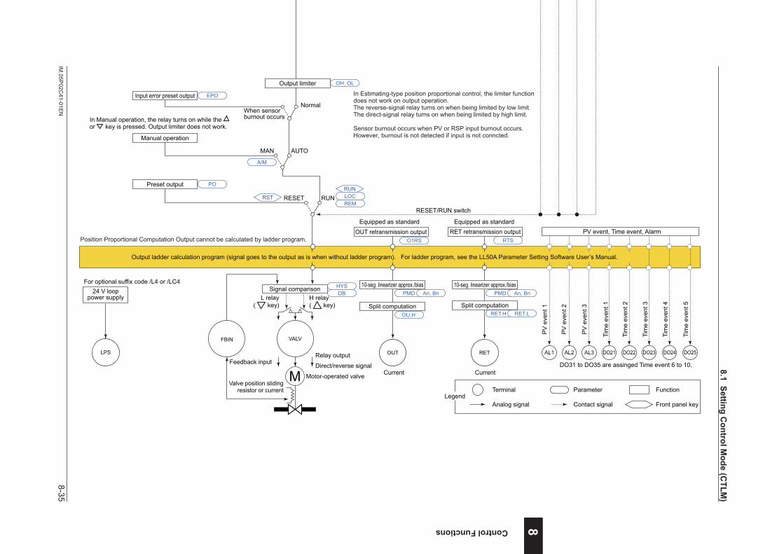
8-35IM
05P02C
41-01EN
Control Functions
nPositionProportionalLoopControlwithPVAuto-selector(2inputs)FunctionBlockDiagram
COM
SP limiter
PV
Input type
Input unit
Input range/scale
Analog input bias
Square root extraction
Analog input filter
10-seg. linearizer approx./bias
PV input bias
PV input filterRatio bias computation
PV auto-selector (Max., Min., Ave., Diff.)
A.BS
A.FL
BS
FL
PMD An, Bn
10-seg. linearizer approx./bias PMD An, Bn 10-seg. linearizer approx./bias PMD An, Bn
PV.ASP.UNI P.DP P.RH, P.RL
CNT ALG
SPH, SPL
A.SR A.LC
UNIT
IN
RH, RLDP
SH, SL
RSP
Input type
Input unit
Input range/scale
Analog input bias
Square root extraction
Analog input filter
A.BS
A.FL
A.SR A.LC
UNIT
IN
RH, RL DPSH, SL
Control computation
Manual operation
Input error preset output
Preset output
AUTO
When sensorburnout occurs
Normal
MAN
RUNRESET
Output limiter
EPO
OH, OL
PO
Signal comparison
Feedback input Direct/reverse signal
Valve position slidingresistor or current
Motor-operated valve
Relay output
VALVFBIN
M
Equipped as standard Equipped as standard
Current Current
OUT RET
PMD
OU.H
HYSDB An, Bn
Split computation
10-seg. linearizer approx./bias
RET.H RET.L
PMD An, Bn
Split computation
10-seg. linearizer approx./bias
OUT retransmission outputO1RS
RET retransmission outputRTS
PV input 1 PV input 2
Aux. analog (remote) input (E1-terminal area)
(for Standard model)Suffix code: Type 2 = 1 or 4 is necessary.
Equipped as standard
In Estimating-type position proportional control, the limiter function does not work on output operation. The reverse-signal relay turns on when being limited by low limit.The direct-signal relay turns on when being limited by high limit.
Sensor burnout occurs when PV or RSP input burnout occurs.However, burnout is not detected if input is not conncted.
In Manual operation, the relay turns on while the or key is pressed. Output limiter does not work.
H relay( key)
L relay( key)
Terminal Parameter Function
Analog signal Contact signal Front panel keyLegend
PV display SP display
Input ladder calculation program (signal goes to the control computation as is when without ladder program). For ladder program, see the LL50A Parameter Setting Software User’s Manual.
Position Proportional Computation Output cannot be calculated by ladder program.
RMS
*1: RS-485, Ethernet, PROFIBUS-DP, DeviceNet, CC-Link
For the model with optional suffix code /DR:Remote input with direct input (E1-terminal area) can be used when suffix code: Type 2 = 1 or 4, and with optional suffix code /DR.However, DI16 is to be deleted.
Program pattern
Local target setpointReset
TSP S.PID
PTNO.
TIME RAMP
L.PIDLSP
REM
LOC
RUN
RST
RESET/RUN switch
DI45DI44DI43DI42DI41DI3DI2DI1 DI16
Program pattern selection(Select a number during a RESET state.)
Contact inputs
(for Standard model)DI16 is equipped when suffix code: Type 2 = 1 or 4.DI41 to DI45 are equipped when suffix code: Type 2 = 0, 1, or 3.
Sta
rt of
pro
gram
ope
ratio
nw
hen
DI c
hang
es fr
om O
FF to
ON
.
Sto
p of
pro
gram
ope
ratio
nw
hen
DI c
hang
es fr
om O
FF to
ON
.
Sta
rt of
loca
l-mod
e op
erat
ion
whe
n D
I cha
nges
from
OFF
to O
N.
Sta
rt of
rem
ote-
mod
e op
erat
ion
whe
n D
I cha
nges
from
OFF
to O
N.
RSTREM
A/M
LOCRUN
AL3AL2AL1
PV
eve
nt 1
PV
eve
nt 2
PV
eve
nt 3
Tim
e ev
ent 1
Tim
e ev
ent 2
Tim
e ev
ent 3
Tim
e ev
ent 4
DO23DO22DO21 DO24
Tim
e ev
ent 5
DO25
PV event, Time event, Alarm
Output ladder calculation program (signal goes to the output as is when without ladder program). For ladder program, see the LL50A Parameter Setting Software User’s Manual.
RTRBS
DO31 to DO35 are assinged Time event 6 to 10.
(for Detailed model)Optional suffix code /R1 is necessary.
(for Detailed model)DI16 is equipped when optional suffix code /R1.DI41 to DI45 are equipped when optional suffix code /X4.
For the model with optional suffix code /U1:Remote input with direct input (E1-terminal area) can be used when optional suffix code /U1.However, DI16 is to be deleted.
LPS
24 V looppower supply
For optional suffix code /L4 or /LC4
SSP
8
8.1SettingControlM
ode(CTLM
)
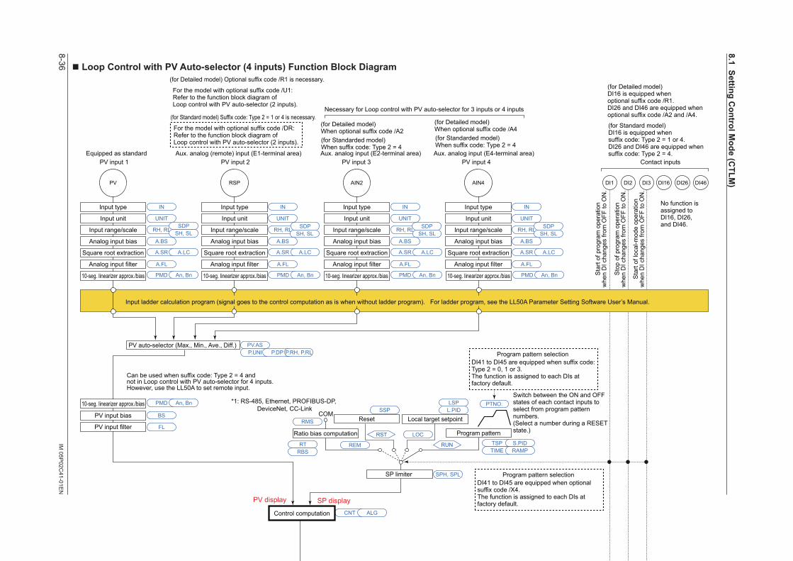
8-36IM
05P02C
41-01EN
nLoopControlwithPVAuto-selector(4inputs)FunctionBlockDiagram
COM
Output limiter
Manual operation
Manual preset output
Error preset output
Preset output
AUTO
When sensorburnout occurs
Normal
MAN
RUNRESET
SP limiter
DI26 DI46PV AIN2
Input type
Input unit
Input range/scale
Analog input bias
Square root extraction
Analog input filter
Input type
Input unit
Input range/scale
Analog input bias
Square root extraction
Analog input filter
10-seg. linearizer approx./bias
PV input bias
PV input filterRatio bias computation
PV auto-selector (Max., Min., Ave., Diff.)
Output limiter
A.BS
A.FL
BS
FL
PMD An, Bn
10-seg. linearizer approx./bias PMD An, Bn 10-seg. linearizer approx./bias PMD An, Bn 10-seg. linearizer approx./bias PMD An, Bn 10-seg. linearizer approx./bias PMD An, Bn
PV.ASP.UNI P.DP P.RH, P.RL
CNT ALG
SPH, SPL
A.SR A.LC
UNIT
IN
RH, RLSDP
SH, SLA.BS
A.FL
A.SR A.LC
UNIT
IN
RH, RL SDPSH, SL
RSP
Input type
Input unit
Input range/scale
Analog input bias
Square root extraction
Analog input filter
A.BS
A.FL
A.SR A.LC
UNIT
IN
RH, RL SDPSH, SL
AIN4
Input type
Input unit
Input range/scale
Analog input bias
Square root extraction
Analog input filter
A.BS
A.FL
A.SR A.LC
UNIT
IN
RH, RL SDPSH, SL
EPOOH, OL
OH, OL OLMT
PO
MPON
OT
Equipped as standard
For optional suffix code /HAHeater break alarm
HAL2HAL1
Heater breakalarm 1
Heater breakalarm 2 Current or
voltage pulseRelay Current
OUTOUT RET
PMD
OU.H OU.L
An, Bn
Split computation
10-seg. linearizer approx./bias
RET.H RET.L
PMD An, Bn
Split computation
10-seg. linearizer approx./bias
OUT retransmission outputO1RS RET retransmission output
RTS
Output terminal assignment
DI16DI2 DI3DI1
Control computation
(Current when retransmission output)
No function is assigned to DI16, DI26, and DI46.
PV input 1 PV input 2 PV input 3 PV input 4 Contact inputs
(for Standard model) Suffix code: Type 2 = 1 or 4 is necessary.
(for Standarded model)When suffix code: Type 2 = 4
(for Standarded model)When suffix code: Type 2 = 4
Aux. analog (remote) input (E1-terminal area) Aux. analog input (E2-terminal area) Aux. analog input (E4-terminal area)Equipped as standard
Necessary for Loop control with PV auto-selector for 3 inputs or 4 inputs
For the model with optional suffix code /DR:Refer to the function block diagram ofLoop control with PV auto-selector (2 inputs).
(for Standard model)DI16 is equipped whensuffix code: Type 2 = 1 or 4.DI26 and DI46 are equipped whensuffix code: Type 2 = 4.
Can be used when suffix code: Type 2 = 4 andnot in Loop control with PV auto-selector for 4 inputs.However, use the LL50A to set remote input.
Sensor burnout occurs when PV, RSP, AIN2, or AIN4 input burnout occurs.However, burnout is not detected if input is not conncted.
* After the control output terminal is specified by the parameter OT, other current output terminals can be used as retransmission output.
Terminal Parameter Function
Analog signal Contact signal Front panel keyLegend
PV display SP display
Input ladder calculation program (signal goes to the control computation as is when without ladder program). For ladder program, see the LL50A Parameter Setting Software User’s Manual.
RMS
*1: RS-485, Ethernet, PROFIBUS-DP, DeviceNet, CC-Link
Program pattern
Local target setpointReset
TSP S.PID
PTNO.
TIME RAMP
L.PIDLSP
REM
LOC
RUN
RST
Program pattern selection
Switch between the ON and OFF states of each contact inputs to select from program pattern numbers.(Select a number during a RESET state.)
DI41 to DI45 are equipped when suffix code: Type 2 = 0, 1 or 3.The function is assigned to each DIs at factory default.
RESET/RUN switch
RSTREM
A/M
LOCRUN
AL3AL2AL1
PV
eve
nt 1
PV
eve
nt 2
PV
eve
nt 3
PV event
Output ladder calculation program (signal goes to the output as is when without ladder program). For ladder program, see the LL50A Parameter Setting Software User’s Manual.
RTRBS
Sta
rt of
pro
gram
ope
ratio
nw
hen
DI c
hang
es fr
om O
FF to
ON
.
Sto
p of
pro
gram
ope
ratio
nw
hen
DI c
hang
es fr
om O
FF to
ON
.
Sta
rt of
loca
l-mod
e op
erat
ion
whe
n D
I cha
nges
from
OFF
to O
N.
(for Detailed model) Optional suffix code /R1 is necessary.
(for Detailed model)When optional suffix code /A2
(for Detailed model)When optional suffix code /A4
For the model with optional suffix code /U1:Refer to the function block diagram ofLoop control with PV auto-selector (2 inputs).
(for Detailed model)DI16 is equipped whenoptional suffix code /R1.DI26 and DI46 are equipped whenoptional suffix code /A2 and /A4.
Program pattern selectionDI41 to DI45 are equipped when optional suffix code /X4.The function is assigned to each DIs at factory default.
LPS
24 V looppower supply
For optional suffix code /L4 or /LC4
SSP
8.1SettingControlM
ode(CTLM
)
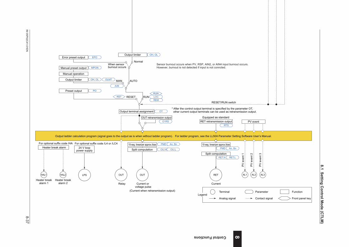
8-37IM
05P02C
41-01EN
Control Functions
nLoopControlwithPVAuto-selector(4inputs)FunctionBlockDiagram
COM
Output limiter
Manual operation
Manual preset output
Error preset output
Preset output
AUTO
When sensorburnout occurs
Normal
MAN
RUNRESET
SP limiter
DI26 DI46PV AIN2
Input type
Input unit
Input range/scale
Analog input bias
Square root extraction
Analog input filter
Input type
Input unit
Input range/scale
Analog input bias
Square root extraction
Analog input filter
10-seg. linearizer approx./bias
PV input bias
PV input filterRatio bias computation
PV auto-selector (Max., Min., Ave., Diff.)
Output limiter
A.BS
A.FL
BS
FL
PMD An, Bn
10-seg. linearizer approx./bias PMD An, Bn 10-seg. linearizer approx./bias PMD An, Bn 10-seg. linearizer approx./bias PMD An, Bn 10-seg. linearizer approx./bias PMD An, Bn
PV.ASP.UNI P.DP P.RH, P.RL
CNT ALG
SPH, SPL
A.SR A.LC
UNIT
IN
RH, RLSDP
SH, SLA.BS
A.FL
A.SR A.LC
UNIT
IN
RH, RL SDPSH, SL
RSP
Input type
Input unit
Input range/scale
Analog input bias
Square root extraction
Analog input filter
A.BS
A.FL
A.SR A.LC
UNIT
IN
RH, RL SDPSH, SL
AIN4
Input type
Input unit
Input range/scale
Analog input bias
Square root extraction
Analog input filter
A.BS
A.FL
A.SR A.LC
UNIT
IN
RH, RL SDPSH, SL
EPOOH, OL
OH, OL OLMT
PO
MPON
OT
Equipped as standard
For optional suffix code /HAHeater break alarm
HAL2HAL1
Heater breakalarm 1
Heater breakalarm 2 Current or
voltage pulseRelay Current
OUTOUT RET
PMD
OU.H OU.L
An, Bn
Split computation
10-seg. linearizer approx./bias
RET.H RET.L
PMD An, Bn
Split computation
10-seg. linearizer approx./bias
OUT retransmission outputO1RS RET retransmission output
RTS
Output terminal assignment
DI16DI2 DI3DI1
Control computation
(Current when retransmission output)
No function is assigned to DI16, DI26, and DI46.
PV input 1 PV input 2 PV input 3 PV input 4 Contact inputs
(for Standard model) Suffix code: Type 2 = 1 or 4 is necessary.
(for Standarded model)When suffix code: Type 2 = 4
(for Standarded model)When suffix code: Type 2 = 4
Aux. analog (remote) input (E1-terminal area) Aux. analog input (E2-terminal area) Aux. analog input (E4-terminal area)Equipped as standard
Necessary for Loop control with PV auto-selector for 3 inputs or 4 inputs
For the model with optional suffix code /DR:Refer to the function block diagram ofLoop control with PV auto-selector (2 inputs).
(for Standard model)DI16 is equipped whensuffix code: Type 2 = 1 or 4.DI26 and DI46 are equipped whensuffix code: Type 2 = 4.
Can be used when suffix code: Type 2 = 4 andnot in Loop control with PV auto-selector for 4 inputs.However, use the LL50A to set remote input.
Sensor burnout occurs when PV, RSP, AIN2, or AIN4 input burnout occurs.However, burnout is not detected if input is not conncted.
* After the control output terminal is specified by the parameter OT, other current output terminals can be used as retransmission output.
Terminal Parameter Function
Analog signal Contact signal Front panel keyLegend
PV display SP display
Input ladder calculation program (signal goes to the control computation as is when without ladder program). For ladder program, see the LL50A Parameter Setting Software User’s Manual.
RMS
*1: RS-485, Ethernet, PROFIBUS-DP, DeviceNet, CC-Link
Program pattern
Local target setpointReset
TSP S.PID
PTNO.
TIME RAMP
L.PIDLSP
REM
LOC
RUN
RST
Program pattern selection
Switch between the ON and OFF states of each contact inputs to select from program pattern numbers.(Select a number during a RESET state.)
DI41 to DI45 are equipped when suffix code: Type 2 = 0, 1 or 3.The function is assigned to each DIs at factory default.
RESET/RUN switch
RSTREM
A/M
LOCRUN
AL3AL2AL1
PV
eve
nt 1
PV
eve
nt 2
PV
eve
nt 3
PV event
Output ladder calculation program (signal goes to the output as is when without ladder program). For ladder program, see the LL50A Parameter Setting Software User’s Manual.
RTRBS
Sta
rt of
pro
gram
ope
ratio
nw
hen
DI c
hang
es fr
om O
FF to
ON
.
Sto
p of
pro
gram
ope
ratio
nw
hen
DI c
hang
es fr
om O
FF to
ON
.
Sta
rt of
loca
l-mod
e op
erat
ion
whe
n D
I cha
nges
from
OFF
to O
N.
(for Detailed model) Optional suffix code /R1 is necessary.
(for Detailed model)When optional suffix code /A2
(for Detailed model)When optional suffix code /A4
For the model with optional suffix code /U1:Refer to the function block diagram ofLoop control with PV auto-selector (2 inputs).
(for Detailed model)DI16 is equipped whenoptional suffix code /R1.DI26 and DI46 are equipped whenoptional suffix code /A2 and /A4.
Program pattern selectionDI41 to DI45 are equipped when optional suffix code /X4.The function is assigned to each DIs at factory default.
LPS
24 V looppower supply
For optional suffix code /L4 or /LC4
SSP
8
8.1SettingControlM
ode(CTLM
)

8-38IM
05P02C
41-01EN
nHeating/coolingLoopControlwithPVAuto-selector(4inputs)FunctionBlockDiagram
COM
SP limiter
DI26 DI46PV AIN2
Input type
Input unit
Input range/scale
Analog input bias
Square root extraction
Analog input filter
Input type
Input unit
Input range/scale
Analog input bias
Square root extraction
Analog input filter
10-seg. linearizer approx./bias
PV input bias
PV input filterRatio bias computation
PV auto-selector (Max., Min., Ave., Diff.)
A.BS
A.FL
BS
FL
PMD An, Bn
10-seg. linearizer approx./bias PMD An, Bn 10-seg. linearizer approx./bias PMD An, Bn 10-seg. linearizer approx./bias PMD An, Bn 10-seg. linearizer approx./bias PMD An, Bn
PV.ASP.UNI P.DP P.RH, P.RL
CNT ALG
SPH, SPL
A.SR A.LC
UNIT
IN
RH, RLSDP
SH, SLA.BS
A.FL
A.SR A.LC
UNIT
IN
RH, RL SDPSH, SL
RSP
Input type
Input unit
Input range/scale
Analog input bias
Square root extraction
Analog input filter
A.BS
A.FL
A.SR A.LC
UNIT
IN
RH, RL SDPSH, SL
AIN4
Input type
Input unit
Input range/scale
Analog input bias
Square root extraction
Analog input filter
A.BS
A.FL
A.SR A.LC
UNIT
IN
RH, RL SDPSH, SL
DI16DI2 DI3DI1
Control computation
Sensor burnout occurs when PV, RSP, AIN2, or AIN4 input burnout occurs.However, burnout is not detected if input is not conncted.
Manual operation
Manual preset output
Input error preset output
Heating-side preset output When Loop-2 sensorburnout occurs
When Loop-2 sensorburnout occurs
Normal Normal
MAN
RUNRESET
Current or voltage pulse
Relay Current or voltage pulse
Relay Current
EPOOH, OL OHc, OLc
Input error preset output
OUT retransmission output OUT2 retransmission output
EPO
POCooling-side preset output
RESETPOc
OT
O1RS O2RS RET retransmission outputRTS
MPON
OUTOUT OUT2 OUT2
Heating/cooling computation
RET
Heating-side output limiter Cooling-side output limiter
RUN
Output terminal assignment
PMD
OU.H OU.L OU2.H OU2.L
An, Bn PMD An, Bn
Split computation
10-seg. linearizer approx./bias
Split computation
10-seg. linearizer approx./bias
RET.H RET.L
PMD An, Bn
Split computation
10-seg. linearizer approx./bias
AUTO
Equipped as standard
(Current when retransmission output) (Current when retransmission output)
PV input 1 PV input 2 PV input 3 PV input 4 Contact inputs
(for Standard model) Suffix code: Type 2 = 1 or 4 is necessary.
(for Standard model)When suffix code: Type 2 = 4
(for Standard model)When suffix code: Type 2 = 4
Aux. analog (remote) input (E1-terminal area) Aux. analog input (E2-terminal area) Aux. analog input (E4-terminal area)Equipped as standard
Necessary for Loop control with PV auto-selector for 3 inputs or 4 inputs
For the model with optional suffix code /DR:Refer to the function block diagram ofLoop control with PV auto-selector (2 inputs).
* After the control output terminal is specified by the parameter OT, other current output terminals can be used as retransmission output.
Heating-sideoutput
Heating-sideoutput
Cooling-sideoutput
Cooling-sideoutput
Terminal Parameter Function
Analog signal Contact signal Front panel keyLegend
PV display SP display
Input ladder calculation program (signal goes to the control computation as is when without ladder program). For ladder program, see the LL50A Parameter Setting Software User’s Manual.
Manual output is prioritized even if sensor burnout occurs in MAN.
RMS
*1: RS-485, Ethernet, PROFIBUS-DP, DeviceNet, CC-Link
(for Standard model)DI16 is equipped whensuffix code: Type 2 = 1 or 4.DI26 and DI46 are equipped whensuffix code: Type 2 = 4.
Program pattern
Local target setpointReset
TSP S.PID
PTNO.
TIME RAMP
L.PIDLSP
REM
LOC
RUN
RST
Program pattern selection
Switch between the ON and OFF states of each contact inputs to select from program pattern numbers.(Select a number during a RESET state.)
DI41 to DI45 are equipped when suffix code: Type 2 = 0, 1 or 3.The function is assigned to each DIs at factory default.
RTRBS
RESET/RUN switchRESET/RUN switch
RST RSTREM
A/M
LOCRUN
REMLOCRUN
AL3AL2AL1
PV
eve
nt 1
PV
eve
nt 2
PV
eve
nt 3
PV event
Output ladder calculation program (signal goes to the output as is when without ladder program). For ladder program, see the LL50A Parameter Setting Software User’s Manual.
No function is assigned to DI16, DI26, and DI46.
Sta
rt of
pro
gram
ope
ratio
nw
hen
DI c
hang
es fr
om O
FF to
ON
.
Sto
p of
pro
gram
ope
ratio
nw
hen
DI c
hang
es fr
om O
FF to
ON
.
Sta
rt of
loca
l-mod
e op
erat
ion
whe
n D
I cha
nges
from
OFF
to O
N.
(for Detailed model) Optional suffix code /R1 is necessary.
(for Detailed model)When optional suffix code /A2
(for Detailed model)When optional suffix code /A4
For the model with optional suffix code /U1:Refer to the function block diagram ofLoop control with PV auto-selector (2 inputs).
(for Detailed model)DI16 is equipped whenoptional suffix code /R1.DI26 and DI46 are equipped whenoptional suffix code /A2 and /A4.
Program pattern selectionDI41 to DI45 are equipped when optional suffix code /X4.The function is assigned to each DIs at factory default.
LPS
24 V looppower supply
For optional suffix code /L4 or /LC4
SSP
8.1SettingControlM
ode(CTLM
)
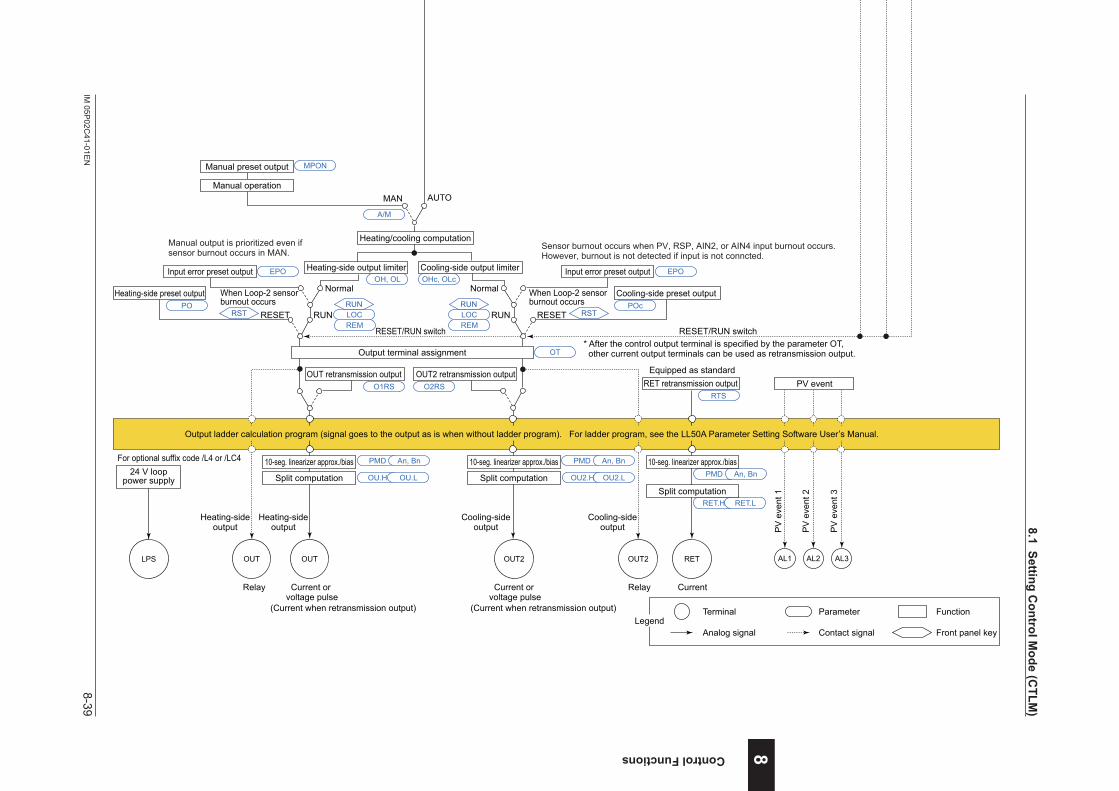
8-39IM
05P02C
41-01EN
Control Functions
nHeating/coolingLoopControlwithPVAuto-selector(4inputs)FunctionBlockDiagram
COM
SP limiter
DI26 DI46PV AIN2
Input type
Input unit
Input range/scale
Analog input bias
Square root extraction
Analog input filter
Input type
Input unit
Input range/scale
Analog input bias
Square root extraction
Analog input filter
10-seg. linearizer approx./bias
PV input bias
PV input filterRatio bias computation
PV auto-selector (Max., Min., Ave., Diff.)
A.BS
A.FL
BS
FL
PMD An, Bn
10-seg. linearizer approx./bias PMD An, Bn 10-seg. linearizer approx./bias PMD An, Bn 10-seg. linearizer approx./bias PMD An, Bn 10-seg. linearizer approx./bias PMD An, Bn
PV.ASP.UNI P.DP P.RH, P.RL
CNT ALG
SPH, SPL
A.SR A.LC
UNIT
IN
RH, RLSDP
SH, SLA.BS
A.FL
A.SR A.LC
UNIT
IN
RH, RL SDPSH, SL
RSP
Input type
Input unit
Input range/scale
Analog input bias
Square root extraction
Analog input filter
A.BS
A.FL
A.SR A.LC
UNIT
IN
RH, RL SDPSH, SL
AIN4
Input type
Input unit
Input range/scale
Analog input bias
Square root extraction
Analog input filter
A.BS
A.FL
A.SR A.LC
UNIT
IN
RH, RL SDPSH, SL
DI16DI2 DI3DI1
Control computation
Sensor burnout occurs when PV, RSP, AIN2, or AIN4 input burnout occurs.However, burnout is not detected if input is not conncted.
Manual operation
Manual preset output
Input error preset output
Heating-side preset output When Loop-2 sensorburnout occurs
When Loop-2 sensorburnout occurs
Normal Normal
MAN
RUNRESET
Current or voltage pulse
Relay Current or voltage pulse
Relay Current
EPOOH, OL OHc, OLc
Input error preset output
OUT retransmission output OUT2 retransmission output
EPO
POCooling-side preset output
RESETPOc
OT
O1RS O2RS RET retransmission outputRTS
MPON
OUTOUT OUT2 OUT2
Heating/cooling computation
RET
Heating-side output limiter Cooling-side output limiter
RUN
Output terminal assignment
PMD
OU.H OU.L OU2.H OU2.L
An, Bn PMD An, Bn
Split computation
10-seg. linearizer approx./bias
Split computation
10-seg. linearizer approx./bias
RET.H RET.L
PMD An, Bn
Split computation
10-seg. linearizer approx./bias
AUTO
Equipped as standard
(Current when retransmission output) (Current when retransmission output)
PV input 1 PV input 2 PV input 3 PV input 4 Contact inputs
(for Standard model) Suffix code: Type 2 = 1 or 4 is necessary.
(for Standard model)When suffix code: Type 2 = 4
(for Standard model)When suffix code: Type 2 = 4
Aux. analog (remote) input (E1-terminal area) Aux. analog input (E2-terminal area) Aux. analog input (E4-terminal area)Equipped as standard
Necessary for Loop control with PV auto-selector for 3 inputs or 4 inputs
For the model with optional suffix code /DR:Refer to the function block diagram ofLoop control with PV auto-selector (2 inputs).
* After the control output terminal is specified by the parameter OT, other current output terminals can be used as retransmission output.
Heating-sideoutput
Heating-sideoutput
Cooling-sideoutput
Cooling-sideoutput
Terminal Parameter Function
Analog signal Contact signal Front panel keyLegend
PV display SP display
Input ladder calculation program (signal goes to the control computation as is when without ladder program). For ladder program, see the LL50A Parameter Setting Software User’s Manual.
Manual output is prioritized even if sensor burnout occurs in MAN.
RMS
*1: RS-485, Ethernet, PROFIBUS-DP, DeviceNet, CC-Link
(for Standard model)DI16 is equipped whensuffix code: Type 2 = 1 or 4.DI26 and DI46 are equipped whensuffix code: Type 2 = 4.
Program pattern
Local target setpointReset
TSP S.PID
PTNO.
TIME RAMP
L.PIDLSP
REM
LOC
RUN
RST
Program pattern selection
Switch between the ON and OFF states of each contact inputs to select from program pattern numbers.(Select a number during a RESET state.)
DI41 to DI45 are equipped when suffix code: Type 2 = 0, 1 or 3.The function is assigned to each DIs at factory default.
RTRBS
RESET/RUN switchRESET/RUN switch
RST RSTREM
A/M
LOCRUN
REMLOCRUN
AL3AL2AL1
PV
eve
nt 1
PV
eve
nt 2
PV
eve
nt 3
PV event
Output ladder calculation program (signal goes to the output as is when without ladder program). For ladder program, see the LL50A Parameter Setting Software User’s Manual.
No function is assigned to DI16, DI26, and DI46.
Sta
rt of
pro
gram
ope
ratio
nw
hen
DI c
hang
es fr
om O
FF to
ON
.
Sto
p of
pro
gram
ope
ratio
nw
hen
DI c
hang
es fr
om O
FF to
ON
.
Sta
rt of
loca
l-mod
e op
erat
ion
whe
n D
I cha
nges
from
OFF
to O
N.
(for Detailed model) Optional suffix code /R1 is necessary.
(for Detailed model)When optional suffix code /A2
(for Detailed model)When optional suffix code /A4
For the model with optional suffix code /U1:Refer to the function block diagram ofLoop control with PV auto-selector (2 inputs).
(for Detailed model)DI16 is equipped whenoptional suffix code /R1.DI26 and DI46 are equipped whenoptional suffix code /A2 and /A4.
Program pattern selectionDI41 to DI45 are equipped when optional suffix code /X4.The function is assigned to each DIs at factory default.
LPS
24 V looppower supply
For optional suffix code /L4 or /LC4
SSP
8
8.1SettingControlM
ode(CTLM
)
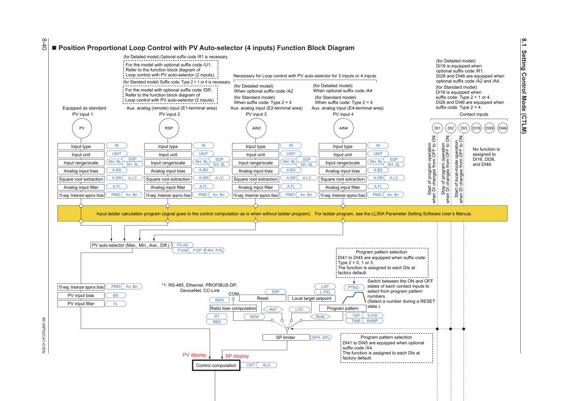
8-40IM
05P02C
41-01EN
nPositionProportionalLoopControlwithPVAuto-selector(4inputs)FunctionBlockDiagram
COM
SP limiter
DI26 DI46PV AIN2
Input type
Input unit
Input range/scale
Analog input bias
Square root extraction
Analog input filter
Input type
Input unit
Input range/scale
Analog input bias
Square root extraction
Analog input filter
10-seg. linearizer approx./bias
PV input bias
PV input filterRatio bias computation
PV auto-selector (Max., Min., Ave., Diff.)
A.BS
A.FL
BS
FL
PMD An, Bn
10-seg. linearizer approx./bias PMD An, Bn 10-seg. linearizer approx./bias PMD An, Bn 10-seg. linearizer approx./bias PMD An, Bn 10-seg. linearizer approx./bias PMD An, Bn
PV.ASP.UNI P.DP P.RH, P.RL
CNT ALG
SPH, SPL
A.SR A.LC
UNIT
IN
RH, RLSDP
SH, SLA.BS
A.FL
A.SR A.LC
UNIT
IN
RH, RL SDPSH, SL
RSP
Input type
Input unit
Input range/scale
Analog input bias
Square root extraction
Analog input filter
A.BS
A.FL
A.SR A.LC
UNIT
IN
RH, RL SDPSH, SL
AIN4
Input type
Input unit
Input range/scale
Analog input bias
Square root extraction
Analog input filter
A.BS
A.FL
A.SR A.LC
UNIT
IN
RH, RL SDPSH, SL
DI16DI2 DI3DI1
Control computation
Manual operation
Input error preset output
Preset output
AUTO
Normal
MAN
RUNRESET
Output limiter
EPO
OH, OL
PO
Signal comparison
Feedback input Direct/reverse signal
Valve position slidingresistor or current
Motor-operated valve
Relay output
VALVFBIN
M
Equipped as standard Equipped as standard
Current Current
OUT RET
PMD
OU.H OU.L
HYSDB An, Bn
Split computation
10-seg. linearizer approx./bias
RET.H RET.L
PMD An, Bn
Split computation
10-seg. linearizer approx./bias
OUT retransmission outputO1RS
RET retransmission outputRTS
PV input 1 PV input 2 PV input 3 PV input 4 Contact inputs
(for Standard model) Suffix code: Type 2 = 1 or 4 is necessary.
(for Standard model)When suffix code: Type 2 = 4
(for Standard model)When suffix code: Type 2 = 4
Aux. analog (remote) input (E1-terminal area) Aux. analog input (E2-terminal area) Aux. analog input (E4-terminal area)Equipped as standard
Necessary for Loop control with PV auto-selector for 3 inputs or 4 inputs
For the model with optional suffix code /DR:Refer to the function block diagram ofLoop control with PV auto-selector (2 inputs).
When sensorburnout occurs
In Estimating-type position proportional control, the limiter function does not work on output operation. The reverse-signal relay turns on when being limited by low limit.The direct-signal relay turns on when being limited by high limit.
Sensor burnout occurs when PV, RSP, AIN2, or AIN4 input burnout occurs.However, burnout is not detected if input is not conncted.
Position Proportional Computation Output cannot be calculated by ladder program.
In Manual operation, the relay turns on while the or key is pressed. Output limiter does not work.
H relay( key)
L relay( key)
Terminal Parameter Function
Analog signal Contact signal Front panel keyLegend
PV display SP display
Input ladder calculation program (signal goes to the control computation as is when without ladder program). For ladder program, see the LL50A Parameter Setting Software User’s Manual.
RMS
*1: RS-485, Ethernet, PROFIBUS-DP, DeviceNet, CC-Link
(for Standard model)DI16 is equipped whensuffix code: Type 2 = 1 or 4.DI26 and DI46 are equipped whensuffix code: Type 2 = 4.
Program pattern
Local target setpointReset
TSP S.PID
PTNO.
TIME RAMP
L.PIDLSP
REM
LOC
RUN
RST
Program pattern selection
Switch between the ON and OFF states of each contact inputs to select from program pattern numbers.(Select a number during a RESET state.)
DI41 to DI45 are equipped when suffix code: Type 2 = 0, 1 or 3.The function is assigned to each DIs at factory default.
RTRBS
RESET/RUN switch
RSTREM
A/M
LOCRUN
AL3AL2AL1
PV
eve
nt 1
PV
eve
nt 2
PV
eve
nt 3
PV event
Output ladder calculation program (signal goes to the output as is when without ladder program). For ladder program, see the LL50A Parameter Setting Software User’s Manual.
No function is assigned to DI16, DI26, and DI46.
Sta
rt of
pro
gram
ope
ratio
nw
hen
DI c
hang
es fr
om O
FF to
ON
.
Sto
p of
pro
gram
ope
ratio
nw
hen
DI c
hang
es fr
om O
FF to
ON
.
Sta
rt of
loca
l-mod
e op
erat
ion
whe
n D
I cha
nges
from
OFF
to O
N.
LPS
24 V looppower supply
For optional suffix code /L4 or /LC4
Program pattern selectionDI41 to DI45 are equipped when optional suffix code /X4.The function is assigned to each DIs at factory default.
(for Detailed model) Optional suffix code /R1 is necessary.
(for Detailed model)When optional suffix code /A2
(for Detailed model)When optional suffix code /A4
For the model with optional suffix code /U1:Refer to the function block diagram ofLoop control with PV auto-selector (2 inputs).
(for Detailed model)DI16 is equipped whenoptional suffix code /R1.DI26 and DI46 are equipped whenoptional suffix code /A2 and /A4.
SSP
8.1SettingControlM
ode(CTLM
)
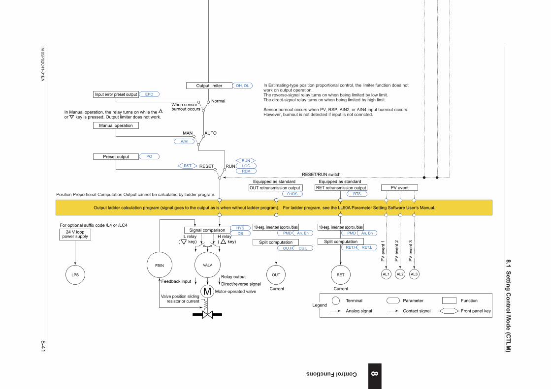
8-41IM
05P02C
41-01EN
Control Functions
nPositionProportionalLoopControlwithPVAuto-selector(4inputs)FunctionBlockDiagram
COM
SP limiter
DI26 DI46PV AIN2
Input type
Input unit
Input range/scale
Analog input bias
Square root extraction
Analog input filter
Input type
Input unit
Input range/scale
Analog input bias
Square root extraction
Analog input filter
10-seg. linearizer approx./bias
PV input bias
PV input filterRatio bias computation
PV auto-selector (Max., Min., Ave., Diff.)
A.BS
A.FL
BS
FL
PMD An, Bn
10-seg. linearizer approx./bias PMD An, Bn 10-seg. linearizer approx./bias PMD An, Bn 10-seg. linearizer approx./bias PMD An, Bn 10-seg. linearizer approx./bias PMD An, Bn
PV.ASP.UNI P.DP P.RH, P.RL
CNT ALG
SPH, SPL
A.SR A.LC
UNIT
IN
RH, RLSDP
SH, SLA.BS
A.FL
A.SR A.LC
UNIT
IN
RH, RL SDPSH, SL
RSP
Input type
Input unit
Input range/scale
Analog input bias
Square root extraction
Analog input filter
A.BS
A.FL
A.SR A.LC
UNIT
IN
RH, RL SDPSH, SL
AIN4
Input type
Input unit
Input range/scale
Analog input bias
Square root extraction
Analog input filter
A.BS
A.FL
A.SR A.LC
UNIT
IN
RH, RL SDPSH, SL
DI16DI2 DI3DI1
Control computation
Manual operation
Input error preset output
Preset output
AUTO
Normal
MAN
RUNRESET
Output limiter
EPO
OH, OL
PO
Signal comparison
Feedback input Direct/reverse signal
Valve position slidingresistor or current
Motor-operated valve
Relay output
VALVFBIN
M
Equipped as standard Equipped as standard
Current Current
OUT RET
PMD
OU.H OU.L
HYSDB An, Bn
Split computation
10-seg. linearizer approx./bias
RET.H RET.L
PMD An, Bn
Split computation
10-seg. linearizer approx./bias
OUT retransmission outputO1RS
RET retransmission outputRTS
PV input 1 PV input 2 PV input 3 PV input 4 Contact inputs
(for Standard model) Suffix code: Type 2 = 1 or 4 is necessary.
(for Standard model)When suffix code: Type 2 = 4
(for Standard model)When suffix code: Type 2 = 4
Aux. analog (remote) input (E1-terminal area) Aux. analog input (E2-terminal area) Aux. analog input (E4-terminal area)Equipped as standard
Necessary for Loop control with PV auto-selector for 3 inputs or 4 inputs
For the model with optional suffix code /DR:Refer to the function block diagram ofLoop control with PV auto-selector (2 inputs).
When sensorburnout occurs
In Estimating-type position proportional control, the limiter function does not work on output operation. The reverse-signal relay turns on when being limited by low limit.The direct-signal relay turns on when being limited by high limit.
Sensor burnout occurs when PV, RSP, AIN2, or AIN4 input burnout occurs.However, burnout is not detected if input is not conncted.
Position Proportional Computation Output cannot be calculated by ladder program.
In Manual operation, the relay turns on while the or key is pressed. Output limiter does not work.
H relay( key)
L relay( key)
Terminal Parameter Function
Analog signal Contact signal Front panel keyLegend
PV display SP display
Input ladder calculation program (signal goes to the control computation as is when without ladder program). For ladder program, see the LL50A Parameter Setting Software User’s Manual.
RMS
*1: RS-485, Ethernet, PROFIBUS-DP, DeviceNet, CC-Link
(for Standard model)DI16 is equipped whensuffix code: Type 2 = 1 or 4.DI26 and DI46 are equipped whensuffix code: Type 2 = 4.
Program pattern
Local target setpointReset
TSP S.PID
PTNO.
TIME RAMP
L.PIDLSP
REM
LOC
RUN
RST
Program pattern selection
Switch between the ON and OFF states of each contact inputs to select from program pattern numbers.(Select a number during a RESET state.)
DI41 to DI45 are equipped when suffix code: Type 2 = 0, 1 or 3.The function is assigned to each DIs at factory default.
RTRBS
RESET/RUN switch
RSTREM
A/M
LOCRUN
AL3AL2AL1
PV
eve
nt 1
PV
eve
nt 2
PV
eve
nt 3
PV event
Output ladder calculation program (signal goes to the output as is when without ladder program). For ladder program, see the LL50A Parameter Setting Software User’s Manual.
No function is assigned to DI16, DI26, and DI46.
Sta
rt of
pro
gram
ope
ratio
nw
hen
DI c
hang
es fr
om O
FF to
ON
.
Sto
p of
pro
gram
ope
ratio
nw
hen
DI c
hang
es fr
om O
FF to
ON
.
Sta
rt of
loca
l-mod
e op
erat
ion
whe
n D
I cha
nges
from
OFF
to O
N.
LPS
24 V looppower supply
For optional suffix code /L4 or /LC4
Program pattern selectionDI41 to DI45 are equipped when optional suffix code /X4.The function is assigned to each DIs at factory default.
(for Detailed model) Optional suffix code /R1 is necessary.
(for Detailed model)When optional suffix code /A2
(for Detailed model)When optional suffix code /A4
For the model with optional suffix code /U1:Refer to the function block diagram ofLoop control with PV auto-selector (2 inputs).
(for Detailed model)DI16 is equipped whenoptional suffix code /R1.DI26 and DI46 are equipped whenoptional suffix code /A2 and /A4.
SSP
8
8.1SettingControlM
ode(CTLM
)
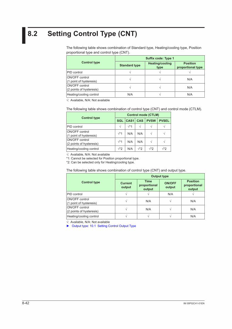
8-42 IM 05P02C41-01EN
8.2 SettingControlType(CNT)
The following table shows combination of Standard type, Heating/cooling type, Position proportional type and control type (CNT).
ControltypeSuffixcode:Type1
Standardtype Heating/cooling type
Position proportionaltype
PID control √ √ √ON/OFF control (1 point of hysteresis) √ √ N/A
ON/OFF control (2 points of hysteresis) √ √ N/A
Heating/cooling control N/A √ N/A
√:Available,N/A:Notavailable
The following table shows combination of control type (CNT) and control mode (CTLM).
ControltypeControl mode (CTLM)
SGL CAS1 CAS PVSW PVSEL
PID control √ √*1 √ √ √ON/OFF control (1 point of hysteresis) √*1 N/A N/A √ √
ON/OFF control (2 points of hysteresis) √*1 N/A N/A √ √
Heating/cooling control √*2 N/A √*2 √*2 √*2
√:Available,N/A:Notavailable*1: Cannot be selected for Position proportional type.*2: Can be selected only for Heating/cooling type.
The following table shows combination of control type (CNT) and output type.
Controltype
Outputtype
Current output
Time proportional
output
ON/OFFoutput
Position proportional
outputPID control √ √ N/A √ON/OFF control (1 point of hysteresis) √ N/A √ N/A
ON/OFF control (2 points of hysteresis) √ N/A √ N/A
Heating/cooling control √ √ √ N/A
√:Available,N/A:Notavailable Output type: 10.1 Setting Control Output Type
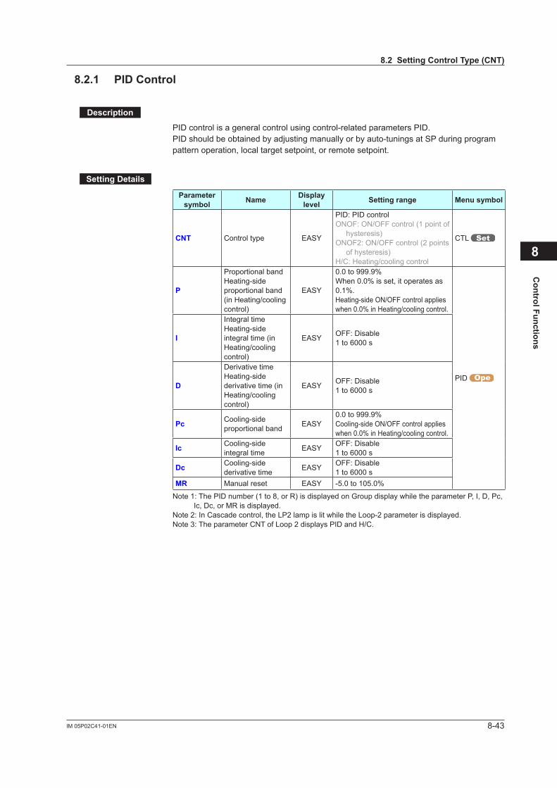
8-43IM 05P02C41-01EN
Control Functions
8.2.1 PIDControl
Description
PID control is a general control using control-related parameters PID.PIDshouldbeobtainedbyadjustingmanuallyorbyauto-tuningsatSPduringprogrampattern operation, local target setpoint, or remote setpoint.
SettingDetails
Parameter symbol Name Display
level Settingrange Menusymbol
CNT Control type EASY
PID: PID controlONOF: ON/OFF control (1 point of
hysteresis)ONOF2: ON/OFF control (2 points
of hysteresis)H/C: Heating/cooling control
CTL
P
Proportional bandHeating-side proportional band (in Heating/cooling control)
EASY
0.0 to 999.9%When 0.0% is set, it operates as 0.1%. Heating-side ON/OFF control applies when 0.0% in Heating/cooling control.
PID
I
Integral timeHeating-side integral time (in Heating/cooling control)
EASY OFF: Disable1 to 6000 s
D
Derivative timeHeating-side derivative time (in Heating/cooling control)
EASY OFF: Disable1 to 6000 s
Pc Cooling-side proportional band EASY
0.0 to 999.9%Cooling-side ON/OFF control applies when 0.0% in Heating/cooling control.
Ic Cooling-side integral time EASY OFF: Disable
1 to 6000 s
Dc Cooling-side derivative time EASY OFF: Disable
1 to 6000 sMR Manual reset EASY -5.0 to 105.0%
Note 1: The PID number (1 to 8, or R) is displayed on Group display while the parameter P, I, D, Pc, Ic, Dc, or MR is displayed.
Note 2: In Cascade control, the LP2 lamp is lit while the Loop-2 parameter is displayed.Note 3: The parameter CNT of Loop 2 displays PID and H/C.
8
8.2SettingControlType(CNT)
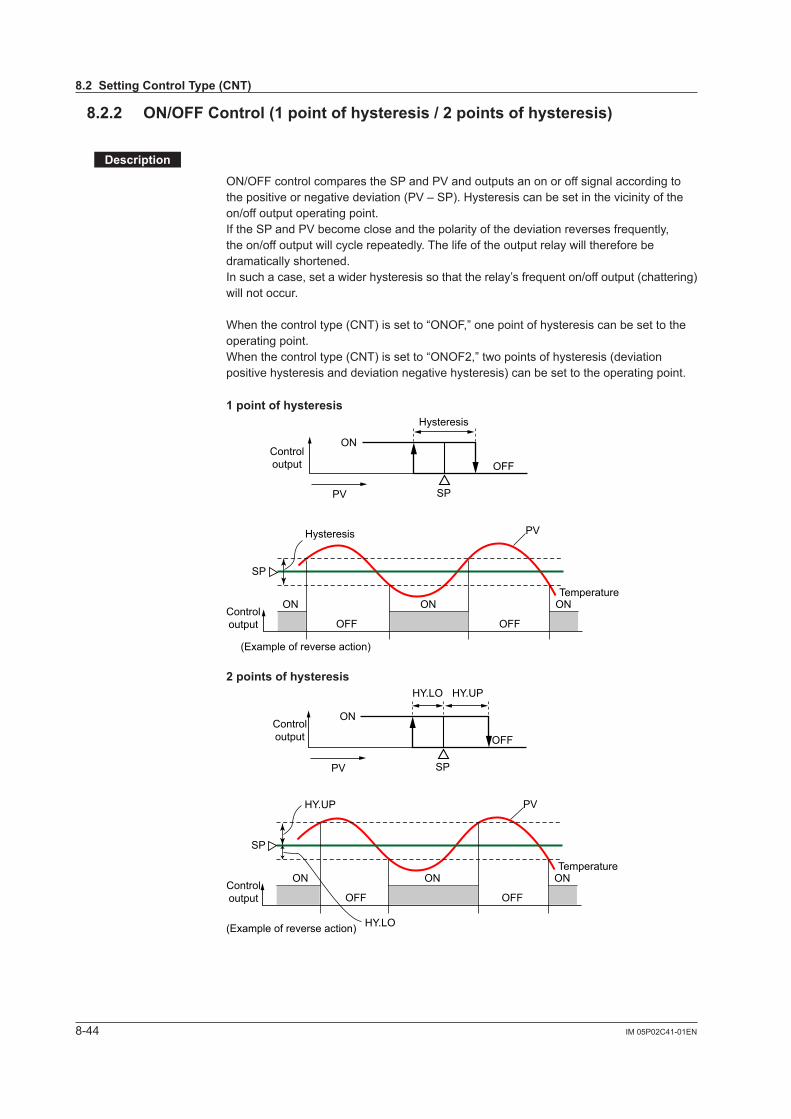
8-44 IM 05P02C41-01EN
8.2.2 ON/OFFControl(1pointofhysteresis/2pointsofhysteresis)
Description
ON/OFF control compares the SP and PV and outputs an on or off signal according to the positive or negative deviation (PV – SP). Hysteresis can be set in the vicinity of the on/off output operating point. If the SP and PV become close and the polarity of the deviation reverses frequently, the on/off output will cycle repeatedly. The life of the output relay will therefore be dramatically shortened.In such a case, set a wider hysteresis so that the relay’s frequent on/off output (chattering) will not occur.
When the control type (CNT) is set to “ONOF,” one point of hysteresis can be set to the operating point.When the control type (CNT) is set to “ONOF2,” two points of hysteresis (deviation positive hysteresis and deviation negative hysteresis) can be set to the operating point.
1pointofhysteresis
Hysteresis
SP
Controloutput
ON
ON
OFF
OFF
ON ON
OFF
PV
PVHysteresis
SP
Controloutput
(Example of reverse action)
Temperature
2pointsofhysteresis
HY.UPHY.LO
SP
Controloutput
ON
ON
OFF
OFF
ON ON
OFF
PV
HY.UP
HY.LO
SP
Controloutput
(Example of reverse action)
Temperature
PV
8.2SettingControlType(CNT)
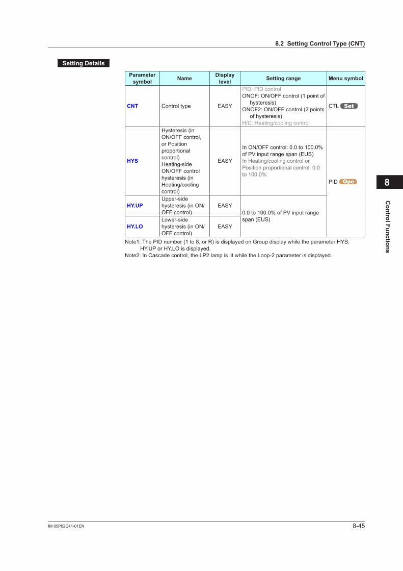
8-45IM 05P02C41-01EN
Control Functions
SettingDetails
Parameter symbol Name Display
level Settingrange Menusymbol
CNT Control type EASY
PID: PID controlONOF: ON/OFF control (1 point of
hysteresis)ONOF2: ON/OFF control (2 points
of hysteresis)H/C: Heating/cooling control
CTL
HYS
Hysteresis (in ON/OFF control, or Position proportional control)Heating-side ON/OFF control hysteresis (in Heating/cooling control)
EASY
In ON/OFF control: 0.0 to 100.0% of PV input range span (EUS)In Heating/cooling control or Position proportional control: 0.0 to 100.0%
PID
HY.UPUpper-side hysteresis (in ON/OFF control)
EASY0.0 to 100.0% of PV input range span (EUS)
HY.LOLower-side hysteresis (in ON/OFF control)
EASY
Note1: The PID number (1 to 8, or R) is displayed on Group display while the parameter HYS, HY.UP or HY.LO is displayed.
Note2: In Cascade control, the LP2 lamp is lit while the Loop-2 parameter is displayed.
8
8.2SettingControlType(CNT)
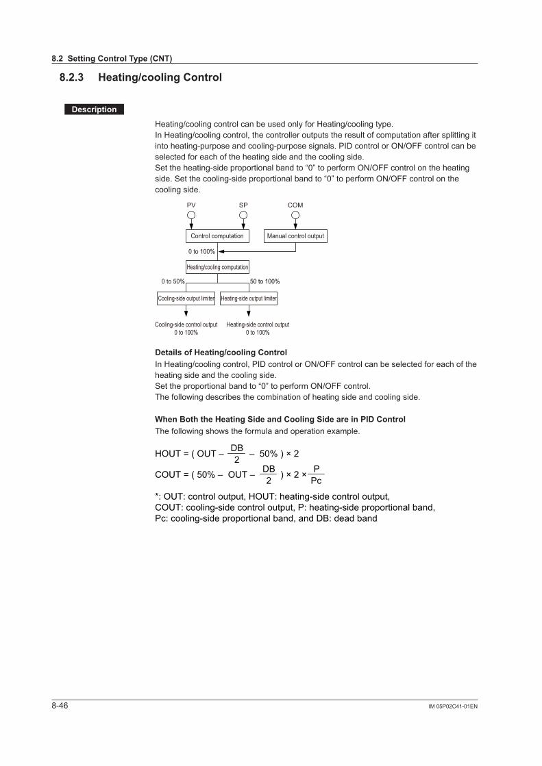
8-46 IM 05P02C41-01EN
8.2.3 Heating/coolingControl
Description
Heating/cooling control can be used only for Heating/cooling type.In Heating/cooling control, the controller outputs the result of computation after splitting it into heating-purpose and cooling-purpose signals. PID control or ON/OFF control can be selected for each of the heating side and the cooling side.Set the heating-side proportional band to “0” to perform ON/OFF control on the heating side. Set the cooling-side proportional band to “0” to perform ON/OFF control on the cooling side.
Control computation
0 to 100%
Heating/cooling computation
0 to 50%
Cooling-side output limiter
Cooling-side control output0 to 100%
Heating-side control output0 to 100%
50 to 100%
Heating-side output limiter
PV SP
Manual control output
COM
DetailsofHeating/coolingControlIn Heating/cooling control, PID control or ON/OFF control can be selected for each of the heating side and the cooling side.Set the proportional band to “0” to perform ON/OFF control.The following describes the combination of heating side and cooling side.
WhenBoththeHeatingSideandCoolingSideareinPIDControlThe following shows the formula and operation example.
HOUT = ( OUT – – 50% ) × 22DB
*: OUT: control output, HOUT: heating-side control output, COUT: cooling-side control output, P: heating-side proportional band,Pc: cooling-side proportional band, and DB: dead band
COUT = ( 50% – OUT – ) × 2 ×2DB
PcP
8.2SettingControlType(CNT)

8-47IM 05P02C41-01EN
Control Functions
PositiveDeadBand
0%
Deadband(DB)
Deadband(DB)
Cooling-side control output (%) Heating-side control output (%)
0%
50%Control computation output
100%
100%
Cooling-sidecontrol output
high limit(OHc)
Heating-sidecontrol outputhigh limit(OH)
0%
100%
0% 50% 100%
(OUT)
NegativeDeadBand
0%
0%
50% 100%
100%
0%
100%
0% 50% 100%
Deadband(DB)
Deadband(DB)
Cooling-side control output (%) Heating-side control output (%)
Control computation output
Cooling-sidecontrol output
high limit(OHc)
Heating-sidecontrol outputhigh limit(OH)
(OUT)
CAUTION• Set the ratio of the heating-side proportional band (P) to the cooling-side
proportional band (Pc) to within 1 to 5. • Setting the heating-side or cooling-side integral time (I or Ic) to “OFF” results in
the integral time of both sides being set to “OFF.”
8
8.2SettingControlType(CNT)
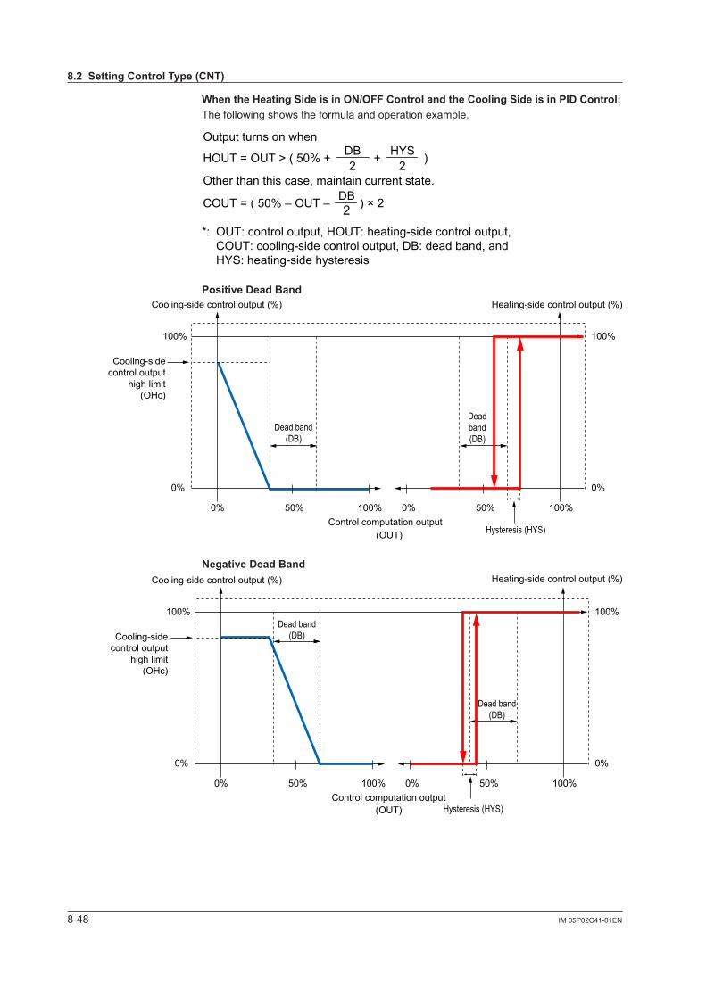
8-48 IM 05P02C41-01EN
WhentheHeatingSideisinON/OFFControlandtheCoolingSideisinPIDControl:The following shows the formula and operation example.
HOUT = OUT > ( 50% + + )
Other than this case, maintain current state.
Output turns on when
2DB
2HYS
*: OUT: control output, HOUT: heating-side control output, COUT: cooling-side control output, DB: dead band, and HYS: heating-side hysteresis
COUT = ( 50% – OUT – ) × 22DB
PositiveDeadBand
0%
Dead band(DB)
Deadband(DB)
Hysteresis (HYS)
Cooling-side control output (%) Heating-side control output (%)
0%
50%Control computation output
100%
100%
Cooling-sidecontrol output
high limit(OHc)
0%
100%
0% 50% 100%
(OUT)
NegativeDeadBand
0%
0%
50% 100%
100%
0%
100%
0% 50% 100%
Dead band(DB)
Dead band(DB)
Hysteresis (HYS)
Cooling-side control output (%) Heating-side control output (%)
Control computation output
Cooling-sidecontrol output
high limit(OHc)
(OUT)
8.2SettingControlType(CNT)
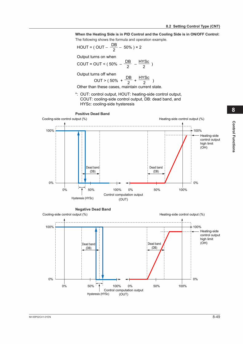
8-49IM 05P02C41-01EN
Control Functions
WhentheHeatingSideisinPIDControlandtheCoolingSideisinON/OFFControl:The following shows the formula and operation example.
HOUT = ( OUT – – 50% ) × 22DB
*: OUT: control output, HOUT: heating-side control output, COUT: cooling-side control output, DB: dead band, and HYSc: cooling-side hysteresis
COUT = OUT < ( 50% – – )
OUT > ( 50% + + )Other than these cases, maintain current state.
Output turns on when
Output turns off when
2DB
2HYSc
2DB
2HYSc
PositiveDeadBand
0%
Dead band(DB)
Dead band(DB)
Cooling-side control output (%) Heating-side control output (%)
0%
50%Control computation output
100%
100%Heating-sidecontrol outputhigh limit(OH)
0%
100%
0% 50% 100%
Hysteresis (HYSc) (OUT)
NegativeDeadBand
0%
0%
50% 100%
100%
0%
100%
0% 50% 100%
Dead band(DB)
Dead band(DB)
Cooling-side control output (%) Heating-side control output (%)
Control computation output
Heating-sidecontrol outputhigh limit(OH)
Hysteresis (HYSc) (OUT)
8
8.2SettingControlType(CNT)
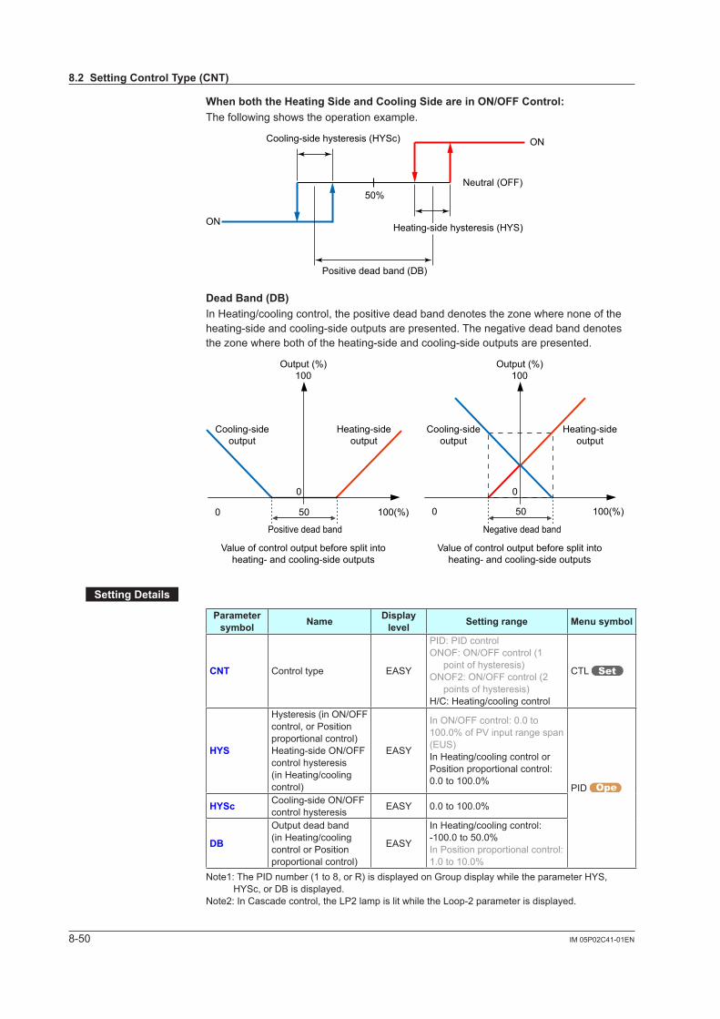
8-50 IM 05P02C41-01EN
WhenboththeHeatingSideandCoolingSideareinON/OFFControl:The following shows the operation example.
50%
ON
ONCooling-side hysteresis (HYSc)
Neutral (OFF)
Heating-side hysteresis (HYS)
Positive dead band (DB)
Dead Band (DB)InHeating/coolingcontrol,thepositivedeadbanddenotesthezonewherenoneoftheheating-side and cooling-side outputs are presented. The negative dead band denotes thezonewherebothoftheheating-sideandcooling-sideoutputsarepresented.
00
50 500 0
Negative dead band
Cooling-sideoutput
Cooling-sideoutput
Heating-sideoutput
Heating-sideoutput
Output (%)100
Output (%)100
Positive dead band
100(%) 100(%)
Value of control output before split intoheating- and cooling-side outputs
Value of control output before split intoheating- and cooling-side outputs
SettingDetails
Parameter symbol Name Display
level Settingrange Menusymbol
CNT Control type EASY
PID: PID controlONOF: ON/OFF control (1
point of hysteresis)ONOF2: ON/OFF control (2
points of hysteresis)H/C: Heating/cooling control
CTL
HYS
Hysteresis (in ON/OFF control, or Position proportional control)Heating-side ON/OFF control hysteresis (in Heating/cooling control)
EASY
In ON/OFF control: 0.0 to 100.0% of PV input range span (EUS)In Heating/cooling control or Position proportional control: 0.0 to 100.0%
PID
HYSc Cooling-side ON/OFF control hysteresis EASY 0.0 to 100.0%
DB
Output dead band (in Heating/cooling control or Position proportional control)
EASY
In Heating/cooling control: -100.0 to 50.0%In Position proportional control: 1.0 to 10.0%
Note1: The PID number (1 to 8, or R) is displayed on Group display while the parameter HYS, HYSc, or DB is displayed.
Note2: In Cascade control, the LP2 lamp is lit while the Loop-2 parameter is displayed.
8.2SettingControlType(CNT)
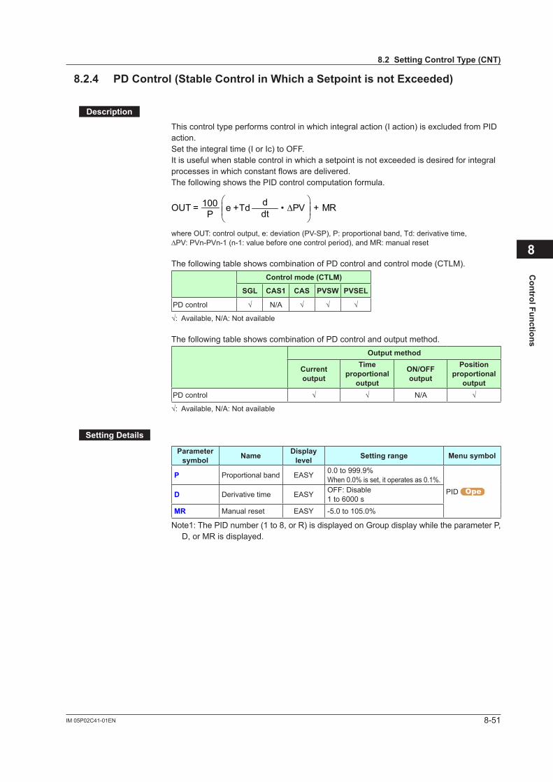
8-51IM 05P02C41-01EN
Control Functions
8.2.4 PDControl(StableControlinWhichaSetpointisnotExceeded)
Description
This control type performs control in which integral action (I action) is excluded from PID action.Set the integral time (I or Ic) to OFF.It is useful when stable control in which a setpoint is not exceeded is desired for integral processes in which constant flows are delivered.The following shows the PID control computation formula.
MR∆PVdeP
OUT +
+ = •dt
100 Td
where OUT: control output, e: deviation (PV-SP), P: proportional band, Td: derivative time, ∆PV:PVn-PVn-1(n-1:valuebeforeonecontrolperiod),andMR:manualreset
The following table shows combination of PD control and control mode (CTLM).Control mode (CTLM)
SGL CAS1 CAS PVSW PVSEL
PD control √ N/A √ √ √
√:Available,N/A:Notavailable
The following table shows combination of PD control and output method.Outputmethod
Current output
Time proportional
output
ON/OFFoutput
Position proportional
outputPD control √ √ N/A √
√:Available,N/A:Notavailable
SettingDetails
Parameter symbol Name Display
level Settingrange Menusymbol
P Proportional band EASY 0.0 to 999.9%When 0.0% is set, it operates as 0.1%.
PID D Derivative time EASY OFF: Disable1 to 6000 s
MR Manual reset EASY -5.0 to 105.0%
Note1: The PID number (1 to 8, or R) is displayed on Group display while the parameter P, D, or MR is displayed.
8
8.2SettingControlType(CNT)
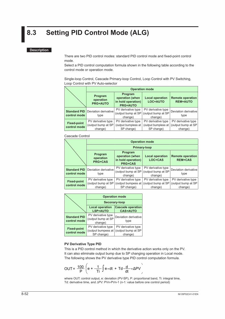
8-52 IM 05P02C41-01EN
8.3 SettingPIDControlMode(ALG)
Description
There are two PID control modes: standard PID control mode and fixed-point control mode.Select a PID control computation formula shown in the following table according to the control mode or operation mode.
Single-loop Control, Cascade Primary-loop Control, Loop Control with PV Switching, Loop Control with PV Auto-selector
Operationmode
Program operationPRG+AUTO
Program operation(when
in hold operation) PRG+AUTO
Local operation LOC+AUTO
Remote operation REM+AUTO
StandardPIDcontrol mode
Deviation derivative type
PV derivative type (output bump at SP
change)
PV derivative type (output bump at SP
change)
Deviation derivative type
Fixed-pointcontrol mode
PV derivative type (output bump at SP
change)
PV derivative type (output bumpless at
SP change)
PV derivative type (output bumpless at
SP change)
PV derivative type (output bump at SP
change)
Cascade ControlOperationmode
Primary-loop
Program operationPRG+CAS
Program operation(when
in hold operation) PRG+CAS
Local operation LOC+CAS
Remote operation REM+CAS
StandardPIDcontrol mode
Deviation derivative type
PV derivative type (output bump at SP
change)
PV derivative type (output bump at SP
change)
Deviation derivative type
Fixed-pointcontrol mode
PV derivative type (output bump at SP
change)
PV derivative type (output bumpess at
SP change)
PV derivative type (output bump at SP
change)
PV derivative type (output bump at SP
change)
Operationmode
Seconary-loopLocal operation LSP+AUTO
Cascade operation CAS+AUTO
StandardPIDcontrol mode
PV derivative type (output bump at SP
change)
Deviation derivative type
Fixed-pointcontrol mode
PV derivative type (output bumpess at
SP change)
PV derivative type (output bump at SP
change)
PVDerivativeTypePIDThis is a PID control method in which the derivative action works only on the PV.It can also eliminate output bump due to SP changing operation in Local mode.The following shows the PV derivative type PID control computation formula.
e eP
OUT + +dt Td ΔPV= 100Ti1
dtd∫
• •
where OUT: control output, e: deviation (PV-SP), P: proportional band, Ti: integral time, Td:derivativetime,and∆PV:PVn-PVn-1(n-1:valuebeforeonecontrolperiod)
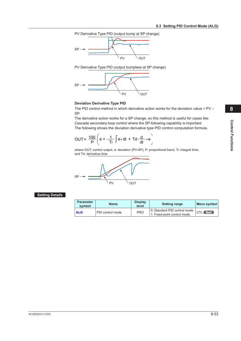
8-53IM 05P02C41-01EN
Control Functions
PV Derivative Type PID (output bump at SP change)
SP
PV OUT
PV Derivative Type PID (output bumpless at SP change)
SP
PV OUT
DeviationDerivativeTypePIDThe PID control method in which derivative action works for the deviation value = PV – SP.The derivative action works for a SP change, so this method is useful for cases like Cascade secondary-loop control where the SP-following capability is important. The following shows the deviation derivative type PID control computation formula.
e eP
OUT + +dt Td e= 100Ti1
dtd∫
• •
where OUT: control output, e: deviation (PV-SP), P: proportional band, Ti: integral time, and Td: derivative time
SP
PV OUT
SettingDetails
Parameter symbol Name Display
level Settingrange Menusymbol
ALG PID control mode PRO 0: Standard PID control mode1: Fixed-point control mode. CTL
8
8.3SettingPIDControlMode(ALG)
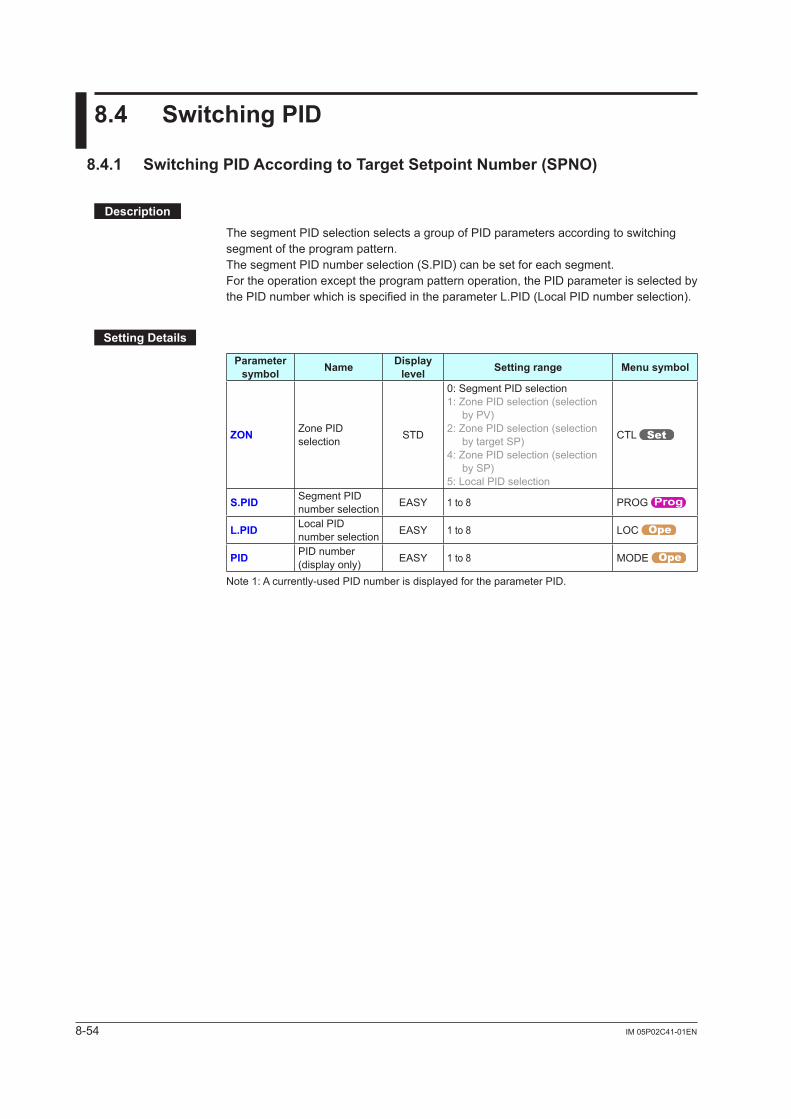
8-54 IM 05P02C41-01EN
8.4 SwitchingPID
8.4.1 SwitchingPIDAccordingtoTargetSetpointNumber(SPNO)
Description
The segment PID selection selects a group of PID parameters according to switching segment of the program pattern.The segment PID number selection (S.PID) can be set for each segment.For the operation except the program pattern operation, the PID parameter is selected by the PID number which is specified in the parameter L.PID (Local PID number selection).
SettingDetails
Parameter symbol Name Display
level Settingrange Menusymbol
ZON Zone PID selection STD
0: Segment PID selection1: Zone PID selection (selection
by PV)2: Zone PID selection (selection
by target SP)4: Zone PID selection (selection
by SP)5: Local PID selection
CTL
S.PID Segment PID number selection EASY 1 to 8 PROG
L.PID Local PID number selection EASY 1 to 8 LOC
PID PID number (display only) EASY 1 to 8 MODE
Note 1: A currently-used PID number is displayed for the parameter PID.
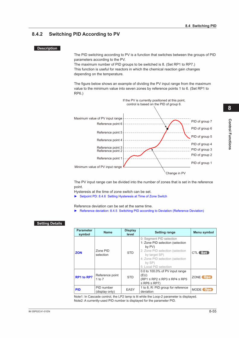
8-55IM 05P02C41-01EN
Control Functions
8.4.2 SwitchingPIDAccordingtoPV
Description
The PID switching according to PV is a function that switches between the groups of PID parameters according to the PV. The maximum number of PID groups to be switched is 8. (Set RP1 to RP7.)This function is useful for reactors in which the chemical reaction gain changes depending on the temperature.
The figure below shows an example of dividing the PV input range from the maximum valuetotheminimumvalueintosevenzonesbyreferencepoints1to6.(Set RP1 to RP6.)
PID of group 1Minimum value of PV input range
Maximum value of PV input range
Reference point 1
Reference point 2Reference point 3
Reference point 4
Reference point 5
Reference point 6
PID of group 2
PID of group 3
PID of group 4
PID of group 5
PID of group 6
PID of group 7
Change in PV
If the PV is currently positioned at this point,control is based on the PID of group 6.
ThePVinputrangecanbedividedintothenumberofzonesthatissetinthereferencepoint. Hysteresisatthetimeofzoneswitchcanbeset. SetpointPD:8.4.6SettingHysteresisatTimeofZoneSwitch
Reference deviation can be set at the same time. Reference deviation: 8.4.5 Switching PID according to Deviation (Reference Deviation)
SettingDetails
Parameter symbol Name Display
level Settingrange Menusymbol
ZON Zone PID selection STD
0: Segment PID selection1: Zone PID selection (selection
by PV)2: Zone PID selection (selection
by target SP)4: Zone PID selection (selection
by SP)5: Local PID selection
CTL
RP1toRP7 Reference point 1 to 7 STD
0.0 to 100.0% of PV input range (EU)(RP1≤RP2≤RP3≤RP4≤RP5≤RP6≤RP7)
ZONE
PID PID number (display only) EASY 1 to 8, R: PID group for reference
deviation MODE
Note1: In Cascade control, the LP2 lamp is lit while the Loop-2 parameter is displayed.Note2: A currently-used PID number is displayed for the parameter PID.
8
8.4SwitchingPID
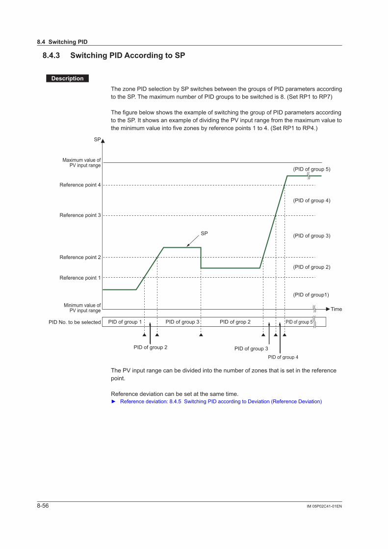
8-56 IM 05P02C41-01EN
8.4.3 SwitchingPIDAccordingtoSP
Description
ThezonePIDselectionbySPswitchesbetweenthegroupsofPIDparametersaccordingto the SP. The maximum number of PID groups to be switched is 8. (Set RP1 to RP7)
The figure below shows the example of switching the group of PID parameters according to the SP. It shows an example of dividing the PV input range from the maximum value to theminimumvalueintofivezonesbyreferencepoints1to4.(SetRP1toRP4.)
Maximum value of PV input range
Minimum value of PV input range
Reference point 4
(PID of group 5)
(PID of group 4)
(PID of group 3)
(PID of group 2)
PID of group 2
SP
SP
PID of group 3
(PID of group1)
Time
PID of group 1 PID of group 3 PID of grop 2 PID of group 5
Reference point 3
Reference point 2
Reference point 1
PID No. to be selected
PID of group 4
ThePVinputrangecanbedividedintothenumberofzonesthatissetinthereferencepoint.
Reference deviation can be set at the same time. Reference deviation: 8.4.5 Switching PID according to Deviation (Reference Deviation)
8.4SwitchingPID

8-57IM 05P02C41-01EN
Control Functions
SettingDetails
Parameter symbol Name Display
level Settingrange Menusymbol
ZON Zone PID selection STD
0: Segment PID selection1: Zone PID selection (selection
by PV)2: Zone PID selection (selection
by target SP)4: Zone PID selection (selection
by SP)5: Local PID selection
CTL
RP1toRP7 Reference point 1 to 7 STD
0.0 to 100.0% of PV input range (EU)(RP1≤RP2≤RP3≤RP4≤RP5≤RP6≤RP7)
ZONE
PID PID number (display only) EASY 1 to 8, R: PID group for reference
deviation MODE
Note1: In Cascade control, the LP2 lamp is lit while the Loop-2 parameter is displayed.Note2: A currently-used PID number is displayed for the parameter PID.
8
8.4SwitchingPID
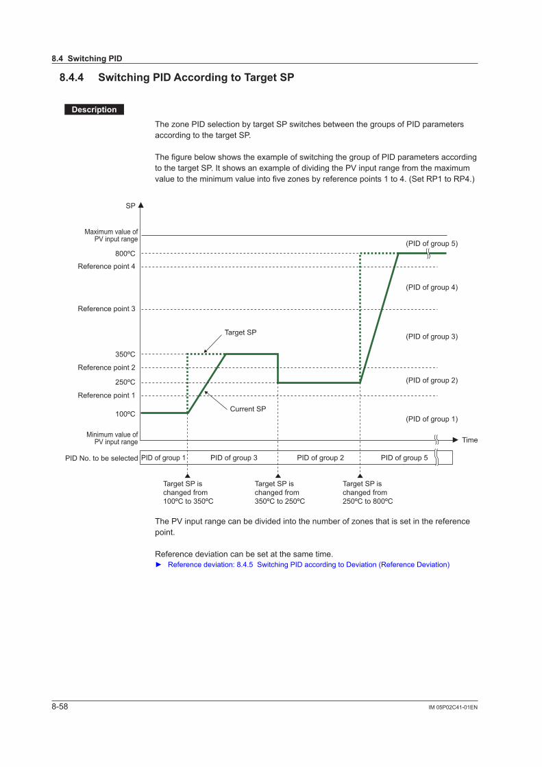
8-58 IM 05P02C41-01EN
8.4.4 SwitchingPIDAccordingtoTargetSP
Description
ThezonePIDselectionbytargetSPswitchesbetweenthegroupsofPIDparametersaccording to the target SP.
The figure below shows the example of switching the group of PID parameters according to the target SP. It shows an example of dividing the PV input range from the maximum valuetotheminimumvalueintofivezonesbyreferencepoints1to4.(SetRP1toRP4.)
SP
250ºC
100ºC
350ºC
800ºC
Target SP ischanged from100ºC to 350ºC
Target SP ischanged from350ºC to 250ºC
Target SP ischanged from250ºC to 800ºC
Reference point 4
(PID of group 5)
(PID of group 4)
(PID of group 3)
(PID of group 2)
(PID of group 1)
Time
PID of group 1 PID of group 3 PID of group 2 PID of group 5
Reference point 3
Target SP
Current SP
Reference point 2
Reference point 1
Maximum value of PV input range
Minimum value of PV input range
PID No. to be selected
ThePVinputrangecanbedividedintothenumberofzonesthatissetinthereferencepoint.
Reference deviation can be set at the same time. Reference deviation: 8.4.5 Switching PID according to Deviation (Reference Deviation)
8.4SwitchingPID
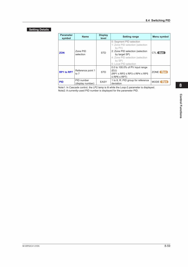
8-59IM 05P02C41-01EN
Control Functions
SettingDetails
Parameter symbol Name Display
level Settingrange Menusymbol
ZON Zone PID selection STD
0: Segment PID selection1: Zone PID selection (selection
by PV)2: Zone PID selection (selection
by target SP)4: Zone PID selection (selection
by SP)5: Local PID selection
CTL
RP1toRP7 Reference point 1 to 7 STD
0.0 to 100.0% of PV input range (EU)(RP1≤RP2≤RP3≤RP4≤RP5≤RP6≤RP7)
ZONE
PID PID number (display number) EASY 1 to 8, R: PID group for reference
deviation MODE
Note1: In Cascade control, the LP2 lamp is lit while the Loop-2 parameter is displayed.Note2: A currently-used PID number is displayed for the parameter PID.
8
8.4SwitchingPID
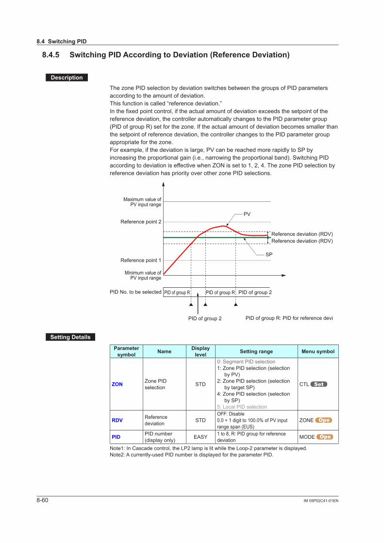
8-60 IM 05P02C41-01EN
8.4.5 SwitchingPIDAccordingtoDeviation(ReferenceDeviation)
Description
ThezonePIDselectionbydeviationswitchesbetweenthegroupsofPIDparametersaccording to the amount of deviation. This function is called “reference deviation.”In the fixed point control, if the actual amount of deviation exceeds the setpoint of the reference deviation, the controller automatically changes to the PID parameter group (PIDofgroupR)setforthezone.Iftheactualamountofdeviationbecomessmallerthanthe setpoint of reference deviation, the controller changes to the PID parameter group appropriateforthezone.For example, if the deviation is large, PV can be reached more rapidly to SP by increasing the proportional gain (i.e., narrowing the proportional band). Switching PID accordingtodeviationiseffectivewhenZONissetto1,2,4.ThezonePIDselectionbyreferencedeviationhaspriorityoverotherzonePIDselections.
Reference deviation (RDV)Reference deviation (RDV)
Reference point 2
Reference point 1
Minimum value of PV input range
SP
PID of group R PID of group R
PID of group 2 PID of group R: PID for reference deviation
PID of group 2
PV
Maximum value of PV input range
PID No. to be selected
SettingDetails
Parameter symbol Name Display
level Settingrange Menusymbol
ZON Zone PID selection STD
0: Segment PID selection1: Zone PID selection (selection
by PV)2: Zone PID selection (selection
by target SP)4: Zone PID selection (selection
by SP)5: Local PID selection
CTL
RDV Reference deviation STD
OFF: Disable0.0 + 1 digit to 100.0% of PV input range span (EUS)
ZONE
PID PID number (display only) EASY 1 to 8, R: PID group for reference
deviation MODE
Note1: In Cascade control, the LP2 lamp is lit while the Loop-2 parameter is displayed.Note2: A currently-used PID number is displayed for the parameter PID.
8.4SwitchingPID

8-61IM 05P02C41-01EN
Control Functions
8.4.6 SettingHysteresisatTimeofPIDSwitchDescription
WhenthezonePIDselectionisselected,hysteresisattimeofeachzoneswitchcanbeset. Thefollowingshowstheoperationexampleofhysteresisattimeofzoneswitch.
Reference point 1
PV
Hysteresis
0.5% of PV input range span
PID of group 1 PID of group 2 PID of group 1 PID of group 2
SettingDetails
Parameter symbol Name Display
level Settingrange Menusymbol
RHY Zone PID switching hysteresis STD 0.0 to 10.0% of PV input
range span (EUS) ZONE
Note1: In Cascade control, the LP2 lamp is lit while the Loop-2 parameter is displayed.
8.4.7 SwitchingPIDIrrespectiveofOperationModeDescription
When the local PID selection is selected (ZON = 5), the PID group set in the local PID number selection (L.PID) is used, irrespective of the operation mode.
SettingDetails
Parameter symbol Name Display
level Settingrange Menusymbol
ZON Zone PID selection STD
0: Segment PID selection1: Zone PID selection (selection
by PV)2: Zone PID selection (selection
by target SP)4: Zone PID selection (selection
by SP)5: Local PID selection
CTL
L.PID Local PID number selection EASY 1 to 8 LOC
PID PID number (display only) EASY 1 to 8 MODE
Note 1: A currently-used PID number is displayed for the parameter PID.
8.4.8 SwitchingPIDbyContactInputDescription
When the local PID selection is selected (ZON = 5), PID can be switching by contact input.
SettingDetails Contact input assignment: 12.1 Setting Contact Input Function
8
8.4SwitchingPID
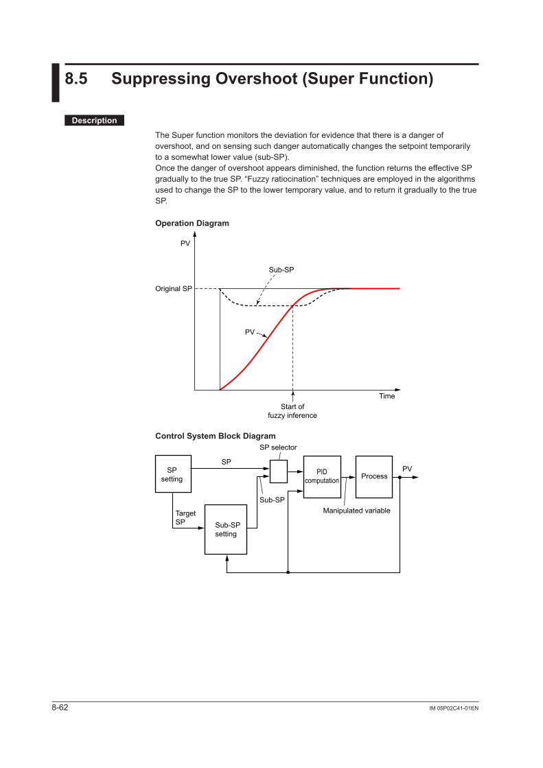
8-62 IM 05P02C41-01EN
8.5 SuppressingOvershoot(SuperFunction)
Description
The Super function monitors the deviation for evidence that there is a danger of overshoot, and on sensing such danger automatically changes the setpoint temporarily to a somewhat lower value (sub-SP).Once the danger of overshoot appears diminished, the function returns the effective SP graduallytothetrueSP.“Fuzzyratiocination”techniquesareemployedinthealgorithmsused to change the SP to the lower temporary value, and to return it gradually to the true SP.
OperationDiagram
Start offuzzy inference
Original SP
PV
Sub-SP
Time
PV
ControlSystemBlockDiagram
SP
SP selector
PV
Manipulated variableSub-SP
TargetSP
SPsetting
Sub-SPsetting
PIDcomputation Process
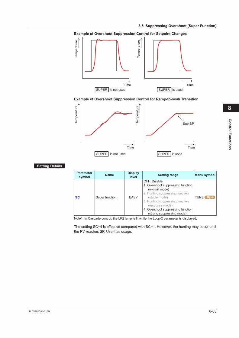
8-63IM 05P02C41-01EN
Control Functions
ExampleofOvershootSuppressionControlforSetpointChanges
Time Time
Tem
pera
ture
Tem
pera
ture
SUPER is not used SUPER is used
ExampleofOvershootSuppressionControlforRamp-to-soakTransition
SUPER is not used SUPER is used
Time Time
Sub-SPTem
pera
ture
Tem
pera
ture
SettingDetails
Parameter symbol Name Display
level Settingrange Menusymbol
SC Super function EASY
OFF: Disable1: Overshoot suppressing function
(normal mode)2: Hunting suppressing function
(stable mode)3: Hunting suppressing function
(response mode)4: Overshoot suppressing function
(strong suppressing mode)
TUNE
Note1: In Cascade control, the LP2 lamp is lit while the Loop-2 parameter is displayed.
The setting SC=4 is effective compared with SC=1. However, the hunting may occur until the PV reaches SP. Use it as usage.
8
8.5SuppressingOvershoot(SuperFunction)
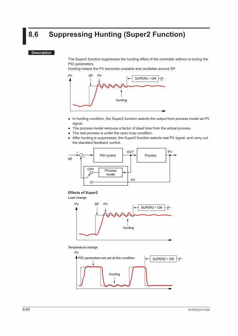
8-64 IM 05P02C41-01EN
8.6 SuppressingHunting(Super2Function)
Description
The Super2 function suppresses the hunting effect of the controller without re-tuning the PID parameters.Hunting means the PV becomes unstable and oscillates around SP.
SUPER2 = ON
Hunting
PV SP PV
Inhuntingcondition,theSuper2functionselectstheoutputfromprocessmodelasPVsignal.
Theprocessmodelremovesafactorofdeadtimefromtheactualprocess. Therealprocessisundertheopen-loopcondition. Afterhuntingissuppressed,theSuper2functionselectsrealPVsignal,andcarryout
the standard feedback control.
PID controlSP
OUT PV
CPV
Process
PV
Processmodel
+–
EffectsofSuper2
SUPER2 = ON
SUPER2 = ON
Hunting
Hunting
PV
PV
SP PV
Load change
Temperature change
PID parameters are set at this condition.
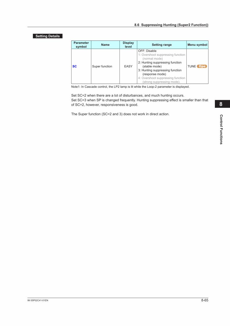
8-65IM 05P02C41-01EN
Control Functions
SettingDetails
Parameter symbol Name Display
level Settingrange Menusymbol
SC Super function EASY
OFF: Disable1: Overshoot suppressing function
(normal mode)2: Hunting suppressing function
(stable mode)3: Hunting suppressing function
(response mode)4: Overshoot suppressing function
(strong suppressing mode).
TUNE
Note1: In Cascade control, the LP2 lamp is lit while the Loop-2 parameter is displayed.
Set SC=2 when there are a lot of disturbances, and much hunting occurs.Set SC=3 when SP is changed frequently. Hunting suppressing effect is smaller than that of SC=2, however, responsiveness is good.
The Super function (SC=2 and 3) does not work in direct action.
8
8.6SuppressingHunting(Super2Function))
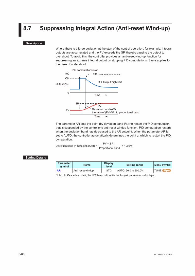
8-66 IM 05P02C41-01EN
8.7 SuppressingIntegralAction(Anti-resetWind-up)
Description
Where there is a large deviation at the start of the control operation, for example, integral outputs are accumulated and the PV exceeds the SP, thereby causing the output to overshoot. To avoid this, the controller provides an anti-reset wind-up function for suppressing an extreme integral output by stopping PID computations. Same applies to the case of undershoot.
100
OH
0
PID computations stop
SP
PID computations restart
OH: Output high limit
Time
Output (%)
Time
PVDeviation band (AR):the ratio of (PV–SP) to proportional band
PV
The parameter AR sets the point (by deviation band (%)) to restart the PID computation that is suspended by the controller’s anti-reset windup function. PID computation restarts when the deviation band has decreased to the AR setpoint. When the parameter AR is set to AUTO, the controller automatically determines the point at which to restart the PID computation.
Deviation band (= Setpoint of AR) = × 100 (%)Proportional band
| PV – SP |
SettingDetails
Parameter symbol Name Display
level Settingrange Menusymbol
AR Anti-reset windup STD AUTO, 50.0 to 200.0% TUNE
Note1: In Cascade control, the LP2 lamp is lit while the Loop-2 parameter is displayed.
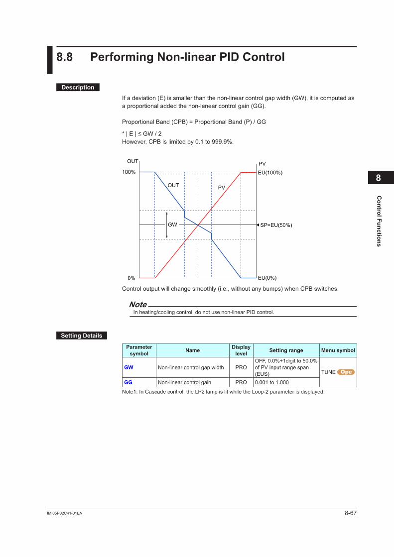
8-67IM 05P02C41-01EN
Control Functions
8.8 PerformingNon-linearPIDControl
Description
If a deviation (E) is smaller than the non-linear control gap width (GW), it is computed as a proportional added the non-lenear control gain (GG).
Proportional Band (CPB) = Proportional Band (P) / GG
*|E|≤GW/2However, CPB is limited by 0.1 to 999.9%.
0%
100%
SP=EU(50%)
EU(100%)
EU(0%)
PV
PV
OUT
OUT
GW
Control output will change smoothly (i.e., without any bumps) when CPB switches.
NoteIn heating/cooling control, do not use non-linear PID control.
SettingDetails
Parameter symbol Name Display
level Settingrange Menusymbol
GW Non-linear control gap width PROOFF, 0.0%+1digit to 50.0% of PV input range span (EUS) TUNE
GG Non-linear control gain PRO 0.001 to 1.000
Note1: In Cascade control, the LP2 lamp is lit while the Loop-2 parameter is displayed.
8
8-68 IM 05P02C41-01EN
8.9 AdjustingAuto-tuningOperation
Description
Auto-tuningType“Normal” of auto-tuning type requires a rapidly rising PID constant. This type is useful for processes that allow some overshooting. On the other hand, “stable” of auto-tuning type requires a slowly rising PID constant.
Auto-tuningOutputLimiterWhen executing auto-tuning, the control output high and low limits can be set.When the control output low limit > AT.OL, or AT.OH < control output high limit, auto-tuning is limited by the control output low or high limit.In Heating/cooling control, AT.OH and AT.OL do not work.
NoteIn time proportional output, the output is turned on and off irrespective of the upper/lower limit.
SettingDetails
Parameter symbol Name Display
level Settingrange Menusymbol
AT.TY Auto-tuning type STD 0: Normal1: Stability
TUNE AT.OH Output high limit in auto-tuning PRO
-5.0 to 105.0% (Disabled in Heating/cooling control)AT.OL Output low limit in
auto-tuning PRO
Note1: In Cascade control, the LP2 lamp is lit while the Loop-2 parameter is displayed.
SP bias in auto-tuning: 6.2 Performing and Canceling Auto-tuning
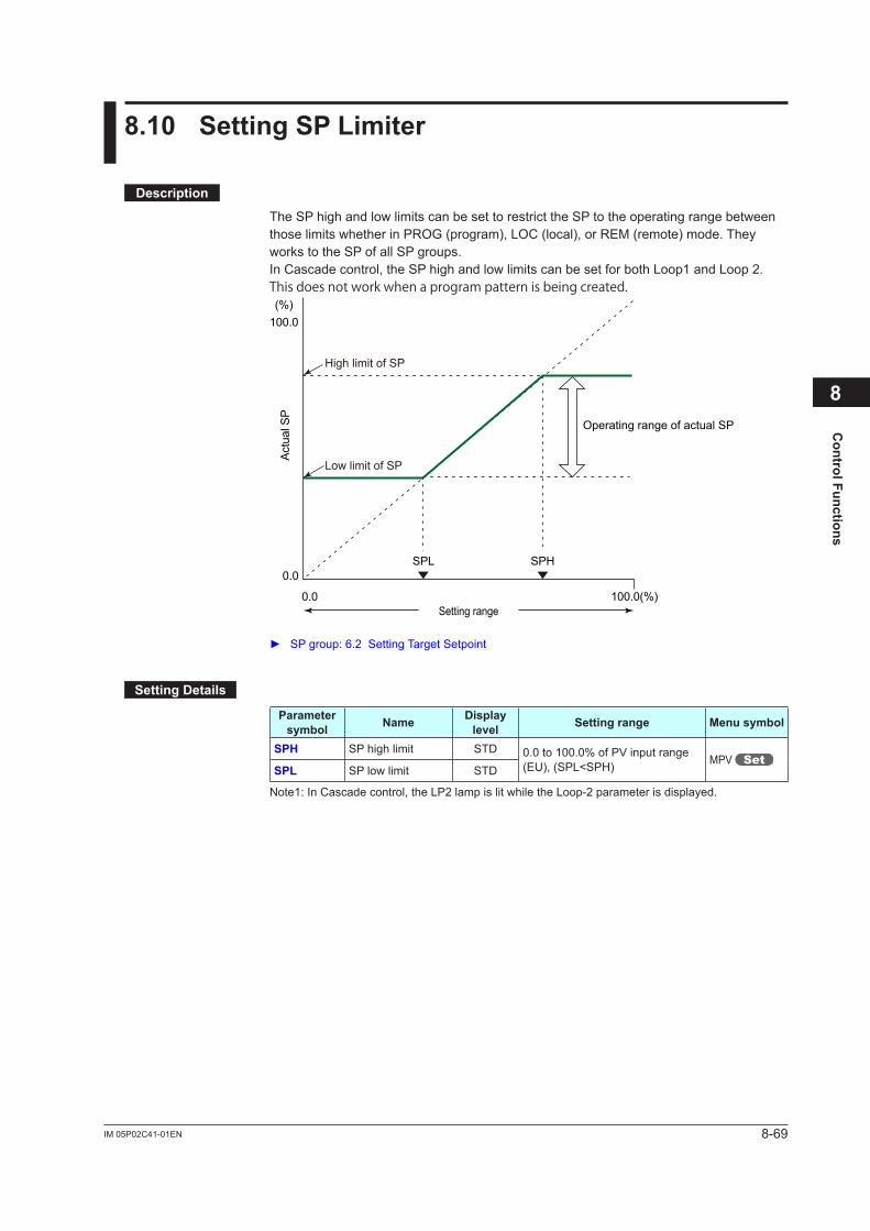
8-69IM 05P02C41-01EN
Control Functions
8.10 SettingSPLimiter
Description
The SP high and low limits can be set to restrict the SP to the operating range between those limits whether in PROG (program), LOC (local), or REM (remote) mode. They works to the SP of all SP groups.In Cascade control, the SP high and low limits can be set for both Loop1 and Loop 2.This does not work when a program pattern is being created.
0.0 100.0(%)
SPH
Actu
al S
P
SPL
Operating range of actual SP
Setting range
0.0
(%)100.0
High limit of SP
Low limit of SP
SP group: 6.2 Setting Target Setpoint
SettingDetails
Parameter symbol Name Display
level Settingrange Menusymbol
SPH SP high limit STD 0.0 to 100.0% of PV input range (EU), (SPL<SPH) MPV
SPL SP low limit STD
Note1: In Cascade control, the LP2 lamp is lit while the Loop-2 parameter is displayed.
8
8-70 IM 05P02C41-01EN
8.11 SettingProgramTimeUnit
Description
The program time unit is applied to the segment time (TIME), segment ramp-rate (TM.RT), wait time (WT.TM1 to WT.TM5), time event (T.ON1 to T.ON16 and T.OF1 to T.OF16), and starting time of program operation (S.TM).
SettingDetails
Parameter symbol Name Display
level Settingrange Menusymbol
TMU Program time unit EASY
HH.MM: hour.minute (when the segment ramp-rate setting is selected in the segment setting method (SEG.T), HH.SS means "per 1 hour.")
MM.SS: minute.second (when the segment ramp-rate setting is selected in the segment setting method (SEG.T), HH.SS means "per 1 minute.")
CTL
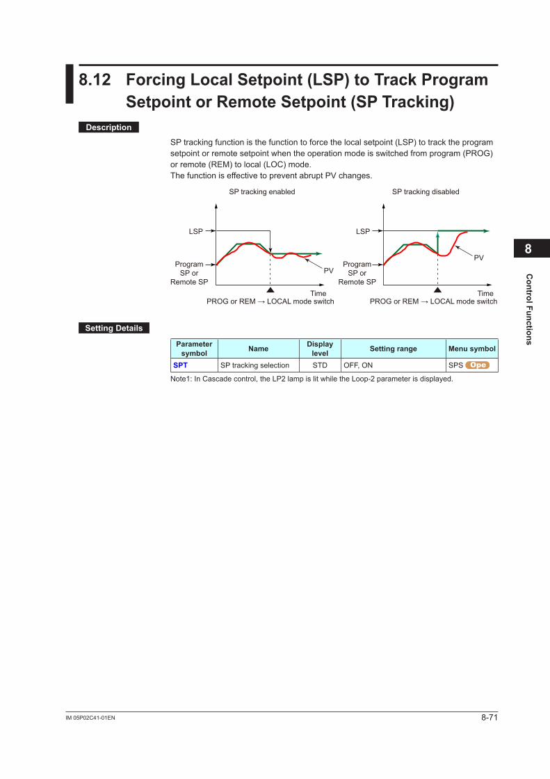
8-71IM 05P02C41-01EN
Control Functions
8.12 ForcingLocalSetpoint(LSP)toTrackProgramSetpointorRemoteSetpoint(SPTracking)
Description
SP tracking function is the function to force the local setpoint (LSP) to track the program setpoint or remote setpoint when the operation mode is switched from program (PROG) or remote (REM) to local (LOC) mode.The function is effective to prevent abrupt PV changes.
PROG or REM → LOCAL mode switchTime
PROG or REM → LOCAL mode switchTime
SP tracking enabled SP tracking disabled
PV
PV
LSPLSP
Program SP or
Remote SP
Program SP or
Remote SP
SettingDetails
Parameter symbol Name Display
level Settingrange Menusymbol
SPT SP tracking selection STD OFF, ON SPS
Note1: In Cascade control, the LP2 lamp is lit while the Loop-2 parameter is displayed.
8
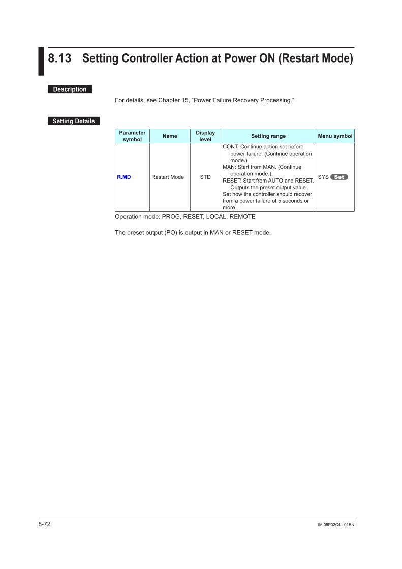
8-72 IM 05P02C41-01EN
8.13 SettingControllerActionatPowerON(RestartMode)
Description
For details, see Chapter 15, “Power Failure Recovery Processing.”
SettingDetails
Parameter symbol Name Display
level Settingrange Menusymbol
R.MD Restart Mode STD
CONT: Continue action set before power failure. (Continue operation mode.)
MAN: Start from MAN. (Continue operation mode.)
RESET: Start from AUTO and RESET. Outputs the preset output value.
Set how the controller should recover from a power failure of 5 seconds or more.
SYS
Operation mode: PROG, RESET, LOCAL, REMOTE
The preset output (PO) is output in MAN or RESET mode.
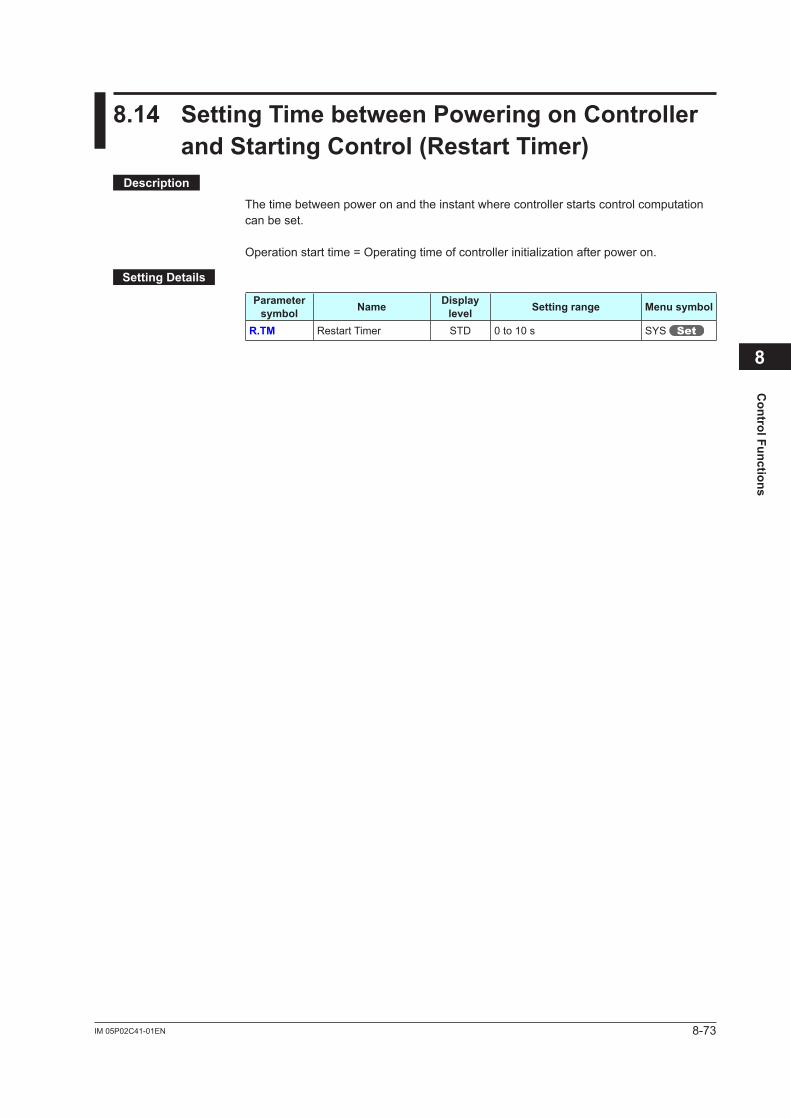
8-73IM 05P02C41-01EN
Control Functions
8.14 SettingTimebetweenPoweringonControllerandStartingControl(RestartTimer)
Description
The time between power on and the instant where controller starts control computation can be set.
Operationstarttime=Operatingtimeofcontrollerinitializationafterpoweron.
SettingDetails
Parameter symbol Name Display
level Settingrange Menusymbol
R.TM Restart Timer STD 0 to 10 s SYS
8

Blank Page
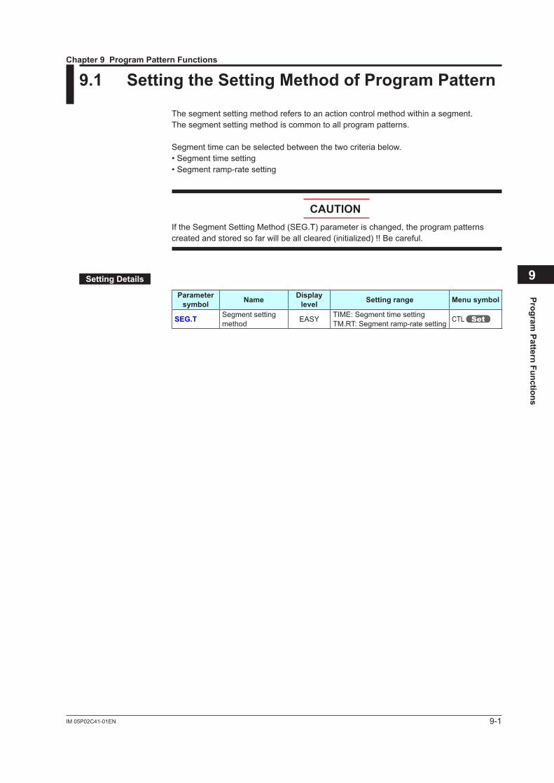
9-1IM 05P02C41-01EN
Program Pattern Functions
9
9.1 SettingtheSettingMethodofProgramPattern
The segment setting method refers to an action control method within a segment.The segment setting method is common to all program patterns.
Segment time can be selected between the two criteria below.• Segment time setting• Segment ramp-rate setting
CAUTIONIf the Segment Setting Method (SEG.T) parameter is changed, the program patterns createdandstoredsofarwillbeallcleared(initialized)!!Becareful.
SettingDetails
Parameter symbol Name Display
level Settingrange Menusymbol
SEG.T Segment setting method EASY TIME: Segment time setting
TM.RT: Segment ramp-rate setting CTL
Chapter 9 Program Pattern Functions
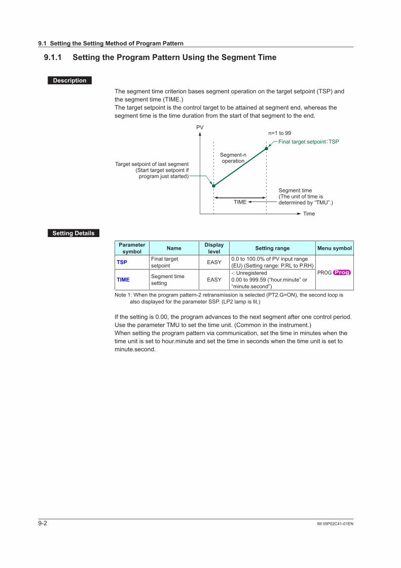
9-2 IM 05P02C41-01EN
9.1.1 SettingtheProgramPatternUsingtheSegmentTime
Description
The segment time criterion bases segment operation on the target setpoint (TSP) and the segment time (TIME.)The target setpoint is the control target to be attained at segment end, whereas the segment time is the time duration from the start of that segment to the end.
PV
TIME
Time
n=1 to 99
Target setpoint of last segment(Start target setpoint if
program just started)
Segment time(The unit of time is determined by “TMU”.)
Segment-noperation
Final target setpoint:TSP
SettingDetails
Parameter symbol Name Display
level Settingrange Menusymbol
TSP Final target setpoint EASY 0.0 to 100.0% of PV input range
(EU) (Setting range: P.RL to P.RH)PROG
TIME Segment time setting EASY
-: Unregistered0.00 to 999.59 (“hour.minute” or “minute.second”)
Note 1: When the program pattern-2 retransmission is selected (PT2.G=ON), the second loop is also displayed for the parameter SSP. (LP2 lamp is lit.)
If the setting is 0.00, the program advances to the next segment after one control period.Use the parameter TMU to set the time unit. (Common in the instrument.)When setting the program pattern via communication, set the time in minutes when the time unit is set to hour.minute and set the time in seconds when the time unit is set to minute.second.
9.1SettingtheSettingMethodofProgramPattern
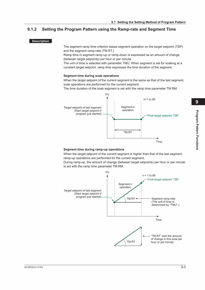
9-3IM 05P02C41-01EN
Program Pattern Functions
9
9.1.2 SettingtheProgramPatternusingtheRamp-rateandSegmentTime
Description
The segment ramp time criterion bases segment operation on the target setpoint (TSP) and the segment ramp-rate (TM.RT.)Ramp time in segment ramp-up or ramp-down is expressed as an amount of change (between target setpoints) per hour or per minute.The unit of time is selected with parameter TMU. When segment is set for soaking at a constant target setpoint, ramp time expresses the time duration of the segment.
SegmenttimeduringsoakoperationsWhen the target setpoint of the current segment is the same as that of the last segment, soak operations are performed for the current segment.The time duration of the soak segment is set with the ramp time parameter TM.RM.
TM.RT
PV
Time
n=1 to 99
Target setpoint of last segment(Start target setpoint if
program just started)
Segment-noperation
Final target setpoint:TSP
Segmenttimeduringramp-upoperationsWhen the target setpoint of the current segment is higher than that of the last segment, ramp-up operations are performed for the current segment.During ramp-up, the amount of change (between target setpoints) per hour or per minute is set with the ramp time parameter TM.RM.
TM.RT
n = 1 to 99
TM.RT
“TM.RT” sets the amount of change in this area per hour or per minute.
PV
Time
Target setpoint of last segment(Start target setpoint if
program just started)Segment ramp-rate(The unit of time is determined by “TMU”.)
Segment-noperation
Final target setpoint:TSP
9.1SettingtheSettingMethodofProgramPattern
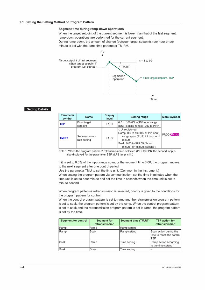
9-4 IM 05P02C41-01EN
Segmenttimeduringramp-downoperationsWhen the target setpoint of the current segment is lower than that of the last segment, ramp-down operations are performed for the current segment.During ramp-down, the amount of change (between target setpoints) per hour or per minute is set with the ramp time parameter TM.RM.
TM.RT
n = 1 to 99
PV
Time
Target setpoint of last segment(Start target setpoint if
program just started)
Segment-noperation Final target setpoint:TSP
SettingDetails
Parameter symbol Name Display
level Settingrange Menusymbol
TSP Final target setpoint EASY 0.0 to 100.0% of PV input range
(EU) (Setting range: P.RL to P.RH)
PROG TM.RT Segment ramp-
rate setting EASY
-: UnregisteredRamp: 0.0 to 100.0% of PV input
range span (EUS) / 1 hour or 1 minute
Soak: 0.00 to 999.59 (“hour.minute” or “minute.second”)
Note 1: When the program pattern-2 retransmission is selected (PT2.G=ON), the second loop is also displayed for the parameter SSP. (LP2 lamp is lit.)
If it is set to 0.0% of the input range span, or the segment time 0.00, the program moves to the next segment after one control period.Use the parameter TMU to set the time unit. (Common in the instrument.)When setting the program pattern via communication, set the time in minutes when the time unit is set to hour.minute and set the time in seconds when the time unit is set to minute.second.
When program pattern-2 retransmission is selected, priority is given to the conditions for the program pattern for control.When the control program pattern is set to ramp and the retransmission program pattern is set to soak, the program pattern is set by the ramp. When the control program pattern is set to soak and the retransmission program pattern is set to ramp, the program pattern is set by the time.
Segmentforcontrol Segmentforretransmission
Segmenttime(TM.RT) TSPactionforretransmission
Ramp Ramp Ramp setting -Ramp Soak Ramp setting Soak action during the
time to reach the control TSP
Soak Ramp Time setting Ramp action according to the time setting
Soak Soak Time setting -
9.1SettingtheSettingMethodofProgramPattern
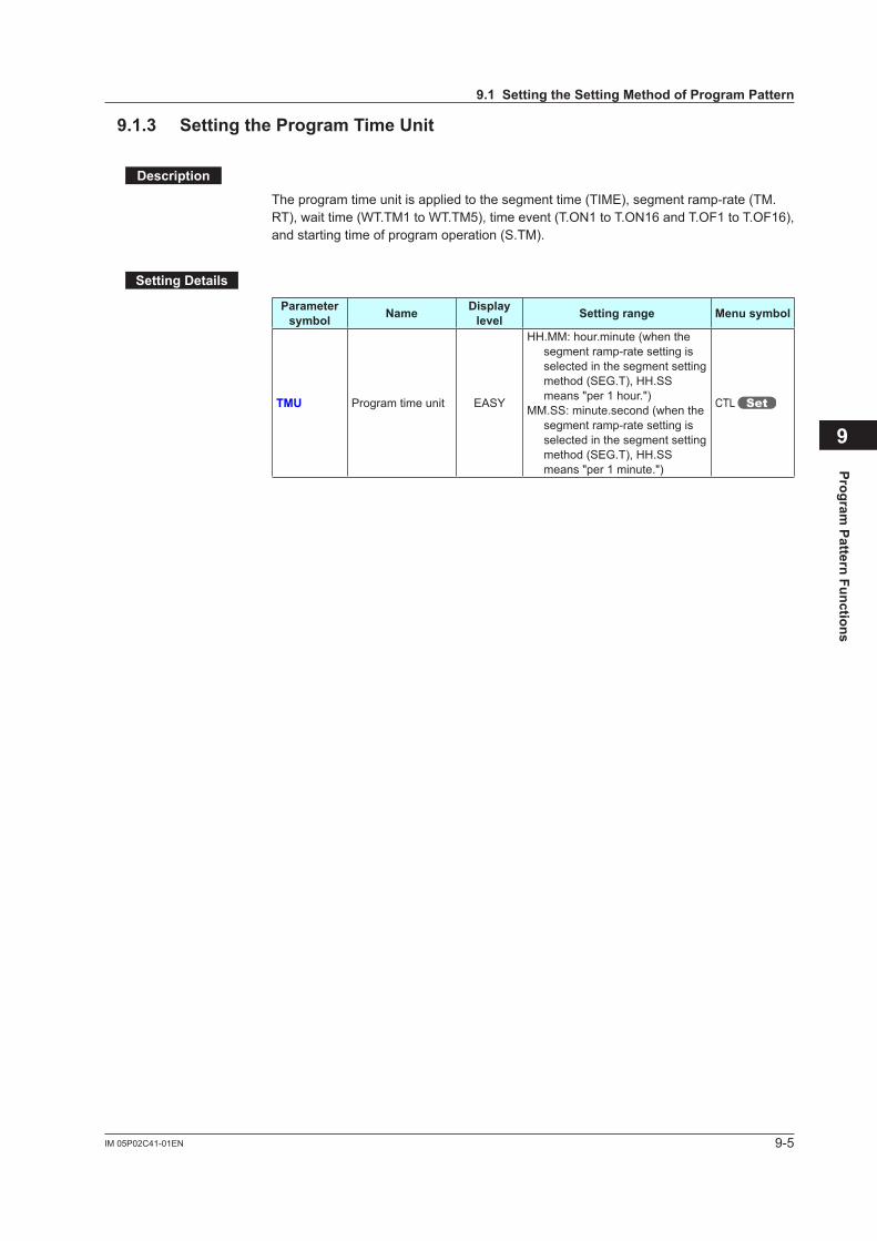
9-5IM 05P02C41-01EN
Program Pattern Functions
9
9.1.3 SettingtheProgramTimeUnit
Description
The program time unit is applied to the segment time (TIME), segment ramp-rate (TM.RT), wait time (WT.TM1 to WT.TM5), time event (T.ON1 to T.ON16 and T.OF1 to T.OF16), and starting time of program operation (S.TM).
SettingDetails
Parameter symbol Name Display
level Settingrange Menusymbol
TMU Program time unit EASY
HH.MM: hour.minute (when the segment ramp-rate setting is selected in the segment setting method (SEG.T), HH.SS means "per 1 hour.")
MM.SS: minute.second (when the segment ramp-rate setting is selected in the segment setting method (SEG.T), HH.SS means "per 1 minute.")
CTL
9.1SettingtheSettingMethodofProgramPattern
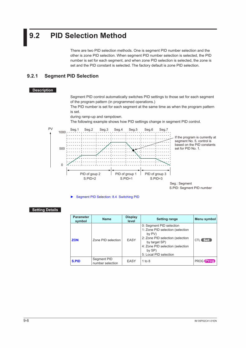
9-6 IM 05P02C41-01EN
9.2 PIDSelectionMethod
There are two PID selection methods. One is segment PID number selection and the otheriszonePIDselection.WhensegmentPIDnumberselectionisselected,thePIDnumberissetforeachsegment,andwhenzonePIDselectionisselected,thezoneissetandthePIDconstantisselected.ThefactorydefaultiszonePIDselection.
9.2.1 SegmentPIDSelection
Description
Segment PID control automatically switches PID settings to those set for each segment of the program pattern (in programmed operations.)The PID number is set for each segment at the same time as when the program pattern is set.during ramp-up and rampdown.The following example shows how PID settings change in segment PID control.
PV
PID of goup 2
Seg.1
Seg.: Segment
1000
500
0
Seg.2 Seg.3 Seg.4 Seg.5 Seg.6 Seg.7
PID of group 1 PID of group 3
If the program is currently at segment No. 5, control is based on the PID constants set for PID No. 1.
S.PID=2 S.PID=1 S.PID=3
S.PID: Segment PID number
Segment PID Selection: 8.4 Switching PID
SettingDetails
Parameter symbol Name Display
level Settingrange Menusymbol
ZON Zone PID selection EASY
0: Segment PID selection1: Zone PID selection (selection
by PV)2: Zone PID selection (selection
by target SP)4: Zone PID selection (selection
by SP)5: Local PID selection
CTL
S.PID Segment PID number selection EASY 1 to 8 PROG
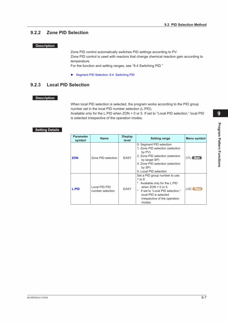
9-7IM 05P02C41-01EN
Program Pattern Functions
9
9.2.2 ZonePIDSelection
Description
Zone PID control automatically switches PID settings according to PV.Zone PID control is used with reactors that change chemical reaction gain according to temperature.For the function and setting ranges, see “8.4 Switching PID.”
Segment PID Selection: 8.4 Switching PID
9.2.3 LocalPIDSelection
Description
When local PID selection is selected, the program works according to the PID group number set in the local PID number selection (L.PID).Available only for the L.PID when ZON = 0 or 5. If set to “Local PID selection,” local PID is selected irrespective of the operation modes.
SettingDetails
Parameter symbol Name Display
level Settingrange Menusymbol
ZON Zone PID selection EASY
0: Segment PID selection1: Zone PID selection (selection
by PV)2: Zone PID selection (selection
by target SP)4: Zone PID selection (selection
by SP)5: Local PID selection
CTL
L.PID Local PID PID number selection EASY
Set a PID group number to use.1 to 8* Available only for the L.PID
when ZON = 0 or 5.* If set to “Local PID selection,”
local PID is selected irrespective of the operation modes.
LOC
9.2PIDSelectionMethod
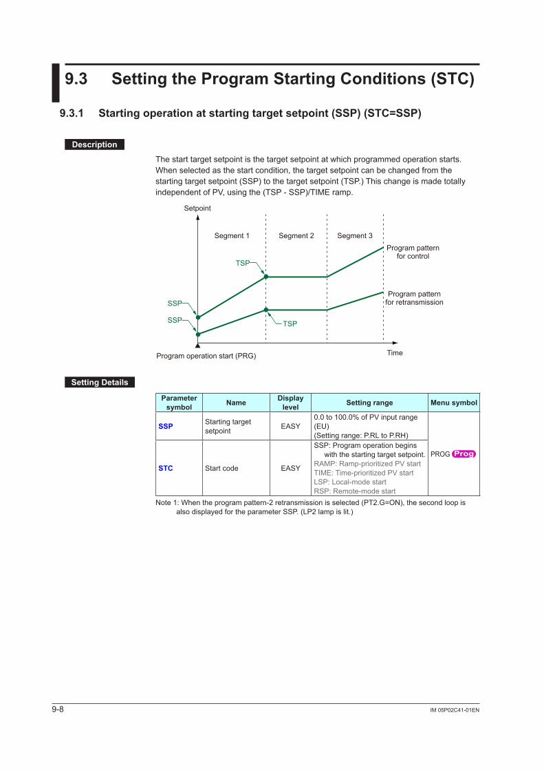
9-8 IM 05P02C41-01EN
9.3 SettingtheProgramStartingConditions(STC)
9.3.1 Startingoperationatstartingtargetsetpoint(SSP)(STC=SSP)
Description
The start target setpoint is the target setpoint at which programmed operation starts.When selected as the start condition, the target setpoint can be changed from the starting target setpoint (SSP) to the target setpoint (TSP.) This change is made totally independent of PV, using the (TSP - SSP)/TIME ramp.
Program operation start (PRG) Time
TSP
SSP
SSP
Segment 1
Program pattern for control
Program pattern for retransmission
Segment 2 Segment 3
Setpoint
TSP
SettingDetails
Parameter symbol Name Display
level Settingrange Menusymbol
SSP Starting target setpoint EASY
0.0 to 100.0% of PV input range (EU)(Setting range: P.RL to P.RH)
PROG
STC Start code EASY
SSP: Program operation begins with the starting target setpoint.
RAMP:Ramp-prioritizedPVstartTIME:Time-prioritizedPVstartLSP: Local-mode startRSP: Remote-mode start
Note 1: When the program pattern-2 retransmission is selected (PT2.G=ON), the second loop is also displayed for the parameter SSP. (LP2 lamp is lit.)
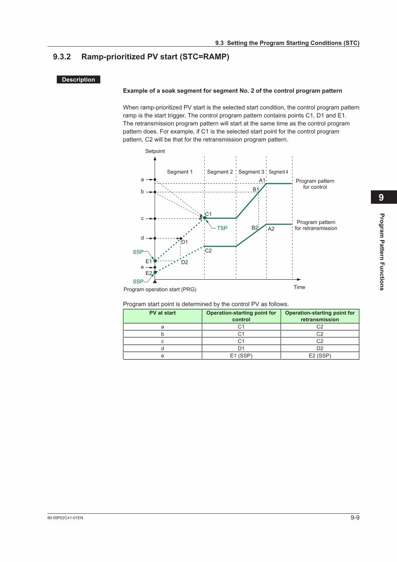
9-9IM 05P02C41-01EN
Program Pattern Functions
9
9.3.2 Ramp-prioritizedPVstart(STC=RAMP)
Description
ExampleofasoaksegmentforsegmentNo.2ofthecontrolprogrampattern
Whenramp-prioritizedPVstartistheselectedstartcondition,thecontrolprogrampatternramp is the start trigger. The control program pattern contains points C1, D1 and E1.The retransmission program pattern will start at the same time as the control program pattern does. For example, if C1 is the selected start point for the control program pattern, C2 will be that for the retransmission program pattern.
TSP
SSP
SSP
Segment 1 Segment 2 Segment 3 Segment 4a
b
c
d
eE1
E2
D1
D2
C1
C2
A1
A2
B1
B2
Program pattern for control
Program pattern for retransmission
Program operation start (PRG) Time
Setpoint
Program start point is determined by the control PV as follows.PV at start Operation-startingpointfor
controlOperation-startingpointfor
retransmissiona C1 C2b C1 C2c C1 C2d D1 D2e E1 (SSP) E2 (SSP)
9.3SettingtheProgramStartingConditions(STC)

9-10 IM 05P02C41-01EN
ExampleofasoaksegmentforsegmentNo.3ofthecontrolprogrampattern
Whenramp-prioritizedPVstartistheselectedstartcondition,thecontrolprogrampatternramp is the start trigger. The control program pattern contains points A1 to E1.The retransmission program pattern will start at the same time as the control program pattern does. For example, if A1 is the selected start point for the control program pattern, A2 will be that for the retransmission program pattern.
D1
E1
E2
D2
B1
C1
C2 B2
TSP
SSP
Segment 1 Segment 2 Segment 3a
b
c
d
e
A1
A2
Program pattern for control
Program pattern for retransmission
Program operation start (PRG) Time
Setpoint
Program start point is determined by the control PV as follows.PV at start Operation-startingpointfor
controlOperation-startingpointfor
retransmissiona A1 A2b B1 B2c C1 C2d D1 D2e E1 (SSP) E2 (SSP)
9.3SettingtheProgramStartingConditions(STC)
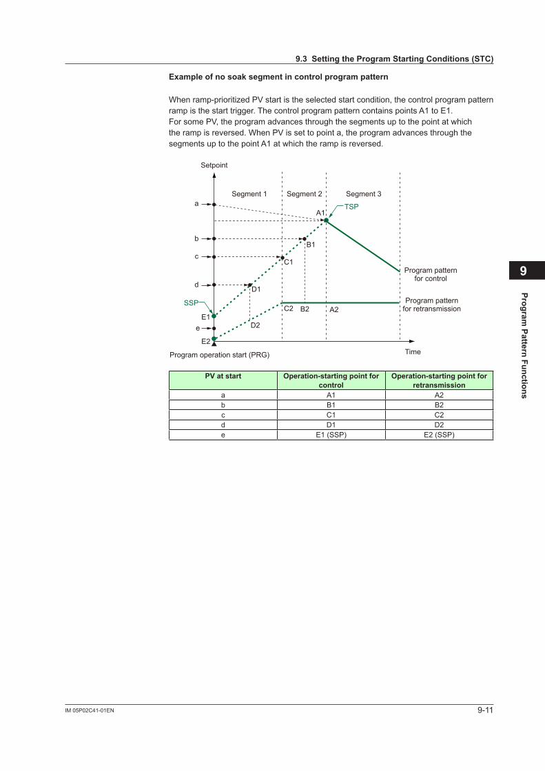
9-11IM 05P02C41-01EN
Program Pattern Functions
9
Exampleofnosoaksegmentincontrolprogrampattern
Whenramp-prioritizedPVstartistheselectedstartcondition,thecontrolprogrampatternramp is the start trigger. The control program pattern contains points A1 to E1.For some PV, the program advances through the segments up to the point at which the ramp is reversed. When PV is set to point a, the program advances through the segments up to the point A1 at which the ramp is reversed.
D1
E1
E2
D2
B1
C1
C2 B2
TSP
SSP
Segment 1 Segment 2 Segment 3a
b
c
d
e
A1
A2
Program pattern for control
Program pattern for retransmission
Program operation start (PRG) Time
Setpoint
PV at start Operation-startingpointforcontrol
Operation-startingpointforretransmission
a A1 A2b B1 B2c C1 C2d D1 D2e E1 (SSP) E2 (SSP)
9.3SettingtheProgramStartingConditions(STC)
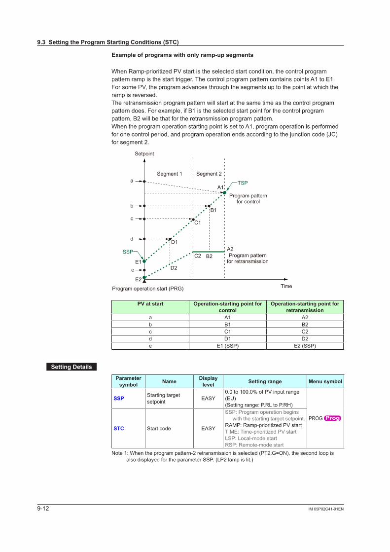
9-12 IM 05P02C41-01EN
Exampleofprogramswithonlyramp-upsegments
WhenRamp-prioritizedPVstartistheselectedstartcondition,thecontrolprogrampattern ramp is the start trigger. The control program pattern contains points A1 to E1.For some PV, the program advances through the segments up to the point at which the ramp is reversed.The retransmission program pattern will start at the same time as the control program pattern does. For example, if B1 is the selected start point for the control program pattern, B2 will be that for the retransmission program pattern.When the program operation starting point is set to A1, program operation is performed foronecontrolperiod,andprogramoperationendsaccordingtothejunctioncode(JC)for segment 2.
D1
E1
E2
D2
B1
C1
C2 B2
TSP
SSP
Segment 1 Segment 2a
b
c
d
e
A1
A2
Program pattern for control
Program pattern for retransmission
Program operation start (PRG) Time
Setpoint
PV at start Operation-startingpointforcontrol
Operation-startingpointforretransmission
a A1 A2b B1 B2c C1 C2d D1 D2e E1 (SSP) E2 (SSP)
SettingDetails
Parameter symbol Name Display
level Settingrange Menusymbol
SSP Starting target setpoint EASY
0.0 to 100.0% of PV input range (EU)(Setting range: P.RL to P.RH)
PROG
STC Start code EASY
SSP: Program operation begins with the starting target setpoint.
RAMP:Ramp-prioritizedPVstartTIME:Time-prioritizedPVstartLSP: Local-mode startRSP: Remote-mode start
Note 1: When the program pattern-2 retransmission is selected (PT2.G=ON), the second loop is also displayed for the parameter SSP. (LP2 lamp is lit.)
9.3SettingtheProgramStartingConditions(STC)
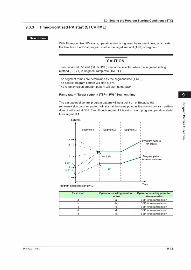
9-13IM 05P02C41-01EN
Program Pattern Functions
9
9.3.3 Time-prioritizedPVstart(STC=TIME)
Description
WithTime-prioritizedPVstarts,operationstartistriggeredbysegmenttime,whichsetsthe time from the PV at program start to the target setpoint (TSP) of segment 1.
CAUTIONTime-prioritizedPVstart(STC=TIME)cannotbeselectedwhenthesegmentsettingmethod (SEG.T) is Segment ramp-rate (TM.RT.)
The segment ramps are determined by the segment time (TIME.)The control program pattern will start at PV.The retransmission program pattern will start at the SSP.
Ramprate=(Targetsetpoint(TSP)-PV)/Segmenttime
The start point of control program pattern will be a point a - e. Because the retransmission program pattern will start at the same point as the control program pattern does, it will start at SSP. Even though segment 2 is set to ramp, program operation starts from segment 1.
TSP
TSP
SSP
SSP
a
b
c
d
e
Segment 1 Segment 2 Segment 3
Program pattern for control
Program pattern for retransmission
Program operation start (PRG) Time
Setpoint
PV at start Operation-startingpointforcontrol
Operation-startingpointforretransmission
a a SSP for retransmissionb b SSP for retransmissionc c SSP for retransmissiond d SSP for retransmissione e SSP for retransmission
9.3SettingtheProgramStartingConditions(STC)
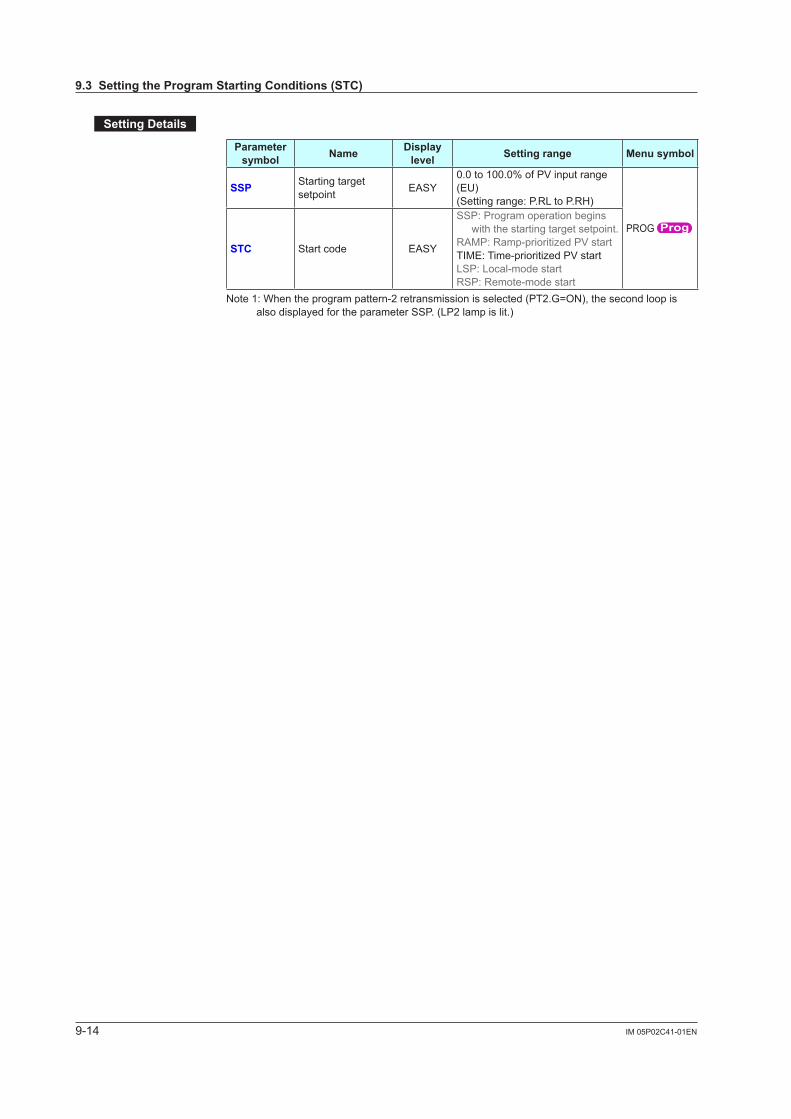
9-14 IM 05P02C41-01EN
SettingDetails
Parameter symbol Name Display
level Settingrange Menusymbol
SSP Starting target setpoint EASY
0.0 to 100.0% of PV input range (EU)(Setting range: P.RL to P.RH)
PROG
STC Start code EASY
SSP: Program operation begins with the starting target setpoint.
RAMP:Ramp-prioritizedPVstartTIME:Time-prioritizedPVstartLSP: Local-mode startRSP: Remote-mode start
Note 1: When the program pattern-2 retransmission is selected (PT2.G=ON), the second loop is also displayed for the parameter SSP. (LP2 lamp is lit.)
9.3SettingtheProgramStartingConditions(STC)

9-15IM 05P02C41-01EN
Program Pattern Functions
9
9.3.4 Startingoperationatlocaltargetsetpoint(STC=LSP)
Description
When selected as the start condition, the target setpoint can be changed from the local target setpoint (LSP) to the target setpoint (TSP.) This change is made totally independent of PV, using the (TSP - LSP)/TIME ramp.Local-mode start (STC=LSP) cannot be selected when the segment setting method (SEG.T) is Segment ramp-rate (TM.RT.)
Seg.1 Seg.2 Seg.3
TSP
TSPSSP
SSP
Local target setpoint (LSP) in Local operation
(for control)
Local target setpoint (LSP) in
Local operation (for retransmission)
Seg.: Segment
TSP
Program pattern for control
Program pattern for retransmission
Program operation start (LOC → PRG) Time
Setpoint
(1)WhenLSPandSSParedifferent
Local target setpoint (LSP) in Local operation
Seg.: Segment
Program pattern for control
Program operation start (LOC → PRG) Time
Setpoint
Seg.1 Seg.2 Seg.3
TSP
SSP
TSP
TSP
9.3SettingtheProgramStartingConditions(STC)
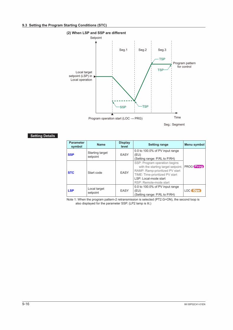
9-16 IM 05P02C41-01EN
(2)WhenLSPandSSParedifferent
Seg.1 Seg.2 Seg.3
TSPSSP
TSP
TSP
Local target setpoint (LSP) in Local operation
Seg.: Segment
Program pattern for control
Program operation start (LOC → PRG) Time
Setpoint
SettingDetails
Parameter symbol Name Display
level Settingrange Menusymbol
SSP Starting target setpoint EASY
0.0 to 100.0% of PV input range (EU)(Setting range: P.RL to P.RH)
PROG
STC Start code EASY
SSP: Program operation begins with the starting target setpoint.
RAMP:Ramp-prioritizedPVstartTIME:Time-prioritizedPVstartLSP: Local-mode startRSP: Remote-mode start
LSP Local target setpoint EASY
0.0 to 100.0% of PV input range (EU) (Setting range: P.RL to P.RH)
LOC
Note 1: When the program pattern-2 retransmission is selected (PT2.G=ON), the second loop is also displayed for the parameter SSP. (LP2 lamp is lit.)
9.3SettingtheProgramStartingConditions(STC)
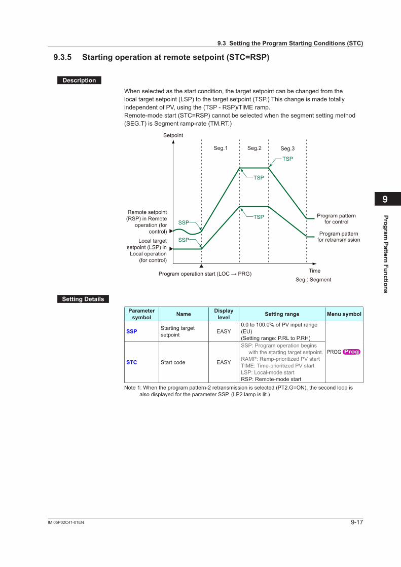
9-17IM 05P02C41-01EN
Program Pattern Functions
9
9.3.5 Startingoperationatremotesetpoint(STC=RSP)
Description
When selected as the start condition, the target setpoint can be changed from the local target setpoint (LSP) to the target setpoint (TSP.) This change is made totally independent of PV, using the (TSP - RSP)/TIME ramp.Remote-mode start (STC=RSP) cannot be selected when the segment setting method (SEG.T) is Segment ramp-rate (TM.RT.)
Seg.1 Seg.2 Seg.3
TSP
TSPSSP
SSP
TSP
Remote setpoint (RSP) in Remote
operation (for control)
Local target setpoint (LSP) in Local operation
(for control)
Seg.: Segment
Program pattern for control
Program pattern for retransmission
Program operation start (LOC → PRG) Time
Setpoint
SettingDetails
Parameter symbol Name Display
level Settingrange Menusymbol
SSP Starting target setpoint EASY
0.0 to 100.0% of PV input range (EU)(Setting range: P.RL to P.RH)
PROG
STC Start code EASY
SSP: Program operation begins with the starting target setpoint.
RAMP:Ramp-prioritizedPVstartTIME:Time-prioritizedPVstartLSP: Local-mode startRSP: Remote-mode start
Note 1: When the program pattern-2 retransmission is selected (PT2.G=ON), the second loop is also displayed for the parameter SSP. (LP2 lamp is lit.)
9.3SettingtheProgramStartingConditions(STC)

9-18 IM 05P02C41-01EN
9.4 SettingtheWaitFunctions
9.4.1 ProgramWaitatSegmentEnd
Description
Program wait at segment end makes the program wait at segment end if PV has not attained the target setpoint.The program will advance to the next segment the moment that the measured input attainsthewaitzone.Ifthemeasuredinputdoesnotattainthewaitzonewithinthewaittime,theprogramwilladvance to the next segment the moment the wait time elapses.
• Operationwhenthemeasuredinputattainsthewaitzonebeforethewaittimeelapses
Fromwhenthewaitoperationstarts,ifthemeasuredinputattainsthewaitzone,thewaitstate is changed to the operating state and the program advances to the next segment.During the wait state, the program timer is stopped, therefore the time event value is held.
TimeWait time
Upper-side wait zone
Lower-side wait zone
Wait operation
PV
TSP
Seg.1 Seg.2
Seg.: SegmentTSP: Final target setpoint
The moment that the PV attains the wait zone, the program advances to the next segment.
Setpoint
Time eventOnOff
Timer stops
Time delayed by timer stops
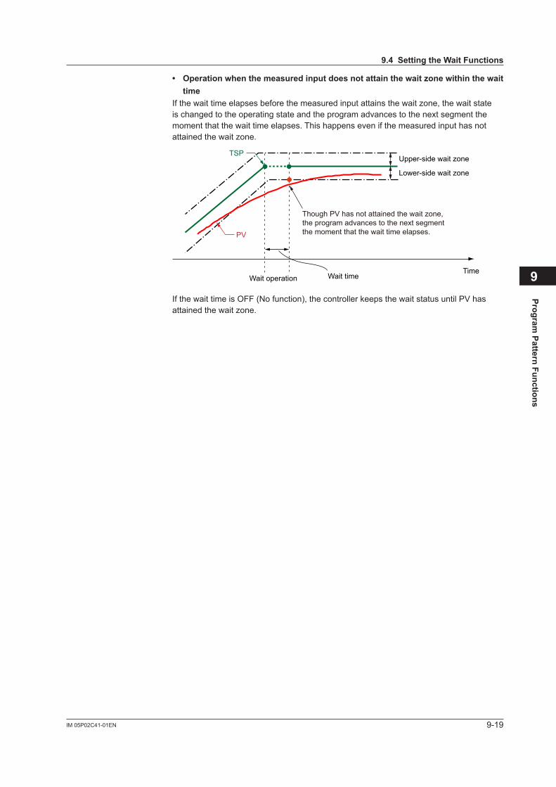
9-19IM 05P02C41-01EN
Program Pattern Functions
9
• Operationwhenthemeasuredinputdoesnotattainthewaitzonewithinthewaittime
Ifthewaittimeelapsesbeforethemeasuredinputattainsthewaitzone,thewaitstateis changed to the operating state and the program advances to the next segment the moment that the wait time elapses. This happens even if the measured input has not attainedthewaitzone.
TimeWait time
Upper-side wait zone
Lower-side wait zone
Wait operation
Though PV has not attained the wait zone,the program advances to the next segmentthe moment that the wait time elapses.PV
TSP
If the wait time is OFF (No function), the controller keeps the wait status until PV has attainedthewaitzone.
9.4SettingtheWaitFunctions
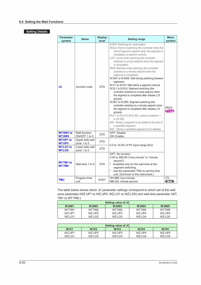
9-20 IM 05P02C41-01EN
SettingDetails
Parameter symbol Name Display
level Settingrange Menu symbol
JC Junction code STD
CONT: Switching for continuationHOLD: Hold-on switching (the controller holds the
end-of-segment setpoint when the segment is completed, to perform control).
LOC: Local-mode switching (the controller switches to a local setpoint when the segment is completed).
REM: Remote-mode switching (the controller switches to a remote setpoint when the segment is completed).
W.SW1 to W.SW5: Wait during switching between segments.
W.IV1 to W.IV5: Wait within a segment interval.W.SL1 to W.SL5: Segment switching (the
controller switches to a local setpoint when the segment is completed after release.) (5 groups)
W.SR1 to W.SR5: Segment switching (the controller switches to a remote setpoint when the segment is completed after release.) (5 groups)
PLK.1 to PLK.30 (PLK.99): Linked to patterns 1 to 30 (99).
INS.: Allows a segment to be added to the end of aspecifiedsegment.
DEL.:Allowsaspecifiedsegmenttobedeleted.
PROG
WT.SW1toWT.SW5
Wait function ON/OFF 1 to 5 STD OFF: Disable
ON: EnableWT.UP1toWT.UP5
Upper-side wait zone1to5 STD
0.0 to 10.0% of PV input range (EU)WT.LO1toWT.LO5
Lower-side wait zone1to5 STD
WT.TM1toWT.TM5 Wait time 1 to 5 STD
OFF: No function0.00 to 999.59 (“hour.minute” or “minute.
second”)* Available only for the wait time at the
segment switching.* Use the parameter TMU to set the time
unit. (Common in the instrument.)
TMU Program time unit EASY HH.MM: hour.minute
MM.SS: minute.secondCTL
The table below shows which JC parameter settings correspond to which set of the wait zoneparameter(WZ.UP1 to WZ.UP5, WZ.LO1 to WZ.LO5) and wait time parameter (WT.TM1 to WT.TM5.)
SettingvalueofJCW.SW1 W.SW2 W.SW3 W.SW4 W.SW5WT.TM1WZ.UP1WZ.LO1
WT.TM2WZ.UP2WZ.LO2
WT.TM3WZ.UP3WZ.LO3
WT.TM4WZ.UP4WZ.LO4
WT.TM5WZ.UP5WZ.LO5
SettingvalueofJCW.IV1 W.IV2 W.IV3 W.IV4 W.IV5
WZ.UP1WZ.LO1
WZ.UP2WZ.LO2
WZ.UP3WZ.LO3
WZ.UP4WZ.LO4
WZ.UP5WZ.LO5
9.4SettingtheWaitFunctions
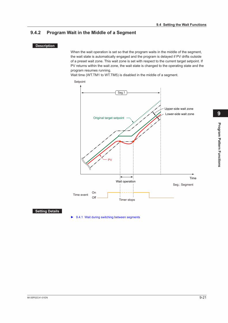
9-21IM 05P02C41-01EN
Program Pattern Functions
9
9.4.2 ProgramWaitintheMiddleofaSegment
Description
When the wait operation is set so that the program waits in the middle of the segment, the wait state is automatically engaged and the program is delayed if PV drifts outside ofapresetwaitzone.Thiswaitzoneissetwithrespecttothecurrenttargetsetpoint.IfPVreturnswithinthewaitzone,thewaitstateischangedtotheoperatingstateandtheprogram resumes running.Wait time (WT.TM1 to WT.TM5) is disabled in the middle of a segment.
Original target setpoint
PV
Seg.1
Time
Upper-side wait zone
Lower-side wait zone
Wait operationSeg.: Segment
Setpoint
Time eventOnOff
Timer stops
SettingDetails 9.4.1 Wait during switching between segments
9.4SettingtheWaitFunctions
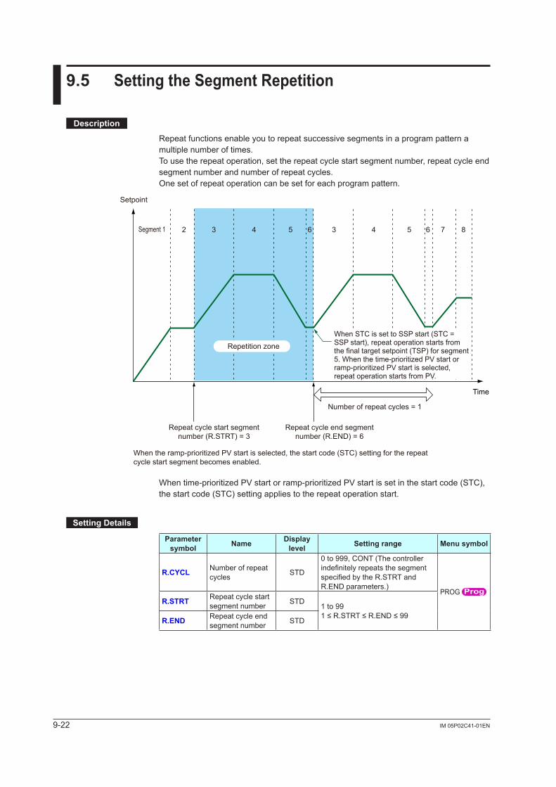
9-22 IM 05P02C41-01EN
9.5 SettingtheSegmentRepetition
Description
Repeat functions enable you to repeat successive segments in a program pattern a multiple number of times.To use the repeat operation, set the repeat cycle start segment number, repeat cycle end segment number and number of repeat cycles.One set of repeat operation can be set for each program pattern.
2 3 4 5 6 3 4 5 6 7 8Segment 1
Repetition zone
Repeat cycle start segment number (R.STRT) = 3
Repeat cycle end segment number (R.END) = 6
Number of repeat cycles = 1
When the ramp-prioritized PV start is selected, the start code (STC) setting for the repeat cycle start segment becomes enabled.
When STC is set to SSP start (STC = SSP start), repeat operation starts from the final target setpoint (TSP) for segment 5. When the time-prioritized PV start or ramp-prioritized PV start is selected, repeat operation starts from PV.
Time
Setpoint
Whentime-prioritizedPVstartorramp-prioritizedPVstartissetinthestartcode(STC),the start code (STC) setting applies to the repeat operation start.
SettingDetails
Parameter symbol Name Display
level Settingrange Menusymbol
R.CYCL Number of repeat cycles STD
0 to 999, CONT (The controller indefinitelyrepeatsthesegmentspecifiedbytheR.STRTandR.END parameters.)
PROG R.STRT Repeat cycle start
segment number STD1 to 991≤R.STRT≤R.END≤99R.END Repeat cycle end
segment number STD
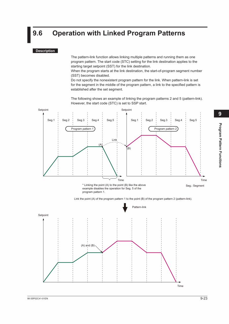
9-23IM 05P02C41-01EN
Program Pattern Functions
9
9.6 OperationwithLinkedProgramPatterns
Description
The pattern-link function allows linking multiple patterns and running them as one program pattern. The start code (STC) setting for the link destination applies to the starting target setpoint (SST) for the link destination. When the program starts at the link destination, the start-of-program segment number (SST) becomes disabled.Do not specify the nonexistent program pattern for the link. When pattern-link is set for the segment in the middle of the program pattern, a link to the specified pattern is established after the set segment.
The following shows an example of linking the program patterns 2 and 5 (pattern-link).However, the start code (STC) is set to SSP start.
Setpoint
Setpoint
Setpoint
Time Time
Time
Seg.: Segment
Seg.1 Seg.2 Seg.3 Seg.4 Seg.5 Seg.1 Seg.2 Seg.3 Seg.4 Seg.5
Pattern-link
Program pattern 1 Program pattern 2
(A) and (B)
Link
(A)(B)
* Linking the point (A) to the point (B) like the above example disables the operation for Seg. 5 of the program pattern 1.
Link the point (A) of the program pattern 1 to the point (B) of the program pattern 2 (pattern-link).
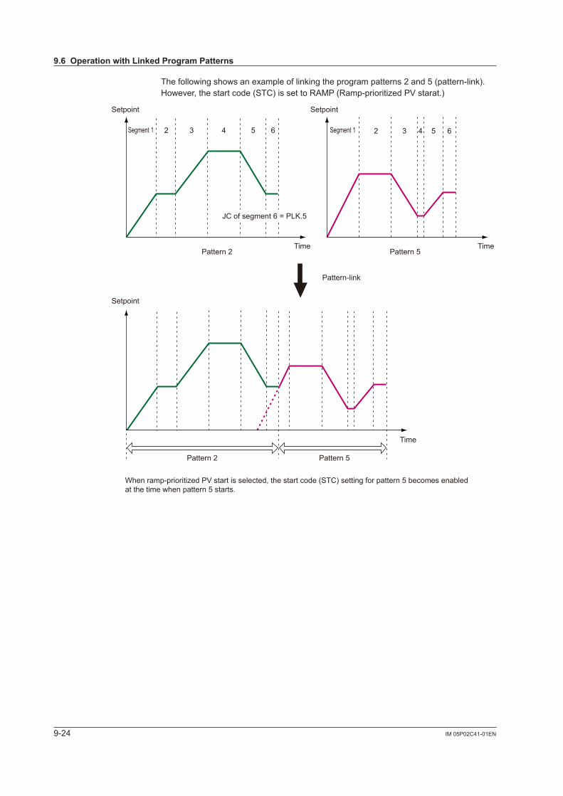
9-24 IM 05P02C41-01EN
The following shows an example of linking the program patterns 2 and 5 (pattern-link).However,thestartcode(STC)issettoRAMP(Ramp-prioritizedPVstarat.)
Setpoint
Setpoint
Setpoint
TimeTime
2 3 4 5 6 2 3 4 5 6
Pattern-link
Pattern 2
Segment 1 Segment 1
Pattern 2 Pattern 5
Time
Pattern 5
When ramp-prioritized PV start is selected, the start code (STC) setting for pattern 5 becomes enabled at the time when pattern 5 starts.
JC of segment 6 = PLK.5
9.6OperationwithLinkedProgramPatterns

9-25IM 05P02C41-01EN
Program Pattern Functions
9
SettingDetails
Parameter symbol Name Display
level Settingrange Menusymbol
JC Junction code STD
CONT: Switching for continuationHOLD: Hold-on switching (the
controller holds the end-of-segment setpoint when the segment is completed, to perform control).
LOC: Local-mode switching (the controller switches to a local setpoint when the segment is completed).
REM: Remote-mode switching (the controller switches to a remote setpoint when the segment is completed).
W.SW1 to W.SW5: Wait during switching between segments.
W.IV1 to W.IV5: Wait within a segment interval.
W.SL1 to W.SL5: Segment switching (the controller switches to a local setpoint when the segment is completed after release.) (5 groups)
W.SR1 to W.SR5: Segment switching (the controller switches to a remote setpoint when the segment is completed after release.) (5 groups)
PLK.1 to PLK.30 (PLK.99): Linked to patterns 1 to 30 (99).
INS.: Allows a segment to be added to theendofaspecifiedsegment.
DEL.:Allowsaspecifiedsegmenttobe deleted.
PROG
9.6OperationwithLinkedProgramPatterns
9-26 IM 05P02C41-01EN
9.7 SettingEventFunctions
The event functions allow outputting an alarm at a preset time under the process of program operation, or turning on the contact output after a specified time elapses. There are two types of event action. One is PV event and the other is time event.Two types of event action, PV event and time event, can be registered with the program operation, and one type of event action, local event, can be registered with the local operation.Up to 8 PV events and up to 16 time events can be set for one program pattern, and up to 8 local events can be set for local operation.The event action for program operation starts at the time when the segment for which the event action is set starts.
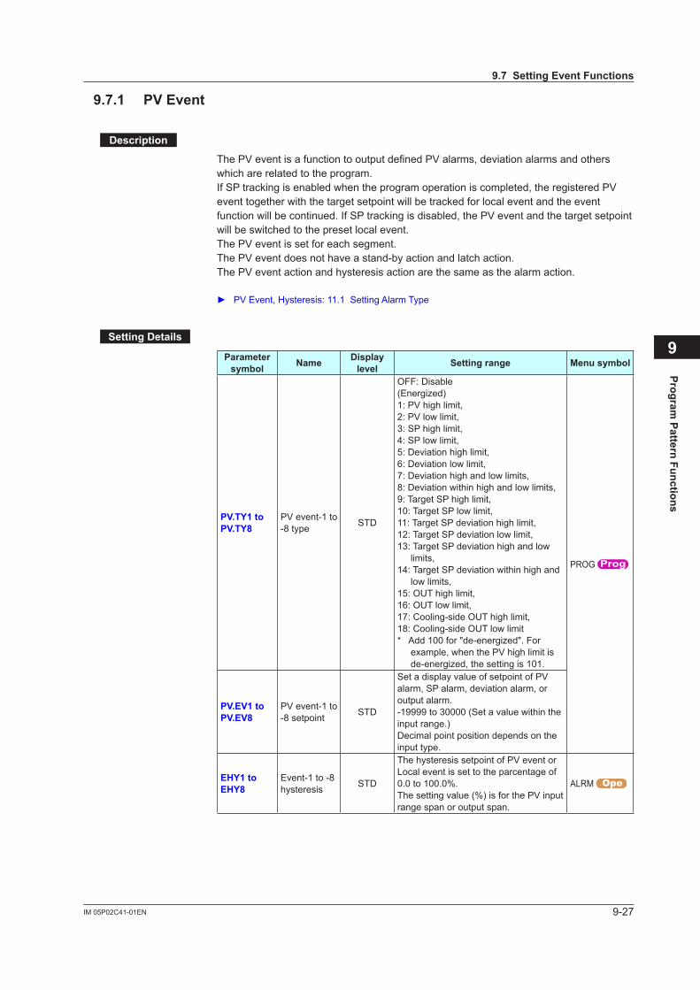
9-27IM 05P02C41-01EN
Program Pattern Functions
9
9.7.1 PVEvent
Description
The PV event is a function to output defined PV alarms, deviation alarms and others which are related to the program.If SP tracking is enabled when the program operation is completed, the registered PV event together with the target setpoint will be tracked for local event and the event function will be continued. If SP tracking is disabled, the PV event and the target setpoint will be switched to the preset local event.The PV event is set for each segment.The PV event does not have a stand-by action and latch action.The PV event action and hysteresis action are the same as the alarm action.
PV Event, Hysteresis: 11.1 Setting Alarm Type
SettingDetails
Parameter symbol Name Display
level Settingrange Menusymbol
PV.TY1toPV.TY8
PV event-1 to -8 type STD
OFF: Disable(Energized)1: PV high limit, 2: PV low limit,3: SP high limit, 4: SP low limit,5: Deviation high limit,6: Deviation low limit,7: Deviation high and low limits,8: Deviation within high and low limits,9: Target SP high limit,10: Target SP low limit,11: Target SP deviation high limit,12: Target SP deviation low limit,13: Target SP deviation high and low
limits,14: Target SP deviation within high and
low limits,15: OUT high limit, 16: OUT low limit,17: Cooling-side OUT high limit,18: Cooling-side OUT low limit*Add100for"de-energized".For
example, when the PV high limit is de-energized,thesetting is 101.
PROG
PV.EV1toPV.EV8
PV event-1 to -8 setpoint STD
Set a display value of setpoint of PV alarm, SP alarm, deviation alarm, or output alarm.-19999 to 30000 (Set a value within the input range.)Decimal point position depends on the input type.
EHY1toEHY8
Event-1 to -8 hysteresis STD
The hysteresis setpoint of PV event or Local event is set to the parcentage of 0.0 to 100.0%.The setting value (%) is for the PV input range span or output span.
ALRM
9.7SettingEventFunctions
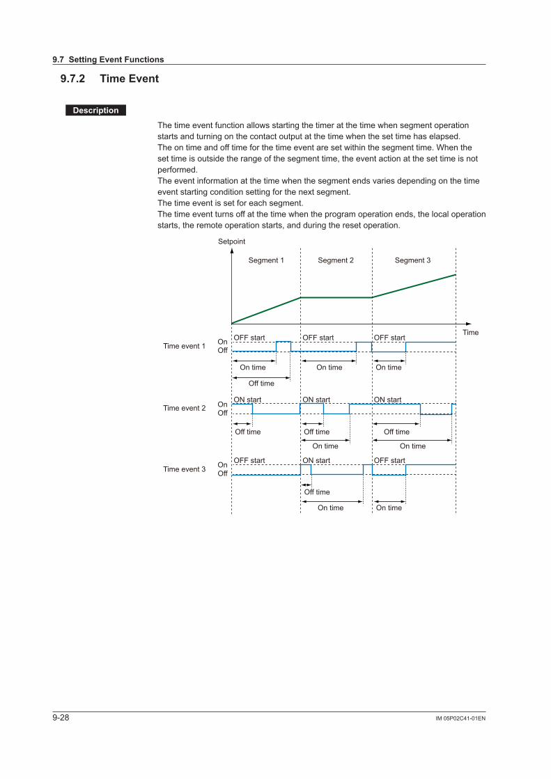
9-28 IM 05P02C41-01EN
9.7.2 TimeEvent
Description
The time event function allows starting the timer at the time when segment operation starts and turning on the contact output at the time when the set time has elapsed.The on time and off time for the time event are set within the segment time. When the set time is outside the range of the segment time, the event action at the set time is not performed. The event information at the time when the segment ends varies depending on the time event starting condition setting for the next segment. The time event is set for each segment.The time event turns off at the time when the program operation ends, the local operation starts, the remote operation starts, and during the reset operation.
Setpoint
OnOff
OnOff
OnOff
Time
Segment 1
OFF start OFF start OFF start
OFF start ON start OFF start
ON start ON start ON start
Time event 1
On time On time
Off timeOff time Off time
Off time
On time
Off time
On time On time
On time On time
Time event 2
Time event 3
Segment 2 Segment 3
9.7SettingEventFunctions

9-29IM 05P02C41-01EN
Program Pattern Functions
9
Timeeventactionwhenstartcode(STC)issettoramp-prioritizedPVstartWhen operation is started in the middle of the segment by the start code (STC), the event action starts in the event setting state at the time when operation should have started, on the assumption that the set event action has been performed by that time.
OnOff
OnOff
OnOff
Time
Segment 1
Time event 1
Time event 2
Time event 3
Segment 2
PV
OFF start
ON start
OFF start
Setpoint
SettingDetails
Parameter symbol Name Display
level Settingrange Menusymbol
TME1toTME16
Start condition of time event 1 to 16 STD ON: Start ON state
OFF: Start OFF state
PROG
T.ON1toT.ON16
On time of time event 1 to 16 STD -: Unregistered
0.01 to 999.59 (“hour.minute” or “minute.second”)
* Available only within the segment time.
* OFF when the operation mode is changed to the mode except the program operation.
* Use the parameter TMU to set the time unit.
(Common in the instrument.)
T.OF1toT.OF16
Off time of time event 1 to 16 STD
TMU Program time unit EASY HH.MM: hour.minuteMM.SS: minute.second CTL
When the off time and on time for the time event coincide in the same segment, priority is given to the off state.
9.7SettingEventFunctions
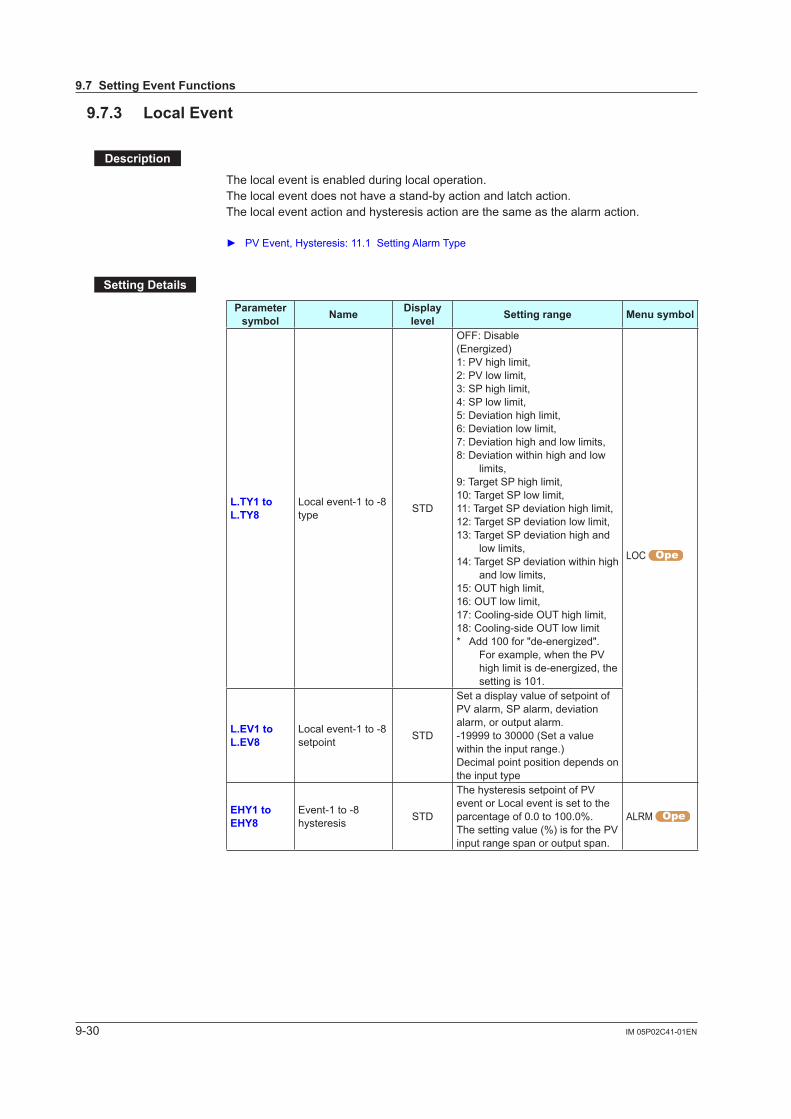
9-30 IM 05P02C41-01EN
9.7.3 LocalEvent
Description
The local event is enabled during local operation.The local event does not have a stand-by action and latch action.The local event action and hysteresis action are the same as the alarm action.
PV Event, Hysteresis: 11.1 Setting Alarm Type
SettingDetails
Parameter symbol Name Display
level Settingrange Menusymbol
L.TY1toL.TY8
Local event-1 to -8 type STD
OFF: Disable(Energized)1: PV high limit, 2: PV low limit,3: SP high limit, 4: SP low limit,5: Deviation high limit,6: Deviation low limit,7: Deviation high and low limits,8: Deviation within high and low
limits,9: Target SP high limit,10: Target SP low limit,11: Target SP deviation high limit,12: Target SP deviation low limit,13: Target SP deviation high and
low limits,14: Target SP deviation within high
and low limits,15: OUT high limit, 16: OUT low limit,17: Cooling-side OUT high limit,18: Cooling-side OUT low limit*Add100for"de-energized".
For example, when the PV highlimitisde-energized,thesetting is 101.
LOC
L.EV1toL.EV8
Local event-1 to -8 setpoint STD
Set a display value of setpoint of PV alarm, SP alarm, deviation alarm, or output alarm.-19999 to 30000 (Set a value within the input range.)Decimal point position depends on the input type
EHY1toEHY8
Event-1 to -8 hysteresis STD
The hysteresis setpoint of PV event or Local event is set to the parcentage of 0.0 to 100.0%.The setting value (%) is for the PV input range span or output span.
ALRM
9.7SettingEventFunctions
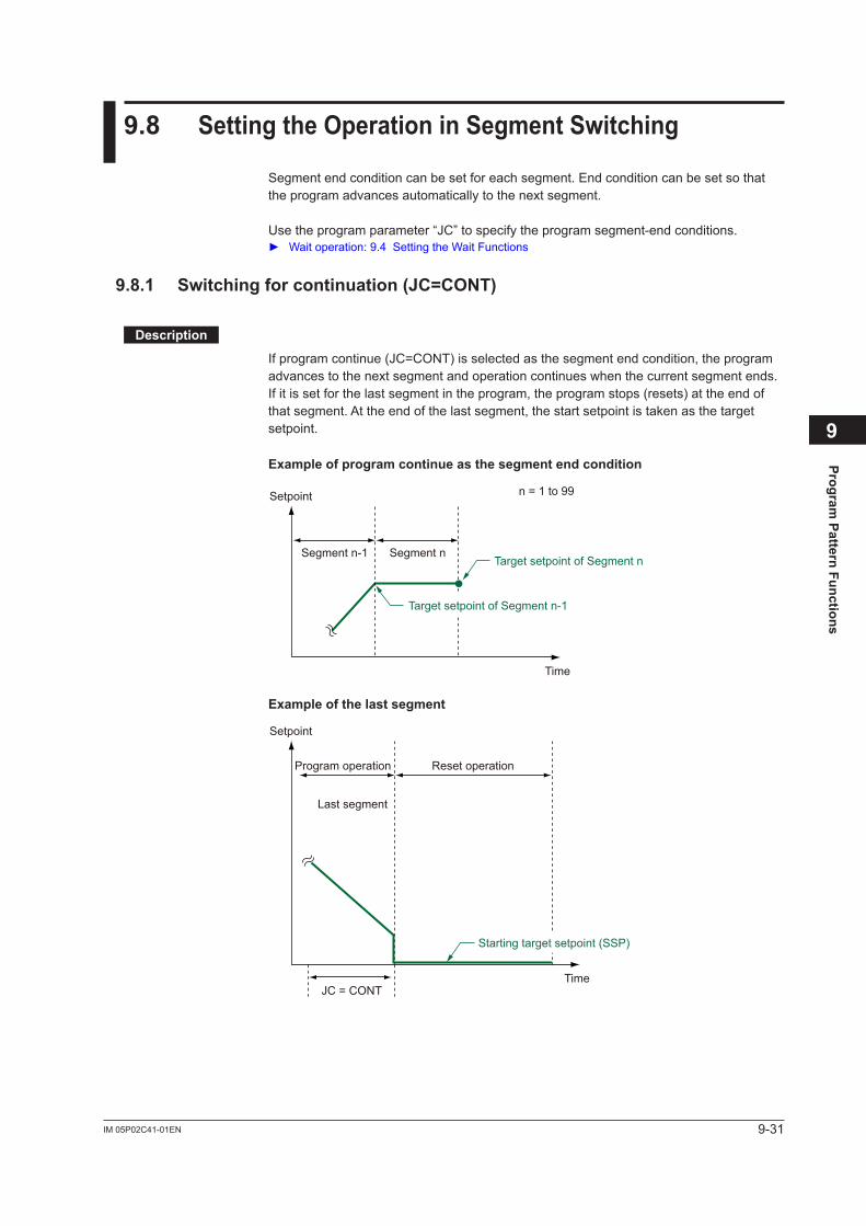
9-31IM 05P02C41-01EN
Program Pattern Functions
9
9.8 SettingtheOperationinSegmentSwitching
Segment end condition can be set for each segment. End condition can be set so that the program advances automatically to the next segment.
Use the program parameter “JC” to specify the program segment-end conditions. Wait operation: 9.4 Setting the Wait Functions
9.8.1 Switchingforcontinuation(JC=CONT)
Description
If program continue (JC=CONT) is selected as the segment end condition, the program advances to the next segment and operation continues when the current segment ends. If it is set for the last segment in the program, the program stops (resets) at the end of that segment. At the end of the last segment, the start setpoint is taken as the target setpoint.
Exampleofprogramcontinueasthesegmentendcondition
n = 1 to 99
Segment n
Setpoint
Time
Segment n-1
Target setpoint of Segment n-1
Target setpoint of Segment n
Exampleofthelastsegment
Reset operation
Setpoint
Time
Program operation
Last segment
JC = CONT
Starting target setpoint (SSP)

9-32 IM 05P02C41-01EN
SettingDetails
Parameter symbol Name Display
level Settingrange Menusymbol
JC Junction code STD
CONT: Switching for continuationHOLD: Hold-on switching (the controller holds
the end-of-segment setpoint when the segment is completed, to perform control).
LOC: Local-mode switching (the controller switches to a local setpoint when the segment is completed).
REM: Remote-mode switching (the controller switches to a remote setpoint when the segment is completed).
W.SW1 to W.SW5: Wait during switching between segments.
W.IV1 to W.IV5: Wait within a segment interval.W.SL1 to W.SL5: Segment switching (the
controller switches to a local setpoint when the segment is completed after release.) (5 groups)
W.SR1 to W.SR5: Segment switching (the controller switches to a remote setpoint when the segment is completed after release.) (5 groups)
PLK.1 to PLK.30 (PLK.99): Linked to patterns 1 to 30 (99).
INS.: Allows a segment to be added to the end of aspecifiedsegment.
DEL.:Allowsaspecifiedsegmenttobedeleted.
PROG
9.8SettingtheOperationinSegmentSwitching
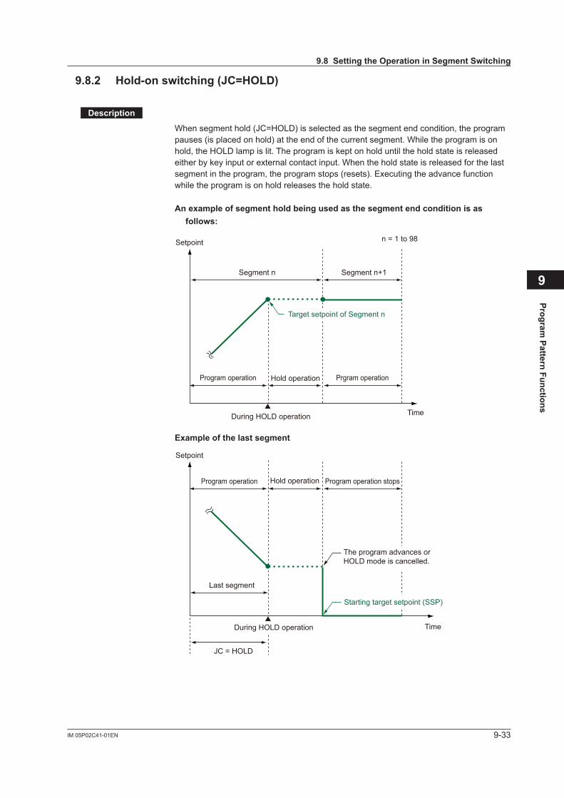
9-33IM 05P02C41-01EN
Program Pattern Functions
9
9.8.2 Hold-onswitching(JC=HOLD)
Description
When segment hold (JC=HOLD) is selected as the segment end condition, the program pauses (is placed on hold) at the end of the current segment. While the program is on hold, the HOLD lamp is lit. The program is kept on hold until the hold state is released either by key input or external contact input. When the hold state is released for the last segment in the program, the program stops (resets). Executing the advance function while the program is on hold releases the hold state.
Anexampleofsegmentholdbeingusedasthesegmentendconditionisasfollows:
During HOLD operation
Hold operation
n = 1 to 98
Program operation
Segment n Segment n+1
Prgram operation
Setpoint
Time
Target setpoint of Segment n
Exampleofthelastsegment
Last segment
JC = HOLD
Starting target setpoint (SSP)
The program advances or HOLD mode is cancelled.
During HOLD operation
Hold operationProgram operation Program operation stops
Setpoint
Time
9.8SettingtheOperationinSegmentSwitching
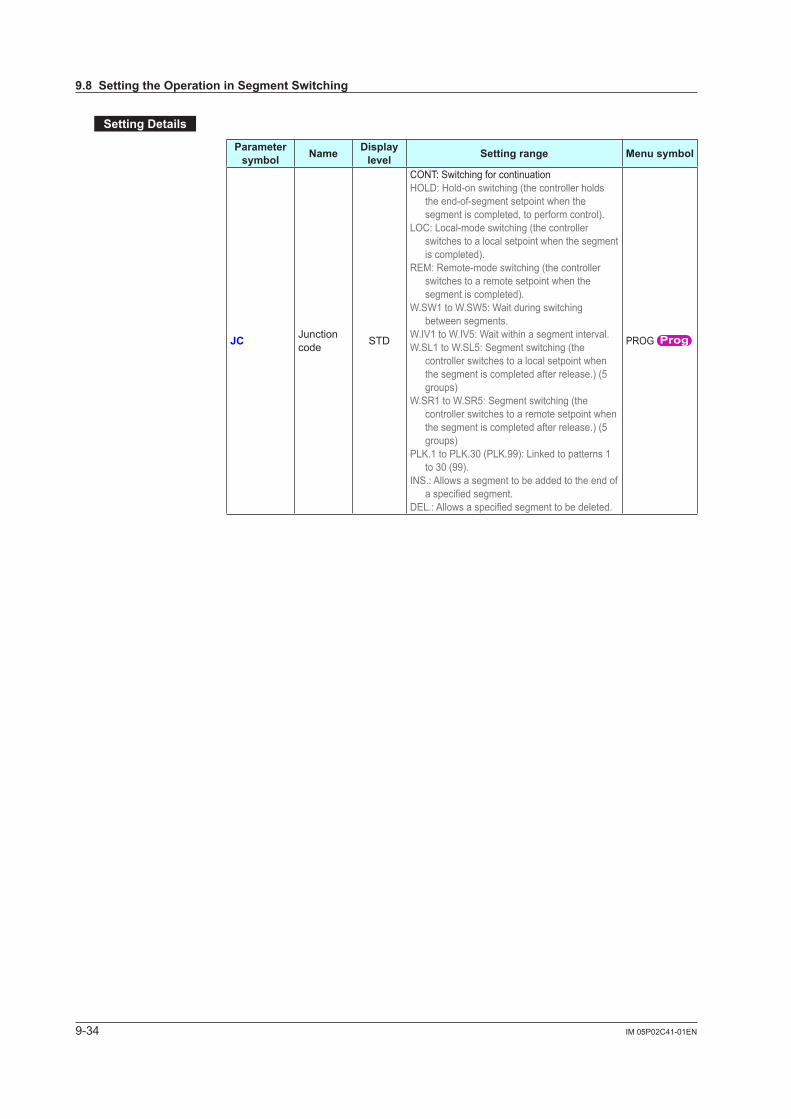
9-34 IM 05P02C41-01EN
SettingDetails
Parameter symbol Name Display
level Settingrange Menusymbol
JC Junction code STD
CONT: Switching for continuationHOLD: Hold-on switching (the controller holds
the end-of-segment setpoint when the segment is completed, to perform control).
LOC: Local-mode switching (the controller switches to a local setpoint when the segment is completed).
REM: Remote-mode switching (the controller switches to a remote setpoint when the segment is completed).
W.SW1 to W.SW5: Wait during switching between segments.
W.IV1 to W.IV5: Wait within a segment interval.W.SL1 to W.SL5: Segment switching (the
controller switches to a local setpoint when the segment is completed after release.) (5 groups)
W.SR1 to W.SR5: Segment switching (the controller switches to a remote setpoint when the segment is completed after release.) (5 groups)
PLK.1 to PLK.30 (PLK.99): Linked to patterns 1 to 30 (99).
INS.: Allows a segment to be added to the end of aspecifiedsegment.
DEL.:Allowsaspecifiedsegmenttobedeleted.
PROG
9.8SettingtheOperationinSegmentSwitching
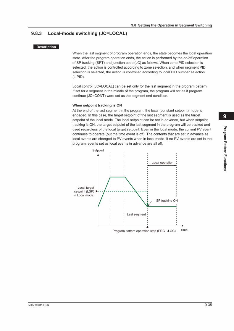
9-35IM 05P02C41-01EN
Program Pattern Functions
9
9.8.3 Local-modeswitching(JC=LOCAL)
Description
When the last segment of program operation ends, the state becomes the local operation state. After the program operation ends, the action is performed by the on/off operation ofSPtracking(SPT)andjunctioncode(JC)asfollows.WhenzonePIDselectionisselected,theactioniscontrolledaccordingtozoneselection,andwhensegmentPIDselection is selected, the action is controlled according to local PID number selection (L.PID).
Local control (JC=LOCAL) can be set only for the last segment in the program pattern.If set for a segment in the middle of the program, the program will act as if program continue (JC=CONT) were set as the segment end condition.
WhensetpointtrackingisONAt the end of the last segment in the program, the local (constant setpoint) mode is engaged. In this case, the target setpoint of the last segment is used as the target setpoint of the local mode. The local setpoint can be set in advance, but when setpoint tracking is ON, the target setpoint of the last segment in the program will be tracked and used regardless of the local target setpoint. Even in the local mode, the current PV event continues to operate (but the time event is off). The contents that are set in advance as local events are changed to PV events when in local mode. If no PV events are set in the program, events set as local events in advance are all off.
Setpoint
Time
Last segment
Program pattern operation stop (PRG→LOC)
Local operation
Local target setpoint (LSP) in Local mode.
SP tracking ON
9.8SettingtheOperationinSegmentSwitching
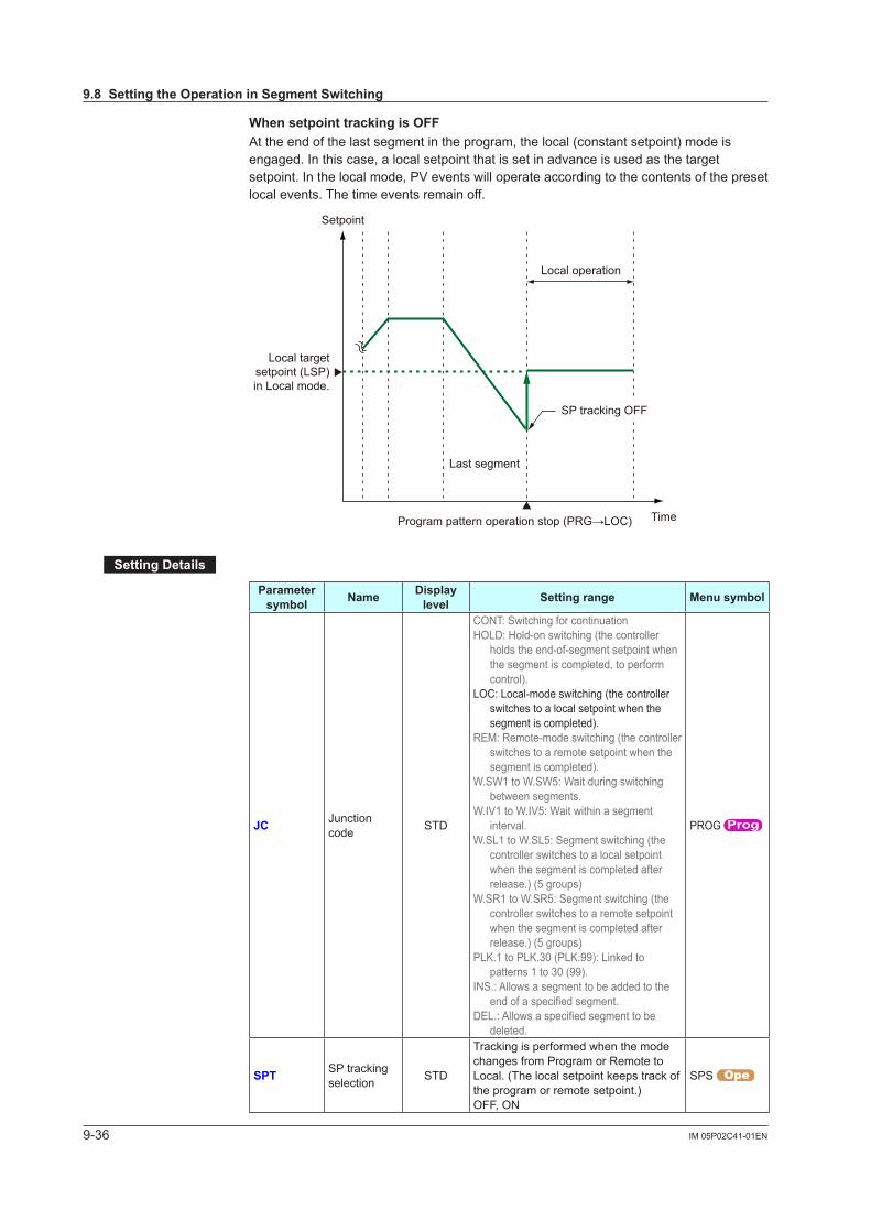
9-36 IM 05P02C41-01EN
WhensetpointtrackingisOFFAt the end of the last segment in the program, the local (constant setpoint) mode is engaged. In this case, a local setpoint that is set in advance is used as the target setpoint. In the local mode, PV events will operate according to the contents of the preset local events. The time events remain off.
Setpoint
Time
Last segment
Program pattern operation stop (PRG→LOC)
Local operation
Local target setpoint (LSP) in Local mode.
SP tracking OFF
SettingDetails
Parameter symbol Name Display
level Settingrange Menusymbol
JC Junction code STD
CONT: Switching for continuationHOLD: Hold-on switching (the controller
holds the end-of-segment setpoint when the segment is completed, to perform control).
LOC: Local-mode switching (the controller switches to a local setpoint when the segment is completed).
REM: Remote-mode switching (the controller switches to a remote setpoint when the segment is completed).
W.SW1 to W.SW5: Wait during switching between segments.
W.IV1 to W.IV5: Wait within a segment interval.
W.SL1 to W.SL5: Segment switching (the controller switches to a local setpoint when the segment is completed after release.) (5 groups)
W.SR1 to W.SR5: Segment switching (the controller switches to a remote setpoint when the segment is completed after release.) (5 groups)
PLK.1 to PLK.30 (PLK.99): Linked to patterns 1 to 30 (99).
INS.: Allows a segment to be added to the endofaspecifiedsegment.
DEL.:Allowsaspecifiedsegmenttobedeleted.
PROG
SPT SP tracking selection STD
Tracking is performed when the mode changes from Program or Remote to Local. (The local setpoint keeps track of the program or remote setpoint.)OFF, ON
SPS
9.8SettingtheOperationinSegmentSwitching
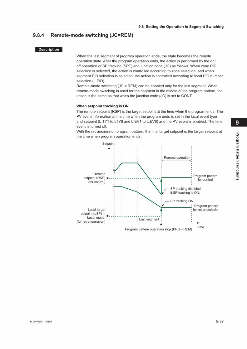
9-37IM 05P02C41-01EN
Program Pattern Functions
9
9.8.4 Remote-modeswitching(JC=REM)
Description
When the last segment of program operation ends, the state becomes the remote operation state. After the program operation ends, the action is performed by the on/offoperationofSPtracking(SPT)andjunctioncode(JC)asfollows.WhenzonePIDselectionisselected,theactioniscontrolledaccordingtozoneselection,andwhensegment PID selection is selected, the action is controlled according to local PID number selection (L.PID). Remote-mode switching (JC = REM) can be enabled only for the last segment. When remote-mode switching is used for the segment in the middle of the program pattern, the actionisthesameasthatwhenthejunctioncode(JC)issettoCONT.
WhensetpointtrackingisONThe remote setpoint (RSP) is the target setpoint at the time when the program ends. The PV event information at the time when the program ends is set in the local event type and setpoint (L.TY1 to LTY8 and L.EV1 to L.EV8) and the PV event is enabled. The time event is turned off.With the retransmission program pattern, the final target setpoint is the target setpoint at the time when program operation ends.
SP tracking disabled if SP tracking is ON.
SP tracking ON
Setpoint
Time
Last segment
Program pattern operation stop (PRG→REM)
Remote operation
Local target setpoint (LSP) in
Local mode.(for retransmission)
Remote setpoint (RSP)
(for control)
Program pattern for control
Program pattern for retransmission
9.8SettingtheOperationinSegmentSwitching
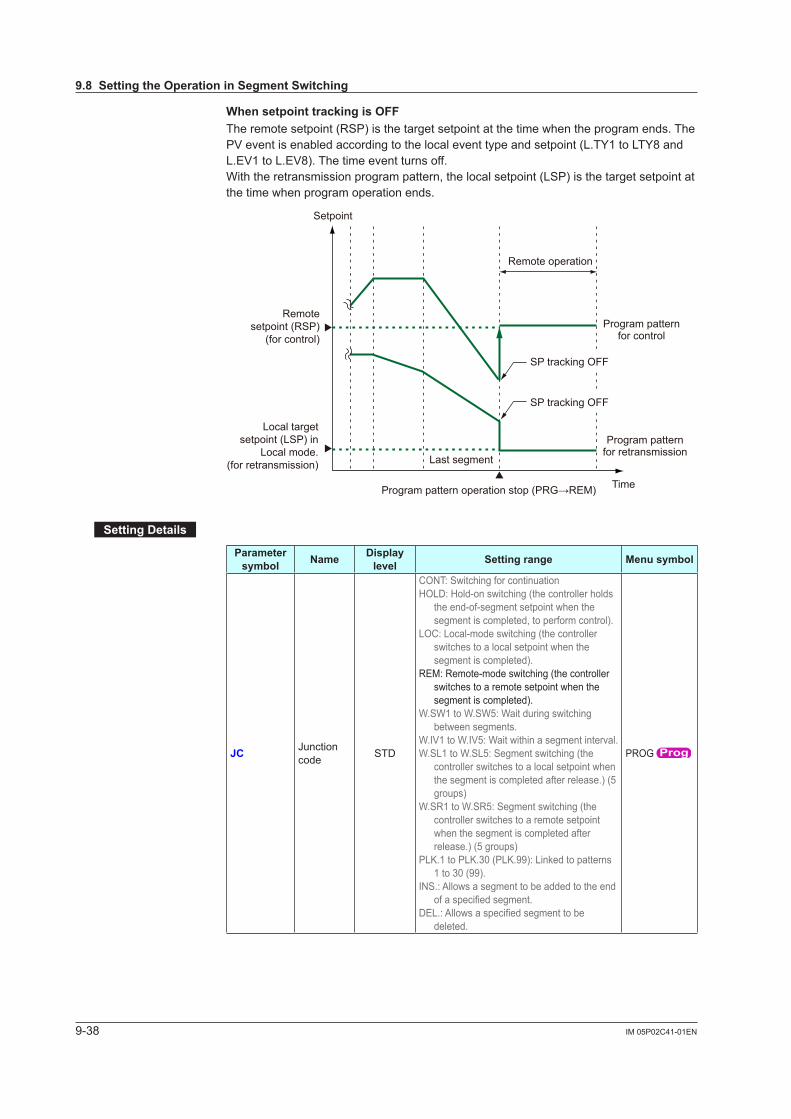
9-38 IM 05P02C41-01EN
WhensetpointtrackingisOFFThe remote setpoint (RSP) is the target setpoint at the time when the program ends. The PV event is enabled according to the local event type and setpoint (L.TY1 to LTY8 and L.EV1 to L.EV8). The time event turns off.With the retransmission program pattern, the local setpoint (LSP) is the target setpoint at the time when program operation ends.
SP tracking OFF
SP tracking OFF
Setpoint
Time
Last segment
Program pattern operation stop (PRG→REM)
Remote operation
Local target setpoint (LSP) in
Local mode.(for retransmission)
Remote setpoint (RSP)
(for control)Program pattern
for control
Program pattern for retransmission
SettingDetails
Parameter symbol Name Display
level Settingrange Menusymbol
JC Junction code STD
CONT: Switching for continuationHOLD: Hold-on switching (the controller holds
the end-of-segment setpoint when the segment is completed, to perform control).
LOC: Local-mode switching (the controller switches to a local setpoint when the segment is completed).
REM: Remote-mode switching (the controller switches to a remote setpoint when the segment is completed).
W.SW1 to W.SW5: Wait during switching between segments.
W.IV1 to W.IV5: Wait within a segment interval.W.SL1 to W.SL5: Segment switching (the
controller switches to a local setpoint when the segment is completed after release.) (5 groups)
W.SR1 to W.SR5: Segment switching (the controller switches to a remote setpoint when the segment is completed after release.) (5 groups)
PLK.1 to PLK.30 (PLK.99): Linked to patterns 1 to 30 (99).
INS.: Allows a segment to be added to the end ofaspecifiedsegment.
DEL.:Allowsaspecifiedsegmenttobedeleted.
PROG
9.8SettingtheOperationinSegmentSwitching
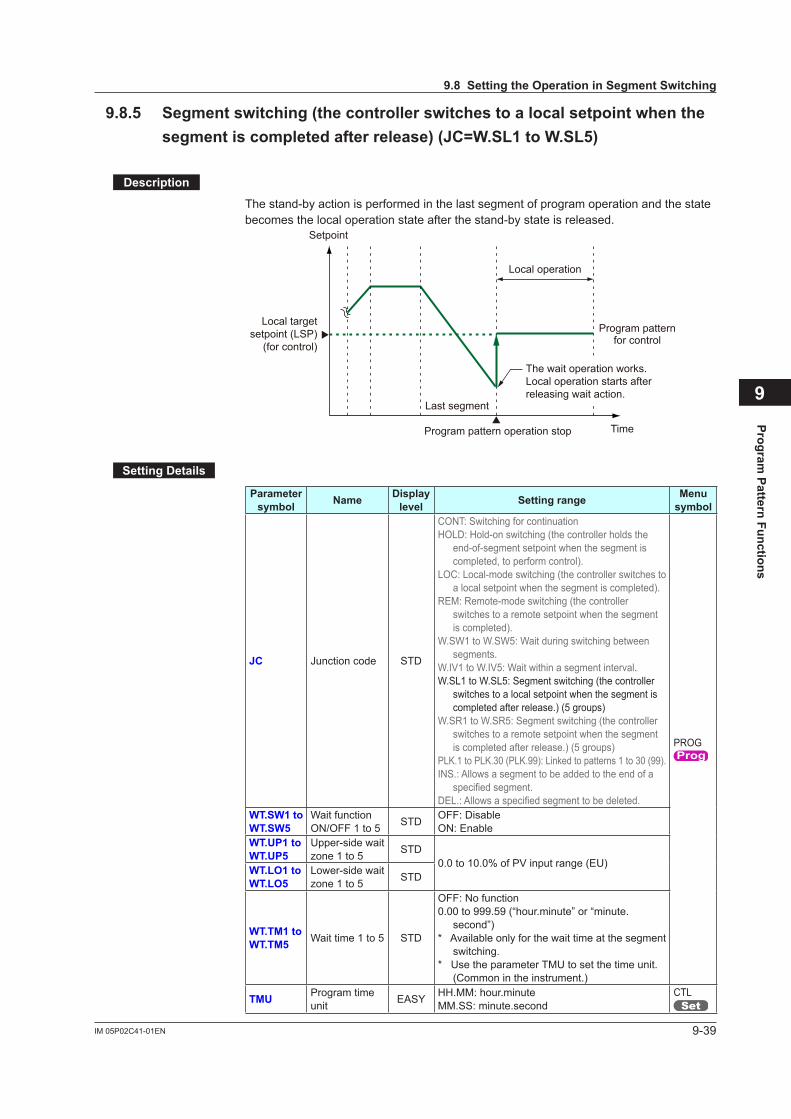
9-39IM 05P02C41-01EN
Program Pattern Functions
9
9.8.5 Segmentswitching(thecontrollerswitchestoalocalsetpointwhenthesegmentiscompletedafterrelease)(JC=W.SL1toW.SL5)
Description
The stand-by action is performed in the last segment of program operation and the state becomes the local operation state after the stand-by state is released.
The wait operation works.Local operation starts after releasing wait action.
Setpoint
TimeProgram pattern operation stop
Local operation
Local target setpoint (LSP)
(for control)
Program pattern for control
Last segment
SettingDetails
Parameter symbol Name Display
level Settingrange Menu symbol
JC Junction code STD
CONT: Switching for continuationHOLD: Hold-on switching (the controller holds the
end-of-segment setpoint when the segment is completed, to perform control).
LOC: Local-mode switching (the controller switches to a local setpoint when the segment is completed).
REM: Remote-mode switching (the controller switches to a remote setpoint when the segment is completed).
W.SW1 to W.SW5: Wait during switching between segments.
W.IV1 to W.IV5: Wait within a segment interval.W.SL1 to W.SL5: Segment switching (the controller
switches to a local setpoint when the segment is completed after release.) (5 groups)
W.SR1 to W.SR5: Segment switching (the controller switches to a remote setpoint when the segment is completed after release.) (5 groups)
PLK.1 to PLK.30 (PLK.99): Linked to patterns 1 to 30 (99).INS.: Allows a segment to be added to the end of a
specifiedsegment.DEL.:Allowsaspecifiedsegmenttobedeleted.
PROG
WT.SW1toWT.SW5
Wait function ON/OFF 1 to 5 STD OFF: Disable
ON: EnableWT.UP1toWT.UP5
Upper-side wait zone1to5 STD
0.0 to 10.0% of PV input range (EU)WT.LO1toWT.LO5
Lower-side wait zone1to5 STD
WT.TM1toWT.TM5 Wait time 1 to 5 STD
OFF: No function0.00 to 999.59 (“hour.minute” or “minute.
second”)* Available only for the wait time at the segment
switching.* Use the parameter TMU to set the time unit.
(Common in the instrument.)
TMU Program time unit EASY HH.MM: hour.minute
MM.SS: minute.secondCTL
9.8SettingtheOperationinSegmentSwitching
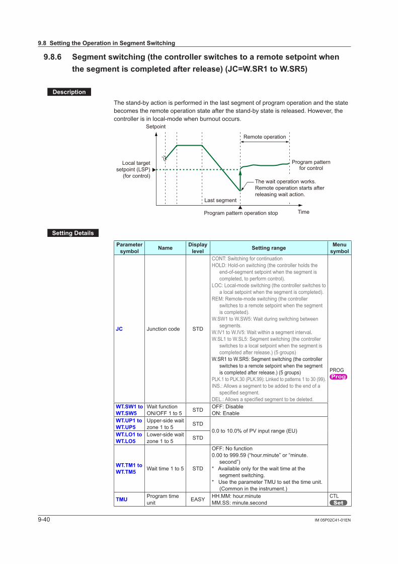
9-40 IM 05P02C41-01EN
9.8.6 Segmentswitching(thecontrollerswitchestoaremotesetpointwhenthesegmentiscompletedafterrelease)(JC=W.SR1toW.SR5)
Description
The stand-by action is performed in the last segment of program operation and the state becomes the remote operation state after the stand-by state is released. However, the controller is in local-mode when burnout occurs.
The wait operation works.Remote operation starts after releasing wait action.
Setpoint
TimeProgram pattern operation stop
Remote operation
Local target setpoint (LSP)
(for control)
Program pattern for control
Last segment
SettingDetails
Parameter symbol Name Display
level Settingrange Menu symbol
JC Junction code STD
CONT: Switching for continuationHOLD: Hold-on switching (the controller holds the
end-of-segment setpoint when the segment is completed, to perform control).
LOC: Local-mode switching (the controller switches to a local setpoint when the segment is completed).
REM: Remote-mode switching (the controller switches to a remote setpoint when the segment is completed).
W.SW1 to W.SW5: Wait during switching between segments.
W.IV1 to W.IV5: Wait within a segment interval.W.SL1 to W.SL5: Segment switching (the controller
switches to a local setpoint when the segment is completed after release.) (5 groups)
W.SR1 to W.SR5: Segment switching (the controller switches to a remote setpoint when the segment is completed after release.) (5 groups)
PLK.1 to PLK.30 (PLK.99): Linked to patterns 1 to 30 (99).INS.: Allows a segment to be added to the end of a
specifiedsegment.DEL.:Allowsaspecifiedsegmenttobedeleted.
PROG
WT.SW1toWT.SW5
Wait function ON/OFF 1 to 5 STD OFF: Disable
ON: EnableWT.UP1toWT.UP5
Upper-side wait zone1to5 STD
0.0 to 10.0% of PV input range (EU)WT.LO1toWT.LO5
Lower-side wait zone1to5 STD
WT.TM1toWT.TM5 Wait time 1 to 5 STD
OFF: No function0.00 to 999.59 (“hour.minute” or “minute.
second”)* Available only for the wait time at the
segment switching.* Use the parameter TMU to set the time unit.
(Common in the instrument.)
TMU Program time unit EASY HH.MM: hour.minute
MM.SS: minute.secondCTL
9.8SettingtheOperationinSegmentSwitching
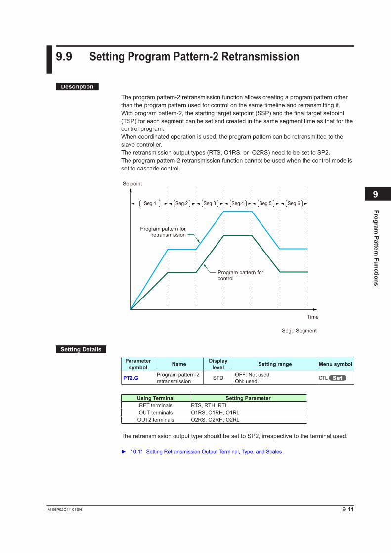
9-41IM 05P02C41-01EN
Program Pattern Functions
9
9.9 SettingProgramPattern-2Retransmission
Description
The program pattern-2 retransmission function allows creating a program pattern other than the program pattern used for control on the same timeline and retransmitting it.With program pattern-2, the starting target setpoint (SSP) and the final target setpoint (TSP) for each segment can be set and created in the same segment time as that for the control program.When coordinated operation is used, the program pattern can be retransmitted to the slave controller. The retransmission output types (RTS, O1RS, or O2RS) need to be set to SP2. The program pattern-2 retransmission function cannot be used when the control mode is set to cascade control.
Setpoint
Time
Seg.: Segment
Program pattern for control
Program pattern for retransmission
Seg.1 Seg.2 Seg.4 Seg.5 Seg.6Seg.3
SettingDetails
Parameter symbol Name Display
level Settingrange Menusymbol
PT2.G Program pattern-2 retransmission STD OFF: Not used.
ON: used. CTL
Using Terminal SettingParameterRET terminals RTS, RTH, RTLOUT terminals O1RS, O1RH, O1RL
OUT2 terminals O2RS, O2RH, O2RL
The retransmission output type should be set to SP2, irrespective to the terminal used.
10.11 Setting Retransmission Output Terminal, Type, and Scales
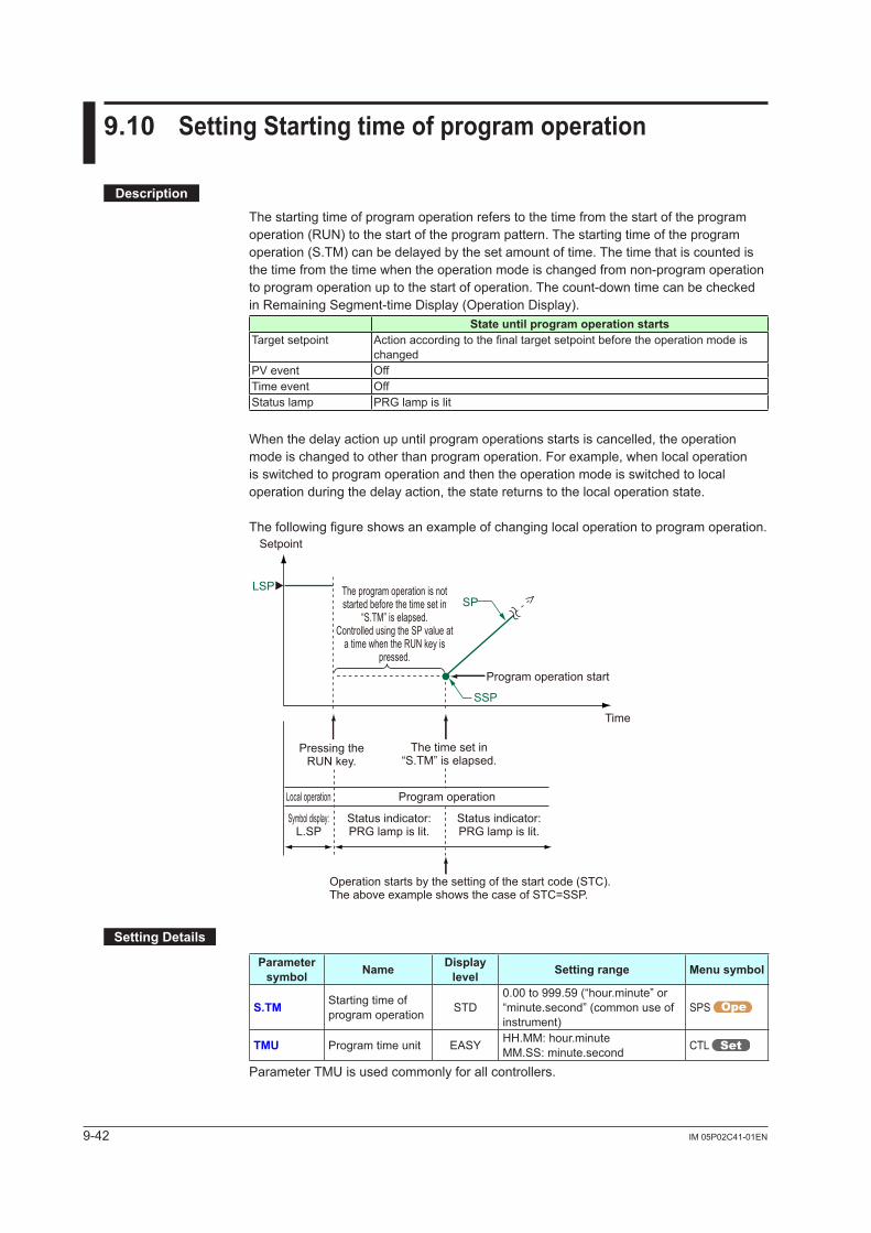
9-42 IM 05P02C41-01EN
9.10 SettingStartingtimeofprogramoperation
Description
The starting time of program operation refers to the time from the start of the program operation (RUN) to the start of the program pattern. The starting time of the program operation (S.TM) can be delayed by the set amount of time. The time that is counted is the time from the time when the operation mode is changed from non-program operation to program operation up to the start of operation. The count-down time can be checked in Remaining Segment-time Display (Operation Display).
StateuntilprogramoperationstartsTarget setpoint Actionaccordingtothefinaltargetsetpointbeforetheoperationmodeis
changedPV event OffTime event OffStatus lamp PRG lamp is lit
When the delay action up until program operations starts is cancelled, the operation mode is changed to other than program operation. For example, when local operation is switched to program operation and then the operation mode is switched to local operation during the delay action, the state returns to the local operation state.
The following figure shows an example of changing local operation to program operation.
Time
SP
Program operation start
The time set in“S.TM” is elapsed.
Pressing the RUN key.
Local operation
LSP
Status indicator:PRG lamp is lit.
Symbol display:L.SP
Status indicator:PRG lamp is lit.
Program operation
Setpoint
SSP
Operation starts by the setting of the start code (STC).The above example shows the case of STC=SSP.
The program operation is not started before the time set in
“S.TM” is elapsed.Controlled using the SP value at
a time when the RUN key is pressed.
SettingDetails
Parameter symbol Name Display
level Settingrange Menusymbol
S.TM Starting time of program operation STD
0.00 to 999.59 (“hour.minute” or “minute.second” (common use of instrument)
SPS
TMU Program time unit EASY HH.MM: hour.minuteMM.SS: minute.second CTL
Parameter TMU is used commonly for all controllers.
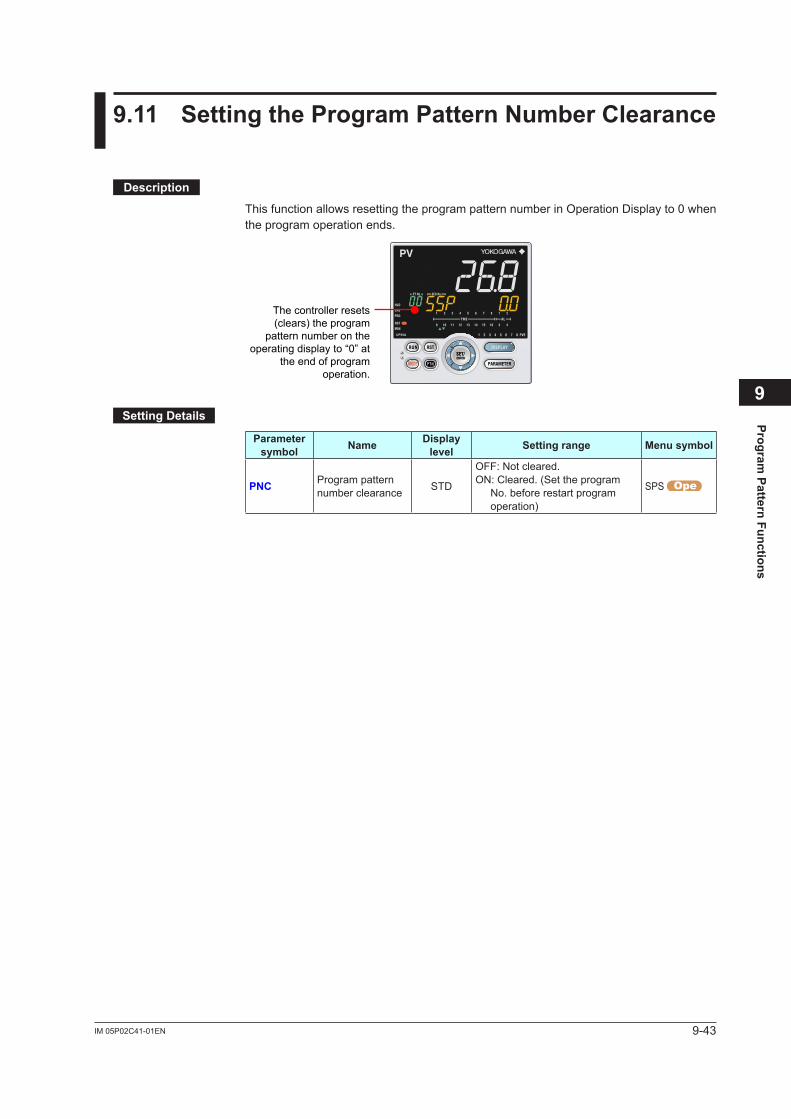
9-43IM 05P02C41-01EN
Program Pattern Functions
9
9.11 SettingtheProgramPatternNumberClearance
Description
This function allows resetting the program pattern number in Operation Display to 0 when the program operation ends.
The controller resets (clears) the program
pattern number on the operating display to “0” at
the end of program operation.
SettingDetails
Parameter symbol Name Display
level Settingrange Menusymbol
PNC Program pattern number clearance STD
OFF: Not cleared.ON: Cleared. (Set the program
No. before restart program operation)
SPS
9-44 IM 05P02C41-01EN
9.12 ProgramPatternEndSignal
Description
A pattern end signal notifies the outside of the end of a program pattern when the execution of the program pattern ends.The pattern end signal can be output by contact output or via communication.There are one-second, three-second, and five-second pattern end signals. When the program is also forcibly terminated by key operation, contact input, or via communication, the pattern end signal is output. When the pattern-link function is used, the pattern end signal is output when the link destination program pattern ends. Even if program operation starts while the pattern end signal is on, the pattern end signal is not turned off.
SettingDetails Pattern End Signal: 12.2 Setting Contact Output Function
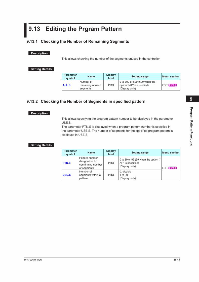
9-45IM 05P02C41-01EN
Program Pattern Functions
9
9.13 EditingthePrgramPattern
9.13.1 CheckingtheNumberofRemainingSegments
Description
This allows checking the number of the segments unused in the controller.
SettingDetails
Parameter symbol Name Display
level Settingrange Menusymbol
ALL.SNumber of remaining unused segments
PRO0 to 300 or 600 (600 when the option“/AP”isspecified)(Display only)
EDIT
9.13.2 CheckingtheNumberofSegmentsinspecifiedpattern
Description
This allows specifying the program pattern number to be displayed in the parameter USE.S. The parameter PTN.S is displayed when a program pattern number is specified in the parameter USE.S. The number of segments for the specified program pattern is displayed in USE.S.
SettingDetails
Parameter symbol Name Display
level Settingrange Menusymbol
PTN.S
Pattern number designation for comfirmingnumberof segments
PRO0 to 30 or 99 (99 when the option “/AP”isspecified)(Display only)
EDIT
USE.SNumber of segments within a pattern
PRO0: disable1 to 99(Display only)
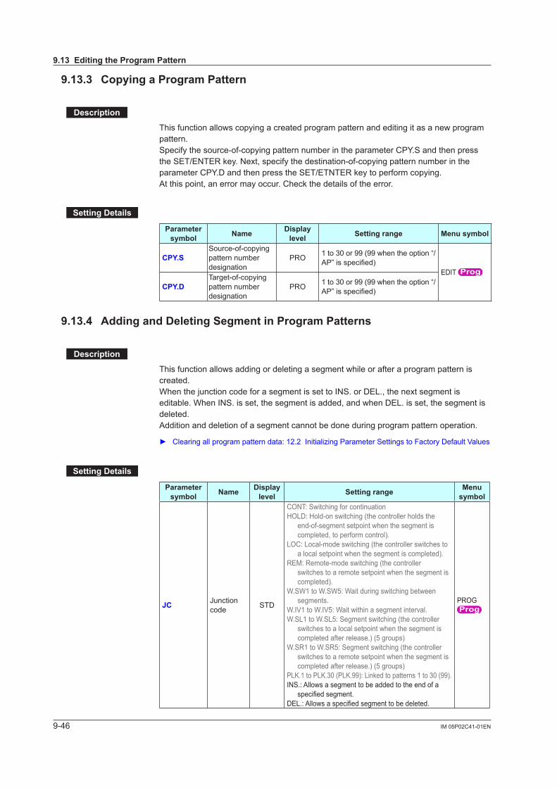
9-46 IM 05P02C41-01EN
9.13.3 CopyingaProgramPattern
Description
This function allows copying a created program pattern and editing it as a new program pattern.Specify the source-of-copying pattern number in the parameter CPY.S and then press the SET/ENTER key. Next, specify the destination-of-copying pattern number in the parameter CPY.D and then press the SET/ETNTER key to perform copying. At this point, an error may occur. Check the details of the error.
SettingDetails
Parameter symbol Name Display
level Settingrange Menusymbol
CPY.SSource-of-copying pattern number designation
PRO 1 to 30 or 99 (99 when the option “/AP”isspecified)
EDIT
CPY.DTarget-of-copying pattern number designation
PRO 1 to 30 or 99 (99 when the option “/AP”isspecified)
9.13.4 AddingandDeletingSegmentinProgramPatterns
Description
This function allows adding or deleting a segment while or after a program pattern is created.WhenthejunctioncodeforasegmentissettoINS.orDEL.,thenextsegmentiseditable. When INS. is set, the segment is added, and when DEL. is set, the segment is deleted.Addition and deletion of a segment cannot be done during program pattern operation.
Clearingallprogrampatterndata:12.2InitializingParameterSettingstoFactoryDefaultValues
SettingDetails
Parameter symbol Name Display
level Settingrange Menu symbol
JC Junction code STD
CONT: Switching for continuationHOLD: Hold-on switching (the controller holds the
end-of-segment setpoint when the segment is completed, to perform control).
LOC: Local-mode switching (the controller switches to a local setpoint when the segment is completed).
REM: Remote-mode switching (the controller switches to a remote setpoint when the segment is completed).
W.SW1 to W.SW5: Wait during switching between segments.
W.IV1 to W.IV5: Wait within a segment interval.W.SL1 to W.SL5: Segment switching (the controller
switches to a local setpoint when the segment is completed after release.) (5 groups)
W.SR1 to W.SR5: Segment switching (the controller switches to a remote setpoint when the segment is completed after release.) (5 groups)
PLK.1 to PLK.30 (PLK.99): Linked to patterns 1 to 30 (99).INS.: Allows a segment to be added to the end of a
specifiedsegment.DEL.:Allowsaspecifiedsegmenttobedeleted.
PROG
9.13EditingtheProgramPattern
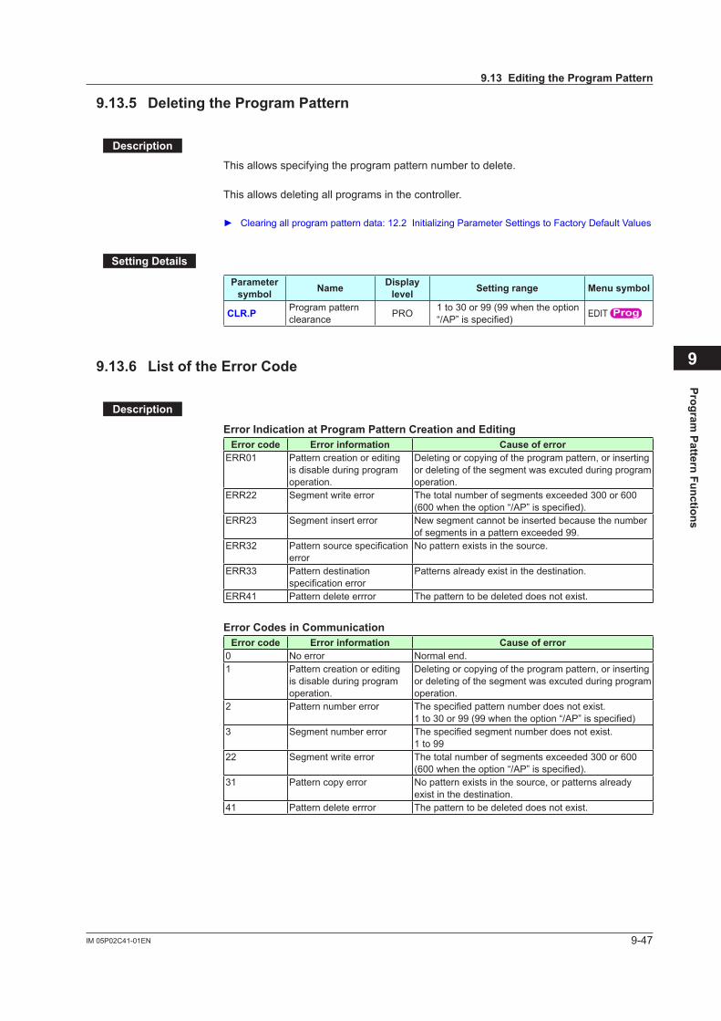
9-47IM 05P02C41-01EN
Program Pattern Functions
9
9.13.5 DeletingtheProgramPattern
Description
This allows specifying the program pattern number to delete.
This allows deleting all programs in the controller.
Clearingallprogrampatterndata:12.2InitializingParameterSettingstoFactoryDefaultValues
SettingDetails
Parameter symbol Name Display
level Settingrange Menusymbol
CLR.P Program pattern clearance PRO 1 to 30 or 99 (99 when the option
“/AP”isspecified) EDIT
9.13.6 ListoftheErrorCode
Description
Error Indication at Program Pattern Creation and EditingError code Errorinformation Causeoferror
ERR01 Pattern creation or editing is disable during program operation.
Deleting or copying of the program pattern, or inserting or deleting of the segment was excuted during program operation.
ERR22 Segment write error The total number of segments exceeded 300 or 600 (600whentheoption“/AP”isspecified).
ERR23 Segment insert error New segment cannot be inserted because the number of segments in a pattern exceeded 99.
ERR32 Patternsourcespecificationerror
No pattern exists in the source.
ERR33 Pattern destination specificationerror
Patterns already exist in the destination.
ERR41 Pattern delete errror The pattern to be deleted does not exist.
Error Codes in CommunicationError code Errorinformation Causeoferror
0 No error Normal end.1 Pattern creation or editing
is disable during program operation.
Deleting or copying of the program pattern, or inserting or deleting of the segment was excuted during program operation.
2 Pattern number error Thespecifiedpatternnumberdoesnotexist.1to30or99(99whentheoption“/AP”isspecified)
3 Segment number error Thespecifiedsegmentnumberdoesnotexist.1 to 99
22 Segment write error The total number of segments exceeded 300 or 600 (600whentheoption“/AP”isspecified).
31 Pattern copy error No pattern exists in the source, or patterns already exist in the destination.
41 Pattern delete errror The pattern to be deleted does not exist.
9.13EditingtheProgramPattern
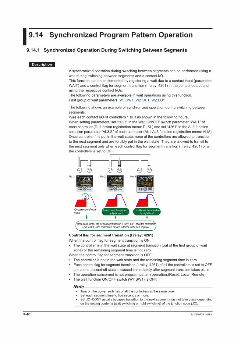
9-48 IM 05P02C41-01EN
9.14 SynchronizedProgramPatternOperation
9.14.1 SynchronizedOperationDuringSwitchingBetweenSegments
Description
Asynchronizedoperationduringswitchingbetweensegmentscanbeperformedusingawait during switching between segments and a contact I/O.This function can be implemented by registering a wait due to a contact input (parameter WAIT) and a control flag for segment transition (I relay: 4261) in the contact output and using the respective contact I/Os.The following parameters are available in wait operations using this function.First group of wait parameters: WT.SW1, WZ.UP1, WZ.LO1
Thefollowingshowsanexampleofsynchronizedoperationduringswitchingbetweensegments.Wire each contact I/O of controllers 1 to 3 as shown in the following figure.When setting parameters, set “5027” in the Wait ON/OFF switch parameter “WAIT” of each controller (DI function registration menu: DI.SL) and set “4261” in the AL3 function selection parameter “AL3.S” of each controller (AL1-AL3 function registration menu: ALM).Once controller 1 is put in the wait state, none of the controllers are allowed to transition to the next segment and are forcibly put in the wait state. They are allowed to transit to the next segment only when each control flag for segment transition (I relay: 4261) of all the controllers is set to OFF.
When each control flag for segment transition (I relay: 4261) of all the controllers is set to OFF, each controller is allowed to transit to the next segment.
Occurrence of wait state
AL3 DI3
No.1 No.2 No.3
AL3 DI3 AL3 DI3
Forcibly wait the operation by digital input
Forcibly wait the operation by digital input
Controlflagforsegmenttransition(Irelay:4261)When the control flag for segment transition is ON:• The controller is in the wait state at segment transition (out of the first group of wait
zone)ortheremainingsegmenttimeisnotzero.When the control flag for segment transition is OFF:• Thecontrollerisnotinthewaitstateandtheremainingsegmenttimeiszero.• Each control flag for segment transition (I relay: 4261) of all the controllers is set to OFF
and a one-second off state is caused immediately after segment transition takes place.• The operation concerned is not program pattern operation.(Reset, Local, Remote)• The wait function ON/OFF switch (WT.SW1) is OFF.
Note• Turn on the power switches of all the controllers at the same time.• Set each segment time to five seconds or more.• Set JC=CONT usually because transition to the next segment may not take place depending
onthesettingcontents(waitswitchingorholdswitching)ofthejunctioncode(JC).
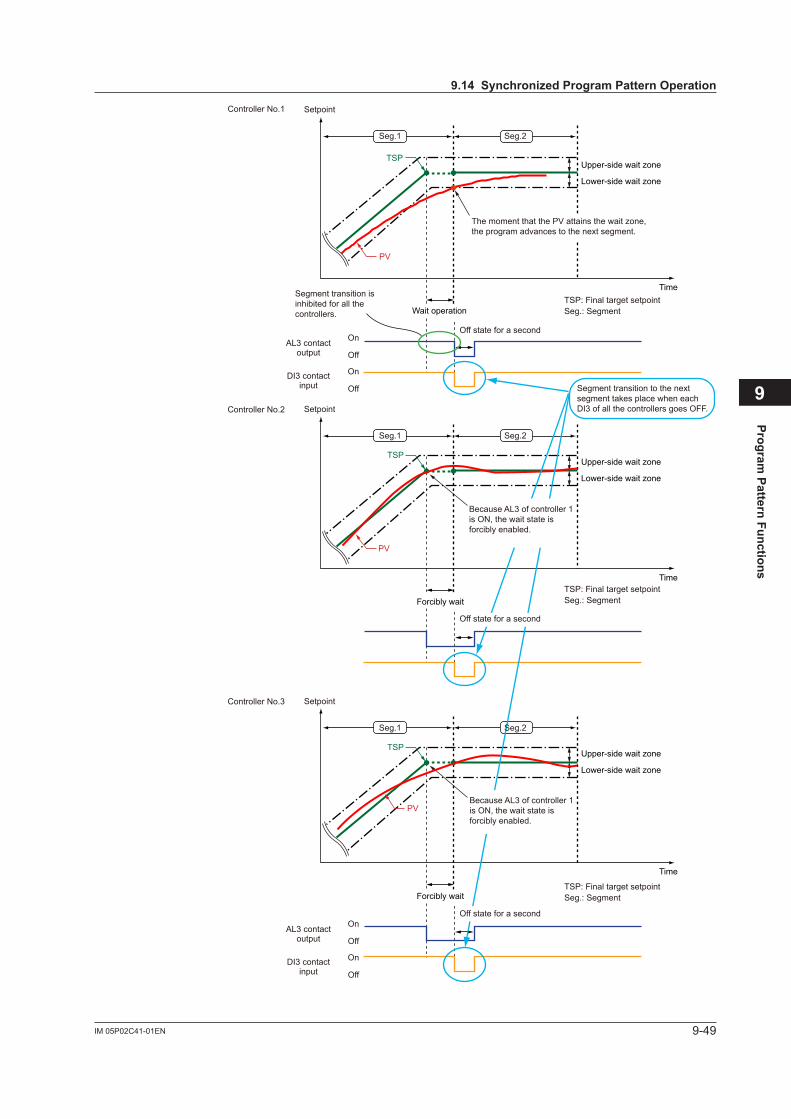
9-49IM 05P02C41-01EN
Program Pattern Functions
9
PV
TSP
TSP
TSP
AL3 contact output
Controller No.1
Controller No.2
Controller No.3
DI3 contact input
Off state for a second
Seg.1 Seg.2
Segment transition is inhibited for all the controllers.
Segment transition to the next segment takes place when each DI3 of all the controllers goes OFF.
Forcibly wait
Forcibly wait
PV
PV
Because AL3 of controller 1 is ON, the wait state is forcibly enabled.
Because AL3 of controller 1 is ON, the wait state is forcibly enabled.
Time
Time
Time
Upper-side wait zone
Lower-side wait zone
Upper-side wait zone
Lower-side wait zone
Upper-side wait zone
Lower-side wait zone
Wait operation Seg.: SegmentTSP: Final target setpoint
Seg.: SegmentTSP: Final target setpoint
Seg.: SegmentTSP: Final target setpoint
The moment that the PV attains the wait zone, the program advances to the next segment.
Setpoint
Setpoint
Setpoint
On
Off
On
Off
AL3 contact output
DI3 contact input
On
Off
On
Off
Seg.1 Seg.2
Seg.1 Seg.2
Off state for a second
Off state for a second
9.14SynchronizedProgramPatternOperation
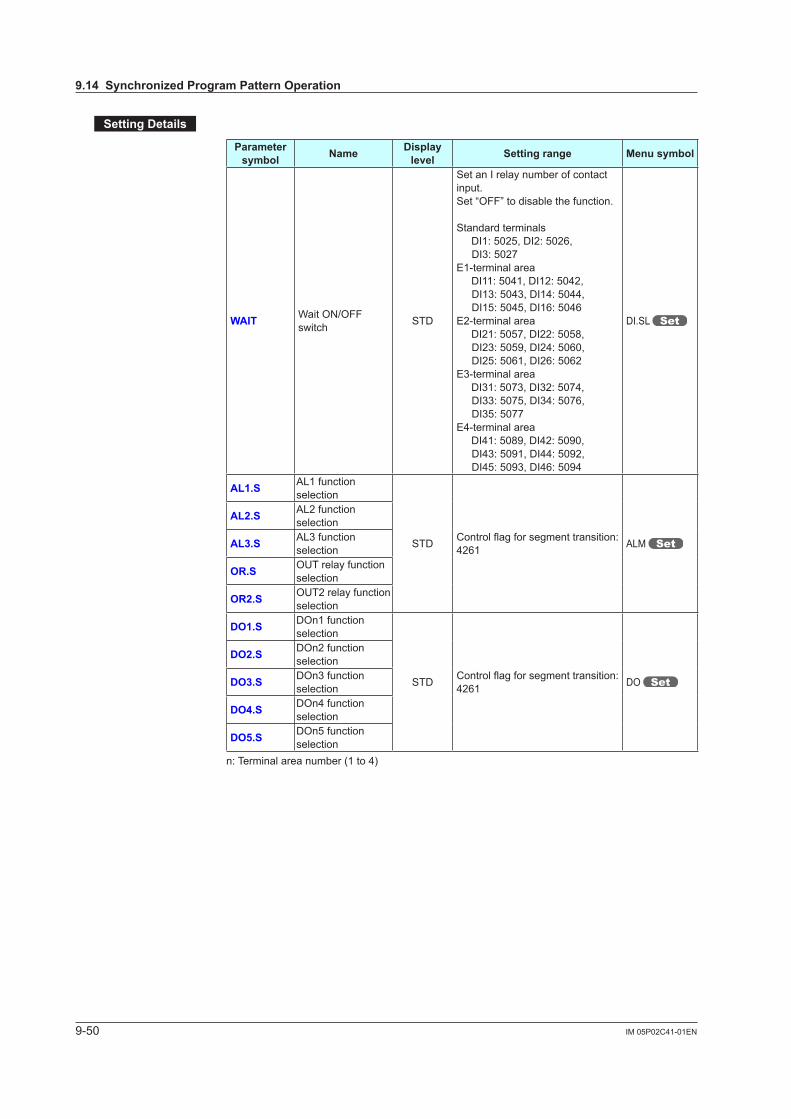
9-50 IM 05P02C41-01EN
SettingDetails
Parameter symbol Name Display
level Settingrange Menusymbol
WAIT Wait ON/OFF switch STD
Set an I relay number of contact input.Set “OFF” to disable the function.
Standard terminals DI1: 5025, DI2: 5026,
DI3: 5027E1-terminal area DI11: 5041, DI12: 5042,
DI13: 5043, DI14: 5044, DI15: 5045, DI16: 5046
E2-terminal area DI21: 5057, DI22: 5058,
DI23: 5059, DI24: 5060, DI25: 5061, DI26: 5062
E3-terminal area DI31: 5073, DI32: 5074,
DI33: 5075, DI34: 5076, DI35: 5077
E4-terminal area DI41: 5089, DI42: 5090,
DI43: 5091, DI44: 5092, DI45: 5093, DI46: 5094
DI.SL
AL1.S AL1 function selection
STD Controlflagforsegmenttransition:4261 ALM
AL2.S AL2 function selection
AL3.S AL3 function selection
OR.S OUT relay function selection
OR2.S OUT2 relay function selection
DO1.S DOn1 function selection
STD Controlflagforsegmenttransition:4261 DO
DO2.S DOn2 function selection
DO3.S DOn3 function selection
DO4.S DOn4 function selection
DO5.S DOn5 function selection
n: Terminal area number (1 to 4)
9.14SynchronizedProgramPatternOperation
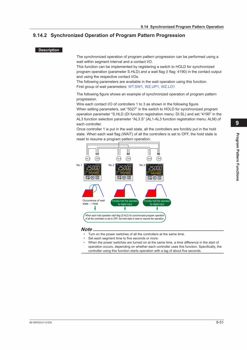
9-51IM 05P02C41-01EN
Program Pattern Functions
9
9.14.2 SynchronizedOperationofProgramPatternProgression
Description
Thesynchronizedoperationofprogrampatternprogressioncanbeperformedusingawait within segment interval and a contact I/O.ThisfunctioncanbeimplementedbyregisteringaswitchtoHOLDforsynchronizedprogram operation (parameter S.HLD) and a wait flag (I flag: 4190) in the contact output and using the respective contact I/Os.The following parameters are available in the wait operation using this function.First group of wait parameters: WT.SW1, WZ.UP1, WZ.LO1
Thefollowingfigureshowsanexampleofsynchronizedoperationofprogrampatternprogression.Wire each contact I/O of controllers 1 to 3 as shown in the following figure.Whensettingparameters,set“5027”intheswitchtoHOLDforsynchronizedprogramoperation parameter “S.HLD (DI function registration menu: DI.SL) and set “4190” in the AL3 function selection parameter “AL3.S” (AL1-AL3 function registration menu: ALM) of each controller.Once controller 1 is put in the wait state, all the controllers are forcibly put in the hold state. When each wait flag (WAIT) of all the controllers is set to OFF, the hold state is reset to resume a program pattern operation.
AL3 DI3
No.1 No.2 No.3
AL3 DI3 AL3 DI3
When each hold operation start flag (S.HLD) for synchronized program operation of all the controllers is set to OFF, the hold state is reset to resume the operation.
Occurrence of wait state → Hold
Forcibly hold the operation by digital input
Forcibly hold the operation by digital input
Note• Turn on the power switches of all the controllers at the same time.• Set each segment time to five seconds or more.• When the power switches are turned on at the same time, a time difference in the start of
operation occurs, depending on whether each controller uses this function. Specifically, the controller using this function starts operation with a lag of about five seconds.
9.14SynchronizedProgramPatternOperation

9-52 IM 05P02C41-01EN
PV
PV
PV
Wait state → Hold state
Hold state
Hold state
Program progression is inhibited for all the controllers. When each AL3 of all the controllers goes OFF, the hold state is reset.
Original target setpoint
Original target setpoint
Original target setpoint
AL3 contact output(Wait flag)
Controller No.1
Controller No.2
Controller No.3
DI3 contact input(Hold flag)
Seg.1 Seg.2
Seg.1 Seg.2
Seg.1 Seg.2
Time
Time
Time
Upper-side wait zone
Upper-side wait zone
Upper-side wait zone
Lower-side wait zone
Lower-side wait zone
Lower-side wait zone
Seg.: Segment
Seg.: Segment
Seg.: Segment
Setpoint
Setpoint
Setpoint
On
Off
On
Off
AL3 contact output(Wait flag)
DI3 contact input(Hold flag)
On
Off
On
Off
AL3 contact output(Wait flag)
DI3 contact input(Hold flag)
On
Off
On
Off
9.14SynchronizedProgramPatternOperation
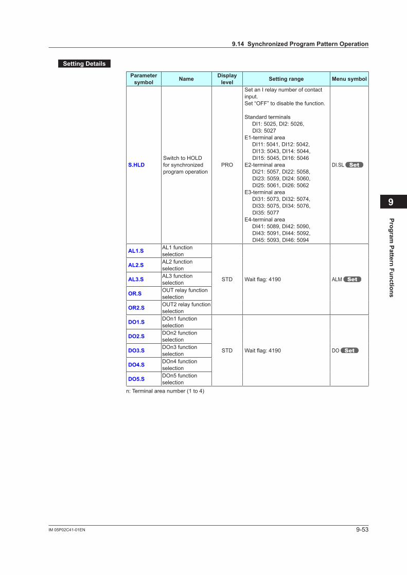
9-53IM 05P02C41-01EN
Program Pattern Functions
9
SettingDetails
Parameter symbol Name Display
level Settingrange Menusymbol
S.HLDSwitch to HOLD forsynchronizedprogram operation
PRO
Set an I relay number of contact input.Set “OFF” to disable the function.
Standard terminals DI1: 5025, DI2: 5026,
DI3: 5027E1-terminal area DI11: 5041, DI12: 5042,
DI13: 5043, DI14: 5044, DI15: 5045, DI16: 5046
E2-terminal area DI21: 5057, DI22: 5058,
DI23: 5059, DI24: 5060, DI25: 5061, DI26: 5062
E3-terminal area DI31: 5073, DI32: 5074,
DI33: 5075, DI34: 5076, DI35: 5077
E4-terminal area DI41: 5089, DI42: 5090,
DI43: 5091, DI44: 5092, DI45: 5093, DI46: 5094
DI.SL
AL1.S AL1 function selection
STD Waitflag:4190 ALM
AL2.S AL2 function selection
AL3.S AL3 function selection
OR.S OUT relay function selection
OR2.S OUT2 relay function selection
DO1.S DOn1 function selection
STD Waitflag:4190 DO
DO2.S DOn2 function selection
DO3.S DOn3 function selection
DO4.S DOn4 function selection
DO5.S DOn5 function selection
n: Terminal area number (1 to 4)
9.14SynchronizedProgramPatternOperation

Blank Page
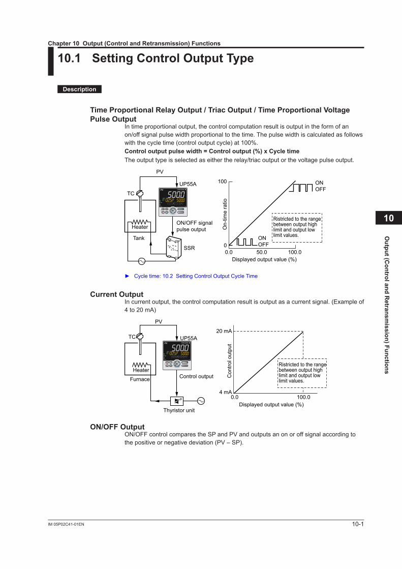
10-1IM 05P02C41-01EN
Output (C
ontrol and Retransm
ission) Functions
10
10.1 SettingControlOutputType
Description
TimeProportionalRelayOutput/TriacOutput/TimeProportionalVoltagePulseOutput
In time proportional output, the control computation result is output in the form of an on/off signal pulse width proportional to the time. The pulse width is calculated as follows with the cycle time (control output cycle) at 100%.Controloutputpulsewidth=Controloutput(%)xCycletimeThe output type is selected as either the relay/triac output or the voltage pulse output.
100
00.0 50.0 100.0
ONOFF
PV
TC
UP55A
Heater
Tank
SSR
ON/OFF signalpulse output
Displayed output value (%)
On-
time
ratio
ONOFF
Ristricted to the range between output high limit and output low limit values.
Cycletime:10.2SettingControlOutputCycleTime
CurrentOutputIn current output, the control computation result is output as a current signal. (Example of 4 to 20 mA)
20 mA
4 mA0.0 100.0
TC UP55A
PV
Heater
Furnace
Displayed output value (%)
Con
trol o
utpu
t
Control output
Thyristor unit
Ristricted to the range between output high limit and output low limit values.
ON/OFFOutputON/OFF control compares the SP and PV and outputs an on or off signal according to the positive or negative deviation (PV – SP).
Chapter10Output(ControlandRetransmission)Functions

10-2 IM 05P02C41-01EN
PositionProportionalOutputPosition proportional output is equipped only with Position proportional type.In position proportional output, valve opening is made proportional to the control computation results. The controller outputs direct and reverse signals (relay) to control motor movement and valve opening.
TC
PV
Furnace
UP55A
Burner
Air
Gas
Motor-operated valve
Control motor
Position signal
H (direct) or L (reverse)contact signal
Feedback-typePositionProportionalOutputIn feedback-type position proportional output, the controller obtains a valve position signalfromafeedbackslide-wireresistor(overallresistance:100Ωto2.5kΩ)attachedto a valve or feedback current input (4 to 20 mA).The following shows an example using feedback slide-wire resistor.
Direct action
Reverseaction
Controlcomputation
M
Motor-operatedvalve
Slide-wire resistor
Controloutput
Valve positionsignal
Feedbackinput
Controller
Comp-arator
When current is used for feedback input, only wiring is different Wiringforcurrent:17.4.5ValvePositionOutputandFeedbackInputWiring
Estimating-typePositionProportionalOutputIn estimating-type position proportional output, set the operating time required for a valve to change from the fully-closed position to the fully-open position beforehand. With the preset operating time, the controller controls the valve by estimating its position. Estimating-type position proportional output is used when feedback input signal cannot be obtained. (Feedback input wiring is not necessary.)Note: When the control output is: upper limit=direct signal, lower limit=reverse signal.
Heating/coolingOutputHeating/cooling output is equipped only with Heating/cooling type. Heating/coolingoutput:8.2.3Heating/coolingControl
10.1SettingControlOutputType
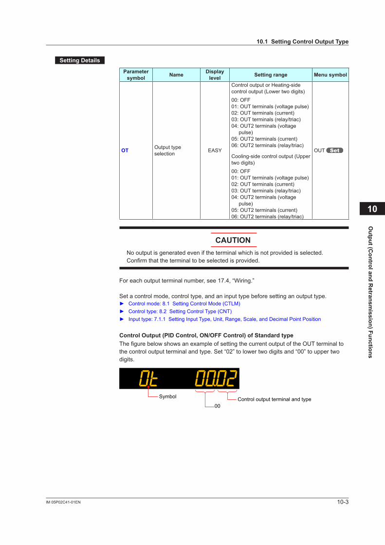
10-3IM 05P02C41-01EN
Output (C
ontrol and Retransm
ission) Functions
10
SettingDetails
Parameter symbol Name Display
level Settingrange Menusymbol
OT Output type selection EASY
Control output or Heating-side control output (Lower two digits)00: OFF01: OUT terminals (voltage pulse)02: OUT terminals (current)03: OUT terminals (relay/triac)04: OUT2 terminals (voltage
pulse)05: OUT2 terminals (current)06: OUT2 terminals (relay/triac)
Cooling-side control output (Upper two digits)00: OFF01: OUT terminals (voltage pulse)02: OUT terminals (current)03: OUT terminals (relay/triac)04: OUT2 terminals (voltage
pulse)05: OUT2 terminals (current)06: OUT2 terminals (relay/triac)
OUT
CAUTIONNo output is generated even if the terminal which is not provided is selected. Confirm that the terminal to be selected is provided.
For each output terminal number, see 17.4, “Wiring.”
Set a control mode, control type, and an input type before setting an output type. Controlmode:8.1SettingControlMode(CTLM) Controltype:8.2SettingControlType(CNT) Inputtype:7.1.1SettingInputType,Unit,Range,Scale,andDecimalPointPosition
ControlOutput(PIDControl,ON/OFFControl)ofStandardtypeThe figure below shows an example of setting the current output of the OUT terminal to the control output terminal and type. Set “02” to lower two digits and “00” to upper two digits.
Control output terminal and type00
Symbol
10.1SettingControlOutputType
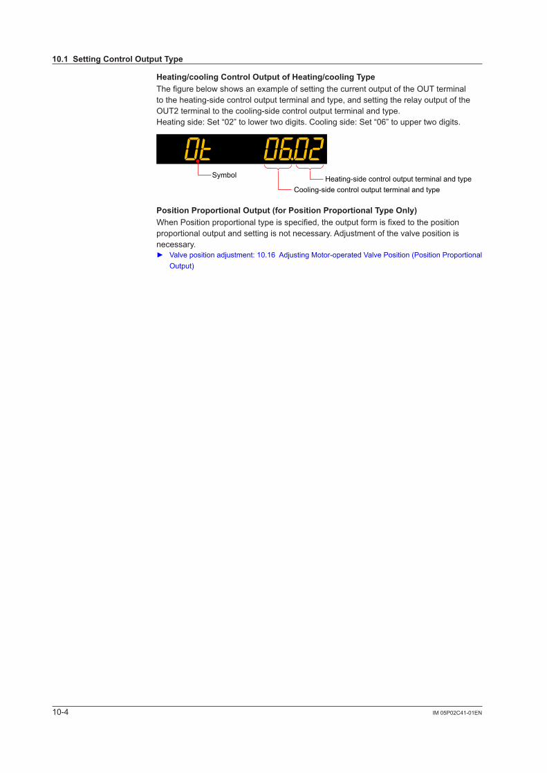
10-4 IM 05P02C41-01EN
Heating/coolingControlOutputofHeating/coolingTypeThe figure below shows an example of setting the current output of the OUT terminal to the heating-side control output terminal and type, and setting the relay output of the OUT2 terminal to the cooling-side control output terminal and type.Heating side: Set “02” to lower two digits. Cooling side: Set “06” to upper two digits.
Heating-side control output terminal and typeCooling-side control output terminal and type
Symbol
PositionProportionalOutput(forPositionProportionalTypeOnly)When Position proportional type is specified, the output form is fixed to the position proportionaloutputandsettingisnotnecessary.Adjustmentofthevalvepositionisnecessary. Valvepositionadjustment:10.16AdjustingMotor-operatedValvePosition(PositionProportional
Output)
10.1SettingControlOutputType
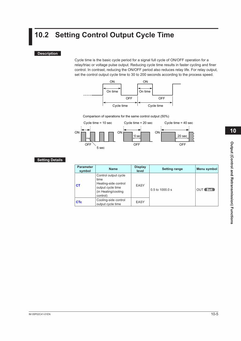
10-5IM 05P02C41-01EN
Output (C
ontrol and Retransm
ission) Functions
10
10.2 SettingControlOutputCycleTime
Description
Cycle time is the basic cycle period for a signal full cycle of ON/OFF operation for a relay/triac or voltage pulse output. Reducing cycle time results in faster cycling and finer control. In contrast, reducing the ON/OFF period also reduces relay life. For relay output, set the control output cycle time to 30 to 200 seconds according to the process speed.
ON
ON ON ON
On time On time
ON
OFF OFF
OFF OFF OFF
Cycle time Cycle time
Comparison of operations for the same control output (50%)
Cycle time = 10 sec Cycle time = 20 sec Cycle time = 40 sec
5 sec
10 sec 20 sec
SettingDetails
Parameter symbol Name Display
level Settingrange Menusymbol
CT
Control output cycle timeHeating-side control output cycle time (in Heating/cooling control)
EASY0.5 to 1000.0 s OUT
CTc Cooling-side control output cycle time EASY
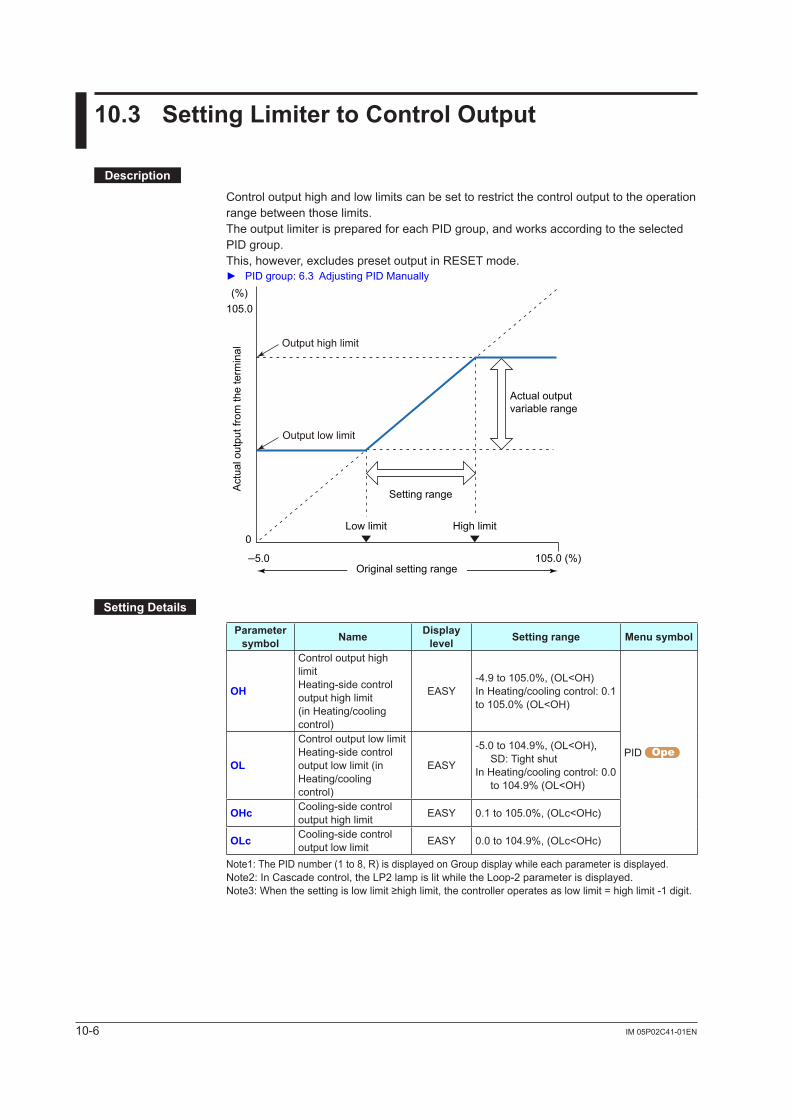
10-6 IM 05P02C41-01EN
10.3 SettingLimitertoControlOutput
Description
Control output high and low limits can be set to restrict the control output to the operation range between those limits.The output limiter is prepared for each PID group, and works according to the selected PID group.This, however, excludes preset output in RESET mode. PIDgroup:6.3AdjustingPIDManually
–5.0 105.0 (%)
Setting range
High limitLow limit
Actual outputvariable range
Original setting range
Act
ual o
utpu
t fro
m th
e te
rmin
al
0
(%)105.0
Output high limit
Output low limit
SettingDetails
Parameter symbol Name Display
level Settingrange Menusymbol
OH
Control output high limitHeating-side control output high limit (in Heating/cooling control)
EASY-4.9 to 105.0%, (OL<OH)In Heating/cooling control: 0.1 to 105.0% (OL<OH)
PID OL
Control output low limitHeating-side control output low limit (in Heating/cooling control)
EASY
-5.0 to 104.9%, (OL<OH), SD: Tight shut
In Heating/cooling control: 0.0 to 104.9% (OL<OH)
OHc Cooling-side control output high limit EASY 0.1 to 105.0%, (OLc<OHc)
OLc Cooling-side control output low limit EASY 0.0 to 104.9%, (OLc<OHc)
Note1: The PID number (1 to 8, R) is displayed on Group display while each parameter is displayed.Note2: In Cascade control, the LP2 lamp is lit while the Loop-2 parameter is displayed.Note3:Whenthesettingislowlimit≥highlimit,thecontrolleroperatesaslowlimit=highlimit-1digit.
10-7IM 05P02C41-01EN
Output (C
ontrol and Retransm
ission) Functions
10.4 DisablingOutputLimiterinMANmode
Description
Output limiter can be released when in MAN mode.However, cannot be released when in Heating/cooling control.Note that the output bump is caused if the operation mode is changed from MAN to AUTO while the control output is out of the range between the control output high limit (OH) and control output low limit (OL).Control output bumps to OH in MAN mode when it is larger than OH.Moreover, it bumps to OL when smaller than OL.
SettingDetails
Parameter symbol Name Display
level Settingrange Menusymbol
OLMT Output limiter switch PRO
OFF: Disable output limiter in MAN mode
ON: Enable output limiter in MAN mode
TUNE
Note1: In Cascade control, the LP2 lamp is lit while the Loop-2 parameter is displayed.10
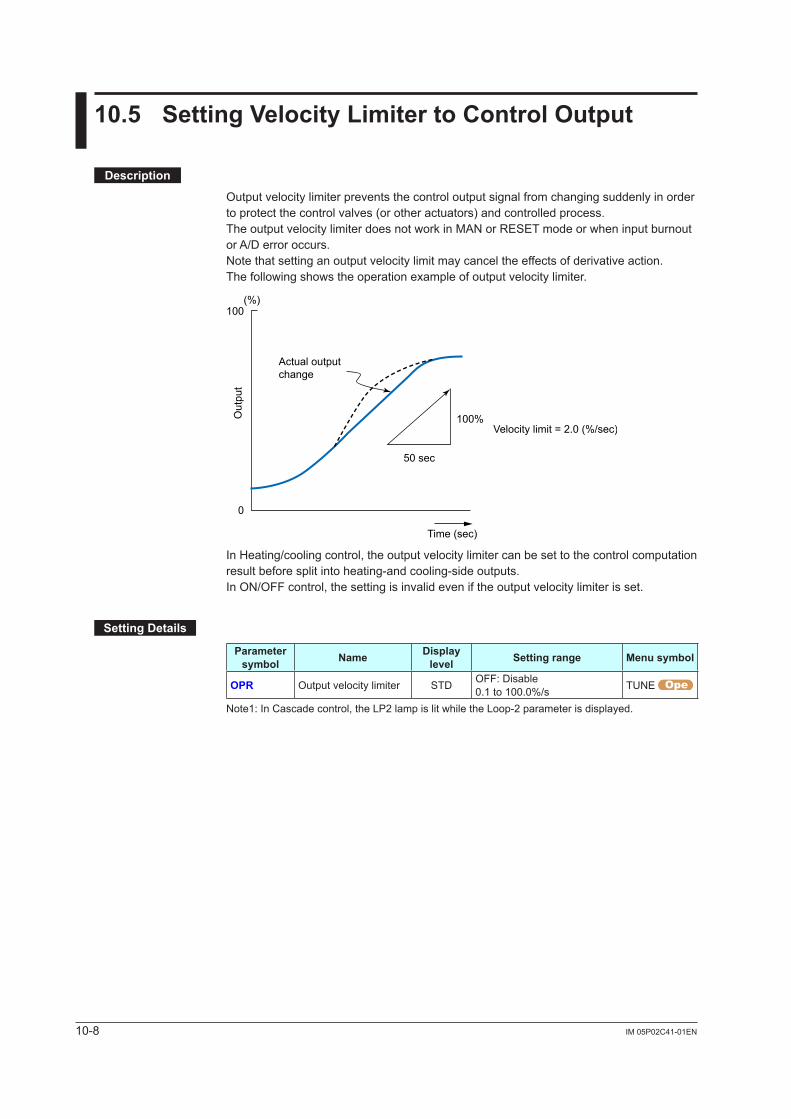
10-8 IM 05P02C41-01EN
10.5 SettingVelocityLimitertoControlOutput
Description
Output velocity limiter prevents the control output signal from changing suddenly in order to protect the control valves (or other actuators) and controlled process.The output velocity limiter does not work in MAN or RESET mode or when input burnout or A/D error occurs.Note that setting an output velocity limit may cancel the effects of derivative action.The following shows the operation example of output velocity limiter.
100
0
(%)
100%
50 sec
Time (sec)
Out
put
Velocity limit = 2.0 (%/sec)
Actual outputchange
In Heating/cooling control, the output velocity limiter can be set to the control computation result before split into heating-and cooling-side outputs.In ON/OFF control, the setting is invalid even if the output velocity limiter is set.
SettingDetails
Parameter symbol Name Display
level Settingrange Menusymbol
OPR Output velocity limiter STD OFF: Disable0.1 to 100.0%/s TUNE
Note1: In Cascade control, the LP2 lamp is lit while the Loop-2 parameter is displayed.
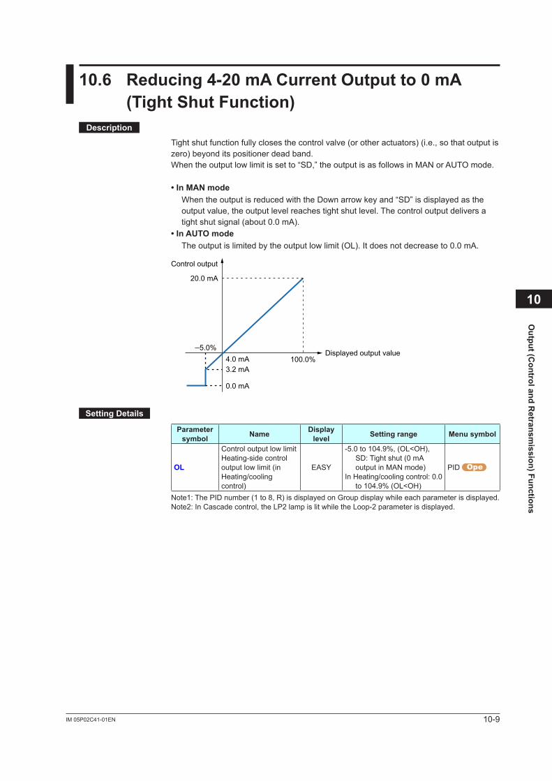
10-9IM 05P02C41-01EN
Output (C
ontrol and Retransm
ission) Functions
10.6 Reducing4-20mACurrentOutputto0mA(TightShutFunction)
Description
Tight shut function fully closes the control valve (or other actuators) (i.e., so that output is zero)beyonditspositionerdeadband.When the output low limit is set to “SD,” the output is as follows in MAN or AUTO mode.
• In MAN mode When the output is reduced with the Down arrow key and “SD” is displayed as the
output value, the output level reaches tight shut level. The control output delivers a tight shut signal (about 0.0 mA).
•InAUTOmode The output is limited by the output low limit (OL). It does not decrease to 0.0 mA.
Control output
20.0 mA
–5.0%100.0%
Displayed output value
3.2 mA4.0 mA
0.0 mA
SettingDetails
Parameter symbol Name Display
level Settingrange Menusymbol
OL
Control output low limitHeating-side control output low limit (in Heating/cooling control)
EASY
-5.0 to 104.9%, (OL<OH), SD: Tight shut (0 mA output in MAN mode)
In Heating/cooling control: 0.0 to 104.9% (OL<OH)
PID
Note1: The PID number (1 to 8, R) is displayed on Group display while each parameter is displayed.Note2: In Cascade control, the LP2 lamp is lit while the Loop-2 parameter is displayed.
10
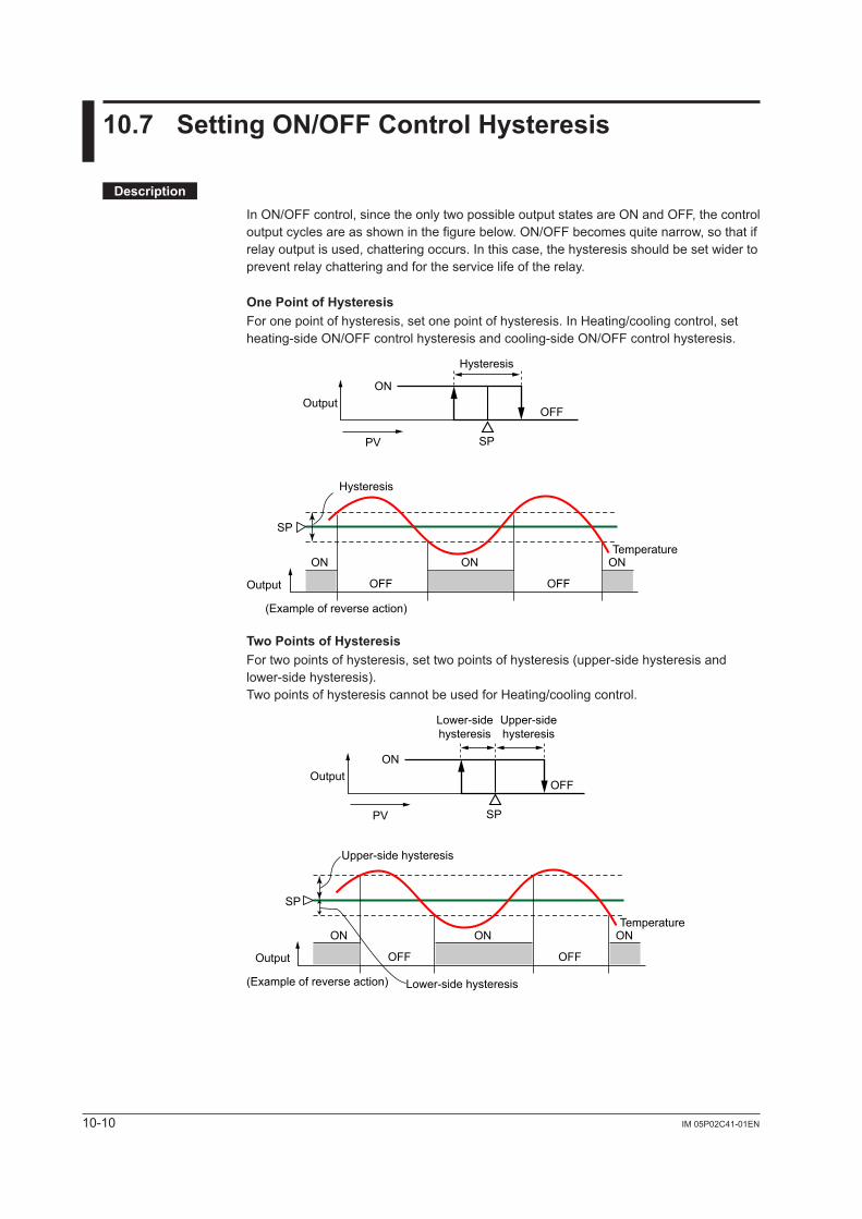
10-10 IM 05P02C41-01EN
10.7 SettingON/OFFControlHysteresis
Description
In ON/OFF control, since the only two possible output states are ON and OFF, the control output cycles are as shown in the figure below. ON/OFF becomes quite narrow, so that if relay output is used, chattering occurs. In this case, the hysteresis should be set wider to prevent relay chattering and for the service life of the relay.
OnePointofHysteresisFor one point of hysteresis, set one point of hysteresis. In Heating/cooling control, set heating-side ON/OFF control hysteresis and cooling-side ON/OFF control hysteresis.
Hysteresis
SP
OutputON
ON
OFF
OFF
ON ON
OFF
PV
Hysteresis
SP
Output
(Example of reverse action)
Temperature
TwoPointsofHysteresisFor two points of hysteresis, set two points of hysteresis (upper-side hysteresis and lower-side hysteresis).Two points of hysteresis cannot be used for Heating/cooling control.
Upper-sidehysteresis
Lower-sidehysteresis
SP
OutputON
ON
OFF
OFF
ON ON
OFF
PV
Upper-side hysteresis
Lower-side hysteresis
SP
Output
(Example of reverse action)
Temperature
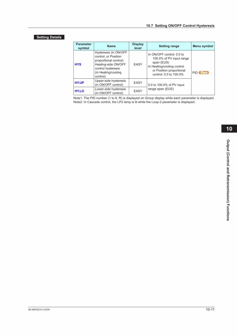
10-11IM 05P02C41-01EN
Output (C
ontrol and Retransm
ission) Functions
SettingDetails
Parameter symbol Name Display
level Settingrange Menusymbol
HYS
Hysteresis (in ON/OFF control, or Position proportional control)Heating-side ON/OFF control hysteresis (in Heating/cooling control)
EASY
In ON/OFF control: 0.0 to 100.0% of PV input range span (EUS)
In Heating/cooling control or Position proportional control: 0.0 to 100.0% PID
HY.UP Upper-side hysteresis (in ON/OFF control) EASY
0.0 to 100.0% of PV input range span (EUS)HY.LO Lower-side hysteresis
(in ON/OFF control) EASY
Note1: The PID number (1 to 8, R) is displayed on Group display while each parameter is displayed.Note2: In Cascade control, the LP2 lamp is lit while the Loop-2 parameter is displayed.
10
10.7SettingON/OFFControlHysteresis
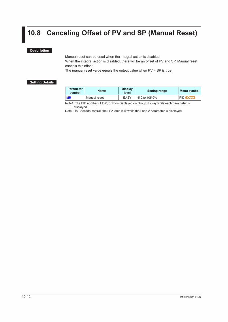
10-12 IM 05P02C41-01EN
10.8 CancelingOffsetofPVandSP(ManualReset)
Description
Manual reset can be used when the integral action is disabled.When the integral action is disabled, there will be an offset of PV and SP. Manual reset cancels this offset.The manual reset value equals the output value when PV = SP is true.
SettingDetails
Parameter symbol Name Display
level Settingrange Menusymbol
MR Manual reset EASY -5.0 to 105.0% PID
Note1: The PID number (1 to 8, or R) is displayed on Group display while each parameter is displayed.
Note2: In Cascade control, the LP2 lamp is lit while the Loop-2 parameter is displayed.
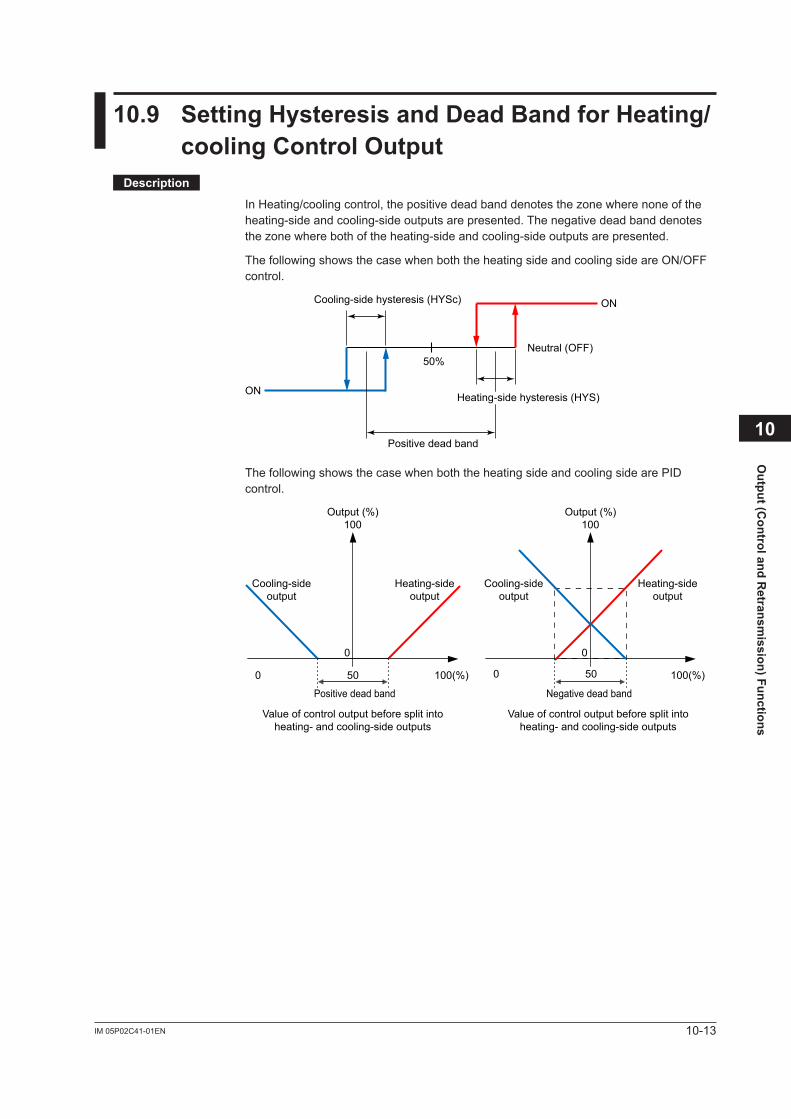
10-13IM 05P02C41-01EN
Output (C
ontrol and Retransm
ission) Functions
10.9 SettingHysteresisandDeadBandforHeating/coolingControlOutput
Description
InHeating/coolingcontrol,thepositivedeadbanddenotesthezonewherenoneoftheheating-side and cooling-side outputs are presented. The negative dead band denotes thezonewherebothoftheheating-sideandcooling-sideoutputsarepresented.
The following shows the case when both the heating side and cooling side are ON/OFF control.
ON
ON
50%
Cooling-side hysteresis (HYSc)
Neutral (OFF)
Heating-side hysteresis (HYS)
Positive dead band
The following shows the case when both the heating side and cooling side are PID control.
0
Negative dead band
0
Cooling-sideoutput
Cooling-sideoutput
Heating-sideoutput
Heating-sideoutput
Output (%)100
Output (%)100
Positive dead band
100(%) 100(%)50 500 0
Value of control output before split intoheating- and cooling-side outputs
Value of control output before split intoheating- and cooling-side outputs
10
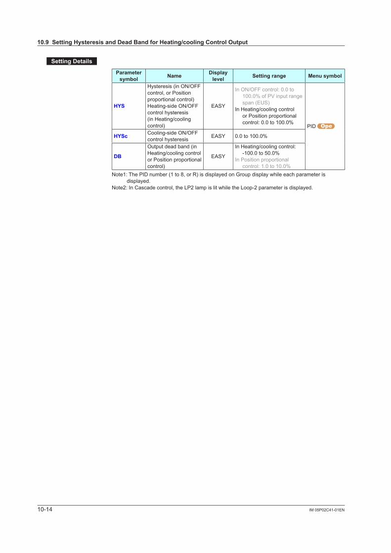
10-14 IM 05P02C41-01EN
SettingDetails
Parameter symbol Name Display
level Settingrange Menusymbol
HYS
Hysteresis (in ON/OFF control, or Position proportional control)Heating-side ON/OFF control hysteresis (in Heating/cooling control)
EASY
In ON/OFF control: 0.0 to 100.0% of PV input range span (EUS)
In Heating/cooling control or Position proportional control: 0.0 to 100.0%
PID
HYSc Cooling-side ON/OFF control hysteresis EASY 0.0 to 100.0%
DB
Output dead band (in Heating/cooling control or Position proportional control)
EASY
In Heating/cooling control: -100.0 to 50.0%
In Position proportional control: 1.0 to 10.0%
Note1: The PID number (1 to 8, or R) is displayed on Group display while each parameter is displayed.
Note2: In Cascade control, the LP2 lamp is lit while the Loop-2 parameter is displayed.
10.9SettingHysteresisandDeadBandforHeating/coolingControlOutput
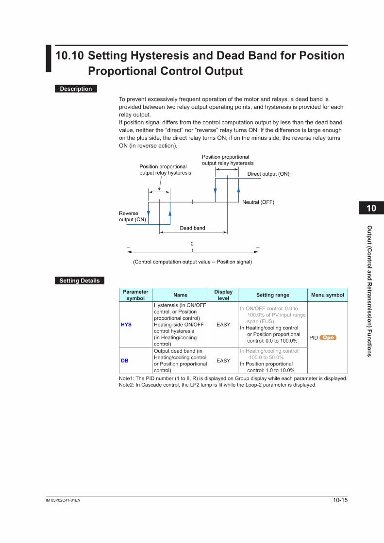
10-15IM 05P02C41-01EN
Output (C
ontrol and Retransm
ission) Functions
10.10SettingHysteresisandDeadBandforPositionProportionalControlOutput
Description
To prevent excessively frequent operation of the motor and relays, a dead band is provided between two relay output operating points, and hysteresis is provided for each relay output.If position signal differs from the control computation output by less than the dead band value, neither the “direct” nor “reverse” relay turns ON. If the difference is large enough on the plus side, the direct relay turns ON; if on the minus side, the reverse relay turns ON (in reverse action).
Reverseoutput (ON)
Direct output (ON)
Neutral (OFF)
Dead band
0
(Control computation output value – Position signal)
Position proportional output relay hysteresis
Position proportional output relay hysteresis
SettingDetails
Parameter symbol Name Display
level Settingrange Menusymbol
HYS
Hysteresis (in ON/OFF control, or Position proportional control)Heating-side ON/OFF control hysteresis (in Heating/cooling control)
EASY
In ON/OFF control: 0.0 to 100.0% of PV input range span (EUS)
In Heating/cooling control or Position proportional control: 0.0 to 100.0% PID
DB
Output dead band (in Heating/cooling control or Position proportional control)
EASY
In Heating/cooling control: -100.0 to 50.0%
In Position proportional control: 1.0 to 10.0%
Note1: The PID number (1 to 8, R) is displayed on Group display while each parameter is displayed.Note2: In Cascade control, the LP2 lamp is lit while the Loop-2 parameter is displayed.
10
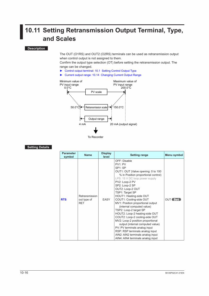
10-16 IM 05P02C41-01EN
10.11SettingRetransmissionOutputTerminal,Type,andScales
Description
The OUT (O1RS) and OUT2 (O2RS) terminals can be used as retransmission output when control output is not assigned to them.Confirm the output type selection (OT) before setting the retransmission output. The range can be changed. Controloutputterminal:10.1SettingControlOutputType Currentoutputrange:10.14ChangingCurrentOutputRange
20 mA (output signal)
0.0°C 200.0°C
4 mA
50.0°C 150.0°CRetransmission scale
PV scale
Output range
Minimum value ofPV input range
Maximum value ofPV input range
To Recorder
SettingDetails
Parameter symbol Name Display
level Settingrange Menusymbol
RTSRetransmission out type of RET
EASY
OFF: DisablePV1: PVSP1: SPOUT1: OUT (Valve opening: 0 to 100
% in Position proportional control)LPS: 15 V DC loop power supplyPV2: Loop-2 PVSP2: Loop-2 SPOUT2: Loop-2 OUTTSP1: Target SPHOUT1: Heating-side OUTCOUT1: Cooling-side OUTMV1: Position proportional output
(internal computed value)TSP2: Loop-2 target SPHOUT2: Loop-2 heating-side OUTCOUT2: Loop-2 cooling-side OUTMV2: Loop-2 position proportional
output (internal computed value)PV: PV terminals analog inputRSP: RSP terminals analog inputAIN2: AIN2 terminals analog inputAIN4: AIN4 terminals analog input
OUT
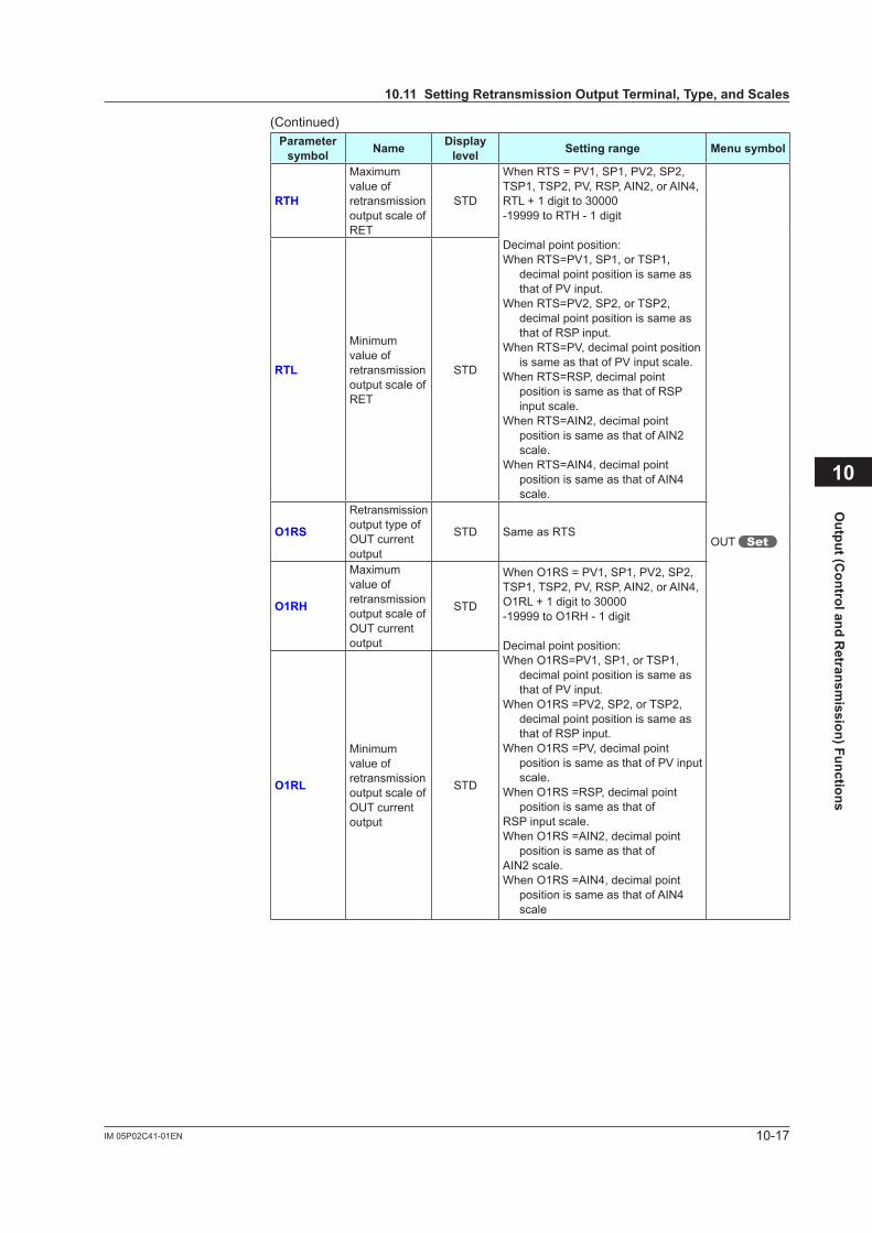
10-17IM 05P02C41-01EN
Output (C
ontrol and Retransm
ission) Functions
(Continued)Parameter symbol Name Display
level Settingrange Menusymbol
RTH
Maximum value of retransmission output scale of RET
STD
When RTS = PV1, SP1, PV2, SP2, TSP1, TSP2, PV, RSP, AIN2, or AIN4, RTL + 1 digit to 30000-19999 to RTH - 1 digit
Decimal point position:When RTS=PV1, SP1, or TSP1,
decimal point position is same as that of PV input.
When RTS=PV2, SP2, or TSP2, decimal point position is same as that of RSP input.
When RTS=PV, decimal point position is same as that of PV input scale.
When RTS=RSP, decimal point position is same as that of RSP input scale.
When RTS=AIN2, decimal point position is same as that of AIN2 scale.
When RTS=AIN4, decimal point position is same as that of AIN4 scale.
OUT
RTL
Minimum value of retransmission output scale of RET
STD
O1RS
Retransmission output type of OUT current output
STD Same as RTS
O1RH
Maximum value of retransmission output scale of OUT current output
STD
When O1RS = PV1, SP1, PV2, SP2, TSP1, TSP2, PV, RSP, AIN2, or AIN4, O1RL + 1 digit to 30000-19999 to O1RH - 1 digit
Decimal point position: When O1RS=PV1, SP1, or TSP1,
decimal point position is same as that of PV input.
When O1RS =PV2, SP2, or TSP2, decimal point position is same as that of RSP input.
When O1RS =PV, decimal point position is same as that of PV input scale.
When O1RS =RSP, decimal point position is same as that of
RSP input scale.When O1RS =AIN2, decimal point
position is same as that ofAIN2 scale.When O1RS =AIN4, decimal point
position is same as that of AIN4 scale
O1RL
Minimum value of retransmission output scale of OUT current output
STD
10
10.11SettingRetransmissionOutputTerminal,Type,andScales

10-18 IM 05P02C41-01EN
(Continued)Parameter symbol Name Display
level Settingrange Menusymbol
O2RS
Retransmission output type of OUT2 current output
STD Same as RTS
OUT
O2RH
Maximum value of retransmission output scale of OUT2 current output
STD
When O2RS = PV1, SP1, PV2, SP2, TSP1, TSP2, PV, RSP, AIN2, or AIN4, O2RL + 1 digit to 30000 -19999 to O2RH - 1 digit
Decimal point position: When O2RS=PV1, SP1, or TSP1,
decimal point position is same as that of PV input.
When O2RS =PV2, SP2, or TSP2, decimal point position is same as that of RSP input.
When O2RS =PV, decimal point position is same as that of PV input scale.
When O2RS =RSP, decimal point position is same as that of RSP input scale.
When O2RS =AIN2, decimal point position is same as that of AIN2 scale.
When O2RS =AIN4, decimal point position is same as that of AIN4 scale.
O2RL
Minimum value of retransmission output scale of OUT2 current output
STD
Setpoints PV2, SP2 and OUT2: Can be used in Cascade control.Setpoints HOUT1 and COUT1: Can be used in Heating/cooling control.Setpoint MV1: Can be used in Position proportional control.
(When opening or closing a valve by key operation in manual mode opration, the transmission output becomes -5.0 %.)
Setpoint TSP2: Can be used in Cascade control.Setpoints HOUT2 and COUT2: Can be used in Cascade control of Heating/cooling type.Setpoint MV2: Can be used in Cascade control of Position proportional type.
(When opening or closing a valve by key operation in manual mode opration, the transmission output becomes -5.0 %.)
Setpoint RSP: Can be used when equipped with remote input.Setpoints AIN2 and AIN4: Can be used when the UP55A suffix code: Type 2 = 4.
Parameters and Corresponding TerminalsRTS, RTH, RTL RET terminal
O1RS, O1RH, O1RL OUT terminal
O2RS, O2RH, O2RL OUT2 terminal
10.11SettingRetransmissionOutputTerminal,Type,andScales
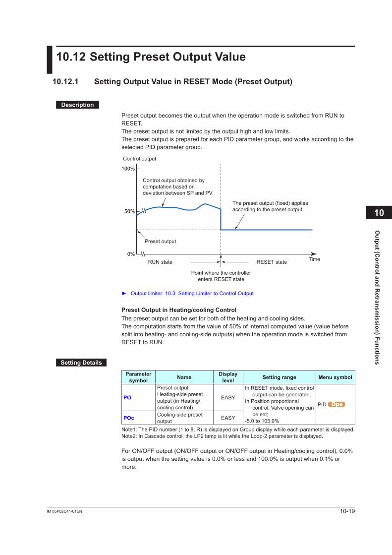
10-19IM 05P02C41-01EN
Output (C
ontrol and Retransm
ission) Functions
10.12SettingPresetOutputValue
10.12.1 SettingOutputValueinRESETMode(PresetOutput)
Description
Preset output becomes the output when the operation mode is switched from RUN to RESET.The preset output is not limited by the output high and low limits.The preset output is prepared for each PID parameter group, and works according to the selected PID parameter group.
Preset output
RUN state RESET state Time0%
50%
100%
Control output
Point where the controllerenters RESET state
The preset output (fixed) applies according to the preset output.
Control output obtained by computation based on deviation between SP and PV.
Outputlimiter:10.3SettingLimitertoControlOutput
PresetOutputinHeating/coolingControlThe preset output can be set for both of the heating and cooling sides.The computation starts from the value of 50% of internal computed value (value before split into heating- and cooling-side outputs) when the operation mode is switched from RESET to RUN.
SettingDetails
Parameter symbol Name Display
level Settingrange Menusymbol
PO
Preset outputHeating-side preset output (in Heating/cooling control)
EASY
InRESETmode,fixedcontroloutput can be generated.
In Position proportional control, Valve opening can be set;
-5.0 to 105.0%
PID
POc Cooling-side preset output EASY
Note1: The PID number (1 to 8, R) is displayed on Group display while each parameter is displayed.Note2: In Cascade control, the LP2 lamp is lit while the Loop-2 parameter is displayed.
For ON/OFF output (ON/OFF output or ON/OFF output in Heating/cooling control), 0.0% is output when the setting value is 0.0% or less and 100.0% is output when 0.1% or more.
10
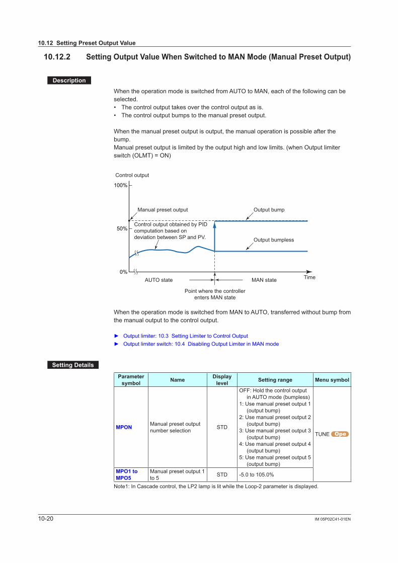
10-20 IM 05P02C41-01EN
10.12SettingPresetOutputValue
10.12.2 SettingOutputValueWhenSwitchedtoMANMode(ManualPresetOutput)
Description
When the operation mode is switched from AUTO to MAN, each of the following can be selected.• The control output takes over the control output as is.• The control output bumps to the manual preset output.
When the manual preset output is output, the manual operation is possible after the bump.Manual preset output is limited by the output high and low limits. (when Output limiter switch (OLMT) = ON)
Manual preset output Output bump
Output bumpless
AUTO state MAN state Time0%
50%
100%
Control output
Point where the controllerenters MAN state
Control output obtained by PID computation based on deviation between SP and PV.
When the operation mode is switched from MAN to AUTO, transferred without bump from the manual output to the control output.
Outputlimiter:10.3SettingLimitertoControlOutput Output limiter switch: 10.4 Disabling Output Limiter in MAN mode
SettingDetails
Parameter symbol Name Display
level Settingrange Menusymbol
MPON Manual preset output number selection STD
OFF: Hold the control output in AUTO mode (bumpless)
1: Use manual preset output 1 (output bump)
2: Use manual preset output 2 (output bump)
3: Use manual preset output 3 (output bump)
4: Use manual preset output 4 (output bump)
5: Use manual preset output 5 (output bump)
TUNE
MPO1toMPO5
Manual preset output 1 to 5 STD -5.0 to 105.0%
Note1: In Cascade control, the LP2 lamp is lit while the Loop-2 parameter is displayed.
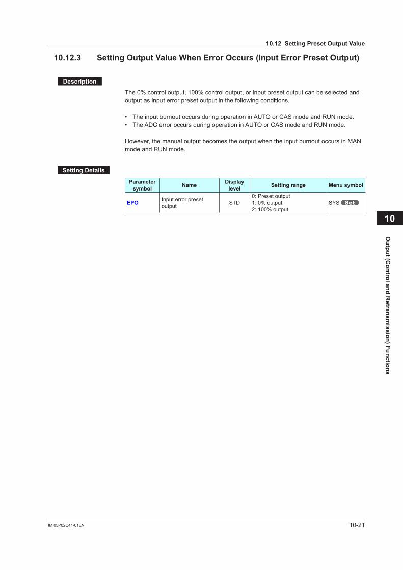
10-21IM 05P02C41-01EN
Output (C
ontrol and Retransm
ission) Functions
10
10.12SettingPresetOutputValue
10.12.3 SettingOutputValueWhenErrorOccurs(InputErrorPresetOutput)
Description
The 0% control output, 100% control output, or input preset output can be selected and output as input error preset output in the following conditions.
• The input burnout occurs during operation in AUTO or CAS mode and RUN mode.• The ADC error occurs during operation in AUTO or CAS mode and RUN mode.
However, the manual output becomes the output when the input burnout occurs in MAN mode and RUN mode.
SettingDetails
Parameter symbol Name Display
level Settingrange Menusymbol
EPO Input error preset output STD
0: Preset output1: 0% output2: 100% output
SYS
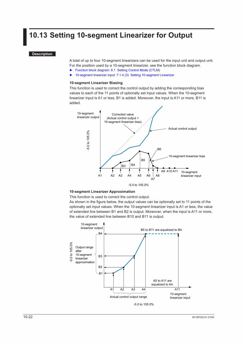
10-22 IM 05P02C41-01EN
10.13Setting10-segmentLinearizerforOutput
Description
Atotalofuptofour10-segmentlinearizerscanbeusedfortheinputunitandoutputunit.Forthepositionusedbya10-segmentlinearizer,seethefunctionblockdiagram. Functionblockdiagram:8.1SettingControlMode(CTLM) 10-segmentlinearizerinput:7.1.4 (3) Setting10-segmentLinearizer
10-segmentLinearizerBiasingThis function is used to correct the control output by adding the corresponding bias values to each of the 11 points of optionally set input values. When the 10-segment linearizerinputisA1orless,B1isadded.Moreover,theinputisA11ormore,B11isadded.
A1 A2 A3 A4 A5 A6A7
A8A9 A10 A11
B3 B4B5
B6
10-segmentlinearizer input
Actual control output
10-segment linearizer bias
Corrected value(Actual control output +
10-segment linearizer bias)
10-segmentlinearizer output
-5.0 to 105.0%
-5.0
to 1
05.0
%
10-segmentLinearizerApproximationThis function is used to correct the control output.As shown in the figure below, the output values can be optionally set to 11 points of the optionallysetinputvalues.Whenthe10-segmentlinearizerinputisA1orless,thevalueof extended line between B1 and B2 is output. Moreover, when the input is A11 or more, the value of extended line between B10 and B11 is output.
B1
A1 A2 A3 A4 A11
B2
B3
B4
-5.0 to 105.0%
-5.0
to 1
05.0
%
A5 to A11 areequalized to A4.
B5 to B11 are equalized to B4.
10-segmentlinearizer input
10-segmentlinearizer output
Actual control output range
Output rangeafter10-segmentlinearizerapproximation

10-23IM 05P02C41-01EN
Output (C
ontrol and Retransm
ission) Functions
10
SettingDetails
Parameter symbol Name Displaylevel Settingrange Menusymbol
PYS10-segment linearizerselection
Group 1, 2: STDGroup 3, 4: PRO
OFF: DisablePV: PV analog inputRSP: RSP analog inputAIN2: AIN2 analog inputAIN4: AIN4 analog inputPVIN: PV inputOUT: OUT analog outputOUT2: OUT2 analog
outputRET: RET analog output
PYS1PYS2PYS3PYS4
A1toA1110-segment linearizerinput 1
Group 1, 2: STDGroup 3, 4: PRO
-66.7 to 105.0% of input range (EU)
Outputlinearizer:-5.0to105.0%
B1toB1110-segment linearizeroutput 1
Group 1, 2: STDGroup 3, 4: PRO
10-segmentlinearizerbias:-66.7 to 105.0% of input range span (EUS)
10-segmentlinearizerapproximation: -66.7 to 105.0% of input range (EU)
Outputlinearizer:-5.0to105.0%
PMD10-segment linearizermode
Group 1, 2: STDGroup 3, 4: PRO
0:10-segmentlinearizerbias
1:10-segmentlinearizerapproximation
Note1: The group number (1 to 4) is displayed on Group display while each parameter is displayed.
Set it in the following orders.(1) PYS:Specifieswherethe10-segmentlinearizerfunctionisused.
Setpoint OUT functions before output to OUT terminal. Setpoint OUT2 functions before output to OUT2 terminal. (for Heating/cooling type only)
Setpoint RET functions before output to RET terminal.(2) PMD: Specifieswhethertouseitasa10-segmentlinearizerbiasora10-segment
linearizerapproximation.(3) A1 to A11, B1 to B11: Setsthe10-segmentlinearizerinputand10-segmentlinearizer
output.
Note• Setthe10-segmentlinearizersothatitincreasesmonotonically.• Ifthesamesetpointissetforthetwoormoreparametersof10-segmentlinearizerselection
(PYS), a smaller group number is used.
10.13Setting10-segmentLinearizerforOutput
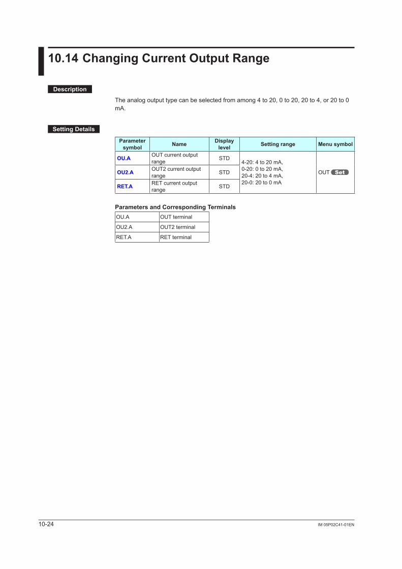
10-24 IM 05P02C41-01EN
10.14ChangingCurrentOutputRange
Description
The analog output type can be selected from among 4 to 20, 0 to 20, 20 to 4, or 20 to 0 mA.
SettingDetails
Parameter symbol Name Display
level Settingrange Menusymbol
OU.A OUT current output range STD
4-20: 4 to 20 mA,0-20: 0 to 20 mA,20-4: 20 to 4 mA,20-0: 20 to 0 mA
OUT OU2.A OUT2 current output range STD
RET.A RET current output range STD
Parameters and Corresponding TerminalsOU.A OUT terminal
OU2.A OUT2 terminal
RET.A RET terminal
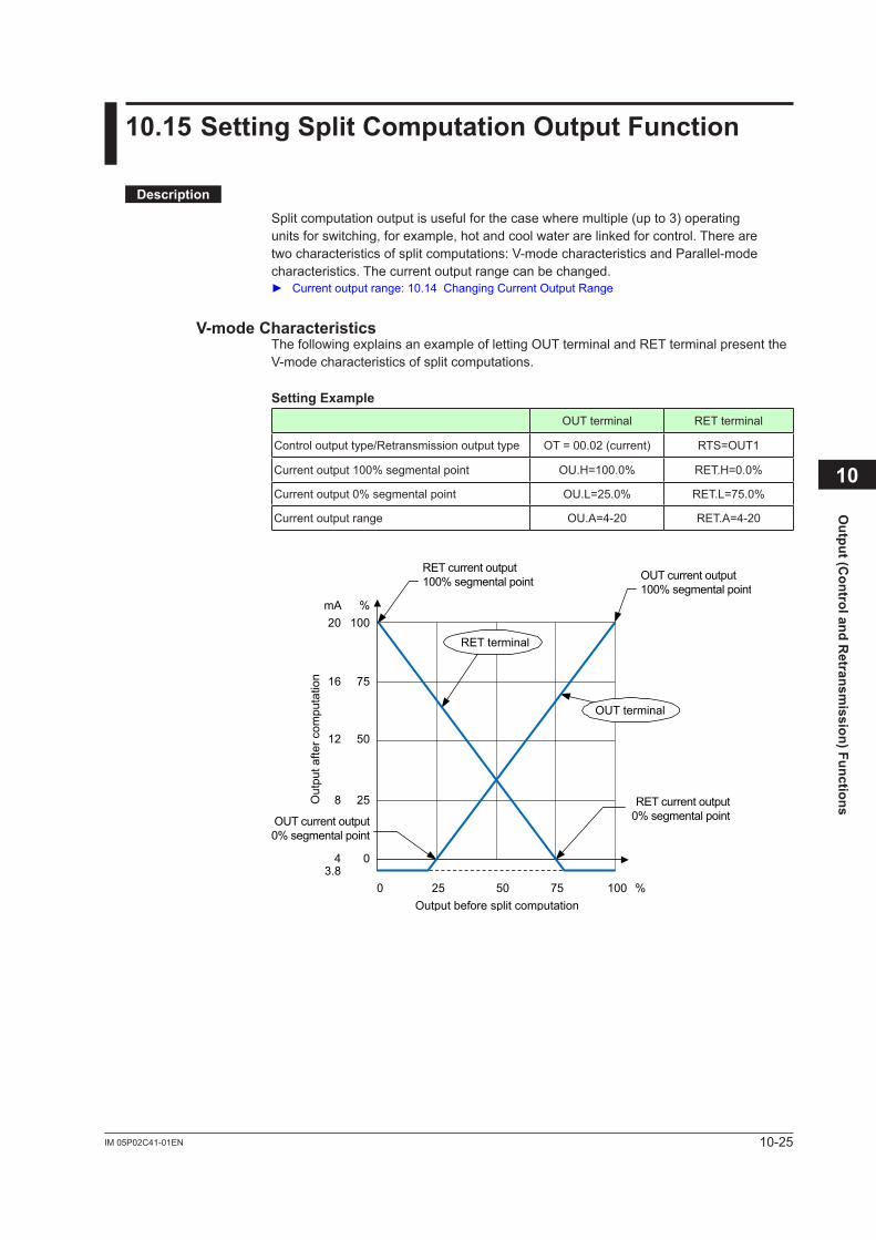
10-25IM 05P02C41-01EN
Output (C
ontrol and Retransm
ission) Functions
10.15SettingSplitComputationOutputFunction
Description
Split computation output is useful for the case where multiple (up to 3) operating units for switching, for example, hot and cool water are linked for control. There are two characteristics of split computations: V-mode characteristics and Parallel-mode characteristics. The current output range can be changed. Currentoutputrange:10.14ChangingCurrentOutputRange
V-modeCharacteristicsThe following explains an example of letting OUT terminal and RET terminal present the V-mode characteristics of split computations.
SettingExampleOUT terminal RET terminal
Control output type/Retransmission output type OT = 00.02 (current) RTS=OUT1
Current output 100% segmental point OU.H=100.0% RET.H=0.0%
Current output 0% segmental point OU.L=25.0% RET.L=75.0%
Current output range OU.A=4-20 RET.A=4-20
0 5025 75 100 %
%mA
Output before split computation
Out
put a
fter c
ompu
tatio
n
OUT current output100% segmental point
OUT current output0% segmental point
RET current output100% segmental point
RET current output0% segmental point
RET terminal
25
0
50
75
10020
43.8
12
8
16
OUT terminal
10
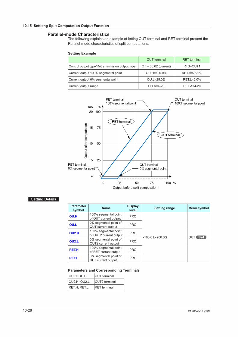
10-26 IM 05P02C41-01EN
Parallel-modeCharacteristicsThe following explains an example of letting OUT terminal and RET terminal present the Parallel-mode characteristics of split computations.
SettingExampleOUT terminal RET terminal
Control output type/Retransmission output type OT = 00.02 (current) RTS=OUT1
Current output 100% segmental point OU.H=100.0% RET.H=75.0%
Current output 0% segmental point OU.L=25.0% RET.L=0.0%
Current output range OU.A=4-20 RET.A=4-20
0 5025 75 100
25
50
75
100
%
%20
mA
4 0
10
5
15
Output before split computation
Out
put a
fter c
ompu
tatio
n
OUT terminal100% segmental point
RET terminal100% segmental point
RET terminal0% segmental point
OUT terminal0% segmental point
OUT terminal
RET terminal
SettingDetails
Parameter symbol Name Display
level Settingrange Menusymbol
OU.H 100% segmental point of OUT current output PRO
-100.0 to 200.0% OUT
OU.L 0% segmental point of OUT current output PRO
OU2.H 100% segmental point of OUT2 current output PRO
OU2.L 0% segmental point of OUT2 current output PRO
RET.H 100% segmental point of RET current output PRO
RET.L 0% segmental point of RET current output PRO
Parameters and Corresponding TerminalsOU.H, OU.L OUT terminal
OU2.H, OU2.L OUT2 terminal
RET.H, RET.L RET terminal
10.15SettisngSplitComputationOutputFunction
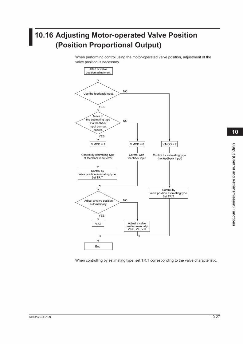
10-27IM 05P02C41-01EN
Output (C
ontrol and Retransm
ission) Functions
10.16AdjustingMotor-operatedValvePosition(PositionProportionalOutput)
Whenperformingcontrolusingthemotor-operatedvalveposition,adjustmentofthevalve position is necessary.
Start of valveposition adjustment.
Use the feedback input.
Adjust a valve positionautomatically.
V.AT
NO
NO
YES
YES
Adjust a valveposition manually.
V.RS, V.L, V.H
End
V.MOD = 1 V.MOD = 0 V.MOD = 2
Move tothe estimating type
if a feedbackinput burnout
occurs.
YES
NO
Control byvalve position estimating type.
Set TR.T.
Control byvalve position estimating type.
Set TR.T.
Control by estimating type at feedback input error.
Control by estimating type (no feedback input)
Control with feedback input
When controlling by estimating type, set TR.T corresponding to the valve characteristic.
10
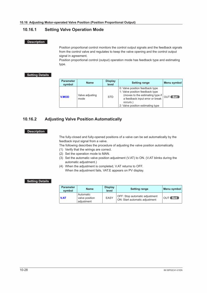
10-28 IM 05P02C41-01EN
10.16.1 SettingValveOperationMode
Description
Position proportional control monitors the control output signals and the feedback signals from the control valve and regulates to keep the valve opening and the control output signal in agreement.Position proportional control (output) operation mode has feedback type and estimating type.
SettingDetails
Parameter symbol Name Display
level Settingrange Menusymbol
V.MOD Valveadjustingmode STD
0: Valve position feedback type1: Valve position feedback type
(moves to the estimating type if a feedback input error or break occurs.)
2: Valve position estimating type
OUT
10.16.2 AdjustingValvePositionAutomatically
Description
The fully-closed and fully-opened positions of a valve can be set automatically by the feedback input signal from a valve.Thefollowingdescribestheprocedureofadjustingthevalvepositionautomatically.(1) Verify that the wirings are correct.(2) Set the operation mode to MAN.(3) Settheautomaticvalvepositionadjustment(V.AT)toON.(V.ATblinksduringthe
automaticadjustment.)(4) Whentheadjustmentiscompleted,V.ATreturnstoOFF. Whentheadjustmentfails,VAT.EappearsonPVdisplay.
SettingDetails
Parameter symbol Name Display
level Settingrange Menusymbol
V.ATAutomatic valve position adjustment
EASY OFF:StopautomaticadjustmentON:Startautomaticadjustment OUT
10.16AdjustingMotor-operatedValvePosition(PositionProportionalOutput)
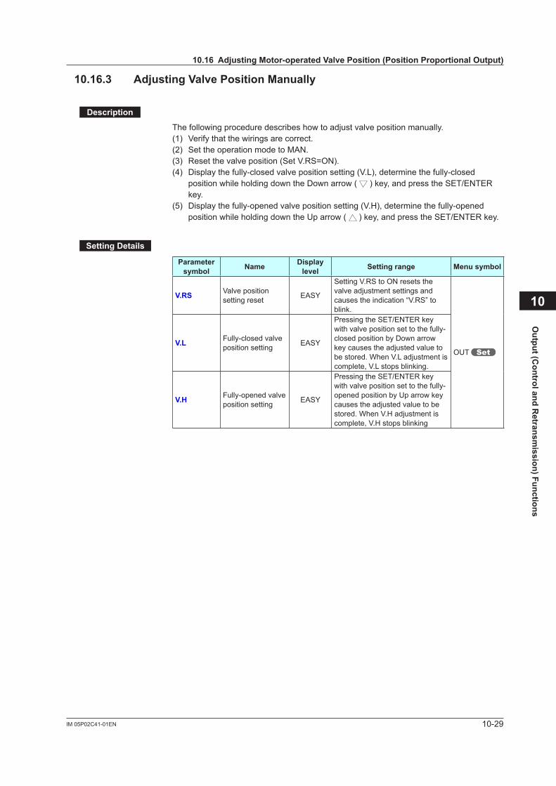
10-29IM 05P02C41-01EN
Output (C
ontrol and Retransm
ission) Functions
10.16.3 AdjustingValvePositionManually
Description
Thefollowingproceduredescribeshowtoadjustvalvepositionmanually.(1) Verify that the wirings are correct. (2) Set the operation mode to MAN.(3) Reset the valve position (Set V.RS=ON).(4) Display the fully-closed valve position setting (V.L), determine the fully-closed
position while holding down the Down arrow ( ) key, and press the SET/ENTER key.
(5) Display the fully-opened valve position setting (V.H), determine the fully-opened position while holding down the Up arrow ( ) key, and press the SET/ENTER key.
SettingDetails
Parameter symbol Name Display
level Settingrange Menusymbol
V.RS Valve position setting reset EASY
Setting V.RS to ON resets the valveadjustmentsettingsandcauses the indication “V.RS” to blink.
OUT V.L Fully-closed valve
position setting EASY
Pressing the SET/ENTER key with valve position set to the fully-closed position by Down arrow keycausestheadjustedvaluetobestored.WhenV.Ladjustmentiscomplete, V.L stops blinking.
V.H Fully-opened valve position setting EASY
Pressing the SET/ENTER key with valve position set to the fully-opened position by Up arrow key causestheadjustedvaluetobestored.WhenV.Hadjustmentiscomplete, V.H stops blinking
10
10.16AdjustingMotor-operatedValvePosition(PositionProportionalOutput)
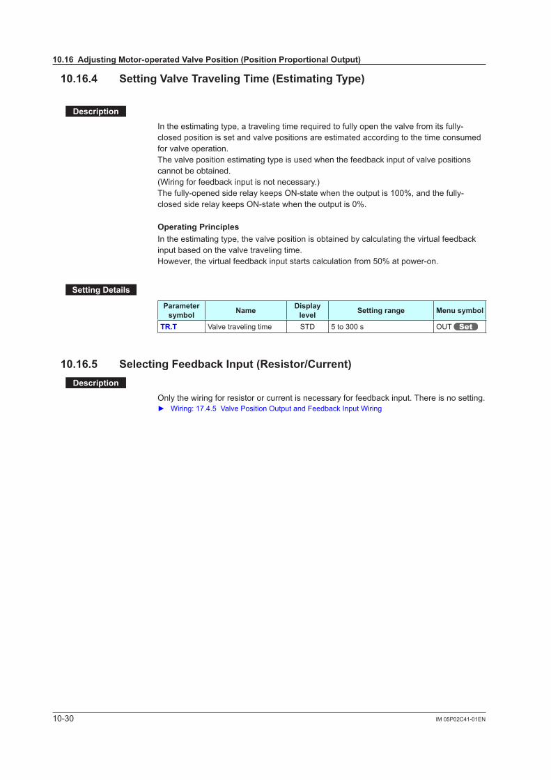
10-30 IM 05P02C41-01EN
10.16.4 SettingValveTravelingTime(EstimatingType)
Description
In the estimating type, a traveling time required to fully open the valve from its fully-closed position is set and valve positions are estimated according to the time consumed for valve operation.The valve position estimating type is used when the feedback input of valve positions cannot be obtained.(Wiring for feedback input is not necessary.)The fully-opened side relay keeps ON-state when the output is 100%, and the fully-closed side relay keeps ON-state when the output is 0%.
OperatingPrinciplesIn the estimating type, the valve position is obtained by calculating the virtual feedback input based on the valve traveling time.However, the virtual feedback input starts calculation from 50% at power-on.
SettingDetails
Parameter symbol Name Display
level Settingrange Menusymbol
TR.T Valve traveling time STD 5 to 300 s OUT
10.16.5 SelectingFeedbackInput(Resistor/Current)Description
Only the wiring for resistor or current is necessary for feedback input. There is no setting. Wiring:17.4.5ValvePositionOutputandFeedbackInputWiring
10.16AdjustingMotor-operatedValvePosition(PositionProportionalOutput)
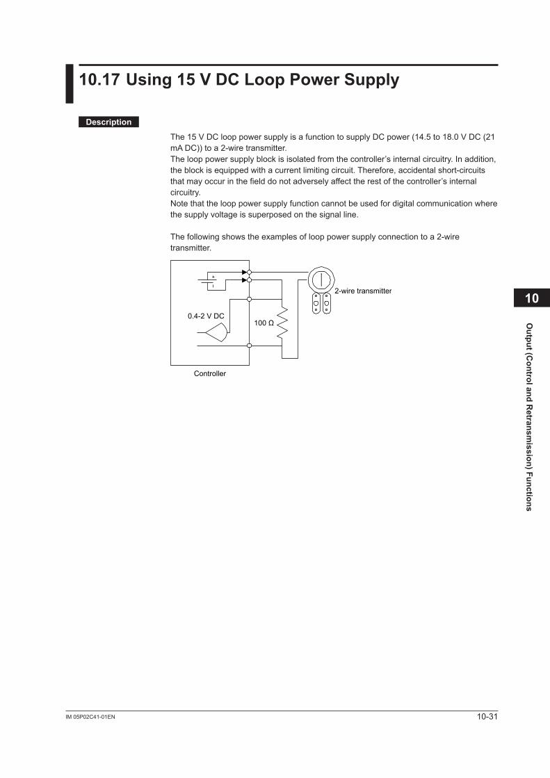
10-31IM 05P02C41-01EN
Output (C
ontrol and Retransm
ission) Functions
10
10.17Using15VDCLoopPowerSupply
Description
The 15 V DC loop power supply is a function to supply DC power (14.5 to 18.0 V DC (21 mA DC)) to a 2-wire transmitter.The loop power supply block is isolated from the controller’s internal circuitry. In addition, the block is equipped with a current limiting circuit. Therefore, accidental short-circuits that may occur in the field do not adversely affect the rest of the controller’s internal circuitry.Note that the loop power supply function cannot be used for digital communication where the supply voltage is superposed on the signal line.
The following shows the examples of loop power supply connection to a 2-wire transmitter.
2-wire transmitter
100 Ω0.4-2 V DC
Controller
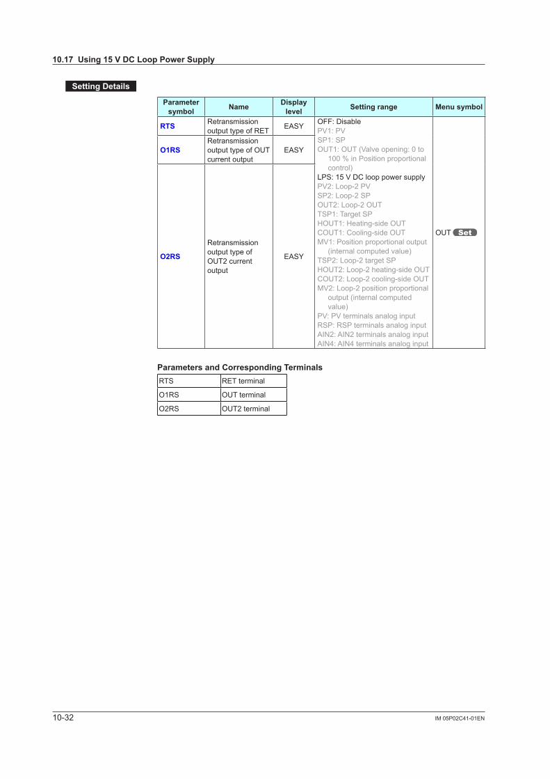
10-32 IM 05P02C41-01EN
SettingDetails
Parameter symbol Name Display
level Settingrange Menusymbol
RTS Retransmission output type of RET EASY OFF: Disable
PV1: PVSP1: SPOUT1: OUT (Valve opening: 0 to
100 % in Position proportional control)
LPS: 15 V DC loop power supplyPV2: Loop-2 PVSP2: Loop-2 SPOUT2: Loop-2 OUTTSP1: Target SPHOUT1: Heating-side OUTCOUT1: Cooling-side OUTMV1: Position proportional output
(internal computed value)TSP2: Loop-2 target SPHOUT2: Loop-2 heating-side OUTCOUT2: Loop-2 cooling-side OUTMV2: Loop-2 position proportional
output (internal computed value)
PV: PV terminals analog inputRSP: RSP terminals analog inputAIN2: AIN2 terminals analog inputAIN4: AIN4 terminals analog input
OUT
O1RSRetransmission output type of OUT current output
EASY
O2RS
Retransmission output type of OUT2 current output
EASY
Parameters and Corresponding TerminalsRTS RET terminal
O1RS OUT terminal
O2RS OUT2 terminal
10.17Using15VDCLoopPowerSupply
11-1IM 05P02C41-01EN
Alarm
Functions
11
11.1 SettingAlarmType
Description
These alarms work irrespective of the operation mode.Thealarm-relatedparametersconsistofthealarmtype(type,stand-byaction,energized/de-energized,andlatchfunction),PVvelocityalarmtimesetpoint,alarmhysteresis,alarm (On-/Off-) delay timer, and alarm setpoint.In Cascade control, both of Loop 1 and Loop 2 have these parameters.
Alarm-relatedparameter Numberofsettings
Alarm type 8 (number of settings) x 2 (number of loops)
PV velocity alarm time setpoint 8 (number of settings) x 2 (number of loops)
Alarm hysteresis 8 (number of settings) x 2 (number of loops)
Alarm (on-/off-) delay timer 8 (number of settings) x 2 (number of loops)
Alarm setpoint 8 (number of settings) x 2 (number of loops)
Alarmhysteresis:11.3SettingHysteresistoAlarmOperation Alarmdelaytimer:11.4DelayingAlarmOutput(AlarmDelayTimer) Alarmsetpoint:6.4SettingAlarmSetpoint
Both of Loop-1 and Loop-2 have eight groups of alarms.Factory default: Only four groups of alarm-related parameters are displayed. Terminalfunction:17.4.7ContactOutputWiring
Alarm output can be assigned to the unused control relay output or contact output. Controlrelayoutput:11.5SettingAlarmOutputtoControlRelayTerminal Contactoutput:12.2.1SettingFunctionofContactOutput
Energized/de-energizedofalarmoutputcanbechanged. Energized/de-energized:12.2.2ChangingContactTypeofContactOutput
To read the conditions of alarms, outputs, or latches via communication, see Communication Interface User's Manual.
Chapter11AlarmFunctions
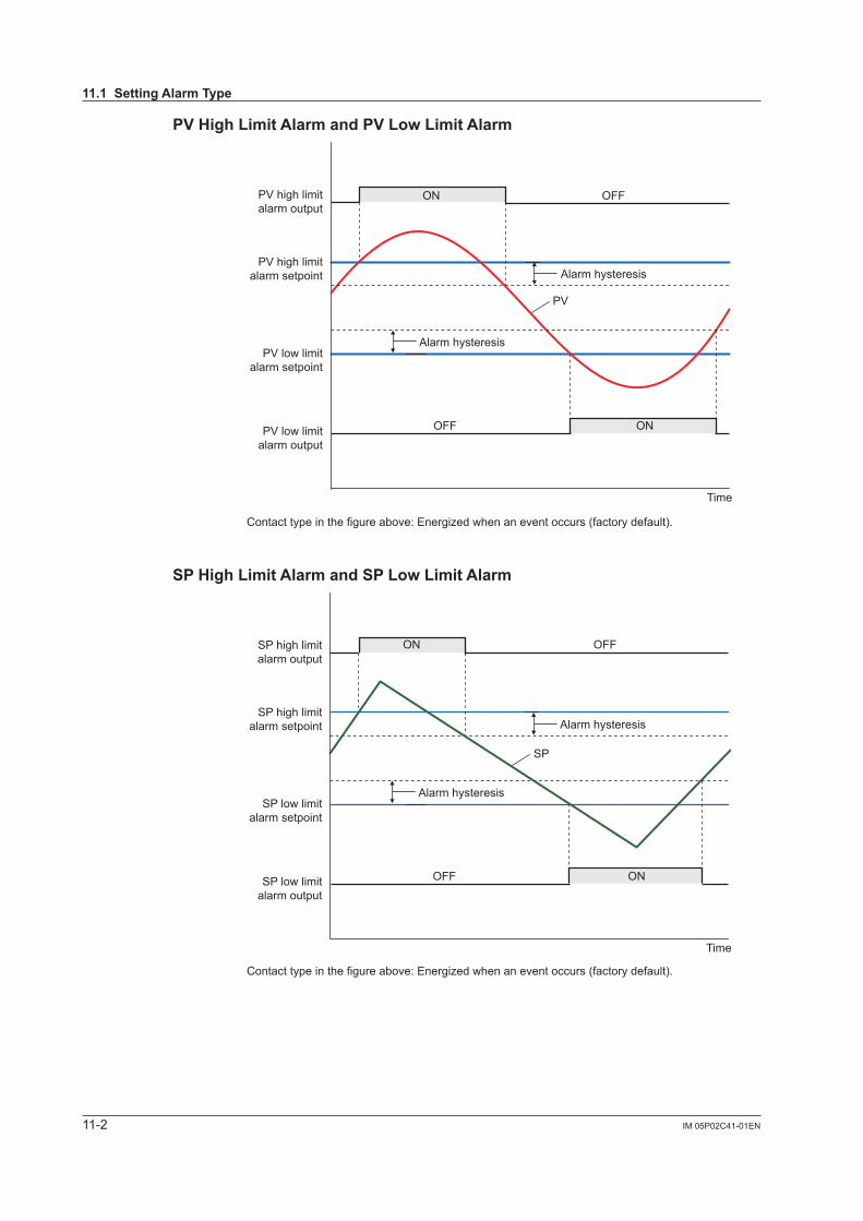
11-2 IM 05P02C41-01EN
PVHighLimitAlarmandPVLowLimitAlarm
PV
ON OFF
ON
Contact type in the figure above: Energized when an event occurs (factory default).
Alarm hysteresis
Alarm hysteresis
OFF
Time
PV high limitalarm setpoint
PV low limitalarm setpoint
PV high limitalarm output
PV low limitalarm output
SPHighLimitAlarmandSPLowLimitAlarm
SP
ON OFF
ON
Contact type in the figure above: Energized when an event occurs (factory default).
Alarm hysteresis
Alarm hysteresis
OFF
Time
SP high limitalarm setpoint
SP low limitalarm setpoint
SP high limitalarm output
SP low limitalarm output
11.1SettingAlarmType
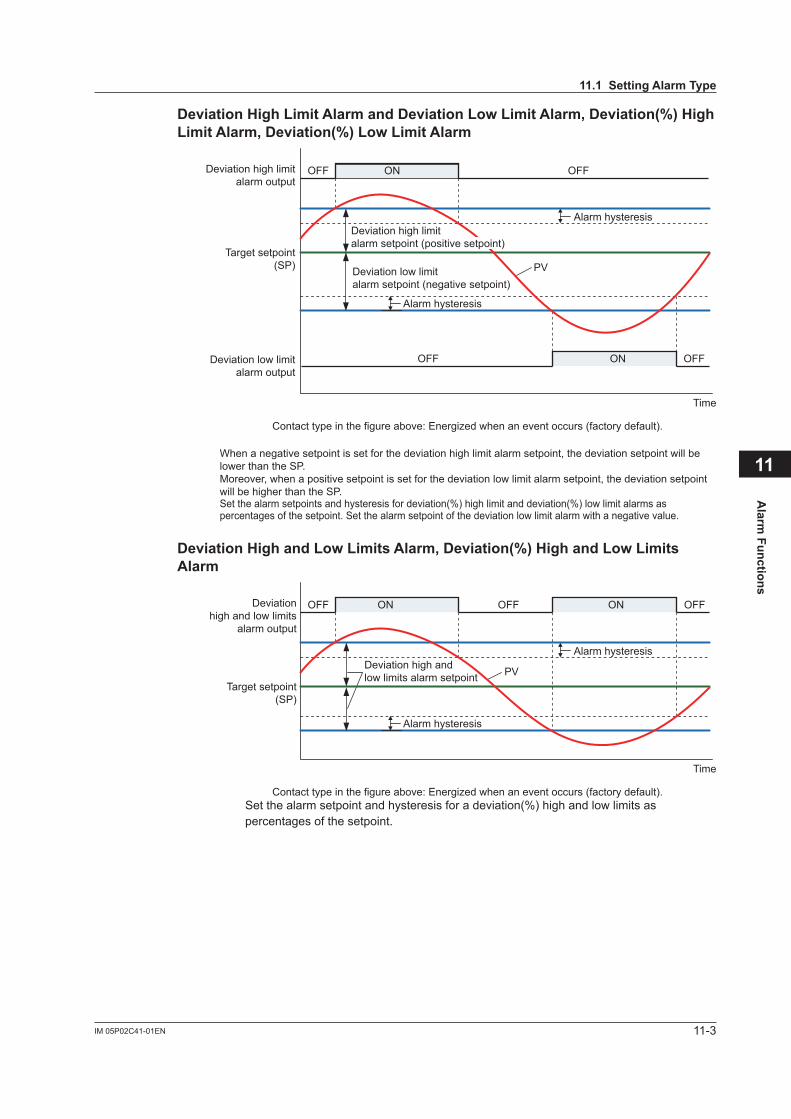
11-3IM 05P02C41-01EN
Alarm
Functions
11
DeviationHighLimitAlarmandDeviationLowLimitAlarm,Deviation(%)HighLimitAlarm,Deviation(%)LowLimitAlarm
PV
Alarm hysteresis
Alarm hysteresis
Deviation low limitalarm setpoint (negative setpoint)
Time
ON OFFOFF
ON OFFOFF
Deviation high limitalarm output
Deviation low limitalarm output
Target setpoint(SP)
Contact type in the figure above: Energized when an event occurs (factory default).
When a negative setpoint is set for the deviation high limit alarm setpoint, the deviation setpoint will be lower than the SP.Moreover, when a positive setpoint is set for the deviation low limit alarm setpoint, the deviation setpoint will be higher than the SP.Set the alarm setpoints and hysteresis for deviation(%) high limit and deviation(%) low limit alarms as percentages of the setpoint. Set the alarm setpoint of the deviation low limit alarm with a negative value.
Deviation high limitalarm setpoint (positive setpoint)
DeviationHighandLowLimitsAlarm,Deviation(%)HighandLowLimitsAlarm
PV
Alarm hysteresis
Alarm hysteresis
Deviation high andlow limits alarm setpoint
Time
ON OFFOFF ON OFFDeviationhigh and low limits
alarm output
Target setpoint(SP)
Contact type in the figure above: Energized when an event occurs (factory default).Set the alarm setpoint and hysteresis for a deviation(%) high and low limits as percentages of the setpoint.
11.1SettingAlarmType
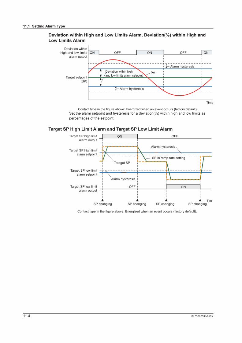
11-4 IM 05P02C41-01EN
DeviationwithinHighandLowLimitsAlarm,Deviation(%)withinHighandLowLimitsAlarm
PV
Alarm hysteresis
Alarm hysteresis
Deviation within highand low limits alarm setpoint
Time
ON ONOFF OFFONDeviation within
high and low limitsalarm output
Target setpoint(SP)
Contact type in the figure above: Energized when an event occurs (factory default).Set the alarm setpoint and hysteresis for a deviation(%) within high and low limits as percentages of the setpoint.
TargetSPHighLimitAlarmandTargetSPLowLimitAlarm
ON
ON
Taraget SP
OFF
OFF
Contact type in the figure above: Energized when an event occurs (factory default).
Time
Target SP high limitalarm setpoint
Target SP low limitalarm setpoint
Target SP high limitalarm output
Target SP low limitalarm output
Alarm hysteresis
SP changing SP changing SP changing SP changing
SP in ramp rate setting
Alarm hysteresis
11.1SettingAlarmType
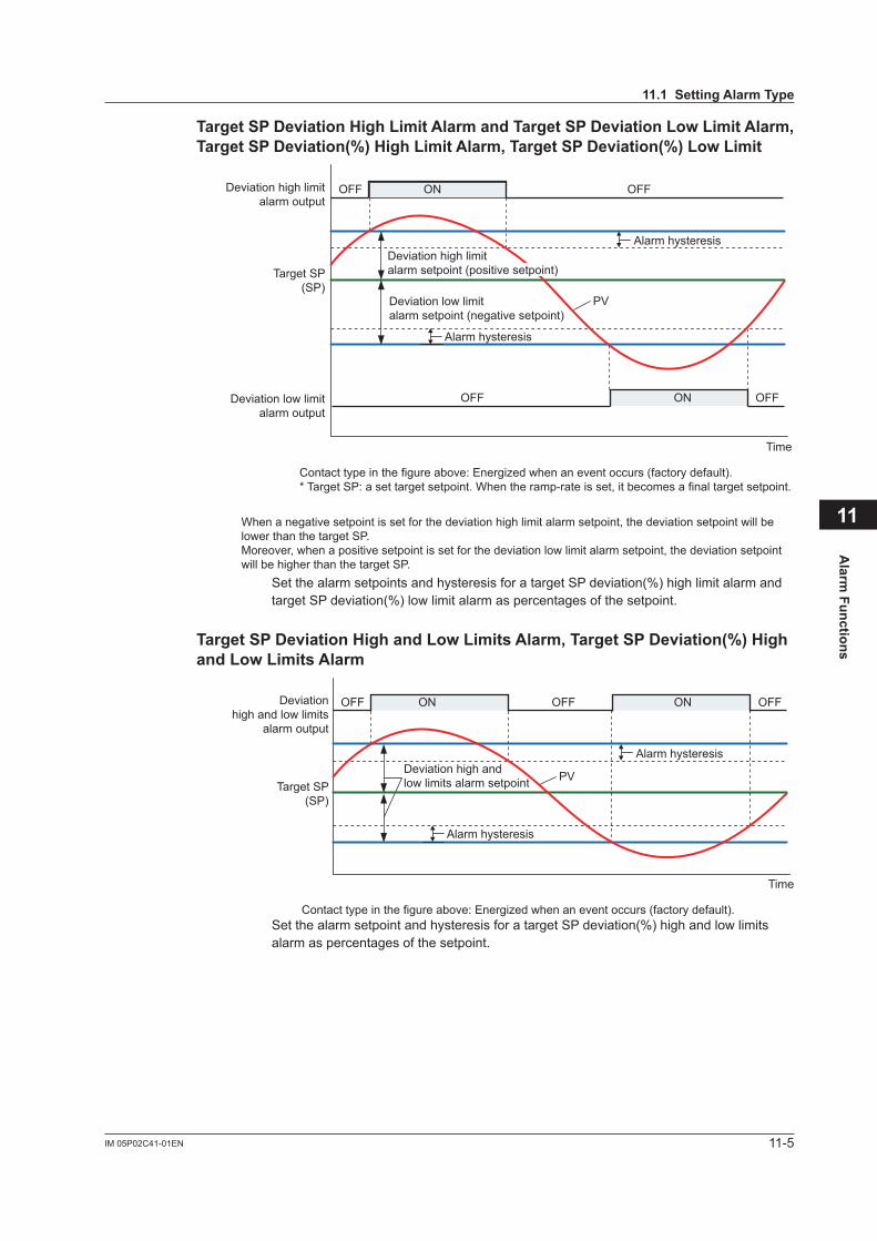
11-5IM 05P02C41-01EN
Alarm
Functions
11
TargetSPDeviationHighLimitAlarmandTargetSPDeviationLowLimitAlarm, TargetSPDeviation(%)HighLimitAlarm,TargetSPDeviation(%)LowLimit
PV
Alarm hysteresis
Alarm hysteresis
Time
ON OFFOFF
ON OFFOFF
Deviation high limitalarm output
Deviation low limitalarm output
Target SP(SP)
Contact type in the figure above: Energized when an event occurs (factory default).* Target SP: a set target setpoint. When the ramp-rate is set, it becomes a final target setpoint.
Deviation low limitalarm setpoint (negative setpoint)
When a negative setpoint is set for the deviation high limit alarm setpoint, the deviation setpoint will be lower than the target SP.Moreover, when a positive setpoint is set for the deviation low limit alarm setpoint, the deviation setpoint will be higher than the target SP.
Deviation high limitalarm setpoint (positive setpoint)
Set the alarm setpoints and hysteresis for a target SP deviation(%) high limit alarm and target SP deviation(%) low limit alarm as percentages of the setpoint.
TargetSPDeviationHighandLowLimitsAlarm,TargetSPDeviation(%)HighandLowLimitsAlarm
PV
Alarm hysteresis
Alarm hysteresis
Deviation high andlow limits alarm setpoint
Time
ON OFFOFF ON OFFDeviationhigh and low limits
alarm output
Target SP(SP)
Contact type in the figure above: Energized when an event occurs (factory default).Set the alarm setpoint and hysteresis for a target SP deviation(%) high and low limits alarm as percentages of the setpoint.
11.1SettingAlarmType
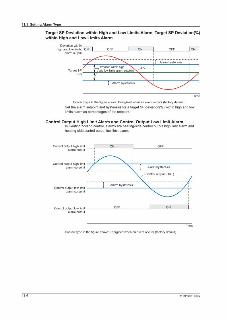
11-6 IM 05P02C41-01EN
TargetSPDeviationwithinHighandLowLimitsAlarm,TargetSPDeviation(%)withinHighandLowLimitsAlarm
PV
Alarm hysteresis
Alarm hysteresis
Deviation within highand low limits alarm setpoint
Time
ON ONOFF OFFONDeviation within
high and low limitsalarm output
Target SP(SP)
Contact type in the figure above: Energized when an event occurs (factory default).Set the alarm setpoint and hysteresis for a target SP deviation(%) within high and low limits alarm as percentages of the setpoint.
ControlOutputHighLimitAlarmandControlOutputLowLimitAlarmIn Heating/cooling control, alarms are heating-side control output high limit alarm and heating-side control output low limit alarm.
Control output (OUT)
ON OFF
ON
Contact type in the figure above: Energized when an event occurs (factory default).
Alarm hysteresis
Alarm hysteresis
OFF
Time
Control output high limitalarm setpoint
Control output low limitalarm setpoint
Control output high limitalarm output
Control output low limitalarm output
11.1SettingAlarmType
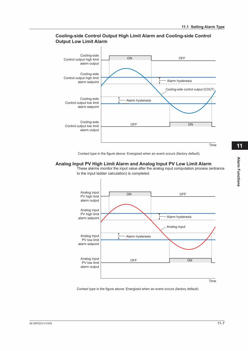
11-7IM 05P02C41-01EN
Alarm
Functions
11
Cooling-sideControlOutputHighLimitAlarmandCooling-sideControlOutputLowLimitAlarm
Cooling-side control output (COUT)
ON OFF
ON
Contact type in the figure above: Energized when an event occurs (factory default).
Alarm hysteresis
Alarm hysteresis
OFF
Time
Cooling-sideControl output high limit
alarm setpoint
Cooling-sideControl output low limit
alarm setpoint
Cooling-sideControl output high limit
alarm output
Cooling-sideControl output low limit
alarm output
AnalogInputPVHighLimitAlarmandAnalogInputPVLowLimitAlarmThese alarms monitor the input value after the analog input computation process (entrance to the input ladder calculation) is completed.
Analog input
ON OFF
ON
Contact type in the figure above: Energized when an event occurs (factory default).
Alarm hysteresis
Alarm hysteresis
OFF
Time
Analog inputPV high limit
alarm setpoint
Analog inputPV low limit
alarm setpoint
Analog inputPV high limitalarm output
Analog inputPV low limit
alarm output
11.1SettingAlarmType
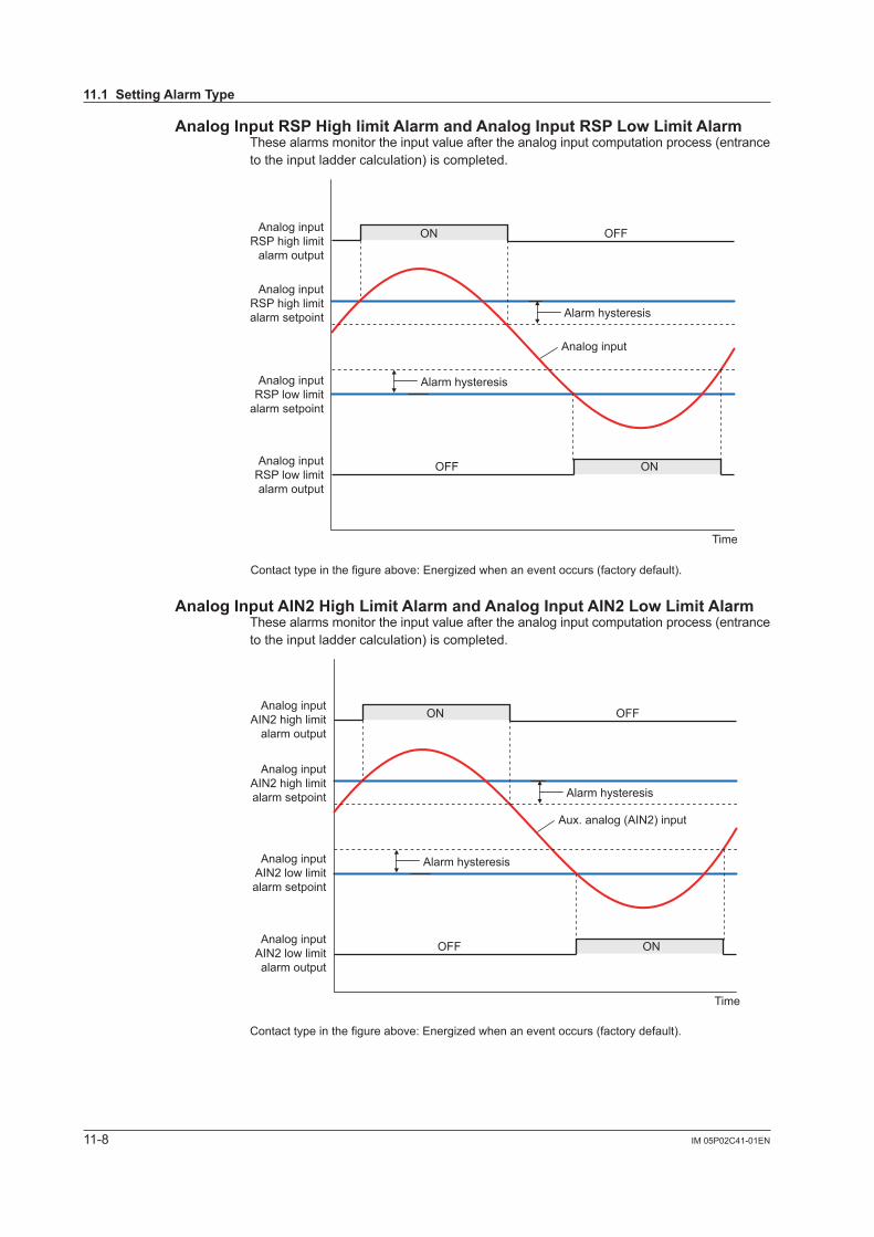
11-8 IM 05P02C41-01EN
AnalogInputRSPHighlimitAlarmandAnalogInputRSPLowLimitAlarmThese alarms monitor the input value after the analog input computation process (entrance to the input ladder calculation) is completed.
Analog input
ON OFF
ON
Contact type in the figure above: Energized when an event occurs (factory default).
Alarm hysteresis
Alarm hysteresis
OFF
Time
Analog inputRSP high limitalarm setpoint
Analog inputRSP low limit
alarm setpoint
Analog inputRSP high limit
alarm output
Analog inputRSP low limitalarm output
AnalogInputAIN2HighLimitAlarmandAnalogInputAIN2LowLimitAlarmThese alarms monitor the input value after the analog input computation process (entrance to the input ladder calculation) is completed.
Aux. analog (AIN2) input
ON OFF
ON
Contact type in the figure above: Energized when an event occurs (factory default).
Alarm hysteresis
Alarm hysteresis
OFF
Time
Analog inputAIN2 high limitalarm setpoint
Analog inputAIN2 low limitalarm setpoint
Analog inputAIN2 high limit
alarm output
Analog inputAIN2 low limitalarm output
11.1SettingAlarmType
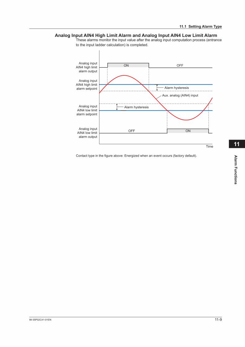
11-9IM 05P02C41-01EN
Alarm
Functions
11
AnalogInputAIN4HighLimitAlarmandAnalogInputAIN4LowLimitAlarmThese alarms monitor the input value after the analog input computation process (entrance to the input ladder calculation) is completed.
Aux. analog (AIN4) input
ON OFF
ON
Contact type in the figure above: Energized when an event occurs (factory default).
Alarm hysteresis
Alarm hysteresis
OFF
Time
Analog inputAIN4 high limitalarm setpoint
Analog inputAIN4 low limitalarm setpoint
Analog inputAIN4 high limit
alarm output
Analog inputAIN4 low limitalarm output
11.1SettingAlarmType
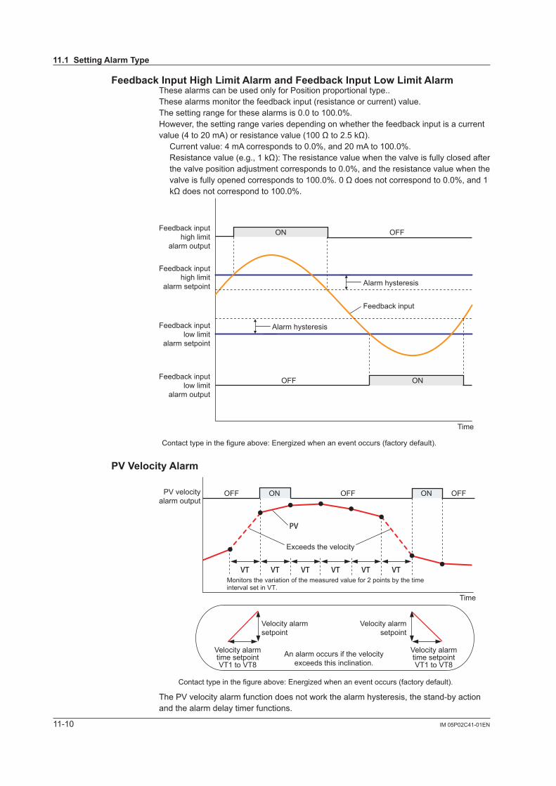
11-10 IM 05P02C41-01EN
FeedbackInputHighLimitAlarmandFeedbackInputLowLimitAlarmThese alarms can be used only for Position proportional type..These alarms monitor the feedback input (resistance or current) value.The setting range for these alarms is 0.0 to 100.0%.However, the setting range varies depending on whether the feedback input is a current value(4to20mA)orresistancevalue(100Ωto2.5kΩ). Current value: 4 mA corresponds to 0.0%, and 20 mA to 100.0%. Resistancevalue(e.g.,1kΩ):Theresistancevaluewhenthevalveisfullyclosedafter
thevalvepositionadjustmentcorrespondsto0.0%,andtheresistancevaluewhenthevalveisfullyopenedcorrespondsto100.0%.0Ωdoesnotcorrespondto0.0%,and1kΩdoesnotcorrespondto100.0%.
Feedback input
ON OFF
ON
Contact type in the figure above: Energized when an event occurs (factory default).
Alarm hysteresis
Alarm hysteresis
OFF
Time
Feedback inputhigh limit
alarm setpoint
Feedback inputlow limit
alarm setpoint
Feedback inputhigh limit
alarm output
Feedback inputlow limit
alarm output
PVVelocityAlarm
PV
VT VT VT VT VT VT
PV velocityalarm output
Time
An alarm occurs if the velocityexceeds this inclination.
OFF OFF OFFON ON
Velocity alarmtime setpointVT1 to VT8
Velocity alarmsetpoint
Velocity alarmsetpoint
Velocity alarmtime setpointVT1 to VT8
Exceeds the velocity
Contact type in the figure above: Energized when an event occurs (factory default).
Monitors the variation of the measured value for 2 points by the time interval set in VT.
The PV velocity alarm function does not work the alarm hysteresis, the stand-by action and the alarm delay timer functions.
11.1SettingAlarmType
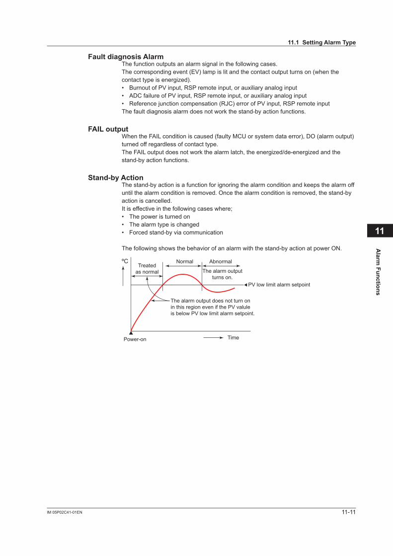
11-11IM 05P02C41-01EN
Alarm
Functions
11
Fault diagnosis AlarmThe function outputs an alarm signal in the following cases.The corresponding event (EV) lamp is lit and the contact output turns on (when the contacttypeisenergized).• Burnout of PV input, RSP remote input, or auxiliary analog input• ADC failure of PV input, RSP remote input, or auxiliary analog input• Referencejunctioncompensation(RJC)error of PV input, RSP remote inputThe fault diagnosis alarm does not work the stand-by action functions.
FAIL outputWhen the FAIL condition is caused (faulty MCU or system data error), DO (alarm output) turned off regardless of contact type.TheFAILoutputdoesnotworkthealarmlatch,theenergized/de-energizedandthestand-by action functions.
Stand-byActionThe stand-by action is a function for ignoring the alarm condition and keeps the alarm off until the alarm condition is removed. Once the alarm condition is removed, the stand-by action is cancelled. It is effective in the following cases where;• The power is turned on• The alarm type is changed• Forced stand-by via communication
The following shows the behavior of an alarm with the stand-by action at power ON.
Treatedas normal
ºC
Power-on Time
The alarm output does not turn onin this region even if the PV valuleis below PV low limit alarm setpoint.
PV low limit alarm setpoint
Normal Abnormal
The alarm outputturns on.
11.1SettingAlarmType
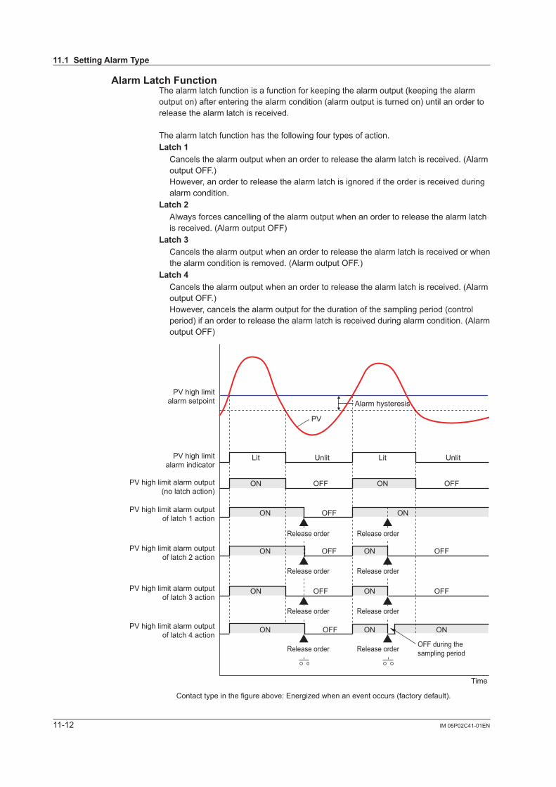
11-12 IM 05P02C41-01EN
Alarm Latch FunctionThe alarm latch function is a function for keeping the alarm output (keeping the alarm output on) after entering the alarm condition (alarm output is turned on) until an order to release the alarm latch is received.
The alarm latch function has the following four types of action. Latch1 Cancels the alarm output when an order to release the alarm latch is received. (Alarm
output OFF.) However, an order to release the alarm latch is ignored if the order is received during alarm condition.
Latch2 Always forces cancelling of the alarm output when an order to release the alarm latch
is received. (Alarm output OFF)Latch 3 Cancels the alarm output when an order to release the alarm latch is received or when
the alarm condition is removed. (Alarm output OFF.)Latch 4 Cancels the alarm output when an order to release the alarm latch is received. (Alarm
output OFF.) However, cancels the alarm output for the duration of the sampling period (control period) if an order to release the alarm latch is received during alarm condition. (Alarm output OFF)
PV
Lit Lit
Contact type in the figure above: Energized when an event occurs (factory default).
Alarm hysteresis
Unlit Unlit
ON
ON ON
ONOFF
OFF
OFF
ON ONOFF OFF
Time
PV high limitalarm setpoint
PV high limitalarm indicator
PV high limit alarm output(no latch action)
PV high limit alarm outputof latch 1 action
PV high limit alarm outputof latch 2 action
ON ONOFF OFFPV high limit alarm outputof latch 3 action
ON ON ON
OFF during the sampling period
OFFPV high limit alarm outputof latch 4 action
Release order Release order
Release order Release order
Release order
Release order
Release order
Release order
11.1SettingAlarmType
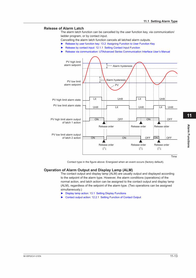
11-13IM 05P02C41-01EN
Alarm
Functions
11
ReleaseofAlarmLatchThe alarm latch function can be cancelled by the user function key, via communication/ladder program, or by contact input.Cancelling the alarm latch function cancels all latched alarm outputs. Releasebyuserfunctionkey:13.2AssigningFunctiontoUserFunctionKey Releasebycontactinput:12.1.1SettingContactInputFunction Releaseviacommunication:UTAdvancedSeriesCommunicationInterfaceUser’sManual
PV
Lit Lit
Contact type in the figure above: Energized when an event occurs (factory default).
Alarm hysteresis
Alarm hysteresis
Unlit Unlit
Lit LitUnlit Unlit Unlit
ON ONOFF OFF
ON ON ONOFF OFF
Time
PV high limitalarm setpoint
PV low limitalarm setpoint
PV high limit alarm state
PV low limit alarm state
PV high limit alarm outputof latch 1 action
PV low limit alarm outputof latch 2 action
Release order Release order Release order
Release order Release order Release order
OperationofAlarmOutputandDisplayLamp(ALM)The contact output and display lamp (ALM) are usually output and displayed according to the setpoint of the alarm type. However, the alarm conditions (operations) of the normal action, and latch action can be assigned to the contact output and display lamp (ALM), regardless of the setpoint of the alarm type. (Two operations can be assigned simultaneously.) Displaylampaction:13.1SettingDisplayFunctions Contactoutputaction:12.2.1SettingFunctionofContactOutput
11.1SettingAlarmType
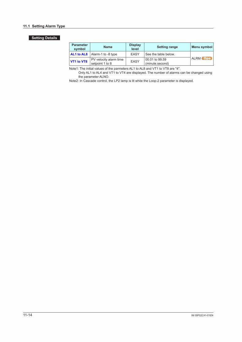
11-14 IM 05P02C41-01EN
SettingDetails
Parameter symbol Name Display
level Settingrange Menusymbol
AL1toAL8 Alarm-1 to -8 type EASY See the table below.ALRM
VT1toVT8 PV velocity alarm time setpoint 1 to 8 EASY 00.01 to 99.59
(minute.second)Note1: The initial values of the parmeters AL1 to AL8 and VT1 to VT8 are "4".
Only AL1 to AL4 and VT1 to VT4 are displayed. The number of alarms can be changed using the parameter ALNO.
Note2: In Cascade control, the LP2 lamp is lit while the Loop-2 parameter is displayed.
11.1SettingAlarmType
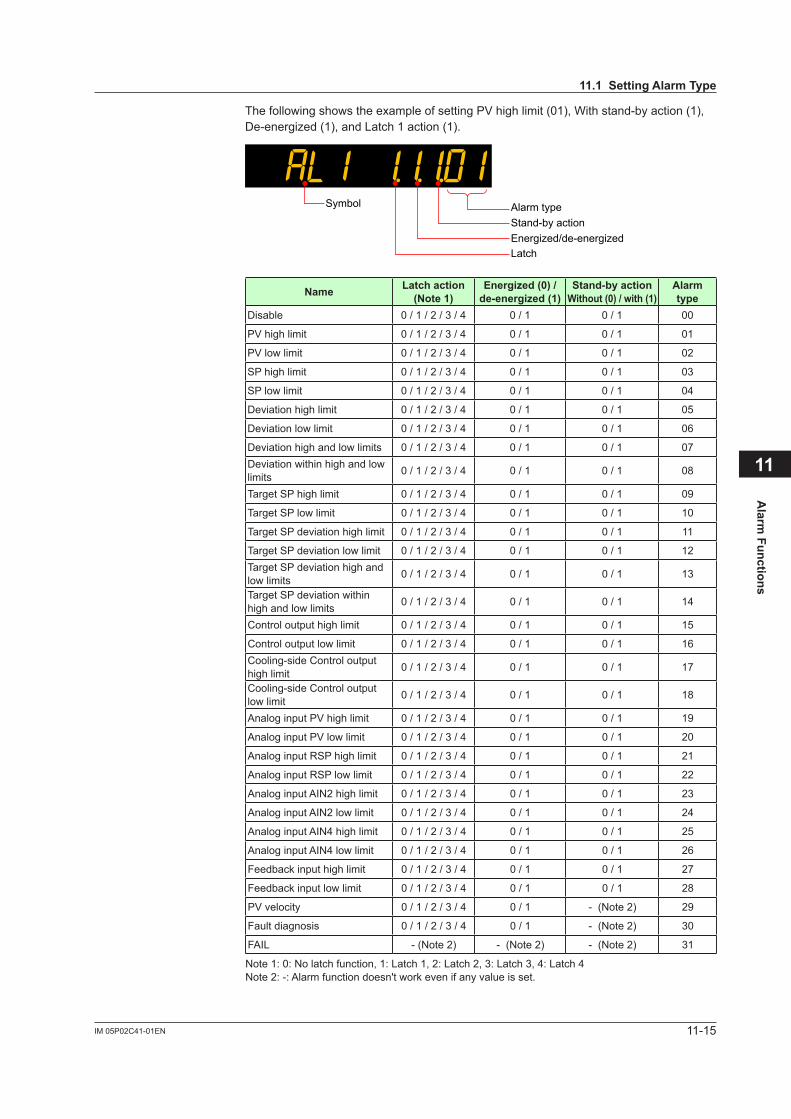
11-15IM 05P02C41-01EN
Alarm
Functions
11
The following shows the example of setting PV high limit (01), With stand-by action (1), De-energized(1),andLatch1action(1).
Alarm typeSymbol
Stand-by actionEnergized/de-energizedLatch
Name Latch action (Note1)
Energized(0)/de-energized(1)
Stand-byactionWithout(0)/with(1)
Alarm type
Disable 0 / 1 / 2 / 3 / 4 0 / 1 0 / 1 00
PV high limit 0 / 1 / 2 / 3 / 4 0 / 1 0 / 1 01
PV low limit 0 / 1 / 2 / 3 / 4 0 / 1 0 / 1 02
SP high limit 0 / 1 / 2 / 3 / 4 0 / 1 0 / 1 03
SP low limit 0 / 1 / 2 / 3 / 4 0 / 1 0 / 1 04
Deviation high limit 0 / 1 / 2 / 3 / 4 0 / 1 0 / 1 05
Deviation low limit 0 / 1 / 2 / 3 / 4 0 / 1 0 / 1 06
Deviation high and low limits 0 / 1 / 2 / 3 / 4 0 / 1 0 / 1 07Deviation within high and low limits 0 / 1 / 2 / 3 / 4 0 / 1 0 / 1 08
Target SP high limit 0 / 1 / 2 / 3 / 4 0 / 1 0 / 1 09
Target SP low limit 0 / 1 / 2 / 3 / 4 0 / 1 0 / 1 10
Target SP deviation high limit 0 / 1 / 2 / 3 / 4 0 / 1 0 / 1 11
Target SP deviation low limit 0 / 1 / 2 / 3 / 4 0 / 1 0 / 1 12Target SP deviation high and low limits 0 / 1 / 2 / 3 / 4 0 / 1 0 / 1 13
Target SP deviation within high and low limits 0 / 1 / 2 / 3 / 4 0 / 1 0 / 1 14
Control output high limit 0 / 1 / 2 / 3 / 4 0 / 1 0 / 1 15
Control output low limit 0 / 1 / 2 / 3 / 4 0 / 1 0 / 1 16Cooling-side Control output high limit 0 / 1 / 2 / 3 / 4 0 / 1 0 / 1 17
Cooling-side Control output low limit 0 / 1 / 2 / 3 / 4 0 / 1 0 / 1 18
Analog input PV high limit 0 / 1 / 2 / 3 / 4 0 / 1 0 / 1 19
Analog input PV low limit 0 / 1 / 2 / 3 / 4 0 / 1 0 / 1 20
Analog input RSP high limit 0 / 1 / 2 / 3 / 4 0 / 1 0 / 1 21
Analog input RSP low limit 0 / 1 / 2 / 3 / 4 0 / 1 0 / 1 22
Analog input AIN2 high limit 0 / 1 / 2 / 3 / 4 0 / 1 0 / 1 23
Analog input AIN2 low limit 0 / 1 / 2 / 3 / 4 0 / 1 0 / 1 24
Analog input AIN4 high limit 0 / 1 / 2 / 3 / 4 0 / 1 0 / 1 25
Analog input AIN4 low limit 0 / 1 / 2 / 3 / 4 0 / 1 0 / 1 26
Feedback input high limit 0 / 1 / 2 / 3 / 4 0 / 1 0 / 1 27
Feedback input low limit 0 / 1 / 2 / 3 / 4 0 / 1 0 / 1 28
PV velocity 0 / 1 / 2 / 3 / 4 0 / 1 - (Note 2) 29
Fault diagnosis 0 / 1 / 2 / 3 / 4 0 / 1 - (Note 2) 30
FAIL - (Note 2) - (Note 2) - (Note 2) 31
Note 1: 0: No latch function, 1: Latch 1, 2: Latch 2, 3: Latch 3, 4: Latch 4Note 2: -: Alarm function doesn't work even if any value is set.
11.1SettingAlarmType
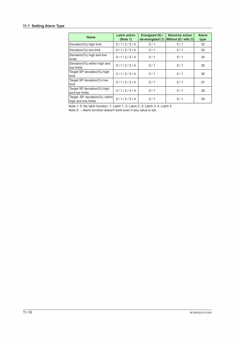
11-16 IM 05P02C41-01EN
Name Latch action (Note1)
Energized(0)/de-energized(1)
Stand-byactionWithout(0)/with(1)
Alarm type
Deviation(%) high limit 0 / 1 / 2 / 3 / 4 0 / 1 0 / 1 32
Deviation(%) low limit 0 / 1 / 2 / 3 / 4 0 / 1 0 / 1 33Deviation(%) high and low limits 0 / 1 / 2 / 3 / 4 0 / 1 0 / 1 34
Deviation(%) within high and low limits 0 / 1 / 2 / 3 / 4 0 / 1 0 / 1 35
Target SP deviation(%) high limit 0 / 1 / 2 / 3 / 4 0 / 1 0 / 1 36
Target SP deviation(%) low limit 0 / 1 / 2 / 3 / 4 0 / 1 0 / 1 37
Target SP deviation(%) high and low limits 0 / 1 / 2 / 3 / 4 0 / 1 0 / 1 38
Target SP deviation(%) within high and low limits 0 / 1 / 2 / 3 / 4 0 / 1 0 / 1 39
Note 1: 0: No latch function, 1: Latch 1, 2: Latch 2, 3: Latch 3, 4: Latch 4Note 2: -: Alarm function doesn't work even if any value is set.
11.1SettingAlarmType

11-17IM 05P02C41-01EN
Alarm
Functions
11
11.2 SettingNumberofAlarmGroupstoUse
Description
Up to eight alarm groups of alarm type, alarm hysteresis, alarm (On-/Off-) delay timer, and alarm setpoint are available.Unused alarm parameters can be hidden and their functions can be turned off. The initial value of parameter ALNO. is “4.”When ALNO. = 4, for example, only the four groups of alarm type, PV velocity alarm time setpoint, alarm hysteresis, alarm delay timer, and alarm setpoint are displayed.Ifthenumberofalarmsissettozero,alarmsetpointparameters,alarmtypeparameters,and menu are not displayed.
SettingDetails
Parameter symbol Name Display
level Settingrange Menusymbol
ALNO. Number of alarm groups PRO 0 to 8 CTL
Note1: In Cascade control, the LP2 lamp is lit while the Loop-2 parameter is displayed.
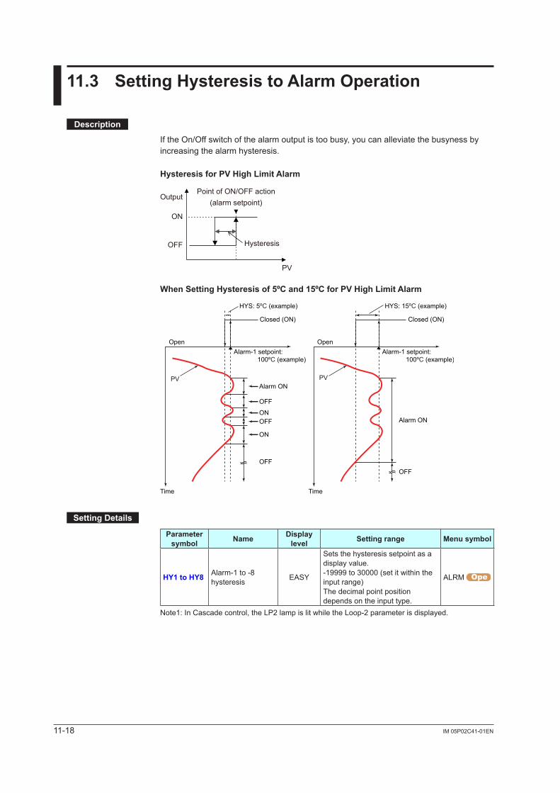
11-18 IM 05P02C41-01EN
11.3 SettingHysteresistoAlarmOperation
Description
If the On/Off switch of the alarm output is too busy, you can alleviate the busyness by increasing the alarm hysteresis.
HysteresisforPVHighLimitAlarm
Point of ON/OFF action(alarm setpoint)
PV
Output
ON
OFF Hysteresis
WhenSettingHysteresisof5ºCand15ºCforPVHighLimitAlarm
Closed (ON)
Open
Time
Alarm-1 setpoint: 100ºC (example)
Closed (ON)
Open
Time
Alarm-1 setpoint: 100ºC (example)
HYS: 15ºC (example)HYS: 5ºC (example)
PV PVAlarm ON
OFF
ONOFF
ON
OFF
Alarm ON
OFF
SettingDetails
Parameter symbol Name Display
level Settingrange Menusymbol
HY1toHY8 Alarm-1 to -8 hysteresis EASY
Sets the hysteresis setpoint as a display value.-19999 to 30000 (set it within the input range)The decimal point position depends on the input type.
ALRM
Note1: In Cascade control, the LP2 lamp is lit while the Loop-2 parameter is displayed.

11-19IM 05P02C41-01EN
Alarm
Functions
11
11.4 DelayingAlarmOutput(AlarmDelayTimer)
Description
The alarm on-delay timer is a function for turning on the alarm when the alarm condition occurs, and the timer starts and the set time elapses.The timer is reset if the alarm condition is removed while the timer is running. No alarm is generated.The figure below shows the example of the On-delay timer
PV
Elapsed time
On-delay timer time
Lit
Contact type in the figure above: Energized when an event occurs (factory default).
Alarm hysteresis
Unlit
OFF
Time
PV high limitalarm setpoint
PV high limitalarm state
(without delay timer)
PV high limitalarm output
Elapsed time
On-delay timer time
ON
The alarm Off-delay timer is a function for turning off the alarm when the alarm condition is removed (normal condition), and the timer starts and the set time elapses.The timer is reset if the alarm condition occurs again while the timer is running. The alarm is not cancelled.
SettingDetails
Parameter symbol Name Display
level Settingrange Menusymbol
DYN1toDYN8
Alarm-1 to -8 On-delay timer STD
0.00 to 99.59 (minute.second) ALRM DYF1toDYF8
Alarm-1 to -8 Off-delay timer PRO
Note1: In Cascade control, the LP2 lamp is lit while the Loop-2 parameter is displayed.

11-20 IM 05P02C41-01EN
11.5 SettingAlarmOutputtoControlRelayTerminal
Description
The control relay terminal can be used for alarm output when it is not used for control output.
SettingDetails
Parameter symbol Name Display
level Settingrange Menusymbol
OR.S OUT relay function selection STD
Same as the setpoint for the contact output function.See 12.2.1, “Setting Function of Contact Output.”
ALM OR.D OUT relay contact type PRO
0: Closes the contact when an event occurs
1: Opens the contact when an event occurs.
OR2.S OUT2 relay function selection STD Same as OR.S.
OR2.D OUT2 relay contact type PRO Same as OR.D
Parameters and Corresponding TerminalsOR.S, OR.D OUT terminal
OR2.S, OR2.D OUT2 terminal
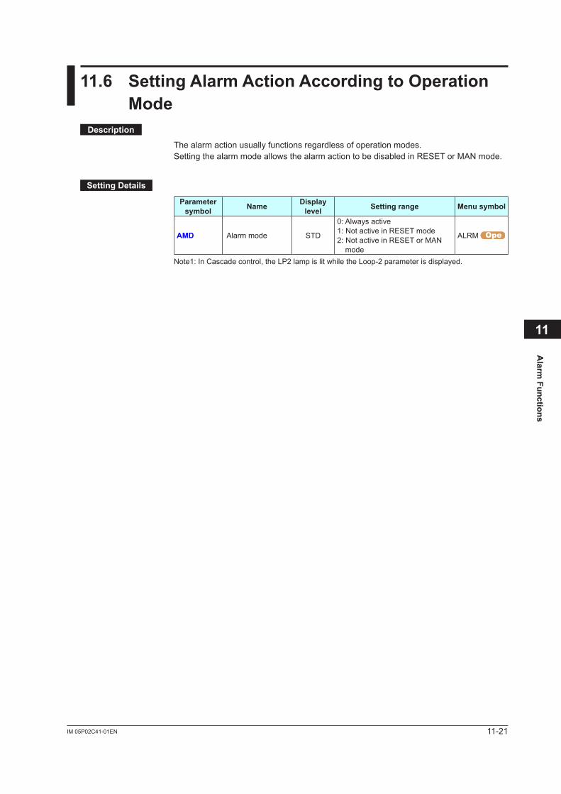
11-21IM 05P02C41-01EN
Alarm
Functions
11
11.6 SettingAlarmActionAccordingtoOperationMode
Description
The alarm action usually functions regardless of operation modes.Setting the alarm mode allows the alarm action to be disabled in RESET or MAN mode.
SettingDetails
Parameter symbol Name Display
level Settingrange Menusymbol
AMD Alarm mode STD
0: Always active1: Not active in RESET mode2: Not active in RESET or MAN
mode
ALRM
Note1: In Cascade control, the LP2 lamp is lit while the Loop-2 parameter is displayed.
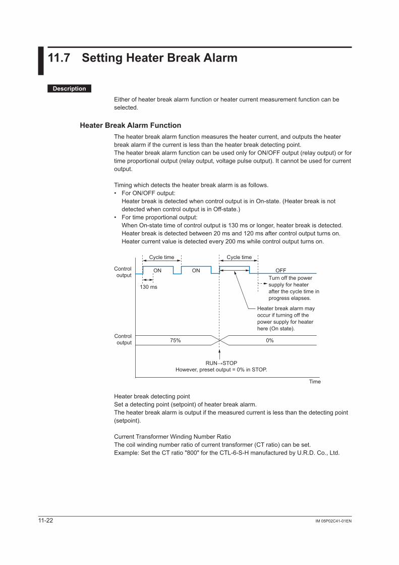
11-22 IM 05P02C41-01EN
11.7 SettingHeaterBreakAlarm
Description
Either of heater break alarm function or heater current measurement function can be selected.
Heater Break Alarm FunctionThe heater break alarm function measures the heater current, and outputs the heater break alarm if the current is less than the heater break detecting point.The heater break alarm function can be used only for ON/OFF output (relay output) or for time proportional output (relay output, voltage pulse output). It cannot be used for current output.
Timing which detects the heater break alarm is as follows.• For ON/OFF output:
Heater break is detected when control output is in On-state. (Heater break is not detected when control output is in Off-state.)
• For time proportional output: When On-state time of control output is 130 ms or longer, heater break is detected. Heater break is detected between 20 ms and 120 ms after control output turns on. Heater current value is detected every 200 ms while control output turns on.
OFFON
130 ms
ON
Cycle time Cycle time
75%
RUN→STOPHowever, preset output = 0% in STOP.
0%
Time
Controloutput
Controloutput
Heater break alarm may occur if turning off the power supply for heater here (On state).
Turn off the power supply for heater after the cycle time in progress elapses.
Heater break detecting pointSet a detecting point (setpoint) of heater break alarm.The heater break alarm is output if the measured current is less than the detecting point (setpoint).
Current Transformer Winding Number RatioThe coil winding number ratio of current transformer (CT ratio) can be set.Example: Set the CT ratio "800" for the CTL-6-S-H manufactured by U.R.D. Co., Ltd.
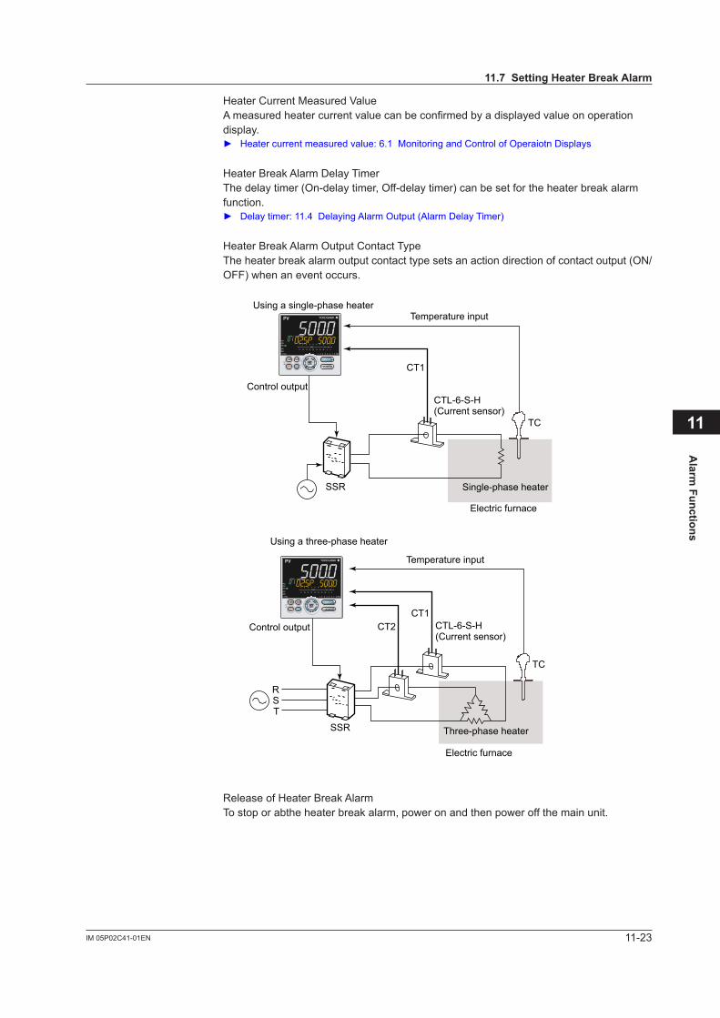
11-23IM 05P02C41-01EN
Alarm
Functions
11
11.7SettingHeaterBreakAlarm
Heater Current Measured ValueA measured heater current value can be confirmed by a displayed value on operation display. Heater current measured value: 6.1 Monitoring and Control of Operaiotn Displays
Heater Break Alarm Delay TimerThe delay timer (On-delay timer, Off-delay timer) can be set for the heater break alarm function. Delaytimer:11.4DelayingAlarmOutput(AlarmDelayTimer)
Heater Break Alarm Output Contact TypeThe heater break alarm output contact type sets an action direction of contact output (ON/OFF) when an event occurs.
CT1
CTL-6-S-H(Current sensor)
SSR
TC
Using a single-phase heaterTemperature input
Control output
Single-phase heater
Electric furnace
CT1CTL-6-S-H(Current sensor)
CT2
SSR
RST
TC
Using a three-phase heater
Temperature input
Three-phase heater
Electric furnace
Control output
Release of Heater Break AlarmTo stop or abthe heater break alarm, power on and then power off the main unit.
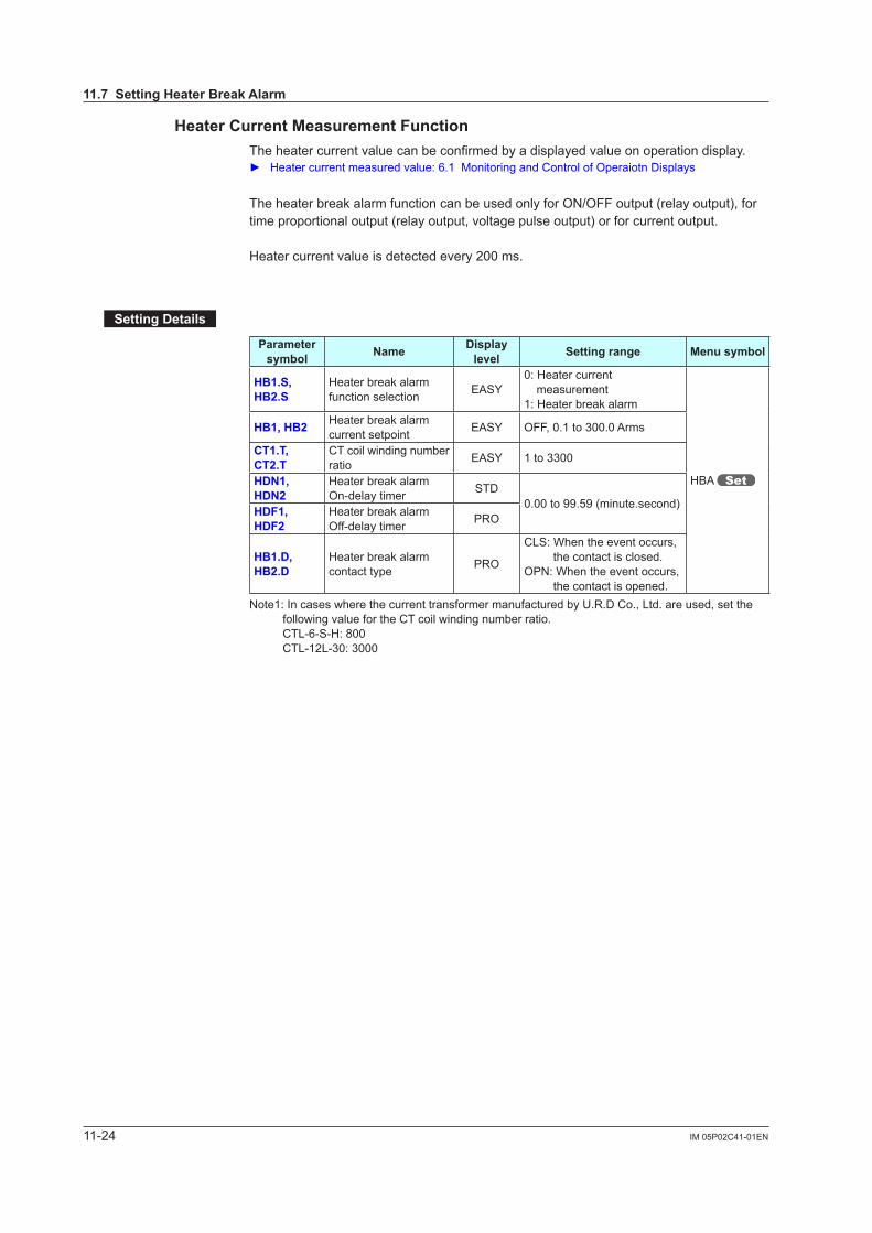
11-24 IM 05P02C41-01EN
Heater Current Measurement FunctionThe heater current value can be confirmed by a displayed value on operation display. Heater current measured value: 6.1 Monitoring and Control of Operaiotn Displays
The heater break alarm function can be used only for ON/OFF output (relay output), for time proportional output (relay output, voltage pulse output) or for current output.
Heater current value is detected every 200 ms.
SettingDetails
Parameter symbol Name Display
level Settingrange Menusymbol
HB1.S,HB2.S
Heater break alarm function selection EASY
0: Heater current measurement
1: Heater break alarm
HBA
HB1,HB2 Heater break alarm current setpoint EASY OFF, 0.1 to 300.0 Arms
CT1.T,CT2.T
CT coil winding number ratio EASY 1 to 3300
HDN1,HDN2
Heater break alarm On-delay timer STD
0.00 to 99.59 (minute.second)HDF1,HDF2
Heater break alarm Off-delay timer PRO
HB1.D,HB2.D
Heater break alarm contact type PRO
CLS: When the event occurs, the contact is closed.
OPN: When the event occurs, the contact is opened.
Note1: In cases where the current transformer manufactured by U.R.D Co., Ltd. are used, set the following value for the CT coil winding number ratio.
CTL-6-S-H: 800 CTL-12L-30: 3000
11.7SettingHeaterBreakAlarm
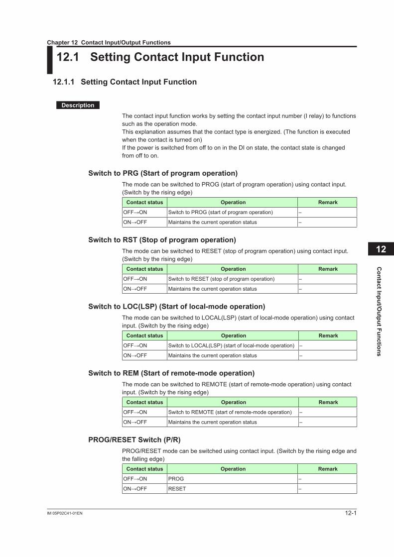
12-1IM 05P02C41-01EN
Contact Input/O
utput Functions
12
12.1 SettingContactInputFunction
12.1.1 SettingContactInputFunction
Description
The contact input function works by setting the contact input number (I relay) to functions such as the operation mode.Thisexplanationassumesthatthecontacttypeisenergized.(Thefunctionisexecutedwhen the contact is turned on) If the power is switched from off to on in the DI on state, the contact state is changed from off to on.
SwitchtoPRG(Startofprogramoperation)The mode can be switched to PROG (start of program operation) using contact input. (Switch by the rising edge)
Contact status Operation Remark
OFF→ON Switch to PROG (start of program operation) –
ON→OFF Maintains the current operation status –
SwitchtoRST(Stopofprogramoperation)The mode can be switched to RESET (stop of program operation) using contact input. (Switch by the rising edge)
Contact status Operation Remark
OFF→ON Switch to RESET (stop of program operation) –
ON→OFF Maintains the current operation status –
SwitchtoLOC(LSP)(Startoflocal-modeoperation)The mode can be switched to LOCAL(LSP) (start of local-mode operation) using contact input. (Switch by the rising edge)
Contact status Operation Remark
OFF→ON Switch to LOCAL(LSP) (start of local-mode operation) –
ON→OFF Maintains the current operation status –
SwitchtoREM(Startofremote-modeoperation)The mode can be switched to REMOTE (start of remote-mode operation) using contact input. (Switch by the rising edge)
Contact status Operation Remark
OFF→ON Switch to REMOTE (start of remote-mode operation) –
ON→OFF Maintains the current operation status –
PROG/RESETSwitch(P/R)PROG/RESET mode can be switched using contact input. (Switch by the rising edge and the falling edge)
Contact status Operation Remark
OFF→ON PROG –
ON→OFF RESET –
Chapter12ContactInput/OutputFunctions
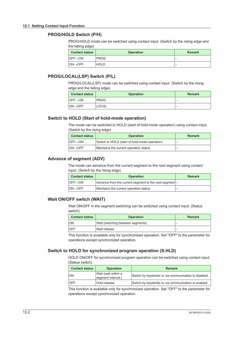
12-2 IM 05P02C41-01EN
PROG/HOLDSwitch(P/H)PROG/HOLD mode can be switched using contact input. (Switch by the rising edge and the falling edge)
Contact status Operation Remark
OFF→ON PROG –
ON→OFF HOLD –
PROG/LOCAL(LSP)Switch(P/L)PROG/LOCAL(LSP) mode can be switched using contact input. (Switch by the rising edge and the falling edge)
Contact status Operation Remark
OFF→ON PROG –
ON→OFF LOCAL –
SwitchtoHOLD(Startofhold-modeoperation)The mode can be switched to HOLD (start of hold-mode operation) using contact input. (Switch by the rising edge)
Contact status Operation Remark
OFF→ON Switch to HOLD (start of hold-mode operation) –
ON→OFF Maintains the current operation status –
Advanceofsegment(ADV)The mode can advance from the current segment to the next segment using contact input. (Switch by the rising edge)
Contact status Operation Remark
OFF→ON Advance from the current segment to the next segment –
ON→OFF Maintains the current operation status –
WaitON/OFFswitch(WAIT)Wait ON/OFF in the segment switching can be switched using contact input. (Status switch)
Contact status Operation Remark
ON Wait (switching between segments) –
OFF Wait release –
Thisfunctionisavailableonlyforsynchronizedoperation.Set"OFF"totheparameterforoperationsexceptsynchronizedoperation.
SwitchtoHOLDforsynchronizedprogramoperation(S.HLD)HOLDON/OFFforsynchronizedprogramoperationcanbeswitchedusingcontactinput.(Status switch)
Contact status Operation Remark
ON Wait (wait within a segment interval.) Switch by keystroke or via communication is disabled.
OFF Hold release Switch by keystroke or via communication is enabled.
Thisfunctionisavailableonlyforsynchronizedoperation.Set"OFF"totheparameterforoperationsexceptsynchronizedoperation.
12.1SettingContactInputFunction
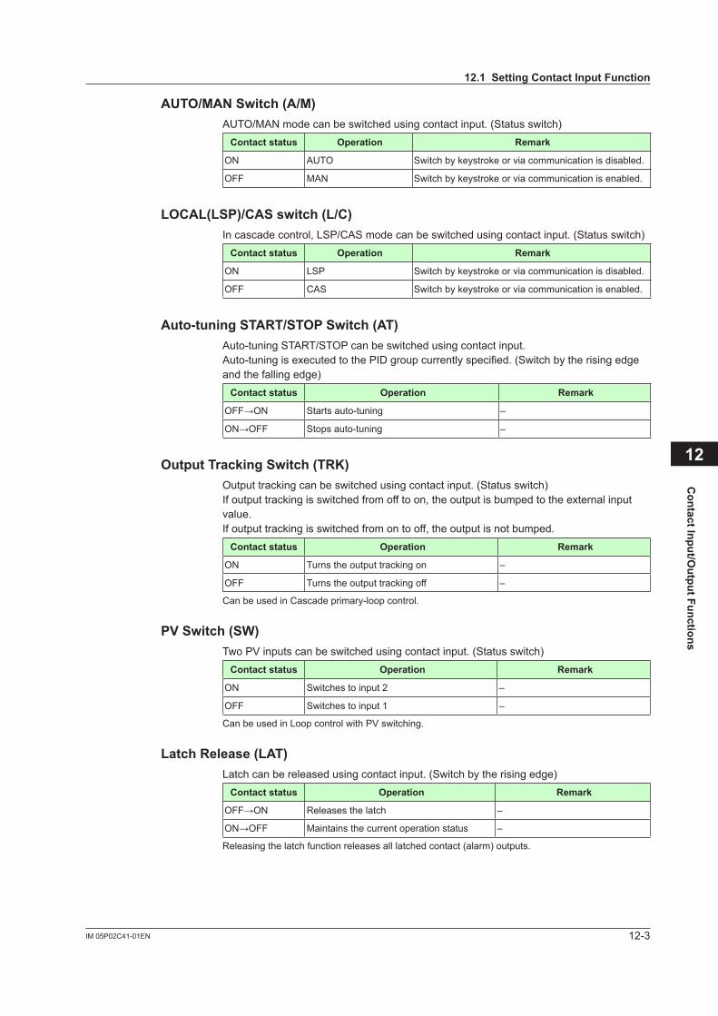
12-3IM 05P02C41-01EN
Contact Input/O
utput Functions
12
AUTO/MANSwitch(A/M)AUTO/MAN mode can be switched using contact input. (Status switch)
Contact status Operation Remark
ON AUTO Switch by keystroke or via communication is disabled.
OFF MAN Switch by keystroke or via communication is enabled.
LOCAL(LSP)/CASswitch(L/C)In cascade control, LSP/CAS mode can be switched using contact input. (Status switch)
Contact status Operation Remark
ON LSP Switch by keystroke or via communication is disabled.
OFF CAS Switch by keystroke or via communication is enabled.
Auto-tuningSTART/STOPSwitch(AT)Auto-tuning START/STOP can be switched using contact input.Auto-tuning is executed to the PID group currently specified. (Switch by the rising edge and the falling edge)
Contact status Operation Remark
OFF→ON Starts auto-tuning –
ON→OFF Stops auto-tuning –
OutputTrackingSwitch(TRK)Output tracking can be switched using contact input. (Status switch)If output tracking is switched from off to on, the output is bumped to the external input value.If output tracking is switched from on to off, the output is not bumped.
Contact status Operation Remark
ON Turns the output tracking on –
OFF Turns the output tracking off –
Can be used in Cascade primary-loop control.
PVSwitch(SW)Two PV inputs can be switched using contact input. (Status switch)
Contact status Operation Remark
ON Switches to input 2 –
OFF Switches to input 1 –
Can be used in Loop control with PV switching.
Latch Release (LAT)Latch can be released using contact input. (Switch by the rising edge)
Contact status Operation Remark
OFF→ON Releases the latch –
ON→OFF Maintains the current operation status –
Releasing the latch function releases all latched contact (alarm) outputs.
12.1SettingContactInputFunction
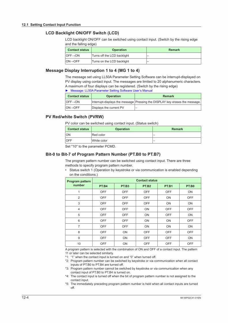
12-4 IM 05P02C41-01EN
LCDBacklightON/OFFSwitch(LCD)LCD backlight ON/OFF can be switched using contact input. (Switch by the rising edge and the falling edge)
Contact status Operation Remark
OFF→ON Turns off the LCD backlight –
ON→OFF Turns on the LCD backlight –
MessageDisplayInterruption1to4(MG1to4)The message set using LL50A Parameter Setting Software can be interrupt-displayed on PV display using contact input. The messages are limited to 20 alphanumeric characters. A maximum of four displays can be registered. (Switch by the rising edge) Message: LL50A Parameter Setting Software User’s Manual
Contact status Operation Remark
OFF→ON Interrupt-displays the message Pressing the DISPLAY key erases the message.
ON→OFF Displays the current PV –
PVRed/whiteSwitch(PVRW)PV color can be switched using contact input. (Status switch)
Contact status Operation Remark
ON Red color –
OFF White color –
Set "10" to the parameter PCMD.
Bit-0toBit-7ofProgramPatternNumber(PT.B0toPT.B7)The program pattern number can be switched using contact input. There are three methods to specify program pattern number.• Status switch 1 (Operation by keystroke or via communication is enabled depending
on the conditions.)
Program pattern number
Contact status
PT.B4 PT.B3 PT.B2 PT.B1 PT.B0
1 OFF OFF OFF OFF ON
2 OFF OFF OFF ON OFF
3 OFF OFF OFF ON ON
4 OFF OFF ON OFF OFF
5 OFF OFF ON OFF ON
6 OFF OFF ON ON OFF
7 OFF OFF ON ON ON
8 OFF ON OFF OFF OFF
9 OFF ON OFF OFF ON
10 OFF ON OFF OFF OFF
A program pattern is selected with the combination of ON and OFF of a contact input. The pattern 11 or later can be selected similarly.*1: “1” when the contact input is turned on and “0” when turned off.*2: Program pattern number can be switched by keystroke or via communication when all contact
inputs of PT.B0 to PT.B4 are turned off.*3: Program pattern number cannot be switched by keystroke or via communication when any
contact input of PT.B0 to PT.B4 is turned on.*4: The contact input is turned off when the bit of program pattern number is not assigned to the
contact input.*5: The immediately preceding program pattern number is held when all contact inputs are turned
off.
12.1SettingContactInputFunction
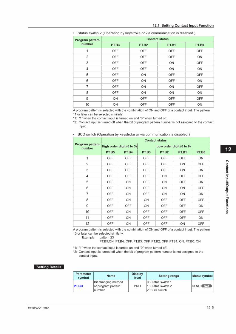
12-5IM 05P02C41-01EN
Contact Input/O
utput Functions
12
• Status switch 2 (Operation by keystroke or via communication is disabled.)
Program pattern number
Contact status
PT.B3 PT.B2 PT.B1 PT.B0
1 OFF OFF OFF OFF
2 OFF OFF OFF ON
3 OFF OFF ON OFF
4 OFF OFF ON ON
5 OFF ON OFF OFF
6 OFF ON OFF ON
7 OFF ON ON OFF
8 OFF ON ON ON
9 ON OFF OFF OFF
10 ON OFF OFF ON
A program pattern is selected with the combination of ON and OFF of a contact input. The pattern 11 or later can be selected similarly.*1: “1” when the contact input is turned on and “0” when turned off.*2: Contact input is turned off when the bit of program pattern number is not assigned to the contact
input.
• BCD switch (Operation by keystroke or via communication is disabled.)
Program pattern number
Contact status
Highorderdigit(0to3) Loworderdigit(0to9)
PT.B5 PT.B4 PT.B3 PT.B2 PT.B1 PT.B0
1 OFF OFF OFF OFF OFF ON
2 OFF OFF OFF OFF ON OFF
3 OFF OFF OFF OFF ON ON
4 OFF OFF OFF ON OFF OFF
5 OFF ON OFF ON OFF ON
6 OFF ON OFF ON ON OFF
7 OFF ON OFF ON ON ON
8 OFF ON ON OFF OFF OFF
9 OFF OFF ON OFF OFF ON
10 OFF ON OFF OFF OFF OFF
11 OFF ON OFF OFF OFF ON
12 OFF ON OFF OFF ON OFF
A program pattern is selected with the combination of ON and OFF of a contact input. The pattern 13 or later can be selected similarly.
Example: pattern 23 PT.B5:ON, PT.B4: OFF, PT.B3: OFF, PT.B2: OFF, PTB1: ON, PT.B0: ON
*1: “1” when the contact input is turned on and “0” when turned off.*2: Contact input is turned off when the bit of program patttern number is not assigned to the
contact input.
SettingDetails
Parameter symbol Name Display
level Settingrange Menusymbol
PT.BCBit changing method of program pattern number
PRO0: Status switch 11: Status switch 22: BCD switch
DI.NU
12.1SettingContactInputFunction
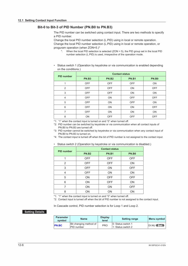
12-6 IM 05P02C41-01EN
Bit-0toBit-3ofPIDNumber(PN.B0toPN.B3)The PID number can be switched using contact input. There are two methods to specify a PID number.Change the local PID number selection (L.PID) using in local or remote operation.Change the local PID number selection (L.PID) using in local or remote operation, or proguram operation (when ZON=5.)*
*: When the local PID selection is selected (ZON = 5), the PID group set in the local PID number selection (L.PID) is used, irrespective of the operation mode.
• Status switch 1 (Operation by keystroke or via communication is enabled depending on the conditions.)
PID numberContact status
PN.B3 PN.B2 PN.B1 PN.B0
1 OFF OFF OFF ON
2 OFF OFF ON OFF
3 OFF OFF ON ON
4 OFF ON OFF OFF
5 OFF ON OFF ON
6 OFF ON ON OFF
7 OFF ON ON ON
8 ON OFF OFF OFF
*1: “1” when the contact input is turned on and “0” when turned off.*2: PID number can be switched by keystroke or via communication when all contact inputs of
PN.B0 to PN.B3 are turned off.*3: PID number cannot be switched by keystroke or via communication when any contact input of
PN.B0 to PN.B3 is turned on.*4: The contact input is turned off when the bit of PID number is not assigned to the contact input.
• Status switch 2 (Operation by keystroke or via communication is disabled.)
PID numberContact status
PN.B2 PN.B1 PN.B0
1 OFF OFF OFF
2 OFF OFF ON
3 OFF ON OFF
4 OFF ON ON
5 ON OFF OFF
6 ON OFF ON
7 ON ON OFF
8 ON ON ON*1: “1” when the contact input is turned on and “0” when turned off.*2: Contact input is turned off when the bit of PID number is not assigned to the contact input.
In Cascade control, PID number selection is for Loop 1 and Loop 2.
SettingDetails
Parameter symbol Name Display
level Settingrange Menusymbol
PN.BC Bit changing method of PID number PRO 0: Status switch 1
1: Status switch 2 DI.NU
12.1SettingContactInputFunction
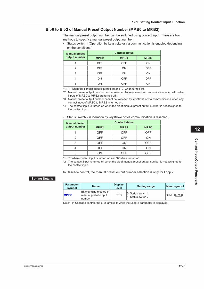
12-7IM 05P02C41-01EN
Contact Input/O
utput Functions
12
Bit-0toBit-2ofManualPresetOutputNumber(MP.B0toMP.B2)The manual preset output number can be switched using contact input. There are two methods to specify a manual preset output number.• Status switch 1 (Operation by keystroke or via communication is enabled depending
on the conditions.)
Manual preset output number
Contact status
MP.B2 MP.B1 MP.B0
1 OFF OFF ON
2 OFF ON OFF
3 OFF ON ON
4 ON OFF OFF
5 ON OFF ON
*1: “1” when the contact input is turned on and “0” when turned off.*2: Manual preset output number can be switched by keystroke via communication when all contact
inputs of MP.B0 to MP.B2 are turned off.*3: Manual preset output number cannot be switched by keystroke or via communication when any
contact input of MP.B0 to MP.B2 is turned on.*4: The contact input is turned off when the bit of manual preset output number is not assigned to
the contact input.
• Status Switch 2 (Operation by keystroke or via communication is disabled.)
Manual preset output number
Contact status
MP.B2 MP.B1 MP.B0
1 OFF OFF OFF
2 OFF OFF ON
3 OFF ON OFF
4 OFF ON ON
5 ON OFF OFF*1: “1” when contact input is turned on and “0” when turned off.*2: The contact input is turned off when the bit of manual preset output number is not assigned to
the contact input.
In Cascade control, the manual preset output number selection is only for Loop 2.
SettingDetails
Parameter symbol Name Display
level Settingrange Menusymbol
MP.BCBit changing method of manual preset output number
PRO 0: Status switch 11: Status switch 2 DI.NU
Note1: In Cascade control, the LP2 lamp is lit while the Loop-2 parameter is displayed.
12.1SettingContactInputFunction
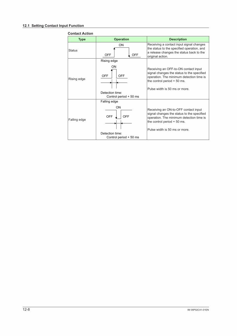
12-8 IM 05P02C41-01EN
Contact ActionType Operation Description
Status
ON
OFFOFF
Receiving a contact input signal changes thestatustothespecifiedoperation,anda release changes the status back to the original action.
Rising edge
Rising edge
ON
OFF OFF
Detection time: Control period + 50 ms
Receiving an OFF-to-ON contact input signalchangesthestatustothespecifiedoperation. The minimum detection time is the control period + 50 ms.
Pulse width is 50 ms or more.
Falling edge
Detection time: Control period + 50 ms
Falling edge
ON
OFFOFF
Receiving an ON-to-OFF contact input signalchangesthestatustothespecifiedoperation. The minimum detection time is the control period + 50 ms.
Pulse width is 50 ms or more.
12.1SettingContactInputFunction

12-9IM 05P02C41-01EN
Contact Input/O
utput Functions
12
SettingDetails
Parameter symbol Name Display
level Settingrange Menusymbol
PRG Switch to PROG (Start of program operation) STD
See the following section, "UP55A DI and Setpoint".
DI.SL
RST Switch to RESET (Stop of program operation) STD
LOC Switch to LOCAL(LSP) (Start of local-mode operation) STD
REM Switch to REMOTE STD
P/R PROG/RESET Switch STD
P/H PROG/HOLD Switch STD
P/L PROG/LOCAL(LSP) Switch STD
HOLD Switch to HOLD (Start of hold-mode operation) STD
ADV Advance of segment STD
WAIT Wait ON/OFF switch STD
S.HLD SwitchtoHOLDforsynchronizedprogram operation PRO
A/M AUTO/MAN switch STD
L/C LOCAL(LSP)/CAS switch STD
AT Auto-tuning START/STOP switch STD
TRK Output tracking switch PRO
SW PV switch PRO
LAT Latch release STD
LCD LCD backlight ON/OFF switch STD
PVRW PV red/white switch STD
MG1 Message display interruption 1 PRO
MG2 Message display interruption 2 PRO
MG3 Message display interruption 3 PRO
MG4 Message display interruption 4 PRO
PT.B0 Bit-0 of program pattern number EASY
DI.NU
PT.B1 Bit-1 of program pattern number EASY
PT.B2 Bit-2 of program pattern number EASY
PT.B3 Bit-3 of program pattern number EASY
PT.B4 Bit-4 of program pattern number EASY
PT.B5 Bit-5 of program pattern number EASY
PT.B6 Bit-6 of program pattern number EASY
PT.B7 Bit-7 of program pattern number EASY
PN.B0 Bit-0 of PID number STD
PN.B1 Bit-1 of PID number STD
PN.B2 Bit-2 of PID number STD
PN.B3 Bit-3 of PID number STD
MP.B0 Bit-0 of manual preset output number STD
MP.B1 Bit-1 of manual preset output number STD
MP.B2 Bit-2 of manual preset output number STD
12.1SettingContactInputFunction

12-10 IM 05P02C41-01EN
UP55A(Standardmdel)DIandSetpoint(Irelaynumber)DI equipped as standardDIsymbol Setpoint
DI1 5025
DI2 5026
DI3 5027
Additional DIDIsymbol Setpoint DIsymbol Setpoint DIsymbol Setpoint
DI11 5041 – – DI41 5089
DI12 5042 – – DI42 5090
DI13 5043 – – DI43 5091
DI14 5044 – – DI44 5092
DI15 5045 – – DI45 5093
DI16 5046 DI26 5062 DI46 5094
UP55A(Detailedmodel)DIandSetpoint(Irelaynumber)DI equipped as standardDIsymbol Setpoint
DI1 5025
DI2 5026
DI3 5027
Additional DIOptionalsuffixcode
/X1Optionalsuffixcode
/X2Optionalsuffixcode
/X3Optionalsuffixcode
/X4DIsymbol Setpoint DIsymbol Setpoint DIsymbol Setpoint DIsymbol Setpoint
DI11 5041 DI21 5057 DI31 5073 DI41 5089
DI12 5042 DI22 5058 DI32 5074 DI42 5090
DI13 5043 DI23 5059 DI33 5075 DI43 5091
DI14 5044 DI24 5060 DI34 5076 DI44 5092
DI15 5045 DI25 5061 DI35 5077 DI45 5093
Additional DIOptionalsuffixcode
/R1Optionalsuffixcode
/A2Optionalsuffixcode
/A4 or /AC4DIsymbol Setpoint DIsymbol Setpoint DIsymbol Setpoint
DI16 5046 DI26 5062 DI46 5094
12.1SettingContactInputFunction
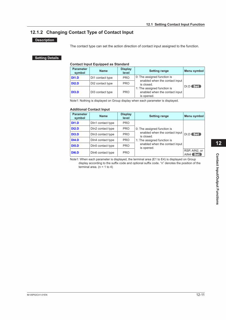
12-11IM 05P02C41-01EN
Contact Input/O
utput Functions
12
12.1.2 ChangingContactTypeofContactInputDescription
The contact type can set the action direction of contact input assigned to the function.
SettingDetails
ContactInputEquippedasStandardParameter symbol Name Display
level Settingrange Menusymbol
DI1.D DI1 contact type PRO 0: The assigned function is enabled when the contact input is closed.
1: The assigned function is enabled when the contact input is opened.
DI.D DI2.D DI2 contact type PRO
DI3.D DI3 contact type PRO
Note1: Nothing is displayed on Group display when each parameter is displayed.
Additional Contact InputParameter symbol Name Display
level Settingrange Menusymbol
DI1.D DIn1 contact type PRO
0: The assigned function is enabled when the contact input is closed.
1: The assigned function is enabled when the contact input is opened.
DI.D
DI2.D DIn2 contact type PRO
DI3.D DIn3 contact type PRO
DI4.D DIn4 contact type PRO
DI5.D DIn5 contact type PRO
DI6.D DIn6 contact type PRO RSP, AIN2, or AIN4
Note1: When each parameter is displayed, the terminal area (E1 to E4) is displayed on Group display according to the suffix code and optional suffix code. “n” denotes the position of the terminal area. (n = 1 to 4)
12.1SettingContactInputFunction
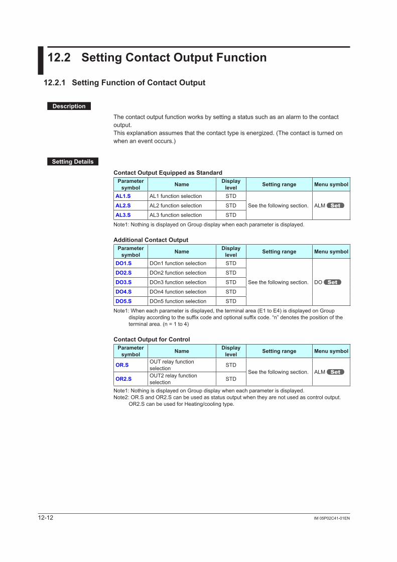
12-12 IM 05P02C41-01EN
12.2 SettingContactOutputFunction
12.2.1 SettingFunctionofContactOutput
Description
The contact output function works by setting a status such as an alarm to the contact output.Thisexplanationassumesthatthecontacttypeisenergized.(Thecontactisturnedonwhen an event occurs.)
SettingDetails
ContactOutputEquippedasStandardParameter symbol Name Display
level Settingrange Menusymbol
AL1.S AL1 function selection STD
See the following section. ALM AL2.S AL2 function selection STD
AL3.S AL3 function selection STD
Note1: Nothing is displayed on Group display when each parameter is displayed.
AdditionalContactOutputParameter symbol Name Display
level Settingrange Menusymbol
DO1.S DOn1 function selection STD
See the following section. DO
DO2.S DOn2 function selection STD
DO3.S DOn3 function selection STD
DO4.S DOn4 function selection STD
DO5.S DOn5 function selection STD
Note1: When each parameter is displayed, the terminal area (E1 to E4) is displayed on Group display according to the suffix code and optional suffix code. “n” denotes the position of the terminal area. (n = 1 to 4)
ContactOutputforControlParameter symbol Name Display
level Settingrange Menusymbol
OR.S OUT relay function selection STD
See the following section. ALM OR2.S OUT2 relay function
selection STD
Note1: Nothing is displayed on Group display when each parameter is displayed.Note2: OR.S and OR2.S can be used as status output when they are not used as control output.
OR2.S can be used for Heating/cooling type.
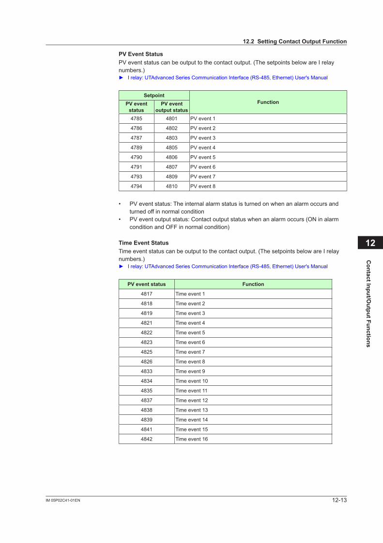
12-13IM 05P02C41-01EN
Contact Input/O
utput Functions
12
PVEventStatusPV event status can be output to the contact output. (The setpoints below are I relay numbers.) I relay: UTAdvanced Series Communication Interface (RS-485, Ethernet) User's Manual
SetpointFunctionPVevent
statusPVevent
output status4785 4801 PV event 1
4786 4802 PV event 2
4787 4803 PV event 3
4789 4805 PV event 4
4790 4806 PV event 5
4791 4807 PV event 6
4793 4809 PV event 7
4794 4810 PV event 8
• PV event status: The internal alarm status is turned on when an alarm occurs and turned off in normal condition
• PV event output status: Contact output status when an alarm occurs (ON in alarm condition and OFF in normal condition)
TimeEventStatusTime event status can be output to the contact output. (The setpoints below are I relay numbers.) I relay: UTAdvanced Series Communication Interface (RS-485, Ethernet) User's Manual
PVeventstatus Function
4817 Time event 1
4818 Time event 2
4819 Time event 3
4821 Time event 4
4822 Time event 5
4823 Time event 6
4825 Time event 7
4826 Time event 8
4833 Time event 9
4834 Time event 10
4835 Time event 11
4837 Time event 12
4838 Time event 13
4839 Time event 14
4841 Time event 15
4842 Time event 16
12.2SettingContactOutputFunction
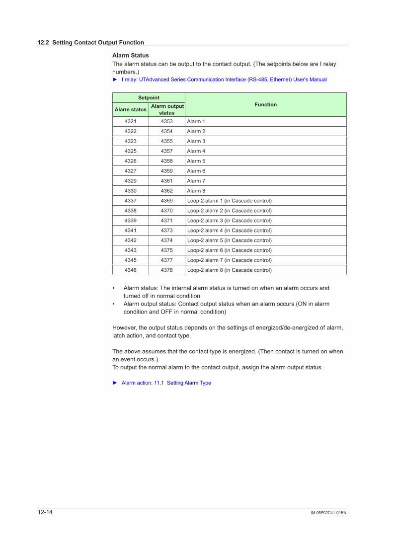
12-14 IM 05P02C41-01EN
AlarmStatusThe alarm status can be output to the contact output. (The setpoints below are I relay numbers.) Irelay:UTAdvancedSeriesCommunicationInterface(RS-485,Ethernet)User'sManual
SetpointFunction
Alarm status Alarm output status
4321 4353 Alarm 1
4322 4354 Alarm 2
4323 4355 Alarm 3
4325 4357 Alarm 4
4326 4358 Alarm 5
4327 4359 Alarm 6
4329 4361 Alarm 7
4330 4362 Alarm 8
4337 4369 Loop-2 alarm 1 (in Cascade control)
4338 4370 Loop-2 alarm 2 (in Cascade control)
4339 4371 Loop-2 alarm 3 (in Cascade control)
4341 4373 Loop-2 alarm 4 (in Cascade control)
4342 4374 Loop-2 alarm 5 (in Cascade control)
4343 4375 Loop-2 alarm 6 (in Cascade control)
4345 4377 Loop-2 alarm 7 (in Cascade control)
4346 4378 Loop-2 alarm 8 (in Cascade control)
• Alarm status: The internal alarm status is turned on when an alarm occurs and turned off in normal condition
• Alarm output status: Contact output status when an alarm occurs (ON in alarm condition and OFF in normal condition)
However,theoutputstatusdependsonthesettingsofenergized/de-energizedofalarm,latch action, and contact type.
Theaboveassumesthatthecontacttypeisenergized.(Thencontactisturnedonwhenan event occurs.)To output the normal alarm to the contact output, assign the alarm output status.
Alarm action: 11.1 Setting Alarm Type
12.2SettingContactOutputFunction
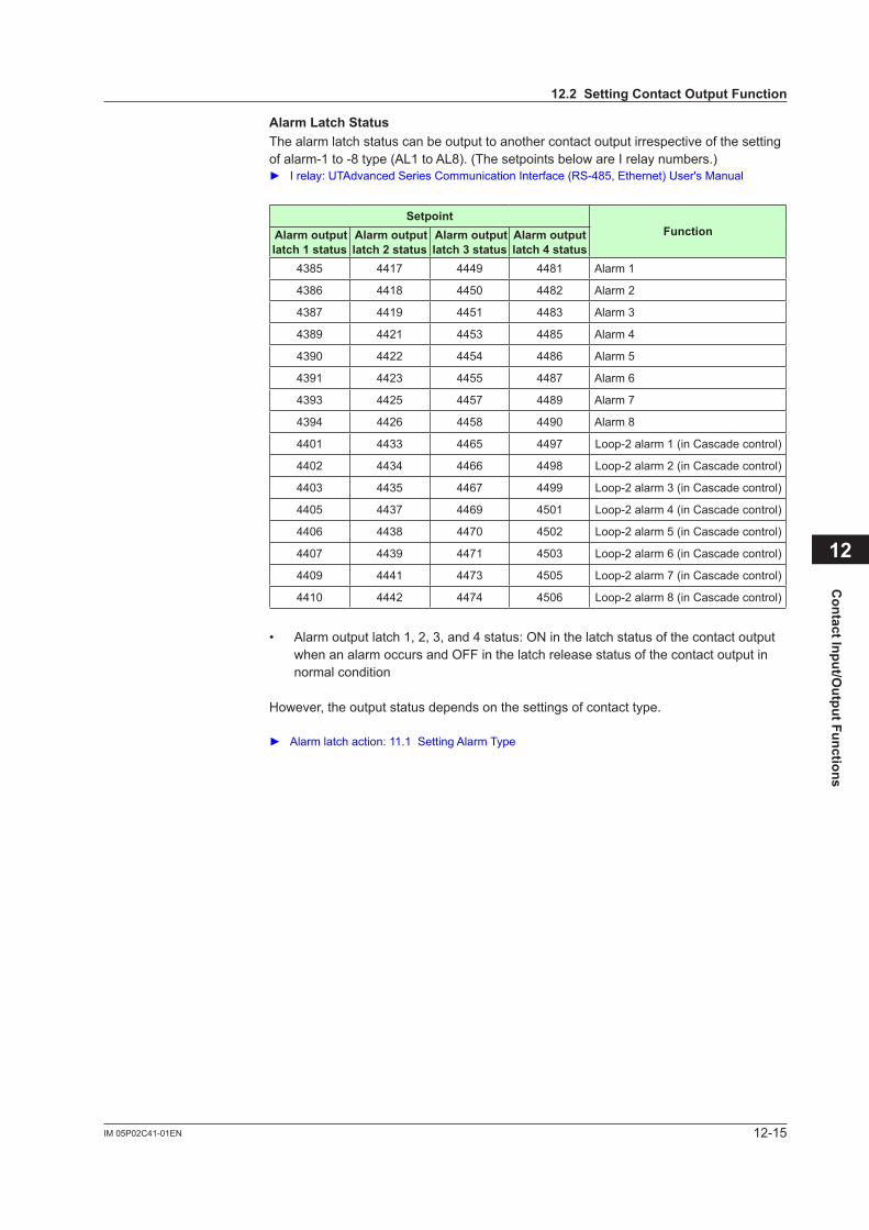
12-15IM 05P02C41-01EN
Contact Input/O
utput Functions
12
AlarmLatchStatusThe alarm latch status can be output to another contact output irrespective of the setting of alarm-1 to -8 type (AL1 to AL8). (The setpoints below are I relay numbers.) I relay: UTAdvanced Series Communication Interface (RS-485, Ethernet) User's Manual
SetpointFunction Alarm output
latch1status Alarm output latch2status
Alarm output latch 3 status
Alarm output latch 4 status
4385 4417 4449 4481 Alarm 1
4386 4418 4450 4482 Alarm 2
4387 4419 4451 4483 Alarm 3
4389 4421 4453 4485 Alarm 4
4390 4422 4454 4486 Alarm 5
4391 4423 4455 4487 Alarm 6
4393 4425 4457 4489 Alarm 7
4394 4426 4458 4490 Alarm 8
4401 4433 4465 4497 Loop-2 alarm 1 (in Cascade control)
4402 4434 4466 4498 Loop-2 alarm 2 (in Cascade control)
4403 4435 4467 4499 Loop-2 alarm 3 (in Cascade control)
4405 4437 4469 4501 Loop-2 alarm 4 (in Cascade control)
4406 4438 4470 4502 Loop-2 alarm 5 (in Cascade control)
4407 4439 4471 4503 Loop-2 alarm 6 (in Cascade control)
4409 4441 4473 4505 Loop-2 alarm 7 (in Cascade control)
4410 4442 4474 4506 Loop-2 alarm 8 (in Cascade control)
• Alarm output latch 1, 2, 3, and 4 status: ON in the latch status of the contact output when an alarm occurs and OFF in the latch release status of the contact output in normal condition
However, the output status depends on the settings of contact type.
Alarm latch action: 11.1 Setting Alarm Type
12.2SettingContactOutputFunction
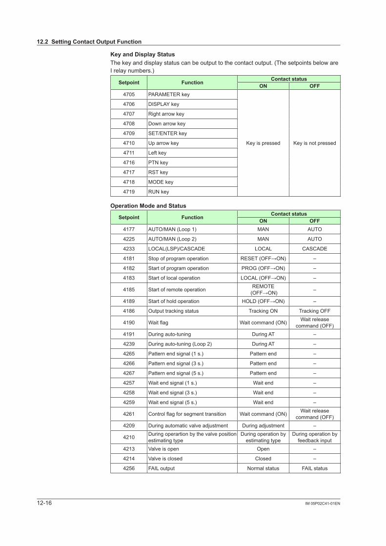
12-16 IM 05P02C41-01EN
KeyandDisplayStatusThe key and display status can be output to the contact output. (The setpoints below are I relay numbers.)
Setpoint Function Contact statusON OFF
4705 PARAMETER key
Key is pressed Key is not pressed
4706 DISPLAY key
4707 Right arrow key
4708 Down arrow key
4709 SET/ENTER key
4710 Up arrow key
4711 Left key
4716 PTN key
4717 RST key
4718 MODE key
4719 RUN key
OperationModeandStatus
Setpoint Function Contact statusON OFF
4177 AUTO/MAN (Loop 1) MAN AUTO
4225 AUTO/MAN (Loop 2) MAN AUTO
4233 LOCAL(LSP)/CASCADE LOCAL CASCADE
4181 Stop of program operation RESET (OFF→ON) –
4182 Start of program operation PROG (OFF→ON) –
4183 Start of local operation LOCAL (OFF→ON) –
4185 Start of remote operation REMOTE (OFF→ON) –
4189 Start of hold operation HOLD (OFF→ON) –
4186 Output tracking status Tracking ON Tracking OFF
4190 Waitflag Wait command (ON) Wait release command (OFF)
4191 During auto-tuning During AT –
4239 During auto-tuning (Loop 2) During AT –
4265 Pattern end signal (1 s.) Pattern end –
4266 Pattern end signal (3 s.) Pattern end –
4267 Pattern end signal (5 s.) Pattern end –
4257 Wait end signal (1 s.) Wait end –
4258 Wait end signal (3 s.) Wait end –
4259 Wait end signal (5 s.) Wait end –
4261 Controlflagforsegmenttransition Wait command (ON) Wait release command (OFF)
4209 Duringautomaticvalveadjustment Duringadjustment –
4210 During operartion by the valve position estimating type
During operation by estimating type
During operation by feedback input
4213 Valve is open Open –
4214 Valve is closed Closed –
4256 FAIL output Normal status FAIL status
12.2SettingContactOutputFunction
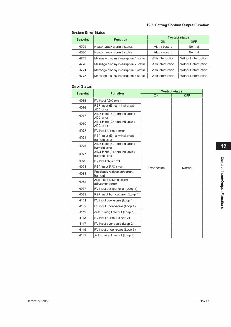
12-17IM 05P02C41-01EN
Contact Input/O
utput Functions
12
SystemErrorStatus
Setpoint Function Contact statusON OFF
4529 Heater break alarm 1 status Alarm occurs Normal
4530 Heater break alarm 2 status Alarm occurs Normal
4769 Message display interruption 1 status With interruption Without interruption
4770 Message display interruption 2 status With interruption Without interruption
4771 Message display interruption 3 status With interruption Without interruption
4773 Message display interruption 4 status With interruption Without interruption
ErrorStatus
Setpoint Function Contact statusON OFF
4065 PV input ADC error
Error occurs Normal
4066 RSP input (E1-terminal area) ADC error
4067 AIN2 input (E2-terminal area) ADC error
4069 AIN4 input (E4-terminal area) ADC error
4073 PV input burnout error
4074 RSP input (E1-terminal area) burnout error
4075 AIN2 input (E2-terminal area) burnout error
4077 AIN4 input (E4-terminal area) burnout error
4070 PV input RJC error
4071 RSP input RJC error
4081 Feedback resistance/current burnout
4082 Automatic valve position adjustmenterror
4097 PV input burnout error (Loop 1)
4098 RSP input burnout error (Loop 1)
4101 PV input over-scale (Loop 1)
4102 PV input under-scale (Loop 1)
4111 Auto-tuning time out (Loop 1)
4113 PV input burnout (Loop 2)
4117 PV input over-scale (Loop 2)
4118 PV input under-scale (Loop 2)
4127 Auto-tuning time out (Loop 2)
12.2SettingContactOutputFunction
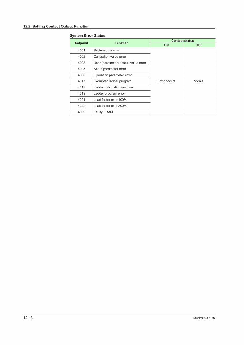
12-18 IM 05P02C41-01EN
SystemErrorStatus
Setpoint Function Contact statusON OFF
4001 System data error
Error occurs Normal
4002 Calibration value error
4003 User (parameter) default value error
4005 Setup parameter error
4006 Operation parameter error
4017 Corrupted ladder program
4018 Laddercalculationoverflow
4019 Ladder program error
4021 Load factor over 100%
4022 Load factor over 200%
4009 Faulty FRAM
12.2SettingContactOutputFunction
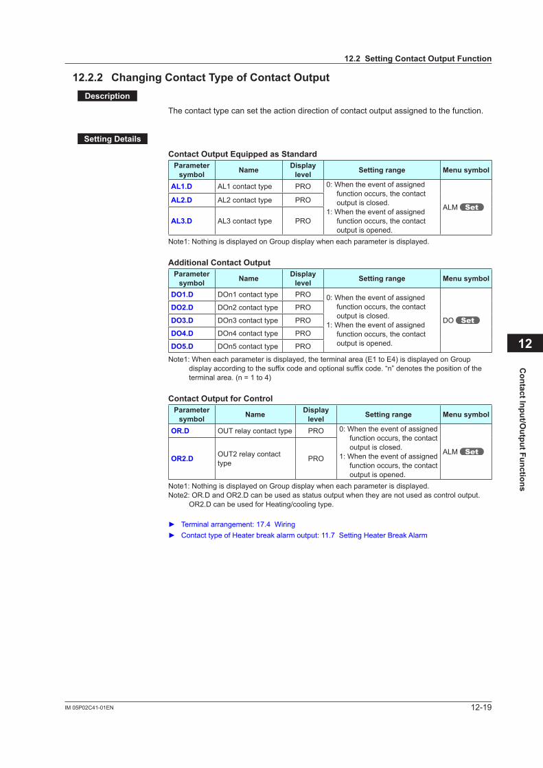
12-19IM 05P02C41-01EN
Contact Input/O
utput Functions
12
12.2.2 ChangingContactTypeofContactOutputDescription
The contact type can set the action direction of contact output assigned to the function.
SettingDetails
ContactOutputEquippedasStandardParameter symbol Name Display
level Settingrange Menusymbol
AL1.D AL1 contact type PRO 0: When the event of assigned function occurs, the contact output is closed.
1: When the event of assigned function occurs, the contact output is opened.
ALM AL2.D AL2 contact type PRO
AL3.D AL3 contact type PRO
Note1: Nothing is displayed on Group display when each parameter is displayed.
AdditionalContactOutputParameter symbol Name Display
level Settingrange Menusymbol
DO1.D DOn1 contact type PRO 0: When the event of assigned function occurs, the contact output is closed.
1: When the event of assigned function occurs, the contact output is opened.
DO
DO2.D DOn2 contact type PRO
DO3.D DOn3 contact type PRO
DO4.D DOn4 contact type PRO
DO5.D DOn5 contact type PRO
Note1: When each parameter is displayed, the terminal area (E1 to E4) is displayed on Group display according to the suffix code and optional suffix code. “n” denotes the position of the terminal area. (n = 1 to 4)
ContactOutputforControlParameter symbol Name Display
level Settingrange Menusymbol
OR.D OUT relay contact type PRO 0: When the event of assigned function occurs, the contact output is closed.
1: When the event of assigned function occurs, the contact output is opened.
ALM OR2.D OUT2 relay contact
type PRO
Note1: Nothing is displayed on Group display when each parameter is displayed.Note2: OR.D and OR2.D can be used as status output when they are not used as control output.
OR2.D can be used for Heating/cooling type.
Terminalarrangement:17.4Wiring ContacttypeofHeaterbreakalarmoutput:11.7SettingHeaterBreakAlarm
12.2SettingContactOutputFunction

Blank Page
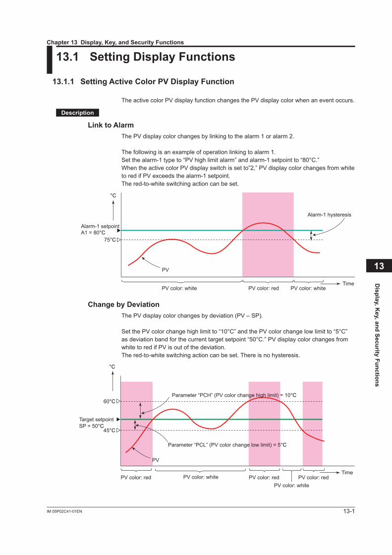
13-1IM 05P02C41-01EN
Display, K
ey, and Security Functions
13
13.1 SettingDisplayFunctions
13.1.1 SettingActiveColorPVDisplayFunction
The active color PV display function changes the PV display color when an event occurs.
Description
Link to AlarmThe PV display color changes by linking to the alarm 1 or alarm 2.
The following is an example of operation linking to alarm 1.Set the alarm-1 type to “PV high limit alarm” and alarm-1 setpoint to “80°C.”When the active color PV display switch is set to”2,” PV display color changes from white to red if PV exceeds the alarm-1 setpoint.The red-to-white switching action can be set.
°C
TimePV color: redPV color: white PV color: white
Alarm-1 setpointA1 = 80°C
PV
75°C
Alarm-1 hysteresis
ChangebyDeviationThe PV display color changes by deviation (PV – SP).
Set the PV color change high limit to “10°C” and the PV color change low limit to “5°C” as deviation band for the current target setpoint “50°C.” PV display color changes from white to red if PV is out of the deviation.The red-to-white switching action can be set. There is no hysteresis.
°C
Time
Target setpointSP = 50°C
60°C
45°C
PV
PV color: redPV color: red PV color: redPV color: white
PV color: white
Parameter “PCH” (PV color change high limit) = 10°C
Parameter “PCL” (PV color change low limit) = 5°C
Chapter13Display,Key,andSecurityFunctions
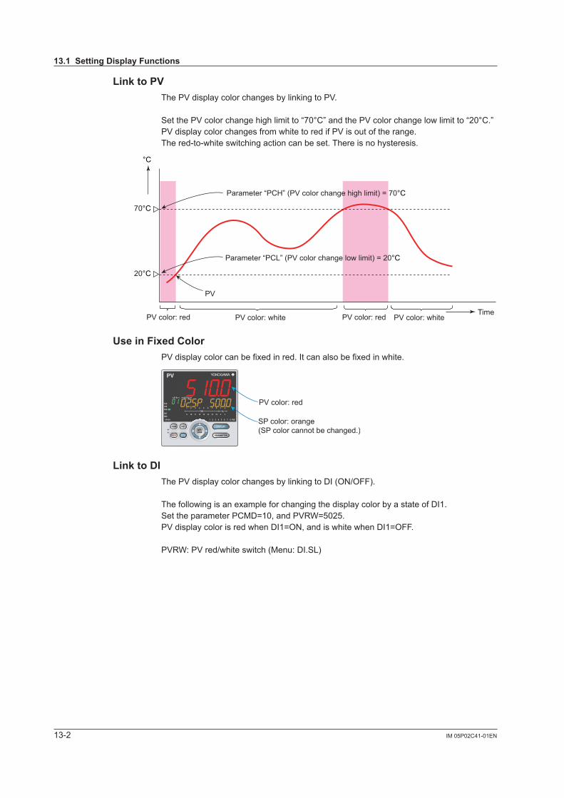
13-2 IM 05P02C41-01EN
Link to PVThe PV display color changes by linking to PV.
Set the PV color change high limit to “70°C” and the PV color change low limit to “20°C.” PV display color changes from white to red if PV is out of the range.The red-to-white switching action can be set. There is no hysteresis.
Time
70°C
20°C
PV
Parameter “PCH” (PV color change high limit) = 70°C
Parameter “PCL” (PV color change low limit) = 20°C
°C
PV color: red PV color: redPV color: white PV color: white
UseinFixedColorPV display color can be fixed in red. It can also be fixed in white.
PV color: red
SP color: orange(SP color cannot be changed.)
Link to DIThe PV display color changes by linking to DI (ON/OFF).
The following is an example for changing the display color by a state of DI1.Set the parameter PCMD=10, and PVRW=5025.PV display color is red when DI1=ON, and is white when DI1=OFF.
PVRW: PV red/white switch (Menu: DI.SL)
13.1SettingDisplayFunctions
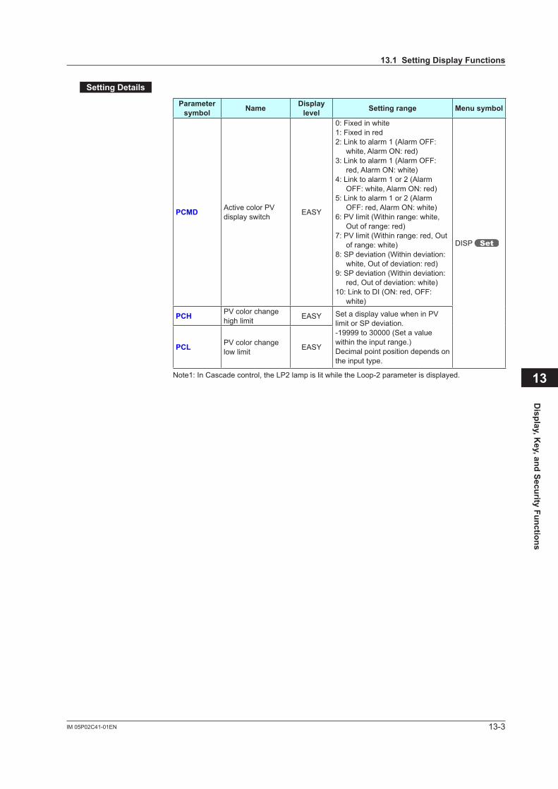
13-3IM 05P02C41-01EN
Display, K
ey, and Security Functions
13
SettingDetails
Parameter symbol Name Display
level Settingrange Menusymbol
PCMD Active color PV display switch EASY
0: Fixed in white1: Fixed in red2: Link to alarm 1 (Alarm OFF:
white, Alarm ON: red)3: Link to alarm 1 (Alarm OFF:
red, Alarm ON: white)4: Link to alarm 1 or 2 (Alarm
OFF: white, Alarm ON: red)5: Link to alarm 1 or 2 (Alarm
OFF: red, Alarm ON: white)6: PV limit (Within range: white,
Out of range: red)7: PV limit (Within range: red, Out
of range: white)8: SP deviation (Within deviation:
white, Out of deviation: red)9: SP deviation (Within deviation:
red, Out of deviation: white)10: Link to DI (ON: red, OFF:
white)
DISP
PCH PV color change high limit EASY Set a display value when in PV
limit or SP deviation.-19999 to 30000 (Set a value within the input range.)Decimal point position depends on the input type.
PCL PV color change low limit EASY
Note1: In Cascade control, the LP2 lamp is lit while the Loop-2 parameter is displayed.
13.1SettingDisplayFunctions
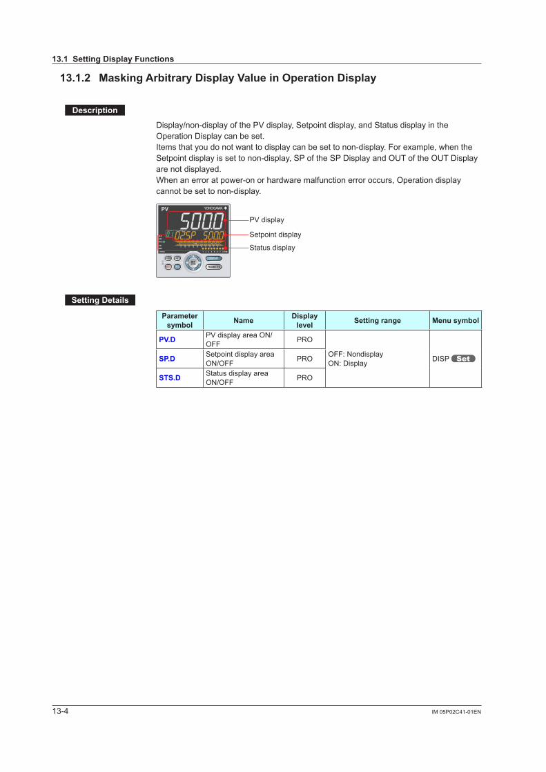
13-4 IM 05P02C41-01EN
13.1.2 MaskingArbitraryDisplayValueinOperationDisplay
Description
Display/non-display of the PV display, Setpoint display, and Status display in the Operation Display can be set.Items that you do not want to display can be set to non-display. For example, when the Setpoint display is set to non-display, SP of the SP Display and OUT of the OUT Display are not displayed. When an error at power-on or hardware malfunction error occurs, Operation display cannot be set to non-display.
PV display
Setpoint display
Status display
SettingDetails
Parameter symbol Name Display
level Settingrange Menusymbol
PV.D PV display area ON/OFF PRO
OFF: NondisplayON: Display DISP SP.D Setpoint display area
ON/OFF PRO
STS.D Status display area ON/OFF PRO
13.1SettingDisplayFunctions

13-5IM 05P02C41-01EN
Display, K
ey, and Security Functions
13
13.1.3 RegisteringSELECTDisplay(Upto5Displays)
Description
Registering frequently changed-operation parameters in the SELECT Display of the Operation Displays will allow you to change parameter settings easily. A maximum of five Displays can be registered.Set the D register number of the parameter you wish to register for the registration to the SELECT Display.However, the parameters in the following menu cannot be set:CTL, PV, RSP, AIN2, AIN4, MPV, OUT, HBA, R485, ETHR, PROF, DNET, CC-L, KEY, DISP, CSEL, KLOC, MLOC, DI.SL, DI.NU, DI.D, ALM, DO, I/O, SYS, INIT, VER, and LVL.When each parameter is displayed, the terminal area (E1 to E4) is displayed on Group display according to the suffix code and optional suffix code.
SP Display
• • • • • • • •
Ordinary Operation Displays
OUT Display
SELECT Display
Example: Alarm Setpoint Setting Display
SettingDetails
Parameter symbol Name Display
level Settingrange Menusymbol
CS1toCS5 SELECT Display-1 to -5 registration STD
OFF: No registration D register number (2201 to 5000) (6701 to 6710)
CSEL
For D register numbers, see the UTAdvanced Series Communication Interface User’s Manual.
13.1SettingDisplayFunctions
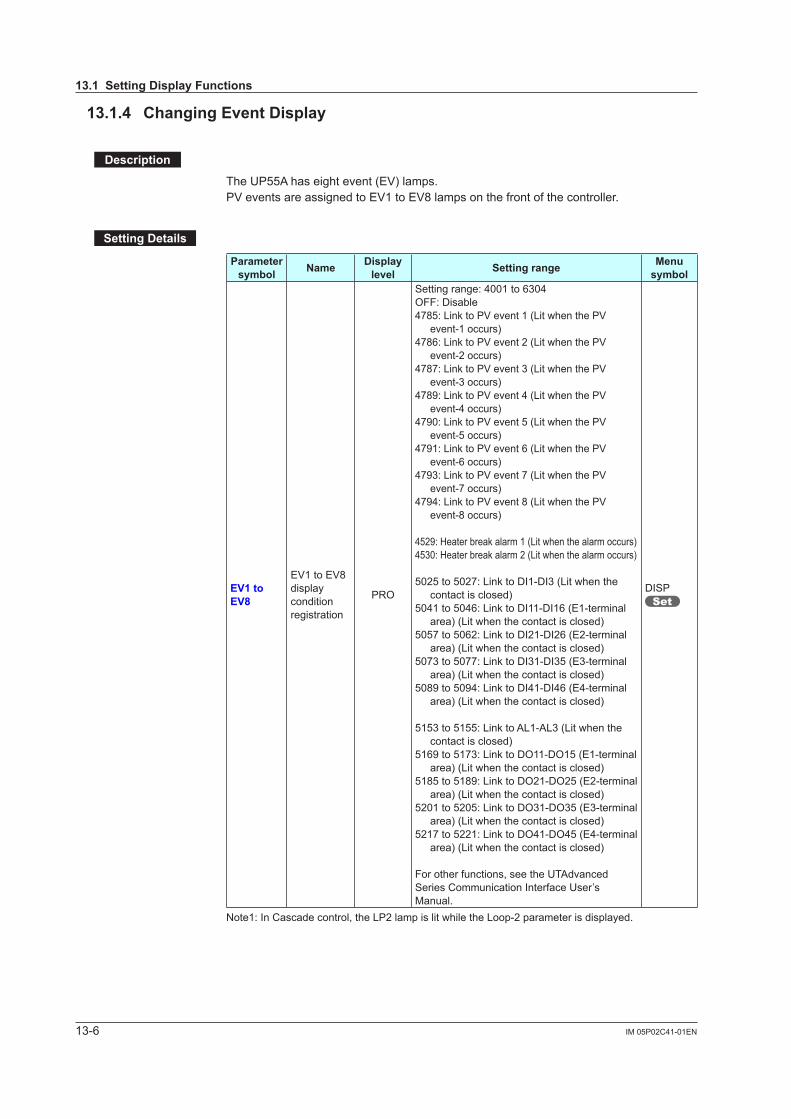
13-6 IM 05P02C41-01EN
13.1.4 ChangingEventDisplay
Description
The UP55A has eight event (EV) lamps.PV events are assigned to EV1 to EV8 lamps on the front of the controller.
SettingDetails
Parameter symbol Name Display
level Settingrange Menu symbol
EV1toEV8
EV1 to EV8 display condition registration
PRO
Setting range: 4001 to 6304OFF: Disable4785: Link to PV event 1 (Lit when the PV
event-1 occurs)4786: Link to PV event 2 (Lit when the PV
event-2 occurs)4787: Link to PV event 3 (Lit when the PV
event-3 occurs)4789: Link to PV event 4 (Lit when the PV
event-4 occurs)4790: Link to PV event 5 (Lit when the PV
event-5 occurs)4791: Link to PV event 6 (Lit when the PV
event-6 occurs)4793: Link to PV event 7 (Lit when the PV
event-7 occurs)4794: Link to PV event 8 (Lit when the PV
event-8 occurs)
4529: Heater break alarm 1 (Lit when the alarm occurs)4530: Heater break alarm 2 (Lit when the alarm occurs)
5025 to 5027: Link to DI1-DI3 (Lit when the contact is closed)
5041 to 5046: Link to DI11-DI16 (E1-terminal area) (Lit when the contact is closed)
5057 to 5062: Link to DI21-DI26 (E2-terminal area) (Lit when the contact is closed)
5073 to 5077: Link to DI31-DI35 (E3-terminal area) (Lit when the contact is closed)
5089 to 5094: Link to DI41-DI46 (E4-terminal area) (Lit when the contact is closed)
5153 to 5155: Link to AL1-AL3 (Lit when the contact is closed)
5169 to 5173: Link to DO11-DO15 (E1-terminal area) (Lit when the contact is closed)
5185 to 5189: Link to DO21-DO25 (E2-terminal area) (Lit when the contact is closed)
5201 to 5205: Link to DO31-DO35 (E3-terminal area) (Lit when the contact is closed)
5217 to 5221: Link to DO41-DO45 (E4-terminal area) (Lit when the contact is closed)
For other functions, see the UTAdvanced Series Communication Interface User’s Manual.
DISP
Note1: In Cascade control, the LP2 lamp is lit while the Loop-2 parameter is displayed.
13.1SettingDisplayFunctions
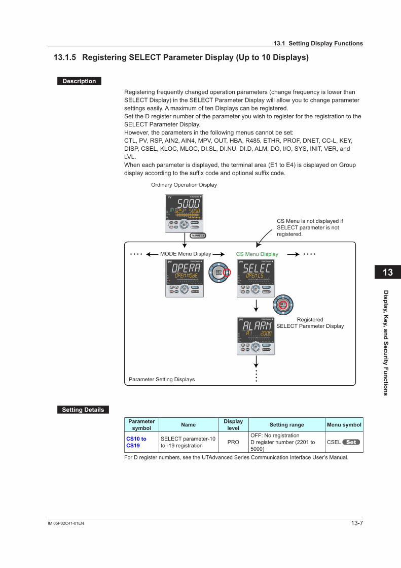
13-7IM 05P02C41-01EN
Display, K
ey, and Security Functions
13.1.5 RegisteringSELECTParameterDisplay(Upto10Displays)
Description
Registering frequently changed operation parameters (change frequency is lower than SELECT Display) in the SELECT Parameter Display will allow you to change parameter settings easily. A maximum of ten Displays can be registered.Set the D register number of the parameter you wish to register for the registration to the SELECT Parameter Display.However, the parameters in the following menus cannot be set:CTL, PV, RSP, AIN2, AIN4, MPV, OUT, HBA, R485, ETHR, PROF, DNET, CC-L, KEY, DISP, CSEL, KLOC, MLOC, DI.SL, DI.NU, DI.D, ALM, DO, I/O, SYS, INIT, VER, and LVL.When each parameter is displayed, the terminal area (E1 to E4) is displayed on Group display according to the suffix code and optional suffix code.
MODE Menu Display
RegisteredSELECT Parameter Display
Parameter Setting Displays
CS Menu Display • • • • • • • • • •
• •
Ordinary Operation Display
CS Menu is not displayed if SELECT parameter is not registered.
SettingDetails
Parameter symbol Name Display
level Settingrange Menusymbol
CS10toCS19
SELECT parameter-10 to -19 registration PRO
OFF: No registrationD register number (2201 to 5000)
CSEL
For D register numbers, see the UTAdvanced Series Communication Interface User’s Manual.
13
13.1SettingDisplayFunctions
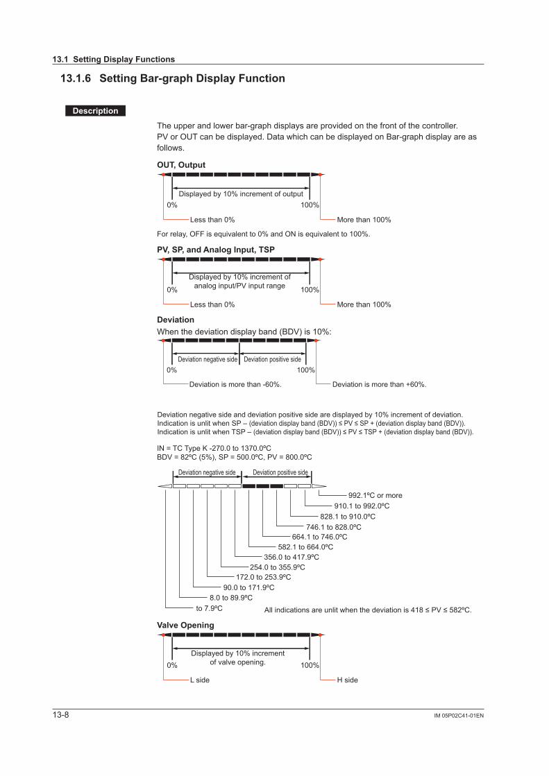
13-8 IM 05P02C41-01EN
13.1.6 SettingBar-graphDisplayFunction
Description
The upper and lower bar-graph displays are provided on the front of the controller.PV or OUT can be displayed. Data which can be displayed on Bar-graph display are as follows.
OUT,Output
Displayed by 10% increment of output
Less than 0%
0% 100%
More than 100%
For relay, OFF is equivalent to 0% and ON is equivalent to 100%.
PV,SP,andAnalogInput,TSP
Displayed by 10% increment of
analog input/PV input range
Less than 0%
0% 100%
More than 100%
DeviationWhen the deviation display band (BDV) is 10%:
Deviation negative side Deviation positive side
Deviation negative side and deviation positive side are displayed by 10% increment of deviation.Indication is unlit when SP – (deviation display band (BDV)) ≤ PV ≤ SP + (deviation display band (BDV)).Indication is unlit when TSP – (deviation display band (BDV)) ≤ PV ≤ TSP + (deviation display band (BDV)).
Deviation is more than -60%.
0% 100%
Deviation is more than +60%.
Deviation negative side Deviation positive side
IN = TC Type K -270.0 to 1370.0ºCBDV = 82ºC (5%), SP = 500.0ºC, PV = 800.0ºC
All indications are unlit when the deviation is 418 ≤ PV ≤ 582ºC.
992.1ºC or more910.1 to 992.0ºC
828.1 to 910.0ºC746.1 to 828.0ºC
664.1 to 746.0ºC582.1 to 664.0ºC
356.0 to 417.9ºC254.0 to 355.9ºC
172.0 to 253.9ºC90.0 to 171.9ºC
8.0 to 89.9ºCto 7.9ºC
ValveOpening
Displayed by 10% increment
of valve opening.
L side
0% 100%
H side
13.1SettingDisplayFunctions
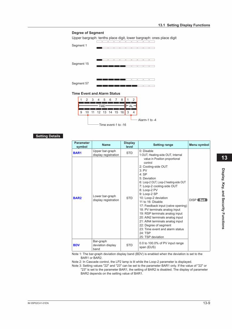
13-9IM 05P02C41-01EN
Display, K
ey, and Security Functions
DegreeofSegmentUpper bargraph: tenths place digit, lower bargraph: ones place digit
Segment 1
Segment 15
Segment 57
TimeEventandAlarmStatus
Time event-1 to -16
9 10 11 12 13 14 15 16 3 4
TME AL
1 2 3 4 5 6 7 8 1 2
Alarm-1 to -4
SettingDetails
Parameter symbol Name Display
level Settingrange Menusymbol
BAR1 Upper bar-graph display registration STD 0: Disable
1:OUT, Heating-side OUT, Internal value in Position proportional control
2: Cooling-side OUT3: PV4: SP5: Deviation6: Loop-2 OUT, Loop-2 heating-side OUT7: Loop-2 cooling-side OUT8: Loop-2 PV9: Loop-2 SP10: Loop-2 deviation11 to 16: Disable17: Feedback input (valve opening)18: PV terminals analog input19: RSP terminals analog input20: AIN2 terminals analog input21: AIN4 terminals analog input22: Degree of segment23: Time event and alarm status24: TSP25: TSP deviation
DISP BAR2 Lower bar-graph display registration STD
BDVBar-graph deviation display band
STD 0.0 to 100.0% of PV input range span (EUS)
Note 1: The bar-graph deviation display band (BDV) is enabled when the deviation is set to the BAR1 or BAR2.
Note 2: In Cascade control, the LP2 lamp is lit while the Loop-2 parameter is displayed.Note 3: Setting values "22" and "23" can be set to the parameter BAR1 only. If the value of "22" or
"23" is set to the parameter BAR1, the setting of BAR2 is disabled. The display of parameter BAR2 depends on the setting value of BAR1.
13
13.1SettingDisplayFunctions
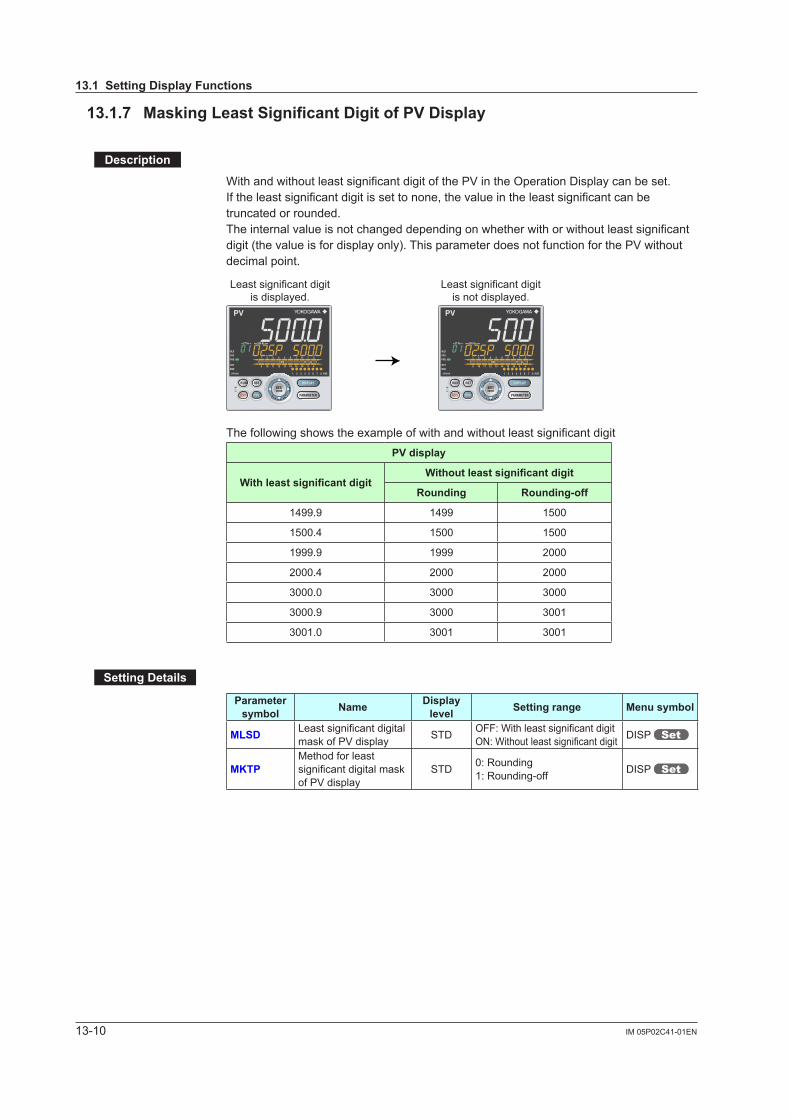
13-10 IM 05P02C41-01EN
13.1.7 MaskingLeastSignificantDigitofPVDisplay
Description
With and without least significant digit of the PV in the Operation Display can be set.If the least significant digit is set to none, the value in the least significant can be truncated or rounded.The internal value is not changed depending on whether with or without least significant digit (the value is for display only). This parameter does not function for the PV without decimal point.
Least significant digitis displayed.
Least significant digitis not displayed.
The following shows the example of with and without least significant digitPVdisplay
WithleastsignificantdigitWithoutleastsignificantdigit
Rounding Rounding-off
1499.9 1499 1500
1500.4 1500 1500
1999.9 1999 2000
2000.4 2000 2000
3000.0 3000 3000
3000.9 3000 3001
3001.0 3001 3001
SettingDetails
Parameter symbol Name Display
level Settingrange Menusymbol
MLSD Leastsignificantdigitalmask of PV display STD OFF:Withleastsignificantdigit
ON:Withoutleastsignificantdigit DISP
MKTPMethod for least significantdigitalmaskof PV display
STD 0: Rounding1: Rounding-off DISP
13.1SettingDisplayFunctions
13-11IM 05P02C41-01EN
Display, K
ey, and Security Functions
13.1.8 SettingEconomyMode
Description
The LCD backlight ON/OFF can be set in the following methods.Setting the LCD backlight to OFF saves energy.
UserFunctionKeys The LCD backlight ON/OFF switch can be assigned to the user function key. Userfunctionkey:13.2AssigningFunctiontoUserFunctionKey
BacklightOFFtimer The backlight OFF timer sets the economy mode parameter to ON.
If no keys are pressed for 30 minutes, the LCD backlight goes off automatically. The backlight OFF can be set to turn off the backlight for the whole display or a display other than the PV display. To turn on the LCD backlight, press any key.
Contact Input The LCD backlight ON/OFF switch can be assigned to the contact input Contactinput:12.1SettingContactInputFunction
In the following cases, the LCD backlight does not go off. • when an alarm occurs • When an error at power-on or a hardware malfunction error occurs
SettingDetails
Parameter symbol Name Display
level Settingrange Menusymbol
ECO Economy mode STD
OFF: Disable1: Economy mode ON (All
indications except PV display OFF)
2: Economy mode ON (All indications OFF)
3: Brightness 10 % (all indications)
DISP
13
13.1SettingDisplayFunctions
13-12 IM 05P02C41-01EN
13.1.9 SelectingtheInitialOperationDisplaythatAppearsatPowerON
Description
The initial Operation Display that appears when the power is turned on can be set.
SettingDetails
Parameter symbol Name Display
level Settingrange Menusymbol
HOME Home Operation Display setting PRO
SP1: SP DisplaySP2: Loop-2 SP DisplayOUT1: OUT DisplayOUT2: Loop-2 OUT DisplayHCO: Heating/cooling OUT DisplayVP: Valve Position DisplayMV: Position Proportional Computation
Output DisplayPID1: PID Number DisplayPID2: Loop-2 PID Number DisplayHC1: Heater Break Alarm-1 Current
DisplayHC2: Heater Break Alarm-2 Current
DisplayPV1: PV2/PV1 DisplayPV2: PV1/PV2 DisplayPV: PV Analog Input DisplayRSP: RSP Analog Input DisplayAIN2: AIN2 Analog Input DisplayAIN4: AIN4 Analog Input DisplayCS1 to CS5: SELECT Display 1 to 5TSP1: TSP DisplayTSP2: Loop-2 TSP DisplayR.TIM: Remaining Segment-tim
DisplaySEG.N: Segment Number DispalyR.CYC: Remaining Repetition DisplayPTN: Program Pattern DisplayAL5.8.1: Alarm-5 to -8 Status DisplayAL5.8.2: Loop-2 Alarm-5 to -8 Status
Display
DISP
13.1SettingDisplayFunctions
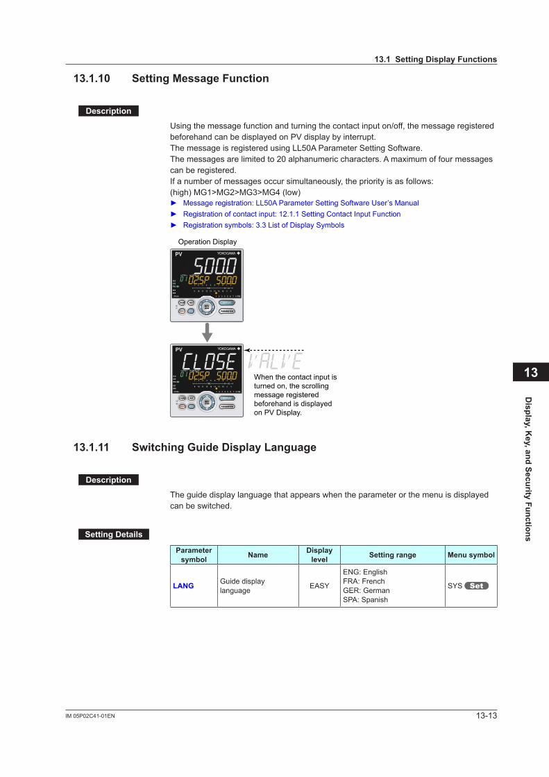
13-13IM 05P02C41-01EN
Display, K
ey, and Security Functions
13.1.10 SettingMessageFunction
Description
Using the message function and turning the contact input on/off, the message registered beforehand can be displayed on PV display by interrupt.The message is registered using LL50A Parameter Setting Software.The messages are limited to 20 alphanumeric characters. A maximum of four messages can be registered.If a number of messages occur simultaneously, the priority is as follows:(high) MG1>MG2>MG3>MG4 (low) Messageregistration:LL50AParameterSettingSoftwareUser’sManual Registration of contact input: 12.1.1 Setting Contact Input Function Registration symbols: 3.3 List of Display Symbols
When the contact input is turned on, the scrolling message registered beforehand is displayed on PV Display.
Operation Display
13.1.11 SwitchingGuideDisplayLanguage
Description
The guide display language that appears when the parameter or the menu is displayed can be switched.
SettingDetails
Parameter symbol Name Display
level Settingrange Menusymbol
LANG Guide display language EASY
ENG: EnglishFRA: FrenchGER: GermanSPA: Spanish
SYS
13
13.1SettingDisplayFunctions
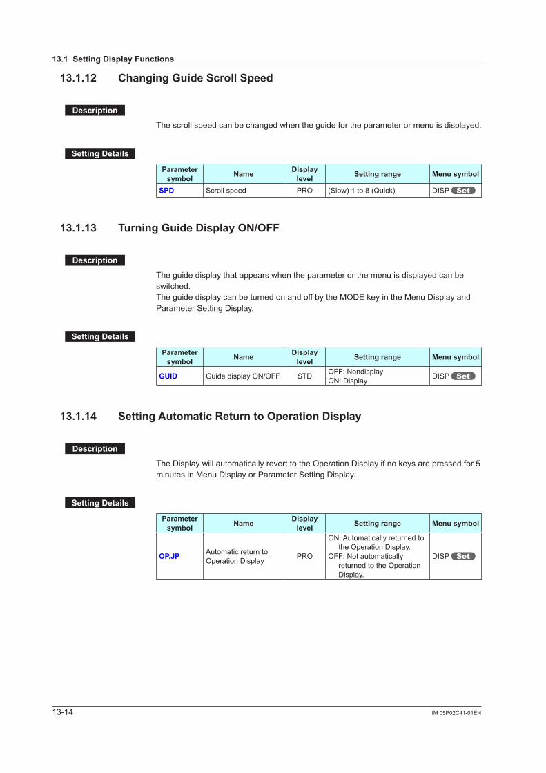
13-14 IM 05P02C41-01EN
13.1.12 ChangingGuideScrollSpeed
Description
The scroll speed can be changed when the guide for the parameter or menu is displayed.
SettingDetails
Parameter symbol Name Display
level Settingrange Menusymbol
SPD Scroll speed PRO (Slow) 1 to 8 (Quick) DISP
13.1.13 TurningGuideDisplayON/OFF
Description
The guide display that appears when the parameter or the menu is displayed can be switched.The guide display can be turned on and off by the MODE key in the Menu Display and Parameter Setting Display.
SettingDetails
Parameter symbol Name Display
level Settingrange Menusymbol
GUID Guide display ON/OFF STD OFF: NondisplayON: Display DISP
13.1.14 SettingAutomaticReturntoOperationDisplay
Description
The Display will automatically revert to the Operation Display if no keys are pressed for 5 minutes in Menu Display or Parameter Setting Display.
SettingDetails
Parameter symbol Name Display
level Settingrange Menusymbol
OP.JP Automatic return to Operation Display PRO
ON: Automatically returned to the Operation Display.
OFF: Not automatically returned to the Operation Display.
DISP
13.1SettingDisplayFunctions

13-15IM 05P02C41-01EN
Display, K
ey, and Security Functions
13.1.15 SettingBrightnessandContrastAdjustmentofLCDandDisplayUpdateCycle
Description
The brightness and contrast for PV, Setpoint, Bar-graph, and Status indicator can be adjusted.Brightness ranges for each display can be set.The LCD has a characteristic that the display action becomes late at the low temperature.Thiscanbesolvedbyadjustingthedisplayupdatecycle(D.CYC).
SettingDetails
Parameter symbol Name Display
level Settingrange Menusymbol
BRI Brightness EASY (Dark) 1 to 5 (Bright)
DISP
B.PVWWhite brightness adjustmentofPVdisplay
PROAdjuststhewhitebrightnessof PV display.(Dark) -4 to 4 (Bright)
B.PVRRed brightness adjustmentofPVdisplay
PROAdjuststheredbrightnessofPV display.(Dark) -4 to 4 (Bright)
B.SP Brightnessadjustmentof Setpoint display PRO
AdjuststhebrightnessofSPdisplay.(Dark) -4 to 4 (Bright)
B.BAR Brightnessadjustmentof Bar-graph display PRO
AdjuststhebrightnessofSPdisplay.(Dark) -4 to 4 (Bright)
B.STS Brightnessadjustmentof Status indicator PRO
AdjuststhebrightnessofStatus indicator.(Dark) -4 to 4 (Bright)
D.CYC Display update cycle PRO
1: 100 ms2: 200 ms3: 500 ms4: 1 s5: 2 s
13
13.1SettingDisplayFunctions

13-16 IM 05P02C41-01EN
13.2 AssigningFunctiontoUserFunction
Description
The UP55A has three user function keys on the front panel.Various functions (operation mode switch etc.) can be assigned to the user function key. Press the user function key to perform the assigned function.The User function key is available only on the Operation Display.The assigned function does not work on the Parameter Setting Display. However, the MODE key can be used to turn on/off the guide display.
User function keys

13-17IM 05P02C41-01EN
Display, K
ey, and Security Functions
SettingDetails
Parameter symbol Name Display
level Settingrange Menusymbol
RUN RUN key action setting PRO
See the table below KEY
RST RST key action setting PRO
PTN PTN key action setting PRO
MODE MODE key action setting PRO
Setpoint Function Action AvailabilityRST RUN PTN MODE
OFF Unassigned – √ √ √ √
PROG Switch to PROG (Start of program operation)
A program pattern starts if the user function key is pressed for one second.If program operation starts in hold-mode, hold-mode operation is disabled.
√ √√ √ √
RESET Switch to RESET (Stop of program operation)
A program pattern stops if the user function key is pressed for one second. √√ √ √ √
LOCAL Switch to LOCAL(LSP) (Start of local-mode operation)
Local-mode operation starts if the user function key is pressed for one second. √ √ √ √
REM Switch to REMOTE Remote-mode operation starts if the user function key is pressed for one second. √ √ √ √
P/R PROG/RESET Switch PROG and RESET switches every time the user function key is pressed for one second. √ √ √ √
P/H PROG/HOLD Switch PROG and HOLD switches every time the user function key is pressed for one second. √ √ √ √
P/L PROG/LOCAL(LSP) Switch PROG and LOCAL switches every time the user function key is pressed for one second. √ √ √ √
L/C LOCAL(LSP)/CAS switch LSP and CASCADE switches every time the user function key is pressed for one second. √ √ √ √
HLD Switch to HOLD (Start of hold-mode operation)
Hold-mode operation starts if the user function key is pressed once. √ √ √ √
ADV Advance of segment Program advance if the user function key is pressed for one second. √ √ √ √
A/M1 AUTO/MAN switch (Loop 1) AUTO and MAN switches every time the user function key is pressed. √ √ √ √
A/M2 AUTO/MAN switch (Loop 2) AUTO and MAN switches every time the user function key is pressed. √ √ √ √
PRG1 Switch to PROG (Start of program-1 operation)
Starts program pattern-1 if the user function key is pressed for one second. √ √ √ √
PRG2 Switch to PROG (Start of program-2 operation)
Starts program pattern-2 if the user function key is pressed for one second. √ √ √ √
AT Auto-tuning Pressing the user function key executes auto-tuning √ √ √ √
LTUP LCD brightness UP The current brightness gradually increases every time the function key is pressed. √ √ √ √
LTDN LCD brightness DOWN The current brightness gradually decreases every time the function key is pressed. √ √ √ √
BRI AdjustLCDbrightness
The current brightness gradually increases every time the function key is pressed.Pressing the function key after reaching the maximum brightness changes to the minimum brightness.Thereafter,minimumbrightness→maximumbrightness→maximumbrightnessisrepeated.
√ √ √ √
LCD LCD Backlight ON/OFF switch The LCD backlight turns on and off every time the user function key is pressed. √ √ √ √
13
13.2AssigningFunctiontoUserFunctionKey
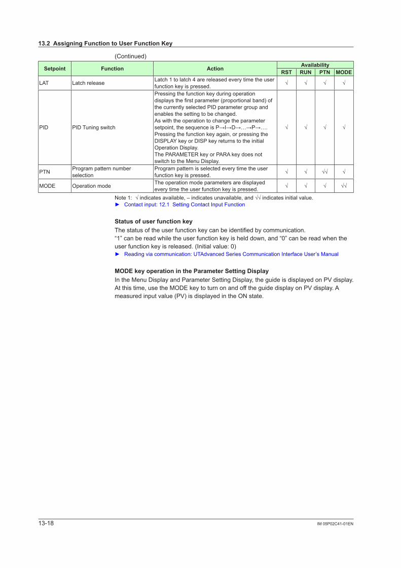
13-18 IM 05P02C41-01EN
(Continued)
Setpoint Function Action AvailabilityRST RUN PTN MODE
LAT Latch release Latch 1 to latch 4 are released every time the user function key is pressed. √ √ √ √
PID PID Tuning switch
Pressing the function key during operation displaysthefirstparameter(proportionalband)ofthe currently selected PID parameter group and enables the setting to be changed.As with the operation to change the parameter setpoint,thesequenceisP→I→D→…→P→….Pressing the function key again, or pressing the DISPLAY key or DISP key returns to the initial Operation Display. The PARAMETER key or PARA key does not switch to the Menu Display.
√ √ √ √
PTN Program pattern number selection
Program pattern is selected every time the user function key is pressed. √ √ √√ √
MODE Operation mode The operation mode parameters are displayed every time the user function key is pressed. √ √ √ √√
Note1: √indicatesavailable,–indicatesunavailable,and√√indicatesinitialvalue. Contact input: 12.1 Setting Contact Input Function
StatusofuserfunctionkeyThe status of the user function key can be identified by communication.“1” can be read while the user function key is held down, and “0” can be read when the user function key is released. (Initial value: 0) Readingviacommunication:UTAdvancedSeriesCommunicationInterfaceUser’sManual
MODEkeyoperationintheParameterSettingDisplayIn the Menu Display and Parameter Setting Display, the guide is displayed on PV display. At this time, use the MODE key to turn on and off the guide display on PV display. A measured input value (PV) is displayed in the ON state.
13.2AssigningFunctiontoUserFunctionKey
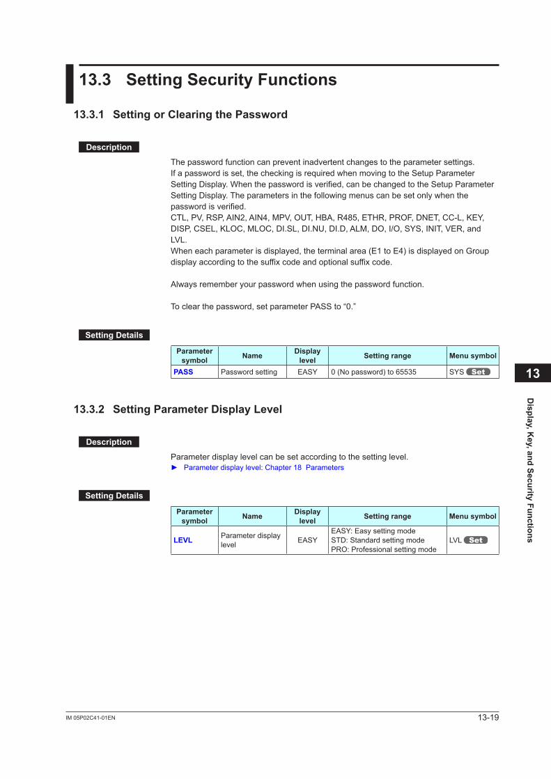
13-19IM 05P02C41-01EN
Display, K
ey, and Security Functions
13.3 SettingSecurityFunctions
13.3.1 SettingorClearingthePassword
Description
The password function can prevent inadvertent changes to the parameter settings.If a password is set, the checking is required when moving to the Setup Parameter Setting Display. When the password is verified, can be changed to the Setup Parameter Setting Display. The parameters in the following menus can be set only when the password is verified.CTL, PV, RSP, AIN2, AIN4, MPV, OUT, HBA, R485, ETHR, PROF, DNET, CC-L, KEY, DISP, CSEL, KLOC, MLOC, DI.SL, DI.NU, DI.D, ALM, DO, I/O, SYS, INIT, VER, and LVL.When each parameter is displayed, the terminal area (E1 to E4) is displayed on Group display according to the suffix code and optional suffix code.
Always remember your password when using the password function.
To clear the password, set parameter PASS to “0.”
SettingDetails
Parameter symbol Name Display
level Settingrange Menusymbol
PASS Password setting EASY 0 (No password) to 65535 SYS
13.3.2 SettingParameterDisplayLevel
Description
Parameter display level can be set according to the setting level. Parameterdisplaylevel:Chapter18Parameters
SettingDetails
Parameter symbol Name Display
level Settingrange Menusymbol
LEVL Parameter display level EASY
EASY: Easy setting modeSTD: Standard setting modePRO: Professional setting mode
LVL
13
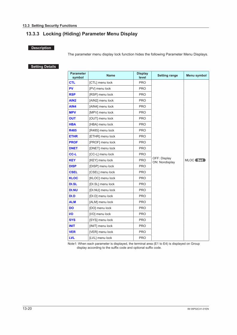
13-20 IM 05P02C41-01EN
13.3.3 Locking(Hiding)ParameterMenuDisplay
Description
The parameter menu display lock function hides the following Parameter Menu Displays.
SettingDetails
Parameter symbol Name Display
level Settingrange Menusymbol
CTL [CTL] menu lock PRO
OFF: DisplayON: Nondisplay MLOC
PV [PV] menu lock PRO
RSP [RSP] menu lock PRO
AIN2 [AIN2] menu lock PRO
AIN4 [AIN4] menu lock PRO
MPV [MPV] menu lock PRO
OUT [OUT] menu lock PRO
HBA [HBA] menu lock PRO
R485 [R485] menu lock PRO
ETHR [ETHR] menu lock PRO
PROF [PROF] menu lock PRO
DNET [DNET] menu lock PRO
CC-L [CC-L] menu lock PRO
KEY [KEY] menu lock PRO
DISP [DISP] menu lock PRO
CSEL [CSEL] menu lock PRO
KLOC [KLOC] menu lock PRO
DI.SL [DI.SL] menu lock PRO
DI.NU [DI.NU] menu lock PRO
DI.D [DI.D] menu lock PRO
ALM [ALM] menu lock PRO
DO [DO] menu lock PRO
I/O [I/O] menu lock PRO
SYS [SYS] menu lock PRO
INIT [INIT] menu lock PRO
VER [VER] menu lock PRO
LVL [LVL] menu lock PRO
Note1: When each parameter is displayed, the terminal area (E1 to E4) is displayed on Group display according to the suffix code and optional suffix code.
13.3SettingSecurityFunctions

13-21IM 05P02C41-01EN
Display, K
ey, and Security Functions
13
(Continued)Parameter symbol Name Display
level Settingrange Menusymbol
MODE [MODE] menu lock PRO
OFF: DisplayON: Nondisplay MLOC
CS [CS] menu lock PRO
PROG [PROG] menu lock PRO
LOC [LOC] menu lock PRO
EDIT [EDIT] menu lock PRO
AL [AL] menu lock PRO
SPS [SPS] menu lock PRO
ALRM [ALRM] menu lock PRO
PVS [PVS] menu lock PRO
PID [PID] menu lock PRO
TUNE [TUNE] menu lock PRO
ZONE [ZONE] menu lock PRO
PPAR [PPAR] menu lock PRO
PYS1 [PYS1] menu lock PRO
PYS2 [PYS2] menu lock PRO
PYS3 [PYS3] menu lock PRO
PYS4 [PYS4] menu lock PRO
Note 1: When each parameter is displayed, the terminal area (E1 to E4) is displayed on Group display according to the suffix code and optional suffix code.
Note 2: In Cascade control, the LP2 lamp is lit while the Loop-2 parameter is displayed.
13.3SettingSecurityFunctions
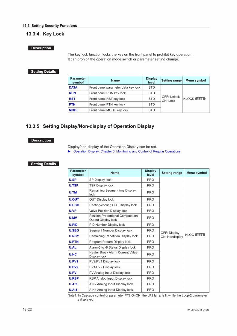
13-22 IM 05P02C41-01EN
13.3.4 KeyLock
Description
The key lock function locks the key on the front panel to prohibit key operation.It can prohibit the operation mode switch or parameter setting change.
SettingDetails
Parameter symbol Name Display
level Settingrange Menusymbol
DATA Front panel parameter data key lock STD
OFF: UnlockON: Lock KLOCK
RUN Front panel RUN key lock STD
RST Front panel RST key lock STD
PTN Front panel PTN key lock STD
MODE Front panel MODE key lock STD
13.3.5 SettingDisplay/Non-displayofOperationDisplay
Description
Display/non-display of the Operation Display can be set. Operation Display: Chapter 6 Monitoring and Control of Regular Operations
SettingDetails
Parameter symbol Name Display
level Settingrange Menusymbol
U.SP SP Display lock PRO
OFF: DisplayON: Nondisplay KLOC
U.TSP TSP Display lock PRO
U.TM Remaining Segmen-time Display lock PRO
U.OUT OUT Display lock PRO
U.HCO Heating/cooling OUT Display lock PRO
U.VP Valve Position Display lock PRO
U.MV Position Proportional Computation Output Display lock PRO
U.PID PID Number Display lock PRO
U.SEG Segment Number Display lock PRO
U.RCY Remaining Repetition Display lock PRO
U.PTN Program Pattern Display lock PRO
U.AL Alarm-5 to -8 Status Display lock PRO
U.HC Heater Break Alarm Current Value Display lock PRO
U.PV1 PV2/PV1 Display lock PRO
U.PV2 PV1/PV2 Display lock PRO
U.PV PV Analog Input Display lock PRO
U.RSP RSP Analog Input Display lock PRO
U.AI2 AIN2 Analog Input Display lock PRO
U.AI4 AIN4 Analog Input Display lock PRO
Note1: In Cascade control or parameter PT2.G=ON, the LP2 lamp is lit while the Loop-2 parameter is displayed.
13.3SettingSecurityFunctions
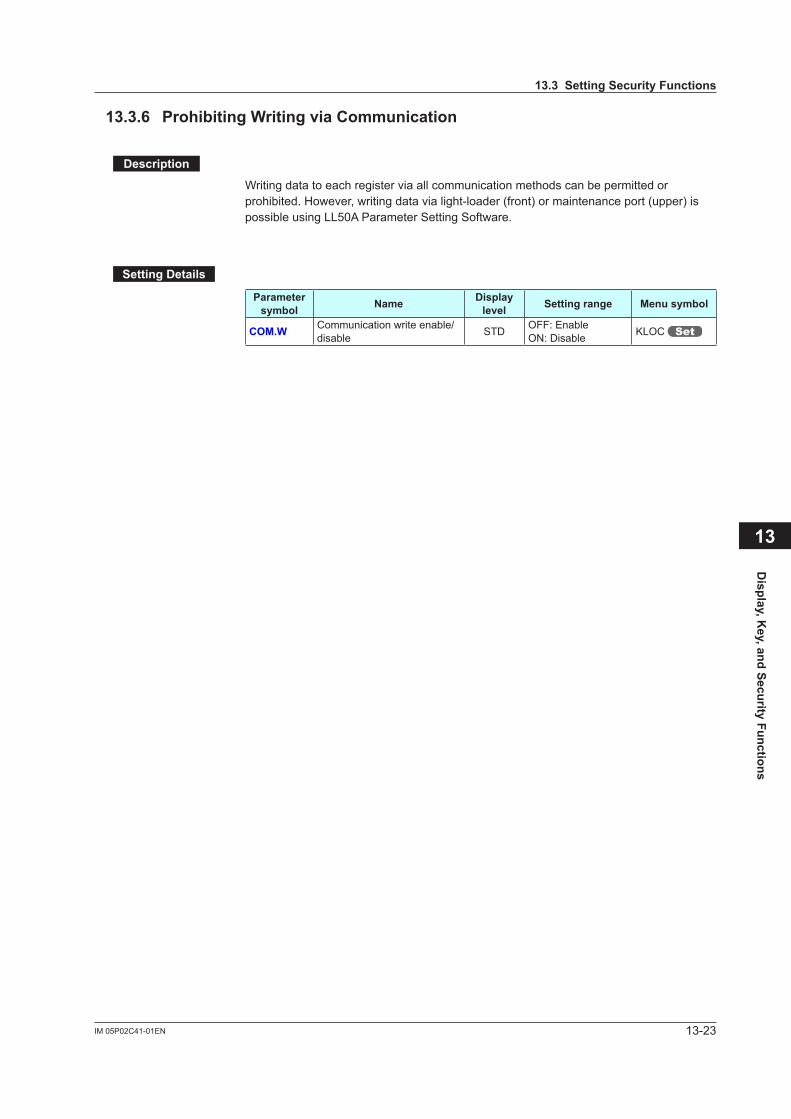
13-23IM 05P02C41-01EN
Display, K
ey, and Security Functions
13
13.3.6 ProhibitingWritingviaCommunication
Description
Writing data to each register via all communication methods can be permitted or prohibited. However, writing data via light-loader (front) or maintenance port (upper) is possible using LL50A Parameter Setting Software.
SettingDetails
Parameter symbol Name Display
level Settingrange Menusymbol
COM.W Communication write enable/disable STD OFF: Enable
ON: Disable KLOC
13.3SettingSecurityFunctions
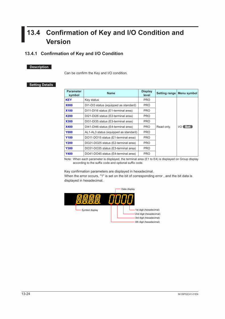
13-24 IM 05P02C41-01EN
13.4 ConfirmationofKeyandI/OConditionandVersion
13.4.1 ConfirmationofKeyandI/OCondition
Description
Can be confirm the Key and I/O condition.
SettingDetails
Parameter symbol Name Display
level Settingrange Menusymbol
KEY Key status PRO
Read only. I/O
X000 DI1-DI3 status (equipped as standard) PRO
X100 DI11-DI16 status (E1-terminal area) PRO
X200 DI21-DI26 status (E2-terminal area) PRO
X300 DI31-DI35 status (E3-terminal area) PRO
X400 DI41-DI46 status (E4-terminal area) PRO
Y000 AL1-AL3 status (equipped as standard) PRO
Y100 DO11-DO15 status (E1-terminal area) PRO
Y200 DO21-DO25 status (E2-terminal area) PRO
Y300 DO31-DO35 status (E3-terminal area) PRO
Y400 DO41-DO45 status (E4-terminal area) PRO
Note: When each parameter is displayed, the terminal area (E1 to E4) is displayed on Group display according to the suffix code and optional suffix code.
Key confirmation parameters are displayed in hexadecimal.When the error occurs, "1" is set on the bit of corresponding error , and the bit data is displayed in hexadecimal.
Data display
1st digit (hexadecimal)
2nd digit (hexadecimal)3rd digit (hexadecimal)
4th digit (hexadecimal)
Symbol display
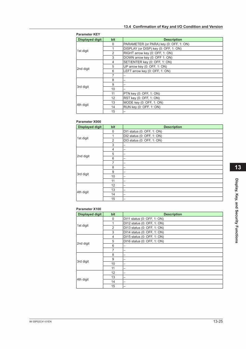
13-25IM 05P02C41-01EN
Display, K
ey, and Security Functions
13
ParameterKEYDisplayeddigit bit Description
1st digit
0 PARAMETER (or PARA) key (0: OFF, 1: ON)1 DISPLAY (or DISP) key (0: OFF, 1: ON)2 RIGHT arrow key (0: OFF, 1: ON)3 DOWN arrow key (0: OFF 1: ON)
2nd digit
4 SET/ENTER key (0: OFF, 1: ON)5 UP arrow key (0: OFF, 1: ON)6 LEFT arrow key (0: OFF, 1: ON)7 –
3rd digit
8 –9 –10 –11 PTN key (0: OFF, 1: ON)
4th digit
12 RST key (0: OFF, 1: ON)13 MODE key (0: OFF, 1: ON)14 RUN key (0: OFF, 1: ON)15 –
ParameterX000Displayeddigit bit Description
1st digit
0 DI1 status (0: OFF, 1: ON)1 DI2 status (0: OFF, 1: ON)2 DI3 status (0: OFF, 1: ON)3 –
2nd digit
4 –5 –6 –7 –
3rd digit
8 –9 –10 –11 –
4th digit
12 –13 –14 –15 –
ParameterX100Displayeddigit bit Description
1st digit
0 DI11 status (0: OFF, 1: ON)1 DI12 status (0: OFF, 1: ON)2 DI13 status (0: OFF, 1: ON)3 DI14 status (0: OFF, 1: ON)
2nd digit
4 DI15 status (0: OFF, 1: ON)5 DI16 status (0: OFF, 1: ON)6 –7 –
3rd digit
8 –9 –10 –11 –
4th digit
12 –13 –14 –15 –
13.4ConfirmationofKeyandI/OConditionandVersion
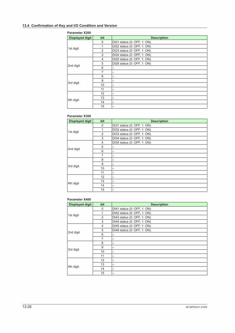
13-26 IM 05P02C41-01EN
ParameterX200Displayeddigit bit Description
1st digit
0 DI21 status (0: OFF, 1: ON)1 DI22 status (0: OFF, 1: ON)2 DI23 status (0: OFF, 1: ON)3 DI24 status (0: OFF, 1: ON)
2nd digit
4 DI25 status (0: OFF, 1: ON)5 DI26 status (0: OFF, 1: ON)6 –7 –
3rd digit
8 –9 –10 –11 –
4th digit
12 –13 –14 –15 –
ParameterX300Displayeddigit bit Description
1st digit
0 DI31 status (0: OFF, 1: ON)1 DI32 status (0: OFF, 1: ON)2 DI33 status (0: OFF, 1: ON)3 DI34 status (0: OFF, 1: ON)
2nd digit
4 DI35 status (0: OFF, 1: ON)5 –6 –7 –
3rd digit
8 –9 –10 –11 –
4th digit
12 –13 –14 –15 –
ParameterX400Displayeddigit bit Description
1st digit
0 DI41 status (0: OFF, 1: ON)1 DI42 status (0: OFF, 1: ON)2 DI43 status (0: OFF, 1: ON)3 DI44 status (0: OFF, 1: ON)
2nd digit
4 DI45 status (0: OFF, 1: ON)5 DI46 status (0: OFF, 1: ON)6 –7 –
3rd digit
8 –9 –10 –11 –
4th digit
12 –13 –14 –15 –
13.4ConfirmationofKeyandI/OConditionandVersion
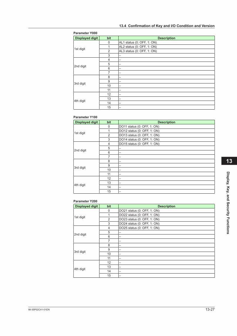
13-27IM 05P02C41-01EN
Display, K
ey, and Security Functions
ParameterY000Displayeddigit bit Description
1st digit
0 AL1 status (0: OFF, 1: ON)1 AL2 status (0: OFF, 1: ON)2 AL3 status (0: OFF, 1: ON)3 –
2nd digit
4 –5 –6 –7 –
3rd digit
8 –9 –10 –11 –
4th digit
12 –13 –14 –15 –
ParameterY100Displayeddigit bit Description
1st digit
0 DO11 status (0: OFF, 1: ON)1 DO12 status (0: OFF, 1: ON)2 DO13 status (0: OFF, 1: ON)3 DO14 status (0: OFF, 1: ON)
2nd digit
4 DO15 status (0: OFF, 1: ON)5 –6 –7 –
3rd digit
8 –9 –10 –11 –
4th digit
12 –13 –14 –15 –
ParameterY200Displayeddigit bit Description
1st digit
0 DO21 status (0: OFF, 1: ON)1 DO22 status (0: OFF, 1: ON)2 DO23 status (0: OFF, 1: ON)3 DO24 status (0: OFF, 1: ON)
2nd digit
4 DO25 status (0: OFF, 1: ON)5 –6 –7 –
3rd digit
8 –9 –10 –11 –
4th digit
12 –13 –14 –15 –
13
13.4ConfirmationofKeyandI/OConditionandVersion
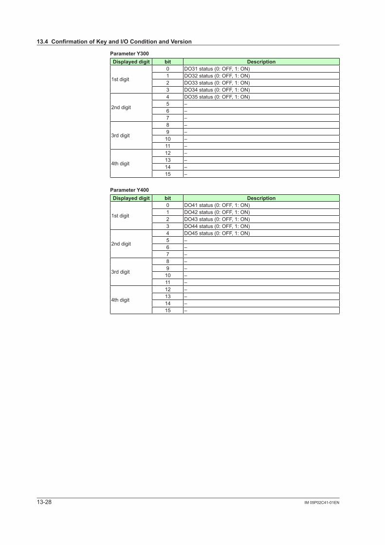
13-28 IM 05P02C41-01EN
ParameterY300Displayeddigit bit Description
1st digit
0 DO31 status (0: OFF, 1: ON)1 DO32 status (0: OFF, 1: ON)2 DO33 status (0: OFF, 1: ON)3 DO34 status (0: OFF, 1: ON)
2nd digit
4 DO35 status (0: OFF, 1: ON)5 –6 –7 –
3rd digit
8 –9 –10 –11 –
4th digit
12 –13 –14 –15 –
ParameterY400Displayeddigit bit Description
1st digit
0 DO41 status (0: OFF, 1: ON)1 DO42 status (0: OFF, 1: ON)2 DO43 status (0: OFF, 1: ON)3 DO44 status (0: OFF, 1: ON)
2nd digit
4 DO45 status (0: OFF, 1: ON)5 –6 –7 –
3rd digit
8 –9 –10 –11 –
4th digit
12 –13 –14 –15 –
13.4ConfirmationofKeyandI/OConditionandVersion
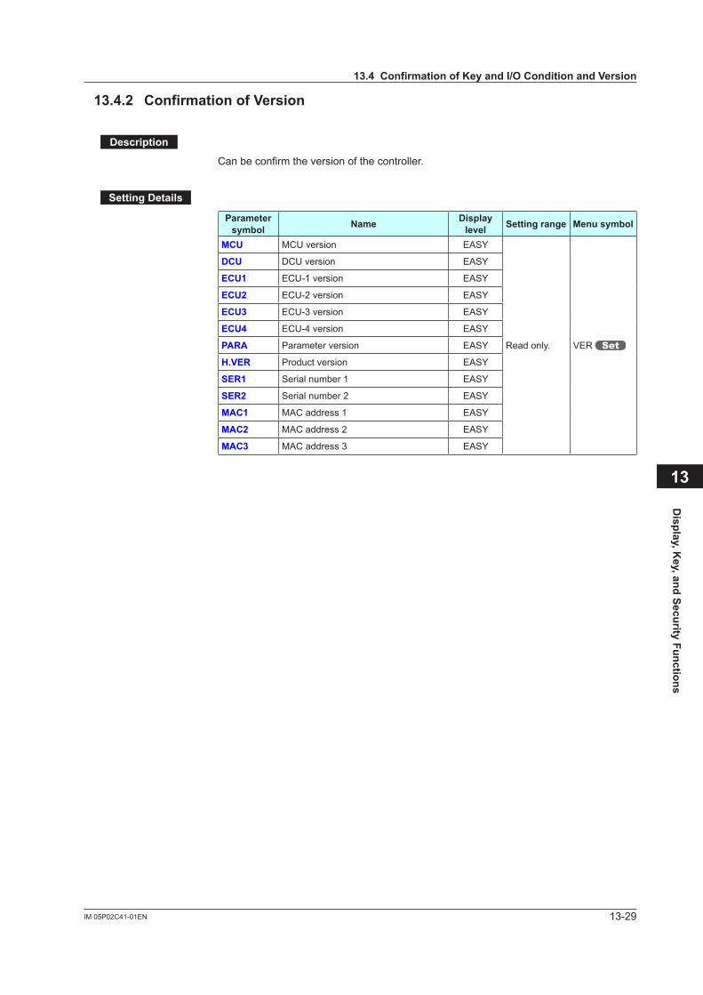
13-29IM 05P02C41-01EN
Display, K
ey, and Security Functions
13.4.2 ConfirmationofVersion
Description
Can be confirm the version of the controller.
SettingDetails
Parameter symbol Name Display
level Settingrange Menusymbol
MCU MCU version EASY
Read only. VER
DCU DCU version EASY
ECU1 ECU-1 version EASY
ECU2 ECU-2 version EASY
ECU3 ECU-3 version EASY
ECU4 ECU-4 version EASY
PARA Parameter version EASY
H.VER Product version EASY
SER1 Serial number 1 EASY
SER2 Serial number 2 EASY
MAC1 MAC address 1 EASY
MAC2 MAC address 2 EASY
MAC3 MAC address 3 EASY
13
13.4ConfirmationofKeyandI/OConditionandVersion

Blank Page
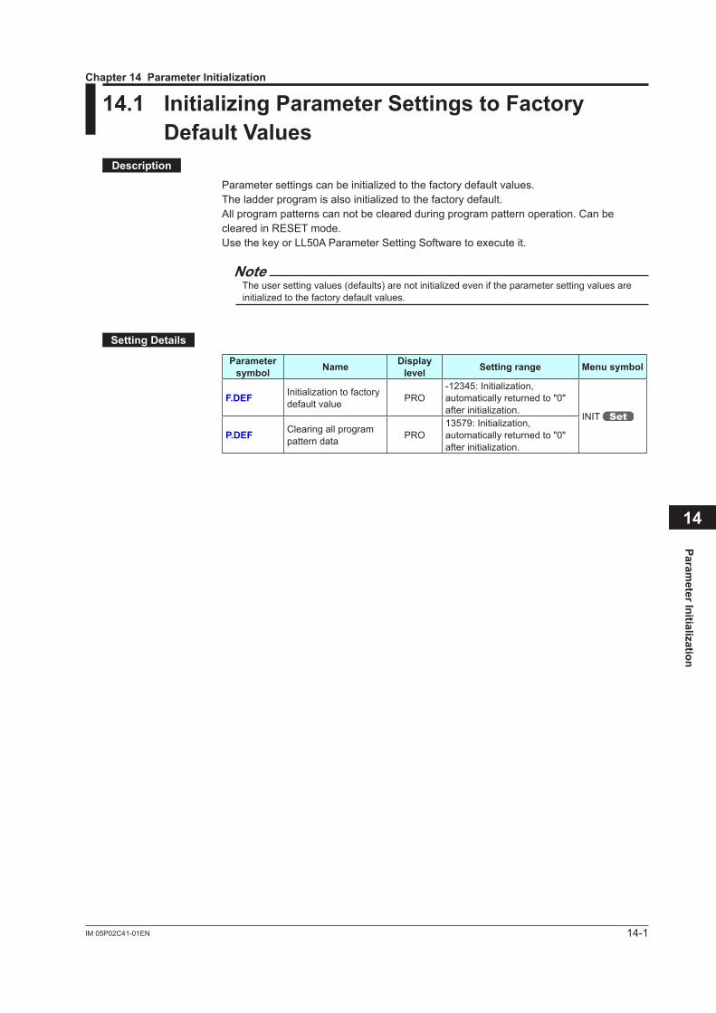
14-1IM 05P02C41-01EN
Parameter Initialization
14
14.1 InitializingParameterSettingstoFactoryDefaultValues
Description
Parametersettingscanbeinitializedtothefactorydefaultvalues.Theladderprogramisalsoinitializedtothefactorydefault.All program patterns can not be cleared during program pattern operation. Can be cleared in RESET mode.Use the key or LL50A Parameter Setting Software to execute it.
NoteTheusersettingvalues(defaults)arenotinitializedeveniftheparametersettingvaluesareinitializedtothefactorydefaultvalues.
SettingDetails
Parameter symbol Name Display
level Settingrange Menusymbol
F.DEF Initializationtofactorydefault value PRO
-12345:Initialization,automatically returned to "0" afterinitialization.
INIT
P.DEF Clearing all program pattern data PRO
13579:Initialization,automatically returned to "0" afterinitialization.
Chapter14ParameterInitialization
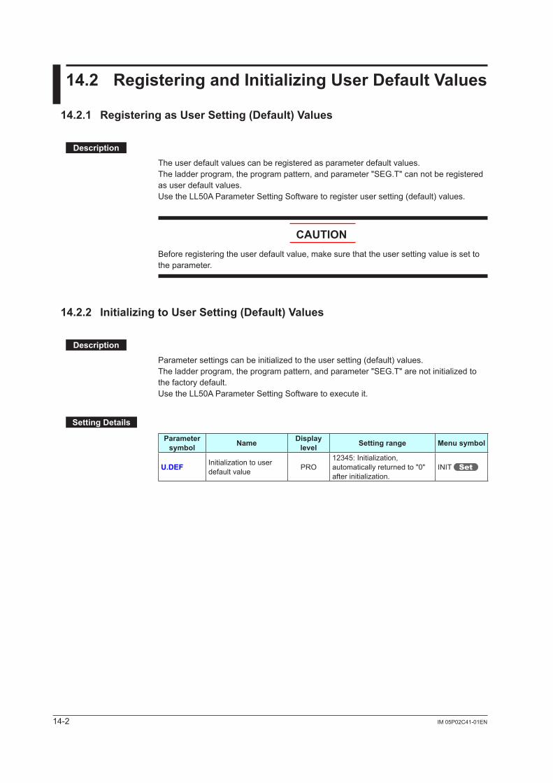
14-2 IM 05P02C41-01EN
14.2 RegisteringandInitializingUserDefaultValues
14.2.1 RegisteringasUserSetting(Default)Values
Description
The user default values can be registered as parameter default values.The ladder program, the program pattern, and parameter "SEG.T" can not be registered as user default values.Use the LL50A Parameter Setting Software to register user setting (default) values.
CAUTIONBefore registering the user default value, make sure that the user setting value is set to the parameter.
14.2.2 InitializingtoUserSetting(Default)Values
Description
Parametersettingscanbeinitializedtotheusersetting(default)values.Theladderprogram,theprogrampattern,andparameter"SEG.T"arenotinitializedtothe factory default.Use the LL50A Parameter Setting Software to execute it.
SettingDetails
Parameter symbol Name Display
level Settingrange Menusymbol
U.DEF Initializationtouserdefault value PRO
12345:Initialization,automatically returned to "0" afterinitialization.
INIT
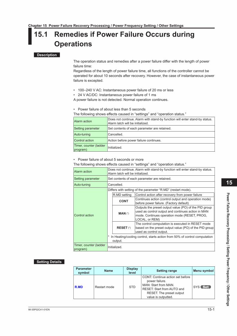
15-1IM 05P02C41-01EN
Power Failure Recovery Processing / Setting Power Frequency / Other Settings
15
15.1 RemediesifPowerFailureOccursduringOperations
Description
The operation status and remedies after a power failure differ with the length of power failure time:Regardless of the length of power failure time, all functions of the controller cannot be operated for about 10 seconds after recovery. However, the case of instantaneous power failure is excepted.
• 100–240 V AC: Instantaneous power failure of 20 ms or less• 24 V AC/DC: Instantaneous power failure of 1 msA power failure is not detected. Normal operation continues.
• Power failure of about less than 5 secondsThe following shows effects caused in “settings” and “operation status.”
Alarm action Does not continue. Alarm with stand-by function will enter stand-by status.Alarmlatchwillbeinitialized.
Setting parameter Set contents of each parameter are retained.
Auto-tuning Cancelled.
Control action Action before power failure continues.Timer, counter (ladder program) Initialized.
• Power failure of about 5 seconds or moreThe following shows effects caused in “settings” and “operation status.”
Alarm action Does not continue. Alarm with stand-by function will enter stand-by status.Alarmlatchwillbeinitialized.
Setting parameter Set contents of each parameter are retained.
Auto-tuning Cancelled.
Control action
Differs with setting of the parameter “R.MD” (restart mode).R.MD setting Control action after recovery from power failure
CONT Continues action (control output and operation mode) before power failure. (Factory default)
MAN (*)
Outputs the preset output value (PO) of the PID group used as control output and continues action in MAN mode. Continues operation mode (RESET, PROG, LOCAL, or REM)
RESET (*)The control computation is executed in RESET mode based on the preset output value (PO) of the PID group used as control output.
* In Heating/cooling control, starts action from 50% of control computation output.
Timer, counter (ladder program) Initialized.
SettingDetails
Parameter symbol Name Display
level Settingrange Menusymbol
R.MD Restart mode STD
CONT: Continue action set before power failure.
MAN: Start from MAN.RESET: Start from AUTO and
RESET. The preset output value is outputted.
SYS
Chapter15PowerFailureRecoveryProcessing/PowerFrequencySetting/OtherSettings
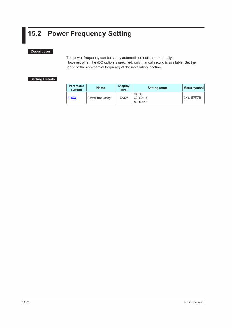
15-2 IM 05P02C41-01EN
15.2 PowerFrequencySetting
Description
The power frequency can be set by automatic detection or manually.However, when the /DC option is specified, only manual setting is available. Set the range to the commercial frequency of the installation location.
SettingDetails
Parameter symbol Name Display
level Settingrange Menusymbol
FREQ Power frequency EASYAUTO60:60Hz50:50Hz
SYS
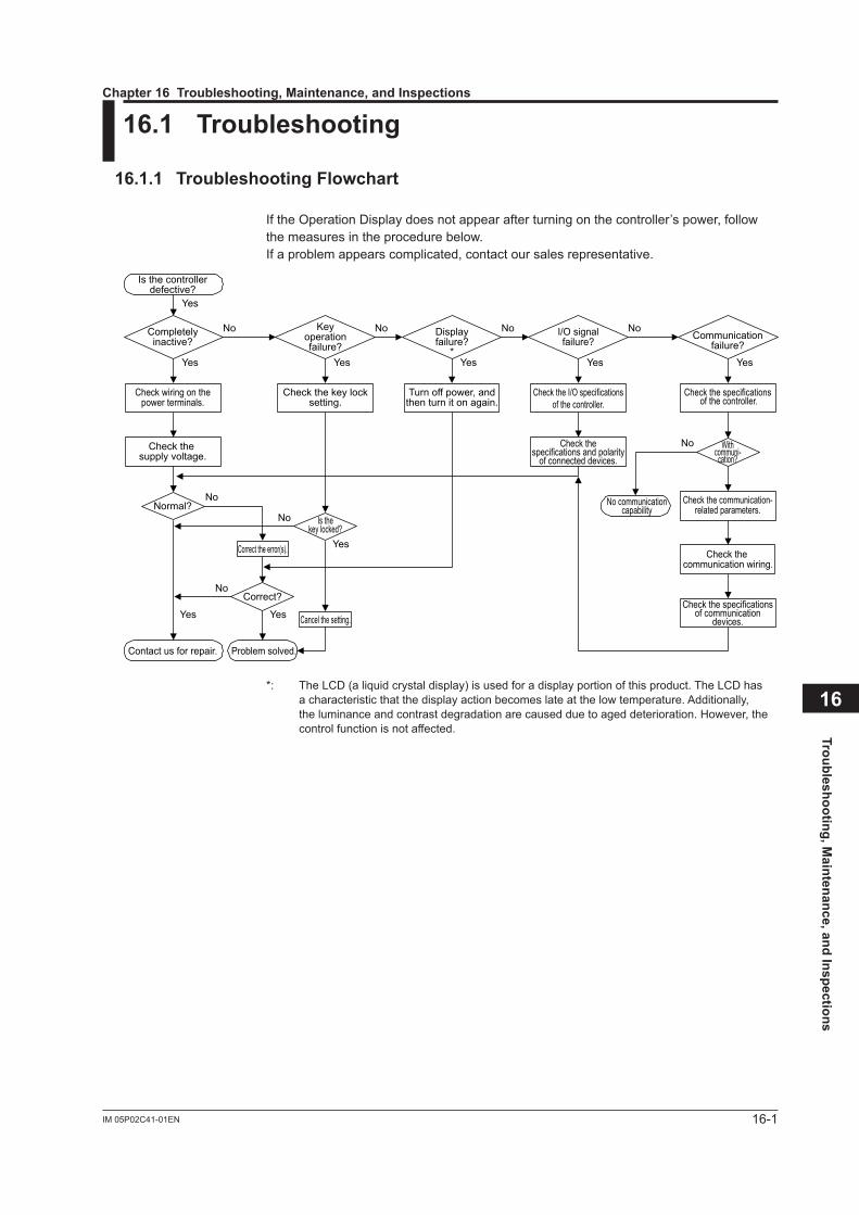
16-1IM 05P02C41-01EN
Troubleshooting, Maintenance, and Inspections
16
16.1 Troubleshooting
16.1.1 TroubleshootingFlowchart
If the Operation Display does not appear after turning on the controller’s power, follow the measures in the procedure below.If a problem appears complicated, contact our sales representative.
Is the controllerdefective?
Contact us for repair. Problem solved.
No communicationcapability
Completelyinactive?
Yes
Yes
Yes
No
No
No
Keyoperationfailure?
Yes
No
Yes
Check wiring on thepower terminals.
Check the key locksetting.
Displayfailure?
*Yes
No
Turn off power, andthen turn it on again.
I/O signalfailure?
Yes
No
Check the I/O specificationsof the controller.
Check the supply voltage.
Check thespecifications and polarity
of connected devices.
Check the communication-related parameters.
Check the specificationsof communication
devices.
Check the communication wiring.
Communicationfailure?
No Withcommuni-
cation?
Yes
Normal?Is the
key locked?
Check the specifications of the controller.
Yes
NoCorrect?
Correct the error(s).
Cancel the setting.
*: The LCD (a liquid crystal display) is used for a display portion of this product. The LCD has a characteristic that the display action becomes late at the low temperature. Additionally, the luminance and contrast degradation are caused due to aged deterioration. However, the control function is not affected.
Chapter16Troubleshooting,Maintenance,andInspections
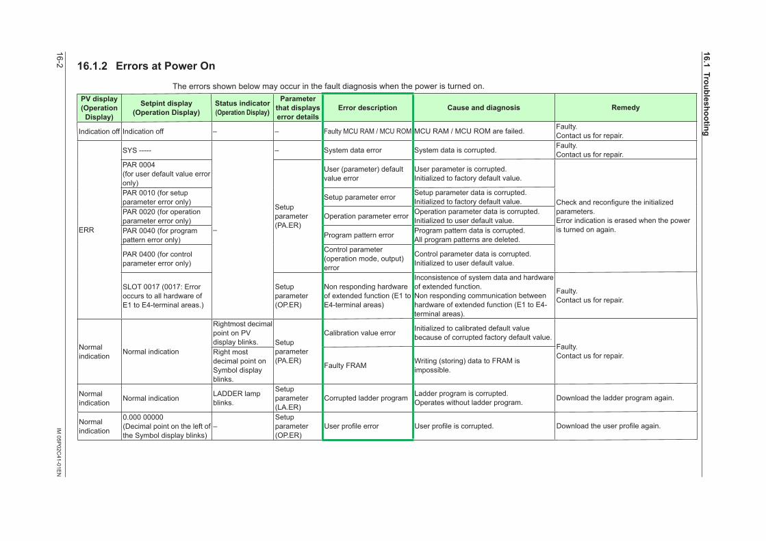
16-2IM
05P02C
41-01EN
16.1.2 ErrorsatPowerOn
The errors shown below may occur in the fault diagnosis when the power is turned on.PVdisplay(OperationDisplay)
Setpintdisplay(OperationDisplay)
Statusindicator(OperationDisplay)
Parameter thatdisplayserror details
Error description Cause and diagnosis Remedy
Indication off Indication off – – Faulty MCU RAM / MCU ROM MCU RAM / MCU ROM are failed. Faulty.Contact us for repair.
ERR
SYS -----
–
– System data error System data is corrupted. Faulty.Contact us for repair.
PAR 0004(for user default value error only)
Setup parameter (PA.ER)
User (parameter) default value error
User parameter is corrupted.Initializedtofactorydefaultvalue.
Checkandreconfiguretheinitializedparameters.Error indication is erased when the power is turned on again.
PAR 0010 (for setup parameter error only) Setup parameter error Setup parameter data is corrupted.
Initializedtofactorydefaultvalue.PAR 0020 (for operation parameter error only) Operation parameter error Operation parameter data is corrupted.
Initializedtouserdefaultvalue.PAR 0040 (for program pattern error only) Program pattern error Program pattern data is corrupted.
All program patterns are deleted.
PAR 0400 (for control parameter error only)
Control parameter (operation mode, output) error
Control parameter data is corrupted.Initializedtouserdefaultvalue.
SLOT 0017 (0017: Error occurs to all hardware of E1 to E4-terminal areas.)
Setup parameter (OP.ER)
Non responding hardware of extended function (E1 to E4-terminal areas)
Inconsistence of system data and hardware of extended function.Non responding communication between hardware of extended function (E1 to E4-terminal areas).
Faulty.Contact us for repair.
Normal indication Normal indication
Rightmost decimal point on PV display blinks. Setup
parameter (PA.ER)
Calibration value error Initializedtocalibrateddefaultvaluebecause of corrupted factory default value.
Faulty.Contact us for repair.Right most
decimal point on Symbol display blinks.
Faulty FRAM Writing (storing) data to FRAM is impossible.
Normal indication Normal indication LADDER lamp
blinks.
Setup parameter (LA.ER)
Corrupted ladder program Ladder program is corrupted.Operates without ladder program. Download the ladder program again.
Normal indication
0.000 00000(Decimal point on the left of the Symbol display blinks)
–Setup parameter (OP.ER)
Userprofileerror Userprofileiscorrupted. Downloadtheuserprofileagain.
16.1Troubleshooting
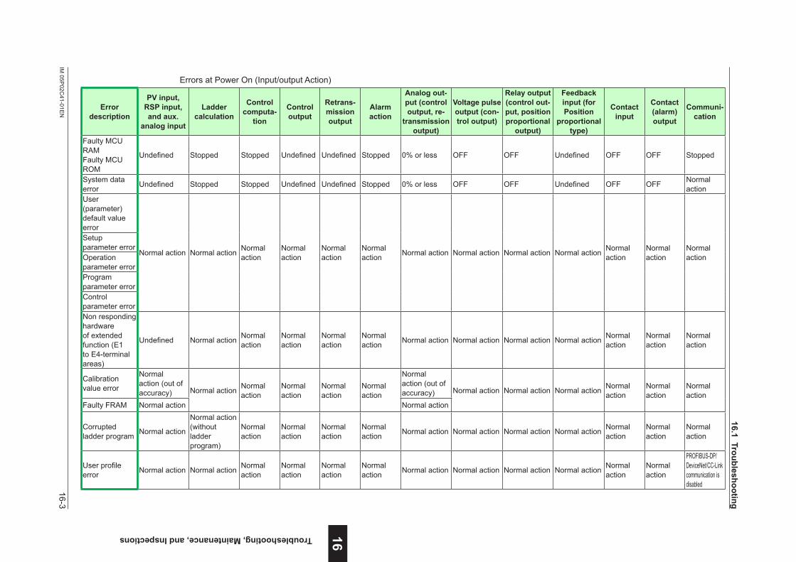
16-3IM
05P02C
41-01EN
Troubleshooting, Maintenance, and Inspections 16
Errors at Power On (Input/output Action)
Error description
PVinput,RSPinput,andaux.
analog input
Ladder calculation
Control computa-
tion
Control output
Retrans-mission output
Alarm action
Analog out-put (control output,re-
transmission output)
Voltage pulse output (con-trol output)
Relayoutput(control out-put,positionproportional
output)
Feedback input(forPosition
proportional type)
Contact input
Contact (alarm) output
Communi-cation
Faulty MCU RAMFaulty MCU ROM
Undefined Stopped Stopped Undefined Undefined Stopped 0% or less OFF OFF Undefined OFF OFF Stopped
System data error Undefined Stopped Stopped Undefined Undefined Stopped 0% or less OFF OFF Undefined OFF OFF Normal
actionUser (parameter) default value error
Normal action Normal action Normal action
Normal action
Normal action
Normal action Normal action Normal action Normal action Normal action Normal
actionNormal action
Normal action
Setup parameter errorOperation parameter errorProgram parameter errorControl parameter errorNon responding hardware of extended function (E1 to E4-terminal areas)
Undefined Normal action Normal action
Normal action
Normal action
Normal action Normal action Normal action Normal action Normal action Normal
actionNormal action
Normal action
Calibration value error
Normal action (out of accuracy) Normal action Normal
actionNormal action
Normal action
Normal action
Normal action (out of accuracy) Normal action Normal action Normal action Normal
actionNormal action
Normal action
Faulty FRAM Normal action Normal action
Corrupted ladder program Normal action
Normal action (without ladder program)
Normal action
Normal action
Normal action
Normal action Normal action Normal action Normal action Normal action Normal
actionNormal action
Normal action
Userprofileerror Normal action Normal action Normal
actionNormal action
Normal action
Normal action Normal action Normal action Normal action Normal action Normal
actionNormal action
PROFIBUS-DP/DeviceNet/CC-Link communication is disabled
16.1Troubleshooting
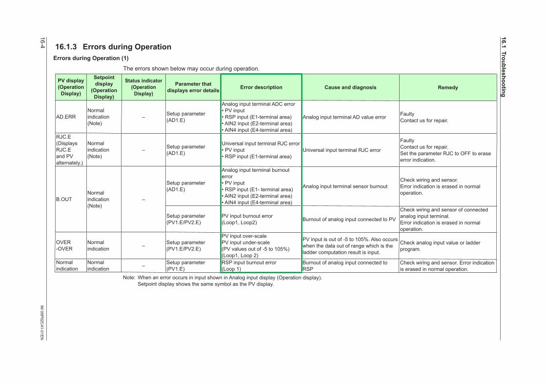
16-4IM
05P02C
41-01EN
16.1.3 ErrorsduringOperationErrorsduringOperation(1)
The errors shown below may occur during operation.
PVdisplay(OperationDisplay)
Setpointdisplay
(OperationDisplay)
Statusindicator(OperationDisplay)
Parameter that displayserrordetails Error description Cause and diagnosis Remedy
AD.ERRNormal indication (Note)
– Setup parameter (AD1.E)
Analog input terminal ADC error• PV input• RSP input (E1-terminal area)• AIN2 input (E2-terminal area)• AIN4 input (E4-terminal area)
Analog input terminal AD value error FaultyContact us for repair.
RJC.E (Displays RJC.E and PV alternately.)
Normal indication(Note)
– Setup parameter (AD1.E)
Universal input terminal RJC error• PV input• RSP input (E1-terminal area)
Universal input terminal RJC error
FaultyContact us for repair.Set the parameter RJC to OFF to erase error indication.
B.OUTNormal indication(Note)
–
Setup parameter (AD1.E)
Analog input terminal burnout error• PV input• RSP input (E1- terminal area)• AIN2 input (E2-terminal area)• AIN4 input (E4-terminal area)
Analog input terminal sensor burnoutCheck wiring and sensor.Error indication is erased in normal operation.
Setup parameter (PV1.E/PV2.E)
PV input burnout error (Loop1, Loop2) Burnout of analog input connected to PV
Check wiring and sensor of connected analog input terminal.Error indication is erased in normal operation.
OVER-OVER
Normal indication – Setup parameter
(PV1.E/PV2.E)
PV input over-scalePV input under-scale(PV values out of -5 to 105%) (Loop1, Loop 2)
PV input is out of -5 to 105%. Also occurs when the data out of range which is the ladder computation result is input.
Check analog input value or ladder program.
Normal indication
Normal indication – Setup parameter
(PV1.E)RSP input burnout error (Loop 1)
Burnout of analog input connected to RSP
Check wiring and sensor. Error indication is erased in normal operation.
Note: When an error occurs in input shown in Analog input display (Operation display). Setpoint display shows the same symbol as the PV display.
16.1Troubleshooting
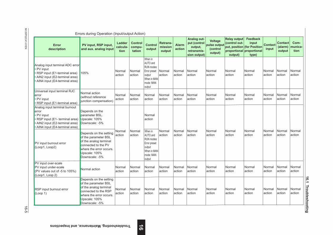
16-5IM
05P02C
41-01EN
Troubleshooting, Maintenance, and Inspections 16
Errors during Operation (Input/output Action)
Error description
PVinput,RSPinput,andaux.analoginput
Ladder calcula-
tion
Control compu-tation
Control output
Retrans-mission output
Alarm action
Analog out-put (control output,
retransmis-sion output)
Voltage pulse output
(control output)
Relayoutput(control out-put,positionproportional
output)
Feedback input
(forPositionproportional
type)
Contact input
Contact (alarm) output
Com-munica-
tion
Analog input terminal ADC error• PV input• RSP input (E1-terminal area)• AIN2 input (E2-terminal area)• AIN4 input (E4-terminal area)
105% Normal action
Normal action
When in AUTO and RUN modes: Error preset outputWhen in MAN mode: MAN output
Normal action
Normal action
Normal action
Normal action
Normal action
Normal action
Normal action
Normal action
Normal action
Universal input terminal RJC error• PV input• RSP input (E1-terminal area)
Normal action(without reference junctioncompensation)
Normal action
Normal action
Normal action
Normal action
Normal action
Normal action
Normal action
Normal action
Normal action
Normal action
Normal action
Normal action
Analog input terminal burnout error• PV input• RSP input (E1- terminal area)• AIN2 input (E2-terminal area)• AIN4 input (E4-terminal area)
Depends on the parameter BSL.Upscale: 105%Downscale: -5%
Normal action
Normal action
Normal action
Normal action
Normal action
Normal action
Normal action
Normal action
Normal action
Normal action
Normal action
Normal action
PV input burnout error (Loop1, Loop2)
Depends on the setting of the parameter BSL of the analog terminal connected to the PV where the error occurs.Upscale: 105%Downscale: -5%
When in AUTO and RUN modes: Error preset outputWhen in MAN mode: MAN output
PV input over-scalePV input under-scale(PV values out of -5 to 105%) (Loop1, Loop 2)
Normal action Normal action
Normal action
Normal action
Normal action
Normal action
Normal action
Normal action
Normal action
Normal action
Normal action
Normal action
Normal action
RSP input burnout error (Loop 1)
Depends on the setting of the parameter BSL of the analog terminal connected to the RSP where the error occurs.Upscale: 105%Downscale: -5%
Normal action
Normal action
Normal action
Normal action
Normal action
Normal action
Normal action
Normal action
Normal action
Normal action
Normal action
Normal action
16.1Troubleshooting
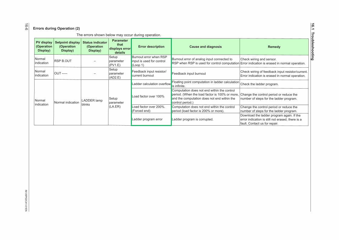
16-6IM
05P02C
41-01EN
ErrorsduringOperation(2)
The errors shown below may occur during operation.
PVdisplay(OperationDisplay)
Setpointdisplay(OperationDisplay)
Statusindicator(OperationDisplay)
Parameter that
displayserrordetails
Error description Cause and diagnosis Remedy
Normal indication RSP B.OUT –
Setup parameter (PV1.E)
Burnout error when RSP input is used for control (Loop 1)
Burnout error of analog input connected to RSP when RSP is used for control computation
Check wiring and sensor.Error indication is erased in normal operation.
Normal indication OUT ----- –
Setup parameter (AD2.E)
Feedback input resistor/current burnout Feedback input burnout Check wiring of feedback input resistor/current.
Error indication is erased in normal operation.
Normal indication Normal indication LADDER lamp
blinks
Setup parameter (LA.ER)
Laddercalculationoverflow Floating point computation in ladder calculation isinfinite. Check the ladder program.
Load factor over 100%
Computation does not end within the control period. (When the load factor is 100% or more, and the computation does not end within the control period.)
Change the control period or reduce the number of steps for the ladder program.
Load factor over 200%. (Forced end)
Computation does not end within the control period (load factor is 200% or more).
Change the control period or reduce the number of steps for the ladder program.
Ladder program error Ladder program is corrupted.Download the ladder program again. If the error indication is still not erased, there is a fault. Contact us for repair.
16.1Troubleshooting
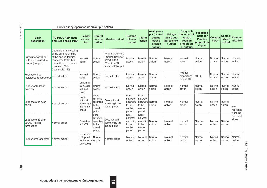
16-7IM
05P02C
41-01EN
Troubleshooting, Maintenance, and Inspections 16
Errors during operation (Input/output Action)
Error description
PVinput,RSPinput,andaux.analoginput
Ladder calcula-
tion
Control compu-tation
Control outputRetrans-mission output
Alarm action
Analog out-put (control output,retrans-mission output)
Voltage pulse out-
put (control output)
Relayout-put (control output,position
proportion-al output)
Feedback input(forPosition
proportion-altype)
Contact input
Contact (alarm) output
Commu-nication
Burnout error when RSP input is used for control (Loop 1)
Depends on the setting of the parameter BSL of the analog terminal connected to the RSP where the error occurs.Upscale: 105%Downscale: -5%
Normal action
Normal action
When in AUTO and RUN modes: Error preset outputWhen in MAN mode: MAN output
Normal action
Normal action
Normal action
Normal action
Normal action
Normal action
Normal action
Normal action
Normal action
Feedback input resistor/current burnout Normal action Normal
actionNormal action Normal action Normal
actionNormal action
Normal action -
Position proportional output: OFF
105% Normal action
Normal action
Normal action
Ladder calculation overflow Normal action
Undefined(calculation with max. value)
Normal action Normal action Normal
actionNormal action
Normal action
Normal action
Normal action
Normal action
Normal action
Normal action
Normal action
Load factor is over 100% Normal action
Does not work according to the control period.
Does not work according to the control period.
Does not work according to the control period.
Does not work according to the control period.
Does not work according to the control period.
Normal action
Normal action
Normal action
Normal action
Normal action
Normal action
The response from the main unit slows. Load factor is over
200%. (Forced termination)
Normal action Forced end at 200%
Does not work according to the control period.
Does not work according to the control period.
Does not work according to the control period.
Does not work according to the control period.
Normal action
Normal action
Normal action
Normal action
Normal action
Normal action
Ladder program error Normal action
Undefined(Stopped at the error detection)
Normal action Normal action Normal
actionNormal action
Normal action
Normal action
Normal action
Normal action
Normal action
Normal action
Normal action 16.1Troubleshooting
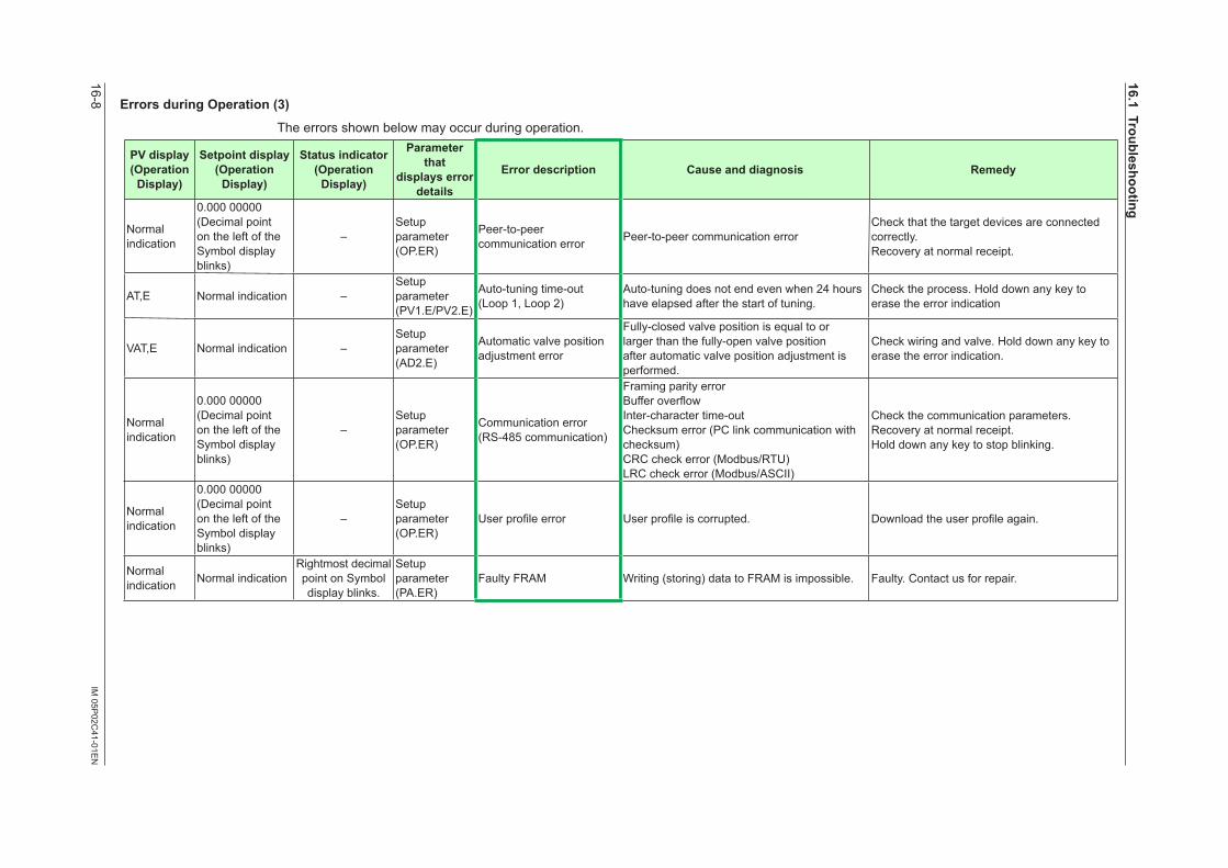
16-8IM
05P02C
41-01EN
ErrorsduringOperation(3)
The errors shown below may occur during operation.
PVdisplay(OperationDisplay)
Setpointdisplay(OperationDisplay)
Statusindicator(OperationDisplay)
Parameter that
displayserrordetails
Error description Cause and diagnosis Remedy
Normal indication
0.000 00000(Decimal point on the left of the Symbol display blinks)
–Setup parameter (OP.ER)
Peer-to-peer communication error Peer-to-peer communication error
Check that the target devices are connected correctly.Recovery at normal receipt.
AT,E Normal indication –Setup parameter (PV1.E/PV2.E)
Auto-tuning time-out (Loop 1, Loop 2)
Auto-tuning does not end even when 24 hours have elapsed after the start of tuning.
Check the process. Hold down any key to erase the error indication
VAT,E Normal indication –Setup parameter (AD2.E)
Automatic valve position adjustmenterror
Fully-closed valve position is equal to or larger than the fully-open valve position after automatic valvepositionadjustmentisperformed.
Check wiring and valve. Hold down any key to erase the error indication.
Normal indication
0.000 00000(Decimal point on the left of the Symbol display blinks)
–Setup parameter (OP.ER)
Communication error (RS-485 communication)
Framing parity errorBufferoverflowInter-character time-outChecksum error (PC link communication with checksum)CRC check error (Modbus/RTU)LRC check error (Modbus/ASCII)
Check the communication parameters.Recovery at normal receipt.Hold down any key to stop blinking.
Normal indication
0.000 00000(Decimal point on the left of the Symbol display blinks)
–Setup parameter (OP.ER)
Userprofileerror Userprofileiscorrupted. Downloadtheuserprofileagain.
Normal indication Normal indication
Rightmost decimal point on Symbol display blinks.
Setup parameter (PA.ER)
Faulty FRAM Writing (storing) data to FRAM is impossible. Faulty. Contact us for repair.
16.1Troubleshooting
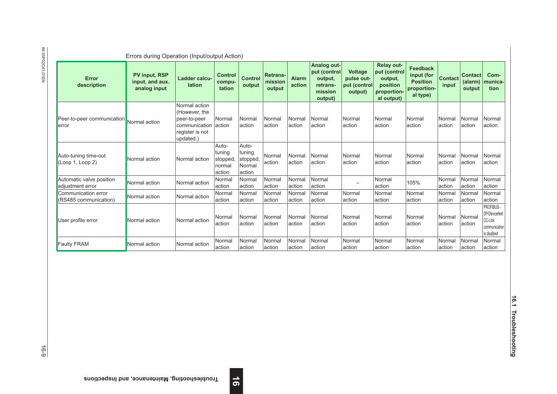
16-9IM
05P02C
41-01EN
Troubleshooting, Maintenance, and Inspections 16
Errors during Operation (Input/output Action)
Error description
PVinput,RSPinput,andaux.
analog input
Ladder calcu-lation
Control compu-tation
Control output
Retrans-mission output
Alarm action
Analog out-put (control output,retrans-mission output)
Voltage pulse out-
put (control output)
Relayout-put (control output,position
proportion-al output)
Feedback input(forPosition
proportion-altype)
Contact input
Contact (alarm) output
Com-munica-
tion
Peer-to-peer communication error Normal action
Normal action (However, the peer-to-peer communication register is not updated.)
Normal action
Normal action
Normal action
Normal action
Normal action
Normal action
Normal action
Normal action
Normal action
Normal action
Normal action
Auto-tuning time-out (Loop 1, Loop 2) Normal action Normal action
Auto-tuning stopped, normal action
Auto-tuning stopped, Normal action
Normal action
Normal action
Normal action
Normal action
Normal action
Normal action
Normal action
Normal action
Normal action
Automatic valve position adjustmenterror Normal action Normal action Normal
actionNormal action
Normal action
Normal action
Normal action – Normal
action 105% Normal action
Normal action
Normal action
Communication error (RS485 communication) Normal action Normal action Normal
actionNormal action
Normal action
Normal action
Normal action
Normal action
Normal action
Normal action
Normal action
Normal action
Normal action
Userprofileerror Normal action Normal action Normal action
Normal action
Normal action
Normal action
Normal action
Normal action
Normal action
Normal action
Normal action
Normal action
PROFIBUS-DP/DeviceNet/CC-Link communication is disabled
Faulty FRAM Normal action Normal action Normal action
Normal action
Normal action
Normal action
Normal action
Normal action
Normal action
Normal action
Normal action
Normal action
Normal action
16.1Troubleshooting
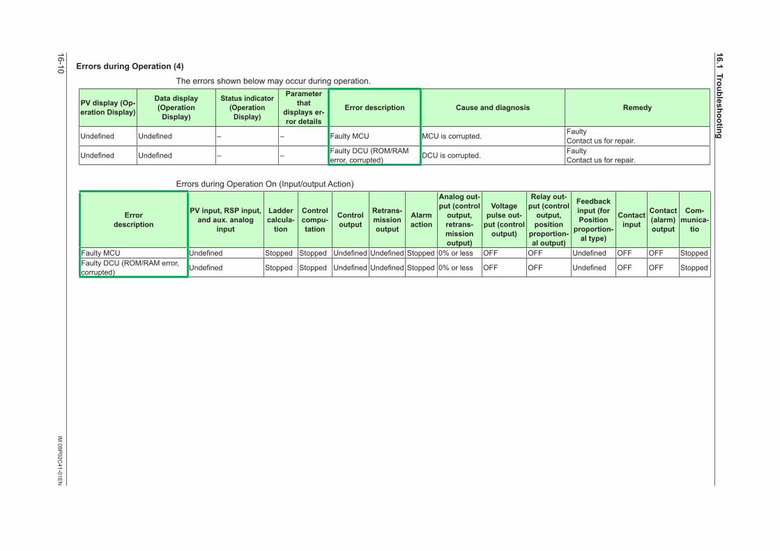
16-10IM
05P02C
41-01EN
ErrorsduringOperation(4)
The errors shown below may occur during operation.
PVdisplay(Op-erationDisplay)
Datadisplay(OperationDisplay)
Statusindicator(OperationDisplay)
Parameter that
displayser-ror details
Error description Cause and diagnosis Remedy
Undefined Undefined – – Faulty MCU MCU is corrupted. Faulty Contact us for repair.
Undefined Undefined – – Faulty DCU (ROM/RAM error, corrupted) DCU is corrupted. Faulty
Contact us for repair.
Errors during Operation On (Input/output Action)
Error description
PVinput,RSPinput,andaux.analog
input
Ladder calcula-
tion
Control compu-tation
Control output
Retrans-mission output
Alarm action
Analog out-put (control output,retrans-mission output)
Voltage pulse out-
put (control output)
Relayout-put (control output,position
proportion-al output)
Feedback input(forPosition
proportion-altype)
Contact input
Contact (alarm) output
Com-munica-
tio
Faulty MCU Undefined Stopped Stopped Undefined Undefined Stopped 0% or less OFF OFF Undefined OFF OFF StoppedFaulty DCU (ROM/RAM error, corrupted) Undefined Stopped Stopped Undefined Undefined Stopped 0% or less OFF OFF Undefined OFF OFF Stopped
16.1Troubleshooting
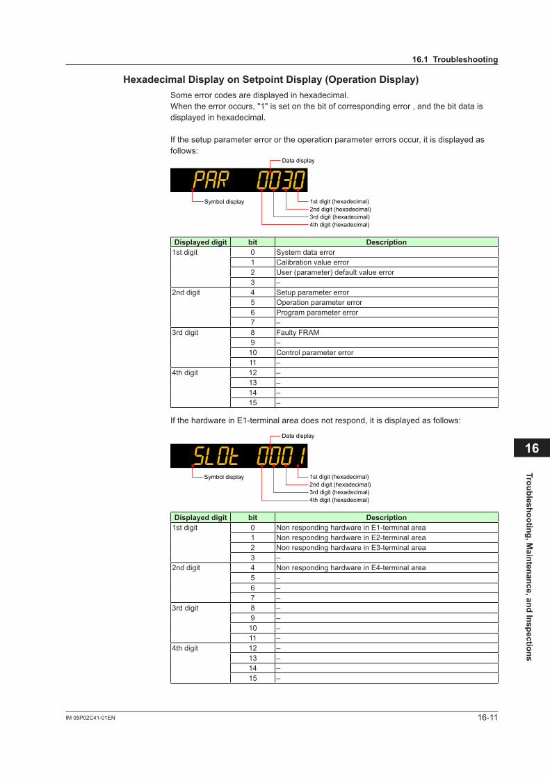
16-11IM 05P02C41-01EN
Troubleshooting, Maintenance, and Inspections
16
HexadecimalDisplayonSetpointDisplay(OperationDisplay)Some error codes are displayed in hexadecimal.When the error occurs, "1" is set on the bit of corresponding error , and the bit data is displayed in hexadecimal.
If the setup parameter error or the operation parameter errors occur, it is displayed as follows:
Data display
1st digit (hexadecimal)2nd digit (hexadecimal)3rd digit (hexadecimal)4th digit (hexadecimal)
Symbol display
Displayeddigit bit Description1st digit 0 System data error
1 Calibration value error2 User (parameter) default value error3 –
2nd digit 4 Setup parameter error5 Operation parameter error6 Program parameter error7 –
3rd digit 8 Faulty FRAM9 –10 Control parameter error11 –
4th digit 12 –13 –14 –15 –
If the hardware in E1-terminal area does not respond, it is displayed as follows:
Data display
1st digit (hexadecimal)2nd digit (hexadecimal)3rd digit (hexadecimal)4th digit (hexadecimal)
Symbol display
Displayeddigit bit Description1st digit 0 Non responding hardware in E1-terminal area
1 Non responding hardware in E2-terminal area2 Non responding hardware in E3-terminal area3 –
2nd digit 4 Non responding hardware in E4-terminal area5 –6 –7 –
3rd digit 8 –9 –10 –11 –
4th digit 12 –13 –14 –15 –
16.1Troubleshooting

16-12 IM 05P02C41-01EN
HexadecimalDisplayoftheParameterwhichShowstheErrorDetailsError confirmation parameters are displayed in hexadecimal.When the error occurs, "1" is set on the bit of corresponding error.
Data display
1st digit (hexadecimal)
2nd digit (hexadecimal)3rd digit (hexadecimal)
4th digit (hexadecimal)
Symbol display
Parameter PA.ERDisplayeddigit bit Description
1st digit 0 System data error1 Calibration value error2 User (parameter) default value error3 –
2nd digit 4 Setup parameter error5 Operation parameter error6 Program parameter error7 –
3rd digit 8 Faulty FRAM9 –10 Control parameter error11 –
4th digit 12 –13 –14 –15 –
Parameter LA.ERDisplayeddigit bit Description
1st digit 0 Ladder program corruption1 Laddercalculationoverflow2 Ladder program error3 –
2nd digit 4 Load factor over 100%5 Load factor over 200%6 –7 –
3rd digit 8 –9 –10 –11 –
4th digit 12 –13 –14 –15 –
16.1Troubleshooting
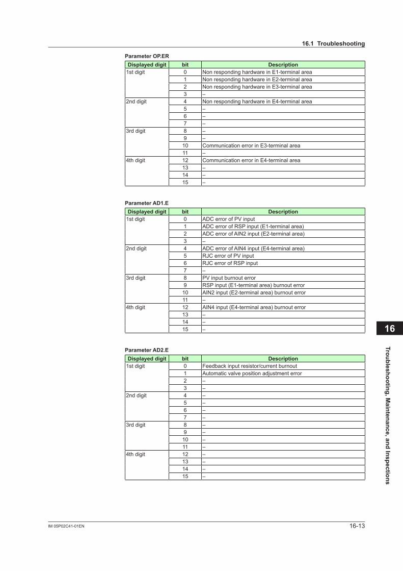
16-13IM 05P02C41-01EN
Troubleshooting, Maintenance, and Inspections
16
ParameterOP.ERDisplayeddigit bit Description
1st digit 0 Non responding hardware in E1-terminal area1 Non responding hardware in E2-terminal area2 Non responding hardware in E3-terminal area3 –
2nd digit 4 Non responding hardware in E4-terminal area5 –6 –7 –
3rd digit 8 –9 –10 Communication error in E3-terminal area11 –
4th digit 12 Communication error in E4-terminal area13 –14 –15 –
ParameterAD1.EDisplayeddigit bit Description
1st digit 0 ADC error of PV input1 ADC error of RSP input (E1-terminal area)2 ADC error of AIN2 input (E2-terminal area)3 –
2nd digit 4 ADC error of AIN4 input (E4-terminal area)5 RJC error of PV input6 RJC error of RSP input7 –
3rd digit 8 PV input burnout error9 RSP input (E1-terminal area) burnout error10 AIN2 input (E2-terminal area) burnout error11 –
4th digit 12 AIN4 input (E4-terminal area) burnout error13 –14 –15 –
ParameterAD2.EDisplayeddigit bit Description
1st digit 0 Feedback input resistor/current burnout1 Automaticvalvepositionadjustmenterror2 –3 –
2nd digit 4 –5 –6 –7 –
3rd digit 8 –9 –10 –11 –
4th digit 12 –13 –14 –15 –
16.1Troubleshooting
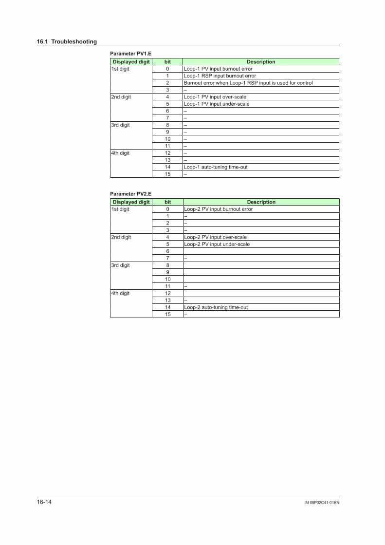
16-14 IM 05P02C41-01EN
ParameterPV1.EDisplayeddigit bit Description
1st digit 0 Loop-1 PV input burnout error1 Loop-1 RSP input burnout error2 Burnout error when Loop-1 RSP input is used for control 3 –
2nd digit 4 Loop-1 PV input over-scale5 Loop-1 PV input under-scale6 –7 –
3rd digit 8 –9 –10 –11 –
4th digit 12 –13 –14 Loop-1 auto-tuning time-out15 –
ParameterPV2.EDisplayeddigit bit Description
1st digit 0 Loop-2 PV input burnout error1 –2 –3 –
2nd digit 4 Loop-2 PV input over-scale5 Loop-2 PV input under-scale67 –
3rd digit 891011 –
4th digit 1213 –14 Loop-2 auto-tuning time-out15 –
16.1Troubleshooting
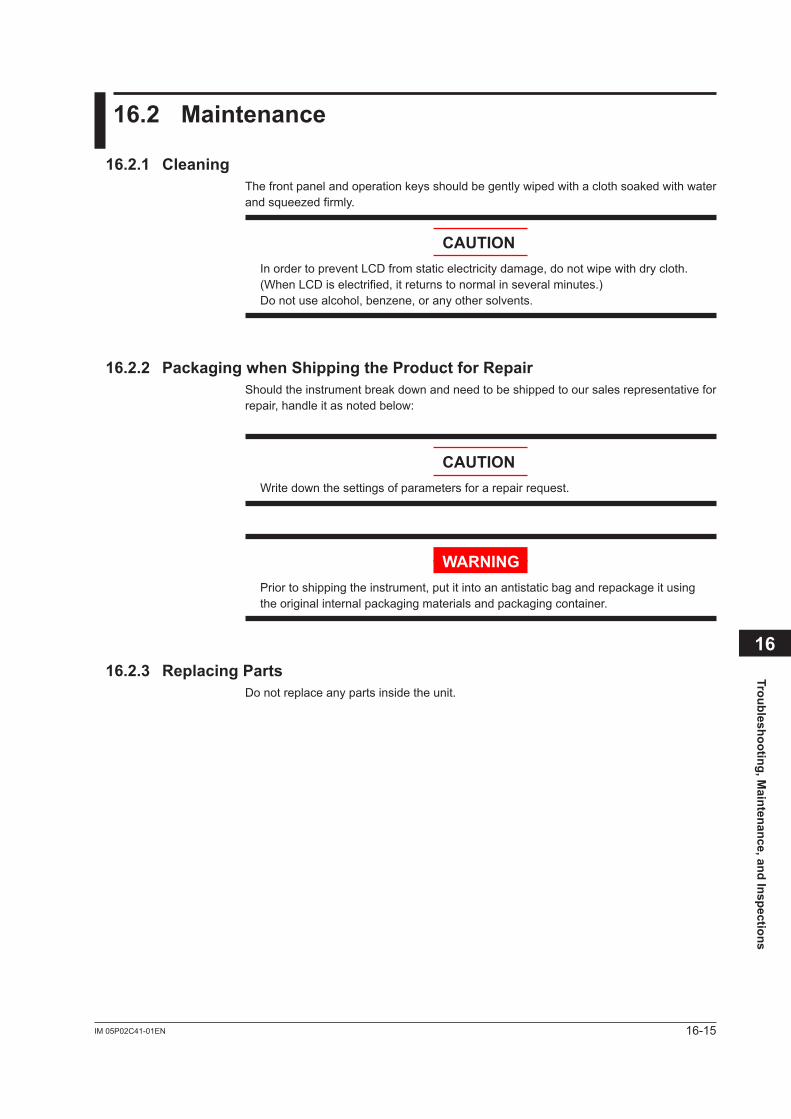
16-15IM 05P02C41-01EN
Troubleshooting, Maintenance, and Inspections
16
16.2 Maintenance
16.2.1 CleaningThe front panel and operation keys should be gently wiped with a cloth soaked with water andsqueezedfirmly.
CAUTIONIn order to prevent LCD from static electricity damage, do not wipe with dry cloth. (When LCD is electrified, it returns to normal in several minutes.) Donotusealcohol,benzene,oranyothersolvents.
16.2.2 PackagingwhenShippingtheProductforRepairShould the instrument break down and need to be shipped to our sales representative for repair, handle it as noted below:
CAUTIONWrite down the settings of parameters for a repair request.
WARNINGPrior to shipping the instrument, put it into an antistatic bag and repackage it using the original internal packaging materials and packaging container.
16.2.3 ReplacingPartsDo not replace any parts inside the unit.
16-16 IM 05P02C41-01EN
16.3 PeriodicMaintenance
Check the operating condition periodically to use this instrument with good condition.
16-17IM 05P02C41-01EN
Troubleshooting, Maintenance, and Inspections
16
16.4 Disposal
When disposing of this instrument, arrange for appropriate disposal as industrial waste according to the rules of a country, the area, or a local government.

Blank Page
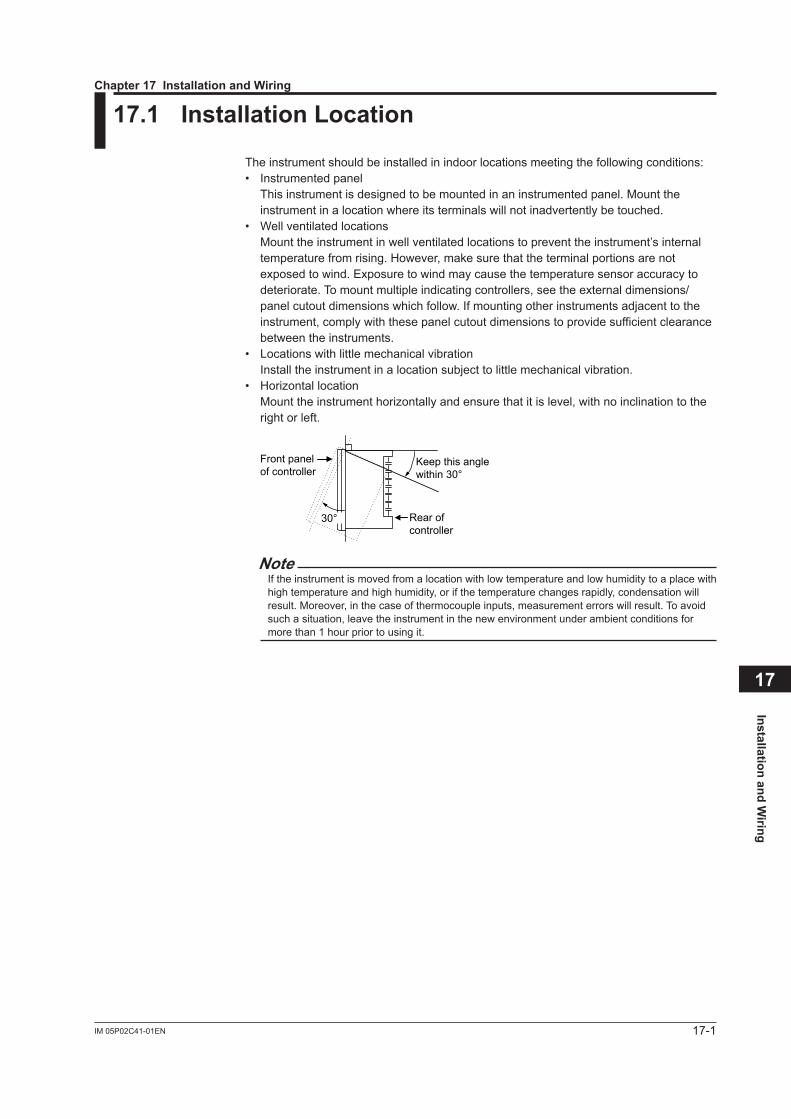
17-1IM 05P02C41-01EN
Installation and Wiring
17
17.1 InstallationLocation
The instrument should be installed in indoor locations meeting the following conditions:• Instrumented panel This instrument is designed to be mounted in an instrumented panel. Mount the
instrument in a location where its terminals will not inadvertently be touched.• Well ventilated locations Mount the instrument in well ventilated locations to prevent the instrument’s internal
temperature from rising. However, make sure that the terminal portions are not exposed to wind. Exposure to wind may cause the temperature sensor accuracy to deteriorate. To mount multiple indicating controllers, see the external dimensions/panelcutoutdimensionswhichfollow.Ifmountingotherinstrumentsadjacenttotheinstrument, comply with these panel cutout dimensions to provide sufficient clearance between the instruments.
• Locations with little mechanical vibration Installtheinstrumentinalocationsubjecttolittlemechanicalvibration.• Horizontallocation Mounttheinstrumenthorizontallyandensurethatitislevel,withnoinclinationtothe
right or left.
Front panelof controller
Keep this anglewithin 30°
Rear ofcontroller
30°
NoteIf the instrument is moved from a location with low temperature and low humidity to a place with high temperature and high humidity, or if the temperature changes rapidly, condensation will result. Moreover, in the case of thermocouple inputs, measurement errors will result. To avoid such a situation, leave the instrument in the new environment under ambient conditions for more than 1 hour prior to using it.
Chapter17InstallationandWiring
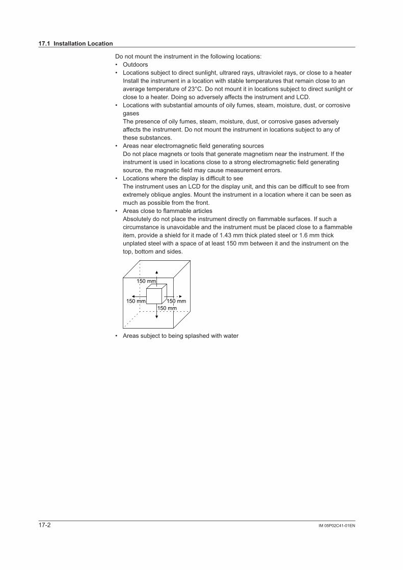
17-2 IM 05P02C41-01EN
Do not mount the instrument in the following locations:• Outdoors• Locationssubjecttodirectsunlight,ultraredrays,ultravioletrays,orclosetoaheater Install the instrument in a location with stable temperatures that remain close to an
averagetemperatureof23°C.Donotmountitinlocationssubjecttodirectsunlightorclose to a heater. Doing so adversely affects the instrument and LCD.
• Locations with substantial amounts of oily fumes, steam, moisture, dust, or corrosive gases
The presence of oily fumes, steam, moisture, dust, or corrosive gases adversely affectstheinstrument.Donotmounttheinstrumentinlocationssubjecttoanyofthese substances.
• Areas near electromagnetic field generating sources Do not place magnets or tools that generate magnetism near the instrument. If the
instrument is used in locations close to a strong electromagnetic field generating source, the magnetic field may cause measurement errors.
• Locations where the display is difficult to see The instrument uses an LCD for the display unit, and this can be difficult to see from
extremely oblique angles. Mount the instrument in a location where it can be seen as much as possible from the front.
• Areas close to flammable articles Absolutely do not place the instrument directly on flammable surfaces. If such a
circumstance is unavoidable and the instrument must be placed close to a flammable item, provide a shield for it made of 1.43 mm thick plated steel or 1.6 mm thick unplated steel with a space of at least 150 mm between it and the instrument on the top, bottom and sides.
150 mm150 mm
150 mm
150 mm
• Areassubjecttobeingsplashedwithwater
17.1InstallationLocation
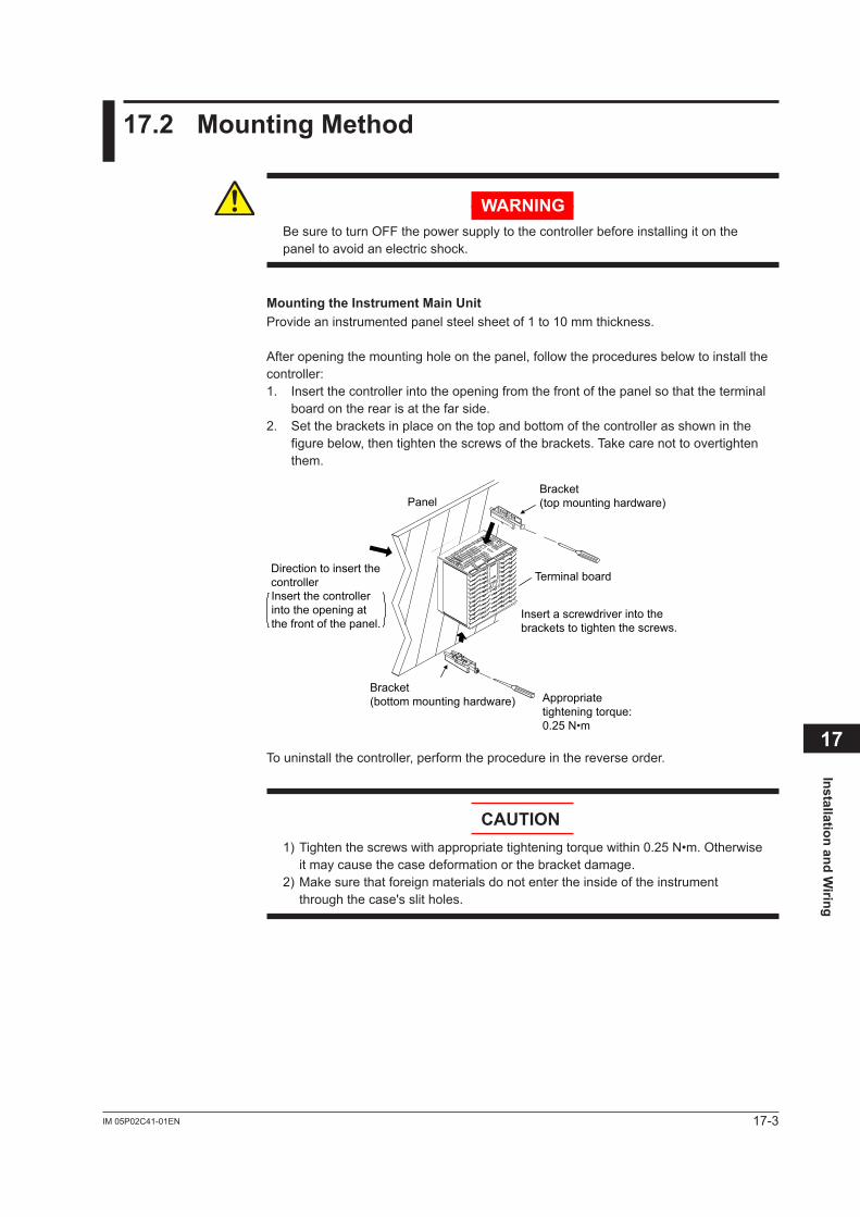
17-3IM 05P02C41-01EN
Installation and Wiring
17
17.2 MountingMethod
WARNINGBe sure to turn OFF the power supply to the controller before installing it on the panel to avoid an electric shock.
Mounting the Instrument Main UnitProvide an instrumented panel steel sheet of 1 to 10 mm thickness.
After opening the mounting hole on the panel, follow the procedures below to install the controller:1. Insert the controller into the opening from the front of the panel so that the terminal
board on the rear is at the far side.2. Set the brackets in place on the top and bottom of the controller as shown in the
figure below, then tighten the screws of the brackets. Take care not to overtighten them.
Bracket(top mounting hardware)
Terminal board
Bracket(bottom mounting hardware)
Panel
Insert a screwdriver into thebrackets to tighten the screws.
Direction to insert thecontroller
Appropriatetightening torque:0.25 N•m
Insert the controllerinto the opening atthe front of the panel.
To uninstall the controller, perform the procedure in the reverse order.
CAUTION1) Tighten the screws with appropriate tightening torque within 0.25 N•m. Otherwise
it may cause the case deformation or the bracket damage.2) Make sure that foreign materials do not enter the inside of the instrument
through the case's slit holes.
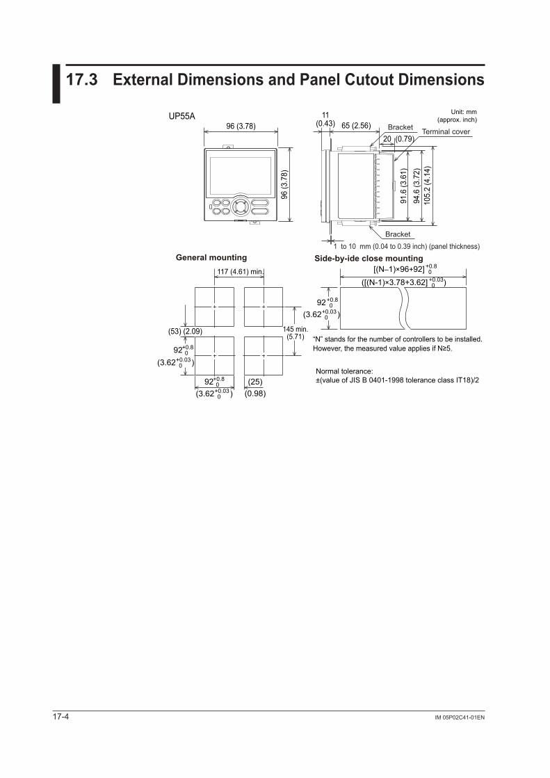
17-4 IM 05P02C41-01EN
17.3 ExternalDimensionsandPanelCutoutDimensions
Unit: mm(approx. inch)
Normal tolerance: ±(value of JIS B 0401-1998 tolerance class IT18)/2(25)
(0.98)
(53) (2.09)
[(N–1)×96+92] +0.80
+0.8092
+0.8092
+0.8092
+0.030(3.62 )
+0.030(3.62 )
+0.030(3.62 )
+0.030([(N-1)×3.78+3.62] )
65 (2.56)20 (0.79)
11(0.43)
UP55A
94.6
(3.7
2)91
.6 (3
.61)
105.
2 (4
.14)
96 (3.78)
96 (3
.78)
Bracket
Bracket
Terminal cover
1 to 10 mm (0.04 to 0.39 inch) (panel thickness)General mounting Side-by-ide close mounting
“N” stands for the number of controllers to be installed.However, the measured value applies if N≥5.
117 (4.61) min.
145 min.(5.71)
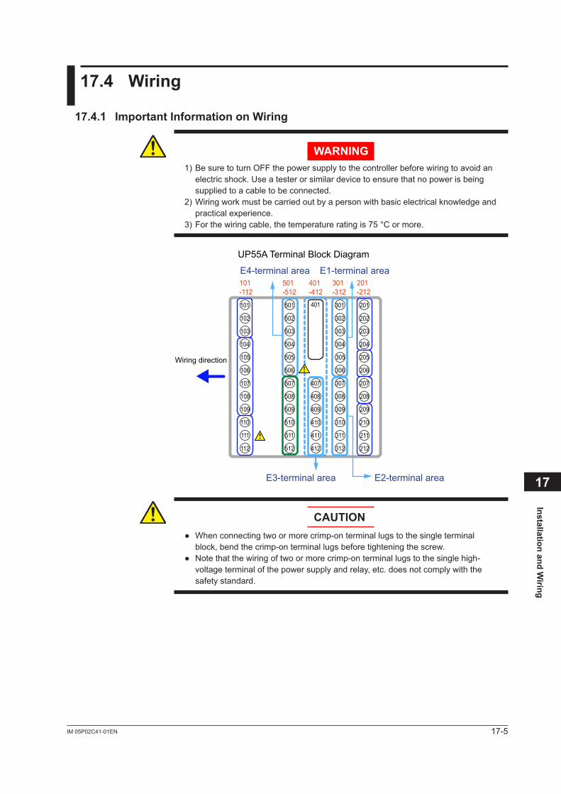
17-5IM 05P02C41-01EN
Installation and Wiring
17
17.4 Wiring
17.4.1 ImportantInformationonWiring
WARNING1) Be sure to turn OFF the power supply to the controller before wiring to avoid an
electric shock. Use a tester or similar device to ensure that no power is being supplied to a cable to be connected.
2) Wiring work must be carried out by a person with basic electrical knowledge and practical experience.
3) For the wiring cable, the temperature rating is 75 °C or more.
E4-terminal area E1-terminal area
E3-terminal area E2-terminal area
UP55A Terminal Block Diagram
101
102
103
104
105
106
107
108
109
110
111
112
501
502
503
504
505
506
507
508
509
510
511
512
407
401
408
409
410
411
412
301
302
303
304
305
306
307
308
309
310
311
312
201
202
203
204
205
206
207
208
209
210
211
212
101-112
501-512
401-412
301-312
201-212
Wiring direction
CAUTION Whenconnectingtwoormorecrimp-onterminallugstothesingleterminal
block, bend the crimp-on terminal lugs before tightening the screw. Notethatthewiringoftwoormorecrimp-onterminallugstothesinglehigh-
voltage terminal of the power supply and relay, etc. does not comply with the safety standard.

17-6 IM 05P02C41-01EN
CAUTIONDo not use an unassigned terminal as the relay terminal.
RecommendedCrimp-onTerminalLugs
(A)
(F)
(ød)
Recommended tightening torque: 0.6 N·mApplicablewiresize:Powersupplywiring1.25mm2 or more
Applicable terminal lug Applicablewiresizemm2(AWG#) (ød) (A) (F)
M3 0.25 to 1.65 (22 to 16) 3.3 5.5 4.2
5.5 3.3
CableSpecificationsPurpose Name and Manufacturer
Power supply, relay contact output
600 V Grade heat-resistant PVC insulated wires, JIS C 3317(HIV), 0.9 to 2.0 mm2
Thermocouple
Shielded compensating lead wire JISC1610For thermocouple input (PV input and remote input with direct input), shielded compensating lead wire of cross-sectional area less than or equal to 0.75 mm2 is recommended. If the crosssectional area is wide, thereferencejunctioncompensationerrormaybelarge.
RTD Shielded wire (three/four conductors) UL2482 (Hitachi Cable)Other signals (other than contact input/output) Shielded wires
Other signals (contact input/output) Non shielded wires
RS485 communication Shielded wires
Ethernet communication 100BASE-TX(CAT-5)/10BASE-TPROFIBUS-DP communication Dedicated cable for PROFIBUS-DP (Shielded two-wires)
DeviceNet communication DedicatedcableforDeviceNet(Shieldedfive-wires)
CC-Link communication Dedicated cable for CC-Link (Shielded three-wires)
PROFIBUS-DP/CC-LinkConnector(wiringside)(Partnumber:A1987JT)DeviceNetConnector(wiringside)(Partnumber:L4502BW)Recommended tightening torque: 0.5 to 0.6 N·m
NoteCommunication wires of cross-sectional area less than or equal to 0.34 mm2 may not be secured firmly to the terminals.Check that the wire is firmly connected to the terminal by folding the conductor of the wire connected to the climp-on lug.Recommended length of the stripped wire: 7 mm
NoteIf the UP is located at the end of a segment for the PROFIBUS communication wiring, terminatingresistorsareseparatelyneeded.Thesearetobepreparedbyusers.(390Ω:2pcs.220Ω:1pc.,oranactiveterminator.)
17.4Wiring
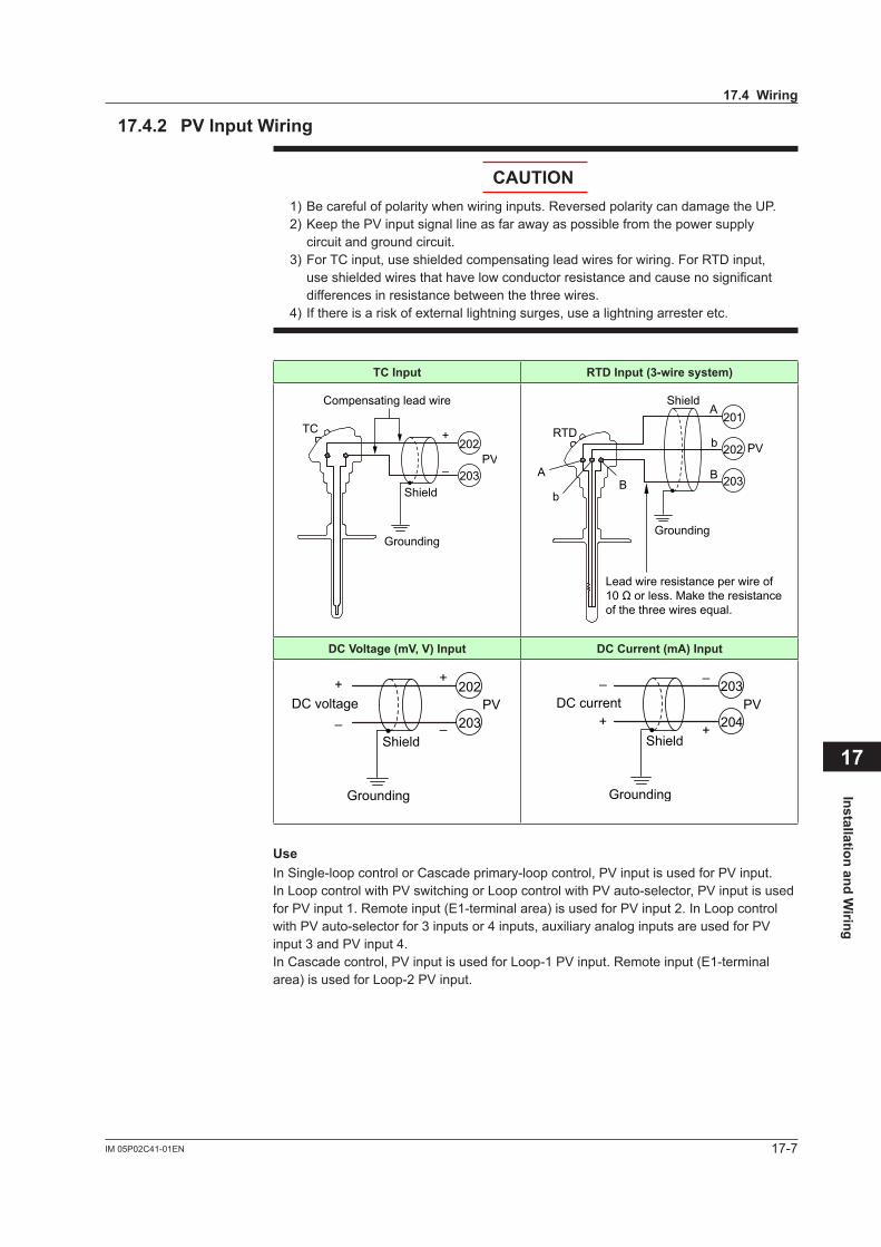
17-7IM 05P02C41-01EN
Installation and Wiring
17
17.4.2 PVInputWiring
CAUTION1) Be careful of polarity when wiring inputs. Reversed polarity can damage the UP.2) Keep the PV input signal line as far away as possible from the power supply
circuit and ground circuit.3) For TC input, use shielded compensating lead wires for wiring. For RTD input,
use shielded wires that have low conductor resistance and cause no significant differences in resistance between the three wires.
4) If there is a risk of external lightning surges, use a lightning arrester etc.
TC Input RTDInput(3-wiresystem)
203
202TC
–
+
Compensating lead wire
Grounding
Shield
PV
203
202
201RTD
A
B
b
Lead wire resistance per wire of10 Ω or less. Make the resistanceof the three wires equal.
A
bB
Grounding
Shield
PV
DCVoltage(mV,V)Input DC Current (mA) Input
203
202
–
++
–DC voltage
Grounding
Shield
PV204
203–
++
–DC current
Grounding
Shield
PV
UseIn Single-loop control or Cascade primary-loop control, PV input is used for PV input.In Loop control with PV switching or Loop control with PV auto-selector, PV input is used for PV input 1. Remote input (E1-terminal area) is used for PV input 2. In Loop control with PV auto-selector for 3 inputs or 4 inputs, auxiliary analog inputs are used for PV input 3 and PV input 4.In Cascade control, PV input is used for Loop-1 PV input. Remote input (E1-terminal area) is used for Loop-2 PV input.
17.4Wiring
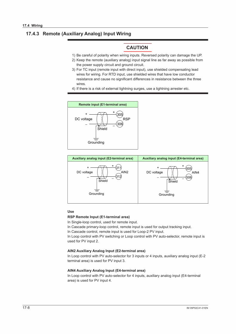
17-8 IM 05P02C41-01EN
17.4.3 Remote(AuxiliaryAnalog)InputWiring
CAUTION1) Be careful of polarity when wiring inputs. Reversed polarity can damage the UP.2) Keep the remote (auxiliary analog) input signal line as far away as possible from
the power supply circuit and ground circuit.3) For TC input (remote input with direct input), use shielded compensating lead
wires for wiring. For RTD input, use shielded wires that have low conductor resistance and cause no significant differences in resistance between the three wires.
4) If there is a risk of external lightning surges, use a lightning arrester etc.
Remoteinput(E1-terminalarea)
306
305
–
++
–DC voltage
Grounding
Shield
RSP
Auxiliaryanaloginput(E2-terminalarea) Auxiliaryanaloginput(E4-terminalarea)
312
311
–
++
–DC voltage
Grounding
Shield
AIN2506
505
–
++
–DC voltage
Grounding
Shield
AIN4
UseRSPRemoteInput(E1-terminalarea)In Single-loop control, used for remote input.In Cascade primary-loop control, remote input is used for output tracking input.In Cascade control, remote input is used for Loop-2 PV input.In Loop control with PV switching or Loop control with PV auto-selector, remote input is used for PV input 2.
AIN2AuxiliaryAnalogInput(E2-terminalarea)In Loop control with PV auto-selector for 3 inputs or 4 inputs, auxiliary analog input (E-2 terminal area) is used for PV input 3.
AIN4AuxiliaryAnalogInput(E4-terminalarea)In Loop control with PV auto-selector for 4 inputs, auxiliary analog input (E4-terminal area) is used for PV input 4.
17.4Wiring
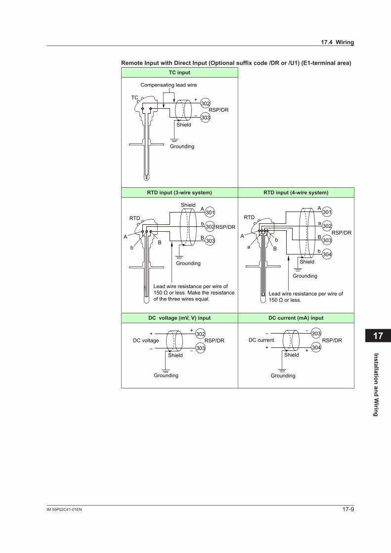
17-9IM 05P02C41-01EN
Installation and Wiring
17
RemoteInputwithDirectInput(Optionalsuffixcode/DRor/U1)(E1-terminalarea)TC input
303
302TC
–
+
Compensating lead wire
Grounding
RSP/DR
Shield
RTDinput(3-wiresystem) RTDinput(4-wiresystem)
303
302
301RTD
A
B
b
Lead wire resistance per wire of150 Ω or less. Make the resistanceof the three wires equal.
A
bB
RSP/DR
Shield
Grounding
304
303
302
301RTD
A
B
b
a
Lead wire resistance per wire of150 Ω or less.
A
ab
B
Grounding
Shield
RSP/DR
DCvoltage(mV,V)input DC current (mA) input
303
302
–
++
–DC voltage
Grounding
Shield
RSP/DR304
303–
++
–DC current
Grounding
Shield
RSP/DR
17.4Wiring
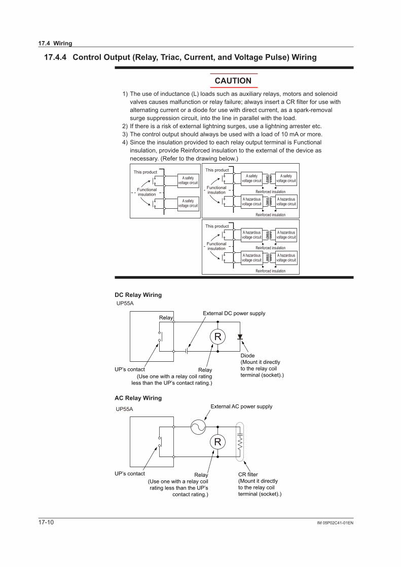
17-10 IM 05P02C41-01EN
17.4.4 ControlOutput(Relay,Triac,Current,andVoltagePulse)Wiring
CAUTION1) The use of inductance (L) loads such as auxiliary relays, motors and solenoid
valves causes malfunction or relay failure; always insert a CR filter for use with alternating current or a diode for use with direct current, as a spark-removal surge suppression circuit, into the line in parallel with the load.
2) If there is a risk of external lightning surges, use a lightning arrester etc.3) The control output should always be used with a load of 10 mA or more.4) Since the insulation provided to each relay output terminal is Functional
insulation, provide Reinforced insulation to the external of the device as necessary. (Refer to the drawing below.)
This product
Functional insulation
A safety voltage circuit
A safety voltage circuit
This product
Reinforced insulation
Reinforced insulation
Functional insulation
A hazardous voltage circuit
A hazardous voltage circuit
A safety voltage circuit
A safety voltage circuit
This product
Reinforced insulation
Reinforced insulation
Functional insulation
A hazardous voltage circuit
A hazardous voltage circuit
A hazardous voltage circuit
A hazardous voltage circuit
DCRelayWiring
R
External DC power supplyRelay
UP55A
UP’s contact
Diode(Mount it directlyto the relay coilterminal (socket).)
Relay(Use one with a relay coil rating
less than the UP’s contact rating.)
ACRelayWiring
UP55A
R
CR filter(Mount it directlyto the relay coilterminal (socket).)
Relay(Use one with a relay coilrating less than the UP’s
contact rating.)
UP’s contact
External AC power supply
17.4Wiring

17-11IM 05P02C41-01EN
Installation and Wiring
17
RelayOutput(ForStandardmodel)StandardtypeoutputorHeating/coolingtypeheating-sideoutput(ForDetailedmodel)SuffixcodeofOutput
1=“-R”or“-U”
(ForStandardmodel)Heating/coolingtypecooling-sideoutput
(ForDetailedmodel)SuffixcodeofOutput2=“R”or“U”
NC
NO
COM
101
102
103
OUT
Contact rating: 250 V AC, 3 A 30 V DC, 3 A (resistance load)
NC
NO
COM
507
508
509
OUT2
Contact rating: 250 V AC, 3 A 30 V DC, 3 A (resistance load)
Note: The control output should always be used with a load of 10 mA or more.
TriacOutput(forDetailedmodel)SuffixcodeofOutput1=“-T” SuffixcodeofOutput2=“T”
OUTNO
COM
101
102
103
Contact rating: 75-250 V ACAllowable load current: 0.8 A
OUT2NO
COM
507
508
509
Contact rating: 75-250 V ACAllowable load current: 0.8 A
CurrentandVoltagePulseOutput(ForStandardmodel)Standardtypeor
Heating/coolingtypeheating-sideoutput(ForDetailedmodel)SuffixcodeofOutput1=
“-A”or“-U”
(ForStandardmodel)Heating/coolingtypecooling-sideoutput
(ForDetailedmodel)SuffixcodeofOutput2=“A”or“U”
208
207OUT
Shield
–
+
Control valves(or otheractuators)
Current: 4 to 20 mA DC or 0 to 20 mA DC (resistance load: 600 Ω or less)Voltage pulse: On-voltage: 12 V DC or more (load resistance: 600 Ω or more) Off-voltage: 0.1 V DC or less
Grounding
512
511OUT2
Shield
–
+
Current: 4 to 20 mA DC or 0 to 20 mA DC (resistance load: 600 Ω or less)Voltage pulse: On-voltage: 12 V DC or more (load resistance: 600 Ω or more) Off-voltage: 0.1 V DC or less
GroundingControl valves(or otheractuators)
UseWhen current/voltage pulse output is not used for control output, it can be used for retransmission output.When retransmission output terminal is not used for retransmission output, it can be used for optional control output. The current output range can be changed.For control output setting, set the control mode (CTLM) and the control type (CNT), then set the output terminal and output type in the output type selection (OT). Controloutputtype:10.1SettingControlOutputType
17.4Wiring
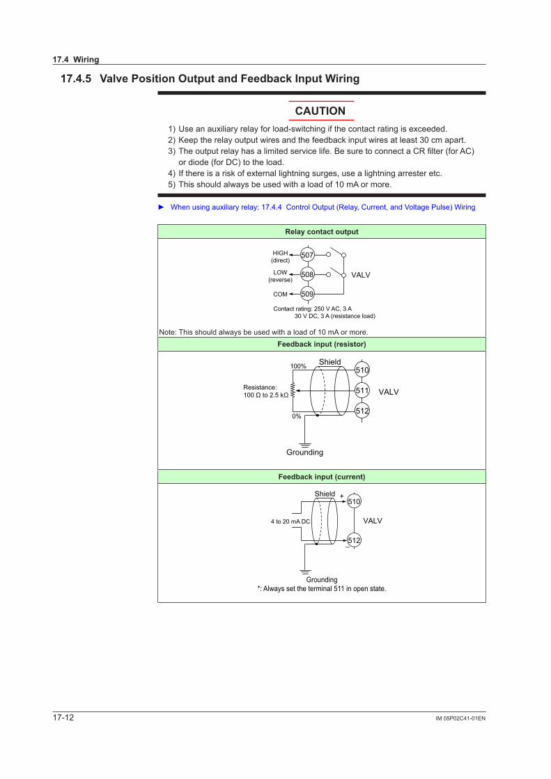
17-12 IM 05P02C41-01EN
17.4.5 ValvePositionOutputandFeedbackInputWiring
CAUTION1) Use an auxiliary relay for load-switching if the contact rating is exceeded.2) Keep the relay output wires and the feedback input wires at least 30 cm apart.3) The output relay has a limited service life. Be sure to connect a CR filter (for AC)
or diode (for DC) to the load.4) If there is a risk of external lightning surges, use a lightning arrester etc.5) This should always be used with a load of 10 mA or more.
Whenusingauxiliaryrelay:17.4.4ControlOutput(Relay,Current,andVoltagePulse)Wiring
Relaycontactoutput
507
508
509
VALV
HIGH(direct)
LOW(reverse)
COM
Contact rating: 250 V AC, 3 A 30 V DC, 3 A (resistance load)
Note: This should always be used with a load of 10 mA or more.Feedback input (resistor)
100%
0%
510
511
512
VALV
Shield
Resistance: 100 Ω to 2.5 kΩ
Grounding
Feedback input (current)
510
512
VALV4 to 20 mA DC
–
+Shield
Grounding*: Always set the terminal 511 in open state.
17.4Wiring
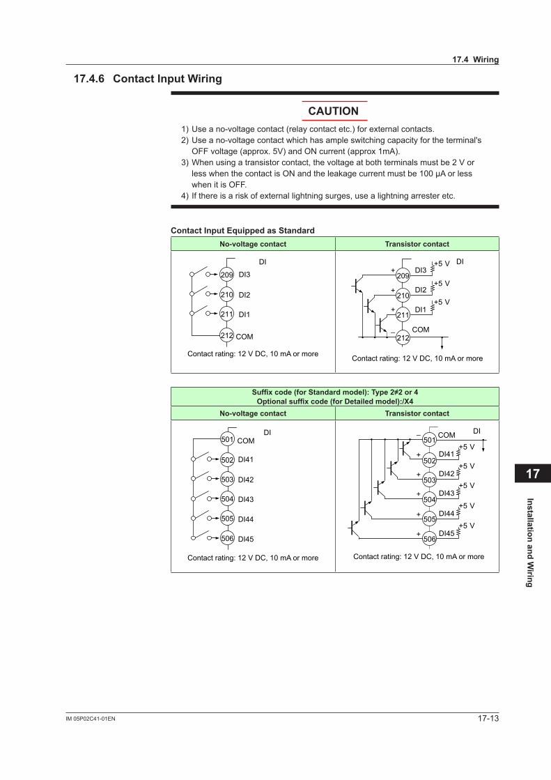
17-13IM 05P02C41-01EN
Installation and Wiring
17
17.4.6 ContactInputWiring
CAUTION1) Use a no-voltage contact (relay contact etc.) for external contacts.2) Use a no-voltage contact which has ample switching capacity for the terminal's
OFF voltage (approx. 5V) and ON current (approx 1mA).3) When using a transistor contact, the voltage at both terminals must be 2 V or
less when the contact is ON and the leakage current must be 100 µA or less when it is OFF.
4) If there is a risk of external lightning surges, use a lightning arrester etc.
ContactInputEquippedasStandardNo-voltagecontact Transistor contact
DI3
DI2
DI1
COM
209
210
211
212
DI
Contact rating: 12 V DC, 10 mA or more
DI3
DI2
DI1
COM
209
210
211
212
DI+
+
+
–
+5 V
+5 V
+5 V
Contact rating: 12 V DC, 10 mA or more
Suffixcode(forStandardmodel):Type2≠2or4Optionalsuffixcode(forDetailedmodel):/X4
No-voltagecontact Transistor contact
DI41
DI42
DI43
DI44
DI45
COM
Contact rating: 12 V DC, 10 mA or more
501
502
503
504
505
506
DI
DI41
DI42
COM
DI43
DI44
DI45
501
502
503
504
505
506
DI
+5 V
+5 V
+5 V
+5 V
+5 V
Contact rating: 12 V DC, 10 mA or more
+
+
+
+
+
–
17.4Wiring
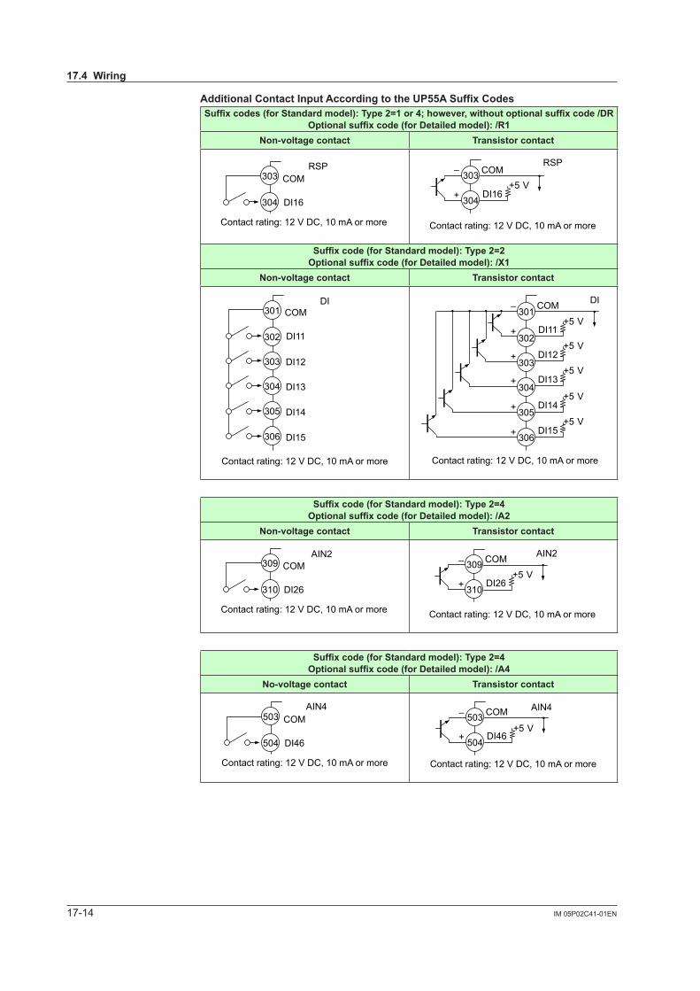
17-14 IM 05P02C41-01EN
AdditionalContactInputAccordingtotheUP55ASuffixCodesSuffixcodes(forStandardmodel):Type2=1or4;however,withoutoptionalsuffixcode/DR
Optionalsuffixcode(forDetailedmodel):/R1Non-voltagecontact Transistor contact
DI16
COM
Contact rating: 12 V DC, 10 mA or more
303
304
RSP
DI16
COM303
304
Contact rating: 12 V DC, 10 mA or more
RSP
+5 V+
–
Suffixcode(forStandardmodel):Type2=2Optionalsuffixcode(forDetailedmodel):/X1
Non-voltagecontact Transistor contact
DI11
DI12
DI13
DI14
DI15
COM
Contact rating: 12 V DC, 10 mA or more
301
302
303
304
305
306
DI
DI11
DI12
COM
DI13
DI14
DI15
301
302
303
304
305
306
DI
+5 V
+5 V
+5 V
+5 V
+5 V
Contact rating: 12 V DC, 10 mA or more
+
+
+
+
+
–
Suffixcode(forStandardmodel):Type2=4Optionalsuffixcode(forDetailedmodel):/A2
Non-voltagecontact Transistor contact
DI26
COM
Contact rating: 12 V DC, 10 mA or more
309
310
AIN2
DI26
COM309
310
AIN2
+5 V
Contact rating: 12 V DC, 10 mA or more
+
–
Suffixcode(forStandardmodel):Type2=4Optionalsuffixcode(forDetailedmodel):/A4
No-voltagecontact Transistor contact
DI46
COM
Contact rating: 12 V DC, 10 mA or more
503
504
AIN4
DI46
COM503
504
AIN4
+5 V
Contact rating: 12 V DC, 10 mA or more
+
–
17.4Wiring

17-15IM 05P02C41-01EN
Installation and Wiring
17
Optionalsuffixcode(forDetailedmodel):/X2
Non-voltagecontact Transistor contact
DI21
DI22
DI23
DI24
DI25
COM
Contact rating: 12 V DC, 10 mA or more
307
308
309
310
311
312
DI
DI21
DI22
COM
DI23
DI24
DI25
307
308
309
310
311
312
DI
+5 V
+5 V
+5 V
+5 V
+5 V
Contact rating: 12 V DC, 10 mA or more
+
+
+
+
+
–
Optionalsuffixcode(forDetailedmodel):/X3
Non-voltagecontact Transistor contact
DI31
DI32
DI33
DI34
DI35
COM
Contact rating: 12 V DC, 10 mA or more
407
408
409
410
411
412
DI
DI31
DI32
COM
DI33
DI34
DI35
407
408
409
410
411
412
DI
+5 V
+5 V
+5 V
+5 V
+5 V
Contact rating: 12 V DC, 10 mA or more
+
+
+
+
+
–
Optionalsuffixcode(forDetailedmodel):/W1
No-voltagecontact Transistor contact
DI11
DI12
COM
Contact rating: 12 V DC, 10 mA or more
301
302
303
DI
DI11
DI12
COM301
302
303
DI
+5 V
+5 V
Contact rating: 12 V DC, 10 mA or more
+
+
–
17.4Wiring

17-16 IM 05P02C41-01EN
Optionalsuffixcode(forDetailedmodel):/W2
No-voltagecontact Transistor contact
DI21
DI22
COM
Contact rating: 12 V DC, 10 mA or more
307
308
309
DI
DI21
DI22
COM307
308
309
DI
+5 V
+5 V
Contact rating: 12 V DC, 10 mA or more
+
+
–
Optionalsuffixcode(forDetailedmodel):/W3
No-voltagecontact Transistor contact
DI31
DI32
COM
Contact rating: 12 V DC, 10 mA or more
407
408
409
DI
DI31
DI32
COM407
408
409
DI
+5 V
+5 V
Contact rating: 12 V DC, 10 mA or more
+
+
–
Optionalsuffixcode(forDetailedmodel):/W4
No-voltagecontact Transistor contact
DI41
DI42
COM
Contact rating: 12 V DC, 10 mA or more
501
502
503
DI
DI41
DI42
COM501
502
503
DI
+5 V
+5 V
Contact rating: 12 V DC, 10 mA or more
+
+
–
The function is assigned to contact inputs for each control mode and control type. InitialvalueofContactinputfunction:8.1SettingControlMode(CTLM) Contact input function registration: 12.1 Setting Contact Input Function
NoteIf the /DR option is additionally specified to the remote input, the remote Input with direct input can be used as remote input. However, DI16 is to be deleted. (See 17.4.3 Remote (Auxiliary Analog) Input Wiring)
17.4Wiring
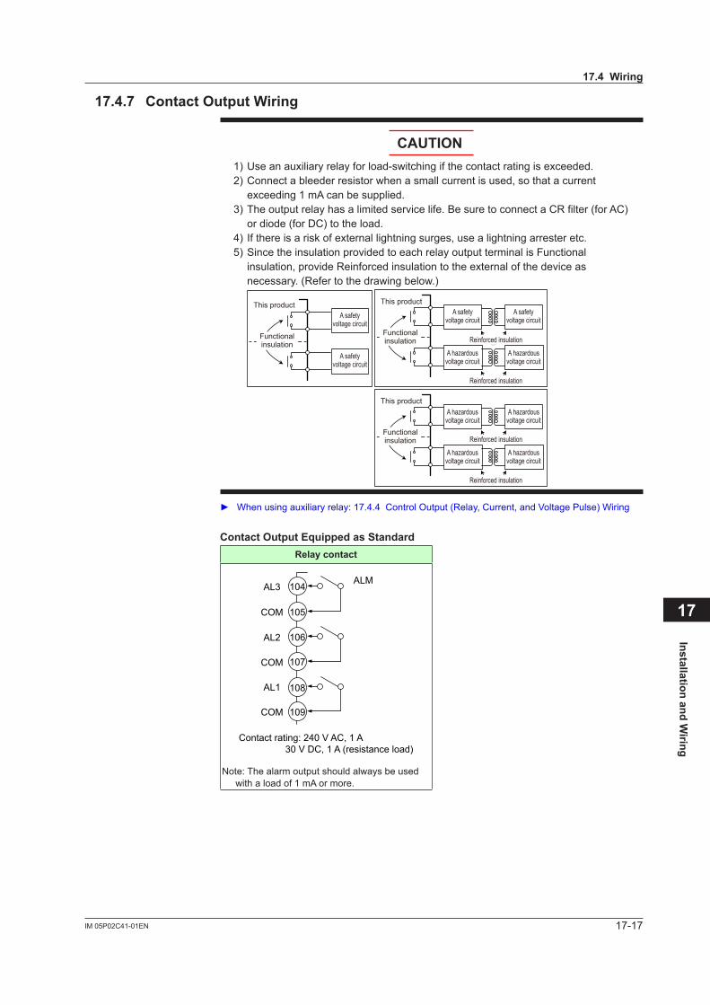
17-17IM 05P02C41-01EN
Installation and Wiring
17
17.4.7 ContactOutputWiring
CAUTION1) Use an auxiliary relay for load-switching if the contact rating is exceeded.2) Connect a bleeder resistor when a small current is used, so that a current
exceeding 1 mA can be supplied.3) The output relay has a limited service life. Be sure to connect a CR filter (for AC)
or diode (for DC) to the load.4) If there is a risk of external lightning surges, use a lightning arrester etc.5) Since the insulation provided to each relay output terminal is Functional
insulation, provide Reinforced insulation to the external of the device as necessary. (Refer to the drawing below.)
This product
Functional insulation
A safety voltage circuit
A safety voltage circuit
This product
Reinforced insulation
Reinforced insulation
Functional insulation
A hazardous voltage circuit
A hazardous voltage circuit
A safety voltage circuit
A safety voltage circuit
This product
Reinforced insulation
Reinforced insulation
Functional insulation
A hazardous voltage circuit
A hazardous voltage circuit
A hazardous voltage circuit
A hazardous voltage circuit
Whenusingauxiliaryrelay:17.4.4ControlOutput(Relay,Current,andVoltagePulse)Wiring
ContactOutputEquippedasStandardRelaycontact
AL3
AL2
AL1
COM
COM
COM
Contact rating: 240 V AC, 1 A 30 V DC, 1 A (resistance load)
104
105
106
107
108
109
ALM
Note: The alarm output should always be used with a load of 1 mA or more.
17.4Wiring
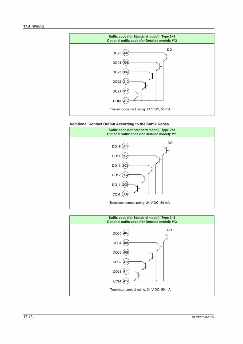
17-18 IM 05P02C41-01EN
Suffixcode(forStandardmodel):Type2≠4Optionalsuffixcode(forDetailedmodel):/Y2
Transistor contact rating: 24 V DC, 50 mA
DO22
DO21
DO23
DO24
DO25
COM
307
308
309
310
311
312
DO
AdditionalContactOutputAccordingtotheSuffixCodesSuffixcode(forStandardmodel):Type2=3Optionalsuffixcode(forDetailedmodel):/Y1
Transistor contact rating: 24 V DC, 50 mA
DO12
DO11
DO13
DO14
DO15
COM
301
302
303
304
305
306
DO
Suffixcode(forStandardmodel):Type2=3Optionalsuffixcode(forDetailedmodel):/Y3
Transistor contact rating: 24 V DC, 50 mA
DO32
DO31
DO33
DO34
DO35
COM
407
408
409
410
411
412
DO
17.4Wiring
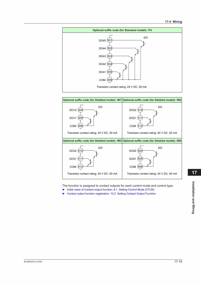
17-19IM 05P02C41-01EN
Installation and Wiring
17
Optionalsuffixcode(forStandardmodel):/Y4
Transistor contact rating: 24 V DC, 50 mA
DO42
DO41
DO43
DO44
DO45
COM
501
502
503
504
505
506
DO
Optionalsuffixcode(forDetailedmodel):/W1 Optionalsuffixcode(forDetailedmodel):/W2
Transistor contact rating: 24 V DC, 50 mA
DO12
DO11
COM
304
305
306
DO
Transistor contact rating: 24 V DC, 50 mA
DO22
DO21
COM
310
311
312
DO
Optionalsuffixcode(forDetailedmodel):/W3 Optionalsuffixcode(forDetailedmodel):/W4
Transistor contact rating: 24 V DC, 50 mA
DO32
DO31
COM
410
411
412
DO
Transistor contact rating: 24 V DC, 50 mA
DO42
DO41
COM
504
505
506
DO
The function is assigned to contact outputs for each control mode and control type. Initial value of Contact output function: 8.1 Setting Control Mode (CTLM) Contactoutputfunctionregistration:12.2SettingContactOutputFunction
17.4Wiring
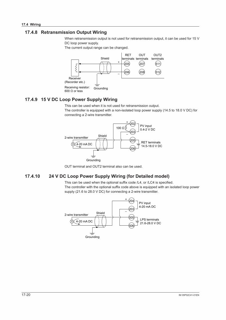
17-20 IM 05P02C41-01EN
17.4.8 RetransmissionOutputWiringWhen retransmission output is not used for retransmission output, it can be used for 15 V DC loop power supply.The current output range can be changed.
206
205
208
207
512
511
Grounding
OUTterminals
RETterminals
OUT2terminalsShield
–
+
Receiver(Recorder etc.)
Receiving resistor:600 Ω or less
17.4.9 15VDCLoopPowerSupplyWiringThis can be used when it is not used for retransmission output.The controller is equipped with a non-isolated loop power supply (14.5 to 18.0 V DC) for connecting a 2-wire transmitter.
Grounding
PV input0.4-2 V DC
Shield –
+
2-wire transmitterRET terminals14.5-18.0 V DC
100 Ω
206
205
203
202
4-20 mA DC
OUT terminal and OUT2 terminal also can be used.
17.4.10 24VDCLoopPowerSupplyWiring(forDetailedmodel)This can be used when the optional suffix code /L4, or /LC4 is specified. The controller with the optional suffix code above is equipped with an isolated loop power supply (21.6 to 28.0 V DC) for connecting a 2-wire transmitter.
Grounding
PV input4-20 mA DC
Shield –
+
2-wire transmitterLPS terminals21.6-28.0 V DC
506
505
203
204
4-20 mA DC
17.4Wiring
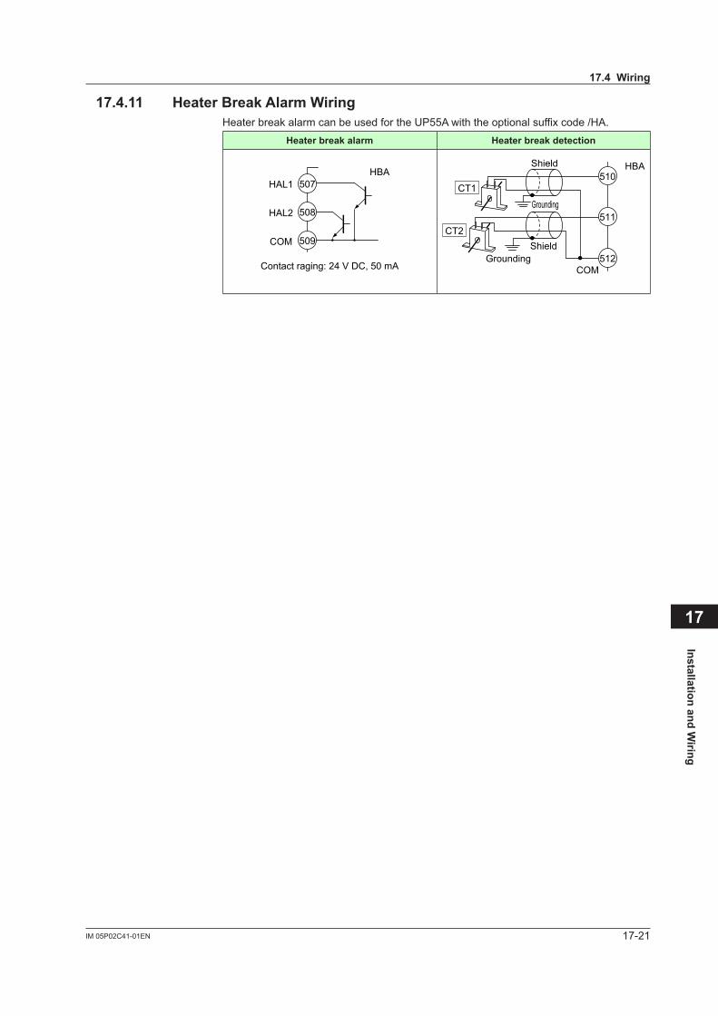
17-21IM 05P02C41-01EN
Installation and Wiring
17
17.4.11 HeaterBreakAlarmWiringHeater break alarm can be used for the UP55A with the optional suffix code /HA.
Heater break alarm Heater break detection
Contact raging: 24 V DC, 50 mA
HAL1
HAL2
COM
507
508
509
HBA
Grounding
GroundingShield
Shield
CT1
CT2
COM
510
511
512
HBA
17.4Wiring
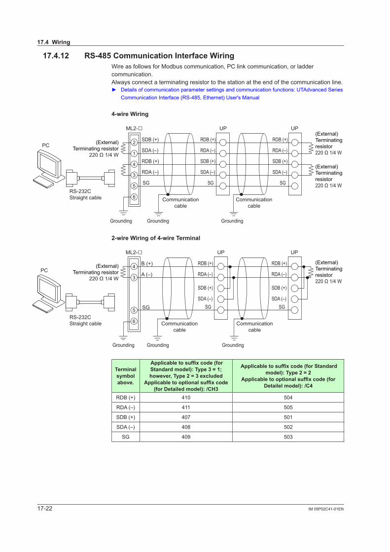
17-22 IM 05P02C41-01EN
17.4.12 RS-485CommunicationInterfaceWiringWire as follows for Modbus communication, PC link communication, or ladder communication.Always connect a terminating resistor to the station at the end of the communication line. Detailsofcommunicationparametersettingsandcommunicationfunctions:UTAdvancedSeries
Communication Interface (RS-485, Ethernet) User's Manual
4-wireWiring
ML2-
SG
SDB (+)
SDA (–)
RDB (+)
RDA (–)
RDB (+)
RDA (–)
SDB (+)
SDA (–)
SG
RDB (+)
RDA (–)
SDB (+)
SDA (–)
SGRS-232CStraight cable
UP
2
1
4
3
5
6
UP
Grounding Grounding Grounding
Communicationcable
Communicationcable
PC (External)Terminating resistor
220 Ω 1/4 W
(External)Terminating resistor220 Ω 1/4 W
(External)Terminating resistor220 Ω 1/4 W
2-wireWiringof4-wireTerminal
SG
ML2- UP
B (+)
A (–)
SDB (+)
SDA (–)
RDB (+)
RDA (–)
SG
SDB (+)
SDA (–)
RDB (+)
RDA (–)
SG
RS-232CStraight cable
PC4
3
5
6
Grounding Grounding Grounding
UP
(External)Terminating resistor
220 Ω 1/4 W
(External)Terminating resistor220 Ω 1/4 W
Communicationcable
Communicationcable
Terminal symbolabove.
Applicabletosuffixcode(forStandardmodel):Type3=1;however,Type2=3excluded
Applicabletooptionalsuffixcode(forDetailedmodel):/CH3
Applicabletosuffixcode(forStandardmodel):Type2=2
Applicabletooptionalsuffixcode(forDetailelmodel):/C4
RDB (+) 410 504
RDA (–) 411 505
SDB (+) 407 501
SDA (–) 408 502
SG 409 503
17.4Wiring
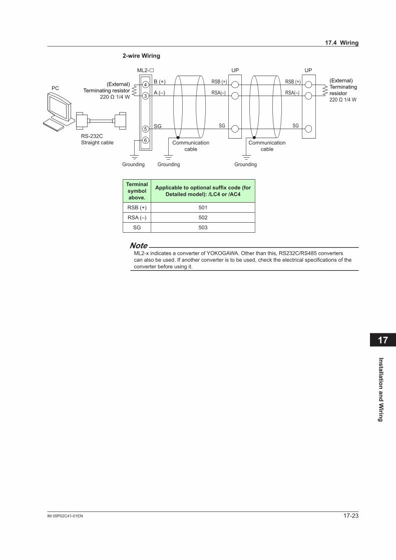
17-23IM 05P02C41-01EN
Installation and Wiring
17
2-wireWiring
SG
ML2-B (+)
A (–)
RSB (+)
RSA(–)
SG
RSB (+)
RSA(–)
SG
RS-232CStraight cable
PC4
3
5
6
UP UP
Grounding Grounding Grounding
(External)Terminating resistor
220 Ω 1/4 W
(External)Terminating resistor220 Ω 1/4 W
Communicationcable
Communicationcable
Terminal symbolabove.
Applicabletooptionalsuffixcode(forDetailedmodel):/LC4or/AC4
RSB (+) 501
RSA (–) 502
SG 503
Note
ML2-x indicates a converter of YOKOGAWA. Other than this, RS232C/RS485 converters can also be used. If another converter is to be used, check the electrical specifications of the converter before using it.
17.4Wiring
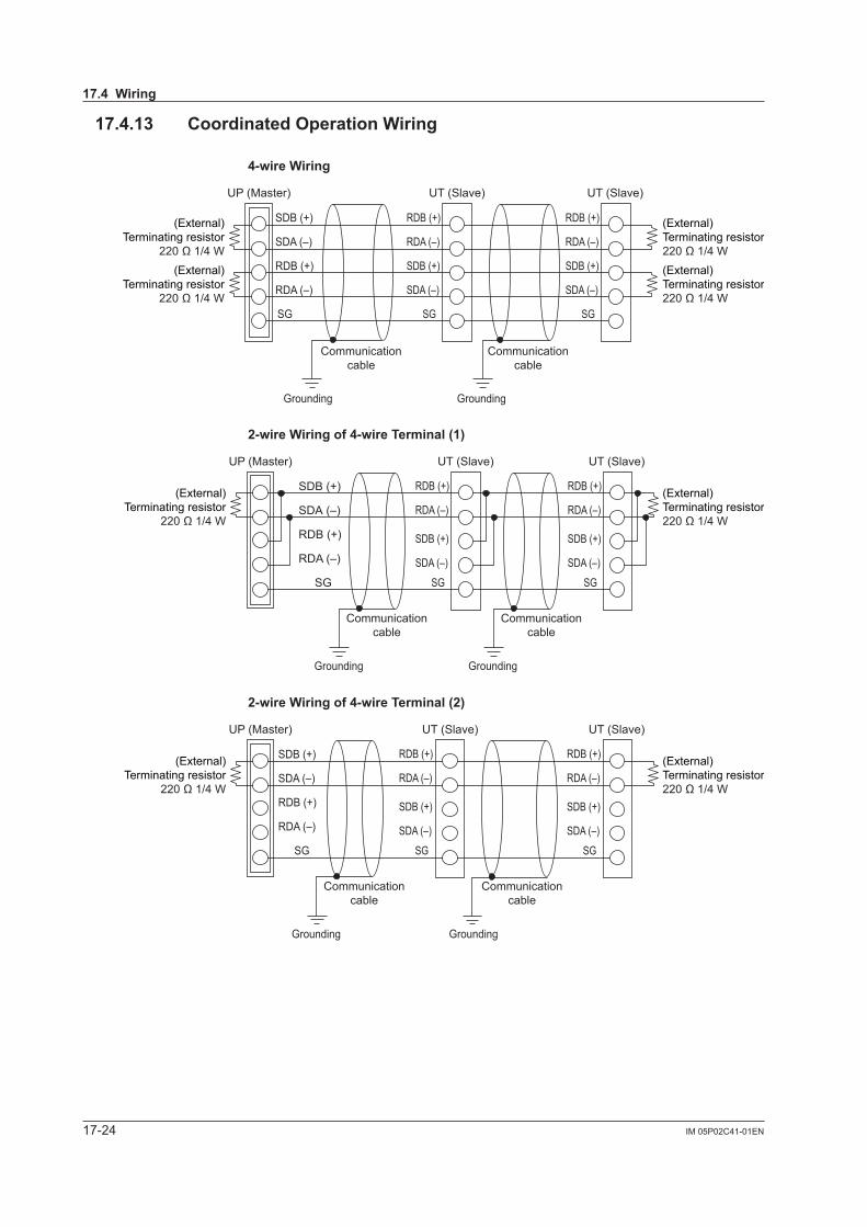
17-24 IM 05P02C41-01EN
17.4.13 CoordinatedOperationWiring
4-wireWiring
UP (Master)
SG
SDB (+)
SDA (–)
RDB (+)
RDA (–)
RDB (+)
RDA (–)
SDB (+)
SDA (–)
SG
RDB (+)
RDA (–)
SDB (+)
SDA (–)
SG
(External)Terminating resistor
220 Ω 1/4 W
(External)Terminating resistor220 Ω 1/4 W
(External)Terminating resistor
220 Ω 1/4 W
(External)Terminating resistor220 Ω 1/4 W
UT (Slave) UT (Slave)
Communicationcable
Communicationcable
Grounding Grounding
2-wireWiringof4-wireTerminal(1)
UP (Master) UT (Slave)
SDB (+)
SDA (–)
RDB (+)
RDA (–)
SG
SDB (+)
SDA (–)
RDB (+)
RDA (–)
SG
SDB (+)
SDA (–)
RDB (+)
RDA (–)
SG
UT (Slave)
Communicationcable
Grounding Grounding
Communicationcable
(External)Terminating resistor
220 Ω 1/4 W
(External)Terminating resistor220 Ω 1/4 W
2-wireWiringof4-wireTerminal(2)
UP (Master)
SDB (+)
SDA (–)
RDB (+)
RDA (–)
SG
SDB (+)
SDA (–)
RDB (+)
RDA (–)
SG
SDB (+)
SDA (–)
RDB (+)
RDA (–)
SG
UT (Slave) UT (Slave)
Communicationcable
Grounding
Communicationcable
Grounding
(External)Terminating resistor
220 Ω 1/4 W
(External)Terminating resistor220 Ω 1/4 W
17.4Wiring
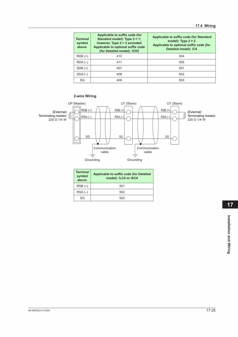
17-25IM 05P02C41-01EN
Installation and Wiring
17
Terminal symbolabove.
Applicabletosuffixcode(forStandardmodel):Type3=1;however,Type2=3excluded
Applicabletooptionalsuffixcode(forDetailedmodel):/CH3
Applicabletosuffixcode(forStandardmodel):Type2=2
Applicabletooptionalsuffixcode(forDetailedmodel):/C4
RDB (+) 410 504
RDA (–) 411 505
SDB (+) 407 501
SDA (–) 408 502
SG 409 503
2-wireWiring
UP (Master) UT (Slave)
RSB (+)
RSA (–)
SG
RSB (+)
RSA (–)
SG
RSB (+)
RSA (–)
SG
UT (Slave)
Communicationcable
Grounding Grounding
Communicationcable
(External)Terminating resistor
220 Ω 1/4 W
(External)Terminating resistor220 Ω 1/4 W
Terminal symbolabove.
Applicabletosuffixcode(forDetailedmodel):/LC4or/AC4
RSB (+) 501
RSA (–) 502
SG 503
17.4Wiring

17-26 IM 05P02C41-01EN
17.4.14 Peer-topeerCommunicationWiringPeer-to-peer communication can be used on ladder program of UP55A.
2-wireWiringof4-wireTerminal
UP
SDB (+)
SDA (–)
RDB (+)
RDA (–)
SG
SDB (+)
SDA (–)
RDB (+)
RDA (–)
SG
SDB (+)
SDA (–)
RDB (+)
RDA (–)
SG
UP UP
Communicationcable
Grounding
Communicationcable
Grounding
(External)Terminating resistor
220 Ω 1/4 W
(External)Terminating resistor220 Ω 1/4 W
Terminal symbolabove.
Applicabletosuffixcode(forStandardmodel):Type3=1;however,Type2=3excluded
Applicabletooptionalsuffixcode(forDetailedmodel):/CH3
Applicabletosuffixcode(forStandardmodel):Type2=2
Applicabletooptionalsuffixcode(forDetailedmodel):/C4
RDB (+) 410 504
RDA (–) 411 505
SDB (+) 407 501
SDA (–) 408 502
SG 409 503
2-wireWiring
UP
RSB (+)
RSA (–)
SG
RSB (+)
RSA (–)
SG
RSB (+)
RSA (–)
SG
UP UP
Communicationcable
Grounding Grounding
Communicationcable
(External)Terminating resistor
220 Ω 1/4 W
(External)Terminating resistor220 Ω 1/4 W
Terminal symbolabove.
Applicabletosuffixcode(forDetailedmodel):/LC4or/AC4
RSB (+) 501
RSA (–) 502
SG 503
Details of communication parameter settings and communication functions: UTAdvanced Series Communication Interface (RS-485, Ethernet) User's Manual
Details of Peer-to-peer communication: LL50A Parameter Setting Software User's Manual
17.4Wiring
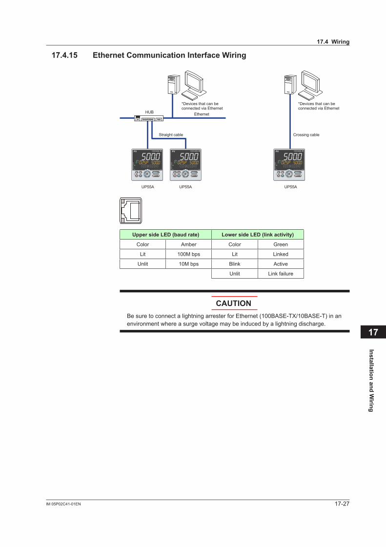
17-27IM 05P02C41-01EN
Installation and Wiring
17
17.4.15 EthernetCommunicationInterfaceWiring
Ethernet
Straight cable
HUB
UP55A UP55A
Crossing cable
*Devices that can be connected via Ethernet
*Devices that can be connected via Ethernet
UP55A
Upper side LED (baud rate) LowersideLED(linkactivity)
Color Amber Color Green
Lit 100M bps Lit Linked
Unlit 10M bps Blink Active
Unlit Link failure
CAUTIONBesuretoconnectalightningarresterforEthernet(100BASE-TX/10BASE-T)inanenvironment where a surge voltage may be induced by a lightning discharge.
17.4Wiring
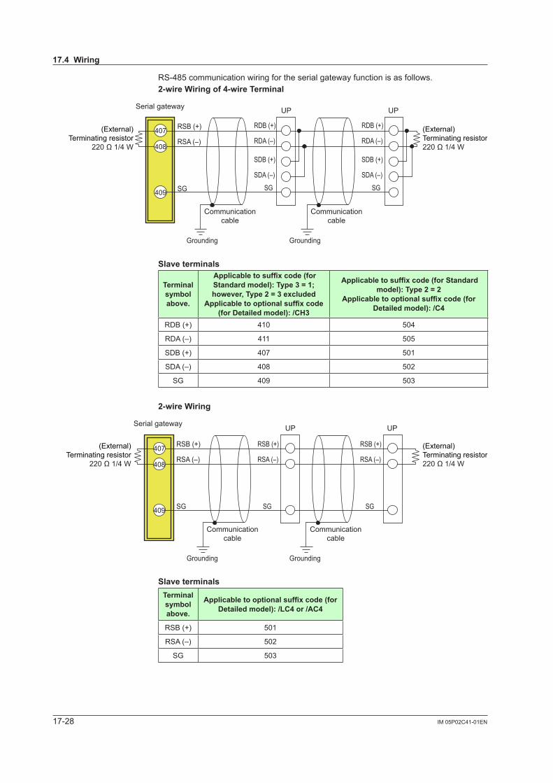
17-28 IM 05P02C41-01EN
RS-485 communication wiring for the serial gateway function is as follows. 2-wireWiringof4-wireTerminal
Serial gateway
SG
RSB (+)
RSA (–)
SDB (+)
SDA (–)
RDB (+)
RDA (–)
SG
SDB (+)
SDA (–)
RDB (+)
RDA (–)
SG
(External)Terminating resistor
220 Ω 1/4 W
(External)Terminating resistor220 Ω 1/4 W
407
408
409
UP UP
Communicationcable
Communicationcable
Grounding Grounding
Slaveterminals
Terminal symbolabove.
Applicabletosuffixcode(forStandardmodel):Type3=1;however,Type2=3excluded
Applicabletooptionalsuffixcode(forDetailedmodel):/CH3
Applicabletosuffixcode(forStandardmodel):Type2=2
Applicabletooptionalsuffixcode(forDetailedmodel):/C4
RDB (+) 410 504
RDA (–) 411 505
SDB (+) 407 501
SDA (–) 408 502
SG 409 503
2-wireWiring
Serial gateway
SG
RSB (+)
RSA (–)
RSB (+)
RSA (–)
SG
RSB (+)
RSA (–)
SG
(External)Terminating resistor220 Ω 1/4 W
(External)Terminating resistor
220 Ω 1/4 W
UP UP
407
408
409
Communicationcable
Communicationcable
Grounding Grounding
SlaveterminalsTerminal symbolabove.
Applicabletooptionalsuffixcode(forDetailedmodel):/LC4or/AC4
RSB (+) 501
RSA (–) 502
SG 503
17.4Wiring
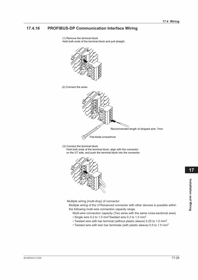
17-29IM 05P02C41-01EN
Installation and Wiring
17
17.4.16 PROFIBUS-DPCommunicationInterfaceWiring
(1) Remove the terminal blockHold both ends of the terminal block and pull straight.
(2) Connect the wires
Flat-blade screwdriver
Recommended length of stripped wire: 7mm
(3) Connect the terminal blockHold both ends of the terminal block, align with the connector on the UT side, and push the terminal block into the connector.
Multiple wiring (multi-drop) of connector Multiple wiring of the UTAdvanced connector with other devices is possible within
the following multi-wire connection capacity range.Multi-wire connection capacity (Two wires with the same cross-sectional area)• Single wire 0.2 to 1.0 mm2/twisted wire 0.2 to 1.5 mm2
• Twisted wire with bar terminal (without plastic sleeve) 0.25 to 1.0 mm2
• Twisted wire with twin bar terminals (with plastic sleeve) 0.5 to 1.5 mm2
17.4Wiring
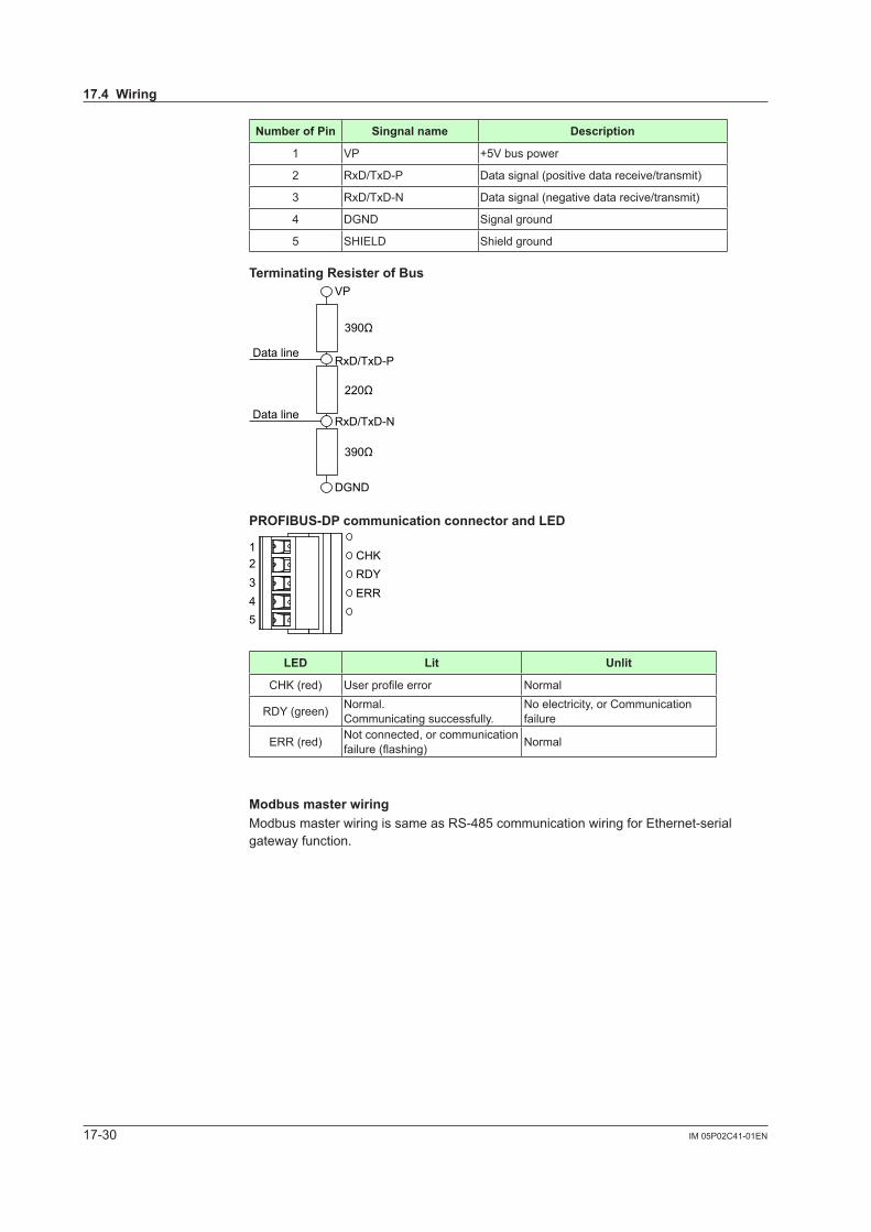
17-30 IM 05P02C41-01EN
NumberofPin Singnalname Description
1 VP +5V bus power
2 RxD/TxD-P Data signal (positive data receive/transmit)
3 RxD/TxD-N Data signal (negative data recive/transmit)
4 DGND Signal ground
5 SHIELD Shield ground
TerminatingResisterofBus
VP
RxD/TxD-PData line
Data line
390Ω
220Ω
390Ω
RxD/TxD-N
DGND
PROFIBUS-DPcommunicationconnectorandLED
CHK12345
RDYERR
LED Lit Unlit
CHK (red) Userprofileerror Normal
RDY (green) Normal.Communicating successfully.
No electricity, or Communication failure
ERR (red) Not connected, or communication failure(flashing) Normal
ModbusmasterwiringModbus master wiring is same as RS-485 communication wiring for Ethernet-serial gateway function.
17.4Wiring
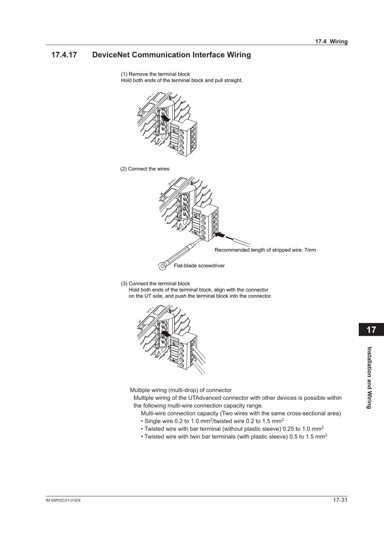
17-31IM 05P02C41-01EN
Installation and Wiring
17
17.4.17 DeviceNetCommunicationInterfaceWiring
(1) Remove the terminal blockHold both ends of the terminal block and pull straight.
(2) Connect the wires
Flat-blade screwdriver
Recommended length of stripped wire: 7mm
(3) Connect the terminal blockHold both ends of the terminal block, align with the connector on the UT side, and push the terminal block into the connector.
Multiple wiring (multi-drop) of connector Multiple wiring of the UTAdvanced connector with other devices is possible within
the following multi-wire connection capacity range.Multi-wire connection capacity (Two wires with the same cross-sectional area)• Single wire 0.2 to 1.0 mm2/twisted wire 0.2 to 1.5 mm2
• Twisted wire with bar terminal (without plastic sleeve) 0.25 to 1.0 mm2
• Twisted wire with twin bar terminals (with plastic sleeve) 0.5 to 1.5 mm2
17.4Wiring
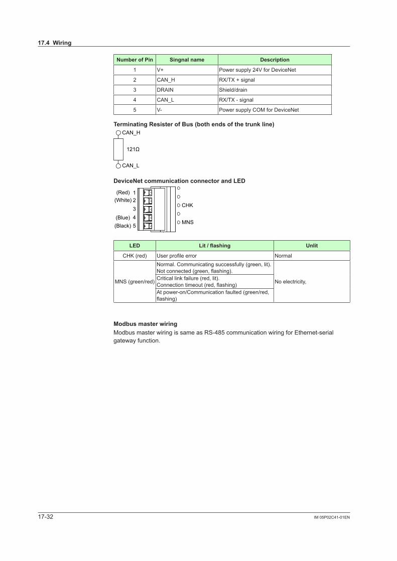
17-32 IM 05P02C41-01EN
NumberofPin Singnalname Description
1 V+ Power supply 24V for DeviceNet
2 CAN_H RX/TX+signal
3 DRAIN Shield/drain
4 CAN_L RX/TX-signal
5 V- Power supply COM for DeviceNet
TerminatingResisterofBus(bothendsofthetrunkline)
CAN_H
CAN_L
121Ω
DeviceNetcommunicationconnectorandLED
CHK
MNS
12345
(Red)(White)
(Blue)(Black)
LED Lit/flashing Unlit
CHK (red) Userprofileerror Normal
MNS (green/red)
Normal. Communicating successfully (green, lit).Notconnected(green,flashing).
No electricity,Critical link failure (red, lit).Connectiontimeout(red,flashing)At power-on/Communication faulted (green/red, flashing)
ModbusmasterwiringModbus master wiring is same as RS-485 communication wiring for Ethernet-serial gateway function.
17.4Wiring
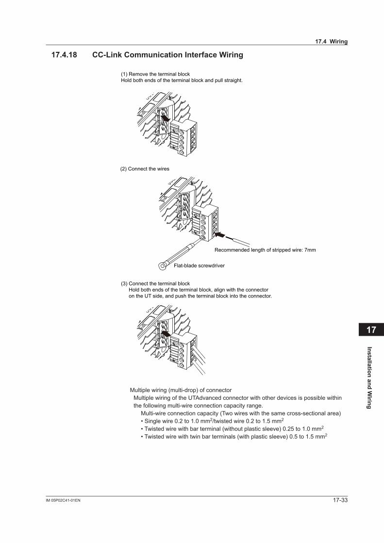
17-33IM 05P02C41-01EN
Installation and Wiring
17
17.4.18 CC-LinkCommunicationInterfaceWiring
(1) Remove the terminal blockHold both ends of the terminal block and pull straight.
(2) Connect the wires
Flat-blade screwdriver
Recommended length of stripped wire: 7mm
(3) Connect the terminal blockHold both ends of the terminal block, align with the connector on the UT side, and push the terminal block into the connector.
Multiple wiring (multi-drop) of connector Multiple wiring of the UTAdvanced connector with other devices is possible within
the following multi-wire connection capacity range.Multi-wire connection capacity (Two wires with the same cross-sectional area)• Single wire 0.2 to 1.0 mm2/twisted wire 0.2 to 1.5 mm2
• Twisted wire with bar terminal (without plastic sleeve) 0.25 to 1.0 mm2
• Twisted wire with twin bar terminals (with plastic sleeve) 0.5 to 1.5 mm2
17.4Wiring
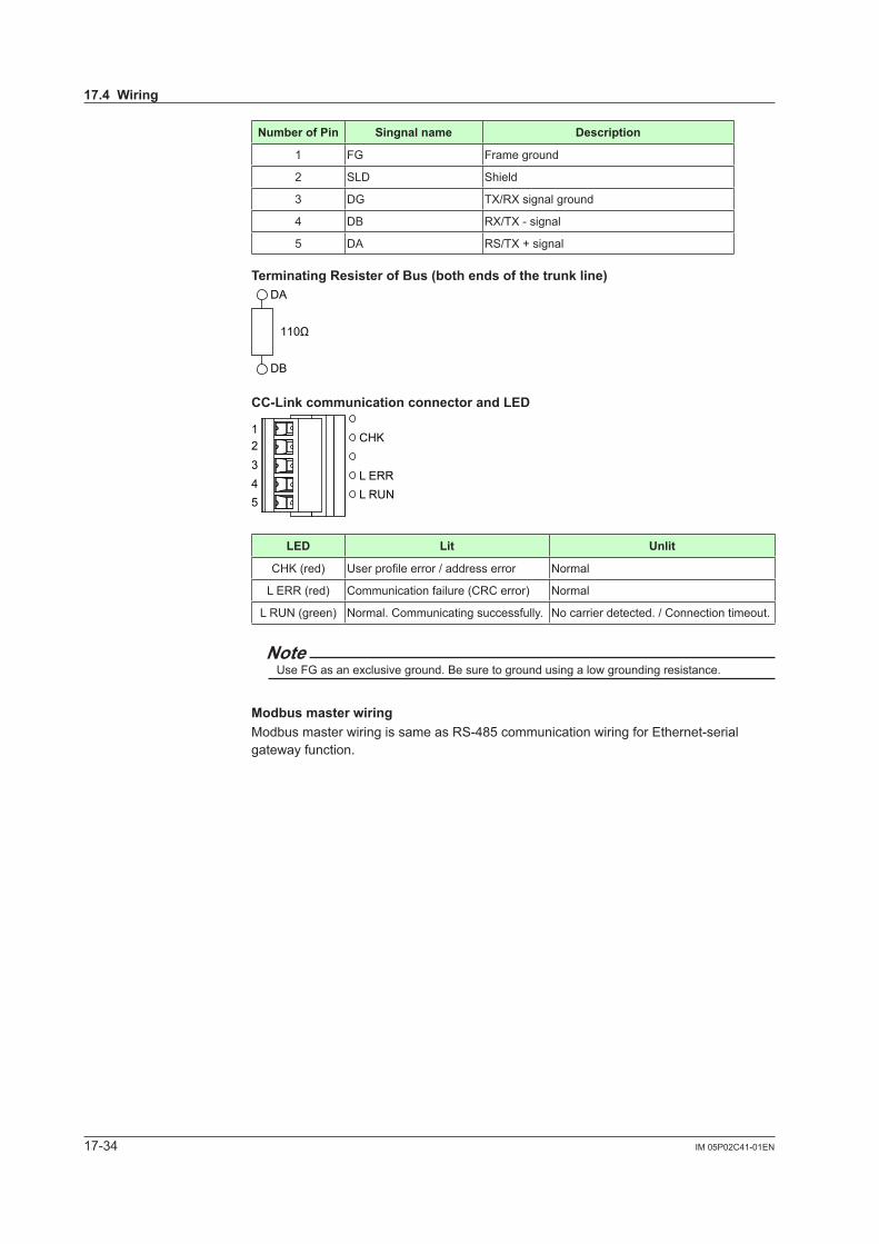
17-34 IM 05P02C41-01EN
NumberofPin Singnalname Description
1 FG Frame ground
2 SLD Shield
3 DG TX/RXsignalground
4 DB RX/TX-signal
5 DA RS/TX+signal
TerminatingResisterofBus(bothendsofthetrunkline)
DA
DB
110Ω
CC-LinkcommunicationconnectorandLED
CHK
L RUNL ERR
12345
LED Lit Unlit
CHK (red) Userprofileerror/addresserror Normal
L ERR (red) Communication failure (CRC error) Normal
L RUN (green) Normal. Communicating successfully. No carrier detected. / Connection timeout.
NoteUse FG as an exclusive ground. Be sure to ground using a low grounding resistance.
ModbusmasterwiringModbus master wiring is same as RS-485 communication wiring for Ethernet-serial gateway function.
17.4Wiring
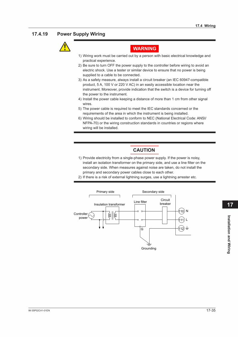
17-35IM 05P02C41-01EN
Installation and Wiring
17
17.4.19 PowerSupplyWiring
WARNING1) Wiring work must be carried out by a person with basic electrical knowledge and
practical experience.2) Be sure to turn OFF the power supply to the controller before wiring to avoid an
electric shock. Use a tester or similar device to ensure that no power is being supplied to a cable to be connected.
3) As a safety measure, always install a circuit breaker (an IEC 60947-compatible product, 5 A, 100 V or 220 V AC) in an easily accessible location near the instrument. Moreover, provide indication that the switch is a device for turning off the power to the instrument.
4) Install the power cable keeping a distance of more than 1 cm from other signal wires.
5) The power cable is required to meet the IEC standards concerned or the requirements of the area in which the instrument is being installed.
6) Wiring should be installed to conform to NEC (National Electrical Code: ANSI/NFPA-70) or the wiring construction standards in countries or regions where wiring will be installed.
CAUTION1) Provide electricity from a single-phase power supply. If the power is noisy,
install an isolation transformer on the primary side, and use a line filter on the secondary side. When measures against noise are taken, do not install the primary and secondary power cables close to each other.
2) If there is a risk of external lightning surges, use a lightning arrester etc.
111
110
L
N
CircuitbreakerLine filter
Insulation transformer
Primary side Secondary side
Controllerpower
112
Grounding
G
17.4Wiring
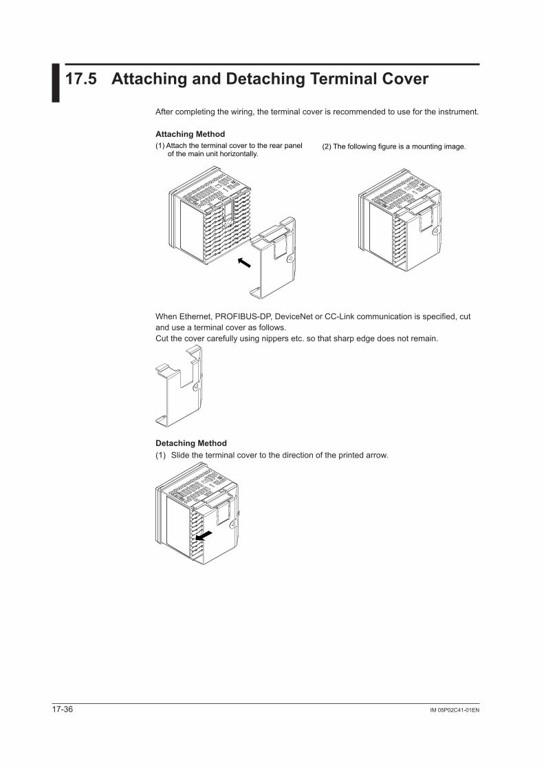
17-36 IM 05P02C41-01EN
17.5 AttachingandDetachingTerminalCover
After completing the wiring, the terminal cover is recommended to use for the instrument.
Attaching Method
(2) The following figure is a mounting image.(1) Attach the terminal cover to the rear panel of the main unit horizontally.
When Ethernet, PROFIBUS-DP, DeviceNet or CC-Link communication is specified, cut and use a terminal cover as follows.Cut the cover carefully using nippers etc. so that sharp edge does not remain.
Detaching Method(1) Slide the terminal cover to the direction of the printed arrow.
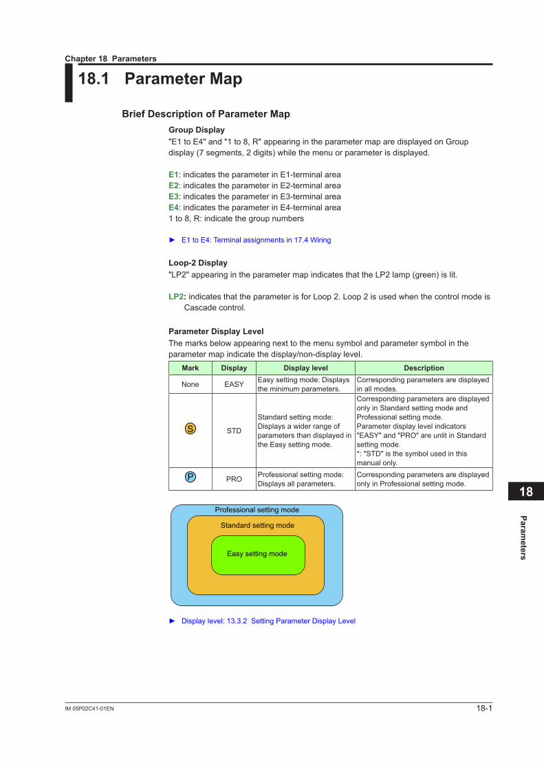
18-1IM 05P02C41-01EN
Parameters
18
18.1 ParameterMap
BriefDescriptionofParameterMapGroupDisplay"E1 to E4" and "1 to 8, R" appearing in the parameter map are displayed on Group display (7 segments, 2 digits) while the menu or parameter is displayed.
E1: indicates the parameter in E1-terminal areaE2: indicates the parameter in E2-terminal areaE3: indicates the parameter in E3-terminal areaE4: indicates the parameter in E4-terminal area1 to 8, R: indicate the group numbers
E1toE4:Terminalassignmentsin17.4Wiring
Loop-2Display"LP2" appearing in the parameter map indicates that the LP2 lamp (green) is lit.
LP2:indicates that the parameter is for Loop 2. Loop 2 is used when the control mode is Cascade control.
ParameterDisplayLevelThe marks below appearing next to the menu symbol and parameter symbol in the parameter map indicate the display/non-display level.
Mark Display Displaylevel Description
None EASY Easy setting mode: Displays the minimum parameters.
Corresponding parameters are displayed in all modes.
S STD
Standard setting mode: Displays a wider range of parameters than displayed in the Easy setting mode.
Corresponding parameters are displayed only in Standard setting mode and Professional setting mode.Parameter display level indicators "EASY" and "PRO" are unlit in Standard setting mode.*: "STD" is the symbol used in this manual only.
P PRO Professional setting mode: Displays all parameters.
Corresponding parameters are displayed only in Professional setting mode.
Professional setting mode
Standard setting mode
Easy setting mode
Displaylevel:13.3.2SettingParameterDisplayLevel
Chapter18Parameters
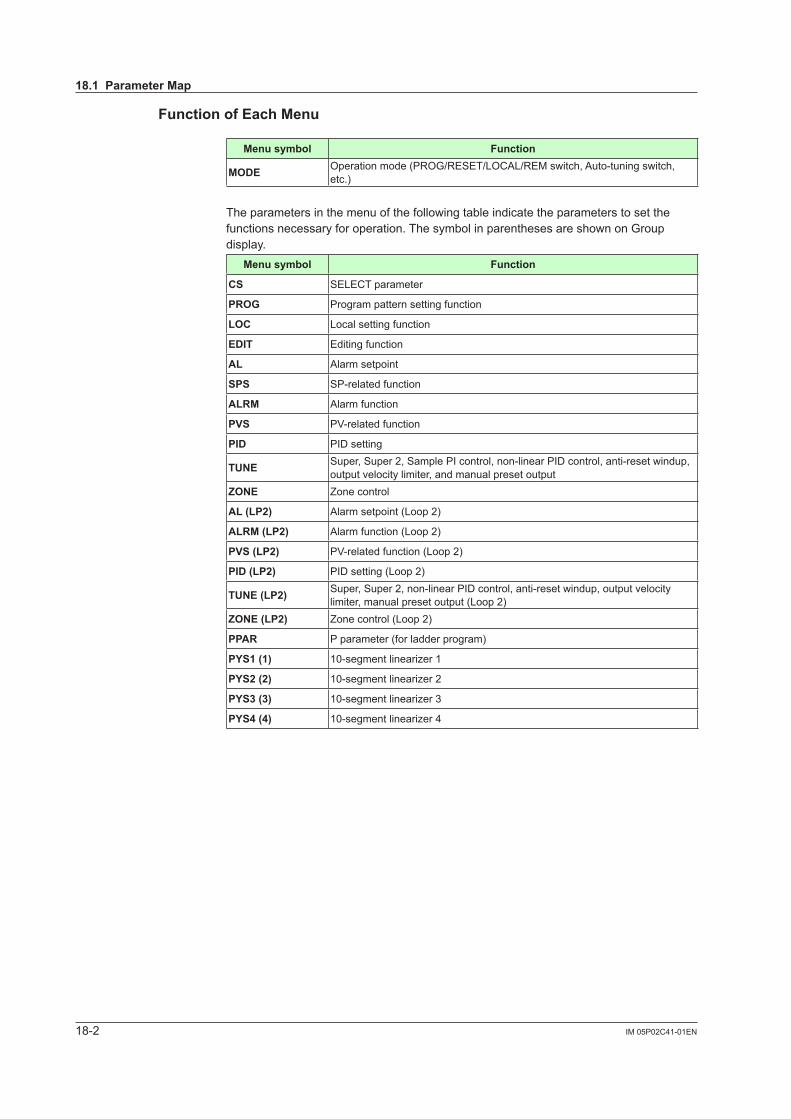
18-2 IM 05P02C41-01EN
FunctionofEachMenu
Menusymbol Function
MODE Operation mode (PROG/RESET/LOCAL/REM switch, Auto-tuning switch, etc.)
The parameters in the menu of the following table indicate the parameters to set the functions necessary for operation. The symbol in parentheses are shown on Group display.
Menusymbol Function
CS SELECT parameter
PROG Program pattern setting function
LOC Local setting function
EDIT Editing function
AL Alarm setpoint
SPS SP-related function
ALRM Alarm function
PVS PV-related function
PID PID setting
TUNE Super, Super 2, Sample PI control, non-linear PID control, anti-reset windup, output velocity limiter, and manual preset output
ZONE Zone control
AL(LP2) Alarm setpoint (Loop 2)
ALRM(LP2) Alarm function (Loop 2)
PVS(LP2) PV-related function (Loop 2)
PID(LP2) PID setting (Loop 2)
TUNE(LP2) Super, Super 2, non-linear PID control, anti-reset windup, output velocity limiter, manual preset output (Loop 2)
ZONE(LP2) Zone control (Loop 2)
PPAR P parameter (for ladder program)
PYS1(1) 10-segmentlinearizer1
PYS2(2) 10-segmentlinearizer2
PYS3(3) 10-segmentlinearizer3
PYS4(4) 10-segmentlinearizer4
18.1ParameterMap
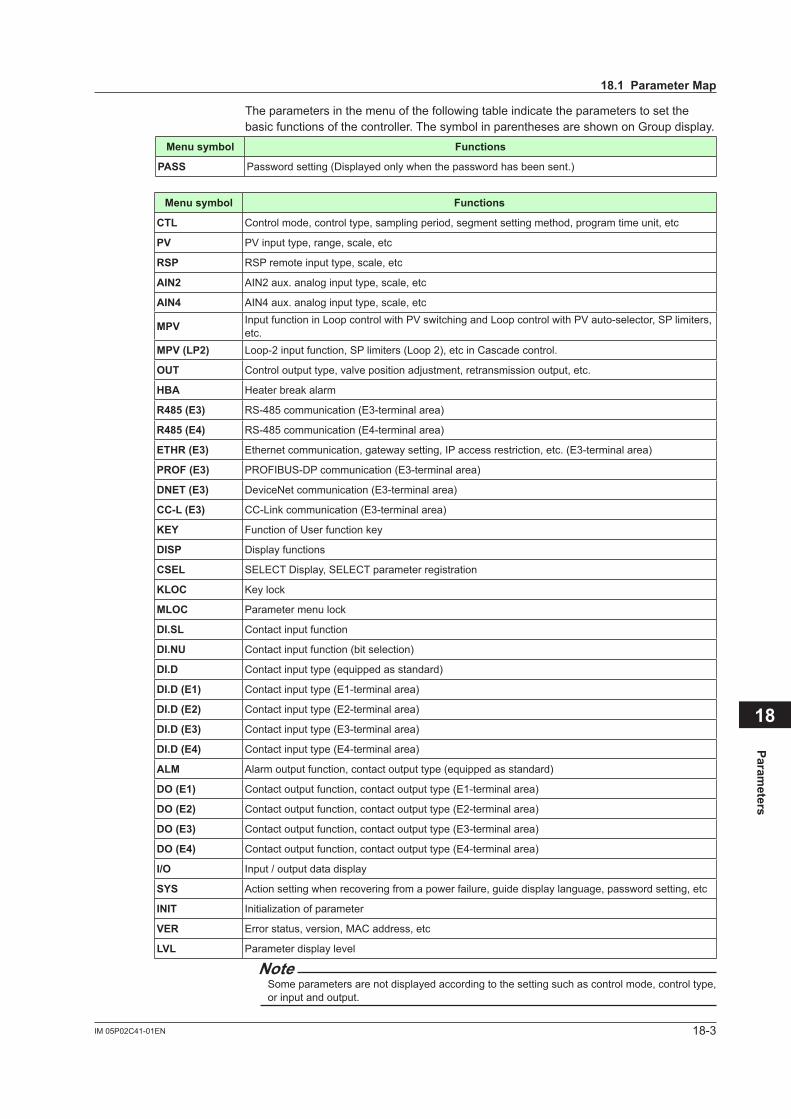
18-3IM 05P02C41-01EN
Parameters
18
The parameters in the menu of the following table indicate the parameters to set the basic functions of the controller. The symbol in parentheses are shown on Group display.
Menusymbol Functions
PASS Password setting (Displayed only when the password has been sent.)
Menusymbol Functions
CTL Control mode, control type, sampling period, segment setting method, program time unit, etc
PV PV input type, range, scale, etc
RSP RSP remote input type, scale, etc
AIN2 AIN2 aux. analog input type, scale, etc
AIN4 AIN4 aux. analog input type, scale, etc
MPV Input function in Loop control with PV switching and Loop control with PV auto-selector, SP limiters, etc.
MPV(LP2) Loop-2 input function, SP limiters (Loop 2), etc in Cascade control.
OUT Controloutputtype,valvepositionadjustment,retransmissionoutput,etc.
HBA Heater break alarm
R485 (E3) RS-485 communication (E3-terminal area)
R485 (E4) RS-485 communication (E4-terminal area)
ETHR (E3) Ethernet communication, gateway setting, IP access restriction, etc. (E3-terminal area)
PROF(E3) PROFIBUS-DP communication (E3-terminal area)
DNET (E3) DeviceNet communication (E3-terminal area)
CC-L(E3) CC-Link communication (E3-terminal area)
KEY Function of User function key
DISP Display functions
CSEL SELECT Display, SELECT parameter registration
KLOC Key lock
MLOC Parameter menu lock
DI.SL Contact input function
DI.NU Contact input function (bit selection)
DI.D Contact input type (equipped as standard)
DI.D(E1) Contact input type (E1-terminal area)
DI.D(E2) Contact input type (E2-terminal area)
DI.D (E3) Contact input type (E3-terminal area)
DI.D (E4) Contact input type (E4-terminal area)
ALM Alarm output function, contact output type (equipped as standard)
DO(E1) Contact output function, contact output type (E1-terminal area)
DO(E2) Contact output function, contact output type (E2-terminal area)
DO(E3) Contact output function, contact output type (E3-terminal area)
DO(E4) Contact output function, contact output type (E4-terminal area)
I/O Input / output data display
SYS Action setting when recovering from a power failure, guide display language, password setting, etc
INIT Initializationofparameter
VER Error status, version, MAC address, etc
LVL Parameter display level
NoteSome parameters are not displayed according to the setting such as control mode, control type, or input and output.
18.1ParameterMap
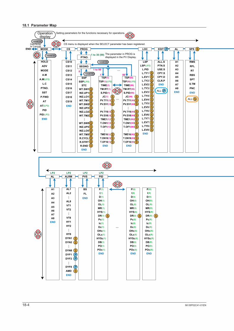
18-4 IM 05P02C41-01EN
CS10
CS11
CS12
CS13
CS14
CS15
CS16
CS17
CS18
CS19
END
A1A2A3A4A5A6A7A8
END
RMS
RFL
RT
RBS
SPT
S.TM
PNC
END
EHY1EHY2
EHY8AL1AL2
AL8VT1VT2
VT8HY1HY2
HY8DYN1DYN2
DYN8DYF1DYF2
DYF8AMDEND
SSPSSP(LP2)
STCWT.SW1WZ.UP1WZ.LO1WT.TM1WT.SW2WZ.UP2WZ.LO2WT.TM2
WT.SW5WZ.UP5WZ.LO5WT.TM5R.CYCLR.STRTR.ENDEND
CS PROG AL
LSPLSP(LP2)
L.PIDL.TY1L.EV1L.TY2L.EV2L.TY3L.EV3L.TY4L.EV4L.TY5L.EV5L.TY6L.EV6L.TY7L.EV7L.TY8L.EV8END
LOC
ALL.SPTN.SUSE.SCPY.SCPY.DCLR.PEND
EDIT
BS
FL
END
P(1)
I(1)
D(1)
OH(1)
OL(1)
MR(1)
HYS(1)
HY.UP(1)
HY.LO(1)
DR(1)
Pc(1)
Ic(1)
Dc(1)
OHc(1)
OLc(1)
HYSc(1)
DB(1)
PO(1)
POc(1)
END
P(8)
I(8)
D(8)
OH(8)
OL(8)
MR(8)
HYS(8)
HY.UP(8)
HY.LO(8)
DR(8)
Pc(8)
Ic(8)
Dc(8)
OHc(8)
OLc(8)
HYSc(8)
DB(8)
PO(8)
POc(8)
END
P(R)
I(R)
D(R)
OH(R)
OL(R)
MR(R)
HYS(R)
HY.UP(R)
HY.LO(R)
DR(R)
Pc(R)
Ic(R)
Dc(R)
OHc(R)
OLc(R)
HYSc(R)
DB(R)
PO(R)
POc(R)
END
PVS PID
SC
AT.TY
AT.OH
AT.OL
AT.BS
GW
GG
AR
OPR
OLMT
MPON
MPO1
MPO5
END
TUNESPS ALRMMODE
TSP(1)
TSP(1)(LP2)
TIME(1)
TM.RT(1)
S.PID(1)
JC(1)
PV.TY1(1)
PV.EV1(1)
PV.TY8(1)
PV.EV8(1)
TME1(1)
T.ON1(1)
T.OF1(1)
TME16(1)
T.ON16(1)
T.OF16(1)
END
RP1
RP2
RP3
RP4
RP5
RP6
RP7
RHY
RDV
END
ZONE
A1
A2
A3
A4
A5A6A7A8
END
BS
FL
END
AL
PYS(1)A1(1)B1(1)A2(1)B2(1)A3(1)B3(1)A4(1)B4(1)A5(1)B5(1)A6(1)B6(1)A7(1)B7(1)A8(1)B8(1)A9(1)B9(1)
A10(1)B10(1)A11(1)B11(1)PMD(1)
END
PYS(2)A1(2)B1(2)A2(2)B2(2)A3(2)B3(2)A4(2)B4(2)A5(2)B5(2)A6(2)B6(2)A7(2)B7(2)A8(2)B8(2)A9(2)B9(2)
A10(2)B10(2)A11(2)B11(2)PMD(2)
END
PYS(3)A1(3)B1(3)A2(3)B2(3)A3(3)B3(3)A4(3)B4(3)A5(3)B5(3)A6(3)B6(3)A7(3)B7(3)A8(3)B8(3)A9(3)B9(3)
A10(3)B10(3)A11(3)B11(3)PMD(3)
END
PYS(4)A1(4)B1(4)A2(4)B2(4)A3(4)B3(4)A4(4)B4(4)A5(4)B5(4)A6(4)B6(4)A7(4)B7(4)A8(4)B8(4)A9(4)B9(4)
A10(4)B10(4)A11(4)B11(4)PMD(4)
END
ZONE PYS1TUNE
SC
AT.TY
AT.OH
AT.OL
AT.BS
GW
GG
AR
OPR
OLMT
MPON
MPO1
MPO2
MPO3
MPO4
MPO5
END
PYS2ALRM PVS
P(1)
I(1)
D(1)
OH(1)
OL(1)
MR(1)
HYS(1)
DR(1)
Pc(1)
Ic(1)
Dc(1)
OHc(1)
OLc(1)
HYSc(1)
DB(1)
PO(1)
POc(1)
END
PID
RP1
RP2
RP3
RP4
RP5
RP6
RP7
RHY
RDV
END
PYS3 PYS4 END
1 to 30 (99)
1 to 99
1 990
LP2 LP2 LP2 LP2 LP2 LP2 1 2 3 4
The parameter in PROG is displayed in the PV Display.
END
……
……
……
…
…
…
…
TSP(99)
TSP(99)(LP2)
TIME(99)
TM.RT(99)
S.PID(99)
JC(99)
PV.TY1(99)
PV.EV1(99)
PV.TY8(99)
PV.EV8(99)
TME1(99)
T.ON1(99)
T.OF1(99)
TME16(99)
T.ON16(99)
T.OF16(99)
END
……
P
PP
P
S
S
S
S
S
SSS
SSSSS
SSS
SSS
SSSSS
SSS
SSSSSSS
SSSSSSS
SSSSSSSSSSSSSSS
S
S
S
SS
PPPPP
P
S
SS
S S SSS
S
S
S SS PPAR
P01
P02
P03
P04
P05
P06
P07
P08
P09
P10
END
S
P
P P
PPPP
P
S
SS
SSSSSS
AL1AL2
AL8VT1VT2
VT8HY1HY2
HY8DYN1DYN2
DYN8DYF1DYF2
DYF8AMDEND
PP
P
SS
S
S
HOLD
ADV
MODE
A.M
A.M(LP2)
L.C
PTNO.
SST
P.FWD
AT
AT(LP2)
PID
PID(LP2)
END
PTNO.
SEGNO.
P(8)
I(8)
D(8)
OH(8)
OL(8)
MR(8)
HYS(8)
DR(8)
Pc(8)
Ic(8)
Dc(8)
OHc(8)
OLc(8)
HYSc(8)
DB(8)
PO(8)
POc(8)
END
P(R)
I(R)
D(R)
OH(R)
OL(R)
MR(R)
HYS(R)
DR(R)
Pc(R)
Ic(R)
Dc(R)
OHc(R)
OLc(R)
HYSc(R)
DB(R)
PO(R)
POc(R)
END
…
…
…
…
MODE
S S S
……
……
…
Operation display
Setting parameters for the functions necessary for operations.
Press the keyfor 3 seconds.
CS menu is displayed when the SELECT parameter has been registered.
SALL
PALL
SALL
SALL
SALL
SALL SALL PALL PALL
18.1ParameterMap
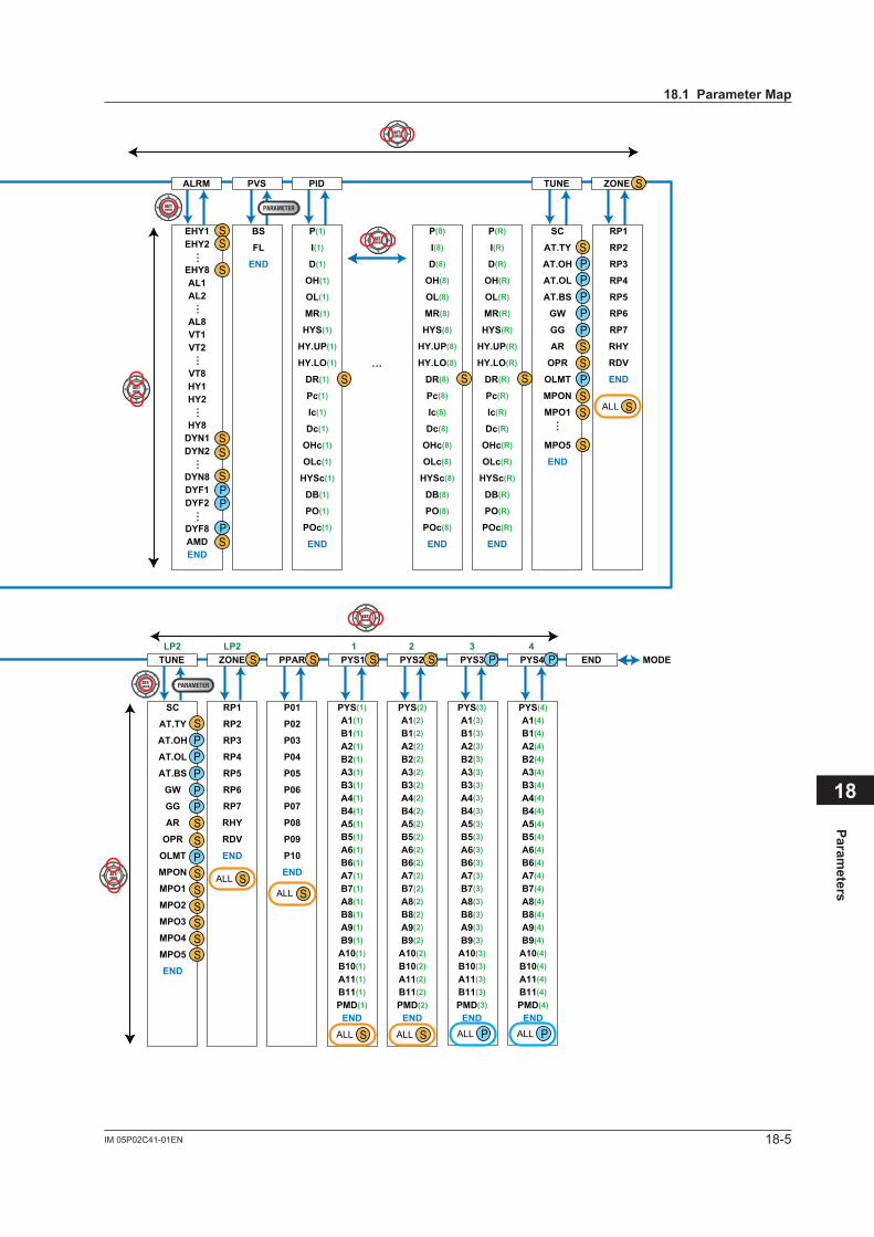
18-5IM 05P02C41-01EN
Parameters
18
CS10
CS11
CS12
CS13
CS14
CS15
CS16
CS17
CS18
CS19
END
A1A2A3A4A5A6A7A8
END
RMS
RFL
RT
RBS
SPT
S.TM
PNC
END
EHY1EHY2
EHY8AL1AL2
AL8VT1VT2
VT8HY1HY2
HY8DYN1DYN2
DYN8DYF1DYF2
DYF8AMDEND
SSPSSP(LP2)
STCWT.SW1WZ.UP1WZ.LO1WT.TM1WT.SW2WZ.UP2WZ.LO2WT.TM2
WT.SW5WZ.UP5WZ.LO5WT.TM5R.CYCLR.STRTR.ENDEND
CS PROG AL
LSPLSP(LP2)
L.PIDL.TY1L.EV1L.TY2L.EV2L.TY3L.EV3L.TY4L.EV4L.TY5L.EV5L.TY6L.EV6L.TY7L.EV7L.TY8L.EV8END
LOC
ALL.SPTN.SUSE.SCPY.SCPY.DCLR.PEND
EDIT
BS
FL
END
P(1)
I(1)
D(1)
OH(1)
OL(1)
MR(1)
HYS(1)
HY.UP(1)
HY.LO(1)
DR(1)
Pc(1)
Ic(1)
Dc(1)
OHc(1)
OLc(1)
HYSc(1)
DB(1)
PO(1)
POc(1)
END
P(8)
I(8)
D(8)
OH(8)
OL(8)
MR(8)
HYS(8)
HY.UP(8)
HY.LO(8)
DR(8)
Pc(8)
Ic(8)
Dc(8)
OHc(8)
OLc(8)
HYSc(8)
DB(8)
PO(8)
POc(8)
END
P(R)
I(R)
D(R)
OH(R)
OL(R)
MR(R)
HYS(R)
HY.UP(R)
HY.LO(R)
DR(R)
Pc(R)
Ic(R)
Dc(R)
OHc(R)
OLc(R)
HYSc(R)
DB(R)
PO(R)
POc(R)
END
PVS PID
SC
AT.TY
AT.OH
AT.OL
AT.BS
GW
GG
AR
OPR
OLMT
MPON
MPO1
MPO5
END
TUNESPS ALRMMODE
TSP(1)
TSP(1)(LP2)
TIME(1)
TM.RT(1)
S.PID(1)
JC(1)
PV.TY1(1)
PV.EV1(1)
PV.TY8(1)
PV.EV8(1)
TME1(1)
T.ON1(1)
T.OF1(1)
TME16(1)
T.ON16(1)
T.OF16(1)
END
RP1
RP2
RP3
RP4
RP5
RP6
RP7
RHY
RDV
END
ZONE
A1
A2
A3
A4
A5A6A7A8
END
BS
FL
END
AL
PYS(1)A1(1)B1(1)A2(1)B2(1)A3(1)B3(1)A4(1)B4(1)A5(1)B5(1)A6(1)B6(1)A7(1)B7(1)A8(1)B8(1)A9(1)B9(1)
A10(1)B10(1)A11(1)B11(1)PMD(1)
END
PYS(2)A1(2)B1(2)A2(2)B2(2)A3(2)B3(2)A4(2)B4(2)A5(2)B5(2)A6(2)B6(2)A7(2)B7(2)A8(2)B8(2)A9(2)B9(2)
A10(2)B10(2)A11(2)B11(2)PMD(2)
END
PYS(3)A1(3)B1(3)A2(3)B2(3)A3(3)B3(3)A4(3)B4(3)A5(3)B5(3)A6(3)B6(3)A7(3)B7(3)A8(3)B8(3)A9(3)B9(3)
A10(3)B10(3)A11(3)B11(3)PMD(3)
END
PYS(4)A1(4)B1(4)A2(4)B2(4)A3(4)B3(4)A4(4)B4(4)A5(4)B5(4)A6(4)B6(4)A7(4)B7(4)A8(4)B8(4)A9(4)B9(4)
A10(4)B10(4)A11(4)B11(4)PMD(4)
END
ZONE PYS1TUNE
SC
AT.TY
AT.OH
AT.OL
AT.BS
GW
GG
AR
OPR
OLMT
MPON
MPO1
MPO2
MPO3
MPO4
MPO5
END
PYS2ALRM PVS
P(1)
I(1)
D(1)
OH(1)
OL(1)
MR(1)
HYS(1)
DR(1)
Pc(1)
Ic(1)
Dc(1)
OHc(1)
OLc(1)
HYSc(1)
DB(1)
PO(1)
POc(1)
END
PID
RP1
RP2
RP3
RP4
RP5
RP6
RP7
RHY
RDV
END
PYS3 PYS4 END
1 to 30 (99)
1 to 99
1 990
LP2 LP2 LP2 LP2 LP2 LP2 1 2 3 4
The parameter in PROG is displayed in the PV Display.
END
……
……
……
…
…
…
…
TSP(99)
TSP(99)(LP2)
TIME(99)
TM.RT(99)
S.PID(99)
JC(99)
PV.TY1(99)
PV.EV1(99)
PV.TY8(99)
PV.EV8(99)
TME1(99)
T.ON1(99)
T.OF1(99)
TME16(99)
T.ON16(99)
T.OF16(99)
END
……
P
PP
P
S
S
S
S
S
SSS
SSSSS
SSS
SSS
SSSSS
SSS
SSSSSSS
SSSSSSS
SSSSSSSSSSSSSSS
S
S
S
SS
PPPPP
P
S
SS
S S SSS
S
S
S SS PPAR
P01
P02
P03
P04
P05
P06
P07
P08
P09
P10
END
S
P
P P
PPPP
P
S
SS
SSSSSS
AL1AL2
AL8VT1VT2
VT8HY1HY2
HY8DYN1DYN2
DYN8DYF1DYF2
DYF8AMDEND
PP
P
SS
S
S
HOLD
ADV
MODE
A.M
A.M(LP2)
L.C
PTNO.
SST
P.FWD
AT
AT(LP2)
PID
PID(LP2)
END
PTNO.
SEGNO.
P(8)
I(8)
D(8)
OH(8)
OL(8)
MR(8)
HYS(8)
DR(8)
Pc(8)
Ic(8)
Dc(8)
OHc(8)
OLc(8)
HYSc(8)
DB(8)
PO(8)
POc(8)
END
P(R)
I(R)
D(R)
OH(R)
OL(R)
MR(R)
HYS(R)
DR(R)
Pc(R)
Ic(R)
Dc(R)
OHc(R)
OLc(R)
HYSc(R)
DB(R)
PO(R)
POc(R)
END
…
…
…
…
MODE
S S S
……
……
…
Operation display
Setting parameters for the functions necessary for operations.
Press the keyfor 3 seconds.
CS menu is displayed when the SELECT parameter has been registered.
SALL
PALL
SALL
SALL
SALL
SALL SALL PALL PALL
18.1ParameterMap
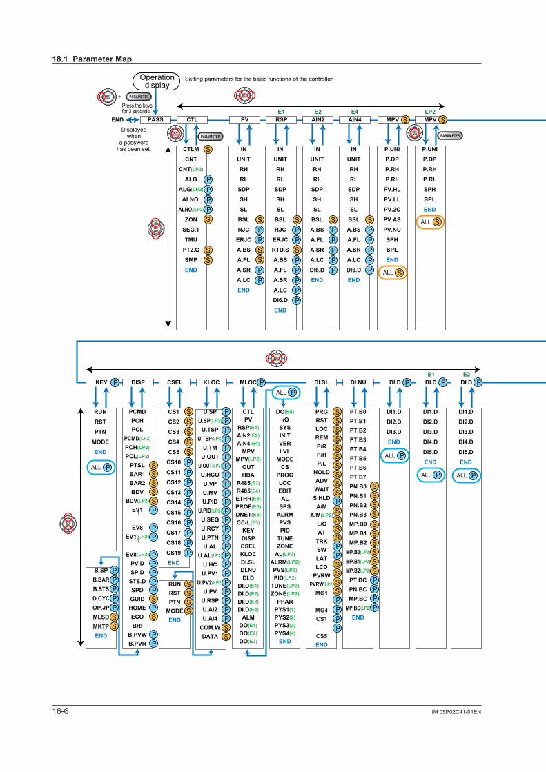
18-6 IM 05P02C41-01EN
BR
ADR
BPS
FILE
SCAN
END
IN
UNIT
RH
RL
SDP
SH
SL
BSL
A.BS
A.FL
A.SR
A.LC
DI6.D
END
IN
UNIT
RH
RL
SDP
SH
SL
BSL
A.BS
A.FL
A.SR
A.LC
DI6.D
END
IN
UNIT
RH
RL
SDP
SH
SL
BSL
RJC
ERJC
RTD.S
A.BS
A.FL
A.SR
A.LC
DI6.D
END
IN
UNIT
RH
RL
SDP
SH
SL
BSL
RJC
ERJC
A.BS
A.FL
A.SR
A.LC
END
CTLM
CNT
CNT(LP2)
ALG
ALG(LP2)
ALNO.
ALNO.(LP2)
ZON
SEG.T
TMU
PT2.G
SMP
END
HSRBPSPRIIP1IP2IP3IP4
SM1SM2SM3SM4DG1DG2DG3DG4PRTIPAR1.IP11.IP2
PSL
BPS
PRI
STP
DLN
ADR
RP.T
END
PSL
BPS
PRI
STP
DLN
ADR
RP.T
END
HB1.S
HB2.S
HB1
HB2
CT1.T
CT2.T
HDN1
HDN2
HDF1
HDF2
HB1.D
HB2.D
END
OU2.HOU2.LRET.HRET.LOU.A
OU2.ARET.AMAN.TEND
OTCT
CTcV.ATV.RSV.LV.HTR.T
V.MODRTSRTHRTL
O1RSO1RHO1RLO2RSO2RHO2RLOU.HOU.L
P.UNI
P.DP
P.RH
P.RL
SPH
SPL
END
DI1.D
DI2.D
DI3.D
END
PT.B0PT.B1PT.B2PT.B3PT.B4PT.B5PT.B6PT.B7PN.B0PN.B1PN.B2PN.B3MP.B0MP.B1MP.B2
MP.B0(LP2)
MP.B1(LP2)
MP.B2(LP2)
PT.BCPN.BCMP.BC
MP.BC(LP2)
END
PRGRSTLOCREMP/RP/HP/L
HOLDADVWAITS.HLD
A/MA/M(LP2)
L/CAT
TRKSWLATLCD
PVRWPVRW(LP2)
MG1
MG4CS1
CS5END
DO(E4)I/O
SYSINITVERLVL
MODECS
PROGLOCEDITAL
SPSALRMPVSPID
TUNEZONE
AL(LP2)ALRM(LP2)PVS(LP2)PID(LP2)
TUNE(LP2)ZONE(LP2)
PPARPYS1(1)PYS2(2)PYS3(3)PYS4(4)
END
CTLPV
RSP(E1)AIN2(E2)AIN4(E4)
MPVMPV(LP2)
OUTHBA
R485(E3)R485(E4)ETHR(E3)PROF(E3)DNET(E3)CC-L(E3)
KEYDISPCSELKLOCDI.SLDI.NUDI.D
DI.D(E1)DI.D(E2)DI.D(E3)DI.D(E4)
ALMDO(E1)DO(E2)DO(E3)
U.SPU.SP(LP2)
U.TSPU.TSP(LP2)
U.TMU.OUT
U.OUT(LP2)
U.HCOU.VPU.MVU.PID
U.PID(LP2)
U.SEGU.RCYU.PTNU.AL
U.AL(LP2)
U.HCU.PV1
U.PV2(LP2)
U.PVU.RSPU.AI2U.AI4
COM.WDATA
CS1
CS2
CS3
CS4
CS5
CS10
CS11
CS12
CS13
CS14
CS15
CS16
CS17
CS18
CS19
END
PCMDPCHPCL
PCMD(LP2)
PCH(LP2)
PCL(LP2)
PTSLBAR1BAR2BDV
BDV(LP2)
EV1
EV8EV1(LP2)
EV8(LP2)
PV.DSP.D
STS.DSPDGUIDHOMEECOBRI
B.PVWB.PVR
RUN
RST
PTN
MODE
END
B.SPB.BARB.STSD.CYCOP.JPMLSDMKTPEND
PA.ER
OP.ER
AD1.E
AD2.E
PV1.E
PV2.E
LA.ER
MCU
DCU
ECU1(E1)
ECU2(E2)
ECU3(E3)
ECU4(E4)
PARA
H.VER
SER1
SER2
MAC1(E3)
MAC2(E3)
MAC3(E3)
END
U.DEF
F.DEF
P.DEF
END
R.MD
R.TM
EPO
C.GRN
FREQ
QSM
LANG
PASS
SMEC
END
KEY
X000
X100(E1)
X200(E2)
X300(E3)
X400(E4)
Y000
Y100(E1)
Y200(E2)
Y300(E3)
Y400(E4)
END
DO1.S
DO2.S
DO3.S
DO4.S
DO5.S
DO1.D
DO2.D
DO3.D
DO4.D
DO5.D
END
DO1.S
DO2.S
DO3.S
DO4.S
DO5.S
DO1.D
DO2.D
DO3.D
DO4.D
DO5.D
END
AL1.S
AL2.S
AL3.S
OR.S
OR2.S
AL1.D
AL2.D
AL3.D
OR.D
OR2.D
END
DI1.D
DI2.D
DI3.D
DI4.D
DI5.D
END
DI1.D
DI2.D
DI3.D
DI4.D
DI5.D
END
AIN4AIN2E2 E4 LP2
E1 E1 E2E3
E3 E4 E3E1RSPPVCTLPASS ETHR
E3PROFR485R485HBAOUTMPV
DI.DDI.NUDI.SLMLOCKLOCCSELDISPKEY VERINITSYSI/ODODOALMDI.DDI.D
LEVL
LVL
END
1.IP31.IP42.IP12.IP22.IP32.IP4ESWEND
…
…
…
…
P
PPP
P
SSPPPP
P P
P
BR
ADR
BPS
FILE
SCAN
END
E3DNET
P
BR
ADR
BPS
FILE
SCAN
END
E3CC-L
P
PP
PPPP
P
P
P
PP
PPPPP
P
PP
P
PPPP
P
P
PPPPPPPPPPPPPPPPPPPPPPP
PPPPPPPPPP
P
P
P
P PP
PP
SSS
S
SS
SS
PPP
PP
S
SS
SS
PPP
P P
PP
S
SS
SS
PPP
DO1.S
DO2.S
DO3.S
DO4.S
DO5.S
DO1.D
DO2.D
DO3.D
DO4.D
DO5.D
END
E3DO
P
P
P
P
S
SS
SS
PPP
DO1.S
DO2.S
DO3.S
DO4.S
DO5.S
DO1.D
DO2.D
DO3.D
DO4.D
DO5.D
END
E4DO
PP
S
SS
SS
PPP
S
SSSS
SSSSS
P
PPPPP
PP
P
PP
S
S
SS
PPPPP
SPPPPP
SPP
PP
PPP
S
S
S
SS
SS
SSS
S
SSS
RUNRSTPTN
MODEEND
SSSSS
S
SSSS
SS
SS
SS
SSSS
SSS
SS
SS
SSSSSSSS
S
P.UNI
P.DP
P.RH
P.RL
PV.HL
PV.LL
PV.2C
PV.AS
PV.NU
SPH
SPL
END
MPV S
SSS
+
END
PASS
DI1.D
DI2.D
DI3.D
DI4.D
DI5.D
END
E4DI.D P
DI1.D
DI2.D
DI3.D
DI4.D
DI5.D
END
E2DI.D P
Displayedwhen
a passwordhas been set.
Setting parameters for the basic functions of the controller
Press the keys for 3 seconds.
Operation display
SALL
SALL
PALL
PALL
PALL
PALL PALL PALL PALL
PALL
PALL
SSSS
18.1ParameterMap

18-7IM 05P02C41-01EN
Parameters
18
BR
ADR
BPS
FILE
SCAN
END
IN
UNIT
RH
RL
SDP
SH
SL
BSL
A.BS
A.FL
A.SR
A.LC
DI6.D
END
IN
UNIT
RH
RL
SDP
SH
SL
BSL
A.BS
A.FL
A.SR
A.LC
DI6.D
END
IN
UNIT
RH
RL
SDP
SH
SL
BSL
RJC
ERJC
RTD.S
A.BS
A.FL
A.SR
A.LC
DI6.D
END
IN
UNIT
RH
RL
SDP
SH
SL
BSL
RJC
ERJC
A.BS
A.FL
A.SR
A.LC
END
CTLM
CNT
CNT(LP2)
ALG
ALG(LP2)
ALNO.
ALNO.(LP2)
ZON
SEG.T
TMU
PT2.G
SMP
END
HSRBPSPRIIP1IP2IP3IP4
SM1SM2SM3SM4DG1DG2DG3DG4PRTIPAR1.IP11.IP2
PSL
BPS
PRI
STP
DLN
ADR
RP.T
END
PSL
BPS
PRI
STP
DLN
ADR
RP.T
END
HB1.S
HB2.S
HB1
HB2
CT1.T
CT2.T
HDN1
HDN2
HDF1
HDF2
HB1.D
HB2.D
END
OU2.HOU2.LRET.HRET.LOU.A
OU2.ARET.AMAN.TEND
OTCT
CTcV.ATV.RSV.LV.HTR.T
V.MODRTSRTHRTL
O1RSO1RHO1RLO2RSO2RHO2RLOU.HOU.L
P.UNI
P.DP
P.RH
P.RL
SPH
SPL
END
DI1.D
DI2.D
DI3.D
END
PT.B0PT.B1PT.B2PT.B3PT.B4PT.B5PT.B6PT.B7PN.B0PN.B1PN.B2PN.B3MP.B0MP.B1MP.B2
MP.B0(LP2)
MP.B1(LP2)
MP.B2(LP2)
PT.BCPN.BCMP.BC
MP.BC(LP2)
END
PRGRSTLOCREMP/RP/HP/L
HOLDADVWAITS.HLD
A/MA/M(LP2)
L/CAT
TRKSWLATLCD
PVRWPVRW(LP2)
MG1
MG4CS1
CS5END
DO(E4)I/O
SYSINITVERLVL
MODECS
PROGLOCEDITAL
SPSALRMPVSPID
TUNEZONE
AL(LP2)ALRM(LP2)PVS(LP2)PID(LP2)
TUNE(LP2)ZONE(LP2)
PPARPYS1(1)PYS2(2)PYS3(3)PYS4(4)
END
CTLPV
RSP(E1)AIN2(E2)AIN4(E4)
MPVMPV(LP2)
OUTHBA
R485(E3)R485(E4)ETHR(E3)PROF(E3)DNET(E3)CC-L(E3)
KEYDISPCSELKLOCDI.SLDI.NUDI.D
DI.D(E1)DI.D(E2)DI.D(E3)DI.D(E4)
ALMDO(E1)DO(E2)DO(E3)
U.SPU.SP(LP2)
U.TSPU.TSP(LP2)
U.TMU.OUT
U.OUT(LP2)
U.HCOU.VPU.MVU.PID
U.PID(LP2)
U.SEGU.RCYU.PTNU.AL
U.AL(LP2)
U.HCU.PV1
U.PV2(LP2)
U.PVU.RSPU.AI2U.AI4
COM.WDATA
CS1
CS2
CS3
CS4
CS5
CS10
CS11
CS12
CS13
CS14
CS15
CS16
CS17
CS18
CS19
END
PCMDPCHPCL
PCMD(LP2)
PCH(LP2)
PCL(LP2)
PTSLBAR1BAR2BDV
BDV(LP2)
EV1
EV8EV1(LP2)
EV8(LP2)
PV.DSP.D
STS.DSPDGUIDHOMEECOBRI
B.PVWB.PVR
RUN
RST
PTN
MODE
END
B.SPB.BARB.STSD.CYCOP.JPMLSDMKTPEND
PA.ER
OP.ER
AD1.E
AD2.E
PV1.E
PV2.E
LA.ER
MCU
DCU
ECU1(E1)
ECU2(E2)
ECU3(E3)
ECU4(E4)
PARA
H.VER
SER1
SER2
MAC1(E3)
MAC2(E3)
MAC3(E3)
END
U.DEF
F.DEF
P.DEF
END
R.MD
R.TM
EPO
C.GRN
FREQ
QSM
LANG
PASS
SMEC
END
KEY
X000
X100(E1)
X200(E2)
X300(E3)
X400(E4)
Y000
Y100(E1)
Y200(E2)
Y300(E3)
Y400(E4)
END
DO1.S
DO2.S
DO3.S
DO4.S
DO5.S
DO1.D
DO2.D
DO3.D
DO4.D
DO5.D
END
DO1.S
DO2.S
DO3.S
DO4.S
DO5.S
DO1.D
DO2.D
DO3.D
DO4.D
DO5.D
END
AL1.S
AL2.S
AL3.S
OR.S
OR2.S
AL1.D
AL2.D
AL3.D
OR.D
OR2.D
END
DI1.D
DI2.D
DI3.D
DI4.D
DI5.D
END
DI1.D
DI2.D
DI3.D
DI4.D
DI5.D
END
AIN4AIN2E2 E4 LP2
E1 E1 E2E3
E3 E4 E3E1RSPPVCTLPASS ETHR
E3PROFR485R485HBAOUTMPV
DI.DDI.NUDI.SLMLOCKLOCCSELDISPKEY VERINITSYSI/ODODOALMDI.DDI.D
LEVL
LVL
END
1.IP31.IP42.IP12.IP22.IP32.IP4ESWEND
…
…
…
…
P
PPP
P
SSPPPP
P P
P
BR
ADR
BPS
FILE
SCAN
END
E3DNET
P
BR
ADR
BPS
FILE
SCAN
END
E3CC-L
P
PP
PPPP
P
P
P
PP
PPPPP
P
PP
P
PPPP
P
P
PPPPPPPPPPPPPPPPPPPPPPP
PPPPPPPPPP
P
P
P
P PP
PP
SSS
S
SS
SS
PPP
PP
S
SS
SS
PPP
P P
PP
S
SS
SS
PPP
DO1.S
DO2.S
DO3.S
DO4.S
DO5.S
DO1.D
DO2.D
DO3.D
DO4.D
DO5.D
END
E3DO
P
P
P
P
S
SS
SS
PPP
DO1.S
DO2.S
DO3.S
DO4.S
DO5.S
DO1.D
DO2.D
DO3.D
DO4.D
DO5.D
END
E4DO
PP
S
SS
SS
PPP
S
SSSS
SSSSS
P
PPPPP
PP
P
PP
S
S
SS
PPPPP
SPPPPP
SPP
PP
PPP
S
S
S
SS
SS
SSS
S
SSS
RUNRSTPTN
MODEEND
SSSSS
S
SSSS
SS
SS
SS
SSSS
SSS
SS
SS
SSSSSSSS
S
P.UNI
P.DP
P.RH
P.RL
PV.HL
PV.LL
PV.2C
PV.AS
PV.NU
SPH
SPL
END
MPV S
SSS
+
END
PASS
DI1.D
DI2.D
DI3.D
DI4.D
DI5.D
END
E4DI.D P
DI1.D
DI2.D
DI3.D
DI4.D
DI5.D
END
E2DI.D P
Displayedwhen
a passwordhas been set.
Setting parameters for the basic functions of the controller
Press the keys for 3 seconds.
Operation display
SALL
SALL
PALL
PALL
PALL
PALL PALL PALL PALL
PALL
PALL
SSSS
18.1ParameterMap
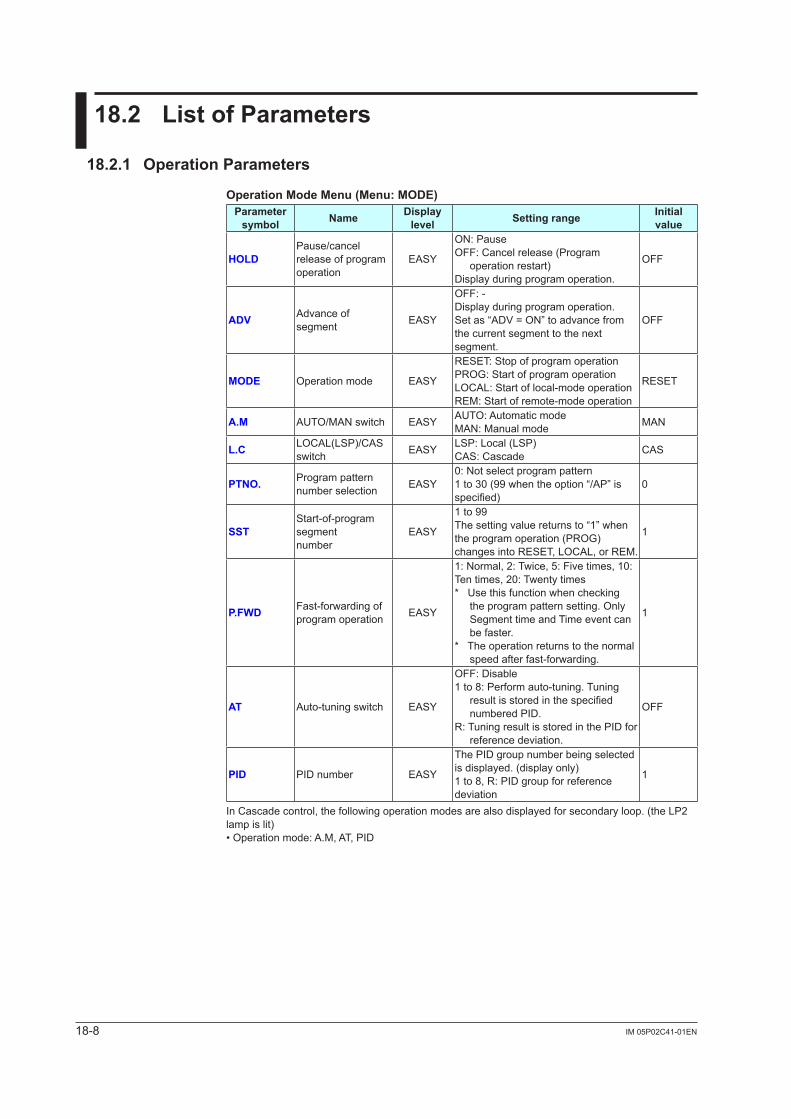
18-8 IM 05P02C41-01EN
18.2 ListofParameters
18.2.1 OperationParameters
OperationModeMenu(Menu: MODE)Parameter symbol Name Display
level Settingrange Initial value
HOLDPause/cancel release of program operation
EASY
ON: PauseOFF: Cancel release (Program
operation restart)Display during program operation.
OFF
ADV Advance of segment EASY
OFF: -Display during program operation.Set as “ADV = ON” to advance from the current segment to the next segment.
OFF
MODE Operation mode EASY
RESET: Stop of program operationPROG: Start of program operationLOCAL: Start of local-mode operationREM: Start of remote-mode operation
RESET
A.M AUTO/MAN switch EASY AUTO: Automatic modeMAN: Manual mode MAN
L.C LOCAL(LSP)/CAS switch EASY LSP: Local (LSP)
CAS: Cascade CAS
PTNO. Program pattern number selection EASY
0: Not select program pattern1 to 30 (99 when the option “/AP” is specified)
0
SSTStart-of-program segmentnumber
EASY
1 to 99The setting value returns to “1” when the program operation (PROG) changes into RESET, LOCAL, or REM.
1
P.FWD Fast-forwarding of program operation EASY
1: Normal, 2: Twice, 5: Five times, 10: Ten times, 20: Twenty times* Use this function when checking
the program pattern setting. Only Segment time and Time event can be faster.
* The operation returns to the normal speed after fast-forwarding.
1
AT Auto-tuning switch EASY
OFF: Disable1 to 8: Perform auto-tuning. Tuning
resultisstoredinthespecifiednumbered PID.
R: Tuning result is stored in the PID for reference deviation.
OFF
PID PID number EASY
The PID group number being selected is displayed. (display only)1 to 8, R: PID group for reference deviation
1
In Cascade control, the following operation modes are also displayed for secondary loop. (the LP2 lamp is lit)• Operation mode: A.M, AT, PID
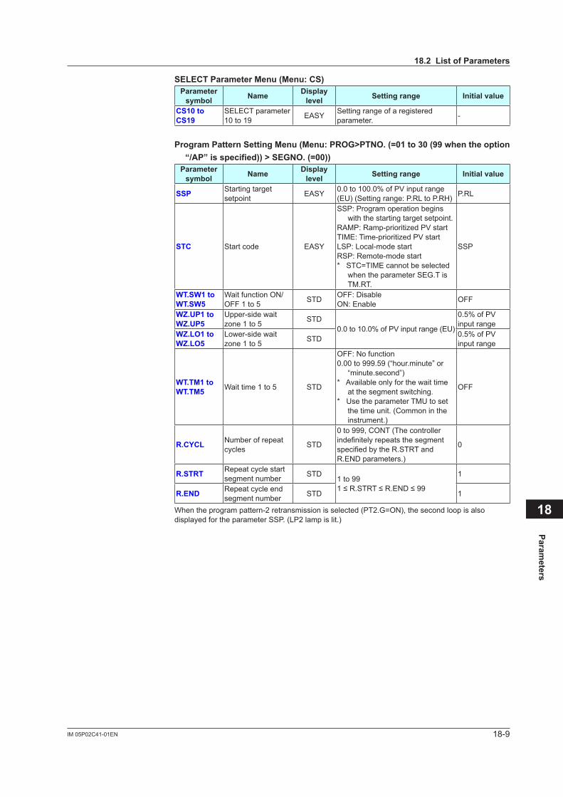
18-9IM 05P02C41-01EN
Parameters
18
SELECTParameterMenu(Menu:CS)Parameter symbol Name Display
level Settingrange Initialvalue
CS10toCS19
SELECT parameter 10 to 19 EASY Setting range of a registered
parameter. -
ProgramPatternSettingMenu(Menu:PROG>PTNO.(=01to30(99whentheoption“/AP”isspecified))>SEGNO.(=00))
Parameter symbol Name Display
level Settingrange Initialvalue
SSP Starting target setpoint EASY 0.0 to 100.0% of PV input range
(EU) (Setting range: P.RL to P.RH) P.RL
STC Start code EASY
SSP: Program operation begins with the starting target setpoint.
RAMP:Ramp-prioritizedPVstartTIME:Time-prioritizedPVstartLSP: Local-mode startRSP: Remote-mode start* STC=TIME cannot be selected
when the parameter SEG.T is TM.RT.
SSP
WT.SW1toWT.SW5
Wait function ON/OFF 1 to 5 STD OFF: Disable
ON: Enable OFF
WZ.UP1toWZ.UP5
Upper-side wait zone1to5 STD
0.0 to 10.0% of PV input range (EU)
0.5% of PV input range
WZ.LO1toWZ.LO5
Lower-side wait zone1to5 STD 0.5% of PV
input range
WT.TM1toWT.TM5 Wait time 1 to 5 STD
OFF: No function0.00 to 999.59 (“hour.minute” or
“minute.second”)* Available only for the wait time
at the segment switching.* Use the parameter TMU to set
the time unit. (Common in the instrument.)
OFF
R.CYCL Number of repeat cycles STD
0 to 999, CONT (The controller indefinitelyrepeatsthesegmentspecifiedbytheR.STRTandR.END parameters.)
0
R.STRT Repeat cycle start segment number STD
1 to 991≤R.STRT≤R.END≤99
1
R.END Repeat cycle end segment number STD 1
When the program pattern-2 retransmission is selected (PT2.G=ON), the second loop is also displayed for the parameter SSP. (LP2 lamp is lit.)
18.2ListofParameters
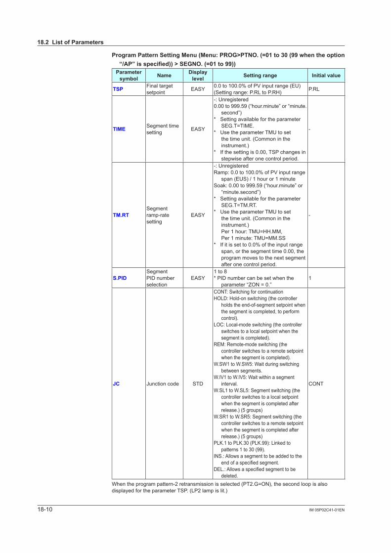
18-10 IM 05P02C41-01EN
ProgramPatternSettingMenu(Menu:PROG>PTNO.(=01to30(99whentheoption“/AP”isspecified))>SEGNO.(=01to99))
Parameter symbol Name Display
level Settingrange Initialvalue
TSP Final target setpoint EASY 0.0 to 100.0% of PV input range (EU)
(Setting range: P.RL to P.RH) P.RL
TIME Segment time setting EASY
-: Unregistered0.00 to 999.59 (“hour.minute” or “minute.
second”)* Setting available for the parameter
SEG.T=TIME.* Use the parameter TMU to set
the time unit. (Common in the instrument.)
* If the setting is 0.00, TSP changes in stepwise after one control period.
-
TM.RTSegment ramp-rate setting
EASY
-: UnregisteredRamp: 0.0 to 100.0% of PV input range
span (EUS) / 1 hour or 1 minuteSoak: 0.00 to 999.59 (“hour.minute” or
“minute.second”)* Setting available for the parameter
SEG.T=TM.RT.* Use the parameter TMU to set
the time unit. (Common in the instrument.) Per 1 hour: TMU=HH.MM, Per 1 minute: TMU=MM.SS
* If it is set to 0.0% of the input range span, or the segment time 0.00, the program moves to the next segment after one control period.
-
S.PIDSegment PID number selection
EASY1 to 8* PID number can be set when the
parameter “ZON = 0.”1
JC Junction code STD
CONT: Switching for continuationHOLD: Hold-on switching (the controller
holds the end-of-segment setpoint when the segment is completed, to perform control).
LOC: Local-mode switching (the controller switches to a local setpoint when the segment is completed).
REM: Remote-mode switching (the controller switches to a remote setpoint when the segment is completed).
W.SW1 to W.SW5: Wait during switching between segments.
W.IV1 to W.IV5: Wait within a segment interval.
W.SL1 to W.SL5: Segment switching (the controller switches to a local setpoint when the segment is completed after release.) (5 groups)
W.SR1 to W.SR5: Segment switching (the controller switches to a remote setpoint when the segment is completed after release.) (5 groups)
PLK.1 to PLK.30 (PLK.99): Linked to patterns 1 to 30 (99).
INS.: Allows a segment to be added to the endofaspecifiedsegment.
DEL.:Allowsaspecifiedsegmenttobedeleted.
CONT
When the program pattern-2 retransmission is selected (PT2.G=ON), the second loop is also displayed for the parameter TSP. (LP2 lamp is lit.)
18.2ListofParameters
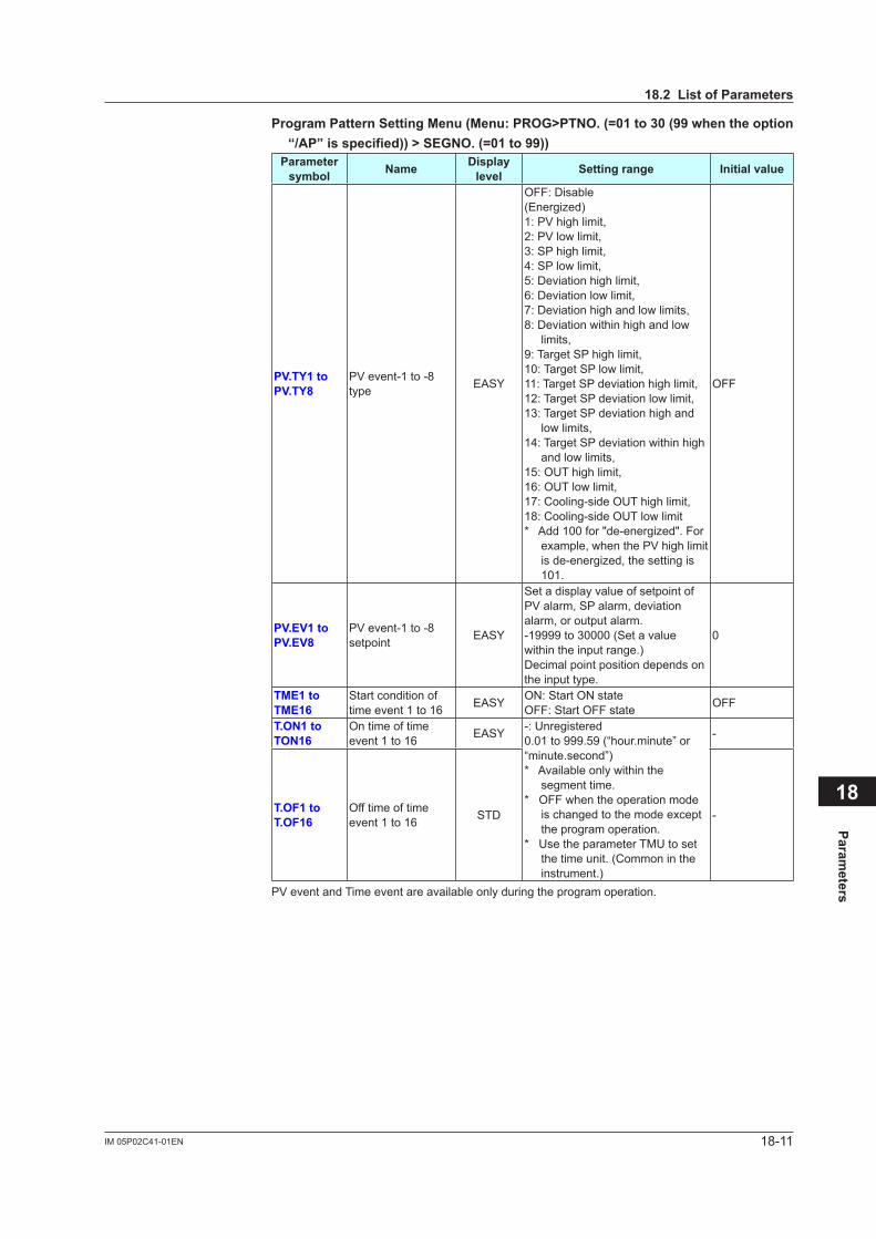
18-11IM 05P02C41-01EN
Parameters
18
ProgramPatternSettingMenu(Menu:PROG>PTNO.(=01to30(99whentheoption“/AP”isspecified))>SEGNO.(=01to99))
Parameter symbol Name Display
level Settingrange Initialvalue
PV.TY1toPV.TY8
PV event-1 to -8 type EASY
OFF: Disable(Energized)1: PV high limit, 2: PV low limit,3: SP high limit, 4: SP low limit,5: Deviation high limit,6: Deviation low limit,7: Deviation high and low limits,8: Deviation within high and low
limits,9: Target SP high limit,10: Target SP low limit,11: Target SP deviation high limit,12: Target SP deviation low limit,13: Target SP deviation high and
low limits,14: Target SP deviation within high
and low limits,15: OUT high limit, 16: OUT low limit,17: Cooling-side OUT high limit,18: Cooling-side OUT low limit*Add100for"de-energized".For
example, when the PV high limit isde-energized,thesettingis101.
OFF
PV.EV1toPV.EV8
PV event-1 to -8 setpoint EASY
Set a display value of setpoint of PV alarm, SP alarm, deviation alarm, or output alarm.-19999 to 30000 (Set a value within the input range.)Decimal point position depends on the input type.
0
TME1toTME16
Start condition of time event 1 to 16 EASY ON: Start ON state
OFF: Start OFF state OFF
T.ON1toTON16
On time of time event 1 to 16 EASY -: Unregistered
0.01 to 999.59 (“hour.minute” or “minute.second”)* Available only within the
segment time.* OFF when the operation mode
is changed to the mode except the program operation.
* Use the parameter TMU to set the time unit. (Common in the instrument.)
-
T.OF1toT.OF16
Off time of time event 1 to 16 STD -
PV event and Time event are available only during the program operation.
18.2ListofParameters
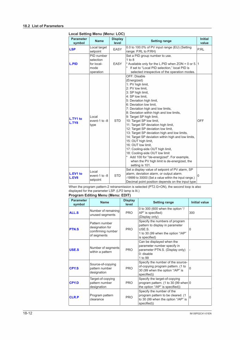
18-12 IM 05P02C41-01EN
LocalSettingMenu(Menu:LOC)Parameter symbol Name Display
level Settingrange Initial value
LSP Local target setpoint EASY 0.0 to 100.0% of PV input range (EU) (Setting
range: P.RL to P.RH) P.RL
L.PID
PID number selectionfor local-mode operation
EASY
Set a PID group number to use.1 to 8* Available only for the L.PID when ZON = 0 or 5.* If set to “Local PID selection,” local PID is
selected irrespective of the operation modes.
1
L.TY1toL.TY8
Local event-1 to -8 type
STD
OFF: Disable(Energized)1: PV high limit, 2: PV low limit,3: SP high limit, 4: SP low limit,5: Deviation high limit,6: Deviation low limit,7: Deviation high and low limits,8: Deviation within high and low limits,9: Target SP high limit,10: Target SP low limit,11: Target SP deviation high limit,12: Target SP deviation low limit,13: Target SP deviation high and low limits,14: Target SP deviation within high and low limits,15: OUT high limit, 16: OUT low limit,17: Cooling-side OUT high limit,18: Cooling-side OUT low limit*Add100for"de-energized".Forexample,
whenthePVhighlimitisde-energized,thesetting is 101.
OFF
L.EV1toL.EV8
Local event-1 to -8 setpoint
STD
Set a display value of setpoint of PV alarm, SP alarm, deviation alarm, or output alarm.-19999 to 30000 (Set a value within the input range.)Decimal point position depends on the input type
0
When the program pattern-2 retransmission is selected (PT2.G=ON), the second loop is also displayed for the parameter LSP. (LP2 lamp is lit.)ProgramEditingMenu(Menu:EDIT)
Parameter symbol Name Display
level Settingrange Initialvalue
ALL.S Number of remaining unused segments PRO
0 to 300 (600 when the option “/AP”isspecified)(Display only)
300
PTN.S
Pattern number designation for comfirmingnumberof segments
PRO
Specify the numbers of program pattern to display in parameter USE.S.1 to 30 (99 when the option “/AP” isspecified)
0
USE.S Number of segments within a pattern PRO
Can be displayed when the parameter number specify in parameter PTN.S. (Display only)0: disable1 to 99
-
CPY.SSource-of-copying pattern number designation
PRO
Specify the number of the source-of-copying program pattern. (1 to 30 (99 when the option “/AP” is specified))
0
CPY.DTarget-of-copying pattern number designation
PROSpecify the target-of-copying program pattern. (1 to 30 (99 when theoption“/AP”isspecified))
0
CLR.P Program pattern clearance PRO
Specify the number of the program pattern to be cleared. (1 to 30 (99 when the option “/AP” is specified))
0
18.2ListofParameters
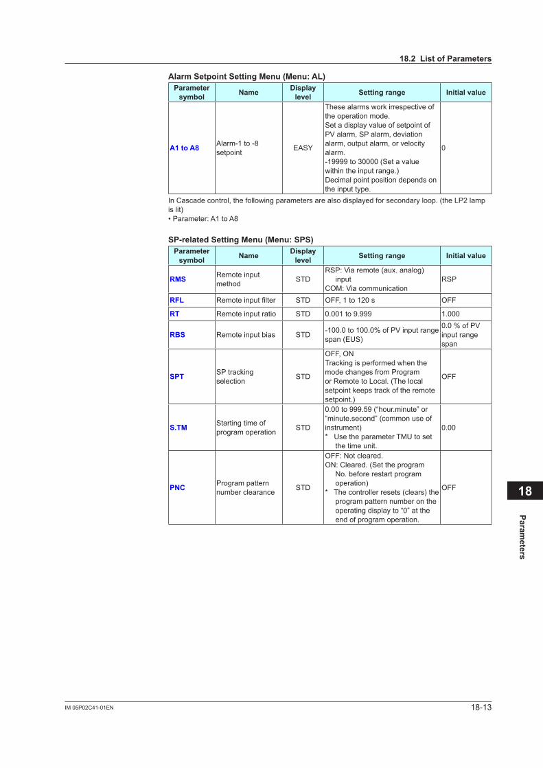
18-13IM 05P02C41-01EN
Parameters
18
AlarmSetpointSettingMenu(Menu:AL)Parameter symbol Name Display
level Settingrange Initialvalue
A1toA8 Alarm-1 to -8 setpoint EASY
These alarms work irrespective of the operation mode.Set a display value of setpoint of PV alarm, SP alarm, deviation alarm, output alarm, or velocity alarm.-19999 to 30000 (Set a value within the input range.)Decimal point position depends on the input type.
0
In Cascade control, the following parameters are also displayed for secondary loop. (the LP2 lamp is lit)• Parameter: A1 to A8
SP-relatedSettingMenu(Menu:SPS)Parameter symbol Name Display
level Settingrange Initialvalue
RMS Remote input method STD
RSP: Via remote (aux. analog) input
COM: Via communicationRSP
RFL Remoteinputfilter STD OFF, 1 to 120 s OFF
RT Remote input ratio STD 0.001 to 9.999 1.000
RBS Remote input bias STD -100.0 to 100.0% of PV input range span (EUS)
0.0 % of PV input range span
SPT SP tracking selection STD
OFF, ONTracking is performed when the mode changes from Program or Remote to Local. (The local setpoint keeps track of the remote setpoint.)
OFF
S.TM Starting time of program operation STD
0.00 to 999.59 (“hour.minute” or “minute.second” (common use of instrument)* Use the parameter TMU to set
the time unit.
0.00
PNC Program pattern number clearance STD
OFF: Not cleared.ON: Cleared. (Set the program
No. before restart program operation)
* The controller resets (clears) the program pattern number on the operating display to “0” at the end of program operation.
OFF
18.2ListofParameters
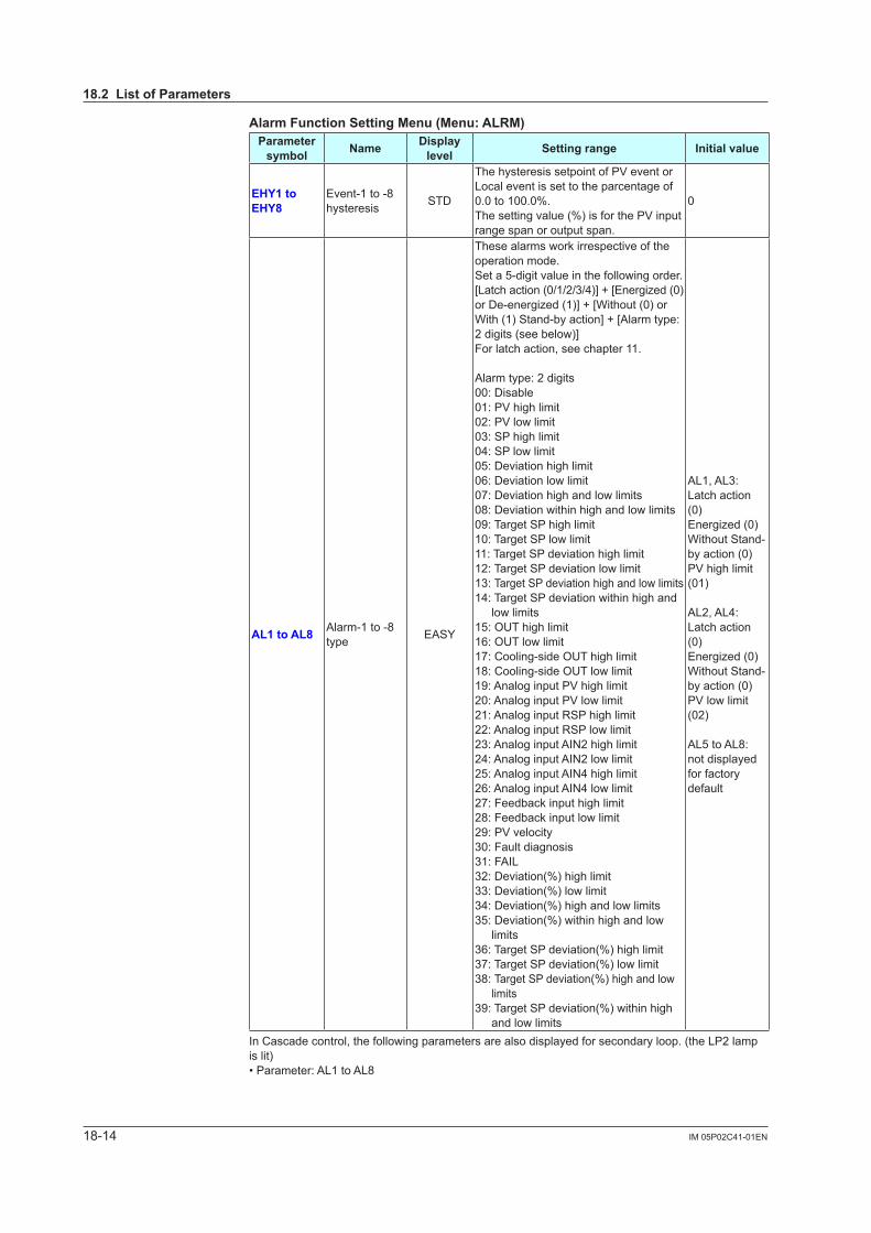
18-14 IM 05P02C41-01EN
AlarmFunctionSettingMenu(Menu:ALRM)Parameter symbol Name Display
level Settingrange Initialvalue
EHY1toEHY8
Event-1 to -8 hysteresis STD
The hysteresis setpoint of PV event or Local event is set to the parcentage of 0.0 to 100.0%.The setting value (%) is for the PV input range span or output span.
0
AL1toAL8 Alarm-1 to -8 type EASY
These alarms work irrespective of the operation mode.Set a 5-digit value in the following order.[Latchaction(0/1/2/3/4)]+[Energized(0)orDe-energized(1)]+[Without(0)orWith (1) Stand-by action] + [Alarm type: 2 digits (see below)]For latch action, see chapter 11.
Alarm type: 2 digits00: Disable01: PV high limit02: PV low limit03: SP high limit04: SP low limit05: Deviation high limit06: Deviation low limit07: Deviation high and low limits08: Deviation within high and low limits09: Target SP high limit10: Target SP low limit11: Target SP deviation high limit12: Target SP deviation low limit13: Target SP deviation high and low limits14: Target SP deviation within high and
low limits15: OUT high limit16: OUT low limit17: Cooling-side OUT high limit18: Cooling-side OUT low limit19: Analog input PV high limit20: Analog input PV low limit21: Analog input RSP high limit22: Analog input RSP low limit23: Analog input AIN2 high limit24: Analog input AIN2 low limit25: Analog input AIN4 high limit26: Analog input AIN4 low limit27: Feedback input high limit28: Feedback input low limit29: PV velocity30: Fault diagnosis31: FAIL32: Deviation(%) high limit33: Deviation(%) low limit34: Deviation(%) high and low limits35: Deviation(%) within high and low
limits36: Target SP deviation(%) high limit37: Target SP deviation(%) low limit38: Target SP deviation(%) high and low
limits39: Target SP deviation(%) within high
and low limits
AL1, AL3: Latch action (0)Energized(0)Without Stand-by action (0)PV high limit (01)
AL2, AL4: Latch action (0)Energized(0)Without Stand-by action (0)PV low limit (02)
AL5 to AL8:not displayed for factory default
In Cascade control, the following parameters are also displayed for secondary loop. (the LP2 lamp is lit)• Parameter: AL1 to AL8
18.2ListofParameters
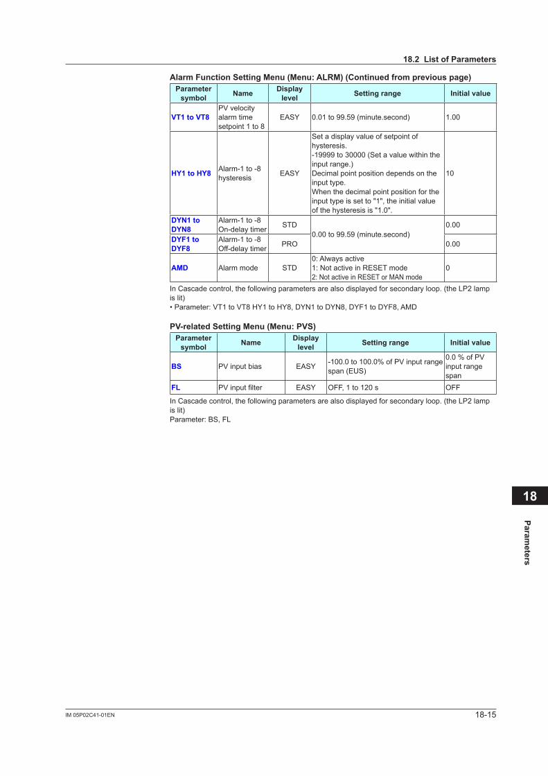
18-15IM 05P02C41-01EN
Parameters
18
AlarmFunctionSettingMenu(Menu:ALRM)(Continuedfrompreviouspage)Parameter symbol Name Display
level Settingrange Initialvalue
VT1toVT8PV velocity alarm time setpoint 1 to 8
EASY 0.01 to 99.59 (minute.second) 1.00
HY1toHY8 Alarm-1 to -8 hysteresis EASY
Set a display value of setpoint of hysteresis.-19999 to 30000 (Set a value within the input range.)Decimal point position depends on the input type.When the decimal point position for the input type is set to "1", the initial value of the hysteresis is "1.0".
10
DYN1toDYN8
Alarm-1 to -8 On-delay timer STD
0.00 to 99.59 (minute.second)0.00
DYF1toDYF8
Alarm-1 to -8 Off-delay timer PRO 0.00
AMD Alarm mode STD0: Always active1: Not active in RESET mode2: Not active in RESET or MAN mode
0
In Cascade control, the following parameters are also displayed for secondary loop. (the LP2 lamp is lit)• Parameter: VT1 to VT8 HY1 to HY8, DYN1 to DYN8, DYF1 to DYF8, AMD
PV-relatedSettingMenu(Menu:PVS)Parameter symbol Name Display
level Settingrange Initialvalue
BS PV input bias EASY -100.0 to 100.0% of PV input range span (EUS)
0.0 % of PV input range span
FL PVinputfilter EASY OFF, 1 to 120 s OFF
In Cascade control, the following parameters are also displayed for secondary loop. (the LP2 lamp is lit)Parameter: BS, FL
18.2ListofParameters
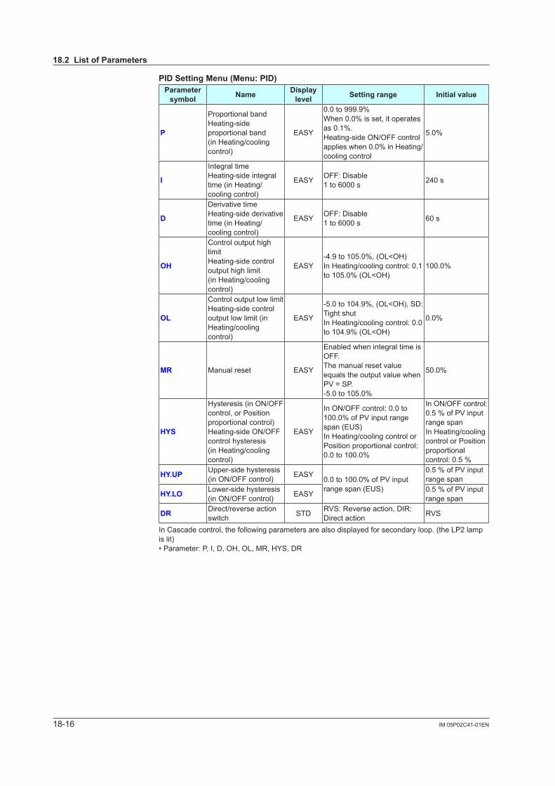
18-16 IM 05P02C41-01EN
PIDSettingMenu(Menu:PID)Parameter symbol Name Display
level Settingrange Initialvalue
P
Proportional bandHeating-side proportional band (in Heating/cooling control)
EASY
0.0 to 999.9%When 0.0% is set, it operates as 0.1%.Heating-side ON/OFF control applies when 0.0% in Heating/cooling control
5.0%
I
Integral timeHeating-side integral time (in Heating/cooling control)
EASY OFF: Disable1 to 6000 s 240 s
D
Derivative timeHeating-side derivative time (in Heating/cooling control)
EASY OFF: Disable1 to 6000 s 60 s
OH
Control output high limitHeating-side control output high limit (in Heating/cooling control)
EASY-4.9 to 105.0%, (OL<OH)In Heating/cooling control: 0.1 to 105.0% (OL<OH)
100.0%
OL
Control output low limitHeating-side control output low limit (in Heating/cooling control)
EASY
-5.0 to 104.9%, (OL<OH), SD: Tight shutIn Heating/cooling control: 0.0 to 104.9% (OL<OH)
0.0%
MR Manual reset EASY
Enabled when integral time is OFF.The manual reset value equals the output value when PV = SP.-5.0 to 105.0%
50.0%
HYS
Hysteresis (in ON/OFF control, or Position proportional control)Heating-side ON/OFF control hysteresis (in Heating/cooling control)
EASY
In ON/OFF control: 0.0 to 100.0% of PV input range span (EUS)In Heating/cooling control or Position proportional control: 0.0 to 100.0%
In ON/OFF control: 0.5 % of PV input range spanIn Heating/cooling control or Position proportional control: 0.5 %
HY.UP Upper-side hysteresis (in ON/OFF control) EASY
0.0 to 100.0% of PV input range span (EUS)
0.5 % of PV input range span
HY.LO Lower-side hysteresis (in ON/OFF control) EASY 0.5 % of PV input
range span
DR Direct/reverse action switch STD RVS: Reverse action, DIR:
Direct action RVS
In Cascade control, the following parameters are also displayed for secondary loop. (the LP2 lamp is lit)• Parameter: P, I, D, OH, OL, MR, HYS, DR
18.2ListofParameters
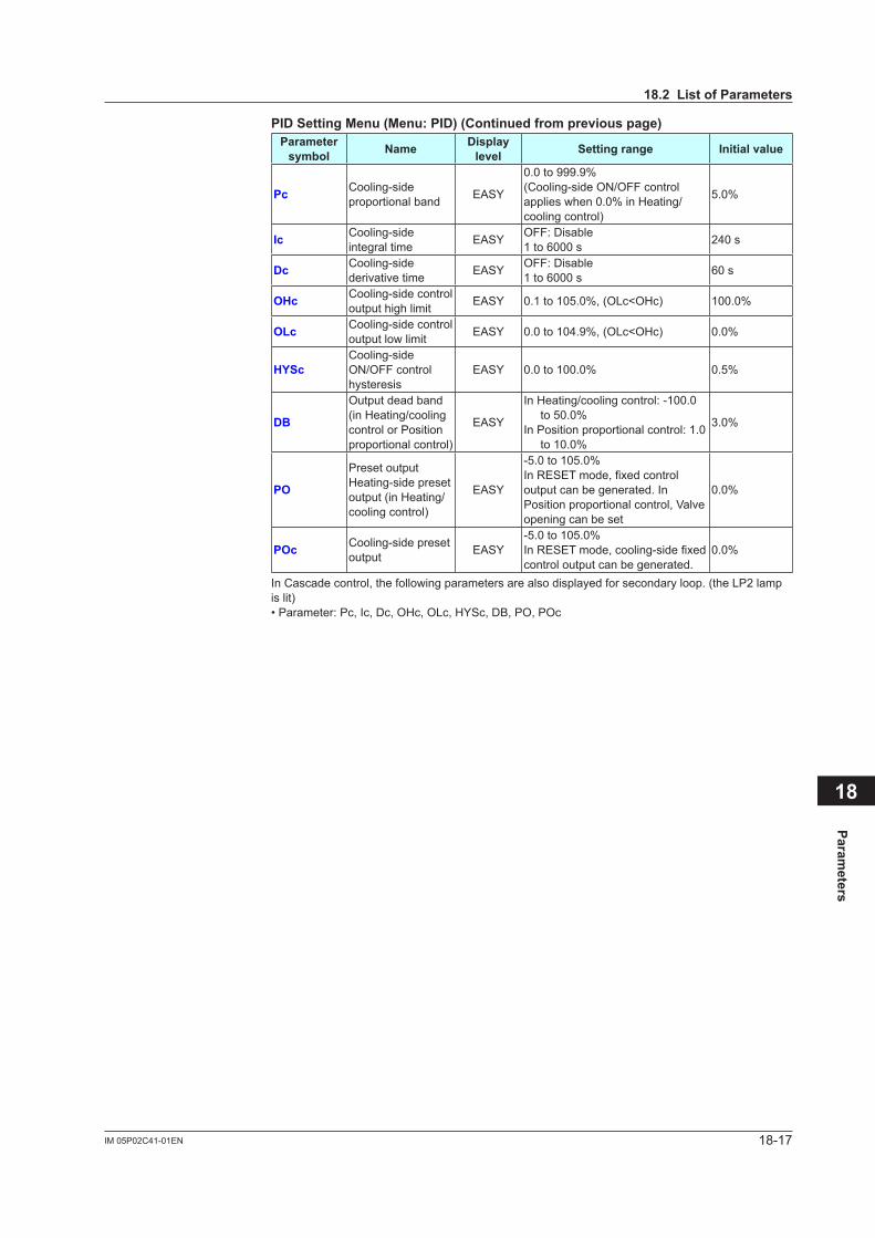
18-17IM 05P02C41-01EN
Parameters
18
PIDSettingMenu(Menu:PID)(Continuedfrompreviouspage)Parameter symbol Name Display
level Settingrange Initialvalue
Pc Cooling-side proportional band EASY
0.0 to 999.9%(Cooling-side ON/OFF control applies when 0.0% in Heating/cooling control)
5.0%
Ic Cooling-side integral time EASY OFF: Disable
1 to 6000 s 240 s
Dc Cooling-side derivative time EASY OFF: Disable
1 to 6000 s 60 s
OHc Cooling-side control output high limit EASY 0.1 to 105.0%, (OLc<OHc) 100.0%
OLc Cooling-side control output low limit EASY 0.0 to 104.9%, (OLc<OHc) 0.0%
HYScCooling-side ON/OFF control hysteresis
EASY 0.0 to 100.0% 0.5%
DB
Output dead band (in Heating/cooling control or Position proportional control)
EASY
In Heating/cooling control: -100.0 to 50.0%
In Position proportional control: 1.0 to 10.0%
3.0%
PO
Preset outputHeating-side preset output (in Heating/cooling control)
EASY
-5.0 to 105.0%InRESETmode,fixedcontroloutput can be generated. In Position proportional control, Valve opening can be set
0.0%
POc Cooling-side preset output EASY
-5.0 to 105.0%InRESETmode,cooling-sidefixedcontrol output can be generated.
0.0%
In Cascade control, the following parameters are also displayed for secondary loop. (the LP2 lamp is lit)• Parameter: Pc, Ic, Dc, OHc, OLc, HYSc, DB, PO, POc
18.2ListofParameters

18-18 IM 05P02C41-01EN
TuningMenu(Menu:TUNE)Parameter symbol Name Display
level Settingrange Initialvalue
SC Super function EASY
OFF: Disable1: Overshoot suppressing function
(normal mode)2: Hunting suppressing function
(stable mode) Enables to answer the wider
characteristic changes compared with response mode.
3: Hunting suppressing function (response mode)
Enables quick follow-up and short converging time of PV for the changed SP.
4: Overshoot suppressing function (strong suppressing mode)
OFF
AT.TY Auto-tuning type STD 0: Normal1: Stability 0
AT.OH Output high limit in auto-tuning PRO
-5.0 to 105.0% (Disabled in Heating/cooling control)
100.0%
AT.OL Output low limit in auto-tuning PRO 0.0%
AT.BS SP bias in auto-tuning PRO -100.0 to 100.0% of PV input range
span (EUS)
0.0 % of PV input range span
GW Non-linear control gap width PRO OFF, 0.0%+1digit to 50.0% of PV
input range span (EUS) OFF
GG Non-linear control gain PRO 0.001 to 1.000 1.000
ARAnti-reset windup (excess integration prevention)
STD AUTO, 50.0 to 200.0% AUTO
OPR Output velocity limiter STD OFF: Disable
0.1 to 100.0%/s OFF
OLMT Output limiter switch PRO
OFF: Disable output limiter in MAN mode
ON: Enable output limiter in MAN mode
ON
MPONManual preset output number selection
STD
OFF: Hold the control output in AUTO mode (bumpless)
1: Use manual preset output 1 (output bump)
2: Use manual preset output 2 (output bump)
3: Use manual preset output 3 (output bump)
4: Use manual preset output 4 (output bump)
5: Use manual preset output 5 (output bump)
OFF
MPO1toMPO5
Manual preset output 1 to 5 STD
-5.0 to 105.0% * However, output is limited to the
output high limit and low limit.0.0%
In Cascade control, the following parameters are also displayed for secondary loop. (the LP2 lamp is lit)• Parameter: SC, AT.TY, AT.OH, AT.OL, AT.BS, GW, GG, AR, OPR, OLMT, MPON, MPO1 to MPO5
18.2ListofParameters

18-19IM 05P02C41-01EN
Parameters
18
ZoneControlMenu(Menu:ZONE)Parameter symbol Name Display
level Settingrange Initialvalue
RP1toRP7 Reference point 1 to 7 STD
0.0 to 100.0% of PV input range (EU) (RP1≤RP2≤RP3≤RP4≤RP5≤RP6≤RP7)* Set reference points at which
switching is carried out between groups of PID constants according to the given temperaturezone.
100.0 % of PV input range
RHY Zone PID switching hysteresis STD
0.0 to 10.0% of PV input range span (EUS)* Hysteresis can be set for
switching at a reference point.
0.5 % of PV input range span
RDV Reference deviation STD
OFF: Disable0.0 + 1 digit to 100.0% of PV input range span (EUS)* Set a deviation from SP. The PID
for reference deviation is used if there is a larger deviation than the preset reference deviation.
OFF
In Cascade control, the following parameters are also displayed for secondary loop. (the LP2 lamp is lit)• Parameter: RP1 to RP7, RHY, RDV
PParameterMenu(Menu:PPAR)Parameter symbol Name Display
level Settingrange Initialvalue
P01toP10 P01 to P10 parameter STD
-19999 to 30000 (Set a decimal point position using LL50A Parameter Setting Software.)
0
18.2ListofParameters
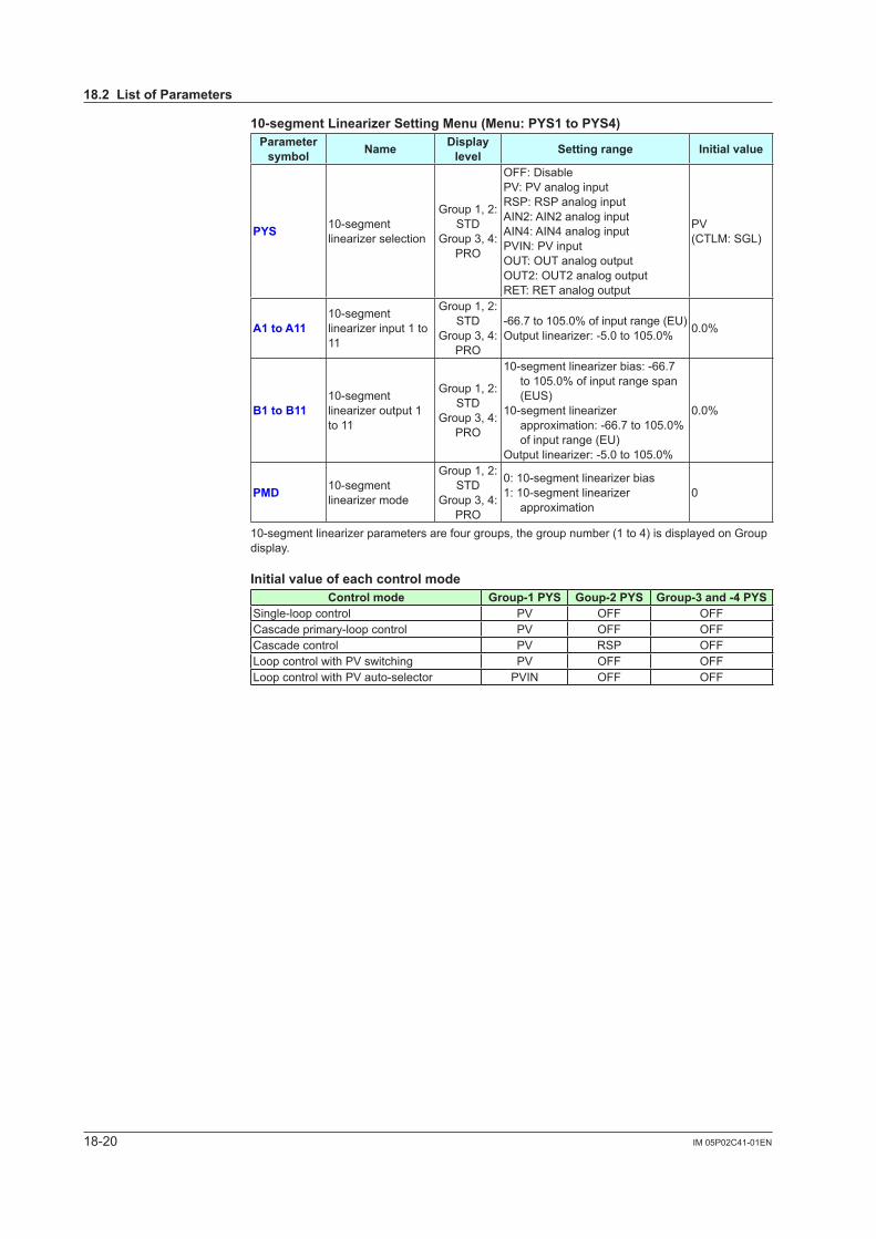
18-20 IM 05P02C41-01EN
10-segmentLinearizerSettingMenu(Menu:PYS1toPYS4)Parameter symbol Name Display
level Settingrange Initialvalue
PYS 10-segment linearizerselection
Group 1, 2: STD
Group 3, 4:PRO
OFF: DisablePV: PV analog inputRSP: RSP analog inputAIN2: AIN2 analog inputAIN4: AIN4 analog inputPVIN: PV inputOUT: OUT analog outputOUT2: OUT2 analog outputRET: RET analog output
PV(CTLM: SGL)
A1toA1110-segment linearizerinput1to11
Group 1, 2: STD
Group 3, 4:PRO
-66.7 to 105.0% of input range (EU)Outputlinearizer:-5.0to105.0% 0.0%
B1toB1110-segment linearizeroutput1to 11
Group 1, 2: STD
Group 3, 4:PRO
10-segmentlinearizerbias:-66.7to 105.0% of input range span (EUS)
10-segmentlinearizerapproximation: -66.7 to 105.0% of input range (EU)
Outputlinearizer:-5.0to105.0%
0.0%
PMD 10-segment linearizermode
Group 1, 2: STD
Group 3, 4:PRO
0:10-segmentlinearizerbias1:10-segmentlinearizer
approximation0
10-segmentlinearizerparameters are four groups, the group number (1 to 4) is displayed on Group display.
InitialvalueofeachcontrolmodeControl mode Group-1PYS Goup-2PYS Group-3and-4PYS
Single-loop control PV OFF OFFCascade primary-loop control PV OFF OFFCascade control PV RSP OFFLoop control with PV switching PV OFF OFFLoop control with PV auto-selector PVIN OFF OFF
18.2ListofParameters
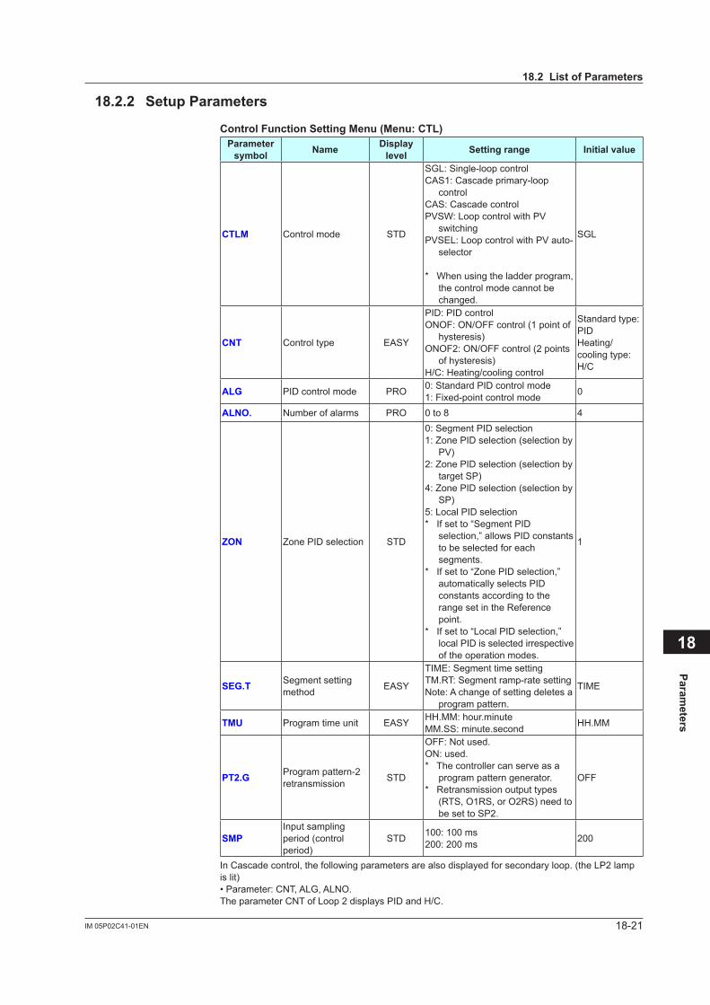
18-21IM 05P02C41-01EN
Parameters
18
18.2.2 SetupParameters
ControlFunctionSettingMenu(Menu:CTL)Parameter symbol Name Display
level Settingrange Initialvalue
CTLM Control mode STD
SGL: Single-loop controlCAS1: Cascade primary-loop
controlCAS: Cascade controlPVSW: Loop control with PV
switchingPVSEL: Loop control with PV auto-
selector
* When using the ladder program, the control mode cannot be changed.
SGL
CNT Control type EASY
PID: PID controlONOF: ON/OFF control (1 point of
hysteresis)ONOF2: ON/OFF control (2 points
of hysteresis)H/C: Heating/cooling control
Standard type: PIDHeating/cooling type: H/C
ALG PID control mode PRO 0: Standard PID control mode1: Fixed-point control mode 0
ALNO. Number of alarms PRO 0 to 8 4
ZON Zone PID selection STD
0: Segment PID selection1: Zone PID selection (selection by
PV)2: Zone PID selection (selection by
target SP)4: Zone PID selection (selection by
SP)5: Local PID selection* If set to “Segment PID
selection,” allows PID constants to be selected for each segments.
* If set to “Zone PID selection,” automatically selects PID constants according to the range set in the Reference point.
* If set to “Local PID selection,” local PID is selected irrespective of the operation modes.
1
SEG.T Segment setting method EASY
TIME: Segment time settingTM.RT: Segment ramp-rate settingNote: A change of setting deletes a
program pattern.
TIME
TMU Program time unit EASY HH.MM: hour.minuteMM.SS: minute.second HH.MM
PT2.G Program pattern-2 retransmission STD
OFF: Not used.ON: used.* The controller can serve as a
program pattern generator.* Retransmission output types
(RTS, O1RS, or O2RS) need to be set to SP2.
OFF
SMPInput sampling period (control period)
STD 100: 100 ms200: 200 ms 200
In Cascade control, the following parameters are also displayed for secondary loop. (the LP2 lamp is lit)• Parameter: CNT, ALG, ALNO.The parameter CNT of Loop 2 displays PID and H/C.
18.2ListofParameters
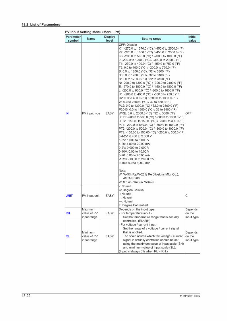
18-22 IM 05P02C41-01EN
PVInputSettingMenu(Menu:PV)Parameter symbol Name Display
level Settingrange Initial value
IN PV input type EASY
OFF: DisableK1: -270.0 to 1370.0 (°C) / -450.0 to 2500.0 (°F)K2: -270.0 to 1000.0 (°C) / -450.0 to 2300.0 (°F)K3: -200.0 to 500.0 (°C) / -200.0 to 1000.0 (°F)J: -200.0 to 1200.0 (°C) / -300.0 to 2300.0 (°F)T1: -270.0 to 400.0 (°C) / -450.0 to 750.0 (°F)T2: 0.0 to 400.0 (°C) / -200.0 to 750.0 (°F)B: 0.0 to 1800.0 (°C) / 32 to 3300 (°F)S: 0.0 to 1700.0 (°C) / 32 to 3100 (°F)R: 0.0 to 1700.0 (°C) / 32 to 3100 (°F)N: -200.0 to 1300.0 (°C) / -300.0 to 2400.0 (°F)E: -270.0 to 1000.0 (°C) / -450.0 to 1800.0 (°F)L: -200.0 to 900.0 (°C) / -300.0 to 1600.0 (°F)U1: -200.0 to 400.0 (°C) / -300.0 to 750.0 (°F)U2: 0.0 to 400.0 (°C) / -200.0 to 1000.0 (°F)W: 0.0 to 2300.0 (°C) / 32 to 4200 (°F)PL2: 0.0 to 1390.0 (°C) / 32.0 to 2500.0 (°F)P2040: 0.0 to 1900.0 (°C) / 32 to 3400 (°F)WRE: 0.0 to 2000.0 (°C) / 32 to 3600 (°F)JPT1: -200.0 to 500.0 (°C) / -300.0 to 1000.0 (°F)JPT2: -150.00 to 150.00 (°C) / -200.0 to 300.0 (°F)PT1: -200.0 to 850.0 (°C) / -300.0 to 1560.0 (°F)PT2: -200.0 to 500.0 (°C) / -300.0 to 1000.0 (°F)PT3: -150.00 to 150.00 (°C) / -200.0 to 300.0 (°F)0.4-2V: 0.400 to 2.000 V1-5V: 1.000 to 5.000 V4-20: 4.00 to 20.00 mA0-2V: 0.000 to 2.000 V0-10V: 0.00 to 10.00 V0-20: 0.00 to 20.00 mA-1020: -10.00 to 20.00 mV0-100: 0.0 to 100.0 mV
Note:W: W-5% Re/W-26% Re (Hoskins Mfg. Co.),
ASTM E988WRE: W97Re3-W75Re25
OFF
UNIT PV input unit EASY
-: No unitC: Degree Celsius-: No unit--: No unit---: No unitF: Degree Fahrenheit
C
RHMaximum value of PV input range
EASYDepends on the input type.- For temperature input - Set the temperature range that is actually
controlled. (RL<RH)- For voltage / current input - Set the range of a voltage / current signal
that is applied. The scale across which the voltage / current
signal is actually controlled should be set using the maximum value of input scale (SH) and minimum value of input scale (SL).
(Input is always 0% when RL = RH.)
Depends on the input type
RLMinimum value of PV input range
EASYDepends on the input type
18.2ListofParameters
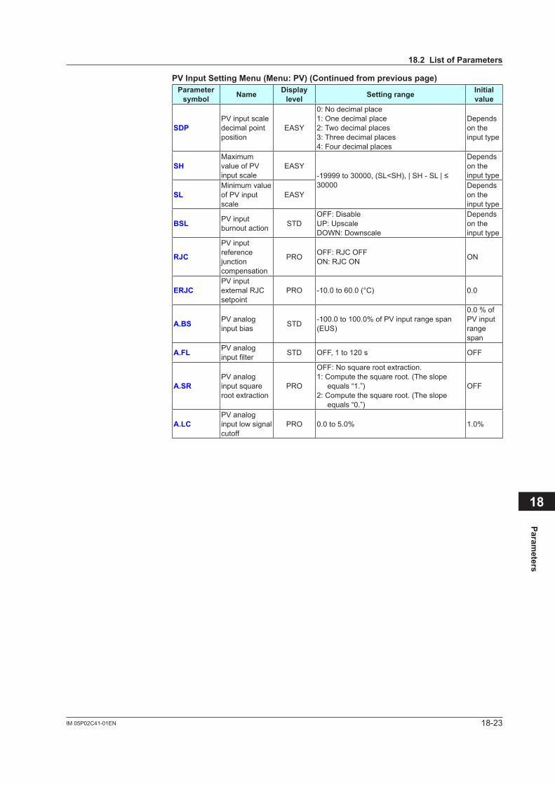
18-23IM 05P02C41-01EN
Parameters
18
PVInputSettingMenu(Menu:PV)(Continuedfrompreviouspage)Parameter symbol Name Display
level Settingrange Initial value
SDPPV input scale decimal point position
EASY
0: No decimal place1: One decimal place2: Two decimal places3: Three decimal places4: Four decimal places
Depends on the input type
SHMaximum value of PV input scale
EASY-19999to30000,(SL<SH),|SH-SL|≤30000
Depends on the input type
SLMinimum value of PV input scale
EASYDepends on the input type
BSL PV input burnout action STD
OFF: DisableUP: UpscaleDOWN: Downscale
Depends on the input type
RJC
PV input reference junctioncompensation
PRO OFF: RJC OFFON: RJC ON ON
ERJCPV input external RJC setpoint
PRO -10.0 to 60.0 (°C) 0.0
A.BS PV analog input bias STD -100.0 to 100.0% of PV input range span
(EUS)
0.0 % of PV input range span
A.FL PV analog inputfilter STD OFF, 1 to 120 s OFF
A.SRPV analog input square root extraction
PRO
OFF: No square root extraction.1: Compute the square root. (The slope
equals “1.”)2: Compute the square root. (The slope
equals “0.”)
OFF
A.LCPV analog input low signal cutoff
PRO 0.0 to 5.0% 1.0%
18.2ListofParameters
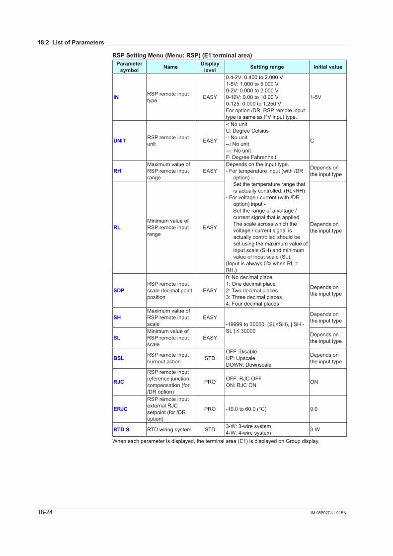
18-24 IM 05P02C41-01EN
RSPSettingMenu(Menu:RSP)(E1terminalarea)Parameter symbol Name Display
level Settingrange Initialvalue
IN RSP remote input type EASY
0.4-2V: 0.400 to 2.000 V1-5V: 1.000 to 5.000 V0-2V: 0.000 to 2.000 V0-10V: 0.00 to 10.00 V0-125: 0.000 to 1.250 VFor option /DR, RSP remote input type is same as PV input type.
1-5V
UNIT RSP remote input unit EASY
-: No unitC: Degree Celsius-: No unit--: No unit---: No unitF: Degree Fahrenheit
C
RHMaximum value of RSP remote input range
EASYDepends on the input type.- For temperature input (with /DR
option) - Set the temperature range that
is actually controlled. (RL<RH)- For voltage / current (with /DR
option) input - Set the range of a voltage /
current signal that is applied. The scale across which the
voltage / current signal is actually controlled should be set using the maximum value of input scale (SH) and minimum value of input scale (SL).
(Input is always 0% when RL = RH.)
Depends on the input type
RLMinimum value of RSP remote input range
EASY Depends on the input type
SDPRSP remote input scale decimal point position
EASY
0: No decimal place1: One decimal place2: Two decimal places3: Three decimal places4: Four decimal places
Depends on the input type
SHMaximum value of RSP remote input scale
EASY-19999 to 30000, (SL<SH), | SH - SL|≤30000
Depends on the input type
SLMinimum value of RSP remote input scale
EASY Depends on the input type
BSL RSP remote input burnout action STD
OFF: DisableUP: UpscaleDOWN: Downscale
Depends on the input type
RJC
RSP remote input referencejunctioncompensation (for /DR option)
PRO OFF: RJC OFFON: RJC ON ON
ERJC
RSP remote input external RJC setpoint (for /DR option)
PRO -10.0 to 60.0 (°C) 0.0
RTD.S RTD wiring system STD 3-W: 3-wire system4-W: 4-wire system 3-W
When each parameter is displayed, the terminal area (E1) is displayed on Group display.
18.2ListofParameters
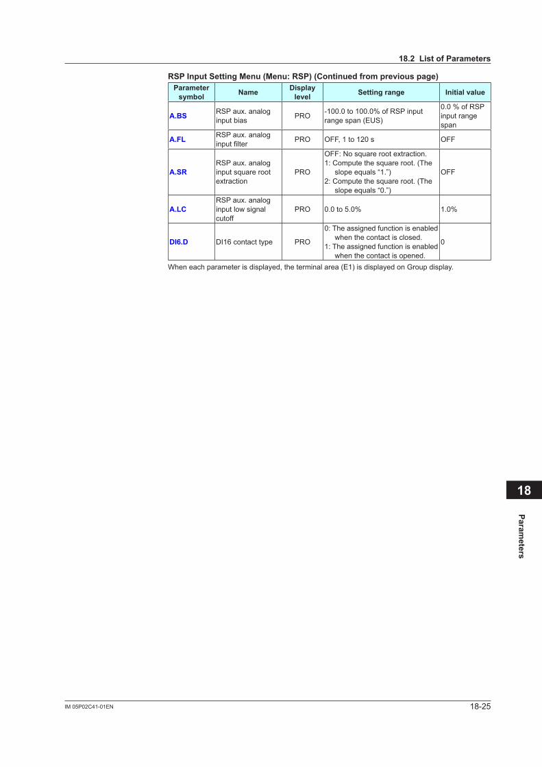
18-25IM 05P02C41-01EN
Parameters
18
RSPInputSettingMenu(Menu:RSP)(Continuedfrompreviouspage)Parameter symbol Name Display
level Settingrange Initialvalue
A.BS RSP aux. analog input bias PRO -100.0 to 100.0% of RSP input
range span (EUS)
0.0 % of RSP input range span
A.FL RSP aux. analog inputfilter PRO OFF, 1 to 120 s OFF
A.SRRSP aux. analog input square root extraction
PRO
OFF: No square root extraction.1: Compute the square root. (The
slope equals “1.”)2: Compute the square root. (The
slope equals “0.”)
OFF
A.LCRSP aux. analog input low signal cutoff
PRO 0.0 to 5.0% 1.0%
DI6.D DI16 contact type PRO
0: The assigned function is enabled when the contact is closed.
1: The assigned function is enabled when the contact is opened.
0
When each parameter is displayed, the terminal area (E1) is displayed on Group display.
18.2ListofParameters

18-26 IM 05P02C41-01EN
AIN2Aux.AnalogInputSettingMenu(Menu:AIN2)(E2terminalarea)Parameter symbol Name Display
level Settingrange Initialvalue
IN AIN2 aux. analog input type EASY
0.4-2V: 0.400 to 2.000 V1-5V: 1.000 to 5.000 V0-2V: 0.000 to 2.000 V0-10V: 0.00 to 10.00 V0-125: 0.000 to 1.250 V
1-5V
UNIT AIN2 aux. analog input unit EASY
-: No unitC: Degree Celsius-: No unit--: No unit---: No unitF: Degree Fahrenheit
C
RHMaximum value of AIN2 aux. analog input range
EASYDepends on the input type.Set the range of a voltage signal that is applied.The scale across which the voltage signal is actually controlled should be set using the maximum value of input scale (SH) and minimum value of input scale (SL).(Input is always 0% when RL = RH.)
Depends on the input type
RLMinimum value of AIN2 aux. analog input range
EASY Depends on the input type
SDPAIN2 aux. analog input scale decimal point position
EASY
0: No decimal place1: One decimal place2: Two decimal places3: Three decimal places4: Four decimal places
Depends on the input type
SHMaximum value of AIN2 aux. analog input scale
EASY-19999 to 30000, (SL<SH), | SH - SL|≤30000
Depends on the input type
SLMinimum value of AIN2 aux. analog input scale
EASY Depends on the input type
BSL AIN2 aux. analog input burnout action STD
OFF: DisableUP: UpscaleDOWN: Downscale
Depends on the input type
A.BS AIN2 aux. analog input bias PRO -100.0 to 100.0% of AIN2 input
range span (EUS)
0.0 % of AIN2 input range span
A.FL AIN2 aux. analog inputfilter PRO OFF, 1 to 120 s OFF
A.SRAIN2 aux. analog input square root extraction
PRO
OFF: No square root extraction.1: Compute the square root. (The
slope equals “1.”)2: Compute the square root. (The
slope equals “0.”)
OFF
A.LCAIN2 aux. analog input low signal cutoff
PRO 0.0 to 5.0% 1.0%
DI6.D DI26 contact type PRO
0: The assigned function is enabled when the contact is closed.
1: The assigned function is enabled when the contact is opened.
0
When each parameter is displayed, the terminal area (E2) is displayed on Group display.
18.2ListofParameters
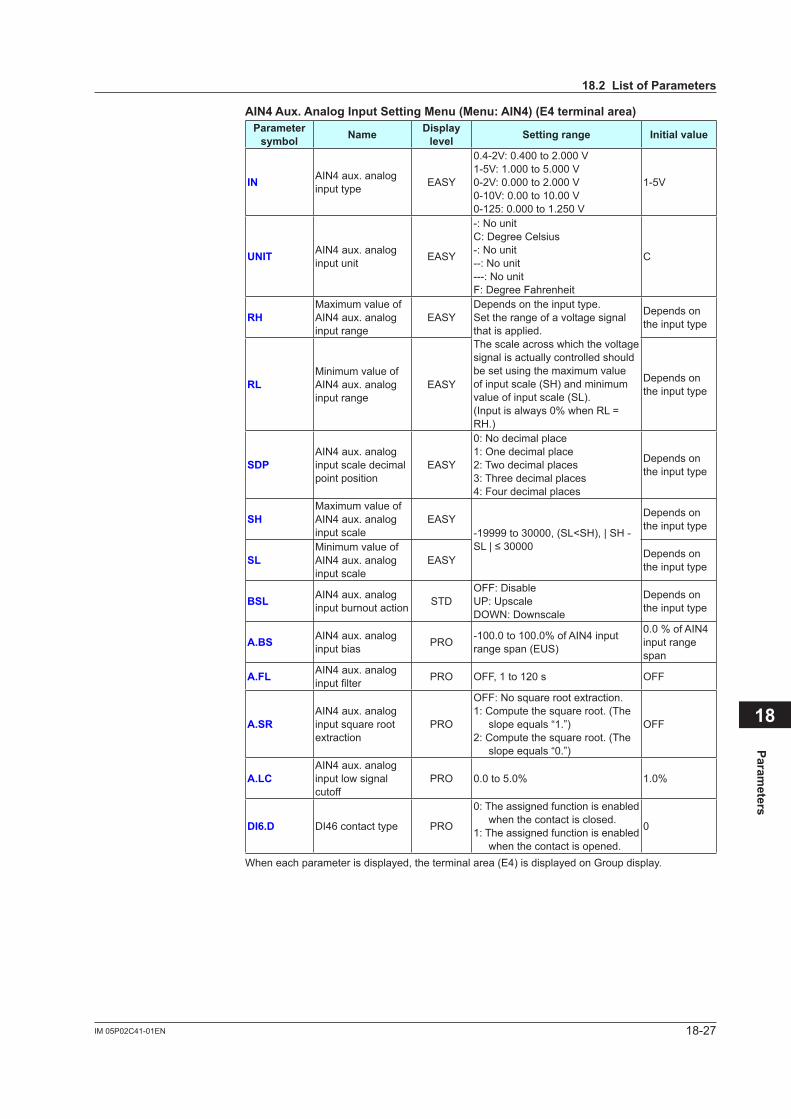
18-27IM 05P02C41-01EN
Parameters
18
AIN4Aux.AnalogInputSettingMenu(Menu:AIN4)(E4terminalarea)Parameter symbol Name Display
level Settingrange Initialvalue
IN AIN4 aux. analog input type EASY
0.4-2V: 0.400 to 2.000 V1-5V: 1.000 to 5.000 V0-2V: 0.000 to 2.000 V0-10V: 0.00 to 10.00 V0-125: 0.000 to 1.250 V
1-5V
UNIT AIN4 aux. analog input unit EASY
-: No unitC: Degree Celsius-: No unit--: No unit---: No unitF: Degree Fahrenheit
C
RHMaximum value of AIN4 aux. analog input range
EASYDepends on the input type.Set the range of a voltage signal that is applied.The scale across which the voltage signal is actually controlled should be set using the maximum value of input scale (SH) and minimum value of input scale (SL).(Input is always 0% when RL = RH.)
Depends on the input type
RLMinimum value of AIN4 aux. analog input range
EASY Depends on the input type
SDPAIN4 aux. analog input scale decimal point position
EASY
0: No decimal place1: One decimal place2: Two decimal places3: Three decimal places4: Four decimal places
Depends on the input type
SHMaximum value of AIN4 aux. analog input scale
EASY-19999 to 30000, (SL<SH), | SH - SL|≤30000
Depends on the input type
SLMinimum value of AIN4 aux. analog input scale
EASY Depends on the input type
BSL AIN4 aux. analog input burnout action STD
OFF: DisableUP: UpscaleDOWN: Downscale
Depends on the input type
A.BS AIN4 aux. analog input bias PRO -100.0 to 100.0% of AIN4 input
range span (EUS)
0.0 % of AIN4 input range span
A.FL AIN4 aux. analog inputfilter PRO OFF, 1 to 120 s OFF
A.SRAIN4 aux. analog input square root extraction
PRO
OFF: No square root extraction.1: Compute the square root. (The
slope equals “1.”)2: Compute the square root. (The
slope equals “0.”)
OFF
A.LCAIN4 aux. analog input low signal cutoff
PRO 0.0 to 5.0% 1.0%
DI6.D DI46 contact type PRO
0: The assigned function is enabled when the contact is closed.
1: The assigned function is enabled when the contact is opened.
0
When each parameter is displayed, the terminal area (E4) is displayed on Group display.
18.2ListofParameters
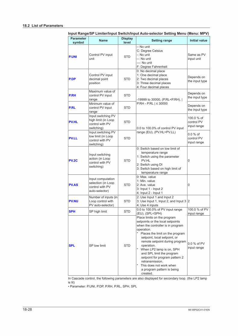
18-28 IM 05P02C41-01EN
InputRange/SPLimiter/InputSwitch/InputAuto-selectorSettingMenu(Menu:MPV)Parameter symbol Name Display
level Settingrange Initialvalue
P.UNI Control PV input unit STD
-: No unitC: Degree Celsius-: No unit--: No unit---: No unitF: Degree Fahrenheit
Same as PV input unit
P.DPControl PV input decimal point position
STD
0: No decimal place1: One decimal place2: Two decimal places3: Three decimal places4: Four decimal places
Depends on the input type
P.RHMaximum value of control PV input range
STD-19999 to 30000, (P.RL<P.RH), | P.RH-P.RL|≤30000
Depends on the input type
P.RLMinimum value of control PV input range
STD Depends on the input type
PV.HL
Input switching PV high limit (in Loop control with PV switching)
STD
0.0 to 100.0% of control PV input range (EU), (PV.HL>PV.LL)
100.0 % of control PV input range
PV.LL
Input switching PV low limit (in Loop control with PV switching)
STD0.0 % of control PV input range
PV.2C
Input switching action (in Loop control with PV switching)
STD
0: Switch based on low limit of temperature range
1: Switch using the parameter PV.HL
2: Switch using DI3: Switch based on high limit of
temperature range
0
PV.AS
Input computation selection (in Loop control with PV auto-selector)
STD
0: Max. value1: Min. value2: Ave. value3: Input 1 - Input 24: Input 2 - Input 1
0
PV.NUNumber of inputs (in Loop control with PV auto-selector)
STD2: Use Input 1 and Input 23: Use Input 1, Input 2, and Input 34: Use 4 inputs
2
SPH SP high limit STD 0.0 to 100.0% of PV input range (EU), (SPL<SPH)Place limits on the program setpoints or the local setpoints when the controller is in program operation.* Places the limit on the program
setpoint, local setpoint, or remote setpoint during program operation.
* When LP2 lamp is on, SPH and SPL limit the program setpoint for program pattern 2 retransmission.
* This does not work when a program pattern is being created.
100.0 % of PV input range
SPL SP low limit STD 0.0 % of PV input range
In Cascade control, the following parameters are also displayed for secondary loop. (the LP2 lamp is lit)• Parameter: P.UNI, P.DP, P.RH, P.RL, SPH, SPL
18.2ListofParameters

18-29IM 05P02C41-01EN
Parameters
18
OutputSettingMenu(Menu:OUT)Parameter symbol Name Display
level Settingrange Initialvalue
OT Output type selection EASY
Control output or Heating-side control output (Lower two digits)00: OFF01: OUT terminals (voltage pulse)02: OUT terminals (current)03: OUT terminals (relay/triac)04: OUT2 terminals (voltage pulse)05: OUT2 terminals (current)06: OUT2 terminals (relay/triac)
Cooling-side control output (Upper two digits)00: OFF01: OUT terminals (voltage pulse)02: OUT terminals (current)03: OUT terminals (relay/triac)04: OUT2 terminals (voltage pulse)05: OUT2 terminals (current)06: OUT2 terminals (relay/triac)
Standard type: 00.03
Heating/cooling type: 06.03
CT
Control output cycle timeHeating-side control output cycle time (in Heating/cooling control)
EASY0.5 to 1000.0 s
30.0 s
CTc Cooling-side control output cycle time EASY 30.0 s
V.AT Automatic valve positionadjustment EASY OFF:Stopautomaticadjustment
ON:Startautomaticadjustment OFF
V.RS Valve position setting reset EASY
Setting V.RS to ON resets the valveadjustmentsettingsandcauses the indication “V.RS” to blink.
OFF
V.L Fully-closed valve position setting EASY
Pressing the SET/ENTER key with valve position set to the fully-closed position by Down arrow keycausestheadjustedvaluetobestored.WhenV.Ladjustmentiscomplete, V.L stops blinking.
-
V.H Fully-open valve position setting EASY
Pressing the SET/ENTER key with valve position set to the fully-opened position by Up arrow key causestheadjustedvaluetobestored.WhenV.Hadjustmentiscomplete, V.H stops blinking.
-
TR.T Valve traveling time STD 5 to 300 s 60 s
V.MOD Valveadjustingmode STD
0: Valve position feedback type1: Valve position feedback type
(moves to the estimating type if a feedback input error or break occurs.)
2: Valve position estimating type
0
18.2ListofParameters
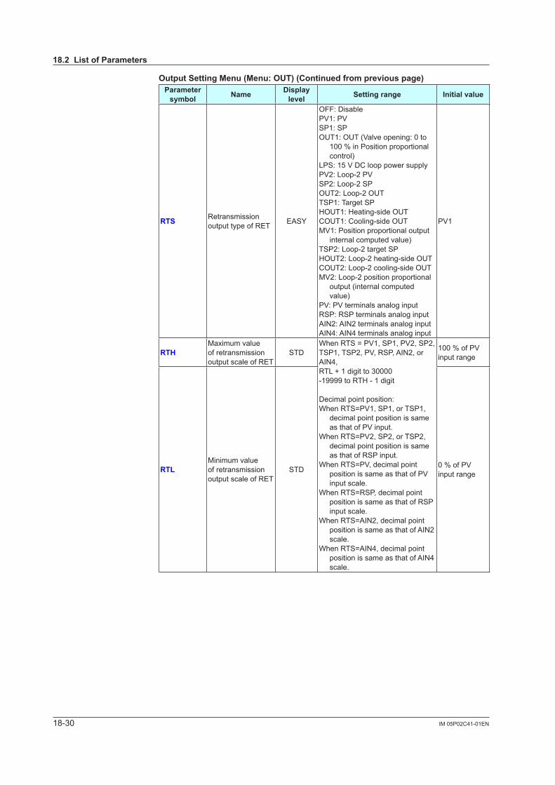
18-30 IM 05P02C41-01EN
OutputSettingMenu(Menu:OUT)(Continuedfrompreviouspage)Parameter symbol Name Display
level Settingrange Initialvalue
RTS Retransmission output type of RET EASY
OFF: DisablePV1: PVSP1: SPOUT1: OUT (Valve opening: 0 to
100 % in Position proportional control)
LPS: 15 V DC loop power supplyPV2: Loop-2 PVSP2: Loop-2 SPOUT2: Loop-2 OUTTSP1: Target SPHOUT1: Heating-side OUTCOUT1: Cooling-side OUTMV1: Position proportional output
internal computed value)TSP2: Loop-2 target SPHOUT2: Loop-2 heating-side OUTCOUT2: Loop-2 cooling-side OUTMV2: Loop-2 position proportional
output (internal computed value)
PV: PV terminals analog inputRSP: RSP terminals analog inputAIN2: AIN2 terminals analog inputAIN4: AIN4 terminals analog input
PV1
RTHMaximum value of retransmission output scale of RET
STDWhen RTS = PV1, SP1, PV2, SP2, TSP1, TSP2, PV, RSP, AIN2, or AIN4, RTL + 1 digit to 30000-19999 to RTH - 1 digit
Decimal point position:When RTS=PV1, SP1, or TSP1,
decimal point position is same as that of PV input.
When RTS=PV2, SP2, or TSP2, decimal point position is same as that of RSP input.
When RTS=PV, decimal point position is same as that of PV input scale.
When RTS=RSP, decimal point position is same as that of RSP input scale.
When RTS=AIN2, decimal point position is same as that of AIN2 scale.
When RTS=AIN4, decimal point position is same as that of AIN4 scale.
100 % of PV input range
RTLMinimum value of retransmission output scale of RET
STD 0 % of PV input range
18.2ListofParameters
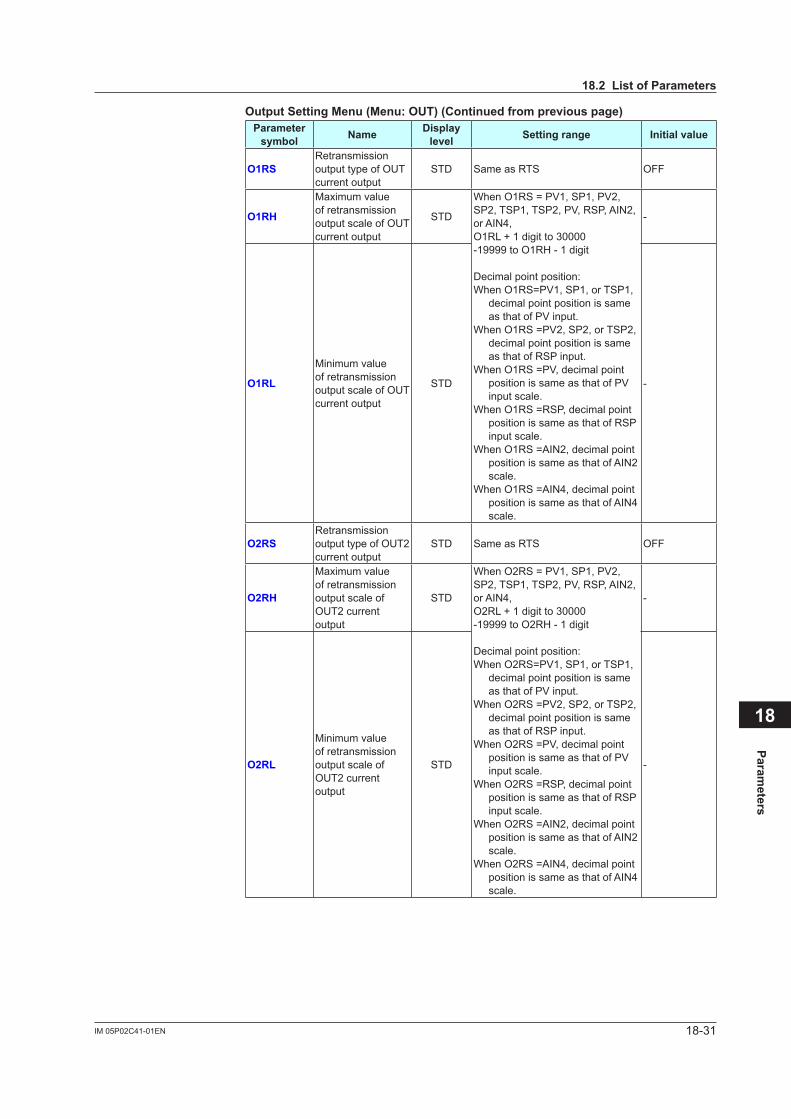
18-31IM 05P02C41-01EN
Parameters
18
OutputSettingMenu(Menu:OUT)(Continuedfrompreviouspage)Parameter symbol Name Display
level Settingrange Initialvalue
O1RSRetransmission output type of OUT current output
STD Same as RTS OFF
O1RH
Maximum value of retransmission output scale of OUT current output
STD
When O1RS = PV1, SP1, PV2, SP2, TSP1, TSP2, PV, RSP, AIN2, or AIN4, O1RL + 1 digit to 30000-19999 to O1RH - 1 digit
Decimal point position:When O1RS=PV1, SP1, or TSP1,
decimal point position is same as that of PV input.
When O1RS =PV2, SP2, or TSP2, decimal point position is same as that of RSP input.
When O1RS =PV, decimal point position is same as that of PV input scale.
When O1RS =RSP, decimal point position is same as that of RSP input scale.
When O1RS =AIN2, decimal point position is same as that of AIN2 scale.
When O1RS =AIN4, decimal point position is same as that of AIN4 scale.
-
O1RL
Minimum value of retransmission output scale of OUT current output
STD -
O2RSRetransmission output type of OUT2 current output
STD Same as RTS OFF
O2RH
Maximum value of retransmission output scale of OUT2 current output
STD
When O2RS = PV1, SP1, PV2, SP2, TSP1, TSP2, PV, RSP, AIN2, or AIN4, O2RL + 1 digit to 30000-19999 to O2RH - 1 digit
Decimal point position:When O2RS=PV1, SP1, or TSP1,
decimal point position is same as that of PV input.
When O2RS =PV2, SP2, or TSP2, decimal point position is same as that of RSP input.
When O2RS =PV, decimal point position is same as that of PV input scale.
When O2RS =RSP, decimal point position is same as that of RSP input scale.
When O2RS =AIN2, decimal point position is same as that of AIN2 scale.
When O2RS =AIN4, decimal point position is same as that of AIN4 scale.
-
O2RL
Minimum value of retransmission output scale of OUT2 current output
STD -
18.2ListofParameters
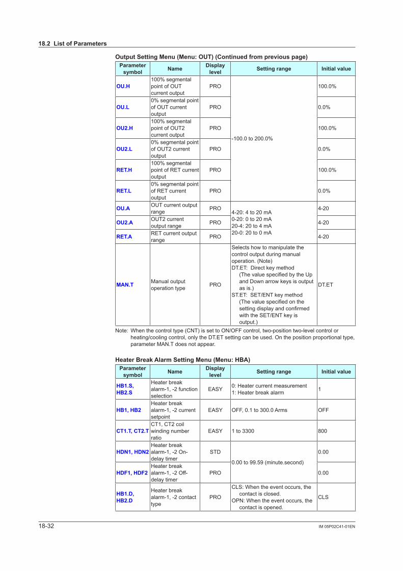
18-32 IM 05P02C41-01EN
OutputSettingMenu(Menu:OUT)(Continuedfrompreviouspage)Parameter symbol Name Display
level Settingrange Initialvalue
OU.H100% segmental point of OUT current output
PRO
-100.0 to 200.0%
100.0%
OU.L0% segmental point of OUT current output
PRO 0.0%
OU2.H100% segmental point of OUT2 current output
PRO 100.0%
OU2.L0% segmental point of OUT2 current output
PRO 0.0%
RET.H100% segmental point of RET current output
PRO 100.0%
RET.L0% segmental point of RET current output
PRO 0.0%
OU.A OUT current output range PRO
4-20: 4 to 20 mA0-20: 0 to 20 mA20-4: 20 to 4 mA20-0: 20 to 0 mA
4-20
OU2.A OUT2 current output range PRO 4-20
RET.A RET current output range PRO 4-20
MAN.T Manual output operation type PRO
Selects how to manipulate the control output during manual operation. (Note)DT.ET: Direct key method(ThevaluespecifiedbytheUp
and Down arrow keys is output as is.)
ST.ET: SET/ENT key method(Thevaluespecifiedonthe
settingdisplayandconfirmedwith the SET/ENT key is output.)
DT.ET
Note: When the control type (CNT) is set to ON/OFF control, two-position two-level control or heating/cooling control, only the DT.ET setting can be used. On the position proportional type, parameter MAN.T does not appear.
HeaterBreakAlarmSettingMenu(Menu:HBA)Parameter symbol Name Display
level Settingrange Initialvalue
HB1.S,HB2.S
Heater break alarm-1, -2 function selection
EASY 0: Heater current measurement1: Heater break alarm 1
HB1,HB2Heater break alarm-1, -2 current setpoint
EASY OFF, 0.1 to 300.0 Arms OFF
CT1.T,CT2.TCT1, CT2 coil winding number ratio
EASY 1 to 3300 800
HDN1,HDN2Heater break alarm-1, -2 On-delay timer
STD
0.00 to 99.59 (minute.second)
0.00
HDF1,HDF2Heater break alarm-1, -2 Off-delay timer
PRO 0.00
HB1.D,HB2.D
Heater break alarm-1, -2 contact type
PRO
CLS: When the event occurs, the contact is closed.
OPN: When the event occurs, the contact is opened.
CLS
18.2ListofParameters
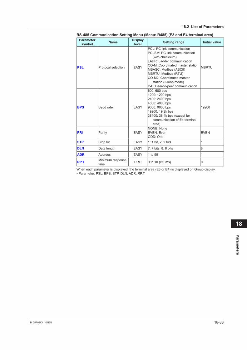
18-33IM 05P02C41-01EN
Parameters
18
RS-485CommunicationSettingMenu(Menu:R485)(E3andE4terminalarea)Parameter symbol Name Display
level Settingrange Initialvalue
PSL Protocol selection EASY
PCL: PC link communicationPCLSM: PC link communication
(with checksum)LADR: Ladder communicationCO-M: Coordinated master stationMBASC: Modbus (ASCII)MBRTU: Modbus (RTU)CO-M2: Coordinated master
station (2-loop mode)P-P: Peer-to-peer communication
MBRTU
BPS Baud rate EASY
600: 600 bps1200: 1200 bps2400: 2400 bps4800: 4800 bps9600: 9600 bps19200: 19.2k bps38400: 38.4k bps (except for
communication of E4 terminal area)
19200
PRI Parity EASYNONE: NoneEVEN: EvenODD: Odd
EVEN
STP Stop bit EASY 1: 1 bit, 2: 2 bits 1
DLN Data length EASY 7: 7 bits, 8: 8 bits 8
ADR Address EASY 1 to 99 1
RP.T Minimum response time PRO 0 to 10 (x10ms) 0
When each parameter is displayed, the terminal area (E3 or E4) is displayed on Group display.• Parameter: PSL, BPS, STP, DLN, ADR, RP.T
18.2ListofParameters
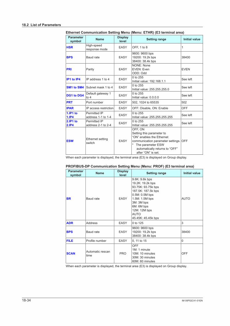
18-34 IM 05P02C41-01EN
EthernetCommunicationSettingMenu(Menu:ETHR)(E3terminalarea)Parameter symbol Name Display
level Settingrange Initialvalue
HSR High-speed response mode EASY OFF, 1 to 8 1
BPS Baud rate EASY9600: 9600 bps19200: 19.2k bps38400: 38.4k bps
38400
PRI Parity EASYNONE: NoneEVEN: EvenODD: Odd
EVEN
IP1toIP4 IP address 1 to 4 EASY 0 to 255Initial value: 192.168.1.1 See left
SM1toSM4 Subnet mask 1 to 4 EASY 0 to 255Initial value: 255.255.255.0 See left
DG1toDG4 Default gateway 1 to 4 EASY 0 to 255
Initial value: 0.0.0.0 See left
PRT Port number EASY 502, 1024 to 65535 502
IPAR IP access restriction EASY OFF: Disable, ON: Enable OFF1.IP1to1.IP4
Permitted IP address 1-1 to 1-4 EASY 0 to 255
Initial value: 255.255.255.255 See left
2.IP1to2.IP4
Permitted IP address 2-1 to 2-4 EASY 0 to 255
Initial value: 255.255.255.255 See left
ESW Ethernet setting switch EASY
OFF, ONSetting this parameter to “ON” enables the Ethernet communication parameter settings.* The parameter ESW
automatically returns to “OFF”after “ON” is set.
OFF
When each parameter is displayed, the terminal area (E3) is displayed on Group display.
PROFIBUS-DPCommunicationSettingMenu(Menu:PROF)(E3terminalarea)Parameter symbol Name Display
level Settingrange Initialvalue
BR Baud rate EASY
9.6K: 9.6k bps19.2K: 19.2k bps93.75K: 93.75k bps187.5K: 187.5k bps0.5M: 0.5M bps1.5M: 1.5M bps3M: 3M bps6M: 6M bps12M: 12M bpsAUTO45.45K: 45.45k bps
AUTO
ADR Address EASY 0 to 125 3
BPS Baud rate EASY9600: 9600 bps19200: 19.2k bps38400: 38.4k bps
38400
FILE Profilenumber EASY 0, 11 to 15 0
SCAN Automatic rescan time PRO
OFF1M: 1 minute10M: 10 minutes30M: 30 minutes60M: 60 minutes
OFF
When each parameter is displayed, the terminal area (E3) is displayed on Group display.
18.2ListofParameters
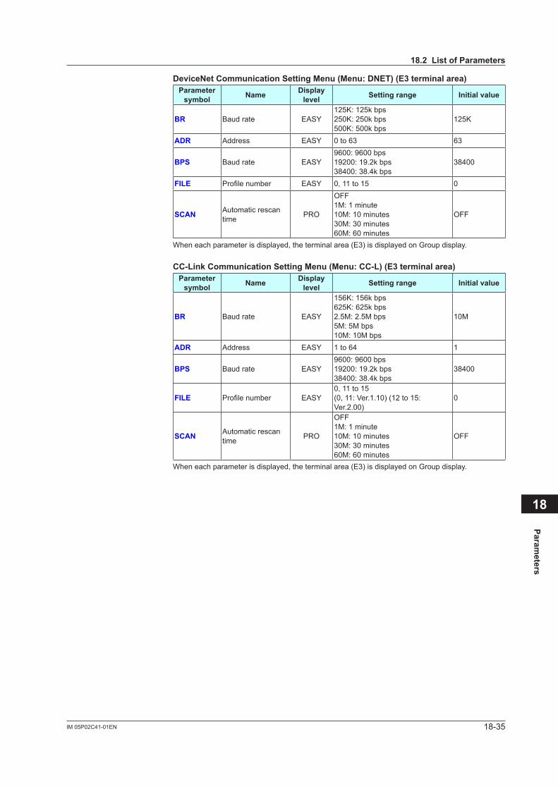
18-35IM 05P02C41-01EN
Parameters
18
DeviceNetCommunicationSettingMenu(Menu:DNET)(E3terminalarea)Parameter symbol Name Display
level Settingrange Initialvalue
BR Baud rate EASY125K: 125k bps250K: 250k bps500K: 500k bps
125K
ADR Address EASY 0 to 63 63
BPS Baud rate EASY9600: 9600 bps19200: 19.2k bps38400: 38.4k bps
38400
FILE Profilenumber EASY 0, 11 to 15 0
SCAN Automatic rescan time PRO
OFF1M: 1 minute10M: 10 minutes30M: 30 minutes60M: 60 minutes
OFF
When each parameter is displayed, the terminal area (E3) is displayed on Group display.
CC-LinkCommunicationSettingMenu(Menu:CC-L)(E3terminalarea)Parameter symbol Name Display
level Settingrange Initialvalue
BR Baud rate EASY
156K: 156k bps625K: 625k bps2.5M: 2.5M bps5M: 5M bps10M: 10M bps
10M
ADR Address EASY 1 to 64 1
BPS Baud rate EASY9600: 9600 bps19200: 19.2k bps38400: 38.4k bps
38400
FILE Profilenumber EASY0, 11 to 15(0, 11: Ver.1.10) (12 to 15: Ver.2.00)
0
SCAN Automatic rescan time PRO
OFF1M: 1 minute10M: 10 minutes30M: 30 minutes60M: 60 minutes
OFF
When each parameter is displayed, the terminal area (E3) is displayed on Group display.
18.2ListofParameters
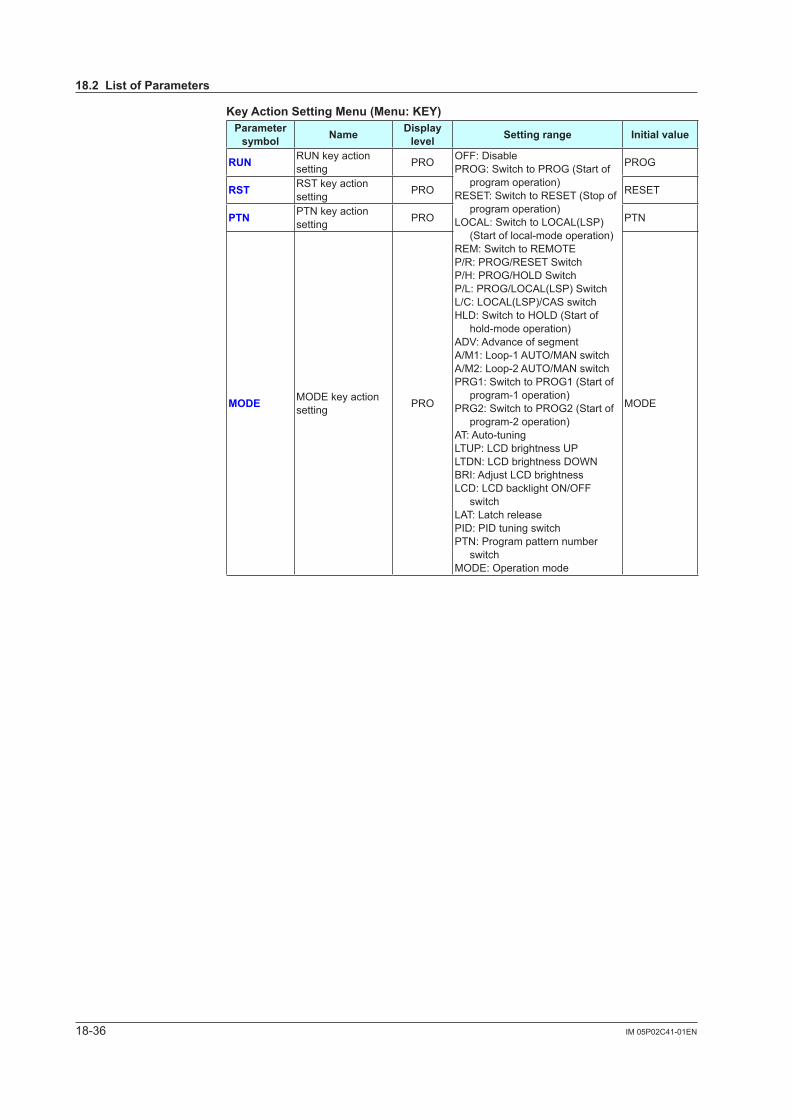
18-36 IM 05P02C41-01EN
KeyActionSettingMenu(Menu:KEY)Parameter symbol Name Display
level Settingrange Initialvalue
RUN RUN key action setting PRO OFF: Disable
PROG: Switch to PROG (Start of program operation)
RESET: Switch to RESET (Stop of program operation)
LOCAL: Switch to LOCAL(LSP) (Start of local-mode operation)
REM: Switch to REMOTEP/R: PROG/RESET SwitchP/H: PROG/HOLD SwitchP/L: PROG/LOCAL(LSP) SwitchL/C: LOCAL(LSP)/CAS switchHLD: Switch to HOLD (Start of
hold-mode operation)ADV: Advance of segmentA/M1: Loop-1 AUTO/MAN switchA/M2: Loop-2 AUTO/MAN switchPRG1: Switch to PROG1 (Start of
program-1 operation)PRG2: Switch to PROG2 (Start of
program-2 operation)AT: Auto-tuningLTUP: LCD brightness UPLTDN: LCD brightness DOWNBRI:AdjustLCDbrightnessLCD: LCD backlight ON/OFF
switchLAT: Latch releasePID: PID tuning switchPTN: Program pattern number
switchMODE: Operation mode
PROG
RST RST key action setting PRO RESET
PTN PTN key action setting PRO PTN
MODE MODE key action setting PRO MODE
18.2ListofParameters
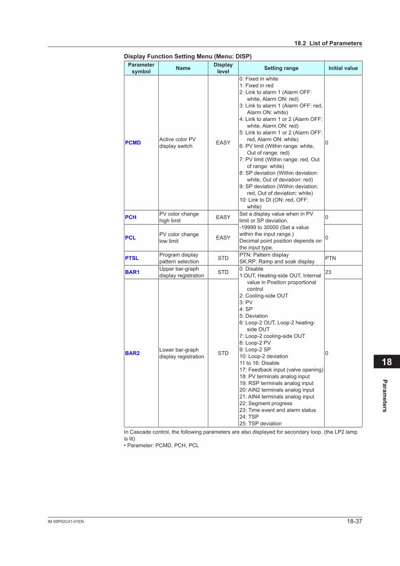
18-37IM 05P02C41-01EN
Parameters
18
DisplayFunctionSettingMenu(Menu:DISP)Parameter symbol Name Display
level Settingrange Initialvalue
PCMD Active color PV display switch EASY
0: Fixed in white1: Fixed in red2: Link to alarm 1 (Alarm OFF:
white, Alarm ON: red)3: Link to alarm 1 (Alarm OFF: red,
Alarm ON: white)4: Link to alarm 1 or 2 (Alarm OFF:
white, Alarm ON: red)5: Link to alarm 1 or 2 (Alarm OFF:
red, Alarm ON: white)6: PV limit (Within range: white,
Out of range: red)7: PV limit (Within range: red, Out
of range: white)8: SP deviation (Within deviation:
white, Out of deviation: red)9: SP deviation (Within deviation:
red, Out of deviation: white)10: Link to DI (ON: red, OFF:
white)
0
PCH PV color change high limit EASY Set a display value when in PV
limit or SP deviation.-19999 to 30000 (Set a value within the input range.)Decimal point position depends on the input type.
0
PCL PV color change low limit EASY 0
PTSL Program display pattern selection STD PTN: Pattern display
SK.RP: Ramp and soak display PTN
BAR1 Upper bar-graph display registration STD 0: Disable
1:OUT, Heating-side OUT, Internal value in Position proportional control
2: Cooling-side OUT3: PV4: SP5: Deviation6: Loop-2 OUT, Loop-2 heating-
side OUT7: Loop-2 cooling-side OUT8: Loop-2 PV9: Loop-2 SP10: Loop-2 deviation11 to 16: Disable17: Feedback input (valve opening)18: PV terminals analog input19: RSP terminals analog input20: AIN2 terminals analog input21: AIN4 terminals analog input22: Segment progress23: Time event and alarm status24: TSP25: TSP deviation
23
BAR2 Lower bar-graph display registration STD 0
In Cascade control, the following parameters are also displayed for secondary loop. (the LP2 lamp is lit)• Parameter: PCMD, PCH, PCL
18.2ListofParameters
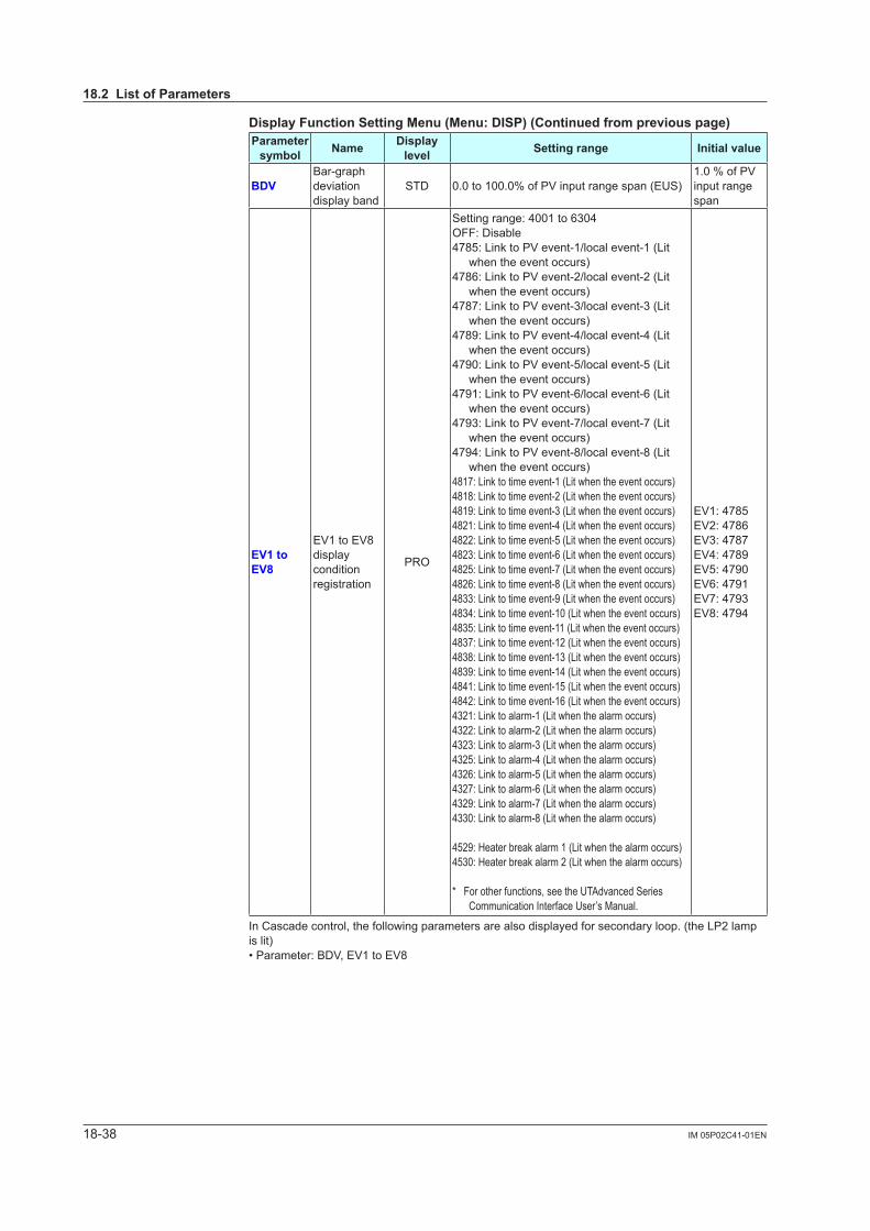
18-38 IM 05P02C41-01EN
DisplayFunctionSettingMenu(Menu:DISP)(Continuedfrompreviouspage)Parameter symbol Name Display
level Settingrange Initialvalue
BDVBar-graph deviation display band
STD 0.0 to 100.0% of PV input range span (EUS)1.0 % of PV input range span
EV1toEV8
EV1 to EV8 display condition registration
PRO
Setting range: 4001 to 6304OFF: Disable4785: Link to PV event-1/local event-1 (Lit
when the event occurs)4786: Link to PV event-2/local event-2 (Lit
when the event occurs)4787: Link to PV event-3/local event-3 (Lit
when the event occurs)4789: Link to PV event-4/local event-4 (Lit
when the event occurs)4790: Link to PV event-5/local event-5 (Lit
when the event occurs)4791: Link to PV event-6/local event-6 (Lit
when the event occurs)4793: Link to PV event-7/local event-7 (Lit
when the event occurs)4794: Link to PV event-8/local event-8 (Lit
when the event occurs)4817: Link to time event-1 (Lit when the event occurs)4818: Link to time event-2 (Lit when the event occurs)4819: Link to time event-3 (Lit when the event occurs)4821: Link to time event-4 (Lit when the event occurs)4822: Link to time event-5 (Lit when the event occurs)4823: Link to time event-6 (Lit when the event occurs)4825: Link to time event-7 (Lit when the event occurs)4826: Link to time event-8 (Lit when the event occurs)4833: Link to time event-9 (Lit when the event occurs)4834: Link to time event-10 (Lit when the event occurs)4835: Link to time event-11 (Lit when the event occurs)4837: Link to time event-12 (Lit when the event occurs)4838: Link to time event-13 (Lit when the event occurs)4839: Link to time event-14 (Lit when the event occurs)4841: Link to time event-15 (Lit when the event occurs)4842: Link to time event-16 (Lit when the event occurs)4321: Link to alarm-1 (Lit when the alarm occurs)4322: Link to alarm-2 (Lit when the alarm occurs)4323: Link to alarm-3 (Lit when the alarm occurs)4325: Link to alarm-4 (Lit when the alarm occurs)4326: Link to alarm-5 (Lit when the alarm occurs)4327: Link to alarm-6 (Lit when the alarm occurs)4329: Link to alarm-7 (Lit when the alarm occurs)4330: Link to alarm-8 (Lit when the alarm occurs)
4529: Heater break alarm 1 (Lit when the alarm occurs)4530: Heater break alarm 2 (Lit when the alarm occurs)
* For other functions, see the UTAdvanced Series Communication Interface User’s Manual.
EV1: 4785EV2: 4786EV3: 4787EV4: 4789EV5: 4790EV6: 4791EV7: 4793EV8: 4794
In Cascade control, the following parameters are also displayed for secondary loop. (the LP2 lamp is lit)• Parameter: BDV, EV1 to EV8
18.2ListofParameters
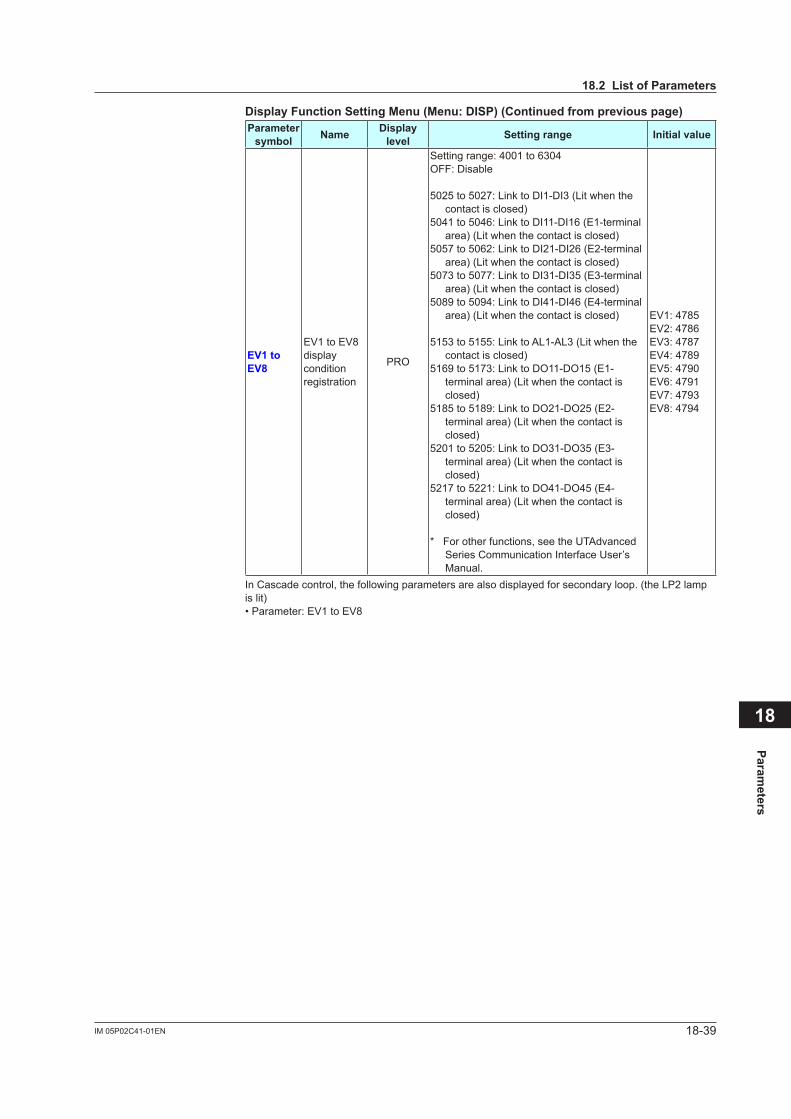
18-39IM 05P02C41-01EN
Parameters
18
DisplayFunctionSettingMenu(Menu:DISP)(Continuedfrompreviouspage)Parameter symbol Name Display
level Settingrange Initialvalue
EV1toEV8
EV1 to EV8 display condition registration
PRO
Setting range: 4001 to 6304OFF: Disable
5025 to 5027: Link to DI1-DI3 (Lit when the contact is closed)
5041 to 5046: Link to DI11-DI16 (E1-terminal area) (Lit when the contact is closed)
5057 to 5062: Link to DI21-DI26 (E2-terminal area) (Lit when the contact is closed)
5073 to 5077: Link to DI31-DI35 (E3-terminal area) (Lit when the contact is closed)
5089 to 5094: Link to DI41-DI46 (E4-terminal area) (Lit when the contact is closed)
5153 to 5155: Link to AL1-AL3 (Lit when the contact is closed)
5169 to 5173: Link to DO11-DO15 (E1-terminal area) (Lit when the contact is closed)
5185 to 5189: Link to DO21-DO25 (E2-terminal area) (Lit when the contact is closed)
5201 to 5205: Link to DO31-DO35 (E3-terminal area) (Lit when the contact is closed)
5217 to 5221: Link to DO41-DO45 (E4-terminal area) (Lit when the contact is closed)
* For other functions, see the UTAdvanced Series Communication Interface User’s Manual.
EV1: 4785EV2: 4786EV3: 4787EV4: 4789EV5: 4790EV6: 4791EV7: 4793EV8: 4794
In Cascade control, the following parameters are also displayed for secondary loop. (the LP2 lamp is lit)• Parameter: EV1 to EV8
18.2ListofParameters

18-40 IM 05P02C41-01EN
DisplayFunctionSettingMenu(Menu:DISP)(Continuedfrompreviouspage)Parameter symbol Name Display
level Settingrange Initial value
PV.D PV display area ON/OFF PRO
OFF: Nondisplay, ON: Display
ON
SP.D Setpoint display area ON/OFF PRO ON
STS.D Status display area ON/OFF PRO ON
SPD Scroll speed PRO (Slow) 1 to 8 (Quick) 4
GUID Guide display ON/OFF STD OFF: Nondisplay
ON: Display ON
HOME Home Operation Display setting PRO
SP1: SP DisplaySP2: Loop-2 SP DisplayOUT1: OUT DisplayOUT2: Loop-2 OUT DisplayHCO: Heating/cooling OUT DisplayVP: Valve Position DisplayMV: Position Proportional Computation Output
DisplayPID1: PID Number DisplayPID2: Loop-2 PID Number DisplayHC1: Heater Break Alarm-1 Current DisplayHC2: Heater Break Alarm-2 Current DisplayPV1: PV2/PV1 DisplayPV2: PV1/PV2 DisplayPV: PV Analog Input DisplayRSP: RSP Analog Input DisplayAIN2: AIN2 Analog Input DisplayAIN4: AIN4 Analog Input DisplayCS1 to CS5: SELECT Display 1 to 5TSP1: TSP DisplayTSP2: Loop-2 TSP DisplayR.TIM: Remaining Segment-tim DisplaySEG.N: Segment Number DispalyR.CYC: Remaining Repetition DisplayPTN: Program Pattern DisplayAL5.8.1: Alarm-5 to -8 Status DisplayAL5.8.2: Loop-2 Alarm-5 to -8 Status Display
SP1
ECO Economy mode STD
OFF: Disable1: Economy mode ON (All indications
except PV display OFF)2: Economy mode ON (All indications OFF)3: Brightness 10 % (All indications)
OFF
BRI Brightness EASY (Dark) 1 to 5 (Bright) 3
B.PVWWhite brightness adjustmentofPVdisplay
PRO AdjuststhewhitebrightnessofPVdisplay.(Dark) -4 to 4 (Bright) 0
B.PVRRed brightness adjustmentofPVdisplay
PRO AdjuststheredbrightnessofPVdisplay.(Dark) -4 to 4 (Bright) 0
B.SPBrightness adjustmentofSetpoint display
PRO AdjuststhebrightnessofSPdisplay.(Dark) -4 to 4 (Bright) 0
B.BARBrightness adjustmentofBar-graph display
PRO AdjuststhebrightnessofSPdisplay.(Dark) -4 to 4 (Bright) 0
B.STSBrightness adjustmentofStatus indicator
PRO AdjuststhebrightnessofStatusindicator.(Dark) -4 to 4 (Bright) 0
D.CYC Display update cycle PRO
1: 100 ms2: 200 ms3: 500 ms4: 1 s5: 2 s
2
18.2ListofParameters
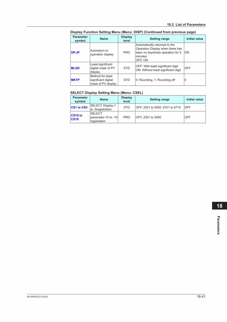
18-41IM 05P02C41-01EN
Parameters
18
DisplayFunctionSettingMenu(Menu:DISP)(Continuedfrompreviouspage)Parameter symbol Name Display
level Settingrange Initialvalue
OP.JP Autoreturn to operation display PRO
Automatically returned to the Operation Display when there has been no keystroke operation for 5 minutes.OFF, ON
ON
MLSDLeastsignificantdigital mask of PV display
STD OFF:WithleastsignificantdigitON:Withoutleastsignificantdigit OFF
MKTPMethod for least significantdigitalmask of PV display
STD 0: Rounding, 1: Rounding-off 0
SELECTDisplaySettingMenu(Menu:CSEL)Parameter symbol Name Display
level Settingrange Initialvalue
CS1toCS5 SELECT Display-1 to -5registration STD OFF, 2201 to 5000, 6701 to 6710 OFF
CS10toCS19
SELECT parameter-10 to -19 registration
PRO OFF, 2201 to 5000 OFF
18.2ListofParameters
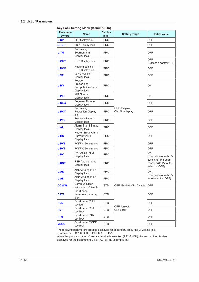
18-42 IM 05P02C41-01EN
KeyLockSettingMenu(Menu:KLOC)Parameter symbol Name Display
level Settingrange Initialvalue
U.SP SP Display lock PRO
OFF: DisplayON: Nondisplay
OFF
U.TSP TSP Display lock PRO OFF
U.TMRemaining Segment-tim Display lock
PRO OFF
U.OUT OUT Display lock PRO OFF(Cascade control: ON)
U.HCO Heating/cooling OUT Display lock PRO OFF
U.VP Valve Position Display lock PRO OFF
U.MV
Position Proportional Computation Output Display lock
PRO ON
U.PID PID Number Display lock PRO ON
U.SEG Segment Number Display lock PRO OFF
U.RCYRemaining Repetition Display lock
PRO OFF
U.PTN Program Pattern Display lock PRO OFF
U.AL Alarm-5 to -8 Status Display lock PRO OFF
U.HCHeater Break Alarm Current Value Display lock
PRO OFF
U.PV1 PV2/PV1 Display lock PRO OFF
U.PV2 PV1/PV2 Display lock PRO OFF
U.PV PV Analog Input Display lock PRO ON
(Loop control with PV switching and Loop control with PV auto-selector: OFF)
U.RSP RSP Analog Input Display lock PRO
U.AI2 AIN2 Analog Input Display lock PRO ON
(Loop control with PV auto-selector: OFF)U.AI4 AIN4 Analog Input
Display lock PRO
COM.W Communication write enable/disable STD OFF: Enable, ON: Disable OFF
DATAFront panel parameter data key lock
STD
OFF: UnlockON: Lock
OFF
RUN Front panel RUN key lock STD OFF
RST Front panel RST key lock STD OFF
PTN Front panel PTN key lock STD OFF
MODE Front panel MODE key lock STD OFF
The following parameters are also displayed for secondary loop. (the LP2 lamp is lit)• Parameter: U.SP, U.OUT, U.PID, U.AL, U.PV2When the program pattern-2 retransmission is selected (PT2.G=ON), the second loop is also displayed for the parameters UT.SP, U.TSP. (LP2 lamp is lit.)
18.2ListofParameters
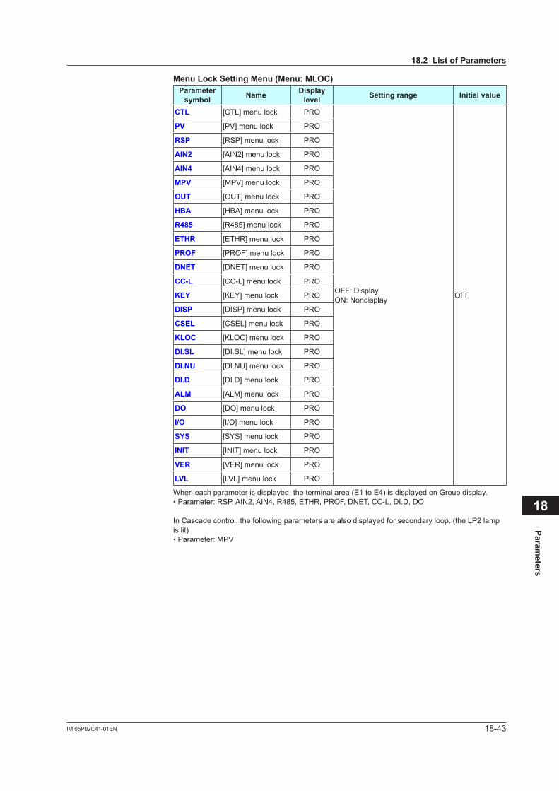
18-43IM 05P02C41-01EN
Parameters
18
MenuLockSettingMenu(Menu:MLOC)Parameter symbol Name Display
level Settingrange Initialvalue
CTL [CTL] menu lock PRO
OFF: DisplayON: Nondisplay OFF
PV [PV] menu lock PRO
RSP [RSP] menu lock PRO
AIN2 [AIN2] menu lock PRO
AIN4 [AIN4] menu lock PRO
MPV [MPV] menu lock PRO
OUT [OUT] menu lock PRO
HBA [HBA] menu lock PRO
R485 [R485] menu lock PRO
ETHR [ETHR] menu lock PRO
PROF [PROF] menu lock PRO
DNET [DNET] menu lock PRO
CC-L [CC-L] menu lock PRO
KEY [KEY] menu lock PRO
DISP [DISP] menu lock PRO
CSEL [CSEL] menu lock PRO
KLOC [KLOC] menu lock PRO
DI.SL [DI.SL] menu lock PRO
DI.NU [DI.NU] menu lock PRO
DI.D [DI.D] menu lock PRO
ALM [ALM] menu lock PRO
DO [DO] menu lock PRO
I/O [I/O] menu lock PRO
SYS [SYS] menu lock PRO
INIT [INIT] menu lock PRO
VER [VER] menu lock PRO
LVL [LVL] menu lock PRO
When each parameter is displayed, the terminal area (E1 to E4) is displayed on Group display.• Parameter: RSP, AIN2, AIN4, R485, ETHR, PROF, DNET, CC-L, DI.D, DO
In Cascade control, the following parameters are also displayed for secondary loop. (the LP2 lamp is lit)• Parameter: MPV
18.2ListofParameters
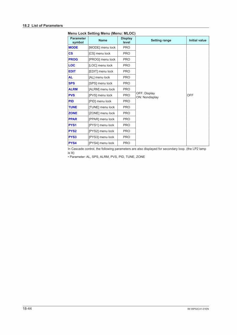
18-44 IM 05P02C41-01EN
MenuLockSettingMenu(Menu:MLOC)Parameter symbol Name Display
level Settingrange Initialvalue
MODE [MODE] menu lock PRO
OFF: DisplayON: Nondisplay OFF
CS [CS] menu lock PRO
PROG [PROG] menu lock PRO
LOC [LOC] menu lock PRO
EDIT [EDIT] menu lock PRO
AL [AL] menu lock PRO
SPS [SPS] menu lock PRO
ALRM [ALRM] menu lock PRO
PVS [PVS] menu lock PRO
PID [PID] menu lock PRO
TUNE [TUNE] menu lock PRO
ZONE [ZONE] menu lock PRO
PPAR [PPAR] menu lock PRO
PYS1 [PYS1] menu lock PRO
PYS2 [PYS2] menu lock PRO
PYS3 [PYS3] menu lock PRO
PYS4 [PYS4] menu lock PRO
In Cascade control, the following parameters are also displayed for secondary loop. (the LP2 lamp is lit)• Parameter: AL, SPS, ALRM, PVS, PID, TUNE, ZONE
18.2ListofParameters
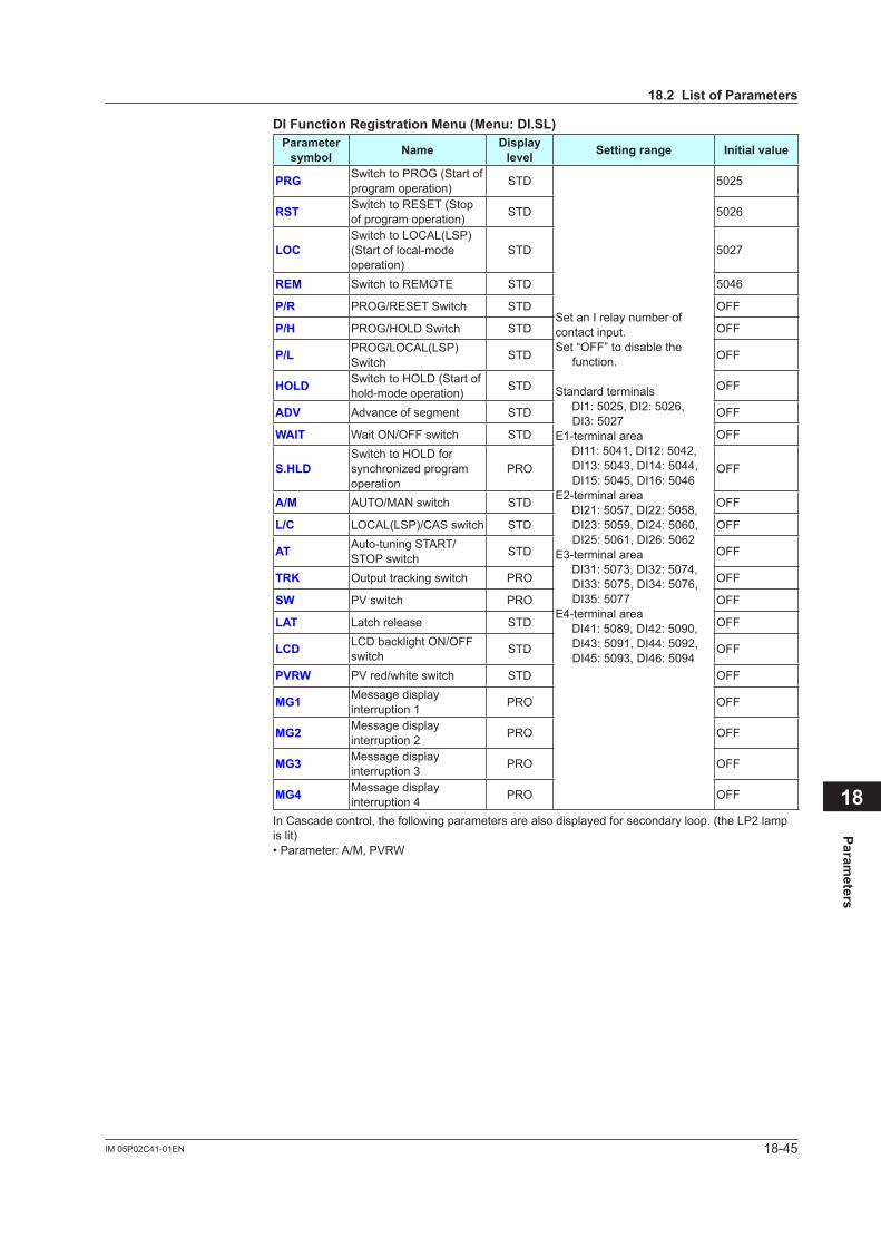
18-45IM 05P02C41-01EN
Parameters
18
DIFunctionRegistrationMenu(Menu:DI.SL)Parameter symbol Name Display
level Settingrange Initialvalue
PRG Switch to PROG (Start of program operation) STD
Set an I relay number of contact input.Set “OFF” to disable the
function.
Standard terminals DI1: 5025, DI2: 5026,
DI3: 5027E1-terminal area DI11: 5041, DI12: 5042,
DI13: 5043, DI14: 5044, DI15: 5045, DI16: 5046
E2-terminal area DI21: 5057, DI22: 5058,
DI23: 5059, DI24: 5060, DI25: 5061, DI26: 5062
E3-terminal area DI31: 5073, DI32: 5074,
DI33: 5075, DI34: 5076, DI35: 5077
E4-terminal area DI41: 5089, DI42: 5090,
DI43: 5091, DI44: 5092, DI45: 5093, DI46: 5094
5025
RST Switch to RESET (Stop of program operation) STD 5026
LOCSwitch to LOCAL(LSP) (Start of local-mode operation)
STD 5027
REM Switch to REMOTE STD 5046
P/R PROG/RESET Switch STD OFF
P/H PROG/HOLD Switch STD OFF
P/L PROG/LOCAL(LSP) Switch STD OFF
HOLD Switch to HOLD (Start of hold-mode operation) STD OFF
ADV Advance of segment STD OFF
WAIT Wait ON/OFF switch STD OFF
S.HLDSwitch to HOLD for synchronizedprogramoperation
PRO OFF
A/M AUTO/MAN switch STD OFF
L/C LOCAL(LSP)/CAS switch STD OFF
AT Auto-tuning START/STOP switch STD OFF
TRK Output tracking switch PRO OFF
SW PV switch PRO OFF
LAT Latch release STD OFF
LCD LCD backlight ON/OFF switch STD OFF
PVRW PV red/white switch STD OFF
MG1 Message display interruption 1 PRO OFF
MG2 Message display interruption 2 PRO OFF
MG3 Message display interruption 3 PRO OFF
MG4 Message display interruption 4 PRO OFF
In Cascade control, the following parameters are also displayed for secondary loop. (the LP2 lamp is lit)• Parameter: A/M, PVRW
18.2ListofParameters
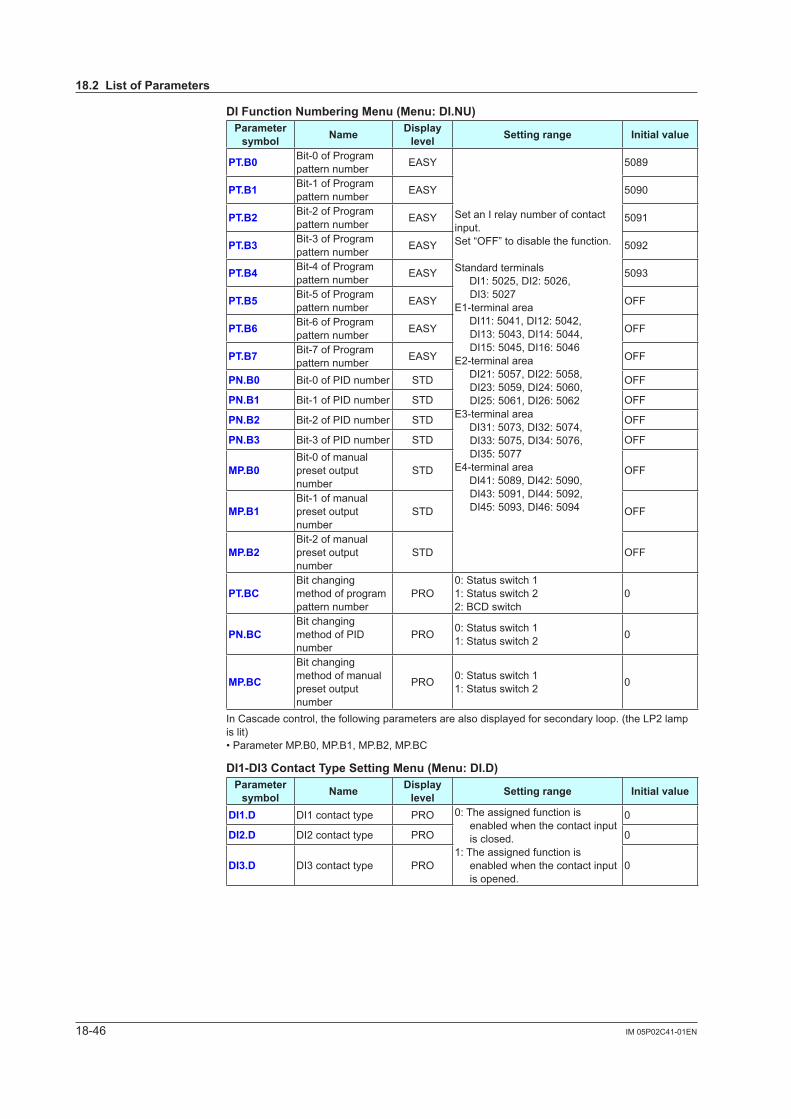
18-46 IM 05P02C41-01EN
DIFunctionNumberingMenu(Menu:DI.NU)Parameter symbol Name Display
level Settingrange Initialvalue
PT.B0 Bit-0 of Program pattern number EASY
Set an I relay number of contact input.Set “OFF” to disable the function.
Standard terminals DI1: 5025, DI2: 5026,
DI3: 5027E1-terminal area DI11: 5041, DI12: 5042,
DI13: 5043, DI14: 5044, DI15: 5045, DI16: 5046
E2-terminal area DI21: 5057, DI22: 5058,
DI23: 5059, DI24: 5060, DI25: 5061, DI26: 5062
E3-terminal area DI31: 5073, DI32: 5074,
DI33: 5075, DI34: 5076, DI35: 5077
E4-terminal area DI41: 5089, DI42: 5090,
DI43: 5091, DI44: 5092, DI45: 5093, DI46: 5094
5089
PT.B1 Bit-1 of Program pattern number EASY 5090
PT.B2 Bit-2 of Program pattern number EASY 5091
PT.B3 Bit-3 of Program pattern number EASY 5092
PT.B4 Bit-4 of Program pattern number EASY 5093
PT.B5 Bit-5 of Program pattern number EASY OFF
PT.B6 Bit-6 of Program pattern number EASY OFF
PT.B7 Bit-7 of Program pattern number EASY OFF
PN.B0 Bit-0 of PID number STD OFF
PN.B1 Bit-1 of PID number STD OFF
PN.B2 Bit-2 of PID number STD OFF
PN.B3 Bit-3 of PID number STD OFF
MP.B0Bit-0 of manual preset output number
STD OFF
MP.B1Bit-1 of manual preset output number
STD OFF
MP.B2Bit-2 of manual preset output number
STD OFF
PT.BCBit changing method of program pattern number
PRO0: Status switch 11: Status switch 22: BCD switch
0
PN.BCBit changing method of PID number
PRO 0: Status switch 11: Status switch 2 0
MP.BC
Bit changing method of manual preset output number
PRO 0: Status switch 11: Status switch 2 0
In Cascade control, the following parameters are also displayed for secondary loop. (the LP2 lamp is lit)• Parameter MP.B0, MP.B1, MP.B2, MP.BC
DI1-DI3ContactTypeSettingMenu(Menu:DI.D)Parameter symbol Name Display
level Settingrange Initialvalue
DI1.D DI1 contact type PRO 0: The assigned function is enabled when the contact input is closed.
1: The assigned function is enabled when the contact input is opened.
0
DI2.D DI2 contact type PRO 0
DI3.D DI3 contact type PRO 0
18.2ListofParameters
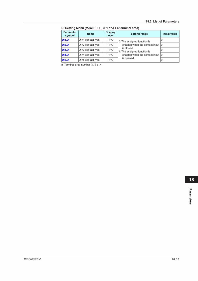
18-47IM 05P02C41-01EN
Parameters
18
DISettingMenu(Menu:DI.D)(E1andE4terminalarea)Parameter symbol Name Display
level Settingrange Initialvalue
DI1.D DIn1 contact type PRO 0: The assigned function is enabled when the contact input is closed.
1: The assigned function is enabled when the contact input is opened.
0
DI2.D DIn2 contact type PRO 0
DI3.D DIn3 contact type PRO 0
DI4.D DIn4 contact type PRO 0
DI5.D DIn5 contact type PRO 0
n: Terminal area number (1, 3 or 4)
18.2ListofParameters
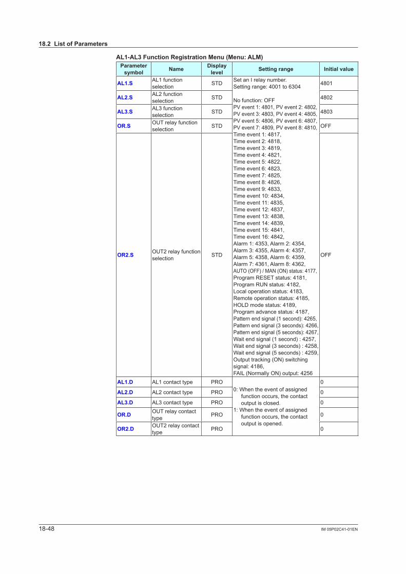
18-48 IM 05P02C41-01EN
AL1-AL3FunctionRegistrationMenu(Menu:ALM)Parameter symbol Name Display
level Settingrange Initialvalue
AL1.S AL1 function selection STD Set an I relay number.
Setting range: 4001 to 6304
No function: OFFPV event 1: 4801, PV event 2: 4802, PV event 3: 4803, PV event 4: 4805, PV event 5: 4806, PV event 6: 4807, PV event 7: 4809, PV event 8: 4810, Time event 1: 4817, Time event 2: 4818, Time event 3: 4819, Time event 4: 4821, Time event 5: 4822, Time event 6: 4823, Time event 7: 4825, Time event 8: 4826, Time event 9: 4833, Time event 10: 4834, Time event 11: 4835, Time event 12: 4837, Time event 13: 4838, Time event 14: 4839, Time event 15: 4841, Time event 16: 4842, Alarm 1: 4353, Alarm 2: 4354, Alarm 3: 4355, Alarm 4: 4357, Alarm 5: 4358, Alarm 6: 4359, Alarm 7: 4361, Alarm 8: 4362, AUTO (OFF) / MAN (ON) status: 4177, Program RESET status: 4181, Program RUN status: 4182, Local operation status: 4183, Remote operation status: 4185, HOLD mode status: 4189, Program advance status: 4187, Pattern end signal (1 second): 4265, Pattern end signal (3 seconds): 4266, Pattern end signal (5 seconds): 4267, Wait end signal (1 second) : 4257, Wait end signal (3 seconds) : 4258, Wait end signal (5 seconds) : 4259, Output tracking (ON) switching signal: 4186, FAIL (Normally ON) output: 4256
4801
AL2.S AL2 function selection STD 4802
AL3.S AL3 function selection STD 4803
OR.S OUT relay function selection STD OFF
OR2.S OUT2 relay function selection STD OFF
AL1.D AL1 contact type PRO0: When the event of assigned
function occurs, the contact output is closed.
1: When the event of assigned function occurs, the contact output is opened.
0
AL2.D AL2 contact type PRO 0
AL3.D AL3 contact type PRO 0
OR.D OUT relay contact type PRO 0
OR2.D OUT2 relay contact type PRO 0
18.2ListofParameters
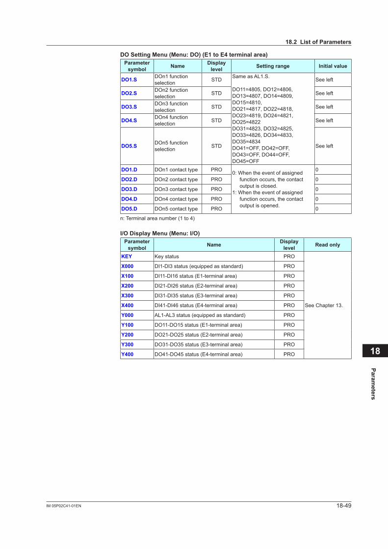
18-49IM 05P02C41-01EN
Parameters
18
DOSettingMenu(Menu:DO)(E1toE4terminalarea)Parameter symbol Name Display
level Settingrange Initialvalue
DO1.S DOn1 function selection STD Same as AL1.S.
DO11=4805, DO12=4806, DO13=4807, DO14=4809, DO15=4810, DO21=4817, DO22=4818, DO23=4819, DO24=4821, DO25=4822DO31=4823, DO32=4825, DO33=4826, DO34=4833, DO35=4834DO41=OFF, DO42=OFF, DO43=OFF, DO44=OFF, DO45=OFF
See left
DO2.S DOn2 function selection STD See left
DO3.S DOn3 function selection STD See left
DO4.S DOn4 function selection STD See left
DO5.S DOn5 function selection STD See left
DO1.D DOn1 contact type PRO 0: When the event of assigned function occurs, the contact output is closed.
1: When the event of assigned function occurs, the contact output is opened.
0
DO2.D DOn2 contact type PRO 0
DO3.D DOn3 contact type PRO 0
DO4.D DOn4 contact type PRO 0
DO5.D DOn5 contact type PRO 0
n: Terminal area number (1 to 4)
I/ODisplayMenu(Menu:I/O)Parameter symbol Name Display
level Readonly
KEY Key status PRO
See Chapter 13.
X000 DI1-DI3 status (equipped as standard) PRO
X100 DI11-DI16 status (E1-terminal area) PRO
X200 DI21-DI26 status (E2-terminal area) PRO
X300 DI31-DI35 status (E3-terminal area) PRO
X400 DI41-DI46 status (E4-terminal area) PRO
Y000 AL1-AL3 status (equipped as standard) PRO
Y100 DO11-DO15 status (E1-terminal area) PRO
Y200 DO21-DO25 status (E2-terminal area) PRO
Y300 DO31-DO35 status (E3-terminal area) PRO
Y400 DO41-DO45 status (E4-terminal area) PRO
18.2ListofParameters
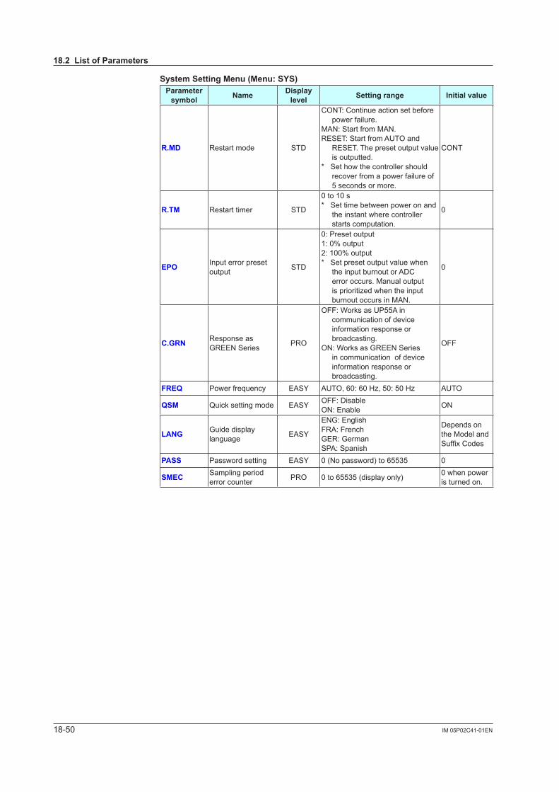
18-50 IM 05P02C41-01EN
SystemSettingMenu(Menu:SYS)Parameter symbol Name Display
level Settingrange Initialvalue
R.MD Restart mode STD
CONT: Continue action set before power failure.
MAN: Start from MAN.RESET: Start from AUTO and
RESET. The preset output value is outputted.
* Set how the controller should recover from a power failure of 5 seconds or more.
CONT
R.TM Restart timer STD
0 to 10 s* Set time between power on and
the instant where controller starts computation.
0
EPO Input error preset output STD
0: Preset output1: 0% output2: 100% output* Set preset output value when
the input burnout or ADC error occurs. Manual output isprioritizedwhentheinputburnout occurs in MAN.
0
C.GRN Response as GREEN Series PRO
OFF: Works as UP55A in communication of device information response or broadcasting.
ON: Works as GREEN Series in communication of device information response or broadcasting.
OFF
FREQ Power frequency EASY AUTO,60:60Hz,50:50Hz AUTO
QSM Quick setting mode EASY OFF: DisableON: Enable ON
LANG Guide display language EASY
ENG: EnglishFRA: FrenchGER: GermanSPA: Spanish
Depends on the Model and SuffixCodes
PASS Password setting EASY 0 (No password) to 65535 0
SMEC Sampling period error counter PRO 0 to 65535 (display only) 0 when power
is turned on.
18.2ListofParameters

18-51IM 05P02C41-01EN
Parameters
18
InitializationMenu(Menu:INIT)Parameter symbol Name Display
level Settingrange Initialvalue
U.DEF Initializationtouserdefault value PRO 12345:Initialization,automatically
returnedto"0"afterinitialization. 0
F.DEF Initializationtofactory default value PRO -12345:Initialization,automatically
returnedto"0"afterinitialization. 0
P.DEF Clearing all program pattern data PRO
13579:Initialization,automaticallyreturnedto"0"afterinitialization.* Data all deletions in menu [PROG]
0
ErrorandVersionConfirmationMenu(Menu:VER)Parameter symbol Name Display
level Readonly
PA.ER Parameter error status EASY
See Chapter 16.
OP.ER Option error status EASY
AD1.E A/D converter error status 1 EASY
AD2.E A/D converter error status 2 EASY
PV1.E Loop-1 PV input error status EASY
PV2.E Loop-2 PV input error status EASY
LA.ER Ladder error status EASY
MCU MCU version EASY
See Chapter 13.
DCU DCU version EASY
ECU1 ECU-1 version EASY
ECU2 ECU-2 version EASY
ECU3 ECU-3 version EASY
ECU4 ECU-4 version EASY
PARA Parameter version EASY
H.VER Product version EASY
SER1 Serial number 1 EASY
SER2 Serial number 2 EASY
MAC1 MAC address 1 EASY
MAC2 MAC address 2 EASY
MAC3 MAC address 3 EASY
When the following parameters are displayed, the terminal area (E1 to E4) is displayed on Group display.• Parameter: ECU1, ECU2, ECU3, ECU4, MAC1, MAC2 and MAC3
ParameterDisplayLevelMenu(Menu:LVL)Parameter symbol Name Display
level Settingrange Initialvalue
LEVL Parameter display level EASY
EASY: Easy setting modeSTD: Standard setting modePRO: Professional setting mode
STD
18.2ListofParameters

Blank Page

GeneralSpecifications
UP55AProgram Controller
Yokogawa Electric Corporation2-9-32, Nakacho, Musashino-shi, Tokyo, 180-8750 JapanTel.: 81-422-52-7179 Fax.: 81-422-52-6619
GS 05P02C41-01EN
GS 05P02C41-01EN©Copyright Aug. 2010
7th Edition Mar.14,2016
n OverviewThe UP55A program controller employs an easy-to-read, 14-segment large color LCD display, along with navigation keys, thus greatly increasing the monitoring and operating capabilities. A ladder sequence function is included as standard. The short depth of the controller helps save instrument panel space. The UP55A also support open networks such as Ethernet communication.
n Features・ Equipped with a large-capacity program
setting function that can store 99 program patterns and 600 program segments. It can be used in a wide variety of heating/cooling control applications (on models with the /AP option).
• A 14-segment, active (PV display color changing function) color LCD display is employed.
Twofive-digit,high-resolutiondisplaysarepossible. Alphabet letters can be displayed in an easy-to-read
manner. The guide display shows parameter names.• Easy to operate Navigation keys (SET/ENTER and Up/Down/Left/
Right arrow keys) are employed to facilitate making settings.
• 65 mm depth The small depth enables the mounting in a thin and
small instrumented panel.• Ladder sequence function is included as standard. This function allows for creating a simple sequence
control. Dedicated LL50A Parameter Setting Software (sold separately) allows for performing programming using a ladder language.
• Various built-in open network functions such as Ethernet are available.
Easy connection with various vendors’ PLCs is possible.
• Quick setting function Setting only the minimum necessary parameters for
operation is possible. (For single-loop control only)• Equipped with a multitude of functions Universal I/O and eight control modes (cascade
control, etc) are included as standard. PID control, heating/cooling control, feed forward control, etc. are available.
• LL50A Parameter Setting Software (sold separately) The parameters and ladder programs of UTAdvanced
digital indicating controller can be built from a PC using this software. It makes data management even easier.
• Dust-proof and drip-proof IP66 (for front panel) (Not applicable to side-by-side
close mounting.) NEMA4 (Hose-down test only)
nFunctionalSpecificationsProgram Pattern Functions The program setting function increases or decreases
the value of a target setpoint (SP) according to a given program pattern that varies with time. The controller stores two or more program patterns and the operator can switch between them according to the operating status. Each program pattern consists of multiple line segments (program segments). The operator sets the time interval of each program segment using the segment time or slope. The operator can also set such instructions as the number of repeats, start/stop, and status output (event output) for a given program pattern.
Number of Program pattern Max. 30 (Max. 99 with /AP option)Number of program segment per pattern Max. 99 (Max. 600 with /AP option)Total number of program segments
Max. 300(Total of all program patterns)
Segment time 0.00 to 999.59 (hour.minute or minute.second)
Number of PV event 8
PV event type
PV (measured value) high/low limitSP (setpoint) high/low limitDeviation high/low limitDeviation high and low limitsDeviation within high and low limitsTarget SP high/low limitTarget SP deviation high/low limitTarget SP deviation high and low limitsTarget SP deviation within high and low limitsControl output high/low limit alarmCooling control output high/low limit alarm
Number of Time event 16
Time of time event 0.01 to 999.59 (hour.minute or minute.second)
Number ofrepeat cycle 0 to 999, CONT (limitless number of times)
Wait operation5 groupsCan be set the upper-side wait zone and the lower zone for program setpoint.
Fast-forwarding ofprogram operation
1: Normal, 2: Twice, 5: Five times, 10: Ten times, 20: Twenty timesUse this function when checking the program pattern setting. Only Time of Segment and Time event can be faster.
Functional
Enhancement
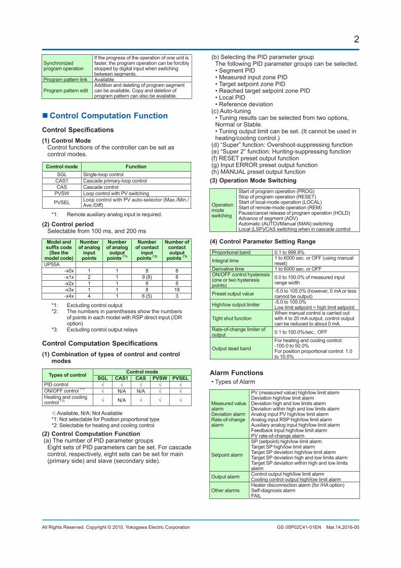
2
All Rights Reserved. Copyright © 2010, Yokogawa Electric Corporation GS 05P02C41-01EN Mar.14,2016-00
Synchronized program operation
If the progress of the operation of one unit is faster, the program operation can be forcibly stopped by digital input when switching between segments.
Program pattern link Available
Program pattern editAddition and deleting of program segment can be available. Copy and deletion of program pattern can also be available.
n Control Computation FunctionControlSpecifications(1) Control Mode Control functions of the controller can be set as
control modes.
Control mode FunctionSGL Single-loop control
CAS1 Cascade primary-loop controlCAS Cascade control
PVSW Loop control with PV switching
PVSEL Loop control with PV auto-selector (Max./Min./Ave./Diff)
*1: Remote auxiliary analog input is required.
(2) Control period Selectable from 100 ms, and 200 ms
Model andsuffixcode
(See themodel code)
Numberof analog
inputpoints
Numberof analog
outputpoints (*1)
Numberof contact
inputpoints (*2)
Number ofcontactoutput
points (*3)
UP55A-x0x 1 1 8 8-x1x 2 1 9 (8) 8-x2x 1 1 8 8-x3x 1 1 8 18-x4x 4 1 6 (5) 3
*1: Excluding control output*2: The numbers in parentheses show the numbers
of points in each model with RSP direct input.(/DR option)
*3: Excluding control output relays
ControlComputationSpecifications(1) Combination of types of control and control
modes
Types of control Control modeSGL CAS1 CAS PVSW PVSEL
PID control √ √ √ √ √ON/OFF control (*1) √ N/A N/A √ √Heating and cooling control (*2) √ N/A √ √ √
√:Available,N/A:NotAvailable*1: Not selectable for Position proportional type*2: Selectable for heating and cooling control
(2) Control Computation Function(a) The number of PID parameter groups Eight sets of PID parameters can be set. For cascade
control, respectively, eight sets can be set for main (primary side) and slave (secondary side).
(b) Selecting the PID parameter group The following PID parameter groups can be selected. • Segment PID • Measured input zone PID • Target setpoint zone PID • Reached target setpoint zone PID • Local PID • Reference deviation(c) Auto-tuning • Tuning results can be selected from two options,
Normal or Stable. • Tuning output limit can be set. (It cannot be used in
heating/cooling control.)(d) “Super” function: Overshoot-suppressing function(e) “Super 2” function: Hunting-suppressing function(f) RESET preset output function(g) Input ERROR preset output function(h) MANUAL preset output function(3) Operation Mode Switching
Operation mode switching
Start of program operation (PROG)Stop of program operation (RESET)Start of local-mode operation (LOCAL)Start of remote-mode operation (REM)Pause/cancel release of program operation (HOLD)Advance of segment (ADV)Automatic (AUTO)/Manual (MAN) switchingLocal (LSP)/CAS switching when in cascade control
(4) Control Parameter Setting RangeProportional band 0.1 to 999.9%Integral time 1 to 6000 sec. or OFF (using manual
reset)Derivative time 1 to 6000 sec. or OFFON/OFF control hysteresis (one or two hysteresis points)
0.0 to 100.0% of measured input range width
Preset output value -5.0 to 105.0% (however, 0 mA or less cannot be output)
High/low output limiter -5.0 to 105.0%Low limit setpoint < high limit setpoint
Tight shut functionWhen manual control is carried out with 4 to 20 mA output, control output can be reduced to about 0 mA.
Rate-of-change limiter of output 0.1 to 100.0%/sec., OFF
Output dead bandFor heating and cooling control: -100.0 to 50.0%For position proportional control: 1.0 to 10.0%
Alarm Functions• Types of Alarm
Measured value alarmDeviation alarmRate-of-change alarm
PV (measured value) high/low limit alarmDeviation high/low limit alarmDeviation high and low limits alarmDeviation within high and low limits alarmAnalog input PV high/low limit alarmAnalog input RSP high/low limit alarmAuxiliary analog input high/low limit alarmFeedback input high/low limit alarmPV rate-of-change alarm
Setpoint alarm
SP (setpoint) high/low limit alarmTarget SP high/low limit alarmTarget SP deviation high/low limit alarmTarget SP deviation high and low limits alarmTarget SP deviation within high and low limits alarm
Output alarm Control output high/low limit alarmCooling control output high/low limit alarm
Other alarmsHeater disconnection alarm (for /HA option)Self-diagnosis alarmFAIL
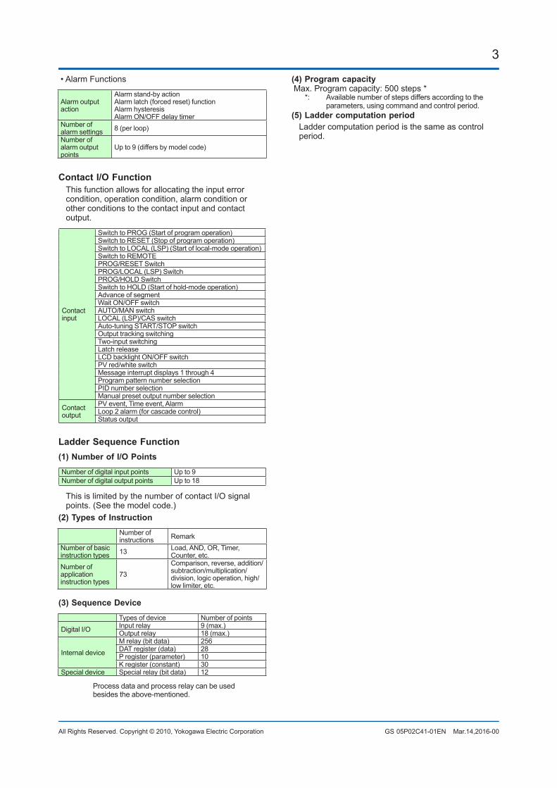
3
All Rights Reserved. Copyright © 2010, Yokogawa Electric Corporation GS 05P02C41-01EN Mar.14,2016-00
• Alarm Functions
Alarm outputaction
Alarm stand-by actionAlarm latch (forced reset) functionAlarm hysteresisAlarm ON/OFF delay timer
Number of alarm settings 8 (per loop)Number of alarm output points
Up to 9 (differs by model code)
Contact I/O Function This function allows for allocating the input error
condition, operation condition, alarm condition or other conditions to the contact input and contact output.
Contact input
Switch to PROG (Start of program operation)Switch to RESET (Stop of program operation)Switch to LOCAL (LSP) (Start of local-mode operation)Switch to REMOTEPROG/RESET SwitchPROG/LOCAL (LSP) SwitchPROG/HOLD SwitchSwitch to HOLD (Start of hold-mode operation)Advance of segmentWait ON/OFF switchAUTO/MAN switchLOCAL (LSP)/CAS switchAuto-tuning START/STOP switchOutput tracking switchingTwo-input switchingLatch releaseLCD backlight ON/OFF switchPV red/white switchMessage interrupt displays 1 through 4Program pattern number selectionPID number selectionManual preset output number selection
Contact output
PV event, Time event, AlarmLoop 2 alarm (for cascade control)Status output
Ladder Sequence Function(1) Number of I/O PointsNumber of digital input points Up to 9Number of digital output points Up to 18
This is limited by the number of contact I/O signal points. (See the model code.)
(2) Types of InstructionNumber of instructions Remark
Number of basicinstruction types 13 Load, AND, OR, Timer,
Counter, etc.Number of applicationinstruction types
73Comparison, reverse, addition/subtraction/multiplication/division, logic operation, high/low limiter, etc.
(3) Sequence DeviceTypes of device Number of points
Digital I/O Input relay 9 (max.)Output relay 18 (max.)
Internal deviceM relay (bit data) 256DAT register (data) 28P register (parameter) 10K register (constant) 30
Special device Special relay (bit data) 12
Process data and process relay can be used besides the above-mentioned.
(4) Program capacityMax. Program capacity: 500 steps *
*: Available number of steps differs according to the parameters, using command and control period.
(5) Ladder computation period Ladder computation period is the same as control
period.
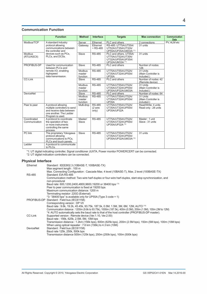
4
All Rights Reserved. Copyright © 2010, Yokogawa Electric Corporation GS 05P02C41-01EN Mar.14,2016-00
Communication Function
Function Method Interface Targets Maxconnection CommunicationData
Modbus/TCP A standard industry protocol allowing communications between the controller anddevices such as PCs, PLCs, and DCSs.
Server Ethernet PLC and others 2 connections PV, ALM etcGateway Ethernet
+ RS-485RS-485: UT75A/UT55A/UT52A/UT35A/UT32A/UP55A/UP35A/UM33A (*1)
31 units
Modbus(RTU/ASCII)
Slave RS-485 PLC and others, UT55A/UT75A/UT52A/UT35A/UT32A/UP55A/UP35A/UP32A/UM33A (*1)
31 units
PROFIBUS-DP Used for communicationbetween PLCs andremote I/O, enabling highspeeddata transmission.
Slave RS-485 PLC and others Number of nodes: 126
Modbus masterfunction
RS-485 UT75A/UT55A/UT52A/UT35A/UT32A/UP55A/UP35A
31 Units(Main Controller is included.)
CC-Link Slave RS-485 PLC and others Number of nodes: 42 (Remote device)
Modbus masterfunction
RS-485 UT75A/UT55A/UT52A/UT35A/UT32A/UP55A/UP35A/UP32A/UM33A
31 Units(Main Controller is included.)
DeviceNet Slave RS-485 PLC and others Number of nodes: 64Modbus masterfunction
RS-485 UT75A/UT55A/UT52A/UT35A/UT32A/UP55A/UP35A
31 Units(Main Controller is included.)
Peer to peer A protocol allowing multiple controllers to send and receive data between one another. The Ladder Program is used.
Multi-drop RS-485(2 wireonly)
UT75A/UT55A/UT52A/UT35A/UT32A/UP55A/UP35A/UP32A
Read/Write: 4 unitsRead only : 28 units
CoordinatedCommunication
A protocol to coordinate the operation of two or more instruments controlling the same process.
Master/Slave
RS-485 UT75A/UT55A/UT52A/UT35A/UT32A/UP55A/UP35A/UP32A (*2)
Master : 1 unitSlave : 31 units
PC link The proprietary Yokogawa protocol allowingcommunications to PCs, PLCs and touch panels.
Slave RS-485 UT75A/UT55A/UT52A/UT35A/UT32A/UP55A/UP35A/UP32A/UM33A (*2)
31 units
Ladder A protocol to communicate to PLCs.
*1: UT digital indicating controller, Signal conditioner JUXTA, Power monitor POWERCERT can be connected.*2: UT digital indication controllers can be connected.
Physical InterfaceEthernet Standard : IEEE802.3 (10BASE-T, 100BASE-TX) Max segment length : 100 m Max.ConnectingConfiguration:CascadeMax.4level(10BASE-T),Max.2level(100BASE-TX)RS-485 Standard: EIA RS-485 Communication method: Two-wire harf-duplex or four-wire harf-duplex, start-stop synchronization, and
non-procedural Baud rate: 600,1200,2400,4800,9600,19200 or 38400 bps (*3)
Peertopeercommunicationisfixedat19200bps Maximum communication distance: 1200 m Terminatingresistor:220Ω(External) *3: “38400 bps” is available only for UP55A (Type 3 code = 1)PROFIBUS-DP Standard : Field bus (IEC61158) Corresponding version : DP V0 Baud rate : 9.6k, 19.2k, 45.45k, 93.75k, 187.5k, 0.5M, 1.5M, 3M, 6M, 12M, AUTO (*4)
Communication distance : 1200m (9.6k to 93.75k), 1000m (187.5k), 400m (0.5M), 200m (1.5M), 100m (3M to 12M) *4: AUTO automatically sets the baud rate to that of the host controller (PROFIBUS-DP master).CC-Link Supported version : Remote device (Ver.1.10, Ver.2.00) Baud rate : 156k, 625k, 2.5M, 5M, 10M bps Transmission distance : 1.2km (156k bps), 600m (625k bps), 200m (2.5M bps), 150m (5M bps), 100m (10M bps) When using optical repeater : 7.6 km (156k) to 4.3 km (10M)DeviceNet Standard : Field bus (IEC61158) Baud rate 125k, 250k, 500k bps Transmission distance 500m (125k bps), 250m (250k bps), 100m (500k bps)
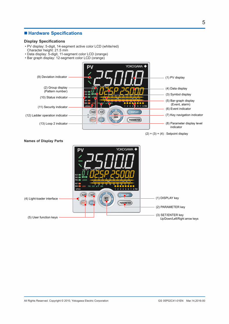
5
All Rights Reserved. Copyright © 2010, Yokogawa Electric Corporation GS 05P02C41-01EN Mar.14,2016-00
nHardwareSpecificationsDisplaySpecifications• PV display: 5-digit, 14-segment active color LCD (white/red) Character height: 21.5 mm• Data display: 5-digit, 11-segment color LCD (orange)• Bar graph display: 12-segment color LCD (orange)
(1) PV display(9) Deviation indicator
(2) Group display(Pattern number)
(10) Status indicator
(11) Security indicator
(12) Ladder operation indicator
(13) Loop 2 indicator
(4) Data display
(2) + (3) + (4) : Setpoint display
(3) Symbol display
(5) Bar-graph display (Event, alarm)(6) Event indicator
(7) Key navigation indicator
(8) Parameter display level indicator
Names of Display Parts
(4) Light-loader interface
(5) User function keys
(1) DISPLAY key
(2) PARAMETER key
(3) SET/ENTER key Up/Down/Left/Right arrow keys
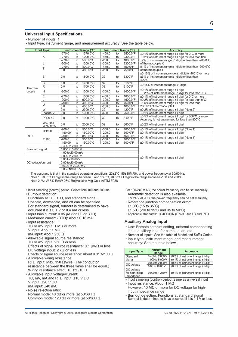
6
All Rights Reserved. Copyright © 2010, Yokogawa Electric Corporation GS 05P02C41-01EN Mar.14,2016-00
UniversalInputSpecifications• Number of inputs: 1• Input type, instrument range, and measurement accuracy: See the table below.
Input Type Instrument Range (°C) Instrument Range (°F) Accuracy
Thermo-couple
K-270.0 to 1370.0°C -450.0 to 2500.0°F ±0.1% of instrument range ±1 digit for 0°C or more
±0.2% of instrument range ±1 digit for less than 0°C±2% of instrument range ±1 digit for less than -200.0°C of thermocouple K ±1% of instrument range ±1 digit for less than -200.0°C of thermocouple T
-270.0 to 1000.0°C -450.0 to 2300.0°F-270.0 to 500.0°C -200.0 to 1000.0°F
J -200.0 to 1200.0°C -300.0 to 2300.0°FT -270.0 to 400.0°C -450.0 to 750.0°F
0.0 to 400.0°C -200.0 to 750.0°F
B 0.0 to 1800.0°C 32 to 3300°F±0.15% of instrument range ±1 digit for 400°C or more±5% of instrument range ±1 digit for less than 400°C
S 0.0 to 1700.0°C 32 to 3100°F ±0.15% of instrument range ±1 digitR 0.0 to 1700.0°C 32 to 3100°FN -200.0 to 1300.0°C -300.0 to 2400.0°F ±0.1% of instrument range ±1 digit
±0.25% of instrument range ±1 digit for less than 0°CE -270.0 to 1000.0°C -450.0 to 1800.0°F ±0.1% of instrument range ±1 digit for 0°C or more
±0.2% of instrument range ±1 digit for less than 0°C±1.5% of instrument range ±1 digit for less than -200.0°C of thermocouple E.
L -200.0 to 900.0°C -300.0 to 1600.0°FU -200.0 to 400.0°C -300.0 to 750.0°F
0.0 to 400.0°C -200.0 to 1000.0°FW 0.0 to 2300.0°C 32 to 4200°F ±0.2% of instrument range ±1 digit (Note 2)Platinel 2 0.0 to 1390.0°C 32.0 to 2500.0°F ±0.1% of instrument range ±1 digitPR20-40 0.0 to 1900.0°C 32 to 3400°F ±0.5% of instrument range ±1 digit for 800°C or more
Accuracy is not guaranteed for less than 800°C.W97Re3-W75Re25 0.0 to 2000.0°C 32 to 3600°F ±0.2% of instrument range ±1 digit
RTDJPt100 -200.0 to 500.0°C -300.0 to 1000.0°F ±0.1% of instrument range ±1 digit (Note 1)
-150.00 to 150.00°C -200.0 to 300.0°F ±0.1% of instrument range ±1 digit
Pt100-200.0 to 850.0°C -300.0 to 1560.0°F ±0.1% of instrument range ±1 digit (Note 1)-200.0 to 500.0°C -300.0 to 1000.0°F-150.00 to 150.00°C -200.0 to 300.0°F ±0.1% of instrument range ±1 digit
Standard signal0.400 to 2.000 V
±0.1% of instrument range ±1 digit
1.000 to 5.000 V4.00 to 20.00 mA
DC voltage/current
0.000 to 2.000 V0.00 to 10.00 V0.00 to 20.00 mA-10.00 to 20.00 mV0.0 to 100.0 mV
The accuracy is that in the standard operating conditions: 23±2°C, 55±10%RH, and power frequency at 50/60 Hz.Note 1: ±0.3°C ±1 digit in the range between 0 and 100°C, ±0.5°C ±1 digit in the range between -100 and 200°C.Note 2: W: W-5% Re/W-26% Re(Hoskins Mfg.Co.). ASTM E988
• Input sampling (control) period: Select from 100 and 200 ms• Burnout detection: Functions at TC, RTD, and standard signal. Upscale,downscale,andoffcanbespecified. For standard signal, burnout is determined to have
occurred if it is 0.1 V or 0.4 mA or less.• Input bias current: 0.05 µA (for TC or RTD)• Measured current (RTD): About 0.16 mA• Input resistance: TCormVinput:1MΩormore Vinput:About1MΩ mAinput:About250Ω• Allowable signal source resistance: TCormVinput:250Ωorless Effectsofsignalsourceresistance:0.1µV/Ωorless DCvoltageinput:2kΩorless Effectsofsignalsourceresistance:About0.01%/100Ω• Allowable wiring resistance: RTDinput:Max.150Ω/wire(Theconductor
resistance between the three wires shall be equal.) Wiringresistanceeffect:±0.1ºC/10Ω• Allowable input voltage/current: TC, mV, mA and RTD input: ±10 V DC V input: ±20 V DC mA input: ±40 mA• Noise rejection ratio: Normal mode: 40 dB or more (at 50/60 Hz) Common mode: 120 dB or more (at 50/60 Hz)
For 100-240 V AC, the power frequency can be set manually. Automatic detection is also available. For 24 V AC/DC, the power frequency can be set manually.• Reference junction compensation error: ±1.0ºC (15 to 35ºC) ±1.5ºC (-10 to 15ºC and 35 to 50ºC)• Applicable standards: JIS/IEC/DIN (ITS-90) for TC and RTD
AuxiliaryAnalogInput• Use: Remote setpoint setting, external compensating
input, auxiliary input for computation, etc.• Numberofinputs:SeethetableofModelandSuffixCodes.• Input type, instrument range, and measurement
accuracy: See the table below.
Input Type Instrument Range Accuracy
Standard signal
0.400 to 2.000 V ±0.2% of instrument range ±1 digit1.000 to 5.000 V ±0.1% of instrument range ±1 digit
DC voltage 0.000 to 2.000 V ±0.2% of instrument range ±1 digit0.00 to 10.00 V ±0.1% of instrument range ±1 digit
DC voltage for high-input impedance
0.000 to 1.250 V ±0.1% of instrument range ±1 digit
• Input sampling (control) period: Same as universal input•Inputresistance:About1MΩ However,10MΩormoreforDCvoltageforhigh-
input impedance range• Burnout detection: Functions at standard signal Burnout is determined to have occurred if it is 0.1 V or less.
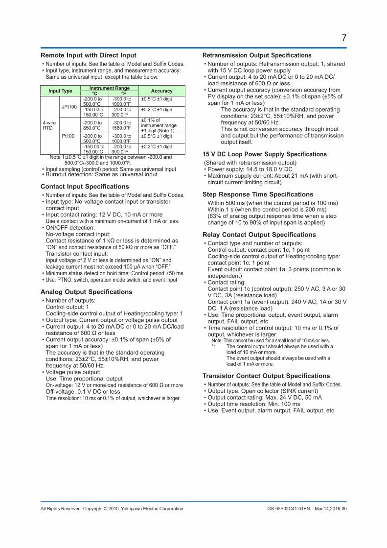
7
All Rights Reserved. Copyright © 2010, Yokogawa Electric Corporation GS 05P02C41-01EN Mar.14,2016-00
Remote Input with Direct Input• Numberofinputs:SeethetableofModelandSuffixCodes.• Input type, instrument range, and measurement accuracy:
Same as universal input except the table below.
Input Type Instrument Range Accuracy°C °F
4-wire RTD
JPt100-200.0 to 500.0°C
-300.0 to 1000.0°F
±0.5°C ±1 digit
-150.00 to 150.00°C
-200.0 to 300.0°F
±0.2°C ±1 digit
Pt100
-200.0 to 850.0°C
-300.0 to 1560.0°F
±0.1% of instrument range ±1 digit (Note 1)
-200.0 to 500.0°C
-300.0 to 1000.0°F
±0.5°C ±1 digit
-150.00 to 150.00°C
-200.0 to 300.0°F
±0.2°C ±1 digit
Note 1:±0.5°C ±1 digit in the range between -200.0 and 500.0°C/-300.0 and 1000.0°F.
• Input sampling (control) period: Same as universal input• Burnout detection: Same as universal input
ContactInputSpecifications• Numberofinputs:SeethetableofModelandSuffixCodes.• Input type: No-voltage contact input or transistor
contact input• Input contact rating: 12 V DC, 10 mA or more Use a contact with a minimum on-current of 1 mA or less.• ON/OFF detection: No-voltage contact input: Contactresistanceof1kΩorlessisdeterminedas“ON”andcontactresistanceof50kΩormoreas“OFF.”
Transistor contact input: Input voltage of 2 V or less is determined as “ON” and
leakage current must not exceed 100 µA when “OFF.”• Minimum status detection hold time: Control period +50 ms• Use: PTNO. switch, operation mode switch, and event input
AnalogOutputSpecifications• Number of outputs: Control output: 1 Cooling-side control output of Heating/cooling type: 1• Output type: Current output or voltage pulse output• Current output: 4 to 20 mA DC or 0 to 20 mA DC/load resistanceof600Ωorless
• Current output accuracy: ±0.1% of span (±5% of span for 1 mA or less)
The accuracy is that in the standard operating conditions: 23±2°C, 55±10%RH, and power frequency at 50/60 Hz.
• Voltage pulse output: Use: Time proportional output On-voltage:12Vormore/loadresistanceof600Ωormore Off-voltage: 0.1 V DC or less Time resolution: 10 ms or 0.1% of output, whichever is larger
RetransmissionOutputSpecifications• Number of outputs: Retransmission output; 1, shared
with 15 V DC loop power supply• Current output: 4 to 20 mA DC or 0 to 20 mA DC/ loadresistanceof600Ωorless
• Current output accuracy (conversion accuracy from PV display on the set scale): ±0.1% of span (±5% of span for 1 mA or less)
The accuracy is that in the standard operating conditions: 23±2°C, 55±10%RH, and power frequency at 50/60 Hz.
This is not conversion accuracy through input and output but the performance of transmission output itself.
15VDCLoopPowerSupplySpecifications(Shared with retransmission output)• Power supply: 14.5 to 18.0 V DC• Maximum supply current: About 21 mA (with short-
circuit current limiting circuit)
StepResponseTimeSpecifications Within 500 ms (when the control period is 100 ms) Within 1 s (when the control period is 200 ms) (63% of analog output response time when a step
change of 10 to 90% of input span is applied)
RelayContactOutputSpecifications• Contact type and number of outputs: Control output: contact point 1c; 1 point Cooling-side control output of Heating/cooling type:
contact point 1c; 1 point Event output: contact point 1a; 3 points (common is
independent)• Contact rating: Contact point 1c (control output): 250 V AC, 3 A or 30
V DC, 3A (resistance load) Contact point 1a (event output): 240 V AC, 1A or 30 V
DC, 1 A (resistance load)• Use: Time proportional output, event output, alarm
output, FAIL output, etc.• Time resolution of control output: 10 ms or 0.1% of
output, whichever is largerNote: This cannot be used for a small load of 10 mA or less.*: The control output should always be used with a
load of 10 mA or more. The event output should always be used with a load of 1 mA or more.
TransistorContactOutputSpecifications• Numberofoutputs:SeethetableofModelandSuffixCodes.• Output type: Open collector (SINK current)• Output contact rating: Max. 24 V DC, 50 mA• Output time resolution: Min. 100 ms• Use: Event output, alarm output, FAIL output, etc.
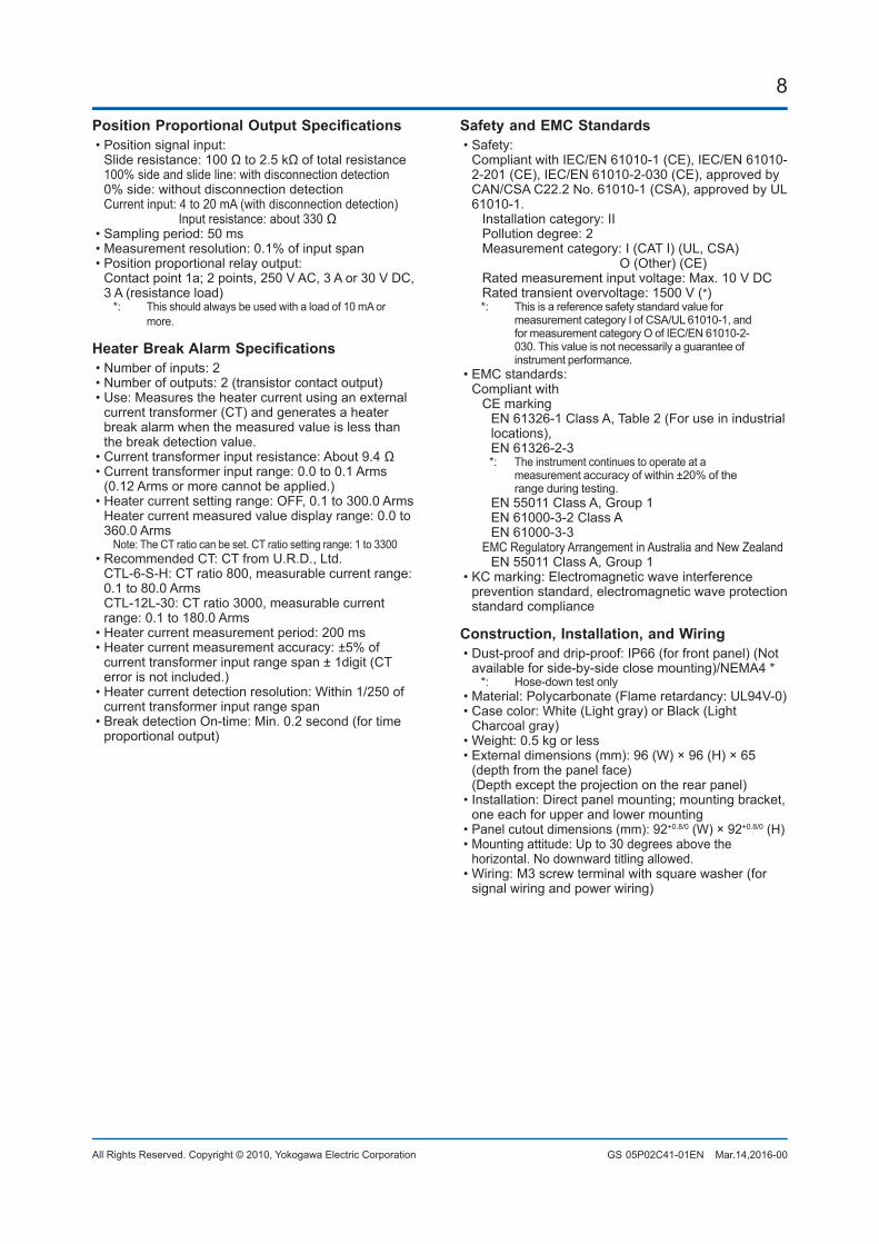
8
All Rights Reserved. Copyright © 2010, Yokogawa Electric Corporation GS 05P02C41-01EN Mar.14,2016-00
PositionProportionalOutputSpecifications• Position signal input: Slideresistance:100Ωto2.5kΩoftotalresistance 100% side and slide line: with disconnection detection 0% side: without disconnection detection Current input: 4 to 20 mA (with disconnection detection) Input resistance: about 330 Ω• Sampling period: 50 ms• Measurement resolution: 0.1% of input span• Position proportional relay output: Contact point 1a; 2 points, 250 V AC, 3 A or 30 V DC,
3 A (resistance load)*: This should always be used with a load of 10 mA or
more.
HeaterBreakAlarmSpecifications• Number of inputs: 2• Number of outputs: 2 (transistor contact output)• Use: Measures the heater current using an external
current transformer (CT) and generates a heater break alarm when the measured value is less than the break detection value.
•Currenttransformerinputresistance:About9.4Ω• Current transformer input range: 0.0 to 0.1 Arms
(0.12 Arms or more cannot be applied.)• Heater current setting range: OFF, 0.1 to 300.0 Arms Heater current measured value display range: 0.0 to
360.0 ArmsNote: The CT ratio can be set. CT ratio setting range: 1 to 3300
• Recommended CT: CT from U.R.D., Ltd. CTL-6-S-H: CT ratio 800, measurable current range:
0.1 to 80.0 Arms CTL-12L-30: CT ratio 3000, measurable current
range: 0.1 to 180.0 Arms• Heater current measurement period: 200 ms• Heater current measurement accuracy: ±5% of
current transformer input range span ± 1digit (CT error is not included.)
• Heater current detection resolution: Within 1/250 of current transformer input range span
• Break detection On-time: Min. 0.2 second (for time proportional output)
Safety and EMC Standards• Safety: Compliant with IEC/EN 61010-1 (CE), IEC/EN 61010-
2-201 (CE), IEC/EN 61010-2-030 (CE), approved by CAN/CSA C22.2 No. 61010-1 (CSA), approved by UL 61010-1.
Installation category: II Pollution degree: 2 Measurement category: I (CAT I) (UL, CSA) O (Other) (CE) Rated measurement input voltage: Max. 10 V DC Rated transient overvoltage: 1500 V (*)
*: This is a reference safety standard value for measurement category I of CSA/UL 61010-1, and for measurement category O of IEC/EN 61010-2-030. This value is not necessarily a guarantee of instrument performance.
• EMC standards: Compliant with CE marking EN 61326-1 Class A, Table 2 (For use in industrial locations), EN 61326-2-3
*: The instrument continues to operate at a measurement accuracy of within ±20% of the range during testing.
EN 55011 Class A, Group 1 EN 61000-3-2 Class A EN 61000-3-3 EMC Regulatory Arrangement in Australia and New Zealand EN 55011 Class A, Group 1• KC marking: Electromagnetic wave interference
prevention standard, electromagnetic wave protection standard compliance
Construction, Installation, and Wiring• Dust-proof and drip-proof: IP66 (for front panel) (Not
available for side-by-side close mounting)/NEMA4 **: Hose-down test only
• Material: Polycarbonate (Flame retardancy: UL94V-0)• Case color: White (Light gray) or Black (Light
Charcoal gray)• Weight: 0.5 kg or less• External dimensions (mm): 96 (W) × 96 (H) × 65
(depth from the panel face) (Depth except the projection on the rear panel)• Installation: Direct panel mounting; mounting bracket,
one each for upper and lower mounting• Panel cutout dimensions (mm): 92+0.8/0 (W) × 92+0.8/0 (H)• Mounting attitude: Up to 30 degrees above the
horizontal. No downward titling allowed.• Wiring: M3 screw terminal with square washer (for
signal wiring and power wiring)
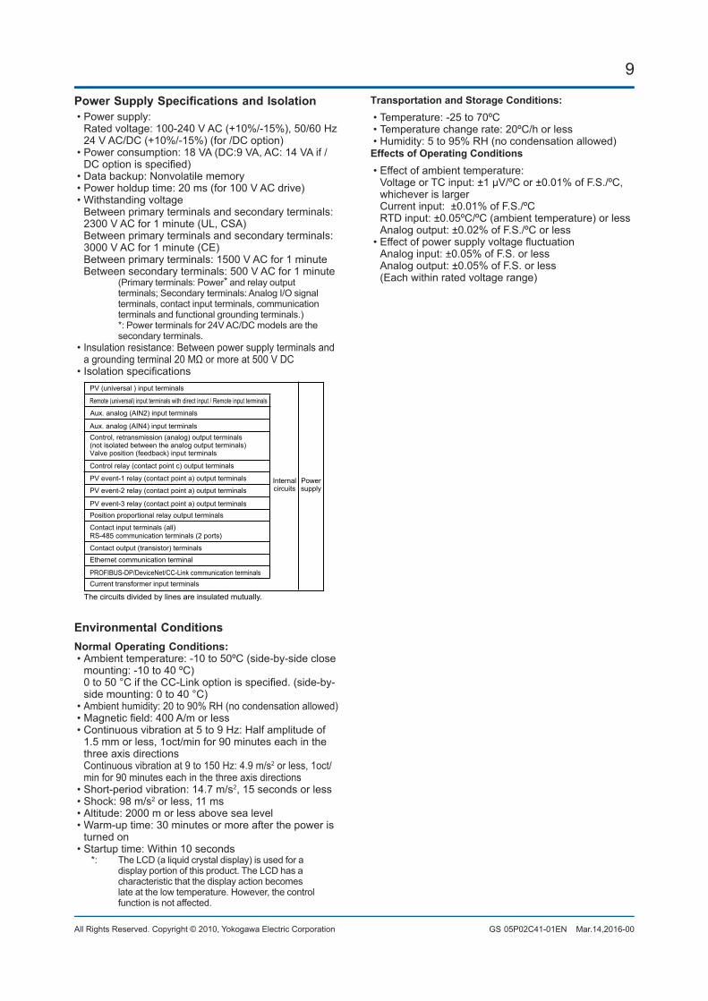
9
All Rights Reserved. Copyright © 2010, Yokogawa Electric Corporation GS 05P02C41-01EN Mar.14,2016-00
PowerSupplySpecificationsandIsolation• Power supply: Rated voltage: 100-240 V AC (+10%/-15%), 50/60 Hz 24 V AC/DC (+10%/-15%) (for /DC option)• Power consumption: 18 VA (DC:9 VA, AC: 14 VA if /DCoptionisspecified)
• Data backup: Nonvolatile memory• Power holdup time: 20 ms (for 100 V AC drive)• Withstanding voltage Between primary terminals and secondary terminals:
2300 V AC for 1 minute (UL, CSA) Between primary terminals and secondary terminals:
3000 V AC for 1 minute (CE) Between primary terminals: 1500 V AC for 1 minute Between secondary terminals: 500 V AC for 1 minute
(Primary terminals: Power* and relay output terminals; Secondary terminals: Analog I/O signal terminals, contact input terminals, communication terminals and functional grounding terminals.)
*: Power terminals for 24V AC/DC models are the secondary terminals.
• Insulation resistance: Between power supply terminals and agroundingterminal20MΩormoreat500VDC
•IsolationspecificationsPV (universal ) input terminals
Remote (universal) input terminals with direct input / Remote input terminals
Aux. analog (AIN2) input terminals
Control relay (contact point c) output terminals
PV event-1 relay (contact point a) output terminals
PV event-2 relay (contact point a) output terminals
PV event-3 relay (contact point a) output terminalsPosition proportional relay output terminals
Contact input terminals (all)RS-485 communication terminals (2 ports)
Contact output (transistor) terminals
Ethernet communication terminal
PROFIBUS-DP/DeviceNet/CC-Link communication terminalsCurrent transformer input terminals
Control, retransmission (analog) output terminals(not isolated between the analog output terminals)Valve position (feedback) input terminals
Internalcircuits
Powersupply
The circuits divided by lines are insulated mutually.
Aux. analog (AIN4) input terminals
Environmental ConditionsNormal Operating Conditions:• Ambient temperature: -10 to 50ºC (side-by-side close
mounting: -10 to 40 ºC) 0to50°CiftheCC-Linkoptionisspecified.(side-by-
side mounting: 0 to 40 °C)• Ambient humidity: 20 to 90% RH (no condensation allowed)•Magneticfield:400A/morless• Continuous vibration at 5 to 9 Hz: Half amplitude of
1.5 mm or less, 1oct/min for 90 minutes each in the three axis directions
Continuous vibration at 9 to 150 Hz: 4.9 m/s2 or less, 1oct/min for 90 minutes each in the three axis directions
• Short-period vibration: 14.7 m/s2, 15 seconds or less• Shock: 98 m/s2 or less, 11 ms• Altitude: 2000 m or less above sea level• Warm-up time: 30 minutes or more after the power is
turned on• Startup time: Within 10 seconds
*: The LCD (a liquid crystal display) is used for a display portion of this product. The LCD has a characteristic that the display action becomes late at the low temperature. However, the control function is not affected.
Transportation and Storage Conditions:• Temperature: -25 to 70ºC• Temperature change rate: 20ºC/h or less• Humidity: 5 to 95% RH (no condensation allowed)Effects of Operating Conditions• Effect of ambient temperature: Voltage or TC input: ±1 µV/ºC or ±0.01% of F.S./ºC,
whichever is larger Current input: ±0.01% of F.S./ºC RTD input: ±0.05ºC/ºC (ambient temperature) or less Analog output: ±0.02% of F.S./ºC or less•Effectofpowersupplyvoltagefluctuation Analog input: ±0.05% of F.S. or less Analog output: ±0.05% of F.S. or less (Each within rated voltage range)
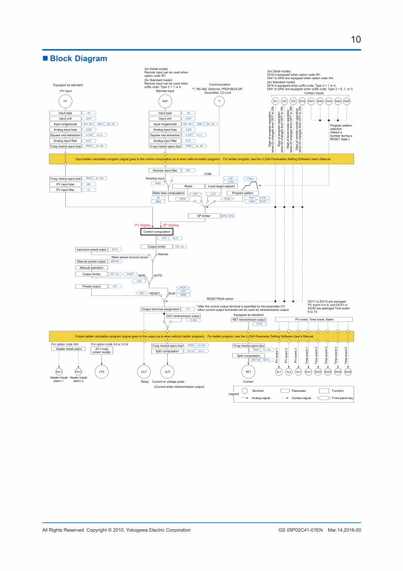
10
All Rights Reserved. Copyright © 2010, Yokogawa Electric Corporation GS 05P02C41-01EN Mar.14,2016-00
n Block Diagram
Program pattern
Local target setpointReset
COMAnaolog input
*1
Output limiter
Manual operation
Manual preset output
Input error preset output
Preset output
RESET/RUN switch
AUTO
When sensor burnout occursNormal
MAN
RUNRESET
SP limiter
DI45PV RSP
Input type
Input unit
Input range/scale
Analog input bias
Square root extraction
Analog input filter
Input type
Input unit
Input range/scale
Analog input bias
Square root extraction
Analog input filter
10-seg. linearizer approx./bias
Remote input filter
PV input bias
PV input filterRatio bias computation
Output limiter
A.BS
A.FL
BS
FL
PMD An, Bn
10-seg. linearizer approx./bias PMD An, Bn
PMD An, Bn
CNT ALG
TSP S.PID
PTNO.
TIME TM.RT
L.PIDLSP
RTRBS
REM
LOC
RMS
SPH, SPL
RFL
A.SR A.LC
UNIT
IN
RH, RL SDP SH, SL
A.BS
A.FL
10-seg. linearizer approx./bias
A.SR A.LC
UNIT
IN
RH, RL SDP SH, SL
EPOOH, OL
OH, OL OLMT
PO
MPON
OT
Equipped as standard
For option code /HAHeater break alarm
HAL2HAL1
Heater breakalarm 1
Heater breakalarm 2 Current or voltage pulseRelay Current
OUTOUT RET AL3AL2AL1
PMD
OU.H OU.L
An, Bn
Split computation
10-seg. linearizer approx./bias
RET.H RET.L
PMD An, Bn
Split computation
10-seg. linearizer approx./bias
OUT retransmission outputO1RS RET retransmission output
RTS
* After the control output terminal is specified by the parameter OT, other current output terminals can be used as retransmission output.Output terminal assignment
DI44DI43DI42DI41DI3DI2DI1 DI16
RUN
RST
Control computation
(Current when retransmission output)
Communication*1: RS-485, Ethernet, PROFIBUS-DP,
DeviceNet, CC-LinkPV input Remote inputContact inputs
Equipped as standard(for Standard model)DI16 is equipped when suffix code: Type 2 = 1 or 4.DI41 to DI45 are equipped when suffix code: Type 2 = 0, 1, or 3.
(for Standard model)Remote input can be used whensuffix code: Type 2 = 1 or 4.
Terminal Parameter Function
Analog signal Contact signal Front panel keyLegend
PV
eve
nt 1
PV
eve
nt 2
PV
eve
nt 3
Tim
e ev
ent 1
Tim
e ev
ent 2
Tim
e ev
ent 3
Tim
e ev
ent 4
DO23DO22DO21 DO24
Tim
e ev
ent 5
DO25
PV display SP display
Input ladder calculation program (signal goes to the control computation as is when without ladder program). For ladder program, see the LL50A Parameters Setting Software User’s Manual.
Output ladder calculation program (signal goes to the output as is when without ladder program). For ladder program, see the LL50A Parameter Setting Software User’s Manual.
Sta
rt of
pro
gram
ope
ratio
nw
hen
DI c
hang
es fr
om O
FF to
ON
.
Sto
p of
pro
gram
ope
ratio
nw
hen
DI c
hang
es fr
om O
FF to
ON
.
Sta
rt of
loca
l-mod
e op
erat
ion
whe
n D
I cha
nges
from
OFF
to O
N.
Sta
rt of
rem
ote-
mod
e op
erat
ion
whe
n D
I cha
nges
from
OFF
to O
N.
RST REM
A/M
LOCRUN
PV event, Time event, Alarm
Program pattern selection(Select a number during a RESET state.)
DO11 to DO15 are assinged PV event 4 to 8, and DO31 to DO35 are assinged Time event 6 to 10.
(for Detail model)DI16 is equipped when option code /R1.DI41 to DI45 are equipped when option code /X4.
(for Detail model) Remote input can be used whenoption code /R1.
LPS
24 V looppower supply
For option code /L4 or /LC4
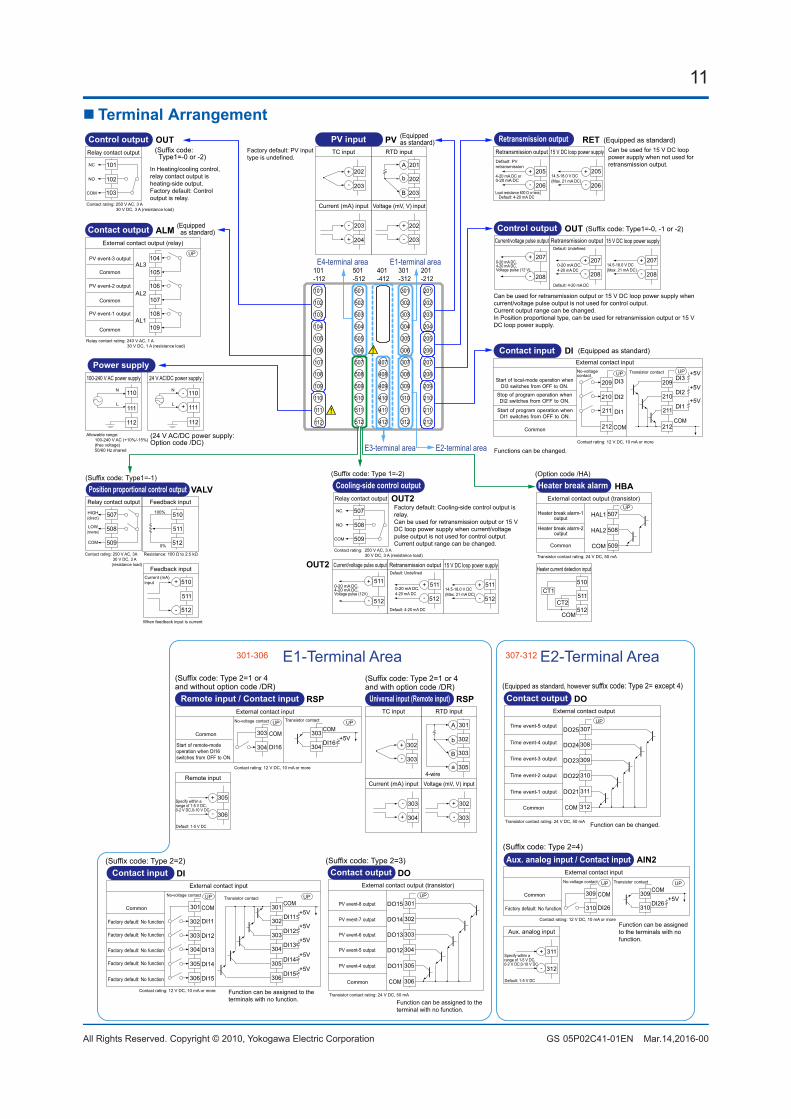
11
All Rights Reserved. Copyright © 2010, Yokogawa Electric Corporation GS 05P02C41-01EN Mar.14,2016-00
n Terminal Arrangement
E4-terminal area
E3-terminal area E2-terminal area
E1-terminal area
101
102
103
104
105
106
107
108
109
110
111
501
502
503
504
505
506
507
508
509
510
511
512
407
408
409
410
411
412
301
302
303
304
305
306
307
308
309
310
311
312
201
202
203
204
205
206
207
208
209
210
211
212
101-112
501-512
401-412
301-312
201-212
ALM (Equipped as standard)Contact output
External contact output (relay)
AL3
AL2
AL1
Relay contact rating: 240 V AC, 1 A 30 V DC, 1 A (resistance load)
PV event-2 output
PV event-3 output
PV event-1 output
Common
Common
Common
UP104
105
106
107
108
109
PVPV inputTC input RTD input
Voltage (mV, V) input
A
+
-
+
-
Current (mA) input
+
-
B
b
(Equippedas standard)
202
203
201
202
203
202
203
203
204
Factory default: PV input type is undefined.
OUT(Suffix code: Type1=-0 or -2)
Control output
101
102
Relay contact output
103
NC
NO
COM
Contact rating: 250 V AC, 3 A 30 V DC, 3 A (resistance load)
In Heating/cooling control, relay contact output is heating-side output.Factory default: Control output is relay.
OUTCurrent/voltage pulse output
0-20 mA DC,4-20 mA DC,Voltage pulse (12 V)
+
Retransmission output
+
-
Default: 4-20 mA DC
Default: Undefined
0-20 mA DC,4-20 mA DC
Control output (Suffix code: Type1=-0, -1 or -2)
15 V DC loop power supply
14.5-18.0 V DC(Max. 21 mA DC)
+
-
207
208
207
- 208
207
208
Can be used for retransmission output or 15 V DC loop power supply when current/voltage pulse output is not used for control output.Current output range can be changed.In Position proportional type, can be used for retransmission output or 15 V DC loop power supply.
OUT2
OUT2
(Suffix code: Type 1=-2)
Current/voltage pulse output
0-20 mA DC,4-20 mA DC,Voltage pulse (12V)
+
-
Retransmission output
+
-
Default: 4-20 mA DC
Default: Undefined
0-20 mA DC,4-20 mA DC
Cooling-side control outputRelay contact output
NC
NO
COM
Contact rating: 250 V AC, 3 A 30 V DC, 3 A (resistance load)
15 V DC loop power supply
14.5-18.0 V DC(Max. 21 mA DC)
+
-
511
512
507
508
509
511
512
511
512
Factory default: Cooling-side control output is relay.Can be used for retransmission output or 15 V DC loop power supply when current/voltage pulse output is not used for control output. Current output range can be changed.
RETRetransmission output
4-20 mA DC or0-20 mA DC
15 V DC loop power supply
14.5-18.0 V DC(Max. 21 mA DC)
+
-
+
-
Default: 4-20 mA DC
Default: PV retransmission
Load resistance 600 Ω or less
Retransmission output (Equipped as standard)
205
206
205
206
Can be used for 15 V DC loop power supply when not used for retransmission output.
VALV(Suffix code: Type1=-1)
Position proportional control output
Resistance: 100 Ω to 2.5 kΩ
Feedback input100%
0%
Relay contact output
HIGH(direct)
LOW(reverse)
COM
Contact rating: 250 V AC, 3A 30 V DC, 3 A (resistance load)
507
508
509
510
511
512
-
Feedback inputCurrent (mA)input
When feedback input is current
510
511
512
+
HBA(Option code /HA)
Heater break alarm
Heater current detection input
CT1
CT2
COM
External contact output (transistor)
Transistor contact rating: 24 V DC, 50 mA
Heater break alarm-1output
Heater break alarm-2output
Common
510
511
512
HAL1
HAL2
COM
UP507
508
509
112
(24 V AC/DC power supply: Option code /DC)
Power supply100-240 V AC power supply
N
L
Allowable range: 100-240 V AC (+10%/-15%) (free voltage) 50/60 Hz shared
110
111
24 V AC/DC power supply
-
+
110
111
112 112
N
L
DI (Equipped as standard)Contact input
Contact rating: 12 V DC, 10 mA or more
External contact input
DI3
DI2
DI1
COMCommon
DI3
DI2
DI1
COM
+5V
+5V
+5V
No-voltagecontact
Transistor contactUP UP
209
210
211
212
209
210
211
212
Functions can be changed.
Start of program operation when DI1 switches from OFF to ON.
Stop of program operation when DI2 switches from OFF to ON.
Start of local-mode operation when DI3 switches from OFF to ON.
E1-Terminal Area301-306 E2-Terminal Area307-312
(Suffix code: Type 2=2)Contact input
External contact input
DI11
DI12
DI13
DI14
DI15
COMCommon
DI11
DI12
COM+5V
+5V
No-voltage contactTransistor contact
Contact rating: 12 V DC, 10 mA or more
DI13+5V
DI14+5V
DI15+5V
Factory default: No function
Factory default: No function
Factory default: No function
Factory default: No function
Factory default: No function
UP UP
301
302
303
304
305
306
301
302
303
304
305
306
Function can be assigned to the terminals with no function.
DI Contact outputExternal contact output (transistor)
Transistor contact rating: 24 V DC, 50 mA
DO12
DO11
DO13
DO14
DO15
COMCommon
UP
(Suffix code: Type 2=3)
PV event-4 output
PV event-5 output
PV event-6 output
PV event-7 output
PV event-8 output 301
302
303
304
305
306
Function can be assigned to the terminal with no function.
DO
(Suffix code: Type 2=1 or 4and with option code /DR)
Universal input (Remote input)TC input RTD input
Voltage (mV, V) input
+
-
+
-
Current (mA) input
+
-
4-wire
302
303
302
303
303
304
RSP
a
B
b
A 301
302
303
305
Contact outputExternal contact output
Transistor contact rating: 24 V DC, 50 mA
DO22
DO21
DO23
DO24
DO25
COMCommon
UP
(Equipped as standard, however suffix code: Type 2= except 4)
307
308
309
310
311
312
Function can be changed.
DO
Time event-5 output
Time event-4 output
Time event-3 output
Time event-2 output
Time event-1 output
(Suffix code: Type 2=4)
Aux. analog input
Default: 1-5 V DC
+
-
Aux. analog input / Contact inputExternal contact input
DI26
COMCommon
DI26
COM+5V
No-voltage contact Transistor contact
Contact rating: 12 V DC, 10 mA or more
Factory default: No function
UP UP
309
310
309
310
311
312
Function can be assigned to the terminals with no function.
AIN2
Specify within a range of 1-5 V DC, 0-2 V DC,0-10 V DC
(Suffix code: Type 2=1 or 4and without option code /DR)
Remote input
Default: 1-5 V DC
+
-
Remote input / Contact inputExternal contact input
DI16
COMCommon
DI16
COM+5V
No-voltage contact Transistor contact
Contact rating: 12 V DC, 10 mA or more
UP UP
303
304
303
304
305
306
RSP
Specify within a range of 1-5 V DC, 0-2 V DC,0-10 V DC
Start of remote-mode operation when DI16 switches from OFF to ON.
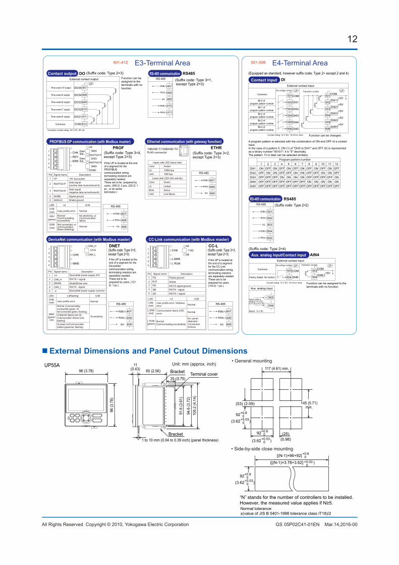
12
All Rights Reserved. Copyright © 2010, Yokogawa Electric Corporation GS 05P02C41-01EN Mar.14,2016-00
E3-Terminal Area401-412 E4-Terminal Area501-506
(Suffix code: Type 3=2, except Type 2=3)
Ethernet communication (with gateway function)
10BASE-T/100BASE-TXRJ45 connector
ColorLitUnlit
Amber100M bps10M bps
Green
LinkedActiveLink failure
Color
LitBlinkUnlit
Upper side LED (baud rate)
Lower side LED (link activity)
RS-485
RSB(+)
RSA(-)
SG
407
408
409
ETHR
RS-485
SDB(+)
SDA(-)
RDB(+)
RDA(-)
SG
RS-485 communication(Suffix code: Type 3=1, except Type 2=3)
407
408
409
410
411
RS485Contact input
External contact input
DI41
DI42
DI43
DI44
DI45
COMDI41
DI42
COM+5V
+5V
DI43+5V
DI44+5V
DI45+5V
UP UP
(Equipped as standard, however suffix code: Type 2= except 2 and 4)
CommonNo-voltage contact Transistor contact
Contact rating: 12 V DC, 10 mA or more
Bit-0 of program pattern number
Bit-1 of program pattern number
Bit-2 of program pattern number
Bit-3 of program pattern number
Bit-4 of program pattern number
501
502
503
504
505
506
501
502
503
504
505
506
Function can be changed.
DIContact output
External contact output
DO32
DO31
DO33
DO34
DO35
COM
Time event-6 output
Time event-7 output
Time event-8 output
Time event-9 output
Time event-10 output
Common
UP
(Suffix code: Type 2=3)
407
408
409
410
411
412
DO
Transistor contact rating: 24 V DC, 50 mA
Function can be assigned to the terminals with no function.
RS-485
SDB(+)
SDA(-)
RDB(+)
RDA(-)
SG
RS-485 communication
501
502
503
504
505
RS485(Suffix code: Type 2=2)
Aux. analog input
Default: 1-5 V DC
+
-
Aux. analog input/Contact inputExternal contact input
DI46
COMDI46
COM+5V
UP UP
(Suffix code: Type 2=4)
Common
No-voltage contact Transistor contact
Contact rating: 12 V DC, 10 mA or more
Factory default: No function
503
504
503
504
505
506
Function can be assigned to the terminals with no function.
AIN4
Specify within a range of 1-5 V DC, 0-2 V DC,0-10 V DC
A program pattern is selected with the combination of ON and OFF of a contact input.In the case of a pattern 5, ON (1) of "DI45 to DI41" and OFF (0) is represented as a binary number "00101": it is "5" decimally.The pattern 13 or later can be selected similarly.
Program pattern number 1 2 3 4 5 6 7 8 9 10 11 12DI41 ON OFF ON OFF ON OFF ON OFF ON OFF ON OFFDI42 OFF ON ON OFF OFF ON ON OFF OFF ON ON OFFDI43 OFF OFF OFF ON ON ON ON OFF OFF OFF OFF ONDI44 OFF OFF OFF OFF OFF OFF OFF ON ON ON ON ONDI45 OFF OFF OFF OFF OFF OFF OFF OFF OFF OFF OFF OFF
(Suffix code: Type 3=5, except Type 2=3)
DeviceNet communication (with Modbus master)
RS-485
RSB(+)
RSA(-)
SG
407
408
409
DNET
If the UP is located at the end of a segment for the DeviceNetcommunication wiring,terminating resistors are separately needed.These are to be prepared by users. (121 Ω: 1 pc.)
CAN_H
CAN_L
121Ω
LEDCHK(red)
MNS(green/
red)
Lit/flashing Unlit
User profile error Normal
Pin12
Signal name Description
CAN_H
CAN_L
3
V+
4
V-5
DRAIN
RX/TX + signal
RX/TX - signalShield/Drain wire
DeviceNet power supply 24V
DeviceNet power supply common
Normal. Communicating successfully (green, lit).Not connected (green, flashing).Critical link failure (red, lit).Communication timeout (red, flashing)At power-on/Communication faulted (green/red, flashing)
No electricity
CHK
MNS
1
2
3
4
5
(Suffix code: Type 3=3, except Type 2=3)
CC-Link communication (with Modbus master)
RS-485
RSB(+)
RSA(-)
SG
407
408
409
CC-L
If the UP is located at the end of a segment for the CC-Linkcommunication wiring,terminating resistors are separately needed.These are to be prepared by users. (110 Ω: 1 pc.)
DA
DB
110Ω
LED
CHK(red)
L ERR(red)
L RUN(green)
Lit Unlit
Normal
Normal
Pin12
Signal name Description
DADB
3 DG4
SLD
5
FG
RX/TX + signalRX/TX - signal
Frame ground
RX/TX signal ground
Shield
Normal Communicating successfully
Communication failure (CRC error)
No carrier detected / Connection timeout
CHK
L RUNL ERR
1
2
3
4
5
PROFIBUS-DP communication (with Modbus master)
Pin1
2
Signal name DescriptionVP
RxD/TxD-P
3 RxD/TxD-N
4 DGND5 SHIELD
+5V bus powerData signal (positive data receive/transmit)
Data signal (negative data recive/transmit)
Signal groundShield ground
RS-485
RSB(+)
RSA(-)
SG
407
408
409
PROF
If the UP is located at the end of a segment for the PROFIBUScommunication wiring,terminating resistors are separately needed.These are to be prepared by users. (390 Ω: 2 pcs. 220 Ω: 1 pc., or an activeterminator.)
VP
RxD/TxD-PData line
Data line
390Ω
220Ω
390ΩRxD/TxD-N
DGND
LEDCHK(red)
RDY(green)
Lit Unlit
ERR(red)
User profile error Normal
NormalNot connected, orcommunicationfailure (flashing)
NormalCommunicatingsuccessfully
No electricity, or Communication failure
(Suffix code: Type 3=4, except Type 2=3)
CHKRDYERR
1
2
3
4
5
User profile error / Address error
nExternalDimensionsandPanelCutoutDimensions
(25)
(53) (2.09)
[(N-1)×96+92]
117 (4.61) min.
145 (5.71)min.
+0.80
+0.8092
“N” stands for the number of controllers to be installed.However, the measured value applies if N≥5.
65 (2.56)
20 (0.79)
11(0.43)
UP55A
1 to 10 mm (0.04 to 0.39 inch) (panel thickness)Bracket
Bracket
94.6
(3.7
2)
91.6
(3.6
1)
105.
2 (4
.14)
Unit: mm (approx. inch)96 (3.78)
96 (3
.78)
• General mounting
• Side-by-side close mounting
Terminal cover
Normal tolerance: ±(value of JIS B 0401-1998 tolerance class IT18)/2
+0.8092
+0.030(3.62 )
(0.98)+0.030(3.62 )
+0.8092
+0.030(3.62 )
([(N-1)×3.78+3.62] )+0.030
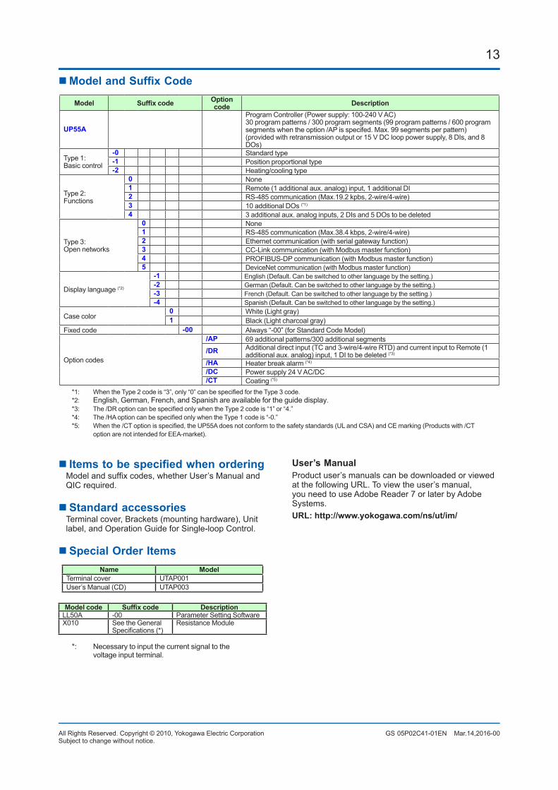
13
All Rights Reserved. Copyright © 2010, Yokogawa Electric Corporation GS 05P02C41-01EN Mar.14,2016-00Subject to change without notice.
nModelandSuffixCode
Model Suffixcode Option code Description
UP55A
Program Controller (Power supply: 100-240 V AC)30 program patterns / 300 program segments (99 program patterns / 600 program segments when the option /AP is specifed. Max. 99 segments per pattern)(provided with retransmission output or 15 V DC loop power supply, 8 DIs, and 8 DOs)
Type 1: Basic control
-0 Standard type-1 Position proportional type-2 Heating/cooling type
Type 2:Functions
0 None1 Remote (1 additional aux. analog) input, 1 additional DI2 RS-485 communication (Max.19.2 kpbs, 2-wire/4-wire)3 10 additional DOs (*1)
4 3 additional aux. analog inputs, 2 DIs and 5 DOs to be deleted
Type 3:Open networks
0 None1 RS-485 communication (Max.38.4 kbps, 2-wire/4-wire)2 Ethernet communication (with serial gateway function)3 CC-Link communication (with Modbus master function)4 PROFIBUS-DP communication (with Modbus master function)5 DeviceNet communication (with Modbus master function)
Display language (*2)
-1 English (Default. Can be switched to other language by the setting.)-2 German (Default. Can be switched to other language by the setting.)-3 French (Default. Can be switched to other language by the setting.)-4 Spanish (Default. Can be switched to other language by the setting.)
Case color0 White (Light gray)1 Black (Light charcoal gray)
Fixed code -00 Always “-00” (for Standard Code Model)
Option codes
/AP 69 additional patterns/300 additional segments/DR Additional direct input (TC and 3-wire/4-wire RTD) and current input to Remote (1
additional aux. analog) input, 1 DI to be deleted (*3)
/HA Heater break alarm (*4)
/DC Power supply 24 V AC/DC/CT Coating (*5)
*1: WhentheType2codeis“3”,only“0”canbespecifiedfortheType3code.*2: English, German, French, and Spanish are available for the guide display.*3: The/DRoptioncanbespecifiedonlywhentheType2codeis“1”or“4.”*4: The/HAoptioncanbespecifiedonlywhentheType1codeis“-0.”*5: Whenthe/CToptionisspecified,theUP55Adoesnotconformtothesafetystandards(ULandCSA)andCEmarking(Productswith/CT
option are not intended for EEA-market).
nItemstobespecifiedwhenordering Modelandsuffixcodes,whetherUser’sManualand
QIC required.
n Standard accessories Terminal cover, Brackets (mounting hardware), Unit
label, and Operation Guide for Single-loop Control.
n Special Order ItemsName Model
Terminal cover UTAP001User’s Manual (CD) UTAP003
Model code Suffixcode DescriptionLL50A -00 Parameter Setting SoftwareX010 See the General
Specifications(*)Resistance Module
*: Necessary to input the current signal to the voltage input terminal.
User’s ManualProduct user’s manuals can be downloaded or viewed at the following URL. To view the user’s manual, you need to use Adobe Reader 7 or later by Adobe Systems.URL: http://www.yokogawa.com/ns/ut/im/


App-1IM 05P02C41-01EN
Input and Output Table
App
AppendixInputandOutputTable
Appendix1 InputandOutputTable(forStandardmodel)
See the next page.
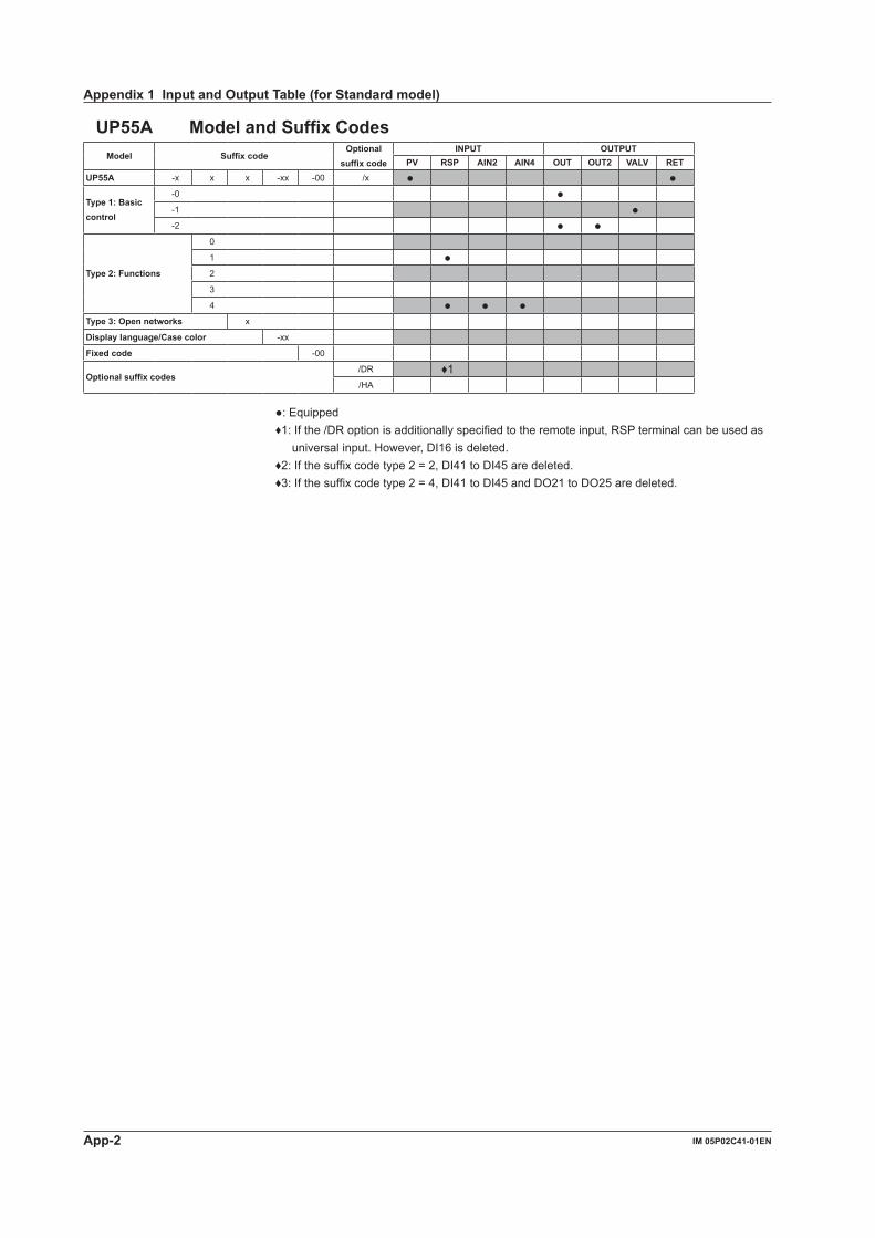
App-2 IM 05P02C41-01EN
UP55A ModelandSuffixCodesModel Suffixcode
Optionalsuffixcode
INPUT OUTPUTPV RSP AIN2 AIN4 OUT OUT2 VALV RET
UP55A -x x x -xx -00 /x
Type1:Basiccontrol
-0 -1 -2
Type2:Functions
0
1 2
3
4 Type3:Opennetworks x
Displaylanguage/Casecolor -xx
Fixedcode -00
Optionalsuffixcodes/DR ♦1/HA
: Equipped♦1: If the /DR option is additionally specified to the remote input, RSP terminal can be used as
universal input. However, DI16 is deleted.♦2: If the suffix code type 2 = 2, DI41 to DI45 are deleted.♦3: If the suffix code type 2 = 4, DI41 to DI45 and DO21 to DO25 are deleted.
Appendix1InputandOutputTable(forStandardmodel)
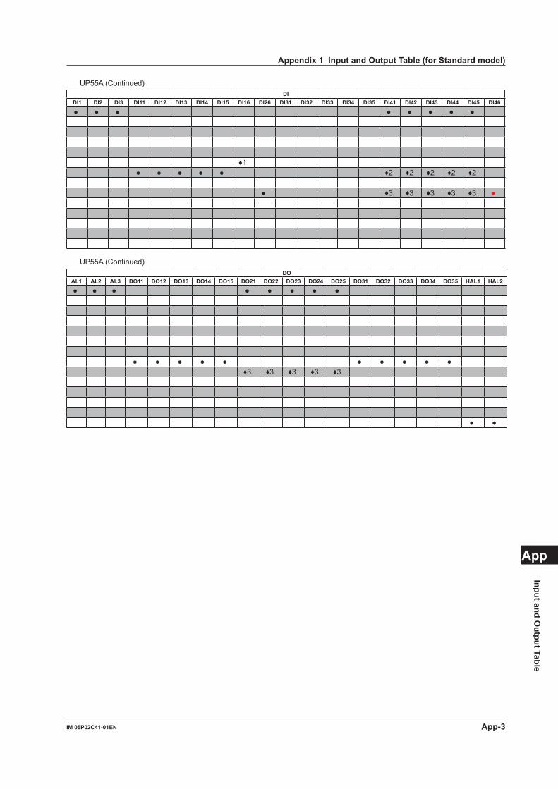
App-3IM 05P02C41-01EN
Input and Output Table
App
UP55A (Continued)DI
DI1 DI2 DI3 DI11 DI12 DI13 DI14 DI15 DI16 DI26 DI31 DI32 DI33 DI34 DI35 DI41 DI42 DI43 DI44 DI45 DI46
♦1 ♦2 ♦2 ♦2 ♦2 ♦2
♦3 ♦3 ♦3 ♦3 ♦3
UP55A (Continued)DO
AL1 AL2 AL3 DO11 DO12 DO13 DO14 DO15 DO21 DO22 DO23 DO24 DO25 DO31 DO32 DO33 DO34 DO35 HAL1 HAL2
♦3 ♦3 ♦3 ♦3 ♦3
Appendix1InputandOutputTable(forStandardmodel)
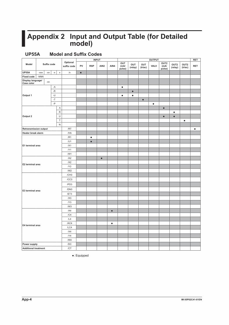
App-4 IM 05P02C41-01EN
Appendix2 InputandOutputTable(forDetailedmodel)
UP55A ModelandSuffixCodes
Model SuffixcodeOptional
suffixcode
INPUT OUTPUT RET
PV RSP AIN2 AIN4OUT(mA/
pulse)
OUT(relay)
OUT(triac) VALV
OUT2(mA/
pulse)
OUT2(relay)
OUT2(triac) RET
UP55A -xxx -xx -x x /x Fixedcode -NNNDisplaylanguage/ Case color -xx
Output1
-A -R -U -T -P
Output2
A R U T N
Retransmission output /RT Heater break alarm /HA
E1terminalarea
/R1 /U1 /X1
/Y1
/W1
E2terminalarea
/A2 /X2
/Y2
/W2
E3 terminal area
/CH3
/CC3
/PD3
/DN3
/ET3
/X3
/Y3
/W3
E4 terminal area
/A4 /C4
/L4
/AC4 /LC4
/X4
/Y4
/W4
Powersupply /DC
Additional treatment /CT
: Equipped
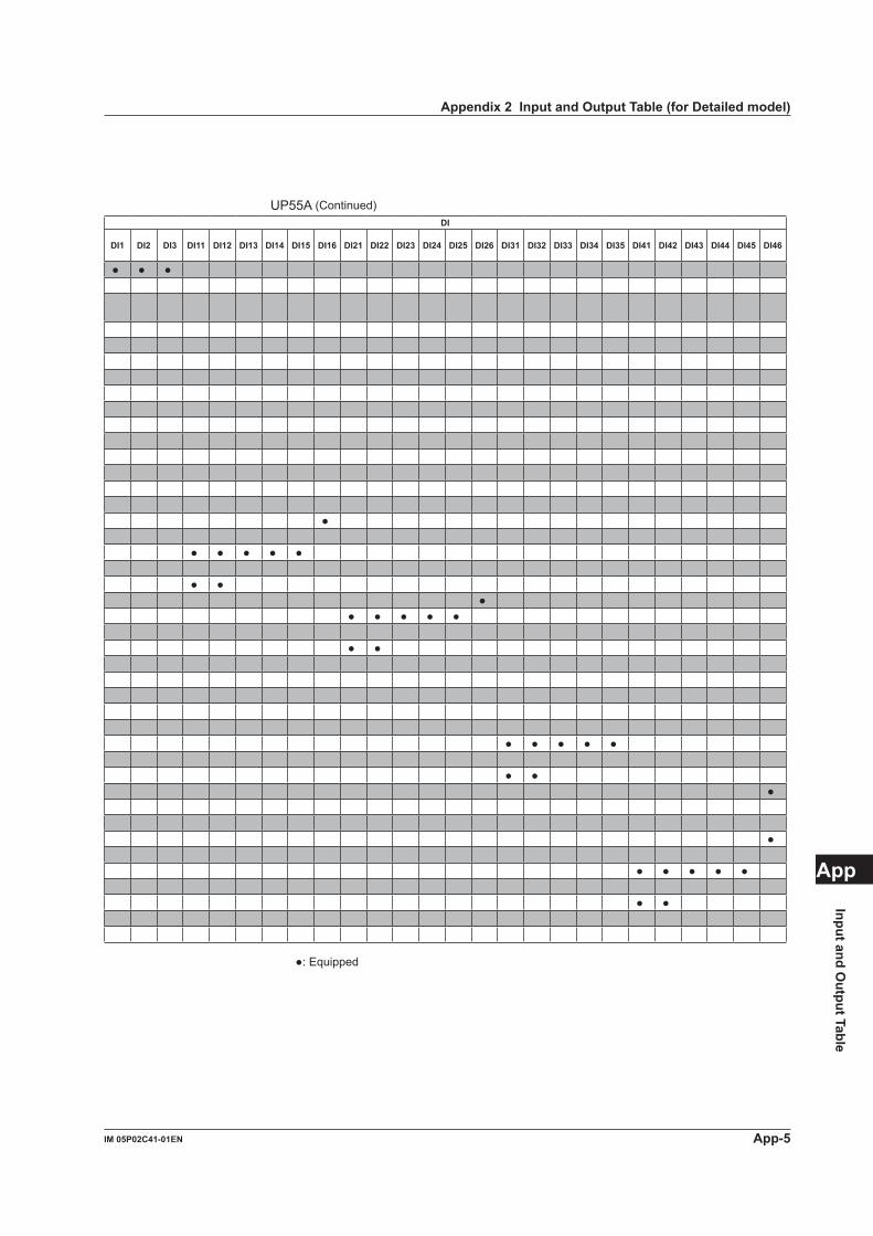
App-5IM 05P02C41-01EN
Input and Output Table
App
UP55A (Continued)DI
DI1 DI2 DI3 DI11 DI12 DI13 DI14 DI15 DI16 DI21 DI22 DI23 DI24 DI25 DI26 DI31 DI32 DI33 DI34 DI35 DI41 DI42 DI43 DI44 DI45 DI46
: Equipped
Appendix2InputandOutputTable(forDetailedmodel)
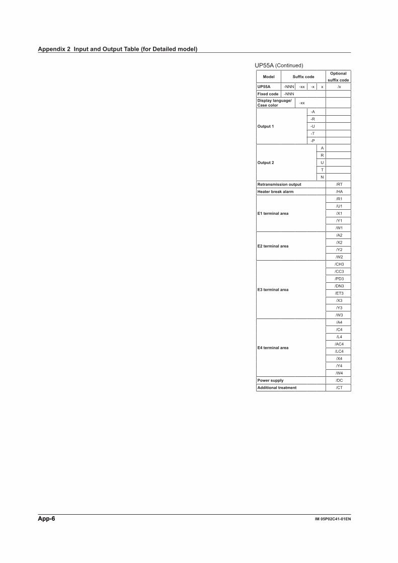
App-6 IM 05P02C41-01ENApp-6
UP55A (Continued)
Model SuffixcodeOptional
suffixcodeUP55A -NNN -xx -x x /x
Fixedcode -NNNDisplaylanguage/ Case color -xx
Output1
-A
-R
-U
-T
-P
Output2
A
R
U
T
N
Retransmission output /RT
Heater break alarm /HA
E1terminalarea
/R1
/U1
/X1
/Y1
/W1
E2terminalarea
/A2
/X2
/Y2
/W2
E3 terminal area
/CH3
/CC3
/PD3
/DN3
/ET3
/X3
/Y3
/W3
E4 terminal area
/A4
/C4
/L4
/AC4
/LC4
/X4
/Y4
/W4
Powersupply /DC
Additional treatment /CT
Appendix2InputandOutputTable(forDetailedmodel)
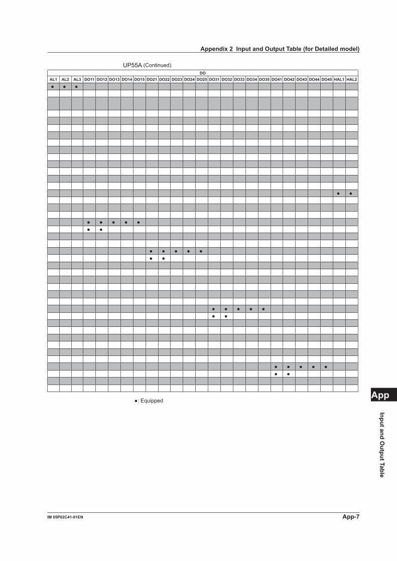
App-7IM 05P02C41-01EN
Input and Output Table
App
UP55A (Continued)DO
AL1 AL2 AL3 DO11 DO12 DO13 DO14 DO15 DO21 DO22 DO23 DO24 DO25 DO31 DO32 DO33 DO34 DO35 DO41 DO42 DO43 DO44 DO45 HAL1 HAL2
: Equipped
Appendix2InputandOutputTable(forDetailedmodel)

Blank Page
i
RevisionInformation Title : UP55A Program Controller User’s Manual Manual No. : IM 05P02C41-01EN
Aug.2010/1stEditionNewly published
Sep.2010/2ndEditionError correction
Jan.2011/3rdEditionUL approved and error correction
Apr.2015/4thEditionFunctional Enhancement
Mar.2016/5thEditionSafety standard IEC/EN 61010-2-201 conformity and error correction.
n Written by Yokogawa Electric Corporation n Published by Yokogawa Electric Corporation 2-9-32 Nakacho, Musashino-shi, Tokyo 180-8750, JAPAN

Blank Page
YOKOGAWA ELECTRIC CORPORATIONHeadquarters2-9-32, Nakacho, Musashino-shi, Tokyo, 180-8750 JAPANPhone : 81-422-52-5555
Branch Sales OfficesOsaka, Nagoya, Hiroshima, Kurashiki, Fukuoka, Kitakyusyu
YOKOGAWA CORPORATION OF AMERICAHead Office12530 West Airport Blvd, Sugar Land, Texas 77478, USAPhone : 1-281-340-3800 Fax : 1-281-340-3838
Georgia Office2 Dart Road, Newnan, Georgia 30265, USA Phone : 1-800-888-6400/ 1-770-253-7000 Fax : 1-770-254-0928
YOKOGAWA AMERICA DO SUL LTDA.Praca Acapulco, 31 - Santo Amaro, Sáo Paulo/SP, BRAZIL, CEP-04675-190Phone : 55-11-5681-2400 Fax : 55-11-5681-4434
YOKOGAWA EUROPE B. V.Euroweg 2, 3825 HD Amersfoort, THE NETHERLANDSPhone : 31-88-4641000 Fax : 31-88-4641111
YOKOGAWA ELECTRIC CIS LTD.Grokholskiy per 13 Building 2, 4th Floor 129090, Moscow, RUSSIAPhone : 7-495-737-7868 Fax : 7-495-737-7869
YOKOGAWA CHINA CO., LTD.3F Tower D Cartelo Crocodile Building, No.568 West Tianshan Road, Shanghai 200335, CHINAPhone : 86-21-62396262 Fax : 86-21-62387866
YOKOGAWA ELECTRIC KOREA CO., LTD.(Yokogawa B/D, Yangpyeong-dong 4-Ga), 21, Seonyu-ro 45-gil, Yeongdeungpo-gu,Seoul, 150-866, KOREAPhone : 82-2-2628-6000 Fax : 82-2-2628-6400
YOKOGAWA ENGINEERING ASIA PTE. LTD.5 Bedok South Road, Singapore 469270, SINGAPOREPhone : 65-6241-9933 Fax : 65-6241-2606
YOKOGAWA INDIA LTD.Plot No.96, Electronic City Complex, Hosur Road, Bangalore - 560 100, INDIAPhone : 91-80-4158-6000 Fax : 91-80-2852-1442
YOKOGAWA AUSTRALIA PTY. LTD.Tower A, 112-118 Talavera Road, Macquarie Park NSW 2113, AUSTRALIAPhone : 61-2-8870-1100 Fax : 61-2-8870-1111
YOKOGAWA MIDDLE EAST & AFRICA B.S.C.(C)P.O. Box 10070, Manama, Building 577, Road 2516, Busaiteen 225, Muharraq,Kingdom of BAHRAINPhone : 973-17358100 Fax : 973-17336100 Apr. '15
Printed in Japan


![RC400G Residual Chlorine Analyzer [Style: S4] - Yokogawa](https://img.dokumen.tips/doc/110x75/6322318cae0f5e819105c82f/rc400g-residual-chlorine-analyzer-style-s4-yokogawa.jpg)


