Embed Size (px)
Citation preview
TFX-11Remote Data Logger/Controller EngineUser’s Guide
TFX-11 HardwareTFBASIC Programming
TFTools IDE
D-2469-C 10/02
Credits
TFX-11 User Guide Project Director: Tom MignoneWriters: Tom Mignone, Lon Hocker, Jim DoddEditors: Tom Mignone, Jim Dodd, Mark McPike, Lisa CapozziLayout and Design: Tom Mignone, Lisa CapozziCover Design and Graphics: Tom Mignone
© 2000–2002 Onset Computer Corporation, all rights reserved.Printed in the USA.
Onset and Tattletale are registered trademarks of Onset Computer Corporation. Microsoft and Windows are registered trademarks of Microsoft Corporation. All other trademarks are the property of their respective companies.
ii TFX-11 User’s Guide
INTRODUCTION
Onset Computer Corporation
Mailing Address
P.O. Box 3450
Pocasset, MA 02559-3450
Physical Address
470 MacArthur Boulevard
Bourne, MA 02532
Technical Support/Customer Service
Tel. (508) 759-9500
Fax (508) 759-9100
www.onsetcomp.com
Sales
Tel. 1-800-LOGGERS (1-800-564-4377)
www.onsetcomp.com
ONSET document D-2469-C
TFX-11 User’s Guide iii
Introducing your TFX
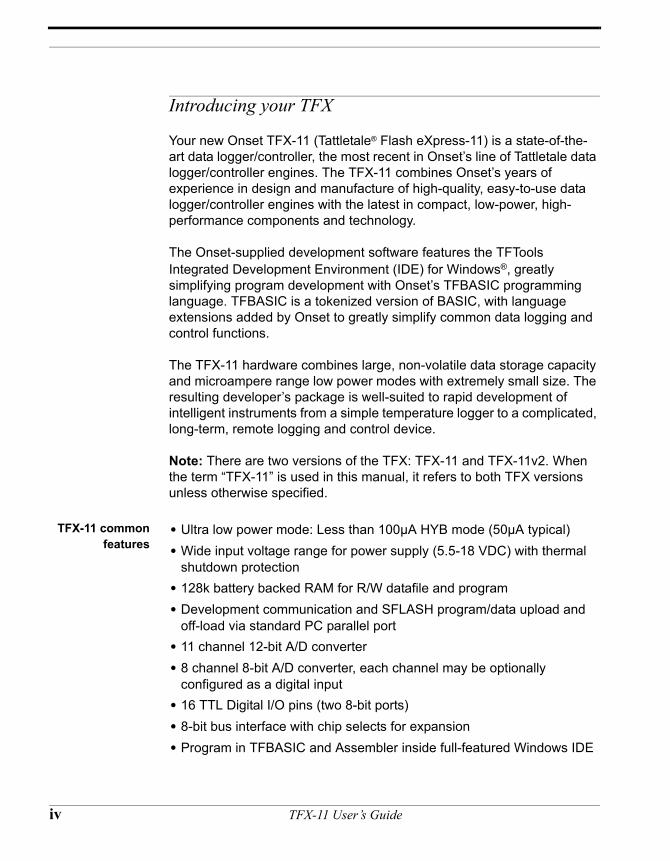
Your new Onset TFX-11 (Tattletale® Flash eXpress-11) is a state-of-the-art data logger/controller, the most recent in Onset’s line of Tattletale data logger/controller engines. The TFX-11 combines Onset’s years of experience in design and manufacture of high-quality, easy-to-use data logger/controller engines with the latest in compact, low-power, high-performance components and technology.
The Onset-supplied development software features the TFTools Integrated Development Environment (IDE) for Windows®, greatly simplifying program development with Onset’s TFBASIC programming language. TFBASIC is a tokenized version of BASIC, with language extensions added by Onset to greatly simplify common data logging and control functions.
The TFX-11 hardware combines large, non-volatile data storage capacity and microampere range low power modes with extremely small size. The resulting developer’s package is well-suited to rapid development of intelligent instruments from a simple temperature logger to a complicated, long-term, remote logging and control device.
Note: There are two versions of the TFX: TFX-11 and TFX-11v2. When the term “TFX-11” is used in this manual, it refers to both TFX versions unless otherwise specified.
TFX-11 commonfeatures
• Ultra low power mode: Less than 100µA HYB mode (50µA typical)• Wide input voltage range for power supply (5.5-18 VDC) with thermal
shutdown protection• 128k battery backed RAM for R/W datafile and program• Development communication and SFLASH program/data upload and
off-load via standard PC parallel port• 11 channel 12-bit A/D converter• 8 channel 8-bit A/D converter, each channel may be optionally
configured as a digital input• 16 TTL Digital I/O pins (two 8-bit ports)• 8-bit bus interface with chip selects for expansion• Program in TFBASIC and Assembler inside full-featured Windows IDE
iv TFX-11 User’s Guide
Introducing your TFX
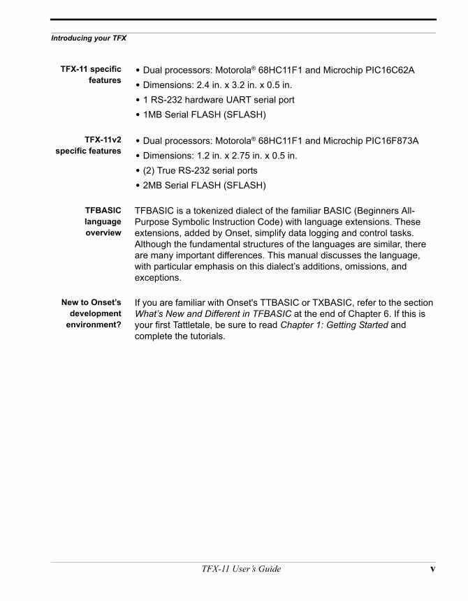
TFX-11 specificfeatures
• Dual processors: Motorola® 68HC11F1 and Microchip PIC16C62A• Dimensions: 2.4 in. x 3.2 in. x 0.5 in.• 1 RS-232 hardware UART serial port• 1MB Serial FLASH (SFLASH)
TFX-11v2specific features
• Dual processors: Motorola® 68HC11F1 and Microchip PIC16F873A• Dimensions: 1.2 in. x 2.75 in. x 0.5 in.• (2) True RS-232 serial ports• 2MB Serial FLASH (SFLASH)
TFBASIClanguageoverview
TFBASIC is a tokenized dialect of the familiar BASIC (Beginners All-Purpose Symbolic Instruction Code) with language extensions. These extensions, added by Onset, simplify data logging and control tasks. Although the fundamental structures of the languages are similar, there are many important differences. This manual discusses the language, with particular emphasis on this dialect’s additions, omissions, and exceptions.
New to Onset’sdevelopment
environment?
If you are familiar with Onset's TTBASIC or TXBASIC, refer to the section What’s New and Different in TFBASIC at the end of Chapter 6. If this is your first Tattletale, be sure to read Chapter 1: Getting Started and complete the tutorials.
TFX-11 User’s Guide v
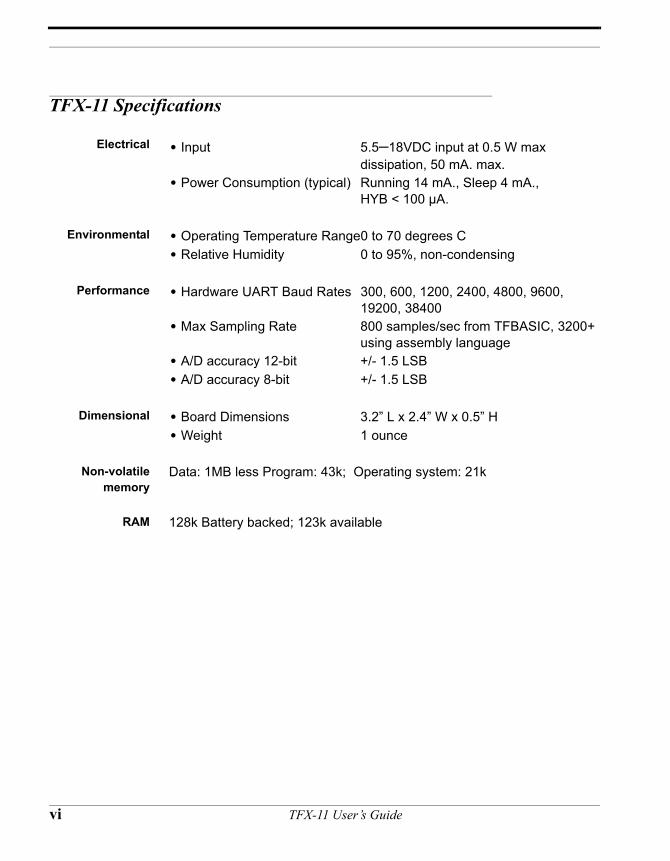
TFX-11 Specifications
Electrical • Input 5.5–18VDC input at 0.5 W max dissipation, 50 mA. max.
• Power Consumption (typical) Running 14 mA., Sleep 4 mA., HYB < 100 µA.
Environmental • Operating Temperature Range0 to 70 degrees C• Relative Humidity 0 to 95%, non-condensing
Performance • Hardware UART Baud Rates 300, 600, 1200, 2400, 4800, 9600, 19200, 38400
• Max Sampling Rate 800 samples/sec from TFBASIC, 3200+ using assembly language
• A/D accuracy 12-bit +/- 1.5 LSB• A/D accuracy 8-bit +/- 1.5 LSB
Dimensional • Board Dimensions 3.2” L x 2.4” W x 0.5” H• Weight 1 ounce
Non-volatilememory
Data: 1MB less Program: 43k; Operating system: 21k
RAM 128k Battery backed; 123k available
vi TFX-11 User’s Guide
Introducing your TFX
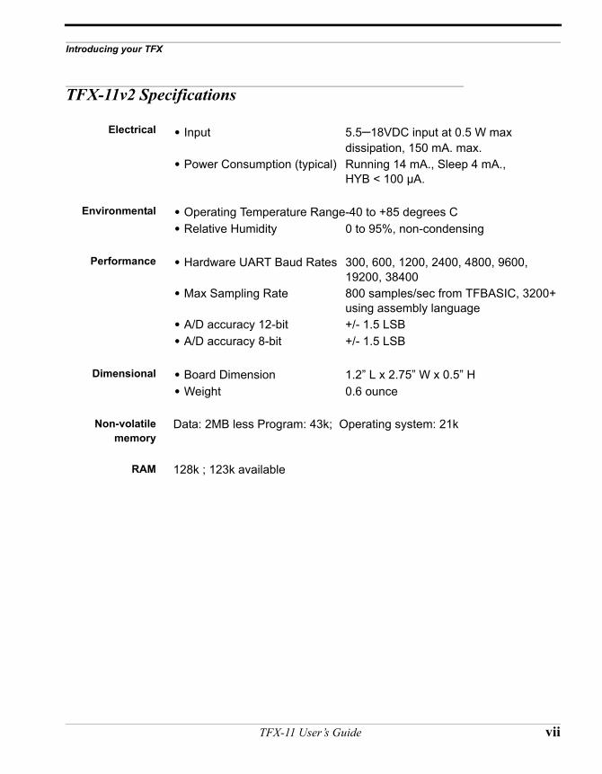
TFX-11v2 Specifications
Electrical • Input 5.5–18VDC input at 0.5 W max dissipation, 150 mA. max.
• Power Consumption (typical) Running 14 mA., Sleep 4 mA., HYB < 100 µA.
Environmental • Operating Temperature Range-40 to +85 degrees C• Relative Humidity 0 to 95%, non-condensing
Performance • Hardware UART Baud Rates 300, 600, 1200, 2400, 4800, 9600, 19200, 38400
• Max Sampling Rate 800 samples/sec from TFBASIC, 3200+ using assembly language
• A/D accuracy 12-bit +/- 1.5 LSB• A/D accuracy 8-bit +/- 1.5 LSB
Dimensional • Board Dimension 1.2” L x 2.75” W x 0.5” H• Weight 0.6 ounce
Non-volatilememory
Data: 2MB less Program: 43k; Operating system: 21k
RAM 128k ; 123k available
TFX-11 User’s Guide vii
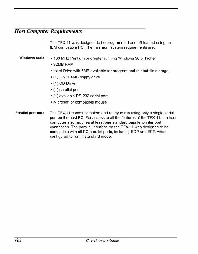
Host Computer Requirements
The TFX-11 was designed to be programmed and off-loaded using an IBM compatible PC. The minimum system requirements are:
Windows tools • 133 MHz Pentium or greater running Windows 98 or higher• 32MB RAM• Hard Drive with 5MB available for program and related file storage• (1) 3.5" 1.4MB floppy drive• (1) CD Drive• (1) parallel port• (1) available RS-232 serial port• Microsoft or compatible mouse
Parallel port note The TFX-11 comes complete and ready to run using only a single serial port on the host PC. For access to all the features of the TFX-11, the host computer also requires at least one standard parallel printer port connection. The parallel interface on the TFX-11 was designed to be compatible with all PC parallel ports, including ECP and EPP, when configured to run in standard mode.
viii TFX-11 User’s Guide
Introducing your TFX
Technical Support Policy, Warranty, and Disclaimers
Read this beforeyou contact
Onset fortechnical
assistance!
Onset provides technical support through a variety of channels. The first and most important is this manual. We have made every effort to provide you with all the information you need in an easy-to-read format; please check through it thoroughly before calling us. If you cannot find what you need in the manuals, please be sure you understand the types of problems we support by reading the following paragraphs.
Software/programming
problems
Onset provides support for its software only and does not provide instruction in how to program. It is expected that you have some familiarity with programming principles and language constructs. We provide an introduction to data logging computing and code examples in the text of this user’s manual and on disk to help you make the transition from software only to software dependent hardware control and data logging.
Hardware/circuitdesign problems
Onset provides support for its hardware only when it does not appear to meet our published specifications or otherwise perform as advertised. Onset does not provide instruction in electronics and electronic instrument design other than what is included in this manual and related application notes. Also, as it says in the disclaimer, Onset does not guarantee its code to be free from errors. It is again assumed you have some familiarity with electronic principles and practices, or have access to someone who does. We try to provide an introduction to data logging fundamental concepts and techniques and simple demonstration code examples in this user’s manual, with the source code to most examples reproduced on the disk.
Warranty Hardware will be repaired or replaced (at Onset’s discretion) if found to be defective in materials or workmanship for a period of one (1) year. Software will be replaced only if the disk supplied is found to be defective. All the programs and other files are offered as-is. If you choose to use the software, Onset cannot be held liable for any damages or loss of data incurred as a result of its use. While we hope you find this software useful, it is up to you to determine the applicability, fitness, and correctness for your application.
Returns All returns require that you first request and obtain a Return Materials Authorization (RMA) number from Onset! The RMA helps us track your return and speeds processing. To obtain an RMA, call Onset
TFX-11 User’s Guide ix
sales support and have available the model number, serial number, invoice number, and a brief explanation of the problem. They will assign you a number to write on the outside of the package and refer to in any correspondence. Returns without prior authorization may be delayed. NOTE: Some returns may be subject to a restocking fee.
Disclaimers Onset does not authorize or approve the use of this equipment in life support or related safety equipment, and cannot be held responsible for any injury or death as a result of it being used in any related application.
If you choose to use the supplied software, you do so at your own risk. Onset cannot be held liable for any damages incurred as a result of its use. While we hope you find this software useful, it is up to you, the user, to determine the applicability, fitness, and correctness for your application. We encourage your feedback for corrections, amplifications, interesting applications and other comments. Application notes or suggestions supplied to us are not eligible for compensation unless details have been worked out in advance. We will incorporate them, when and where appropriate, for the benefit of all users.
x TFX-11 User’s Guide
Introducing your TFX
Contacting Onset
Preparing tocontact Onset
If you have searched our manuals, help files, and other sources of assistance and still have not found an answer, then you need to contact Onset. Before you contact Onset, please have the following information available:
Please havehandy thefollowing
information:
• Operating system name and version number• Host computer brand name and model• Number of MB of installed RAM • Processor type• Processor speed• TFTools version number• TFX board serial number• PIC software version number• Installed or attached devices (modems, network, printers etc.) and their
corresponding ports
Please be sure to include this information in any correspondence. If possible (and if appropriate to the problem), please try to be seated at your computer when you call.
How to contactOnset
You can contact us by phone, fax, email, U.S. mail, and the internet. See the inside front cover of this manual for the current numbers. Our web and FTP sites contain the latest software and example programs for the TFX.
TFX-11 User’s Guide xi

xii TFX-11 User’s Guide
TABLE OF CONTENTS
CHAPTER 1 1Getting Started
Getting Started 2Quick Start Tutorial 3A Short TFTools Tutorial 4Build a Data logger, One Step at a Time 10
CHAPTER 2 17The TFTools IDE
Understanding the TFTools Integrated Development Environment 18Navigating the IDE without a Mouse 22
CHAPTER 3 25TFTools Menu Command Reference
FILE 26EDIT 27SEARCH 29TATTLETALE 33COMMPORT 37WINDOW 39HELP 40
CHAPTER 4 41TFBASIC Language Reference
Legend 42Predefined Read-only variables in TFBASIC 43TFBASIC Quick Reference (grouped by function) 44TFBASIC Quick Reference (alphabetical) 47
TFX-11 User’s Guide xiii
TFBASIC Language Reference for the TFX-11 50ABS ................................... absolute value 51AINT ............................... round float down to integer 52ASC ........................................ Returns the ASCII value of the first character of the string 53ASFLT .......................... interpret argument as float 54ASM ................................. assemble to memory 55ATN .................................. arctangent 58BAUDSET ............... Set the baud rate of the main UART 59BAUDGET.............. Get the baud rate of the main UART 60CALL ............................. Call an assembly language subroutine 61CBREAK .................. go to label on CTRL-C 62CHAN ............................ get result of A-D conversion 64CHR ......................................... Returns a one-character string of the ASCII value of an integer 65COS .................................. cosine 66COUNT ....................... count positive edges at I/O line 0 67DIM .................................. dimension array 69EXP ................................... raise e to a power 70FIX ..................................... convert a float to an integer 71FLOAT ........................ convert integer to float 72FOR .................................. for - next loop 73FVAL.............................. convert string to floating point value 75GET .................................. Get n-byte value from datafile 76GETS .............................. Get string from datafile 77GOSUB ........................ go to subroutine, saving return address 78GOTO............................ go to label 79HALT ............................. stop in lowest power mode 80HYB.................................. very low power mode with wakeup 81IF .......................................... branch on result of comparison 83INPUT ........................... get value from console (buffered) 85INSTR ........................... returns a substring’s position in a string 88INT .................................... convert float to integer 89IVAL ............................... convert numeric string to integer value 90LEN .................................. return length of string variable 91LOG ................................. natural logarithm 92LOG10 .......................... common logarithm 93
xiv TFX-11 User’s Guide
MID .................................. Return a substring of a string 94ONERR ....................... go to label on error 95PCLR ............................. set I/O pin low 97PEEK ............................. read memory byte 98PERIOD ..................... measure period of signal 99PICINT ........................ external interrupt for wakeup 100PIN..................................... read input state of I/O pin 102POKE............................. place byte into RAM 103PRINT........................... print to console 104PSET ............................... set I/O line high 107PTOG............................. toggle I/O line to opposite state 108RATE ............................. Change sleep interval 109READRTC ............. load PIC RTC time to local variable 111REPEAT .................... execute loop until expression true 113RETURN................... return from subroutine 115RTIME......................... Read local software real-time-clock 116RUN ................................. Start Background Process 117SDI ..................................... shift register input 119SDO .................................. shift register output 121SETRTC .................... transfer local time in seconds to PIC RTC 123SIN ..................................... Sine 124SLEEP .......................... low power wait over a precise time interval 125SQR .................................. square root 126STIME .......................... set local software real-time-clock 127STOP .............................. stop program execution 128STORE......................... store to datafile 129STR ................................... assign ASCII formatted output to string 130TAN .................................. Tangent 131TEMP ............................ convert number to temperature 132TONE............................. send square wave out 133UGET............................. bring character in software UART 135USEND......................... send characters out software UART 136VARPTR ................... get address of named variable 137VGET............................. get variable from user EEPROM 138VSTORE ................... store variable to user EEPROM 139WHILE ........................ loop while expression true 140
TFX-11 User’s Guide xv
XMIT+, XMIT– enable, disable console output 141TFBASIC Error Messages 142General Guidelines for Background Tasks: 144
CHAPTER 5 149TFBASIC Assembly Language Reference
TFBASIC Assembly Language Reference 150ASM mnemonics and addressing modes 155Summary of TFBASIC Assembler Directives 157Details of the TFBASIC Assembler Directives 158
ALIGN 159DATA, DB, FCB, DW, FDB, FCC 160END 162EQU 163RES, DS, RMB 164
Assembly Language Subroutines 165Important Addresses in TFBASIC 168
Interrupt Vector Table 169
CHAPTER 6 171TFBASIC Internals
TFBASIC Structure 172TFBASIC Integers 176TFBASIC Floating Point 179Characters and Strings in TFBASIC 186TFBASIC Memory Map 189If you are coming to TFBASIC from TxBASIC 192
CHAPTER 7 195TFX-11 Interfacing
Interfacing to Real World Signals 196Digital Input Protection 197Digital Output Protection 198
xvi TFX-11 User’s Guide
Using the Onboard A/D Converters 199Convert a Bipolar Signal Input to Unipolar 200Operational Amplifiers 202Instrumentation Amplifiers 206
CHAPTER 8 207TFX-11 Hardware Reference
TFX-11 Hardware Notes 208TFX-11 Hardware Reference 209TFX-11 Board Dimensions 210The PR-11 Prototype Board 212Explanation of Connector Pin Functions 217
CHAPTER 9 223TFX-11v2 Hardware Reference
TFX-11v2 Board Pinout and Dimensions 224TFX-11v2 Board Pinout and Dimensions 225The PR-11v2 Prototype Board 226Explanation of Connector Pin Functions 229
CHAPTER 10 235TFX-11 General Hardware Reference
TFX Timekeeping 236TFX-11 Data Storage Options 239Guidelines for Storing Data to the Datafile 242TFX-11 High-Level Hardware Description 244
CHAPTER 11 249Glossary of Terms
Glossary of TFBASIC Terms and Definitions 250INDEX 257
TFX-11 User’s Guide xvii

xviii TFX-11 User’s Guide
CHAPTER 1
Getting Started
TFX-11 User’s Guide
Getting Started
Componentchecklist
The following is a list of what you should have received in your development kit:
• This User’s Guide• PR-11/PR-11v2 breadboard• Program and documentation CD• Parallel cable, DB25 to 9-pin mini-DIN• Serial cable, DB9 to 3.5mm stereo phone jack• 9 volt battery• Plastic case• Combo screwdriver• Assorted jacks for the PR-11/PR-11v2 breadboard• Goodie bag containing:
(1) 10k thermistor (1) 10k 0.1% resistor (1) Transistor (FET)
If anything appears to be missing, please contact Onset immediately!
What you willneed to get
started
• A TFX-11/TFX-11v2 board (purchased separately from the development kit)
• An IBM-compatible computer meeting the minimum system requirements as described in the Introduction on page viii
• A fine point electronics soldering iron and electronics type solder
Additional itemsyou will find
extremely useful
• A benchtop power supply, 9V battery, or 9V battery eliminator• A voltmeter or multimeter• An oscilloscope• The reference book by Horowitz and Hill, The Art of Electronics,
Second Edition, Cambridge University Press (ISBN 0-521-37095-7)
2 TFX-11 User’s Guide
Quick Start Tutorial
Quick Start Tutorial
Let's try it out! Acknowledging that it is a rare person who wants to read the entire manual before using his or her TFX-11, this section presents some simple instructions and examples to get you up and running.
Do youunderstand
BASIC?
Do you have some familiarity with electronics and programming? If you are reasonably familiar with BASIC and have a fundamental understanding of analog and digital circuits, continue with this tutorial. If not, you can wing it, but should probably consider reading an introductory text or finding a mentor. For a good all-around electronics reference, we recommend Horowitz and Hill, The Art of Electronics.
OK, unpack yourTattletale
Remember - it's all CMOS and thus static sensitive! Normal care in handling CMOS devices is all you must observe to prevent damage to the TFX-11. You must take extra precautions if you are in a very dry climate and get a shock every time you touch something metallic, if you like wearing wool sweaters, or if you work on a wool rug. It is always good CMOS practice to touch the negative (-) battery lead first when picking up the TFX-11. Even better is to use a grounded wrist strap and table mat when handling. Be warned - static damage is easily identified and is NOT covered under warranty!
Install theTFTools software
Put the CD in the drive and wait for the splash screen with installation options to appear. If the Install screen does not automatically appear then....??... Follow the installation instructions.
Connect theserial cable
The serial cable has a DB9F connector to connect to the host computer, and a mini stereo phone plug to connect to the TFX breadboard. PC serial ports are either DB9M or DB25M. If you only have a DB25M COM port available, you will need to get a DB25F to DB9M adapter, available at your local RadioShack.
The latest TFTools supports COM1 thru COM16 on your host computer. This connection is used to communicate with the program while it is running. Be sure to remember which COM port you are connected to, and that no other devices conflict with it (see notes below).
Important notesabout COM ports
Note 1. Older computers may share interrupts on the COM ports. Typically COM1 and COM3 share one interrupt, and COM2 and COM4
Chapter 1: Getting Started 3
share another. Only one device using interrupts can be active on either pair at one time. Therefore, if your mouse is connected to COM1, DO NOT use COM3, but restrict your choice to COM2 or COM4. If you have a mouse on COM1 and modem on COM2, then you may use COM4, as long as you do not use the modem or load its drivers while TFTools is active.
Note 2. Most likely if you have a USB to Serial converter, it should work with the TFX-11. If not, contact Onset technical support for more information on USB adapters.
Windows NT andthe parallel port
driver
Under Windows, the parallel port requires a special driver be installed. Windows NT has special requirements for installation of this driver. If you have Windows NT, refer to the readme file on the CD for more information on the proper installation of this driver.
Start TFTools To start TFTools, click the Start menu, and select Programs, Onset Applications, TFTools, or double-click the TFtools icon on the desktop. The program opens, displaying the main TFTools window and the terminal window.
A Short TFTools Tutorial
Who should usethis tutorial?
This tutorial is recommended for those who have never used a TattleTale along with an Onset Integrated Development Environment (IDE) for Win-dows, such as TxTools for Windows, or Crosscut for Windows. If you have, you can probably skip this section.
Supplying power While your computer is running TFTools and the terminal window is displayed, power up the TFX-11 by connecting its battery clip to a battery or power supply. If you use a power supply, make sure that the polarity is not reversed when you connect the power to the board, or you may damage the board.
We strongly recommend a current-limited power supply for development. A 50 mA current limit will protect your TFX-11 from most common disasters. It's not hard to go through a lot of 9 volt batteries when developing a program for the TFX-11. For example, just leaving a TFX-11 plugged in running at full speed over a weekend can use up to half of an
4 TFX-11 User’s Guide
A Short TFTools Tutorial
alkaline 9 volt battery. The Radioshack 9 volt battery eliminator plugs into a wall outlet and the TFX-11 battery snap connector. It has a long cord and works nicely in all applications we've tested (check radioshack.com for current prices and ordering information; at press time it was $6.49). Its electrical current is very limited so if you add external circuitry, make sure it can deliver the current or the TFX-11 will not power up properly.
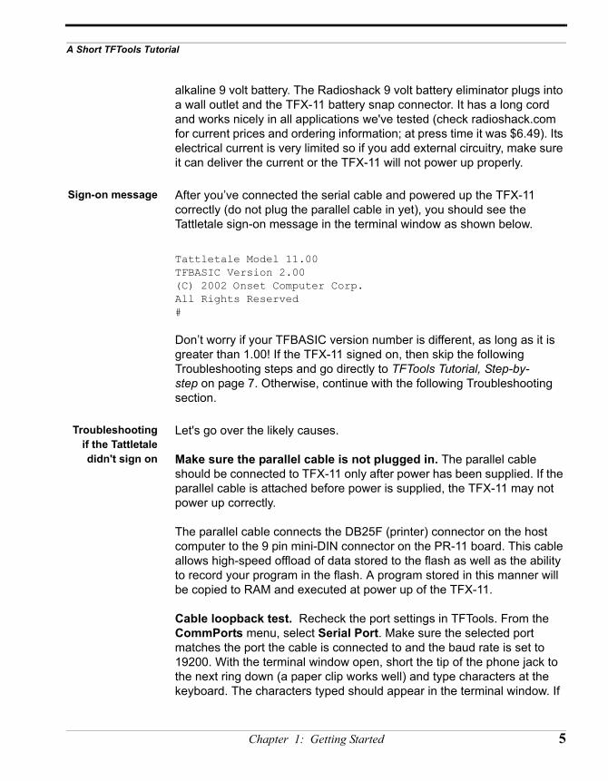
Sign-on message After you’ve connected the serial cable and powered up the TFX-11 correctly (do not plug the parallel cable in yet), you should see the Tattletale sign-on message in the terminal window as shown below.
Tattletale Model 11.00TFBASIC Version 2.00(C) 2002 Onset Computer Corp.All Rights Reserved#
Don’t worry if your TFBASIC version number is different, as long as it is greater than 1.00! If the TFX-11 signed on, then skip the following Troubleshooting steps and go directly to TFTools Tutorial, Step-by-step on page 7. Otherwise, continue with the following Troubleshooting section.
Troubleshootingif the Tattletaledidn't sign on
Let's go over the likely causes.
Make sure the parallel cable is not plugged in. The parallel cable should be connected to TFX-11 only after power has been supplied. If the parallel cable is attached before power is supplied, the TFX-11 may not power up correctly.
The parallel cable connects the DB25F (printer) connector on the host computer to the 9 pin mini-DIN connector on the PR-11 board. This cable allows high-speed offload of data stored to the flash as well as the ability to record your program in the flash. A program stored in this manner will be copied to RAM and executed at power up of the TFX-11.
Cable loopback test. Recheck the port settings in TFTools. From the CommPorts menu, select Serial Port. Make sure the selected port matches the port the cable is connected to and the baud rate is set to 19200. With the terminal window open, short the tip of the phone jack to the next ring down (a paper clip works well) and type characters at the keyboard. The characters typed should appear in the terminal window. If
Chapter 1: Getting Started 5
characters do not appear, check the cable connection and try again. If characters still do not appear, you may have a faulty cable or COM port. If there is another COM port available, try moving the cable to it and repeating the above procedure. If you change to another COM port, don’t forget to change the port number in TFTools (from the CommPort menu, select Serial Port) .
If the previous test did not work, try connecting to another computer. If that is not possible, insert a break-out box between the terminal and the Tattletale serial cable and verify that your terminal is driving pin 2.
Check the battery or power supply. If the connections are OK, perhaps the battery you are using to power the Tattletale is bad. Test it under load to see if the voltage is correct for its rating.
Run a scope test. If the battery checks out and you are convinced that the TFX-11 isn't working, go back to the break-out box and use an oscilloscope to look for the signal transmitted from the TFX-11. This signal should appear on the serial connector at pin 3. Each time you power up the TFX-11, it will send its sign-on message out on this pin, and you will see a digital signal on this pin switching between -4.5V and +4.5V. If you don't see a signal on this pin, the TFX-11 may indeed have a problem. You can send it back to Onset for a check-out, but I'll wager that you tried the wrong pin or have a dead battery! Double-check and check again!
If the TFX-11 passed the scope test, this means the TFX-11 is sending, but the computer is not receiving. Check the connections again as described in the cable loopback test above. In the terminal window, press Enter. The TFX-11 should respond with its prompt:
#
If this test succeeds, it proves that the serial interface can send as well as receive. (The number sign, #, is analogous to the C:\> prompt in DOS and means the Tattletale is idle while waiting for a command.) Continue on to TFTools Tutorial, Step-by-step on page 7.
It just won't work:returning the
TFX-11 to Onset
So nothing you tried worked...
If the above tests failed, or you do not have the tools to properly perform the tests, then you may need to return the TFX-11 to Onset. Contact us at
6 TFX-11 User’s Guide
A Short TFTools Tutorial
the numbers in the front of this manual to obtain an RMA and shipping instructions for returns.
PLEASE DO NOT RETURN THE TFX-11 WITHOUT FIRST OBTAINING A RETURN MATERIALS AUTHORIZATION (RMA).
Attempting a return without an RMA will delay processing.
TFTools Tutorial,Step-by-step
The following procedures show you how to start the TFTools program, load a test program, debug it, and save the debugged version.
TFX-11connections for
serialcommunication
At this point, the serial communications cable should be properly connected between the TFX-11 and the computer, and the TFX-11 should be connected to a power supply or battery (the parallel cable is not necessary for this tutorial). The Tattletale start-up message should be displayed in the terminal window and the ‘#’ prompt should appear below it.
Press the ENTER key. The ‘#’ prompt should display again. This verifies that the serial interface is operating correctly.
From the File menu, select Open. Select the file “DebugMe.tfb” in the directory where TFTools was installed. DO NOT make any edits yet.
Chapter 1: Getting Started 7
Checking aTFBASIC
program from thetext editor
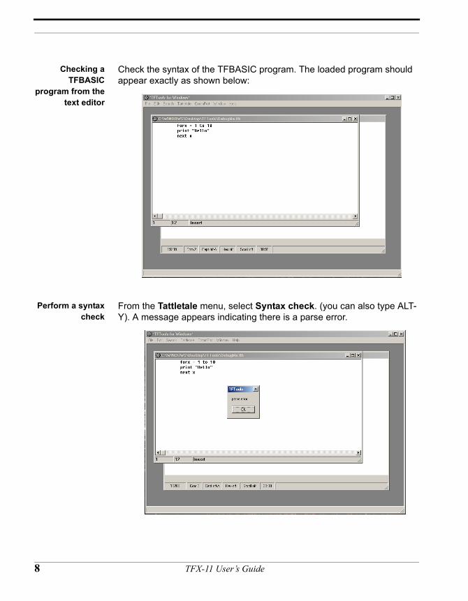
Check the syntax of the TFBASIC program. The loaded program should appear exactly as shown below:
Perform a syntaxcheck
From the Tattletale menu, select Syntax check. (you can also type ALT-Y). A message appears indicating there is a parse error.
8 TFX-11 User’s Guide
A Short TFTools Tutorial
Parse error! This error was introduced intentionally to demonstrate how the integrated parser detects syntax errors in your programs. The parser does a syntax check that detects common syntax errors such as misspelled keywords or missing arguments, but it does NOT detect programming logic errors!
Fix that error! Press Enter or click OK to close the parse error message. The cursor is placed in the line (but not necessarily the exact spot) with the error. In this example program, the cursor “forx” has the syntax error: it’s missing a space. Add a space between “for” and “x.”
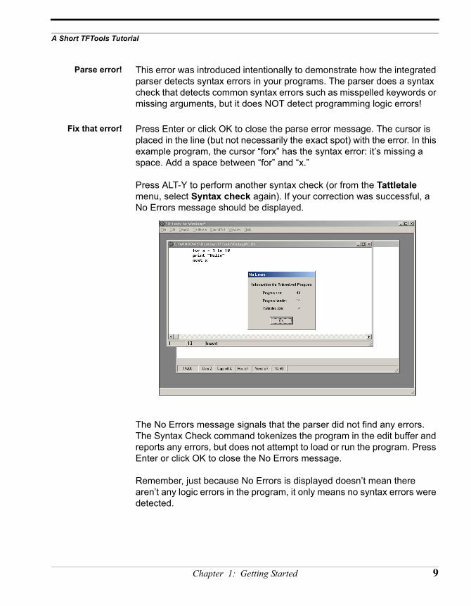
Press ALT-Y to perform another syntax check (or from the Tattletale menu, select Syntax check again). If your correction was successful, a No Errors message should be displayed.
The No Errors message signals that the parser did not find any errors. The Syntax Check command tokenizes the program in the edit buffer and reports any errors, but does not attempt to load or run the program. Press Enter or click OK to close the No Errors message.
Remember, just because No Errors is displayed doesn’t mean there aren’t any logic errors in the program, it only means no syntax errors were detected.
Chapter 1: Getting Started 9
Save yourprogram to a file
From the File menu, select Save as. Save the file with the name “Debugged.tfb.” By default, the file is saved in the same directory as the TFTools program unless you specify a new directory.
Congratulations! You now have debugged a TFBASIC program. While it is certainly not the most useful program ever written, it does demonstrate the basic operations of the TFTools Windows IDE.
All is well, let'scontinue!
This completes the TFTools introductory tutorial. The other TFTools commands and options are explained in detail in Chapters 2 and 3. To build a sample data logger, continue to the next section.
Build a Data logger, One Step at a Time
Building atemperature
monitor
This section illustrates how to build a simple data logger application, starting with a simple temperature monitor and then extending its utility by adding other useful features.
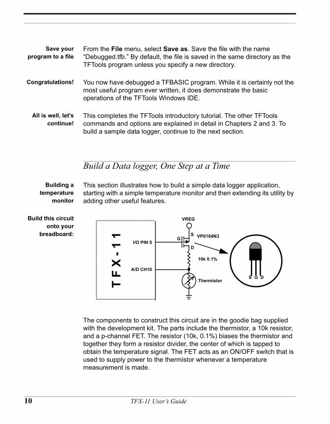
Build this circuitonto your
breadboard:
The components to construct this circuit are in the goodie bag supplied with the development kit. The parts include the thermistor, a 10k resistor, and a p-channel FET. The resistor (10k, 0.1%) biases the thermistor and together they form a resistor divider, the center of which is tapped to obtain the temperature signal. The FET acts as an ON/OFF switch that is used to supply power to the thermistor whenever a temperature measurement is made.
VREG
A/D CH10
I/O PIN 5
T F
X - 1
1 VP0104N3
10k 0.1%
ThermistorS G D
SG
D
10 TFX-11 User’s Guide
Build a Data logger, One Step at a Time
Enter thisprogram into the
editor:
sleep 0start: sleep 100
pclr 5print temp(chan(10))pset 5goto startstop
The Commands The example code above prints the temperature out on the HOST terminal display. Five commands unique to TFBASIC are used: SLEEP, TEMP(), PSET, PCLR and CHAN( ). These commands are fundamental to many data logging and control applications and are explained below. Be sure you have a good understanding of how they work before proceeding.
SLEEP The SLEEP instruction combines two important features: precise timing and power conservation. Each count of the SLEEP argument represents 10 ms (1/100 of a second), so SLEEP 100 sets the SLEEP countdown timer for one second. When using the SLEEP function it should always be first initialized by a SLEEP 0 instruction. This resets the SLEEP timer.
When a SLEEP command is invoked, it checks the already running SLEEP timer from the previous SLEEP command to see if it has expired. If not, it waits in a low power mode until it does expire. When the timer finally expires, the SLEEP timer is updated with the new value from the current command, and the program proceeds to execute the instruction statements that follow until the program reaches the next SLEEP statement. At this point it again checks the sleep timer and again waits until it expires before updating the counter and allowing the program to proceed. NOTE: SLEEP commands, to be effective, must allow sufficient time for the intervening statements to execute. If the command(s) between the two SLEEP instructions take longer than the SLEEP interval, the SLEEP timer will expire before the next SLEEP command is reached. This generates a non-fatal error, signaled by the program writing an '*' out the serial port, which identifyes the fact that precise timing has been compromised due to a timer overrun. To reset the SLEEP timer, use the SLEEP 0 statement, otherwise the first invocation of SLEEP will generate an '*'.
PSET and PCLR PSET sets the corresponding pin(s) to outputs and then sets them to +5V. PCLR also sets the corresponding pin(s) to outputs, but then sets them to 0V.
Chapter 1: Getting Started 11
CHAN() The function CHAN(n) returns a digital value proportional to the analog voltage at pin n.
TEMP() The thermistor is in a divider circuit with a 10K resistor. TFBASIC has a convenient function, TEMP, which converts the output of the converter to a temperature in hundredths of degrees C. The command only works correctly when used with the divider circuit and components illustrated above.
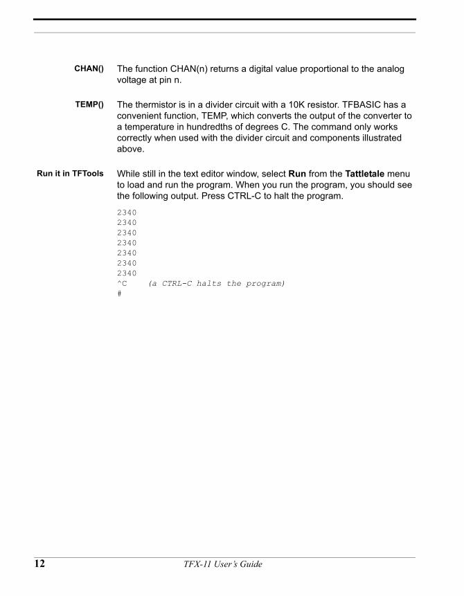
Run it in TFTools While still in the text editor window, select Run from the Tattletale menu to load and run the program. When you run the program, you should see the following output. Press CTRL-C to halt the program.
2340234023402340234023402340^C (a CTRL-C halts the program)#
12 TFX-11 User’s Guide
Build a Data logger, One Step at a Time
A slightly morecomplex program
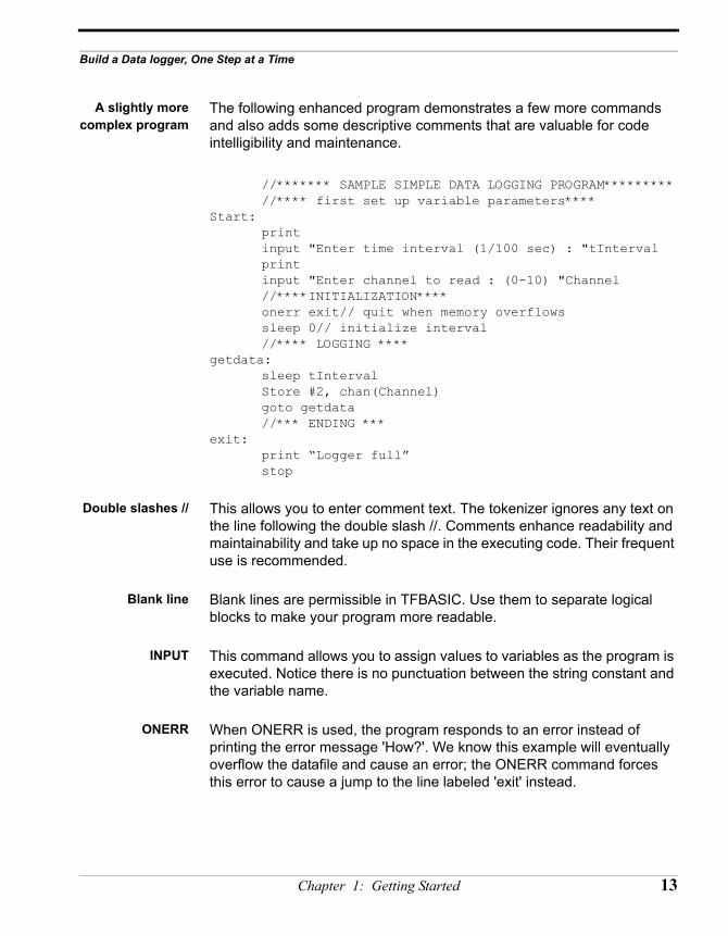
The following enhanced program demonstrates a few more commands and also adds some descriptive comments that are valuable for code intelligibility and maintenance.
//******* SAMPLE SIMPLE DATA LOGGING PROGRAM*********//**** first set up variable parameters****
Start:printinput "Enter time interval (1/100 sec) : "tIntervalprintinput "Enter channel to read : (0-10) "Channel//****INITIALIZATION****onerr exit// quit when memory overflowssleep 0// initialize interval//**** LOGGING ****
getdata: sleep tIntervalStore #2, chan(Channel)goto getdata//*** ENDING ***
exit: print “Logger full”stop
Double slashes // This allows you to enter comment text. The tokenizer ignores any text on the line following the double slash //. Comments enhance readability and maintainability and take up no space in the executing code. Their frequent use is recommended.
Blank line Blank lines are permissible in TFBASIC. Use them to separate logical blocks to make your program more readable.
INPUT This command allows you to assign values to variables as the program is executed. Notice there is no punctuation between the string constant and the variable name.
ONERR When ONERR is used, the program responds to an error instead of printing the error message 'How?'. We know this example will eventually overflow the datafile and cause an error; the ONERR command forces this error to cause a jump to the line labeled 'exit' instead.
Chapter 1: Getting Started 13
STORE The Store command sends data to the non-volatile serial Flash (SFLASH) datafile. Once data is written to this datafile, it cannot be read or modified by the program. The datafile pointer is available as the read-only variable DFPNT. After each write to the datafile, DFPNT is automatically updated to point to the next available location. Data is retrieved after the program is completed. The channel command returns the two bytes from the A/D converter padded out to four bytes for compatibility with the standard TFBASIC integer variable. The #2 after the Store command is a formatting command that says only store the two least significant bytes of the four bytes, which, in this instance, are the only bytes that contain data.
STOP This command ends program execution. It is added here for readability since it really isn't needed. The last line of the program halts execution anyway.
The above code, employing the ONERR command, is a little fancy; the following code works just as well:
for A = 1 to dfmax sleep tInterval Store #2, chan(Channel)next A
Here 'dfmax' is a predefined variable that returns the size of the datafile.
FOR / NEXT This command, along with NEXT, forms a powerful looping structure in TFBASIC. The loop starts with the assignment of the first specified value (1) to A and executes all the code up to the NEXT command. At the NEXT command, the variable (A) increments and the program goes back to the FOR line. The new value of the variable is then compared with the value after the TO. If it is less, the intervening code between the FOR and the NEXT is executed again. If not, execution is passed to the line following the NEXT statement.
Note that the current drain after executing the STOP command is as low as it would be executing SLEEP; the logger is waiting for an incoming character. Data can then be off-loaded.
Retrieving storeddata
To retrieve the data from the SFLASH, you need to be running TFTools. The TFBASIC program, if running, must be halted and the # prompt must appear in the terminal. Next, from the Tattletale menu, select either
14 TFX-11 User’s Guide
Build a Data logger, One Step at a Time
XMODEM off-load or Parallel off-load, which will copy the data from the datafile to a file on the host PC (the parallel cable must be connected for parallel off-load to work).
Making yourprogram boot on
power up
The program may be stored in the non-volatile flash memory along with the TFBASIC operating system. To write the program to flash, first connect the parallel cable, and then select Launch from the Tattletale menu (instead of Run). This will load the program and start its execution. Once loaded, the user program will execute from the beginning at power up or when you select Relaunch from the Tattletale menu. To erase the program and get the # prompt back, select Load OS only from the Tattletale menu.
Chapter 1: Getting Started 15

16 TFX-11 User’s Guide
CHAPTER 2
The TFTools IDE
TFX-11 User’s Guide
Understanding the TFTools Integrated Development Environment
Introduction toTFTools
(For latest release information please be sure to read the README files on the distribution disks.)
TFTools for Windows provides a complete interactive programming environment for developing and maintaining programs for the TFX-11. TFTools includes a programming editor for writing and debugging TFBASIC, and a terminal program for uploading and downloading data and programs between the host PC and the TFX-11. This chapter explains the basics of working with the primary components of the TFTools IDE. For details on specific menu commands, refer to Chapter 3.
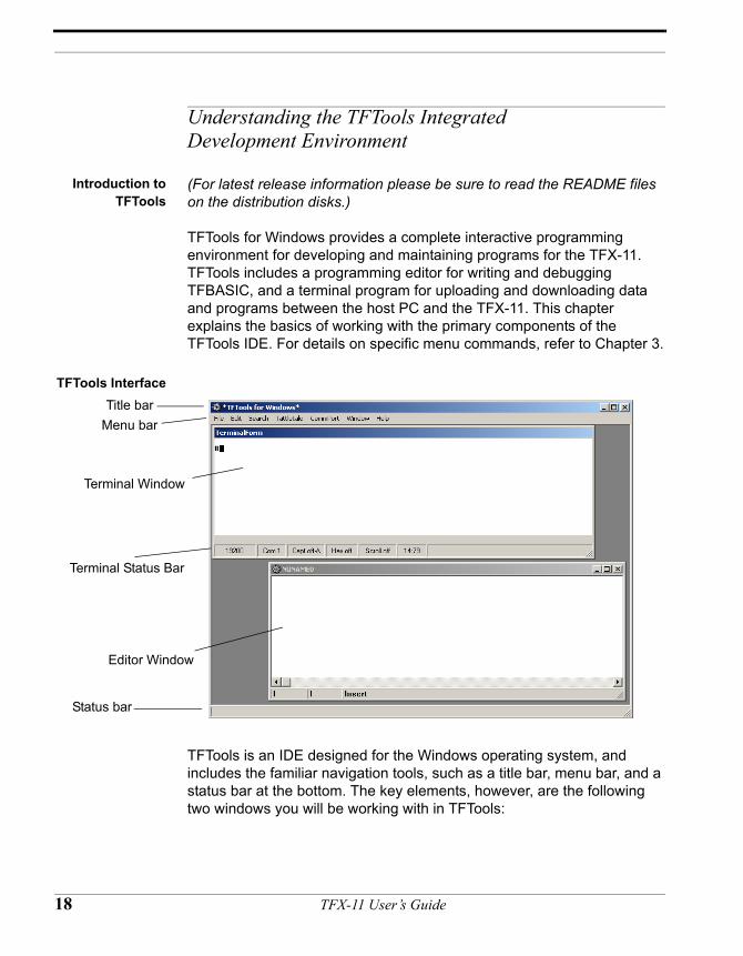
TFTools Interface
TFTools is an IDE designed for the Windows operating system, and includes the familiar navigation tools, such as a title bar, menu bar, and a status bar at the bottom. The key elements, however, are the following two windows you will be working with in TFTools:
Terminal Window
Editor Window
Terminal Status Bar
Title barMenu bar
Status bar
18 TFX-11 User’s Guide
Understanding the TFTools Integrated Development Environment
• The terminal window, which displays the TFTools integrated terminal program used for communicating with the TFX-11 and has an integrated compiler for generating tokenized TFBASIC code.
• The editor window, which is a multi-window programming editor for writing and debugging TFBasic code.
Terminal window There is only one terminal window and it is always open. Although the terminal window can be resized or hidden by an editor window, it cannot be minimized or closed.
The terminal program communicates with the TFX-11 through an Onset supplied cable connected to a PC serial (COM) port. Program upload and data off-load use a standard PC parallel (LPT) port connected by an Onset-supplied cable (there is also a two-step process that allows you to upload via serial port; see Editor window on page 20).
As soon as a powered TFX-11 is properly connected to the PC via the serial cable, the terminal window displays any characters that are received by the host PC serial port. Keyboard characters go out the host PC serial port to the Tattletale’s main UART. Tattletale replies sent out via the TFX-11 main UART appear in this terminal window.
Press the # key any time you want to make sure the terminal program is communicating with the TFX-11. It is also good practice to use the PRINT command to print a message with the name and version number of your program to the terminal window. This can be helpful for future troubleshooting and a visual cue that you are connected to the correct board.
The terminal window has a 16,000 character circular buffer, which holds about 8 pages of packed text. When the buffer fills, the oldest characters are discarded. Characters in this window cannot be saved using cut and paste, but they can be captured to a text file. From the CommPort menu, select Capture to File, and type the file name where you’d like to save these characters. Only characters received after Capture to File has been activated will be saved. The number of characters saved is limited only by disk space. By default, Capture to File is turned off every time you open TFTools. If you choose to use the existing file when you turn it back on, you will be prompted to either append the new text to the file or overwrite it.
Chapter 2: The TFTools IDE 19
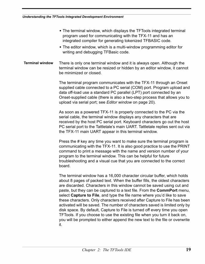
Terminal statusbar
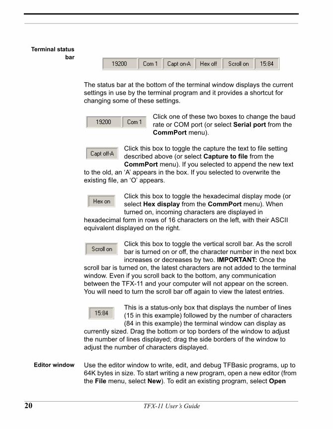
The status bar at the bottom of the terminal window displays the current settings in use by the terminal program and it provides a shortcut for changing some of these settings.
Click one of these two boxes to change the baud rate or COM port (or select Serial port from the CommPort menu).
Click this box to toggle the capture the text to file setting described above (or select Capture to file from the CommPort menu). If you selected to append the new text
to the old, an ‘A’ appears in the box. If you selected to overwrite the existing file, an ‘O’ appears.
Click this box to toggle the hexadecimal display mode (or select Hex display from the CommPort menu). When turned on, incoming characters are displayed in
hexadecimal form in rows of 16 characters on the left, with their ASCII equivalent displayed on the right.
Click this box to toggle the vertical scroll bar. As the scroll bar is turned on or off, the character number in the next box increases or decreases by two. IMPORTANT: Once the
scroll bar is turned on, the latest characters are not added to the terminal window. Even if you scroll back to the bottom, any communication between the TFX-11 and your computer will not appear on the screen. You will need to turn the scroll bar off again to view the latest entries.
This is a status-only box that displays the number of lines (15 in this example) followed by the number of characters (84 in this example) the terminal window can display as
currently sized. Drag the bottom or top borders of the window to adjust the number of lines displayed; drag the side borders of the window to adjust the number of characters displayed.
Editor window Use the editor window to write, edit, and debug TFBasic programs, up to 64K bytes in size. To start writing a new program, open a new editor (from the File menu, select New). To edit an existing program, select Open
20 TFX-11 User’s Guide
Understanding the TFTools Integrated Development Environment
from the File menu and select the .tfb file you wish to open. The title bar in the editor window displays the full path and file name for the .tfb file. For new programs, “NONAME” is listed in the title bar until you save the file.
Unlike the terminal window, multiple editor windows can be open at once. You can cut or copy text from one window and paste it to another via the Windows clipboard. You can also switch between several open windows and minimize, maximize, or close them as needed, but only the currently selected window is active. Use the Window menu to keep track of all open editor windows.
Although each editor window is an independent text editor, there are some global settings shared by all open edit windows. From the Edit menu, select Editor Options to set the global tab setting, autoindent mode, and date/time string format.
There are two edit modes you can switch between while entering code: insert and overwrite. Press the Insert key to toggle between these modes. In insert mode, text is added to the line before the flashing cursor. In overwrite mode, the cursor changes to a block and each new character typed will overwrite the one under the cursor. The editor also has a limited undo capability. From the Edit menu, select Undo or press Ctrl-Z to undo the most recent action. As soon as you move the cursor, the Undo buffer is cleared and the previous operation cannot be undone.
As you write your code, use the syntax checker to compile and debug the program (from the Tattletale menu, select Syntax check or press Alt-Y). When the syntax checker finds an error, it informs you of the nature of the error and places the cursor on the line where the error was found. This allows rapid corrections of simple mistakes, decreasing the time it normally would take to find and correct the error. To quickly find a specific string or jump to a particular line number, use the options in the Search menu.
After the program compiles successfully, press ALT-R (or from the Tattletale menu, select Run) to load and run your program. Then, to copy it to the flash memory via serial cable, select Copy program to flash from the Tattletale menu. Alternatively, you can select Launch from the Tattletale menu to load the program via a parallel cable.
Tip: To add a bookmark to text in the editor window, go to the line where you want to place the bookmark and press Ctrl-Shift 0.
Chapter 2: The TFTools IDE 21
Navigating the IDE without a Mouse
EquivalentKeyboard
commands
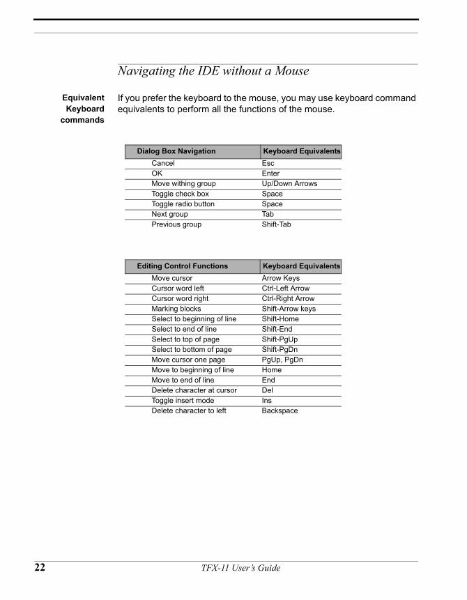
If you prefer the keyboard to the mouse, you may use keyboard command equivalents to perform all the functions of the mouse.
Dialog Box Navigation Keyboard EquivalentsCancel EscOK EnterMove withing group Up/Down ArrowsToggle check box SpaceToggle radio button SpaceNext group TabPrevious group Shift-Tab
Editing Control Functions Keyboard EquivalentsMove cursor Arrow KeysCursor word left Ctrl-Left ArrowCursor word right Ctrl-Right ArrowMarking blocks Shift-Arrow keysSelect to beginning of line Shift-HomeSelect to end of line Shift-EndSelect to top of page Shift-PgUpSelect to bottom of page Shift-PgDnMove cursor one page PgUp, PgDnMove to beginning of line HomeMove to end of line EndDelete character at cursor DelToggle insert mode InsDelete character to left Backspace
22 TFX-11 User’s Guide
Navigating the IDE without a Mouse
Main/Submenu items Hot KeyKey
sequence Term Edit
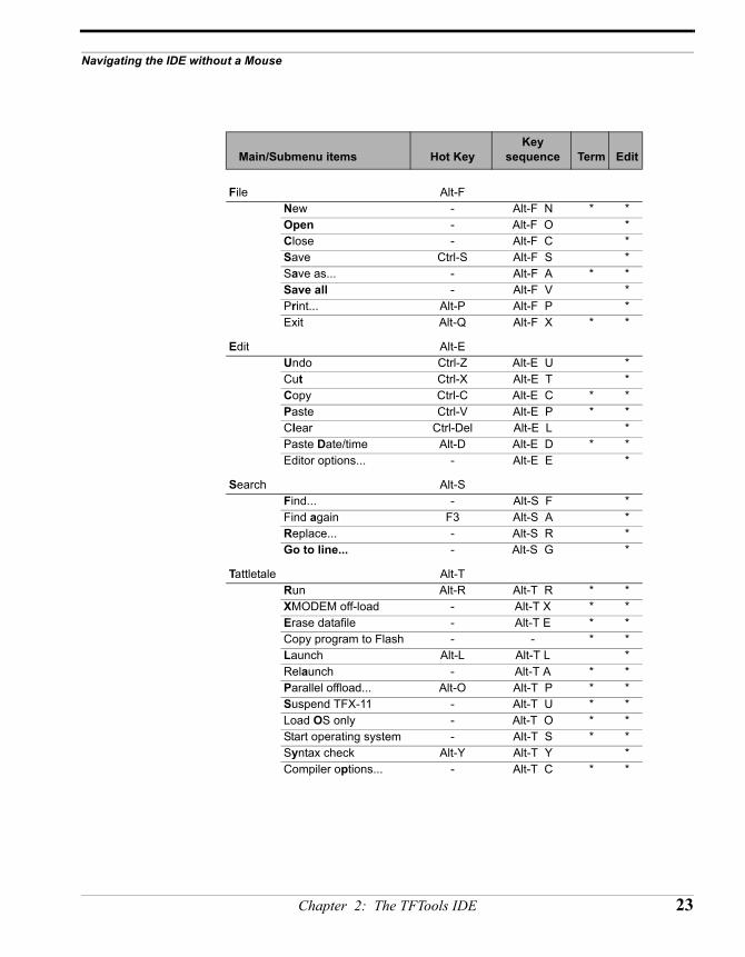
File Alt-FNew - Alt-F N * *Open - Alt-F O *Close - Alt-F C *Save Ctrl-S Alt-F S *Save as... - Alt-F A * *Save all - Alt-F V *Print... Alt-P Alt-F P *Exit Alt-Q Alt-F X * *
Edit Alt-E Undo Ctrl-Z Alt-E U *Cut Ctrl-X Alt-E T *Copy Ctrl-C Alt-E C * *Paste Ctrl-V Alt-E P * *Clear Ctrl-Del Alt-E L *Paste Date/time Alt-D Alt-E D * *Editor options... - Alt-E E *
Search Alt-S Find... - Alt-S F *Find again F3 Alt-S A *Replace... - Alt-S R *Go to line... - Alt-S G *
Tattletale Alt-T Run Alt-R Alt-T R * *XMODEM off-load - Alt-T X * *Erase datafile - Alt-T E * *Copy program to Flash - - * *Launch Alt-L Alt-T L *Relaunch - Alt-T A * *Parallel offload... Alt-O Alt-T P * *Suspend TFX-11 - Alt-T U * *Load OS only - Alt-T O * *Start operating system - Alt-T S * *Syntax check Alt-Y Alt-T Y *Compiler options... - Alt-T C * *
Chapter 2: The TFTools IDE 23
Main/Submenu items Hot KeyKey
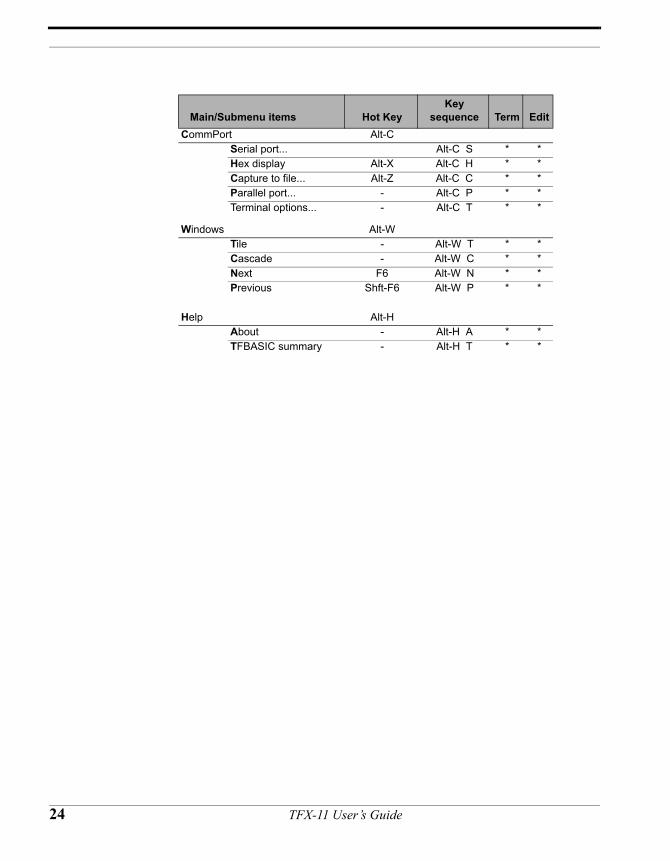
sequence Term EditCommPort Alt-C
Serial port... Alt-C S * *Hex display Alt-X Alt-C H * *Capture to file... Alt-Z Alt-C C * *Parallel port... - Alt-C P * *Terminal options... - Alt-C T * *
Windows Alt-W Tile - Alt-W T * *Cascade - Alt-W C * *Next F6 Alt-W N * *Previous Shft-F6 Alt-W P * *
Help Alt-HAbout - Alt-H A * *TFBASIC summary - Alt-H T * *
24 TFX-11 User’s Guide
CHAPTER 3
TFTools Menu CommandReference
TFX-11 User’s Guide
FILE
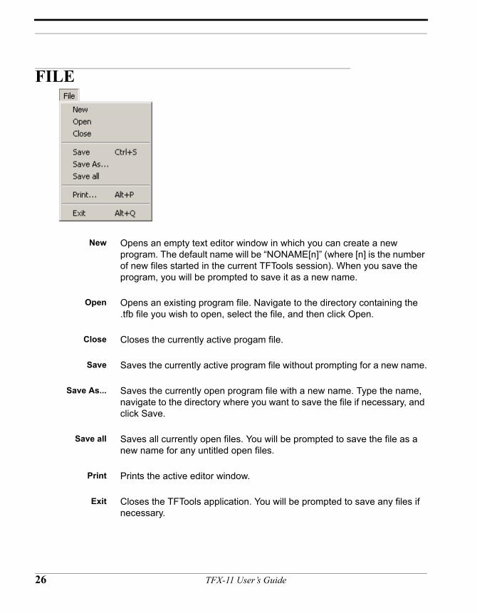
New Opens an empty text editor window in which you can create a new program. The default name will be “NONAME[n]” (where [n] is the number of new files started in the current TFTools session). When you save the program, you will be prompted to save it as a new name.
Open Opens an existing program file. Navigate to the directory containing the .tfb file you wish to open, select the file, and then click Open.
Close Closes the currently active progam file.
Save Saves the currently active program file without prompting for a new name.
Save As... Saves the currently open program file with a new name. Type the name, navigate to the directory where you want to save the file if necessary, and click Save.
Save all Saves all currently open files. You will be prompted to save the file as a new name for any untitled open files.
Print Prints the active editor window.
Exit Closes the TFTools application. You will be prompted to save any files if necessary.
26 TFX-11 User’s Guide
EDIT
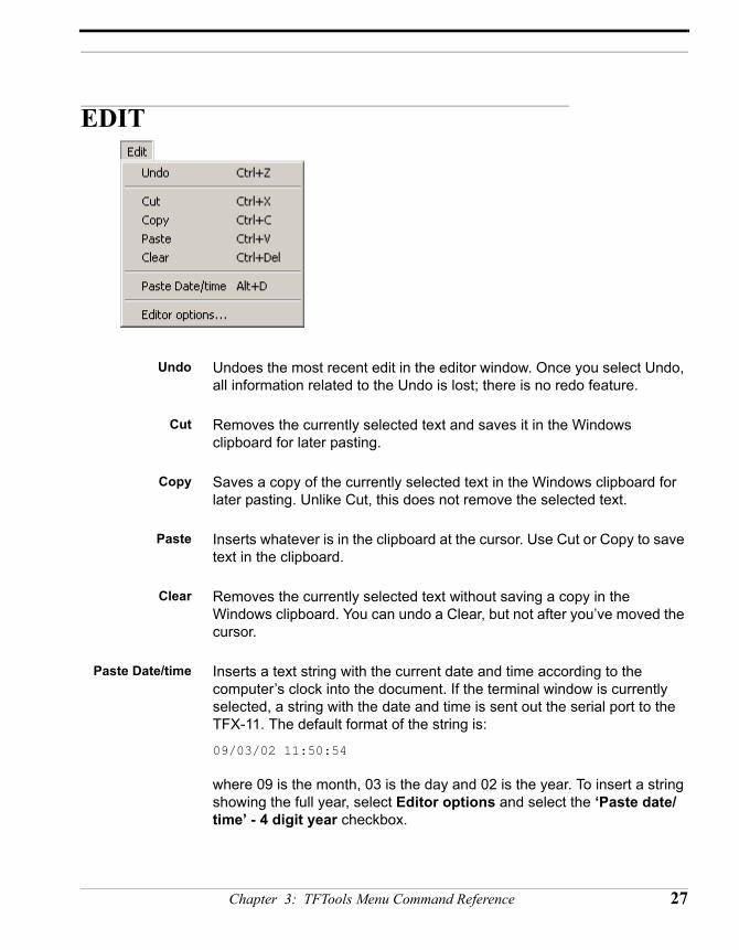
Undo Undoes the most recent edit in the editor window. Once you select Undo, all information related to the Undo is lost; there is no redo feature.
Cut Removes the currently selected text and saves it in the Windows clipboard for later pasting.
Copy Saves a copy of the currently selected text in the Windows clipboard for later pasting. Unlike Cut, this does not remove the selected text.
Paste Inserts whatever is in the clipboard at the cursor. Use Cut or Copy to save text in the clipboard.
Clear Removes the currently selected text without saving a copy in the Windows clipboard. You can undo a Clear, but not after you’ve moved the cursor.
Paste Date/time Inserts a text string with the current date and time according to the computer’s clock into the document. If the terminal window is currently selected, a string with the date and time is sent out the serial port to the TFX-11. The default format of the string is:
09/03/02 11:50:54
where 09 is the month, 03 is the day and 02 is the year. To insert a string showing the full year, select Editor options and select the ‘Paste date/time’ - 4 digit year checkbox.
Chapter 3: TFTools Menu Command Reference 27
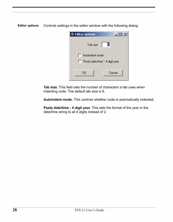
Editor options Controls settings in the editor window with the following dialog:
Tab size. This field sets the number of characters a tab uses when indenting code. The default tab size is 8.
Autoindent mode. This controls whether code is automatically indented.
Paste date/time - 4 digit year. This sets the format of the year in the date/time string to all 4 digits instead of 2.
28 TFX-11 User’s Guide
SEARCH
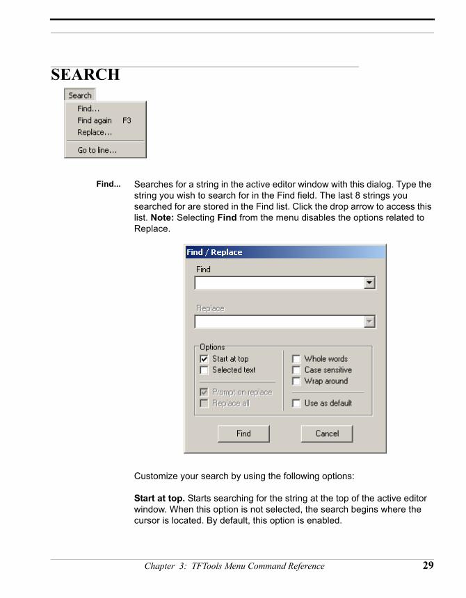
Find... Searches for a string in the active editor window with this dialog. Type the string you wish to search for in the Find field. The last 8 strings you searched for are stored in the Find list. Click the drop arrow to access this list. Note: Selecting Find from the menu disables the options related to Replace.
Customize your search by using the following options:
Start at top. Starts searching for the string at the top of the active editor window. When this option is not selected, the search begins where the cursor is located. By default, this option is enabled.
Chapter 3: TFTools Menu Command Reference 29
Selected text. Searches for the string in only the text that you’ve highlighted in the editor window.
Whole words. Searches for only complete words that match the search string, instead of partial words (for example if you’re searching for the word “stopped,” find will not display “stop” as a positive match when this is selected).
Case sensitive. Searches for an exact match based on the uppercase and lowercase usage in the Find field.
Wrap around. Continues the search from the beginning again if no match was found.
Use as default. Saves the currently selected options as the default settings for all future searches.
Find Again Once a string has been located with Find, use this option (or press F3) to locate the next occurrence of the same string.
Replace... Searches in the editor window for one string and replaces it with another. Type the string you wish to search for in the Find field, and then type the new string you wish to use in the Replace field. Or, use the drop arrows to select a string previously entered in the Find field or the Replace field (the
30 TFX-11 User’s Guide
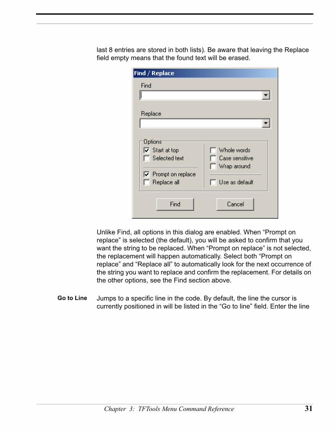
last 8 entries are stored in both lists). Be aware that leaving the Replace field empty means that the found text will be erased.
Unlike Find, all options in this dialog are enabled. When “Prompt on replace” is selected (the default), you will be asked to confirm that you want the string to be replaced. When “Prompt on replace” is not selected, the replacement will happen automatically. Select both “Prompt on replace” and “Replace all” to automatically look for the next occurrence of the string you want to replace and confirm the replacement. For details on the other options, see the Find section above.
Go to Line Jumps to a specific line in the code. By default, the line the cursor is currently positioned in will be listed in the “Go to line” field. Enter the line
Chapter 3: TFTools Menu Command Reference 31
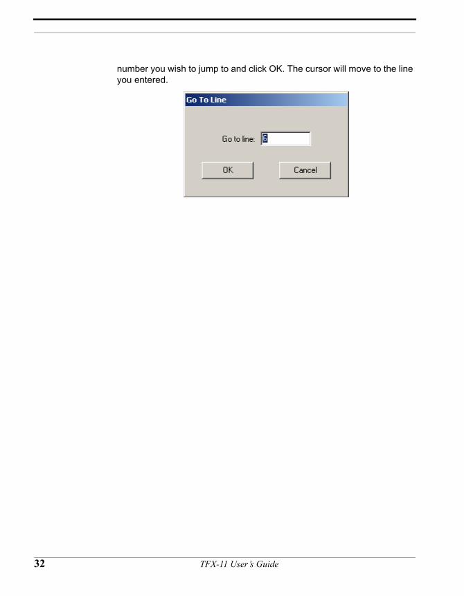
number you wish to jump to and click OK. The cursor will move to the line you entered.
32 TFX-11 User’s Guide
TATTLETALE
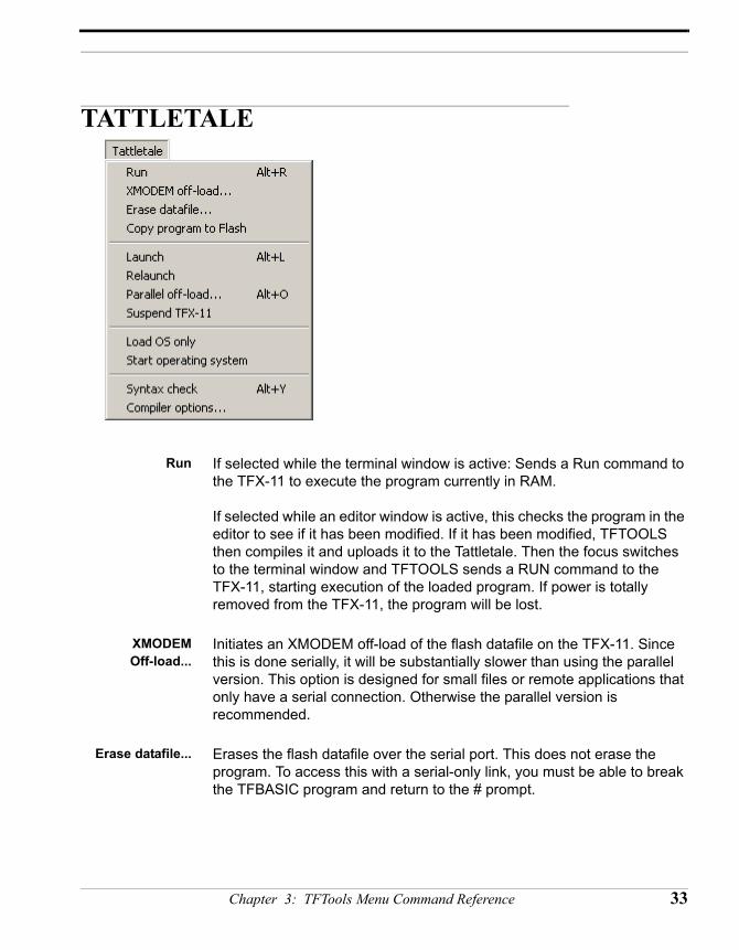
Run If selected while the terminal window is active: Sends a Run command to the TFX-11 to execute the program currently in RAM.
If selected while an editor window is active, this checks the program in the editor to see if it has been modified. If it has been modified, TFTOOLS then compiles it and uploads it to the Tattletale. Then the focus switches to the terminal window and TFTOOLS sends a RUN command to the TFX-11, starting execution of the loaded program. If power is totally removed from the TFX-11, the program will be lost.
XMODEMOff-load...
Initiates an XMODEM off-load of the flash datafile on the TFX-11. Since this is done serially, it will be substantially slower than using the parallel version. This option is designed for small files or remote applications that only have a serial connection. Otherwise the parallel version is recommended.
Erase datafile... Erases the flash datafile over the serial port. This does not erase the program. To access this with a serial-only link, you must be able to break the TFBASIC program and return to the # prompt.
Chapter 3: TFTools Menu Command Reference 33
Copy program toFlash
Copies the program that you executed with the Run command to the TFX-11’s flash storage. This enables you to permanently load a program using only the serial cable.
Launch Tokenizes and loads the program in the edit buffer into the TFX-11’s flash storage through the parallel connection. The datafile is erased and the datafile pointer is reset to 0. If there is data in the TFX-11, it saves the data before the Launch proceeds.
Relaunch Causes a reset of the TFX-11, which will restart the currently burned-in program. The datafile is not erased and the datafile pointer is not reset. This requires a parallel connection.
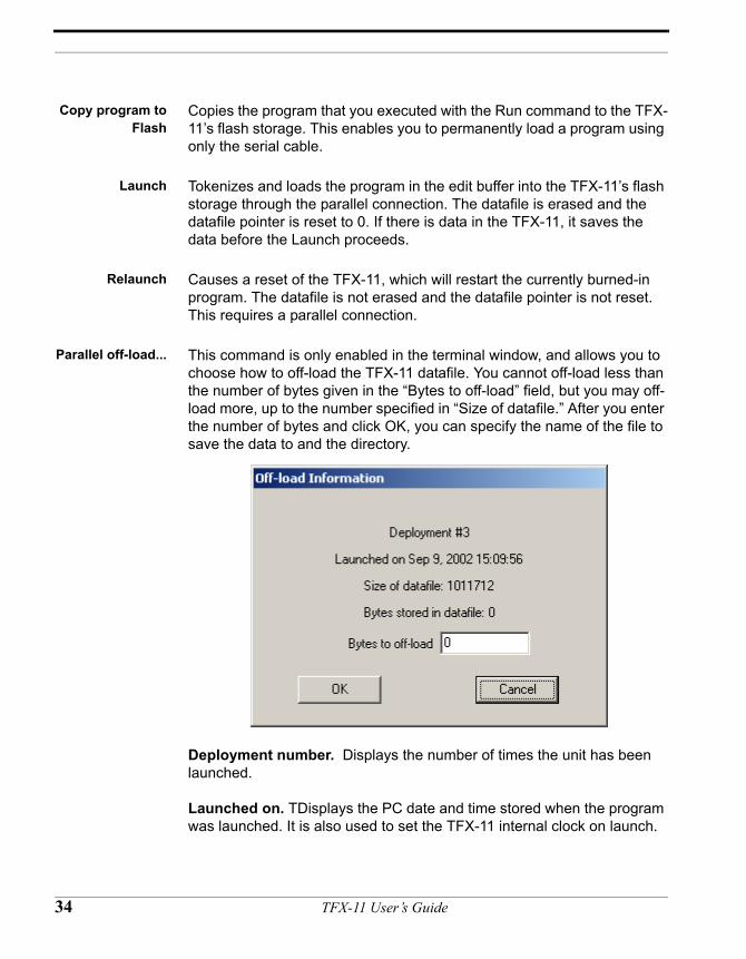
Parallel off-load... This command is only enabled in the terminal window, and allows you to choose how to off-load the TFX-11 datafile. You cannot off-load less than the number of bytes given in the “Bytes to off-load” field, but you may off-load more, up to the number specified in “Size of datafile.” After you enter the number of bytes and click OK, you can specify the name of the file to save the data to and the directory.
Deployment number. Displays the number of times the unit has been launched.
Launched on. TDisplays the PC date and time stored when the program was launched. It is also used to set the TFX-11 internal clock on launch.
34 TFX-11 User’s Guide
Size of datafile. Displays the total number of bytes available for storing data in the SFLASH after the program and other information is stored.
Bytes stored in datafile. Displays is the total amount of data bytes stored in the SFLASH.
Bytes to off-load. Enter the number of the bytes in the datafile you wish to off-load.
Suspend TFX-11 Places the TFX in its lowest power state.
Load OS Only Loads only the TFBASIC operating system; this requires the parallel cable to be attached. This erases any program loaded in the Tattletale so the next time it boots up, it will give a sign-on message followed by the # prompt. This returns the TFX-11 to the way it was when it was shipped.
Start operatingsystem
Reboots the TFX-11 and stops at the # prompt in the terminal window. Does not start running your program; waits for you do that manually.
Syntax check Tokenizes the program in the edit buffer and reports errors, but does not attempt to load the program into the Tattletale. This is affected by the Compiler Options (see below). Upon a successful check, a message displays the size (in bytes) of the compiled program, the size of the program header (this is information generated by the compiler and will be added to the front of the program), and the size of the variables area used by this program.
Chapter 3: TFTools Menu Command Reference 35
Compileroptions...
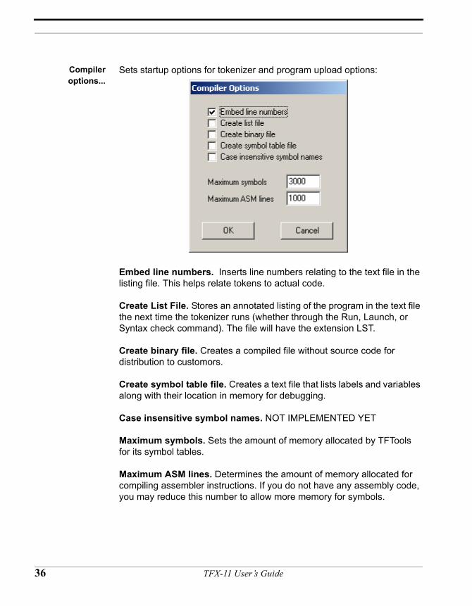
Sets startup options for tokenizer and program upload options:
Embed line numbers. Inserts line numbers relating to the text file in the listing file. This helps relate tokens to actual code.
Create List File. Stores an annotated listing of the program in the text file the next time the tokenizer runs (whether through the Run, Launch, or Syntax check command). The file will have the extension LST.
Create binary file. Creates a compiled file without source code for distribution to customors.
Create symbol table file. Creates a text file that lists labels and variables along with their location in memory for debugging.
Case insensitive symbol names. NOT IMPLEMENTED YET
Maximum symbols. Sets the amount of memory allocated by TFTools for its symbol tables.
Maximum ASM lines. Determines the amount of memory allocated for compiling assembler instructions. If you do not have any assembly code, you may reduce this number to allow more memory for symbols.
36 TFX-11 User’s Guide
COMMPORT
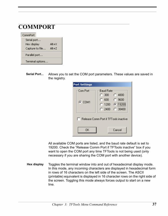
Serial Port... Allows you to set the COM port parameters. These values are saved in the registry.
All available COM ports are listed, and the baud rate default is set to 19200. Check the “Release Comm Port if TFTools inactive” box if you want to open the COM port any time TFTools is not being used (only necessary if you are sharing the COM port with another device).
Hex display Toggles the terminal window into and out of hexadecimal display mode. In this mode, any incoming characters are displayed in hexadecimal form in rows of 16 characters on the left side of the screen. The ASCII (printable) equivalent is displayed in 16 character rows on the right side of the screen. Toggling this mode always forces output to start on a new line.
Chapter 3: TFTools Menu Command Reference 37
Capture to file... Saves the characters in the terminal window to a file, which is useful for debugging or direct recording and storing of data.
The first time you select this command in a session, you are prompted for a file name to save the characters. Either accept the default name capture.txt and directory, or specify your own name and/or directory. Once the file is open and active, you can toggle the capture mode on and off (press Alt-Z or click the "CAPT" box in the terminal window’s Status line). Capture to file does not remain on when you exit TFTools; you will need to turn it on each time you start TFTools.
There are two file capture modes: Append and Overwrite. The default mode is append. If you select an existing text file when you turn “Capture to file” on, you will be prompted to either append the new information to the existing file or to overwrite the existing file.
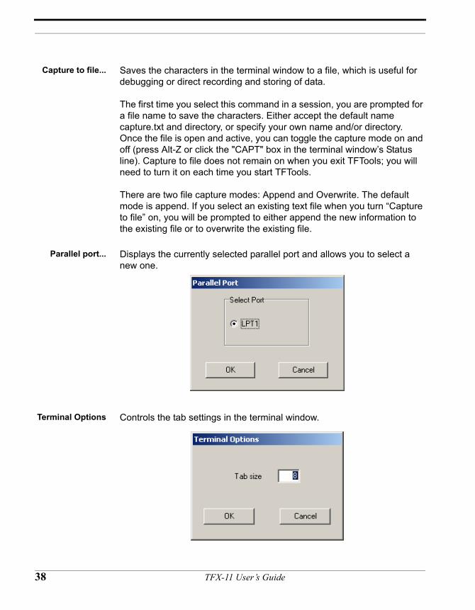
Parallel port... Displays the currently selected parallel port and allows you to select a new one.
Terminal Options Controls the tab settings in the terminal window.
38 TFX-11 User’s Guide
WINDOW
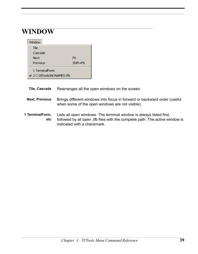
Tile, Cascade Rearranges all the open windows on the screen.
Next, Previous Brings different windows into focus in forward or backward order (useful when some of the open windows are not visible).
1 TerminalForm,etc
Lists all open windows. The terminal window is always listed first, followed by all open .tfb files with the complete path. The active window is indicated with a checkmark.
Chapter 3: TFTools Menu Command Reference 39
HELP
About Displays the About Box, which lists the version number of TFTools you are using. This information is important if you need to contact technical support.
TFBASICsummary
Provides a list of TFBASIC commands and keywords in alphabetical order.
40 TFX-11 User’s Guide
CHAPTER 4
TFBASIC Language Reference
TFX-11 User’s Guide
Legend
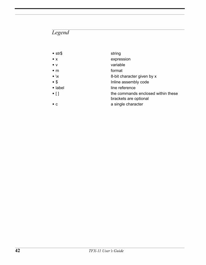
• str$ string• x expression• v variable• m format• \x 8-bit character given by x• $ Inline assembly code• label line reference• [ ] the commands enclosed within these
brackets are optional• c a single character
42 TFX-11 User’s Guide
Predefined Read-only variables in TFBASIC
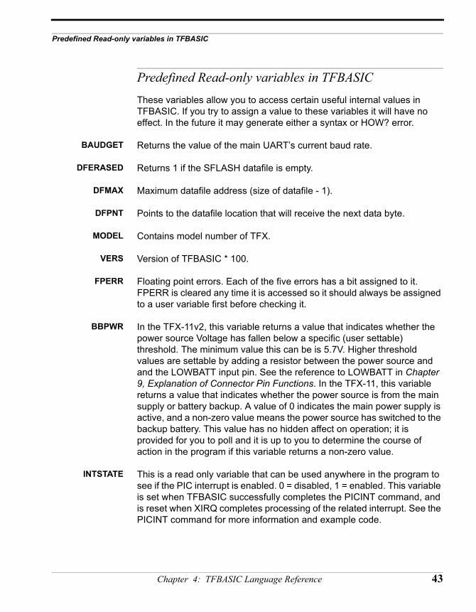
Predefined Read-only variables in TFBASICThese variables allow you to access certain useful internal values in TFBASIC. If you try to assign a value to these variables it will have no effect. In the future it may generate either a syntax or HOW? error.
BAUDGET Returns the value of the main UART’s current baud rate.
DFERASED Returns 1 if the SFLASH datafile is empty.
DFMAX Maximum datafile address (size of datafile - 1).
DFPNT Points to the datafile location that will receive the next data byte.
MODEL Contains model number of TFX.
VERS Version of TFBASIC * 100.
FPERR Floating point errors. Each of the five errors has a bit assigned to it. FPERR is cleared any time it is accessed so it should always be assigned to a user variable first before checking it.
BBPWR In the TFX-11v2, this variable returns a value that indicates whether the power source Voltage has fallen below a specific (user settable) threshold. The minimum value this can be is 5.7V. Higher threshold values are settable by adding a resistor between the power source and and the LOWBATT input pin. See the reference to LOWBATT in Chapter 9, Explanation of Connector Pin Functions. In the TFX-11, this variable returns a value that indicates whether the power source is from the main supply or battery backup. A value of 0 indicates the main power supply is active, and a non-zero value means the power source has switched to the backup battery. This value has no hidden affect on operation; it is provided for you to poll and it is up to you to determine the course of action in the program if this variable returns a non-zero value.
INTSTATE This is a read only variable that can be used anywhere in the program to see if the PIC interrupt is enabled. 0 = disabled, 1 = enabled. This variable is set when TFBASIC successfully completes the PICINT command, and is reset when XIRQ completes processing of the related interrupt. See the PICINT command for more information and example code.
Chapter 4: TFBASIC Language Reference 43
TFBASIC Quick Reference (grouped by function)
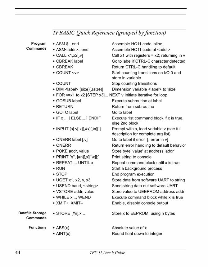
ProgramCommands
• ASM $...end Assemble HC11 code inline• ASM<addr>...end Assemble HC11 code at <addr> • CALL x1,x2[,v] Call x1 with registers = x2; returning in v • CBREAK label Go to label if CTRL-C character detected • CBREAK Return CTRL-C handling to default • COUNT <v> Start counting transitions on I/O 0 and
store in variable• COUNT Stop counting transitions• DIM <label> (size)[,(size)] Dimension variable <label> to 'size'• FOR v=x1 to x2 [STEP x3]... NEXT v Initiate iterative for loop• GOSUB label Execute subroutine at label• RETURN Return from subroutine• GOTO label Go to label• IF x ... [ ELSE... ] ENDIF Execute 1st command block if x is true,
else 2nd block• INPUT [s] v[,x][,#x][,\x][;] Prompt with s, load variable v (see full
description for complete arg list)• ONERR label [,v] Go to label if error [, error in v]• ONERR Return error handling to default behavior• POKE addr, value Store byte 'value' at address 'addr' • PRINT "s", [#n][,x][,\x][;] Print string to console• REPEAT ... UNTIL x Repeat command block until x is true• RUN Start a background process• STOP End program execution• UGET x1, x2, v, x3 Store data from software UART to string• USEND baud, <string> Send string data out software UART• VSTORE addr, value Store value to UEEPROM address addr• WHILE x ... WEND Execute command block while x is true• XMIT+, XMIT– Enable, disable console output
Datafile StorageCommands
• STORE [#n],x... Store x to EEPROM, using n bytes
Functions • ABS(x) Absolute value of x• AINT(x) Round float down to integer
44 TFX-11 User’s Guide
TFBASIC Quick Reference (grouped by function)
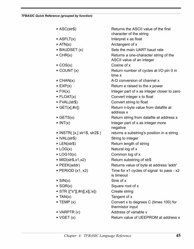
• ASC(str$) Returns the ASCII value of the first character of the string
• ASFLT(x) Interpret x as float• ATN(x) Arctangent of x• BAUDSET (x) Sets the main UART baud rate• CHR(x) Returns a one-character string of the
ASCII value of an integer• COS(x) Cosine of x• COUNT (x) Return number of cycles at I/O pin 0 in
time x• CHAN(x) A-D conversion of channel x• EXP(x) Return e raised to the x power• FIX(x) Integer part of x as integer closer to zero• FLOAT(x) Convert integer x to float• FVAL(str$) Convert string to float• GET(x[,#n]) Return n-byte value from datafile at
address x• GETS(x) Return string from datafile at address x• INT(x) Integer part of x as integer more
negative• INSTR( [x,] str1$, str2$ ) returns a substring’s position in a string• IVAL(str$) String to integer• LEN(str$) Return length of string• LOG(x) Natural log of x• LOG10(x) Common log of x• MID(str$,x1,x2) Return substring of str$• PEEK(addr) Returns value of byte at address 'addr' • PERIOD (x1, x2) Time for x1 cycles of signal to pass - x2
is timeout• SIN(x) Sine of x• SQR(x) Square root of x• STR (["s"][,#n][,x][,\x]) Create string • TAN(x) Tangent of x• TEMP (x) Convert x to degrees C (times 100) for
thermistor input• VARPTR (v) Address of variable v • VGET (x) Return value of UEEPROM at address x
Chapter 4: TFBASIC Language Reference 45
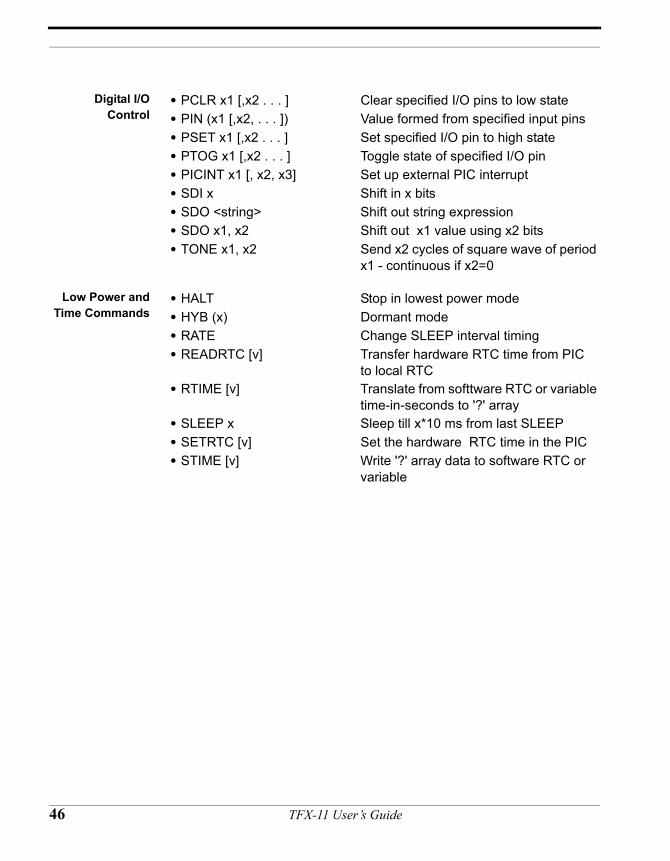
Digital I/OControl
• PCLR x1 [,x2 . . . ] Clear specified I/O pins to low state• PIN (x1 [,x2, . . . ]) Value formed from specified input pins• PSET x1 [,x2 . . . ] Set specified I/O pin to high state• PTOG x1 [,x2 . . . ] Toggle state of specified I/O pin • PICINT x1 [, x2, x3] Set up external PIC interrupt• SDI x Shift in x bits• SDO <string> Shift out string expression• SDO x1, x2 Shift out x1 value using x2 bits• TONE x1, x2 Send x2 cycles of square wave of period
x1 - continuous if x2=0
Low Power andTime Commands
• HALT Stop in lowest power mode• HYB (x) Dormant mode • RATE Change SLEEP interval timing• READRTC [v] Transfer hardware RTC time from PIC
to local RTC• RTIME [v] Translate from softtware RTC or variable
time-in-seconds to '?' array• SLEEP x Sleep till x*10 ms from last SLEEP • SETRTC [v] Set the hardware RTC time in the PIC• STIME [v] Write '?' array data to software RTC or
variable
46 TFX-11 User’s Guide
TFBASIC Quick Reference (alphabetical)
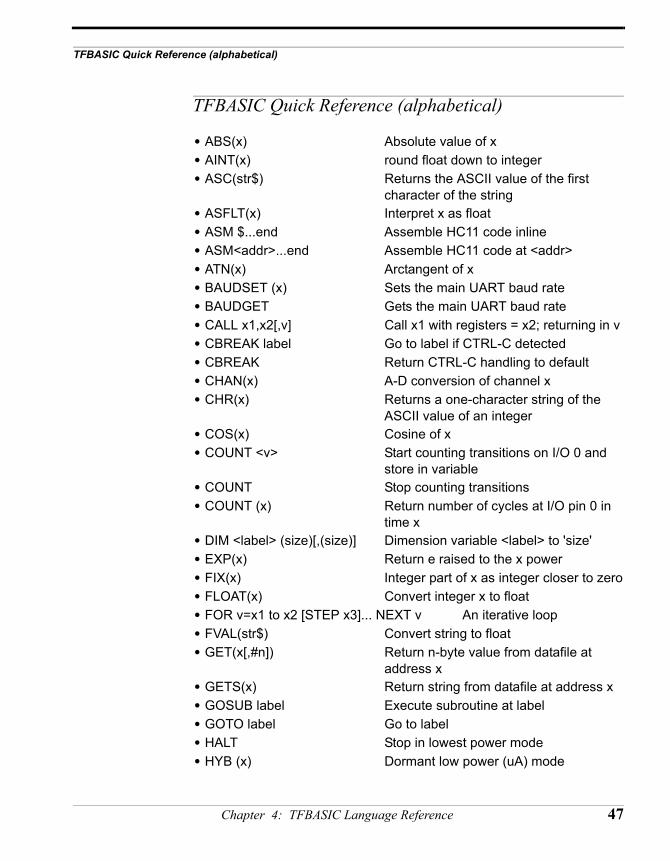
TFBASIC Quick Reference (alphabetical)
• ABS(x) Absolute value of x• AINT(x) round float down to integer• ASC(str$) Returns the ASCII value of the first
character of the string• ASFLT(x) Interpret x as float• ASM $...end Assemble HC11 code inline• ASM<addr>...end Assemble HC11 code at <addr> • ATN(x) Arctangent of x• BAUDSET (x) Sets the main UART baud rate• BAUDGET Gets the main UART baud rate• CALL x1,x2[,v] Call x1 with registers = x2; returning in v • CBREAK label Go to label if CTRL-C detected • CBREAK Return CTRL-C handling to default • CHAN(x) A-D conversion of channel x• CHR(x) Returns a one-character string of the
ASCII value of an integer• COS(x) Cosine of x• COUNT <v> Start counting transitions on I/O 0 and
store in variable• COUNT Stop counting transitions• COUNT (x) Return number of cycles at I/O pin 0 in
time x• DIM <label> (size)[,(size)] Dimension variable <label> to 'size'• EXP(x) Return e raised to the x power• FIX(x) Integer part of x as integer closer to zero• FLOAT(x) Convert integer x to float• FOR v=x1 to x2 [STEP x3]... NEXT v An iterative loop• FVAL(str$) Convert string to float• GET(x[,#n]) Return n-byte value from datafile at
address x• GETS(x) Return string from datafile at address x• GOSUB label Execute subroutine at label• GOTO label Go to label• HALT Stop in lowest power mode• HYB (x) Dormant low power (uA) mode
Chapter 4: TFBASIC Language Reference 47
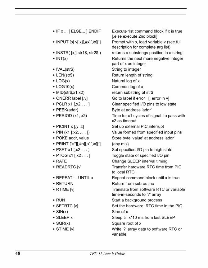
• IF x ... [ ELSE... ] ENDIF Execute 1st command block if x is true [,else execute 2nd block]
• INPUT [s] v[,x][,#x][,\x][;] Prompt with s, load variable v (see full description for complete arg list)
• INSTR( [x,] str1$, str2$ ) returns a substrings position in a string• INT(x) Returns the next more negative integer
part of x as integer• IVAL(str$) String to integer• LEN(str$) Return length of string• LOG(x) Natural log of x• LOG10(x) Common log of x• MID(str$,x1,x2) return substring of str$• ONERR label [,v] Go to label if error [, error in v]• PCLR x1 [,x2 . . . ] Clear specified I/O pins to low state• PEEK(addr) Byte at address 'addr' • PERIOD (x1, x2) Time for x1 cycles of signal to pass with
x2 as timeout• PICINT x [,y ,z] Set up external PIC interrupt• PIN (x1 [,x2, . . . ]) Value formed from specified input pins• POKE addr, value Store byte 'value' at address 'addr' • PRINT ["s"][,#n][,x][,\x][;] {any mix}• PSET x1 [,x2 . . . ] Set specified I/O pin to high state• PTOG x1 [,x2 . . . ] Toggle state of specified I/O pin • RATE Change SLEEP interval timing• READRTC [v] Transfer hardware RTC time from PIC
to local RTC• REPEAT ... UNTIL x Repeat command block until x is true • RETURN Return from subroutine• RTIME [v] Translate from software RTC or variable
time-in-seconds to '?' array• RUN Start a background process• SETRTC [v] Set the hardware RTC time in the PIC• SIN(x) Sine of x• SLEEP x Sleep till x*10 ms from last SLEEP • SQR(x) Square root of x• STIME [v] Write '?' array data to software RTC or
variable
48 TFX-11 User’s Guide
TFBASIC Quick Reference (alphabetical)
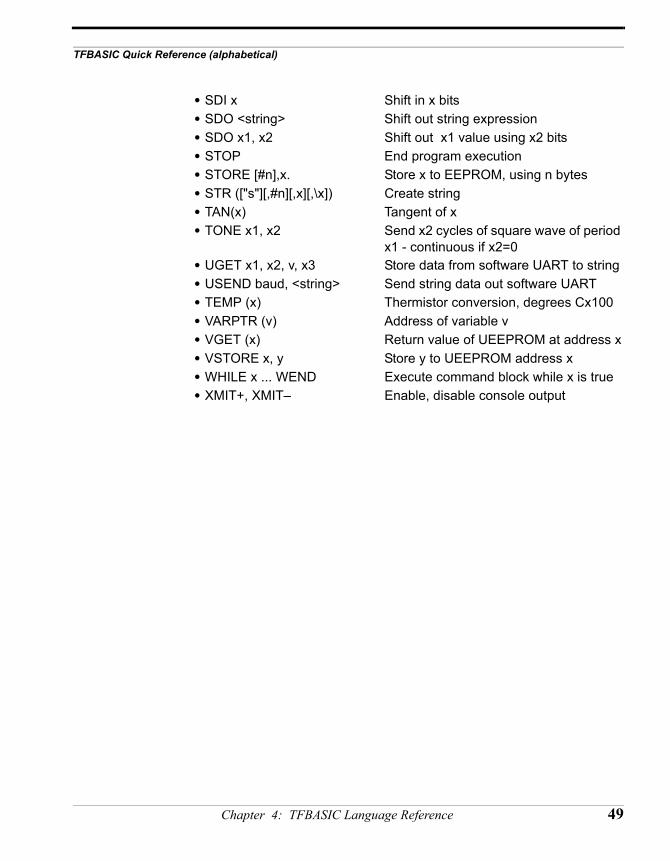
• SDI x Shift in x bits• SDO <string> Shift out string expression• SDO x1, x2 Shift out x1 value using x2 bits• STOP End program execution• STORE [#n],x. Store x to EEPROM, using n bytes• STR (["s"][,#n][,x][,\x]) Create string • TAN(x) Tangent of x• TONE x1, x2 Send x2 cycles of square wave of period
x1 - continuous if x2=0• UGET x1, x2, v, x3 Store data from software UART to string• USEND baud, <string> Send string data out software UART• TEMP (x) Thermistor conversion, degrees Cx100 • VARPTR (v) Address of variable v • VGET (x) Return value of UEEPROM at address x• VSTORE x, y Store y to UEEPROM address x• WHILE x ... WEND Execute command block while x is true• XMIT+, XMIT– Enable, disable console output
Chapter 4: TFBASIC Language Reference 49
TFBASIC Language Reference for the TFX-11
Arithmetic,Relational, and
LogicalOperators:
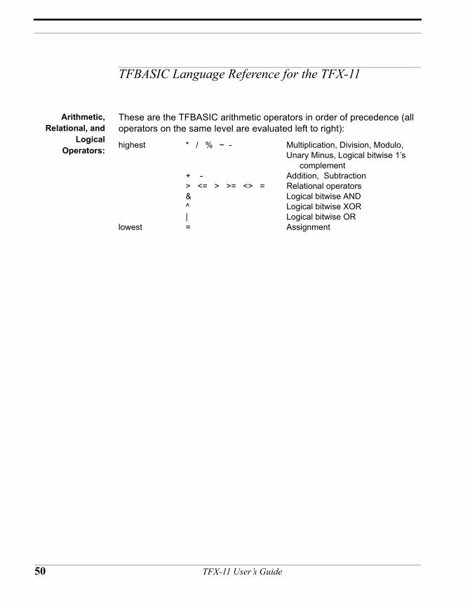
These are the TFBASIC arithmetic operators in order of precedence (all operators on the same level are evaluated left to right):
highest * / % ~ - Multiplication, Division, Modulo, Unary Minus, Logical bitwise 1’s complement
+ - Addition, Subtraction> <= > >= <> = Relational operators& Logical bitwise AND^ Logical bitwise XOR| Logical bitwise OR
lowest = Assignment
50 TFX-11 User’s Guide
TFBASIC Language Reference for the TFX-11
ABS absolute value
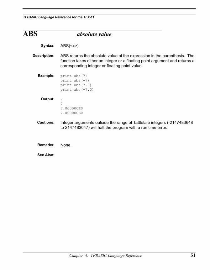
Syntax: ABS(<x>)
Description: ABS returns the absolute value of the expression in the parenthesis. The function takes either an integer or a floating point argument and returns a corresponding integer or floating point value.
Example: print abs(7)print abs(-7)print abs(7.0)print abs(-7.0)
Output: 777.000000E07.000000E0
Cautions: Integer arguments outside the range of Tattletale integers (-2147483648 to 2147483647) will halt the program with a run time error.
Remarks: None.
See Also:
Chapter 4: TFBASIC Language Reference 51
AINT round float down to integer
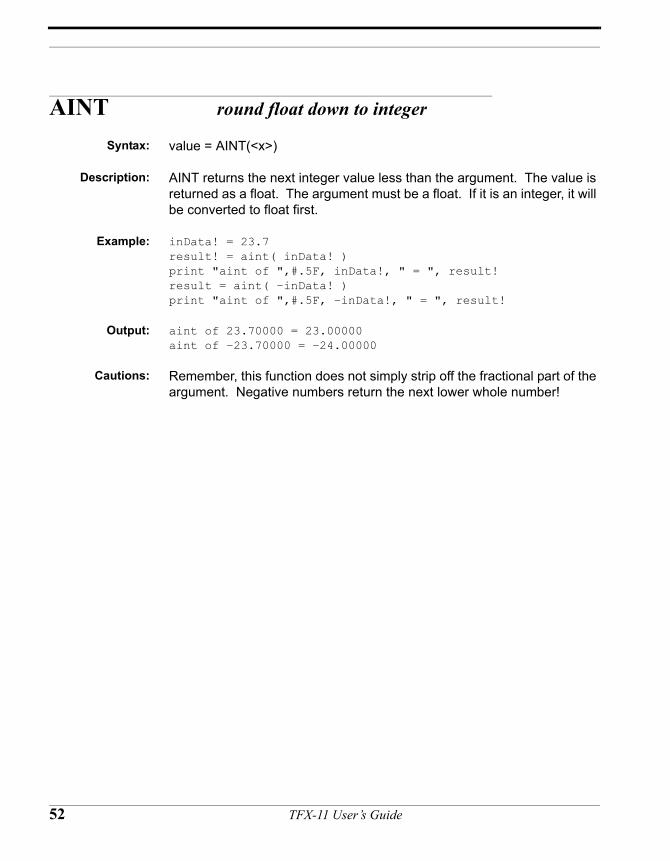
Syntax: value = AINT(<x>)
Description: AINT returns the next integer value less than the argument. The value is returned as a float. The argument must be a float. If it is an integer, it will be converted to float first.
Example: inData! = 23.7result! = aint( inData! )print "aint of ",#.5F, inData!, " = ", result!result = aint( –inData! )print "aint of ",#.5F, –inData!, " = ", result!
Output: aint of 23.70000 = 23.00000aint of –23.70000 = –24.00000
Cautions: Remember, this function does not simply strip off the fractional part of the argument. Negative numbers return the next lower whole number!
52 TFX-11 User’s Guide
TFBASIC Language Reference for the TFX-11
ASC Returns the ASCII value of the first character of the string
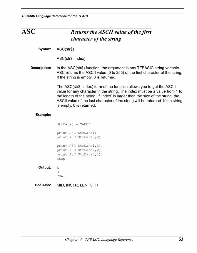
Syntax: ASC(str$)
ASC(str$, index)
Description: In the ASC(str$) function, the argument is any TFBASIC string variable. ASC returns the ASCII value (0 to 255) of the first character of the string. If the string is empty, 0 is returned.
The ASC(str$, index) form of the function allows you to get the ASCII value for any character in the string. The index must be a value from 1 to the length of the string. If ‘index’ is larger than the size of the string, the ASCII value of the last character of the string will be returned. If the string is empty, 0 is returned.
Example:
StrData$ = "ABC"
print ASC(StrData$) print ASC(StrData$,2)
print ASC(StrData$,3);print ASC(StrData$,2);print ASC(StrData$,1)stop
Output: ABCBA
See Also: MID, INSTR, LEN, CHR
Chapter 4: TFBASIC Language Reference 53
ASFLT interpret argument as float
Syntax: ASFLT(<x>)
Description: Integer and float variables both take up four bytes of storage. There is nothing in the storage format that allows the two to be distinguished from each other. Therefore all variables are assumed to be integer unless otherwise designated. ASFLT is used to tell TFBASIC to interpret data retrieved from storage as a floating point value.
Example: FltVal! = 100.0 // create floating point valuevstore 10, FltVal! // store it in UEEPROM@(0) = 2.0*FltVal! // store another value in
// bank-switched RAMprint vget(10) // retrieve and print as integer
// (default)print @(0) // Print bank-switched RAM as
// integerprint #1F, asflt(vget(10)) // retrieve and print as floatprint #1F, asflt(@(0)) // retrieve and print as floatstop
Output: 11204034561120403456100.00100.00
Cautions: This function does not convert the data - it only tells TFBASIC how to interpret it correctly, assuming it was stored as a floating point value.
Remarks: None.
See Also: VGET
54 TFX-11 User’s Guide
TFBASIC Language Reference for the TFX-11
ASM assemble to memory
Syntax: ASM $ or ASM <address>
<code>
...
...
END
Description: Assembly language can be written directly using ASM. HC11 instructions, with some limitations (see the TFBASIC Assembly Language reference for details), are supported in all addressing modes. Assembly starts when it encounters the ASM command and stops when it encounters the END command. This assembler allows the use of named labels and it can access TFBASIC variables by name.
If the optional <address> is included, the code is assembled starting at the specified address. If <address> is replaced with the $ character, assembly is done in line and automatically called when reached.
Labels: Labels can be used in the assembly code for flow control and to define local variables. Labels MUST start in the first column. Labels can be up to 32 characters long and must begin with a letter or an underscore (_). The only valid characters in a label are upper and lower case characters, the numbers and underscore. The label name can be terminated with a colon (when the label is defined) but this is not necessary in the assembler. These labels will not be accessible to TFBASIC except through the CALL command and TFBASIC labels are not accessible to the assembly code (although TFBASIC variables are).
Opcodes: The TFBASIC assembler recognizes most of the opcodes defined in the Motorola literature. See the section "TFBASIC Assembly Language" for details. Opcodes must have at least one character of whitespace (space character or tab) in front of them on the line OR a label terminated with a colon.
Inline assemblycode (ASM $)
This version allows you to install assembly language code that will be executed in line with the TFBASIC code and has the form:
<TFBASIC code>
Chapter 4: TFBASIC Language Reference 55
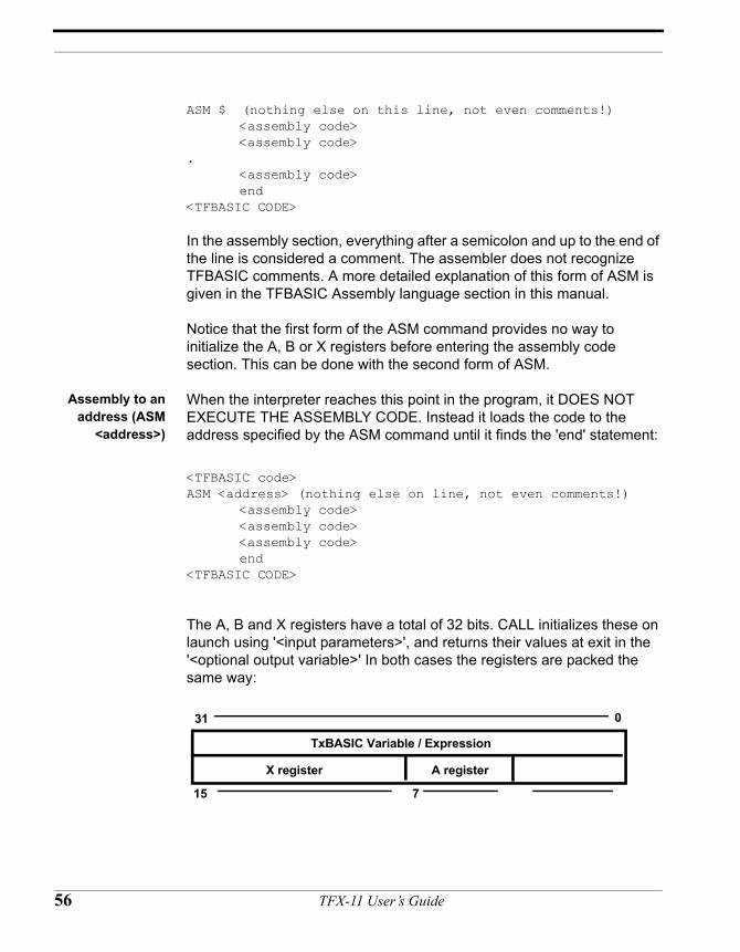
ASM $ (nothing else on this line, not even comments!)<assembly code><assembly code>
.<assembly code>end
<TFBASIC CODE>
In the assembly section, everything after a semicolon and up to the end of the line is considered a comment. The assembler does not recognize TFBASIC comments. A more detailed explanation of this form of ASM is given in the TFBASIC Assembly language section in this manual.
Notice that the first form of the ASM command provides no way to initialize the A, B or X registers before entering the assembly code section. This can be done with the second form of ASM.
Assembly to anaddress (ASM
<address>)
When the interpreter reaches this point in the program, it DOES NOT EXECUTE THE ASSEMBLY CODE. Instead it loads the code to the address specified by the ASM command until it finds the 'end' statement:
<TFBASIC code>ASM <address> (nothing else on line, not even comments!)
<assembly code><assembly code><assembly code>end
<TFBASIC CODE>
The A, B and X registers have a total of 32 bits. CALL initializes these on launch using '<input parameters>', and returns their values at exit in the '<optional output variable>' In both cases the registers are packed the same way:
TxBASIC Variable / Expression
X register A register
31 0
15 7
56 TFX-11 User’s Guide
TFBASIC Language Reference for the TFX-11
The assembler automatically appends an RTS to the end of your code. If your assembly routine is launched by an interrupt you should end your code with an RTI. The assembler will append an RTS to this but it will not be executed.
A more detailed explanation of this form of ASM is given in the TFBASIC Assembly language section earlier in the manual.
Radix: Assembly code allows more methods of defining the number base of constants. You have these options IN THE ASSEMBLER ONLY in defining a constant 19 decimal as:
• hexadecimal: 13H or &H13 or H'13 or $13 notice &H works as in TFBASIC
• octal: 23O or 23Q or Q'23 or @23• binary: 10011B or B'10011 or %10011• decimal: 19 or 19D or D'19 - decimal is the default number base
Remarks: Define and call functions by name
Make sure in-line code is not executed by mistake
See Also: CALL and the "TFBASIC Assembly Language" manual section.
Chapter 4: TFBASIC Language Reference 57
ATN arctangent
Syntax: value = ATN( <x>)
Description: ATN returns the angle (in degrees!) of the expression in the parenthesis. The function takes a floating point argument and returns a floating point value. An integer argument will be converted to float first.
Example: tangnt! = 1.0 degrees! = 0.0
degrees! = atn(tangnt!)print “The arctangent of “, #7.1F, tangnt!,“ is “,#6.3F,degrees
Output: The arctangent of 1.0 is 45.000
Remarks: If the argument is +inf the result is 90.0
If the argument is -inf the result is -90.0
Cautions: DON’T FORGET! The result is in degrees, not radians.
See Also: COS, SIN, TAN
58 TFX-11 User’s Guide
TFBASIC Language Reference for the TFX-11
BAUDSET Set the baud rate of the main UART
Syntax: Baudset (x)
Description: Sets the send and receive baud rate of the main UART to the selected baud where x = baud. Baud is one of these: 300, 600, 1200, 2400, 4800, 9600, 19200, or 38400
Remarks: The default baud rate on reset is always initialized to19200.
Cautions: DON’T FORGET! Changing the baud rate on the TFX-11 will NOT automatically change the baud rate of TFTools. If the baud is set incorrectly, CTRL-C will no longer work to break the program.
See Also: BAUDGET
Chapter 4: TFBASIC Language Reference 59
BAUDGET Get the baud rate of the main UART
Syntax: value = BAUDGET
Description: Baudget returns the value of the current baud rate of the main UART. The function returns an integer. Value is one of the following bauds: 300, 600, 1200, 2400, 4800, 9600, 19200, or 38400
Remarks: The default baud rate on reset is always initialized to 19200.
Cautions: None
See Also: BAUDSET
60 TFX-11 User’s Guide
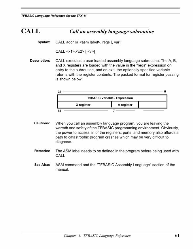
TFBASIC Language Reference for the TFX-11
CALL Call an assembly language subroutine
Syntax: CALL addr or <asm label>, regs [, var]
CALL <x1>,<x2> [,<v>]
Description: CALL executes a user loaded assembly language subroutine. The A, B, and X registers are loaded with the value in the "regs" expression on entry to the subroutine, and on exit, the optionally specified variable returns with the register contents. The packed format for register passing is shown below:
Cautions: When you call an assembly language program, you are leaving the warmth and safety of the TFBASIC programming environment. Obviously, the power to access all of the registers, ports, and memory also affords a path to catastrophic program crashes which may be very difficult to diagnose.
Remarks: The ASM label needs to be defined in the program before being used with CALL
See Also: ASM command and the "TFBASIC Assembly Language" section of the manual.
TxBASIC Variable / Expression
X register A register
31 0
15 7
Chapter 4: TFBASIC Language Reference 61
CBREAK go to label on CTRL-C
Syntax: CBREAK [label]
Description: This command allows you to redirect the flow of your program when it receives a Ctrl-C character. Normally, the program terminates and returns to the monitor. If you use the CBREAK command (followed by a label name) at the beginning of your program, it will vector to the label when it receives a Ctrl-C character. To return to the normal Ctrl-C action, use CBREAK with no argument.
Example:(indentation for
clarity only)
CBREAK getdata // goto 'getdata' when Ctrl-C hit
sleep 0savedata:
for icount = 1 to 2000 // collect 2000 data pts store #2,chan(1) sleep 5 next icount
goto savedata // reset datafile pointer to startgetdata:
print "ready to off-load"stop
This code fragment shows one use for CBREAK. When a Ctrl-C character is received, the program will vector to the code at label 'getdata' and be at the # prompt awaiting the command for an XMODEM off-load.
Remarks: The Ctrl-C handler may be changed any number of times by executing CBREAK with different arguments.
As with ONERR , CBREAK must be executed to be effective. For this reason, you should put CBREAK near the beginning of the program.
Disable CTRL-C breaks by writing a zero byte to address 9C hex (POKE H’9C,0). Beware: Some other way of stopping program should be considered or the parallel port connection is the only way to stop it. Re-enable breaks by writing a non-zero byte (POKE H’9C,1). A count of CTRL-C characters will continue to be updated at address 9B hex. To clear this before you re-enable break-outs use (POKE H’9B,0).
62 TFX-11 User’s Guide
TFBASIC Language Reference for the TFX-11
Cautions: Do not vector CBREAK to a label inside a subroutine. When a CTRL-C is detected the program will act as if you did a GOTO into the subroutine. It will not have a proper return address on the stack and operation will be unpredictable.
Chapter 4: TFBASIC Language Reference 63
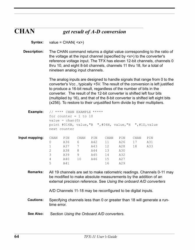
CHAN get result of A-D conversion
Syntax: value = CHAN( <x>)
Description: The CHAN command returns a digital value corresponding to the ratio of the voltage at the input channel (specified by <x>) to the converter's reference voltage input. The TFX has eleven 12-bit channels, channels 0 thru 10, and eight 8-bit channels, channels 11 thru 18, for a total of nineteen analog input channels.
The analog inputs are designed to handle signals that range from 0 to the converter's Vcc , typically +5V. The result of the conversion is left justified to produce a 16-bit result, regardless of the number of bits in the converter. The result of the 12-bit converter is shifted left four bits (multiplied by 16), and that of the 8-bit converter is shifted left eight bits (x256). To restore to their unjustified form divide by their multipliers.
Example: // **** CHAN EXAMPLE *****for counter = 1 to 10value = chan(0)print #016B, value,"B ",#04H, value,"H ",#1D,valuenext counter
Input mapping: CHAN PIN CHAN PIN CHAN PIN CHAN PIN0 A36 6 A42 11 A26 17 A311 A37 7 A43 12 A28 18 A332 A38 8 A44 13 A303 A39 9 A45 14 A324 A40 10 A46 15 A275 A41 16 A29
Remarks: All 19 channels are set to make ratiometric readings. Channels 0-11 may be modified to make absolute measurements by the addition of an external precision reference. See Using the onboard A/D converters
A/D Channels 11-18 may be reconfigured to be digital inputs.
Cautions: Specifying channels less than 0 or greater than 18 will generate a run-time error.
See Also: Section Using the Onboard A/D converters.
64 TFX-11 User’s Guide
TFBASIC Language Reference for the TFX-11
CHR Returns a one-character string of the ASCII value of an integer
Syntax: CHR(x)
Description: This function returns a one-character string comprised of the ASCII value of the argument. This argument must be an integer and must be a value from 0 to 255.
Example: For instance, since the ASCII values of the letters A, B, and C are 41 hex, 42 hex, and 43 hex, we could execute this code:
string$ = chr(&41) + chr(&h42) + chr(&h43)print string$
and the string “ABC” should print. This function is also useful in getting data from the datafile that you know is a string, but doesn’t have a length byte at the beginning. For instance, the INPUT command defaults to storing a carriage return at the end of a typed string. We could STORE this string without a length byte using the #$ option (see explanation above) and then read it back with GET and CHR:
input "Enter a string: "string$savedfp = dfpntstore #$, string$newstring$ = ““x= savedfploop:
i = get(x,#1)if i = &h0D goto donenewstring = newstring + chr(i)goto loop
done:print newstring$
Output: (Will echo back the string that you originally entered)
Remarks:
See Also: ASC, MID, INSTR, LEN
Chapter 4: TFBASIC Language Reference 65
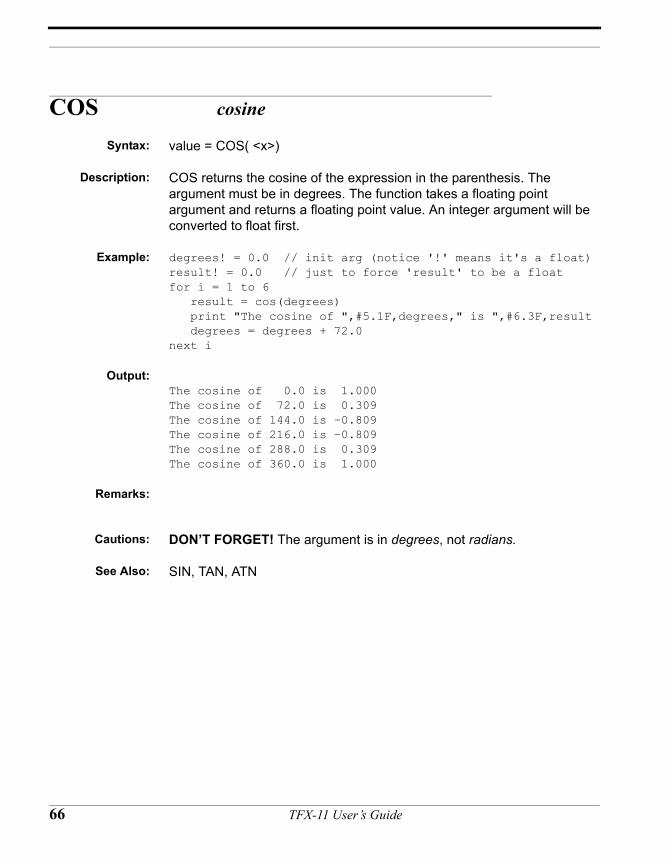
COS cosine
Syntax: value = COS( <x>)
Description: COS returns the cosine of the expression in the parenthesis. The argument must be in degrees. The function takes a floating point argument and returns a floating point value. An integer argument will be converted to float first.
Example: degrees! = 0.0 // init arg (notice '!' means it's a float)result! = 0.0 // just to force 'result' to be a floatfor i = 1 to 6 result = cos(degrees) print "The cosine of ",#5.1F,degrees," is ",#6.3F,result degrees = degrees + 72.0next i
Output:The cosine of 0.0 is 1.000The cosine of 72.0 is 0.309The cosine of 144.0 is –0.809The cosine of 216.0 is –0.809The cosine of 288.0 is 0.309The cosine of 360.0 is 1.000
Remarks:
Cautions: DON’T FORGET! The argument is in degrees, not radians.
See Also: SIN, TAN, ATN
66 TFX-11 User’s Guide
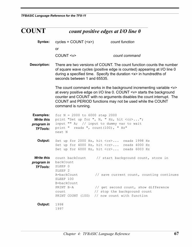
TFBASIC Language Reference for the TFX-11
COUNT count positive edges at I/O line 0
Syntax: cycles = COUNT (<x>) count function
or
COUNT <v> count command
Description: There are two versions of COUNT. The count function counts the number of square wave cycles (positive edge is counted) appearing at I/O line 0 during a specified time. Specify the duration <x> in hundredths of seconds between 1 and 65535.
The count command works in the background incrementing variable <v> at every positive edge on I/O line 0. COUNT <v> starts the background counter and COUNT with no arguments disables the count interrupt. The COUNT and PERIOD functions may not be used while the COUNT command is running.
Examples:Write this
program inTFTools:
for N = 2000 to 6000 step 2000print "Set up for ", N, " Hz, hit <cr>...";input "" A; // input to dummy var to waitprint " reads ", count(100), " Hz"next N
Output: Set up for 2000 Hz, hit <cr>... reads 1998 HzSet up for 4000 Hz, hit <cr>... reads 4000 HzSet up for 6000 Hz, hit <cr>... reads 6003 Hz
Write thisprogram in
TFTools:
count backCount // start background count, store in backCountSLEEP 0SLEEP 2A=backCount // save current count, counting continuesSLEEP 100B=backCountPRINT B–A // get second count, show differencecount // stop the background countPRINT COUNT (100) // now count with function
Output: 19981997
Chapter 4: TFBASIC Language Reference 67
Remarks: Triggering off the positive edge. In the same amount of time, the PERIOD function will return a more accurate timing measurement. COUNT has two advantages:
• It can be simpler to use.• The number of transitions in 'duration' can be unknown.
Note about 5 channel count example.
Cautions: The maximum input frequency is about 30KHz. Rates higher than that may return erroneous results. Durations greater than 65535 or less than 0 will generate run-time errors.
See Also: PERIOD.
68 TFX-11 User’s Guide
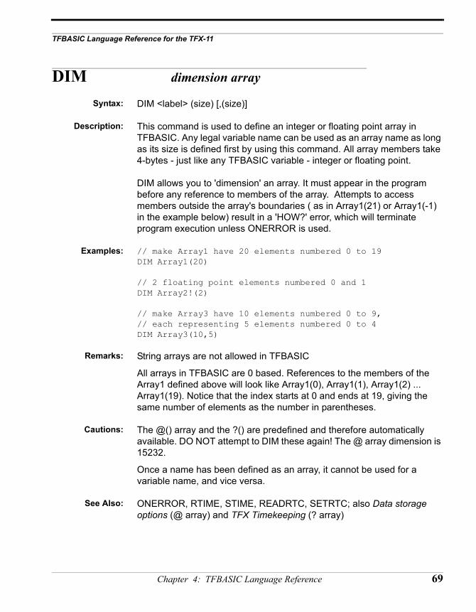
TFBASIC Language Reference for the TFX-11
DIM dimension array
Syntax: DIM <label> (size) [,(size)]
Description: This command is used to define an integer or floating point array in TFBASIC. Any legal variable name can be used as an array name as long as its size is defined first by using this command. All array members take 4-bytes - just like any TFBASIC variable - integer or floating point.
DIM allows you to 'dimension' an array. It must appear in the program before any reference to members of the array. Attempts to access members outside the array's boundaries ( as in Array1(21) or Array1(-1) in the example below) result in a 'HOW?' error, which will terminate program execution unless ONERROR is used.
Examples: // make Array1 have 20 elements numbered 0 to 19DIM Array1(20)
// 2 floating point elements numbered 0 and 1DIM Array2!(2)
// make Array3 have 10 elements numbered 0 to 9, // each representing 5 elements numbered 0 to 4DIM Array3(10,5)
Remarks: String arrays are not allowed in TFBASIC
All arrays in TFBASIC are 0 based. References to the members of the Array1 defined above will look like Array1(0), Array1(1), Array1(2) ... Array1(19). Notice that the index starts at 0 and ends at 19, giving the same number of elements as the number in parentheses.
Cautions: The @() array and the ?() are predefined and therefore automatically available. DO NOT attempt to DIM these again! The @ array dimension is 15232.
Once a name has been defined as an array, it cannot be used for a variable name, and vice versa.
See Also: ONERROR, RTIME, STIME, READRTC, SETRTC; also Data storage options (@ array) and TFX Timekeeping (? array)
Chapter 4: TFBASIC Language Reference 69
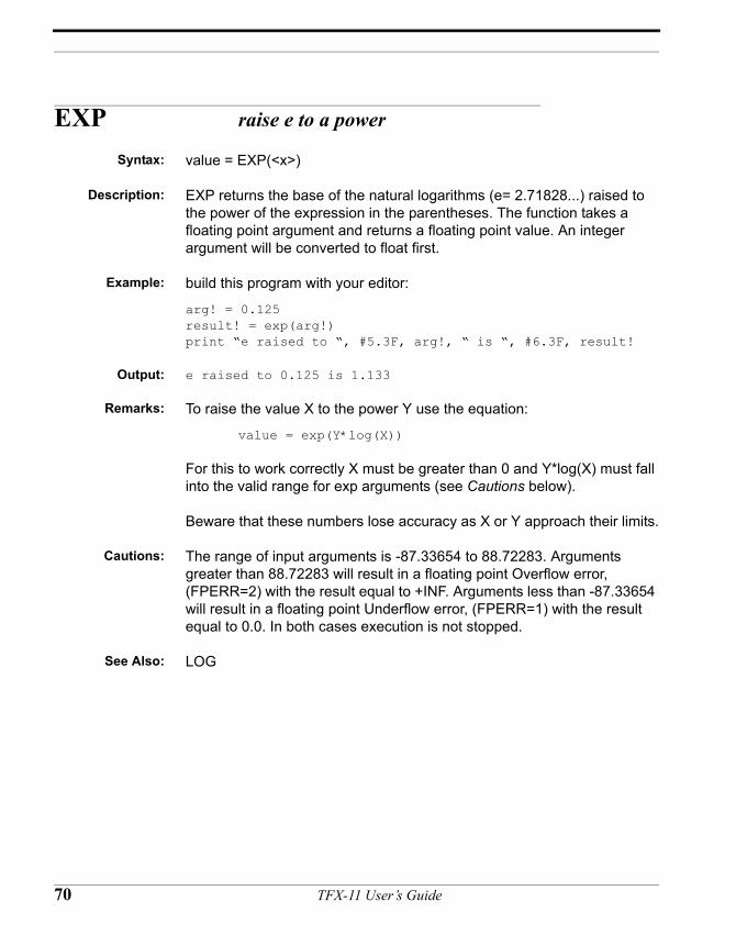
EXP raise e to a power
Syntax: value = EXP(<x>)
Description: EXP returns the base of the natural logarithms (e= 2.71828...) raised to the power of the expression in the parentheses. The function takes a floating point argument and returns a floating point value. An integer argument will be converted to float first.
Example: build this program with your editor:
arg! = 0.125result! = exp(arg!)print “e raised to “, #5.3F, arg!, “ is “, #6.3F, result!
Output: e raised to 0.125 is 1.133
Remarks: To raise the value X to the power Y use the equation:
value = exp(Y*log(X))
For this to work correctly X must be greater than 0 and Y*log(X) must fall into the valid range for exp arguments (see Cautions below).
Beware that these numbers lose accuracy as X or Y approach their limits.
Cautions: The range of input arguments is -87.33654 to 88.72283. Arguments greater than 88.72283 will result in a floating point Overflow error, (FPERR=2) with the result equal to +INF. Arguments less than -87.33654 will result in a floating point Underflow error, (FPERR=1) with the result equal to 0.0. In both cases execution is not stopped.
See Also: LOG
70 TFX-11 User’s Guide
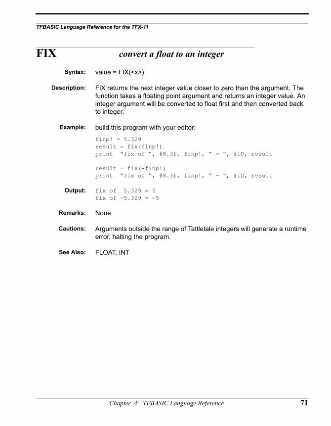
TFBASIC Language Reference for the TFX-11
FIX convert a float to an integer
Syntax: value = FIX(<x>)
Description: FIX returns the next integer value closer to zero than the argument. The function takes a floating point argument and returns an integer value. An integer argument will be converted to float first and then converted back to integer.
Example: build this program with your editor:
finp! = 5.329result = fix(finp!)print “fix of “, #8.3f, finp!, “ = “, #1D, result
result = fix(-finp!)print “fix of “, #8.3f, finp!, “ = “, #1D, result
Output: fix of 5.329 = 5fix of -5.329 = -5
Remarks: None
Cautions: Arguments outside the range of Tattletale integers will generate a runtime error, halting the program.
See Also: FLOAT, INT
Chapter 4: TFBASIC Language Reference 71
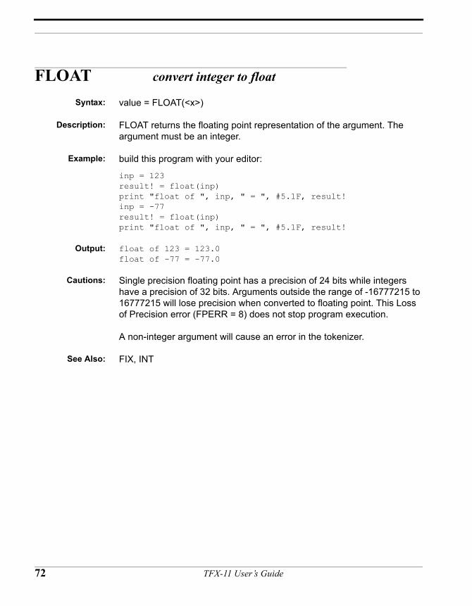
FLOAT convert integer to float
Syntax: value = FLOAT(<x>)
Description: FLOAT returns the floating point representation of the argument. The argument must be an integer.
Example: build this program with your editor:
inp = 123result! = float(inp)print "float of ", inp, " = ", #5.1F, result!inp = -77result! = float(inp)print "float of ", inp, " = ", #5.1F, result!
Output: float of 123 = 123.0float of -77 = -77.0
Cautions: Single precision floating point has a precision of 24 bits while integers have a precision of 32 bits. Arguments outside the range of -16777215 to 16777215 will lose precision when converted to floating point. This Loss of Precision error (FPERR = 8) does not stop program execution.
A non-integer argument will cause an error in the tokenizer.
See Also: FIX, INT
72 TFX-11 User’s Guide
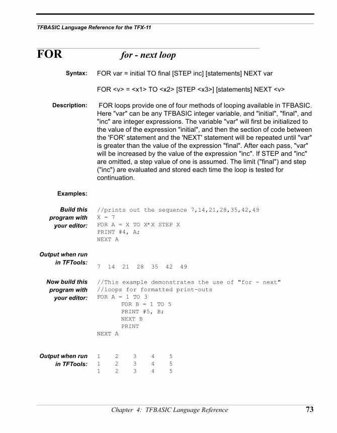
TFBASIC Language Reference for the TFX-11
FOR for - next loop
Syntax: FOR var = initial TO final [STEP inc] [statements] NEXT var
FOR <v> = <x1> TO <x2> [STEP <x3>] [statements] NEXT <v>
Description: FOR loops provide one of four methods of looping available in TFBASIC. Here "var" can be any TFBASIC integer variable, and "initial", "final", and "inc" are integer expressions. The variable "var" will first be initialized to the value of the expression "initial", and then the section of code between the 'FOR' statement and the 'NEXT' statement will be repeated until "var" is greater than the value of the expression "final". After each pass, "var" will be increased by the value of the expression "inc". If STEP and "inc" are omitted, a step value of one is assumed. The limit ("final") and step ("inc") are evaluated and stored each time the loop is tested for continuation.
Examples:
Build thisprogram with
your editor:
//prints out the sequence 7,14,21,28,35,42,49X = 7FOR A = X TO X*X STEP XPRINT #4, A;NEXT A
Output when runin TFTools:
7 14 21 28 35 42 49
Now build thisprogram with
your editor:
//This example demonstrates the use of "for - next" //loops for formatted print-outsFOR A = 1 TO 3
FOR B = 1 TO 5PRINT #5, B;NEXT BPRINT
NEXT A
Output when runin TFTools:
1 2 3 4 51 2 3 4 51 2 3 4 5
Chapter 4: TFBASIC Language Reference 73
Remarks The test for continuation occurs at the beginning of the loop and the STEP and LIMIT expressions are evaluated each time this test is done. This allows you to use a GOTO to exit the loop. Also, because this structure stores nothing on the stack, you can nest these loops as deeply as you like and a GOTO can be used to exit any number of FOR loops. Use of GOTO to exit a loop, while useful in certain circumstances, is NOT generally considered good programming practice! If you feel the need to use a GOTO to exit, chances are the whole construct could be more effectively coded using a WHILE or REPEAT.
Cautions: STEP may be positive or negative, but do not use STEP 0!
At this time, only integer variables and expressions can be used in the FOR loop specification.
See Also: WHILE, REPEAT, GOTO
74 TFX-11 User’s Guide
TFBASIC Language Reference for the TFX-11
FVAL convert string to floating point value
Syntax: FVAL(str$)
Description: FVAL takes a string representing a floating point value and converts it to its numeric floating point variable equivalent.
Examples: astr$ = “1.234e1”aflt! = FVAL(astr$)print #5.2f, aflt!
Output: 12.34
Remarks: Valid characters are 0-9, +, -, ., E, and e. If the number contains other characters it will terminate the conversion at the unrecognized character. In the case of “12.3x5” the number returned will be 12.3
If the number evaluated is out of the floating point range it will generate the appropriate FPERR but will not halt the program.
See Also: IVAL
Chapter 4: TFBASIC Language Reference 75
GET Get n-byte value from datafile
Syntax: GET(x[,#n])
Description: GET <variable> returns the value of the data in the datafile pointed to by the specified pointer variable "x". As shown in the examples below, this can be used to format readouts as well as manipulate data in the logger's memory. Formats #1, #2, and #4 are used to specify whether the data is to be read as one, two or four bytes. #1 specifies that the next 8 bits ( one byte) be read, #2 specifies that the next 16 bits( two bytes) be read, and #4 specifies that 32 bits ( four bytes) be read. The pointer variable x is updated after all the data bytes have been read. The default format of GET will read a single byte so that the #1 can be omitted in byte read commands.
Example: X = DFPNT // save current write location in datafileFOR index = 1 to 15 // put some data in the datafile STORE #1, (129+index)NEXT index
FOR A = 1 TO 5 FOR B = 1 TO 3 PRINT #4, GET(X, #1); NEXT B PRINTNEXT A
Output: The following will be displayed when you run it in TFTools:
130 131 132133 134 135136 137 138139 140 141142 143 144
Remarks: The STORE command uses the read only variable DFPNT to point to the next spot where data will be written. DFPNT is not affected by GET or GETS. Performing a GET from a location greater than DFPNT will not generate an error.
See Also: GETS
76 TFX-11 User’s Guide
TFBASIC Language Reference for the TFX-11
GETS Get string from datafile
Syntax: GET(x)
Description: Return string from datafile at address pointed to by variable x. Argument 'x' is either a constant or a variable that produces an address in the datafile from which the data is read. When a constant is used the string is always read from the same location. When a variable is used it is updated to ppoint to the next location after the end of the string. GETS assumes that the first byte is the length of the string (this is how STORE puts strings in the datafile, unless the #$ option is used in STORE). GETS returns a string that can be assigned to another string variable or used as an argument to another command.
Examples: This assumes the string was stored in with the length byte.
astring$ = "This is a test string"x = DFPNTstore, astringprint gets (x)
Output: This is a test string
Remarks: This function can be used anywhere a string variable or string constant would be used.
Cautions: GETS will not work properly on strings that have been stored using the #$ option. GETS depends on the first byte of the stored string being the length byte. The #$ does not allow the length byte to be stored in the datafile. If GETS is used and the target is not a string, it will not generate an error - it will read the first location as the number of bytes to return and then return that number of bytes as a text string. If the bytes are not in the ASCII Range 32-127, it will still try to display it as text, but most likely it will appear as garbage.
See Also: GET
Chapter 4: TFBASIC Language Reference 77
GOSUB go to subroutine, saving return address
Syntax: GOSUB label
...
...
RETURN
Description: The GOSUB and RETURN commands allow you to use subroutines in TFBASIC. The label specifier can be a line number or label. The RETURN statement signals the end of the subroutine. GOSUBs can be nested at least 20 deep.
Examples:
Build thisprogram with
your editor:(indentation for
clarity only)
'***** GOSUB EXAMPLE 1 ***** GOSUB SUB1
GOSUB SUB3 STOP
SUB1: PRINT “1st Subroutine” GOSUB SUB2 RETURNSUB2: PRINT “2nd Subroutine” RETURNSUB3: PRINT “too much excitement - PLEASE STOP!” RETURN
Program Output: 1st Subroutine2nd Subroutinetoo much excitement - PLEASE STOP!
Remarks: Never use GOTO to exit a subroutine called by GOSUB
See Also: GOTO, RETURN
78 TFX-11 User’s Guide
TFBASIC Language Reference for the TFX-11
GOTO go to label
Syntax: GOTO label
Description: GOTO causes an unconditional transfer of the program to the specified label.
Examples: // ***** GOTO EXAMPLE 1 *****// simple unconditional jump
GOTO SKIP PRINT "you won't see this"
SKIP: PRINT "you will see this" STOP
Remarks: GOTO can be used to exit any number of nested FOR, WHILE and REPEAT loops. Good programming practice avoids using GOTO. Never use GOTO to exit a subroutine called by GOSUB. Never use GOTO to jump to code that will execute a return statement.
See Also: WHILE, REPEAT, FOR, GOOD, RETURN
Chapter 4: TFBASIC Language Reference 79
HALT stop in lowest power mode
Syntax: HALT
Description: This command puts the Tattletale into its lowest power mode where it has a typical power drain of <100 µA. It is up to the user to configure all I/O and external devices into their lowest power states. The only exits from this mode are disconnecting and re-connecting the main battery, or interrupting the process by commanding a LAUNCH (restart) from the HOST via the parallel port.
Example: HALT
Remarks: None
Cautions: Before going into the dormant mode using 'HALT', all of the unused I/O lines need to be converted to inputs and asserted according to their pull-down or pull-up resistor configuration. Any hardware attached should drop into its minimum power drain state when the lines are so asserted. In order to make use of the low power HALT state you must provide termination for all of the unused input lines or set them to outputs.
See Also: HYB, SLEEP, STOP, BBPWR read-only variable
80 TFX-11 User’s Guide
TFBASIC Language Reference for the TFX-11
HYB very low power mode with wakeup
Syntax: HYB x
Description: This command puts the Tattletale into its lowest power mode where it has a typical power drain of <100 µA. The parameter is the number of seconds to remain in this state before being awakened by the supervisory alarm in the PIC. The only other exits from this mode are disconnecting and re-connecting the main battery, commanding a restart from the HOST via the parallel port, a PICINT interrupt, or a high to low transition on the IRQ line. The maximum value of the parameter is 65535 (seconds).
HYB works in a similar manner to SLEEP. The HYB timer runs from HYB wake-up to HYB wake-up. For example, if you exit a HYB at time 0 (or perform a HYB 0 ), and then execute code that takes 3 seconds to complete, and then execute another HYB with an argument of 5, you will be in the low-power HYB for only 2 seconds. Thus, you exit the second HYB when 5 seconds have elapsed since the previous HYB. As with SLEEP, you must first execute a HYB 0 to initialize the HYB clock.
There is no ‘*’ printout ( as with the SLEEP command ) if the time has already gone past. Check the oversleep byte (with PEEK(&H9E)) and if MSB is set, it did run out of time.
Example 1: HYB 0for i=1 to 12HYB 5print “Awake from HYB with ? = “,?next i
Example 2 The following example shows how to awake early from a HYB using the PICINT. It assumes a pull-up resistor has been added (a 100K resistor would work) to connect I/O Pin 16 to 5V (pin B22 on the pin-strip is one location for this). Normally, the HYB will awake every 10 seconds. If you ground I/O Pin 16, the HYB will awake early and the "Seconds =" print will reflect this.
hyb 0loop:
print "Seconds = ",?// print current timeif intstate = 0 // if PICINT disabled,
picint 1,0 // enable PICINT
Chapter 4: TFBASIC Language Reference 81
endifsleep 0 // arm SLEEP countersleep 200 // allow 2 seconds for
Ctrl-C exithyb 10 // HYB exits 10 sec after last HYBgoto loop
Remarks: In order to make use of the low power HYB state you must provide termination for all of the unused lines.To make the most of the low power capabilities of the HYB command all I/O and peripherals should be configured to their lowest power states. Unused I/O lines may be set to outputs, or set to inputs if pull-ups or pull-downs are attached. Any power switched device should be powered off.
Timekeeping. When the HC11 is in HYB its clock is shut down - when it awakens from a HYB it automatically reads the PIC time value into the ? variable.
Finding what woke the HYB.
Cautions: Care must be taken when setting a driven input to an output. If you are sure the state will not change (for example if it is connected to a pullup or pulldown resistor) during the HYB duration this is what may be done:
• Read the state of the input using PIN• Depending on the state of the pin read, use PSET or PCLR to set the
output to the correct state.
See Also: HALT, SLEEP, STOP, PICINT, INTSTATE read-only variable.
82 TFX-11 User’s Guide
TFBASIC Language Reference for the TFX-11
IF branch on result of comparison
Syntax: IF expression
...command...
[...more commands...]
[ELSE
...command...
...block 2...]
ENDIF
Alternate form(all on one line,
no ENDIFrequired)
IF expression statement [ELSE statement]
Description: IF allows you conditional control of your program. If the 'expression' is true (does not evaluate to 0), command block 1 is executed. Otherwise, if the ELSE block exists, command block 2 is executed. The ELSE block is optional but the ENDIF is not. If one of the operands of the comparison is a floating point value, the integer is treated like a float and the operands are compared as floating point values.
Examples:(indentation for
clarity only)
input Value if Value > 100 // execute block 1 if Value > 100 print "The value “,Value,” is > 100 - not allowed!"
Value = 100 //end of command block 1 else // otherwise, execute command block 2
print "The value is NOT greater than 100 - OK" endif //end of command block 2 print “Value = “,Value
Output, trial 1: 27The value 27 is NOT greater than 100 - OK" Value = 27
Output, trial 2: 127The value 127 is > 100 - not allowed!"Value = 100
Chapter 4: TFBASIC Language Reference 83
Alternate FormExamples:
if (i > 10 & i < 20) print "Value between 10 and 20"if i > 100 print "Value > 100" else print "Value <= 100"if char = 'A' gosub Acommandif char = 'B' goto Bcommandif value > 100 flag = 1 else flag = 0
Remarks: The result of a comparison using one of the relational operators is: 0 for false, and 1 for true. Do not write programs depending on this, however.
See Also: Relational Operators
84 TFX-11 User’s Guide
TFBASIC Language Reference for the TFX-11
INPUT get value from console (buffered)
Syntax: INPUT ["prompt"] var[;]
INPUT ["<s1>"] <v1> [,\x1] [,#x2] [,x3] [,!c] [;]
Description: INPUT allows you to assign a value to a variable entered through the main UART from a terminal. You can use a string (in double quotes) as a prompt. A default prompt of the variable name is used if you don't include one. If you don't want a prompting string, use a zero-length string (quotes with no intervening characters). Input will accept all variable types; integer, floating point, and string. Floating point input can be in either fixed point or scientific notation. The default terminator is a <CR>, and the default time-out is none. By default up to 255 characters can be input. As explained below, these defaults may be overridden by the optional parameters, each of which must be INTEGER expressions, except for the !c options, which are single, case-sensitive characters.
AdditionalSwitches:
\x1 Set terminating character. This byte value represents the terminating character for the input stream. The special case \~ means no terminator, useful with the [#x2] parameter (below) for binary transfers of fixed length with all values possible.
#x2 Set byte count. This expression fixes the count of characters to read as input before termination. If a specific termination character is defined it takes priority over the count. If the terminating character is present in the input stream, it will terminate input before the total count is reached.
x3 Set time-out. If present, sets a non-zero time-out in increments of 0.01 seconds. If the time between incoming characters exceeds this value then input is terminated and the program proceeds, whether or not there are terminating characters or a terminating character count set. IMPORTANT NOTE: If the value ‘0’ (zero) is specified for the time-out then INPUT checks the buffer to see if a character is available; if there is a character it returns with it, otherwise it returns immediately. Similar to the INKEY$ function in other BASICs.
!c c = E Force echoing characters
Chapter 4: TFBASIC Language Reference 85
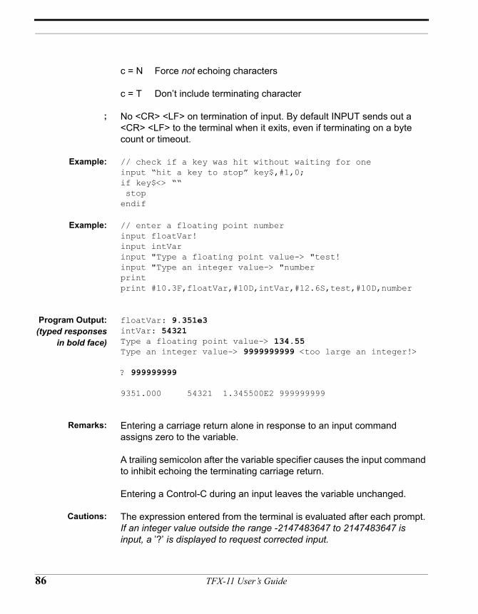
c = N Force not echoing characters
c = T Don’t include terminating character
; No <CR> <LF> on termination of input. By default INPUT sends out a <CR> <LF> to the terminal when it exits, even if terminating on a byte count or timeout.
Example: // check if a key was hit without waiting for oneinput “hit a key to stop” key$,#1,0;if key$<> ““ stopendif
Example: // enter a floating point numberinput floatVar!input intVarinput "Type a floating point value-> "test!input "Type an integer value-> "numberprintprint #10.3F,floatVar,#10D,intVar,#12.6S,test,#10D,number
Program Output:(typed responses
in bold face)
floatVar: 9.351e3intVar: 54321Type a floating point value-> 134.55Type an integer value-> 9999999999 <too large an integer!>
? 999999999
9351.000 54321 1.345500E2 999999999
Remarks: Entering a carriage return alone in response to an input command assigns zero to the variable.
A trailing semicolon after the variable specifier causes the input command to inhibit echoing the terminating carriage return.
Entering a Control-C during an input leaves the variable unchanged.
Cautions: The expression entered from the terminal is evaluated after each prompt. If an integer value outside the range -2147483647 to 2147483647 is input, a ’?’ is displayed to request corrected input.
86 TFX-11 User’s Guide
TFBASIC Language Reference for the TFX-11
A floating point input between -1.175494E-38 and +1.175494E-38 assigns zero to the variable and, if the input is not exactly zero, sets the FPERR variable to indicate an underflow error. A value of +Infinity is assigned to the variable if the input is greater than 3.402823E+38. A value of -Infinity is assigned to the variable if the input is less than -3.402823E+38. The value of FPERR will be updated to show an overflow occurred for either infinite result. If a floating point input cannot be evaluated, a '?' is displayed to request corrected input.
Leading spaces and trailing spaces for integer or floating point values will cause the INPUT command to fail. It will display a '?' to request corrected input.
See Also: PRINT
Chapter 4: TFBASIC Language Reference 87
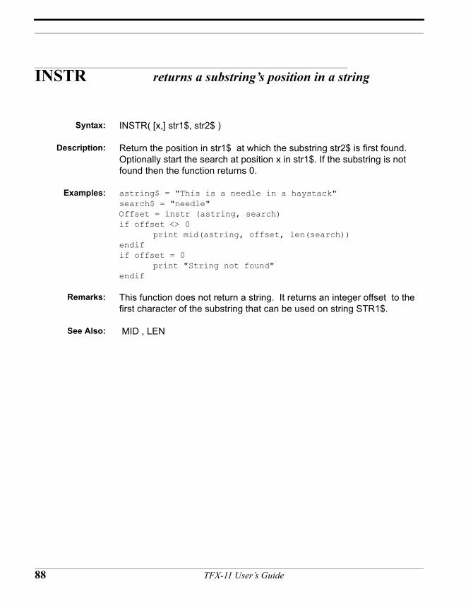
INSTR returns a substring’s position in a string
Syntax: INSTR( [x,] str1$, str2$ )
Description: Return the position in str1$ at which the substring str2$ is first found. Optionally start the search at position x in str1$. If the substring is not found then the function returns 0.
Examples: astring$ = "This is a needle in a haystack"search$ = "needle"Offset = instr (astring, search)if offset <> 0
print mid(astring, offset, len(search))endifif offset = 0
print "String not found"endif
Remarks: This function does not return a string. It returns an integer offset to the first character of the substring that can be used on string STR1$.
See Also: MID , LEN
88 TFX-11 User’s Guide
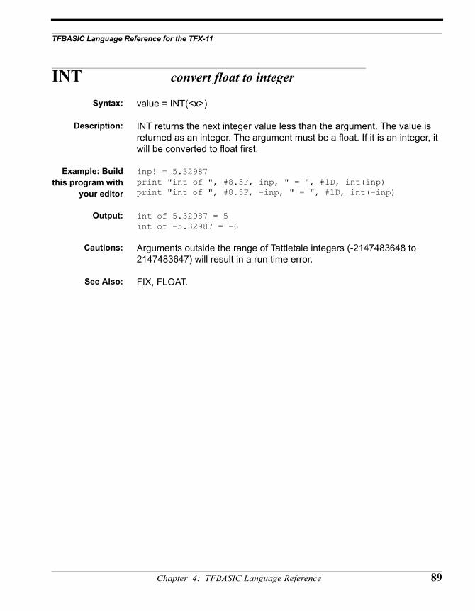
TFBASIC Language Reference for the TFX-11
INT convert float to integer
Syntax: value = INT(<x>)
Description: INT returns the next integer value less than the argument. The value is returned as an integer. The argument must be a float. If it is an integer, it will be converted to float first.
Example: Buildthis program with
your editor
inp! = 5.32987print "int of ", #8.5F, inp, " = ", #1D, int(inp)print "int of ", #8.5F, -inp, " = ", #1D, int(-inp)
Output: int of 5.32987 = 5int of -5.32987 = -6
Cautions: Arguments outside the range of Tattletale integers (-2147483648 to 2147483647) will result in a run time error.
See Also: FIX, FLOAT.
Chapter 4: TFBASIC Language Reference 89
IVAL convert numeric string to integer value
Syntax: IVAL(str$)
Description: IVAL takes a string representing an integer value and converts it to its numeric integer variable equivalent.
Examples: astr$ = “1234”anint= IVAL(astr$)print #4, anint
Output: 1234
Remarks: Valid characters are 0-9, +, -. If the number contains other characters it will terminate the conversion at the unrecognized character. In the case of “123x567” the number returned will be 123.
See Also: FVAL
90 TFX-11 User’s Guide
TFBASIC Language Reference for the TFX-11
LEN return length of string variable
Syntax: LEN(str$)
Description: LEN takes the string argument and returns an integer value representing the number of characters, including terminating characters. The Maximum length is 255 characters.
Examples: TestString = “This is string one”print “Length of string one is “, len(TestString$”) print “Length of string 2 is “, len(“this is string 2”)
Output: Length of string one is 18Length of string 2 is 16
Remarks: none.
Cautions: none.
See Also: MID, INSTR
Chapter 4: TFBASIC Language Reference 91
LOG natural logarithm
Syntax: value = LOG(<x>)
Description: LOG returns the natural logarithm of the expression in the parenthesis. The function takes a floating point argument and returns a floating point value. An integer argument will be converted to float first.
Example: build this program with your editor:
arg! = 0.125result! = log(arg!)print “Natural Log of “, #%.3F, arg!, “ is “, #6.3F, result!
output: Natural Log of 0.125 is -2.079
Remarks: Arguments less than or equal to zero will generate a Not-a-Number (NaN) floating point error (FPERR=4), but execution is not stopped.
See Also: EXP, LOG10
92 TFX-11 User’s Guide
TFBASIC Language Reference for the TFX-11
LOG10 common logarithm
Syntax: value = LOG10(<x>)
Description: LOG10 returns the common logarithm of the expression in the parenthesis. The function takes a floating point argument and returns a floating point value. An integer argument will be converted to float first.
Example: build this program with your editor:
arg! = 0.125result! = log10(arg!)print “Common Log of “, #%.3F, arg!, “ is “, #6.3F, result!
output: Common Log of 0.125 is -0.903
Remarks: Arguments less than or equal to zero will generate a Not-a-Number (NaN) floating point error (FPERR=4), but execution is not stopped.
See Also: LOG, EXP
Chapter 4: TFBASIC Language Reference 93
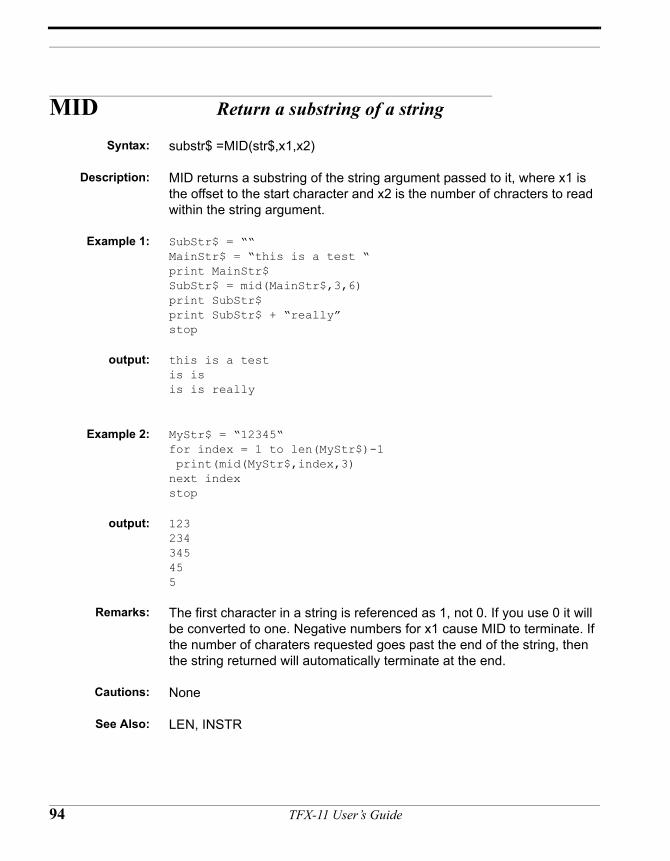
MID Return a substring of a string
Syntax: substr$ =MID(str$,x1,x2)
Description: MID returns a substring of the string argument passed to it, where x1 is the offset to the start character and x2 is the number of chracters to read within the string argument.
Example 1: SubStr$ = ““MainStr$ = “this is a test “print MainStr$SubStr$ = mid(MainStr$,3,6)print SubStr$print SubStr$ + “really”stop
output: this is a testis is is is really
Example 2: MyStr$ = “12345“for index = 1 to len(MyStr$)-1 print(mid(MyStr$,index,3)next indexstop
output: 123234345455
Remarks: The first character in a string is referenced as 1, not 0. If you use 0 it will be converted to one. Negative numbers for x1 cause MID to terminate. If the number of charaters requested goes past the end of the string, then the string returned will automatically terminate at the end.
Cautions: None
See Also: LEN, INSTR
94 TFX-11 User’s Guide
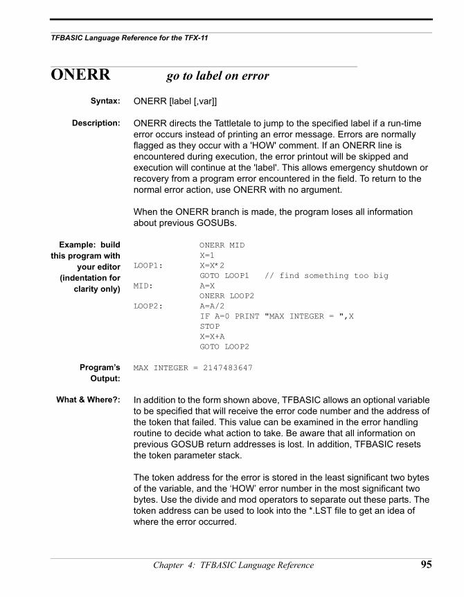
TFBASIC Language Reference for the TFX-11
ONERR go to label on error
Syntax: ONERR [label [,var]]
Description: ONERR directs the Tattletale to jump to the specified label if a run-time error occurs instead of printing an error message. Errors are normally flagged as they occur with a 'HOW' comment. If an ONERR line is encountered during execution, the error printout will be skipped and execution will continue at the 'label'. This allows emergency shutdown or recovery from a program error encountered in the field. To return to the normal error action, use ONERR with no argument.
When the ONERR branch is made, the program loses all information about previous GOSUBs.
Example: buildthis program with
your editor(indentation for
clarity only)
ONERR MID X=1LOOP1: X=X*2
GOTO LOOP1 // find something too bigMID: A=X
ONERR LOOP2LOOP2: A=A/2 IF A=0 PRINT "MAX INTEGER = ",X
STOP X=X+A
GOTO LOOP2
Program’sOutput:
MAX INTEGER = 2147483647
What & Where?: In addition to the form shown above, TFBASIC allows an optional variable to be specified that will receive the error code number and the address of the token that failed. This value can be examined in the error handling routine to decide what action to take. Be aware that all information on previous GOSUB return addresses is lost. In addition, TFBASIC resets the token parameter stack.
The token address for the error is stored in the least significant two bytes of the variable, and the ‘HOW’ error number in the most significant two bytes. Use the divide and mod operators to separate out these parts. The token address can be used to look into the *.LST file to get an idea of where the error occurred.
Chapter 4: TFBASIC Language Reference 95
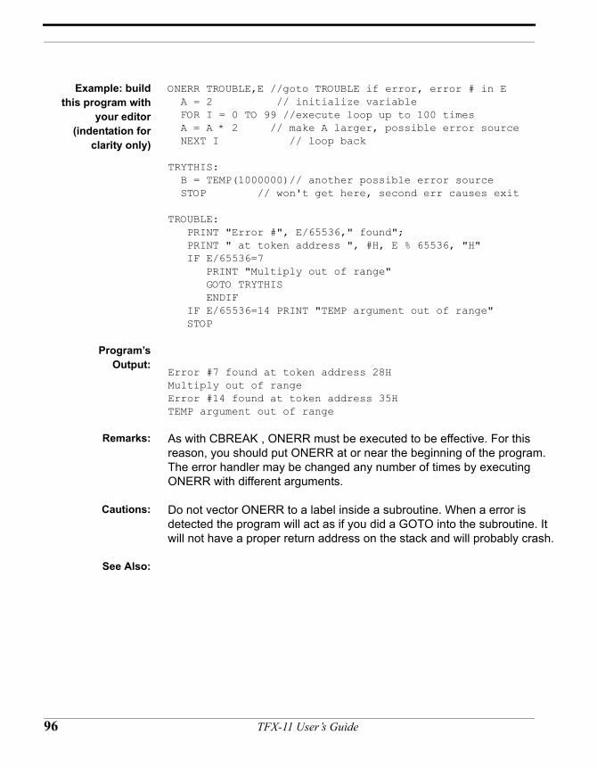
9
Example: buildthis program with
your editor(indentation for
clarity only)
ONERR TROUBLE,E //goto TROUBLE if error, error # in E A = 2 // initialize variable FOR I = 0 TO 99 //execute loop up to 100 times A = A * 2 // make A larger, possible error source NEXT I // loop back
TRYTHIS: B = TEMP(1000000)// another possible error source STOP // won't get here, second err causes exit
TROUBLE: PRINT "Error #", E/65536," found"; PRINT " at token address ", #H, E % 65536, "H" IF E/65536=7 PRINT "Multiply out of range" GOTO TRYTHIS ENDIF IF E/65536=14 PRINT "TEMP argument out of range" STOP
Program’sOutput:
Error #7 found at token address 28HMultiply out of rangeError #14 found at token address 35HTEMP argument out of range
Remarks: As with CBREAK , ONERR must be executed to be effective. For this reason, you should put ONERR at or near the beginning of the program.The error handler may be changed any number of times by executing ONERR with different arguments.
Cautions: Do not vector ONERR to a label inside a subroutine. When a error is detected the program will act as if you did a GOTO into the subroutine. It will not have a proper return address on the stack and will probably crash.
See Also:
6 TFX-11 User’s Guide
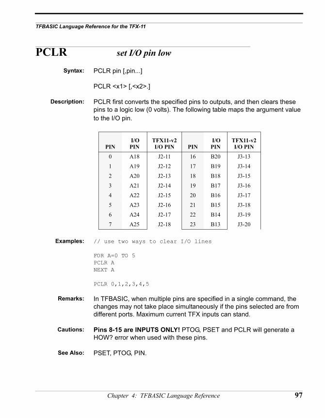
TFBASIC Language Reference for the TFX-11
PCLR set I/O pin low
Syntax: PCLR pin [,pin...]
PCLR <x1> [,<x2>.]
Description: PCLR first converts the specified pins to outputs, and then clears these pins to a logic low (0 volts). The following table maps the argument value to the I/O pin.
Examples: // use two ways to clear I/O lines
FOR A=0 TO 5PCLR ANEXT A
PCLR 0,1,2,3,4,5
Remarks: In TFBASIC, when multiple pins are specified in a single command, the changes may not take place simultaneously if the pins selected are from different ports. Maximum current TFX inputs can stand.
Cautions: Pins 8-15 are INPUTS ONLY! PTOG, PSET and PCLR will generate a HOW? error when used with these pins.
See Also: PSET, PTOG, PIN.
PIN I/O PIN
TFX11-v2I/O PIN PIN
I/O PIN
TFX11-v2I/O PIN
0 A18 J2-11 16 B20 J3-13
1 A19 J2-12 17 B19 J3-14
2 A20 J2-13 18 B18 J3-15
3 A21 J2-14 19 B17 J3-16
4 A22 J2-15 20 B16 J3-17
5 A23 J2-16 21 B15 J3-18
6 A24 J2-17 22 B14 J3-19
7 A25 J2-18 23 B13 J3-20
Chapter 4: TFBASIC Language Reference 97
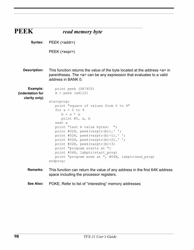
PEEK read memory byte
Syntax: PEEK (<addr>)
PEEK (<expr>)
Description: This function returns the value of the byte located at the address <a> in parentheses. The <a> can be any expression that evaluates to a valid address in BANK 0.
Example:(indentation for
clarity only)
print peek ($H74C0) A = peek (&H112)
startprog: print "square of values from 0 to 9" for a = 0 to 9 b = a * a print #5, a, b next a print "last b value bytes: "; print #02H, peek(varptr(b)),' '; print #02H, peek(varptr(b)+1),' '; print #02H, peek(varptr(b)+2),' '; print #02H, peek(varptr(b)+3) print "program starts at "; print #04H, labptr(start_prog) print "program ends at ", #04H, labptr(end_prog)endprog:
Remarks: This function can return the value of any address in the first 64K address space including the processor registers.
See Also: POKE, Refer to list of “interesting” memory addresses
98 TFX-11 User’s Guide
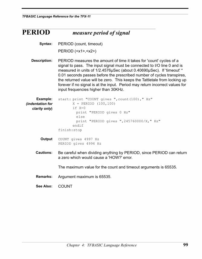
TFBASIC Language Reference for the TFX-11
PERIOD measure period of signal
Syntax: PERIOD (count, timeout)
PERIOD (<x1>,<x2>)
Description: PERIOD measures the amount of time it takes for 'count' cycles of a signal to pass. The input signal must be connected to I/O line 0 and is measured in units of 1/2.4576µSec (about 0.40690µSec). If 'timeout' * 0.01 seconds passes before the prescribed number of cycles transpires, the returned value will be zero. This keeps the Tattletale from locking up forever if no signal is at the input. Period may return incorrect values for input frequencies higher than 30KHz.
Example:(indentation for
clarity only)
start: print "COUNT gives ",count(100)," Hz"X = PERIOD (100,100)
if X=0 print "PERIOD gives 0 Hz"elseprint "PERIOD gives ",245760000/X," Hz"
endiffinish:stop
Output COUNT gives 4997 HzPERIOD gives 4996 Hz
Cautions: Be careful when dividing anything by PERIOD, since PERIOD can return a zero which would cause a 'HOW?' error.
The maximum value for the count and timeout arguments is 65535.
Remarks: Argument maximum is 65535.
See Also: COUNT
Chapter 4: TFBASIC Language Reference 99
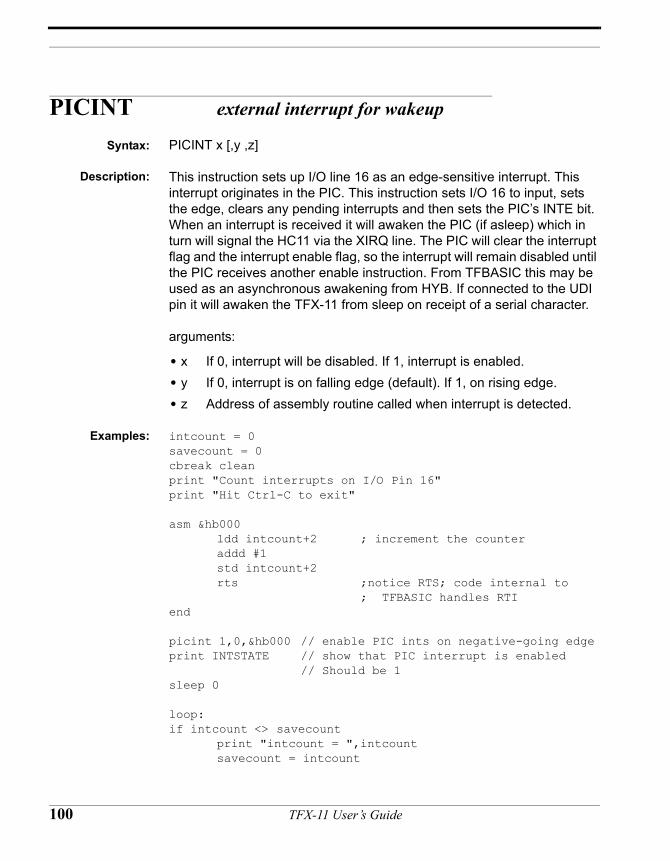
PICINT external interrupt for wakeup
Syntax: PICINT x [,y ,z]
Description: This instruction sets up I/O line 16 as an edge-sensitive interrupt. This interrupt originates in the PIC. This instruction sets I/O 16 to input, sets the edge, clears any pending interrupts and then sets the PIC’s INTE bit. When an interrupt is received it will awaken the PIC (if asleep) which in turn will signal the HC11 via the XIRQ line. The PIC will clear the interrupt flag and the interrupt enable flag, so the interrupt will remain disabled until the PIC receives another enable instruction. From TFBASIC this may be used as an asynchronous awakening from HYB. If connected to the UDI pin it will awaken the TFX-11 from sleep on receipt of a serial character.
arguments:
• x If 0, interrupt will be disabled. If 1, interrupt is enabled.• y If 0, interrupt is on falling edge (default). If 1, on rising edge.• z Address of assembly routine called when interrupt is detected.
Examples: intcount = 0savecount = 0cbreak cleanprint "Count interrupts on I/O Pin 16"print "Hit Ctrl-C to exit"
asm &hb000ldd intcount+2 ; increment the counteraddd #1std intcount+2rts ;notice RTS; code internal to
; TFBASIC handles RTIend
picint 1,0,&hb000 // enable PIC ints on negative-going edgeprint INTSTATE // show that PIC interrupt is enabled
// Should be 1sleep 0
loop:if intcount <> savecount
print "intcount = ",intcountsavecount = intcount
100 TFX-11 User’s Guide
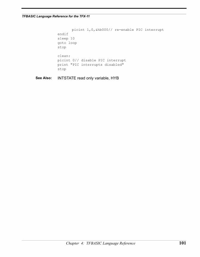
TFBASIC Language Reference for the TFX-11
picint 1,0,&hb000// re-enable PIC interruptendifsleep 10goto loopstop
clean:picint 0// disable PIC interruptprint "PIC interrupts disabled"stop
See Also: INTSTATE read only variable, HYB
Chapter 4: TFBASIC Language Reference 101
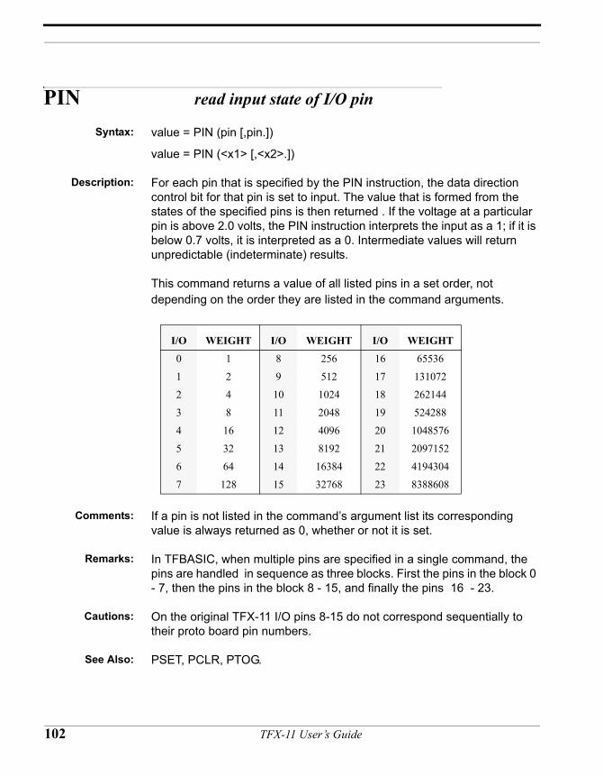
PIN read input state of I/O pin
Syntax: value = PIN (pin [,pin.])
value = PIN (<x1> [,<x2>.])
Description: For each pin that is specified by the PIN instruction, the data direction control bit for that pin is set to input. The value that is formed from the states of the specified pins is then returned . If the voltage at a particular pin is above 2.0 volts, the PIN instruction interprets the input as a 1; if it is below 0.7 volts, it is interpreted as a 0. Intermediate values will return unpredictable (indeterminate) results.
This command returns a value of all listed pins in a set order, not depending on the order they are listed in the command arguments.
Comments: If a pin is not listed in the command’s argument list its corresponding value is always returned as 0, whether or not it is set.
Remarks: In TFBASIC, when multiple pins are specified in a single command, the pins are handled in sequence as three blocks. First the pins in the block 0 - 7, then the pins in the block 8 - 15, and finally the pins 16 - 23.
Cautions: On the original TFX-11 I/O pins 8-15 do not correspond sequentially to their proto board pin numbers.
See Also: PSET, PCLR, PTOG.
I/O WEIGHT I/O WEIGHT I/O WEIGHT
0 1 8 256 16 65536
1 2 9 512 17 131072
2 4 10 1024 18 262144
3 8 11 2048 19 524288
4 16 12 4096 20 1048576
5 32 13 8192 21 2097152
6 64 14 16384 22 4194304
7 128 15 32768 23 8388608
102 TFX-11 User’s Guide
TFBASIC Language Reference for the TFX-11
POKE place byte into RAM
Syntax: POKE <addr>,<value>
POKE <expr1>,<expr2>
Description: This command stores the least significant byte of the value of the expression <expr2> at the address that results from the evaluation of the expression <expr1>.
Examples: poke &H74C0,123
b=123456789 // write 123456789 to locations
for a=&H74C3 to &H74C0 step -1 // 112H -115H, msb first poke a,b%256 b=b/256next a
Remarks: This modifies memory directly and should be used with care. Its use is restricted to the 64K bank of program memory.
See Also: PEEK, VARPTR, refer to list of interesting memory addresses
Chapter 4: TFBASIC Language Reference 103
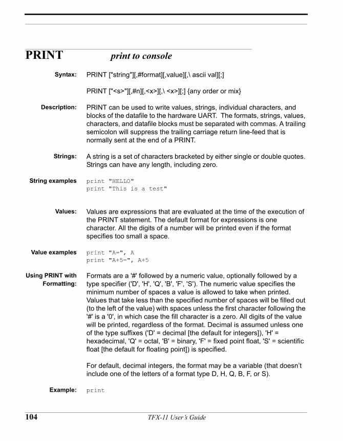
PRINT print to console
Syntax: PRINT ["string"][,#format][,value][,\ ascii val][;]
PRINT ["<s>"][,#n][,<x>][,\ <x>][;] {any order or mix}
Description: PRINT can be used to write values, strings, individual characters, and blocks of the datafile to the hardware UART. The formats, strings, values, characters, and datafile blocks must be separated with commas. A trailing semicolon will suppress the trailing carriage return line-feed that is normally sent at the end of a PRINT.
Strings: A string is a set of characters bracketed by either single or double quotes. Strings can have any length, including zero.
String examples print "HELLO"print "This is a test"
Values: Values are expressions that are evaluated at the time of the execution of the PRINT statement. The default format for expressions is one character. All the digits of a number will be printed even if the format specifies too small a space.
Value examples print "A=", A print "A+5=", A+5
Using PRINT withFormatting:
Formats are a '#' followed by a numeric value, optionally followed by a type specifier ('D', 'H', 'Q', 'B', 'F', 'S'). The numeric value specifies the minimum number of spaces a value is allowed to take when printed. Values that take less than the specified number of spaces will be filled out (to the left of the value) with spaces unless the first character following the '#' is a '0', in which case the fill character is a zero. All digits of the value will be printed, regardless of the format. Decimal is assumed unless one of the type suffixes ('D' = decimal [the default for integers]), 'H' = hexadecimal, 'Q' = octal, 'B' = binary, 'F' = fixed point float, 'S' = scientific float [the default for floating point]) is specified.
For default, decimal integers, the format may be a variable (that doesn’t include one of the letters of a format type D, H, Q, B, F, or S).
Example: print
104 TFX-11 User’s Guide
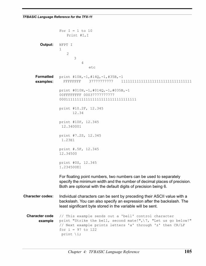
TFBASIC Language Reference for the TFX-11
For I = 1 to 10Print #I,I
Output: NFPT I1
23
4etc
Formattedexamples:
print #10H,-1,#14Q,-1,#35B,-1 FFFFFFFF 37777777777 11111111111111111111111111111111
print #010H,-1,#014Q,-1,#035B,-100FFFFFFFF 00037777777777 00011111111111111111111111111111111
print #10.2F, 12.345 12.34
print #10F, 12.345 12.340001
print #7.2S, 12.345 1.23E1
print #.5F, 12.34512.34500
print #0S, 12.3451.234500E1
For floating point numbers, two numbers can be used to separately specify the minimum width and the number of decimal places of precision. Both are optional with the default digits of precision being 6.
Character codes: Individual characters can be sent by preceding their ASCII value with a backslash. You can also specify an expression after the backslash. The least significant byte stored in the variable will be sent.
Character codeexample
// This example sends out a 'bell' control characterprint "Strike the bell, second mate!",\7, "Let us go below!"// Next example prints letters 'a' through 'z' then CR/LFfor i = 97 to 122 print \i;
Chapter 4: TFBASIC Language Reference 105
next i print
Trailingsemicolon:
A trailing semicolon causes TFBASIC to omit the CR, LF that is normally sent at the end of a print statement.
Trailingsemicolon
example:
print “this is “; // these two lines produce print “a test” // identical output
print “this is a test” // to this one line
Remarks: To send a CR without a LF at the end of a line use \13 to send the carriage return, and a semicolon to suppress the normal CR LF. This is useful for updating a value on the display without generating a new line. It will continuously write over the value on the same line.
Cautions: The PRINT command's output is buffered. All print format declarations require a numeric value between the # sign and the type specifiers.
See Also: STORE
106 TFX-11 User’s Guide
TFBASIC Language Reference for the TFX-11
PSET set I/O line high
Syntax: PSET pin [,pin, pin,...]
PSET <x1> [,<x2>.]
Description: This command sets the data direction register for the specified pins to outputs, and then sets the pins to a logic high (+5 volts).
Example Code: // example 1FOR A=0 TO 7PSET ANEXT A
// example 2PSET 0,1,2,3,4,5,6,7
Either one of these will set all of the output lines high. This is useful in an application where the I/O lines that are not used do not have pull-ups or pull-downs. Setting them to outputs keeps them from being floating inputs that can draw extra current needlessly.
Remarks: See PCLR for I/O pin mapping.
In TFBASIC, when multiple pins are specified in a single command, the pins are handled individually and in sequence as three blocks. First the pins in the block 0 - 7, then the pins in the block 8 - 15, and finally the pins in the block 16 and above.
1.6mA maximum output current ofr I/0 Pins 0-7. Pins 16-23 can source and sink up to 25mA, subject to the limitations of maximum current. See the PIC data sheet for more information.
Cautions: Pins 8-15 are INPUTS ONLY! PTOG, PSET and PCLR will generate a HOW? error when used with these pins.
See Also: PCLR, PTOG, PIN
Chapter 4: TFBASIC Language Reference 107
PTOG toggle I/O line to opposite state
Syntax: PTOG pin [,pin, pin,...]
PTOG <x1> [,<x2>.]
Description: The PTOG command sets the data direction register for the specified pins to outputs, and then changes the pins to the opposite state they held before this command was executed.
Example code: FOR A=0 TO 13PTOG 1NEXT A
This example will cause pin D1 to change state 14 times ending up in its original state.
Remarks: In TFBASIC, when multiple pins are specified in a single command, the pins are handled individually and in sequence as three blocks. First the pins in the block 0 - 7, then the pins in the block 8 - 15, and finally the pins in the block 16 and above.
Maximum source current (1.6mA) and maximum sine current(?)
Cautions: Pins 8-15 are INPUTS ONLY! PTOG, PSET and PCLR will generate a HOW? error when used with these pins.
See Also: PCLR, PSET, PIN.
108 TFX-11 User’s Guide
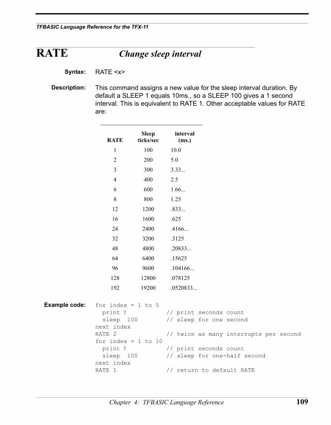
TFBASIC Language Reference for the TFX-11
RATE Change sleep interval
Syntax: RATE <x>
Description: This command assigns a new value for the sleep interval duration. By default a SLEEP 1 equals 10ms., so a SLEEP 100 gives a 1 second interval. This is equivalent to RATE 1. Other acceptable values for RATE are:
Example code: for index = 1 to 5 print ? // print seconds count sleep 100 // sleep for one secondnext indexRATE 2 // twice as many interrupts per secondfor index = 1 to 10 print ? // print seconds count sleep 100 // sleep for one-half secondnext indexRATE 1 // return to default RATE
RATESleep
ticks/secinterval
(ms.)
1 100 10.0
2 200 5.0
3 300 3.33...
4 400 2.5
6 600 1.66...
8 800 1.25
12 1200 .833...
16 1600 .625
24 2400 .4166...
32 3200 .3125
48 4800 .20833...
64 6400 .15625
96 9600 .104166...
128 12800 .078125
192 19200 .0520833...
Chapter 4: TFBASIC Language Reference 109
Remarks: ? variable timekeeping update rate is NOT affected by different RATES, but is always updated 100 times a second. Actual update time may be delayed slightly when using higher RATE values.
Cautions: Using values for RATE not in the table will cause a run time error. Using a high RATE may cause sleep overruns where there were none before. Use this command with care.
See Also: SLEEP and STPWCH example program in Chapter 5 section assembly language subroutines.
110 TFX-11 User’s Guide
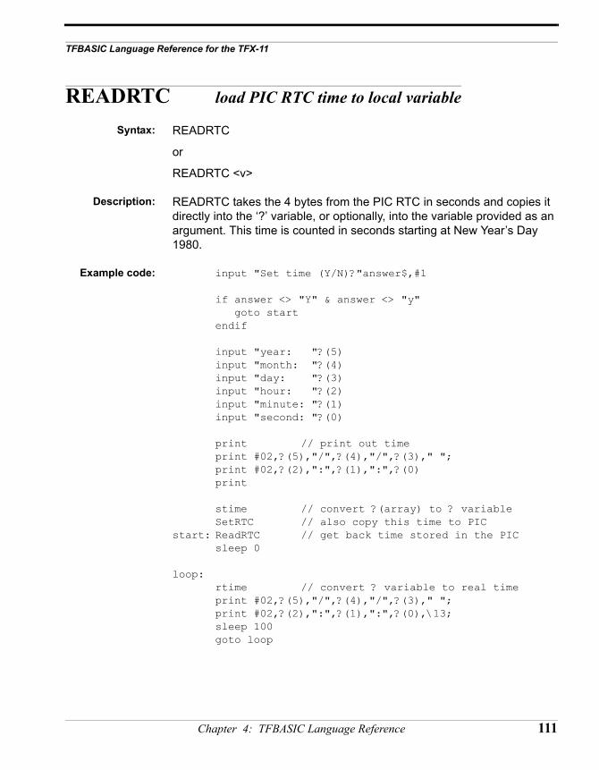
TFBASIC Language Reference for the TFX-11
READRTC load PIC RTC time to local variable
Syntax: READRTC
or
READRTC <v>
Description: READRTC takes the 4 bytes from the PIC RTC in seconds and copies it directly into the ‘?’ variable, or optionally, into the variable provided as an argument. This time is counted in seconds starting at New Year’s Day 1980.
Example code: input "Set time (Y/N)?"answer$,#1
if answer <> "Y" & answer <> "y" goto startendif
input "year: "?(5)input "month: "?(4)input "day: "?(3)input "hour: "?(2)input "minute: "?(1)input "second: "?(0)
print // print out timeprint #02,?(5),"/",?(4),"/",?(3)," ";print #02,?(2),":",?(1),":",?(0)print
stime // convert ?(array) to ? variableSetRTC // also copy this time to PIC
start: ReadRTC // get back time stored in the PICsleep 0
loop:rtime // convert ? variable to real timeprint #02,?(5),"/",?(4),"/",?(3)," ";print #02,?(2),":",?(1),":",?(0),\13;sleep 100goto loop
Chapter 4: TFBASIC Language Reference 111
Output: Set time (Y/N)?yyear: 99month: 12day: 31hour: 23minute: 59second: 45
99/12/31 23:59:45
1999/12/31 23:59:451999/12/31 23:59:461999/12/31 23:59:471999/12/31 23:59:481999/12/31 23:59:491999/12/31 23:59:501999/12/31 23:59:511999/12/31 23:59:521999/12/31 23:59:531999/12/31 23:59:541999/12/31 23:59:551999/12/31 23:59:561999/12/31 23:59:571999/12/31 23:59:581999/12/31 23:59:592000/01/01 00:00:002000/01/01 00:00:012000/01/01 00:00:022000/01/01 00:00:032000/01/01 00:00:04
^C
#
Remarks:
Cautions:
See Also: RTIME, STIME, SETRTC, and section “TFX Timekeeping”
112 TFX-11 User’s Guide
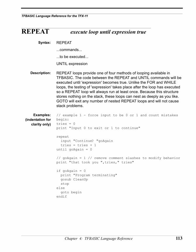
TFBASIC Language Reference for the TFX-11
REPEAT execute loop until expression true
Syntax: REPEAT
...commands...
...to be executed...
UNTIL expression
Description: REPEAT loops provide one of four methods of looping available in TFBASIC. The code between the REPEAT and UNTIL commands will be executed until 'expression' becomes true. Unlike the FOR and WHILE loops, the testing of 'expression' takes place after the loop has executed so a REPEAT loop will always run at least once. Because this structure stores nothing on the stack, these loops can nest as deeply as you like. GOTO will exit any number of nested REPEAT loops and will not cause stack problems.
Examples:(indentation for
clarity only)
// example 1 - force input to be 0 or 1 and count mistakesbegin: tries = 0print "Input 0 to exit or 1 to continue"
repeat input "Continue? "goAgain tries = tries + 1until goAgain = 0
// goAgain = 1 // remove comment slashes to modify behaviorprint "that took you ",tries," tries"
if goAgain = 0 print "Program terminating" gosub CleanUp stopelse goto beginendif
Chapter 4: TFBASIC Language Reference 113
// example 2 - force input between 0 and 100, quit on 99// count number out of range and quit after 10
repeat tries = 0 repeat input newNumber tries = tries + 1 if tries >= 10 goto give_up until newNumber < 100 & newNumber > 0 until newNumber = 99
print "99 was input. Time to stop." stop
give_up: print "Ten numbers out of range - you are finished!" stop
Remarks: None
See Also: FOR, GOTO, WHILE
114 TFX-11 User’s Guide
TFBASIC Language Reference for the TFX-11
RETURN return from subroutine
Syntax: RETURN
Description: RETURN is used with GOSUB to signal that it is time to go back to the calling routine.
Cautions: GOSUB stores the return address on the stack and RETURN uses it to know where to jump back to. If no GOSUB has placed a valid return address on the stack then executing a RETURN without a corresponding GOSUB will take whatever is on the stack and use it as the return address, most likely sending the program off into space. BE SURE that there is no path to a RETURN that is not deliberate. This type of error is usually associated with indiscriminate use of GOTOs.
See Also: GOSUB, GOTO
Chapter 4: TFBASIC Language Reference 115
RTIME Read local software real-time-clock
Syntax: RTIME
or
RTIME <v>
Description: RTIME translates the '?' variable (seconds) to the seven elements of the '?()' array. Time is counted in 1/100 ths of a second starting at New Year’s Day 1980. This command, with STIME, allows translation between the all seconds format and the year, month, day, hour, minute, second format. RTIME <v> translates the variable v, which represents seconds only (no subseconds), to the members of the ? array.
?(0) gets the second (0 to 59)
?(1) gets the minute (0 to 59)
?(2) gets the hour (0 to 23)
?(3) gets the day (1 to 31)
?(4) gets the month (1 to 12)
?(5) gets the year (1980 to 2047).
?(6) gets the number of 0.01 sec ticks (0-99).
Example code:Build this
program withyour editor
(indentation forclarity only)
sleep 0loop: rtime print "THE TIME IS ",?(2),":",?(1),":",?(0); print " on ",?(4),"/",?(3),"/",?(5) sleep 100 goto loop
Output: THE TIME IS 16:24:18 on 5/8/1996THE TIME IS 16:24:19 on 5/8/1996THE TIME IS 16:24:20 on 5/8/1996
Remarks: Dates beyond 2047 are out of range. Leap years are handled properly.
Cautions: The ? array is predefined; do not initialize with DIM!
See Also: STIME, SETRTC, READRTC, and section “TFX Timekeeping”
116 TFX-11 User’s Guide
TFBASIC Language Reference for the TFX-11
RUN Start Background Process
Syntax: RUN <label>
Description: 'RUN’ launches a background task. The background program is rigorously timed, interrupting the foreground task as needed to perform its job. <label> defines the start of the background task. Background tasks are stopped by STOP or a reset. Only one background task can be enabled at a time. Most all commands are available to the background task that are available to the foreground task (see General Guidelines for Background Tasks at the end of this chapter). When a background task is running, the SLEEP timing for the foreground is no longer rigorous (it’s easy to oversleep). So the * print is disabled for the foreground task - ONLY WHILE A BACKGROUND TASK IS RUNNING. To distinguish between SLEEP commands, the background task prints a tilde ‘~’ if it oversleeps instead of *. All variables are available to both the foreground and background tasks. Use the RUN command to launch a background task. Follow the RUN with the line number or label of the routine you want to execute in the background. For example, "RUN back1" will cause the program starting at the label "back1" to run in the background. The program starting at label "back1" must have a SLEEP or STOP somewhere to pass control back to the foreground, or the foreground task will never have a chance to run! When a background task is started with RUN, it doesn’t start immediately. A flag is set internally in TFBASIC that shows it is available to start. It waits in suspended mode until the next clock interrupt occurs (every 10msec or the rate chosen with the RATE command) which truly starts the background task.
Example: printprint "Self-terminating dual-tasking program"
bgflag = 1 // use as signal from background// that it will stop
run bgtasksleep 0while bgflag = 1 // while background running... print "FG" // show foreground presence sleep 50wend
print "Done"stop // stop foreground
Chapter 4: TFBASIC Language Reference 117
bgtask: // the background tasksleep 0print "Ready...";sleep 100print "Set...";sleep 100print "Go"bgflag = 0 // signal to foregroundstop // stop background
Cautions: Background and foreground operations can interact since the background task has priority. The following lists the commands you should not use when running a background operation and why:
Command Failure
USEND, UGET Both use software timing which is interfered with by a background task interrupting them.
TONE, PERIOD,COUNT Timing can be incorrect or input edges can be missed.
HYB Keeps the other task, either foreground or background, from executing while HYB is active.
INPUT Hangs up foreground task while waiting for characters
Do not use RETURN to end the background as it will cause a stack failure, crashing the program. Background and foreground operations can interact since the background task has priority.
See also: STOP, SLEEP, and section on General Guidelines for Background Tasks at the end of this chapter.
118 TFX-11 User’s Guide
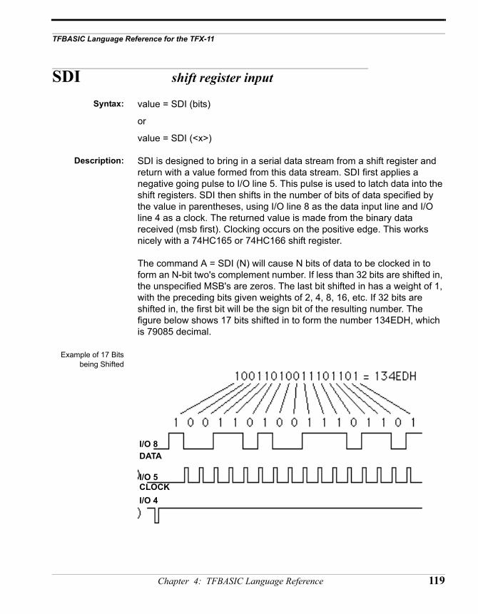
TFBASIC Language Reference for the TFX-11
SDI shift register input
Syntax: value = SDI (bits)
or
value = SDI (<x>)
Description: SDI is designed to bring in a serial data stream from a shift register and return with a value formed from this data stream. SDI first applies a negative going pulse to I/O line 5. This pulse is used to latch data into the shift registers. SDI then shifts in the number of bits of data specified by the value in parentheses, using I/O line 8 as the data input line and I/O line 4 as a clock. The returned value is made from the binary data received (msb first). Clocking occurs on the positive edge. This works nicely with a 74HC165 or 74HC166 shift register.
The command A = SDI (N) will cause N bits of data to be clocked in to form an N-bit two's complement number. If less than 32 bits are shifted in, the unspecified MSB's are zeros. The last bit shifted in has a weight of 1, with the preceding bits given weights of 2, 4, 8, 16, etc. If 32 bits are shifted in, the first bit will be the sign bit of the resulting number. The figure below shows 17 bits shifted in to form the number 134EDH, which is 79085 decimal.
Example of 17 Bitsbeing Shifted
I/O 5
I/O 8
I/O 4
DATA
CLOCK
Chapter 4: TFBASIC Language Reference 119
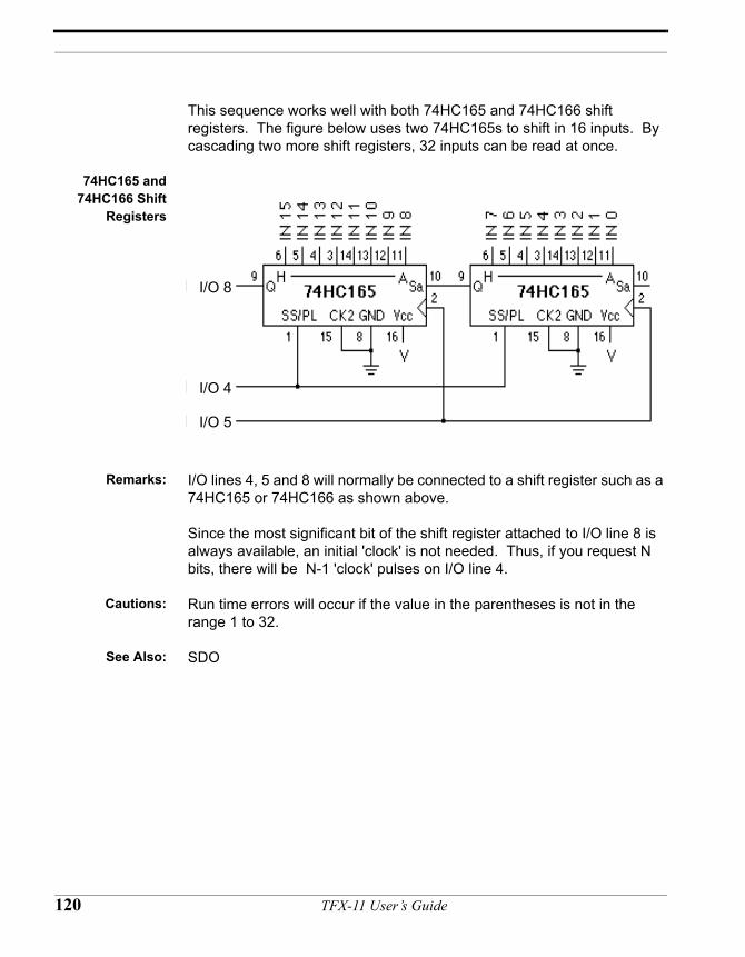
This sequence works well with both 74HC165 and 74HC166 shift registers. The figure below uses two 74HC165s to shift in 16 inputs. By cascading two more shift registers, 32 inputs can be read at once.
74HC165 and74HC166 Shift
Registers
Remarks: I/O lines 4, 5 and 8 will normally be connected to a shift register such as a 74HC165 or 74HC166 as shown above.
Since the most significant bit of the shift register attached to I/O line 8 is always available, an initial 'clock' is not needed. Thus, if you request N bits, there will be N-1 'clock' pulses on I/O line 4.
Cautions: Run time errors will occur if the value in the parentheses is not in the range 1 to 32.
See Also: SDO
I/O 8
I/O 4
I/O 5
120 TFX-11 User’s Guide
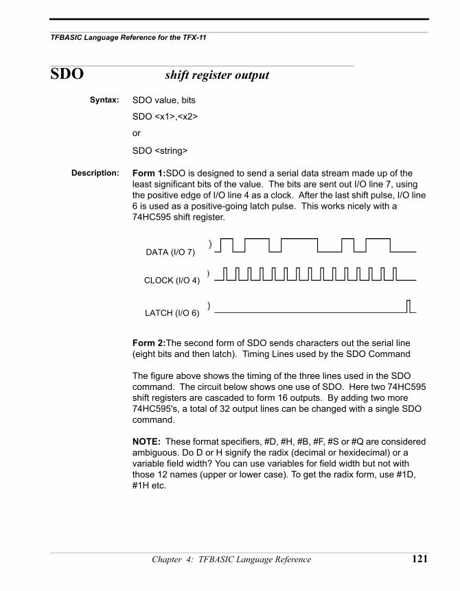
TFBASIC Language Reference for the TFX-11
SDO shift register output
Syntax: SDO value, bits
SDO <x1>,<x2>
or
SDO <string>
Description: Form 1:SDO is designed to send a serial data stream made up of the least significant bits of the value. The bits are sent out I/O line 7, using the positive edge of I/O line 4 as a clock. After the last shift pulse, I/O line 6 is used as a positive-going latch pulse. This works nicely with a 74HC595 shift register.
Form 2:The second form of SDO sends characters out the serial line (eight bits and then latch). Timing Lines used by the SDO Command
The figure above shows the timing of the three lines used in the SDO command. The circuit below shows one use of SDO. Here two 74HC595 shift registers are cascaded to form 16 outputs. By adding two more 74HC595's, a total of 32 output lines can be changed with a single SDO command.
NOTE: These format specifiers, #D, #H, #B, #F, #S or #Q are considered ambiguous. Do D or H signify the radix (decimal or hexidecimal) or a variable field width? You can use variables for field width but not with those 12 names (upper or lower case). To get the radix form, use #1D, #1H etc.
DATA (I/O 7)
CLOCK (I/O 4)
LATCH (I/O 6)
Chapter 4: TFBASIC Language Reference 121
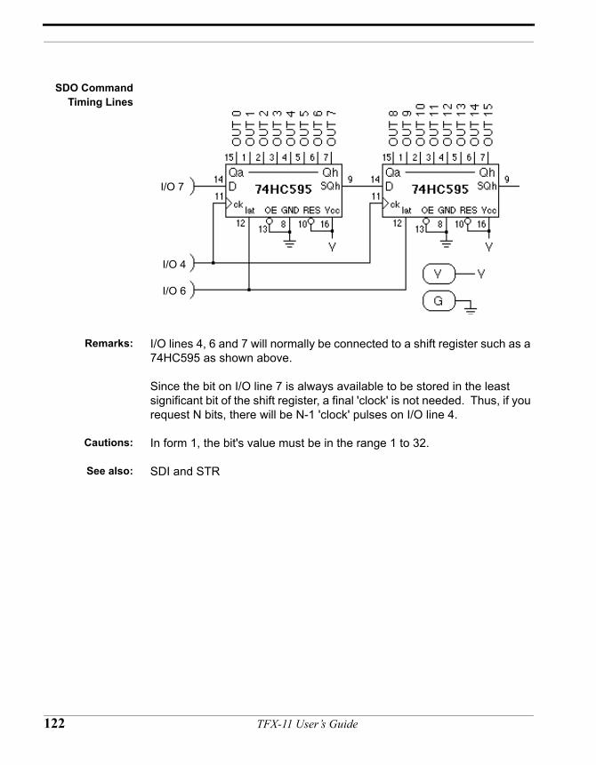
SDO CommandTiming Lines
Remarks: I/O lines 4, 6 and 7 will normally be connected to a shift register such as a 74HC595 as shown above.
Since the bit on I/O line 7 is always available to be stored in the least significant bit of the shift register, a final 'clock' is not needed. Thus, if you request N bits, there will be N-1 'clock' pulses on I/O line 4.
Cautions: In form 1, the bit's value must be in the range 1 to 32.
See also: SDI and STR
I/O 7
I/O 4
I/O 6
122 TFX-11 User’s Guide
TFBASIC Language Reference for the TFX-11
SETRTC transfer local time in seconds to PIC RTC
Syntax: SETRTC
or
SETRTC <v>
Description: SETRTC takes the four byte ‘?’ variable time in seconds and uses it to set the time in the PIC, or optionally takes the time in seconds from the variable v if present. Time is counted in seconds starting at New Year’s Day 1980.
Example code: See READRTC
See Also: RTIME, STIME, READRTC, and section “TFX Timekeeping”
Chapter 4: TFBASIC Language Reference 123
SIN Sine
Syntax: value = SIN( <x>)
Description: SIN returns the sine of the expression in the parenthesis. The argument must be in degrees. The function takes a floating point argument and returns a floating point value. An integer argument will be converted to float first degrees! = 0.0 // init arg (notice '!' means it's a float)
Example: result! = 0.0 // just to force 'result' to be a floatfor i = 1 to 6 result = sin(degrees) print "The sine of ",#5.1F,degrees," is ",#6.3F,result degrees = degrees + 72.0next i
Output: The sine of 0.0 is 0.000The sine of 72.0 is 0.951The sine of 144.0 is 0.588The sine of 216.0 is –0.588The sine of 288.0 is –0.951The sine of 360.0 is 0.000
Cautions: DON’T FORGET! The argument is in degrees, not radians.
See Also: COS, TAN, ATN
124 TFX-11 User’s Guide
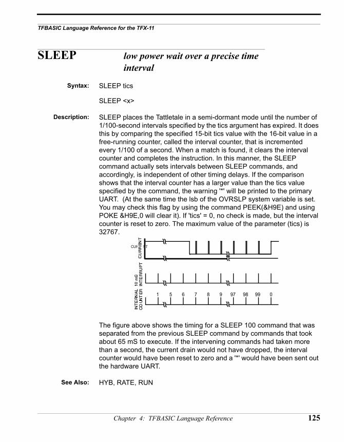
TFBASIC Language Reference for the TFX-11
SLEEP low power wait over a precise time interval
Syntax: SLEEP tics
SLEEP <x>
Description: SLEEP places the Tattletale in a semi-dormant mode until the number of 1/100-second intervals specified by the tics argument has expired. It does this by comparing the specified 15-bit tics value with the 16-bit value in a free-running counter, called the interval counter, that is incremented every 1/100 of a second. When a match is found, it clears the interval counter and completes the instruction. In this manner, the SLEEP command actually sets intervals between SLEEP commands, and accordingly, is independent of other timing delays. If the comparison shows that the interval counter has a larger value than the tics value specified by the command, the warning '*' will be printed to the primary UART. (At the same time the lsb of the OVRSLP system variable is set. You may check this flag by using the command PEEK(&H9E) and using POKE &H9E,0 will clear it). If 'tics' = 0, no check is made, but the interval counter is reset to zero. The maximum value of the parameter (tics) is 32767.
The figure above shows the timing for a SLEEP 100 command that was separated from the previous SLEEP command by commands that took about 65 mS to execute. If the intervening commands had taken more than a second, the current drain would not have dropped, the interval counter would have been reset to zero and a '*' would have been sent out the hardware UART.
See Also: HYB, RATE, RUN
CURRENT
1 5 6 7 8 97 98 99 09
Chapter 4: TFBASIC Language Reference 125
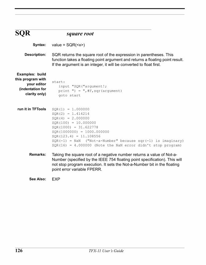
SQR square root
Syntax: value = SQR(<x>)
Description: SQR returns the square root of the expression in parentheses. This function takes a floating point argument and returns a floating point result. If the argument is an integer, it will be converted to float first.
Examples: buildthis program with
your editor(indentation for
clarity only)
start: input "SQR("argument!; print ") = ",#F,sqr(argument) goto start
run it in TFTools SQR(1) = 1.000000SQR(2) = 1.414214SQR(4) = 2.000000SQR(100) = 10.000000SQR(1000) = 31.622778SQR(1000000) = 1000.000000SQR(123.4) = 11.108556SQR(-1) = NaN ("Not-a-Number" because sqr(-1) is imaginary)SQR(16) = 4.000000 (Note the NaN error didn't stop program)
Remarks: Taking the square root of a negative number returns a value of Not-a-Number (specified by the IEEE 754 floating point specification). This will not stop program execution. It sets the Not-a-Number bit in the floating point error variable FPERR.
See Also: EXP
126 TFX-11 User’s Guide
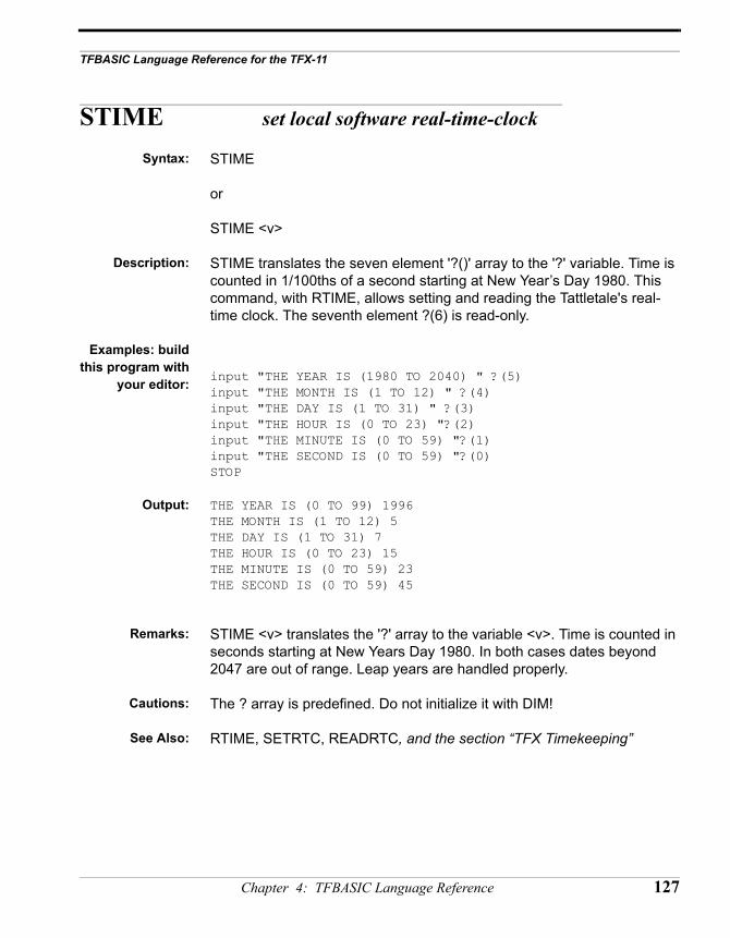
TFBASIC Language Reference for the TFX-11
STIME set local software real-time-clock
Syntax: STIME
or
STIME <v>
Description: STIME translates the seven element '?()' array to the '?' variable. Time is counted in 1/100ths of a second starting at New Year’s Day 1980. This command, with RTIME, allows setting and reading the Tattletale's real-time clock. The seventh element ?(6) is read-only.
Examples: buildthis program with
your editor: input "THE YEAR IS (1980 TO 2040) " ?(5)input "THE MONTH IS (1 TO 12) " ?(4)input "THE DAY IS (1 TO 31) " ?(3)input "THE HOUR IS (0 TO 23) "?(2)input "THE MINUTE IS (0 TO 59) "?(1)input "THE SECOND IS (0 TO 59) "?(0)STOP
Output: THE YEAR IS (0 TO 99) 1996THE MONTH IS (1 TO 12) 5THE DAY IS (1 TO 31) 7THE HOUR IS (0 TO 23) 15THE MINUTE IS (0 TO 59) 23THE SECOND IS (0 TO 59) 45
Remarks: STIME <v> translates the '?' array to the variable <v>. Time is counted in seconds starting at New Years Day 1980. In both cases dates beyond 2047 are out of range. Leap years are handled properly.
Cautions: The ? array is predefined. Do not initialize it with DIM!
See Also: RTIME, SETRTC, READRTC, and the section “TFX Timekeeping”
Chapter 4: TFBASIC Language Reference 127
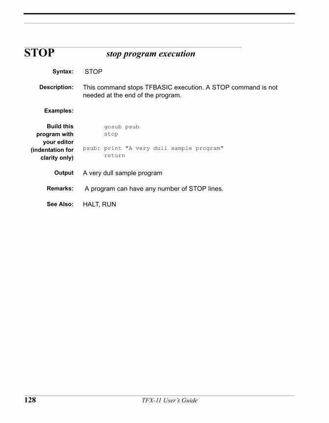
STOP stop program execution
Syntax: STOP
Description: This command stops TFBASIC execution. A STOP command is not needed at the end of the program.
Examples:
Build thisprogram with
your editor(indentation for
clarity only)
gosub psub stop
psub: print "A very dull sample program" return
Output A very dull sample program
Remarks: A program can have any number of STOP lines.
See Also: HALT, RUN
128 TFX-11 User’s Guide
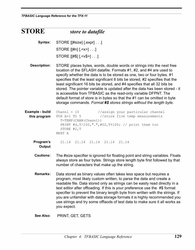
TFBASIC Language Reference for the TFX-11
STORE store to datafile
Syntax: STORE [[#size] [,expr] . . .]
STORE [[#n] [,<x>] . . .]
STORE [[#$] [,<v$>] . . .]
Description: STORE places bytes, words, double words or strings into the next free location of the SFLASH datafile. Formats #1, #2, and #4 are used to specify whether the data is to be stored as one, two or four bytes. #1 specifies that the least significant 8 bits be stored, #2 specifies that the least significant 16 bits be stored, and #4 specifies that all 32 bits be stored. The pointer variable is updated after the data has been stored - it is accessible from TFBASIC as the read-only variable DFPNT. The default format of store is in bytes so that the #1 can be omitted in byte storage commands. Format #$ stores strings without the length byte.
Example - buildthis program
Channl = 10 //assign your particular channel FOR A=1 TO 5 //store five temp measurements T=TEMP(CHAN(Channl)) PRINT #4,T/100,".",#02,T%100; // print them too STORE #2,TNEXT A
Program’sOutput
21.14 21.14 21.14 21.14 21.14
Cautions: The #size specifier is ignored for floating point and string variables. Floats always store as four bytes. Strings store length byte first followed by that number of characters that make up the string.
Remarks: Data stored as binary values often takes less space but requires a program, most likely custom written, to parse the data and create a readable file. Data stored only as strings can be easily read directly in a text editor after offloading. If this is your preference use the #$ format specifier to prevent the binary length byte from written with the strings. If you are unfamiliar with data storage formats it is highly recommended you use strings and try some offlaods of test data to make sure it all works as you expect.
See Also: PRINT, GET, GETS
Chapter 4: TFBASIC Language Reference 129
STR assign ASCII formatted output to string
Syntax: STR ([“s”] [,#n ] [,x1] [,\x2 ])
Description: Create a string by concatenating quoted strings, converted numerical values (optionally formatted), string variables and character constants in any order.
“s” represents a quoted string
#n optional numeric formatting
x1 integer, floating point, or string expressions
\x2 character constants
Examples: tempc! = float(temp(chan(0)))/100.0rh! = float(chan(2))BigStr$ = str(“degrees c =”, #6.2F, fempC!,” : RH = “, rh!)print BigStr$store BigStr$
Output: degrees c = 50.5 : RH = 64.00
Remarks: This function formats output exactly like the print statement, but allows assignment of the results to a string variable.
Cautions: After the output string reaches 255 characters in length all other characters are discarded.
See Also: PRINT
130 TFX-11 User’s Guide
TFBASIC Language Reference for the TFX-11
TAN Tangent
Syntax: value = TAN( <x>)
Description: TAN returns the tangent of the expression in the parenthesis. The argument must be in degrees. The function takes a floating point argument and returns a floating point value. An integer argument will be converted to float first.
Example: degrees! = 0.0 // init arg (notice '!' means it's a float)result! = 0.0 // just to force 'result' to be a floatfor i = 0 to 6 result = tan(degrees) print "The tangent of ", #5.1F, degrees, " is ", #6.3F, result degrees = degrees + 72.0next i
Output: The tangent of 0.0 is 0.000The tangent of 72.0 is 3.078The tangent of 144.0 is –0.726The tangent of 216.0 is 0.726The tangent of 288.0 is –3.078The tangent of 360.0 is 0.000
Cautions: DON’T FORGET! The argument is in degrees, not radians.
See Also: SIN, COS, ATN
Chapter 4: TFBASIC Language Reference 131
TEMP convert number to temperature
Syntax: value = TEMP(<x>)
Description: TEMP converts the 0-65535 value 'x' to a temperature, assuming that x results from a measurement of one of the A/D channels that is connected to a thermistor voltage divider circuit. The temperature conversion is given in hundredths of degrees C.
Examples: Buildthis program with
your editor
for A = 0 to 65520 step 256 tempVal = temp(A) print #4,tempVal/100,".",#02,abs(tempVal) % 100; if ((A/256) % 10) = 9 printnext A
Program’sOutput
166.00 166.00 166.00 166.00 165.88 158.48 151.08 143.68 136.33 132.00 127.68 123.35 119.05 116.12 113.20 110.27 107.36 105.16 102.96 100.76 98.57 96.82 95.07 93.32 91.57 90.10 88.62 87.15 85.68 84.4083.13 81.85 80.58 79.48 78.38 77.28 76.18 75.18 74.18 73.18 72.18 71.31 70.43 69.56 68.68 67.86 67.03 66.21 65.38 64.6163.83 63.06 62.28 61.58 60.88 60.18 59.48 58.83 58.18 57.5356.89 56.26 55.64 55.01 54.39 53.81 53.24 52.66 52.09 51.5150.94 50.36 49.79 49.26 48.74 48.21 47.69 47.16 46.64 46.1145.59 45.09 44.59 44.09 43.59 43.11 42.64 42.16 41.69 41.2440.79 40.34 39.89 39.44 38.99 38.54 38.09 37.64 37.19 36.7436.29 35.86 35.44 35.01 34.59 34.16 33.74 33.31 32.89 32.4932.09 31.69 31.29 30.89 30.49 30.09 29.69 29.29 28.89 28.4928.09 27.69 27.29 26.89 26.49 26.11 25.74 25.36 24.99 24.5924.19 23.79 23.39 23.01 22.64 22.26 21.89 21.49 21.09 20.6920.29 19.91 19.54 19.16 18.79 18.41 18.04 17.66 17.29 16.9116.54 16.16 15.79 15.39 14.99 14.59 14.19 13.81 13.44 13.0612.69 12.29 11.89 11.49 11.09 10.71 10.34 9.96 9.59 9.198.79 8.39 7.99 7.59 7.19 6.79 6.39 5.96 5.54 5.114.69 4.26 3.84 3.41 2.99 2.56 2.14 1.71 1.29 0.860.44 0.01 0.41 0.89 -1.36 -1.84 -2.31 -2.79 -3.26 -3.74-4.21 -4.69 -5.16 -5.64 -6.11 -6.64 -7.16 -7.69 -8.21 -8.76-9.31 -9.86 -10.41 -10.99 -11.56 -12.14 -12.71 -13.34 -13.96 -14.59-15.22 -15.87 -16.52 -17.17 -17.82 -18.57 -19.32 -20.07 -20.82 -21.62-22.42 -23.22 -24.02 -24.97 -25.92 -26.87 -27.82 -28.90 -29.97 -31.05-32.13 -33.48 -34.83 -36.18 -37.53 -39.36 -41.18 -43.01 -44.85 -47.65-50.45 -53.25 -56.00 -56.00 -56.00 -56.00
Cautions: No attempt has been made to resolve temperatures greater than 166 C or less than -56C. Using the 12-bit converter gives about 0.03C resolution for temperatures between about 0C and 35C.
Remarks: The Getting Started section shows the schematic for the circuit and describes how to connect the thermistor to take temperature readings
See Also:
132 TFX-11 User’s Guide
TFBASIC Language Reference for the TFX-11
TONE send square wave out
Syntax: TONE period, count
TONE <x1>,<x2>
Description: TONE allows you to produce a square wave of predetermined period and duration output on I/O line 3 The expression 'period' gives the square wave period, which is measured in multiples of 0.8138µSec. The range of period is 70 (about 17554Hz) to 65535 (about19Hz). The expression 'count' gives the number of cycles to be output, which can be as few as one, or as many as 32767 cycles. This output can be used to drive a speaker and produce notes covering a large portion of the audio spectrum. TONE sets I/O line 3 to an output and leaves I/O line 3 low at the end of a command.
A special form of TONE is available to produce a continuous square wave. Use a value of 0 for the count argument and the square wave will continue (at the period you select) until you execute a TONE with a zero value for both the period and count arguments. You can change the period of this continuous signal “on the fly “ by using TONE with the new period argument and a zero count argument. The square wave period will change on the next transition of the signal.
Example 1: X=1000000/4/44/16// Two octaves above 440 'A'for A=24 to 0 step –1@(A)=XX=X*106/100next A // Have half tone scale from @(0) to @(23)Y=500000tone @(21),Y/@(21)tone @(23),Y/@(23)tone @(19),Y/@(19)tone @(5),Y/@(5)tone @(14),Y/@(14)// Recognize that?
Example 2: sleep 0for i = 10 to 1 step –1tone i*60,0 // update continuous signal periodsleep 10 // produce this frequency for 100 mSecnext itone 0, 0 // stop the tone
Chapter 4: TFBASIC Language Reference 133
Remarks: In the example above, the number of cycles is normalized by the interval to make the length of the note constant. The above poorly-tempered scale is actually remarkably close to a well-tempered scale. PRINT 10000*@(24)/@(0) yields the value 2515, about 0.7% away from the right number (2500). The 1.06 ratio is good to about 1/10 of a half tone per octave.
Cautions: Driving circuitry should expect the quiescent state to be low. If the TONE command is not used for a while after power-up, set that line low with a PCLR 3 command to ensure that the speaker driver is in its low power state!
134 TFX-11 User’s Guide
TFBASIC Language Reference for the TFX-11
UGET bring character in software UART
Syntax: UGET baud, count, strvar, timeout
UGET <x1>, <x2>, <v>, <x3>
Description: The UGET command treats I/O line 1 as a UART input line to receive serial data. The input expects CMOS levels and has the marking state high, inverted from the normal RS-232 sense. The baud rate is specified by the expression 'baud' and can be any value between 100 baud and 19200. The expression 'count' specifies the number of bytes to be received. 'Strvar' specifies the string variable to be used to store the data as it is received. The data is stored directly into memory and is not echoed to the screen. The expression 'timeout' specifies the time-out (in 1/100ths of a second); this time-out aborts the receiving routine in case of an external system failure and continues execution at the beginning of the next command. Time-out can be set to any value between 0.01 and 655.35 seconds.
Example:(indentation for
clarity only)
X$ =””UGET 4800,10,X$,800IF LEN(X$)<10
GOTO LT10ENDIFPRINT “RECEIVED ALL”:STOP
LT10: PRINT “RECEIVED ONLY ”,LEN(X$),“ CHARACTERS”
Output: RECEIVED ONLY 0 CHARACTERS
This program will try to receive 10 characters at 4800 baud, storing them int the variable X$, and timing out if all ten are not received in eight seconds. Provisions are also made to detect and deal with external system failure.
Remarks: UGET uses I/O line 1 as a UART input line. Like USEND, this line uses CMOS levels and has a marking high state, inverted from the normal RS-232 sense. The transfer format for the received characters is eight data bits, no parity, with one stop bit (at least). The 'count' parameter has a maximum of 255.
See Also: USEND
Chapter 4: TFBASIC Language Reference 135
USEND send characters out software UART
Syntax: USEND baud, <string>
Description: USEND sends serial data out I/O line 2. The argument can be any string expression; constant, variable,or function. The range for ‘baud’ is 100 to 19200 or a runtime error will occur.
Example 1:(indentation for
clarity only)
start: input “enter text : “istring$usend 300,istring$usend 300, “\x0D\x0A” // send <cr> <lf>stop
input this stringat the prompt
followed by<ENTER>
THIS IS A TEST
Output: : THIS IS A TEST
Example 2 USEND 9600," seconds from power-up";loop: X=? USEND 9600 str(\13,#8,X/100,".",#02,X%100) GOTO loop
This simple program continuously displays the time on a terminal connected to I/O line 2 through a level shifter.
Remarks: USEND uses I/O line 2 as a UART output line. Like UGET, this line uses CMOS levels and has a marking high state, inverted from the normal RS-232 sense. The transfer format for the transmitted characters is eight data bits, no parity, with one stop bit (at least).
Cautions: There is no breakout from USEND, and sending 220K bytes at 110 baud will take about 6 hours!
See Also: UGET, STR
136 TFX-11 User’s Guide
TFBASIC Language Reference for the TFX-11
VARPTR get address of named variable
Syntax: VARPTR (<variable>)
Description: This function returns the address of the variable named in parentheses. Since variables are defined when they are first used in a program, the variable can be used here before being defined elsewhere. Also, the variable can be an array but it cannot include the index value. Be aware that VARPTR returns the address of the most significant byte of the variable. The least significant byte = VARPTR (data) + 3.
Examples:(indentation for
clarity only)
print varptr(data) //address of beginning of 'data' array (MSB)print varptr(data)+3 //address of beginning of 'data' array (LSB)
start_prog: print "square of values from 0 to 9" for a = 0 to 9 b = a * a print #5, a, b next a print "last b value bytes : "; print #02H, peek(varptr(b)), " ", peek(varptr(b)+1), " "; print #02H, peek(varptr(b)+2), " ", peek(varptr(b)+3)end_prog:
See Also: PEEK, POKE
Chapter 4: TFBASIC Language Reference 137
VGET get variable from user EEPROM
Syntax: value = VGET( <expr>)
Description: VGET returns the corresponding variable value from the User EEPROM (UEEPROM). Although there are 128 bytes available in the UEEPROM, they can only be assigned to in 4-byte blocks. These correspond to locations 0-31.
Example: // Store and retrieve two bytes and a word in a single loca-tion
CalValA = 124CalValB = 37CalValC = 1027VSTORE 0, (CalValA + CalValB*256 + CalValB*65536)...CalValA = (VGET(0) & &H000000FF)CalValB = ((VGET(0)/256) & &H000000FF)CalValC = ((VGET(0)/65536) & &H0000FFFF)
Remarks: VGET can be used to retrieve unique user calibration parameters stored in the UEEPROM by VSTORE. This permits instruments to have identical TFBASIC programs while allowing for variations in sensors calibrations.
All values stored in the UEEPROM are assumed to be integer. ASFLT can be used to recover a floating point value stored in the UEEPROM.
FLPTV! = 80.86VSTORE 20, FLPTV!FLPTV! = ASFLT(VGET(20))
Cautions: The UEEPROM is only readable and writable from TFBASIC. Any values stored will not be off-loaded with the main flash off-load unless deliberately stored into the main flash by your TFBASIC program.
See Also: VSTORE, ASFLT
138 TFX-11 User’s Guide
TFBASIC Language Reference for the TFX-11
VSTORE store variable to user EEPROM
Syntax: VSTORE <address>, <expr>
Description: VSTORE stores the 32-bit value of expr at the UEEPROM address. There are 128 bytes available in the UEEPROM, but they can only be assigned to in 4-byte blocks. Valid addresses are 0-31.
Example: TempCalVal = 5PressCalVal! = 1.05HumidCalVal! = 0.24
VSTORE 0, TempCalVal // store an integer valueVSTORE 1, PressCalVal! // store a floating point valueVSTORE 2, HumidCalVal!
CurrTemp = CHAN(6)* VGET(0)CurrPress! = float(CHAN(1))* ASFLT(VGET(1))CurrHumid! = float(CHAN(3))* ASFLT(VGET(2))
Remarks: Both integer and float variables take four bytes, and thus either will neatly fit into one location. A simple VGET will return the proper integer value, but ASFLT() is necessary to recover a floating point value stored in the UEEPROM. No special commands are necessary to store a floating point value.
Cautions: The UEEPROM is only readable and writable from TFBASIC. Any values stored will not be off-loaded with the main flash off-load unless deliberately stored into the main flash by your TFBASIC program.
The UEEPROM has a finite number of write cycles, so avoid frequent rewriting of locations such as might happen if the VSTORE command appears in a loop.
See Also: VGET, ASFLT
Chapter 4: TFBASIC Language Reference 139
WHILE loop while expression true
Syntax: WHILE expression
...commands...
...to be executed...
WEND
Description: WHILE loops provide one of four methods of looping available in TFBASIC. The code between the WHILE and WEND commands will be executed as long as 'expression' is true. Like the FOR loop, and unlike the REPEAT loop, the testing of 'expression' takes place before the loop is executed. Because this structure stores nothing on the stack, you can nest these loops as deeply as you like. A GOTO can be used to exit any number of nested WHILE loops.
Example:(indentation for
clarity only)
// collect data as long as I/O pin 0 is low
onerr HandleError, errVar dfPointer = 0 sleep 0
while pin(0) = 0 store dfPointer, #2, chan(0), chan(2) sleep 100 wend
print "Finished logging, ready to off-load" stop
HandleError: if errVar/65536 = 4 print "Ran out of datafile. Stopped logging" else
print "Logging stopped by error #",errVar/65536 endif stop
Remarks: none
See Also: FOR, GOTO, REPEAT
140 TFX-11 User’s Guide
TFBASIC Language Reference for the TFX-11
XMIT+, XMIT– enable, disable console output
Syntax: XMIT–
or
XMIT+
Description: On receiving the XMIT– command, the Tattletale will stop echoing characters received by the main UART. XMIT– remains in effect until the Tattletale receives XMIT+ or a power-on reset. Under the influence of XMIT–, characters sent to the hardware UART are simply thrown away.
Example: xmit–print "You won't see this"xmit+print "You WILL see this"print "Input a number: ";xmit–input "this prompt will be lost"aNumberxmit+print "the number is ", aNumber
Output: you WILL see thisInput a number: <type 123 here> the number is 123
Remarks: XMIT– is most useful when you don't what characters entered into the Tattletale to be echoed.
Cautions: Remember, everything is suppressed by XMIT–, even error messages!
See Also: INPUT for another method of not echoing input characters.
Chapter 4: TFBASIC Language Reference 141
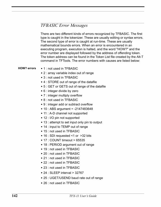
TFBASIC Error Messages
There are two different kinds of errors recognized by TFBASIC. The first type is caught in the tokenizer. These are usually editing or syntax errors. The second type of error is caught at run-time. These are usually mathematical bounds errors. When an error is encountered in an executing program, execution is halted, and the word "HOW?" and the error number are displayed followed by the address of offending token. The token address can be found in the Token List file created by the Alt-T command in TFTools. The error numbers with causes are listed below:
HOW? errors • 1 : not used in TFBASIC• 2 : array variable index out of range• 3 : not used in TFBASIC• 4 : STORE out of range of the datafile• 5 : GET or GETS out of range of the datafile• 6 : integer divide by zero• 7 : integer multiply overflow• 8 : not used in TFBASIC• 9 : integer add or subtract overflow• 10 : ABS argument = -2147483648• 11 : A-D channel not supported• 12 : I/O pin not supported• 13 : attempt to set input only pin to output• 14 : input to TEMP out of range• 15 : not used in TFBASIC• 16 : SDI requested <1 or >32 bits• 17 : COUNT timeout > 65535• 18 : PERIOD argument out of range• 19 : not used in TFBASIC• 20 : not used in TFBASIC• 21 : not used in TFBASIC• 22 : not used in TFBASIC• 23 : not used in TFBASIC• 24 : SLEEP interval > 32767• 25 : UGET/USEND baud rate out of range• 26 : not used in TFBASIC
142 TFX-11 User’s Guide
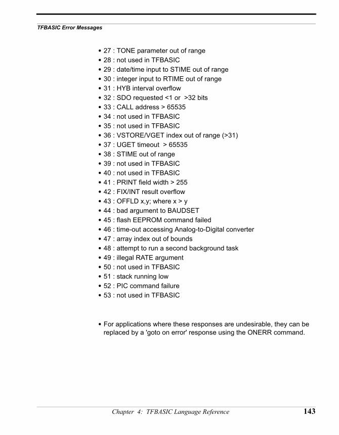
TFBASIC Error Messages
• 27 : TONE parameter out of range• 28 : not used in TFBASIC• 29 : date/time input to STIME out of range• 30 : integer input to RTIME out of range• 31 : HYB interval overflow• 32 : SDO requested <1 or >32 bits• 33 : CALL address > 65535• 34 : not used in TFBASIC• 35 : not used in TFBASIC• 36 : VSTORE/VGET index out of range (>31)• 37 : UGET timeout > 65535• 38 : STIME out of range• 39 : not used in TFBASIC• 40 : not used in TFBASIC• 41 : PRINT field width > 255• 42 : FIX/INT result overflow• 43 : OFFLD x,y; where x > y• 44 : bad argument to BAUDSET• 45 : flash EEPROM command failed• 46 : time-out accessing Analog-to-Digital converter• 47 : array index out of bounds• 48 : attempt to run a second background task• 49 : illegal RATE argument• 50 : not used in TFBASIC• 51 : stack running low• 52 : PIC command failure• 53 : not used in TFBASIC
• For applications where these responses are undesirable, they can be replaced by a 'goto on error' response using the ONERR command.
Chapter 4: TFBASIC Language Reference 143
General Guidelines for Background Tasks:• Shouldn’t use HYB, INPUT, TONE, COUNT with timeout, or PERIOD in
the background task.• Must use Sleep or Stop to allow foreground to execute.• Some commands will be affected. USEND and UGET in foreground will
be adversely affected by the background task.• The foreground task is defined as starting with the first line of the
program.• The background task can only be launched from the foreground task
(using the RUN command as described in the command reference)• Once the background task begins, it only returns control to the
foreground if it executes a STOP or a SLEEP.a. If the background task executes a STOP, only the foreground task can start it again.b. If the background task executes a SLEEP, the foreground runs again but is interrupted every 10mS (or the rate chosen with the RATE command) to check if it’s time to end the background SLEEP. Once the background SLEEP expires, the background task has full control.
• When a background task is running, the SLEEP timing for the foreground is no longer rigorous (it’s easy to oversleep). So the * print is disabled for the foreground task - only while a background task is running. To distinguish between SLEEP commands, the background task prints a tilde ‘~’ if it oversleeps instead of *.
• All TFBASIC variables are global. That is, they are available to both the foreground and background. They can be used to pass messages or flags between the two tasks. The example below shows how the foreground can signal the background to stop itself when the time is ready.
• Use the RUN command to launch a background task. Follow the RUN with the label of the routine you want to execute in the background. For example - 'RUN GetData' will cause the program starting at label 'GetData' to run in the background. Presumably, the routine starting at label 'GetData' has a SLEEP or STOP somewhere to pass control back to the foreground.
NOTE: The second task is NOT a GOSUB statement, do NOT use RETURN to end the background task.
144 TFX-11 User’s Guide
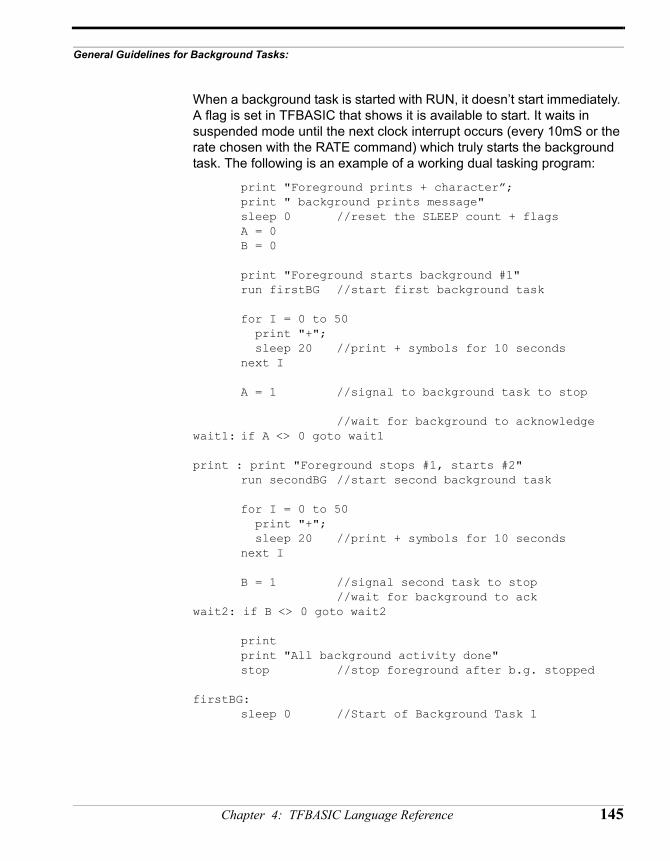
General Guidelines for Background Tasks:
When a background task is started with RUN, it doesn’t start immediately. A flag is set in TFBASIC that shows it is available to start. It waits in suspended mode until the next clock interrupt occurs (every 10mS or the rate chosen with the RATE command) which truly starts the background task. The following is an example of a working dual tasking program:
print "Foreground prints + character”;print " background prints message"sleep 0 //reset the SLEEP count + flags
A = 0B = 0
print "Foreground starts background #1"run firstBG //start first background task
for I = 0 to 50 print "+"; sleep 20 //print + symbols for 10 secondsnext I
A = 1 //signal to background task to stop
//wait for background to acknowledgewait1: if A <> 0 goto wait1
print : print "Foreground stops #1, starts #2"run secondBG //start second background task
for I = 0 to 50 print "+"; sleep 20 //print + symbols for 10 secondsnext I
B = 1 //signal second task to stop//wait for background to ack
wait2: if B <> 0 goto wait2
printprint "All background activity done"stop //stop foreground after b.g. stopped
firstBG: sleep 0 //Start of Background Task 1
Chapter 4: TFBASIC Language Reference 145
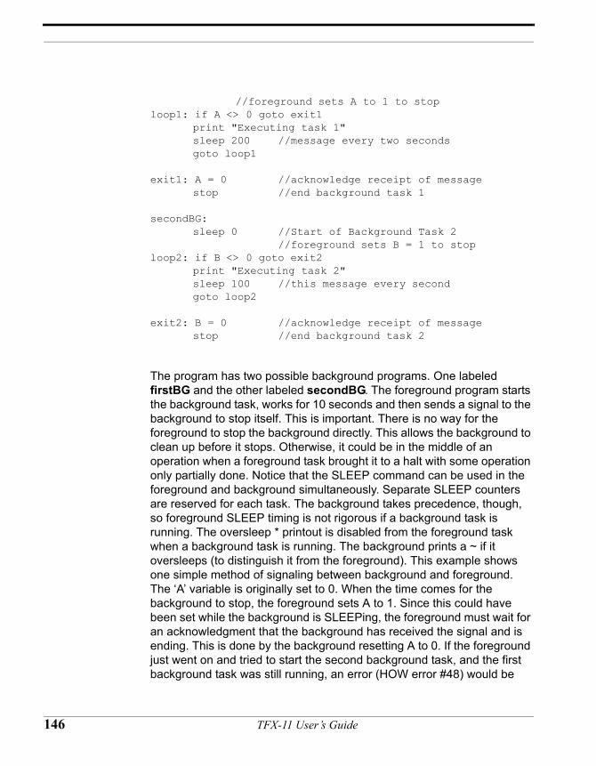
//foreground sets A to 1 to stoploop1: if A <> 0 goto exit1
print "Executing task 1"sleep 200 //message every two secondsgoto loop1
exit1: A = 0 //acknowledge receipt of messagestop //end background task 1
secondBG: sleep 0 //Start of Background Task 2
//foreground sets B = 1 to stoploop2: if B <> 0 goto exit2
print "Executing task 2"sleep 100 //this message every secondgoto loop2
exit2: B = 0 //acknowledge receipt of messagestop //end background task 2
The program has two possible background programs. One labeled firstBG and the other labeled secondBG. The foreground program starts the background task, works for 10 seconds and then sends a signal to the background to stop itself. This is important. There is no way for the foreground to stop the background directly. This allows the background to clean up before it stops. Otherwise, it could be in the middle of an operation when a foreground task brought it to a halt with some operation only partially done. Notice that the SLEEP command can be used in the foreground and background simultaneously. Separate SLEEP counters are reserved for each task. The background takes precedence, though, so foreground SLEEP timing is not rigorous if a background task is running. The oversleep * printout is disabled from the foreground task when a background task is running. The background prints a ~ if it oversleeps (to distinguish it from the foreground). This example shows one simple method of signaling between background and foreground. The ‘A’ variable is originally set to 0. When the time comes for the background to stop, the foreground sets A to 1. Since this could have been set while the background is SLEEPing, the foreground must wait for an acknowledgment that the background has received the signal and is ending. This is done by the background resetting A to 0. If the foreground just went on and tried to start the second background task, and the first background task was still running, an error (HOW error #48) would be
146 TFX-11 User’s Guide
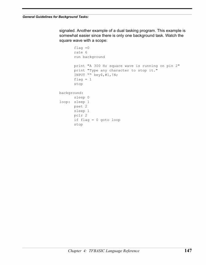
General Guidelines for Background Tasks:
signaled. Another example of a dual tasking program. This example is somewhat easier since there is only one background task. Watch the square wave with a scope:
flag =0rate 6run background
print "A 300 Hz square wave is running on pin 2"print "Type any character to stop it."INPUT ““ key$,#1,!N;flag = 1stop
background: sleep 0
loop: sleep 1pset 2sleep 1pclr 2if flag = 0 goto loopstop
Chapter 4: TFBASIC Language Reference 147

148 TFX-11 User’s Guide
CHAPTER 5
TFBASIC Assembly LanguageReference
TFX-11 User’s Guide
TFBASIC Assembly Language Reference
TFBASICassemblylanguage
The TFBASIC tokenizer (running on the host computer) has a built-in assembler. The tokenizer switches from generating tokens to assembling when it encounters the ASM command and switches back to tokenizing when it encounters the END command. This assembler allows the use of named labels and it can access TFBASIC variables by name.
Labels,assembler
Labels can be used in the assembly code for flow control and to define local variables. Labels must start in the first column. Labels can be up to 32 characters long and must begin with a letter or an underscore ( _ ). The only valid characters in a label are upper and lower case characters, numbers, and underscore. The label name can be terminated with a colon (when the label is defined) but this is not necessary in the assembler. These labels are accessible to the CALL command as long as they are defined before CALL is invoked. TFBASIC labels are not accessible to the assembly code (although TFBASIC variables are).
Assembleropcodes
The TFBASIC assembler recognizes all of the opcodes defined in the Motorola manuals with some exceptions including all those using the Y register. These include ABY, CPY, DEY, INY, LDY, PSHY, PULY, STY, TSY, TYS, XGDY, CPD, STOP, BRCLR, BRSET, IDIV, and FDIV.
Opcodes must have at least one character of whitespace (space character or tab) in front of them on the line OR a label terminated with a colon.
ReferencingHC11 control
registers
The Motorola reference manual places the control registers starting at location 1000H. On startup, the TFX-11 relocates these registers to start at location 0. When referencing the control registers in your assembly code don’t forget to subtract the 1000H from the addresses given in the Motorola manual to get the correct address.
Two forms ofASM
Assembly routines can be either executed in-line with TFBASIC commands or accessed as subroutines from TFBASIC using the CALL command depending on the argument that follows ASM.
In-line assembly(ASM $)
The assembler (built in to the tokenizer) assembles from the line after the ASM $ until it detects the END command. The interpreter will switch from interpreting tokens to executing the assembly code when it reaches the
150 TFX-11 User’s Guide
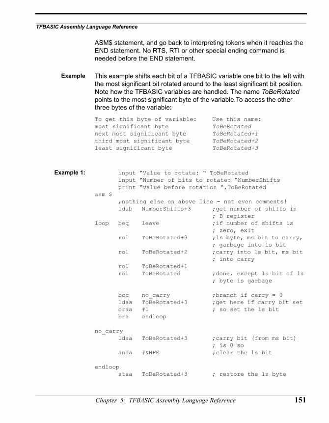
TFBASIC Assembly Language Reference
ASM$ statement, and go back to interpreting tokens when it reaches the END statement. No RTS, RTI or other special ending command is needed before the END statement.
Example This example shifts each bit of a TFBASIC variable one bit to the left with the most significant bit rotated around to the least significant bit position. Note how the TFBASIC variables are handled. The name ToBeRotated points to the most significant byte of the variable.To access the other three bytes of the variable:
To get this byte of variable: Use this name:most significant byte ToBeRotatednext most significant byte ToBeRotated+1third most significant byte ToBeRotated+2least significant byte ToBeRotated+3
Example 1: input “Value to rotate: “ ToBeRotatedinput “Number of bits to rotate: “NumberShiftsprint “value before rotation “,ToBeRotated
asm $ ;nothing else on above line - not even comments!ldab NumberShifts+3 ;get number of shifts in
; B registerloop beq leave ;if number of shifts is
; zero, exitrol ToBeRotated+3 ;ls byte, ms bit to carry,
; garbage into ls bitrol ToBeRotated+2 ;carry into ls bit, ms bit
; into carryrol ToBeRotated+1rol ToBeRotated ;done, except ls bit of ls
; byte is garbage
bcc no_carry ;branch if carry = 0ldaa ToBeRotated+3 ;get here if carry bit set oraa #1 ; so set the ls bitbra endloop
no_carryldaa ToBeRotated+3 ;carry bit (from ms bit)
; is 0 soanda #&HFE ;clear the ls bit
endloopstaa ToBeRotated+3 ; restore the ls byte
Chapter 5: TFBASIC Assembly Language Reference 151
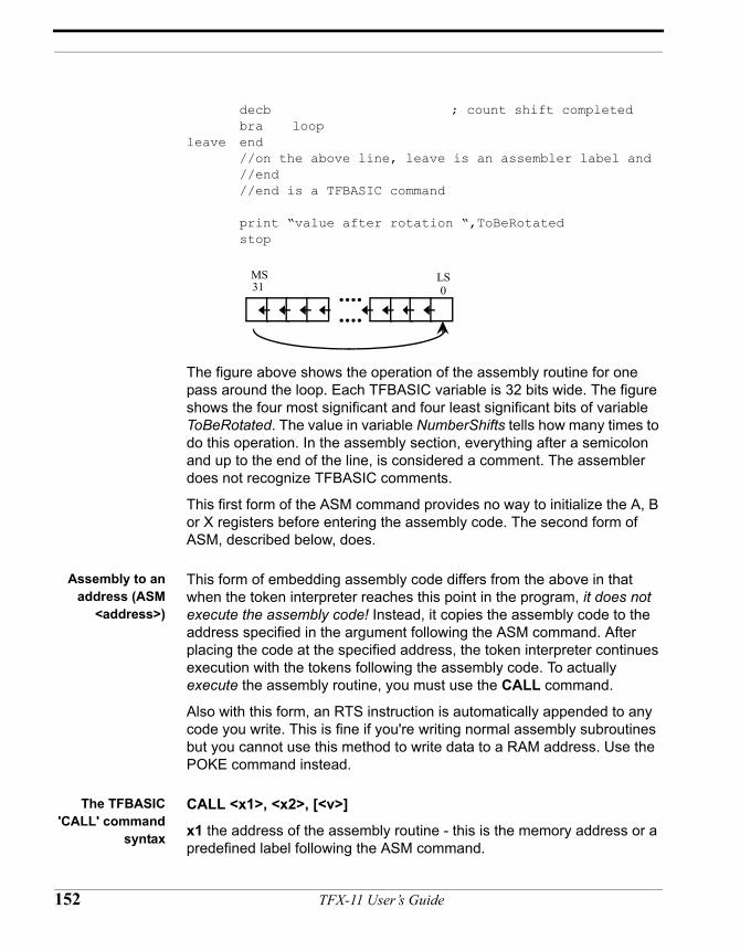
decb ; count shift completedbra loop
leave end//on the above line, leave is an assembler label and
//end//end is a TFBASIC command
print “value after rotation “,ToBeRotatedstop
The figure above shows the operation of the assembly routine for one pass around the loop. Each TFBASIC variable is 32 bits wide. The figure shows the four most significant and four least significant bits of variable ToBeRotated. The value in variable NumberShifts tells how many times to do this operation. In the assembly section, everything after a semicolon and up to the end of the line, is considered a comment. The assembler does not recognize TFBASIC comments.
This first form of the ASM command provides no way to initialize the A, B or X registers before entering the assembly code. The second form of ASM, described below, does.
Assembly to anaddress (ASM
<address>)
This form of embedding assembly code differs from the above in that when the token interpreter reaches this point in the program, it does not execute the assembly code! Instead, it copies the assembly code to the address specified in the argument following the ASM command. After placing the code at the specified address, the token interpreter continues execution with the tokens following the assembly code. To actually execute the assembly routine, you must use the CALL command.
Also with this form, an RTS instruction is automatically appended to any code you write. This is fine if you're writing normal assembly subroutines but you cannot use this method to write data to a RAM address. Use the POKE command instead.
The TFBASIC'CALL' command
syntax
CALL <x1>, <x2>, [<v>]
x1 the address of the assembly routine - this is the memory address or a predefined label following the ASM command.
••••
••••
31 0MS LS
152 TFX-11 User’s Guide
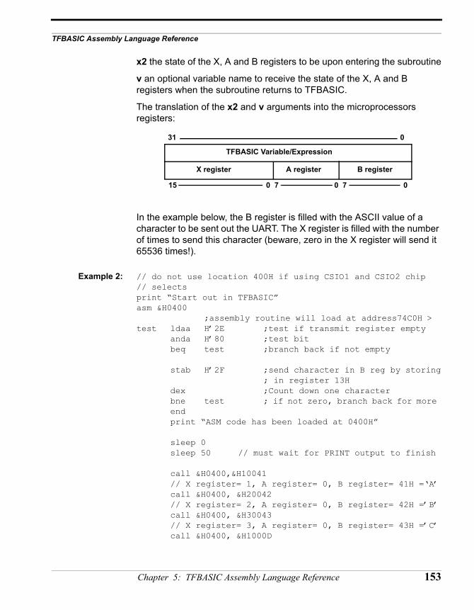
TFBASIC Assembly Language Reference
x2 the state of the X, A and B registers to be upon entering the subroutine
v an optional variable name to receive the state of the X, A and B registers when the subroutine returns to TFBASIC.
The translation of the x2 and v arguments into the microprocessors registers:
In the example below, the B register is filled with the ASCII value of a character to be sent out the UART. The X register is filled with the number of times to send this character (beware, zero in the X register will send it 65536 times!).
Example 2: // do not use location 400H if using CSIO1 and CSIO2 chip// selectsprint “Start out in TFBASIC”asm &H0400
;assembly routine will load at address74C0H >test ldaa H’2E ;test if transmit register empty
anda H’80 ;test bitbeq test ;branch back if not empty
stab H’2F ;send character in B reg by storing; in register 13H
dex ;Count down one characterbne test ; if not zero, branch back for more endprint “ASM code has been loaded at 0400H”
sleep 0sleep 50 // must wait for PRINT output to finish
call &H0400,&H10041// X register= 1, A register= 0, B register= 41H =‘A’call &H0400, &H20042// X register= 2, A register= 0, B register= 42H =’B’call &H0400, &H30043// X register= 3, A register= 0, B register= 43H =’C’call &H0400, &H1000D
TFBASIC Variable/Expression
X register A register B register
31
15
0
0 7 0 7 0
Chapter 5: TFBASIC Assembly Language Reference 153
// X register= 1, A register= 0, B register= 0DH = CRcall &H0400, &H1000A// X register= 1, A register= 0, B register= 0AH = LFprint “Finished”
Notice the lines sleep 0 followed by sleep 50. The PRINT command in TFBASIC sends all its output to a buffer. The characters in this buffer are sent out the UART in the background as fast as the baud rate will allow, but this is slow compared to the speed of the CPU. When the PRINT command is completed, TFBASIC continues on with the next command while characters may still be waiting in the buffer to be sent out the UART. The assembly routine we wrote bypasses the UART buffer and will interfere with characters being automatically output from the buffer. So, we pause to let the buffer clear before using our routine.
Radix Notice the new methods of defining the number base of constants. You have these options IN THE ASSEMBLER ONLY. For example, the constant 19 decimal can be defined as:
Decimal is the default base&H works the same as in TFBASIC
decimal: 19D or D’19 or 19hex: 13H or &H13 or H’13 or $13octal: 23O or 23Q or Q’23 or @23binary: 10011B or B’10011 or %10011
154 TFX-11 User’s Guide
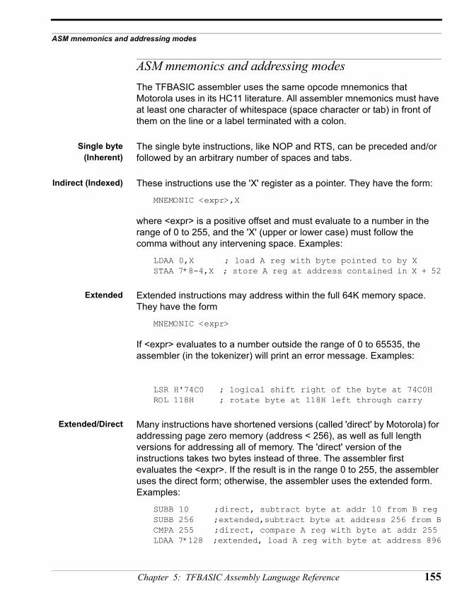
ASM mnemonics and addressing modes
ASM mnemonics and addressing modesThe TFBASIC assembler uses the same opcode mnemonics that Motorola uses in its HC11 literature. All assembler mnemonics must have at least one character of whitespace (space character or tab) in front of them on the line or a label terminated with a colon.
Single byte(Inherent)
The single byte instructions, like NOP and RTS, can be preceded and/or followed by an arbitrary number of spaces and tabs.
Indirect (Indexed) These instructions use the 'X' register as a pointer. They have the form:
MNEMONIC <expr>,X
where <expr> is a positive offset and must evaluate to a number in the range of 0 to 255, and the 'X' (upper or lower case) must follow the comma without any intervening space. Examples:
LDAA 0,X ; load A reg with byte pointed to by XSTAA 7*8-4,X ; store A reg at address contained in X + 52
Extended Extended instructions may address within the full 64K memory space. They have the form
MNEMONIC <expr>
If <expr> evaluates to a number outside the range of 0 to 65535, the assembler (in the tokenizer) will print an error message. Examples:
LSR H'74C0 ; logical shift right of the byte at 74C0HROL 118H ; rotate byte at 118H left through carry
Extended/Direct Many instructions have shortened versions (called 'direct' by Motorola) for addressing page zero memory (address < 256), as well as full length versions for addressing all of memory. The 'direct' version of the instructions takes two bytes instead of three. The assembler first evaluates the <expr>. If the result is in the range 0 to 255, the assembler uses the direct form; otherwise, the assembler uses the extended form. Examples:
SUBB 10 ;direct, subtract byte at addr 10 from B regSUBB 256 ;extended,subtract byte at address 256 from BCMPA 255 ;direct, compare A reg with byte at addr 255LDAA 7*128 ;extended, load A reg with byte at address 896
Chapter 5: TFBASIC Assembly Language Reference 155
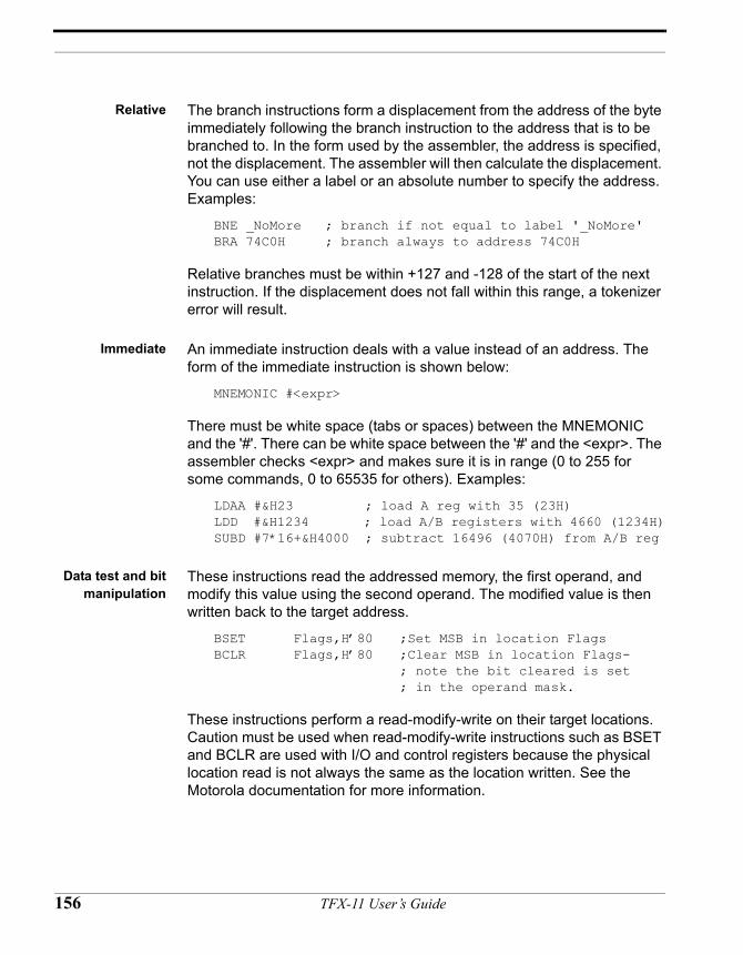
Relative The branch instructions form a displacement from the address of the byte immediately following the branch instruction to the address that is to be branched to. In the form used by the assembler, the address is specified, not the displacement. The assembler will then calculate the displacement. You can use either a label or an absolute number to specify the address. Examples:
BNE _NoMore ; branch if not equal to label '_NoMore'BRA 74C0H ; branch always to address 74C0H
Relative branches must be within +127 and -128 of the start of the next instruction. If the displacement does not fall within this range, a tokenizer error will result.
Immediate An immediate instruction deals with a value instead of an address. The form of the immediate instruction is shown below:
MNEMONIC #<expr>
There must be white space (tabs or spaces) between the MNEMONIC and the '#'. There can be white space between the '#' and the <expr>. The assembler checks <expr> and makes sure it is in range (0 to 255 for some commands, 0 to 65535 for others). Examples:
LDAA #&H23 ; load A reg with 35 (23H)LDD #&H1234 ; load A/B registers with 4660 (1234H)SUBD #7*16+&H4000 ; subtract 16496 (4070H) from A/B reg
Data test and bitmanipulation
These instructions read the addressed memory, the first operand, and modify this value using the second operand. The modified value is then written back to the target address.
BSET Flags,H’80 ;Set MSB in location FlagsBCLR Flags,H’80 ;Clear MSB in location Flags-
; note the bit cleared is set; in the operand mask.
These instructions perform a read-modify-write on their target locations. Caution must be used when read-modify-write instructions such as BSET and BCLR are used with I/O and control registers because the physical location read is not always the same as the location written. See the Motorola documentation for more information.
156 TFX-11 User’s Guide
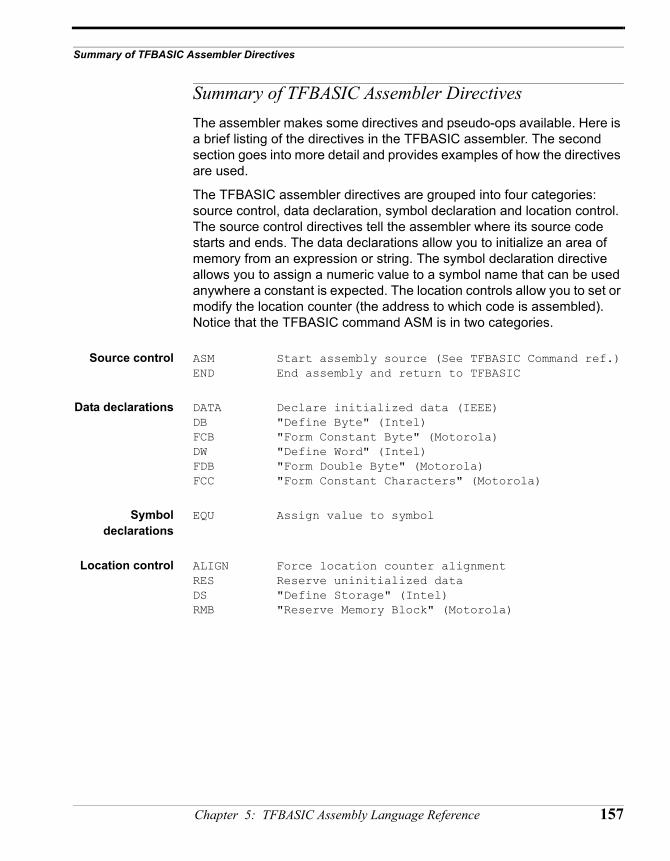
Summary of TFBASIC Assembler Directives
Summary of TFBASIC Assembler DirectivesThe assembler makes some directives and pseudo-ops available. Here is a brief listing of the directives in the TFBASIC assembler. The second section goes into more detail and provides examples of how the directives are used.
The TFBASIC assembler directives are grouped into four categories: source control, data declaration, symbol declaration and location control. The source control directives tell the assembler where its source code starts and ends. The data declarations allow you to initialize an area of memory from an expression or string. The symbol declaration directive allows you to assign a numeric value to a symbol name that can be used anywhere a constant is expected. The location controls allow you to set or modify the location counter (the address to which code is assembled). Notice that the TFBASIC command ASM is in two categories.
Source control ASM Start assembly source (See TFBASIC Command ref.)END End assembly and return to TFBASIC
Data declarations DATA Declare initialized data (IEEE)DB "Define Byte" (Intel)FCB "Form Constant Byte" (Motorola)DW "Define Word" (Intel)FDB "Form Double Byte" (Motorola)FCC "Form Constant Characters" (Motorola)
Symboldeclarations
EQU Assign value to symbol
Location control ALIGN Force location counter alignmentRES Reserve uninitialized dataDS "Define Storage" (Intel)RMB "Reserve Memory Block" (Motorola)
Chapter 5: TFBASIC Assembly Language Reference 157
Details of the TFBASIC Assembler Directives
158 TFX-11 User’s Guide
Details of the TFBASIC Assembler Directives
ALIGN
Syntax: [label]align expr [; comments]
Description: The align directive forces the location counter to align to a boundary that is a multiple of the value specified by the expression in the operand field.
Examples: _align: align 2 ; align on word boundarydata "word"align 4 ; align on long boundarydata "long"align 256 ; align on page boundarydata "page"align 32768 ; align on enormous boundarydata "huge"align 1 ; back to byte boundarydata "byte"
Remarks: Values in the align expression must not contain any forward references.
Chapter 5: TFBASIC Assembly Language Reference 159
DATA, DB, FCB, DW, FDB, FCCSyntax: [label]data[.size] expr|"string" [,expr|"string"...][; comments]
[label]db expr|"string" [,expr|"string"...] [; comments][label]fcb expr|"string" [,expr|"string"...] [; comments][label]dw expr|"string" [,expr|"string"...] [; comments][label]fdb expr|"string" [,expr|"string"...] [; comments][label]fcc <delim>"string" <delim> [; comments]
Size Specifiers(for 'data'
directive only)
.b .B Byte
.s .S Short(2 Bytes)
.w .W Word (2 Bytes)
.l .L Long (4 Bytes)
.q .Q Quad (8 Bytes)
Description: The various data declaration directives instruct the assembler to generate initialized data from expressions and strings. The size of the data generated for each expression is determined either explicitly with "dot-size" suffixing as in the data directive, or implicitly by the directive name. Expression values are truncated to fit into objects of the specified size. The data directive and the "dot-size" suffixes shown in the table conform to the guidelines of the IEEE-694 standard for microprocessor assembly language. The fcb (Form Constant Byte), fdb (Form Double Byte), and fcc (Form Constant Characters) are provided as a convenience to programmers more comfortable with Motorola pseudo-ops, while the db (Define Byte), and dw (Define Word) are available for programmers preferring Intel mnemonics. With the exception of the fcc directive, all of the data directives accept any combination of strings and expressions. Strings used with these directives must be enclosed inside double-quotes. Use two consecutive double-quotes to generate one double-quote character in the output data.
The fcc directive generates data from string expressions bracketed by the first character encountered in the operand field. Use two consecutive occurrences of the delimiting character to generate one instance of the character in the output data.
Examples: _data: data "sample string"data "several", "different", "strings"data "several", 0, "terminated", 0, "strings", 0data "sample string with quote ("") character"data "string with byte expression", 10
160 TFX-11 User’s Guide
Details of the TFBASIC Assembler Directives
;data 0,1,2,3 ; yields: 00 01 02 03data.b 0,1,2,3 ; yields: 00 01 02 03data.w 0,1,2,3 ; yields: 00 00 00 01 00 02 00 03data.l 0,1 ; yields: 00 00 00 00 00 00 00 01data.q 0 ; yields: 00 00 00 00 00 00 00 00
;_db: db "string with ending bit 7 hig", 'h' + h'80_fcb: fcb "string with embedded quote ("")"
db 'ab' ; should just be h'61fcb '''' ; the single-quote character
;_dw: dw 0,1,2,3 ; yields: 00 00 00 01 00 02 00 03
dw 'ab' ; should be h'6162_fdb: fdb '''''' ; two single-quote characters;_fcc: fcc :string with colon (::) terminators:
fcc ~string with tilde (~~) terminators~fcc /string with forward slash (//) terminators/
Limits: Maximum of 255 bytes generated from a single data statement.
Chapter 5: TFBASIC Assembly Language Reference 161
END
Syntax: [label]end [; comments]
Description: The end directive instructs the assembler to stop reading the current source file and return control to the TFBASIC tokenizer.
Example: asm $ldaa #12ldx #H'86staa 0,xend ; Configuration Byte set
162 TFX-11 User’s Guide
Details of the TFBASIC Assembler Directives
EQUSyntax: label equ expr [; comments]
Description The equ directive permanently assigns a numeric value to a symbol which may be used anywhere a constant is expected. Both the label and operand fields are required.
Examples: FALSE equ 0TRUE equ ~FALSEDEBUG equ FALSEDEL equ H'7F ; ASCII deleteCR equ H'0D ; carriage returnLF equ H'0A ; line feedTAB equ H'09 ; horizontal tabSP equ H'20 ; 'space' character
Remarks: Values used in the assignment expression must not contain any forward references. The TFBASIC assembler does not adapt EQU to perform text substitution on arguments which do not evaluate to a number.
Chapter 5: TFBASIC Assembly Language Reference 163
RES, DS, RMBSyntax: [label]res expr [; comments]
[label]ds expr [; comments][label]rmb expr [; comments]
Description: The res, ds, and rmb directives define a block of uninitialized data equal in length to the value of the expression in the operand field multiplied by the optional size specifier. Blocks declared using the reserve directives affect only the location counter and do not generate any output data in the object file.
Examples: asm h'4000_res: res h'100 ; should be 4000 - 40FF
res.b h'100 ; should be 4100 - 41FFres.s h'100 ; should be 4200 - 43FFres.w h'100 ; should be 4400 - 45FFres.l h'100 ; should be 4600 - 49FFres.q h'100 ; should be 4A00 - 51FF
Remarks: Values used in reserve statements must not contain any forward references.
164 TFX-11 User’s Guide
Assembly Language Subroutines
Assembly Language SubroutinesThe following locations are the entry points into fixed assembly language routines. The value at the beginning of each function's description is the address of that function; this address is the argument to the CALL command.
ATOD12 FD9A. Get reading from 12-bit A-D converter. Enter with one of the channel numbers (0 - 13) in B register. Channels 0 - 10 specify one of the external A-D input channels. Channels 11, 12 or 13 specify one of the reference channels. Return with MSB value in A register, LSB value in B register with value shifted left four bits.
PDAD12 FD9D. Power-down 12-bit A-D converter.
ATOD8 FDA0. Get reading from 8-bit A-D converter internal to 68HC11. Enter with one of the channel numbers (0 - 7) in B register. Return with value in A reg, zero in B register.
GETBSR FDA3. Read byte from Bank-switched RAM. Offset into bank in X register, values from 0 to 60927 valid. Byte returned in A register
STRBSR FDA6. Store byte in Bank-switched RAM. Byte to store in A register. Offset into bank in X register, values from 0 to 60927 valid.
STRMEM FDA9. Store byte in A register to next location in datafile.
CHIBUF FDAC. Return next byte in UART input buffer without removing it. Byte returned in A register.
FLUSHI FDAF. Flush UART input buffer.
FLUSHO FDB2. Flush UART output buffer.
OUTTST FDB5. Check for characters in UART output buffer. Number of characters remaining is returned in the A register.
URTGET FDB8. Receive next byte from UART buffer and return in A register. Returns the number of characters remaining in the buffer in the B register. Waits for a byte before returning.
Chapter 5: TFBASIC Assembly Language Reference 165
URTSND FDBB. Send byte in A register out UART (via buffer).
URTTST FDBE. Return number of characters available in UART input buffer in A register.
FEESBF FD88. Flush the SFLASH RAM buffer to EEPROM.
SLEEPF FD94. Enter with sleep argument in D register. No check is made if argument >32767. Returns with Overflow flag set if over-sleep (instead of printing '*' or setting OVRSLP). Uses same routine as TFBASIC SLEEP command.
STPWCH FD97. Stopwatch functions. Values returned are four-bytes, with MSBs in register X and LSBs in register D. Units are in ticks and will depend on the RATE command. Call with a value of 0-4 in the B register for one of five functions:.
Exampleshowing how
RATE interactswith Stopwatch
function
start: input "RATE value "rif r > 32goto start // limit RATE to 32 for nowendif
rate r // set to change timer resolutionsecPerTick! = 1.0 / (100. * r)print "Timer resolution = ",#.4f,secPerTick," seconds"
input "Hit key to start"dummy,#1
B reg Function
0 Initialize. Chains the stopwatch interrupt to the system clock and zeroes the clock. Must be called before other functions are used.
1 Remove stopwatch clock. Calling this saves the extra time stopwatch adds to the system clock handler.
2 Clear clock. Clears the stopwatch to zero. Stopwatch keeps running.
3 Get clock. Returns current stopwatch value then clears stopwatch to zero. Stopwatch keeps running.
4 Split clock. Returns current stopwatch value but DOES NOT clear stopwatch value. Stopwatch keeps running
166 TFX-11 User’s Guide
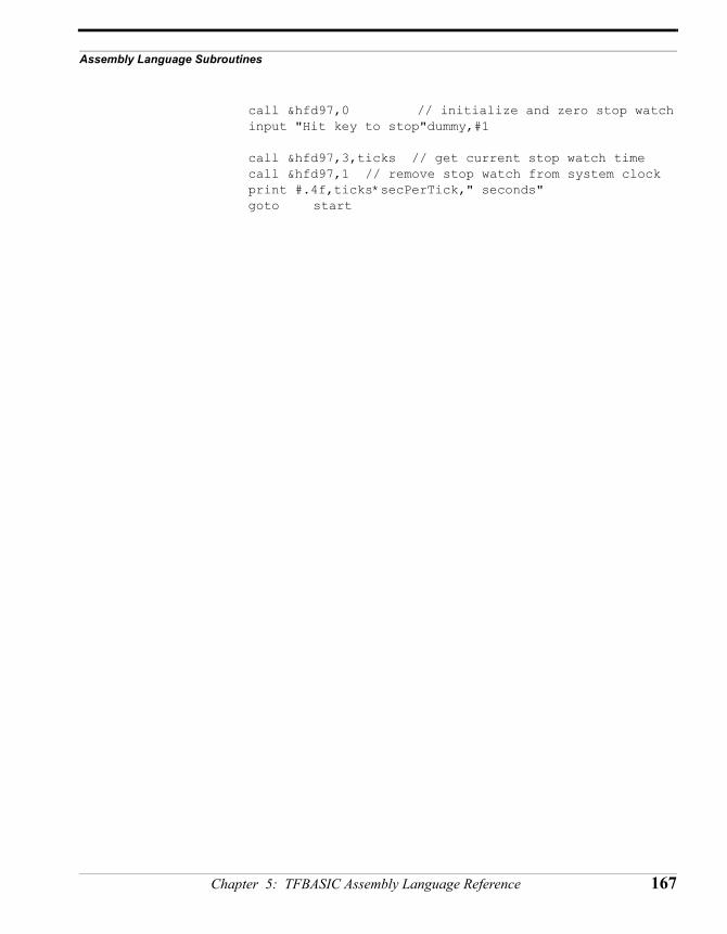
Assembly Language Subroutines
call &hfd97,0 // initialize and zero stop watchinput "Hit key to stop"dummy,#1
call &hfd97,3,ticks // get current stop watch timecall &hfd97,1 // remove stop watch from system clockprint #.4f,ticks*secPerTick," seconds"goto start
Chapter 5: TFBASIC Assembly Language Reference 167
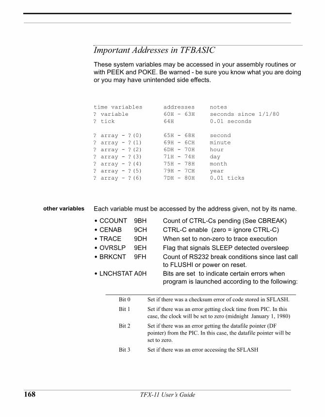
16
Important Addresses in TFBASICThese system variables may be accessed in your assembly routines or with PEEK and POKE. Be warned - be sure you know what you are doing or you may have unintended side effects.
time variables addresses notes? variable 60H - 63H seconds since 1/1/80? tick 64H 0.01 seconds
? array - ?(0) 65H - 68H second? array - ?(1) 69H - 6CH minute? array - ?(2) 6DH - 70H hour? array - ?(3) 71H - 74H day? array - ?(4) 75H - 78H month? array - ?(5) 79H - 7CH year? array - ?(6) 7DH - 80H 0.01 ticks
other variables Each variable must be accessed by the address given, not by its name.
• CCOUNT 9BH Count of CTRL-Cs pending (See CBREAK)• CENAB 9CH CTRL-C enable (zero = ignore CTRL-C)• TRACE 9DH When set to non-zero to trace execution• OVRSLP 9EH Flag that signals SLEEP detected oversleep• BRKCNT 9FH Count of RS232 break conditions since last call
to FLUSHI or power on reset.• LNCHSTAT A0H Bits are set to indicate certain errors when
program is launched according to the following:
Bit 0 Set if there was a checksum error of code stored in SFLASH.
Bit 1 Set if there was an error getting clock time from PIC. In this case, the clock will be set to zero (midnight January 1, 1980)
Bit 2 Set if there was an error getting the datafile pointer (DF pointer) from the PIC. In this case, the datafile pointer will be set to zero.
Bit 3 Set if there was an error accessing the SFLASH
8 TFX-11 User’s Guide
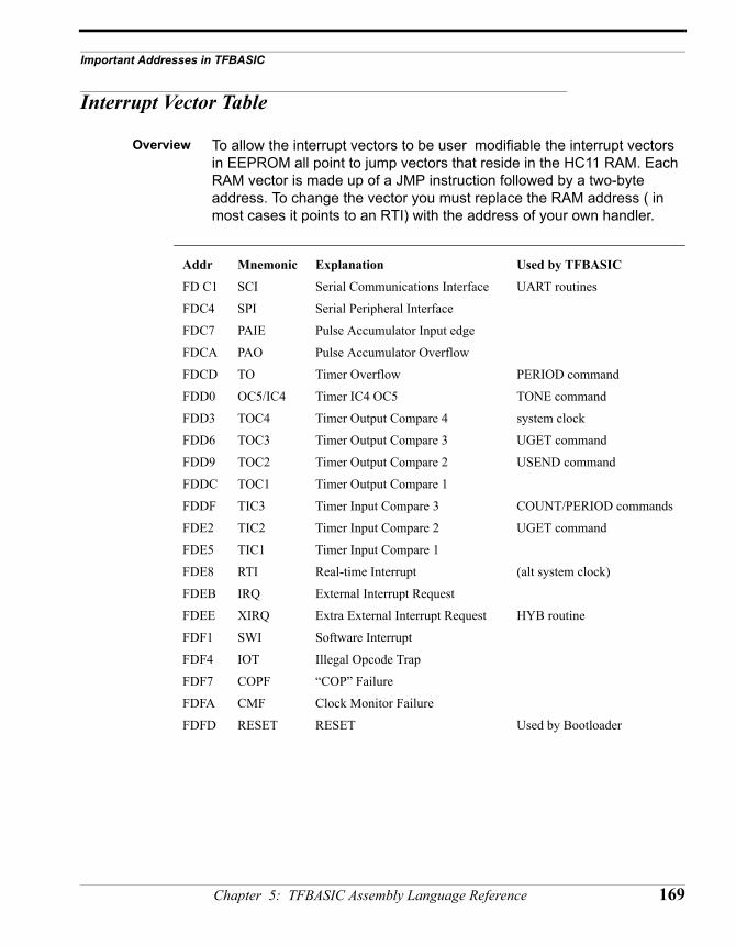
Important Addresses in TFBASIC
Interrupt Vector Table
Overview To allow the interrupt vectors to be user modifiable the interrupt vectors in EEPROM all point to jump vectors that reside in the HC11 RAM. Each RAM vector is made up of a JMP instruction followed by a two-byte address. To change the vector you must replace the RAM address ( in most cases it points to an RTI) with the address of your own handler.
Addr Mnemonic Explanation Used by TFBASIC
FD C1 SCI Serial Communications Interface UART routines
FDC4 SPI Serial Peripheral Interface
FDC7 PAIE Pulse Accumulator Input edge
FDCA PAO Pulse Accumulator Overflow
FDCD TO Timer Overflow PERIOD command
FDD0 OC5/IC4 Timer IC4 OC5 TONE command
FDD3 TOC4 Timer Output Compare 4 system clock
FDD6 TOC3 Timer Output Compare 3 UGET command
FDD9 TOC2 Timer Output Compare 2 USEND command
FDDC TOC1 Timer Output Compare 1
FDDF TIC3 Timer Input Compare 3 COUNT/PERIOD commands
FDE2 TIC2 Timer Input Compare 2 UGET command
FDE5 TIC1 Timer Input Compare 1
FDE8 RTI Real-time Interrupt (alt system clock)
FDEB IRQ External Interrupt Request
FDEE XIRQ Extra External Interrupt Request HYB routine
FDF1 SWI Software Interrupt
FDF4 IOT Illegal Opcode Trap
FDF7 COPF “COP” Failure
FDFA CMF Clock Monitor Failure
FDFD RESET RESET Used by Bootloader
Chapter 5: TFBASIC Assembly Language Reference 169

170 TFX-11 User’s Guide
CHAPTER 6
TFBASIC Internals
TFX-11 User’s Guide
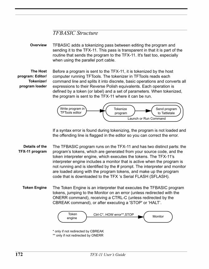
TFBASIC Structure
Overview TFBASIC adds a tokenizing pass between editing the program and sending it to the TFX-11. This pass is transparent in that it is part of the routine that sends the program to the TFX-11. It's fast too, especially when using the parallel port cable.
The Hostprogram: Editor/
Tokenizer/program loader
Before a program is sent to the TFX-11, it is tokenized by the host computer running TFTools. The tokenizer in TFTools reads each command line and splits it into discrete, basic operations and converts all expressions to their Reverse Polish equivalents. Each operation is defined by a token (or label) and a set of parameters. When tokenized, the program is sent to the TFX-11 where it can be run.
If a syntax error is found during tokenizing, the program is not loaded and the offending line is flagged in the editor so you can correct the error.
Details of theTFX-11 program
The TFBASIC program runs on the TFX-11 and has two distinct parts: the program’s tokens, which are generated from your source code, and the token interpreter engine, which executes the tokens. The TFX-11's interpreter engine includes a monitor that is active when the program is not running and is identified by the # prompt. The interpreter and monitor are loaded along with the program tokens, and make up the program code that is downloaded to the TFX ‘s Serial FLASH (SFLASH).
Token Engine The Token Engine is an interpreter that executes the TFBASIC program tokens, jumping to the Monitor on an error (unless redirected with the ONERR command), receiving a CTRL-C (unless redirected by the CBREAK command), or after executing a 'STOP' or ‘HALT’.
* only if not redirected by CBREAK** only if not redirected by ONERR
Write program in TFTools editor
Tokenize program
Send program to Tattletale
Launch or Run Command
Token engine MonitorCtrl-C*, HOW error**,STOP
172 TFX-11 User’s Guide
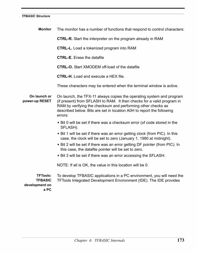
TFBASIC Structure
Monitor The monitor has a number of functions that respond to control characters:
CTRL-R. Start the interpreter on the program already in RAM
CTRL-L. Load a tokenized program into RAM
CTRL-E. Erase the datafile
CTRL-O. Start XMODEM off-load of the datafile
CTRL-H. Load and execute a HEX file.
These characters may be entered when the terminal window is active.
On launch orpower-up RESET
On launch, the TFX-11 always copies the operating system and program (if present) from SFLASH to RAM. It then checks for a valid program in RAM by verifying the checksum and performing other checks as described below. Bits are set in location A0H to report the following errors:
• Bit 0 will be set if there was a checksum error (of code stored in the SFLASH).
• Bit 1 will be set if there was an error getting clock (from PIC). In this case, the clock will be set to zero (January 1, 1980 at midnight).
• Bit 2 will be set if there was an error getting DF pointer (from PIC). In this case, the datafile pointer will be set to zero.
• Bit 3 will be set if there was an error accessing the SFLASH.
NOTE: If all is OK, the value in this location will be 0.
TFTools:TFBASIC
development ona PC
To develop TFBASIC applications in a PC environment, you will need the TFTools Integrated Development Environment (IDE). The IDE provides
Chapter 6: TFBASIC Internals 173
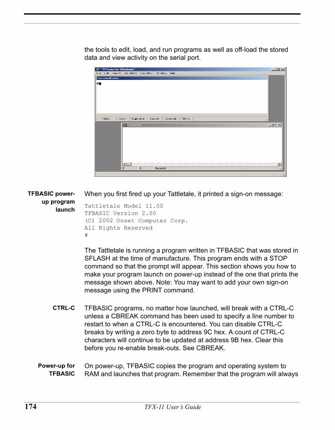
the tools to edit, load, and run programs as well as off-load the stored data and view activity on the serial port.
TFBASIC power-up program
launch
When you first fired up your Tattletale, it printed a sign-on message:
Tattletale Model 11.00TFBASIC Version 2.00(C) 2002 Onset Computer Corp.All Rights Reserved#
The Tattletale is running a program written in TFBASIC that was stored in SFLASH at the time of manufacture. This program ends with a STOP command so that the prompt will appear. This section shows you how to make your program launch on power-up instead of the one that prints the message shown above. Note: You may want to add your own sign-on message using the PRINT command.
CTRL-C TFBASIC programs, no matter how launched, will break with a CTRL-C unless a CBREAK command has been used to specify a line number to restart to when a CTRL-C is encountered. You can disable CTRL-C breaks by writing a zero byte to address 9C hex. A count of CTRL-C characters will continue to be updated at address 9B hex. Clear this before you re-enable break-outs. See CBREAK.
Power-up forTFBASIC
On power-up, TFBASIC copies the program and operating system to RAM and launches that program. Remember that the program will always
174 TFX-11 User’s Guide
TFBASIC Structure
break out upon finding a CTRL-C unless a CBREAK command has been used to specify a label to vector to when a CTRL-C is encountered.
Making yourprogram
permanent
Using the LAUNCH command will erase the contents of the datafile and reset the datafile pointer to 0. It then replaces previously the stored program (if any) with a fresh copy of the TFBASIC token interpreter engine and your compiled program tokens.
Chapter 6: TFBASIC Internals 175
TFBASIC Integers
Internalrepresentation
Integers are represented as a signed sequence of 32 bits, arranged as four bytes. The format is as follows:
MSB byte 2 byte 3 LSB
SBBBBBBB BBBBBBBB BBBBBBBB BBBBBBBB
where S is the sign bit and B represents the remaining 31 individual bits in descending order.
The range of Tattletale integers is 232, which with the sign bit, gives a range of –2147483648 to 2147483647. Any attempt to create a number outside this range will result in a run time error.
Assigning A/Dconversionvalues to a
TFBASIC variable
The A/D converters return two bytes, left-justified, so that all conversions, no matter the resolution, span a range of 0-65520 for the 12-bit A/D and 0-65280 for the eight bit. The TFX supports only unipolar operation of the A/D so the assignment of the type:
A_D_Value = CHAN(12)
will always produce the correct value and sign.
Big-endian vs.Little-endian
In the early days of microprocessors, Intel and Motorola independently devised equal but opposite storage sequences for the order of significance in multi-byte data items. In Intel’s little-endian world, the Least Significant Byte (LSB) is stored first in the lowest address, and the Most Significant Byte (MSB) in the highest address. Motorola’s order, big-endian, is just the reverse. The Motorola processor in the TFX-11 uses the Motorola sequence, but when the data is off-loaded directly from the datafile to an Intel-based PC, the order for multiple-byte data items is now reversed. If you try to access a four byte integer stored as binary from a BASIC or C program, this byte reversal will cause incorrect results. This reversal has been a cause of much confusion, partly because it always works correctly for single bytes.
176 TFX-11 User’s Guide
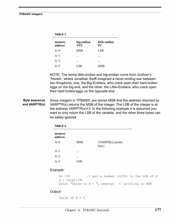
TFBASIC Integers
NOTE: The terms little-endian and big-endian come from Gulliver’s Travels., where Jonathan Swift imagined a never-ending war between two Kingdoms; one, the Big-Endians, who crack open their hard boiled-eggs on the big end, and the other, the Little-Endians, who crack open their hard boiled-eggs on the opposite end.
Byte sequenceand VARPTR(x)
Since integers in TFBASIC are stored MSB first the address returned by VARPTR(x) returns the MSB of the integer. The LSB of the integer is at the address VARPTR(x)+3. In the following example it is assumed you want to only return the LSB of the variable, and the other three bytes can be safely ignored.
Example:
X= 100 // put a number (<255) in the LSB of Xy = varptr(X)print “Value of X = “, peek(y) // pointing to MSB
Output:
Value of X = 0
TABLE 1.
memory address
big-endianTFX
little-endianPC
A+0 MSB LSB
A+1 ... ...
A+2 ... ...
A+3 LSB MSB
TABLE 2.
memory address
A+0 MSB (VARPTR(x) points here)
A+1 ...
A+2 ...
A+3 LSB
Chapter 6: TFBASIC Internals 177
This is obviously not the correct answer. The +3 added to y in the peek function of the following code corrects the problem:
Example:
X= 100y = varptr(X)print “Value of X = “, peek(y+3) // now pointing to LSB
Output:
Value of X = 100
178 TFX-11 User’s Guide
TFBASIC Floating Point
TFBASIC Floating Point
The floating point format used is based on the IEEE 754 single precision floating point standard. The range of representable values is ±1.175494E-38 to ±3.402823E+38 and zero. Also, ±infinity and not-a-number (NaN) are represented.
Internalrepresentation
Single-precision floating point numbers are represented in four bytes. The format is as follows :
MSB byte 2 byte 3 LSB
SEEEEEEE EMMMMMMM MMMMMMMM MMMMMMMM
S = sign bit; 0 = positive, 1 = negative
E = binary exponent with bias of 128
M = mantissa with 23 explicit bits and an implied 1 bit as the most significant bit
In the Tattletales, the most significant byte is at the lowest address of the four bytes. This is important if binary data is transferred directly to a computer that interprets numbers in the opposite order (as all computers with Intel microprocessors do). See the previous section on TFBASIC integers for further explanation.
Variables When using a floating point variable for the first time, append an exclamation point (!) after the last character of the name. It allows the tokenizer to check that the correct types are being used for arguments. It also allows the tokenizer to automatically convert data to the correct representation.
Example: sineValue! = sin( 90.0 )sineSquared! = sineValue! * sineValue!dim sineList!(100)
Although the ! type identifier only needs to be used the first time a variable is declared, for clarity it is recommended that it also be used with every instance of the same variable. Notice how the variable was declared as a floating point array. This MUST be done in the DIM statement because this is the first place an array is used.
Chapter 6: TFBASIC Internals 179
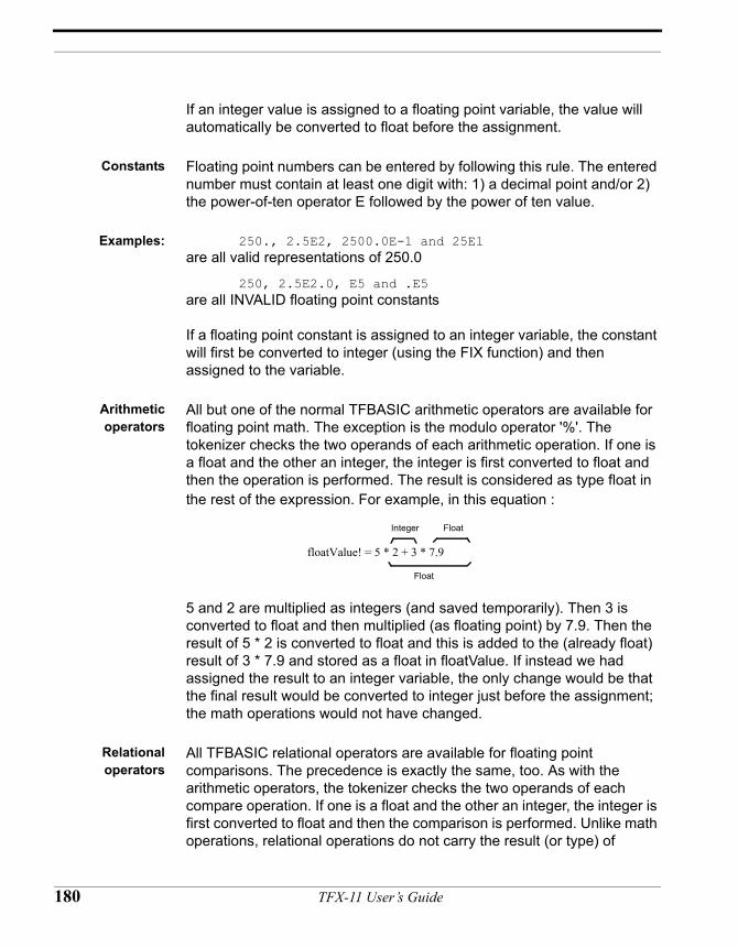
If an integer value is assigned to a floating point variable, the value will automatically be converted to float before the assignment.
Constants Floating point numbers can be entered by following this rule. The entered number must contain at least one digit with: 1) a decimal point and/or 2) the power-of-ten operator E followed by the power of ten value.
Examples: 250., 2.5E2, 2500.0E-1 and 25E1 are all valid representations of 250.0
250, 2.5E2.0, E5 and .E5 are all INVALID floating point constants
If a floating point constant is assigned to an integer variable, the constant will first be converted to integer (using the FIX function) and then assigned to the variable.
Arithmeticoperators
All but one of the normal TFBASIC arithmetic operators are available for floating point math. The exception is the modulo operator '%'. The tokenizer checks the two operands of each arithmetic operation. If one is a float and the other an integer, the integer is first converted to float and then the operation is performed. The result is considered as type float in the rest of the expression. For example, in this equation :
5 and 2 are multiplied as integers (and saved temporarily). Then 3 is converted to float and then multiplied (as floating point) by 7.9. Then the result of 5 * 2 is converted to float and this is added to the (already float) result of 3 * 7.9 and stored as a float in floatValue. If instead we had assigned the result to an integer variable, the only change would be that the final result would be converted to integer just before the assignment; the math operations would not have changed.
Relationaloperators
All TFBASIC relational operators are available for floating point comparisons. The precedence is exactly the same, too. As with the arithmetic operators, the tokenizer checks the two operands of each compare operation. If one is a float and the other an integer, the integer is first converted to float and then the comparison is performed. Unlike math operations, relational operations do not carry the result (or type) of
floatValue! = 5 * 2 + 3 * 7.9
Integer Float
Float
180 TFX-11 User’s Guide
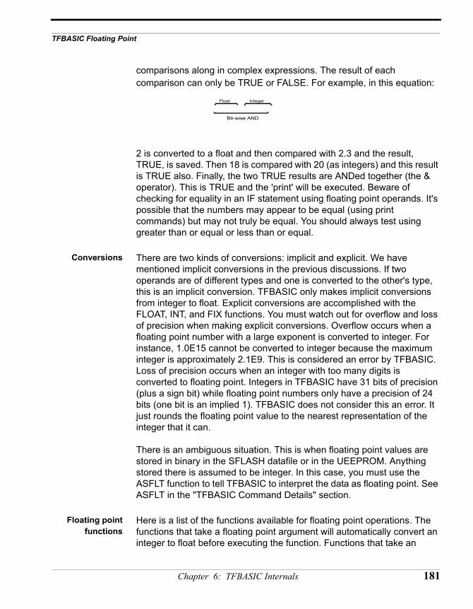
TFBASIC Floating Point
comparisons along in complex expressions. The result of each comparison can only be TRUE or FALSE. For example, in this equation:
2 is converted to a float and then compared with 2.3 and the result, TRUE, is saved. Then 18 is compared with 20 (as integers) and this result is TRUE also. Finally, the two TRUE results are ANDed together (the & operator). This is TRUE and the 'print' will be executed. Beware of checking for equality in an IF statement using floating point operands. It's possible that the numbers may appear to be equal (using print commands) but may not truly be equal. You should always test using greater than or equal or less than or equal.
Conversions There are two kinds of conversions: implicit and explicit. We have mentioned implicit conversions in the previous discussions. If two operands are of different types and one is converted to the other's type, this is an implicit conversion. TFBASIC only makes implicit conversions from integer to float. Explicit conversions are accomplished with the FLOAT, INT, and FIX functions. You must watch out for overflow and loss of precision when making explicit conversions. Overflow occurs when a floating point number with a large exponent is converted to integer. For instance, 1.0E15 cannot be converted to integer because the maximum integer is approximately 2.1E9. This is considered an error by TFBASIC. Loss of precision occurs when an integer with too many digits is converted to floating point. Integers in TFBASIC have 31 bits of precision (plus a sign bit) while floating point numbers only have a precision of 24 bits (one bit is an implied 1). TFBASIC does not consider this an error. It just rounds the floating point value to the nearest representation of the integer that it can.
There is an ambiguous situation. This is when floating point values are stored in binary in the SFLASH datafile or in the UEEPROM. Anything stored there is assumed to be integer. In this case, you must use the ASFLT function to tell TFBASIC to interpret the data as floating point. See ASFLT in the "TFBASIC Command Details" section.
Floating pointfunctions
Here is a list of the functions available for floating point operations. The functions that take a floating point argument will automatically convert an integer to float before executing the function. Functions that take an
Float Integer
Bit-wise AND
Chapter 6: TFBASIC Internals 181
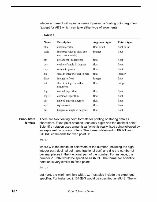
integer argument will signal an error if passed a floating point argument (except for ABS which can take either type of argument)
Print / Storeformats
There are two floating point formats for printing or storing data as characters. Fixed point notation uses only digits and the decimal point. Scientific notation uses a mantissa (which is really fixed point) followed by an exponent (in powers of ten). The format statement in PRINT and STORE commands for fixed point is:
#w.dF
where w is the minimum field width of the number (including the sign, integer part, decimal point and fractional part) and d is the number of decimal places in the fractional part of the number. For instance, the number -15.302 would be specified as #7.3F. The format for scientific notation is very similar to fixed point:
#w.dS
but here, the minimum field width, w, must also include the exponent specifier. For instance, 2.1345E-3 would be specified as #9.4S. The w
TABLE 3.
Name Description Argument type Return type
abs absolute value float or int float or int
asflt interpret value as float (no conversion made)
integer float
atn arctangent (in degrees) float float
cos cosine of angle in degrees float float
exp raise e to power float float
fix float to integer closer to zero float integer
float integer to float integer float
int float to integer less than argument
float integer
log natural logarithm float float
log10 common logarithm float float
sin sine of angle in degrees float float
sqr square root float float
tan tangent of angle in degrees float float
182 TFX-11 User’s Guide
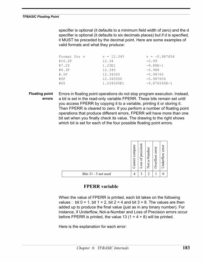
TFBASIC Floating Point
specifier is optional (it defaults to a minimum field width of zero) and the d specifier is optional (it defaults to six decimals places) but if d is specified, it MUST be preceded by the decimal point. Here are some examples of valid formats and what they produce:
Format for v v = 12.345 v = -0.987654#10.2F 12.34 -0.99#7.2S 1.23E1 -9.88E-1#6.3F 12.345 -0.988#.5F 12.34500 -0.98765#0F 12.345000 -0.987654#0S 1.234500E1 -9.876540E-1
Floating pointerrors
Errors in floating point operations do not stop program execution. Instead, a bit is set in the read-only variable FPERR. These bits remain set until you access FPERR by copying it to a variable, printing it or storing it. Then FPERR is cleared to zero. If you perform a number of floating point operations that produce different errors, FPERR will have more than one bit set when you finally check its value. The drawing to the right shows which bit is set for each of the four possible floating point errors.
When the value of FPERR is printed, each bit takes on the following values : bit 0 = 1, bit 1 = 2, bit 2 = 4 and bit 3 = 8. The values are then added up to produce the final value (just as in any binary number). For instance, if Underflow, Not-a-Number and Loss of Precision errors occur before FPERR is printed, the value 13 (1 + 4 + 8) will be printed.
Here is the explanation for each error:
Can
not c
ompa
re
Loss
of p
reci
sion
Not
-a-N
umbe
r
Ove
rflo
w e
rror
Und
erflo
w e
rror
Bits 31 - 5 not used 4 3 2 1 0
FPERR variable
Chapter 6: TFBASIC Internals 183
Underflow. - Bit 0 (weight = 1) is set if a number between +1.175494E-38 and zero results or a number between -1.175494E-38 and zero results. This is not representable in single precision. The result is set to zero.
Example:
floatValue! = 3.0E-28 * 3.1E-15 produce the errorprint "result = ", #F, floatValue print the resultprint "error = ", FPERR print FPERR value
Printed:
result = 0.000000 value of floatValueerror = 1 value of FPERR
Overflow. - Bit 1 (weight = 2) is set if a number greater than +3.402823E+38 or less than -3.402823E+38 resulted. This is not representable in single precision. The result is set to +Infinity or -Infinity.
Example:
floatValue! = -2.0E30 * 1.0E20 produce the errorprint "result = ", #F, floatValue print the resultprint "error = ", FPERR print FPERR value
Printed:
result = -INF value of floatValueerror = 2 value of FPERR
Not-a-Number. - Bit 2 (weight = 4) is set when the floating point routine has no idea of how to represent the result. One way to get this is to take the square root of a negative number which is an imaginary number. The result is flagged as a 'not-a-number'.
Example:
floatValue! = sqr(-4.0) produce the errorprint "result = ", #F, floatValue print the resultprint "error = ", FPERR value of FPERR
Printed:
result = NaN value of floatValue
184 TFX-11 User’s Guide
TFBASIC Floating Point
error = 4 value of FPERR
Loss of Precision. - Bit 3 (weight = 8) is set when an integer greater than 16777215 or less than -16777215 is converted to floating point. This is because it takes more than 24 bits to represent such a number and single precision floating point has only 24 bits to represent the precision of a number. TFBASIC will convert the value to the nearest floating point equivalent.
Example:
floatValue! = float(17789321) produce the errorprint "result = ", #F, floatValue print the resultprint "error = ", FPERR print out FPERR
Printed:
result = 17789319.000000 value of floatValue error = 8 value of FPERR
Could not Compare. This error occurs when you attempt to compare any floating point value with NaN or if you try to compare +INF with itself or -INF with itself. NOTE: You can compare +INF with -INF: + Infinity is greater than - Infinity
Chapter 6: TFBASIC Internals 185
Characters and Strings in TFBASIC
Overview String variables are denoted by adding a $ suffix to the name of the variable. When a string variable is declared, 256 bytes are reserved for it. The first byte is the length of the string so a string cannot contain more than 255 characters. 256 bytes are always reserved for the string whether used or not. Like the integer and floating point variables, TFBASIC does not initialize its string variables. If the programmer does not initialize each string variable, it may contain from 0 to 255 characters of any type when it is accessed in the program.
String constants must be enclosed in double quotes. This is different from earlier versions where single or double quotes could be used. String constants can be up to 255 characters in length (although the editor only handles lines 256 characters long). String constants can be used as arguments to commands and functions and can be assigned to string variables.
String functionsin TFBASIC
String functions can be used just as any other function. All other functions can be used as a variable or argument in another expression. Of course, functions returning a string can only be used where a string is expected. Functions returning an integer can only be used when an integer is expected.
Characterconstants
You can now use the character ‘A’ as a synonym for &H41. There can be up to four characters enclosed in single quotes. The type of the character constant is a four-byte integer. Characters are shifted into the least significant byte of the integer as they are read with unused bytes set to zero. For instance, ‘A’ is a character constant equivalent to value 41 H. ‘AB’ is equivalent to 4142 H. ‘ABC’ is equivalent to 414243 H. ‘ABCD’ is equivalent to 41424344 H. Character constants can be used anywhere an integer value is used. These are especially useful when checking if a character from the UART is equal to one or more characters. For instance, if you got a character from the UART in variable ch:
if ch = ‘Y’ | ch = ‘y’ print “Yes”else if ch = ‘N’ | ch = ‘n’ print “No” endifendif
186 TFX-11 User’s Guide
Characters and Strings in TFBASIC
Special characters can be embedded in a character constant by preceding a pattern with the escape character ‘\’. See the full explanation under “Other String Operations” that follows.
Other stringoperations
String Input. You may input a string to a variable using the INPUT command as in Input "Enter: " astring$.
String output/storing to datafile. PRINT and STORE. Special instructions for STORE: the string is stored with the length byte first followed by the string.
String assignment . String assignment from other string variables and from string constants is performed like any other assignment as in astring$ = "Test Line".
String concatenation . String concatenation is performed using the ‘+’ operator.
Example:
astring$ = “abc” + “defg” + “hij” print astring$
output:
“abcdefghij”
Embeddingspecial
characters
Special characters can be embedded within a string constant or a character constant by including an escape sequence. Each escape sequence determines the code value for a single character. Escape sequences are used to represent characters that cannot be otherwise represented.
There are two forms of escape sequences, numeric and mnemonic. Both forms start with a backslash. Numeric escape sequences allow you to represent a single character using a numeric code. Mnemonic escape sequences represent the character code with a single character related to its function, such as a \t to represent the TAB character code .
Mnemonic and numeric forms may be used interchangeably. The mnemonic form for a the tab character is “\t” and the numeric equivalent is “\x09”. Both these sequences generate a single byte code of 09h. The
Chapter 6: TFBASIC Internals 187
surrounding double quotes are necessary as all escape sequences are strings.
Example To embed a double quote:
TFBASIC code:
print “He said,\”I’m not sure\”.”
Output:
He said,”I’m not sure”.
The following code is equivalent to the example code above:
print “He said,\x22I’m not sure\x22.”
and will give the same output, although the code it is far less obvious in conveying what the programmer was up to. Note also there is no space after the digits in the second example. The escape sequence terminates with the last character in the sequence. A space included after the sequence will show up as a space in the output.
mnemonicescape
sequences list
Here is a list of mnemonic escape sequences, the ASCII characters they represent, and their hex character code:
\a BEL alarm, the bell character 07H\b BS backspace character 08H\f FF formfeed character 0CH\n NL newline, the line feed character 0AH\r CR carriage return character 0DH\t HT horizontal tab character 09H\v VT vertical tab character 0BH\” the double quote character 22H\’ the single quote character 27H\\ the backslash character 5CH
numeric escapesequences list
\xhh where hh is the hex value of the character toembed - BOTH CHARACTERS MUST BE PRESENT!
NOTE: Octal is not supported.
188 TFX-11 User’s Guide
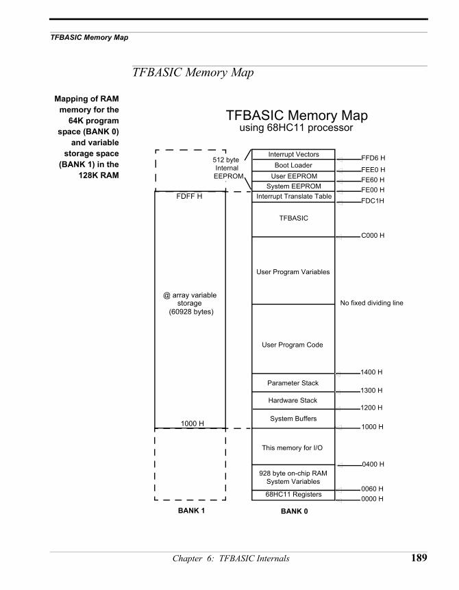
TFBASIC Memory Map
TFBASIC Memory Map
Mapping of RAMmemory for the
64K programspace (BANK 0)
and variablestorage space
(BANK 1) in the128K RAM
Interrupt Vectors
TFBASIC
User Program Variables
User Program Code
Hardware Stack
Parameter Stack
FFD6 H
C000 H
1200 H
1300 H
No fixed dividing line
TFBASIC Memory Map
0060 H0000 H68HC11 Registers
928 byte on-chip RAMSystem Variables
512 byte Internal
EEPROM
0400 H
1000 H
using 68HC11 processor
This memory for I/O
1400 H
System Buffers
FE00 H
Boot LoaderUser EEPROM
System EEPROM
FEE0 HFE60 H
Interrupt Translate Table FDC1H
1000 H
FDFF H
BANK 0BANK 1
@ array variable storage
(60928 bytes)
Chapter 6: TFBASIC Internals 189
RAM memoryoverview
The TFX-11 has 128K of RAM which is split into two 64K banks. Bank 0 contains the executing code as well as the HC11 internal memory, registers and EEPROM, which includes the UEEPROM. Bank 1 is the upper 64K of RAM and is devoted to data storage only. Access to this storage requires using the @ array. Because of hardware addressing schemes in the HC11, not all of the 64K bytes of RAM in Bank 1are available. The area that is available starts at 1000h and ends at FDFFh, or 60928 bytes. Access to this area requires bank switching which slows operation slightly. You do not need to be concerned with bank switching or addressing since TFBASIC takes care of all that when you make an assignment statement. The data in memory is referenced by the array’s index value, which is zero based. Each @ array variable is four bytes, the typical TFBASIC variable size. There are 15321 4-byte variables, thus the indices range from 0–15320.
Memory map details by address
0000h–0060h HC11 Hardware Registers. These are the registers of the processor. These may be read and written directly from an assembly routine embedded in your TFBASIC program. The register list is available in TFTools help. For detailed information on these registers and what they control, consult the Motorola MC68HC11F1 Technical Data Book and the Motorola MC68HC11 Reference Manual.
0060h–03FFh System Variables. This is the HC11’s on board RAM. It is used by TFBASIC to keep track of its operations. Your code should neither read nor write within this area. Reading, while generally a benign activity, will not give you any useful information and future revisions of the software may modify this area. Therefore, any code written to depend on values read from this area is risky at best. Writing to this area is a sure recipe for disaster.
0400h–0FFFh I/O memory. Can be mapped for CSIO1 and CSIO2 chip select addressing. Refer to the Motorola MC68HC11F1 technical manual for details. If not used with chip selects, it is available as a general purpose RAM.
1000h–11FFh System Buffers. This area contains the UART buffers and other similar TFBASIC structures. Keep out.
190 TFX-11 User’s Guide
TFBASIC Memory Map
1200h–12FFh Hardware Stack. Do not touch.
1300h–13FFh Parameter Stack. Keep out.
1400h–BFFFh User Program code and Variable area. The lowest part of this area contains the TFBASIC tokens and other code to be executed by the TFBASIC token engine. It grows up from the low address. The user variables grow downward from the location BFFFh.
C000h–FDC0h TFBASIC. This is dedicated to the TFBASIC token engine.
FDC1h–FDFFh Interrupt translate table. The interrupts vectors in the HC11’s EEPROM point here. Since this area is located in RAM, these vectors may be modified for those who might like to write their own ISRs. Not for the beginner or the faint of heart.
FE00h–FE5Fh EEPROM System Info Area. This area contains configuration information stored at time of manufacture for use by ONSET and TFBASIC.
FE60h–FEDFh EEPROM User Area. (SEEPROM) This area contains128 bytes accessed as an array by the VSTORE and VGET commands. They have been set aside for user parameter storage. The are read and written as four byte variables indexed from 0–31.
FEE0h–FFD5h Bootloader. This is the code that loads the program from flash to RAM and starts it executing.
FFD7h–FFFFh Interrupt Vectors. These are the primary interrupt vectors that point to the interrupt table in RAM.
Chapter 6: TFBASIC Internals 191
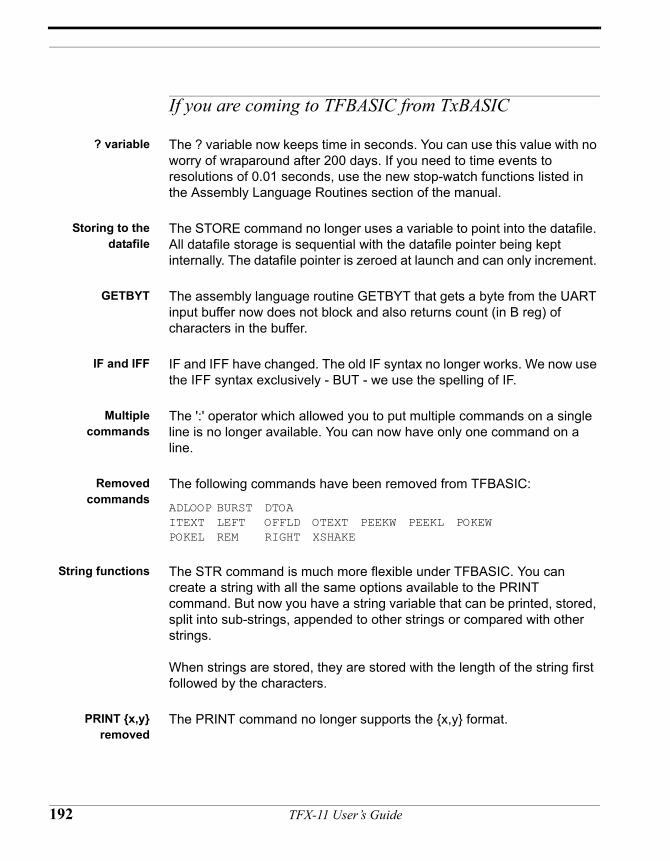
If you are coming to TFBASIC from TxBASIC
? variable The ? variable now keeps time in seconds. You can use this value with no worry of wraparound after 200 days. If you need to time events to resolutions of 0.01 seconds, use the new stop-watch functions listed in the Assembly Language Routines section of the manual.
Storing to thedatafile
The STORE command no longer uses a variable to point into the datafile. All datafile storage is sequential with the datafile pointer being kept internally. The datafile pointer is zeroed at launch and can only increment.
GETBYT The assembly language routine GETBYT that gets a byte from the UART input buffer now does not block and also returns count (in B reg) of characters in the buffer.
IF and IFF IF and IFF have changed. The old IF syntax no longer works. We now use the IFF syntax exclusively - BUT - we use the spelling of IF.
Multiplecommands
The ':' operator which allowed you to put multiple commands on a single line is no longer available. You can now have only one command on a line.
Removedcommands
The following commands have been removed from TFBASIC:
ADLOOP BURST DTOAITEXT LEFT OFFLD OTEXT PEEKW PEEKL POKEWPOKEL REM RIGHT XSHAKE
String functions The STR command is much more flexible under TFBASIC. You can create a string with all the same options available to the PRINT command. But now you have a string variable that can be printed, stored, split into sub-strings, appended to other strings or compared with other strings.
When strings are stored, they are stored with the length of the string first followed by the characters.
PRINT {x,y}removed
The PRINT command no longer supports the {x,y} format.
192 TFX-11 User’s Guide
If you are coming to TFBASIC from TxBASIC
VAL functionexpanded
The VAL function has been split into IVAL (for integers) and FVAL (for floating point numbers). This allows these functions to be used anywhere. VAL could only be used where it was being asigned to a variable so the compiler could decide if an integer or floating point value was to be output.
No early wakeupfrom SLEEP
The form of SLEEP with early wake-up (if D1 goes high) has been removed.
ITEXT removed The INPUT command covers most of the functionality of ITEXT but is more flexible because it stores to a variable.
Datafile pointervariable replaced
with DFPNTread-only
variable
Notice the addition of the DFPNT read-only variable. This was necessary because you don’t have control of the datafile pointer as before. The datafile pointer is automatically set to zero when a new program is loaded and is only changed by the STORE command. This makes accidental overwriting of data impossible - unless you load a new program without off-loading the data first! TFTools gives a warning if you attempt to do this.
Setting the BAUDrate
There are two new commands to read (GETBAUD) and change (SETBAUD) the baud rate of the main UART. The following baud rates are available: 300, 600, 1200, 2400, 4800, 9600, 19200, and 38400.
Enteringcomments in the
code
The only method of entering comments in a TFBASIC program is with the // operator. You can no longer use the ' at the beginning of a line to make the rest of the line a comment. Neither can you use the REM command to enter comments. The semicolon, ;, is still the only way to enter comments in assembly language code in TFBASIC.
PIN command The PIN command returns weighted values for the various digital I/O pins when they are high.
PCLR, PSET, andPTOG limitations
The PCLR, PSET, and PTOG commands only work with digital I/O pins 0-7 and digital I/O pins 16–23. Digital I/O pins 8–15 are input-only pins and work only with the PIN command.
HYB commandacts differently
The HYB command does not awake once every 10 seconds to check for an RS-232 BREAK condition at the input to the main UART. You can use the PIC Interrupt or the IRQ line to awake from HYB early.
Chapter 6: TFBASIC Internals 193
Timekeeping RTIME and STIME do not access the hardware real-time clock. They make conversions between the TFBASIC software clock clock (the ? variable) and the ? array. To access the RTC in the PIC use SETRTC and READRTC.
UGET/USEND UGET and USEND no longer use the datafile for storage. Instead thay use a string variable. In addition, USEND can now use a string constant or a string variable. The UGET and USEND baud rate limit has been increased to 19200.
194 TFX-11 User’s Guide
CHAPTER 7
TFX-11 Interfacing
TFX-11 User’s Guide
Interfacing to Real World Signals The TFX-11 as delivered is extremely versatile and has many capabilities, but it is far from a complete instrument. This is where you come in. In order to make the Tattletale TFX-11 into the device you envision, you will most likely need to connect external sensors and devices to its different I/O ports. Understanding of the capabilities and limitations of the different I/O options available is critical to completing an instrument or device that works reliably and repeatably.
The following sections review general issues associated with interfacing your Tattletale TFX-11 to the outside world. We hope this will give you some background and ideas that will help you make the best choices for your design. Admittedly this section is brief—for more detail we recommend you read some of the books listed as references, especially the Motorola HC11 manuals and The Art of Electronics by Horowitz and Hill.
196 TFX-11 User’s Guide
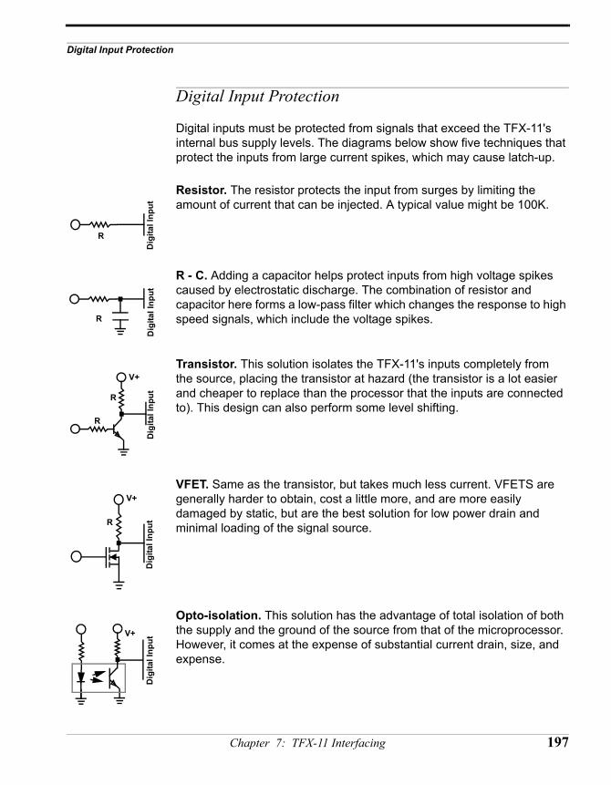
Digital Input Protection
Digital Input Protection
Digital inputs must be protected from signals that exceed the TFX-11's internal bus supply levels. The diagrams below show five techniques that protect the inputs from large current spikes, which may cause latch-up.
Resistor. The resistor protects the input from surges by limiting the amount of current that can be injected. A typical value might be 100K.
R - C. Adding a capacitor helps protect inputs from high voltage spikes caused by electrostatic discharge. The combination of resistor and capacitor here forms a low-pass filter which changes the response to high speed signals, which include the voltage spikes.
Transistor. This solution isolates the TFX-11's inputs completely from the source, placing the transistor at hazard (the transistor is a lot easier and cheaper to replace than the processor that the inputs are connected to). This design can also perform some level shifting.
VFET. Same as the transistor, but takes much less current. VFETS are generally harder to obtain, cost a little more, and are more easily damaged by static, but are the best solution for low power drain and minimal loading of the signal source.
Opto-isolation. This solution has the advantage of total isolation of both the supply and the ground of the source from that of the microprocessor. However, it comes at the expense of substantial current drain, size, and expense.
R
Dig
ital I
nput
R
Dig
ital I
nput
R
R
V+
Dig
ital I
nput
R
V+
Dig
ital I
nput
V+
Dig
ital I
nput
Chapter 7: TFX-11 Interfacing 197
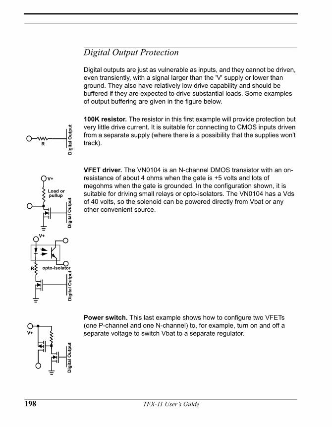
Digital Output Protection
Digital outputs are just as vulnerable as inputs, and they cannot be driven, even transiently, with a signal larger than the 'V' supply or lower than ground. They also have relatively low drive capability and should be buffered if they are expected to drive substantial loads. Some examples of output buffering are given in the figure below.
100K resistor. The resistor in this first example will provide protection but very little drive current. It is suitable for connecting to CMOS inputs driven from a separate supply (where there is a possibility that the supplies won't track).
VFET driver. The VN0104 is an N-channel DMOS transistor with an on-resistance of about 4 ohms when the gate is +5 volts and lots of megohms when the gate is grounded. In the configuration shown, it is suitable for driving small relays or opto-isolators. The VN0104 has a Vds of 40 volts, so the solenoid can be powered directly from Vbat or any other convenient source.
Power switch. This last example shows how to configure two VFETs (one P-channel and one N-channel) to, for example, turn on and off a separate voltage to switch Vbat to a separate regulator.
R
Dig
ital O
utpu
tD
igita
l Out
put
Load or
V+
pullup
Dig
ital O
utpu
t
V+
opto-isolatorR
Dig
ital O
utpu
t
V+
198 TFX-11 User’s Guide

Using the Onboard A/D Converters
Using the Onboard A/D Converters
Signalconditioning of
analog inputs
The analog inputs are designed to handle signals that range from 0 to the converter's Vcc , typically +5V. This full range ratiometric conversion is ideal for potentiometer inputs with the wiper attached to the input and the ends tied to Vsw and ground. Other sensors, such as strain gauges, may need amplification before they can be attached to the converter input.
Ratiometric A/Ds The TFX-11 has its negative reference tied to ground and its positive reference input tied to the converter's +5V positive supply. This means that if you are measuring your sensor as a fraction of the reference input (a potentiometer, or a bridge), your conversion will give solid, repeatable results. Otherwise you may require an external reference.
Externalreference
The 12-bit A-D converters will work well with an externally applied precision reference that is 2.5 volts or greater up to Vdd. The converter's accuracy depends on the reference voltage and begins to deteriorate with reference inputs less than 2.5 volts.
Chapter 7: TFX-11 Interfacing 199
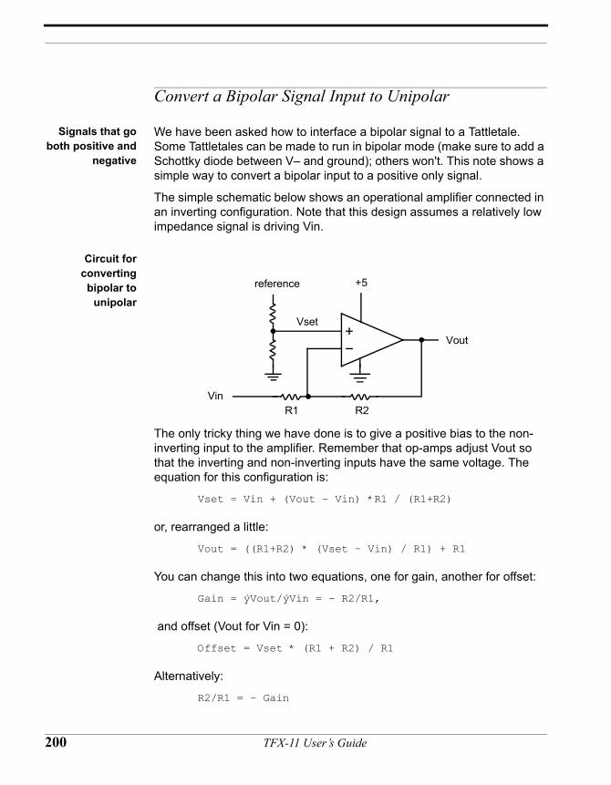
Convert a Bipolar Signal Input to Unipolar
Signals that goboth positive and
negative
We have been asked how to interface a bipolar signal to a Tattletale. Some Tattletales can be made to run in bipolar mode (make sure to add a Schottky diode between V– and ground); others won't. This note shows a simple way to convert a bipolar input to a positive only signal.
The simple schematic below shows an operational amplifier connected in an inverting configuration. Note that this design assumes a relatively low impedance signal is driving Vin.
Circuit forconvertingbipolar to
unipolar
The only tricky thing we have done is to give a positive bias to the non-inverting input to the amplifier. Remember that op-amps adjust Vout so that the inverting and non-inverting inputs have the same voltage. The equation for this configuration is:
Vset = Vin + (Vout – Vin) *R1 / (R1+R2)
or, rearranged a little:
Vout = ((R1+R2) * (Vset – Vin) / R1) + R1
You can change this into two equations, one for gain, another for offset:
Gain = ýVout/ýVin = - R2/R1,
and offset (Vout for Vin = 0):
Offset = Vset * (R1 + R2) / R1
Alternatively:
R2/R1 = – Gain
+5
Vset
R1 R2Vin
Vout
reference
200 TFX-11 User’s Guide
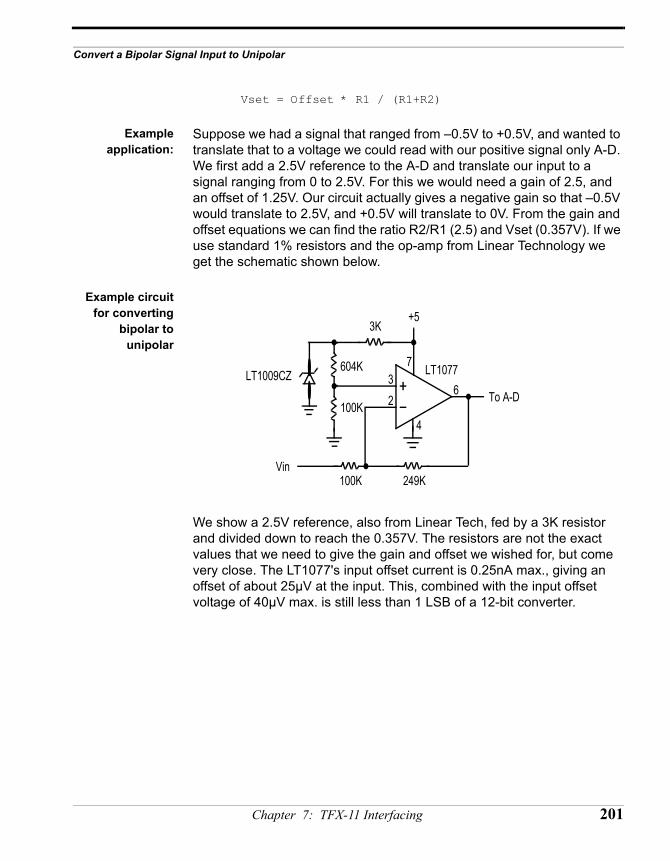
Convert a Bipolar Signal Input to Unipolar
Vset = Offset * R1 / (R1+R2)
Exampleapplication:
Suppose we had a signal that ranged from –0.5V to +0.5V, and wanted to translate that to a voltage we could read with our positive signal only A-D. We first add a 2.5V reference to the A-D and translate our input to a signal ranging from 0 to 2.5V. For this we would need a gain of 2.5, and an offset of 1.25V. Our circuit actually gives a negative gain so that –0.5V would translate to 2.5V, and +0.5V will translate to 0V. From the gain and offset equations we can find the ratio R2/R1 (2.5) and Vset (0.357V). If we use standard 1% resistors and the op-amp from Linear Technology we get the schematic shown below.
Example circuitfor converting
bipolar tounipolar
We show a 2.5V reference, also from Linear Tech, fed by a 3K resistor and divided down to reach the 0.357V. The resistors are not the exact values that we need to give the gain and offset we wished for, but come very close. The LT1077's input offset current is 0.25nA max., giving an offset of about 25µV at the input. This, combined with the input offset voltage of 40µV max. is still less than 1 LSB of a 12-bit converter.
+5
Vin
To A-D
100K 249K
LT1077LT1009CZ
3K
100K
604K
6
4
32
7
Chapter 7: TFX-11 Interfacing 201
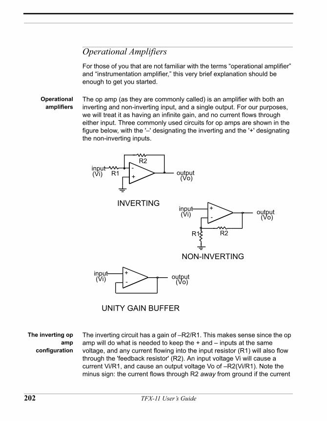
Operational Amplifiers For those of you that are not familiar with the terms “operational amplifier” and “instrumentation amplifier,” this very brief explanation should be enough to get you started.
Operationalamplifiers
The op amp (as they are commonly called) is an amplifier with both an inverting and non-inverting input, and a single output. For our purposes, we will treat it as having an infinite gain, and no current flows through either input. Three commonly used circuits for op amps are shown in the figure below, with the '–' designating the inverting and the '+' designating the non-inverting inputs.
The inverting opamp
configuration
The inverting circuit has a gain of –R2/R1. This makes sense since the op amp will do what is needed to keep the + and – inputs at the same voltage, and any current flowing into the input resistor (R1) will also flow through the 'feedback resistor' (R2). An input voltage Vi will cause a current Vi/R1, and cause an output voltage Vo of –R2(Vi/R1). Note the minus sign: the current flows through R2 away from ground if the current
R1 R2
+-
input output
R1
R2
+-input
output
INVERTING
NON-INVERTING
(Vi) (Vo)
(Vi) (Vo)
+-
input output
UNITY GAIN BUFFER
(Vi) (Vo)
202 TFX-11 User’s Guide
Operational Amplifiers
through R1 is flowing toward ground. An op amp is not magic and it cannot give an output that is larger than its positive supply or lower than its negative supply. The TFX-11 has a regulated 5V, but its negative supply is ground, so most applications will supply the op amp with ground and +5V. This makes it impossible to use the inverting circuit as drawn, unless the input is a negative voltage.
Advantages: R1 protects input from external voltage
Disadvantages: To get a large gain, R1 must be small, loading the input. Requires the input signal be negative for the positive signal needed by the TFX-11.
The non-inverting op amp
configuration
Following the same analysis we did for the inverting configuration, we find that the gain of the circuit is (R1+R2)/R1 for the non-inverting circuit. In this case we are limited to positive inputs, since the TFX-11 has no negative supply.
Advantages: High input impedance (will not load down your signal source).
Disadvantages: Takes a positive input only. To handle a negative input in a Tattletale TFX-11 application would require adding a negative supply to the Tattletale TFX-11.
Unity gain bufferop amp
configuration
The analysis for this configuration is simple. Since one of the fundamental operational rules of op-amps states that the output will do all it can to make the + and - inputs equal to each other, we can see that the input will follow the output. Since the signal is directly into the + input, the impedance is essentially infinite and the output impedance is zero. (theoretically of course!). Again we are limited to positive inputs, since the TFX-11 has no negative supply. Real op amps will have real values for input and output impedance, as well as potential limitations when attempting to drive a signal near V- supply or the V+ supply.
Advantages: High input impedance (will not load down your signal source). Makes an excellent signal buffer. Low output impedance is appropriate for driving A/D inputs.
Disadvantages: Takes a positive input only. To handle a negative input in a Tattletale TFX-11 application would require adding a negative supply to the Tattletale TFX-11. Signal may be distorted near the rails.
Chapter 7: TFX-11 Interfacing 203
The real world As magical as they appear to be, op amps are not perfect. Some limitations are described below.
Op amplimitations
Current drain. In your Tattletale TFX-11 application, you won't want to use any more power than needed. Check the current drain specs on the part you choose.
Supply voltage. Not all op amps work with supply voltages of +5 and ground. In some applications you may even want your circuit to work while the TFX-11 is running from 3 volts.
Max output swing. Most op amps can only drive to within about a volt of their positive supply, others to only about a volt of their negative supply.
Input voltage range. Not all op amps are pleased with inputs close to the supply lines; some will work with input voltages below ground. Don't be confused by the inverting configuration described above. In that circuit the input voltage is always at ground.
Input offset voltage. The input offset voltage can be understood as the voltage difference between the positive and negative inputs needed to make the output voltage zero. Ideally this should be zero; in reality many op amps have input offsets of 10mV or more. This offset will appear as an error at the output equal to the input offset times the gain of the circuit.
Input offset current. Many op amps have FET inputs that take almost no current at the input, but some can have sizable currents flowing (nanoamps) into or out of the inputs. This can lead to sizable errors if your input resistor is a large value.
That's not all, but should be enough to give you some idea of what to look for in op amp data sheets.
Op amps we haveused:
We will show some of our biases by giving you short descriptions of three op amps we like. Note that each has its own strengths.
LT1077, 1078,1079
Single, dual, and quad amplifier from Linear Technology at linear.com (408) 432-1900. This part has lovely current drain, input voltage range, and input offset voltage specs.
204 TFX-11 User’s Guide
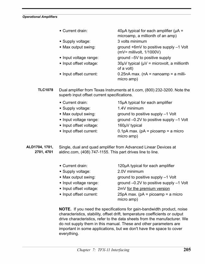
Operational Amplifiers
• Current drain: 40µA typical for each amplifier (µA = microamp, a millionth of an amp)
• Supply voltage: 3 volts minimum• Max output swing: ground +6mV to positive supply –1 Volt
(mV= millivolt, 1/1000V)• Input voltage range: ground –5V to positive supply• Input offset voltage: 30µV typical (µV = microvolt, a millionth
of a volt)• Input offset current: 0.25nA max. (nA = nanoamp = a milli-
micro amp)
TLC1078 Dual amplifier from Texas Instruments at ti.com, (800) 232-3200. Note the superb input offset current specifications.
• Current drain: 15µA typical for each amplifier• Supply voltage: 1.4V minimum• Max output swing: ground to positive supply –1 Volt• Input voltage range: ground –0.2V to positive supply –1 Volt• Input offset voltage: 160µV typical• Input offset current: 0.1pA max. (pA = picoamp = a micro
micro amp)
ALD1704, 1701,2701, 4701
Single, dual and quad amplifier from Advanced Linear Devices at aldinc.com, (408) 747-1155. This part drives line to line.
• Current drain: 120µA typical for each amplifier• Supply voltage: 2.0V minimum• Max output swing: ground to positive supply –1 Volt• Input voltage range: ground –0.2V to positive supply –1 Volt• Input offset voltage: 2mV for the premium version• Input offset current: 25pA max. (pA = picoamp = a micro
micro amp)
NOTE. If you need the specifications for gain-bandwidth product, noise characteristics, stability, offset drift, temperature coefficients or output drive characteristics, refer to the data sheets from the manufacturer. We do not supply them in this manual. These and other parameters are important in some applications, but we don't have the space to cover everything.
Chapter 7: TFX-11 Interfacing 205
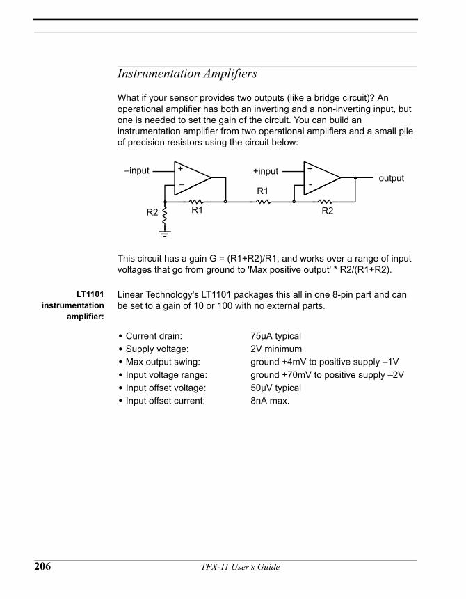
Instrumentation Amplifiers
What if your sensor provides two outputs (like a bridge circuit)? An operational amplifier has both an inverting and a non-inverting input, but one is needed to set the gain of the circuit. You can build an instrumentation amplifier from two operational amplifiers and a small pile of precision resistors using the circuit below:
This circuit has a gain G = (R1+R2)/R1, and works over a range of input voltages that go from ground to 'Max positive output' * R2/(R1+R2).
LT1101instrumentation
amplifier:
Linear Technology's LT1101 packages this all in one 8-pin part and can be set to a gain of 10 or 100 with no external parts.
• Current drain: 75µA typical• Supply voltage: 2V minimum• Max output swing: ground +4mV to positive supply –1V• Input voltage range: ground +70mV to positive supply –2V• Input offset voltage: 50µV typical• Input offset current: 8nA max.
R1R2
+–
–inputoutput
R1
R2
+-
+input
206 TFX-11 User’s Guide
CHAPTER 8
TFX-11 HardwareReference
TFX-11 User’s Guide
TFX-11 Hardware Notes
Overview of I/O The TFX-11 provides up to 19 A/D converter input and up to 24 I/O pins. Eight I/O pins are shared between digital input functions and 8-bit A/D functions. Therefore, if all the 8-bit A/D pins are used for digital input, then only the eleven 12-bit A/D inputs are left. There are 16 pins available exclusively for digital I/O. Eight are located on the HC11, and eight are located on the PIC. Because of their placement, each set has slightly different operational characteristics. Since the HC11 is the primary controller for the TFX-11, TFBASIC has direct access to the HC11 port I/O pins. In contrast, the HC11 uses synchronous serial communications with hardware handshaking to operate on the PIC I/O pins.
Selecting digitalI/O pins
Therefore, it is recommended that all high-speed bit twiddling be performed using the 8-bit port on the HC11, while the PIC I/O be used for slower speed operations.
A/D input choices The 8-bit A/D converter is internal to the HC11. These A/D input pins can also double as digital inputs. The 12-bit converter is a separate device and communicates with the HC11 via the SPI bus. Here the choice of which inputs to use is mainly based on resolution required. The 8 bit converter does allow you to sample more quickly due to its lower resolution and its registers being internal to the HC11.
Attachingdevices to the
bus
Also available are some of the HC11 bus signals: the data lines, chip selects, and other qualifying signals for attaching external memory-mapped items to the HC11. The two chip selects, CSIO1 and CSIO2, may be programmed to map into specific addresses, simplifying the addition of memory mapped I/O devices (see TFBASIC Memory Map on page 189 and the HC11F1 Technical Data Book for details).
TFX-11 referenceschematic
The simplified schematic on the following page identifies only the major components and external connections needed to properly interface additional hardware to the TFX-11.
208 TFX-11 User’s Guide
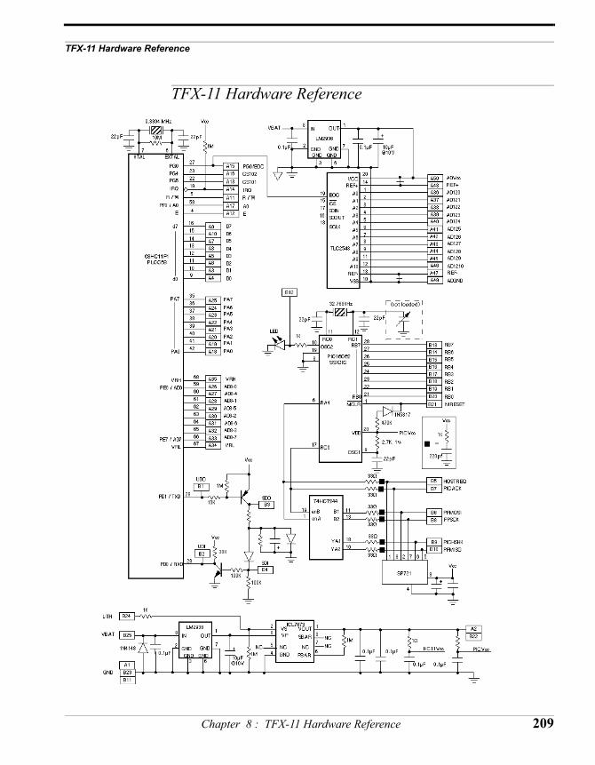
TFX-11 Hardware Reference
TFX-11 Hardware Reference
Chapter 8 : TFX-11 Hardware Reference 209
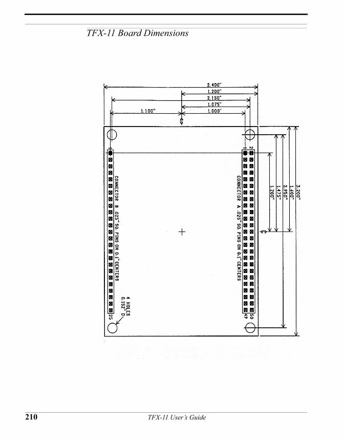
TFX-11 Board Dimensions
210 TFX-11 User’s Guide
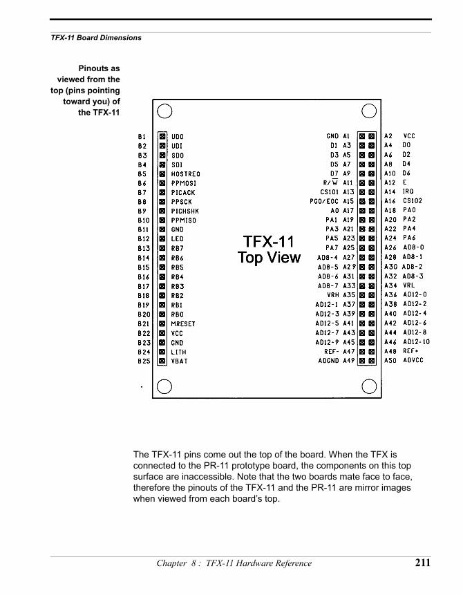
TFX-11 Board Dimensions
Pinouts asviewed from the
top (pins pointingtoward you) of
the TFX-11
The TFX-11 pins come out the top of the board. When the TFX is connected to the PR-11 prototype board, the components on this top surface are inaccessible. Note that the two boards mate face to face, therefore the pinouts of the TFX-11 and the PR-11 are mirror images when viewed from each board’s top.
Chapter 8 : TFX-11 Hardware Reference 211
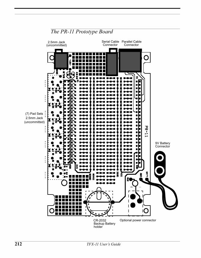
The PR-11 Prototype Board
Parallel Cable Connector
Serial Cable Connector
2.5mm Jack(uncommitted)
CR-2032 Backup Battery holder
9V Battery Connector
2.5mm Jack(uncommitted)
(7) Pad Sets
Optional power connector
212 TFX-11 User’s Guide
The PR-11 Prototype Board
Overview The PR-11 Prototype board was designed to support many different configurations and applications. It carries Power, Serial, and Parallel jacks as well as pads to take common connectors, which you may purchase separately and install yourself as necessary.
The PR-11 board outline is designed to fit inside a standard SERPAC A-279V plastic enclosure, included in the deluxe development kit. The case comes with the parts needed to handle the basic PR-11 board configuration as delivered. Depending on what optional connectors you install, you may have to modify the case to access them.
The standard configuration includes a 9V battery connector for power, a 9-pin mini-din connector to mate to the Parallel cable, and a 3.5mm stereo phone jack to mate to the serial cable. The CR2032 backup battery holder is mounted on the underside of the PR-11 board. When the TFX-11 is plugged into the PR-11 board, the PR-11 board provides all the necessary connections to fully operate the TFX-11.
Typically, 9V batteries have a rating of 500 mA-Hour (although some are rated at up to 1 Amp-Hour) and CR2032 lithium 3.2V batteries have a rating of 190 mA-Hr.
Powerconnections
Main power is connected through a 9V battery connector. The fully assembled case has a 9V battery compartment to house the battery if so desired.
Optional powerjack
Another set of pads are on the board to allow mounting of a jack (KYCON KLD-0202-A) compatible with standard wall mount DC power supply modules. The thru holes for this connector are used to attach the tie-wrap used as a strain relief for the 9V battery connector. This tie-wrap must be removed to install the jack. When this connector is used, the 9V battery compartment will no longer fit inside the case. The mating connector of the DC power supply must have a 2.1mm inside post, which must be ground. BE SURE THE POLARITY IS CORRECT BEFORE CONNECTING!
The backupbattery
The Backup battery is not a requirement for operation of the TFX-11, but can be useful in some applications. Important Note: Simply inserting a battery into the PR-11 battery holder does not automatically provide battery backup. The backup battery circuitry allows a separate power supply to be connected to TFX-11. It should be somewhere between 3.3V and 4.75V. It cannot exceed 5V or damage to the TFX-11 may result. If
Chapter 8 : TFX-11 Hardware Reference 213
below 4.5V, the main power must be applied before the backup battery is inserted or the logger may not start up properly. As long as the main power is attached, the backup battery is electrically disconnected from the circuit by the ICL7673. (NOTE: The backup battery has a 1M resistor across it. This is to allow proper operation with the battery removed.) The backup battery allows retention of the clock time and data both in the 128K RAM and internal to the HC11 and PIC when main power is removed. It does this by switching to the backup power when the primary voltage falls below the backup voltage. The backup power now becomes the primary power. The BBPWR flag changes state but NO OTHER POWER SAVING OPERATIONS ARE PERFORMED; THIS IS UP TO THE SYSTEM DESIGNER.
Important designnotes for those
intending to usethe backup
battery
When the backup battery is switched in, it powers all the circuitry that the main battery powered. It is up to the system designer to have the program explicitly check the Battery Source Flag (BBPWR) on a regular basis. When the BBPWR flag reports the system is on backup power, it is recommended that the system power off any peripherals that are connected to Vcc. When this is complete then the TFX-11 program should put the TFX-11 into its lowest power state, HYB. With everything powered down and HYB active the TFX will draw minimal current, typically less than 100uA. Periodic brief wakeups from HYB allow the program to check the BBPWR flag to see if main power has been restored with little impact on power consumption. For example, if HYB wakes every thirty seconds, it can check to see if the primary battery has been replaced, and if so continue from where it left off. With the backup battery powering the system and the TFX-11 in HYB, the primary battery can be easily swapped out and replaced with a fresh one. If the program is not structured to follow this scenario as described above, then the TFX-11 will operate as if running off main power. The system will draw the same current from the backup battery as it did from the main battery, and the backup battery will drain at the same rate as the main battery. The system will most likely not operate as intended; note that when the power supplies switch over, Vcc must be below 5 volts. In theory the system can operate down to 3.3V, but unless your design reconfigured the A/Ds with a separate reference, or they are running ratiometrically, the readings will not be accurate during the fall from 5V to 3.3V. Also RS-232 communications may fail at low voltages, but will return as soon as the voltage is restored.
214 TFX-11 User’s Guide
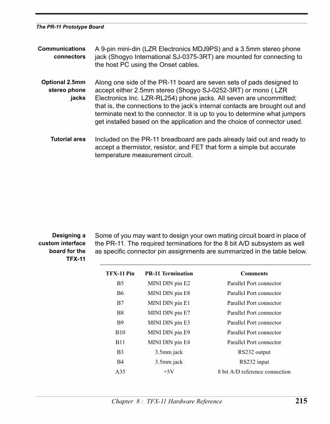
The PR-11 Prototype Board
Communicationsconnectors
A 9-pin mini-din (LZR Electronics MDJ9PS) and a 3.5mm stereo phone jack (Shogyo International SJ-0375-3RT) are mounted for connecting to the host PC using the Onset cables.
Optional 2.5mmstereo phone
jacks
Along one side of the PR-11 board are seven sets of pads designed to accept either 2.5mm stereo (Shogyo SJ-0252-3RT) or mono ( LZR Electronics Inc. LZR-RL254) phone jacks. All seven are uncommitted; that is, the connections to the jack’s internal contacts are brought out and terminate next to the connector. It is up to you to determine what jumpers get installed based on the application and the choice of connector used.
Tutorial area Included on the PR-11 breadboard are pads already laid out and ready to accept a thermistor, resistor, and FET that form a simple but accurate temperature measurement circuit.
Designing acustom interface
board for theTFX-11
Some of you may want to design your own mating circuit board in place of the PR-11. The required terminations for the 8 bit A/D subsystem as well as specific connector pin assignments are summarized in the table below.
TFX-11 Pin PR-11 Termination Comments
B5 MINI DIN pin E2 Parallel Port connector
B6 MINI DIN pin E8 Parallel Port connector
B7 MINI DIN pin E1 Parallel Port connector
B8 MINI DIN pin E7 Parallel Port connector
B9 MINI DIN pin E3 Parallel Port connector
B10 MINI DIN pin E9 Parallel Port connector
B11 MINI DIN pin E4 Parallel Port connector
B3 3.5mm jack RS232 output
B4 3.5mm jack RS232 input
A35 +5V 8 bit A/D reference connection
Chapter 8 : TFX-11 Hardware Reference 215
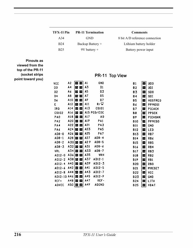
Pinouts asviewed from thetop of the PR-11
(socket stripspoint toward you)
A34 GND 8 bit A/D reference connection
B24 Backup Battery + Ltihium battery holder
B25 9V battery + Battery power input
TFX-11 Pin PR-11 Termination Comments
216 TFX-11 User’s Guide
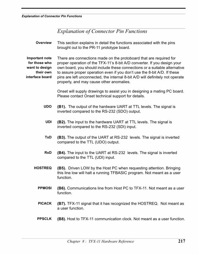
Explanation of Connector Pin Functions
Explanation of Connector Pin Functions
Overview This section explains in detail the functions associated with the pins brought out to the PR-11 prototype board.
Important notefor those who
want to designtheir own
interface board
There are connections made on the protoboard that are required for proper operation of the TFX-11’s 8-bit A/D converter. If you design your own board, you should include these connections or a suitable alternative to assure proper operation even if you don’t use the 8-bit A/D. If these pins are left unconnected, the internal 8-bit A/D will definitely not operate properly, and may cause other anomalies.
Onset will supply drawings to assist you in designing a mating PC board. Please contact Onset technical support for details.
UDO (B1). The output of the hardware UART at TTL levels. The signal is inverted compared to the RS-232 (SDO) output.
UDI (B2). The input to the hardware UART at TTL levels. The signal is inverted compared to the RS-232 (SDI) input.
TxD (B3). The output of the UART at RS-232 levels. The signal is inverted compared to the TTL (UDO) output.
RxD (B4). The input to the UART at RS-232 levels. The signal is inverted compared to the TTL (UDI) input.
HOSTREQ (B5). Driven LOW by the Host PC when requesting attention. Bringing this line low will halt a running TFBASIC program. Not meant as a user function.
PPMOSI (B6). Communications line from Host PC to TFX-11. Not meant as a user function.
PICACK (B7). TFX-11 signal that it has recognized the HOSTREQ. Not meant as a user function.
PPSCLK (B8). Host to TFX-11 communication clock. Not meant as a user function.
Chapter 8 : TFX-11 Hardware Reference 217
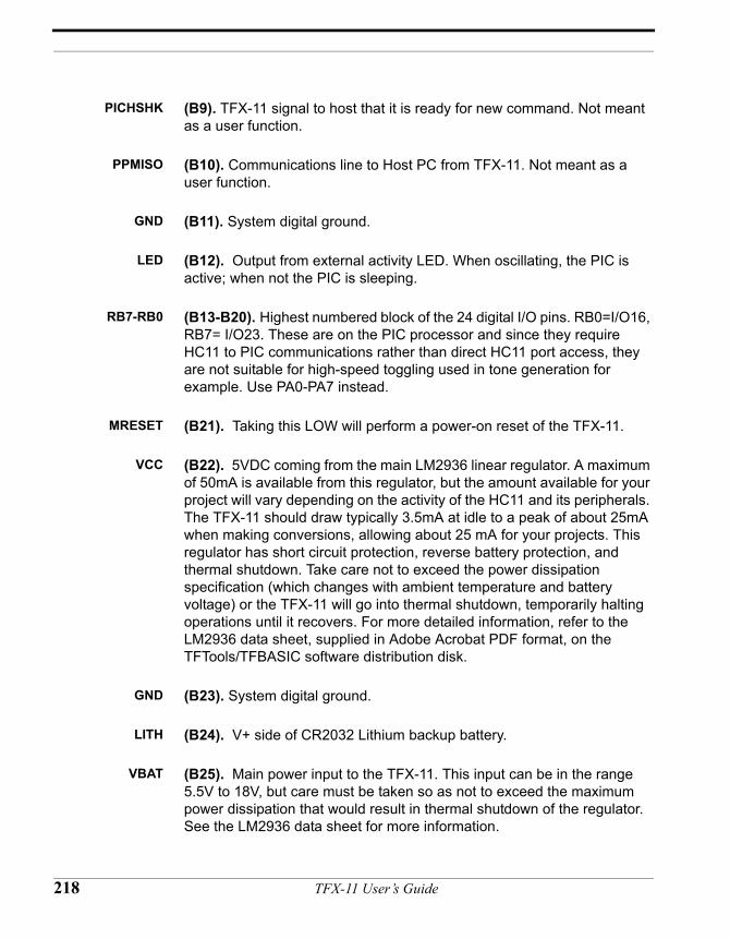
PICHSHK (B9). TFX-11 signal to host that it is ready for new command. Not meant as a user function.
PPMISO (B10). Communications line to Host PC from TFX-11. Not meant as a user function.
GND (B11). System digital ground.
LED (B12). Output from external activity LED. When oscillating, the PIC is active; when not the PIC is sleeping.
RB7-RB0 (B13-B20). Highest numbered block of the 24 digital I/O pins. RB0=I/O16, RB7= I/O23. These are on the PIC processor and since they require HC11 to PIC communications rather than direct HC11 port access, they are not suitable for high-speed toggling used in tone generation for example. Use PA0-PA7 instead.
MRESET (B21). Taking this LOW will perform a power-on reset of the TFX-11.
VCC (B22). 5VDC coming from the main LM2936 linear regulator. A maximum of 50mA is available from this regulator, but the amount available for your project will vary depending on the activity of the HC11 and its peripherals. The TFX-11 should draw typically 3.5mA at idle to a peak of about 25mA when making conversions, allowing about 25 mA for your projects. This regulator has short circuit protection, reverse battery protection, and thermal shutdown. Take care not to exceed the power dissipation specification (which changes with ambient temperature and battery voltage) or the TFX-11 will go into thermal shutdown, temporarily halting operations until it recovers. For more detailed information, refer to the LM2936 data sheet, supplied in Adobe Acrobat PDF format, on the TFTools/TFBASIC software distribution disk.
GND (B23). System digital ground.
LITH (B24). V+ side of CR2032 Lithium backup battery.
VBAT (B25). Main power input to the TFX-11. This input can be in the range 5.5V to 18V, but care must be taken so as not to exceed the maximum power dissipation that would result in thermal shutdown of the regulator. See the LM2936 data sheet for more information.
218 TFX-11 User’s Guide
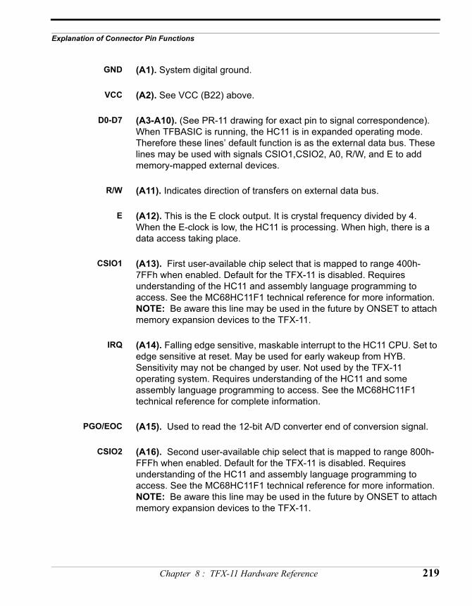
Explanation of Connector Pin Functions
GND (A1). System digital ground.
VCC (A2). See VCC (B22) above.
D0-D7 (A3-A10). (See PR-11 drawing for exact pin to signal correspondence). When TFBASIC is running, the HC11 is in expanded operating mode. Therefore these lines’ default function is as the external data bus. These lines may be used with signals CSIO1,CSIO2, A0, R/W, and E to add memory-mapped external devices.
R/W (A11). Indicates direction of transfers on external data bus.
E (A12). This is the E clock output. It is crystal frequency divided by 4. When the E-clock is low, the HC11 is processing. When high, there is a data access taking place.
CSIO1 (A13). First user-available chip select that is mapped to range 400h-7FFh when enabled. Default for the TFX-11 is disabled. Requires understanding of the HC11 and assembly language programming to access. See the MC68HC11F1 technical reference for more information. NOTE: Be aware this line may be used in the future by ONSET to attach memory expansion devices to the TFX-11.
IRQ (A14). Falling edge sensitive, maskable interrupt to the HC11 CPU. Set to edge sensitive at reset. May be used for early wakeup from HYB. Sensitivity may not be changed by user. Not used by the TFX-11 operating system. Requires understanding of the HC11 and some assembly language programming to access. See the MC68HC11F1 technical reference for complete information.
PGO/EOC (A15). Used to read the 12-bit A/D converter end of conversion signal.
CSIO2 (A16). Second user-available chip select that is mapped to range 800h-FFFh when enabled. Default for the TFX-11 is disabled. Requires understanding of the HC11 and assembly language programming to access. See the MC68HC11F1 technical reference for more information. NOTE: Be aware this line may be used in the future by ONSET to attach memory expansion devices to the TFX-11.
Chapter 8 : TFX-11 Hardware Reference 219
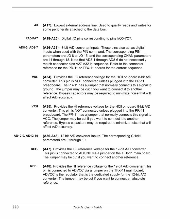
A0 (A17). Lowest external address line. Used to qualify reads and writes for some peripherals attached to the data bus.
PA0-PA7 (A18-A25). Digital I/O pins corresponding to pins I/O0-I/O7.
AD8-0, AD8-7 (A26-A33). 8-bit A/D converter inputs. These pins also act as digital inputs when used with the PIN command. The corresponding PIN parameters are I/O 8 to I/O 15, and the corresponding CHAN parameters are 11 through 18. Note that AD8-1 through AD8-6 do not necessarily match connector pins A27-A32 in sequence. Refer to the connector reference for the PR-11 or TFX-11 boards for the correct sequence.
VRL (A34). Provides the LO reference voltage for the HCll on-board 8-bit A/D converter. This pin is NOT connected unless plugged into the PR-11 breadboard. The PR-11 has a jumper that normally connects this signal to ground. The jumper may be cut if you want to connect it to another reference. Bypass capacitors may be required to minimize noise that will affect A/D accuracy.
VRH (A35). Provides the HI reference voltage for the HCll on-board 8-bit A/D converter. This pin is NOT connected unless plugged into the PR-11 breadboard. The PR-11 has a jumper that normally connects this signal to VCC. The jumper may be cut if you want to connect it to another reference. Bypass capacitors may be required to minimize noise that will affect A/D accuracy.
AD12-0, AD12-10 (A36-A46). 12 bit A/D converter inputs. The corresponding CHAN parameters are 0 through 10.
REF- (A47). Provides the LO reference voltage for the 12-bit A/D converter. This pin is connected to ADGND via a jumper on the TFX-11 main board. The jumper may be cut if you want to connect another reference.
REF+ (A48). Provides the HI reference voltage for the 12-bit A/D converter. This pin is connected to ADVCC via a jumper on the TFX-11 main board. ADVCC is the regulator that is the dedicated supply for the 12-bit A/D converter. The jumper may be cut if you want to connect an absolute reference.
220 TFX-11 User’s Guide
Explanation of Connector Pin Functions
ADGND (A49). Analog ground connection for the 12-bit A/D converter input signals. To avoid introducing noise in the A/D conversions, DO NOT attach any other grounds to this point
ADVCC (A50). Analog reference for the 12-bit A/D converter input signals.
Chapter 8 : TFX-11 Hardware Reference 221

222 TFX-11 User’s Guide
CHAPTER 9
TFX-11v2HardwareReference
TFX-11 User’s Guide
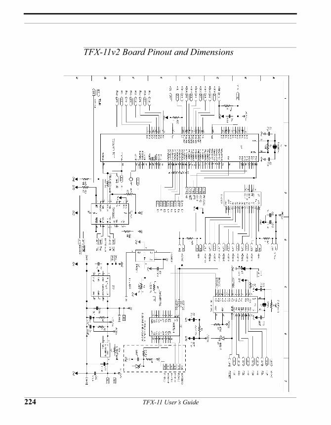
TFX-11v2 Board Pinout and Dimensions
224 TFX-11 User’s Guide
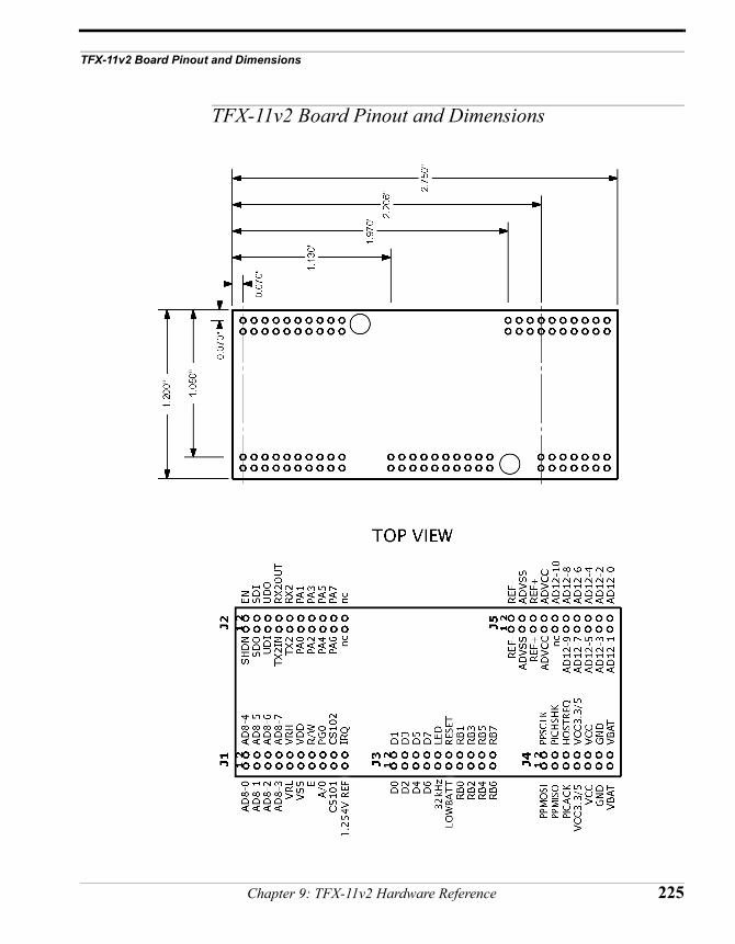
TFX-11v2 Board Pinout and Dimensions
TFX-11v2 Board Pinout and Dimensions
Chapter 9: TFX-11v2 Hardware Reference 225
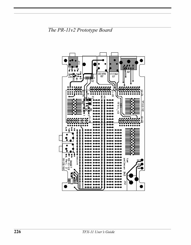
The PR-11v2 Prototype Board
226 TFX-11 User’s Guide
The PR-11v2 Prototype Board
Overview The PR-11v2 Prototype board was designed to support many different configurations and applications. It carries Power, Serial, and Parallel jacks as well as pads to take common connectors, which you may purchase separately and install yourself as necessary.
The PR-11v2 board outline is designed to fit inside a standard SERPAC A-279V plastic enclosure, included in the deluxe development kit. The case comes with the parts needed to handle the basic PR-11v2 board configuration as delivered. Depending on what optional connectors you install, you may have to modify the case to access them.
The standard configuration includes a 9V battery connector for power, a 9-pin mini-DIN connector to mate to the Parallel cable, and a 3.5mm stereo phone jack to mate to the serial cable. When the TFX-11v2 is plugged into the PR-11v2 board, the PR-11v2 board provides all the necessary connections to fully operate the TFX-11v2.
Typically, 9V batteries have a rating of 500 mA-Hour, although some are rated at up to 1 Amp-Hour.
Powerconnections
Main power is connected through a 9V battery connector. The fully assembled case has a 9V battery compartment to house the battery if so desired.
Optional powerjack
Another set of pads are on the board to allow mounting of a jack (KYCON KLD-0202-A) compatible with standard wall mount DC power supply modules. The thru holes for this connector are used to attach the tie-wrap used as a strain relief for the 9V battery connector. This tie-wrap must be removed to install the jack. When this connector is used, the 9V battery compartment will no longer fit inside the case. The mating connector of the DC power supply must have a 2.1mm inside post, which must be ground. BE SURE THE POLARITY IS CORRECT BEFORE CONNECTING!
Communicationsconnectors
A 9 pin mini-din (LZR Electronics MDJ9PS) and a 3.5mm stereo phone jack (Shogyo International SJ-0375-3RT) are mounted for connecting to the host PC using the Onset cables. There is a position for a second 3.5mm stereo phone jack that can be used to connect to the second RS-232 levels channel or any other pins you would like to use.
Chapter 9: TFX-11v2 Hardware Reference 227
Optional 2.5mmstereo phone
jacks
Along one side of the PR-11v2 board are two sets of pads designed to accept either 2.5mm stereo (Shogyo SJ-0252-3RT) or mono (LZR Electronics Inc. LZR-RL254) phone jacks. Both are uncommitted; that is, the connections to the jack’s internal contacts are brought out and terminate next to the connector. It is up to you to determine what jumpers get installed and to what I/O they are connected based on the application and the choice of connector used.
Tutorial area Included on the PR-11v2 breadboard are pads already laid out and ready to accept a thermistor, resistor, and transistor (FET) that form a simple but accurate temperature measurement circuit.
Designing acustom interface
board for theTFX-11v2
Some of you may want to design your own mating circuit board in place of the PR-11v2. The required terminations for the 8-bit A/D subsystem as well as specific connector pin assignments are summarized in the table below.
TFX-11v2 Pin PR-11v2
Termination Comments
J4-5 MINI DIN pin E2 Parallel Port connector (HOSTREQ)
J4-1 MINI DIN pin E8 Parallel Port connector (PPMOSI)
J4-5 MINI DIN pin E1 Parallel Port connector (PICACK)
J4-2 MINI DIN pin E7 Parallel Port connector (PPSCK)
J4-4 MINI DIN pin E3 Parallel Port connector (PICSHK)
J4-3 MINI DIN pin E9 Parallel Port connector (PPMISO)
J2-11 MINI DIN pin E4 Parallel Port connector (GND)
J2-3 3.5mm jack RS232 (Primary) output
J2-4 3.5mm jack RS232 (Primary) input
J2-9 3.5mm jack RS232 (Secondary) output
J2-10 3.5mm jack RS232 (Secondary) input
J2-13,14 9V battery + Battery power input
228 TFX-11 User’s Guide
Explanation of Connector Pin Functions
Explanation of Connector Pin Functions
Overview The following paragraphs explain in detail the functions associated with the pins brought out to the PR-11v2 prototype board.
Important notefor those who
want to designtheir own
interface board
There are connections made on the protoboard that are required for proper operation of the TFX-11v2’s eight bit A/D converter. If you design your own board, you should include these connections or a suitable alternative to assure proper operation even if you don’t use the 8 bit A/D. If these pins are left unconnected, the internal 8-bit A/D will definitely not operate properly, and may cause other anomalies.
Onset will supply drawings to assist you in designing a mating PC board. Please contact Onset technical support for details.
UDO (J2-6). The output of the hardware UART at TTL levels. The signal is inverted compared to the RS-232 (SDO) output.
UDI (J2-5). The input to the hardware UART at TTL levels. The signal is inverted compared to the RS-232 (SDI) input.
SDO J2-3). The output of the UART at RS-232 levels. The signal is inverted compared to the TTL (UDO) output.
SDI (J2-4). The input to the UART at RS-232 levels. The signal is inverted compared to the TTL (UDI) input.
RX2OUT (J2-8). The output of the secondary RS232 port at TTL levels. The signal is inverted compared to the RS-232 (RX2) output.
TX2IN (J2-7). The input to the secondary RS232 port at TTL levels. The signal is inverted compared to the RS-232 (TX2) input.
TX2 J2-3). The output of the secondary RS232 port at RS-232 levels. The signal is inverted compared to the TTL (RX2OUT) output.
RX2 (J2-4). The input to the secondary RS232 port at RS-232 levels. The signal is inverted compared to the TTL (TX2IN) input.
Chapter 9: TFX-11v2 Hardware Reference 229
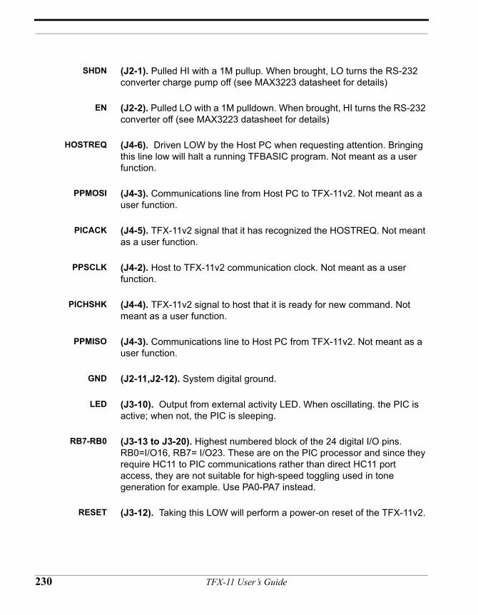
SHDN (J2-1). Pulled HI with a 1M pullup. When brought, LO turns the RS-232 converter charge pump off (see MAX3223 datasheet for details)
EN (J2-2). Pulled LO with a 1M pulldown. When brought, HI turns the RS-232 converter off (see MAX3223 datasheet for details)
HOSTREQ (J4-6). Driven LOW by the Host PC when requesting attention. Bringing this line low will halt a running TFBASIC program. Not meant as a user function.
PPMOSI (J4-3). Communications line from Host PC to TFX-11v2. Not meant as a user function.
PICACK (J4-5). TFX-11v2 signal that it has recognized the HOSTREQ. Not meant as a user function.
PPSCLK (J4-2). Host to TFX-11v2 communication clock. Not meant as a user function.
PICHSHK (J4-4). TFX-11v2 signal to host that it is ready for new command. Not meant as a user function.
PPMISO (J4-3). Communications line to Host PC from TFX-11v2. Not meant as a user function.
GND (J2-11,J2-12). System digital ground.
LED (J3-10). Output from external activity LED. When oscillating. the PIC is active; when not, the PIC is sleeping.
RB7-RB0 (J3-13 to J3-20). Highest numbered block of the 24 digital I/O pins. RB0=I/O16, RB7= I/O23. These are on the PIC processor and since they require HC11 to PIC communications rather than direct HC11 port access, they are not suitable for high-speed toggling used in tone generation for example. Use PA0-PA7 instead.
RESET (J3-12). Taking this LOW will perform a power-on reset of the TFX-11v2.
230 TFX-11 User’s Guide
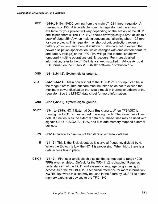
Explanation of Connector Pin Functions
VCC (J4-9,J4-10). 5VDC coming from the main LT1521 linear regulator. A maximum of 150mA is available from this regulator, but the amount available for your project will vary depending on the activity of the HC11 and its peripherals. The TFX-11v2 should draw typically 3.5mA at idle to a peak of about 25mA when making conversions, allowing about 125 mA for your projects. This regulator has short circuit protection, reverse battery protection, and thermal shutdown. Take care not to exceed the power dissipation specification (which changes with ambient temperature and battery voltage) or the TFX-11v2 will go into thermal shutdown, temporarily halting operations until it recovers. For more detailed information, refer to the LT1521 data sheet, supplied in Adobe Acrobat PDF format, on the TFTools/TFBASIC software distribution disk.
GND (J4-11,J4-12). System digital ground.
VBAT (J4-13,J4-14). Main power input to the TFX-11v2. This input can be in the range 5.5V to 18V, but care must be taken so as not to exceed the maximum power dissipation that would result in thermal shutdown of the regulator. See the LT1521 data sheet for more information.
GND (J2-11,J2-12). System digital ground.
D0-D7 (J3-1 to J3-8). HC11 External Data Bus signals. When TFBASIC is running the HC11 is in expanded operating mode. Therefore these lines’ default function is as the external data bus. These lines may be used with signals CSIO1,CSIO2, A0, R/W, and E to add memory mapped external devices.
R/W (J1-14). Indicates direction of transfers on external data bus.
E (J1-13). This is the E clock output. It is crystal frequency divided by 4. When the E-clock is low, the HC11 is processing. When high, there is a data access taking place.
CSIO1 (J1-17). First user-available chip select that is mapped to range 400h-7FFh when enabled. Default for the TFX-11v2 is disabled. Requires understanding of the HC11 and assembly language programming to access. See the MC68HC11F1 technical reference for more information. NOTE: Be aware this line may be used in the future by ONSET to attach memory expansion devices to the TFX-11v2.
Chapter 9: TFX-11v2 Hardware Reference 231
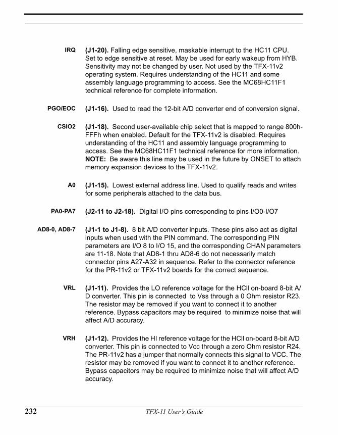
IRQ (J1-20). Falling edge sensitive, maskable interrupt to the HC11 CPU. Set to edge sensitive at reset. May be used for early wakeup from HYB. Sensitivity may not be changed by user. Not used by the TFX-11v2 operating system. Requires understanding of the HC11 and some assembly language programming to access. See the MC68HC11F1 technical reference for complete information.
PGO/EOC (J1-16). Used to read the 12-bit A/D converter end of conversion signal.
CSIO2 (J1-18). Second user-available chip select that is mapped to range 800h-FFFh when enabled. Default for the TFX-11v2 is disabled. Requires understanding of the HC11 and assembly language programming to access. See the MC68HC11F1 technical reference for more information. NOTE: Be aware this line may be used in the future by ONSET to attach memory expansion devices to the TFX-11v2.
A0 (J1-15). Lowest external address line. Used to qualify reads and writes for some peripherals attached to the data bus.
PA0-PA7 (J2-11 to J2-18). Digital I/O pins corresponding to pins I/O0-I/O7
AD8-0, AD8-7 (J1-1 to J1-8). 8 bit A/D converter inputs. These pins also act as digital inputs when used with the PIN command. The corresponding PIN parameters are I/O 8 to I/O 15, and the corresponding CHAN parameters are 11-18. Note that AD8-1 thru AD8-6 do not necessarily match connector pins A27-A32 in sequence. Refer to the connector reference for the PR-11v2 or TFX-11v2 boards for the correct sequence.
VRL (J1-11). Provides the LO reference voltage for the HCll on-board 8-bit A/D converter. This pin is connected to Vss through a 0 Ohm resistor R23. The resistor may be removed if you want to connect it to another reference. Bypass capacitors may be required to minimize noise that will affect A/D accuracy.
VRH (J1-12). Provides the HI reference voltage for the HCll on-board 8-bit A/D converter. This pin is connected to Vcc through a zero Ohm resistor R24. The PR-11v2 has a jumper that normally connects this signal to VCC. The resistor may be removed if you want to connect it to another reference. Bypass capacitors may be required to minimize noise that will affect A/D accuracy.
232 TFX-11 User’s Guide
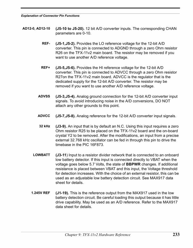
Explanation of Connector Pin Functions
AD12-0, AD12-10 (J5-10 to J5-20). 12 bit A/D converter inputs. The corresponding CHAN parameters are 0-10.
REF- (J5-1,J5-2). Provides the LO reference voltage for the 12-bit A/D converter. This pin is connected to ADGND through a zero Ohm resistor R26 on the TFX-11v2 main board. The resistor may be removed if you want to use another A/D reference voltage.
REF+ (J5-5,J5-6). Provides the HI reference voltage for the 12-bit A/D converter. This pin is connected to ADVCC through a zero Ohm resistor R27on the TFX-11v2 main board. ADVCC is the regulator that is the dedicated supply for the 12-bit A/D converter. The resistor may be removed if you want to use another A/D reference voltage.
ADVSS (J5-3,J5-4). Analog ground connection for the 12-bit A/D converter input signals. To avoid introducing noise in the A/D conversions, DO NOT attach any other grounds to this point.
ADVCC (J5-7,J5-8). Analog reference for the 12-bit A/D converter input signals.
32 kHz (J3-9). An input that is by default an N.C. Using this input requires a zero Ohm resistor R25 to be placed on the TFX-11v2 board and the on-board crystal Y2 to be removed. After the modifications, an input from a precise external 32.768 kHz oscillator can be fed in through this pin to drive the timebase in the PIC 16F873.
LOWBATT (J3-11) Input to a resistor divider network that is connected to an onboard low battery detector. If this input is connected directly to VBAT when the voltage goes below 5.7 Volts, the state of BBPWR changes. If additional resistance is placed between VBAT and this input, the Voltage threshold for detection increases. With the choice of an external resistor, this can be used as an adjustable low battery detection circuit. See MAX917 data sheet for details.
1.245V REF (J1-19). This is the reference output from the MAX917 used in the low battery detection circuit. Be careful loading this output because it has little drive capability. May be used as an A/D reference. Refer to the MAX917 data sheet for details.
Chapter 9: TFX-11v2 Hardware Reference 233

234 TFX-11 User’s Guide
CHAPTER 10
TFX-11 GeneralHardwareReference
TFX-11 User’s Guide
23
TFX Timekeeping
RTC storage structures TFXBASIC has two structures for holding time related information: the ? variable and the ?() array.
The ? variable. The ? variable consists of 4 bytes and increments every second.
The ?( ) array. The ?() array is a separate structure of seven 4-byte integer variables with:
• ?(0) holding seconds (0-59)• ?(1) holding minutes (0-59)• ?(2) holding hours (0-23)• ?(3) holding days (0-31)• ?(4) holding months (1-12)• ?(5) holding years (1980-2040)
The ?() array is only updated by invoking the RTIME command or by directly modifying it with an assignment to one or more of the elements. ?(6) contains the current ticks count (0-99). Ticks occur a the rate of 100 per second and cannot be changed.
Using these predefined structures simplifies date and timekeeping and time-based math calculations. Note that the ?(5), the year array element, contains all four significant digits of the year, not just the last two, to allow simpler and error-free date calculations.
Two separate crystals Because the PIC and HC11 use separate clock crystals, it is possible that the time kept in one processor will drift from the other. Therefore a clear understanding of how the two interact is necessary to ensure critical timing sequences are not compromised.
Clock resolution The PIC keeps time in one second increments. TFBASIC on the HC11 keeps time to 1/100 second. Because of the HYB overhead, it is recommended that all intervals below 5 seconds
6 TFX-11 User’s Guide
TFX Timekeeping
only be handled by SLEEP, and intervals longer than 5 seconds be handled by HYB. Use SLEEP where interval timing must be precise within a sub-second.
PIC as primary RTC Since the PIC clock crystal is always running, even in HYB mode, the PIC processor is considered the principal RTC on the TFX-11. At Program Launch, the Host PC copies its current system clock time, in seconds, to the PIC. When the PIC starts the HC11 by removing it from RESET, the PIC time is copied to the TFBASIC ? variable by the TFBASIC startup code, with tenths of seconds being initialized to 0. After this initialization, there is nothing explicitly built into the TFX-11 to keep the two clocks synchronized, but since the commands available between the PIC and TFBASIC use calculations based on relative time, there is no problem.
When an RTIME or STIME command is executed in TFBASIC, it only acts locally; that is it does not affect and is not affected by the time in the PIC. After TFBASIC initialization, all timekeeping data is kept locally on the HC11 and it is updated locally, unless otherwise commanded from the TFBASIC program.
Timing dependencies SLEEP commands. All SLEEP clock timing is relative to the TFBASIC periodic timer interrupt on the HC11. TFBASIC keeps a separate SLEEP timer which, while clocked from the same HC11 periodic interrupt, does not share count values with the ? variable, and therefore is not affected by the RTIME or STIME commands. It can only be modified by a SLEEP x command.
HYB commands. Since the HC11’s clock is stopped during HYB, absolute HYB timing is dependent on the PIC’s clock crystal. Wakeup from HYB timing is calculated as relative time, as seconds from the current value in the HC11 clock to the requested wakeup time. This value is transferred to the PIC and added to the current PIC time to calculate the alarm wakeup time. The HC11 stores locally this offset count as well as the time it entered HYB. When the PIC wakes it up, TFBASIC gets the current time from the PIC. Assuming no drift between the two crystals, this technique will wake it up at the exact time requested, with the ? variable containing the correct time for TFBASIC even if the times on the PIC and HC11 differ. Since the
Chapter 10: TFX-11 General Hardware Reference 237
23
HC11 has been stopped during HYB, the only valid time available is the PIC time in seconds.
Clock drift Any drift error during an HYB period depends on the PIC’s crystal oscillator. Any drift error during TFBASIC operation is dependent on the HC11 crystal. The PIC crystal drifts at a rate of -0.04 PPM /°C.
8 TFX-11 User’s Guide
TFX-11 Data Storage Options
TFX-11 Data Storage Options
The TFX-11 offers some different data storage options, each designed to suit a particular purpose best. Different methods of write and read access define appropriateness for using each of these different storage areas. The major on-board memory areas are listed below:
• Program and Variables memory, bank 0 of the 128K static RAM• @ array memory, bank 1 of the 128K static RAM• UEEPROM, 128 bytes User EEPROM inside the HC11• 1MB (TFX-11) or 2MB (TFX-11v2) Serial flash EEPROM
(SFLASH)
Refer to the TFBASIC memory map on page 189 for a graphical representation of the descriptions that follow.
Program and Variables memory, bank 0 of the 128K static RAM. This is the default RAM bank that contains the running TFBASIC program, token interpreter, and variable storage space. It is TFBASIC’s prime operating area. User storage in this area is accessed directly through TFBASIC variables. The total area available for storage is reduced by the overhead used by the token interpreter and the storage used by the user’s program tokens.
This memory is battery-backed and retains its information as long as the backup battery is not removed. This memory is not accessible directly via the parallel port. Any data stored here must be transferred to the SFLASH before off-load or transferred directly out the UART via a running TFBASIC program.
@ array memory, bank 1 of the 128K static RAM. This area of RAM is set aside for random access data storage. It is predefined as a single array containing 15232 elements, called the @ array. Each element of this array is a standard 4-byte variable. This section of RAM is easily accessible; any assignment to or from an @ array variable transfers the data, automatically performing the bank switching. This area is NOT automatically initialized on startup. As it is battery-backed, it can retain its contents from one reset to another as long as the backup battery is not removed.
Chapter 10: TFX-11 General Hardware Reference 239
24
This bank of RAM is also accessible using the GETBSR and STRBSR described in the Assembly Language Subroutines section.
This memory is not accessible directly via the parallel port. Any data stored here must be transferred to the SFLASH before off-load or transferred directly out the UART via a running TFBASIC program.
@ARRAY limitations. The @ARRAY is mainly meant for use as a datafile. Unlike the SFLASH datafile, which is write only, the @ARRAY may be written and read. It is battery-backed and can be considered non-volatile as long as the backup battery is viable. @ARRAY variables CANNOT be used as the following:
• FOR loop variable• RTIME argument• STIME argument• READRTC argument• SETRTC argument• CALL return variable• INPUT variable• ONERR return variable
This should present no problem as there is plenty of RAM available for regular variables.
UEEPROM, 128 bytes User EEPROM (inside the HC11). This is located in a section of the internal memory map of the HC11. It is read, erased, and written in units of four bytes, the standard TFBASIC variable. As with all EEPROMs, any one location can only be written a limited number of times (approx 10,000) before it fails. This is in contrast to reads, which are unlimited.
The most appropriate use for this limited memory is to store configuration information or sensor calibration parameters.These values would be written once when the instrument is calibrated or setup and then could be read any number of times as necessary. This technique allows a single program to compensate for sensor
0 TFX-11 User’s Guide
TFX-11 Data Storage Options
or external hardware variations across otherwise identical instruments.
These 128 locations are divided into 32 groups of four, making the integer (or float) the default storage unit. They are accessed only by the TFBASIC commands VGET and VSTORE, with valid locations being 0-31. These locations are totally non-volatile; they will remain even if all power is removed.
472K/2Mb bytes Serial flash EEPROM (SFLASH). This storage is in an external serial-linked flash EEPROM, or SFLASH. This SFLASH can be read, written, or erased directly by the Host computer via the parallel port, but it is write-only to the TFBASIC program. The SFLASH is written to using the STORE command. After each write to the SFLASH, TFBASIC updates an internal pointer variable to point to the next location in which data can be written to. The only way to erase this memory is to perform a successful OFFLOAD from the Host computer, after which you will be prompted “Do you really want to erase this data?” This is to help protect the data from accidently being corrupted or erased by a programming logic, accidental restart, or other error.
Minimum SFLASHdatafile storage
The SFLASH holds both the program and the data. Therefore the amount of data storage is impacted slightly by the size of the program. Given the largest program, there will be a minimum of 405k for data. Use the DFMAX read-only variable from inside your program to report the exact amount available.
This storage is best suited to holding data that does not need to be referenced once written.
This storage is non-volatile. The information written into it will remain intact even if all power, including the battery backup power, is removed. Even if the other components are not functioning, it may still be possible to read out the data from the SFLASH.
Chapter 10: TFX-11 General Hardware Reference 241
24
Guidelines for Storing Data to the Datafile
Data Storage Issues The ultimate task of a datalogger is retrieval of the data, accurate and complete. The TFX-11 has been designed to support these goals, and at the same time to be simple, yet flexible, in the operations of storing data to and retrieving data from the datafile. The integral non-volatile memory offers a safeguard against accidental data loss due to power loss.
STORE Command The STORE command offers several options for formatting your data for storage. The two fundamental format choices for a datum value are text (ASCII) and binary. String format is another way of saying text format, as strings are made up of text characters. The resultant offloaded datafile can be viewed directly in any word processing program. Binary format cannot be viewed directly, but requires intermediary software that transforms it to text format before it can be presented. Strings and text can be stored directly, as the STORE command accepts the format specifiers used by the PRINT command. When using these format specifiers the data is effectively “printed” to the datafile.
Trade-offs While storing data as ASCII text is often results in a far less efficient use of space, filling up the datafile more quickly than storing the same data in binary format, the trade-off is space vs. the convenience of having the offloaded datafile be a readable version of the data. If stored in binary format the offloaded datafile must be run through a program to parse the data and reformat for display or printing, whereas a datafile properly stored in string format can be opened and viewed in any Word processing program, file viewer and even printed directly, immediately after offload.
Recommendations For applications that don’t worry about cramming the maximum amount of data into the datafile it is recommended that the data be stored in text format. The following code is offered as an example:
2 TFX-11 User’s Guide
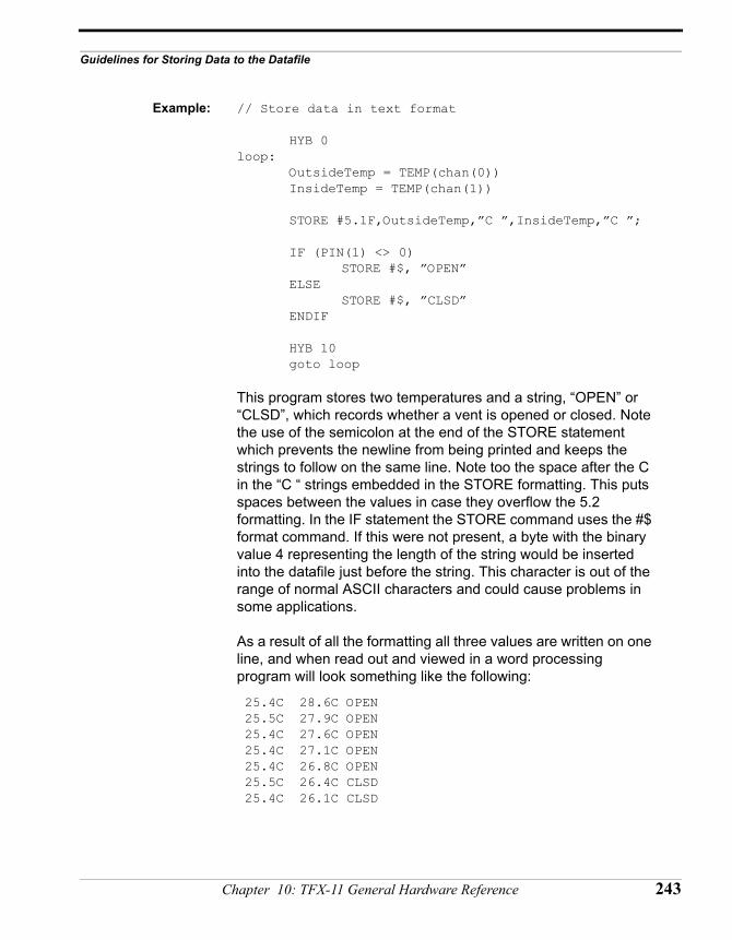
Guidelines for Storing Data to the Datafile
Example: // Store data in text format
HYB 0loop:
OutsideTemp = TEMP(chan(0))InsideTemp = TEMP(chan(1))
STORE #5.1F,OutsideTemp,”C ”,InsideTemp,”C ”;
IF (PIN(1) <> 0)STORE #$, ”OPEN”
ELSESTORE #$, ”CLSD”
ENDIF
HYB 10goto loop
This program stores two temperatures and a string, “OPEN” or “CLSD”, which records whether a vent is opened or closed. Note the use of the semicolon at the end of the STORE statement which prevents the newline from being printed and keeps the strings to follow on the same line. Note too the space after the C in the “C “ strings embedded in the STORE formatting. This puts spaces between the values in case they overflow the 5.2 formatting. In the IF statement the STORE command uses the #$ format command. If this were not present, a byte with the binary value 4 representing the length of the string would be inserted into the datafile just before the string. This character is out of the range of normal ASCII characters and could cause problems in some applications.
As a result of all the formatting all three values are written on one line, and when read out and viewed in a word processing program will look something like the following:
25.4C 28.6C OPEN 25.5C 27.9C OPEN 25.4C 27.6C OPEN 25.4C 27.1C OPEN 25.4C 26.8C OPEN 25.5C 26.4C CLSD 25.4C 26.1C CLSD
Chapter 10: TFX-11 General Hardware Reference 243
24
TFX-11 High-Level Hardware Description
Functional overview ofthe TFX-11
The TFX-11 contains two processors: 128K static RAM, 472k/2Mb flash EEPROM (SFLASH), and a parallel port and an RS232 serial port for development/communications interface. This section provides a general overview of the relationships, responsibilities, and interactions of the major subsystems.
The architecture of the TFX-11 includes an HC11 with 128K of RAM, 64K of which is used for the TFBASIC token engine, the users program, and user variable storage. The TFBASIC program is stored complete in flash as an executable image. This image is created using TFTools on the host computer. It is up to the TFTools host software to put together the image that will be loaded by the HC11 from the flash into its RAM for execution. The initial step is for the host computer to load this image directly into the SFLASH via the parallel port connection. The SFLASH provides permanent (until deliberately erased and rewritten) storage of the program and prepares the way for the next step, which is having the HC11 copy the image into RAM. Once loaded into the RAM, the PIC controls the start of the program because it controls the HC11’s RESET line. The PIC’s timing functions can include a delayed start or periodic wakeup and shutdown of the HC11, providing the very lowest power modes when the HC11 is shutdown.
Fundamental to the design of the TFX-11 is its clean slate (64K RAM) at RESET. Resident on the host computer, TFTOOLS formats (compiles/assembles) both the user’s code and a copy of the token engine into an image that is uploaded to the TFX-11 for execution. The PIC controls RESET and at power on or Launch, instructs the HC11 to load this program in the flash and then RESETs the HC11 to start to execute this code.
TFX-11 in operation Both the HC11 and the Host PC may become the master of operations, but not simultaneously. The following discusses each as master separately, as well as the supervisory role of the PIC.
Host computer in charge. Under the control of the host computer, the devices active are the PIC and the SFLASH. Through the signal HOSTREQ, the PIC will detect that the TFX is
4 TFX-11 User’s Guide
TFX-11 High-Level Hardware Description
connected to the host interface and wants service. At this point the PIC commands an orderly shutdown of the HC11. When this process has been completed, the PIC is slave to the host computer along with the SFLASH and the A/D. When the PIC has completed configuring itself as slave, it asserts the SFLASH CS and responds to HOSTREQ with a PICACK. The PIC has now given control to the HOST and set up the bus so that the default communication from the HOST is with the SFLASH. The host is not required to communicate to the PIC for any SFLASH related activities, READ, WRITE, or ERASE. If the HOST wants to talk directly to the PIC or the A/D, it must grab the attention of the PIC by toggling the HOSTREQ line. The PIC continually polls the state of the HOSTREQ line, which acts as a PIC CS. If it changes state, it can mean only one of two things: either the HOST is no longer requesting control or the HOST is requesting communication with the PIC. If the HOSTREQ remains de-asserted for more than 2 seconds, it is understood to be a disconnect, otherwise the PIC disables all CS on the bus and waits for a command from the HOST.
Communications to the PIC from the host include functions such as reading and setting the time, setting an alarm start time or periodic sleep/wake cycle time, getting status information such as serial number and Model number of the board, and version information for the PIC firmware. The primary use of this interface is off-loading of the SFLASH data and uploading new program images to the SFLASH using TFTOOLS. The HC11 is completely shut down while the HOST is active.
PIC processor in charge When the HOST parallel interface is disconnected, the PIC assumes the position of supervisory controller and holds the HC11 in RESET until the PIC finishes setting up the HC11’s environment. In this state, the PIC can only communicate with the HC11 via the SPI, and the HC11 must be running for those communications to take place. On power up, the PIC’s tasks include detecting if the HOST parallel interface is connected and if it isn’t connected, controlling the orderly power up of the HC11. When the PIC determines the HOST interface is not connected, it releases the reset it holds on the HC11 so it can start running in expanded mode. At this point, the PIC becomes a slave to the HC11.
Chapter 10: TFX-11 General Hardware Reference 245
HC11 in charge When the HC11 is up and running, it is the main processor, with all its program information in RAM. In this mode, it is running almost exactly like any of the previous Tattletales, with the PIC acting primarily as the RTC and wakeup alarm.
The PIC as RTC and lowpower controller
With the HC11 in charge, the PIC still has the power to take back control in response to external events (i.e. the interface attached) or as necessary to control low power mode requests from the HC11. The HC11 can command the PIC (via the SPI bus) to set an alarm wakeup time, and then the HC11 can put itself into STOP mode. When the PIC alarm times out, it uses the XIRQ line to interrupt the HC11 to wake it up, and, after a brief handshake with the PIC over the SPI, the HC11 resumes processing from where it left off. If the handshake does not take place, the PIC will assume an operational problem with the HC11 and place it in reset.
Low power operation This can be initiated by the TFBASIC program requesting a HYB interval. The PIC sets its alarm timer to the wakeup time (one second resolution) and when the PIC timer times out, the PIC will use XIRQ to awaken the HC11. While in HYB, only the PIC is active. HALT will put the TFX-11 in this same low power state, but it does not provide an automatic wakeup.
246 TFX-11 User’s Guide
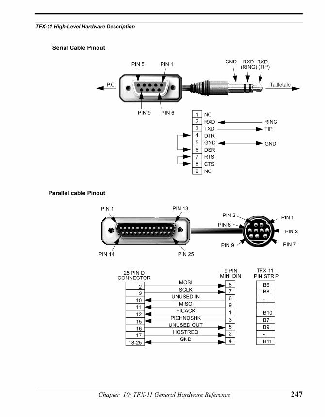
TFX-11 High-Level Hardware Description
Serial Cable Pinout
Parallel cable Pinout
PIN 1
PIN 9
PIN 5 GND(TIP)(RING)
TattletaleP.C.
PIN 6
TXDRXD
123456789
RXDTXDDTR
DSRGND
RTSCTS
RINGTIP
GND
NC
NC
PIN 1 PIN 13
PIN 14 PIN 25
PIN 7
PIN 2
PIN 6
PIN 9
25 PIN D
SCLKUNUSED IN
MISO
PICHNDSHKPICACK
UNUSED OUTHOSTREQ
GND
MOSI 876913524
PIN 1
PIN 3
B6B8--B10B7B9-B11
29
101112151617
18-25
TFX-11PIN STRIPCONNECTOR
9 PINMINI DIN
Chapter 10: TFX-11 General Hardware Reference 247

248 TFX-11 User’s Guide
CHAPTER 11
Glossary of Terms
TFX-11 User’s Guide
Glossary of TFBASIC Terms and Definitions
Abbreviations There are no abbreviations allowed for any TFBASIC commands.
Arrays The number of arrays in TFBASIC is limited only by the size of the variable storage area.
ArithmeticOperators
The five arithmetic operators have the highest priority of all of the TFBASIC operators. Note that TFBASIC does not have a separate high priority unary minus operator, but instead treats the negation of a constant or variable as zero minus the value of the variable or constant.
These are the TFBASIC arithmetic operators in order of precedence (all operators on the same level are evaluated left to right):
highest * / % Multiplication, Division, Modulo+ - Addition, Subtraction> <= > >= <> = Relational operators& Logical bitwise AND
lowest | Logical bitwise OR
See TFBASIC Floating Point on page 179 for details about arithmetic operations involving floats.
AssemblyLanguage
The TFBASIC tokenizer has a built-in assembler. Code can be assembled in line with the program or into a separate area as desired. See TFBASIC Assembly Language Reference on page 150 for details.
Break A CTRL-C sent via the primary serial port can break a running TFBASIC program. A special command 'CBREAK' followed by a label can be used to specify the address to restart to when a CTRL-C is received. You can disable CTRL-C breaks by writing a zero byte to address 9C hex. A count of CTRL-C characters will continue to be updated at address 9B hex. Clear this before re-enabling break-outs. See the section CBREAK go to label on CTRL-C on page 62.
Case Labels and variable names are case sensitive; commands and keywords are case insensitive.
Comments TFBASIC provides two ways to include comments in your code: one for TFBASIC code, the other for assembly code. In TFBASIC, a pair of
250 TFX-11 User’s Guide
Glossary of TFBASIC Terms and Definitions
forward slashes (//) can appear anywhere on a line and cause the rest of the line to be ignored. In assembly code, a semicolon (;) is used to separate comments from code. Comments are stripped before the tokenizing pass and therefore do not affect execution code size.
Constants TFBASIC supports string, integer, and floating point constants. Integer constants are signed decimal numbers in the range -2147483648 to +2147483647 or unsigned hexadecimal numbers in the range &H0 to &HFFFFFFFF. Floating point constants must include a decimal point and/or the power-of-ten specifier 'E'. All floating point constants are single precision with a range of ±1.175494E-38 to ±3.402823E+38 and 0.0. See the TFBASIC Floating Point on page 179 for details. There are no short integer constants, and no octal constants.
Character constants of up to four characters in single quotes are allowed. The character on the right is placed as the least significant byte in the four byte constant.
String constants must be bracketed by double quote characters. String constants can be used with the PRINT, INPUT, and STORE commands.
Datafile: Storageand Retrieval
The TFX-11 has a special non-volatile data storage area called the datafile, which can only be written from the TFBASIC program. Datafile commands are STORE for writing, and OFFLD for reading. An OFFLD command is not available from the TFBASIC program, but is a menu command in TFTools. The datafile contains a read-only pointer that points to the next empty datafile byte, and this pointer automatically increments after each STORE command. NOTE: Once the data is stored in the SFLASH, it cannot be read back or written over by the program!
Data Types TFBASIC supports long integers, string constants, and strings as well as IEEE 754 single-precision floating point. There are both implicit and explicit conversion operators to convert numbers between integer and floating point formats and back again. See TFBASIC Floating Point on page 179 for details.
Decimal See Radix
Division by Zero Integer division by zero will cause the program to stop executing and display the "HOW" message. Refer to the "Errors" definition below for more information on error handling. Floating point division by zero DOES
Chapter 11: Glossary of Terms 251
NOT stop program execution. As with other floating point errors, it sets a bit in the FPERR error variable to indicate an error. Division by zero returns a result of infinity. See TFBASIC Floating Point on page 179.
Editing Editing is done on the host computer in the TFTools IDE. The TFX-11 board is not running an interpreter and therefore has no facilities for editing.
Errors A list of error statements and their causes can be found in TFBASIC Error Messages on page 142. An error will stop program execution and display a message unless an ONERR command has been executed by the program. The ONERR command is detailed in the section ONERR go to label on error on page 95.
Floating Point Single precision floating point math (IEEE 754) is available in TFBASIC along with a number of trigonometric functions. See TFBASIC Floating Point on page 179 for more information.
Hexadecimals See Radix
IDE Acronym for Integrated Development Environment
I/O: Analog/Digital
Standard dialects of BASIC use the keyboard and disk storage for data input. In the TFX-11, these inputs are augmented by the logger's analog and digital inputs. A number of new commands and functions have been designed to deal with these inputs and outputs simply and efficiently. The analog command to get a value from an A/D channel is CHAN(X), where X is the channel to be read. The digital I/O input read command is PIN(X), and the digital output commands are PSET, PCLR, and PTOG. See the language reference for more information.
Labels,Assembler
Labels can be used in the assembly code for flow control and to define local variables. Assembler labels can be up to 32 characters long, must begin with a letter or an underscore ( _ ), and may end with a colon. The only valid characters in a label are upper and lower case characters, numbers, and underscore. The label name must start in the first column of the line. Assembler label names are not required to be terminated with a colon when defined.
252 TFX-11 User’s Guide
Glossary of TFBASIC Terms and Definitions
Labels, TFBASIC TFBASIC labels can be up to 32 characters long, must begin with a letter, an underscore ( _ ) or the @ symbol, and end with a colon. The only valid characters in a label are upper and lower case characters, numbers, underscore and @. TFBASIC labels DO NOT have to begin in the first column of the line. Line numbers are not acceptable as labels!
Line Forms There are almost no immediate commands and line numbers are not allowed. Blank lines are permissible and are encouraged for readability.
Line Numbers Line numbers are not allowed in TFBASIC.
LogicalOperators
The TFX-11 supports the two logical operators, AND and OR, which are used for both bit-wise operations and logical connectives. Unlike most other BASIC dialects, the operators are not spelled out, but instead are represented by the symbols "&" for AND, and "|" for OR.
MultipleStatements
TFBASIC does not support the use of colons to allow multiple statements on a single program line.
Octal See Radix
Overflow Overflow errors are detected during the evaluation of an expression when the intermediate value becomes greater than the maximum long integer (four byte integer) value of 2,147,483,647, or less than the minimum long integer value of -2,147,483,648. Overflow or underflow can occur in floating point numbers if the intermediate value is outside the range ±1.175494E-38 to ±3.402823E+38. See the TFBASIC Floating Point on page 179 section for details. Integer overflow errors cause the program to stop executing and display the "HOW" message. Refer to the “Errors” definition in this section for more information on error handling.
Quotation Marks Single quotes are used to enclose character constants; double quotes enclose character strings. Using single quotes for character strings may generate an error or cause unexpected behavior.
Radix The radix is the number base used to interpret numeric constants, typically either decimal, octal, binary, or hexadecimal. Decimal is the default Radix, and there is no way to globally change this. Any number with a radix other than decimal must be specifically identified using the
Chapter 11: Glossary of Terms 253
following techniques: (NOTE : The identifying characters are not case sensitive.)
(Base 16) Hexadecimal. Hexadecimal (Base 16) numbers can be entered in TFBASIC by preceding the number with '&H'. The entered number must be unsigned and may include up to eight hexadecimal characters. It will be treated as a signed 32-bit two's-complement number internally. TFBASIC assembly code accepts H’, $, 0xxh, in addition to the above. The H’ prefix is preferred for designating hex numbers in assembler.
(Base 8) Octal. Octal (Base 8) numbers can be entered in TFBASIC by preceding the number with &O where O is the character o, not the digit zero. The entered number must be unsigned and may include up to eleven octal characters. It will be treated as a signed 32-bit two's-complement number internally. TFBASIC assembly code accepts Q’ xxQ, and xxO in addition to the above. The Q’ prefix is the preferred method for designating octal numbers in assembler.
(Base 2) Binary. Binary (Base 2) numbers can be entered in TFBASIC by preceding the number with '&B'. The entered number must be unsigned and may include up to 32 binary characters. It will be treated as a signed 32-bit two's-complement number internally. TFBASIC assembly code accepts B’, %, and xxB in addition to the above. The B’ prefix is the preferred method for designating binary numbers in assembler.
(Base 10) Decimal. Decimal (Base 10) is the default radix in TFBASIC, and therefore requires no identifying code. The entered number must be in the range -2,147,483,647 to 2,147,483,647. It will be treated as a signed 32-bit two's-complement number internally. TFBASIC assembly code has decimal as its default radix, but also accepts D’ and xxD as radix identifiers.
RelationalOperators
TFBASIC supports seven relational operators which are used for comparing two values. Relational operations return 1 if the result of the comparison is true, and 0 if the result is false. See TFBASIC Floating Point on page 179 for details about comparisons involving floats. The relational operators are:
< less than A<B<= less than or equal to A<=B> greater than A>B>= greater than or equal to A>=B
254 TFX-11 User’s Guide
Glossary of TFBASIC Terms and Definitions
<> not equal to A<>B>< not equal to A><B= equal to A=B
SFLASH This is the main non-volatile storage area. It is a Serial Electrically Erasable Programmable Read Only Memory. To help protect the user from data loss due to program errors, the SFLASH interface is designed to only be read out and erased when the TFX-11 is connected to the parallel or serial port. The SFLASH will retain the data for up to ten years with no power applied.
Strings See Variables
String Operators TFBASIC supports string operations, and includes the functions MID$( ) and LEN$( ). See TFBASIC Language Reference for the TFX-11 on page 50 for details on string functions.
Tabs Tabs are just fine in TFBASIC, and are used to increase readability.
Timing In standard BASIC dialects, there is little need to pace a program (the sooner it's over, the happier you are!). In a logging/control application, however, program timing is critical. Timing functions in the TFX-11 are handled by the SLEEP and HYB commands. SLEEP puts the logger in a low-power mode for an integral number of 10 ms steps from the wake-up of the previous SLEEP command. This not only provides the necessary timing, but also ensures that the logger is in a low-power mode during the interval. HYB puts the TFX-11 in an ultra low power (dormant) mode with wakeup at a fixed time in the future or at regular intervals. HYB is especially appropriate where the application has long periods of quiescence with periodic short bursts of logging and control activity.
UEEPROM This is a small block of 128 bytes of non-volatile data storage located inside the HC-11 processor. It is accessible only from TFBASIC and can be read and written at any time using VSTORE and VGET. It is specifically meant for calibration or configuration parameters that are unique to the particular instrument. This allows a single program to run on different TFX-11s without having to have different versions of the program that depends on sensor calibration or environmental factors. This data will be retained with no power applied.
Chapter 11: Glossary of Terms 255
Variables Integers. Variable names up to 32-characters long are allowed in TFBASIC. All variables not specifically typed are 4 byte integers
IEEE 754 Floating Point. Variables intended to be floating point variables must have a ! suffix.
Strings. Variables intended to hold strings must have a $ suffix.
Arrays. Arrays must be declared using the DIM statement. An array may be either floating point or integer. Up to two dimensions are allowed and total array size is limited to the size of available memory. String arrays are not allowed in TFBASIC.
White Space White space is stripped out (except in strings!) before it is sent to the TFX-11. White space is necessary around command, variable, and array names.
256 TFX-11 User’s Guide
INDEX
Symbols50, 250, 254, 255
- 50, 250" 253$ 254% 50, 250, 254& 50, 250, 253* 50, 250+ 50, 250/ 50, 250// 13, 251= 50, 250, 255> 50, 250, 254, 255>= 50, 250, 254@ 253_ 252| 50, 250
AA/D converter 208A/D input choices 208A0 220, 232About Box 40ABS 43, 182AD12-0, AD12-10 220, 233AD8-0-AD8-7 220, 232ADGND 221, 233ADVCC 221, 233AINT 44, 47, 52, 263ALIGN 159Arithmetic Operators 180ASFLT 54, 182ASM 55
mnemonics 155two forms of 150
Assembler Opcodes 150Assembly Language Subroutines 165ATN 58, 182
ATOD12 165ATOD8 165
BBackup Battery 213Baud rate 135baud rate 60BAUDGET 43, 60BAUDSET 59Big-endian 176Bipolar mode 200Blank line 13BRKCNT 168
CCALL 152Capture to File... 38Cascade 39CBREAK 62CCOUNT 168CENAB 168CHAN() 12, 64Character codes 105Character constants 186CHIBUF 165chip selects 208Circuit for Converting Bipolar to Unipolar 200Clear 27Clock Resolution 236Communications Connectors 215, 227Contacting Onset xiCopy 27COS 66, 182Could not Compare 185COUNT 67Crystals 236CSIO1 219, 231CSIO2 219, 232
TFX-11 User’s Guide
CTRL-C 12, 62, 174, 250CTRL-E 173CTRL-H 173CTRL-L 173CTRL-O 173CTRL-R 173custom interface board 215, 228Cut 27
DD0-D7 219, 231DATA 160Datafile Storage Commands 44development kit 2DFERASED 43DFMAX 43DFPNT 43, 129Digital I/O Control 46Digital I/O pins 208DIM 69Disclaimers ix, xDS 164DW 160
EE 219, 231editor 11enclosure, plastic 213, 227END 162EQU 163Erase datafile... 33Error Messages, TFBASIC 142escape sequence 187escape sequences
mnemonic 188numeric 188
Exit 26EXP 70, 182
FFCB 160FCC 160FDB 160Find Again 30Find... 29FIX 71, 182FLOAT 72, 182Float 44, 47, 52, 263Floating Point Errors 183Floating Point Functions 181FLUSHI 165
FLUSHO 165FOR 14, 73FPERR 43, 183Functions 44FVAL 75
GGETBSR 165GND 218, 219, 230, 231GOSUB 78GOTO 79
HHALT 80Hex display 37Host Computer Requirements viiiHOSTREQ 217, 230HOW? error 43HOW? errors 142HYB 81
IIDE 173IEEE 754 floating point 126, 179IF 83INPUT 13, 85Input Protection 197INSTR 88Instrumentation amplifier 202, 206INT 89int 182Integers 176interrupt vectors 169Inverting op amp 202IRQ 219, 232IVAL 90
Jjacks, optional 215, 228
LLabels, assembler 150LAUNCH 175Launch 34, 174LED 218, 230LEN 91LITH 218Little-endian 176LNCHSTAT 168Load OS Only 35
258 TFX-11 User’s Guide
LOG 92, 182LOG10 93, 182Loss of Precision 185Low Power and Time Commands 46LT1077, 1078, 1079 204
MMemory Map 189MID 94MODEL 43monitor 172, 173MRESET 218, 230
NNaN 92, 93New 26NEXT 14Next 39Non-inverting op amp 203Not-a-Number 92, 93, 184
OOffload
Parallel offload... 34XMODEM Offload... 33
ONERR 13, 95, 143Onset, contacting iiiOp amp limitations 204Open... 26operational amplifier 202Options... 36Opto-isolation 197Output Protection 198OUTTST 165Overflow 184OVRSLP 168
PPA0-PA7 220, 232Parallel cable Pinout 247Parallel Port viiiParallel Port... 38Parse Error 9Paste 27Paste Date/time 27PCL 11PCLR 97PDAD12 165PEEK 98, 168PERIOD 99
PGO/EOC 219, 232PICACK 217, 230PICHSHK 218, 230PIN 102Pin outs, TFX-11 board 211POKE 103, 168Power Connections 213, 227PPMISO 218, 230PPMOSI 217, 230PPSCLK 217, 230PR-11 breadboard 215, 217, 228, 229PR-11 Prototype Board 212, 226Previous 39PRINT 104PRINT Formatting 104Program Commands 44PSET 11, 107PTOG 108
QQuick Start 3
RR - C 197R/W 219, 231Radix 57, 154RATE 109Ratiometric 199ratiometric 64RB7-RB0 218, 230READRTC 111REF- 220, 233REF+ 220, 233Registers 119Relational operators 180Relaunch 34REPEAT 113Replace... 30RES 164RESET 173Resistor 197RETURN 78, 115Returns ixRMB 164RTC Storage Structures 236RTIME 116, 117Run 33
Sschematic 208Schottky diode 200
Chapter : 259
SDI 119SDO 121serial cable 3Serial Cable Pinout 247Serial Port... 37SETRTC 123SFLASH v, 14, 35, 43, 129, 168, 172, 173, 174, 181,
239, 240, 241, 251, 255sign bit 176Sign-on message 5SIN 124, 182SLEEP 11, 125Special characters, embedding 187Specifications vi, viiSQR 126, 182Square wave 133STIME 127STOP 14, 128Stopwatch functions. 166STORE 129STPWCH 166STR 130STRBSR 165String functions 186String handling operations 187Strings in TxBASIC 186STRMEM 165Suspend TFX-11 35Syntax check 8, 35syntax error 172
TTAN 131, 182technical assistance ixTEMP 132TEMP() 12Terminal Window 18TFBASIC Assembly Language 150TFBASIC summary 40TFBASIC, Important Addresses in 168TFTools menu commands
COMMPORT 37EDIT 27FILE 26HELP 40SEARCH 29TATTLETALE 33WINDOWS 39
TFTools Tutorial 4TFTools, Introduction to 18TFX-11 Features iv
TFxBASIC LANGUAGE OVERVIEW vthermistor 10, 132Tile 39Timing 121TLC1078 205Token Engine 172token interpreter 172Tokenizer 172TRACE 168Transistor 197
UUART 166UDI 217, 229UDO 217, 229UEEPROM 138, 139Underflow 184Undo 27Unity gain buffer 203URTGET 165URTSND 166URTTST 166USEND 136
VVARPTR 137VBAT 218, 231VCC 218, 219, 231VERS 43VFET 197VGET 138VRH 220, 232VRL 220, 232VSTORE 139
WWarranty ixWHILE 140
XXMIT– 44, 49, 141, 263XMIT+ 141
260 TFX-11 User’s Guide

Chapter : 261

262 TFX-11 User’s Guide
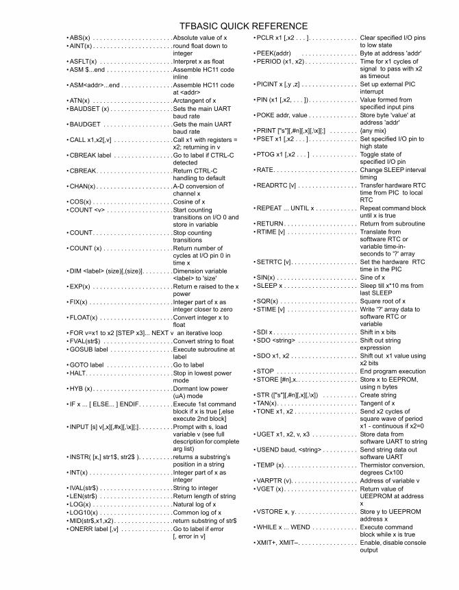
• ABS(x) . . . . . . . . . . . . . . . . . . . . . . .Absolute value of x• AINT(x) . . . . . . . . . . . . . . . . . . . . . . .round float down to
integer• ASFLT(x) . . . . . . . . . . . . . . . . . . . . . Interpret x as float• ASM $...end . . . . . . . . . . . . . . . . . . .Assemble HC11 code
inline• ASM<addr>...end . . . . . . . . . . . . . . .Assemble HC11 code
at <addr> • ATN(x) . . . . . . . . . . . . . . . . . . . . . . .Arctangent of x• BAUDSET (x) . . . . . . . . . . . . . . . . . .Sets the main UART
baud rate• BAUDGET . . . . . . . . . . . . . . . . . . . .Gets the main UART
baud rate• CALL x1,x2[,v] . . . . . . . . . . . . . . . . .Call x1 with registers =
x2; returning in v • CBREAK label . . . . . . . . . . . . . . . . .Go to label if CTRL-C
detected • CBREAK. . . . . . . . . . . . . . . . . . . . . .Return CTRL-C
handling to default • CHAN(x) . . . . . . . . . . . . . . . . . . . . . .A-D conversion of
channel x• COS(x) . . . . . . . . . . . . . . . . . . . . . . .Cosine of x• COUNT <v> . . . . . . . . . . . . . . . . . . .Start counting
transitions on I/O 0 and store in variable
• COUNT. . . . . . . . . . . . . . . . . . . . . . .Stop counting transitions
• COUNT (x) . . . . . . . . . . . . . . . . . . . .Return number of cycles at I/O pin 0 in time x
• DIM <label> (size)[,(size)]. . . . . . . . .Dimension variable <label> to 'size'
• EXP(x) . . . . . . . . . . . . . . . . . . . . . . .Return e raised to the x power
• FIX(x) . . . . . . . . . . . . . . . . . . . . . . . .Integer part of x as integer closer to zero
• FLOAT(x) . . . . . . . . . . . . . . . . . . . . .Convert integer x to float
• FOR v=x1 to x2 [STEP x3]... NEXT v an iterative loop• FVAL(str$) . . . . . . . . . . . . . . . . . . . .Convert string to float• GOSUB label . . . . . . . . . . . . . . . . . .Execute subroutine at
label• GOTO label . . . . . . . . . . . . . . . . . . .Go to label• HALT. . . . . . . . . . . . . . . . . . . . . . . . .Stop in lowest power
mode• HYB (x) . . . . . . . . . . . . . . . . . . . . . . .Dormant low power
(uA) mode • IF x ... [ ELSE... ] ENDIF. . . . . . . . . .Execute 1st command
block if x is true [,else execute 2nd block]
• INPUT [s] v[,x][,#x][,\x][;] . . . . . . . . . .Prompt with s, load variable v (see full description for complete arg list)
• INSTR( [x,] str1$, str2$ ). . . . . . . . . .returns a substring’s position in a string
• INT(x) . . . . . . . . . . . . . . . . . . . . . . . .Integer part of x as integer
• IVAL(str$) . . . . . . . . . . . . . . . . . . . . .String to integer• LEN(str$) . . . . . . . . . . . . . . . . . . . . .Return length of string• LOG(x) . . . . . . . . . . . . . . . . . . . . . . .Natural log of x• LOG10(x) . . . . . . . . . . . . . . . . . . . . .Common log of x• MID(str$,x1,x2) . . . . . . . . . . . . . . . . .return substring of str$• ONERR label [,v] . . . . . . . . . . . . . . .Go to label if error
[, error in v]
• PCLR x1 [,x2 . . . ]. . . . . . . . . . . . . . Clear specified I/O pins to low state
• PEEK(addr) . . . . . . . . . . . . . . . . Byte at address 'addr' • PERIOD (x1, x2) . . . . . . . . . . . . . . . Time for x1 cycles of
signal to pass with x2 as timeout
• PICINT x [,y ,z] . . . . . . . . . . . . . . . . Set up external PIC interrupt
• PIN (x1 [,x2, . . . ]) . . . . . . . . . . . . . . Value formed from specified input pins
• POKE addr, value . . . . . . . . . . . . . . Store byte 'value' at address 'addr'
• PRINT ["s"][,#n][,x][,\x][;] . . . . . . . . {any mix}• PSET x1 [,x2 . . . ] . . . . . . . . . . . . . . Set specified I/O pin to
high state• PTOG x1 [,x2 . . . ] . . . . . . . . . . . . . Toggle state of
specified I/O pin • RATE. . . . . . . . . . . . . . . . . . . . . . . . Change SLEEP interval
timing• READRTC [v] . . . . . . . . . . . . . . . . . Transfer hardware RTC
time from PIC to local RTC
• REPEAT ... UNTIL x . . . . . . . . . . . . Repeat command block until x is true
• RETURN . . . . . . . . . . . . . . . . . . . . . Return from subroutine• RTIME [v] . . . . . . . . . . . . . . . . . . . . Translate from
softtware RTC or variable time-in-seconds to '?' array
• SETRTC [v]. . . . . . . . . . . . . . . . . . . Set the hardware RTC time in the PIC
• SIN(x) . . . . . . . . . . . . . . . . . . . . . . . Sine of x• SLEEP x . . . . . . . . . . . . . . . . . . . . . Sleep till x*10 ms from
last SLEEP • SQR(x) . . . . . . . . . . . . . . . . . . . . . . Square root of x• STIME [v] . . . . . . . . . . . . . . . . . . . . Write '?' array data to
software RTC or variable
• SDI x . . . . . . . . . . . . . . . . . . . . . . . . Shift in x bits• SDO <string> . . . . . . . . . . . . . . . . . Shift out string
expression• SDO x1, x2 . . . . . . . . . . . . . . . . . . . Shift out x1 value using
x2 bits• STOP . . . . . . . . . . . . . . . . . . . . . . . End program execution• STORE [#n],x. . . . . . . . . . . . . . . . . . Store x to EEPROM,
using n bytes• STR (["s"][,#n][,x][,\x]) . . . . . . . . . . Create string • TAN(x). . . . . . . . . . . . . . . . . . . . . . . Tangent of x• TONE x1, x2 . . . . . . . . . . . . . . . . . . Send x2 cycles of
square wave of period x1 - continuous if x2=0
• UGET x1, x2, v, x3 . . . . . . . . . . . . . Store data from software UART to string
• USEND baud, <string> . . . . . . . . . . Send string data out software UART
• TEMP (x). . . . . . . . . . . . . . . . . . . . . Thermistor conversion, degrees Cx100
• VARPTR (v). . . . . . . . . . . . . . . . . . . Address of variable v • VGET (x) . . . . . . . . . . . . . . . . . . . . . Return value of
UEEPROM at address x
• VSTORE x, y. . . . . . . . . . . . . . . . . . Store y to UEEPROM address x
• WHILE x ... WEND . . . . . . . . . . . . . Execute command block while x is true
• XMIT+, XMIT–. . . . . . . . . . . . . . . . . Enable, disable console output
TFBASIC QUICK REFERENCE


