Embed Size (px)
Citation preview
Controller
Every attempt has been made to ensure that this documentation is as accurate and up-to-date as
possible. However, Vertical Express assumes no liability for consequences, directly or indirectly,
resulting from any error or omission. The material contained herein is subject to revision. Please report
any problems with this manual to Vertical Express, P.O. Box 2019, Memphis, Tennessee 38101.
Vertical Express • P.O. Box 2019 • Memphis, Tennessee 38101
©2020 Vertical Express. All rights reserved.Published April 2020
First EditionPrinted in the United States of America
Manual Number: 88500 v.1.0

INS
TA
LLA
TIO
N S
EC
TIO
N

INS
TA
LLA
TIO
N S
EC
TIO
N
Installation Section Contents
Contents
Preliminary Installation . . . . . . . . . . . . . . . . . . . . . . . . . . . . . . . . . . . . . . . . . . . . . . . . . . . . . 1-3
Prepare for Temporary Operation . . . . . . . . . . . . . . . . . . . . . . . . . . . . . . . . . . . . . . . 1-3
Configure the UPS . . . . . . . . . . . . . . . . . . . . . . . . . . . . . . . . . . . . . . . . . . . . . . . . . . 1-5
Temporary Operation . . . . . . . . . . . . . . . . . . . . . . . . . . . . . . . . . . . . . . . . . . . . . . . . . . . . . . 1-6
Runbug Set Up . . . . . . . . . . . . . . . . . . . . . . . . . . . . . . . . . . . . . . . . . . . . . . . . . . . . 1-6
Electronic Starter Setup . . . . . . . . . . . . . . . . . . . . . . . . . . . . . . . . . . . . . . . . . . . . . 1-10
Mechanical Starter Set Up with ESP200 Overloads . . . . . . . . . . . . . . . . . . . . . . . . . 1-11
Pump Motor Rotation . . . . . . . . . . . . . . . . . . . . . . . . . . . . . . . . . . . . . . . . . . . . . . . 1-13
I-2/I-3 Valve . . . . . . . . . . . . . . . . . . . . . . . . . . . . . . . . . . . . . . . . . . . . . . . . . . . . . . . . . . . . 1-14
Relief Pressure Verification . . . . . . . . . . . . . . . . . . . . . . . . . . . . . . . . . . . . . . . . . . . 1-15
Low Pressure Adjustment . . . . . . . . . . . . . . . . . . . . . . . . . . . . . . . . . . . . . . . . . . . 1-15
Selector Tape . . . . . . . . . . . . . . . . . . . . . . . . . . . . . . . . . . . . . . . . . . . . . . . . . . . . . . . . . . 1-17
Mount the Tape . . . . . . . . . . . . . . . . . . . . . . . . . . . . . . . . . . . . . . . . . . . . . . . . . . . 1-17
Hoistway Wiring . . . . . . . . . . . . . . . . . . . . . . . . . . . . . . . . . . . . . . . . . . . . . . . . . . . . . . . . . 1-20
Wireway and Conduit Layout . . . . . . . . . . . . . . . . . . . . . . . . . . . . . . . . . . . . . . . . . 1-21
Typical Hoistway Conduit/Duct Layout . . . . . . . . . . . . . . . . . . . . . . . . . . . . . . . . . . 1-22
Typical Front Conduit/Duct Layout . . . . . . . . . . . . . . . . . . . . . . . . . . . . . . . . . . . . . 1-23
Typical Rear Conduit/Duct Layout . . . . . . . . . . . . . . . . . . . . . . . . . . . . . . . . . . . . . . 1-24
Interlock Wiring . . . . . . . . . . . . . . . . . . . . . . . . . . . . . . . . . . . . . . . . . . . . . . . . . . . 1-25
Traveling Cable Installation . . . . . . . . . . . . . . . . . . . . . . . . . . . . . . . . . . . . . . . . . . 1-27
Hoistway Entrance Frames and Doors . . . . . . . . . . . . . . . . . . . . . . . . . . . . . . . . . . . . . . . . . 1-28
Cab . . . . . . . . . . . . . . . . . . . . . . . . . . . . . . . . . . . . . . . . . . . . . . . . . . . . . . . . . . . . . . . . . . 1-28
Door Operator . . . . . . . . . . . . . . . . . . . . . . . . . . . . . . . . . . . . . . . . . . . . . . . . . . . . . . . . . . 1-28
Selector Box Mounting and Alignment . . . . . . . . . . . . . . . . . . . . . . . . . . . . . . . . . . . . . . . . . 1-28
Formed Rail Selector Box . . . . . . . . . . . . . . . . . . . . . . . . . . . . . . . . . . . . . . . . . . . . 1-29
T-Rail Selector Box . . . . . . . . . . . . . . . . . . . . . . . . . . . . . . . . . . . . . . . . . . . . . . . . 1-30
Twin Post Selector Box . . . . . . . . . . . . . . . . . . . . . . . . . . . . . . . . . . . . . . . . . . . . . . 1-31
Tape Selector Bolt Kit for Crosshead Mount (200BWY001) . . . . . . . . . . . . . . . . . . . 1-32
Car Top Wiring . . . . . . . . . . . . . . . . . . . . . . . . . . . . . . . . . . . . . . . . . . . . . . . . . . . . . . . . . . 1-33
Swing Return Wiring . . . . . . . . . . . . . . . . . . . . . . . . . . . . . . . . . . . . . . . . . . . . . . . 1-34
Machine Room Wiring . . . . . . . . . . . . . . . . . . . . . . . . . . . . . . . . . . . . . . . . . . . . . . . . . . . . 1-34
Vertical Express Product Manual 1-1 88500 v.1.0

Contents Installation Section
This pageintentionallyleft blank.
1-2©Vertical Express Printed in USA April 2020
INS
TA
LLA
TIO
NInstallation Section Preliminary Installation
Preliminary InstallationInstall the following items. Refer to the Vertical Express Installation Manual (located at: http://www.verticalxpress.com/component_manuals/Installation Manual), and the installation instructions that ship with the equipment.
• Pit template (if provided), pit channel, and buffers
• Jack, jack follower guides (as required), rail brackets and rails
• Car sling and platform
• Power unit and controller
• Fluid line (jack line)
Prepare for Temporary Operation
1. Turn OFF, Lockout, and Tagout the mainline disconnect.
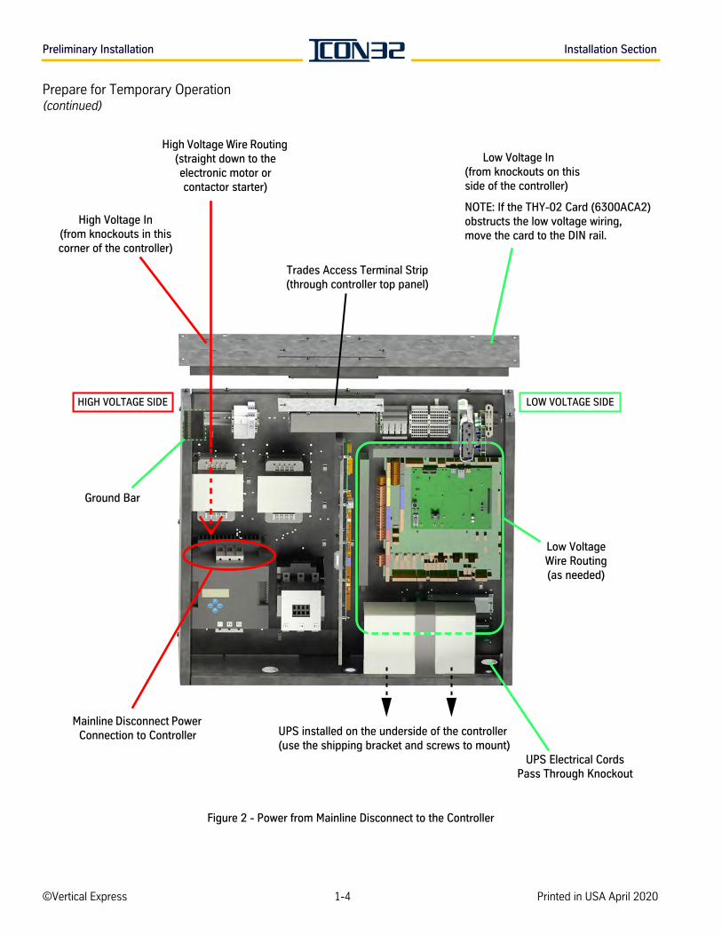
2. Pipe and install power from the mainline disconnect to the controller. See Figure 2 on page 1-4.
• Conduit for the wires from the mainline disconnect must be installed on the same side of the controller cabinet as the motor starter.
• The fourth wire ground from the disconnect is to be landed on the dedicated ground bar of the controller, not the motor starter heatsink.
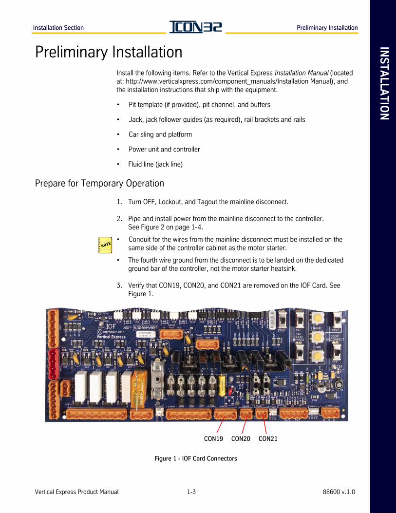
3. Verify that CON19, CON20, and CON21 are removed on the IOF Card. See Figure 1.
Figure 1 - IOF Card Connectors
CON19 CON20 CON21
Vertical Express Product Manual 1-3 88600 v.1.0
Preliminary Installation Installation Section
Prepare for Temporary Operation(continued)
Figure 2 - Power from Mainline Disconnect to the Controller
Mainline Disconnect Power Connection to Controller
UPS Electrical CordsPass Through Knockout
UPS installed on the underside of the controller (use the shipping bracket and screws to mount)
High Voltage In (from knockouts in this corner of the controller)
High Voltage Wire Routing (straight down to the electronic motor or contactor starter)
Trades Access Terminal Strip (through controller top panel)
Low Voltage In(from knockouts on this side of the controller)
NOTE: If the THY-02 Card (6300ACA2) obstructs the low voltage wiring, move the card to the DIN rail.
Ground Bar
Low Voltage Wire Routing(as needed)
HIGH VOLTAGE SIDE LOW VOLTAGE SIDE
©Vertical Express 1-4 Printed in USA April 2020
INS
TA
LLA
TIO
NInstallation Section Preliminary Installation
Installation(continued) Configure the UPS
1. When on temporary operation, connect the following:
a. The AC receptacle cord from the IOF Card - CON18, pins 1, 2, and 3.
b. The AC plug from the IOF Card - CON18, pins 4, 5, and 6.
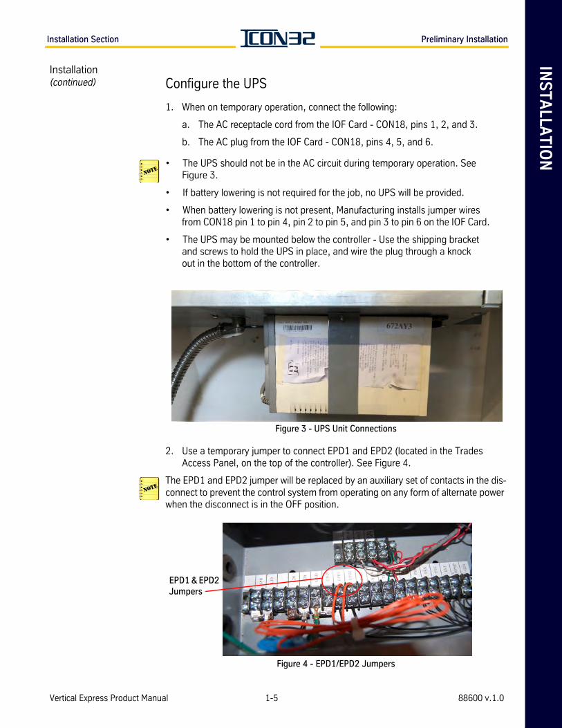
• The UPS should not be in the AC circuit during temporary operation. See Figure 3.
• If battery lowering is not required for the job, no UPS will be provided.
• When battery lowering is not present, Manufacturing installs jumper wires from CON18 pin 1 to pin 4, pin 2 to pin 5, and pin 3 to pin 6 on the IOF Card.
• The UPS may be mounted below the controller - Use the shipping bracket and screws to hold the UPS in place, and wire the plug through a knock out in the bottom of the controller.
Figure 3 - UPS Unit Connections
2. Use a temporary jumper to connect EPD1 and EPD2 (located in the Trades Access Panel, on the top of the controller). See Figure 4.
The EPD1 and EPD2 jumper will be replaced by an auxiliary set of contacts in the dis-connect to prevent the control system from operating on any form of alternate power when the disconnect is in the OFF position.
Figure 4 - EPD1/EPD2 Jumpers
EPD1 & EPD2 Jumpers
Vertical Express Product Manual 1-5 88600 v.1.0
Temporary Operation Installation Section
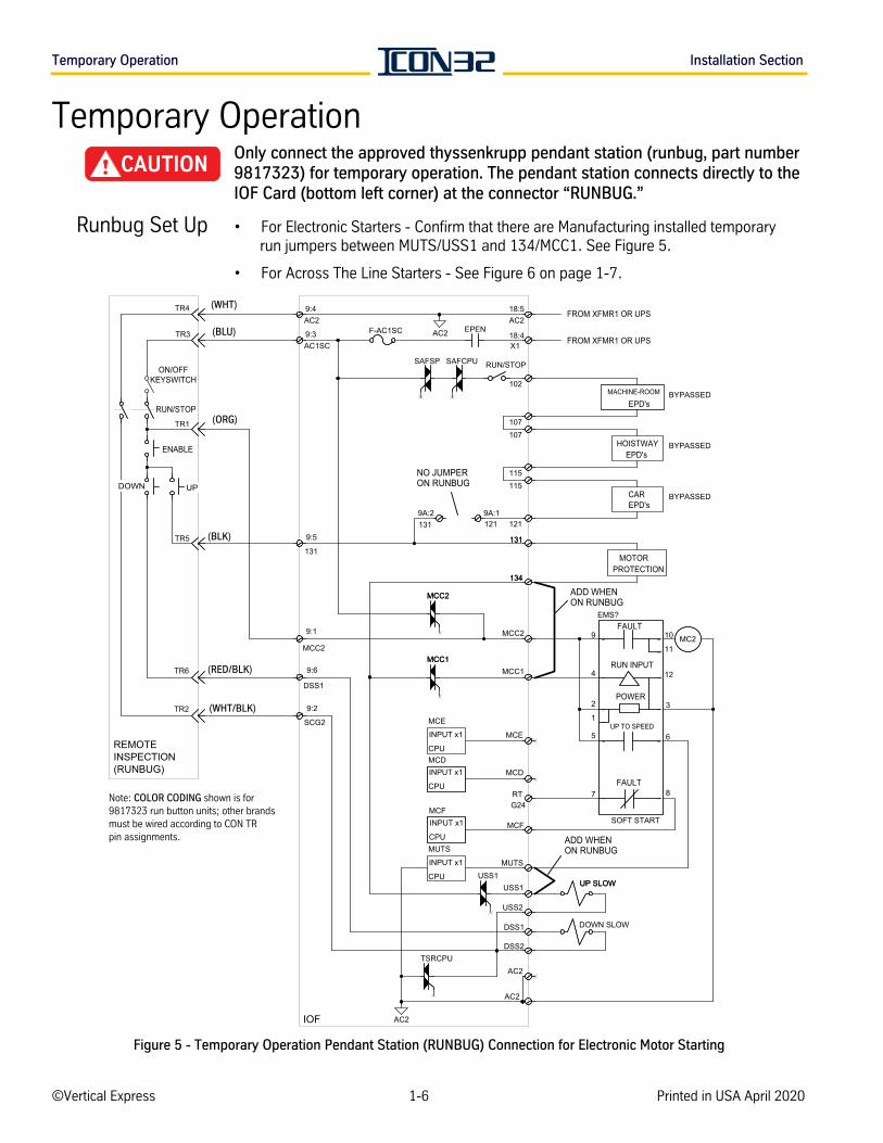
Temporary OperationOnly connect the approved thyssenkrupp pendant station (runbug, part number 9817323) for temporary operation. The pendant station connects directly to the IOF Card (bottom left corner) at the connector “RUNBUG.”
Runbug Set Up • For Electronic Starters - Confirm that there are Manufacturing installed temporary run jumpers between MUTS/USS1 and 134/MCC1. See Figure 5.
• For Across The Line Starters - See Figure 6 on page 1-7.
Figure 5 - Temporary Operation Pendant Station (RUNBUG) Connection for Electronic Motor Starting
AC2
RUN/STOP
ON/OFFKEYSWITCH
ENABLE
REMOTEINSPECTION(RUNBUG)
IOF
FROM XFMR1 OR UPS
FROM XFMR1 OR UPS
MOTORPROTECTION
ADD WHEN ON RUNBUG
MACHINE-ROOM
EPD's
HOISTWAYEPD's
CAREPD's
NO JUMPER ON RUNBUG
BYPASSED
BYPASSED
BYPASSED
MCC2MC2
AC2
TR6
MCE
DSS1
DSS1
9:6
AC2
TR5
TR1
TR2
SCG2
9:2
1219A:1
USS1
134134
USS1
TSRCPU
DOWN SLOW
MCD
DSS2
UP SLOWUP SLOW
MCC1
MCC2MCC2
MCC2
9:1
TR4
MCC1MCC1
MCF
RUN INPUT
FAULT
EMS?FAULT
POWER
UP TO SPEED
SOFT START
-9 - 10
- 11
-4 - 12
-2
-1- 3
-5
- 6
-7 -8
USS2
TR3
RTG24
131
9:5
AC2 EPEN
115
AC1SC9:3
107
115
F-AC1SCAC218:5
RUN/STOPSAFSP
107
SAFCPU
102
AC29:4
X118:4
121
MUTS
131131
1319A:2
MCE
INPUT x1
CPUMCDINPUT x1
CPU
MCFINPUT x1
CPUMUTS
INPUT x1
CPU
Note: COLOR CODING shown is for 9817323 run button units; other brands must be wired according to CON TR pin assignments.
(WHT)
(BLU)
(ORG)
(BLK)
(RED/BLK)
(WHT/BLK)
ADD WHEN ON RUNBUG
DOWN UP
©Vertical Express 1-6 Printed in USA April 2020
INS
TA
LLA
TIO
NInstallation Section Temporary Operation
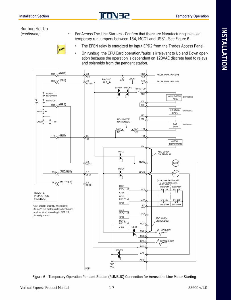
Runbug Set Up (continued) • For Across The Line Starters - Confirm that there are Manufacturing installed
temporary run jumpers between 134, MCC1 and USS1. See Figure 6.
• The EPEN relay is energized by input EPD2 from the Trades Access Panel.
• On runbug, the CPU Card operation/faults is irrelevant to Up and Down oper-ation because the operation is dependent on 120VAC discrete feed to relays and solenoids from the pendant station.
Figure 6 - Temporary Operation Pendant Station (RUNBUG) Connection for Across the Line Motor Starting
AC2
AC2
RUN/STOP
ON/OFFKEYSWITCH
ENABLE
FROM XFMR1 OR UPS
FROM XFMR1 OR UPS
TSRCPU
TR4
MC1AUX13 14
MC2AUX
21 22
131
UP SLOW
EPEN
AC2
SAFSP SAFCPU RUN/STOP
AC218:2
1211219A:1
MCEINPUT x1
CPU
TR3
1319:5
RT
AC1SC9:3
AC29:4
MC2
MC1
TR1
SCG2
MCE
MCF
MCC2
DSS1
G24
MCC1
MCD
MCC2
DOWN SLOW
X118:3
TR5
MC2AUX13 14
9:2
TR6
9:1
9:6
TR2
DSS1
USS2
MUTS
USS1
AC2
USS1
DSS2
1319A:2
102
MC1AUX
21 22
F-AC1SC
MCC1
107
115115
107
MCC2
134
MCDINPUT x1
CPU
MCFINPUT x1
CPU
MUTSINPUT x1
CPU
(on Across the Line with 2 Contactors only).(WHT/BLK)
(RED/BLK)
(WHT)
(BLU)
(ORG)
(BLK)
NO JUMPER ON RUNBUGDOWN UP
REMOTEINSPECTION(RUNBUG)
Note: COLOR CODING shown is for 9817323 run button units; other brands must be wired according to CON TR pin assignments.
ADD WHEN ON RUNBUG
ADD WHEN ON RUNBUG
IOF
MOTORPROTECTION
MACHINE-ROOM
EPD's
HOISTWAYEPD's
CAREPD's
BYPASSED
BYPASSED
BYPASSED
Vertical Express Product Manual 1-7 88600 v.1.0

Temporary Operation Installation Section
Runbug Set Up(continued) 1. Remove the plug at CON16 on the IOF Card. See Figure 7.
Figure 7 - IOF Card (6300AHV001)
Initial power application occurs in the next step. If incorrect, the electronic starter may be damaged.
2. View the nameplate sticker on the electronic starter to determine its voltage rating, and view the power unit data tag for the motor voltage rating.
a. Compare these ratings to the known building voltage provided at the disconnect. Before continuing, correct as required.
Most electronic starters are rated at 200-460VAC (and for special applications up to 575VAC), and should not be damaged by incorrect voltage from the disconnect that is within this range. However, Electronic Starter #787AF14 is rated for 200-230VAC, and application of 3 phase voltage above that rating could damage it.
b. Turn ON the mainline disconnect.
3. Use a volt meter on the AC mode, and confirm that the secondary output from XFMR1 is between 108VAC and 132VAC.
If the voltage is not correct, do not continue until this issue is resolved.
4. Turn OFF the mainline disconnect.
5. Install the plug at CON16 on the IOF Card.
6. Remove CON9A, located at the bottom left corner of the IOF Card. Be sure to save CON9A as it will be reinstalled after temporary operation.
CON16
©Vertical Express 1-8 Printed in USA April 2020
INS
TA
LLA
TIO
NInstallation Section Temporary Operation
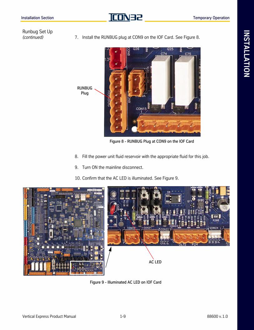
Runbug Set Up(continued) 7. Install the RUNBUG plug at CON9 on the IOF Card. See Figure 8.
Figure 8 - RUNBUG Plug at CON9 on the IOF Card
8. Fill the power unit fluid reservoir with the appropriate fluid for this job.
9. Turn ON the mainline disconnect.
10. Confirm that the AC LED is illuminated. See Figure 9.
Figure 9 - Illuminated AC LED on IOF Card
RUNBUG Plug
AC LED
Vertical Express Product Manual 1-9 88600 v.1.0
Temporary Operation Installation Section
Electronic Starter Setup
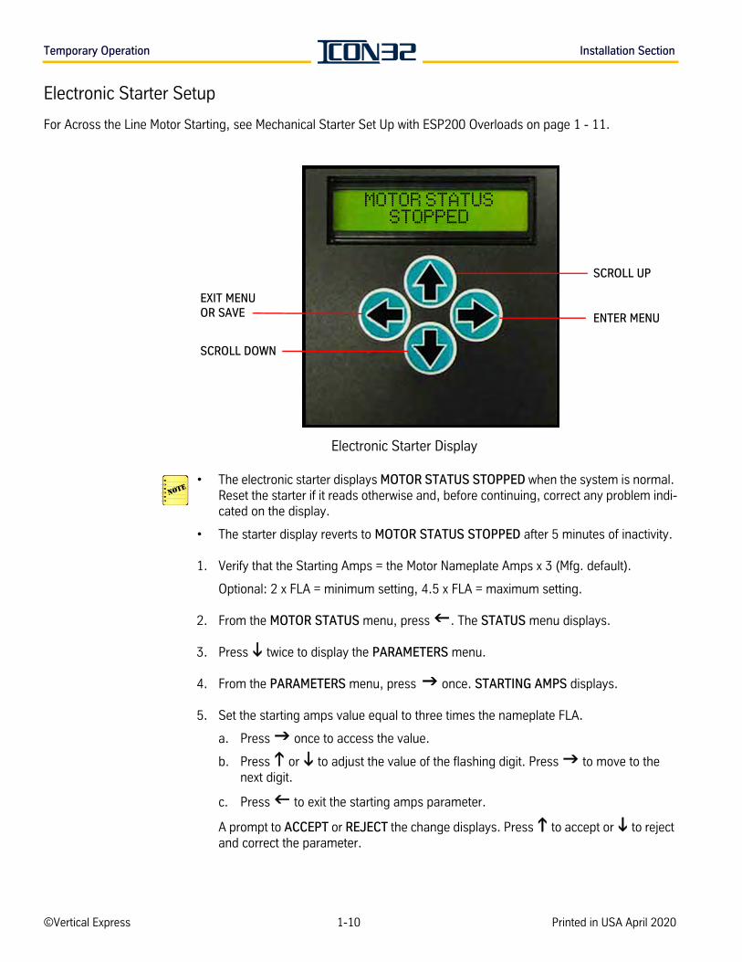
For Across the Line Motor Starting, see Mechanical Starter Set Up with ESP200 Overloads on page 1 - 11.
Electronic Starter Display
• The electronic starter displays MOTOR STATUS STOPPED when the system is normal. Reset the starter if it reads otherwise and, before continuing, correct any problem indi-cated on the display.
• The starter display reverts to MOTOR STATUS STOPPED after 5 minutes of inactivity.
1. Verify that the Starting Amps = the Motor Nameplate Amps x 3 (Mfg. default).
Optional: 2 x FLA = minimum setting, 4.5 x FLA = maximum setting.
2. From the MOTOR STATUS menu, press . The STATUS menu displays.
3. Press twice to display the PARAMETERS menu.
4. From the PARAMETERS menu, press once. STARTING AMPS displays.
5. Set the starting amps value equal to three times the nameplate FLA.
a. Press once to access the value.
b. Press or to adjust the value of the flashing digit. Press to move to the next digit.
c. Press to exit the starting amps parameter.
A prompt to ACCEPT or REJECT the change displays. Press to accept or to reject and correct the parameter.
EXIT MENU OR SAVE
SCROLL DOWN
SCROLL UP
ENTER MENU
MOTOR STATUS STOPPED
©Vertical Express 1-10 Printed in USA April 2020
INS
TA
LLA
TIO
NInstallation Section Temporary Operation
Electronic Starter Setup(continued)
6. Press once and OVERLOAD AMPS displays.
a. If the value is correct, skip to Step 8.
b. If the value is not correct, continue to Step 7.
7. Press once to access the value.
a. Press or to adjust the value of the flashing digit.
b. Press to move to the next digit.
8. Press to exit to the PARAMETERS Menu.
A prompt to ACCEPT or REJECT the change appears. Press to accept, or to reject and correct the parameter.
Mechanical Starter Set Up with ESP200 Overloads
Overload relay current settings are preset by Manufacturing. The following initial adjustment can also be used during temporary operation for jobs that trip overloads, but the actual overload current will be set during final adjustment.
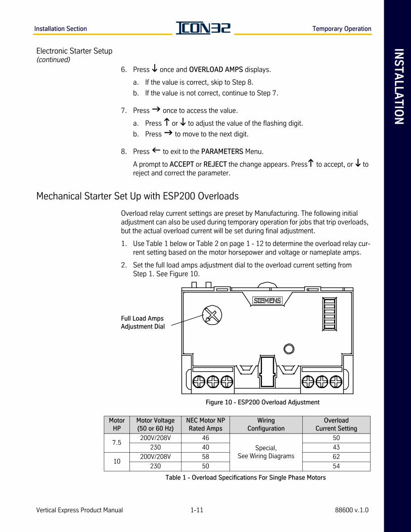
1. Use Table 1 below or Table 2 on page 1 - 12 to determine the overload relay cur-rent setting based on the motor horsepower and voltage or nameplate amps.
2. Set the full load amps adjustment dial to the overload current setting from Step 1. See Figure 10.
Figure 10 - ESP200 Overload Adjustment
Table 1 - Overload Specifications For Single Phase Motors
Full Load Amps Adjustment Dial
Motor HP
Motor Voltage(50 or 60 Hz)
NEC Motor NPRated Amps
Wiring Configuration
OverloadCurrent Setting
7.5200V/208V 46
Special, See Wiring Diagrams
50
230 40 43
10200V/208V 58 62
230 50 54
Vertical Express Product Manual 1-11 88600 v.1.0
Temporary Operation Installation Section
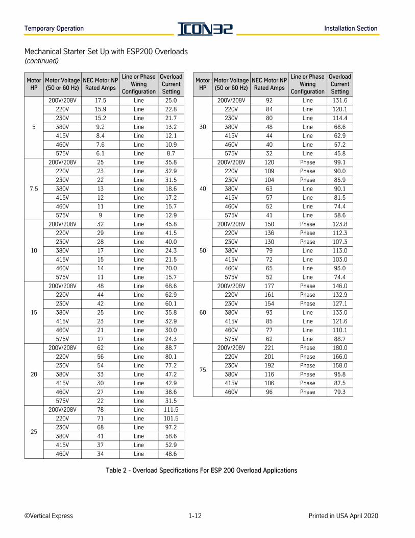
Mechanical Starter Set Up with ESP200 Overloads(continued)
Table 2 - Overload Specifications For ESP 200 Overload Applications
Motor HP
Motor Voltage(50 or 60 Hz)
NEC Motor NPRated Amps
Line or Phase Wiring
Configuration
OverloadCurrent Setting
Motor HP
Motor Voltage(50 or 60 Hz)
NEC Motor NPRated Amps
Line or Phase Wiring
Configuration
OverloadCurrent Setting
5
200V/208V 17.5 Line 25.0
30
200V/208V 92 Line 131.6
220V 15.9 Line 22.8 220V 84 Line 120.1
230V 15.2 Line 21.7 230V 80 Line 114.4
380V 9.2 Line 13.2 380V 48 Line 68.6
415V 8.4 Line 12.1 415V 44 Line 62.9
460V 7.6 Line 10.9 460V 40 Line 57.2
575V 6.1 Line 8.7 575V 32 Line 45.8
7.5
200V/208V 25 Line 35.8
40
200V/208V 120 Phase 99.1
220V 23 Line 32.9 220V 109 Phase 90.0
230V 22 Line 31.5 230V 104 Phase 85.9
380V 13 Line 18.6 380V 63 Line 90.1
415V 12 Line 17.2 415V 57 Line 81.5
460V 11 Line 15.7 460V 52 Line 74.4
575V 9 Line 12.9 575V 41 Line 58.6
10
200V/208V 32 Line 45.8
50
200V/208V 150 Phase 123.8
220V 29 Line 41.5 220V 136 Phase 112.3
230V 28 Line 40.0 230V 130 Phase 107.3
380V 17 Line 24.3 380V 79 Line 113.0
415V 15 Line 21.5 415V 72 Line 103.0
460V 14 Line 20.0 460V 65 Line 93.0
575V 11 Line 15.7 575V 52 Line 74.4
15
200V/208V 48 Line 68.6
60
200V/208V 177 Phase 146.0
220V 44 Line 62.9 220V 161 Phase 132.9
230V 42 Line 60.1 230V 154 Phase 127.1
380V 25 Line 35.8 380V 93 Line 133.0
415V 23 Line 32.9 415V 85 Line 121.6
460V 21 Line 30.0 460V 77 Line 110.1
575V 17 Line 24.3 575V 62 Line 88.7
20
200V/208V 62 Line 88.7
75
200V/208V 221 Phase 180.0
220V 56 Line 80.1 220V 201 Phase 166.0
230V 54 Line 77.2 230V 192 Phase 158.0
380V 33 Line 47.2 380V 116 Phase 95.8
415V 30 Line 42.9 415V 106 Phase 87.5
460V 27 Line 38.6 460V 96 Phase 79.3
575V 22 Line 31.5
25
200V/208V 78 Line 111.5
220V 71 Line 101.5
230V 68 Line 97.2
380V 41 Line 58.6
415V 37 Line 52.9
460V 34 Line 48.6
©Vertical Express 1-12 Printed in USA April 2020
INS
TA
LLA
TIO
NInstallation Section Temporary Operation
Pump Motor Rotation
Swapping motor leads to correct motor rotation will result in a motor wiring fault. Motor rotation is controlled through adjustments in the starter and also the line input to the starter.
1. Turn ON the mainline disconnect.
2. Momentarily press UP and SAFE on the temporary run box, and observe the direction of the motor rotation (clockwise rotation is standard for Vertical Express equipment when viewed from the shaft end).
ABC = Standard Dry (AP) units (CW rotation as viewed from the shaft end). The motor is mounted to the left of the pump.
CBA = Standard Wet (EP) units (CCW rotation as viewed from the pump end).
– If the motor rotation is correct, continue to Step 5.
– If the rotation is incorrect, complete the appropriate procedure below.
• For Mechanical Starters - Reverse L1 and L2 on the starter.
• For Electronic Starters - Change the line rotation setting in the starter.
a. Press once. The STATUS menu displays.
b. Press twice. The PARAMETERS menu displays.
c. Press and STARTING AMPS displays.
d. Press until LINE ROTATION displays.
e. Press to access the value.
f. Press for CBA. (CBA = standard wet unit.)
g. Press to select the value displayed.
h. Press to accept the value, or to reject the change. If the wrong value is accepted, repeat steps e. through h.
3. Verify the correct motor wiring. See Figure 11 on page 1-14.
4. Check the motor rotation direction. If the direction is incorrect or if the motor is making loud sounds, swap two phase leads at the top of the con-troller’s main line fuses (FL1 - FL3).
5. Confirm the motor rotation. It may take multiple attempts to get the incoming line phase relationship correct.
Vertical Express Product Manual 1-13 88600 v.1.0
I-2/I-3 Valve Installation Section
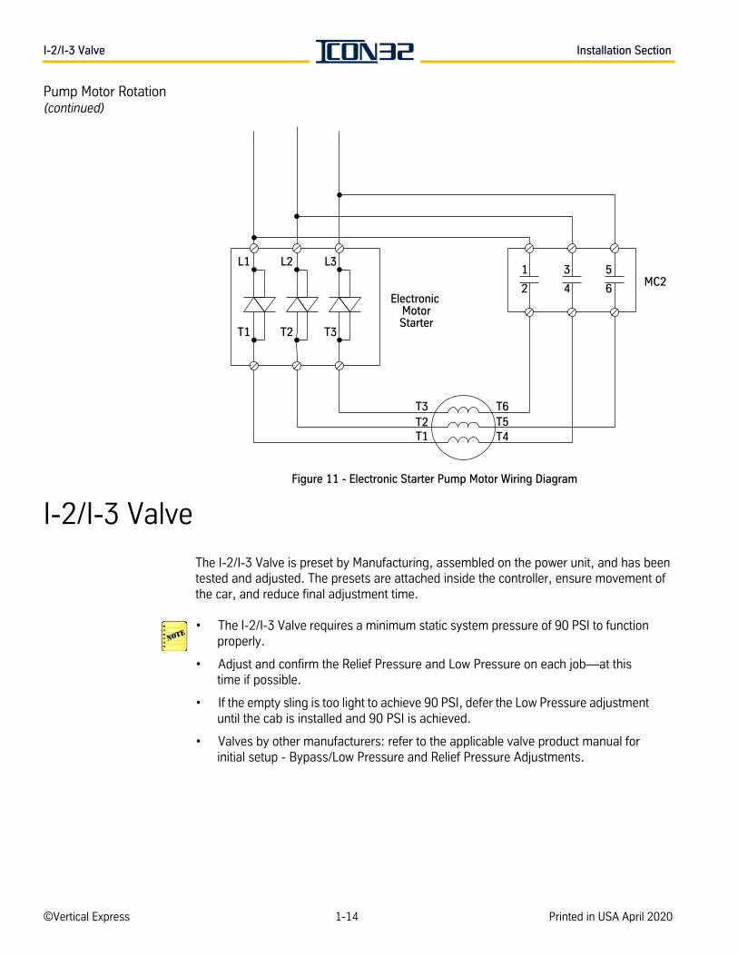
Pump Motor Rotation(continued)
Figure 11 - Electronic Starter Pump Motor Wiring Diagram
I-2/I-3 Valve
The I-2/I-3 Valve is preset by Manufacturing, assembled on the power unit, and has been tested and adjusted. The presets are attached inside the controller, ensure movement of the car, and reduce final adjustment time.
• The I-2/I-3 Valve requires a minimum static system pressure of 90 PSI to function properly.
• Adjust and confirm the Relief Pressure and Low Pressure on each job—at this time if possible.
• If the empty sling is too light to achieve 90 PSI, defer the Low Pressure adjustment until the cab is installed and 90 PSI is achieved.
• Valves by other manufacturers: refer to the applicable valve product manual for initial setup - Bypass/Low Pressure and Relief Pressure Adjustments.
Electronic MotorStarter
L1 L2 L3
T1 T2 T3
MC2
T3
T1T2
T4T5T6
5
2
31
4 6
©Vertical Express 1-14 Printed in USA April 2020
INS
TA
LLA
TIO
NInstallation Section I-2/I-3 Valve
I-2/I-3 Valve(continued) Relief Pressure Verification
This preliminary check is to ensure that the pipe couplings and valve will not be dam-aged if the elevator system’s oil flow or platform become restricted. The final check for the relief pressure is set with the procedure Final Relief Pressure with Full Load on page 2-33.
1. Close the shut-off valve.
2. Install a pressure gauge on the silencer's quick connect.
Immediately stop the power unit if the pressure exceeds 625 PSI.
3. While monitoring the pressure gauge, run the power unit in the up direction from the runbug in short bursts. Once confirmed that the pressure will not exceed 625 PSI, the pump motor can run constantly to verify the relief pressure setting.
4. Adjust the pressure relief (if necessary) to reduce pressure below 625 PSI.
a. IN (CW) = Increase Relief Pressure
b. OUT (CCW) = Decrease Relief Pressure
5. Briefly open the Manual Lowering Valve to relieve pressure from the valve, and confirm that the valve is fully closed when finished.
Low Pressure Adjustment
When operating elevator from the controller, follow all safety precautions.
• If the low pressure adjustment is made with the CPUC online, temporarily set the Z44 timer to 10 seconds, and run the motor less than 10 seconds at a time from Inspection Operation.
• OUT = Counterclockwise, CCWIN = Clockwise, CW
1. Ensure that the car is empty and the manual lowering valve is closed.
2. Turn OFF, Lockout, and Tagout the mainline disconnect.
3. Disconnect CON15 (on the IOF Card in the controller) to disable the valve’s up slow solenoid.
4. Turn the Low Pressure adjustment screw OUT 13/4" beyond the cover plate. See Figure 12 on page 1-16.
5. Turn the Low Pressure adjustment screw IN by hand until it touches the regu-lator piston.
Vertical Express Product Manual 1-15 88600 v.1.0
I-2/I-3 Valve Installation Section
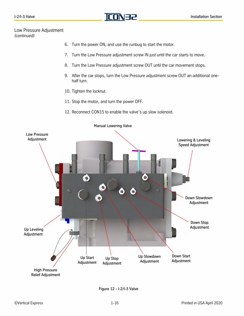
Low Pressure Adjustment(continued)
6. Turn the power ON, and use the runbug to start the motor.
7. Turn the Low Pressure adjustment screw IN just until the car starts to move.
8. Turn the Low Pressure adjustment screw OUT until the car movement stops.
9. After the car stops, turn the Low Pressure adjustment screw OUT an additional one-half turn.
10. Tighten the locknut.
11. Stop the motor, and turn the power OFF.
12. Reconnect CON15 to enable the valve’s up slow solenoid.
Figure 12 - I-2/I-3 Valve
Low PressureAdjustment
Manual Lowering Valve
Lowering & LevelingSpeed Adjustment
Down SlowdownAdjustment
Down StopAdjustment Up Leveling
Adjustment
Down StartAdjustment
Up StartAdjustment
Up StopAdjustment
Up SlowdownAdjustment
High PressureRelief Adjustment
©Vertical Express 1-16 Printed in USA April 2020
INS
TA
LLA
TIO
NInstallation Section Selector Tape
Selector Tape
Mount the Tape Close floor equipment is not required for this control system; see Floor Landing and Close Floor Leveling Magnet Installation on page 2-19.
Selector tape is constructed of spring steel. Use EXTREME CAUTION when cutting the band that holds the selector tape onto the spool.
Selector tape must be handled carefully. One kink will ruin the entire tape.
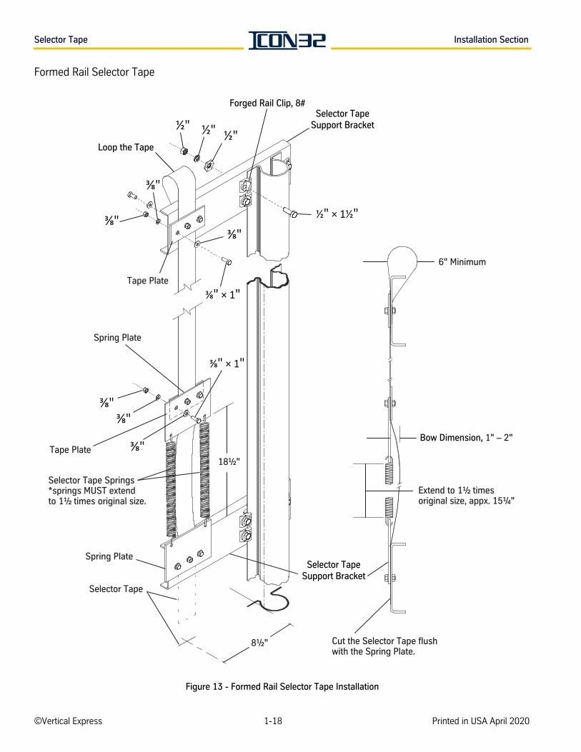
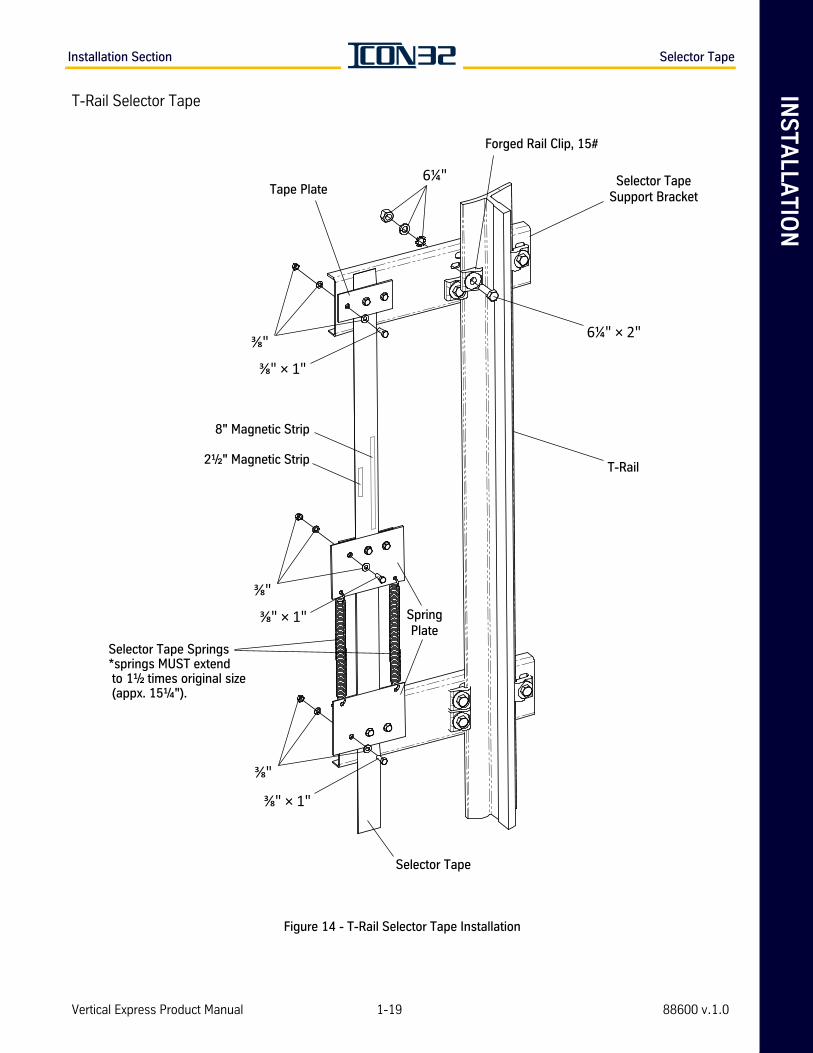
1. Install the top tape support bracket. See the job layout for the proper quadrant and position.
2. Attach the selector tape to the top tape support bracket; loop the tape over the bracket. The loop should be a minimum of 6" at its widest point. See Figure 13 on page 1-18 or Figure 14 on page 1-19.
3. Move to the bottom of the hoistway. Attach a spring plate and tape plate to the selector tape at a point that will be no less than 6" below the selector box when the car is on the buffers.
4. Install the bottom tape support bracket on the guide rail 181/2" below the bottom of the spring plate.
5. Install the other spring plate on the tape support bracket. Ensure that the selec-tor is between the spring plate and bracket.
6. Stretch the two selector tape springs between the spring plates. If properly installed, the springs will be one and a half times their normal length; e.g., a 10" spring will be stretched to 15".
7. Check the bow dimension in the selector tape. If the dimension is incorrect, adjust the tape at the bottom support bracket.
8. Ensure that the selector tape is even with the bottom spring plate. Measure from about 2" below the bottom mounting bracket, and cut off the excess selector tape.
9. Verify that the centerline of the selector tape is aligned within 5/16" of the center-line of the guide rails and also free of kinks throughout the hoistway.
10. The 3" wide x 3" vertical plane of the tape must be parallel to the back of the rail ±5/16" of the centerline of the guide rails and also free of kinks throughout the hoistway.
Vertical Express Product Manual 1-17 88600 v.1.0
Selector Tape Installation Section
Formed Rail Selector Tape
Figure 13 - Formed Rail Selector Tape Installation
Selector Tape
Selector Tape Springs*springs MUST extendto 1½ times original size.
Spring Plate
Tape Plate
Spring Plate
18½"
Loop the Tape
Extend to 1½ timesoriginal size, appx. 15¼"
6" Minimum
Cut the Selector Tape flushwith the Spring Plate.
Bow Dimension, 1" – 2"
Selector TapeSupport Bracket
Tape Plate
8½"
" × 1"
Selector TapeSupport Bracket
" × 1"
½" × 1½"
½"½"½"
Forged Rail Clip, 8#
©Vertical Express 1-18 Printed in USA April 2020
INS
TA
LLA
TIO
NInstallation Section Selector Tape
T-Rail Selector Tape
Figure 14 - T-Rail Selector Tape Installation
T-Rail2½" Magnetic Strip
8" Magnetic Strip
6¼" × 2"
6¼"
Selector Tape
Selector Tape Springs*springs MUST extend to 1½ times original size (appx. 15¼").
SpringPlate
Selector TapeSupport Bracket
Tape Plate
Forged Rail Clip, 15#
Vertical Express Product Manual 1-19 88600 v.1.0
Hoistway Wiring Installation Section
Hoistway Wiring
The wiring and conduit installation details represent a typical two car group, and installa-tion for other car and group configurations is similar.
All wiring run in the duct is tied back on each side – separate high voltage from low voltage. Do not run any low voltage wiring (including any communication wir-ing) with any wiring that is high voltage switching, such as motor leads.
• Flexible metallic tubing (flex) can be used in conduit runs up to 6 feet.
• Use electrical metallic tubing (EMT) in conduit runs longer than 6 feet.
• Check the job layout to determine the proper quadrant for location of equipment.
• Anchor bolts and hardware (for fastening conduit to the wall) are not furnished as part of the wiring package.
• All conduit, wireway, wire, and cable is furnished in bulk and must be cut to length.
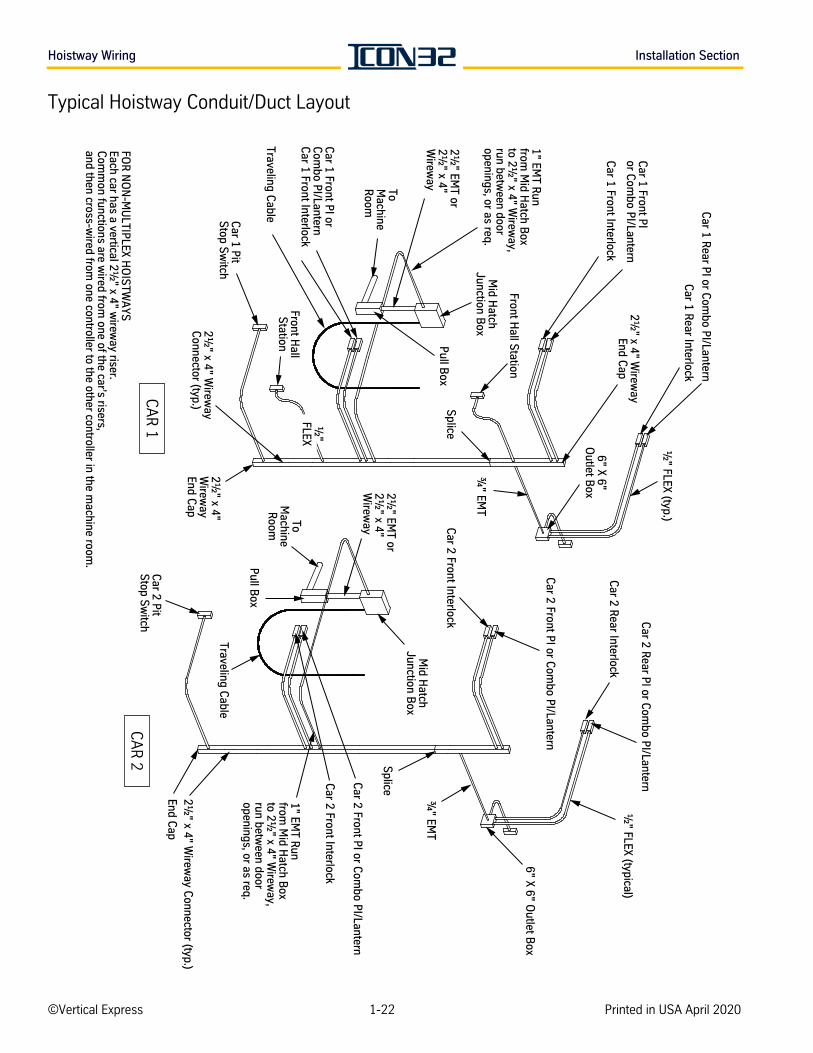
• 21/2" x 4" wireway (duct) is provided for the door interlock wiring and hall node riser. The hall node riser consists of hall nodes mounted within the duct at each floor loca-tion to provide interconnection and communication to hall devices such as position indicators, hall calls, and hall lanterns for up to two cars.
• Install one 3/4" EMT run at each landing with a rear opening.
• Install EMT from the wireway to the 4" x 4" box at the rear wall.
• For rear applications, a rear riser of hall nodes is also required. The rear riser of hall nodes is mounted in the same duct as the front riser. The rear riser provides the hall device interconnections for up to two cars with rear openings.
• Strain bolts are supplied for installing down the hoistway wireway (at as many places as may be necessary) to adequately support the hoistway wiring.
• Common functions within a group are wired to a single controller from the hoistway, and then cross-connected to the remaining cars within the same group (grouped con-trollers only).
©Vertical Express 1-20 Printed in USA April 2020
INS
TA
LLA
TIO
NInstallation Section Hoistway Wiring
Wireway and Conduit Layout
The following procedure is a suggested method of installation. See the job wiring diagrams and the wiring diagrams on the following pages.
Required Wireways/Conduits
• Hall station and door interlock riser
• Machine room to junction box
• Hoistway access and final limits (if required)
• Controller cross-connects (group jobs only)
1. Mount the junction box to the guide rail at a point above the center point of car travel and also above the entrance header. See the job layout for the proper quadrant.
2. Run wireway/conduit from the power unit/controller in the machine room to the junction box.
3. Install the hall station and the door interlock riser.
4. Run conduit and mount the hall signal fixture boxes.
5. Run conduit and mount boxes for the position indicators, the lanterns, and the pit stop switch.
6. Run conduit for final limits as required.
Vertical Express Product Manual 1-21 88600 v.1.0
Hoistway Wiring Installation Section
Typical Hoistway Conduit/Duct Layout
½" FLEX (typical)
6" X 6"O
utlet Box
¾" EM
T
Car 2 Front P
I or Com
bo PI/Lantern
Car 2 Front Interlock
Car 1 Front P
Ior C
ombo P
I/Lantern
Car 1 Front Interlock
Car 2 P
itS
top Sw
itch
Front Hall S
tation
½" FLEX (typ.)
Car 1 P
itS
top Sw
itch
Splice
Pull B
ox
2½" x 4" W
ireway
Connector (typ.)
2½" x 4" W
ireway
End Cap
2½" EM
T or2½
" x 4"W
ireway
Mid H
atchJunction B
ox
1" EMT R
unfrom
Mid H
atch Box
to 2½" x 4" W
ireway,
run between door
openings, or as req.
FOR
NO
N-M
ULTIP
LEX HO
ISTW
AYS
Each car has a vertical 2½" x 4" w
ireway riser.
Com
mon functions are w
ired from one of the car’s risers,
and then cross-wired from
one controller to the other controller in the machine room
.
Traveling Cable
Traveling Cable
Pull B
ox
¾" EM
T
6" X 6" Outlet B
ox
Car 1 R
ear PI or C
ombo P
I/Lantern
Car 1 R
ear Interlock
Car 1 Front P
I orC
ombo P
I/LanternC
ar 1 Front InterlockFront H
allS
tation
2½" x 4" W
ireway C
onnector (typ.)End C
ap
CA
R 1
CA
R 2
2½" x 4"
Wirew
ayEnd C
ap
ToMachine
Room
½"
FLEX1" EM
T Run
from M
id Hatch B
oxto 2½
" x 4" Wirew
ay,run betw
een dooropenings, or as req.
Car 2 R
ear PI or C
ombo P
I/Lantern
Car 2 R
ear Interlock
2½" EM
T or2½
" x 4"W
ireway
ToM
achineR
oom
Mid H
atchJunction B
ox
Splice
Car 2 Front P
I or Com
bo PI/Lantern
Car 2 Front Interlock
©Vertical Express 1-22 Printed in USA April 2020
INS
TA
LLA
TIO
NInstallation Section Hoistway Wiring
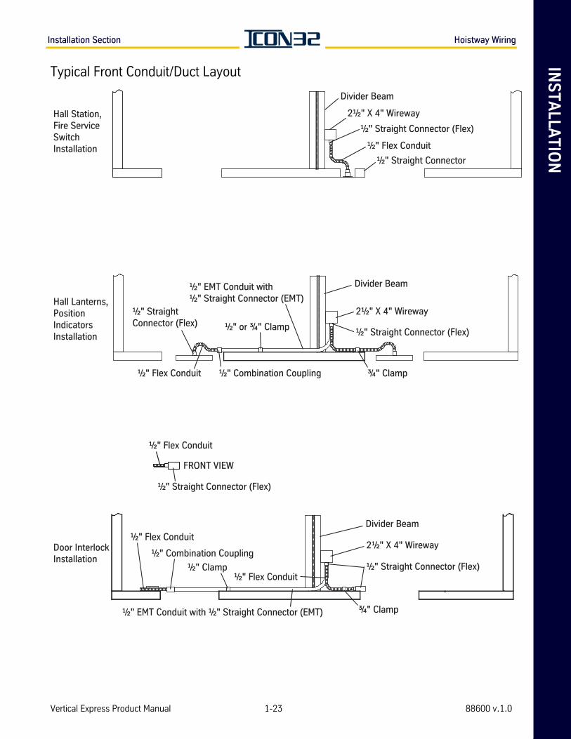
Typical Front Conduit/Duct Layout
Hall Station, Fire Service Switch Installation
Hall Lanterns, Position Indicators Installation
Door Interlock Installation
Divider Beam
2½" X 4" Wireway
½" Straight Connector (Flex)
½" Flex Conduit
½" Straight Connector
½" EMT Conduit with ½" Straight Connector (EMT)
½" or ¾" Clamp
½" Combination Coupling½" Flex Conduit
½" Straight Connector (Flex)
Divider Beam
2½" X 4" Wireway
½" Straight Connector (Flex)
¾" Clamp
½" Flex Conduit
½" Straight Connector (Flex)
½" Flex Conduit
½" Combination Coupling
½" Clamp
Divider Beam
2½" X 4" Wireway
½" Straight Connector (Flex)½" Flex Conduit
¾" Clamp½" EMT Conduit with ½" Straight Connector (EMT)
FRONT VIEW
Vertical Express Product Manual 1-23 88600 v.1.0
Hoistway Wiring Installation Section
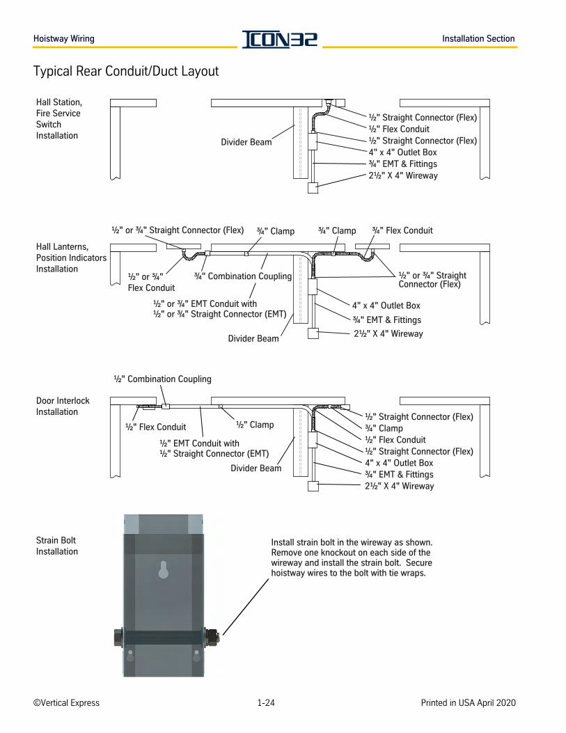
Typical Rear Conduit/Duct Layout
Hall Lanterns, Position Indicators Installation
½" or ¾" EMT Conduit with ½" or ¾" Straight Connector (EMT)
½" or ¾" Straight Connector (Flex)
Divider Beam 2½" X 4" Wireway
½" or ¾" Straight Connector (Flex)
¾" EMT & Fittings
¾" Flex Conduit
4" x 4" Outlet Box
¾" Clamp
½" or ¾" Flex Conduit
¾" Clamp
Hall Station, Fire Service Switch Installation
Divider Beam
½" Flex Conduit½" Straight Connector (Flex)
2½" X 4" Wireway
½" Straight Connector (Flex)
4" x 4" Outlet Box¾" EMT & Fittings
Door Interlock Installation
¾" Clamp½" Clamp
Divider Beam
½" Flex Conduit½" Straight Connector (Flex)
½" Straight Connector (Flex)
2½" X 4" Wireway¾" EMT & Fittings4" x 4" Outlet Box
½" EMT Conduit with ½" Straight Connector (EMT)
½" Combination Coupling
½" Flex Conduit
Strain Bolt Installation
Install strain bolt in the wireway as shown. Remove one knockout on each side of the wireway and install the strain bolt. Secure hoistway wires to the bolt with tie wraps.
¾" Combination Coupling
©Vertical Express 1-24 Printed in USA April 2020
INS
TA
LLA
TIO
NInstallation Section Hoistway Wiring
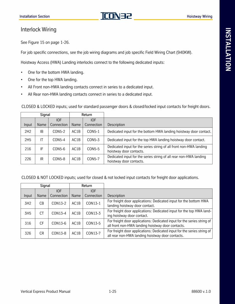
Interlock Wiring
See Figure 15 on page 1-26.
For job specific connections, see the job wiring diagrams and job specific Field Wiring Chart (940KW).
Hoistway Access (HWA) Landing interlocks connect to the following dedicated inputs:
• One for the bottom HWA landing.
• One for the top HWA landing.
• All Front non-HWA landing contacts connect in series to a dedicated input.
• All Rear non-HWA landing contacts connect in series to a dedicated input.
CLOSED & LOCKED inputs; used for standard passenger doors & closed/locked input contacts for freight doors.
Signal Return
Input NameIOF
Connection NameIOF
Connection Description
2H2 IB CON5-2 AC1B CON5-1 Dedicated input for the bottom HWA landing hoistway door contact.
2H5 IT CON5-4 AC1B CON5-3 Dedicated input for the top HWA landing hoistway door contact.
216 IF CON5-6 AC1B CON5-5Dedicated input for the series string of all front non-HWA landing hoistway door contacts.
226 IR CON5-8 AC1B CON5-7Dedicated input for the series string of all rear non-HWA landing hoistway door contacts.
CLOSED & NOT LOCKED inputs; used for closed & not locked input contacts for freight door applications.
Signal Return
Input NameIOF
Connection NameIOF
Connection Description
3H2 CB CON13-2 AC1B CON13-1For freight door applications: Dedicated input for the bottom HWA landing hoistway door contact.
3H5 CT CON13-4 AC1B CON13-3For freight door applications: Dedicated input for the top HWA land-ing hoistway door contact.
316 CF CON13-6 AC1B CON13-5For freight door applications: Dedicated input for the series string of all front non-HWA landing hoistway door contacts.
326 CR CON13-8 AC1B CON13-7For freight door applications: Dedicated input for the series string of all rear non-HWA landing hoistway door contacts.
Vertical Express Product Manual 1-25 88600 v.1.0
Hoistway Wiring Installation Section
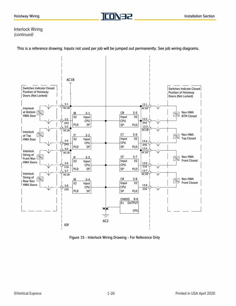
Interlock Wiring(continued)
Figure 15 - Interlock Wiring Drawing - For Reference Only
Switches Indicate Closed Position of HoistwayDoors (Not Locked)
Interlock at Bottom HWA Door
Interlock String ofFront NonHWA Doors
Interlock String ofRear NonHWA Doors
Interlockat TopHWA Door
Non HWABTM Closed
Non HWATop Closed
Non HWAFront Closed
Non HWAFront Closed
IOF
AC1B
AC2
CBInputCPUSP
CTInputCPUSP
CFInputCPUSP
CRInputCPUSP
CHKDSX1
3-1InputCPU
SP
3-2InputCPU
SP
3-3InputCPU
SP
3-4InputCPU
SP
3-5X2
PLD
3-6X2
PLD
3-7X2
PLD
3-8X2
PLD
8-6OUTPUT
CPU
IBX2
PLD
ITX2
PLD
IFX2
PLD
IRX2
PLD
5:1AC1B
5:22H25:3
AC1B
5:5AC1B
5:7AC1B
5:42H5
5:6216
5:8226
13:23H2
13:43H5
13:6316
13:8326
13:1AC1B
13:3AC1B
13:5AC1B
13:7AC1B
Switches Indicate Closed Position of HoistwayDoors (Not Locked)
This is a reference drawing. Inputs not used per job will be jumped out permanently. See job wiring diagrams.
©Vertical Express 1-26 Printed in USA April 2020
INS
TA
LLA
TIO
NInstallation Section Hoistway Wiring
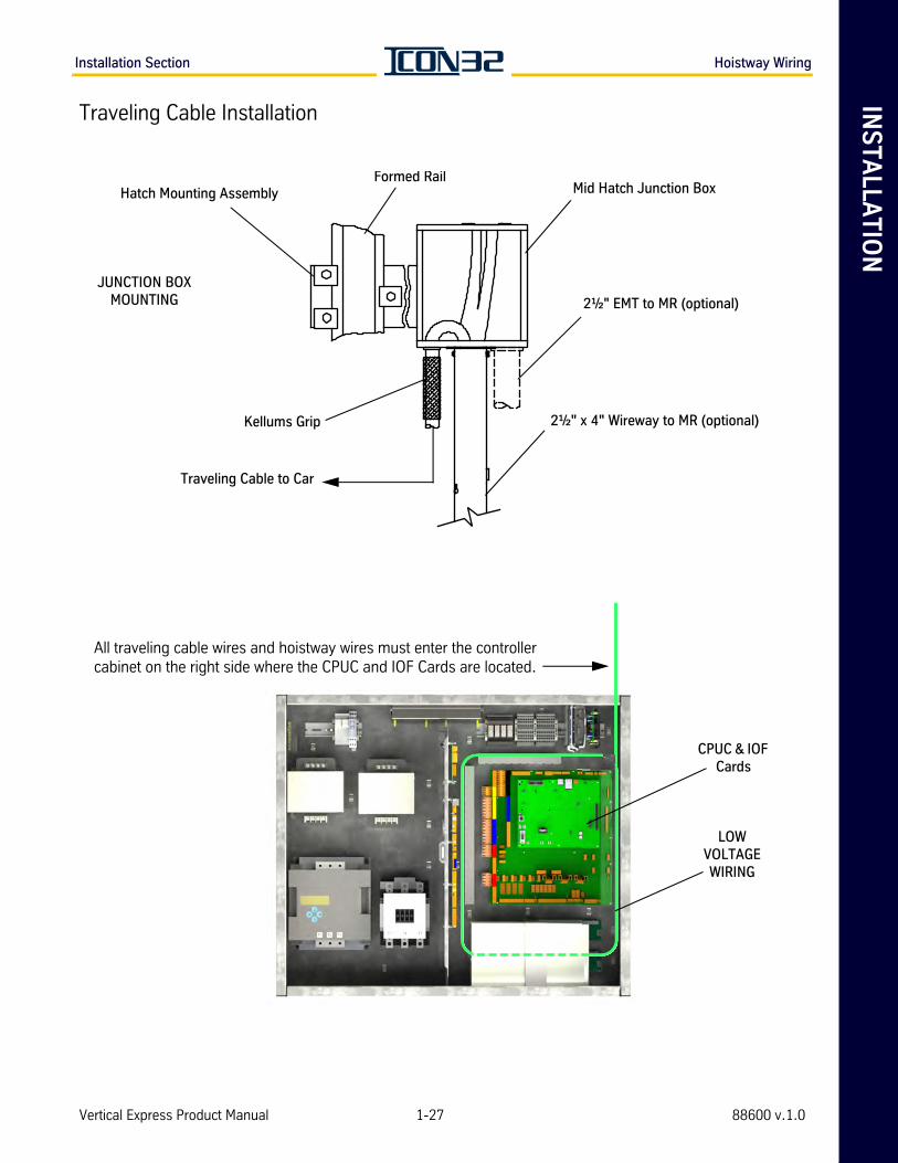
Traveling Cable Installation
Hatch Mounting AssemblyFormed Rail
Mid Hatch Junction Box
2½" EMT to MR (optional)
2½" x 4" Wireway to MR (optional)Kellums Grip
Traveling Cable to Car
JUNCTION BOX MOUNTING
All traveling cable wires and hoistway wires must enter the controller cabinet on the right side where the CPUC and IOF Cards are located.
CPUC & IOF Cards
LOW VOLTAGE WIRING
Vertical Express Product Manual 1-27 88600 v.1.0
Hoistway Entrance Frames and Doors Installation Section
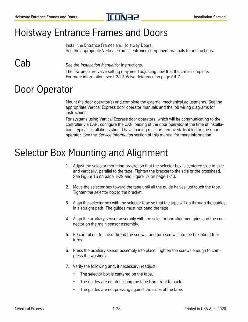
Hoistway Entrance Frames and DoorsInstall the Entrance Frames and Hoistway Doors. See the appropriate Vertical Express entrance component manuals for instructions.
Cab See the Installation Manual for instructions.
The low pressure valve setting may need adjusting now that the car is complete. For more information, see I-2/I-3 Valve Reference on page 5R-7.
Door OperatorMount the door operator(s) and complete the external mechanical adjustments. See the appropriate Vertical Express door operator manuals and the job wiring diagrams for instructions.
For systems using Vertical Express door operators, which will be communicating to the controller via CAN, configure the CAN loading of the door operator at the time of installa-tion. Typical installations should have loading resistors removed/disabled on the door operator. See the Service Information section of this manual for more information.
Selector Box Mounting and Alignment1. Adjust the selector mounting bracket so that the selector box is centered side to side
and vertically, parallel to the tape. Tighten the bracket to the stile or the crosshead. See Figure 16 on page 1-29 and Figure 17 on page 1-30.
2. Move the selector box toward the tape until all the guide halves just touch the tape. Tighten the selector box to the bracket.
3. Align the selector box with the selector tape so that the tape will go through the guides in a straight path. The guides must not bend the tape.
4. Align the auxiliary sensor assembly with the selector box alignment pins and the con-nector on the main sensor assembly.
5. Be careful not to cross-thread the screws, and turn screws into the box about four turns.
6. Press the auxiliary sensor assembly into place. Tighten the screws enough to com-press the washers.
7. Verify the following and, if necessary, readjust:
• The selector box is centered on the tape.
• The guides are not deflecting the tape from front to back.
• The guides are not pressing against the sides of the tape.
©Vertical Express 1-28 Printed in USA April 2020
INS
TA
LLA
TIO
NInstallation Section Selector Box Mounting and Alignment
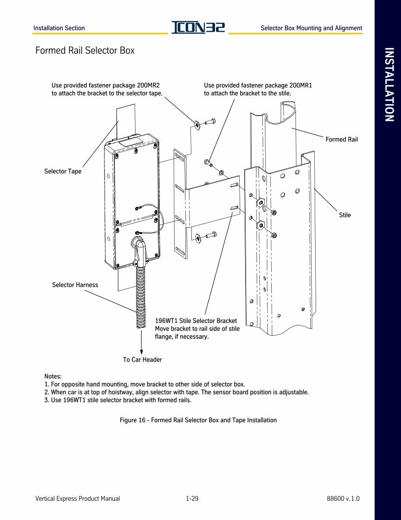
Formed Rail Selector Box
Figure 16 - Formed Rail Selector Box and Tape Installation
Notes:1. For opposite hand mounting, move bracket to other side of selector box. 2. When car is at top of hoistway, align selector with tape. The sensor board position is adjustable.3. Use 196WT1 stile selector bracket with formed rails.
Selector Harness
To Car Header
Formed Rail
196WT1 Stile Selector BracketMove bracket to rail side of stile flange, if necessary.
Selector Tape
Stile
Use provided fastener package 200MR2to attach the bracket to the selector tape.
Use provided fastener package 200MR1to attach the bracket to the stile.
Vertical Express Product Manual 1-29 88600 v.1.0
Selector Box Mounting and Alignment Installation Section
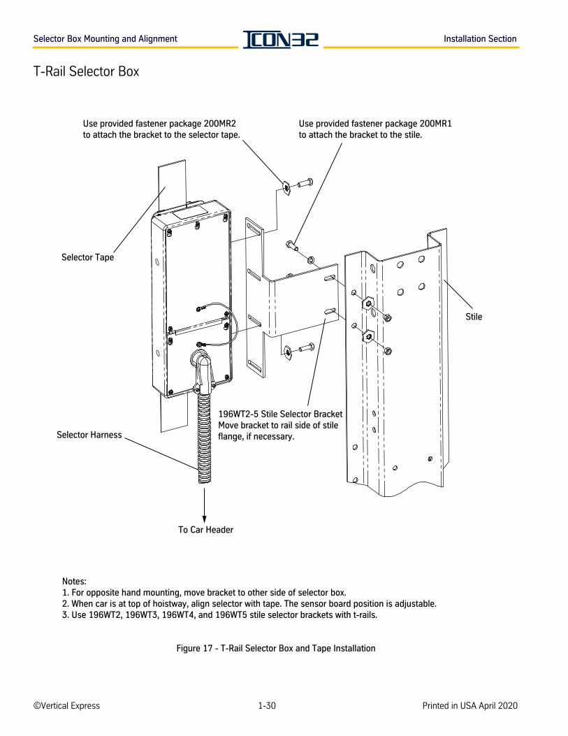
T-Rail Selector Box
Figure 17 - T-Rail Selector Box and Tape Installation
Notes:1. For opposite hand mounting, move bracket to other side of selector box. 2. When car is at top of hoistway, align selector with tape. The sensor board position is adjustable.3. Use 196WT2, 196WT3, 196WT4, and 196WT5 stile selector brackets with t-rails.
Selector Harness
To Car Header
196WT2-5 Stile Selector BracketMove bracket to rail side of stile flange, if necessary.
Selector Tape
Stile
Use provided fastener package 200MR2to attach the bracket to the selector tape.
Use provided fastener package 200MR1to attach the bracket to the stile.
©Vertical Express 1-30 Printed in USA April 2020
INS
TA
LLA
TIO
NInstallation Section Selector Box Mounting and Alignment
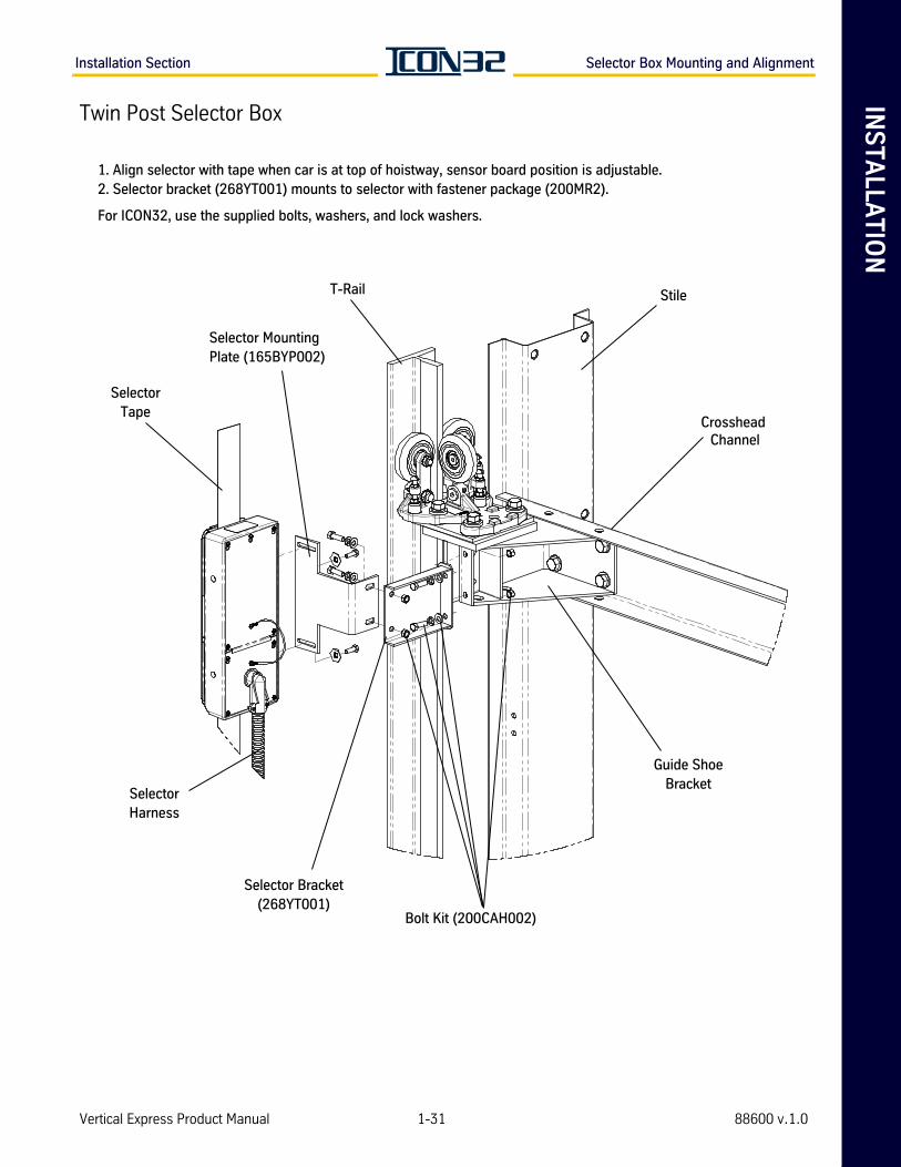
Twin Post Selector Box
1. Align selector with tape when car is at top of hoistway, sensor board position is adjustable.2. Selector bracket (268YT001) mounts to selector with fastener package (200MR2).
For ICON32, use the supplied bolts, washers, and lock washers.
Bolt Kit (200CAH002)
T-Rail Stile
Crosshead Channel
Guide ShoeBracket
Selector Bracket(268YT001)
SelectorHarness
SelectorTape
Selector MountingPlate (165BYP002)
Vertical Express Product Manual 1-31 88600 v.1.0
Selector Box Mounting and Alignment Installation Section
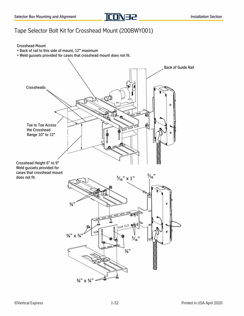
Tape Selector Bolt Kit for Crosshead Mount (200BWY001)
Crosshead Height 6" to 9"Weld gussets provided for cases that crosshead mountdoes not fit.
Toe to Toe Acrossthe CrossheadRange 10" to 12"
Crosshead Mount • Back of rail to this side of mount, 12" maximum• Weld gussets provided for cases that crosshead mount does not fit.
Back of Guide Rail
Crossheads
1
©Vertical Express 1-32 Printed in USA April 2020
INS
TA
LLA
TIO
NInstallation Section Car Top Wiring
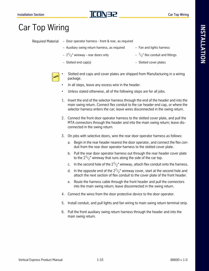
Car Top Wiring
• Slotted end caps and cover plates are shipped from Manufacturing in a wiring package.
• In all steps, leave any excess wire in the header.
• Unless stated otherwise, all of the following steps are for all jobs.
1. Insert the end of the selector harness through the end of the header and into the main swing return. Connect flex conduit to the car header end cap, or where the selector harness enters the car; leave wires disconnected in the swing return.
2. Connect the front door operator harness to the slotted cover plate, and pull the MTA connectors through the header and into the main swing return; leave dis-connected in the swing return.
3. On jobs with selective doors, wire the rear door operator harness as follows:
a. Begin in the rear header nearest the door operator, and connect the flex con-duit from the rear door operator harness to the slotted cover plate.
b. Pull the rear door operator harness out through the rear header cover plate to the 21/2" wireway that runs along the side of the car top.
c. In the second hole of the 21/2" wireway, attach flex conduit onto the harness.
d. In the opposite end of the 21/2" wireway cover, start at the second hole and attach the next section of flex conduit to the cover plate of the front header.
e. Route the harness cable through the front header and pull the connectors into the main swing return; leave disconnected in the swing return.
4. Connect the wires from the door protective device to the door operator.
5. Install conduit, and pull lights and fan wiring to main swing return terminal strip.
6. Pull the front auxiliary swing return harness through the header and into the main swing return.
Required Material – Door operator harness - front & rear, as required
– Auxiliary swing return harness, as required – Fan and lights harness
– 21/2" wireway - rear doors only – 1/2" flex conduit and fittings
– Slotted end cap(s) – Slotted cover plates
Vertical Express Product Manual 1-33 88600 v.1.0
Machine Room Wiring Installation Section
Car Top Wiring(continued) 7. On jobs with selective doors, wire the rear auxiliary swing return harness as follows:
a. Pull the rear auxiliary swing return harness through the rear header to the end cap nearest the 21/2" wireway that runs along the side of the car top.
b. Attach the flex conduit to the rear header end cap and also to the first hole in the 21/2" wireway cover.
c. Attach the flex conduit to the other end of the wireway cover and also to the end cap of the front header.
d. Route the harness cable through the front header and into the main swing return.
Swing Return Wiring
The selector, the car top inspection station, and the hoistway access inputs (when pro-vided) must be connected and functional to accomplish Controller Inspection or Car Top Inspection modes of operation.
1. Turn OFF, Lockout, and Tagout the cab lighting circuit.
2. Connect the traveling cable to the swing return rail terminals (RT). See the swing return terminal labels and the job wiring diagrams.
The LD-16 door operator has an adapter harness that wires the operator into the COP rail terminals (RT).
3. Connect the lights and fan wiring (L10, L10s, L20, and ground) to the swing return ter-minal strip.
Machine Room WiringController Card Connections
1. Turn OFF, Lockout and Tagout the mainline disconnect.
2. Make wiring connections in the Trades Access terminals.
3. Make wiring connections between the swing return (RT) and the elevator controller.
4. The various I/O will be assigned connections to the CNA Card(s), the IOF Card, the RT (rail terminals), and the DPIA Card. See the wiring diagrams and provided job specific Field Wiring Chart (940KW).
• Route the mainline power through the top left-hand corner of the controller.
• Route the hoistway wiring and traveling cable through the top right-hand corner of the controller.
• Group jobs only: Working from the right-hand side of the controllers, wire control-ler cross-connects between the controllers.
5. Wire the building power and other necessary connections (cab lighting, telephone, etc.) to the Trades Access terminals.
©Vertical Express 1-34 Printed in USA April 2020

AD
JU
ST
ME
NT
SE
CT
ION

AD
JU
ST
ME
NT
SE
CT
ION
Adjustment Section Contents
Contents
Preliminary Adjustment . . . . . . . . . . . . . . . . . . . . . . . . . . . . . . . . . . . . . . . . . . . . . . . . . . . . 2-3
Remove Temporary Operation. . . . . . . . . . . . . . . . . . . . . . . . . . . . . . . . . . . . . . . . . . 2-3
User Interface Tool (UIT) Menu Tree . . . . . . . . . . . . . . . . . . . . . . . . . . . . . . . . . . . . . 2-5
Software Verification Procedure. . . . . . . . . . . . . . . . . . . . . . . . . . . . . . . . . . . . . . . . . 2-6
Safety Processor Verification. . . . . . . . . . . . . . . . . . . . . . . . . . . . . . . . . . . . . . . . . . . 2-7
Configure the Safety Processor . . . . . . . . . . . . . . . . . . . . . . . . . . . . . . . . . . . . . . . . . 2-8
CAN Node Address Assignment . . . . . . . . . . . . . . . . . . . . . . . . . . . . . . . . . . . . . . . . 2-8
Verify Proper Resistive Loading for the CAN Channels . . . . . . . . . . . . . . . . . . . . . . . 2-11
CAN Node Configuration via the Startup Wizard . . . . . . . . . . . . . . . . . . . . . . . . . . . . . . . . . . 2-13
I/O and Safety String Checkout . . . . . . . . . . . . . . . . . . . . . . . . . . . . . . . . . . . . . . . . . . . . . . 2-14
Troubleshooting I/O Issues . . . . . . . . . . . . . . . . . . . . . . . . . . . . . . . . . . . . . . . . . . . 2-17
Car Top Inspection Operation . . . . . . . . . . . . . . . . . . . . . . . . . . . . . . . . . . . . . . . . . . . . . . . 2-17
Selector Tape Magnet Installation . . . . . . . . . . . . . . . . . . . . . . . . . . . . . . . . . . . . . . . . . . . . 2-18
Selector Tape and Box Inspection . . . . . . . . . . . . . . . . . . . . . . . . . . . . . . . . . . . . . . 2-18
Magnet Placement . . . . . . . . . . . . . . . . . . . . . . . . . . . . . . . . . . . . . . . . . . . . . . . . . 2-18
Preliminary Setup for Automatic Operation . . . . . . . . . . . . . . . . . . . . . . . . . . . . . . . . . . . . . 2-25
Hoistway Scan Through the Startup Wizard . . . . . . . . . . . . . . . . . . . . . . . . . . . . . . . 2-25
Door Setup and Final Adjustments . . . . . . . . . . . . . . . . . . . . . . . . . . . . . . . . . . . . . 2-26
I-2/I-3 Valve - Final Adjustments . . . . . . . . . . . . . . . . . . . . . . . . . . . . . . . . . . . . . . . . . . . . . 2-27
Valve Adjustment Up Section . . . . . . . . . . . . . . . . . . . . . . . . . . . . . . . . . . . . . . . . . 2-28
Valve Adjustment Down Section . . . . . . . . . . . . . . . . . . . . . . . . . . . . . . . . . . . . . . . 2-29
Performance Check with Full Load. . . . . . . . . . . . . . . . . . . . . . . . . . . . . . . . . . . . . . 2-33
Final Relief Pressure with Full Load . . . . . . . . . . . . . . . . . . . . . . . . . . . . . . . . . . . . . 2-33
Floor Position & Leveling Magnet Adjustment . . . . . . . . . . . . . . . . . . . . . . . . . . . . . . . . . . . 2-34
Terminal Slowdown Check . . . . . . . . . . . . . . . . . . . . . . . . . . . . . . . . . . . . . . . . . . . . . . . . . 2-35
Verify Proper Function of the UP Terminal Slowdown Magnets via the UIT . . . . . . . . . 2-35
Verify Proper Function of the DOWN Terminal Slowdown Magnets via the UIT . . . . . . 2-36
Final Adjustments . . . . . . . . . . . . . . . . . . . . . . . . . . . . . . . . . . . . . . . . . . . . . . . . . . . . . . . 2-37
ESP200 Overload . . . . . . . . . . . . . . . . . . . . . . . . . . . . . . . . . . . . . . . . . . . . . . . . . . 2-37
Electronic Starter . . . . . . . . . . . . . . . . . . . . . . . . . . . . . . . . . . . . . . . . . . . . . . . . . . 2-38
Operational Adjustments . . . . . . . . . . . . . . . . . . . . . . . . . . . . . . . . . . . . . . . . . . . . . . . . . . 2-39
Configure the THY02 Card. . . . . . . . . . . . . . . . . . . . . . . . . . . . . . . . . . . . . . . . . . . . 2-39
Additional Operational Adjustments. . . . . . . . . . . . . . . . . . . . . . . . . . . . . . . . . . . . . 2-41
Save Parameters and Backup Job Software. . . . . . . . . . . . . . . . . . . . . . . . . . . . . . . 2-42
Vertical Express Product Manual 2-1 88500 v.1.0

Contents Adjustment Section
This pageintentionallyleft blank.
2-2©Vertical Express Printed in USA April 2020
AD
JU
ST
ME
NT
Adjustment Section Preliminary Adjustment
Preliminary Adjustment
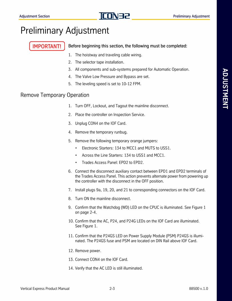
Before beginning this section, the following must be completed:
1. The hoistway and traveling cable wiring.
2. The selector tape installation.
3. All components and sub-systems prepared for Automatic Operation.
4. The Valve Low Pressure and Bypass are set.
5. The leveling speed is set to 10-12 FPM.
Remove Temporary Operation
1. Turn OFF, Lockout, and Tagout the mainline disconnect.
2. Place the controller on Inspection Service.
3. Unplug CON4 on the IOF Card.
4. Remove the temporary runbug.
5. Remove the following temporary orange jumpers:
• Electronic Starters: 134 to MCC1 and MUTS to USS1.
• Across the Line Starters: 134 to USS1 and MCC1.
• Trades Access Panel: EPD2 to EPD2.
6. Connect the disconnect auxiliary contact between EPD1 and EPD2 terminals of the Trades Access Panel. This action prevents alternate power from powering up the controller with the disconnect in the OFF position.
7. Install plugs 9a, 19, 20, and 21 to corresponding connectors on the IOF Card.
8. Turn ON the mainline disconnect.
9. Confirm that the Watchdog (WD) LED on the CPUC is illuminated. See Figure 1 on page 2-4.
10. Confirm that the AC, P24, and P24G LEDs on the IOF Card are illuminated. See Figure 1.
11. Confirm that the P24GS LED on Power Supply Module (PSM) P24GS is illumi-nated. The P24GS fuse and PSM are located on DIN Rail above IOF Card.
12. Remove power.
13. Connect CON4 on the IOF Card.
14. Verify that the AC LED is still illuminated.
Vertical Express Product Manual 2-3 88500 v.1.0
Preliminary Adjustment Adjustment Section
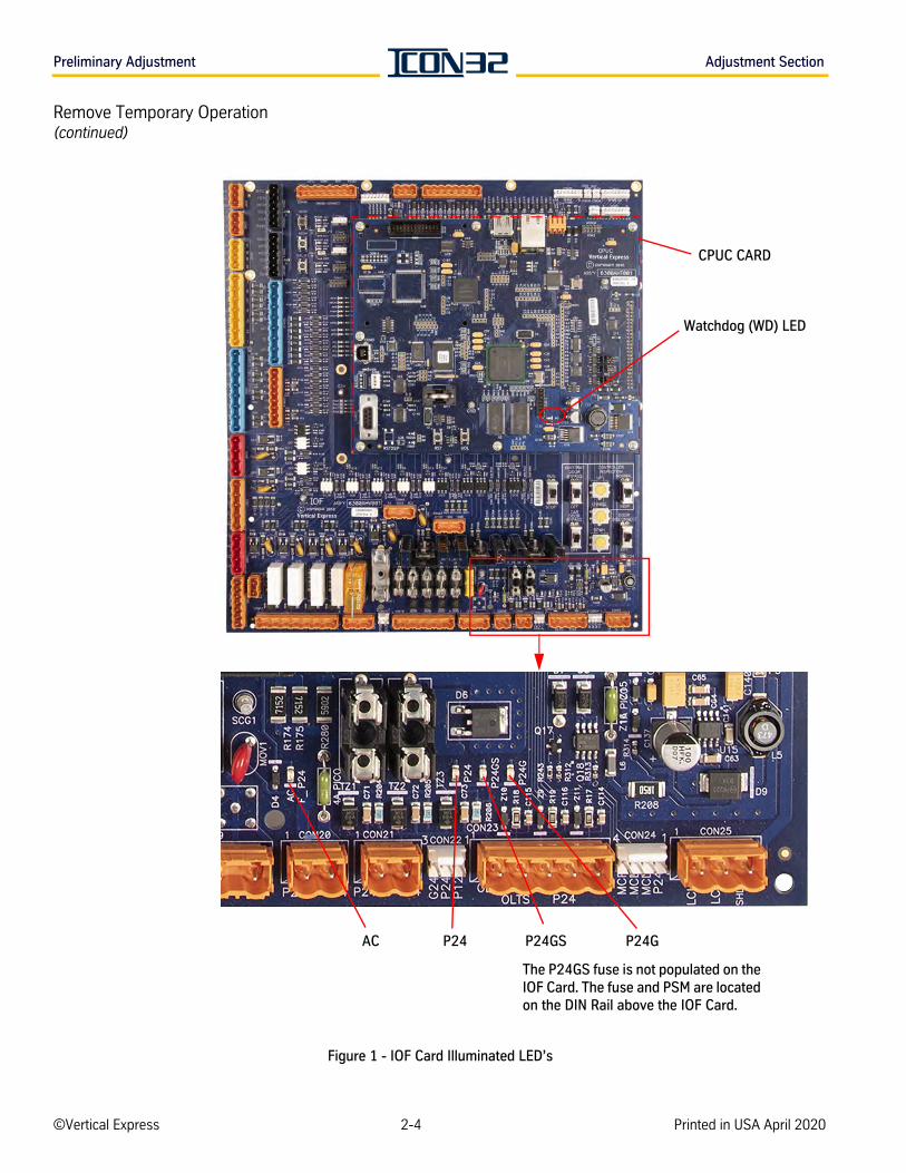
Remove Temporary Operation(continued)
Figure 1 - IOF Card Illuminated LED’s
Watchdog (WD) LED
AC P24
The P24GS fuse is not populated on the IOF Card. The fuse and PSM are located on the DIN Rail above the IOF Card.
P24G
CPUC CARD
P24GS
©Vertical Express 2-4 Printed in USA April 2020
AD
JU
ST
ME
NT
Adjustment Section Preliminary Adjustment
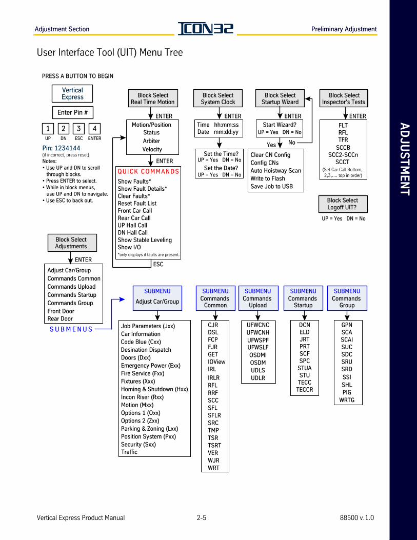
User Interface Tool (UIT) Menu Tree
Block SelectSystem Clock
Time hh:mm:ssDate mm:dd:yy
ENTER
Set the Time?UP = Yes DN = No
Set the Date?UP = Yes DN = No
SUBMENU
Adjust Car/Group
Job Parameters (Jxx)
Code Blue (Cxx)
Doors (Dxx)Emergency Power (Exx)Fire Service (Fxx)Fixtures (Xxx)Homing & Shutdown (Hxx)Incon Riser (Rxx)Motion (Mxx)Options 1 (Oxx)Options 2 (Zxx)Parking & Zoning (Lxx)Position System (Pxx)Security (Sxx)
SUBMENUCommands
Group
GPNSCASCAISUCSDCSRUSRDSSISHLPIG
WRTG
Show Faults*
Clear Faults*Reset Fault ListFront Car CallRear Car CallUP Hall CallDN Hall CallShow Stable LevelingShow I/O*only displays if faults are present.
QUICK COMMANDS
Block SelectAdjustments
ENTER
S U B M E N U S
Adjust Car/GroupCommands CommonCommands UploadCommands StartupCommands GroupFront DoorRear Door
Block SelectStartup Wizard
ENTER
Start Wizard?UP = Yes DN = No
Yes No
Clear CN ConfigConfig CNsAuto Hoistway ScanWrite to FlashSave Job to USB
Block SelectReal Time Motion
Motion/Position Status
Arbiter
ENTER
Velocity
SUBMENUCommands
Common
CJRDSLFCP
GETIOViewIRL
IRLRRFLRRFSCCSFLSFLRSRCTMP
VER
WRT
TSRTSRT
SUBMENUCommands
Upload
UFWCNCUFWCNHUFWSPF
OSDMUDLSUDLR
SUBMENUCommands
Startup
DCNELD
SCFSPC
STUTECC
TECCR
PRESS A BUTTON TO BEGIN
Notes: • Use UP and DN to scroll through blocks.• Press ENTER to select.• While in block menus, use UP and DN to navigate. • Use ESC to back out.
Pin: 1234144(if incorrect, press reset)
VerticalExpress
Enter Pin #
1 2 3 4UP ENTERDN ESC
Block SelectInspector’s Tests
FLTRFLTFR
SCCBSCC2-SCCn
SCCT (Set Car Call Bottom, 2,3,.... top in order)
ENTER
ENTER
ESC
Logoff UIT?
UP = Yes DN = No
Block Select
Show Fault Details*
FJR
WJR
Car Information
Desination Dispatch
Traffic
UFWSLFOSDMI
JRTPRT
STUA
Vertical Express Product Manual 2-5 88500 v.1.0
Preliminary Adjustment Adjustment Section
Software Verification Procedure
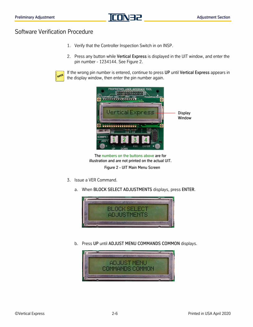
1. Verify that the Controller Inspection Switch in on INSP.
2. Press any button while Vertical Express is displayed in the UIT window, and enter the pin number - 1234144. See Figure 2.
If the wrong pin number is entered, continue to press UP until Vertical Express appears in the display window, then enter the pin number again.
Figure 2 - UIT Main Menu Screen
3. Issue a VER Command.
a. When BLOCK SELECT ADJUSTMENTS displays, press ENTER.
b. Press UP until ADJUST MENU COMMANDS COMMON displays.
1 2 3 4
The numbers on the buttons above are for illustration and are not printed on the actual UIT.
Display Window
Vertical Express
BLOCK SELECTADJUSTMENTS
ADJUST MENUCOMMANDS COMMON
©Vertical Express 2-6 Printed in USA April 2020
AD
JU
ST
ME
NT
Adjustment Section Preliminary Adjustment
Software Verification Procedure(continued)
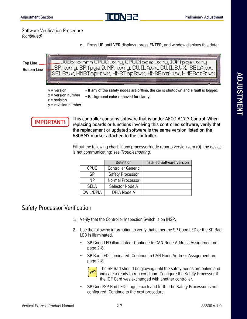
c. Press UP until VER displays, press ENTER, and window displays this data:
This controller contains software that is under AECO A17.7 Control. When replacing boards or functions involving this controlled software, verify that the replacement or updated software is the same version listed on the 580AMY marker attached to the controller.
Fill out the following chart. If any processor/node reports version zero (0), the device is not communicating; see Troubleshooting.
Safety Processor Verification
1. Verify that the Controller Inspection Switch is on INSP.
2. Use the following information to verify that either the SP Good LED or the SP Bad LED is illuminated.
• SP Good LED illuminated: Continue to CAN Node Address Assignment on page 2-8.
• SP Bad LED illuminated: Continue to CAN Node Address Assignment on page 2-8.
The SP Bad should be glowing until the safety nodes are online and indicate a ready to run condition. Configure the Safety Processor if the IOF Card was exchanged with another controller.
• SP Good/SP Bad LEDs toggle back and forth: The Safety Processor is not configured. Continue to the next procedure.
Top Line
Bottom Line
v = versionx = version numberr = revisiony = revision number
• If any of the safety nodes are offline, the car is shutdown and a fault is logged.
• Background color removed for clarity.
JOB:xxxnnn CPUC:vxry, CPUCfpga: vxry, IOFfpga:vxrySP: vxry, SP:fpga:0, NP: vxry, CWILA:vx, CWILB:VX, SELA:vx,
SELB:vx, HNBTopA: vx, HNBTopB:vx, HNBBotA:vx, HNBBotB: vx
Definition Installed Software Version
CPUC Controller GenericSP Safety ProcessorNP Normal Processor
SELA Selector Node ACWIL/DPIA DPIA Node A
Vertical Express Product Manual 2-7 88500 v.1.0

Preliminary Adjustment Adjustment Section
Configure the Safety Processor
1. Find the Safety Processor (SP) Programming Jumper JP2 (located on the IOF Card next to RSTSP).
2. Place the SP Programming Jumper on pins 1 and 2.
3. From the UIT, press any button while Vertical Express is displayed, and enter the pin number - 1234144. If the wrong pin number is entered, continue to press UP until Ver-tical Express appears in the window, then enter the pin number again. See Figure 2 on page 2-6.
4. From the UIT, access Block Select Adjustments and press ENTER.
5. Press UP or DOWN to scroll to Commands Startup, and press ENTER.
6. Press UP or DOWN to scroll to the SPC Command, and press ENTER.
• The UIT should display SP Config Complete.
• If the SP Programming Jumper is in the wrong position or the jumper shunt is bad, the UIT will return SP Programming Jumper Not Installed. Correct the jumper, and press ENTER again.
7. Place the SP Programming Jumper on pins 2 and 3.
8. Press RST on the CPUC Card. Once the controller recovers, repeat the steps to access the main menu screen.
At this point, the Safety Processor is configured and either the SP Good or the SP Bad LED should be illuminated.
NEW The SP BAD LED will remain lit until the safety nodes are online and indicate a ready to run condition.
CAN Node Address Assignment
Overview CAN nodes must be correctly addressed by jumpers in order to be properly identified by the controller software for I/O assignment. The CAN Node Address Assignment procedure uses the DCN Command to display each of the possible nodes (0-11), and this information is recorded so that the node addressing is set correctly for each node. CAN resistive load-ing is checked and corrected as necessary to ensure stable communications to all nodes. The nodes are then configured to prepare for Automatic Operation.
CAN nodes may not indicate ONLINE until they have been successfully configured (TECC).
©Vertical Express 2-8 Printed in USA April 2020
AD
JU
ST
ME
NT
Adjustment Section Preliminary Adjustment
CAN Node Address Assignment(continued)
1. Have some paper and pen/pencil ready to record the following data for future use: Node ID, SmartName, online status, and channel.
2. Access the UIT.
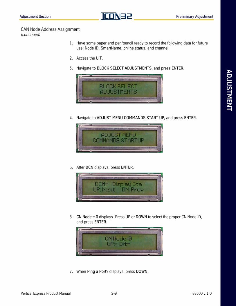
3. Navigate to BLOCK SELECT ADJUSTMENTS, and press ENTER.
4. Navigate to ADJUST MENU COMMANDS START UP, and press ENTER.
5. After DCN displays, press ENTER.
6. CN Node = 0 displays. Press UP or DOWN to select the proper CN Node ID, and press ENTER.
7. When Ping a Port? displays, press DOWN.
BLOCK SELECTADJUSTMENTS
ADJUST MENUCOMMANDS STARTUP
DCN— Display StaUP: Next DN: Prev
CN Node=0UP:+ DN:—
Vertical Express Product Manual 2-9 88500 v.1.0

Preliminary Adjustment Adjustment Section
CAN Node Address Assignment(continued)
The CN Node ID (selected from step 6) displays, followed by its SmartName. The DCN information will begin to scroll from left to right on both lines at different rates, see image below. Pressing UP or DOWN will pause the scroll until the UP or DOWN is pressed again.
8. Record the CN, the SmartName, and the CH information.
ICON32 Controllers should have the MODCTRL1 node on CH: 2 — the main interface node for the typical job mounted on the center divider of the controller.
9. Press ESC.
10. Repeat step 6 through step 9 for each node 0-11.
11. Verify the addressing jumpers for any CAN Node Card used in the system. See Table 1 on page 6-11.
A CAN node may be CN, CNA, or any future CAN Node Card. When the jumpers are populated on the card, the jumpers assigned functions are the same across the card assemblies.
CN:1 CNAMAIN1--- ONLINE:1 Pcks:86 CH:2 v:32 uP18Fxxxx SP:0 TP:12Ports: 3, 24, 25, 26, 2, 23, 24, 2, 255, 255, 255
Top Line Display
CN: The node ID
CNA- SmartName
Online: Online status: 0 = Offline, 1 = Online
Pcks: # of received data packets
CH:CAN channel from which the node is assigned to communicate: 2 = Car, 3 = Hall
V: Software version
uP18Fxxxx microprocessor version for that node
SP: # of shared ports
TP: # of total ports assigned to the node
Bottom Line Display
Port assignments for ports 0 (zero) through 15 = the numbers represent the port number of the I/O map the port is to use, and all unused ports for a node receive a port assignment of 255.
CNA Cards always have 12 total ports assigned to them.
BottomLineDisplay
Top Line Display
©Vertical Express 2-10 Printed in USA April 2020
AD
JU
ST
ME
NT
Adjustment Section Preliminary Adjustment
CAN Node Address Assignment(continued)
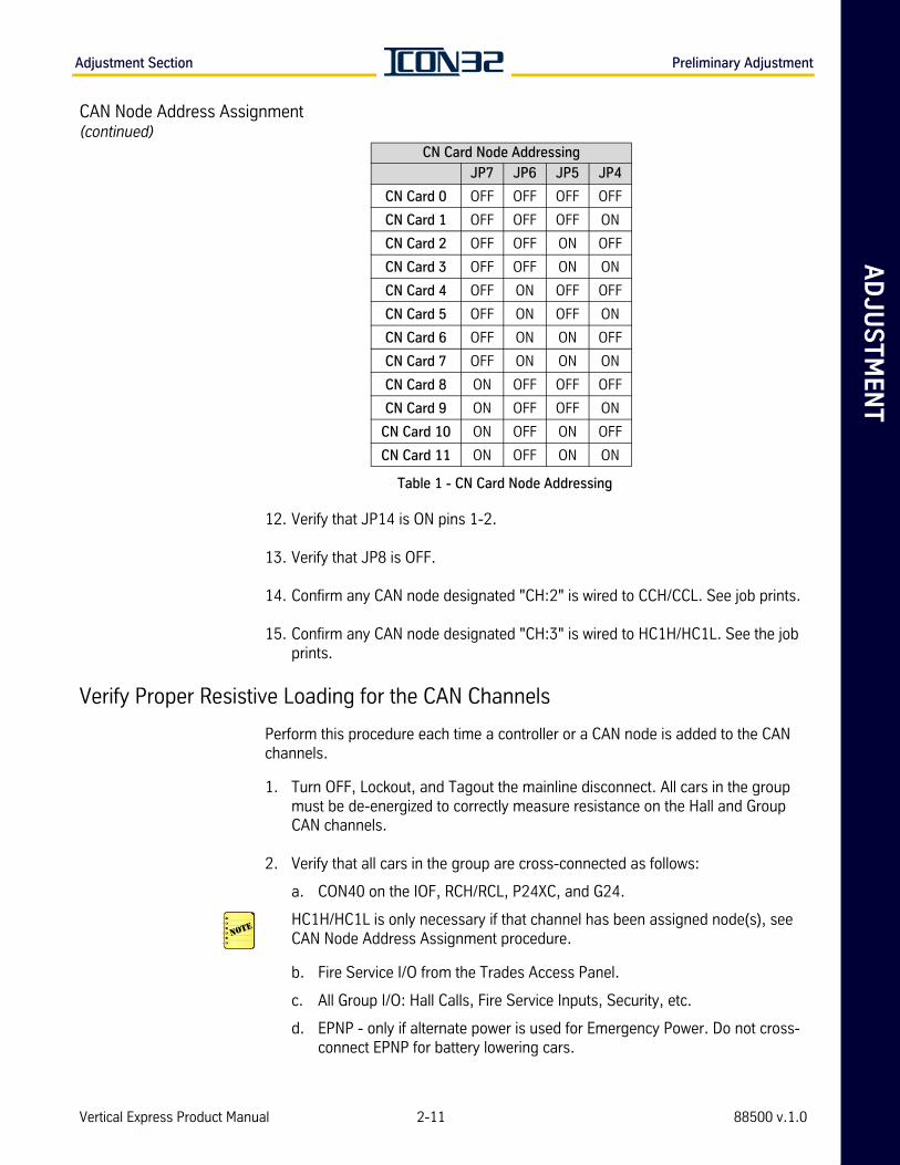
Table 1 - CN Card Node Addressing
12. Verify that JP14 is ON pins 1-2.
13. Verify that JP8 is OFF.
14. Confirm any CAN node designated "CH:2" is wired to CCH/CCL. See job prints.
15. Confirm any CAN node designated "CH:3" is wired to HC1H/HC1L. See the job prints.
Verify Proper Resistive Loading for the CAN Channels
Perform this procedure each time a controller or a CAN node is added to the CAN channels.
1. Turn OFF, Lockout, and Tagout the mainline disconnect. All cars in the group must be de-energized to correctly measure resistance on the Hall and Group CAN channels.
2. Verify that all cars in the group are cross-connected as follows:
a. CON40 on the IOF, RCH/RCL, P24XC, and G24.
HC1H/HC1L is only necessary if that channel has been assigned node(s), see CAN Node Address Assignment procedure.
b. Fire Service I/O from the Trades Access Panel.
c. All Group I/O: Hall Calls, Fire Service Inputs, Security, etc.
d. EPNP - only if alternate power is used for Emergency Power. Do not cross- connect EPNP for battery lowering cars.
CN Card Node Addressing
JP7 JP6 JP5 JP4
CN Card 0 OFF OFF OFF OFF
CN Card 1 OFF OFF OFF ON
CN Card 2 OFF OFF ON OFF
CN Card 3 OFF OFF ON ON
CN Card 4 OFF ON OFF OFF
CN Card 5 OFF ON OFF ON
CN Card 6 OFF ON ON OFF
CN Card 7 OFF ON ON ON
CN Card 8 ON OFF OFF OFF
CN Card 9 ON OFF OFF ON
CN Card 10 ON OFF ON OFF
CN Card 11 ON OFF ON ON
Vertical Express Product Manual 2-11 88500 v.1.0
Preliminary Adjustment Adjustment Section
Verify Proper Resistive Loading(continued)
3. Measure the resistive loading for the Car CAN channel, between CCH and CCL.
a. Measure from CON2 or CON3 on the IOF Card (located in the controller) across CCH and CCL. The typical measurement is 60 ohms +/-3 ohms.
b. If the resistive loading is incorrect, see CAN Channel Resistive Loading Verification on page 4-7.
4. Repeat step 3 for each controller.
Remove all power from connected controllers before performing any Group and Hall CAN channel resistance checks.
5. Perform the following appropriate procedure. If either procedure does not apply to the job, continue to step 6.
• If the controller is connected to other controllers (grouped):
a. Remove power from all controllers in the group.
b. Measure resistance, as if the systems were in operation, between RCH and RCL (Group CAN Channel) with all control system CAN communication connections connected.
c. Check the resistance from any controller in the group, across RCH and RCL from CON40 of the IOF Card. The typical measurement is 60 ohms +/-3 ohms.
d. If the resistive loading is incorrect, see CAN Channel Resistive Loading Verification on page 4-7.
• If the Hall CAN channel is used and the controller is not connected to other controllers (grouped):
a. Remove power from all controllers in the group.
b. Measure the resistance, as if the systems were in operation, between HC1H and HC1L (Hall CAN Channel) with all control system CAN communication connections connected.
c. Check the resistance from each connected controller in the group, across HC1H and HC1L from CON1 of the IOF Card. The typical measurement is 60 ohms +/-3 ohms.
d. If the resistive loading is incorrect, see CAN Channel Resistive Loading Verification on page 4-7.
6. Restore power, return elevator(s) to service, and verify proper operation.
©Vertical Express 2-12 Printed in USA April 2020
AD
JU
ST
ME
NT
Adjustment Section CAN Node Configuration via the Startup Wizard
CAN Node Configuration via the Startup WizardThe Startup Wizard will guide the user through the set up, configure all CAN Nodes, execute a hoistway scan, and save parameter changes.
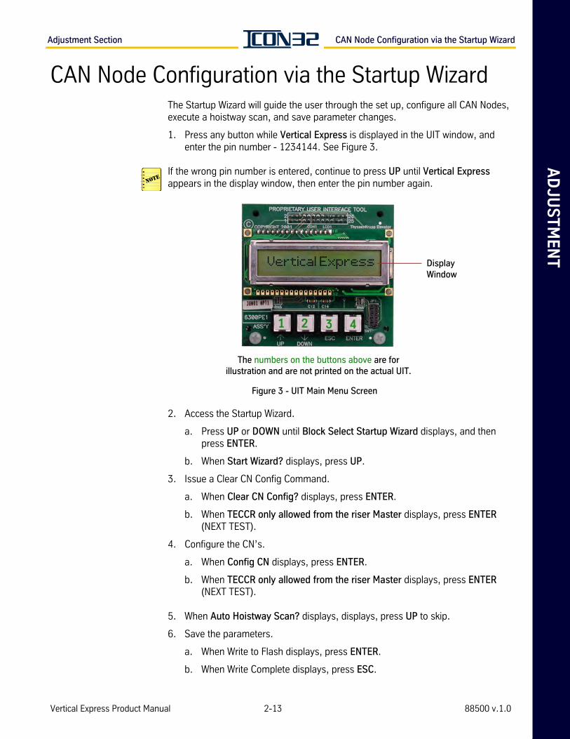
1. Press any button while Vertical Express is displayed in the UIT window, and enter the pin number - 1234144. See Figure 3.
If the wrong pin number is entered, continue to press UP until Vertical Express appears in the display window, then enter the pin number again.
Figure 3 - UIT Main Menu Screen
2. Access the Startup Wizard.
a. Press UP or DOWN until Block Select Startup Wizard displays, and then press ENTER.
b. When Start Wizard? displays, press UP.
3. Issue a Clear CN Config Command.
a. When Clear CN Config? displays, press ENTER.
b. When TECCR only allowed from the riser Master displays, press ENTER (NEXT TEST).
4. Configure the CN’s.
a. When Config CN displays, press ENTER.
b. When TECCR only allowed from the riser Master displays, press ENTER (NEXT TEST).
5. When Auto Hoistway Scan? displays, displays, press UP to skip.
6. Save the parameters.
a. When Write to Flash displays, press ENTER.
b. When Write Complete displays, press ESC.
1 2 3 4
The numbers on the buttons above are for illustration and are not printed on the actual UIT.
Vertical Express Display Window
Vertical Express Product Manual 2-13 88500 v.1.0
I/O and Safety String Checkout Adjustment Section
I/O and Safety String Checkout
1. Verify the following:
a. The controller stop switch is in the STOP position.
b. The controller inspection switch is in the NORMAL position.
c. The car top inspection switch is in the INSP position.
d. The car doors are closed, and the Car Door Bypass switch on the IOF is in the OFF position.
e. The hoistway doors are closed, and the Hoistway Door Bypass switch on the IOF is in the OFF position.
f. All Emergency Protective Devices (EPD) in the safety string are in the ready to run position.
g. All in-car stop switches are in the Run position.
h. All temporary jumpers are removed from the system.
i. No jumpers are installed on the IOF Card, CON46 or CON47.
The safety processor system is configured by manufacturing and the CAN nodes should, upon power up, result in an illuminated SPGOOD LED. If not, SPGOOD and SPBAD LED’s will toggle and a 1920 Fault is registered. For details, see Configure the Safety Processor on page 2-8.
2. Turn ON the mainline disconnect.
3. Place the controller stop switch in the RUN position.
4. Check for 120VAC from Ground to:
• IOF CON4-1 (CDCR)
• IOF CON4-2 (CDCF)
• IOF CON4-3 (121)
• IOF CON4-4 (CST)
• IOF CON8-1 (131)
Any open interlock circuit will cause a power loss at 121 (IOF CON4-3) via SAFCPU or SAFSP. See the job wiring diagrams to troubleshoot any missing voltages.
5. Scroll to Real Time Motion > ENTER > Quick Commands, then scroll to Show I/O.
©Vertical Express 2-14 Printed in USA April 2020
AD
JU
ST
ME
NT
Adjustment Section I/O and Safety String Checkout
I/O and Safety String Checkout(continued)
6. Verify the I/O states per Table 2 on page 2-16. If the I/O states do not match the chart, use the job wiring diagrams for the following:
a. If an optional I/O is not as indicated, and not used by the system, ignore it.
b. Verify that the safety string is made.
c. Verify that the door circuits (interlock and gate switches) are made.
d. Verify that the car stop switch circuit is made.
EPNP, PRSW, OLTO are required to be in the active state to permit expected operation.
• EPNP may prohibit up runs.
• OLTO will shut the car down.
• PRSW will prevent a down run.
7. Press ENTER.
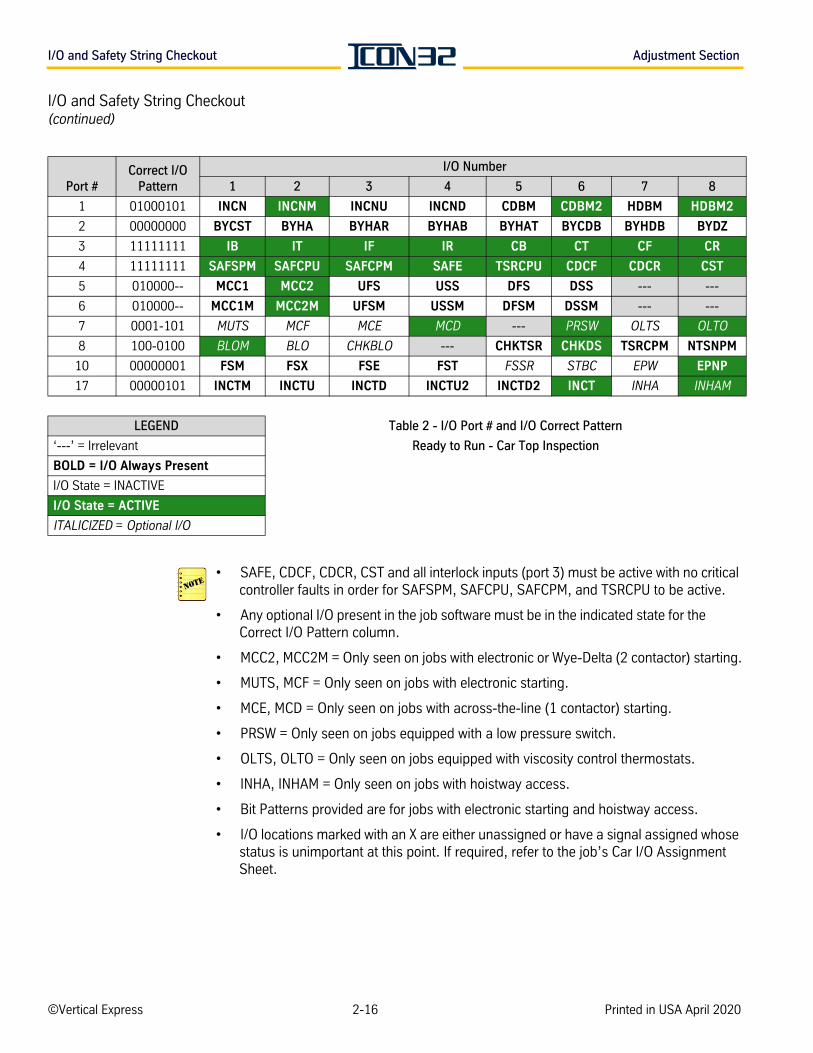
8. Verify the I/O Port # and Correct I/O Pattern per Table 2 on page 2-16.
9. Confirm that the SPGOOD, NPGOOD, and PLDGOOD LED’s (located on the IOF Card) are illuminated (green LED’s).
• If the above LED’s are illuminated, proceed to the next section.
• If the above LED’s are not illuminated, and the corresponding red LED’s (NPBAD, SPBAD, or PLDBAD) are illuminated, perform the following steps:
a. Scroll to Real Time Motion.
b. Press ENTER, and then press ENTER a second time.
c. Press UP or DOWN until Reset Faults displays.
d. Press ENTER.
e. Press UP or DOWN until Clear Faults displays.
f. Press ENTER.
g. Press UP until Show Faults displays.
h. Correct issues causing critical faults. For details, see Diagnostics section.
i. Once the SPGOOD LED is illuminated, proceed to the next section.
Vertical Express Product Manual 2-15 88500 v.1.0
I/O and Safety String Checkout Adjustment Section
I/O and Safety String Checkout(continued)
• SAFE, CDCF, CDCR, CST and all interlock inputs (port 3) must be active with no critical controller faults in order for SAFSPM, SAFCPU, SAFCPM, and TSRCPU to be active.
• Any optional I/O present in the job software must be in the indicated state for the Correct I/O Pattern column.
• MCC2, MCC2M = Only seen on jobs with electronic or Wye-Delta (2 contactor) starting.
• MUTS, MCF = Only seen on jobs with electronic starting.
• MCE, MCD = Only seen on jobs with across-the-line (1 contactor) starting.
• PRSW = Only seen on jobs equipped with a low pressure switch.
• OLTS, OLTO = Only seen on jobs equipped with viscosity control thermostats.
• INHA, INHAM = Only seen on jobs with hoistway access.
• Bit Patterns provided are for jobs with electronic starting and hoistway access.
• I/O locations marked with an X are either unassigned or have a signal assigned whose status is unimportant at this point. If required, refer to the job’s Car I/O Assignment Sheet.
Port #Correct I/O
Pattern
I/O Number
1 2 3 4 5 6 7 8
1 01000101 INCN INCNM INCNU INCND CDBM CDBM2 HDBM HDBM2
2 00000000 BYCST BYHA BYHAR BYHAB BYHAT BYCDB BYHDB BYDZ
3 11111111 IB IT IF IR CB CT CF CR
4 11111111 SAFSPM SAFCPU SAFCPM SAFE TSRCPU CDCF CDCR CST
5 010000-- MCC1 MCC2 UFS USS DFS DSS --- ---
6 010000-- MCC1M MCC2M UFSM USSM DFSM DSSM --- ---
7 0001-101 MUTS MCF MCE MCD --- PRSW OLTS OLTO
8 100-0100 BLOM BLO CHKBLO --- CHKTSR CHKDS TSRCPM NTSNPM
10 00000001 FSM FSX FSE FST FSSR STBC EPW EPNP
17 00000101 INCTM INCTU INCTD INCTU2 INCTD2 INCT INHA INHAM
LEGEND Table 2 - I/O Port # and I/O Correct Pattern
‘---’ = Irrelevant Ready to Run - Car Top Inspection
BOLD = I/O Always Present
I/O State = INACTIVE
I/O State = ACTIVE
ITALICIZED = Optional I/O
©Vertical Express 2-16 Printed in USA April 2020
AD
JU
ST
ME
NT
Adjustment Section Car Top Inspection Operation
Troubleshooting I/O Issues
1. Check the controller fault log for applicable faults.
2. If Ports 1 - 10 all display zeros, both the Safety Processor and the NTSD Processor have mismatched I/O with the CPU.
a. Verify F1 on the IOF Card is good.
b. Reload the controller generic files and the job configuration files.
c. Configure the Safety Processor. See page 2-8.
d. Perform the following from the Startup Wizard.
• Clear CN Config?
• Config CN.
3. If the SP and NP I/O mismatch faults still exist, then communication is faulty between the IOF and the CPUC Cards. See the Troubleshooting section for more help.
Car Top Inspection Operation
1. Verify there are no jumpers installed that interfere with car or hall door interlocks.
2. Ensure that the car door bypass and hoistway door bypass switches on the IOF are in the OFF position.
3. Place the car top stop switch in the STOP position.
4. Confirm that the car top inspection switch is in the INSP position.
5. Ensure that the car will not run with the car top stop switch in the STOP position.
6. Place the car top RUN/STOP switch in the RUN position.
7. Verify that the car will only run Up when UP and ENABLE are pressed.
8. Confirm that the car will only run Down when DOWN and ENABLE are pressed.
9. Ensure that the car will not run with the car door or any hoistway door open.
10. Verify that the car will not run when any contact in the safety circuit is opened (pit stop switch, final limits, fireman’s stop, emergency exit, car stop switch). See the Safety Circuit page in the job wiring diagrams.
11. Leave the AUTO/INSP switch in the INSP position.
Vertical Express Product Manual 2-17 88500 v.1.0
Selector Tape Magnet Installation Adjustment Section
Selector Tape Magnet InstallationSelector Tape and Box Inspection
1. Inspect and clean the selector tape. Use a wire brush to remove cement, drywall, mud, etc., and use fine sandpaper (400 grit) to remove nicks and burrs.
2. After cleaning, wipe down the tape with a clean rag. If the tape cannot be completely cleaned, it MUST be replaced.
3. Inspect the selector box for damage or defects. The guides must be free of dirt, not binding on the tape, or extremely loose.
Magnet Placement
• Floor level magnets are the only magnets placed on the front (or car side) of the tape. See Figure 6 on page 2-22.
• Slowdown and directional magnets are placed on the side of the tape facing away from the car (back side). See Figure 4 on page 2-20 and Figure 5 on page 2-21.
• Handed references are noted as if facing the tape from the car.
• The magnets have their magnetic south marked with a yellow stripe. The yellow-striped south side faces out and should be visible for all tape magnets except the top floor slowdown (NTSD) magnets.
Top Terminal Slowdown & Directional Limits
1. Position the car so that it is level and at the top landing.
In the next step, a metal scribe will damage the tape.
2. Use a marker that will not damage the tape, and mark the tape at the top of the selector box. See Figure 4 on page 2-20.
3. Move the car out of the way to provide access for installation of the magnets.
4. Determine how many initial terminal slowdown magnets are to be installed.
5. Start placement of the bottom edge of the first terminal slowdown magnet "T" inches below the top of the selector box mark. Stack the determined number of magnets up toward the "Top of Tape Selector Box"—line the magnets end to end with the north polarity facing out (black side out).
6. Start placement of the directional limit magnets 61/4" below the selector box mark. Place two 8" magnets end to end with the south polarity facing out (yellow side out).
The magnets must be extended up the hoistway far enough so that the selector sensors cannot run off of the magnets at the extreme limit of travel up past the top floor. See Figure 8 on page 2-24.
Bottom Terminal Slowdown & Directional Limits
1. Position the car so that it is level and at the bottom landing.
©Vertical Express 2-18 Printed in USA April 2020
AD
JU
ST
ME
NT
Adjustment Section Selector Tape Magnet Installation
Magnet Placement(continued)
In the next step, a metal scribe will damage the tape.
2. Use a marker that will not damage the tape, and mark the tape at the top of the selector box. See Figure 5 on page 2-21.
3. Move the car out of the way to provide access for installation of the magnets.
4. Determine how many initial terminal slowdown magnets are to be installed.
5. Start placement of the top edge of the first terminal slowdown magnet "D" inches above the top of the selector box mark. Place the magnets end to end with the south polarity facing out (yellow side out).
6. Start placement of the directional limit magnets 91/4" below the top of the selec-tor box mark. Place two 8" magnets end to end with the south polarity facing out (yellow side out).
The magnets must be extended up the hoistway far enough so that the selector sensors cannot run off of the magnets at the extreme limit of travel up past the top floor. See Figure 8 on page 2-24.
Floor Landing and Close Floor Leveling Magnet Installation
1. Position the car so that it is level and at the top landing.
In the next step, a metal scribe will damage the tape.
2. Use a marker that will not damage the tape, and mark the tape at the top of the selector box. See the following figures for this procedure:
Floor Landing - See Figure 6 on page 2-22.
Close Floor - See Figure 7 on page 2-23.
3. Move the car out of the way to provide access for installation of the magnets.
4. Position the template (814CH001) on the tape as follows:
a. The template top at the top of the selector box mark on the tape.
b. The sides of the template with the sides of the tape.
5. Place and center an 8" magnet in the right-hand slot of the template, and ensure that the yellow stripe of the magnet (south pole) is facing out.
A close floor is defined as a floor with 4"- 16" of travel to the floor above it. The template can be lifted over the nearby magnet to allow the installation of the "close landing" magnet.
6. After installation, verify the position of the magnet.
a. The magnet top is 33/4" below the top of the selector box mark.
b. The magnet side is 1/2" from the edge of the tape side.
7. Repeat the above steps for each floor—except when performing step 5 (above), a close floor's 8" magnet would be placed on the left-hand slot of the template with the yellow stripe of the magnet (south pole) facing out. The top landing always uses the right-hand slot of the template.
Vertical Express Product Manual 2-19 88500 v.1.0
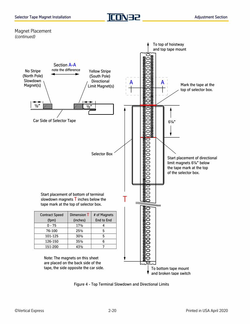
Selector Tape Magnet Installation Adjustment Section
Magnet Placement(continued)
Figure 4 - Top Terminal Slowdown and Directional Limits
Mark the tape at the top of selector box.
To top of hoistway and top tape mount
Contract Speed
(fpm)
0 - 75
76-100
101-125
126-150
151-200
Dimension T(inches)
17½
25½
30½
35½
43½
# of Magnets
End to End
4
5
5
6
7
6¼"
Start placement of bottom of terminal slowdown magnets T inches below the tape mark at the top of selector box.
Start placement of directional limit magnets 6¼" below the tape mark at the top of the selector box.
Section A-Anote the differenceNo Stripe
(North Pole)Yellow Stripe(South Pole)
Slowdown Magnet(s)
Directional Limit Magnet(s)
Car Side of Selector Tape
A A
T
Note: The magnets on this sheet are placed on the back side of the tape, the side opposite the car side.
½"½"
To bottom tape mountand broken tape switch
Selector Box
©Vertical Express 2-20 Printed in USA April 2020
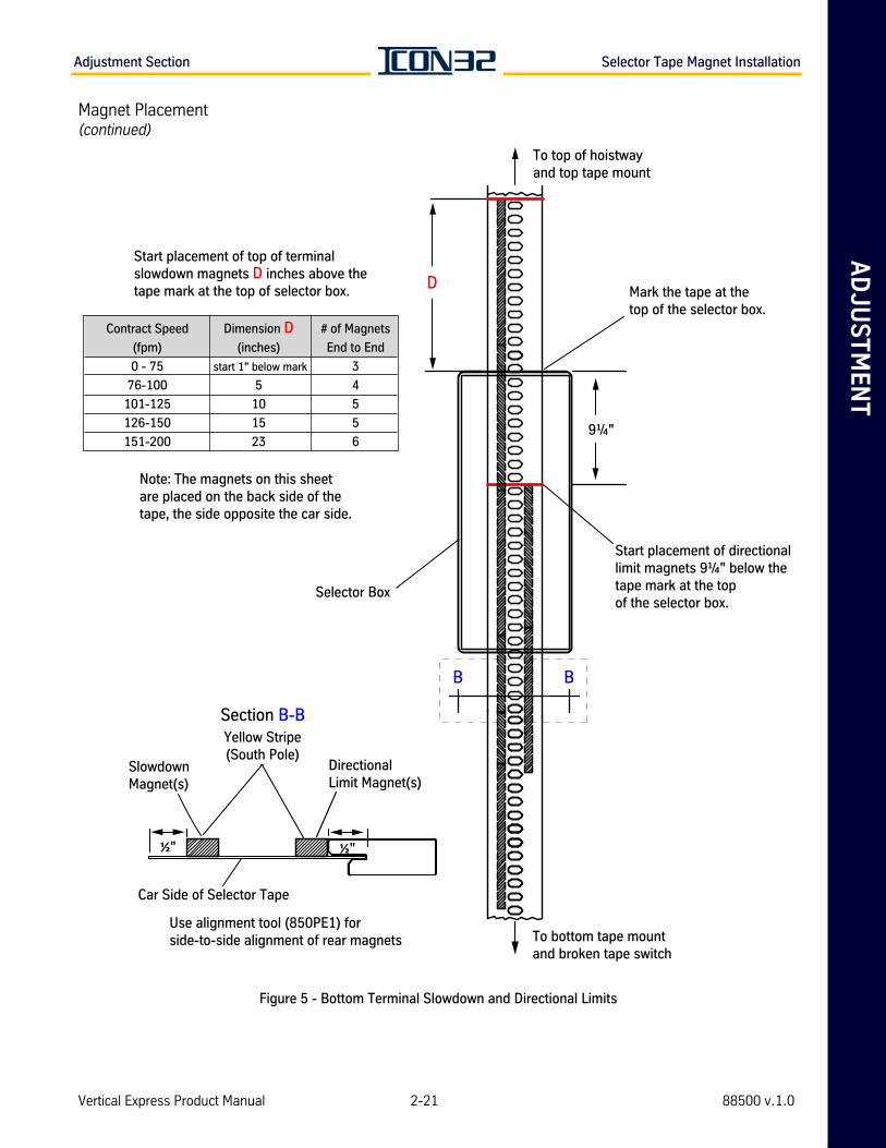
AD
JU
ST
ME
NT
Adjustment Section Selector Tape Magnet Installation
Magnet Placement(continued)
Figure 5 - Bottom Terminal Slowdown and Directional Limits
Mark the tape at the top of the selector box.
To top of hoistway and top tape mount
To bottom tape mountand broken tape switch
Contract Speed
(fpm)
0 - 75
76-100
101-125
126-150
151-200
Dimension D(inches)
5
10
15
23
# of Magnets
End to End
3
4
5
5
69¼"
Start placement of top of terminal slowdown magnets D inches above the tape mark at the top of selector box.
Start placement of directional limit magnets 9¼" below the tape mark at the top of the selector box.
B B
Note: The magnets on this sheet are placed on the back side of the tape, the side opposite the car side.
D
start 1" below mark
Section B-B
Slowdown Magnet(s)
½"
Directional Limit Magnet(s)
Car Side of Selector Tape
Yellow Stripe(South Pole)
½"
Use alignment tool (850PE1) forside-to-side alignment of rear magnets
Selector Box
Vertical Express Product Manual 2-21 88500 v.1.0
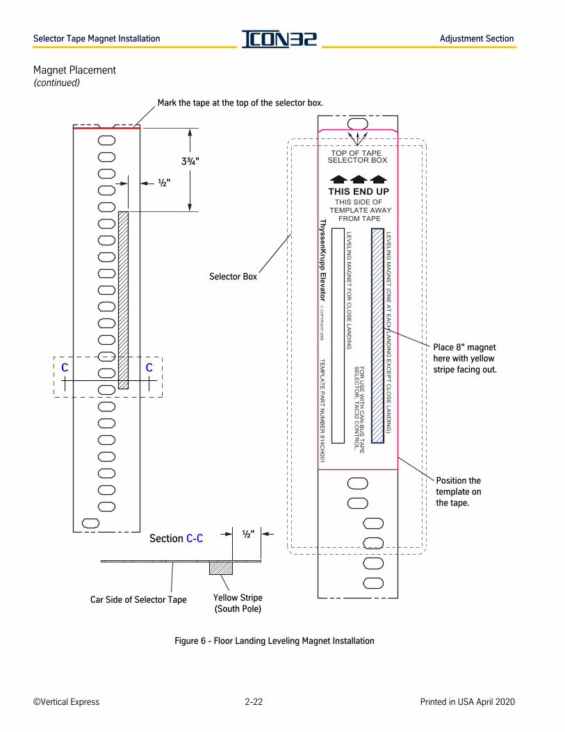
Selector Tape Magnet Installation Adjustment Section
Magnet Placement(continued)
Figure 6 - Floor Landing Leveling Magnet Installation
Mark the tape at the top of the selector box.
3¾"
Yellow Stripe(South Pole)
Car Side of Selector Tape
Section C-C
C C
Position the template on the tape.
Place 8" magnet here with yellow stripe facing out.
Selector Box
½"
½"
©Vertical Express 2-22 Printed in USA April 2020
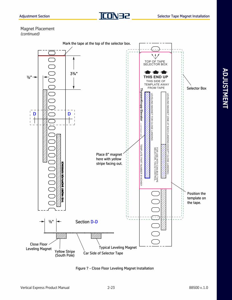
AD
JU
ST
ME
NT
Adjustment Section Selector Tape Magnet Installation
Magnet Placement(continued)
Figure 7 - Close Floor Leveling Magnet Installation
Mark the tape at the top of the selector box.
3¾"
D D
Position the template on the tape.
Place 8" magnet here with yellow stripe facing out.
Selector Box
½"
Yellow Stripe(South Pole)
Car Side of Selector Tape
Section D-D
Close FloorLeveling Magnet Typical Leveling Magnet
½"
Vertical Express Product Manual 2-23 88500 v.1.0
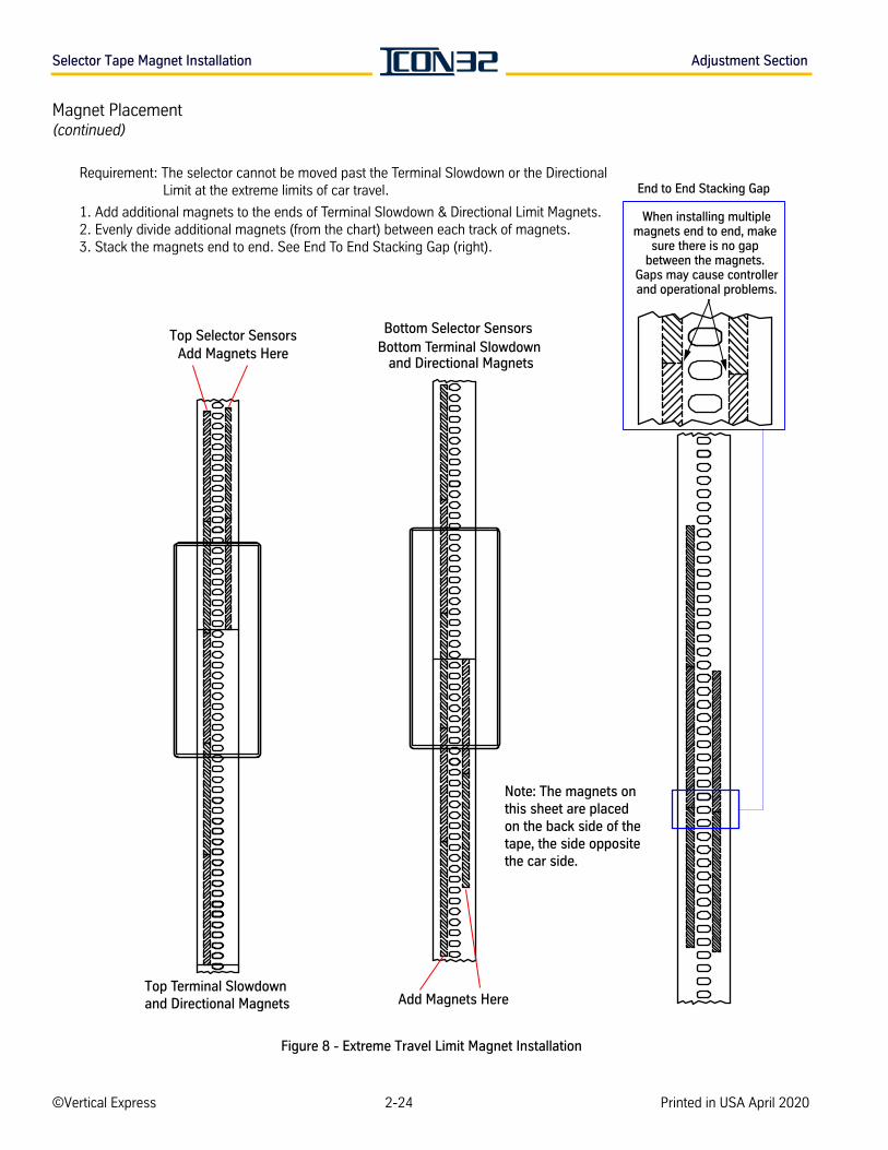
Selector Tape Magnet Installation Adjustment Section
Magnet Placement(continued)
Figure 8 - Extreme Travel Limit Magnet Installation
When installing multiplemagnets end to end, make
sure there is no gap between the magnets.
Gaps may cause controllerand operational problems.
Requirement: The selector cannot be moved past the Terminal Slowdown or the Directional Limit at the extreme limits of car travel.
1. Add additional magnets to the ends of Terminal Slowdown & Directional Limit Magnets.2. Evenly divide additional magnets (from the chart) between each track of magnets.3. Stack the magnets end to end. See End To End Stacking Gap (right).
Add Magnets Here
Add Magnets HereTop Terminal Slowdown and Directional Magnets
Bottom Terminal Slowdown and Directional Magnets
Top Selector Sensors Bottom Selector Sensors
End to End Stacking Gap
Note: The magnets on this sheet are placed on the back side of the tape, the side opposite the car side.
©Vertical Express 2-24 Printed in USA April 2020
AD
JU
ST
ME
NT
Adjustment Section Preliminary Setup for Automatic Operation
Preliminary Setup for Automatic Operation
Before starting a hoistway setup, complete the following items:
1. Door operator adjustments. See the appropriate door operator component manual for this job.
2. Mechanical setup.
3. Gate switch (CDCF, CDCR) and limit setting (DOL, DCL - DOL and DCL are always required for Automatic Operation, regardless of door operator type).
4. Card configuration and setup.
5. Verify that the car stops on the directional magnets 1 - 11/2" out of the terminal landings.
• Before the car can run on Automatic Operation, the selector must scan (count) the number of selector tape holes between floors.
• Any time a leveling magnet or directional limit magnet is moved, the hoistway must be scanned again.
Hoistway Scan Through the Startup Wizard
The Startup Wizard sets up and configures all CAN nodes, performs a hoistway scan,and executes job archive functions. Upon successful completion, the system will be on Automatic Operation and ready for final valve adjustments. Previously, the CAN nodes were configured. It is not necessary to duplicate those steps at this time, unless there was incorrect CAN loading or bad nodes at the time of the original configuration. It will not cause any harm to repeat the steps, and the following procedure will complete the hoistway scan.
1. From Inspection Operation, place the car at, or above, the first landing.
2. Access the UIT.
3. Set the close floor adjustment. A close floor is defined as a floor with 4"- 16" of travel to the floor above it.
a. If no close floor is present on this job, continue to step 4.
b. If system has a close floor, set P12=1.
Block Select Adjustments> Adjust Car/Group> Position System> P12.
4. Place all switches in the RUN or AUTOMATIC position (Pit Stop, Fireman's Stop, Emergency Exit, SOS, Car Top Inspection Stop, etc.).
5. On the IOF Card, place the following switches in the Ready To Run on DOOR DISCONNECT position:
• Car Door Bypass: OFF (DN)
• Hoistway Door Bypass: OFF (DN)
• Stop Switch: RUN (UP)
• Inspection Switch: NORMAL (UP)
• Door Disconnect Switch: Door Disconnect (UP)
Vertical Express Product Manual 2-25 88500 v.1.0
Preliminary Setup for Automatic Operation Adjustment Section
Hoistway Scan Through the Startup Wizard(continued)
6. Press UP or DOWN to scroll to the Startup Wizard.
7. Press ENTER, and then press UP.
Reminder: Before starting a hoistway scan, the door operator limits (DCL, DOL) must be correctly adjusted.
8. Repeatedly press UP until the UIT displays Auto Hoistway Scan.
9. Press ENTER to scan the hoistway, and the UIT displays Auto Hoistway Scan.
The Auto Hoistway Scan will automatically run the car at leveling speed to the bottom directional limit, and then up to the top directional limit, scanning the hoistway tape to learn the floor levels. If the hoistway scan was successful, the car should have leveled down into the top terminal landing.
a. If the hoistway scan was not successful, verify and correct magnet placement and orientation.
• Leveling speed = 8-12 FPM.
• Gate/Lock circuits are not opening up during the run.
• Direction limits should not exceed 11/2" from the terminal landing.
• The appropriate NTS and LV I/Os must be active when on DL.
• The proper polarity of each magnet must be used.
b. To view learned floor levels, scroll to Commands > Commands Common >FCP.
10. The UIT displays Write to Flash, and this function saves all settings and values to the CPU’s card memory. Press ENTER to perform this operation.
11. When NEXT TEST? displays, press ENTER and the UIT displays Save Job to USB. This action archives the job’s controller CPU files to a USB memory stick.
a. Install the manufacturing-provided USB flash drive included with the job.
b. Press ENTER to perform this operation, and the UIT displays Backing Software.
c. When the UIT displays Backup Complete, press ENTER and then press DOWN to exit the Startup Wizard.
d. On the IOF Card, place the door disconnect switch in the OFF position.
Door Setup and Final Adjustments
See the appropriate door operator component manual.
©Vertical Express 2-26 Printed in USA April 2020
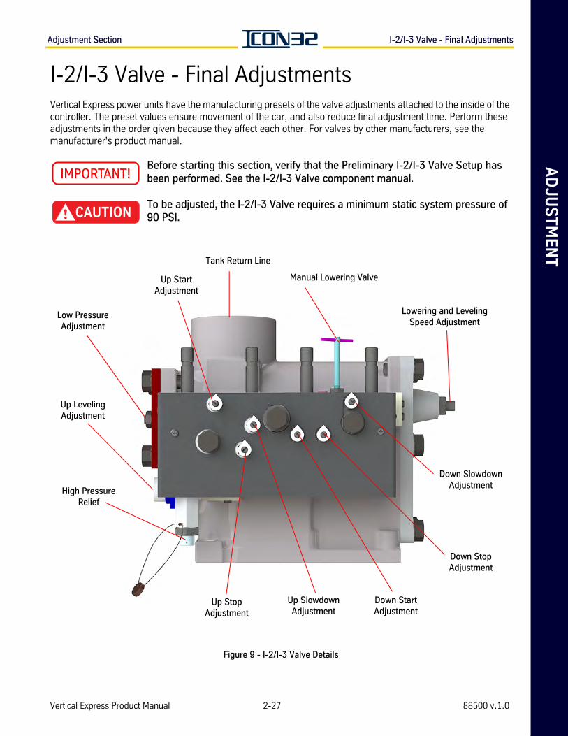
AD
JU
ST
ME
NT
Adjustment Section I-2/I-3 Valve - Final Adjustments
I-2/I-3 Valve - Final AdjustmentsVertical Express power units have the manufacturing presets of the valve adjustments attached to the inside of the controller. The preset values ensure movement of the car, and also reduce final adjustment time. Perform these adjustments in the order given because they affect each other. For valves by other manufacturers, see the manufacturer's product manual.
Before starting this section, verify that the Preliminary I-2/I-3 Valve Setup has been performed. See the I-2/I-3 Valve component manual.
To be adjusted, the I-2/I-3 Valve requires a minimum static system pressure of 90 PSI.
Figure 9 - I-2/I-3 Valve Details
Low Pressure Adjustment
Up Leveling Adjustment
High Pressure Relief
Up Start Adjustment
Up Stop Adjustment
Up Slowdown Adjustment
Down Start Adjustment
Down Stop Adjustment
Down Slowdown Adjustment
Manual Lowering Valve
Lowering and Leveling Speed Adjustment
Tank Return Line
Vertical Express Product Manual 2-27 88500 v.1.0
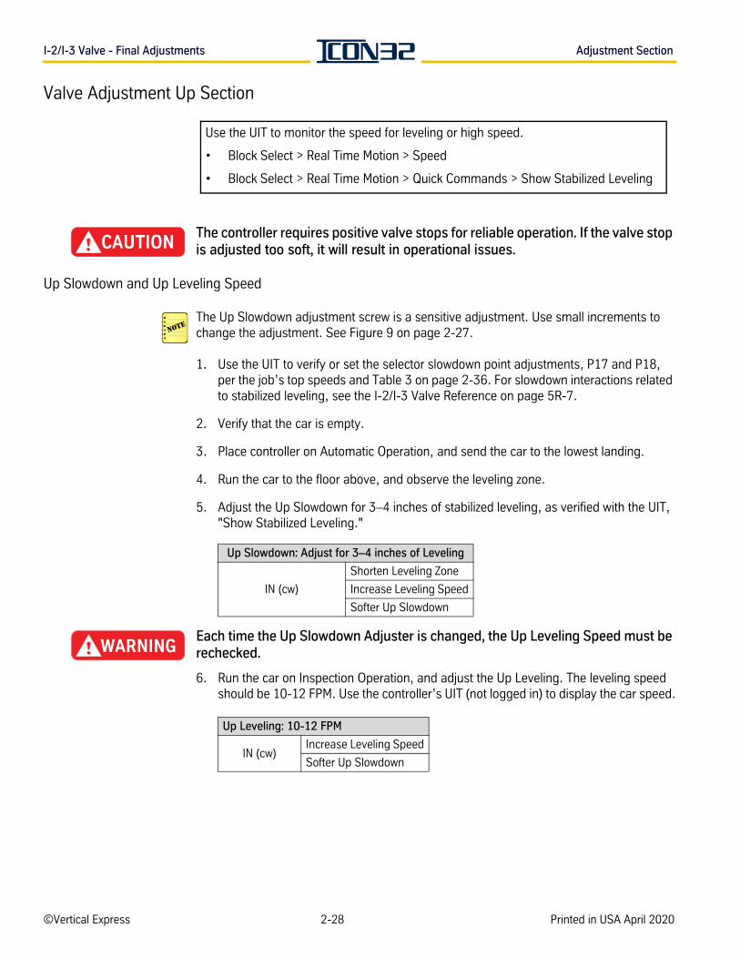
I-2/I-3 Valve - Final Adjustments Adjustment Section
Valve Adjustment Up Section
The controller requires positive valve stops for reliable operation. If the valve stop is adjusted too soft, it will result in operational issues.
Up Slowdown and Up Leveling Speed
The Up Slowdown adjustment screw is a sensitive adjustment. Use small increments to change the adjustment. See Figure 9 on page 2-27.
1. Use the UIT to verify or set the selector slowdown point adjustments, P17 and P18, per the job’s top speeds and Table 3 on page 2-36. For slowdown interactions related to stabilized leveling, see the I-2/I-3 Valve Reference on page 5R-7.
2. Verify that the car is empty.
3. Place controller on Automatic Operation, and send the car to the lowest landing.
4. Run the car to the floor above, and observe the leveling zone.
5. Adjust the Up Slowdown for 3–4 inches of stabilized leveling, as verified with the UIT, "Show Stabilized Leveling."
Each time the Up Slowdown Adjuster is changed, the Up Leveling Speed must be rechecked.
6. Run the car on Inspection Operation, and adjust the Up Leveling. The leveling speed should be 10-12 FPM. Use the controller’s UIT (not logged in) to display the car speed.
Use the UIT to monitor the speed for leveling or high speed.
• Block Select > Real Time Motion > Speed
• Block Select > Real Time Motion > Quick Commands > Show Stabilized Leveling
Up Slowdown: Adjust for 3–4 inches of Leveling
IN (cw)
Shorten Leveling Zone
Increase Leveling Speed
Softer Up Slowdown
Up Leveling: 10-12 FPM
IN (cw)Increase Leveling Speed
Softer Up Slowdown
©Vertical Express 2-28 Printed in USA April 2020
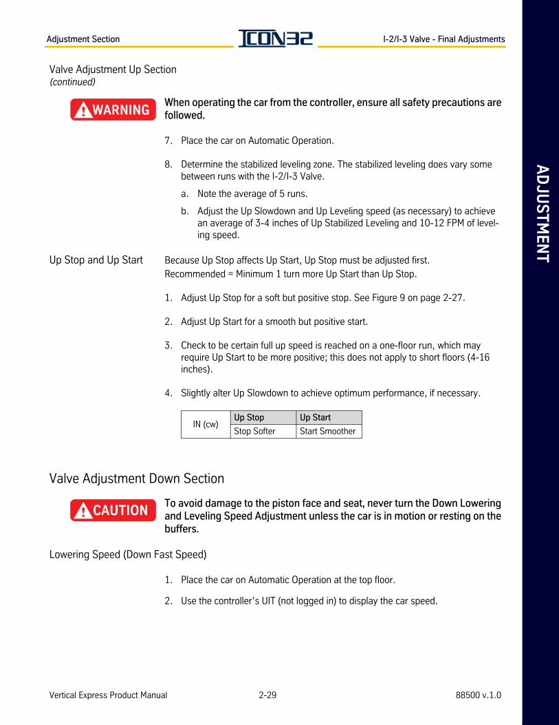
AD
JU
ST
ME
NT
Adjustment Section I-2/I-3 Valve - Final Adjustments
Valve Adjustment Up Section(continued)
When operating the car from the controller, ensure all safety precautions are followed.
7. Place the car on Automatic Operation.
8. Determine the stabilized leveling zone. The stabilized leveling does vary some between runs with the I-2/I-3 Valve.
a. Note the average of 5 runs.
b. Adjust the Up Slowdown and Up Leveling speed (as necessary) to achieve an average of 3-4 inches of Up Stabilized Leveling and 10-12 FPM of level-ing speed.
Up Stop and Up Start Because Up Stop affects Up Start, Up Stop must be adjusted first. Recommended = Minimum 1 turn more Up Start than Up Stop.
1. Adjust Up Stop for a soft but positive stop. See Figure 9 on page 2-27.
2. Adjust Up Start for a smooth but positive start.
3. Check to be certain full up speed is reached on a one-floor run, which may require Up Start to be more positive; this does not apply to short floors (4-16 inches).
4. Slightly alter Up Slowdown to achieve optimum performance, if necessary.
Valve Adjustment Down Section
To avoid damage to the piston face and seat, never turn the Down Lowering and Leveling Speed Adjustment unless the car is in motion or resting on the buffers.
Lowering Speed (Down Fast Speed)
1. Place the car on Automatic Operation at the top floor.
2. Use the controller’s UIT (not logged in) to display the car speed.
IN (cw)Up Stop Up Start
Stop Softer Start Smoother
Vertical Express Product Manual 2-29 88500 v.1.0
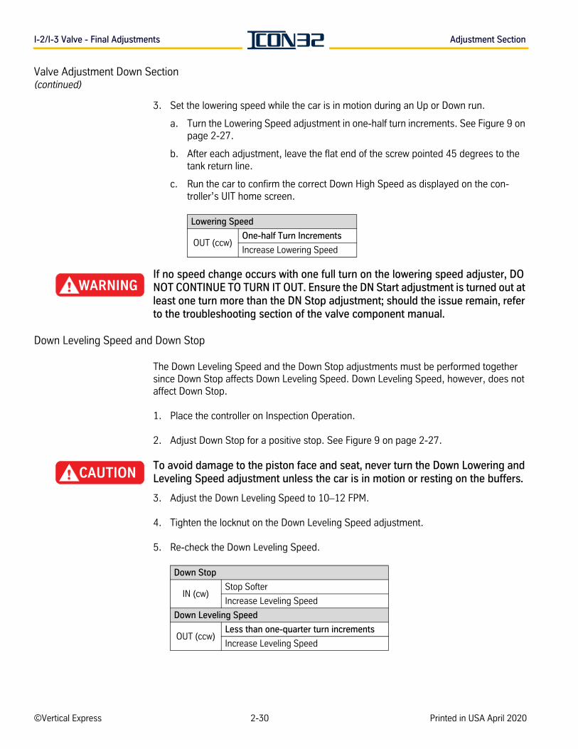
I-2/I-3 Valve - Final Adjustments Adjustment Section
Valve Adjustment Down Section(continued)
3. Set the lowering speed while the car is in motion during an Up or Down run.
a. Turn the Lowering Speed adjustment in one-half turn increments. See Figure 9 on page 2-27.
b. After each adjustment, leave the flat end of the screw pointed 45 degrees to the tank return line.
c. Run the car to confirm the correct Down High Speed as displayed on the con-troller’s UIT home screen.
If no speed change occurs with one full turn on the lowering speed adjuster, DO NOT CONTINUE TO TURN IT OUT. Ensure the DN Start adjustment is turned out at least one turn more than the DN Stop adjustment; should the issue remain, refer to the troubleshooting section of the valve component manual.
Down Leveling Speed and Down Stop
The Down Leveling Speed and the Down Stop adjustments must be performed together since Down Stop affects Down Leveling Speed. Down Leveling Speed, however, does not affect Down Stop.
1. Place the controller on Inspection Operation.
2. Adjust Down Stop for a positive stop. See Figure 9 on page 2-27.
To avoid damage to the piston face and seat, never turn the Down Lowering and Leveling Speed adjustment unless the car is in motion or resting on the buffers.
3. Adjust the Down Leveling Speed to 10–12 FPM.
4. Tighten the locknut on the Down Leveling Speed adjustment.
5. Re-check the Down Leveling Speed.
Lowering Speed
OUT (ccw)One-half Turn Increments
Increase Lowering Speed
Down Stop
IN (cw)Stop Softer
Increase Leveling Speed
Down Leveling Speed
OUT (ccw)Less than one-quarter turn increments
Increase Leveling Speed
©Vertical Express 2-30 Printed in USA April 2020
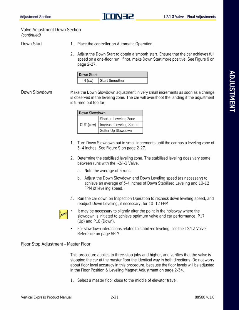
AD
JU
ST
ME
NT
Adjustment Section I-2/I-3 Valve - Final Adjustments
Valve Adjustment Down Section(continued)
Down Start 1. Place the controller on Automatic Operation.
2. Adjust the Down Start to obtain a smooth start. Ensure that the car achieves full speed on a one-floor run. If not, make Down Start more positive. See Figure 9 on page 2-27.
Down Slowdown Make the Down Slowdown adjustment in very small increments as soon as a change is observed in the leveling zone. The car will overshoot the landing if the adjustment is turned out too far.
1. Turn Down Slowdown out in small increments until the car has a leveling zone of 3–4 inches. See Figure 9 on page 2-27.
2. Determine the stabilized leveling zone. The stabilized leveling does vary some between runs with the I-2/I-3 Valve.
a. Note the average of 5 runs.
b. Adjust the Down Slowdown and Down Leveling speed (as necessary) to achieve an average of 3-4 inches of Down Stabilized Leveling and 10-12 FPM of leveling speed.
3. Run the car down on Inspection Operation to recheck down leveling speed, and readjust Down Leveling, if necessary, for 10–12 FPM.
• It may be necessary to slightly alter the point in the hoistway where the slowdown is initiated to achieve optimum valve and car performance, P17 (Up) and P18 (Down).
• For slowdown interactions related to stabilized leveling, see the I-2/I-3 Valve Reference on page 5R-7.
Floor Stop Adjustment - Master Floor
This procedure applies to three-stop jobs and higher, and verifies that the valve is stopping the car at the master floor the identical way in both directions. Do not worry about floor level accuracy in this procedure, because the floor levels will be adjusted in the Floor Position & Leveling Magnet Adjustment on page 2-34.
1. Select a master floor close to the middle of elevator travel.
Down Start
IN (cw) Start Smoother
Down Slowdown
OUT (ccw)
Shorten Leveling Zone
Increase Leveling Speed
Softer Up Slowdown
Vertical Express Product Manual 2-31 88500 v.1.0
I-2/I-3 Valve - Final Adjustments Adjustment Section
Valve Adjustment(continued)
2. Run the empty car on Automatic Operation up into the master floor. Note where the car sill is in relation to the master floor hatch sill.
3. Run the empty car on Automatic Operation down into the master floor. Note where the car sill is in relation to the master floor hatch sill.
4. Achieve a valve stop that results in the same final car location in both travel directions.
To avoid damage to the piston face and seat, never turn the Down Lowering and Leveling Speed Adjustment unless the car is in motion or resting on the buffers.
How to change the leveling speeds for the appropriate travel direction.
• Increase the leveling speed - To increase car momentum and put the car further in its travel direction upon the stop.
• Decrease the leveling speed - To decrease the car momentum and shorten the final resting place of the car in its travel direction.
DO NOT exceed 14 FPM maximum for empty car leveling speeds.
The UP and DOWN stop adjustments need to be firm so that the stop can be felt slightly (a soft but noticeable bump at the stop), as this prevents fluid temperature-based variations in performance and allows the control system to achieve increased car level positioning control.
Relevel Check - All Jobs
1. Place the empty car on Automatic Operation at the master floor or at the top floor of a two-stop job.
2. Force an UP relevel, and verify that the control system and the valve place the car at floor level.
a. On the I-2/I-3 Valve, slowly turn the Manual Lowering Valve (t-handle) counter-clockwise (ccw) to open, allow the car to lower slightly, then quickly turn the valve clockwise (cw) to close.
b. Ensure that the car went low enough: >1/2" with P19 & P22 at default value.
• If the car did not go low enough: Troubleshoot the Manual Lowering Valve to identify the problem, and repeat the relevel check until correct.
• If the car went low enough: The motor and valve should energize and place the car back at floor level.
©Vertical Express 2-32 Printed in USA April 2020
AD
JU
ST
ME
NT
Adjustment Section I-2/I-3 Valve - Final Adjustments
Performance Check with Full Load
1. Place a capacity load on the car.
2. Run the car on Automatic Operation, and the check performance at all floors. All valve functions will become firmer at upper landings. If adjustments are necessary, it will affect the empty car performance.
• The Down Leveling Speed will increase and the Down Leveling Zone will be shorter. It may be necessary to change the Down Slowdown adjustment to be certain there are at least 2 inches of leveling.
• If necessary, turn IN on the Down Slowdown to increase the leveling zone.
• The Up Leveling Speed will increase. The Up Leveling Zone will change between no load and full load. Do not change any adjustments made with no load if there is at least 1 inch of Up Leveling Zone with a full load.
• If necessary, turn OUT on the Up Slowdown adjustment to increase the Up Level-ing Zone.
3. Verify that the car is obtaining full speed in both directions on a one-floor run.
4. Record the working pressure in the up direction. The working pressure value will be used in the next procedure.
5. Remove the capacity load from the car.
Final Relief Pressure with Full Load
1. Place the controller on Inspection Operation, close the line shut-off valve, and set Z44 = 10 seconds.
2. Start the pump, and read the relief pressure.
Do Not adjust the relief pressure to 150%, as allowed by code, unless the entire hydraulic system has been replaced.
3. Add 25% to the working pressure recorded in step 4 of the previous procedure, and set the relief valve to relieve at this new pressure value.
4. Stop the power unit, and tighten the locknut on the relief pressure adjustment.
5. Re-check the relief pressure.
Immediately stop the power unit if the pressure exceeds 625 PSI.
6. Open line shut-off valve, place car on Automatic Operation, and reset Z44 = 2.
Vertical Express Product Manual 2-33 88500 v.1.0
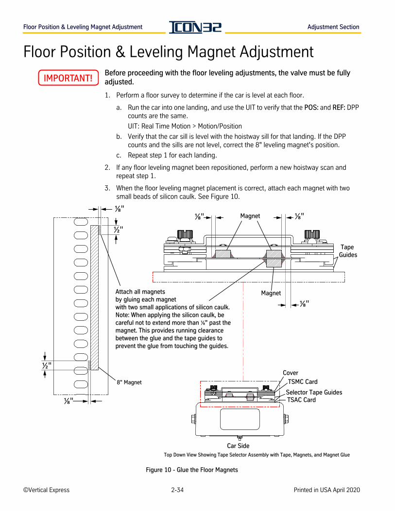
Floor Position & Leveling Magnet Adjustment Adjustment Section
Floor Position & Leveling Magnet AdjustmentBefore proceeding with the floor leveling adjustments, the valve must be fully adjusted.
1. Perform a floor survey to determine if the car is level at each floor.
a. Run the car into one landing, and use the UIT to verify that the POS: and REF: DPP counts are the same.
UIT: Real Time Motion > Motion/Position
b. Verify that the car sill is level with the hoistway sill for that landing. If the DPP counts and the sills are not level, correct the 8" leveling magnet's position.
c. Repeat step 1 for each landing.
2. If any floor leveling magnet been repositioned, perform a new hoistway scan and repeat step 1.
3. When the floor leveling magnet placement is correct, attach each magnet with two small beads of silicon caulk. See Figure 10.
Figure 10 - Glue the Floor Magnets
½"
8" Magnet
Attach all magnets by gluing each magnet with two small applications of silicon caulk. Note: When applying the silicon caulk, be careful not to extend more than " past the magnet. This provides running clearance between the glue and the tape guides to prevent the glue from touching the guides.
Cover
TSMC Card
Selector Tape GuidesTSAC Card
Car SideTop Down View Showing Tape Selector Assembly with Tape, Magnets, and Magnet Glue
Tape Guides
Magnet
Magnet
½"
©Vertical Express 2-34 Printed in USA April 2020
AD
JU
ST
ME
NT
Adjustment Section Terminal Slowdown Check
Terminal Slowdown Check
1. Confirm the P17 and P18 slowdown position counts, based on job speed. See Table 3 on page 2-36 for the proper values and for all steps in this procedure.
2. Adjust the terminal slowdown magnets so that they activate 2–4" after the selector slowdown.
Example
Both up and down car speeds are 100 FPM. Table 3 shows that the up selector slowdown is 939 counts (each count = 1/40"). Therefore, the up terminal slow-down magnet should activate 18–20" before the landing. The down selector slowdown is 683 counts, so the down terminal slowdown magnet should acti-vate 12–14" before the landing.
Verify Proper Function of the UP Terminal Slowdown Magnets via the UIT
1. In the UIT, scroll to Block Select Adjustments > Adjust Car/Group > Position Sys-tem > P17, and press ENTER to edit the value.
2. Press UP or DOWN to adjust P17 to one half of the recommended value from Table 3 on page 2-36.
3. Place the car at a floor below the top terminal landing. This action will allow the car to achieve contract speed in the up direction.
4. Run the car to the top terminal landing.
• NTST should activate, slow the car down, and stop the car within door zone.
• The controller should log faults (981,2801, 1062, etc.) showing the NTS system was activated.
In the next step, a metal scribe will damage the tape.
a. If the car does not stop within the door zone, use a marker that will not damage the selector tape to mark the bottom edge of the slowdown mag-net’s current location.
b. Use the alignment tool as a guide, and slide the slowdown magnets down in 1" increments. Repeat until the car stops within the door zone.
5. Restore P17 to the value indicated in Table 3. If the slowdown magnets were repositioned to achieve proper operation, add 43 to the value of P17 for each inch the magnets were moved.
6. Scroll to Block Select Adjustments > Adjustment Car/Group > Car Adjustments > WRT, and issue a WRT Command to save the adjustments.
7. Attach each magnet in its final location with two small beads of silicone caulk. See Figure 10 on page 2-34.
Vertical Express Product Manual 2-35 88500 v.1.0

Terminal Slowdown Check Adjustment Section
Verify Proper Function of the DOWN Terminal Slowdown Magnets via the UIT
1. In the UIT, scroll to Block Select Adjustments > Adjust Car/Group > Position System > P18, and press ENTER to edit the value.
2. Press UP or DOWN to adjust P18 to one half of the recommended value from Table 3.
3. Place the car at the first non-close floor above the bottom terminal landing. This action will allow the car to achieve contract speed in the down direction.
4. Run the car to the bottom terminal landing.
• NTSB should activate, slow the car down, and stop the car within the door zone.
• The controller should log faults (981,2801, 1062, etc.) showing the NTS system was activated.
In the next step, a metal scribe will damage the tape.
a. If the car does not stop within the door zone, use a marker that will not damage the selector tape to mark the bottom edge of the slowdown magnet’s current location.
b. Use the alignment tool as a guide, and slide the slowdown magnets down in 1" increments. Repeat until the car stops within the door zone.
5. Restore P18 to the value indicated in Table 3. If the slowdown magnets had to be repositioned to achieve proper operation, add 43 to the value of P18 for each inch the magnets were moved.
6. Scroll to Block Select Adjustments > Adjustment Car/Group > Car Adjustments > WRT, and issue a WRT Command to save the adjustments.
7. Attach each magnet in its final location with two small beads of silicone caulk. See Figure 10 on page 2-34.
Table 3 - Selector Slowdown Distance
Car Speed (FPM)
Up Adjustment Down Adjustment
DistanceSlowdown
CountDistance
Slowdown Count
50 11" 470 8" 342
75 16" 683 12" 512
100 22" 939 16" 683
125 28" 1195 22" 939
150 34" 1451 28" 1195
175 42" 1792 34" 1451
200 50" 2134 42" 1792
©Vertical Express 2-36 Printed in USA April 2020
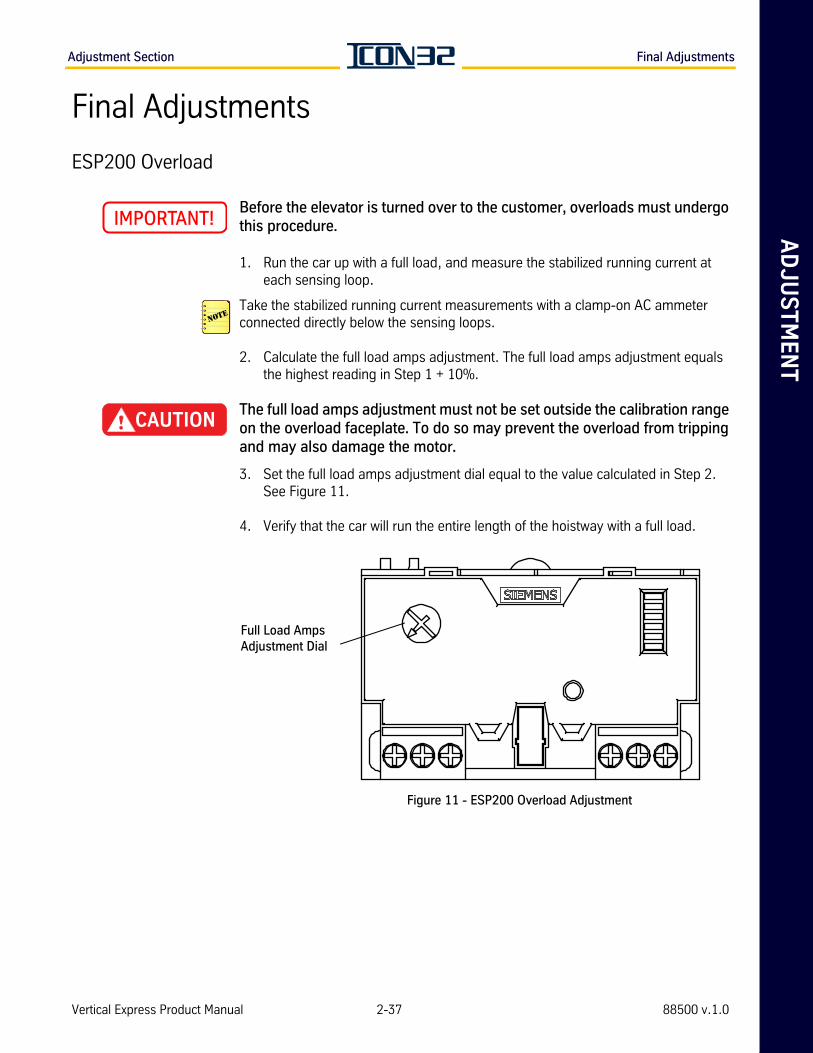
AD
JU
ST
ME
NT
Adjustment Section Final Adjustments
Final Adjustments
ESP200 Overload
Before the elevator is turned over to the customer, overloads must undergo this procedure.
1. Run the car up with a full load, and measure the stabilized running current at each sensing loop.
Take the stabilized running current measurements with a clamp-on AC ammeter connected directly below the sensing loops.
2. Calculate the full load amps adjustment. The full load amps adjustment equals the highest reading in Step 1 + 10%.
The full load amps adjustment must not be set outside the calibration range on the overload faceplate. To do so may prevent the overload from tripping and may also damage the motor.
3. Set the full load amps adjustment dial equal to the value calculated in Step 2. See Figure 11.
4. Verify that the car will run the entire length of the hoistway with a full load.
Figure 11 - ESP200 Overload Adjustment
Full Load Amps Adjustment Dial
Vertical Express Product Manual 2-37 88500 v.1.0
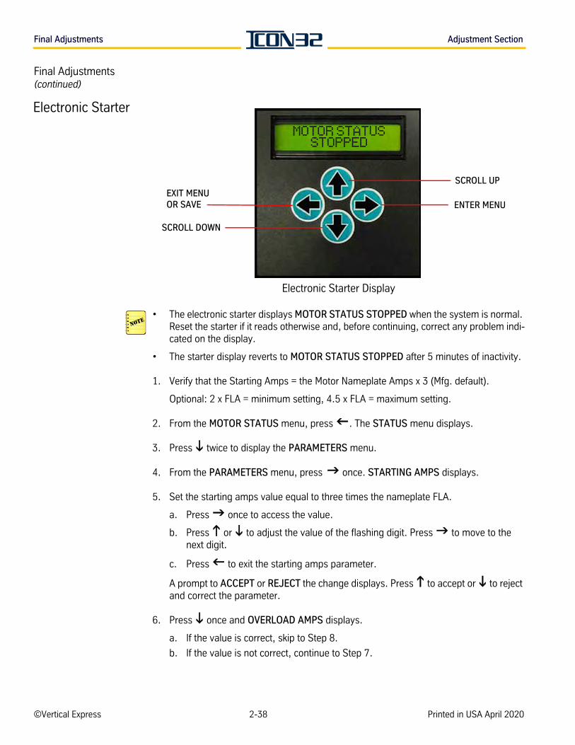
Final Adjustments Adjustment Section
Final Adjustments(continued)
Electronic Starter Display
• The electronic starter displays MOTOR STATUS STOPPED when the system is normal. Reset the starter if it reads otherwise and, before continuing, correct any problem indi-cated on the display.
• The starter display reverts to MOTOR STATUS STOPPED after 5 minutes of inactivity.
1. Verify that the Starting Amps = the Motor Nameplate Amps x 3 (Mfg. default).
Optional: 2 x FLA = minimum setting, 4.5 x FLA = maximum setting.
2. From the MOTOR STATUS menu, press . The STATUS menu displays.
3. Press twice to display the PARAMETERS menu.
4. From the PARAMETERS menu, press once. STARTING AMPS displays.
5. Set the starting amps value equal to three times the nameplate FLA.
a. Press once to access the value.
b. Press or to adjust the value of the flashing digit. Press to move to the next digit.
c. Press to exit the starting amps parameter.
A prompt to ACCEPT or REJECT the change displays. Press to accept or to reject and correct the parameter.
6. Press once and OVERLOAD AMPS displays.
a. If the value is correct, skip to Step 8.
b. If the value is not correct, continue to Step 7.
EXIT MENU OR SAVE
SCROLL DOWN
SCROLL UP
ENTER MENU
MOTOR STATUS STOPPED
Electronic Starter
©Vertical Express 2-38 Printed in USA April 2020
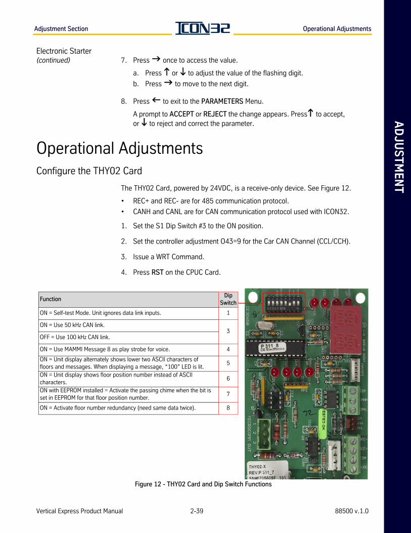
AD
JU
ST
ME
NT
Adjustment Section Operational Adjustments
Electronic Starter(continued) 7. Press once to access the value.
a. Press or to adjust the value of the flashing digit.
b. Press to move to the next digit.
8. Press to exit to the PARAMETERS Menu.
A prompt to ACCEPT or REJECT the change appears. Press to accept, or to reject and correct the parameter.
Operational AdjustmentsConfigure the THY02 Card
The THY02 Card, powered by 24VDC, is a receive-only device. See Figure 12.
• REC+ and REC- are for 485 communication protocol.
• CANH and CANL are for CAN communication protocol used with ICON32.
1. Set the S1 Dip Switch #3 to the ON position.
2. Set the controller adjustment O43=9 for the Car CAN Channel (CCL/CCH).
3. Issue a WRT Command.
4. Press RST on the CPUC Card.
Figure 12 - THY02 Card and Dip Switch Functions
FunctionDip
Switch
ON = Self-test Mode. Unit ignores data link inputs. 1
ON = Use 50 kHz CAN link. 3
OFF = Use 100 kHz CAN link.
ON = Use MAMMI Message 8 as play strobe for voice. 4
ON = Unit display alternately shows lower two ASCII characters of floors and messages. When displaying a message, “100” LED is lit.
5
ON = Unit display shows floor position number instead of ASCII characters.
6
ON with EEPROM installed = Activate the passing chime when the bit is set in EEPROM for that floor position number.
7
ON = Activate floor number redundancy (need same data twice). 8
Vertical Express Product Manual 2-39 88500 v.1.0
Operational Adjustments Adjustment Section
Additional Operational Adjustments
Verify the following settings:
1. TIM set correctly.
2. DAT set correctly.
3. L10 - L34 for lobby request (parking options) - some jobs ship with parking enabled.
4. Multistage jacks.
a. JRT set to desired time.
b. O29 = 6-10 seconds.
c. O44 - # motor starts to trigger a jack resync.
d. O30 - Jack resync interval in days (1-3).
e. O32 - Jack resync door.
5. Fire service.
a. F10 - Main fire return landing.
b. F11 - Alternate fire return landing.
6. Set Hoistway Access (optional).
• Z38 - Hoistway Access Bottom Floor Door Selection
• Z39 - Hoistway Access Top Floor Door Selection
• O11- Hoistway Access Bottom Zone
• O21- Hoistway Access Top Floor
• O22- Hoistway Access Top Zone
• Configure the Safety Processor
• Issue TECC Command
©Vertical Express 2-40 Printed in USA April 2020
AD
JU
ST
ME
NT
Adjustment Section Operational Adjustments
Save Parameters and Backup Job Software
1. Place the controller inspection switch in the INSP position.
2. Access the UIT.
3. Press UP or DOWN to scroll to the Startup Wizard.
4. Press ENTER to select the Startup Wizard, and then press UP.
5. Press UP until Write to Flash displays.
6. Press ENTER, and press ENTER again, and the UIT displays Save Job To USB.
7. Insert the USB flash drive for the job, and press ENTER. The CPU will create a backup folder in the tke folder, and save the job software. This process will take several minutes.
8. When the process is complete, press ENTER.
9. Press DOWN.
10. Place the controller inspection switch in the NORMAL position.
11. Return the car to service.
Vertical Express Product Manual 2-41 88500 v.1.0

Operational Adjustments Adjustment Section
This pageintentionallyleft blank.
©Vertical Express 2-42 Printed in USA April 2020

DIA
GN
OS
TIC
S S
EC
TIO
N

DIA
GN
OS
TIC
S S
EC
TIO
N
Diagnostics Section Contents
Contents
Adjustments . . . . . . . . . . . . . . . . . . . . . . . . . . . . . . . . . . . . . . . . . . . . . . . . . . . . . . . . . . . . 3-3
Commands . . . . . . . . . . . . . . . . . . . . . . . . . . . . . . . . . . . . . . . . . . . . . . . . . . . . . . . . . . . . 3-19
Inputs and Outputs . . . . . . . . . . . . . . . . . . . . . . . . . . . . . . . . . . . . . . . . . . . . . . . . . . . . . . 3-21
No Known Application Rule I/O . . . . . . . . . . . . . . . . . . . . . . . . . . . . . . . . . . . . . . . . 3-29
Control System Fault Codes . . . . . . . . . . . . . . . . . . . . . . . . . . . . . . . . . . . . . . . . . . . . . . . . 3-33
SP Fault Codes - Safety Processor . . . . . . . . . . . . . . . . . . . . . . . . . . . . . . . . . . . . . . . . . . . 3-43
NP Fault Codes - NTSD Processor . . . . . . . . . . . . . . . . . . . . . . . . . . . . . . . . . . . . . . . . . . . . 3-45
WPT Diagnostics . . . . . . . . . . . . . . . . . . . . . . . . . . . . . . . . . . . . . . . . . . . . . . . . . . . . . . . . 3-46
Vertical Express Product Manual 3-1 88500 v.1.0

Contents Diagnostics Section
This pageintentionallyleft blank.
3-2©Vertical Express Printed in USA April 2020
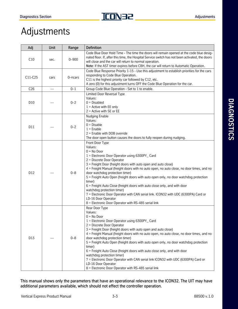
DIA
GN
OS
TIC
SDiagnostics Section Adjustments
Adjustments
Adj Unit Range Definition
C10 sec. 0–900
Code Blue Door Hold Time - The time the doors will remain opened at the code blue desig-nated floor. If, after this time, the Hospital Service switch has not been activated, the doors will close and the car will return to normal operation.Note: If the AST timer expires before CBH, the car will return to Automatic Operation.
C11-C25 cars 0–ncars
Code Blue Response Priority 1-15 - Use this adjustment to establish priorities for the cars responding to Code Blue Operation. C11 is the highest priority car followed by C12, etc. A zero (0) for this adjustment turns OFF the Code Blue Operation for the car.
C26 — 0–1 Group Code Blue Operation - Set to 1 to enable.
D10 — 0–2
Limited Door Reversal Type Values:0 = Disabled1 = Active with EE only2 = Active with SE or EE
D11 — 0–2
Nudging EnableValues:0 = Disable1 = Enable2 = Enable with DOB overrideThe door open button causes the doors to fully reopen during nudging.
D12 — 0–8
Front Door Type Values:0 = No Door1 = Electronic Door Operator using 6300PY_ Card2 = Discrete Door Operator3 = Freight Door (freight doors with auto open and auto close)4 = Freight Manual (freight doors with no auto open, no auto close, no door times, and no door watchdog protection timer)5 = Freight Auto Open (freight doors with auto open only, no door watchdog protection timer)6 = Freight Auto Close (freight doors with auto close only, and with door watchdog protection timer)7 = Electronic Door Operator with CAN serial link. ICON32 with UDC (6300PA) Card or LD-16 Door Operator8 = Electronic Door Operator with RS-485 serial link
D13 — 0–8
Rear Door Type Values:0 = No Door1 = Electronic Door Operator using 6300PY_ Card2 = Discrete Door Operator3 = Freight Door (freight doors with auto open and auto close)4 = Freight Manual (freight doors with no auto open, no auto close, no door times, and no door watchdog protection timer)5 = Freight Auto Open (freight doors with auto open only, no door watchdog protection timer)6 = Freight Auto Close (freight doors with auto close only, and with door watchdog protection timer)7 = Electronic Door Operator with CAN serial link ICON32 with UDC (6300PA) Card or LD-16 Door Operator8 = Electronic Door Operator with RS-485 serial link
Vertical Express Product Manual 3-3 88500 v.1.0
This manual shows only the parameters that have an operational relevance to the ICON32. The UIT may have additional parameters available, which should not effect the controller operation.
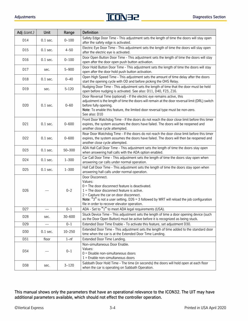
Adjustments Diagnostics Section
D14 0.1 sec. 0–100Safety Edge Door Time - This adjustment sets the length of time the doors will stay open after the safety edge is activated.
D15 0.1 sec. 4–50Electric Eye Door Time - This adjustment sets the length of time the doors will stay open after the electric eye is activated.
D16 0.1 sec. 0–100Door Open Button Door Time - This adjustment sets the length of time the doors will stay open after the door open push button activation.
D17 sec. 5–900Door Hold Button Door Time - This adjustment sets the length of time the doors will stay open after the door hold push button activation.
D18 0.1 sec. 0–40Open High Speed Time - This adjustment sets the amount of time delay after the doors start the opening cycle with OD and before picking the OHS Relay.
D19 sec. 5-120Nudging Door Time - This adjustment sets the length of time that the door must be held open before nudging is activated. See also: D11, D40, F23, Z16.
D20 0.1 sec. 0–60
Door Reversal Time (optional) - If the electric eye remains active, this adjustment is the length of time the doors will remain at the door reversal limit (DRL) switch before fully opening. Note: To enable this feature, the limited door reversal type must be non-zero.See also: D10
D21 0.1 sec. 0–600Front Door Watchdog Time - If the doors do not reach the door close limit before this timer expires, the system assumes the doors have failed. The doors will be reopened and another close cycle attempted.
D22 0.1 sec. 0–600Rear Door Watchdog Time - If the doors do not reach the door close limit before this timer expires, the system assumes the doors have failed. The doors will then be reopened and another close cycle attempted.
D23 0.1 sec. 50–300ADA Hall Call Door Time - This adjustment sets the length of time the doors stay open when answering hall calls with the ADA option enabled.
D24 0.1 sec. 1–300Car Call Door Time - This adjustment sets the length of time the doors stay open when answering car calls under normal operation.
D25 0.1 sec. 1–300Hall Call Door Time - This adjustment sets the length of time the doors stay open when answering hall calls under normal operation.
D26 — 0–2
Door Disconnect.Values:0 = The door disconnect feature is deactivated.1 = The door disconnect feature is active.2 = Capture the car on door disconnect.Note: "3" is not a user setting. D26 = 3 followed by WRT will reload the job configuration file in order to recover elevator operation.
D27 — 0–1 ADA - Set to "1" to meet ADA legal requirements (USA).
D28 sec. 30–600Stuck Device Time - This adjustment sets the length of time a door opening device (such as the Door Open Button) must be active before it is recognized as being stuck.
D29 — 0–1 Extended Door Time Enable - To activate this feature, set adjustment D30.
D30 0.1 sec. 10–250Extended Door Time - This adjustment sets the length of time added to the standard door time when the car is at the Extended Door Time Landing.
D31 floor 1–nf Extended Door Time Landing.
D34 — 0–1
Non-simultaneous Door Enable.Values:0 = Disable non-simultaneous doors1 = Enable non-simultaneous doors
D38 sec. 3–120Sabbath Door Hold Time - The time (in seconds) the doors will hold open at each floor when the car is operating on Sabbath Operation.
Adj (cont.) Unit Range Definition (cont.)
©Vertical Express 3-4 Printed in USA April 2020
This manual shows only the parameters that have an operational relevance to the ICON32. The UIT may have additional parameters available, which should not effect the controller operation.
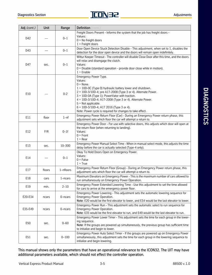
DIA
GN
OS
TIC
SDiagnostics Section Adjustments
D42 — 0–1
Freight Doors Present - Informs the system that the job has freight doors -Values:0 = No freight doors1 = Freight doors
D43 — 0–1Door Open Device Stuck Detection Disable - This adjustment, when set to 1, disables the detection for the door open device and the doors will remain open indefinitely.
D47 sec. 0–1
Wittur Keeper Timeout - The controller will disable Close Door after this time, and the doors will relax and disengage the clutch. Values:0 = Disable (standard operation - provide door close while in motion).1 = Enable
E10 — 0-2
Emergency Power Type.Values:0 = None.1 = 10D-0C (Type 0) hydraulic battery lower and shutdown.2 = 10D-3/10D-4; pre A17-2008 (Type 3 or 4). Alternate Power.3 = 10D-0A (Type 1); PowerVator with traction.4 = 10D-3/10D-4; A17-2008 (Type 3 or 4). Alternate Power.5 = Not applicable.6 = 10D-3/10D-4; A17 2016 (Type 3 or 4).Note: Power cycle is required for changes to take effect.
E11 floor 1–nfEmergency Power Return Floor (Car) - During an Emergency Power return phase, this adjustment sets which floor the car will attempt a return to.
E12 F/R 0–1f
Emergency Power Door - For use with selective doors, this adjusts which door will open at the return floor (when returning to landing).Values:0 = Front1 = Rear
E13 sec. 10–300Emergency Power Manual Select Time - When in manual select mode, this adjusts the time delay before the car is actually selected (Type-4 only).
E14 — 0–1
Okay To Hold Doors Open on Emergency Power.Values:0 = False1 = True
E17 floors 1–nfloorsEmergency Power Return Floor (Group) - During an Emergency Power return phase, this adjustment sets which floor the car will attempt a return to.
E18 cars 1–ncarsMaximum Elevators on Emergency Power - This is the maximum number of cars allowed to run simultaneously on Emergency Power Operation.
E19 min. 2–10Emergency Power Extended Lowering Time - Use this adjustment to set the time allowed for cars to arrive at the emergency power floor.
E20-E34 ncars 0–ncarsEmergency Power Lowering - This adjustment sets the automatic lowering sequence for Emergency Power Operation. Note: E20 would be the first elevator to lower, and E34 would be the last elevator to lower.
E35-E49 ncars 0–ncarsEmergency Power Run - This adjustment sets the automatic select to run sequence for Emergency Power Operation. Note: E35 would be the first elevator to run, and E49 would be the last elevator to run.
E50 sec. 0–60
Emergency Power Lower Timer - This adjustment sets the time for each group in the lower-ing sequence.Note: If the groups are powered up simultaneously, the previous group has sufficient time to initialize and begin to lower.
E51 sec. 0–100Emergency Power Auto Select Timer - If the groups are powered up on Emergency Power simultaneously, this adjustment sets the time for each group in the lowering sequence to initialize and begin lowering.
Adj (cont.) Unit Range Definition (cont.)
Vertical Express Product Manual 3-5 88500 v.1.0
This manual shows only the parameters that have an operational relevance to the ICON32. The UIT may have additional parameters available, which should not effect the controller operation.
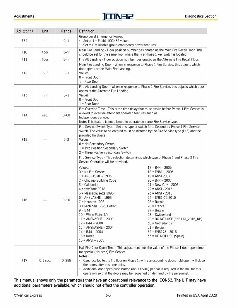
Adjustments Diagnostics Section
E52 — 0–1Group Level Emergency Power. • Set to 1 = Enable ICON32 value.• Set to 0 = Disable group emergency power features.
F10 floor 1–nfMain Fire Landing - Floor position number designated as the Main Fire Recall Floor. This should be set for the same floor where the Fire Phase 1 key switch is located.
F11 floor 1–nf Fire Alt Landing - Floor position number designated as the Alternate Fire Recall Floor.
F12 F/R 0–1
Main Fire Landing Door - When in response to Phase 1 Fire Service, this adjusts which door opens at the Main Fire Landing.Values:0 = Front Door1 = Rear Door
F13 F/R 0–1
Fire Alt Landing Door - When in response to Phase 1 Fire Service, this adjusts which door opens at the Alternate Fire Landing. Values:0 = Front Door1 = Rear Door
F14 sec. 0–60
Fire Override Time - This is the time delay that must expire before Phase 1 Fire Service is allowed to override attendant operated features such as Independent Service. Note: This feature is not allowed to operate on some Fire Service types.
F15 — 0–2
Fire Service Switch Type - Set this type of switch for a Secondary Phase 1 Fire Service switch. The value to be entered must be dictated by the Fire Service type (F16) and the provided hardware.Values:0 = No Secondary Switch 1 = Two Position Secondary Switch2 = Three Position Secondary Switch
F16 — 0–20
Fire Service Type - This selection determines which type of Phase 1 and Phase 2 Fire Service Operation will be provided.
F17 0.1 sec. 0–255
Hall Fire Door Open Time - This adjustment sets the value of the Phase 1 door open time for special (Houston) Fire Service. Notes:• Cars recalled to the fire floor on Phase 1, with corresponding doors held open, will close
the doors after this time delay. • Additional door open push button (input FSDO) per car is required in the hall for this
operation so that the doors may be reopened on demand by fire personnel.
Adj (cont.) Unit Range Definition (cont.)
Values:0 = No Fire Service1 = ANSI/ASME – 19932 = Chicago Building Code3 = California4 =New York RS185 = Massachusetts 1998 6 = ANSI/ASME – 19987 = Houston 19988 = Michigan 1998, Detroit9 = B44 10 = White Plains NY11 = ANSI/ASME – 200012 = B44 – 200013 = ANSI/ASME – 200414 = B44 – 200415 = Korea16 = ANSI – 2005
17 = B44 – 200518 = EN81 – 200519 = ANSI 200720 = B44 – 200721 = New York - 200322 = ANSI - 201323 = ANSI - 201624 = EN81-72 201525 = Russia26 = France27 = Britain28 = Switzerland29 = DO NOT USE (EN8173_2016_NH)30 = Netherlands31 = Belgium32 = EN8173 - 201633 = DO NOT USE (Spain)
©Vertical Express 3-6 Printed in USA April 2020
This manual shows only the parameters that have an operational relevance to the ICON32. The UIT may have additional parameters available, which should not effect the controller operation.
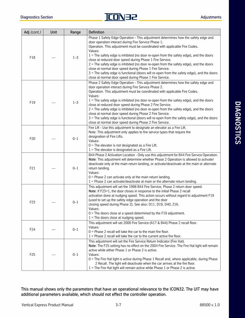
DIA
GN
OS
TIC
SDiagnostics Section Adjustments
F18 — 1–3
Phase 1 Safety Edge Operation - This adjustment determines how the safety edge and door operation interact during Fire Service Phase 1. Operation. This adjustment must be coordinated with applicable Fire Codes.Values:1 = The safety edge is inhibited (no door re-open from the safety edge), and the doors close at reduced door speed during Phase 1 Fire Service.2 = The safety edge is inhibited (no door re-open from the safety edge), and the doors close at normal door speed during Phase 1 Fire Service.3 = The safety edge is functional (doors will re-open from the safety edge), and the doors close at normal door speed during Phase 1 Fire Service.
F19 — 1–3
Phase 2 Safety Edge Operation - This adjustment determines how the safety edge and door operation interact during Fire Service Phase 2. Operation. This adjustment must be coordinated with applicable Fire Codes.Values:1 = The safety edge is inhibited (no door re-open from the safety edge), and the doors close at reduced door speed during Phase 2 Fire Service.2 = The safety edge is inhibited (no door re-open from the safety edge), and the doors close at normal door speed during Phase 2 Fire Service.3 = The safety edge is functional (doors will re-open from the safety edge), and the doors close at normal door speed during Phase 2 Fire Service.
F20 — 0–1
Fire Lift - Use this adjustment to designate an elevator as a Fire Lift. Note: This adjustment only applies to fire service types that require the designation of Fire Lifts.Values:0 = The elevator is not designated as a Fire Lift.1 = The elevator is designated as a Fire Lift.
F21 — 0–1
B44 Phase 2 Activation Location - Only use this adjustment for B44 Fire Service Operation. Note: This adjustment will determine whether Phase 2 Operation is allowed to activate/deactivate only at the main return landing, or activate/deactivate at the main or alternate return landing.Values:0 = Phase 2 can activate only at the main return landing.1 = Phase 2 can activate/deactivate at main or the alternate return landing.
F23 — 0–1
This adjustment will set the 1998 B44 Fire Service, Phase 2 return door speed. Note: If F23=1, the door closes in response to the initial Phase 2 recall activation done at nudging speed. This action occurs without regard to adjustment F19 (used to set up the safety edge operation and the door closing speed during Phase 2). See also: D11, D19, D40, Z16.Values:0 = The doors close at a speed determined by the F19 adjustment.1 = The doors close at nudging speed.
F24 — 0–1
This adjustment will set 2000 Fire Service (A17 & B44) Phase 2 recall floor.Values:0 = Phase 2 recall will take the car to the main fire floor.1 = Phase 2 recall will take the car to the current active fire floor.
F25 — 0–1
This adjustment will set the Fire Service Return Indicator (Fire Hat).Note: The F25 setting has no effect on the 2004 Fire Service. The Fire Hat light will remain active while either Phase 1 or Phase 2 is active.Values:0 = The Fire Hat light is active during Phase 1 Recall and, where applicable, during Phase
2 Recall. The light will deactivate when the car arrives at the fire floor.1 = The Fire Hat light will remain active while Phase 1 or Phase 2 is active.
Adj (cont.) Unit Range Definition (cont.)
Vertical Express Product Manual 3-7 88500 v.1.0
This manual shows only the parameters that have an operational relevance to the ICON32. The UIT may have additional parameters available, which should not effect the controller operation.
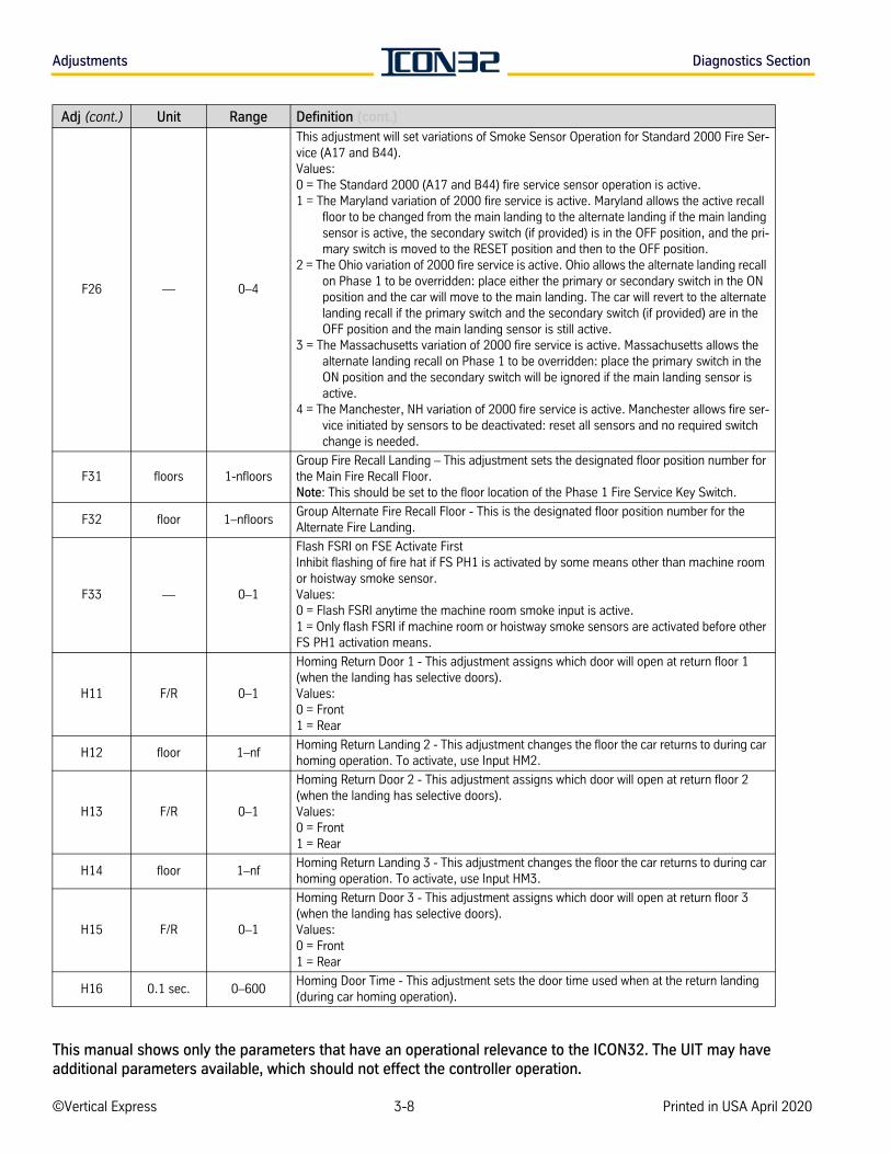
Adjustments Diagnostics Section
F26 — 0–4
This adjustment will set variations of Smoke Sensor Operation for Standard 2000 Fire Ser-vice (A17 and B44).Values:0 = The Standard 2000 (A17 and B44) fire service sensor operation is active.1 = The Maryland variation of 2000 fire service is active. Maryland allows the active recall
floor to be changed from the main landing to the alternate landing if the main landing sensor is active, the secondary switch (if provided) is in the OFF position, and the pri-mary switch is moved to the RESET position and then to the OFF position.
2 = The Ohio variation of 2000 fire service is active. Ohio allows the alternate landing recall on Phase 1 to be overridden: place either the primary or secondary switch in the ON position and the car will move to the main landing. The car will revert to the alternate landing recall if the primary switch and the secondary switch (if provided) are in the OFF position and the main landing sensor is still active.
3 = The Massachusetts variation of 2000 fire service is active. Massachusetts allows the alternate landing recall on Phase 1 to be overridden: place the primary switch in the ON position and the secondary switch will be ignored if the main landing sensor is active.
4 = The Manchester, NH variation of 2000 fire service is active. Manchester allows fire ser-vice initiated by sensors to be deactivated: reset all sensors and no required switch change is needed.
F31 floors 1-nfloorsGroup Fire Recall Landing – This adjustment sets the designated floor position number for the Main Fire Recall Floor. Note: This should be set to the floor location of the Phase 1 Fire Service Key Switch.
F32 floor 1–nfloorsGroup Alternate Fire Recall Floor - This is the designated floor position number for the Alternate Fire Landing.
F33 — 0–1
Flash FSRI on FSE Activate FirstInhibit flashing of fire hat if FS PH1 is activated by some means other than machine room or hoistway smoke sensor.Values:0 = Flash FSRI anytime the machine room smoke input is active.1 = Only flash FSRI if machine room or hoistway smoke sensors are activated before other FS PH1 activation means.
H11 F/R 0–1
Homing Return Door 1 - This adjustment assigns which door will open at return floor 1 (when the landing has selective doors).Values:0 = Front1 = Rear
H12 floor 1–nfHoming Return Landing 2 - This adjustment changes the floor the car returns to during car homing operation. To activate, use Input HM2.
H13 F/R 0–1
Homing Return Door 2 - This adjustment assigns which door will open at return floor 2 (when the landing has selective doors).Values:0 = Front1 = Rear
H14 floor 1–nfHoming Return Landing 3 - This adjustment changes the floor the car returns to during car homing operation. To activate, use Input HM3.
H15 F/R 0–1
Homing Return Door 3 - This adjustment assigns which door will open at return floor 3 (when the landing has selective doors).Values:0 = Front1 = Rear
H16 0.1 sec. 0–600Homing Door Time - This adjustment sets the door time used when at the return landing (during car homing operation).
Adj (cont.) Unit Range Definition (cont.)
©Vertical Express 3-8 Printed in USA April 2020
This manual shows only the parameters that have an operational relevance to the ICON32. The UIT may have additional parameters available, which should not effect the controller operation.
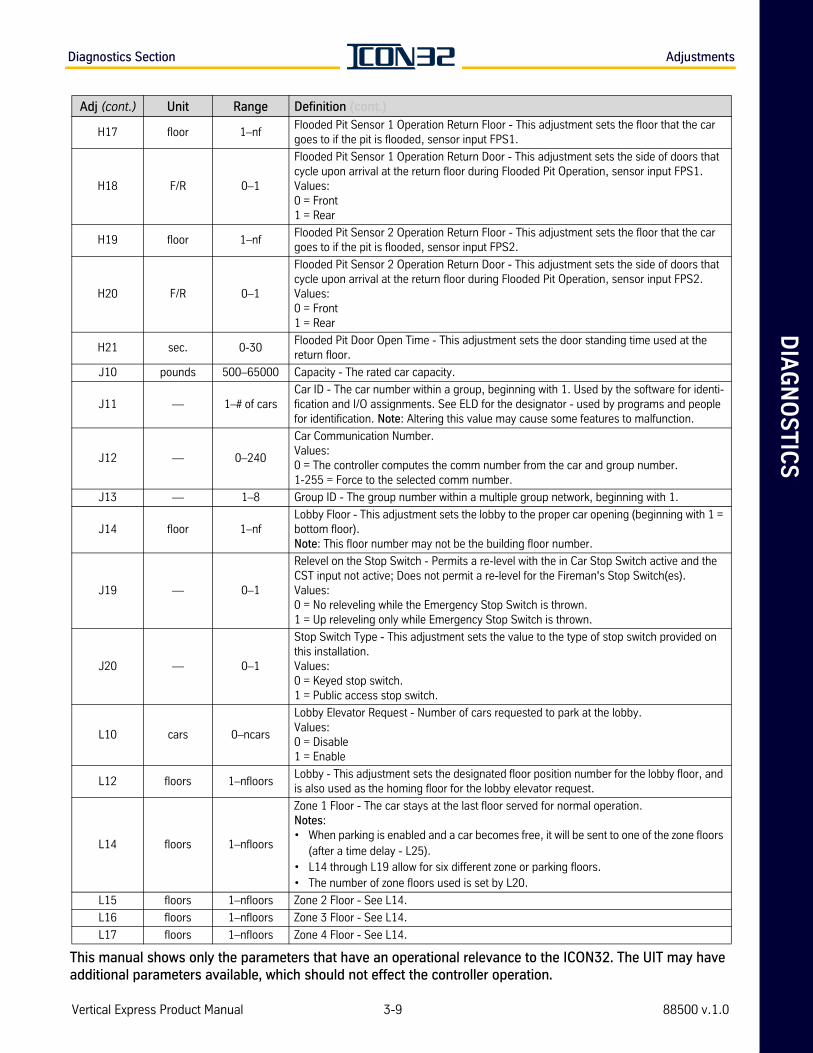
DIA
GN
OS
TIC
SDiagnostics Section Adjustments
H17 floor 1–nfFlooded Pit Sensor 1 Operation Return Floor - This adjustment sets the floor that the car goes to if the pit is flooded, sensor input FPS1.
H18 F/R 0–1
Flooded Pit Sensor 1 Operation Return Door - This adjustment sets the side of doors that cycle upon arrival at the return floor during Flooded Pit Operation, sensor input FPS1.Values:0 = Front1 = Rear
H19 floor 1–nfFlooded Pit Sensor 2 Operation Return Floor - This adjustment sets the floor that the car goes to if the pit is flooded, sensor input FPS2.
H20 F/R 0–1
Flooded Pit Sensor 2 Operation Return Door - This adjustment sets the side of doors that cycle upon arrival at the return floor during Flooded Pit Operation, sensor input FPS2.Values:0 = Front1 = Rear
H21 sec. 0-30Flooded Pit Door Open Time - This adjustment sets the door standing time used at the return floor.
J10 pounds 500–65000 Capacity - The rated car capacity.
J11 — 1–# of carsCar ID - The car number within a group, beginning with 1. Used by the software for identi-fication and I/O assignments. See ELD for the designator - used by programs and people for identification. Note: Altering this value may cause some features to malfunction.
J12 — 0–240
Car Communication Number.Values:0 = The controller computes the comm number from the car and group number.1-255 = Force to the selected comm number.
J13 — 1–8 Group ID - The group number within a multiple group network, beginning with 1.
J14 floor 1–nfLobby Floor - This adjustment sets the lobby to the proper car opening (beginning with 1 = bottom floor). Note: This floor number may not be the building floor number.
J19 — 0–1
Relevel on the Stop Switch - Permits a re-level with the in Car Stop Switch active and the CST input not active; Does not permit a re-level for the Fireman's Stop Switch(es).Values:0 = No releveling while the Emergency Stop Switch is thrown.1 = Up releveling only while Emergency Stop Switch is thrown.
J20 — 0–1
Stop Switch Type - This adjustment sets the value to the type of stop switch provided on this installation.Values:0 = Keyed stop switch.1 = Public access stop switch.
L10 cars 0–ncars
Lobby Elevator Request - Number of cars requested to park at the lobby.Values:0 = Disable1 = Enable
L12 floors 1–nfloorsLobby - This adjustment sets the designated floor position number for the lobby floor, and is also used as the homing floor for the lobby elevator request.
L14 floors 1–nfloors
Zone 1 Floor - The car stays at the last floor served for normal operation. Notes:• When parking is enabled and a car becomes free, it will be sent to one of the zone floors
(after a time delay - L25). • L14 through L19 allow for six different zone or parking floors. • The number of zone floors used is set by L20.
L15 floors 1–nfloors Zone 2 Floor - See L14.
L16 floors 1–nfloors Zone 3 Floor - See L14.
L17 floors 1–nfloors Zone 4 Floor - See L14.
Adj (cont.) Unit Range Definition (cont.)
Vertical Express Product Manual 3-9 88500 v.1.0
This manual shows only the parameters that have an operational relevance to the ICON32. The UIT may have additional parameters available, which should not effect the controller operation.
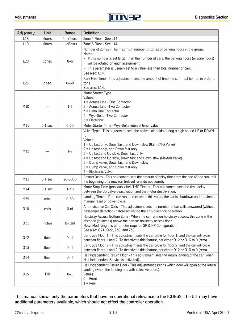
Adjustments Diagnostics Section
L18 floors 1–nfloors Zone 5 Floor - See L14.
L19 floors 1–nfloors Zone 6 Floor - See L14.
L20 zones 0–6
Number of Zones - The maximum number of zones or parking floors in the group. Notes:• If this number is set larger than the number of cars, the parking floors (or zone floors)
will be rotated on each assignment. • This parameter is usually set to a value less than total number of cars.See also: L14.
L25 2 sec. 0–60Park Free Time - This adjustment sets the amount of time the car must be free in order to zone.See also: L14.
M10 — 1-5
Motor Starter Type.Values:1 = Across Line - One Contactor2 = Across Line -Two Contactor 3 = Delta One Contactor4 = Wye-Delta -Two Contactor5 = Electronic
M11 0.1 sec. 0-20 Motor Starter Time - Wye-Delta interval timer value.
M12 — 1-7
Valve Type - This adjustment sets the active solenoids during a high speed UP or DOWN run.Values:1 = Up fast only, Down fast, and Down slow (tkE I-2/I-3 Valve)2 = Up fast only, and Down fast only3 = Up fast and Up slow, Down fast only4 = Up fast and Up slow, Down fast and Down slow (Maxton Valve)5 = Dump valve, Down fast, and Down slow 6 = Dump valve, and Down fast only 7 = Electronic Valve
M13 0.1 sec. 20-6000Restart Delay - This adjustment sets the amount of delay time from the end of one run until the beginning of a new run (relevel runs do not count).
M14 0.1 sec. 1-30Motor Stop Time (previous label, TMS Timer) - This adjustment sets the time delay between the Up Valve deactivation and the motor deactivation.
M79 min. 0-60Landing Timer - If the car run time exceeds this value, the car is shutdown and requires a manual reset or power cycle.
O10 calls 0-nfAnti-nuisance Car Calls - This adjustment sets the number of car calls answered (without passenger detection) before activating the anti-nuisance operation.
O11 inches 0–168
Hoistway Access Bottom Zone - When the car runs on hoistway access, this zone is the distance (in inches) above the bottom hoistway access floor.Note: Modifying this parameter requires SP & NP Configuration.See also: O21, O22, Z38, and Z39.
O12 floor 0–nfCar Cycle Floor 1 - This adjustment sets the car cycle for floor 1, and the car will cycle between floors 1 and 2. To deactivate this feature, set either O12 or O13 to 0 (zero).
O13 floor 0–nfCar Cycle Floor 2 - This adjustment sets the car cycle for floor 2, and the car will cycle between floors 1 and 2. To deactivate this feature, set either O12 or O13 to 0 (zero).
O14 floor 0–nfHall Independent Return Floor - This adjustment sets the return landing of the car (when Hall Independent Service is activated).
O15 F/R 0–1
Hall Independent Return Door - This adjustment assigns which door will open at the return landing (when the landing has with selective doors).Values:0 = Front1 = Rear
Adj (cont.) Unit Range Definition (cont.)
©Vertical Express 3-10 Printed in USA April 2020
This manual shows only the parameters that have an operational relevance to the ICON32. The UIT may have additional parameters available, which should not effect the controller operation.
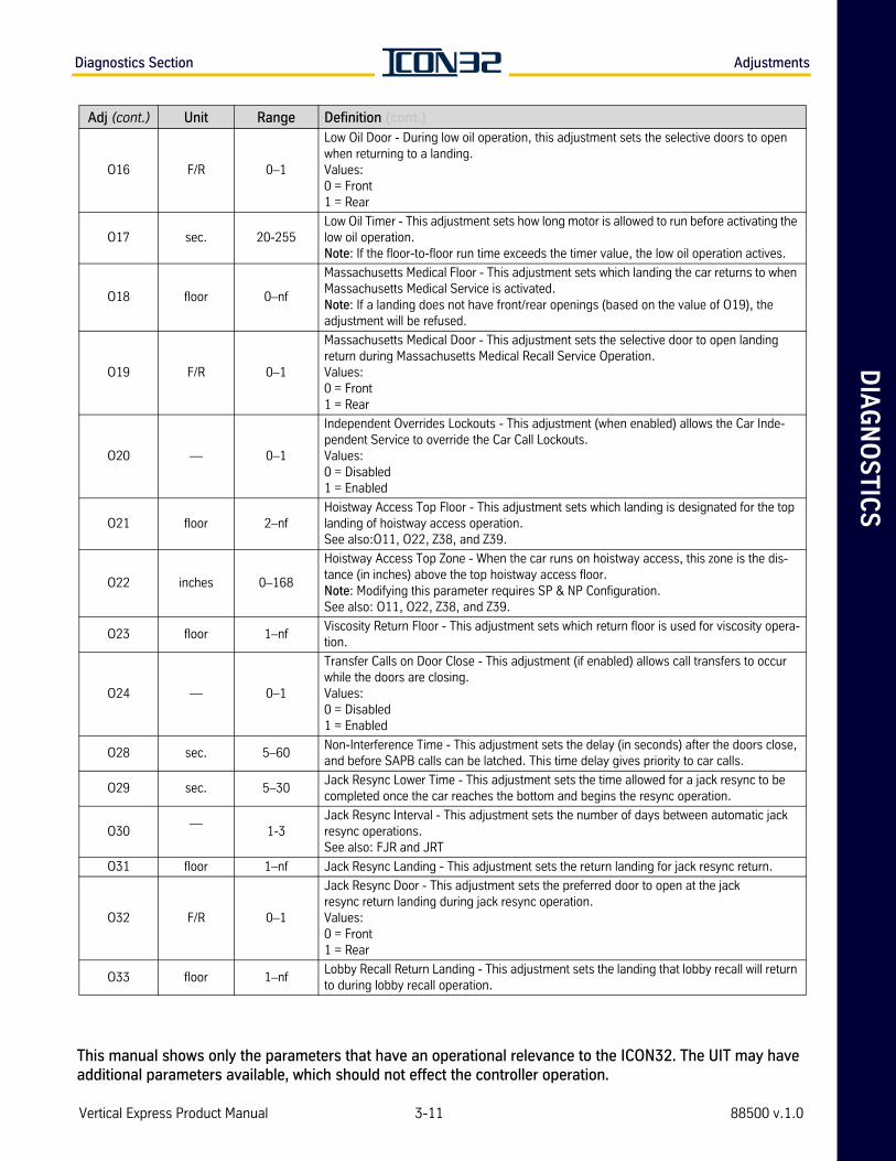
DIA
GN
OS
TIC
SDiagnostics Section Adjustments
O16 F/R 0–1
Low Oil Door - During low oil operation, this adjustment sets the selective doors to open when returning to a landing.Values:0 = Front1 = Rear
O17 sec. 20-255Low Oil Timer - This adjustment sets how long motor is allowed to run before activating the low oil operation.Note: If the floor-to-floor run time exceeds the timer value, the low oil operation actives.
O18 floor 0–nf
Massachusetts Medical Floor - This adjustment sets which landing the car returns to when Massachusetts Medical Service is activated. Note: If a landing does not have front/rear openings (based on the value of O19), the adjustment will be refused.
O19 F/R 0–1
Massachusetts Medical Door - This adjustment sets the selective door to open landing return during Massachusetts Medical Recall Service Operation.Values:0 = Front1 = Rear
O20 — 0–1
Independent Overrides Lockouts - This adjustment (when enabled) allows the Car Inde-pendent Service to override the Car Call Lockouts. Values:0 = Disabled1 = Enabled
O21 floor 2–nfHoistway Access Top Floor - This adjustment sets which landing is designated for the top landing of hoistway access operation.See also:O11, O22, Z38, and Z39.
O22 inches 0–168
Hoistway Access Top Zone - When the car runs on hoistway access, this zone is the dis-tance (in inches) above the top hoistway access floor.Note: Modifying this parameter requires SP & NP Configuration.See also: O11, O22, Z38, and Z39.
O23 floor 1–nfViscosity Return Floor - This adjustment sets which return floor is used for viscosity opera-tion.
O24 — 0–1
Transfer Calls on Door Close - This adjustment (if enabled) allows call transfers to occur while the doors are closing.Values:0 = Disabled1 = Enabled
O28 sec. 5–60Non-Interference Time - This adjustment sets the delay (in seconds) after the doors close, and before SAPB calls can be latched. This time delay gives priority to car calls.
O29 sec. 5–30Jack Resync Lower Time - This adjustment sets the time allowed for a jack resync to be completed once the car reaches the bottom and begins the resync operation.
O30—
1-3Jack Resync Interval - This adjustment sets the number of days between automatic jack resync operations.See also: FJR and JRT
O31 floor 1–nf Jack Resync Landing - This adjustment sets the return landing for jack resync return.
O32 F/R 0–1
Jack Resync Door - This adjustment sets the preferred door to open at the jackresync return landing during jack resync operation.Values:0 = Front1 = Rear
O33 floor 1–nfLobby Recall Return Landing - This adjustment sets the landing that lobby recall will return to during lobby recall operation.
Adj (cont.) Unit Range Definition (cont.)
Vertical Express Product Manual 3-11 88500 v.1.0
This manual shows only the parameters that have an operational relevance to the ICON32. The UIT may have additional parameters available, which should not effect the controller operation.
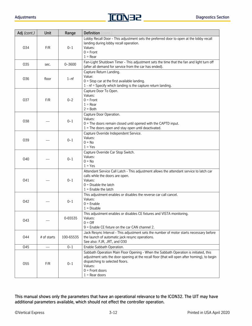
Adjustments Diagnostics Section
O34 F/R 0–1
Lobby Recall Door - This adjustment sets the preferred door to open at the lobby recall landing during lobby recall operation.Values:0 = Front1 = Rear
O35 sec. 0–3600Fan-Light Shutdown Timer - This adjustment sets the time that the fan and light turn off (after all demand for service from the car has ended).
O36 floor 1–nf
Capture Return Landing.Value:0 = Stop car at the first available landing.1 - nf = Specify which landing is the capture return landing.
O37 F/R 0–2
Capture Door To Open.Values:0 = Front1 = Rear2 = Both
O38 — 0–1
Capture Door Operation.Values:0 = The doors remain closed until opened with the CAPTD input.1 = The doors open and stay open until deactivated.
O39 — 0–1
Capture Override Independent Service.Values:0 = No1 = Yes
O40 — 0–1
Capture Override Car Stop Switch.Values:0 = No1 = Yes
O41 — 0–1
Attendant Service Call Latch - This adjustment allows the attendant service to latch car calls while the doors are open.Values:0 = Disable the latch1 = Enable the latch
O42 — 0–1
This adjustment enables or disables the reverse car call cancel.Values:0 = Enable1 = Disable
O43 — 0-65535
This adjustment enables or disables CE fixtures and VISTA monitoring.Values:0 = Off9 = Enable CE fixture on the car CAN channel 2.
O44 # of starts 100-65535Jack Resync Interval - This adjustment sets the number of motor starts necessary before the launch of automatic jack resync operations.See also: FJR, JRT, and O30
O45 — 0–1 Enable Sabbath Operation.
O55 F/R 0–1
Sabbath Operation Main Floor Opening - When the Sabbath Operation is initiated, this adjustment sets the door opening at the recall floor (that will open after homing), to begin dispatching to selected floors. Values:0 = Front doors1 = Rear doors
Adj (cont.) Unit Range Definition (cont.)
©Vertical Express 3-12 Printed in USA April 2020
This manual shows only the parameters that have an operational relevance to the ICON32. The UIT may have additional parameters available, which should not effect the controller operation.
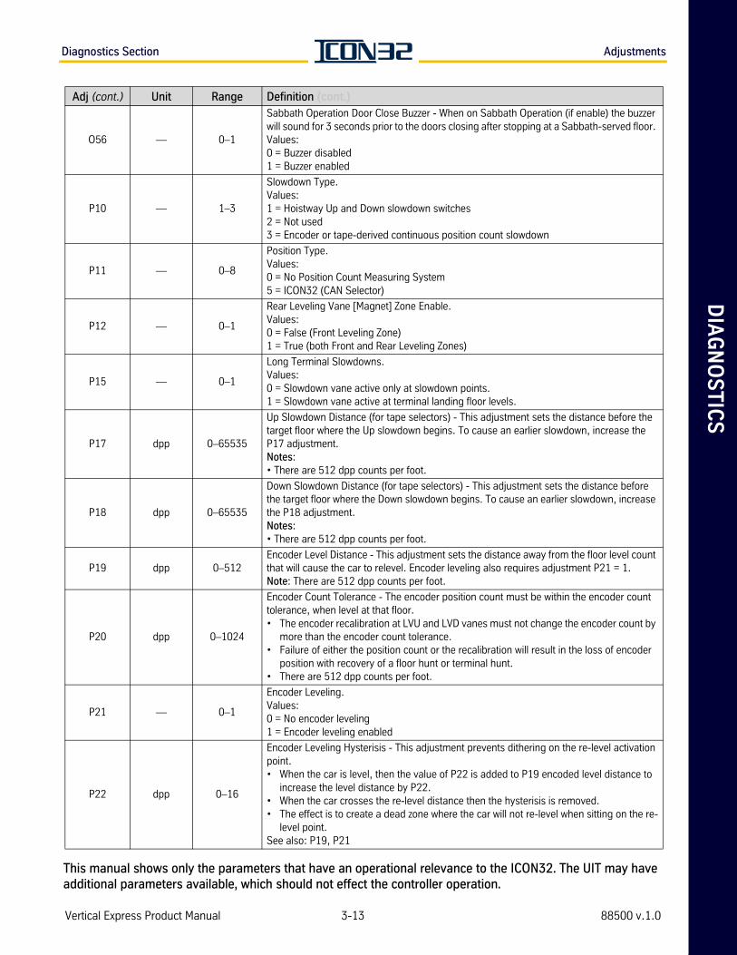
DIA
GN
OS
TIC
SDiagnostics Section Adjustments
O56 — 0–1
Sabbath Operation Door Close Buzzer - When on Sabbath Operation (if enable) the buzzer will sound for 3 seconds prior to the doors closing after stopping at a Sabbath-served floor. Values:0 = Buzzer disabled1 = Buzzer enabled
P10 — 1–3
Slowdown Type.Values:1 = Hoistway Up and Down slowdown switches 2 = Not used 3 = Encoder or tape-derived continuous position count slowdown
P11 — 0–8
Position Type.Values:0 = No Position Count Measuring System5 = ICON32 (CAN Selector)
P12 — 0–1
Rear Leveling Vane [Magnet] Zone Enable.Values:0 = False (Front Leveling Zone)1 = True (both Front and Rear Leveling Zones)
P15 — 0–1
Long Terminal Slowdowns.Values:0 = Slowdown vane active only at slowdown points.1 = Slowdown vane active at terminal landing floor levels.
P17 dpp 0–65535
Up Slowdown Distance (for tape selectors) - This adjustment sets the distance before the target floor where the Up slowdown begins. To cause an earlier slowdown, increase the P17 adjustment. Notes: • There are 512 dpp counts per foot.
P18 dpp 0–65535
Down Slowdown Distance (for tape selectors) - This adjustment sets the distance before the target floor where the Down slowdown begins. To cause an earlier slowdown, increase the P18 adjustment. Notes: • There are 512 dpp counts per foot.
P19 dpp 0–512Encoder Level Distance - This adjustment sets the distance away from the floor level count that will cause the car to relevel. Encoder leveling also requires adjustment P21 = 1.Note: There are 512 dpp counts per foot.
P20 dpp 0–1024
Encoder Count Tolerance - The encoder position count must be within the encoder count tolerance, when level at that floor. • The encoder recalibration at LVU and LVD vanes must not change the encoder count by
more than the encoder count tolerance. • Failure of either the position count or the recalibration will result in the loss of encoder
position with recovery of a floor hunt or terminal hunt.• There are 512 dpp counts per foot.
P21 — 0–1
Encoder Leveling.Values:0 = No encoder leveling1 = Encoder leveling enabled
P22 dpp 0–16
Encoder Leveling Hysterisis - This adjustment prevents dithering on the re-level activation point.• When the car is level, then the value of P22 is added to P19 encoded level distance to
increase the level distance by P22. • When the car crosses the re-level distance then the hysterisis is removed. • The effect is to create a dead zone where the car will not re-level when sitting on the re-
level point.See also: P19, P21
Adj (cont.) Unit Range Definition (cont.)
Vertical Express Product Manual 3-13 88500 v.1.0
This manual shows only the parameters that have an operational relevance to the ICON32. The UIT may have additional parameters available, which should not effect the controller operation.
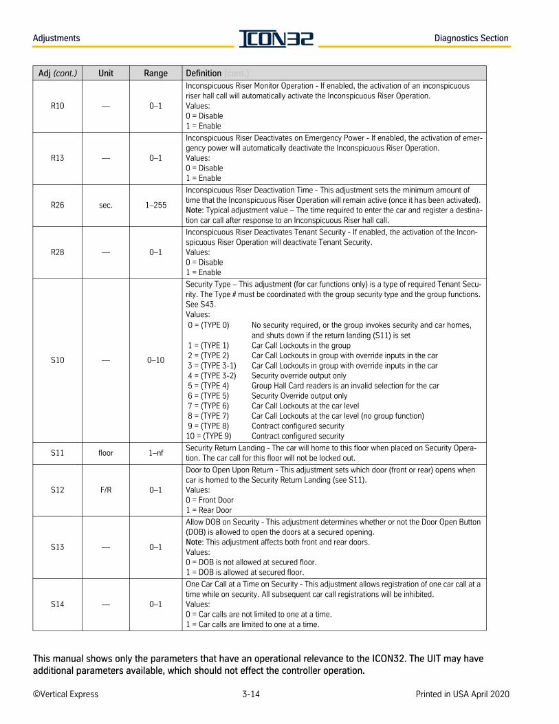
Adjustments Diagnostics Section
R10 — 0–1
Inconspicuous Riser Monitor Operation - If enabled, the activation of an inconspicuous riser hall call will automatically activate the Inconspicuous Riser Operation.Values:0 = Disable1 = Enable
R13 — 0–1
Inconspicuous Riser Deactivates on Emergency Power - If enabled, the activation of emer-gency power will automatically deactivate the Inconspicuous Riser Operation.Values:0 = Disable 1 = Enable
R26 sec. 1–255
Inconspicuous Riser Deactivation Time - This adjustment sets the minimum amount of time that the Inconspicuous Riser Operation will remain active (once it has been activated). Note: Typical adjustment value – The time required to enter the car and register a destina-tion car call after response to an Inconspicuous Riser hall call.
R28 — 0–1
Inconspicuous Riser Deactivates Tenant Security - If enabled, the activation of the Incon-spicuous Riser Operation will deactivate Tenant Security.Values:0 = Disable1 = Enable
S10 — 0–10
Security Type – This adjustment (for car functions only) is a type of required Tenant Secu-rity. The Type # must be coordinated with the group security type and the group functions. See S43.Values: 0 = (TYPE 0) No security required, or the group invokes security and car homes,
and shuts down if the return landing (S11) is set 1 = (TYPE 1) Car Call Lockouts in the group 2 = (TYPE 2) Car Call Lockouts in group with override inputs in the car 3 = (TYPE 3-1) Car Call Lockouts in group with override inputs in the car 4 = (TYPE 3-2) Security override output only 5 = (TYPE 4) Group Hall Card readers is an invalid selection for the car 6 = (TYPE 5) Security Override output only 7 = (TYPE 6) Car Call Lockouts at the car level 8 = (TYPE 7) Car Call Lockouts at the car level (no group function) 9 = (TYPE 8) Contract configured security10 = (TYPE 9) Contract configured security
S11 floor 1–nfSecurity Return Landing - The car will home to this floor when placed on Security Opera-tion. The car call for this floor will not be locked out.
S12 F/R 0–1
Door to Open Upon Return - This adjustment sets which door (front or rear) opens when car is homed to the Security Return Landing (see S11). Values:0 = Front Door1 = Rear Door
S13 — 0–1
Allow DOB on Security - This adjustment determines whether or not the Door Open Button (DOB) is allowed to open the doors at a secured opening.Note: This adjustment affects both front and rear doors.Values:0 = DOB is not allowed at secured floor.1 = DOB is allowed at secured floor.
S14 — 0–1
One Car Call at a Time on Security - This adjustment allows registration of one car call at a time while on security. All subsequent car call registrations will be inhibited.Values:0 = Car calls are not limited to one at a time.1 = Car calls are limited to one at a time.
Adj (cont.) Unit Range Definition (cont.)
©Vertical Express 3-14 Printed in USA April 2020
This manual shows only the parameters that have an operational relevance to the ICON32. The UIT may have additional parameters available, which should not effect the controller operation.
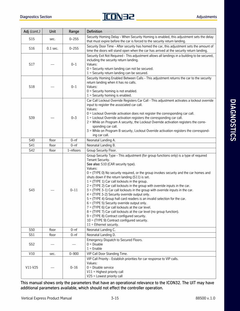
DIA
GN
OS
TIC
SDiagnostics Section Adjustments
S15 sec. 0–255Security Homing Delay - When Security Homing is enabled, this adjustment sets the delay that must expire before the car is forced to the security return landing.
S16 0.1 sec. 0–255Security Door Time - After security has homed the car, this adjustment sets the amount of time the doors will stand open when the car has arrived at the security return landing.
S17 — 0–1
Security Exit Not Required - This adjustment allows all landings in a building to be secured, including the security return landing.Values:0 = Security return landing can not be secured.1 = Security return landing can be secured.
S18 — 0–1
Security Homing Enabled Between Calls - This adjustment returns the car to the security return landing when it has no calls.Values:0 = Security homing is not enabled.1 = Security homing is enabled.
S39 — 0–3
Car Call Lockout Override Registers Car Call - This adjustment activates a lockout override input to register the associated car call.Values:0 = Lockout Override activation does not register the corresponding car call.1 = Lockout Override activation registers the corresponding car call.2 = While on Program A security, the Lockout Override activation registers the corre-
sponding car call.3 = While on Program B security, Lockout Override activation registers the correspond-
ing car call.
S40 floor 0–nf Neonatal Landing A.
S41 floor 0–nf Neonatal Landing B.
S42 floor 1–nfloors Group Security Floor.
S43 — 0–11
Group Security Type - This adjustment (for group functions only) is a type of required Tenant Security.See also: S10 (CAR security type).Values:0 = (TYPE 0) No security required, or the group invokes security and the car homes and shuts down if the return landing (S11) is set. 1 = (TYPE 1) Car call lockouts in the group. 2 = (TYPE 2) Car call lockouts in the group with override inputs in the car. 3 = (TYPE 3-1) Car call lockouts in the group with override inputs in the car.4 = (TYPE 3-2) Security override output only. 5 = (TYPE 4) Group hall card readers is an invalid selection for the car. 6 = (TYPE 5) Security override output only. 7 = (TYPE 6) Car call lockouts at the car level.8 = (TYPE 7) Car call lockouts at the car level (no group function). 9 = (TYPE 8) Contract configured security. 10 = (TYPE 9) Contract configured security. 11 = Ethernet security.
S50 floor 0–nf Neonatal Landing C.
S51 floor 0–nf Neonatal Landing D.
S52 — —Emergency Dispatch to Secured Floors.0 = Disable 1 = Enable
V10 sec. 0–900 VIP Call Door Standing Time.
V11-V25 — 0–16
VIP Call Priority - Establish priorities for car response to VIP calls. Values:0 = Disable serviceV11 = Highest priority callV25 = Lowest priority call
Adj (cont.) Unit Range Definition (cont.)
Vertical Express Product Manual 3-15 88500 v.1.0
This manual shows only the parameters that have an operational relevance to the ICON32. The UIT may have additional parameters available, which should not effect the controller operation.
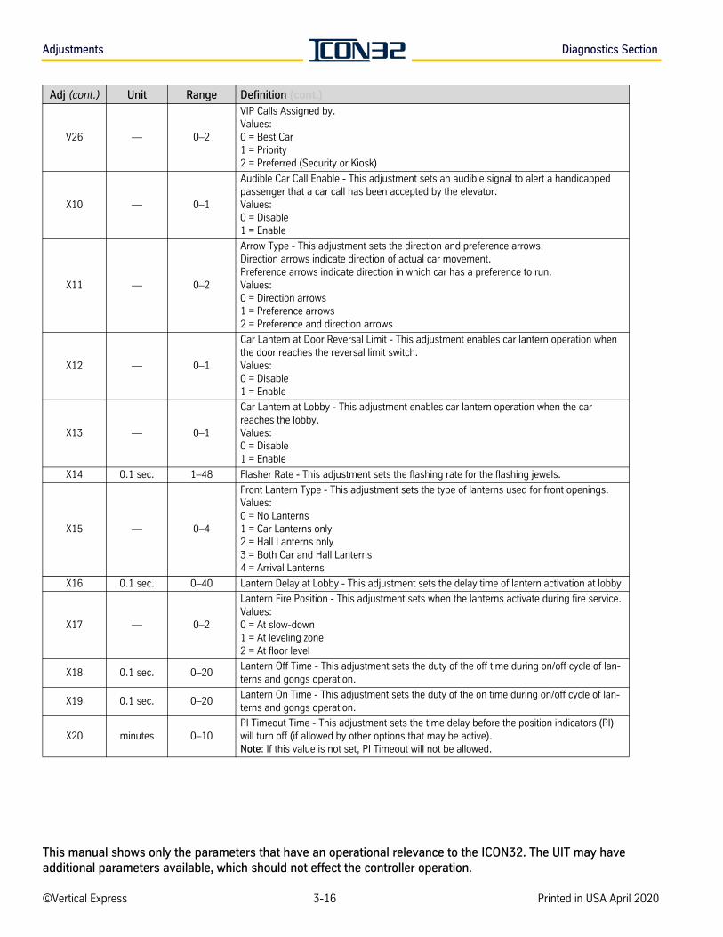
Adjustments Diagnostics Section
V26 — 0–2
VIP Calls Assigned by.Values:0 = Best Car 1 = Priority 2 = Preferred (Security or Kiosk)
X10 — 0–1
Audible Car Call Enable - This adjustment sets an audible signal to alert a handicapped passenger that a car call has been accepted by the elevator.Values:0 = Disable1 = Enable
X11 — 0–2
Arrow Type - This adjustment sets the direction and preference arrows. Direction arrows indicate direction of actual car movement. Preference arrows indicate direction in which car has a preference to run.Values:0 = Direction arrows1 = Preference arrows2 = Preference and direction arrows
X12 — 0–1
Car Lantern at Door Reversal Limit - This adjustment enables car lantern operation when the door reaches the reversal limit switch. Values:0 = Disable1 = Enable
X13 — 0–1
Car Lantern at Lobby - This adjustment enables car lantern operation when the car reaches the lobby.Values:0 = Disable1 = Enable
X14 0.1 sec. 1–48 Flasher Rate - This adjustment sets the flashing rate for the flashing jewels.
X15 — 0–4
Front Lantern Type - This adjustment sets the type of lanterns used for front openings.Values:0 = No Lanterns1 = Car Lanterns only2 = Hall Lanterns only3 = Both Car and Hall Lanterns4 = Arrival Lanterns
X16 0.1 sec. 0–40 Lantern Delay at Lobby - This adjustment sets the delay time of lantern activation at lobby.
X17 — 0–2
Lantern Fire Position - This adjustment sets when the lanterns activate during fire service.Values:0 = At slow-down1 = At leveling zone2 = At floor level
X18 0.1 sec. 0–20Lantern Off Time - This adjustment sets the duty of the off time during on/off cycle of lan-terns and gongs operation.
X19 0.1 sec. 0–20Lantern On Time - This adjustment sets the duty of the on time during on/off cycle of lan-terns and gongs operation.
X20 minutes 0–10PI Timeout Time - This adjustment sets the time delay before the position indicators (PI) will turn off (if allowed by other options that may be active). Note: If this value is not set, PI Timeout will not be allowed.
Adj (cont.) Unit Range Definition (cont.)
©Vertical Express 3-16 Printed in USA April 2020
This manual shows only the parameters that have an operational relevance to the ICON32. The UIT may have additional parameters available, which should not effect the controller operation.
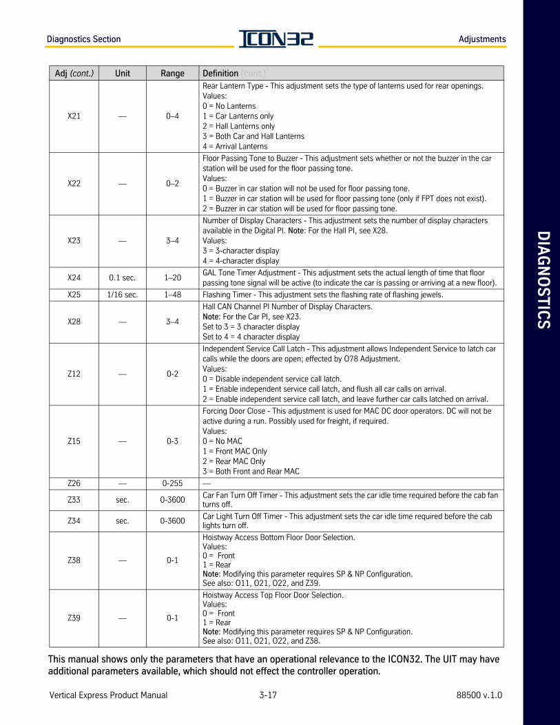
DIA
GN
OS
TIC
SDiagnostics Section Adjustments
X21 — 0–4
Rear Lantern Type - This adjustment sets the type of lanterns used for rear openings.Values:0 = No Lanterns1 = Car Lanterns only2 = Hall Lanterns only3 = Both Car and Hall Lanterns4 = Arrival Lanterns
X22 — 0–2
Floor Passing Tone to Buzzer - This adjustment sets whether or not the buzzer in the car station will be used for the floor passing tone.Values:0 = Buzzer in car station will not be used for floor passing tone.1 = Buzzer in car station will be used for floor passing tone (only if FPT does not exist).2 = Buzzer in car station will be used for floor passing tone.
X23 — 3–4
Number of Display Characters - This adjustment sets the number of display characters available in the Digital PI. Note: For the Hall PI, see X28.Values:3 = 3-character display4 = 4-character display
X24 0.1 sec. 1–20GAL Tone Timer Adjustment - This adjustment sets the actual length of time that floor passing tone signal will be active (to indicate the car is passing or arriving at a new floor).
X25 1/16 sec. 1–48 Flashing Timer - This adjustment sets the flashing rate of flashing jewels.
X28 — 3–4
Hall CAN Channel PI Number of Display Characters.Note: For the Car PI, see X23.Set to 3 = 3 character displaySet to 4 = 4 character display
Z12 — 0-2
Independent Service Call Latch - This adjustment allows Independent Service to latch car calls while the doors are open; effected by O78 Adjustment.Values:0 = Disable independent service call latch.1 = Enable independent service call latch, and flush all car calls on arrival.2 = Enable independent service call latch, and leave further car calls latched on arrival.
Z15 — 0-3
Forcing Door Close - This adjustment is used for MAC DC door operators. DC will not be active during a run. Possibly used for freight, if required.Values:0 = No MAC1 = Front MAC Only2 = Rear MAC Only3 = Both Front and Rear MAC
Z26 — 0-255 —
Z33 sec. 0-3600Car Fan Turn Off Timer - This adjustment sets the car idle time required before the cab fan turns off.
Z34 sec. 0-3600Car Light Turn Off Timer - This adjustment sets the car idle time required before the cab lights turn off.
Z38 — 0-1
Hoistway Access Bottom Floor Door Selection.Values:0 = Front1 = RearNote: Modifying this parameter requires SP & NP Configuration.See also: O11, O21, O22, and Z39.
Z39 — 0-1
Hoistway Access Top Floor Door Selection. Values:0 = Front 1 = RearNote: Modifying this parameter requires SP & NP Configuration.See also: O11, O21, O22, and Z38.
Adj (cont.) Unit Range Definition (cont.)
Vertical Express Product Manual 3-17 88500 v.1.0
This manual shows only the parameters that have an operational relevance to the ICON32. The UIT may have additional parameters available, which should not effect the controller operation.
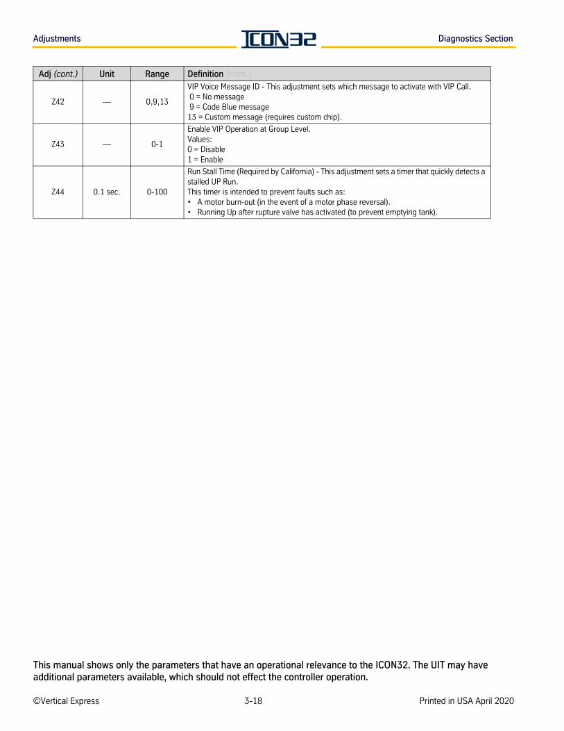
Adjustments Diagnostics Section
Z42 — 0,9,13
VIP Voice Message ID - This adjustment sets which message to activate with VIP Call. 0 = No message 9 = Code Blue message13 = Custom message (requires custom chip).
Z43 — 0-1
Enable VIP Operation at Group Level. Values:0 = Disable1 = Enable
Z44 0.1 sec. 0-100
Run Stall Time (Required by California) - This adjustment sets a timer that quickly detects a stalled UP Run. This timer is intended to prevent faults such as:• A motor burn-out (in the event of a motor phase reversal).• Running Up after rupture valve has activated (to prevent emptying tank).
Adj (cont.) Unit Range Definition (cont.)
©Vertical Express 3-18 Printed in USA April 2020
This manual shows only the parameters that have an operational relevance to the ICON32. The UIT may have additional parameters available, which should not effect the controller operation.

DIA
GN
OS
TIC
SDiagnostics Section Commands
Commands
Name Definition
CJR This command clears the jack resync statistics.
DCN
DCN Display CN stats and channel/port assignments where:Name = User friendly name of the node stored in the CPUOn = State of CAN communication (Online=1, Offline=0)RxTot = Total number of frames receivedID = CN address per CN jumpers JP(7,6,5,4)Ch = Physical channel (2=COP, 3=Hall)SP = Number of shared ports between cars (Remote I/O Box)TP = Number of total ports used by this CN
channel: Where 2=>Car, 3=>HallnumPorts: 0-15 defines the number of ports used by this CNport0 port1...port15: For each physical CN port used by this CN, list the associated port in I/O layout matching the IMS I/O screen column.
DSL Display Stabilized Leveling Distance.
ELDElevator Designator Display - This command displays the ASCII designator for this car. ELD shows the designa-tor displayed by Owner's IMS Group Dispatch Window. See also PIG.
FCP Floor Count Position Display Command - This command displays the encoder position count for each floor.
FJR Force Jack Resync - This command signals an immediate request for a jack resync operation.
GET
GET Parameters - This command retrieves the saved parameters from the EEPROM and moves them into RAM. • The CPU only works with parameter values that are stored in its RAM memory. • To display a parameter that caused an out of range error, type GET and press Enter. • To eliminate a parameter error, enter a value in the appropriate range, save with the WRT Command, and
recall with the GET Command.
GPN Display Group Node - This command displays which node the car is communicating to (for group functions).
IOView IOView - This command displays the I/O names by bit location.
IRLInconspicuous Riser Lockouts - This command displays front landings that are locked out by the Inconspicuous Riser Operation.
IRLRInconspicuous Riser Lockouts Rear - This command displays rear landings that are locked out by the Inconspic-uous Riser Operation.
JRT Jack Resync Time - This command sets the time of day that a jack resync will occur.
OSDM Operating System Diagnostics - This command displays information to be sent to the log file.
PIG Group Floor Display - This command changes the position indicator display for the group.
PRT
Pressure Relief Test - This command allows the car to run to the stop ring to perform a Pressure Relief Test.1. Place the car at the top landing.2. Put the car on Inspection Operation.3. Run the car onto the Top Directional Limit (DL).4. Issue the PRT Command. 5. Run the car UP on Inspection Operation past the DL.
SCAScan Call Assignment Table - This command reviews the scan assignment table of all floors that effect group (hall call) service.
SCCSet Car Call - This command sets the nth landing car call. For rear calls, see SRC.See also: SCCB, SCCT, SDC, SRC, SRD, SRU, and SUC.
SCFSet Close Floor - This command allows viewing and editing of the close floor table. Note: This automatically sets itself up during a hoistway scan. Close floor is 4–16 inches of travel between floors.
SCCB
Set Car Call Bottom - This command sets the bottom landing car call. To set, type SCCB and press Enter.• If the bottom landing has a front opening, the front car call will be set. • If the bottom landing does not have a front opening, the rear car call will be set.See also: SCC, SCCT, SDC, SRC, SRD, SRU, SUC
Vertical Express Product Manual 3-19 88500 v.1.0
This manual shows only the parameters that have an operational relevance to the ICON32. The UIT may have additional parameters available, which should not effect the controller operation.
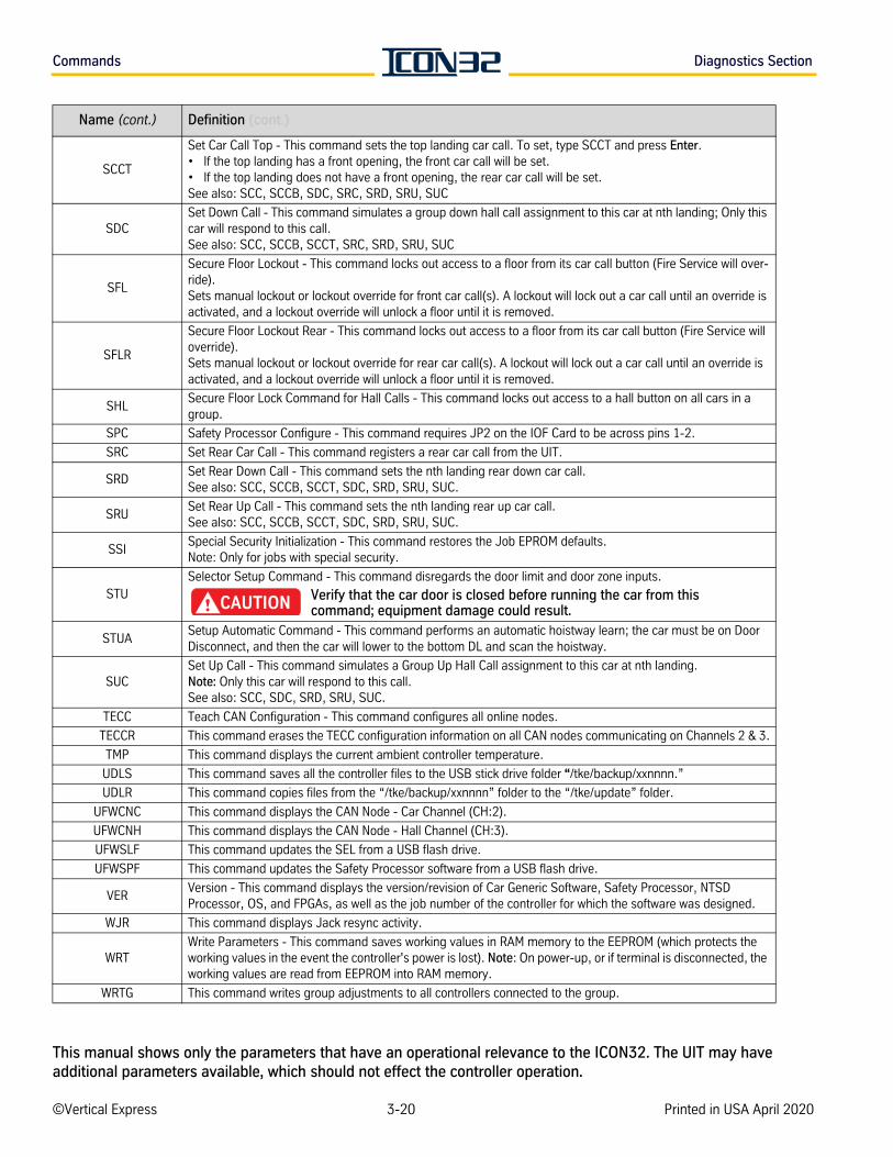
Commands Diagnostics Section
SCCT
Set Car Call Top - This command sets the top landing car call. To set, type SCCT and press Enter.• If the top landing has a front opening, the front car call will be set. • If the top landing does not have a front opening, the rear car call will be set.See also: SCC, SCCB, SDC, SRC, SRD, SRU, SUC
SDCSet Down Call - This command simulates a group down hall call assignment to this car at nth landing; Only this car will respond to this call.See also: SCC, SCCB, SCCT, SRC, SRD, SRU, SUC
SFL
Secure Floor Lockout - This command locks out access to a floor from its car call button (Fire Service will over-ride).Sets manual lockout or lockout override for front car call(s). A lockout will lock out a car call until an override is activated, and a lockout override will unlock a floor until it is removed.
SFLR
Secure Floor Lockout Rear - This command locks out access to a floor from its car call button (Fire Service will override).Sets manual lockout or lockout override for rear car call(s). A lockout will lock out a car call until an override is activated, and a lockout override will unlock a floor until it is removed.
SHLSecure Floor Lock Command for Hall Calls - This command locks out access to a hall button on all cars in a group.
SPC Safety Processor Configure - This command requires JP2 on the IOF Card to be across pins 1-2.
SRC Set Rear Car Call - This command registers a rear car call from the UIT.
SRDSet Rear Down Call - This command sets the nth landing rear down car call.See also: SCC, SCCB, SCCT, SDC, SRD, SRU, SUC.
SRUSet Rear Up Call - This command sets the nth landing rear up car call.See also: SCC, SCCB, SCCT, SDC, SRD, SRU, SUC.
SSISpecial Security Initialization - This command restores the Job EPROM defaults. Note: Only for jobs with special security.
STUSelector Setup Command - This command disregards the door limit and door zone inputs.
Verify that the car door is closed before running the car from this command; equipment damage could result.
STUASetup Automatic Command - This command performs an automatic hoistway learn; the car must be on Door Disconnect, and then the car will lower to the bottom DL and scan the hoistway.
SUCSet Up Call - This command simulates a Group Up Hall Call assignment to this car at nth landing. Note: Only this car will respond to this call.See also: SCC, SDC, SRD, SRU, SUC.
TECC Teach CAN Configuration - This command configures all online nodes.
TECCR This command erases the TECC configuration information on all CAN nodes communicating on Channels 2 & 3.
TMP This command displays the current ambient controller temperature.
UDLS This command saves all the controller files to the USB stick drive folder “/tke/backup/xxnnnn.”
UDLR This command copies files from the “/tke/backup/xxnnnn” folder to the “/tke/update” folder.
UFWCNC This command displays the CAN Node - Car Channel (CH:2).
UFWCNH This command displays the CAN Node - Hall Channel (CH:3).
UFWSLF This command updates the SEL from a USB flash drive.
UFWSPF This command updates the Safety Processor software from a USB flash drive.
VERVersion - This command displays the version/revision of Car Generic Software, Safety Processor, NTSD Processor, OS, and FPGAs, as well as the job number of the controller for which the software was designed.
WJR This command displays Jack resync activity.
WRTWrite Parameters - This command saves working values in RAM memory to the EEPROM (which protects the working values in the event the controller's power is lost). Note: On power-up, or if terminal is disconnected, the working values are read from EEPROM into RAM memory.
WRTG This command writes group adjustments to all controllers connected to the group.
Name (cont.) Definition (cont.)
©Vertical Express 3-20 Printed in USA April 2020
This manual shows only the parameters that have an operational relevance to the ICON32. The UIT may have additional parameters available, which should not effect the controller operation.
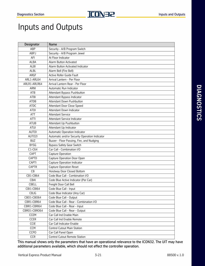
DIA
GN
OS
TIC
SDiagnostics Section Inputs and Outputs
Inputs and Outputs
Designator NameABP Security - A/B Program Switch
ABPJ Security - A/B Program Jewel
AFI At Floor Indicator
ALBA Alarm Button Activated
ALBI Alarm Button Activated Indicator
ALBL Alarm Bell (Fire Bell)
ARGF Active Roller Guide Fault
ARL1-ARL64 Arrival Lantern - Per Floor
ARLR1-ARLR64 Arrival Lantern Rear - Per Floor
ARNI Automatic Run Indicator
ATB Attendant Bypass Pushbutton
ATBI Attendant Bypass Indicator
ATDB Attendant Down Pushbutton
ATDC Attendant Door Close Speed
ATDI Attendant Down Indicator
ATT Attendant Service
ATTI Attendant Service Indicator
ATUB Attendant Up Pushbutton
ATUI Attendant Up Indicator
AUTOI Automatic Operation Indicator
AUTO2I Automatic and/or Security Operation Indicator
BUZ Buzzer - Floor Passing, Fire, and Nudging
BYSG Bypass Safety Gear Switch
C1-C64 Car Call - Combination I/O
CAPT Capture Operation
CAPTD Capture Operation Door Open
CAPTI Capture Operation Indicator
CAPTR Capture Operation Reset
CB Hoistway Door Closed Bottom
CB1-CB64 Code Blue Call - Combination I/O
CBAI Code Blue Active Indicator (Per Car)
CBELL Freight Door Call Bell
CBI1-CBI64 Code Blue Call - Input
CBJG Code Blue Indicator (Any Car)
CBO1-CBO64 Code Blue Call - Output
CBR1-CBR64 Code Blue Call - Rear - Combination I/O
CBRI1-CBRI64 Code Blue Call - Rear - Input
CBRO1-CBRO64 Code Blue Call - Rear - Output
CCEM Car Call Ind Enable Main
CCER Car Call Ind Enable Remote
CCIE Car Call Indicator Enable
CCM Control Cutout Main Station
CCPO Car Call Panel Open
CCR Control Cutout Remote Station
Vertical Express Product Manual 3-21 88500 v.1.0
This manual shows only the parameters that have an operational relevance to the ICON32. The UIT may have additional parameters available, which should not effect the controller operation.
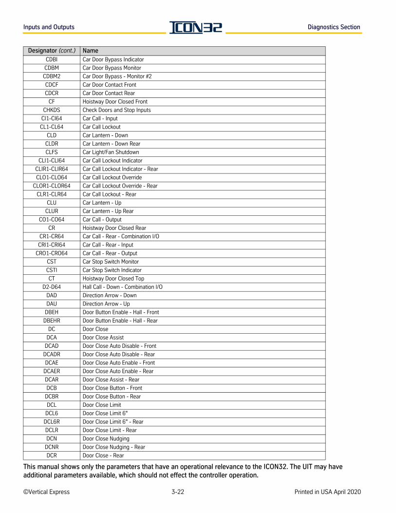
Inputs and Outputs Diagnostics Section
CDBI Car Door Bypass Indicator
CDBM Car Door Bypass Monitor
CDBM2 Car Door Bypass - Monitor #2
CDCF Car Door Contact Front
CDCR Car Door Contact Rear
CF Hoistway Door Closed Front
CHKDS Check Doors and Stop Inputs
CI1-CI64 Car Call - Input
CL1-CL64 Car Call Lockout
CLD Car Lantern - Down
CLDR Car Lantern - Down Rear
CLFS Car Light/Fan Shutdown
CLI1-CLI64 Car Call Lockout Indicator
CLIR1-CLIR64 Car Call Lockout Indicator - Rear
CLO1-CLO64 Car Call Lockout Override
CLOR1-CLOR64 Car Call Lockout Override - Rear
CLR1-CLR64 Car Call Lockout - Rear
CLU Car Lantern - Up
CLUR Car Lantern - Up Rear
CO1-CO64 Car Call - Output
CR Hoistway Door Closed Rear
CR1-CR64 Car Call - Rear - Combination I/O
CRI1-CRI64 Car Call - Rear - Input
CRO1-CRO64 Car Call - Rear - Output
CST Car Stop Switch Monitor
CSTI Car Stop Switch Indicator
CT Hoistway Door Closed Top
D2-D64 Hall Call - Down - Combination I/O
DAD Direction Arrow - Down
DAU Direction Arrow - Up
DBEH Door Button Enable - Hall - Front
DBEHR Door Button Enable - Hall - Rear
DC Door Close
DCA Door Close Assist
DCAD Door Close Auto Disable - Front
DCADR Door Close Auto Disable - Rear
DCAE Door Close Auto Enable - Front
DCAER Door Close Auto Enable - Rear
DCAR Door Close Assist - Rear
DCB Door Close Button - Front
DCBR Door Close Button - Rear
DCL Door Close Limit
DCL6 Door Close Limit 6"
DCL6R Door Close Limit 6" - Rear
DCLR Door Close Limit - Rear
DCN Door Close Nudging
DCNR Door Close Nudging - Rear
DCR Door Close - Rear
Designator (cont.) Name
©Vertical Express 3-22 Printed in USA April 2020
This manual shows only the parameters that have an operational relevance to the ICON32. The UIT may have additional parameters available, which should not effect the controller operation.
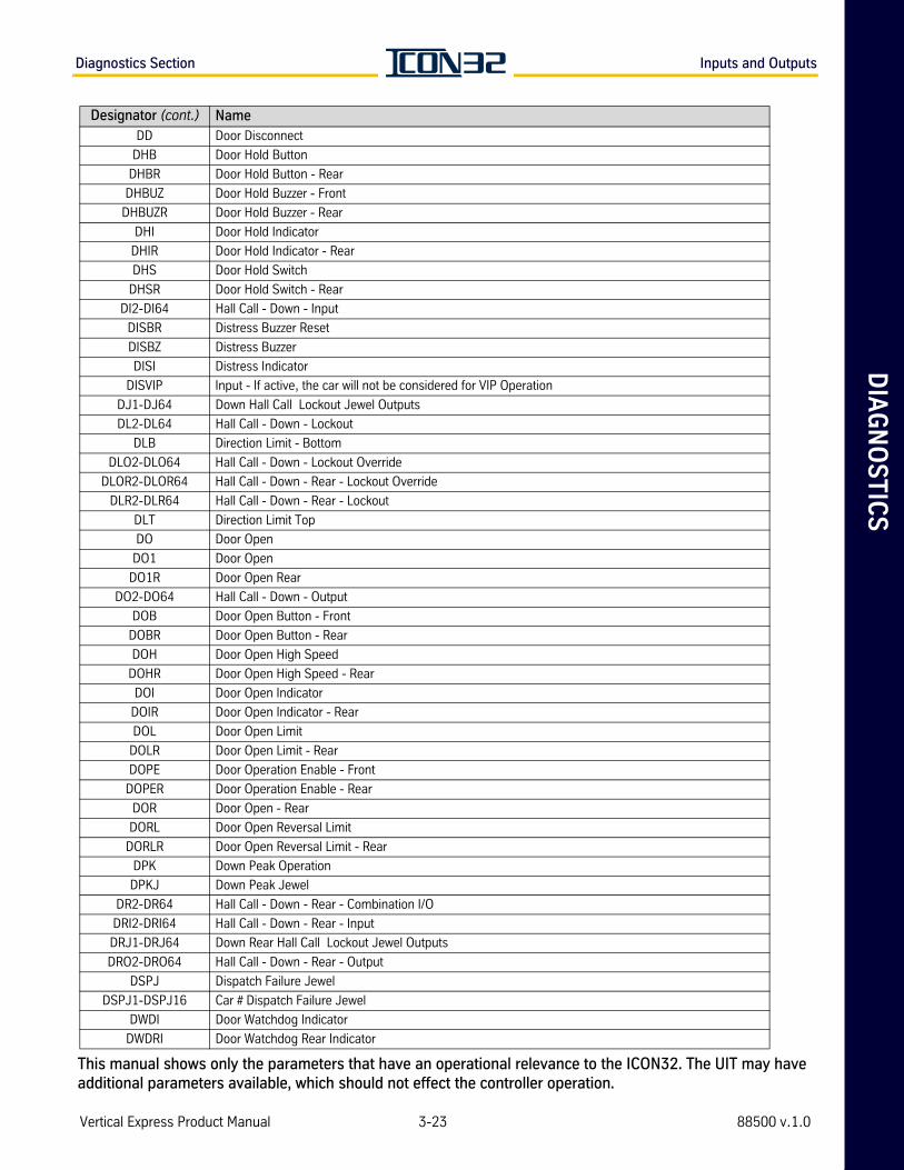
DIA
GN
OS
TIC
SDiagnostics Section Inputs and Outputs
DD Door Disconnect
DHB Door Hold Button
DHBR Door Hold Button - Rear
DHBUZ Door Hold Buzzer - Front
DHBUZR Door Hold Buzzer - Rear
DHI Door Hold Indicator
DHIR Door Hold Indicator - Rear
DHS Door Hold Switch
DHSR Door Hold Switch - Rear
DI2-DI64 Hall Call - Down - Input
DISBR Distress Buzzer Reset
DISBZ Distress Buzzer
DISI Distress Indicator
DISVIP Input - If active, the car will not be considered for VIP Operation
DJ1-DJ64 Down Hall Call Lockout Jewel Outputs
DL2-DL64 Hall Call - Down - Lockout
DLB Direction Limit - Bottom
DLO2-DLO64 Hall Call - Down - Lockout Override
DLOR2-DLOR64 Hall Call - Down - Rear - Lockout Override
DLR2-DLR64 Hall Call - Down - Rear - Lockout
DLT Direction Limit Top
DO Door Open
DO1 Door Open
DO1R Door Open Rear
DO2-DO64 Hall Call - Down - Output
DOB Door Open Button - Front
DOBR Door Open Button - Rear
DOH Door Open High Speed
DOHR Door Open High Speed - Rear
DOI Door Open Indicator
DOIR Door Open Indicator - Rear
DOL Door Open Limit
DOLR Door Open Limit - Rear
DOPE Door Operation Enable - Front
DOPER Door Operation Enable - Rear
DOR Door Open - Rear
DORL Door Open Reversal Limit
DORLR Door Open Reversal Limit - Rear
DPK Down Peak Operation
DPKJ Down Peak Jewel
DR2-DR64 Hall Call - Down - Rear - Combination I/O
DRI2-DRI64 Hall Call - Down - Rear - Input
DRJ1-DRJ64 Down Rear Hall Call Lockout Jewel Outputs
DRO2-DRO64 Hall Call - Down - Rear - Output
DSPJ Dispatch Failure Jewel
DSPJ1-DSPJ16 Car # Dispatch Failure Jewel
DWDI Door Watchdog Indicator
DWDRI Door Watchdog Rear Indicator
Designator (cont.) Name
Vertical Express Product Manual 3-23 88500 v.1.0
This manual shows only the parameters that have an operational relevance to the ICON32. The UIT may have additional parameters available, which should not effect the controller operation.
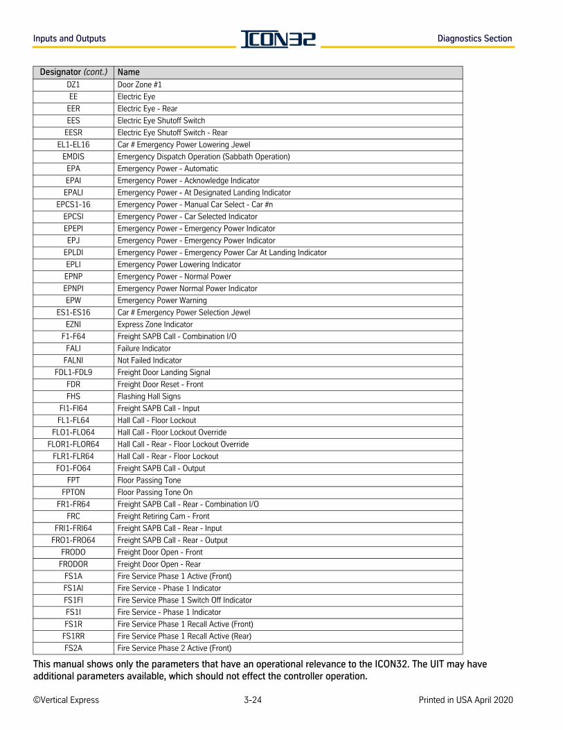
Inputs and Outputs Diagnostics Section
DZ1 Door Zone #1
EE Electric Eye
EER Electric Eye - Rear
EES Electric Eye Shutoff Switch
EESR Electric Eye Shutoff Switch - Rear
EL1-EL16 Car # Emergency Power Lowering Jewel
EMDIS Emergency Dispatch Operation (Sabbath Operation)
EPA Emergency Power - Automatic
EPAI Emergency Power - Acknowledge Indicator
EPALI Emergency Power - At Designated Landing Indicator
EPCS1-16 Emergency Power - Manual Car Select - Car #n
EPCSI Emergency Power - Car Selected Indicator
EPEPI Emergency Power - Emergency Power Indicator
EPJ Emergency Power - Emergency Power Indicator
EPLDI Emergency Power - Emergency Power Car At Landing Indicator
EPLI Emergency Power Lowering Indicator
EPNP Emergency Power - Normal Power
EPNPI Emergency Power Normal Power Indicator
EPW Emergency Power Warning
ES1-ES16 Car # Emergency Power Selection Jewel
EZNI Express Zone Indicator
F1-F64 Freight SAPB Call - Combination I/O
FALI Failure Indicator
FALNI Not Failed Indicator
FDL1-FDL9 Freight Door Landing Signal
FDR Freight Door Reset - Front
FHS Flashing Hall Signs
FI1-FI64 Freight SAPB Call - Input
FL1-FL64 Hall Call - Floor Lockout
FLO1-FLO64 Hall Call - Floor Lockout Override
FLOR1-FLOR64 Hall Call - Rear - Floor Lockout Override
FLR1-FLR64 Hall Call - Rear - Floor Lockout
FO1-FO64 Freight SAPB Call - Output
FPT Floor Passing Tone
FPTON Floor Passing Tone On
FR1-FR64 Freight SAPB Call - Rear - Combination I/O
FRC Freight Retiring Cam - Front
FRI1-FRI64 Freight SAPB Call - Rear - Input
FRO1-FRO64 Freight SAPB Call - Rear - Output
FRODO Freight Door Open - Front
FRODOR Freight Door Open - Rear
FS1A Fire Service Phase 1 Active (Front)
FS1AI Fire Service - Phase 1 Indicator
FS1FI Fire Service Phase 1 Switch Off Indicator
FS1I Fire Service - Phase 1 Indicator
FS1R Fire Service Phase 1 Recall Active (Front)
FS1RR Fire Service Phase 1 Recall Active (Rear)
FS2A Fire Service Phase 2 Active (Front)
Designator (cont.) Name
©Vertical Express 3-24 Printed in USA April 2020
This manual shows only the parameters that have an operational relevance to the ICON32. The UIT may have additional parameters available, which should not effect the controller operation.
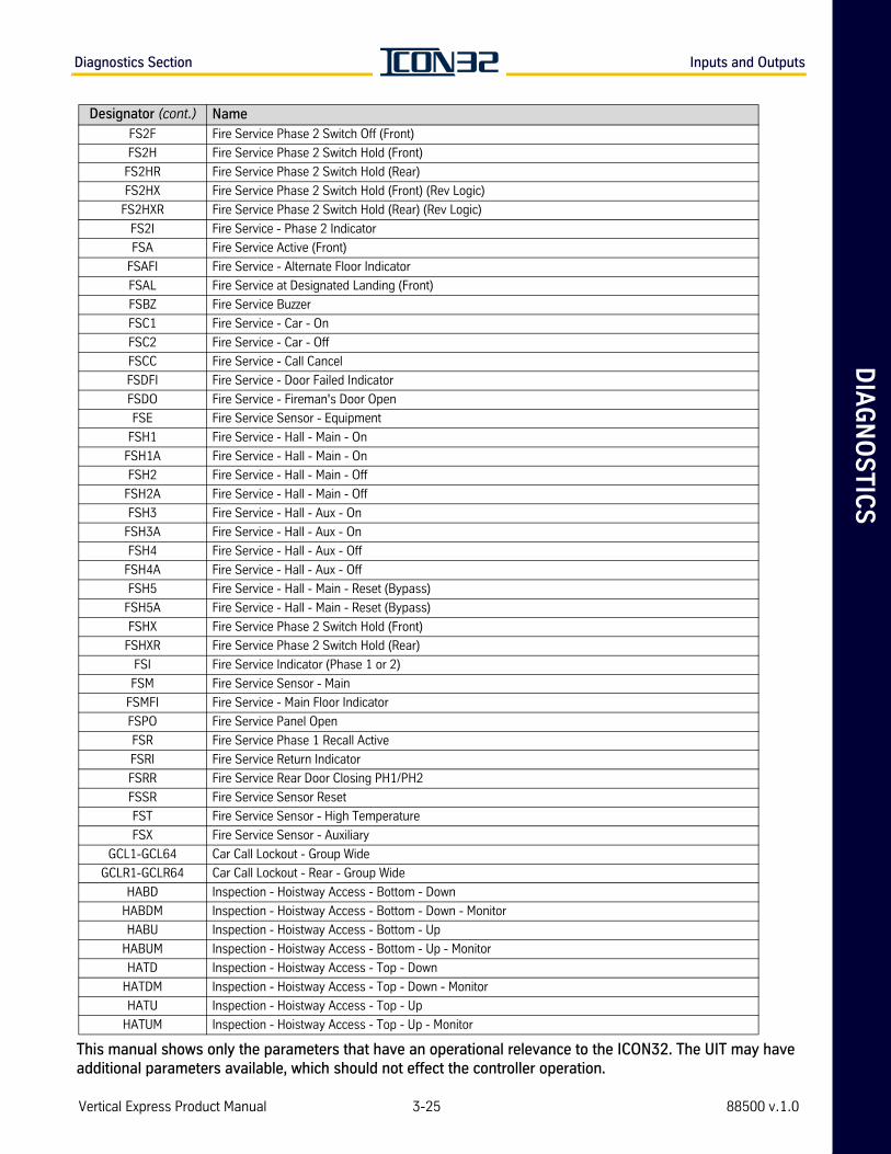
DIA
GN
OS
TIC
SDiagnostics Section Inputs and Outputs
FS2F Fire Service Phase 2 Switch Off (Front)
FS2H Fire Service Phase 2 Switch Hold (Front)
FS2HR Fire Service Phase 2 Switch Hold (Rear)
FS2HX Fire Service Phase 2 Switch Hold (Front) (Rev Logic)
FS2HXR Fire Service Phase 2 Switch Hold (Rear) (Rev Logic)
FS2I Fire Service - Phase 2 Indicator
FSA Fire Service Active (Front)
FSAFI Fire Service - Alternate Floor Indicator
FSAL Fire Service at Designated Landing (Front)
FSBZ Fire Service Buzzer
FSC1 Fire Service - Car - On
FSC2 Fire Service - Car - Off
FSCC Fire Service - Call Cancel
FSDFI Fire Service - Door Failed Indicator
FSDO Fire Service - Fireman's Door Open
FSE Fire Service Sensor - Equipment
FSH1 Fire Service - Hall - Main - On
FSH1A Fire Service - Hall - Main - On
FSH2 Fire Service - Hall - Main - Off
FSH2A Fire Service - Hall - Main - Off
FSH3 Fire Service - Hall - Aux - On
FSH3A Fire Service - Hall - Aux - On
FSH4 Fire Service - Hall - Aux - Off
FSH4A Fire Service - Hall - Aux - Off
FSH5 Fire Service - Hall - Main - Reset (Bypass)
FSH5A Fire Service - Hall - Main - Reset (Bypass)
FSHX Fire Service Phase 2 Switch Hold (Front)
FSHXR Fire Service Phase 2 Switch Hold (Rear)
FSI Fire Service Indicator (Phase 1 or 2)
FSM Fire Service Sensor - Main
FSMFI Fire Service - Main Floor Indicator
FSPO Fire Service Panel Open
FSR Fire Service Phase 1 Recall Active
FSRI Fire Service Return Indicator
FSRR Fire Service Rear Door Closing PH1/PH2
FSSR Fire Service Sensor Reset
FST Fire Service Sensor - High Temperature
FSX Fire Service Sensor - Auxiliary
GCL1-GCL64 Car Call Lockout - Group Wide
GCLR1-GCLR64 Car Call Lockout - Rear - Group Wide
HABD Inspection - Hoistway Access - Bottom - Down
HABDM Inspection - Hoistway Access - Bottom - Down - Monitor
HABU Inspection - Hoistway Access - Bottom - Up
HABUM Inspection - Hoistway Access - Bottom - Up - Monitor
HATD Inspection - Hoistway Access - Top - Down
HATDM Inspection - Hoistway Access - Top - Down - Monitor
HATU Inspection - Hoistway Access - Top - Up
HATUM Inspection - Hoistway Access - Top - Up - Monitor
Designator (cont.) Name
Vertical Express Product Manual 3-25 88500 v.1.0
This manual shows only the parameters that have an operational relevance to the ICON32. The UIT may have additional parameters available, which should not effect the controller operation.
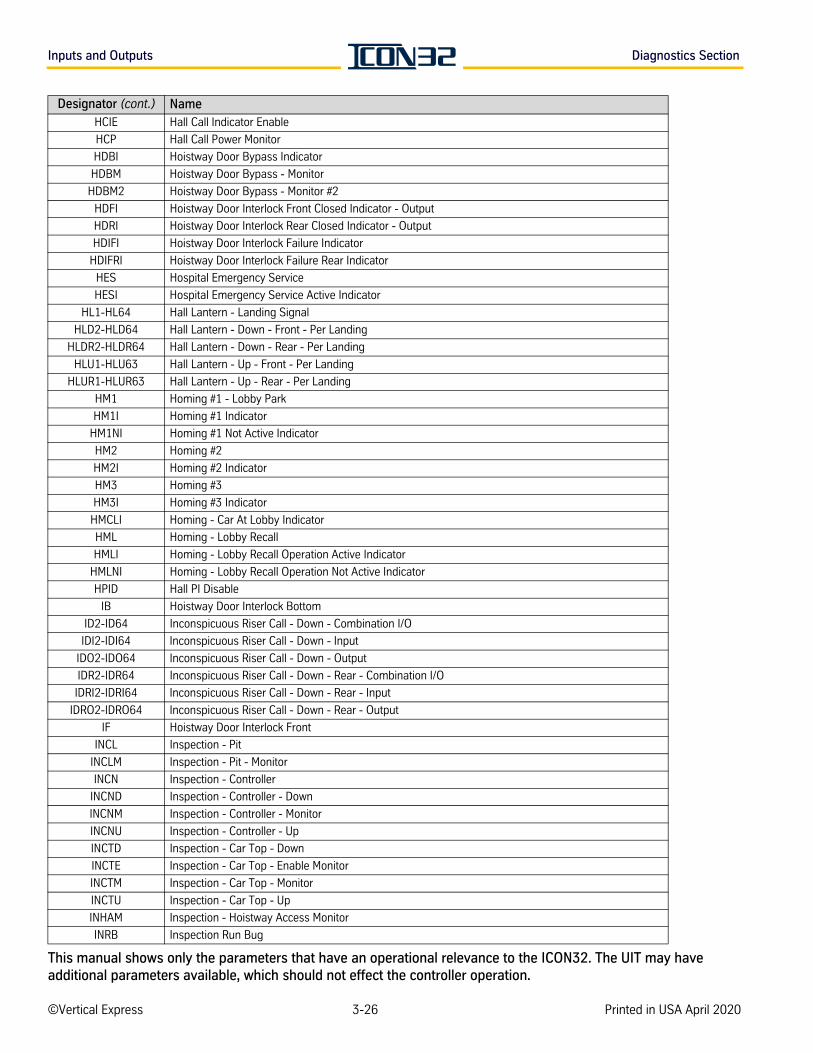
Inputs and Outputs Diagnostics Section
HCIE Hall Call Indicator Enable
HCP Hall Call Power Monitor
HDBI Hoistway Door Bypass Indicator
HDBM Hoistway Door Bypass - Monitor
HDBM2 Hoistway Door Bypass - Monitor #2
HDFI Hoistway Door Interlock Front Closed Indicator - Output
HDRI Hoistway Door Interlock Rear Closed Indicator - Output
HDIFI Hoistway Door Interlock Failure Indicator
HDIFRI Hoistway Door Interlock Failure Rear Indicator
HES Hospital Emergency Service
HESI Hospital Emergency Service Active Indicator
HL1-HL64 Hall Lantern - Landing Signal
HLD2-HLD64 Hall Lantern - Down - Front - Per Landing
HLDR2-HLDR64 Hall Lantern - Down - Rear - Per Landing
HLU1-HLU63 Hall Lantern - Up - Front - Per Landing
HLUR1-HLUR63 Hall Lantern - Up - Rear - Per Landing
HM1 Homing #1 - Lobby Park
HM1I Homing #1 Indicator
HM1NI Homing #1 Not Active Indicator
HM2 Homing #2
HM2I Homing #2 Indicator
HM3 Homing #3
HM3I Homing #3 Indicator
HMCLI Homing - Car At Lobby Indicator
HML Homing - Lobby Recall
HMLI Homing - Lobby Recall Operation Active Indicator
HMLNI Homing - Lobby Recall Operation Not Active Indicator
HPID Hall PI Disable
IB Hoistway Door Interlock Bottom
ID2-ID64 Inconspicuous Riser Call - Down - Combination I/O
IDI2-IDI64 Inconspicuous Riser Call - Down - Input
IDO2-IDO64 Inconspicuous Riser Call - Down - Output
IDR2-IDR64 Inconspicuous Riser Call - Down - Rear - Combination I/O
IDRI2-IDRI64 Inconspicuous Riser Call - Down - Rear - Input
IDRO2-IDRO64 Inconspicuous Riser Call - Down - Rear - Output
IF Hoistway Door Interlock Front
INCL Inspection - Pit
INCLM Inspection - Pit - Monitor
INCN Inspection - Controller
INCND Inspection - Controller - Down
INCNM Inspection - Controller - Monitor
INCNU Inspection - Controller - Up
INCTD Inspection - Car Top - Down
INCTE Inspection - Car Top - Enable Monitor
INCTM Inspection - Car Top - Monitor
INCTU Inspection - Car Top - Up
INHAM Inspection - Hoistway Access Monitor
INRB Inspection Run Bug
Designator (cont.) Name
©Vertical Express 3-26 Printed in USA April 2020
This manual shows only the parameters that have an operational relevance to the ICON32. The UIT may have additional parameters available, which should not effect the controller operation.
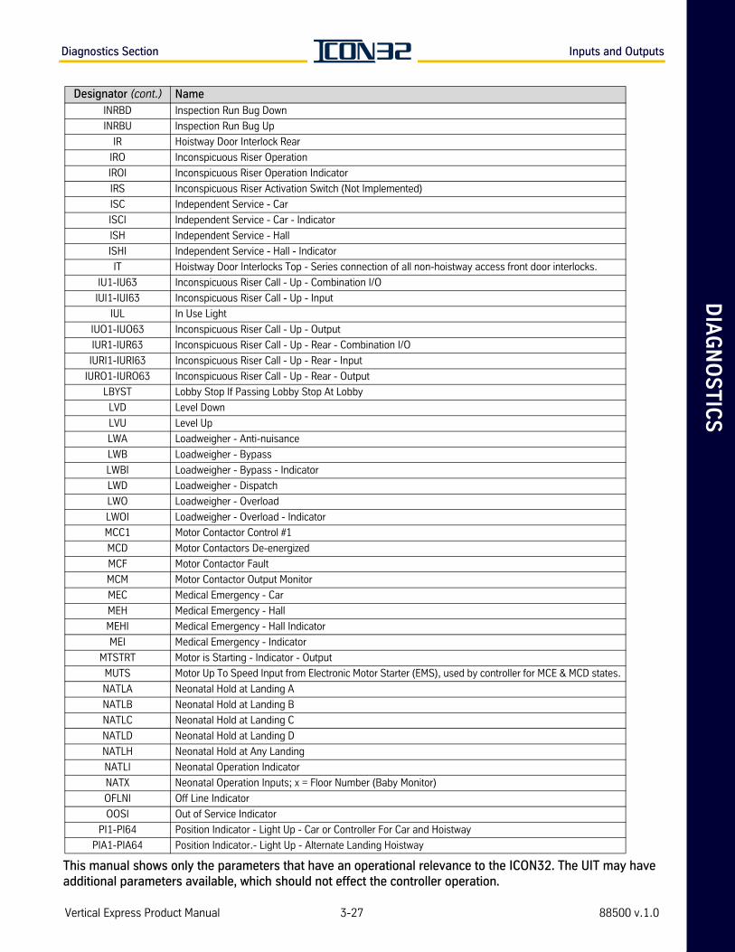
DIA
GN
OS
TIC
SDiagnostics Section Inputs and Outputs
INRBD Inspection Run Bug Down
INRBU Inspection Run Bug Up
IR Hoistway Door Interlock Rear
IRO Inconspicuous Riser Operation
IROI Inconspicuous Riser Operation Indicator
IRS Inconspicuous Riser Activation Switch (Not Implemented)
ISC Independent Service - Car
ISCI Independent Service - Car - Indicator
ISH Independent Service - Hall
ISHI Independent Service - Hall - Indicator
IT Hoistway Door Interlocks Top - Series connection of all non-hoistway access front door interlocks.
IU1-IU63 Inconspicuous Riser Call - Up - Combination I/O
IUI1-IUI63 Inconspicuous Riser Call - Up - Input
IUL In Use Light
IUO1-IUO63 Inconspicuous Riser Call - Up - Output
IUR1-IUR63 Inconspicuous Riser Call - Up - Rear - Combination I/O
IURI1-IURI63 Inconspicuous Riser Call - Up - Rear - Input
IURO1-IURO63 Inconspicuous Riser Call - Up - Rear - Output
LBYST Lobby Stop If Passing Lobby Stop At Lobby
LVD Level Down
LVU Level Up
LWA Loadweigher - Anti-nuisance
LWB Loadweigher - Bypass
LWBI Loadweigher - Bypass - Indicator
LWD Loadweigher - Dispatch
LWO Loadweigher - Overload
LWOI Loadweigher - Overload - Indicator
MCC1 Motor Contactor Control #1
MCD Motor Contactors De-energized
MCF Motor Contactor Fault
MCM Motor Contactor Output Monitor
MEC Medical Emergency - Car
MEH Medical Emergency - Hall
MEHI Medical Emergency - Hall Indicator
MEI Medical Emergency - Indicator
MTSTRT Motor is Starting - Indicator - Output
MUTS Motor Up To Speed Input from Electronic Motor Starter (EMS), used by controller for MCE & MCD states.
NATLA Neonatal Hold at Landing A
NATLB Neonatal Hold at Landing B
NATLC Neonatal Hold at Landing C
NATLD Neonatal Hold at Landing D
NATLH Neonatal Hold at Any Landing
NATLI Neonatal Operation Indicator
NATX Neonatal Operation Inputs; x = Floor Number (Baby Monitor)
OFLNI Off Line Indicator
OOSI Out of Service Indicator
PI1-PI64 Position Indicator - Light Up - Car or Controller For Car and Hoistway
PIA1-PIA64 Position Indicator.- Light Up - Alternate Landing Hoistway
Designator (cont.) Name
Vertical Express Product Manual 3-27 88500 v.1.0
This manual shows only the parameters that have an operational relevance to the ICON32. The UIT may have additional parameters available, which should not effect the controller operation.
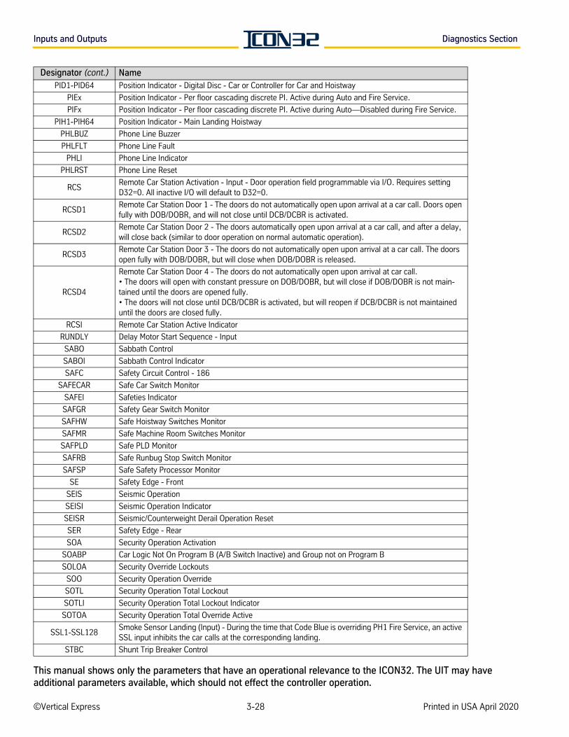
Inputs and Outputs Diagnostics Section
PID1-PID64 Position Indicator - Digital Disc - Car or Controller for Car and Hoistway
PIEx Position Indicator - Per floor cascading discrete PI. Active during Auto and Fire Service.
PIFx Position Indicator - Per floor cascading discrete PI. Active during Auto—Disabled during Fire Service.
PIH1-PIH64 Position Indicator - Main Landing Hoistway
PHLBUZ Phone Line Buzzer
PHLFLT Phone Line Fault
PHLI Phone Line Indicator
PHLRST Phone Line Reset
RCSRemote Car Station Activation - Input - Door operation field programmable via I/O. Requires setting D32=0. All inactive I/O will default to D32=0.
RCSD1Remote Car Station Door 1 - The doors do not automatically open upon arrival at a car call. Doors open fully with DOB/DOBR, and will not close until DCB/DCBR is activated.
RCSD2Remote Car Station Door 2 - The doors automatically open upon arrival at a car call, and after a delay, will close back (similar to door operation on normal automatic operation).
RCSD3Remote Car Station Door 3 - The doors do not automatically open upon arrival at a car call. The doors open fully with DOB/DOBR, but will close when DOB/DOBR is released.
RCSD4
Remote Car Station Door 4 - The doors do not automatically open upon arrival at car call.• The doors will open with constant pressure on DOB/DOBR, but will close if DOB/DOBR is not main-tained until the doors are opened fully.• The doors will not close until DCB/DCBR is activated, but will reopen if DCB/DCBR is not maintained until the doors are closed fully.
RCSI Remote Car Station Active Indicator
RUNDLY Delay Motor Start Sequence - Input
SABO Sabbath Control
SABOI Sabbath Control Indicator
SAFC Safety Circuit Control - 186
SAFECAR Safe Car Switch Monitor
SAFEI Safeties Indicator
SAFGR Safety Gear Switch Monitor
SAFHW Safe Hoistway Switches Monitor
SAFMR Safe Machine Room Switches Monitor
SAFPLD Safe PLD Monitor
SAFRB Safe Runbug Stop Switch Monitor
SAFSP Safe Safety Processor Monitor
SE Safety Edge - Front
SEIS Seismic Operation
SEISI Seismic Operation Indicator
SEISR Seismic/Counterweight Derail Operation Reset
SER Safety Edge - Rear
SOA Security Operation Activation
SOABP Car Logic Not On Program B (A/B Switch Inactive) and Group not on Program B
SOLOA Security Override Lockouts
SOO Security Operation Override
SOTL Security Operation Total Lockout
SOTLI Security Operation Total Lockout Indicator
SOTOA Security Operation Total Override Active
SSL1-SSL128Smoke Sensor Landing (Input) - During the time that Code Blue is overriding PH1 Fire Service, an active SSL input inhibits the car calls at the corresponding landing.
STBC Shunt Trip Breaker Control
Designator (cont.) Name
©Vertical Express 3-28 Printed in USA April 2020
This manual shows only the parameters that have an operational relevance to the ICON32. The UIT may have additional parameters available, which should not effect the controller operation.
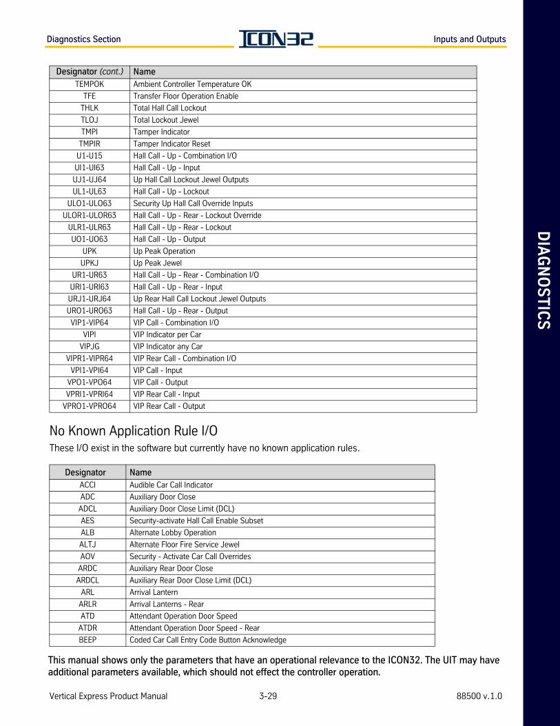
DIA
GN
OS
TIC
SDiagnostics Section Inputs and Outputs
No Known Application Rule I/OThese I/O exist in the software but currently have no known application rules.
TEMPOK Ambient Controller Temperature OK
TFE Transfer Floor Operation Enable
THLK Total Hall Call Lockout
TLOJ Total Lockout Jewel
TMPI Tamper Indicator
TMPIR Tamper Indicator Reset
U1-U15 Hall Call - Up - Combination I/O
UI1-UI63 Hall Call - Up - Input
UJ1-UJ64 Up Hall Call Lockout Jewel Outputs
UL1-UL63 Hall Call - Up - Lockout
ULO1-ULO63 Security Up Hall Call Override Inputs
ULOR1-ULOR63 Hall Call - Up - Rear - Lockout Override
ULR1-ULR63 Hall Call - Up - Rear - Lockout
UO1-UO63 Hall Call - Up - Output
UPK Up Peak Operation
UPKJ Up Peak Jewel
UR1-UR63 Hall Call - Up - Rear - Combination I/O
URI1-URI63 Hall Call - Up - Rear - Input
URJ1-URJ64 Up Rear Hall Call Lockout Jewel Outputs
URO1-URO63 Hall Call - Up - Rear - Output
VIP1-VIP64 VIP Call - Combination I/O
VIPI VIP Indicator per Car
VIPJG VIP Indicator any Car
VIPR1-VIPR64 VIP Rear Call - Combination I/O
VPI1-VPI64 VIP Call - Input
VPO1-VPO64 VIP Call - Output
VPRI1-VPRI64 VIP Rear Call - Input
VPRO1-VPRO64 VIP Rear Call - Output
Designator NameACCI Audible Car Call Indicator
ADC Auxiliary Door Close
ADCL Auxiliary Door Close Limit (DCL)
AES Security-activate Hall Call Enable Subset
ALB Alternate Lobby Operation
ALTJ Alternate Floor Fire Service Jewel
AOV Security - Activate Car Call Overrides
ARDC Auxiliary Rear Door Close
ARDCL Auxiliary Rear Door Close Limit (DCL)
ARL Arrival Lantern
ARLR Arrival Lanterns - Rear
ATD Attendant Operation Door Speed
ATDR Attendant Operation Door Speed - Rear
BEEP Coded Car Call Entry Code Button Acknowledge
Designator (cont.) Name
Vertical Express Product Manual 3-29 88500 v.1.0
This manual shows only the parameters that have an operational relevance to the ICON32. The UIT may have additional parameters available, which should not effect the controller operation.
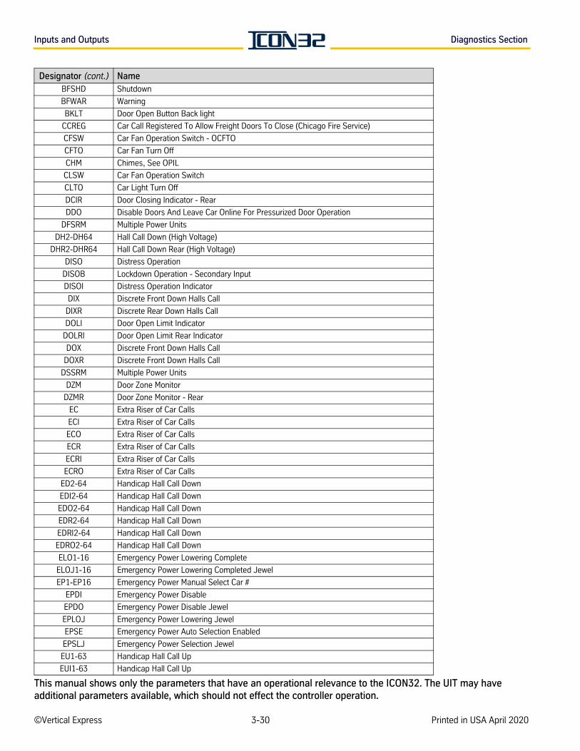
Inputs and Outputs Diagnostics Section
BFSHD Shutdown
BFWAR Warning
BKLT Door Open Button Back light
CCREG Car Call Registered To Allow Freight Doors To Close (Chicago Fire Service)
CFSW Car Fan Operation Switch - OCFTO
CFTO Car Fan Turn Off
CHM Chimes, See OPIL
CLSW Car Fan Operation Switch
CLTO Car Light Turn Off
DCIR Door Closing Indicator - Rear
DDO Disable Doors And Leave Car Online For Pressurized Door Operation
DFSRM Multiple Power Units
DH2-DH64 Hall Call Down (High Voltage)
DHR2-DHR64 Hall Call Down Rear (High Voltage)
DISO Distress Operation
DISOB Lockdown Operation - Secondary Input
DISOI Distress Operation Indicator
DIX Discrete Front Down Halls Call
DIXR Discrete Rear Down Halls Call
DOLI Door Open Limit Indicator
DOLRI Door Open Limit Rear Indicator
DOX Discrete Front Down Halls Call
DOXR Discrete Front Down Halls Call
DSSRM Multiple Power Units
DZM Door Zone Monitor
DZMR Door Zone Monitor - Rear
EC Extra Riser of Car Calls
ECI Extra Riser of Car Calls
ECO Extra Riser of Car Calls
ECR Extra Riser of Car Calls
ECRI Extra Riser of Car Calls
ECRO Extra Riser of Car Calls
ED2-64 Handicap Hall Call Down
EDI2-64 Handicap Hall Call Down
EDO2-64 Handicap Hall Call Down
EDR2-64 Handicap Hall Call Down
EDRI2-64 Handicap Hall Call Down
EDRO2-64 Handicap Hall Call Down
ELO1-16 Emergency Power Lowering Complete
ELOJ1-16 Emergency Power Lowering Completed Jewel
EP1-EP16 Emergency Power Manual Select Car #
EPDI Emergency Power Disable
EPDO Emergency Power Disable Jewel
EPLOJ Emergency Power Lowering Jewel
EPSE Emergency Power Auto Selection Enabled
EPSLJ Emergency Power Selection Jewel
EU1-63 Handicap Hall Call Up
EUI1-63 Handicap Hall Call Up
Designator (cont.) Name
©Vertical Express 3-30 Printed in USA April 2020
This manual shows only the parameters that have an operational relevance to the ICON32. The UIT may have additional parameters available, which should not effect the controller operation.
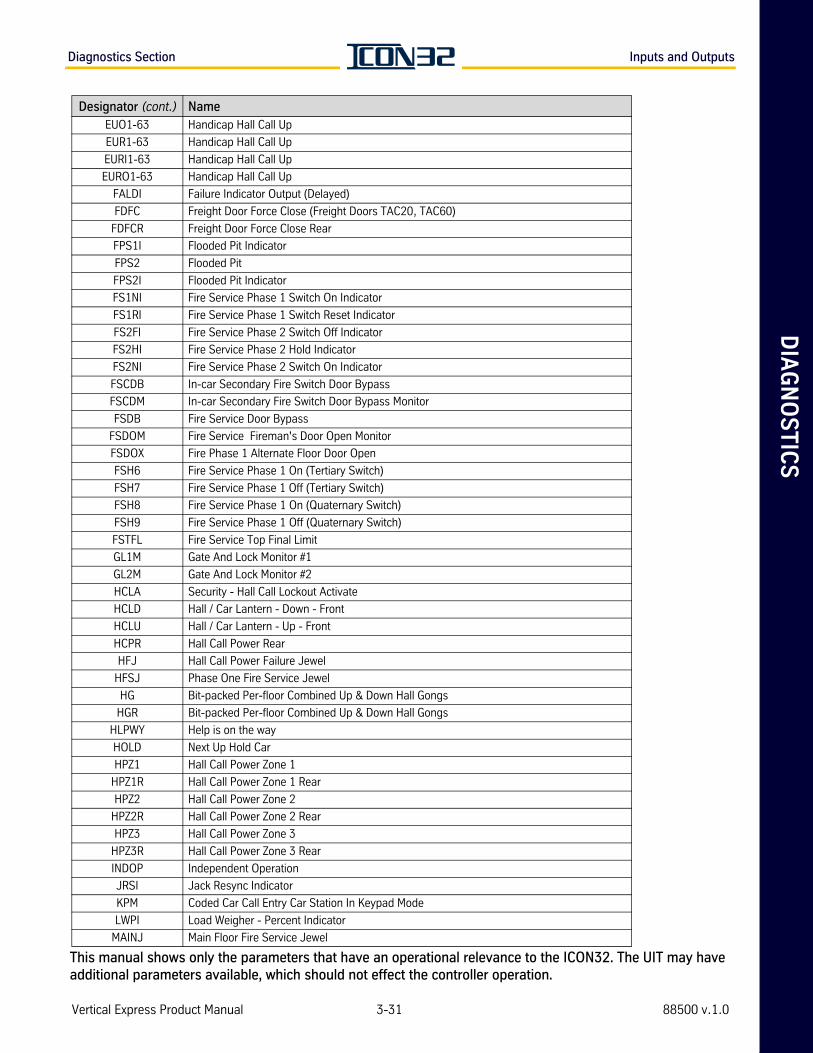
DIA
GN
OS
TIC
SDiagnostics Section Inputs and Outputs
EUO1-63 Handicap Hall Call Up
EUR1-63 Handicap Hall Call Up
EURI1-63 Handicap Hall Call Up
EURO1-63 Handicap Hall Call Up
FALDI Failure Indicator Output (Delayed)
FDFC Freight Door Force Close (Freight Doors TAC20, TAC60)
FDFCR Freight Door Force Close Rear
FPS1I Flooded Pit Indicator
FPS2 Flooded Pit
FPS2I Flooded Pit Indicator
FS1NI Fire Service Phase 1 Switch On Indicator
FS1RI Fire Service Phase 1 Switch Reset Indicator
FS2FI Fire Service Phase 2 Switch Off Indicator
FS2HI Fire Service Phase 2 Hold Indicator
FS2NI Fire Service Phase 2 Switch On Indicator
FSCDB In-car Secondary Fire Switch Door Bypass
FSCDM In-car Secondary Fire Switch Door Bypass Monitor
FSDB Fire Service Door Bypass
FSDOM Fire Service Fireman's Door Open Monitor
FSDOX Fire Phase 1 Alternate Floor Door Open
FSH6 Fire Service Phase 1 On (Tertiary Switch)
FSH7 Fire Service Phase 1 Off (Tertiary Switch)
FSH8 Fire Service Phase 1 On (Quaternary Switch)
FSH9 Fire Service Phase 1 Off (Quaternary Switch)
FSTFL Fire Service Top Final Limit
GL1M Gate And Lock Monitor #1
GL2M Gate And Lock Monitor #2
HCLA Security - Hall Call Lockout Activate
HCLD Hall / Car Lantern - Down - Front
HCLU Hall / Car Lantern - Up - Front
HCPR Hall Call Power Rear
HFJ Hall Call Power Failure Jewel
HFSJ Phase One Fire Service Jewel
HG Bit-packed Per-floor Combined Up & Down Hall Gongs
HGR Bit-packed Per-floor Combined Up & Down Hall Gongs
HLPWY Help is on the way
HOLD Next Up Hold Car
HPZ1 Hall Call Power Zone 1
HPZ1R Hall Call Power Zone 1 Rear
HPZ2 Hall Call Power Zone 2
HPZ2R Hall Call Power Zone 2 Rear
HPZ3 Hall Call Power Zone 3
HPZ3R Hall Call Power Zone 3 Rear
INDOP Independent Operation
JRSI Jack Resync Indicator
KPM Coded Car Call Entry Car Station In Keypad Mode
LWPI Load Weigher - Percent Indicator
MAINJ Main Floor Fire Service Jewel
Designator (cont.) Name
Vertical Express Product Manual 3-31 88500 v.1.0
This manual shows only the parameters that have an operational relevance to the ICON32. The UIT may have additional parameters available, which should not effect the controller operation.
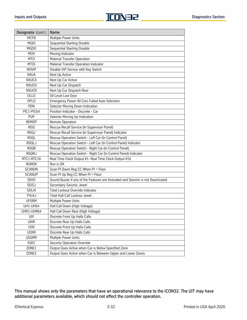
Inputs and Outputs Diagnostics Section
MCFB Multiple Power Units
MGDI Sequential Starting Disable
MGDO Sequential Starting Disable
MOV Moving Indicator
MTO Material Transfer Operation
MTOI Material Transfer Operation Indicator
NOVIP Disable VIP Service with Key Switch
NXUA Next Up Active
NXUCA Next Up Car Active
NXUCD Next Up Car Dispatch
NXUCR Next Up Car Dispatch Rear
OLLD Oil Level Low Door
OFLO Emergency Power All Cars Failed Auto Selection
PDN Selector Moving Down Indication
PIC1-PIC64 Position Indicator - Discrete - Car
PUP Selector Moving Up Indication
REMOP Remote Operation
RSQ Rescue Recall Service (In Supervisor Panel)
RSQJ Rescue Recall Service (In Supervisor Panel) Indicator
RSQL Rescue Operation Switch - Left Car (In Control Panel)
RSQLJ Rescue Operation Switch - Left Car (In Control Panel) Indicator
RSQR Rescue Operation Switch - Right Car (In Control Panel)
RSQRJ Rescue Operation Switch - Right Car (In Control Panel) Indicator
RTC1-RTC16 Real Time Clock Output #1- Real Time Clock Output #16
RUNOK Run is OK
SCANDN Scan PI Down Reg CC When PI = Floor
SCANUP Scan PI Up Reg CC When PI = Floor
SEIOI Sound Buzzer if any of the Features are Activated and Seismic is not Deactivated
SEISJ Secondary Seismic Jewel
SOLAI Total Lockout Override Indicator
THLKJ Total Hall Call Lockout Jewel
UFSRM Multiple Power Units
UH1-UH64 Hall Call Down (High Voltage)
UHR1-UHR64 Hall Call Down Rear (High Voltage)
UIX Discrete Front Up Halls Calls
UIXR Discrete Rear Up Halls Calls
UOX Discrete Front Up Halls Calls
UOXR Discrete Rear Up Halls Calls
USSRM Multiple Power Units
XSEC Security Operation Override
ZONE1 Output Goes Active when Car is Below Specified Zone
ZONE2 Output Goes Active when Car is Between Upper and Lower Zones
Designator (cont.) Name
©Vertical Express 3-32 Printed in USA April 2020
This manual shows only the parameters that have an operational relevance to the ICON32. The UIT may have additional parameters available, which should not effect the controller operation.
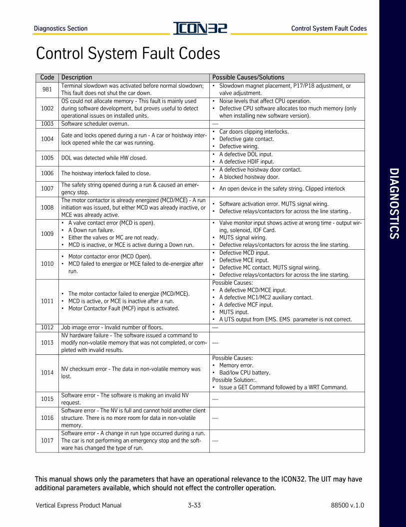
DIA
GN
OS
TIC
SDiagnostics Section Control System Fault Codes
Control System Fault CodesCode Description Possible Causes/Solutions
981Terminal slowdown was activated before normal slowdown;This fault does not shut the car down.
• Slowdown magnet placement, P17/P18 adjustment, or valve adjustment.
1002OS could not allocate memory - This fault is mainly used during software development, but proves useful to detect operational issues on installed units.
• Noise levels that affect CPU operation. • Defective CPU software allocates too much memory (only
when installing new software version).1003 Software scheduler overrun. —
1004Gate and locks opened during a run - A car or hoistway inter-lock opened while the car was running.
• Car doors clipping interlocks.• Defective gate contact.• Defective wiring.
1005 DOL was detected while HW closed.• A defective DOL input.• A defective HDIF input.
1006 The hoistway interlock failed to close.• A defective hoistway door contact.• A blocked hoistway door.
1007The safety string opened during a run & caused an emer-gency stop.
• An open device in the safety string. Clipped interlock
1008The motor contactor is already energized (MCD/MCE) - A run initiation was issued, but either MCD was already inactive, or MCE was already active.
• Software activation error. MUTS signal wiring.• Defective relays/contactors for across the line starting..
1009
• A valve contact error (MCD is open). • A Down run failure.• Either the valves or MC are not ready.• MCD is inactive, or MCE is active during a Down run.
• Valve monitor input shows active at wrong time - output wir-ing, solenoid, IOF Card.
• MUTS signal wiring.• Defective relays/contactors for across the line starting.
1010• Motor contactor error (MCD Open). • MCD failed to energize or MCE failed to de-energize after
run.
• Defective MCD input.• Defective MCE input.• Defective MC contact. MUTS signal wiring.• Defective relays/contactors for across the line starting.
1011• The motor contactor failed to energize (MCD/MCE).• MCD is active, or MCE is inactive after a run.• Motor Contactor Fault (MCF) input is activated.
Possible Causes:• A defective MCD/MCE input.• A defective MC1/MC2 auxiliary contact.• A defective MCF input.• MUTS input.• A UTS output from EMS. EMS parameter is not correct.
1012 Job image error - Invalid number of floors. —
1013NV hardware failure - The software issued a command to modify non-volatile memory that was not completed, or com-pleted with invalid results.
—
1014NV checksum error - The data in non-volatile memory was lost.
Possible Causes:• Memory error. • Bad/low CPU battery.Possible Solution:. • Issue a GET Command followed by a WRT Command.
1015Software error - The software is making an invalid NV request.
—
1016Software error - The NV is full and cannot hold another client structure. There is no more room for data in non-volatile memory.
—
1017Software error - A change in run type occurred during a run. The car is not performing an emergency stop and the soft-ware has changed the type of run.
—
Vertical Express Product Manual 3-33 88500 v.1.0
This manual shows only the parameters that have an operational relevance to the ICON32. The UIT may have additional parameters available, which should not effect the controller operation.
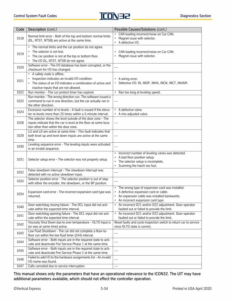
Control System Fault Codes Diagnostics Section
1018Normal limit error - Both of the top and bottom normal limits (DL, NTST, NTSB) are active at the same time.
• CAN loading incorrect/noise on Car CAN.• Magnet issue with selector.• A defective I/O.
1019
• The normal limits and the car position do not agree. • The selector is not lost. • The car position is not at the top or bottom floor. • The I/O DL, NTST, NTSB do not agree.
• CAN loading incorrect/noise on Car CAN.• Magnet issue with selector.
1020Software error - The I/O database has been corrupted, or the checksum for I/O has changed.
—
1021
• A safety node is offline.• Inspection indicates an invalid I/O condition. • The status of an I/O indicates a combination of active and
inactive inputs that are not allowed.
• A wiring error.• Defective I/O: IN, INOP, INHA, INCN, INCT, INHAM.
1022 Run monitor - The run protect timer has expired. • Ran too long at leveling speed.
1023Run monitor - The wrong direction run. The software issued a command to run in one direction, but the car actually ran in the other direction.
—
1024Excessive number of re-levels - A fault is issued if the eleva-tor re-levels more than 25 times within a 5-minute interval.
• A defective valve.• A mis-adjusted valve.
1028The selector shows the level outside of the door zone - The inputs indicate that the car is level at the floor-at some loca-tion other than within the door zone.
—
1029LU and LD are active at same time - This fault indicates that both level up and level down inputs are active at the same time.
—
1030Leveling sequence error - The leveling inputs were activated in an invalid sequence.
—
1031 Selector setup error - The selector was not properly setup.
• Incorrect number of leveling vanes was detected.• A bad floor position setup.• The selector setup is incomplete.• Scanning the hatch too fast.
1032False slowdown interrupt - The slowdown interrupt was detected with no active slowdown input.
—
1033Selector position error - The selector position is out of step with either the encoder, the slowdown, or the BP position.
—
1034Expansion card error - The incorrect expansion card type was returned.
• The wrong type of expansion card was installed.• A defective expansion card or cable.• An expansion cable was installed backwards.• An incorrect expansion card type.
1040Door watchdog closing failure - The DCL input did not acti-vate within the expected time interval.
• An incorrect D21 and/or D22 adjustment. Door operator faulted out or failed to provide the limit.
1041Door watchdog opening failure - The DCL input did not acti-vate within the expected time interval.
• An incorrect D21 and/or D22 adjustment. Door operator faulted out or failed to provide the limit.
1042Viscosity Shut Down due to over temperature – OLTO input is (or was at some time) active.
Reset faults and cycle inspection switch to return car to service once OLTO state is correct.
1043Low Fluid Shutdown - The car did not complete a floor-to-floor run within the low fluid timer (Z44) interval.
—
1044Software error - Both inputs are in the required state to acti-vate and deactivate Fire Service Phase 1 at the same time.
—
1045Software error - Both inputs are in the required state to acti-vate and deactivate Fire Service Phase 2 at the same time.
—
1046Failed to add I/O to the hardware assignments list - An invalid I/O name was found.
—
1047 Calls canceled due to service interruption. —
Code Description (cont.) Possible Causes/Solutions (cont.)
©Vertical Express 3-34 Printed in USA April 2020
This manual shows only the parameters that have an operational relevance to the ICON32. The UIT may have additional parameters available, which should not effect the controller operation.
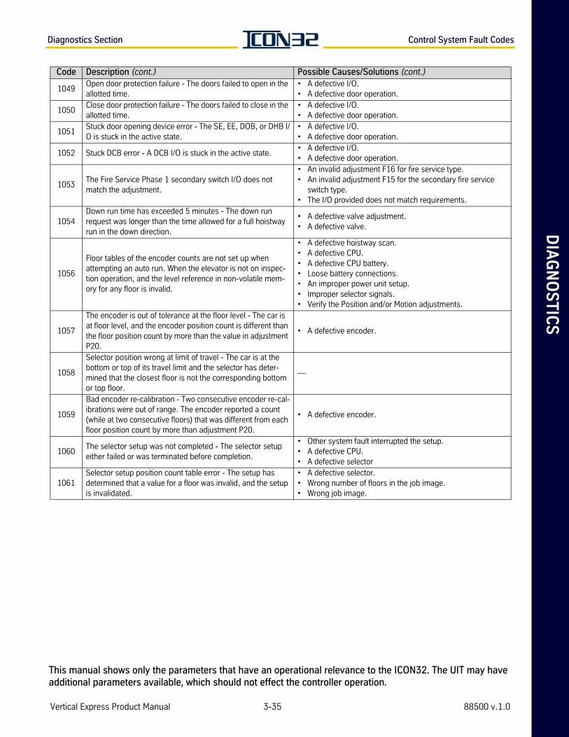
DIA
GN
OS
TIC
SDiagnostics Section Control System Fault Codes
1049Open door protection failure - The doors failed to open in the allotted time.
• A defective I/O.• A defective door operation.
1050Close door protection failure - The doors failed to close in the allotted time.
• A defective I/O.• A defective door operation.
1051Stuck door opening device error - The SE, EE, DOB, or DHB I/O is stuck in the active state.
• A defective I/O.• A defective door operation.
1052 Stuck DCB error - A DCB I/O is stuck in the active state.• A defective I/O.• A defective door operation.
1053The Fire Service Phase 1 secondary switch I/O does not match the adjustment.
• An invalid adjustment F16 for fire service type.• An invalid adjustment F15 for the secondary fire service
switch type.• The I/O provided does not match requirements.
1054Down run time has exceeded 5 minutes - The down run request was longer than the time allowed for a full hoistway run in the down direction.
• A defective valve adjustment.• A defective valve.
1056
Floor tables of the encoder counts are not set up when attempting an auto run. When the elevator is not on inspec-tion operation, and the level reference in non-volatile mem-ory for any floor is invalid.
• A defective hoistway scan.• A defective CPU.• A defective CPU battery.• Loose battery connections.• An improper power unit setup.• Improper selector signals.• Verify the Position and/or Motion adjustments.
1057
The encoder is out of tolerance at the floor level - The car is at floor level, and the encoder position count is different than the floor position count by more than the value in adjustment P20.
• A defective encoder.
1058
Selector position wrong at limit of travel - The car is at the bottom or top of its travel limit and the selector has deter-mined that the closest floor is not the corresponding bottom or top floor.
—
1059
Bad encoder re-calibration - Two consecutive encoder re-cal-ibrations were out of range. The encoder reported a count (while at two consecutive floors) that was different from each floor position count by more than adjustment P20.
• A defective encoder.
1060The selector setup was not completed - The selector setup either failed or was terminated before completion.
• Other system fault interrupted the setup. • A defective CPU.• A defective selector
1061Selector setup position count table error - The setup has determined that a value for a floor was invalid, and the setup is invalidated.
• A defective selector. • Wrong number of floors in the job image. • Wrong job image.
Code Description (cont.) Possible Causes/Solutions (cont.)
Vertical Express Product Manual 3-35 88500 v.1.0
This manual shows only the parameters that have an operational relevance to the ICON32. The UIT may have additional parameters available, which should not effect the controller operation.
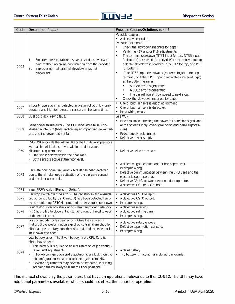
Control System Fault Codes Diagnostics Section
1062
1. Encoder interrupt failure - A car passed a slowdown point without receiving confirmation from the encoder.
2. Improper normal terminal slowdown magnet placement.
Possible Causes:• A defective encoder.Possible Solutions: • Check the slowdown magnets for gaps.• Verify the P17 and/or P18 adjustments.• The terminal slowdown (NTST input for top, NTSB input
for bottom) is reached too early (before the corresponding selector slowdown is reached). See P17 for top, and P18 for bottom.
• If the NTSB input deactivates (metered logic) at the top terminal, or if the NTST input deactivates (metered logic) at the bottom terminal, • A 1086 error is generated, • A 1062 error is generated,• The car will run at slow speed to next stop.
• Check the slowdown magnets for gaps.
1067Viscosity operation has detected activation of both low tem-perature and high temperature sensors at the same time.
• One or both sensors is out of adjustment.• One or both sensors is defective.• Input wiring error.
1068 Dual post jack resync fault. See WJR.
1069False power failure error - The CPU received a false Non-Maskable Interrupt (NMI), indicating an impending power fail-ure, and the power did not fail.
• Electrical noise affecting the power fail detection signal and/or the power supply (check grounding and noise suppres-sion).
• Power supply adjustment.• Defective power supply.
1070
LVU-LVD error - Neither of the LVU or the LVD leveling sensors were active while the car was within the door zone. Minimum requirements: • One sensor active within the door zone. • Both sensors active at the floor level.
• Defective selector sensors.
1073Car/Gate door open limit error - A fault has been detected due to the simultaneous activation of the car gate contact and the door open limit.
• A defective gate contact and/or door open limit.• Improper wiring.• Defective communication between the CPU Card and the
electronic door operator.• Defective CPU Card &/or electronic door operator.• A defective DOL or CDCF input.
1074 Input PRSW Active (Pressure Switch). —
1075Car stop switch override error - The car stop switch override circuit (controlled by CSTO output) has been detected faulty by its monitoring CSTOM input, and the elevator shuts down.
• A defective CSTOM input.• A defective CSTO output.• Improper wiring.
1076Freight door interlock stuck error - The freight door interlock (FDI) has failed to close at the start of a run, or failed to open at the end of a run.
• A defective interlock.• A defective retiring cam.• Improper wiring.
1077
Loss of encoder pulse train error - While the car was in motion, the encoder motion signal pulse train (furnished by either a tape or rotary encoder) was lost, and the elevator is shut down at a floor.
• A defective rotary encoder.• Defective tape motion sensors.• Improper wiring.
1078
Low battery error - The 3-volt battery in the CPU Card is either low or dead:• This battery is required to ensure retention of job configu-
ration and adjustments. • If the job configuration and adjustments are lost, then the
job configuration must be uploaded again from IMS. • Elevator adjustments may have to be repeated, including
scanning the hoistway to learn the floor positions.
• A dead battery. • The battery is missing, or installed backwards.
Code Description (cont.) Possible Causes/Solutions (cont.)
©Vertical Express 3-36 Printed in USA April 2020
This manual shows only the parameters that have an operational relevance to the ICON32. The UIT may have additional parameters available, which should not effect the controller operation.
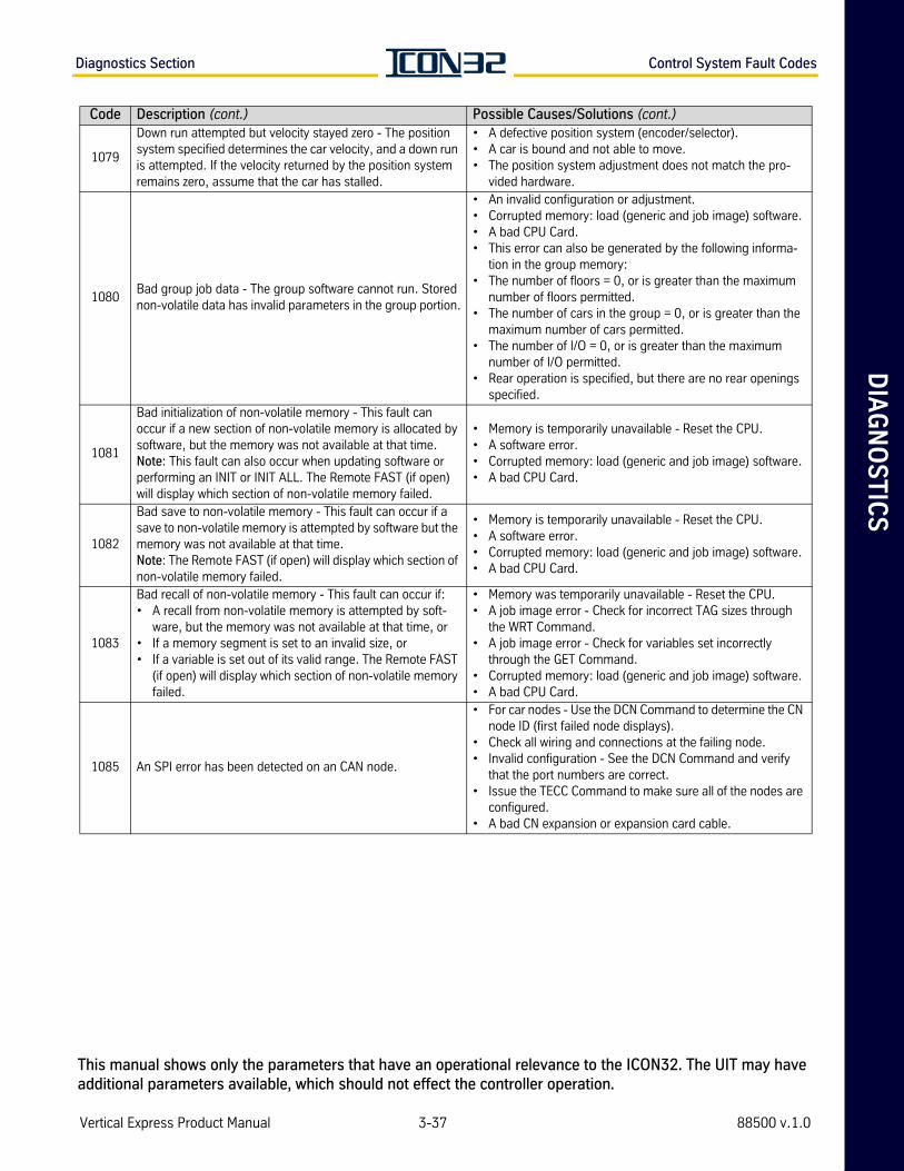
DIA
GN
OS
TIC
SDiagnostics Section Control System Fault Codes
1079
Down run attempted but velocity stayed zero - The position system specified determines the car velocity, and a down run is attempted. If the velocity returned by the position system remains zero, assume that the car has stalled.
• A defective position system (encoder/selector).• A car is bound and not able to move.• The position system adjustment does not match the pro-
vided hardware.
1080Bad group job data - The group software cannot run. Stored non-volatile data has invalid parameters in the group portion.
• An invalid configuration or adjustment.• Corrupted memory: load (generic and job image) software.• A bad CPU Card.• This error can also be generated by the following informa-
tion in the group memory:• The number of floors = 0, or is greater than the maximum
number of floors permitted.• The number of cars in the group = 0, or is greater than the
maximum number of cars permitted.• The number of I/O = 0, or is greater than the maximum
number of I/O permitted.• Rear operation is specified, but there are no rear openings
specified.
1081
Bad initialization of non-volatile memory - This fault can occur if a new section of non-volatile memory is allocated by software, but the memory was not available at that time. Note: This fault can also occur when updating software or performing an INIT or INIT ALL. The Remote FAST (if open) will display which section of non-volatile memory failed.
• Memory is temporarily unavailable - Reset the CPU.• A software error.• Corrupted memory: load (generic and job image) software.• A bad CPU Card.
1082
Bad save to non-volatile memory - This fault can occur if a save to non-volatile memory is attempted by software but the memory was not available at that time. Note: The Remote FAST (if open) will display which section of non-volatile memory failed.
• Memory is temporarily unavailable - Reset the CPU.• A software error.• Corrupted memory: load (generic and job image) software.• A bad CPU Card.
1083
Bad recall of non-volatile memory - This fault can occur if: • A recall from non-volatile memory is attempted by soft-
ware, but the memory was not available at that time, or • If a memory segment is set to an invalid size, or • If a variable is set out of its valid range. The Remote FAST
(if open) will display which section of non-volatile memory failed.
• Memory was temporarily unavailable - Reset the CPU.• A job image error - Check for incorrect TAG sizes through
the WRT Command.• A job image error - Check for variables set incorrectly
through the GET Command.• Corrupted memory: load (generic and job image) software.• A bad CPU Card.
1085 An SPI error has been detected on an CAN node.
• For car nodes - Use the DCN Command to determine the CN node ID (first failed node displays).
• Check all wiring and connections at the failing node.• Invalid configuration - See the DCN Command and verify
that the port numbers are correct.• Issue the TECC Command to make sure all of the nodes are
configured.• A bad CN expansion or expansion card cable.
Code Description (cont.) Possible Causes/Solutions (cont.)
Vertical Express Product Manual 3-37 88500 v.1.0
This manual shows only the parameters that have an operational relevance to the ICON32. The UIT may have additional parameters available, which should not effect the controller operation.
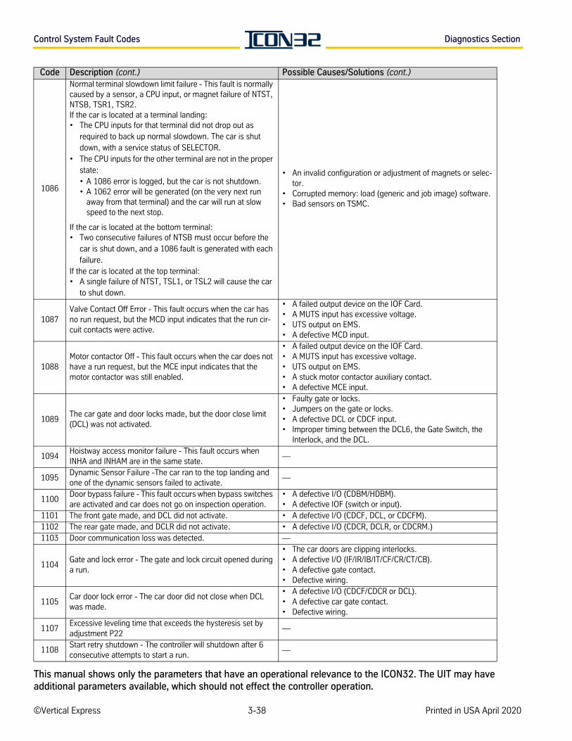
Control System Fault Codes Diagnostics Section
1086
Normal terminal slowdown limit failure - This fault is normally caused by a sensor, a CPU input, or magnet failure of NTST, NTSB, TSR1, TSR2.If the car is located at a terminal landing:• The CPU inputs for that terminal did not drop out as
required to back up normal slowdown. The car is shut down, with a service status of SELECTOR.
• The CPU inputs for the other terminal are not in the proper state:• A 1086 error is logged, but the car is not shutdown. • A 1062 error will be generated (on the very next run
away from that terminal) and the car will run at slow speed to the next stop.
If the car is located at the bottom terminal: • Two consecutive failures of NTSB must occur before the
car is shut down, and a 1086 fault is generated with each failure.
If the car is located at the top terminal: • A single failure of NTST, TSL1, or TSL2 will cause the car
to shut down.
• An invalid configuration or adjustment of magnets or selec-tor.
• Corrupted memory: load (generic and job image) software.• Bad sensors on TSMC.
1087Valve Contact Off Error - This fault occurs when the car has no run request, but the MCD input indicates that the run cir-cuit contacts were active.
• A failed output device on the IOF Card.• A MUTS input has excessive voltage. • UTS output on EMS.• A defective MCD input.
1088Motor contactor Off - This fault occurs when the car does not have a run request, but the MCE input indicates that the motor contactor was still enabled.
• A failed output device on the IOF Card.• A MUTS input has excessive voltage. • UTS output on EMS.• A stuck motor contactor auxiliary contact.• A defective MCE input.
1089The car gate and door locks made, but the door close limit (DCL) was not activated.
• Faulty gate or locks.• Jumpers on the gate or locks.• A defective DCL or CDCF input.• Improper timing between the DCL6, the Gate Switch, the
Interlock, and the DCL.
1094Hoistway access monitor failure - This fault occurs when INHA and INHAM are in the same state.
—
1095Dynamic Sensor Failure -The car ran to the top landing and one of the dynamic sensors failed to activate.
—
1100Door bypass failure - This fault occurs when bypass switches are activated and car does not go on inspection operation.
• A defective I/O (CDBM/HDBM).• A defective IOF (switch or input).
1101 The front gate made, and DCL did not activate. • A defective I/O (CDCF, DCL, or CDCFM). 1102 The rear gate made, and DCLR did not activate. • A defective I/O (CDCR, DCLR, or CDCRM.)1103 Door communication loss was detected. —
1104Gate and lock error - The gate and lock circuit opened during a run.
• The car doors are clipping interlocks.• A defective I/O (IF/IR/IB/IT/CF/CR/CT/CB).• A defective gate contact.• Defective wiring.
1105Car door lock error - The car door did not close when DCL was made.
• A defective I/O (CDCF/CDCR or DCL).• A defective car gate contact.• Defective wiring.
1107Excessive leveling time that exceeds the hysteresis set by adjustment P22
—
1108Start retry shutdown - The controller will shutdown after 6 consecutive attempts to start a run.
—
Code Description (cont.) Possible Causes/Solutions (cont.)
©Vertical Express 3-38 Printed in USA April 2020
This manual shows only the parameters that have an operational relevance to the ICON32. The UIT may have additional parameters available, which should not effect the controller operation.
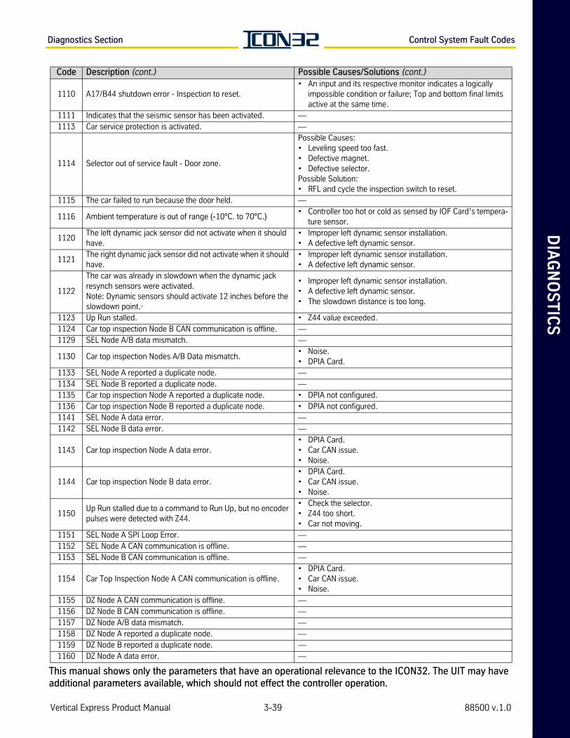
DIA
GN
OS
TIC
SDiagnostics Section Control System Fault Codes
1110 A17/B44 shutdown error - Inspection to reset.• An input and its respective monitor indicates a logically
impossible condition or failure; Top and bottom final limits active at the same time.
1111 Indicates that the seismic sensor has been activated. —1113 Car service protection is activated. —
1114 Selector out of service fault - Door zone.
Possible Causes:• Leveling speed too fast.• Defective magnet.• Defective selector.Possible Solution:• RFL and cycle the inspection switch to reset.
1115 The car failed to run because the door held. —
1116 Ambient temperature is out of range (-10°C. to 70°C.) • Controller too hot or cold as sensed by IOF Card’s tempera-
ture sensor.
1120The left dynamic jack sensor did not activate when it should have.
• Improper left dynamic sensor installation.• A defective left dynamic sensor.
1121The right dynamic jack sensor did not activate when it should have.
• Improper left dynamic sensor installation.• A defective left dynamic sensor.
1122
The car was already in slowdown when the dynamic jack resynch sensors were activated.Note: Dynamic sensors should activate 12 inches before the slowdown point.·
• Improper left dynamic sensor installation.• A defective left dynamic sensor.• The slowdown distance is too long.
1123 Up Run stalled. • Z44 value exceeded.1124 Car top inspection Node B CAN communication is offline. —1129 SEL Node A/B data mismatch. —
1130 Car top inspection Nodes A/B Data mismatch.• Noise.• DPIA Card.
1133 SEL Node A reported a duplicate node. —1134 SEL Node B reported a duplicate node. —1135 Car top inspection Node A reported a duplicate node. • DPIA not configured.1136 Car top inspection Node B reported a duplicate node. • DPIA not configured.1141 SEL Node A data error. —1142 SEL Node B data error. —
1143 Car top inspection Node A data error.• DPIA Card. • Car CAN issue.• Noise.
1144 Car top inspection Node B data error.• DPIA Card. • Car CAN issue.• Noise.
1150Up Run stalled due to a command to Run Up, but no encoder pulses were detected with Z44.
• Check the selector. • Z44 too short. • Car not moving.
1151 SEL Node A SPI Loop Error. —1152 SEL Node A CAN communication is offline. —1153 SEL Node B CAN communication is offline. —
1154 Car Top Inspection Node A CAN communication is offline.• DPIA Card. • Car CAN issue.• Noise.
1155 DZ Node A CAN communication is offline. —1156 DZ Node B CAN communication is offline. —1157 DZ Node A/B data mismatch. —1158 DZ Node A reported a duplicate node. —1159 DZ Node B reported a duplicate node. —1160 DZ Node A data error. —
Code Description (cont.) Possible Causes/Solutions (cont.)
Vertical Express Product Manual 3-39 88500 v.1.0
This manual shows only the parameters that have an operational relevance to the ICON32. The UIT may have additional parameters available, which should not effect the controller operation.
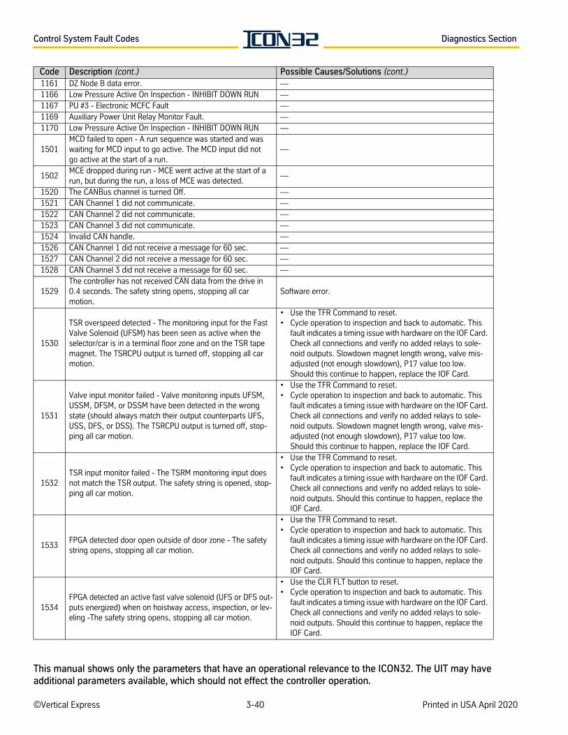
Control System Fault Codes Diagnostics Section
1161 DZ Node B data error. —1166 Low Pressure Active On Inspection - INHIBIT DOWN RUN —1167 PU #3 - Electronic MCFC Fault —1169 Auxiliary Power Unit Relay Monitor Fault. —1170 Low Pressure Active On Inspection - INHIBIT DOWN RUN —
1501MCD failed to open - A run sequence was started and waswaiting for MCD input to go active. The MCD input did notgo active at the start of a run.
—
1502MCE dropped during run - MCE went active at the start of a run, but during the run, a loss of MCE was detected.
—
1520 The CANBus channel is turned Off. —1521 CAN Channel 1 did not communicate. —1522 CAN Channel 2 did not communicate. —1523 CAN Channel 3 did not communicate. —1524 Invalid CAN handle. —1526 CAN Channel 1 did not receive a message for 60 sec. —1527 CAN Channel 2 did not receive a message for 60 sec. —1528 CAN Channel 3 did not receive a message for 60 sec. —
1529The controller has not received CAN data from the drive in 0.4 seconds. The safety string opens, stopping all car motion.
Software error.
1530
TSR overspeed detected - The monitoring input for the Fast Valve Solenoid (UFSM) has been seen as active when the selector/car is in a terminal floor zone and on the TSR tape magnet. The TSRCPU output is turned off, stopping all car motion.
• Use the TFR Command to reset. • Cycle operation to inspection and back to automatic. This
fault indicates a timing issue with hardware on the IOF Card. Check all connections and verify no added relays to sole-noid outputs. Slowdown magnet length wrong, valve mis-adjusted (not enough slowdown), P17 value too low. Should this continue to happen, replace the IOF Card.
1531
Valve input monitor failed - Valve monitoring inputs UFSM, USSM, DFSM, or DSSM have been detected in the wrong state (should always match their output counterparts UFS, USS, DFS, or DSS). The TSRCPU output is turned off, stop-ping all car motion.
• Use the TFR Command to reset. • Cycle operation to inspection and back to automatic. This
fault indicates a timing issue with hardware on the IOF Card. Check all connections and verify no added relays to sole-noid outputs. Slowdown magnet length wrong, valve mis-adjusted (not enough slowdown), P17 value too low. Should this continue to happen, replace the IOF Card.
1532TSR input monitor failed - The TSRM monitoring input does not match the TSR output. The safety string is opened, stop-ping all car motion.
• Use the TFR Command to reset. • Cycle operation to inspection and back to automatic. This
fault indicates a timing issue with hardware on the IOF Card. Check all connections and verify no added relays to sole-noid outputs. Should this continue to happen, replace the IOF Card.
1533FPGA detected door open outside of door zone - The safety string opens, stopping all car motion.
• Use the TFR Command to reset. • Cycle operation to inspection and back to automatic. This
fault indicates a timing issue with hardware on the IOF Card. Check all connections and verify no added relays to sole-noid outputs. Should this continue to happen, replace the IOF Card.
1534FPGA detected an active fast valve solenoid (UFS or DFS out-puts energized) when on hoistway access, inspection, or lev-eling -The safety string opens, stopping all car motion.
• Use the CLR FLT button to reset. • Cycle operation to inspection and back to automatic. This
fault indicates a timing issue with hardware on the IOF Card. Check all connections and verify no added relays to sole-noid outputs. Should this continue to happen, replace the IOF Card.
Code Description (cont.) Possible Causes/Solutions (cont.)
©Vertical Express 3-40 Printed in USA April 2020
This manual shows only the parameters that have an operational relevance to the ICON32. The UIT may have additional parameters available, which should not effect the controller operation.
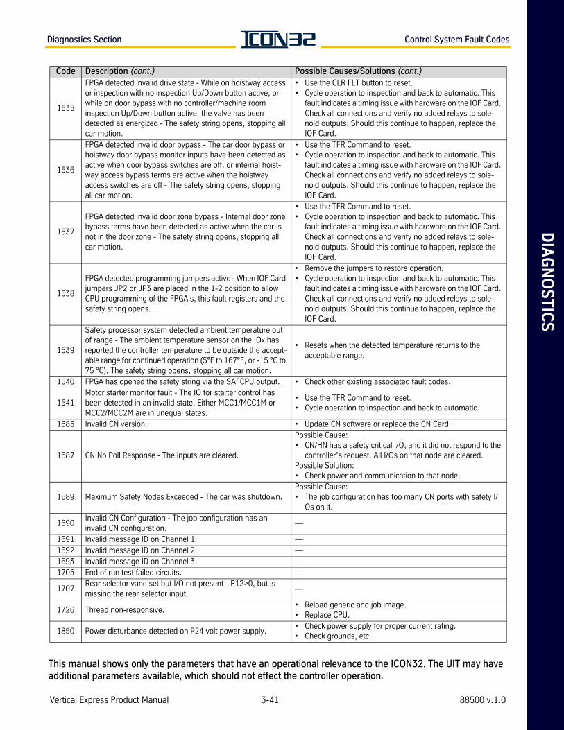
DIA
GN
OS
TIC
SDiagnostics Section Control System Fault Codes
1535
FPGA detected invalid drive state - While on hoistway access or inspection with no inspection Up/Down button active, or while on door bypass with no controller/machine room inspection Up/Down button active, the valve has been detected as energized - The safety string opens, stopping all car motion.
• Use the CLR FLT button to reset.• Cycle operation to inspection and back to automatic. This
fault indicates a timing issue with hardware on the IOF Card. Check all connections and verify no added relays to sole-noid outputs. Should this continue to happen, replace the IOF Card.
1536
FPGA detected invalid door bypass - The car door bypass or hoistway door bypass monitor inputs have been detected as active when door bypass switches are off, or internal hoist-way access bypass terms are active when the hoistway access switches are off - The safety string opens, stopping all car motion.
• Use the TFR Command to reset. • Cycle operation to inspection and back to automatic. This
fault indicates a timing issue with hardware on the IOF Card. Check all connections and verify no added relays to sole-noid outputs. Should this continue to happen, replace the IOF Card.
1537
FPGA detected invalid door zone bypass - Internal door zone bypass terms have been detected as active when the car is not in the door zone - The safety string opens, stopping all car motion.
• Use the TFR Command to reset. • Cycle operation to inspection and back to automatic. This
fault indicates a timing issue with hardware on the IOF Card. Check all connections and verify no added relays to sole-noid outputs. Should this continue to happen, replace the IOF Card.
1538
FPGA detected programming jumpers active - When IOF Card jumpers JP2 or JP3 are placed in the 1-2 position to allow CPU programming of the FPGA's, this fault registers and the safety string opens.
• Remove the jumpers to restore operation.• Cycle operation to inspection and back to automatic. This
fault indicates a timing issue with hardware on the IOF Card. Check all connections and verify no added relays to sole-noid outputs. Should this continue to happen, replace the IOF Card.
1539
Safety processor system detected ambient temperature out of range - The ambient temperature sensor on the IOx has reported the controller temperature to be outside the accept-able range for continued operation (5°F to 167°F, or -15 °C to 75 °C). The safety string opens, stopping all car motion.
• Resets when the detected temperature returns to the acceptable range.
1540 FPGA has opened the safety string via the SAFCPU output. • Check other existing associated fault codes.
1541Motor starter monitor fault - The IO for starter control has been detected in an invalid state. Either MCC1/MCC1M or MCC2/MCC2M are in unequal states.
• Use the TFR Command to reset. • Cycle operation to inspection and back to automatic.
1685 Invalid CN version. • Update CN software or replace the CN Card.
1687 CN No Poll Response - The inputs are cleared.
Possible Cause:• CN/HN has a safety critical I/O, and it did not respond to the
controller’s request. All I/Os on that node are cleared.Possible Solution: • Check power and communication to that node.
1689 Maximum Safety Nodes Exceeded - The car was shutdown.Possible Cause:• The job configuration has too many CN ports with safety I/
Os on it.
1690Invalid CN Configuration - The job configuration has an invalid CN configuration.
—
1691 Invalid message ID on Channel 1. —1692 Invalid message ID on Channel 2. —1693 Invalid message ID on Channel 3. —1705 End of run test failed circuits. —
1707Rear selector vane set but I/O not present - P12>0, but is missing the rear selector input.
—
1726 Thread non-responsive.• Reload generic and job image. • Replace CPU.
1850 Power disturbance detected on P24 volt power supply.• Check power supply for proper current rating.• Check grounds, etc.
Code Description (cont.) Possible Causes/Solutions (cont.)
Vertical Express Product Manual 3-41 88500 v.1.0
This manual shows only the parameters that have an operational relevance to the ICON32. The UIT may have additional parameters available, which should not effect the controller operation.
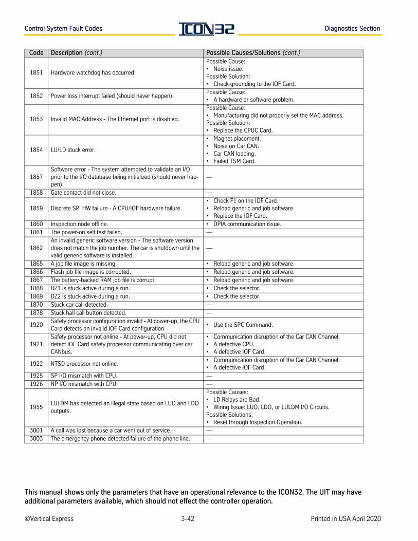
Control System Fault Codes Diagnostics Section
1851 Hardware watchdog has occurred.
Possible Cause:• Noise issue.Possible Solution: • Check grounding to the IOF Card.
1852 Power loss interrupt failed (should never happen).Possible Cause:• A hardware or software problem.
1853 Invalid MAC Address - The Ethernet port is disabled.
Possible Cause:• Manufacturing did not properly set the MAC address.Possible Solution: • Replace the CPUC Card.
1854 LU/LD stuck error.
• Magnet placement. • Noise on Car CAN. • Car CAN loading. • Failed TSM Card.
1857Software error - The system attempted to validate an I/O prior to the I/O database being initialized (should never hap-pen).
—
1858 Gate contact did not close. —
1859 Discrete SPI HW failure - A CPU/IOF hardware failure.• Check F1 on the IOF Card. • Reload generic and job software.• Replace the IOF Card.
1860 Inspection node offline. • DPIA communication issue.1861 The power-on self test failed. —
1862An invalid generic software version - The software version does not match the job number. The car is shutdown until the valid generic software is installed.
—
1865 A job file image is missing. • Reload generic and job software.1866 Flash job file image is corrupted. • Reload generic and job software.1867 The battery-backed RAM job file is corrupt. • Reload generic and job software.1868 DZ1 is stuck active during a run. • Check the selector.1869 DZ2 is stuck active during a run. • Check the selector.1870 Stuck car call detected. —1878 Stuck hall call button detected. —
1920Safety processor configuration invalid - At power-up, the CPU Card detects an invalid IOF Card configuration.
• Use the SPC Command.
1921Safety processor not online - At power-up, CPU did not detect IOF Card safety processor communicating over car CANbus.
• Communication disruption of the Car CAN Channel.• A defective CPU.• A defective IOF Card.
1922 NTSD processor not online.• Communication disruption of the Car CAN Channel.• A defective IOF Card.
1925 SP I/O mismatch with CPU. —1926 NP I/O mismatch with CPU. —
1955LULDM has detected an illegal state based on LUO and LDO outputs.
Possible Causes:• LD Relays are Bad.• Wiring Issue: LUO, LDO, or LULDM I/O Circuits.Possible Solutions:• Reset through Inspection Operation.
3001 A call was lost because a car went out of service. —3003 The emergency phone detected failure of the phone line. —
Code Description (cont.) Possible Causes/Solutions (cont.)
©Vertical Express 3-42 Printed in USA April 2020
This manual shows only the parameters that have an operational relevance to the ICON32. The UIT may have additional parameters available, which should not effect the controller operation.
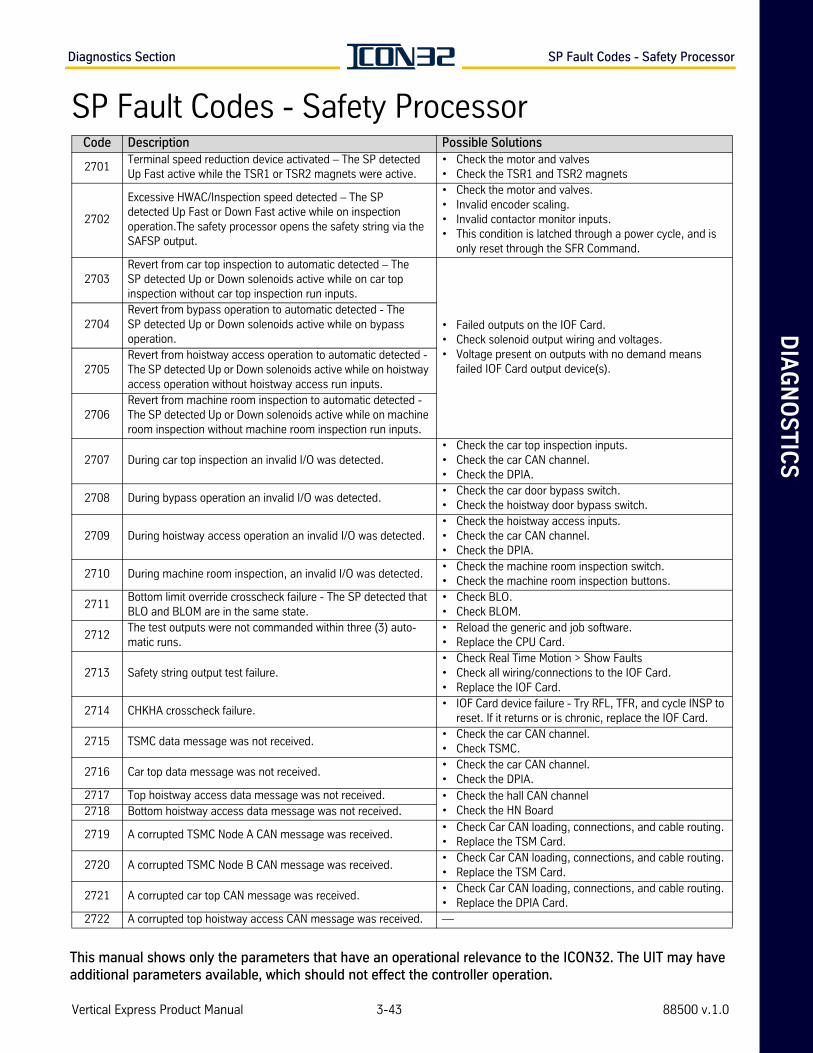
DIA
GN
OS
TIC
SDiagnostics Section SP Fault Codes - Safety Processor
SP Fault Codes - Safety ProcessorCode Description Possible Solutions
2701Terminal speed reduction device activated – The SP detected Up Fast active while the TSR1 or TSR2 magnets were active.
• Check the motor and valves• Check the TSR1 and TSR2 magnets
2702
Excessive HWAC/Inspection speed detected – The SPdetected Up Fast or Down Fast active while on inspectionoperation.The safety processor opens the safety string via the SAFSP output.
• Check the motor and valves.• Invalid encoder scaling.• Invalid contactor monitor inputs.• This condition is latched through a power cycle, and is
only reset through the SFR Command.
2703Revert from car top inspection to automatic detected – TheSP detected Up or Down solenoids active while on car topinspection without car top inspection run inputs.
• Failed outputs on the IOF Card. • Check solenoid output wiring and voltages. • Voltage present on outputs with no demand means
failed IOF Card output device(s).
2704Revert from bypass operation to automatic detected - TheSP detected Up or Down solenoids active while on bypassoperation.
2705Revert from hoistway access operation to automatic detected - The SP detected Up or Down solenoids active while on hoistway access operation without hoistway access run inputs.
2706Revert from machine room inspection to automatic detected - The SP detected Up or Down solenoids active while on machine room inspection without machine room inspection run inputs.
2707 During car top inspection an invalid I/O was detected.• Check the car top inspection inputs.• Check the car CAN channel.• Check the DPIA.
2708 During bypass operation an invalid I/O was detected.• Check the car door bypass switch.• Check the hoistway door bypass switch.
2709 During hoistway access operation an invalid I/O was detected.• Check the hoistway access inputs.• Check the car CAN channel.• Check the DPIA.
2710 During machine room inspection, an invalid I/O was detected.• Check the machine room inspection switch.• Check the machine room inspection buttons.
2711Bottom limit override crosscheck failure - The SP detected that BLO and BLOM are in the same state.
• Check BLO.• Check BLOM.
2712The test outputs were not commanded within three (3) auto-matic runs.
• Reload the generic and job software.• Replace the CPU Card.
2713 Safety string output test failure.• Check Real Time Motion > Show Faults • Check all wiring/connections to the IOF Card. • Replace the IOF Card.
2714 CHKHA crosscheck failure.• IOF Card device failure - Try RFL, TFR, and cycle INSP to
reset. If it returns or is chronic, replace the IOF Card.
2715 TSMC data message was not received.• Check the car CAN channel.• Check TSMC.
2716 Car top data message was not received.• Check the car CAN channel.• Check the DPIA.
2717 Top hoistway access data message was not received. • Check the hall CAN channel• Check the HN Board2718 Bottom hoistway access data message was not received.
2719 A corrupted TSMC Node A CAN message was received.• Check Car CAN loading, connections, and cable routing. • Replace the TSM Card.
2720 A corrupted TSMC Node B CAN message was received.• Check Car CAN loading, connections, and cable routing. • Replace the TSM Card.
2721 A corrupted car top CAN message was received.• Check Car CAN loading, connections, and cable routing. • Replace the DPIA Card.
2722 A corrupted top hoistway access CAN message was received. —
Vertical Express Product Manual 3-43 88500 v.1.0
This manual shows only the parameters that have an operational relevance to the ICON32. The UIT may have additional parameters available, which should not effect the controller operation.
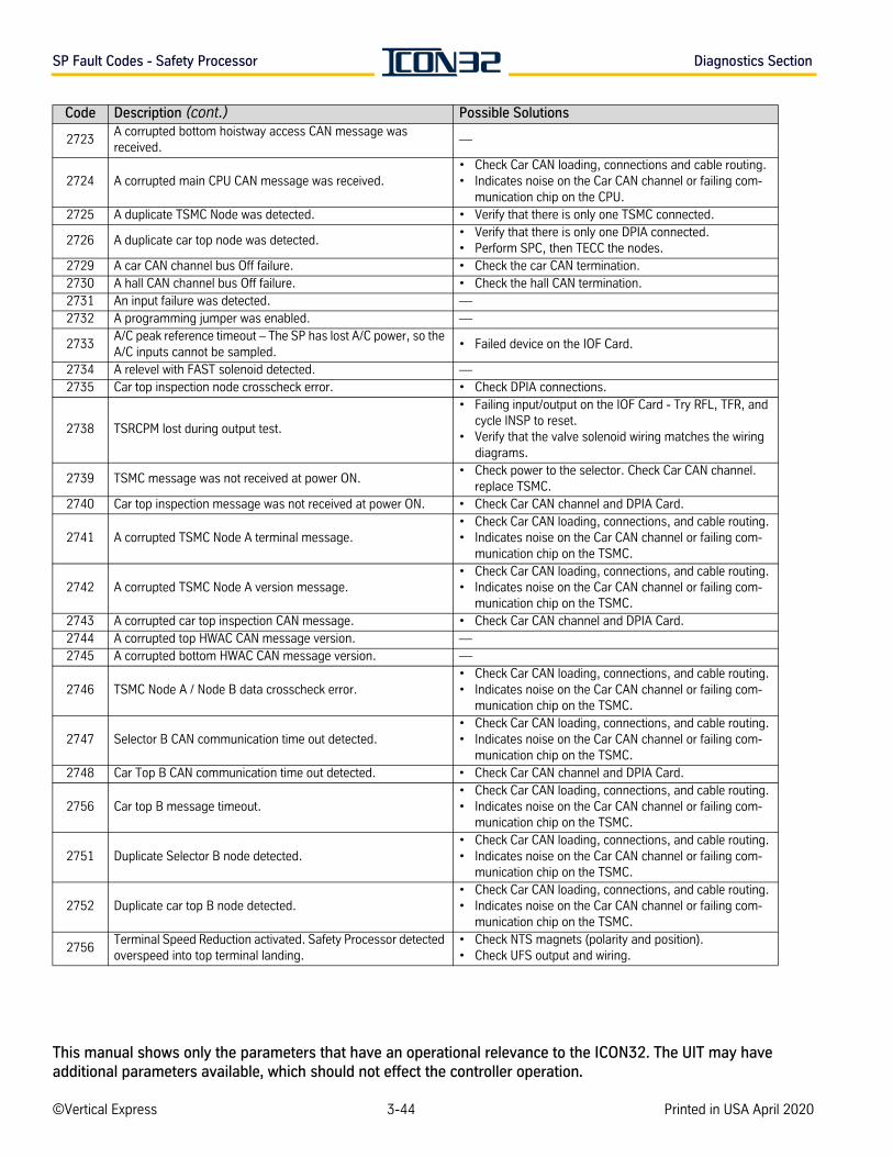
SP Fault Codes - Safety Processor Diagnostics Section
2723A corrupted bottom hoistway access CAN message was received.
—
2724 A corrupted main CPU CAN message was received.• Check Car CAN loading, connections and cable routing. • Indicates noise on the Car CAN channel or failing com-
munication chip on the CPU.2725 A duplicate TSMC Node was detected. • Verify that there is only one TSMC connected.
2726 A duplicate car top node was detected.• Verify that there is only one DPIA connected.• Perform SPC, then TECC the nodes.
2729 A car CAN channel bus Off failure. • Check the car CAN termination.2730 A hall CAN channel bus Off failure. • Check the hall CAN termination.2731 An input failure was detected. —2732 A programming jumper was enabled. —
2733A/C peak reference timeout – The SP has lost A/C power, so the A/C inputs cannot be sampled.
• Failed device on the IOF Card.
2734 A relevel with FAST solenoid detected. —2735 Car top inspection node crosscheck error. • Check DPIA connections.
2738 TSRCPM lost during output test.
• Failing input/output on the IOF Card - Try RFL, TFR, and cycle INSP to reset.
• Verify that the valve solenoid wiring matches the wiring diagrams.
2739 TSMC message was not received at power ON.• Check power to the selector. Check Car CAN channel.
replace TSMC.2740 Car top inspection message was not received at power ON. • Check Car CAN channel and DPIA Card.
2741 A corrupted TSMC Node A terminal message.• Check Car CAN loading, connections, and cable routing. • Indicates noise on the Car CAN channel or failing com-
munication chip on the TSMC.
2742 A corrupted TSMC Node A version message.• Check Car CAN loading, connections, and cable routing. • Indicates noise on the Car CAN channel or failing com-
munication chip on the TSMC.2743 A corrupted car top inspection CAN message. • Check Car CAN channel and DPIA Card.2744 A corrupted top HWAC CAN message version. —2745 A corrupted bottom HWAC CAN message version. —
2746 TSMC Node A / Node B data crosscheck error.• Check Car CAN loading, connections, and cable routing. • Indicates noise on the Car CAN channel or failing com-
munication chip on the TSMC.
2747 Selector B CAN communication time out detected.• Check Car CAN loading, connections, and cable routing. • Indicates noise on the Car CAN channel or failing com-
munication chip on the TSMC.2748 Car Top B CAN communication time out detected. • Check Car CAN channel and DPIA Card.
2756 Car top B message timeout.• Check Car CAN loading, connections, and cable routing. • Indicates noise on the Car CAN channel or failing com-
munication chip on the TSMC.
2751 Duplicate Selector B node detected.• Check Car CAN loading, connections, and cable routing. • Indicates noise on the Car CAN channel or failing com-
munication chip on the TSMC.
2752 Duplicate car top B node detected.• Check Car CAN loading, connections, and cable routing. • Indicates noise on the Car CAN channel or failing com-
munication chip on the TSMC.
2756Terminal Speed Reduction activated. Safety Processor detected overspeed into top terminal landing.
• Check NTS magnets (polarity and position).• Check UFS output and wiring.
Code Description (cont.) Possible Solutions
©Vertical Express 3-44 Printed in USA April 2020
This manual shows only the parameters that have an operational relevance to the ICON32. The UIT may have additional parameters available, which should not effect the controller operation.
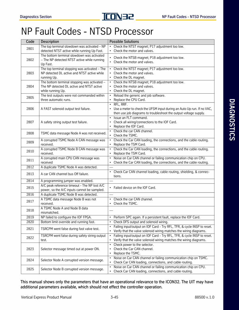
DIA
GN
OS
TIC
SDiagnostics Section NP Fault Codes - NTSD Processor
NP Fault Codes - NTSD Processor Code Description Possible Solutions
2801The top terminal slowdown was activated – NP detected NTST active while running Up Fast.
• Check the NTST magnet; P17 adjustment too low.• Check the motor and valves.
2802The bottom terminal slowdown was activated – The NP detected NTST active while running Up Fast.
• Check the NTSB magnet; P18 adjustment too low.• Check the motor and valves.
2803The top terminal stopping was activated – The NP detected DL active and NTST active while running Up.
• Check the NTST magnet; P17 adjustment too low.• Check the motor and valves.• Check the DL magnet.
2804The bottom terminal stopping was activated – The NP detected DL active and NTST active while running Up.
• Check the NTSB magnet; P18 adjustment too low.• Check the motor and valves.• Check the DL magnet.
2805The test outputs were not commanded within three automatic runs.
• Reload the generic and job software.• Replace the CPU Card.
2806 A FAST solenoid output test failure.• RFL, RRF. • Use a meter to check the UFSM input during an Auto Up run. If no VAC,
then use job diagrams to troubleshoot the output voltage supply.
2807 A safety string output test failure.• Issue an FLT command. • Check all wiring/connections to the IOF Card. • Replace the IOF Card.
2808 TSMC data message Node A was not received.• Check the car CAN channel.• Check the TSMC.
2809A corrupted TSMC Node A CAN message was received.
• Check the Car CAN loading, the connections, and the cable routing. • Replace the TSM Card.
2810A corrupted TSMC Node B CAN message was received.
• Check the Car CAN loading, the connections, and the cable routing. • Replace the TSM Card.
2811A corrupted main CPU CAN message was received
• Noise on Car CAN channel or failing communication chip on CPU.• Check the Car CAN loading, the connections, and the cable routing.
2812 A duplicate TSMC Node A was detected. —
2813 A car CAN channel bus Off failure.• Check Car CAN channel loading, cable routing, shielding, & connec-
tions.2814 A programming jumper was enabled. —
2815A/C peak reference timeout - The NP lost A/C power, so the A/C inputs cannot be sampled.
• Failed device on the IOF Card.
2816 A duplicate TSMC Node B was detected. —
2817A TSMC data message Node B was not received.
• Check the car CAN channel.• Check the TSMC.
2818A TSMC Node A and Node B data mismatched.
—
2819 NP failed to configure the IOF FPGA. • Perform SPC again. If a persistent fault, replace the IOF Card.2820 Bottom limit override and running fast. • Check DFS output and solenoid wiring.
2821 TSRCPM went false during fast valve test.• Failing input/output on IOF Card - Try RFL, TFR, & cycle INSP to reset.• Verify that the valve solenoid wiring matches the wiring diagrams.
2822TSRCPM went false during safety string output test.
• Failing input/output on IOF Card - Try RFL, TFR, & cycle INSP to reset.• Verify that the valve solenoid wiring matches the wiring diagrams.
2823 Selector message timed out at power ON.• Check power to the selector. • Check the Car CAN channel. • Replace the TSMC.
2824 Selector Node A corrupted version message.• Noise on Car CAN channel or failing communication chip on TSMC.• Check Car CAN loading, connections, and cable routing.
2825 Selector Node B corrupted version message.• Noise on Car CAN channel or failing communication chip on CPU.• Check Car CAN loading, connections, and cable routing.
Vertical Express Product Manual 3-45 88500 v.1.0
This manual shows only the parameters that have an operational relevance to the ICON32. The UIT may have additional parameters available, which should not effect the controller operation.
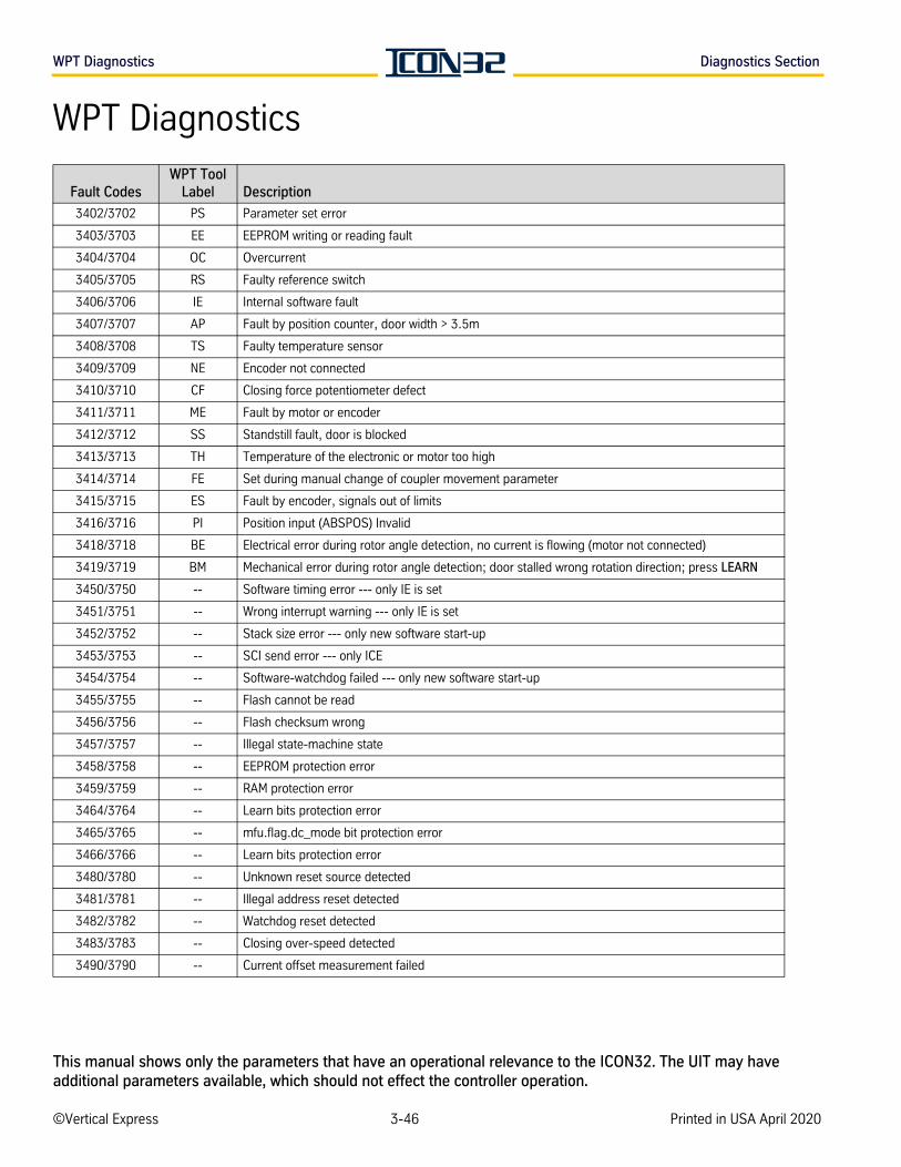
WPT Diagnostics Diagnostics Section
WPT Diagnostics
Fault CodesWPT Tool
Label Description
3402/3702 PS Parameter set error
3403/3703 EE EEPROM writing or reading fault
3404/3704 OC Overcurrent
3405/3705 RS Faulty reference switch
3406/3706 IE Internal software fault
3407/3707 AP Fault by position counter, door width > 3.5m
3408/3708 TS Faulty temperature sensor
3409/3709 NE Encoder not connected
3410/3710 CF Closing force potentiometer defect
3411/3711 ME Fault by motor or encoder
3412/3712 SS Standstill fault, door is blocked
3413/3713 TH Temperature of the electronic or motor too high
3414/3714 FE Set during manual change of coupler movement parameter
3415/3715 ES Fault by encoder, signals out of limits
3416/3716 PI Position input (ABSPOS) Invalid
3418/3718 BE Electrical error during rotor angle detection, no current is flowing (motor not connected)
3419/3719 BM Mechanical error during rotor angle detection; door stalled wrong rotation direction; press LEARN
3450/3750 -- Software timing error --- only IE is set
3451/3751 -- Wrong interrupt warning --- only IE is set
3452/3752 -- Stack size error --- only new software start-up
3453/3753 -- SCI send error --- only ICE
3454/3754 -- Software-watchdog failed --- only new software start-up
3455/3755 -- Flash cannot be read
3456/3756 -- Flash checksum wrong
3457/3757 -- Illegal state-machine state
3458/3758 -- EEPROM protection error
3459/3759 -- RAM protection error
3464/3764 -- Learn bits protection error
3465/3765 -- mfu.flag.dc_mode bit protection error
3466/3766 -- Learn bits protection error
3480/3780 -- Unknown reset source detected
3481/3781 -- Illegal address reset detected
3482/3782 -- Watchdog reset detected
3483/3783 -- Closing over-speed detected
3490/3790 -- Current offset measurement failed
©Vertical Express 3-46 Printed in USA April 2020
This manual shows only the parameters that have an operational relevance to the ICON32. The UIT may have additional parameters available, which should not effect the controller operation.

TR
OU
BLE
SH
OO
TIN
G S
EC
TIO
N

TR
OU
BLE
SH
OO
TIN
G S
EC
TIO
N
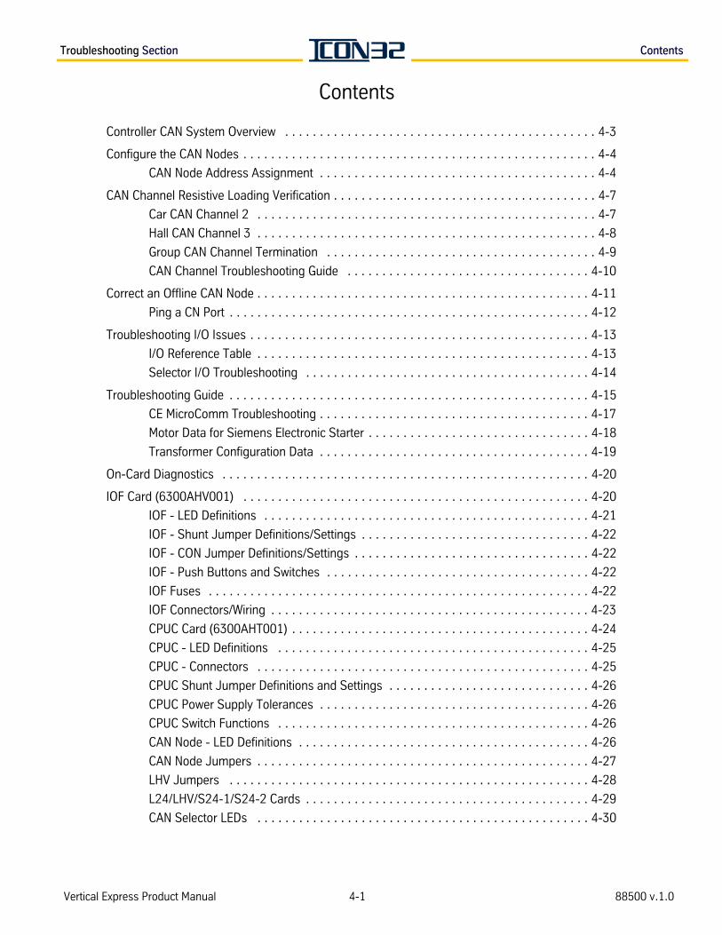
Troubleshooting Section Contents
Contents
Controller CAN System Overview . . . . . . . . . . . . . . . . . . . . . . . . . . . . . . . . . . . . . . . . . . . . . 4-3
Configure the CAN Nodes . . . . . . . . . . . . . . . . . . . . . . . . . . . . . . . . . . . . . . . . . . . . . . . . . . . 4-4
CAN Node Address Assignment . . . . . . . . . . . . . . . . . . . . . . . . . . . . . . . . . . . . . . . . 4-4
CAN Channel Resistive Loading Verification . . . . . . . . . . . . . . . . . . . . . . . . . . . . . . . . . . . . . . 4-7
Car CAN Channel 2 . . . . . . . . . . . . . . . . . . . . . . . . . . . . . . . . . . . . . . . . . . . . . . . . . 4-7
Hall CAN Channel 3 . . . . . . . . . . . . . . . . . . . . . . . . . . . . . . . . . . . . . . . . . . . . . . . . . 4-8
Group CAN Channel Termination . . . . . . . . . . . . . . . . . . . . . . . . . . . . . . . . . . . . . . . 4-9
CAN Channel Troubleshooting Guide . . . . . . . . . . . . . . . . . . . . . . . . . . . . . . . . . . . 4-10
Correct an Offline CAN Node . . . . . . . . . . . . . . . . . . . . . . . . . . . . . . . . . . . . . . . . . . . . . . . . 4-11
Ping a CN Port . . . . . . . . . . . . . . . . . . . . . . . . . . . . . . . . . . . . . . . . . . . . . . . . . . . . 4-12
Troubleshooting I/O Issues . . . . . . . . . . . . . . . . . . . . . . . . . . . . . . . . . . . . . . . . . . . . . . . . . 4-13
I/O Reference Table . . . . . . . . . . . . . . . . . . . . . . . . . . . . . . . . . . . . . . . . . . . . . . . . 4-13
Selector I/O Troubleshooting . . . . . . . . . . . . . . . . . . . . . . . . . . . . . . . . . . . . . . . . . 4-14
Troubleshooting Guide . . . . . . . . . . . . . . . . . . . . . . . . . . . . . . . . . . . . . . . . . . . . . . . . . . . . 4-15
CE MicroComm Troubleshooting . . . . . . . . . . . . . . . . . . . . . . . . . . . . . . . . . . . . . . . 4-17
Motor Data for Siemens Electronic Starter . . . . . . . . . . . . . . . . . . . . . . . . . . . . . . . . 4-18
Transformer Configuration Data . . . . . . . . . . . . . . . . . . . . . . . . . . . . . . . . . . . . . . . 4-19
On-Card Diagnostics . . . . . . . . . . . . . . . . . . . . . . . . . . . . . . . . . . . . . . . . . . . . . . . . . . . . . 4-20
IOF Card (6300AHV001) . . . . . . . . . . . . . . . . . . . . . . . . . . . . . . . . . . . . . . . . . . . . . . . . . . 4-20
IOF - LED Definitions . . . . . . . . . . . . . . . . . . . . . . . . . . . . . . . . . . . . . . . . . . . . . . . 4-21
IOF - Shunt Jumper Definitions/Settings . . . . . . . . . . . . . . . . . . . . . . . . . . . . . . . . . 4-22
IOF - CON Jumper Definitions/Settings . . . . . . . . . . . . . . . . . . . . . . . . . . . . . . . . . . 4-22
IOF - Push Buttons and Switches . . . . . . . . . . . . . . . . . . . . . . . . . . . . . . . . . . . . . . 4-22
IOF Fuses . . . . . . . . . . . . . . . . . . . . . . . . . . . . . . . . . . . . . . . . . . . . . . . . . . . . . . . 4-22
IOF Connectors/Wiring . . . . . . . . . . . . . . . . . . . . . . . . . . . . . . . . . . . . . . . . . . . . . . 4-23
CPUC Card (6300AHT001) . . . . . . . . . . . . . . . . . . . . . . . . . . . . . . . . . . . . . . . . . . . 4-24
CPUC - LED Definitions . . . . . . . . . . . . . . . . . . . . . . . . . . . . . . . . . . . . . . . . . . . . . 4-25
CPUC - Connectors . . . . . . . . . . . . . . . . . . . . . . . . . . . . . . . . . . . . . . . . . . . . . . . . 4-25
CPUC Shunt Jumper Definitions and Settings . . . . . . . . . . . . . . . . . . . . . . . . . . . . . 4-26
CPUC Power Supply Tolerances . . . . . . . . . . . . . . . . . . . . . . . . . . . . . . . . . . . . . . . 4-26
CPUC Switch Functions . . . . . . . . . . . . . . . . . . . . . . . . . . . . . . . . . . . . . . . . . . . . . 4-26
CAN Node - LED Definitions . . . . . . . . . . . . . . . . . . . . . . . . . . . . . . . . . . . . . . . . . . 4-26
CAN Node Jumpers . . . . . . . . . . . . . . . . . . . . . . . . . . . . . . . . . . . . . . . . . . . . . . . . 4-27
LHV Jumpers . . . . . . . . . . . . . . . . . . . . . . . . . . . . . . . . . . . . . . . . . . . . . . . . . . . . 4-28
L24/LHV/S24-1/S24-2 Cards . . . . . . . . . . . . . . . . . . . . . . . . . . . . . . . . . . . . . . . . . 4-29
CAN Selector LEDs . . . . . . . . . . . . . . . . . . . . . . . . . . . . . . . . . . . . . . . . . . . . . . . . 4-30
Vertical Express Product Manual 4-1 88500 v.1.0

Contents Troubleshooting Section
This pageintentionallyleft blank.
4-2©Vertical Express Printed in USA April 2020
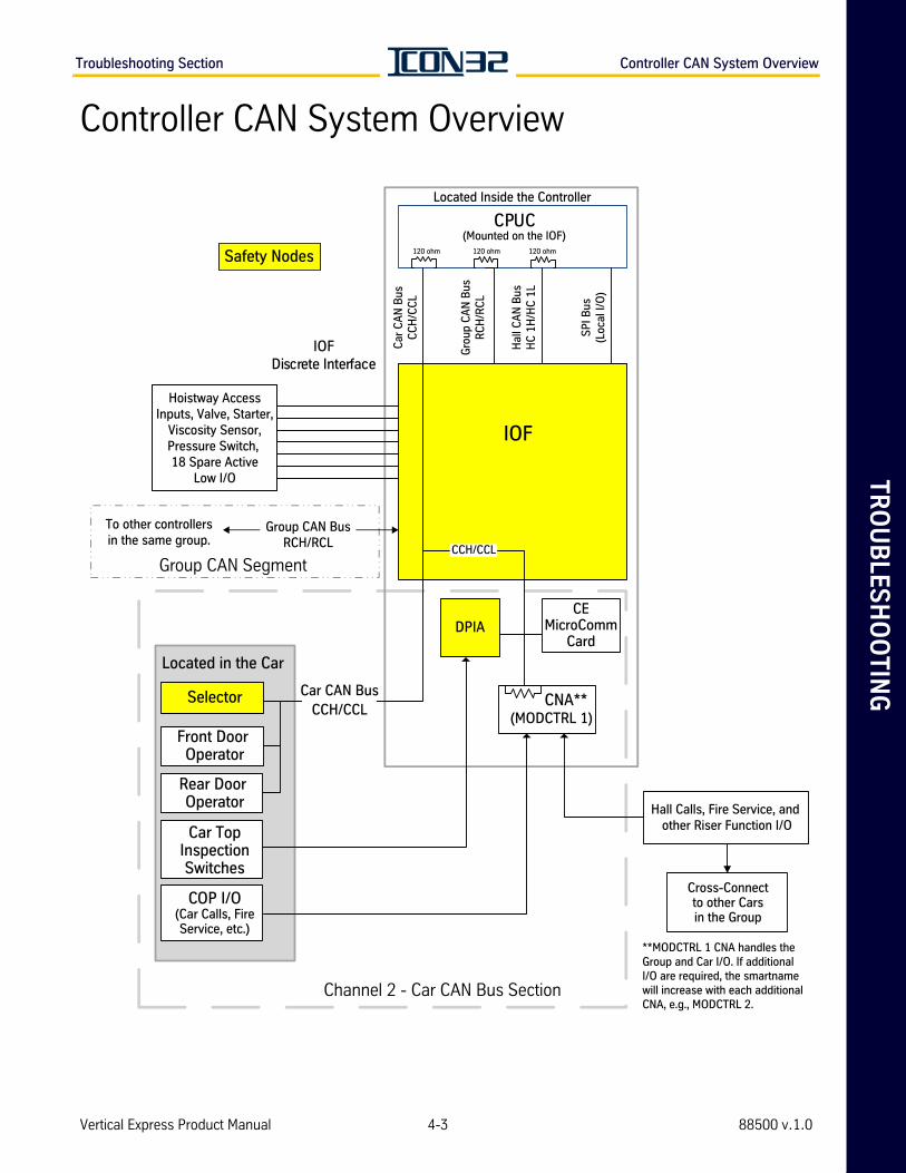
TR
OU
BLE
SH
OO
TIN
GTroubleshooting Section Controller CAN System Overview
Controller CAN System Overview
CPUC
IOFDiscrete Interface
Group CAN Segment
120 ohm 120 ohm120 ohm
Located Inside the Controller
(Mounted on the IOF)
Safety Nodes
IOF
Hoistway AccessInputs, Valve, Starter,
Viscosity Sensor,Pressure Switch, 18 Spare Active
Low I/O
Car
CA
N B
usC
CH
/CC
L
SP
I Bus
(Loc
al I/
O)
Hal
l CA
N B
usH
C 1
H/H
C 1
L
Gro
up C
AN
Bus
RC
H/R
CL
Group CAN BusRCH/RCL
CCH/CCL
To other controllersin the same group.
DPIA
Located in the Car
Car CAN BusCCH/CCL
Selector
Front Door Operator
Car TopInspectionSwitches
Rear Door Operator
COP I/O(Car Calls, FireService, etc.)
Channel 2 - Car CAN Bus Section
CEMicroComm
Card
CNA**(MODCTRL 1)
Hall Calls, Fire Service, and other Riser Function I/O
Cross-Connectto other Carsin the Group
**MODCTRL 1 CNA handles theGroup and Car I/O. If additionalI/O are required, the smartnamewill increase with each additionalCNA, e.g., MODCTRL 2.
Vertical Express Product Manual 4-3 88500 v.1.0
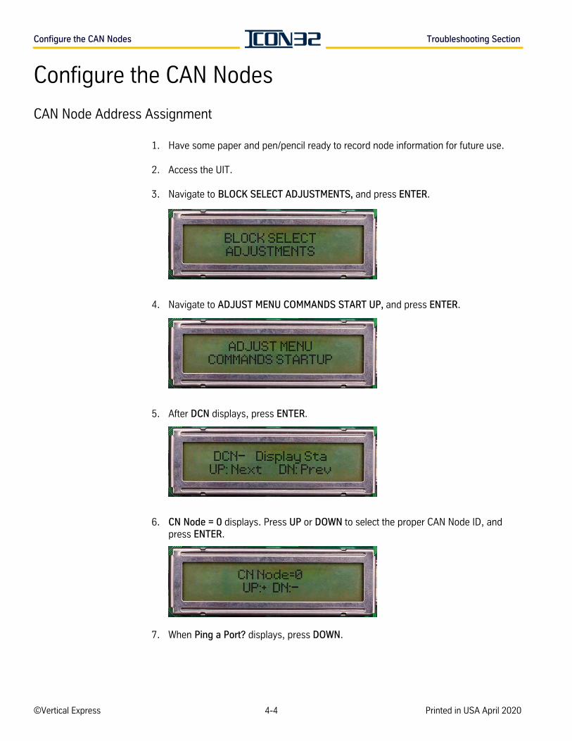
Configure the CAN Nodes Troubleshooting Section
Configure the CAN Nodes
CAN Node Address Assignment
1. Have some paper and pen/pencil ready to record node information for future use.
2. Access the UIT.
3. Navigate to BLOCK SELECT ADJUSTMENTS, and press ENTER.
4. Navigate to ADJUST MENU COMMANDS START UP, and press ENTER.
5. After DCN displays, press ENTER.
6. CN Node = 0 displays. Press UP or DOWN to select the proper CAN Node ID, and press ENTER.
7. When Ping a Port? displays, press DOWN.
BLOCK SELECTADJUSTMENTS
ADJUST MENUCOMMANDS STARTUP
DCN— Display StaUP: Next DN: Prev
CN Node=0UP:+ DN:—
©Vertical Express 4-4 Printed in USA April 2020
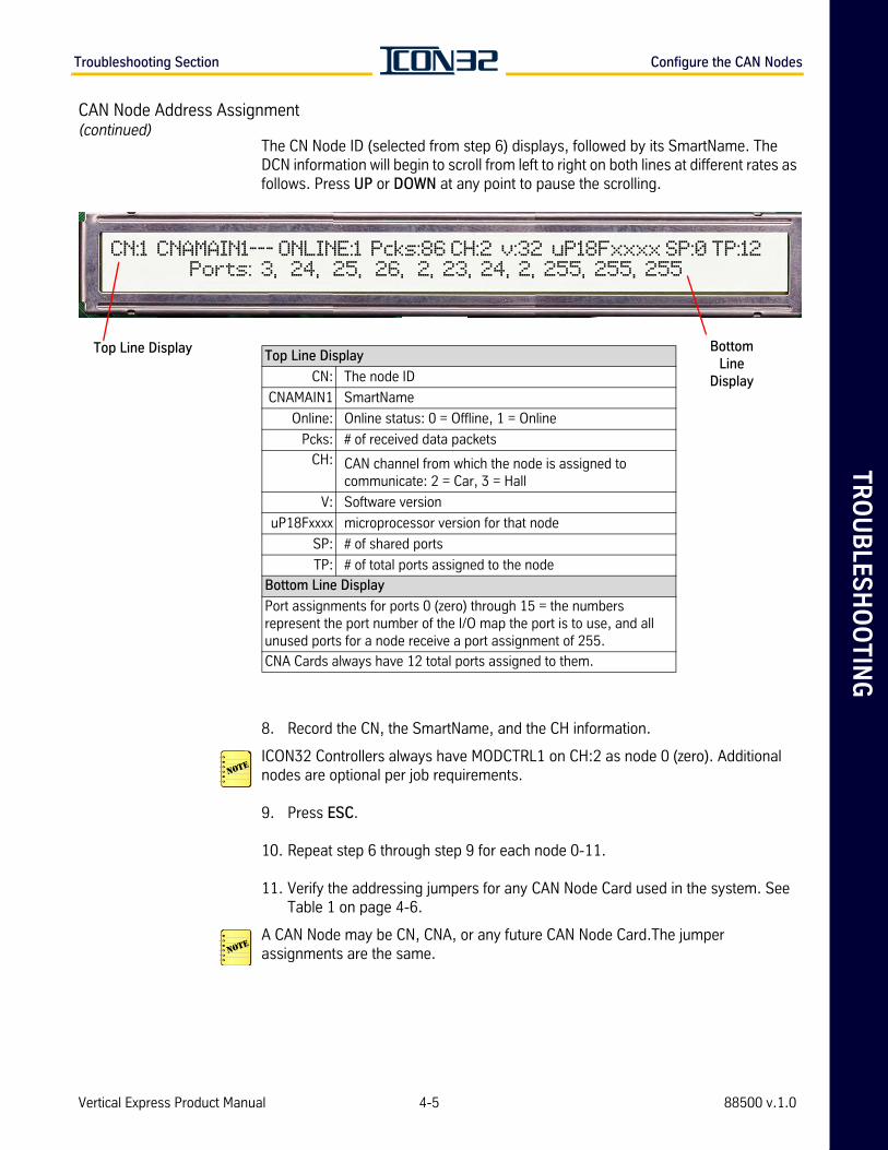
TR
OU
BLE
SH
OO
TIN
GTroubleshooting Section Configure the CAN Nodes
CAN Node Address Assignment(continued)
The CN Node ID (selected from step 6) displays, followed by its SmartName. The DCN information will begin to scroll from left to right on both lines at different rates as follows. Press UP or DOWN at any point to pause the scrolling.
8. Record the CN, the SmartName, and the CH information.
ICON32 Controllers always have MODCTRL1 on CH:2 as node 0 (zero). Additional nodes are optional per job requirements.
9. Press ESC.
10. Repeat step 6 through step 9 for each node 0-11.
11. Verify the addressing jumpers for any CAN Node Card used in the system. See Table 1 on page 4-6.
A CAN Node may be CN, CNA, or any future CAN Node Card.The jumper assignments are the same.
CN:1 CNAMAIN1--- ONLINE:1 Pcks:86 CH:2 v:32 uP18Fxxxx SP:0 TP:12Ports: 3, 24, 25, 26, 2, 23, 24, 2, 255, 255, 255
Top Line Display
CN: The node ID
CNAMAIN1 SmartName
Online: Online status: 0 = Offline, 1 = Online
Pcks: # of received data packets
CH: CAN channel from which the node is assigned to communicate: 2 = Car, 3 = Hall
V: Software version
uP18Fxxxx microprocessor version for that node
SP: # of shared ports
TP: # of total ports assigned to the node
Bottom Line Display
Port assignments for ports 0 (zero) through 15 = the numbers represent the port number of the I/O map the port is to use, and all unused ports for a node receive a port assignment of 255.
CNA Cards always have 12 total ports assigned to them.
BottomLine
Display
Top Line Display
Vertical Express Product Manual 4-5 88500 v.1.0
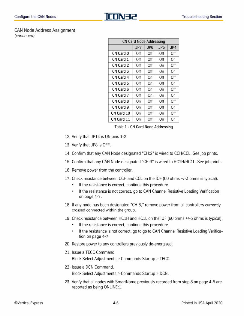
Configure the CAN Nodes Troubleshooting Section
CAN Node Address Assignment(continued)
Table 1 - CN Card Node Addressing
12. Verify that JP14 is ON pins 1-2.
13. Verify that JP8 is OFF.
14. Confirm that any CAN Node designated "CH:2" is wired to CCH/CCL. See job prints.
15. Confirm that any CAN Node designated "CH:3" is wired to HC1H/HC1L. See job prints.
16. Remove power from the controller.
17. Check resistance between CCH and CCL on the IOF (60 ohms +/-3 ohms is typical).
• If the resistance is correct, continue this procedure.
• If the resistance is not correct, go to CAN Channel Resistive Loading Verification on page 4-7.
18. If any node has been designated "CH:3," remove power from all controllers currently crossed connected within the group.
19. Check resistance between HC1H and HC1L on the IOF (60 ohms +/-3 ohms is typical).
• If the resistance is correct, continue this procedure.
• If the resistance is not correct, go to go to CAN Channel Resistive Loading Verifica-tion on page 4-7.
20. Restore power to any controllers previously de-energized.
21. Issue a TECC Command.
Block Select Adjustments > Commands Startup > TECC.
22. Issue a DCN Command.
Block Select Adjustments > Commands Startup > DCN.
23. Verify that all nodes with SmartName previously recorded from step 8 on page 4-5 are reported as being ONLINE:1.
CN Card Node Addressing
JP7 JP6 JP5 JP4
CN Card 0 Off Off Off Off
CN Card 1 Off Off Off On
CN Card 2 Off Off On Off
CN Card 3 Off Off On On
CN Card 4 Off On Off Off
CN Card 5 Off On Off On
CN Card 6 Off On On Off
CN Card 7 Off On On On
CN Card 8 On Off Off Off
CN Card 9 On Off Off On
CN Card 10 On Off On Off
CN Card 11 On Off On On
©Vertical Express 4-6 Printed in USA April 2020
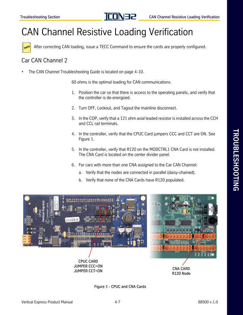
TR
OU
BLE
SH
OO
TIN
GTroubleshooting Section CAN Channel Resistive Loading Verification
CAN Channel Resistive Loading VerificationAfter correcting CAN loading, issue a TECC Command to ensure the cards are properly configured.
Car CAN Channel 2
• The CAN Channel Troubleshooting Guide is located on page 4-10.
60 ohms is the optimal loading for CAN communications.
1. Position the car so that there is access to the operating panels, and verify that the controller is de-energized.
2. Turn OFF, Lockout, and Tagout the mainline disconnect.
3. In the COP, verify that a 121 ohm axial leaded resistor is installed across the CCH and CCL rail terminals.
4. In the controller, verify that the CPUC Card jumpers CCC and CCT are ON. See Figure 1.
5. In the controller, verify that R120 on the MODCTRL1 CNA Card is not installed. The CNA Card is located on the center divider panel.
6. For cars with more than one CNA assigned to the Car CAN Channel:
a. Verify that the nodes are connected in parallel (daisy-chained).
b. Verify that none of the CNA Cards have R120 populated.
Figure 1 - CPUC and CNA Cards
CPUC CARD JUMPER CCC=ON JUMPER CCT=ON
CNA CARDR120 Node
Vertical Express Product Manual 4-7 88500 v.1.0
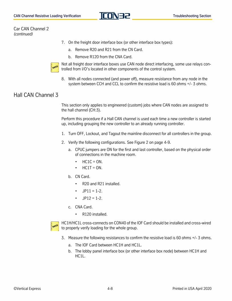
CAN Channel Resistive Loading Verification Troubleshooting Section
Car CAN Channel 2(continued)
7. On the freight door interface box (or other interface box types):
a. Remove R20 and R21 from the CN Card.
b. Remove R120 from the CNA Card.
Not all freight door interface boxes use CAN node direct interfacing, some use relays con-trolled from I/O’s located in other components of the control system.
8. With all nodes connected (and power off), measure resistance from any node in the system between CCH and CCL to confirm the resistive load is 60 ohms +/- 3 ohms.
Hall CAN Channel 3
This section only applies to engineered (custom) jobs where CAN nodes are assigned to the hall channel (CH:3).
Perform this procedure if a Hall CAN channel is used each time a new controller is started up, including grouping the new controller to an already running controller.
1. Turn OFF, Lockout, and Tagout the mainline disconnect for all controllers in the group.
2. Verify the following configurations. See Figure 2 on page 4-9.
a. CPUC jumpers are ON for the first and last controller, based on the physical order of connections in the machine room.
• HC1C = ON.
• HC1T = ON.
b. CN Card.
• R20 and R21 installed.
• JP11 = 1-2.
• JP12 = 1-2.
c. CNA Card.
• R120 installed.
HC1H/HC1L cross-connects on CON40 of the IOF Card should be installed and cross-wired to properly verify loading for the whole group.
3. Measure the following resistances to confirm the resistive load is 60 ohms +/- 3 ohms.
a. The IOF Card between HC1H and HC1L.
b. The lobby panel interface box (or other interface box node) between HC1H and HC1L.
©Vertical Express 4-8 Printed in USA April 2020
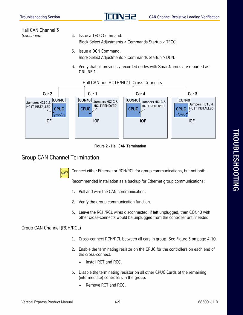
TR
OU
BLE
SH
OO
TIN
GTroubleshooting Section CAN Channel Resistive Loading Verification
Hall CAN Channel 3(continued) 4. Issue a TECC Command.
Block Select Adjustments > Commands Startup > TECC.
5. Issue a DCN Command.
Block Select Adjustments > Commands Startup > DCN.
6. Verify that all previously recorded nodes with SmartNames are reported as ONLINE:1.
Figure 2 - Hall CAN Termination
Group CAN Channel Termination
Connect either Ethernet or RCH/RCL for group communications, but not both.
Recommended Installation as a backup for Ethernet group communications:
1. Pull and wire the CAN communication.
2. Verify the group communication function.
3. Leave the RCH/RCL wires disconnected; if left unplugged, then CON40 with other cross-connects would be unplugged from the controller until needed.
Group CAN Channel (RCH/RCL)
1. Cross-connect RCH/RCL between all cars in group. See Figure 3 on page 4-10.
2. Enable the terminating resistor on the CPUC for the controllers on each end of the cross-connect.
» Install RCT and RCC.
3. Disable the terminating resistor on all other CPUC Cards of the remaining (intermediate) controllers in the group.
» Remove RCT and RCC.
Hall CAN bus HC1H/HC1L Cross Connects
Car 2
IOF
Car 1
Jumpers HC1C &HC1T REMOVED
CPUC
Car 4 Car 3
CON40CON40 CON40 CON40Jumpers HC1C &HC1T REMOVED
Jumpers HC1C &HC1T INSTALLED
Jumpers HC1C &HC1T INSTALLED
IOFIOF IOF
CPUCCPUCCPUC
Vertical Express Product Manual 4-9 88500 v.1.0
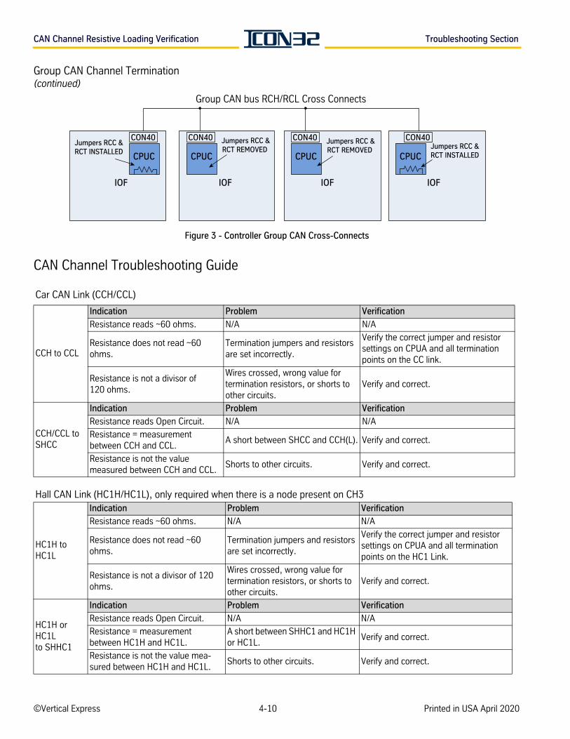
CAN Channel Resistive Loading Verification Troubleshooting Section
Group CAN Channel Termination(continued)
Figure 3 - Controller Group CAN Cross-Connects
CAN Channel Troubleshooting Guide
Car CAN Link (CCH/CCL)
CCH to CCL
Indication Problem Verification
Resistance reads ~60 ohms. N/A N/A
Resistance does not read ~60 ohms.
Termination jumpers and resistors are set incorrectly.
Verify the correct jumper and resistor settings on CPUA and all termination points on the CC link.
Resistance is not a divisor of 120 ohms.
Wires crossed, wrong value for termination resistors, or shorts to other circuits.
Verify and correct.
CCH/CCL to SHCC
Indication Problem Verification
Resistance reads Open Circuit. N/A N/A
Resistance = measurement between CCH and CCL.
A short between SHCC and CCH(L). Verify and correct.
Resistance is not the value measured between CCH and CCL.
Shorts to other circuits. Verify and correct.
Hall CAN Link (HC1H/HC1L), only required when there is a node present on CH3
HC1H to HC1L
Indication Problem Verification
Resistance reads ~60 ohms. N/A N/A
Resistance does not read ~60 ohms.
Termination jumpers and resistors are set incorrectly.
Verify the correct jumper and resistor settings on CPUA and all termination points on the HC1 Link.
Resistance is not a divisor of 120 ohms.
Wires crossed, wrong value for termination resistors, or shorts to other circuits.
Verify and correct.
HC1H or HC1Lto SHHC1
Indication Problem Verification
Resistance reads Open Circuit. N/A N/A
Resistance = measurement between HC1H and HC1L.
A short between SHHC1 and HC1H or HC1L.
Verify and correct.
Resistance is not the value mea-sured between HC1H and HC1L.
Shorts to other circuits. Verify and correct.
Group CAN bus RCH/RCL Cross Connects
IOF
Jumpers RCC &RCT REMOVED
CPUC
CON40CON40 CON40 CON40Jumpers RCC &RCT REMOVED
Jumpers RCC &RCT INSTALLED
Jumpers RCC &RCT INSTALLED
IOFIOF IOF
CPUCCPUCCPUC
©Vertical Express 4-10 Printed in USA April 2020
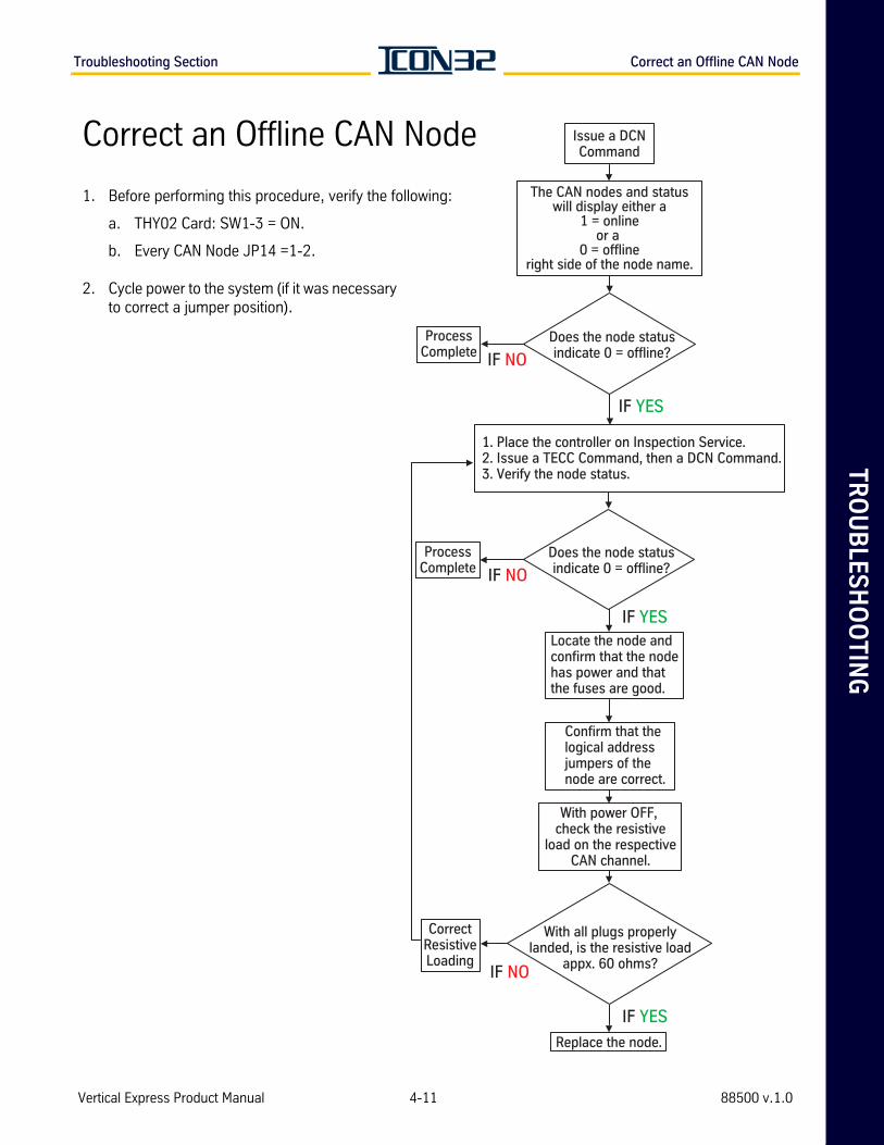
TR
OU
BLE
SH
OO
TIN
GTroubleshooting Section Correct an Offline CAN Node
Issue a DCNCommand
The CAN nodes and statuswill display either a
1 = onlineor a
0 = offlineright side of the node name.
Does the node statusindicate 0 = offline?
ProcessComplete IF NO
IF YES
IF YES
IF YES
IF NO
1. Place the controller on Inspection Service.2. Issue a TECC Command, then a DCN Command.3. Verify the node status.
Locate the node andconfirm that the nodehas power and thatthe fuses are good.
Confirm that thelogical addressjumpers of thenode are correct.
With power OFF, check the resistive
load on the respectiveCAN channel.
With all plugs properlylanded, is the resistive load
appx. 60 ohms?
CorrectResistiveLoading
Replace the node.
Does the node statusindicate 0 = offline?
ProcessComplete IF NO
Correct an Offline CAN Node
1. Before performing this procedure, verify the following:
a. THY02 Card: SW1-3 = ON.
b. Every CAN Node JP14 =1-2.
2. Cycle power to the system (if it was necessary to correct a jumper position).
Vertical Express Product Manual 4-11 88500 v.1.0
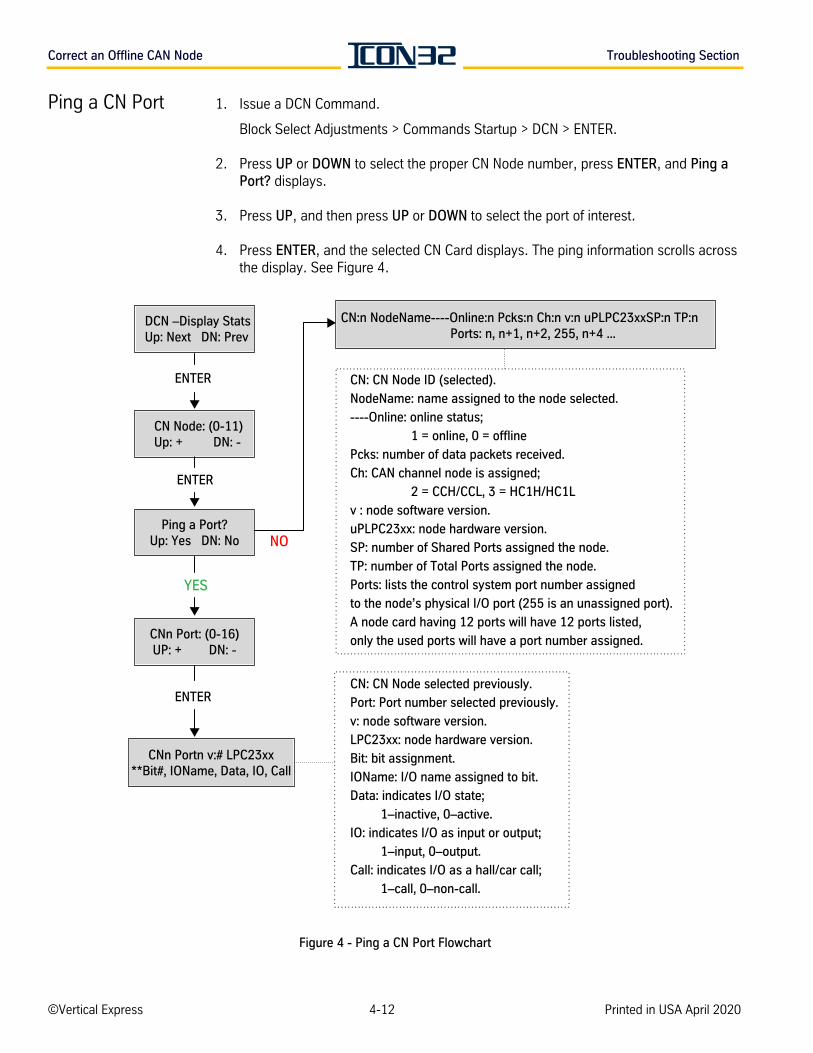
Correct an Offline CAN Node Troubleshooting Section
Ping a CN Port 1. Issue a DCN Command.
Block Select Adjustments > Commands Startup > DCN > ENTER.
2. Press UP or DOWN to select the proper CN Node number, press ENTER, and Ping a Port? displays.
3. Press UP, and then press UP or DOWN to select the port of interest.
4. Press ENTER, and the selected CN Card displays. The ping information scrolls across the display. See Figure 4.
Figure 4 - Ping a CN Port Flowchart
DCN –Display StatsUp: Next DN: Prev
CN Node: (0-11)Up: + DN: -
Ping a Port?Up: Yes DN: No
YES
CNn Port: (0-16)UP: + DN: -
NO
CN:n NodeName----Online:n Pcks:n Ch:n v:n uPLPC23xxSP:n TP:n Ports: n, n+1, n+2, 255, n+4 ...
CN: CN Node ID (selected).
NodeName: name assigned to the node selected.
----Online: online status;
1 = online, 0 = offline
Pcks: number of data packets received.
Ch: CAN channel node is assigned;
2 = CCH/CCL, 3 = HC1H/HC1L
v : node software version.
uPLPC23xx: node hardware version.
SP: number of Shared Ports assigned the node.
TP: number of Total Ports assigned the node.
Ports: lists the control system port number assigned
to the node’s physical I/O port (255 is an unassigned port).
A node card having 12 ports will have 12 ports listed,
only the used ports will have a port number assigned.
CN: CN Node selected previously.
Port: Port number selected previously.
v: node software version.
LPC23xx: node hardware version.
Bit: bit assignment.
IOName: I/O name assigned to bit.
Data: indicates I/O state;
1–inactive, 0–active.
IO: indicates I/O as input or output;
1–input, 0–output.
Call: indicates I/O as a hall/car call;
1–call, 0–non-call.
ENTER
ENTER
ENTER
CNn Portn v:# LPC23xx**Bit#, IOName, Data, IO, Call
©Vertical Express 4-12 Printed in USA April 2020
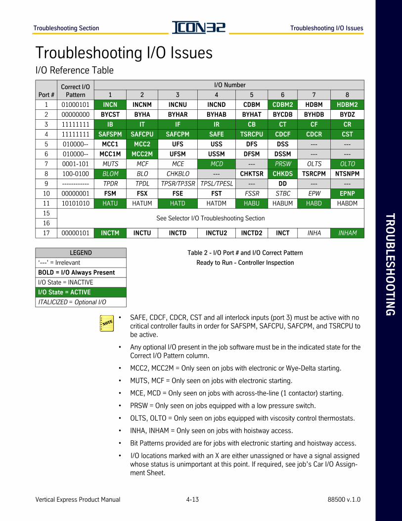
TR
OU
BLE
SH
OO
TIN
GTroubleshooting Section Troubleshooting I/O Issues
Troubleshooting I/O IssuesI/O Reference Table
• SAFE, CDCF, CDCR, CST and all interlock inputs (port 3) must be active with no critical controller faults in order for SAFSPM, SAFCPU, SAFCPM, and TSRCPU to be active.
• Any optional I/O present in the job software must be in the indicated state for the Correct I/O Pattern column.
• MCC2, MCC2M = Only seen on jobs with electronic or Wye-Delta starting.
• MUTS, MCF = Only seen on jobs with electronic starting.
• MCE, MCD = Only seen on jobs with across-the-line (1 contactor) starting.
• PRSW = Only seen on jobs equipped with a low pressure switch.
• OLTS, OLTO = Only seen on jobs equipped with viscosity control thermostats.
• INHA, INHAM = Only seen on jobs with hoistway access.
• Bit Patterns provided are for jobs with electronic starting and hoistway access.
• I/O locations marked with an X are either unassigned or have a signal assigned whose status is unimportant at this point. If required, see job’s Car I/O Assign-ment Sheet.
Port #Correct I/O
Pattern
I/O Number
1 2 3 4 5 6 7 8
1 01000101 INCN INCNM INCNU INCND CDBM CDBM2 HDBM HDBM2
2 00000000 BYCST BYHA BYHAR BYHAB BYHAT BYCDB BYHDB BYDZ
3 11111111 IB IT IF IR CB CT CF CR
4 11111111 SAFSPM SAFCPU SAFCPM SAFE TSRCPU CDCF CDCR CST
5 010000-- MCC1 MCC2 UFS USS DFS DSS --- ---
6 010000-- MCC1M MCC2M UFSM USSM DFSM DSSM --- ---
7 0001-101 MUTS MCF MCE MCD --- PRSW OLTS OLTO
8 100-0100 BLOM BLO CHKBLO --- CHKTSR CHKDS TSRCPM NTSNPM
9 ------------ TPDR TPDL TPSR/TP3SR TPSL/TPESL --- DD --- ---
10 00000001 FSM FSX FSE FST FSSR STBC EPW EPNP
11 10101010 HATU HATUM HATD HATDM HABU HABUM HABD HABDM
15See Selector I/O Troubleshooting Section
16
17 00000101 INCTM INCTU INCTD INCTU2 INCTD2 INCT INHA INHAM
LEGEND Table 2 - I/O Port # and I/O Correct Pattern
‘---’ = Irrelevant Ready to Run - Controller Inspection
BOLD = I/O Always Present
I/O State = INACTIVE
I/O State = ACTIVE
ITALICIZED = Optional I/O
Vertical Express Product Manual 4-13 88500 v.1.0
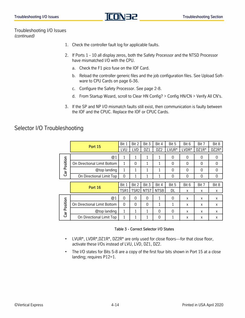
Troubleshooting I/O Issues Troubleshooting Section
Troubleshooting I/O Issues(continued)
1. Check the controller fault log for applicable faults.
2. If Ports 1 - 10 all display zeros, both the Safety Processor and the NTSD Processor have mismatched I/O with the CPU.
a. Check the F1 pico fuse on the IOF Card.
b. Reload the controller generic files and the job configuration files. See Upload Soft-ware to CPU Cards on page 6-36.
c. Configure the Safety Processor. See page 2-8.
d. From Startup Wizard, scroll to Clear HN Config? > Config HN/CN > Verify All CN's.
3. If the SP and NP I/O mismatch faults still exist, then communication is faulty between the IOF and the CPUC. Replace the IOF or CPUC Cards.
Selector I/O Troubleshooting
Table 3 - Correct Selector I/O States
• LVUR*, LVDR*,DZ1R*, DZ2R* are only used for close floors—for that close floor, activate these I/Os instead of LVU, LVD, DZ1, DZ2.
• The I/O states for Bits 5-8 are a copy of the first four bits shown in Port 15 at a close landing; requires P12=1.
Bit 1 Bit 2 Bit 3 Bit 4 Bit 5 Bit 6 Bit 7 Bit 8
LVU LVD DZ1 DZ2 LVUR* LVDR* DZ1R* DZ2R*
@1 1 1 1 1 0 0 0 0
On Directional Limit Bottom 1 0 1 1 0 0 0 0
@top landing 1 1 1 1 0 0 0 0
On Directional Limit Top 0 1 1 1 0 0 0 0
Bit 1 Bit 2 Bit 3 Bit 4 Bit 5 Bit 6 Bit 7 Bit 8
TSR1 TSR2 NTST NTSB DL x x x
@1 0 0 0 1 0 x x x
On Directional Limit Bottom 0 0 0 1 1 x x x
@top landing 1 1 1 0 0 x x x
On Directional Limit Top 1 1 1 0 1 x x x
Port 16
Car
Pos
ition
Car
Pos
ition
Port 15
©Vertical Express 4-14 Printed in USA April 2020
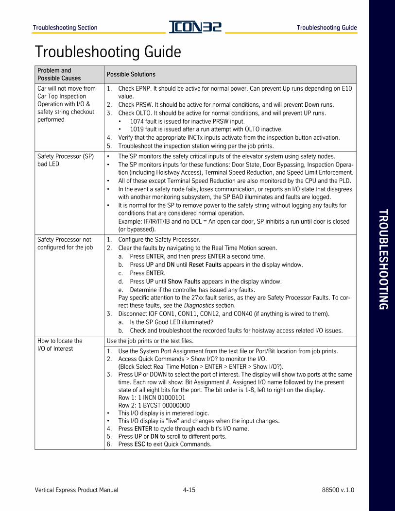
TR
OU
BLE
SH
OO
TIN
GTroubleshooting Section Troubleshooting Guide
Troubleshooting GuideProblem and Possible Causes
Possible Solutions
Car will not move from Car Top Inspection Operation with I/O & safety string checkout performed
1. Check EPNP. It should be active for normal power. Can prevent Up runs depending on E10 value.
2. Check PRSW. It should be active for normal conditions, and will prevent Down runs.3. Check OLTO. It should be active for normal conditions, and will prevent UP runs.
• 1074 fault is issued for inactive PRSW input.• 1019 fault is issued after a run attempt with OLTO inactive.
4. Verify that the appropriate INCTx inputs activate from the inspection button activation. 5. Troubleshoot the inspection station wiring per the job prints.
Safety Processor (SP) bad LED
• The SP monitors the safety critical inputs of the elevator system using safety nodes.• The SP monitors inputs for these functions: Door State, Door Bypassing, Inspection Opera-
tion (including Hoistway Access), Terminal Speed Reduction, and Speed Limit Enforcement.• All of these except Terminal Speed Reduction are also monitored by the CPU and the PLD.• In the event a safety node fails, loses communication, or reports an I/O state that disagrees
with another monitoring subsystem, the SP BAD illuminates and faults are logged.• It is normal for the SP to remove power to the safety string without logging any faults for
conditions that are considered normal operation.Example: IF/IR/IT/IB and no DCL = An open car door, SP inhibits a run until door is closed (or bypassed).
Safety Processor not configured for the job
1. Configure the Safety Processor. 2. Clear the faults by navigating to the Real Time Motion screen.
a. Press ENTER, and then press ENTER a second time.b. Press UP and DN until Reset Faults appears in the display window.c. Press ENTER.d. Press UP until Show Faults appears in the display window.e. Determine if the controller has issued any faults.Pay specific attention to the 27xx fault series, as they are Safety Processor Faults. To cor-rect these faults, see the Diagnostics section.
3. Disconnect IOF CON1, CON11, CON12, and CON40 (if anything is wired to them).a. Is the SP Good LED illuminated?b. Check and troubleshoot the recorded faults for hoistway access related I/O issues.
How to locate theI/O of Interest
Use the job prints or the text files.
1. Use the System Port Assignment from the text file or Port/Bit location from job prints.2. Access Quick Commands > Show I/O? to monitor the I/O.
(Block Select Real Time Motion > ENTER > ENTER > Show I/O?).3. Press UP or DOWN to select the port of interest. The display will show two ports at the same
time. Each row will show: Bit Assignment #, Assigned I/O name followed by the present state of all eight bits for the port. The bit order is 1-8, left to right on the display.Row 1: 1 INCN 01000101Row 2: 1 BYCST 00000000
• This I/O display is in metered logic.• This I/O display is "live" and changes when the input changes.4. Press ENTER to cycle through each bit's I/O name.5. Press UP or DN to scroll to different ports.6. Press ESC to exit Quick Commands.
Vertical Express Product Manual 4-15 88500 v.1.0
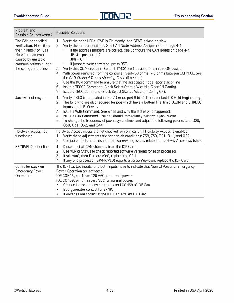
Troubleshooting Guide Troubleshooting Section
The CAN node failed verification. Most likely the "In Mask" or "Call Mask" has an error caused by unstable communications during the configure process.
1. Verify the node LEDs: PWR is ON steady, and STAT is flashing slow.2. Verify the jumper positions. See CAN Node Address Assignment on page 4-4.
• If the address jumpers are correct, see Configure the CAN Nodes on page 4-4.JP14 = position 1-2.JP8 = OFF.
• If jumpers were corrected, press RST.3. Verify that CE MicroComm Card (THY-02) SW1 position 3, is in the ON position.4. With power removed from the controller, verify 60 ohms +/-3 ohms between CCH/CCL. See
the CAN Channel Troubleshooting Guide (if needed).5. Use the DCN command to ensure that the associated node reports as online6. Issue a TECCR Command (Block Select Startup Wizard > Clear CN Config).7. Issue a TECC Command (Block Select Startup Wizard > Config CN).
Jack will not resync 1. Verify if BLO is populated in the I/O map, port 8 bit 2. If not, contact ITS Field Engineering.2. The following are also required for jobs which have a bottom final limit: BLOM and CHKBLO
inputs and a BLO relay.3. Issue a WJR Command. See when and why the last resync happened.4. Issue a FJR Command. The car should immediately perform a jack resync.5. To change the frequency of jack resync, check and adjust the following parameters: O29,
O30, O31, O32, and O44.
Hoistway access not functioning
Hoistway Access inputs are not checked for conflicts until Hoistway Access is enabled.1. Verify these adjustments are set per job conditions: Z38, Z39, O21, O11, and O22.2. Use job prints to troubleshoot hardware/wiring issues related to Hoistway Access switches.
SP/NP/PLD not online 1. Disconnect all CAN channels from the IOF Card. 2. Use VER or Status to check reported software versions for each processor. 3. If still v0r0, then if all are v0r0, replace the CPU. 4. If any one processor (SP/NP/PLD) reports a version/revision, replace the IOF Card.
Controller stuck on Emergency PowerOperation
The IOF has two inputs, and both inputs have to indicate that Normal Power or Emergency Power Operation are activated. IOF CON18, pin 1 has 120 VAC for normal power. IOE CON39, pin 6 has zero VDC for normal power. • Connection issue between trades and CON39 of IOF Card. • Bad generator contact for EPNP. • If voltages are correct at the IOF Car, a failed IOF Card.
Problem and Possible Causes (cont.)
Possible Solutions
©Vertical Express 4-16 Printed in USA April 2020
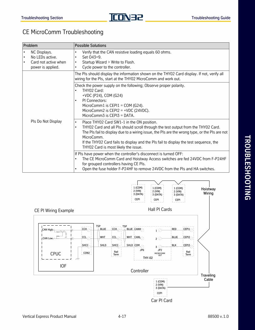
TR
OU
BLE
SH
OO
TIN
GTroubleshooting Section Troubleshooting Guide
CE MicroComm Troubleshooting
Problem Possible Solutions
• NC Displays.• No LEDs active.• Card not active when
power is applied.
• Verify that the CAN resistive loading equals 60 ohms. • Set O43=9.• Startup Wizard > Write to Flash.• Cycle power to the controller.
PIs Do Not Display
The PIs should display the information shown on the THY02 Card display. If not, verify all wiring for the PIs, start at the THY02 MicroComm and work out.
Check the power supply on the following; Observe proper polarity.• THY02 Card:
+VDC (P24), COM (G24)• PI Connectors:
MicroComm1 is CEPI1 = COM (G24). MicroComm2 is CEPI2 = +VDC (24VDC). MicroComm3 is CEPI3 = DATA.
• Place THY02 Card SW1-1 in the ON position.• THY02 Card and all PIs should scroll through the test output from the THY02 Card.
The PIs fail to display due to a wiring issue, the PIs are the wrong type, or the PIs are not MicroComm.If the THY02 Card fails to display and the PIs fail to display the test sequence, the THY02 Card is most likely the issue.
If PIs have power when the controller's disconnect is turned OFF:• The CE MicroComm Card and Hoistway Access switches are fed 24VDC from F-P24HF
for grouped controllers having CE PIs.• Open the fuse holder F-P24HF to remove 24VDC from the PIs and HA switches.
Hall PI Cards
Car PI Card
CE PI Wiring Example
CPUC
IOFController
Traveling Cable
HoistwayWiring
1 (COM)2 (VIN)3 (DATA)
CEPI
1 (COM)2 (VIN)3 (DATA)
CEPI
1 (COM)2 (VIN)3 (DATA)
CEPI
CCH
CCL
SHCC
1 (COM)2 (VIN)3 (DATA)
CEPI
CCH
CCL
SHCC
BLUE
WHT
SHLD
BLUE
WHT
SHLD
RED
BLUE
BLK
CEPI1
CEPI2
CEPI3
CANH
CANL
COM
1
2
3JP6 JP2
CON2
TSPTSP
RailTerm
RailTerm MICROCOMM
OUT
THY-02
CAN High
CAN Low
Vertical Express Product Manual 4-17 88500 v.1.0
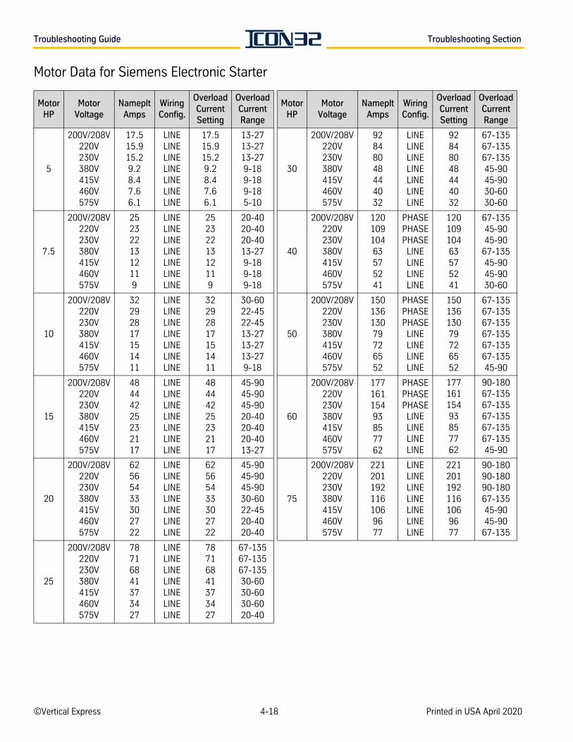
Troubleshooting Guide Troubleshooting Section
Motor Data for Siemens Electronic Starter
MotorHP
MotorVoltage
NamepltAmps
WiringConfig.
OverloadCurrentSetting
OverloadCurrentRange
MotorHP
MotorVoltage
NamepltAmps
WiringConfig.
OverloadCurrentSetting
OverloadCurrentRange
5
200V/208V220V230V380V415V460V575V
17.515.915.29.28.47.66.1
LINELINELINELINELINELINELINE
17.515.915.29.28.47.66.1
13-2713-2713-279-189-189-185-10
30
200V/208V220V230V380V415V460V575V
92848048444032
LINELINELINELINELINELINELINE
92848048444032
67-13567-13567-13545-9045-9030-6030-60
7.5
200V/208V220V230V380V415V460V575V
2523221312119
LINELINELINELINELINELINELINE
2523221312119
20-4020-4020-4013-279-189-189-18
40
200V/208V220V230V380V415V460V575V
12010910463575241
PHASEPHASEPHASELINELINELINELINE
12010910463575241
67-13545-9045-90
67-13545-9045-9030-60
10
200V/208V220V230V380V415V460V575V
32292817151411
LINELINELINELINELINELINELINE
32292817151411
30-6022-4522-4513-2713-2713-279-18
50
200V/208V220V230V380V415V460V575V
15013613079726552
PHASEPHASEPHASELINELINELINELINE
15013613079726552
67-13567-13567-13567-13567-13567-13545-90
15
200V/208V220V230V380V415V460V575V
48444225232117
LINELINELINELINELINELINELINE
48444225232117
45-9045-9045-9020-4020-4020-4013-27
60
200V/208V220V230V380V415V460V575V
17716115493857762
PHASEPHASEPHASELINELINELINELINE
17716115493857762
90-18067-13567-13567-13567-13567-13545-90
20
200V/208V220V230V380V415V460V575V
62565433302722
LINELINELINELINELINELINELINE
62565433302722
45-9045-9045-9030-6022-4520-4020-40
75
200V/208V220V230V380V415V460V575V
2212011921161069677
LINELINELINELINELINELINELINE
2212011921161069677
90-18090-18090-18067-13545-9045-90
67-135
25
200V/208V220V230V380V415V460V575V
78716841373427
LINELINELINELINELINELINELINE
78716841373427
67-13567-13567-13530-6030-6030-6020-40
©Vertical Express 4-18 Printed in USA April 2020
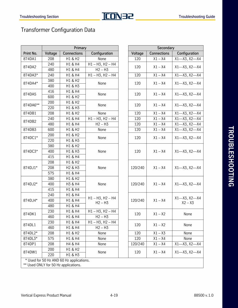
TR
OU
BLE
SH
OO
TIN
GTroubleshooting Section Troubleshooting Guide
Transformer Configuration Data
Primary Secondary
Print No. Voltage Connections Configuration Voltage Connections Configuration
874DA1 208 H1 & H2 None 120 X1 – X4 X1—X3, X2—X4
874DA2240 H1 & H4 H1 – H3, H2 – H4
120 X1 – X4 X1—X3, X2—X4480 H1 & H4 H2 – H3
874DA3* 240 H1 & H4 H1 – H3, H2 – H4 120 X1 – X4 X1—X3, X2—X4
874DA4*380 H1 & H2
None 120 X1 – X4 X1—X3, X2—X4400 H1 & H3
874DA5416 H1 & H4
None 120 X1 – X4 X1—X3, X2—X4600 H1 & H2
874DA6**200 H1 & H2
None 120 X1 – X4 X1—X3, X2—X4220 H1 & H3
874DB1 208 H1 & H2 None 120 X1 – X4 X1—X3, X2—X4
874DB2240 H1 & H4 H1 – H3, H2 – H4 120 X1 – X4 X1—X3, X2—X4
480 H1 & H4 H2 – H3 120 X1 – X4 X1—X3, X2—X4
874DB3 600 H1 & H2 None 120 X1 – X4 X1—X3, X2—X4
874DC1*200 H1 & H2
None 120 X1 – X4 X1—X3, X2—X4220 H1 & H3
874DC3*
380 H1 & H2
None 120 X1 – X4 X1—X3, X2—X4400 H1 & H3
415 H1 & H4
874DJ1*
208 H1 & H2
None 120/240 X1 – X4 X1—X3, X2—X4208 H2 & H3
575 H1 & H4
874DJ2*
380 H1 & H2
None 120/240 X1 – X4 X1—X3, X2—X4400 H3 & H4
415 H1 & H4
874DJ4*
240 H1 & H4H1 – H3, H2 – H4
H2 – H3120/240 X1 – X4
X1—X3, X2—X4X2 – X3
400 H1 & H4
480 H1 & H4
874DK1230 H1 & H4 H1 – H3, H2 – H4
120 X1 – X2 None460 H1 & H4 H2 – H3
874DL1230 H1 & H4 H1 – H3, H2 – H4
120 X1 – X2 None460 H1 & H4 H2 – H3
874DL2* 208 H1 & H2 None 120 X1 – X3 None
874DL3* 575 H1 & H4 None 120 X1 – X4 None
874DP1 208 H4 & H4 None 120/240 X1 – X4 X1—X3, X2—X4
874DW1200 H1 & H2
None 120 X1 – X4 X1—X3, X2—X4220 H1 & H3
* Used for 50 Hz AND 60 Hz applications. ** Used ONLY for 50 Hz applications.
Vertical Express Product Manual 4-19 88500 v.1.0
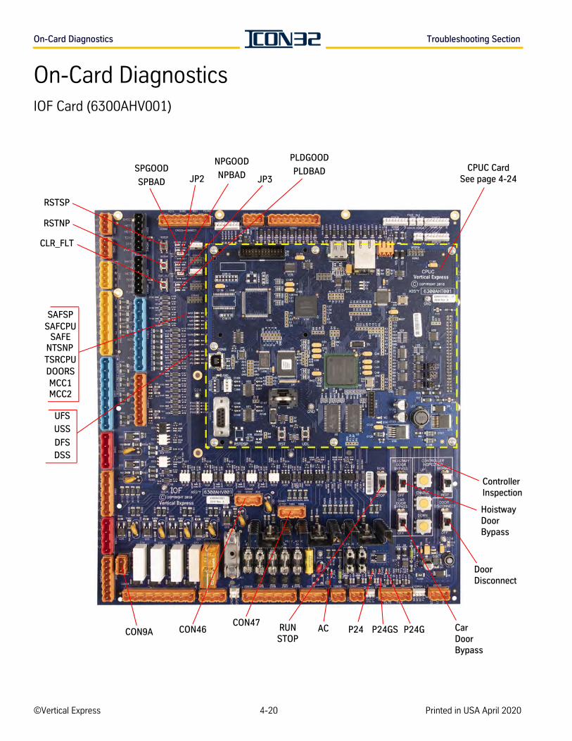
On-Card Diagnostics Troubleshooting Section
On-Card DiagnosticsIOF Card (6300AHV001)
NPBAD
RSTSP
CON46
DOORS
CLR_FLT
Hoistway Door Bypass
CON47CON9A ACRUN
STOP
JP2
RSTNP
Door Disconnect
Car Door Bypass
SPGOODNPGOOD PLDGOOD
PLDBADSPBAD
SAFCPUSAFSP
SAFENTSNPTSRCPU
DSSDFS
UFS
USS
P24 P24GP24GS
JP3
Controller Inspection
CPUC CardSee page 4-24
MCC1MCC2
©Vertical Express 4-20 Printed in USA April 2020
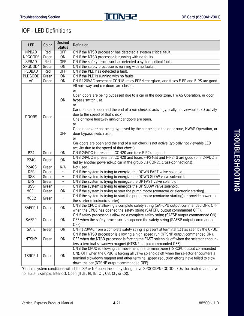
TR
OU
BLE
SH
OO
TIN
GTroubleshooting Section IOF Card (6300AHV001)
IOF - LED Definitions
*Certain system conditions will let the SP or NP open the safety string, have SPGOOD/NPGOOD LEDs illuminated, and have no faults. Example: Interlock Open (IT,IF, IR, IB, CT, CB, CF, or CR).
LED ColorDesired Status
Definition
NPBAD Red OFF ON if the NTSD processor has detected a system critical fault. NPGOOD* Green ON ON if the NTSD processor is running with no faults.
SPBAD Red OFF ON if the safety processor has detected a system critical fault. SPGOOD* Green ON ON if the safety processor is running with no faults. PLDBAD Red OFF ON if the PLD has detected a fault.
PLDGOOD Green ON ON if the PLD is running with no faults. AC Green ON ON if 120VAC present at CON18, relay EPEN energized, and fuses F-EP and F-PS are good.
DOORS Green
ON
All hoistway and car doors are closed,orOpen doors are being bypassed due to a car in the door zone, HWAS Operation, or door bypass switch use, orCar doors are open and the end of a run check is active (typically not viewable LED activity due to the speed of that check)
OFF
One or more hoistway and/or car doors are open,orOpen doors are not being bypassed by the car being in the door zone, HWAS Operation, or door bypass switch use,orCar doors are open and the end of a run check is not active (typically not viewable LED activity due to the speed of that check)
P24 Green ON ON if 24VDC is present at CON20 and fuse F-P24 is good.
P24G Green ONON if 24VDC is present at CON20 and fuses F-P24GS and F-P24G are good (or if 24VDC is fed by another powered-up car in the group via CON21 cross-connections).
P24GS Green N/A Not used.DFS Green ~ ON if the system is trying to energize the DOWN FAST valve solenoid.DSS Green ~ ON if the system is trying to energize the DOWN SLOW valve solenoid.UFS Green ~ ON if the system is trying to energize the UP FAST valve solenoid.USS Green ~ ON if the system is trying to energize the UP SLOW valve solenoid.
MCC1 Green ON ON if the system is trying to start the pump motor (contactor or electronic starting).
MCC2 Green ~ON if the system is trying to start the pump motor (contactor starting) or provide power to the starter (electronic starter).
SAFCPU Green ONON if the CPUC is allowing a complete safety string (SAFCPU output commanded ON). OFF when the CPUC has opened the safety string (SAFCPU output commanded OFF).
SAFSP Green ONON if safety processor is allowing a complete safety string (SAFSP output commanded ON). OFF when the safety processor has opened the safety string (SAFSP output commanded OFF).
SAFE Green ON ON if 120VAC from a complete safety string is present at terminal 131 as seen by the CPUC.
NTSNP Green ONON if the NTSD processor is allowing a high speed run (NTSNP output commanded ON). OFF when the NTSD processor is forcing the FAST solenoids off when the selector encoun-ters a terminal slowdown magnet (NTSNP output commanded OFF).
TSRCPU Green ON
ON if the CPUC is allowing car movement in a terminal zone (TSRCPU output commanded ON). OFF when the CPUC is forcing all valve solenoids off when the selector encounters a terminal slowdown magnet and other terminal speed reduction efforts have failed to slow down the car (NTSNP output commanded OFF).
Vertical Express Product Manual 4-21 88500 v.1.0
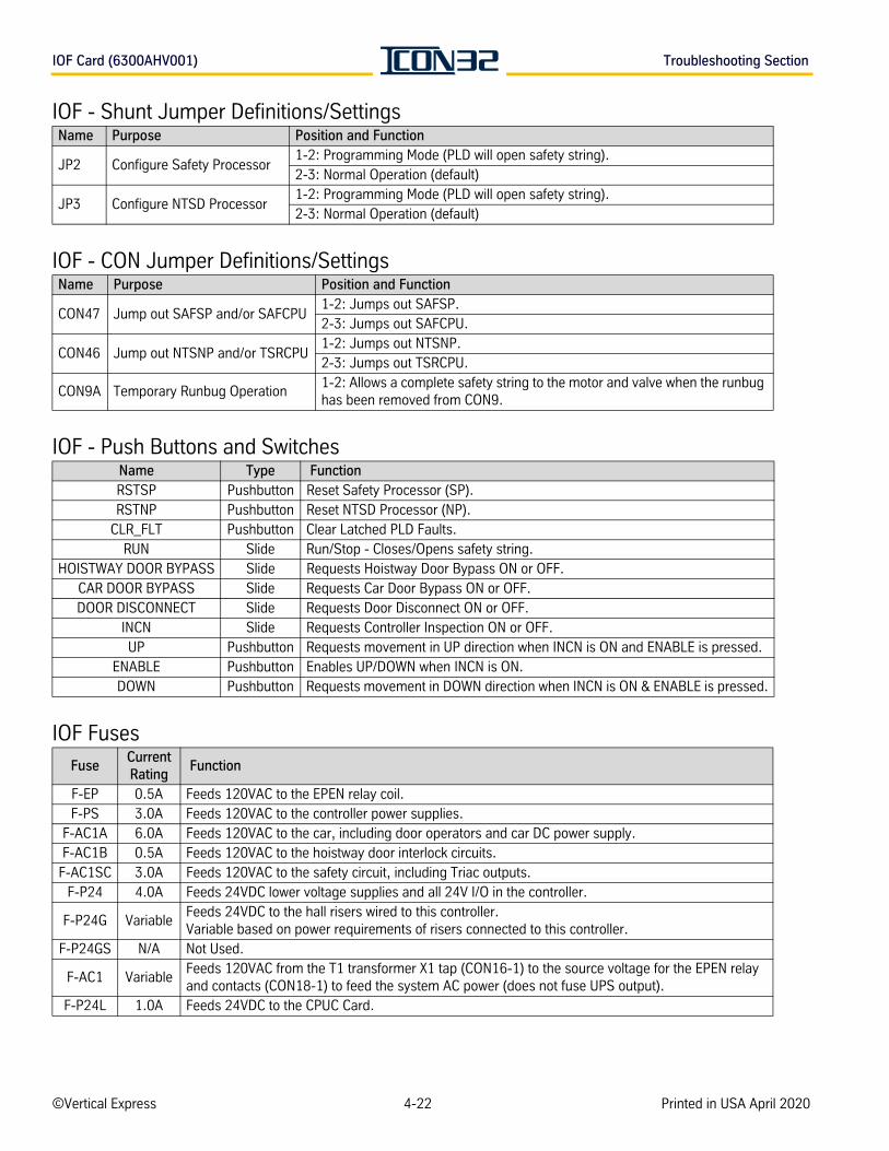
IOF Card (6300AHV001) Troubleshooting Section
IOF - Shunt Jumper Definitions/Settings
IOF - CON Jumper Definitions/Settings
IOF - Push Buttons and Switches
IOF Fuses
Name Purpose Position and Function
JP2 Configure Safety Processor1-2: Programming Mode (PLD will open safety string).2-3: Normal Operation (default)
JP3 Configure NTSD Processor 1-2: Programming Mode (PLD will open safety string).2-3: Normal Operation (default)
Name Purpose Position and Function
CON47 Jump out SAFSP and/or SAFCPU1-2: Jumps out SAFSP.2-3: Jumps out SAFCPU.
CON46 Jump out NTSNP and/or TSRCPU1-2: Jumps out NTSNP.2-3: Jumps out TSRCPU.
CON9A Temporary Runbug Operation1-2: Allows a complete safety string to the motor and valve when the runbug has been removed from CON9.
Name Type FunctionRSTSP Pushbutton Reset Safety Processor (SP).RSTNP Pushbutton Reset NTSD Processor (NP).
CLR_FLT Pushbutton Clear Latched PLD Faults.RUN Slide Run/Stop - Closes/Opens safety string.
HOISTWAY DOOR BYPASS Slide Requests Hoistway Door Bypass ON or OFF.CAR DOOR BYPASS Slide Requests Car Door Bypass ON or OFF.DOOR DISCONNECT Slide Requests Door Disconnect ON or OFF.
INCN Slide Requests Controller Inspection ON or OFF.UP Pushbutton Requests movement in UP direction when INCN is ON and ENABLE is pressed.
ENABLE Pushbutton Enables UP/DOWN when INCN is ON.DOWN Pushbutton Requests movement in DOWN direction when INCN is ON & ENABLE is pressed.
FuseCurrent Rating
Function
F-EP 0.5A Feeds 120VAC to the EPEN relay coil.F-PS 3.0A Feeds 120VAC to the controller power supplies.
F-AC1A 6.0A Feeds 120VAC to the car, including door operators and car DC power supply.F-AC1B 0.5A Feeds 120VAC to the hoistway door interlock circuits.
F-AC1SC 3.0A Feeds 120VAC to the safety circuit, including Triac outputs.F-P24 4.0A Feeds 24VDC lower voltage supplies and all 24V I/O in the controller.
F-P24G VariableFeeds 24VDC to the hall risers wired to this controller.Variable based on power requirements of risers connected to this controller.
F-P24GS N/A Not Used.
F-AC1 VariableFeeds 120VAC from the T1 transformer X1 tap (CON16-1) to the source voltage for the EPEN relay and contacts (CON18-1) to feed the system AC power (does not fuse UPS output).
F-P24L 1.0A Feeds 24VDC to the CPUC Card.
©Vertical Express 4-22 Printed in USA April 2020
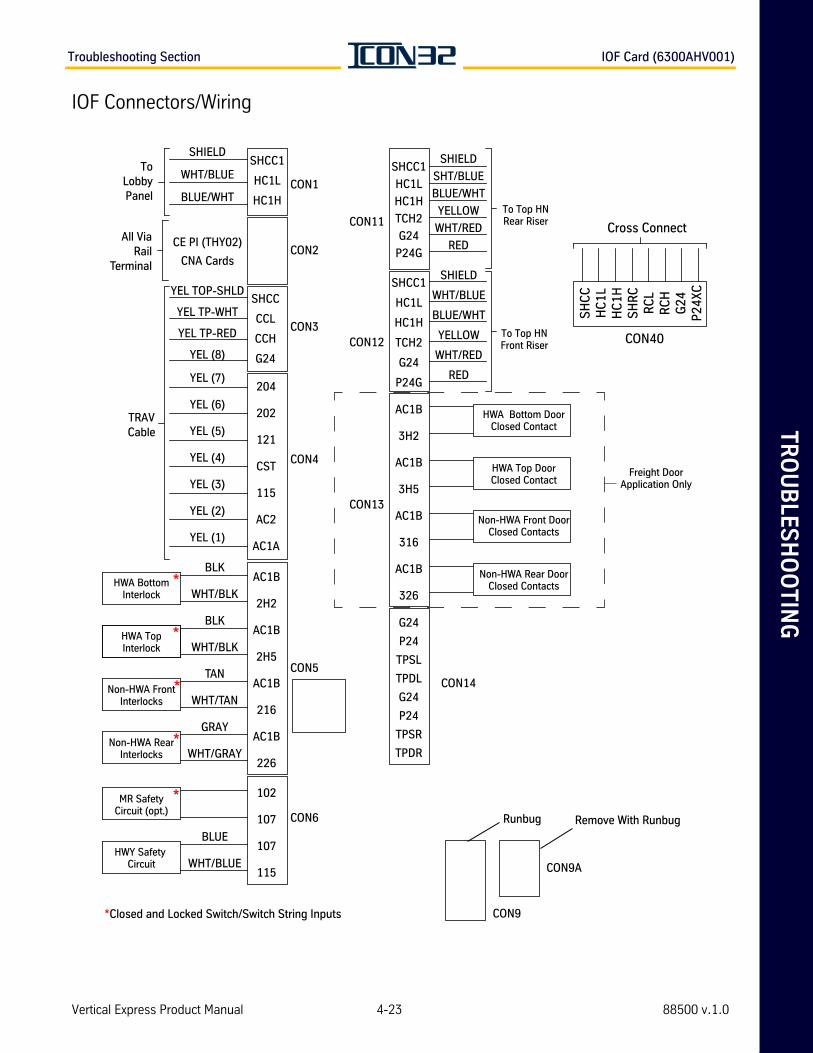
TR
OU
BLE
SH
OO
TIN
GTroubleshooting Section IOF Card (6300AHV001)
IOF Connectors/Wiring
SHCC
CCL
CCH
G24
Cross Connect
CON40
G24
P24
TPSL
TPDL
G24
P24
TPSR
TPDR
CON1
CON2
CON3
CON4
CON5
CON6
CON9
CON9A
CON11
CON12
CON13
CON14
Remove With RunbugRunbug
To Top HNRear Riser
To Top HNFront Riser
SH
CC
HC
1LH
C1H
SH
RC
RC
LR
CH
G24
P24
XC
HWA Bottom DoorClosed Contact
Non-HWA Front DoorClosed Contacts
Non-HWA Rear DoorClosed Contacts
HWA Top DoorClosed Contact
YEL TOP-SHLD
YEL TP-WHT
YEL TP-RED
YEL (8)
HWA BottomInterlock
HWA TopInterlock
Non-HWA FrontInterlocks
Non-HWA RearInterlocks
MR SafetyCircuit (opt.)
HWY Safety Circuit
TRAVCable
All ViaRail
Terminal
ToLobbyPanel
SHIELD
WHT/BLUE
BLUE/WHT
CE PI (THY02)
CNA Cards
SHCC1
HC1L
HC1H
SHIELD
SHT/BLUE
BLUE/WHT
YELLOW
WHT/RED
RED
SHIELD
WHT/BLUE
BLUE/WHT
YELLOW
WHT/RED
RED
SHCC1
HC1L
HC1H
TCH2
G24
P24G
AC1B
3H2
AC1B
3H5
AC1B
316
AC1B
326
SHCC1
HC1L
HC1H
TCH2
G24
P24G204
202
121
CST
115
AC2
AC1A
102
107
107
115
YEL (7)
YEL (6)
YEL (5)
YEL (4)
YEL (3)
YEL (2)
YEL (1)
*Closed and Locked Switch/Switch String Inputs
*
*
*
*
*
BLK
WHT/BLK
BLK
WHT/BLK
TAN
WHT/TAN
GRAY
WHT/GRAY
BLUE
WHT/BLUE
AC1B
2H2
AC1B
2H5
AC1B
216
AC1B
226
Freight DoorApplication Only
Vertical Express Product Manual 4-23 88500 v.1.0
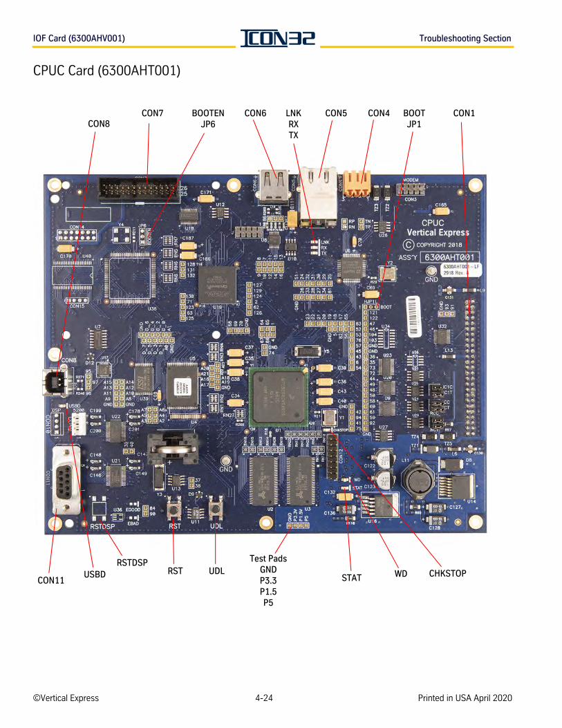
IOF Card (6300AHV001) Troubleshooting Section
CPUC Card (6300AHT001)
CON8
Test PadsGNDP3.3P1.5P5
RSTDSP
CON11
CON5LNKRXTX
BOOTENJP6
CHKSTOPWD
BOOTJP1
UDLUSBD
CON4CON6
RST
CON7 CON1
STAT
©Vertical Express 4-24 Printed in USA April 2020
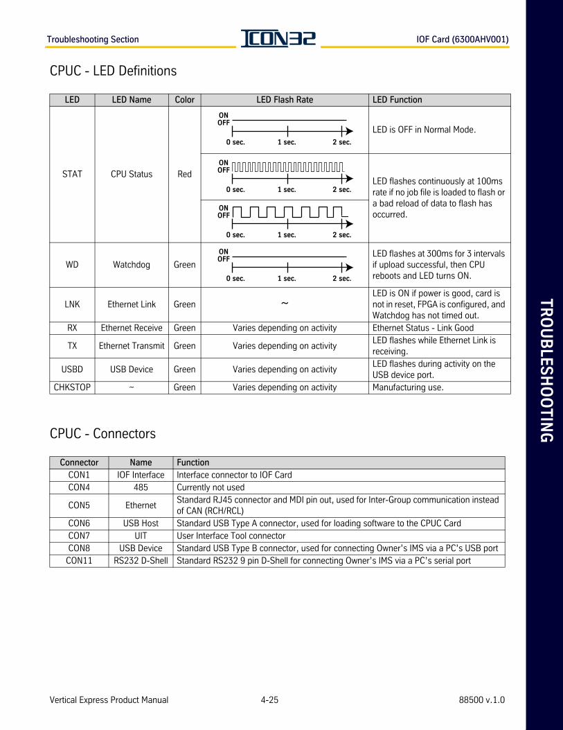
TR
OU
BLE
SH
OO
TIN
GTroubleshooting Section IOF Card (6300AHV001)
CPUC - LED Definitions
CPUC - Connectors
LED LED Name Color LED Flash Rate LED Function
STAT CPU Status Red
LED is OFF in Normal Mode.
LED flashes continuously at 100ms rate if no job file is loaded to flash or a bad reload of data to flash has occurred.
WD Watchdog GreenLED flashes at 300ms for 3 intervals if upload successful, then CPU reboots and LED turns ON.
LNK Ethernet Link Green ~LED is ON if power is good, card is not in reset, FPGA is configured, and Watchdog has not timed out.
RX Ethernet Receive Green Varies depending on activity Ethernet Status - Link Good
TX Ethernet Transmit Green Varies depending on activityLED flashes while Ethernet Link is receiving.
USBD USB Device Green Varies depending on activityLED flashes during activity on the USB device port.
CHKSTOP ~ Green Varies depending on activity Manufacturing use.
Connector Name FunctionCON1 IOF Interface Interface connector to IOF CardCON4 485 Currently not used
CON5 EthernetStandard RJ45 connector and MDI pin out, used for Inter-Group communication instead of CAN (RCH/RCL)
CON6 USB Host Standard USB Type A connector, used for loading software to the CPUC CardCON7 UIT User Interface Tool connectorCON8 USB Device Standard USB Type B connector, used for connecting Owner’s IMS via a PC’s USB port
CON11 RS232 D-Shell Standard RS232 9 pin D-Shell for connecting Owner’s IMS via a PC’s serial port
ONOFF
0 sec. 1 sec. 2 sec.
ONOFF
0 sec. 1 sec. 2 sec.
ONOFF
0 sec. 1 sec. 2 sec.
ONOFF
0 sec. 1 sec. 2 sec.
Vertical Express Product Manual 4-25 88500 v.1.0
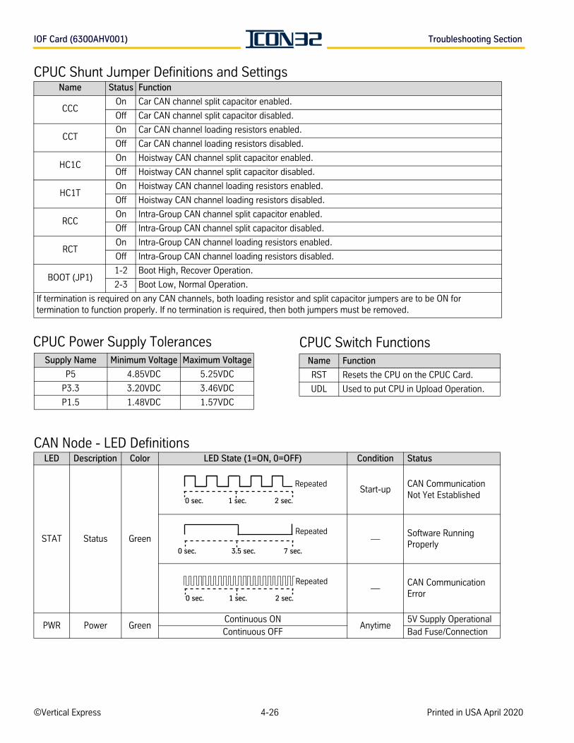
IOF Card (6300AHV001) Troubleshooting Section
CPUC Shunt Jumper Definitions and Settings
CAN Node - LED Definitions
Name Status Function
CCCOn Car CAN channel split capacitor enabled.
Off Car CAN channel split capacitor disabled.
CCTOn Car CAN channel loading resistors enabled.
Off Car CAN channel loading resistors disabled.
HC1COn Hoistway CAN channel split capacitor enabled.
Off Hoistway CAN channel split capacitor disabled.
HC1TOn Hoistway CAN channel loading resistors enabled.
Off Hoistway CAN channel loading resistors disabled.
RCCOn Intra-Group CAN channel split capacitor enabled.
Off Intra-Group CAN channel split capacitor disabled.
RCTOn Intra-Group CAN channel loading resistors enabled.
Off Intra-Group CAN channel loading resistors disabled.
BOOT (JP1)1-2 Boot High, Recover Operation.
2-3 Boot Low, Normal Operation.
If termination is required on any CAN channels, both loading resistor and split capacitor jumpers are to be ON for termination to function properly. If no termination is required, then both jumpers must be removed.
LED Description Color LED State (1=ON, 0=OFF) Condition Status
STAT Status Green
Start-upCAN Communication Not Yet Established
—Software Running Properly
—CAN Communication Error
PWR Power GreenContinuous ON
Anytime5V Supply Operational
Continuous OFF Bad Fuse/Connection
Supply Name Minimum Voltage Maximum Voltage
P5 4.85VDC 5.25VDC
P3.3 3.20VDC 3.46VDC
P1.5 1.48VDC 1.57VDC
CPUC Power Supply TolerancesName Function
RST Resets the CPU on the CPUC Card.
UDL Used to put CPU in Upload Operation.
CPUC Switch Functions
Repeated
2 sec.1 sec.0 sec.
Repeated
7 sec.3.5 sec.0 sec.
Repeated
2 sec.1 sec.0 sec.
©Vertical Express 4-26 Printed in USA April 2020
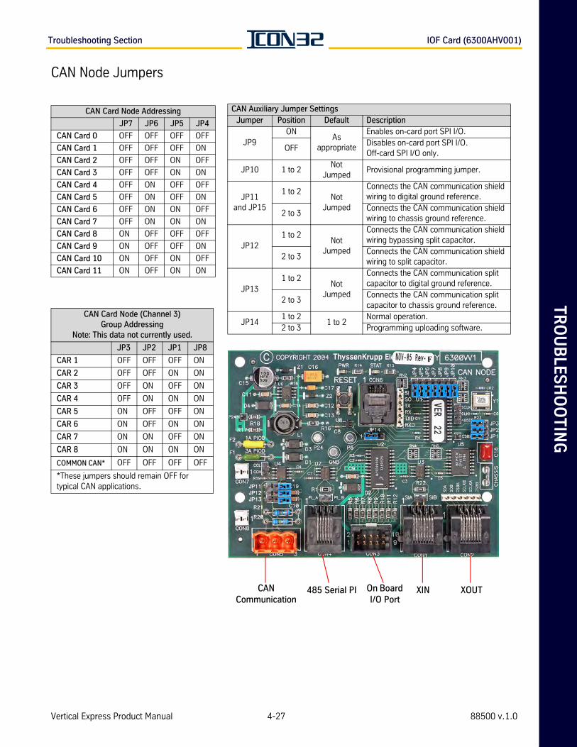
TR
OU
BLE
SH
OO
TIN
GTroubleshooting Section IOF Card (6300AHV001)
CAN Node Jumpers
CAN Card Node (Channel 3) Group Addressing
Note: This data not currently used.
JP3 JP2 JP1 JP8
CAR 1 OFF OFF OFF ON
CAR 2 OFF OFF ON ON
CAR 3 OFF ON OFF ON
CAR 4 OFF ON ON ON
CAR 5 ON OFF OFF ON
CAR 6 ON OFF ON ON
CAR 7 ON ON OFF ON
CAR 8 ON ON ON ON
COMMON CAN* OFF OFF OFF OFF
*These jumpers should remain OFF for typical CAN applications.
CAN Auxiliary Jumper SettingsJumper Position Default Description
JP9ON
As appropriate
Enables on-card port SPI I/O.
OFFDisables on-card port SPI I/O. Off-card SPI I/O only.
JP10 1 to 2Not
JumpedProvisional programming jumper.
JP11and JP15
1 to 2Not
Jumped
Connects the CAN communication shield wiring to digital ground reference.
2 to 3Connects the CAN communication shield wiring to chassis ground reference.
JP121 to 2
Not Jumped
Connects the CAN communication shield wiring bypassing split capacitor.
2 to 3Connects the CAN communication shield wiring to split capacitor.
JP131 to 2
Not Jumped
Connects the CAN communication split capacitor to digital ground reference.
2 to 3Connects the CAN communication split capacitor to chassis ground reference.
JP141 to 2
1 to 2Normal operation.
2 to 3 Programming uploading software.
CAN Card Node Addressing
JP7 JP6 JP5 JP4
CAN Card 0 OFF OFF OFF OFF
CAN Card 1 OFF OFF OFF ON
CAN Card 2 OFF OFF ON OFF
CAN Card 3 OFF OFF ON ON
CAN Card 4 OFF ON OFF OFF
CAN Card 5 OFF ON OFF ON
CAN Card 6 OFF ON ON OFF
CAN Card 7 OFF ON ON ON
CAN Card 8 ON OFF OFF OFF
CAN Card 9 ON OFF OFF ON
CAN Card 10 ON OFF ON OFF
CAN Card 11 ON OFF ON ON
XOUTXIN485 Serial PICAN Communication
On Board I/O Port
Vertical Express Product Manual 4-27 88500 v.1.0
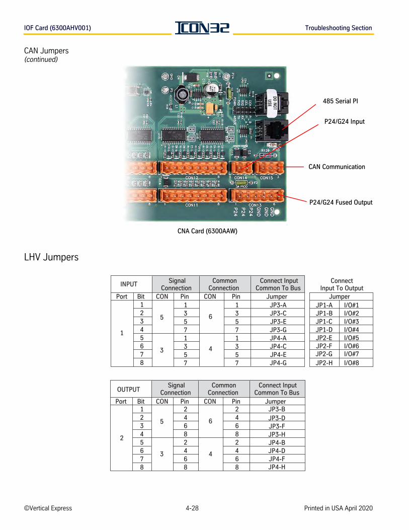
IOF Card (6300AHV001) Troubleshooting Section
CAN Jumpers(continued)
LHV Jumpers
485 Serial PI
P24/G24 Input
CAN Communication
P24/G24 Fused Output
CNA Card (6300AAW)
JP3-BJP3-DJP3-FJP3-HJP4-BJP4-DJP4-FJP4-H
5
3
6
4
2
Connect InputCommon To Bus
Port Bit CON Pin CON Pin Jumper12345678
JP3-AJP3-CJP3-EJP3-GJP4-AJP4-CJP4-EJP4-G
SignalConnection
INPUT
5
3
6
4
JP1-A I/O#1JP1-B I/O#2JP1-C I/O#3JP1-D I/O#4JP2-E I/O#5JP2-F I/O#6JP2-G I/O#7JP2-H I/O#8
ConnectInput To Output
Jumper
1
13571357
13571357
12345678
24682468
24682468
OUTPUT
Port Bit CON Pin CON Pin Jumper
CommonConnection
Connect InputCommon To Bus
SignalConnection
CommonConnection
©Vertical Express 4-28 Printed in USA April 2020
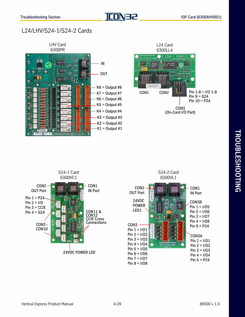
TR
OU
BLE
SH
OO
TIN
GTroubleshooting Section IOF Card (6300AHV001)
L24/LHV/S24-1/S24-2 Cards
LHV Card6300PR
IN
OUT
K8 = Output #8
K7 = Output #7
K6 = Output #6
K5 = Output #5
K4 = Output #4
K3 = Output #3
K2 = Output #2K1 = Output #1
S24-1 Card6300VC1
CON11 & CON12CCIE Cross Connections
CON2OUT Port
CON1IN Port
Pin 1 = P24Pin 2 = I/OPin 3 = CCIEPin 4 = G24
CON3 - CON10
24VDC POWER LED
L24 Card6300LL4
CON1
CON3(On-Card I/O Port)
CON2 Pin 1-8 = I/O 1-8Pin 9 = G24Pin 10 = P24
S24-2 Card6300VL1
CON2OUT Port
CON1IN Port
24VDC POWER LED1
CON3Pin 1 = I/O1Pin 2 = I/O2Pin 3 = I/O3Pin 4 = I/O4Pin 5 = I/O5Pin 6 = I/O6Pin 7 = I/O7Pin 8 = I/O8
CON3BPin 1 = I/O5Pin 2 = I/O6Pin 3 = I/O7Pin 4 = I/O8Pin 5 = P24
CON3APin 1 = I/O1Pin 2 = I/O2Pin 3 = I/O3Pin 4 = I/O4Pin 5 = P24
Vertical Express Product Manual 4-29 88500 v.1.0
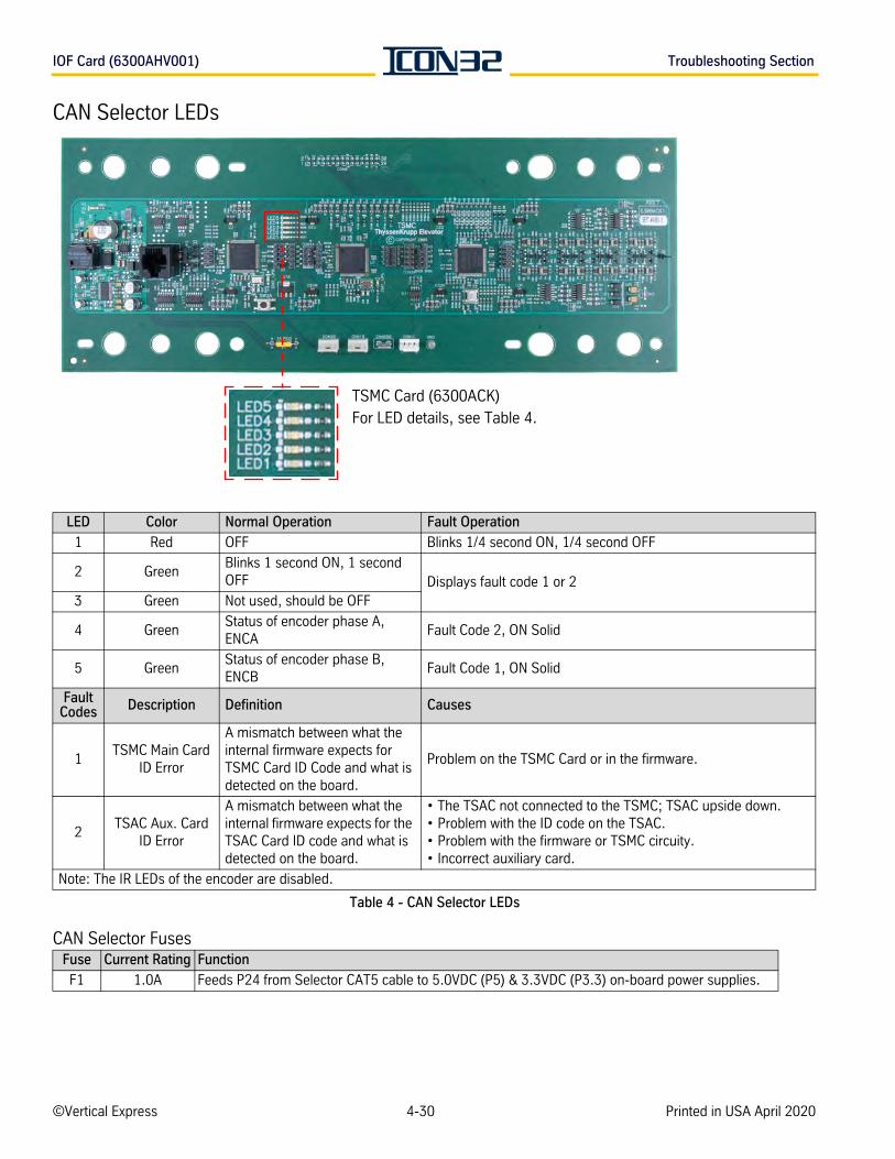
IOF Card (6300AHV001) Troubleshooting Section
CAN Selector LEDs
Table 4 - CAN Selector LEDs
CAN Selector Fuses
LED Color Normal Operation Fault Operation
1 Red OFF Blinks 1/4 second ON, 1/4 second OFF
2 GreenBlinks 1 second ON, 1 second OFF Displays fault code 1 or 2
3 Green Not used, should be OFF
4 GreenStatus of encoder phase A, ENCA
Fault Code 2, ON Solid
5 GreenStatus of encoder phase B, ENCB
Fault Code 1, ON Solid
Fault Codes Description Definition Causes
1TSMC Main Card
ID Error
A mismatch between what the internal firmware expects for TSMC Card ID Code and what is detected on the board.
Problem on the TSMC Card or in the firmware.
2TSAC Aux. Card
ID Error
A mismatch between what the internal firmware expects for the TSAC Card ID code and what is detected on the board.
• The TSAC not connected to the TSMC; TSAC upside down.• Problem with the ID code on the TSAC.• Problem with the firmware or TSMC circuity. • Incorrect auxiliary card.
Note: The IR LEDs of the encoder are disabled.
Fuse Current Rating Function
F1 1.0A Feeds P24 from Selector CAT5 cable to 5.0VDC (P5) & 3.3VDC (P3.3) on-board power supplies.
TSMC Card (6300ACK)For LED details, see Table 4.
©Vertical Express 4-30 Printed in USA April 2020
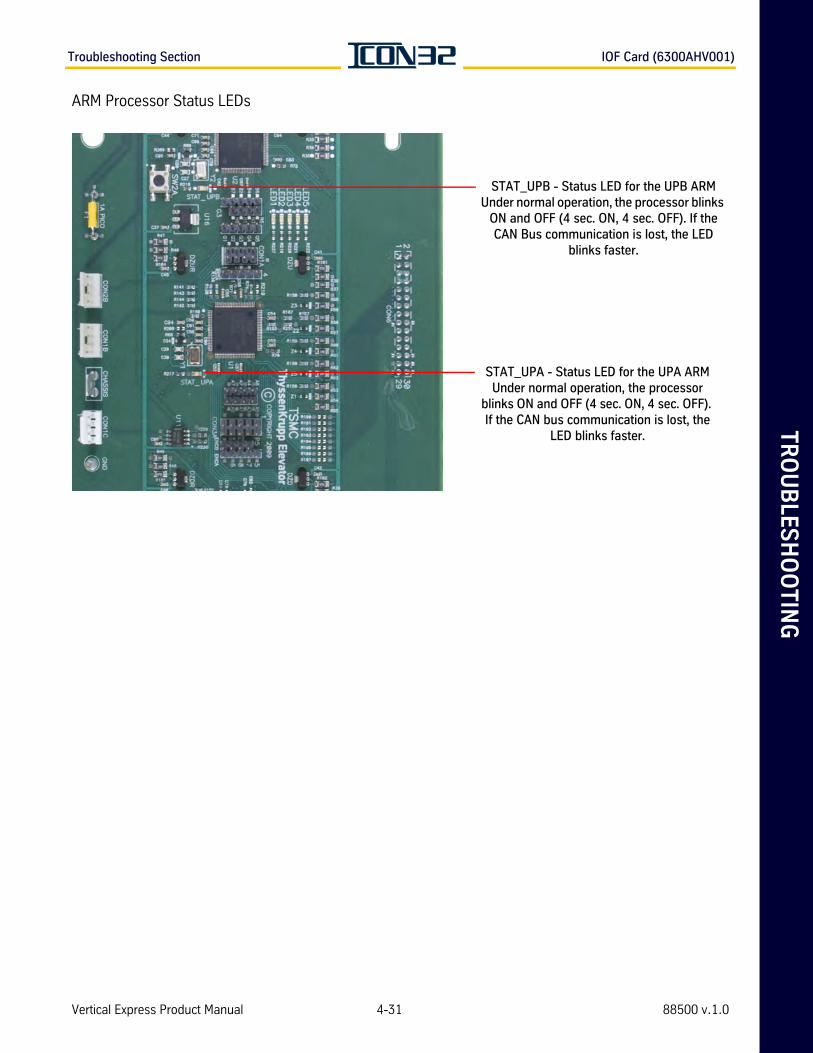
TR
OU
BLE
SH
OO
TIN
GTroubleshooting Section IOF Card (6300AHV001)
ARM Processor Status LEDs
STAT_UPB - Status LED for the UPB ARM Under normal operation, the processor blinks
ON and OFF (4 sec. ON, 4 sec. OFF). If the CAN Bus communication is lost, the LED
blinks faster.
STAT_UPA - Status LED for the UPA ARM Under normal operation, the processor
blinks ON and OFF (4 sec. ON, 4 sec. OFF). If the CAN bus communication is lost, the
LED blinks faster.
Vertical Express Product Manual 4-31 88500 v.1.0

IOF Card (6300AHV001) Troubleshooting Section
This pageintentionallyleft blank.
©Vertical Express 4-32 Printed in USA April 2020

SE
RV
ICE
INFO
RM
AT
ION
SE
CT
ION

SE
RV
ICE
IN
FO
RM
AT
ION
SE
CT
ION
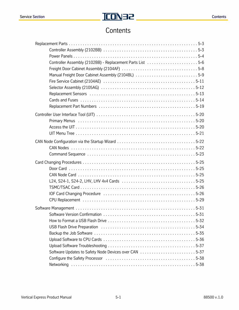
Service Section Contents
Vertical Express Product Manual 5-1 88500 v.1.0
Contents
Replacement Parts . . . . . . . . . . . . . . . . . . . . . . . . . . . . . . . . . . . . . . . . . . . . . . . . . . . . . . . . 5-3
Controller Assembly (2102BB) . . . . . . . . . . . . . . . . . . . . . . . . . . . . . . . . . . . . . . . . . 5-3
Power Panels . . . . . . . . . . . . . . . . . . . . . . . . . . . . . . . . . . . . . . . . . . . . . . . . . . . . . . 5-4
Controller Assembly (2102BB) - Replacement Parts List . . . . . . . . . . . . . . . . . . . . . . 5-6
Freight Door Cabinet Assembly (2104AF) . . . . . . . . . . . . . . . . . . . . . . . . . . . . . . . . . 5-8
Manual Freight Door Cabinet Assembly (2104BL) . . . . . . . . . . . . . . . . . . . . . . . . . . . 5-9
Fire Service Cabinet (2104AE) . . . . . . . . . . . . . . . . . . . . . . . . . . . . . . . . . . . . . . . . 5-11
Selector Assembly (2105AG) . . . . . . . . . . . . . . . . . . . . . . . . . . . . . . . . . . . . . . . . . 5-12
Replacement Sensors . . . . . . . . . . . . . . . . . . . . . . . . . . . . . . . . . . . . . . . . . . . . . . 5-13
Cards and Fuses . . . . . . . . . . . . . . . . . . . . . . . . . . . . . . . . . . . . . . . . . . . . . . . . . . 5-14
Replacement Part Numbers . . . . . . . . . . . . . . . . . . . . . . . . . . . . . . . . . . . . . . . . . . 5-19
Controller User Interface Tool (UIT) . . . . . . . . . . . . . . . . . . . . . . . . . . . . . . . . . . . . . . . . . . . 5-20
Primary Menus . . . . . . . . . . . . . . . . . . . . . . . . . . . . . . . . . . . . . . . . . . . . . . . . . . . 5-20
Access the UIT . . . . . . . . . . . . . . . . . . . . . . . . . . . . . . . . . . . . . . . . . . . . . . . . . . . . 5-20
UIT Menu Tree . . . . . . . . . . . . . . . . . . . . . . . . . . . . . . . . . . . . . . . . . . . . . . . . . . . . 5-21
CAN Node Configuration via the Startup Wizard . . . . . . . . . . . . . . . . . . . . . . . . . . . . . . . . . . 5-22
CAN Nodes . . . . . . . . . . . . . . . . . . . . . . . . . . . . . . . . . . . . . . . . . . . . . . . . . . . . . . 5-22
Command Sequence . . . . . . . . . . . . . . . . . . . . . . . . . . . . . . . . . . . . . . . . . . . . . . . 5-23
Card Changing Procedures . . . . . . . . . . . . . . . . . . . . . . . . . . . . . . . . . . . . . . . . . . . . . . . . . 5-25
Door Card . . . . . . . . . . . . . . . . . . . . . . . . . . . . . . . . . . . . . . . . . . . . . . . . . . . . . . . 5-25
CAN Node Card . . . . . . . . . . . . . . . . . . . . . . . . . . . . . . . . . . . . . . . . . . . . . . . . . . . 5-25
L24, S24-1, S24-2, LHV, LHV 4x4 Cards . . . . . . . . . . . . . . . . . . . . . . . . . . . . . . . . 5-25
TSMC/TSAC Card . . . . . . . . . . . . . . . . . . . . . . . . . . . . . . . . . . . . . . . . . . . . . . . . . . 5-26
IOF Card Changing Procedure . . . . . . . . . . . . . . . . . . . . . . . . . . . . . . . . . . . . . . . . 5-26
CPU Replacement . . . . . . . . . . . . . . . . . . . . . . . . . . . . . . . . . . . . . . . . . . . . . . . . . 5-29
Software Management . . . . . . . . . . . . . . . . . . . . . . . . . . . . . . . . . . . . . . . . . . . . . . . . . . . . 5-31
Software Version Confirmation . . . . . . . . . . . . . . . . . . . . . . . . . . . . . . . . . . . . . . . . 5-31
How to Format a USB Flash Drive . . . . . . . . . . . . . . . . . . . . . . . . . . . . . . . . . . . . . . 5-32
USB Flash Drive Preparation . . . . . . . . . . . . . . . . . . . . . . . . . . . . . . . . . . . . . . . . . 5-34
Backup the Job Software . . . . . . . . . . . . . . . . . . . . . . . . . . . . . . . . . . . . . . . . . . . . 5-35
Upload Software to CPU Cards . . . . . . . . . . . . . . . . . . . . . . . . . . . . . . . . . . . . . . . . 5-36
Upload Software Troubleshooting . . . . . . . . . . . . . . . . . . . . . . . . . . . . . . . . . . . . . . 5-37
Software Updates to Safety Node Devices over CAN . . . . . . . . . . . . . . . . . . . . . . . . 5-37
Configure the Safety Processor . . . . . . . . . . . . . . . . . . . . . . . . . . . . . . . . . . . . . . . 5-38
Networking . . . . . . . . . . . . . . . . . . . . . . . . . . . . . . . . . . . . . . . . . . . . . . . . . . . . . . 5-38

5-2©Vertical Express Printed in USA April 2020
Contents Service Section
This pageintentionallyleft blank.
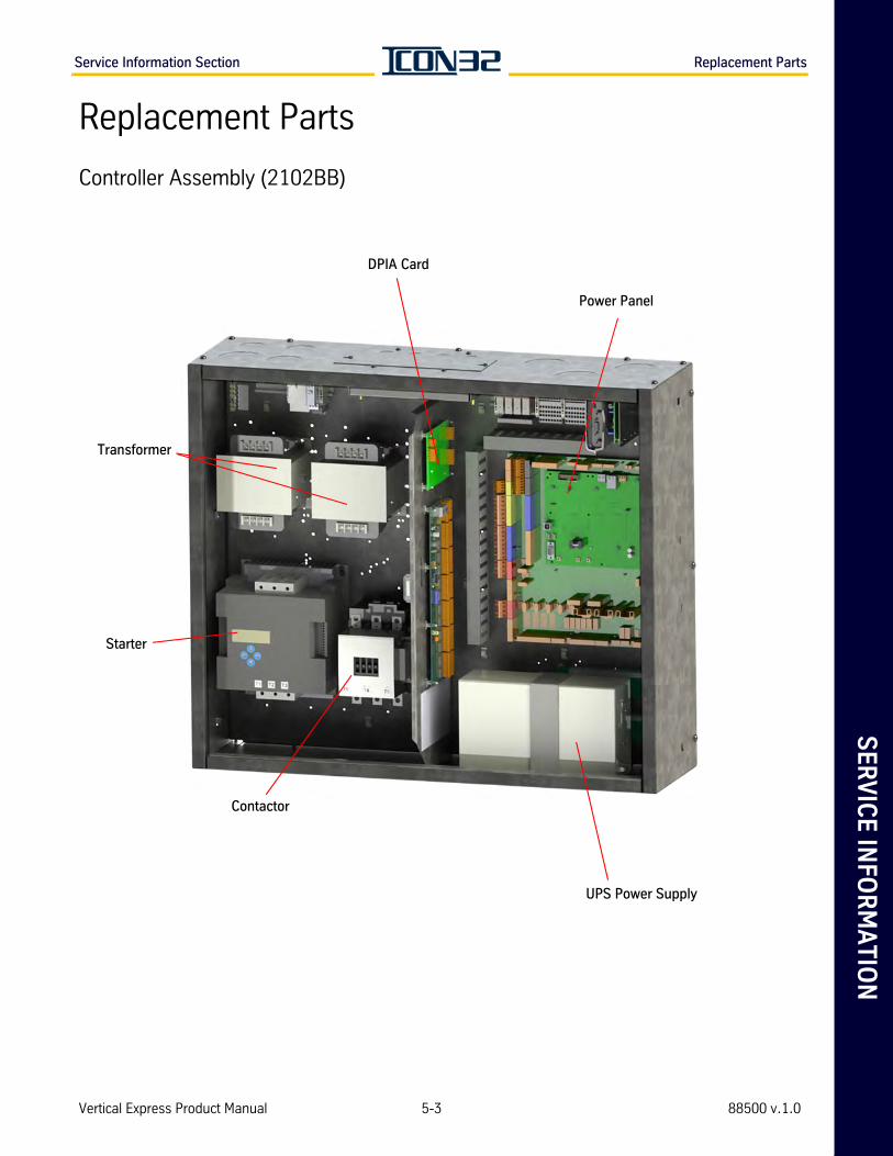
SE
RV
ICE
INFO
RM
AT
ION
Service Information Section Replacement Parts
Replacement Parts
Controller Assembly (2102BB)
Power Panel
DPIA Card
UPS Power Supply
Transformer
Contactor
Starter
Vertical Express Product Manual 5-3 88500 v.1.0
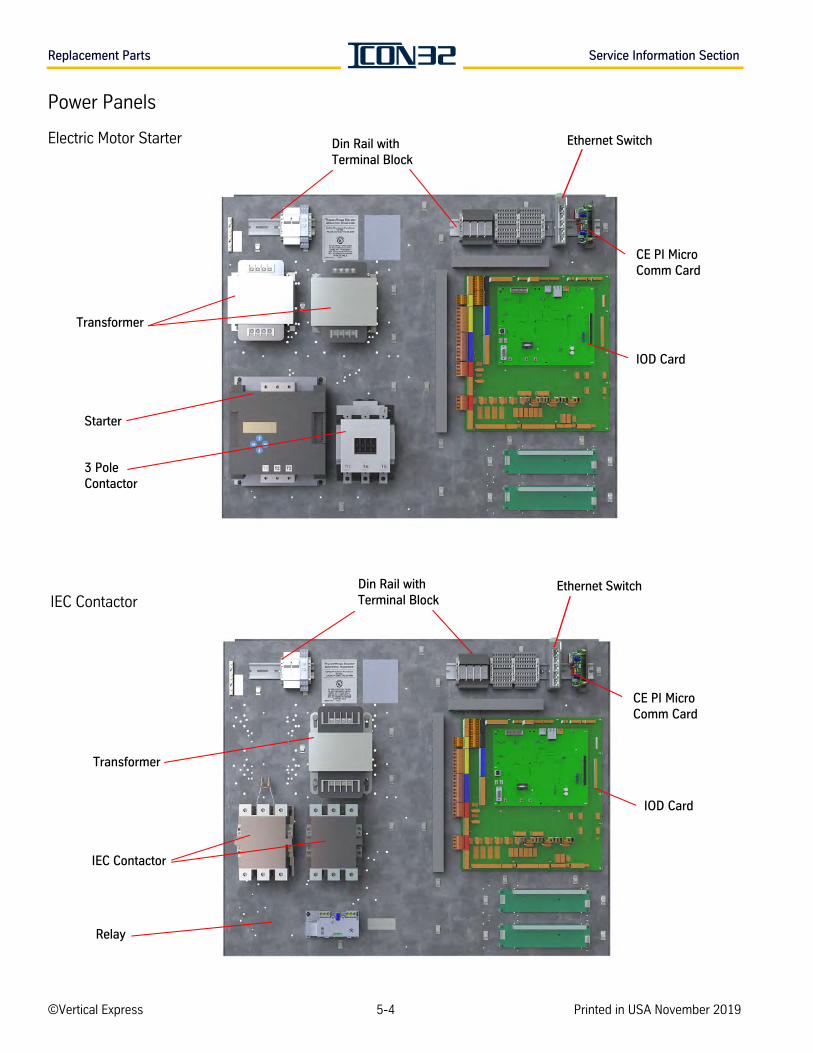
Replacement Parts Service Information Section
Power Panels
Electric Motor Starter
IEC Contactor
CE PI Micro Comm Card
IOD Card
Starter
Transformer
3 Pole Contactor
Din Rail with Terminal Block
CE PI Micro Comm Card
IOD Card
Transformer
IEC Contactor
Relay
Din Rail with Terminal Block
Ethernet Switch
Ethernet Switch
©Vertical Express 5-4 Printed in USA November 2019
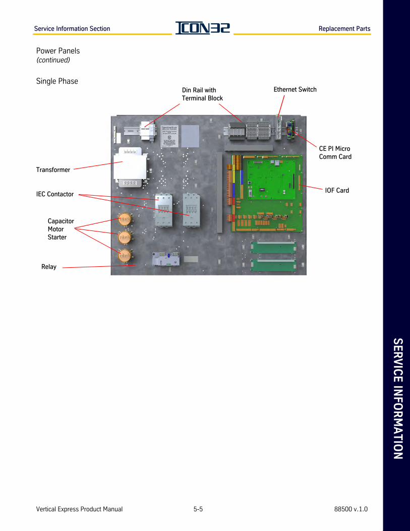
SE
RV
ICE
INFO
RM
AT
ION
Service Information Section Replacement Parts
Power Panels(continued)
Single Phase
Capacitor Motor Starter
CE PI Micro Comm Card
IOF Card
Relay
IEC Contactor
Din Rail with Terminal Block
Transformer
Ethernet Switch
Vertical Express Product Manual 5-5 88500 v.1.0
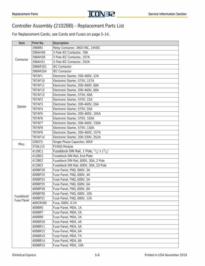
Replacement Parts Service Information Section
Controller Assembly (2102BB) - Replacement Parts List
For Replacement Cards, see Cards and Fuses on page 5-14.
Item Print No. Description
Contactor
298BB1 Relay Contactor, 3NO/1NC, 24VDC
298AH49 3 Pole IEC Contactor, 78A
298AH28 3 Pole IEC Contactor, 157A
298AH31 3 Pole IEC Contactor, 252A
298AR101 IEC Contactor
298AR104 IEC Contactor
Starter
787AF1 Electronic Starter, 200-460V, 22A
787AF10 Electronic Starter, 575V, 157A
787AF11 Electronic Starter, 200-460V, 68A
787AF12 Electronic Starter, 200-460V, 80A
787AF13 Electronic Starter, 575V, 68A
787AF2 Electronic Starter, 575V, 22A
787AF3 Electronic Starter, 200-460V, 55A
787AF4 Electronic Starter, 575V, 55A
787AF5 Electronic Starter, 200-460V, 105A
787AF6 Electronic Starter, 575V, 105A
787AF7 Electronic Starter, 200-460V, 130A
787AF8 Electronic Starter, 575V, 130A
787AF9 Electronic Starter, 200-460V, 157A
787AF14 Electronic Starter, 200-230V, 252A
Misc.238CF2 Single Phase Capacitor, 60Uf
370AJ13 P24GS Module
Fuseblock/Fuse Panel
412BC1 Fuseblock DIN Rail, 1 Pole, 1/4" x 11/4"
412BD1 Fuseblock DIN Rail, End Plate
412BE2 Fuseblock DIN Rail, 600V, 30A, 2 Pole
412BE3 Fuseblock DIN Rail, 600V, 30A, 23 Pole
409BP20 Fuse Panel, FNQ, 600V, 3A
409BP23 Fuse Panel, FNQ, 600V, 4A
409BP24 Fuse Panel, FNQ, 600V, 5A
409BP25 Fuse Panel, FNQ, 600V, 6A
409BP28 Fuse Panel, FNQ, 600V, 8A
409BP30 Fuse Panel, FNQ, 600V, 10A
409BP31 Fuse Panel, FNQ, 600V, 12A
409CR200 Fuse, 600V, 0.2A
409BR5 Fuse Panel, MDA, 1A
409BR7 Fuse Panel, MDA, 2A
409BR9 Fuse Panel, MDA, 3A
409BR10 Fuse Panel, MDA, 4A
409BR11 Fuse Panel, MDA, 5A
409BR12 Fuse Panel, MDA, 6A
409BR13 Fuse Panel, MDA, 7A
409BR14 Fuse Panel, MDA, 8A
409BR15 Fuse Panel, MDA, 10A
©Vertical Express 5-6 Printed in USA November 2019
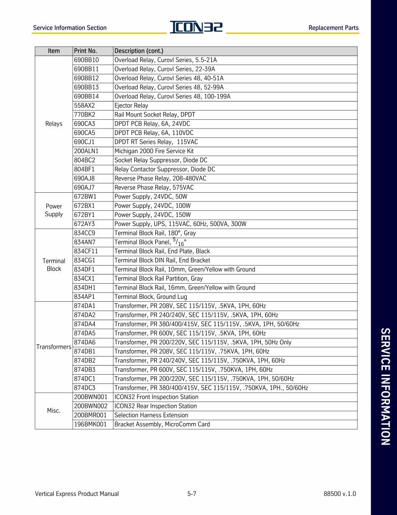
SE
RV
ICE
INFO
RM
AT
ION
Service Information Section Replacement Parts
Relays
690BB10 Overload Relay, Curovl Series, 5.5-21A
690BB11 Overload Relay, Curovl Series, 22-39A
690BB12 Overload Relay, Curovl Series 48, 40-51A
690BB13 Overload Relay, Curovl Series 48, 52-99A
690BB14 Overload Relay, Curovl Series 48, 100-199A
558AX2 Ejector Relay
770BK2 Rail Mount Socket Relay, DPDT
690CA3 DPDT PCB Relay, 6A, 24VDC
690CA5 DPDT PCB Relay, 6A, 110VDC
690CJ1 DPDT RT Series Relay, 115VAC
200ALN1 Michigan 2000 Fire Service Kit
804BC2 Socket Relay Suppressor, Diode DC
804BF1 Relay Contactor Suppressor, Diode DC
690AJ8 Reverse Phase Relay, 208-480VAC
690AJ7 Reverse Phase Relay, 575VAC
Power Supply
672BW1 Power Supply, 24VDC, 50W
672BX1 Power Supply, 24VDC, 100W
672BY1 Power Supply, 24VDC, 150W
672AY3 Power Supply, UPS, 115VAC, 60Hz, 500VA, 300W
Terminal Block
834CC9 Terminal Block Rail, 180°, Gray
834AN7 Terminal Block Panel, 5/16"
834CF11 Terminal Block Rail, End Plate, Black
834CG1 Terminal Block DIN Rail, End Bracket
834DF1 Terminal Block Rail, 10mm, Green/Yellow with Ground
834CX1 Terminal Block Rail Partition, Gray
834DH1 Terminal Block Rail, 16mm, Green/Yellow with Ground
834AP1 Terminal Block, Ground Lug
Transformers
874DA1 Transformer, PR 208V, SEC 115/115V, .5KVA, 1PH, 60Hz
874DA2 Transformer, PR 240/240V, SEC 115/115V, .5KVA, 1PH, 60Hz
874DA4 Transformer, PR 380/400/415V, SEC 115/115V, .5KVA, 1PH, 50/60Hz
874DA5 Transformer, PR 600V, SEC 115/115V, .5KVA, 1PH, 60Hz
874DA6 Transformer, PR 200/220V, SEC 115/115V, .5KVA, 1PH, 50Hz Only
874DB1 Transformer, PR 208V, SEC 115/115V, .75KVA, 1PH, 60Hz
874DB2 Transformer, PR 240/240V, SEC 115/115V, .750KVA, 1PH, 60Hz
874DB3 Transformer, PR 600V, SEC 115/115V, .750KVA, 1PH, 60Hz
874DC1 Transformer, PR 200/220V, SEC 115/115V, .750KVA, 1PH, 50/60Hz
874DC3 Transformer, PR 380/400/415V, SEC 115/115V, .750KVA, 1PH., 50/60Hz
Misc.
200BWN001 ICON32 Front Inspection Station
200BWN002 ICON32 Rear Inspection Station
200BMR001 Selection Harness Extension
196BMK001 Bracket Assembly, MicroComm Card
Item Print No. Description (cont.)
Vertical Express Product Manual 5-7 88500 v.1.0
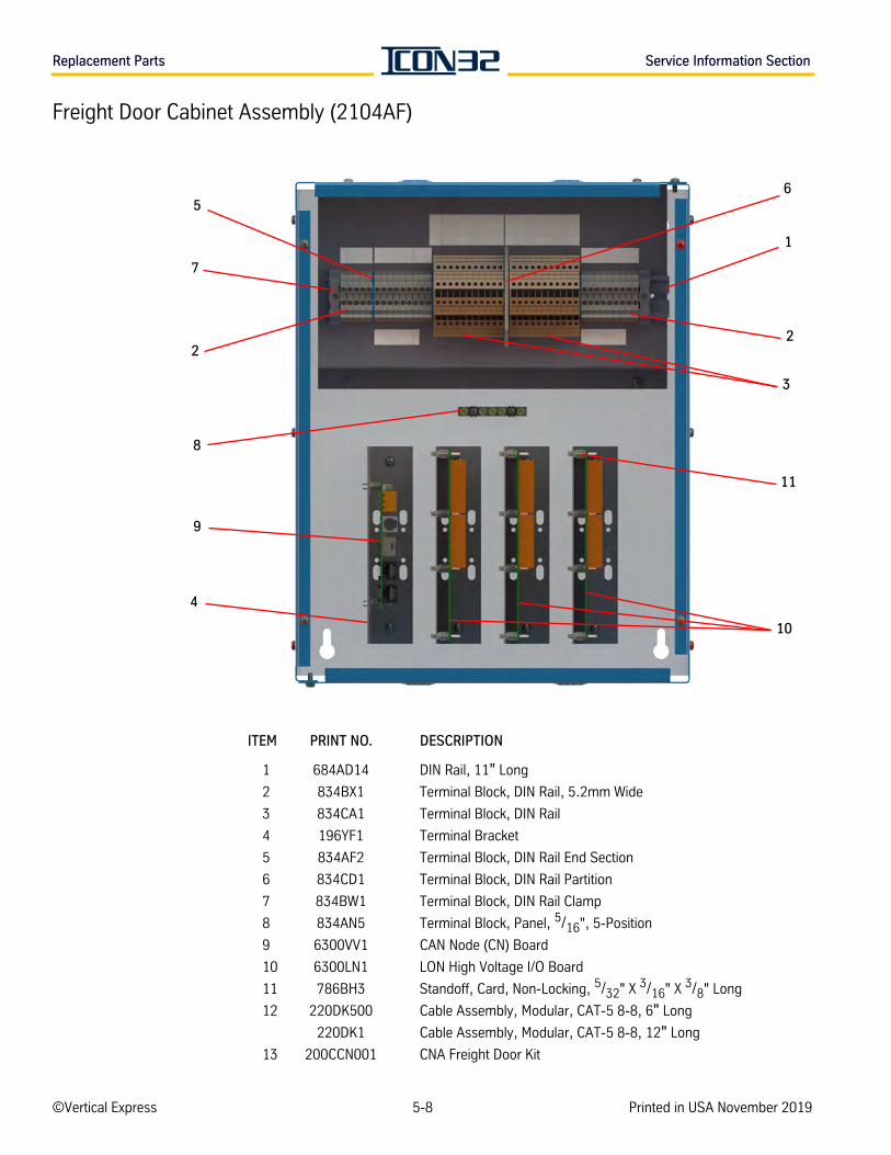
Replacement Parts Service Information Section
Freight Door Cabinet Assembly (2104AF)
ITEM PRINT NO. DESCRIPTION
1 684AD14 DIN Rail, 11" Long
2 834BX1 Terminal Block, DIN Rail, 5.2mm Wide
3 834CA1 Terminal Block, DIN Rail
4 196YF1 Terminal Bracket
5 834AF2 Terminal Block, DIN Rail End Section
6 834CD1 Terminal Block, DIN Rail Partition
7 834BW1 Terminal Block, DIN Rail Clamp
8 834AN5 Terminal Block, Panel, 5/16", 5-Position
9 6300VV1 CAN Node (CN) Board
10 6300LN1 LON High Voltage I/O Board
11 786BH3 Standoff, Card, Non-Locking, 5/32" X 3/16" X 3/8" Long
12 220DK500 Cable Assembly, Modular, CAT-5 8-8, 6" Long
220DK1 Cable Assembly, Modular, CAT-5 8-8, 12" Long
13 200CCN001 CNA Freight Door Kit
6
1
2
3
11
5
7
2
8
9
4
10
©Vertical Express 5-8 Printed in USA November 2019
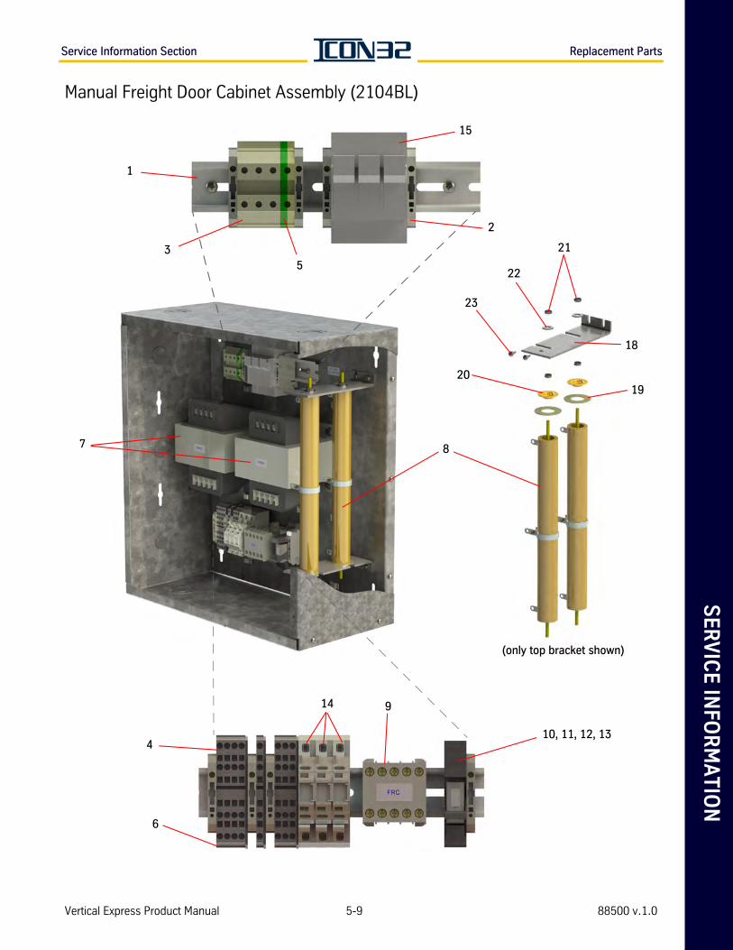
SE
RV
ICE
INFO
RM
AT
ION
Service Information Section Replacement Parts
Manual Freight Door Cabinet Assembly (2104BL)
8
2
7
1
10, 11, 12, 13
9
3
4
5
6
15
14
(only top bracket shown)
1920
21
22
23
18
Vertical Express Product Manual 5-9 88500 v.1.0
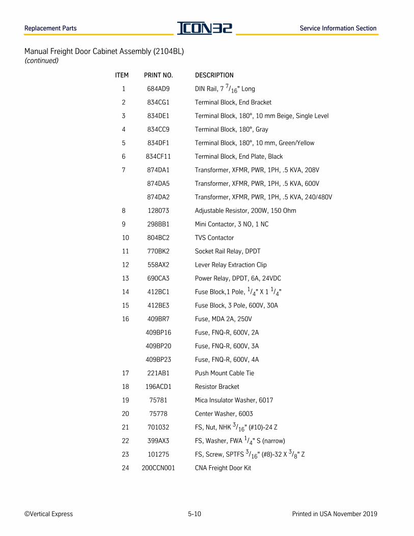
Replacement Parts Service Information Section
Manual Freight Door Cabinet Assembly (2104BL)(continued)
ITEM PRINT NO. DESCRIPTION
1 684AD9 DIN Rail, 7 7/16" Long
2 834CG1 Terminal Block, End Bracket
3 834DE1 Terminal Block, 180°, 10 mm Beige, Single Level
4 834CC9 Terminal Block, 180°, Gray
5 834DF1 Terminal Block, 180°, 10 mm, Green/Yellow
6 834CF11 Terminal Block, End Plate, Black
7 874DA1 Transformer, XFMR, PWR, 1PH, .5 KVA, 208V
874DA5 Transformer, XFMR, PWR, 1PH, .5 KVA, 600V
874DA2 Transformer, XFMR, PWR, 1PH, .5 KVA, 240/480V
8 128073 Adjustable Resistor, 200W, 150 Ohm
9 298BB1 Mini Contactor, 3 NO, 1 NC
10 804BC2 TVS Contactor
11 770BK2 Socket Rail Relay, DPDT
12 558AX2 Lever Relay Extraction Clip
13 690CA3 Power Relay, DPDT, 6A, 24VDC
14 412BC1 Fuse Block,1 Pole, 1/4" X 1 1/4"
15 412BE3 Fuse Block, 3 Pole, 600V, 30A
16 409BR7 Fuse, MDA 2A, 250V
409BP16 Fuse, FNQ-R, 600V, 2A
409BP20 Fuse, FNQ-R, 600V, 3A
409BP23 Fuse, FNQ-R, 600V, 4A
17 221AB1 Push Mount Cable Tie
18 196ACD1 Resistor Bracket
19 75781 Mica Insulator Washer, 6017
20 75778 Center Washer, 6003
21 701032 FS, Nut, NHK 3/16" (#10)-24 Z
22 399AX3 FS, Washer, FWA 1/4" S (narrow)
23 101275 FS, Screw, SPTFS 3/16" (#8)-32 X 3/8" Z
24 200CCN001 CNA Freight Door Kit
©Vertical Express 5-10 Printed in USA November 2019
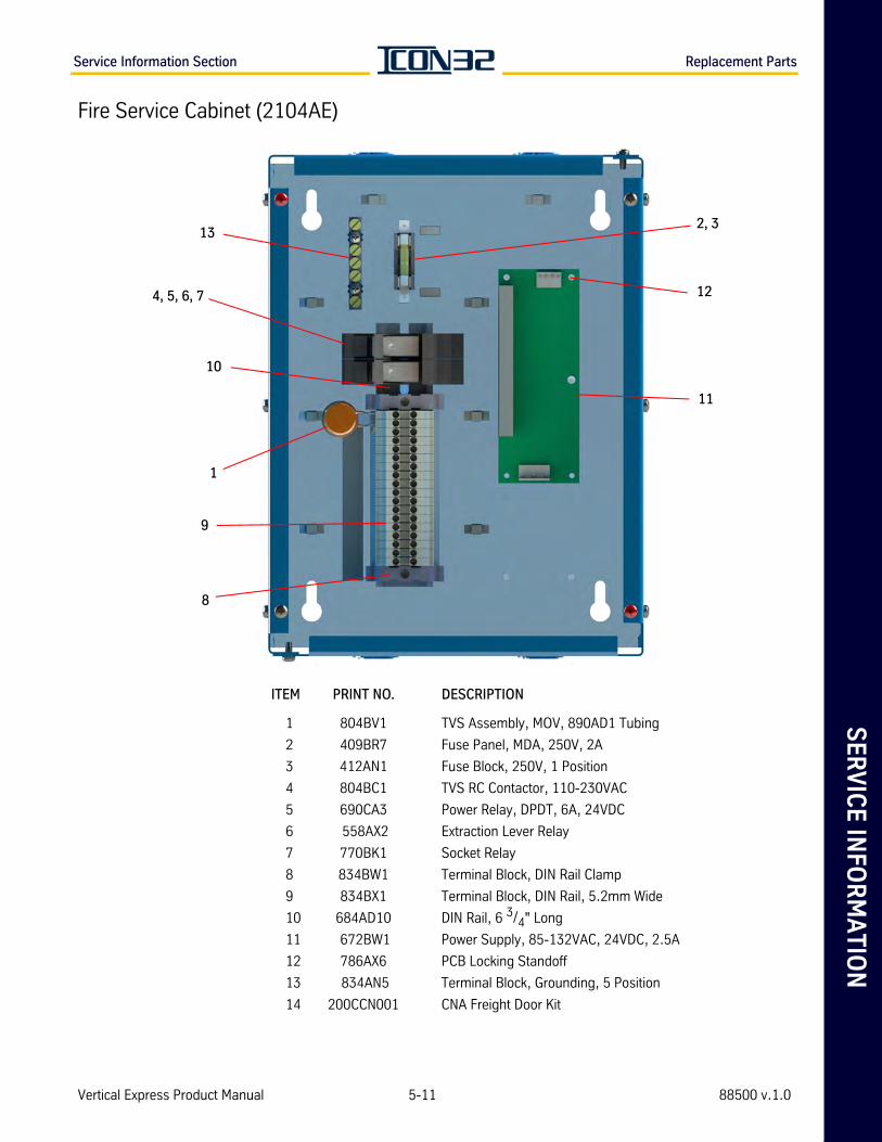
SE
RV
ICE
INFO
RM
AT
ION
Service Information Section Replacement Parts
Fire Service Cabinet (2104AE)
ITEM PRINT NO. DESCRIPTION
1 804BV1 TVS Assembly, MOV, 890AD1 Tubing
2 409BR7 Fuse Panel, MDA, 250V, 2A
3 412AN1 Fuse Block, 250V, 1 Position
4 804BC1 TVS RC Contactor, 110-230VAC
5 690CA3 Power Relay, DPDT, 6A, 24VDC
6 558AX2 Extraction Lever Relay
7 770BK1 Socket Relay
8 834BW1 Terminal Block, DIN Rail Clamp
9 834BX1 Terminal Block, DIN Rail, 5.2mm Wide
10 684AD10 DIN Rail, 6 3/4" Long
11 672BW1 Power Supply, 85-132VAC, 24VDC, 2.5A
12 786AX6 PCB Locking Standoff
13 834AN5 Terminal Block, Grounding, 5 Position
14 200CCN001 CNA Freight Door Kit
8
4, 5, 6, 7
2, 3
9
1
10
11
12
13
Vertical Express Product Manual 5-11 88500 v.1.0
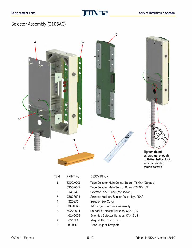
Replacement Parts Service Information Section
Selector Assembly (2105AG)
ITEM PRINT NO. DESCRIPTION
1 6300ACK1 Tape Selector Main Sensor Board (TSMC), Canada
6300ACK2 Tape Selector Main Sensor Board (TSMC), US
2 141549 Selector Tape Guide (not shown)
3 736CE001 Selector Auxiliary Sensor Assembly, TSAC
4 320GX1 Selector Box Cover
5 900AD60 14 Gauge Green Wire Assembly
6 462VC001 Standard Selector Harness, CAN-BUS
462VC002 Extended Selector Harness, CAN-BUS
7 850PE1 Magnet Alignment Tool
8 814CH1 Floor Magnet Template
Tighten thumb screws just enough to flatten helical lock washers on the thumb screws.
8
7
1
5
6
3
4
©Vertical Express 5-12 Printed in USA November 2019
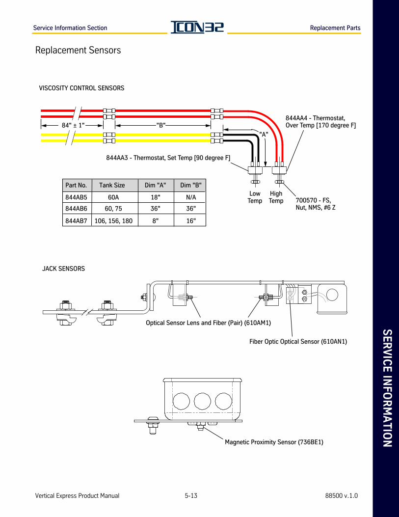
SE
RV
ICE
INFO
RM
AT
ION
Service Information Section Replacement Parts
Replacement Sensors
VISCOSITY CONTROL SENSORS
"B"84" ± 1"
LowTemp
HighTemp
"A"
844AA4 - Thermostat,Over Temp [170 degree F]
844AA3 - Thermostat, Set Temp [90 degree F]
700570 - FS,Nut, NMS, #6 Z844AB6 36" 36"60, 75
Part No. Dim "A"Tank Size Dim "B"
844AB7 106, 156, 180 8" 16"
844AB5 18"60A N/A
Optical Sensor Lens and Fiber (Pair) (610AM1)
Fiber Optic Optical Sensor (610AN1)
JACK SENSORS
Magnetic Proximity Sensor (736BE1)
Vertical Express Product Manual 5-13 88500 v.1.0
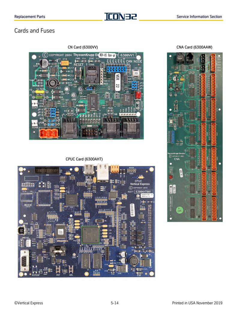
Replacement Parts Service Information Section
Cards and Fuses
CPUC Card (6300AHT)
CN Card (6300VV) CNA Card (6300AAW)
©Vertical Express 5-14 Printed in USA November 2019

SE
RV
ICE
INFO
RM
AT
ION
Service Information Section Replacement Parts
Cards and Fuses(continued)
DPIA Card 6300ADF1 DIN Rail, RJ45 Shielded Jack Breakout Card (6300AJA)
L24 Card (6300LL) LHV 4X4 Card (6300PR)
S24-1 Card (6300VC) S24-2 Card (6300VL)
Vertical Express Product Manual 5-15 88500 v.1.0
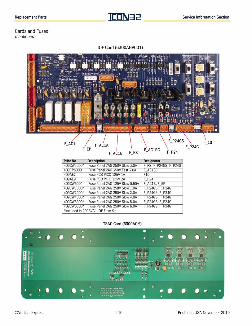
Replacement Parts Service Information Section
Cards and Fuses(continued)
F_EPF_PS
F_P24GSF_AC1A F_P24G
F_AC1SC
F_10
F_P24F_AC1B
F_AC1
IOF Card (6300AHV001)
Print No. Description Designator409CW3000* Fuse Panel 2AG 250V Slow 3.0A F_PS, F_P24GS, F_P24G409CP3000 Fuse Panel 2AG 350V Fast 3.0A F_AC1SC409AE7 Fuse PCB PICO 125V 1A F10409AE9 Fuse PCB PICO 125V 2A F_P24409CW500* Fuse Panel 2AG 125V Slow 0.50A F_AC1B, F_EP409CW1000* Fuse Panel 2AG 250V Slow 1.0A F_P24GS, F_P24G409CW2000* Fuse Panel 2AG 250V Slow 2.0A F_P24GS, F_P24G409CW4000* Fuse Panel 2AG 250V Slow 4.0A F_P24GS, F_P24G409CW5000* Fuse Panel 2AG 250V Slow 5.0A F_P24GS, F_P24G409CW6000* Fuse Panel 2AG 250V Slow 6.0A F_P24GS, F_P24G*Included in 200BVG1 IOF Fuse Kit
TSAC Card (6300ACM)
©Vertical Express 5-16 Printed in USA November 2019
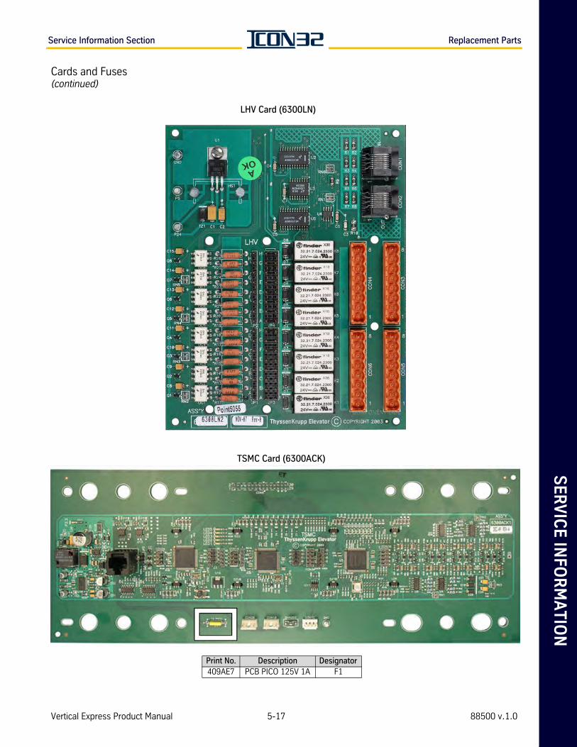
SE
RV
ICE
INFO
RM
AT
ION
Service Information Section Replacement Parts
Cards and Fuses(continued)
LHV Card (6300LN)
TSMC Card (6300ACK)
Print No. Description Designator409AE7 PCB PICO 125V 1A F1
Vertical Express Product Manual 5-17 88500 v.1.0
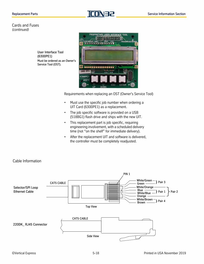
Replacement Parts Service Information Section
Cards and Fuses(continued)
User Interface Tool (6300PE1)Must be ordered as an Owner's Service Tool (OST).
Requirements when replacing an OST (Owner's Service Tool)
• Must use the specific job number when ordering a UIT Card (6300PE1) as a replacement.
• The job specific software is provided on a USB (518BG1) flash drive and ships with the new UIT.
• This replacement part is job specific, requiring engineering involvement, with a scheduled delivery time (not “on the shelf” for immediate delivery).
• After the replacement UIT and software is delivered, the controller must be completely readjusted.
Selector/SPI LoopEthernet Cable
CAT5 CABLE
CAT5 CABLE
Top View
Side View
PIN 1
Pair 3
Pair 2Pair 1
Pair 4
Blue
BrownWhite/Brown
White/Green
White/Blue
GreenWhite/Orange
Orange
220DK_ RJ45 Connector
Cable Information
©Vertical Express 5-18 Printed in USA November 2019
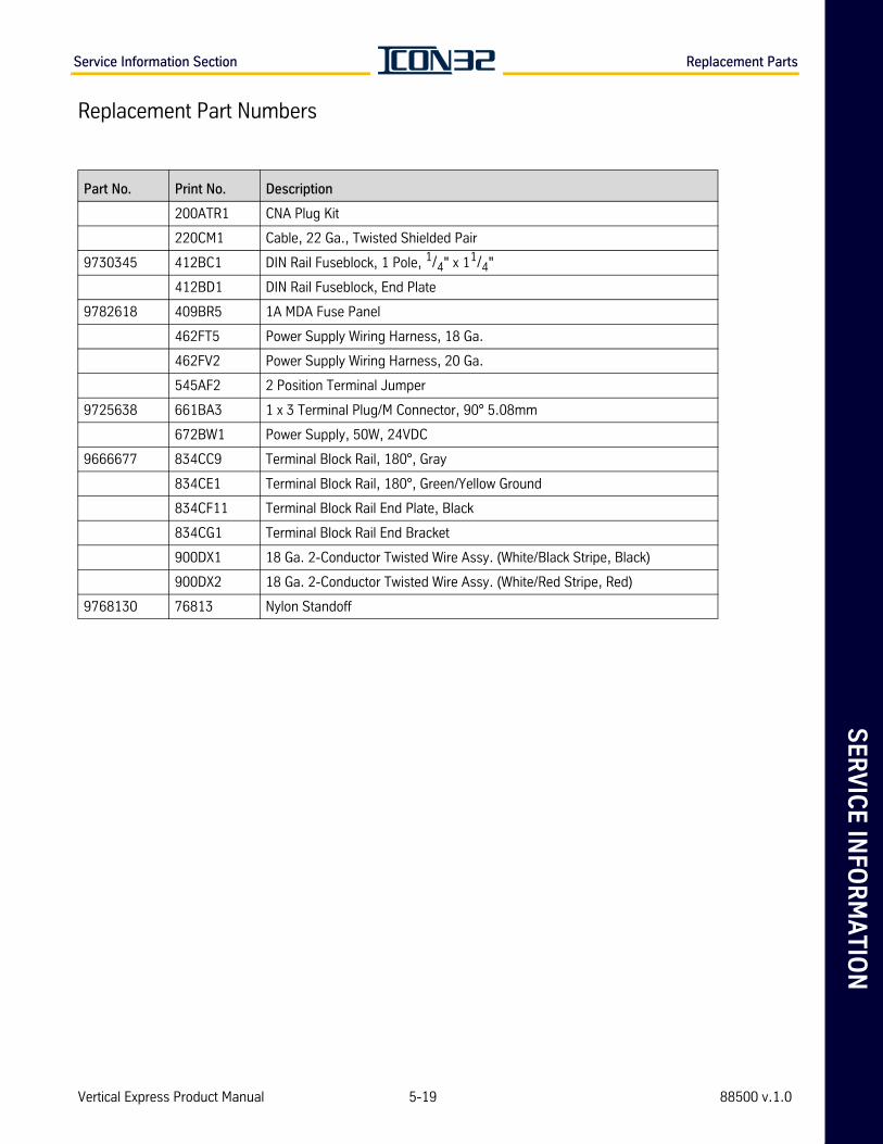
SE
RV
ICE
INFO
RM
AT
ION
Service Information Section Replacement Parts
Replacement Part Numbers
Part No. Print No. Description
200ATR1 CNA Plug Kit
220CM1 Cable, 22 Ga., Twisted Shielded Pair
9730345 412BC1 DIN Rail Fuseblock, 1 Pole, 1/4" x 11/4"
412BD1 DIN Rail Fuseblock, End Plate
9782618 409BR5 1A MDA Fuse Panel
462FT5 Power Supply Wiring Harness, 18 Ga.
462FV2 Power Supply Wiring Harness, 20 Ga.
545AF2 2 Position Terminal Jumper
9725638 661BA3 1 x 3 Terminal Plug/M Connector, 90° 5.08mm
672BW1 Power Supply, 50W, 24VDC
9666677 834CC9 Terminal Block Rail, 180°, Gray
834CE1 Terminal Block Rail, 180°, Green/Yellow Ground
834CF11 Terminal Block Rail End Plate, Black
834CG1 Terminal Block Rail End Bracket
900DX1 18 Ga. 2-Conductor Twisted Wire Assy. (White/Black Stripe, Black)
900DX2 18 Ga. 2-Conductor Twisted Wire Assy. (White/Red Stripe, Red)
9768130 76813 Nylon Standoff
Vertical Express Product Manual 5-19 88500 v.1.0
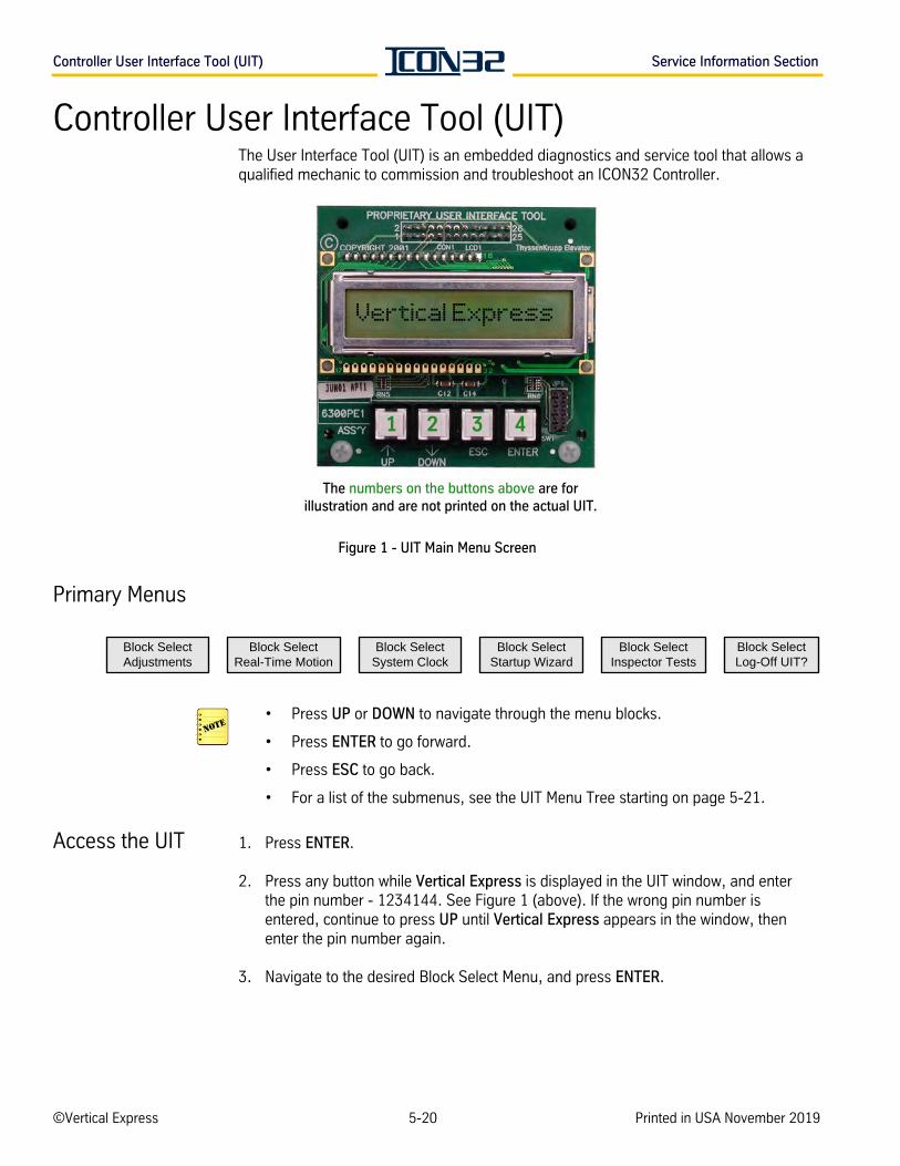
Controller User Interface Tool (UIT) Service Information Section
Controller User Interface Tool (UIT)The User Interface Tool (UIT) is an embedded diagnostics and service tool that allows a qualified mechanic to commission and troubleshoot an ICON32 Controller.
Figure 1 - UIT Main Menu Screen
Primary Menus
• Press UP or DOWN to navigate through the menu blocks.
• Press ENTER to go forward.
• Press ESC to go back.
• For a list of the submenus, see the UIT Menu Tree starting on page 5-21.
Access the UIT 1. Press ENTER.
2. Press any button while Vertical Express is displayed in the UIT window, and enter the pin number - 1234144. See Figure 1 (above). If the wrong pin number is entered, continue to press UP until Vertical Express appears in the window, then enter the pin number again.
3. Navigate to the desired Block Select Menu, and press ENTER.
1 2 3 4
Vertical Express
The numbers on the buttons above are for illustration and are not printed on the actual UIT.
Block SelectStartup Wizard
Block SelectInspector Tests
Block SelectLog-Off UIT?
Block SelectSystem Clock
Block SelectAdjustments
Block SelectReal-Time Motion
©Vertical Express 5-20 Printed in USA November 2019
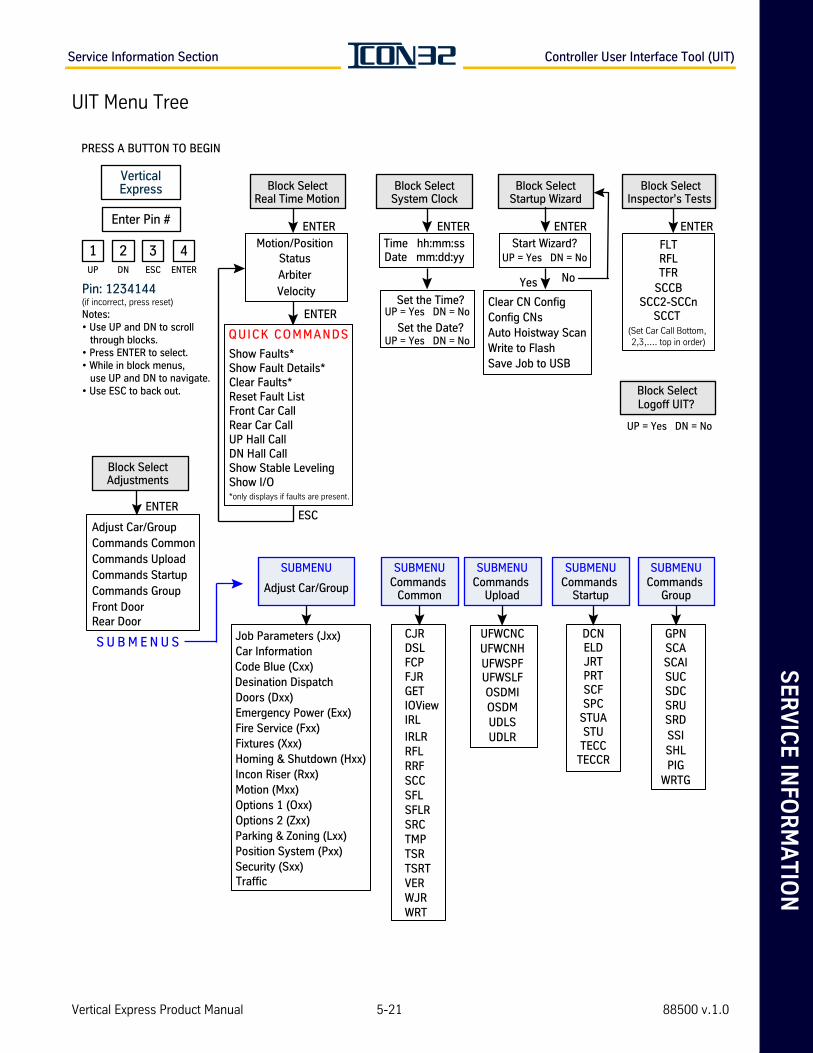
SE
RV
ICE
INFO
RM
AT
ION
Service Information Section Controller User Interface Tool (UIT)
UIT Menu Tree
Block SelectSystem Clock
Time hh:mm:ssDate mm:dd:yy
ENTER
Set the Time?UP = Yes DN = No
Set the Date?UP = Yes DN = No
SUBMENU
Adjust Car/Group
Job Parameters (Jxx)
Code Blue (Cxx)
Doors (Dxx)Emergency Power (Exx)Fire Service (Fxx)Fixtures (Xxx)Homing & Shutdown (Hxx)Incon Riser (Rxx)Motion (Mxx)Options 1 (Oxx)Options 2 (Zxx)Parking & Zoning (Lxx)Position System (Pxx)Security (Sxx)
SUBMENUCommands
Group
GPNSCASCAISUCSDCSRUSRDSSISHLPIG
WRTG
Show Faults*
Clear Faults*Reset Fault ListFront Car CallRear Car CallUP Hall CallDN Hall CallShow Stable LevelingShow I/O*only displays if faults are present.
QUICK COMMANDS
Block SelectAdjustments
ENTER
S U B M E N U S
Adjust Car/GroupCommands CommonCommands UploadCommands StartupCommands GroupFront DoorRear Door
Block SelectStartup Wizard
ENTER
Start Wizard?UP = Yes DN = No
Yes No
Clear CN ConfigConfig CNsAuto Hoistway ScanWrite to FlashSave Job to USB
Block SelectReal Time Motion
Motion/Position Status
Arbiter
ENTER
Velocity
SUBMENUCommands
Common
CJRDSLFCP
GETIOViewIRL
IRLRRFLRRFSCCSFLSFLRSRCTMP
VER
WRT
TSRTSRT
SUBMENUCommands
Upload
UFWCNCUFWCNHUFWSPF
OSDMUDLSUDLR
SUBMENUCommands
Startup
DCNELD
SCFSPC
STUTECC
TECCR
PRESS A BUTTON TO BEGIN
Notes: • Use UP and DN to scroll through blocks.• Press ENTER to select.• While in block menus, use UP and DN to navigate. • Use ESC to back out.
Pin: 1234144(if incorrect, press reset)
VerticalExpress
Enter Pin #
1 2 3 4UP ENTERDN ESC
Block SelectInspector’s Tests
FLTRFLTFR
SCCBSCC2-SCCn
SCCT (Set Car Call Bottom, 2,3,.... top in order)
ENTER
ENTER
ESC
Logoff UIT?
UP = Yes DN = No
Block Select
Show Fault Details*
FJR
WJR
Car Information
Desination Dispatch
Traffic
UFWSLFOSDMI
JRTPRT
STUA
Vertical Express Product Manual 5-21 88500 v.1.0
CAN Node Configuration via the Startup Wizard Service Information Section
CAN Node Configuration via the Startup Wizard
The Startup Wizard will setup and configure all CAN nodes, execute a hoistway scan, and save parameter changes.
CAN Nodes Before using the Startup Wizard, the door operator and safety system nodes must be installed and completely wired to the cards (CNA, Selector, DPIA, CNs, etc.). When the cor-rect termination scheme is used, CAN channels 2 (and 3 when required) should measure 60 ohms +/- 3 ohms, with power removed and all connections made.
Configure the CAN System
1. Access the UIT.
2. Access the Startup Wizard.
a. Press UP or DOWN until Block Select Startup Wizard displays, and then press ENTER.
b. When Start Wizard? displays, press UP.
3. Issue the Teach Command.
a. When Teach Front CN? displays,
• For Front Riser - press ENTER, and press ENTER again.
• No Front Riser - press UP.
b. When Teach Rear CN? displays,
• For Rear Riser - press ENTER, and press ENTER again.
• No Rear Riser - press UP.
4. Configure the CNs.
a. When Config CN displays, press ENTER.
b. When Completed Config displays, press ENTER.
5. Skip Automatic Hoistway Scan. When Auto Hoistway Scan? displays, press UP.
6. Save the parameters.
a. When Write to Flash displays, press ENTER.
b. When Write Complete displays, press ESC.
©Vertical Express 5-22 Printed in USA November 2019
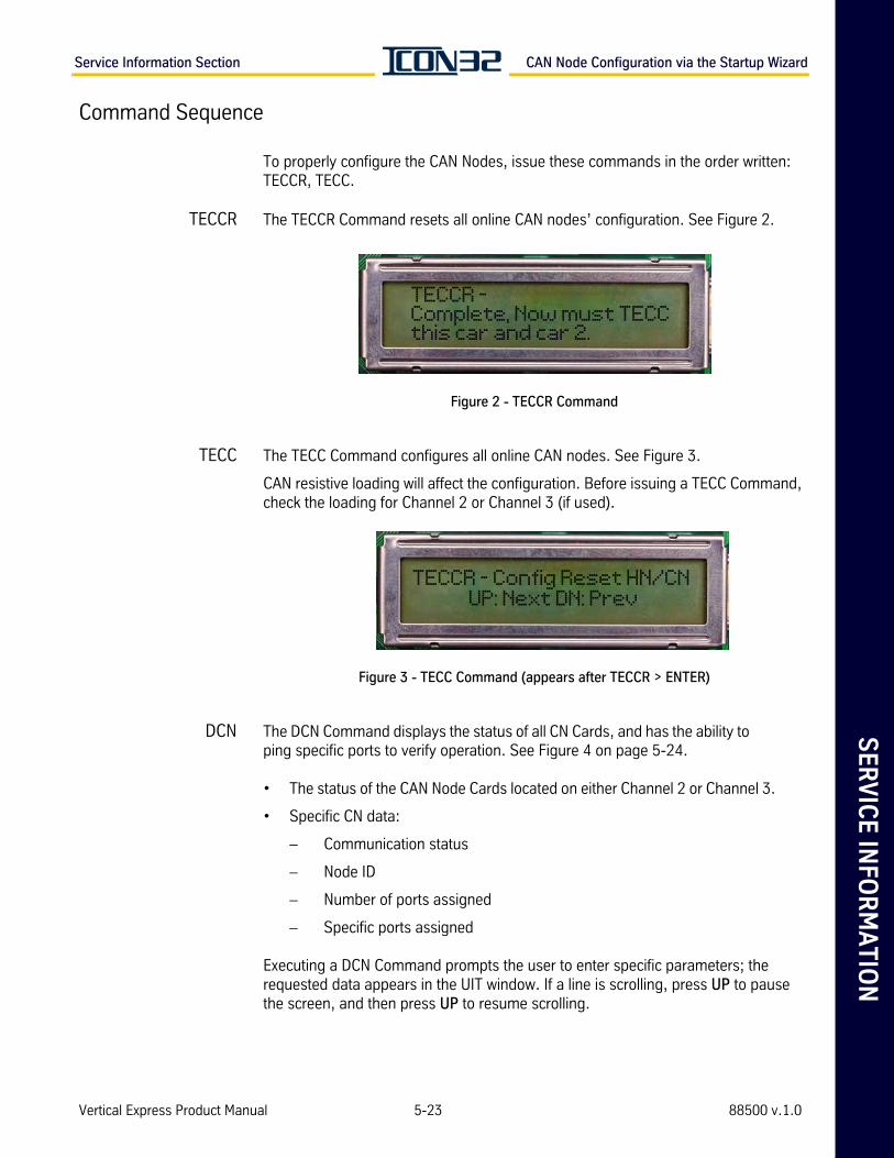
SE
RV
ICE
INFO
RM
AT
ION
Service Information Section CAN Node Configuration via the Startup Wizard
Command Sequence
To properly configure the CAN Nodes, issue these commands in the order written: TECCR, TECC.
TECCR The TECCR Command resets all online CAN nodes’ configuration. See Figure 2.
Figure 2 - TECCR Command
TECC The TECC Command configures all online CAN nodes. See Figure 3.
CAN resistive loading will affect the configuration. Before issuing a TECC Command, check the loading for Channel 2 or Channel 3 (if used).
Figure 3 - TECC Command (appears after TECCR > ENTER)
DCN The DCN Command displays the status of all CN Cards, and has the ability to ping specific ports to verify operation. See Figure 4 on page 5-24.
• The status of the CAN Node Cards located on either Channel 2 or Channel 3.
• Specific CN data:
– Communication status
– Node ID
– Number of ports assigned
– Specific ports assigned
Executing a DCN Command prompts the user to enter specific parameters; the requested data appears in the UIT window. If a line is scrolling, press UP to pause the screen, and then press UP to resume scrolling.
TECCR - Complete, Now must TECC this car and car 2.
TECCR - Config Reset HN/CN UP: Next DN: Prev
Vertical Express Product Manual 5-23 88500 v.1.0
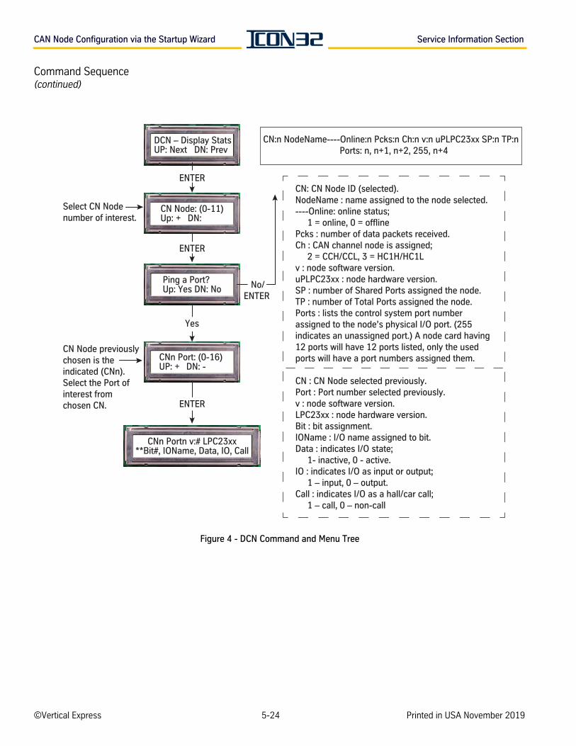
CAN Node Configuration via the Startup Wizard Service Information Section
Command Sequence(continued)
Figure 4 - DCN Command and Menu Tree
CN:n NodeName----Online:n Pcks:n Ch:n v:n uPLPC23xx SP:n TP:n Ports: n, n+1, n+2, 255, n+4
CN: CN Node ID (selected).NodeName : name assigned to the node selected.----Online: online status; 1 = online, 0 = offlinePcks : number of data packets received. Ch : CAN channel node is assigned; 2 = CCH/CCL, 3 = HC1H/HC1Lv : node software version. uPLPC23xx : node hardware version.SP : number of Shared Ports assigned the node. TP : number of Total Ports assigned the node.Ports : lists the control system port number assigned to the node’s physical I/O port. (255 indicates an unassigned port.) A node card having 12 ports will have 12 ports listed, only the used ports will have a port numbers assigned them. CN : CN Node selected previously.Port : Port number selected previously. v : node software version.LPC23xx : node hardware version. Bit : bit assignment.IOName : I/O name assigned to bit. Data : indicates I/O state; 1- inactive, 0 - active.IO : indicates I/O as input or output; 1 – input, 0 – output.Call : indicates I/O as a hall/car call; 1 – call, 0 – non-call
CN Node: (0-11)Up: + DN:
ENTER
Ping a Port? Up: Yes DN: No
CNn Port: (0-16) UP: + DN: -
CNn Portn v:# LPC23xx**Bit#, IOName, Data, IO, Call
ENTER
Yes
No/ENTER
CN Node previously chosen is the indicated (CNn). Select the Port of interest from chosen CN.
ENTER
Select CN Nodenumber of interest.
DCN – Display Stats UP: Next DN: Prev
©Vertical Express 5-24 Printed in USA November 2019
SE
RV
ICE
INFO
RM
AT
ION
Service Information Section Card Changing Procedures
Card Changing ProceduresDoor Card See the appropriate door operator manual.
CAN Node Card 1. Remove the car from service.
2. Turn OFF, Lockout, and Tagout the mainline disconnect.
3. Note the connector locations, and then remove all connectors from the old card.
4. Note the jumper positions and socketed resistor configurations, and then remove the old card.
5. Place jumpers and resistor configurations in same positions as on the old card.
6. Install the replacement card.
7. Install all wires and connectors on the new card.
8. Turn ON the mainline disconnect.
9. Log into the UIT using the PIN number (1234144).
10. Navigate to ADJUSTMENTS BLOCK > COMMANDS STARTUP.
11. Issue a TECC Command.
12. To confirm communication and port assignments, issue a DCN Command.
13. Verify proper operation, and return the car to service.
L24, S24-1, S24-2, LHV, LHV 4x4 Cards
These cards have no software and can be used where needed. Ensure that the cables are correctly marked so they may be correctly reconnected after replacing the suspected failed card.
1. Remove the car from service.
2. Turn OFF, Lockout, and Tagout the mainline disconnect.
3. Note locations, and remove all connectors from the I/O Cards.
4. Install the replacement card.
5. Install all wires and connectors on the new card.
6. Turn ON the mainline disconnect.
7. Verify proper operation, and return the car to service.
Vertical Express Product Manual 5-25 88500 v.1.0
Card Changing Procedures Service Information Section
Card Changing Procedures(continued)
TSMC/TSAC Card 1. Position the car to easily access the car top, if possible.
2. Remove the car from service.
3. Turn OFF, Lockout, and Tagout the mainline disconnect.
4. Access the car top.
5. Disassemble the selector. See the Selector Assembly (2105AG) on page 5-12.
6. Replace the TSMC/TSAC Card, and reassemble the selector.
7. Restore power to the controller.
8. Log into the UIT using the PIN number (1234144).
9. Navigate to STARTUP WIZARD BLOCK.
10. Place the car on Automatic Service.
11. Activate the Door Disconnect Switch on the IOF Card.
12. Press UP until Auto Hoistway Scan? appears, and then press ENTER.
IOF Card Changing Procedure
Download Existing Files from the CPUC and Remove Old Cards
1. Place the controller on Inspection Operation.
2. Insert the manufacturing-supplied USB flash drive into the USB Host Port (CON6 on the existing CPUC Card). Most USB flash drives may be used, if they are properly for-matted and have the correct file folder structure. See USB Flash Drive Preparation on page 5-34.
Transferring software between the CPUC and USB flash drives requires a few minutes to complete. Resetting the card during this time could result in corrupt-ing the USB and the CPUC.
3. Issue a UDLS Command.This process will backup image and generic software files from the CPUC to the USB flash drive.
Controller UIT: Block Select Adjustments > Commands Upload > UDLS.
4. Remove the USB flash drive from the CPUC.
5. Turn OFF, Lockout, and Tagout the mainline disconnect.
©Vertical Express 5-26 Printed in USA November 2019
SE
RV
ICE
INFO
RM
AT
ION
Service Information Section Card Changing Procedures
IOF Card(continued) 6. Disconnect CON40. This process removes the P24XC feed from other controllers
in the group. See Figure 5 on page 5-28 for the remaining steps in this section.
7. Verify that the following LEDs are not illuminated:
• P24.
• P24G.
• P24GS.
• AC (located in the bottom right half of the IOF).
8. Verify that the P24GS PSM (located on the DIN rail above the IOF) is not illuminated.
9. Detach all connectors from the IOF and CPUC Cards.
10. Remove the CPUC Card from the plastic standoffs of the IOF Card, and place the CPUC Card on a static-free surface.
11. Remove the IOF Card from the controller cabinet, and place the IOF Card on a static-free surface.
Transfer and Install New Cards
1. Transfer the following items from the old card to the new card.
• Plastic Standoffs.
• CON9A.
• Jumpers JP2 and JP3 (in 2-3 positions).
• Any fuses including, but not limited to, F-AC1.
– Use the job prints to verify that all necessary fuses are populated with the correct size and fuse type.
– F-P24GS on the IOF Card is not used, a PSM is located on the DIN rail above the IOF Card to supply voltage.
2. Install the CPUC Card onto the IOF Card. Take care not to bend pins that join the CPUC and the IOF Cards together. The pins are located at CON1, CPUC Card.
3. Place the combined cards in the controller cabinet.
4. Replace all connectors except CON40, CON1, CON12, and CON11 on IOF Card.
5. Where Ethernet communication is used, leave the Ethernet cable disconnected from CON5 on the CPUC Card.
6. Verify that the controller inspection switch is in the INSP position.
Vertical Express Product Manual 5-27 88500 v.1.0
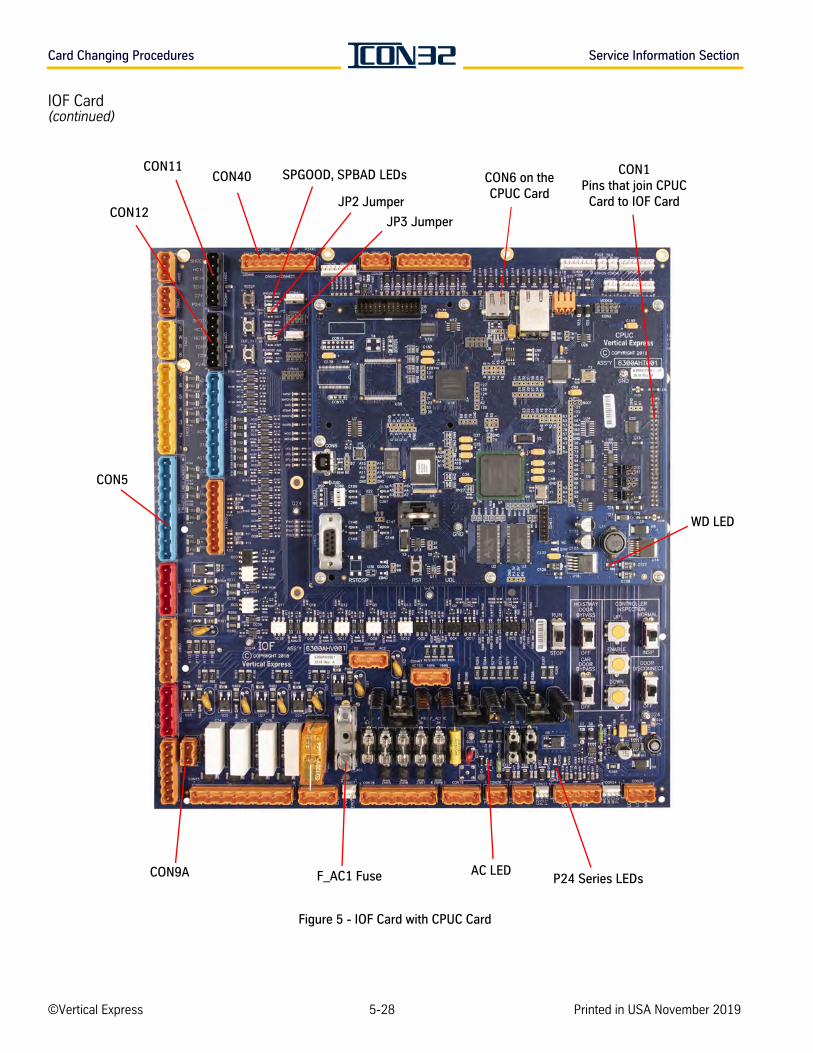
Card Changing Procedures Service Information Section
IOF Card(continued)
Figure 5 - IOF Card with CPUC Card
CON1 Pins that join CPUC
Card to IOF Card
CON6 on the CPUC Card
JP2 Jumper
SPGOOD, SPBAD LEDs
CON9A F_AC1 Fuse AC LEDP24 Series LEDs
CON11CON40
WD LED
CON5
CON12JP3 Jumper
©Vertical Express 5-28 Printed in USA November 2019
SE
RV
ICE
INFO
RM
AT
ION
Service Information Section Card Changing Procedures
CPU Replacement
Back Up the Job Software
1. Place the controller on Inspection Operation.
2. Insert the manufacturing-supplied USB flash drive into the USB Host Port (CON6 on the existing CPUC Card). Most USB flash drives may be used, if they are prop-erly formatted and have the correct file folder structure. See USB Flash Drive Preparation on page 5-34.
Transferring software between the CPUC and USB flash drives requires a few minutes to complete. Resetting the card during this time could result in corrupting the USB and the CPUC.
3. Issue a UDLS Command. This process will backup the generic and job configuration files to the USB flash drive.
Controller UIT: Block Select Adjustments > Commands Upload > UDLS.
Replace the CPUC Card
1. Turn OFF, Lockout, and Tagout the mainline disconnect.
2. Unplug CON40 from the IOF Card.
3. Unplug the Ethernet cable (if used) from CON5 of the CPUC Card.
4. Set jumper positions on the replacement CPUC Card to match the faulty CPUC Card.
5. Confirm that all LEDs on the IOF Card are not illuminated.
6. Carefully uninstall the faulty CPUC Card. Take care not to bend the pins that join the CPUC to the IOF Card, CON1 of the CPUC Card.
7. Remove the UIT and standoffs from the faulty CPUC Card.
The UIT Card is bound to the specific job configuration (software) for the job. The UIT Card will not permit the adjustment of any other job.
During replacement:
• Do Not Swap UIT Cards between controllers/CPU Cards.
• Remove the UIT Card from the failed CPUC Card.
8. Install the UIT and standoffs on the replacement CPUC Card.
9. Carefully install the replacement CPUC Card onto the IOF Card. Before applying pressure, ensure that CON1 of the CPUC properly aligns with the IOF Card's mat-ing pins.
Vertical Express Product Manual 5-29 88500 v.1.0
Card Changing Procedures Service Information Section
CPU Replacement(continued)
10. For jobs where the Hall CAN channel is being used, remove CON1, CON12, and CON11 on the IOF Card.
11. Where Ethernet communication is used, leave the Ethernet cable disconnected from CON5 on the CPUC Card.
12. Use the USB with the job's backup files (from the UDLS earlier), and copy the backup files into the update folder of drive. See USB Flash Drive Preparation on page 5-34.
13. Restore the mainline power.
14. Install the USB flash drive (used earlier) into CON6 on the CPUC Card.
15. Press RST on the CPUC Card.
16. Release RST.
17. Press and hold UDL until the STAT LED blinks Morse Code `Z' (two long and two short blinks). When complete, the STAT LED blinks 3 times before CPUC Card resets itself.
If the upload takes longer than 15 minutes, or if the STAT LED blinks every 100ms contin-uously, the upload has failed. Cycle power to the controller and then remove the USB from the CPUC Card. See Upload Software Troubleshooting on page 5-37.
18. After the upload is successful, verify that the controller will run from Inspection Oper-ation. Should the car fail to run, troubleshoot fault codes and I/O states to determine the issue. See Troubleshooting I/O Issues on page 4-13.
19. Place the door disconnect switch in the Door Disconnect position.
20. Place the inspection switch in the Normal position.
21. Use Quick Commands, and issue car calls to verify Automatic Operation. This action verifies the hoistway scan. If the car will not run on Automatic Operation, perform a new hoistway scan.
Block Select Real Time Motion > Quick Commands > Front Car Call/Rear Car Call.
22. Reconnect CON40, CON1, CON11, and CON12 on the IOF Card.
23. Reconnect the Ethernet cable (if used) to CON5 on the CPUC Card.
24. Verify group service operation.
©Vertical Express 5-30 Printed in USA November 2019
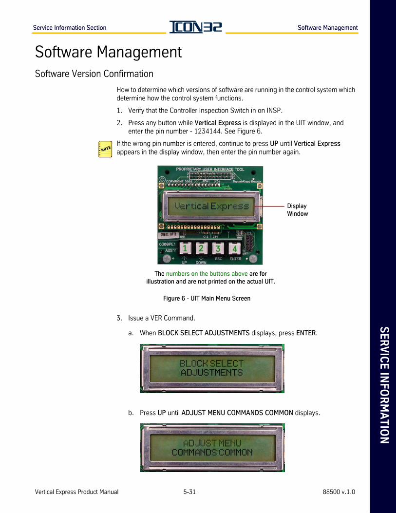
SE
RV
ICE
INFO
RM
AT
ION
Service Information Section Software Management
Software ManagementSoftware Version Confirmation
How to determine which versions of software are running in the control system which determine how the control system functions.
1. Verify that the Controller Inspection Switch in on INSP.
2. Press any button while Vertical Express is displayed in the UIT window, and enter the pin number - 1234144. See Figure 6.
If the wrong pin number is entered, continue to press UP until Vertical Express appears in the display window, then enter the pin number again.
Figure 6 - UIT Main Menu Screen
3. Issue a VER Command.
a. When BLOCK SELECT ADJUSTMENTS displays, press ENTER.
b. Press UP until ADJUST MENU COMMANDS COMMON displays.
1 2 3 4
The numbers on the buttons above are for illustration and are not printed on the actual UIT.
Vertical Express Display Window
BLOCK SELECTADJUSTMENTS
ADJUST MENUCOMMANDS COMMON
Vertical Express Product Manual 5-31 88500 v.1.0
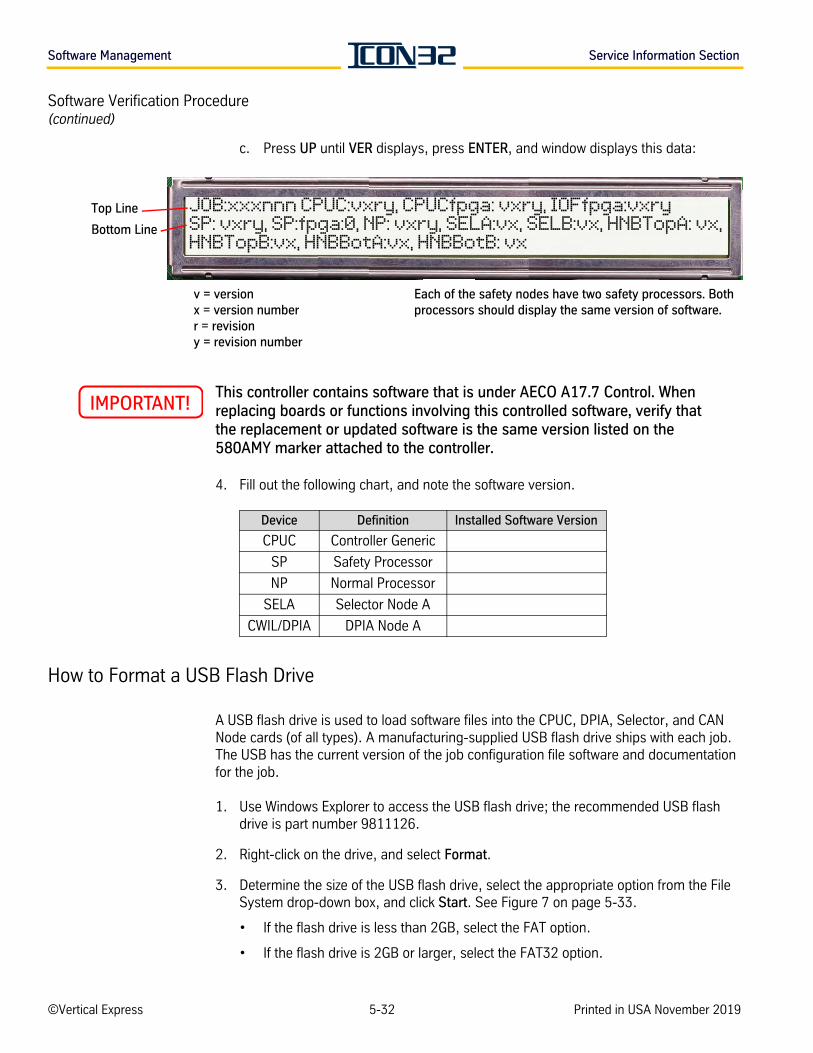
Software Management Service Information Section
Software Verification Procedure(continued)
c. Press UP until VER displays, press ENTER, and window displays this data:
This controller contains software that is under AECO A17.7 Control. When replacing boards or functions involving this controlled software, verify that the replacement or updated software is the same version listed on the 580AMY marker attached to the controller.
4. Fill out the following chart, and note the software version.
How to Format a USB Flash Drive
A USB flash drive is used to load software files into the CPUC, DPIA, Selector, and CAN Node cards (of all types). A manufacturing-supplied USB flash drive ships with each job. The USB has the current version of the job configuration file software and documentation for the job.
1. Use Windows Explorer to access the USB flash drive; the recommended USB flash drive is part number 9811126.
2. Right-click on the drive, and select Format.
3. Determine the size of the USB flash drive, select the appropriate option from the File System drop-down box, and click Start. See Figure 7 on page 5-33.
• If the flash drive is less than 2GB, select the FAT option.
• If the flash drive is 2GB or larger, select the FAT32 option.
Top Line
Bottom Line
v = versionx = version numberr = revisiony = revision number
Each of the safety nodes have two safety processors. Both processors should display the same version of software.
JOB:xxxnnn CPUC:vxry, CPUCfpga: vxry, IOFfpga:vxrySP: vxry, SP:fpga:0, NP: vxry, SELA:vx, SELB:vx, HNBTopA: vx, HNBTopB:vx, HNBBotA:vx, HNBBotB: vx
Device Definition Installed Software Version
CPUC Controller Generic
SP Safety Processor
NP Normal Processor
SELA Selector Node A
CWIL/DPIA DPIA Node A
©Vertical Express 5-32 Printed in USA November 2019
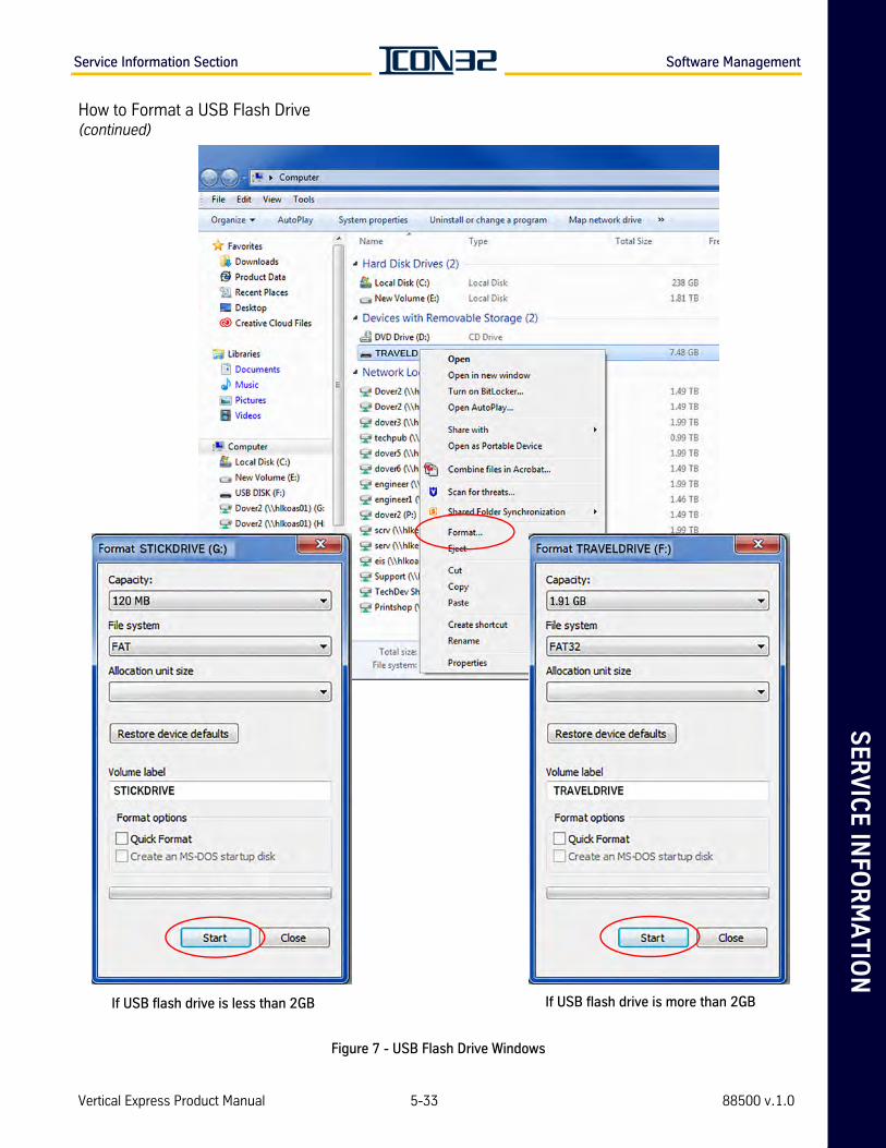
SE
RV
ICE
INFO
RM
AT
ION
Service Information Section Software Management
How to Format a USB Flash Drive(continued)
Figure 7 - USB Flash Drive Windows
If USB flash drive is less than 2GB If USB flash drive is more than 2GB
Vertical Express Product Manual 5-33 88500 v.1.0
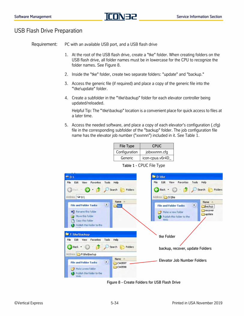
Software Management Service Information Section
USB Flash Drive Preparation
Requirement: PC with an available USB port, and a USB flash drive
1. At the root of the USB flash drive, create a "tke" folder. When creating folders on the USB flash drive, all folder names must be in lowercase for the CPU to recognize the folder names. See Figure 8.
2. Inside the "tke" folder, create two separate folders: "update" and "backup."
3. Access the generic file (if required) and place a copy of the generic file into the "\tke\update" folder.
4. Create a subfolder in the "\tke\backup" folder for each elevator controller being updated/reloaded.
Helpful Tip: The "\tke\backup" location is a convenient place for quick access to files at a later time.
5. Access the needed software, and place a copy of each elevator's configuration (.cfg) file in the corresponding subfolder of the "backup" folder. The job configuration file name has the elevator job number ("xxxnnn") included in it. See Table 1.
Table 1 - CPUC File Type
Figure 8 - Create Folders for USB Flash Drive
File Type CPUC
Configuration jobxxxnnn.cfg
Generic icon-cpua.v6r4D_
tke Folder
backup, recover, update Folders
Elevator Job Number Folders
©Vertical Express 5-34 Printed in USA November 2019
SE
RV
ICE
INFO
RM
AT
ION
Service Information Section Software Management
USB Flash Drive Preparation(continued)
6. Use Windows Explorer to access the job files placed in the "\tke\backup\" folder and copy the required elevator's "jobxxnnnn.cfg" file to the "\tke\update" folder.
7. Use Windows Explorer to verify that the required software files are in the "/tke/update" folder on the USB flash drive.
• Only one version of generic file is permitted in the folder at a time.
• If multiple job files are placed in the update folder, the STAT LED will continuously flash every 100ms.
• If multiple generic files are present in the update folder at the time of an update, the CPUC Card could become corrupted, requiring the Recover Utility to be used.
• The generic and configuration upload may be processed either individually or simultaneously.
• The CPU uploads the configuration (_.cfg) file located in the "\tke\update" folder. When the upload completes, the _.cfg file is deleted from the update folder.
• The generic file remains in "\tke\update\" folder until manually deleted. This is to facilitate updating generic files across a group of controllers using one USB flash drive.
9. Remove the USB flash drive from the computer.
Backup the Job Software
1. Place the controller on Inspection Operation.
2. Insert the prepared USB flash drive into the CON6 USB port on the CPUC Card.
Transferring software between the CPUC and USB flash drives requires a few minutes to complete. Resetting the card during this time could result in corrupting the USB and the CPUC.
3. Enter the UDLS Command to copy the "jobxxnnnn.cfg" file and generic file from the CPUC Card to the "\tke\backup\jobnumber" folder on the USB Flash Drive.
From UIT: Block Select Adjustments > Commands Upload > UDLS.
4. Once the backup is complete, remove the USB flash drive from the CPUC, and return the car to operation.
Vertical Express Product Manual 5-35 88500 v.1.0
Software Management Service Information Section
Upload Software to CPU Cards
Recommendations • Before starting any software updates in control system, backup the software.
• For grouped controllers: When updating the master controller, isolate it from the rest of the group by disconnecting IOF CON40, CON1, CON11, and CON12 as well as CPUC CON5. This action will cause the next car to take over the master controller of group operations assignment while software is being loaded. After software is loaded and operation is restored, restore the connectors and cable.
Uploading software to the CPU requires a few minutes to complete. Resetting the card during this time could result in corrupting the USB flash drive and damaging the card.
1. Place the controller on Inspection Operation.
2. Insert the prepared USB flash drive into the CPUC Card, CON6 USB port.
3. Press and release RST.
4. Press and hold UDL while the CPU is rebooting.
5. Press and hold UDL until the STAT LED blinks a Morse Code `Z' (two long and two short blinks). When the upload is complete, the STAT LED blinks 3 times before the CPUC Card resets itself.
• If the upload takes longer than 15 minutes, or if the STAT LED blinks every 100ms continuously, the upload has failed. Cycle power to the controller and then remove the USB from the CPUC Card. See Upload Software Troubleshooting on page 5-37.
• If the CPU is stuck in Zmodem for longer than 15 minutes, remove power from the card, and remove the USB flash drive.
6. After the upload is successful, issue the following commands from Block Select Adjust > Commands Common: GET, WRT, RFL, and RRF.
7. Cycle from Inspection to Automatic and back to Inspection.
8. Cycle power.
9. Verify that the controller will run from Inspection Operation. Should the car fail to run, troubleshoot fault codes and I/O states to determine the issue. See Troubleshooting I/O Issues on page 4-13.
10. Place the door disconnect switch in the Door Disconnect position.
11. Place the inspection switch in the Normal position.
©Vertical Express 5-36 Printed in USA November 2019
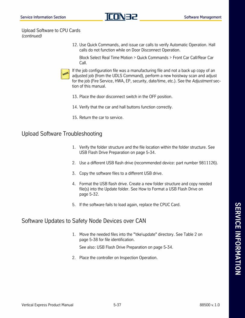
SE
RV
ICE
INFO
RM
AT
ION
Service Information Section Software Management
Upload Software to CPU Cards(continued)
12. Use Quick Commands, and issue car calls to verify Automatic Operation. Hall calls do not function while on Door Disconnect Operation.
Block Select Real Time Motion > Quick Commands > Front Car Call/Rear Car Call.
If the job configuration file was a manufacturing file and not a back up copy of an adjusted job (from the UDLS Command), perform a new hoistway scan and adjust for the job (Fire Service, HWA, EP, security, date/time, etc.). See the Adjustment sec-tion of this manual.
13. Place the door disconnect switch in the OFF position.
14. Verify that the car and hall buttons function correctly.
15. Return the car to service.
Upload Software Troubleshooting
1. Verify the folder structure and the file location within the folder structure. See USB Flash Drive Preparation on page 5-34.
2. Use a different USB flash drive (recommended device: part number 9811126).
3. Copy the software files to a different USB drive.
4. Format the USB flash drive. Create a new folder structure and copy needed file(s) into the Update folder. See How to Format a USB Flash Drive on page 5-32.
5. If the software fails to load again, replace the CPUC Card.
Software Updates to Safety Node Devices over CAN
1. Move the needed files into the "\tke\update" directory. See Table 2 on page 5-38 for file identification.
See also: USB Flash Drive Preparation on page 5-34.
2. Place the controller on Inspection Operation.
Vertical Express Product Manual 5-37 88500 v.1.0
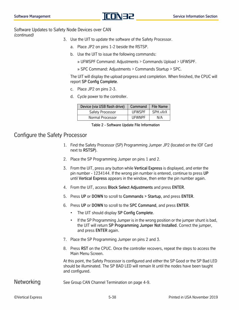
Software Management Service Information Section
Software Updates to Safety Node Devices over CAN(continued)
3. Use the UIT to update the software of the Safety Processor.
a. Place JP2 on pins 1-2 beside the RSTSP.
b. Use the UIT to issue the following commands:
» UFWSPF Command: Adjustments > Commands Upload > UFWSPF.
» SPC Command: Adjustments > Commands Startup > SPC.
The UIT will display the upload progress and completion. When finished, the CPUC will report SP Config Complete.
c. Place JP2 on pins 2-3.
d. Cycle power to the controller.
Table 2 - Software Update File Information
Configure the Safety Processor
1. Find the Safety Processor (SP) Programming Jumper JP2 (located on the IOF Card next to RSTSP).
2. Place the SP Programming Jumper on pins 1 and 2.
3. From the UIT, press any button while Vertical Express is displayed, and enter the pin number - 1234144. If the wrong pin number is entered, continue to press UP until Vertical Express appears in the window, then enter the pin number again.
4. From the UIT, access Block Select Adjustments and press ENTER.
5. Press UP or DOWN to scroll to Commands > Startup, and press ENTER.
6. Press UP or DOWN to scroll to the SPC Command, and press ENTER.
• The UIT should display SP Config Complete.
• If the SP Programming Jumper is in the wrong position or the jumper shunt is bad, the UIT will return SP Programming Jumper Not Installed. Correct the jumper, and press ENTER again.
7. Place the SP Programming Jumper on pins 2 and 3.
8. Press RST on the CPUC. Once the controller recovers, repeat the steps to access the Main Menu Screen.
At this point, the Safety Processor is configured and either the SP Good or the SP Bad LED should be illuminated. The SP BAD LED will remain lit until the nodes have been taught and configured.
Networking See Group CAN Channel Termination on page 4-9.
Device (via USB flash drive) Command File Name
Safety Processor UFWSPF SPH.vXrX
Normal Processor UFWNPF N/A
©Vertical Express 5-38 Printed in USA November 2019

RE
FE
RE
NC
E S
EC
TIO
N
SERVICE REFERENCE SECTION

RE
FE
RE
NC
E S
EC
TIO
N
Reference Section Contents
Contents
UIT Menu Tree . . . . . . . . . . . . . . . . . . . . . . . . . . . . . . . . . . . . . . . . . . . . . . . . . . . . . . . . . . 5R-3
Cable Connections . . . . . . . . . . . . . . . . . . . . . . . . . . . . . . . . . . . . . . . . . . . . . . . . . . . . . . . 5R-4
CNA Fixed I/O Charts . . . . . . . . . . . . . . . . . . . . . . . . . . . . . . . . . . . . . . . . . . . . . . . . . . . . . 5R-7
ICON32 I/O Chart . . . . . . . . . . . . . . . . . . . . . . . . . . . . . . . . . . . . . . . . . . . . . . . . . . . . . . . . 5R-8
I-2/I-3 Valve Reference . . . . . . . . . . . . . . . . . . . . . . . . . . . . . . . . . . . . . . . . . . . . . . . . . . . . 5R-9
Vertical Express Product Manual 5R-1 88500 v.1.0

Contents Reference Section
This pageintentionallyleft blank.
5R-2©Vertical Express Printed in USA April 2020
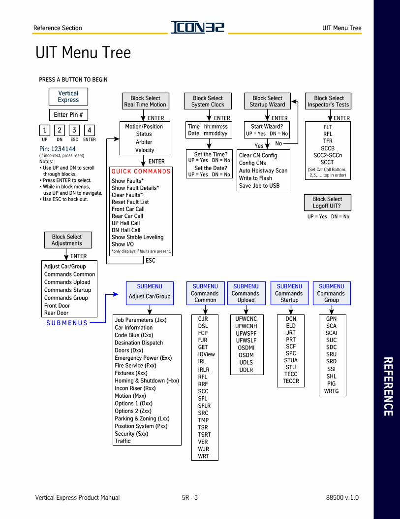
RE
FE
RE
NC
EReference Section UIT Menu Tree
UIT Menu Tree
Block SelectSystem Clock
Time hh:mm:ssDate mm:dd:yy
ENTER
Set the Time?UP = Yes DN = No
Set the Date?UP = Yes DN = No
SUBMENU
Adjust Car/Group
Job Parameters (Jxx)
Code Blue (Cxx)
Doors (Dxx)Emergency Power (Exx)Fire Service (Fxx)Fixtures (Xxx)Homing & Shutdown (Hxx)Incon Riser (Rxx)Motion (Mxx)Options 1 (Oxx)Options 2 (Zxx)Parking & Zoning (Lxx)Position System (Pxx)Security (Sxx)
SUBMENUCommands
Group
GPNSCASCAISUCSDCSRUSRDSSISHLPIG
WRTG
Show Faults*
Clear Faults*Reset Fault ListFront Car CallRear Car CallUP Hall CallDN Hall CallShow Stable LevelingShow I/O*only displays if faults are present.
QUICK COMMANDS
Block SelectAdjustments
ENTER
S U B M E N U S
Adjust Car/GroupCommands CommonCommands UploadCommands StartupCommands GroupFront DoorRear Door
Block SelectStartup Wizard
ENTER
Start Wizard?UP = Yes DN = No
Yes No
Clear CN ConfigConfig CNsAuto Hoistway ScanWrite to FlashSave Job to USB
Block SelectReal Time Motion
Motion/Position Status
Arbiter
ENTER
Velocity
SUBMENUCommands
Common
CJRDSLFCP
GETIOViewIRL
IRLRRFLRRFSCCSFLSFLRSRCTMP
VER
WRT
TSRTSRT
SUBMENUCommands
Upload
UFWCNCUFWCNHUFWSPF
OSDMUDLSUDLR
SUBMENUCommands
Startup
DCNELD
SCFSPC
STUTECC
TECCR
PRESS A BUTTON TO BEGIN
Notes: • Use UP and DN to scroll through blocks.• Press ENTER to select.• While in block menus, use UP and DN to navigate. • Use ESC to back out.
Pin: 1234144(if incorrect, press reset)
VerticalExpress
Enter Pin #
1 2 3 4UP ENTERDN ESC
Block SelectInspector’s Tests
FLTRFLTFR
SCCBSCC2-SCCn
SCCT (Set Car Call Bottom, 2,3,.... top in order)
ENTER
ENTER
ESC
Logoff UIT?
UP = Yes DN = No
Block Select
Show Fault Details*
FJR
WJR
Car Information
Desination Dispatch
Traffic
UFWSLFOSDMI
JRTPRT
STUA
Vertical Express Product Manual 5R - 3 88500 v.1.0
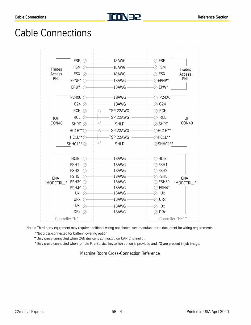
Cable Connections Reference Section
Cable Connections
Machine Room Cross-Connection Reference
18AWG
18AWG
18AWG
18AWG
18AWG
18AWG
18AWG
TSP 22AWG
FSE FSE
FSM FSM
FSX FSX
EPW*
EPNP*
EPW*
P24XC
TSP 22AWG
SHLD
TSP 22AWG
TSP 22AWG
G24
RCH
RCL
SHRC
SHLD
TradesAccess
PNL
P24XC
G24
RCH
HC1H**
HC1L**
SHHC1**
RCL
SHRC
HC1H**
HC1L**
IOFCON40
IOFCON40
18AWG
18AWG
18AWG
18AWG
FSH2
FSH5
Notes: Third party equipment may require additional wiring not shown, see manufacturer’s document for wiring requirements.
SHHC1**
EPNP*
TradesAccess
PNL
18AWG
18AWG18AWG
18AWG
FSH3^
FSH4^Ux
URx
DRx
Dx
FSH1 18AWG FSH1
FSH2
FSH5FSH3^
FSH4^Ux
URx
Dx
DRx
“MODCTRL_”
*Not cross-connected for battery lowering option.
**Only cross-connected when CAN device is connected on CAN Channel 3.
^Only cross-connected when remote Fire Service keyswitch option is provided and I/O are present in job image.
CNA“MODCTRL_”
Controller “N” Controller “N+1”
HCIE 18AWG HCIE
CNA
©Vertical Express 5R - 4 Printed in USA April 2020
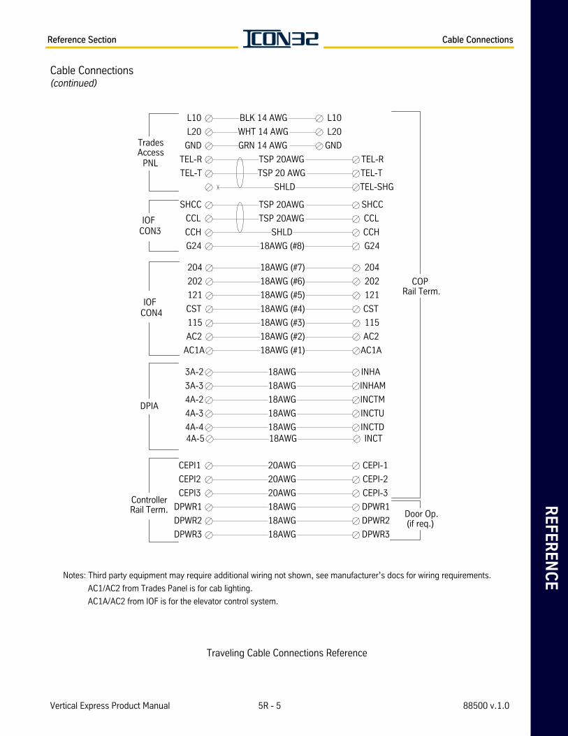
RE
FE
RE
NC
EReference Section Cable Connections
Cable Connections(continued)
AC1/AC2 from Trades Panel is for cab lighting.
AC1A/AC2 from IOF is for the elevator control system.
Traveling Cable Connections Reference
BLK 14 AWG
WHT 14 AWG
GRN 14 AWG
TSP 20AWG
TSP 20 AWG
SHLD
TSP 20AWG
TSP 20AWG
L10 L10
L20 L20
GND GND
TEL-R
TEL-T
TEL-R
TEL-T
TEL-SHG
SHLD
18AWG (#8)
18AWG (#7)
18AWG (#6)
SHCC
CCL
CCH
G24
SHCC
CCL
CCH
G24
IOF CON3
18AWG (#5)
18AWG (#4)
18AWG (#3)
18AWG (#2)
18AWG (#1)
TradesAccess
PNL
204
202
121
204
202
121
CST CST
115 115
AC2 AC2
AC1A AC1A
IOFCON4
COP Rail Term.
20AWG
20AWG
18AWG
18AWG
18AWG
CEPI1 CEPI-1
CEPI2 CEPI-2
CEPI3 CEPI-3
20AWG
DPWR1 DPWR1
DPWR2
DPWR3
DPWR2
DPWR3
ControllerRail Term. Door Op.
(if req.)
18AWG
18AWG
18AWG
18AWG
18AWG
3A-2 INHA
3A-3 INHAM
4A-2 INCTM
4A-3 INCTU
4A-4 INCTD
DPIA
18AWG4A-5 INCT
Notes: Third party equipment may require additional wiring not shown, see manufacturer’s docs for wiring requirements.
Vertical Express Product Manual 5R - 5 88500 v.1.0
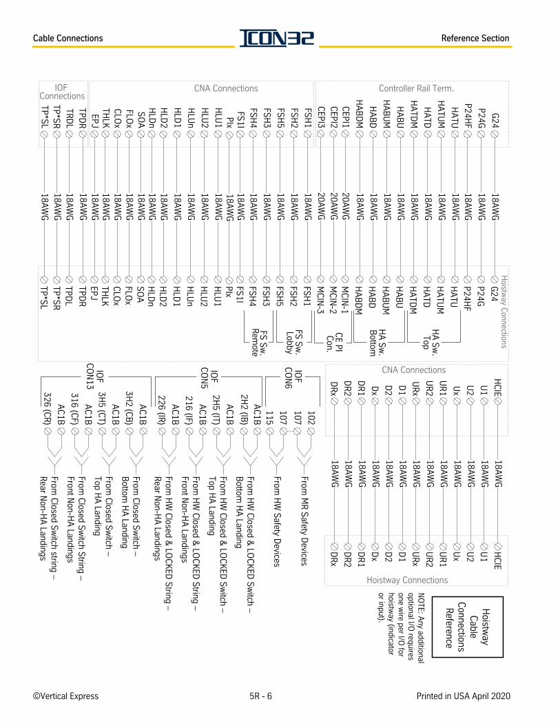
Cable Connections Reference Section
NO
TE: Any additional
optional I/O requires
one wire per I/O
forhoistw
ay (indicatoror input).
Hoistw
ay C
able C
onnections R
eference
18AW
G
18AW
G
18AW
G18A
WG
18AW
G
18AW
G
18AW
G
18AW
G
G24
G24
P24HF
P24HF
18AW
G
18AW
G
18AW
G
18AW
G
18AW
G
18AW
G
18AW
G
18AW
G
18AW
G
18AW
G18A
WG
18AW
G
18AW
G
18AW
G
18AW
G
18AW
G18A
WG
18AW
G
18AW
G18A
WG
20AW
G
20AW
G
CEPI1
MC
IN-1
CEPI2
MC
IN-2
CEPI3
MC
IN-3
20AW
GC
E PI C
on.
FSH
1FS
H1
FSH
2FS
H2
FSH
5FS
H5
FSH
3FS
H3
FSH
4FS
H4
FS1I
FS1I
HLU
1H
LU1
HLU
2H
LU2
HLU
nH
LUn
18AW
G
18AW
GH
LD1
HLD
1
HLD
2H
LD2
HLD
nH
LDn
SO
AFLO
xS
OA
FLOx
CLO
xC
LOx
THLK
THLK
EPJEPJ
TPDR
TPDR
TPDL
TRD
L
Hoistw
ay Connections
18AW
GPIx
PIx
18AW
GTP*S
RTP*S
R
TP*SL
TP*SL
18AW
G
FS S
w.
Lobby
FS S
w.
Rem
ote
18AW
G
18AW
G
18AW
G
18AW
G
18AW
G
18AW
G
18AW
G
18AW
G
HC
IEH
CIE
U1
U1
U2
U2
18AW
G
18AW
G
18AW
G
18AW
G
UR
x
D1
D2
UR
x
D1
D2
18AW
G
Ux
Ux
UR
1U
R1
UR
2U
R2
Dx
Dx
DR
1D
R1
DR
2D
R2
DR
xD
Rx
CNA Connections
Hoistway Connections
102
107
107
115
From M
R S
afety Devices
From H
W S
afety Devices
IOF
CO
N6
AC
1B
AC
1B
AC
1B
AC
1B
2H2 (IB
)
2H5 (IT)
216 (IF)
226 (IR)
IOF
CO
N5
From H
W C
losed & LO
CK
ED S
witch –
Bottom
HA
Landing
From H
W C
losed & LO
CK
ED S
witch –
Top HA
Landing
From H
W C
losed & LO
CK
ED S
tring – Front N
on-HA
Landings
From H
W C
losed & LO
CK
ED S
tring – R
ear Non-H
A Landings
AC
1B
AC
1B
AC
1B
AC
1B
3H2 (C
B)
3H5 (C
T)
316 (CF)
326 (CR
)
IOF
CO
N13
From C
losed Sw
itch – B
ottom H
A Landing
From C
losed Sw
itch – Top H
A Landing
From C
losed Sw
itch String –
Front Non-H
A Landings
From C
losed Sw
itch string – R
ear Non-H
A Landings
P24G
HA
TDM
HA
BU
HA
BU
M
HA
TU
HA
TUM
HA
TD
HA
BD
HA
BD
M
HA
Sw
.Top
HA
Sw
.B
ottom
Controller Rail Term.
HA
TDM
HA
BU
HA
BU
M
HA
TU
HA
TUM
HA
TD
HA
BD
HA
BD
M
P24GCNA ConnectionsIOF
Connections
©Vertical Express 5R - 6 Printed in USA April 2020
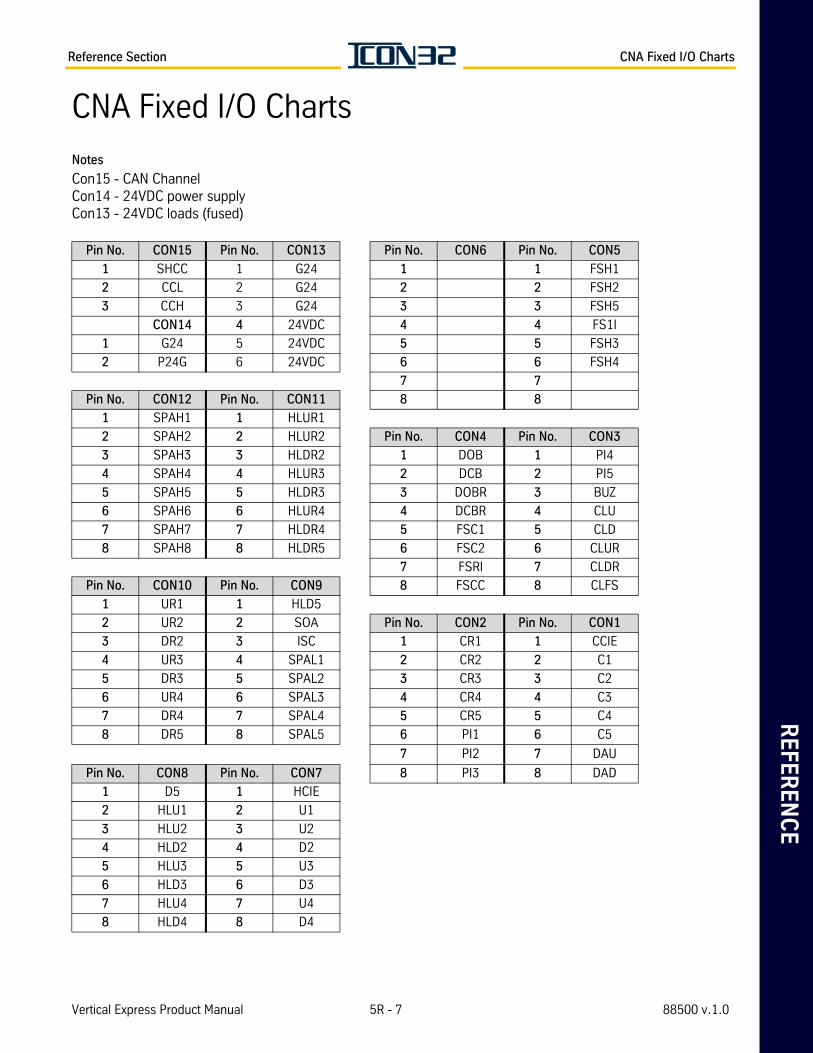
RE
FE
RE
NC
EReference Section CNA Fixed I/O Charts
CNA Fixed I/O Charts
Notes
Con15 - CAN ChannelCon14 - 24VDC power supplyCon13 - 24VDC loads (fused)
Pin No. CON15 Pin No. CON13 Pin No. CON6 Pin No. CON5
1 SHCC 1 G24 1 1 FSH1
2 CCL 2 G24 2 2 FSH2
3 CCH 3 G24 3 3 FSH5
CON14 4 24VDC 4 4 FS1I
1 G24 5 24VDC 5 5 FSH3
2 P24G 6 24VDC 6 6 FSH4
7 7
Pin No. CON12 Pin No. CON11 8 8
1 SPAH1 1 HLUR1
2 SPAH2 2 HLUR2 Pin No. CON4 Pin No. CON3
3 SPAH3 3 HLDR2 1 DOB 1 PI4
4 SPAH4 4 HLUR3 2 DCB 2 PI5
5 SPAH5 5 HLDR3 3 DOBR 3 BUZ
6 SPAH6 6 HLUR4 4 DCBR 4 CLU
7 SPAH7 7 HLDR4 5 FSC1 5 CLD
8 SPAH8 8 HLDR5 6 FSC2 6 CLUR
7 FSRI 7 CLDR
Pin No. CON10 Pin No. CON9 8 FSCC 8 CLFS
1 UR1 1 HLD5
2 UR2 2 SOA Pin No. CON2 Pin No. CON1
3 DR2 3 ISC 1 CR1 1 CCIE
4 UR3 4 SPAL1 2 CR2 2 C1
5 DR3 5 SPAL2 3 CR3 3 C2
6 UR4 6 SPAL3 4 CR4 4 C3
7 DR4 7 SPAL4 5 CR5 5 C4
8 DR5 8 SPAL5 6 PI1 6 C5
7 PI2 7 DAU
Pin No. CON8 Pin No. CON7 8 PI3 8 DAD
1 D5 1 HCIE
2 HLU1 2 U1
3 HLU2 3 U2
4 HLD2 4 D2
5 HLU3 5 U3
6 HLD3 6 D3
7 HLU4 7 U4
8 HLD4 8 D4
Vertical Express Product Manual 5R - 7 88500 v.1.0
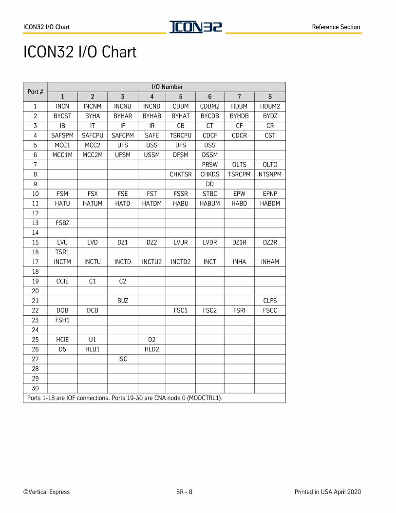
ICON32 I/O Chart Reference Section
ICON32 I/O Chart
Port # I/O Number
1 2 3 4 5 6 7 8
1 INCN INCNM INCNU INCND CDBM CDBM2 HDBM HDBM2
2 BYCST BYHA BYHAR BYHAB BYHAT BYCDB BYHDB BYDZ
3 IB IT IF IR CB CT CF CR
4 SAFSPM SAFCPU SAFCPM SAFE TSRCPU CDCF CDCR CST
5 MCC1 MCC2 UFS USS DFS DSS
6 MCC1M MCC2M UFSM USSM DFSM DSSM
7 PRSW OLTS OLTO
8 CHKTSR CHKDS TSRCPM NTSNPM
9 DD
10 FSM FSX FSE FST FSSR STBC EPW EPNP
11 HATU HATUM HATD HATDM HABU HABUM HABD HABDM
12
13 FSBZ
14
15 LVU LVD DZ1 DZ2 LVUR LVDR DZ1R DZ2R
16 TSR1
17 INCTM INCTU INCTD INCTU2 INCTD2 INCT INHA INHAM
18
19 CCIE C1 C2
20
21 BUZ CLFS
22 DOB DCB FSC1 FSC2 FSRI FSCC
23 FSH1
24
25 HCIE U1 D2
26 D5 HLU1 HLD2
27 ISC
28
29
30
Ports 1-18 are IOF connections. Ports 19-30 are CNA node 0 (MODCTRL1).
©Vertical Express 5R - 8 Printed in USA April 2020
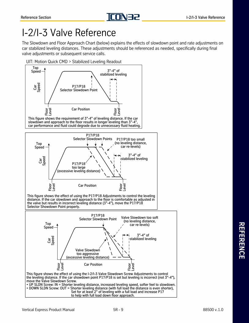
RE
FE
RE
NC
EReference Section I-2/I-3 Valve Reference
I-2/I-3 Valve ReferenceThe Slowdown and Floor Approach Chart (below) explains the effects of slowdown point and rate adjustments on car stabilized leveling distances. These adjustments should be referenced as needed, specifically during final valve adjustments or subsequent service calls.
Top Speed
Car Position
3"-4" ofstabilized leveling
P17/P18Selector Slowdown Point
This figure shows the requirement of 3"-4" of leveling distance. If the carslowdown and approach to the floor results in longer leveling than 3"-4",car performance and fluid could degrade due to unnecessary fluid heating.
Car
Spe
ed
Floo
rLe
vel
Floo
rLe
vel
Top Speed
Car Position
Car
Spe
ed
Floo
rLe
vel
Floo
rLe
vel
3"-4" ofstabilized leveling
P17/P18Selector Slowdown Points
P17/P18too large
(excessive leveling distance)
P17/P18 too small(no leveling distance,
car re-levels)
This figure shows the effect of using the P17/P18 Adjustments to control the levelingdistance. If the car slowdown and approach to the floor is comfortable as adjusted inthe valve but results in incorrect leveling distance (3"-4"), move the P17/P18Selector Showdown Point properly.
Top Speed
Car Position
Car
Spe
ed
Floo
rLe
vel
Floo
rLe
vel
3"-4" ofstabilized leveling
P17/P18Selector Slowdown Point Valve Slowdown too soft
(no leveling distance,car re-levels)
Valve Slowdowntoo aggressive
(excessive leveling distance)
This figure shows the effect of using the I-2/I-3 Valve Slowdown Screw Adjustments to controlthe leveling distance. If the car showdown point P17/P18 is set but leveling is incorrect (not 3"-4"),move the Valve Slowdown Screw.• UP SLDN Screw: IN = Shorter leveling distance, increased leveling speed, softer feel to slowdown.• DOWN SLDN Screw: OUT = Shorter leveling distance (with full load the distance is even shorter), Set for at least 2" of leveling with a full load and increase P17 to help with full load down floor approach.
UIT: Motion Quick CMD > Stabilized Leveling Readout
Vertical Express Product Manual 5R - 9 88500 v.1.0
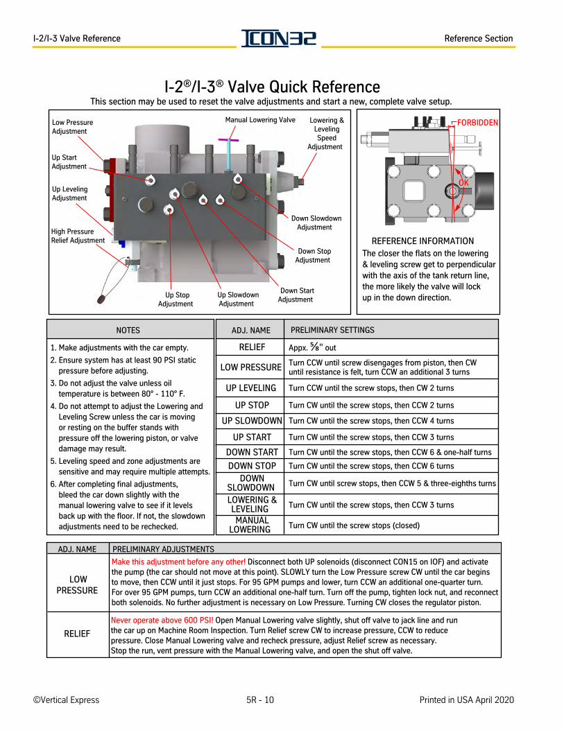
I-2/I-3 Valve Reference Reference Section
REFERENCE INFORMATIONThe closer the flats on the lowering& leveling screw get to perpendicularwith the axis of the tank return line,the more likely the valve will lockup in the down direction.
Up StartAdjustment
Low PressureAdjustment
Up LevelingAdjustment
Up StopAdjustment
Up SlowdownAdjustment
Down StartAdjustment
Down StopAdjustment
Down SlowdownAdjustment
Lowering &LevelingSpeed
Adjustment
Manual Lowering Valve
High PressureRelief Adjustment
NOTES
1. Make adjustments with the car empty.
2. Ensure system has at least 90 PSI static pressure before adjusting.
3. Do not adjust the valve unless oil temperature is between 80° - 110° F.
4. Do not attempt to adjust the Lowering and Leveling Screw unless the car is moving or resting on the buffer stands with pressure off the lowering piston, or valve damage may result.
5. Leveling speed and zone adjustments are sensitive and may require multiple attempts.
6. After completing final adjustments, bleed the car down slightly with the manual lowering valve to see if it levels back up with the floor. If not, the slowdown adjustments need to be rechecked.
ADJ. NAME PRELIMINARY SETTINGS
Appx. " out
LOW PRESSURE Turn CCW until screw disengages from piston, then CWuntil resistance is felt, turn CCW an additional 3 turns
Turn CCW until the screw stops, then CW 2 turns
UP STOP
UP SLOWDOWN
UP START
DOWN START
Turn CW until the screw stops, then CCW 6 turns
DOWN SLOWDOWN Turn CW until screw stops, then CCW 5 & three-eighths turns
LOWERING &LEVELING Turn CW until the screw stops, then CCW 3 turns
MANUALLOWERING Turn CW until the screw stops (closed)
ADJ. NAME PRELIMINARY ADJUSTMENTS
Make this adjustment before any other! Disconnect both UP solenoids (disconnect CON15 on IOF) and activatethe pump (the car should not move at this point). SLOWLY turn the Low Pressure screw CW until the car beginsto move, then CCW until it just stops. For 95 GPM pumps and lower, turn CCW an additional one-quarter turn. For over 95 GPM pumps, turn CCW an additional one-half turn. Turn off the pump, tighten lock nut, and reconnect both solenoids. No further adjustment is necessary on Low Pressure. Turning CW closes the regulator piston.
RELIEF
Never operate above 600 PSI! Open Manual Lowering valve slightly, shut off valve to jack line and runthe car up on Machine Room Inspection. Turn Relief screw CW to increase pressure, CCW to reducepressure. Close Manual Lowering valve and recheck pressure, adjust Relief screw as necessary. Stop the run, vent pressure with the Manual Lowering valve, and open the shut off valve.
I-2®/I-3® Valve Quick ReferenceThis section may be used to reset the valve adjustments and start a new, complete valve setup.
FORBIDDEN
OK
RELIEF
UP LEVELING
Turn CW until the screw stops, then CCW 2 turns
Turn CW until the screw stops, then CCW 4 turns
Turn CW until the screw stops, then CCW 3 turns
Turn CW until the screw stops, then CCW 6 & one-half turns
DOWN STOP
LOWPRESSURE
©Vertical Express 5R - 10 Printed in USA April 2020
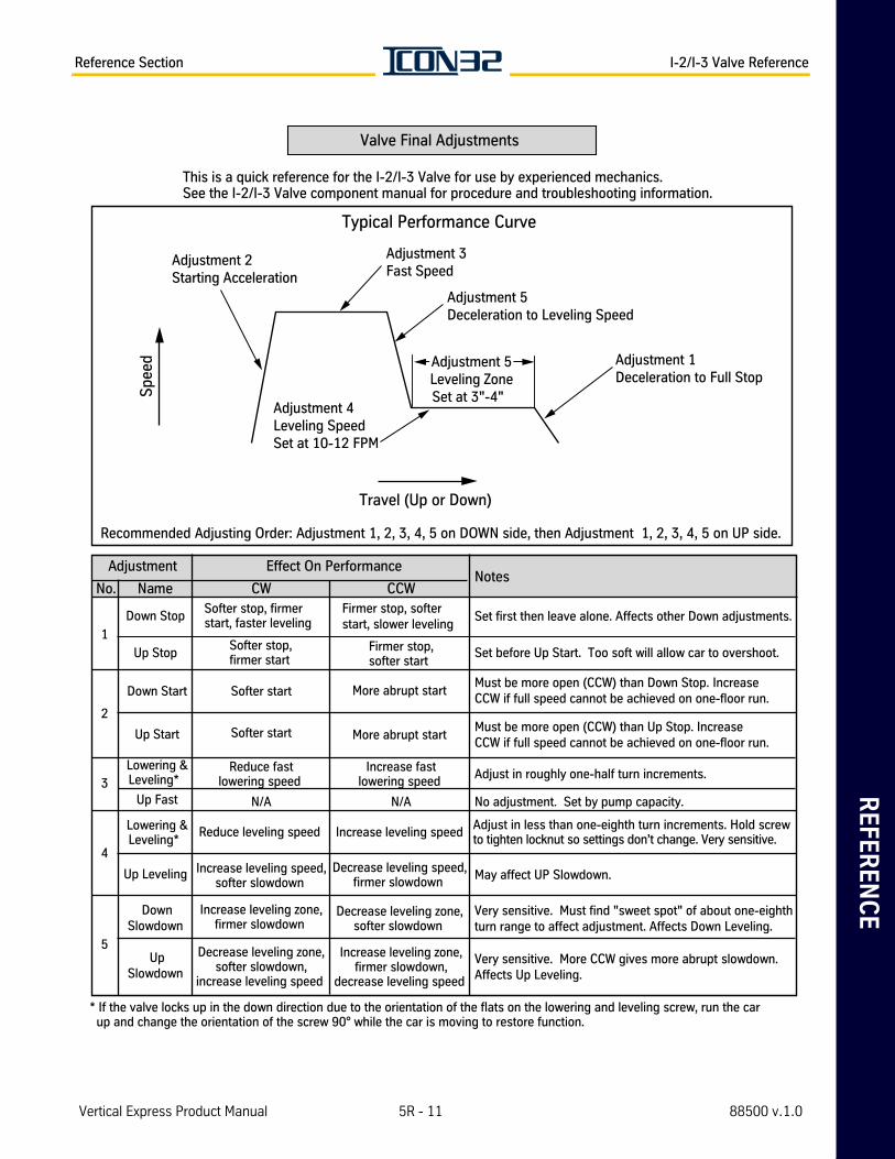
RE
FE
RE
NC
EReference Section I-2/I-3 Valve Reference
Valve Final Adjustments
* If the valve locks up in the down direction due to the orientation of the flats on the lowering and leveling screw, run the car up and change the orientation of the screw 90° while the car is moving to restore function.
Adjustment Effect On Performance Notes
No. Name CW CCW
1
Down Stop Softer stop, firmerstart, faster leveling
Firmer stop, softerstart, slower leveling
Set first then leave alone. Affects other Down adjustments.
Up Stop Softer stop,firmer start
Firmer stop,softer start
Set before Up Start. Too soft will allow car to overshoot.
2
Down StartMust be more open (CCW) than Down Stop. IncreaseCCW if full speed cannot be achieved on one-floor run.
Must be more open (CCW) than Up Stop. IncreaseCCW if full speed cannot be achieved on one-floor run.
3Reduce fast
lowering speed Adjust in roughly one-half turn increments.
Up Fast
4
Lowering &Leveling*
Reduce leveling speed Increase leveling speed Adjust in less than one-eighth turn increments. Hold screwto tighten locknut so settings don’t change. Very sensitive.
Up Leveling May affect UP Slowdown.
5
DownSlowdown
UpSlowdown
Very sensitive. More CCW gives more abrupt slowdown.Affects Up Leveling.
Travel (Up or Down)
Spe
ed
Recommended Adjusting Order: Adjustment 1, 2, 3, 4, 5 on DOWN side, then Adjustment 1, 2, 3, 4, 5 on UP side.
Typical Performance Curve
Adjustment 2Starting Acceleration
This is a quick reference for the I-2/I-3 Valve for use by experienced mechanics. See the I-2/I-3 Valve component manual for procedure and troubleshooting information.
Adjustment 3Fast Speed
Adjustment 4Leveling SpeedSet at 10-12 FPM
Adjustment 1Deceleration to Full Stop
Adjustment 5Deceleration to Leveling Speed
Adjustment 5Leveling ZoneSet at 3"-4"
Lowering &Leveling*
More abrupt start Softer start
Up Start Softer start More abrupt start
N/A No adjustment. Set by pump capacity.
Increase leveling speed,softer slowdown
Decrease leveling speed,firmer slowdown
Increase leveling zone,firmer slowdown
Increase fastlowering speed
Decrease leveling zone,softer slowdown
Decrease leveling zone,softer slowdown,
increase leveling speed
Increase leveling zone,firmer slowdown,
decrease leveling speed
N/A
Very sensitive. Must find "sweet spot" of about one-eighth turn range to affect adjustment. Affects Down Leveling.
Vertical Express Product Manual 5R - 11 88500 v.1.0

I-2/I-3 Valve Reference Reference Section
This pageintentionallyleft blank.
©Vertical Express 5R - 12 Printed in USA April 2020

9280 Crestwyn Hills Memphis, TN 38125Tel: (866) 448-3789 (toll free) Fax: (901) 877-8099
www.verticalxpress.comAll illustrations and specifications are based on information in effect at time of publication
approval. Vertical Express reserves the right to change specifications or design and to discontinue items without prior notice or obligation. © 2020 Vertical Express

9280 Crestwyn Hills Memphis, TN 38125Tel: (866) 448-3789 (toll free) Fax: (901) 877-8099
www.verticalxpress.comAll illustrations and specifications are based on information in effect at time of publication
approval. Vertical Express reserves the right to change specifications or design and to discontinue items without prior notice or obligation. ©2020 Vertical Express