Embed Size (px)
Citation preview
6F8C1132
����� ���� ������ ���������
��� ������ ����� � �������� �
Important Information
No patent liability is assumed by TOSHIBA Corporation with respect to use of information, illustrations, circuits, equipment or examples of application in this publication.
TOSHIBA Corporation reserves the right to make changes and improvements to this publication and/or related products at any time without notice. No obligation shall be incurred other than as noted in this publication.
This publication is copyrighted and contains proprietary material. No part of this book may be reproduced, stored in a retrieval system, or transmitted, in any form or by any means — electrical, mechanical, photocopying, recording, or otherwise — without obtaining prior written permission from TOSHIBA Corporation.
PROSEC, TOSLINE and TOSDIC are trademarks or registered trademarks of TOSHIBA Corporation.
IBM is a registered trademark of International Business Machines Corporation.
Microsoft, MS-DOS, Windows and Windows NT are registered trademarks of Microsoft Corporation in the U.S.A. and other countries.
DeviceNet is a trademark of the Open DeviceNet Vender Association, Inc.
© TOSHIBA CORPORATION 2005. All rights reserved
Safety PrecautionsThis manual contains important information for the operator to operate this product safely and correctly and avoid bodily injury and property damage.Grasp the meanings of the following marks and their descriptions before reading this manual.
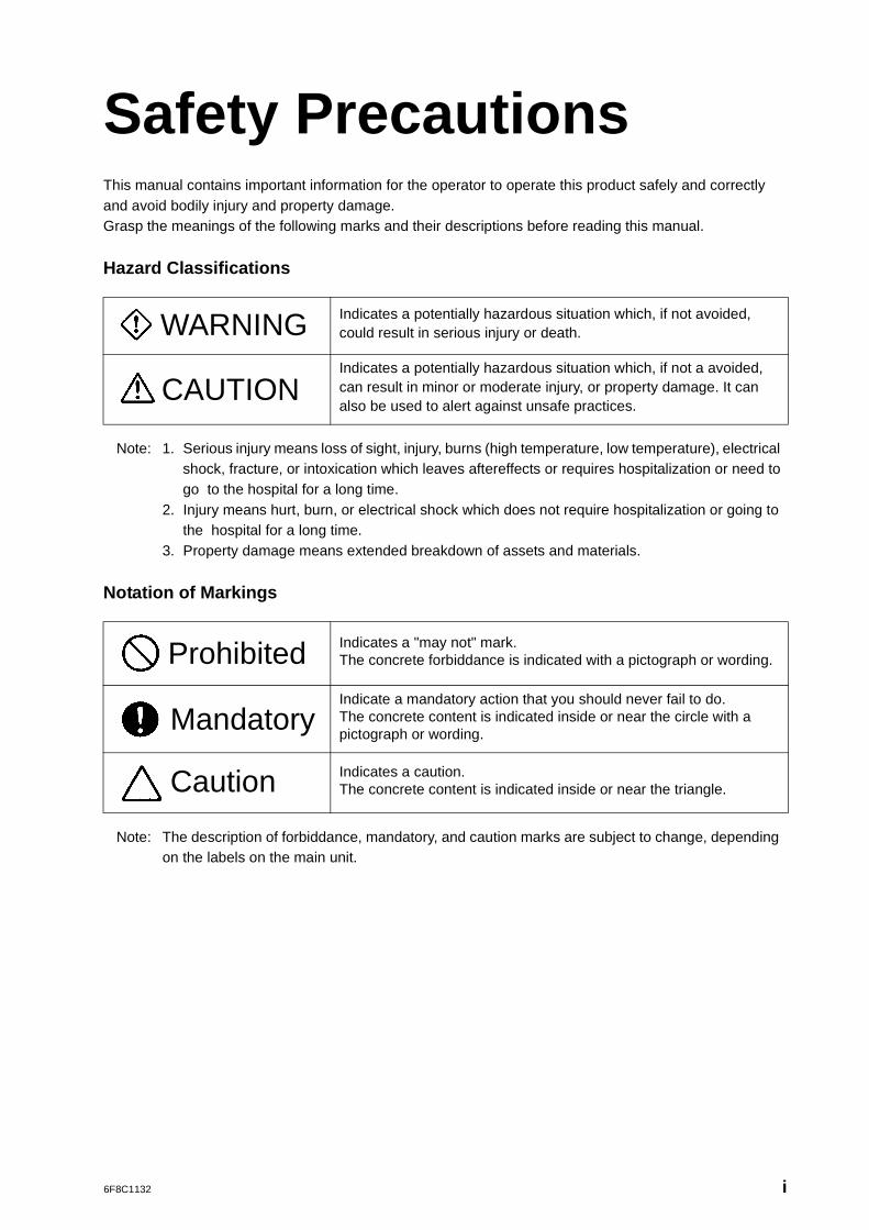
Hazard Classifications
Note: 1. Serious injury means loss of sight, injury, burns (high temperature, low temperature), electrical shock, fracture, or intoxication which leaves aftereffects or requires hospitalization or need to go to the hospital for a long time.
2. Injury means hurt, burn, or electrical shock which does not require hospitalization or going to the hospital for a long time.
3. Property damage means extended breakdown of assets and materials.
Notation of Markings
Note: The description of forbiddance, mandatory, and caution marks are subject to change, depending on the labels on the main unit.
WARNING Indicates a potentially hazardous situation which, if not avoided, could result in serious injury or death.
CAUTIONIndicates a potentially hazardous situation which, if not a avoided, can result in minor or moderate injury, or property damage. It can also be used to alert against unsafe practices.
Prohibited Indicates a "may not" mark.The concrete forbiddance is indicated with a pictograph or wording.
MandatoryIndicate a mandatory action that you should never fail to do.The concrete content is indicated inside or near the circle with a pictograph or wording.
Caution Indicates a caution.The concrete content is indicated inside or near the triangle.
6F8C1132 i
[Warning Mark on the model 2000]
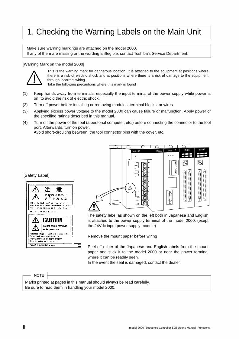
(1) Keep hands away from terminals, especially the input terminal of the power supply while power ison, to avoid the risk of electric shock.
(2) Turn off power before installing or removing modules, terminal blocks, or wires.
(3) Applying excess power voltage to the model 2000 can cause failure or malfunction. Apply power ofthe specified ratings described in this manual.
(4) Turn off the power of the tool (a personal computer, etc.) before connecting the connector to the toolport. Afterwards, turn on power.Avoid short-circuiting between the tool connector pins with the cover, etc.
1. Checking the Warning Labels on the Main Unit
Make sure warning markings are attached on the model 2000.If any of them are missing or the wording is illegible, contact Toshiba's Service Department.
This is the warning mark for dangerous location. It is attached to the equipment at positions wherethere is a risk of electric shock and at positions where there is a risk of damage to the equipmentthrough incorrect wiring. Take the following precautions where this mark is found
[Safety Label]
The safety label as shown on the left both in Japanese and Englishis attached to the power supply terminal of the model 2000. (exeptthe 24Vdc input power supply module)
Remove the mount paper before wiring
Peel off either of the Japanese and English labels from the mountpaper and stick it to the model 2000 or near the power terminalwhere it can be readily seen. In the event the seal is damaged, contact the dealer.
NOTE
Marks printed at pages in this manual should always be read carefully. Be sure to read them in handling your model 2000.
!
ii model 2000 Sequence Controller S2E User’s Manual -Functions-
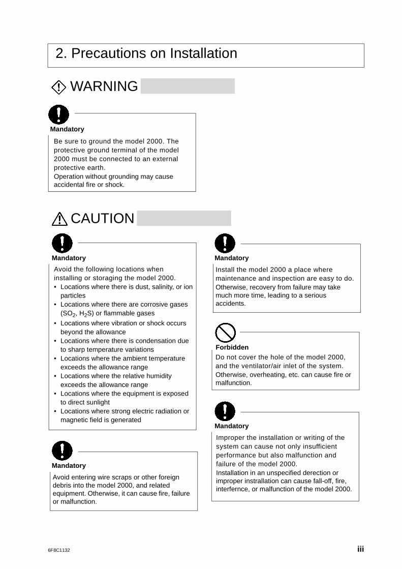
2. Precautions on Installation
WARNING
CAUTION
Mandatory
Be sure to ground the model 2000. The protective ground terminal of the model 2000 must be connected to an external protective earth.Operation without grounding may cause accidental fire or shock.
Mandatory
Avoid the following locations when installing or storaging the model 2000.• Locations where there is dust, salinity, or ion
particles• Locations where there are corrosive gases
(SO2, H2S) or flammable gases
• Locations where vibration or shock occurs beyond the allowance
• Locations where there is condensation due to sharp temperature variations
• Locations where the ambient temperature exceeds the allowance range
• Locations where the relative humidity exceeds the allowance range
• Locations where the equipment is exposed to direct sunlight
• Locations where strong electric radiation or magnetic field is generated
Improper the installation or writing of the system can cause not only insufficient performance but also malfunction and failure of the model 2000.Installation in an unspecified derection or improper instrallation can cause fall-off, fire, interfernce, or malfunction of the model 2000.
Do not cover the hole of the model 2000, and the ventilator/air inlet of the system.Otherwise, overheating, etc. can cause fire or malfunction.
Mandatory
Install the model 2000 a place where maintenance and inspection are easy to do.Otherwise, recovery from failure may take much more time, leading to a serious accidents.
Mandatory
Forbidden
Mandatory
Avoid entering wire scraps or other foreign debris into the model 2000, and related equipment. Otherwise, it can cause fire, failure or malfunction.
6F8C1132 iii
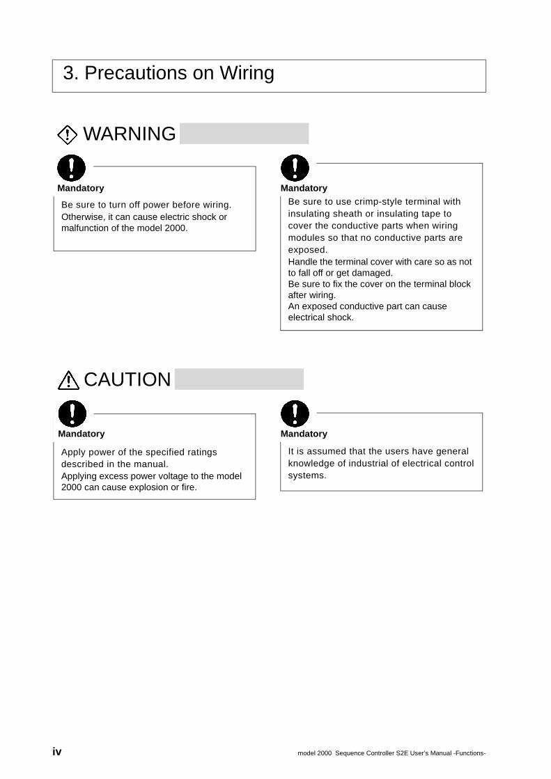
3. Precautions on Wiring
WARNING
CAUTION
Be sure to turn off power before wiring.Otherwise, it can cause electric shock or malfunction of the model 2000.
Be sure to use crimp-style terminal with insulating sheath or insulating tape to cover the conductive parts when wiring modules so that no conductive parts are exposed.Handle the terminal cover with care so as not to fall off or get damaged.Be sure to fix the cover on the terminal block after wiring.An exposed conductive part can cause electrical shock.
Mandatory Mandatory
Apply power of the specified ratings described in the manual.Applying excess power voltage to the model 2000 can cause explosion or fire.
It is assumed that the users have general knowledge of industrial of electrical control systems.
Mandatory Mandatory
iv model 2000 Sequence Controller S2E User’s Manual -Functions-
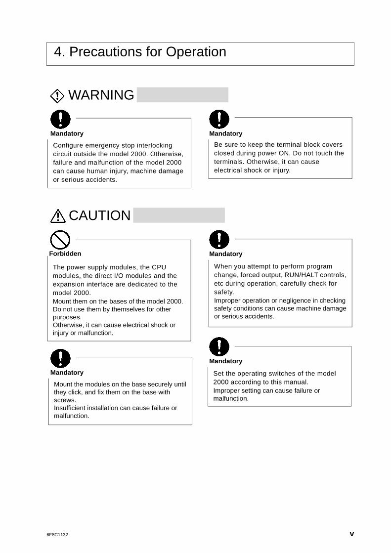
4. Precautions for Operation
WARNING
CAUTION
Configure emergency stop interlocking circuit outside the model 2000. Otherwise, failure and malfunction of the model 2000 can cause human injury, machine damage or serious accidents.
Be sure to keep the terminal block covers closed during power ON. Do not touch the terminals. Otherwise, it can cause electrical shock or injury.
Mandatory Mandatory
Mount the modules on the base securely until they click, and fix them on the base with screws.Insufficient installation can cause failure or malfunction.
When you attempt to perform program change, forced output, RUN/HALT controls, etc during operation, carefully check for safety.Improper operation or negligence in checking safety conditions can cause machine damage or serious accidents.
The power supply modules, the CPU modules, the direct I/O modules and the expansion interface are dedicated to the model 2000.Mount them on the bases of the model 2000.Do not use them by themselves for other purposes.Otherwise, it can cause electrical shock or injury or malfunction.
Set the operating switches of the model 2000 according to this manual.Improper setting can cause failure or malfunction.
Mandatory
Mandatory
Mandatory
Forbidden
6F8C1132 v
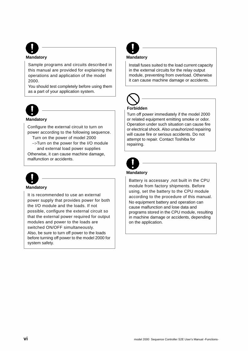
Configure the external circuit to turn on power according to the following sequence.
Turn on the power of model 2000−>Turn on the power for the I/O module
and external load power suppliesOtherwise, it can cause machine damage, malfunction or accidents.
Mandatory
Battery is accessary ,not built in the CPU module from factory shipments. Before using, set the battery to the CPU module according to the procedure of this manual.No equipment battery and operation can cause malfunction and lose data and programs stored in the CPU module, resulting in machine damage or accidents, depending on the application.
Mandatory
Turn off power immediately if the model 2000 or related equipment emitting smoke or odor. Operation under such situation can cause fire or electrical shock. Also unauhorized repairing will cause fire or serious accidents. Do not attempt to repair. Contact Toshiba for repairing.
Forbidden
It is recommended to use an external power supply that provides power for both the I/O module and the loads. If not possible, configure the external circuit so that the external power required for output modules and power to the loads are switched ON/OFF simultaneously.Also, be sure to turn off power to the loads before turning off power to the model 2000 for system safety.
Mandatory
Sample programs and circuits described in this manual are provided for explaining the operations and application of the model 2000.You should test completely before using them as a part of your application system.
Mandatory
Install fuses suited to the load current capacity in the external circuits for the relay output module, preventing from overload. Otherwise it can cause machine damage or accidents.
Mandatory
vi model 2000 Sequence Controller S2E User’s Manual -Functions-
5. Safety Precautions on Maintenance and inspection
WARNING
CAUTION
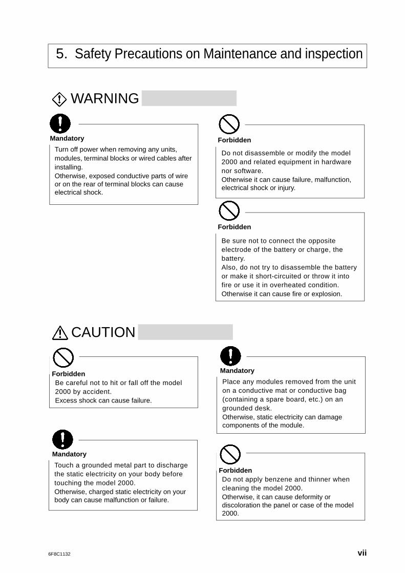
Be sure not to connect the opposite electrode of the battery or charge, the battery.Also, do not try to disassemble the battery or make it short-circuited or throw it into fire or use it in overheated condition.Otherwise it can cause fire or explosion.
Do not disassemble or modify the model 2000 and related equipment in hardware nor software.Otherwise it can cause failure, malfunction, electrical shock or injury.
Turn off power when removing any units, modules, terminal blocks or wired cables after installing.Otherwise, exposed conductive parts of wire or on the rear of terminal blocks can cause electrical shock.
Mandatory
Forbidden
Forbidden
Be careful not to hit or fall off the model 2000 by accident.Excess shock can cause failure.
ForbiddenPlace any modules removed from the unit on a conductive mat or conductive bag (containing a spare board, etc.) on an grounded desk.Otherwise, static electricity can damage components of the module.
Mandatory
Touch a grounded metal part to discharge the static electricity on your body before touching the model 2000.Otherwise, charged static electricity on your body can cause malfunction or failure.
Mandatory
Do not apply benzene and thinner when cleaning the model 2000.Otherwise, it can cause deformity or discoloration the panel or case of the model 2000.
Forbidden
6F8C1132 vii
6. Safety Precautions on Replacing Components
WARNING
CAUTION
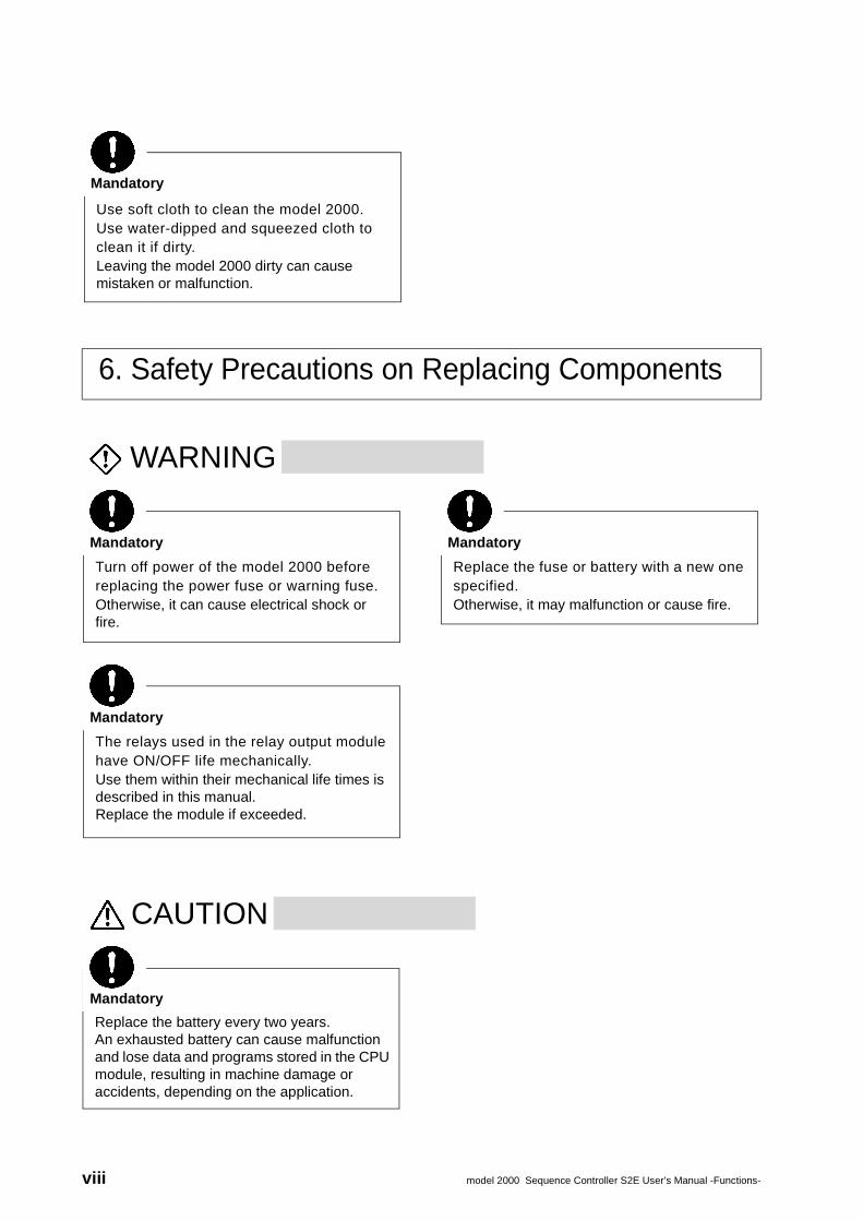
Use soft cloth to clean the model 2000.Use water-dipped and squeezed cloth to clean it if dirty.Leaving the model 2000 dirty can cause mistaken or malfunction.
Mandatory
Turn off power of the model 2000 before replacing the power fuse or warning fuse.Otherwise, it can cause electrical shock or fire.
Mandatory
Replace the fuse or battery with a new one specified.Otherwise, it may malfunction or cause fire.
Mandatory
The relays used in the relay output module have ON/OFF life mechanically.Use them within their mechanical life times is described in this manual.Replace the module if exceeded.
Mandatory
Replace the battery every two years.An exhausted battery can cause malfunction and lose data and programs stored in the CPU module, resulting in machine damage or accidents, depending on the application.
Mandatory
viii model 2000 Sequence Controller S2E User’s Manual -Functions-
7. Safety Precautions in Daily Operation
WARNING
CAUTION
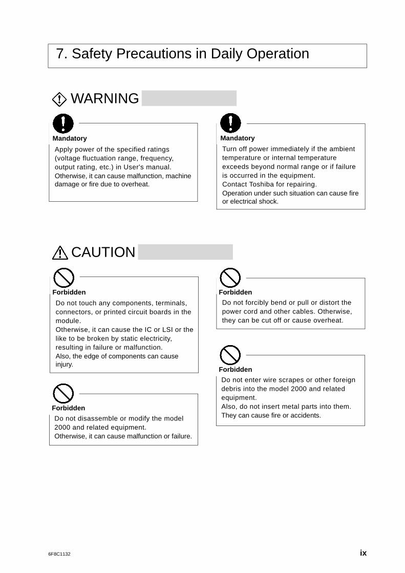
Apply power of the specified ratings (voltage fluctuation range, frequency, output rating, etc.) in User's manual.Otherwise, it can cause malfunction, machine damage or fire due to overheat.
Mandatory
Turn off power immediately if the ambient temperature or internal temperature exceeds beyond normal range or if failure is occurred in the equipment.Contact Toshiba for repairing.Operation under such situation can cause fire or electrical shock.
Mandatory
Do not touch any components, terminals, connectors, or printed circuit boards in the module.Otherwise, it can cause the IC or LSI or the like to be broken by static electricity, resulting in failure or malfunction.Also, the edge of components can cause injury.
Forbidden
Do not forcibly bend or pull or distort the power cord and other cables. Otherwise, they can be cut off or cause overheat.
Forbidden
Do not disassemble or modify the model 2000 and related equipment.Otherwise, it can cause malfunction or failure.
Forbidden
Do not enter wire scrapes or other foreign debris into the model 2000 and related equipment.Also, do not insert metal parts into them.They can cause fire or accidents.
Forbidden
6F8C1132 ix
8. Safety Precautions on Disposal
WARNING
CAUTION
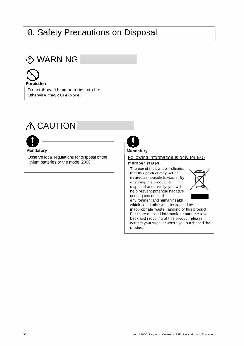
Do not throw lithium batteries into fire.Otherwise, they can explode.
Forbidden
Observe local regulations for disposal of the lithium batteries or the model 2000.
Mandatory
Following information is only for EU-member states:
The use of the symbol indicates that this product may not be treated as household waste. By ensuring this product is disposed of correctly, you will help prevent potential negative consequences for the environment and human health, which could otherwise be caused by inappropriate waste handling of this product. For more detailed information about the take-back and recycling of this product, please contact your supplier where you purchased the product.
Mandatory
x model 2000 Sequence Controller S2E User’s Manual -Functions-
Limitation of Applications• The model 2000 has been designed and manufactured for use in an industrial environment.
However, the model 2000 is not intended to be used for systems which can endanger human life (Note 1).
• Consult Toshiba if you intend to use the model 2000 for a special application which involves human life and has great influence on the maintenance of the public function (Note 2). This is why such application requires special care on the operation, maintenance, and control of the system (Note 3).
(Note 1) The systems which can endanger human life are life maintenance systems, equipment installed in the surgery, and other medical equipment.
(Note 2) The systems which involve human life and have great influence on the maintenance of the public function mean the main control system of a nuclear power plant, safety and protection system of a nuclear power facility, transport operation and control systems for mass transportation, control systems of aviation and space systems, and other systems and subsystems where safety is critical.
(Note 3) "Special care" means to build a safety system (foolproof design, fail safe design, redundancy design, etc.) in full consultation with Toshiba's engineers.
Immunity• Toshiba is not liable for any loss caused by fire, earthquake, action by a third party, or other
accidents, or the operator's intentional or accidental misuse, incorrect use, or use under abnormal condition.
• Toshiba is not liable for any incidental loss caused by the use or non-use of this product, such as loss of business profits, suspension of business, or loss or change of data on memory.
• Toshiba is not liable for the loss caused by an operation contradictory to any of the instructions stated in this manual.
• Toshiba is not liable for the loss caused by an incorrect operation in combination with other equipment.
• Toshiba is not liable for the loss caused by a malfunction in combination with an application program made by the customer.
NOTE:
Use cellular phones and PHSs at least one meter away from the working equipment, transmission cables, and I/O bus cable. Otherwise, the system can malfunction.
6F8C1132 xi

6F8C1132
Preface
Purpose of this manual
This manual describes the functions (those functions which can be achieved by the CPU and the basic hardware) of the Programmable Controller S2E. This manual also provides the necessary information for designing application programs and operating the S2E.
Read this manual carefully to use the S2E with it’s maximum performance.
Inside of this manual
This manual is divided into the following 4 Parts.
• Part 1. Basic ProgrammingGives the basic information for programming, and shows how to write a program into the S2E with a simple example.
• Part 2. FunctionsFor the full understanding of the S2E functions, first explains the internal operation of the S2E CPU, and then explains the detailed functions of the S2E.
• Part 3. Programming InformationExplains the information for designing a program which will fully use the functions of the S2E. Also explains Ladder diagram and SFC as programming languages for the S2E. Explains in the detailed information summarized in Part 1.
• Part 4. Transmission FunctionExplains the support of TOSLINE-S20.
Those who are using the S2E for the first time should first read Part 1 in order to understand the basics of programming.When Parts 2, 3 and 4 are read in addition, the advanced control functions of the S2E will be understood without difficulty.Those experienced in using the S2E may skip Part 1, but refer to Parts 2, 3 and 4 as necessary so as to fully use performance. An index is provided at the end of this manual for that purpose.When it comes to the configuration, some of the contents of Parts 1 and 3 are duplicated. However, please note that some portions of the explanation in Part 1 are summarized for ease of understanding.
xiii
Be Sure To Observe The FollowingTo ensure operator safety and normal product operation, be sure to observe the following.
1. Carefully read the manual before using the product.
2. Avoid installing and storing the product in any of the following places.
(1) Dusty place
(2) Place generating corrosive gases (SO2, H2S, etc.)
(3) Place where the product may be subject to vibration and shock
(4) Temperatures too low or too high to meet the conditions of installation specifiedin the manual
(5) Highly humid place
3. If the ambient temperature or the internal temperature of the product has risentoo high, or if the product has failed, stop using it, switch it off, and contact thenearest Toshiba service office.
4. Do not open the casing of the product.
5. Do not modify the product.
6. Do not drop the product during transit.
7. Installation, wiring, operation, and maintenance should be performed bypersons with general knowledge of control equipment. Erroneous use canresult in electrical shock, fire, malfunction, or operation error. Therefore, if youdo not have sufficient knowledge of control equipment, avoid performinginstallation, wiring, operation, or maintenance by yourself. Ask a qualifiedperson.
8. This manual has been written for users who are familiar with ProgrammableControllers and industrial control equipment. Contact Toshiba if you have anyquestions about this manual.
xiv model 2000 Sequence Controller S2E User’s Manual -Functions-
Documentation SystemThe following documents are available for S2E .
S2E User’s Manual-Hardware
This manual covers the S2E’s main body and basic I/O-their specifications, handling, maintenance and services.
S2E User’s Manual-Functions
This document explains the functions of the S2E and how to use them. The necessary information to create user programs is covered in this volume.
T-series Instruction Set
This manual provides the detailed specifications of instructions for Toshiba’s T-series Programmable Controllers.
T-PDS Basic Operation Manual
This manual explains how to install the T-series program development system (T-PDS) into your personal computer and provides basic programming operations.
T-PDS Command Reference Manual
This manual explains all the commands of the T-series program development system (T-PDS) in detail.
T-series Computer Link Function
This manual explains the specification and handling method of the T-series Programmable Controller’s Computer Link function.
6F8C1132 xv

xvi model 2000 Sequence Controller S2E User’s Manual -Functions-
CONTENTS
6F8C1132
PART 1 BASIC PROGRAMMING . . . . . . . . . 1
1 Overview . . . . . . . . . . . . . . . . . . . . . . . 31.1 System design procedures . . . . . . . . . . . . . . . . . . . . .3
1.2 Basic programming procedures . . . . . . . . . . . . . . . . .4
2 Operation Outline . . . . . . . . . . . . . . . . 72.1 Operation modes and functions . . . . . . . . . . . . . . . . .7
2.2 Modes transition conditions . . . . . . . . . . . . . . . . . . . .8
2.3 Operation flow chart . . . . . . . . . . . . . . . . . . . . . . . . .10
3 I/O Allocation . . . . . . . . . . . . . . . . . . . 133.1 I/O allocation . . . . . . . . . . . . . . . . . . . . . . . . . . . . . .13
3.2 Input and output registers . . . . . . . . . . . . . . . . . . . . .15
3.3 Rules for I/O allocation . . . . . . . . . . . . . . . . . . . . . .16
3.4 Unit base address setting functions . . . . . . . . . . . . .19
4 User Program . . . . . . . . . . . . . . . . . . . 214.1 User program configuration . . . . . . . . . . . . . . . . . . .21
4.2 System information . . . . . . . . . . . . . . . . . . . . . . . . . .22
4.3 User program . . . . . . . . . . . . . . . . . . . . . . . . . . . . . .23
4.4 Program execution sequence . . . . . . . . . . . . . . . . . .25
5 User Data . . . . . . . . . . . . . . . . . . . . . . 275.1 User data types and functions . . . . . . . . . . . . . . . . .27
5.2 Conditions for data initialization . . . . . . . . . . . . . . . .30
6 Programming Example . . . . . . . . . . . 316.1 Sample system . . . . . . . . . . . . . . . . . . . . . . . . . . . .31
6.2 Input/output allocation . . . . . . . . . . . . . . . . . . . . . . . .33
6.3 Sample program . . . . . . . . . . . . . . . . . . . . . . . . . . . .35
6.4 Programming procedure . . . . . . . . . . . . . . . . . . . . . .39
PART 2 FUNCTIONS . . . . . . . . . . . . . . . . . . 47
1 Overview . . . . . . . . . . . . . . . . . . . . . . 491.1 S2E System configuration . . . . . . . . . . . . . . . . . . . .49
1.2 Functional specifications . . . . . . . . . . . . . . . . . . . . . .50
xvii
CONTENTS
x
2 Internal Operation . . . . . . . . . . . . . . . 512.1 Basic internal operation flow . . . . . . . . . . . . . . . . . . 51
2.2 System initialization . . . . . . . . . . . . . . . . . . . . . . . . . 52
2.3 Mode control . . . . . . . . . . . . . . . . . . . . . . . . . . . . . . 54
2.4 Scan control . . . . . . . . . . . . . . . . . . . . . . . . . . . . . . . 582.4.1 Scan mode . . . . . . . . . . . . . . . . . . . . . . . . . . . . . . 60
2.4.2 Batch I/O processing . . . . . . . . . . . . . . . . . . . . . . 61
2.4.3 Timer update . . . . . . . . . . . . . . . . . . . . . . . . . . . . . 62
2.5 Peripheral support . . . . . . . . . . . . . . . . . . . . . . . . . . 64
2.6 Programming support functions . . . . . . . . . . . . . . . . 65
3 User Program Execution Control . . . 673.1 Program types . . . . . . . . . . . . . . . . . . . . . . . . . . . . . 67
3.2 Main/sub programs execution control . . . . . . . . . . . 68
3.3 Interrupt programs execution control . . . . . . . . . . . . 75
4 Peripheral Memory Support Functions . . . . . . . . . . . . . . . . . . . . . . 77
4.1 Flash Memory (EEPROM) support . . . . . . . . . . . . 77
5 RAS Functions . . . . . . . . . . . . . . . . . . 795.1 Overview . . . . . . . . . . . . . . . . . . . . . . . . . . . . . . . . . 79
5.2 Self-diagnosis . . . . . . . . . . . . . . . . . . . . . . . . . . . . . 80
5.3 Event history . . . . . . . . . . . . . . . . . . . . . . . . . . . . . . 83
5.4 Power interruption detection function . . . . . . . . . . . 845.4.1 Hot restart function . . . . . . . . . . . . . . . . . . . . . . . . 84
5.5 Execution status monitoring . . . . . . . . . . . . . . . . . . . 85
5.6 Sampling trace function . . . . . . . . . . . . . . . . . . . . . . 86
5.7 Status latch function . . . . . . . . . . . . . . . . . . . . . . . . . 88
5.8 Debug support function . . . . . . . . . . . . . . . . . . . . . . 905.8.1 Force function . . . . . . . . . . . . . . . . . . . . . . . . . . . . 90
5.8.2 Online program changing function . . . . . . . . . . . . 90
5.9 System diagnostics . . . . . . . . . . . . . . . . . . . . . . . . . 91
5.10 Password function . . . . . . . . . . . . . . . . . . . . . . . . . 95
viii model 2000 Sequence Controller S2E User’s Manual -Functions-
CONTENTS
6F8C1132
PART 3 PROGRAMMING INFORMATION . 97
1 Overview . . . . . . . . . . . . . . . . . . . . . . 991.1 Aims of Part 3 . . . . . . . . . . . . . . . . . . . . . . . . . . . . . .99
1.2 User memory configuration . . . . . . . . . . . . . . . . . . .100
2 User Program Configuration . . . . . 1012.1 Overview . . . . . . . . . . . . . . . . . . . . . . . . . . . . . . . . .101
2.2 System information . . . . . . . . . . . . . . . . . . . . . . . . .103
2.3 User program . . . . . . . . . . . . . . . . . . . . . . . . . . . . .1052.3.1 Main program . . . . . . . . . . . . . . . . . . . . . . . . . . . 105
2.3.2 Sub-program . . . . . . . . . . . . . . . . . . . . . . . . . . . . 106
2.3.3 Interrupt program . . . . . . . . . . . . . . . . . . . . . . . . 107
2.3.4 Sub-routines . . . . . . . . . . . . . . . . . . . . . . . . . . . . 110
2.4 Comments . . . . . . . . . . . . . . . . . . . . . . . . . . . . . . .112
3 User Data . . . . . . . . . . . . . . . . . . . . . 1133.1 Overview . . . . . . . . . . . . . . . . . . . . . . . . . . . . . . . .113
3.2 Registers and devices . . . . . . . . . . . . . . . . . . . . . .116
3.3 Register data types . . . . . . . . . . . . . . . . . . . . . . . . .137
3.4 Index modification . . . . . . . . . . . . . . . . . . . . . . . . . .144
3.5 Digit designation . . . . . . . . . . . . . . . . . . . . . . . . . . .147
4 I/O Allocation . . . . . . . . . . . . . . . . . . 1514.1 Overview . . . . . . . . . . . . . . . . . . . . . . . . . . . . . . . .151
4.2 Methods of VO allocation . . . . . . . . . . . . . . . . . . . .152
4.3 Register and module correspondence . . . . . . . . . .157
4.4 Network assignment . . . . . . . . . . . . . . . . . . . . . . . .159
5 Programming Language . . . . . . . . . 1635.1 Overview . . . . . . . . . . . . . . . . . . . . . . . . . . . . . . . . .163
5.2 Ladder diagram . . . . . . . . . . . . . . . . . . . . . . . . . . . .165
5.3 SFC . . . . . . . . . . . . . . . . . . . . . . . . . . . . . . . . . . . . .172
5.4 Programming precautions . . . . . . . . . . . . . . . . . . . .186
5.5 List of instructions . . . . . . . . . . . . . . . . . . . . . . . . . .188
xix
CONTENTS
x
PART 4 TRANSMISSION FUNCTION . . . . 211
1 Overview . . . . . . . . . . . . . . . . . . . . . 2131.1 Overview . . . . . . . . . . . . . . . . . . . . . . . . . . . . . . . . 213
1.2 Function specification . . . . . . . . . . . . . . . . . . . . . . 2141.2.1 Scan data transfer . . . . . . . . . . . . . . . . . . . . . . . 214
1.2.2 FUN236 (XFER) Expanded data transfer . . . . . . 216
1.2.3 READ / WRITE INSTRUCTION . . . . . . . . . . . . . 216
x model 2000 Sequence Controller S2E User’s Manual -Functions-
PART 1BASIC PROGRAMMING

6F8C1132
Overview
Chapter 11.1 System design procedures
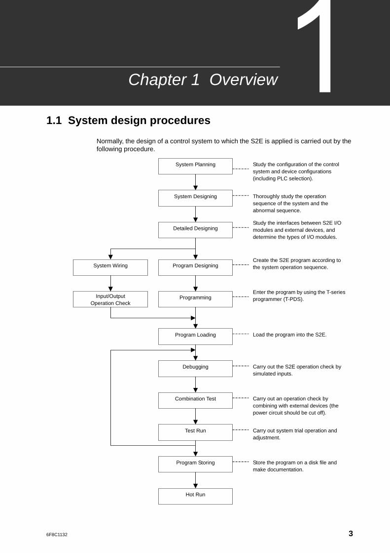
Normally, the design of a control system to which the S2E is applied is carried out by the following procedure.
Input/Output Operation Check
System Wiring
System Planning
System Designing
Detailed Designing
Programming
Program Loading
Debugging
Combination Test
Test Run
Program Storing
Hot Run
Program Designing
Study the configuration of the control system and device configurations (including PLC selection).
Study the interfaces between S2E I/O modules and external devices, and determine the types of I/O modules.
Thoroughly study the operation sequence of the system and the abnormal sequence.
Create the S2E program according to the system operation sequence.
Enter the program by using the T-series programmer (T-PDS).
Load the program into the S2E.
Carry out the S2E operation check by simulated inputs.
Carry out an operation check by combining with external devices (the power circuit should be cut off).
Carry out system trial operation and adjustment.
Store the program on a disk file and make documentation.
3
Chapter 1 Overview
1
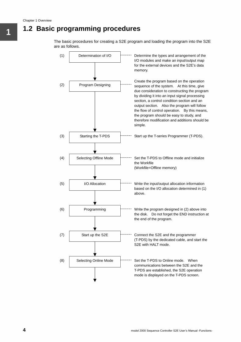
1.2 Basic programming proceduresThe basic procedures for creating a S2E program and loading the program into the S2E are as follows.
(3)
(4)
(1)
(8)
(6)
(7)
(5)
(2)
Starting the T-PDS
Selecting Offline Mode
Determination of I/O
Selecting Online Mode
Programming
Start up the S2E
I/O Allocation
Program Designing
Determine the types and arrangement of the I/O modules and make an input/output map for the external devices and the S2E’s data memory.
Create the program based on the operation sequence of the system. At this time, give due consideration to constructing the program by dividing it into an input signal processing section, a control condition section and an output section. Also the program will follow the flow of control operation. By this means, the program should be easy to study, and therefore modification and additions should be simple.
Start up the T-series Programmer (T-PDS).
Set the T-PDS to Offline mode and initialize the Workfile (Workfile=Offline memory)
Write the input/output allocation information based on the I/O allocation determined in (1) above.
Write the program designed in (2) above into the disk. Do not forget the END instruction at the end of the program.
Connect the S2E and the programmer (T-PDS) by the dedicated cable, and start the S2E with HALT mode.
Set the T-PDS to Online mode. When communications between the S2E and the T-PDS are established, the S2E operation mode is displayed on the T-PDS screen.
4 model 2000 Sequence Controller S2E User’s Manual -Functions-
1.2 Basic programming procedures
1
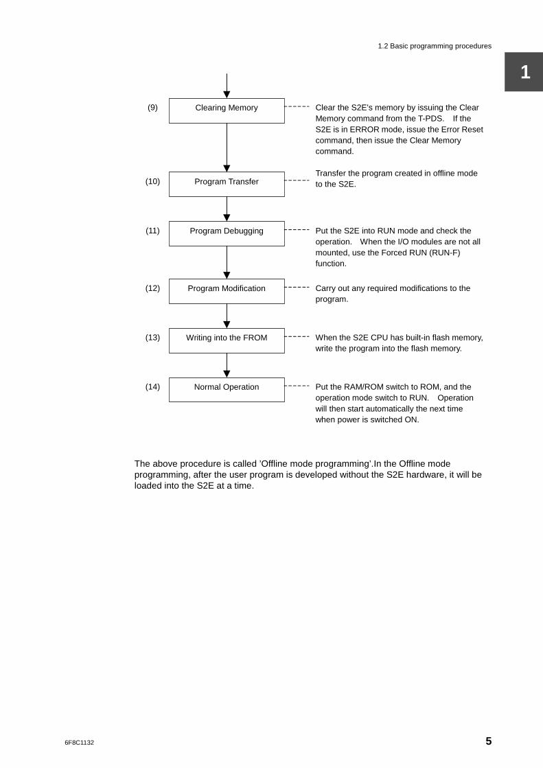
The above procedure is called ’Offline mode programming’.In the Offline mode programming, after the user program is developed without the S2E hardware, it will be loaded into the S2E at a time.
(11)
(12)
(9)
(14)
(13)
(10)
Program Debugging
Program Modification
Clearing Memory
Normal Operation
Writing into the FROM
Program Transfer
Clear the S2E’s memory by issuing the Clear Memory command from the T-PDS. If the S2E is in ERROR mode, issue the Error Reset command, then issue the Clear Memory command.
Transfer the program created in offline mode to the S2E.
Put the S2E into RUN mode and check the operation. When the I/O modules are not all mounted, use the Forced RUN (RUN-F) function.
Carry out any required modifications to the program.
When the S2E CPU has built-in flash memory, write the program into the flash memory.
Put the RAM/ROM switch to ROM, and the operation mode switch to RUN. Operation will then start automatically the next time when power is switched ON.
6F8C1132 5
Chapter 1 Overview
1
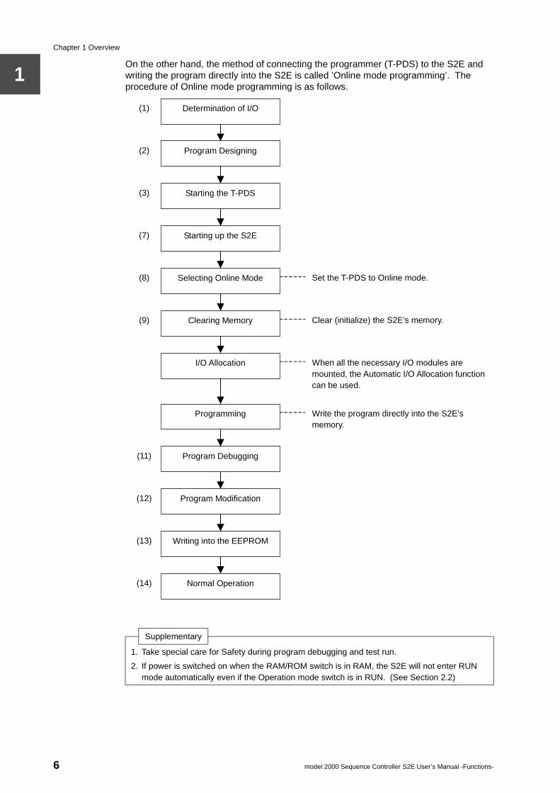
On the other hand, the method of connecting the programmer (T-PDS) to the S2E and writing the program directly into the S2E is called ’Online mode programming’. The procedure of Online mode programming is as follows.Supplementary
1. Take special care for Safety during program debugging and test run.
2. If power is switched on when the RAM/ROM switch is in RAM, the S2E will not enter RUN mode automatically even if the Operation mode switch is in RUN. (See Section 2.2)
(3)
(7)
(1)
(12)
(9)
(11)
(8)
(2)
Starting the T-PDS
Starting up the S2E
Determination of I/O
Program Modification
Clearing Memory
Program Debugging
Selecting Online Mode
Program Designing
Set the T-PDS to Online mode.
Clear (initialize) the S2E’s memory.
When all the necessary I/O modules are mounted, the Automatic I/O Allocation function can be used.
Write the program directly into the S2E’s memory.
I/O Allocation
Programming
(14)
(13)
Normal Operation
Writing into the EEPROM
6 model 2000 Sequence Controller S2E User’s Manual -Functions-
6F8C1132
OperationOutline
Chapter 2
2.1 Operation modes and functions
There are 3 modes of RUN, HALT and ERROR as basic operation modes of the S2E. Also, as a variation of the RUN mode, the RUN-F mode is available for debugging.
RUN Mode: This is the program execution mode. The S2E repeats the reading of external inputs, execution of the user program and the determination of external output states. (One cycle of this operation is called a ’scan’). Monitoring of the program execution state and forced input/output can be performed using the programmer.
RUN-F Mode: This is a mode to force the program execution even when the I/O modules are not mounted. (In the normal RUN mode, this would give an I/O no answer error). This is used for program debugging.
HALT Mode: This is the operation stop mode. The S2E switches OFF all outputs and stops user program execution. Normally, programming is carried out in this mode.Also, writing the program into the flash memory is available in this mode only.
ERROR Mode: This is the ’Error Down’ state. When the S2E detects an error by self-diagnosis which renders continuation of operation impossible, it will switch OFF all outputs, stop the use program execution and enter the ERROR mode. In the ERROR mode, all writing operations to the S2E are prohibited. In order to escape from this mode, it is necessary either execute ’Error Reset’ from the programmer, or to switch the power supply OFF and ON again.
Supplementary
1. Programs can be changed in both the RUN mode and the RUN-F mode (this is called the ’online program changing function’). However, only normal programming in the HALT mode is described in Part 1. See Part 2 for the online program changing function.
2. Apart from the above 4 modes, there are actually the HOLD mode as well. These are described in Part 2.
7
Chapter 2 Operation Outline
2
2.2 Modes transition conditions
To determine/change the operation mode of the S2E, the operation mode switch on the CPU module, programmer PLC control commands and S2E self-diagnosis are available. Also, the RAM/ROM switch on the CPU module controls the operation mode at power up. These are described below.
• Operation Mode Switch...HALT/RUN
• Auto-RUN/Standby selection
• RAM/ROM switch:
Switch Position Operation Mode
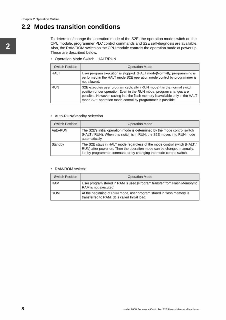
HALT User program execution is stopped. (HALT mode)Normally, programming is performed in the HALT mode.S2E operation mode control by programmer is not allowed.
RUN S2E executes user program cyclically. (RUN mode)It is the normal switch position under operation.Even in the RUN mode, program changes are possible. However, saving into the flash memory is available only in the HALT mode.S2E operation mode control by programmer is possible.
Switch Position Operation Mode
Auto-RUN The S2E’s initial operation mode is determined by the mode control switch (HALT / RUN). When this switch is in RUN, the S2E moves into RUN mode automatically.
Standby The S2E stays in HALT mode regardless of the mode control switch (HALT / RUN) after power on. Then the operation mode can be changed manually, i.e. by programmer command or by changing the mode control switch.
Switch Position Operation Mode
RAM User program stored in RAM is used.(Program transfer from Flash Memory to RAM is not executed)
ROM At the beginning of RUN mode, user program stored in flash memory is transferred to RAM. (It is called Initial load)
8 model 2000 Sequence Controller S2E User’s Manual -Functions-
2.2 Modes transition conditions
2
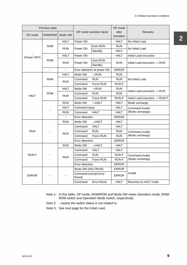
Note 1: In this table, OP mode, RAM/ROM and Mode SW mean Operation mode, RAM/ROM switch and Operation Mode switch, respectively.
Note 2: - means the switch status is not related to.
Note 3: See next page for the Initial Load.
Previous stateOP mode transition factor
OP mode after
transitionRemarks
OP mode RAM/ROM Mode SW
−(Power OFF)
RAM
HALT Power ON HALT No Initial Load
RUN Power ONAuto-RUN RUN
No Initial LoadStandby HALT
ROM
HALT Power ON HALT Initial Load execution
RUN Power ONAuto-RUN
RUN Initial Load execution −> RUNStandby
− − Error detection at power ON ERROR
HALT
RAM
HALT Mode SW −>RUN RUN
No Initial LoadRUN
Command RUN RUN
Command Force RUN RUN-F
ROM
HALT Mode SW −>RUN RUNInitial Load execution −> RUN
RUNCommand RUN RUN
Command Force RUN RUN-F Initial Load execution −> RUN-F
−
RUN Mode SW −>HALT HALT Mode unchange
HALT Command (any) HALT Command invalid (Mode unchange)RUN Command HALT HALT
- Error detection ERROR
RUN −
RUN Mode SW −>HALT HALT
RUN
Command HALT HALT
Command RUN RUN Command invalid (Mode unchange)Command Force RUN RUN
Error detection ERROR
RUN-F −
RUN Mode SW −>HALT HALT
RUN
Command HALT HALT
Command RUN RUN-F Command invalid (Mode unchange)Command Force RUN RUN-F
Error detection ERROR
ERROR − −
Mode SW (HALT/RUN) ERROR
InvalidCommand (except Error Reset)
ERROR
Command Error Reset HALT Recovery to HALT mode
6F8C1132 9
Chapter 2 Operation Outline
2
2.3 Operation flow chart
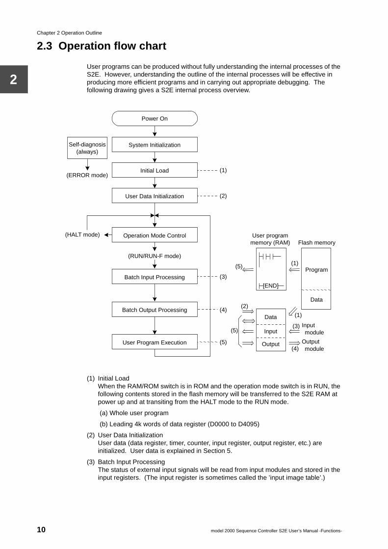
User programs can be produced without fully understanding the internal processes of the S2E. However, understanding the outline of the internal processes will be effective in producing more efficient programs and in carrying out appropriate debugging. The following drawing gives a S2E internal process overview.
(1) Initial LoadWhen the RAM/ROM switch is in ROM and the operation mode switch is in RUN, the following contents stored in the flash memory will be transferred to the S2E RAM at power up and at transiting from the HALT mode to the RUN mode.
(a) Whole user program
(b) Leading 4k words of data register (D0000 to D4095)
(2) User Data InitializationUser data (data register, timer, counter, input register, output register, etc.) are initialized. User data is explained in Section 5.
(3) Batch Input ProcessingThe status of external input signals will be read from input modules and stored in the input registers. (The input register is sometimes called the ’input image table’.)
System Initialization
Initial Load
User Data Initialization
User Program Execution
Self-diagnosis (always)
Operation Mode Control
Batch Input Processing
Batch Output Processing
(RUN/RUN-F mode)
Power On
(ERROR mode)
(HALT mode) User program memory (RAM)
(2)
(1)
(3)
(4)
(5) (4)
(5) (1)
(1)
(3)
(2)
Flash memory
Program
Data
Data
Input
Output
Input module
Output module
[END]
(5)
10 model 2000 Sequence Controller S2E User’s Manual -Functions-
2.3 Operation flow chart
2
(4) Batch Output ProcessingThe status of output registers is written to the output modules. The output module determines the ON/OFF state of output based on this. (The output register is sometimes called the ’output image table’.)
(5) User Program ExecutionThe instructions stored in the user program memory are read one by one, and the contents of the output register are updated while referring to the contents of the user data. This is an essential function of the S2E.
One cycle from operation mode control to user program execution is called ’one scan’. The time required for 1 scan is called the ’scan cycle’ (or the ’scan time’).
Generally, the shorter the scan cycle, the faster the output response to a change in input signal.
Supplementary
The important items related to the S2E operation mode and the switches are summarized below.1. When power is turned on with the RAM/ROM switch at RAM position, the S2E starts up in
HALT mode. Therefore, use the RAM position during debug and test run, and set to ROM in normal operation, regardless of the type of the S2E CPU.
2. The object of the Initial Load is whole program and the leading 4k words of data register (D0000 to D4095).Therefore, even if the range of D0000 to D4095 is specified as retentive, these data will be initialized by the data of the flash memory.
6F8C1132 11

6F8C1132
Allocation
Chapter 3 I/O3.1 I/O allocation
As described in Section 2.3, communication between input modules or output modules and the user program is executed via the input registers and the output registers.
I/O allocation is the determination of which address of the I/O registers shall be assigned to which I/O module. Basically, this is determined by the mounting order of the modules. Therefore, informing the CPU of the module mounting order is called ’I/O allocation’.
The following two methods are available for performing I/O allocation. Either method requires that the S2E is in the HALT mode and that the operation mode switch is in a position RUN.
(1) Automatic I/O AllocationExecute the automatic I/O allocation command to the S2E from the programmer. The S2E CPU reads the module types of I/O modules mounted (see the table on the next page) and stores this in the user program memory as I/O allocation information.
(2) Manual I/O AllocationSet the mounting positions and the module types of I/O modules on the I/O allocation screen of the programmer, and write this information to the S2E.Manual I/O allocation is used when performing programming in a state in which not all the I/O modules have been mounted, or when using the unit base address settings described in Section 3.4.Manual I/O allocation is also used for offline mode programming.
When the I/O allocation information is stored in the S2E memory by these methods, the correspondence between the I/O modules and the I/O register is automatically determined by the rules described in Section 3.3.
Note: In practice, special allocation of module types other than those shown in the tableon the next page can be executed by manual I/O allocation. However, thedescription is omitted here. The details are described in Part 3.
13
Chapter 3 I/O Allocation
3
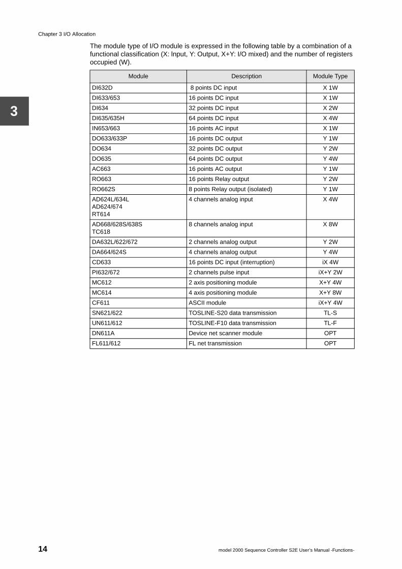
The module type of I/O module is expressed in the following table by a combination of a functional classification (X: lnput, Y: Output, X+Y: I/O mixed) and the number of registers occupied (W).
Module Description Module Type
DI632D 8 points DC input X 1W
DI633/653 16 points DC input X 1W
DI634 32 points DC input X 2W
DI635/635H 64 points DC input X 4W
IN653/663 16 points AC input X 1W
DO633/633P 16 points DC output Y 1W
DO634 32 points DC output Y 2W
DO635 64 points DC output Y 4W
AC663 16 points AC output Y 1W
RO663 16 points Relay output Y 2W
RO662S 8 points Relay output (isolated) Y 1W
AD624L/634LAD624/674RT614
4 channels analog input X 4W
AD668/628S/638STC618
8 channels analog input X 8W
DA632L/622/672 2 channels analog output Y 2W
DA664/624S 4 channels analog output Y 4W
CD633 16 points DC input (interruption) iX 4W
PI632/672 2 channels pulse input iX+Y 2W
MC612 2 axis positioning module X+Y 4W
MC614 4 axis positioning module X+Y 8W
CF611 ASCII module iX+Y 4W
SN621/622 TOSLINE-S20 data transmission TL-S
UN611/612 TOSLINE-F10 data transmission TL-F
DN611A Device net scanner module OPT
FL611/612 FL net transmission OPT
14 model 2000 Sequence Controller S2E User’s Manual -Functions-
3.2 Input and output registers
3
3.2 Input and output registers
In the previous Section, I/O allocation is the performance of correspondence between I/O modules and input/output registers. Here, the configurations of input registers and output registers, and methods of address expression are described.
In descriptions hitherto, input registers and output registers have been treated as separate entities. However, from the viewpoint of memory configuration, this is not correct.
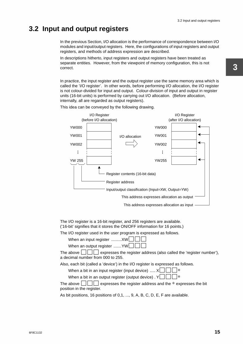
In practice, the input register and the output register use the same memory area which is called the ’I/O register’. In other words, before performing I/O allocation, the I/O register is not colour-divided for input and output. Colour-division of input and output in register units (16-bit units) is performed by carrying out I/O allocation. (Before allocation, internally, all are regarded as output registers).
This idea can be conveyed by the following drawing.
The I/O register is a 16-bit register, and 256 registers are available. (’16-bit’ signifies that it stores the ON/OFF information for 16 points.)
The I/O register used in the user program is expressed as follows.
When an input register .........XW
When an output register .......YW
The above expresses the register address (also called the ’register number’), a decimal number from 000 to 255.
Also, each bit (called a ’device’) in the I/O register is expressed as follows.
When a bit in an input register (input device) ..... X ∗When a bit in an output register (output device) . Y ∗
The above expresses the register address and the ∗ expresses the bit position in the register.
As bit positions, 16 positions of 0,1, ..., 9, A, B, C, D, E, F are available.
Register contents (16-bit data)
Register address
Input/output classification (Input=XW, Output=YW)
This address expresses allocation as output
This address expresses allocation as input
I/O Register (before I/O allocation)
I/O Register (after I/O allocation)
YW000
YW001
YW002
. . . YW 255
YW000
YW001
YW002
. . . YW255
I/O allocation
6F8C1132 15
Chapter 3 I/O Allocation
3
3.3 Rules for I/O allocation
When I/O allocation is performed either by the automatic I/O allocation or the manual I/O allocation method, the I/O allocation information (information on which type of module is mounted in which position) is produced in the user program memory. The coordination between the registers and the I/O modules is decided according to the following rules.
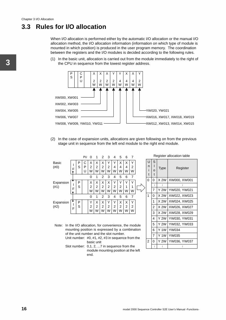
(1) In the basic unit, allocation is carried out from the module immediately to the right of the CPU in sequence from the lowest register address.
(2) In the case of expansion units, allocations are given following on from the previous stage unit in sequence from the left end module to the right end module.
P S
C P U
X
2 W
X
2 W
X
2 W
Y
2 W
Y
4 W
X
4 W
X
4 W
Y
2 W
XW000, XW001
XW002, XW003
XW004, XW005
YW006, YW007
YW008, YW009, YW010, YW011
YW020, YW021
XW016, XW017, XW018, XW019
XW012, XW013, XW014, XW015
PU 0 1 2 3 4 5 6 7
Basic(#0)
IF
PS
CPU
X2W
X2W
X2W
Y2W
Y4W
X4W
X4W
Y2W
0 1 2 3 4 5 6 7
Expansion(#1)
IF
PS
X2W
X2W
X2W
X2W
Y2W
Y2W
Y1W
Y1W
0 1 2 3 4 5 6 7
Expansion(#2)
IF
PS
Y2W
X2W
X2W
Y2W
Y2W
X2W
X2W
Y2W
Register allocation table
Unit
Slot
Type Register
0 0 X 2W XW000, XW001
∼ ∼ ∼
7 Y 2W YW020, YW021
1 0 X 2W XW022, XW023
1 X 2W XW024, XW025
2 X 2W XW026, XW027
3 X 2W XW028, XW029
4 Y 2W YW030, YW031
5 Y 2W YW032, YW033
6 Y 1W YW034
7 Y 1W YW035
2 0 Y 2W YW036, YW037
∼ ∼ ∼
Note: In the I/O allocation, for convenience, the modulemounting position is expressed by a combinationof the unit number and the slot number.Unit number: #0, #1, #2, #3 in sequence from the
basic unitSlot number: 0,1, 2, ...7 in sequence from the
module mounting position at the left end.
16 model 2000 Sequence Controller S2E User’s Manual -Functions-
3.3 Rules for I/O allocation
3
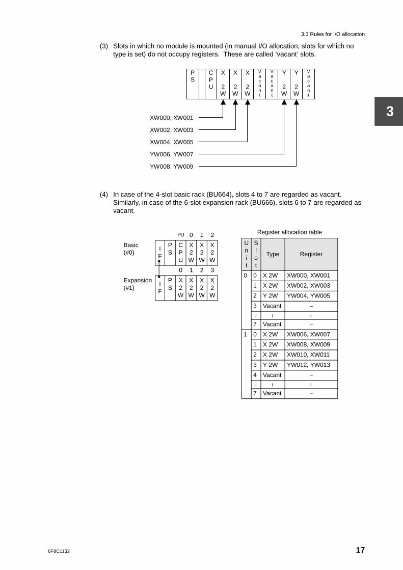
(3) Slots in which no module is mounted (in manual I/O allocation, slots for which no type is set) do not occupy registers. These are called ’vacant’ slots.
(4) In case of the 4-slot basic rack (BU664), slots 4 to 7 are regarded as vacant. Similarly, in case of the 6-slot expansion rack (BU666), slots 6 to 7 are regarded as vacant.
P S
C P U
X
2 W
X
2 W
X
2 W
V a c a n t
Y
2 W
Y
2 W
XW000, XW001
XW002, XW003
XW004, XW005
YW006, YW007
YW008, YW009
V a c a n t
V a c a n t
PU 0 1 2
Basic(#0)
IF
PS
CPU
X2W
X2W
X2W
0 1 2 3
Expansion(#1)
IF
PS
X2W
X2W
X2W
X2W
Register allocation table
Unit
Slot
Type Register
0 0 X 2W XW000, XW001
1 X 2W XW002, XW003
2 Y 2W YW004, YW005
3 Vacant −
~ ~ ~
7 Vacant −
1 0 X 2W XW006, XW007
1 X 2W XW008, XW009
2 X 2W XW010, XW011
3 Y 2W YW012, YW013
4 Vacant −
~ ~ ~
7 Vacant −
6F8C1132 17
Chapter 3 I/O Allocation
3
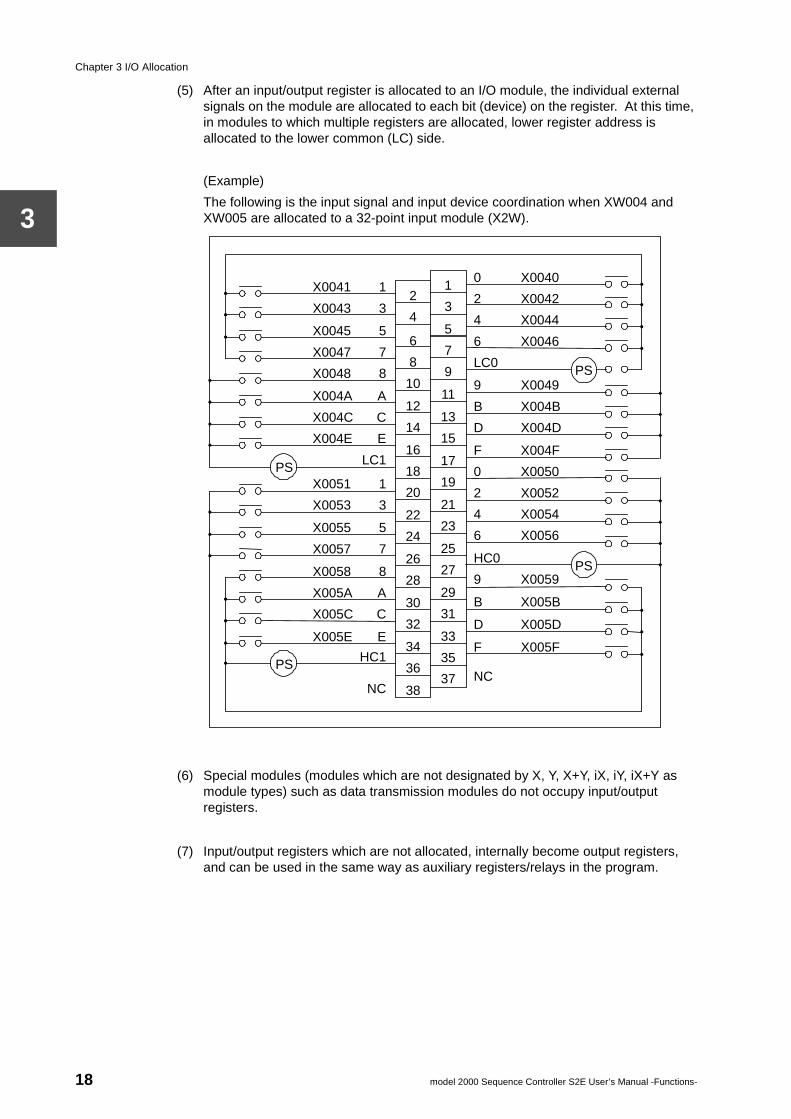
(5) After an input/output register is allocated to an I/O module, the individual external signals on the module are allocated to each bit (device) on the register. At this time, in modules to which multiple registers are allocated, lower register address is allocated to the lower common (LC) side.
(Example)
The following is the input signal and input device coordination when XW004 and XW005 are allocated to a 32-point input module (X2W).
(6) Special modules (modules which are not designated by X, Y, X+Y, iX, iY, iX+Y as module types) such as data transmission modules do not occupy input/output registers.
(7) Input/output registers which are not allocated, internally become output registers, and can be used in the same way as auxiliary registers/relays in the program.
X0041 1
X0043 3
X0045 5
X0047 7
X0048 8
X004A A
X004C C
X004E E
LC1
X0051 1
X0053 3
X0055 5
X0057 7
X0058 8
X005A A
X005C C
X005E E
HC1
NC
2
4
6
8
10
12
14
16
18
20
22
24
26
28
30
32
34
36
38
PS
PS
PS
PS
0 X0040
2 X0042
4 X0044
6 X0046
LC0
9 X0049
B X004B
D X004D
F X004F
0 X0050
2 X0052
4 X0054
6 X0056
HC0
9 X0059
B X005B
D X005D
F X005F
NC
1
3
5
7
9
11
13
15
17
19
21
23
25
27
29
31
33
35
37
18 model 2000 Sequence Controller S2E User’s Manual -Functions-
3.4 Unit base address setting functions
3
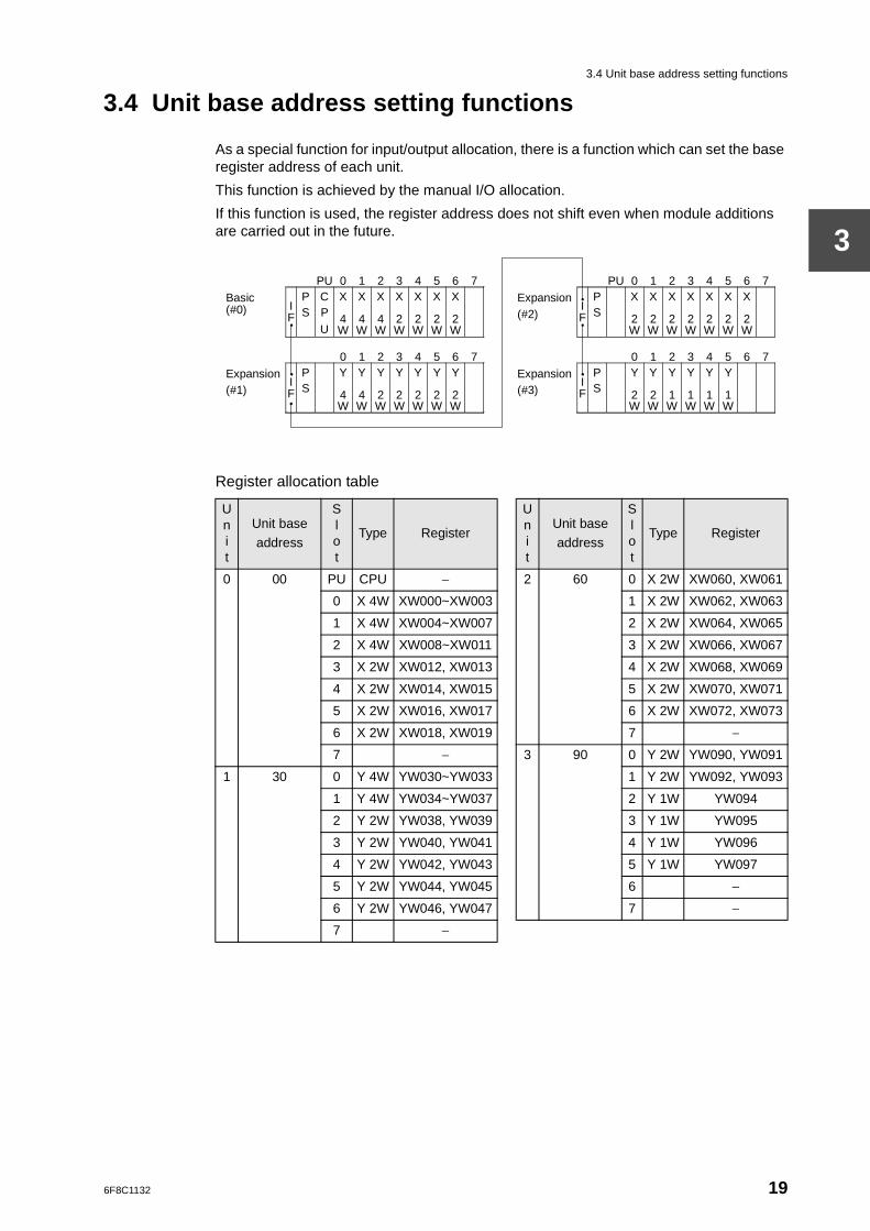
3.4 Unit base address setting functions
As a special function for input/output allocation, there is a function which can set the base register address of each unit.
This function is achieved by the manual I/O allocation.
If this function is used, the register address does not shift even when module additions are carried out in the future.
Register allocation table
Unit
Unit base
address
Slot
Type Register
Unit
Unit base
address
Slot
Type Register
0 00 PU CPU − 2 60 0 X 2W XW060, XW061
0 X 4W XW000~XW003 1 X 2W XW062, XW063
1 X 4W XW004~XW007 2 X 2W XW064, XW065
2 X 4W XW008~XW011 3 X 2W XW066, XW067
3 X 2W XW012, XW013 4 X 2W XW068, XW069
4 X 2W XW014, XW015 5 X 2W XW070, XW071
5 X 2W XW016, XW017 6 X 2W XW072, XW073
6 X 2W XW018, XW019 7 −
7 − 3 90 0 Y 2W YW090, YW091
1 30 0 Y 4W YW030~YW033 1 Y 2W YW092, YW093
1 Y 4W YW034~YW037 2 Y 1W YW094
2 Y 2W YW038, YW039 3 Y 1W YW095
3 Y 2W YW040, YW041 4 Y 1W YW096
4 Y 2W YW042, YW043 5 Y 1W YW097
5 Y 2W YW044, YW045 6 −
6 Y 2W YW046, YW047 7 −
7 −
PU 0 1 2 3 4 5 6 7
Expansion (#2)
I F
P S
X
2 W
X 2 W
X 2 W
X
2 W
X 2 W
X 2 W
X
2 W
0 1 2 3 4 5 6 7
Expansion (#3)
I F
P S
Y
2 W
Y 2 W
Y 1 W
Y
1 W
Y 1 W
Y 1 W
PU 0 1 2 3 4 5 6 7
Basic (#0) I
F
P S
C P
U
X
4 W
X 4 W
X 4 W
X
2 W
X 2 W
X 2 W
X
2 W
0 1 2 3 4 5 6 7
Expansion (#1)
I F
P S
Y
4 W
Y 4 W
Y 2 W
Y
2 W
Y 2 W
Y 2 W
Y
2 W
6F8C1132 19
Chapter 3 I/O Allocation
3
Supplementary
1. Apart from register address skipping between units, when the unit base address setting function is used, it follows the I/O allocation rules described in Section 3.3.
2. A setting which gives a latter stage unit a low register address cannot be performed. For example, a setting by which the base address of Unit #1 is 50 and the base address of Unit #2 is 30 cannot be performed.
3. When automatic I/O allocation is performed, there is no base address designation for any unit. The registers are allocated in succession. (As described in Section 3.3).
20 model 2000 Sequence Controller S2E User’s Manual -Functions-
6F8C1132
r Program
Chapter 4 Use4.1 User program configuration
A group of instructions for executing control is called a ’user program’. This is also called an ’application program’, a ’sequence program’ or a ’logic circuit’. In this manual it will be called a ’user program’.
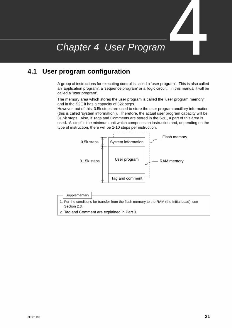
The memory area which stores the user program is called the ’user program memory’, and in the S2E it has a capacity of 32k steps.However, out of this, 0.5k steps are used to store the user program ancillary information (this is called ’system information’). Therefore, the actual user program capacity will be 31.5k steps. Also, if Tags and Comments are stored in the S2E, a part of this area is used. A ’step’ is the minimum unit which composes an instruction and, depending on the type of instruction, there will be 1-10 steps per instruction.
Supplementary
1. For the conditions for transfer from the flash memory to the RAM (the Initial Load), see Section 2.3.
2. Tag and Comment are explained in Part 3.
Flash memory System information
User program
Tag and comment
RAM memory
0.5k steps
31.5k steps
21
Chapter 4 User Program
4
4.2 System information
’System information’ is the area which stores execution control parameters and user program control information for executing the user program, and occupies 0.5k steps. The following contents are included in the system information.
(1) Machine parameters (model type, memory capacity)
(2) User program information (program ID, system comments, number of steps used, etc.)
(3) Execution control parameters (scanning mode, sub-program and interrupt program execution conditions)
(4) Retentive memory area information
(5) I/O allocation information
(6) I/O interrupt assignment information
(7) Network assignment information
(8) Computer link parameters
(9) System diagnosis function execution conditions
Out of these, the CPU automatically performs the setting/updating of the machine parameters of (1) and the number of steps used of (2). Items apart from these are set by the user from the programmer. Here, only the retentive memory area information of (4) and the I/O allocation information of (5) are described. The other items are described in Part 2 and Part 3.
• Retentive memory areaThe ranges for retaining the data during power off can be set for the auxiliary register (RW), the timer register (T), the counter register (C) and the data register (D). Data other than within these set ranges will be 0-cleared (device is OFF) in the data initialization process at power up. This setting is performed in a way to designate from the first address (0) to a designated address for each of the above registers. (See Section 5.2 for details)
• I/O allocation informationAs described in Section 3,I/O allocation information is stored here by executing automatic I/O allocation or manual I/O allocation. The CPU determines input/output register allocation based on this information. Also, as self-diagnosis, the CPU executes a check as to whether the modules in the allocation information are correctly mounted.
22 model 2000 Sequence Controller S2E User’s Manual -Functions-
4.3 User program
4
4.3 User program
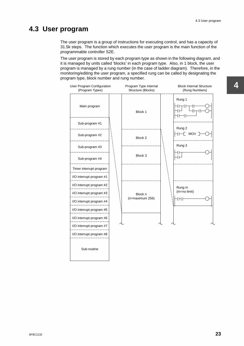
The user program is a group of instructions for executing control, and has a capacity of 31.5k steps. The function which executes the user program is the main function of the programmable controller S2E.
The user program is stored by each program type as shown in the following diagram, and it is managed by units called ’blocks’ in each program type. Also, in 1 block, the user program is managed by a rung number (in the case of ladder diagram). Therefore, in the monitoring/editing the user program, a specified rung can be called by designating the program type, block number and rung number.
User Program Configuration (Program Types)
Program Type Internal Structure (Blocks)
Block Internal Structure (Rung Numbers)
Main program
Sub-program #1
Sub-program #2
Sub-program #3
Sub-program #4
Timer interrupt program
I/O interrupt program #1
I/O interrupt program #2
I/O interrupt program #3
I/O interrupt program #4
I/O interrupt program #5
I/O interrupt program #6
I/O interrupt program #7
I/O interrupt program #8
Sub-routine
Block 1
Block 2
Block 3
Block n (n=maximum 256)
Rung 1
Rung 2
Rung 3
Rung m (m=no limit)
MOV
6F8C1132 23
Chapter 4 User Program
4
• Program TypesAs program types, the main program, sub-programs (#1-#4), the timer interrupt program, I/O interrupt programs (#1-#8) and the sub-routines are available. Although there is a capacity limit of within a total of 31.5K steps, there is no capacity limit on any of the program types.
• BlocksFrom 1 to 256 are effective as block numbers. Every block has no capacity limit. In the S2E, apart from the Ladder diagram, the SEC language can be used. However multiple languages cannot be used in one block. In other words, when multiple languages are used, it is necessary to separate blocks. In the case of using the ladder diagram only, there is no need to divide the block.
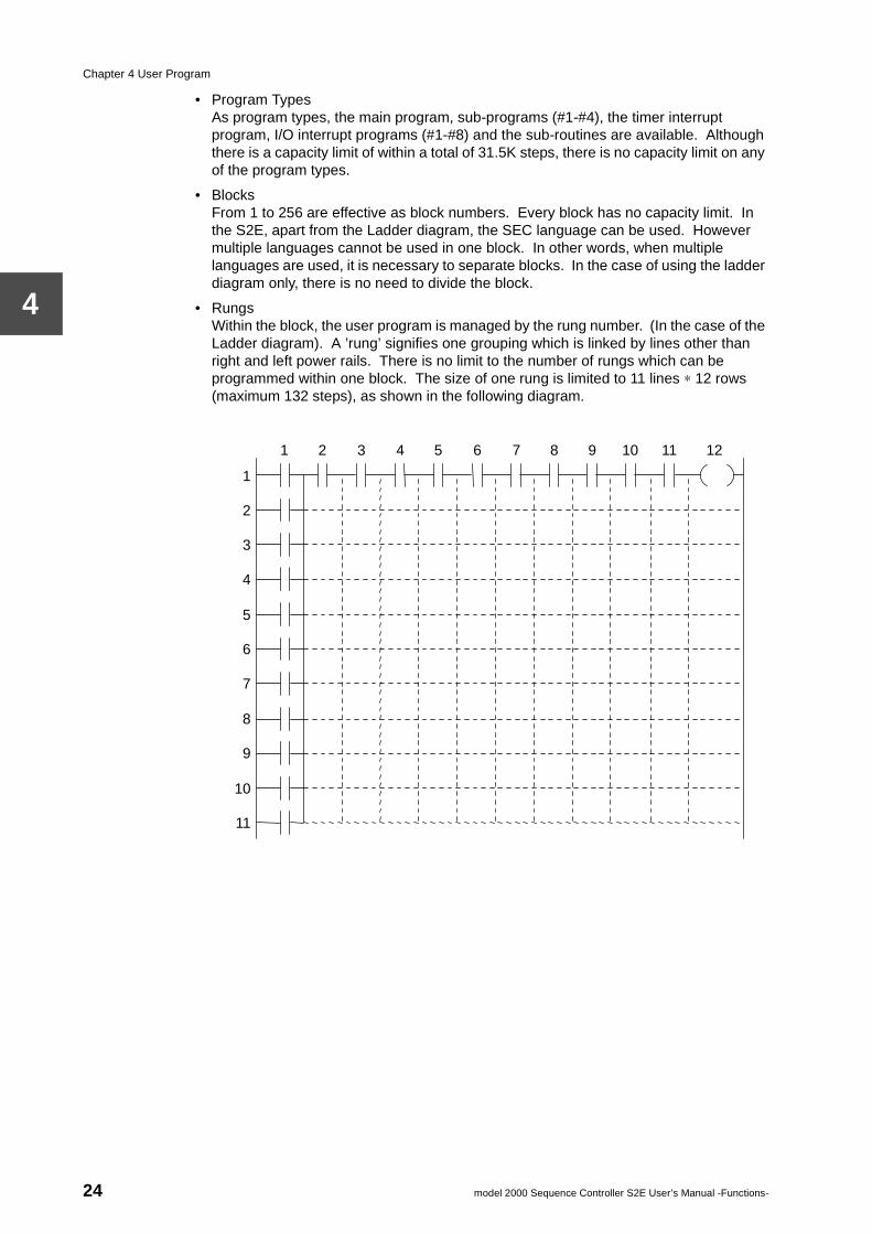
• RungsWithin the block, the user program is managed by the rung number. (In the case of the Ladder diagram). A ’rung’ signifies one grouping which is linked by lines other than right and left power rails. There is no limit to the number of rungs which can be programmed within one block. The size of one rung is limited to 11 lines ∗ 12 rows (maximum 132 steps), as shown in the following diagram.
1 2 3 4 5 6 7 8 9 10 11 12
1
2
3
4
5
6
7
8
9
10
11
24 model 2000 Sequence Controller S2E User’s Manual -Functions-
4.4 Program execution sequence
4
4.4 Program execution sequence
The main program is the main body of the user program which executes every scan, and must have at least one END instruction. Here, the program execution sequence is described in the case of the main program only. The operation of other program types is described in Part 2.
The user program is executed in the following sequence.
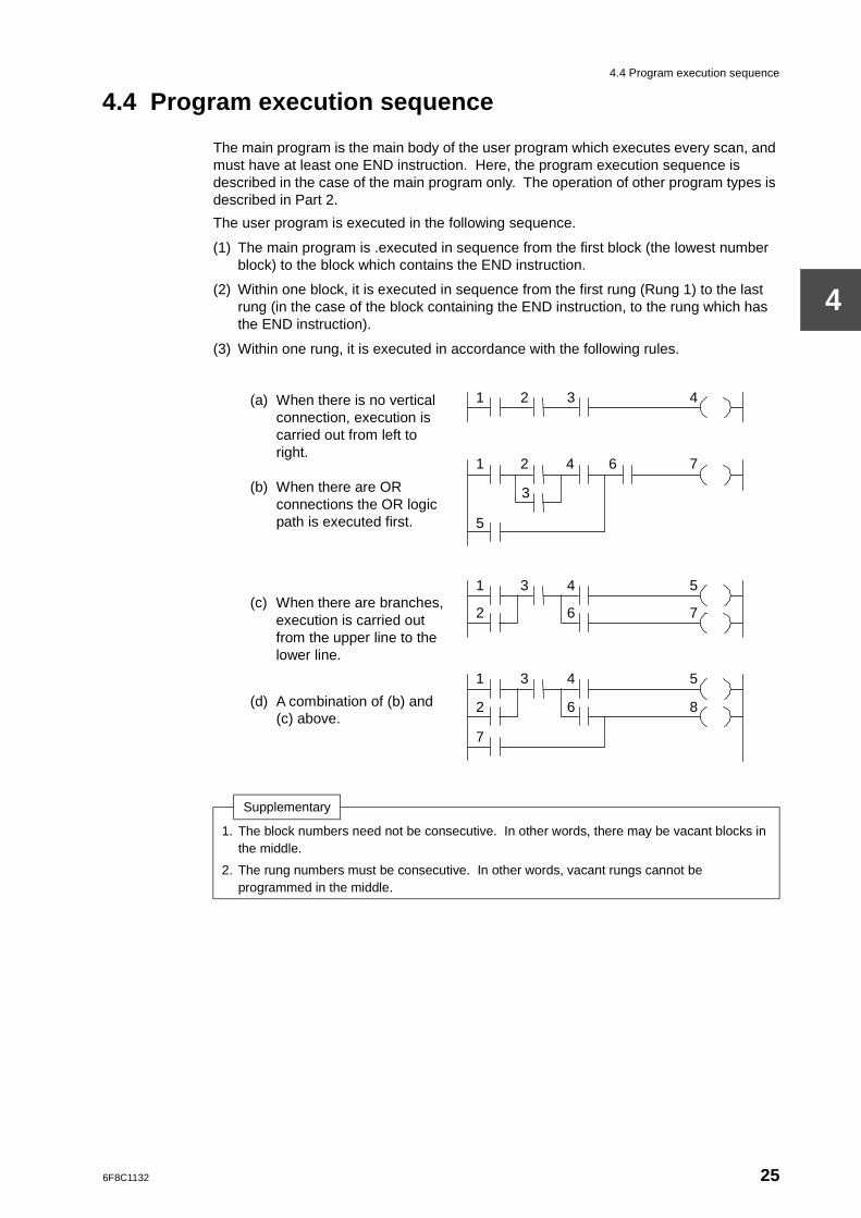
(1) The main program is .executed in sequence from the first block (the lowest number block) to the block which contains the END instruction.
(2) Within one block, it is executed in sequence from the first rung (Rung 1) to the last rung (in the case of the block containing the END instruction, to the rung which has the END instruction).
(3) Within one rung, it is executed in accordance with the following rules.
Supplementary
1. The block numbers need not be consecutive. In other words, there may be vacant blocks in the middle.
2. The rung numbers must be consecutive. In other words, vacant rungs cannot be programmed in the middle.
(a) When there is no vertical connection, execution is carried out from left to right.
(b) When there are OR
connections the OR logic path is executed first.
(c) When there are branches, execution is carried out from the upper line to the lower line.
(d) A combination of (b) and
(c) above.
1 2 3 4
1 2 4 6 7
5
7
1 3 4 5
3
2 6 7
1 3 4 5
2 6 8
6F8C1132 25

6F8C1132
User Data
Chapter 55.1 User data types and functions
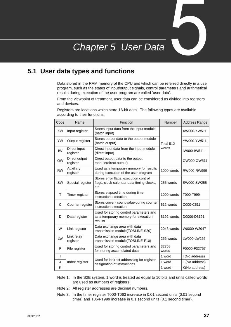
Data stored in the RAM memory of the CPU and which can be referred directly in a user program, such as the states of input/output signals, control parameters and arithmetical results during execution of the user program are called ’user data’.
From the viewpoint of treatment, user data can be considered as divided into registers and devices.
Registers are locations which store 16-bit data. The following types are available according to their functions.
Note 1: In the S2E system, 1 word is treated as equal to 16 bits and units called words are used as numbers of registers.
Note 2: All register addresses are decimal numbers.
Note 3: In the timer register T000-T063 increase in 0.01 second units (0.01 second timer) and T064-T999 increase in 0.1 second units (0.1 second timer).
Code Name Function Number Address Range
XW Input registerStores input data from the input module (batch input)
Total 512 words
XW000-XW511
YW Output registerStores output data to the output module (batch output)
YW000-YW511
IWDirect input register
Direct input data from the input module (direct input)
IW000-IW511
OWDirect output register
Direct output data to the output module(direct output)
OW000-OW511
RWAuxiliary register
Used as a temporary memory for results during execution of the user program
1000 words RW000-RW999
SW Special registerStores error flags, execution control flags, clock-calendar data timing clocks, etc.
256 words SW000-SW255
T Timer registerStores elapsed time during timer instruction execution
1000 words T000-T999
C Counter registerStores current count value during counter instruction execution
512 words C000-C511
D Data registerUsed for storing control parameters and as a temporary memory for execution results
8192 words D0000-D8191
W Link registerData exchange area with data transmission module(TOSLINE-S20)
2048 words W0000-W2047
LWLink relay register
Data exchange area with data transmission module(TOSLINE-F10)
256 words LW000-LW255
F File registerUsed for storing control parameters and for storing accumulated data
32768 words
F0000-F32767
I
Index registerUsed for indirect addressing for register designation of instructions
1 word I (No address)
J 1 word J (No address)
K 1 word K(No address)
27
Chapter 5 User Data
5
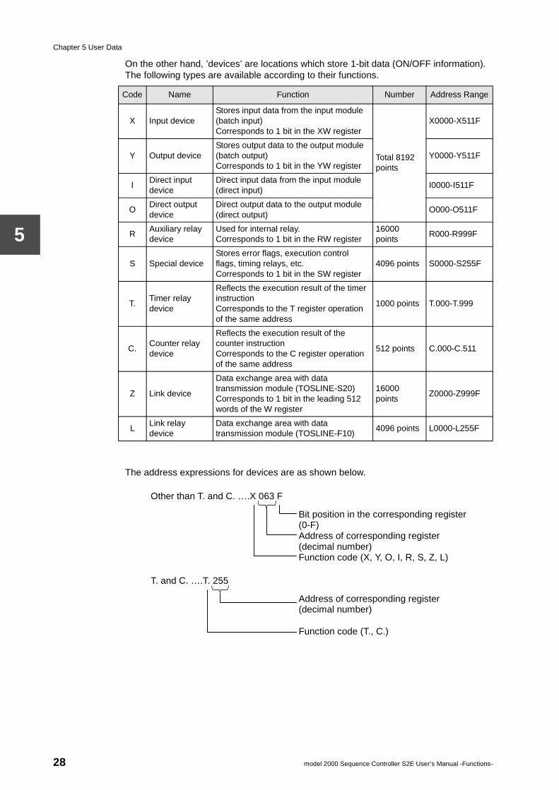
On the other hand, ’devices’ are locations which store 1-bit data (ON/OFF information). The following types are available according to their functions.
The address expressions for devices are as shown below.
Code Name Function Number Address Range
X Input deviceStores input data from the input module (batch input)Corresponds to 1 bit in the XW register
Total 8192 points
X0000-X511F
Y Output deviceStores output data to the output module (batch output)Corresponds to 1 bit in the YW register
Y0000-Y511F
IDirect input device
Direct input data from the input module (direct input)
I0000-I511F
ODirect output device
Direct output data to the output module (direct output)
O000-O511F
RAuxiliary relay device
Used for internal relay.Corresponds to 1 bit in the RW register
16000 points
R000-R999F
S Special deviceStores error flags, execution control flags, timing relays, etc.Corresponds to 1 bit in the SW register
4096 points S0000-S255F
T.Timer relay device
Reflects the execution result of the timer instructionCorresponds to the T register operation of the same address
1000 points T.000-T.999
C.Counter relay device
Reflects the execution result of the counter instructionCorresponds to the C register operation of the same address
512 points C.000-C.511
Z Link device
Data exchange area with data transmission module (TOSLINE-S20)Corresponds to 1 bit in the leading 512 words of the W register
16000 points
Z0000-Z999F
LLink relay device
Data exchange area with data transmission module (TOSLINE-F10)
4096 points L0000-L255F
Bit position in the corresponding register (0-F) Address of corresponding register (decimal number) Function code (X, Y, O, I, R, S, Z, L)
Other than T. and C. ….X 063 F
T. and C. ….T. 255
Address of corresponding register (decimal number)
Function code (T., C.)
28 model 2000 Sequence Controller S2E User’s Manual -Functions-
5.1 User data types and functions
5
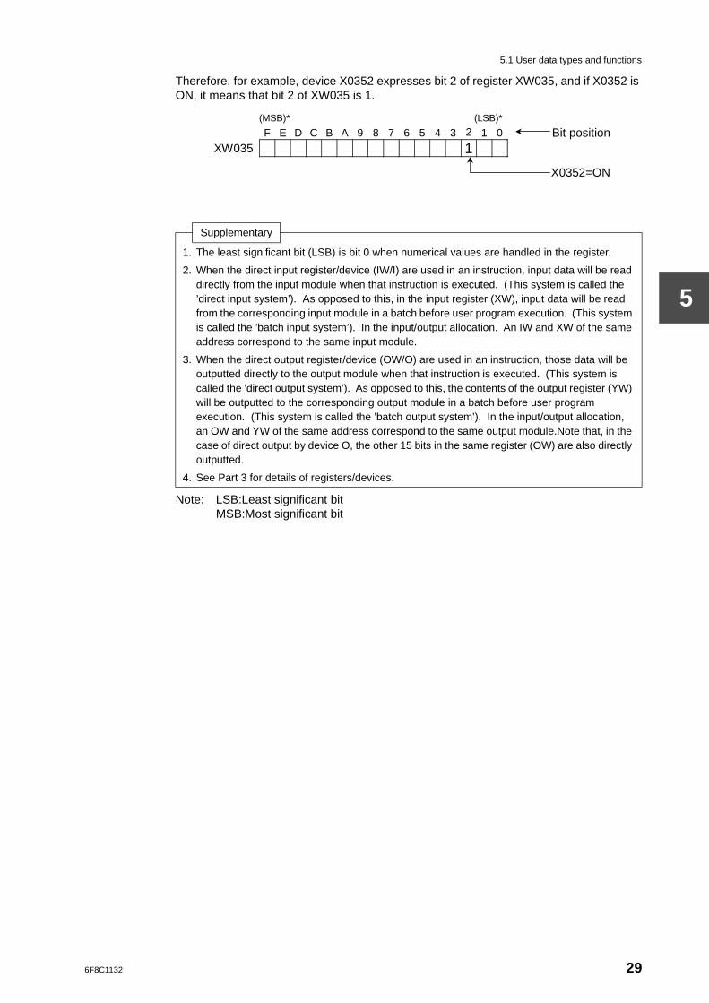
Therefore, for example, device X0352 expresses bit 2 of register XW035, and if X0352 is ON, it means that bit 2 of XW035 is 1.
Note: LSB:Least significant bitMSB:Most significant bit
Supplementary
1. The least significant bit (LSB) is bit 0 when numerical values are handled in the register.
2. When the direct input register/device (IW/I) are used in an instruction, input data will be read directly from the input module when that instruction is executed. (This system is called the ’direct input system’). As opposed to this, in the input register (XW), input data will be read from the corresponding input module in a batch before user program execution. (This system is called the ’batch input system’). In the input/output allocation. An IW and XW of the same address correspond to the same input module.
3. When the direct output register/device (OW/O) are used in an instruction, those data will be outputted directly to the output module when that instruction is executed. (This system is called the ’direct output system’). As opposed to this, the contents of the output register (YW) will be outputted to the corresponding output module in a batch before user program execution. (This system is called the ’batch output system’). In the input/output allocation, an OW and YW of the same address correspond to the same output module.Note that, in the case of direct output by device O, the other 15 bits in the same register (OW) are also directly outputted.
4. See Part 3 for details of registers/devices.
(MSB)* (LSB)*
F E D C B A 9 8 7 6 5 4 3 2 1 0 Bit position XW035 1
X0352=ON
6F8C1132 29
Chapter 5 User Data
5
5.2 Conditions for data initialization
The user data are initialized according to the conditions in the following table at power up and at transiting the RUN mode.
Also, the leading 4k words of the data register (D0000 to D4095), are the subjects of the Initial Load. Therefore, when the Initial Load conditions are established, initialization will be carried out in the sequence Initial Load −> data initialization. (See Section 2.3 for Initial Load)
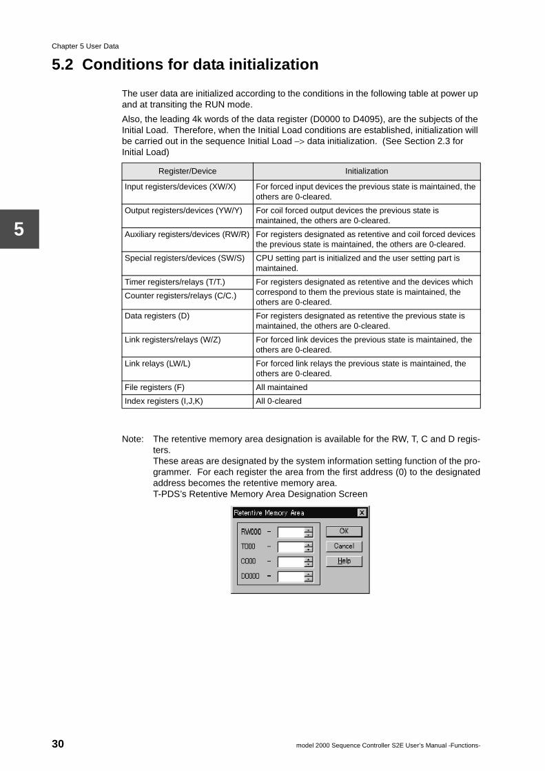
Note: The retentive memory area designation is available for the RW, T, C and D regis-ters.These areas are designated by the system information setting function of the pro-grammer. For each register the area from the first address (0) to the designatedaddress becomes the retentive memory area.T-PDS’s Retentive Memory Area Designation Screen
Register/Device Initialization
Input registers/devices (XW/X) For forced input devices the previous state is maintained, the others are 0-cleared.
Output registers/devices (YW/Y) For coil forced output devices the previous state is maintained, the others are 0-cleared.
Auxiliary registers/devices (RW/R) For registers designated as retentive and coil forced devices the previous state is maintained, the others are 0-cleared.
Special registers/devices (SW/S) CPU setting part is initialized and the user setting part is maintained.
Timer registers/relays (T/T.) For registers designated as retentive and the devices which correspond to them the previous state is maintained, the others are 0-cleared.
Counter registers/relays (C/C.)
Data registers (D) For registers designated as retentive the previous state is maintained, the others are 0-cleared.
Link registers/relays (W/Z) For forced link devices the previous state is maintained, the others are 0-cleared.
Link relays (LW/L) For forced link relays the previous state is maintained, the others are 0-cleared.
File registers (F) All maintained
Index registers (I,J,K) All 0-cleared
30 model 2000 Sequence Controller S2E User’s Manual -Functions-
6F8C1132
ogrammingExample
Chapter 6 Pr
6.1 Sample system
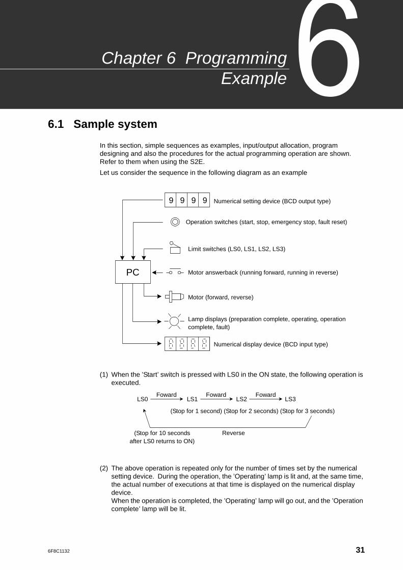
In this section, simple sequences as examples, input/output allocation, program designing and also the procedures for the actual programming operation are shown. Refer to them when using the S2E.
Let us consider the sequence in the following diagram as an example
(1) When the ’Start’ switch is pressed with LS0 in the ON state, the following operation is executed.
(2) The above operation is repeated only for the number of times set by the numerical setting device. During the operation, the ’Operating’ lamp is lit and, at the same time, the actual number of executions at that time is displayed on the numerical display device.When the operation is completed, the ’Operating’ lamp will go out, and the ’Operation complete’ lamp will be lit.
9 9 9 9 Numerical setting device (BCD output type)
PC
Operation switches (start, stop, emergency stop, fault reset)
Limit switches (LS0, LS1, LS2, LS3)
Motor answerback (running forward, running in reverse)
Motor (forward, reverse)
Lamp displays (preparation complete, operating, operation complete, fault)
Numerical display device (BCD input type)
LS0 LS1 LS2 LS3 Foward Foward Foward
(Stop for 1 second) (Stop for 2 seconds) (Stop for 3 seconds)
Reverse (Stop for 10 seconds after LS0 returns to ON)
31
Chapter 6 Programming Example
6
(3) If the ’Stop’ switch is pressed during the operation, the motor is stopped at that position and, after 1 second, starts in reverse. When the LS0 becomes ON, the motor is stopped and, after 1 second, the ’Preparation complete’ lamp is lit.
(4) When LS0 is ON in states other than during operation, the ’Preparation complete’ lamp is lit. The ’Start’ switch is only effective when the ’Preparation complete’ lamp is lit.
(5) When the ’Emergency stop’ switch has been pressed, the motor is stopped in that position and the ’Fault’ lamp is lit. In that state, if the ’Fault reset’ switch is pressed, the ’Fault’ lamp will go out.
32 model 2000 Sequence Controller S2E User’s Manual -Functions-
6.2 Input/output allocation
6
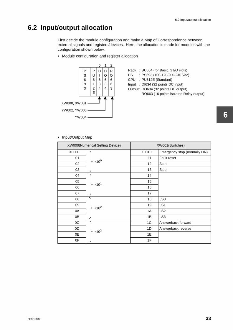
6.2 Input/output allocation
First decide the module configuration and make a Map of Correspondence between external signals and registers/devices. Here, the allocation is made for modules with the configuration shown below.
• Module configuration and register allocation
• Input/Output Map
XW000(Numerical Setting Device) XW001(Switches)
X0000
∗100
X0010 Emergency stop (normally ON)
01 11 Fault reset
02 12 Start
03 13 Stop
04
∗101
14
05 15
06 16
07 17
08
∗102
18 LS0
09 19 LS1
0A 1A LS2
0B 1B LS3
0C
∗103
1C Answerback forward
0D 1D Answerback reverse
0E 1E
0F 1F
XW000, XW001
YW002, YW003
YW004
0 1 2
P S 6 9 3
P U 6 1 2 E
D I 6 3 4
D O 6 3 4
R O 6 6 3
Rack : BU664 (for Basic, 3 I/O slots) PS : PS693 (100-120/200-240 Vac) CPU : PU612E (Standard) Input : DI634 (32 points DC input) Output : DO634 (32 points DC output)
RO663 (16 points isolated Relay output)
6F8C1132 33
Chapter 6 Programming Example
6
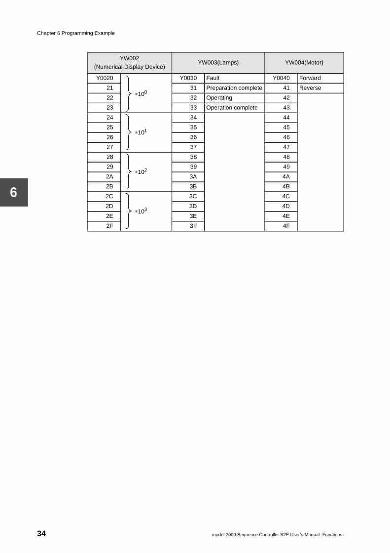
YW002(Numerical Display Device)
YW003(Lamps) YW004(Motor)
Y0020
∗100
Y0030 Fault Y0040 Forward
21 31 Preparation complete 41 Reverse
22 32 Operating 42
23 33 Operation complete 43
24
∗101
34 44
25 35 45
26 36 46
27 37 47
28
∗102
38 48
29 39 49
2A 3A 4A
2B 3B 4B
2C
∗103
3C 4C
2D 3D 4D
2E 3E 4E
2F 3F 4F
34 model 2000 Sequence Controller S2E User’s Manual -Functions-
6.3 Sample program
6
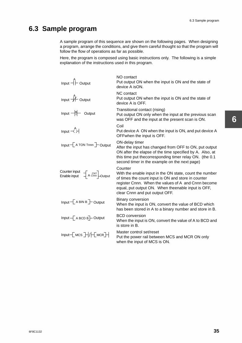
6.3 Sample program
A sample program of this sequence are shown on the following pages. When designing a program, arrange the conditions, and give them careful thought so that the program will follow the flow of operations as far as possible.
Here, the program is composed using basic instructions only. The following is a simple explanation of the instructions used in this program.
Input Output
NO contactPut output ON when the input is ON and the state of device A isON.
Input Output
NC contactPut output ON when the input is ON and the state of device A is OFF.
Input OutputTransitional contact (rising)Put output ON only when the input at the previous scan was OFF and the input at the present scan is ON.
Input
CoilPut device A ON when the input is ON, and put device A OFFwhen the input is OFF.
Input OutputON-delay timerAfter the input has changed from OFF to ON, put output ON after the elapse of the time specified by A. Also, at this time put thecorresponding timer relay ON. (the 0.1 second timer in the example on the next page)
Counter inputEnable input
CounterWith the enable input in the ON state, count the number of times the count input is ON and store in counter register Cnnn. When the values of A and Cnnn become equal, put output ON. When theenable input is OFF, clear Cnnn and put output OFF.
Input OutputBinary conversionWhen the input is ON, convert the value of BCD which has been stored in A to a binary number and store in B.
Input Output BCD conversionWhen the input is ON, convert the value of A to BCD and is store in B.
InputMaster control set/resetPut the power rail between MCS and MCR ON only when the input of MCS is ON.
A
A
↑
A( )
A TON Tnnn
CNTA Cnnn Output
A BIN B
A BCD B
MCS MCR
6F8C1132 35
Chapter 6 Programming Example
6
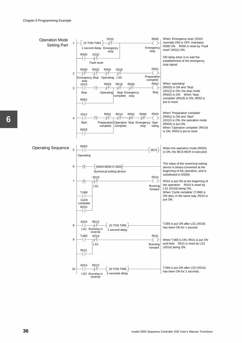
When ‘Emergency stop’ (X010: normally ON) is OFF, maintains R000 ON. R000 is reset by ‘Fault reset’ (X011) ON. ON delay timer is to wait the establishment of the emergency stop signal.
When ‘operating’ (R003) is ON and ‘Stop’ (X013) is ON, the stop mode (R002) is ON. When ‘Stop complete’ (R016) is ON, R002 is put to reset. When ‘Preparation complete’ (R001) is ON and ‘Start’ (X012) is ON, the operation mode (R003) is put ON. When ‘Operation complete’ (R014) is ON, R003 is put to reset.
When the operation mode (R003) is ON, the MCS-MCR is executed.
The value of the numerical setting device is binary-converted at the beginning of the operation, and is substituted in D5000. R010 is put ON at the beginning of the operation. R010 is reset by LS1 (X019) being ON. When ‘Cycle complete’ (T.068) is ON also, in the same way, R010 is put ON.
T.065 is put ON after LS1 (X019) has been ON for 1 second.
When T.065 is ON, R011 is put ON and held. R011 is reset by LS2 (X01A) being ON.
T.066 is put ON after LS2 (X01A) has been ON for 2 seconds.
Operation Mode Setting Part
Operating Sequence
10 TON T064
1 second delay
1
Emergency stop
2
3
X010
Emergency stop
X010 R000
R002 R000 R003 X018
R000
Emergency stop
Preparation complete
R001
R002
Ope- rating
R003
Running forward
R010
Running forward
R011
R000 R016 R003 X013 ↑
Stop Operating LS0
Fault reset
Emergency stop
Stop Operating
R002
Stop complete
Stop
4 R002 R014 R001 X012
↑
Emergency stop
Start Operation complete
R003
Stop
R000
Preparation complete
MCS R003
↑
Operating
XW00 BIND D 5000
5
6
Numerical setting device
↑
X019
LS1
7
T.068
Cycle complete
R010
10 TON T065 R013 X019
1 second delay LS1
X01A T.065
Running in reverse
LS2
R011
8
9
10 R013 X01A
LS2 Running in reverse
20 TON T066
2 seconds delay
36 model 2000 Sequence Controller S2E User’s Manual -Functions-
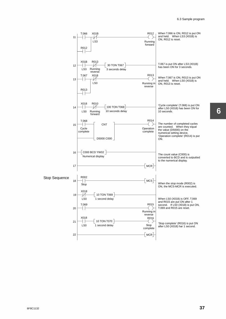
6.3 Sample program
6
When T.066 is ON, R012 is put ON and held. When LS3 (X01B) is ON, R012 is reset. T.067 is put ON after LS3 (X01B) has been ON for 3 seconds.
When T.067 is ON, R013 is put ON and held. When LS0 (X018) is ON, R013 is reset. ‘Cycle complete’ (T.068) is put ON after LS0 (X018) has been ON for 10 seconds. The number of completed cycles are counted. When they equal the value (D5000) on the numerical setting device, ‘Operation complete’ (R014) is put ON. The count value (C000) is converted to BCD and is outputted to the numerical display.
When the stop mode (R002) is ON, the MCS-MCR is executed. When LS0 (X018) is OFF, T.069 and R015 are put ON after 1 second. If LS0 (X018) is put ON, T.069 and R015 are reset. ‘Stop complete’ (R016) is put ON after LS0 (X018) har 1 second.
Stop Sequence
11
12
13
X01B
Running forward
R012
R012
Operation complete
R014
Running in reverse
R015
14
T.068
Cycle complete
MCR
R002
Stop
15
16
17
10 TON T069 X018
1 second delay LS0
18
19
22
R010 X018
LS0 Running forward
100 TON T068
10 seconds delay
20
21
X018 T.067
T.066
LS3
LS0
R013 X01B
LS3 Running reverse
30 TON T067
3 seconds delay
Running in reverse
R013
CNT
D5000 C000
R013
MCS
MCR
C000 BCD YW02
Numerical display
T.069
10 TON T070 X018
1 second delay LS0 Stop complete
R016
6F8C1132 37
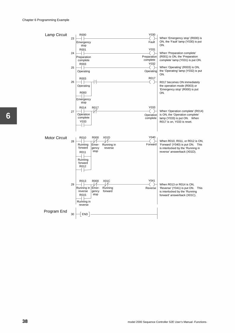
Chapter 6 Programming Example
6
When ‘Emergency stop’ (R000) is ON, the ‘Fault’ lamp (Y030) is put ON.
When ‘Preparation complete’ (R001) is ON, the ‘Preparation complete’ lamp (Y031) is put ON. When ‘Operating’ (R003) is ON, the ‘Operating’ lamp (Y032) is put ON.
R017 becomes ON immediately the operation mode (R003) or ‘Emergency stop’ (R000) is put ON. When ‘Operation complete’ (R014) is ON, the ‘Operation complete’ lamp (Y033) is put ON. When R017 is on, Y033 is reset.
When R010, R011, or R012 is ON, ‘Forward’ (Y040) is put ON. This is interlocked by the ‘Running in reverse’ answerback (X01D).
When R013 or R014 is ON, ‘Reverse’ (Y041) is put ON. This is interlocked by the ‘Running forward’ answerback (X01C).
Motor Circuit
23
24
25
Fault
Y030
26
END
27
28
29
30
R000 Lamp Circuit
Program End
Emergency stop
Forward
Y040
Reverse
Y041
R011
Running forward R012
R000 R013
R015
Y031 R001
Preparation complete
R017 R003
Operating
Preparation complete
↑
R000
Emergency stop
Operation complete
Y033 R014
Y033
R017
Operation complete
X01C
Running in reverse
Running in reverse
Emer- gency stop
Running forward
R010
Running forward
Operating
Y032 R003
Operating
R000 X01D
Emer- gency stop
Running in reverse
38 model 2000 Sequence Controller S2E User’s Manual -Functions-
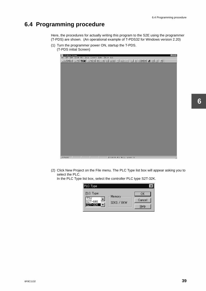
6.4 Programming procedure
6
6.4 Programming procedure
Here, the procedures for actually writing this program to the S2E using the programmer (T-PDS) are shown. (An operational example of T-PDS32 for Windows version 2.20)
(1) Turn the programmer power ON, startup the T-PDS.(T-PDS initial Screen)
(2) Click New Project on the File menu. The PLC Type list box will appear asking you to select the PLC.In the PLC Type list box, select the controller PLC type S2T-32K.
6F8C1132 39
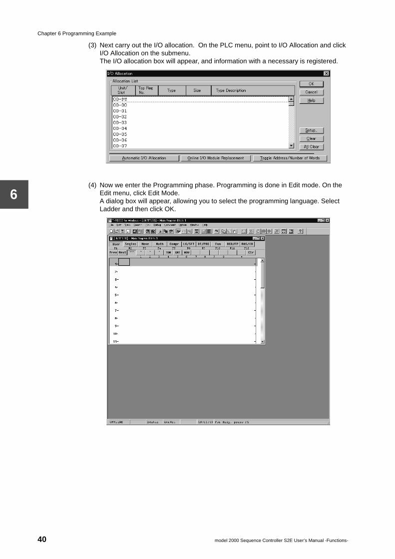
Chapter 6 Programming Example
6
(3) Next carry out the I/O allocation. On the PLC menu, point to I/O Allocation and click I/O Allocation on the submenu. The I/O allocation box will appear, and information with a necessary is registered.
(4) Now we enter the Programming phase. Programming is done in Edit mode. On the Edit menu, click Edit Mode.A dialog box will appear, allowing you to select the programming language. Select Ladder and then click OK.
40 model 2000 Sequence Controller S2E User’s Manual -Functions-
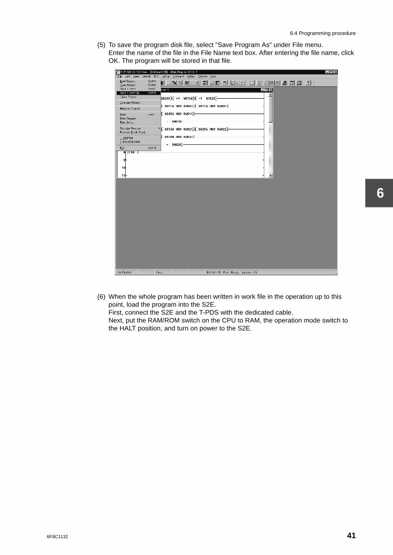
6.4 Programming procedure
6
(5) To save the program disk file, select "Save Program As" under File menu.Enter the name of the file in the File Name text box. After entering the file name, click OK. The program will be stored in that file.
(6) When the whole program has been written in work file in the operation up to this point, load the program into the S2E.First, connect the S2E and the T-PDS with the dedicated cable.Next, put the RAM/ROM switch on the CPU to RAM, the operation mode switch to the HALT position, and turn on power to the S2E.
6F8C1132 41
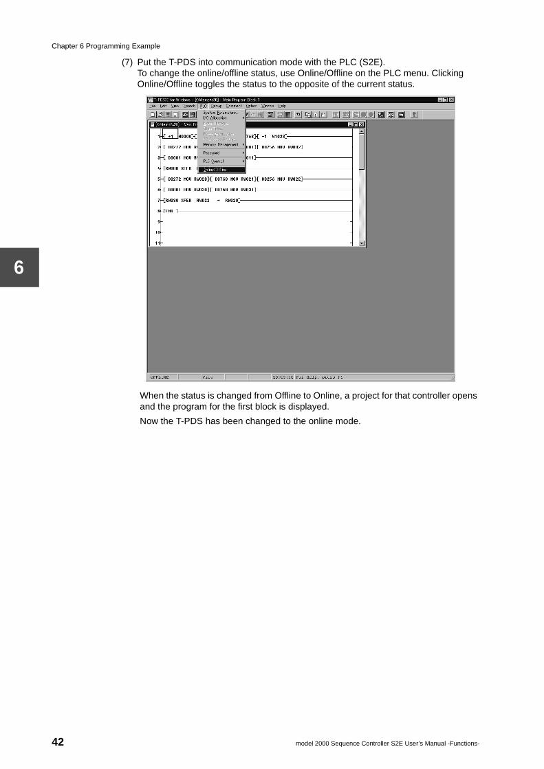
Chapter 6 Programming Example
6
(7) Put the T-PDS into communication mode with the PLC (S2E).To change the online/offline status, use Online/Offline on the PLC menu. Clicking Online/Offline toggles the status to the opposite of the current status.
When the status is changed from Offline to Online, a project for that controller opens and the program for the first block is displayed.
Now the T-PDS has been changed to the online mode.
42 model 2000 Sequence Controller S2E User’s Manual -Functions-
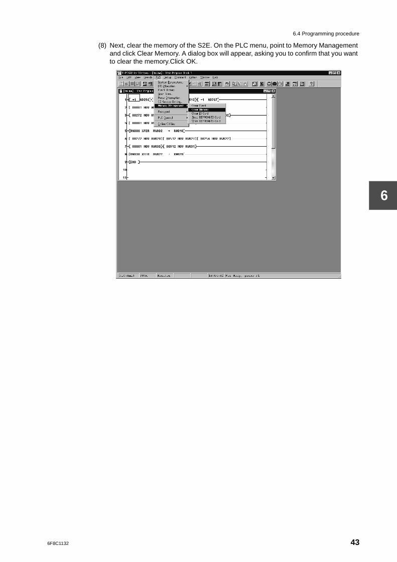
6.4 Programming procedure
6
(8) Next, clear the memory of the S2E. On the PLC menu, point to Memory Management and click Clear Memory. A dialog box will appear, asking you to confirm that you want to clear the memory.Click OK.
6F8C1132 43
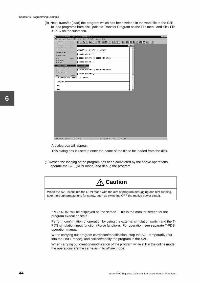
Chapter 6 Programming Example
6
(9) Next, transfer (load) the program which has been written in the work file to the S2E. To load programs from disk, point to Transfer Program on the File menu and click File -> PLC on the submenu.
A dialog box will appear.
This dialog box is used to enter the name of the file to be loaded from the disk.
(10)When the loading of the program has been completed by the above operations, operate the S2E (RUN mode) and debug the program.
"PLC: RUN" will be displayed on the screen. This is the monitor screen for the program execution state.
Perform confirmation of operation by using the external simulation switch and the T-PDS simulation input function (Force function). For operation, see separate T-PDS operation manual.
When carrying out program correction/modification, stop the S2E temporarily (put into the HALT mode), and correct/modify the program in the S2E.
When carrying out creation/modification of the program while still in the online mode, the operations are the same as in to offline mode.
Caution
When the S2E is put into the RUN mode with the aim of program debugging and test running, take thorough precautions for safety, such as switching OFF the motive power circuit.
44 model 2000 Sequence Controller S2E User’s Manual -Functions-
6.4 Programming procedure
6
(11)When program correction and operation check are completed, save the program in the disk and switch OFF the S2E power.The above completes the programming procedure. If the S2E’s RAM/ROM switch is put to ROM and the Operation Mode switch is put to RUN, the S2E will operate automatically when power is next switched ON.
Caution
In the case of a CPU with a built-in flash memory, write the program into the flash memory before the above procedure (10).The operation can be performed by click "Write EEPROM/IC Card". (See the screen on the procedure (8)).
6F8C1132 45

PART 2FUNCTIONS

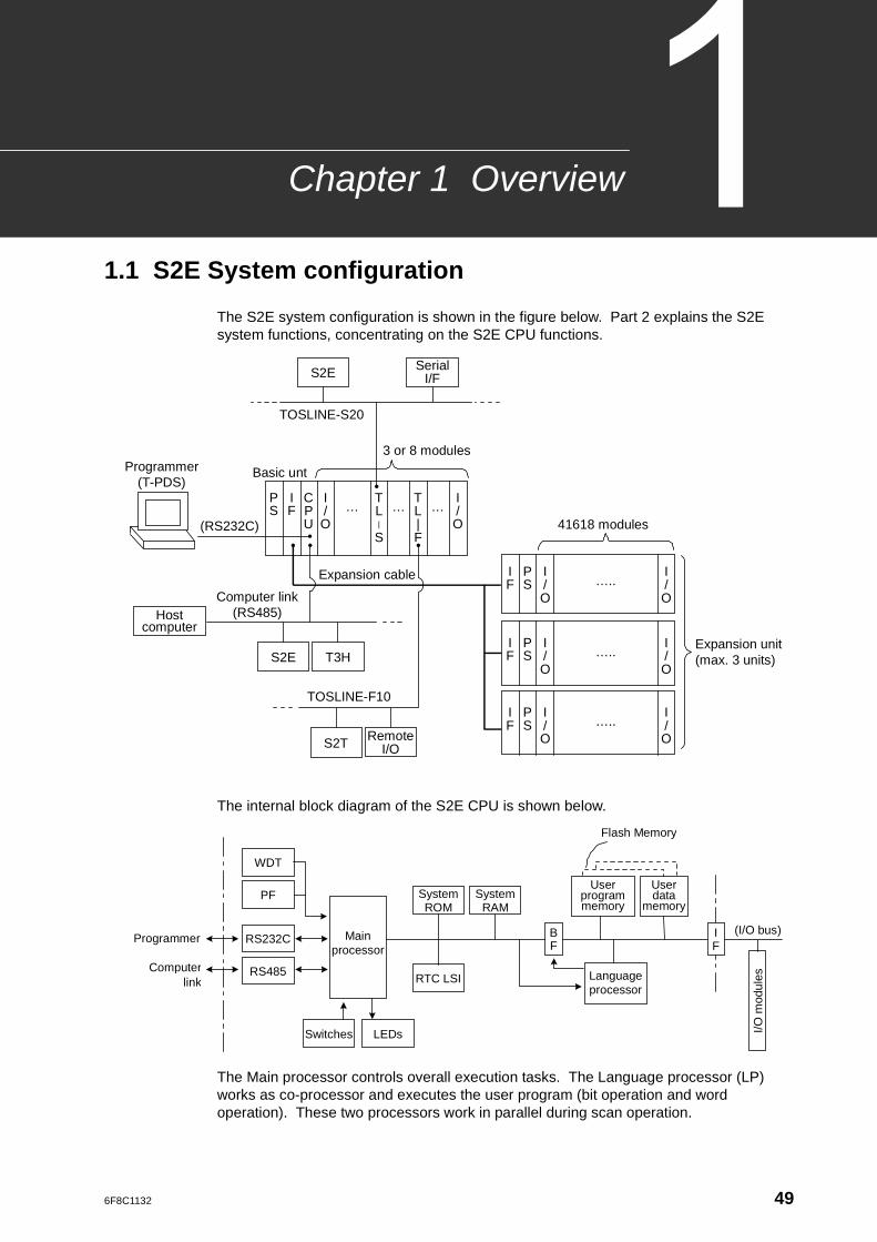
6F8C1132
Overview
Chapter 11.1 S2E System configuration
The S2E system configuration is shown in the figure below. Part 2 explains the S2E system functions, concentrating on the S2E CPU functions.
The internal block diagram of the S2E CPU is shown below.
The Main processor controls overall execution tasks. The Language processor (LP) works as co-processor and executes the user program (bit operation and word operation). These two processors work in parallel during scan operation.
TOSLINE-S20
Serial I/F
Host computer
S2E
S2E T3H
S2T Remote I/O
Expansion unit (max. 3 units)
41618 modules
3 or 8 modules
Basic unt
(RS232C)
Expansion cable
TOSLINE-F10
Programmer (T-PDS)
Computer link (RS485)
T L |
S
T L | F
I / O
I / O
P S
I F
C P U
… … …
I / O
P S
I F …..
I / O
I / O
P S
I F …..
I / O
I / O
P S
I F …..
I / O
Programmer
WDT
RS232C
RS485
PF System ROM
Switches LEDs
User program memory
RTC LSI
User data
memory
Language processor
I/O m
odul
es Computer
link
B F
I F
Main processor
Flash Memory
System RAM
(I/O bus)
49
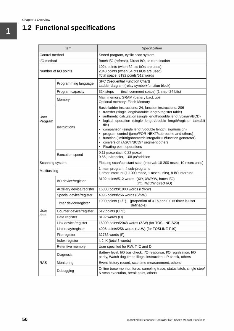
Chapter 1 Overview
1
1.2 Functional specificationsItem Specification
Control method Stored program, cyclic scan system
I/O method Batch I/O (refresh), Direct I/O, or combination
Number of I/O points1024 points (when 32 pts I/Os are used)2048 points (when 64 pts I/Os are used)Total space: 8192 points/512 words
User Program
Programming languageSFC (Sequential Function Chart)Ladder diagram (relay symbol+function block)
Program capacity 32k steps (incl. comment space) (1 step=24 bits)
MemoryMain memory: SRAM (battery back up)Optional memory: Flash Memory
Instructions
Basic ladder instructions: 24, function instructions: 206• transfer (single length/double length/register table)• arithmetic calculation (single length/double length/binary/BCD)• logical operation (single length/double length/register table/bit
file)• comparison (single length/double length, sign/unsign)• program control (jump/FOR-NEXT/subroutine and others)• function (limit/trigonometric integral/PID/function generator)• conversion (ASCII/BCD/7 segment other)• Floating point operations
Execution speed0.11 µs/contact, 0.22 µs/coil0.65 µs/transfer, 1.08 µs/addition
Scanning system Floating scan/constant scan (interval: 10-200 msec. 10 msec units)
Multitasking1 main program, 4 sub-programs1 timer interrupt (1-1000 msec, 1 msec units), 8 I/O interrupt
User data
I/O device/register8192 points/512 words (X/Y, XW/YW, batch I/O)
(I/O, lW/OW direct I/O)
Auxiliary device/register 16000 points/1000 words (R/RW)
Special device/register 4096 points/256 words (S/SW)
Timer device/register1000 points (T./T) (proportion of 0.1s and 0.01s timer is user
definable)
Counter device/register 512 points (C./C)
Data register 8192 words (D)
Link device/register 16000 points/2048 words (Z/W) (for TOSLINE-S20)
Link relay/register 4096 points/256 words (L/LW) (for TOSLINE-F10)
File register 32768 words (F)
Index register I, J, K (total 3 words)
Retentive memory User specified for RW, T, C and D
RAS
DiagnosisBattery level, I/O bus check, I/O response, I/O registration, I/O parity, Watch dog timer, illegal instruction, LP check, others
Monitoring Event history record, scantime measurement, others
DebuggingOnline trace monitor, force, sampling trace, status latch, single step/N scan execution, break point, others
50 model 2000 Sequence Controller S2E User’s Manual -Functions-
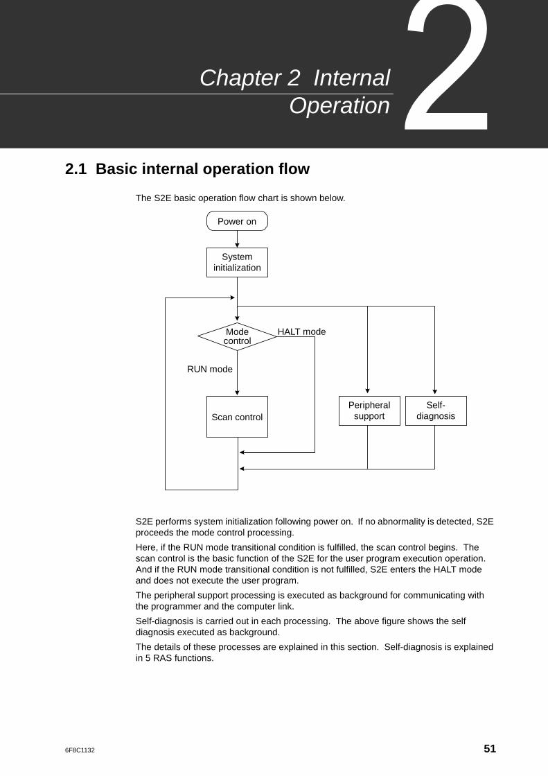
6F8C1132
2 InternalOperation
Chapter
2.1 Basic internal operation flow
The S2E basic operation flow chart is shown below.
S2E performs system initialization following power on. If no abnormality is detected, S2E proceeds the mode control processing.
Here, if the RUN mode transitional condition is fulfilled, the scan control begins. The scan control is the basic function of the S2E for the user program execution operation. And if the RUN mode transitional condition is not fulfilled, S2E enters the HALT mode and does not execute the user program.
The peripheral support processing is executed as background for communicating with the programmer and the computer link.
Self-diagnosis is carried out in each processing. The above figure shows the self diagnosis executed as background.
The details of these processes are explained in this section. Self-diagnosis is explained in 5 RAS functions.
Mode control
System initialization
Scan control Peripheral
support Self-
diagnosis
HALT mode
RUN mode
Power on
51
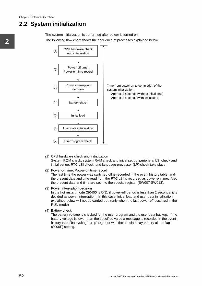
Chapter 2 Internal Operation
2
2.2 System initialization
The system initialization is performed after power is turned on.
The following flow chart shows the sequence of processes explained below.
(1) CPU hardware check and initializationSystem ROM check, system RAM check and initial set up, peripheral LSI check and initial set up, RTC LSI check, and language processor (LP) check take place.
(2) Power-off time, Power-on time recordThe last time the power was switched off is recorded in the event history table, and the present date and time read from the RTC LSI is recorded as power-on time. Also the present date and time are set into the special register (SW007-SW013).
(3) Power interruption decisionIn the hot restart mode (S0400 is ON), if power-off period is less than 2 seconds, it is decided as power interruption. In this case, initial load and user data initialization explained below will not be carried out. (only when the last power-off occurred in the RUN mode)
(4) Battery checkThe battery voltage is checked for the user program and the user data backup. If the battery voltage is lower than the specified value a message is recorded in the event history table ’batt voltage drop’ together with the special relay battery alarm flag (S000F) setting.
Time from power on to completion of the system initialization:
Approx. 2 seconds (without initial load) Approx. 3 seconds (with initial load)
CPU hardware check and initialization
Power-off time, Power-on time record
Power interruption decision
Battery check
Initial load
User data initialization
User program check
(2)
(1)
(4)
(3)
(5)
(6)
(7)
52 model 2000 Sequence Controller S2E User’s Manual -Functions-
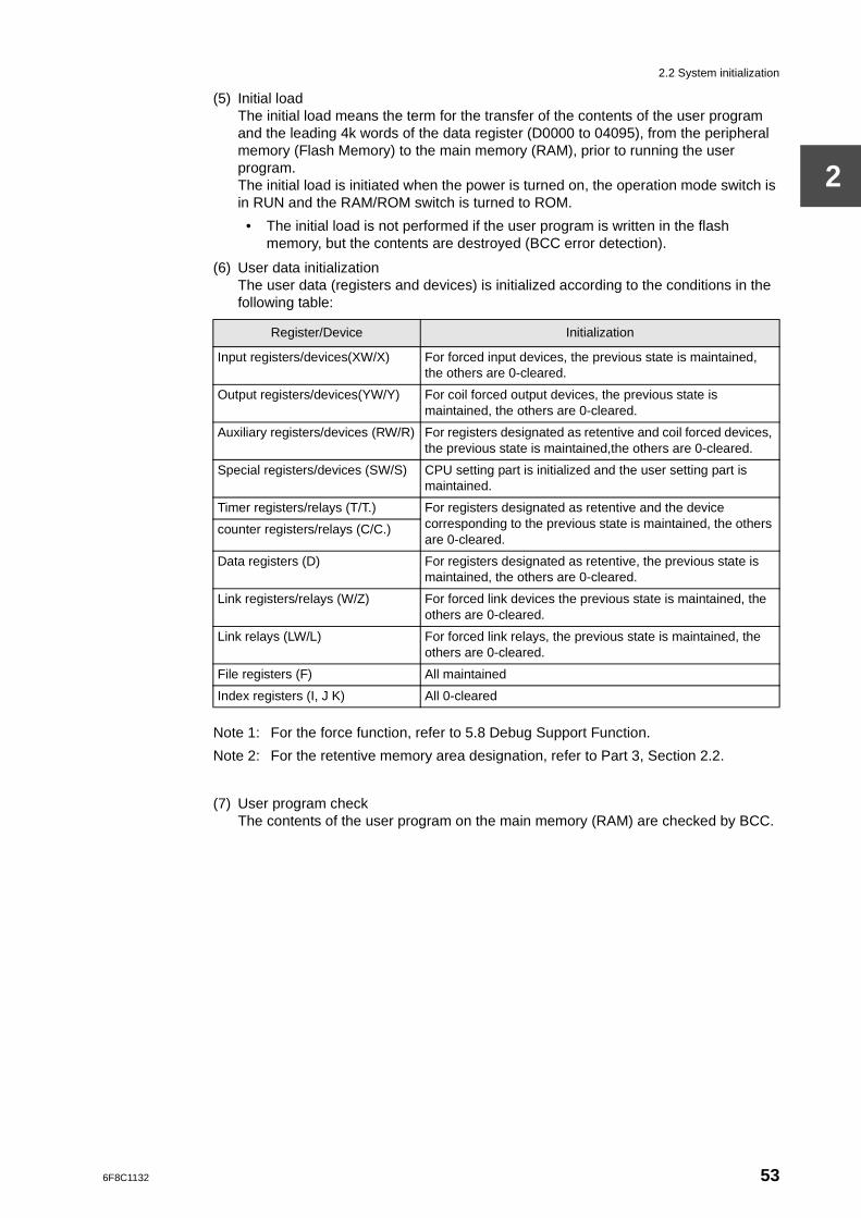
2.2 System initialization
2
(5) Initial loadThe initial load means the term for the transfer of the contents of the user program and the leading 4k words of the data register (D0000 to 04095), from the peripheral memory (Flash Memory) to the main memory (RAM), prior to running the user program.The initial load is initiated when the power is turned on, the operation mode switch is in RUN and the RAM/ROM switch is turned to ROM.
• The initial load is not performed if the user program is written in the flash memory, but the contents are destroyed (BCC error detection).
(6) User data initializationThe user data (registers and devices) is initialized according to the conditions in the following table:
Note 1: For the force function, refer to 5.8 Debug Support Function.
Note 2: For the retentive memory area designation, refer to Part 3, Section 2.2.
(7) User program checkThe contents of the user program on the main memory (RAM) are checked by BCC.
Register/Device Initialization
Input registers/devices(XW/X) For forced input devices, the previous state is maintained, the others are 0-cleared.
Output registers/devices(YW/Y) For coil forced output devices, the previous state is maintained, the others are 0-cleared.
Auxiliary registers/devices (RW/R) For registers designated as retentive and coil forced devices, the previous state is maintained,the others are 0-cleared.
Special registers/devices (SW/S) CPU setting part is initialized and the user setting part is maintained.
Timer registers/relays (T/T.) For registers designated as retentive and the device corresponding to the previous state is maintained, the others are 0-cleared.
counter registers/relays (C/C.)
Data registers (D) For registers designated as retentive, the previous state is maintained, the others are 0-cleared.
Link registers/relays (W/Z) For forced link devices the previous state is maintained, the others are 0-cleared.
Link relays (LW/L) For forced link relays, the previous state is maintained, the others are 0-cleared.
File registers (F) All maintained
Index registers (I, J K) All 0-cleared
6F8C1132 53
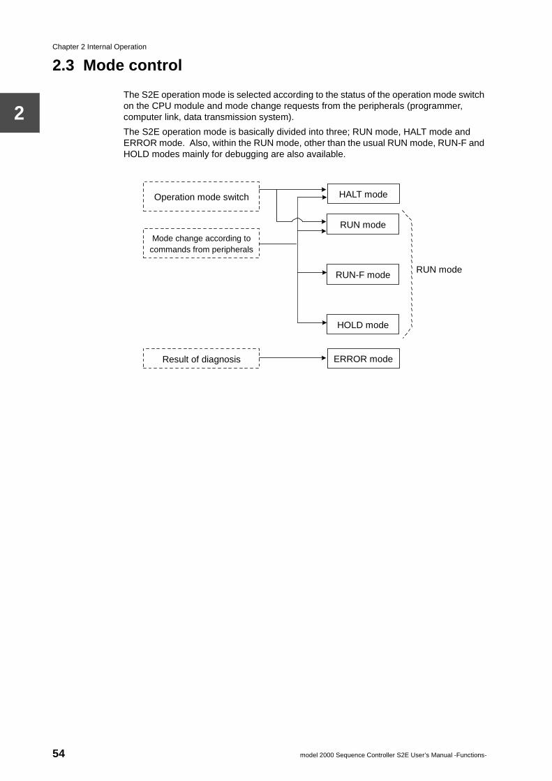
Chapter 2 Internal Operation
2
2.3 Mode control
The S2E operation mode is selected according to the status of the operation mode switch on the CPU module and mode change requests from the peripherals (programmer, computer link, data transmission system).
The S2E operation mode is basically divided into three; RUN mode, HALT mode and ERROR mode. Also, within the RUN mode, other than the usual RUN mode, RUN-F and HOLD modes mainly for debugging are also available.
RUN mode
HALT mode
RUN mode
RUN-F mode
HOLD mode
ERROR mode
Operation mode switch
Mode change according to commands from peripherals
Result of diagnosis
54 model 2000 Sequence Controller S2E User’s Manual -Functions-
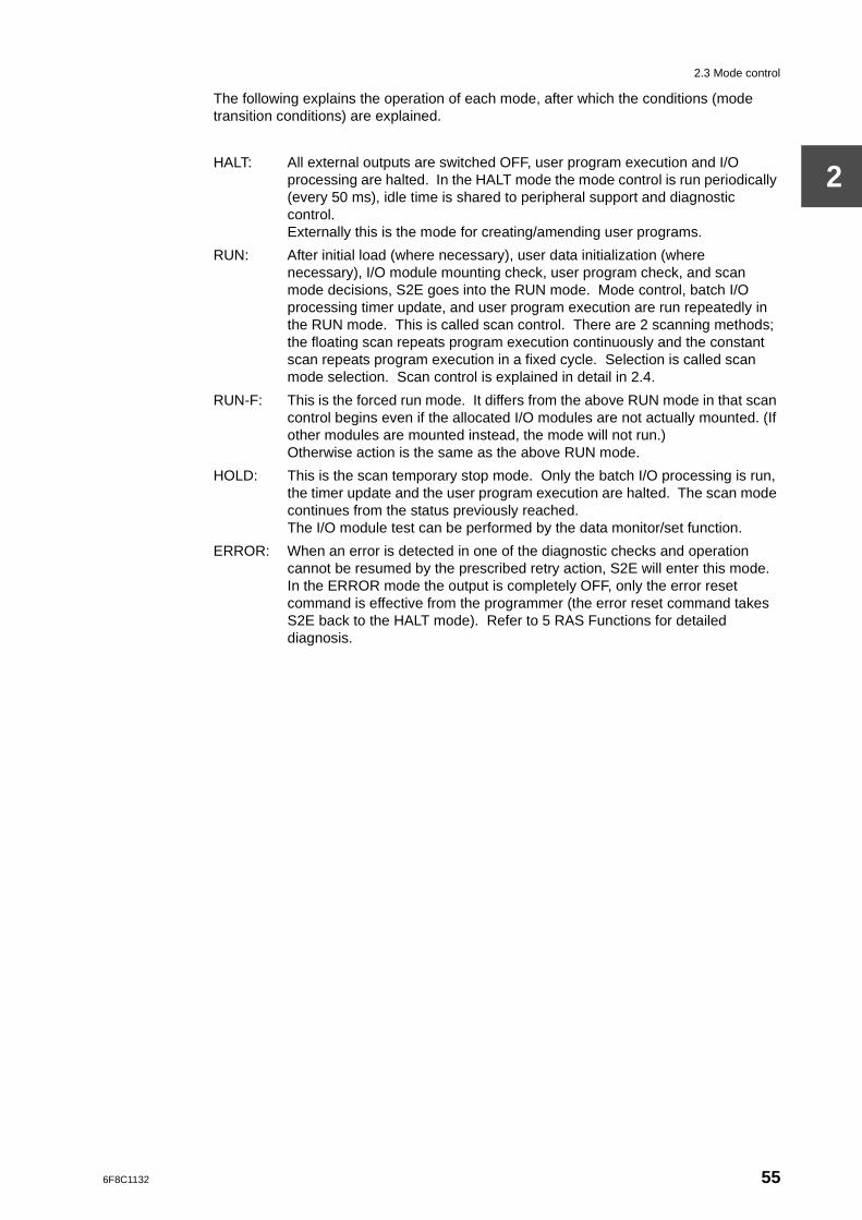
2.3 Mode control
2
The following explains the operation of each mode, after which the conditions (mode transition conditions) are explained.
HALT: All external outputs are switched OFF, user program execution and I/O processing are halted. In the HALT mode the mode control is run periodically (every 50 ms), idle time is shared to peripheral support and diagnostic control. Externally this is the mode for creating/amending user programs.
RUN: After initial load (where necessary), user data initialization (where necessary), I/O module mounting check, user program check, and scan mode decisions, S2E goes into the RUN mode. Mode control, batch I/O processing timer update, and user program execution are run repeatedly in the RUN mode. This is called scan control. There are 2 scanning methods; the floating scan repeats program execution continuously and the constant scan repeats program execution in a fixed cycle. Selection is called scan mode selection. Scan control is explained in detail in 2.4.
RUN-F: This is the forced run mode. It differs from the above RUN mode in that scan control begins even if the allocated I/O modules are not actually mounted. (If other modules are mounted instead, the mode will not run.)Otherwise action is the same as the above RUN mode.
HOLD: This is the scan temporary stop mode. Only the batch I/O processing is run, the timer update and the user program execution are halted. The scan mode continues from the status previously reached.The I/O module test can be performed by the data monitor/set function.
ERROR: When an error is detected in one of the diagnostic checks and operation cannot be resumed by the prescribed retry action, S2E will enter this mode. In the ERROR mode the output is completely OFF, only the error reset command is effective from the programmer (the error reset command takes S2E back to the HALT mode). Refer to 5 RAS Functions for detailed diagnosis.
6F8C1132 55
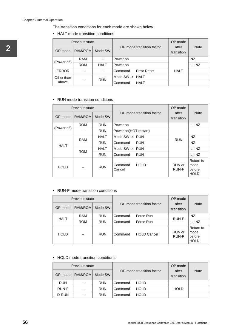
Chapter 2 Internal Operation
2
The transition conditions for each mode are shown below.
• HALT mode transition conditions
• RUN mode transition conditions
• RUN-F mode transition conditions
• HOLD mode transition conditions
Previous state
OP mode transition factor
OP mode
after transition
NoteOP mode RAM/ROM Mode SW
(Power off)RAM − Power on
HALT
INZ
ROM HALT Power on IL, INZ
ERROR − − Command Error Reset
Other than above
− RUNMode SW -> HALT
Command HALT
Previous stateOP mode transition factor
OP mode after
transition
NoteOP mode RAM/ROM Mode SW
(Power off)ROM RUN Power on
RUN
IL, INZ
− RUN Power on(HOT restart)
HALT
RAMHALT Mode SW -> RUN INZ
RUN Command RUN INZ
ROMHALT Mode SW -> RUN IL, INZ
RUN Command RUN IL, INZ
HOLD − RUNCommand HOLDCancel
RUN or RUN-F
Return to mode before HOLD
Previous state
OP mode transition factor
OP mode
after transition
NoteOP mode RAM/ROM Mode SW
HALTRAM RUN Command Force Run
RUN-FINZ
ROM RUN Command Force Run IL, INZ
HOLD − RUN Command HOLD CancelRUN or RUN-F
Return to mode before HOLD
Previous stateOP mode transition factor
OP mode after
transitionNote
OP mode RAM/ROM Mode SW
RUN − RUN Command HOLD
HOLDRUN-F − RUN Command HOLD
D-RUN − RUN Command HOLD
56 model 2000 Sequence Controller S2E User’s Manual -Functions-
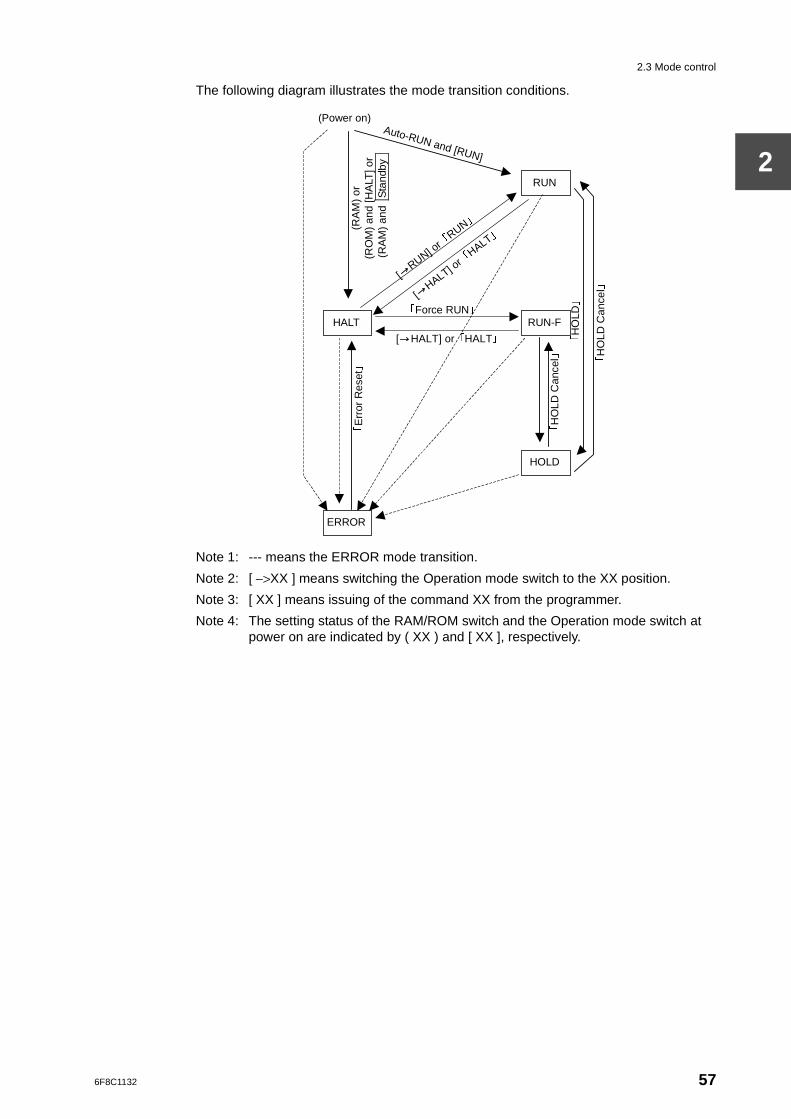
2.3 Mode control
2
The following diagram illustrates the mode transition conditions.
Note 1: --- means the ERROR mode transition.
Note 2: [ −>XX ] means switching the Operation mode switch to the XX position.
Note 3: [ XX ] means issuing of the command XX from the programmer.
Note 4: The setting status of the RAM/ROM switch and the Operation mode switch at power on are indicated by ( XX ) and [ XX ], respectively.
[ HALT] or「HALT」
[ H
ALT] or「
HALT」
[ R
UN] or「
RUN」
Auto-RUN and [RUN]
(RA
M)
or
(RO
M)
and
[HA
LT] o
r (R
AM
) an
d S
tand
by
(Power on)
「
HO
LD C
ance
l」
「
HO
LD
」
「Force RUN」 HALT
RUN
RUN-F
HOLD
ERROR
「
HO
LD C
ance
l」
「
Err
or R
eset
」
6F8C1132 57
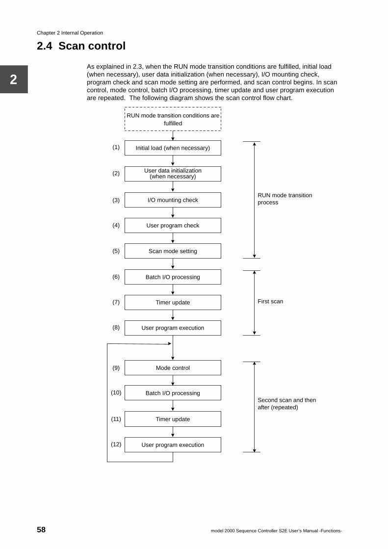
Chapter 2 Internal Operation
2
2.4 Scan control
As explained in 2.3, when the RUN mode transition conditions are fulfilled, initial load (when necessary), user data initialization (when necessary), I/O mounting check, program check and scan mode setting are performed, and scan control begins. In scan control, mode control, batch I/O processing, timer update and user program execution are repeated. The following diagram shows the scan control flow chart.
RUN mode transition conditions are
fulfilled
Initial load (when necessary)
User data initialization (when necessary)
I/O mounting check
User program check
Scan mode setting
Batch I/O processing
Timer update
User program execution
Mode control
Batch I/O processing
Timer update
RUN mode transition process
First scan
Second scan and then after (repeated)
(1)
(2)
(3)
(7)
(8)
(9)
(10)
(4)
(5)
(6)
(11)
(12) User program execution
58 model 2000 Sequence Controller S2E User’s Manual -Functions-
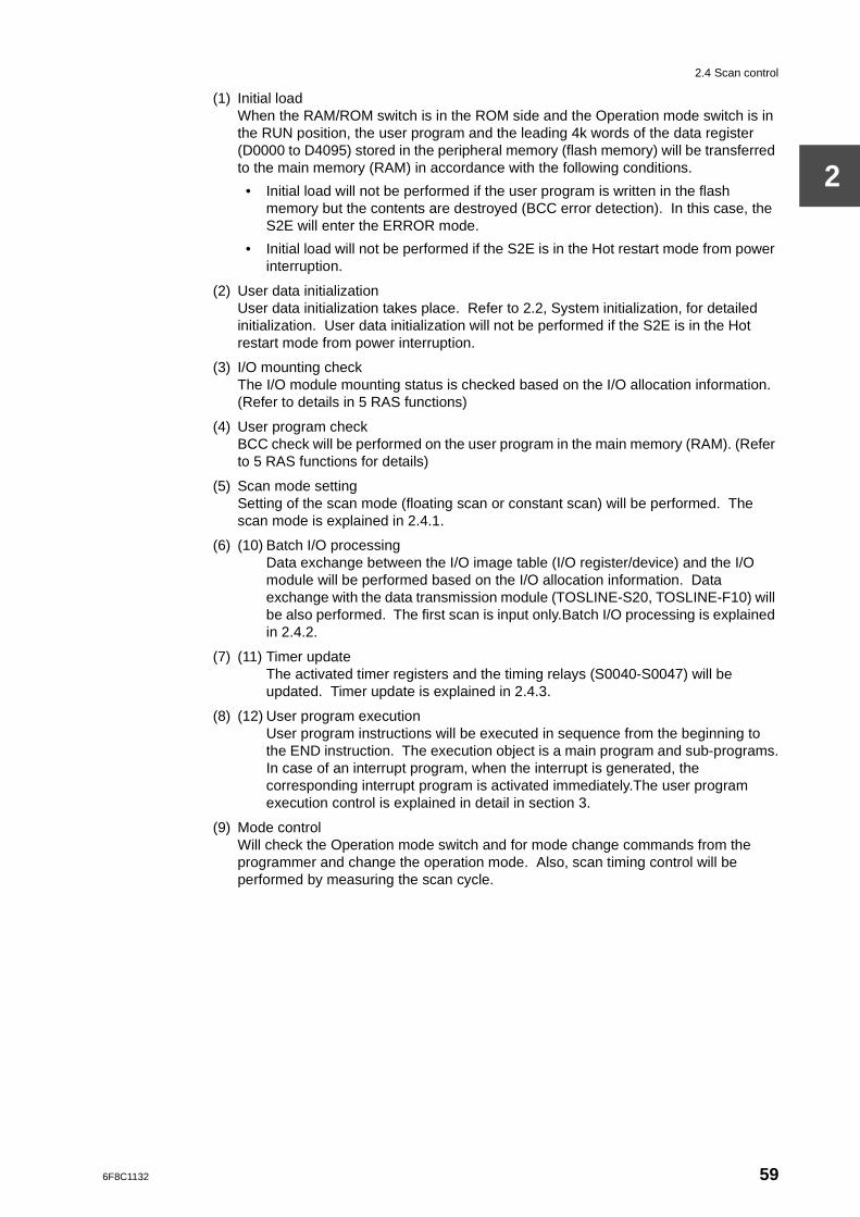
2.4 Scan control
2
(1) Initial loadWhen the RAM/ROM switch is in the ROM side and the Operation mode switch is in the RUN position, the user program and the leading 4k words of the data register (D0000 to D4095) stored in the peripheral memory (flash memory) will be transferred to the main memory (RAM) in accordance with the following conditions.
• Initial load will not be performed if the user program is written in the flash memory but the contents are destroyed (BCC error detection). In this case, the S2E will enter the ERROR mode.
• Initial load will not be performed if the S2E is in the Hot restart mode from power interruption.
(2) User data initializationUser data initialization takes place. Refer to 2.2, System initialization, for detailed initialization. User data initialization will not be performed if the S2E is in the Hot restart mode from power interruption.
(3) I/O mounting checkThe I/O module mounting status is checked based on the I/O allocation information. (Refer to details in 5 RAS functions)
(4) User program checkBCC check will be performed on the user program in the main memory (RAM). (Refer to 5 RAS functions for details)
(5) Scan mode settingSetting of the scan mode (floating scan or constant scan) will be performed. The scan mode is explained in 2.4.1.
(6) (10) Batch I/O processingData exchange between the I/O image table (I/O register/device) and the I/O module will be performed based on the I/O allocation information. Data exchange with the data transmission module (TOSLINE-S20, TOSLINE-F10) will be also performed. The first scan is input only.Batch I/O processing is explained in 2.4.2.
(7) (11) Timer updateThe activated timer registers and the timing relays (S0040-S0047) will be updated. Timer update is explained in 2.4.3.
(8) (12) User program executionUser program instructions will be executed in sequence from the beginning to the END instruction. The execution object is a main program and sub-programs.In case of an interrupt program, when the interrupt is generated, the corresponding interrupt program is activated immediately.The user program execution control is explained in detail in section 3.
(9) Mode controlWill check the Operation mode switch and for mode change commands from the programmer and change the operation mode. Also, scan timing control will be performed by measuring the scan cycle.
6F8C1132 59
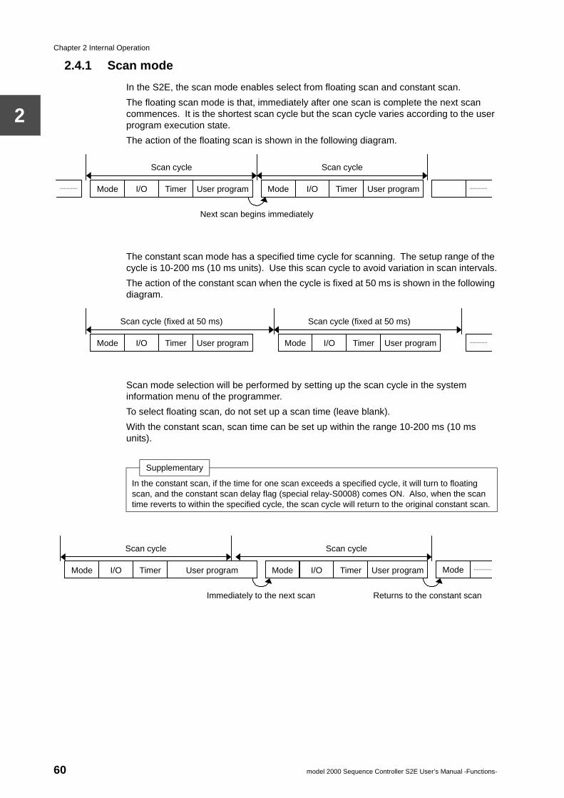
Chapter 2 Internal Operation
2
2.4.1 Scan mode
In the S2E, the scan mode enables select from floating scan and constant scan.
The floating scan mode is that, immediately after one scan is complete the next scan commences. It is the shortest scan cycle but the scan cycle varies according to the user program execution state.
The action of the floating scan is shown in the following diagram.
The constant scan mode has a specified time cycle for scanning. The setup range of the cycle is 10-200 ms (10 ms units). Use this scan cycle to avoid variation in scan intervals.
The action of the constant scan when the cycle is fixed at 50 ms is shown in the following diagram.
Scan mode selection will be performed by setting up the scan cycle in the system information menu of the programmer.
To select floating scan, do not set up a scan time (leave blank).
With the constant scan, scan time can be set up within the range 10-200 ms (10 ms units).
Mode I/O Timer User program Mode I/O Timer User program
Scan cycle Scan cycle
Next scan begins immediately
Mode I/O Timer User program Mode I/O Timer User program
Scan cycle (fixed at 50 ms) Scan cycle (fixed at 50 ms)
Supplementary
In the constant scan, if the time for one scan exceeds a specified cycle, it will turn to floating scan, and the constant scan delay flag (special relay-S0008) comes ON. Also, when the scan time reverts to within the specified cycle, the scan cycle will return to the original constant scan.
Mode I/O Timer User program Mode I/O Timer User program Mode
Scan cycle Scan cycle
Immediately to the next scan Returns to the constant scan
60 model 2000 Sequence Controller S2E User’s Manual -Functions-
2.4 Scan control
2
2.4.2 Batch I/O processing
The status of the external input signals will be read from input modules onto the I/O register/device (XW/X). Output register/device (YW/Y) status will be output to the output modules. This process takes place before user program execution and is done in batches, hence named batch I/O processing. The object of the batch I/O processing is as follows:
Batch input ... signals from input modules without i designation on I/O allocation and input registers/device (XW/X) which are not forced.
Batch output ... output registers/devices (YW/Y) corresponding to output modules without i designation on I/O allocation.
Also, data reading/writing between the data transmission module (TOSLINE-S20, TOSLINE-F10) and the link registers/relays (W/Z and LW/L) will be performed in this process.
If we consider S2E operation simply from the viewpoint of external signal exchanges, batch I/O processing and user program execution can be considered to be repeated continuously, as shown in the following diagram.
I/O register/device
TOSLINE-F10
TOSLINE-S20
Output module
Input module
Link register/device
Link relay
Link register allocated to TOSLINE-S20
Link relay allocated to TOSLINE-F10
XW000
XW001
YW002
YW003
W0000
W0001
W0002
W0003
LW000
LW001
LW002
LW003
L0F … L01 L00
L1F … L11 L10
L2F … L21 L20
L3F … L31 L30
Scan
Latest input data incorporated in XW YW data output externally
YW data updated with reference to XW data
Batch I/O processing
Running user program
6F8C1132 61
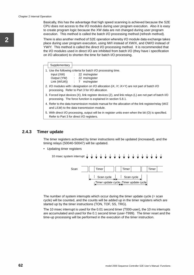
Chapter 2 Internal Operation
2
Basically, this has the advantage that high speed scanning is achieved because the S2E CPU does not access to the I/O modules during user program execution. Also it is easy to create program logic because the XW data are not changed during user program execution. This method is called the batch I/O processing method (refresh method).
There is also another method of S2E operation whereby I/O module data exchange takes place during user program execution, using IW/I instead of XW/X, and OW/O instead of YW/Y. This method is called the direct I/O processing method. It is recommended that the I/O modules used in direct I/O are inhibited from batch I/O (they have i specification on I/O allocation) to shorten the time for batch I/O processing.
2.4.3 Timer update
The timer registers activated by timer instructions will be updated (increased), and the timing relays (S0040-S0047) will be updated.
• Updating timer registers
The number of system interrupts which occur during the timer update cycle (= scan cycle) will be counted, and the counts will be added up in the timer registers which are started up by the timer instructions (TON, TOF, SS, TRG).
The 10 msec interrupt is used for the 0.01 second timer (T000-user), the 10 ms interrupts are accumulated and used for the 0.1 second timer (user-T999). The timer reset and the time-up processing will be performed in the execution of the timer instruction.
Supplementary
1. Use the following criteria for batch I/O processing time.Input (XW) : 22 ms/registerOutput (YW) : 22 ms/registerLink (W/LW)) : 7 ms/register
2. I/O modules with i designation on I/O allocation (iX, iY, iX+Y) are not part of batch I/O processing. Refer to Part 3 for I/O allocation.
3. Forced input devices (X), link register devices (Z), and link relays (L) are not part of batch I/O processing. The force function is explained in section 5.8.1.
4. Refer to the data transmission module manual for the allocation of the link register/relay (W/Z and L/LW) to the data transmission module.
5. With direct I/O processing, output will be in register units even when the bit (O) is specified. Refer to Part 3 for direct I/O registers.
10 msec system interrupt
Scan Timer Timer Timer
Scan cycle Scan cycle
Timer update cycle Timer update cycle
62 model 2000 Sequence Controller S2E User’s Manual -Functions-
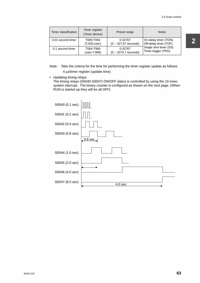
2.4 Scan control
2
Note: Take the criteria for the time for performing the timer register update as follows.
4 µs/timer register (update time)
• Updating timing relaysThe timing relays (S0040-S0047) ON/OFF status is controlled by using the 10 msec system interrupt. The binary counter is configured as shown on the next page. (When RUN is started up they will be all OFF)
Timer classificationTimer register(Timer device)
Preset range Notes
0.01 second timer T000-T063(T.000-user)
0-32767(0 ~ 327.67 seconds)
On-delay timer (TON)Off-delay timer (TOF)Single shot timer (SS)Timer trigger (TRG)
0.1 second timer T064-T999(user-T.999)
0-32767(0 ~ 3276.7 seconds)
S0040 (0.1 sec)
S0041 (0.2 sec)
S0042 (0.4 sec)
S0043 (0.8 sec)
S0044 (1.0 sec)
S0045 (2.0 sec)
S0047 (8.0 sec)
S0046 (4.0 sec)
0.8 sec
4.0 sec
6F8C1132 63
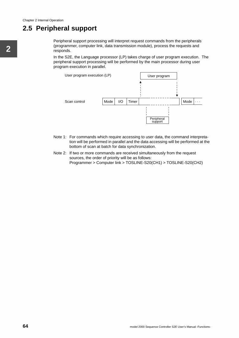
Chapter 2 Internal Operation
2
2.5 Peripheral support
Peripheral support processing will interpret request commands from the peripherals (programmer, computer link, data transmission module), process the requests and responds.
In the S2E, the Language processor (LP) takes charge of user program execution. The peripheral support processing will be performed by the main processor during user program execution in parallel.
Note 1: For commands which require accessing to user data, the command interpreta-tion will be performed in parallel and the data accessing will be performed at the bottom of scan at batch for data synchronization.
Note 2: If two or more commands are received simultaneously from the request sources, the order of priority will be as follows:Programmer > Computer link > TOSLINE-S20(CH1) > TOSLINE-S20(CH2)
User program execution (LP)
Scan control I/O Mode Timer . . . Mode
User program
Peripheral support
64 model 2000 Sequence Controller S2E User’s Manual -Functions-
2.6 Programming support functions
2
2.6 Programming support functions
The programming support functions are part of the functions realized as a result of peripheral support processing. Detailed programming support functions are explained in separate manuals for the programmer. The explanation here relates to an overview of the functions and their relation to the S2E operation modes.
(1) Memory clearWhen the memory clear command is received, the content of the user program memory (RAM) will be initialized and the content of the user data memory (RAM) will be cleared to 0.
(2) Automatic I/O allocationWhen the automatic I/O allocation command is received, the types of I/O modules mounted will be read and the I/O allocation information will be stored on the system information. (System information is in the user program memory.)
(3) Reading the I/O allocation informationThe I/O allocation information will be read from the system information, and sent to the peripherals.
(4) Writing I/O allocation informationI/O allocation information received from peripherals is stored on the system information.
(5) Reading the system informationThe system information (program ID, retentive memory specification, number of steps used, scan mode specification, other) is read and sent to the peripherals.
(6) Writing system informationThe system information (user setup items) received from the peripherals is stored in the system information.
(7) Reading the programIn response to a request from peripherals, a specified range of instructions will be read from the user program memory, and sent to the peripherals.
(8) Writing the programA specified range of instructions is received from peripherals and written onto the user program memory. After writing, the BCC (check code) correction will be carried out immediately.
(9) On-line program changeChanging the content of the user program memory (adding/changing/inserting/deleting) and the BCC correction will be carried out in the RUN mode. This action is performed after completion of one scan, so the scan cycle is extended while this is being processed.Changing the program on-line is subject to the following restrictions.
• You may not change the number or running order of instructions which are related to the program execution (see below).
END, MCS, MCR, JOS, JCR, JUMP, LBL, FOR, NEXT, CALL, SUBR, RET, IRET
• You may not change the SFC structure in the SFC program, but you may change the action corresponding to a step and a transition condition. (Ladder diagram part).
(10)Batch reading of programThe content of the user program memory (including the system information) is read and sent to the peripherals.It is used for the program uploading (S2E -> Programmer -> Disk).
6F8C1132 65
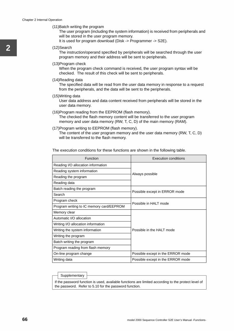
Chapter 2 Internal Operation
2
(11)Batch writing the programThe user program (including the system information) is received from peripherals and will be stored in the user program memory.It is used for program download (Disk -> Programmer -> S2E).
(12)SearchThe instruction/operand specified by peripherals will be searched through the user program memory and their address will be sent to peripherals.
(13)Program checkWhen the program check command is received, the user program syntax will be checked. The result of this check will be sent to peripherals.
(14)Reading dataThe specified data will be read from the user data memory in response to a request from the peripherals, and the data will be sent to the peripherals.
(15)Writing dataUser data address and data content received from peripherals will be stored in the user data memory.
(16)Program reading from the EEPROM (flash memory).The checked the flash memory content will be transferred to the user program memory and user data memory (RW, T, C, D) of the main memory (RAM).
(17)Program writing to EEPROM (flash memory).The content of the user program memory and the user data memory (RW, T, C, D) will be transferred to the flash memory.
The execution conditions for these functions are shown in the following table.
Function Execution conditions
Reading I/O allocation information
Always possibleReading system information
Reading the program
Reading data
Batch reading the programPossible except in ERROR mode
Search
Program checkPossible in HALT mode
Program writing to IC memory card/EEPROM
Memory clear
Possible in the HALT mode
Automatic I/O allocation
Writing I/O allocation information
Writing the system information
Writing the program
Batch writing the program
Program reading from flash memory
On-line program change Possible except in the ERROR mode
Writing data Possible except in the ERROR mode
Supplementary
If the password function is used, available functions are limited according to the protect level of the password. Refer to 5.10 for the password function.
66 model 2000 Sequence Controller S2E User’s Manual -Functions-
6F8C1132
r Programion Control
Chapter 3 UseExecut
3.1 Program types
The S2E can run several different program types in parallel (this function is called the multitask function). This function can be used to realize the optimal response time for each application.
The programs are classified into the 3 types below. There are a total of 14 programs.
• Main program (one)This program will be executed every scan and forms the main part of the scan.
• Sub-programs (4)This program can be activated by other programs. A total of 4 (#1-#4) are provided. (#1 is fixed function)In the floating scan, the sub-program will be executed after the main program execution with time limit (user setting). And in the constant scan, the sub-program will be executed in idle time from completion of the main program execution to the beginning of the next scan.By means of sub-programs, the main program can be used as fast scanning task, and the sub-programs as slow scanning (background) tasks.
• Interrupt programs (9)When the interrupt condition is fulfilled, the S2E will stop other operations and execute the corresponding interrupt program immediately. A total of 5 are provided: one program which starts up at specified intervals (Timer interrupt program), and 8 programs which start up according to interrupt signals from I/O modules with an interrupt function (I/O interrupt programs #1-#8).By means of timer interrupt, time critical control can be achieved, and by means of I/O interrupts, I/O responses can take place without affecting the scan cycle.
The sub-programs and the interrupt programs execution method and the execution conditions are explained in this section.
67
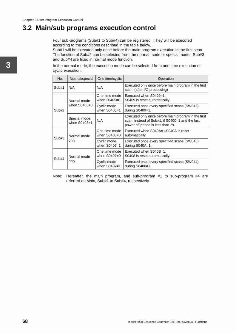
Chapter 3 User Program Execution Control
3
3.2 Main/sub programs execution control
Four sub-programs (Sub#1 to Sub#4) can be registered. They will be executed according to the conditions described in the table below. Sub#1 will be executed only once before the main program execution in the first scan. The function of Sub#2 can be selected from the normal mode or special mode. Sub#3 and Sub#4 are fixed in normal mode function.
In the normal mode, the execution mode can be selected from one time execution or cyclic execution.
Note: Hereafter, the main program, and sub-program #1 to sub-program #4 arereferred as Main, Sub#1 to Sub#4, respectively.
No. Normal/special One time/cyclic Operation
Sub#1 N/A N/AExecuted only once before main program in the first scan. (after I/O processing)
Sub#2
Normal mode when S0403=0
One time mode when 30405=0
Executed when S0409=1.S0409 is reset automatically.
Cyclic mode when S0405=1
Executed once every specified scans (SW042) during S0409=1.
Special mode when S0403=1
N/AExecuted only once before main program in the first scan, instead of Sub#1, if S0400=1 and the last power off period is less than 2s.
Sub#3Normal mode only
One time mode when S0406=0
Executed when S040A=1.S040A is reset automatically.
Cyclic mode when S0406=1
Executed once every specified scans (SW043) during S040A=1.
Sub#4Normal mode only
One time mode when S0407=0
Executed when S040B=1.S0408 is reset automatically.
Cyclic mode when S0407=1
Executed once every specified scans (SW044) during S0408=1.
68 model 2000 Sequence Controller S2E User’s Manual -Functions-
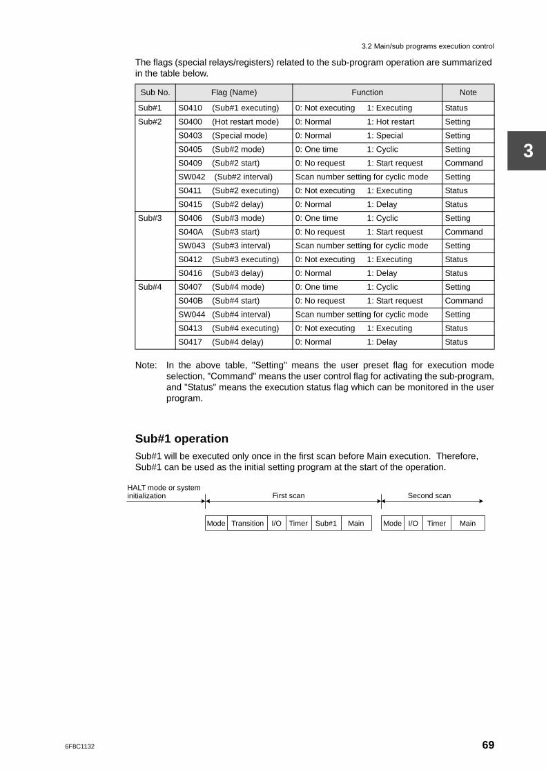
3.2 Main/sub programs execution control
3
The flags (special relays/registers) related to the sub-program operation are summarized in the table below.
Note: In the above table, "Setting" means the user preset flag for execution modeselection, "Command" means the user control flag for activating the sub-program,and "Status" means the execution status flag which can be monitored in the userprogram.
Sub#1 operationSub#1 will be executed only once in the first scan before Main execution. Therefore, Sub#1 can be used as the initial setting program at the start of the operation.
Sub No. Flag (Name) Function Note
Sub#1 S0410 (Sub#1 executing) 0: Not executing 1: Executing Status
Sub#2 S0400 (Hot restart mode) 0: Normal 1: Hot restart Setting
S0403 (Special mode) 0: Normal 1: Special Setting
S0405 (Sub#2 mode) 0: One time 1: Cyclic Setting
S0409 (Sub#2 start) 0: No request 1: Start request Command
SW042 (Sub#2 interval) Scan number setting for cyclic mode Setting
S0411 (Sub#2 executing) 0: Not executing 1: Executing Status
S0415 (Sub#2 delay) 0: Normal 1: Delay Status
Sub#3 S0406 (Sub#3 mode) 0: One time 1: Cyclic Setting
S040A (Sub#3 start) 0: No request 1: Start request Command
SW043 (Sub#3 interval) Scan number setting for cyclic mode Setting
S0412 (Sub#3 executing) 0: Not executing 1: Executing Status
S0416 (Sub#3 delay) 0: Normal 1: Delay Status
Sub#4 S0407 (Sub#4 mode) 0: One time 1: Cyclic Setting
S040B (Sub#4 start) 0: No request 1: Start request Command
SW044 (Sub#4 interval) Scan number setting for cyclic mode Setting
S0413 (Sub#4 executing) 0: Not executing 1: Executing Status
S0417 (Sub#4 delay) 0: Normal 1: Delay Status
First scan Second scan
HALT mode or system initialization
Transition Mode Mode I/O I/O Timer Timer Main Main Sub#1
6F8C1132 69
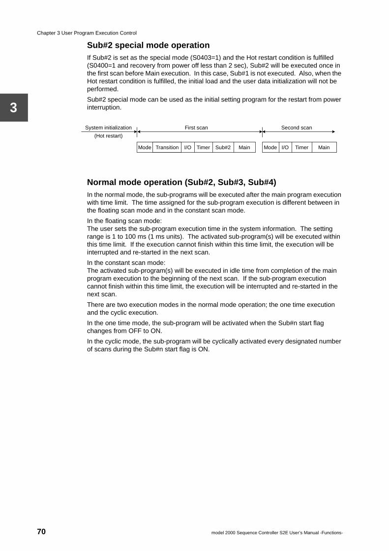
Chapter 3 User Program Execution Control
3
Sub#2 special mode operationIf Sub#2 is set as the special mode (S0403=1) and the Hot restart condition is fulfilled (S0400=1 and recovery from power off less than 2 sec), Sub#2 will be executed once in the first scan before Main execution. In this case, Sub#1 is not executed. Also, when the Hot restart condition is fulfilled, the initial load and the user data initialization will not be performed.
Sub#2 special mode can be used as the initial setting program for the restart from power interruption.
Normal mode operation (Sub#2, Sub#3, Sub#4)In the normal mode, the sub-programs will be executed after the main program execution with time limit. The time assigned for the sub-program execution is different between in the floating scan mode and in the constant scan mode.
In the floating scan mode:The user sets the sub-program execution time in the system information. The setting range is 1 to 100 ms (1 ms units). The activated sub-program(s) will be executed within this time limit. If the execution cannot finish within this time limit, the execution will be interrupted and re-started in the next scan.
In the constant scan mode:The activated sub-program(s) will be executed in idle time from completion of the main program execution to the beginning of the next scan. If the sub-program execution cannot finish within this time limit, the execution will be interrupted and re-started in the next scan.
There are two execution modes in the normal mode operation; the one time execution and the cyclic execution.
In the one time mode, the sub-program will be activated when the Sub#n start flag changes from OFF to ON.
In the cyclic mode, the sub-program will be cyclically activated every designated number of scans during the Sub#n start flag is ON.
First scan Second scan System initialization
(Hot restart)
Transition Mode Mode I/O I/O Timer Timer Main Main Sub#2
70 model 2000 Sequence Controller S2E User’s Manual -Functions-
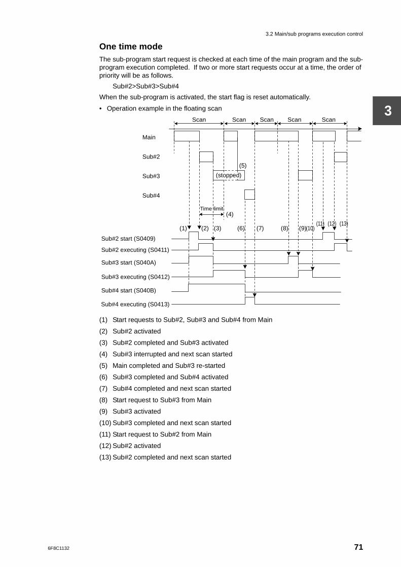
3.2 Main/sub programs execution control
3
One time modeThe sub-program start request is checked at each time of the main program and the sub-program execution completed. If two or more start requests occur at a time, the order of priority will be as follows.
Sub#2>Sub#3>Sub#4
When the sub-program is activated, the start flag is reset automatically.
• Operation example in the floating scan
(1) Start requests to Sub#2, Sub#3 and Sub#4 from Main
(2) Sub#2 activated
(3) Sub#2 completed and Sub#3 activated
(4) Sub#3 interrupted and next scan started
(5) Main completed and Sub#3 re-started
(6) Sub#3 completed and Sub#4 activated
(7) Sub#4 completed and next scan started
(8) Start request to Sub#3 from Main
(9) Sub#3 activated
(10) Sub#3 completed and next scan started
(11) Start request to Sub#2 from Main
(12) Sub#2 activated
(13) Sub#2 completed and next scan started
Sub#4 executing (S0413)
Main
Sub#2
Sub#3
Sub#4
Sub#2 start (S0409)
Sub#2 executing (S0411)
Sub#3 start (S040A)
Sub#3 executing (S0412)
Sub#4 start (S040B)
Time limit
(5)
(6) (7) (1) (2)
(4)
(8) (9) (10) (11) (12) (13)
(3)
Scan Scan Scan Scan Scan
(stopped)
6F8C1132 71
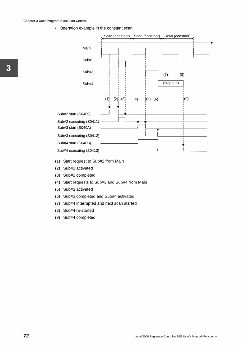
Chapter 3 User Program Execution Control
3
• Operation example in the constant scan
(1) Start request to Sub#2 from Main
(2) Sub#2 activated
(3) Sub#2 completed
(4) Start requests to Sub#3 and Sub#4 from Main
(5) Sub#3 activated
(6) Sub#3 completed and Sub#4 activated
(7) Sub#4 interrupted and next scan started
(8) Sub#4 re-started
(9) Sub#4 completed
Sub#4 executing (S0413)
Main
Sub#2
Sub#3
Sub#4
Sub#2 start (S0409)
Sub#2 executing (S0411)
Sub#3 start (S040A)
Sub#3 executing (S0412)
Sub#4 start (S040B)
Scan (constant)
(5) (6)
(7)
(1) (2) (4)
(8)
(9) (3)
Scan (constant) Scan (constant)
(stopped)
72 model 2000 Sequence Controller S2E User’s Manual -Functions-
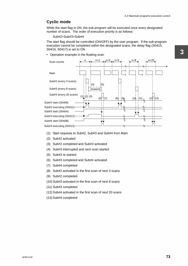
3.2 Main/sub programs execution control
3
Cyclic modeWhile the start flag is ON, the sub-program will be executed once every designated number of scans. The order of execution priority is as follows:
Sub#2>Sub#3>Sub#4
The start flag should be controlled (ON/OFF) by the user program. If the sub-program execution cannot be completed within the designated scans, the delay flag (S0415, S0416, S0417) is set to ON.
• Operation example in the floating scan
(1) Start requests to Sub#2, Sub#3 and Sub#4 from Main
(2) Sub#2 activated
(3) Sub#2 completed and Sub#3 activated
(4) Sub#3 interrupted and next scan started
(5) Sub#3 re-started
(6) Sub#3 completed and Sub#4 activated
(7) Sub#4 completed
(8) Sub#2 activated in the first scan of next 3 scans
(9) Sub#2 completed
(10) Sub#3 activated in the first scan of next 8 scans
(11) Sub#3 completed
(12) Sub#4 activated in the first scan of next 20 scans
(13) Sub#4 completed
Sub#4 executing (S0413)
Scan counts
Main
Sub#2 (every 3 scans)
Sub#3 (every 8 scans)
Sub#4 (every 20 scans)
Sub#2 start (S0409)
Sub#2 executing (S0411)
Sub#3 start (S040A)
Sub#3 executing (S0412)
Sub#4 start (S040B)
n
(5)
(6) (7) (1) (2)
(4)
(8) (9) (10) (11) (12) (13) (3)
n+1 n+2 n+3 n+20
(stopped)
n+8
6F8C1132 73
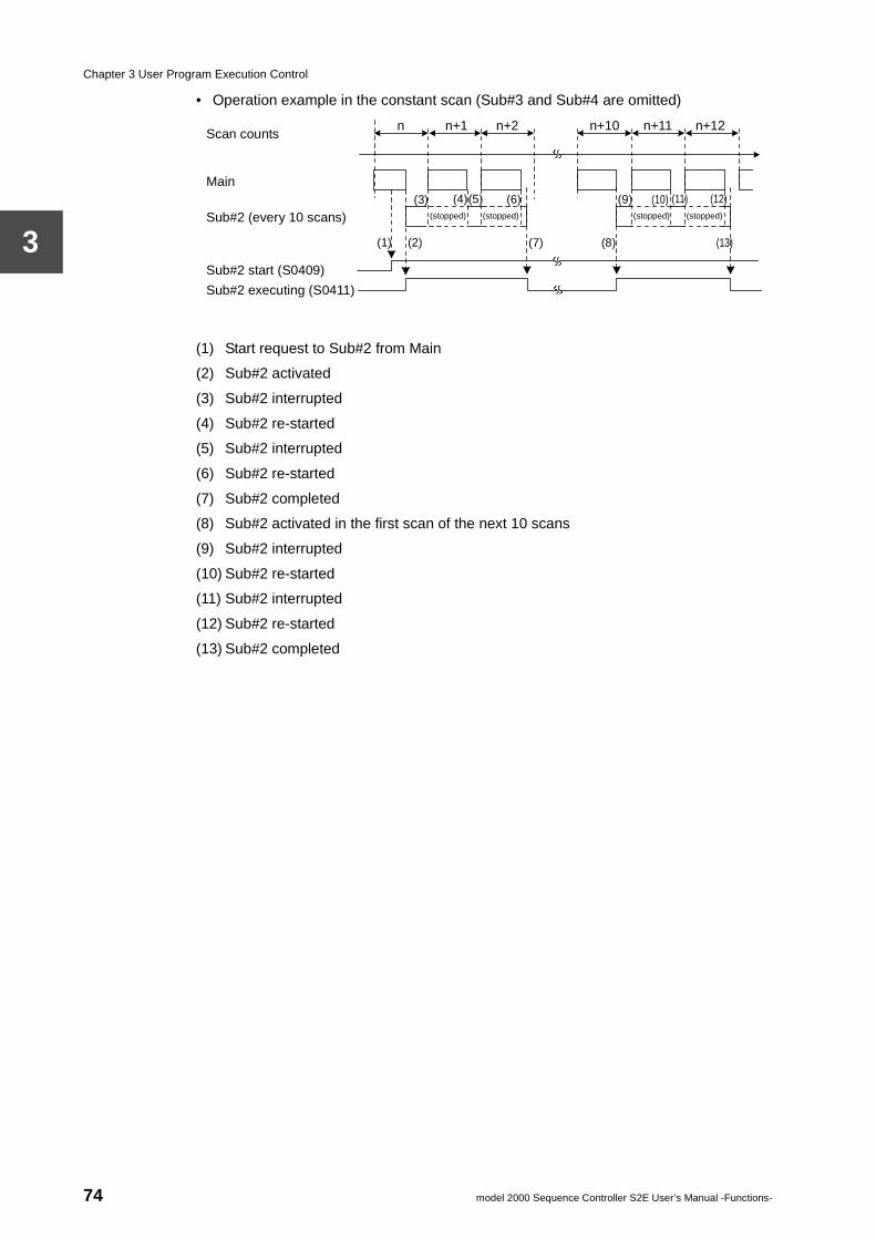
Chapter 3 User Program Execution Control
3
• Operation example in the constant scan (Sub#3 and Sub#4 are omitted)
(1) Start request to Sub#2 from Main
(2) Sub#2 activated
(3) Sub#2 interrupted
(4) Sub#2 re-started
(5) Sub#2 interrupted
(6) Sub#2 re-started
(7) Sub#2 completed
(8) Sub#2 activated in the first scan of the next 10 scans
(9) Sub#2 interrupted
(10) Sub#2 re-started
(11) Sub#2 interrupted
(12) Sub#2 re-started
(13) Sub#2 completed
Scan counts
Main
Sub#2 (every 10 scans)
Sub#2 start (S0409)
Sub#2 executing (S0411)
n
(5) (6)
(7) (1) (2)
(4)
(8)
(9) (10) (11) (12) (3)
n+1 n+2 n+10 n+12
(stopped)
n+11
(stopped) (stopped) (stopped)
(13)
74 model 2000 Sequence Controller S2E User’s Manual -Functions-
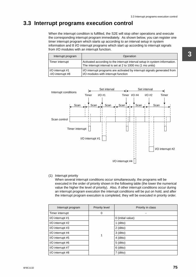
3.3 Interrupt programs execution control
3
3.3 Interrupt programs execution control
When the interrupt condition is fulfilled, the S2E will stop other operations and execute the corresponding interrupt program immediately. As shown below, you can register one timer interrupt program which starts up according to an interval setup in system information and 8 I/O interrupt programs which start up according to interrupt signals from I/O modules with an interrupt function.
(1) Interrupt priorityWhen several interrupt conditions occur simultaneously, the programs will be executed in the order of priority shown in the following table (the lower the numerical value the higher the level of priority). Also, if other interrupt conditions occur during an interrupt program execution the interrupt conditions will be put on hold, and after the interrupt program execution is completed, they will be executed in priority order.
Interrupt program Operation
Timer interrupt Activated according to the interrupt interval setup in system information. The interrupt interval is set at 2 to 1000 ms (1 ms units)
I/O interrupt #1-I/O interrupt #8
I/O interrupt programs are activated by interrupt signals generated from I/O modules with interrupt function
Interrupt program Priority level Priority in class
Timer interrupt 0 −
I/O interrupt #1
1
0 (initial value)
I/O interrupt #2 1 (ditto)
I/O interrupt #3 2 (ditto)
I/O interrupt #4 3 (ditto)
I/O interrupt #5 4 (ditto)
I/O interrupt #6 5 (ditto)
I/O interrupt #7 6 (ditto)
I/O interrupt #8 7 (ditto)
Scan
Timer
Scan Scan Scan Scan Scan
Scan control
Timer
Set interval Set interval
I/O #1 Timer I/O #4 I/O #2 Interrupt conditions
Timer interrupt
I/O interrupt #1
I/O interrupt #4
I/O interrupt #2
6F8C1132 75
Chapter 3 User Program Execution Control
3
The timer interrupt has the highest level of priority, followed by the I/O interrupt programs in order.With respect to the level of priority for I/O interrupt, the I/O interrupt from the module nearest the CPU has the highest level of priority. Refer to (3) below regarding the correspondence between interrupt programs and I/O modules.
(2) Interrupt enable/disableYou can switch between interrupt disable and enable by using the Dl instruction (interrupt disable) and El instruction (interrupt enable). By executing the Dl instruction, the interrupt conditions which occur during interrupt disable mode will be put on hold; these will be then executed instantly when the interrupt enable mode is entered by executing the El instruction. (DI and El should be used in a pair) Also, in transition to RUN mode, the interrupt will be disabled in the first scan. It will be enabled automatically from the second scan.
(3) Allocation of I/O interrupt programThe I/O interrupt with the lowest number corresponds to the I/O module with interrupt function nearest the CPU, in the initial state. This allocation can be changed. See Part 3 Section 2.3.3.There are no restrictions on the mounting position of I/O modules with the interrupt function.
Supplementary
The I/O interrupt response time (from the time interrupt conditions arise until interrupt program starts up), with normal interrupt enable and no other interrupt program started up, is an instruction execution time +500 µs in worst case.
76 model 2000 Sequence Controller S2E User’s Manual -Functions-
6F8C1132
al Memoryt Functions
Chapter 4 PeripherSuppor
4.1 Flash Memory (EEPROM) support
The contents of the user program and the register data can be stored in the flash memory. They can be read into the main memory (RAM) by the initial load function or programmer operation. Also, the data registers (D) stored in the flash memory can be accessed from the user program. Flash memory makes it possible to run without battery, and recovery is easy in the event of a program being destroyed.
The following functions are available with EEPROM.
Function Details Conditions
Program write into flash memory
Writes the contents of the user program (including the system information) and the data registers (D), the timer registers (T), the counter registers (C) and the auxiliary relay registers(RW) in the main memory (RAM) into the flash memory.
Performed by the ’Program write (RAM -> IC card/ EEPROM)’ command from the programmer in the following state.• HALT mode
Program read from flash memory
Transfers the contents of the flash memory to the user program memory, the data registers (D), the timer registers (T), the counter registers (C), and the auxiliary relay registers (RW) in the main memory (RAM).
Performed by the ’Program read (RAM <- IC card/ EEPROM)’ command from the programmer in the following state.• HALT mode
Initial load Transfers the contents of the flash memory to the user program memory and the leading 4 k words of the data registers (D0000 to D4095) in the main memory (RAM).
At system initialization:
• RAM/ROM switch is in ROM
At transition to RUN mode:• RAM/ROM switch is in ROM• Mode switch is in RUN
Read/write the data registers in flash memory
Reads the data of data registers in flash memory and stores in the main memory by user program. Writes the specified data of the main memory into the data registers in flash memory by user program.
Accessed by Expanded data transfer instruction (XFER)
Supplementary
1. Refer to 2.2, System Initialization and 2.4, Scan Control, with respect to the initial load function.
2. The number of times the flash memory can be written will be limited by the hardware to 100,000 times. The S2E counts the number of times the flash memory write is performed. If the 100,000 times is exceeded, the flash memory alarm flag (S0007) will come ON. However, this checking is not effective for data writing by XFER instruction. It is recommended to check it by user program for the XFER instruction.
77

6F8C1132
Functions
Chapter 5 RAS5.1 Overview
The meaning of RAS is Reliability, Availability and Serviceability. The RAS function is the general term used for the functions installed in the S2E which increase the reliability and serviceability of the applied systems and support the operation of the system.
This section explains the self-diagnostic functions, maintenance functions, the debugging functions installed in the S2E, and the system diagnostic function which can be used by the S2E user.
79
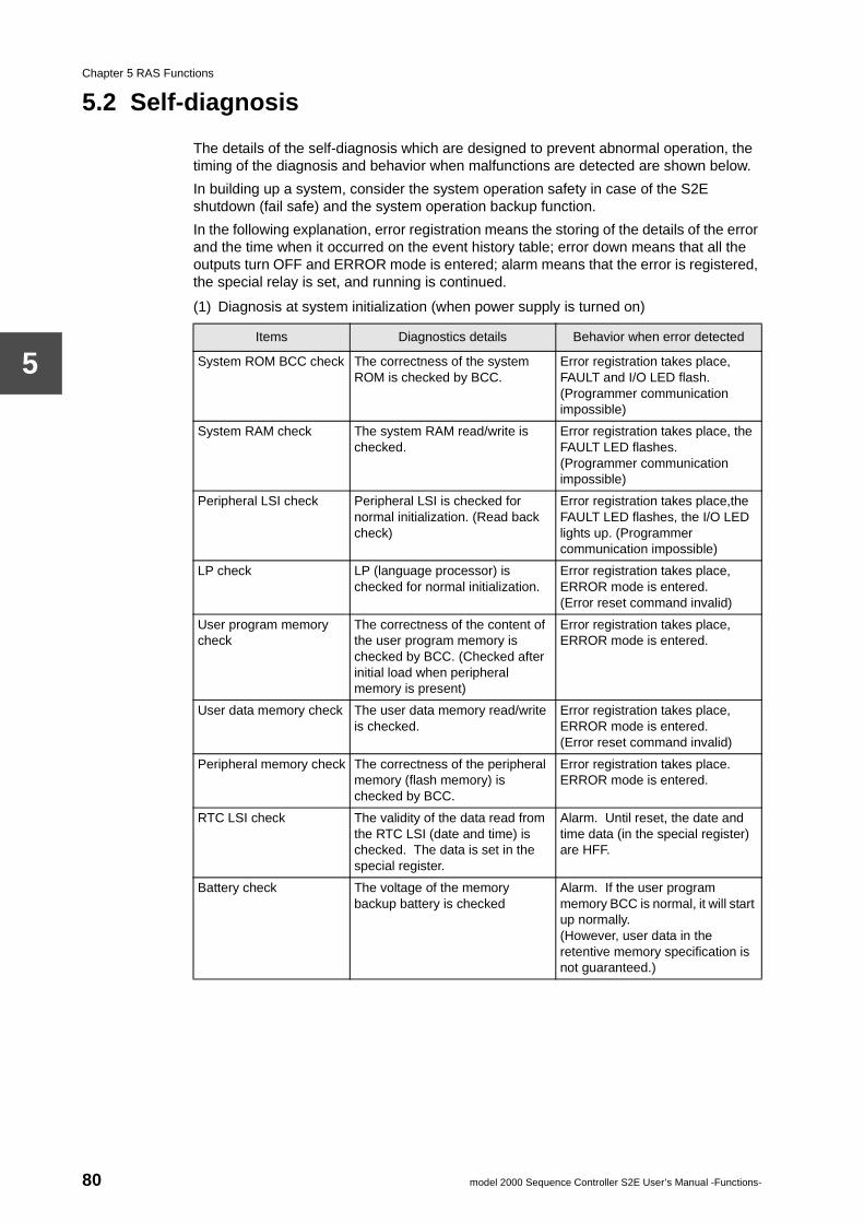
Chapter 5 RAS Functions
5
5.2 Self-diagnosis
The details of the self-diagnosis which are designed to prevent abnormal operation, the timing of the diagnosis and behavior when malfunctions are detected are shown below.
In building up a system, consider the system operation safety in case of the S2E shutdown (fail safe) and the system operation backup function.
In the following explanation, error registration means the storing of the details of the error and the time when it occurred on the event history table; error down means that all the outputs turn OFF and ERROR mode is entered; alarm means that the error is registered, the special relay is set, and running is continued.
(1) Diagnosis at system initialization (when power supply is turned on)
Items Diagnostics details Behavior when error detected
System ROM BCC check The correctness of the system ROM is checked by BCC.
Error registration takes place, FAULT and I/O LED flash.(Programmer communication impossible)
System RAM check The system RAM read/write is checked.
Error registration takes place, the FAULT LED flashes.(Programmer communication impossible)
Peripheral LSI check Peripheral LSI is checked for normal initialization. (Read back check)
Error registration takes place,the FAULT LED flashes, the I/O LED lights up. (Programmer communication impossible)
LP check LP (language processor) is checked for normal initialization.
Error registration takes place, ERROR mode is entered.(Error reset command invalid)
User program memory check
The correctness of the content of the user program memory is checked by BCC. (Checked after initial load when peripheral memory is present)
Error registration takes place, ERROR mode is entered.
User data memory check The user data memory read/write is checked.
Error registration takes place, ERROR mode is entered.(Error reset command invalid)
Peripheral memory check The correctness of the peripheral memory (flash memory) is checked by BCC.
Error registration takes place. ERROR mode is entered.
RTC LSI check The validity of the data read from the RTC LSI (date and time) is checked. The data is set in the special register.
Alarm. Until reset, the date and time data (in the special register) are HFF.
Battery check The voltage of the memory backup battery is checked
Alarm. If the user program memory BCC is normal, it will start up normally.(However, user data in the retentive memory specification is not guaranteed.)
80 model 2000 Sequence Controller S2E User’s Manual -Functions-
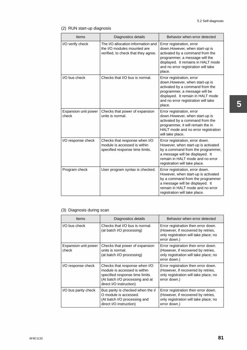
5.2 Self-diagnosis
5
(2) RUN start-up diagnosis
(3) Diagnosis during scan
Items Diagnostics details Behavior when error detected
I/O verify check The I/O allocation information and the I/O modules mounted are verified, to check that they agree.
Error registration, error down.However, when start-up is activated by a command from the programmer, a message will the displayed. It remains in HALT mode and no error registration will take place.
I/O bus check Checks that I/O bus is normal. Error registration, error down.However, when start-up is activated by a command from the programmer, a message will be displayed. It remain in HALT mode and no error registration will take place.
Expansion unit power check
Checks that power of expansion units is normal.
Error registration, error down.However, when start-up is activated by a command from the programmer, it will remain the in HALT mode and no error registration will take place.
I/O response check Checks that response when I/O module is accessed is within specified response time limits.
Error registration, error down.However, when start-up is activated by a command from the programmer, a message will be displayed. It remain in HALT mode and no error registration will take place.
Program check User program syntax is checked. Error registration, error down.However, when start-up is activated by a command from the programmer a message will be displayed. It remain in HALT mode and no error registration will take place.
Items Diagnostics details Behavior when error detected
I/O bus check Checks that I/O bus is normal.(at batch I/O processing)
Error registration then error down.(However, if recovered by retries, only registration will take place; no error down.)
Expansion unit power check
Checks that power of expansion units is normal.(at batch I/O processing)
Error registration then error down.(However, if recovered by retries, only registration will take place; no error down.)
I/O response check Checks that response when I/O module is accessed is within specified response time limits.(At batch I/O processing and at direct I/O instruction)
Error registration then error down.(However, if recovered by retries, only registration will take place; no error down.)
I/O bus parity check Bus parity is checked when the I/O module is accessed.(At batch I/O processing and direct I/O instruction)
Error registration then error down.(However, if recovered by retries, only registration will take place; no error down.)
6F8C1132 81
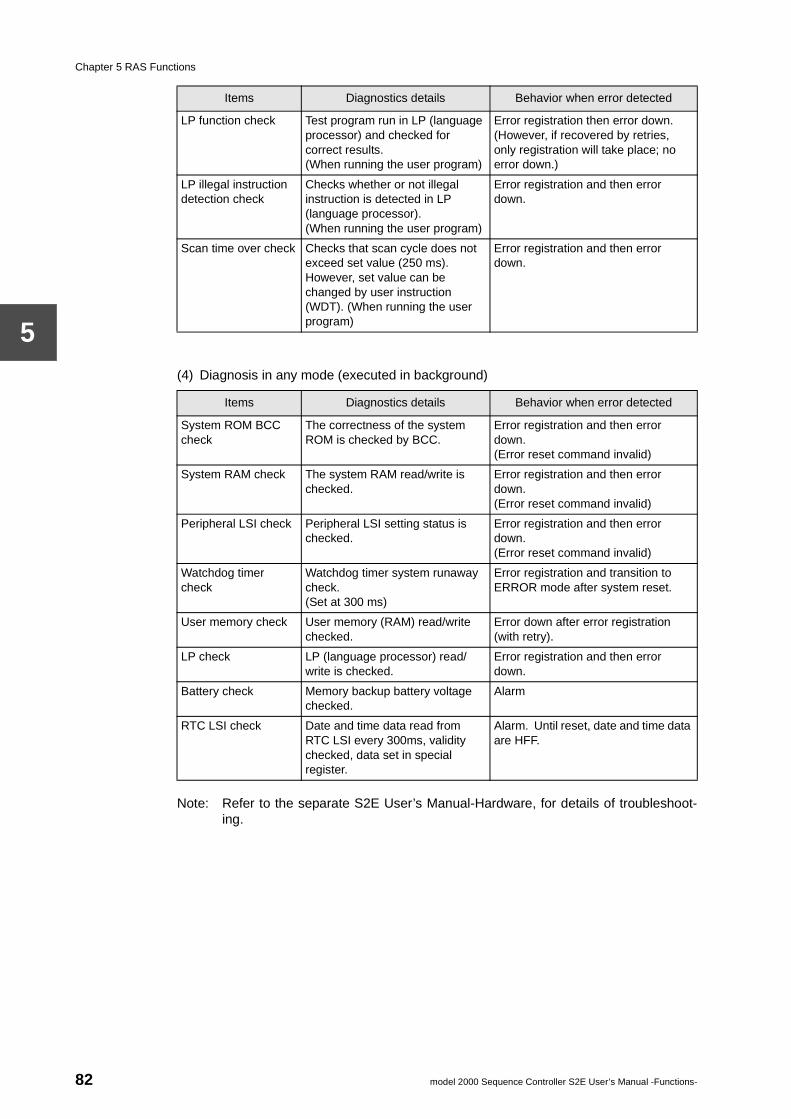
Chapter 5 RAS Functions
5
(4) Diagnosis in any mode (executed in background)Note: Refer to the separate S2E User’s Manual-Hardware, for details of troubleshoot-ing.
LP function check Test program run in LP (language processor) and checked for correct results.(When running the user program)
Error registration then error down.(However, if recovered by retries, only registration will take place; no error down.)
LP illegal instruction detection check
Checks whether or not illegal instruction is detected in LP (language processor).(When running the user program)
Error registration and then error down.
Scan time over check Checks that scan cycle does not exceed set value (250 ms).However, set value can be changed by user instruction (WDT). (When running the user program)
Error registration and then error down.
Items Diagnostics details Behavior when error detected
System ROM BCC check
The correctness of the system ROM is checked by BCC.
Error registration and then error down.(Error reset command invalid)
System RAM check The system RAM read/write is checked.
Error registration and then error down.(Error reset command invalid)
Peripheral LSI check Peripheral LSI setting status is checked.
Error registration and then error down.(Error reset command invalid)
Watchdog timer check
Watchdog timer system runaway check.(Set at 300 ms)
Error registration and transition to ERROR mode after system reset.
User memory check User memory (RAM) read/write checked.
Error down after error registration (with retry).
LP check LP (language processor) read/write is checked.
Error registration and then error down.
Battery check Memory backup battery voltage checked.
Alarm
RTC LSI check Date and time data read from RTC LSI every 300ms, validity checked, data set in special register.
Alarm. Until reset, date and time data are HFF.
Items Diagnostics details Behavior when error detected
82 model 2000 Sequence Controller S2E User’s Manual -Functions-
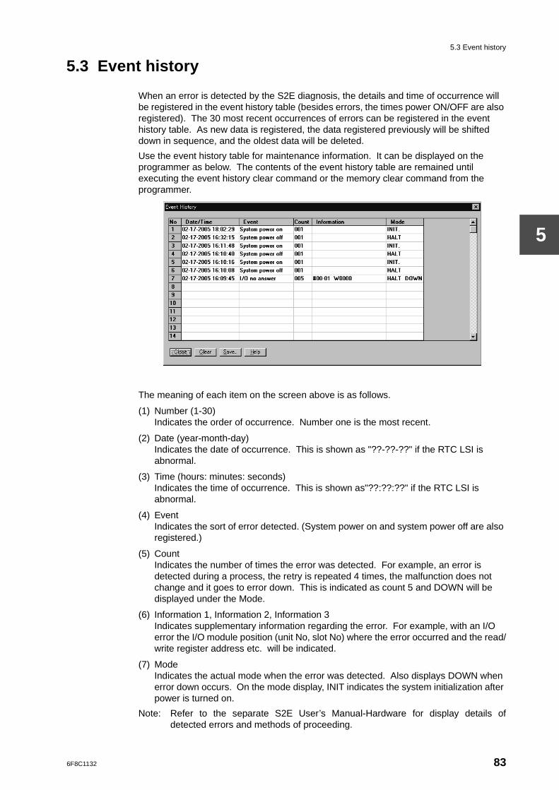
5.3 Event history
5
5.3 Event history
When an error is detected by the S2E diagnosis, the details and time of occurrence will be registered in the event history table (besides errors, the times power ON/OFF are also registered). The 30 most recent occurrences of errors can be registered in the event history table. As new data is registered, the data registered previously will be shifted down in sequence, and the oldest data will be deleted.
Use the event history table for maintenance information. It can be displayed on the programmer as below. The contents of the event history table are remained until executing the event history clear command or the memory clear command from the programmer.
The meaning of each item on the screen above is as follows.
(1) Number (1-30)Indicates the order of occurrence. Number one is the most recent.
(2) Date (year-month-day)Indicates the date of occurrence. This is shown as "??-??-??" if the RTC LSI is abnormal.
(3) Time (hours: minutes: seconds)Indicates the time of occurrence. This is shown as"??:??:??" if the RTC LSI is abnormal.
(4) EventIndicates the sort of error detected. (System power on and system power off are also registered.)
(5) CountIndicates the number of times the error was detected. For example, an error is detected during a process, the retry is repeated 4 times, the malfunction does not change and it goes to error down. This is indicated as count 5 and DOWN will be displayed under the Mode.
(6) Information 1, Information 2, Information 3Indicates supplementary information regarding the error. For example, with an I/O error the I/O module position (unit No, slot No) where the error occurred and the read/write register address etc. will be indicated.
(7) ModeIndicates the actual mode when the error was detected. Also displays DOWN when error down occurs. On the mode display, INIT indicates the system initialization after power is turned on.
Note: Refer to the separate S2E User’s Manual-Hardware for display details ofdetected errors and methods of proceeding.
6F8C1132 83
Chapter 5 RAS Functions
5
5.4 Power interruption detection function
The S2E has one function that control the S2E’s operation in the event of power interruption. That is the hot restart function which enables the restart from the power interruption without initialization.
5.4.1 Hot restart function
For the S2E, the user can decide the operation re-start condition at the recovery from the power interruption.
The hot restart function will be effective when the special relay S0400 is set to ON (S0400=1). In this case, if power is turned off in the RUN mode and recovered within 2 seconds, the S2E moves into RUN mode without the initial load and the user data initialization.
By using this function together with the special mode of the sub-program #2, the user can decide the operation re-start condition as follows:
Interruption time Re-start condition Method
Longer than 2 seconds
Re-start after the normal initialization −
Within 2 seconds Re-start after the normal initialization Do not use the hot restart function (S0400=0)
Re-start after setting the prespecified data into registers/devices
Use sub-program #2 as special mode to set prespecified data
Re-start after setting the data according to input status
Use sub-program #2 as special mode to set data according to input status
Re-start without any initialization (hot restart)
Do not use sub-program #2 special mode
Supplementary
1. When power interruption is longer than 2 seconds, normal initialization will be carried out even if S0400 is ON.
2. The hot restart function is also available by using the programmer’s System Diagnosis menu in addition to setting S0400 to ON.
84 model 2000 Sequence Controller S2E User’s Manual -Functions-
5.5 Execution status monitoring
5
5.5 Execution status monitoring
The following functions are served by the S2E for user to monitor the S2E execution status. (Refer to separate manuals for the programmer for operation of these.)
(1) Execution time measurement functionMeasures the following execution times. This data can be monitored on the programmer.
• Scan cyclecurrent value, maximum value, minimum value (1 ms units)
• Main program execution timecurrent value, maximum value, minimum value (1 ms units)
• Sub-program execution time (Sub#1-#4)current value, maximum value, minimum value (1 ms units)
• Timer interrupt execution timelatest value, maximum value, minimum value (0.1 ms units)
• I/O interrupt execution time (I/O #1-#8)latest value, maximum value, minimum value (0.1 ms units)
(2) Online trace functionThis function traces the status during program execution and displays on the programmer screen (power flow display, register value display). Since this displays data from the paint in time that the instruction is executed rather than at the end of a scan cycle, it is useful for program debugging.
Supplementary
1. The scan cycle value includes the scan overhead and all interrupts occurring during the scan.
2. With the main program and the sub-program execution times the interrupt time for any interrupts occurring are excluded.
6F8C1132 85
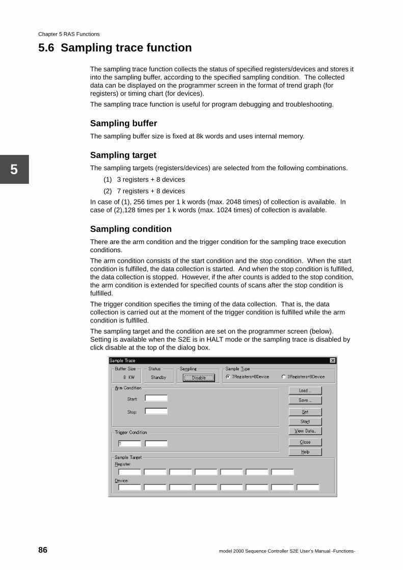
Chapter 5 RAS Functions
5
5.6 Sampling trace function
The sampling trace function collects the status of specified registers/devices and stores it into the sampling buffer, according to the specified sampling condition. The collected data can be displayed on the programmer screen in the format of trend graph (for registers) or timing chart (for devices).
The sampling trace function is useful for program debugging and troubleshooting.
Sampling bufferThe sampling buffer size is fixed at 8k words and uses internal memory.
Sampling targetThe sampling targets (registers/devices) are selected from the following combinations.
(1) 3 registers + 8 devices
(2) 7 registers + 8 devices
In case of (1), 256 times per 1 k words (max. 2048 times) of collection is available. In case of (2),128 times per 1 k words (max. 1024 times) of collection is available.
Sampling conditionThere are the arm condition and the trigger condition for the sampling trace execution conditions.
The arm condition consists of the start condition and the stop condition. When the start condition is fulfilled, the data collection is started. And when the stop condition is fulfilled, the data collection is stopped. However, if the after counts is added to the stop condition, the arm condition is extended for specified counts of scans after the stop condition is fulfilled.
The trigger condition specifies the timing of the data collection. That is, the data collection is carried out at the moment of the trigger condition is fulfilled while the arm condition is fulfilled.
The sampling target and the condition are set on the programmer screen (below). Setting is available when the S2E is in HALT mode or the sampling trace is disabled by click disable at the top of the dialog box.
86 model 2000 Sequence Controller S2E User’s Manual -Functions-
5.6 Sampling trace function
5
The sampling trace is executed when it is enabled by click enable at the top of the dialog box.
Supplementary
The sampling trace can also be started/stopped by manually without setting the arm condition. Click "Start" and click "Stop" are used.
6F8C1132 87
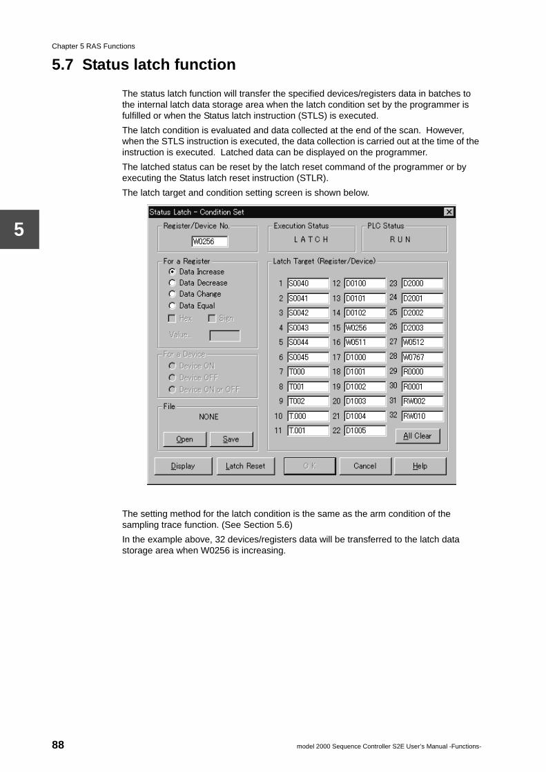
Chapter 5 RAS Functions
5
5.7 Status latch function
The status latch function will transfer the specified devices/registers data in batches to the internal latch data storage area when the latch condition set by the programmer is fulfilled or when the Status latch instruction (STLS) is executed.
The latch condition is evaluated and data collected at the end of the scan. However, when the STLS instruction is executed, the data collection is carried out at the time of the instruction is executed. Latched data can be displayed on the programmer.
The latched status can be reset by the latch reset command of the programmer or by executing the Status latch reset instruction (STLR).
The latch target and condition setting screen is shown below.
The setting method for the latch condition is the same as the arm condition of the sampling trace function. (See Section 5.6)
In the example above, 32 devices/registers data will be transferred to the latch data storage area when W0256 is increasing.
88 model 2000 Sequence Controller S2E User’s Manual -Functions-
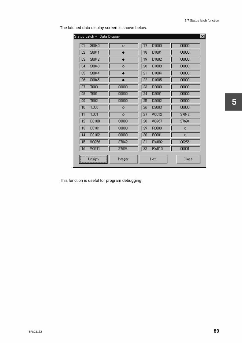
5.7 Status latch function
5
The latched data display screen is shown below.
This function is useful for program debugging.
6F8C1132 89
Chapter 5 RAS Functions
5
5.8 Debug support function
The following functions are supported by S2E for effective program debugging.
(Refer to separate manuals for programmers for operation of these.)
5.8.1 Force function
There are two functions in the force function, input force and coil force. Batch input data is not updated in the input force specified register/device. The registers/devices which can be specified for forced input are the input register/device (XW/X), link register/relay (W/Z) in the receiver area and link register/relay (LW/L) in the receiver area. On the other hand, coil force specified coil instruction can not be processed when the program is running, so despite the state of the program, the coil device maintains its previous state.
Simulated input and simulated output are made possible by the combined use of the force function and the data setting function.
5.8.2 Online program changing function
This function enables to change the user program online (during RUN). The changes are made after completion of one scan, so it extends the inter-scan cycle.
Online program change is subject to the following conditions.
• You cannot make changes to the number or order of execution control instructions (below).END, MCS, MCR, JOS, JCR, JUMP, LBL, FOR, NEXT, CALL, SUBR, RET, IRET
• You cannot change the SFC structure in the SFC program section, but you can change the detail parts (ladder diagram) which relate to steps and transitions.
Also, there is the constant operand changing function.This function enables to change the constant operand, such as timer/counter preset value and constant data used in function instructions, online (during RUN). For the timer/counter presets, changing is possible even in the memory protect state (P-RUN).
Caution
When using the online program changing function, pay attention for safety.If changed rung contains a transition-sensing type instruction (below), the instruction will be executed at the online changing if the input condition is ON, because the input condition of last scan is initialized. Pay attention for this point.
, , , Edged function instructions. P P
90 model 2000 Sequence Controller S2E User’s Manual -Functions-
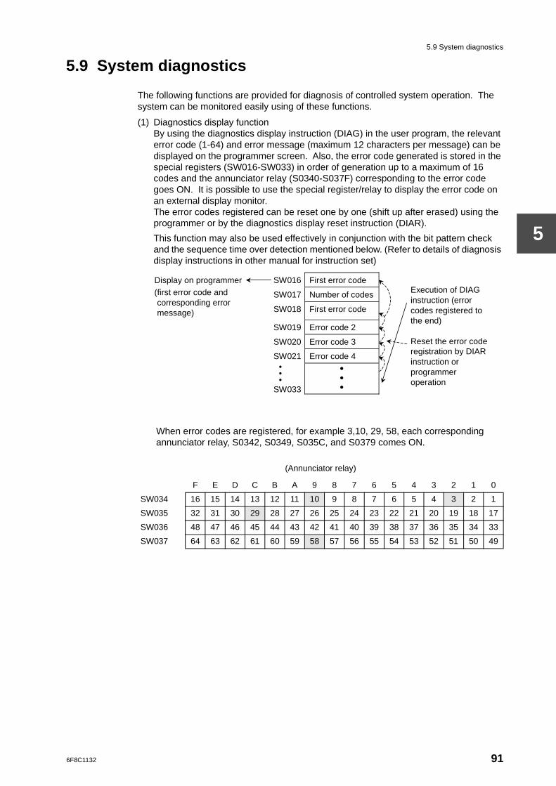
5.9 System diagnostics
5
5.9 System diagnostics
The following functions are provided for diagnosis of controlled system operation. The system can be monitored easily using of these functions.
(1) Diagnostics display functionBy using the diagnostics display instruction (DIAG) in the user program, the relevant error code (1-64) and error message (maximum 12 characters per message) can be displayed on the programmer screen. Also, the error code generated is stored in the special registers (SW016-SW033) in order of generation up to a maximum of 16 codes and the annunciator relay (S0340-S037F) corresponding to the error code goes ON. It is possible to use the special register/relay to display the error code on an external display monitor.The error codes registered can be reset one by one (shift up after erased) using the programmer or by the diagnostics display reset instruction (DIAR).
This function may also be used effectively in conjunction with the bit pattern check and the sequence time over detection mentioned below. (Refer to details of diagnosis display instructions in other manual for instruction set)
When error codes are registered, for example 3,10, 29, 58, each corresponding annunciator relay, S0342, S0349, S035C, and S0379 comes ON.
(Annunciator relay)
F E D C B A 9 8 7 6 5 4 3 2 1 0
SW034 16 15 14 13 12 11 10 9 8 7 6 5 4 3 2 1
SW035 32 31 30 29 28 27 26 25 24 23 22 21 20 19 18 17
SW036 48 47 46 45 44 43 42 41 40 39 38 37 36 35 34 33
SW037 64 63 62 61 60 59 58 57 56 55 54 53 52 51 50 49
SW016 First error code
SW017 Number of codes
Display on programmer (first error code and corresponding error message) SW018 First error code
SW019 Error code 2
SW020 Error code 3
SW021 Error code 4
•• •
SW033
• • •
Execution of DIAG instruction (error codes registered to the end) Reset the error code registration by DIAR instruction or programmer operation
6F8C1132 91
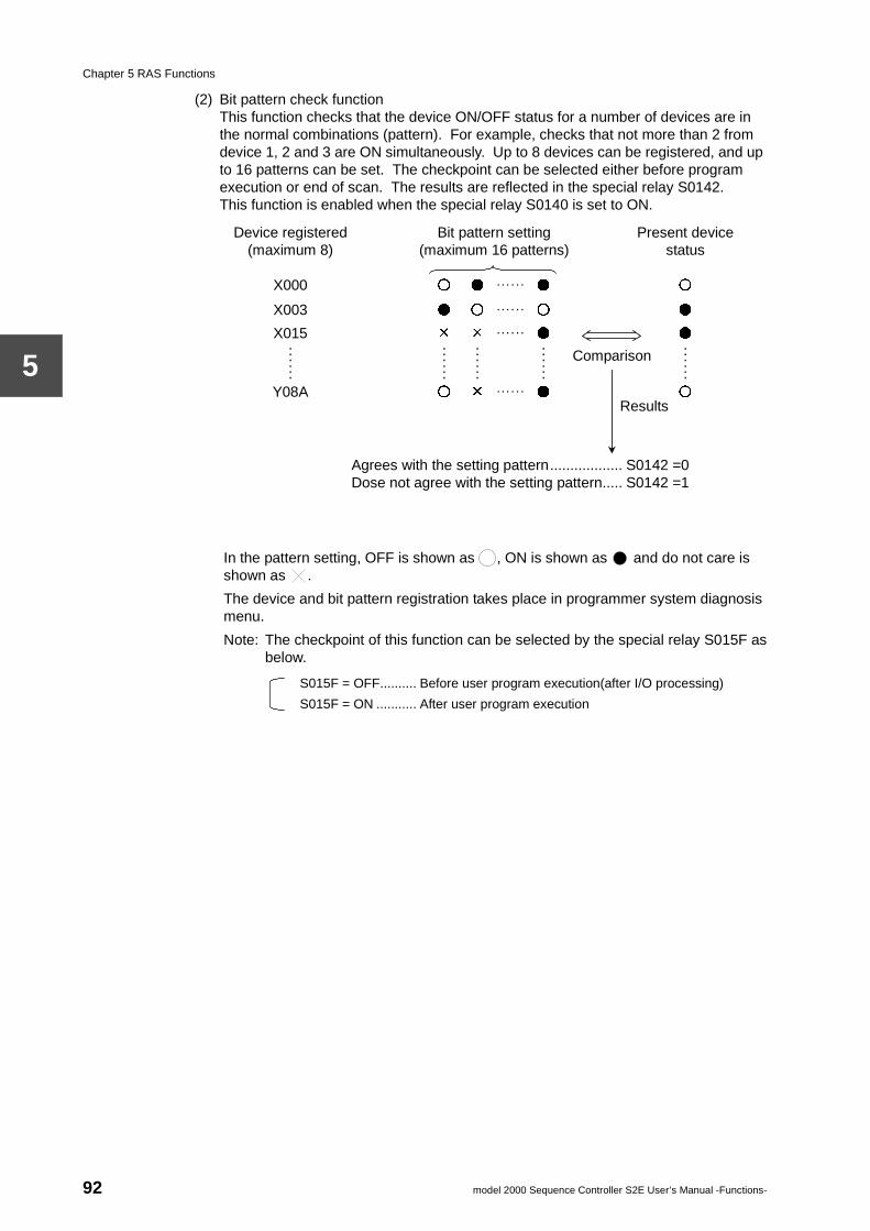
Chapter 5 RAS Functions
5
(2) Bit pattern check functionThis function checks that the device ON/OFF status for a number of devices are in the normal combinations (pattern). For example, checks that not more than 2 from device 1, 2 and 3 are ON simultaneously. Up to 8 devices can be registered, and up to 16 patterns can be set. The checkpoint can be selected either before program execution or end of scan. The results are reflected in the special relay S0142.This function is enabled when the special relay S0140 is set to ON.
In the pattern setting, OFF is shown as , ON is shown as and do not care is shown as .
The device and bit pattern registration takes place in programmer system diagnosis menu.
Note: The checkpoint of this function can be selected by the special relay S015F asbelow.
S015F = OFF.......... Before user program execution(after I/O processing)
S015F = ON ........... After user program execution
Device registered (maximum 8)
Bit pattern setting (maximum 16 patterns)
Present device status
X000 ○ ● . . . . . . ● ○
X003 ● ○ . . . . . . ○ ●
X015 × × . . . . . . ● ● . . . . . .
. . . . . .
. . . . . .
. . . . . .
. . . . . . Y08A ○ × . . . . . . ● ○
Agrees with the setting pattern.................. S0142 =0 Dose not agree with the setting pattern..... S0142 =1
Comparison
Results
92 model 2000 Sequence Controller S2E User’s Manual -Functions-
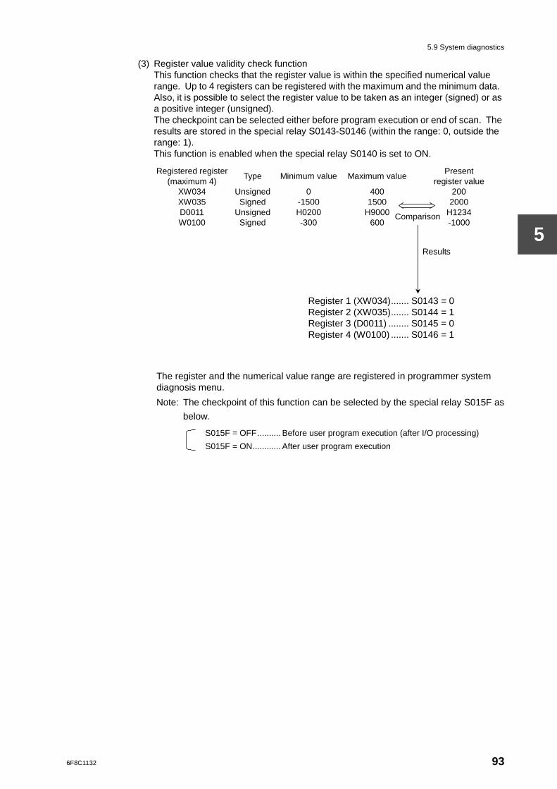
5.9 System diagnostics
5
(3) Register value validity check functionThis function checks that the register value is within the specified numerical value range. Up to 4 registers can be registered with the maximum and the minimum data. Also, it is possible to select the register value to be taken as an integer (signed) or as a positive integer (unsigned).The checkpoint can be selected either before program execution or end of scan. The results are stored in the special relay S0143-S0146 (within the range: 0, outside the range: 1).This function is enabled when the special relay S0140 is set to ON.
The register and the numerical value range are registered in programmer system diagnosis menu.
Note: The checkpoint of this function can be selected by the special relay S015F as
below.
S015F = OFF.......... Before user program execution (after I/O processing)
S015F = ON............ After user program execution
Registered register (maximum 4)
Type Minimum value Maximum value Present
register value XW034 XW035 D0011 W0100
Unsigned Signed
Unsigned Signed
0 -1500 H0200 -300
400 1500
H9000 600
200 2000
H1234 -1000
Register 1 (XW034)....... S0143 = 0 Register 2 (XW035)....... S0144 = 1 Register 3 (D0011) ........ S0145 = 0 Register 4 (W0100) ....... S0146 = 1
Comparison
Results
6F8C1132 93
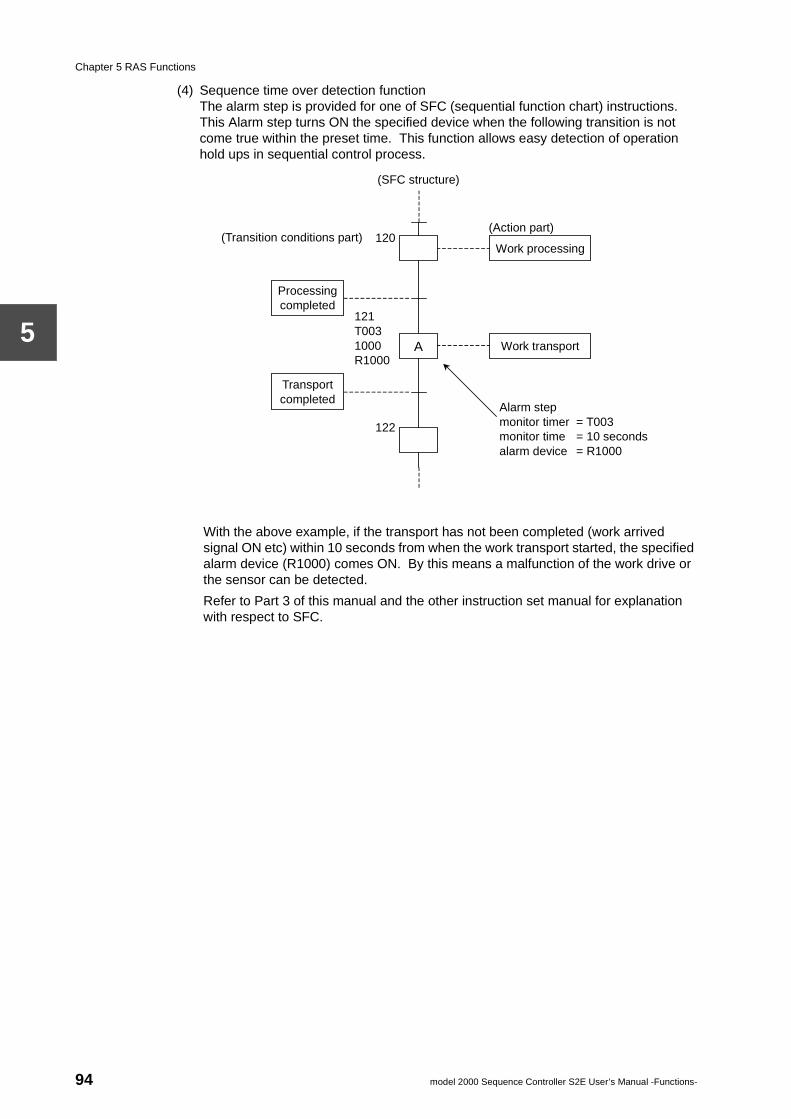
Chapter 5 RAS Functions
5
(4) Sequence time over detection functionThe alarm step is provided for one of SFC (sequential function chart) instructions. This Alarm step turns ON the specified device when the following transition is not come true within the preset time. This function allows easy detection of operation hold ups in sequential control process.
With the above example, if the transport has not been completed (work arrived signal ON etc) within 10 seconds from when the work transport started, the specified alarm device (R1000) comes ON. By this means a malfunction of the work drive or the sensor can be detected.
Refer to Part 3 of this manual and the other instruction set manual for explanation with respect to SFC.
Alarm step monitor timer = T003 monitor time = 10 seconds alarm device = R1000
121 T003 1000 R1000
(Transition conditions part) 120
Processing completed
Transport completed
Work processing
Work transport
A
122
(SFC structure)
(Action part)
94 model 2000 Sequence Controller S2E User’s Manual -Functions-
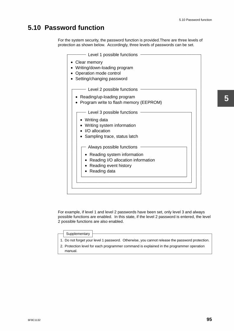
5.10 Password function
5
5.10 Password function
For the system security, the password function is provided.There are three levels of protection as shown below. Accordingly, three levels of passwords can be set.
For example, if level 1 and level 2 passwords have been set, only level 3 and always possible functions are enabled. In this state, if the level 2 password is entered, the level 2 possible functions are also enabled.
Supplementary
1. Do not forget your level 1 password. Otherwise, you cannot release the password protection.
2. Protection level for each programmer command is explained in the programmer operation manual.
Level 1 possible functions
• Clear memory • Writing/down-loading program • Operation mode control • Setting/changing password
Level 2 possible functions
• Reading/up-loading program • Program write to flash memory (EEPROM)
Level 3 possible functions
• Writing data • Writing system information • I/O allocation • Sampling trace, status latch
Always possible functions
• Reading system information • Reading I/O allocation information • Reading event history • Reading data
6F8C1132 95

PART 3PROGRAMMING INFORMATION

6F8C1132
Overview
Chapter 11.1 Aims of Part 3
The main functions of the S2E are to store the user program, to execute the stored user program and to control and monitor the operation/state of machines/processes which are the result of such execution.
The user program is a series of instructions for achieving the request control function, operation conditions, data processing and the interface with the operator. It is stored in the user program memory. The execution of the user program is the sequential performance of the processes of reading user data in which external input/output data and control parameters are stored, processing the respective instructions and storing the results of this in the user data memory.
Part 2 described the types of processing which are executed by the S2E internally, functions for executing the user program efficiently and the RAS functions. Part 3 describes the necessary information for creating user programs, that is to say detailed user data, detail of the input/output allocation and the programming languages. Also, the user program configuration is described to use the S2E’s multi-tasking function.
99
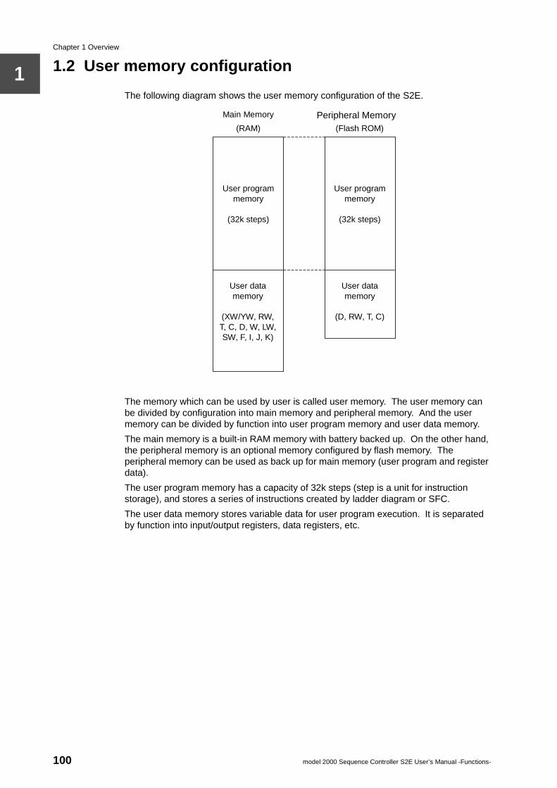
Chapter 1 Overview
1
1.2 User memory configurationThe following diagram shows the user memory configuration of the S2E.
The memory which can be used by user is called user memory. The user memory can be divided by configuration into main memory and peripheral memory. And the user memory can be divided by function into user program memory and user data memory.
The main memory is a built-in RAM memory with battery backed up. On the other hand, the peripheral memory is an optional memory configured by flash memory. The peripheral memory can be used as back up for main memory (user program and register data).
The user program memory has a capacity of 32k steps (step is a unit for instruction storage), and stores a series of instructions created by ladder diagram or SFC.
The user data memory stores variable data for user program execution. It is separated by function into input/output registers, data registers, etc.
Peripheral Memory Main Memory
(RAM) (Flash ROM)
User program memory
(32k steps)
User program memory
(32k steps)
User data memory
(D, RW, T, C)
User data memory
(XW/YW, RW, T, C, D, W, LW, SW, F, I, J, K)
100 model 2000 Sequence Controller S2E User’s Manual -Functions-
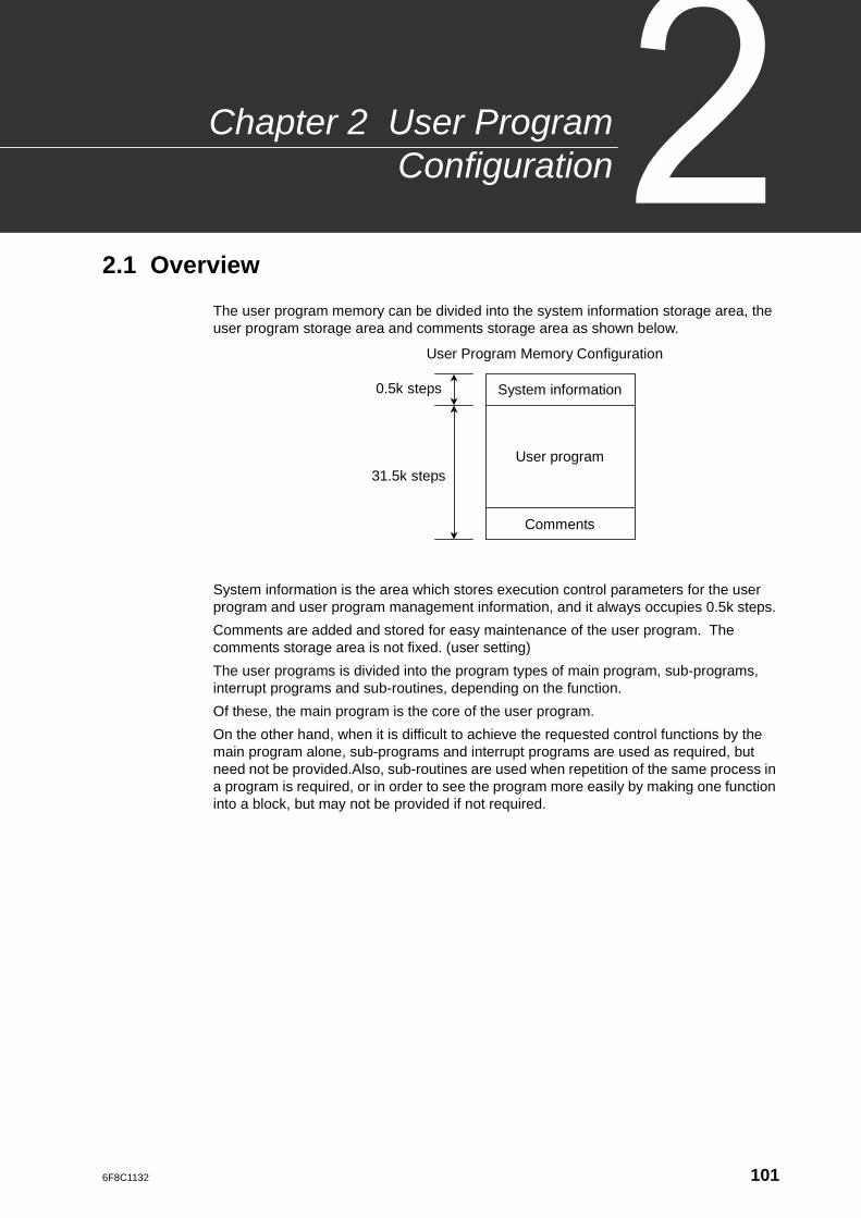
6F8C1132
r Programnfiguration
Chapter 2 UseCo
2.1 Overview
The user program memory can be divided into the system information storage area, the user program storage area and comments storage area as shown below.
System information is the area which stores execution control parameters for the user program and user program management information, and it always occupies 0.5k steps.
Comments are added and stored for easy maintenance of the user program. The comments storage area is not fixed. (user setting)
The user programs is divided into the program types of main program, sub-programs, interrupt programs and sub-routines, depending on the function.
Of these, the main program is the core of the user program.
On the other hand, when it is difficult to achieve the requested control functions by the main program alone, sub-programs and interrupt programs are used as required, but need not be provided.Also, sub-routines are used when repetition of the same process in a program is required, or in order to see the program more easily by making one function into a block, but may not be provided if not required.
User Program Memory Configuration
System information
User program
Comments
0.5k steps
31.5k steps
101
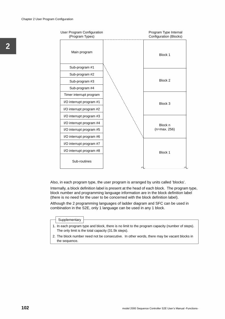
Chapter 2 User Program Configuration
2
Also, in each program type, the user program is arranged by units called ’blocks’.
Internally, a block definition label is present at the head of each block. The program type, block number and programming language information are in the block definition label (there is no need for the user to be concerned with the block definition label).
Although the 2 programming languages of ladder diagram and SFC can be used in combination in the S2E, only 1 language can be used in any 1 block.
Supplementary
1. In each program type and block, there is no limit to the program capacity (number of steps). The only limit is the total capacity (31.5k steps).
2. The block number need not be consecutive. In other words, there may be vacant blocks in the sequence.
User Program Configuration (Program Types)
Program Type Internal Configuration (Blocks)
Main program
Sub-program #1
Sub-program #2
Sub-program #3
Sub-program #4
I/O interrupt program #1
I/O interrupt program #2
I/O interrupt program #3
I/O interrupt program #4
I/O interrupt program #5
I/O interrupt program #6
I/O interrupt program #7
I/O interrupt program #8
Sub-routines
Block 1
Block 2
Block 3
Block n (n=max. 256)
Block 1
Timer interrupt program
102 model 2000 Sequence Controller S2E User’s Manual -Functions-
2.2 System information
2
2.2 System information
System information is the area which stores execution control parameters and user program management information when executing a user program, and occupies 0.5k steps of the user program memory. The following details are included in system information.
(1) Program IDThis is the user program identification. A setting of up to 10 alphanumeric characters can be set. The program ID can be registered/monitored on the system information screen of the programmer.
(2) System CommentsThese are comments attached to the user program. A setting of up to 30 alphanumeric characters can be set. The system comments can be registered/monitored on the system information screen of the programmer.
(3) Memory CapacityThis stores the memory type (user program capacity/data register capacity). The memory capacity can be monitored on the system information screen of the programmer. (monitor only)
(4) Steps UsedThis stores the number of steps used in the user program. The number of steps used can be monitored on the system information screen of the programmer. (monitor only)
(5) PLC TypeThis stores the model type. The PLC type can be monitored on the system information screen of the programmer. (monitor only)
(6) Program Size SettingThis is the capacity assigned to the user program. The rest of this setting out of total 32k steps is assigned to the comments. The program size setting can be registered/monitored on the system information screen of the programmer.
(7) Sampling Buffer SettingThis performs the setting and registration of the storage capacity of the sampling buffer for the sampling trace function. The maximum setting is 8k words. The sampling buffer setting can be registered/monitored on the system information screen of the programmer.
(8) Retentive Memory Area DesignationThis sets and registers the address ranges for the auxiliary register (RW), timer register (T), counter register (C) and data register (D) which retain pre-power cut data out of the user data. The ranges registered here are outside the subjects of the user data initialization process. For each of these registers, the ranges from the leading address (0) to the designated address are the retentive memory areas. The retentive memory area designations can be registered/monitored on the system information screen of the programmer.
(9) Scan Time SettingThis sets and registers the scan mode (floating/constant). When no scan time is registered (blank), the mode becomes the floating scan mode. When a numerical value is set for the scan time, the mode becomes a constant scan mode which takes that time as the scan cycle. The setting for the scan cycle is 10-200 ms (in 10 ms units).The scan time setting can be registered/monitored on the system information screen of the programmer.
(10) Sub-Program Execution TimeTime limit factor assigned for sub-programs in the floating scan. The setting range is 1-100 ms (in 1 ms units). The sub-program execution time can be registered/monitored on the system information screen of the programmer.
6F8C1132 103
Chapter 2 User Program Configuration
2
(11) Timer Interrupt IntervalThis sets and registers the interrupt cycle of the timer interrupt program. The setting range is 1-1000 ms (in 1 ms units). The timer interrupt interval can be registered/monitored on the system information screen of the programmer.
(12) Computer Link ParametersThis sets and registers the parameters for the computer link.The computer link parameters can be registered/monitored on the system information screen of the programmer.
The parameter items and their setting ranges are as follows:
• Station No............. 1-32 (initial value=1)
• Baud rate.............. 300, 600,1200, 2400, 4800, 9600, 19200(initial value 9600)
• Parity .................... None, odd, even (initial value=odd)
• Data length (bits) .. 7, 8 (initial value=8)
• Stop bit ................. 1, 2 (initial value=1)
(13) I/O Allocation InformationThis stores I/O allocation information and unit base address designation information. This information is created either by executing the automatic I/O allocation command or by setting and registering an I/O module type for each slot (manual I/O allocation) on the I/O allocation information screen of the programmer.
(14) Interrupt Assignment InformationThis stores the information of correspondence between the I/O interrupt program and I/O modules with interrupt functions. In the initial state (without setting this information), the lower number of I/O interrupt programs are assigned in sequence from the interrupt module closest to the CPU.This information can be registered/monitored on the interrupt assignment screen of the programmer.
(15) Network Assignment InformationInformation on the link register areas allocated to the data transmission modules (TOSLINE-S20, TOSLINE-F10) is stored here. This information can be registered/monitored on the network assignment information screen of the programmer.
104 model 2000 Sequence Controller S2E User’s Manual -Functions-
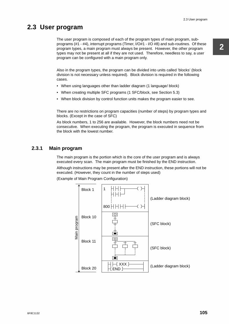
2.3 User program
2
2.3 User program
The user program is composed of each of the program types of main program, sub-programs (#1 - #4), interrupt programs (Timer, I/O#1 - I/O #8) and sub-routines. Of these program types, a main program must always be present. However, the other program types may not be present at all if they are not used. Therefore, needless to say, a user program can be configured with a main program only.
Also in the program types, the program can be divided into units called ’blocks’ (block division is not necessary unless required). Block division is required in the following cases.
• When using languages other than ladder diagram (1 language/ block)
• When creating multiple SFC programs (1 SFC/block, see Section 5.3)
• When block division by control function units makes the program easier to see.
There are no restrictions on program capacities (number of steps) by program types and blocks. (Except in the case of SFC)
As block numbers, 1 to 256 are available. However, the block numbers need not be consecutive. When executing the program, the program is executed in sequence from the block with the lowest number.
2.3.1 Main program
The main program is the portion which is the core of the user program and is always executed every scan. The main program must be finished by the END instruction.
Although instructions may be present after the END instruction, these portions will not be executed. (However, they count in the number of steps used)
(Example of Main Program Configuration)
Mai
n pr
ogra
m
Block 1
Block 10
Block 11
Block 20
1
800
(Ladder diagram block)
(SFC block)
(SFC block)
(Ladder diagram block) END
XXX
6F8C1132 105
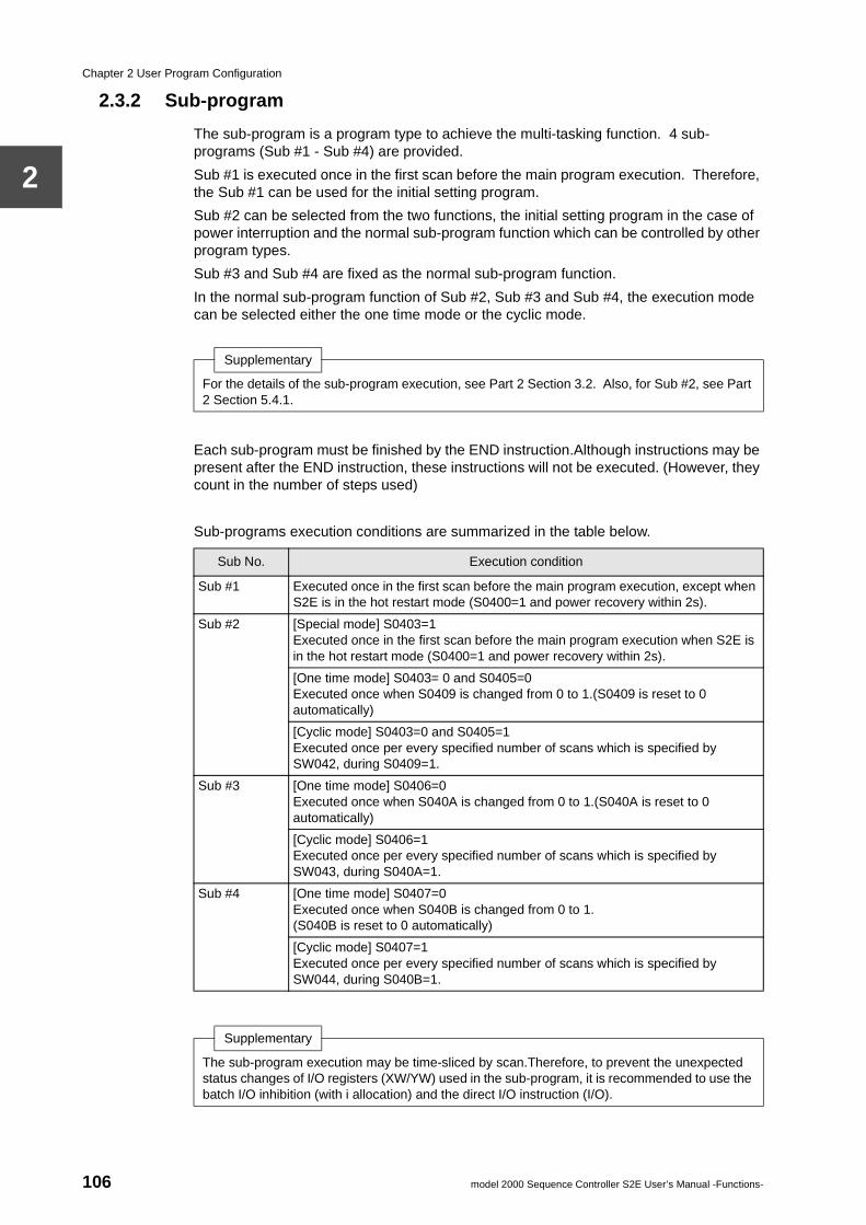
Chapter 2 User Program Configuration
2
2.3.2 Sub-program
The sub-program is a program type to achieve the multi-tasking function. 4 sub-programs (Sub #1 - Sub #4) are provided.
Sub #1 is executed once in the first scan before the main program execution. Therefore, the Sub #1 can be used for the initial setting program.
Sub #2 can be selected from the two functions, the initial setting program in the case of power interruption and the normal sub-program function which can be controlled by other program types.
Sub #3 and Sub #4 are fixed as the normal sub-program function.
In the normal sub-program function of Sub #2, Sub #3 and Sub #4, the execution mode can be selected either the one time mode or the cyclic mode.
Each sub-program must be finished by the END instruction.Although instructions may be present after the END instruction, these instructions will not be executed. (However, they count in the number of steps used)
Sub-programs execution conditions are summarized in the table below.
Supplementary
For the details of the sub-program execution, see Part 2 Section 3.2. Also, for Sub #2, see Part 2 Section 5.4.1.
Sub No. Execution condition
Sub #1 Executed once in the first scan before the main program execution, except when S2E is in the hot restart mode (S0400=1 and power recovery within 2s).
Sub #2 [Special mode] S0403=1Executed once in the first scan before the main program execution when S2E is in the hot restart mode (S0400=1 and power recovery within 2s).
[One time mode] S0403= 0 and S0405=0Executed once when S0409 is changed from 0 to 1.(S0409 is reset to 0 automatically)
[Cyclic mode] S0403=0 and S0405=1Executed once per every specified number of scans which is specified by SW042, during S0409=1.
Sub #3 [One time mode] S0406=0Executed once when S040A is changed from 0 to 1.(S040A is reset to 0 automatically)
[Cyclic mode] S0406=1Executed once per every specified number of scans which is specified by SW043, during S040A=1.
Sub #4 [One time mode] S0407=0Executed once when S040B is changed from 0 to 1.(S040B is reset to 0 automatically)
[Cyclic mode] S0407=1Executed once per every specified number of scans which is specified by SW044, during S040B=1.
Supplementary
The sub-program execution may be time-sliced by scan.Therefore, to prevent the unexpected status changes of I/O registers (XW/YW) used in the sub-program, it is recommended to use the batch I/O inhibition (with i allocation) and the direct I/O instruction (I/O).
106 model 2000 Sequence Controller S2E User’s Manual -Functions-
2.3 User program
2
2.3.3 Interrupt program
There are a total of 9 types of interrupt program. These are 1 timer interrupt program which is executed cyclically with a cycle which is set in system information, and 8 I/O interrupt programs (#1 - #8) which are started by interrupt signals from I/O modules with interrupt function.
• Timer interrupt programThis is executed cyclically with a cycle of 1-1000 ms which is registered in system information. When no cycle is registered (blank), it is not executed.Set the interval setting of the timer interrupt with 1 ms units in item 16 of the T-PDS system information screen.For details, see T-PDS operation manuals.
• I/O interrupt programs (#1 - #8)These are started by interrupt signals generated by I/O modules with the interrupt function. The coordination between the interrupt program numbers and the I/O modules with interrupt function can be changed by the interrupt assignment function.
Each interrupt program must be finished by the IRET instruction.
The following modules are available as the I/O module with the interrupt function (interrupt I/O).
• 2 channels pulse input(Part No.: PI632/672, allocation type: iX+Y2W)
• 16 points DC input(Part No.: CD633, allocation type: iX 4W)
When automatic I/O allocation is carried out in the state with interrupt I/O mounted, for coordination between the interrupt program number and the interrupt I/O, the lower number I/O interrupt programs are allocated in sequence from the interrupt I/O closest to the CPU. (See the example on the following page)
Supplementary
1. For details of interrupt program operation, see Part 2 Section 3.3.
2. SFC cannot be used in the interrupt program.
6F8C1132 107
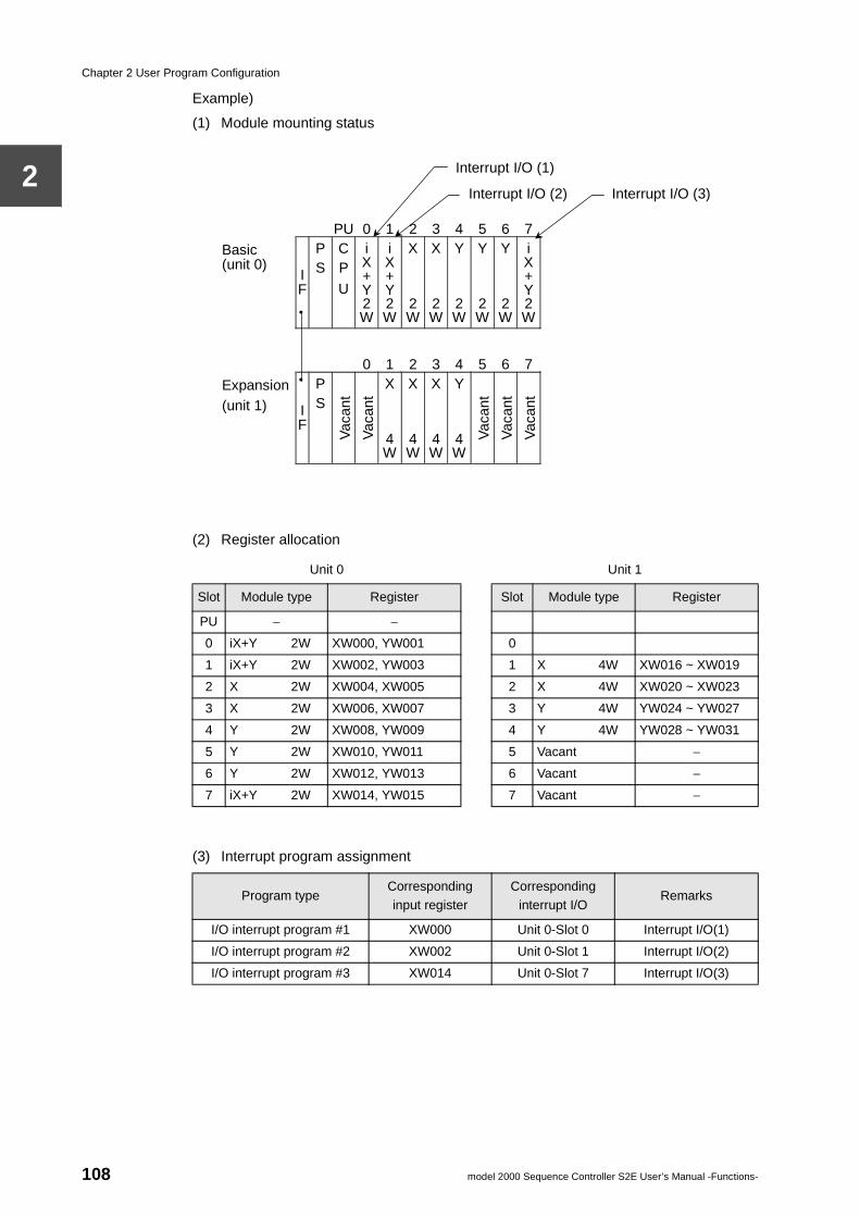
Chapter 2 User Program Configuration
2
Example)
(1) Module mounting status
(2) Register allocation
(3) Interrupt program assignment
Unit 0 Unit 1
Slot Module type Register Slot Module type Register
PU − −
0 iX+Y 2W XW000, YW001 0
1 iX+Y 2W XW002, YW003 1 X 4W XW016 ~ XW019
2 X 2W XW004, XW005 2 X 4W XW020 ~ XW023
3 X 2W XW006, XW007 3 Y 4W YW024 ~ YW027
4 Y 2W XW008, YW009 4 Y 4W YW028 ~ YW031
5 Y 2W XW010, YW011 5 Vacant −
6 Y 2W XW012, YW013 6 Vacant −
7 iX+Y 2W XW014, YW015 7 Vacant −
Program typeCorresponding input register
Corresponding interrupt I/O
Remarks
I/O interrupt program #1 XW000 Unit 0-Slot 0 Interrupt I/O(1)
I/O interrupt program #2 XW002 Unit 0-Slot 1 Interrupt I/O(2)
I/O interrupt program #3 XW014 Unit 0-Slot 7 Interrupt I/O(3)
PU 0 1 2 3 4 5 6 7 Basic (unit 0)
I F
P S
C P
U
i X + Y 2 W
i X + Y 2 W
X 2 W
X 2 W
Y 2 W
Y 2 W
Y 2 W
i X + Y 2 W
0 1 2 3 4 5 6 7 Expansion (unit 1) I
F
P S
Vac
ant
Vac
ant
X 4 W
X 4 W
X 4 W
Y 4 W
Vac
ant
Vac
ant
Vac
ant
Interrupt I/O (1)
Interrupt I/O (2) Interrupt I/O (3)
108 model 2000 Sequence Controller S2E User’s Manual -Functions-
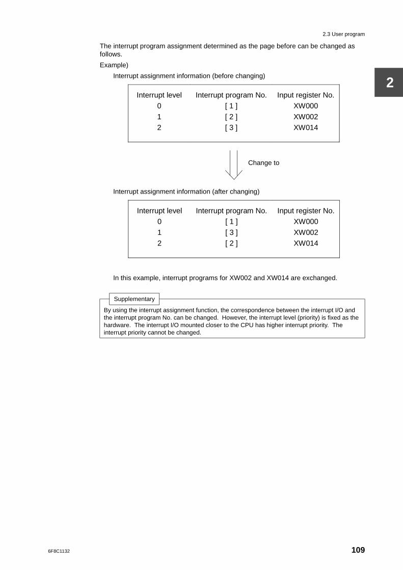
2.3 User program
2
The interrupt program assignment determined as the page before can be changed as follows.
Example)
Interrupt assignment information (before changing)
Interrupt assignment information (after changing)
In this example, interrupt programs for XW002 and XW014 are exchanged.
Supplementary
By using the interrupt assignment function, the correspondence between the interrupt I/O and the interrupt program No. can be changed. However, the interrupt level (priority) is fixed as the hardware. The interrupt I/O mounted closer to the CPU has higher interrupt priority. The interrupt priority cannot be changed.
Interrupt level
0
1
2
Interrupt program No.
[ 1 ]
[ 2 ]
[ 3 ]
Input register No.
XW000
XW002
XW014
Change to
Interrupt level
0
1
2
Interrupt program No.
[ 1 ]
[ 3 ]
[ 2 ]
Input register No.
XW000
XW002
XW014
6F8C1132 109
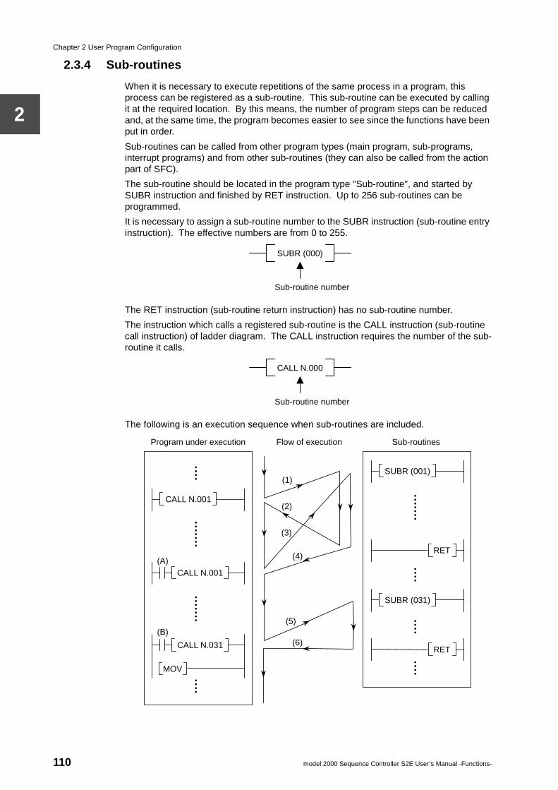
Chapter 2 User Program Configuration
2
2.3.4 Sub-routines
When it is necessary to execute repetitions of the same process in a program, this process can be registered as a sub-routine. This sub-routine can be executed by calling it at the required location. By this means, the number of program steps can be reduced and, at the same time, the program becomes easier to see since the functions have been put in order.
Sub-routines can be called from other program types (main program, sub-programs, interrupt programs) and from other sub-routines (they can also be called from the action part of SFC).
The sub-routine should be located in the program type "Sub-routine", and started by SUBR instruction and finished by RET instruction. Up to 256 sub-routines can be programmed.
It is necessary to assign a sub-routine number to the SUBR instruction (sub-routine entry instruction). The effective numbers are from 0 to 255.
The RET instruction (sub-routine return instruction) has no sub-routine number.
The instruction which calls a registered sub-routine is the CALL instruction (sub-routine call instruction) of ladder diagram. The CALL instruction requires the number of the sub-routine it calls.
The following is an execution sequence when sub-routines are included.
SUBR (000)
Sub-routine number
CALL N.000
Sub-routine number
Program under execution Flow of execution Sub-routines
CALL N.001
CALL N.001
CALL N.031
MOV
(B)
(A)
SUBR (001)
SUBR (031)
RET
RET
(5)
(6)
(1)
(2)
(4)
(3)
110 model 2000 Sequence Controller S2E User’s Manual -Functions-
2.3 User program
2
(1) By the sub-routine 001 CALL instruction execution, the execution shifts to sub-routine 001
(2) When it has proceeded to the RET instruction, the execution returns to the instruction following the CALL instruction in (1)
(3) When device (A) is ON, the CALL instruction is executed, andthe execution shifts to sub-routine 001
(4) When it has proceeded to the RET instruction, the execution returns to the instruction following the CALL instruction in (3)
(5) When device (B) is ON, the CALL instruction is executed, andthe execution shifts to sub-routine 031
(6) When it has proceeded to the RET instruction, the execution returns to the instruction following the CALL instruction in (5) (the MOV instruction in this example)
Supplementary
1. Multiple sub-routines can be programmed in a block. However for execution monitor by programmer, 1 sub-routine on 1 block is recommended.
2. SFC cannot be used in a sub-routine.
3. Other sub-routines can be called from a sub-routine (nesting), up to 6 layers.
4. Since the operation will become abnormal in cases such as calling the same sub-routine during the execution of a sub-routine, take care that the cases do not occur.
6F8C1132 111
Chapter 2 User Program Configuration
2
2.4 Comments
Comments can be added and stored in the S2E’s user program memory. By this means, the user program becomes easier to understand.
The types of comments which can be stored in the S2E are tags/comments for registers, devices and SFC steps.
Tag............... up to 5 characters
Comment..... up to 20 characters
The comments storage capacity is the rest of the program size setting out of total 32k steps.
The maximum storage number of comments (tag and comment paired) is calculated as follows.
Supplementary
Here, the comments which can be stored in the S2E are explained. Comments can also be saved in a disk file.For the disk file usage, see separate manual for the programmer (T-PDS).
(1024 × (32 − N) − 38) / 10
Program size setting (assigned to the user program)
112 model 2000 Sequence Controller S2E User’s Manual -Functions-
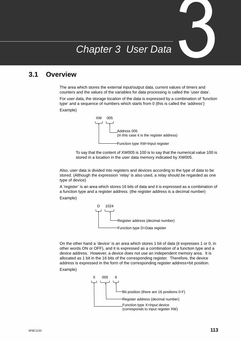
6F8C1132
User Data
Chapter 33.1 Overview
The area which stores the external input/output data, current values of timers and counters and the values of the variables for data processing is called the ’user data’.
For user data, the storage location of the data is expressed by a combination of ’function type’ and a sequence of numbers which starts from 0 (this is called the ’address’)
Example)
To say that the content of XW005 is 100 is to say that the numerical value 100 is stored in a location in the user data memory indicated by XW005.
Also, user data is divided into registers and devices according to the type of data to be stored. (Although the expression ’relay’ is also used, a relay should be regarded as one type of device)
A ’register’ is an area which stores 16 bits of data and it is expressed as a combination of a function type and a register address. (the register address is a decimal number)
Example)
On the other hand a ’device’ is an area which stores 1 bit of data (it expresses 1 or 0, in other words ON or OFF), and it is expressed as a combination of a function type and a device address. However, a device does not use an independent memory area. It is allocated as 1 bit in the 16 bits of the corresponding register. Therefore, the device address is expressed in the form of the corresponding register address+bit position.
Example)
XW
Address 005 (in this case it is the register address)
Function type XW=lnput register
005
D
Register address (decimal number)
Function type D=Data register
1024
X
Bit position (there are 16 positions 0-F)
Register address (decimal number)
005 6
Function type X=lnput device (corresponds to input register XW)
113
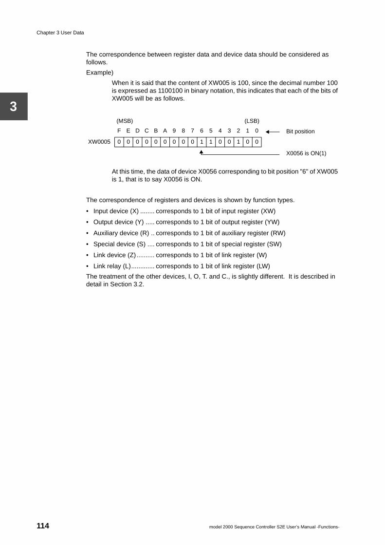
Chapter 3 User Data
3
The correspondence between register data and device data should be considered as follows.
Example)
When it is said that the content of XW005 is 100, since the decimal number 100 is expressed as 1100100 in binary notation, this indicates that each of the bits of XW005 will be as follows.
At this time, the data of device X0056 corresponding to bit position "6" of XW005 is 1, that is to say X0056 is ON.
The correspondence of registers and devices is shown by function types.
• Input device (X) ........ corresponds to 1 bit of input register (XW)
• Output device (Y) ..... corresponds to 1 bit of output register (YW)
• Auxiliary device (R) .. corresponds to 1 bit of auxiliary register (RW)
• Special device (S) .... corresponds to 1 bit of special register (SW)
• Link device (Z) .......... corresponds to 1 bit of link register (W)
• Link relay (L)............. corresponds to 1 bit of link register (LW)
The treatment of the other devices, I, O, T. and C., is slightly different. It is described in detail in Section 3.2.
(MSB) (LSB)
F E D C B A 9 8 7 6 5 4 3 2 1 0 Bit position
XW0005 0 0 0 0 0 0 0 0 0 1 1 0 0 1 0 0
X0056 is ON(1)
114 model 2000 Sequence Controller S2E User’s Manual -Functions-
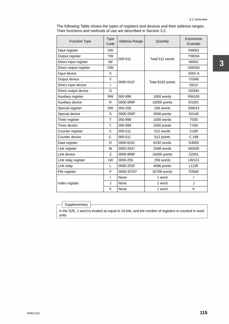
3.1 Overview
3
The following Table shows the types of registers and devices and their address ranges. Their functions and methods of use are described in Section 3.2.
Function TypeType Code
Address Range QuantityExpression Example
Input register XW
000-511 Total 512 words
XW001
Output register YW YW034
Direct input register IW IW001
Direct output register OW OW034
Input device X
0000-511F Total 8192 points
X001 A
Output device Y Y0348
Direct input device I I0012
Direct output device O O0340
Auxiliary register RW 000-999 1000 words RW100
Auxiliary device R 0000-999F 16000 points R1001
Special register SW 000-255 256 words SW014
Special device S 0000-255F 4096 points S0140
Timer register T 000-999 1000 words T030
Timer device T. 000-999 1000 points T.030
Counter register C 000-511 512 words C199
Counter device C. 000-511 512 points C.199
Data register D 0000-8191 8192 words D4055
Link register W 0000-2047 2048 words W0200
Link device Z 0000-999F 16000 points Z2001
Link relay register LW 0000-255 256 words LW123
Link relay L 0000-255F 4096 points L123F
File register F 0000-32767 32768 words F0500
Index register
I None 1 word I
J None 1 word J
K None 1 word K
Supplementary
In the S2E, 1 word is treated as equal to 16 bits, and the number of registers is counted in word units.
6F8C1132 115
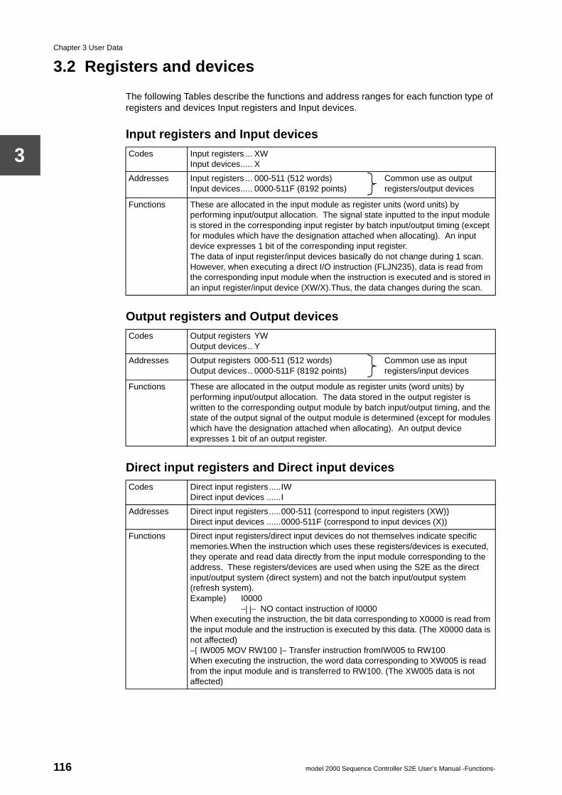
Chapter 3 User Data
3
3.2 Registers and devices
The following Tables describe the functions and address ranges for each function type of registers and devices Input registers and Input devices.
Input registers and Input devices
Output registers and Output devices
Direct input registers and Direct input devices
Codes Input registers ... XWInput devices..... X
Addresses Input registers ... 000-511 (512 words)Input devices..... 0000-511F (8192 points)
Common use as output registers/output devices
Functions These are allocated in the input module as register units (word units) by performing input/output allocation. The signal state inputted to the input module is stored in the corresponding input register by batch input/output timing (except for modules which have the designation attached when allocating). An input device expresses 1 bit of the corresponding input register.The data of input register/input devices basically do not change during 1 scan. However, when executing a direct I/O instruction (FLJN235), data is read from the corresponding input module when the instruction is executed and is stored in an input register/input device (XW/X).Thus, the data changes during the scan.
Codes Output registers YWOutput devices.. Y
Addresses Output registers 000-511 (512 words)Output devices.. 0000-511F (8192 points)
Common use as input registers/input devices
Functions These are allocated in the output module as register units (word units) by performing input/output allocation. The data stored in the output register is written to the corresponding output module by batch input/output timing, and the state of the output signal of the output module is determined (except for modules which have the designation attached when allocating). An output device expresses 1 bit of an output register.
Codes Direct input registers.....IWDirect input devices ......I
Addresses Direct input registers.....000-511 (correspond to input registers (XW))Direct input devices ......0000-511F (correspond to input devices (X))
Functions Direct input registers/direct input devices do not themselves indicate specific memories.When the instruction which uses these registers/devices is executed, they operate and read data directly from the input module corresponding to the address. These registers/devices are used when using the S2E as the direct input/output system (direct system) and not the batch input/output system (refresh system).Example) I0000
−| |− NO contact instruction of I0000When executing the instruction, the bit data corresponding to X0000 is read from the input module and the instruction is executed by this data. (The X0000 data is not affected)−[ IW005 MOV RW100 ]− Transfer instruction fromIW005 to RW100When executing the instruction, the word data corresponding to XW005 is read from the input module and is transferred to RW100. (The XW005 data is not affected)
116 model 2000 Sequence Controller S2E User’s Manual -Functions-
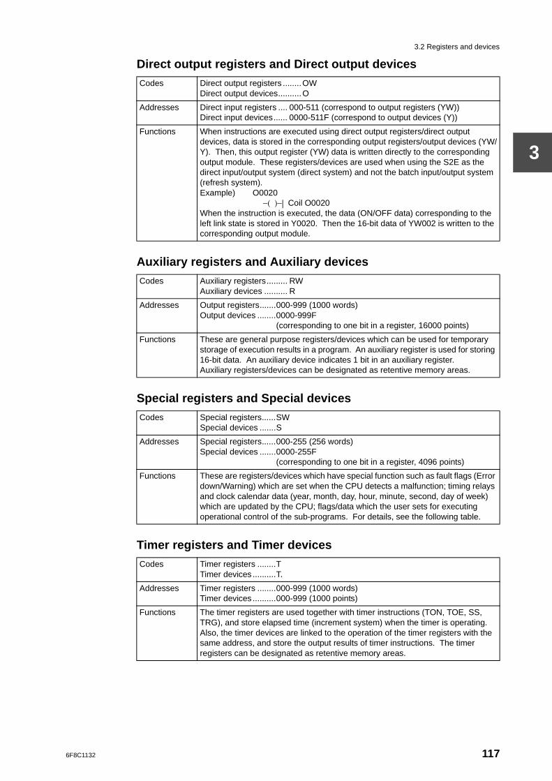
3.2 Registers and devices
3
Direct output registers and Direct output devices
Auxiliary registers and Auxiliary devices
Special registers and Special devices
Timer registers and Timer devices
Codes Direct output registers ........OWDirect output devices..........O
Addresses Direct input registers .... 000-511 (correspond to output registers (YW))Direct input devices...... 0000-511F (correspond to output devices (Y))
Functions When instructions are executed using direct output registers/direct output devices, data is stored in the corresponding output registers/output devices (YW/Y). Then, this output register (YW) data is written directly to the corresponding output module. These registers/devices are used when using the S2E as the direct input/output system (direct system) and not the batch input/output system (refresh system).Example) O0020
−( )−| Coil O0020When the instruction is executed, the data (ON/OFF data) corresponding to the left link state is stored in Y0020. Then the 16-bit data of YW002 is written to the corresponding output module.
Codes Auxiliary registers......... RWAuxiliary devices .......... R
Addresses Output registers.......000-999 (1000 words)Output devices ........0000-999F
(corresponding to one bit in a register, 16000 points)
Functions These are general purpose registers/devices which can be used for temporary storage of execution results in a program. An auxiliary register is used for storing 16-bit data. An auxiliary device indicates 1 bit in an auxiliary register.Auxiliary registers/devices can be designated as retentive memory areas.
Codes Special registers......SWSpecial devices .......S
Addresses Special registers......000-255 (256 words)Special devices .......0000-255F
(corresponding to one bit in a register, 4096 points)
Functions These are registers/devices which have special function such as fault flags (Error down/Warning) which are set when the CPU detects a malfunction; timing relays and clock calendar data (year, month, day, hour, minute, second, day of week) which are updated by the CPU; flags/data which the user sets for executing operational control of the sub-programs. For details, see the following table.
Codes Timer registers ........TTimer devices ..........T.
Addresses Timer registers ........000-999 (1000 words)Timer devices ..........000-999 (1000 points)
Functions The timer registers are used together with timer instructions (TON, TOE, SS, TRG), and store elapsed time (increment system) when the timer is operating. Also, the timer devices are linked to the operation of the timer registers with the same address, and store the output results of timer instructions. The timer registers can be designated as retentive memory areas.
6F8C1132 117
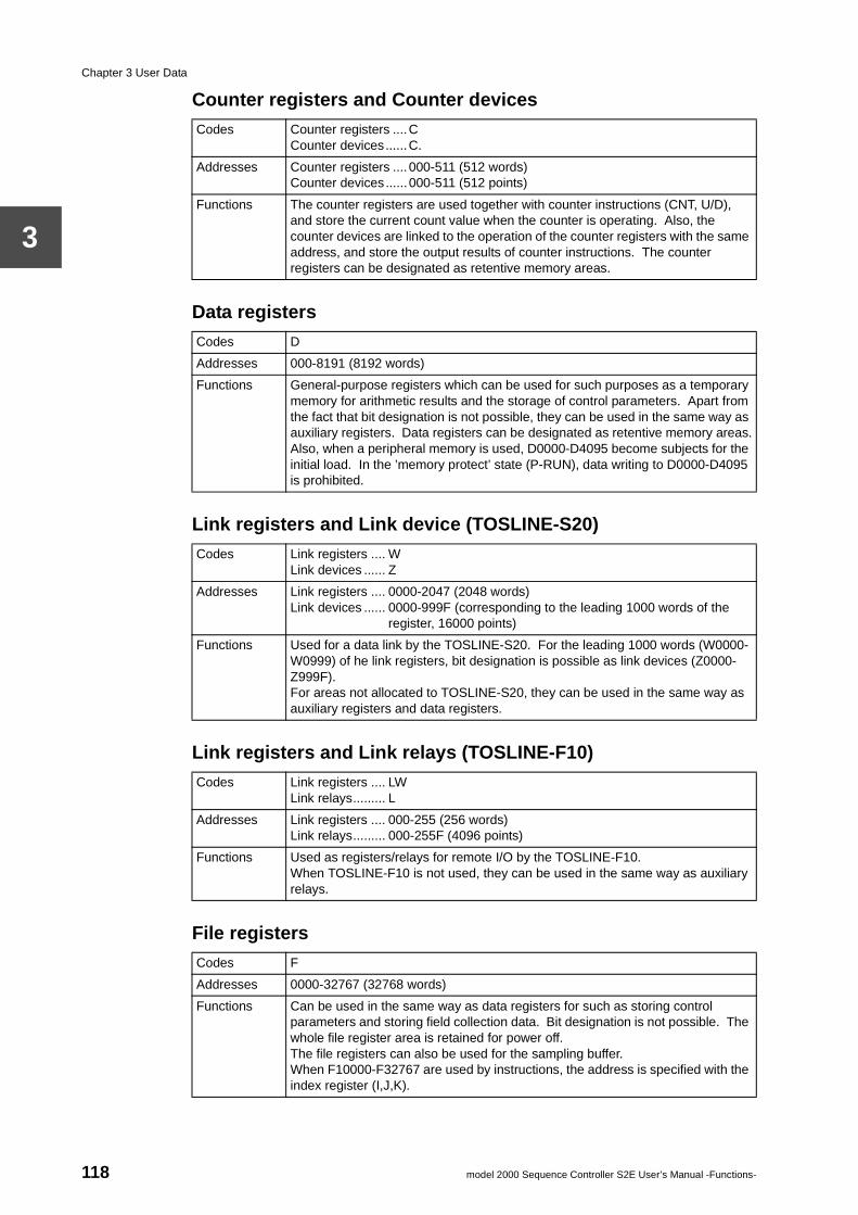
Chapter 3 User Data
3
Counter registers and Counter devices
Data registers
Link registers and Link device (TOSLINE-S20)
Link registers and Link relays (TOSLINE-F10)
File registers
Codes Counter registers ....CCounter devices......C.
Addresses Counter registers ....000-511 (512 words)Counter devices......000-511 (512 points)
Functions The counter registers are used together with counter instructions (CNT, U/D), and store the current count value when the counter is operating. Also, the counter devices are linked to the operation of the counter registers with the same address, and store the output results of counter instructions. The counter registers can be designated as retentive memory areas.
Codes D
Addresses 000-8191 (8192 words)
Functions General-purpose registers which can be used for such purposes as a temporary memory for arithmetic results and the storage of control parameters. Apart from the fact that bit designation is not possible, they can be used in the same way as auxiliary registers. Data registers can be designated as retentive memory areas.Also, when a peripheral memory is used, D0000-D4095 become subjects for the initial load. In the ’memory protect’ state (P-RUN), data writing to D0000-D4095 is prohibited.
Codes Link registers .... WLink devices ...... Z
Addresses Link registers .... 0000-2047 (2048 words)Link devices ...... 0000-999F (corresponding to the leading 1000 words of the
register, 16000 points)
Functions Used for a data link by the TOSLINE-S20. For the leading 1000 words (W0000-W0999) of he link registers, bit designation is possible as link devices (Z0000-Z999F).For areas not allocated to TOSLINE-S20, they can be used in the same way as auxiliary registers and data registers.
Codes Link registers .... LWLink relays......... L
Addresses Link registers .... 000-255 (256 words)Link relays......... 000-255F (4096 points)
Functions Used as registers/relays for remote I/O by the TOSLINE-F10.When TOSLINE-F10 is not used, they can be used in the same way as auxiliary relays.
Codes F
Addresses 0000-32767 (32768 words)
Functions Can be used in the same way as data registers for such as storing control parameters and storing field collection data. Bit designation is not possible. The whole file register area is retained for power off.The file registers can also be used for the sampling buffer.When F10000-F32767 are used by instructions, the address is specified with the index register (I,J,K).
118 model 2000 Sequence Controller S2E User’s Manual -Functions-
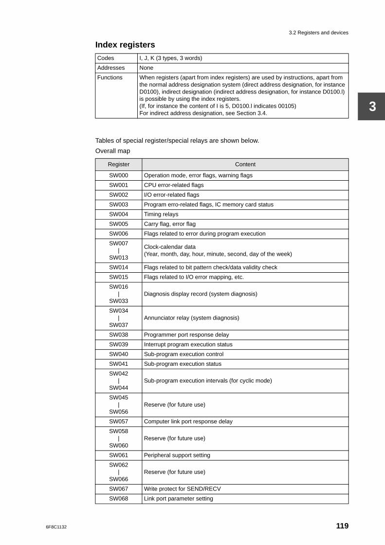
3.2 Registers and devices
3
Index registers
Tables of special register/special relays are shown below.
Overall map
Codes I, J, K (3 types, 3 words)
Addresses None
Functions When registers (apart from index registers) are used by instructions, apart from the normal address designation system (direct address designation, for instance D0100), indirect designation (indirect address designation, for instance D0100.l) is possible by using the index registers.(If, for instance the content of I is 5, D0100.l indicates 00105)For indirect address designation, see Section 3.4.
Register Content
SW000 Operation mode, error flags, warning flags
SW001 CPU error-related flags
SW002 I/O error-related flags
SW003 Program erro-related flags, IC memory card status
SW004 Timing relays
SW005 Carry flag, error flag
SW006 Flags related to error during program execution
SW007|
SW013
Clock-calendar data(Year, month, day, hour, minute, second, day of the week)
SW014 Flags related to bit pattern check/data validity check
SW015 Flags related to I/O error mapping, etc.
SW016|
SW033Diagnosis display record (system diagnosis)
SW034|
SW037Annunciator relay (system diagnosis)
SW038 Programmer port response delay
SW039 Interrupt program execution status
SW040 Sub-program execution control
SW041 Sub-program execution status
SW042|
SW044Sub-program execution intervals (for cyclic mode)
SW045|
SW056Reserve (for future use)
SW057 Computer link port response delay
SW058|
SW060Reserve (for future use)
SW061 Peripheral support setting
SW062|
SW066Reserve (for future use)
SW067 Write protect for SEND/RECV
SW068 Link port parameter setting
6F8C1132 119
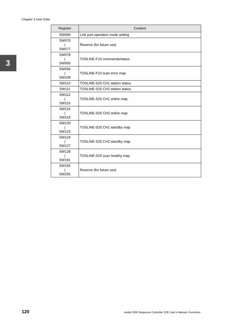
Chapter 3 User Data
3
SW069 Link port operation mode setting
SW070|
SW077Reserve (for future use)
SW078|
SW093TOSLINE-F10 commands/status
SW094|
SW109TOSLINE-F10 scan error map
SW110 TOSLINE-S20 CH1 station status
SW111 TOSLINE-S20 CH2 station status
SW112|
SW115TOSLINE-S20 CH1 online map
SW116|
SW119TOSLINE-S20 CH2 online map
SW120|
SW123TOSLINE-S20 CH1 standby map
SW124|
SW127TOSLINE-S20 CH2 standby map
SW128|
SW191TOSLINE-S20 scan healthy map
SW192|
SW255Reserve (for future use)
Register Content
120 model 2000 Sequence Controller S2E User’s Manual -Functions-
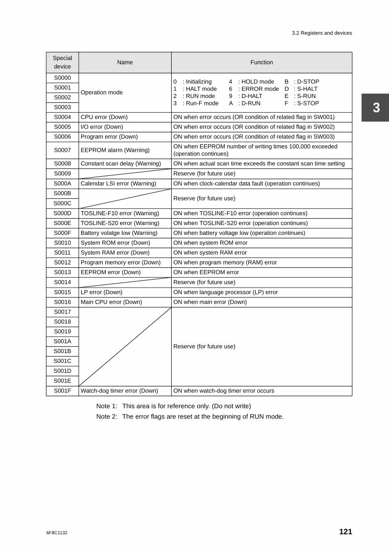
3.2 Registers and devices
3
Note 1: This area is for reference only. (Do not write)
Note 2: The error flags are reset at the beginning of RUN mode.
Special device
Name Function
S0000
Operation mode
0 : Initializing 4 : HOLD mode B : D-STOP1 : HALT mode 6 : ERROR mode D : S-HALT2 : RUN mode 9 : D-HALT E : S-RUN3 : Run-F mode A : D-RUN F : S-STOP
S0001
S0002
S0003
S0004 CPU error (Down) ON when error occurs (OR condition of related flag in SW001)
S0005 I/O error (Down) ON when error occurs (OR condition of related flag in SW002)
S0006 Program error (Down) ON when error occurs (OR condition of related flag in SW003)
S0007 EEPROM alarm (Warning)ON when EEPROM number of writing times 100,000 exceeded (operation continues)
S0008 Constant scan delay (Warning) ON when actual scan time exceeds the constant scan time setting
S0009 Reserve (for future use)
S000A Calendar LSI error (Warning) ON when clock-calendar data fault (operation continues)
S000BReserve (for future use)
S000C
S000D TOSLINE-F10 error (Warning) ON when TOSLINE-F10 error (operation continues)
S000E TOSLINE-S20 error (Warning) ON when TOSLINE-S20 error (operation continues)
S000F Battery volatge low (Warning) ON when battery voltage low (operation continues)
S0010 System ROM error (Down) ON when system ROM error
S0011 System RAM error (Down) ON when system RAM error
S0012 Program memory error (Down) ON when program memory (RAM) error
S0013 EEPROM error (Down) ON when EEPROM error
S0014 Reserve (for future use)
S0015 LP error (Down) ON when language processor (LP) error
S0016 Main CPU error (Down) ON when main error (Down)
S0017
Reserve (for future use)
S0018
S0019
S001A
S001B
S001C
S001D
S001E
S001F Watch-dog timer error (Down) ON when watch-dog timer error occurs
6F8C1132 121
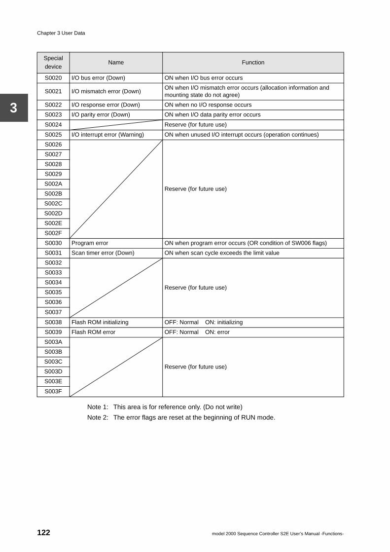
Chapter 3 User Data
3
Note 1: This area is for reference only. (Do not write)
Note 2: The error flags are reset at the beginning of RUN mode.
Special device
Name Function
S0020 I/O bus error (Down) ON when I/O bus error occurs
S0021 I/O mismatch error (Down)ON when I/O mismatch error occurs (allocation information and mounting state do not agree)
S0022 I/O response error (Down) ON when no I/O response occurs
S0023 I/O parity error (Down) ON when I/O data parity error occurs
S0024 Reserve (for future use)
S0025 I/O interrupt error (Warning) ON when unused I/O interrupt occurs (operation continues)
S0026
Reserve (for future use)
S0027
S0028
S0029
S002A
S002B
S002C
S002D
S002E
S002F
S0030 Program error ON when program error occurs (OR condition of SW006 flags)
S0031 Scan timer error (Down) ON when scan cycle exceeds the limit value
S0032
Reserve (for future use)
S0033
S0034
S0035
S0036
S0037
S0038 Flash ROM initializing OFF: Normal ON: initializing
S0039 Flash ROM error OFF: Normal ON: error
S003A
Reserve (for future use)
S003B
S003C
S003D
S003E
S003F
122 model 2000 Sequence Controller S2E User’s Manual -Functions-
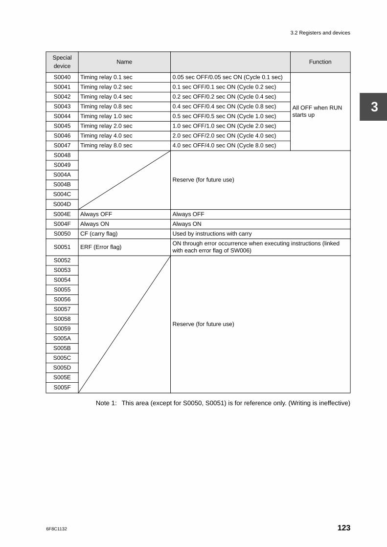
3.2 Registers and devices
3
Note 1: This area (except for S0050, S0051) is for reference only. (Writing is ineffective)
Special device
Name Function
S0040 Timing relay 0.1 sec 0.05 sec OFF/0.05 sec ON (Cycle 0.1 sec)
All OFF when RUN starts up
S0041 Timing relay 0.2 sec 0.1 sec OFF/0.1 sec ON (Cycle 0.2 sec)
S0042 Timing relay 0.4 sec 0.2 sec OFF/0.2 sec ON (Cycle 0.4 sec)
S0043 Timing relay 0.8 sec 0.4 sec OFF/0.4 sec ON (Cycle 0.8 sec)
S0044 Timing relay 1.0 sec 0.5 sec OFF/0.5 sec ON (Cycle 1.0 sec)
S0045 Timing relay 2.0 sec 1.0 sec OFF/1.0 sec ON (Cycle 2.0 sec)
S0046 Timing relay 4.0 sec 2.0 sec OFF/2.0 sec ON (Cycle 4.0 sec)
S0047 Timing relay 8.0 sec 4.0 sec OFF/4.0 sec ON (Cycle 8.0 sec)
S0048
Reserve (for future use)
S0049
S004A
S004B
S004C
S004D
S004E Always OFF Always OFF
S004F Always ON Always ON
S0050 CF (carry flag) Used by instructions with carry
S0051 ERF (Error flag)ON through error occurrence when executing instructions (linked with each error flag of SW006)
S0052
Reserve (for future use)
S0053
S0054
S0055
S0056
S0057
S0058
S0059
S005A
S005B
S005C
S005D
S005E
S005F
6F8C1132 123
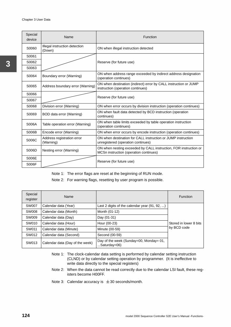
Chapter 3 User Data
3
Note 1: The error flags are reset at the beginning of RUN mode.
Note 2: For warning flags, resetting by user program is possible.
Note 1: The clock-calendar data setting is performed by calendar setting instruction (CLND) or by calendar setting operation by programmer. (It is ineffective to write data directly to the special registers)
Note 2: When the data cannot be read correctly due to the calendar LSI fault, these reg-isters become H00FF.
Note 3: Calendar accuracy is 30 seconds/month.
Special device
Name Function
S0060Illegal instruction detection (Down)
ON when illegal instruction detected
S0061
Reserve (for future use)S0062
S0063
S0064 Boundary error (Warning)ON when address range exceeded by indirect address designation (operation continues)
S0065 Address boundary error (Warning)ON when destination (indirect) error by CALL instruction or JUMP instruction (operation continues)
S0066Reserve (for future use)
S0067
S0068 Division error (Warning) ON when error occurs by division instruction (operation continues)
S0069 BOD data error (Warning)ON when fault data detected by BCD instruction (operation continues)
S006A Table operation error (Warning)ON when table limits exceeded by table operation instruction (operation continues)
S006B Encode error (Warning) ON when error occurs by encode instruction (operation continues)
S006CAddress registration error (Warning)
ON when destination for CALL instruction or JUMP instruction unregistered (operation continues)
S006D Nesting error (Warning)ON when nesting exceeded by CALL instruction, FOR instruction or MCSn instruction (operation continues)
S006EReserve (for future use)
S006F
Specialregister
Name Function
SW007 Calendar data (Year) Last 2 digits of the calendar year (91, 92, ...)
Stored in lower 8 bits by BCD code
SW008 Calendar data (Month) Month (01-12)
SW009 Calendar data (Day) Day (01-31)
SW010 Calendar data (Hour) Hour (00-23)
SW011 Calendar data (Minute) Minute (00-59)
SW012 Calendar data (Second) Second (00-59)
SW013 Calendar data (Day of the week)Day of the week (Sunday=00, Monday= 01, ...Saturday=06)
124 model 2000 Sequence Controller S2E User’s Manual -Functions-
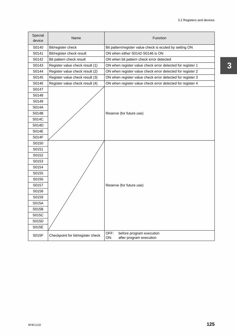
3.2 Registers and devices
3
Special device
Name Function
S0140 Bit/register check Bit pattern/register value check is ecuted by setting ON
S0141 Bit/register check result ON when either S0142-S0146 is ON
S0142 Bit pattern check result ON when bit pattern check error detected
S0143 Register value check result (1) ON when register value check error detected for register 1
S0144 Register value check result (2) ON when register value check error detected for register 2
S0145 Register value check result (3) ON when register value check error detected for register 3
S0146 Register value check result (4) ON when register value check error detected for register 4
S0147
Reserve (for future use)
S0148
S0149
S014A
S014B
S014C
S014D
S014E
S014F
S0150
Reserve (for future use)
S0151
S0152
S0153
S0154
S0155
S0156
S0157
S0158
S0159
S015A
S015B
S015C
S015D
S015E
S015F Checkpoint for bit/register checkOFF: before program executionON: after program execution
6F8C1132 125
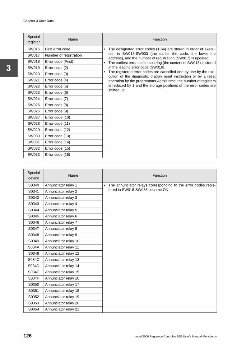
Chapter 3 User Data
3
Specialregister
Name Function
SW016 First error code • The designated error codes (1-64) are stored in order of execu-tion in SW018-SW033 (the earlier the code, the lower theaddress), and the number of registration (SW017) is updated.
• The earliest error code occurring (the content of SW018) is storedin the leading error code (SW016).
• The registered error codes are cancelled one by one by the exe-cution of the diagnostic display reset instruction or by a resetoperation by the programmer.At this time, the number of registersis reduced by 1 and the storage positions of the error codes areshifted up.
SW017 Number of registration
SW018 Error code (First)
SW019 Error code (2)
SW020 Error code (3)
SW021 Error code (4)
SW022 Error code (5)
SW023 Error code (6)
SW024 Error code (7)
SW025 Error code (8)
SW026 Error code (9)
SW027 Error code (10)
SW028 Error code (11)
SW029 Error code (12)
SW030 Error code (13)
SW031 Error code (14)
SW032 Error code (15)
SW033 Error code (16)
Special device
Name Function
S0340 Annunciator relay 1 • The annunciator relays corresponding to the error codes regis-tered in SW018-SW033 become ONS0341 Annunciator relay 2
S0342 Annunciator relay 3
S0343 Annunciator relay 4
S0344 Annunciator relay 5
S0345 Annunciator relay 6
S0346 Annunciator relay 7
S0347 Annunciator relay 8
S0348 Annunciator relay 9
S0349 Annunciator relay 10
S034A Annunciator relay 11
S0348 Annunciator relay 12
S034C Annunciator relay 13
S034D Annunciator relay 14
S034E Annunciator relay 15
S034F Annunciator relay 16
S0350 Annunciator relay 17
S0351 Annunciator relay 18
S0352 Annunciator relay 19
S0353 Annunciator relay 20
S0354 Annunciator relay 21
126 model 2000 Sequence Controller S2E User’s Manual -Functions-
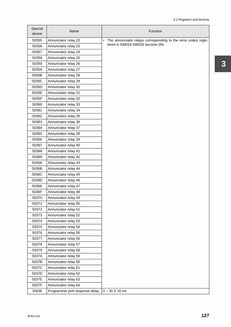
3.2 Registers and devices
3
S0355 Annunciator relay 22 • The annunciator relays corresponding to the error codes regis-tered in SW018-SW033 become ONS0356 Annunciator relay 23
S0357 Annunciator relay 24
S0358 Annunciator relay 25
S0359 Annunciator relay 26
S035A Annunciator relay 27
S035B Annunciator relay 28
S035C Annunciator relay 29
S035D Annunciator relay 30
S035E Annunciator relay 31
S035F Annunciator relay 32
S0360 Annunciator relay 33
S0361 Annunciator relay 34
S0362 Annunciator relay 35
S0363 Annunciator relay 36
S0364 Annunciator relay 37
S0365 Annunciator relay 38
S0366 Annunciator relay 39
S0367 Annunciator relay 40
S0368 Annunciator relay 41
S0369 Annunciator relay 42
S036A Annunciator relay 43
S036B Annunciator relay 44
S036C Annunciator relay 45
S036D Annunciator relay 46
S036E Annunciator relay 47
S036F Annunciator relay 48
S0370 Annunciator relay 49
S0371 Annunciator relay 50
S0372 Annunciator relay 51
S0373 Annunciator relay 52
S0374 Annunciator relay 53
S0375 Annunciator relay 54
S0376 Annunciator relay 55
S0377 Annunciator relay 56
S0378 Annunciator relay 57
S0379 Annunciator relay 58
S037A Annunciator relay 59
S037B Annunciator relay 60
S037C Annunciator relay 61
S037D Annunciator relay 62
S037E Annunciator relay 63
S037F Annunciator relay 64
SW38 Programmer port response delay 0 ~ 30 X 10 ms
Special device
Name Function
6F8C1132 127
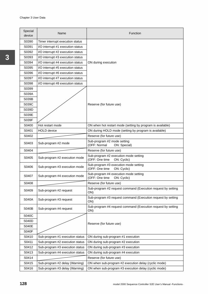
Chapter 3 User Data
3
Special device
Name Function
S0390 Timer interrupt execution status
ON during execution
S0391 I/O interrupt #1 execution status
S0392 I/O interrupt #2 execution status
S0393 I/O interrupt #3 execution status
S0394 I/O interrupt #4 execution status
S0395 I/O interrupt #5 execution status
S0396 I/O interrupt #6 execution status
S0397 I/O interrupt #7 execution status
S0398 I/O interrupt #8 execution status
S0399
Reserve (for future use)
S039A
S039B
S039C
S039D
S039E
S039F
S0400 Hot restart mode ON when hot restart mode (setting by program is available)
S0401 HOLD device ON during HOLD mode (setting by program is available)
S0402 Reserve (for future use)
S0403 Sub-program #2 modeSub-program #2 mode setting(OFF: Normal ON: Special)
S0404 Reserve (for future use)
S0405 Sub-program #2 execution modeSub-program #2 execution mode setting(OFF: One time ON: Cyclic)
S0406 Sub-program #3 execution modeSub-program #3 execution mode setting(OFF: One time ON: Cyclic)
S0407 Sub-program #4 execution modeSub-program #4 execution mode setting(OFF: One time ON: Cyclic)
S0408 Reserve (for future use)
S0409 Sub-program #2 requestSub-program #2 request command (Execution request by setting ON)
S040A Sub-program #3 requestSub-program #3 request command (Execution request by setting ON)
S040B Sub-program #4 requestSub-program #4 request command (Execution request by setting ON)
S040C
Reserve (for future use)S040D
S040E
S040F
S0410 Sub-program #1 execution status ON during sub-program #1 execution
S0411 Sub-program #2 execution status ON during sub-program #2 execution
S0412 Sub-program #3 execution status ON during sub-program #3 execution
S0413 Sub-program #4 execution status ON during sub-program #4 execution
S0414 Reserve (for future use)
S0415 Sub-program #2 delay (Warning) ON when sub-program #2 execution delay (cyclic mode)
S0416 Sub-program #3 delay (Warning) ON when sub-program #3 execution delay (cyclic mode)
128 model 2000 Sequence Controller S2E User’s Manual -Functions-
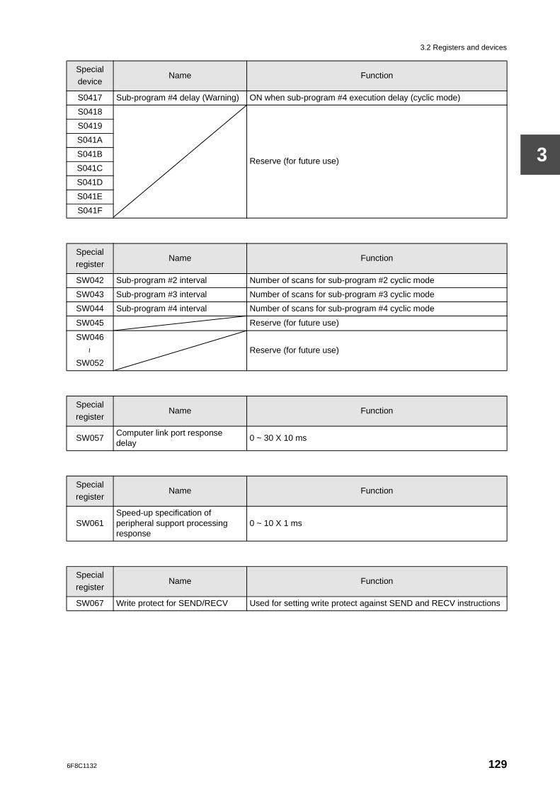
3.2 Registers and devices
3
S0417 Sub-program #4 delay (Warning) ON when sub-program #4 execution delay (cyclic mode)
S0418
Reserve (for future use)
S0419
S041A
S041B
S041C
S041D
S041E
S041F
Special device
Name Function
Specialregister
Name Function
SW042 Sub-program #2 interval Number of scans for sub-program #2 cyclic mode
SW043 Sub-program #3 interval Number of scans for sub-program #3 cyclic mode
SW044 Sub-program #4 interval Number of scans for sub-program #4 cyclic mode
SW045 Reserve (for future use)
SW046
Reserve (for future use)~
SW052
Specialregister
Name Function
SW057Computer link port response delay
0 ~ 30 X 10 ms
Specialregister
Name Function
SW061Speed-up specification of peripheral support processing response
0 ~ 10 X 1 ms
Specialregister
Name Function
SW067 Write protect for SEND/RECV Used for setting write protect against SEND and RECV instructions
6F8C1132 129
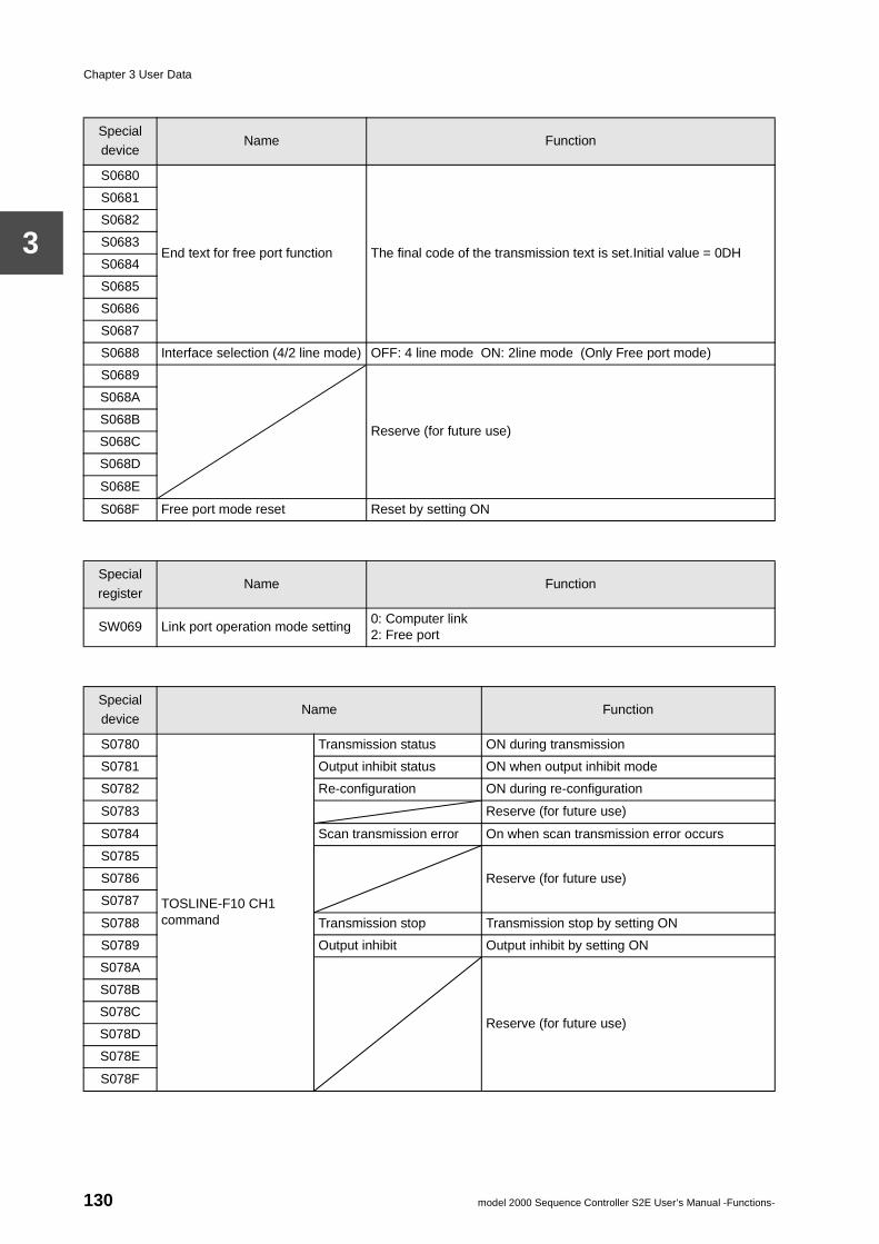
Chapter 3 User Data
3
Special device
Name Function
S0680
End text for free port function The final code of the transmission text is set.Initial value = 0DH
S0681
S0682
S0683
S0684
S0685
S0686
S0687
S0688 Interface selection (4/2 line mode) OFF: 4 line mode ON: 2line mode (Only Free port mode)
S0689
Reserve (for future use)
S068A
S068B
S068C
S068D
S068E
S068F Free port mode reset Reset by setting ON
Special
registerName Function
SW069 Link port operation mode setting0: Computer link2: Free port
Special device
Name Function
S0780
TOSLINE-F10 CH1 command
Transmission status ON during transmission
S0781 Output inhibit status ON when output inhibit mode
S0782 Re-configuration ON during re-configuration
S0783 Reserve (for future use)
S0784 Scan transmission error On when scan transmission error occurs
S0785
Reserve (for future use)S0786
S0787
S0788 Transmission stop Transmission stop by setting ON
S0789 Output inhibit Output inhibit by setting ON
S078A
Reserve (for future use)
S078B
S078C
S078D
S078E
S078F
130 model 2000 Sequence Controller S2E User’s Manual -Functions-
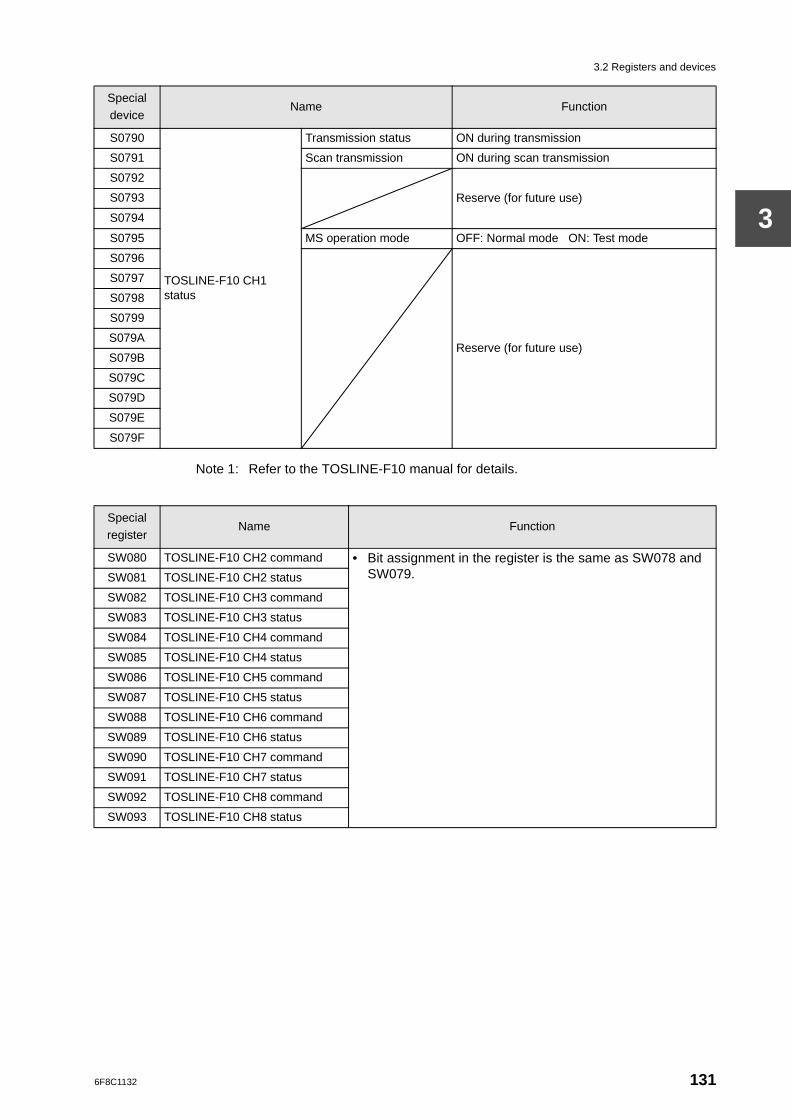
3.2 Registers and devices
3
Note 1: Refer to the TOSLINE-F10 manual for details.
S0790
TOSLINE-F10 CH1 status
Transmission status ON during transmission
S0791 Scan transmission ON during scan transmission
S0792
Reserve (for future use)S0793
S0794
S0795 MS operation mode OFF: Normal mode ON: Test mode
S0796
Reserve (for future use)
S0797
S0798
S0799
S079A
S079B
S079C
S079D
S079E
S079F
Special device
Name Function
Specialregister
Name Function
SW080 TOSLINE-F10 CH2 command • Bit assignment in the register is the same as SW078 and SW079.SW081 TOSLINE-F10 CH2 status
SW082 TOSLINE-F10 CH3 command
SW083 TOSLINE-F10 CH3 status
SW084 TOSLINE-F10 CH4 command
SW085 TOSLINE-F10 CH4 status
SW086 TOSLINE-F10 CH5 command
SW087 TOSLINE-F10 CH5 status
SW088 TOSLINE-F10 CH6 command
SW089 TOSLINE-F10 CH6 status
SW090 TOSLINE-F10 CH7 command
SW091 TOSLINE-F10 CH7 status
SW092 TOSLINE-F10 CH8 command
SW093 TOSLINE-F10 CH8 status
6F8C1132 131
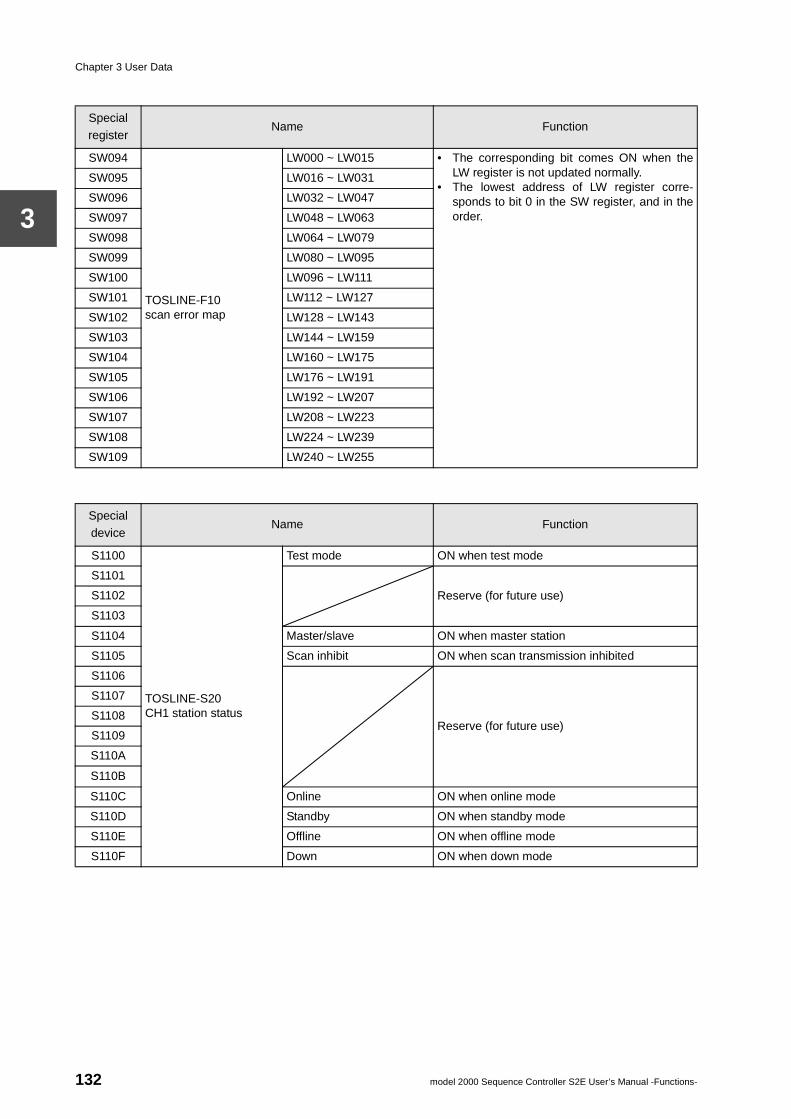
Chapter 3 User Data
3
Specialregister
Name Function
SW094
TOSLINE-F10 scan error map
LW000 ~ LW015 • The corresponding bit comes ON when theLW register is not updated normally.
• The lowest address of LW register corre-sponds to bit 0 in the SW register, and in theorder.
SW095 LW016 ~ LW031
SW096 LW032 ~ LW047
SW097 LW048 ~ LW063
SW098 LW064 ~ LW079
SW099 LW080 ~ LW095
SW100 LW096 ~ LW111
SW101 LW112 ~ LW127
SW102 LW128 ~ LW143
SW103 LW144 ~ LW159
SW104 LW160 ~ LW175
SW105 LW176 ~ LW191
SW106 LW192 ~ LW207
SW107 LW208 ~ LW223
SW108 LW224 ~ LW239
SW109 LW240 ~ LW255
Specialdevice
Name Function
S1100
TOSLINE-S20 CH1 station status
Test mode ON when test mode
S1101
Reserve (for future use)S1102
S1103
S1104 Master/slave ON when master station
S1105 Scan inhibit ON when scan transmission inhibited
S1106
Reserve (for future use)
S1107
S1108
S1109
S110A
S110B
S110C Online ON when online mode
S110D Standby ON when standby mode
S110E Offline ON when offline mode
S110F Down ON when down mode
132 model 2000 Sequence Controller S2E User’s Manual -Functions-
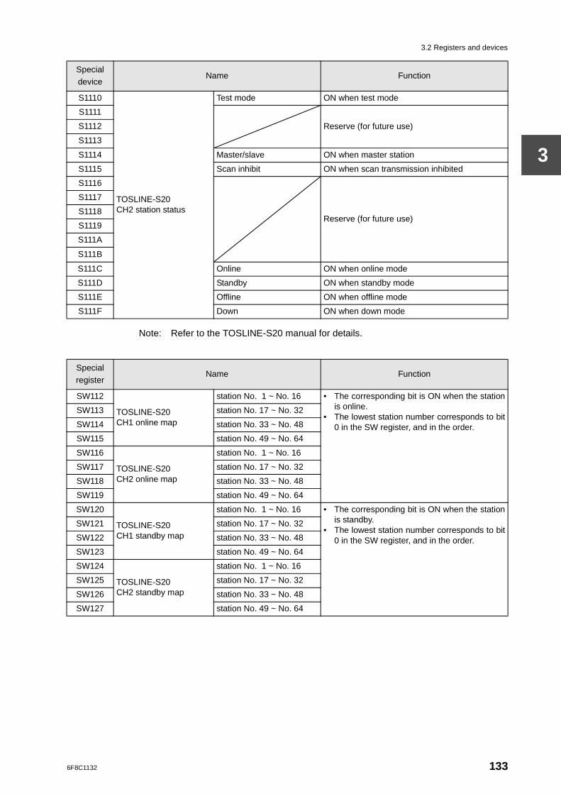
3.2 Registers and devices
3
Note: Refer to the TOSLINE-S20 manual for details.
S1110
TOSLINE-S20 CH2 station status
Test mode ON when test mode
S1111
Reserve (for future use)S1112
S1113
S1114 Master/slave ON when master station
S1115 Scan inhibit ON when scan transmission inhibited
S1116
Reserve (for future use)
S1117
S1118
S1119
S111A
S111B
S111C Online ON when online mode
S111D Standby ON when standby mode
S111E Offline ON when offline mode
S111F Down ON when down mode
Specialdevice
Name Function
Specialregister
Name Function
SW112
TOSLINE-S20 CH1 online map
station No. 1 ~ No. 16 • The corresponding bit is ON when the stationis online.
• The lowest station number corresponds to bit0 in the SW register, and in the order.
SW113 station No. 17 ~ No. 32
SW114 station No. 33 ~ No. 48
SW115 station No. 49 ~ No. 64
SW116
TOSLINE-S20 CH2 online map
station No. 1 ~ No. 16
SW117 station No. 17 ~ No. 32
SW118 station No. 33 ~ No. 48
SW119 station No. 49 ~ No. 64
SW120
TOSLINE-S20 CH1 standby map
station No. 1 ~ No. 16 • The corresponding bit is ON when the stationis standby.
• The lowest station number corresponds to bit0 in the SW register, and in the order.
SW121 station No. 17 ~ No. 32
SW122 station No. 33 ~ No. 48
SW123 station No. 49 ~ No. 64
SW124
TOSLINE-S20 CH2 standby map
station No. 1 ~ No. 16
SW125 station No. 17 ~ No. 32
SW126 station No. 33 ~ No. 48
SW127 station No. 49 ~ No. 64
6F8C1132 133
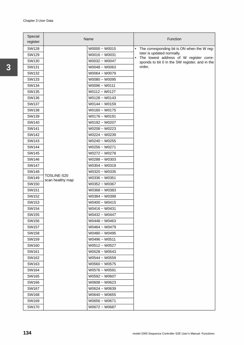
Chapter 3 User Data
3
Specialregister
Name Function
SW128
TOSLINE-S20 scan healthy map
W0000 ~ W0015 • The corresponding bit is ON when the W reg-ister is updated normally.
• The lowest address of W register corre-sponds to bit 0 in the SW register, and in theorder.
SW129 W0016 ~ W0031
SW130 W0032 ~ W0047
SW131 W0048 ~ W0063
SW132 W0064 ~ W0079
SW133 W0080 ~ W0095
SW134 W0096 ~ W0111
SW135 W0112 ~ W0127
SW136 W0128 ~ W0143
SW137 W0144 ~ W0159
SW138 W0160 ~ W0175
SW139 W0176 ~ W0191
SW140 W0192 ~ W0207
SW141 W0208 ~ W0223
SW142 W0224 ~ W0239
SW143 W0240 ~ W0255
SW144 W0256 ~ W0271
SW145 W0272 ~ W0278
SW146 W0288 ~ W0303
SW147 W0304 ~ W0319
SW148 W0320 ~ W0335
SW149 W0336 ~ W0351
SW150 W0352 ~ W0367
SW151 W0368 ~ W0383
SW152 W0384 ~ W0399
SW153 W0400 ~ W0415
SW154 W0416 ~ W0431
SW155 W0432 ~ W0447
SW156 W0448 ~ W0463
SW157 W0464 ~ W0479
SW158 W0480 ~ W0495
SW159 W0496 ~ W0511
SW160 W0512 ~ W0527
SW161 W0528 ~ W0543
SW162 W0544 ~ W0559
SW163 W0560 ~ W0575
SW164 W0576 ~ W0591
SW165 W0592 ~ W0607
SW166 W0608 ~ W0623
SW167 W0624 ~ W0639
SW168 W0640 ~ W0655
SW169 W0656 ~ W0671
SW170 W0672 ~ W0687
134 model 2000 Sequence Controller S2E User’s Manual -Functions-
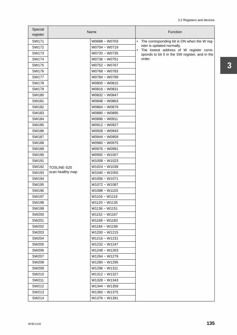
3.2 Registers and devices
3
SW171
TOSLINE-S20 scan healthy map
W0688 ~ W0703 • The corresponding bit is ON when the W reg-ister is updated normally.
• The lowest address of W register corre-sponds to bit 0 in the SW register, and in theorder.
SW172 W0704 ~ W0719
SW173 W0720 ~ W0735
SW174 W0736 ~ W0751
SW175 W0752 ~ W0767
SW176 W0768 ~ W0783
SW177 W0784 ~ W0799
SW178 W0800 ~ W0815
SW179 W0816 ~ W0831
SW180 W0832 ~ W0847
SW181 W0848 ~ W0863
SW182 W0864 ~ W0879
SW183 W0880 ~ W0895
SW184 W0896 ~ W0911
SW185 W0912 ~ W0927
SW186 W0928 ~ W0943
SW187 W0944 ~ W0959
SW188 W0960 ~ W0975
SW189 W0976 ~ W0991
SW190 W0992 ~ W1007
SW191 W1008 ~ W1023
SW192 W1024 ~ W1039
SW193 W1040 ~ W1055
SW194 W1056 ~ W1071
SW195 W1072 ~ W1087
SW196 W1088 ~ W1103
SW197 W1104 ~ W1119
SW198 W1120 ~ W1135
SW199 W1136 ~ W1151
SW200 W1152 ~ W1167
SW201 W1168 ~ W1183
SW202 W1184 ~ W1199
SW203 W1200 ~ W1215
SW204 W1216 ~ W1231
SW205 W1232 ~ W1247
SW206 W1248 ~ W1263
SW207 W1264 ~ W1279
SW208 W1280 ~ W1295
SW209 W1296 ~ W1311
SW210 W1312 ~ W1327
SW211 W1328 ~ W1343
SW212 W1344 ~ W1359
SW213 W1360 ~ W1375
SW214 W1376 ~ W1391
Specialregister
Name Function
6F8C1132 135
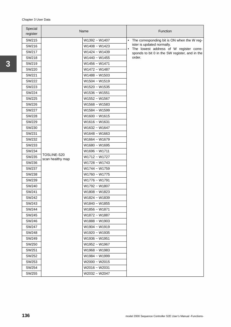
Chapter 3 User Data
3
SW215
TOSLINE-S20 scan healthy map
W1392 ~ W1407 • The corresponding bit is ON when the W reg-ister is updated normally.
• The lowest address of W register corre-sponds to bit 0 in the SW register, and in theorder.
SW216 W1408 ~ W1423
SW217 W1424 ~ W1439
SW218 W1440 ~ W1455
SW219 W1456 ~ W1471
SW220 W1472 ~ W1487
SW221 W1488 ~ W1503
SW222 W1504 ~ W1519
SW223 W1520 ~ W1535
SW224 W1536 ~ W1551
SW225 W1552 ~ W1567
SW226 W1568 ~ W1583
SW227 W1584 ~ W1599
SW228 W1600 ~ W1615
SW229 W1616 ~ W1631
SW230 W1632 ~ W1647
SW231 W1648 ~ W1663
SW232 W1664 ~ W1679
SW233 W1680 ~ W1695
SW234 W1696 ~ W1711
SW235 W1712 ~ W1727
SW236 W1728 ~ W1743
SW237 W1744 ~ W1759
SW238 W1760 ~ W1775
SW239 W1776 ~ W1791
SW240 W1792 ~ W1807
SW241 W1808 ~ W1823
SW242 W1824 ~ W1839
SW243 W1840 ~ W1855
SW244 W1856 ~ W1871
SW245 W1872 ~ W1887
SW246 W1888 ~ W1903
SW247 W1904 ~ W1919
SW248 W1920 ~ W1935
SW249 W1936 ~ W1951
SW250 W1952 ~ W1967
SW251 W1968 ~ W1983
SW252 W1984 ~ W1999
SW253 W2000 ~ W2015
SW254 W2016 ~ W2031
SW255 W2032 ~ W2047
Specialregister
Name Function
136 model 2000 Sequence Controller S2E User’s Manual -Functions-
3.3 Register data types
3
3.3 Register data types
It has already been explained the register is "a location which stores 16 bits of data". In the S2E instructions, the following types of data can be processed using single registers or multiple consecutive registers.
• Unsigned integers (integers in the range 0 to 65535)
• Integers (integers in the range -32768 to 32767)
• BCD (integers in the range 0 to 9999 expressed by BCD code)
• Unsigned double-length integers (integers in the range 0 to 4294967295)
• Double-length integers (integers in the range -2147483648 to 2147483647)
• Double-length BCD (integers in the range 0 to 99999999 expressed by BCD code)
• Floating point data (real number in the range -3.40282 X 1038 to 3.40282 X 1038)
However, there are no dedicated registers corresponding to the types for processing these types of data. The processing of the register data varies according to which instruction is used.
In other words, as shown in the following example, even when the same register is used, if the data type of the instruction differs, the processing of the register data will also differ.
Example)
When the value of D0005 is HFFFF (hexadecimal FFFF):
(1) In the unsigned comparison instruction (Greater than), −[ D0005 U > 100 ]− decision output (ON when true) The value of D0005 is regarded as 65535 (unsigned integer), therefore it is judged to be greater than the compared value (100) and the output of the instruction becomes ON.
(2) In the (signed) comparison instruction (Greater than), −[ D0005 > 100 ]− decision output (ON when true) The value of D0005 is regarded as -1 (integer), therefore it is judged not to be greater than the compared value (100) and the output of the instruction becomes OFF.
In this way, since there is no classification of registers by data type, it is possible to execute complex data operations provided their use is thoroughly understood. However, in order to make the program easier to see, it is recommended that registers be used by allocation by data types (1 register is processed by 1 data type) as far as possible.
6F8C1132 137
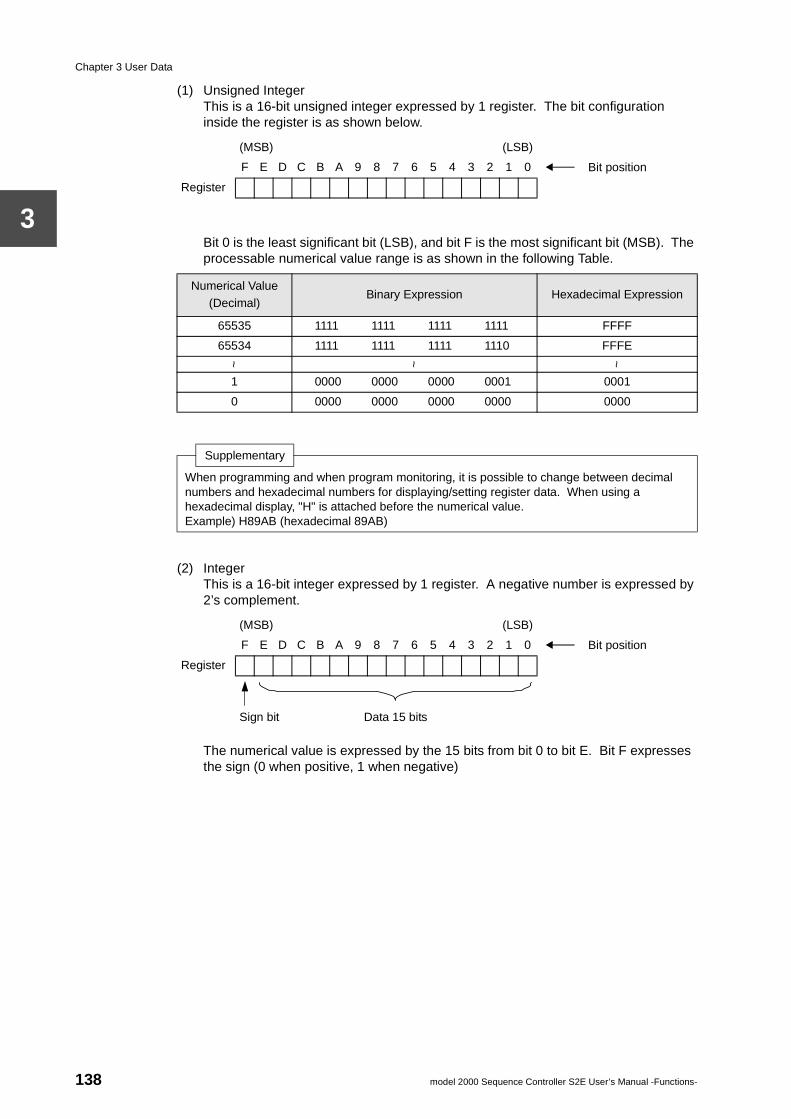
Chapter 3 User Data
3
(1) Unsigned IntegerThis is a 16-bit unsigned integer expressed by 1 register. The bit configuration inside the register is as shown below.
Bit 0 is the least significant bit (LSB), and bit F is the most significant bit (MSB). The processable numerical value range is as shown in the following Table.
(2) IntegerThis is a 16-bit integer expressed by 1 register. A negative number is expressed by 2’s complement.
The numerical value is expressed by the 15 bits from bit 0 to bit E. Bit F expresses the sign (0 when positive, 1 when negative)
(MSB) (LSB)
F E D C B A 9 8 7 6 5 4 3 2 1 0 Bit position
Register
Numerical Value (Decimal)
Binary Expression Hexadecimal Expression
65535 1111 1111 1111 1111 FFFF
65534 1111 1111 1111 1110 FFFE
~ ~ ~
1 0000 0000 0000 0001 0001
0 0000 0000 0000 0000 0000
Supplementary
When programming and when program monitoring, it is possible to change between decimal numbers and hexadecimal numbers for displaying/setting register data. When using a hexadecimal display, "H" is attached before the numerical value.Example) H89AB (hexadecimal 89AB)
(MSB) (LSB)
F E D C B A 9 8 7 6 5 4 3 2 1 0 Bit position
Register
Sign bit Data 15 bits
138 model 2000 Sequence Controller S2E User’s Manual -Functions-
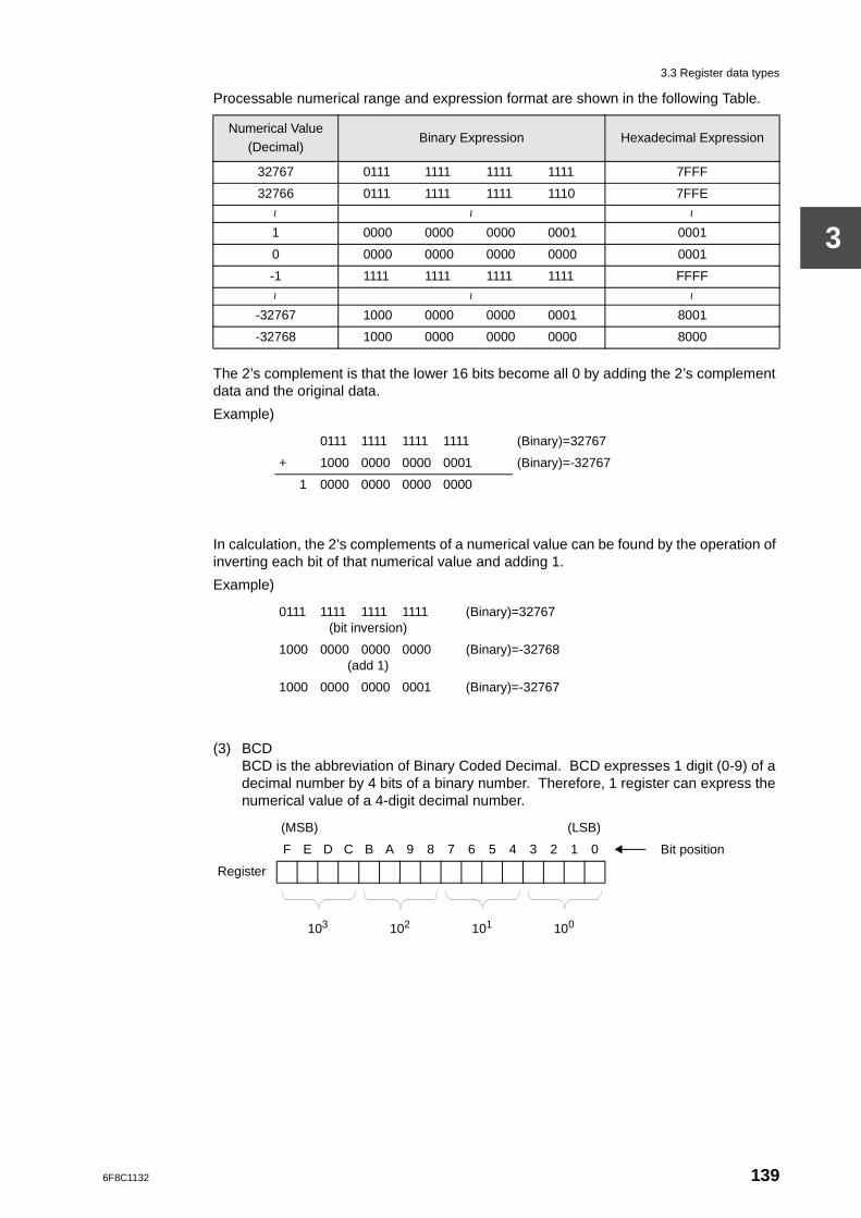
3.3 Register data types
3
Processable numerical range and expression format are shown in the following Table.
The 2’s complement is that the lower 16 bits become all 0 by adding the 2’s complement data and the original data.
Example)
In calculation, the 2’s complements of a numerical value can be found by the operation of inverting each bit of that numerical value and adding 1.
Example)
(3) BCDBCD is the abbreviation of Binary Coded Decimal. BCD expresses 1 digit (0-9) of a decimal number by 4 bits of a binary number. Therefore, 1 register can express the numerical value of a 4-digit decimal number.
Numerical Value (Decimal)
Binary Expression Hexadecimal Expression
32767 0111 1111 1111 1111 7FFF
32766 0111 1111 1111 1110 7FFE
~ ~ ~
1 0000 0000 0000 0001 0001
0 0000 0000 0000 0000 0001
-1 1111 1111 1111 1111 FFFF~ ~ ~
-32767 1000 0000 0000 0001 8001
-32768 1000 0000 0000 0000 8000
0111 1111 1111 1111 (Binary)=32767
+ 1000 0000 0000 0001 (Binary)=-32767
1 0000 0000 0000 0000
0111 1111 1111 1111(bit inversion)
(Binary)=32767
1000 0000 0000 0000(add 1)
(Binary)=-32768
1000 0000 0000 0001 (Binary)=-32767
(MSB) (LSB)
F E D C B A 9 8 7 6 5 4 3 2 1 0 Bit position
Register
103 102 101 100
6F8C1132 139
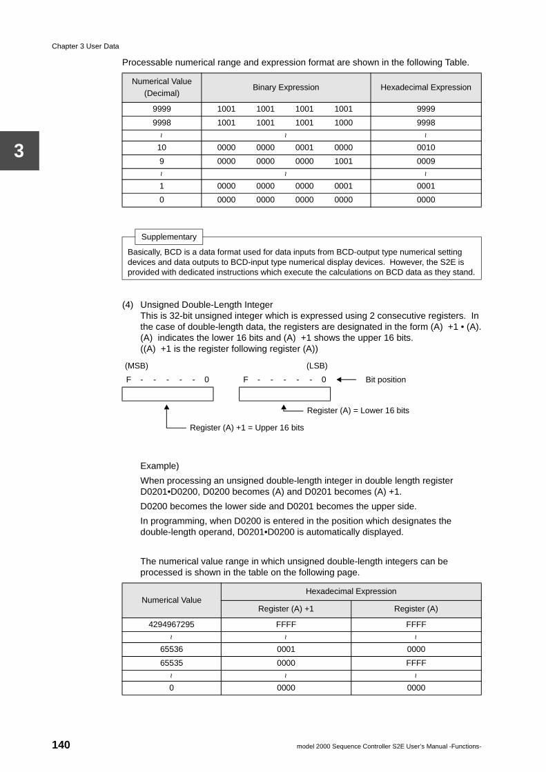
Chapter 3 User Data
3
Processable numerical range and expression format are shown in the following Table.
(4) Unsigned Double-Length IntegerThis is 32-bit unsigned integer which is expressed using 2 consecutive registers. In the case of double-length data, the registers are designated in the form (A) +1 • (A).(A) indicates the lower 16 bits and (A) +1 shows the upper 16 bits. ((A) +1 is the register following register (A))
Example)
When processing an unsigned double-length integer in double length register D0201•D0200, D0200 becomes (A) and D0201 becomes (A) +1.
D0200 becomes the lower side and D0201 becomes the upper side.
In programming, when D0200 is entered in the position which designates the double-length operand, D0201•D0200 is automatically displayed.
The numerical value range in which unsigned double-length integers can be processed is shown in the table on the following page.
Numerical Value (Decimal)
Binary Expression Hexadecimal Expression
9999 1001 1001 1001 1001 9999
9998 1001 1001 1001 1000 9998
~ ~ ~
10 0000 0000 0001 0000 0010
9 0000 0000 0000 1001 0009~ ~ ~
1 0000 0000 0000 0001 0001
0 0000 0000 0000 0000 0000
Supplementary
Basically, BCD is a data format used for data inputs from BCD-output type numerical setting devices and data outputs to BCD-input type numerical display devices. However, the S2E is provided with dedicated instructions which execute the calculations on BCD data as they stand.
(MSB) (LSB)
F - - - - - 0 F - - - - - 0 Bit position
Register (A) = Lower 16 bits
Register (A) +1 = Upper 16 bits
Numerical ValueHexadecimal Expression
Register (A) +1 Register (A)
4294967295 FFFF FFFF
~ ~ ~
65536 0001 0000
65535 0000 FFFF
~ ~ ~
0 0000 0000
140 model 2000 Sequence Controller S2E User’s Manual -Functions-
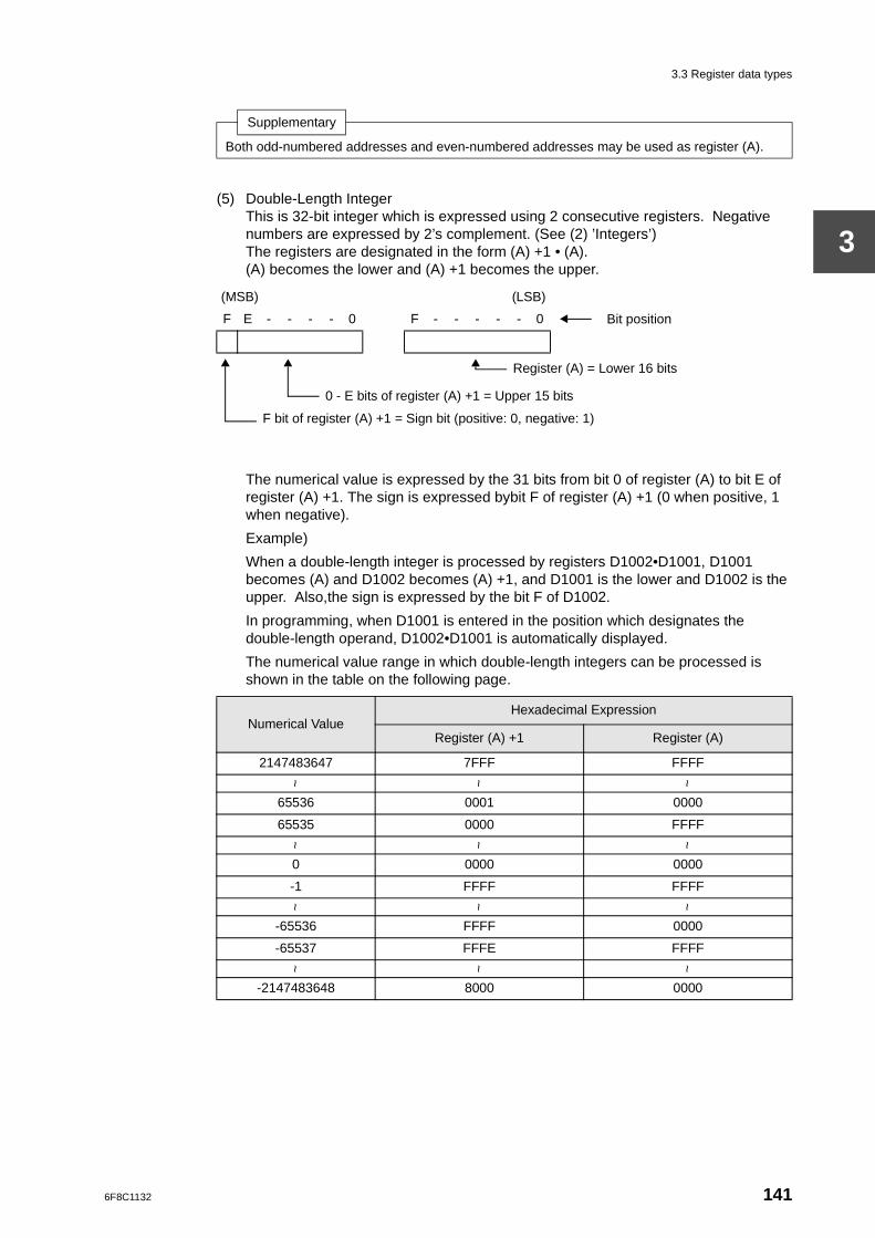
3.3 Register data types
3
(5) Double-Length IntegerThis is 32-bit integer which is expressed using 2 consecutive registers. Negative numbers are expressed by 2’s complement. (See (2) ’Integers’)The registers are designated in the form (A) +1 • (A).(A) becomes the lower and (A) +1 becomes the upper.
The numerical value is expressed by the 31 bits from bit 0 of register (A) to bit E of register (A) +1. The sign is expressed bybit F of register (A) +1 (0 when positive, 1 when negative).
Example)
When a double-length integer is processed by registers D1002•D1001, D1001 becomes (A) and D1002 becomes (A) +1, and D1001 is the lower and D1002 is the upper. Also,the sign is expressed by the bit F of D1002.
In programming, when D1001 is entered in the position which designates the double-length operand, D1002•D1001 is automatically displayed.
The numerical value range in which double-length integers can be processed is shown in the table on the following page.
Supplementary
Both odd-numbered addresses and even-numbered addresses may be used as register (A).
(MSB) (LSB)
F E - - - - 0 F - - - - - 0 Bit position
Register (A) = Lower 16 bits
0 - E bits of register (A) +1 = Upper 15 bits
F bit of register (A) +1 = Sign bit (positive: 0, negative: 1)
Numerical ValueHexadecimal Expression
Register (A) +1 Register (A)
2147483647 7FFF FFFF
~ ~ ~
65536 0001 0000
65535 0000 FFFF
~ ~ ~
0 0000 0000
-1 FFFF FFFF
~ ~ ~
-65536 FFFF 0000
-65537 FFFE FFFF
~ ~ ~
-2147483648 8000 0000
6F8C1132 141
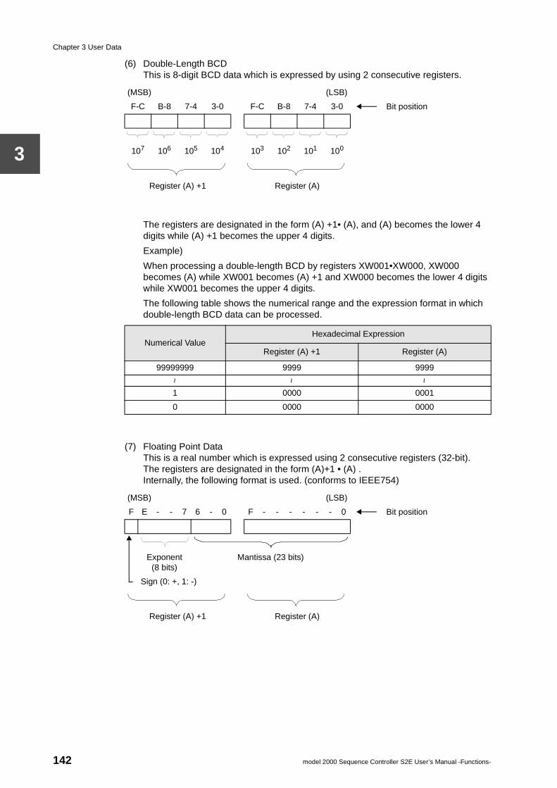
Chapter 3 User Data
3
(6) Double-Length BCDThis is 8-digit BCD data which is expressed by using 2 consecutive registers.
The registers are designated in the form (A) +1• (A), and (A) becomes the lower 4 digits while (A) +1 becomes the upper 4 digits.
Example)
When processing a double-length BCD by registers XW001•XW000, XW000 becomes (A) while XW001 becomes (A) +1 and XW000 becomes the lower 4 digits while XW001 becomes the upper 4 digits.
The following table shows the numerical range and the expression format in which double-length BCD data can be processed.
(7) Floating Point DataThis is a real number which is expressed using 2 consecutive registers (32-bit).The registers are designated in the form (A)+1 • (A) .Internally, the following format is used. (conforms to IEEE754)
(MSB) (LSB)
F-C B-8 7-4 3-0 F-C B-8 7-4 3-0 Bit position
107 106 105 104 103 102 101 100
Register (A) +1 Register (A)
Numerical ValueHexadecimal Expression
Register (A) +1 Register (A)
99999999 9999 9999
~ ~ ~
1 0000 0001
0 0000 0000
(MSB) (LSB)
F E - - 7 6 - 0 F - - - - - - 0 Bit position
Exponent (8 bits)
Mantissa (23 bits)
Sign (0: +, 1: -)
Register (A) +1 Register (A)
142 model 2000 Sequence Controller S2E User’s Manual -Functions-
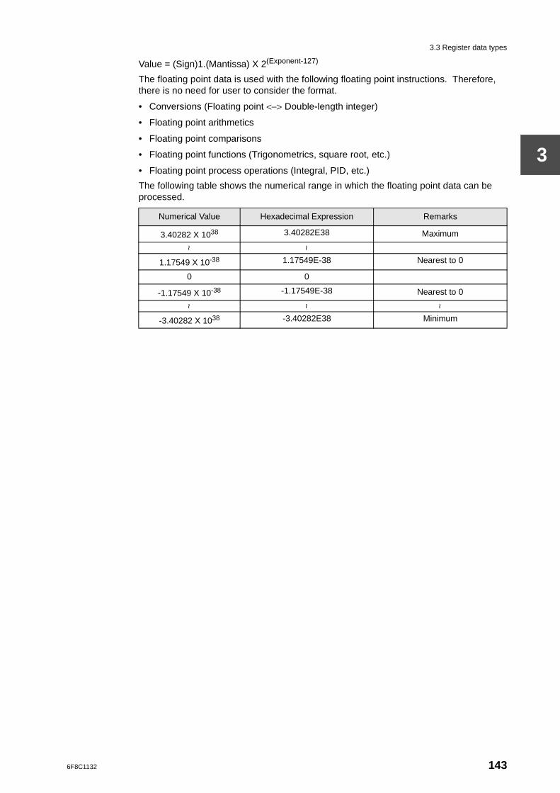
3.3 Register data types
3
Value = (Sign)1.(Mantissa) X 2(Exponent-127)
The floating point data is used with the following floating point instructions. Therefore, there is no need for user to consider the format.
• Conversions (Floating point <−> Double-length integer)
• Floating point arithmetics
• Floating point comparisons
• Floating point functions (Trigonometrics, square root, etc.)
• Floating point process operations (Integral, PID, etc.)
The following table shows the numerical range in which the floating point data can be processed.
Numerical Value Hexadecimal Expression Remarks
3.40282 X 1038 3.40282E38 Maximum
~ ~
1.17549 X 10-38 1.17549E-38 Nearest to 0
0 0
-1.17549 X 10-38 -1.17549E-38 Nearest to 0
~ ~ ~
-3.40282 X 1038 -3.40282E38 Minimum
6F8C1132 143
Chapter 3 User Data
3
3.4 Index modification
When registers are used by instructions, the method of directly designating the register address as shown in Example 1) below is called ’direct addressing’.
As opposed to this, the method of indirectly designating the register by combination with the contents of the index registers (I, J, K) as shown in Example 2) below is called the ’indirect addressing’. In particular, in this case, since the address is modified using an index register, this is called ’index modification’.
Example 1)
−[ RW100 MOV D3500 ]−Data transfer instruction Transfer content of RW100 to D3500
Example 2)
I J
−[ RW100 MOV D3500 ]−Data transfer instruction (index modification attached) Transfer content of RW(100+l) to D(3500+J) (If I=3 and J=200, the content of RW103 is transferred to D3700)
There are 3 types of index register, I, J and K. Each type processes 16-bit integers (-32768 to 32767). There are no particular differences in function between these 3 types of index register.
There is no special instruction for substituting values in these index registers. There are designated as destination for normal instructions.
Example 1) Substituting a constant in an index register
−[ 64 MOV I ]− (Substitute 64 in index register I)
−[ -2 MOV J ]− (Substitute -2 in index register J)
Example 2) Substituting register data in an index register
−[ D0035 MOV K ]− (Substitute the value of D0035 in index register K)
−[ RW078 MOV I ]− (Substitute the value of RW078 in index register I)
Example 3) Substituting the result of an operation in an index register
−[ RW200 - 30 −> I ]−(Substitute the result of subtracting 30 from RW200 in I)
−[ XW004 ENC (4) J ]−(Substitute the uppermost ON bit position of XW004 in J (encode))
Supplementary
Although, basically, index registers are processed as single-length (16 bits), when, for instance, using an index register as the storage destination for a instruction which becomes double-length as the result of a multiplication instruction or the like, only the combinations J • I or K • J are effective. In this case, it becomes J • I by designating I in the double-length operand position, and J becomes upper while I becomes lower. In the same, by designating J, it becomes K • J, and K becomes upper while J becomes lower.Example)
−[ D1357 * 10 −> J • I ]−
144 model 2000 Sequence Controller S2E User’s Manual -Functions-
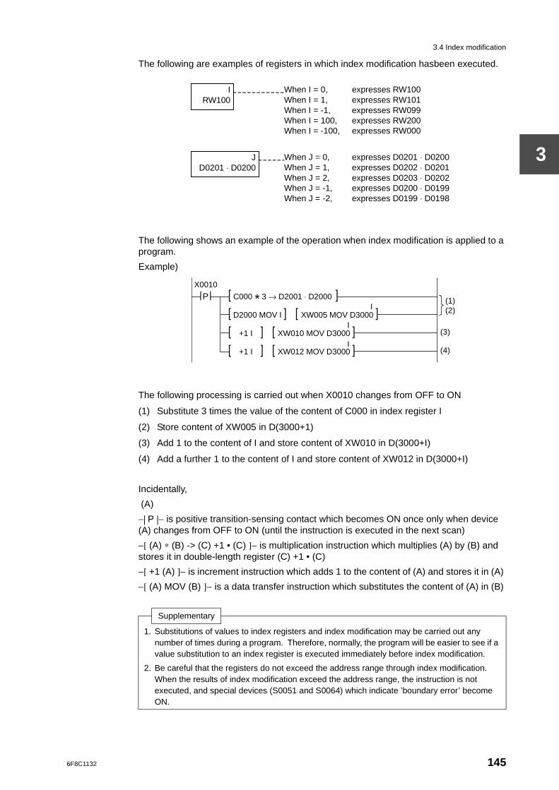
3.4 Index modification
3
The following are examples of registers in which index modification hasbeen executed.
The following shows an example of the operation when index modification is applied to a program.
Example)
The following processing is carried out when X0010 changes from OFF to ON
(1) Substitute 3 times the value of the content of C000 in index register I
(2) Store content of XW005 in D(3000+1)
(3) Add 1 to the content of I and store content of XW010 in D(3000+I)
(4) Add a further 1 to the content of I and store content of XW012 in D(3000+I)
Incidentally,
(A)
−| P |− is positive transition-sensing contact which becomes ON once only when device (A) changes from OFF to ON (until the instruction is executed in the next scan)
−[ (A) ∗ (B) -> (C) +1 • (C) ]− is multiplication instruction which multiplies (A) by (B) and stores it in double-length register (C) +1 • (C)
−[ +1 (A) ]− is increment instruction which adds 1 to the content of (A) and stores it in (A)
−[ (A) MOV (B) ]− is a data transfer instruction which substitutes the content of (A) in (B)
Supplementary
1. Substitutions of values to index registers and index modification may be carried out any number of times during a program. Therefore, normally, the program will be easier to see if a value substitution to an index register is executed immediately before index modification.
2. Be careful that the registers do not exceed the address range through index modification. When the results of index modification exceed the address range, the instruction is not executed, and special devices (S0051 and S0064) which indicate ’boundary error’ become ON.
When I = 0, When I = 1, When I = -1, When I = 100, When I = -100,
IRW100
expresses RW100 expresses RW101 expresses RW099 expresses RW200 expresses RW000
When J = 0, When J = 1, When J = 2, When J = -1, When J = -2,
expresses D0201 ⋅ D0200 expresses D0202 ⋅ D0201 expresses D0203 ⋅ D0202 expresses D0200 ⋅ D0199 expresses D0199 ⋅ D0198
JD0201 ⋅ D0200
X0010 | P | [ C000 * 3 → D2001 ⋅ D2000 ] [ D2000 MOV I ] [ XW005 MOV D3000 ]
[ +1 I ] [ XW010 MOV D3000 ]
[ +1 I ] [ XW012 MOV D3000 ]
(1) (2)
(3)
(4)
I
I
I
6F8C1132 145
Chapter 3 User Data
3
As explained before, the main purpose of the index modification is indirect designation of register. However, as the special usage of the index modification, the followings are also possible.
• For CALL and JUMP instructions, indirect designation of the destination address is possible.
I
-[ JUMP N.000 ]- (If I=5, jump to Label 5)
If indexed destination is not registered, the special devices (S0051 and S006C) become ON. If indexed destination exceeds the range, the special devices (S0051 and S0065) become ON. And both cases, the instruction is not executed.
• For SET and RST instructions, indirect designation of device is possible.
I
-[ SET R0100 ]- (If l=H005F, set R015F to ON)
• For constant operand, the constant value can be modified by the index register.
I
-[ 500 MOV D5000 ]- (If 1=10, 510 is stored in D5000)
Supplementary
Refer to the Instruction Set manual for the operands to which the index modification is available in each instruction.
146 model 2000 Sequence Controller S2E User’s Manual -Functions-
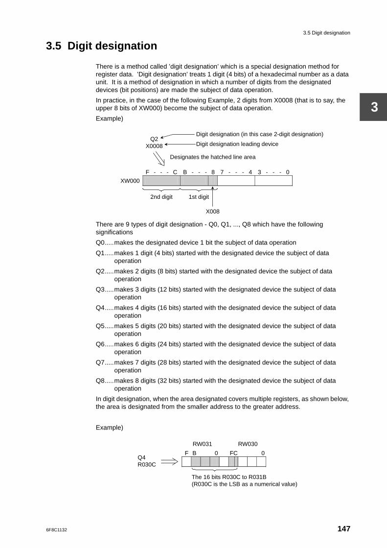
3.5 Digit designation
3
3.5 Digit designation
There is a method called ’digit designation’ which is a special designation method for register data. ’Digit designation’ treats 1 digit (4 bits) of a hexadecimal number as a data unit. It is a method of designation in which a number of digits from the designated devices (bit positions) are made the subject of data operation.
In practice, in the case of the following Example, 2 digits from X0008 (that is to say, the upper 8 bits of XW000) become the subject of data operation.
Example)
There are 9 types of digit designation - Q0, Q1, ..., Q8 which have the following significations
Q0.....makes the designated device 1 bit the subject of data operation
Q1.....makes 1 digit (4 bits) started with the designated device the subject of data operation
Q2.....makes 2 digits (8 bits) started with the designated device the subject of data operation
Q3.....makes 3 digits (12 bits) started with the designated device the subject of data operation
Q4.....makes 4 digits (16 bits) started with the designated device the subject of data operation
Q5.....makes 5 digits (20 bits) started with the designated device the subject of data operation
Q6.....makes 6 digits (24 bits) started with the designated device the subject of data operation
Q7.....makes 7 digits (28 bits) started with the designated device the subject of data operation
Q8.....makes 8 digits (32 bits) started with the designated device the subject of data operation
In digit designation, when the area designated covers multiple registers, as shown below, the area is designated from the smaller address to the greater address.
Example)
F - - - C B - - - 8 7 - - - 4 3 - - - 0
XW000
2nd digit 1st digit
X008
Q2 X0008
Digit designation (in this case 2-digit designation)
Digit designation leading device
Designates the hatched line area
F B 0 FC 0
RW031
The 16 bits R030C to R031B (R030C is the LSB as a numerical value)
RW030
Q4 R030C
6F8C1132 147
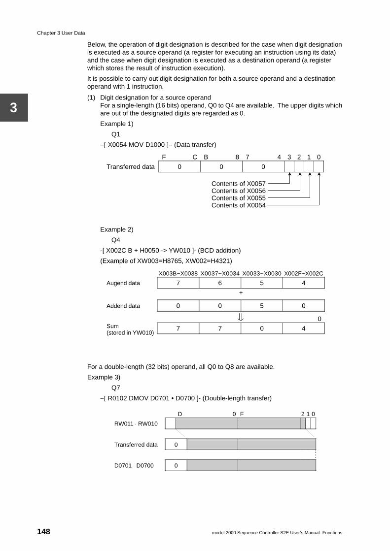
Chapter 3 User Data
3
Below, the operation of digit designation is described for the case when digit designation is executed as a source operand (a register for executing an instruction using its data) and the case when digit designation is executed as a destination operand (a register which stores the result of instruction execution).
It is possible to carry out digit designation for both a source operand and a destination operand with 1 instruction.
(1) Digit designation for a source operandFor a single-length (16 bits) operand, Q0 to Q4 are available. The upper digits which are out of the designated digits are regarded as 0.
Example 1)
Q1
−[ X0054 MOV D1000 ]− (Data transfer)
Example 2)
Q4
-[ X002C B + H0050 -> YW010 ]- (BCD addition)
(Example of XW003=H8765, XW002=H4321)
For a double-length (32 bits) operand, all Q0 to Q8 are available.
Example 3)
Q7
−[ R0102 DMOV D0701 • D0700 ]- (Double-length transfer)
F C B 8 7 4 3 2 1 0
Transferred data 0 0 0
Contents of X0057
Contents of X0056Contents of X0055Contents of X0054
X003B~X0038 X0037~X0034 X0033~X0030 X002F~X002C
Augend data 7 6 5 4
+
Addend data 0 0 5 0
0
7 7 0 4 Sum (stored in YW010)
D 0 F 2 1 0
RW011 ⋅ RW010
Transferred data 0
D0701 ⋅ D0700 0
148 model 2000 Sequence Controller S2E User’s Manual -Functions-
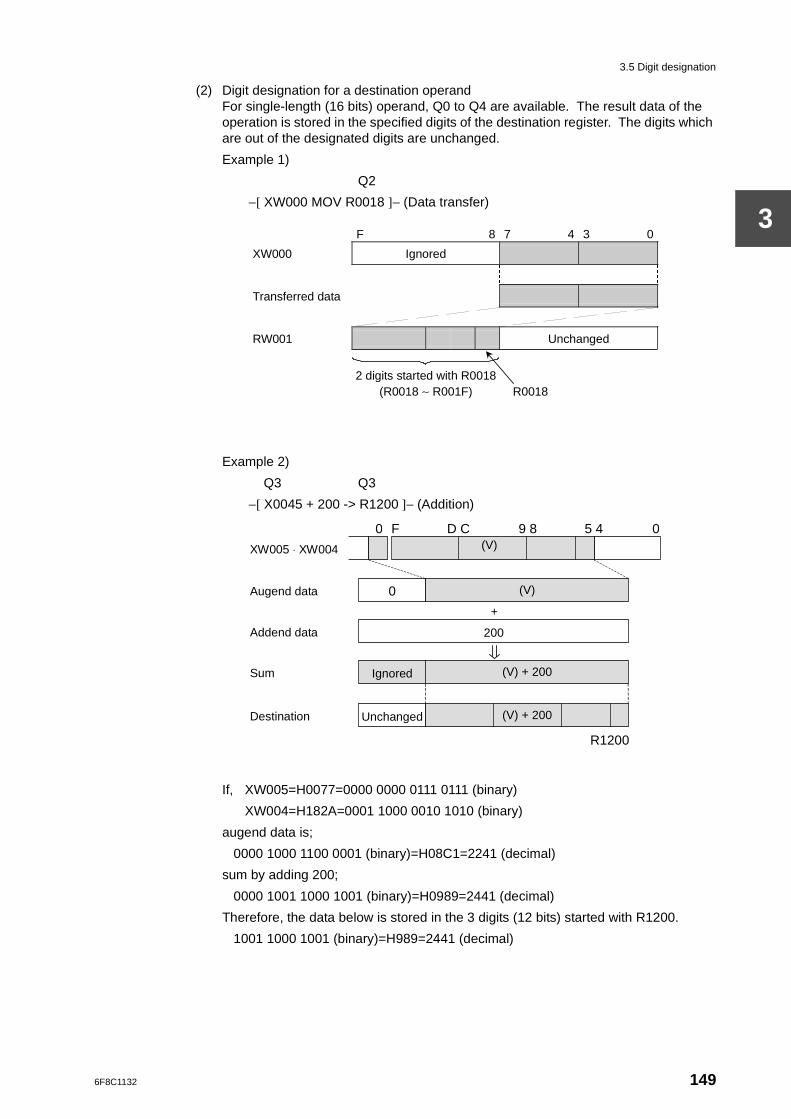
3.5 Digit designation
3
(2) Digit designation for a destination operandFor single-length (16 bits) operand, Q0 to Q4 are available. The result data of the operation is stored in the specified digits of the destination register. The digits which are out of the designated digits are unchanged.
Example 1)
Q2
−[ XW000 MOV R0018 ]− (Data transfer)
Example 2)
Q3 Q3
−[ X0045 + 200 -> R1200 ]− (Addition)
If, XW005=H0077=0000 0000 0111 0111 (binary)
XW004=H182A=0001 1000 0010 1010 (binary)
augend data is;
0000 1000 1100 0001 (binary)=H08C1=2241 (decimal)
sum by adding 200;
0000 1001 1000 1001 (binary)=H0989=2441 (decimal)
Therefore, the data below is stored in the 3 digits (12 bits) started with R1200.
1001 1000 1001 (binary)=H989=2441 (decimal)
F 8 7 4 3 0
XW000 Ignored
Transferred data
RW001 Unchanged
2 digits started with R0018 (R0018 ∼ R001F) R0018
(V)
200
0
(V) + 200 Ignored
(V) + 200 Unchanged
+
R1200
0 F D C 9 8 5 4 0
Addend data
Augend data
Sum
Destination
XW005 ⋅ XW004 (V)
6F8C1132 149
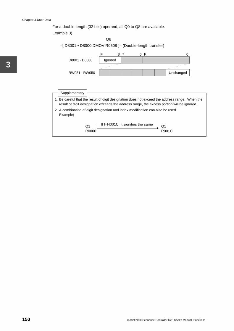
Chapter 3 User Data
3
For a double-length (32 bits) operand, all Q0 to Q8 are available.
Example 3)
Q6
−[ D8001 • D8000 DMOV R0508 ]− (Double-length transfer)
Supplementary
1. Be careful that the result of digit designation does not exceed the address range. When the result of digit designation exceeds the address range, the excess portion will be ignored.
2. A combination of digit designation and index modification can also be used.Example)
F 8 7 0 F 0
D8001 ⋅ D8000 Ignored
RW051 ⋅ RW050 Unchanged
Q1 I Q1 R0000 R001C
If I=H001C, it signifies the same
150 model 2000 Sequence Controller S2E User’s Manual -Functions-
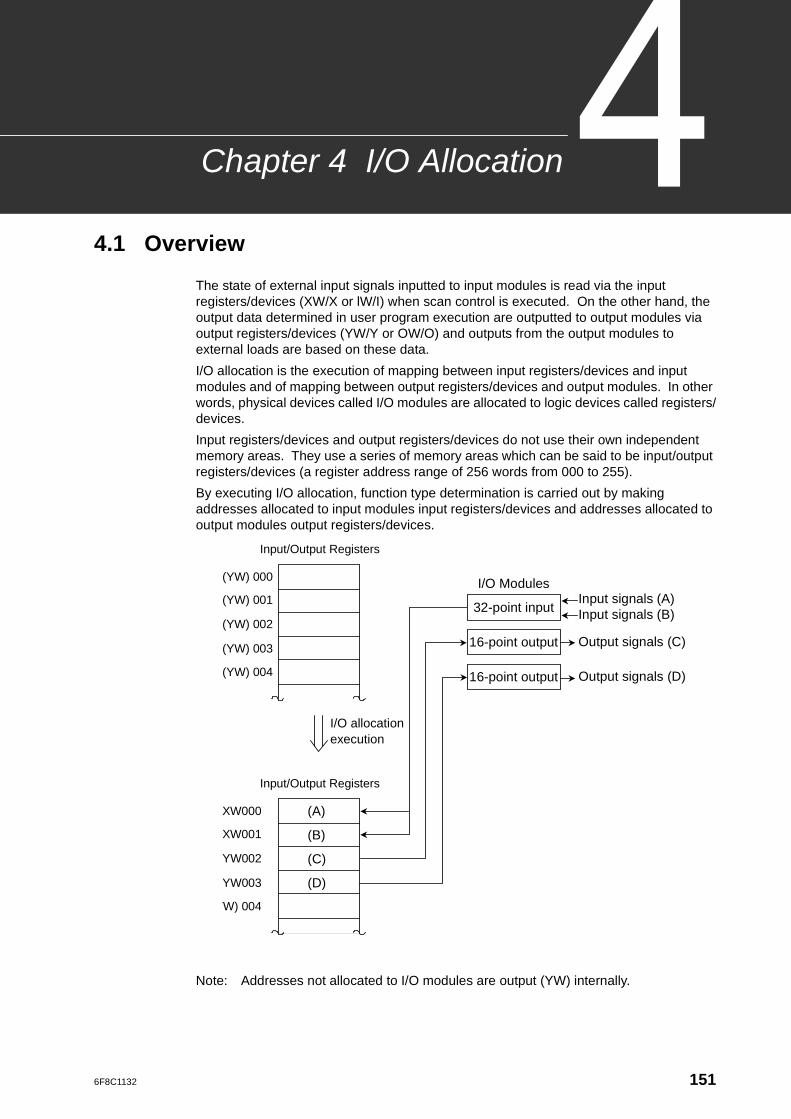
6F8C1132
Allocation
Chapter 4 I/O4.1 Overview
The state of external input signals inputted to input modules is read via the input registers/devices (XW/X or lW/I) when scan control is executed. On the other hand, the output data determined in user program execution are outputted to output modules via output registers/devices (YW/Y or OW/O) and outputs from the output modules to external loads are based on these data.
I/O allocation is the execution of mapping between input registers/devices and input modules and of mapping between output registers/devices and output modules. In other words, physical devices called I/O modules are allocated to logic devices called registers/devices.
Input registers/devices and output registers/devices do not use their own independent memory areas. They use a series of memory areas which can be said to be input/output registers/devices (a register address range of 256 words from 000 to 255).
By executing I/O allocation, function type determination is carried out by making addresses allocated to input modules input registers/devices and addresses allocated to output modules output registers/devices.
Note: Addresses not allocated to I/O modules are output (YW) internally.
32-point input
16-point output
16-point output
Input signals (A) Input signals (B)
Output signals (C)
Output signals (D)
I/O Modules (YW) 000
(YW) 001
(YW) 002
(YW) 003
(YW) 004
Input/Output Registers
XW000
XW001
YW002
YW003
(YW) 004
Input/Output Registers
(A)
I/O allocation execution
(B)
(C)
(D)
151
Chapter 4 I/O Allocation
4
4.2 Methods of VO allocation
The execution of I/O allocation can be said in other words to be the carrying out of the registration of I/O allocation information in system information. The S2E CPU checks whether the I/O modules are correctly mounted based on this I/O allocation information when RUN starts-up. Also, at the same time, the correspondence between the input/output registers (XW/YW) and the I/O modules is determined based on this I/O allocation information. On the other hand, the programmer reads this I/O allocation information when communicating with the S2E and recognizes the assignment whether input. (XW) or output (YW) for every input/output register address.
There are 2 methods for the registration of I/O allocation information in system information. These are automatic I/O allocation and manual I/O allocation.
The registration of I/O allocation information is only available when the S2E is in the HALT mode.
Automatic I/O allocationThis is a method of causing the S2E to execute the registration of I/O allocation information. It is carried out by selecting and executing the AutoSet command on the I/O allocation screen of the programmer (T-PDS).
When the automatic I/O allocation is executed, the S2E CPU reads out state of the I/O modules which are mounted (what type of module is mounted in which position) and registers the I/O allocation information.
Each I/O module has one of the module types shown below.
152 model 2000 Sequence Controller S2E User’s Manual -Functions-
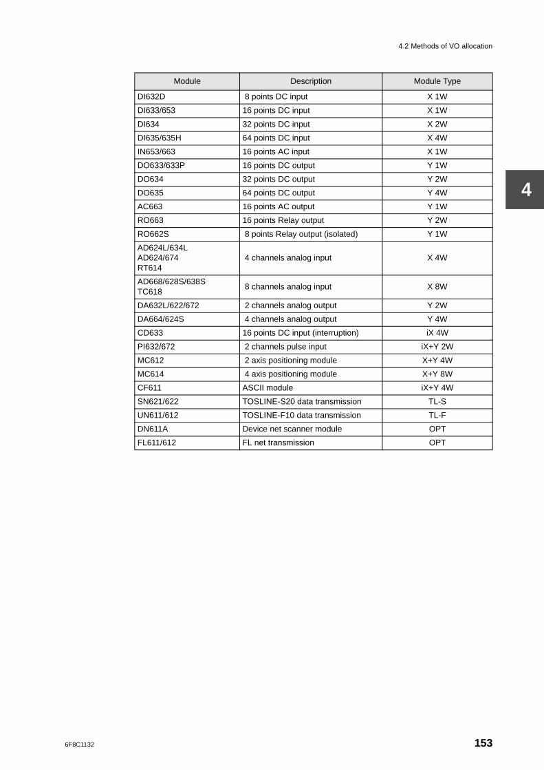
4.2 Methods of VO allocation
4
Module Description Module Type
DI632D 8 points DC input X 1W
DI633/653 16 points DC input X 1W
DI634 32 points DC input X 2W
DI635/635H 64 points DC input X 4W
IN653/663 16 points AC input X 1W
DO633/633P 16 points DC output Y 1W
DO634 32 points DC output Y 2W
DO635 64 points DC output Y 4W
AC663 16 points AC output Y 1W
RO663 16 points Relay output Y 2W
RO662S 8 points Relay output (isolated) Y 1W
AD624L/634LAD624/674RT614
4 channels analog input X 4W
AD668/628S/638STC618
8 channels analog input X 8W
DA632L/622/672 2 channels analog output Y 2W
DA664/624S 4 channels analog output Y 4W
CD633 16 points DC input (interruption) iX 4W
PI632/672 2 channels pulse input iX+Y 2W
MC612 2 axis positioning module X+Y 4W
MC614 4 axis positioning module X+Y 8W
CF611 ASCII module iX+Y 4W
SN621/622 TOSLINE-S20 data transmission TL-S
UN611/612 TOSLINE-F10 data transmission TL-F
DN611A Device net scanner module OPT
FL611/612 FL net transmission OPT
6F8C1132 153
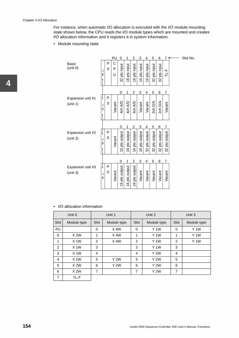
Chapter 4 I/O Allocation
4
For instance, when automatic I/O allocation is executed with the I/O module mounting state shown below, the CPU reads the I/O module types which are mounted and creates I/O allocation information and it registers it in system information.
• Module mounting state
• I/O allocation information
Unit 0 Unit 1 Unit 2 Unit 3
Slot Module type Slot Module type Slot Module type Slot Module type
PU 0 X 4W 0 Y 1W 0 Y 1W
0 X 2W 1 X 4W 1 Y 1W 1 Y 1W
1 X 1W 2 X 4W 2 Y 1W 2 Y 1W
2 X 1W 3 3 Y 1W 3
3 X 1W 4 4 Y 2W 4
4 X 1W 5 Y 2W 5 Y 2W 5
5 X 2W 6 Y 2W 6 Y 2W 6
6 X 2W 7 7 Y 2W 7
7 TL-F
PU 0 1 2 3 4 5 6 7 Slot No.
Basic (unit 0)
I F
P
S
C
P
U
32 p
ts in
put
16 p
ts in
put
16 p
ts in
put
16 p
ts in
put
16 p
ts in
put
32 p
ts in
put
32 p
ts in
put
TL-
F
0 1 2 3 4 5 6 7
Expansion unit #1
(unit 1) I F
P
S
Vac
ant
4ch
A/D
4ch
A/D
4ch
A/D
Vac
ant
Vac
ant
2ch
D/A
2ch
D/A
Vac
ant
0 1 2 3 4 5 6 7
Expansion unit #2
(unit 2) I F
P
S
Vac
ant
16 p
ts o
utpu
t
16 p
ts o
utpu
t
16 p
ts o
utpu
t
16 p
ts o
utpu
t
32 p
ts o
utpu
t
32 p
ts o
utpu
t
32 p
ts o
utpu
t
32 p
ts o
utpu
t
0 1 2 3 4 5 6 7
Expansion unit #3
(unit 3) I F
P
S
Vac
ant
16 p
ts o
utpu
t
16 p
ts o
utpu
t
16 p
ts o
utpu
t
Vac
ant
Vac
ant
Vac
ant
Vac
ant
Vac
ant
154 model 2000 Sequence Controller S2E User’s Manual -Functions-
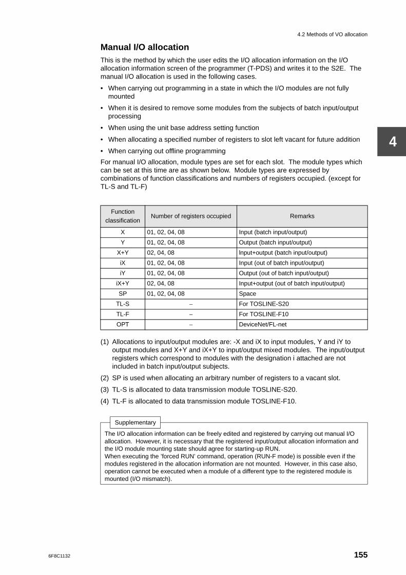
4.2 Methods of VO allocation
4
Manual I/O allocationThis is the method by which the user edits the I/O allocation information on the I/O allocation information screen of the programmer (T-PDS) and writes it to the S2E. The manual I/O allocation is used in the following cases.
• When carrying out programming in a state in which the I/O modules are not fully mounted
• When it is desired to remove some modules from the subjects of batch input/output processing
• When using the unit base address setting function
• When allocating a specified number of registers to slot left vacant for future addition
• When carrying out offline programming
For manual I/O allocation, module types are set for each slot. The module types which can be set at this time are as shown below. Module types are expressed by combinations of function classifications and numbers of registers occupied. (except for TL-S and TL-F)
(1) Allocations to input/output modules are: -X and iX to input modules, Y and iY to output modules and X+Y and iX+Y to input/output mixed modules. The input/output registers which correspond to modules with the designation i attached are not included in batch input/output subjects.
(2) SP is used when allocating an arbitrary number of registers to a vacant slot.
(3) TL-S is allocated to data transmission module TOSLINE-S20.
(4) TL-F is allocated to data transmission module TOSLINE-F10.
Function classification
Number of registers occupied Remarks
X 01, 02, 04, 08 Input (batch input/output)
Y 01, 02, 04, 08 Output (batch input/output)
X+Y 02, 04, 08 lnput+output (batch input/output)
iX 01, 02, 04, 08 Input (out of batch input/output)
iY 01, 02, 04, 08 Output (out of batch input/output)
iX+Y 02, 04, 08 Input+output (out of batch input/output)
SP 01, 02, 04, 08 Space
TL-S − For TOSLINE-S20
TL-F − For TOSLINE-F10
OPT − DeviceNet/FL-net
Supplementary
The I/O allocation information can be freely edited and registered by carrying out manual I/O allocation. However, it is necessary that the registered input/output allocation information and the I/O module mounting state should agree for starting-up RUN.When executing the ’forced RUN’ command, operation (RUN-F mode) is possible even if the modules registered in the allocation information are not mounted. However, in this case also, operation cannot be executed when a module of a different type to the registered module is mounted (I/O mismatch).
6F8C1132 155
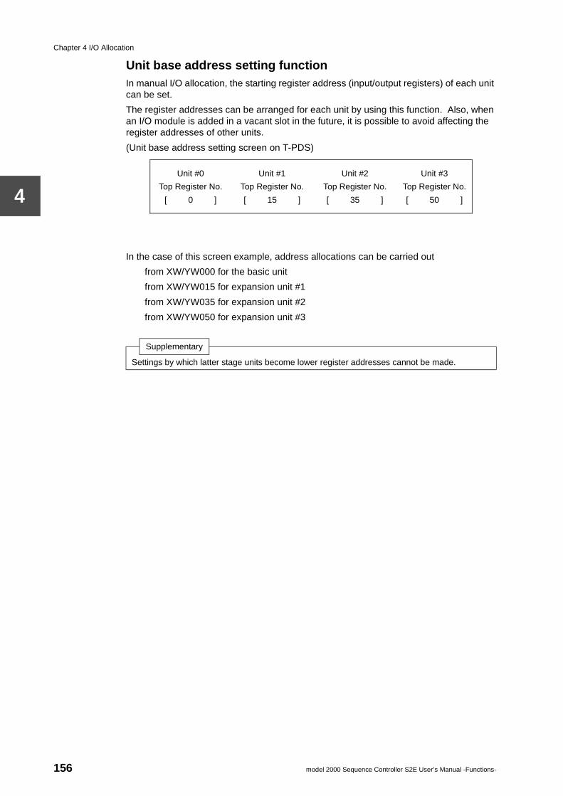
Chapter 4 I/O Allocation
4
Unit base address setting functionIn manual I/O allocation, the starting register address (input/output registers) of each unit can be set.
The register addresses can be arranged for each unit by using this function. Also, when an I/O module is added in a vacant slot in the future, it is possible to avoid affecting the register addresses of other units.
(Unit base address setting screen on T-PDS)
In the case of this screen example, address allocations can be carried out
from XW/YW000 for the basic unit
from XW/YW015 for expansion unit #1
from XW/YW035 for expansion unit #2
from XW/YW050 for expansion unit #3
Supplementary
Settings by which latter stage units become lower register addresses cannot be made.
Unit #0 Unit #1 Unit #2 Unit #3
Top Register No. Top Register No. Top Register No. Top Register No.
[ 0 ] [ 15 ] [ 35 ] [ 50 ]
156 model 2000 Sequence Controller S2E User’s Manual -Functions-
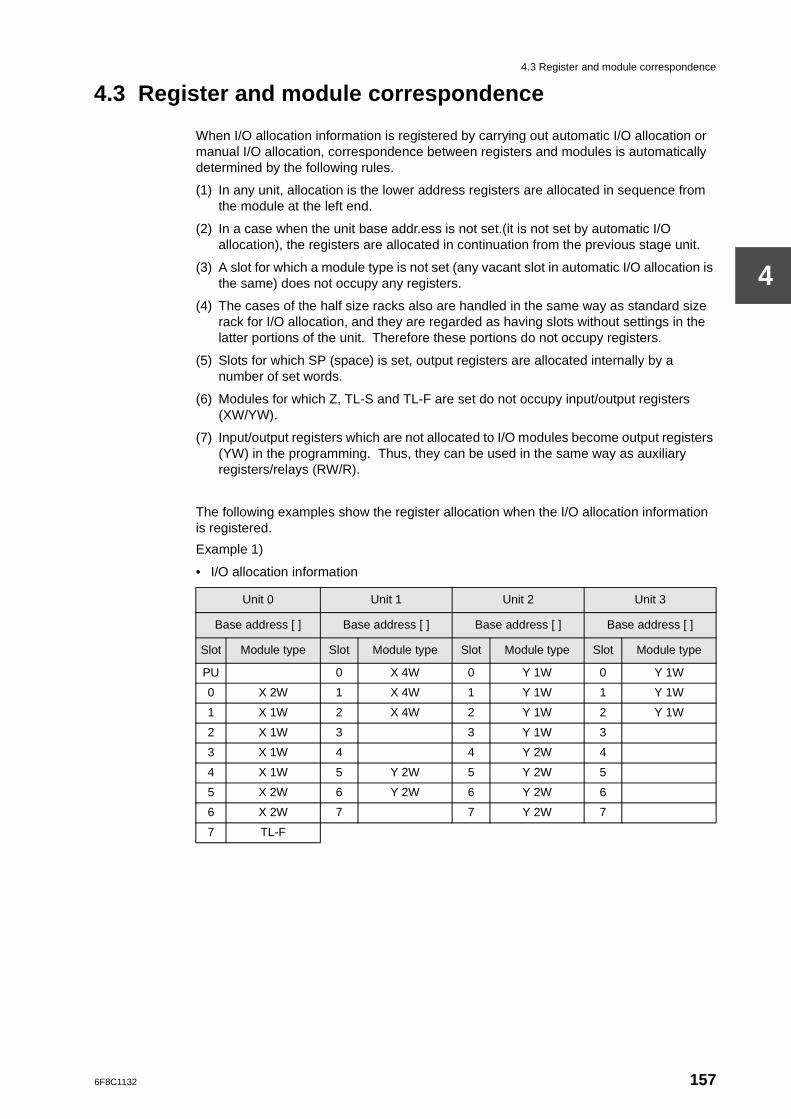
4.3 Register and module correspondence
4
4.3 Register and module correspondence
When I/O allocation information is registered by carrying out automatic I/O allocation or manual I/O allocation, correspondence between registers and modules is automatically determined by the following rules.
(1) In any unit, allocation is the lower address registers are allocated in sequence from the module at the left end.
(2) In a case when the unit base addr.ess is not set.(it is not set by automatic I/O allocation), the registers are allocated in continuation from the previous stage unit.
(3) A slot for which a module type is not set (any vacant slot in automatic I/O allocation is the same) does not occupy any registers.
(4) The cases of the half size racks also are handled in the same way as standard size rack for I/O allocation, and they are regarded as having slots without settings in the latter portions of the unit. Therefore these portions do not occupy registers.
(5) Slots for which SP (space) is set, output registers are allocated internally by a number of set words.
(6) Modules for which Z, TL-S and TL-F are set do not occupy input/output registers (XW/YW).
(7) Input/output registers which are not allocated to I/O modules become output registers (YW) in the programming. Thus, they can be used in the same way as auxiliary registers/relays (RW/R).
The following examples show the register allocation when the I/O allocation information is registered.
Example 1)
• I/O allocation information
Unit 0 Unit 1 Unit 2 Unit 3
Base address [ ] Base address [ ] Base address [ ] Base address [ ]
Slot Module type Slot Module type Slot Module type Slot Module type
PU 0 X 4W 0 Y 1W 0 Y 1W
0 X 2W 1 X 4W 1 Y 1W 1 Y 1W
1 X 1W 2 X 4W 2 Y 1W 2 Y 1W
2 X 1W 3 3 Y 1W 3
3 X 1W 4 4 Y 2W 4
4 X 1W 5 Y 2W 5 Y 2W 5
5 X 2W 6 Y 2W 6 Y 2W 6
6 X 2W 7 7 Y 2W 7
7 TL-F
6F8C1132 157
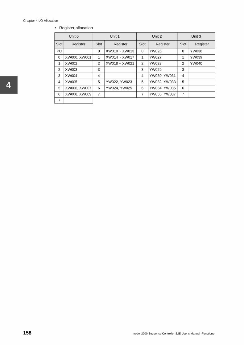
Chapter 4 I/O Allocation
4
• Register allocation
Unit 0 Unit 1 Unit 2 Unit 3
Slot Register Slot Register Slot Register Slot Register
PU 0 XW010 ~ XW013 0 YW026 0 YW038
0 XW000, XW001 1 XW014 ~ XW017 1 YW027 1 YW039
1 XW002 2 XW018 ~ XW021 2 YW028 2 YW040
2 XW003 3 3 YW029 3
3 XW004 4 4 YW030, YW031 4
4 XW005 5 YW022, YW023 5 YW032, YW033 5
5 XW006, XW007 6 YW024, YW025 6 YW034, YW035 6
6 XW008, XW009 7 7 YW036, YW037 7
7
158 model 2000 Sequence Controller S2E User’s Manual -Functions-
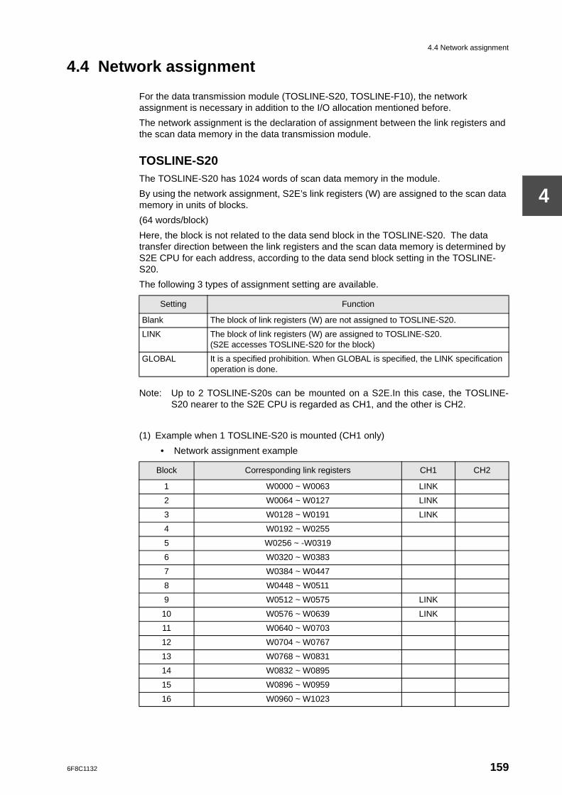
4.4 Network assignment
4
4.4 Network assignment
For the data transmission module (TOSLINE-S20, TOSLINE-F10), the network assignment is necessary in addition to the I/O allocation mentioned before.
The network assignment is the declaration of assignment between the link registers and the scan data memory in the data transmission module.
TOSLINE-S20The TOSLINE-S20 has 1024 words of scan data memory in the module.
By using the network assignment, S2E’s link registers (W) are assigned to the scan data memory in units of blocks.
(64 words/block)
Here, the block is not related to the data send block in the TOSLINE-S20. The data transfer direction between the link registers and the scan data memory is determined by S2E CPU for each address, according to the data send block setting in the TOSLINE-S20.
The following 3 types of assignment setting are available.
Note: Up to 2 TOSLINE-S20s can be mounted on a S2E.In this case, the TOSLINE-S20 nearer to the S2E CPU is regarded as CH1, and the other is CH2.
(1) Example when 1 TOSLINE-S20 is mounted (CH1 only)
• Network assignment example
Setting Function
Blank The block of link registers (W) are not assigned to TOSLINE-S20.
LINK The block of link registers (W) are assigned to TOSLINE-S20.(S2E accesses TOSLINE-S20 for the block)
GLOBAL It is a specified prohibition. When GLOBAL is specified, the LINK specification operation is done.
Block Corresponding link registers CH1 CH2
1 W0000 ~ W0063 LINK
2 W0064 ~ W0127 LINK
3 W0128 ~ W0191 LINK
4 W0192 ~ W0255
5 W0256 ~ -W0319
6 W0320 ~ W0383
7 W0384 ~ W0447
8 W0448 ~ W0511
9 W0512 ~ W0575 LINK
10 W0576 ~ W0639 LINK
11 W0640 ~ W0703
12 W0704 ~ W0767
13 W0768 ~ W0831
14 W0832 ~ W0895
15 W0896 ~ W0959
16 W0960 ~ W1023
6F8C1132 159
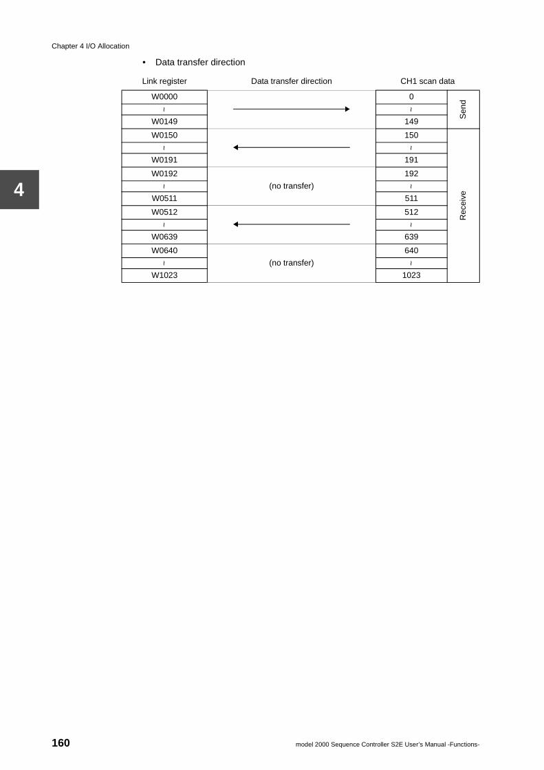
Chapter 4 I/O Allocation
4
• Data transfer direction
Link register Data transfer direction CH1 scan data
W0000 0
Sen
d
~ ~
W0149 149
W0150 150
Rec
eive
~ ~
W0191 191
W0192
(no transfer)
192~ ~
W0511 511
W0512 512
~ ~
W0639 639
W0640
(no transfer)
640
~ ~
W1023 1023
160 model 2000 Sequence Controller S2E User’s Manual -Functions-
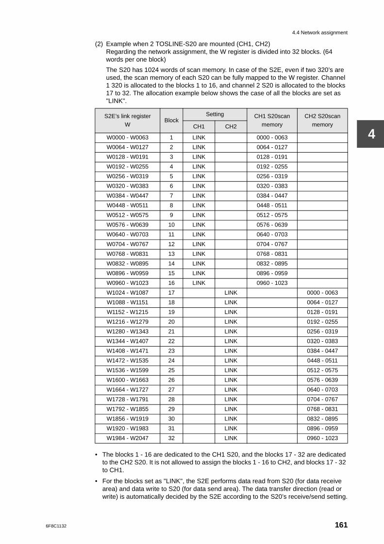
4.4 Network assignment
4
(2) Example when 2 TOSLINE-S20 are mounted (CH1, CH2)Regarding the network assignment, the W register is divided into 32 blocks. (64 words per one block)
The S20 has 1024 words of scan memory. In case of the S2E, even if two 320’s are used, the scan memory of each S20 can be fully mapped to the W register. Channel 1 320 is allocated to the blocks 1 to 16, and channel 2 S20 is allocated to the blocks 17 to 32. The allocation example below shows the case of all the blocks are set as "LINK".
• The blocks 1 - 16 are dedicated to the CH1 S20, and the blocks 17 - 32 are dedicated to the CH2 S20. It is not allowed to assign the blocks 1 - 16 to CH2, and blocks 17 - 32 to CH1.
• For the blocks set as "LINK", the S2E performs data read from S20 (for data receive area) and data write to S20 (for data send area). The data transfer direction (read or write) is automatically decided by the S2E according to the S20’s receive/send setting.
S2E’s link register
WBlock
Setting CH1 S20scan
memory
CH2 S20scan
memoryCH1 CH2
W0000 - W0063 1 LINK 0000 - 0063
W0064 - W0127 2 LINK 0064 - 0127
W0128 - W0191 3 LINK 0128 - 0191
W0192 - W0255 4 LINK 0192 - 0255
W0256 - W0319 5 LINK 0256 - 0319
W0320 - W0383 6 LINK 0320 - 0383
W0384 - W0447 7 LINK 0384 - 0447
W0448 - W0511 8 LINK 0448 - 0511
W0512 - W0575 9 LINK 0512 - 0575
W0576 - W0639 10 LINK 0576 - 0639
W0640 - W0703 11 LINK 0640 - 0703
W0704 - W0767 12 LINK 0704 - 0767
W0768 - W0831 13 LINK 0768 - 0831
W0832 - W0895 14 LINK 0832 - 0895
W0896 - W0959 15 LINK 0896 - 0959
W0960 - W1023 16 LINK 0960 - 1023
W1024 - W1087 17 LINK 0000 - 0063
W1088 - W1151 18 LINK 0064 - 0127
W1152 - W1215 19 LINK 0128 - 0191
W1216 - W1279 20 LINK 0192 - 0255
W1280 - W1343 21 LINK 0256 - 0319
W1344 - W1407 22 LINK 0320 - 0383
W1408 - W1471 23 LINK 0384 - 0447
W1472 - W1535 24 LINK 0448 - 0511
W1536 - W1599 25 LINK 0512 - 0575
W1600 - W1663 26 LINK 0576 - 0639
W1664 - W1727 27 LINK 0640 - 0703
W1728 - W1791 28 LINK 0704 - 0767
W1792 - W1855 29 LINK 0768 - 0831
W1856 - W1919 30 LINK 0832 - 0895
W1920 - W1983 31 LINK 0896 - 0959
W1984 - W2047 32 LINK 0960 - 1023
6F8C1132 161
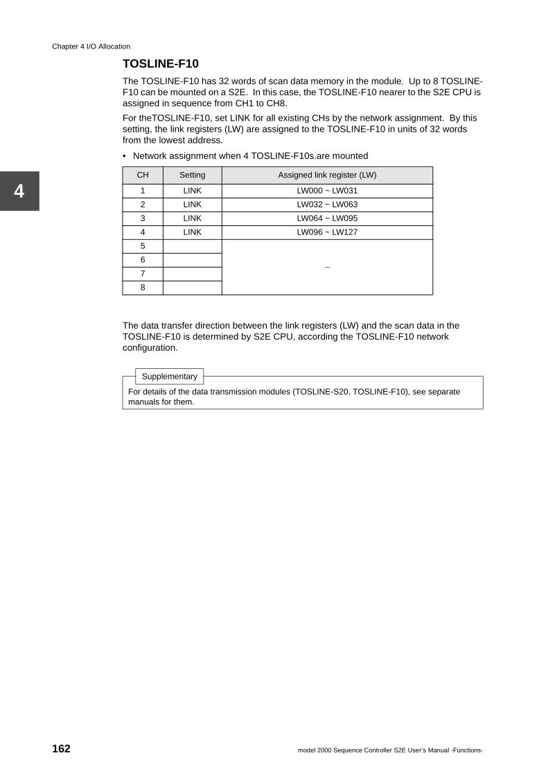
Chapter 4 I/O Allocation
4
TOSLINE-F10The TOSLINE-F10 has 32 words of scan data memory in the module. Up to 8 TOSLINE-F10 can be mounted on a S2E. In this case, the TOSLINE-F10 nearer to the S2E CPU is assigned in sequence from CH1 to CH8.
For theTOSLINE-F10, set LINK for all existing CHs by the network assignment. By this setting, the link registers (LW) are assigned to the TOSLINE-F10 in units of 32 words from the lowest address.
• Network assignment when 4 TOSLINE-F10s.are mounted
The data transfer direction between the link registers (LW) and the scan data in the TOSLINE-F10 is determined by S2E CPU, according the TOSLINE-F10 network configuration.
CH Setting Assigned link register (LW)
1 LINK LW000 ~ LW031
2 LINK LW032 ~ LW063
3 LINK LW064 ~ LW095
4 LINK LW096 ~ LW127
5
−6
7
8
Supplementary
For details of the data transmission modules (TOSLINE-S20, TOSLINE-F10), see separate manuals for them.
162 model 2000 Sequence Controller S2E User’s Manual -Functions-
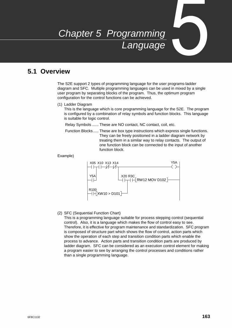
6F8C1132
ogrammingLanguage
Chapter 5 Pr
5.1 Overview
The S2E support 2 types of programming language for the user programs-ladder diagram and SFC. Multiple programming languages can be used in mixed by a single user program by separating blocks of the program. Thus, the optimum program configuration for the control functions can be achieved.
(1) Ladder DiagramThis is the language which is core programming language for the S2E. The program is configured by a combination of relay symbols and function blocks. This language is suitable for logic control.
Relay Symbols ...... These are NO contact, NC contact, coil, etc.
Function Blocks ..... These are box type instructions which express single functions. They can be freely positioned in a ladder diagram network by treating them in a similar way to relay contacts. The output of one function block can be connected to the input of another function block.
Example)
(2) SFC (Sequential Function Chart) This is a programming language suitable for process stepping control (sequential control). Also, it is a language which makes the flow of control easy to see. Therefore, it is effective for program maintenance and standardization. SFC program is composed of structure part which shows the flow of control, action parts which show the operation of each step and transition condition parts which enable the process to advance. Action parts and transition condition parts are produced by ladder diagram. SFC can be considered as an execution control element for making a program easier to see by arranging the control processes and conditions rather than a single programming language.
RW12 MOV D102
X05
Y5A
X14 Y5A X10 X13
R100
R3C X20
XW10 > D101
163
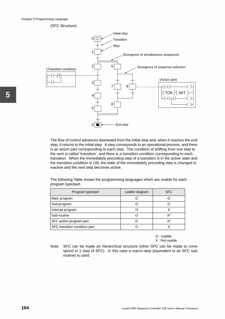
Chapter 5 Programming Language
5
(SFC Structure)
The flow of control advances downward from the initial step and, when it reaches the end step, it returns to the initial step. A step corresponds to an operational process, and there is an action part corresponding to each step. The condition of shifting from one step to the next is called ’transition’, and there is a transition condition corresponding to each transition. When the immediately preceding step of a transition is in the active state and the transition condition is ON, the state of the immediately preceding step is changed to inactive and the next step becomes active.
The following Table shows the programming languages which are usable for each program type/part.
O : UsableX : Not usable
Note: SFC can be made an hierarchical structure (other SFC can be made to corre-spond to 1 step of SFC). In this case a macro-step (equivalent to an SFC sub-routine) is used.
(Action part)
TON SET
(Transition condition)
Initial step
Transition
Divergence of simultaneous sequences
Divergence of sequence selection
Step
End step
0
1
2
3
4
5
0
6
7
8
9
Program type/part Ladder diagram SFC
Main program O O
Sub-program O O
Interupt program O X
Sub-routine O X*
SFC action program part O X*
SFC transition condition part O X
164 model 2000 Sequence Controller S2E User’s Manual -Functions-
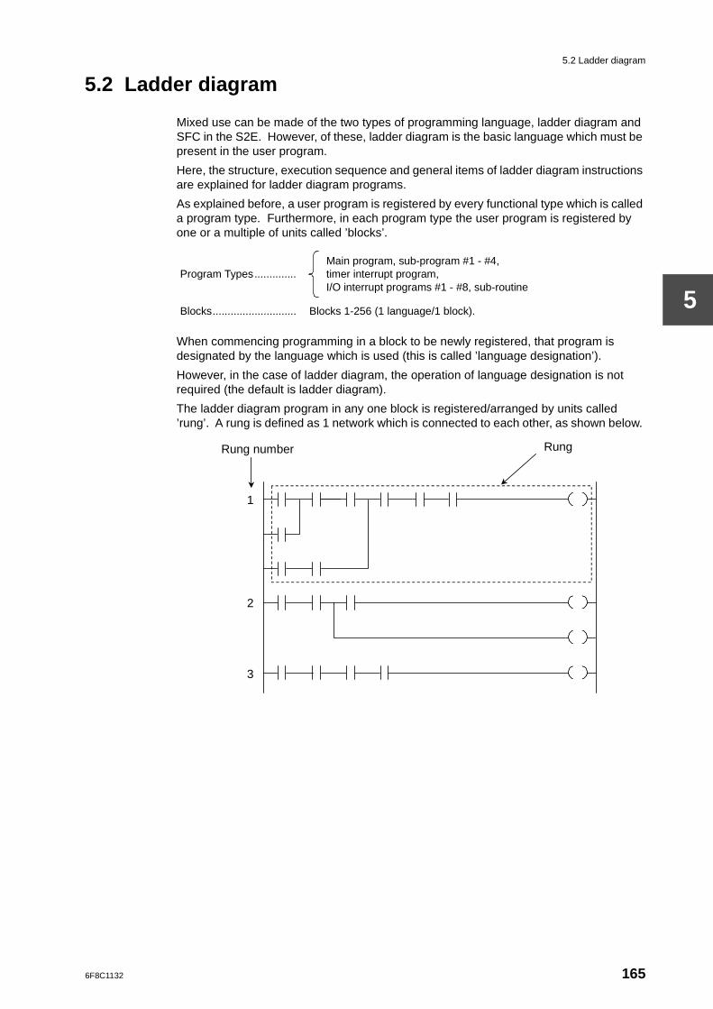
5.2 Ladder diagram
5
5.2 Ladder diagram
Mixed use can be made of the two types of programming language, ladder diagram and SFC in the S2E. However, of these, ladder diagram is the basic language which must be present in the user program.
Here, the structure, execution sequence and general items of ladder diagram instructions are explained for ladder diagram programs.
As explained before, a user program is registered by every functional type which is called a program type. Furthermore, in each program type the user program is registered by one or a multiple of units called ’blocks’.
When commencing programming in a block to be newly registered, that program is designated by the language which is used (this is called ’language designation’).
However, in the case of ladder diagram, the operation of language designation is not required (the default is ladder diagram).
The ladder diagram program in any one block is registered/arranged by units called ’rung’. A rung is defined as 1 network which is connected to each other, as shown below.
Program Types..............Main program, sub-program #1 - #4, timer interrupt program, I/O interrupt programs #1 - #8, sub-routine
Blocks............................ Blocks 1-256 (1 language/1 block).
Rung number Rung
1
2
3
6F8C1132 165
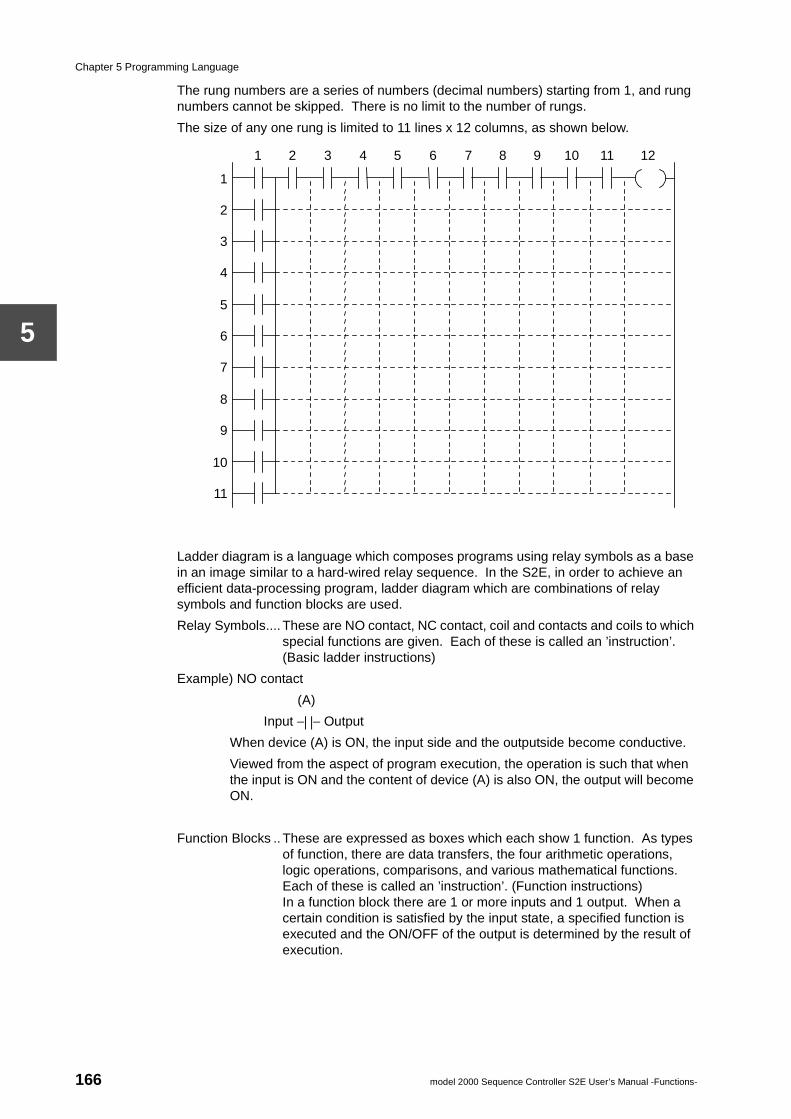
Chapter 5 Programming Language
5
The rung numbers are a series of numbers (decimal numbers) starting from 1, and rung numbers cannot be skipped. There is no limit to the number of rungs.
The size of any one rung is limited to 11 lines x 12 columns, as shown below.
Ladder diagram is a language which composes programs using relay symbols as a base in an image similar to a hard-wired relay sequence. In the S2E, in order to achieve an efficient data-processing program, ladder diagram which are combinations of relay symbols and function blocks are used.
Relay Symbols.... These are NO contact, NC contact, coil and contacts and coils to which special functions are given. Each of these is called an ’instruction’. (Basic ladder instructions)
Example) NO contact
(A)
Input −| |− Output
When device (A) is ON, the input side and the outputside become conductive.
Viewed from the aspect of program execution, the operation is such that when the input is ON and the content of device (A) is also ON, the output will become ON.
Function Blocks .. These are expressed as boxes which each show 1 function. As types of function, there are data transfers, the four arithmetic operations, logic operations, comparisons, and various mathematical functions. Each of these is called an ’instruction’. (Function instructions)In a function block there are 1 or more inputs and 1 output. When a certain condition is satisfied by the input state, a specified function is executed and the ON/OFF of the output is determined by the result of execution.
1 2 3 4 5 6 7 8 9 10 11 12
1
2
3
4
5
6
7
8
9
10
11
166 model 2000 Sequence Controller S2E User’s Manual -Functions-
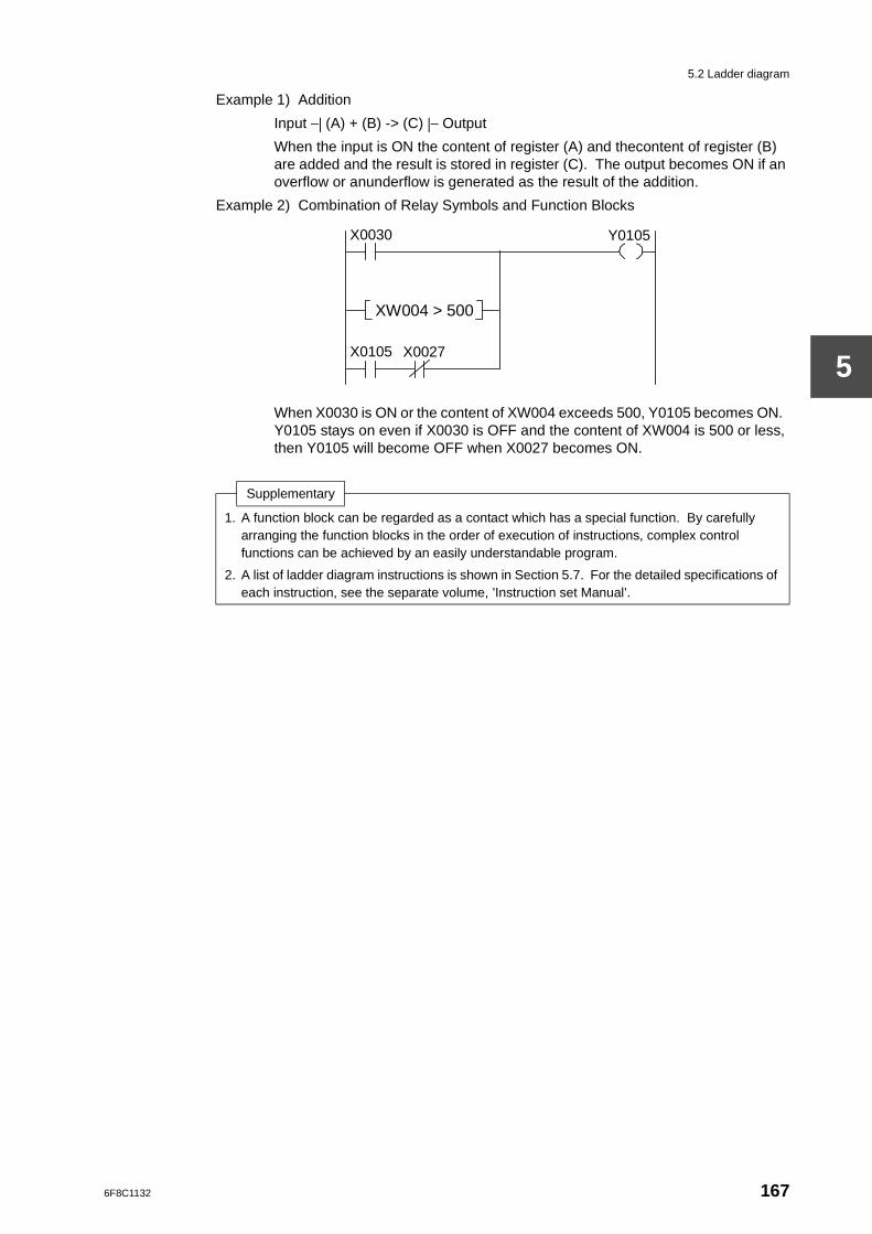
5.2 Ladder diagram
5
Example 1) Addition
Input −| (A) + (B) -> (C) |− Output
When the input is ON the content of register (A) and thecontent of register (B) are added and the result is stored in register (C). The output becomes ON if an overflow or anunderflow is generated as the result of the addition.
Example 2) Combination of Relay Symbols and Function Blocks
When X0030 is ON or the content of XW004 exceeds 500, Y0105 becomes ON. Y0105 stays on even if X0030 is OFF and the content of XW004 is 500 or less, then Y0105 will become OFF when X0027 becomes ON.
Supplementary
1. A function block can be regarded as a contact which has a special function. By carefully arranging the function blocks in the order of execution of instructions, complex control functions can be achieved by an easily understandable program.
2. A list of ladder diagram instructions is shown in Section 5.7. For the detailed specifications of each instruction, see the separate volume, ’Instruction set Manual’.
X0030 Y0105
X0027
XW004 > 500
X0105
6F8C1132 167
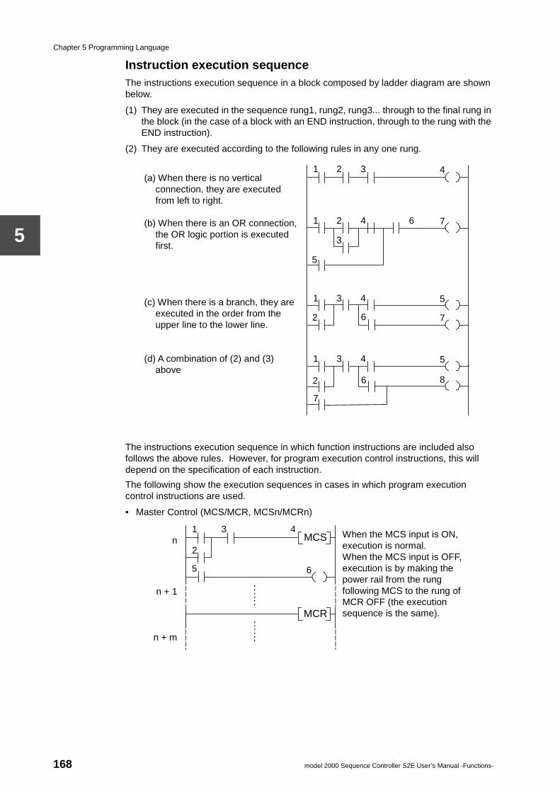
Chapter 5 Programming Language
5
Instruction execution sequenceThe instructions execution sequence in a block composed by ladder diagram are shown below.
(1) They are executed in the sequence rung1, rung2, rung3... through to the final rung in the block (in the case of a block with an END instruction, through to the rung with the END instruction).
(2) They are executed according to the following rules in any one rung.
The instructions execution sequence in which function instructions are included also follows the above rules. However, for program execution control instructions, this will depend on the specification of each instruction.
The following show the execution sequences in cases in which program execution control instructions are used.
• Master Control (MCS/MCR, MCSn/MCRn)
1 4 2 3 (a) When there is no vertical
connection, they are executed from left to right.
(b) When there is an OR connection,
the OR logic portion is executed first.
(c) When there is a branch, they are
executed in the order from the upper line to the lower line.
(d) A combination of (2) and (3)
above
1 7 2 4 6
3
5
1 5 3 4
1 5 3 4
6 2 8
7
6 2 7
1
5 6
3
MCR
MCS 2
n
n + 1
n + m
When the MCS input is ON, execution is normal. When the MCS input is OFF, execution is by making the power rail from the rung following MCS to the rung of MCR OFF (the execution sequence is the same).
4
. . . . . .
. . . . . .
168 model 2000 Sequence Controller S2E User’s Manual -Functions-
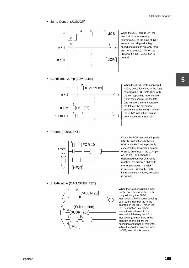
5.2 Ladder diagram
5
• Jump Control (JCS/JCR)
• Conditional Jump (JUMP/LBL)
• Repeat (FOR/NEXT)
• Sub-Routine (CALL/SUBR/RET)
1
6
3
JCR
JCS 2
n
n + 1
n + m
When the JCS input is ON, the instructions from the rung following JCS to the rung of JCR are read and skipped at high speed (instructions are only read and not executed). When the JCS input is OFF, execution is normal.
5 4
7
. . . . . .
. . . . . .
1
4 6
2
LBL (03)
JUMP N.03
3
n
n + 1
n + m
When the JUMP instruction input is ON, execution shifts to the rung following the LBL instruction with the corresponding label number (03 in the example on the left) (the numbers in the diagram on the left are the execution sequence at this time). When the JUMP instruction input is OFF, execution is normal.
. . . . . .
. . . . . .
n + m + 1 5
1
NEXT
FOR 10 times
When the FOR instruction input is ON, the instructions between FOR and NEXT are repeatedly executed the designated number of times (10 times in the example on the left), and when the designated number of times is reached, execution is shifted to the rung following the NEXT instruction. When the FOR instruction input is OFF, execution is normal.
2
6
1
RET
CALL N.20 When the CALL instruction input is ON, execution is shifted to the rung following the SUBR instruction with the corresponding sub-routine number (20 in the example in the left). When the RET instruction is reached, execution is returned to the instruction following the CALL instruction (the numbers in the diagram on the left are the execution sequence at this time). When the CALL instruction input is OFF, execution is normal.
2
7 8 9
4 5 SUBR (20)
3 (Sub-routine)
6F8C1132 169
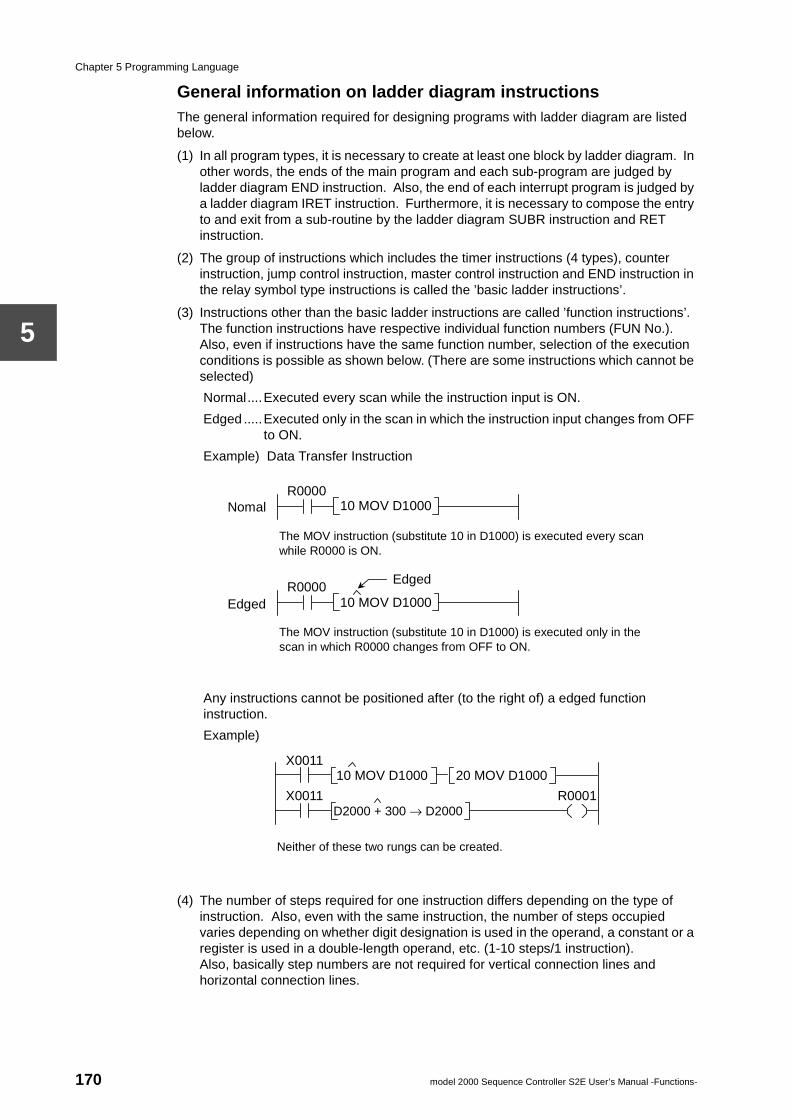
Chapter 5 Programming Language
5
General information on ladder diagram instructionsThe general information required for designing programs with ladder diagram are listed below.
(1) In all program types, it is necessary to create at least one block by ladder diagram. In other words, the ends of the main program and each sub-program are judged by ladder diagram END instruction. Also, the end of each interrupt program is judged by a ladder diagram IRET instruction. Furthermore, it is necessary to compose the entry to and exit from a sub-routine by the ladder diagram SUBR instruction and RET instruction.
(2) The group of instructions which includes the timer instructions (4 types), counter instruction, jump control instruction, master control instruction and END instruction in the relay symbol type instructions is called the ’basic ladder instructions’.
(3) Instructions other than the basic ladder instructions are called ’function instructions’. The function instructions have respective individual function numbers (FUN No.). Also, even if instructions have the same function number, selection of the execution conditions is possible as shown below. (There are some instructions which cannot be selected)
Normal....Executed every scan while the instruction input is ON.
Edged .....Executed only in the scan in which the instruction input changes from OFF to ON.
Example) Data Transfer Instruction
Any instructions cannot be positioned after (to the right of) a edged function instruction.
Example)
(4) The number of steps required for one instruction differs depending on the type of instruction. Also, even with the same instruction, the number of steps occupied varies depending on whether digit designation is used in the operand, a constant or a register is used in a double-length operand, etc. (1-10 steps/1 instruction).Also, basically step numbers are not required for vertical connection lines and horizontal connection lines.
10 MOV D1000
R0000 10 MOV D1000
The MOV instruction (substitute 10 in D1000) is executed every scan while R0000 is ON.
R0000
The MOV instruction (substitute 10 in D1000) is executed only in the scan in which R0000 changes from OFF to ON.
Edged symbol
Edged
Nomal
R0001 X0011 D2000 + 300 → D2000
X0011 10 MOV D1000 20 MOV D1000
Neither of these two rungs can be created.
170 model 2000 Sequence Controller S2E User’s Manual -Functions-
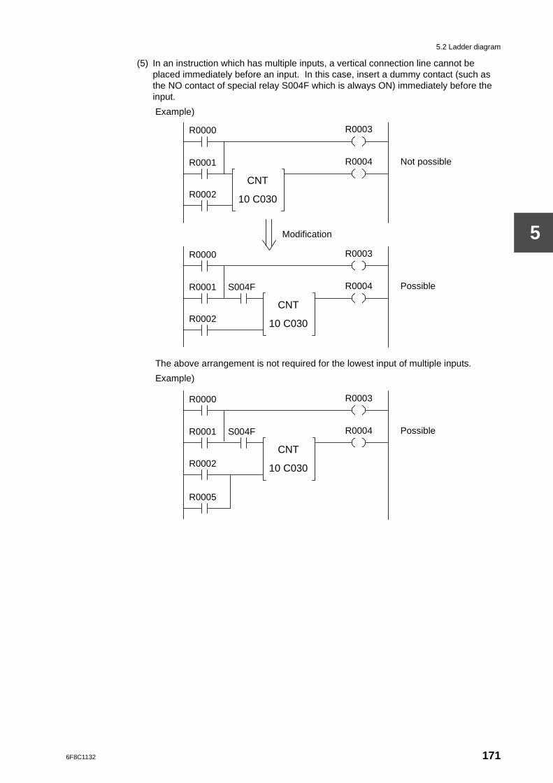
5.2 Ladder diagram
5
(5) In an instruction which has multiple inputs, a vertical connection line cannot be placed immediately before an input. In this case, insert a dummy contact (such as the NO contact of special relay S004F which is always ON) immediately before the input.
Example)
The above arrangement is not required for the lowest input of multiple inputs.
Example)
R0000 R0003
CNT
10 C030
R0001 R0004
R0002
Modification
Not possible
R0000 R0003
CNT
10 C030
R0001 R0004
R0002
Possible S004F
R0000 R0003
CNT
10 C030
R0001 R0004
R0002
Possible S004F
R0005
6F8C1132 171
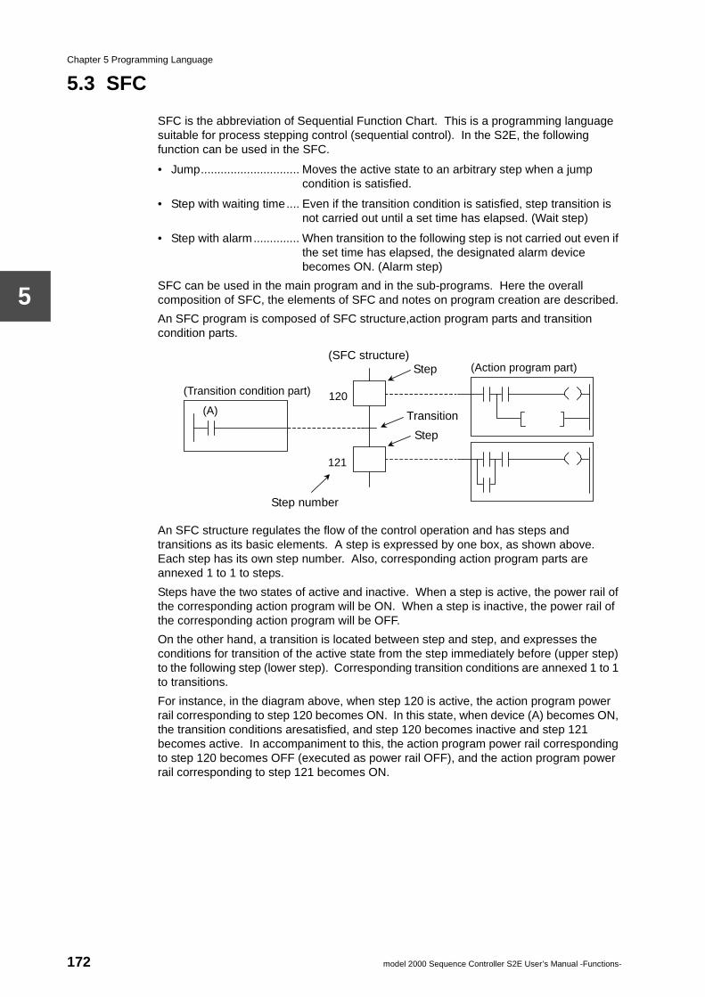
Chapter 5 Programming Language
5
5.3 SFC
SFC is the abbreviation of Sequential Function Chart. This is a programming language suitable for process stepping control (sequential control). In the S2E, the following function can be used in the SFC.
• Jump.............................. Moves the active state to an arbitrary step when a jump condition is satisfied.
• Step with waiting time.... Even if the transition condition is satisfied, step transition is not carried out until a set time has elapsed. (Wait step)
• Step with alarm.............. When transition to the following step is not carried out even if the set time has elapsed, the designated alarm device becomes ON. (Alarm step)
SFC can be used in the main program and in the sub-programs. Here the overall composition of SFC, the elements of SFC and notes on program creation are described.
An SFC program is composed of SFC structure,action program parts and transition condition parts.
An SFC structure regulates the flow of the control operation and has steps and transitions as its basic elements. A step is expressed by one box, as shown above. Each step has its own step number. Also, corresponding action program parts are annexed 1 to 1 to steps.
Steps have the two states of active and inactive. When a step is active, the power rail of the corresponding action program will be ON. When a step is inactive, the power rail of the corresponding action program will be OFF.
On the other hand, a transition is located between step and step, and expresses the conditions for transition of the active state from the step immediately before (upper step) to the following step (lower step). Corresponding transition conditions are annexed 1 to 1 to transitions.
For instance, in the diagram above, when step 120 is active, the action program power rail corresponding to step 120 becomes ON. In this state, when device (A) becomes ON, the transition conditions aresatisfied, and step 120 becomes inactive and step 121 becomes active. In accompaniment to this, the action program power rail corresponding to step 120 becomes OFF (executed as power rail OFF), and the action program power rail corresponding to step 121 becomes ON.
(Action program part)
(SFC structure)
Transition
Step number
(Transition condition part)
Step
120
121
Step
(A)
172 model 2000 Sequence Controller S2E User’s Manual -Functions-
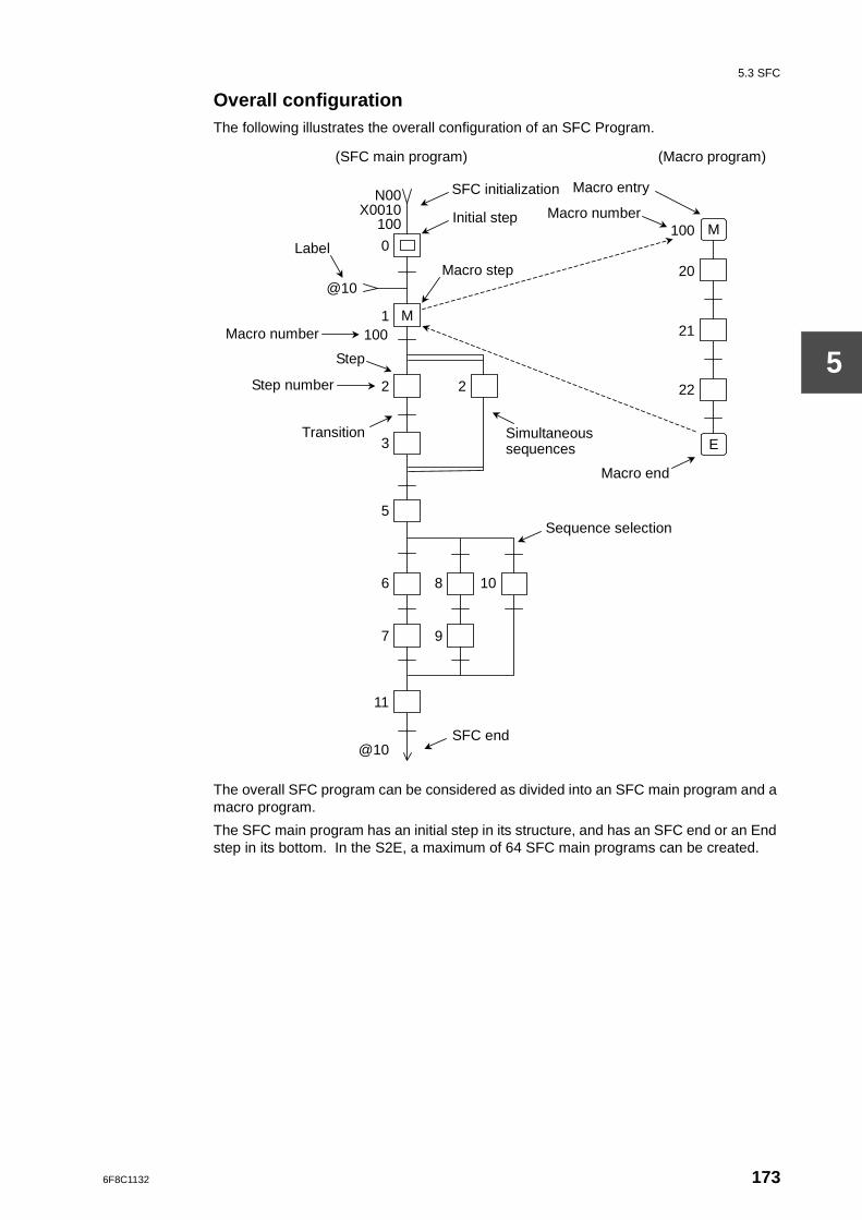
5.3 SFC
5
Overall configurationThe following illustrates the overall configuration of an SFC Program.
The overall SFC program can be considered as divided into an SFC main program and a macro program.
The SFC main program has an initial step in its structure, and has an SFC end or an End step in its bottom. In the S2E, a maximum of 64 SFC main programs can be created.
M
SFC initialization
Initial step
Macro step
Simultaneous sequences
Sequence selection
Macro number
Macro entry
Label
Macro number
Step number
Macro end
Transition
SFC end
Step
M
E
7
6
9
8 10
11
@10
5
3
2
1
0
2 22
21
20
100
(Macro program) (SFC main program)
N00X0010
100
@10
100
6F8C1132 173
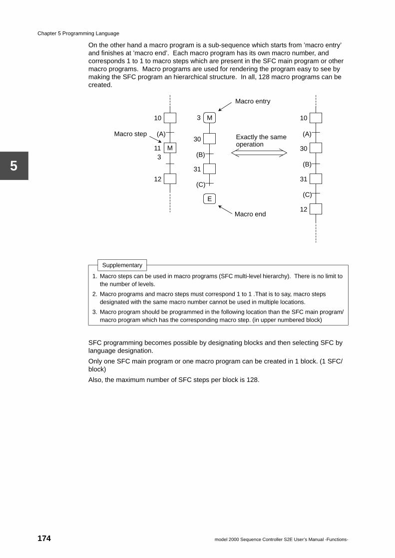
Chapter 5 Programming Language
5
On the other hand a macro program is a sub-sequence which starts from ’macro entry’ and finishes at ’macro end’. Each macro program has its own macro number, and corresponds 1 to 1 to macro steps which are present in the SFC main program or other macro programs. Macro programs are used for rendering the program easy to see by making the SFC program an hierarchical structure. In all, 128 macro programs can be created.
SFC programming becomes possible by designating blocks and then selecting SFC by language designation.
Only one SFC main program or one macro program can be created in 1 block. (1 SFC/block)
Also, the maximum number of SFC steps per block is 128.
Supplementary
1. Macro steps can be used in macro programs (SFC multi-level hierarchy). There is no limit to the number of levels.
2. Macro programs and macro steps must correspond 1 to 1 .That is to say, macro steps designated with the same macro number cannot be used in multiple locations.
3. Macro program should be programmed in the following location than the SFC main program/macro program which has the corresponding macro step. (in upper numbered block)
M
Macro step
Macro entry
Macro end
12
11 3
10 M
E
31
30
3
(A)
(B)
(C)
Exactly the same operation
31
30
10
(A)
12
(B)
(C)
174 model 2000 Sequence Controller S2E User’s Manual -Functions-
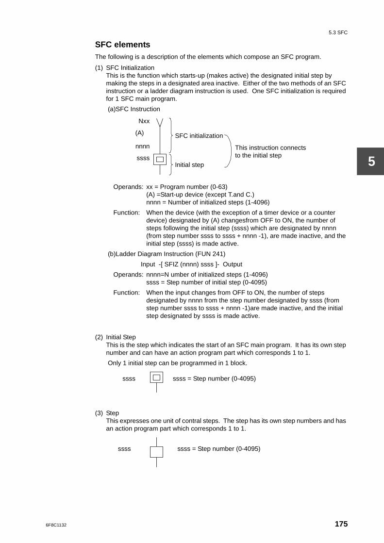
5.3 SFC
5
SFC elementsThe following is a description of the elements which compose an SFC program.
(1) SFC InitializationThis is the function which starts-up (makes active) the designated initial step by making the steps in a designated area inactive. Either of the two methods of an SFC instruction or a ladder diagram instruction is used. One SFC initialization is required for 1 SFC main program.
(a)SFC Instruction
Operands: xx = Program number (0-63)(A) =Start-up device (except T.and C.)nnnn = Number of initialized steps (1-4096)
Function: When the device (with the exception of a timer device or a counter device) designated by (A) changesfrom OFF to ON, the number of steps following the initial step (ssss) which are designated by nnnn (from step number ssss to ssss + nnnn -1), are made inactive, and the initial step (ssss) is made active.
(b)Ladder Diagram Instruction (FUN 241)
Input -[ SFIZ (nnnn) ssss ]- Output
Operands: nnnn=N umber of initialized steps (1-4096)ssss = Step number of initial step (0-4095)
Function: When the input changes from OFF to ON, the number of steps designated by nnnn from the step number designated by ssss (from step number ssss to ssss + nnnn -1)are made inactive, and the initial step designated by ssss is made active.
(2) Initial StepThis is the step which indicates the start of an SFC main program. It has its own step number and can have an action program part which corresponds 1 to 1.
Only 1 initial step can be programmed in 1 block.
(3) StepThis expresses one unit of contral steps. The step has its own step numbers and has an action program part which corresponds 1 to 1.
(A)
Nxx
nnnn
ssss
SFC initialization
Initial step
This instruction connects to the initial step
ssss ssss = Step number (0-4095)
ssss ssss = Step number (0-4095)
6F8C1132 175
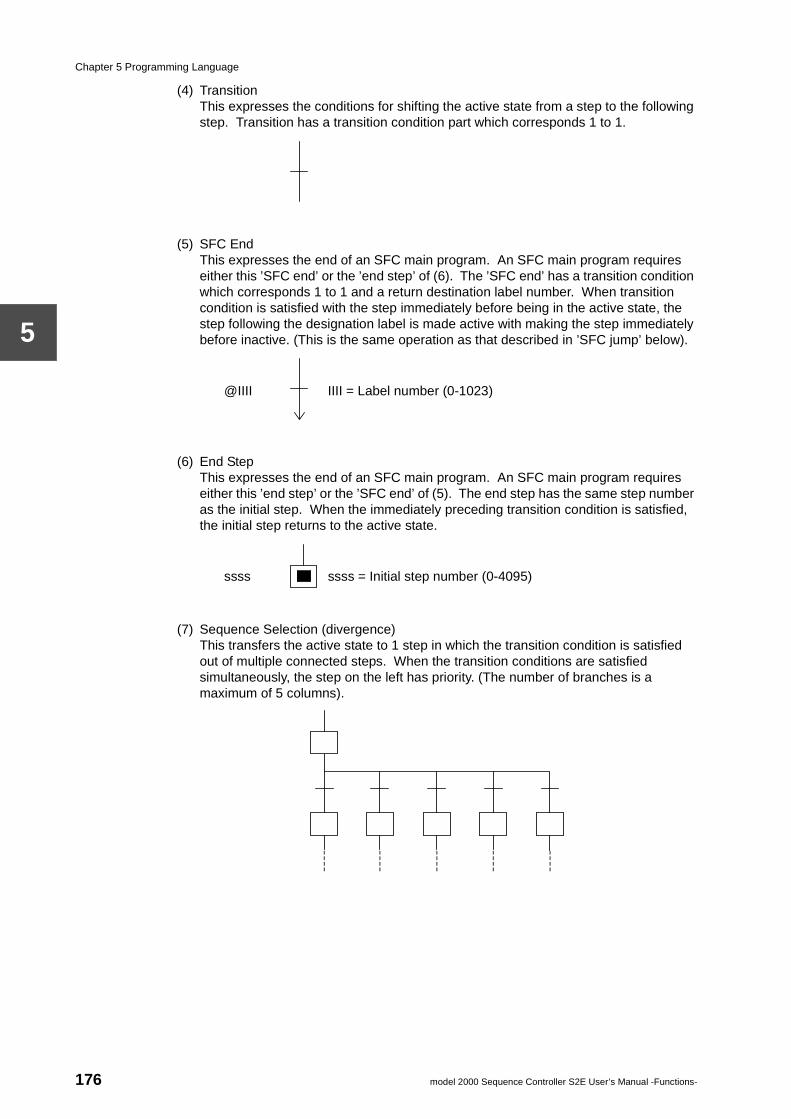
Chapter 5 Programming Language
5
(4) TransitionThis expresses the conditions for shifting the active state from a step to the following step. Transition has a transition condition part which corresponds 1 to 1.
(5) SFC EndThis expresses the end of an SFC main program. An SFC main program requires either this ’SFC end’ or the ’end step’ of (6). The ’SFC end’ has a transition condition which corresponds 1 to 1 and a return destination label number. When transition condition is satisfied with the step immediately before being in the active state, the step following the designation label is made active with making the step immediately before inactive. (This is the same operation as that described in ’SFC jump’ below).
(6) End StepThis expresses the end of an SFC main program. An SFC main program requires either this ’end step’ or the ’SFC end’ of (5). The end step has the same step number as the initial step. When the immediately preceding transition condition is satisfied, the initial step returns to the active state.
(7) Sequence Selection (divergence)This transfers the active state to 1 step in which the transition condition is satisfied out of multiple connected steps. When the transition conditions are satisfied simultaneously, the step on the left has priority. (The number of branches is a maximum of 5 columns).
@IIII IIII = Label number (0-1023)
ssss ssss = Initial step number (0-4095)
176 model 2000 Sequence Controller S2E User’s Manual -Functions-
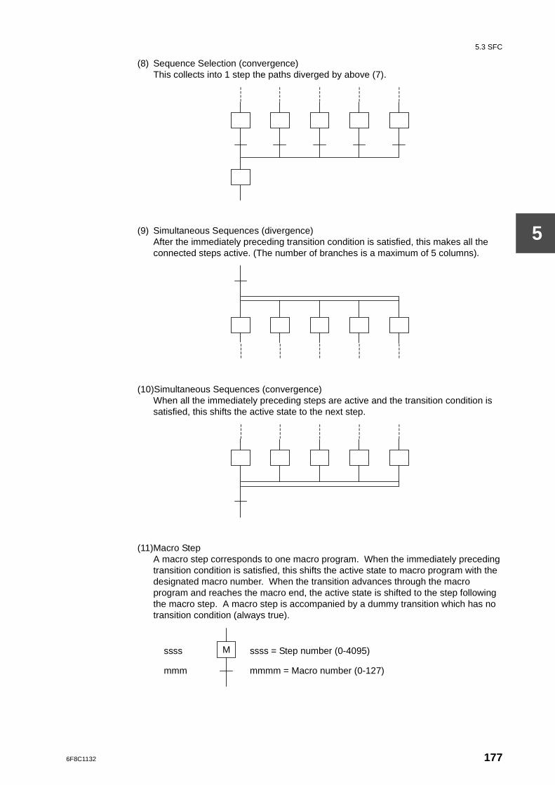
5.3 SFC
5
(8) Sequence Selection (convergence)This collects into 1 step the paths diverged by above (7).
(9) Simultaneous Sequences (divergence)After the immediately preceding transition condition is satisfied, this makes all the connected steps active. (The number of branches is a maximum of 5 columns).
(10)Simultaneous Sequences (convergence)When all the immediately preceding steps are active and the transition condition is satisfied, this shifts the active state to the next step.
(11)Macro StepA macro step corresponds to one macro program. When the immediately preceding transition condition is satisfied, this shifts the active state to macro program with the designated macro number. When the transition advances through the macro program and reaches the macro end, the active state is shifted to the step following the macro step. A macro step is accompanied by a dummy transition which has no transition condition (always true).
M ssss
mmm
ssss = Step number (0-4095)
mmmm = Macro number (0-127)
6F8C1132 177
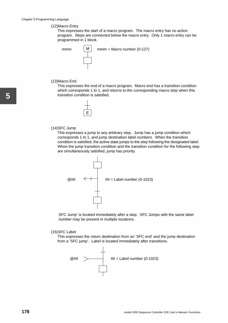
Chapter 5 Programming Language
5
(12)Macro EntryThis expresses the start of a macro program. The macro entry has no action program. Steps are connected below the macro entry. Only 1 macro entry can be programmed in 1 block.
(13)Macro EndThis expresses the end of a macro program. Macro end has a transition condition which corresponds 1 to 1, and returns to the corresponding macro step when this transition condition is satisfied.
(14)SFC JumpThis expresses a jump to any arbitrary step. Jump has a jump condition which corresponds 1 to 1, and jump destination label numbers. When the transition condition is satisfied, the active state jumps to the step following the designated label. When the jump transition condition and the transition condition for the following step are simultaneously satisfied, jump has priority.
SFC Jump’ is located immediately after a step. SFC Jumps with the same label number may be present in multiple locations.
(15)SFC LabelThis expresses the return destination from an ’SFC end’ and the jump destination from a ’SFC jump’. Label is located immediately after transitions.
M mmm mmm = Macro number (0-127)
E
@IIII IIII = Label number (0-1023)
@IIII IIII = Label number (0-1023)
178 model 2000 Sequence Controller S2E User’s Manual -Functions-
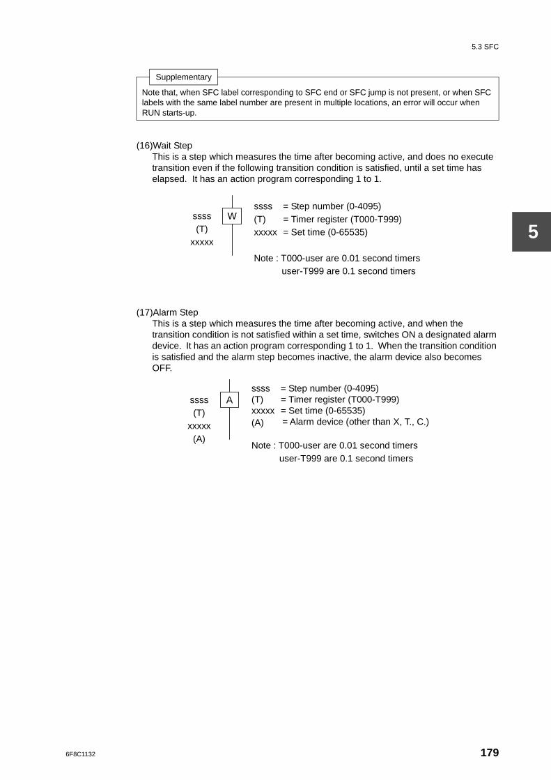
5.3 SFC
5
(16)Wait StepThis is a step which measures the time after becoming active, and does no execute transition even if the following transition condition is satisfied, until a set time has elapsed. It has an action program corresponding 1 to 1.
(17)Alarm StepThis is a step which measures the time after becoming active, and when the transition condition is not satisfied within a set time, switches ON a designated alarm device. It has an action program corresponding 1 to 1. When the transition condition is satisfied and the alarm step becomes inactive, the alarm device also becomes OFF.
Supplementary
Note that, when SFC label corresponding to SFC end or SFC jump is not present, or when SFC labels with the same label number are present in multiple locations, an error will occur when RUN starts-up.
W ssss (T)
xxxxx
ssss = Step number (0-4095) (T) = Timer register (T000-T999) xxxxx = Set time (0-65535) Note : T000-user are 0.01 second timers
user-T999 are 0.1 second timers
A ssss (T)
xxxxx (A)
ssss = Step number (0-4095) (T) = Timer register (T000-T999) xxxxx = Set time (0-65535) (A) = Alarm device (other than X, T., C.) Note : T000-user are 0.01 second timers
user-T999 are 0.1 second timers
6F8C1132 179
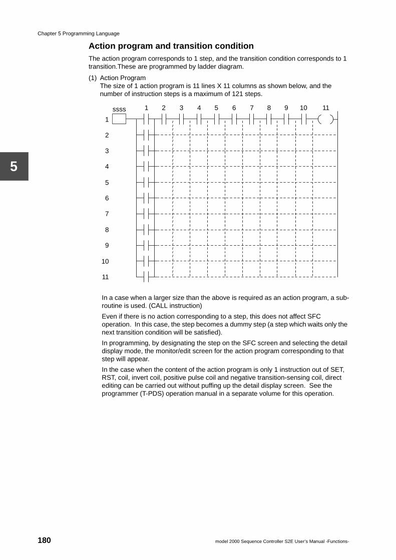
Chapter 5 Programming Language
5
Action program and transition conditionThe action program corresponds to 1 step, and the transition condition corresponds to 1 transition.These are programmed by ladder diagram.
(1) Action ProgramThe size of 1 action program is 11 lines X 11 columns as shown below, and the number of instruction steps is a maximum of 121 steps.
In a case when a larger size than the above is required as an action program, a sub-routine is used. (CALL instruction)
Even if there is no action corresponding to a step, this does not affect SFC operation. In this case, the step becomes a dummy step (a step which waits only the next transition condition will be satisfied).
In programming, by designating the step on the SFC screen and selecting the detail display mode, the monitor/edit screen for the action program corresponding to that step will appear.
In the case when the content of the action program is only 1 instruction out of SET, RST, coil, invert coil, positive pulse coil and negative transition-sensing coil, direct editing can be carried out without puffing up the detail display screen. See the programmer (T-PDS) operation manual in a separate volume for this operation.
1 2 3 4 5 6 7 8 9 10 11
1
2
3
4
5
6
7
8
9
10
11
ssss
180 model 2000 Sequence Controller S2E User’s Manual -Functions-

5.3 SFC
5
(2) Transition ConditionThe size of 1 transition condition is 11 lines X 10 columns, and the number of instruction steps is a maximum of 110 steps.
When there is no transition condition corresponding to a certain transition, that transition condition is always regarded as true. (Dummy transition)
In programming, by designating the transition on the SFC screen and selecting the detail display mode, the monitor/edit screen for the transition condition corresponding to that transition will appear. In the case when the content of the transition condition is only 1 instruction of NO contact or NC contact, direct editing can be carried out without putting up the detail display screen. See the programmer (T-PDS) operation manual in a separate volume for this operation.
Supplementary
The following execution control instructions cannot be used in action programs and transition conditions.• Jump (JSC/JCR, JUMP/LBL)• Master control (MCS/MCR, MCSn/MCRn)• End (END)• FOR-NEXT (FOR/NEXT)Also, the invert contact and various coil instructions cannot be used in transition conditions.
1 2 3 4 5 6 7 8 9 10
1
2
3
4
5
6
7
8
9
10
11
6F8C1132 181
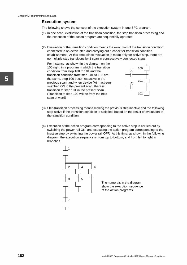
Chapter 5 Programming Language
5
Execution systemThe following shows the concept of the execution system in one SFC program.
(1) In one scan, evaluation of the transition condition, the step transition processing and the execution of the action program are sequentially operated.
(2) Evaluation of the transition condition means the execution of the transition condition connected to an active step and carrying out a check for transition condition establishment. At this time, since evaluation is made only for active step, there are no multiple step transitions by 1 scan in consecutively connected steps.
For instance, as shown in the diagram on the 100 right, in a program in which the transition condition from step 100 to 101 and the transition condition from step 101 to 102 are the same, step 100 becomes active in the previous scan, and when device (A) hasbeen switched ON in the present scan, there is transition to step 101 in the present scan. (Transition to step 102 will be from the next scan onward)
(3) Step transition processing means making the previous step inactive and the following step active if the transition condition is satisfied, based on the result of evaluation of the transition condition.
(4) Execution of the action program corresponding to the active step is carried out by switching the power rail ON, and executing the action program corresponding to the inactive step by switching the power rail OFF. At this time, as shown in the following diagram, the execution sequence is from top to bottom, and from left to right in branches.
(A)
(A)
100
101
102
The numerals in the diagram show the execution sequence of the action programs.
2 4 6
3 5
7
1
182 model 2000 Sequence Controller S2E User’s Manual -Functions-
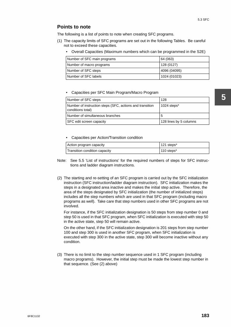
5.3 SFC
5
Points to noteThe following is a list of points to note when creating SFC programs.
(1) The capacity limits of SFC programs are set out in the following Tables. Be careful not to exceed these capacities.
• Overall Capacities (Maximum numbers which can be programmed in the S2E)
• Capacities per SFC Main Program/Macro Program
• Capacities per Action/Transition condition
Note: See 5.5 ’List of instructions’ for the required numbers of steps for SFC instruc-tions and ladder diagram instructions.
(2) The starting and re-setting of an SFC program is carried out by the SFC initialization instruction (SFC instruction/ladder diagram instruction). SFC initialization makes the steps in a designated area inactive and makes the initial step active. Therefore, the area of the steps designated by SFC initialization (the number of initialized steps) includes all the step numbers which are used in that SFC program (including macro programs as well). Take care that step numbers used in other SFC programs are not involved.
For instance, if the SFC initialization designation is 50 steps from step number 0 and step 50 is used in that SFC program, when SFC initialization is executed with step 50 in the active state, step 50 will remain active.
On the other hand, if the SFC initialization designation is 201 steps from step number 100 and step 300 is used in another SFC program, when SFC initialization is executed with step 300 in the active state, step 300 will become inactive without any condition.
(3) There is no limit to the step number sequence used in 1 SFC program (including macro programs). However, the initial step must be made the lowest step number in that sequence. (See (2) above)
Number of SFC main programs 64 (063)
Number of macro programs 128 (0127)
Number of SFC steps 4096 (04095)
Number of SFC labels 1024 (01023)
Number of SFC steps 128
Number of instruction steps (SFC, actions and transition conditions total)
1024 steps*
Number of simultaneous branches 5
SFC edit screen capacity 128 lines by 5 columns
Action program capacity 121 steps*
Transition condition capacity 110 steps*
6F8C1132 183
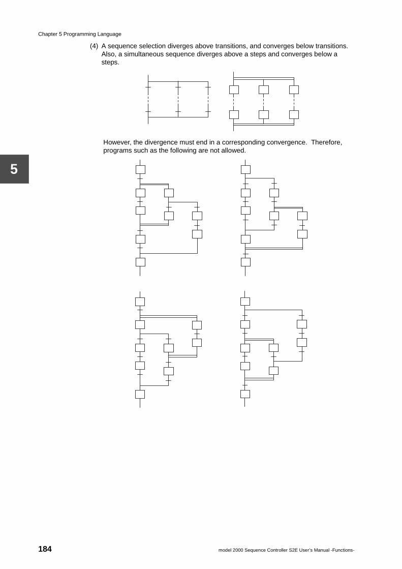
Chapter 5 Programming Language
5
(4) A sequence selection diverges above transitions, and converges below transitions. Also, a simultaneous sequence diverges above a steps and converges below a steps.
However, the divergence must end in a corresponding convergence. Therefore, programs such as the following are not allowed.
184 model 2000 Sequence Controller S2E User’s Manual -Functions-
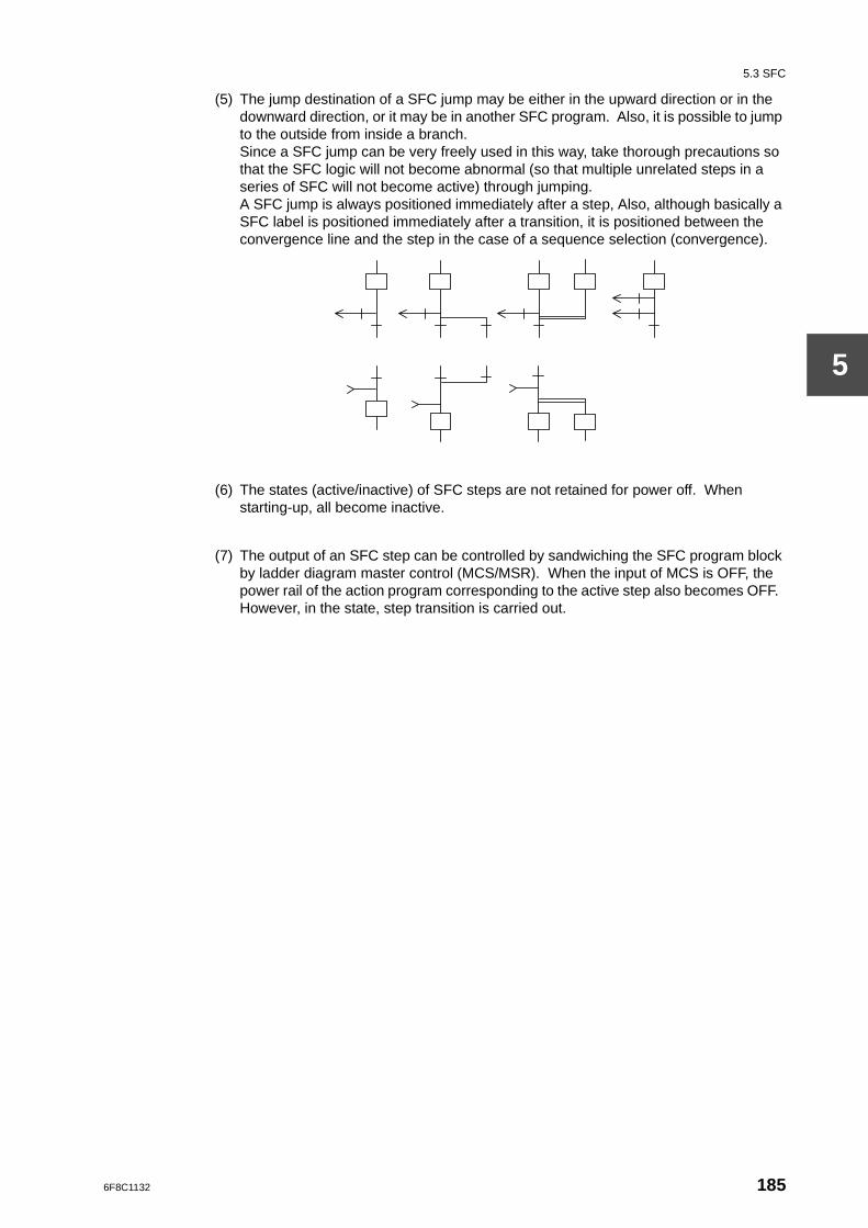
5.3 SFC
5
(5) The jump destination of a SFC jump may be either in the upward direction or in the downward direction, or it may be in another SFC program. Also, it is possible to jump to the outside from inside a branch.Since a SFC jump can be very freely used in this way, take thorough precautions so that the SFC logic will not become abnormal (so that multiple unrelated steps in a series of SFC will not become active) through jumping.A SFC jump is always positioned immediately after a step, Also, although basically a SFC label is positioned immediately after a transition, it is positioned between the convergence line and the step in the case of a sequence selection (convergence).
(6) The states (active/inactive) of SFC steps are not retained for power off. When starting-up, all become inactive.
(7) The output of an SFC step can be controlled by sandwiching the SFC program block by ladder diagram master control (MCS/MSR). When the input of MCS is OFF, the power rail of the action program corresponding to the active step also becomes OFF. However, in the state, step transition is carried out.
6F8C1132 185
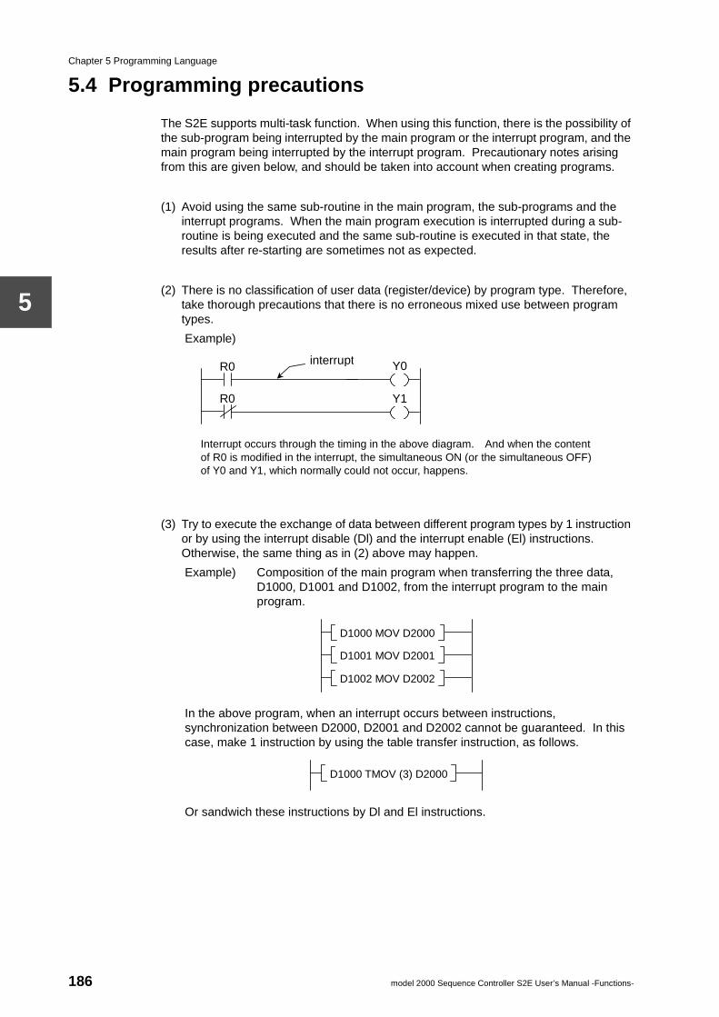
Chapter 5 Programming Language
5
5.4 Programming precautions
The S2E supports multi-task function. When using this function, there is the possibility of the sub-program being interrupted by the main program or the interrupt program, and the main program being interrupted by the interrupt program. Precautionary notes arising from this are given below, and should be taken into account when creating programs.
(1) Avoid using the same sub-routine in the main program, the sub-programs and the interrupt programs. When the main program execution is interrupted during a sub-routine is being executed and the same sub-routine is executed in that state, the results after re-starting are sometimes not as expected.
(2) There is no classification of user data (register/device) by program type. Therefore, take thorough precautions that there is no erroneous mixed use between program types.
Example)
(3) Try to execute the exchange of data between different program types by 1 instruction or by using the interrupt disable (Dl) and the interrupt enable (El) instructions. Otherwise, the same thing as in (2) above may happen.
Example) Composition of the main program when transferring the three data, D1000, D1001 and D1002, from the interrupt program to the main program.
In the above program, when an interrupt occurs between instructions, synchronization between D2000, D2001 and D2002 cannot be guaranteed. In this case, make 1 instruction by using the table transfer instruction, as follows.
Or sandwich these instructions by Dl and El instructions.
Y1 R0
R0 interrupt
Interrupt occurs through the timing in the above diagram. And when the content of R0 is modified in the interrupt, the simultaneous ON (or the simultaneous OFF) of Y0 and Y1, which normally could not occur, happens.
Y0
D1000 MOV D2000
D1001 MOV D2001
D1002 MOV D2002
D1000 TMOV (3) D2000
186 model 2000 Sequence Controller S2E User’s Manual -Functions-
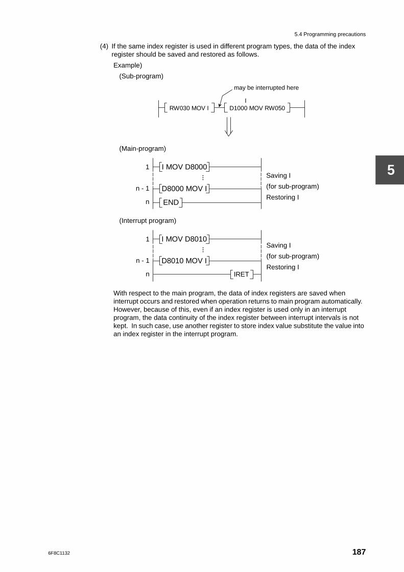
5.4 Programming precautions
5
(4) If the same index register is used in different program types, the data of the index register should be saved and restored as follows.
Example)
(Sub-program)
(Main-program)
(Interrupt program)
With respect to the main program, the data of index registers are saved when interrupt occurs and restored when operation returns to main program automatically. However, because of this, even if an index register is used only in an interrupt program, the data continuity of the index register between interrupt intervals is not kept. In such case, use another register to store index value substitute the value into an index register in the interrupt program.
RW030 MOV I
may be interrupted here
D1000 MOV RW050 I
END
1
n - 1
n
D8000 MOV I
I MOV D8000 Saving I
(for sub-program)
Restoring I
IRET
Saving I
(for sub-program)
Restoring I D8010 MOV I
I MOV D8010 1
n - 1
n
6F8C1132 187
Chapter 5 Programming Language
5
5.5 List of instructions
An instruction list is given in the sequence of ladder diagram instructions and SFC instructions on the next page and thereafter.
The groups in the list correspond to the group classifications of function instructions used in the programmer (T-PDS). (Except for SFC).
The required numbers of steps signify the size of memory required for storing these instructions. The showing of the required number of steps by a range such as 4-7, is because the number of steps changes due to the following conditions, even for the same instruction.
• When using digit designation, there is an increase of 1 step per 1 operand.
• When a constant is used in a double-length operand, there is an increase of 1 step.
• When executing index modification in a constant, there is an increase of 1 step.
The minimum execution time figure shows normal case value, i.e. when no index modification, no digit designation and normal registers are used for each operand.
The maximum execution time figure shows worst case value, i.e. when direct input/output registers (lW/OW) are used for each operand, etc.
Supplementary
Here, an overview of each instruction is given. See the instruction set manual in a separate volume for details.
188 model 2000 Sequence Controller S2E User’s Manual -Functions-
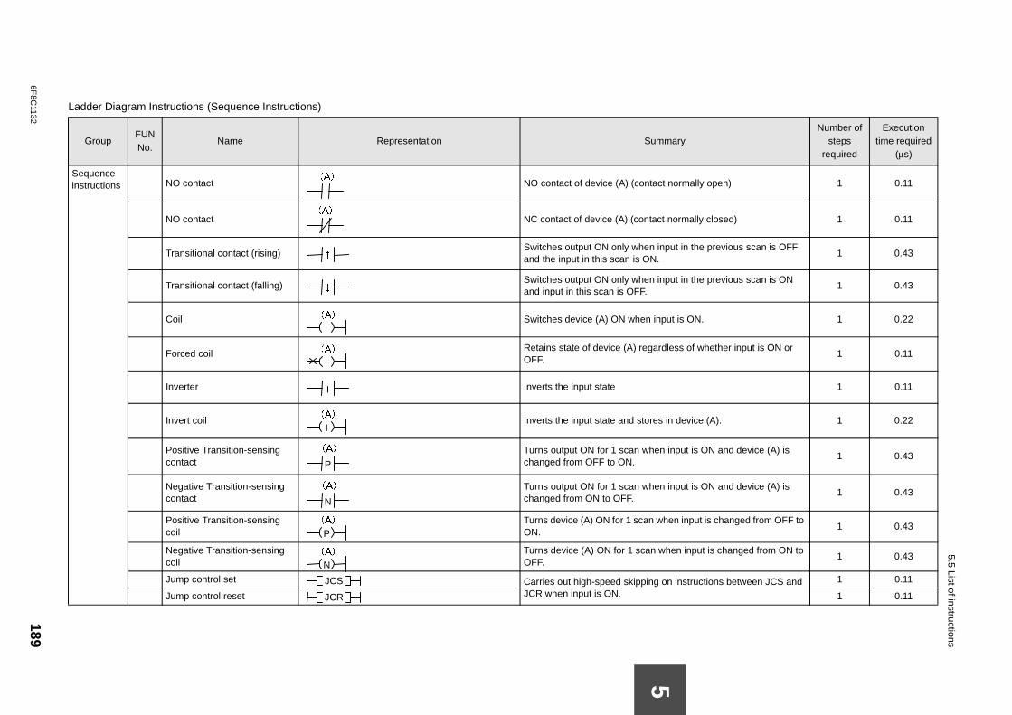
6F8C
1132189
5.5 List of instructions
La
maryNumber of
steps required
Execution time required
(µs)
Sin t normally open) 1 0.11
t normally closed) 1 0.11
nput in the previous scan is OFF 1 0.43
nput in the previous scan is ON 1 0.43
put is ON. 1 0.22
rdless of whether input is ON or 1 0.11
1 0.11
s in device (A). 1 0.22
n input is ON and device (A) is 1 0.43
n input is ON and device (A) is 1 0.43
hen input is changed from OFF to 1 0.43
when input is changed from ON to 1 0.43
on instructions between JCS and 1 0.11
1 0.11
5
dder Diagram Instructions (Sequence Instructions)
GroupFUN No.
Name Representation Sum
equence structions NO contact
NO contact of device (A) (contac
NO contact
NC contact of device (A) (contac
Transitional contact (rising) Switches output ON only when i
and the input in this scan is ON.
Transitional contact (falling) Switches output ON only when i
and input in this scan is OFF.
Coil
Switches device (A) ON when in
Forced coil Retains state of device (A) rega
OFF.
Inverter
Inverts the input state
Invert coil
Inverts the input state and store
Positive Transition-sensing contact
Turns output ON for 1 scan whechanged from OFF to ON.
Negative Transition-sensing contact
Turns output ON for 1 scan whechanged from ON to OFF.
Positive Transition-sensing coil
Turns device (A) ON for 1 scan wON.
Negative Transition-sensing coil
Turns device (A) ON for 1 scan OFF.
Jump control set Carries out high-speed skippingJCR when input is ON.Jump control reset
(A)
(A)
↑
↓
(A)
(A)
I
(A)
I
P
(A)
N
(A)
(A)
P
(A)
N
JCS
JCR
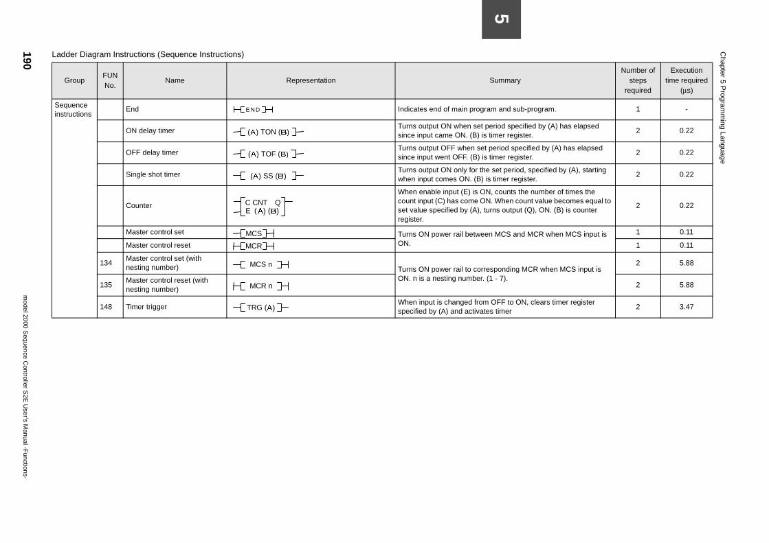
190m
odel 2000 Sequence C
ontroller S2E
User’s M
anual -Functions-
Chapter 5 P
rogramm
ing Language
5
m and sub-program. 1 -
eriod specified by (A) has elapsed timer register.
2 0.22
period specified by (A) has elapsed timer register.
2 0.22
set period, specified by (A), starting s timer register.
2 0.22
, counts the number of times the . When count value becomes equal to rns output (Q), ON. (B) is counter
2 0.22
n MCS and MCR when MCS input is 1 0.11
1 0.11
sponding MCR when MCS input is 1 - 7).
2 5.88
2 5.88
OFF to ON, clears timer register s timer
2 3.47
SummaryNumber of
steps required
Execution time required
(µs)
Sequence instructions
End
Indicates end of main progra
ON delay timer Turns output ON when set p
since input came ON. (B) is
OFF delay timer Turns output OFF when set
since input went OFF. (B) is
Single shot timer Turns output ON only for the
when input comes ON. (B) i
Counter
When enable input (E) is ONcount input (C) has come ONset value specified by (A), turegister.
Master control set Turns ON power rail betweeON.Master control reset
134Master control set (with nesting number)
Turns ON power rail to correON. n is a nesting number. (
135Master control reset (with nesting number)
148 Timer trigger When input is changed fromspecified by (A) and activate
Ladder Diagram Instructions (Sequence Instructions)
GroupFUN No.
Name Representation
E ND
(A) TON (B)
(A) TOF (B)
(A) SS (B)
C CNT Q E (A) (B)
MCS
MCR
MCS n
MCR n
TRG (A)
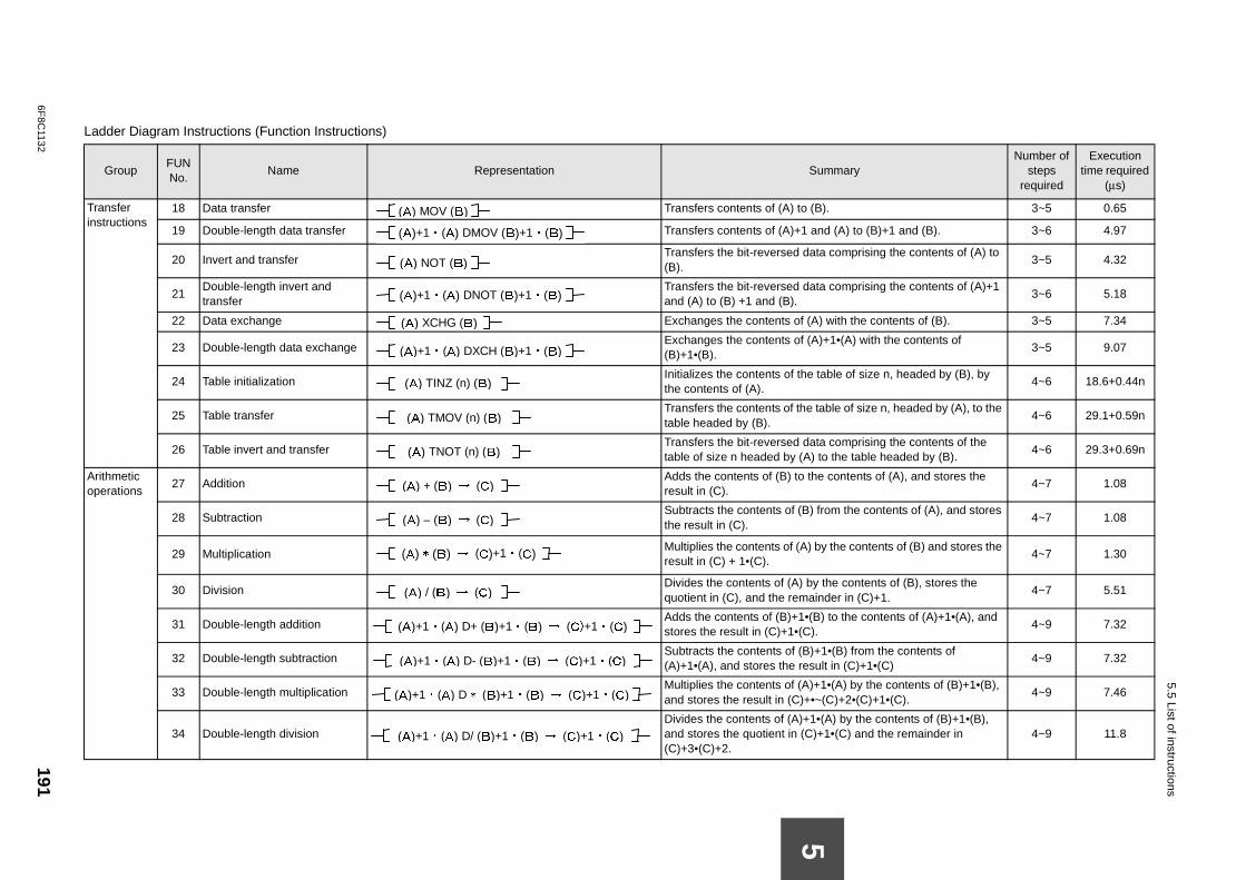
6F8C
1132191
5.5 List of instructions
La
ummaryNumber of
steps required
Execution time required
(µs)
Tin
(B). 3~5 0.65
and (A) to (B)+1 and (B). 3~6 4.97
ta comprising the contents of (A) to 3~5 4.32
ta comprising the contents of (A)+1 3~6 5.18
A) with the contents of (B). 3~5 7.34
A)+1•(A) with the contents of 3~5 9.07
table of size n, headed by (B), by 4~6 18.6+0.44n
table of size n, headed by (A), to the 4~6 29.1+0.59n
ta comprising the contents of the ) to the table headed by (B).
4~6 29.3+0.69n
Ao
he contents of (A), and stores the 4~7 1.08
from the contents of (A), and stores 4~7 1.08
by the contents of (B) and stores the 4~7 1.30
y the contents of (B), stores the inder in (C)+1.
4~7 5.51
B) to the contents of (A)+1•(A), and ).
4~9 7.32
+1•(B) from the contents of ult in (C)+1•(C)
4~9 7.32
+1•(A) by the contents of (B)+1•(B), •~(C)+2•(C)+1•(C).
4~9 7.46
•(A) by the contents of (B)+1•(B), )+1•(C) and the remainder in 4~9 11.8
5
dder Diagram Instructions (Function Instructions)
GroupFUN No.
Name Representation S
ransfer structions
18 Data transfer Transfers contents of (A) to
19 Double-length data transfer Transfers contents of (A)+1
20 Invert and transfer Transfers the bit-reversed da(B).
21Double-length invert and transfer
Transfers the bit-reversed daand (A) to (B) +1 and (B).
22 Data exchange Exchanges the contents of (
23 Double-length data exchange Exchanges the contents of ((B)+1•(B).
24 Table initialization Initializes the contents of the
the contents of (A).
25 Table transfer Transfers the contents of the
table headed by (B).
26 Table invert and transfer Transfers the bit-reversed da
table of size n headed by (A
rithmetic perations
27 Addition Adds the contents of (B) to t
result in (C).
28 Subtraction Subtracts the contents of (B)
the result in (C).
29 Multiplication Multiplies the contents of (A)
result in (C) + 1•(C).
30 Division Divides the contents of (A) b
quotient in (C), and the rema
31 Double-length addition Adds the contents of (B)+1•(
stores the result in (C)+1•(C
32 Double-length subtraction Subtracts the contents of (B)
(A)+1•(A), and stores the res
33 Double-length multiplication Multiplies the contents of (A)
and stores the result in (C)+
34 Double-length division Divides the contents of (A)+1
and stores the quotient in (C(C)+3•(C)+2.
(A) MOV (B)
(A)+1・(A) DMOV (B)+1・(B)
(A) NOT (B)
(A)+1・(A) DNOT (B)+1・(B)
(A) XCHG (B)
(A)+1・(A) DXCH (B)+1・(B)
(A) TINZ (n) (B)
(A) TMOV (n) (B)
(A) TNOT (n) (B)
(A) + (B) → (C)
(A) – (B) → (C)
(A) * (B) → (C)+1・(C)
(A) / (B) → (C)
(A)+1・(A) D+ (B)+1・(B) → (C)+1・(C)
(A)+1・(A) D- (B)+1・(B) → (C)+1・(C)
(A)+1・(A) D * (B)+1・(B) → (C)+1・(C)
(A)+1・(A) D/ (B)+1・(B) → (C)+1・(C)
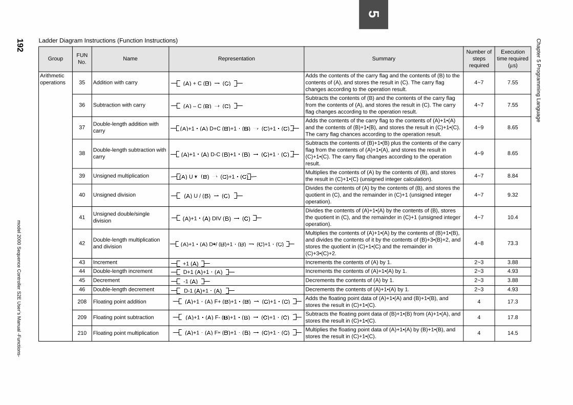
192m
odel 2000 Sequence C
ontroller S2E
User’s M
anual -Functions-
Chapter 5 P
rogramm
ing Language
5
carry flag and the contents of (B) to the es the result in (C). The carry flag e operation result.
4~7 7.55
f (B) and the contents of the carry flag and stores the result in (C). The carry to the operation result.
4~7 7.55
carry flag to the contents of (A)+1•(A) 1•(B), and stores the result in (C)+1•(C). ccording to the operation result.
4~9 8.65
f (B)+1•(B) plus the contents of the carry (A)+1•(A), and stores the result in changes according to the operation
4~9 8.65
f (A) by the contents of (B), and stores nsigned integer calculation).
4~7 8.84
A) by the contents of (B), and stores the emainder in (C)+1 (unsigned integer 4~7 9.32
A)+1•(A) by the contents of (B), stores he remainder in (C)+1 (unsigned integer 4~7 10.4
f (A)+1•(A) by the contents of (B)+1•(B), of it by the contents of (B)+3•(B)+2, and )+1•(C) and the remainder in
4~8 73.3
of (A) by 1. 2~3 3.88
of (A)+1•(A) by 1. 2~3 4.93
s of (A) by 1. 2~3 3.88
s of (A)+1•(A) by 1. 2~3 4.93
ata of (A)+1•(A) and (B)+1•(B), and •(C).
4 17.3
int data of (B)+1•(B) from (A)+1•(A), and •(C).
4 17.8
int data of (A)+1•(A) by (B)+1•(B), and •(C).
4 14.5
SummaryNumber of
steps required
Execution time required
(µs)
Arithmetic operations 35 Addition with carry
Adds the contents of thecontents of (A), and storchanges according to th
36 Subtraction with carry Subtracts the contents o
from the contents of (A),flag changes according
37Double-length addition with carry
Adds the contents of theand the contents of (B)+The carry flag chances a
38Double-length subtraction with carry
Subtracts the contents oflag from the contents of(C)+1•(C). The carry flagresult.
39 Unsigned multiplication Multiplies the contents o
the result in (C)+1•(C) (u
40 Unsigned division Divides the contents of (
quotient in (C), and the roperation).
41Unsigned double/single division
Divides the contents of (the quotient in (C), and toperation).
42Double-length multiplication and division
Multiplies the contents oand divides the contentsstores the quotient in (C(C)+3•(C)+2.
43 Increment Increments the contents
44 Double-length increment Increments the contents
45 Decrement Decrements the content
46 Double-length decrement Decrements the content
208 Floating point addition Adds the floating point dstores the result in (C)+1
209 Floating point subtraction Subtracts the floating po
stores the result in (C)+1
210 Floating point multiplication Multiplies the floating postores the result in (C)+1
Ladder Diagram Instructions (Function Instructions)
GroupFUN No.
Name Representation
(A) + C (B) → (C)
(A) – C (B) → (C)
(A)+1・(A) D+C (B)+1・(B) → (C)+1・(C)
(A)+1・(A) D-C (B)+1・(B) → (C)+1・(C)
(A) U * (B) → (C)+1・(C)
(A) U / (B) → (C)
(A)+1・(A) DIV (B) → (C)
(A)+1・(A) D*/ (B)+1・(B) → (C)+1・(C)
+1 (A) D+1 (A)+1・(A)
-1 (A)
D-1 (A)+1・(A)
(A)+1・(A) F+ (B)+1・(B) → (C)+1・(C)
(A)+1・(A) F- (B)+1・(B) → (C)+1・(C)
(A)+1・(A) F* (B)+1・(B) → (C)+1・(C)
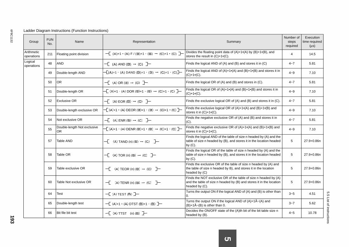
6F8C
1132193
5.5 List of instructions
Ao
a of (A)+1•(A) by (B)+1•(B), and ).
4 14.5
Lo
and (B) and stores it in (C) 4~7 5.81
+1•(A) and (B)+1•(B) and stores it in 4~9 7.10
nd (B) and stores in (C). 4~7 5.81
•(A) and (B)+1•(B) and stores it in 4~9 7.10
R of (A) and (B) and stores it in (C). 4~7 5.81
R of (A)+1•(A) and (B)+1•(B) and 4~9 7.10
OR of (A) and (B) and stores it in 4~7 5.81
OR of (A)+1•(A) and (B)+1•(B) and 4~9 7.10
table of size n headed by (A) and the , and stores it in the location headed 5 27.9+0.86n
able of size n headed by (A) and the , and stores it in the location headed 5 27.9+0.86n
e table of size n headed by (A) and B), and stores it in the location 5 27.9+0.86n
of the table of size n headed by (A) d by (B) and stores it in the location 5 27.9+0.86n
ical AND of (A) and (B) is other than 3~5 4.51
gical AND of (A)+1Å~(A) and 3~7 5.62
f the (A)th bit of the bit table size n 4~5 10.78
La
ummaryNumber of
steps required
Execution time required
(µs)
5
rithmetic perations
211 Floating point division Divides the floating point datstores the result in (C)+1•(C
ogical perations
48 AND
Finds the logical AND of (A)
49 Double-length AND Finds the logical AND of (A)(C)+1•(C).
50 OR
Finds the logical OR of (A) a
51 Double-length OR Finds the logical OR of (A)+1(C)+1•(C).
52 Exclusive OR
Finds the exclusive logical O
53 Double-length exclusive OR Finds the exclusive logical Ostores it in (C)+1•(C).
54 Not exclusive OR Finds the negative exclusive
(C).
55Double-length Not exclusive OR
Finds the negative exclusivestores it in (C)+1•(C).
57 Table AND Finds the logical AND of the
table of size n headed by (B)by (C).
58 Table OR Finds the logical OR of the t
table of size n headed by (B)by (C).
59 Table exclusive OR Finds the exclusive OR of th
the table of size n headed byheaded by (C)
60 Table Not exclusive OR Finds the NOT exclusive OR
and the table of size n headeheaded by (C).
64 Test Turns the output ON if the log
0.
65 Double-length test Turns the output ON if the lo
(B)+1Å~(B) is other than 0.
66 Bit file bit test Decides the ON/OFF state o
headed by (B).
dder Diagram Instructions (Function Instructions)
GroupFUN No.
Name Representation S
(A)+1・(A) F / (B)+1・(B) → (C)+1・(C)
(A) AND (B) → (C)
(A)+1・(A) DAND (B)+1・(B) → (C)+1・(C)
(A) OR (B) → (C)
(A)+1・(A) DOR (B)+1・(B) → (C)+1・(C)
(A) EOR (B) → (C)
(A)+1・(A) DEOR (B)+1・(B) → (C)+1・(C)
(A) ENR (B) → (C)
(A)+1・(A) DENR (B)+1・(B) → (C)+1・(C)
(A) TAND (n) (B) → (C)
(A) TOR (n) (B) → (C)
(A) TEOR (n) (B) → (C)
(A) TENR (n) (B) → (C)
(A) TEST (B)
(A)+1・(A) DTST (B)+1・(B)
(A) TTST (n) (B)
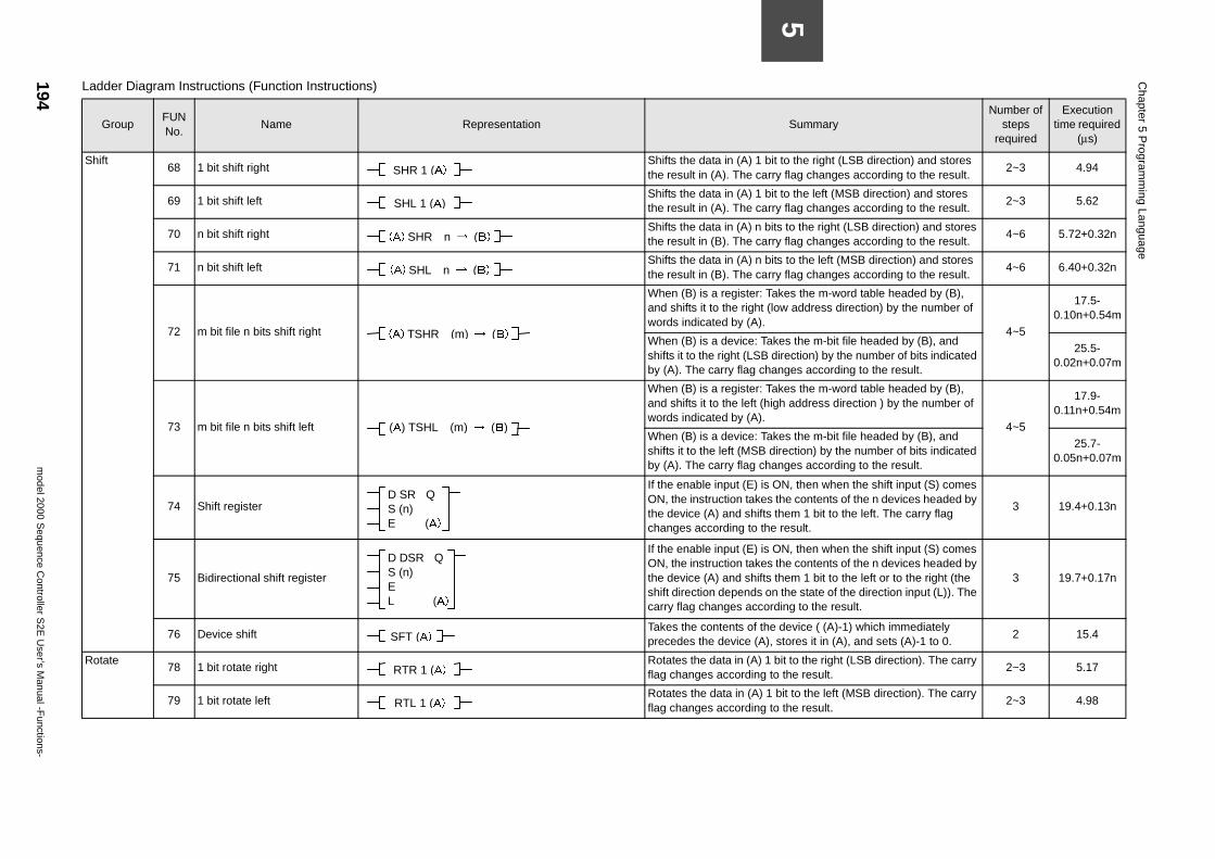
194m
odel 2000 Sequence C
ontroller S2E
User’s M
anual -Functions-
Chapter 5 P
rogramm
ing Language
5
it to the right (LSB direction) and stores ry flag changes according to the result.
2~3 4.94
it to the left (MSB direction) and stores ry flag changes according to the result.
2~3 5.62
its to the right (LSB direction) and stores ry flag changes according to the result.
4~6 5.72+0.32n
its to the left (MSB direction) and stores ry flag changes according to the result.
4~6 6.40+0.32n
akes the m-word table headed by (B), low address direction) by the number of
4~5
17.5-0.10n+0.54m
kes the m-bit file headed by (B), and direction) by the number of bits indicated anges according to the result.
25.5-0.02n+0.07m
akes the m-word table headed by (B), igh address direction ) by the number of
4~5
17.9-0.11n+0.54m
kes the m-bit file headed by (B), and irection) by the number of bits indicated
anges according to the result.
25.7-0.05n+0.07m
ON, then when the shift input (S) comes the contents of the n devices headed by them 1 bit to the left. The carry flag e result.
3 19.4+0.13n
ON, then when the shift input (S) comes the contents of the n devices headed by them 1 bit to the left or to the right (the n the state of the direction input (L)). The rding to the result.
3 19.7+0.17n
device ( (A)-1) which immediately stores it in (A), and sets (A)-1 to 0.
2 15.4
bit to the right (LSB direction). The carry to the result.
2~3 5.17
bit to the left (MSB direction). The carry to the result.
2~3 4.98
SummaryNumber of
steps required
Execution time required
(µs)
Shift68 1 bit shift right
Shifts the data in (A) 1 bthe result in (A). The car
69 1 bit shift left Shifts the data in (A) 1 b
the result in (A). The car
70 n bit shift right Shifts the data in (A) n b
the result in (B). The car
71 n bit shift left Shifts the data in (A) n b
the result in (B). The car
72 m bit file n bits shift right
When (B) is a register: Tand shifts it to the right (words indicated by (A).
When (B) is a device: Tashifts it to the right (LSB by (A). The carry flag ch
73 m bit file n bits shift left
When (B) is a register: Tand shifts it to the left (hwords indicated by (A).
When (B) is a device: Tashifts it to the left (MSB dby (A). The carry flag ch
74 Shift register
If the enable input (E) is ON, the instruction takesthe device (A) and shiftschanges according to th
75 Bidirectional shift register
If the enable input (E) is ON, the instruction takesthe device (A) and shiftsshift direction depends ocarry flag changes acco
76 Device shift Takes the contents of the
precedes the device (A),
Rotate78 1 bit rotate right
Rotates the data in (A) 1flag changes according
79 1 bit rotate left Rotates the data in (A) 1
flag changes according
Ladder Diagram Instructions (Function Instructions)
GroupFUN No.
Name Representation
SHR 1 (A)
SHL 1 (A)
(A) SHR n → (B)
(A) SHL n → (B)
(A) TSHR (m) → (B)
(A) TSHL (m) → (B)
D SR Q S (n) E (A)
D DSR Q S (n) E L (A)
SFT (A)
RTR 1 (A)
RTL 1 (A)
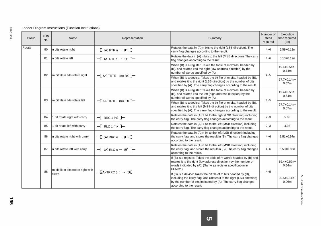
6F8C
1132195
5.5 List of instructions
R to the right (LSB direction). The to the result.
4~6 6.59+0.12n
to the left (MSB direction). The carry e result.
4~6 6.13+0.12n
s the table of m words, headed by t (low address direction) by the y (A).
4~5
19.4+0.54n+0.54m
the bit file of m bits, headed by (B), B direction) by the number of bits ag changes according to the result.
27.7+0.14n+0.07m
s the table of m words, headed by (high address direction) by the y (A).
4~5
19.4+0.55n+0.54m
the bit file of m bits, headed by (B), direction) by the number of bits
ag changes according to the result.
27.7+0.14n+0.07m
to the right (LSB direction) including changes according to the result.
2~3 5.63
to the left (MSB direction) including changes according to the result.
2~3 4.98
to the left (LSB direction) including result in (B). The carry flag changes 4~6 5.51+0.97n
to the left (MSB direction) including result in (B). The carry flag changes 4~6 6.53+0.86n
table of m words headed by (B) and dress direction) by the number of e as register specification in
4~5
19.4+0.52n+0.54m
it file of m bits headed by (B), rotates it to the right (LSB direction) ed by (A). The carry flag changes
30.5+0.14n+0.06m
La
ummaryNumber of
steps required
Execution time required
(µs)
5
otate80 n bits rotate right
Rotates the data in (A) n bitscarry flag changes according
81 n bits rotate left Rotates the data in (A) n bits
flag changes according to th
82 m bit file n bits rotate right
When (B) is a register: Take(B), and rotates it to the righnumber of words specified b
When (B) is a device: Takesand rotates it to the right (LSspecified by (A). The carry fl
83 m bit file n bits rotate left
When (B) is a register: Take(B), and rotates it to the left number of words specified b
When (B) is a device: Takesand rotates it to the left (MSBspecified by (A). The carry fl
84 1 bit rotate right with carry Rotates the data in (A) 1 bit
the carry flag. The carry flag
85 1 bit rotate left with carry Rotates the data in (A) 1 bit
the carry flag. The carry flag
86 n bits rotate right with carry Rotates the data in (A) n bit
the carry flag, and stores theaccording to the result.
87 n bits rotate left with carry Rotates the data in (A) n bit
the carry flag, and stores theaccording to the result.
88m bit file n bits rotate right with carry
If (B) is a register: Takes therotates it to the right (low adwords indicated by (A). (SamFUN82.)
If (B) is a device: Takes the bincluding the carry flag, and by the number of bits indicataccording to the result.
dder Diagram Instructions (Function Instructions)
GroupFUN No.
Name Representation S
(A) RTR n → (B)
(A) RTL n → (B)
(A) TRTR (m) (B)
(A) TRTL (m) (B)
RRC 1 (A)
RLC 1 (A)
(A) RRC n → (B)
(A) RLC n → (B)
(A) TRRC (m) → (B)
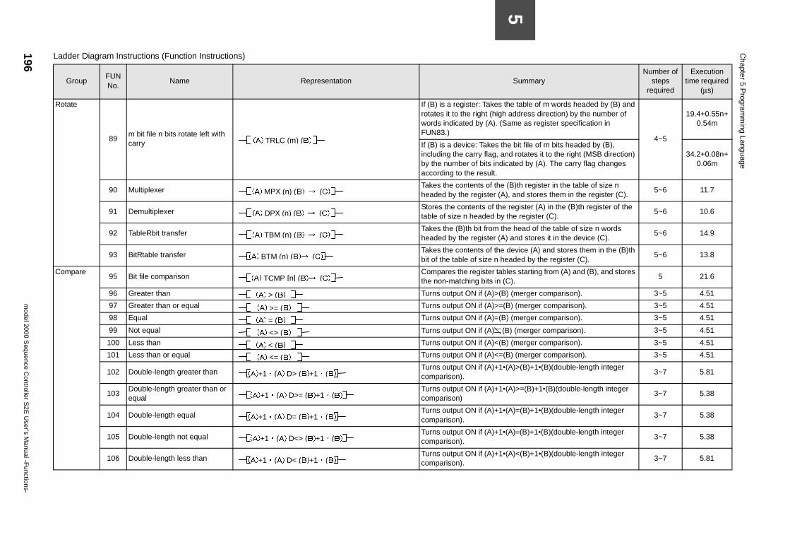
196m
odel 2000 Sequence C
ontroller S2E
User’s M
anual -Functions-
Chapter 5 P
rogramm
ing Language
5
the table of m words headed by (B) and h address direction) by the number of Same as register specification in
4~5
19.4+0.55n+0.54m
the bit file of m bits headed by (B), nd rotates it to the right (MSB direction) icated by (A). The carry flag changes
34.2+0.08n+0.06m
(B)th register in the table of size n ), and stores them in the register (C).
5~6 11.7
e register (A) in the (B)th register of the y the register (C).
5~6 10.6
the head of the table of size n words ) and stores it in the device (C).
5~6 14.9
device (A) and stores them in the (B)th eaded by the register (C).
5~6 13.8
bles starting from (A) and (B), and stores (C).
5 21.6
B) (merger comparison). 3~5 4.51
(B) (merger comparison). 3~5 4.51
B) (merger comparison). 3~5 4.51
(B) (merger comparison). 3~5 4.51
B) (merger comparison). 3~5 4.51
(B) (merger comparison). 3~5 4.51
•(A)>(B)+1•(B)(double-length integer 3~7 5.81
•(A)>=(B)+1•(B)(double-length integer 3~7 5.38
•(A)=(B)+1•(B)(double-length integer 3~7 5.38
•(A)=(B)+1•(B)(double-length integer 3~7 5.38
•(A)<(B)+1•(B)(double-length integer 3~7 5.81
SummaryNumber of
steps required
Execution time required
(µs)
Rotate
89m bit file n bits rotate left with carry
If (B) is a register: Takesrotates it to the right (higwords indicated by (A). (FUN83.)
If (B) is a device: Takes including the carry flag, aby the number of bits indaccording to the result.
90 Multiplexer Takes the contents of the
headed by the register (A
91 Demultiplexer Stores the contents of th
table of size n headed b
92 TableRbit transfer Takes the (B)th bit from
headed by the register (A
93 BitRtable transfer Takes the contents of the
bit of the table of size n h
Compare95 Bit file comparison
Compares the register tathe non-matching bits in
96 Greater than Turns output ON if (A)>(
97 Greater than or equal Turns output ON if (A)>=
98 Equal Turns output ON if (A)=(
99 Not equal Turns output ON if (A)
100 Less than Turns output ON if (A)<(
101 Less than or equal Turns output ON if (A)<=
102 Double-length greater than Turns output ON if (A)+1
comparison).
103Double-length greater than or equal
Turns output ON if (A)+1comparison)
104 Double-length equal Turns output ON if (A)+1
comparison).
105 Double-length not equal Turns output ON if (A)+1
comparison).
106 Double-length less than Turns output ON if (A)+1
comparison).
Ladder Diagram Instructions (Function Instructions)
GroupFUN No.
Name Representation
(A) TRLC (m) (B)
(A) MPX (n) (B) → (C)
(A) DPX (n) (B) → (C)
(A) TBM (n) (B) → (C)
(A) BTM (n) (B)→ (C)
(A) TCMP [n] (B)→ (C)
(A) > (B)
(A) >= (B)
(A) = (B)
(A) <> (B)
(A) < (B)
(A) <= (B)
(A)+1・(A) D> (B)+1・(B)
(A)+1・(A) D>= (B)+1・(B)
(A)+1・(A) D= (B)+1・(B)
(A)+1・(A) D<> (B)+1・(B)
(A)+1・(A) D< (B)+1・(B)
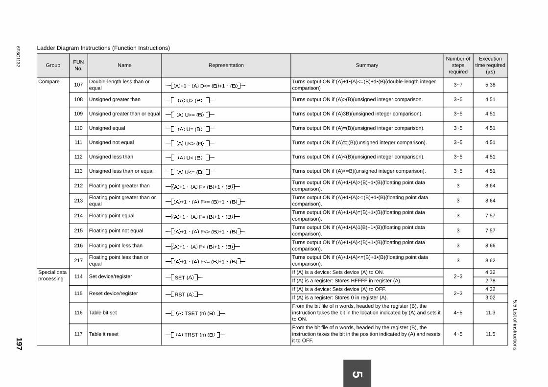
6F8C
1132197
5.5 List of instructions
C <=(B)+1•(B)(double-length integer 3~7 5.38
nsigned integer comparison. 3~5 4.51
signed integer comparison). 3~5 4.51
nsigned integer comparison). 3~5 4.51
unsigned integer comparison). 3~5 4.51
nsigned integer comparison). 3~5 4.51
nsigned integer comparison). 3~5 4.51
>(B)+1•(B)(floating point data 3 8.64
>=(B)+1•(B)(floating point data 3 8.64
=(B)+1•(B)(floating point data 3 7.57
1(B)+1•(B)(floating point data 3 7.57
<(B)+1•(B)(floating point data 3 8.66
<=(B)+1•(B)(floating point data 3 8.62
Sp
e (A) to ON.2~3
4.32
FFF in register (A). 2.78
e (A) to OFF.2~3
4.32
n register (A). 3.02
headed by the register (B), the location indicated by (A) and sets it 4~5 11.3
headed by the register (B), the position indicated by (A) and resets 4~5 11.5
La
ummaryNumber of
steps required
Execution time required
(µs)
5
ompare107
Double-length less than or equal
Turns output ON if (A)+1•(A)comparison)
108 Unsigned greater than
Turns output ON if (A)>(B)(u
109 Unsigned greater than or equal
Turns output ON if (A)3B)(un
110 Unsigned equal
Turns output ON if (A)=(B)(u
111 Unsigned not equal
Turns output ON if (A) (B)(
112 Unsigned less than
Turns output ON if (A)<(B)(u
113 Unsigned less than or equal
Turns output ON if (A)<=B)(u
212 Floating point greater than Turns output ON if (A)+1•(A)
comparison).
213Floating point greater than or equal
Turns output ON if (A)+1•(A)comparison).
214 Floating point equal Turns output ON if (A)+1•(A)
comparison).
215 Floating point not equal Turns output ON if (A)+1•(A)
comparison).
216 Floating point less than Turns output ON if (A)+1•(A)
comparison).
217Floating point less than or equal
Turns output ON if (A)+1•(A)comparison).
pecial data rocessing 114 Set device/register
If (A) is a device: Sets devic
If (A) is a register: Stores HF
115 Reset device/register If (A) is a device: Sets devic
If (A) is a register: Stores 0 i
116 Table bit set From the bit file of n words,
instruction takes the bit in theto ON.
117 Table it reset From the bit file of n words,
instruction takes the bit in theit to OFF.
dder Diagram Instructions (Function Instructions)
GroupFUN No.
Name Representation S
(A)+1・(A) D<= (B)+1・(B)
(A) U> (B)
(A) U>= (B)
(A) U= (B)
(A) U<> (B)
(A) U< (B)
(A) U<= (B)
(A)+1・(A) F> (B)+1・(B)
(A)+1・(A) F>= (B)+1・(B)
(A)+1・(A) F= (B)+1・(B)
(A)+1・(A) F<> (B)+1・(B)
(A)+1・(A) F< (B)+1・(B)
(A)+1・(A) F<= (B)+1・(B)
SET (A)
RST (A)
(A) TSET (n) (B)
(A) TRST (n) (B)
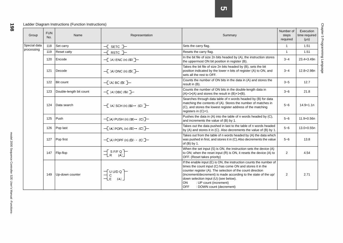
198m
odel 2000 Sequence C
ontroller S2E
User’s M
anual -Functions-
Chapter 5 P
rogramm
ing Language
5
1 1.51
1 1.51
its headed by (A), the instruction stores sition in register (B).
3~4 23.4+3.49n
2n bits headed by (B), sets the bit lower n bits of register (A) to ON, and 3~4 12.8+2.98n
N bits in the data in (A) and stores the 3~5 12.7
N bits in the double-length data in result in (B)+1•(B).
3~6 21.8
able of n words headed by (B) for data f (A). Stores the number of matches in st register address of the matching
5~6 14.9+1.1n
to the table of n words headed by (C), e of (B) by 1.
5~6 11.9+0.56n
ed in last to the table of n words headed ). Also decrements the value of (B) by 1.
5~6 13.0+0.55n
of n words headed by (A) the data which tores it in (C).Also decrements the value 5~6 13.8
ON, the instruction sets the device (A) put (R) is ON, it resets the device (A) to y)
2 4.54
ON, the instruction counts the number of ) has come ON and stores it in the selection of the count direction s made according to the state of the up/ (see below).rement)(decrement)
2 2.71
SummaryNumber of
steps required
Execution time required
(µs)
Special data processing
118 Set carry Sets the carry flag.
119 Reset catty Resets the carry flag.
120 Encode In the bit file of size 2n b
the uppermost ON bit po
121 Decode Takes the bit file of size
position indicated by thesets all the rest to OFF.
122 Bit count Counts the number of O
result in (B).
123 Double-length bit count Counts the number of O
(A)+1•(A) and stores the
124 Data search
Searches through data tmatching the contents o(C), and stores the loweregisters in (C)+1.
125 Push Pushes the data in (A) in
and increments the valu
126 Pop last Takes out the data push
by (A) and stores it in (C
127 Pop first Takes out from the table
was pushed in first, and sof (B) by 1.
147 Flip-flop When the set input (S) is
to ON; when the reset inOFF. (Reset takes priorit
149 Up-down counter
If the enable input (E) is times the count input (Ccounter register (A). The(increment/decrement) idown selection input (U)ON : UP count (incOFF : DOWN count
Ladder Diagram Instructions (Function Instructions)
GroupFUN No.
Name Representation
SETC
RSTC
(A) ENC (n) (B)
(A) DNC (n) (B)
(A) BC (B)
(A) DBC (B)
(A) SCH (n) (B)→ (C)
(A) PUSH (n) (B)→ (C)
(A) POPL (n) (B)→ (C)
(A) POPF (n) (B)→ (C)
S F/F Q R (A)
U U/D Q C E (A)
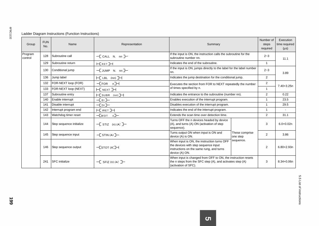
6F8C
1132199
5.5 List of instructions
La
ummaryNumber of
steps required
Execution time required
(µs)
Pc
tion calls the subroutine for the 2~3
11.1outine. 1
ctly to the label for the label number 2~3
3.89 n for the conditional jump. 2
OR to NEXT repeatedly the number 27.40+3.25n
1
subroutine (number nn). 2 0.22
rrupt program. 1 23.5
errupt program. 1 29.5
rupt program. 1 -
detection time. 2 31.1
aded by device tion of step
These comprise one step sequence.
3 6.0+0.02n
is ON and 2 3.86
ction turns OFF ce input
g, and turns 2 6.80+2.93n
OFF to ON, the instruction resets p (A), and activates step (A) 3 8.34+0.06n
5
dder Diagram Instructions (Function Instructions)
GroupFUN No.
Name Representation S
rogram ontrol
128 Subroutine call If the input is ON, the instruc
subroutine number nn.
129 Subroutine return Indicates the end of the subr
130 Conditional jump If the input is ON, jumps dire
nn.
136 Jump label Indicates the jump destinatio
132 FOR-NEXT loop (FOR) Executes the section from Fof times specified by n.133 FOR-NEXT loop (NEXT)
137 Subroutine entry Indicates the entrance to the
140 Enable interrupt Enables execution of the inte
141 Disable interrupt Disables execution of the int
142 Interrupt program end Indicates the end of the inter
143 Watchdog timer reset Extends the scan time over
144 Step sequence initialize Turns OFF the n devices he
(A), and turns (A) ON (activasequence).
145 Step sequence input Tums output ON when input
device (A) is ON.
146 Step sequence output
When input is ON, the instruthe devices with step sequeninstructions on the same rundevice (A) ON.
241 SFC initialize When input is changed from
the n steps from the SFC ste(activation of SFC).
CALL N. nn
R E T
JUMP N. nn
LBL (nn)
FOR n
NEXT
SUBR (nn)
EI
DI
IRET
W DT n
STIZ (n) (A)
STIN (A)
STOT (A)
SFIZ (n) (A)
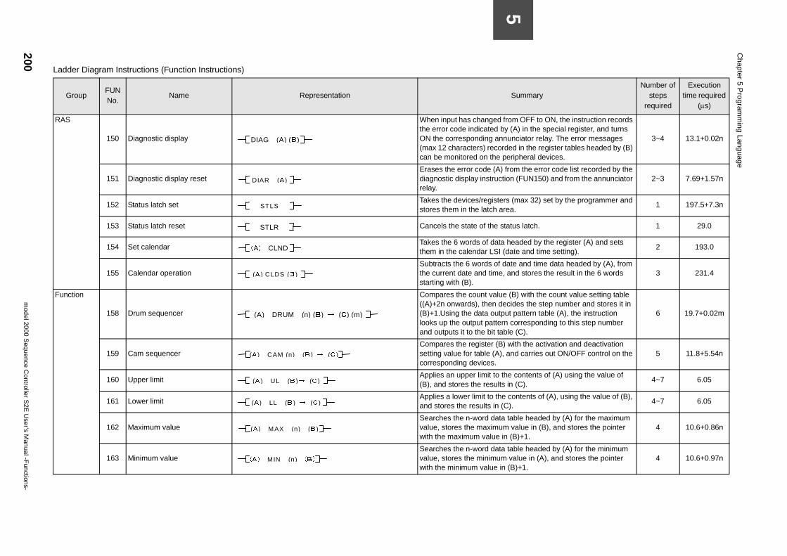
200m
odel 2000 Sequence C
ontroller S2E
User’s M
anual -Functions-
Chapter 5 P
rogramm
ing Language
5
SummaryNumber of
steps required
Execution time required
(µs)
from OFF to ON, the instruction records by (A) in the special register, and turns nnunciator relay. The error messages rded in the register tables headed by (B) peripheral devices.
3~4 13.1+0.02n
) from the error code list recorded by the tion (FUN150) and from the annunciator 2~3 7.69+1.57n
ers (max 32) set by the programmer and area.
1 197.5+7.3n
status latch. 1 29.0
ta headed by the register (A) and sets I (date and time setting).
2 193.0
date and time data headed by (A), from e, and stores the result in the 6 words 3 231.4
e (B) with the count value setting table ecides the step number and stores it in
tput pattern table (A), the instruction rn corresponding to this step number
able (C).
6 19.7+0.02m
) with the activation and deactivation ), and carries out ON/OFF control on the 5 11.8+5.54n
the contents of (A) using the value of ts in (C).
4~7 6.05
e contents of (A), using the value of (B), (C).
4~7 6.05
ta table headed by (A) for the maximum um value in (B), and stores the pointer in (B)+1.
4 10.6+0.86n
ta table headed by (A) for the minimum m value in (A), and stores the pointer in (B)+1.
4 10.6+0.97n
Ladder Diagram Instructions (Function Instructions)
GroupFUN No.
Name Representation
RAS
150 Diagnostic display
When input has changedthe error code indicated ON the corresponding a(max 12 characters) recocan be monitored on the
151 Diagnostic display reset Erases the error code (A
diagnostic display instrucrelay.
152 Status latch set Takes the devices/regist
stores them in the latch
153 Status latch reset
Cancels the state of the
154 Set calendar Takes the 6 words of da
them in the calendar LS
155 Calendar operation Subtracts the 6 words of
the current date and timstarting with (B).
Function
158 Drum sequencer
Compares the count valu((A)+2n onwards), then d(B)+1.Using the data oulooks up the output patteand outputs it to the bit t
159 Cam sequencer Compares the register (B
setting value for table (Acorresponding devices.
160 Upper limit Applies an upper limit to
(B), and stores the resul
161 Lower limit Applies a lower limit to th
and stores the results in
162 Maximum value Searches the n-word da
value, stores the maximwith the maximum value
163 Minimum value Searches the n-word da
value, stores the minimuwith the minimum value
DIAG (A) (B)
DIAR (A)
STLS
STLR
(A) CLND
(A ) CLDS (B )
(A) DRUM (n) (B) → (C) (m)
(A ) CAM (n) (B ) → (C )
(A ) UL (B )→ (C )
(A ) LL (B ) → (C )
(A ) MAX (n) (B )
(A) MIN (n) (B )
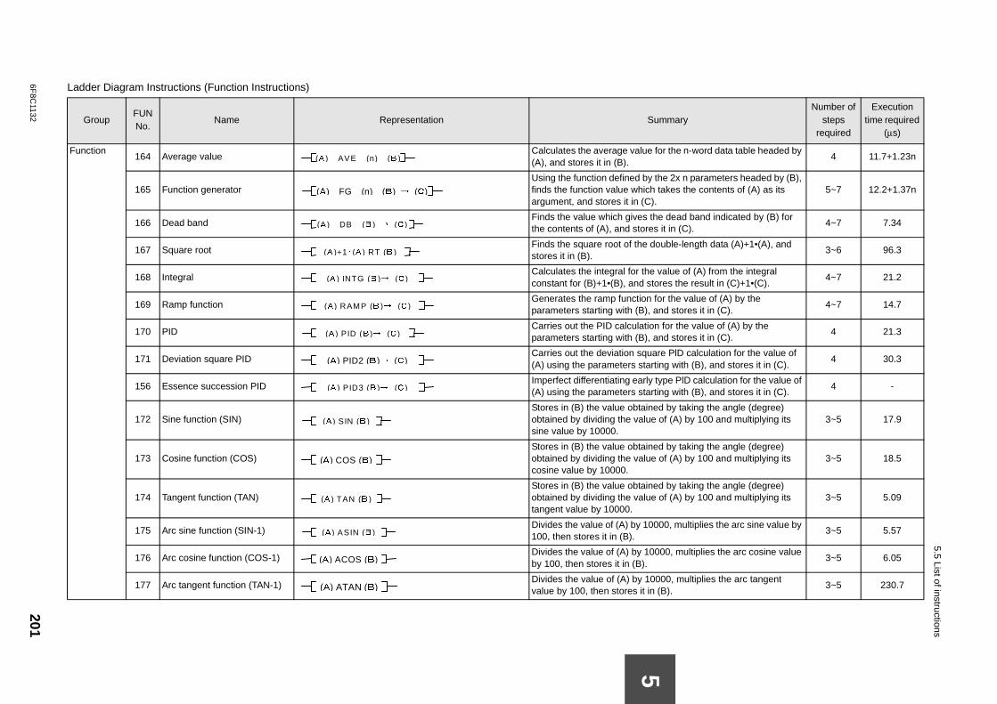
6F8C
1132201
5.5 List of instructions
F for the n-word data table headed by 4 11.7+1.23n
the 2x n parameters headed by (B), h takes the contents of (A) as its ).
5~7 12.2+1.37n
the dead band indicated by (B) for es it in (C).
4~7 7.34
double-length data (A)+1•(A), and 3~6 96.3
e value of (A) from the integral tores the result in (C)+1•(C).
4~7 21.2
for the value of (A) by the and stores it in (C).
4~7 14.7
on for the value of (A) by the and stores it in (C).
4 21.3
are PlD calculation for the value of rting with (B), and stores it in (C).
4 30.3
type PlD calculation for the value of rting with (B), and stores it in (C).
4 -
ed by taking the angle (degree) e of (A) by 100 and multiplying its 3~5 17.9
ed by taking the angle (degree) e of (A) by 100 and multiplying its 3~5 18.5
ed by taking the angle (degree) e of (A) by 100 and multiplying its 3~5 5.09
000, multiplies the arc sine value by 3~5 5.57
0000, multiplies the arc cosine value 3~5 6.05
0000, multiplies the arc tangent n (B).
3~5 230.7
La
ummaryNumber of
steps required
Execution time required
(µs)
5
unction164 Average value
Calculates the average value(A), and stores it in (B).
165 Function generator Using the function defined by
finds the function value whicargument, and stores it in (C
166 Dead band Finds the value which gives
the contents of (A), and stor
167 Square root Finds the square root of the
stores it in (B).
168 Integral Calculates the integral for th
constant for (B)+1•(B), and s
169 Ramp function Generates the ramp function
parameters starting with (B),
170 PID Carries out the PID calculati
parameters starting with (B),
171 Deviation square PID Carries out the deviation squ
(A) using the parameters sta
156 Essence succession PID Imperfect differentiating early
(A) using the parameters sta
172 Sine function (SIN) Stores in (B) the value obtain
obtained by dividing the valusine value by 10000.
173 Cosine function (COS) Stores in (B) the value obtain
obtained by dividing the valucosine value by 10000.
174 Tangent function (TAN) Stores in (B) the value obtain
obtained by dividing the valutangent value by 10000.
175 Arc sine function (SIN-1) Divides the value of (A) by 10
100, then stores it in (B).
176 Arc cosine function (COS-1) Divides the value of (A) by 1
by 100, then stores it in (B).
177 Arc tangent function (TAN-1) Divides the value of (A) by 1
value by 100, then stores it i
dder Diagram Instructions (Function Instructions)
GroupFUN No.
Name Representation S
(A ) AVE (n) (B )
(A) FG (n) (B) → (C)
(A ) DB (B ) → (C )
(A )+1・(A ) RT (B )
(A ) INTG (B )→ (C )
(A ) RAMP (B )→ (C )
(A ) PID (B )→ (C )
(A) PID2 (B)→ (C)
(A ) PID3 (B )→ (C )
(A ) SIN (B )
(A) COS (B)
(A ) TAN (B )
(A ) ASIN (B )
(A) ACOS (B)
(A) ATAN (B)
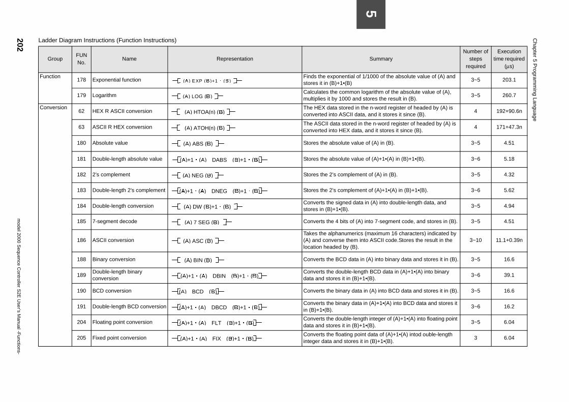
202m
odel 2000 Sequence C
ontroller S2E
User’s M
anual -Functions-
Chapter 5 P
rogramm
ing Language
5
1/1000 of the absolute value of (A) and 3~5 203.1
logarithm of the absolute value of (A), stores the result in (B).
3~5 260.7
the n-word register of headed by (A) is ta, and it stores it since (B).
4 192+90.6n
the n-word register of headed by (A) is , and it stores it since (B).
4 171+47.3n
e of (A) in (B). 3~5 4.51
e of (A)+1•(A) in (B)+1•(B). 3~6 5.18
nt of (A) in (B). 3~5 4.32
nt of (A)+1•(A) in (B)+1•(B). 3~6 5.62
in (A) into double-length data, and 3~5 4.94
) into 7-segment code, and stores in (B). 3~5 4.51
(maximum 16 characters) indicated by nto ASCII code.Stores the result in the 3~10 11.1+0.39n
n (A) into binary data and stores it in (B). 3~5 16.6
gth BCD data in (A)+1•(A) into binary 1•(B).
3~6 39.1
in (A) into BCD data and stores it in (B). 3~5 16.6
in (A)+1•(A) into BCD data and stores it 3~6 16.2
th integer of (A)+1•(A) into floating point 1•(B).
3~5 6.04
nt data of (A)+1•(A) intod ouble-length t in (B)+1•(B).
3 6.04
SummaryNumber of
steps required
Execution time required
(µs)
Function178 Exponential function
Finds the exponential ofstores it in (B)+1•(B)
179 Logarithm Calculates the common
multiplies it by 1000 and
Conversion62 HEX R ASCII conversion
The HEX data stored in converted into ASCII da
63 ASCII R HEX conversionThe ASCII data stored inconverted into HEX data
180 Absolute value
Stores the absolute valu
181 Double-length absolute value
Stores the absolute valu
182 2’s complement
Stores the 2’s compleme
183 Double-length 2’s complement
Stores the 2’s compleme
184 Double-length conversion Converts the signed data
stores in (B)+1•(B).
185 7-segment decode
Converts the 4 bits of (A
186 ASCII conversion Takes the alphanumerics
(A) and converse them ilocation headed by (B).
188 Binary conversion
Converts the BCD data i
189Double-length binary conversion
Converts the double-lendata and stores it in (B)+
190 BCD conversion
Converts the binary data
191 Double-length BCD conversion Converts the binary data
in (B)+1•(B).
204 Floating point conversion Converts the double-leng
data and stores it in (B)+
205 Fixed point conversion Converts the floating poi
integer data and stores i
Ladder Diagram Instructions (Function Instructions)
GroupFUN No.
Name Representation
(A ) EXP (B )+1・ (B )
(A) LOG (B)
(A) HTOA(n) (B)
(A) ATOH(n) (B)
(A) ABS (B)
(A)+1・(A) DABS (B)+1・(B)
(A) NEG (B)
(A)+1・(A) DNEG (B)+1・(B)
(A) DW (B)+1・(B)
(A) 7 SEG (B)
(A) ASC (B)
(A) BIN (B)
(A)+1・(A) DBIN (B)+1・(B)
(A) BCD (B)
(A)+1・(A) DBCD (B)+1・(B)
(A)+1・(A) FLT (B)+1・(B)
(A)+1・(A) FIX (B)+1・(B)
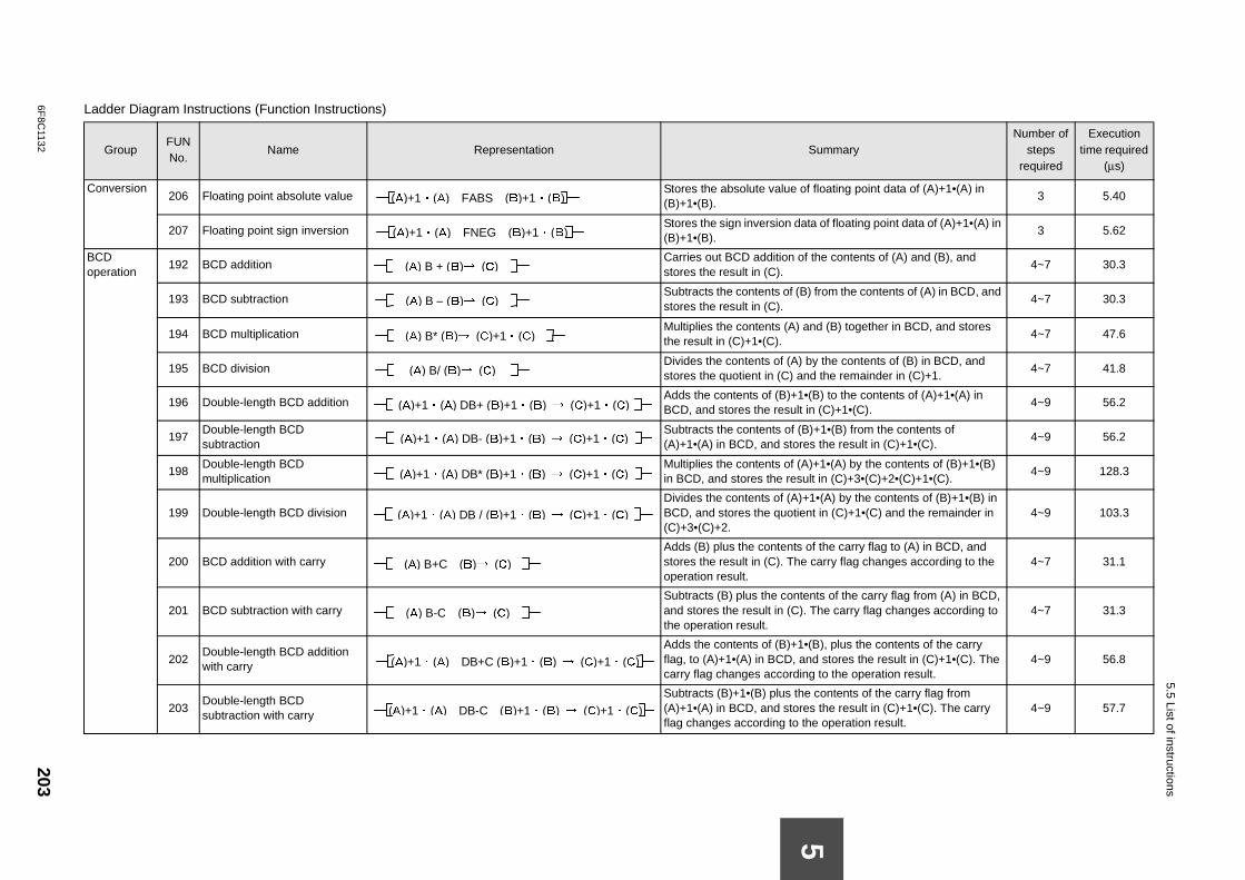
6F8C
1132203
5.5 List of instructions
C floating point data of (A)+1•(A) in 3 5.40
a of floating point data of (A)+1•(A) in 3 5.62
Bo
the contents of (A) and (B), and 4~7 30.3
from the contents of (A) in BCD, and 4~7 30.3
nd (B) together in BCD, and stores 4~7 47.6
y the contents of (B) in BCD, and d the remainder in (C)+1.
4~7 41.8
B) to the contents of (A)+1•(A) in (C)+1•(C).
4~9 56.2
+1•(B) from the contents of s the result in (C)+1•(C).
4~9 56.2
+1•(A) by the contents of (B)+1•(B) t in (C)+3•(C)+2•(C)+1•(C).
4~9 128.3
•(A) by the contents of (B)+1•(B) in t in (C)+1•(C) and the remainder in 4~9 103.3
f the carry flag to (A) in BCD, and carry flag changes according to the 4~7 31.1
nts of the carry flag from (A) in BCD, The carry flag changes according to 4~7 31.3
B), plus the contents of the carry d stores the result in (C)+1•(C). The to the operation result.
4~9 56.8
contents of the carry flag from s the result in (C)+1•(C). The carry e operation result.
4~9 57.7
La
ummaryNumber of
steps required
Execution time required
(µs)
5
onversion206 Floating point absolute value
Stores the absolute value of(B)+1•(B).
207 Floating point sign inversion Stores the sign inversion dat
(B)+1•(B).
CD peration
192 BCD addition Carries out BCD addition of
stores the result in (C).
193 BCD subtraction Subtracts the contents of (B)
stores the result in (C).
194 BCD multiplication Multiplies the contents (A) a
the result in (C)+1•(C).
195 BCD division Divides the contents of (A) b
stores the quotient in (C) an
196 Double-length BCD addition Adds the contents of (B)+1•(BCD, and stores the result in
197Double-length BCD subtraction
Subtracts the contents of (B)(A)+1•(A) in BCD, and store
198Double-length BCD multiplication
Multiplies the contents of (A)in BCD, and stores the resul
199 Double-length BCD division Divides the contents of (A)+1
BCD, and stores the quotien(C)+3•(C)+2.
200 BCD addition with carry Adds (B) plus the contents o
stores the result in (C). The operation result.
201 BCD subtraction with carry Subtracts (B) plus the conte
and stores the result in (C). the operation result.
202Double-length BCD addition with carry
Adds the contents of (B)+1•(flag, to (A)+1•(A) in BCD, ancarry flag changes according
203Double-length BCD subtraction with carry
Subtracts (B)+1•(B) plus the(A)+1•(A) in BCD, and storeflag changes according to th
dder Diagram Instructions (Function Instructions)
GroupFUN No.
Name Representation S
(A)+1・(A) FABS (B)+1・(B)
(A)+1・(A) FNEG (B)+1・(B)
(A) B + (B)→ (C)
(A) B – (B)→ (C)
(A) B* (B)→ (C)+1・(C)
(A) B/ (B)→ (C)
(A)+1・(A) DB+ (B)+1・(B) → (C)+1・(C)
(A)+1・(A) DB- (B)+1・(B) → (C)+1・(C)
(A)+1・(A) DB* (B)+1・(B) → (C)+1・(C)
(A)+1・(A) DB / (B)+1・(B) → (C)+1・(C)
(A) B+C (B)→ (C)
(A) B-C (B)→ (C)
(A)+1・(A) DB+C (B)+1・(B) → (C)+1・(C)
(A)+1・(A) DB-C (B)+1・(B) → (C)+1・(C)
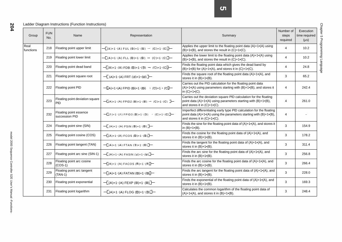
204m
odel 2000 Sequence C
ontroller S2E
User’s M
anual -Functions-
Chapter 5 P
rogramm
ing Language
5
the floating point data (A)+1•(A) using result in (C)+1•(C).
4 10.2
the floating point data (A)+1•(A) using result in (C)+1•(C).
4 10.2
ata which gives the dead band by and stores it in (C)+1•(C).
4 24.8
the floating point data (A)+1•(A), and 3 65.2
ulation for the floating point data ers starting with (B)+1•(B), and stores it 4 242.4
square PlD calculation for the floating g parameters starting with (B)+1•(B), ).
4 261.0
early type PlD calculation for the floating g the parameters starting with (B)+1•(B), ).
4 -
ting point data of (A)+1•(A), and stores it 3 154.9
floating point data of (A)+1•(A), and 3 178.2
floating point data of (A)+1•(A), and 3 311.4
floating point data of (A)+1•(A), and 3 256.8
the floating point data of (A)+1•(A), and 3 266.4
the floating point data of (A)+1•(A), and 3 228.0
the floating point data of (A)+1•(A), and 3 169.3
logarithm of the floating point data of n (B)+1•(B).
3 248.4
SummaryNumber of
steps required
Execution time required
(µs)
Real functions
218 Floating point upper limit Applies the upper limit to
(B)+1•(B), and stores the
219 Floating point lower limit Applies the lower limit to
(B)+1•(B), and stores the
220 Floating point dead band Finds the floating point d
(B)+1•(B) for (A)+1•(A),
221 Floating point square root Finds the square root of
stores it in (B)+1•(B).
222 Floating point PlD Carries out the PID calc
(A)+1•(A) using parametin (C)+1•(C).
223Floating point deviation square PlD
Carries out the deviationpoint data (A)+1•(A) usinand stores it in (C)+1•(C
232Floating point essence succession PID
Imperfect differentiating point data (A)+1•(A) usinand stores it in (C)+1•(C
224 Floating point sine (SIN) Finds the sine for the floa
in (B)+1•(B).
225 Floating point cosine (COS) Finds the cosine for the
stores it in (B)+1•(B).
226 Floating point tangent (TAN) Finds the tangent for the
stores it in (B)+1•(B).
227 Floating point arc sine (SIN-1) Finds the arc sine for the
stores it in (B)+1•(B).
228Floating point arc cosine (COS-1)
Finds the arc cosine for stores it in (B)+1•(B).
229Floating point arc tangent (TAN-1)
Finds the arc tangent forstores it in (B)+1•(B).
230 Floating point exponential Finds the exponential of
stores it in (B)+1•(B).
231 Floating point logarithm Calculates the common
(A)+1•(A), and stores it i
Ladder Diagram Instructions (Function Instructions)
GroupFUN No.
Name Representation
(A )+1・ (A ) FUL (B )+1・(B ) → (C )+1・(C )
(A )+1・(A ) FLL (B )+1・ (B ) → (C )+1・ (C )
(A)+1・(A) FDB (B)+1・(B) → (C)+1・(C)
(A)+1・(A) FRT (B)+1・(B)
(A)+1・(A) FPID (B)+1・(B) → (C)+1・(C)
(A )+1・(A) FPID2 (B )+1・(B ) → (C )+1・(C )
(A )+1・ (A ) F P ID 3 (B )+1・ (B ) → (C )+1・ (C )
(A )+1・(A ) FSIN (B )+1・(B )
(A )+1・(A ) FCOS (B )+1・(B )
(A )+1・(A ) FTAN (B )+1・(B )
(A )+1・(A ) FASIN (B )+1・(B )
(A )+1・(A ) FACOS (B )+1・(B )
(A)+1・(A) FATAN (B)+1・(B)
(A)+1・(A) FEXP (B)+1・(B)
(A)+1・(A) FLOG (B)+1・(B)
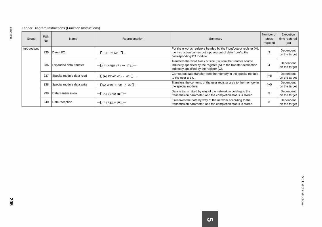
6F8C
1132205
5.5 List of instructions
In aded by the input/output register (A), ut/output of data from/to the 3
Dependent on the target
ize (B) from the transfer source gister (A) to the transfer destination gister (C).
4Dependent
on the target
the memory in the special module 4~5
Dependent on the target
user register area to the memory in 4~5
Dependent on the target
f the network according to the the completion status is stored.
3Dependent
on the target
f the network according to the the completion status is stored.
3Dependent
on the target
La
ummaryNumber of
steps required
Execution time required
(µs)
5
put/output235 Direct I/O
For the n words registers hethe instruction carries out inpcorresponding I/O module.
236 Expanded data transfer Transfers the word block of s
indirectly specified by the reindirectly specified by the re
237 Special module data read Carries out data transfer from
to the user area.
238 Special module data write Transfers the contents of the
the special module.
239 Data transmission Data is transmitted by way o
transmission parameter, and
240 Data reception It receives the data by way o
transmission parameter, and
dder Diagram Instructions (Function Instructions)
GroupFUN No.
Name Representation S
I/O (n) (A )
(A ) XFER (B ) → (C )
(A ) READ (B )→ (C )
(A ) W RITE (B ) → (C )
(A ) SEND (B )
(A ) RECV (B )
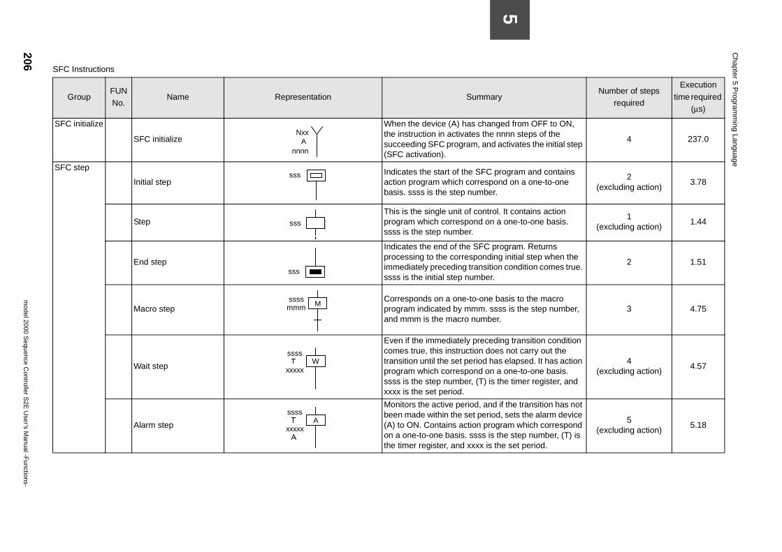
206m
odel 2000 Sequence C
ontroller S2E
User’s M
anual -Functions-
Chapter 5 P
rogramm
ing Language
5
yNumber of steps
required
Execution
time required (µs)
ged from OFF to ON, nnnn steps of the activates the initial step
4 237.0
rogram and contains nd on a one-to-one
2(excluding action)
3.78
l. It contains action a one-to-one basis.
1(excluding action)
1.44
rogram. Returns g initial step when the n condition comes true.
2 1.51
asis to the macro ss is the step number, r.
3 4.75
ing transition condition s not carry out the s elapsed. It has action a one-to-one basis. the timer register, and
4(excluding action)
4.57
if the transition has not d, sets the alarm device ram which correspond
the step number, (T) is he set period.
5(excluding action)
5.18
SFC Instructions
GroupFUN No.
Name Representation Summar
SFC initialize
SFC initialize
When the device (A) has chanthe instruction in activates the succeeding SFC program, and(SFC activation).
SFC step
Initial step
Indicates the start of the SFC paction program which correspobasis. ssss is the step number.
Step This is the single unit of contro
program which correspond on ssss is the step number.
End step
Indicates the end of the SFC pprocessing to the correspondinimmediately preceding transitiossss is the initial step number.
Macro step
Corresponds on a one-to-one bprogram indicated by mmm. ssand mmm is the macro numbe
Wait step
Even if the immediately precedcomes true, this instruction doetransition until the set period haprogram which correspond on ssss is the step number, (T) is xxxx is the set period.
Alarm step
Monitors the active period, andbeen made within the set perio(A) to ON. Contains action progon a one-to-one basis. ssss is the timer register, and xxxx is t
NxxA
nnnn
sss
ssssss
sss
Mssssmmm
WssssT
xxxxx
AssssT
xxxxxA
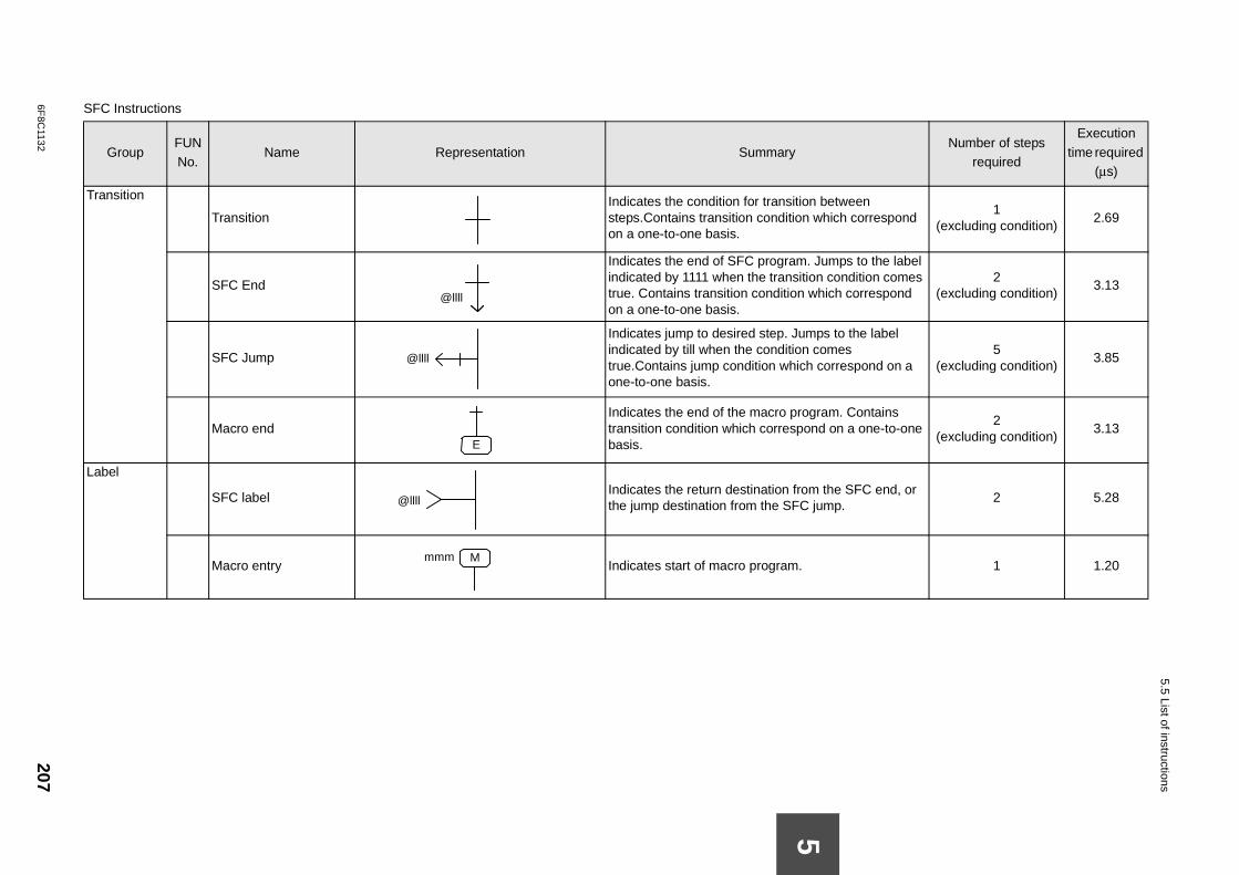
6F8C
1132207
5.5 List of instructions
T n between which correspond
1(excluding condition)
2.69
. Jumps to the label on condition comes which correspond
2(excluding condition)
3.13
ps to the label comes h correspond on a
5(excluding condition)
3.85
gram. Contains nd on a one-to-one
2(excluding condition)
3.13
Lm the SFC end, or jump.
2 5.28
1 1.20
S
Number of steps required
Execution
time required (µs)
5
ransition
TransitionIndicates the condition for transitiosteps.Contains transition conditionon a one-to-one basis.
SFC End
Indicates the end of SFC programindicated by 1111 when the transititrue. Contains transition condition on a one-to-one basis.
SFC Jump
Indicates jump to desired step. Jumindicated by till when the conditiontrue.Contains jump condition whicone-to-one basis.
Macro endIndicates the end of the macro protransition condition which correspobasis.
abel
SFC labelIndicates the return destination frothe jump destination from the SFC
Macro entry Indicates start of macro program.
FC Instructions
GroupFUN No.
Name Representation Summary
@llll
@llll
E
@llll
Mmmm
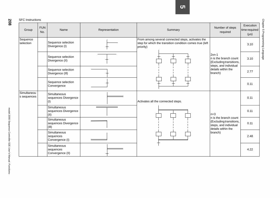
208m
odel 2000 Sequence C
ontroller S2E
User’s M
anual -Functions-
Chapter 5 P
rogramm
ing Language
5
d steps, activates the ndition comes true (left
2xn-1n is the branch count(Excluding transitions, steps, and individual details within the branch)
3.10
3.10
2.77
0.11
ps.
n+3n is the branch count(Excluding transitions, steps, and individual details within the branch)
0.11
0.11
0.11
2.48
4.22
yNumber of steps
required
Execution
time required (µs)
Sequence selection Sequence selection
Divergence (I)
From among several connectestep for which the transition copriority)
Sequence selection Divergence (II)
Sequence selection Divergence (Ill)
Sequence selection Convergence
Simultaneous sequences
Simultaneous sequences Divergence (I)
Activates all the connected ste
Simultaneous sequences Divergence (II)
Simultaneous sequences Divergence (Ill)
Simultaneous sequences Convergence (I)
Simultaneous sequences Convergence (II)
SFC Instructions
GroupFUN No.
Name Representation Summar
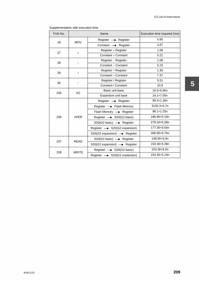
5.5 List of instructions
5
Supplementation with execution time
FUN No. Name Execution time required (ms)
18 MOVRegister Register 0.65
Constant Register 3.67
27 +Register + Register 1.08
Constant + Constant 5.21
28 −Register − Register 1.08
Constant − Constant 5.23
29 ∗Register ∗ Register 1.30
Constant ∗ Constant 7.37
30 /Register / Register 5.51
Constant / Constant 10.9
235 I/OBasic unit base 10.5+6.95n
Expansion unit base 14.1+7.05n
236 XFER
Register Register 99.3+1.30n
Register Flash Memory 3132.3+0.7n
Flash Memory Register 98.1+1.25n
Register S20(G2 basic) 186.96+5.18n
S20(G2 basic) Register 278.16+5.28n
Register S20(G2 expansion) 177.36+5.64n
S20(G2 expansion) Register 268.56+5.76n
237 READS20(G2 basic) Register 148.56+5.0n
S20(G2 expansion) Register 153.36+5.38n
238 WRITERegister S20(G2 basic) 153.36+5.0n
Register S20(G2 expansion) 153.36+5.24n
6F8C1132 209

PART 4TRANSMISSION FUNCTION

6F8C1132
Overview
Chapter 11.1 Overview
This chapter explains the support of TOSLINE-S20 (G2I/O type : SN621,SN622).
The part that functionally was changed, and added with S2E is described. Please refer to the outline book on TOSLINE-S20 for a basic function.
(1) Scan data memory accessG2I/O TOSLINE-S20 1k words Synchronous mode
• XFER instructionThe XFER instruction is unconditionally accessed without distinguishing the DPM access distinguishing the DPM access permission flag for TOSLINE-S20.Please execute the XFER instruction after distinguishing the DPM access permission flag by the READ instruction, and make it to the program that sets the DPM access permission flag by the WRITE instruction.
• GLOBAL specificationThe GLOBAL specification for TOSLINE-S20 is a prohibition.When GLOBAL is specified, it operates of the LINK specification.
(2) TOSLINE-S20 RAS InformationTOSLINE-S20 information (Online map, Standby map, Scan healthy map) is regularly updated to the scan healthy map reading area (SW128 to SW255).
(3) Module ErrorIt sets in S000E under the OR condition of 2 TOSLINE-S20, and it resets it by the recovery.
213
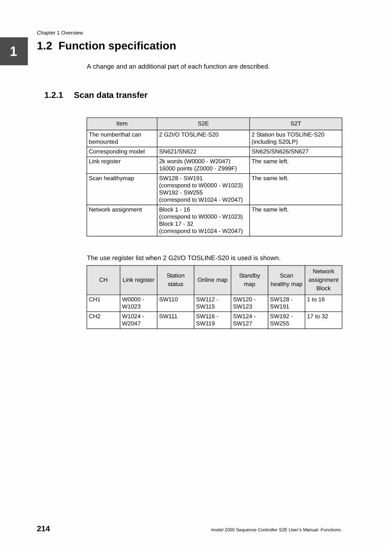
Chapter 1 Overview
1
1.2 Function specificationA change and an additional part of each function are described.
1.2.1 Scan data transfer
The use register list when 2 G2I/O TOSLINE-S20 is used is shown.
Item S2E S2T
The numberthat can bemounted
2 G2I/O TOSLINE-S20 2 Station bus TOSLINE-S20(including S20LP)
Corresponding model SN621/SN622 SN625/SN626/SN627
Link register 2k words (W0000 - W2047)16000 points (Z0000 - Z999F)
The same left.
Scan healthymap SW128 - SW191(correspond to W0000 - W1023)SW192 - SW255(correspond to W1024 - W2047)
The same left.
Network assignment Block 1 - 16(correspond to W0000 - W1023)Block 17 - 32(correspond to W1024 - W2047)
The same left.
CH Link registerStation
statusOnline map
Standby
map
Scan
healthy map
Network
assignment Block
CH1 W0000 -W1023
SW110 SW112 -SW115
SW120 -SW123
SW128 -SW191
1 to 16
CH2 W1024 -W2047
SW111 SW116 -SW119
SW124 -SW127
SW192 -SW255
17 to 32
214 model 2000 Sequence Controller S2E User’s Manual -Functions-
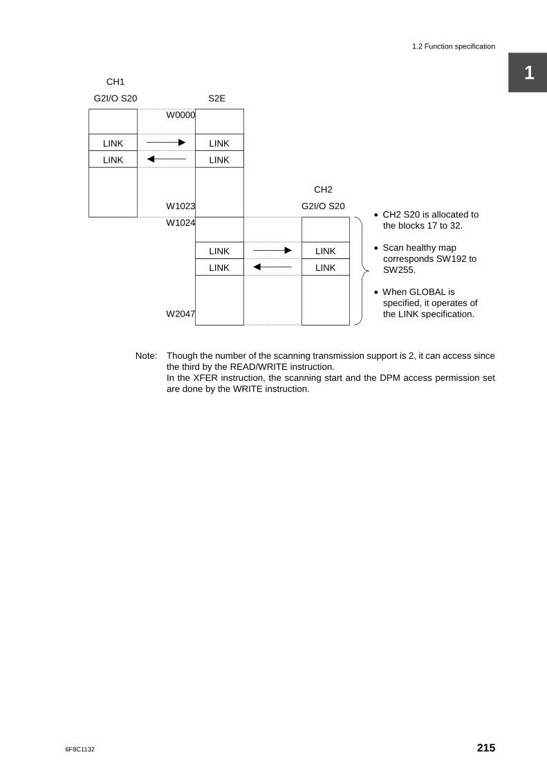
1.2 Function specification
1
Note: Though the number of the scanning transmission support is 2, it can access sincethe third by the READ/WRITE instruction.In the XFER instruction, the scanning start and the DPM access permission setare done by the WRITE instruction.
G2I/O S20
• CH2 S20 is allocated to the blocks 17 to 32.
• Scan healthy map corresponds SW192 to SW255. • When GLOBAL is
specified, it operates of the LINK specification.
LINK
LINK
LINK
LINK
LINK
LINK
LINK
LINK
CH1
S2E
G2I/O S20
CH2
W0000
W1023
W1024
W2047
6F8C1132 215
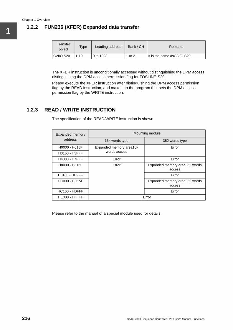
Chapter 1 Overview
1
1.2.2 FUN236 (XFER) Expanded data transferThe XFER instruction is unconditionally accessed without distinguishing the DPM access distinguishing the DPM access permission flag for TOSLINE-S20.
Please execute the XFER instruction after distinguishing the DPM access permission flag by the READ instruction, and make it to the program that sets the DPM access permission flag by the WRITE instruction.
1.2.3 READ / WRITE INSTRUCTION
The specification of the READ/WRITE instruction is shown.
Please refer to the manual of a special module used for details.
Transfer object
Type Leading address Bank / CH Remarks
G2I/O S20 H10 0 to 1023 1 or 2 It is the same asG3I/O S20.
Expanded memory address
Mounting module
16k words type 352 words type
H0000 - H015F Expanded memory area16k words access
Error
H0160 - H3FFF
H4000 - H7FFF Error Error
H8000 - H815F Error Expanded memory area352 words access
H8160 - HBFFF Error
HC000 - HC15F Expanded memory area352 words access
HC160 - HDFFF Error
HE000 - HFFFF Error
216 model 2000 Sequence Controller S2E User’s Manual -Functions-

Integrated Controller Vseries
model 2000 Sequence Controller S2E User’s Manual -Functions-
2nd edition 20th Oct 2005 1132.2.0510
INDUSTRIAL AND POWER SYSTEMS & SERVICES COMPANYElectrical Apparatus & Measurement Division
Overseas Sales & Marketing Department - Group 3 TEL.: +81-3-3457-48941-1, Shibaura 1-chome, Minato-ku, Tokyo 105-8001, JapanMicroelectronics & System Components Department
- System Components Support Group TEL.: +81-42-333-21921, Toshiba-cho, Fuchu-shi, Tokyo 183-8511, Japan
© TOSHIBA Corporation 2005 All Right Reserved.


6F8C1132
1132.1.0503
����� ���� ������ ���������
��� ������ ����� � �������� �


