Embed Size (px)
Citation preview


I
1 u h i c a l Report Docrmr~i in Peg.
- - The University of Michigan Transportat ion Research I n s t i t u t e
3, Rwcipiont's Cwtoiq NO. 1. R W No.
uMTRI-85- 7 I
4. Titl* ad Subtitlw
REPORT ON THE STATUS OF ORGANIZATIONS WORKING IN THE FIELD OF VEHICLE HANDLING
7. A"hd1)
L. Segel, A. Grim 9. P r h i ~ O n r r i u r i m HI. d M&WSS
11. G n w m .r Grmt No.
2. Cmrrrmt Accwrsi.n Mo.
5. Rwport Dore
February 1985 6. P h i n g 0 1 ~ i x e t i . n UW
I. P . r k i w O M S * R m No.
UMTRI-85-7 10. W& Unit No.
16. Abs-t
Organizations i n the publ ic and p r i v a t e s ec to r s , both non-profit and for-prof i t (including motor vehic le and t i r e manufacturing firms) a r e i d e n t i f i e d and discussed with respec t t o t h e i r c a p a b i l i t i e s f o r (1) conducting inves t iga t ions i n the f i e l d of vehic le handling and (2 ) ensuring t h a t a given motor c a r meets o r exceeds a spec i f ied performance c r i t e r i o n .
17, Kw Wuh vehic le handling s tud ie s ; research resources; survey of
18. Discributim St-t
c a p a b i l i t i e s ; research capab i l i t y assessment I

PREFACE
The b u l k of t h e d a t a and documents used t o produce t h i s r e p o r t were
c o l l e c t e d and provided by Mrs. A. Grimm, who i s Coordinator , Research
In format ion and P u b l i c a t i o n s , U n i v e r s i t y of Michigan T r a n s p o r t a t i o n Research
I n s t i t u t e (UMTRI). The r e p o r t , i t s e l f , was prepared by Mr. L. Sege l , who
i s Head of UMTRI'S Engineering Research Div i s ion and i s a P r o f e s s o r of
Mechanical Engineer ing and Applied Mechanics i n The U n i v e r s i t y of Michigan's
Col lege of Engineering


INTRODUCTION
The purpose of t h i s document i s t o assemble , on behal f of t h e General
Motors C o r p o r a t i o n , i n fo rma t ion and d a t a ( r e s i d i n g w i t h i n t h e f i l e s of t h e
T r a n s p o r t a t i o n Research I n s t i t u t e of The U n i v e r s i t y of Michigan) r ega rd ing
o r g a n i z a t i o n s which have a c a p a b i l i t y f o r conduct ing a n a l y t i c a l and expe r imen ta l
s t u d i e s i n t h e f i e l d of motor v e h i c l e handl ing . To t h e e x t e n t t h a t i t has
proved f e a s i b l e t o do s o , t h i s survey i s i n t e r n a t i o n a l i n scope. However, no
a t t e m p t i s made t o i n t e r p r e t "motor v e h i c l e " i n i t s b r o a d e s t s e n s e ; r a t h e r ,
emphasis i s g i v e n t o t h e motor c a r .
It i s t h e a u t h o r ' s unde r s t and ing t h a t Genera l Motors has a twofold
o b j e c t i v e : (1) i t would l i k e t o compile a comprehensive p i c t u r e of t h e
c a p a b i l i t i e s of o r g a n i z a t i o n s which c o n s t i t u t e i t s compe t i t i on i n t h e automotive
wor ld ; ( 2 ) i t would l i k e t o o b t a i n a comprehensive view of r e s e a r c h
o r g a n i z a t i o n s and personnel who c o n s t i t u t e an e x t e r n a l r e s o u r c e i n t h e f i e l d of
v e h i c l e handl ing . This o b j e c t i v e i s indeed ambi t i ous and t o s a t i s f y t h i s
o b j e c t i v e , i n an i d e a l manner, t h e fo l lowing types of i n f o r m a t i o n should be
ob ta ined :
1 ) d e s c r i p t i v e i n fo rma t ion
2 ) number of s t a f f
3 ) computer f a c i l i t i e s
4 ) t e s t f a c i l i t i e s
5 ) o f f i c e and l a b o r a t o r y a r e a
6 ) budget
7 ) b i l l i n g r a t e s
8 ) e t c .
I n p r a c t i c e , we found t h a t o u r d a t a r e s o u r c e s (e .g . , p e r s o n a l f i l e s ,
UMTRI L i b r a r y ) were n o t s u f f i c i e n t l y d e t a i l e d t o p rov ide i n f o r m a t i o n on each of
t h e above l i s t e d i t e m s f o r each o r g a n i z a t i o n t h a t i s i d e n t i f i e d and surveyed i n
t h i s r e p o r t . I n f a c t , t h e i n f o r m a t i o n gaps w i t h r e s p e c t t o each of t h e s e
o b j e c t i v e e n t i t i e s a r e s u f f i c i e n t l y l a r g e t h a t t h e i d e a of p r e s e n t i n g t h i s
survey i n a t a b u l a r form was abandoned. R a t h e r , t h e r e p o r t c o n s i s t s of a
summary n a r r a t i v e which d i r e c t s the reader t o more d e t a i l e d informat ion, a s
presented i n a l a r g e number of appendices. For the benef i t of t h e reader , the
r e p o r t opens wi th an "executive summary" which a t tempts t o summarize, a s b r i e f l y
a s p o s s i b l e , the s t a t u s of the engineering and research e n t e r p r i s e which i s
c u r r e n t l y address ing the t o p i c of veh ic le handling. This summary i s followed by
a n a r r a t i v e which i s organized i n t o seven c a t e g o r i e s , namely:
1.0 Motor Vehicle Manufacturers
2.0 T i r e Manufacturers
3.0 Univers i ty A f f i l i a t e d Research I n s t i t u t e s
4.0 P r i v a t e Research Organizations
5.0 Research Organizations Created by and Supported by the
Motor Vehicle Indust ry
6.0 National Labora to r i es
7 . 0 Individual Academicians
The repor t concludes with copies of m a t e r i a l s e l e c t e d both from personal f i l e s
and the UMTRI Libra ry , a s c a l l e d ou t i n the preceding n a r r a t i v e .
I1 EXECUTIVE SUMMARY
The i d e n t i f i c a t i o n of resources i n the f i e l d of veh ic le handling i s
d i f f i c u l t , p a r t i c u l a r l y wi thin the p r i v a t e sec to r . I n g e n e r a l , t h r e e
obse rva t ions appear t o be worthy of being recorded here. One i s t h a t motor
veh ic le f i rms o u t s i d e the U.S. appear t o have d i f f e r e n t c r i t e r i a than U.S. f i rms
f o r deciding how much c a p i t a l should be inves ted i n l a b o r a t o r i e s and f a c i l i t i e s
which r e l a t e t o obta ining a b e t t e r understanding of the physics of the motor
veh ic le . I n g e n e r a l , the European engineer and the Japanese engineer seem t o be
more generously supported than t h e i r t y p i c a l U.S. counterpar ts . Whether t h i s i s
a r e f l e c t i o n of d i f f e r e n c e s i n U.S. and non-U.S. markets regarding customer
demands f o r c e r t a i n performance c h a r a c t e r i s t i c s o r a r e f l e c t i o n of managerial
and business phi losophies i s not c l e a r t o t h i s w r i t e r .
The second observat ion i s t h a t the educat ion of engineers i n Europe
d i f f e r s from t h a t of engineers elsewhere ( i . e . , i n the U.S. and Japan) , i n t h a t
European educat ional p r a c t i c e s encompass much more s p e c i a l i z e d t r a i n i n g i n
automotive engineer ing and work towards producing a p r a c t i t i o n e r of the
engineer ing p ro fess ion r a t h e r than a graduate who has b a s i c s k i l l s and
knowledge. This p r a c t i c e i s c a r r i e d t o the extreme i n Germany where i t i s
r a t h e r common f o r engineer ing s tuden t s t o o b t a i n a d o c t o r a t e i n automotive
engineering and f o r companies t o u t i l i z e such g radua tes f o r providing
engineer ing l eadersh ip i n the managerial and execut ive ranks, Whether the re a r e
long-term impl ica t ions of these d i f f e r e n c e s i n educa t iona l p o l i c i e s i n regard t o
the compet i t ive s t ance of G.M. vis-a-vis i t s European competi t ion c o n s t i t u t e s a
ques t ion t h a t i s not answerable without s e r i o u s i n q u i r y and r e f l e c t i o n .
F i n a l l y , i t i s poss ib le t o observe t h a t v e h i c l e handling resea rch i n
the U.S. tended t o be exc lus ive ly pursued w i t h i n the p r i v a t e s e c t o r u n t i l the
time t h a t the motor veh ic le i n d u s t r y became a regu la ted indus t ry . Such was not
the case i n Europe, where t echn ica l u n i v e r s i t i e s provided a s c h o l a r l y ambiance
f o r r e sea rch involving the motor v e h i c l e , w i t h r i d e , handl ing, and braking
i s s u e s being addressed by academicians a s w e l l a s eng inee rs i n the p r i v a t e
sec to r . Fur the r , i t must be noted t h a t the motor veh ic le production e n t e r p r i s e
was never a s l a i s s e z f a i r e i n Europe as i t was i n the U.S. The h i s t o r i c a l
record shows t h a t motor vehic le design experienced regula tory c o n s t r a i n t s i n
Europe and Japan long before regula tory c o n s t r a i n t s were introduced i n the U. S.
on a n a t i o n a l sca le .
With regard t o the p o s s i b i l i t i e s of engaging an ou t s ide o rgan iza t ion t o
provide e x t e r n a l support on a p r o j e c t which requ i res e x p e r t i s e o r t e s t
c a p a b i l i t i e s i n t h e a r e a of veh ic le handl ing, the o p p o r t u n i t i e s i n the U.S. a r e
d i f f e r e n t from those which e x i s t abroad. S p e c i f i c a l l y , one f i n d s t h a t the re a r e
very few u n i v e r s i t y - a f f i l i a t e d research organizat ions i n the U.S., b u t , on the
o the r hand, the re e x i s t s a modest number of p r i v a t e r e sea rch o rgan iza t ions . I n
Europe, however, t h e r e i s a s u b s t a n t i a l number of u n i v e r s i t y - a f f i l i a t e d research
o rgan iza t ions , but a much smal ler number of p r i v a t e f irms. On the o t h e r hand,
these p r i v a t e f i rms (e .g . , Lotus and Porsche) a r e a b l e t o provide s e r v i c e s t h a t
could not be matched by the remainder of the research community.

111 INFORMATION SUMMARY BY CATEGORY
1.0 MOTOR VEHICLE MANUFACTURERS
I d e n t i f y i n g the resources devoted by motor v e h i c l e manufacturers t o
r e s e a r c h , d e s i g n , and development a c t i v i t i e s dedicated t o achieving a product
wi th good handling c h a r a c t e r i s t i c s i s almost impossible. F u r t h e r , t o o b t a i n
i n s i g h t a s t o the e x t e n t t o which the var ious motor v e h i c l e manufacturing f i rms
organize t h e i r engineer ing a c t i v i t i e s t o ensure t h a t adequate a t t e n t i o n i s given
t o handling p r o p e r t i e s i s most d i f f i c u l t . Accordingly, most of what fo l lows i s
based on a minimal amount of hard suppor t ing d a t a and tends t o be r a t h e r
anecdota l i n nature .
1.1 Domestic
1.1.1 Ford Motor Company. Ford engineer ing personnel concerned with -- handl ing i s s u e s appear t o be s c a t t e r e d throughout the o r g a n i z a t i o n and i t i s
d i f f i c u l t to i d e n t i f y where the c u r r e n t and advanced eng ineer ing
r e s p o n s i b i l i t i e s l i e . A t the resea rch end of the spectrum, i t appears t h a t
t h e i r concern f o r va r ious aspec t s of veh ic le dynamic behavior ( inc lud ing r i d e )
r e s i d e s wi th in a so-cal led "Vehicle Concepts Research Laboratory." This
Laboratory inc ludes t h r e e departments, v i z . , "Vehicle Methods and Components,"
"Vehicle Concepts," and "Vehicle Systems." The Laboratory i s headed by a Dr.
C.L. Magee whose s p e c i a l i z e d background i s i n the mechanics of s t r u c t u r e s .
Reporting t o the head of the Vehicle Methods and Components Department, however,
a r e a number of eng inee rs who could be l abe led a s "veh ic le dynamicists" and who
a r e concerned wi th r i d e and handling i s sues . Fac t s r e l a t e d t o number of
personnel , computer f a c i l i t i e s , l a b o r a t o r y f a c i l i t i e s , e t c . , a r e not a v a i l a b l e .
Because of U M T R I ' s s t rong highway s a f e t y o r i e n t a t i o n , we have been ab le
t o perceive t h a t a p o r t i o n of Ford 's i n t e r e s t i n v e h i c l e handl ing r e s i d e s wi th in
t h e i r "Automotive Safe ty Office" (Environmental and Safe ty Engineering S t a f f ) .
Although t h i s group does experimental work requ i r ing the measurement of v e h i c l e
responses t o s t e e r i n g , they apparent ly have not seen f i t t o i n v e s t i n a
d i r e c t i o n a l response measurement package, s i n c e they have e l e c t e d t o r e n t
UMTRI's Humphrey u n i t on numerous occasions.
With respec t t o Ford 's proving ground t e s t f a c i l i t i e s , i t i s known t h a t
t h e i r Arizona Proving Ground ( s e e Appendix A) con ta ins a 17-acre asphalt-paved
s u r f a c e f o r purposes of v e h i c l e dynamics t e s t i n g . We have heard Ford personnel
r e f e r t o a handling t r a c k and a c i r c u l a r "skid pad" a t t h e i r small t e s t f a c i l i t y
ad jacen t t o t h e i r engineer ing c e n t e r i n Dearborn. It i s p o s s i b l e t h a t t h i s
l a t t e r f a c i l i t y has been descr ibed i n an SAE p u b l i c a t i o n , bu t we have been
unable t o l o c a t e such a document.
1.1.2 Chrysler Corporation. The absence of any o r g a n i z a t i o n a l
breakdown i n t h e i r co rpora te telephone d i r e c t o r y makes Chrysler even a b igger
enigma than Ford. It i s known t h a t t h e r e a r e v e h i c l e dynamics personnel both a t
the Proving Ground i n Chelsea and a t the engineer ing o f f i c e s i n Highland Park.
However, t h e manner i n which Chrysler d i v i d e s up c u r r e n t eng inee r ing , advanced
eng ineer ing , and longer-term resea rch endeavors i s not evident . The Company
does appear t o be h igh ly c e n t r a l i z e d and apparen t ly has a l l of i t s t e c h n i c a l
support personnel ( i n c l u d i n g computing f a c i l i t i e s p lus o t h e r l a b o r a t o r i e s ) under
t h e d i r e c t i o n of one manager (R. Brauberger) . A r e c e n t meeting wi th seven
Chrysler s t a f f members gave UMTRI the impression t h a t Chrysler goes t o
cons ide rab le e f f o r t t o ensure t h a t t h e i r s t a f f remain a b r e a s t of t h e l a t e s t
t echno log ica l developments which impact on product des ign and manufacturing
methods. It appears t h a t Chrysler has been engaged i n a major expansion of
t h e i r c e n t r a l computing f a c i l i t i e s which c o n s i s t s of CDC equipment.
Their v e h i c l e dynamic t e s t f a c i l i t y ( s e e Appendix B) has an a r e a of 18
ac res . In g e n e r a l , t h i s proving-ground f a c i l i t y appears t o be i n excess of the
f i r m ' s needs , wi th the r e s u l t t h a t Chrysler makes t h i s f a c i l i t y a v a i l a b l e t o
o u t s i d e p a r t i e s a t r a t e s quoted i n an e s t a b l i s h e d f e e schedule. (UMTRI, f o r
example, has made use of t h e i r v e h i c l e dynamics t e s t a r e a on numerous
occasions. )
1.1.3 American Motors Corporation. Since no o rgan iza t ion c h a r t could
be uncovered and the telephone d i r e c t o r y has no departmental breakdown, we a r e
unable t o say anything subs tan t ive about the ex ten t t o which American Motors
devotes resources t o veh ic le handling mat ters , Rather than specu la te on t h i s
i s s u e , we merely provide, i n Appendix C , a layout of the American Motors Proving
Ground i n Bur l ington, Wisconsin, on which a skid pad and a r i d e and handling
loop a r e i d e n t i f i e d .
1.2 European
1.2.1 Volkswagenwerk - AG. The t echn ica l l i t e r a t u r e g i v e s considerable
evidence of W ' s s u b s t a n t i a l i n t e r e s t i n , and involvement wi th , veh ic le handling
top ics . The i r e f f o r t s i n developing a d r iv ing s imulator a r e well known and,
given t h a t Dr. Ernst F i a l a ( formerly , the p ro fessor i n charge of the automotive
engineer ing program a t the Technical Univers i ty of B e r l i n ) has r i s e n t o the
h ighest echelons of Company management, i t i s not s u r p r i s i n g t h a t r e sea rch
endeavors have been given a high p r i o r i t y .
Cur ren t ly , t h e d i r e c t o r of VW's Research and Development Divis ion i s
Dr. Ul r i ch S e i f f e r t . In 1977 , a t the ISATA Symposium on Automotive Technology
and Automation, he descr ibed some of the f a c i l i t i e s which VW has a t t h e i r
research and development c e n t e r i n Wolfsburg. It i s c l e a r t h a t VW has a t e s t
t r ack and a wind tunnel i n c l o s e proximity t o i t s s a f e t y t e s t c e n t e r , R & D t e s t
a r e a , and "prototype fac tory ." Of p a r t i c u l a r i n t e r e s t , i s t h e i r veh ic le
dynamics t e s t a r e a (500 meters by 500 meters) which they c la im makes i t the
l a r g e s t f a c i l i t y of i t s kind i n Europe. A d e t a i l e d d e s c r i p t i o n of t h i s
f a c i l i t y , toge the r with a d e s c r i p t i o n of the equipment which enables them t o
perform handling t e s t s by remote c o n t r o l , i s g iven i n Appendix Do Data on
number of s t a f f devoted t o veh ic le handling engineer ing and/or r e sea rch
a c t i v i t i e s a r e not a v a i l a b l e .
1.2.2 Daimler Benz AG. The ins t rumenta t ion and measurement methods -- used by Daimler Benz t o eva lua te the handling of automobiles i s ou t l ined i n a

l e c t u r e ( s e e Appendix E) which was given by Dr. Adam Zomotor i n 1981 a t t h e
I n t e r n a t i o n a l Center f o r Mechanical Sciences (Udine, I t a l y ) . I n a d d i t i o n t o
t h i s in fo rmat ion , which can be d i r e c t l y compared wi th the methods employed by
GM, we can no te t h a t Daimler Benz has a complement of wind t u n n e l s ( inc lud ing a
tunnel* l a r g e enough t o conduct t e s t s on f u l l - s c a l e automobiles) and crosswind
t e s t f a c i l i t i e s ( p l u s s p e c i a l pavement-imbedded ins t rumenta t ion) t o measure the
l a t e r a l d r i f t of a c a r i n a sidewind. D e t a i l s ( i n German) r e l a t i n g t o t h i s
l a t t e r t e s t c a p a b i l i t y w i l l be found i n Appendix F.
1.2.3 -- Volvo Car Corporation. No s p e c i f i c informat ion has been found
which speaks e i t h e r t o s t a f f o r f a c i l i t i e s devoted t o handl ing engineer ing and
resea rch by Volvo. I t can only be noted t h a t Volvo has seen f i t t o devote
s i g n i f i c a n t e n e r g i e s t o v e h i c l e handling s t u d i e s , a s have been d i s c l o s e d and
presented by Mr. F r i e d r i c h Jacksh a t ESV conferences and i n papers published i n
var ious journa l s .
Evidence a l s o e x i s t s t o i n d i c a t e t h a t the t r u c k des ign and
manufacturing p o r t i o n of the Volvo group has been, and i s c u r r e n t l y , concerned
with t ruck r i d e and handling i s s u e s . However, no d e f i n i t i v e o r o b j e c t i v e
s ta tements can be made.
1.2.4 Saab-Scania - AB. The v a r i e t y and scope of Saab-Scania's product
l i n e suggest t h a t i t i s , r e l a t i v e l y speaking, a high-tech o r g a n i z a t i o n
*A. Kuhn, "Der g rosse Daimler Benz Windkanal," ATZ 80 (1978) 1 , p. 27.

a s expected i n view of i t s a i r c r a f t design and manufacturing a c t i v i t y . Whereas
no d a t a a r e a v a i l a b l e t o i n d i c a t e the breadth and depth of t h e i r a c t i v i t i e s and
f a c i l i t i e s r e l a t i n g t o motor veh ic le handling, i t i s known t h a t , i n the ea r ly -
and mid-seventies , the computer s imulat ion c a p a b i l i t i e s of the a i r c r a f t s i d e of
the Company were being brought t o bear on i s s u e s faced by the motor ca r
d i v i s i o n .
More r e c e n t l y , Saab-Scania has s e n t engineers t o a course on t ruck
mechanics taught by UMTRI s t a f f i n the United Kingdom and has subsequently
engaged UMTRI personnel t o repeat t h i s course a t t h e i r f a c i l i t y . During t h i s
even t , the q u a l i t y and t r a i n i n g of Saab-Scania s t a f f ( a s perceived by UMTRI
personnel) appeared t o be exce l l en t .
1.2.5 - Other European Manufacturers. Unfor tunate ly , no d a t a could be
found which speaks t o the investments i n s t a f f and f a c i l i t i e s being made by
f i rms such as Renault , Citroen, Peugeot, Audi, BW, Ford (overseas ) , Jaguar ,
Morris , Rover, Alfa Romeo, F e r r a r i , F i a t , and Lancia. Severa l f i rms (e -g . ,
Porsche) a r e known t o have inves ted heavi ly i n t i r e dynamometers and one can
presume t h a t a por t ion of the motivation f o r t h i s investment stems from t h e i r
apprec ia t ion of the t i r e mechanics involved i n handling maneuvers. Firms such
a s Porsche and Lotus provide engineering resea rch and development s e r v i c e s t o
o t h e r car-producing f i rms and thus a r e l i s t e d i n Sect ion 4.0-Private Research
Organizations.
Japanese
1.3.1 Toyota Motor Company, Ltd. Information regarding the - - c a p a b i l i t i e s of Toyota i n veh ic le handling engineer ing and resea rch d e r i v e s
p r imar i ly from personal observat ions made dur ing my two-month s t a y (MarchIApril
1975) i n Japan under the auspices of the Japan Socie ty f o r the Promotion of
Science. The v i s i t t o Toyota was 2-112 days i n l eng th and the b r i e f i n g e f f o r t
r e f l e c t e d t h e i r g r a t i t u d e f o r UMTRI1s hos t ing of two young Toyota engineers
during the years 1968-70.

The v i s i t began with a t o u r of t h e i r H i g a s h i f u j i Technical Center which
con ta ins t h e i r primary outdoor t e s t f a c i l i t y . Although I do no t have any
q u a n t i t a t i v e d a t a , my no tes show t h a t I was very impressed wi th t h e i r t e s t
f a c i l i t i e s . With r e s p e c t t o making comparative judgments, my po in t of r e fe rence
was the GM Proving Ground which I have toured on s e v e r a l occas ions . It i s
s u f f i c i e n t t o say t h a t I was most impressed--they have a l a r g e v e h i c l e dynamics
t e s t a r e a and a l a r g e amount of l a b o r a t o r y space. It was c l e a r t h a t Toyota was
inf luenced by UMTRI's work on l i m i t maneuver measurements--they had a c a r wi th
an automatic c o n t r o l l e r complete wi th an on-board func t ion g e n e r a t o r ,
t e l emete r ing system, e t c . They a l s o had a l a r g e mobile t i r e dynamometer and an
i n e r t i a measurement device. The "Vehicle Test ing and Research Department" a t
H i g a s h i f u j i conta ined a :
Tes t Engineering Sect ion
Test Operations Sect ion
Vehicle Dynamics Laboratory
Vehicle Brake Performance Laboratory
Concept Engineering Laboratory
Vehicle Sa fe ty Research Laboratory
It should be noted t h a t t h e Vehicle Dynamics Laboratory possessed a smal l wind
tunnel and a very l a r g e crosswind-generating f a c i l i t y which was most impressive.
As was noted e a r l i e r i n a l e t t e r t o Mr. Eber le ( t h e n P r e s i d e n t of MVMA)
dated June 26 , 1975 , i n which I observed t h a t the "engineer ing e n t e r p r i s e i n
Japan [appears t o be] supported more l i b e r a l l y wi th c a p i t a l expend i tu res than i s
t r u e f o r the smal le r motor v e h i c l e f i rms i n the U.S.," i t appears t h a t p a r t ( o r
perhaps a l l ) of the reason f o r t h i s s t a t e of a f f a i r s i s t h a t t h e Japanese
c a r e f u l l y observe what o t h e r s have done and a r e i n c l i n e d t o assume t h a t i f
o t h e r s have seen f i t t o c r e a t e a p a r t i c u l a r f a c i l i t y , then t h e i r eng inee rs
should be given a s i m i l a r f a c i l i t y , o r perhaps an even b e t t e r f a c i l i t y *
C l e a r l y , i t i s not p o s s i b l e t o know whether t h e i r f a c i l i t y d e c i s i o n s r e f l e c t
t h e i r own independent a n a l y s e s , o r whether they have been in f luenced by e x t e r n a l
events . I r r e s p e c t i v e of whether the Japanese a r e l e a d e r s o r f o l l o w e r s , t h e
Toyota v i s i t gave ample evidence t h a t Toyota execut ives were inc l ined t o be most
generous i n response t o requests o r i g i n a t i n g from t h e i r engineering departments.
As a f i n a l remark on Toyota, i t should be noted t h a t they saw f i t t o
i d e n t i f y a l abora to ry a s a "vehic le dynamics laboratory ." This p r a c t i c e i s a l s o
followed by o t h e r Japanese f i rms ( a s w i l l be noted l a t e r ) and appears t o be i n
marked c o n t r a s t wi th p r a c t i c e s i n which the t i t l e of a group o r l abora to ry may
imply t h a t v e h i c l e dynamic behavior i s a mat ter of concern but does not
e x p l i c i t l y so s t a t e .
1.3.2 -- Nissan Motor Company, Ltd. Again no hard d a t a , but Nissan's - concern with handling i s s u e s can be perceived on the bas i s of ( 1 ) d i scuss ions
and ( 2 ) observat ion of t h e i r f a c i l i t i e s . Two days were devoted t o v i s i t i n g
Nissan, with the f i r s t day devoted t o tour ing t h e i r proving ground, s a f e t y t e s t
l a b o r a t o r i e s , and c e n t r a l engineer ing l a b o r a t o r i e s . Their f u l l - s c a l e wind
tunnel ( see Appendix G) was most impressive and t h e i r t e s t t r a c k s , skid pads,
e t c . , appeared t o be wel l conceived--very compact, wi th everything ad jacen t t o
the fac to ry . Nissan had seen f i t t o c r e a t e f o u r ( o r f i v e ) au tomat ica l ly
con t ro l l ed c a r s f o r t e s t purposes. They used e l e c t r i c d r i v e and, i n my
judgment, the engineer ing of these u n i t s was not very impressive. They a l s o had
a chase ca r equipped with a second s e t of c o n t r o l s ( s t e e r i n g wheel, brake pedal ,
and a c c e l e r a t o r ) t o genera te the command s i g n a l s s e n t by r a d i o t ransmiss ion t o
the t e s t car . (The l o g i c of t h i s arrangement was not obvious.)
A t the Cen t ra l Engineering Labora to r i es , they had a number of d r i v i n g
s imula to r s which had varying l e v e l s of complexity--with the most complete system
being r a t h e r impressive. ( I do not r e c a l l t h e i r r a t i o n a l e f o r c r e a t i n g these
s imula to r s , a l though i t was c l e a r t h a t they were devot ing considerable e f f o r t
towards obta ining a b e t t e r understanding of the d r i v i n g process.)
On the second day a t Nissan headquar te r s , movies were shown which
revealed t h a t they had designed a d r ive r -veh ic le s tudy having some s i m i l a r i t y t o
work t h a t GM i s reputed t o have conducted. My no tes s t a t e t h a t these f i l m s
"depicted a d r i v e r approaching a s e r i e s of p l a s t i c mockups of the f r o n t end of a
c a r which da r t ed i n t o the pa th of the [ t e s t ] car . The p l a s t i c c a r s were pul led
i n t o the l ane by bungee cords t r i g g e r e d by the t e s t veh ic le pass ing over a t ape
switch. The fake c a r s were t r i g g e r e d a t random and sometimes d i d not g e t
t r i g g e r e d a t a l l . A v a r i e t y of approach speeds were used which the d r i v e r was
forced t o mainta in , r e q u i r i n g t h a t he maneuver i n o rde r t o avoid h i t t i n g the
fake cars . A cons tan t time i n t e r v a l was used i n t r i g g e r i n g the obs tac le . I n
g e n e r a l , they found g r e a t e r d i f f e r e n c e s between d r i v e r s than between cars." My
no tes s t a t e t h a t t h i s work i s cont inuing.
The personnel met dur ing the v i s i t i n 1975 have advanced t o p o s i t i o n s
of h igher r e s p o n s i b i l i t y , It i s of i n t e r e s t t o observe t h a t the ch ie f of
Nissan 's Research and Development Of f i ce i n 1975 had obta ined h i s masters degree
i n mechanical engineer ing from The Univers i ty of Michigan. F u r t h e r , the person
who c u r r e n t l y i s "General Manager, General Planning Department, Product
Development Off ice" came t o the U.S, a s a young man i n 1959 (approximate ly) t o
observe the v e h i c l e dynamics resea rch being conducted a t t h e Corne l l
Aeronaut ica l Laboratory, He s tayed f o r a period of s e v e r a l months p r i o r t o
e n r o l l i n g a s a g radua te s t u d e n t a t Pr inceton. This eng inee r o r i g i n a l l y had an
i n t e n s e i n t e r e s t i n r i d e dynamics considered a s a random p r o c e s s , b u t , a t t h e
time of my v i s i t i n 1975, was mainly occupied wi th t h e d r ive r -veh ic le s t u d i e s
r e f e r r e d t o e a r l i e r .
1.3.3 Honda Motor Company, Ltd. This company i s somewhat unique i n -- - t h a t the resea rch and development a s s o c i a t e d wi th va r ious product l i n e s i s
performed wi thin an independent company under the name of Honda R & D Co., Ltd,
As such, the re a r e s e v e r a l Honda R & D c e n t e r s , each devoted t o a s p e c i f i c
product l i n e .
During my v i s i t i n 1975, emphasis was given t o motorcycle dynamics.
Never theless , I had some oppor tun i ty t o see t h e i r t e s t c i r c u i t and s k i d pad
f a c i l i t i e s which, a t t h a t t ime , were loca ted i n the v i c i n i t y of the Suzuka
p lan t . Since then, Honda R & D has developed a full-blown proving ground
f a c i l i t y a t i t s Tochigi Center. Unfor tuna te ly , d e t a i l e d d a t a d e s c r i b i n g the
Tochigi Center (acquired dur ing a v i s i t i n 1982) has been misplaced. It can be
s t a t e d , however, t h a t the Tochigi Center, i n conjunction with the o the r R & D
Centers , c o n s t i t u t e s a most modern t e s t f a c i l i t y , f u l l y equipped f o r conducting
veh ic le handling inves t iga t ions .
During the 1975 v i s i t , i t was q u i t e c l e a r t h a t Honda was concerned with
handling i s sues . For example, demonstrat ions were conducted which included:
(1 ) emergency lane-change comparisons of d i f f e r e n t c a r s , inc luding a
va r i ab le - s t ee r ing c a r ( a Pontiac F i r e b i r d ) ; ( 2 ) a wire less-control led c a r wi th
servos mounted on the s t e e r i n g system, brake, and a c c e l e r a t o r pedals ; ( 3 )
a d d i t i o n a l t a s k performance eva lua t ions of the Honda ESV and o t h e r v e h i c l e s ,
with and without a n t i s k i d systems i n s t a l l e d ; and ( 4 ) eva lua t ion of the
performance of th ree d i f f e r e n t " run-f la t" t i r e s . I n g e n e r a l , i t can be s t a t e d
t h a t , whereas i t was my impression i n 1975 t h a t Honda was not on a par with
Toyota and Nissan ( e i t h e r with respec t t o f a c i l i t i e s and experience i n the a r e a
of veh ic le dynamics), they appear t o have cor rec ted t h i s s t a t e of a f f a i r s i n a
remarkably s h o r t period of time.
1 . 3 . 4 Mitsubishi Motors Corporation. A one-day v i s i t t o Mitsubishi
d id not provide f o r observat ions of t h e i r l abora to ry and outdoor t e s t
f a c i l i t i e s . Af ter viewing l a b o r a t o r i e s devoted mainly t o d u r a b i l i t y t e s t i n g and
tour ing a t ruck assembly p l a n t , Mitsubishi engineers (bo th c a r and t ruck) saw
f i t t o conduct a broad-ranging d i scuss ion on a v a r i e t y of handling i s s u e s and
problems t h a t they were encountering on both t h e i r c a r and t ruck product l i n e s .
Whereas i t was not p a r t i c u l a r l y unusual f o r c a r engineers t o be d i scuss ing and
pondering these i s s u e s , i t was mind boggling t o see t ruck engineers engaging i n
s i m i l a r d i scuss ions . During t h i s d i scuss ion , I learned t h a t Mitsubishi had a l s o
developed a remote-control motor c a r f o r limit-maneuver t e s t i n g . It should be
reca l l ed t h a t , during 1975, Mitsubishi and a l l o t h e r Japanese f i rms expor t ing t o
the U.S . were heav i ly caught up i n the e f f o r t t o meet s a f e t y s tandards being
promulgated by NHTSA.
1.3.5 Mazda Motor Company ( formerly Toyo Kogyo Co., Ltd. No d a t a a r e -- a v a i l a b l e regarding s t a f f and f a c i l i t i e s . A v i s i t t o t h e Toyo Kogyo Proving
Ground was cance l l ed , i n l i g h t of the f i v e hours d r i v i n g time required t o make
the round t r i p . F u r t h e r , t h e absence of any p r i o r con tac t wi th Toyo Kogyo
personnel made t h i s v i s i t somewhat more s t i f f and formal , a s compared t o v i s i t s
t o o t h e r Japanese companies. The meeting d i d , however, r evea l t h a t they had a
Tes t ing and Research Divis ion which included a "Safety Research Laboratory" and
a "Vehicle Handling Research Section." S u r p r i s i n g l y , t h e personnel t h a t I met
d id not inc lude any of the au thors of the 1973 SAE paper , e n t i t l e d "Evaluation
of Vehicle Handling and S t a b i l i t y by Computer Simulation a t the F i r s t Stage of
Vehicle Planning. I'
I n g e n e r a l , Toyo Kogyo s t a f f gave me the impression of having a
s u f f i c i e n t l y high l e v e l of confidence i n t h e i r own a b i l i t i e s t h a t they were no t
i n c l i n e d t o spend much e f f o r t t o d i s c e r n what o t h e r s were doing. They were,
however, keeping a wary eye on NHTSA's a c t i v i t i e s and, i n common wi th o t h e r
Japanese f i rms , seemed t o be very concerned about t h e r o l l o v e r problem.
1.3.6 F u j i Heavy I n d u s t r i e s , Ltd. This Company began a s an a i r c r a f t - f i r m which was d i s so lved and reorganized a f t e r the war. It d i d not e n t e r t h e
four-wheel motor v e h i c l e market u n t i l 1958 and, c u r r e n t l y , i n a d d i t i o n t o t h e
Subaru c a r , i t produces i n d u s t r i a l eng ines , ra i lway r o l l i n g s t o c k , buses , and
a i r c r a f t . Its proving ground f a c i l i t y i s loca ted immediately ad jacen t t o i t s
main motor veh ic le p l a n t i n Gunma. This f a c i l i t y included a high-speed t r a c k
(one mile i n l e n g t h ) and o t h e r road and s u r f a c e a r e a s , a s needed f o r v e h i c l e
t e s t i n g . A crosswind g e n e r a t o r , c o n s i s t i n g of t h r e e f a n s ( p l u s vanes , e t c . , f o r
c o n t r o l of a i r f l o w ) was loca ted on s i t e . A t t h a t po in t i n t ime, t h e Subaru was
the only front-wheel-drive c a r b u i l t i n Japan and t e s t s were conducted f o r
demonstrat ing the s u p e r i o r i t y of front-wheel d r i v e i n t r a v e r s i n g a road bump
while tu rn ing i n a t i g h t c i r c l e . ( I d o n ' t r e c a l l t h a t I was a b l e t o pe rce ive
the d i f f e r e n c e s which they were demonstra t ing. )
The round-table d i s c u s s i o n s , conducted subsequent t o t h e proving ground
v i s i t , revealed t h a t F u j i was very much aware t h a t t h e i r c u r r e n t c a r model r o l l s
over when subjected t o a very rap id lane-change maneuver. They showed f i l m s of
t h i s behavior without appear ing t o be se l f -conscious o r embarrassed, p r i o r t o
exp la in ing the e x t e n t t o which they were engaged i n s tudy ing t h e r o l l o v e r

process , t o the end t h a t improvements i n r o l l o v e r immunity could be achieved.
1.3.7 - Isuzu Motors, - Ltd. Given t h a t GM owns a por t ion of I suzu ' s
s t o c k , i t should have substant ive information on t h e i r c a p a b i l i t i e s .
Never theless , I was so impressed with the q u a l i t y of I zuzu ' s s t a f f t h a t , a t the
r i s k of r epea t ing what i s already ava i l ab le t o GM, I w i l l inc lude a few
s ta tements i n t h i s r epor t .
I suzu had ( i n 1975) a "Vehicle Dynamics Laboratory" which was p a r t of
t h e i r "Research and Experiment Department." This department had a t o t a l s t a f f
of 250 people, inc luding 100 engineers. It was divided i n t o l i g h t - and
heavy-duty d i v i s i o n s , given t h e i r production of both c a r s and trucks. A t e s t
t r a c k was loca ted immediately adjacent t o the engineer ing o f f i c e s , enabling them
t o demonstrate the l a t e r a l g t h a t could be a t t a i n e d by the Gemini. A tour of
the i n s t a l l a t i o n revealed t h a t t echn ica l information was being exchanged wi th
GM. A l l i n a l l , they appeared t o be a f i r s t - c l a s s o u t f i t who had an e x c e l l e n t
grasp of veh ic le dynamics theory and p rac t i ce .
2.0 TIRE PlANUFACTURERS
It i s known t h a t t i r e coupanies supplying t i r e s f o r passenger c a r s f ind
i t use fu l t o conduct t h e i r own handling s t u d i e s of prospect ive t i r e - v e h i c l e
combinations. Never theless , an i d e n t i f i c a t i o n of the resources devoted by t i r e
companies t o t h i s p a r t i c u l a r t o p i c i s more problemat ica l than i s the case f o r
motor veh ic le firms. Accordingly, the s ta tements which fol low a r e based only on
personal c o n t a c t s and v i s i t s .
2.1 Domestic
2.1.1 Goodyear T i r e and Rubber Company. I be l i eve t h a t GM has been --- b r i e f e d i n some d e t a i l by Goodyear personnel regarding t h e i r a c t i v i t i e s i n the
t i r e - v e h i c l e i n t e r a c t i o n area . The photographs provided i n Appendix H give t h e
reader some i d e a of the v e h i c l e ins t rumenta t ion and d a t a process ing c a p a b i l i t y
t h a t Goodyear has acquired f a i r l y r ecen t ly . The s i z e of the group us ing t h i s
equipment and i t s r e l a t i o n s h i p t o t i r e r e sea rch and/or development i s no t known
t o the au thor , however.
2.1.2 F i res tone T i r e and Rubber Company. It i s only p o s s i b l e t o s t a t e --- t h a t , wi th in the Centra l Research Labora to r i es of the F i res tone T i r e and Rubber
Company, a dec i s ion has been made t o develop an increased c a p a b i l i t y f o r
analyzing, modeling, s imula t ing , and measuring t h e d i r e c t i o n a l behavior of
t i r e -veh ic le systems. I n t h i s connect ion, t h e l a b o r a t o r i e s have given Dr. Sun i l
Jha (formerly a s e n i o r r e sea rcher i n the a r e a of v i b r a t i o n and no i se a t the
I n s t i t u t e of Sound and Vibra t ion , Univers i ty of Southhampton) r e s p o n s i b i l i t y f o r
developing t h i s c a p a b i l i t y . Although t h e r e was con tac t a t the beginning of t h i s
endeavor, we a r e not c u r r e n t l y informed on t h e i r progress.
2.1.3 - Other Domestic - T i r e Companies. Uniroyal , going back t o the t ime
when Dr. Bul l was the d i r e c t o r of r e s e a r c h , has had a long h i s t o r y of being
concerned with the p r o p e r t i e s of the t i r e t h a t i n f l u e n c e i t s performance a s a
veh ic le component. Judging by the na tu re of t h e i r p u b l i c a t i o n s , t h i s i n t e r e s t
cont inues today, but the e x t e n t t o which they c u r r e n t l y conduct a s u b s t a n t i v e
e f f o r t t o examine the handl ing of p rospec t ive t i r e - v e h i c l e combinations, e i t h e r
by a n a l y s i s o r t e s t , i s not known.
Approximately the same remarks can be made wi th respec t t o the B.F.
Goodrich Company and the Gencorp Company ( formerly the General T i r e and Rubber
Company).
2.2 European
2 .2 .1 Soc ie ta Pneumatici P i r e l l i S.p.A. P i r e l l i produces a f u l l l i n e
of t i r e s f o r a broad spectrum of motor vehic les . By v i r t u e of i t s investment i n
an automotive proving-ground f a c i l i t y ( see Appendix I ) comparable t o what might
be owned by a major v e h i c l e manufacturer, and on the b a s i s of the type of
p u b l i c a t i o n s which o r i g i n a t e from P i r e l l i s t a f f (going back t o the period of Dr.
Chiesa) , i t appears t h a t t h i s coupany has made, and i s s t i l l making, a major
commitment towards developing an improved understanding of the s t a t i c s and
dynamics of t i r e - v e h i c l e systems.
I n June, 1984, I v i s i t e d P i r e l l i i n Milan. I saw t h e i r tire-mechanics
l abora to ry and was b r i e f e d by s e v e r a l s t a f f members. On the one hand, t h e i r
equipment f o r measuring the q u a s i - s t a t i c c h a r a c t e r i s t i c s of t i r e s seemed t o be
r a t h e r low budget i n c o n t r a s t t o t h e i r investment i n a proving ground. On the
o t h e r hand, P i r e l l i seemed t o be much more i n t e r e s t e d i n t h e dynamic
c h a r a c t e r i s t i c s of t i r e s than I would have expected. My r e c o l l e c t i o n i s t h a t
P i r e l l i had inves ted i n t i r e dynamometers having a dynamic t e s t c a p a b i l i t y t o a
g r e a t e r e x t e n t than was inves ted i n q u a s i - s t a t i c t e s t devices .
P i r e l l i appeared t o be reasonably advanced i n t h e use of computers f o r
des ign and s imula t ion and had s e v e r a l p i e c e s of hardware which I had no t seen
before. (As an i tem of i n t e r e s t , I noted i n a r e c e n t v i s i t (September 1984) t o
the T i r e Research Laboratory i n Moscow t h a t t h e i r computing f a c i l i t i e s bore a
g r e a t resemblance t o what I saw i n Milan. L a t e r i n the day , I learned t h a t t h e
P i r e l l i Company had provided t e c h n i c a l a s s i s t a n c e t o t h e t i r e i n d u s t r y i n t h e
Sovie t Union. )
As a f i n a l remark, I can s t a t e t h a t Dr. P. Bandel ( t h e d i r e c t o r of
r e sea rch a t P i r e l l i T i r e ) and h i s a s s o c i a t e s appear t o have a s u b s t a n t i v e
understanding of t i r e mechanics and t h e manner i n which the t i r e i n f l u e n c e s t h e
17

behavior of t i r e -veh ic le systems. My guess i s t h a t veh ic le manufacturers i n
Europe probably f i n d P i r e l l i t o be very h e l p f u l and productive i n a
car-development p ro jec t .
2.2.2 Michelin. No informat ion could be found which shows how and t o
what e x t e n t the parent company i n France addresses the problem of matching t i r e s
t o a v e h i c l e t o achieve good handling. Our only contact wi th Michelin personnel
has involved s t a f f assigned t o t h e i r opera t ions i n the U.S. For example,
Michelin has seen f i t t o send s e v e r a l engineers t o The Univers i ty of Michigan .
Engineering Summer Conference Course e n t i t l e d "Mechanics of Heavy-Duty Trucks
and Truck Combinations.'' On another occas ion, I had an oppor tuni ty t o meet wi th
Michelin eng ineers engaged i n defending the Company aga ins t p l a i n t i f f s i n law
s u i t s and found t h e i r understanding of the d i r e c t i o n a l mechanics of t i r e - v e h i c l e
systems t o be r a t h e r pedest r ian . I would specu la te t h a t Michelin s t a f f i n
France a r e more s o l i d i n d i v i d u a l s , b u t , g iven t h e i r r e p u t a t i o n f o r sec recy , I
doubt t h a t i t i s poss ib le t o s i z e them up, u n l e s s a buyer-supplier r e l a t i o n s h i p
e x i s t s .
2.2.3 Dunlop Limited. Deta i led f a c i l i t i e s and s t a f f i n g d a t a a r e
lacking. Although I v i s i t e d t h e i r opera t ion i n Birmingham i n 1956, 1 do n o t
r e c a l l any d e t a i l s o t h e r than see ing t h e i r co rner ing f o r c e measurement machine
which was noteworthy because of i t s age. Dunlop, being the f i r s t company t o
make t i r e s , has a long h i s t o r y of p ioneer ing i n t h e f i e l d of t i r e
force-and-moment p r o p e r t i e s measurement. This h i s t o r y i s we l l known because of
the many p u b l i c a t i o n s which have been prepared by Dunlop personnel , most notably
E r i c Gough.
However, t h e ex ten t t o which Dunlop engages i n a c t i v i t i e s devoted t o
advancing the handling of a t i r e - v e h i c l e system i s not immediately evident . A
recen t Dunlop t e c h n i c a l p r e s e n t a t i o n ( s e e Appendix J) sugges t s t h a t Dunlop t a k e s
very s e r i o u s l y the requirement t o provide t i r e mechanics d a t a t o the v e h i c l e
manufacturer. This same p u b l i c a t i o n a l s o shows t h a t t h e T i r e Research
Department of the T i r e Technical Div i s ion of Dunlop Ltd. saw f i t t o develop a
t i r e f o r c e and moment dynamometer capable of making dynamic measurements a s we l l
a s q u a s i - s t a t i c measurements. I n t h i s r egard , Dunlop appears t o have adopted a
t e s t pos tu re which a l s o appeared t o e x i s t a t P i r e l l i .

2 . 3 Japanese
2.3.1 Bridgestone T i r e Company Ltd. I n 1975, when I v i s i t e d - 9 -
Bridgestone, t h i s Company had approximately 50% of the t i r e business i n Japan.
C l e a r l y , they were very success fu l and t h i s success showed i n the s i z e of t h e i r
t e c h n i c a l c e n t e r and the q u a l i t y of the bu i ld ings devoted t o engineer ing and
development. Whether any por t ion of t h i s success could be a t t r i b u t e d t o t h e i r
t e c h n i c a l arrangement wi th Goodyear i s not known.
From my p e r s p e c t i v e , the t o t a l operation--factory and t e c h n i c a l c e n t e r ,
inc lud ing t h e var ious t e s t bu i ld ings and sk id pad--was most impressive. It was
a l l r e l a t i v e l y new, wi th the f a c t o r y d a t i n g from the e a r l y s i x t i e s and the
t e c h n i c a l c e n t e r from the l a t e s i x t i e s . Up-to-date and l a r g e amounts of
computational equipment were i n evidence. They had a very l a r g e f la t -bed t i r e
t e s t e r s e t up wi th t h r e e s e p a r a t e t e s t frames which could be r o l l e d i n t o p lace
on r a i l s . Th i s t e s t e r had a b u i l t - i n c a l i b r a t i n g system. They a l s o used dead
weights f o r loading the t i r e , thereby s impl i fy ing t h e i r load c e l l measuring
system. As I r e c a l l , t h e Japanese made no e f f o r t t o des ign t h i s t e s t f a c i l i t y
s o a s t o look a t t r ac t ive - - they seemed t o be concerned only wi th funct ion.
S u r p r i s i n g l y , no e f f o r t s appeared t o be underway t o measure t i r e
p r o p e r t i e s a t speed on a c t u a l road su r faces . Bridgestone had an ASTM sk id
t r a i l e r and they used a t e the red sk id pad t o determine t h e speed a t which t h e
r e a r d r i v i n g wheels break loose on a wet su r face . They were a l s o us ing computer
s imulat ion t o address handling top ics . I n p a r t i c u l a r , they had developed a
d r i v e r model which could be used t o c l o s e the loop i n execu t ing a lane-change
maneuver. The d e t a i l s could not be grasped, but i t was c l e a r t h a t t h e d r i v e r
t y p i c a l l y produces a s t e e r i n g inpu t very s i m i l a r t o a s i n e wave and, f u r t h e r ,
t h i s inpu t i s approximately two seconds i n length . My r e a c t i o n , a t t h e t ime,
was t h a t Bridgestone s t a f f a r e e i t h e r b r i l l i a n t o r very lucky. It appeared
t h a t , i n t h i s s imula t ion , they c h a r a c t e r i z e d t h e t i r e by a combination of
f r i c t i o n - e l l i p s e theory and the so-cal led F i a l a model. Addi t iona l p r e s e n t a t i o n s
were made regarding t h e i r t i r e mechanics s t u d i e s which (1) s t r u c k me a s
impressive and ( 2 ) gave a favorab le impress ion wi th r e s p e c t t o t h e i r
p ro fess iona l c a p a b i l i t i e s .
2 . 3 . 2 Yokohama Rubber Company, This i s the number-two t i r e
company i n Japan, s i n c e , i n 1975, i t accounted f o r 23% of the t i r e business. I n
c o n t r a s t wi th Bridgestone, who seemed t o be doing t h e i r own t h i n g , Yokohama
seemed t o be very much aware of and inf luenced by the resea rch e f f o r t s of
o u t s i d e p a r t i e s . For example, they appeared t o be s u b s t a n t i a l l y inf luenced by
the t i r e t r a c t i o n s t u d i e s t h a t were being performed a t UMTRI (under MVMA
sponsorship) i n the e a r l y sevent ies . Accordingly, they had b u i l t separa te
l o n g i t u i d n a l and l a t e r a l fo rce dynamometers which were i n s t a l l e d i n a smal l bus.
Since Goodrich ( a t t h a t t ime) owned 33% of Yokohama, Yokohama personnel were
completely informed on A. Ve i th ' s work i n the f i e l d of t i r e t r a c t i o n .
Yokohama had a l a r g e number of t i r e dynamometers which included a
c a p a b i l i t y f o r applying brake o r d r i v e torque. I n a d d i t i o n , they had a l a r g e
f la t -bed wi th a pressure probe. For many y e a r s , they have had a b e l t machine
which they were using spa r ing ly , s i n c e i t was worn. These dynamometer se tups
were huge and were e i t h e r of t h e i r own des ign and c o n s t r u c t i o n o r had been b u i l t
by ou t s ide f i rms t o t h e i r s p e c i f i c a t i o n s .
3.0 UNIVERSITY-AFFILIATED RESEARCH INSTITUTES
The above t i t l e can be misleading. I n g e n e r a l , i t i s an appropr ia te
t i t l e f o r o rgan iza t ions i n North America, but i t i s not an appropr ia te t i t l e f o r
European organizat ions . The reason i s t h a t e n t i t i e s known a s v e h i c l e r e sea rch
i n s t i t u t e s a r e an i n t e g r a l p a r t of t h e teaching process i n t h e t e c h n i c a l
u n i v e r s i t i e s which e x i s t i n Europe, both West and East. Contrary t o t h e
p r a c t i c e followed i n the U.S., Canada, A u s t r a l i a , and Japan where t h e emphasis
i s on teaching major d i s c i p l i n e s , such a s mechanical eng inee r ing , European
schools of engineer ing almost i n v a r i a b l y o f f e r s t u d e n t s t h e oppor tuni ty t o major
i n s p e c i a l i z e d f i e l d s , such a s "automotive engineering." This i s p a r t i c u l a r l y
t r u e i n Germany, where almost every engineer ing school has one o r two p r o f e s s o r s
who run an automotive engineer ing program which comprises the l a s t two y e a r s of
a f ive-year educat ional program. To t h e degree t h a t t h e s e p ro fessors manage t o
develop a r esea rch program of s u f f i c i e n t substance a s t o g ive t h e i r i n s t i t u t i o n
a s u b s t a n t i v e r e p u t a t i o n i n the f i e l d of v e h i c l e dynamics, these i n s t i t u t e s , o r
i n s t i t u t i o n s , a r e d iscussed below.
3.1 North America -
3.1.1 UMTRI. When the Highway Safe ty Research I n s t i t u t e , the
forerunner of UMTRI, was es tab l i shed i n 1966, i t was s e t up a s a research
o rgan iza t ion wi th in the Univers i ty ' s I n s t i t u t e of Science and Technology, This
arrangement r e s u l t e d i n UMTRI being detached from the var ious academic
departments, and t h i s independent r e sea rch s t a t u s , p lus an absence of support
from the genera l fund of the Univers i ty , l ed t o UMTRI's becoming a research
o rgan iza t ion dependent almost completely on g r a n t s and c o n t r a c t u a l awards from '
e x t e r n a l sponsors. I n t h i s environment, the Engineering Research Division of
UMTRI has , over t ime, acquired a c a p a b i l i t y , i n terms of f a c i l i t i e s and s t a f f ,
f o r conducting research and solving problems i n a r e a s r e l a t e d t o the mechanics
and dynamics of t i r e -veh ic le systems. The Division c u r r e n t l y has eleven
p ro fess iona l employees who a r e supported ( c u r r e n t l y ) by a fu l l - t ime s t a f f of s i x
people and a varying number of part-time s tudents . These personnel a r e
a v a i l a b l e t o undertake research programs i n a reas i n which t h e Divis ion i s
p a r t i c u l a r l y q u a l i f i e d , provided, of course , t h a t ongoing p r o j e c t commitments
permit them t o do so.
An overview of l abora to ry f a c i l i t i e s and a l i s t i n g of s t a f f members i s
provided i n Appendix K. Research e f f o r t s involving these f a c i l i t i e s and these
personnel may be acquired by e i t h e r of t h r e e methods: ( I ) a g i f t t o the
Univers i ty , ( 2 ) a c o n t r a c t u a l award, and ( 3 ) a purchase o rde r f o r se rv ices . The
Univers i ty does not have a veh ic le t e s t a r e a of i t s own and t h e r e f o r e engages,
a s r equ i red , the t e s t a reas a v a i l a b l e a t va r ious proving-ground f a c i l i t i e s i n
Michigan, Ohio, and Indiana.
3.1.2 - Texas Transpor ta t ion I n s t i t u t e . This I n s t i t u t e i s an i n t e g r a l
u n i t of Texas A&M Univers i ty , b u t , s i m i l a r t o UMTRI, does not have a primary
teaching mission, per se. Founded i n 1950, i t has developed i n t o an
o rgan iza t ion whose main resea rch t h r u s t i s i n highway t r a n s p o r t a t i o n and whose
s t a f f i s , secondar i ly and i n p a r t , providing graduate i n s t r u c t i o n i n highway,
t r a f f i c , and t r a n s p o r t a t i o n engineer ing and s t r u c t u r a l mechanics. The I n s t i t u t e
i s organized i n t o e i g h t Divis ions (v iz . : Economics and Planning; Transpor ta t ion
Systems; Human Fac to r s ; Mate r i a l s and Const ruct ion; Sa fe ty ; S t r u c t u r a l Systems;
Accident Analys is ; Specia l Programs) wi th a Safe ty ~ i v i s i o n organized,
o r i g i n a l l y , t o develop crashworthy hardware and s a f e r roadside s t r u c t u r e s .
Subsequently, the a c t i v i t i e s of the Safe ty Divis ion were expanded t o inc lude
s t u d i e s r e l a t e d t o tire-pavement i n t e r a c t i o n ; v e h i c l e handl ing, s t a b i l i t y , and
c o n t r o l ; d r i v e r v i s i b i l i t y ; automobile f u e l economy and engine emissions.
The t o t a l number of personnel comprising TTI s t a f f i s i n the
neighborhood of 250 people. They a r e housed both on the main campus of the
Univers i ty and a t the Highway Safe ty Research Center (HSRC). Appendix L
provides informat ion with respec t t o TTI f a c i l i t i e s loca ted a t t h e main campus
and a t the HSRC.
3.1.3 - IIT Research I n s t i t u t e (IITRI). IITRI i s a s e p a r a t e l y
incorpora ted nonprof i t r e sea rch i n s t i t u t e a f f i l i a t e d wi th the I l l i n o i s I n s t i t u t e
of Technology. It has a s t a f f i n excess of 1600, inc lud ing 675 p r o f e s s i o n a l s ,
who a r e supported by resea rch c o n t r a c t s wi th U.S. government and indus t ry . Its
r e s e a r c h a c t i v i t i e s cover a wide range of d i s c i p l i n e s . I n view of i t s
c a p a b i l i t i e s i n engineer ing mechanics ( a s can be app l i ed t o r e s e a r c h i n
environmental and s a f e t y eng ineer ing) , IITRI has , from time t o t ime, become
involved i n s t u d i e s r e l a t e d t o the v e h i c l e c o n s t r a i n i n g performance of highway
s t r u c t u r e s and t h e s t a b i l i t y and c o n t r o l l a b i l i t y of mul t i -uni t commercial
veh ic les . With respec t t o the l a t t e r endeavor, i t can be s t a t e d t h a t t h i s
a c t i v i t y i s not a major t h r u s t of the t o t a l IITRI program. I n a d d i t i o n , i t
appears t h a t t h i s work has no t been held i n p a r t i c u l a r l y h igh regard.
3.1.4 The Pennsylvania Transpor ta t ion I n s t i t u t e (PTI). PTI i s an
i n t e g r a l u n i t of t h e I n t e r c o l l e g e Research Program of The Pennsylvania S t a t e
Univers i ty . This program i s adminis tered by t h e Vice P r e s i d e n t f o r Research and
Graduate S tud ies and tends t o be app l i ed t o r esea rch d i r e c t e d a t environmental
o r s o c i e t a l problems. The PTI i s organized i n t o seven major programs (v iz . :
Accident Analysis; Automotive Research; Pub l i c T r a n s p o r t a t i o n ; T r a f f i c
Engineer ing; Transpor ta t ion Pavement and M a t e r i a l s ; Transpor ta t ion Po l i cy
Analys is ; and Transpor ta t ion Systems). I ts Automotive Research Program i s
concerned p r imar i ly wi th t h e i n t e r a c t i o n between pavements and veh ic les . I n
suppor t of t h i s concern, the I n s t i t u t e has developed two outdoor t e s t
f a c i l i t i e s , namely, a Skid Resis tance Research F a c i l i t y and a Pavement Roughness
Research F a c i l i t y ( see Appendix M). In a d d i t i o n , PTI has developed a number of
TireIPavement Labora to r i es which inc lude a "Stone Po l i sh ing Laboratory," a
"Moving Be l t F r i c t i o n Tes te r , ' ' a "Tire Energy Loss Test F a c i l i t y , " and a
"Ci rcu la r Track Apparatust' ( see Appendix M). Appendix M a l s o inc ludes a
d e s c r i p t i o n of the so-called "Penn S t a t e Road F r i c t i o n Testers ' ' and "Penn S t a t e
GMR Prof i lometer ."
PTI occupies t h r e e b u i l d i n g s which provide 20,000 sq. f t . of space f o r
83 pe r sonne l , comprising 41 f a c u l t y members, 3 resea rch a s s i s t a n t s , 22 graduate
a s s i s t a n t s , and 17 o t h e r s t a f f members.
3.1.5 Concordia Univers i ty Vehicle Dynamics - & Systems Research Group.
Although i n d i v i d u a l p ro fessors i n engineer ing schools i n t h e U.S. and Canada
a r e known t o pursue a veh ic le dynamics resea rch t o p i c from time t o t ime, i t does
not appear t h a t , o t h e r than the "Vehicle Dynamics and Systems Research Group" i n
Concordia Univers i ty i n Montreal, mechanical engineer ing departments a r e
i n c l i n e d t o s i n g l e out t h i s p a r t i c u l a r f i e l d of endeavor. The one excep t ion ,
noted above, has announced t h a t i t i s a c t i v e l y pursuing r e s e a r c h and development
work i n the f i e l d of "vehic le suspension, hand l ing , and r i d e control ." A recen t
brochure l is ts e leven people a s fu l l - t ime personnel and two people a s "part-time
researchers ." Appendix N i d e n t i f i e s the r e s e a r c h f a c i l i t i e s possessed by t h i s
p a r t i c u l a r group. I f f u r t h e r informat ion i s d e s i r e d , i t i s recommended t h a t one
examine the Concordia Univers i ty document e n t i t l e d "Research and Development
A c t i v i t i e s i n Vehicle Dynamics" a v a i l a b l e i n UMTRI's l i b r a r y .
3 . 2 Europe
3.2.1 Vehicle Research Laboratory , - D e l f t U n i v e r s i t y - of Technology
(VRL). This Laboratory s e r v e s both a t each ing and r e s e a r c h funct ion. It was
founded i n 1950, when H . C . A . van E l d i k Thieme was appointed Professor Vehic le
Engineering. By 1960, VRL had become a r a t h e r s u b s t a n t i v e resea rch o r g a n i z a t i o n
i n view of the d e s c r i p t i o n of i t s r e s e a r c h a c t i v i t i e s presented* by P r o f e s s o r
van Eldik Thieme on the occas ion of the 8 t h FISITA Congress. Whereas some of
the resea rch descr ibed i n t h i s paper was very l i k e l y conducted f o r o u t s i d e
sponsors , i t i s bel ieved t h a t a s i g n i f i c a n t p o r t i o n was suppor ted by Univers i ty
funds. To a l a r g e e x t e n t , t h i s s i t u a t i o n appears t o hold t r u e today and i s a
r a t h e r remarkable s t a t e of a f f a i r s , g iven t h a t the Netherlands cannot be
considered t o be a major motor v e h i c l e producing country. However, i t should be
noted t h a t t h i s l abora to ry i s r e spons ib le f o r teaching and resea rch r e l a t e d t o
rai lway systems a s we l l a s motor veh ic les .
A l ayou t of t h e VRL bu i ld ing i s provided i n Appendix N. It can be seen
t h a t many of the i d e n t i f i e d t e s t f a c i l i l t i e s a r e concerned wi th making
measurements of the p r o p e r t i e s of t i r e s . It would not be an exaggerat ion t o say
t h a t t h i s l a b o r a t o r y has a t t a i n e d a preeminent s t a t u s i n t h e t i r e mechanics
measurement f i e l d . A v i s i t and an examination of t h e i r p u b l i c a t i o n s provides
ample evidence of the h igh l e v e l of e x p e r t i s e i n des ign and c o n s t r u c t i o n of t i r e
dynamometers which e x i s t s wi th in t h i s p a r t i c u l a r l abora to ry . Although VRL s t a f f
have not been p r o l i f i c producers of t e c h n i c a l papers i n the open l i t e r a t u r e , i t
i s obvious t h a t they a r e knowledgeable and capable i n v e s t i g a t o r s i n t h e a r e a of
v e h i c l e dynamics, p a r t i c u l a r l y i n a l a b o r a t o r y s e t t i n g . I n a d d i t i o n , t h e
c u r r e n t p ro fessor i n charge of motor v e h i c l e r e sea rch (H.B. Pacejka) has
developed an i n t e r n a t i o n a l r e p u t a t i o n a s a s c h o l a r i n the f i e l d of t i r e - v e h i c l e
systems.
3.2.2 I n s t i t u t e -- f o r Motor Vehicle Research, Technical Univers i ty of - Braunschweig. This I n s t i t u t e s e r v e s both a teaching and r e s e a r c h funct ion.
Although, i n p r i n c i p l e , i t does resea rch on ra i lway v e h i c l e s a s we l l a s motor
v e h i c l e s , t h e bulk of the resea rch and most of t h e i r f a c i l i t i e s apply t o
t i r e - v e h i c l e systems.
As i s t r u e f o r comparable i n s t i t u t i o n s i n Germany, t h e r e s e a r c h
a c t i v i t i e s of the I n s t i t u t e a t Braunschweig r e f l e c t t h e i n t e r e s t s of t h e
academicians who have served a s i t s d i r e c t o r . During t h e f i f t i e s and t h e
s i x t i e s (and perhaps e a r l i e r ) , t h e d i r e c t o r was Professor Paul Koess le r , who,
toge the r with Professor Buschmann, i s the au thor of a major German t e x t e n t i t l e d
"Handbook of Motor Vehicle Technology" (p rev ious ly , the "Handbook f o r t h e Motor
Vehicle Engineer"). P ro fessor Koess ler i s now deceased and h i s successor dur ing
*H.C.A. Van E ld ik Thieme, "Experimental and T h e o r e t i c a l Research on Mass-Spring Systems by the V.R.L. of t h e Technological Univers i ty of D e l f t ," Proceedings of the 8 t h F I S I T A Congress, 1960.
t h e s e v e n t i e s and the e i g h t i e s i s P ro fessor Manfred Mitschke, who i s the author
of a more recen t t e x t e n t i t l e d "The Dynamics of High-Speed Motor Vehicles. 'I
These two academicians had, and s t i l l have, a s t rong i n t e r e s t i n the
dynamic behavior of motor veh ic les . I n 1970, the resea rch a c t i v i t i e s of the
I n s t i t u t e embraced the following a r e a s : "brakes, v e h i c l e v i b r a t i o n s , v e h i c l e
handl ing, t i r e s , ins t rumenta t ion and miscellaneous items." Brake research began
a s f a r back a s 1939. In 1954, the I n s t i t u t e moved i n t o i t s p resen t bui ld ing.
The s i z e of the c u r r e n t s t a f f i s not known. However, i t employed approximately
30 people i n 1970.
Although, wi th the informat ion a v a i l a b l e , i t i s d i f f i c u l t t o rank t h e
va r ious v e h i c l e r e sea rch i n s t i t u t i o n s i n Germany i n regard t o the
subs tan t iveness of t h e i r e f f o r t s i n t h e a r e a of v e h i c l e handl ing, i t i s c l e a r
t h a t Mitschke and h i s col leagues and s t u d e n t s a t Braunschweig have been major
c o n t r i b u t o r s t o the veh ic le dynamics resea rch scene. Although I do not have any
hard d a t a r evea l ing the s i z e of t h e i r l a b o r a t o r i e s , photographs i n a r e p o r t
e n t i t l e d "The I n s t i t u t e and I ts A c t i v i t i e s " i n d i c a t e t h a t t h e resea rch
i n s t a l l a t i o n a t Braunschweig i s s u b s t a n t i a l l y l a r g e r than t h a t which e x i s t s a t
Delf t . It i s p o s s i b l e t o observe t h a t Braunschweig has equipment which enab les
them t o p r e d i c t v e h i c l e behavior a s we l l a s measure t h i s behavior. Appendix 0
provides two photographic views of the I n s t i t u t e a t Braunschweig.
3.2.3 I n s t i t u t e f o r Motor Vehicle Technology, Technical Univers i ty of -- - Berlin. I n view of an absence of p r i n t e d m a t e r i a l , we must r e l y on memory t o
r e c a l l informat ion gathered dur ing v i s i t s i n 1975, 1978, and 1979.
This I n s t i t u t e i s a t l e a s t a s o ld a s t h a t a t Braunschweig, i f no t
o lder . I t s phys ica l p l a n t i s not a s new a s Braunschweig s i n c e some, i f no t a l l ,
of i t s l a b o r a t o r y space was b u i l t i n t h e twent ies . Th i s e s t i m a t e i s based on my
being shown t h e smal l drum on which Becker, Fromm, and Maruhn performed t h e
pioneer ing t i r e measurements i n the l a t e twent ies . It i s s t i l l o p e r a t i o n a l
today, a l though used e x c l u s i v e l y f o r s t u d e n t i n s t r u c t i o n . A s i s t r u e f o r
Braunschweig, t h e I n s t i t u t e i n B e r l i n i s respons ib le f o r the i n s t r u c t i o n t h a t i s
g iven t o four th- and f i f t h - y e a r s t u d e n t s ( s p e c i a l i z i n g i n Automotive
Engineer ing) l ead ing t o the Dipl. Ing. degree.
Subsequent t o the depar tu re of Dr. F i a l a from Ber l in , two men took up
the d i r e c t o r s h i p of t h i s I n s t i t u t e , v iz . : Professor HI Appel and Professor H.P.
Willumeit. I n g e n e r a l , the former i s mainly responsible f o r t h e i r r e sea rch
a c t i v i t i e s i n "passive sa fe ty" (c rashwor th iness ) , wi th the l a t t e r p r imar i ly
r espons ib le f o r r e sea rch i n the f i e l d of a c t i v e sa fe ty . The i r i n t e r e s t i n
v e h i c l e handling t o p i c s could be perceived by not ing a s u b s t a n t i a l investment i n
d r i v i n g s i m u l a t o r s , i n a d d i t i o n t o what i s ind ica ted by t h e i r pub l i ca t ions . It
was my impression t h a t the heads of t h i s I n s t i t u t e d e a l d i r e c t l y wi th c l i e n t s
and run, i n e f f e c t , a r e sea rch business wi th l i t t l e a d m i n i s t r a t i v e support o r
c o n t r o l by the Univers i ty . F u r t h e r , a s i s g e n e r a l l y t r u e throughout Germany,
the t i e s between the I n s t i t u t e and the motor veh ic le i n d u s t r y a r e exce l l en t .
3.2.4 Research I n s t i t u t e f o r Motor Vehicle Engineering and Engines, -- - Univers i ty - of S t u t t g a r t (FKFS). A s both a r e sea rch and teaching i n s t i t u t e , FKFS
was founded i n 1930. Since i t s founding, i t has had t h r e e d i r e c t o r s , namely, W.
Kamm (1930-1945), P. Rieker t (1945-1971), and U. Esse r s (1971-present). Each of
these men have put t h e i r own stamp on t h i s I n s t i t u t e which i s considerably
broader i n scope than t h a t a t Braunschweig and B e r l i n , i n t h a t engine resea rch
and wind-tunnel t e s t i n g a r e major endeavors i n S t u t t g a r t , a s w e l l a s r e s e a r c h
r e l a t e d t o t h e remainder of the motor vehic le . An impression of the magnitude
of i t s physical p l a n t i s given by a photograph of a model of t h e I n s t i t u t e
( c i r c a 1940) ( s e e Appendix P). It a l s o appears t h a t t h i s I n s t i t u t e was given a
new bu i ld ing i n 1978 and t h a t i t s a l r eady s u b s t a n t i a l investment i n wind-tunnel
f a c i l i t i e s has been augmented by the cons t ruc t ion (1981-83) of a tunnel capable
of t e s t i n g f u l l - s c a l e motor veh ic les . (For a d d i t i o n a l in fo rmat ion , the reader
i s r e f e r r e d t o an a r t i c l e i n ATZ 83 (1981)1, pp. 9-14).
An ATZ a r t i c l e commemorating f i f t y y e a r s of r e sea rch a t FKFS c o n t a i n s
f i g u r e s and t e x t showing t h a t , notwi ths tanding t h e heavy emphasis g iven t o
i n t e r n a l combustion engines and v e h i c l e aerodynamics, t h i s I n s t i t u t e was, and
i s , concerned with the d i r e c t i o n a l dynamics of t i r e - v e h i c l e systems. The f i g u r e
cap t ion under a photograph of a t i r e s ide-force measurement f a c i l i t y i n d i c a t e s
t h a t t h i s machine was b u i l t i n 1954/55.
3.2.5 I n s t i t u t e of I n t e r n a l Combustion Engines and Automotive - - - 26
Engineer ing, Technical Univers i ty - of Vienna. Although the t i t l e of t h i s
I n s t i t u t e impl ies t h a t i t has a research program which extends beyond the f i e l d
of I . C . eng ines , and an account of the work performed i n Vienna from 1974-1984
s t a t e s t h a t they conduct " inves t iga t ions i n the f i e l d of v e h i c l e dynamics," i t
i s c l e a r t h a t , during the 1974-84 time per iod, very l i t t l e a t t e n t i o n has been
given t o v e h i c l e dynamics i s sues . Presumably, the s i t u a t i o n was d i f f e r e n t
dur ing the tenure of Dr. Robert Eberan-Eberhorst. However, dur ing Dr. H.P.
Lenz's t e n u r e , the only paper which can be i d e n t i f i e d a s being concerned wi th
v e h i c l e dynamics i s a paper presented t o the XX FISITA Congress i n May 1984
( v i z . , E. Diem, "Systematic and Automatic Development of Vehicle-Dynamic
Simulation Models"). Fur the r , no c h a s s i s and t i r e measurement f a c i l i t i e s a r e
c i t e d , thereby r a i s i n g some quest ions a s t o whether the i n s t r u c t i o n i n
"Automotive Engineering," "Automotive Design," and "Design and Technology of
Tires ' ' i s supported wi th l abora to ry demonstrat ions. Data on s t a f f and s i z e of
t h e I n s t i t u t e a r e not a v a i l a b l e .
3 . 2 . 6 Addi t ional European I n s t i t u t e s . Although hard d a t a a r e not
a v a i l a b l e , t h e r e a r e a d d i t i o n a l automotive resea rch and t e s t c a p a b i l i t i e s
r e s i d i n g w i t h i n European engineer ing schools. Within t h e Federa l Republic of
Germany, t h e r e should be mentioned, f i r s t , t h e I n s t i t u t e d i r e c t e d by Professor
Gauss ( r e c e n t l y r e t i r e d ) a t the Technical Univers i ty of Hanover. Deserving of
mention, n e x t , a r e the Technical U n i v e r s i t i e s of Munich and Aachen, both of
which t r a i n s t u d e n t s i n automotive engineering.
Five-year engineer ing programs wi th courses of i n s t r u c t i o n i n
automotive engineer ing ( fo l lowing the model e x i s t i n g i n German schools and i n
D e l f t ) a r e known t o e x i s t a t t e c h n i c a l u n i v e r s i t i e s i n Belgium, Denmark, Sweden,
and Finland. Because they (apparen t ly ) do l i t t l e r e s e a r c h nor pub l i sh t h e i r
f i n d i n g s i n the open l i t e r a t u r e , they a r e not we l l known i n the English-speaking
coun t r i e s . I n a d d i t i o n , t h e r e a r e a hos t of i n s t i t u t e s (a long the l i n e s of the
German i n s t i t u t i o n s ) e x i s t i n g wi th in the s o c i a l i s t c o u n t r i e s i n Eas te rn Europe.
3 . 3 Japan
As f a r a s t h i s w r i t e r has been ab le t o a s c e r t a i n , engineer ing schools
i n Japan appear t o fo l low the American model. I am not aware of any
o r g a n i z a t i o n a l e n t i t y i n Japan which could be considered t o be a
u n i v e r s i t y - a f f i l i a t e d resea rch i n s t i t u t e .
4.0 PRIVATE RESEARCH ORGANIZATIONS
Domestic
4.1.1 CALSPAN Corporation. I t s Advanced Technology Center c o n s t i t u t e s
a l a r g e independent r e sea rch and development o rgan iza t ion whose o r i g i n was the
Cornel l Aeronaut ica l Laboratory, Inc. (1946-1972). Beginning wi th a
GM-sponsored p r o j e c t i n 1953 on automotive s t a b i l i t y and c o n t r o l , i t s r e sea rch
a c t i v i t i e s r e l a t e d t o ground-supported v e h i c l e s grew s t e a d i l y , l ead ing t o the
formation of a Vehicle Dynamics Department i n 1960 and the subsequent
e s t ab l i shment of a Transpor ta t ion Research Department i n 1967. Subsequent t o
becoming the CALSPAN Corporation, a 33-acre proving ground ( s e e Appendix Q) was
b u i l t t o f a c i l i t a t e v e h i c l e c rash t e s t s , handling q u a l i t i e s t e s t s and o t h e r
t r a n s p o r t a t i o n s a f e t y experiments. A l a b o r a t o r y t i r e f o r c e and moment
dynamometer capable of t e s t i n g c a r and t ruck t i r e s a t speeds up t o 170 mph on a
f l a t s u r f a c e was a l s o designed and developed.
F a c i l i t i e s and s t a f f (400 p r o f e s s i o n a l s , 80 d o c t o r a t e s ) a r e a v a i l a b l e
t o conduct r e s e a r c h under c o n t r a c t t o o u t s i d e sponsors. Within the a e r o n a u t i c a l
and t r a n s p o r t a t i o n engineer ing s e c t o r , CALSPAN has been a c t i v e i n ( a ) t h e
development of more crashworthy v e h i c l e s , ( b ) c rash t e s t i n g a s required t o
a s s e s s compliance with f e d e r a l s a f e t y s t a n d a r d s , ( c ) t e s t i n g and s imula t ion i n
the s tudy of human occupant dynamics, and ( d ) s t u d i e s concerned wi th the
mechanical p r o p e r t i e s of t i r e s and wi th t h e mechanics and dynamics of
t i r e - v e h i c l e systems. The maintenance of s t a f f wi th q u a l i f i c a t i o n s i n t h e s e
l a t t e r a r e a s has been d i f f i c u l t , however, i n view of t h e e r r a t i c suppor t
received from government and i n d u s t r i a l c i r c l e s .
4.1.2 Mil l iken Research Associa tes . UMTRI f i l e s do not c o n t a i n any
m a t e r i a l d e s c r i b i n g t h i s organizat ion. Mr. Mi l l iken i s , however, w e l l known t o
many GM s t a f f members a s the s i n g l e i n d i v i d u a l who was respons ib le f o r CALSPAN's
e n t r y i n t o t h e automotive resea rch f i e l d and who, subsequent t o h i s r e t i r e m e n t
from CALSPAN, c rea ted h i s own consu l t ing f i r m o f f e r i n g v e h i c l e dynamics
e x p e r t i s e t o ou t s ide c l i e n t s . It seems l i k e l y t h a t GM s t a f f have b e t t e r
informat ion than we a r e i n a p o s i t i o n t o supply.
4.1.3 Systems Technology, Inc. (STI). This California-based f i rm was -- e s t a b l i s h e d by i t s p r e s i d e n t , D.T. McRuer, t o o f f e r app l i ed resea rch and
development c a p a b i l i t i e s i n the broad f i e l d of c o n t r o l systems. S ta f fed
o r i g i n a l l y by engineers who were concerned with s t a b i l i t y and c o n t r o l i s s u e s
a r i s i n g w i t h i n ae ronau t i c s , ST1 personnel subsequently became i n t e r e s t e d i n
automotive veh ic les . . A t p r e s e n t , they i d e n t i f y the f i e l d s of r e sea rch and
development i n automatic and manual c o n t r o l systems f o r a l l types of v e h i c l e s
( a i r c r a f t , automobiles, and s h i p s ) a s being t h e i r s p e c i a l a r e a of exper t i se .
No hard d a t a i s a v a i l a b l e a t UMTRI regarding t h e f a c i l i t i e s which ST1
has designed and b u i l t i n connection wi th t h e i r automotive resea rch a c t i v i t i e s .
However, i t i s known t h a t ST1 has developed a d r i v i n g s imulator . F u r t h e r , they
have conducted a s u b s t a n t i a l number of f i e l d t e s t s i n the r i d e and handling
a r e a , wi th these t e s t s incorpora t ing a s i g n i f i c a n t human f a c t o r s component.
C l e a r l y , they have a s t rong ins t rumenta t ion c a p a b i l i t y and they a r e ab le t o draw
upon t echno log ica l developments i n aerospace. I n 1977, ST1 had a p r o f e s s i o n a l
s t a f f of 34 people, inc luding 3 doc to ra tes .
4.1.4 F a i l u r e Analysis Associates. This f i r m , which i s headquartered
i n Palo Al to , C a l i f o r n i a , c la ims t o be the l a r g e s t engineer ing and m e t a l l u r g i c a l
consu l t ing o rgan iza t ion i n the U.S. s p e c i a l i z i n g i n the a n a l y s i s and prevent ion
of engineer ing f a i l u r e s . Recent ly , they purchased the 156-acre t e s t f a c i l i t y
( i n Phoenix, Arizona) which was previously owned by Dynamic Science , Inc. This
f a c i l i t y ( s e e Appendix R) inc ludes a two-mile oval t e s t t r a c k , a 10-acre v e h i c l e
dynamics t e s t a r e a , v a r i a b l e - c o e f f i c i e n t braking s u r f a c e s , a 1200-foot powered
c rash r a i l , a 90-foot drop tower, and some miscel laneous t e s t f i x t u r e s . The
d i r e c t o r of the Phoenix o f f i c e i s Dr. N.K. Cooperr ider , who, p rev ious ly , was a
member of the mechanical engineer ing f a c u l t y of Arizona S t a t e Univers i ty . His
s p e c i a l a r e a of e x p e r t i s e has been the dynamics of ra i lway veh ic les .
Whereas F a i l u r e Analysis Associa tes have t r a d i t i o n a l l y provided
consu l t ing s e r v i c e s p r imar i ly t o i n d u s t r i a l c l i e n t s , t h e t e s t f a c i l i t y i n
Phoenix was used by Dynamic Science i n t e s t programs performed (mainly) f o r
2 9
government agencies. It can be assumed that Failure Analysis Associates will be
most receptive to undertaking studies in the vehicle dynamics field,
irrespective of the nature of the prospective client. Other than a knowledge of
Dr. Cooperrider's background and experience, data are lacking with respect to
other staff members. When Dynamic Science, Inc. operated the Phoenix facility,
it had (in 1977) a professional staff of 30 people covering a range of
disciplines, plus 50 technicians and auxiliaries.
4.1.5 Mechanical Dynamics, Inc. (MDI). This firm is located in Ann -- Arbor, Michigan and provides dynamic analysis services to a variety of clients,
primarily industrial. It was established in 1977 by Dr. M.A. Chace to develop
and market software which had been created by him and his doctoral students at
The University of Michigan. The Company specializes in software which can
describe and simulate the dynamic behavior of multi-degree-of-freedom,
constrained, mechanical systems undergoing large displacements such that the
system behaves in a highly nonlinear manner. This software has been applied to
a number of motor vehicle design and/or analysis applications.
MDI does not appear to have any laboratory or field test capability.
However, no hard data exists to confirm or negate the previous statement, nor is
data in hand at UMTRI indicating the size of the organization, either in terms
of personnel or space. It is likely that GM has such information.
4.1.6 - MGA Research Corporation (MGA). This firm was established by - Dr. P.M. Miller, formerly of CALSPAN Corporation, to provide engineering
services both to the public and private sector. Staff expertise lies in the
fields of vehicle dynamics, vehicle crashworthiness, test procedure design,
instrumentation development, and engine and component development, as well as
engine and vehicle noise abatement design. In-house laboratory capabilities
appear to be limited, in that MGA typically obtains facilities (as needed)
through subcontractual agreements. The firm, similarly, goes outside when
necessary to obtain a large-scale computational capability. Small-scale
computing is done in house on their own equipment.
In 1980, MGA consisted of seven full-time professionals assisted by a
number of part-time consultants. Its staffing procedures, coupled with a
minimal investment i n c o s t l y l a b o r a t o r y f a c i l i t i e s , apparen t ly enable MGA t o
opera te wi th a minimal overhead burden, leading t o a r e s e a r c h c a p a b i l i t y t h a t i s
very a t t r a c t i v e from a c o s t point of view.
4.1.7 Dynamic Research. This i s a smal l f i rm which i s mentioned here
only because i t s p r i n c i p a l s t a f f member i s Dr. David Weir, who developed
cons ide rab le s t a t u r e a s a veh ic le dynamicist while employed by Systems
Technology, Inc. No d a t a a r e a v a i l a b l e a t UMTRI wi th regard t o p a r t i c u l a r s such
a s s t a f f and f a c i l i t i e s .
4.1.8 Transpor ta t ion Research Center of Ohio (TRC). This f a c i l i t y i s ---- a hybrid i n t h a t i t was e s t a b l i s h e d by the S t a t e of Ohio, but i s opera ted a s a
p r i v a t e bus iness providing t e s t s e r v i c e s t o c l i e n t s w i t h i n both the p u b l i c and
p r i v a t e s e c t o r s . TRC i s an 8100-acre t e s t f a c i l i t y , which repu ted ly makes i t
the "world ' s l a r g e s t highway and t r a n s p o r t a t i o n resea rch complex." Ohio's
i n i t i a l investment t o c r e a t e t h i s automotive proving ground f a c i l i t y was 30
m i l l i o n d o l l a r s . The Center p r e s e n t l y con ta ins a 7.5-mile high-speed ova l t r a c k
(wi th two 1.88-mile s t r a igh taways) , a 50-acre v e h i c l e dynamics t e s t a r e a (1800
f t by 1200 f t ) , and a braking t e s t f a c i l i t y wi th t e s t s u r f a c e s 2500 f e e t i n
length . (See Appendix S f o r a view of the g e n e r a l l ayou t . )
TRC i s p r imar i ly s e t up t o provide a t e s t f a c i l i t y t o p rospec t ive
c l i e n t s r a t h e r than t o provide p r o f e s s i o n a l a s s i s t a n c e i n s t u d i e s address ing a
broad spectrum of automotive development a c t i v i t i e s . It was c r e a t e d t o make
Ohio more a t t r a c t i v e t o automotive f irms. Since i t s e s t ab l i shment roughly
coincided wi th the inc reased involvement of t h e f e d e r a l government i n t h e
development of s a f e t y s t a n d a r d s , a s i g n i f i c a n t p o r t i o n of t h e budget has been
devoted t o c r e a t i n g "crash" t e s t f a c i l i t i e s . I n a d d i t i o n , t h e Nat ional Highway
T r a f f i c Sa fe ty Adminis t ra t ion e s t a b l i s h e d i t s Vehicle Researeh and Tes t Center
(VRTC) a t TRC. VRTC i s a f e d e r a l l y owned and opera ted l a b o r a t o r y which has been
loca ted on S t a t e of Ohio proper ty i n o rde r t o t ake advantage of the s u b s t a n t i a l
c a p i t a l investment which the S t a t e had a l ready made.
It should a l s o be noted t h a t the c l o s e proximity of Ohio S t a t e
Univers i ty t o TRC has l ed t o j o i n t working arrangements between OSU Col lege of
Engineering s t a f f and TRC s t a f f . More r e c e n t l y , s i m i l a r working arrangements
3 1
have been made with VRTC s t a f f .
4.2 European
I n c o n t r a s t t o the s i t u a t i o n which e x i s t s i n t h e U.S., t h e r e appears t o
be very l i t t l e i n c e n t i v e f o r small p r i v a t e groups t o o f f e r r e sea rch s e r v i c e s t o
government agencies and i n d u s t r i a l f irms. On t h e o t h e r hand, t h e r e a r e a t l e a s t
two, i f not more, automotive f i rms who can be engaged by o t h e r automotive f i rms
t o o b t a i n a s s i s t a n c e i n a major r e sea rch and/or development endeavor. The
primary examples a r e Porsche i n Germany and Lotus i n England. A completely
d i f f e r e n t type of o rgan iza t ion , namely, "Technischen Uberwachungs-Vereinl' (TUV)
e x i s t s i n t h e Federal Republic of Germany t o provide the va r ious German s t a t e s
and the f e d e r a l government wi th a wide v a r i e t y of t e c h n i c a l i n s p e c t i o n s e r v i c e s ,
inc lud ing , f o r example, those needed f o r the annual i n s p e c t i o n of motor v e h i c l e s
and the motor v e h i c l e type approval process. The TUV which s e r v i c e s t h e S t a t e
of Rheinland i s loca ted i n Cologne and inc ludes an e n t i t y known a s t h e I n s t i t u t e
f o r T r a f f i c Safety. This I n s t i t u t e i s unique i n t h a t i t i s not a f f i l i a t e d wi th
a t e c h n i c a l u n i v e r s i t y . However, i t i s s t a f f e d wi th p r o f e s s i o n a l s (many wi th
d o c t o r a t e s ) who engage i n veh ic le handling resea rch under t h e ausp ices ( I
b e l i e v e ) of the f e d e r a l government.

4.2.1 Porsche. Information with respect t o t h i s f i r m ' s performance of
r e sea rch and development f o r ou t s ide sponsors has been gathered from the
February 1984 i s s u e of Car and Driver and from s e v e r a l i s s u e s of Porsche
Panorama, a monthly pub l i ca t ion of the Porsche Club of America.
I n b r i e f , Porsche, i n add i t ion t o the R and D conducted on behalf of
i t s own product l i n e , conducts R and D f o r ou t s ide sponsors under con t rac t . I n
the f i s c a l year ending Ju ly 31, 1984, i t i s reported t h a t t h e i r annual b i l l i n g
t o o u t s i d e c l i e n t s (numbering 40 t o 45 o rgan iza t ions ) reached 31 mi l l ion
d o l l a r s . It i s est imated t h a t over 80 percent of t h e i r c l i e n t s a r e d i r e c t l y o r
i n d i r e c t l y r e l a t e d t o the motor indust ry .
R and D i s performed by Porsche a t i t s Weissach experimental grounds
which was opened between 1967 and 1970. A t t h i s c e n t e r ( see Appendix T) , 1800
people a r e employed, c o n s t i t u t i n g 29 percent of Porsche 's e n t i r e labor force .
As has been repor ted i n the l i t e r a t u r e , Porsche has i t s own t i r e t e s t f a c i l i t y
c o n s i s t i n g of a 20-foot drum on which they measure both wet and dry t r a c t i o n .
They w i l l s h o r t l y have t h e i r own f u l l - s c a l e wind tunnel .
U n t i l 1974, t h e i r main e x t e r n a l c l i e n t was Volkswagen, wi th whom they
had an exc lus ive consu l t ing c o n t r a c t dur ing the t h i r t i e s and f o r t i e s . Although
i t i s Porsche 's pol icy t o keep t h e i r a c t i v i t i e s on behalf of t h e i r o u t s i d e
c l i e n t s completely c o n f i d e n t i a l , --- Car and Driver has been ab le t o i d e n t i f y a few
of Porsche's customers.
4.2.2 Lotus. No hard d a t a a r e a v a i l a b l e , but we g a t h e r t h a t GM i s a
c l i e n t of Lotus and consequently should be r e l a t i v e l y we l l informed.
4.2.3 i n s t i t u t e - f o r T r a f f i c Safe ty . As i n d i c a t e d e a r l i e r , t h i s
I n s t i t u t e i s a p a r t of TUV, Rheinland. As such, i t mainta ins a motor v e h i c l e
l abora to ry which can conduct t e s t s , a s r equ i red , t o secure type approval f o r a
complete veh ic le o r a veh ic le components. This t e c h n i c a l s e r v i c e i s provided t o
the Federal Republic of Germany t o ensure t h a t v e h i c l e s comply wi th ECE
regu la t ions i n the a r e a s of primary and secondary s a f e t y . In a d d i t i o n , i t
appears t h a t the I n s t i t u t e i s a l s o charged with developing t e s t procedures t h a t
r e l a t e t o handling q u a l i t i e s evaluat ion. In t h i s connect ion, D r . K.
3 3
Rompe, t h e d i r e c t o r of the I n s t i t u t e , has , on s e v e r a l r ecen t occas ions ,
authored papers which demonstrate the I n s t i t u t e ' s a c t i v e i n t e r e s t i n veh ic le
handling. Appendix U i s a copy of a paper e n t i t l e d "The Motor Vehicle
Laboratory a t the TUV, Rheinland" which appeared i n ATZ i n 1981.
5.0 RESEARCH ORGANIZATIONS CREATED BY AND SUPPORTED BY THE MOTOR VEHICLE INDUSTRY
Only two o rgan iza t ions a r e i d e n t i f i e d below a s being i n t h i s category.
However, i t should be noted t h a t UMTRI, which was i d e n t i f i e d e a r l i e r a s a
u n i v e r s i t y - a f f i l i a t e d resea rch o rgan iza t ion , came i n t o e x i s t e n c e a s a r e s u l t of
a f i n a n c i a l g i f t made t o The Univers i ty of Michigan i n 1965 by t h e General
Motors Corporat ion, the Ford Motor Company, and the Motor Vehicle Manufacturers
Associa t ion of the United S t a t e s . Although UMTRI, i n r e a l i t y , was c rea ted (and
p a r t i a l l y suppor ted) by the motor veh ic le i n d u s t r y , t h i s ca tegory i s r e s t r i c t e d
t o those o rgan iza t ions t h a t owe t h e i r ex i s t ence t o a d e c i s i o n on the p a r t of
motor v e h i c l e manufacturers ( w i t h i n a g iven country) t o j o i n f o r c e s i n c r e a t i n g
a r e sea rch o r proving ground o rgan iza t ion t h a t would se rve t h e i r combined needs.
Motor 7
I n d u s t r i e s Research
Research a s s o c i a t i o n s were f i r s t s e t up i n t h e U.K. i n 1919 by the
government, wi th the c o l l a b o r a t i o n of va r ious t r a d e a s s o c i a t i o n s . The i n t e n t
was t o s t i m u l a t e manufacturing technology t o enable the country t o be more
compet i t ive a f t e r the F i r s t World War. MIRA was formed i n 1946 a s a c l a s s i c a l
r e sea rch a s s o c i a t i o n funded by member's s u b s c r i p t i o n s and government a id . It
continued t o opera te a s such u n t i l 1970 when i t was decided t o change t o
c o n t r a c t funding a s being more appropr ia te t o t h e economic c l ima te . This change
was made over t h e period 1970-75 ( see Appendix V), r e s u l t i n g i n r e s e a r c h and
development c o n t r a c t s wi th a v a r i e t y of c l i e n t s ( s e e Appendix V), account ing f o r
the major p o r t i o n of MIRA's c u r r e n t income (6.4 m i l l i o n d o l l a r s pe r annum).
Today, MIRA has a s t a f f of over 200 people engaged i n a wide v a r i e t y of
automotive research. It i s loca ted a d j a c e n t t o a 600-acre proving ground ( s e e
Appendix V) con ta in ing some 26 mi les of s p e c i a l t e s t t r acks .
Subsequent t o the depar tu re of Dr. F. Hales , who was the primary
3 4
i n d i v i d u a l involved i n e s t a b l i s h i n g t h e i r veh ic le handling resea rch c a p a b i l i t y ,
MIRA has continued t o maintain a veh ic le handling assessment and ana lys i s
a c t i v i t y . MIRA has a s i g n i f i c a n t ins t rumenta t ion c a p a b i l i t y and i s well known
f o r i t s aerodynamic t e s t f a c i l i t i e s , which have included a wind tunnel
s u f f i c i e n t i n s i z e t o make aerodynamic measurements on f u l l - s c a l e c a r s s i n c e the
e a r l y 1960's. A 1976 annual r epor t i d e n t i f i e d nine resea rch departments, v iz . , Noise, Aerodynamics, Ins t rumenta t ion, Engines, Braking and Handling, Ride and
Service S t r e s s e s , Sa fe ty , Crash Tes t ing , Mater ia ls and Components. A v i s i t t o
MIRA i n 1981 by UMTRI s t a f f gave a very favorable reading regarding i t s
management and i t s c a p a b i l i t i e s .
5.2 Japan Automobile Research I n s t i t u t e - (JARI)
J A R I began a s the Automotive High Speed Proving Ground, Inc. , which was
e s t a b l i s h e d i n 1961, presumably under the auspices of the Japan Automobile
Manufacturers Associa t ion (JAMA), In 1969, J A R I came i n t o being a s a non-profi t
pub l i c research o rgan iza t ion under the superv i s ion of the Minis t ry of
I n t e r n a t i o n a l Trade and Indust ry . The o b j e c t i v e was t o c r e a t e a r e sea rch
i n s t i t u t e which would r e i n f o r c e the research and development c a p a b i l i t i e s of the
Japan automobile i n d u s t r y , fo l lowing the l i b e r a t i o n i n i n t e r n a t i o n a l t r a d e i n
the l a t e 1960's.
Cur ren t ly , JARI i s supported by a mix of c l i e n t s , but i t i s bel ieved
t h a t , over t ime, J A R I w i l l evolve i n t o a c o n t r a c t r e sea rch o rgan iza t ion , such a s
has occurred a t MIRA. For example, i n 1982-1983, t h e JARI budget was j u s t under
5,000,000,000 yen, wi th t h i s amount being der ived from the fo l lowing sources :
Percent
Grant i n a i d from government agencies :
Subsc r ip t ion from JAMA and o the r s :
Contractual suppor t :
F a c i l i t y r e n t a l s :
Assoc. membership subsc r ip t ions :
Previous su rp lus :
Land s a l e s :
Misc. income:
Loans :
(No exp lana t ion was provided a s t o why JARI saw f i t t o go i n t o deb t i n t h a t
p a r t i c u l a r f i s c a l year. )
Twenty-four s e p a r a t e t e s t f a c i l i t i e s a r e i d e n t i f i e d and b r i e f l y
desc r ibed i n Appendix W. The I n s t i t u t e has four r e sea rch departments and one
so-called exper imenta l department. The resea rch f i e l d s of t h e t h i r d and f o u r t h
departments, r e s p e c t i v e l y , a r e (1) v i b r a t i o n , n o i s e , dynamics, r i d e comfort and
( 2 ) t i r e s , k inemat ics , c o n t r o l l a b i l i t y , s t a b i l i t y , human engineer ing. The top
a d m i n i s t r a t o r i s c a l l e d "Pres ident" and, i n v a r i a b l y has been a former
academician, beginning wi th Dr. Kondo, who was, i n t u r n , succeeded by Drs.
Watari and Ohigashi. It i s worth no t ing t h a t Drs. Kondo and Watari were both
d i s t i n g u i s h e d "vehic le dynamicists ." Dr. Watari i s now deceased and p r i o r t o
becoming P r e s i d e n t of J A R I was a p ro fessor of mechanical eng inee r ing a t the
Univers i ty of Tokyo. Dr. Kondo, on t h e o t h e r hand, i s a former a e r o n a u t i c a l
eng inee r , who a f t e r the war took up automotive s t a b i l i t y and c o n t r o l a s h i s
primary f i e l d of i n t e r e s t . H i s two-volume t e x t , e n t i t l e d "Basic Automobile
~ n g i n e e r i n g " (publ ished i n 1973 and 1 9 7 4 , r e s p e c t i v e l y ) , remains, today, the
s tandard r e f e r e n c e work used by Japanese eng ineers concerned wi th the mechanics
of t i r e -veh ic le -d r ive r systems.
Personal obse rva t ions (made dur ing a v i s i t i n 1975) i n c l u d e no t ing t h a t
" the f a c i l i t i e s a t JARI a r e most impressive." My n o t e s go on t o say t h a t " the
investment i n engine t e s t and combustion resea rch equipment i s f a n t a s t i c , not
t o mention the t i r e mechanics l a b o r a t o r i e s and the e lec t romagne t i c r a d i a t i o n
absorp t ion chamber and the a c o u s t i c chamber used f o r c a l i b r a t i n g a c o u s t i c a l
instruments." A t t h a t po in t i n t ime, JARI had completed b u i l d i n g i t s l a r g e wind
tunne l and was i n t h e midst of c a l i b r a t i n g t h i s tunnel . My g e n e r a l impress ion
was t h a t JARI management was no t p a r t i c u l a r l y s a t i s f i e d wi th t h e i r r e s e a r c h
p r o d u c t i v i t y ( i n 1975) and was envious ( r i g h t l y o r wrongly) of r a t e s of p rogress
perceived a s being made elsewhere.
The s t a f f of 282 persons (June 1984) conducts r e s e a r c h from which they
produce t h r e e types of p u b l i c a t i o n s , v iz . , Technical Repor t s , Technical
Memoranda, and Technical Notes. A l i s t i n g of t h e s e p u b l i c a t i o n s i n d i c a t e s t h a t
very few resea rch p r o j e c t s were completed and repor ted during t h e yea r s of 1 9 7 9 ,
1980, and 1981, f o r reasons t h a t a r e not evident.
6.0 NATIONAL LABORATORIES (GOVERNMENT OWNED AND OPERATED)
6.1 NHTSA's Vehicle Research and Test Center (VRTC) ----
As ind ica ted i n Sect ion 4 .0 , VRTC has a symbiotic r e l a t i o n s h i p wi th TRC
of Ohio and the Engineering College of Ohio S t a t e Universi ty. I ts mission i s
def ined a s :
1 ) crash-avoidance resea rch
2 ) crashworthiness r esea rch
3 ) pedes t r i an and biomechanics research
4 ) d e f e c t i n v e s t i g a t i o n s , t e s t , and eva lua t ion
To accomplish t h i s mission, t h e Center i s organized i n t o an "Engineering Test
F a c i l i t y " and a "Safety Research Laboratory."
It i s not known how d e c i s i o n s a r e made and p r i o r i t i e s a r e s e t regarding
the resea rch goa l s being pursued a t VRTC. A t the p resen t t ime, the emphasis i n
the crash-avoidance a r e a i s on the mechanics of braking, p a r t i c u l a r l y t h e
braking performance of heavy-duty t rucks and t ruck combinations. It can be
specula ted t h a t NHTSA has concluded t h a t t h e only r e l i a b l e way of genera t ing a
revised heavy-duty t ruck braking performance s tandard which w i l l s tand up t o
e x t e r n a l c r i t i c i s m i s f o r VRTC s t a f f t o become more knowledgeable about t h e
braking process than a l l o t h e r p a r t i e s . Consequently, t h e i r c u r r e n t involvement
with t ruck braking i s s u e s , inc lud ing the i n t e r a c t i o n between braking and
d i r e c t i o n a l response and s t a b i l i t y , has been s u f f i c i e n t l y l a r g e s o a s t o exclude
s t a f f from devoting any s i g n i f i c a n t a t t e n t i o n t o t h e passenger ca r .
Tota l number of VRTC s t a f f i s not known. An i n e r t i a l - t y p e brake
dynamometer of impressive s i z e and t e s t c a p a b i l i t i e s would appear t o be t h e i r
l a r g e s t c a p i t a l investment t o date . The Center i s equipped t o ins t rument
veh ic les t o conduct t e s t s and i s i n possess ion of s p e c i a l i z e d t i r e dynamometers,
a s b u i l t under var ious NHTSA resea rch c o n t r a c t s . There i s reason t o b e l i e v e
t h a t the Center i s c u r r e n t l y i n the process of des igning and b u i l d i n g i t s own
3 7
l abora to ry f a c i l i t y f o r measuring the i n e r t i a l , k inemat ic , and mechanical
p r o p e r t i e s of motor cars .
6.2 Swedish Road and T r a f f i c Research I n s t i t u t e (VTI) -- -
This I n s t i t u t e i s an independent government a u t h o r i t y under the Swedish
Minis t ry of Communications. I t s a c t i v i t i e s a r e f inanced through government
g r a n t s and commissions from o t h e r a u t h o r i t i e s , o rgan iza t ions , and p r i v a t e
companies. Under i t s c o n s t i t u t i o n , i t bears r e s p o n s i b i l i t y f o r r e sea rch and
development work r e l a t i n g t o roads , road t r a f f i c , and t r a f f i c s a f e t y , The
I n s t i t u t e i s a l s o responsible f o r pursuing resea rch and development r e l a t e d t o
o t h e r forms of t r a n s p o r t and t r a f f i c when such t a s k s a r e compatible wi th i t s
o t h e r work,
I n support of t h i s assignment, VTI i s organized i n t o ( I ) a Road
Divis ion, ( 2 ) a Road User and Vehicle Div i s ion , and ( 3 ) a T r a f f i c Divis ion,
About 200 people a r e employed, supported by s e r v i c e s provided by an
Adminis t ra t ive Divis ion, M u l t i d i s c i p l i n a r y resea rch p r o j e c t s a r e s t a f f e d by
forming p r o j e c t groups with resea rchers from d i f f e r e n t d i v i s i o n s .
The Road Users and Vehicle Divis ion has the fo l lowing mission:
1) develop and apply methods f o r s tudying t h e f u n c t i o n of v e h i c l e s
and v e h i c l e components i n d i f f e r e n t t r a f f i c s i t u a t i o n s i n o r d e r
t o improve the background d a t a and informat ion needed f o r codes
( i . e . , r e g u l a t i o n s ) concerning v e h i c l e s , v e h i c l e components, and
t r a f f i c environment
2) develop and apply methods f o r t h e s t u d i e s of human performance
c h a r a c t e r i s t i c s and behavior i n d i f f e r e n t t r a f f i c s i t u a t i o n s
i n o rde r t o improve the background da ta and informat ion needed
f o r d e c i s i o n s concerning v e h i c l e s and t r a f f i c environment and
measures r e l a t i n g t o road use r s .

VTI was formed i n 1971 and was re loca ted , i n 1975, from Stockholm t o
Linkoping. A t t h i s l a t t e r s i t e , i t has created the fo l lowing f a c i l i t i e s :
1 ) a d r i v i n g s imulator with a wide-angle v i s u a l system and
complete movement c o n t r o l system ( see Appendix X)
2 ) computer programs f o r studying veh ic le movements i n
s tandardized maneuvers
3 ) indoor and outdoor impact t e s t t r a c k
4 ) dynamometer f o r measuring t i r e c h a r a c t e r i s t i c s
5 ) on-road machine f o r s tudying the i n t e r a c t i o n between
a t i r e and the pavement
6 ) o t h e r l a b o r a t o r i e s a s needed t o s tudy t r a f f i c and
pavement des ign and cons t ruc t ion
A l i s t i n g of R 6 D r e sources , a s e x i s t e d i n 1981, can be found i n Appendix X.
Transpor t -- and Road Research Laboratory--U.K. (TRRL)
TRRL was o r i g i n a l l y founded i n 1933 a s a Road Research Laboratory
wi thin the government Department of S c i e n t i f i c and I n d u s t r i a l Research. Over
the y e a r s , i t has been reorganized numerous t imes and l o c a t e d w i t h i n va r ious
governmental u n i t s . It became the Transport and Road Research Laboratory i n
1972 and c u r r e n t l y r e t a i n s t h a t t i t l e i n i t s mission t o provide resea rch
s e r v i c e s t o the Department of the Environment and the Department of Transpor t .
I t s c u r r e n t r e s p o n s i b i l i t y i s t o provide t e c h n i c a l and s c i e n t i f i c advice and
informat ion t o he lp these departments formulate , develop, and implement
government p o l i c i e s r e l a t i n g t o roads and t r a n s p o r t , inc lud ing t h e i r i n t e r a c t i o n
wi th urban and reg iona l planning.
TRRL l a b o r a t o r i e s and o f f i c e s occupy a s i t e of 250 acres . I n 1979, i t s
t o t a l s t a f f numbered about 1000, approximately h a l f being s c i e n t i s t s and
engineers . The o r g a n i z a t i o n a l s t r u c t u r e ( a t t h a t t ime) i s t h a t shown i n
Appendix Y , namely, s i x departments forming a Transpor t Group, a T r a f f i c and
Safe ty Group, and an Engineering Group. Of p a r t i c u l a r i n t e r e s t t o GM, i s t h e
Transport Systems Department (wi th in the Transpor t Group) and the S a f e t y
Department (wi th in the T r a f f i c and Safe ty Group). It should be noted t h a t i n
1983, the Transpor t Systems Department was r e s t r u c t u r e d t o con ta in a Vehicle
Engineering Divis ion, formed from p a r t s of the former Transpor t Engineering and
Fre igh t Divis ions .
Cur ren t ly , the Vehicle Engineering Divis ion c o n s i s t s of f i v e s e c t i o n s
( v i z . , ( 1 ) F r e i g h t , ( 2 ) Noise and Vibra t ion , ( 3 ) Vehicle E f f i c i e n c y , ( 4 )
Vehicles f o r the Disabled, and ( 5 ) Dynamic Pavement Loads) employing 21
p r o f e s s i o n a l persons. The resea rch emphasis i s on commercial v e h i c l e s ( i . e . ,
t r u c k s , buses , and t a x i s ) . S imi la r informat ion i s not a v a i l a b l e regarding the
"Vehicle Sa fe ty Division.' ' However, the l i t e r a t u r e g i v e s evidence t h a t t h i s
d i v i s i o n has been and i s concerned with handling i s s u e s a s they impinge on the
s a f e t y q u a l i t y of the highway t r a f f i c system. A TRRL brochure prepared i n 1979
s t a t e s t h a t the "Vehicle Safe ty Divis ion i s concerned wi th improving the
accident-avoidance and road-user p r o t e c t i o n aspec t s of c a r s , commercial
v e h i c l e s , motor c y c l e s , and pedal cycles."
A "Technical Service Unit" c o n t r o l s the use of t h e resea rch t r a c k ( s e e
Appendix Y f o r an a e r i a l view of TRRL) and inc ludes both workshops and garage
se rv ices . A Research Services Unit provides computing, l i b r a r y , t e c h n i c a l
informat ion, t r a n s l a t i n g and i n t e r p r e t i n g s e r v i c e s t o t h e s t a f f of the
l abora to ry .
6.4 Aust ra l i an - Road Research Board (ARRB) --
ARRB was founded i n 1960 t o se rve a s A u s t r a l i a ' s n a t i o n a l road resea rch
c e n t e r under the sponsorship of the Nat ional Associa t ion of A u s t r a l i a n S t a t e
Road A u t h o r i t i e s and the Commonwealth Department of Transpor t . A s such, i t has
a mission s i m i l a r t o t h a t of TRRL. However, ARRB i s much smal le r than TRRL,
having a s t a f f of approximately 100 persons. Although ARRB does have a smal l '
resea rch u n i t concerned wi th the mechanical a t t r i b u t e s of motor v e h i c l e s , i t
does not have a road network and t e s t a r e a on which motor v e h i c l e behavior can
be s tudied. I n r ecen t y e a r s , ARRB's v e h i c l e r e sea rch u n i t has concentra ted on
the commercial v e h i c l e , s p e c i f i c a l l y , the pavement load ing process and t h e
mechanisms of ro l lover . This l a t t e r concern has l e d t o t h e development of a
t i l t - t a b l e f a c i l i t y , which i s i n s t a l l e d ad jacen t t o t h e ARRB complex a t Vermont
South, Vic to r i a .
T r a f f i c Safe ty and Nuisance Research I n s t i t u t e Japan (TSNRI) -
TSNRI i s the l abora to ry arm of the Motor Vehicle Department of the Road
Transport Bureau, Minis t ry of Transport.
Under the p rov i s ions of the Road Vehicle Act, the Motor Vehicle
Department i s required t o i s s u e regu la t ions f o r s a f e t y and p o l l u t i o n con t ro l .
TSNRI, on t h e o t h e r hand, i s charged with conducting the resea rch which
presumably l e a d s t o r egu la t ions . It i s a l s o charged with developing the t e s t
methods by which the compliance with a r egu la t ion can be assessed. I n a d d i t i o n ,
t h i s l a b o r a t o r y c a r r i e s ou t the examinations which a r e p a r t of the type-approval
system used i n Japan. I n e f f e c t , t h i s l abora to ry examines a l l new v e h i c l e
models f o r compliance wi th regu la t ions governing dimensions, weights , braking
system, s t e e r i n g performance, l i g h t i n g equipment, exhaust emiss ions , e t c . , p r i o r
t o t h e i r being approved f o r s a l e t o the public.
In 1975, TSNRI had r e s p o n s i b i l i t y f o r s a f e t y and nuisance-control
r e sea rch f o r ra i lway and a i r c r a f t t r a f f i c systems a s we l l a s the automotive
system. To accomplish i t s mission, i t was organized i n t o t h r e e d i v i s i o n s ,
namely, a T r a f f i c Safe ty Divis ion, a T r a f f i c Nuisance Div i s ion , and an
Automobile Type Approval Test Divis ion ( see Appendix 2 f o r i d e n t i f i c a t i o n of t h e
s e c t i o n s making up each d i v i s i o n ) .
Given the breadth of t h e i r mission and r e s p o n s i b i l i t i e s , i t was r a t h e r
s u r p r i s i n g t o l e a r n (dur ing a v i s i t i n 1975) t h a t the t o t a l s t a f f cons i s t ed of
79 people (of which 45 were resea rch personnel) . It was p o s s i b l e t o observe ,
however, t h a t type-approval t e s t s were expedited wi th the a i d of company
personnel accompanying t h e v e h i c l e , such t h a t TSNRI s t a f f had need only t o
supervise and conduct the required t e s t s . It i s of i n t e r e s t t o note t h a t TSNRI
became a s e p a r a t e l a b o r a t o r y only a s r e c e n t l y a s J u l y 1970 when i t was detached
from the "Ship Research I n s t i t u t e . " P r i o r t o the es tab l i shment of the Ship
Research I n s t i t u t e i n Apr i l 1963, t r a n s p o r t a t i o n r e s e a r c h concerned wi th
a v i a t i o n , sh ipp ing , ha rbors , r a i lways , and the automobile was performed w i t h i n
the "Transpor ta t ion Technical Research I n s t i t u t e " which c o n s t i t u t e d the
predecessor o rgan iza t ion t o TSNRI.
6. 6 Transpor t Canada
This min i s t ry ( o r governmental department) inc ludes t h e "Road Safe ty
and Motor Vehicle Regulation D i r e c t o r a t e , " which was reorganized i n 1983 i n t o
the o rgan iza t ion diagrammed i n Appendix AA. The o b j e c t i v e of t h i s d i r e c t o r a t e
i s " t o reduce d e a t h s , s e v e r i t y of i n j u r i e s , h e a l t h impairment, proper ty damage,
and f u e l consumption r e s u l t i n g from motor v e h i c l e use i n Canada." To t h i s end,
t h e T r a f f i c Sa fe ty Standards and Research Branch i s r e spons ib le f o r i s s u i n g
s a f e t y s t andards under the a u t h o r i t y of the Motor Vehicle Sa fe ty and T i r e Safe ty
Acts. I n suppor t of t h i s branch and the compliance t e s t a c t i v i t i e s of the
Vehicle Sa fe ty Operations Branch, t h e d i r e c t o r a t e has e s t a b l i s h e d a Motor
Vehicle Test Center (MVTC). I n a d d i t i o n t o suppor t ing the d i r e c t o r a t e , t h i s
Center w i l l a l s o be a veh ic le t e s t resource f o r o t h e r u n i t s of government,
i n d u s t r y , and p r i v a t e r esea rch agencies .
The MVTC was completed i n 1979 a t a t o t a l c o s t of 25.7 m i l l i o n d o l l a r s
(Canadian). It i s loca ted on 550 h e c t a r e s of f e d e r a l land n o r t h of Montreal.
As can be seen i n an a i r view of t h e Center ( s e e Appendix AA), it c o n t a i n s a
t r i a n g u l a r shaped veh ic le dynamics a r e a cover ing 9 hec ta res . Deta i led
informat ion regarding the Vehicle Systems Sec t ion ( s e e Appendix AA) and i t s
c a p a b i l i t i e s f o r conducting instrumented v e h i c l e t e s t s wi th the a i d of t h i s
f a c i l i t y a r e not ava i l ab le . Appendix AA c o n t a i n s a b r i e f d e s c r i p t i o n of t h e
va r ious t e s t f a c i l i t a i e s and l a b o r a t o r i e s t h a t have been e s t a b l i s h e d a t MVTC.
6.7 Other National Government L a b o r a t o r i e s - It i s presumed t h a t n a t i o n a l government l a b o r a t o r i e s , o t h e r than those
i d e n t i f i e d above, e x i s t i n western buropean c o u n t r i e s , i n view of t h e i r type
approval system. However, o t h e r than t h e o r g a n i z a t i o n i n t h e Nether lands , known
as TNO, l i t t l e o r no informat ion was uncovered regarding t h e e x i s t e n c e ,
l o c a t i o n , and mission of these v a r i o u s type approval a c t i v i t i e s .
National government l a b o r a t o r i e s and r e s e a r c h u n i t s concerned w i t h t h e
motor veh ic le a r e a l s o known t o e x i s t i n e a s t e r n European c o u n t r i e s , and i n t h e
Sovie t Union and the People ' s Republic of China. For example, t h e r e i s t h e
Cent ra l Research I n s t i t u t e f o r Automotive Engineering i n Moscow (which I v i s i t e d
f o r two hours i n 1984 without seeing any of t h e i r l a b o r a t o r i e s ) and the Motor
Vehicle Research I n s t i t u t e i n Changchun, PRC. The l a t t e r i n s t i t u t e has seen f i t
t o send s t a f f members abroad a s v i s i t i n g s c h o l a r s , providing oppor tuni ty f o r
people i n t h e West t o o b t a i n impressions of the resea rch i n t e r e s t s and
a c t i v i t i e s of t h i s p a r t i c u l a r organizat ion.
7.0 I N D I V I D U A L ACADEMICIANS
Whereas t h i s r e p o r t has attempted t o i d e n t i f y the o r g a n i z a t i o n a l
e n t i t i e s engaged e i t h e r i n v e h i c l e dynamics resea rch o r having a veh ic le t e s t
c a p a b i l i t y , i t should be noted t h a t t h e r e a r e i n d i v i d u a l s , who, by v i r t u e of
t h e i r e x p e r t i s e and t r a i n i n g , should be considered a s p a r t of the worldwide'
community of t e c h n o l o g i s t s having s p e c i a l i z e d knowledge on v e h i c l e handling
top ics . In g e n e r a l , these persons a r e academicians a s s o c i a t e d wi th engineer ing
schools i n a hos t of d i f f e r e n t coun t r i e s . To a l a r g e e x t e n t , t h e s e persons
r e s i d e o u t s i d e the U.S. No l i s t i n g i s supp l i ed , but people a p p r o p r i a t e t o a
s p e c i f i c undertaking could be i d e n t i f i e d upon request .

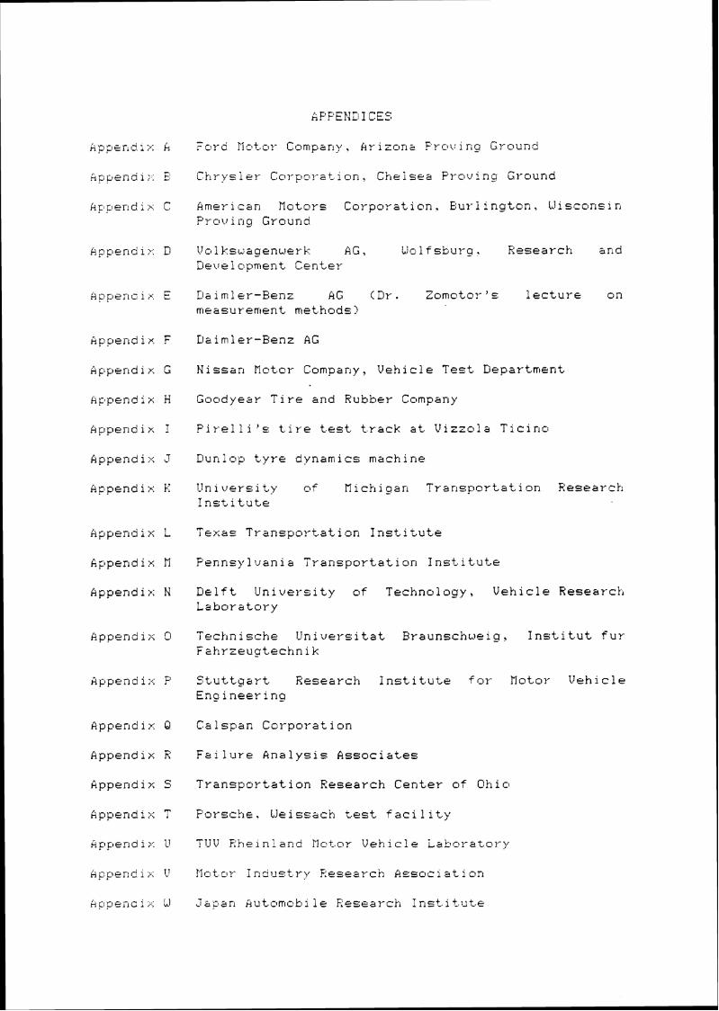
Appendix F
Appendix G
Ap,pendix H
Appendix I
Appendix J
Appendix K
kpper115 i r: L
Appendix H
Appendix N
Appendix P
Appendix 63
Appendix R
Appendix 5:
m Appendix I
kpp~ndii-: U
Append:>; \'
.Agr;~enci;.; iJ
- r CTG' MO~OI' Company , kr- i zon;? FI-ov i rig G~ound
Chi-ys i el- CCII-pol-s t i on, Chelsea PI-ou i ng Ground
American Motors Coupouation, Buylington, Wisconsin Proving Ground
Volkswagenwerk AG, Llri 1 f sbul-g ? Research knd D e ~ e 1 opment Centev
D&imler-Benz AG (Dr. Z o m o t o ~ ' ~ lectuue on measurement methods)
Nissan Mct.olP Company, Vehicle Test. Liepartrrtent
Goodyear Tire and Rubber Company
Fir-elli'c tire track at Vizzola Ticincl
Dunlop t,yre dynamics machine
Unluersi t y of Uichi can Transportati on Reseavch Institute
Pennsylvania Transportation Institute
Delft Univevsity o f Technology, Vehicle Researck~ Laboratory
". ~echnische Universitat braunschweig, Institut fur Fahrzeuptechnik
Stuttgart Research Institute for- Motor Vehicle Engineering
Calspan Corpovation
Failuve Analysis Associ3tes
Transportation Research Center o f Ohio
Porscke, We issach tes t f aci 1 ity
TUV F;k~einland i7ot.o~ Vehicle Laboratel-v

kpperl!i i x X Sued I s h F;oad and T r a f f i c Research i n s t a i t .utae (VT 1 )
Append 1 x Y TY-anspoy-t. and Road R e s e a r c h L a b o r a t o r y
Uppend ix Z Traf f i c Saf et.y and Nuisance Research i n s t i t u t e , J = p a n M i n i s t r y o f T r a n s p o r t .
Append ix A A T r a n s p o r t Canada

APPENDIX A

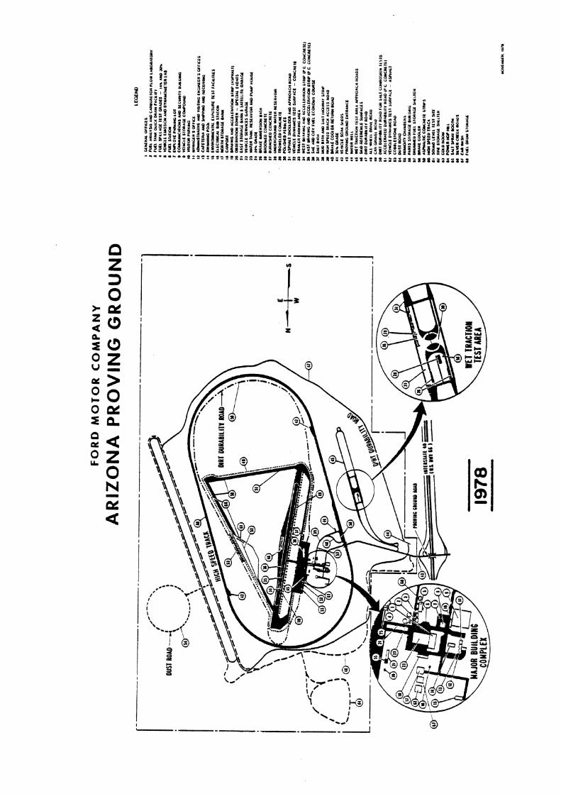


APPENDIX B

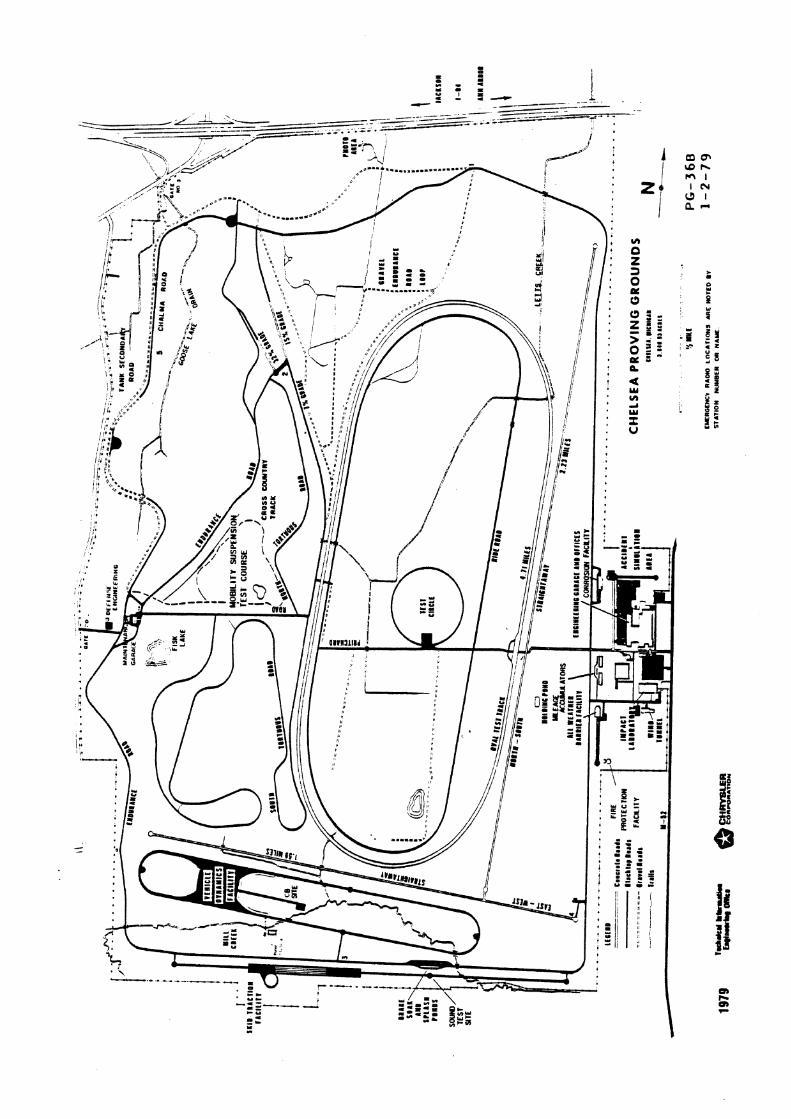


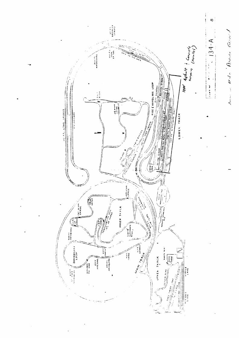


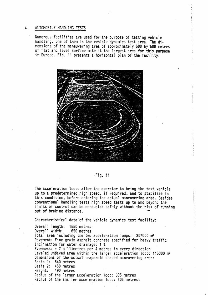
4. AUTOMOBILE HANDLING TESTS '
Numerous f a c i l i t i e s are used for the purpose of tes t ing vehicle handling. One of them i s the vehicle dynamics t e s t area. 'The d i - mensions of the maneuvering area of approximately 500 by 500 metres of f l a t and level surface make i t the largest area fo r t h i s purpose in Europe. F i g . 1 1 presents a horizontal plan of the f a c i l i t y .
The acceleration loops allow the operator t o bring the t e s t vehicle u p to a predetermined high speed, i f required, and t o s t ab i l i z e i n ! t h i s condition, before entering the actual maneuvering area. Besides
I
conventional handling t e s t s high speed t e s t s up t o and beyond the l imi ts of control can be conducted safe ly without the risk o f running out of braking distance.
characterist ical data o f the vehicle dynamics t e s t f a c i l i t y : Overall 1 ength: 1550 metres Overall w i d t h : 650 metres Total area including the two acceleration loops: 307000 IT? Pavement: Fine grain asphalt concrete specified f o r heavy t r a f f i c Inclination for water drainage: 1 % Evenness: + 2 mil 1 imetres per 4 metres i n every direction Leveled unpaved area within the larger acceleration loop: 115000 m2 Dimensions of the actual trapezoid shaped maneuvering area: Basis 1 : 540 metres Basis 2: 450 metres Height: 490 metres Radius of the larger acceleration loop: 305 metres Radius of the smaller acceleration loop: 205 metres.

llithin the smaller loop a water storage basin i s located for drainage purposes. The acceleration 1 oops consist of two-1 ane super-el evated roads of a total width of 10 metres. The funnel-shaped junctions with the maneuvering area are clothoids of 70 metres length with a design speed of 200 km/h. Besides testing by actual drivers, handling tests can be performed by remotely con- t rol ling the test vehicle from a follow car or from a monitoring and control centre (MC-centre). Fig. 12 shows a device which allows t o control steering, brake and accelerator from a follow vehicle.
Fig. 1 2
The second possibility i s the use of a remote control system from a stationary monitoring and control centre (MC-centre) with telemetric feedback from the t e s t vehicle to the operator. Electronical and mechanical components installed i n the t e s t vehicle are designed to withstand impacts up t o 80 km/h without damage t o vital parts. Data are not only transmitted from the MC-centre t o the t e s t car; response data 1 i ke steering angle, steering couple, brake 1 ine pressure, velo- c i ty and lateral acceleration will be telemetrically transmitted
'
back t o the MC-centre, where they serve as imnediate information for . the operator. I n p u t and response data are recorded for evaluation. An additional modification of the remote control system into a te le- metric microprocessor-controlled driving-machine i s in the planning stages. Reproducible input parameter variation will generate response data for further refined evaluation of automobile hand1 ing characte- r i s t i c s .
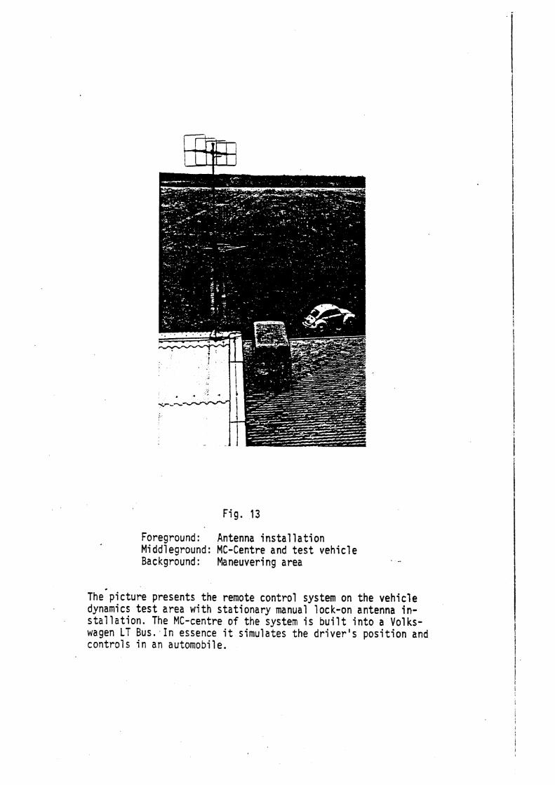
Fig. 13
Foreground : Antenna instal lation Mi ddl eground: MC-Centre and t e s t vehicle Background : Maneuvering area
The picture presents the remote control system on the vehicle dynamics t e s t area with stationary manual lock-on antenna i n - s ta l la t ion. The MC-centre of the system i s built into a Volks- wagen LT Bus., In essence i t simulates the dr iver 's position a n d controls in an automobile.
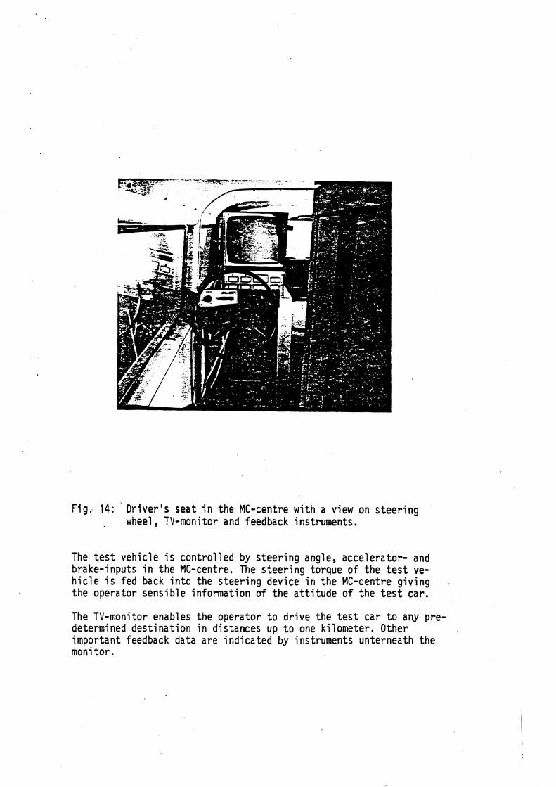
Fig. 14: Driver's seat in the MC-centre with a view on steering wheel , TV-moni tor and feedback instruments.
The test vehicle i s control led by steering angle, accelerator- and brake-inputs in the MC-centre. The steering torque of the tes t ve- hicle i s fed back into the steering device in the MC-centre giving the operator sensible information of the attitude of the t es t car.
The TV-monitor enables the operator t o drive the test car t o any pre- determined destination in distances u p t o one kilometer. Other important feedback d a t a are indicated by instruments unterneath the monitor.
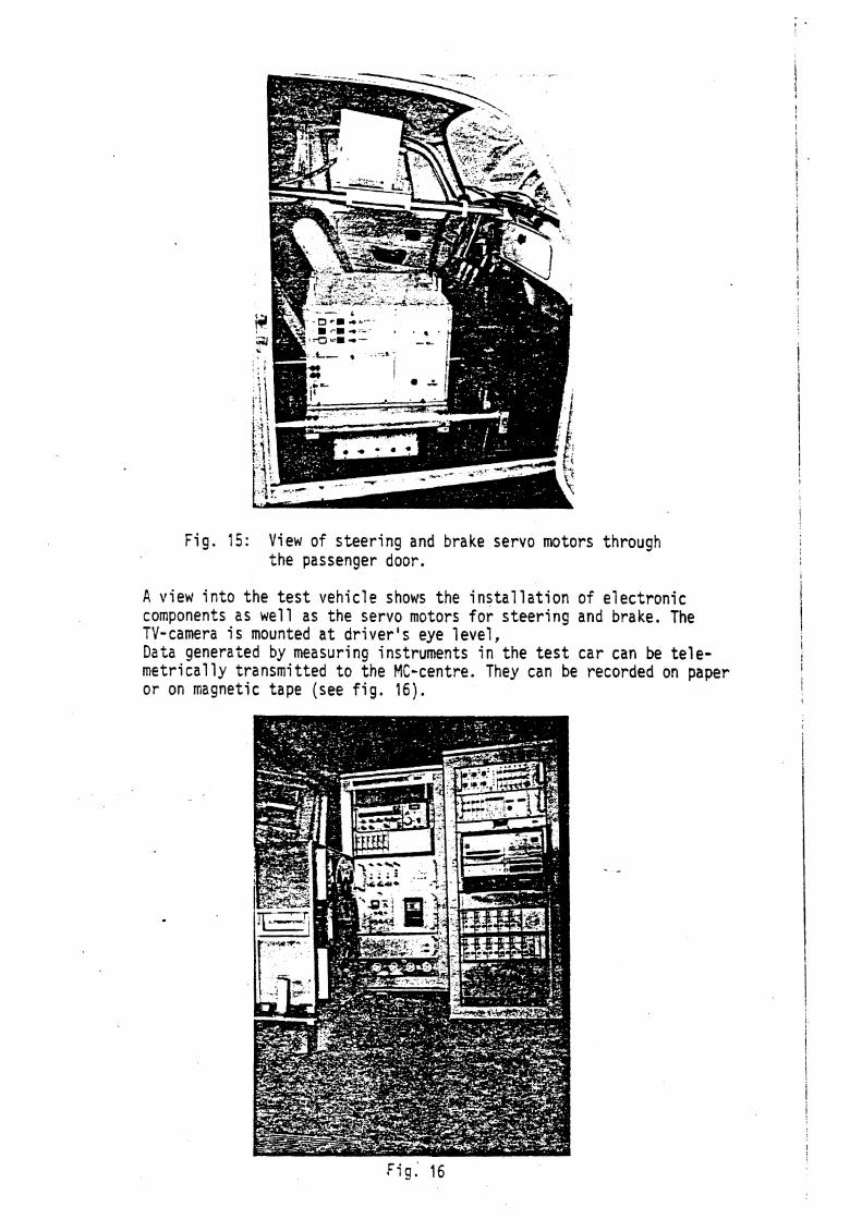
Fig. 15: View of steering and brake servo motors through the passenger door.
A view into the t e s t vehicle shows the installation of electronic components as well as the servo motors for steering and brake. The TV-camera i s mounted a t driver 's eye level, Data generated by measuring instruments i n the t e s t car can be tele- metrically transmitted t o the MC-centre. They can be recorded on paper or on magnetic tape (see f ig . 1 6 ) .
Fig. 16

External data recording decreases the weight o f test vehicle in- stal lations and speeds up the running o f extensive test programs.

APPENDIX E

23R;:O!~~Xi ':??IO:; 0' ALJTDi.lO,S!LSS, TZHiCLE HXNDLISC, >E.4SL'REIES? ?.ETIIODS AS3 EXPE2IlE hTAL RESULTS
Dr. -1ng. Adam Zomotor Daimler-Ben: AG Postfach 2 02
7000 Stuttgart 60
In addition ro the subjective evaluation of vehicle handling, mezsureaents of vehicle dynanic are more and more used 2s an aid in the development of vehicles. The genera: desire to retain the feeling of skilled test engineers in the shape of reproducible data for the puTose of obtaining the means for compzrarive improvements resulted especially during the p2st years iz an increesed applkcation of measuring techniques; BaseL on this development, a numbe~ of test nethods w e r e established which cover important driving situations for vehicle evkluation. The same assignment and last but not least the cooperation between manufacrurers of vehicles and the manufacturers of measuring instruments, as well as between institutes, resulted worldwide in a certain stan2ardi:ztion of measuring methods and measuring instruments. The succesrfci support of research and development by means
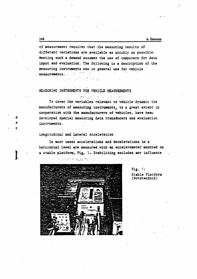
of measurement requires that the measuring r e s u l t s of d i f f e r en t uar ia t ions a r e ovoilable as quickly as poss ible . Meeting such + denand assumes t h e use of computers f o r data input znd evaluarion. The following is a description of the measuring instruments now i n general use fo r vehicle
. - . . .. - . . .
To cover the va r i ab l e s relevant t o vehicle dynamic the nianufacturm o f measuring insrmments., t o a great extent i n . cooperation with the marmfatturert of vehicles, have beell developed special measwing data . t ransducers and evaluation instruments.
Longitudinal and Lateral Acce len t ion
In most cases acc t l e r a t i on t and decelerations irr a hor izon ta l l ev t f ate measured w i t h ul accelerom+ter mounted on 2 stahle p b t f o r r ~ , Fig.- I- S t g b i l i r i n g excluder lay influence ,
Fig. 1 :
Stable Platform (Novotechai k )
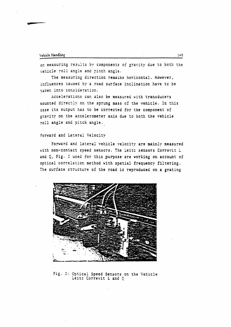
OR measuring r e s r ; l = s by components ci' g r a v i t y due t o bo th :he v e h i c i e r o l l a n g l e anc ? i t c h a n g l e .
The measuring d i r e c t i o n remains h o r i t o n z a l . However, i n f l u e n c e s caused by E road s u r f a c e i n c l i n a t i o n have t o be raken i n r o c o n s i d e r a r i o n .
A c c e l e r a r i c n s cac a l s o be measured w i t h t r a n s d u c e r s
3oun;ed d = r e c r l y on t h e sprung mars of t h e v e h i c l e . I n :his case i t s o u t p u r h a s r o be c o r r e c t e d f o r t h e conponen: of g r a v i t y oc zhe a c c e i e r o m e t e r a x i s due =c both t h e v e h i c l e r o l l a n g l e and p i t c h a n g l e .
f o r v a r d and L a t e r a i V e l o c i t y
Forward anc l a t e r a l v e h i c l e v e i o c i t p a r e main ly measured u i t h non-con tac t speed s e n s o r s . The L e i t r s e n s o r s C o r r e v i t L
and 0, F i g . 2 used f o r t h i s .purpose a r e working on account of o p t i c a l c o r r e ? a r i o n method w i t h s p a t i h i f requency f i l t e r i n g . The s u r f a c e s t r u c t u r e c i t h e road i s reproduced on a g r a t i n e
F i g . 2 : O p r i c a l Speed Sensors on the V e h i c l e Lei t : C o r r e v i t L and Q
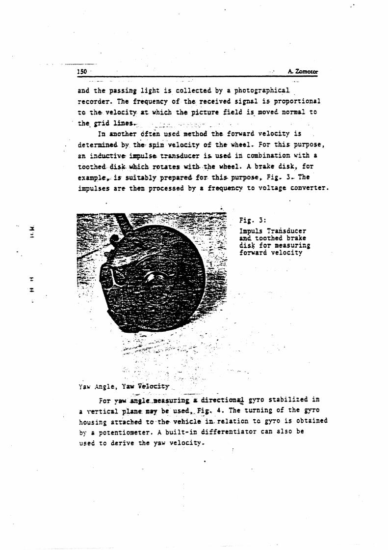
and t h e pastirrg l i g h t i.s c o l l e c t e d by a photograpniciil . .
recorder . The frequency of t h e r ece ived s i g n a l is p ropor t iona l t o t h a v e l o c i t y at which the p i c t u r e f i e l d i s . lnoved nomal t o the. g r i d lines, - .. - . . . . . .. -
In a n o t h e ~ dfttn used matbod the forward v e l o c i t y i s . d e i e d t d by t h e spin v e l o c i t y of the u h t t l . For this purpose,
an inductive inpalst, transducer is wed i n conbina t ion with a too-Aed disk- which. rotates uizh the wheel. A brake disk, for example,. is suitably prepare& f o r this purpose, Fig. 3 - The impulses are then processed by a frequency t o v o l t a g e conver te r .
Fig. 3: Impuls Trhs duc e r and toothed brake disk f o r measuring forward v e l o c i t y
- prr -- -.
f o r paw mglr..rsertsuring a diremima$ gyro s t a b i l i z e d in a t .er t ica1 plant . m q r be used,-Fig. 4. The turning of t h e g y ~ o housing atraehed t o . t h e vehicle in. r e l a t i o n t o g y ~ o is obtained by a potent iometer . A b u i l t - i n d i f f e r e n t i a t o r can a l s o be used t o de r ive the yaw ve loc i ty .
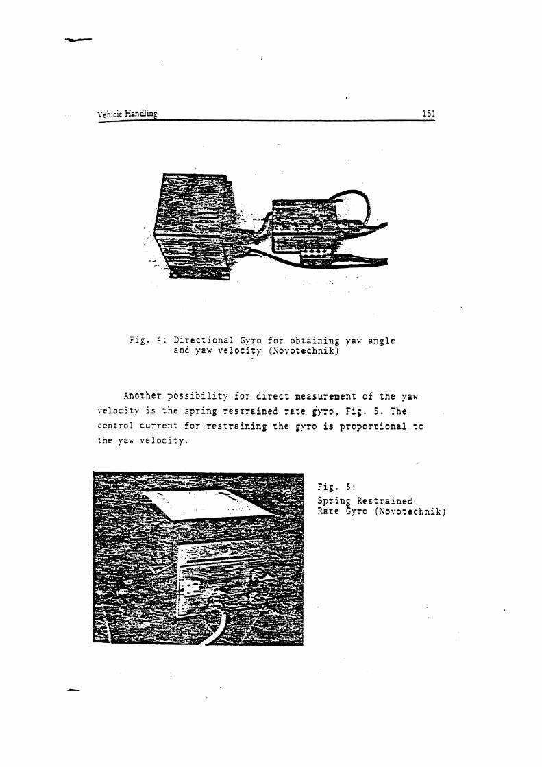
- . r ~ g . 4 : Directional Gyro for obtaining yaw angle and yav velocity (Sovocechnik)
Another possibility for direct measurement of the yau
relocity is the spring restrained rete gyro, Fig. 5 . The
control current for restraining the gyro is proportional ro :he y 2 ~ velocity.
Spring Restrained Rate Gyro (kovotechn

- F f e b: Bate Seosor (Novotechnik) '
* - . . - .
For direct measurement of the yaw velocity the so-called rate sensor is oftea wed, Fig. 6. The principle i s based on the fact that during tbe roarion of the housing o gas jet is diverted by the Corriol$s force. This diversion is proportional t o the aapulrr ve loc i ty . The mrIT dinensions and the robust- a
ness of -At i n s t m u m are uf adnatogr. Them are no sensitive bearings in contrast t o the gyro.
,. - ,; .... . .<~ - 0
Steering Wbeel Angle, Front Wheel Angle
- Special measuring steering wbetls are used for measuring the steering wheel angle, Fig. 7 . The angles are transferred t o a potentiomttcr by means of c pear wheel transmission. A tors ion measari:ng hub w i t h a strain gages bridge i s i n t e p t e d in rhc m u r i n g steering wheel for .
, - . .. - measuring the torque. . , - .., .>,. - A number of devices bas be- developed for measuring the
frant wheel angle in relation to the vehicle body. The device for measuring the front whet1 lo& while driving consists o f
.. ..r .Y ,- ,-.. .
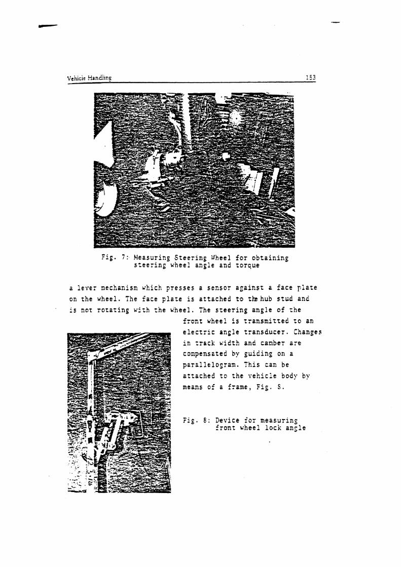
Fig. 7 : .Measuring S t e e r i n g Wheel f o r o b t a i n i n g s t e e r i n g wheel angle and t o r q u e
2 l e v e r nechanism vhich p r e s s e s a s e n s o r a ~ a i n s t a f a c e p l a t e on t h e wheel . The f a c e p l a t e i s a t t a c h e d t o t h h u b s t u d and
' i s nor r o t a r i n g wi th t h e wheel . The s r e e r i n g a n g l e o f :he l r o n r wheel i s t r a n s m i t t e d t o an e l e c t r i c a n g l e t r a n s d u c e r . Changes i n t r a c k u i i t h and c a n b e r sre coapensz ted by p u i i i n g on a p a r a l l e l o g r a m . T h i s can be a t t a c h e d t o t h e v e h i c l e body by
means of i f rame , f i g . S.
F i g . 8 : Device f o r measur ing f r o n t wheel l o c k a n g l e
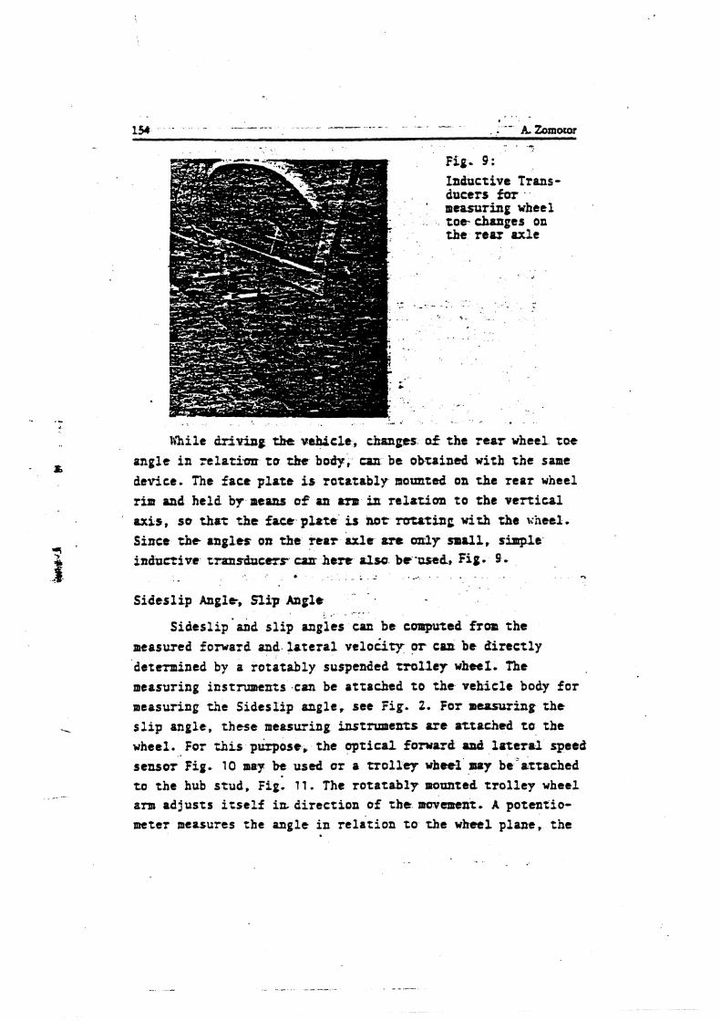
Fig.. 9:
Inductive Trans- ducers far . measuring wheel t o o changes on tke rear axle
lrhile driving the vehicle, changes of the rear wheel toe angle in relatian tu t)N body, csa be obtained with the same device. The face plow i s rotstably mounted on the rear wheel rim and held by means a9 an am in relation to the vertical axis, so that the face p u t 8 i s not rutating with the \;heel. Since tbe angles oa the rear axle are a y small, simple inductive trxnsbccrr~ h e m allso be -used, Fig. 9
* . .. 1
. - Sideslip Angle, Slip Angle
. . . - . Sideslip'nad slip mpies can be coraputed fro. the
measwed forward and lateral velocity pr can be airectly determined by a rotatably suspended rrolley wheel. The measuring instruments can be attached to the vehicle body for measuring the Sideslip angle, see Fig. 2. For measuring the slip angle, these measuring instrumeKts are attached ta the wheel. For &is p k o s c , the optical forward axid lote~al speed sensm Fig. 10 may be used or a t ~ o l l q wheel u y be'rrtached to the hub stud, Fig. 11. The rotatably mrmted trolley wheel am adjusts itself irt direction of the movtmcnt. A potentio- m t e t measures the angle in relation to the wheel plane, the
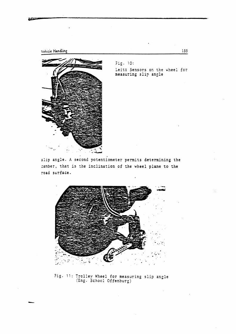
F i g . 10:
Leitz Sensors on the wheel is: measuring slip ensle
. i d
slip angle. A second potentiometer permits determining the
:anbey, that is rhe inclinstion of the wheel plane to rhe road surfsce.
Fig. 1 1 : Troiley Wheel for measuring slip angle (Eng. S c h o c l Offenburg)
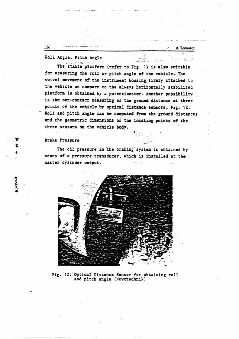
Roll Angle, Pitch Angle . - . . , - . . , & . - .. . Ih- L I,-
The siable platform (refer to Fig. 1) i d also suitable for measuring tbe 'ro l l ar pitch angle o f the vehicle- The swivel mwemenr of the instrument housing finuly attached-ta the vehicle as c&rpara to the always hcrUontally stabilized platform is &taint& by a potentiometer. Anather pos s ib i l i t y is t&e non-contarr measuring of the ground distance or a r e e points of the uehic2e by optical d i s w m a r s , f i ~ . 12.
Roll and pitch anglt can be computcd.fior the grwnd distances a
and the geometric dimensionr of the 1wtShg points of the three sensors on the vehicle body.
Brake Pressure ... ..: ,.a,,-
The o i l pressyre i n 'the braking-system is obtained by means of a pressure transducer; which is installed a t the master cylinder ootptzt. . .
Fig. f 2: Optical' Distance Sensor f a r obtaining ro l l and p i t c h angle (Novotechnik]
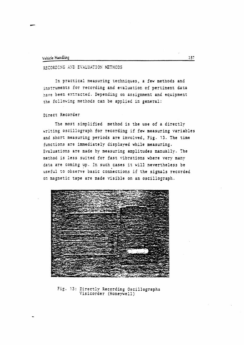
I n p r a c t i c a l mezsur ing t e c h n i q u e s , a few methods an2 ins t ruments f o r r e c o r d i n g and e v a l u a t i o n of p e r t i n e n t 2ara have been e x t r a c t e l . Depending on zssignment and equipment ;he f o l l o ~ i n g methods can be a p p l i e d i c g e n e r a l :
Direct Recorder
The most s i m p l i f i e d method i s t h e use o f a d i r e c t l y v r i r i n g o s c i l l o g r a p h f o r r e c o r d i n g if few measur ing v a r i a b l e s and s h o r t measuring p e r i o d s a r e i n v o l v e d , F i g . 1 3 . The t ime f u n c t i o n s a r e immeais te ly d i s p l z y e d whi le measur ing. Evz lua t ions a r e made by measur ing ampl i tudes n a n u z l l y . The ng:hod i s l e s s s u i t e d f o r f a s t v i b r a t i o n s where v e r y many d a t a a r e coning up. I n sucn c a s e s i t n e v e r z h e l e s s be use fu l t o observe ~ e s i c connecr ions i f t h e s i g n a l s r e c o r d e d oz ~ a g n e t i c t a p e a r e made v i s i b l e on an o s c i l l o g r a p h .
Fie. 13: D i r e c t l y Recording O s c i l l o g r a p h s l r i s i c o r d e r (Honeywell)

FM Nagnetic Tape
For long measuring periods and quick processes, the recording with frequency modulation on a tape recorder has proven i t s u.mth, Fig. T4. T'1ie'frequency modulated analog tapes are subsequently digital ized f a r evaluation by a
- - . -- - - - - . computer. Th% conversi.on of t)le tapes requires addi t ional
time and computer capacity, for this reason the method should be used where r e s u l t s a r e no t required immediately. The
. . number af- choantl.s.'is limited. - - -. . - With ari:'l'/td tape seven. tricks aad one voice t rack are
. avai lable . A disadvmtope- i s t h a t - f luc tua t ions of tape speed will show up. .as meas- faults an$ therefore very accurate synchronizatioa is required. Onfy a few tape recorders a r e ava i lab le t o wi'&stand any .acceleration suitable f o r use i n t h e vehicles; they a r e i n addi t ion relat ively. la rge and are consequently mthez hcsvy. -
- ,... .
F i g . 1 4 : F?J-Tape Recorder, Frequency Modulation, (Honeywell)

Fig. 1 5 : PC?.! :.leesuring System, Pulse-Code-Noau!ation, ilennart: and Hewlert-Packart)
PCB: !lethod
The recording of measuring signals with a PC1.I system (pulse-code-mo2ulation) permics the storage of large quantities o f csta at lo^ space requirenents for the unit, Fig. 1 5 . For zhis method regular samples are taken from analog signals and are shown as a binary digit on the nagnetic tape. The time-
eqcivalent sanples of different functions are recorded on s
t ~ p e by a mulfiples system one after the other. This system permits r h r recording of eight functions on one track. Upon ccnuerrion these measuring ~~ariab!es can lirectly be evzluated by a computer. .A disadvantage is ;ha: The measuring signals s r e no: visible and thrt the evaluation cannot b e made E: :he tesz site.
lobile, Computer-Aided Neasuring and Evaluation System C '
l n e high demands of today's practical research an2 :he need to quickly obtain large volumes of data for immediate
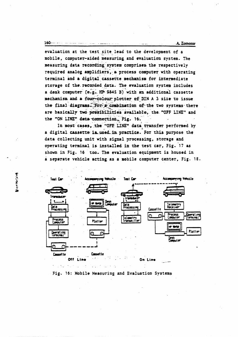
I*- - -- . . - - . ,. - . - . . A ~ o T
eva lua t ion a t t he test site l ead t o the development of a --
mobile, computer-aided m e ~ s w i n g and ctraluatian system. The measuring data recazding system comprises t h e respect ively required analog amplafie;s-, : a process computer wizb operating t enn ina l and a d i g i t a l c a s s e t t e mechanism f o r intermediate s t o r age of the-recurded data. The cuolustion system includes a desk co.putcr (e:g: H$ 9805 3)'uith an r d d i r i o d ca s se t t e mecbrnirp and a fourk&ru.pluttcr &-DIN A 5 t i r e t o issue t h e m a l - di.w~ii.i&i&-fQlt &- ch= two s y s r e u - the re are basicrL1y fwd p&sib'&&s .&ailable, the. "OFF LINE" and
. . the "ON LINEn d m umnec&i, kit. 16:. .
I n mst 'cHes. :tke X&EW ht;. Gansfer performed by a digital c u s l n t is &+h in prrrrice.' For t h i s purpose the d a t a c o l l e c t i n g unit with s i p 1 processing, storage and opera t ing terminal is instoried in the test car, Fig. 1 7 as s h a m i n Fig. 16 too. The evaluat ion e q u h e n t is housed in o s e p s r a t e veh ic le a c t i n g as a mobile computer cen te r , F i g . 1 8 .
Plot tcr LE%n
Fig. 16: Mobile Measuring and Evaluation Systems
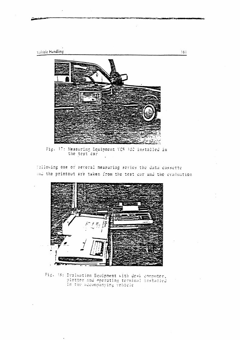
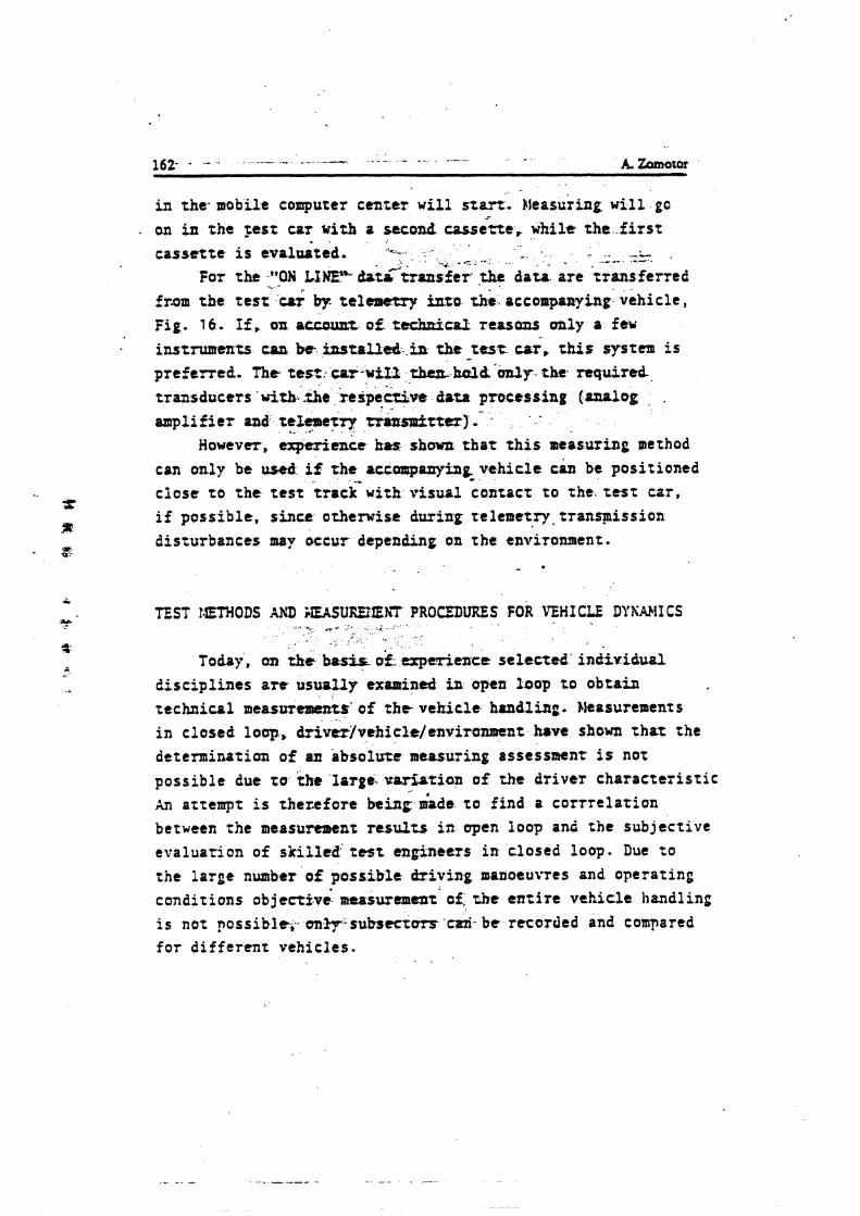
in the. mobile computer center w i l l star t . ~feasu'ting w i l l go an i n t h e rest car with a u c w d w d ; t e . while t h e f i r s t c a s s e t t e i s eval&ted. -..-. . . - . -L , .* . -7 - " _*.- .I-.
For the -. "ON - LIWFL b t ~ * k r f e r +b, d a u . a r e . t ransferred from t b t t e s t car by t e l v bzo thi a c c o ~ ~ ~ a n ~ i n ~ : vehic le , Fig. 16. If, on accwrrr. of teduzicaf- rcasans only a feu instruments can be i ; ~ l s t o ~ ~ - . i s the test car, a s system i s preferred. The rest- c e r - w = thuL ktzlbYon.ly t h e required,
t ransducers with-athe ~ e s p e e c i v e . . datz processing (analog . -
ampl i f i e r and tellcaact.r)r .. .- . tranetter) . However, experience has shown t h a t t h i s measuring method
can only be use$ i Z the rcra~lponyinp vehic le c& be posit ioned c lo se ro t h e test t r a c k w i t h v i sua l ;ontact t o the. t e s t car, i f poss ib le , s ince otherwise during r t l emet ry . t ran+iss ion disturbances may occur depending on t he environment.
TEST t.ETHODS AXD i , E A S U ~ l E K T PROCDURES FOR VEHICLE DYiiAMI CS - -, -,. * '. .. -
. ,
Today, an tkt buk if- experience se lec ted individual d i s c ip l i ne s are usuolfy exmined in upen loop t o obta in t echn ica l measuttmthts'of t h e veh i c l e bondling. Measurements i n closed lev, M v e r ~ r e h i c l t / e n v i r o n n n ~ b v e shown t h a t the determination of aa hbsolute measuring assessment is not
poss ib le due t o the'lsrgs-u&r5atian o f t he d r i ve r cha r ac t e r i s t i c An attempt is thezefore king made t o f ind a co r r r e l a r i on between the measurement results i n open loop anZ the subject ive evaluat ion of ski l led; test engineers i n closed loop. Due t o
the large number o f poss ib le d r i v i n g manoeuvres and operating condit ions ob jec t fve measurement' of, the e n t i r e veh ic le bandling i s not possible,., on--subsectm'czri- b e recorded and compared f o r d i f f e r en t vehic les .
, .
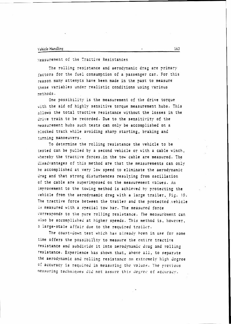
The r o l l i n g r e s i s t a n c e 2nd aerodynamic d rag a r e p r i n a r y i a c t o t s f o r t h e f u e l consumption of a p a s s e n g e r Cai. For t h i s reason many a r r e m p t s have been made i n t h e p a s t t o measure :j-,ese v a r i a b i e s under r e a l i s z i c c o n d i t i o n s u s i n s : . ~ r i o u s
nc:nods.
One p o s s i b i l i i y i s t h e measurement of tile ? r i v e zorque t h e a i d of h i g h l y s e n s i t i v e t o r q u e measurement hubs . T h i s
~ ! l o v s t h e t o r i 1 t r z c t i v e r e s i s t a n c e w i t h o u t t h e l o s s e s i n :he 2ri1.e t r a i n t c be r e c o r d e d . Due t o t h e s e n s i z i v i t y of tile .easu;emenr h u b s such t e s t s can o n l y be accompl i she2 on a blocked t r a c k v h i l e a v o i d i n g s h a r p s t a r t i n g , b r a k i n g and i s r n i n g nanoeuvers .
To d e t e r n i n e t h e r o l l i n g r e s i s t a n c e t h e ire'nic!e t o be :es;ed can be p u ? l e c by r second v e h i c l e o r v i t h z c a b l e winch , \;hereby t h e t r a c t i j r e f o r c e s . i n t h e to^ t a b l e a r e measured. The
d i sad i -an tages o f t h i s method e r e r i la t t h e me3snrenents can o n l y be s c c o n p l i s h e d e t very iow speed t o e l i m i n a t e rne aerodynanlic drag and t h a t s:ronp d i s t u ~ b a n c e s r e s u l r i n g from o s c i l l a t i o n o f i h e c a b l e a r e super imposed on t h e measurement ~ n l u e s . XI)
iaprovemenr t o t h e touin: method i s a c h i e v e d hy p r o t e c t i n g t h e veh ic le f r o r t h e aerodynamic d rag ~ i r b a l a r p t t r a i l e r . F i r . 1 9 .
T h e : r a c t i v e f o r c e berween rlle t r a i l e r and t h e p r o t e c t e d \,chicle
i s measured w i t h 2 s p e c i z l :ox b a r . The measured f o r c e corresponds t o iAe pure r o l l i n g r e s i s t a n c e . h e measurement c 2 ~
:ilso be e c c o m p l i s i ~ e d a t h i g h e r s p e e d s . This nlerhod i s , i ~ o v c r e r , 3 l a r g e - s c a l e a f f a i r due t o t h e r e q u i r e d t r a i i c r .
The c o a s t - u o u c t e s i v h i c h has a l r e a d y hcen i n use f o r some
:iao o f f e r s t h e p o s s i b i l i t y t o measure t h e r n t i r e t r a c t i v e r e s i s t a n c e and s u b d i v i d e i t i n t o aerodynamic drag and r o l l i n 2 r e s i s t a n c e . E s p e r i e n c e h a s shown t h a t , above a l l , t o s e p a r i i t e the aerodynamic and r o i l i n c r e s i s t n n c : nc e r i r c m c l y h i g h dcgree c: accurlc!. i s reqoi red i n m r s s u r i ~ l g t h c v a ! u c i . ! !~ l . c r . j ous ~ ~ c ~ s u r i n p i c c i l ~ ~ i q l l e s i d not a6sti1.c t l i i i tic::~.cc o f YCSLI~.IC!..
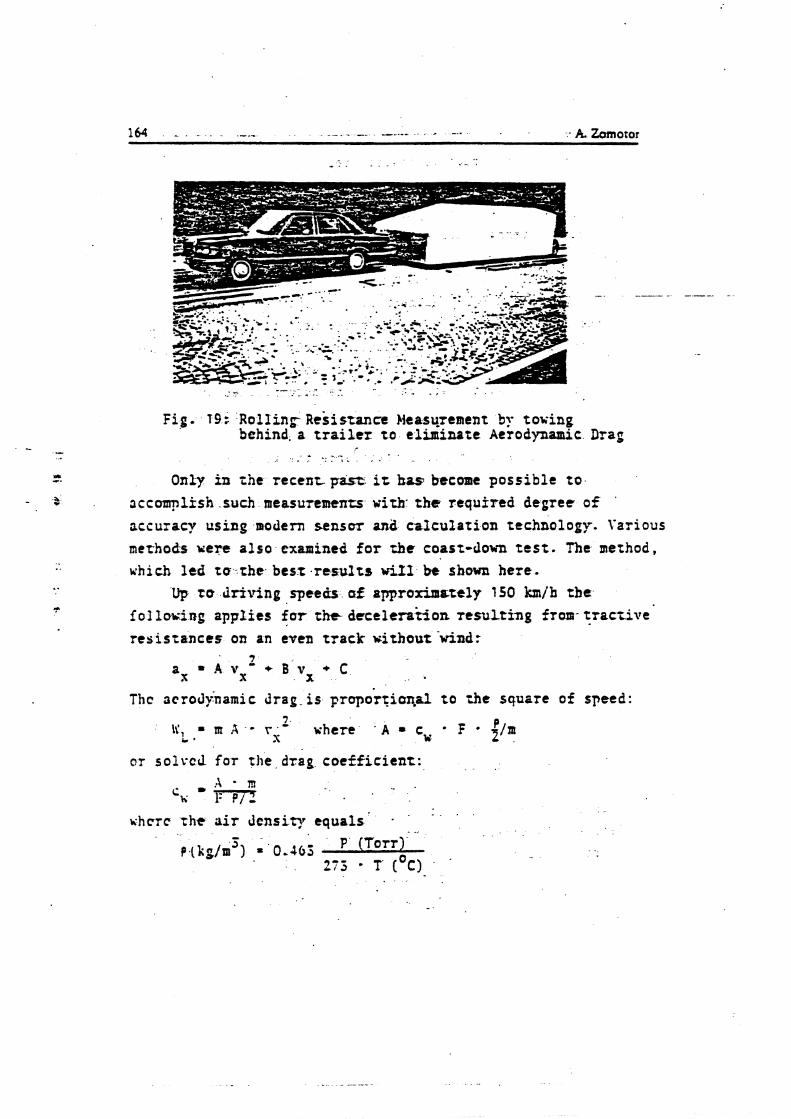
Fig. 19: Rolling- ~esistance Heasqrtaent by roving behind, a t r a i l e r to eliminate Aerodynamic Drag
Only i n the- recent. pasts it h a s become possible to accomplfsh such measurtmtnzs with. t h e required degree o f accuracy using modern sensor and calculation technology. Various methods uere also exmined for rhr coast-John t e s t . The method, which led to -rhe besx .resul ts wir1 bt' shown here.
Up to dr iv ing speccis af approximately 150 km/h t b e f 01 l m i n g applf es for the deceleration resulting from- trarcive resistances on an even track without 'wind:
Tbc acrod).narnic drag-is Frop&tiarlnl to ;he square of speed: /.
I(, = rn A - rs- where . A = cy F f / m i. '
or solvcd for the drag coe f f i c i ent :
. . ~ h c r c the a i r Jcnsity equals -
. .,
~ 1 k ~ / r n ' ) = 0.46: P (Torr) 213 - T ( O C )
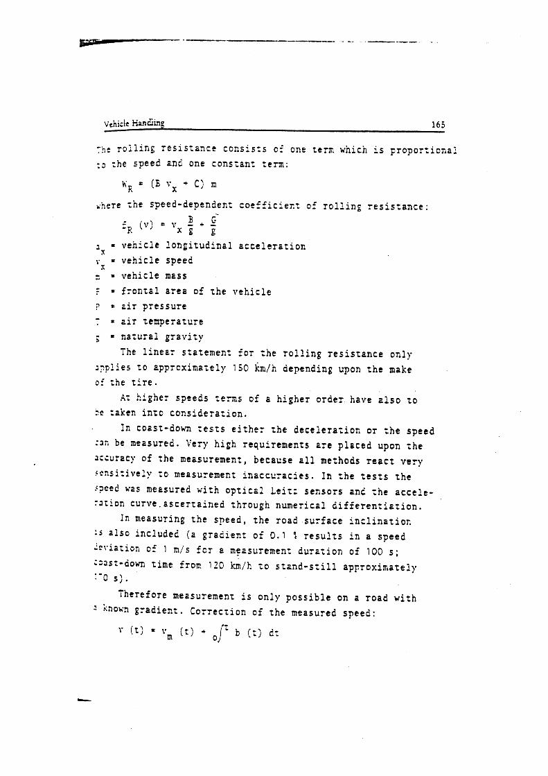
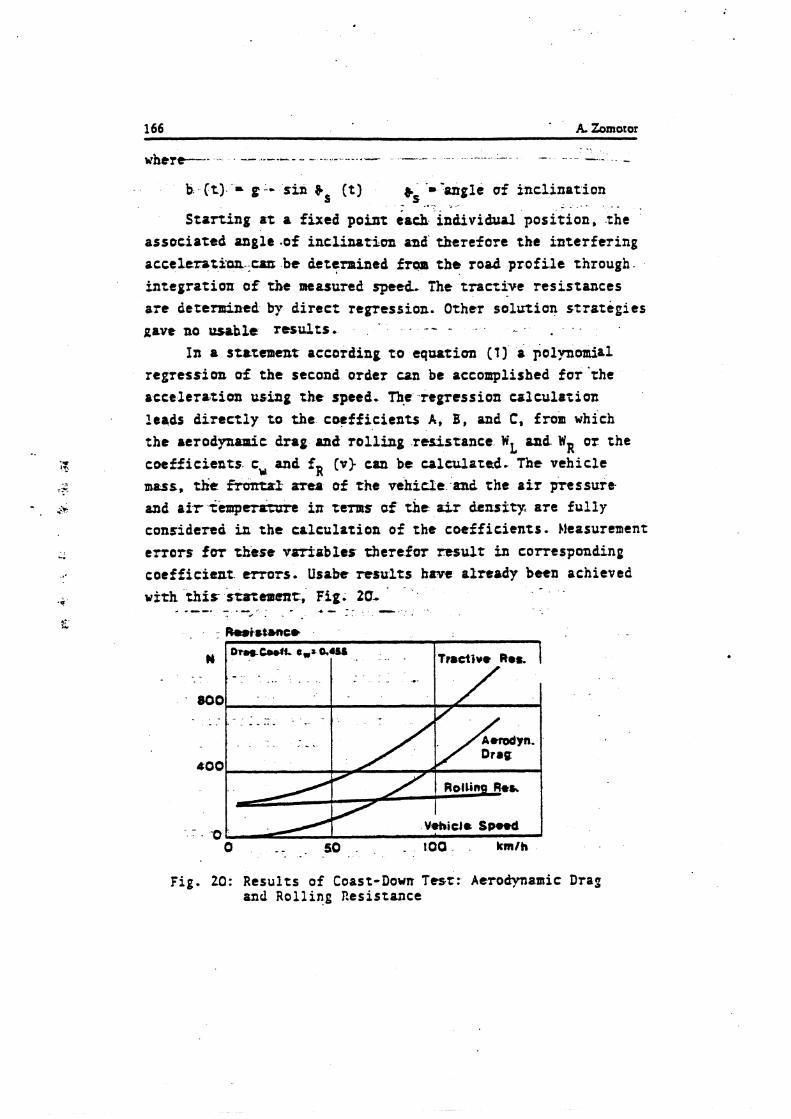
166 A. Zomotor
where--- _- _-.-_ _ - - " -.- .- - - .---- - - .- - - -
b (t) - p.- sin bS (t) 8s '- -angle of inclination - ,. . - - .
Starting st a fixed point esch individual position, the associated stngle.of inclinatiun and' tbtrefore the interfering acceltrat5an.,cna be determined fram t h e road profi le through. integration of the measured speed. The tmctive resistances are determined by direct regression. Other solartion strategies
In a statement according t o equation (1) a polynomi~l regressi an crf t h e second order can be accomplished f o r 'the acceleration using the speed. p ,regression crlculatian leads direct ly to the coefficients A, B, and C, from which
t h e aerodyntnic drag and rol l ingresisrance WL nnd WR o r the cotff ie ients c, and fR [v) can be calculated. The vehicle m a s s , the -1 aztn of the vehicle and the a i r pressure and a t r i i m p r r o t r m in trrors uf the air &rutty are ful ly considered in the colculotian of t h e cotfficients. ).itasurement errors for these vori-abler therefor m u l t in correspondinp coefficieat. mars. Usabc results have already been achieved
. . w ~ t h this stacemcnt, Fig. 20,
+ .--. - . - . a . . - 4 - - . - .
- . .o Vehicle SO& 0 - - . 50 - 100. krnlh
F i g . 20: Results of Coast-Down Test: Aerodynamic Drag and R o l l i n g Resistance
. .- \.?;iicic Handling ! o
One o f t h e c ides : r e s r ne:hods i n 1 - e h i c i e 2 y n a ~ i c s i s :!.? stead?. ;ta:e t ~ ~ r n i n g . I t s c p p i l ? ~ b a s i c c o n p a r n t l ; . ? 23:: {J: :he a e ~ + e l o p n e ~ . r o f ~ e h i c l e s . I n a d d i t i o n t o :hc a z s i x u c
: i ; ;eler .at ion t h i s d a t a a l s o i n c l u d e i 'ne cur.;.e of :a:.iol:s . . * ; e f l ; ~ l e dynamic \ - a r i z b l e s u s i n 5 ;he l a t e r a l a c c e l e r a r i o r on : i r c u l a r t r a c k lc i th 2 c o n s t a n r r a d i u s . Other me:hods \$there
: h e s t e e r i n 2 wheel a n g l e o r t h e d r i ~ i n g s ~ e e c r e m s i n c o z s z a n z . ~ : e used i e s s o f t e n because t h e y r e q u i r e a v e r y l a r g e t e s z < , ' T . , , f a c e .
I n t h e s t e a c y s t a t e t u r n i n g r e s t t h e l a t e r a l a c c e i e r a t i o ~ , 5 ;ee r ing wheel a n z l e 2nd c o m e n t , s i d e s l i p a n g l e and r o i l
; z ~ ! e a r e measured . The v e h i c l e i s z c c e l s r a t e d t o ;he d e s i r e d
s?ee l on a c i r c u l a r t r a c k u s u a l l > r v i r h a r a d i u s ber\\:eer, j G
3ni jC n . Pihen t h e s z e a d y s t a t e c o n d i t i o r . i s r e a c h e d , t h e d a t a
sbzl! be r e c o r d e d . The s p e e d s can be r u n i n ' s t c p s o r t h e v e h i c l e :an be a c c e l e r a t e d i n a q u ~ s i - s z e a d y s t a t e from t h e l o w e s t
speed up t o t h e l i m i t r a n g e , whereby t h e measured v a r i a b l e s 3 r e r e c o r d e d d u r i n g t h e e n t i r e p r o c e d u r e .
The e v a l u a t i o n i s a c c o m ? l i s h e l by 2 computer p rogram. The recorded t a p e i s c o n t i n u o u s l y r e a d and checked whe the r t h e
measurea l a t e r a l a c c e l e r a r i o n i s w i t h i n c e r t a i n l imits; ' i f so, a l l measured v a l u e s a r e s i m u l t a n e o u s l y c o o r d i n z t e d t o t h i s
l a t e r a l a c c e l e r t h o n i n t e r v a l . T h i s program a l l o w s t h e r a n g e 2 from minus 10 t o p l u s 10 mis t o b; e v a l u a t e d i n 100 c l a s s e s .
The c l a s s t h e n c o r r e s p o n d s t o 0 . 2 n/s2. The mean v a l u e , s t a n d a r d d e v i a t i c n and ?eak v a l u e s a r e c z l c u l a t e d an2 r e c o r d e d
. . .
i r o n t h e a d j o i n e d v g r i i i b l e s measured . T h e s e values c a n be
given i n t a b u l a r fo rm. P r e s e n t e t i o n o f t h e measured v a l u e s a s 3 f u n c t i o n of ;he l a t e r a l a c c e l e r a t i o n i s a l s o p o s s i b l e . F i g . 2 1 shows t h e s t e e r i n g wheel a n e l e , s t e e r i n g wheel t o r q u e ,
s i d e s l i p a n g l e and r o l l a n g l e . The l a t e r a l f o r c e s on t h e whee l s
C a n n l s o be measured w i t h s p e c i a l measurement h u b s , F i g . 2 2 .
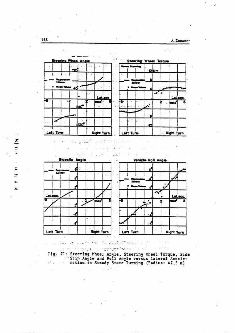
- - . ' . -: - . - -.. - - -
T i = . 23: Steering ?%eel Angle, Steering a t e 3 Torque, Side - S l i p Ansle and Roll Angle versus lateral Accele- ratioa. in Steady Stare Turning (Padius: 4 2 , s m)

~ a t e r a l Force Front Wheel ,left Lateral Force Fron! Wheel right
i
, 1
.I. R*pre&b~on / 2 Or01 r -
i 1 , .
1 ,
I a I Lat.acc. !
8 1 ' I
' I
I t : j j - R m g w s s ~ a
2.oroer
I '
~ e i t Turn ,
F i g . 2 2 : L a t e r a l Force on t h e f r o n t wheels i n S teady S t a t e Turn ing (Radius: . 4 2 , s m )
- r o r d e t e r n i c a r i o n o f t h e s t e e r p r o p e r t i e s r h e e l a s t o - kinemazic c h a r a c r e r i s ; i c s of t h e wheel s u s r e n s i o n a r e used i n ~ d d i t i o n . E s s e n t i a l i n f o r m a t i o n can be o b t z i n e d f o r t h e s t e e r ?ro?er:ies from ;he chanzes i n t h e s t e e r a n g l e of t h e i n d i r i a u z l
uhcels due t o t h e l a t e r a l f o r c e and d u r i n g v e h i c l e r o l i . For :his r e a s o n t h e v h e e l a n g l e s a r e r e c o r d e d v e r s u s l a t e r a : ~ : c e l e i a t i o n on a c i r c u l a r p a t h , F i g . 2 5 .
Front Wheel Steer Angle I I I I I 1
I Lef t ~ u r b 20j 1 ~ i ~ h t urn / I
F r o n t \;heel s;eer a n z l e v e r s u s l a t e r a l a c c e i e - r a t i o n i n s t e a d y s t a t e ~ u r n i n g (Padius 4 2 , 5 n>

1 rans ient Ees~onr t . . -- -- ->-.-. .. , --.- -- -- .--.. -. . - - - .
- -4., . . To- inres t igota the- uthi.cle handring it is. a l so necessary
t o determine the t ransient response of the vehicle i n addi'tion . .. t o the steady s t a t e st& proFerrier;$ariour t e s t methods have been Btttelcped to- msasure the t irztsient response. The methods used most o f t e n * i n . ~ s c t i c e , . the .. s t q - - - input and tbe frequency response method, are exfltioed tn the fallowing.--
---- -- I - ---rr -.--------,..-. *.,- .' " - . . - - - - - -- - - - - -. ..----.-. < .
.>- - .. r . - -I--- ..- .---_ _--_
For the s tep iqut method the-most important input and
- steer ing ~ h e e f - q l e and . -. - .. .. . - - , - . - yaw velocixy - - as well as t h e f o l l w i a g reference variables art measured:
- s t e e r h p wheel a n ~ l e velocity - '- forward velocity . .
- l a t e r a l achTcsstian- For cumporison w i t h the subjective evaluation t h e
- sidcsiiP angle and , - . - r o l l aasle . - - are recorded in addit ion.
A t the ~ i v e n speed, senerally between 80 and 120 'knlh. the vehicle is moved from a .straight path. into a c i r cu la r
2 path with a given l a t e r a l acceleration (4 and 6 m/s ) v i t h the quickest.possible ramp fom steering wheel angle input. Durirq t h i s procedure t h e n e e r i n g wheel ancle veloci ty should be between 200 and 500 O j s . . -- . . -- -.
. ~ a r m e t e t s are detenuined from the t imt functions of the - - recorded variables fot characiei i zatiw of the zransient response. Evaluation i s - - accomplished - - - w i t h a Frogran system resul t ing i n the fo3 lauin .~ charac ter i s t ic values:
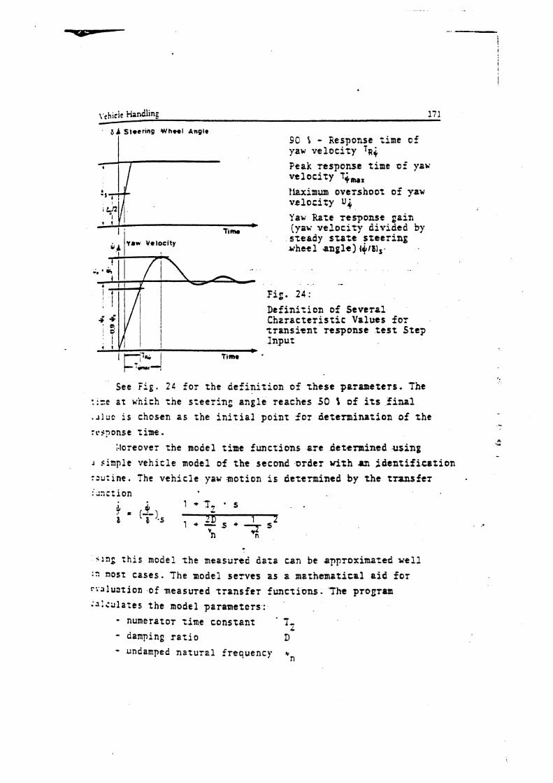
8 A steertng Wheel A n Q k 90 f - Response time of yaw v e l o c i t y 1 ~ 4
Peak response t ime of yaw v e l o c i t y T+,,, ?kximum overshoot of yaw velocity U C
Yaw Rate response ga in e
TI nu (yaw v e l o c i t y d iv ided by s t eady s t a t t f r e e r i n g wheel a n g l e ) 44r6)s-
4.2 I I 4 I Y .-
f i g . 2 4 :
D e f i n i t i o n 05 Seve ra l C h z r a c t e r i s t i c Values for s r a n s i e n t r t s p o n s t t e s t Step Input
b 7 imr
See Fig. 2 4 f o r rhe d e f i n i t i o n of t h e s e parameters . The ::=c a t which rne s teer in : angle reaches 50 t of its final . ~ l u c i s chosen a s the i n i t i a l p o i n t f o r de t e rmina t ion af zht rtbsnonse t ime.
a
I.loreover t h e model time func t ions ar t determined using ...
J sinple vehic le model of =he second ,order w i t h an i d e n t i f i c a z i o n s2u;ine. The v e h i c l e yaw motion i s determined by t h e transfez
<lag :his model t h e mezsured da ta can ~e a ~ p r o x i m a z e d well :: nosz cases . he model s e rves as a mathamatiral aid for r: 'llu3tion of measured z r a n s f e s f u n c t i o n s . The P T o S r a ;3 :culates t he model parameters :
- numerator t ime cons t an t ' T I - damping r a t i o D - undamped n a t u r ~ l frequency v,,
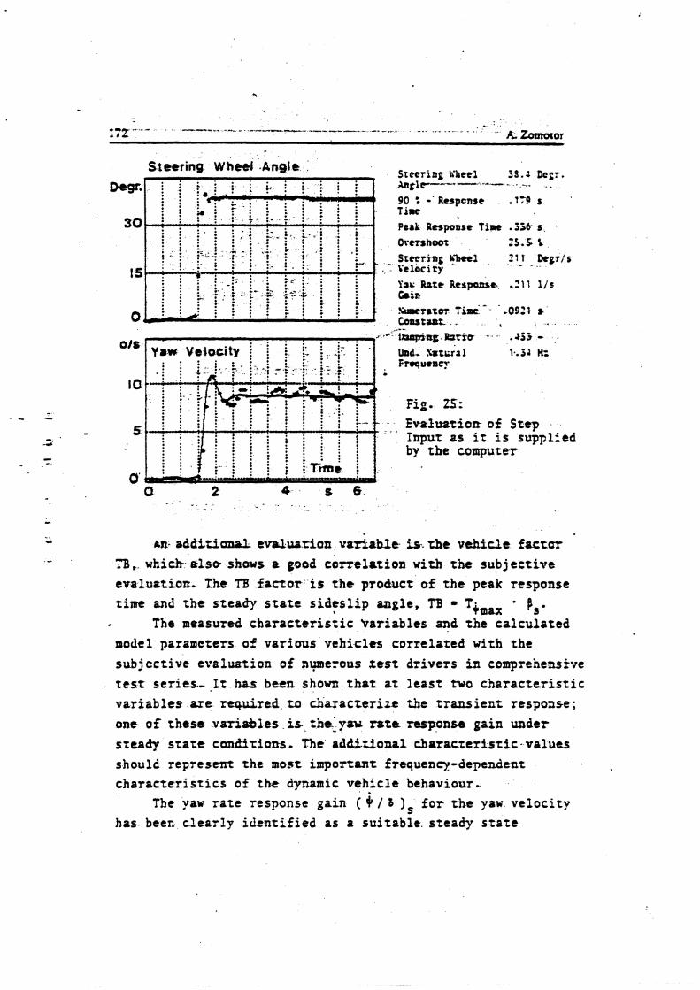
Steering Wheel .Angle Steering h'hetl 5 9 . 4 Dcgr. ;UItlr----- - a-- - . .-.- . . . 90 : -'Response ,779 s '
T i r Perk Response Time .336 s . Overs hoar 23.4. L Stacring 4-1 21 1 Degr/s
.,: Velocity -. ._ _ _
- Evaluatiost of St tp - . . Input as it is supplied by the coqmter
*n. odditianol evaluation v & r b ~ t is, zhe vehicle factur '
TB ,_ which. also shows a good correlation with the sub j ec t ive evalu+tion- The TB factor is the proctuct of the peak response rim and t h e steady s t a t e s ides l ip angle, T3 T+mpx t Is*
The measured cbaracter is t ic Var iables and the calculated model parameters of various veh ic les correlated with the subjcctive evaluation of nwerous zest dr ivers i n comprehensive t e s t ser ies- It has been shown tha t at l eas t two character is t ic variables are required ta characterize the transient response; one of these vsriobles is the'ysu rate response gain uxider szeady s t a t e conditions. The' addi t ional chor rc te r i s t i c~va lues should represent the most important frequency-dependent dlaracrer is t ics o f the dynamic vehicle behaviow.
The yaw r a t e response gain ( + / 8 1, for rhe yaw velocity has been clearly identif ied as a sui tabl t . s teady s tate
-- 1 2 = Y
r! t
4 i: Vehicic Handlmg
., 173
I
c h z r a c t e r l s t i c value. The yaw r a t e response g a i n snows a c o r r e l z t l o n w i t h :he s u b j e c t i v e e v a l u a t i o n e n ;a curvy pa th f o r more than 0.8. The g r e a t e r ( 4 / 3 ) s sas, fhe better the veh ic l e was t v a l u z t e d . Above a l l t h e damping D, t h e peak response time Tc,,, and rhe f a c t o r T3 prnved so be she s u i t a b l e dynamic c h a r a r r e r i s t i c va lues f o r rhe e v a l u a t i o n of the v e h i c l e based on :he torre1.atio.n. The s e a t e r zbe damping and the sma l l e r T max and TB were, %he 5etrter 'the f va lua t ion
of the veh ic l e s . To compare d i f f e r e n t v e h i c l e s in regard t o t h e i r i r a n s i e n t
respons t based on t h e r rep input maasu renen~r t h e c h r z a c t e r i s t i c values given h e r e , above all, jnusr .be txam'ined nore c l o s e l y i n a d i i t i o n t o t h e t ime h i s t o r y of t h e individual v a r i a b l e s .
Frequency Response
A f u r t h e r p o s s i b i l i t y f o r eva lua t ing t h e t r ansmis s ion c h a s a c t e r i s t i c s of 2 veh ic l e i s t h e measuresnent,and c h a r t i n g o f the frequency response. Here t h e inpu t and output variables - a r e c o l l a t e d with one another a t var ious 3 inuso ida l e x c i t a t i o n f requencies , a s is usu r l i n . c o n t r o l technology. These t r a n s - mission cha rac t e r i s ; icr change according ri ampl i tude and phase
C
over t he s t e e r frequency. The advantage i n r e l a t i o n t o t he step input oleasurcment
i s zhat a l a r g e t e s t s u r f a c e i s n o t r equ i r ed ; a long s t r a i g h t path with corresponding width i s s u f f i c i e n t . A t c o n s t a n t d r i v i n g speed t h e s t e e r frequency i s increased in s t eps - I t has proven p r a c t i c a l t a use a n automatic s t e e r i n g machine f o r r h e s e measurements. Fig. 26 shows an c l e c t t o h y d ~ a u l i r s r e e r i n g machine i n s t a l l e d in a vehic le . The r e s t s were performed wi th a d r i v e r vho acce l e ra t ed t h e zest v e h i c l e t o t he correct t e s t speed and held t h i s speed cons t an t dur ing t h e measurement procedure.
During the measurement p e r i o d zht d r i v e r removes h i s hands from t h e s t e e r i n g wheel and a c t u a t e s TWO push b u t t o n s rihich s t a r t t h e s t e e r i n g machine. The s t e e r a n g l e i n p u t i s then
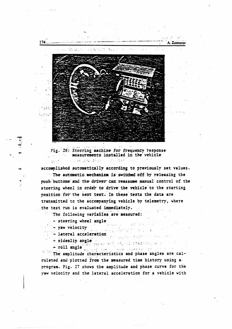
. . - - I . . Fig. 26: Stccring nochine f o r frequency fesponse
nrcrsurcl~tnts. instelled in the vehicle
accomplished automatically actmding to previously set values. - The aawmcic met.fr&pt is- suizckt off by releasing the
psh'buttcms and the cWver.cut reassme manual' control o f the s teer ing w h e e l in ordir to drive the vehicle' t o the start ing position for- t h e n m t tesr. In these tests the data are tronsnitted t o rhe accompanying vehicle by telemetry, vhere the t e s t run is evaluated imnediately. . . .
The following varia5Ics ore measured: - s t c e ~ i n g whee l angle '
. - - yaw ve loc i ty - . - - . .
. - - la tera l acccleratioo . -
* 9 s i d e s l i p angli , . . z . f. L . - * . : s - t . : ' *. - r o l l angle - . - . . - -, : - . -
. - The amplitude char&teristics and phase angles are ca l -
culated a d plotted f ~ a m t h e measured time history using a.
program. F i g . 27 shows the amplitude and phase curve for thi yaw ve loc i ty and the l a t e r a l acceleration for a vehicle with
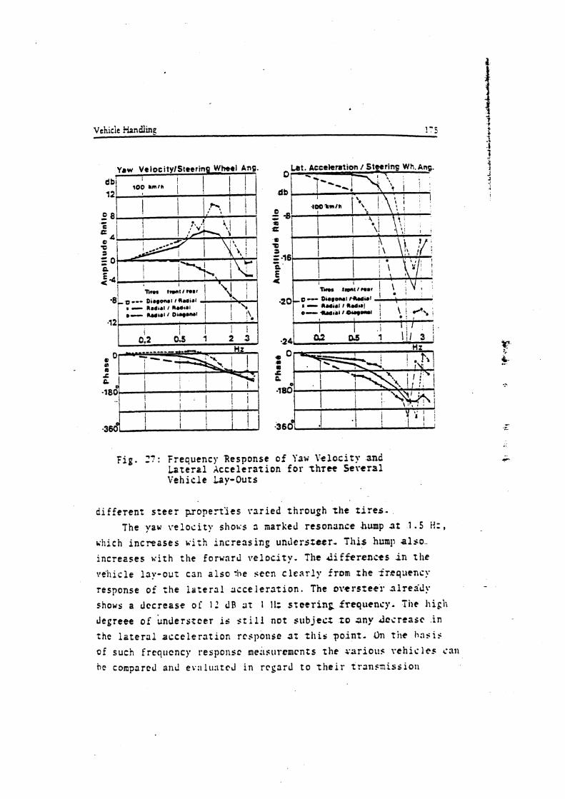
Vehicle Handling 1 - j
F i g . 27: Frequency Response of 'isv Y.elocity and Lateral Xccelerazion for t h r e S e v c r s l Vehicle Lay-Outs
d i f ferent s t e e r properties varied through t h e z i r e s . The yaw veloci ty shoris 3 marked resonance .fcump 3 2 1 . 5 H:,
~ i i i c h increases with increasing unrlerstetr. ?Iris hump a l s o increases w i t h t h e forward veloc.ity. The J i f k r c n c t s i n t h e
vehicle lay-OUT can a l s o :be seen c l e a r l y from rhe irsq~ienc!. response of' the ioterc l l acce l e r s t i on . The ovcrsrecr. .rtlrelidy -
shows a decrease o f 1 2 dB a t 1 11: steering frequency. Tile h i g h
Jegreee of bnderstcer is $ t i l l not subject ro any Jcsrrast . i n
the l a t e r a l acceleration rrsponsc 3 t zliis po in t . On t i l t ilcis is
of such Ercqi~cncy responsc mcnsurcmcnts t he various vehic lcs call
hc compnrcd arid ev:il~;atcJ in regard t o t h e i r t r a n $ x i s s i o ~ i
chorac te r i s t ics . - -..,.::: . I. - , .. .:-; 'i.'..-.* ;.. , ,..- -- --... * - .L.-.) ..--(. "r,v*.:Y-)-::- - ..
Braking in a 'furxi' , , -, . . .
.,,'-. . - -1.- .-a- .-.,-- -- - : - . - - . . --.-..- . - .-- - .--_ - An imporrant, hoctic&related driving manoeuwe i s braking
ia a turrr; During this m ~ e w r e tbe-vehic le shouzd nat"dtvi'ote from t h e i;oirid. path, if possible,. nos should it. spin.- While the tests c s i d t z e d up t o t h i s po in t could only be perfomed' - . - - i n =he' up& ioop procedure-due t o +b&; chsr~ctez. fm braking in a - m a-cIese& .loop. t e s t , f .r. rif* the -iafiucnrr- of the driver, ' is al~a'~&sQ1e..1& the cIose& loop tes t .& q th i c l e path.
. is usuolly e v e n io tbi fom o f o anzked lam, and the driver *
manipulate^ tbe*stterSg.-&igl+ aa& deceleration so that t h e vehicle rm&s in-* lane- and stops wirhio. r given distance. ~ h & test is very clork to. practice; ' however,. the r+;ults-are dependent u p m the d r i v u su , that o mrrnbcl of drivers have t o be used. Such tests are l o e l l suited fur a subjective comparison of vehicles.
0x1 - the o r h c l hand, i f - t h e vehicle motion i s t o be r c e o ~ d e d and t v t l u t e d oa the b a t i s of objeczivc c b r r a c t e r i s t i c values, the opA loup p&c& ha& tu ite used. he gia o f this tes t i s t o determint- t h e effect of brakIri;ng upon tht.bizectiorroL beha'- viour o f tbe vek ic l t d o s e srtady stace. turniag: is disrupted only
by the braking procedure. The neesing wheel is kept fix during the test. The fallawing variables r r c measured: - steering wheel m g l e
- b n k t $.ZeSSUTb
- longitudinal dectleta%ion - farword velocity - .' - yaw ve loc i ty - sideslip angle .
It has been deterjainect that the differences between vatious - vehicles can best b e determined using an i n i t i a l c i r c l e with a diameter o f 100 m. a t an i n i t i a l l a t e s o l accele=tiun value with
2 a minimum af 5 m / s .
Vehicie Handling . .-- I , /
- C i h i ; cc r responds ;o an i n i t i a l 3,-ehicle speeci o f SC..; ks;i;.
dece1era:ion f r o n t h e s t eady s z a t c cir tu!ar t u r n i n g . During :his ? rocedcre the brake pedal i s a c t u i t e d as . q u i c k l y a s .possible.
The brzke 7 r e s s u r e is i n c r e a s e d r h i s f a r , u n t i l a l l v h e e l s lock
U? . - 3 ~ n e r e c o r d e l measurement v a r i a b l e s a r e processed f u r t h e r
cs iog a computer. IR t n i s procedure t h e f o l lo \ i i ng a d d i t i o n a l
v a r i a b l e s a r e c a l c u l a t e d :
- r e f e r e n c e yaw v e l o c i t y - r e f e r e n c e i a t e r a l a c c e l e r a t i o n
- yalc z n g l e d e v i a t i o n i r o n i n i t i a l c i r c l e The r e f e r e n c e c o n d i t i o n i s t h e c o n d i t i o n of t h e L-elliclc
s l o x i n g down x i t h t h e same l o n g i t u d i n a l d e c e l e r a t i o n t ime - h i s i o r ~ z s rne t e s t v e n i c l e u i zhou t any . dev ia t ion of t h e v e h i c l e ..- - cer,ter of g r a v i t y l r o n :he i n i t i a l c i r c u l a r r ~ a j e c t o r y . I n .) - addizion t h e s t eady s t a t e va lues from t h e beginning of t h e a. - brsking p rocedure , mean v r l u e s and maxinum x-alues as well as values a t t h e t ime 1 s a f t e r b rak ing begins are de termined -
C .from t h e t ime h i s t o r y of t he .messu red v a r i a b l e s f o r e a c h r e s t . - C
The time 1 s tias t h e r e f o r e chosen, because % h i s . p e r i o d - corresponds approximate ly t o t h e r e a c t i o n tM i ' of the d r i v e r . -e
Ifhen t h e d r i ~ . e r . a f t e r t h i s p e r i o d desires t o ' isitiatc a c o r r e c t i o n t h e v e h i c l e m ~ t i o n .should s t i l l be under h i s c o n t r o l . The mean v a l u e s , naximum v a l u e s and t h e 1 second \'sluts a r e s t anda rd ize? i n p a r t t o t h e s t e a d y s t a t e v a l u e s .or ' t b e '
re ference va lues i n o rde r t o ovo id d i f f e r e n c e s t h rough dispersion
I n t h e i n i t i a l c o n d i t i o n s .
The. cu rves f o r t h r e e d i f f e r e n t v e h i c l e s arc shown lrcrc T O
i l l u s t r a t e rhe hehaviour r h a r a s t e r i s z i c s ob ta ined I r o n a largc number of r e s t s . Due t o t h e f ac t t h a t t h e vehicle hand l ing
changes a t v a r i o u s l y h igh degrces of d e c e l e r a t i o n , t h e cu rves . .
zre charzed i n r e l a t i o n t o t h e d e c e l e r a t i o n . The 1 s v a l u e s a r e graphed \ T e r s ~ s rhe 1 s va lue f o r t h e d e c e l e r a t i o n and the mcar!
values versus t!le mean d e c e l e r a t i o n v a l u e . .
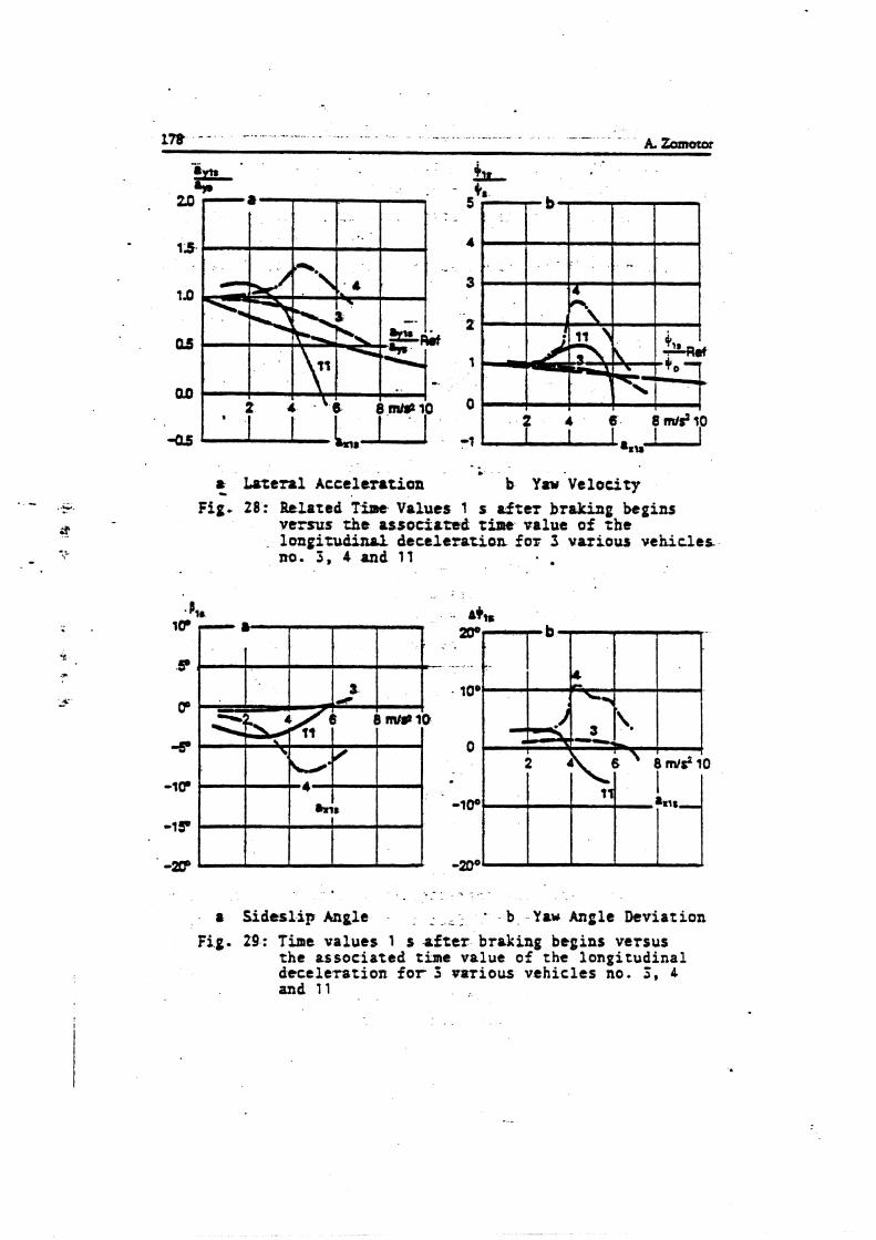
Lateral Acceleration - b Y a u ~ e l o c i t ~ F i g 28: Related in Valuer 1 s after braking bepins
versus the associated time value o f the longitudinal d t c t l e z a t i a n for 3 various v e h i c l e s nu. 3 , 4 and 11
r Sideslip Angle - - . . - - - - b - Y a w Angle Deviation Fig. 29: Time ualues 1 s after braking begins versus
the associated time value o f t h e longitudinal decele lat ion f o r 3 votious vehicles no. 5 , 4 and 11
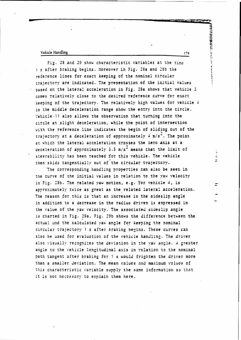
Vehicle iiandling 17 9
f i g . 28 end 29 shox c h a r z c t e r i s t i c v a r i a b l e s a i =he t i n e
1 s z f z e r braking begins. >loreover i n Fig. 28a and 2Sb the reference l i n e s f o r e x a c t keeping of t h e nominal c i r c u l a r ; r a j ec to ry a r e i nd ica t ed . The p re senza t ion of rhe i n i t i a l va lues based on t h e l a t e r a l a c c e l e r a t i o n i n f i g . 28a shows iha: vehic le 3
comes r e l a t i v e l y c lose t o t h e d e s i r e d ~ e f e r e n c e su rve f o r t U C i
keeping of t h e t r a j e c t o r y . The r e l a t i v e l y high va lues f o r veh ic l e 4 i n the middle d e c e l e r a t i o n range show t h e e n t r y i n t o the c i r c l e . Yehicle.11 a l s o al lows the observar ion t h a t t u rn ing i n t o t h e c i r c l e a t s l i g h t d e c e l e r a t i o n , u h i l e t h e p o i n t o f i n t e r s e c t i o n w i t h t h e r e f e rence l i n e i n d i c a t e s t h e begin of s l i d i n g 7 out o f t h e
t r a j e c t o r y a t a d e c e l e r a t i o n of approximately 4 m/s' . The p o i n t a t t i h i ~ h rhe l a t e r a l a c c e l e r a t i o n c ros ses t h t zero axis a t a
7 dece le ra r ion of approsimatelp 5 . 5 m/s' means tiat t h e l i n i r of
*
s z e e r a b i l i i y has been reached f o r t h i s \vehicle. The v e h i c l e then s k i d s r a n g e n t i a l l y our of t h e c i r c u l a r r z a j e c t o r y -
The corresponding handling p r o p e r t i e s can a l s o be seen i n the curve of ihe i n i t i a l values i n r e l a t i o n t~ t h e yaw s e l o c i r y i n F i g . 28b. The r e l a t e d yak. motion, e . g . 'for v e h i c l e 4, i s approsimztely t u i c e a s g r e a t a5 the r e l a t e d l a t e r a l a c c e l e r a t i o n . The reason for t h i s i s t h a t an i n c r e a s e i n t h e s i d e s l i p angle i n a d d i t i o n t o a decrease i n the radius d r i v e n i s expressed i n rhe value of the yaw v e l o c i t y . The a s s o c i a t e d s i d e s l i p a n g l e i s char ted i n F ig . 19a. f i g . 29b shows t h e d i f f e r e n c e betueen t h e ac tua l und t h e c a l c u l a t e d yaii ang le f o r keeping t h e nominal c i r c u l a r t r a j e c t o r y 1 s a f t e r braking begins. These curves can
also be used f o r e r a l u a t i o n of t h e \*ehic ie handl ing . The d r i v e r a i so \ . i sua l l? . recogni:es t he d e v i a t i o n i n t h e ?.a\; angle. A g r e a t e r angle t o t he i -eh ic le l o n g i t u d i n a l asis i n r c l a t i o n T O tile nominal path zangent a f t e r braking f a r 1 s i ~ o u l d f r i g h t e n r k e d r i v e r more than a smal le r J e s i a t i o n . The mean r s l u c s and masinun ~.alucs of :his c l ia rac te : i s t i s r a r i a b l e supply the sane i n i o n n a t i o n s o t h a t i t i s not ncccssary i o e x p l a i n them here .
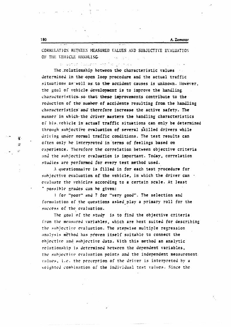
60KKI~I.:l'r I US HliTUfiIiS jIISASUIIEII VALUES .4SD SUBJECTTYE E\'ALUATI OS 01: TIII. YE1 I I CIA. I-l:lS1)I.I SC
. . . - . - . . . . . . . 'Thc -rcl ;r t ionship hctuecrr the c h a r a c t e r i s t i c values .
Jetcrmincd i n tb -opm loop procedure and the aczual t r a f f i c s i u l a t j o n s as. wcl3. 3-s. to the accident causes i s unkno~n . l i o u e ~ e r ,
tilt go:^? of vch i c l c Jcvelopawxt is t o improve t h e handling.
ch3r;actcris-t ics- SO. fht these inqimvcm~nts cuntribure t o the
rcd~icr i on o f tkc n u m b of ecdclenrs r e s u l t i n g iram t h e handling
c h ; ~ i a c f c r i s t icS' an& thcrefo~e i nmease t h c ac t i ve sa fe ty . n~c urunncr i n r;h.ich-the d r i v e r masters t h e handling c h a r a c t e r i s t i c s
oi' h i s . v c h i c l e i n actuaT traffic s i t u a t i o n s can only be determined zhrough st thjcct ikc cralustius of several s k l l e d d r i v e r s while
. - a d r iv ing mdcr rrarml t r a f f t c conditions. The t e s t r e s u l t s can
- n
- orrcn only hc inrrrprctcd i n tcms of fee l ings based on
- .. cspcr ience . 'T1)crcforc t h e c a r r e l a t i o n between ob j e t t i v e c r i t e r i a :inJ t h e s t l h j c ~ r i v c cvaJuatioa i s important. Today, co r r e l a t i on
studies a r c pcrfanncd Ear every test method used. c ~ t ~ e s t i o n m i r c is f i l l e d i n f o r each zest procedure f o r
s r ~ h j c c t i ~ c cvtllustion of the vehicle, i n which t h e d r i v e r can
c v ; ~ I ~ i ; ~ t c thc rchiclcs according t o a cc r r a in scale. A t least possible graJcs c3n he given:
1 for "poor" and 7 f o r " v e q good". The s e l e c t i o n and form~ll :~t ion of the questions asked play a primary r o l l f o r the SIJL'~'CFS o t ~ I I C cvif illat ion.
I'hc go31 01 thc stud? is t o f i nd the ob j ec t i ve c r i t e r i a
I'rom tllr mt*:lsilrcd rarj ab les , uhi ch a r e hcs t s u i t e d f o r descr ib ing ~ I I C . ;~~h- icct i rr m'31~0 t i on . The stepwise mul t ip le regress ion
: r n : i l y $ i s &hod 113s proven itself s u i t a h l c t o connect the a h j c c t i \ . r :lac1 ?; i~hjcs t ivc data. l i i tb this mertrod an a n a l y t i c
rc 1:1t i o n s h i p i s Jctcrmincd hctvccn thc dependent va r i ab l e s , 7 h c s i ~ h - i c ~ r i vc* cv:i 1 unr i on po in t s and thc independent mensurencnt
~ . ;~ l t l c s , i . c . r h c pcrccption o f t h c d r i v e r is i n t e rp r e t ed by a a c j p h t c J comhin:ttion of the i n J i \ - i t c s t ~o lk rc s . S ince thc
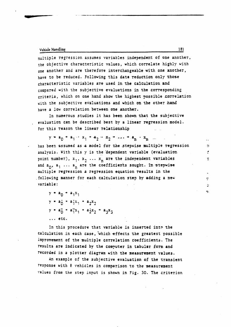
vehicle fkndl in~ 181
3u l r ip l e reg'ess 10" 2 s sumes v a r i a b l e s independent o f one anorhe r , :he o t j e c z i v r c h 2 r a r t e r i s t i c va lues , which c o r r e l a t e h igh ly i ' i t h one ano the r anc a r t t h e r t f o z t i n t t r c h a n g e a b l t v i t h one m o t h e r , have t o be reduced. Following % h i s data r educ t ion only 1kose ~ h a r a c t t r i s Z i c v a r i a b l e s a t e used i n t h e c a l c u l s t i o n and coupered wi th =he sub j r cz ive e v a l u a t i o n s i n t h e c o r r c s p ~ n d i n p c r i t e r i a , which on one hand show ;he h ighes t ~ o s s i b l e s n r r t l a t i o n v i th =he s u b j e c t i v e eva lua t ions and which on the o t h e r hand have a l o v c o r r e l a t i o n between one a n o t h t r .
In numerous s t u d i e s i t has been shown t h a t t h e s u b j e c t i v e
, evalua t ion t a n bt descr ibed b e s t by a l i n e a r t e g r t s s i o n model. For t h i s Teason t h e l i n e a r r e l a t i o n s h i p
y = zO + al-• X , + a 2 - xf + ... + an • xn .-..
- has been assumed as a model f o r t h e s t e p w i s e m u l t i p l e r e g r e s s i o n anz lys i s . W i t h t h i s y i s t h e 'dependent v a r i a b l e ( e v a l u a t i o n point number), x , , x 2 ... xn a r e the independent v a r i a b l e s and ao, a, . . . 'n a t e the c o e f f i r i e n i s soughz. 'In s r e p w i s e mult iple r e g r e s s i o n a r e g r e s s i o n t q u a t i o n r t s u l z s i n r h e follosing manner f o r each t a l r u l a t i o n step by adding a new var iab le :
y - a0 a , x ,
y = a; a;x, a2x2
y = a; + a"x + a j x 2 + a-x- 1 1 3 2
... e t c .
In t h i s procedure t h a t v a r i a b l e i s i n s e r t e d i n t o t h e ca l cu la t ion .in each c a s e , k h i c h e f f e c t s t h e greartsr p o s s i b l e improvemenr of t h e mrul t ipl t c o r r e l a t i o n c o e f f i c i e n t s . The r e s u l t s a r e i n d i c a t e d by t h e computer in tabulor form and recorded i n a p l o t t e r diagram with the measur taent va lues .
An example o f t h e s u b j e c t i v e .eva lua t ion of =he t r a n s i e n t response w i t h 8 v e h i c l e s i n comparison t o r h e measurement
Values from the s tep i n ~ u t i s sh0a.n i n F i g . 30. The c r i t e r i o n
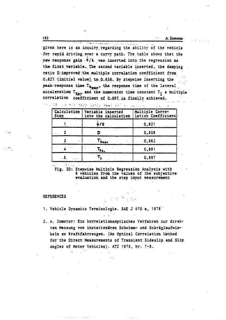
- given here i s an inquiry- regarding the a b i l i t y af the vehicle f o r rapid driving. over a curvy path. The t ab l e shows t h a t the
yow respunse gain ( / I / L was inse r ted i n to the regression as t h e first mriahfe, B e second var iable inserted, t h e damping r a t i o R rimprovtrl. tkt. m d t i p l t corrtLation coef f i c i s n t from
'
0.821. (ipitirl ~ a l u e ) ~ ta 0.858. By s t epx i r e i n se r t i ng the . ... peskttrponse tirpe T b w zhe response time of t h e l a t e r a l a c c e l m t h r T sad t h e ntmerazaz time constant T, a multiple
Roy C
c ~ r r t l a t i o a coef f i t i cm: of 0.891 i s , f h a l l y achieved.
* 1 - . .
fig. 50: Stepu is t Multiple Ragression Analysis with 8 vehicles from the values o f the subj t c t i v t tvaluatioa and t h e s t ep i m u r measurement
- 0 - . - - . . - - ,-. : " - * ' .i , : 4 " O ? ' " . .. . - . .
REFERENCES . -
Calculat ion .Step
I
2
1 . Vehicle Dynamics T e m i n o ~ o g i e . SAE J 670 e , 1 9 7 8 - .
2. A . Zomotor: Efn k o n e l a t i m s o p t i s c h e s Verfahren zur direk-
Vizri~blc inse r ted i n t o the calcula t ion
br8 D'
t en Messung von b s t a t i o n i r e n Schwimm- und SchrYglaufwin- keln an Kraftfahrzcugen. (Am Optical Carre la t ion Giethod
Multiple Corr* lo t ion Coeff ic ient ,
0,821
0,858
3 1 T b , z
f o r the Direct- Mtasurtments of Transient S ides l ip and S l ip Angles o f Motor Vehicles). A T 2 1 9 7 5 , Hr. 7 - 8 .
0,882
4 TR., 1 0,891
s . % Tz 0.897
j. R . Roniz:, E.E. Braess , A . Zomotor: Verfahren und K r i t e r i e n r u r Sewertung des f a h r v t r h a l ~ e n s von Personenkrafrwagen. (?qltthods 2nd C r i t e r i a fo r t h e Evalua t ion of Handling and Road-Holding P rope r t i e s of Passenger Czrs - Sta t t -o f - the - Art and P r o ~ l e m s ) . Automobi l indns t r i t 1977, Hefz 1 und 5 .
4 . .A. :ornotor: Nel3veriahren b e i d t r Awlegrrng des F a h r v e ~ h a l -
t e n s . (Measuring Procedures f o r r h e Eva lua t ion of Vehicle Handling) . .4uzomobilindusttie 1978, Hefz 2.
5 . f .P. Yasin: The Analy t ica l Bes i s of -Automobile Coastdohn
T e s t i n g . S.G 780334.
6 . ISO/TC ??/SC 9 : Road v e h i c l e s - Stzady S t a t e C i r c u l a r Tes t
Procedure. Draft IS0 S tanda rd , DIS 4138.2, 1980.
* . E . Bis imis , H . D . Beckmann, R . RGniz:, A. Zomoter: Ltnk-
winkelsprung und Obergangsvernalten von Kraf t fahrzeugen . ( S t e e r S tep input and T r a n s i e n t Response of Mozor Veh ic l e s ) . AT2 1977, K T . 1 2
8. A . tomotor , A . florn, :ll. Rompe: 3r t rnstn i n d e r Kurve - Unttrsuchung t i n e s Tes rve r f ah r tns . (Braking i n .a Turn - I n v e s t i g a t i b n o f a Tes tprocedure) . AT2 1980, N r . 9 .
9 . l 4 . - U . Lgcke, N. Renz: bIobiles ~ e c h n t r g e s r t u t r r t s MeOdottn- t r f a s sungs - und -auswt r tesys tem fiir den fah rzeug t insat:. ;-Jessen und Priifen, Ju l i /Augus t 1981.


APPENDIX F


Dlpl.4ng. H. stelnbnnnor, DLpl.4ng. H.4. Fbm, ing. H. Gramar, SMgnt
Semc 7 t c e e s +=IT$ Einige spezielle Methoden fiir Messungen an Fahrzeugenau der Yetsuchsbahn
Mitteiiung ~ P S der Abteiktng Versudrr-MeBhaus der bider-Benz AG, Wt@ 1
Bei der ~nkrw&ung urd bwartong von Fohn W h t U h det 6 h m h h und ondcnr ~rokteris~scher G r b h ilnd W u n w ufordrbi&, Ah. z. 8. b r die ~ M ~ l o g e , da B e s e i t M nnn n odn her Brunrepe Awkunfi goben. h sol1 oud vntersuht mdn, wie i h Cokmuge in k r i t i s h Sibdonen, r 4. bim%holen, nrhden. D u h l b mrden firr die 6hfohkdtn der Firmo Daimkr&ru AG mi* .MaBv&hm, mhuidcelt, d e on bartimmte Stradrenob- schnitk gekmdcn rind und doher nvr wf urn &pmn h h n ongwmded uarda C h s n , M r abbr rrrsnig Ribheif a Wnwg bal))igen urd dot W s m6;glichst rehndl onnigenpho hpwemt die fntnackiung von fohmwgen urheblih t r l e i h - tern. Einige dieser MeBuadohmn wlkn h b M l t mrdsn.
1. Gmschwindigkoitsrneswng zwgm Unfollgefohr bedruten. W d e n oie d e r verzsnkt an- gebmdrt, darn berbht Vtrs-efohr 4 Gefuhr der
1.1 M e s t u n g d e s G e s c h w i n d i g k e i t t - Stbung okrreh herdbbiiende U M e r und durgteihsn. &hn- v e r l o u f s iiches'uilt Jirr S c h d t n , die mit Uttr~schol~l -iten.
Zur Gewinnung des DbLihn Gosehwinciigkeits-Zeitdim- gromms existieren nnchkdene Verfdrren. Bei einem Verfoh- ten wird ein 5. Rod emgesetzt, welhts i m allgememen ainen dektrischen hpvlsgeber ktet igt . Diese Wegimpukcwbrden in rine geschwindigkeibproporiionale Gleiehsponnung u m p seM, welhe mis t Jber der Zeit oufgazeichnet wid. &i einem onderen Verfohmn wird entlong dner Teststreeke mittelt Rodor die Gbtchwindigkeit Bemessen und ebenfolls durch eimn Liniens&reiber oufgezeichnet 11). Die nochfol- v n d genonnten Mbglid-~keiten sollen diere MeeverFahrsn ergbnzen.
12 V e r f a h r e n z u r M e s s u n g d e r G e s c h w i n - d i g k c i t Gber e i n e n d c f i n i e r t e n S t r cC - k e n a b s c h n i t t
Vilfach k t di k u n g der GeschwWgkeit sines Mr- z q s irbsr eine bertimmte Mnfirecke, z. 8. w d h r d einsr gwnsen krhnvstondsr, e d o r d d i . In andenn M l k n toH die Gesehwkdiikeit en eintr kstimmten SteHt eintr Twt- h d t e (2. 8. om Beginn d e n o h ) ewwiltdt w a k n . W r tind h i Skimler&m auf der Ve- on m h m Stdlen dcratige Msbinrichtungen geddfm wonden, und m r iikr Stredten von 10,100 d r r i h r 1IKK) m. G e ddmi angewondte Tochnik dl c n emem 8ehpid hdmisben m r - An.
Die h~immurrg der Geshwindrgkeit gerchieht dwch kr. m q der hit f ber sine Fdrrrbdce definisrter w. W m der crfaledichen Gemxi+& m h m ~~ eldrtrarirh Zeitmtsrer ( f b h m t e ) e i nweh t ursrdbn. h s Storhn w d Stappen c l e w k n arfdgt €her e M & h p h , die z B. Sotoelekkrisch gmmnen &n kbwwn. Der +bMl d & e r Lidrbchmnken ist, doe sia i m dlgefnh9n an &r # d h d m l w r w m g e n u r d ~ b i s i n s m A n b r e ~ v a , F a h r -
Bikll. G e s c h w ' d i ~ b i b r n ~ mitkk sldctronkdmr Zsiimausl ud Dmhtsehbifm in ck r fohrbohn
Am-&sen Gtihden M e t sin induktives Ver fnhn mi+ D d h M f e n Wewendung, B i l d 1. 8ei dieser Enrichhmg bsfirrdst d i cim Wmeug ein 4deimr Gsnemtor, m l h r e k e Wecbekpamung mit ainer f-mquanr von z. 8.5 kHz enwgt. Am fotrrreug, z 0. on dw h'itcran Sto&tonge, wird e k e Sen- desprlQ mit h&em qeb rod r t . D i e Antsnne errbugt ein mognekches Wdselfeld. h die b h b h n ist aim M t - rchldi eiwgebrsen, w k h e den zu marterrden Absehnitt ge- m defwriert. C)bd&W das Fchneug die Oruhtschkifc, to enbtaht t i n k m Impukpuket {mit der Wef reqwnz) . Mon ehdi elso um Beginn und am W e dm Stmdtembschnittes je mine s d h e -impuio)o)ge 5n die &ohh&Ieife indvoiirL. An diese st sin h p f b g e r mges&hen, welher ad die Sonde- frequsru abgesCkmnt kt und ckc)wch Stbhmprrke vnttrddickt. Der hpf6nger k t mit &em hpukformer v d n d a n , welcher reinemits den e M c h e n Ztitmesser slanrt. Aot der SO gemesmen 20% 4601 ti& n o d der Bemiehung
v =-36 . slt
d h i kt v-hsctnrirrdigkeit in h l h , r- Weg inm, t-Zeit in s, die Gehh&&sit enaclmn. bi rich oft wiederhdeden Mtwungen +stdie lhmraehnung umrffindlich. Violfa& wird h i ~ w h n m g a wrbngt, do% dm f gebnin dem M t b r sofmt, E %. dud T&h, ongezeigt 4. Fiir diem MI1 &titam s l e W i c i m Unwechung der gmessenen ttil in d'e ' b i t ar)ordnJid Qies getchietrt mit binem n n m o u l E Uiein. Tettnong,eniwi&eh Go- d t . h i dietem G a d t wird die eletctroniich gemassane Zeit digital no& dot & e n gencmtan Buz iehg umgemchnet und rofort ovf ~ e i g e n r ~ h r m datgaskllt. Dm Gem ist do- ki t o d g e k $ & k i ~ r S t r o d r e n l d ~ e y o n 1Omd'idrsi- s t e b e An- in lfl0 &nh angezeigt wid, +tune! hi sinw 100 rn6brscke die Antsige &kt in lrmh srfdgt.
121 Anwsmdung dietss G e s c t t w i n d i g k e i t s - McBverfa+tsms bairn Wsdsitest. bi dm UnAr- ucfrung As FemHw kfert derrog . W&I tes t , de r denObbmadvagwrgddor6tm9errochahmt1dmwi~ A v s r o g e . & i ~ T e s t w i n d s i n e ~ ~ ~ d ~ fohran, Bi ld 2 v n d 3. ODbsi kt ss notwdndi, die b

d
AT2 lo (1968) 2 SteinbrwnwMorvslGrois~r, Mwsqjen an fahrzougen ovf &r Verruchrbuhn 47
h r h die bbim Dbduhrsn $or Sehkifendr6hk sntstoheden Smpuk- pdrete spricht i m Gbrdt sin hpb- - former on. Dazu ist eine htimmte m-
II e gnetische fekkt6rke erfwderiid-t. Dohcr '
kommt cs t&on kwz vor h ichon der * " * a Mtschkife zwn Anspnhn. Diese krtfewnmg kt von der Hbhe der Sen&
- 1 ScMM2SaNnkC) spuk h r der Mnbohn abhbngig, Bild 3. Dmht#M.ihrdnun~ in &r Fahrbohn ftrr dm W d s l ~ t wdrl wit dem Absbnd 4 di Wst6dce b&d. +lot
mnhi dbrbLl f06PIdb i ( k r AtttW ~ k k n H~~~ der Sdespde, dorm d t (rein MOB fehler. 00 die McBsprlk + k h atw ~miidkeitrgrtmd.n on da -,d. +I. cm dm Sto&knga, hr lgemod 4, kbnnem dvrch b m g m p n dcr Ktmsanie bsim AMmnron odcr Bsrddemigen H&ernmturchiede zuidm M d w t und
s c ~ * f r 1 w f e z w f r J Avtfahrt d h t e n . IZiwe hflh w d e n mterrudrt. t t 3 L S h i kner H6ht der Spuk von 100 mm *pi& der hpr)l.
fcmner 200 mm vor W d m n des ScMferdmhtm m. M r t &&die Sprlein h f l 6 h e u m +Smm--&ind.r Pmxh d e n v o r k o d r Wort -I dann dndort M b r v o h r
4 DmSkUrn &urn!
gemmte Ampdw& un +a mm. Dic, €in- bm. M r - merrkbnrindokomitsincr U n r i d l e f h d t v a , f 2 5 m m ~ -
~&ueden den. &writ +bt rich sine M c ~ ~ vwl S$O/o. h BiM 4. Impulse om der bchiafen ttr dm Wddtest Ger&gkd kt im eeme'mn . v o U m ausnihnd. fdk
sr h r erfaderiich itt, die Fchkr ~ e r m mohn, kmn do, schwidieit kim E'mSd,ren i n die Wedektredca und ou&r- &fost+n 4er Spuk on dw Ache d d w w rr& dem die wdhrend des goxrmten W d d v o m s vomomlene wtdm. 1 1 nMhn G a s W i W w m e m . Aus d i e m Gwnda rind, wie Bild 3 zeigt, ovf der b)tb& dmi Shifen -mehen; die 2hsumg (kl k - d W .on Fa- ente Sde* dient doru, die €infohrgeschwid&eit rn Ibs. stimmm; dw w i t e dozu km {+ n h Be. fur W Ar hibn*mfl**t Foh-
b&ni&n wird), d* Abbge &-&&m, 4 %m kt Q U ~ &#f 'I-e Y e n d.r &e $ae ~&;b ermm worn b h ~ ~ ~ * DoMw-Bern ainc A d l w G e b b n zur Mbh
+hd dst w a s . ~h sd~sifbn 4 hr rwf* 12), m*J.bn * ~0f'bdrfCIW. h- h x k 4imiemimde~md#hd. OMlit srgibr .oich an Aus. ~ h n g d & & d f t & s ~ b e h V o ~ i ~ d e r h i n t t r s i r # K l e ~ r s M e t m S W n & ~ % i ~ d 4 ' " * ~ ~ 6 r r n ~ ~ ~ . L l i c : A n l o g e ~ r t h % i l d ~ gezeichnete impukpbn. mit e ' m V e r d d c k a q w 8 h d h e r b h t s n fnt-
~eweils % ~berfohmn -s der eiqebsencn ~ d h t e enttteht ain bn-et. Dir witd in &m h + b r , der 0" *'** * M e a ~ r Mawvng * M d f t h t e h t dm bnpfdnger ~dgarchd)r t id, nr 6t-h- m. MI +W 9rcrf)krFt W m 4 n n d dos Dvrdr- or$citet.&e l m p r k e g e ~ i n d e m n n A n b g e ~ f a b r m r r a r f ~ ~ ~ ~ * . ~ ~ * ~ ~ * den St-e&t arf &pHer, hr a Sknd &r ~ r r g v r d'n Abdrifr -811 ~ h . st- nun r-me& mit den Impuken 1 9 && & v e r ~ ~ a m sbilarhdig urd hi ekktronitcht Geschwindiglteirs-Me~erdt, so & & 3)weh. R d hd MfDhr t#r . h b d m n -fUKt at 4 hi f o h n der S M i e 1 gezbhh rmd sofort die Geschwindigkeit Fcrhrt#rl* ~ * ~ C M ~ t c h e e ~ ~ ~ ~ emchnet und ungezht wind. impvls 3 vvind rrwn &&&en der 4 J " c i h e . Anzsige b r &dvhrgesdrwin+ke% vowendot. hp6 4- Es 6estod ckher -fftr clen Eklr)roniker die AvfOok, & z u r Yorinnitung iSr e h now k m g . tmprrh 5 W i t die %&h W ~ W S Anfona und am Ede der ?at- new Mesung ein,urd imp& 6 beemdot dime. fa Comntdonn s t d m ~~ und *am -. h d &- ~Dwhfohm&rSdr ls%e3diem~GescSmird igkd h & c i i t * q o i t m & h * v i r d * s b M dar W e d o i v o ~ s zw Anzeige. Diwes €&nk v~hrbm*n Ve*m ddWOh19 d b M ongezeigt, bk as d d Qrtdtbn eimr Taste m Wt ds -W m. fi -r dohat d d b d , d
* wider gelbrht wid. h i t kt ouch +in neuer Mbykks va- * *-. bmitet. Die Abst6ndc zwji$wn der S & M 1 und 2, d.h. rrui. r h dm hnpvlun 2 und 3, tind so W N t , duB ouch hi den h b h e n G e s ~ u i t e n , die k i d.r Mesung worm k0WlWWn1 Wdl bine AbhZdt VOllO$ 6 d d t .
122 G e n o v i g k e i t d e r G e s c h w i n d i g k ~ i t s - M t B a n o r d n u n g . Die Ms&msichthitdes Ge&tcsrelbst &t rich ous der Umichcmeit der wrd dem Rechdehler bei dw ErmWhg &r Geschwinciigkeit. DieMe& genarigkeit der 3aitmemmg md der Umndmuwg ist mcht -hods, &r h k r htr6gt +O,lo1m. Wsitedrin gaht in die Ijb- &&it die hidwhoi t der Weg- .ein.Diese kt sin- mat durch dagsastrirchsn AbsbnddurDrWa d r u m a d o . rsn d d ~ ciie M i k t der A n s p c h r M e , mit d s r dm lmpukpdtet 4+n Oberfd-trn v d der Loge dm SchMen- ddks P b e r w k h m t , g e g h . Die Schlde (oom u d 1 un mnau nriegt &. Damit Mei& die #Mmichemeil hkr- ckrrrh mbr O,? O/oc (ki 100 rn). Bild 5. Abdrift 4 n . c Fuhnwges d u d Sdtarwind

%ild 6. kBprin@p w r Erfwwnp der Wri f i a m fohnwees
EntsprcdTad B i Id 6 wird die induktive Koppkrng h e r Spulen ah MeBprimip knutzt. Am k h e u g hfmdst sich eine Sdespule, die von einer Weehtdtpmwwtg kkincr Lei. stung, die rim Ifohrzeug crzewgt wird, emgt wid. Die Spde besieht im Pninrip ous e i n m Ferritrtab, der mit d r wid- bung versehen ist, t o duB sich am mapetkcha Fekl e t . In der f o h h h n eingeiwren eind eim Reihe von Empfongs. spulen. 6 hand& sich daki um offene Topfqwien, d e m Johe &nf& M ferritmoteknl bestohen. S td t die kndt. spvle g e m ikber einer Empfangspult, r o shd dime beiden Spvlen om enpten gekoppelt. Am Aorvng h w Empfangs- spvle enMsht donn di h6ahrte Spamung. Die doneben- liagenden S p h n werden rwor no& van St& &rSsndb. spuk erfa8tIgsben &r k l d i m Spmwngen &. Bbim Dber- fohran der Empfongscpdrn mii der Sendbtpde m Fohrrcrug enwehen je no& Ge~~chwindig&ir on den S p b n khereadsr ibngere knpkpdtde. Dit in & Spukn indvtiarte Weehsel- rpoMlung mind glJehgoridW, Bild 7. Diest Weiispon- mmg l d t sinen K d e f w t o r d. Da w der Splle, d c h e ch Anteme a m ict, ciie g M t e Spamwng awtsbht, ist on dibser ovsmt sin dcfihierter Gpwnwngrwbrt errmi& d ckdvreh die %We mrkia, m weldtor & Fdrrsbog die SpuleMdht tbadohm hot.
L-. .I Bild B.Verknbpfungs&ng Mr die D-rung
Aus dsn viden in der Falnbottn cringdorwncn Sprlen mu6 ab die@wige o r r r g e d ~ t werda, w l&e N c n t rmen b hmmten Spomwnespegel emicht. Die dazu motwendige Ver- hitpfungsthatbng ist in 8 i I d 8 a~ rehen. Dic on den SDU. 4en mei*h& Spamnwgen geJongen ru e'mr fwz&l- tw. Zt~ldehft sird die T m d i e oobffnet, md die Spanun- g6 l r bnnm die &mxh fdgwden?~ ig~er hinf l -n. ~ n i e r Trigew WW m dabci eine Sbttung, die bei *met ge- nou defmisrkn 5.ingan- mkippt und dobei am Auspng ain akkbiihs 3 ' i l pt9 ' i t . h r Vdnirpfur is! so avfeebt, do& -wsnn &I Trigger mgdrippt kt, ;aWe Ton und domit o h dk m d e m T~gge r gespwt rind.
Wind mm b h n D b e h h n -mit dot SMdespule 4ei airtor fmpfongmpde dm?-d smiht,so rp r ih t nur dsrzu &her gehbrrrde T r i m on. Ein *st- i i akt& & rrvr at~ dkwm Trigger. Dcu vmhndene ~ l ~ m n z . % . o v f 4 n e m ~ r n ~ t ~ n , wol&dt che Numner der &wbbenen Spule w ~ t . Dic Aur-
nde det T-r L b m n ouoh rrmd~-w;dsn, m e Anee'ge den . t d 5 6 c h ~ ~ Absthdon enhpradrend ET-
34 der awpf ih r ten Adage, B i Id 9, ktrogen die Spu- 4enobsttinde 5 rn. 4n der AwfahrposiCim sind Spvlen i)kr
a i m L* von-4 m qmr w r Fahrbohn in dime singelossen worden. 8 ' i e Strde m i h t .fiK die vorkommcden Wsrta der A M out. %i dm Ahsungem sol1 zwar r ~ s l diner gemu gskennrsidmeten StsYeisingbfahm wsrdsn, ww +ch nieht h r ex& 4npethoh wedm kann. lnfolgadassen kt at noMn+, w& arf der fmfohrmita Spvlen i n dar rohrkrh untmihhpn ,v rdcks die sitio ion (rwtaichnen. His: kcmmn nic g-re Abweichtmgen ds fSD m uor, to da8 Spulbn &er 1 m l h ~ ~ haler F a h e onurodnen sind. Di biden SprleMtze skd mit ie a'mr Verknbpfmgssholtung whvndsn. {st die TsPtsidce von einem Fohnwg, welchtr mit Genedor d Sedespule besttckt id, durchfehm ww- den, so k t i n den Verknlrpfuhgsschdtvngen die Einfohr- h. (knFohrpwitionW J n 3 i g d morkiert. Do die A W h v n g in an q m h t d e n dl, warden die Wgnok vmcodiert. Worm t. 8. die 7. Spvle Obeddmn d e n i r t , donn roll nieM b r Wort 7 s m c h die Zahl35 emciteinen. Do die Anzeige wit w r r b h r e n srblgt, irt naeh der Umdknmg ie- &Is no& sin M t m i b c r srfoddi&. Die Zi&mrueigr der &I- und h h h & m wed ~ ~ ~ n e untbr- s M e r o n g h c h t , wit i m Bild 9ckwpe6tellt.
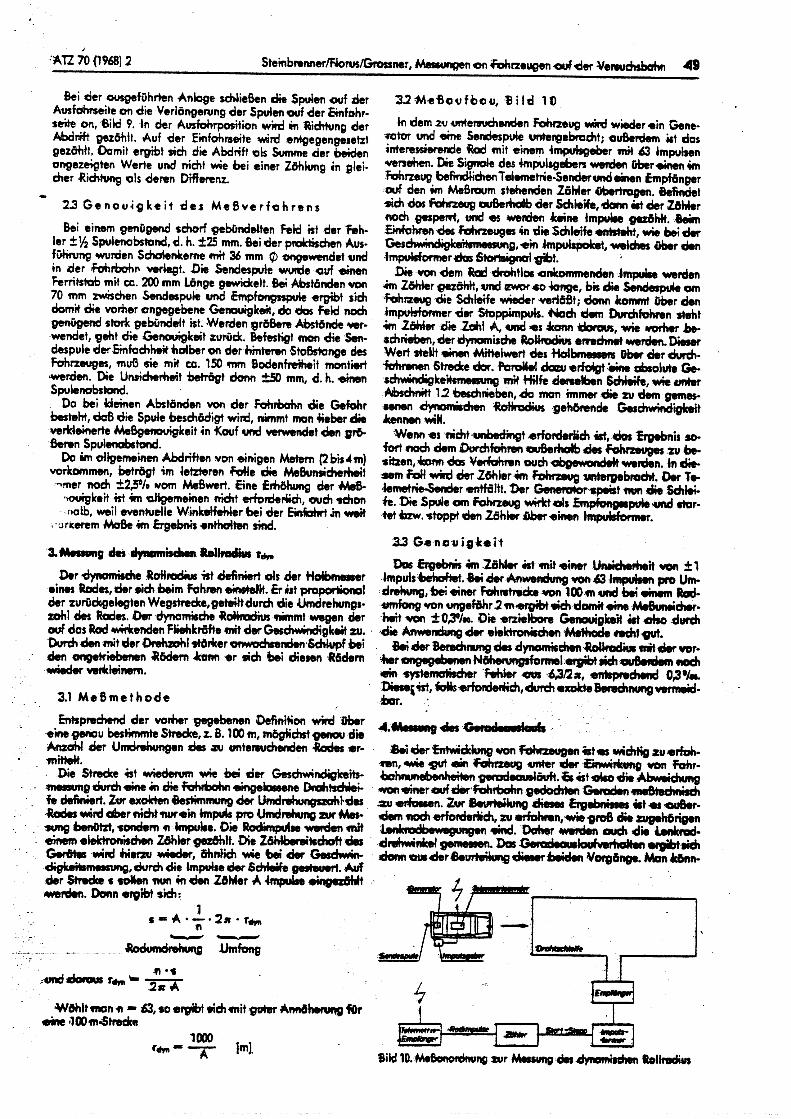
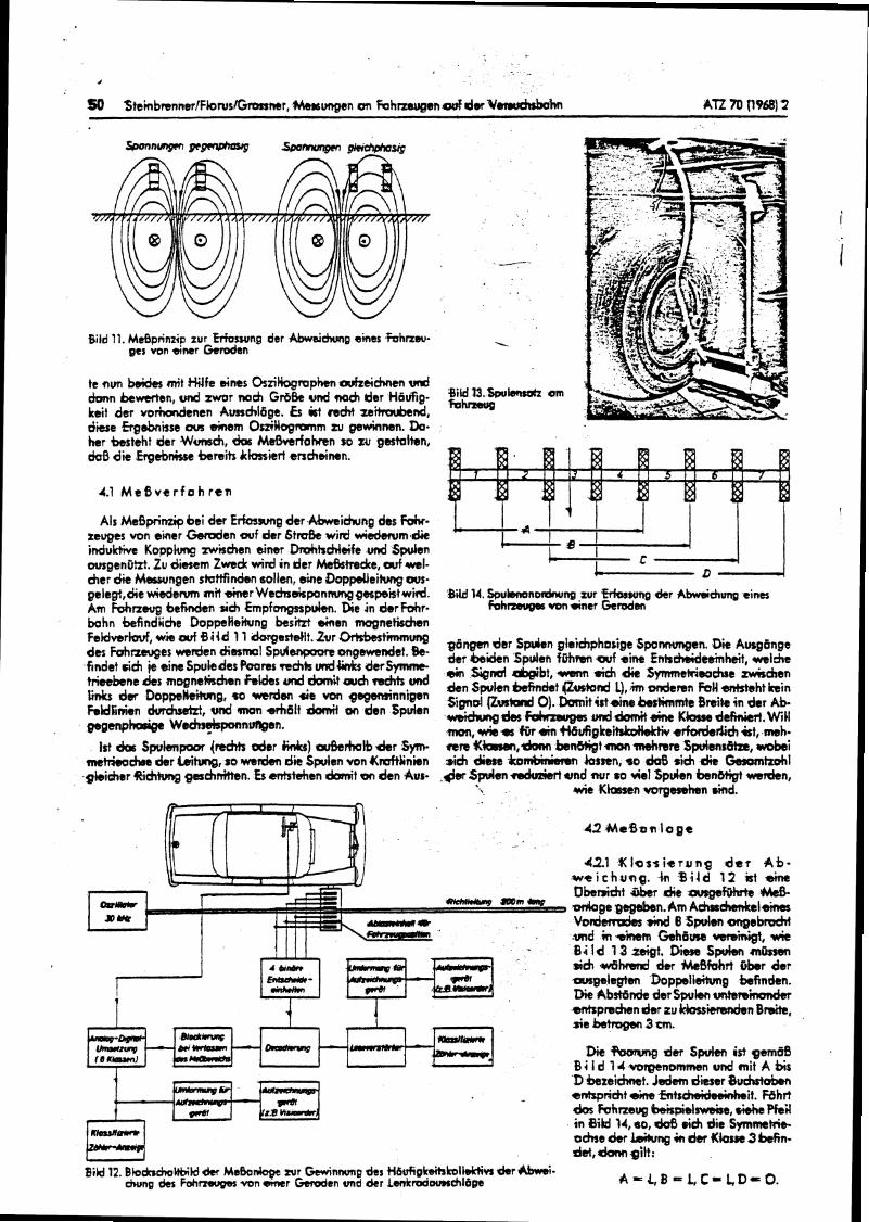
4-
Bild 11. Mtepnnzip zur ErFos~mg der Abwsidnrng sines hhrzw- 1 get von acntr Gemden
te nun be& mit M f e eines OsriHogrrrphcn avfruchen d h n &ewerten, d zwor mrh Gr6& wd meh ller H 6 d g g u z w - Om
keit dm vorhadenen AunddBge. b k t re& h t h u b ~ n d , d i Ergebnitse a n &em OsriNogrrmm ar gswhnen. Do. her besteht der W ~ e h , &IS MeDvtrfofKen so zu gestalten, rioO die Ergebnkst kre i ts klorriert anchdmn.
4.1 M e 8 v e r f o h r s n
Als McBprimip ki d w Erfcnsung der Abweidung des FotK. zevgts von einer M e n zwf der 6 t d e wird wisdsnrm dic indukfiw Kopplwg mischen einer DrohkcMeife und Spulen mgenPht. Zu diesem Zwedc wid i n der W t r e d t e , arf -1- h e r die Msrwngen sbttfindm sollen, eine DoppeUeihg ws- gelegt,die w iedem mk &nor Wectnskponmmg gmpeist w e d . Bild 14. Spukmonordnung zur frforwng dsr Abweichvng +ins Am fohneug btfKIclen sich h p f o n g s r p h . Die i n der M r . fohmetqas von aner G e d a bahn befindhehe DoppeHeihrng bes'hzi airren magnatkchen FeMmrMt w* ovfBi'd dorge*dlt'Zur mtimmung 86ngcn der S p h n gleiehphorige Spor#wngen. Dii Aucglnge des m ~ e s *Iden ' p v l ~ on~ewbde'. &- der &den Spu)en fhm -f *iM f nb&&dthh&+, findet dch @ eine Spuledrs f'uarer mchh u n d h derSymmc- ,i, 3ied eb,, - firt, A Symmehiwhe tri-kne mqnekchen hks rrnd dan'Ct und den Spulan hfmdet (&)and L), iim d e m n W enhteht b i n fik d e 9basminnigen Sigrid 0). mi+ir+sinr b h w e f)&k in drr & hldlmm cluhdzt, und man srhdlt tlomit on den Spvlen
-h Kbdafm#,,wll p g e n p h d p Wdn$sp~lnvngen. m, uu#-+s 4Or 4 n H6vfigkeitctcoHdrti doderii& k t , meh-
1st crks Spulsnpm {rachtt aler W ] ateshrt, dar Sym. -re X ~ , ~ knwt mon mehrsre SprrlentBtra, wok; m c t 6 m b der Csiiuq, so mndsn di Spulen von Umftiinkn && dims b-n hmn, so M sdch die Gammtzcrhl gkieher Ridltung geshrritten. Es enbtshm &nit on den Avt- & Spvlen +#kniert und rmr SO vie1 Spden h n w t d n ,
wie Ktanan votgesehen rind.
42 M e . 8 ~ n l e g t
42.1 % l a t s i t r r r n g de? Ab- weithung. 4;n % i l d 12 k t sinc Dberwi&t & e r die ang6f3h Me& d o g e gegahn.Am A&ssch6nkelh V o d d +ind 8 Sprlen mgebmchf und in ainem Goheuse vem'bigi, wie Bild 13 zeigt. Diem Spvkm m a sich dhzsrrl dar MaSfahit O k r der .ousgsle@m Boppeli&ung befindan. Die Ab*nk dot Spulsn tmbm'& ettispnchendw t u Gikrritrwdbn Bnsitc, r i e betrogbn 3 m.
Die der Spulfn ist gem68 0 i l d 14 voqenommen und mit A b i s D kzeiehmt. ldm dieter 8~dst&en enbpricht sins fsltrdmihidmit. Rh r t dos Fcrhne- B a i s p i e l ~ , d e Pfs'rl i n BiW 14, so, lcks i c h die Symwtetrie- ochre der bikrng in dm Kkrw 3 bch- d & , h gilt:
bikl12. BbktchoHtriM d+r Mshnlagt xur Cminnvng des tlbvflgk&tolLsHi~~ r k r -- hung des Foh- van c a r W e n und dcr lenlrmdounchlbge # + = L , B ~ l . , t - l . , f ) ~ O .
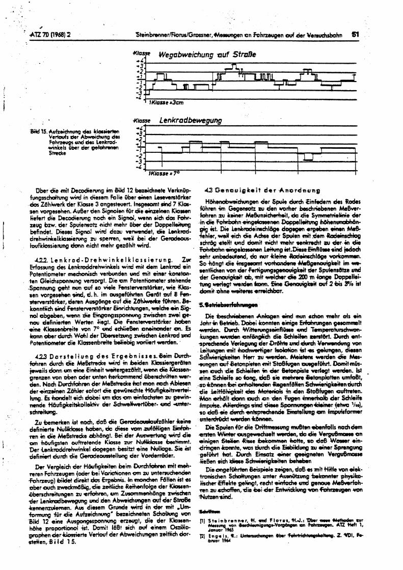
Ober d e mit D e d e n m g im &iM 12 bezbichnete Verknitp fvngrrchdtvng wird in diesern falie Cber einen ~ v e m t 6 r k e r da Zbhhverk der K k e 3 angesteuert. lnsgswmt rind 7 Klm- sen volrgtrh. A d e r dm Signden firr die s i n z e h e n Kbsm Refert die Decodie~ng noch ein Signd, wenn eich dos Fahr- raug bm. der Spvlenrotz aicht mehr I r k dcr Doppctlsitung bcfidet. D iem S i d wid doov wmsndet, die Lmkmd- dmhwinkelkbienwtg zu spewen, mid hi der Gemchous- tmdkkmienmg h n nicht mehr gezdMt wird.
42.2. Lenkrcd.DrehwinkeIklasiitrung. ZIM Moswng dts Lnkraddrehwiels wird mit dem b n k d sin Potentiometer rneh6nisch v e r b d e n wrd mit binor Conston. k n Glciehsponwng verrwgt. Die om Potentiometer stehenck -Sponnung gsht nwl avf ro viek Femtervcntbritar, nrie Xks. ten vorgesehm M, d. h. im o u s p M n h r 6 t ovf 8 Fsn- oterverrtbdcer, demn AusgCmge ouf die ZtMmdce fthren. b- kmn)ii& rind fsnskrvent6rker &~chlungen, welcht ain $ip d obgoben, wenn die wngaponslong rwirchtn zwbi gc. w u definieftm Wertsn )iegt. Qie Fsmtwmst(rrker habsn *'he Wosscbngnite von 7 O und rcMieBsn MIbinandtr em. b h abar du& W&l der DbvmttAmg I v J i t h n Lenkmd md PotenComcter die K l a n h m i h Webig d m r t wrden.
423 D a r s t e l l u n g d e s f r g e b n i s s e s . 8 e i m M - M m n du rh die Me&trsde Grd in beiden Kbrshgeriiten jweils dorm om +im Einheit wsitergez6Mt1 wmn die Ubsow grsnzen von d e n d e r unbn herkommerd h r r h r i t t e n w r . den. No& Burchfcrhm dtr k h & e k t man mch A b b n d s r d i e n %r rofort die pnSrmchte Mgk6ittvtr)si- hmg, b h d e l t rich dobei WII dm am &fo&m zu gowin- mnde t46ufigkaWdldc);Iv k r Schwe-r. ond -1-
sdtrdrturg.
Zu tnmerlrrn t t noch, do0 d i e GedaowbuhBhler Ce-he definierte N u b e Wen, da &ere vom a r f w e n M- .rm in die MsBstmdte dbh6-t. 86 der AWW&WQ wid die um hbvfigtten wfbetede Kbsse zvr N-re ht immt . Der .LenktPddrshwinkel ckgcgen h i k t eine Nolkge. Sic k t definisrt ch~rd~ die Gerode&dtung der V o r d d e r .
Dm Verglaich der ).lkmg&ten h i m Durchfdmn mit 4- nren ~ n e u g e n {oder lbti Vwidionen a n w vnte- -Fohnwg) direkt dm Erghms. h modten FdHm kt ar uber wch zwekmbBig,die zsitliche Rsihanfolge der K h a n - frben&rdingen tv srfohrwr, om Zmmsnh6nge zw)r&n der LeMbswsgvng vnd den A W u n g s n arf der 6- 4enntnrv)emsn. Am diesem G r d e wird i n dm mit ,Urn fonmmg f i ir die Aufzeihnmg' keiehneten Schcrl)ung vm Bikl 12 eine Ausgmpsponnung snsugt, die der Kbmen- h&he propohad kt. Domit 160t sich ouf ainem M o - pmphen der km ie r t e V e h f der Abwbiehmpn zeitbich &r- stcilen, 8 i Id 1 5.
iiliher#tmaidnmgen der Sprle durch €infedern As Robs Ghmn im Gegemtz mu den worhw hchr isbenm MeBver- fahren zu k e k r I b B u n D i M t t , ek die Symmtr4eLinie b r in die f ~ n ~ h ~ DagplMmg h&henm&Mn- gig kt. Die Lenkdeinsch46ge d o e m ergoban eirm Me& i e k , wsW sieh die AcCne der Spulen mit dem U d o i d d q sdw@ &Ht und h i t nidrt m h r senkndtt su &r in die rohrtrerhn 4 n ~ e W Lsikmg )rt.DbseEinRPrcsid . a h r unbbdeutsnd, do nur Irkm Wekwhl6ge vdwrnnm. 30 hdngt die h p m n i w r h h e Mm6gmouigkeit im w e wntiichen von der hrtigungsgmwigkdt der Spukns8tze ud dcr Genarigk.it 6, mit d d m r die 200 m Doppllei. t u n g ~ e g t ~ n d m 6 # m . 5 n e ~ l r s i t arf2bis 30h irt $anii ahne weitem stnidrbar.
Die b -n a n .ind rmn rhon m h r ds em Jahrin &+ti&. Dabei konnten ehige Eduhrungsn gesommlt d e n . D#ch W ~ ~ ~ f l k e urd fempemhmchwon- kungan w d e n ~nfhg l i ch die Schleif.n m. M ent- t m b n d e Verhuna der Sdhe und +krreh Y d g von - - Lsitungen wit h d w e d g e r W o n ist a -n, dimsn ~chb*ei ien Herr .u weden. Maintern warden die Mas- mngen wf Betapisten mit Stdfvgen v f D h r t . Domitmb- sen much ,die S&ldtfm in &r Betonpirte wdegt -don. 1st cine S&eife SO hq, daS sit rrwhrac htonpktten umfoet, - so4hw.n bei onhdbaden bgenf&Wm S d w h i g h b n d v r e h die IsMhigkdt des Muhkk m den Qtoefrrgbn dtretan. Man h 6 l t fknn arch e n den &men irmehdb drr Sehle'h
mkrCMKkt wwk4cbwmn. Die Spulen & die lhhnuwmg muetbn e&Mls nu& d m
arr)sn Whbr angevdmtt wden, do die Vbgr&nors on i n i gsn &den Rive bdtownen bh, so dd3 Warsr ,in- dringen ~ t e , wm d u d die M u n g tnr einer Spmngvng g e W W. Shrrch fimatr sinar geeignrrtsn YwguB- ) i ek sich h e Schwiajgkeiin b a t d m
D i e o n g e W Beispi& zeigen, doBsr mit Hilk von Jek- tronisdwn S-en unter Avuthrmg hkvnnier physik~. fidw Eflekte ge);ngt, 4 t a'kderh ond g e m Mskrfoh. m n ru d d h m , die h i der fntwickhg va, hhmupn van S1utZm8ind.
-trkrilcm
111 5teinbrwnn*r, H. @ f l o r u t , S I J . ~ wr Ahsung, von M L . V ~ ( O ~ I - V O I O Q P I I ~ on Fob- );n M 1, Jawr 965
121 En91 I s , It.: 4 h w w h m p B k r V H n p . Z -1, h- &NOI 1964

APPENDIX G

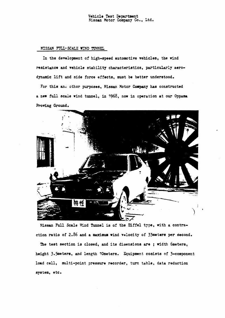
Vehicle Test hpa r t a en t Nissan Motor Company Cob, Ltdb
HISSAN FIJLL-SCALE UIND T[TNNEL
fa the development of high-speed automotive vehicles, the rind
resietance and vehicle s t a b i l i t y character is t ics , particulaFly aero-
dynamic l i f t and side force effects , m a t be bet ter understood.
For t h i s a n u othor purposes, Nissan Motor Coorpany has constructed
a new f u l l scale r ind tunnel, i n 1968, now in operation at our Oppam
ProrLag Ground.
Niasrn FLll Scale Wind Tunnel is of the E i l f e l t j ~ , with a contra-
ction r a t i o of 2,86 and a maJdrmrn r i n d velocity of 3 3 e t e r s per second.
'5e t e s t section is closed, and it8 dimensions a r e ; width bmetera,
height 3.5neter8, and length 10metera. Quipmnt cos i s t s of Fcomponent
load c e l l , multi-point pressure recorder, turn table , data reduction
system, etc.
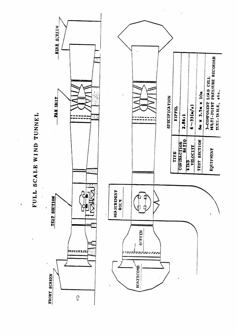
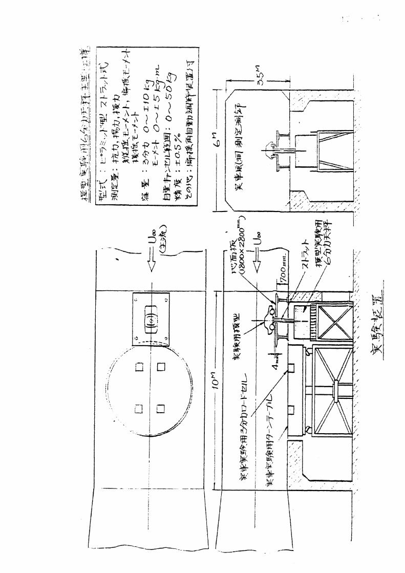


APPENDIX H

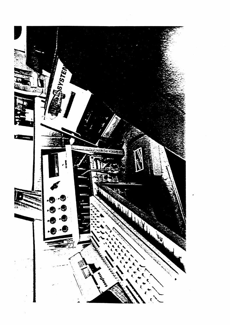
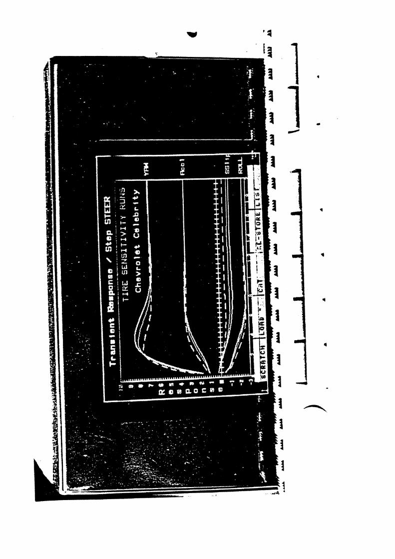
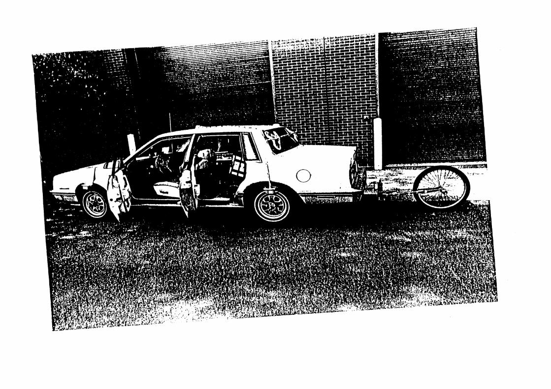
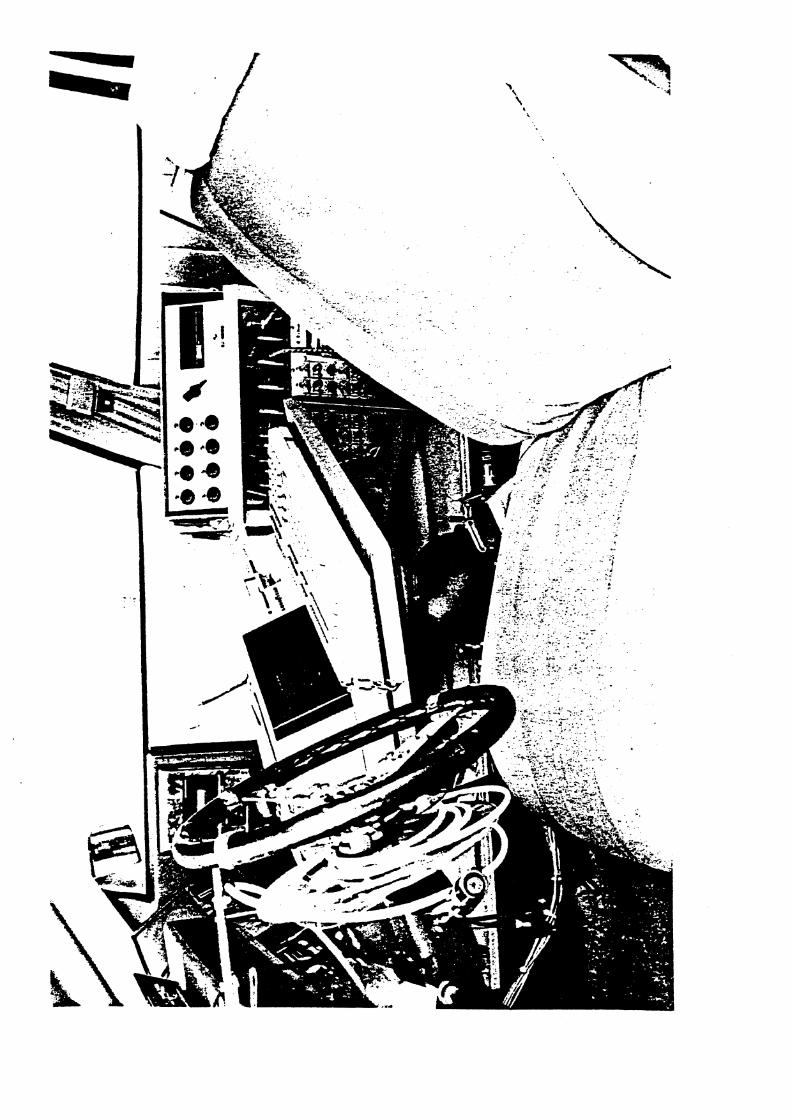

APPENDIX I

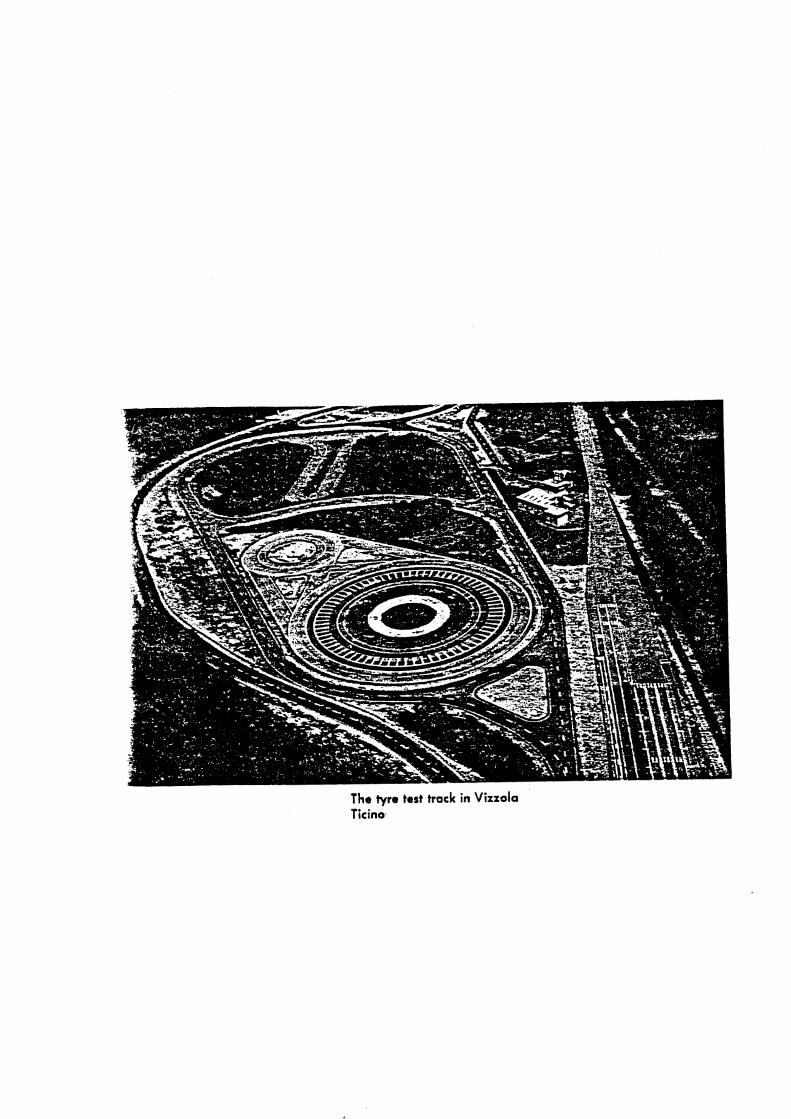
The tyro test track in Vizzola Ticino,


APPENDIX J

THE DUNLOP TYRE DYNAMICS MACHINE
D. J . Osborne
Dunlop Limited, U.K.
1 . Introduct ion
During the last decade, increasing emphasis has been placed upon vehicle s a f e t y by both the t y r e and vehicle manufacturer,
The t y r e s play an important r o l e from the poin t of view of wet and dry g r i p performance, cont ro l under def la ted condit ions, and high speed s t a b i l i t y and responee, The t y r e designer is cont inual ly optimising the t y r e construct ion i n an endeavour t o s a t i s f y these
. cons t r a in t s . In the case of vehicle handling, t he designer must first determine the c r i t i c a l components before such modifications can be made.
On the o the r hand, t he vehicle manufacturer, while not being concerned about the basic t y r e mechanics, demands performance c h a r a c t e r i s t i c s of t y r e s f o r use i n mathematical models of vehic le and suspensions. These models were o r i g i n a l l y based upon steady- s t a t e t y r e da t a , which proved adequate f o r models r e l a t i n g t o normal dr iving condit ions involving low frequency manoeuvres, However, f o r the study of events a r i s i n g from rapid wheel movements, as i n the case of shimmy o r accident avoidance s i t u a t i o n s , it is necessary t o account f o r the t r a n s i e n t c h a r a c t e r i s t i c s of t y r e s ,
To provide information of t h i s type, the Dunlop Tyre Dynamics Machine has been developed. This equipment p e d t a fou r independent t r a n s i e n t motions t o be appl ied t o the t y r e , namely v e r t i c a l end l a t e r a l displacements, together with s t e e r and camber ro t a t ions . Potentiometers which record the instantaneous wheel pos i t i on , and a strain-gauged force transducer ~ y s t e m , enable t h e r e s u l t i n g s i x components of t y r e force and moments t o be evaluated a t the contac t patch as a function of wheel o r i en t a t ion and time.
2. Description of Machine
2.1. Frameworks
The Tyre Dynamics Machine comprises a l a rge diameter smooth c a s t i ron drum upon which r o l l s a tyre/wheel assembly supported by moveable frames. The frames are th ree interconnected s t r u c t u r e s shown schematically i n Figure 1. The wheel hub is supported by t h e s i x strain-gauged l i n k s mounted i n a cube arrangement. Such a system allows the forces i n the l i n k s t o be resolved i n t o t h r e e forces and three moments with respec t t o mutually perpendicular axes. The "cubeM is at tached by means of l i n e a r bearings t o the s t e e r ( s l i p ) angle framework, This allows the wheel axle t o be moved v e r t i c a l l y r e l a t i v e t o the s l i p angle frame thus giv ing v a r i a t i o n i n u l e he ight and t y r e load.

-2-
VERTICAL MOTION
L SIDE MOTION .I ACTUATOR
CUBE OF FORCES CAMBER AXIS
bSUP ANGLE 4IIYa
\
CAMBER DRUM SURFACE SPEED I\ I ACTUATOR
DRUM CIRCUMFERENCE 7.50 M DRUM DIAMETER 2.39 M
CONFIGURATION OF DUNLOP TYRE DYNmICS MACHINE
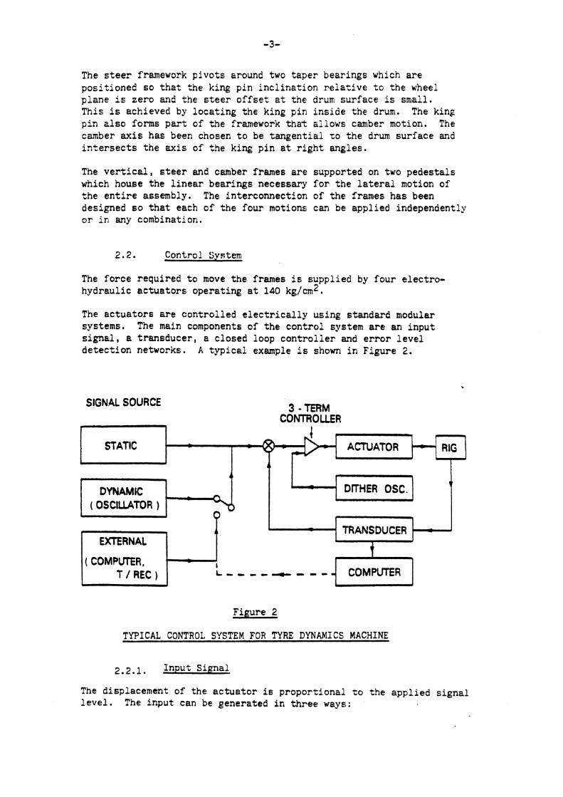
The s t e e r framework p i v o t s around two t a p e r bear ings which a r e p o s i t i o n e d s o t h a t tne king p i n i n c l i n a t i o n r e l a t i v e t o t h e wheel p lane i s z e r o and t h e s t e e r o f f s e t a t t h e drum s u r f a c e is small. This i s achieved by l o c a t i n g t h e king p in i n s i d e t h e drum. The king p i n z l s o forms p a r t of t h e framework t h a t a l lows camber motion. The camber a x i s has been chosen t o be t a n g e n t i a l TO t h e drum s u r f a c e and i n t e r s e c t s t h e a x i s of t h e king p i n a t r i g h t ang les .
The v e r t i c e l , s t e e r and camber frames a r e supported on two p e d e s t a l s which house t h e l i n e a r bear ings necessary f o r t h e l a t e r a l motion of t h e e n t i r e assembly, The in te rconnec t ion of t h e frames h a s been designed s o t h a t each o f t h e f o u r motions can be app l ied independently o r i n any combination.
2.2. Control System
The f o r c e requ i red t o move t h e frames i s supp l ied by f o u r e l e c t r o - h y d r a u l i c a c t u a t o r s opera t ing a t 140 kg/cm2.
The a c t u a t o r s a r e c o n t r o l l e d e l e c t r i c a l l y us ing s tandard modular systems. The main components of t h e c o n t r o l system a r e an i n p u t s i g n a l , a t r a n s d u c e r , a c losed loop c o n t r o l l e r and e r r o r l e v e l d e t e c t i o n networks. A t y p i c a l example i s shown i n Figure 2.
SIGNAL SOURCE 3 - TERM COrnOLLER
1 . STATIC ACTU AT0 R
DITHER OSC. - I 1 I TRANSDUCER -
t
T / REC )
Figure 2
TYPICAL CONTROL SYSTEM FOR TYRE DYNAMICS MACHINE
2.2.1, I n p u t S igna l
The displacement of t h e a c t u a t o r is p r o p o r t i o n a l t o t h e a p p l i e d s i g n a l l e v e l . The i n p u t can be genera ted i n t h r e e ways:
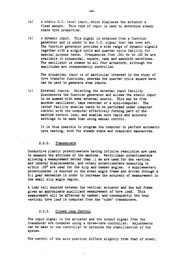
( a ) A s t a t i c D . C . l eve l input , which d isp laces the ac tua to r a f ixed amount. This type of input is used t o determine steady s t a t e t y r e proper t ies .
(b) A dynamic input . This s igna l i s obtained from a funct ion generator and i s added t o any D . C . s igna l t h a t has been s e t . The funct ion generator provides a wide range of dynamic s igna l s together with a s i n g l e cycle and quar te r cycle f a c i l i t y f o r spec i a l purpose t e s t s . Frequencies from .001 Hz t o 100 Hz a r e ava i l ab l e i n s inusoida l , square, ramp and sawtooth waveforms. The o s c i l l a t o r i s common t o a l l four ac tua to r s , although the amplitudes a r e independently cont ro l led .
The s inusoide l input is of p a r t i c u l a r i n t e r e s t i n the study of t y r e t r a n s f e r func t ions , whereas the quar te r cyc le square wave can be used t o generate s t e p inputs .
( c ) External inputs . Selecting; the ex terna l input f a c i l i t y disconnects the funct ion generator and allows the s t a t i c input t o be summed with some ex te rna l source. This may be from another o s c i l l a t o r , tape recorder o r a mini-computer. The l a t t e r f a c i l i t y enables t e s t s t o be performed under computer cont ro l with the computer e f f e c t i v e l y forming p a r t of t he machine cont ro l loop, and enables more rapid and accurate s e t t i n g s t o be made than using manual con t ro l .
I t is thus possible t o program the computer t o perform automatic tyre t e s t i n g , both f o r steady s t a t e and t r a n s i e n t manoeuvres.
Transducers
Conductive p l a s t i c potentiometers having i n f i n i t e r e s o l u t i o n a r e used t o measure the a t t i t u d e of t h e machine. Rec t i l i nea r potentiometers allowing a measurement b e t t e r than .1 mm a r e used f o r the v e r t i c a l and l a t e r a l displacements, and r o t a r y potent iometers measuring t o within .05O a r e used fo r the s l i p and camber angles . A supplementary potentiometer is mounted on the s t e e r angle frame and dr iven through a 5 : l gear mechanism i n order t o increase t h e accuracy of measurement i n the small s l i p angle region.
A load c e l l mounted between the v e r t i c a l ac tua to r and t h e hub frame g ives an approximate a u x i l l i a r y measurement of t y r e load. This measurement w i l l be a f fec ted by camber, and consequently t h e t r u e v e r t i c a l t y r e load is computed from the "cube" t ransducers .
Closed Loop Control
The input s igna l t o the a c t u a t o r and t h e output s i g n a l from the transducer a r e compared using a three-term c o n t r o l l e r . Adjustments can be made t o the c o n t r o l l e r t o opt imise the s t a b i l i s a t i o n o f t he system.
The cont ro l of t he ax le pos i t i on d i f f e r s s l i g h t l y from t h a t of s t e e r ,
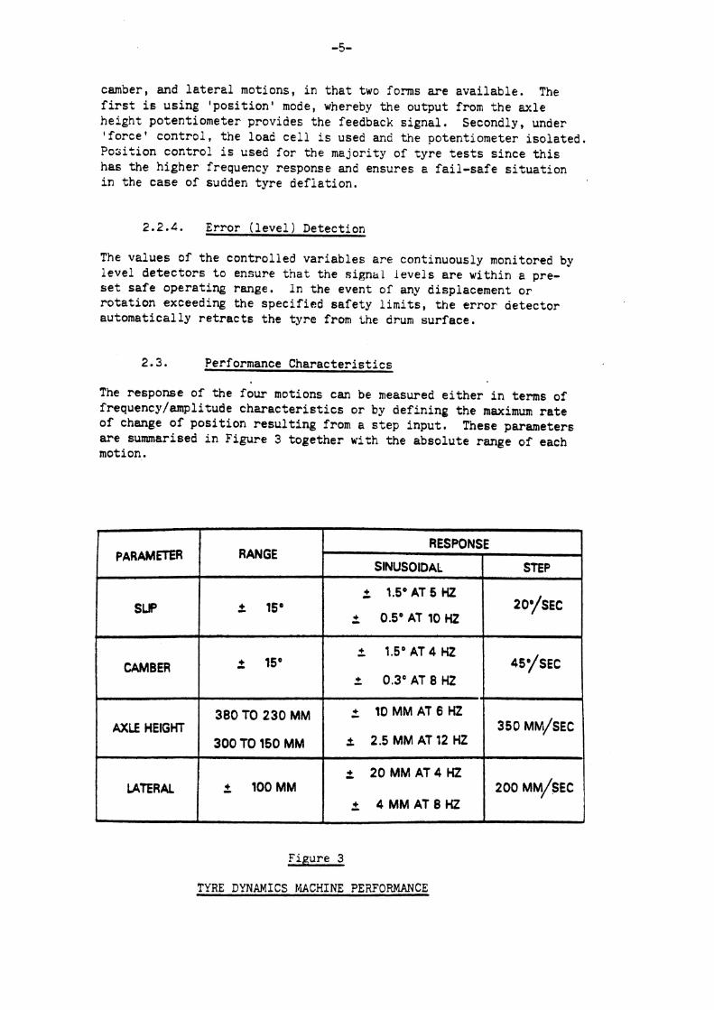
camber, and l a t e r a l motions, i n t h a t two forms a r e a v a i l a b l e . The first is u s i n g ' p o s i t i o n ' mode, whereby t h e ou tpu t from t h e a x l e h e i g h t po ten t iomete r provides t h e feedback s i g n a l . Secondly, under ' f o r c e ' c o n t r o l , t h e load c e l l i s used and the potent iometer i s o l a t e d . P o s i t i o n c o n t r o l i s used f o r t h e major i ty of t y r e t e s t s s i n c e t h i s has t h e h i g h e r frequency response and ensures e f a i l - s a f e s i t u a t i o n i n t h e c a s e of sudden t y r e d e f i a t i o n .
E r r o r ( l e v e l ) Detect ion
The v a l u e s of t h e c o n t r o l l e d v a r i a b l e s are cont inuously monitored by l e v e l d e t e c t o r s t o ensure t h a t t h e ~ i g n a l i e v e l s a r e wi th in a pre- s e t s a f e o p e r a t i n g range. I n t h e event of any displacement o r r o t a t i o n exceeding t h e s p e c i f i e d s a f e t y limits, t h e e r r o r d e t e c t o r a u t o m a t i c a l l y r e t r a c t s t h e t y r e from the drum s u r f a c e .
2.3. Performance C h a r a c t e r i s t i c s
The response of t h e four motions can be measured e i t h e r i n terms of frequency/emplitude c h a r a c t e r i s t i c s o r by def in ing t h e maximum r a t e o f change of p o s i t i o n r e s u l t i n g from a s t e p i n p u t . These parameters a r e sumrnarised i n F igure 3 t o g e t h e r with t h e a b s o l u t e range o f each motion.
Figure 3
TYRE DYNAMICS fh'+CFINE PE2FORMANCE
RANGE
2 I S 0
2 15'
380 TO 230 MM
300 TO 150 MM
2 IOOMM
1
\
PAR AM^ .
SUP
. CAMBER
AXLE HEIGHT
LATERAL
. RESPONSE
SlNUSOlDAL
2 1.5'AT 5 HZ
0.5°AT10Ht
2 1.5OAT4 HZ
2 0,3' AT 8 HZ
+ 10MMAT6HZ - + 2.5MMAT12Hf
2 20 MM AT4 Ht
+ 4 M M A T 8 H Z -
STEP
2oysac
*~./sEc
350 MM/SEC
200 MM/SEC
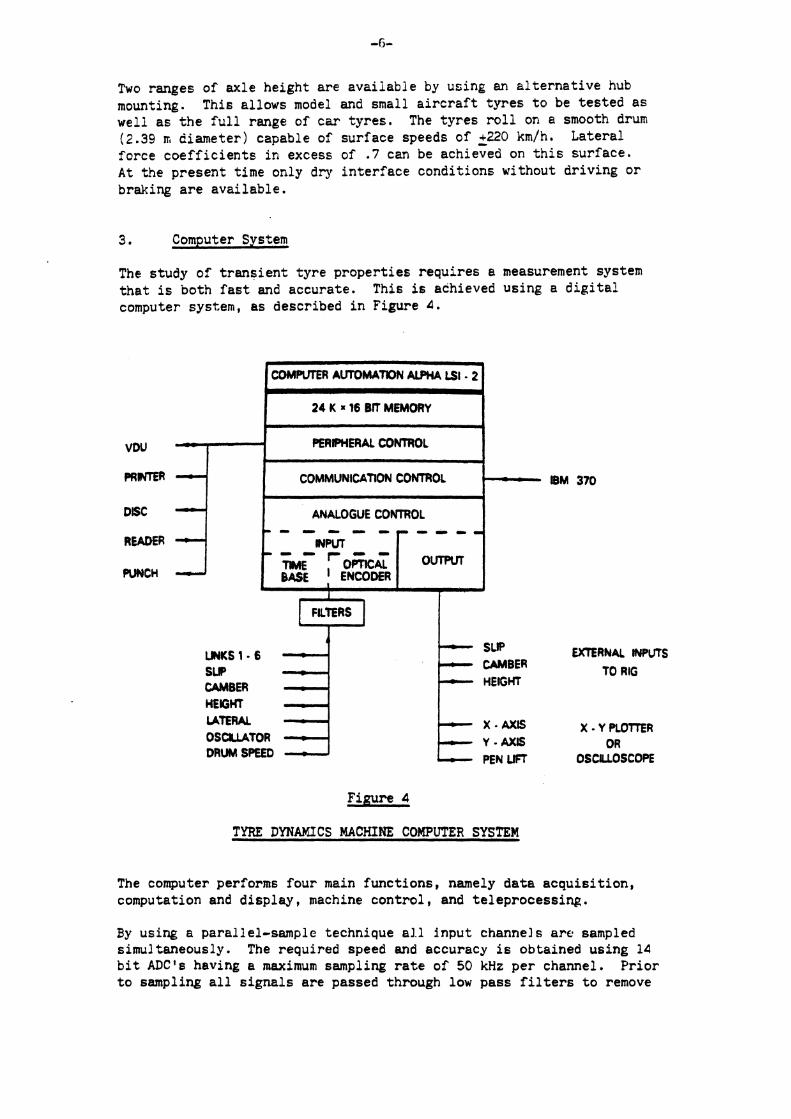
Two ranges of axle height a r e ava i lab le by using an a l t e r n a t i v e hub mounting. This allows model and small a i r c r a f t t y r e s t o be t e s t ed a s well a s t h e f u l l range of car t y re s . The t y r e s r o l l on a smooth drum (2.39 IT, diameter) capable of surface speeds of ~ 2 2 0 km/h. Lateral force c o e f f i c i e n t s i n excess of . 7 can be achieved on t h i s sur face , A t t!!e present time only dry in t e r f ace condit ions without dr iv ing o r braking a r e ava i lab le .
3. Computer System
The study of t r ans i en t t y re proper t ies requi res a measurement system t h a t is both f a s t and accurate. This is achieved using a d i g i t a l computer system, a s described i n Figure 4 .
DISC
READER
PUNCH
IBM 370
4
C O M R m R AUTOMATON ALPHA LSI 2 T I
24 K R 16 BK MEMORY I
PERRWERAL CONTROL I - COMMUNICATION CONTROL
EXTERNAL INPUTS
TO RIG
- -
X.YPLOlTER OR
OSCILLOSCOPE
Figure 4
L
ANALOGUE CONTROL - - - I.. - p - . r - -
TYRE DYNAMICS MACHINE COMPUTER SYSTEM
- - a HWT
0 0
TME r ~ m ~ ~ BASE I ENCODER
The computer performs four main func t ions , namely d a t a acqu i s i t i on , computation and d i sp l ay , machine con t ro l , and te leprocess ing .
wwr
1
UNKS 1 . 6 SUP CAMBER HEIGHT LATERAL O S U T O R DRUM SPEED
By using a parallel-sample technique a l l input channels are sampled simultaneously. The required speed and accuracy i s obtained using 14 b i t A D C ' s having a maximum sampling r a t e of 50 kHz per channel. P r io r t o sampling a l l s igna l s a r e passed through low pass f i l t e r s t o remove
- SUP CAMBER HEIGHT
- X . AXIS - Y - A X I S PEN UCT
high frequency no i se . The a c t u a l sampling r a t e can e i t h e r be c o n t r o l l e d by e clock t o g ive se lec2ab le f requencies i n t h e range 1 t o 5000 Hz over a l l channels o r , a l t e r n a t i v e l y , measurements can be made a t equi-spaced p o s i t i o n s around t h e r o t a t i n g t y r e i n t h e range 1 t o 512 samples pel r e v o l u t i o n , The l a t t e r f a c i l i t y i s achieved us ing an opticz! encoder mounted on t h e wheel a x l e . This dual sampling method g i v e s s convenient way of s tudying e i t h e r t ime o r d i s t a n c e dependent phenomena.
The raw d a t a is s t o r e d i n memory u n t i l a l l t h e requ i red samples have been obta ined. The computer then performs t h e necessary s c a l i n g , t r ans format ion o f axes , and c o r r e c t i o n s a r i s i n g from c a l i b r a t i o n , s o zs t o o b t a i n t h e t h r e e f o r c e s and moments a c t i n g a t t h e c o n t a c t pa tch , according t o t h e S . A . E . s i g n convention. The c a l i b r a t i o n of t h e machine was obtained by applying known s t a t i c f o r c e s and moments and c a l c u l a t i n g e r r o r s due t o cross-coupling. This g e n e r a t e s a 6 x 6 matr ix o f c o r r e c t i o n cons tan t s which is approximately a u n i t matrix.
The computed values can then be displayed on a number o f ou tpu t devices . Tne mini-computer i s l inked t o an IBM 370, which handles long- term d a t a s t o r a g e , t o g e t h e r with more complex d a t a process ing such a s smoothing and automatic g raph ica l ou tpu t .
A s u i t e o f programs a r e a v a i l a b l e t o perform a wide v a r i e t y of t e s t s . These inc lude s teady s t a t e a n a l y s i s , impulse and s i n u s o i d a l frequency response, and s imula t ion of wheel motions t o reproduce in-service cond i t ions . A l l programs a r e w r i t t e n i n e i t h e r Assembler o r For t ran and can be r e a d i l y modified t o incorpora te any s p e c i f i c t e s t requirements.
4. Tyre T e s t i n g
M ~ t h e m a t i c a l models r e l a t i n g t o some a s p e c t s o f t r a n s i e n t t y r e p r o p e r t i e s have been developed by a number o f a u t h o r s . I n p a r t i c u l a r , Pacejka ( I ) , and Segel ( 2 ) have given s o l u t i o n s f o r t h e s t e e r response of t y r e s based upon the analogy of a s t r e t c h e d s t r i n g on an e l a s t i c foundat ion, corresponding t o the t r e a d and c a r c a s s reg ions r e s p e c t i v e l y . The Tyre Dynamics Machine p rov ides a p r a c t i c a l means of eva lua t ing t h e v a l i d i t y o f such t h e o r i e s . Of p a r t i c u l a r i n t e r e s t . a r e t h e genera t ion of t y r e f o r c e s a s s o c i a t e d wi th a s t e p inpu t of s t e e r ang le , as a r i s e s dur ing emergency banoeuvres, and secondly t h e more genera l frequency response c h a r a c t e r i s t i c s o f t h e t y r e expressed as an amplitude and phase r e l a t i o n s h i p t o t h e a p p l i e d motions.
4 .1 . Response t o a Step I n p u t
When t h e t y r e is sub jec ted t o a s t e p change o f s t e e r a n g l e , t h e l a t e r a l f o r c e generated by t h e t y r e r o l l s a f i n i t e d i s t a n c e before a t t a i n i n g a new s teady s t a t e cond i t ion . The mathematical model d i f f e r e n t i a t e s between two reg ions , When t h e d i s t a n c e r o l l e d i s l e s s than t h e con tac t l e n g t h , t h e build-up of l a t e r a l f o r c e is propor t iona l t o t h e d i s t a n c e t r a v e l l e d , and beyond t h i s r e g i o n t h e curve becomes exponent ia l -
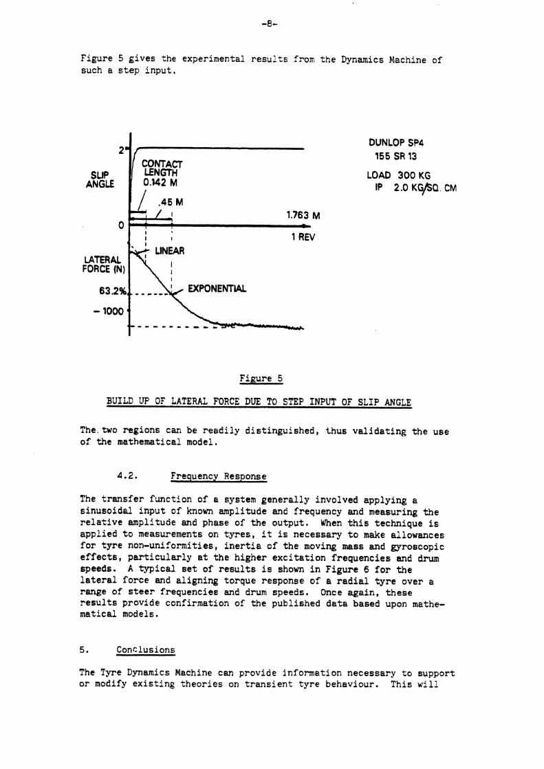
Figure 5 g ives the experimental r e s u l t s from the Dynamics Machine of such a s t e p inpu t ,
CONTACT
ANGLE 0.142 M
DUNLOP SP4 155 SR 13
LOAD 300 KG IP 2.0 K ~ Q , CM
I r I 1 REV
FORCE (N)
63.2% , , , , , , EXPONENTIAL
Figure 5
BUILD UP OF LATERAL FORCE DUE TO STEP INPUT OF SLIP ANGLE
The,two regions can be r ead i ly d is t inguished , thus va l ida t ing the use of the mathematical model.
4.2. Frequency Response
The t r a n s f e r function of a system genera l ly involved applying a s inusoidal input of known amplitude and frequency and measuring t h e r e l a t i v e amplitude and phase of t he output . When t h i s technique is appl ied t o measurements on t y r e s , it i s necessary t o make allowances f o r t y r e non-uniformities, i n e r t i a of t he moving mass and gyroscopic e f f e c t s , p a r t i c u l a r l y a t t he higher e x c i t a t i o n frequencies and drum speeds. A t y p i c a l s e t of r e s u l t s i s shown i n Figure 6 f o r t h e l a t e r a l force and a l ign ing torque response of a r a d i a l t y r e over a range of s t e e r frequencies and drum speeds. Once again, t hese r e s u l t s provide confirmation of the published da t a based upon mathe- matical models.
5. Conclusions
The Tyre Dynamics Machine can provide information necessary t o support o r modify ex i s t i ng theo r i e s on t r a n s i e n t t y r e behaviour. This w i l l
enable vehicle designers to make more realistic representations of tyres in future development studies.
Tyre Research and Development is based upon quantifying the effect of small differences in design.
Historically, this work has been largely empirical, but with the advent of test machines of the type described, future advances will be possible by detailed analysis of the tyre components and the part each plays in the generation of tyre forces.
References
(1) Pacejka H. B. Analysis of the dynamic response of a rolling string-type tyre model to lateral wheel-plane vibrations. Vehicle System Dynamics (1972).
( 2 ) Segel L. Force and moment response of pneumatic tyres to lateral motion inputs. Journal of Engineering for Industry (1965).
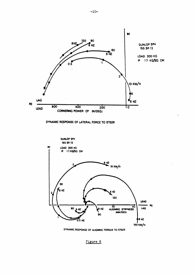
I
LEAD 600 400 200 10
CORNERHG POWER CP (NIDEG)
DYNAMC RESPONSE OF UTERAL FORCE TO STEER
IM LOAD 300 KG
R 1.7 Kli/SQ CM
rso KM/H
DYNAMIC RESPONSE OF ALIGNING TOROUE TO STEER
Fipure 6

APPENDIX K

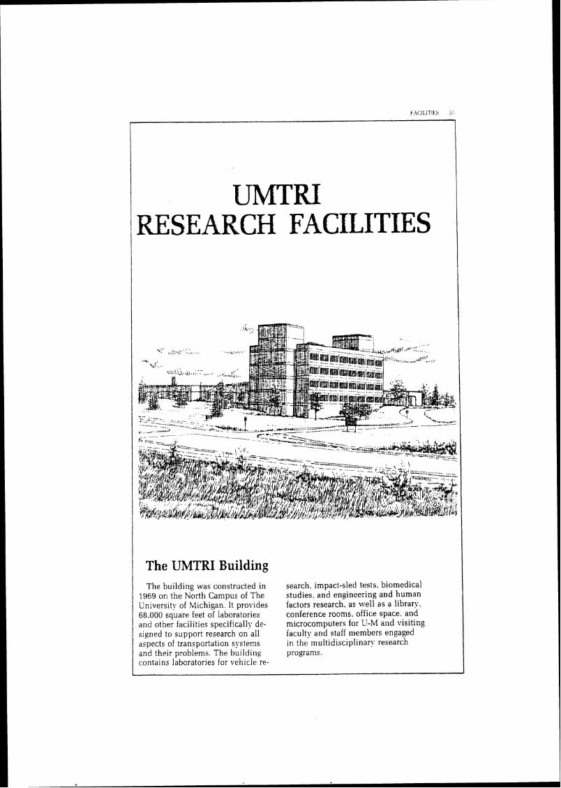
UMTRI 1 RESEARCH FACILITIES
1 The UMTRI Building The building was constructed in
1969 on the North Campus of The University of Michigan. It provides 68.000 square feet of laboratories and other facilities specifically de- signed to support research on all aspects of transportation systems and their problems. The building contains laboratories for vehicle re-
search, impact-sled tests, biomedical studies, and engineering and human factors research, as well as a library. conference rooms, office space. and microcomputers for U-M and visiting faculty and staff nlenlbers engaged in the multidisciplinary research programs.
The UMTRI Library This facility provides a specialized
inforn~ation service for the institute staff and other members of the trans- portation research community. Its collection includes more than 57.000 cataloged documents and more than 225 periodical titles. The subject areas of the collection reflect the many different ways in rrhich transportation problems can be ap- proached, with materials drawn from the literature of engineering, physics.
medicine, public health, laiz. eco- nomics, psycholog!.. sociology, sta- tistics, computer science, and other fields. The library concentrates on obtaining the most current iriforma- tion on transportation problems and making it readil~z accessible to the research staff. The library also em- ploys its unique classified subject file to conduct retrospective litera- ture searches. and it provides UMTRl staff with access to all other University of Michigan library resources.
motorc\rcle tire dvnamometer for
Computing Equipment ULITRI maintains a variety of ter-
minals for read!: access to the Uni- versity's ,4hIDd4HL 5860 computer. Microcon~puters at the Institute in- clude Apples. IBM PC's, and Zenith Z-100's for data processing and ivord processing. A Data General Eclipse S,'250 computer is employed in the
on-l ine 'cal~ulat i~ns and automatic control of its test procedures. .4lso. small and portable digital systems have been developed for use in ex- periments requiring automated data acquisition and programmed test procedures. These small computer systems are typically employed in tests conducted at vehicle proving grounds.
The data sets can also be accessed Automated Data by OSIRIS. SPSS, or MIDAS, SO that
more sophisticated analytic opera- Access and tions may be performed. System The system is largely self-
documentary and self-describing. The UhlTRl Automated Data Ac- so that novice users can quickly be-
cess and Analysis System (ADAAS) come familiar with its operations. is an integrated set of computer pro- Because the system offers a simple grams used to access, manipulate, technique for using accident data in and analyze more than 350 accident- important safety-related research related data sets maintained by questions and decisions, i t is em- UMTRI. The system is resident ployed about 35 times a day by gov- on the University of Michigan's ernment, industry, and university AhlDAHL 5860 computer. and may researchers in the U.S. and Canada. be operated in either batch or con- Current users include persons in the versational mode through remote NHTSA, the Canadian Ministry of terminals, via a telephone line. Transport, the Michigan Department
Data access is provided by a key- of State, the Missouri Highway Pa- word unique to each data set. All trol, member companies of the Motor physical file manipulations (for ex- Vehicle Manufacturers Association. ample. uses of magnetic tapes) are and staff members in several uni- performed by the system. Six simple versities and private research data manipulationianalysis opera- organizations. tions are provided to, handle most preliminar! data search functions.

Mobile Truck Tire-Brake Tester
Constructed by UMTRI under hII'h1.4 sponsorship, this over-the- road apparatus is a six-axle, 36-ton tractor-semitrailer specially designed and instrumented to measure the longitudinal and lateral shear-force properties of truck tires under realis- tic braking and cornering conditions on all types of roadway surfaces, un- der various loads. at velocities up to 70 mph. Test tires are mounted on test stations located on both the trac- tor and the semitrailer. The braking and cornering behavior of the test tire is measured with the aid of load cells and recorded at an onboard op- erator's module. The mobile system carries its own hydraulic. pneuma- tic, and electrical power services. and also pro\~ides a water.-delivery capability for tests on wet roadwa!ls.
The Mobile Tire-Brake Tester is also used as a dynamometer for measuring the torque characteristics of commercial vehicle brakes. The load cell that measures longitudinal force also measures the torque pro- duced by the brake installed on the test wheel located on the semitrailer
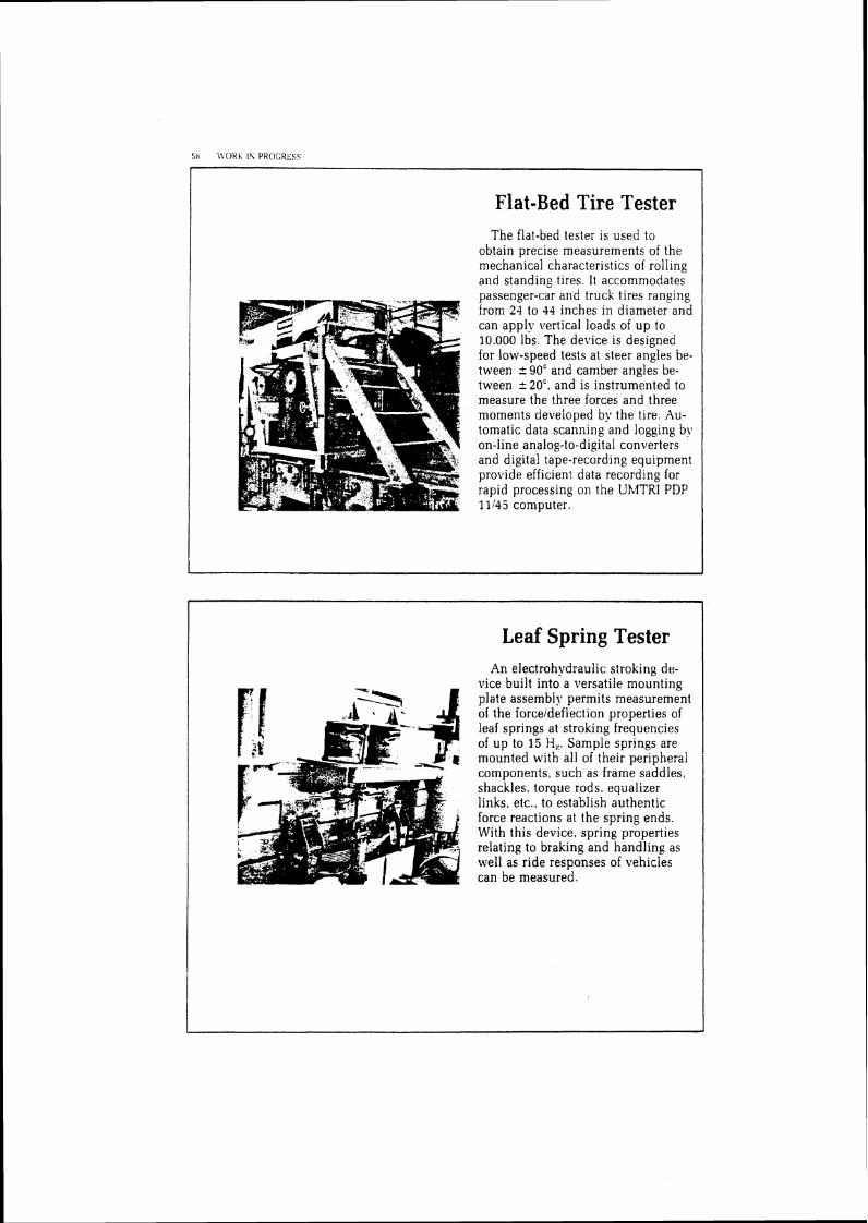
Flat-Bed Tire Tester The flat-bed tester is used to
obtain precise measurements of the mechanical characteristics of roiling and standing tires. It accommodates - passenger-car and truck tires ranging from 24 to 44 inches in diameter and can apply vertical loads of up to 10,000 Ibs. The device is designed for low-speed tests at steer angles be- tween -c W a n d camber angles be- tween i 20'. and is instrumented to measure the three forces and three moments developed by the tire. Au- tomatic data scanning and logging by on-line analog-to-digital converters and digital tape-recording equipment provide efficient data recording for rapid processing on the UMTRI PDP 11/45 computer.
Leaf Spring Tester An electrohydraulic stroking de-
vice built into a versatile mounting plate assembly permits measurement of the forceldeflection properties of leaf springs at stroking frequencies of up to 15 H,. Sample springs are mounted with all of their peripheral components, such as frame saddles, shackles. torque rods, equalizer links, etc.. to establish authentic force reactions at the spring ends. With this device, spring properties relating to braking and handling as well as ride responses of vehicles can be measured.
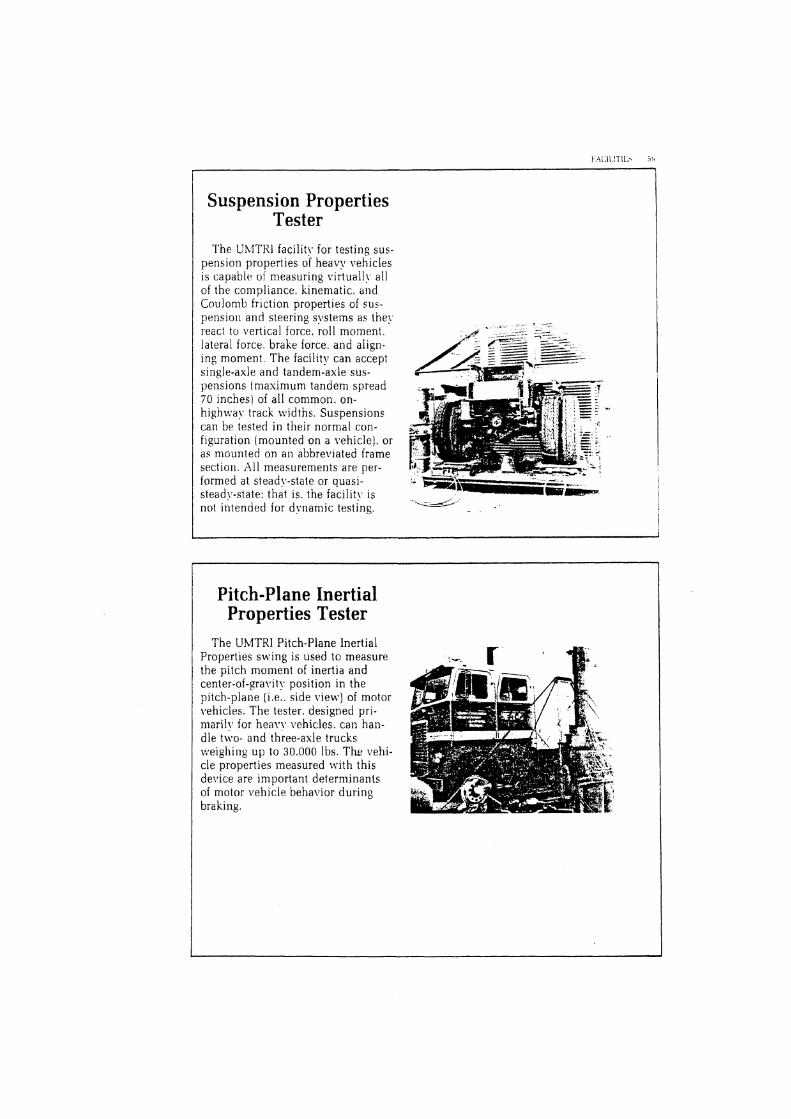
Suspension Properties Tester
The UhtTRI facility for testing sus- pension properties of heavy vehicles is capable of measuring virtually all of the compljance, kinematic. and Coulomb friction properties of sus - pension and steering systems as the! react to \ ~ e r t ~ c a l force, roll moment. lateral force. brake force, and aiign- ing moment. The facility can accept single-axle and tandem-axle sus- pensions [maximum tandem spread 70 inches) of all common, on- highway track widths. Suspensions can be tested in their normal con- figuration [mounted on a vehicle), or as mounted on an abbreviated frame section. All measurements are per- formed at steady-state or quasi- stead!,-state: that is. the facilit!. is not intended for dynamic testing.
Pitch-Plane Inertial Properties Tester
The UhlTRI Pitch-Plane Inertial Properties swing is used to measure the pitch moment of inertia and center-of-gravity position in the pitch-plane (i .e. . side view) of motor \~ehicles. The tester, designed pri- n~ar i ly for heal,! vehicles. can han- dle two- and three-axle trucks weighing u p to 30.000 Ibs. T h vehi- cle properties measured with this device are important determinants of motor vehicle behavior during braking.
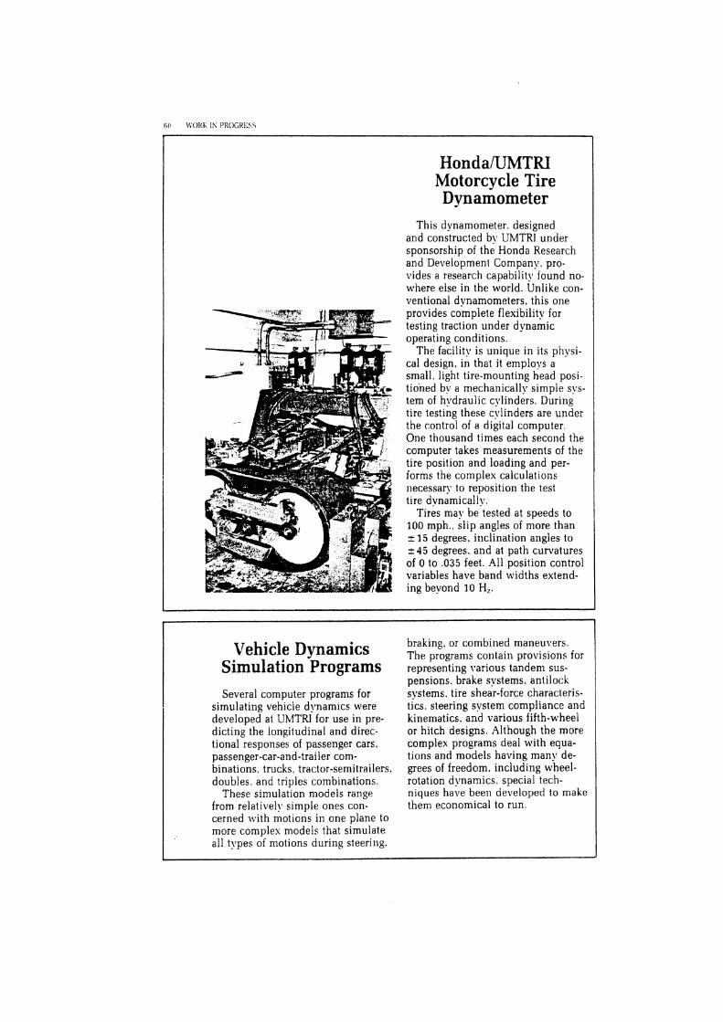
61 M'OKh 1% PROGKESS
I HondaIUMTRI
Motorcycle Tire Dynamometer
This dynamometer, designed and constructed by UMTRI under sponsorship of the Honda Research and Development Company, pro- vides a research capability found no- where else in the world. Unlike con- ventional dynamometers. this one provides complete flexibility for testing traction under dynamic operating conditions.
The facility is unique in its physi- cal design, in that it employs a small, light tire-mounting head posi- tioned by a mechanically simple sys- tem of hydraulic cylinders. During tire testing these cylinders are under the control of a digital computer. One thousand times each second the computer takes measurements of the tire position and loading and per- forms the complex calculations necessary to reposition the test tire dvnamically.
Tires may be tested at speeds to 100 mph.. slip angles of more than 1 1 5 degrees, i~lclination angles to 245 degrees, and at path curvatures of 0 to .035 feet. All position control variables have band widths extend- ing beyond 10 Hz.
Vehicle Dynamics Simulation Programs Several computer programs for
simulating vehicle dynamics were developed at UMTRl for use in pre- dicting the longitudinal and direc- tional responses of passenger cars, passenger-car-and-trailer com- binations, trucks, tractor-semitrailers. doubles, and triples combinations.
These simulation n~odels range from relatively simple ones con- cerned lvith motions in one plane to more complex models that simulate all types of motions during steering.
braking, or combined maneuvers. The programs contain provisions for representing various tandem sus- pensions, brake systems. antilock systems, tire shear-force characteris- tics, steering svstem compliance and kinematics, and various fifth-wheel or hitch designs. Although the more complex programs deal with equa- tions and models having many de- grees of freedom, including wheel- rotation dynamics, special tech- niques have been developed to make them economical to run.

Professional Staff and Program Participants
Alem. Nabih hl. Cleveland. Donald E. Ph.D.. Mechanical Engineering Ph.D.. Civil Engineering Associate Research Scientist Professor of Civil Engineering
Barhydt. Wendy H. B.S.. Special Education Research i\ssistant
Cole. David E. Ph.D., Mechanical Engineering Head. Office for the Study of
Automotive Transportation Bennett. Robert 0. Associate Professor. Mechanical h4.S., Physics Engineering and Applied Senior Research Associate Mechanics Benson, Joseph B. h1.S.. Bioengineering Senior Research Associate
Boissonneault, Joseph F. Foreman
Bowman. Bruce M. Ph.D.. Engineering Mechanics Associate Research Scientist
Bowman. Marion J . Research Associate
Bunch. Howard M. C.M.A., M.B.A.. Marketing and
Transportation
Compton, Charles P. M.S.. Biology Programmer ,4nal!rst
Cooley. Peter B.S.. Electrical Engineering Research Scientist
Creque, Denise M. Administrative Associate
Dallas. Andrew B.S.. Naval Architecture and
Marine Engineering. Physical Oceanography
Research Associate ~ e s e a r c h Scientist and Head. Marine Dsvinich,
Systems Division I\.I.P.H., Health Planning Associate Professor of Transportation Accident Investigator
Management
Businski. Karen L. B.S.. Social \Pork .4ccident Investigator
Ervin. Robert D. M.S., Mechanical Engineering Research Scientist
Fancher, Paul S. Campbell. John D. M.S.. Instrumentation Engineering h4.S.. Information and Control Research Scientist
Engineering Senior Research Associate Filkins, Lyle D.
M.S., Industrial Engineering Campbell, Kenneth L. Research Scientist Ph.D.. Mechanical Engineering Associate Research ~ c j e n t i s t - Flora, jairus D.
Carsten. Oliver M. Ph.D.. History Research Associate
Ph.D.. Statistics Research Scientist Professor of Biostatistics

bR LYORh IU PROGRESS
Gattis. R. Guy h4.A.. Library Science Assistant Coordinator, Research
Information and Publications
Gillespie, Thomas D. Ph.D., Mechanical Engineering Research Scientist
Gordus. Jeanne P. Ph.D.. Economic Histor!. Assistant Research Scientist
Green, Charles P. M.S., Civil Engineering Research Associate
Green, John A. Ph.D., Physics Research Scientist
Green. Paul A. Ph.D.. Industrial and Operations
Engineering, Psycholog!. Assistant Research Scientist
Green, Richard C. B.A., English Assistant Director, UMTRI
Grimm, Ann C. M.A.. Library Science Coordinator, Research Information
and Publications
Hagan, Michael R. B.S., Electrical Engineering Engineer in Research
Haney, James E. M.A.. English Senior Science Writer
Harbeck, Lawrence T. M.A.. Business Administration Associate Research Scientist
Hess. Robert L. Ph.D.. Engineering Mechanics Professor of Mechanical Engineering
and Applied Mechanics
Huelke, Donald F. Ph.D.. Anatomy Professor of Anatomy
Jessup, John E. B.S.. Naval Architecture and Marine
Engineering Research Associate
Kaiker, Patricia S. B.A. . English. Spanish Engineer in Research
Lehman, Richard J . B.A.. Psychology Research Associate
Lux, Paula B.A.. Applied Art Research Associate
MacAdam, Charles C. M.S., Aerospace Engineering Assistant Research Scientist
Mackenzie, James R. B.Sc., M.D., C.M. Associate Professor of Surgery Medical School
Melvin, John W. Ph.D., Theoretical and Applied
Mechanics Research Scientist and Head.
Biosciences Division Associate Professor of Mechanical
Engineering
Minahan, Daniel J. B.S.. Civil Engineering Staff Consultant
Moore, Joseph A. Administrative Associate
Mumemasa, Fuse Visiting Scientist Nissan Motor Company
Nusholtz, Guy S. M.S.. Bioengineering Assistant Research Scientist
O'Day, James M.S.. Physics Research Scientist and Head.
Systems Analysis Division Acting Director. UMTRI
O'Keefe, Brian J. B.A., Geography Research Assistant
Olson, Paul L. Ph.D., IndustrialExperimental
Psychology Research Scientist and Head, Human
Factors Division
Kadlubowski, James Mr. B.S.. Psychology Accident investigator
Owings. Clyde L. 1I.D.. Ph.D.. Bioengineering Associate Professor of Pediatrics and
Con1municabIe Diseases Associate Professor of Electrical and
Computer Engineering
Perrin. Nancy A. Conference Assistant
Pettis, Leslie C. B.S.. History Research Assistant
Pflug. Melissa A. h4.A.. Physical Anthropology Research Associate
Pollock. William T. Ph.D.. Psychology Research Scientist
Ricci, Leda L. B.A.. English. Sociology Research Assistant
Richards. Kathleen C. bl.,Z., Elementary Education Senior Graphic Artist
Robbins, Delmar H. Ph.D.. Engineering Mechanics Research Scientist
Sayers. Michael W. h1.S.. Mechanical Engineering Senior Research Associate
Scher, Robert M. M.S.. Naval Architecture and Marine
Engineering Research Associate
Schneider, Lawrence W. Ph.D.. Bioengineering Research Scientist
Scott, Robert E. hl.S.. Electrical Engineering Research Scientist
Segel. Leonard hl.S., Engineering Research Scientist and Head.
Engineering Research Division Professor of Mechanical Engineering
and Applied Mechanics
i I . , .
Siepel. Marilyn C. B.A., French Technical Library Assistant
Sivak, Michael Ph.D.. Psycholog!. .Associate Research Scientist
Snyder, Richard G. Ph.D.. Physical Anthropology
zooiogy Research Scientist Professor of .4nthropology
Spenny. Curtis H. Ph.D. Engineering and Applied
Physics Visiting Scientist Transportation Systems Center. U.S
Department of Transportation Lecturer, Mechanical Engineering
and Applied h4echanics
Vickers, Paul M'. h4.S.. Naval Architecture and Marine
Engineering Research Associate
Wagenaar, Alexander C. Ph.D.. Public Health Assistant Research Scientist
Watanabe. Yoshinori i'isiting Research Engineer Honda R & D Ltd.
Weber, Kathleen M.A., Library Science Senior Research Associate
Winkler, Christopher B. M.S.. Mechanical Engineering Associate Research Scientist
Wolf, Arthur C. Ph.D.. Political Science Associate Research Scientist
Sherman. Harold 1-Y. B.S.. Electrical Erlgineering Senior Research Associate


APPENDIX L

FACILITIES ON THE MAIN CAMPUS
Office Facilities Having outgroun the original building that served as its
administrative headquarters for more than 2j years, the lnsti- tute moved to new facilities in the newly completed Academic and Agencies Building in mid-1981. Ths building provides facilities for the administration, two complete TT? research divisions, and significant portions of three more divisions. These elements of the lnstitute nowr occupy 26,800 square feet on the fourth and fifih floors of the new building. For the first time in recent years a major portion of the 'ITI staff is housed in the same building, substantially increasing the efficiency of the overall administrative and research operations of the institute. T I research divisions also occupy some 10$000 additional square feet in several main campus buildings shared with various departments of the Universih.
Research Facilties ahd Semces hbortziuh: Available to and extensively used by the
Institute are fully equipped laboratories for researcb on mate- &, soils, and pavements. These laboratories are shared with tbe Civil Engineering Department of the Univenib. Principal among these facilities are the:
McNeu Materials Laboratom ~i&minous Pavement Laboratory ~ s p M t Rheology Laboraton Synthetic Aggregate Laboratory Geotechnical Laboratories
These laboratories provide a full apabiiity for asphalt and concrete materials testing required by the Materials h. Con- struction Division. h c h testing ranges from standard quality control tests to more sophisticated tests such as beam fatigue, overlay shear, and resilient modulus. The laboratories are sMed by skilled technicians, well-trained in operating a wide selection of testing equipment and instrumentation. Included in the laboratories' inventow is equipment which permits researchers to conduct extensive field testing such as surface texture measurements, construction monitoring, coring, and dyndect measurements.
Auto& Data Promkg: Readily accessible automatic data processing services are provided b!~ the Texas A&M University Data Processing Center (DPC). The DPC is a centrahzed computing facility operated by the Texas Engneer- ing Experiment Station that provides computational support and data processing services to all components of the Texas A&M University, other universities, and state agencies. The
DPC campus network, serving the academic, research and administrative needs of the University is one of the most complete and extensive local networks of any college or univer- sity.
Research projects account for about 40% of the DPC computer usage. Highly quaified DPC personnel are available to assist researchers with the computer-related aspects of research projects. Plotting, analog-todigital conversion, statis- tical analysis, and other services can be provided to research- ers.
The DPC has two computers in the Amdahl 470 series which are fully programcompatible with tbe IBM 370 line. The system has an on-he storage capability of over 24,000 megabytes of information and machine cycle times of 32.5 or 26.0 nanoseconds. The two computers, combined with exten- sive and sophisticated peripheral equipment, provide a capa- bility to handle any data processing task with peat speed and efficiency. To supplement the available central computing services of the DPC and to increase the efficiency with which it can meet its ever expanding need for data processing, the institute has, over the past five years, steadily increased its own inventor?. of mini- and micrcl-computers, word processors, and terminal equipment and accessories.
Libzay: The resource$ of the Texas A&M University Library, one of the major libraries in the Southwest, are fully available to the Institute's staff. Present holdings of this library are approximately 1,300,000 volumes and 1,800,000 mi- croforms in all collections. The Library subscribes to 15,000 journals, including 5,000 from foreign countries. The Universi- ty Library is desipated a depositon for U.S. Government publications and receives 908 of its publications.
The Libran. has available all major indexing and ab- stracting publications. In addition, its Automated Information Retrieval Service offers access to U)O on-line bibliographic and statistical data bases. Materials retrieved by the system cover the many disciplines of rJl research and include reports and articles, both domestic and foreign.
The Library's Technical Reports Center has comprehen- sive holdings in all facets of the transportation field, repre- senting reports from universities engaged in transportation research, the highway departments of various states, national and international transportation organiations.
The Institute has on its s t d a full-time Research Librarian who is officed in the University Library. He is on call to conduct intensive literature searches for researchers when needed.

. ., . _ , '. . " . ,. : : - 2 . .*% > .* .: .& . . ,. 2.. - .- - - - 0- m-
777 Administmtiw H e a Q w e m and a sizable number of the Institute's researchers am now housed in the Academic and Agencies Building.
Word processors haw streamlined the ptduction process jor Microcarputers haw incnnsed the econmny and efficiency of 77'1's many technical reports and other written cummunica- the Institute's many data processing tasks. tions.
. .
t / ! 4 ,i ! 1 . , . , . .
L&: 'Making asphalt concrete samples in gyratory compactor.
Right: Preparing pavement core sample for lobomtoy tests.
r
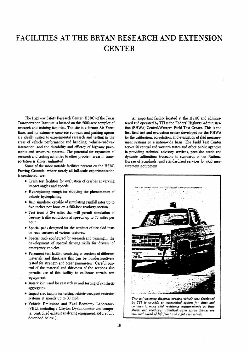
FACILITIES AT THE BRYAN RESEARCH AND EXTENSION CENTER
The Highwa! Safe? Research Center (HSRC) of the Texas Transportation Institute is located on this 2000 acre complm of research and training facilities. The site is a former Air Force Base, and its extensive concrete runways and parking aprons are ~deally suited to experimental research and testing in the areas of vehicle periormance and handling, vehicle-roadway interaction, and the durabi l i~. and efficacy of highway pave- ments and structural systems. The potential for expansion of research and testing activities to other problem areas in trans- portation is almost unlimited.
Some of the more notable facilities present on the HSRC Proving Grounds, where nearly all full-scale experimentation is conducted, are:
Crash test facilities for evaluation of mashes at varying impact angks and speeds. Hydropianing trough for studying the phenomenon of vehicle hvdroplaning. Rain simulator capable of simulating rainfall rates up to five inches per hour on a 2 W o o t roadway section. Test tract of 3% miles that will permit simulation of freeway traffic conditions at speeds up to 70 miles per hour. Special pads designed for the conduct of tire skid tests on road surfaces of various textures. Special track configured for research and training in the development of special driving skills for drivers of emergency vehicles. Pavement test facility consisting of sections of m e r e n t materials and thickness that can be nondestructively tested for strength and other parameters. Careful con- trol of the material and thickness of the sections also permits use of this faciliv to calibrate certain test
- equipment. Rotary kiln used for research in and testing of synthetic aggregates. lmpact sled facility for testing vehide occupant restraint systems at speeds up to 30 mph. Vehicle Emissions and Fuel Economy Laboratov I\'EL), including a Clayton Dynamometer and compu- ter controlled exhaust analyzing equipment. (More fully described belon..)
An important facility located at the HSRC and adminis- tered and operated by TII is the Federal Highway Administra- tion (FHU7A) CentraVWestern Field Test Center. This is the first field test and evaluation center developed for the FHM'A for the calibration, correlation, and evaluation of skid measure- ment systems on a nationwide basis. The Field Test Center serves 26 central and western states and other public agencies in prov~ding technical advisor? services, precision static and dynamic calibrations traceable to standards of the National Bureau of Standards, and standardized services for skid mea- surement equipment.
: * - - p P S - & ----
f L .
Thw selj-wtenng drogonal bralnng vehick ums dewloped by TTI to prmdc an econom~cul svstem for a t ~ c s and countws to make sku! resutance measurements a thar streets and roadways I&nttcai water spray devices arc mounted ahead of Iej? front and npht rear uihecL
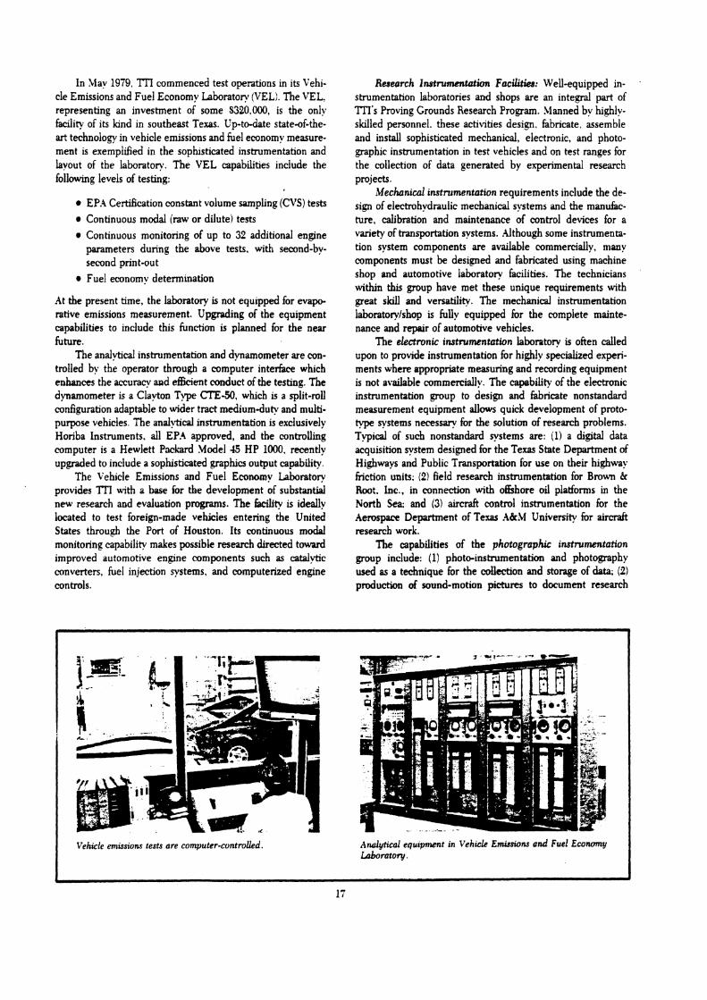
In May 1979, ?TI commenced test operations in its vehi- cle Emissions and Fuel Economy Laboratory (VELI. The VEL. representing an investment of some S20.000, is the only Fdcility of its kind in southeast Texas. Up-to-date state-of-the- art technology in vehicle emissions and fuel economy measure- ment is exemplified in the sophisticated instrumentation and layout of the laboratory. The VEL capabilities include the following levels of testing:
EP.4 Certification constant volume sampling (CVS) tests Continuous modal (raw or dilute) tests Continuous monitoring of up to 32 additional engine parameters during the above tests. with second-by- second print-out Fuel economy determ~nation
At the present time, the laboratory is not equipped for evapo- rative emissions measurement. Upgrading of the equipment capabilities to include this function is planned for the near future.
The analytical instrumentation and dynamometer are con- trolled by the operator through a computer interface which enhances the muracy and efficient conduct of the testing. The dynamometer is a Clayton Type CTE-50, which is a split-roll configuration adaptable to wider tract mediumduty and multi- purpose vehicles. The analytical instrumentation is exclusively Horiba Instruments, all EPA approved, and the controlling computer is a Hewlett Pwliard Model 45 HP 1000, recently upgraded to include a sophisticated graphics output capability.
The Vehicle Emissions and Fuel Economy Laboratory provides 'ITI with a base for the development of substantial new research and evaluation progranls. The Edcility is ideally located to test foreign-made vehicles entering the United States through the Port of Houston. Its continuous modal monitoring capability makes possible research directed toward improved automotive engine components such as catalytic converters, fuel injection systems, and computerized engine controls.
Reseorch lnstrummtution Facilities: Well-equipped in- .
strumentation laboratories and shops are an integral part of ??l's Proving Grounds Research Program. Manned by highly- skilled personnel. these activities design. fabricate. assemble and install sophisticated mechanical, electronic, and photo- graphic instrumentation in test vehicles and on test ranges for the collection of data generated by experimental research projects.
Mechnicd instrumentation requirements include the de- sign of electrohydraulic mechanical systems and the manufac- ture, calibration and maintenance of control devices for a variety of transportation systems. .dthough some instrumenta- tion system components are available commercially, mmy components must be designed and fabricated using machine shop and automotive laboratory facilities. The technicians within this group have met these unique requirements with pea t skill and versatility. The mechanical instrumentation laboratorylshop is fully equipped for the complete mainte- nance and repair of automotive vehicles.
The electronic instmmentation labontory is often called upon to provide instrumentation for highly specialized experi- ments where appropriate measuring and recording equipment is not available commercially. The capability of the electronic instrumentation group to design and fabricate nonstandard measurement equipment allows quick development of proto- type systems necessary for the solution of research problems. Typical of such nonstandard systems are: il) a digital data acquisition system designed for the Texas State Department of Highways and Public Transportation for use on their highway friction units; (2) field research instrumentation for Brown & Root. lnc., in connection with offshore oil platforms in the North Sea: and (3) aircraft control instrumentation for the Aerospace Department of Texas A&M University for aircraft research work.
The capabilities of the photographic instrumentation group include: (1) photo-instrumentation and photography used as a technique for the couection and storage of data; (2) production of sound-motion pictures to document research
Vehicle ernissionr tests are computer-controlled. Analytical equipment in Vehicle Emissions and Fuel Econumy h b o r o t o y .
b
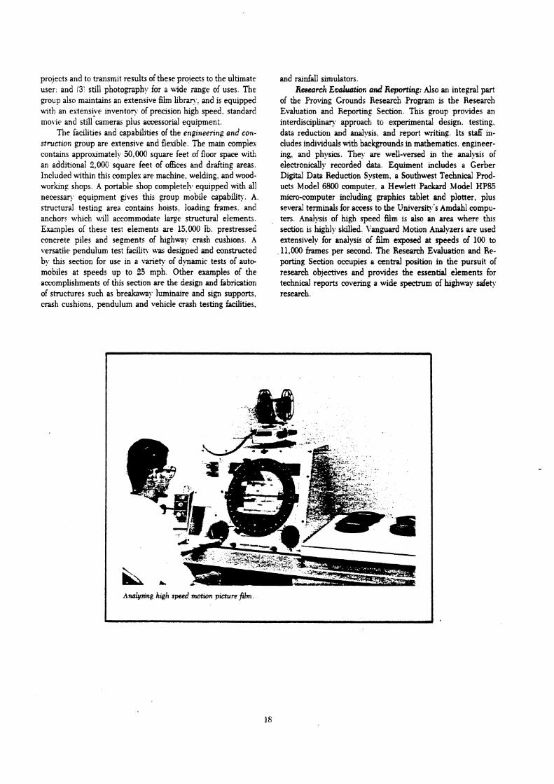
projects and to transmit results of these prolects to the ultimate user: and 13: still photography for a wide range of uses. The group also maintains an extensive film libran.! and is equipped uith an extensiye inventon. of precision high speed. standard movie and still cameras plus acressorial equipment.
The facilities and capabilities of the engineering and con- struction group are extensive and flexible. The main complex contains approximately 50,000 square feet of floor space with an additional 2.000 square feet of offices and drafting areas. Included uithin this complex are machine, welding, and wood- worlung shops. -4 portable shop completely equipped with all necessan equipment gives this group mobile capabilitl\. A. structural testing area contains hoists, loading frames. and anchors which a~ill accommodate large structural elements. Examples of these test elements are 15.000 lb. prestressed concrete piles and segments of hghwa! crash cushions. .4 versatile pendulum test facilit\. u w designed and constructed b!, this section for use in a variety of dylamic tests of auto- mobiles at speeds up to 2.5 mph. Other examples of the accomplishments of this section are the design and fabrication of structures such as breaknwa!. luminaire and sign supports, crash cushions, pendulum and vehicle crash testing facilities,
and rainfall simulators. Reeeurch Eoalwtwn and Repotting: Also an integral part
of the Proving Grounds Research Program is the Research Evaluation and Reporting Section. This group provides an interdisciplinary approach to experimental design, testing. data reduction and analysis. and report writing. Its staff in- cludes individuals with backgrounds in mathematics. engineer- ing, and physics. They are well-versed in the analysis of electronically rewrded data. Equiment includes a Gerber Digital Data Reduction System, a Southwest Technical Prod- ucts Model 6800 computer, a Hewlett Packard Model HP83 micro-computer including graphics tablet and plotter. plus several terminals for access to the Universit\.'s Amdahl compu- ters. Analysis of high speed film is also an area where this section is highly skilled. Vanguard Motion Analyzers are used extensively for analysis of h exposed at speeds of 100 to
,11,000 frames per second. The Research Evaluation and Re- porting Section occupies a central position in the pursuit of research objectives and provides the essential elements for technical reports covering a wide spectrum of highway safety research.
1
Ardysing high speed mation picture fih.


APPENDIX H


Skid Resistance Research Facility
Tne Skid Resis:ance Research Facility is located on a separate lane aojacent to one tangent of the experimental highway. The lane is 15 f t wide and 1,150 fi long, with an approach that allows vehicle speeds up to 60 rnph. The instrumentation permits precise rnezsurement of vehlcle speeds and lateral placements throughout the test area.
Each test surface is 6 ft wide by 200 f t long. The area includes six different sur- faces: two densegraded asphalt friction courses, one with a polishing limestone aggregate and one with a nonpolishlng aggregate; two open-graded asphalt fric- tion courses, also with polishing and non- polishing limestone aggregates; a dense-graded asphalt friction course wlth a jenn~te surface treatment; and a dense-graded asphalt course wlth a sand-epoxy treatment. The various sur- face textures are based on maximum aggregate sizes ranglng from 0.033 in. (sand-epoxy) to 0.25 In. (open-graded as- phalt irlction course). The sk~d resistances of the test surfaces are monitored routinely, and skid numbers range from 15 to 60.
Originally constructed in 1972, the tacli- ity was rebuilt in 1982. It has been used extensively for skid resistance research, tire noise and pavement texture studies, hydroplaning research, and an evaluation of methods of skid resistance measure- ment other than the locked-wheel method. Current research at the facility includes the development of high-speed, noncon- tact macrotexture measurement methods and a study of the effects of weather con- dit~ons on pavement materials.
Pavement Roughness Research Facility
The Pavement Roughness Research Facility is a pavement lane constructed adjacent to the Skid Resistance Research Facility at the lower tangent of the ex- perlmental highway. It consists of two troughs. 2 ft wide by 4 in. deep by 800 fi long, located where the wheel ~ a t h s for automobiles and light trucks would nor- mally be. Interchangeable concrete molded lnseRs provide a choice of run- nlng surfaces with a variety of roughness characteristics. These pavement suriaces exhibit roughness wrthin a range of values sign~iicant for routine testing.
T ire/Pavement Laboratories
Stone Polishing Laboratory The Stone Polishing Laboratory is used for studylng the techniques of polishing so that the properties that pavements and aggregates require for adequate skid re- srstance can be defined more precisely. Equipment includes:
1. The Penn State reciprocating pave- ment polisher (RPP) on whicn pave- ment cores or stone samples are polished by a sliding rubber pad. The RPP may also be transponed to actual pavements for in situ operation. The resulting decrease in frlction IS mea- sured by a pendulum friction tester.
2. A drum polisher on which ten individual particles of an aggregate sample are polished by a rotating rubber-coated drum. The decrease in average friction is measured by a special device di- rectly attached to the machine.
3. The Penn State circular track. which can be used for polishing samples mounted in the wheel tracks. Here fric- tion can be measured either continu- ously by the torque-measuring system or periodically by other methods.
Related experimental work n the Stone Polishing Laboratory includes the mea- surement of pavement surface texture, which affects frlction between tlre and pavement. The texture measurement facil- ~ t y includes two portable profile tracers for macrotexture and microtexture measure- ment: these tracers can also be used on pavements in the field. The macrotexture
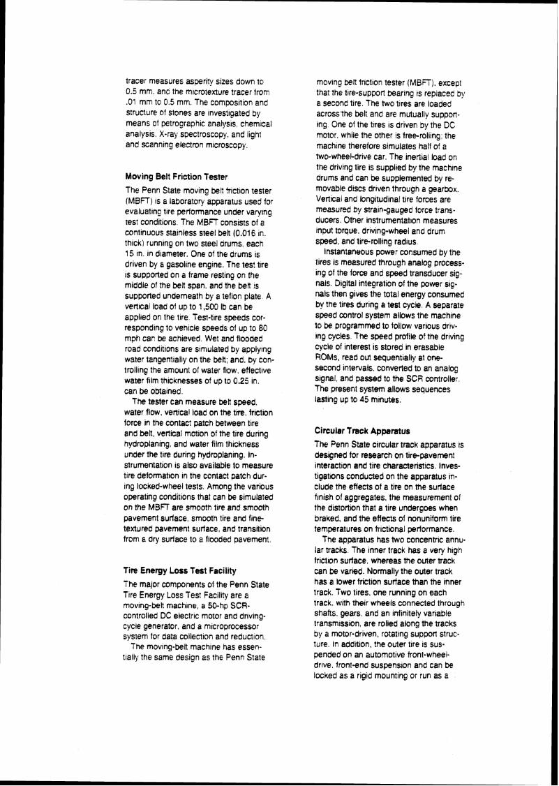
tracer measures asperlty sizes down to 0.5 mm. and the mlcrotexture tracer from .O1 mm to 0.5 mm. The compos~tion and structure of Stones are investigated by means ot petrographic analysis, chemical analysis. X-ray spectroscopy. and light and scanning electron microscopy.
Moving Belt Friction Tester
The Penn State moving belt tr~ction tester (MBFT) 1s a laboratory apparatus used for evaluating tire performance under varylng test conditions. The MBFT consists of a continuous slainless steel belt (0.016 in. thick) runnlng on two steel drums. each 15 in. in diameter. One of the drums is driven by a gasollne engine. The test tire is supported on a frame resting on the middle of the belt span, and the belt fs supponed underneath by a teflon plate A vertical load of up to 1,500 Ib can be appl~ed on the trre. Test-t~re speeds cor- responding to vehicle speeds of up to 80 mph can be achieved. Wet and flooded road conditions are simulated by applylng water tangentially on the belt; and, by con. trolbng the amount of water flow, effectwe water film thicknesses of up to 0.25 in. can be obtained.
The tester can measure be# speed, water flow, vertical load on the tire, friction force in the contact patch between tire and belt, vertical motion of the tire during hydroplanmg. and water film thickness under the tire during hydroplaning. In- strumentation is also available to measure tire deformat~on in the contact patch dur- lng locked-wheel tests. Among the various operating conditions that can be simulated on the MBFT are smooth tire and smooth pavement surface, smooth tire and fine textured pavement surface, and transition from a dry suriace to a flooded pavement.
Tire Energy Loss Test Facility
The major components of the Penn State T~re Energy Loss Test Facil~ty are a mov~ng-belt mach~ne, a 50-hp SCR- controlled DC ekctrlc motor and drlvng- cycle generator, and a mrcroprocessor system for data collection and reduction
The movlng-belt machlne has essen- trally the same des~gn as the Penn State
moving belt friction tester (MBFT), except that the tlre-support bearing is replaced by a second tire. The two tires are loaded across'the belt and are mutually support- ing. One of the tlres IS driven by the DC motor. while the other is freeroliing: the machlne therefore simulates half of a two-wheel-drive car. The ineriial load on the driving tire is supplied by the machtne drums and can be supplemented by re- movable discs driven through a gearbox. Vertical and longitudinal tire forces are measured by stram-gauged force trans- ducers. Other instrumentat~on measures Input torque, driving-wheel and drum speed, and tire-rolling rad~us.
Instantaneous power consumed by the tires is measured through analog process- ing of the force and speed transducer sig- nals. Digital integration of the power sig- nals then gives the total energy consumed by tne tires during a test cycle. A separate speed control system allows the machine to be programmed to follow various ariv- ing cycks, The speed profile of the driving cycle of interest is stored in erasable ROMs, read out sequentially at one- second wtervals, converted to an analog signal, and passed to the SCR controller. The present system allows sequences lasting up to 45 minutes.
Circular Track Apparatus
The Penn State circular track apparatus is deslgned for research on tire-pavement interactron and tire characteristics. Inves- tigatlons conducted on the apparatus in- clude the effects of a tire on the surface frnish of aggregates, the measurement of the distortion that a tire undergoes when braked. and the effects of nonuniform tire temperatures on frictional performance.
Tne apparatus has two concentrK: annu. lar tracks. The inner track has a very hrgh frictlon surtace, whereas the outer track can be varied. Normally the outer track has a lower friction surface than the inner track. Two tires, one running on each track. with their wheels connected through shafts. gears, and an Infinitely vanable transmission, are rolled along the tracks by a motor-driven, rotating suppon struc- ture. In addition, the outer tire is suss pended on an automotive tront-wheei- drlve, front-end suspension and can be locked as a rigid mounting or run as a
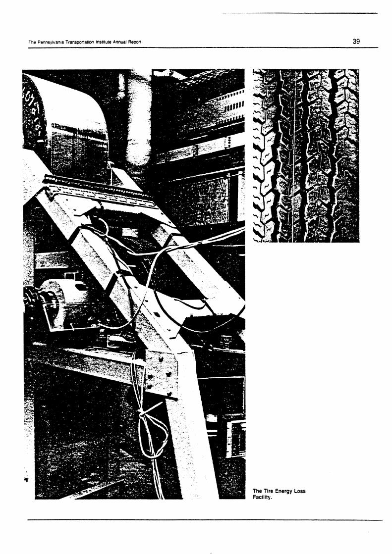
The Pennsytvan~a Transponat~on lnstltute Annual R e ~ o n 39
The Tire Energy Loss Facility.
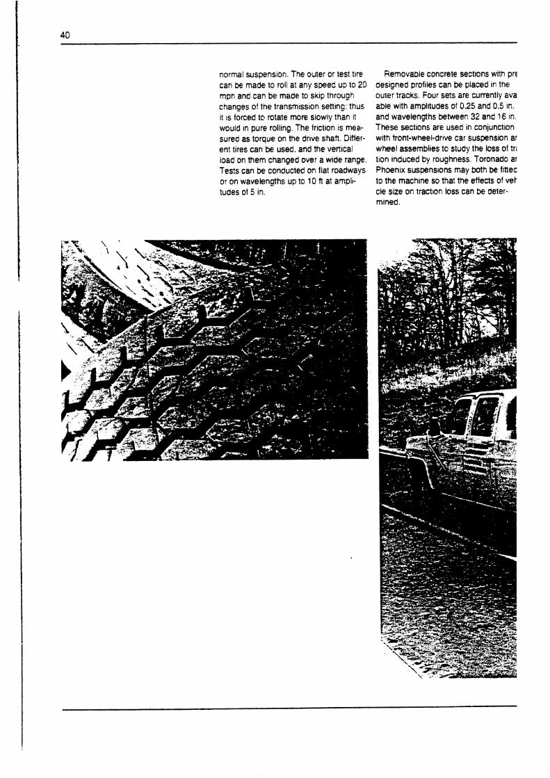
normal suspension. The outer or test t~re can be made to roll at any speed up to 20 mph and can be made to s ~ i p through changes of the transmission settlng: thus it IS forced t@ rotate more slowly than it would In pure rollng. The friction is mea- sured as torque on the drive shaft. Differ- ent tires can be used, and the vertical load on them changed over a wide range. Tests can be conducted on flat roadways or on wavelengths up to 10 ft at ampli- tudes of 5 in.
Removable concrete sections with pre designed profiles can be placed in the outer tracks. Four sets are currently ava able with amptltudes of 0.25 and 0.5 in. and wavelengths between 32 and 16 In. These sectlons are used In conjunction with tront-wheel-drive car suspension ar wheel assemblies to study the loss of tri tion induced by roughness. Toronado ar Phoenix suspensions may both be finec to the mach~ne so that the effects of vet cle size on tract~on loss can be deter- mined.
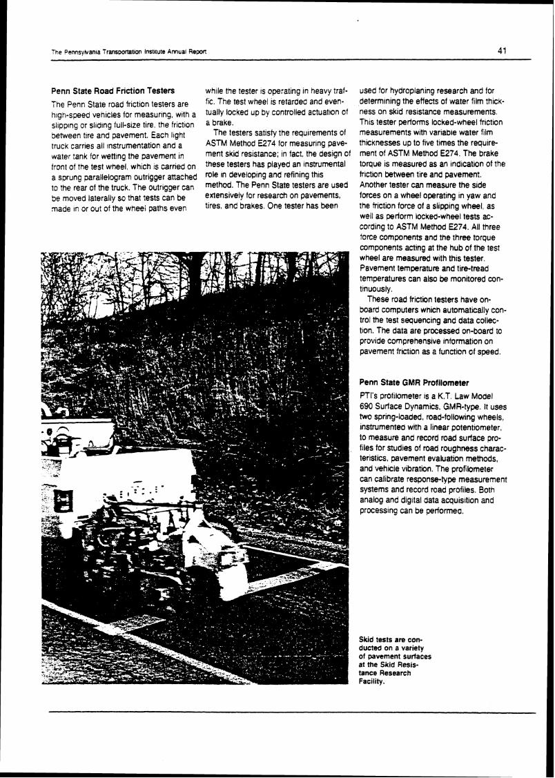
The Pennsyivan~a Transponatlon lnrt~tute Annual Repon 41
Penn State Road Friction Testers
The Penn State road friction testers are high-speed venicles for measuring, wrth a sl~pplng or sl~dlng full-size tire, the friction Detween trre and pavement. Each tight truck carries all ~nstrumentation and a water tank for wetting the pavement in front of the test wheel, which is carried on a sprung parallelogram outrigger attached to the rear of the truck. The outrigger can be moved laterally so that tests can be made In or out of the wheei paths even
while the tester a operating in heavy traf- fic. The test wheel is retamed and even- tually locked up by controlled actuatlon of a brake.
The testers satisfy the requirements of ASTM Method E274 for measuring pave- ment skid resistance; in fact, the design of these testers has played an instrumental role In developing and refining this method. The Penn State testers are used extensively for research on pavements, tires, and brakes. One tester has been
used for hydroplaning research and for determining the effects of water film thick- ness on skid resistance measurements, This tester petforms locked-wheel frictlon measurements with variable water film thicknesses up to five times the r q u l r e ment of ASTM Method E274. The brake toque is measured as an indication of the frictlon between tire and pavement. Another tester can measure the side forces on a wheel operating in yaw and the triction force of a slipping wheel, as well as periorm locked-wheel tests ac- cording to ASTM Method E274. All three force components and the three torque components acting at the hub of the test wheel are measured with this tester. Pavement temperature and tire-tread temperatures can also be monitored con- tinuously.
These road friction testers have on- board computers which automatically con- trol the test sequencing and data collec- tlon. The data are processed on-board to provide comprehensive information on pavement friction as a function of speed.
Penn State GMR Profilometer
PTl's profilometer is a K.T. Law Model 690 Surface Dynamics, GMR-type. It uses two spring-loaded, road-following wheels, instrumented with a linear potentiometer, to measure and record road surface pro- files for studies of road roughness charac- teristics. pavement evaluation methods, and vehicle vibration. The profilometer can calibrate response-type measurement systems and record road profiles. Both analog and digital data acquisition and processing can be performea.
Skid tests ere con- ducted on a variety of pavement surtaces at the Skid Resis- tance Research Facility.


APPENDIX N

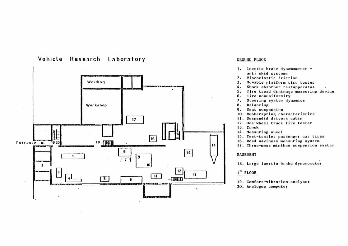
V e h i c l e R e s e a r c h L a b o r a t o r y
l n e r t i a b r a k e dy~lamometer - a n t i s k i d systcr~tr , V i s c o e l a s t i c f r i c t i o n Movable p l a t f o r n l t i r e t e s t e r Shock a1)sorber t c s t a p p a r a t t r s T i r e t r e a d d r a i n a g e measrrrirlg d e v i c e T i r e n o n u e i f o r n ~ i t y S t e e r i n g sys t em dynamics Ba lanc ing S e a t s u s p e n s i o n Rubbe r sp r ing c h a r n c t e r i s t i c s Suspendid d r i v e r s c a b i n One-wheel t r u c k t i r e t e s t e r Trnck Measr~r i n g wllce 1 T e s t - t r a i l e r p a s s e n g e r c a r ires Road wav ines s m c a s r ~ r i n g sys t em Three-mass m i n i b u s suspe r l s ion sysLeni . .
BAS ENENT
I 18. La rge i n e r t i a b r a k e dyna~nometer
1 * I e FLOOR
1 19. C o m f o r t - v i b r a t i o n a n a l y s e r 20. Analogue computer


APPENDIX 0

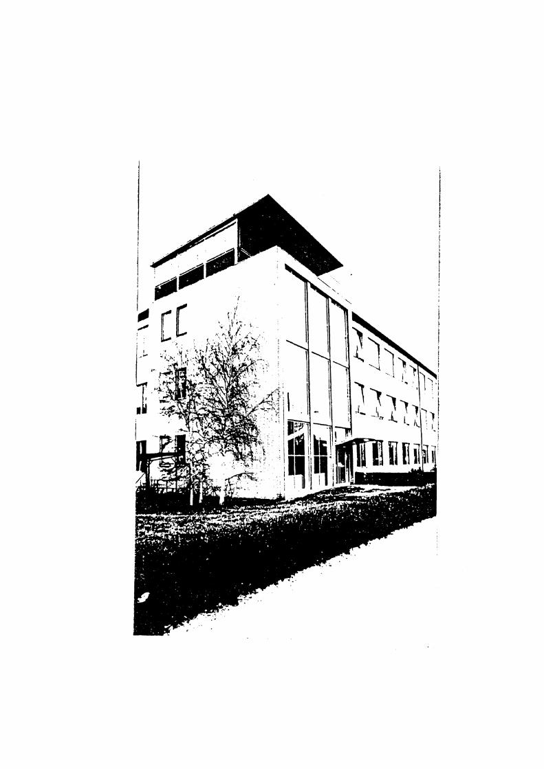
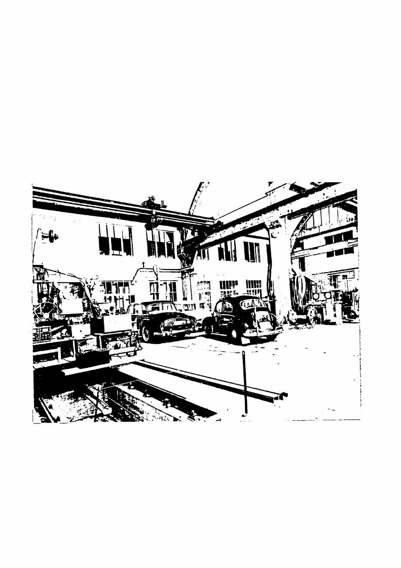

APPENDIX P

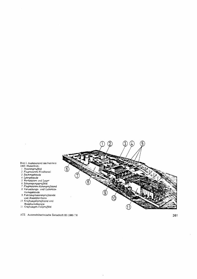
Bild 5 Ausbaustand deslnstttuts 1940 (.Modeilbrldi
1 Motorenpwfeid 2 Flugmotoren-Windkana1 3 Stammgeoaude 4 Lehrgebaude 5 Werkstatten und Lager 6 Schunngungspruffeid 7 Flugmtorm-Hohenprdfstand 8 Verwaltungs. undo Laborato-
numsgebaude 9 Fahrzeug.notorenprufstande und .bfodellfahtoahn
10 Kraftuagenprufsrand und Modellwtndkanale
! 1 Krafttwagen.VollpruffeLd
AT2 Automobiltechnische Zeitschrift 82 (1980) 7'8 361


APPENDIX Q

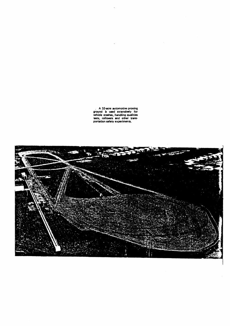
. A 33-acre wtomotive proving ground & used extenriwly for vehicle crashes, handling qualities tarts, rollwars and other trans- portation safety experiments.

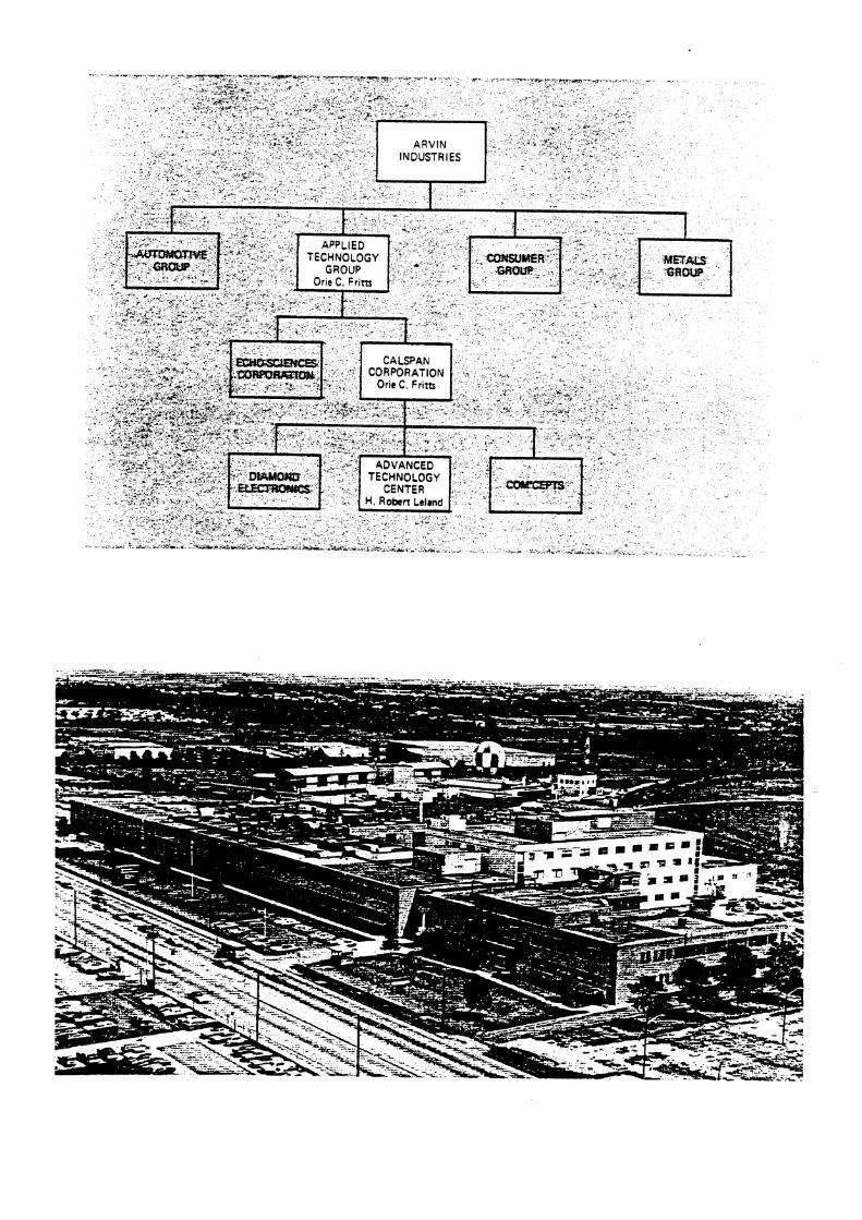


APPENDIX R


APPENDIX S


"New Town" adjoins the Research Center. P?f& c /5 -z-7' "Now Town" wlll bo close l o molropollln~~ celllers. wlthln 30 minates dclvlng linw o l lour lnrgn Inkes. altd live mllea l lmn a skl slope. t l o ~ o Is counl~y slyls llvlng wllh clly cnnvenlencn Developers nm Showo Oullclars. 111c . Ccdun~bu Ohlo
Cnmmnrrlal
U. S. Departmerrt of Transportation Motor Vehicle Conipliance Center. 1 hls $9.6 ~nl l l l t~n l i~cll l ly lobe conslruclcd and operated by lllo Nnllonal I lighwny lrnl l lc Snlely Admlr~fslrnllon. 1% schcdt~lcd lor complollr~n III 1974.11 will ho oprrnlnd b y n slnll nl25O el~gi- nenrs. lcchr~lcinns end sl~pporl pcrsonrlnl.


APPENDIX T

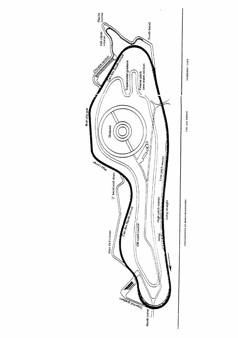


APPENDIX U

Sondefaruck aus A n Autornobiltecnn~s Zettschnft 83 Jahrgang Nr 111981 =ranckh'sche Verlagshandlung Sturtgarl
Klaus Rompe und Peter W~egner
Das Kraftfahrzeuglabor des TOV Rheinland Beror neue Fanr-aige oder Fah7,teugreiie xi rn Strajenverkenr zugeiassen werden Konnen tnlij3 aas Gutacnren e-ner Techntschei! P-ufstelle dte Cbererirst~mn~rng in~t den gelzenaen Vorschri?ften oescnel?lgen Htev:u szna :d9n Tell tirnialtgrelche Prujungen notcmdrg, fur ale lnsbesoi~aere r r n Rahmen tnrenrarlonaier Genehmigun- gen ron aem jewe?k Sealiftragten Technrscnen D~ensr komplexe ?~ufetnrzchruirgen vor2uhaiten srird Dte :In iCraftja'lrzeugiaoor des TCV Rneznland u~ Koln rornandenen Elnnchruirgen tina ihre Etnsat:moglrch~eiten sollen h~e-mzt aer ~nteressterren Facnuelr :.orgestellt urndell
The Xotor Vehicle Laboratory at the T1.T Rheinland, Co- logne
Abstract
To get the type approval for a new vehicle or vehicle part the nanufacturer needs in many cases a test certificate of the Technical Ser.,ice The TVT' Rhe~nland is the Technical Ser-
for the FRG. for some of the ECE- or EG-Reguiauons m the field of primary or secondary safety.
Therefore. the association has to keep ready the conespond- ing facilities for carrying out crash tests wlth complete vehic- les or components, for testing spare steering wheels, seats. head restraints, safety-belt anchorages. protection helmets. safety glass. dnvers' field of view. and vehicle vibration and handling characteristics.
The aim of this art~cle is to give a sun.e!: on the test facditles of :his laboratory and to show the possibihties of use to interes- ted exper!
I. Aufgaben des Kraftfahneuglabon
Bei der Seantragung einer natlonalen Allgemeinen Betriebs- rriaubnis werden von den Fahrzeug- und Fahrzeugteileher- stellern 1.1 zunehrnendem MaRe Genehrnigungen nach inter- narionalen Regelungen und Richtlinien verwendet, die in ai- len der ECE bzw. der EG angehorenden Landern Gultigkeit besitzen. Zur Erzielune einer rauonellen .bbeitsteilung und um die notwendigen Investitionen fiir Priifanlagen in Gren- Zen zg halten, ist f8r die Priifungnach einer bestimmten Rege- lung oder Richt!inie im aligemeinen ir. jedem Land nur eine Institution als zustandiger Tcchnischer Dienst benannt. In der Bundesrepublik hat aer Bundesverkehrsminister fur eine Reihe von ECE-Regelungen und EG-Richtiinien auf den Ge- bleten der passwen und aktiven Sicherhelt den TUV Rhein- land r n ~ t cieser Aufgabe betraut, Tcfei I .
Diese Benennung macht es notwendig, entsprechenae Priif- einrichtungen zu entwickeln und bereltzustellen, damit auch soiche Hersteller z. B. von Zubehorteilen, die keine entspre-
Tajel 1 Tecnnuche D~enste des TCi' Rheiniana
SCE-iiegelung EG-31cnthn:e Verha~ten der Lewaniage ." - 74 297 EWG
7.-erankerun$en aer 14 7 6 115 EWG S~cne rne~ t seu r t e Wiaerstandsfa!ligke:t der 17 74 408IEWG Sitze und inrer Verankeruneer
Koorsrutzen 35 ;P 932 E R G Sicqttela 77 549'EU'G Enttros:ungs. ~ n d T r o c ~ n ~ f i p s . 78 31; EWG anizpen fur Scne~oen Scre!benw!scner una S c n e i ~ e n . li: 318 EWG
Cnrerfanrscnutz 70 221,EWG S~cnt le id be! l a n a oder 74:317 EWG !'orst\v!nscnaAl~chen iuernascn!nen
chenden Einrichtungen besitzen, die Moglicnkeit zur P i - fung an neutraler und unabhangiger Stelle haben.
, a t dieser Verpflichtung zur Vornaltung solcher Anlagen 1st jedoch keineswegs auch - sozusagen automatisch - die Zu- weisung eines bestimmten Priifvolumens zur Nutzung dieser Anlagen verbunden. So machen Hersteller aus der Bundesre- publik unter anderem von der Moglichke~t Gebrauch, diese lnternationaien Pnifungen in anderen iandern durchfiihren tu iassen. Hier besteht daher ein freier Wettbewerb, der aller- dings in rnanchen Landern durch ein lnsgesamt beschleunig- tes Priif- und Genehmigungsverfahren zudtzliche Anreize erhalt.
Bei den groBen Fahneugherstellem werden die entspre- chenden Priifungen aus Kostengriinden auf den hersteller- eigenen Anlagen von den ?Zv-Sachverstindigen durchge- fuhrt. Um diese Tatigkeit wahmehmen zu konnen, muD der Sachverstindge jedoch rnit derarcigen Priif- und MeRverfah- ren als Experte umgehen konnen, und diese Erfanrung kann er nur auf eigenen ..Magen gewnnen. Weiterhin werden ins- besondere die Sachverstiindigen der Technischen Dienste von den Vertretern der rustandigen Behorden als Berater herangezogen zu alien Fragen, welche die spez~elle Richtlinie oder Regelung betreffen. Dies setzt ebenfalls umfangreiche. selbst erarbeitete Priiferfahrungen lioraus. Dariiber ninaus sind die Technischen D~enste n a t ~ r g e m ~ z'u Mitarbeit be1 der Verbesserung der Priifgrundlagen und -ver!'ahren irn Sinne hoherer Reproduzierbarkeit und groberer Objektivitit aufgefordert und werden dazu auch rnit der Durchfiihrung entsprechender Forschungsaufgaben betraut.
Ein weiteres Aufgabengebiet des Kraftf*.rzeuglabors des TLV Rheinland sind vergleichende Untersilchungen an Fahneugteilen. z. B. im Auftrage von Verbraucherorgamsa. tionen. Jedoch auch fur die einzelnen Teilehorsteller bietet der TtY Rheinland die Ausarbeitung und DurchWhmng ei- nes aussagekraftigen Prufprogramms zur Ermittlung von Si- cherheit und Qualitat an. Uber diese Pl?ifung wird .in Zertifi- kat erteilt. und der Hersteller kann d e iiunden uber ein ent- sprechendes Priifzeichen darauf hmweisen.
Schliefilich werden die Priifanlagen verhunden mit dern Know-how des Personals im Rahmen von EntwlcUungsauf- tragen von den Fahrzeug- und Fahrzeugteileherstellern in .Inspruch genommen.
2. Priifeinrichtungen
Die nachfolgende Beschreibung soll cinen kunen t'berblick uber die Einrichtungen dieses Labors geben und Hinweise fiir die Anwendbarkelt aufze~gen. Auf einer Gesamtflache von etwa 1000 ma sind neben den verschiedenen Priifanlagen eine klelne Mechanische Werkstatt zur Vorbereitung der Versuche und rneRtechn~sche Priif- und Arbeitspltze zur Entwiciriung und Anpassung aer Meagerate und Priife~nrichtunger~ unter- gebracht.
2 . ; . Crashanlage
Die vom Flgchenbedarf her aufwendigste Elnrichtung 1st die im vergangenen Jahr neu In Betrieb genomrnene Crashanla- ge. Biid : und?. Uber ein Endlosseil wlrd das Fahrzeug auiei- ner 60 rn langen Strecke beschleunigt. Der .Aufprallblock mit einer Masse von 200 t enrspricht den elnschiagigen SAE- und
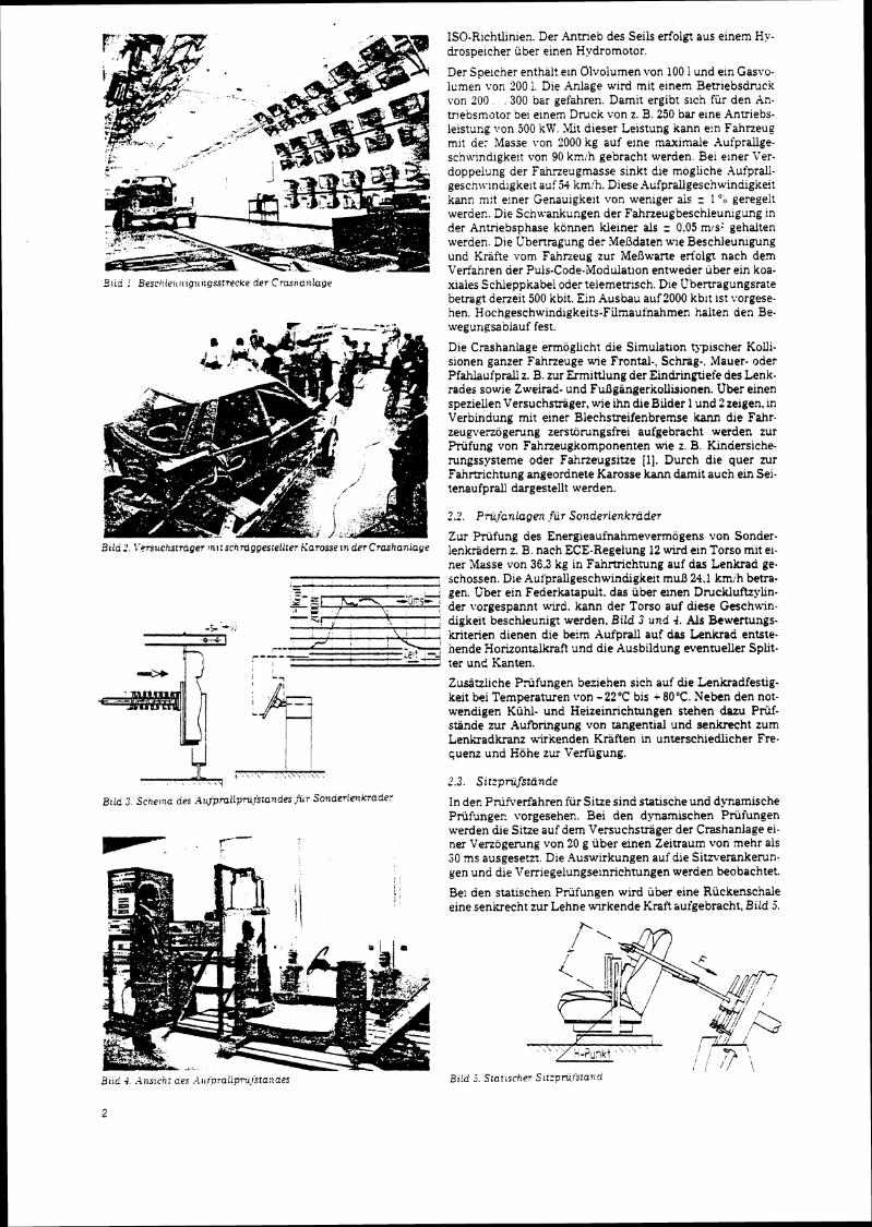
Slid : Besci!le~c~t~g~r?lgsstrecke der Crasnanlage
a ~ i o 2 I'~rstrchstrager ~n~:schrnggesiellier Kasosse tn der Crashanlaye
B ~ l d 2 . Sche:na des .?~~jprallpru.fs~andes $7 Sonderienkrader
ISO-Richtlinien. Der Antneb des Seils erfolgt aus einem Hy. drospelcher uber einen Hydromotor.
Der Spelcher enthal! eln Olvolumen iron 100 1 und ein Gasvo- lumen von 200 1. Die hnlage wird rnit einem Betriebsdruck von 200 ,300 bar gefahren. Damit ergibt slch fur den hn- triebsmator be! einern Druck von z. B. 250 bar eine Antriebs- leistung Iron 500 kW. 4Iit dieser Leistung kann ein Fahrzeug mit de: Masse von 2000 kg auf eine maximale Aufprallge- scnwindigite:t von 90 km:h gebracht werden. Be1 einer Ver- doppelung der Fahneugmasse sinkt die mogliche Aufprall- geschwindigkeit auf 54 kmih. Diese.4ufprallgeschwindigkeit kann m:t e~ner Genauigkeit von wenlger als = 1 % geregelt werder.. Die Schwankungen der Fahneugbeschleunigung in der Antriebsphase konnen kieiner als = 0.05 mrs: gehalten werden. Dle Ubenragung der MeDdaten w e Beschleunigung und Kriifte vom Fahrzeug zur MeRwarte eriolgt nach d e n Verfahren aer Puis-Code-Modulation entweder uber ein koa- xiales Schleppkabel oder telemetrisch. Die t'bertragungsrate betragt deneit 500 kbit. Ein Ausbau auf2000 kblt IS! vorgese- hen. Hochgeschwin&gkeits-Filmaufnahmen halten den Be- wegur~gsablauf fest.
Die Crzshanlaqe errnoglicht die Simulation typischer Kolli- sionen ganzer Fahrzeuge wie Frontal-, Schrag-. Mauer- oder Pfahlaufprall z. B. zur Ermittlung der Eindringtlefe des Lenk- rades sowie Zweirad- und FuRgangerkollisionen. Uber einen speziellen Versuchsdger, wie ihn die Bilder 1 und 2 zeigen, in Verbindung mit einer Blechstreifenbremse kann die Fahr. zeugverzogemng zersttimngsfrei aufgebracht werden zur Priifung von Fahrzeugkomponenten wie z. B. Kindersiche- rungssysteme oder Fahneugsitze [I]. Durch die quer zur Fahmichtung angeordnete Karosse kann damit auch ein Sei- tenaufprail dargestellt werden.
Zur Priifung des Energieaufnahmevermaens von Sonder- lenkfidern z. B. nach ECE-Regelung 12 wird ein Torso rnit el- ner Masse von 36.3 kg in Fahmichtung auf das Lenkrad ge- schossen. Die AufPrallgeschwindigkeit muB 24.1 kmlh betra- gen, t'ber ein Federkatapult. das uber einen Druckluftzylin- der vorgespannt wird. kann der Torso auf &ese Geschwin- digkeit beschleucigt werden. Bild 3 und 4. Als Bewertungs- kriterien dienen die beim Aufprall auf das Lenkrad entste- hende Horizontalkraft und die Ausbildung eventueller Split- ter und Kanten.
Zusitzliche Priifungen beziehen sich auf die Lenkradfestig- keit bei Temperaturen \?on - 22°C bis i 80°C. Neben den not- wendigen Kiihl- und Heizeinrichtungen stehen dazu Priif- stiinde zur Aufbringung von tangential und senkrecht zum Lenkradkranz uirkenden Kraften in unterschiedlicher Fre. quenz und Hohe zur Verfiigung.
In der. Pnifverfahren fur Sitze sind statische und dynamische Priifunger. vorgesehen. Bei den dynamischen Priifungen werden die Sitze auf dem Versuchstriiger der Crashaniage ei- ner Venogerung von 20 g iiber elnen Zeitraum von mehr als 50 ms ausgesetzt. Die Auswirkungen auf die Sitrverankemn- pen und die Ve~legelungseinrichtungen werden beobachtet.
Be! den statischen Priifungen wird uber elne Riickenschde eine senkrecht zur Lehne w~rkende Kraft tiufgebracht, Bild 5.
aria 4. . i l~slcni aes .J.ic<pralipm.rstanaes
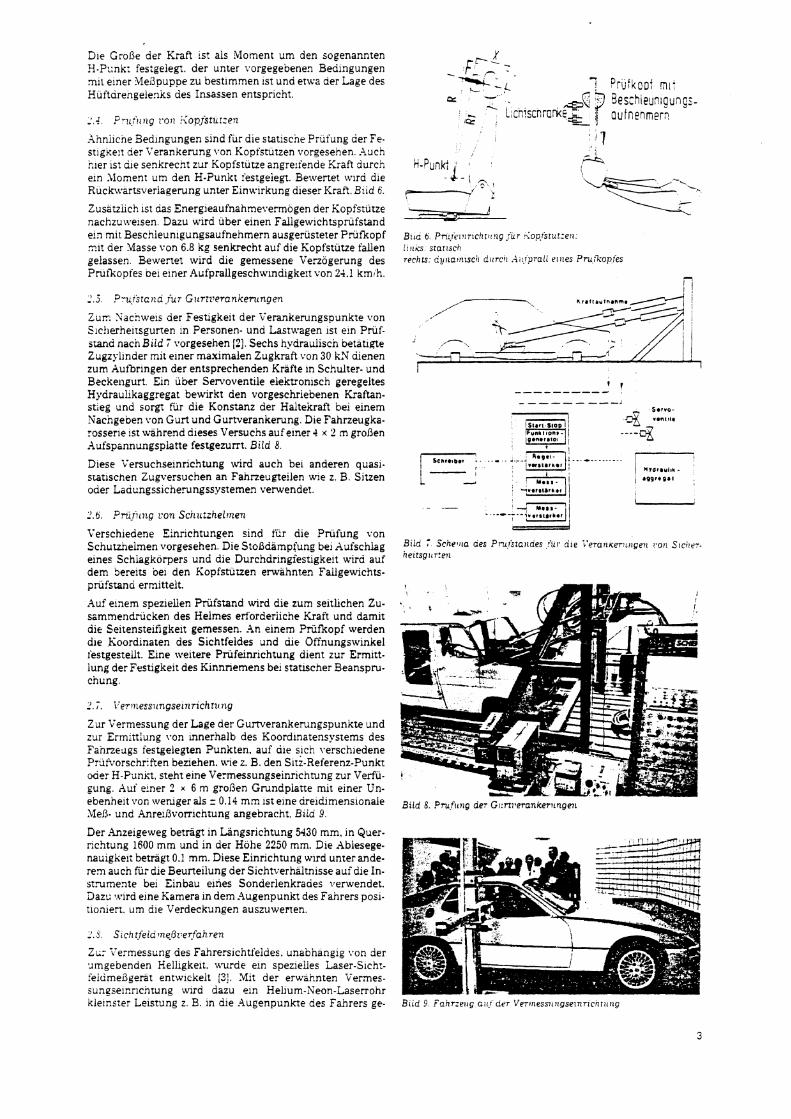
Die GroRe der Kraft 1st ais Moment um den sogenannten H.?::~K: festgelegt. der unter vorgegeoenen Beaingungen mil elner Me13puppe zu bestimmen 1st und etwa der Lage des Huftarengelen~s des Insassen entsprlcht.
.%nnilcne Bedlngungen sind fur dle statiscne Prufung aer Fe- stigse!? aer Yerankerung von Koptstutzen vorqesehen .%uch nler 1st ale senkrecnt zur Kopfstutze angreiiende Kraft durci; ein l lomen? urn den H-Punkt restgeiegt Bervertet \tflrci die Ruckwarts\ eriaqerung unter Einwlrkung dieser Kraft Brid 6
Zusatzlicn 1st das Energieaufnahmevermogen der Kopfstutze nachzu\velsen Dazu wird uber einen Fallgewlchtsprufstand el2 mlt Beschieunigungsaufnehmern ausgerusteter P r ~ f i o p f z a der Masse von 6.8 kg senkrecht auf dle Kopfstutze fallen gelassen Bewertot wlrd dle gemessene Verzogerung des P ru f~opfes oel emer .4ufprallgeschwindigkeit von 21.1 km h
Z u n Sachweis der Festigkeit der Verankerungspunkte von Slc!ierheltsgurten In Personen- und Lastwagen 1st em Priif- stand nacn Biid 7 vorgesehen 121. Sechs hydrauiisch betatipte Zugzyl~nder mit elner maximalen Zugkraft von 30 kN dienen zum Aufbringen der entsprechenden Krafte in Schulter- und Beckengurt. Ein iiber Senoventile elektronisch geregeltes Hydraulikaggregat bewirkt den vorgeschriebenen Kraftan- stieg und sorgt fur die Konstanz der Hal te~raf t bei einem Nacngeben von Gurt und Gurtverankerung. Die Fahrzeugka- rosserle 1st wahrend dieses Versuchs auf einer 4 x 2 m grofien Aufspannungsplatte festgezurrt. Bild 8.
Diese Versuchseinrichtung wird auch be1 anderen quasi. statlschen Zugversuchen an Fahneugteilen wie z. B. Sitzen oder Laaungssicherungssystemen verwende!.
2.6. Pni~icng con Schuizhei~nen
Verschieaene Einricntunger. sind fiir die Pnifung von Schutzheimen vorgesehen. Die StoBdampfung bei Aufschlag eines Schlagkorpers und die Durchdringfestigkelt wird auf dem Sereits bei den Kopfsturzen envahnten Fallgewichts- priifsrand ermittelt.
Auf einem speziellen Priifstand wird die zum seitlichen Zu- scmmendricken des Helrnes erforderiiche Kraft und damit d!e Seitensteifigkeit gemessen. .In einem Priifkopf werden dle Koordinaten des Sichtfeldes and die Offnungswinkel festgestedt. Eine weitere Priifeinrichtung dient zur Ermnt- lung der Festigkeit des f innr iemens bei statlscher Beanspru- chung.
Zur Vermessung der Lage des Gurtverankerungspunkte und zur Ermrttlune von innerhalb des Koordlnatensvsrems des - Fahnedgs festgeiegten Punkten, auf die s,ich verschiedene Prdtkorschriften beziehen. wie z. B. den Sitz-Referenz-Punkt oder H-Pankt, steht eine Vermessungseinrichtung zur Verfii- sung. h u i einer 2 x 6 m groBen Grundpiatte mit einer Un- ebenhelt von weniger als z 0.14 mm 1st elne dreldimensionale Meh- und Anreifivo~~ichtung angebracht. Biia 9.
Der .4nzelgeweg betragt in Langsrichtung 5430 mm, In Quer- richtung 1600 mm und in der Hohe 2250 mm. Die hblesege- na~igkei: betragt 0.1 mm. Diese Einrichtung wird unter ande. rem auch fiir die Beurteilung der Sichtverhiltnisse auidie In- strumente bei Einbau elries Sonaerienkraaes verwendet. 3a.z:: wlrd eine Kamera in dem -4ugenpunkt des Fahrers posi- tloniert, urn ale Verdeckungen auszuwenen.
ZL: Yermessung des Fahrerslchtfeiaes. unabhanglg \,on der %~rngebenaen Helligkeit. uv rde eir. spezielles Laser-S~cht- feiume13gerat entwlckelt [3] Mit der erwafinten Vermes- s~ngseicricnrung wlrd dazu eln Hehum-Keon-Laserrohr kie1ns:er Lelstung z B in die Augenpunkte des Fahrers ge-
Siia : Sche~ita aes Pmfstatldes .%i. dle i'eran~errrigeli !,on Sic i i r r - he~rsg:cr:en
Biid 8. PruStct~g der G~:rt?,erankentngen
Bird 9 r'anrze~cg a1t: arr Ver~nessrcngse!nr~cqr~c~ig
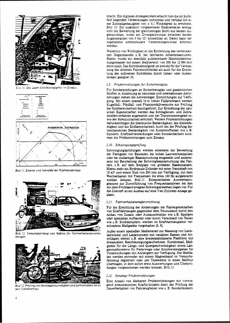
B u d I I . Sche~nc zind iiennfeld der Hydropukanhge
Brld I:' I'etsuchsjahneug unc Mp5ou $UT Fahrwrhalte~rsuntetsii. chungen
bracht. Ein digltaies Anzeigesystem erlaubt nun die in; Slcht- feid llegenden Verdeckungen horzontal und venika! mit ei- ner Einsteligenauigkeit von = 0.1 Rinkelgrad zu ermltteln. Biid ! O . Ein z u s a a c h vorgesehener Strahlenteler ermog. hch: die Bewertung der glelchzeitlgen Sicht aus be~der. Au- genpunkten, wobei ein Divergenzu.in~ei mischen beiaer: Augenstrahien von 0 bis 12' einstellbar ist. Damit kann oer sogenannte amblnokulare Verdeckungsw:nke! ermittrl; werden.
Weiternln von Kichtigkeit m die Entfernung des verdecken- den Gegenstandes z. B. be: fahrbaren Arbeitsmaschiner.. Hierzu ururde em ebenfak aufsteckbarer Nkschbiidentiei- nungsmesser mit einem MeDbereich von 300 bis 12 000 m n entwickelt. Das SichtfeldmeRgerat 1st sowohl fur dle Vermes. sung des direkten Fahrersichtfeides als such fur die Ermiti- lung des inbrekten Sichtfeldes durch lnnen- oder Adsen- spiegei geeignet 141.
Fur Sonderpriifungen an Sicherheitsglae und giaskhnhchen Stoffen in Anlennung an natlonaie. und internationale Anfor- derungen stehen dle notwenhgen Einrichtungen zur Verfii- gung. U t einem sperjell 14 m hohen Fallpriifstand werden KugelfaU-, Pfeilfall- und Pnantomfallversuche zur Prilfung der Sphttersicherheit durchgefiihrt. Zur Ermittlung der opti- schen Eigenschaften werden das Schraglinien- und Zebra- srreifenverfahren angewandt und der Transrmssionsgrad so- wie der Streulichtanteil ermittelt. Weitere Priifeinrichtungen beriicksichtigen Qe thermische Bestindigktit, die Abriebfe- stigkeit und die EnMammbarkeit. Auch be1 der Priifung drr mechanischen Bestiindigkeit von Kunststoffteilen wle z. B. Spoilern. Kraftradverkleidungen oder Sonnendacnern korn- men die Priifeinrichtungen rum Einsatr.
2.1 0. Schwingungsprilfung
Schwingungspriifungen werden einerseits nu Bewertung der Festigkeit von Bauteilen bei hohen Lastwechseizahlen oder be1 s to5mger Beansprucnung eingesetzr und anderer- seits zur Beurteilung der Schwingbeanspruchung des Fah- re:s, z.B auf dem Sluplatz von groberen Rasenmahern Hienu sreht em HydropdeZyhnder mit smer Nennkraft van 16 W und einem Hub von 250 mm zur Verfugung. rn~t dem Wechsellasten mlt Requenzen bis etwa 100 Hz aufgebracht werden konnen, Btld 11. Entsprechende Auswenepro- gramrne zur Durchfuhrung von Frequenzanalgsen be! den rnit dem Prbfstand erregten Schwvlgpstemen hegen vor. Fur b e Zukunft 1st ein Ausbau auf elne Vier-Zyhnder-Adage ge- P ~ L .
Fur die Erminlung der h d e r u n g e n Jer Fahreigenschaften von Iiraftfahrzeugen gegeniiber dem Neuzustand durch den Anbau von Zusatz- oder Austauschteiien wie z.B. Spoilern oder speziellen Aufoauten oder dwch Verschlein von Teilen wie z. B. StoBdampfem, werden im Kraftfahrzeuglaboi ver- schledene Meagerate vorgehalten (5 . 61.
AuBer einem speziellen MeBlenkrad zur Messung von Lenk. radwinkel und Lenkmoment mil variablen Rasren und An- schlagen stehen 2.B. eine kreiselstabilisierte Plattform mi: dreiaxialem Beschleunigungsaufnehmer. Kurskreisel, MeB- geriite fiir die Langs- und Quergeschwindgkeit sowie Lan- genmeRsysteme fiir Federwepe oder K n i c k W e l g e b e r fiir Untersuchungen mit Anhangern zur Verfugung. Die Mefida- ten ulerden entweder mit einem Magnetband irn Versuche- fahrzeug registriert ode; per Telemetrie in einen Mefibus iibertragen, in dem sofort erste Auswertungen und qberpru- fungen vorgenommen werden konnen. Bild 1 2 .
?.i2. Sonstige Priifeinrichtungen
Eine Amah1 von Weineren Priifeinrichtun~en rnit vons7ie- - -~
gend pneumauschen firaftzykndern dient ber Prufung de: Dauerfestlgkeit vor. Fahrzeugteiler. w e z. 9.. Sonderlenkerr.

Kir Motorriider. Zur Uberpriifung von Austauschschall- darnpiern stehen entsprechende Schallpegel-MeB- und Regi- striereinrichtungen zur Verfugung. Die Ermittlung der Mo- torleistung be1 Kraftfahneugen oder der Hochstgeschwin- lgke i t von kleineren rnotonsierten Zweiradern. Bild ;3. ist ebenfalls moglich.
Da das Kraftfanneuglabor weiterhm fur die Vartung und Ka. !ibrierung der im Rahmen der Fahneugreihenuntersuchung und der Typprufung yerwendeten Mefigerate zustanhg 1st. z. B. fur &e Scheinwerfereinstellung, die Ern~ssion von CO irn Abgas oder d ~ e Ermittiung der Fanneugverzegerung, wurden auch hierzu entsprechende Pmf- und Kahbriergerate entwik- kelt
3. Mendatenerfassung und -verarbeitung
Die Datenaufzeichnung erfolgt im allgerneinen auf Bandspei- chern. Fur die Fahrversuche stehen FM-Analog-Bandgerite oder PCM-Bandgerate zur Verfiigung. Weiterhin k t die tele- metrische Gateniibervagung an Versuchstragern in b e MeDwane oder den ~MeBbus vorgegeben. Zur anschliefienden Weitewerarbeitung werden die Daten digi+A oder analog von einem Prozefirechner, der rnlt zwei Plattenspeichern und ei- ner Bandstation ausgeriistet ist, ubernommen. Fiu die Aus- wertung der iiblichen Crash- und Fahrversuche wurden spe- zielle Auswertungsprogamme entwickelt. Die Ergebnisse werden dann in Tabellenform uber einen Dmcker oder anaiog zur Aufzeichnung auf einen XY-Schreiber ausgegeben. Der Prozearechner dient dariiber hinaus auch direkt zur Steue- rung von Einrichtungen wie der Crashanlage und der Hydro- puisanlage.
4. Ausblick
Im Rahrnen einer NeubaurnaBnahme des TUV Rheinland ; c ~ r d e n b e verschiedenen Kraftfahneugprbfeinrichtungen
zu einem Kraftfahneuglabor zusamrnengefiu3t. Obwohl eine grobe Zahl der Priifeinnchtungen spezlell nu Erfiillung der Aniorderungen der geltenden Regelungen und Richtlinien erstellt werden, ergeben sich in vielen F a e n zahlreiche wei- tere Anwendungsmoglichkeiten im Rahmen der Weiterent. wicklung von Fahneugen, Fahneugteilen und Priifverfah- ren. Interessiene HersteUer und Behorden auf &ese Moglich- ke~ten hinzuweisen, 1st das Ziel dieser Darstellung.
[ l ] Hlrscnberger. H. G.. Rompe. K. und Tupova. J.. iintersuchung zur Belastung von Nutzfahneugen be1 Auf fah~nfd ien . Auromobiiin. dusme (1977i. 2. S. 1 1 4 8
121 Hrschberger. H. G. und Felten. G.: Aniorderungen an Gumeran- kerungen. Technische Gbenvachung (1978) 718. S. 215-218
131 Engei. G.: Meoverfahren fur das Slchtfeld aus Kraftfahrzeugen. KoUoquiumsbericht ,,Sicht aus Kraftfahneugen" TLV Rhelnland 1979. S. 189-205
[I] Rompe, K.. Reimann. S. und Engel. G.: Zwecicma!31gkeit elnes rechten AuOensp~egels be1 Personenkraflwagen. Jahrestamng tier Deutschen ~eselischafl fhr ~erkehrsme&z~n e. V.. ~Lnkf.ut. 9.4. 1976
[ 5 ] Rompe. K. und Grunow, D.: Fahrbahngnffigkelt una Fahnerhal- ten von Pkw beim Bremsen m tier Kume. 18. Internat~onaier TISI. T.4.CongreO. 5 . 4 . 5. 1980, Hamburg
[6] Burow, K, und Grunow. D.: Beurteilung des Fahr- und Brernsver. haltens von Pkw-Wohnanhbger-Ziigen. 18. Internationaier PISI. TA-Congrefl, 5 . 4 . 5. 1980, Hamburg
Anschn,ft der VeVasser: Ptivatdozmt Dr.-lng. Klaus Ro.mpe Vordersten Biichel4la. 5064 Rosrarh-Hoxfnungsthal Dr..lng. Peter Wiegner Werheider StraJe 21. 5000 Koin 80


APPENDIX V


I I M I R A 1 I I
1 I _ 1 COUNCIL
3EsT O C I I :
I I I
r I DEFT c7F 1 I
I I L ; ~ A % S ~ C ; T I 1 I I I I
U i R L , E X E C L T I VE C3MMi T T E E 1
1 i i
I I
I ' M i R A I 1 DIRE!T3i?
t I I
I
COMPANY C I R E C T S ? Of S E C R E T A B Y V A K A G E R 1 A ~ E s S ' ~ ~ ~ ~ ~ 1
I I
j S i p v i c E 1 3 E 3 A R T E i N T S j ~ E D ~ ~ ; M E ~ T s
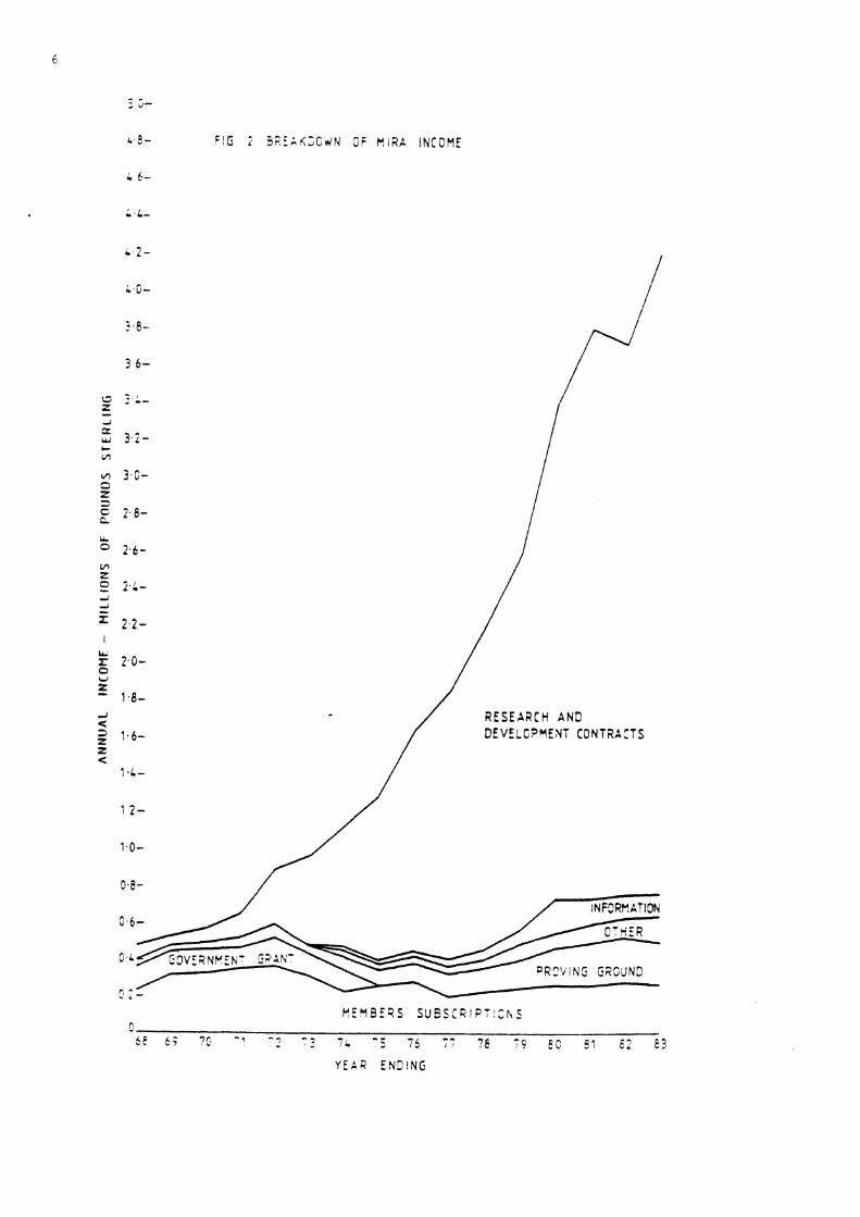
E i G i 3F;EAK;GdN 3 i n i R A I N C O M E
b 2 -
L .0 -
3 6-
2.L-
5 i rr - w 3.2- C L'l
rn 3 .6 - 3 5
2 . 6 - C.
LL
O 2 . 6 - VI Z 0 2.; - - i i
5 2 . 2 - I
2.0- u z - 1.8- -I 4
R E S E A a C H AND
1.6- DEVELC?YENT CONT2A:TS P <
'I ,i-
1 2 -
1.0-
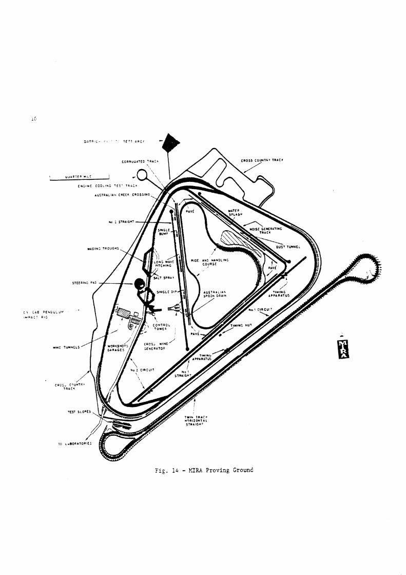
Fig. 1.4 - MIU Proving Grounl


APPENDIX W

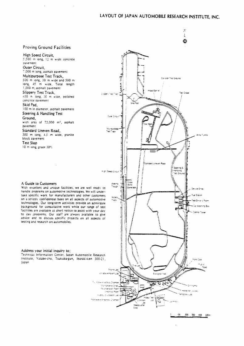
LAYOUT OF jAPAN AUTOMOBILE RESEARCH INSTITUTE, INC.
Proving G r o u n d Facilities
High Speed Circuit, 5,500 m long, 1 2 m w ~ d e concrete lavernent
Outer Circuit, -,000 m long, 2s~ha l t pavement
Multipurpose Test Track, 50G rn ~ong, 30 m w ~ d e and 500 m long, 45 m w ~ d e , Total length 1,000 m, aspnal: pavement
Slippery Test Track, 250 TI long 50 m wroe, pollshed concrete aavemenr
Skid Pad, 100 m In d~amerer, asphalt pavement
Steering & Handling Test Ground, wtth area o f 72,000 m a , asphalt pavement
Standard Uneven Road, 300 rn iong, 4.5 m w ~ d e , eranite block Davement
Test Slop 10 T long, graae 30°1
A Guide to Customers With excelient and unipue facilities, we are well ready to -'OU"
handle problems on automotive technologies. We will under- take specific work for manufacturers and other custom on a strictly coniidential basis on all aspects of automot technologies. Our long-term activities provide an admirable background for consultative work while our range of test facilities are available at short notice to assist with vour day to day .proDiems. Our sraif are always available to give advice and to discuss specific projects on 311 aspects o f testing and research on automobiles.
Address vour initial inquiry to; Technical lniormation Center, Japan Automobile Researcn Institute, Yatabe-cho, Tsukuba-gun, Ibaraki-ken 300.21, Japan
: * ~ c,."*. j:G, Z m
7 , s ' ; - : . 'S .a ' , c r - 3 5
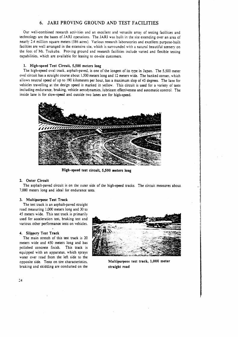
6. JARI PROVING GROUND AND TEST FACILITIES
Our well-combined research activities and an excellent and versatile array of testing facilities and technology are the bases of JARI operations. The JARI was built in the site extending over an area of nearly 2.4 million square meters (586 acres). Various research laboratories and excellent purpose-built facilties are well arranged in the extensive site, which is surrounded with a natural beautiful scenery on the TOOL of Mr. Tsukuba. Pro18ing ground and research facilities include varied and flexible testing capabilities, which are available for leasing to on-site customers.
1. Higb-speed Test Circuit, 5,500 meters long The high-speed oval track, asphalt-paved, is one of the longest of its type in Japan. The 5.500 meter
ovel circuit has 2 suaight course about 1,500 meters long and 12 meters wide. The banked corner. which allows neutral speed of up to 190 kilometers per hour, has a maximum slop of 45 degrees. The lane for vehicles ravelling at the design speed is marked in yellow. This circuit is used for a variety of tests including endurance. braking, vehicle aerodynamics, lubricant efictiveness and automatic control. The inside lane is for slow-speed and outside two lanes are for high-speed.
High-speed test circuit, 5,500 meters long
2. Outer Circuit The asphalt-paved circuit is on the outer side of the high-speed tracks. The circuit measures about
7J00 meters long and ideal for endurance tests.
3. Multipurpose Test Track The test track is an asphalt-paved straight
road measuring 1,000 meters long and 30 to 45 meters wide. This test track is primarily used for acceleration test, braking test and various other performance tests on vehicles.
4. Slippery Test Track The main stretch of this test uack is 20
meters wide and 450 meters long and has polished concrete finish. This track is equipped with an apparatus, which sprays water over road from the left side to the opposite side. Tests on tire characteristics. Multipurpose test track, 1,000 meter braking and skidding are conducted on the straight road

c e ; road surface. I t it also possible to conduct tests on hydroplanning caused by the water film on the road surface. -. _ 5. Wading Trough
The trough is 0.6 meters deep and about 50 meters long. Water depth is adjustable u p to 0.6 meters. I; is used to rest body underfloor construction sealing.
6. Skid P a d A n 1 0 0 - m e t e r
alameter circular rest faciilty paved u i th
-. - asphalt is used prima-
ril! for all types of kandiing tens icclud- - ing tire and brike testing. From the cente: of the pad. u.ater is sprinit led rapid]! for wet testing. Skid pad, 100 meters in diameter
7. Brake Slop It is used mainiy for parking brake test
The length is 10 merers. width 4 meters. grade 30% (16'42') paved with cement concrete
8. Belgian Block Course It is a road featuring rough, uneven
surface for standard test o n general per- formance and d u r a b i l l ~ . Specifications of rhe road surface here eslablished by calcu- lating the mean jalue of the bump) roads rhroughout Japan Four types of granite blocks u l t h bump] surface are embedded inlo the road measuring 300 meters long. 4.5 meters u ~ d e
Belgian block course
9 . Steer ing and Handling Tes t Ground The test ground was constructed in 1972 to conduct o\lerrurning Immunity tests of the domestic
E~per l rnenta l safe^ Vehlcles ( E S I i ) It covers an area of 72.300 square meters and ~t 1s of lnternarional stsndard Slalom and 3-turn tests at thrgh speed and constant clrcular t u r n ~ n g tests are conducted to check the ovenurning immuniry in braking and steering of high-speed resr vehicles. Automatic driving is made possible by an automatic guddance cable system buried under the road surface.
10. Cross-wind Genera tor Thls has five huge eiectric blowers usith maximum output 220 kilo~vatts each in parallel formation.
The mouth of rhe blower mezsures about two meters high and 15 meters long. Wind velocity is changeable i~ three stages from 15 merers to 30 meters per second. This equipment is used to test the
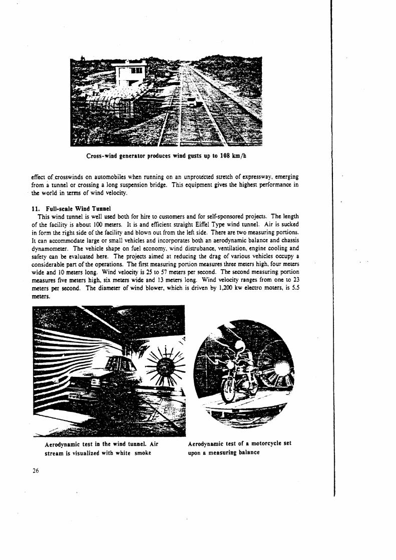
Cross-wind generator produces wind gusts up to 108 km/h
effect of crosswinds on automobiles when running on an unproected suetch of expressway, emerging from a tunnel or crossing a long suspension bridge. This equipment gives the highest performance in the world in terms of wind velocity.
11. Full-scale Wind Tunnel This wind tunnel is well used both for hire to customers and for self-sponsored projects. The length
of the facility is about 100 meters. It is and efficient straight Eiffel Type wind tunnel. Air is sucked in form the right side of the facility and blown out from the left side. There are two measuring portions. It can accommodate large or small vehicles and incorporates both an aerodynamic balance and chassis dynamometer. The vehicle shape on fuel economy, wind disuubance, ventilation, engine cooling and safety can be evaluated here. The projects aimed at reducing the drag of various vehicles occup)~ a considerable pan of the operations. The first measuring ponion measures three merers high, four meters wide and 10 meters long. Wind velocity is 25 to 57 meters per second. The second measuring ponion measures five meters high, six meters wide and 13 meters long. Wind velocity ranges from one to 23 meters per second. The diameter of wind blower, which is driven by 1,200 kw elecvo rnoters, is 5.5 meters.
Aerodynamic test in the wind tunnel. Air Aerodynamic test of a motorcycle set stream is visualized with white smoke upon a measuring balance
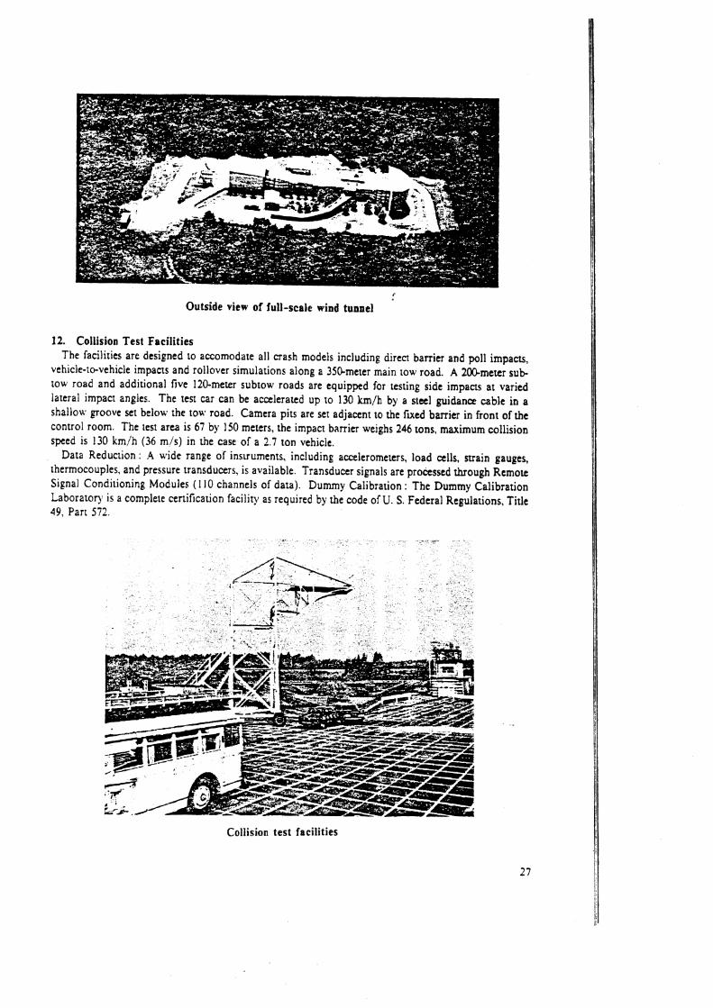
i
Outside view of full-scale wind tunnel
12. Collision Test Facilities The facilities are designed Lo accomodate all crash models including direct barrier and poll impactr,
vehicle-to-vehicle impacts and rollover simulations along a 350-meter main tow road. A 200-meter s u b tow road and additional five 120-meter subtow roads are equipped for testing side impacts at varied lateral impact angles. The test car can be accelerated up to 130 km/h by a steel guidance cable in a shallow groove xt below the tow road. Camera pits are set adjacent to the rued barrier in front of the control room. The test area is 67 by 150 meters, the impact barrier weighs 246 tons, maximum collision speed is !30 !im/h (36 mis) in the case of a 2.7 ton vehicle.
Data Rcducrion : A wide range of insuuments, including accelerometers, load cells, srrain gauges, thermocouples, and pressure transducers, is available. Transducer signals are processed through Remote Signal Conditioning Modules ( 1 10 channels of data). Dummy Calibration : The Dummy Calibration Laborator) is a complete certification facility as required by the code of U. S. Federal Regulations, Title 49, Part 572.
Collision test facilities
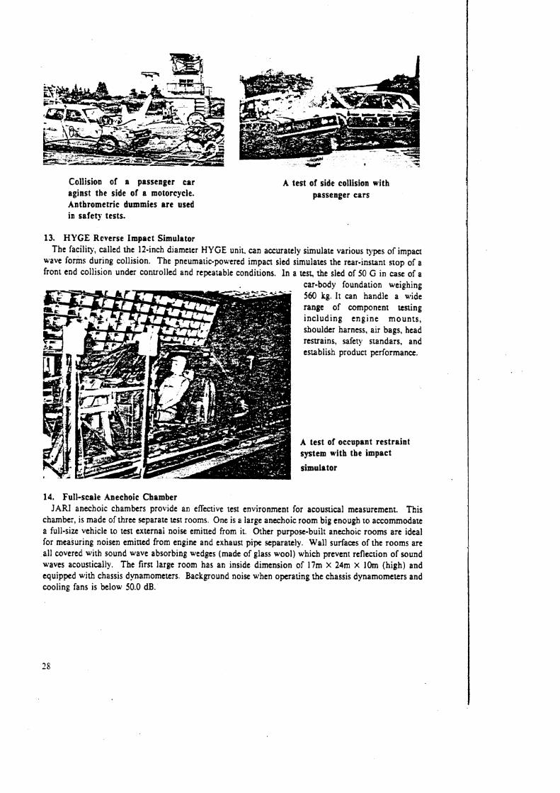
Collision of a passenger car aginst the side of a motorcycle. Anthrometric dummies a re used in safety tests.
A test of side collision with passenger ca rs
13. HYGE Reverse Impact Simulator The facility, called the It-inch diameter HYGE unit, can accurately simulate various types of impact
wave forms during collision. The pneumatic-powered impact sled simulates the rear-instant stop of a front end collision under controlled and repeatable conditions. In a test, the sled of 50 G in case of a
car-body foundation weinhinn 560 kg.-lt can handle a -wid; range of component testing including engine mounts , shoulder harness, air bags, head restrains, safety standars, and establish product performance.
A test of occupant restraint system with the impact
simulator
14. Full-scale Anechoic Chamber J A N anechoic chambers provide an effective test environment for acoustical measurement. This
chamber, is made of three separate test rooms. One is a large anechoic room big enough to accommodate a full-size vehicle to test externai noise emitted from it. Other purpose-built anechoic rooms are ideal for measuring noisen emitted from engine and exhaust pipe separately. Wall surfaces of the rooms are all covered with sound wave absorbing wedges (made of glass wool) which prevent reflection of sound waves acoustically. The first large room has an inside dimension of 17m X 24m X 10m (high) and equipped with chassis dynamometers. Background noise when operating the chassis dynamometers and cooling fans is below 50.0 dB.
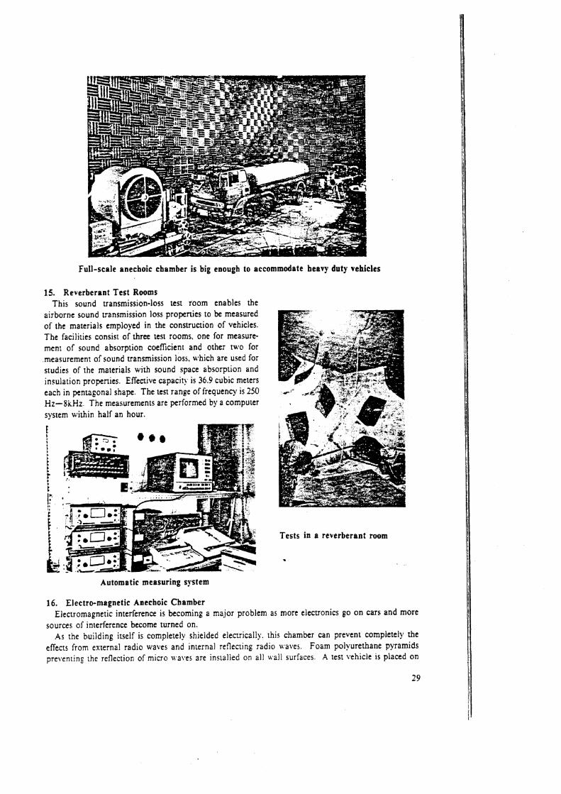
Full-scale anechoic chamber is big enough to accommodate heavy duty vehicles
15. Reverberant Test Rooms This sound transmission-loss test room enables the
airborne sound transmission loss properties to be measured of the materials employed in the construction of vehicles. The facilities consist of three test rooms. one for measure- ment of sound absorption coeficient and other two for .measurement of sound transmission loss, u9hich are used for srudies of the materials with sound space absorption and insulation properties. Effective capacity is 36.9 cubic meters each in pentagonal shape, The ten range of frequency is 250 Hz-8kHz. The measurements are performed by a computer system within half an hour.
Tests in a reverberant room
Automatic measuring system
16. Electro-magnetic Anechoic Chamber Electromagnetic interference is becoming a major problem as more electronics go on cars and more
sources of interference become turned on. As the building itself is completely shielded electrically. this chamber can prevent completely the
effects from external radio ufaves and internal reflecting radio waves. Foam polyurethane pyramids pre \ . en~in the reflection of micro waItes are installed on all wall surfaces. A test vehicle is placed on
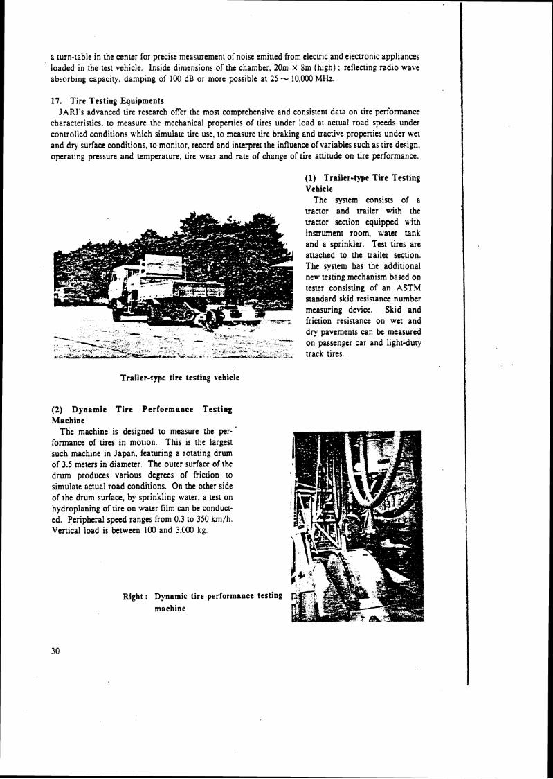
a turn-table in the center for precise measurement of noise emitted from electric and electronic appliances loaded in :he test vehicle. Inside dimensions of the chamber, 20m x 8m (high) ; reflecting radio wave absorbing capacity, damping of 100 dB or more possible at 25 -c 10,000 MHz.
17. Tire Testing Equipments JARl's advanced tire research offer the most comprehensive and consistent data on tire performance
characteristics, to measure the mechanical properties of tires under load at actual road speeds under controlled conditions which simulate tire use, to measure tire braking and tractive properties under wet and dry surface conditions, to monitor, record and interpret the influence of variables such as tire design, operating pressure and temperature, lire wear and rate of change of tire attitude on tire performance.
( 1 ) Trailer-type Tire Testing Vehicle
The system consists of a v a a o r and trailer with the u a a o r section equipped with instrument room, water tank and a sprinkler. Test tires are attached to the trailer section. The system has the additional new testing mechanism based on tester consisting of an ASTM standard skid resistance number measuring device. Skid and - friction resistance on wet and
,. - ".' C
d~ pavements can be measured - - _ ' X-w . - *". . - . on passenger car and light-duty
,b3#k.c .*, ", -,+ -5 -* *- --,,, =--' - - . >, , track tires.
Trailer-type tire testing vehicle
(2) Dynamic T i r e Per formance Test ing M o c b i ~ e
The machine is designed to measure the per- ' formance of tires in motion. This is the largest such machine in Japan, featuring a rotating drum of 3.5 meters in diameter. The outer surface of the drum produces various degrees of friction to simulate actual road conditions. On the other side of the drum surface, by sprinkling water, a test on hydroplaning of tire on water film can be conduct- ed. Peripheral speed ranges from 0.3 to 350 km/h. Venical load is between 100 and 3.000 kg.
Right : Dynamic tire performa machine
.nce testing
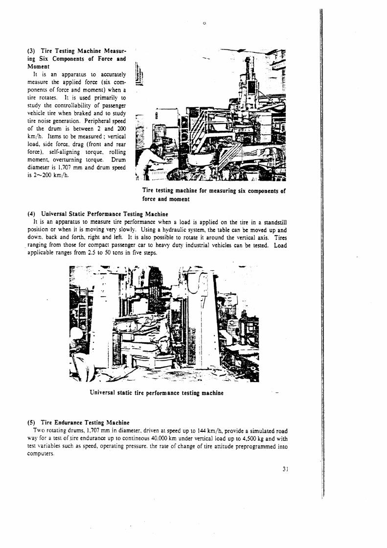
(3) Tire Testing Machine Measur- ing Six Components of Force and Moment
I t is an apparatus to accurately measure the applied force (six com- ponents of force and moment) when a tire rotales. It is used primarily to study the conrrollability of passenger vehicle tire when braked and to study tire noise generation. Peripheral speed of the drum is between 2 and 200 km,!h. Items to be measured ; venical load, side force, drag (front and rear force), self-aligning torque. rolling moment, overturning torque. Drum diameter is 1.707 mm and drum speed is 2-200 km/h.
Tire testing machine for measuring six components of force and moment
(4) Universal Stat ic Performance Testing Machine I t is an apparatus to measure tire performance when a load is applied on the tire in a standstill
position or when it is moving very slowly. Using a hydraulic system, the table can be moved up and down. back and forth, right and left. It is also possible to rotate it around the vertical axis. Tires ranging from those for compacr passenger car to heavy duty industrial vehicles can be tested. Load applicable ranges from 2.5 to 50 tons in five steps.
Universal static tire performance testing machine -
(5) Tire Endurance Testing Machine 'Taro rotating drums, 1,707 mrn in diameter, driven at speed up to la4 km/h, provide a simulated road
ara)' for a test of lire endurance up to contineous 40.000 km under vertical load up to 4,500 kg and with test lfariables such as speed, operating pressure. the rate of change of tire attitude preprogrammed inlo computers.
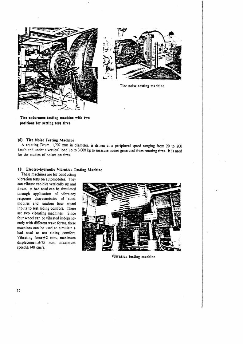
Tire noise testing machine
Tire endurance testing machine with two positions for setting test tires
(6) Tire Noise Testing Machine A rotating Drum, 1,707 rnm in diameter, is driven at a peripheral speed ranging from 20 to 200
km/h and under a vertical load up to 3,000 kg to measure noises generaled from rotating tires. It is used for the studies of noises on tires.
18. Electro-hydraulic Vibration Testing Machine These machines are for conducting
vibration tests on automobiles. They can vibrate vehicles vertically up and down. A bad road can be simulated through application of vibratory response characteristics of auto- mobiles and random four wheel inputs to test riding comfon. There are two vibrating machines. Since four wheel can be vibrated independ- ently with different wave forms, these machines can be used to simulate a bad road to test riding comfon. Vibrating f o r c e l 2 tons. maximum displacement* 75 rnrn, maximum speed+ 140 cm/s.
Vibration testing machine
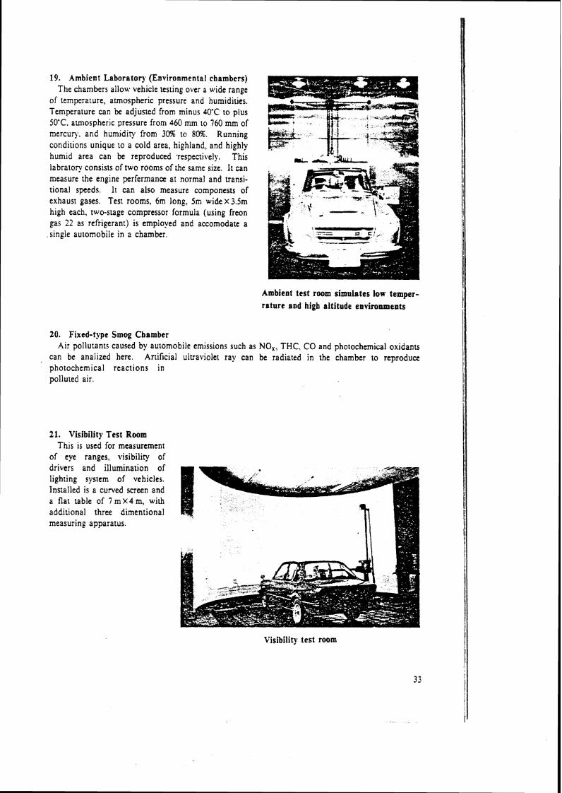
19. Ambient Laboratory (Environmental chambers) The chambers allow vehicle testing over a wide range
of temperature, aunospheric pressure and humidities. Temperature can be adjusted from minus 40'C to plus 50'C. atmospheric pressure from 460 mm to 760 mm of mercury. and humidity from 3m to 80%. Running conaltions unique to a cold area, highland, and highly h u m ~ d area can be reproduced ~espectively. This labratory consists of two rooms of the same size. It can measure the englne perfermancc at normal and transi- tional speeds. It can also measure componests of exhaust gases, Test rooms, 6m long, 5m wide x 3.5m high each, two-stage compressor formula (using freon pas 22 as refriperant) is employed and accomodate a slngle automobile in a chamber.
Ambient test room simulates low temper- rature and high altitude environments
20. Fixed-type Smog Chamber Air pollutants caused by automobile emissions such as NO,, THC, CO and photochemical oxidants
can be analized here. Artificial ultraviolet ray can be radiated in the chamber KO reproduce photochemical reactions in polluted air.
21. Visibility Test Room This is used for measurement
of eye ranges, visibility of drivers and illumination of lighting system of vehicles. Installed is a curved screen and a flat table of 7 m X 4 m, with additional three dimentional measuring apparatus.
Visibility test room

22. Chassis Dynamometers I 1 These d~namomelers, r i l h absorption capacip of up 10 220 H. P., are mainly used for emission s s u ,
but are of course also suitable for general performance testing of vehicles such as measurement of power I at the driving wheels and fuel consumption Test room is operated under a eansunr t c m p n t u r e and ' humidity.
Emission tests with a chasis dynamometer I
Control and measurement room attached to chassis dynamometer
23. Fatigue & Endurance Testing Machine
This is used for the study on the fatigue and endurance performances of various composite ma~erials developed for automotive applications.
Faitigue 8; endurance testing machine
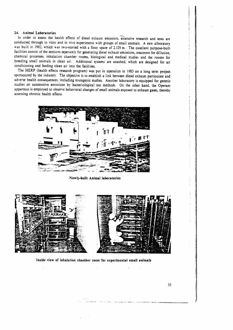
24. Animal Laboratories In order to assess the health effects of diesel exhaust emissiors. ;;tenrive research and tests are
conducted through in viuo and in vivo expr imeas with groups of small animals A new alboratory was built in 1982, which was IWO-storied with a floor space of 2.129 m The excellent purpose-buih facilities consin of the sections seprately for generating diesel exhaust emissions, treatment for dillution, chemical processes, inhalation chamber rooms, biological and medical studies and the rooms for breeding small animals in clean air. Additional systems are attached, which are designed for air conditioning and feeding clean air into the facilities.
The HERP (health ef icts research program) was put in operation in 1983 on a long term project sponsoured by the industry. The objective is to establish a link between diesel exhaust particulate and adverse health consequences, including mutagenic studies. Another laboratory is equipped for genetic studies on automotive emissions by bacteriological test methods On the other hand, the Operant apparatus is employed to observe behavioral changes of small animals exposed to exhaust gases, thereby assessing chronic health effecrs.
Newly-built Animal laboratories


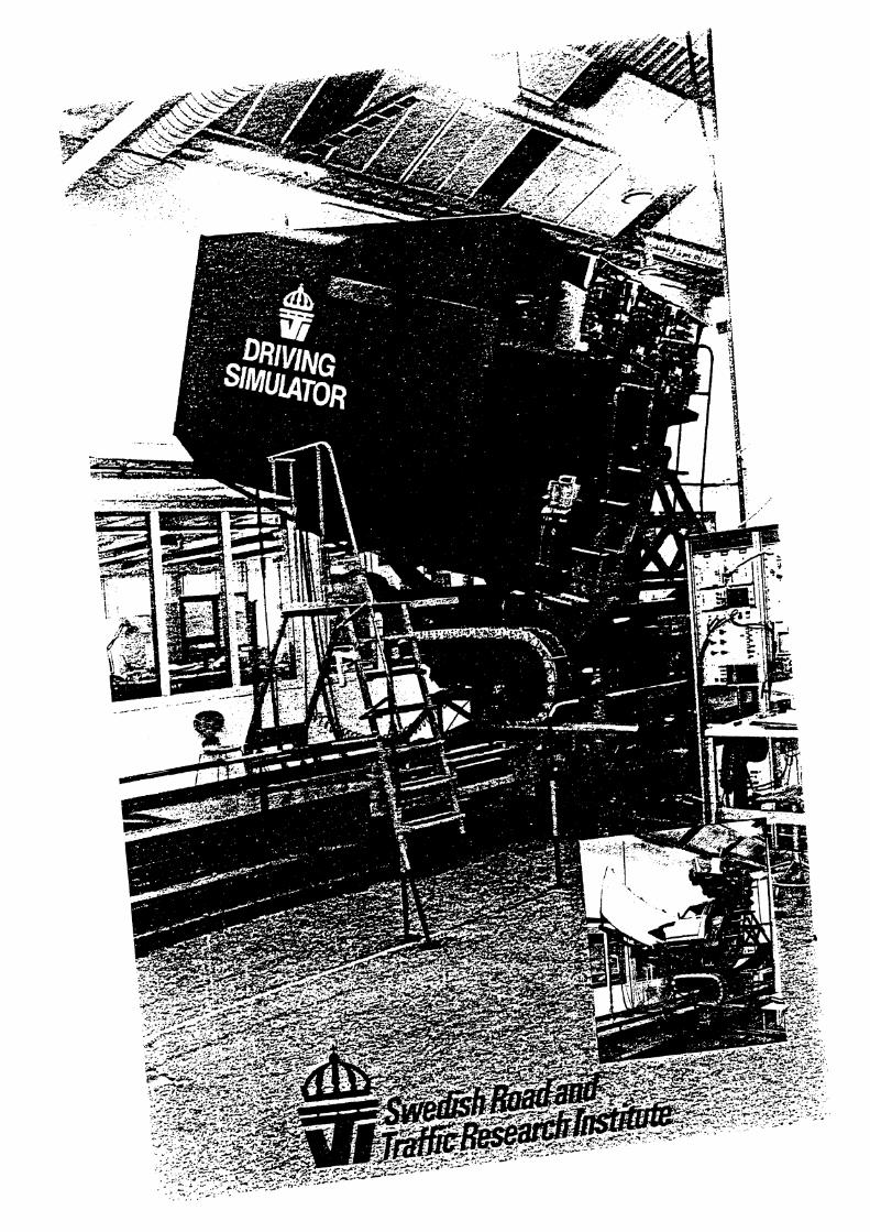
Laborarorie~ for the routine resting of road materials Routine tests of road materials are carried out at a number of laboratories.
5. R8;D RESOURCES The Institute's main R&D resource consists of the competence of individual researchers and groups of researchers in the fields of traffic ingineering transport economy. traffic safety, road user behaviour. biomechanics. vehicle engineering and the construction and operation of roads. In addition the following resources are also available at the Institute.
Esperimen~al road and ciimate units These three units each contain a "tank" in tvhich a full scale roadbed can be built up. "Groundwater" can be led Into the tank. Vari- ous measuring devices. both mechanical and electronic. can be located at desired levels in the different courses making up the roadbed. These units are insulated so that experiments can be carried out throughout the year. One of the units. the climate unit, has especi- ally insulated walls so that temperatures can be varied between -20" and +3U°C irrespective of the time of the year.
Surfacing unir This unit is intended for full scale laboratory experiments on surfacings. It can be heated up to 118" and can therefore be used for experi- ments throughout the year under the same types of conditions.
Road testing machine The machine consists of six wheels that rotate on a circular track - with a median radius of 2.5 m - which can be covered with the different materials to be tested. The machine thus en- ables the rapid testing of different surfacing materials or of studded tyres under "traffic conditions" and under completely controlled conditions with regard to "distance". wheel loading and climate.
Road research laborarories In the road research laboratories experiments are carried out in the f~elds of frost physics. road geolog!'. surface engineering and loading capacity.
Equipmen! for measuring road characrerisric~ .4 considerable proportion of R&D work is carried out in this field. For this purpose a number of special vehicles are available. equipped for measuring and recording the evenness of road surfaces. friction and light re- flecting properties as well as load bearing and deformation properties.
General vehicle equipmenr Experimental vehicle research is carried o u ~ in a well-equipped laboratory which includes a vehicle testing unit and equipment for the test- ing of wheels. vehicle braking and power trans- mission systems, fuel consumption. rolling re- sistance. lyre wear and the strength of towing bars. For the testing of apparatus and the test- lng under driving conditions (not requiring too great space) there is an asphalt covered road- way immediately adjacent to the laboratory.
Tvre testing equipment At present there is some basic laboratory equipment for the testing of tyres. With the aid of funds from the Swedish Board of Technical Development a highly advanced and unique unit is currently being constructed for studies of the dynamic properties of tyres under differ- ent road and climatic conditions. The unit is ex- pected to be completed by 1982.
The biomechanical laborarory In the indoor unit full scale collision tests are carried out (for the analysis of e.g, safety belts. crash helmets, seats, etc.). In an outdoor unit collision test are carried out e.g, on car against car. .car against crash barriers and against lampposts. Both installations permit speeds of up to 110 kmlh with masses of up to 3 metric tons. For recording and evaluation there are anthropometric dummies of various sizes. high- speed accelerometers. a fifty channel tape re- corder and high-speed cameras.
Car simularors A number of simpler types of car simulators (e.g, visual field, vibration. noice) are already available. RTith the aid of funds from the Swed- ish Board of Technical Development work is cur- rentl!; in progress on the development of an ad- vanced car simulator. The car simulator enab- les studies of situations that are either impos- sible or very expensive to test in traffic or at full scale e.g. the different handling characteristics of cars when driven by normal or disabled drivers. or tests concerning different traffic situations or training for cri~ical situations. driving on ice. etc.

The measurement and recording of road user behaviour Equipment is available for the analysis of dif- ferent road user behaviour by recording the movements of driving controls as well as of road user eye. foot and hand movement together with other physiological phenomena such as pulse. breathing and skin resistance. Advanced equipment is also available for the mzasure- ment of various physical reactions that affect behaviour such as light. noise. vibrations and iriction.
Equipmrnrfor rraffic studies Traffic studies are carried out with the aid of traffic recorders which are able to distinguish different types of vehicles and vehicle combin- ations with regard to axle arrangement. the time taken to pass. direction. speed and time gaps between vehicles. Computer cameras adapted for mono-optic or sequence filming under electronic control can be linked to and be synchronically controlled by the traffic recording units. Traffic movements within limited areas are re- corded on video tape.
Trrtffic simularion motiel The development of this model has enabled the description of changes to traffic flows through the detailed study o f the movements of indi- vidual vehicles crossing a given section of road. The simulation model can be used e.g. for com- paring the effects of alternative measures. or combinations of measures. before these are implemented such as changes to speed limits or the introduction of grades.
Compiirer rlehicle simulurion The simulation of a vehicle's movements as a function of the vehicle's construction. loading, speed. road characteristics. tyre characteristics and manoeuvrability can be carried out with the aid of different computer programmes. These enable the testing even iir the construc- tion design stage of the suitability of different construction^.
Consrrucrion office and design workshop The Institute has an office for general machine construction and an experimental workshop. In consultation with research personnel, ap- paratus . measuring devices and machines are developed and produced for the Institute's various R&D activities.
Computers For theoretical research there is a hybrid type EAI-SEL computer system. For digital com- puter programmes the Institute has a type NORD-101s computer equipped with a d ~ s c memory. magnetic band units. line printer and plotter. At present nine terminals are linked to the computer. Some of these terminals can also be linked to outside computers by means of the telephone network.
Information and documenrurion services The Institute's information and documentation section provides scientific documentation and library services. Library s tau are specialists in document searches for literature references as well as projects within the fields covered by the Institute. For these purposes they employ the library's computer terminals for on-line searches with the aid of the library's own corn uterized library catalogue G E O R O A D . the I ~ R D (In- ternational Road Research Documentation) data base as well as a number of other interna- tional data bases. Books etc may be borrowed from the library. or copies can be made. and among other things the library contains 1100 journals and report series.


APPENDIX Y

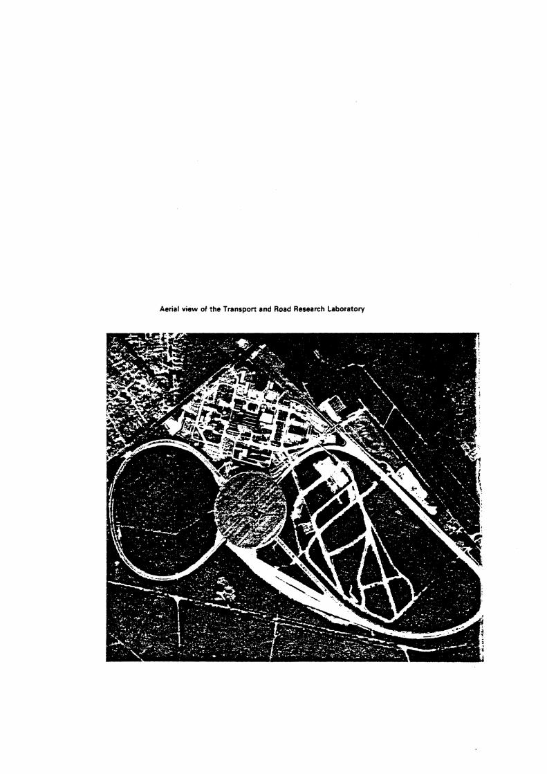
Aerial view of the Transport and Road Research Laboratory
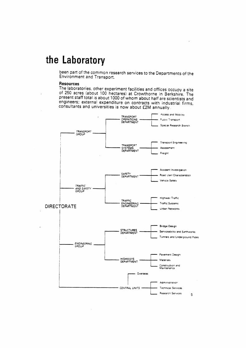
the Laboratory been part of the common research services to the Departments of the Environment and Transport.
Resources The laboratories, other experiment facilities and offices occupy a site of 250 acres (about 100 hectares) at Crowthorne in Berkshire. The present staff total is about 1000 of whom about half are scientists and engineers; external expenditure on contracts with industrial firms, consultants and universities is now about E2M annually.
TRANSPORT [ ~ ~ ~ ~ ~ s 7 ~ ~ ~ s ~ ~ ~ " 1 r '
I
OPERATIONS DEPARTMENT
Specla1 Research Branc-,
TRANSPORT - GROUP
I ransoon Engineering
Assessment DEPARTMENT
AND SAFETY ; : -1 I Htghwav Traffic
DIRECTORATE Trafftc Svsrems
DEPARTMENT Uroan hlerworks
I 1
Brtdge Des~gn
STRUCTURES DEPARTMENT
Se~lceabl l l tv ano Eanhworks i 1 funnels ana Underprouna Pmes
i ENGINERING GROUP
I Pavement 3 m g n 1 . HIGHWAYS
DEPARTMEh? M a r e r ~ a ~ r
I Consrruct~on ana M a ~ n t e n a n c ~
A d m ~ n l s t r a r ~ o ~
Tecnnlcar Services
1 Researcn Services 5

APPENDIX Z

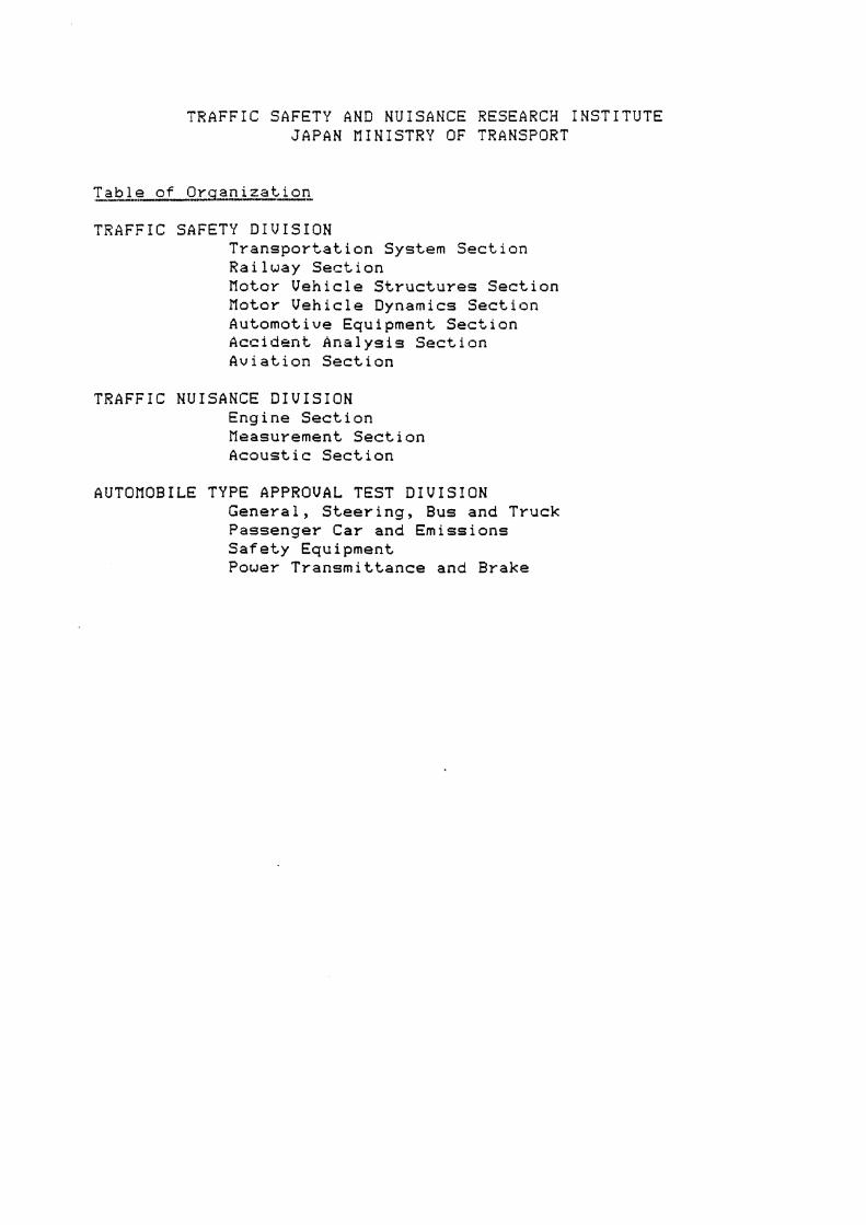
TRAFFIC SAFETY AND NUISANCE RESEARCH INSTITUTE JAPAN MINISTRY OF TRANSPORT
TRAFFIC SAFETY DIVISION Transportation System Section Railway Section Motor Vehicle Structures Section Motor Vehicle Dynamics Section Automotive Equipment Section Accident Analysis Section Aviation Section
TRAFFIC NUISANCE DIVISION Engine Section Measurement Section Acoustic Section
AUTOMOBILE TYPE APPROVAL TEST DIVISION General, Steering, Bus and Truck Passenger Car and Emissions Safety Equipment Power Transmittance and Brake


Bockground
The Federal Motor Vehicle Safety Act passed in 1970 resulted from government recognition of the need for safe motor vehicle daign as one step in arresting the rising human and financial cost of rpotor vehicule acadents.
This legislation and the regulations that followed were designed to develop and enforce safety standards for Canadian and imported passenger vehicles, trucks, trailers, motorcycles and snowmobiles.
The Motor Vehicle Test Centre hiu been established to ensure that these safety standards are properly appiied. The T a t Centre offen a wide range of vehide test facilities to government, industry and private raearch agencies.
The Test Centre is located in Blainvillc, north of Montreal on 550 ha of federal land formerly pan of Camp Boucbrd.
The consmction of the Cmtre was com- pleted in 1979. The cost of the project is S25,7 million, with the buildings accounting for 48.5 million, the equipment 43.5 million and the track facilities S13,7 million.
Administration
This Division of the Test Centre is responsible for the general administration of personnel, finance and other central support services such as budgcwy controi, contact administration, employee relations, publicity, security, purchasing, buildings and maintenance.
Security is maintained 24 hours per day by the Canadian Corps of Commistionaires using a system of pauois and a dosed circuit television system.
The regulations which cover secrrrity and confidentiality of operations at the Test Centre provide that access is Limited to persons bearing identity cards issued by management and speEifying those areas to which access is rauictcd.
Clienrs will be accorded exclusive use of test areas, upon r q u a t , subject to supplementai charges.
Operational safety is the dim respon- sibility of a safety officer with complete control o v a track access and operations. No vehicle is permitted access to tracks without driver certification and being quipped with a mobii radio.
First aid facilities arc available on sire. An ambulance can be provided on stand by, at dient's request.
Fi control is provided by the T a t Centre's own emergency vehicle which is a prototype of the package designed for small airport operations.
TRACKS High Sped Tmck
- Oval design 6.5 km in length
- concrete construction 23 cm thick - width varying from 7.3 m in straight.
ways to 9 m in the curva.
- length of straightways: 1.6 km each
- curves have bem constructed to give "hands off ' speeds of up to 180 kml h
- this track gives dinct access to the brake test a m and the vehicle dynamics area.
Bmk. T r n A m
- Length: 670 m - Width: 27 m
A paved surface of a uniform skid nsis- trance to permit tests by automobiles and trucks. Includes a 4.7 m wide loop at one end to pmnit limited vehide acceleration, as well as a brake soak area up to 1.3 rn in depth.
This track is 7.3 m wide and 6.9 km long. It provides for kilometrage accumulation and o t h a low sped vehide tens ail year round. This track also serves as an access road to orha innallorions.
A nion@k shap#i. 9 ha (2 m) test area to be used for a wide range of tests such as: performance, bnking, handling and guard-&.
Skid Troiiu
A tire and pavement friction testa is available to ten tim in accordance with SAE J345 and pavements in accordance with WM-Ef74-70.
Thit vehide is provided with highly special- ized Bruel & Kjacr equipment such as:
- chart recorders type 2306F and 2307 A - sound level metm type 2209 and 2210
- anaiyren type 2131C and 4426 - ~ p e reorder type 7003F
- exterior miaophone type 4921.
In addition, a pomble NTSC compatible video syrtem and portable weather m a - suring innnvnenu arc available in the rnobiie iabotatory to suppon tests.
Collision Tosting Facility
The facility permits nonnal collision barrier and roilover t a u to be con- ducted and comprises:
- An exterior track of 100 m on which vehicla up to 6 800 kg may be pro- pded against the concrete mass of 181 metric tons, up to spetds of 48 kmlh,
- A computer system aad ample pboto. graphic and supponing facilities to record aasb phenomena
- a propulsion system which includes a linear induction motor of 746 kw.
Can simuiate harsh winta conditions with temperatures between 40OC to 26'C controlied to within 1.5'C and winds up to 24 kmlh and accommodates automobiles and buses.
The overall area is 502 m2 divided in the following way:
- Large chamber:
a surface area of 93 rn2 with a height of 6.4 m.
- Small chamber: a surface area of 28 m2 with a height of 3.7 m.
- Refrigention system con~ining of compressors in series to produce both low temperame ( -15'0 and very low temperature (-45'0 conditions.
- CRR Compressor model 5H40 for low temperature and model SH120 for very low temperature
- Exhaust system for each chamber.
The large environmental t m chamber is unique in that it allows vettide operation under controlkd tcmpeature conditions. To this end, two dynamometm with different characteristics are available to usm:
Smdl dynamometer
Claylon model CTE 50 for t W g of vehicles weighing between 455 kg and 3 034 kg.
The dynamometer is mounted flush with the floor and consisu of two steel rollm with air brakes and pneumaric lift b m e e n the rollm. A powet absorption unit is connected d i y to one of the rollen and inmia weights pennit the simulation if loadings from 455 kg to 4 034 kg.
Large dynamometer
Clayton model CrtGU for testing of heavy vehicles and capable of supporting 10 277 kg per axle with t i m of up to 2.7 m exterior dieter.
The dynamometer is mounted flush with the floor. It consisu of two sets of steel rollers in order to permit the testing of vehicies with twin axles. The dynamo- mern bogie wheels (2 groups of 3 rollers) can be adjured to accept axle spacings of from 1 m to 1.5 m. The dynamometer is also quipped wirfi an independent mechan- ical braking system for safety purposes and to permit easy movement of the vehicles.
bborotory
Area of 4 700 m2 housing many facilities:
A strueturn laboratory quipped with:
- Vehicle Test Struaure having the capacity of verifying the following compliance standards:
- 207 sea anchorage - 210 seat-belt anchorage
- 214 side door strength - 216 roof intrusion
- a bumper pendulum used for testing compliance with standard 21 5
- equipment for verifying compliance standard 201 for occupant restraints.
A vtbide prepamtion loborntory with the foUowing facilities:
- work stations for automobiles and buses
- a Bear T elatronic model 685 whet1 alignment system for automobiles and small trucks
- a dynamometer identical to the small dynamometer located in the environ- mental chamber.
krvio Stat ion
This faciiity which is adjacent to the low sped track is fully quipped to handle normal vehicie service and maintenance operations as well as providing standard fuel ~ r e s and lubricants.
Near the laboratory, this facility pcrmirs intaior storage of a s d number af vehides for short periods of time.
Clients wishmg to store a large number of vehida indoon for kngthy periods of time will be offered somewhat more remote garage facilities.
Weigh kolo
A fully enclosed demonic balance is available to weigh t a t vehiciu. Its maximum capacity is 36 metric tons.
C o n f u u u e Room
A large boardroom with audievisual facilities may be wd for personnel vaining or major m d n g s .
The Test Centre is equipped with a wide range of speclai purpose veScles. These include standard pick-up trucks and station wagon type vehicles, a 4 whet1 drive, 9 090 kg capacity wrecker vehicle. trailors and a multi-purpose industrial all-terrain vehicle.
Electronics laboratory providing for insvument calibration and data acquisi- tion. It includes a computer centre and an independent heating and air condi- tioning system.
A full range of photogxaphic equipment is available for documentation of tests. This includes 35 mm SLR's, Luge format cameras, high speed photographic systems and video tape, all with a full range of acccuories.
A small darkroom facility and photo montage workshop arc also available.
Macbh sbop
Completiy equipped for general repairs and design of new spcchhed equipment.
Gm=otm shop Complesdy equipped for emergency nplirs and design of new equipment.
The control tower enables bolf the low and high speed mlts to be in full v i m and also the complete brake test area. A safety officer conwk all aaivhies on the exterior tcn areas. Effmive conuol is exaciKd mainiy througb the medium of a mobile radio system, supplemented as ncasary by a light signalling system. Also meteorological data are available from the control tower.
A rate schedule which has been developed for services available at the Test Centre is intended to be comparable with other facilities of a similar nature.


