Embed Size (px)
Citation preview
Tutorial #2
(Sessions 1 to 5)
University of Auckland
Faculty of Engineering
Bk/EVolocity/CAD/UoA/20/Tutorial 2/Sessions 1- 5 1.
CAD Tutorial #2: Making a Rocket for 3D printing.
Prepared by University of Auckland Engineering Dept. (Charlie) for EVolocity. Support tutoring by Dr Stephen Kavermann.
Session 1: Rocket Body This tutorial carries on from Tutorial 1 “Making a Key fob Model of KillaJoule”.
Skills developed: Revolving, dimensions, constraints, drawing arcs, etc
Introductory information: This step-by-step tutorial how to create a model rocket Autodesk Fusion 360, suitable for 3D printing. Fusion 360 is a cloud-based, parametric CAD modelling software. It can be run both on PC and Mac. It is free for students and hobbyists and can be downloaded from https://www.autodesk.com/products/fusion-360/overview. A free Autodesk account is needed to access use Fusion 360. You need to name your school or if the school already has an account, check with your teachers to obtain access to it. Follow the onscreen instructions to create an account, download the software, install Fusion 360 and verify your email address. Make sure to select “Free Trial” and then “For personal use”.
1) Open Fusion 360. The first time you open the program you might be asked if you want to create a
team. Follow the instructions and create a single-person team.
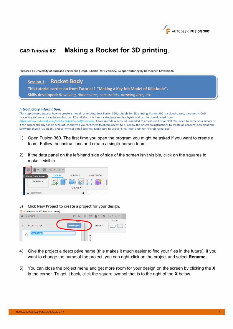
2) If the data panel on the left-hand side of side of the screen isn’t visible, click on the squares to
make it visible
3) Click New Project to create a project for your design.
4) Give the project a descriptive name (this makes it much easier to find your files in the future). If you
want to change the name of the project, you can right-click on the project and select Rename.
5) You can close the project menu and get more room for your design on the screen by clicking the X
in the corner. To get it back, click the square symbol that is to the right of the X below.
Bk/EVolocity/CAD/UoA/20/Tutorial 2/Sessions 1- 5 2.
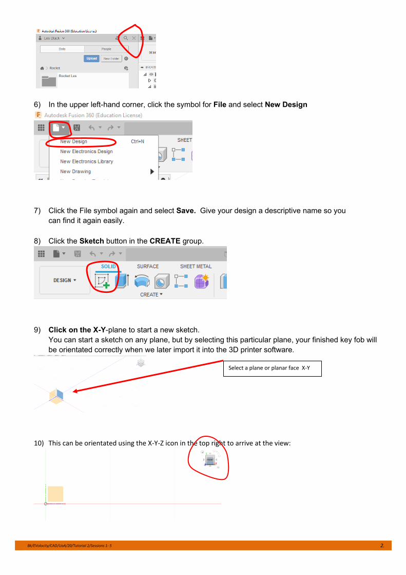
6) In the upper left-hand corner, click the symbol for File and select New Design
7) Click the File symbol again and select Save. Give your design a descriptive name so you
can find it again easily.
8) Click the Sketch button in the CREATE group.
9) Click on the X-Y-plane to start a new sketch.
You can start a sketch on any plane, but by selecting this particular plane, your finished key fob will
be orientated correctly when we later import it into the 3D printer software.
10) This can be orientated using the X-Y-Z icon in the top right to arrive at the view:
Select a plane or planar face X-Y
Bk/EVolocity/CAD/UoA/20/Tutorial 2/Sessions 1- 5 3.
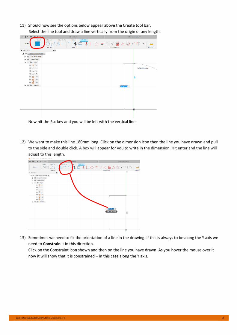
11) Should now see the options below appear above the Create tool bar.
Select the line tool and draw a line vertically from the origin of any length.
Now hit the Esc key and you will be left with the vertical line.
12) We want to make this line 180mm long. Click on the dimension icon then the line you have drawn and pull
to the side and double click. A box will appear for you to write in the dimension. Hit enter and the line will
adjust to this length.
13) Sometimes we need to fix the orientation of a line in the drawing. If this is always to be along the Y axis we
need to Constrain it in this direction.
Click on the Constraint icon shown and then on the line you have drawn. As you hover the mouse over it
now it will show that it is constrained – in this case along the Y axis.
Bk/EVolocity/CAD/UoA/20/Tutorial 2/Sessions 1- 5 4.
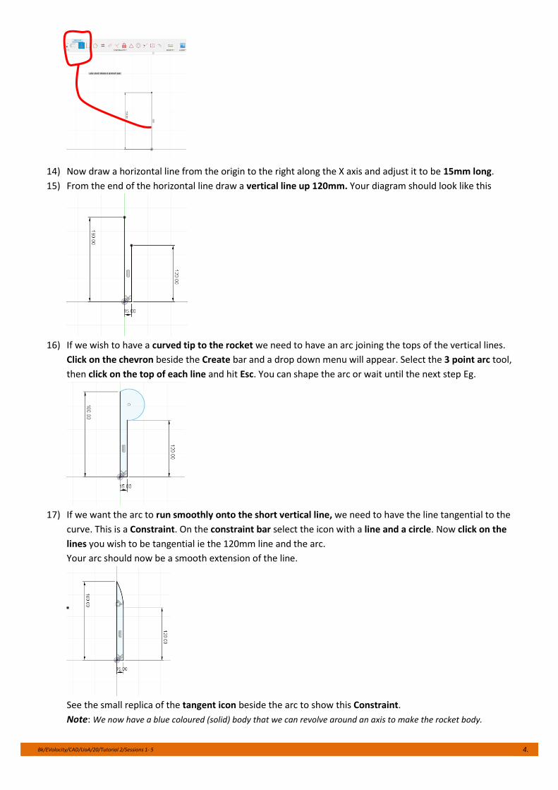
14) Now draw a horizontal line from the origin to the right along the X axis and adjust it to be 15mm long.
15) From the end of the horizontal line draw a vertical line up 120mm. Your diagram should look like this
16) If we wish to have a curved tip to the rocket we need to have an arc joining the tops of the vertical lines.
Click on the chevron beside the Create bar and a drop down menu will appear. Select the 3 point arc tool,
then click on the top of each line and hit Esc. You can shape the arc or wait until the next step Eg.
17) If we want the arc to run smoothly onto the short vertical line, we need to have the line tangential to the
curve. This is a Constraint. On the constraint bar select the icon with a line and a circle. Now click on the
lines you wish to be tangential ie the 120mm line and the arc.
Your arc should now be a smooth extension of the line.
See the small replica of the tangent icon beside the arc to show this Constraint.
Note: We now have a blue coloured (solid) body that we can revolve around an axis to make the rocket body.
Bk/EVolocity/CAD/UoA/20/Tutorial 2/Sessions 1- 5 5.
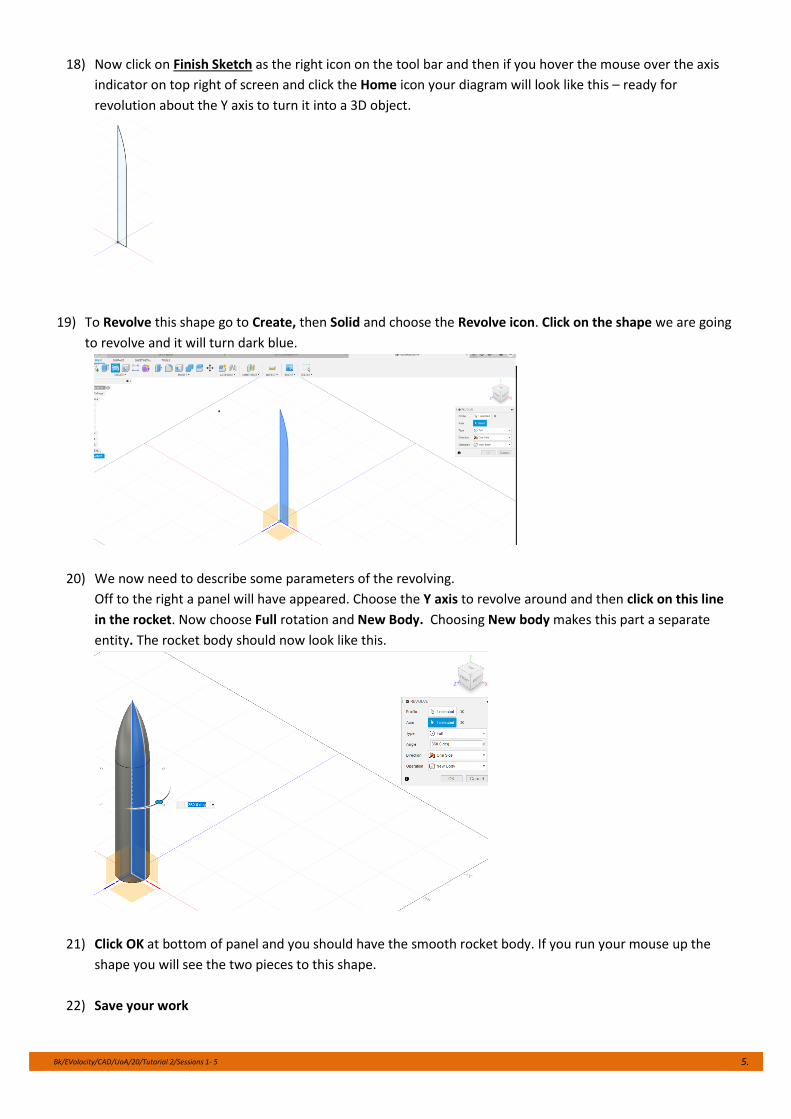
18) Now click on Finish Sketch as the right icon on the tool bar and then if you hover the mouse over the axis
indicator on top right of screen and click the Home icon your diagram will look like this – ready for
revolution about the Y axis to turn it into a 3D object.
19) To Revolve this shape go to Create, then Solid and choose the Revolve icon. Click on the shape we are going
to revolve and it will turn dark blue.
20) We now need to describe some parameters of the revolving.
Off to the right a panel will have appeared. Choose the Y axis to revolve around and then click on this line
in the rocket. Now choose Full rotation and New Body. Choosing New body makes this part a separate
entity. The rocket body should now look like this.
21) Click OK at bottom of panel and you should have the smooth rocket body. If you run your mouse up the
shape you will see the two pieces to this shape.
22) Save your work
Bk/EVolocity/CAD/UoA/20/Tutorial 2/Sessions 1- 5 6.
Session 2: Rocket Fins
We now have the main body of the rocket and will need to give it fins to stabilise it in flight.
Skills developed: extruding, chamfer, fillet. Fixed parameters and pattern tools
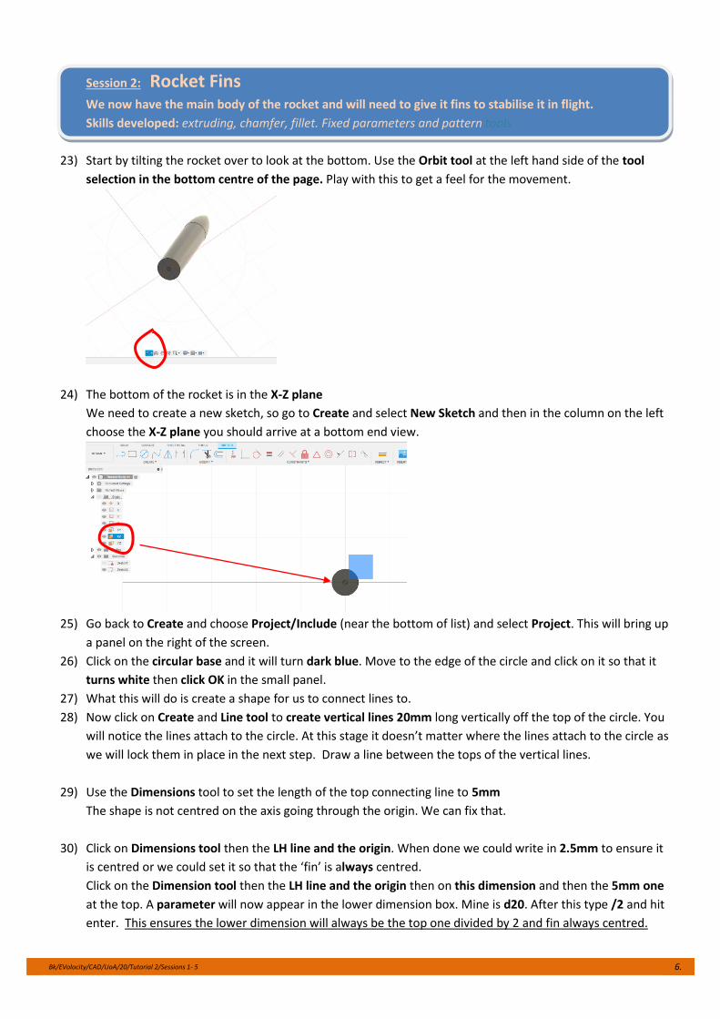
23) Start by tilting the rocket over to look at the bottom. Use the Orbit tool at the left hand side of the tool
selection in the bottom centre of the page. Play with this to get a feel for the movement.
24) The bottom of the rocket is in the X-Z plane
We need to create a new sketch, so go to Create and select New Sketch and then in the column on the left
choose the X-Z plane you should arrive at a bottom end view.
25) Go back to Create and choose Project/Include (near the bottom of list) and select Project. This will bring up
a panel on the right of the screen.
26) Click on the circular base and it will turn dark blue. Move to the edge of the circle and click on it so that it
turns white then click OK in the small panel.
27) What this will do is create a shape for us to connect lines to.
28) Now click on Create and Line tool to create vertical lines 20mm long vertically off the top of the circle. You
will notice the lines attach to the circle. At this stage it doesn’t matter where the lines attach to the circle as
we will lock them in place in the next step. Draw a line between the tops of the vertical lines.
29) Use the Dimensions tool to set the length of the top connecting line to 5mm
The shape is not centred on the axis going through the origin. We can fix that.
30) Click on Dimensions tool then the LH line and the origin. When done we could write in 2.5mm to ensure it
is centred or we could set it so that the ‘fin’ is always centred.
Click on the Dimension tool then the LH line and the origin then on this dimension and then the 5mm one
at the top. A parameter will now appear in the lower dimension box. Mine is d20. After this type /2 and hit
enter. This ensures the lower dimension will always be the top one divided by 2 and fin always centred.
Bk/EVolocity/CAD/UoA/20/Tutorial 2/Sessions 1- 5 7.
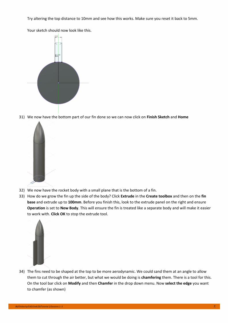
Try altering the top distance to 10mm and see how this works. Make sure you reset it back to 5mm.
Your sketch should now look like this.
31) We now have the bottom part of our fin done so we can now click on Finish Sketch and Home
32) We now have the rocket body with a small plane that is the bottom of a fin.
33) How do we grow the fin up the side of the body? Click Extrude in the Create toolbox and then on the fin
base and extrude up to 100mm. Before you finish this, look to the extrude panel on the right and ensure
Operation is set to New Body. This will ensure the fin is treated like a separate body and will make it easier
to work with. Click OK to stop the extrude tool.
34) The fins need to be shaped at the top to be more aerodynamic. We could sand them at an angle to allow
them to cut through the air better, but what we would be doing is chamfering them. There is a tool for this.
On the tool bar click on Modify and then Chamfer in the drop down menu. Now select the edge you want
to chamfer (as shown)
Bk/EVolocity/CAD/UoA/20/Tutorial 2/Sessions 1- 5 8.
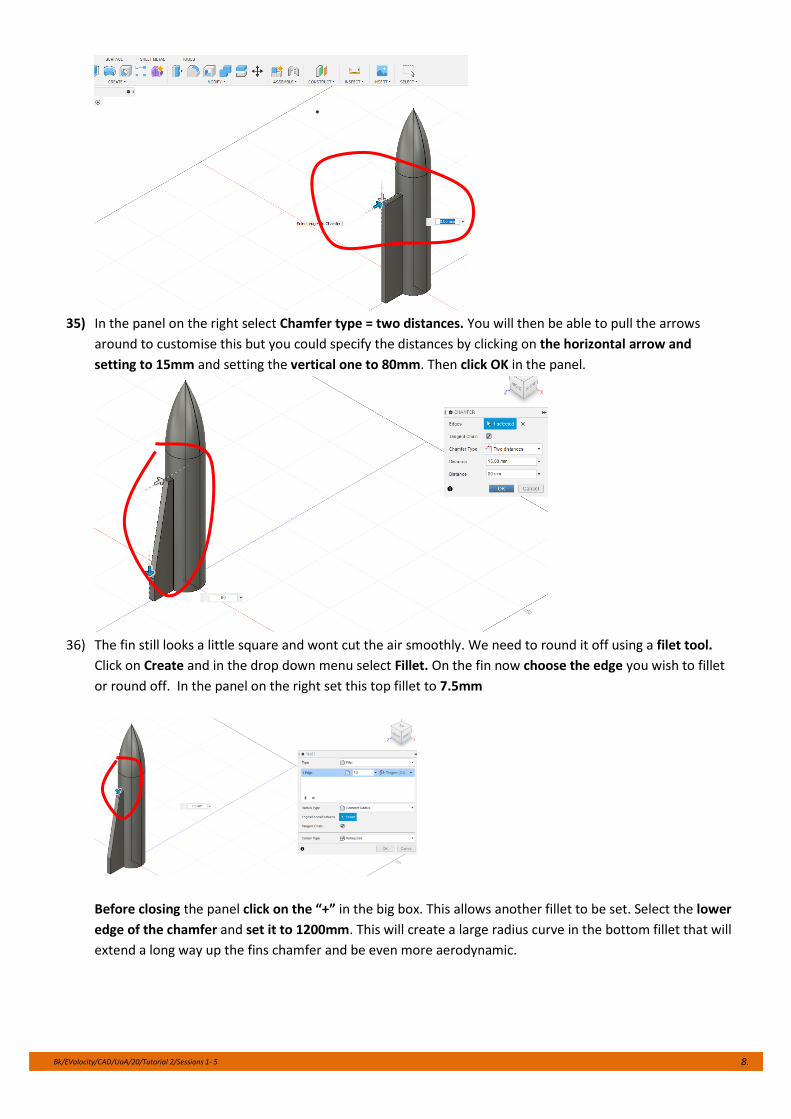
35) In the panel on the right select Chamfer type = two distances. You will then be able to pull the arrows
around to customise this but you could specify the distances by clicking on the horizontal arrow and
setting to 15mm and setting the vertical one to 80mm. Then click OK in the panel.
36) The fin still looks a little square and wont cut the air smoothly. We need to round it off using a filet tool.
Click on Create and in the drop down menu select Fillet. On the fin now choose the edge you wish to fillet
or round off. In the panel on the right set this top fillet to 7.5mm
Before closing the panel click on the “+” in the big box. This allows another fillet to be set. Select the lower
edge of the chamfer and set it to 1200mm. This will create a large radius curve in the bottom fillet that will
extend a long way up the fins chamfer and be even more aerodynamic.
Bk/EVolocity/CAD/UoA/20/Tutorial 2/Sessions 1- 5 9.
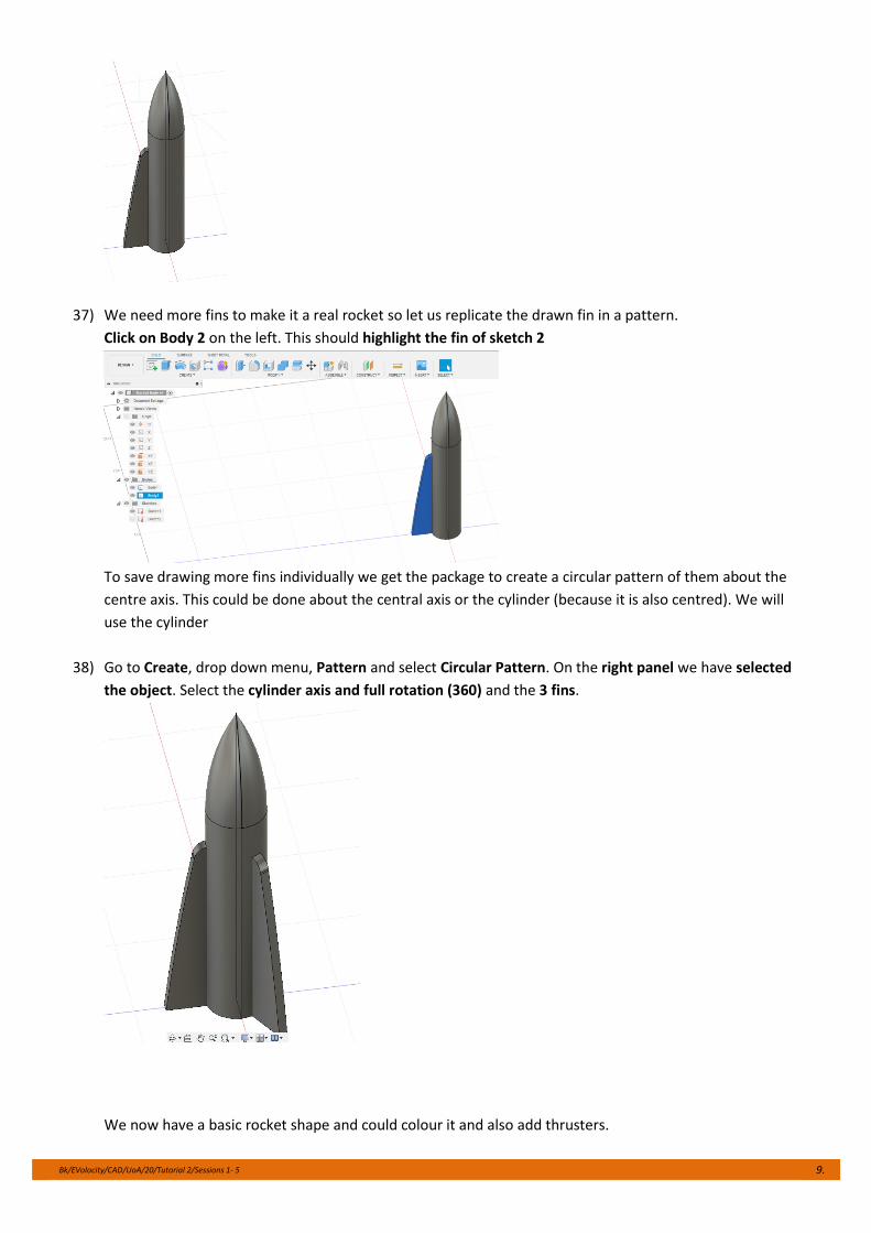
37) We need more fins to make it a real rocket so let us replicate the drawn fin in a pattern.
Click on Body 2 on the left. This should highlight the fin of sketch 2
To save drawing more fins individually we get the package to create a circular pattern of them about the
centre axis. This could be done about the central axis or the cylinder (because it is also centred). We will
use the cylinder
38) Go to Create, drop down menu, Pattern and select Circular Pattern. On the right panel we have selected
the object. Select the cylinder axis and full rotation (360) and the 3 fins.
We now have a basic rocket shape and could colour it and also add thrusters.
Bk/EVolocity/CAD/UoA/20/Tutorial 2/Sessions 1- 5 10.
Session 3: Thrusters
Rockets need motors or thrusters. These need to be placed under the main body.
Skills developed; Offset plane, attaching, lofting, creating a shell hole, creating a pattern
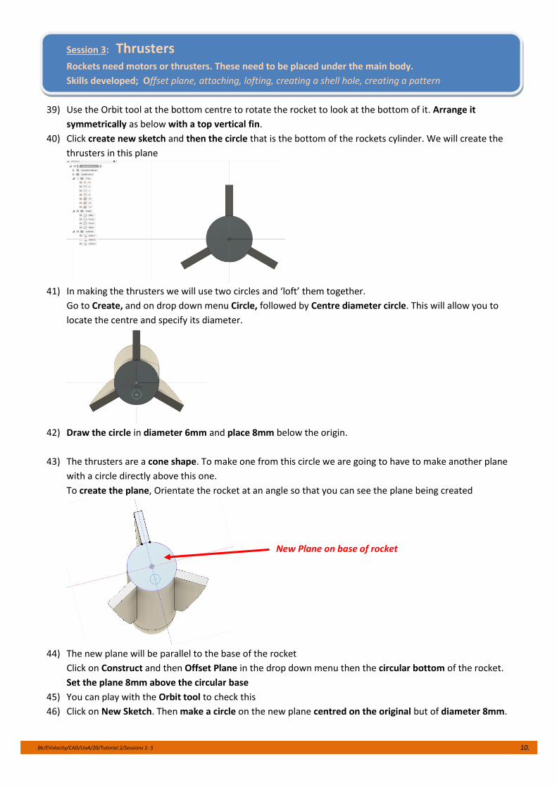
39) Use the Orbit tool at the bottom centre to rotate the rocket to look at the bottom of it. Arrange it
symmetrically as below with a top vertical fin.
40) Click create new sketch and then the circle that is the bottom of the rockets cylinder. We will create the
thrusters in this plane
41) In making the thrusters we will use two circles and ‘loft’ them together.
Go to Create, and on drop down menu Circle, followed by Centre diameter circle. This will allow you to
locate the centre and specify its diameter.
42) Draw the circle in diameter 6mm and place 8mm below the origin.
43) The thrusters are a cone shape. To make one from this circle we are going to have to make another plane
with a circle directly above this one.
To create the plane, Orientate the rocket at an angle so that you can see the plane being created
44) The new plane will be parallel to the base of the rocket
Click on Construct and then Offset Plane in the drop down menu then the circular bottom of the rocket.
Set the plane 8mm above the circular base
45) You can play with the Orbit tool to check this
46) Click on New Sketch. Then make a circle on the new plane centred on the original but of diameter 8mm.
New Plane on base of rocket
Bk/EVolocity/CAD/UoA/20/Tutorial 2/Sessions 1- 5 11.
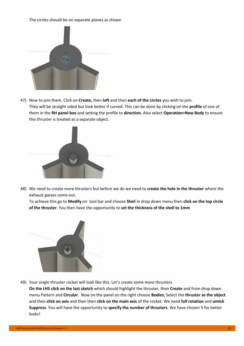
The circles should be on separate planes as shown
47) Now to join them. Click on Create, then loft and then each of the circles you wish to join.
They will be straight sided but look better if curved. This can be done by clicking on the profile of one of
them in the RH panel box and setting the profile to direction. Also select Operation=New Body to ensure
this thruster is treated as a separate object.
48) We need to create more thrusters but before we do we need to create the hole in the thruster where the
exhaust gasses come out.
To achieve this go to Modify on tool bar and choose Shell in drop down menu then click on the top circle
of the thruster. You then have the opportunity to set the thickness of the shell to 1mm
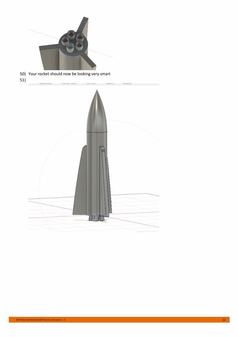
49) Your single thruster rocket will look like this. Let’s create some more thrusters
On the LHS click on the last sketch which should highlight the thruster, then Create and from drop down
menu Pattern and Circular. Now on the panel on the right choose Bodies, Select the thruster as the object
and then click on axis and then then click on the main axis of the rocket. We need full rotation and untick
Suppress. You will have the opportunity to specify the number of thrusters. We have chosen 5 for better
looks!
Bk/EVolocity/CAD/UoA/20/Tutorial 2/Sessions 1- 5 12.
50) Your rocket should now be looking very smart
51)
Bk/EVolocity/CAD/UoA/20/Tutorial 2/Sessions 1- 5 13.
Session 4: A Stand for the Rocket
The rocket probably is quite stable sitting on its thrusters but real rockets have a stand which we can
now create. This requires us to create a place where we can put the tube for the stand ie a little part
with a hole in it that comes off the cylindrical shape.
Skills developed: Off set plane, fixing a position, extruding, creating a hole
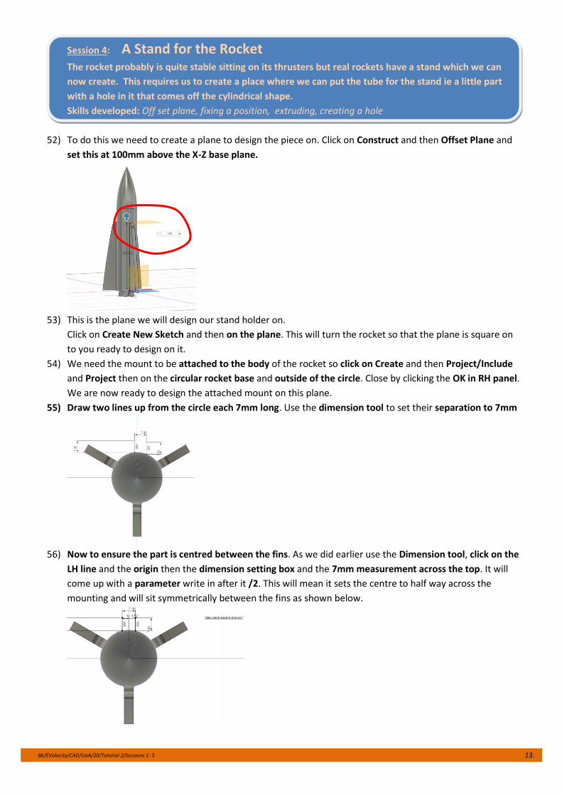
52) To do this we need to create a plane to design the piece on. Click on Construct and then Offset Plane and
set this at 100mm above the X-Z base plane.
53) This is the plane we will design our stand holder on.
Click on Create New Sketch and then on the plane. This will turn the rocket so that the plane is square on
to you ready to design on it.
54) We need the mount to be attached to the body of the rocket so click on Create and then Project/Include
and Project then on the circular rocket base and outside of the circle. Close by clicking the OK in RH panel.
We are now ready to design the attached mount on this plane.
55) Draw two lines up from the circle each 7mm long. Use the dimension tool to set their separation to 7mm
56) Now to ensure the part is centred between the fins. As we did earlier use the Dimension tool, click on the
LH line and the origin then the dimension setting box and the 7mm measurement across the top. It will
come up with a parameter write in after it /2. This will mean it sets the centre to half way across the
mounting and will sit symmetrically between the fins as shown below.
Bk/EVolocity/CAD/UoA/20/Tutorial 2/Sessions 1- 5 14.
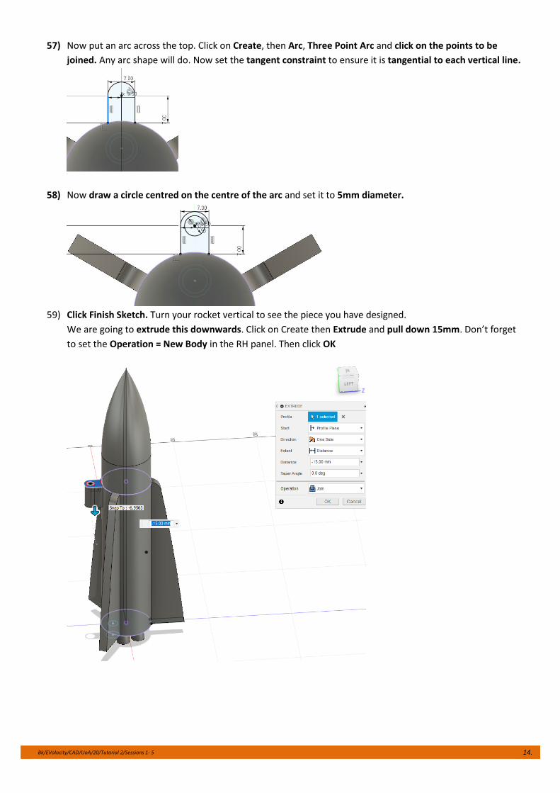
57) Now put an arc across the top. Click on Create, then Arc, Three Point Arc and click on the points to be
joined. Any arc shape will do. Now set the tangent constraint to ensure it is tangential to each vertical line.
58) Now draw a circle centred on the centre of the arc and set it to 5mm diameter.
59) Click Finish Sketch. Turn your rocket vertical to see the piece you have designed.
We are going to extrude this downwards. Click on Create then Extrude and pull down 15mm. Don’t forget
to set the Operation = New Body in the RH panel. Then click OK
Bk/EVolocity/CAD/UoA/20/Tutorial 2/Sessions 1- 5 15.
Session 5: Finishing
Rockets need to look good with an attractive finish and sponsors logos etc on them.
Skills developed: Painting, attaching logos or decals
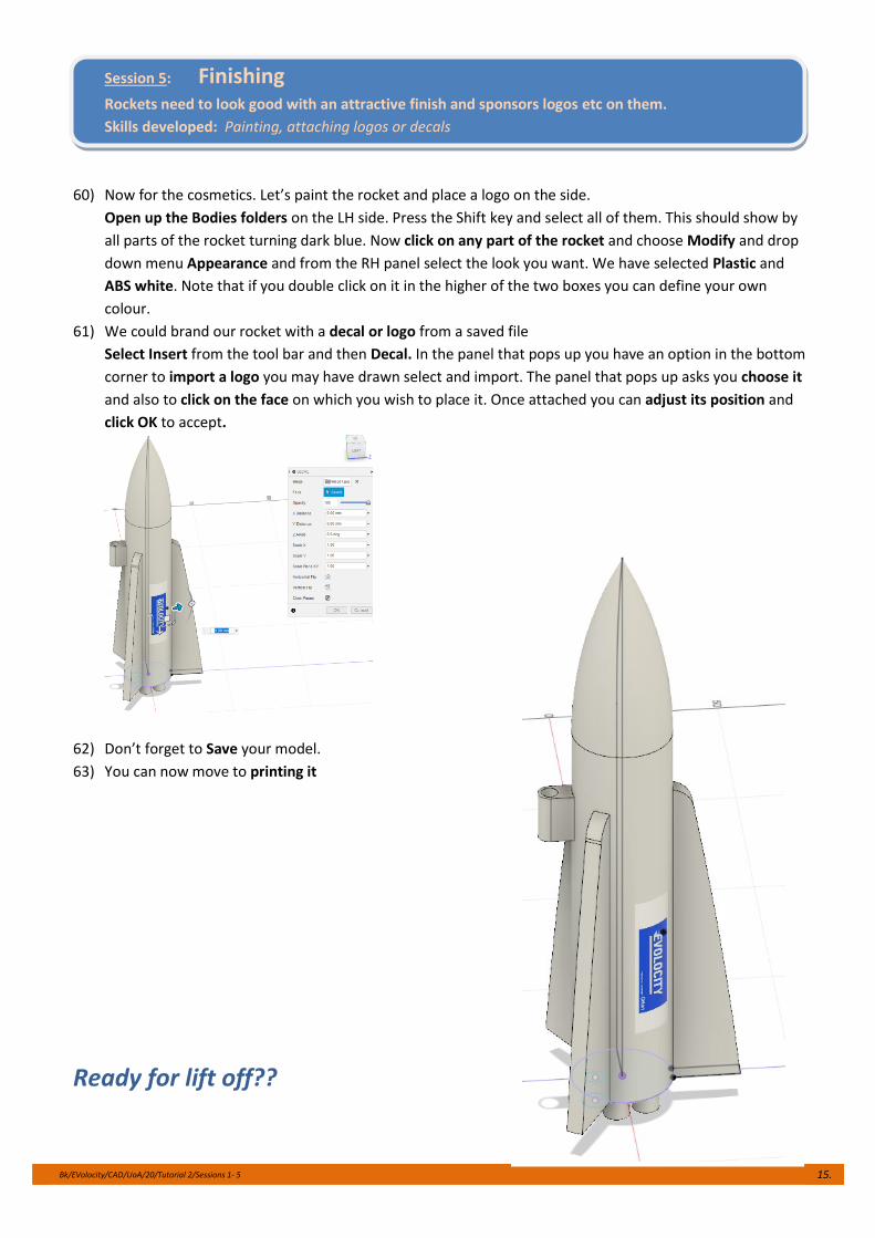
60) Now for the cosmetics. Let’s paint the rocket and place a logo on the side.
Open up the Bodies folders on the LH side. Press the Shift key and select all of them. This should show by
all parts of the rocket turning dark blue. Now click on any part of the rocket and choose Modify and drop
down menu Appearance and from the RH panel select the look you want. We have selected Plastic and
ABS white. Note that if you double click on it in the higher of the two boxes you can define your own
colour.
61) We could brand our rocket with a decal or logo from a saved file
Select Insert from the tool bar and then Decal. In the panel that pops up you have an option in the bottom
corner to import a logo you may have drawn select and import. The panel that pops up asks you choose it
and also to click on the face on which you wish to place it. Once attached you can adjust its position and
click OK to accept.
62) Don’t forget to Save your model.
63) You can now move to printing it
Ready for lift off??