Embed Size (px)
Citation preview

319
© 2010 Pearson Education, Inc., Upper Saddle River, NJ. All rights reserved. This material is protected under all copyright laws as they currentlyexist. No portion of this material may be reproduced, in any form or by any means, without permission in writing from the publisher.
•5–1. Draw the free-body diagram of the 50-kg paper rollwhich has a center of mass at G and rests on the smoothblade of the paper hauler. Explain the significance of eachforce acting on the diagram. (See Fig. 5–7b.)
B
30�
35 mm
A
G
5–2. Draw the free-body diagram of member AB, which issupported by a roller at A and a pin at B. Explain thesignificance of each force on the diagram. (See Fig. 5–7b.)
A
B
8 ft30�
4 ft 3 ft
13 12
5800 lb � ft
390 lb1950 N
1200 N · m
0.9 m1.2 m2.4 m
0.9 m
1950 N
1200 N · m
1.2 m2.4 m
05a Ch05a 319-360.indd 31905a Ch05a 319-360.indd 319 6/12/09 8:42:31 AM6/12/09 8:42:31 AM

320
© 2010 Pearson Education, Inc., Upper Saddle River, NJ. All rights reserved. This material is protected under all copyright laws as they currentlyexist. No portion of this material may be reproduced, in any form or by any means, without permission in writing from the publisher.
5–3. Draw the free-body diagram of the dumpster D of thetruck, which has a weight of 5000 lb and a center of gravityat G. It is supported by a pin at A and a pin-connectedhydraulic cylinder BC (short link). Explain the significanceof each force on the diagram. (See Fig. 5–7b.) 1.5 m
3 m1 m
20� 30�
BA
DG
C
*5–4. Draw the free-body diagram of the beam whichsupports the 80-kg load and is supported by the pin at A anda cable which wraps around the pulley at D. Explain thesignificance of each force on the diagram. (See Fig. 5–7b.)
2 m 2 m
43
5
1.5 m
BA
CE
D
25 kN
truck, which has a weight of 25 kN and a center of gravity
05a Ch05a 319-360.indd 32005a Ch05a 319-360.indd 320 6/12/09 8:42:32 AM6/12/09 8:42:32 AM

•5–5. Draw the free-body diagram of the truss that issupported by the cable AB and pin C. Explain the significanceof each force acting on the diagram. (See Fig. 5–7b.)
A
B
C
2 m 2 m 2 m
2 m
30�
3 kN 4 kN
5–6. Draw the free-body diagram of the crane boom ABwhich has a weight of 650 lb and center of gravity at G. Theboom is supported by a pin at A and cable BC. The load of1250 lb is suspended from a cable attached at B. Explainthe significance of each force acting on the diagram. (SeeFig. 5–7b.)
12
135
GC
A
B
30�
18 ft
12 ft
321
© 2010 Pearson Education, Inc., Upper Saddle River, NJ. All rights reserved. This material is protected under all copyright laws as they currentlyexist. No portion of this material may be reproduced, in any form or by any means, without permission in writing from the publisher.
6.25 kN
W = 3.25 kN
3.6 m
5.4 m
3.6 m
5.4 m
which has a weight of 3.25 kN and center of gravity at G. The boom is supported by a pin at A and cable BC. The load of 6.25 kN is suspended from a cable attached at B. Explain
The Significance of Each Force :
W is the effect of gravity (weight) on the boom.
Ay and Ax are the pin A reactions on the boom.
TBC is the cable BC force reactions on the boom.
6.25 kN force is the suspended load reaction on the boom.
05a Ch05a 319-360.indd 32105a Ch05a 319-360.indd 321 6/12/09 8:42:37 AM6/12/09 8:42:37 AM

322
© 2010 Pearson Education, Inc., Upper Saddle River, NJ. All rights reserved. This material is protected under all copyright laws as they currentlyexist. No portion of this material may be reproduced, in any form or by any means, without permission in writing from the publisher.
5–7. Draw the free-body diagram of the “spannerwrench” subjected to the 20-lb force. The support at A canbe considered a pin, and the surface of contact at B issmooth. Explain the significance of each force on thediagram. (See Fig. 5–7b.)
A
B
6 in.
20 lb
1 in.
*5–8. Draw the free-body diagram of member ABC whichis supported by a smooth collar at A, roller at B, and shortlink CD. Explain the significance of each force acting on thediagram. (See Fig. 5–7b.)
6 m
2.5 kN
60�3 m
4 kN � m
4 m
45�A B
C D
25 mm
150 mm
100 N
100 N
25 mm
175 mm
Wrench” subjected to the 100-N force. The support at A can
05a Ch05a 319-360.indd 32205a Ch05a 319-360.indd 322 6/12/09 8:42:40 AM6/12/09 8:42:40 AM

•5–9. Draw the free-body diagram of the bar, which has anegligible thickness and smooth points of contact at A, B,and C. Explain the significance of each force on thediagram. (See Fig. 5–7b.)
3 in.
5 in.
8 in.A
30�
10 lb
30�
BC
323
© 2010 Pearson Education, Inc., Upper Saddle River, NJ. All rights reserved. This material is protected under all copyright laws as they currentlyexist. No portion of this material may be reproduced, in any form or by any means, without permission in writing from the publisher.
50 N
50 N
200 mm
125 mm
75 mm
75 mm
125 mm
200 mm
75 tan 30° = 43.301 mm
75cos 30°
= 86.603 mm
NA, NB, NC force of wood on bar.
50 N force of hand on bar.
05a Ch05a 319-360.indd 32305a Ch05a 319-360.indd 323 6/12/09 8:42:44 AM6/12/09 8:42:44 AM

324
© 2010 Pearson Education, Inc., Upper Saddle River, NJ. All rights reserved. This material is protected under all copyright laws as they currentlyexist. No portion of this material may be reproduced, in any form or by any means, without permission in writing from the publisher.
5–10. Draw the free-body diagram of the winch, whichconsists of a drum of radius 4 in. It is pin-connected at itscenter C, and at its outer rim is a ratchet gear having a meanradius of 6 in. The pawl AB serves as a two-force member(short link) and prevents the drum from rotating. Explainthe significance of each force on the diagram. (See Fig. 5–7b.)
3 in.
2 in.
6 in.
B
A
500 lb
C
4 in.
5–11. Determine the normal reactions at A and B inProb. 5–1.
75 mm
50 mm
150 mm
2500 N
100 mm
2500 N
100 mm
150 mm
consists of a drum of radius 100 mm. It is pin-connected at its
radius of 150 mm. The pawl AB serves as a two-force member (short link) and prevents the drum from rotating. Explain the significance of each force on the diagram. (See Fig. 5–7b.)
Cx, Cy force of pin on drum.
FAB force of pawl on drum gear.
2500 N force of cable on drum.
05a Ch05a 319-360.indd 32405a Ch05a 319-360.indd 324 6/12/09 8:42:46 AM6/12/09 8:42:46 AM

325
© 2010 Pearson Education, Inc., Upper Saddle River, NJ. All rights reserved. This material is protected under all copyright laws as they currentlyexist. No portion of this material may be reproduced, in any form or by any means, without permission in writing from the publisher.
*5–12. Determine the tension in the cord and thehorizontal and vertical components of reaction at support Aof the beam in Prob. 5–4.
•5–13. Determine the horizontal and vertical componentsof reaction at C and the tension in the cable AB for thetruss in Prob. 5–5.
05a Ch05a 319-360.indd 32505a Ch05a 319-360.indd 325 6/12/09 8:42:48 AM6/12/09 8:42:48 AM

326
© 2010 Pearson Education, Inc., Upper Saddle River, NJ. All rights reserved. This material is protected under all copyright laws as they currentlyexist. No portion of this material may be reproduced, in any form or by any means, without permission in writing from the publisher.
5–14. Determine the horizontal and vertical componentsof reaction at A and the tension in cable BC on the boom inProb. 5–6.
5–15. Determine the horizontal and vertical componentsof reaction at A and the normal reaction at B on thespanner wrench in Prob. 5–7.
*5–16. Determine the normal reactions at A and B and theforce in link CD acting on the member in Prob. 5–8.
3.6 m
5.4 m
6.25 kN
W = 3.25 kN
100 N
150 mm
25 mm
Equations of Equilibrium : The force in cable BC can be obtained directly by summing moments about point A.
�
+ ΣMA = 0; TBC sin 7.380° (9) – 3.25 cos 30° (5.4) – 6.25 sin 60° (9) = 0
TBC = 55.29 kN Ans
+→ ΣFx = 0; Ax – 55.29
12
13
⎛⎝⎜
⎞⎠⎟
= 0
Ax = 51.04 kN Ans
+↑ΣFy = 0; Ay – 3.25 – 6.25 – 55.295
13
⎛⎝⎜
⎞⎠⎟
= 0
Ay = 30.77 kN Ans
�
+ ΣMA = 0; NB (25) – 100 (175) = 0
NB = 700 N Ans
+→ ΣFx = 0; –Ax + 700 = 0
Ax = 700 N Ans
+↑ΣFy = 0; Ay – 100 = 0
Ay = 100 N Ans
05a Ch05a 319-360.indd 32605a Ch05a 319-360.indd 326 6/12/09 8:42:49 AM6/12/09 8:42:49 AM

•5–17. Determine the normal reactions at the points ofcontact at A, B, and C of the bar in Prob. 5–9.
5–18. Determine the horizontal and vertical componentsof reaction at pin C and the force in the pawl of the winch inProb. 5–10.
327
© 2010 Pearson Education, Inc., Upper Saddle River, NJ. All rights reserved. This material is protected under all copyright laws as they currentlyexist. No portion of this material may be reproduced, in any form or by any means, without permission in writing from the publisher.
125 mm
75 tan 30° = 43.3075 mm
50 N
200 mm
150 mm
2500 N
1000 mm
� + ΣMC = 0; FAB
3
13
⎛
⎝⎜
⎞
⎠⎟ 150 – 2500 (100) = 0
FAB = 2003.1 N = 2.003 kN Ans
+→ ΣFx = 0; –Cx + 2003.1
3
13
⎛
⎝⎜
⎞
⎠⎟ = 0
Cx = 1666.7 N = 1.667 kN Ans
+↑ΣFy = 0; –2500 + Cy – 2003.12
13
⎛
⎝⎜
⎞
⎠⎟ = 0
Cy = 3611.1 N = 3.611 kN Ans
+ ↑ΣFx = 0; NC sin 60° – 50 sin 30° = 0
NC = 28.87 N Ans
�
+ ΣMB = 0; 50 cos 30° (325 – 43.30) – NA (125 – 43.30)
– 28.8775
cos 30°
⎛⎝⎜
⎞⎠⎟
= 0
NA = 118.70 N Ans
+ ↑ ΣFy = 0; NB + 28.87 cos 60° + 50 cos 30° – 118.70 = 0
NB = 60.96 N Ans
05a Ch05a 319-360.indd 32705a Ch05a 319-360.indd 327 6/12/09 8:42:50 AM6/12/09 8:42:50 AM

328
© 2010 Pearson Education, Inc., Upper Saddle River, NJ. All rights reserved. This material is protected under all copyright laws as they currentlyexist. No portion of this material may be reproduced, in any form or by any means, without permission in writing from the publisher.
5–19. Compare the force exerted on the toe and heel of a120-lb woman when she is wearing regular shoes andstiletto heels. Assume all her weight is placed on one footand the reactions occur at points A and B as shown.
A AB B
5.75 in.3.75 in.0.75 in.1.25 in.
120 lb120 lb
600 N600 N
31.25 mm
143.75 mm
93.75 mm18.75 mm
600 N woman when she is wearing regular shoes and
600 N600 N
93.75 mm18.75 mm143.75 mm
31.25 mm
�
+ ΣMB = 0; 600 (143.75) – (NA)r (175) = 0
(NA)r = 492.9 N Ans
+↑ΣFy = 0; (NB)r + 492.9 – 600 = 0
(NB)r = 107.1 N Ans
Stiletto heal shoe,
�
+ ΣMB = 0; 600 (93.75) – (NA)s (112.5) = 0
(NA)s = 500 N Ans
+↑ΣFy = 0; (NB)s + 500 – 600 = 0
(NB)s = 100 N Ans
05a Ch05a 319-360.indd 32805a Ch05a 319-360.indd 328 6/12/09 8:42:51 AM6/12/09 8:42:51 AM

*5–20. The train car has a weight of 24 000 lb and a centerof gravity at G. It is suspended from its front and rear on thetrack by six tires located at A, B, and C. Determine thenormal reactions on these tires if the track is assumed to bea smooth surface and an equal portion of the load issupported at both the front and rear tires.
5 ft
A
C
B
G
4 ft
6 ft
329
© 2010 Pearson Education, Inc., Upper Saddle River, NJ. All rights reserved. This material is protected under all copyright laws as they currentlyexist. No portion of this material may be reproduced, in any form or by any means, without permission in writing from the publisher.
1.8 m
120 kN
1.5 m
1.2 m
1.2 m
1.5 m
*5–20. The train car has a weight of 120 kN and a center
�
+ ΣMO = 0; (2 NC) (1.2) – 120 (1.5) = 0
NC = 75 kN Ans
+→ ΣFx = 0; 2 NA – 2 (75) = 0
NA = 75 kN Ans
+↑ΣFy = 0; 2 NB – 120 = 0
NB = 60 kN Ans
05a Ch05a 319-360.indd 32905a Ch05a 319-360.indd 329 6/12/09 8:42:56 AM6/12/09 8:42:56 AM

330
© 2010 Pearson Education, Inc., Upper Saddle River, NJ. All rights reserved. This material is protected under all copyright laws as they currentlyexist. No portion of this material may be reproduced, in any form or by any means, without permission in writing from the publisher.
•5–21. Determine the horizontal and vertical componentsof reaction at the pin A and the tension developed in cableBC used to support the steel frame.
A
B
C
30 kN � m
60 kN
1 m
3 m
1 m 1 m
5 4
3
05a Ch05a 319-360.indd 33005a Ch05a 319-360.indd 330 6/12/09 8:43:00 AM6/12/09 8:43:00 AM

5–22. The articulated crane boom has a weight of 125 lb andcenter of gravity at G. If it supports a load of 600 lb, determinethe force acting at the pin A and the force in the hydrauliccylinder BC when the boom is in the position shown.
C
40�
BGA 1 ft
4 ft
1 ft
8 ft
331
© 2010 Pearson Education, Inc., Upper Saddle River, NJ. All rights reserved. This material is protected under all copyright laws as they currentlyexist. No portion of this material may be reproduced, in any form or by any means, without permission in writing from the publisher.
1.2 m
0.3 m
2.4 m
0.3 m
2.4 m
625 N
3000 N
1.2 m
0.3 m
0.3 m
5–22. The articulated crane boom has a weight of 625 N and center of gravity at G. If it supports a load of 3000 N, determine the force acting at the pin A and the force in the hydraulic cylinder BC when the boom is in the position shown.
�
+ ΣMA = 0; FB cos 40° (0.3) + FB sin 40° (0.3) – 625 (1.2) – 3000 (2.7) = 0
FB = 20939.3 N = 20.94 kN Ans
+→ ΣFx = 0; –Ax + 20939.3 cos 40° = 0
Ax = 16040.4 = 16.04 kN Ans
+↑ΣFy = 0; –Ay + 20939.3 sin 40° – 3000 – 625 = 0
Ay = 9.83 kN Ans
05a Ch05a 319-360.indd 33105a Ch05a 319-360.indd 331 6/12/09 8:43:03 AM6/12/09 8:43:03 AM

332
© 2010 Pearson Education, Inc., Upper Saddle River, NJ. All rights reserved. This material is protected under all copyright laws as they currentlyexist. No portion of this material may be reproduced, in any form or by any means, without permission in writing from the publisher.
5–23. The airstroke actuator at D is used to apply a force ofF = 200 N on the member at B. Determine the horizontaland vertical components of reaction at the pin A and theforce of the smooth shaft at C on the member.
A
C
B
D60�
600 mm
600 mm
15�
200 mmF
05a Ch05a 319-360.indd 33205a Ch05a 319-360.indd 332 6/12/09 8:43:05 AM6/12/09 8:43:05 AM

*5–24. The airstroke actuator at D is used to apply a forceof F on the member at B. The normal reaction of thesmooth shaft at C on the member is 300 N. Determine themagnitude of F and the horizontal and vertical componentsof reaction at pin A.
A
C
B
D60�
600 mm
600 mm
15�
200 mmF
333
© 2010 Pearson Education, Inc., Upper Saddle River, NJ. All rights reserved. This material is protected under all copyright laws as they currentlyexist. No portion of this material may be reproduced, in any form or by any means, without permission in writing from the publisher.
05a Ch05a 319-360.indd 33305a Ch05a 319-360.indd 333 6/12/09 8:43:08 AM6/12/09 8:43:08 AM

334
© 2010 Pearson Education, Inc., Upper Saddle River, NJ. All rights reserved. This material is protected under all copyright laws as they currentlyexist. No portion of this material may be reproduced, in any form or by any means, without permission in writing from the publisher.
•5–25. The 300-lb electrical transformer with center of gravityat G is supported by a pin at A and a smooth pad at B.Determine the horizontal and vertical components of reactionat the pin A and the reaction of the pad B on the transformer.
B
A
1.5 ft
3 ft G
0.45 m
0.9 m
0.45 m
1500 N
0.9 m
•5–25. The 1500-N electrical transformer with center of gravity at G is supported by a pin at A and a smooth pad at B. Determine the horizontal and vertical components of reaction at the pin A and the reaction of the pad B on the transformer.
Equations of Equilibrium: From the free – body diagram of the transformer, Fig. a, NB and Ay can be obtained by writing the moment equation of equilibrium about point A and the force equation of equilibrium along the y axis.
�
+ ΣMA = 0; NB (0.9) – 1500 (0.45) = 0
NB = 750 N Ans.
+↑ΣFy = 0; Ay – 1500 = 0
Ay = 1500 N Ans.
Using the result NB = 750 N and writing the force equation of equilibrium along the x axis,
+→ ΣFx = 0; 750 – Ax = 0
Ax = 750 N Ans.
05a Ch05a 319-360.indd 33405a Ch05a 319-360.indd 334 6/12/09 8:43:11 AM6/12/09 8:43:11 AM

335
© 2010 Pearson Education, Inc., Upper Saddle River, NJ. All rights reserved. This material is protected under all copyright laws as they currentlyexist. No portion of this material may be reproduced, in any form or by any means, without permission in writing from the publisher.
5–26. A skeletal diagram of a hand holding a load is shownin the upper figure. If the load and the forearm have massesof 2 kg and 1.2 kg, respectively, and their centers of mass arelocated at and , determine the force developed in thebiceps CD and the horizontal and vertical components ofreaction at the elbow joint B. The forearm supportingsystem can be modeled as the structural system shown inthe lower figure.
G2G1
B
BC
C
D
D
G2
G2
G1
G1
A
A135 mm
65 mm
75�
100 mm
05a Ch05a 319-360.indd 33505a Ch05a 319-360.indd 335 6/12/09 8:43:15 AM6/12/09 8:43:15 AM

336
© 2010 Pearson Education, Inc., Upper Saddle River, NJ. All rights reserved. This material is protected under all copyright laws as they currentlyexist. No portion of this material may be reproduced, in any form or by any means, without permission in writing from the publisher.
5–27. As an airplane’s brakes are applied, the nose wheelexerts two forces on the end of the landing gear as shown.Determine the horizontal and vertical components ofreaction at the pin C and the force in strut AB.
20�
30�
2 kN
6 kN
B
A
600 mm
400 mm
C
05a Ch05a 319-360.indd 33605a Ch05a 319-360.indd 336 6/12/09 8:43:18 AM6/12/09 8:43:18 AM

337
© 2010 Pearson Education, Inc., Upper Saddle River, NJ. All rights reserved. This material is protected under all copyright laws as they currentlyexist. No portion of this material may be reproduced, in any form or by any means, without permission in writing from the publisher.
*5–28. The 1.4-Mg drainpipe is held in the tines of the forklift. Determine the normal forces at A and B as functions ofthe blade angle and plot the results of force (vertical axis)versus (horizontal axis) for 0 … u … 90°.u
u 0.4 m
AB u
05a Ch05a 319-360.indd 33705a Ch05a 319-360.indd 337 6/12/09 8:43:20 AM6/12/09 8:43:20 AM

338
© 2010 Pearson Education, Inc., Upper Saddle River, NJ. All rights reserved. This material is protected under all copyright laws as they currentlyexist. No portion of this material may be reproduced, in any form or by any means, without permission in writing from the publisher.
•5–29. The mass of 700 kg is suspended from a trolleywhich moves along the crane rail from to
. Determine the force along the pin-connectedknee strut BC (short link) and the magnitude of force at pinA as a function of position d. Plot these results of and (vertical axis) versus d (horizontal axis).
FAFBC
d = 3.5 md = 1.7 m A
B
C
2 m
1.5 m
d
05a Ch05a 319-360.indd 33805a Ch05a 319-360.indd 338 6/12/09 8:43:21 AM6/12/09 8:43:21 AM

339
© 2010 Pearson Education, Inc., Upper Saddle River, NJ. All rights reserved. This material is protected under all copyright laws as they currentlyexist. No portion of this material may be reproduced, in any form or by any means, without permission in writing from the publisher.
5–30. If the force of F = 100 lb is applied to the handle ofthe bar bender, determine the horizontal and verticalcomponents of reaction at pin A and the reaction of theroller B on the smooth bar.
60�
F40 in.
5 in.
BA
C
1000 mm
125 mm
500 N
1000 mm
125
mm
5–30. If the force of F = 500 N is applied to the handle of
Equations of Equilibrium: From the free – body diagram of the handle of the bar bender, Fig. a, Ay and NB can be obtained by writing the force equation of equilibrium along the y axis and the moment equation of equilibrium about point A, respectively.
+↑ΣFy = 0; Ay – 500 sin 30° = 0
Ay = 250 N Ans.
�
+ ΣMA = 0; NB cos 60° (125) – 500 (1000) = 0
NB = 8000 N = 8.0 kN Ans.
Using the result NB = 8000 N and writing the force equation of equilibrium along the x axis,
+→ ΣFx = 0; Ax – 8000 + 500 cos 30° = 0
Ax = 7567.0 N = 7.567 kN Ans.
05a Ch05a 319-360.indd 33905a Ch05a 319-360.indd 339 6/12/09 8:43:24 AM6/12/09 8:43:24 AM

340
© 2010 Pearson Education, Inc., Upper Saddle River, NJ. All rights reserved. This material is protected under all copyright laws as they currentlyexist. No portion of this material may be reproduced, in any form or by any means, without permission in writing from the publisher.
5–31. If the force of the smooth roller at B on the barbender is required to be 1.5 kip, determine the horizontaland vertical components of reaction at pin A and therequired magnitude of force F applied to the handle.
60�
F40 in.
5 in.
BA
C
125
mm
1000 mm
1000 mm
125 mm
bender is required to be 7.5 kN, determine the horizontal
Equations of Equilibrium: From the free – body diagram of the handle of the bar bender, Fig. a, force F can be obtained by writing the moment equation of equilibrium about point A.
�
+ ΣMA = 0; 7.5 cos 60° (125) – F(1000) = 0
F = 0.46875 kN Ans.
Using the above result and writing the force equation of equilibrium along the x and y axis,
+→ ΣFx = 0; Ax + 0.46875 cos 30° – 7.5 = 0
Ax = 7.094 kN Ans.
+↑ΣFy = 0; Ay – 0.46875 sin 30° = 0
Ay = 0.234 kN Ans.
05a Ch05a 319-360.indd 34005a Ch05a 319-360.indd 340 6/12/09 8:43:26 AM6/12/09 8:43:26 AM

341
© 2010 Pearson Education, Inc., Upper Saddle River, NJ. All rights reserved. This material is protected under all copyright laws as they currentlyexist. No portion of this material may be reproduced, in any form or by any means, without permission in writing from the publisher.
*5–32. The jib crane is supported by a pin at C and rod AB.If the load has a mass of 2 Mg with its center of mass locatedat G, determine the horizontal and vertical components ofreaction at the pin C and the force developed in rod AB onthe crane when x = 5 m.
GD
4 m
0.2 m
3.2 m
BC
A
x
05a Ch05a 319-360.indd 34105a Ch05a 319-360.indd 341 6/12/09 8:43:29 AM6/12/09 8:43:29 AM

342
© 2010 Pearson Education, Inc., Upper Saddle River, NJ. All rights reserved. This material is protected under all copyright laws as they currentlyexist. No portion of this material may be reproduced, in any form or by any means, without permission in writing from the publisher.
•5–33. The jib crane is supported by a pin at C and rod AB.The rod can withstand a maximum tension of 40 kN. If theload has a mass of 2 Mg, with its center of mass located at G,determine its maximum allowable distance x and thecorresponding horizontal and vertical components ofreaction at C.
GD
4 m
0.2 m
3.2 m
BC
A
x
05a Ch05a 319-360.indd 34205a Ch05a 319-360.indd 342 6/12/09 8:43:32 AM6/12/09 8:43:32 AM

5–34. Determine the horizontal and vertical componentsof reaction at the pin A and the normal force at the smoothpeg B on the member.
A
C
F � 600 NB
30�
0.4 m
0.4 m30�
343
© 2010 Pearson Education, Inc., Upper Saddle River, NJ. All rights reserved. This material is protected under all copyright laws as they currentlyexist. No portion of this material may be reproduced, in any form or by any means, without permission in writing from the publisher.
05a Ch05a 319-360.indd 34305a Ch05a 319-360.indd 343 6/12/09 8:43:34 AM6/12/09 8:43:34 AM

344
© 2010 Pearson Education, Inc., Upper Saddle River, NJ. All rights reserved. This material is protected under all copyright laws as they currentlyexist. No portion of this material may be reproduced, in any form or by any means, without permission in writing from the publisher.
5–35. The framework is supported by the member ABwhich rests on the smooth floor. When loaded, the pressuredistribution on AB is linear as shown. Determine the length dof member AB and the intensity w for this case.
4 ft
800 lb
dw
7 ft
A B
1.2 m
4 kN
4 kN
d – 1.21.2 m
2.1 m
+↑ΣFy = 0; FP – 4 = 0
FP = 4 kN Ans
When tipping;
�+ ΣMB = 0; –4 d
3⎛⎝⎜
⎞⎠⎟
+ 4 (d – 1.2) = 0
d = 1.8 m Ans
FP = 12
wd = 12
(w) (6) = 4
w = 1.333 kN/m Ans
05a Ch05a 319-360.indd 34405a Ch05a 319-360.indd 344 6/12/09 8:43:37 AM6/12/09 8:43:37 AM

345
© 2010 Pearson Education, Inc., Upper Saddle River, NJ. All rights reserved. This material is protected under all copyright laws as they currentlyexist. No portion of this material may be reproduced, in any form or by any means, without permission in writing from the publisher.
*5–36. Outriggers A and B are used to stabilize the cranefrom overturning when lifting large loads. If the load to belifted is 3 Mg, determine the maximum boom angle so thatthe crane does not overturn. The crane has a mass of 5 Mgand center of mass at , whereas the boom has a mass of0.6 Mg and center of mass at .GB
GC
u
2.8 m
4.5 m
A B
5 m
0.7 m2.3 m
GB
GC
u
05a Ch05a 319-360.indd 34505a Ch05a 319-360.indd 345 6/12/09 8:43:39 AM6/12/09 8:43:39 AM
346
© 2010 Pearson Education, Inc., Upper Saddle River, NJ. All rights reserved. This material is protected under all copyright laws as they currentlyexist. No portion of this material may be reproduced, in any form or by any means, without permission in writing from the publisher.
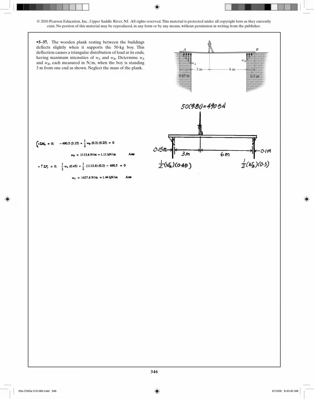
•5–37. The wooden plank resting between the buildingsdeflects slightly when it supports the 50-kg boy. Thisdeflection causes a triangular distribution of load at its ends,having maximum intensities of and . Determine and , each measured in , when the boy is standing3 m from one end as shown. Neglect the mass of the plank.
N>mwBwAwBwA
3 m
0.45 m 0.3 m
6 m
A B
wAwB
05a Ch05a 319-360.indd 34605a Ch05a 319-360.indd 346 6/12/09 8:43:40 AM6/12/09 8:43:40 AM

5–38. Spring CD remains in the horizontal position at alltimes due to the roller at D. If the spring is unstretchedwhen and the bracket achieves its equilibriumposition when , determine the stiffness k of thespring and the horizontal and vertical components ofreaction at pin A.
u = 30°u = 0° 0.45 m
0.6 m
kD C
B
AF � 300 N
u
347
© 2010 Pearson Education, Inc., Upper Saddle River, NJ. All rights reserved. This material is protected under all copyright laws as they currentlyexist. No portion of this material may be reproduced, in any form or by any means, without permission in writing from the publisher.
05a Ch05a 319-360.indd 34705a Ch05a 319-360.indd 347 6/12/09 8:43:43 AM6/12/09 8:43:43 AM

348
© 2010 Pearson Education, Inc., Upper Saddle River, NJ. All rights reserved. This material is protected under all copyright laws as they currentlyexist. No portion of this material may be reproduced, in any form or by any means, without permission in writing from the publisher.
5–39. Spring CD remains in the horizontal position at alltimes due to the roller at D. If the spring is unstretchedwhen and the stiffness is , determinethe smallest angle for equilibrium and the horizontal andvertical components of reaction at pin A.
u
k = 1.5 kN>mu = 0° 0.45 m
0.6 m
kD C
B
AF � 300 N
u
05a Ch05a 319-360.indd 34805a Ch05a 319-360.indd 348 6/12/09 8:43:45 AM6/12/09 8:43:45 AM

349
© 2010 Pearson Education, Inc., Upper Saddle River, NJ. All rights reserved. This material is protected under all copyright laws as they currentlyexist. No portion of this material may be reproduced, in any form or by any means, without permission in writing from the publisher.
*5–40. The platform assembly has a weight of 1.25 kN andcenter of gravity at If it is intended to support amaximum load of 2 kN placed at point determine thesmallest counterweight W that should be placed at B inorder to prevent the platform from tipping over.
2 ,1.
1.8 m
2.4 m
0.3 m0.3 m
C
B
G1
D
0.6 m1.8 m
G2
When tipping occurs, RC = 0
�
+ ΣMD = 0; –2 (0.6) + 1.25 (0.3) + WB (2.1) = 0
WB = 0.393 kN Ans
1.8 m0.6 m
2.4 m
0.3 m1.8 m0.3 m
1.25 kN
2 kN
*5–40. The platform assembly has a weight of 1.25 kN and center of gravity at G1. If it is intended to support a maximum load of 2 kN placed at point G2, determine the smallest counterweight W that should be placed at B in order to prevent the platform from tipping over.
05a Ch05a 319-360.indd 34905a Ch05a 319-360.indd 349 6/12/09 8:43:48 AM6/12/09 8:43:48 AM

350
© 2010 Pearson Education, Inc., Upper Saddle River, NJ. All rights reserved. This material is protected under all copyright laws as they currentlyexist. No portion of this material may be reproduced, in any form or by any means, without permission in writing from the publisher.
•5–41. Determine the horizontal and vertical componentsof reaction at the pin A and the reaction of the smoothcollar B on the rod.
A
B
D
C
2 ft
300 lb
4 ft
1 ft 1 ft
30�
450 lb
0.6 m0.3 m 0.3 m
2250 N1500 N
1.2 m
0.6 m0.3 m 0.3 m
2250 N1500 N
1.2 m
Equations of Equilibrium: From the free – body diagram, Ay and NB can be obtained by writing the force equation of equilibrium along the y axis and the moment equation of equilibrium about point A.
+↑ΣFy = 0; Ay – 1500 – 2250 = 0
Ay = 3750 N Ans.
�
+ ΣMA = 0; NB (1.2 sin 30°) – 1500 (0.3) – 2250 (0.9) = 0
NB = 4125 N Ans.
Using the result NB = 4125 N and writing the force equation of equilibrium along the x axis,
+→ ΣFx = 0; Ax – 4125 = 0
Ax = 4125 N Ans.
05a Ch05a 319-360.indd 35005a Ch05a 319-360.indd 350 6/12/09 8:43:50 AM6/12/09 8:43:50 AM

351
© 2010 Pearson Education, Inc., Upper Saddle River, NJ. All rights reserved. This material is protected under all copyright laws as they currentlyexist. No portion of this material may be reproduced, in any form or by any means, without permission in writing from the publisher.
5–42. Determine the support reactions of roller A and thesmooth collar B on the rod. The collar is fixed to the rodAB, but is allowed to slide along rod CD.
A
1 m
2 m
600 N � m
1 m
B
D
C
900 N
45�
45�
05a Ch05a 319-360.indd 35105a Ch05a 319-360.indd 351 6/12/09 8:43:54 AM6/12/09 8:43:54 AM

352
© 2010 Pearson Education, Inc., Upper Saddle River, NJ. All rights reserved. This material is protected under all copyright laws as they currentlyexist. No portion of this material may be reproduced, in any form or by any means, without permission in writing from the publisher.
5–43. The uniform rod AB has a weight of 15 lb. Determinethe force in the cable when the rod is in the position shown.
A10�
30�
5 ft
C
B
T
*5–44. Determine the horizontal and vertical componentsof force at the pin A and the reaction at the rocker B of thecurved beam.
A B
500 N200 N
10� 15�
2 m
1.5 sin 40°
75 N
0.75 cos 40°
5–43. The uniform rod AB has a weight of 75 N. Determine the force in the cable when the rod is in the position shown.
�
+ ΣMA = 0; NB (1.5 sin 40°) – 75 (0.75 cos 40°) = 0 NB = 44.69 N
+→ ΣFx = 0; T cos 10° – 44.69 = 0 T = 45.38 N Ans
05a Ch05a 319-360.indd 35205a Ch05a 319-360.indd 352 6/12/09 8:43:57 AM6/12/09 8:43:57 AM

353
© 2010 Pearson Education, Inc., Upper Saddle River, NJ. All rights reserved. This material is protected under all copyright laws as they currentlyexist. No portion of this material may be reproduced, in any form or by any means, without permission in writing from the publisher.
•5–45. The floor crane and the driver have a total weightof 2500 lb with a center of gravity at G. If the crane isrequired to lift the 500-lb drum, determine the normalreaction on both the wheels at A and both the wheels at Bwhen the boom is in the position shown.
12 ft
30�
3 ft
6 ft
8.4 ft2.2 ft
1.4 ft
A B
D
E
F
C
G
3.6 m
0.9 m
2.52 m
0.42 m0.66 m
1.8 m
12.5 kN
2.5 kN
2.52 m
0.42 m0.66 m
4.5 m
of 12.5 kN with a center of gravity at G. If the crane is required to lift the 2.5-kN drum, determine the normal
Equations of Equilibrium: From the free – body diagram of the floor crane, Fig. a,
�
+ ΣMB = 0; 12.5 (0.42 + 2.52) – 2.5 (4.5 cos 30° – 2.52) – NA (0.66 + 0.42 + 2.52) = 0
NA = 9.252 kN Ans.
+↑ΣFy = 0; 9.252 – 12.5 – 2.5 + NB = 0
NB = 5.748 kN Ans.
05a Ch05a 319-360.indd 35305a Ch05a 319-360.indd 353 6/12/09 8:44:00 AM6/12/09 8:44:00 AM

354
© 2010 Pearson Education, Inc., Upper Saddle River, NJ. All rights reserved. This material is protected under all copyright laws as they currentlyexist. No portion of this material may be reproduced, in any form or by any means, without permission in writing from the publisher.
5–46. The floor crane and the driver have a total weight of2500 lb with a center of gravity at G. Determine the largestweight of the drum that can be lifted without causing thecrane to overturn when its boom is in the position shown.
12 ft
30�
3 ft
6 ft
8.4 ft2.2 ft
1.4 ft
A B
D
E
F
C
G
3.6 m
0.9 m
2.52 m
0.42 m0.66 m
1.8 m
12.5 kN
2.52 m
0.42 m0.66 m
4.5 m
Equations of Equilibrium: Since the floor crane tends to overturn about point B, the wheel at A will leave the ground and NA = 0. From the free – body diagram of the floor crane, Fig. a, W can be obtained by writing the moment equation of equilibrium about point B.
�
+ ΣMB = 0; 12.5 (0.42 + 2.52) – W(4.5 cos 30° – 2.52) = 0
W = 26.69 kN Ans.
05a Ch05a 319-360.indd 35405a Ch05a 319-360.indd 354 6/12/09 8:44:02 AM6/12/09 8:44:02 AM

355
© 2010 Pearson Education, Inc., Upper Saddle River, NJ. All rights reserved. This material is protected under all copyright laws as they currentlyexist. No portion of this material may be reproduced, in any form or by any means, without permission in writing from the publisher.
5–47. The motor has a weight of 850 lb. Determine theforce that each of the chains exerts on the supporting hooksat A, B, and C. Neglect the size of the hooks and thethickness of the beam. 1.5 ft1 ft
0.5 ft
CA
B
30�10�10�
850 lb
*5–48. Determine the force P needed to pull the 50-kg rollerover the smooth step.Take u = 60°.
20�
A
B
P
0.6 m
0.1 m
u
0.3 m 0.45 m
4.25 kN
0.15 m
0.3 m 4.25 kN0.15 m 0.45 m
5–47. The motor has a weight of 4.25 kN. Determine the
�
+ ΣMB = 0; FA cos 10° (0.3) + 4.25 (0.15) – FC cos 10° (0.6) = 0 (1)
+→ ΣFx = 0; FC sin 10° – FB sin 30° – FA sin 10° = 0 (2)
+↑ΣFy = 0; 4.25 – FA cos 10° – FB cos 30° – FC cos 10° = 0 (3)
Solving Eqs. (1), (2) and (3) yields:
FA = 2.16 kN FB = 0 FC = 2.16 kN Ans
05a Ch05a 319-360.indd 35505a Ch05a 319-360.indd 355 6/12/09 8:44:06 AM6/12/09 8:44:06 AM

356
© 2010 Pearson Education, Inc., Upper Saddle River, NJ. All rights reserved. This material is protected under all copyright laws as they currentlyexist. No portion of this material may be reproduced, in any form or by any means, without permission in writing from the publisher.
•5–49. Determine the magnitude and direction of theminimum force P needed to pull the 50-kg roller over thesmooth step.
u
20�
A
B
P
0.6 m
0.1 m
u
05a Ch05a 319-360.indd 35605a Ch05a 319-360.indd 356 6/12/09 8:44:09 AM6/12/09 8:44:09 AM

5–50. The winch cable on a tow truck is subjected to aforce of when the cable is directed at .Determine the magnitudes of the total brake frictionalforce F for the rear set of wheels B and the total normalforces at both front wheels A and both rear wheels B forequilibrium. The truck has a total mass of 4 Mg and masscenter at G.
u = 60°T = 6 kN
1.25 m
3 m
A
G
B F T
1.5 m2 m 2.5 m
u
357
© 2010 Pearson Education, Inc., Upper Saddle River, NJ. All rights reserved. This material is protected under all copyright laws as they currentlyexist. No portion of this material may be reproduced, in any form or by any means, without permission in writing from the publisher.
05a Ch05a 319-360.indd 35705a Ch05a 319-360.indd 357 6/12/09 8:44:12 AM6/12/09 8:44:12 AM

358
© 2010 Pearson Education, Inc., Upper Saddle River, NJ. All rights reserved. This material is protected under all copyright laws as they currentlyexist. No portion of this material may be reproduced, in any form or by any means, without permission in writing from the publisher.
5–51. Determine the minimum cable force T and criticalangle which will cause the tow truck to start tipping, i.e., forthe normal reaction at A to be zero. Assume that the truck isbraked and will not slip at B. The truck has a total mass of 4 Mg and mass center at G.x
u
1.25 m
3 m
A
G
B F T
1.5 m2 m 2.5 m
u
*5–52. Three uniform books, each having a weight W andlength a, are stacked as shown. Determine the maximumdistance d that the top book can extend out from thebottom one so the stack does not topple over.
a d
05a Ch05a 319-360.indd 35805a Ch05a 319-360.indd 358 6/12/09 8:44:15 AM6/12/09 8:44:15 AM

•5–53. Determine the angle at which the link ABC isheld in equilibrium if member BD moves 2 in. to the right.The springs are originally unstretched when . Eachspring has the stiffness shown. The springs remainhorizontal since they are attached to roller guides.
u = 0°
u
kCF � 100 lb/ft
kAE � 500 lb/ft
E
F
C
A
B
D
F
6 in.
6 in.
u
359
© 2010 Pearson Education, Inc., Upper Saddle River, NJ. All rights reserved. This material is protected under all copyright laws as they currentlyexist. No portion of this material may be reproduced, in any form or by any means, without permission in writing from the publisher.
20 kN/m
150 mm
150 mm
100 kN/m
150 mm
150 mm
0.150 m
0.05 F
0.04 F
0.05 m
0.05 – 0.01 F
0.150 m
xA = 0.01 F
held in equilibrium if member BD moves 50 mm to the right. The springs are originally unstretched when � = 0°. Each spring has the stiffness shown. The springs remain horizontal since they are attached to roller guides.
�
+ ΣMB = 0; FC (0.150 cos �) – FA (0.150 cos �) = 0
FC = FA = F
xC = F20
= 0.05F and xA = F
100 = 0.01F
Using similar triangles
0.040.30
F =
0.05 – 0.010.15
F F = 3 kN
sin � = 0.04 (3)
0.30 = 0.4
� = 23.6° Ans
05a Ch05a 319-360.indd 35905a Ch05a 319-360.indd 359 6/12/09 8:44:18 AM6/12/09 8:44:18 AM

360
© 2010 Pearson Education, Inc., Upper Saddle River, NJ. All rights reserved. This material is protected under all copyright laws as they currentlyexist. No portion of this material may be reproduced, in any form or by any means, without permission in writing from the publisher.
5–54. The uniform rod AB has a weight of 15 lb and thespring is unstretched when . If , determinethe stiffness k of the spring.
u = 30°u = 0°6 ft
u
B
A
3 ftk
5–55. The horizontal beam is supported by springs at itsends. Each spring has a stiffness of and isoriginally unstretched so that the beam is in the horizontalposition. Determine the angle of tilt of the beam if a load of800 N is applied at point C as shown.
k = 5 kN>m800 N
B
C
A
3 m
1 m
1.8 m
0.9 m
0.45 m
0.45 m75 N
0.9 m
0.9 tan 30°= 0.5196 m
1.8 – 0.9
cos 30°= 0.7608 m
0.9cos 30°
m
5–54. The uniform rod AB has a weight of 75 N and the
Geometry : From triangle CDB, the cosine law gives
l = 0.7608 + 0.5196 – 2(0.7608) (0.5196) cos2 2 1120° = 1.1154 m
Using the sine law,
sin0.7608
α =
sin 120°1.1154
� = 36.21°
Equations of Equilibrium : The force in the spring can be obtained directly by summing moments about point A.
�
+ ΣMA = 0; 75 cos 30° (0.45) – Fsp cos 36.21° (0.9) = 0
Fsp = 40.25 N
Spring Force Formula : The spring stretches x = 1.1154 – 0.9 = 0.2154 m
k = F
xsp =
40.250.2154
= 186.9 N/m Ans
05a Ch05a 319-360.indd 36005a Ch05a 319-360.indd 360 6/12/09 8:44:21 AM6/12/09 8:44:21 AM


