Embed Size (px)
Citation preview

TSX MicroTSX ETZ 410/510 ModulesUser Manual Eng Version V1.1

2
Table of Contents
About the book . . . . . . . . . . . . . . . . . . . . . . . . . . . . . . . . . . . . . . .7
Chapter 1 TSX ETZ 410/510 Modules: General . . . . . . . . . . . . . . . . . . . . . .9At a Glance . . . . . . . . . . . . . . . . . . . . . . . . . . . . . . . . . . . . . . . . . . . . . . . . . . . . . . 9
1.1 Introduction to the TSX ETZ 410/510 Modules . . . . . . . . . . . . . . . . . . . . . . . . . . 11At a Glance . . . . . . . . . . . . . . . . . . . . . . . . . . . . . . . . . . . . . . . . . . . . . . . . . . . . . 11About ETHERNET. . . . . . . . . . . . . . . . . . . . . . . . . . . . . . . . . . . . . . . . . . . . . . . . 12At a Glance . . . . . . . . . . . . . . . . . . . . . . . . . . . . . . . . . . . . . . . . . . . . . . . . . . . . . 13General Information on TSX ETZ 410 and TSX ETZ 510 Modules . . . . . . . . . . 15Synthesis of Module Functions . . . . . . . . . . . . . . . . . . . . . . . . . . . . . . . . . . . . . . 17
Chapter 2 Utilities. . . . . . . . . . . . . . . . . . . . . . . . . . . . . . . . . . . . . . . . . . . . . 21At a Glance . . . . . . . . . . . . . . . . . . . . . . . . . . . . . . . . . . . . . . . . . . . . . . . . . . . . . 21
2.1 Uni-Telway Communication Function . . . . . . . . . . . . . . . . . . . . . . . . . . . . . . . . . 23Uni-Telway Communication . . . . . . . . . . . . . . . . . . . . . . . . . . . . . . . . . . . . . . . . 23
2.2 TCP/IP Messaging . . . . . . . . . . . . . . . . . . . . . . . . . . . . . . . . . . . . . . . . . . . . . . . 24At a Glance . . . . . . . . . . . . . . . . . . . . . . . . . . . . . . . . . . . . . . . . . . . . . . . . . . . . . 24Summary of TCP/IP Specifications . . . . . . . . . . . . . . . . . . . . . . . . . . . . . . . . . . . 25Addressing Management . . . . . . . . . . . . . . . . . . . . . . . . . . . . . . . . . . . . . . . . . . 26IP Address. . . . . . . . . . . . . . . . . . . . . . . . . . . . . . . . . . . . . . . . . . . . . . . . . . . . . . 27Sub-Addressing, Gateway. . . . . . . . . . . . . . . . . . . . . . . . . . . . . . . . . . . . . . . . . . 29Connection Management . . . . . . . . . . . . . . . . . . . . . . . . . . . . . . . . . . . . . . . . . . 30Opening a Connection on the Ethernet Network. . . . . . . . . . . . . . . . . . . . . . . . . 31Opening a Serial Link Connection via a Modem . . . . . . . . . . . . . . . . . . . . . . . . . 33Closing the Connection . . . . . . . . . . . . . . . . . . . . . . . . . . . . . . . . . . . . . . . . . . . . 37Behavior during a Connection Breakdown . . . . . . . . . . . . . . . . . . . . . . . . . . . . . 38Communication Functions on TCP/IP . . . . . . . . . . . . . . . . . . . . . . . . . . . . . . . . . 40UNI-TE Communication . . . . . . . . . . . . . . . . . . . . . . . . . . . . . . . . . . . . . . . . . . . 41 Modbus Communication on the TCP/IP Profile.. . . . . . . . . . . . . . . . . . . . . . . . . 42Structure supported by a Modbus Communication on the TCP/IP Profile . . . . . 43Modbus Messaging on the TCP/IP Profile . . . . . . . . . . . . . . . . . . . . . . . . . . . . . 44Messaging Service . . . . . . . . . . . . . . . . . . . . . . . . . . . . . . . . . . . . . . . . . . . . . . . 46Examples of Programming on the Ethernet Profile . . . . . . . . . . . . . . . . . . . . . . . 48Example of Programming via a RTC Modem Connection. . . . . . . . . . . . . . . . . . 53Limitations . . . . . . . . . . . . . . . . . . . . . . . . . . . . . . . . . . . . . . . . . . . . . . . . . . . . . . 55
3

2.3 BOOTP and DHCP(FDR) Utilities . . . . . . . . . . . . . . . . . . . . . . . . . . . . . . . . . . . . 56At a Glance . . . . . . . . . . . . . . . . . . . . . . . . . . . . . . . . . . . . . . . . . . . . . . . . . . . . . 56BOOTP/DHCP(FDR) Utilities - General. . . . . . . . . . . . . . . . . . . . . . . . . . . . . . . . 57TSX ETZ BOOTP client . . . . . . . . . . . . . . . . . . . . . . . . . . . . . . . . . . . . . . . . . . . . 58TSX ETZ DHCP(FDR) client . . . . . . . . . . . . . . . . . . . . . . . . . . . . . . . . . . . . . . . . 59
2.4 SNMP Server . . . . . . . . . . . . . . . . . . . . . . . . . . . . . . . . . . . . . . . . . . . . . . . . . . . . 61SNMP Communication on UDP/IP. . . . . . . . . . . . . . . . . . . . . . . . . . . . . . . . . . . . 61
2.5 HTTP Server . . . . . . . . . . . . . . . . . . . . . . . . . . . . . . . . . . . . . . . . . . . . . . . . . . . . 64At a Glance . . . . . . . . . . . . . . . . . . . . . . . . . . . . . . . . . . . . . . . . . . . . . . . . . . . . . 64Installed HTTP Server . . . . . . . . . . . . . . . . . . . . . . . . . . . . . . . . . . . . . . . . . . . . . 65HTTP Server Home Page . . . . . . . . . . . . . . . . . . . . . . . . . . . . . . . . . . . . . . . . . . 67Diagnostics Home Page . . . . . . . . . . . . . . . . . . . . . . . . . . . . . . . . . . . . . . . . . . . 69Ethernet Statistics Page. . . . . . . . . . . . . . . . . . . . . . . . . . . . . . . . . . . . . . . . . . . . 71Unitelway Statistics Pages. . . . . . . . . . . . . . . . . . . . . . . . . . . . . . . . . . . . . . . . . . 72 RS232 Modem Link Page Diagnostics . . . . . . . . . . . . . . . . . . . . . . . . . . . . . . . . 73Rack Display Page. . . . . . . . . . . . . . . . . . . . . . . . . . . . . . . . . . . . . . . . . . . . . . . . 75Data Editor Page . . . . . . . . . . . . . . . . . . . . . . . . . . . . . . . . . . . . . . . . . . . . . . . . . 77Faulty Device Replacement Statistics Page - FDR . . . . . . . . . . . . . . . . . . . . . . . 79Configuration Pages for the TSX ETZ Module. . . . . . . . . . . . . . . . . . . . . . . . . . . 81Security Page. . . . . . . . . . . . . . . . . . . . . . . . . . . . . . . . . . . . . . . . . . . . . . . . . . . . 83Configuration Page for the TCP/IP Utilities . . . . . . . . . . . . . . . . . . . . . . . . . . . . . 86Configuration Page for the Unitelway Link. . . . . . . . . . . . . . . . . . . . . . . . . . . . . . 87Automatic Configuration Page . . . . . . . . . . . . . . . . . . . . . . . . . . . . . . . . . . . . . . . 88Configuration Page for the SNMP Function. . . . . . . . . . . . . . . . . . . . . . . . . . . . . 89Module Reboot Page . . . . . . . . . . . . . . . . . . . . . . . . . . . . . . . . . . . . . . . . . . . . . . 90
Chapter 3 Installing the TSX ETZ 410/510 Module . . . . . . . . . . . . . . . . . . 91At a Glance . . . . . . . . . . . . . . . . . . . . . . . . . . . . . . . . . . . . . . . . . . . . . . . . . . . . . 91
3.1 Topology Principles . . . . . . . . . . . . . . . . . . . . . . . . . . . . . . . . . . . . . . . . . . . . . . . 93At a Glance . . . . . . . . . . . . . . . . . . . . . . . . . . . . . . . . . . . . . . . . . . . . . . . . . . . . . 93General . . . . . . . . . . . . . . . . . . . . . . . . . . . . . . . . . . . . . . . . . . . . . . . . . . . . . . . . 94Direct Connection between TSX Micro and TSX ETZ . . . . . . . . . . . . . . . . . . . . . 96Connection of a TSX ETZ on the Uni-Telway Network . . . . . . . . . . . . . . . . . . . . 98TSX ETZ Connection via Modem . . . . . . . . . . . . . . . . . . . . . . . . . . . . . . . . . . . 100
3.2 Configuring TSX ETZ 410/510 Modules . . . . . . . . . . . . . . . . . . . . . . . . . . . . . . 102At a Glance . . . . . . . . . . . . . . . . . . . . . . . . . . . . . . . . . . . . . . . . . . . . . . . . . . . . 102Access to the Module Configuration . . . . . . . . . . . . . . . . . . . . . . . . . . . . . . . . . 103Configuration Parameters linked to TCP/IP Utilities . . . . . . . . . . . . . . . . . . . . . 105Ethernet Connection Parameters. . . . . . . . . . . . . . . . . . . . . . . . . . . . . . . . . . . . 107Modem Connection Parameters . . . . . . . . . . . . . . . . . . . . . . . . . . . . . . . . . . . . 110Configuration Parameters Connected to the Uni-Telway Link . . . . . . . . . . . . . . 114Automatic Configuration. . . . . . . . . . . . . . . . . . . . . . . . . . . . . . . . . . . . . . . . . . . 115Configuration of the SNMP Module . . . . . . . . . . . . . . . . . . . . . . . . . . . . . . . . . . 117
3.3 Configuration of Serial RS232 Links . . . . . . . . . . . . . . . . . . . . . . . . . . . . . . . . . 120Configuration of Serial RS232 Links . . . . . . . . . . . . . . . . . . . . . . . . . . . . . . . . . 120
4

3.4 Installing the TSX ETZ - Summary . . . . . . . . . . . . . . . . . . . . . . . . . . . . . . . . . . 121Installing the TSX ETZ - Summary . . . . . . . . . . . . . . . . . . . . . . . . . . . . . . . . . . 121
Chapter 4 Hardware Specifications . . . . . . . . . . . . . . . . . . . . . . . . . . . . .123At a Glance . . . . . . . . . . . . . . . . . . . . . . . . . . . . . . . . . . . . . . . . . . . . . . . . . . . . 123
4.1 Description . . . . . . . . . . . . . . . . . . . . . . . . . . . . . . . . . . . . . . . . . . . . . . . . . . . . 125At a Glance . . . . . . . . . . . . . . . . . . . . . . . . . . . . . . . . . . . . . . . . . . . . . . . . . . . . 125Physical Description . . . . . . . . . . . . . . . . . . . . . . . . . . . . . . . . . . . . . . . . . . . . . 126Description of the Support Plate . . . . . . . . . . . . . . . . . . . . . . . . . . . . . . . . . . . . 128
4.2 Installing TSX ETZ Modules . . . . . . . . . . . . . . . . . . . . . . . . . . . . . . . . . . . . . . . 129Dimensions and Mounting of TSX ETZ modules . . . . . . . . . . . . . . . . . . . . . . . 129
4.3 Connections . . . . . . . . . . . . . . . . . . . . . . . . . . . . . . . . . . . . . . . . . . . . . . . . . . . 132At a Glance . . . . . . . . . . . . . . . . . . . . . . . . . . . . . . . . . . . . . . . . . . . . . . . . . . . . 132Module Connectors . . . . . . . . . . . . . . . . . . . . . . . . . . . . . . . . . . . . . . . . . . . . . . 133Linking Cables. . . . . . . . . . . . . . . . . . . . . . . . . . . . . . . . . . . . . . . . . . . . . . . . . . 138
4.4 Diagnostics . . . . . . . . . . . . . . . . . . . . . . . . . . . . . . . . . . . . . . . . . . . . . . . . . . . . 142Indicator LEDs. . . . . . . . . . . . . . . . . . . . . . . . . . . . . . . . . . . . . . . . . . . . . . . . . . 142
4.5 Electrical Specifications. . . . . . . . . . . . . . . . . . . . . . . . . . . . . . . . . . . . . . . . . . . 144Electrical Specifications. . . . . . . . . . . . . . . . . . . . . . . . . . . . . . . . . . . . . . . . . . . 144
4.6 Norms and Standards . . . . . . . . . . . . . . . . . . . . . . . . . . . . . . . . . . . . . . . . . . . . 145Norms and Standards . . . . . . . . . . . . . . . . . . . . . . . . . . . . . . . . . . . . . . . . . . . . 145
4.7 Service Conditions . . . . . . . . . . . . . . . . . . . . . . . . . . . . . . . . . . . . . . . . . . . . . . 146Service Conditions . . . . . . . . . . . . . . . . . . . . . . . . . . . . . . . . . . . . . . . . . . . . . . 146
Glossary . . . . . . . . . . . . . . . . . . . . . . . . . . . . . . . . . . . . . . . . . . . . . 147
Index . . . . . . . . . . . . . . . . . . . . . . . . . . . . . . . . . . . . . . . . . . . . . 153
5

6

About the book
At a Glance
Document Scope Installing Ethernet TSX ETZ 410/510 communication modules
User Comments We welcome your comments about this document. You can reach us by e-mail at [email protected]
04/2001 7

About the book
8 04/2001

04/2001
1
TSX ETZ 410/510 Modules: GeneralAt a Glance
Aim of this Chapter
This chapter contains general information about the TSX ETZ 410 and TSX ETZ 510 network modules.
What’s in this Chapter?
This Chapter contains the following Sections:
Section Topic Page
1.1 Introduction to the TSX ETZ 410/510 Modules 11
9

General
10 04/2001

General
1.1 Introduction to the TSX ETZ 410/510 Modules
At a Glance
Aim of this Section
This section introduces the TSX ETZ 410 and TSX ETZ 510 modules.
What’s in this Section?
This Section contains the following Maps:
Topic Page
About ETHERNET 12
At a Glance 13
General Information on TSX ETZ 410 and TSX ETZ 510 Modules 15
Synthesis of Module Functions 17
04/2001 11

General
About ETHERNET
Introduction ETHERNET communication principally targets the following applications:l coordination between programmable PLCs,l local or centralized supervision,l communication with production management computers,l communication with remote input/output.
The TCP/IP communication profile on ETHERNET, supported by the TSX ETZ modules, allows communication in:l UNI-TE messaging with the X-WAY structure package,l Modbus Messaging
TSX ETZ modules also allow, in agent mode, the management of the SNMP network supervision standard.
Associated Manuals
For more information, refer to the following manuals:
Title Reference
Communication Application Setup Manual TLX DS COMPL7 V4
ETHERNET network - Reference manual TSX DR ETH
TSX Micro PLCs - Application Setup Manual TSX DM 37
X-Way communication - Reference Manual TSX DR NET
Modbus - User guide TSX DG MDB
Wiring recommendations - User guide TSX DG KBL
FactoryCast - User guide 890 USE 152
Uni-Telway Communication Bus TSX DG UTW
12 04/2001

General
At a Glance
General The TSX ETZ 410 and TSX ETZ 510 products are autonomous TCP-IP/Uni-Telway gateway modules, which allow the connection of TSX Micro PLCs on a TCP-IP network.They do not fit into a PLC rack.They communicate with the TSX Micro PLCs (from TSX 37-10 onwards) via the Terminal port, the AUX port, or using a TSX SCP114 PCMCIA series link card in a TSX 37-2•, directly or on a Uni-Telway bus via a TSX P ACC 01 isolation box.The TSX ETZ 410/510 modules can be configured using an integrated Web server, as they will not be recognized by PL7 software. These modules are therefore outside the PLCs and can be fixed on a profiled DIN or on a Telequick perforated mounting plate.They are supplied with 24 VDC and integrate a RS232 series link for connecting an external modem or to configure the module.
Illustration Principle diagram:
TER AUX
TERAUX
TSX 37-2•
TSX PACC 01 Uni-Telway Bus
TCP-IP Network
TSX ETZ
Consolefor programming oradjustment
OR
Externalmodem
04/2001 13

General
Compatibility and Interoperability
The TSX ETZ 410 and TSX ETZ 510 modules can function with the following products:
l TSX ETY 110 (outside of Ethway profile)l TSX ETY 210l TSX ETY 410/510l NOE 241l NOE 771l M1El All Uni-TE and Modbus TCP/IP devicesl ATV58l Magelis
Note: Important: in order to be able to connect to a Micro PLC via an XIP driver (X-Way TCP/IP driver), it is essential that V4.2 or higher PL7 software is used.
14 04/2001

General
General Information on TSX ETZ 410 and TSX ETZ 510 Modules
At a Glance The TSX ETZ 410 and TSX ETZ 510 modules have the following specification:
l 24 volts direct current supply,l 10/100 Base-T Ethernet connection,l UNITELWAY slave (2 addresses used),l RS485 serial link for UNITELWAY communication,l RS 232 serial link for communication with an external modem or the
configuration,l 3 indicator LEDs,l 4 Mb of non-volatile Flash Memory for saving loaded software and the web site.
The TSX ETZ 410 Module
The following utilities are offered:
l Configuration using web pages, via Ethernet or through RS 232 serial link,l IP configuration of the module in question, either by configuration, or
automatically,l BOOTP client,l DHCP client: automatic reconfiguration on replacement of the module (FDR
function).l Default server accessible without configuration with secure access including:
l module configuration pages,l diagnostic utilities.
l Management of the SNMP module V1, MIB-II agent and MIB private Ethernet Transparent Factory,
l Uni-TE/Modbus messaging on TCP/IP with a maximum of 32 simultaneous connections and Uni-TE/Modbus request limited to 128 bytes,
l Diagnostics by LEDs,l Possibility of simultaneously connecting 8 Internet browsers,
Note: In operating phase, the RS232 modem and Ethernet interfaces are exclusive.
04/2001 15

General
The TSX ETZ 510 Module
The following utilities are offered:
l Configuration using web pages, via Ethernet or through RS 232 serial link,l IP configuration of the module in question, either by configuration, or
automatically,l BOOTP client,l DHCP client: automatic reconfiguration on replacement of the module (FDR
function).l Default server accessible without configuration with secure access including:
l module configuration pages,l diagnostic utilities.
l Management of the SNMP module V1, MIB-II agent and MIB private Ethernet Transparent Factory,
l Uni-TE/Modbus messaging on TCP/IP with a maximum of 32 simultaneous connections and Uni-TE/Modbus request limited to 128 bytes,
l Diagnostics by LEDs,l Possibility of simultaneously connecting 8 Internet browsers,l FactoryCast utilities support (refer to the FactoryCast User Guide documents ref.:
890 USE 152), l 8 Mbytes of additional Flash Memory reserved for the user application in
FactoryCast: the user can add their own pages or "Applets" to the initial web site.
16 04/2001

General
Synthesis of Module Functions
At a Glance Depending on the module reference, the functions offered are different.
TSX ETZ 410 Module
The table below summarizes the different functions of the TSX ETZ 410 module:
Function Details
Messaging on port 502(Xway or Modbus on TCP/IP)
l 32 simultaneous connections maximum (Client + Server).
l Access control via configuration table.
TCP/IP connections l 32 messaging connections.
Bootp client utility -
DHCP(FDR) client utility -
SNMP module l SNMP MIB-II agent and MIB Ethernet Transparent Factory.
RS 232 link for external modem l Up to 56 Kbauds.
Unitelway link l Speed configurable from 9600 to 19200 baud
Web site l Simultaneous connection of 8 Internet browsers.l Non-modifiable factory -installed web site, with
diagnostics and configuration pages.
04/2001 17

General
TSX ETZ 510 Module
The table below summarizes the different functions of the TSX ETZ 510 module:
Function Details
Messaging on port 502(Xway or Modbus on TCP/IP)
l 32 simultaneous connections maximum (Client + Server).
l Access control via configuration table.
TCP/IP connections l 32 messaging connections.
Bootp client utility -
DHCP(FDR) client utility -
SNMP module l SNMP MIB-II agent and MIB Ethernet Transparent Factory.
RS 232 link for external modem l Up to 56 Kbauds.
Unitelway link l Speed configurable from 9600 to 19200 baud
Web site l Simultaneous connection of 8 Internet browsers.l Non-modifiable factory -installed web site, with
diagnostics and configuration pages.l 8 Mbytes reserved for users web site.
18 04/2001

General
Note The inter-network routing is not realized by TSX ETZ modules (e.g.: TCP/IP - Fipway routing). It is responsible for the application.Illustration
UNI-TE Communication
PremiumMicro
ETHERNET
FIPWAY
04/2001 19

General
20 04/2001

04/2001
2
UtilitiesAt a Glance
Aim of this Chapter
This chapter describes the utilities offered by the TSX ETZ 410/510 modules.
What’s in this Chapter?
This Chapter contains the following Sections:
Section Topic Page
2.1 Uni-Telway Communication Function 23
2.2 TCP/IP Messaging 24
2.3 BOOTP and DHCP(FDR) Utilities 56
2.4 SNMP Server 61
2.5 HTTP Server 64
21

Utilities
22 04/2001

Utilities
2.1 Uni-Telway Communication Function
Uni-Telway Communication
Principles The TSX ETZ 410/510 is a TCP-IP/Uni-Telway gateway for transporting Modbus and UNI-TE requests.The TSX ETZ 410/510 module is an Uni-Telway slave. So that the gateway functions, the module should be connected to a master TSX 3710/3721/3722.The Uni-Telway link can be configured (speed, parity, address, etc.) so that it is compatible with the master.The module communicates with the master PLC thanks to 2 consecutive slave numbers:l 1st address: network access address, used in TSX Micro client mode to access
devices connected to the TCP/IP network.l 2nd address: reserved, used by the module when it receives a message from a
TCP/IP device, which is intended for the TSX Micro (TSX Micro server). It is equal to the 1st address + 1.
Uni-Telway Parameters
The table below gives the parameters to be configures for the module:
Parameters Value
Address 1 for the network access Can be configured from the web page: Unitelway Configuration.
Address 2 for the network access It is equal to address 1 + 1: reserved (cannot be configured)
Speed 9600, 19200 baud or automatically adapts between these two values.
8 bits of data Cannot be configured
1 stop bit Cannot be configured
Parity Even, odd or none
Time Out Configurable between 1 and 10 seconds.
04/2001 23

Utilities
2.2 TCP/IP Messaging
At a Glance
Aim of this Section
This section introduces the TCP/IP messaging service on the TSX ETZ 410/510 modules.
What’s in this Section?
This Section contains the following Maps:
Topic Page
Summary of TCP/IP Specifications 25
Addressing Management 26
IP Address 27
Sub-Addressing, Gateway 29
Connection Management 30
Opening a Connection on the Ethernet Network 31
Opening a Serial Link Connection via a Modem 33
Closing the Connection 37
Behavior during a Connection Breakdown 38
Communication Functions on TCP/IP 40
UNI-TE Communication 41
Modbus Communication on the TCP/IP Profile. 42
Structure supported by a Modbus Communication on the TCP/IP Profile 43
Modbus Messaging on the TCP/IP Profile 44
Messaging Service 46
Examples of Programming on the Ethernet Profile 48
Example of Programming via a RTC Modem Connection 53
Limitations 55
24 04/2001

Utilities
Summary of TCP/IP Specifications
Communication Port
The communication port reserved for the TSX ETZ 410/510 module is the port 502 (Schneider reserved port). When a client device requires access to the module, it asks for a connection to this port to be opened.
Timeout on TCP Connection
If a TCP connection cannot be established (when the destination is absent for example), the timeout error occurs after 80 seconds.It is advised that each of the timeout values for these communication functions should be set higher than 80 seconds if the 1st exchange was not successful.
"Keep Alive" Function
The function automatically generates a frame almost every 2 hours to detect any breakage in the connection. This mechanism is further detailed in the (See Behavior during a Connection Breakdown, p. 38) section.
04/2001 25

Utilities
Addressing Management
At a Glance When installing ETZ modules, the following addresses must be configured:l The IP addressl The X-WAY address
IP Address It is defined by the user when configuring the module and identifies a machine linked to the network. On the same local network, this address must be unique.Important: each module has an IP address by interface:l An IP address for the Ethernet interfacel An IP address for the modem serial link interface, used by the PPP protocol.
X-WAY Address All TSX ETZ modules are Uni-Telway slaves. It has an X-WAY address, which is also unique on the whole X-WAY structure.
Note: From the factory, each module has a unique Ethernet interface IP address by default, which is calculated using it’s MAC address. The MAC address is defined in the factory by the manufacturer and engraved on the front face of the module.
Note: On a "private" network, it is not necessary to alter the IP address by default.
26 04/2001

Utilities
IP Address
General Each device on the network should have a unique IP address.The uniqueness of the IP address is guaranteed by attributing "ID network" by an authorized party. The choice between the different classes depends upon the number of networks in the installation and on the number of machines to be connected.
Address Composition
Conceptually, each IP address is a pair (network name, machine identifier), whereby the network name identifies a network (or a site) and the machine identifier denotes a machine connected to this network. There are 3 types of IP addresses.
Address Types The structure of the address types is as follows
Externally, an IP address for a machine is represented by a character string of 4 8-bit values (0 to 255), separated by the points: " a.b.c.d ".
Class Values of "a"
A 0-127
B 128-191
C 192-223
0 Network identifier Machine identifier
1 Network identifier Machine identifier0
1 Network identifier01 Machine identifier
7 bits 24 bits
14 bits 16 bits
21 bits 8 bits
Class A
Class B
Class C
04/2001 27

Utilities
Default Ethernet Interface IP Address for the ETZ Module
The default Ethernet interface IP address for the TSX ETZ module is made from it’s MAC address:085.016.xxx.yyy where xxx and yyy are the last two numbers of the MAC address.
Example:The module’s MAC address is (in hexadecimal): 00 80 F4 01 12 20.In this case the default IP address is (in decimal): 085.016.018.032.
PPP Interface IP Address
The TSX ETZ manages an IP address by interface, the Ethernet interface IP address (configured by the user or service) and the IP address of the PPP interface. The latter is assigned during connection negotiation by the PPP protocol.The TSX ETZ is configured to accept any type of IP address during negotiation. To do this, it is recommended that any machine with which the TSX ETZ has to open a Modem/PPP connection be configured to assign the IP address to the TSX ETZ.However, if the remote device is configured to receive its IP address from the TSX ETZ, the IP addresses following negotiation will be: l TSX ETZ: 85.16.0.2l Remote device: 85.16.0.1If the connection is a TSX ETZ <-> TSX ETZ connection, the two machines will use the IP address: 85.16.0.2 in respect of their PPP interface.
28 04/2001

Utilities
Sub-Addressing, Gateway
Sub-Addressing The principle of sub-addressing is to break down the IP address (format a) into network and a local parts:l The network part is identical to the IP address: it identifies a network (or a site).l The local part is left to the initiative of the site: it is therefore sub-divided into a
physical subnetwork number and a machine identification (format b).Illustration:
Mask A Subnet(work) Mask, coded on 32 bits, allows the bits from an IP address to be defined as a network part.The mask bits are:l set to 1, if the corresponding IP address bits are to be identified as a part of the
network address.l set to 0 for machine identification.This system allows internal local networks to be addressed using a single attributed IP address.Illustration:
Gateway The Gateway is used to route a message towards a machine that is not on the current network.
Internet part = network Id Local part
Internet partPhysical sub-network
numberMachine
identification
Format a
Format b
Internet part = network Id Local part
Internet partPhysical sub-network
numberMachine
identification
Format a
Format b
Subnet(work)Mask
Bits to 1 Bits to 0
04/2001 29

Utilities
Connection Management
At a Glance The connection can be opened either by the local TSX Micro PLC or by a remote dialog that wishes to enter into a dialog with the local PLC.
A connection is characterized by the module:Local TCP port, local IP address/remote TCP port, remote IP address.
The configuration screen is used to configure:
l Either the modem profilel Or the Ethernet profileThe RS232 Modem and Ethernet interfaces are exclusive.
Note: Important: The number of simultaneously open connections is 32. However, messaging saturation on these links can cause connection breakages. In the event of messaging saturation, it is advisable to decrease the number of Uni-Telway slaves and/or use a 19200 speed.
Note: Connection management is transparent to the user.
30 04/2001

Utilities
Opening a Connection on the Ethernet Network
At a Glance A connection can be opened either:
l Upon request from a remote device.l Or upon request from a local TSX Micro.
Upon Request from Remote Devices.
In this case, the TSX ETZ 410/510 is the connection server.When a connection request is received from a remote device, the remote machine’s IP address is only checked if and only if access control has been activated in the configuration.The test consists of checking whether this address belongs to the list of remote machines that are authorized to be connected. If it is, the connection is accepted. If not, the connection is closed.Illustration
TSX ETZ server
PC remote client
XWay IP Address Protocol Access Mode8.3 139.160.234.41 UNITE Allowed MULTI1
Phone N° User0452352020 SA
PA
Configured access control
Ethernet TCP/IP
8,3139.160.234.41
04/2001 31

Utilities
Upon Request from the Local Micro
In this case, the TSX ETZ 410/510 is the connection client.When a message is transmitted by a communication function and if there is no connection with the remote device a connection is opened automatically by the TSX ETZ towards the remote device’s port 502.The remote device must be referenced in the X-WAY/IP configuration table.Illustration
TSX ETZ client
Premium server
XWay IP Address Protocol Access Mode8.3 139.160.234.42 UNITE Allowed MULTI1
Phone N° User0452352020 SA
PaAZ
Configured access control
Ethernet TCP/IP
8,3139.160.234.42
32 04/2001
Utilities
Opening a Serial Link Connection via a Modem
At a Glance A serial link connection via a modem can be opened either:
l Upon request from a remote device (server mode).l Or upon request from a local TSX Micro (client mode).
PPP and PAP Protocols
The connection uses the PPP protocol (Point-to-Point Protocol). Thanks to this protocol, once the telephone link has been established the modem link will be viewed on the application level in the same way as a TCP/IP link.For PPPconnection, the identification protocol is PAP (Password Authentification Protocol). Any device with which TSX ETZ is in Modem/PPP connection must be configured using the PAP. The CHAP protocol is not implemented on the TSX ETZ.For the connection to be accepted, the UserName and Password PAP of the remote device must be known. Before connecting the TSX ETZ to the remote device, the remote device must also be configured to use the PAP protocol.The TSX ETZ password and user name used by the PAP protocol are the same as those of the HTTP server (by default: USER/USER).The modem connected to the TSX ETZ must respond to AT commands in ASCII mode.
Note: Important: client mode takes priority over server mode. If a remote device in server mode has established communication with the TSX Micro, the TSX ETZ will close the connection if this TSX Micro wants to establish a connection in client mode with a different remote device.
Note: Important: the module only allows management of an RTC modem (the specialized mode line is not managed).
04/2001 33

Utilities
The TSX ETZ manages an IP address by interface, the Ethernet interface IP address (configured by the user or service) and the IP address of the PPP interface. The latter is assigned during connection negotiation by the PPP protocol.The TSX ETZ is configured to accept any type of IP address during negotiation. We recommend that any device with which the TSX ETZ must open a Modem/PPP connection be configured to assign the IP address to the TSX ETZ.However, if the remote device is configured to receive its IP address from the TSX ETZ, the IP addresses following negotiation will be: l TSX ETZ: 85.16.0.2l Remote device: 85.16.0.1
Note: If the connection is a TSX ETZ <-> TSX ETZ connection, the two machines will use the IP address: 85.16.0.2 in respect of their PPP interface.
Connection Establishment Time
The maximum connection establishment time is fixed. It comprises the following times:l Maximum modem configuration time (transmission and HAYES command
recognition times): 5 seconds.l Maximum call time (telephone dialing + time to establish line with remote
modem): 90 seconds (1mn 30s.)l PPP connection time (IP address negotiation + password validation): 60
seconds (1mn).A total maximum time of155 seconds, or 2mn 35s. This time should correspond to the Time out of the request that makes the telephone call (SEND_REQ()).
Example of telephone call programming:(*Micro client: exchange Mirror request to the Premium system port - @X-way:2.4*)%MW10:=16#0402;%MW11:=16#0000;%MW12:=16#0000;
(*Start of Mirror request input parameters*)%MW13:=...;
(*Connection establishment time=160seconds*) %MW2:=1660;
Send_Req(ADR#0.0.4,#FA,%MW10:13,%MW100:10,%MW0:4)
34 04/2001

Utilities
EF Reports Operation reports specific to the modem connection are available.List of possible operation reports:
RS 232 Modem Diagnostics link
The PPP/Modem LogFile page on the HTTP server reports on the last four connections (See RS232 Modem Link Page Diagnostics, p. 73).
Connection on Request from Remote Devices
In this case, the TSX ETZ 410/510 is the connection server.If the TSX ETZ module is used with a modem configuration, the module listens for an incoming request for telephone connection.Once the telephone link is established and when a connection request is received from a remote device, the remote device’s IP address is only checked (if and only if access control has been activated in the configuration).This test consists of checking whether this address belongs to the list of remote machines with authorization to connect.If the test is positive, the TCP connection is accepted. If not, the TCP connection is closed and the telephone link is cut.
Illustration:
If communication report = 16#FF
ErrnoValue:
Operation report: (least significant byte)Meaning:
16#E8 Connection refusal by remote device (e.g.: invalid password)
16#E9 Line busy
16#EA No data carrier and/or no tone
16#EB No response from remote modem
16#EC No response from local modem
Commuted Telephone Network
TSX ETZ server
Modem Modem
Remote PC client
PPP and PAP ProtocolsTSX ETZ details:
Tel: 04 93 35 20 20 UserName: USER Password: USER
TSX Micro
XWay IP Address Protocol Access Mode8.3 139.160.234.42 UNITE Allowed MULTI1
Phone N° User0452352020 SA
PasswordQWERTY
Configured access control
04/2001 35

Utilities
Connection on Request from Local Machines
In this case, the TSX ETZ 410/510 is the connection client.When a message is transmitted for the first time by a communication function and if there is no modem connection with the remote device and if the remote device is part of the configuration table, a modem connection is opened automatically by the TSX ETZ. The module then establishes the telephone link by dialing the telephone number configured for the remote device.The TCP/IP connection is then automatically opened by the TSX ETZ towards the remote device’s port 502.The remote device must be referenced in the X-WAY/IP configuration table.
Illustration:
Note: Important: For a defined remote device, the telephone number to be dialed can only be modified by accessing the Web server’s Online Configuration menu. It is then necessary to reboot the TSX ETZ so that the new configuration is recognized.
Commuted Telephone Network
TSX ETZ client
Modem Modem
TSX ETZ server
PPP and PAP Protocols
ccess Modellowed MULTI
Phone N° User0452352020 SA
PasswordQWERTY
Table of configured addresses
Remote details:
Tel: 04 52 35 20 20 UserName: SA Password: QWERTY
TSX Micro TSX Micro
36 04/2001

Utilities
Closing the Connection
At a Glance There are two different ways in which the TCP/IP connection can be closed:
l By the remote station deciding to cease communication and sending a TCP/IP connection close.
l By the TSX ETZ if the maximum number of open connections is reached (in which case the oldest open connection is closed).
When a connection is closed, the application is informed by an error report (message refused) once the exchange is activated.
In the case of a telephone link, the link is cut:l By the remote station deciding to cease communication and cutting the telephone
connection,l If the remote device does not have authorization to connect,l If the time between two frames, which is set at configuration, elapses,l If connection duration exceeds the time defined at configuration (See Modem
Connection Parameters, p. 110).l If a TSX Micro, which is a remote station server, wishes to establish a client mode
connection to another remote station.
04/2001 37

Utilities
Behavior during a Connection Breakdown
At a Glance Connection breakdown can occur in two ways:l Network cable cut off (cable has been disconnected, cut, etc.)l disappearance of remote devices (broken down devices, power outage, etc.)
Loss of connection is detected after 2 hours by a Keep Alive request.
If during this time the connection is re-established, the resumption of communication differs according to the type of breakdown.
Cable Reconnection
In this case the connection breakdown originates from the network cable but the two stations remain operational.
Once the cable is reconnected, communication between the ETZ module and the remote device will resume on the TDP/IP connection previously opened.
Server Remote Device
The remote device, which has disappeared, was the server.
1 The ETZ client module still transmits data on the old connection (which remained semi-open).
2 When the server receives data without a connection, it transmits a Reset command and closes the old connection.
3 The ETZ client module opens a new connection.
1
2
3
Remote device
ServerClient
38 04/2001

Utilities
Client Remote Device
The remote device which has disappeared was the client.
1 The client opens a new connection.
2 The server ETZ module receives a request to open a new connection.
3 The ETZ slave module closes the old connection (if there is no current activity) and authorizes the new connection.
12
3
Remote device
Client
Server
04/2001 39

Utilities
Communication Functions on TCP/IP
At a Glance The communication profile on TCP/IP allows data exchange services.The same communication services are available on Ethernet or on a link series via the PPP protocol.Illustration:
TCP
IP
PPP protocol
Ethernet Serial link
Modbus / UNI-TE
Modem
40 04/2001

Utilities
UNI-TE Communication
At a Glance The UNI-TE utility allows the exchange of data on the Mast task.
Server Mode In server mode, the TSX ETZ module is transparent with regard to UNI-TE requests from the PLC.
Client Mode In client mode, it is possible to transmit the following UNI-TE request: SEND_REQ().This request is sent to the TSX ETZ module’s Address 1.The following requests are addressed to remote devices to read and write variables:
See Examples of Programming on the Ethernet Profile, p. 48.
Type of request UNI-TE communication function
Reading of 1 or n bits SEND_REQ(#36...)
Reading of 1 or n words SEND_REQ(#36...)
Writing of 1 or n bits SEND_REQ(#37...)
Writing of 1 or n bits SEND_REQ(#37...)
Refer to TSX DR NET Communication Reference manuals for the coding of UNI-TE requests.
Note: Important: SEND_REQ request does not monitor coherence of input parameters (e.g.: checking between the number of facts to write and the size of the data buffer). The user should do this.
04/2001 41

Utilities
Modbus Communication on the TCP/IP Profile.
At a Glance This utility allows communication through the Modbus protocol between a TSX Micro PLC and a TSX Micro, Premium, Quantum, Momentum PLC or any other device complying with the Modbus protocol.Illustration
A similar TSX ETZ can communicate with a remote device in the master mode (for example a Quantum PLC) and another remote device in the slave mode (for example a Supervisor PC)
The TSX Micro PLC is the master of the Quantum PLC. It opens the TCP/IP connection and sends messages to the Quantum.
The TSX Micro PLC is the slave of the supervisor. The supervisor has opened a TCP/IP connection and sends Modbus messages to the TSX Micro.
Note: the double profile of UNI-TE/ Modbus is not supported on a similar distant station.
ModbusProtocol
ModbusProtocol
ModbusProtocol
PremiumClient/Server
MicroClient/Server
QuantumServer
TCP/IP ETHERNET
Supervisorclient
42 04/2001

Utilities
Structure supported by a Modbus Communication on the TCP/IP Profile
At a Glance Illustration of the supported structure:
Accessibility The Modbus protocol guarantees interoperability between Premium, Micro and Quantum stations on an Ethernet TCP/IP network.
However, access from a Micro PLC to a Modbus Plus network connected to the Quantum PLC is not possible via TCP/IP.
The Modbus protocol does not cross X-Way Premium bridges.
Modbus Modbus
UNI-TE Communication
PremiumMicro
Quantum
ETHERNET
Supervisor programmingTerminal
FIPWAYModbus Plus
Modbus Communication
04/2001 43

Utilities
Modbus Messaging on the TCP/IP Profile
Installation Principle
Exchanges in the client and server modes are carried out in the same way as in UNI-TE, with the following restrictions.Even though a Modbus remote station does not have an X-WAY format address, each communication function uses an X-WAY format address to denote a remote IP station.For each Modbus remote station, you must configure the two following factors in the correspondence table: IP address, network station X-WAY with:
l Network: network number of the local X-WAY station.l Station: X Way station logic number = 100 to 164.Example: X-Way address 2.108 is associated with IP address 139.160.2.8.
Exchange of data As seen from the TSX Micro’s PL7 application, the communication function to be installed is always the UNI-TE request SEND-REQ. It is the TSX ETZ module that performs the conversion to the corresponding remote station.
The following requests are addressed to remote devices to read and write variables:
See Examples of Programming on the Ethernet Profile, p. 48.
Note: This address is used by the TSX ETZ module but is not transmitted on the network. In the case of a remote station configured with the Modbus protocol, it is necessary to give an X-Way station address equal to the local X-Way station number plus 100.
Note: Important: SEND_REQ request does not monitor coherence of input parameters (e.g.: checking between the number of facts to write and the size of the data buffer). The user should do this.
Modbus request Modbus function code
Corresponding UNI-TE communication function
Reading of 1 or n bits 16#01 SEND_REQ(#36...)
Reading of 1 or n words 16#03 SEND_REQ(#36...)
Writing of 1 or n bits 16#05 or 16#0F SEND_REQ(#37...)
Writing of 1 or n bits 16#06 or 16#0F SEND_REQ(#37...)
See communication reference manuals TSX DR NET for the coding of UNI-TE requests and manual TSX DG MDB for the coding of Modbus requests.
44 04/2001

Utilities
Correspondence of types of objects
The following table gives the correspondence between the types of objects of a TSX Micro PLC and a TSX Quantum PLC or Momentum input/output.
TSX Micro objects Quantum or Momentum objects
%MW: Internal Words 4x... memory area
%M: Internal bits 0x... memory area
04/2001 45

Utilities
Messaging Service
At a Glance The TSX ETZ messaging module allows the following modes:
l The client model The server mode
Client Mode In this mode, the TSX Micro has the initiative of an exchange into a remote station, by using the SEND_REQ() communication functions in the application (a maximum of 4 communication functions can be used simultaneously).Usage in the client mode requires the introduction of a table of 6 bytes corresponding to the destination address at the beginning of the transmission stamp.For more information refer to the TSX DR NET manual.
Illustration:
Example: transmission to the system gate of a remote PLC (network 2.station3):
Note: For these modes it is only possible to have access to the device’s system gate. It would not be possible to access for example the Fipway network of a TSX Micro.
Byte 1 (most significant)
Byte 0 (least significant)
Word 1 Station number Network number
Word 2 0 0
Word 3 0 0
Byte 1 (most significant)
Byte 0 (least significant)
Word 1 3 2
Word 2 0 0
Word 3 0 0
46 04/2001

Utilities
Server Mode In this case, the TSX Micro is the server of exchanges, which originate from remote stations. The system gate of the TSX Micro is accessible from remote stations using the following address:
AdressNetworkETZ.AdresseStationETZ.SYS
04/2001 47
Utilities
Examples of Programming on the Ethernet Profile
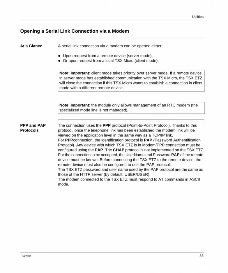
Configuration Example
Namely the following configuration:
Example of Programming a Mirror Request
Using the configuration below, the programming is the following:
(*Micro exchange client Mirror request to the Premium system gate*)%MW10:=16#0402;%MW11:=16#0000;%MW12:=16#0000;
(*Start of Mirror request input parameters*)%MW13:=...;
Send_Req(ADR#0.0.4,#FA,%MW10:13,%MW100:10,%MW0:4)
TSX Micro Server The system gate of the TSX Micro is accessible from stations on the Ethernet network using the following address: 2.1SYS
PL7/PC
TSX ETZ TSX Micro
TSX Premium
Operator dialogueterminal
UNI-TELWAY master
TSX ETZ configuration:
X-Way Address: 2.1AD0 Address: 4
IP Address: 84.0.8.1
X-Way/IP table:2.4 / 84.0.8.4
TSX ETY configuration:
X-Way Address: 2.4IP Address: 84.0.8.4
XIP configuration:
X-Way Address: 2.5IP Address: 84.0.8.5
X-Way/IP table:2.1 / 84.0.8.1
Ethernet TCP/IP
48 04/2001

Utilities
Example of word reading programming in UNI-TE
This program allows a UNI-TE request to be sent to a remote device with an X-Way address: 60.18 (16#123C). The request allows the words %MW10000, %MW10001, %MW10002. to be read
(*ETZ in client mode*)(*request for the reading of three words (UNITE)*)If NOT %MW300:X0 THEN%MW302:=60;(*time out by 100ms*)%MW303:=12;(*length in bytes of data to transmit*)%MW100:=16#123C;(*station-network: XWAY address (UNITE)*)%MW101:=16#0000;%MW102:=16#0000;%MW103:=16#0768;(*segment type: internal word*)%MW104:=10000;(*address of the first word to read*)%MW105:=3;(*nb word to read*)
(*%MW200:4 = 4 word reception table: type of object on 1 byte + 3 words of data*)SEND_REQ(ADR#0.0.4,16#0036,%MW100:6,%MW200:4,%MW300:4);END_IF
The confirmation of the correct report is: 16#6600
Note: Caution: In the reception table, the significance of the first word of the read data is contiguous with the object byte.
04/2001 49

Utilities
Example of programming of writing words in Modbus
This program allows the sending of a request for writing in Modbus messaging to the same remote device. 100 is added to the address below: 60.118 (16#763C). The request allows the writing in the words %MW10006, %MW10007, %MW10008, of the values 4, 5 and 6 respectively.
(*ETZ in client mode*)(*Request to write 3 words (Modbus)*)If NOT %MW1200:X0 THEN%MW1202:=60;(*time out by 100ms*)%MW1203:=18;(*length in bytes of data to transmit*)%MW1000:=16#763C;(*station-network: XWAY address (Modbus*)%MW1001:=16#0000;%MW1002:=16#0000;%MW1003:=16#0768;(*segment type: internal word*)%MW1004:=10009;(*address of the 1st word to write*)%MW1005:=3;(*no. words to write*)%MW1006:=4;(*value of facts to write*)%MW1007:=5;(*value of facts to write*)%MW1008:=6;(*value of facts to write*)
(*%MW1100:1 = 1 word reception table: Report on 1 byte*)SEND_REQ(ADR#0.0.4,16#0037,%MW1000:9,%MW1100:1,%MW1200:4);END_IF
The confirmation of the correct report is: 16#FE00
50 04/2001
Utilities
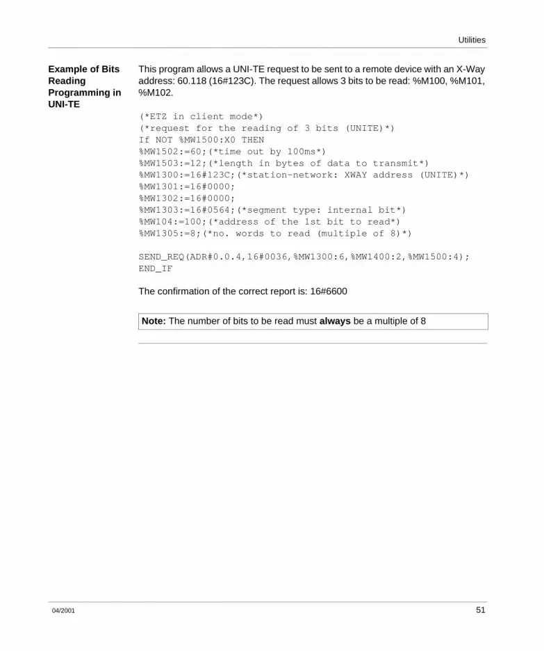
Example of Bits Reading Programming in UNI-TE
This program allows a UNI-TE request to be sent to a remote device with an X-Way address: 60.118 (16#123C). The request allows 3 bits to be read: %M100, %M101, %M102.
(*ETZ in client mode*)(*request for the reading of 3 bits (UNITE)*)If NOT %MW1500:X0 THEN%MW1502:=60;(*time out by 100ms*)%MW1503:=12;(*length in bytes of data to transmit*)%MW1300:=16#123C;(*station-network: XWAY address (UNITE)*)%MW1301:=16#0000;%MW1302:=16#0000;%MW1303:=16#0564;(*segment type: internal bit*)%MW104:=100;(*address of the 1st bit to read*)%MW1305:=8;(*no. words to read (multiple of 8)*)
SEND_REQ(ADR#0.0.4,16#0036,%MW1300:6,%MW1400:2,%MW1500:4);END_IF
The confirmation of the correct report is: 16#6600
Note: The number of bits to be read must always be a multiple of 8
04/2001 51
Utilities
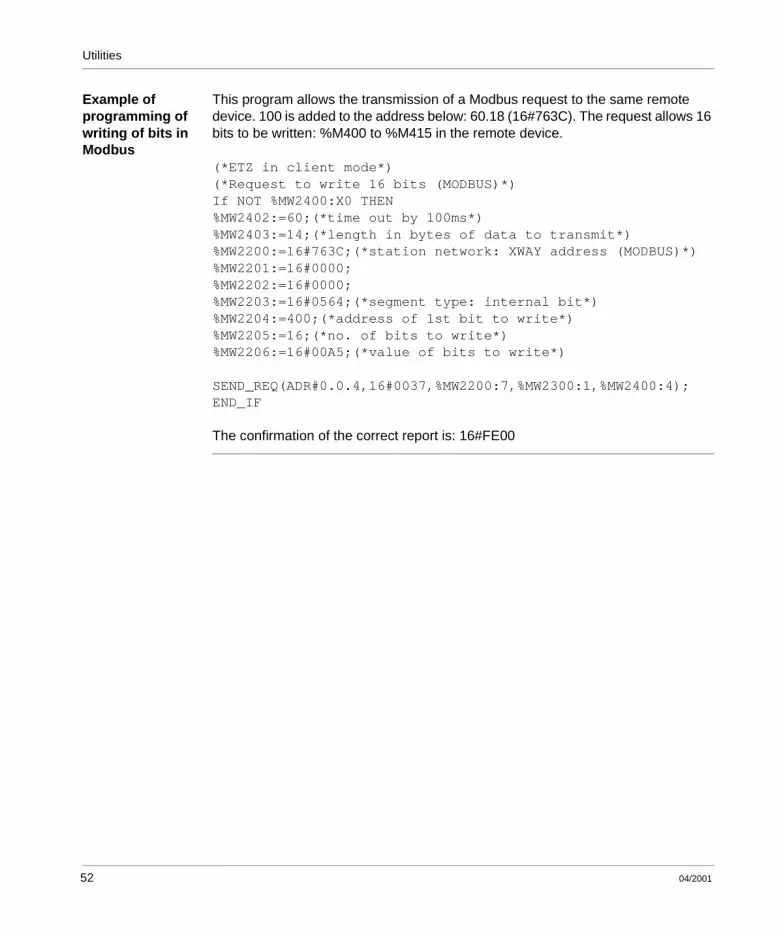
Example of programming of writing of bits in Modbus
This program allows the transmission of a Modbus request to the same remote device. 100 is added to the address below: 60.18 (16#763C). The request allows 16 bits to be written: %M400 to %M415 in the remote device.
(*ETZ in client mode*)(*Request to write 16 bits (MODBUS)*)If NOT %MW2400:X0 THEN%MW2402:=60;(*time out by 100ms*)%MW2403:=14;(*length in bytes of data to transmit*)%MW2200:=16#763C;(*station network: XWAY address (MODBUS)*)%MW2201:=16#0000;%MW2202:=16#0000;%MW2203:=16#0564;(*segment type: internal bit*)%MW2204:=400;(*address of 1st bit to write*)%MW2205:=16;(*no. of bits to write*)%MW2206:=16#00A5;(*value of bits to write*)
SEND_REQ(ADR#0.0.4,16#0037,%MW2200:7,%MW2300:1,%MW2400:4);END_IF
The confirmation of the correct report is: 16#FE00
52 04/2001

Utilities
Example of Programming via a RTC Modem Connection
Configuration Example
Namely the following configuration:
PL7/PC TSX ETZTSX Micro
TSX Premium
TSX ETZ configuration:
X-Way address: 2.1AD0 address: 4
IP Address: 84.0.8.1
X-Way/IP table: 2.4 / 84.0.8.1
Modem configuration:No. to be dialed: 04 93 20 •• ••
TSX ETY configuration:
X-Way address: 2.4IP Address: 84.0.8.4
Ethernet TCP/IP
Dialing modem
Modem dialed:No. 04 93 20 •• ••.
Commuted telephonenetwork
Serial link gateway to Ethernet TCP/IP
04/2001 53

Utilities
Example of Programming of a Client TSX Micro
Using the configuration below, the programming is the following:
(*Micro client: exchange Mirror request to the Premium system port - @X-way:2.4*)%MW10:=16#0402;%MW11:=16#0000;%MW12:=16#0000;
(*Start of Mirror request input parameters*)%MW13:=...;
(*Connection establishment time=160seconds*) %MW2:=1660;%MW2:=1660;
Send_Req(ADR#0.0.4,#FA,%MW10,%MW100,%MW0:4)
TSX Micro Server The system door of the TSX Micro shown in the example below, is accessible from stations on the Ethernet network using the following address:
2.1SYS
Note: Programming via a modem connection is the same as on the Ethernet profile, it is only the TSX ETZ configuration that changes (See Examples of Programming on the Ethernet Profile, p. 48).
54 04/2001

Utilities
Limitations
At a Glance The limit to the number of messages is linked to that of the Terminal port of the Micro PLC.In Uni-Telway master mode, the terminal port authorizes the processing of: l 4 messages being sent to the Uni-Telway busl 4 messages being receivedThe maximum size of each message is 128 bytes.
04/2001 55

Utilities
2.3 BOOTP and DHCP(FDR) Utilities
At a Glance
Aim of this Section
This section introduces the BOOTP and DHCP (FDR) utilities.
What’s in this Section?
This Section contains the following Maps:
Topic Page
BOOTP/DHCP(FDR) Utilities - General 57
TSX ETZ BOOTP client 58
TSX ETZ DHCP(FDR) client 59
56 04/2001

Utilities
BOOTP/DHCP(FDR) Utilities - General
At a Glance The TSX ETZ module can be configured directly with its Ethernet interface IP address in the IP Configuration page or by using an automatic configuration protocol. These protocols are: BOOTP and DHCP.BOOTP (Bootstrap Protocol) and DHCP (Dynamic Host Configuration Protocol) are the start up protocols for terminals or stations without disks via centralized management of network parameters. They are mainly used to supply an IP address or a configuration to a station that starts up on the network.The TSX ETZ is a BOOTP client or DHCP client.The BOOTP/DHCP server can therefore be a TSX Premium fitted with a TSX ETY module, or a Quantum fitted with a NOE module.
Note: Automatic configuration only works via the Ethernet connection. It does not work via the RS 232 link or via modem.
04/2001 57

Utilities
TSX ETZ BOOTP client
Principle The principle applied is as follows:
l The TSX ETZ module requests an IP configuration (IP address, Subnetwork Mask, Gateway) from a BOOTP server, using its MAC address,
l The BOOTP server uses a MAC Address/IP Configuration correspondence table to return the IP configuration to the TSX ETZ.
At Initial Start-Up Behavior of TSX ETZ module during its initial start-up:The TSX ETZ module sends the server a request in order to obtain a configuration:l If this module is not recognized, it will start up using its default IP configuration
(factory settings),l If the BOOTP server sends an IP configuration, the TSX ETZ will use it but
without saving it in the Flash memory.
At Subsequent Start-Ups
Behavior of modules during subsequent start-ups:The TSX ETZ module sends the server a request in order to obtain a configuration:l If the BOOTP server sends a configuration, the TSX ETZ will use it.l If the BOOTP server does not respond after approximately 1 minute has elapsed,
the TSX ETZ module will use the IP configuration saved in the Flash memory (the default configuration, the factory set configuration or the one saved in the Flash memory using the module’s Web server).
Note: Important: to use the BOOTP utility, the address server (eg. TSX ETY410•/510•) must be configured to the BOOTP server, and the client device identified by its MAC address.
Note: The BOOTP server only sends back the IP address, the Subnetwork mask and the Gateway. Other information has to be filled out in the configuration page (e.g. XWay/IP connections correspondence table).
58 04/2001

Utilities
TSX ETZ DHCP(FDR) client
At a Glance This utility allows automatic retrieval of IP, Uni-Telway and SNMP configurations by a TSX ETZ module connected to an Ethernet Transparent Factory segment.The FDR function uses a combination of DHCP and FTP/TFTP protocols.The TSX ETZ uses a Name (Device Role Name) to obtain its configuration from the server. The Device Role Name is a character string (maximum 15) associated with the module and which must be unique in the architecture.The TSX ETZ can therefore be automatically configured using a parameters file that has been saved in the DHCP server, for example a Premium TSX ETY 5102.
Operation The operating principle of the FDR utility is as follows:
Note: Important: to use the FDR utility, the address server (eg. TSX ETY410•/510•) must be configured to the DHCP server, and the client device identified by its Role Name.
Note: Important: passwords are not saved in the server. The passwords recovered will be the default passwords.
1 A TSX ETZ is connected to the network using a configured Name (Device Role Name)
2 The TSX ETZ sends a request to the DHCP server, indicating its associated Device Role Name.
3 If the Device Role Name appears in the DHCP server configuration table, the DHCP server sends the following to the module:l the IP address that must be used,l the FTP/TFTP server’s IP address,l the location in the FTP/TFTP server of the configuration file to be retrieved.
4 In this case, the TSX ETZ accesses the FTP/TFTP server so that the configuration file is remotely loaded to or from the FTP/TFTP server. The configuration file is identified by a name consisting of the Device Role Name with the .prm extension.
04/2001 59

Utilities
At Initial Start-Up Behavior of TSX ETZ module during its initial start-up:The TSX ETZ module sends the server a request in order to obtain a configuration:l If this module is not recognized, it will start up using its default configuration
(factory settings), after about 1 minute has elapsed.l If the module is recognized, the TSX ETZ will start up using the Client/Server
configuration and will save this in its Flash memory (except the IP configuration).
At Subsequent Start-Ups
Behavior of modules during subsequent start-ups:The TSX ETZ module sends the server a request in order to obtain a configuration:l If the module is recognized, the TSX ETZ will start up using the Client/Server
configuration and will save this in its Flash memory (except the IP configuration).l If this module is not recognized, it will start up after about 1 minute has elapsed,
with the default configuration saved in its Flash memory.
60 04/2001

Utilities
2.4 SNMP Server
SNMP Communication on UDP/IP
At a Glance The SNMP (Simple Network Management Protocol) standard defines network management solutions in terms of protocol and the exchange of supervised data.
The SNMP structure relies on the following essential elements: l The Manager allows entire or partial network supervision,l One or more Agents. Each supervised device has a software module named
Agent used by the SNMP protocol.l An MIB (Management Information Base) is a database or a collection of objects
updated by the agents.
The SNMP module agent is implemented on the TSX ETZ modules. The SNMP protocol allows a Manager to access MIB standardized objects from the TSX ETZ module.The MIB-II allows the management of TCP/IP communication layers.The MIB Ethernet Transparent Factory allows a Manager to access information about messaging services from port 502.Branching view of the MIB Ethernet Transparent Factory via a Manager:
The MIB Ethernet Transparent Factory source file is available on the TSX ETZ 410/510 module. It can be remotely loaded from an internet browser by clicking the link "MIB Upload" from the Diagnostics (See Diagnostics Home Page, p. 69) home page. This file may be compiled by the main SNMP Managers on the market.
experimental
private
enterprises
schneidergroup
transparentFactoryEthernetswitchport502Messaging
ioScanningglobalData
web
addressServer
deviceProfile
04/2001 61

Utilities
The SNMP Protocol
The SNMP protocol defines 5 types of message between the agent and the manager. These messages are encapsulated in the UDP datagrams.
Messages from the manager to an agent:l Get_Request: message used to obtain the value of one or more variables.l Get_Next_Request: obtains the value of the next variables.l Set_Request: sets the value of a variable.
Messages from an agent to the manager:l Get_Response: allows the agent to re-send the value of the requested variable.l Trap: allows the agent to signal an event to the Manager (non-authorized access
attempt or device restart).
62 04/2001
Utilities
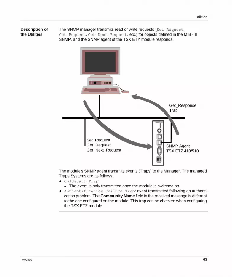
Description of the Utilities
The SNMP manager transmits read or write requests (Set_Request, Get_Request, Get_Next_Request, etc.) for objects defined in the MIB - II SNMP, and the SNMP agent of the TSX ETY module responds.
The module’s SNMP agent transmits events (Traps) to the Manager. The managed Traps Systems are as follows: l Coldstart Trap:
l The event is only transmitted once the module is switched on.l Authentification Failure Trap: event transmitted following an authenti-
cation problem. The Community Name field in the received message is different to the one configured on the module. This trap can be checked when configuring the TSX ETZ module.
Get_ResponseTrap
Set_RequestGet_RequestGet_Next_Request
SNMP AgentTSX ETZ 410/510
04/2001 63

Utilities
2.5 HTTP Server
At a Glance
Aim of this Section
This section introduces the HTTP server utility on TSX ETZ 410/510 modules.
What’s in this Section?
This Section contains the following Maps:
Topic Page
Installed HTTP Server 65
HTTP Server Home Page 67
Diagnostics Home Page 69
Ethernet Statistics Page 71
Unitelway Statistics Pages 72
RS232 Modem Link Page Diagnostics 73
Rack Display Page 75
Data Editor Page 77
Faulty Device Replacement Statistics Page - FDR 79
Configuration Pages for the TSX ETZ Module 81
Security Page 83
Configuration Page for the TCP/IP Utilities 86
Configuration Page for the Unitelway Link 87
Automatic Configuration Page 88
Configuration Page for the SNMP Function 89
Module Reboot Page 90
64 04/2001

Utilities
Installed HTTP Server
At a Glance TSX modules have a Web server installed on them by default, allowing: l the module to be configured:
l TCP/IP Parametersl Modeml UNI-TELWAYl SNMP
l to modify the user name and the password to access the site,l access to PLC data,l to view the TSX Micro rack,l to assign a Device Role Name if auto-configuration has been chosenNone of the functions supplied by the Web site require any prior configuration or programming within the module.
All server data is constructed as standard Web pages in HTML format. It can therefore be accessed by any current Internet browser that can run installed JAVA code. These pages can be viewed using an Internet browser or FactoryCast software.
Differences between the two module types:
Default Web Server Functions
The functions are as follows:l Diagnostic module functions:
l Ethernet and Uni-Telway network statistics,l View of TSX Micro rack driving the TSX ETZ,l TSX data editor driving the module,l RS232 modem link diagnostics.
l Module configuration functions:l Password modification,l TCP/IP Parameter Configuration,l UNI-TELWAY Parameter Configuration,l SNMP Parameter Configuration,l Resetting module.
Functions TSX ETZ 410 TSX ETZ 510
Number of Connected Browsers 8 max. 8 max.
Default Web Site installed Yes Yes
Memory reserved for user page creation No 8 Mbytes
04/2001 65

Utilities
HTTP Connections
The following connection rules should be followed:l 1 connected Internet browser can open 2 connections and the TSX ETZ
authorizes a maximum of 16 connections.l Each HTTP connection is automatically closed after one minute of inactivity.l The connection remains active whilst passwords are entered.As a result, 8 Internet browsers can be connected to a TSX ETZ module.
If the number of HTTP connections is reached, the browser displays the following page:
e 503 Service Unavailable - Microsoft Internet Explorer
File Edit View Tools HelpFavorites
LinksAddress http://192.168.2.14
Back Forward StopX
Refresh Home Search
e
Internete eDone
Maximum number of connections has been exceeded
Pleased try again later!!!
>>
>>
Go
66 04/2001

Utilities
HTTP Server Home Page
At a Glance This page is the web site home page. It allows access to the utility pages on this site:l the access page to the module diagnostics: Diagnosticsl the access page to the module configuration: Online Configuration.
How to Access the Home Page
The following procedure shows you how to access the web site home page.
Illustration The TSX ETZ 410 home page is presented as an example:
Step Action
1 Open your usual browser.
2 Enter the IP address for the ETHERNET module in the Addresses zone
LinksAddress
File Edit View Go Help
Copyright 2000−2001, Schneider Automation SA. All rights reserved
Internet zone
Web ManagementFor Transparent Factory TSX ETZ TCP/IP-Modem Module
DiagnosticsOnlineConfiguration
Favorites
Operating System: Windows 98Screen Résolution: 1024 x 768
Browser: Microsoft Internet Explorer 4
http://139.160.234.13/index.htm
SchneiderElectricS
Welcome to Schneider Automation Web Server for TSX ETZ Module - Microsoft Internet Explorer
e
e
Back Forward StopX
Refresh Home Search Favorites History Channels Fullscreen
e
e
e
04/2001 67

Utilities
Note: If the module is a TSX ETZ510 the home page of the web site is different. This page contains 2 additional links:l "Custom Pages with password": access to user pages protected by a
password. l "Custom Pages without password": access to user pages not protected by a
passwordRefer to the FactoryCast documentation for the creation of a web page user.
68 04/2001
Utilities
Diagnostics Home Page
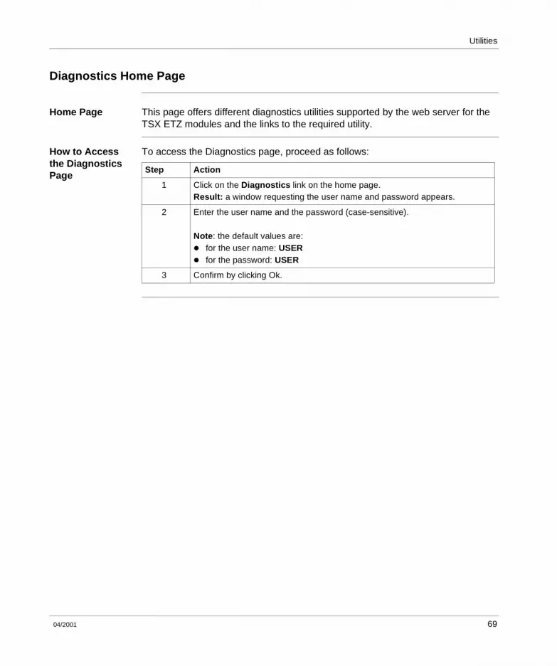
Home Page This page offers different diagnostics utilities supported by the web server for the TSX ETZ modules and the links to the required utility.
How to Access the Diagnostics Page
To access the Diagnostics page, proceed as follows:
Step Action
1 Click on the Diagnostics link on the home page.Result: a window requesting the user name and password appears.
2 Enter the user name and the password (case-sensitive).
Note: the default values are:l for the user name: USERl for the password: USER
3 Confirm by clicking Ok.
04/2001 69

Utilities
Illustration The Diagnostics home page is the following:
To access a chosen utility, click on a link.
LinksAddress
File Edit View Go Help
Copyright 2000−2001, Schneider Automation SA. All rights reserved
Internet zone
Diagnostics
HomeEthernet StatisticsUnitelway Statistics
PPP/Modem Log FileRack viewerData Editor
FDR Statistics
Favorites
http://139.160.234.13/secure/system/indexdiag.htm
SchneiderElectricS
Welcome to Schneider Automation Web Server for TSX ETZ Module - Microsoft Internet Explorer
e
e
Back StopX
Refresh Home Search Favorites History Channels
e
e
e
Forward
for Transparent Factory TSX ETZ TCP/IP-Modem Module
Version ETZ 410 V1.1
70 04/2001

Utilities
Ethernet Statistics Page
At a Glance This page shows the Ethernet network statistics. It is used to perform diagnostics on a network.
Illustration View of the TSX ETZ 410 Ethernet Statistics page:
e
Address
File Edit View HelpFavorites
X
Tools
http://so-etz1/secure/system/stat.htm
Home Rack Viewer
e
Ethernet Statistics Unitelways Statistics Data Editor FDR Statistics
Copyright 2000−2001, Schneider Automation SA. All rights reserved
Done local Intranet
e
IP Adress :
Operational Statistics
Functioning Errors
Transmit Timeout Errors :
Restart :
Receiver Statistics
Framing Errors :
CRC Errors :
Transmitter Statistics
Late Collision :
Transmit Retries :
Receive Buffer Errors :
Silo Underflow :
Receive Interrupts :
Transmit Buffer Errors :
Missed Packet Errors :
Lost Carrier :
Overflow Errors :
Memory Errors :
Collision Errors :
Mac Address :
Transmit Interrupts :
so-etz1
848022
0
0
0
0
0
0
0
0
0
0
0
2
0
39
555896
00.80.f4.01.03.84
Ethernet Module Statistics
Reset counters
ETZ - Stat - Microsoft Internet Explorer
04/2001 71

Utilities
Unitelway Statistics Pages
At a Glance This page shows the Unitelway network statistics. It is used to perform diagnostics on a network.
Illustration View of the TSX ETZ 410 Unitelway Statistics page:
e
Address
File Edit View HelpFavorites
X
Tools
http://so-etz1/secure/system/unitelstat.htme
Home Rack Viewer
e
Ethernet Statistics Unitelways Statistics Data Editor FDR Statistics
Copyright 2000−2001, Schneider Automation SA. All rights reserved
Done Local Intranet
Reset counters
Unitelway Statistics
Messages sent and not acknowledged
Local error counters
Messages sent and acknowledged in 1 sec.
Performance counters
ATZ slave addresses
Transmission refused
Received and not acknowledged
Messages received and acknowledged in 1 sec.
Received and refused
0
0
0
0
0
0
4 5
ETZ - Stat - Microsoft Internet Explorer
72 04/2001

Utilities
RS232 Modem Link Page Diagnostics
At a Glance This page is used to perform diagnostics on the RS232 Modem link.
Illustration View of the PPP/Modem Log File page:
LinksAddress
File Edit View Go Help
Internet zone
Favorites
http://139.160.234.13/secure/system/pppLog.txt
http://139.160.234.13/secure/system/pppLog.txt - Microsoft Internet Explorer
e
e
Back StopX
Refresh Home Search Favorites History
Channels
e
e
e
Forward
Done
*****************************************TSX ETZ410-510 --- PPP/Modem Log File ---*****************************************------------------------Modem connection configuredPPP server okPPP Server: IP Remote Address: 85.16.0.1PPP Server: IP Local Address: 85.16.0.2PPP Link down------------------------Modem connection configuredRs232 link down------------------------Modem connection configured
Channels
04/2001 73

Utilities
Description The page displays a text file reporting on the last four connections.Possible reports are as follows:
Name Meaning
Dial phone number... The modem is dialing the remote number.
No Remote Modem Answer The remote modem does not reply.
Remote Modem connection OK modem connection is established.
Phone line Busy remote modem is engaged.
Phone Line Error No dialing tone.
No Modem answer local modem does not reply.
PPP Client Connected on Remote
network
Local client has successfully connected to a network or a remote station.
PPP Client: IP Remote Address:
xx.xx.xx.xx
IP address of the station dialed
PPP Client: IP Remote Network:
xx.xx.xx.xx
Network number of the IP station dialed
PPP Client: IP Local Address:
xx.xx.xx.xx
Local IP address of the dialing station
PPP Client Connection Error The PPP connection does not set up (password problem or IP address problem).
Direct cable connection
configured
The RS232 link is ready for a cable connection.
Modem connection configured A modem connection is configured.
PPP server ok A call from a remote station has been established.
PPP Server: IP Remote Address: IP address of the remote dialing station
PPP Server: IP Local Address Local IP address of the station
RS232 link down Communication breakdown (cable disconnected etc.)Caution: this report is usual procedure before the modem dials a remote number (Dial phone number).
PPP connection timeout expired Detection of connection Time Out, communication has been cut.
PPP Link down Modem communication has been cut.
74 04/2001

Utilities
Rack Display Page
At a Glance This page allows a diagnostic to be performed on the TSX Micro, which deals with the Ethernet TSX ETZ module. By clicking on a TSX Micro module, a range of diagnostic information is obtained:l TSX Micro LED status,l TSX Micro version and type.l etc.
Note: The TSX ETZ 410 and TSX ETZ 510 modules are not viewed by the Rack Viewer function, only the TSX Micro appears on screen.
04/2001 75

Utilities
Illustration View of the TSX ETZ 410 Rack Viewer page:
Note: For further information, refer to the FactoryCast user manual ref. 890 USE 152.
e
Address
File Edit View HelpFavorites
X
Tools
http://so-etz1/secure/system/plccfg.htme
Home Rack Viewer
e
Ethernet Statistics Unitelways Statistics Data Editor FDR Statistics
Copyright 2000−2001, Schneider Automation SA. All rights reserved
Applet started Local Intranet zone
CTZ 1A
TSX3721
2
DMZ28DTK
AEZ801
3
ASZ200
DEZ12D2K
0 1
4
5
6
7
8 10
9
DMZ
4,0,0,20 DEZ12D2K
Diagnostic Equipment for Micro - Microsoft Internet Explorer
76 04/2001

Utilities
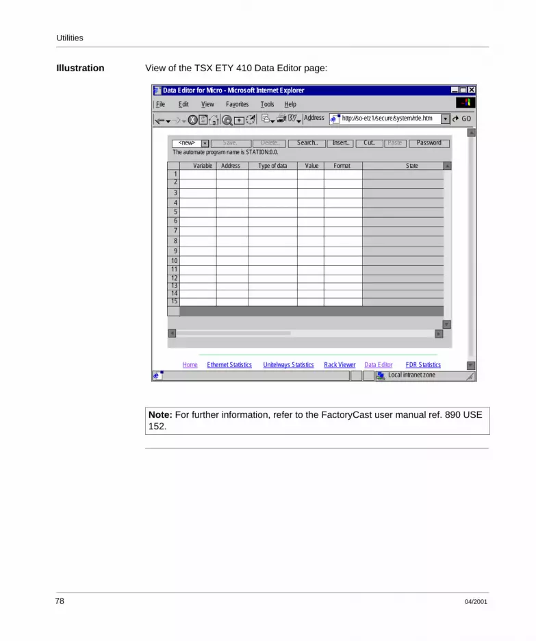
Data Editor Page
At a Glance This page is used to create animation tables containing lists of PLC variables to be displayed or modified. This function is useful when running diagnostics on an application. Variables are accessed:l By numbers for the TSX ETZ 410,l By numbers and symbols for the TSX ETZ 510.
Note: Write access is managed by password (default value): USER).
04/2001 77
Utilities
Illustration View of the TSX ETY 410 Data Editor page:
Note: For further information, refer to the FactoryCast user manual ref. 890 USE 152.
e
Address
File Edit View HelpFavorites
X
Tools
http://so-etz1/secure/system/rde.htm
Home Rack Viewer
eEthernet Statistics Unitelways Statistics Data Editor FDR Statistics
Local intranet zone
e GO
<new> Save. Delete.. Search.. Insert.. Cut.. Paste Password
12
3
4
6
7
8
5
9
101112131415
Variable Address Type of data Value Format State
The automate program name is STATION:0.0.
Data Editor for Micro - Microsoft Internet Explorer
78 04/2001

Utilities
Faulty Device Replacement Statistics Page - FDR
At a Glance This page allows diagnostics for the Faulty Device Replacement (FDR) function.
Illustration View of the TSX ETZ 410 faulty device replacement statistics page:
e
Address
File Edit View HelpFavorites
X
Tools
http://so-etz1/secure/system/fdr.htme
Home Rack Viewer
e
Ethernet Statistics Unitelway Statistics Data Editor FDR Statistics
Copyright 2000−2001, Schneider Automation SA. All rights reserved
Done Local intranet
Faulty Device Replacement Statistics
Status :
Parameters saved on the server :
Dhcp Tries :
Automatic Backups :
User Backup :
Ftp Connections Errors :
Ftp Backup/Restore Errors :
Reset counters
Stopped
NO
0
0
0
0
0
ETZ - Fdr Diagnostic - Microsoft Internet Explorer
04/2001 79

Utilities
Parameters Description of the parameters:
Name Description
Status Indicates the FDR function status:l Starting, Running, Stopped or Error
Parameters saved on server Parameters saved on the server: l Yes or Nothis information is only important when the FDR function is active.
Dhcp Tries Total number of DHCP tries.
Automatic Backups Total number of TSX ETZ configuration backups successfully performed automatically in the server (see Commands Zone, p. 115).
User Backups Total number of TSX ETZ configuration backups successfully performed in the server by the user, using the Force Backup button on the Automatic Configuration (See Commands Zone, p. 115) page.
Ftp Connections Errors Number of times, where the FTP connection could not be made. This error counter indicates FTP errors besides those of reading or writing the configuration file.
Ftp Backup/Restore Errors Number of times, where the backup or restoration by FTP of the configuration file could not be performed.
80 04/2001

Utilities
Configuration Pages for the TSX ETZ Module
Home Page This page offers different configuration utilities supported by the web server by default for the TSX ETZ modules and the links to the required utility.
How to Access the Configuration Page
To access the Online Configuration page, proceed as follows:
Step Action
1 Click on the Online Configuration link on the home page.Result: a window requesting the user name and password appears.
2 Enter the user name and the password (case-sensitive).
Note: the default values are:l for the user name: USERl for the password: USER
3 Confirm by clicking Ok.
04/2001 81

Utilities
Illustration The Online Configuration home page is the following:
To access a chosen utility, click on a link.
LinksAddress
File Edit View Go Help
Copyright 2000−2001, Schneider Automation SA. All rights reserved
Internet zone
Online Configuration
HomeSecurity
IP ConfigurationUnitelway ConfigurationAutomatic Configuration
SNMP ConfigurationReboot
Favorites
http://139.160.234.13/secure/system/indexdiag.htm
SchneiderElectricS
e
e
Back StopX
Refresh Home Search Favorites History Channels
e
e
e
Forward
for Transparent Factory TSX ETZ TCP/IP-Modem Module
Version TSX ETZ V1.1
Welcome to Schneider Automation Web Server for TSX ETZ Module - Microsoft Internet Explorer
82 04/2001

Utilities
Security Page
At a Glance When accessing via HTTP, this page allows modification of:l The user name and the password for accessing the home page,l The password for writing variables in the data editor,l The password for access to configuration parameters.The user name and passwords are a maximum of 15 characters in non-extended ASCII.The default values of the Username/Password fields protecting access to web pages are set to USER/USER.
Note: In the case of a TSX ETZ 510 module, the HTTP Password and Data Password zones do not appear. It is the FactoryCast Configurator, which allows these passwords to be modified.
04/2001 83

Utilities
Illustration View of the TSX ETZ 410 security page:
How to Modify HTTP Access Rights
The procedure is as follows:
e
Address
File Edit View HelpFavorites
X
Tools
http://so-etz1/secure/system/security.htme
Home Automatic Configuration
e
Security Unitelway Parameters SNMP Parameters
Copyright © 2000 - 2001, Schneider Automation SA. All rights reserved.
Local ntranet
Passwords
Write Data Password :
HTTP Password :
Confirm HTTP Password :
HTTP User Name :
Write Configuration Password :
Apply
HTTP Password
Confirm Write Password :
Data Password
Configuration Password
Reset
IP Parameters Reboot
Confirm Write Password :
ETZ - Security - Microsoft Internet Explorer
Step Action
1 Enter the new User name.
2 Enter the new password.
3 Confirm the new password.
4 Enable the alteration with the Apply button.
Result: a confirmation window appears.
5 Click on the Reboot button to accept the modification in the module.
84 04/2001

Utilities
How to Modify the Data Password
The procedure is as follows:
How to Modify the Configuration Password
The procedure is as follows:
Step Action
1 Enter the current password (case sensitive).
2 Enter the new password.
3 Confirm the new password.
4 Enable the alteration with the Apply button.
Result: a confirmation window appears.
5 Click on the OK button to accept the modification in the module.Result: a window appears to signal that the password has been successfully changed
Step Action
1 Enter the current password (case sensitive).
2 Enter the new password.
3 Confirm the new password.
4 Enable the alteration with the Apply button.
Result: a confirmation window appears.
5 Click on the OK button to accept the modification in the module.Result: a window appears to signal that the password has been successfully changed.
04/2001 85

Utilities
Configuration Page for the TCP/IP Utilities
At a Glance This page allows the configuration of the TCP/IP utilities of the TSX ETZ module.
Illustration View of the IP Configuration page:
Note: Write access is managed by a password (Configuration password) which is by default USER.The content of this page is explained in the chapter Configuring TSX ETZ Modules (See Configuring TSX ETZ 410/510 Modules, p. 102).
e
Address
File Edit View HelpFavorites
X
Tools
http://so-etz1/secure/system/confip.htme
IP Parameters
IP Address
XWAY Address
Ethernet configuration
Configuration of Connections
IP address :Configured Automatic configuration
Subnetwork mask :Gateway adress :
Network : Station :
Connections : Access Control
Xway Address : IP Address : Protocol : Access : Mode :
New Edit Remove Ok Cancel
UNITE MULTI
139
160
234 41255139
255 254160
23401
48
Network ConnectionEthernet Modem
1
8 139 2343 160 42
Ok Cancel
Ethernet II 802.3
XWay IP Address Protocol Access Mode8.3 139.160.234.42 UNITE Allowed MULTI1
Apply Reset
Home Automatic Configuration
e
Security Unitelway Configuration SNMP Configuration
Copyright 2000−2001, Schneider Automation SA. All rights reserved
Local Intranet
IP Configuration Reboot
ETZ - IP Configuration - Microsoft Internet Explorer
86 04/2001

Utilities
Configuration Page for the Unitelway Link
At a Glance This page allows the configuration of the Unitelway function of the TSX ETZ module.
Illustration View of the Unitelway Configuration page:
Note: Write access is managed by a password (Configuration password) which is by default USER.The content of this page is explained in the chapter Configuring TSX ETZ Modules (See Configuring TSX ETZ 410/510 Modules, p. 102).
e
Address
File Edit View HelpFavorites
X
Tools
http://so-etz1/secure/system/unitel.htme
Home Automatic Configuration
e
Security Unitelway Configuration SNMP Configuration
Copyright 2000−2001, Schneider Automation SA. All rights reserved
Local intranet
IP Configuration Reboot
Done
Odd
Apply Reset
Auto
4
2
Ad0 Number :
Adresse Number :
Baud Rate :
Parity :
Unitelway Configuration
1Timeout (s) :
ETZ - Unitelway Configuration - Microsoft Internet Explorer
04/2001 87
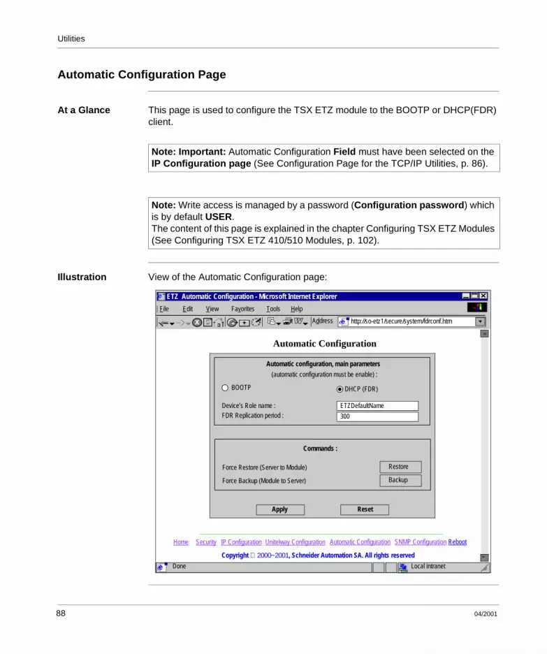
Utilities
Automatic Configuration Page
At a Glance This page is used to configure the TSX ETZ module to the BOOTP or DHCP(FDR) client.
Illustration View of the Automatic Configuration page:
Note: Important: Automatic Configuration Field must have been selected on the IP Configuration page (See Configuration Page for the TCP/IP Utilities, p. 86).
Note: Write access is managed by a password (Configuration password) which is by default USER.The content of this page is explained in the chapter Configuring TSX ETZ Modules (See Configuring TSX ETZ 410/510 Modules, p. 102).
e
Address
File Edit View HelpFavorites
X
Tools
http://so-etz1/secure/system/fdrconf.htme
Home Automatic Configuration
e
Security Unitelway Configuration SNMP Configuration
Copyright 2000−2001, Schneider Automation SA. All rights reserved
Local intranet
IP Configuration Reboot
Done
Automatic Configuration
Apply Reset
ETZ Automatic Configuration - Microsoft Internet Explorer
Device’s Role name :
(automatic configuration must be enable) :
FDR Replication period :
Automatic configuration, main parameters
ETZDefaultName
300
BOOTP DHCP (FDR)
Commands :
Force Restore (Server to Module)
Force Backup (Module to Server)
Restore
Backup
88 04/2001

Utilities
Configuration Page for the SNMP Function
At a Glance This page allows the configuration of the SNMP function of the TSX ETZ module.
Illustration View of the SNMP Configuration page:
Note: Write access is managed by a password (Configuration password) which is by default USER.The content of this page is explained in the chapter Configuring TSX ETZ Modules (See Configuring TSX ETZ 410/510 Modules, p. 102).
e
Address
File Edit View HelpFavorites
X
Tools
http://so-etz1/secure/system/snmp.htme
Home Automatic Configuration
e
Security Unitelway Configuration SNMP Configuration
Copyright 2000−2001, Schneider Automation SA. All rights reserved
Local intranet
IP Configuration Reboot
Done
IP address manager 1
IP address manager 2
Location (SysLocation)
Contact (SysContact)
IP address managers
Agent
SNMP Configuration
Community names
Set
Get
Trap
SecurityEnable “Authentification Failure” Trap
0 0 0 0
0 0 0 0
public
public
public
Apply Reset
ETZ - SNMP Configuration - Microsoft Internet Explorer
04/2001 89

Utilities
Module Reboot Page
At a Glance This page reboots the TSX ETZ module. The reboot should be performed to accept new configuration parameters. All connections are broken following a reboot.
Illustration View of the reboot page:
Note: Reboot is managed by a password (Configuration password) which is by default USER.
e
Address
File Edit View HelpFavorites
X
Tools
http://so-etz1/secure/system/reboot.htme
Home Automatic Configuration
e
Security Unitelway Configuration SNMP Configuration
Copyright 2000−2001, Schneider Automation SA. All rights reserved
Local intranet
IP Configuration Reboot
Reboot
Click button to reboot
GO
Reboot device
ETZ - Reboot - Microsoft Internet Explorer
90 04/2001

04/2001
3
Installing the TSX ETZ 410/510 ModuleAt a Glance
Aim of this Chapter
This chapter deals with the installation of the TSX ETZ 410/510 modules.For an overview of the installation of the module, see Installing the TSX ETZ - Summary, p. 121.
What’s in this Chapter?
This Chapter contains the following Sections:
Section Topic Page
3.1 Topology Principles 93
3.2 Configuring TSX ETZ 410/510 Modules 102
3.3 Configuration of Serial RS232 Links 120
3.4 Installing the TSX ETZ - Summary 121
91

Installation
92 04/2001

Installation
3.1 Topology Principles
At a Glance
Aim of this Section
This section introduces the topology principles for connecting the TSX ETZ modules.
What’s in this Section?
This Section contains the following Maps:
Topic Page
General 94
Direct Connection between TSX Micro and TSX ETZ 96
Connection of a TSX ETZ on the Uni-Telway Network 98
TSX ETZ Connection via Modem 100
04/2001 93

Installation
General
At a Glance The ETZ module is autonomous.Changing speed on the Ethernet medium (10/100 Mbits) is automatic. So that the module is operational, it should be powered and connected by a Unitelway network to a Unitelway master TSX 3710/3721/3722.A lit RUN LED indicates that the module is operating (correct Unitelway scanning, module configured on the TCP/IP level, etc.).The module does not have the concept of starting from cold or warm as the memory is not backed up when there is a power outage.When powered, the module systematically reboots the hardware and the software.The connection speed on the Terminal port of the TSX Micro is optimized at 19200 baud.
94 04/2001

Installation
Front Face View of the front face of the TSX ETZ 510 module:
Terminal blockModule power supply
9-pin SUB D RS 232 portfor modem link
RJ45 portEthernet link
RJ45 RS 485 portUni-Telway link
Mini Din terminalPort
LED indicators
Module MAC address.01.12.20
04/2001 95

Installation
Direct Connection between TSX Micro and TSX ETZ
At a Glance From the possible direct connections of the TSX ETZ module, the most common ones are given below.
Connection on TER Port
Example of connection of a TSX ETZ on the TER port of a TSX 3710:
TSX 3710
Ethernet connection
Connection to a modem
TSX ETZ
Programmingterminal
PCU 1030PCU 1031
TER
OR
TSX ETZ CDN 003
96 04/2001

Installation
Connection on AUX Port
Example of connection of a TSX ETZ on the AUX port of a TSX 3721:
FTX 117 adjustment terminal
PCU 1030/1031
Programmingterminal
PCU 1030/1031
Ethernet connection
Modem connection
Programmingterminal
TSX ETZ TSX 3721/22
AUX
OR
OR
TSX ETZ CDN 003
04/2001 97
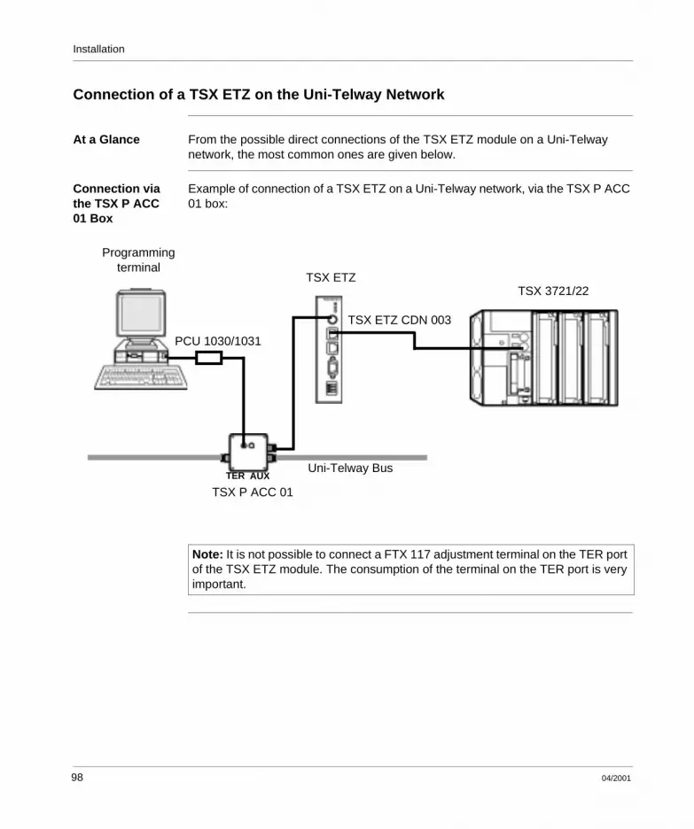
Installation
Connection of a TSX ETZ on the Uni-Telway Network
At a Glance From the possible direct connections of the TSX ETZ module on a Uni-Telway network, the most common ones are given below.
Connection via the TSX P ACC 01 Box
Example of connection of a TSX ETZ on a Uni-Telway network, via the TSX P ACC 01 box:
Uni-Telway Bus
Programmingterminal
TSX ETZ
TSX P ACC 01TER AUX
PCU 1030/1031
TSX 3721/22
TSX ETZ CDN 003
Note: It is not possible to connect a FTX 117 adjustment terminal on the TER port of the TSX ETZ module. The consumption of the terminal on the TER port is very important.
98 04/2001

Installation
Connection on the TSX P ACC 01 AUX Port
Example of connection of a TSX ETZ on a Uni-Telway network, via the TSX P ACC 01 port:
This configuration is recommended, as it leaves the TER port of the TSX ETZ module available to connect a terminal, for example.
In this case, the TER port of the TSX Micro offers a maximum of 8 configurable slave addresses:l the TSX ETZ occupies 2 Uni-Telway addresses,l the programming terminal occupies 3 addresses,There therefore remains 3 available addresses.
Uni-Telway Bus
Programmingterminal TSX ETZ
TSX P ACC 01
TER AUX
TSX 3721/22
TER
PCU 1030/1031TSX ETZ CDN 003
04/2001 99

Installation
TSX ETZ Connection via Modem
At a Glance From the possible connections of the TSX ETZ module, the most common ones are given below.
ETZ to ETZ Connection
Example of a connection between two TSX Micros via a modem link.
ETZ to PC Connection
Connection between a TSX Micro and a remote PC via a modem
Commuted Telephone Network
TSX ETZ
Modem Modem
TSX ETZ
PPP and PAP Protocols
TSX 3721/22 TSX 3721/22
TSX ETZ CDN 003 TSX ETZ CDN 003
Commuted Telephone Network
TSX ETZ
Modem Modem
Remote PC
PPP and PAP Protocols
TSX 3721/22
TSX ETZ CDN 003
100 04/2001

Installation
ETZ Connection to an Ethernet Network
Connection between a TSX Micro and an Ethernet network via a modem
Commuted Telephone Network
TSX ETZ
Modem Modem
Remote AccessServer
PPP and PAP Protocols
TSX 3721/22
TSX ETZ CDN 003
Ethernet Network
04/2001 101

Installation
3.2 Configuring TSX ETZ 410/510 Modules
At a Glance
Aim of this Section
This section deals with the configuration of the TSX ETZ 410/510 modules.
What’s in this Section?
This Section contains the following Maps:
Topic Page
Access to the Module Configuration 103
Configuration Parameters linked to TCP/IP Utilities 105
Ethernet Connection Parameters 107
Modem Connection Parameters 110
Configuration Parameters Connected to the Uni-Telway Link 114
Automatic Configuration 115
Configuration of the SNMP Module 117
102 04/2001

Installation
Access to the Module Configuration
At a Glance The TSX ETZ modules are only configured using an Internet browser, which is currently available on the market.It is possible to access the configuration page either by Ethernet link, or by RS 232 serial link.The module configuration does not require connection to a TSX Micro. In this case, the RUN LED will be extinguished and the ERR LED will flash.
Configuring via Ethernet Link
To access the module configuration pages for the first time, via a HTTP link, follow the steps below:
Step Action
1 Connect the module to the Ethernet network and switch it on.
2 Open the Internet browser on your PC
3 In the "Address" field, enter the command: http://<ETZ_default_IP_address>, then <Enter>.Note: the IP address is calculated using the MAC address of the module, which is printed on its front face (See Default Ethernet Interface IP Address for the ETZ Module, p. 28).The home page is displayed on the screen.
4 Click the link marked Online Configuration
5 Enter the default user name (UserName): "USER" and the default password: "USER" (without quotation marks), then <Enter>.
6 The configuration index page appears: then click on the required link (See Configuration Pages for the TSX ETZ Module, p. 81)
Note: For the following connections, proceed in the same way, but enter the IP address, the corresponding user name and password, if these have been modified.
04/2001 103

Installation
Configuring via RS 232 Serial Link
For the first connection, it is necessary to configure the components of your operating system, so that it can communicate with the TSX ETZ module (see Configuration of Serial RS232 Links, p. 120). Once these components are configured, follow the steps below:
Step Action
1 Connect a RS 232 crossover cable between a PC COM port and the 9-pin SUB-D port on the ETZ module (see RS232 Lead to PC, p. 141).
2 Establish the serial connection between the PC and the module.
3 Open the Internet browser on your PC
4 In the "Address" field, type: http://85.16.0.2, then <Enter>.
5 Enter the default user name (UserName): "USER" and the default password: "USER" (without quotation marks), then <Enter>.
6 The configuration index page appears: then click on the required link (See Configuration Pages for the TSX ETZ Module, p. 81)
Note: For the following connections, the IP address to be entered is always the same, but enter the corresponding user name and password, if these have been modified.
104 04/2001

Installation
Configuration Parameters linked to TCP/IP Utilities
At a Glance The TCP/IP utilities are configured using the IP Configuration (See Configuration Page for the TCP/IP Utilities, p. 86) screen and the Online Configuration menu in the HTTP server embedded into the module.
IP Address Zone View of the IP address
This zone allows the Ethernet Interface IP address of a module to be defined in two distinct ways:
l Either by manually configuring the address by clicking on the Configured button.l Or the address is supplied by a BOOTP server device by clicking on the
Automatic configuration, the entry zone for the addresses is therefore grayed.
l If manual configuration is selected, you can enter:l The IP address of the module in the IP Address zone.l The subnetwork mask, Subnetwork maskl The Gateway address
l If you select the auto configuration, the IP address of the module is configured via a remote device, which serves as the BOOTP/DHCP server.
IP Address
Configured
IP Address :
Subnetwork mask :
Gateway Address :
Automatic configuration
139 160 234 41
255
139
255 254 0
160 234 1
04/2001 105

Installation
XWAY Address Zone
X-Way address entry: Network and Station numberIllustration
Network Connection Zone
View of the Network connection zone:
This zone allows the selection of the type of link to be used:
l Ethernet (default)l ModemDepending on the type of link selected, certain sections of the IP configuration page are different.
XWAY Address
Network : Station :8 4
Network Connection
Ethernet Modem
106 04/2001

Installation
Ethernet Connection Parameters
At a Glance If Ethernet is selected in the Network Connection zone, the configuration page allows the modification of:l The Ethernet format in the Ethernet Configuration zone.l The configuration and the list of connections that can be opened by the module,
in the Configuration of connections zone.
Ethernet Configuration
This is configured in the following zone:
The two available buttons allow the selection of:l The Ethernet II format, corresponding to the RFC 894 standard (most commonly
used).l The 802.3 format, corresponding to the RFC 1042 standard. This format will be
used when the remote devices use this format.
Ethernet configuration
Ethernet II 802.3
04/2001 107
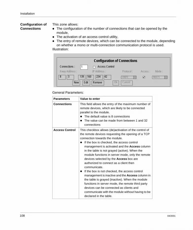
Installation
Configuration of Connections
This zone allows:l The configuration of the number of connections that can be opened by the
module,l The activation of an access control utility,l The entry of remote devices, which can be connected to the module, depending
on whether a mono or multi-connection communication protocol is used.Illustration:
General Parameters:
Parameters Value to enter
Connections This field allows the entry of the maximum number of remote devices, which are likely to be connected parallel to the module.l The default value is 8 connectionsl The value can be made from between 1 and 32
connections
Access Control This checkbox allows (de)activation of the control of the remote devices requesting the opening of a TCP connection towards the module.l If the box is checked, the access control
management is activated and the Access column in the table is not grayed (active). When the module functions in server mode, only the remote devices selected by the Access box are authorized to connect as a client then communicate.
l If the box is not checked, the access control management is inactive and the Access column in the table is grayed (inactive). When the module functions in server mode, the remote third party devices can be connected as clients and communicate with the module without having to be declared in the table.
Configuration of ConnectionsConnections : 1 Access Control
Xway Address : IP Address : Protocol : Access : Mode :
8 3 139 160 234 42 UNITE MULTI
New Edit Remove Ok Cancel
108 04/2001

Installation
Entry of information for remote devices to be connected to the module:
Correspondence Table
A table lists all the remote devices connected to the TSX ETZ module:Illustration
To edit a device, double click on the required line.
Parameters Values
Editing buttons
l New: allows entry of a new devicel Edit: allows a device to be modifiedl Remove: removes a devicel OK: confirms the entryl Cancel: cancels the current modifications
Entry zones
X-Way Address Allows entry of X-Way address:l Network number: between 0 and 127l Station number. Between:
l 0 and 63 for a UNITE connectionl 100 and 163 for a Modbus connection
IP Address Allows entry of device’s IP address.
Protocol List, which allows the selection of the communication protocol used by each remote device:l UNITE (default)l MODBUS
Access When checked, this box denotes the remote devices, which are authorized to open a TCP connection, then send to the PLC (TSX Micro in server mode).
Mode l MONO: the module only allows one connection with the same remote IP address.
l MULTI: the module allows only one connection in client mode with the same remote IP address and several connections in server mode with the same remote IP address.
XWay IP Address Protocol Access Mode
8.3
8.5
1
2
139.160.234.42
139.255.250.255
UNITE
MODBUS
Allowed
Allowed
MULTI
MONO
04/2001 109

Installation
Modem Connection Parameters
At a Glance If Modem is chosen in the Network Connection zone, the configuration page allows the modification of the configuration and the list of connections, which can be opened by the module, in the Configuration of connections zone.
Configuration of the RS 232/Modem Parameters
These parameters are configured in the following zone:
Parameters to configure:
* Refer to your modem’s documentation for the supported Hayes commands.Example: AT&FS0=2
Parameters Values
Baud Rate Speed of RS 232 link to be chosen according to the modem you have: 4800, 9600, 19200, 38400 and 57400.
Parity Odd, even or without parity
Stop Bit Number of stop bits
Max. time between 2 frames If the time between two frames is greater than the entry value in this field (in seconds), the connection will be cut. If the entry time is 0; no checks are carried out.
Max. connection time This field allows the maximum connection time (in seconds) to be set. At the end of this time the connection will be cut. If the entry time is 0; no checks are carried out.
Hayes Configuration by string of Hayes characters. Allows the sending of commands in Hayes* format to the modem
RS232/Modem Parameters
Baud Rate :
Stop Bit :
Max. time beetween 2 frames (s) :
Max. connection time (s) :
Hayes :
0
0
4800 Parity None
1
110 04/2001

Installation
Configuration of Connections
This zone allows:l The configuration of the number of connections that can be opened by the
modulel The activation of an access control utilityl The entry of remote devices, which can be connected to the module, depending
on whether a mono or multi-connection communication protocol is used.Illustration:
General Parameters:
Parameters Value to enter
Connections This field allows the entry of the maximum number of remote devices, which are likely to be connected to the module.
Access Control This checkbox allows (de)activation of the control of the remote devices requesting the opening of a TCP connection towards the module.l If the box is checked, the access control
management is activated and the Access column in the table is not grayed (active). When the module functions in server mode, only the remote devices selected by the Access box are authorized to connect as a client then communicate.
l If the box is not checked, the access control management is inactive and the Access column in the table is grayed (inactive). When the module functions in server mode, the remote third party devices can be connected as clients and communicate with the module without having to be declared in the table.
Configuration of Connections
Connections : 1 Access Control
Xway Address : IP Address : Protocol : Access : Mode :
8 3 139 160 234 42 UNITE MULTI
New Edit Remove Ok Cancel
N° : User : Password :
04/2001 111

Installation
Entry of information for remote devices to be connected to the module:
Parameters Values
Editing buttons
l New: allows entry of a new devicel Edit: allows a device to be modifiedl Remove: removes a devicel OK: confirms the entryl Cancel: cancels the current modifications
Entry zones
X-Way Address Allows entry of X-Way address:l Network number: between 0 and 127l Station number. Must be between:
l 0 and 63 for a UNITE connectionl 100 and 163 for a Modbus connection
IP Address Allows entry of an IP address
Protocol List, which allows the selection of the communication protocol used by each remote device:l UNITE (default)l MODBUS
Access When checked, this box denotes the remote devices, which are authorized to open a TCP connection, then send to the PLC (TSX Micro in server mode).
Mode l MONO: the module only allows one connection with the same remote IP address.
l MULTI: the module allows only one connection in client mode with the same remote IP address and several connections in server mode with the same remote IP address.
No. This field allows the entry of the number of each remote device.
User This field allows the entry of the username of each remote device.
Password This field allows the entry of the password of each remote device.
Note: The TSX ETZ module does not manage the password associated with the modem connection in server mode. All telephone connections are accepted. Access control takes place on the IP address level of the remote device, as well as by the PAP protocol. The password should be managed on the modem level.
112 04/2001

Installation
Correspondence Table
A table lists all the remote devices connected to the TSX ETZ module:Illustration
To edit a device, double click on the required line.
XWay IP Address Protocol Access Mode8.3 139.160.234.42 UNITE Allowed MULTI1
Phone N° User0452352020 User
04/2001 113

Installation
Configuration Parameters Connected to the Uni-Telway Link
At a Glance The Uni-Telway link is configured using the Uni-Telway Configuration (See Configuration Page for the Unitelway Link, p. 87) screen and the Online Configuration menu in the HTTP server loaded into the module. View of the entry zone:
Parameters Table of the parameters:
Click on the Apply button to validate the alterations performed.Click on the Reset button to cancel the current alterations.
Odd
Apply Reset
Auto
4
2
Ad0 Number :
Adresse Number :
Baud Rate :
Parity :
1Timeout (s) :
Parameter Values
Ad0 Number Network access address, used in TSX Micro client mode to access devices connected to the TCP/IP network.Values: 4 to 98
Address Number
Cannot be configured. The TSX ETZ occupies 2 Uni-Telway addresses. The second is used by the loaded software when the TSX ETZ receives a message from a TCP/IP device, which is intended for the TSX Micro (TSX Micro server).
Baud Rate Auto, 9600 or 19200 baud (recommended).
Parity Odd, Even, None (recommended).
Timeout (s) Value of the completion time (in seconds).
114 04/2001

Installation
Automatic Configuration
At a Glance In order to use the module in automatic configuration mode, you must set the configuration parameters. Configuration takes place with the help of the Automatic Configuration (See Automatic Configuration Page, p. 88) page from the Online Configuration menu.The Automatic Configuration option must then be chosen in the IP Configuration (See IP Address Zone, p. 105) page.Two buttons: Apply and Reset allow you to confirm the modifications or reset the old values.
Main Parameters Zone
Illustration:
Utility choice:l The BOOTP/DHCP(FDR) buttons allow you to choose between a BOOTP or a
DHCP (FDR) server.If the Faulty Device Replacement function (FDR) is required, set the button to DHCP(FDR), then:l in the entry zone Device’s Role name enter the name given to the module.l In the FDR Replication period entry zone, enter the period of automatic
comparison (in seconds) between the TSX ETZ configuration and the configuration saved in the DHCP server. If a difference is detected, the TSX ETZ module automatically saves the configuration in the server.
Commands Zone Illustration:
l The Restore button: Forces the TSX ETZ to revert to the configuration from the server.
l The Backup button: Forces the TSX ETZ to save its configuration in the server.
Device’s Role name :
(automatic configuration must be enable) :
FDR Replication period :
Automatic configuration, main parameters
ETZDefaultName
300
BOOTP DHCP (FDR)
Commands :
Force Restore (Server to Module)
Force Backup (Module to Server)
Restore
Backup
04/2001 115
Installation
Important
Note: when DHCP(FDR) mode is active, any modification of the content of a configuration page is automatically saved in the server (Backup), as soon as the modification is validated by the Apply button.
116 04/2001

Installation
Configuration of the SNMP Module
At a Glance In order to use the module as an SNMP agent, you must set the configuration parameters.The configuration of the SNMP module is carried out using the SNMP Configuration (See Configuration Page for the SNMP Function, p. 89) screen and the Online Configuration menu of the HTTP server embedded into the module.Parameters linked to the SNMP module are divided into 4 categories:l IP address managers zone zl Agent zonel Zone Community names zonel Security zoneTwo buttons: Apply and Reset allow you to confirm the modifications or reset the old values.
IP Address Managers Zone
Illustration:
This zone allows the completion of the SNMP administrator’s IP addresses. The modules authorize a maximum of two administrators.These addresses are used during possible transmission of events (TRAP).
Note: Only 7-bit ASCII characters can be used in the character string entry fields.
IP Address managers
IP Address manager 1
IP Address manager 2
0 0 0 0
0 0 0 0
04/2001 117

Installation
Agent Zone Illustration:
This zone allows the localization and identification of an agent from the SNMP administrator. It comprises two fields:l The Location (SysLocation) field: indicates the physical location of the device
(maximum string of 32 characters).l The Contact (SysContact) field: indicates the personnel to contact for device
management and the method of contact (maximum string of 32 characters).
Community Zone Illustration:
This zone allows the definition of a community name by utility family Set, Get and Trap. It comprises three fields:l The Set field: defines the community name to the Set utility (maximum string of
16 characters). The default value of the field is "Public".l The Get field: defines the community name to the Get utility (maximum string of
16 characters). The default value of the field is "Public".l The Trap field: defines the community name to the Trap utility (maximum string
of 16 characters). The default value of the field is "Public".
Agent
Location (SysLocation)
Contact (SysContact)
Community names
Set
Get
Trap
public
public
public
118 04/2001

Installation
Security Zone Illustration:
This zone contains a checkbox that allows the validation of the transmission of an identification error event (TRAP) from the SNMP agent to the administrator who sent the request transmission.In this way, the agent warns the administrator that the request has been refused following an identification error (community name configured in the administrator is different to the one configured in the agent).
Security
Enable “Authentification Failure” Trap
Apply Reset
04/2001 119

Installation
3.3 Configuration of Serial RS232 Links
Configuration of Serial RS232 Links
At a Glance In order to use a connection by serial modem link, you need to install and/or configure certain elements in your Windows operating system.To do this, refer to the general Readme file on the CD-ROM supplied with this product.
120 04/2001

Installation
3.4 Installing the TSX ETZ - Summar
Installing the TSX ETZ - Summary
Illustration Summary of operations to be performed
Automatic
Installation of the TSX ETZ Module
Configuration of the TSX ETZ Module
On an Ethernet network Via a serial linkby modem
Manual
ChooseAutomatic Configuration
in the Uni-TelwayIP Configuration page
Select DHCP(FDR)in the Uni-Telway
Automatic Configuration page
Access the configuration via an internet browser
Configure the serial linkof the PC
Enter Uni-Telwayparameters
in the Uni-TelwayConfiguration page
Enter IP parametersin the Uni-Telway
IP Configuration page
Enter IP parametersin the Uni-Telway
IP Configuration page
Enter Uni-Telwayparameters
in the Uni-TelwayConfiguration page
Enter IP parametersin the Uni-Telway
IP Configuration page
Enter Uni-Telwayparameters
in the Uni-TelwayConfiguration page
ChooseAutomatic Configuration
in the Uni-TelwayIP Configuration page
Reboot the module inthe Reboot page
DHCP(FDR)BOOTP
3
2
1
3
4 4
5
6 7
6
4
8
Access the HTTP server of the TSX ETZ Module
via an Internet browser
2
Select BOOTPin the Uni-Telway
Automatic Configuration page
5
04/2001 121

Installation
Rapid access
Number Page number
1 Dimensions and Mounting of TSX ETZ modules, p. 129
2 Access to the Module Configuration, p. 103
3 Configuration Parameters linked to TCP/IP Utilities, p. 105
4 Configuration Parameters Connected to the Uni-Telway Link, p. 114
5 Automatic Configuration, p. 115
6 Ethernet Connection Parameters, p. 107
7 Modem Connection Parameters, p. 110
8 Module Reboot Page, p. 90
122 04/2001
04/2001
4
Hardware SpecificationsAt a Glance
Aim of this Chapter
This chapter deals with the hardware specifications of the TSX ETZ 410/510 modules.
What’s in this Chapter?
This Chapter contains the following Sections:
Section Topic Page
4.1 Description 125
4.2 Installing TSX ETZ Modules 129
4.3 Connections 132
4.4 Diagnostics 142
4.5 Electrical Specifications 144
4.6 Norms and Standards 145
4.7 Service Conditions 146
123

Hardware Specifications
124 04/2001

Hardware Specifications
4.1 Description
At a Glance
Aim of this Section
This section deals with the physical description of the TSX ETZ 410/510 modules.
What’s in this Section?
This Section contains the following Maps:
Topic Page
Physical Description 126
Description of the Support Plate 128
04/2001 125

Hardware Specifications
Physical Description
At a Glance View of the TSX ETZ module:
1
2
3
4
5
67
126 04/2001

Hardware Specifications
Description Description of the front of the module:
Number Description
1 3 indicator LEDs (See Indicator LEDs, p. 142):l A RUN LED (green)l An ERR LED (red)l An Rx/Tx LED (orange)
2 A Mini-Din connector for terminal port (See Mini Din Connector, p. 136).
3 A type RJ45connector for Uni-Telway RS 485 link (See RJ45 Uni-Telway link connector, p. 136).
4 A type RJ45 connector for Ethernet link (See RJ45 Ethernet Connector, p. 134).
5 A SUB D 9 points connector for modem link (See Series RS 232 modem link connector, p. 135).
6 A screw in terminal block to link the 24 VDC supply voltage (See Supply Terminal Block, p. 133).
7 Support plate allowing for the attachment of the module directly on AM1-DE200/DP200 type DIN profile or Telequick AM1-PA perforated mounting plate.
04/2001 127

Hardware Specifications
Description of the Support Plate
At a Glance Each TSX ETZ module is delivered mounted on a support plate, which allows attachment to either: the DIN AM1-DE200 or AM1-DP200 profile, or to a Telequick AM1-PA perforated mounting plate.
Illustration View of the plate:
Description Description of the plate:
12
3
1
4
Number Description
1 Two 5.5-mm diameter holes allow attachment of the plate on to a panel or AM1-PA perforated mounting plate with an entre-axe of 140-mm (TSX Micro entre-axe attachment).
2 M4 attachment hole allowing the attachment of the TSX ETZ module.
3 Two 6.5-mm diameter holes allow attachment of the plate on to a panel or AM1-PA perforated mounting plate with an entre-axe distance of 88.9-mm (TSX Premium entre-axe attachment distance).
4 Windows designed to ink pins situated at the bottom and at the back of the module.
128 04/2001

Hardware Specifications
4.2 Installing TSX ETZ Modules
Dimensions and Mounting of TSX ETZ modules
Dimensions Illustration:
04/2001 129

Hardware Specifications
Dimensions of Fitted Module
Dimensions of module with cables on front face
Mounting on profile or plate
Illustration of module mounted on profile AM1-DE200, AM1-DP200 or on plate AM1-PA:
(1) 143.7 mm (AM1-DE200)136.2 mm (AM1-DP200) (2) 132.7 mm (AM1-PA)
130 04/2001

Hardware Specifications
Dismounting Module from the Plate
To remove the module from its plate proceed as follows:
Step Action Illustration
1 Unscrew the screw at the top part of the module in order to remove it from its support
2 Swing the module forwards and disengage the module’s pins from the holes situated in the bottom part of the support.
04/2001 131

Hardware Specifications
4.3 Connections
At a Glance
Aim of this Section
This section deals with the electrical connections of TSX ETZ modules
What’s in this Section?
This Section contains the following Maps:
Topic Page
Module Connectors 133
Linking Cables 138
132 04/2001

Hardware Specifications
Module Connectors
At a Glance The different linking connectors of the TSX ETZ module are described below.
Supply Terminal Block
The supply terminal block consists of 3 limits with frontal threaded joints. It cannot
be disconnected. Each limit accepts 2.5 mm of cable 2 maximum.Illustration:
+24 VDC
Ground Connection
0 V
04/2001 133

Hardware Specifications
RJ45 Ethernet Connector
Illustration of the RJ 45 connector shielded for Ethernet link:
Wiring:
No. Signal
1 Tx+
2 Tx-
3 Rx+
4 Not connected
5 Not connected
6 Rx-
7 Not connected
8 Not connected
8
7
6
5
4
3
2
1
134 04/2001

Hardware Specifications
Series RS 232 modem link connector
Illustration of the 9-pin SUB-D connector for series RS 232 modem link:
Wiring:
The cable used between the Ethernet connector and the TSX Micro has the reference number: TSX ETZ CDN 003
No. Signal
1 Data Carrier Detect
2 Received Data
3 Transmitted Data
4 Data Terminal Ready
5 Signal Ground
6 Data Set Ready
7 Request to send
8 Clear to Send
9 Ring Indicator
Note: This connector conforms with PC standards
1
2
3
4
5
8
7
6
9
04/2001 135

Hardware Specifications
RJ45 Uni-Telway link connector
Illustration of the RJ 45 connector shielded for Uni-Telway RS 485 link:
Mini Din Connector
Illustration of the Mini Din connector for the Terminal port:
Wiring:
Note: The pin assignment conforms the Schneider standards.
8
7
6
5
4
3
2
1
No. Signal
1 D(B)
2 D(A)
3 Reserved
4 Not connected
5 Not connected
6 Not connected
7 0 V
8 5 V
136 04/2001

Hardware Specifications
Ground Connection
The ground connection situated at the end of the Ethernet cable can be of a different voltage than that of the module.Due to the length of the Ethernet cable, the difference in voltage can be significant. The ground connection package is linked locally to the module socket. For more information refer to the TSX DGKBLF ground wiring Guidance Manual.
WARNING
It is essential to ground the module through the supply terminal block.
Failure to observe this precaution can result in severe injury or equipment damage.
04/2001 137

Hardware Specifications
Linking Cables
At a Glance It is possible to use different cables to link TSX ETZ modules. These cables are either available in the Schneider Automation catalog, or can be produced by the user. For the Application Setup of a Uni-Telway bus, refer to the TSX DG UTW manual.
RJ45 Lead to Mini Din
The lead which is delivered with the TSX ETZ module and which has the following reference TSX ETZ CDN 003 is designed to link a TSX Micro to the module’s RJ45 Uni-Telway port, directly or via a TSX P ACC 01 linking box. Its length is 35cm (See Topology Principles, p. 93).
If it is not the correct length, it is possible to make a new lead from a reference TSX CX 100 lead with a Mini Din port at one end and nothing at the other end. It is 10m in length.Cut the cable to the desired length and at the free end, fasten a connector of type RJ45 cat 5 with 8 contacts.Wiring:
RJ45 TSX CX 100
1 White
2 Orange
3 Yellow
4 Black
5 Brown
6 Red
7 Green
8 Blue
138 04/2001

Hardware Specifications
Mini Din Lead to TSX SCA 50
This lead has the reference number: TSX CX 100. On one end it has a Mini Din connector and it has nothing at the other end. It allows a link between the Mini Din port of the TSX ETZ and the linking terminal block of a Bus Uni-Telway TSX SCA 50. Its length is 10m.Wiring:
RJ45 Lead to TSX SCA 50
This lead is not available in the Schneider Automation catalog. However, it is possible to make one using an uncrossed Ethernet cat 5 (TIA 568A/TIA568A) lead with 4 twisted shield pairs.You should cut one end and expose the conductors for wiring on the TSX SCA 50.Wiring:
Free end of the cable TSX SCA 50
Color Terminal number
Signal
Black 5 D(B)
Brown 4 D(A)
Red - -
Orange - -
Yellow - -
Green - -
Blue 2 and 3 0 V
White - -
Shield covering 1 Earth
RJ45 TSX SCA 50
No. Color Terminal number
Signal
1 White/Green - -
2 Green - -
3 White/Orange - -
4 Blue 5 D(B)
5 White/Blue 4 D(A)
6 Orange - -
7 White/Brown - -
8 Brown 2 and 3 0 V
Shield Shield covering - -
04/2001 139

Hardware Specifications
RJ45 Lead to TSX SCA 62
This lead is not available in the Schneider Automation catalog. However, it is possible to make one using an uncrossed Ethernet cat 5 (TIA 568A/TIA568A) lead with 4 twisted shield pairs.You should cut one end and link it to a Sub D 15 pin female connector.Wiring:
Linking Leads on the Ethernet Network
For connection to the Ethernet network, the use of cables with the following connectors RJ 45 (interface 10/100baseT) with pairs of 100 Ω, STP type (shield twisted pair) twisted shields or category 5 Ethernet cables which conform to the TIA/EIA-568A standard is recommended.
RJ45 Sub D 15 pin
No. Color No. Signal
1 White/Green - -
2 Green - -
3 White/Orange - -
4 Blue 14 D(B)
5 White/Blue 7 D(A)
6 Orange - -
7 White/Brown - -
8 Brown 8 0 V
Shield Shield covering Shield -
140 04/2001

Hardware Specifications
RS232 Lead to PC
This lead is a standard lead available on the market. It is a DTE/DTE type crossed lead. It is also called "Nullmodem" by some suppliers.Example of possible supply: EYN257H-0006-FF reference from Black Box.Connectors: 9-way SUB-D female with a UNC-4-40-2B screw.Shielded cable.Wiring:
9-pin SUB-D female 9-pin SUB-D female
2 RD 3 TD
3 TD 2 RD
4 DTR 6 and 1 DSR + CD
5 GND 5 GND
6 and 1 DSR + CD 4 DTR
7 RTS 8 CTS
8 CTS 7 RTS
9 NC 9 NC
Body - Shield covering
Body - Shield covering
Note: the DSR and CD signals are linked to simulate an on-line situation for the application (see the following site for more information: http://www.shadownet.com/hwb/ca_nullmodem9to9.htm).
04/2001 141
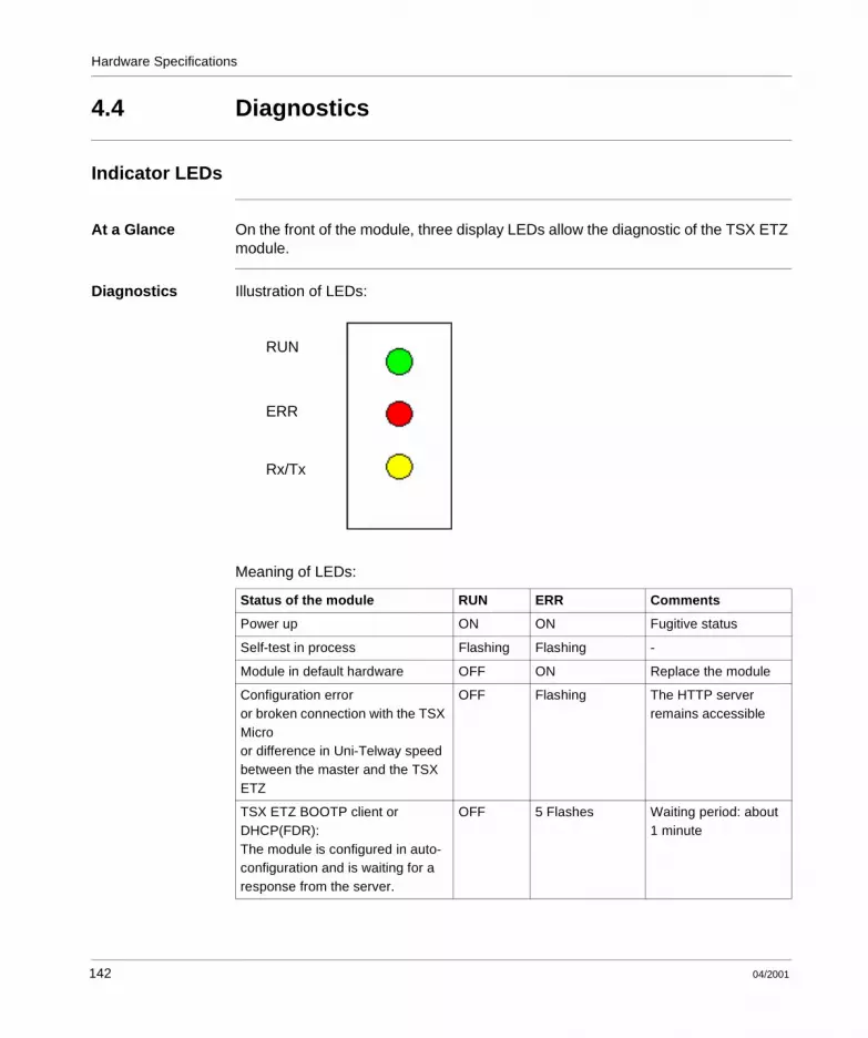
Hardware Specifications
4.4 Diagnostics
Indicator LEDs
At a Glance On the front of the module, three display LEDs allow the diagnostic of the TSX ETZ module.
Diagnostics Illustration of LEDs:
Meaning of LEDs:
Status of the module RUN ERR Comments
Power up ON ON Fugitive status
Self-test in process Flashing Flashing -
Module in default hardware OFF ON Replace the module
Configuration erroror broken connection with the TSX Microor difference in Uni-Telway speed between the master and the TSX ETZ
OFF Flashing The HTTP server remains accessible
TSX ETZ BOOTP client or DHCP(FDR):The module is configured in auto-configuration and is waiting for a response from the server.
OFF 5 Flashes Waiting period: about 1 minute
RUN
ERR
Rx/Tx
142 04/2001

Hardware Specifications
The Rx/TX LED flashes in time with communication.
TSX ETZ BOOTP client or DHCP(FDR):No response from server.
ON 5 Flashes Graded mode:the module then uses the configuration saved in its flash memory
In operation ON OFF -
Status of the module RUN ERR Comments
04/2001 143

Hardware Specifications
4.5 Electrical Specifications
Electrical Specifications
General The TSX ETZ module is an autonomous module, which should be powered from a 24 VDC supply.
Specifications Table of electrical specifications:
Parameter Minimum Nominal Maximum
Supply voltage 19.2 VDC 24 VDC 30 VDC
Wave rate - - 5%
Permissible overvoltage(for 1 hour and per 24 hours)
- - 34 VDC
Power consumption 50 mA 100 mA 200 mA
Power dissipation(excluding consumption on the Terminal port)
- 2.4 W 4 W
Period of invisible supply disconnection - - 1 ms
Note: The supply input is protected against accidental polarity inversions.
144 04/2001

Hardware Specifications
4.6 Norms and Standards
Norms and Standards
Conformity to the norms
The TSX ETZ module conforms with the following standards and norms: l ISO/IEC 8802-3l ANSI/IEEE Std 802.3 (4th edition 1993-07-08)l UL 508l IEC 1131-2l CSA C22.2/142l Conforms with FCC-B regulation for radiated emissions (50082-1).l EC markl Merchant navy classification
04/2001 145
Hardware Specifications
4.7 Service Conditions
Service Conditions
Applicable Conditions
l Usage conditionsl Temperature: from 0 to +60 °Cl Relative humidity: from 10 to 95% (excluding condensation)l Altitude: from 0 to 2000 ml Resistance to vibrations: conforms to IEC 68-2-6 test Fc norml Resistance to shocks: conforms to IEC 68-2-27 test Ea norml Resistance to free falls, conditioned hardware: conforms to norm 1131-2
l Storage conditionsl Temperature: from -25 to +70°Cl Relative humidity: from 5 to 95% (excluding condensation)
146 04/2001

Glossary
ASCII American Standard Code for Information Interchange.Pronounced "aski" An American code (but which has become the international standard) which, using 7 bits allows the definition of all alphanumeric characters used in English, punctuation marks, and certain graphics characters, as well as various commands.
BIT Contraction of English words Binary Digit.It is the binary unit of quantity of information, which can represent two distinct values (or states): 0 or 1.A field of 8 bits constitutes what we call 1 Byte or 1 Eight-bit byte.
BOOTP Bootstrap Protocol: start up protocol of terminals or stations without disks by centralized management of the network parameters.
Communication fault
Fault detected by the module when periodic exchanges with the PLC CPU are no longer carried out.
A
B
C
04/2001 147
Glossary
Configuration The configuration unites all the data which characterizes the machine (invariant) and which are necessary to the working of the module.
CPU Control Processing Unit.This is the microprocessor. It is made up of the unit control package and the arithmetic unit. The control unit aims to extract the instruction to be executed, as well as the data necessary for its execution from the central memory, to establish electrical connections in the arithmetic and logic unit and to launch the processing of this data in this unit. We can sometimes find ROM or RAM memories included on the same chip, or even some I/O interfaces or buffers.
CPU Central Processing Unit: generic designation of Schneider Automation CPUs
DHCP Dynamic Host Configuration Protocol: protocol that allows a station connected to a network to dynamically obtain its configuration.
DIN Deutsches Institut für Normung: German Normalization Institute.
Driver Program informing the operating system of the presence and specifications of a device. Also known as the device driver.
FDR Faulty Device Replacement: utility offered by its configuration’s automatic retrieval module.
FTP/TFTP File Transfer Protocol/Trivial File Transfer Protocol : transfer protocol for files on the network.
HTTP HyperText Transfer Protocol : transfer protocol for supply of documents written in Hypertext (links).
D
F
H
148 04/2001

Glossary
IP Internet Protocol: communication protocol used by Internet.
ISO International Standard Organization. The ISO code is the most used code. The transmission rules, formats and symbols are ISO standards. AFNOR is a member of ISO.
MIB Management Information Base: database used by the SNMP protocol for network management and which contains information on the transmission of data, on the station’s components or on the bridge etc.l MIB II: MIB standardl Schneider Automation MIB: Private MIB
Modbus Plus Communication protocol based on the logic token bus principle.
MTBF Mean Time Between Failure: mean time between two failures.
Operating mode All these rules regulate the module’s behavior during transitory phases or if a fault occurs.
PAP Password Authentification Protocol: identification protocol by password used in case of a remote connection by modem.
PCMCIA Personal Computer Memory Card International Association
PL7 Schneider Automation PLC programming software.
I
M
O
P
04/2001 149

Glossary
PPP Point-to-Point Protocol: point-to-point communication protocol used in the case of connection by modem.
Premium Schneider Automation programmable PLC family.
Quantum Schneider Automation programmable PLC family.
RS 232C Communication serial standard, which particularly defines the voltage of the following service:l a signal from +3V to +25V indicates a logic of 0,l a signal from -3V to -25V indicates a logic 1.Between +3V and -3V, the signal will be considered as invalid.RS 232 links are quite sensitive to interference. The standard recommends that a distance of 15 meters and a maximum of 20000 baud (bits/s) should not be exceeded.
RS 485 Serial link standard which works with a +/-5V differential. The link uses two leads for to send and to receive. This "three state" output allows it to switch to standby status when the transmission is finished.
RUN Function allowing the start up of the execution of the application program in the PLC.
SNMP Simple Network Management Protocol: Network Management Protocol, which allows the remote control of a network, by interrogating the stations on their status and modifying their configuration, carrying out security tests and observing different information linked to the transmission of data. It can even be used to remotely manage software and databases.
Q
R
S
150 04/2001

Glossary
TCP Transmission Control Protocol: data transmission protocol on a network.
Time Out Exceeding the time limit.Application shut down or disconnection following a period of non-usage, which is too long.
T
04/2001 151

Glossary
152 04/2001

Index
Aaddressing
TCP/IP, 26
BBOOTP client, 58BOOTP/DHCP, 57
Ccables, 138closing the connection
TCP/IP, 37configuration
access, 103auto, 115SNMP, 117
ConnectionModem, 110
connectiondirect, 96Ethernet, 107modem, 100Uni-Telway, 98
connection breakdown, 38connections
Modem and Ethernet, 30
04/2001
DDHCP(FDR) client, 59diagnostics
LEDs, 142Dimensions, 129
Eelectrical specifications, 144environment, 146example
Ethernet, 48modem connection, 53
HHTTP
Auto-Configuration, 88data editor, 77diagnostics home, 69Ethernet statistics, 71FDR diagnostics, 79module configuration, 81rack display page, 75Reboot, 90security page, 83SNMP configuration, 89TCP/IP configuration, 86Unitelway configuration, 87Unitelway statistics, 72
HTTP Server, 65
153

Index
Iintroduction
ETHERNET, 12IP address, 27
Llimitations, 55
Mmessaging, 46Modbus, 43Modbus on TCP/IP, 42modem
diagnostics, 73module physical description, 126
Oopening Ethernet connection
TCP/IP, 31opening modem connection
TCP/IP, 33
PParameters
TCP/IP, 105Uni-Telway, 114
SSNMP, 61specifications
TCP/IP, 25sub-addressing, 29support plate, 128synthesis of functions, 17
UUni-Telway, 23
154
04/2001