Embed Size (px)
Citation preview
*LC517* LC517
ClimateMaster works continually to improve its products. As a result, the design and specifi cations of each product at the time of order may be changed without notice and may not be as described herein. Please contact ClimateMaster's Customer Service Department at 1-405-745-6000 for specifi c information on the current design and specifi cations. Statements and other information contained herein are not express warranties and do not form the basis of any bargain between the parties,
but are merely ClimateMaster's opinion or commendation of its products. The latest version of this document is available at climatemaster.com.
Rev.:June 16, 2017
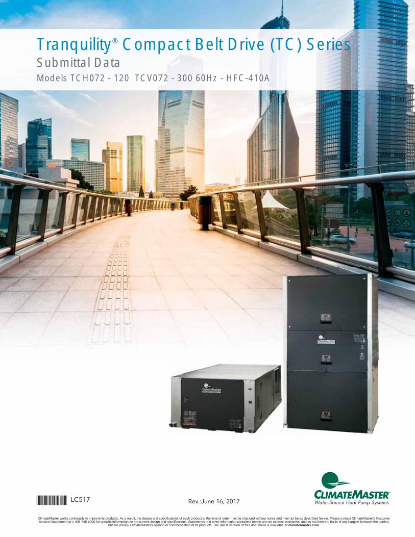
Tranquility® Compact Belt Drive (TC) Series Submittal DataModels TCH072 - 120 TCV072 - 300 60Hz - HFC-410A
ClimateMaster works continually to improve its products. As a result, the design and specifi cations of each product at the time of order may be changed without notice and may not be as described herein. Please contact ClimateMaster's Customer Service Department at 1-405-745-6000 for specifi c information on the current design and specifi cations. Statements and other information contained herein are not express warranties and do not form the basis of any bargain between the parties, but are merely ClimateMaster's opinion or commendation of its products. The latest version of this document is available at climatemaster.com.
Page ______ of ______LC517 - 2
Table of Contents
Document page number is shown next to part number (e.g. LC517 - 3 = page 3). Since not all pages are typically used in the submittals process, the page number in the lower right corner can still be used (page ____of_____).
Unit Features 4Selection Procedure 5
TCH/V Series Nomenclature 7Performance Data – AHRI/ASHRAE/ISO 13256-1 8
Performance Data – Selection Notes 9Performance Data – TCH/V072 10
Performance Data – TCH/V096 11Performance Data – TCH/V120 12
Performance Data – TCV160 13Performance Data – TCV192 14Performance Data – TCV240 15Performance Data – TCV300 16
TCH/V Performance Data – Correction Tables 17Antifreeze Correction Table 18
Blower Performance Data – TCH/V072 Standard Unit 19Blower Performance Data – TCH/V096 Standard Unit 20Blower Performance Data – TCH/V120 Standard Unit 23
Blower Performance Data – TCV160 Standard Unit 24Blower Performance Data – TCV192 Standard Unit 25Blower Performance Data – TCV240 Standard Unit 26Blower Performance Data – TCV240 Standard Unit 27Blower Performance Data – TCV300 Standard Unit 28
Waterside Ecomomizer Data 29Waterside Ecomomizer Correction Tables 32
TCH Physical Data 34TC072 - 120 Dimensional Data 35
TC072 - 120 w/wse Dimensional Data 36TCV Physical Data 37
TCV072 - 120 Dimensional Data 38TCV072 - 120 W/WSE Dimensional Data 39
TCV160 - 240 Dimensional Data 40TCV160 - 240 W/WSE Dimensional Data 41
TCV300 Dimensional Data 42TCV300 W/WSE Dimensional Data 43
TCH/V Electrical Data – Standard 44TCH/V Electrical Data - Dual Point Power 45
TCH-V Compact Belt Drive Series
ClimateMaster works continually to improve its products. As a result, the design and specifi cations of each product at the time of order may be changed without notice and may not be as described herein. Please contact ClimateMaster's Customer Service Department at 1-405-745-6000 for specifi c information on the current design and specifi cations. Statements and other information contained herein are not express warranties and do not form the basis of any bargain between the parties, but are merely ClimateMaster's opinion or commendation of its products. The latest version of this document is available at climatemaster.com.
Page ______ of ______LC517 - 3
TCH/V Series Wiring Diagram Matrix 46Typical Wiring Diagram – Three Phase TCH/V072-300 with CXM Controller 47
Typical Wiring Diagram – Three Phase TCH/V072-300 with DXM 48Typical Wiring Diagram for MPC with CXM and DXM 49
Typical Wiring Diagram – for LON with CXM and DXM 50Typical Wiring Diagram – TVH/V072-120 with Waterside Ecomizer 51Typical Wiring Diagram – TVH/V160-300 with Waterside Ecomizer 52
Typical Wiring Diagram – Waterside Economizer Control 53Engineering Specifi cations 54
Performance Sheet 62Revision History 64
Table of Contents
TCH-V Compact Belt Drive Series
ClimateMaster works continually to improve its products. As a result, the design and specifi cations of each product at the time of order may be changed without notice and may not be as described herein. Please contact ClimateMaster's Customer Service Department at 1-405-745-6000 for specifi c information on the current design and specifi cations. Statements and other information contained herein are not express warranties and do not form the basis of any bargain between the parties, but are merely ClimateMaster's opinion or commendation of its products. The latest version of this document is available at climatemaster.com.
Page ______ of ______LC517 - 4
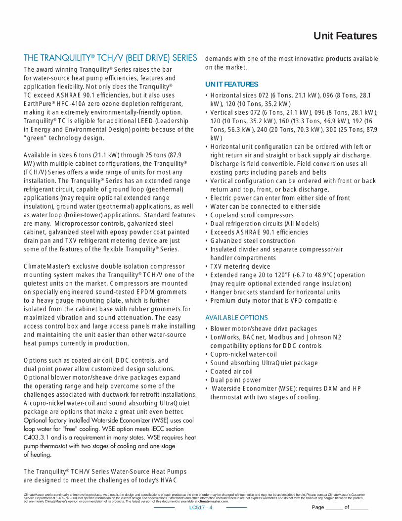
THE TRANQUILITY® TCH/V (BELT DRIVE) SERIESThe award winning Tranquility® Series raises the bar for water-source heat pump effi ciencies, features and application fl exibility. Not only does the Tranquility® TC exceed ASHRAE 90.1 effi ciencies, but it also uses EarthPure® HFC-410A zero ozone depletion refrigerant, making it an extremely environmentally-friendly option. Tranquility® TC is eligible for additional LEED (Leadership in Energy and Environmental Design) points because of the “green” technology design.
Available in sizes 6 tons (21.1 kW) through 25 tons (87.9 kW) with multiple cabinet confi gurations, the Tranquility® (TCH/V) Series offers a wide range of units for most any installation. The Tranquility® Series has an extended range refrigerant circuit, capable of ground loop (geothermal) applications (may require optional extended range insulation), ground water (geothermal) applications, as well as water loop (boiler-tower) applications. Standard features are many. Microprocessor controls, galvanized steel cabinet, galvanized steel with epoxy powder coat painted drain pan and TXV refrigerant metering device are just some of the features of the fl exible Tranquility® Series.
ClimateMaster’s exclusive double isolation compressor mounting system makes the Tranquility® TCH/V one of the quietest units on the market. Compressors are mounted on specially engineered sound-tested EPDM grommets to a heavy gauge mounting plate, which is further isolated from the cabinet base with rubber grommets for maximized vibration and sound attenuation. The easy access control box and large access panels make installing and maintaining the unit easier than other water-source heat pumps currently in production.
Options such as coated air coil, DDC controls, and dual point power allow customized design solutions. Optional blower motor/sheave drive packages expand the operating range and help overcome some of the challenges associated with ductwork for retrofi t installations. A cupro-nickel water-coil and sound absorbing UltraQuiet package are options that make a great unit even better. Optional factory installed Waterside Economizer (WSE) uses cool loop water for "free" cooling. WSE option meets IECC section C403.3.1 and is a requirement in many states. WSE requires heat pump thermostat with two stages of cooling and one stage of heating.
The Tranquility® TCH/V Series Water-Source Heat Pumps are designed to meet the challenges of today’s HVAC
demands with one of the most innovative products available on the market.
UNIT FEATURES• Horizontal sizes 072 (6 Tons, 21.1 kW), 096 (8 Tons, 28.1
kW), 120 (10 Tons, 35.2 kW)• Vertical sizes 072 (6 Tons, 21.1 kW), 096 (8 Tons, 28.1 kW),
120 (10 Tons, 35.2 kW), 160 (13.3 Tons, 46.9 kW), 192 (16 Tons, 56.3 kW), 240 (20 Tons, 70.3 kW), 300 (25 Tons, 87.9 kW)
• Horizontal unit confi guration can be ordered with left or right return air and straight or back supply air discharge. Discharge is fi eld convertible. Field conversion uses all existing parts including panels and belts
• Vertical confi guration can be ordered with front or back return and top, front, or back discharge.
• Electric power can enter from either side of front• Water can be connected to either side• Copeland scroll compressors• Dual refrigeration circuits (All Models)• Exceeds ASHRAE 90.1 effi ciencies• Galvanized steel construction• Insulated divider and separate compressor/air
handler compartments• TXV metering device • Extended range 20 to 120°F (-6.7 to 48.9°C) operation
(may require optional extended range insulation)• Hanger brackets standard for horizontal units• Premium duty motor that is VFD compatible
AVAILABLE OPTIONS
• Blower motor/sheave drive packages• LonWorks, BACnet, Modbus and Johnson N2
compatibility options for DDC controls• Cupro-nickel water-coil• Sound absorbing UltraQuiet package• Coated air coil• Dual point power• Waterside Economizer (WSE): requires DXM and HP
thermostat with two stages of cooling.
Unit Features
ClimateMaster works continually to improve its products. As a result, the design and specifi cations of each product at the time of order may be changed without notice and may not be as described herein. Please contact ClimateMaster's Customer Service Department at 1-405-745-6000 for specifi c information on the current design and specifi cations. Statements and other information contained herein are not express warranties and do not form the basis of any bargain between the parties, but are merely ClimateMaster's opinion or commendation of its products. The latest version of this document is available at climatemaster.com.
Page ______ of ______LC517 - 5
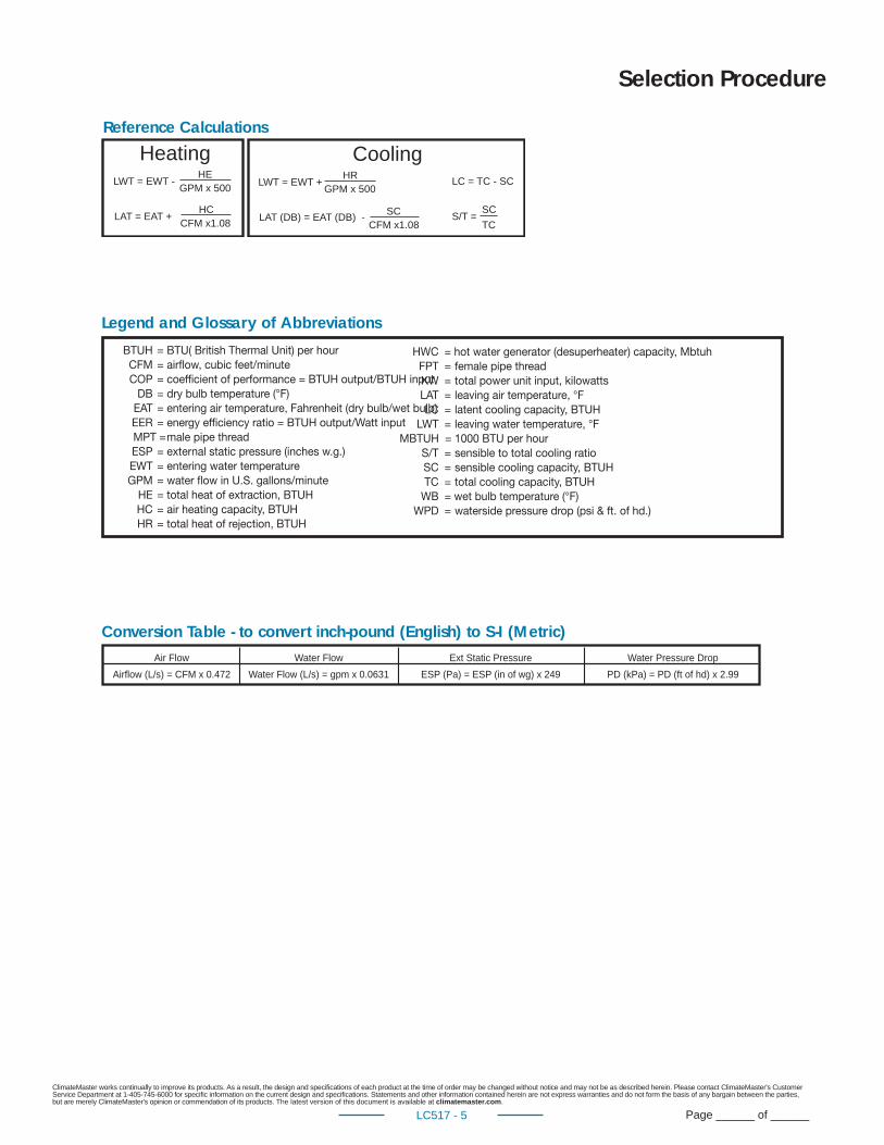
LWT = EWT -HE
GPM x 500
LAT = EAT +HC
CFM x1.08
LWT = EWT +HR
GPM x 500
LAT (DB) = EAT (DB) - SCCFM x1.08
LC = TC - SC
S/T =SCTC
Heating Cooling
Air Flow Water Flow Ext Static Pressure Water Pressure DropAirflow (L/s) = CFM x 0.472 Water Flow (L/s) = gpm x 0.0631 ESP (Pa) = ESP (in of wg) x 249 PD (kPa) = PD (ft of hd) x 2.99
Reference Calculations
BTUH = BTU( British Thermal Unit) per hour CFM = airfl ow, cubic feet/minute COP = coeffi cient of performance = BTUH output/BTUH input DB = dry bulb temperature (°F) EAT = entering air temperature, Fahrenheit (dry bulb/wet bulb) EER = energy effi ciency ratio = BTUH output/Watt input MPT = male pipe thread ESP = external static pressure (inches w.g.) EWT = entering water temperature GPM = water fl ow in U.S. gallons/minute HE = total heat of extraction, BTUH HC = air heating capacity, BTUH HR = total heat of rejection, BTUH
HWC = hot water generator (desuperheater) capacity, Mbtuh FPT = female pipe thread KW = total power unit input, kilowatts LAT = leaving air temperature, °F LC = latent cooling capacity, BTUH LWT = leaving water temperature, °FMBTUH = 1000 BTU per hour S/T = sensible to total cooling ratio SC = sensible cooling capacity, BTUH TC = total cooling capacity, BTUH WB = wet bulb temperature (°F) WPD = waterside pressure drop (psi & ft. of hd.)
Conversion Table - to convert inch-pound (English) to S-I (Metric)
Legend and Glossary of Abbreviations
Selection Procedure
ClimateMaster works continually to improve its products. As a result, the design and specifi cations of each product at the time of order may be changed without notice and may not be as described herein. Please contact ClimateMaster's Customer Service Department at 1-405-745-6000 for specifi c information on the current design and specifi cations. Statements and other information contained herein are not express warranties and do not form the basis of any bargain between the parties, but are merely ClimateMaster's opinion or commendation of its products. The latest version of this document is available at climatemaster.com.
Page ______ of ______LC517 - 6
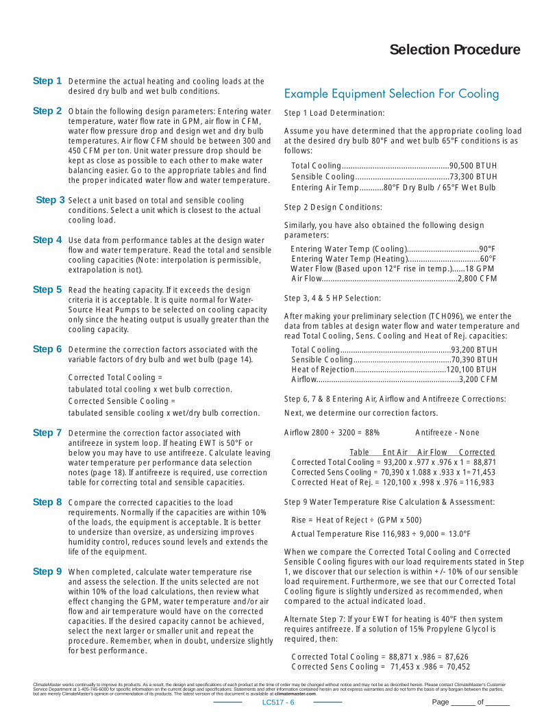
Step 1 Determine the actual heating and cooling loads at the desired dry bulb and wet bulb conditions.
Step 2 Obtain the following de sign parameters: Entering water temperature, water fl ow rate in GPM, air fl ow in CFM, water fl ow pressure drop and design wet and dry bulb temperatures. Air fl ow CFM should be between 300 and 450 CFM per ton. Unit water pressure drop should be kept as close as possible to each other to make water balancing easier. Go to the ap pro pri ate tables and fi nd the proper indicated water fl ow and water tem per a ture.
Step 3 Select a unit based on total and sensible cooling conditions. Select a unit which is closest to the actual cooling load.
Step 4 Use data from performance tables at the design water fl ow and water temperature. Read the total and sensible cooling capacities (Note: interpolation is per mis si ble, ex trap o la tion is not).
Step 5 Read the heating capacity. If it exceeds the design criteria it is acceptable. It is quite normal for Water-Source Heat Pumps to be selected on cooling capacity only since the heating output is usually greater than the cooling capacity.
Step 6 Determine the correction factors associated with the variable factors of dry bulb and wet bulb (page 14).
Corrected Total Cooling = tabulated total cooling x wet bulb correction. Corrected Sensible Cooling = tabulated sensible cooling x wet/dry bulb correction.
Step 7 Determine the correction factor associated with antifreeze in system loop. If heating EWT is 50°F or below you may have to use antifreeze. Calculate leaving water temperature per performance data selection notes (page 18). If antifreeze is required, use correction table for correcting total and sensible capacities.
Step 8 Compare the corrected capacities to the load re quire ments. Normally if the capacities are within 10% of the loads, the equipment is ac cept able. It is better to undersize than oversize, as undersizing improves humidity control, reduces sound levels and extends the life of the equip ment.
Step 9 When completed, calculate water temperature rise and assess the selection. If the units selected are not within 10% of the load cal cu la tions, then review what effect chang ing the GPM, water temperature and/or air fl ow and air tem per a ture would have on the corrected capacities. If the desired capacity cannot be achieved, select the next larger or smaller unit and repeat the procedure. Remember, when in doubt, undersize slightly for best performance.
Example Equipment Selection For Cool ingStep 1 Load Determination:
Assume you have determined that the appropriate cooling load at the desired dry bulb 80°F and wet bulb 65°F con di tions is as follows:
Total Cooling.................................................90,500 BTUH Sensible Cooling...........................................73,300 BTUH Entering Air Temp...........80°F Dry Bulb / 65°F Wet Bulb
Step 2 Design Conditions:
Similarly, you have also obtained the following design pa ram e ters:
Entering Water Temp (Cooling).................................90°F Entering Water Temp (Heating).................................60°F Water Flow (Based upon 12°F rise in temp.)......18 GPM Air Flow..............................................................2,800 CFM
Step 3, 4 & 5 HP Selection:
After making your preliminary selection (TCH096), we enter the data from tables at design water fl ow and water tem per a ture and read Total Cooling, Sens. Cooling and Heat of Rej. ca pac i ties:
Total Cooling....................................................93,200 BTUH Sensible Cooling..............................................70,390 BTUH Heat of Rejection...........................................120,100 BTUH Airfl ow...................................................................3,200 CFM
Step 6, 7 & 8 Entering Air, Airfl ow and Antifreeze Corrections:
Next, we determine our correction factors.
Airfl ow 2800 ÷ 3200 = 88% Antifreeze - None
Table Ent Air Air Flow Cor rect ed Corrected Total Cooling = 93,200 x .977 x .976 x 1 = 88,871 Corrected Sens Cooling = 70,390 x 1.088 x .933 x 1=71,453 Corrected Heat of Rej. = 120,100 x .998 x .976 =116,983
Step 9 Water Temperature Rise Calculation & As sess ment:
Rise = Heat of Reject ÷ (GPM x 500)
Actual Temperature Rise 116,983 ÷ 9,000 = 13.0°F
When we compare the Corrected Total Cooling and Corrected Sensible Cooling fi gures with our load re quire ments stated in Step 1, we discover that our selection is within +/- 10% of our sensible load requirement. Fur ther more, we see that our Cor rect ed Total Cooling fi gure is slightly undersized as recommended, when compared to the actual in di cat ed load.
Alternate Step 7: If your EWT for heating is 40°F then system requires antifreeze. If a solution of 15% Propylene Glycol is required, then:
Corrected Total Cooling = 88,871 x .986 = 87,626 Corrected Sens Cooling = 71,453 x .986 = 70,452
Selection Procedure
ClimateMaster works continually to improve its products. As a result, the design and specifi cations of each product at the time of order may be changed without notice and may not be as described herein. Please contact ClimateMaster's Customer Service Department at 1-405-745-6000 for specifi c information on the current design and specifi cations. Statements and other information contained herein are not express warranties and do not form the basis of any bargain between the parties, but are merely ClimateMaster's opinion or commendation of its products. The latest version of this document is available at climatemaster.com.
Page ______ of ______LC517 - 7
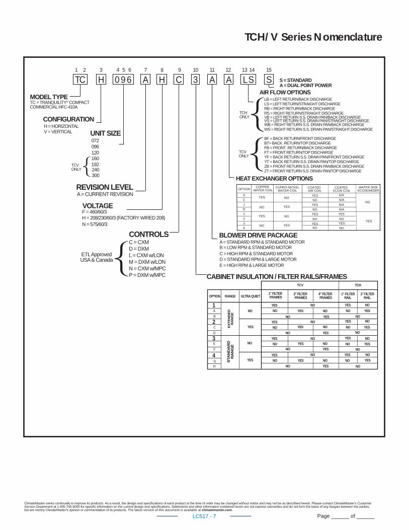
TCH/V Series Nomenclature
TC H A0 9 6 CH 3 A A L S S1 2 3 4 5 6 7 8 9 10 11 12 13 14 15
TC = TRANQUILITY® COMPACTCOMMERCIAL HFC-410A
MODEL TYPE
H = HORIZONTALCONFIGURATION
072UNIT SIZE
096120
REVISION LEVELA = CURRENT REVISION
VOLTAGE
C = CXMCONTROLS
D = DXML = CXM w/LONM = DXM w/LONN = CXM w/MPCP = DXM w/MPC
BLOWER DRIVE PACKAGE
HEAT EXCHANGER OPTIONS
LB = LEFT RETURN/BACK DISCHARGE
AIR FLOW OPTIONS
LS = LEFT RETURN/STRAIGHT DISCHARGERB = RIGHT RETURN/BACK DISCHARGE
S = STANDARD
RS = RIGHT RETURN/STRAIGHT DISCHARGEVB = LEFT RETURN S.S. DRAIN PAN/BACK DISCHARGEVS = LEFT RETURN S.S. DRAIN PAN/STRAIGHT DISCHARGE
ETL ApprovedUSA & Canada
A = STANDARD RPM & STANDARD MOTORB = LOW RPM & STANDARD MOTORC = HIGH RPM & STANDARD MOTORD = STANDARD RPM & LARGE MOTORE = HIGH RPM & LARGE MOTOR
WB = RIGHT RETURN S.S. DRAIN PAN/BACK DISCHARGEWS = RIGHT RETURN S.S. DRAIN PAN/STRAIGHT DISCHARGE
A = DUAL POINT POWER
V = VERTICAL
TCHONLY
BF = BACK RETURN/FRONT DISCHARGEBT= BACK RETURN/TOP DISCHARGEFB = FRONT RETURN/BACK DISCHARGEFT = FRONT RETURN/TOP DISCHARGEYF = BACK RETURN S.S. DRAIN PAN/FRONT DISCHARGEYT = BACK RETURN S.S. DRAIN PAN/TOP DISCHARGEZB = FRONT RETURN S.S. DRAIN PAN/BACK DISCHARGEZT = FRONT RETURN S.S. DRAIN PAN/TOP DISCHARGE
TCVONLY160
192240300
CABINET INSULATION / FILTER RAILS/FRAMES
H = 208/230/60/3 (FACTORY WIRED 208)F = 460/60/3
N = 575/60/3
OPTION RANGE2” FILTERFRAMES
4” FILTERFRAMES
1A
B
C
D
E
F
GH
ULTRA QUIET
TCV TCH
NO
NO
YES
YES
NO NO
NO
NONO
NO
NO
NO
NO
NO
NO
NO
NO
NO
NO
NO
NO
NO
NO
YES
YES
YES
YES
YES
NO
YES
YES
YES
YES
YES
YES
YES
YES
YES
YES
YES
1” FILTERFRAMES
1” FILTERRAIL
2” FILTERRAIL
YES
NO
YES
NO
YES
NO
YES
NO
NO
NO
NO
NO
2
3
4
OPTION
A
C
J
N
1
2
3
4
COATEDAIR COIL
COPPER CUPRO-NICKELWATER COIL
COATEDECON COIL
WATER SIDEECONOMIZER
NO
YES
NO
N/A
N/AYES
YESYES
NO
NO
WATER COIL
YES
YES
NO
YES
NO
YESNO
N/A
N/A
YES
NO
NO
YES
NO
NO
YES
TCVONLY
ClimateMaster works continually to improve its products. As a result, the design and specifi cations of each product at the time of order may be changed without notice and may not be as described herein. Please contact ClimateMaster's Customer Service Department at 1-405-745-6000 for specifi c information on the current design and specifi cations. Statements and other information contained herein are not express warranties and do not form the basis of any bargain between the parties, but are merely ClimateMaster's opinion or commendation of its products. The latest version of this document is available at climatemaster.com.
Page ______ of ______LC517 - 8
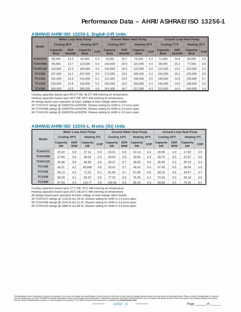
Performance Data – AHRI/ASHRAE/ISO 13256-1
ASHRAE/AHRI/ISO 13256-1. English (I-P) Units
ASHRAE/AHRI/ISO 13256-1. Metric (S-I) Units
Model
Water Loop Heat Pump Ground Water Heat Pump Ground Loop Heat Pump
Cooling 86°F Heating 68°F Cooling 59°F Heating 50°F Cooling 77°F Heating 32°F
CapacityBtuh
EERBtuh/W
CapacityBtuh
COPCapacity
BtuhEER
Btuh/WCapacity
BtuhCOP
CapacityBtuh
EERBtuh/W
CapacityBtuh
COP
TCH/V072 69,000 13.3 92,500 5.0 78,500 19.7 75,500 4.4 71,000 14.6 58,000 3.5
TCH/V096 95,000 13.7 123,000 5.0 104,500 20.0 101,000 4.4 98,000 15.2 77,000 3.6
TCH/V120 119,000 13.3 160,000 4.6 134,000 19.3 132,500 4.0 122,500 14.5 103,000 3.3
TCV160 157,000 14.2 207,000 4.9 172,000 19.6 168,000 4.4 162,000 15.2 125,000 3.5
TCV192 191,500 14.3 243,000 5.1 211,000 19.5 196,500 4.5 199,000 15.8 149,000 3.7
TCV240 233,000 13.9 318,000 5.0 263,500 19.2 260,500 4.4 240,000 14.8 198,500 3.5
TCV300 300,000 13.5 395,000 4.8 341,500 18.7 321,500 4.3 310,000 14.5 240,000 3.4
Cooling capacities based upon 80.6°F DB, 66.2°F WB entering air temperature.Heating capacities based upon 68°F DB, 59°F WB entering air temperature.All ratings based upon operation at lower voltage of dual voltage rated models.All TCH/V072 ratings @ 2400CFM w/20GPM. Sheave setting for AHRI is 2.5 turns open.All TCH/V096 ratings @ 3200CFM w/24GPM. Sheave setting for AHRI is 3.0 turns open.All TCH/V120 ratings @ 4000CFM w/30GPM. Sheave setting for AHRI is 3.0 turns open.
Model
Water Loop Heat Pump Ground Water Heat Pump Ground Loop Heat Pump
Cooling 30ºC Heating 2ºC Cooling 15ºC Heating 10ºC Cooling 25ºC Heating 0ºC
Capacity kW
EER W/W
Capacity kW
COPCapacity
kWEER W/W
Capacity kW
COPCapacity
kWEER W/W
Capacity kW
COP
TCH/V072 20.22 3.9 27.11 5.0 23.01 5.8 22.13 4.4 20.80 4.3 17.00 3.5
TCH/V096 27.84 4.0 36.04 5.0 30.63 5.9 29.60 4.4 28.72 4.5 22.57 3.6
TCH/V120 34.88 3.9 46.89 4.6 39.27 5.7 38.83 4.0 35.90 4.2 30.19 3.3
TCV160 46.01 4.2 60,668 4.9 50.41 5.7 49.24 4.4 47.48 4.5 36.64 3.5
TCV192 56.13 4.2 71.22 5.1 61.84 5.7 57.59 4.5 58.32 4.6 43.67 3.7
TCV240 68.29 4.1 93.20 5.0 77.23 5.6 76.35 4.4 70.34 4.3 58.18 3.5
TCV300 87.93 4.0 115.77 4.8 100.09 5.5 95.23 4.3 90.86 4.2 70.34 3.4
Cooling capacities based upon 27°C DB, 19°C WB entering air temperature.Heating capacities based upon 20°C DB,15°C WB entering air temperature.All ratings based upon operation at lower voltage of dual voltage rated models.All TCH/V072 ratings @ 1133 l/s w/1.26 l/s. Sheave setting for AHRI is 2.5 turns open.All TCH/V096 ratings @ 1510 l/s w/1.51 l/s. Sheave setting for AHRI is 3.0 turns open.All TCH/V120 ratings @ 1888 l/s w/1.89 l/s. Sheave setting for AHRI is 3.0 turns open.
ClimateMaster works continually to improve its products. As a result, the design and specifi cations of each product at the time of order may be changed without notice and may not be as described herein. Please contact ClimateMaster's Customer Service Department at 1-405-745-6000 for specifi c information on the current design and specifi cations. Statements and other information contained herein are not express warranties and do not form the basis of any bargain between the parties, but are merely ClimateMaster's opinion or commendation of its products. The latest version of this document is available at climatemaster.com.
Page ______ of ______LC517 - 9
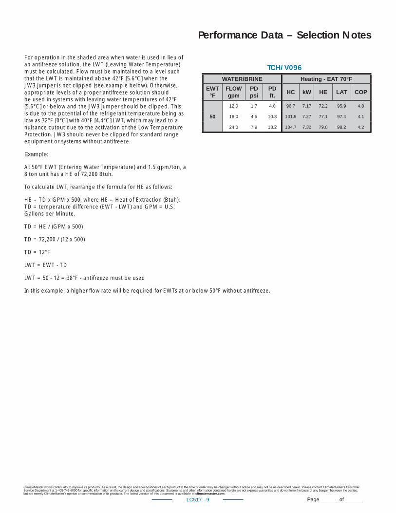
For operation in the shaded area when water is used in lieu of an antifreeze solution, the LWT (Leaving Water Temperature) must be calculated. Flow must be maintained to a level such that the LWT is maintained above 42°F [5.6°C] when the JW3 jumper is not clipped (see example below). Otherwise, appropriate levels of a proper antifreeze solution should be used in systems with leaving water temperatures of 42ºF [5.6°C] or below and the JW3 jumper should be clipped. This is due to the potential of the refrigerant temperature being as low as 32°F [0°C] with 40°F [4.4°C] LWT, which may lead to a nuisance cutout due to the activation of the Low Temperature Protection. JW3 should never be clipped for standard range equipment or systems without antifreeze.
Example:
At 50°F EWT (Entering Water Temperature) and 1.5 gpm/ton, a 8 ton unit has a HE of 72,200 Btuh.
To calculate LWT, rearrange the formula for HE as follows:
HE = TD x GPM x 500, where HE = Heat of Extraction (Btuh); TD = temperature difference (EWT - LWT) and GPM = U.S. Gallons per Minute.
TD = HE / (GPM x 500)
TD = 72,200 / (12 x 500)
TD = 12°F
LWT = EWT - TD
LWT = 50 - 12 = 38°F - antifreeze must be used
In this example, a higher fl ow rate will be required for EWTs at or below 50°F without antifreeze.
Performance Data – Selection Notes
WATER/BRINEEWT
°FFLOWgpm
PDpsi
PD ft.
50
12.0 1.7 4.0
18.0 4.5 10.3
24.0 7.9 18.2
TCH/V096Heating - EAT 70°F
HC kW HE LAT COP
96.7 7.17 72.2 95.9 4.0
101.9 7.27 77.1 97.4 4.1
104.7 7.32 79.8 98.2 4.2
ClimateMaster works continually to improve its products. As a result, the design and specifi cations of each product at the time of order may be changed without notice and may not be as described herein. Please contact ClimateMaster's Customer Service Department at 1-405-745-6000 for specifi c information on the current design and specifi cations. Statements and other information contained herein are not express warranties and do not form the basis of any bargain between the parties, but are merely ClimateMaster's opinion or commendation of its products. The latest version of this document is available at climatemaster.com.
Page ______ of ______LC517 - 10
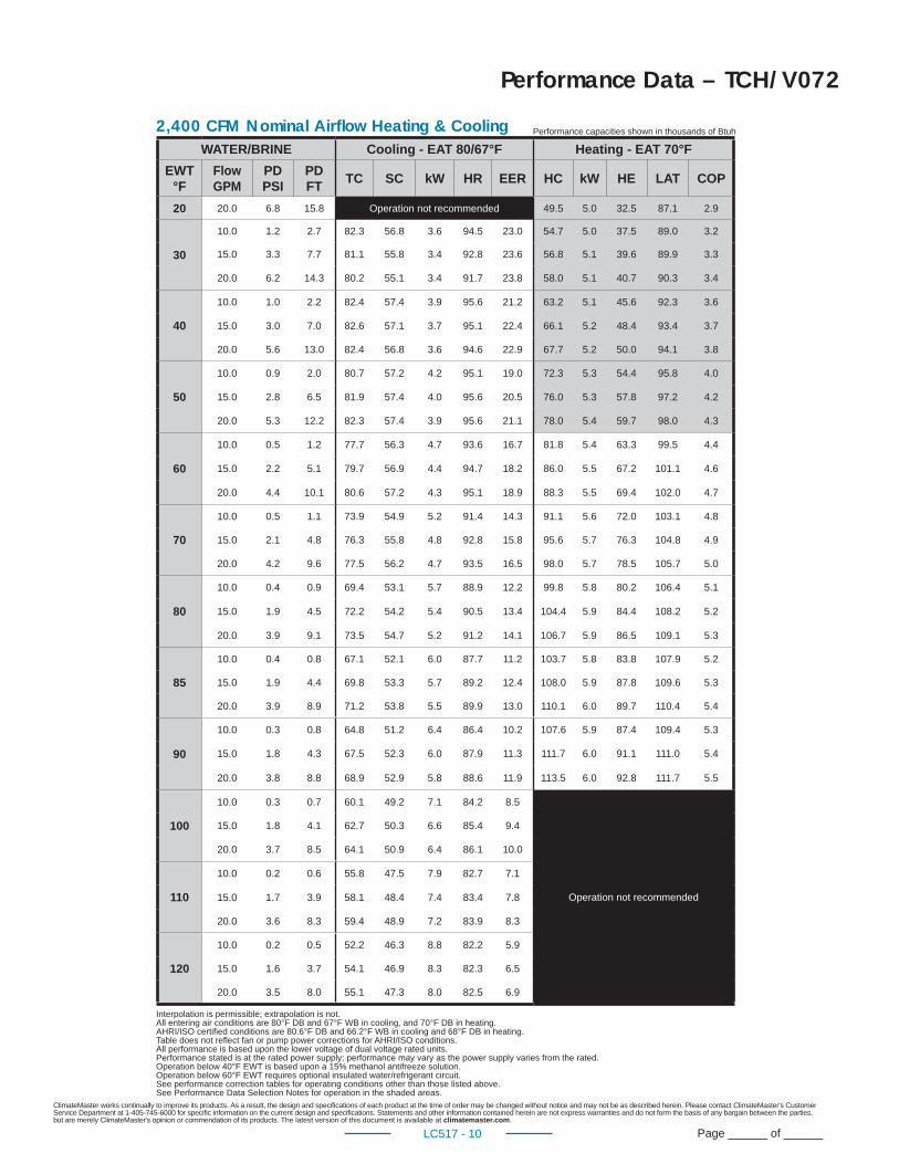
Performance Data – TCH/V072
Performance capacities shown in thousands of Btuh2,400 CFM Nominal Airfl ow Heating & CoolingWATER/BRINE Cooling - EAT 80/67°F Heating - EAT 70°F
EWT°F
Flow GPM
PDPSI
PD FT
TC SC kW HR EER HC kW HE LAT COP
20 20.0 6.8 15.8 Operation not recommended 49.5 5.0 32.5 87.1 2.9
30
10.0 1.2 2.7 82.3 56.8 3.6 94.5 23.0 54.7 5.0 37.5 89.0 3.2
15.0 3.3 7.7 81.1 55.8 3.4 92.8 23.6 56.8 5.1 39.6 89.9 3.3
20.0 6.2 14.3 80.2 55.1 3.4 91.7 23.8 58.0 5.1 40.7 90.3 3.4
40
10.0 1.0 2.2 82.4 57.4 3.9 95.6 21.2 63.2 5.1 45.6 92.3 3.6
15.0 3.0 7.0 82.6 57.1 3.7 95.1 22.4 66.1 5.2 48.4 93.4 3.7
20.0 5.6 13.0 82.4 56.8 3.6 94.6 22.9 67.7 5.2 50.0 94.1 3.8
50
10.0 0.9 2.0 80.7 57.2 4.2 95.1 19.0 72.3 5.3 54.4 95.8 4.0
15.0 2.8 6.5 81.9 57.4 4.0 95.6 20.5 76.0 5.3 57.8 97.2 4.2
20.0 5.3 12.2 82.3 57.4 3.9 95.6 21.1 78.0 5.4 59.7 98.0 4.3
60
10.0 0.5 1.2 77.7 56.3 4.7 93.6 16.7 81.8 5.4 63.3 99.5 4.4
15.0 2.2 5.1 79.7 56.9 4.4 94.7 18.2 86.0 5.5 67.2 101.1 4.6
20.0 4.4 10.1 80.6 57.2 4.3 95.1 18.9 88.3 5.5 69.4 102.0 4.7
70
10.0 0.5 1.1 73.9 54.9 5.2 91.4 14.3 91.1 5.6 72.0 103.1 4.8
15.0 2.1 4.8 76.3 55.8 4.8 92.8 15.8 95.6 5.7 76.3 104.8 4.9
20.0 4.2 9.6 77.5 56.2 4.7 93.5 16.5 98.0 5.7 78.5 105.7 5.0
80
10.0 0.4 0.9 69.4 53.1 5.7 88.9 12.2 99.8 5.8 80.2 106.4 5.1
15.0 1.9 4.5 72.2 54.2 5.4 90.5 13.4 104.4 5.9 84.4 108.2 5.2
20.0 3.9 9.1 73.5 54.7 5.2 91.2 14.1 106.7 5.9 86.5 109.1 5.3
85
10.0 0.4 0.8 67.1 52.1 6.0 87.7 11.2 103.7 5.8 83.8 107.9 5.2
15.0 1.9 4.4 69.8 53.3 5.7 89.2 12.4 108.0 5.9 87.8 109.6 5.3
20.0 3.9 8.9 71.2 53.8 5.5 89.9 13.0 110.1 6.0 89.7 110.4 5.4
90
10.0 0.3 0.8 64.8 51.2 6.4 86.4 10.2 107.6 5.9 87.4 109.4 5.3
15.0 1.8 4.3 67.5 52.3 6.0 87.9 11.3 111.7 6.0 91.1 111.0 5.4
20.0 3.8 8.8 68.9 52.9 5.8 88.6 11.9 113.5 6.0 92.8 111.7 5.5
100
10.0 0.3 0.7 60.1 49.2 7.1 84.2 8.5
Operation not recommended
15.0 1.8 4.1 62.7 50.3 6.6 85.4 9.4
20.0 3.7 8.5 64.1 50.9 6.4 86.1 10.0
110
10.0 0.2 0.6 55.8 47.5 7.9 82.7 7.1
15.0 1.7 3.9 58.1 48.4 7.4 83.4 7.8
20.0 3.6 8.3 59.4 48.9 7.2 83.9 8.3
120
10.0 0.2 0.5 52.2 46.3 8.8 82.2 5.9
15.0 1.6 3.7 54.1 46.9 8.3 82.3 6.5
20.0 3.5 8.0 55.1 47.3 8.0 82.5 6.9
Interpolation is permissible; extrapolation is not.All entering air conditions are 80°F DB and 67°F WB in cooling, and 70°F DB in heating. AHRI/ISO certifi ed conditions are 80.6°F DB and 66.2°F WB in cooling and 68°F DB in heating. Table does not refl ect fan or pump power corrections for AHRI/ISO conditions.All performance is based upon the lower voltage of dual voltage rated units.Performance stated is at the rated power supply; performance may vary as the power supply varies from the rated.Operation below 40°F EWT is based upon a 15% methanol antifreeze solution. Operation below 60°F EWT requires optional insulated water/refrigerant circuit.See performance correction tables for operating conditions other than those listed above.See Performance Data Selection Notes for operation in the shaded areas.
ClimateMaster works continually to improve its products. As a result, the design and specifi cations of each product at the time of order may be changed without notice and may not be as described herein. Please contact ClimateMaster's Customer Service Department at 1-405-745-6000 for specifi c information on the current design and specifi cations. Statements and other information contained herein are not express warranties and do not form the basis of any bargain between the parties, but are merely ClimateMaster's opinion or commendation of its products. The latest version of this document is available at climatemaster.com.
Page ______ of ______LC517 - 11
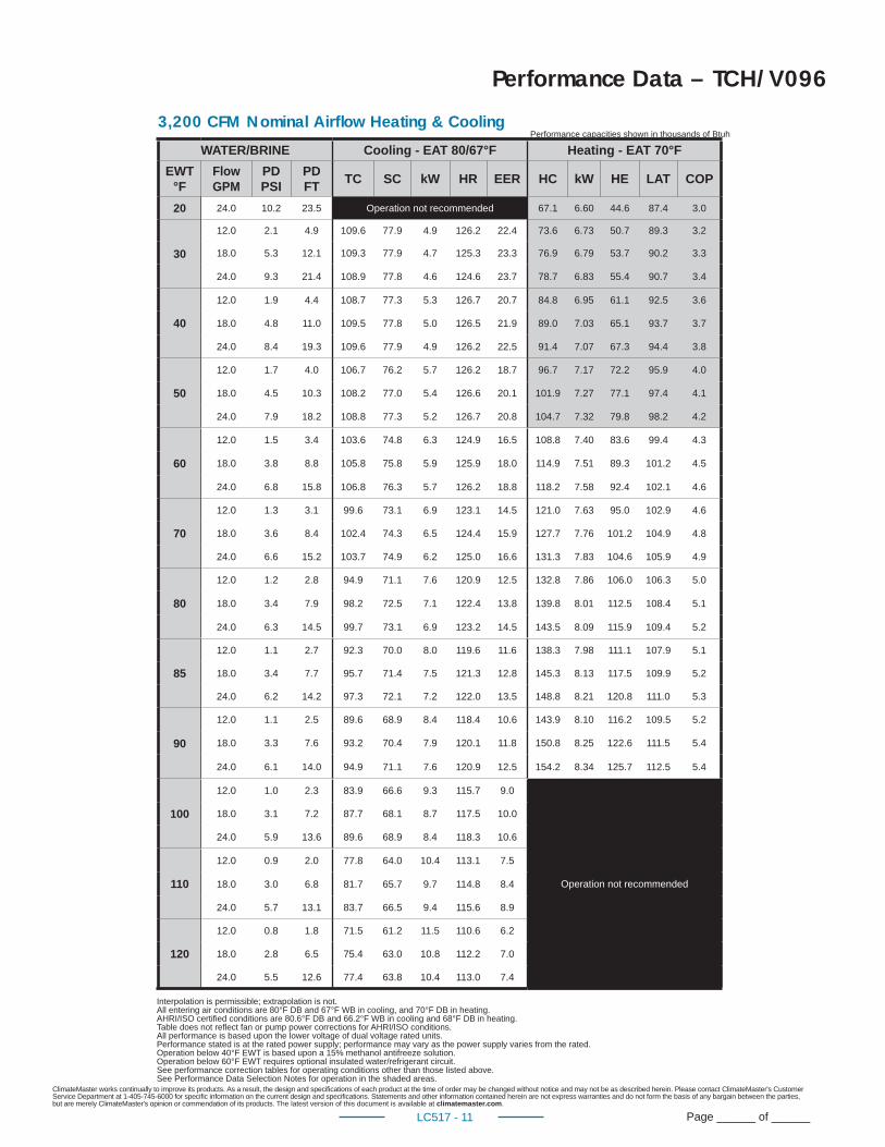
Performance Data – TCH/V096
Performance capacities shown in thousands of Btuh3,200 CFM Nominal Airfl ow Heating & Cooling
WATER/BRINE Cooling - EAT 80/67°F Heating - EAT 70°F
EWT°F
Flow GPM
PDPSI
PD FT
TC SC kW HR EER HC kW HE LAT COP
20 24.0 10.2 23.5 Operation not recommended 67.1 6.60 44.6 87.4 3.0
30
12.0 2.1 4.9 109.6 77.9 4.9 126.2 22.4 73.6 6.73 50.7 89.3 3.2
18.0 5.3 12.1 109.3 77.9 4.7 125.3 23.3 76.9 6.79 53.7 90.2 3.3
24.0 9.3 21.4 108.9 77.8 4.6 124.6 23.7 78.7 6.83 55.4 90.7 3.4
40
12.0 1.9 4.4 108.7 77.3 5.3 126.7 20.7 84.8 6.95 61.1 92.5 3.6
18.0 4.8 11.0 109.5 77.8 5.0 126.5 21.9 89.0 7.03 65.1 93.7 3.7
24.0 8.4 19.3 109.6 77.9 4.9 126.2 22.5 91.4 7.07 67.3 94.4 3.8
50
12.0 1.7 4.0 106.7 76.2 5.7 126.2 18.7 96.7 7.17 72.2 95.9 4.0
18.0 4.5 10.3 108.2 77.0 5.4 126.6 20.1 101.9 7.27 77.1 97.4 4.1
24.0 7.9 18.2 108.8 77.3 5.2 126.7 20.8 104.7 7.32 79.8 98.2 4.2
60
12.0 1.5 3.4 103.6 74.8 6.3 124.9 16.5 108.8 7.40 83.6 99.4 4.3
18.0 3.8 8.8 105.8 75.8 5.9 125.9 18.0 114.9 7.51 89.3 101.2 4.5
24.0 6.8 15.8 106.8 76.3 5.7 126.2 18.8 118.2 7.58 92.4 102.1 4.6
70
12.0 1.3 3.1 99.6 73.1 6.9 123.1 14.5 121.0 7.63 95.0 102.9 4.6
18.0 3.6 8.4 102.4 74.3 6.5 124.4 15.9 127.7 7.76 101.2 104.9 4.8
24.0 6.6 15.2 103.7 74.9 6.2 125.0 16.6 131.3 7.83 104.6 105.9 4.9
80
12.0 1.2 2.8 94.9 71.1 7.6 120.9 12.5 132.8 7.86 106.0 106.3 5.0
18.0 3.4 7.9 98.2 72.5 7.1 122.4 13.8 139.8 8.01 112.5 108.4 5.1
24.0 6.3 14.5 99.7 73.1 6.9 123.2 14.5 143.5 8.09 115.9 109.4 5.2
85
12.0 1.1 2.7 92.3 70.0 8.0 119.6 11.6 138.3 7.98 111.1 107.9 5.1
18.0 3.4 7.7 95.7 71.4 7.5 121.3 12.8 145.3 8.13 117.5 109.9 5.2
24.0 6.2 14.2 97.3 72.1 7.2 122.0 13.5 148.8 8.21 120.8 111.0 5.3
90
12.0 1.1 2.5 89.6 68.9 8.4 118.4 10.6 143.9 8.10 116.2 109.5 5.2
18.0 3.3 7.6 93.2 70.4 7.9 120.1 11.8 150.8 8.25 122.6 111.5 5.4
24.0 6.1 14.0 94.9 71.1 7.6 120.9 12.5 154.2 8.34 125.7 112.5 5.4
100
12.0 1.0 2.3 83.9 66.6 9.3 115.7 9.0
Operation not recommended
18.0 3.1 7.2 87.7 68.1 8.7 117.5 10.0
24.0 5.9 13.6 89.6 68.9 8.4 118.3 10.6
110
12.0 0.9 2.0 77.8 64.0 10.4 113.1 7.5
18.0 3.0 6.8 81.7 65.7 9.7 114.8 8.4
24.0 5.7 13.1 83.7 66.5 9.4 115.6 8.9
120
12.0 0.8 1.8 71.5 61.2 11.5 110.6 6.2
18.0 2.8 6.5 75.4 63.0 10.8 112.2 7.0
24.0 5.5 12.6 77.4 63.8 10.4 113.0 7.4
Interpolation is permissible; extrapolation is not.All entering air conditions are 80°F DB and 67°F WB in cooling, and 70°F DB in heating. AHRI/ISO certifi ed conditions are 80.6°F DB and 66.2°F WB in cooling and 68°F DB in heating. Table does not refl ect fan or pump power corrections for AHRI/ISO conditions.All performance is based upon the lower voltage of dual voltage rated units.Performance stated is at the rated power supply; performance may vary as the power supply varies from the rated.Operation below 40°F EWT is based upon a 15% methanol antifreeze solution. Operation below 60°F EWT requires optional insulated water/refrigerant circuit.See performance correction tables for operating conditions other than those listed above.See Performance Data Selection Notes for operation in the shaded areas.
ClimateMaster works continually to improve its products. As a result, the design and specifi cations of each product at the time of order may be changed without notice and may not be as described herein. Please contact ClimateMaster's Customer Service Department at 1-405-745-6000 for specifi c information on the current design and specifi cations. Statements and other information contained herein are not express warranties and do not form the basis of any bargain between the parties, but are merely ClimateMaster's opinion or commendation of its products. The latest version of this document is available at climatemaster.com.
Page ______ of ______LC517 - 12
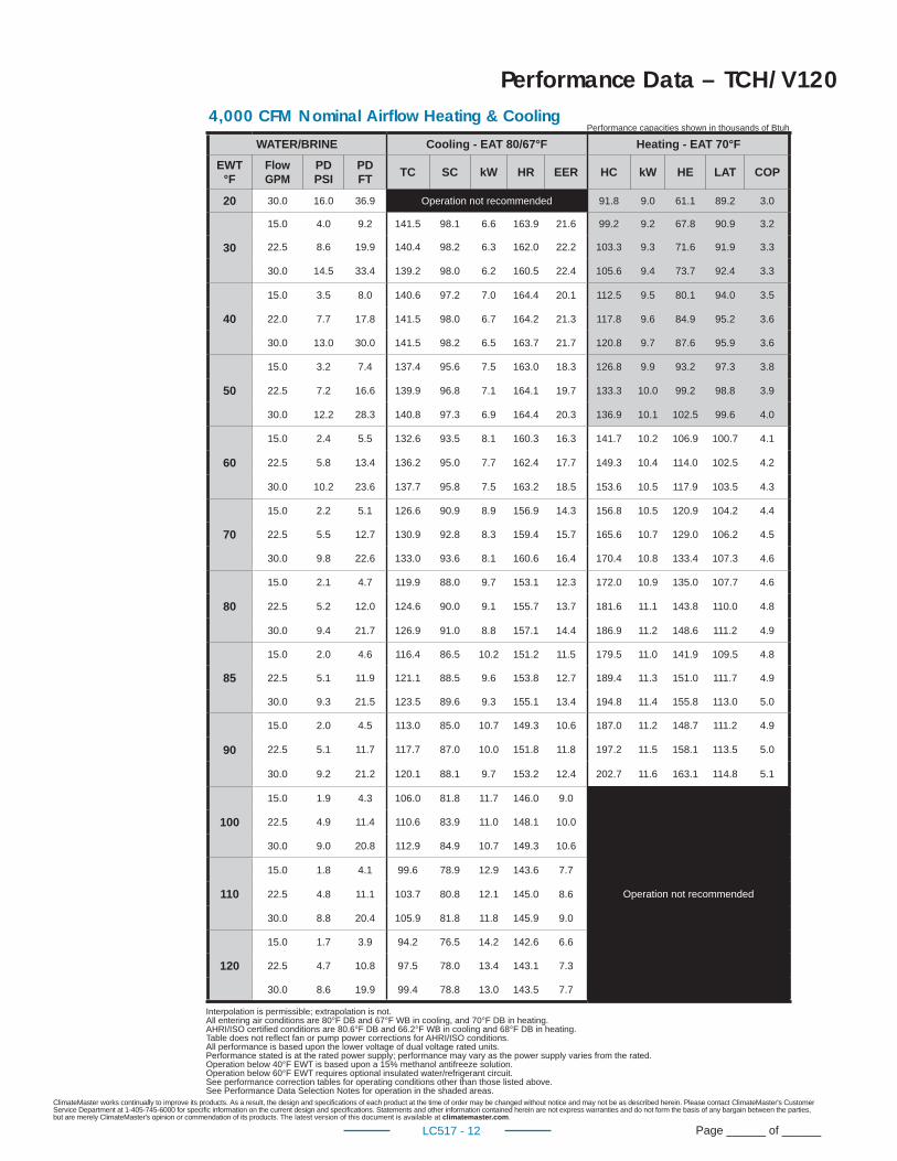
Performance Data – TCH/V120
Performance capacities shown in thousands of Btuh4,000 CFM Nominal Airfl ow Heating & Cooling
WATER/BRINE Cooling - EAT 80/67°F Heating - EAT 70°F
EWT°F
FlowGPM
PDPSI
PDFT
TC SC kW HR EER HC kW HE LAT COP
20 30.0 16.0 36.9 Operation not recommended 91.8 9.0 61.1 89.2 3.0
30
15.0 4.0 9.2 141.5 98.1 6.6 163.9 21.6 99.2 9.2 67.8 90.9 3.2
22.5 8.6 19.9 140.4 98.2 6.3 162.0 22.2 103.3 9.3 71.6 91.9 3.3
30.0 14.5 33.4 139.2 98.0 6.2 160.5 22.4 105.6 9.4 73.7 92.4 3.3
40
15.0 3.5 8.0 140.6 97.2 7.0 164.4 20.1 112.5 9.5 80.1 94.0 3.5
22.0 7.7 17.8 141.5 98.0 6.7 164.2 21.3 117.8 9.6 84.9 95.2 3.6
30.0 13.0 30.0 141.5 98.2 6.5 163.7 21.7 120.8 9.7 87.6 95.9 3.6
50
15.0 3.2 7.4 137.4 95.6 7.5 163.0 18.3 126.8 9.9 93.2 97.3 3.8
22.5 7.2 16.6 139.9 96.8 7.1 164.1 19.7 133.3 10.0 99.2 98.8 3.9
30.0 12.2 28.3 140.8 97.3 6.9 164.4 20.3 136.9 10.1 102.5 99.6 4.0
60
15.0 2.4 5.5 132.6 93.5 8.1 160.3 16.3 141.7 10.2 106.9 100.7 4.1
22.5 5.8 13.4 136.2 95.0 7.7 162.4 17.7 149.3 10.4 114.0 102.5 4.2
30.0 10.2 23.6 137.7 95.8 7.5 163.2 18.5 153.6 10.5 117.9 103.5 4.3
70
15.0 2.2 5.1 126.6 90.9 8.9 156.9 14.3 156.8 10.5 120.9 104.2 4.4
22.5 5.5 12.7 130.9 92.8 8.3 159.4 15.7 165.6 10.7 129.0 106.2 4.5
30.0 9.8 22.6 133.0 93.6 8.1 160.6 16.4 170.4 10.8 133.4 107.3 4.6
80
15.0 2.1 4.7 119.9 88.0 9.7 153.1 12.3 172.0 10.9 135.0 107.7 4.6
22.5 5.2 12.0 124.6 90.0 9.1 155.7 13.7 181.6 11.1 143.8 110.0 4.8
30.0 9.4 21.7 126.9 91.0 8.8 157.1 14.4 186.9 11.2 148.6 111.2 4.9
85
15.0 2.0 4.6 116.4 86.5 10.2 151.2 11.5 179.5 11.0 141.9 109.5 4.8
22.5 5.1 11.9 121.1 88.5 9.6 153.8 12.7 189.4 11.3 151.0 111.7 4.9
30.0 9.3 21.5 123.5 89.6 9.3 155.1 13.4 194.8 11.4 155.8 113.0 5.0
90
15.0 2.0 4.5 113.0 85.0 10.7 149.3 10.6 187.0 11.2 148.7 111.2 4.9
22.5 5.1 11.7 117.7 87.0 10.0 151.8 11.8 197.2 11.5 158.1 113.5 5.0
30.0 9.2 21.2 120.1 88.1 9.7 153.2 12.4 202.7 11.6 163.1 114.8 5.1
100
15.0 1.9 4.3 106.0 81.8 11.7 146.0 9.0
Operation not recommended
22.5 4.9 11.4 110.6 83.9 11.0 148.1 10.0
30.0 9.0 20.8 112.9 84.9 10.7 149.3 10.6
110
15.0 1.8 4.1 99.6 78.9 12.9 143.6 7.7
22.5 4.8 11.1 103.7 80.8 12.1 145.0 8.6
30.0 8.8 20.4 105.9 81.8 11.8 145.9 9.0
120
15.0 1.7 3.9 94.2 76.5 14.2 142.6 6.6
22.5 4.7 10.8 97.5 78.0 13.4 143.1 7.3
30.0 8.6 19.9 99.4 78.8 13.0 143.5 7.7
Interpolation is permissible; extrapolation is not.All entering air conditions are 80°F DB and 67°F WB in cooling, and 70°F DB in heating. AHRI/ISO certifi ed conditions are 80.6°F DB and 66.2°F WB in cooling and 68°F DB in heating. Table does not refl ect fan or pump power corrections for AHRI/ISO conditions.All performance is based upon the lower voltage of dual voltage rated units.Performance stated is at the rated power supply; performance may vary as the power supply varies from the rated.Operation below 40°F EWT is based upon a 15% methanol antifreeze solution. Operation below 60°F EWT requires optional insulated water/refrigerant circuit.See performance correction tables for operating conditions other than those listed above.See Performance Data Selection Notes for operation in the shaded areas.
ClimateMaster works continually to improve its products. As a result, the design and specifi cations of each product at the time of order may be changed without notice and may not be as described herein. Please contact ClimateMaster's Customer Service Department at 1-405-745-6000 for specifi c information on the current design and specifi cations. Statements and other information contained herein are not express warranties and do not form the basis of any bargain between the parties, but are merely ClimateMaster's opinion or commendation of its products. The latest version of this document is available at climatemaster.com.
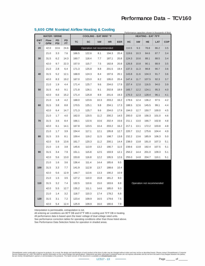
Page ______ of ______LC517 - 13
Performance Data – TCV160
WATER / BRINE COOLING - EAT 80/67 °F HEATING - EAT 70°F
EWT °F
Flow GPM
PD PSI
PD FT
TC SC kW HR EER HC kW HE LAT COP
20 42.0 10.6 24.6 Operation not recommended 110.5 9.3 78.8 86.2 3.5
30
21.0 3.3 7.6 166.5 122.6 8.1 194.3 20.4 119.6 10.3 84.6 87.7 3.4
31.5 6.2 14.3 160.7 118.4 7.7 187.1 20.8 124.3 10.6 88.1 88.5 3.4
42.0 9.7 22.3 157.0 115.7 7.5 182.8 20.8 126.8 10.8 90.1 88.9 3.5
40
21.0 2.8 6.4 171.3 125.8 8.8 201.5 19.4 137.3 11.3 98.8 90.7 3.6
31.5 5.2 12.1 168.9 124.3 8.4 197.6 20.1 143.8 11.6 104.3 91.7 3.6
42.0 8.3 19.2 167.0 123.0 8.2 195.0 20.4 147.4 11.7 107.5 92.3 3.7
50
21.0 1.9 4.4 171.4 125.7 9.6 204.0 17.9 157.4 12.0 116.5 94.0 3.9
31.5 4.0 9.1 171.8 126.1 9.1 202.8 18.9 165.7 12.2 124.1 95.3 4.0
42.0 6.6 15.2 171.4 125.8 8.9 201.6 19.3 170.3 12.3 128.4 96.1 4.1
60
21.0 1.8 4.2 168.0 123.6 10.3 203.2 16.2 178.6 12.4 136.2 97.5 4.2
31.5 3.8 8.8 170.5 125.1 9.8 204.1 17.3 188.5 12.6 145.5 99.1 4.4
42.0 6.4 14.7 171.3 125.7 9.6 204.0 17.9 194.0 12.7 150.7 100.0 4.5
70
21.0 1.7 4.0 162.0 120.5 11.2 200.2 14.5 200.0 12.8 156.3 101.0 4.6
31.5 3.6 8.4 166.1 122.6 10.6 202.4 15.6 211.1 13.0 166.7 102.8 4.8
42.0 6.1 14.1 167.8 123.5 10.4 203.2 16.2 217.1 13.1 172.2 103.8 4.8
80
21.0 1.7 3.9 154.4 117.1 12.1 195.8 12.7 220.7 13.2 175.6 104.4 4.9
31.5 3.5 8.1 159.4 119.2 11.5 198.7 13.8 232.2 13.6 185.9 106.3 5.0
42.0 5.9 13.6 161.7 120.3 11.2 200.1 14.4 238.0 13.8 191.0 107.3 5.1
90
21.0 1.6 3.8 145.6 113.9 13.2 190.7 11.0 239.6 13.8 192.4 107.5 5.1
31.5 3.4 7.9 151.1 115.8 12.5 193.9 12.1 250.2 14.4 201.0 109.3 5.1
42.0 5.6 13.0 153.8 116.8 12.2 195.5 12.6 255.0 14.8 204.7 110.1 5.1
100
21.0 1.6 3.6 136.4 111.4 14.4 185.6 9.5
Operation not recommended
31.5 3.3 7.7 141.9 112.8 13.7 188.6 10.4
42.0 5.6 12.9 144.7 113.6 13.3 190.2 10.9
110
21.0 1.5 3.5 127.2 110.0 15.8 181.2 8.0
31.5 3.2 7.4 132.5 110.6 15.0 183.6 8.8
42.0 5.5 12.7 135.2 111.1 14.6 185.0 9.3
120
21.0 1.4 3.2 118.7 110.3 17.4 178.2 6.8
31.5 3.1 7.2 123.4 109.9 16.5 179.6 7.5
42.0 5.4 12.4 125.9 109.9 16.0 180.6 7.9
Performance capacities shown in thousands of Btuh5,600 CFM Nominal Airfl ow Heating & Cooling
Interpolation is permissable, extrapolation is not.All entering air conditions are 80°F DB and 67°F WB in cooling and 70°F DB in heating.All performance data is based upon the lower voltage of dual voltage rated units.See performance correction tables for operating conditions other than those listed above.See Performance Data Selection Notes for operation in shaded areas.
ClimateMaster works continually to improve its products. As a result, the design and specifi cations of each product at the time of order may be changed without notice and may not be as described herein. Please contact ClimateMaster's Customer Service Department at 1-405-745-6000 for specifi c information on the current design and specifi cations. Statements and other information contained herein are not express warranties and do not form the basis of any bargain between the parties, but are merely ClimateMaster's opinion or commendation of its products. The latest version of this document is available at climatemaster.com.
Page ______ of ______LC517 - 14
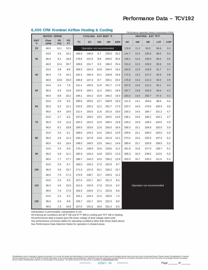
Performance Data – TCV192
WATER / BRINE COOLING - EAT 80/67 °F HEATING - EAT 70°F
EWT °F
Flow GPM
PD PSI
PD FT
TC SC kW HR EER HC kW HE LAT COP
20 48.0 14.1 32.5 Operation not recommended 128.8 11.3 90.3 86.6 3.3
30
24.0 4.4 10.1 195.9 146.9 9.7 229.0 20.2 141.7 12.0 100.6 88.5 3.4
36.0 8.1 18.6 179.6 137.5 8.8 209.5 20.5 148.1 12.3 105.9 89.4 3.5
48.0 12.4 28.7 169.8 131.7 8.3 198.2 20.4 151.6 12.5 109.0 89.9 3.6
40
24.0 3.8 8.8 209.3 154.3 10.9 246.4 19.2 164.0 12.9 119.8 91.7 3.7
36.0 7.0 16.1 202.2 150.4 10.1 236.8 19.9 172.2 13.2 127.2 92.9 3.8
48.0 10.8 25.0 196.8 147.4 9.7 230.1 20.2 176.8 13.3 131.3 93.5 3.9
50
24.0 3.3 7.6 211.4 155.5 11.8 251.7 17.9 187.6 13.6 141.2 95.1 4.0
36.0 5.5 12.6 210.9 155.1 11.2 249.1 18.9 197.7 13.8 150.5 96.5 4.2
48.0 8.8 20.2 209.1 154.2 10.9 246.2 19.3 203.3 14.0 155.7 97.3 4.3
60
24.0 2.8 6.5 206.6 153.5 12.7 249.9 16.3 211.9 14.1 163.6 98.6 4.4
36.0 5.2 12.1 210.5 155.2 12.1 251.7 17.4 223.7 14.4 174.6 100.3 4.6
48.0 8.4 19.5 211.4 155.6 11.8 251.6 18.0 230.2 14.5 180.7 101.2 4.7
70
24.0 2.7 6.2 197.8 149.5 13.5 244.0 14.6 236.1 14.6 186.2 102.1 4.7
36.0 5.0 11.6 204.2 152.4 12.9 248.4 15.8 249.2 14.9 198.4 104.0 4.9
48.0 8.1 18.8 206.9 153.6 12.6 250.0 16.4 256.3 15.1 204.9 105.0 5.0
80
24.0 2.6 6.1 186.9 144.3 14.5 236.3 12.9 259.6 15.1 208.0 105.5 5.0
36.0 4.9 11.4 194.4 147.8 13.8 241.6 14.1 273.4 15.5 220.5 107.5 5.2
48.0 8.0 18.4 198.0 149.5 13.5 244.1 14.6 280.6 15.7 226.9 108.5 5.2
90
24.0 2.5 5.9 175.4 138.9 15.6 228.6 11.2 281.8 15.8 227.9 108.7 5.2
36.0 4.8 11.1 182.9 142.4 14.8 233.5 12.3 295.3 16.3 239.5 110.6 5.3
48.0 7.7 17.7 186.7 144.2 14.5 236.2 12.9 302.0 16.7 245.0 111.6 5.3
100
24.0 2.5 5.7 165.0 134.2 17.0 222.9 9.7
Operation not recommended
36.0 4.6 10.7 171.3 137.0 16.1 226.2 10.7
48.0 7.5 17.4 174.9 138.7 15.7 228.3 11.2
110
24.0 2.4 5.5 157.4 131.7 18.7 221.2 8.4
36.0 4.5 10.5 161.6 132.9 17.6 221.6 9.2
48.0 7.4 17.0 164.3 134.0 17.1 222.6 9.6
120
24.0 2.3 5.3 155.1 133.4 21.0 226.8 7.4
36.0 4.3 9.9 155.7 131.7 19.5 222.3 8.0
48.0 7.3 16.8 157.0 131.6 18.9 221.4 8.3
Performance capacities shown in thousands of Btuh6,400 CFM Nominal Airfl ow Heating & Cooling
Interpolation is permissable, extrapolation is not.All entering air conditions are 80°F DB and 67°F WB in cooling and 70°F DB in heating.All performance data is based upon the lower voltage of dual voltage rated units.See performance correction tables for operating conditions other than those listed above.See Performance Data Selection Notes for operation in shaded areas.

ClimateMaster works continually to improve its products. As a result, the design and specifi cations of each product at the time of order may be changed without notice and may not be as described herein. Please contact ClimateMaster's Customer Service Department at 1-405-745-6000 for specifi c information on the current design and specifi cations. Statements and other information contained herein are not express warranties and do not form the basis of any bargain between the parties, but are merely ClimateMaster's opinion or commendation of its products. The latest version of this document is available at climatemaster.com.
Page ______ of ______LC517 - 15
Performance Data – TCV240
WATER / BRINE COOLING - EAT 80/67 °F HEATING - EAT 70°F
EWT °F
Flow GPM
PD PSI
PD FT
TC SC kW HR EER HC kW HE LAT COP
20 60.0 11.4 26.4 Operation not recommended 165.0 16.7 108.0 87.1 2.9
30
30.0 3.6 8.3 263.8 186.8 13.2 309.0 19.9 182.6 17.1 124.4 89.1 3.1
45.0 6.7 15.5 255.5 183.3 12.8 299.0 20.0 191.0 17.2 132.2 90.1 3.3
60.0 10.6 24.4 249.5 180.9 12.6 292.4 19.9 195.7 17.3 136.7 90.6 3.3
40
30.0 3.4 7.8 267.5 188.9 14.1 315.5 19.0 211.9 17.6 151.9 92.5 3.5
45.0 6.3 14.5 265.9 187.7 13.5 311.9 19.7 222.9 17.8 162.3 93.7 3.7
60.0 9.3 21.4 263.5 186.7 13.2 308.6 19.9 229.1 17.9 168.1 94.5 3.8
50
30.0 2.9 6.6 263.8 188.5 15.0 314.9 17.6 242.8 18.1 181.1 96.0 3.9
45.0 4.8 11.1 267.1 189.0 14.3 315.9 18.6 256.5 18.3 194.0 97.6 4.1
60.0 7.7 17.8 267.5 188.8 14.0 315.4 19.1 264.1 18.4 201.2 98.5 4.2
60
30.0 2.5 5.8 254.8 186.2 16.0 309.5 15.9 274.6 18.6 211.1 99.7 4.3
45.0 4.7 10.7 261.5 188.0 15.3 313.7 17.1 290.7 18.9 226.3 101.6 4.5
60.0 7.5 17.3 264.1 188.5 14.9 315.0 17.7 299.6 19.0 234.7 102.6 4.6
70
30.0 2.4 5.6 242.4 182.2 17.2 301.1 14.1 306.5 19.1 241.2 103.4 4.7
45.0 4.5 10.4 251.2 185.1 16.4 307.1 15.3 324.7 19.5 258.2 105.5 4.9
60.0 7.3 16.8 255.2 186.3 16.0 309.7 16.0 334.6 19.7 267.4 106.6 5.0
80
30.0 2.4 5.5 228.0 176.9 18.5 291.1 12.3 338.0 19.8 270.5 107.0 5.0
45.0 4.4 10.2 237.7 180.5 17.6 297.8 13.5 357.5 20.2 288.6 109.3 5.2
60.0 7.1 16.5 242.5 182.2 17.2 301.1 14.1 368.0 20.5 298.1 110.5 5.3
90
30.0 2.3 5.3 212.7 170.5 20.0 280.9 10.6 368.2 20.5 298.3 110.5 5.3
45.0 4.3 9.9 222.5 174.7 19.0 287.4 11.7 388.3 21.1 316.4 112.8 5.4
60.0 6.9 15.9 227.5 176.7 18.5 290.8 12.3 398.7 21.4 325.6 114.0 5.5
100
30.0 2.3 5.2 197.8 163.6 21.7 271.6 9.1
Operation not recommended
45.0 4.2 9.7 206.8 167.9 20.6 277.1 10.0
60.0 6.8 15.7 211.7 170.0 20.1 280.2 10.5
110
30.0 2.2 5.1 184.4 157.0 23.5 264.8 7.8
45.0 4.1 9.5 192.1 160.8 22.4 268.5 8.6
60.0 6.7 15.4 196.4 162.9 21.8 270.9 9.0
120
30.0 2.2 5.0 174.1 151.8 25.7 261.9 6.8
45.0 4.0 9.3 179.7 154.6 24.4 263.0 7.4
60.0 6.6 15.1 183.0 156.3 23.8 264.2 7.7
Performance capacities shown in thousands of Btuh8,000 CFM Nominal Airfl ow Heating & Cooling
Interpolation is permissable, extrapolation is not.All entering air conditions are 80°F DB and 67°F WB in cooling and 70°F DB in heating.All performance data is based upon the lower voltage of dual voltage rated units.See performance correction tables for operating conditions other than those listed above.See Performance Data Selection Notes for operation in shaded areas.
ClimateMaster works continually to improve its products. As a result, the design and specifi cations of each product at the time of order may be changed without notice and may not be as described herein. Please contact ClimateMaster's Customer Service Department at 1-405-745-6000 for specifi c information on the current design and specifi cations. Statements and other information contained herein are not express warranties and do not form the basis of any bargain between the parties, but are merely ClimateMaster's opinion or commendation of its products. The latest version of this document is available at climatemaster.com.
Page ______ of ______LC517 - 16
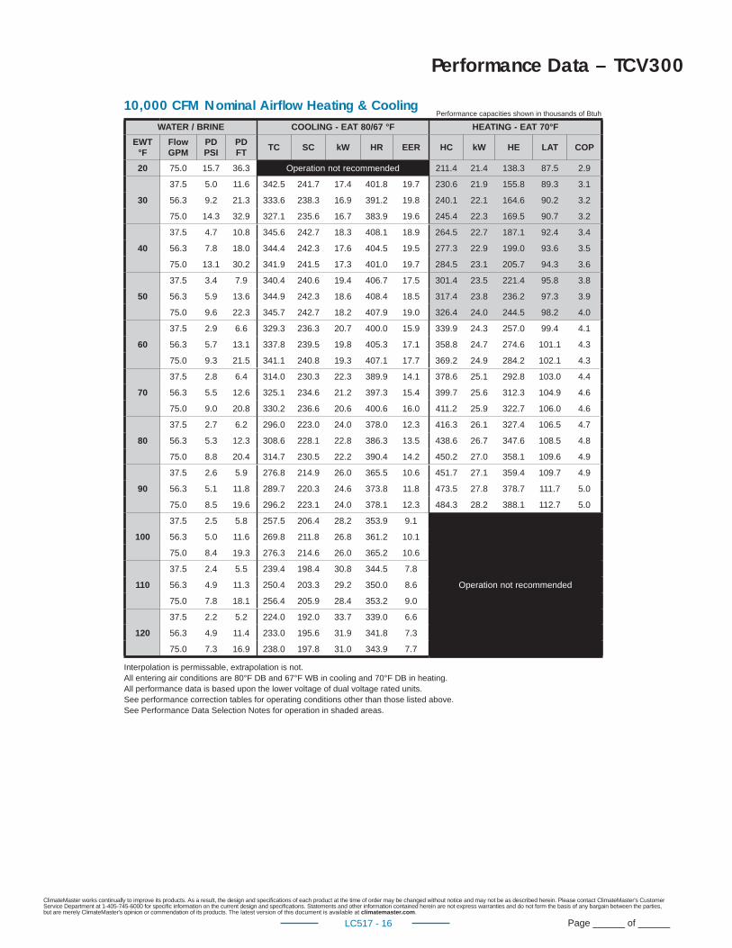
Performance Data – TCV300
WATER / BRINE COOLING - EAT 80/67 °F HEATING - EAT 70°F
EWT °F
Flow GPM
PD PSI
PD FT
TC SC kW HR EER HC kW HE LAT COP
20 75.0 15.7 36.3 Operation not recommended 211.4 21.4 138.3 87.5 2.9
30
37.5 5.0 11.6 342.5 241.7 17.4 401.8 19.7 230.6 21.9 155.8 89.3 3.1
56.3 9.2 21.3 333.6 238.3 16.9 391.2 19.8 240.1 22.1 164.6 90.2 3.2
75.0 14.3 32.9 327.1 235.6 16.7 383.9 19.6 245.4 22.3 169.5 90.7 3.2
40
37.5 4.7 10.8 345.6 242.7 18.3 408.1 18.9 264.5 22.7 187.1 92.4 3.4
56.3 7.8 18.0 344.4 242.3 17.6 404.5 19.5 277.3 22.9 199.0 93.6 3.5
75.0 13.1 30.2 341.9 241.5 17.3 401.0 19.7 284.5 23.1 205.7 94.3 3.6
50
37.5 3.4 7.9 340.4 240.6 19.4 406.7 17.5 301.4 23.5 221.4 95.8 3.8
56.3 5.9 13.6 344.9 242.3 18.6 408.4 18.5 317.4 23.8 236.2 97.3 3.9
75.0 9.6 22.3 345.7 242.7 18.2 407.9 19.0 326.4 24.0 244.5 98.2 4.0
60
37.5 2.9 6.6 329.3 236.3 20.7 400.0 15.9 339.9 24.3 257.0 99.4 4.1
56.3 5.7 13.1 337.8 239.5 19.8 405.3 17.1 358.8 24.7 274.6 101.1 4.3
75.0 9.3 21.5 341.1 240.8 19.3 407.1 17.7 369.2 24.9 284.2 102.1 4.3
70
37.5 2.8 6.4 314.0 230.3 22.3 389.9 14.1 378.6 25.1 292.8 103.0 4.4
56.3 5.5 12.6 325.1 234.6 21.2 397.3 15.4 399.7 25.6 312.3 104.9 4.6
75.0 9.0 20.8 330.2 236.6 20.6 400.6 16.0 411.2 25.9 322.7 106.0 4.6
80
37.5 2.7 6.2 296.0 223.0 24.0 378.0 12.3 416.3 26.1 327.4 106.5 4.7
56.3 5.3 12.3 308.6 228.1 22.8 386.3 13.5 438.6 26.7 347.6 108.5 4.8
75.0 8.8 20.4 314.7 230.5 22.2 390.4 14.2 450.2 27.0 358.1 109.6 4.9
90
37.5 2.6 5.9 276.8 214.9 26.0 365.5 10.6 451.7 27.1 359.4 109.7 4.9
56.3 5.1 11.8 289.7 220.3 24.6 373.8 11.8 473.5 27.8 378.7 111.7 5.0
75.0 8.5 19.6 296.2 223.1 24.0 378.1 12.3 484.3 28.2 388.1 112.7 5.0
100
37.5 2.5 5.8 257.5 206.4 28.2 353.9 9.1
Operation not recommended
56.3 5.0 11.6 269.8 211.8 26.8 361.2 10.1
75.0 8.4 19.3 276.3 214.6 26.0 365.2 10.6
110
37.5 2.4 5.5 239.4 198.4 30.8 344.5 7.8
56.3 4.9 11.3 250.4 203.3 29.2 350.0 8.6
75.0 7.8 18.1 256.4 205.9 28.4 353.2 9.0
120
37.5 2.2 5.2 224.0 192.0 33.7 339.0 6.6
56.3 4.9 11.4 233.0 195.6 31.9 341.8 7.3
75.0 7.3 16.9 238.0 197.8 31.0 343.9 7.7
Performance capacities shown in thousands of Btuh10,000 CFM Nominal Airfl ow Heating & Cooling
Interpolation is permissable, extrapolation is not.All entering air conditions are 80°F DB and 67°F WB in cooling and 70°F DB in heating.All performance data is based upon the lower voltage of dual voltage rated units.See performance correction tables for operating conditions other than those listed above.See Performance Data Selection Notes for operation in shaded areas.
ClimateMaster works continually to improve its products. As a result, the design and specifi cations of each product at the time of order may be changed without notice and may not be as described herein. Please contact ClimateMaster's Customer Service Department at 1-405-745-6000 for specifi c information on the current design and specifi cations. Statements and other information contained herein are not express warranties and do not form the basis of any bargain between the parties, but are merely ClimateMaster's opinion or commendation of its products. The latest version of this document is available at climatemaster.com.
Page ______ of ______LC517 - 17
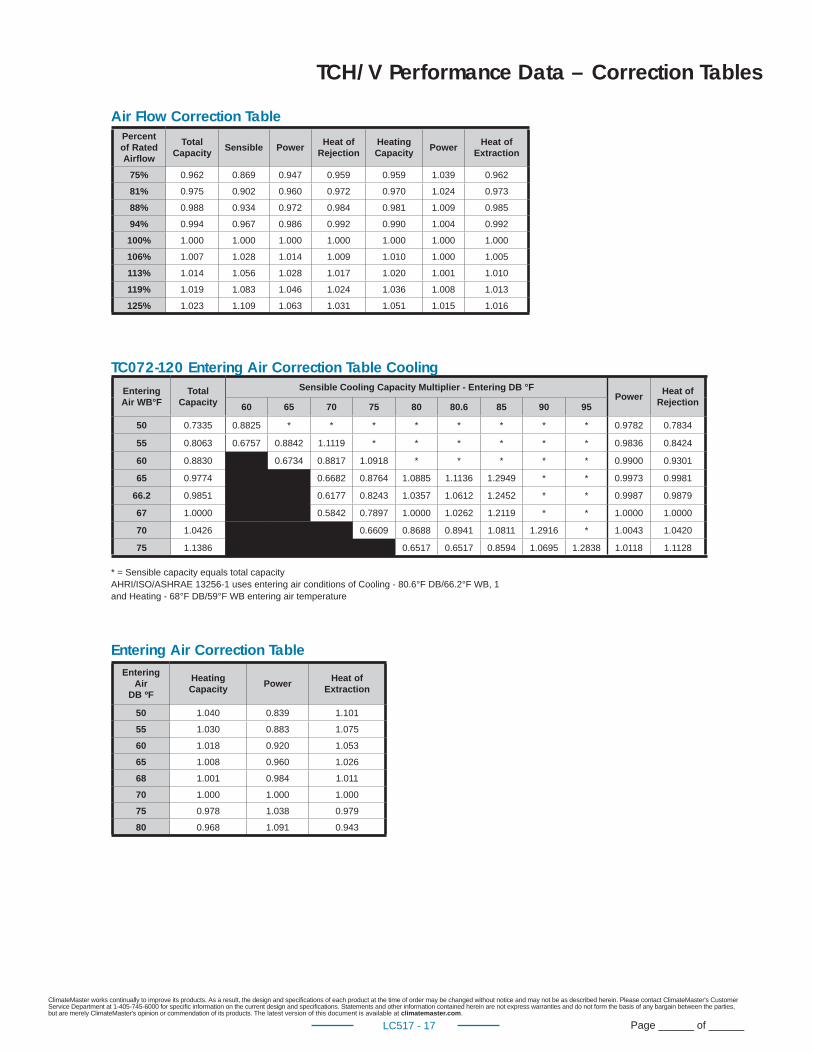
Air Flow Correction Table
Entering Air Correction Table
TCH/V Performance Data – Correction Tables
Percent of Rated Airfl ow
Total Capacity
Sensible PowerHeat of
RejectionHeating Capacity
PowerHeat of
Extraction
75% 0.962 0.869 0.947 0.959 0.959 1.039 0.962
81% 0.975 0.902 0.960 0.972 0.970 1.024 0.973
88% 0.988 0.934 0.972 0.984 0.981 1.009 0.985
94% 0.994 0.967 0.986 0.992 0.990 1.004 0.992
100% 1.000 1.000 1.000 1.000 1.000 1.000 1.000
106% 1.007 1.028 1.014 1.009 1.010 1.000 1.005
113% 1.014 1.056 1.028 1.017 1.020 1.001 1.010
119% 1.019 1.083 1.046 1.024 1.036 1.008 1.013
125% 1.023 1.109 1.063 1.031 1.051 1.015 1.016
EnteringAir WB°F
TotalCapacity
Sensible Cooling Capacity Multiplier - Entering DB °FPower
Heat ofRejection60 65 70 75 80 80.6 85 90 95
50 0.7335 0.8825 * * * * * * * * 0.9782 0.7834
55 0.8063 0.6757 0.8842 1.1119 * * * * * * 0.9836 0.8424
60 0.8830 0.6734 0.8817 1.0918 * * * * * 0.9900 0.9301
65 0.9774 0.6682 0.8764 1.0885 1.1136 1.2949 * * 0.9973 0.9981
66.2 0.9851 0.6177 0.8243 1.0357 1.0612 1.2452 * * 0.9987 0.9879
67 1.0000 0.5842 0.7897 1.0000 1.0262 1.2119 * * 1.0000 1.0000
70 1.0426 0.6609 0.8688 0.8941 1.0811 1.2916 * 1.0043 1.0420
75 1.1386 0.6517 0.6517 0.8594 1.0695 1.2838 1.0118 1.1128
* = Sensible capacity equals total capacityAHRI/ISO/ASHRAE 13256-1 uses entering air conditions of Cooling - 80.6°F DB/66.2°F WB, 1and Heating - 68°F DB/59°F WB entering air temperature
Entering Air
DB ºF
Heating Capacity
PowerHeat of
Extraction
50 1.040 0.839 1.101
55 1.030 0.883 1.075
60 1.018 0.920 1.053
65 1.008 0.960 1.026
68 1.001 0.984 1.011
70 1.000 1.000 1.000
75 0.978 1.038 0.979
80 0.968 1.091 0.943
TC072-120 Entering Air Correction Table Cooling
ClimateMaster works continually to improve its products. As a result, the design and specifi cations of each product at the time of order may be changed without notice and may not be as described herein. Please contact ClimateMaster's Customer Service Department at 1-405-745-6000 for specifi c information on the current design and specifi cations. Statements and other information contained herein are not express warranties and do not form the basis of any bargain between the parties, but are merely ClimateMaster's opinion or commendation of its products. The latest version of this document is available at climatemaster.com.
Page ______ of ______LC517 - 18
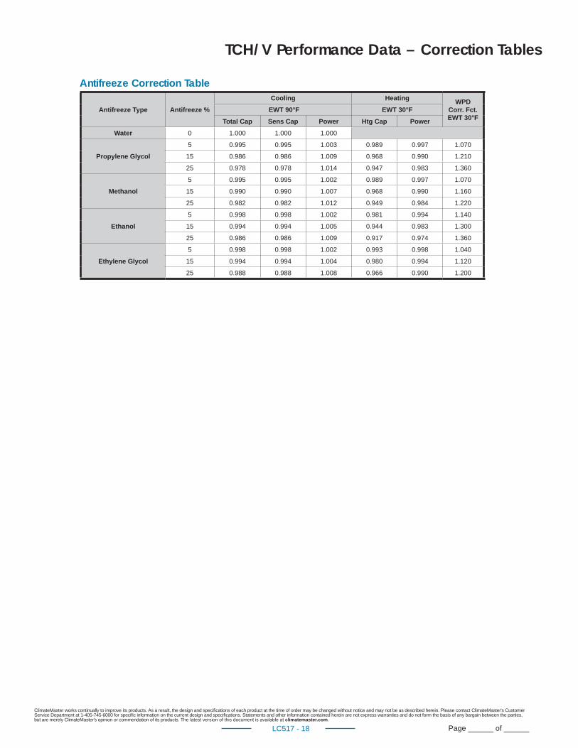
Antifreeze Type Antifreeze %
Cooling HeatingWPD
Corr. Fct.EWT 30°F
EWT 90°F EWT 30°F
Total Cap Sens Cap Power Htg Cap Power
Water 0 1.000 1.000 1.000
Propylene Glycol
5 0.995 0.995 1.003 0.989 0.997 1.070
15 0.986 0.986 1.009 0.968 0.990 1.210
25 0.978 0.978 1.014 0.947 0.983 1.360
Methanol
5 0.995 0.995 1.002 0.989 0.997 1.070
15 0.990 0.990 1.007 0.968 0.990 1.160
25 0.982 0.982 1.012 0.949 0.984 1.220
Ethanol
5 0.998 0.998 1.002 0.981 0.994 1.140
15 0.994 0.994 1.005 0.944 0.983 1.300
25 0.986 0.986 1.009 0.917 0.974 1.360
Ethylene Glycol
5 0.998 0.998 1.002 0.993 0.998 1.040
15 0.994 0.994 1.004 0.980 0.994 1.120
25 0.988 0.988 1.008 0.966 0.990 1.200
Antifreeze Correction Table
TCH/V Performance Data – Correction Tables
ClimateMaster works continually to improve its products. As a result, the design and specifi cations of each product at the time of order may be changed without notice and may not be as described herein. Please contact ClimateMaster's Customer Service Department at 1-405-745-6000 for specifi c information on the current design and specifi cations. Statements and other information contained herein are not express warranties and do not form the basis of any bargain between the parties, but are merely ClimateMaster's opinion or commendation of its products. The latest version of this document is available at climatemaster.com.
Page ______ of ______LC517 - 19
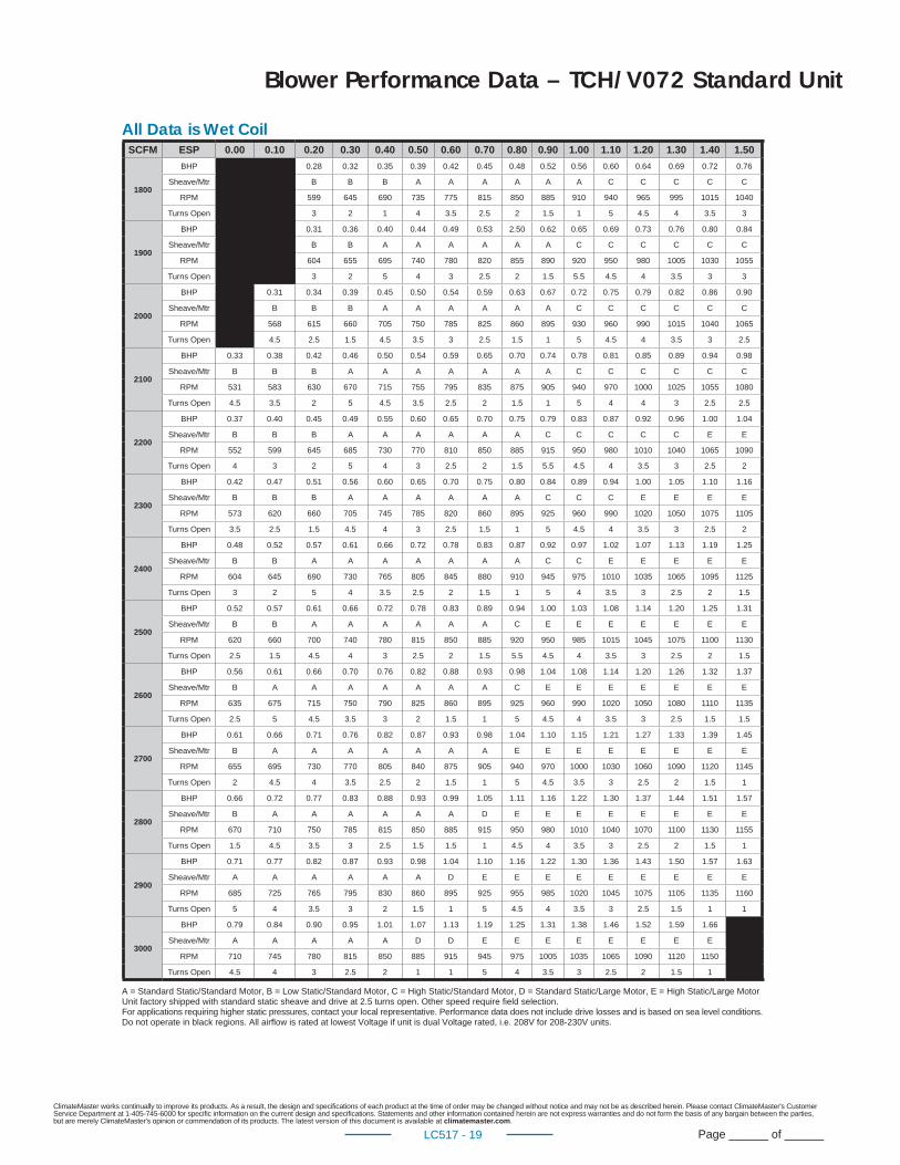
Blower Performance Data – TCH/V072 Standard Unit
All Data is Wet CoilSCFM ESP 0.00 0.10 0.20 0.30 0.40 0.50 0.60 0.70 0.80 0.90 1.00 1.10 1.20 1.30 1.40 1.50
1800
BHP 0.28 0.32 0.35 0.39 0.42 0.45 0.48 0.52 0.56 0.60 0.64 0.69 0.72 0.76
Sheave/Mtr B B B A A A A A A C C C C C
RPM 599 645 690 735 775 815 850 885 910 940 965 995 1015 1040
Turns Open 3 2 1 4 3.5 2.5 2 1.5 1 5 4.5 4 3.5 3
1900
BHP 0.31 0.36 0.40 0.44 0.49 0.53 2.50 0.62 0.65 0.69 0.73 0.76 0.80 0.84
Sheave/Mtr B B A A A A A A C C C C C C
RPM 604 655 695 740 780 820 855 890 920 950 980 1005 1030 1055
Turns Open 3 2 5 4 3 2.5 2 1.5 5.5 4.5 4 3.5 3 3
2000
BHP 0.31 0.34 0.39 0.45 0.50 0.54 0.59 0.63 0.67 0.72 0.75 0.79 0.82 0.86 0.90
Sheave/Mtr B B B A A A A A A C C C C C C
RPM 568 615 660 705 750 785 825 860 895 930 960 990 1015 1040 1065
Turns Open 4.5 2.5 1.5 4.5 3.5 3 2.5 1.5 1 5 4.5 4 3.5 3 2.5
2100
BHP 0.33 0.38 0.42 0.46 0.50 0.54 0.59 0.65 0.70 0.74 0.78 0.81 0.85 0.89 0.94 0.98
Sheave/Mtr B B B A A A A A A A C C C C C C
RPM 531 583 630 670 715 755 795 835 875 905 940 970 1000 1025 1055 1080
Turns Open 4.5 3.5 2 5 4.5 3.5 2.5 2 1.5 1 5 4 4 3 2.5 2.5
2200
BHP 0.37 0.40 0.45 0.49 0.55 0.60 0.65 0.70 0.75 0.79 0.83 0.87 0.92 0.96 1.00 1.04
Sheave/Mtr B B B A A A A A A C C C C C E E
RPM 552 599 645 685 730 770 810 850 885 915 950 980 1010 1040 1065 1090
Turns Open 4 3 2 5 4 3 2.5 2 1.5 5.5 4.5 4 3.5 3 2.5 2
2300
BHP 0.42 0.47 0.51 0.56 0.60 0.65 0.70 0.75 0.80 0.84 0.89 0.94 1.00 1.05 1.10 1.16
Sheave/Mtr B B B A A A A A A C C C E E E E
RPM 573 620 660 705 745 785 820 860 895 925 960 990 1020 1050 1075 1105
Turns Open 3.5 2.5 1.5 4.5 4 3 2.5 1.5 1 5 4.5 4 3.5 3 2.5 2
2400
BHP 0.48 0.52 0.57 0.61 0.66 0.72 0.78 0.83 0.87 0.92 0.97 1.02 1.07 1.13 1.19 1.25
Sheave/Mtr B B A A A A A A A C C E E E E E
RPM 604 645 690 730 765 805 845 880 910 945 975 1010 1035 1065 1095 1125
Turns Open 3 2 5 4 3.5 2.5 2 1.5 1 5 4 3.5 3 2.5 2 1.5
2500
BHP 0.52 0.57 0.61 0.66 0.72 0.78 0.83 0.89 0.94 1.00 1.03 1.08 1.14 1.20 1.25 1.31
Sheave/Mtr B B A A A A A A C E E E E E E E
RPM 620 660 700 740 780 815 850 885 920 950 985 1015 1045 1075 1100 1130
Turns Open 2.5 1.5 4.5 4 3 2.5 2 1.5 5.5 4.5 4 3.5 3 2.5 2 1.5
2600
BHP 0.56 0.61 0.66 0.70 0.76 0.82 0.88 0.93 0.98 1.04 1.08 1.14 1.20 1.26 1.32 1.37
Sheave/Mtr B A A A A A A A C E E E E E E E
RPM 635 675 715 750 790 825 860 895 925 960 990 1020 1050 1080 1110 1135
Turns Open 2.5 5 4.5 3.5 3 2 1.5 1 5 4.5 4 3.5 3 2.5 1.5 1.5
2700
BHP 0.61 0.66 0.71 0.76 0.82 0.87 0.93 0.98 1.04 1.10 1.15 1.21 1.27 1.33 1.39 1.45
Sheave/Mtr B A A A A A A A E E E E E E E E
RPM 655 695 730 770 805 840 875 905 940 970 1000 1030 1060 1090 1120 1145
Turns Open 2 4.5 4 3.5 2.5 2 1.5 1 5 4.5 3.5 3 2.5 2 1.5 1
2800
BHP 0.66 0.72 0.77 0.83 0.88 0.93 0.99 1.05 1.11 1.16 1.22 1.30 1.37 1.44 1.51 1.57
Sheave/Mtr B A A A A A A D E E E E E E E E
RPM 670 710 750 785 815 850 885 915 950 980 1010 1040 1070 1100 1130 1155
Turns Open 1.5 4.5 3.5 3 2.5 1.5 1.5 1 4.5 4 3.5 3 2.5 2 1.5 1
2900
BHP 0.71 0.77 0.82 0.87 0.93 0.98 1.04 1.10 1.16 1.22 1.30 1.36 1.43 1.50 1.57 1.63
Sheave/Mtr A A A A A A D E E E E E E E E E
RPM 685 725 765 795 830 860 895 925 955 985 1020 1045 1075 1105 1135 1160
Turns Open 5 4 3.5 3 2 1.5 1 5 4.5 4 3.5 3 2.5 1.5 1 1
3000
BHP 0.79 0.84 0.90 0.95 1.01 1.07 1.13 1.19 1.25 1.31 1.38 1.46 1.52 1.59 1.66
Sheave/Mtr A A A A A D D E E E E E E E E
RPM 710 745 780 815 850 885 915 945 975 1005 1035 1065 1090 1120 1150
Turns Open 4.5 4 3 2.5 2 1 1 5 4 3.5 3 2.5 2 1.5 1
A = Standard Static/Standard Motor, B = Low Static/Standard Motor, C = High Static/Standard Motor, D = Standard Static/Large Motor, E = High Static/Large MotorUnit factory shipped with standard static sheave and drive at 2.5 turns open. Other speed require fi eld selection.For applications requiring higher static pressures, contact your local representative. Performance data does not include drive losses and is based on sea level conditions.Do not operate in black regions. All airfl ow is rated at lowest Voltage if unit is dual Voltage rated, i.e. 208V for 208-230V units.
ClimateMaster works continually to improve its products. As a result, the design and specifi cations of each product at the time of order may be changed without notice and may not be as described herein. Please contact ClimateMaster's Customer Service Department at 1-405-745-6000 for specifi c information on the current design and specifi cations. Statements and other information contained herein are not express warranties and do not form the basis of any bargain between the parties, but are merely ClimateMaster's opinion or commendation of its products. The latest version of this document is available at climatemaster.com.
Page ______ of ______LC517 - 20
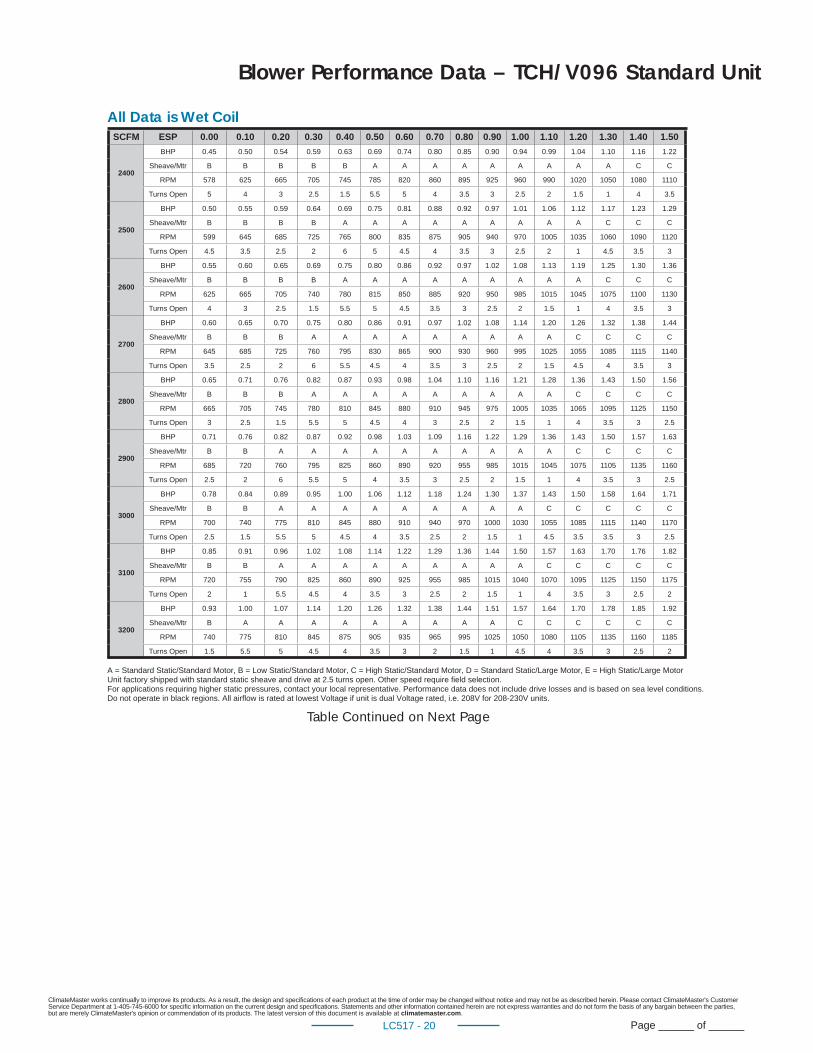
Blower Performance Data – TCH/V096 Standard Unit
All Data is Wet Coil
A = Standard Static/Standard Motor, B = Low Static/Standard Motor, C = High Static/Standard Motor, D = Standard Static/Large Motor, E = High Static/Large MotorUnit factory shipped with standard static sheave and drive at 2.5 turns open. Other speed require fi eld selection.For applications requiring higher static pressures, contact your local representative. Performance data does not include drive losses and is based on sea level conditions.Do not operate in black regions. All airfl ow is rated at lowest Voltage if unit is dual Voltage rated, i.e. 208V for 208-230V units.
Table Continued on Next Page
SCFM ESP 0.00 0.10 0.20 0.30 0.40 0.50 0.60 0.70 0.80 0.90 1.00 1.10 1.20 1.30 1.40 1.50
2400
BHP 0.45 0.50 0.54 0.59 0.63 0.69 0.74 0.80 0.85 0.90 0.94 0.99 1.04 1.10 1.16 1.22
Sheave/Mtr B B B B B A A A A A A A A A C C
RPM 578 625 665 705 745 785 820 860 895 925 960 990 1020 1050 1080 1110
Turns Open 5 4 3 2.5 1.5 5.5 5 4 3.5 3 2.5 2 1.5 1 4 3.5
2500
BHP 0.50 0.55 0.59 0.64 0.69 0.75 0.81 0.88 0.92 0.97 1.01 1.06 1.12 1.17 1.23 1.29
Sheave/Mtr B B B B A A A A A A A A A C C C
RPM 599 645 685 725 765 800 835 875 905 940 970 1005 1035 1060 1090 1120
Turns Open 4.5 3.5 2.5 2 6 5 4.5 4 3.5 3 2.5 2 1 4.5 3.5 3
2600
BHP 0.55 0.60 0.65 0.69 0.75 0.80 0.86 0.92 0.97 1.02 1.08 1.13 1.19 1.25 1.30 1.36
Sheave/Mtr B B B B A A A A A A A A A C C C
RPM 625 665 705 740 780 815 850 885 920 950 985 1015 1045 1075 1100 1130
Turns Open 4 3 2.5 1.5 5.5 5 4.5 3.5 3 2.5 2 1.5 1 4 3.5 3
2700
BHP 0.60 0.65 0.70 0.75 0.80 0.86 0.91 0.97 1.02 1.08 1.14 1.20 1.26 1.32 1.38 1.44
Sheave/Mtr B B B A A A A A A A A A C C C C
RPM 645 685 725 760 795 830 865 900 930 960 995 1025 1055 1085 1115 1140
Turns Open 3.5 2.5 2 6 5.5 4.5 4 3.5 3 2.5 2 1.5 4.5 4 3.5 3
2800
BHP 0.65 0.71 0.76 0.82 0.87 0.93 0.98 1.04 1.10 1.16 1.21 1.28 1.36 1.43 1.50 1.56
Sheave/Mtr B B B A A A A A A A A A C C C C
RPM 665 705 745 780 810 845 880 910 945 975 1005 1035 1065 1095 1125 1150
Turns Open 3 2.5 1.5 5.5 5 4.5 4 3 2.5 2 1.5 1 4 3.5 3 2.5
2900
BHP 0.71 0.76 0.82 0.87 0.92 0.98 1.03 1.09 1.16 1.22 1.29 1.36 1.43 1.50 1.57 1.63
Sheave/Mtr B B A A A A A A A A A A C C C C
RPM 685 720 760 795 825 860 890 920 955 985 1015 1045 1075 1105 1135 1160
Turns Open 2.5 2 6 5.5 5 4 3.5 3 2.5 2 1.5 1 4 3.5 3 2.5
3000
BHP 0.78 0.84 0.89 0.95 1.00 1.06 1.12 1.18 1.24 1.30 1.37 1.43 1.50 1.58 1.64 1.71
Sheave/Mtr B B A A A A A A A A A C C C C C
RPM 700 740 775 810 845 880 910 940 970 1000 1030 1055 1085 1115 1140 1170
Turns Open 2.5 1.5 5.5 5 4.5 4 3.5 2.5 2 1.5 1 4.5 3.5 3.5 3 2.5
3100
BHP 0.85 0.91 0.96 1.02 1.08 1.14 1.22 1.29 1.36 1.44 1.50 1.57 1.63 1.70 1.76 1.82
Sheave/Mtr B B A A A A A A A A A C C C C C
RPM 720 755 790 825 860 890 925 955 985 1015 1040 1070 1095 1125 1150 1175
Turns Open 2 1 5.5 4.5 4 3.5 3 2.5 2 1.5 1 4 3.5 3 2.5 2
3200
BHP 0.93 1.00 1.07 1.14 1.20 1.26 1.32 1.38 1.44 1.51 1.57 1.64 1.70 1.78 1.85 1.92
Sheave/Mtr B A A A A A A A A A C C C C C C
RPM 740 775 810 845 875 905 935 965 995 1025 1050 1080 1105 1135 1160 1185
Turns Open 1.5 5.5 5 4.5 4 3.5 3 2 1.5 1 4.5 4 3.5 3 2.5 2
ClimateMaster works continually to improve its products. As a result, the design and specifi cations of each product at the time of order may be changed without notice and may not be as described herein. Please contact ClimateMaster's Customer Service Department at 1-405-745-6000 for specifi c information on the current design and specifi cations. Statements and other information contained herein are not express warranties and do not form the basis of any bargain between the parties, but are merely ClimateMaster's opinion or commendation of its products. The latest version of this document is available at climatemaster.com.
Page ______ of ______LC517 - 21
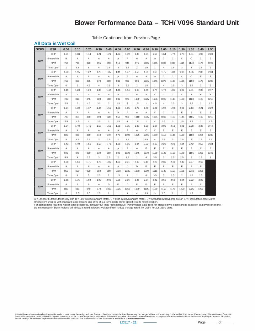
Blower Performance Data – TCH/V096 Standard Unit
Table Continued from Previous Page
3300
BHP 1.01 1.08 1.14 1.21 1.28 1.33 1.39 1.45 1.51 1.58 1.64 1.72 1.78 1.84 1.93 2.00
Sheave/Mtr B A A A A A A A A A C C C C C E
RPM 755 790 820 855 890 915 945 975 1005 1035 1060 1090 1115 1140 1170 1195
Turns Open 1 5.5 5 4 3.5 3 2.5 2 1.5 1 4 3.5 3 3 2.5 2
3400
BHP 1.08 1.15 1.22 1.29 1.35 1.41 1.47 1.53 1.59 1.68 1.75 1.83 1.90 1.96 2.02 2.08
Sheave/Mtr A A A A A A A A A A C C C C E E
RPM 765 800 835 870 900 930 960 990 1015 1045 1070 1100 1125 1150 1175 1200
Turns Open 6 5 4.5 4 3.5 3 2.5 2 1.5 1 4 3.5 3 2.5 2 2
3500
BHP 1.16 1.23 1.29 1.36 1.42 1.48 1.54 1.60 1.66 1.73 1.79 1.85 1.92 2.01 2.09 2.17
Sheave/Mtr A A A A A A A A A C C C C E E E
RPM 780 815 845 880 910 940 970 1000 1025 1055 1080 1105 1130 1160 1185 1210
Turns Open 5.5 5 4.5 3.5 3 2.5 2 1.5 1 4.5 4 3.5 3 2.5 2 1.5
3600
BHP 1.24 1.30 1.37 1.44 1.51 1.58 1.65 1.72 1.78 1.86 1.92 1.98 2.06 2.13 2.21 2.29
Sheave/Mtr A A A A A A A A A C C C E E E E
RPM 795 825 860 890 920 950 980 1010 1035 1065 1090 1115 1145 1165 1190 1215
Turns Open 5.5 4.5 4 3.5 3 2.5 2 1.5 1 4 3.5 3 2.5 2.5 2 1.5
3700
BHP 1.34 1.40 1.46 1.53 1.61 1.68 1.75 1.82 1.90 1.97 2.06 2.13 2.21 2.28 2.36 2.44
Sheave/Mtr A A A A A A A A C C E E E E E E
RPM 820 850 880 910 940 970 1000 1025 1055 1080 1110 1135 1160 1180 1205 1230
Turns Open 5 4.5 3.5 3 2.5 2 1.5 1 4.5 4 3.5 3 2.5 2 1.5 1.5
3800
BHP 1.43 1.49 1.56 1.63 1.70 1.78 1.86 1.94 2.02 2.12 2.20 2.28 2.34 2.42 2.50 2.58
Sheave/Mtr A A A A A A A A E E E E E E E E
RPM 840 870 900 930 960 990 1020 1045 1070 1100 1125 1150 1170 1195 1220 1245
Turns Open 4.5 4 3.5 3 2.5 2 1.5 1 4 3.5 3 2.5 2.5 2 1.5 1
3900
BHP 1.58 1.64 1.71 1.78 1.85 1.93 2.01 2.09 2.19 2.27 2.35 2.41 2.49 2.57 2.65
Sheave/Mtr A A A A A A D D E E E E E E E
RPM 865 890 920 950 980 1010 1035 1060 1090 1115 1140 1160 1185 1210 1235
Turns Open 4 4 3 2.5 2 1.5 1 1 4 3.5 3 2.5 2 1.5 1.5
4000
BHP 1.68 1.75 1.83 1.92 2.00 2.08 2.16 2.26 2.34 2.42 2.50 2.56 2.64 2.72 2.80
Sheave/Mtr A A A A D D D E E E E E E E E
RPM 885 910 940 970 1000 1025 1050 1080 1105 1130 1155 1175 1200 1225 1250
Turns Open 4 3.5 2.5 2.5 2 1 1 4 3.5 3 2.5 2 2 1.5 1
All Data is Wet Coil
A = Standard Static/Standard Motor, B = Low Static/Standard Motor, C = High Static/Standard Motor, D = Standard Static/Large Motor, E = High Static/Large MotorUnit factory shipped with standard static sheave and drive at 2.5 turns open. Other speed require fi eld selection.For applications requiring higher static pressures, contact your local representative. Performance data does not include drive losses and is based on sea level conditions.Do not operate in black regions. All airfl ow is rated at lowest Voltage if unit is dual Voltage rated, i.e. 208V for 208-230V units.
SCFM ESP 0.00 0.10 0.20 0.30 0.40 0.50 0.60 0.70 0.80 0.90 1.00 1.10 1.20 1.30 1.40 1.50
ClimateMaster works continually to improve its products. As a result, the design and specifi cations of each product at the time of order may be changed without notice and may not be as described herein. Please contact ClimateMaster's Customer Service Department at 1-405-745-6000 for specifi c information on the current design and specifi cations. Statements and other information contained herein are not express warranties and do not form the basis of any bargain between the parties, but are merely ClimateMaster's opinion or commendation of its products. The latest version of this document is available at climatemaster.com.
Page ______ of ______LC517 - 22
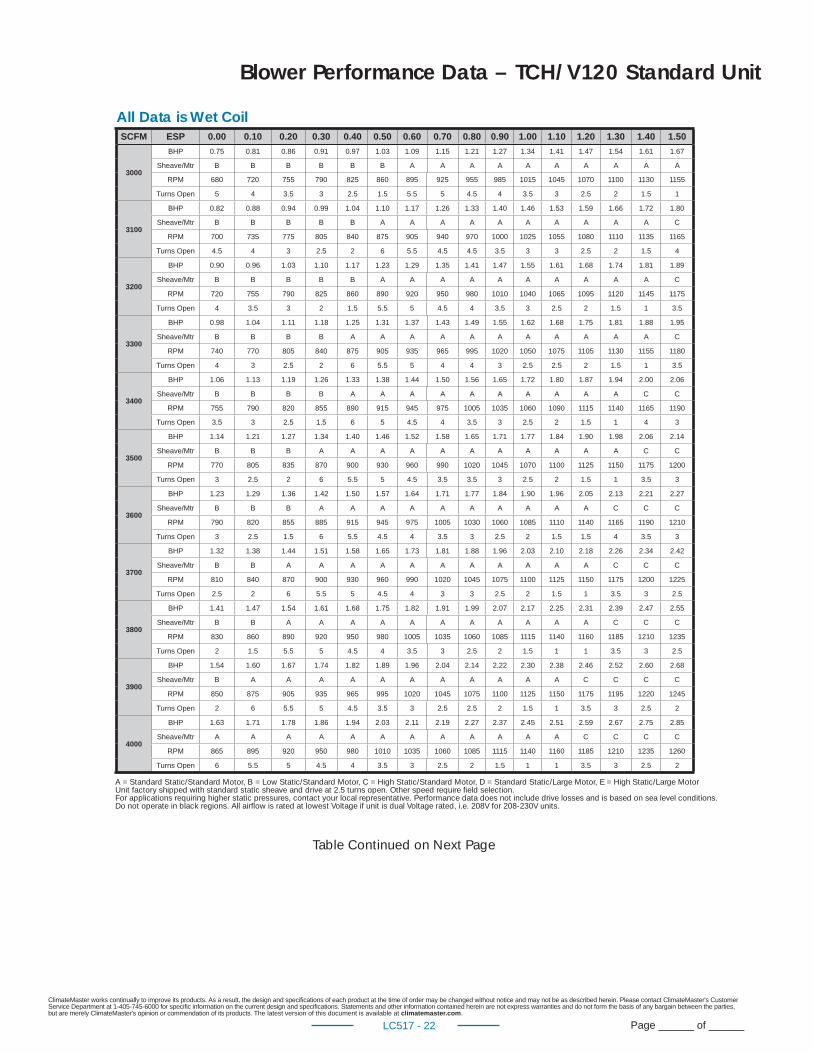
Blower Performance Data – TCH/V120 Standard Unit
All Data is Wet Coil
Table Continued on Next Page
SCFM ESP 0.00 0.10 0.20 0.30 0.40 0.50 0.60 0.70 0.80 0.90 1.00 1.10 1.20 1.30 1.40 1.50
3000
BHP 0.75 0.81 0.86 0.91 0.97 1.03 1.09 1.15 1.21 1.27 1.34 1.41 1.47 1.54 1.61 1.67
Sheave/Mtr B B B B B B A A A A A A A A A A
RPM 680 720 755 790 825 860 895 925 955 985 1015 1045 1070 1100 1130 1155
Turns Open 5 4 3.5 3 2.5 1.5 5.5 5 4.5 4 3.5 3 2.5 2 1.5 1
3100
BHP 0.82 0.88 0.94 0.99 1.04 1.10 1.17 1.26 1.33 1.40 1.46 1.53 1.59 1.66 1.72 1.80
Sheave/Mtr B B B B B A A A A A A A A A A C
RPM 700 735 775 805 840 875 905 940 970 1000 1025 1055 1080 1110 1135 1165
Turns Open 4.5 4 3 2.5 2 6 5.5 4.5 4.5 3.5 3 3 2.5 2 1.5 4
3200
BHP 0.90 0.96 1.03 1.10 1.17 1.23 1.29 1.35 1.41 1.47 1.55 1.61 1.68 1.74 1.81 1.89
Sheave/Mtr B B B B B A A A A A A A A A A C
RPM 720 755 790 825 860 890 920 950 980 1010 1040 1065 1095 1120 1145 1175
Turns Open 4 3.5 3 2 1.5 5.5 5 4.5 4 3.5 3 2.5 2 1.5 1 3.5
3300
BHP 0.98 1.04 1.11 1.18 1.25 1.31 1.37 1.43 1.49 1.55 1.62 1.68 1.75 1.81 1.88 1.95
Sheave/Mtr B B B B A A A A A A A A A A A C
RPM 740 770 805 840 875 905 935 965 995 1020 1050 1075 1105 1130 1155 1180
Turns Open 4 3 2.5 2 6 5.5 5 4 4 3 2.5 2.5 2 1.5 1 3.5
3400
BHP 1.06 1.13 1.19 1.26 1.33 1.38 1.44 1.50 1.56 1.65 1.72 1.80 1.87 1.94 2.00 2.06
Sheave/Mtr B B B B A A A A A A A A A A C C
RPM 755 790 820 855 890 915 945 975 1005 1035 1060 1090 1115 1140 1165 1190
Turns Open 3.5 3 2.5 1.5 6 5 4.5 4 3.5 3 2.5 2 1.5 1 4 3
3500
BHP 1.14 1.21 1.27 1.34 1.40 1.46 1.52 1.58 1.65 1.71 1.77 1.84 1.90 1.98 2.06 2.14
Sheave/Mtr B B B A A A A A A A A A A A C C
RPM 770 805 835 870 900 930 960 990 1020 1045 1070 1100 1125 1150 1175 1200
Turns Open 3 2.5 2 6 5.5 5 4.5 3.5 3.5 3 2.5 2 1.5 1 3.5 3
3600
BHP 1.23 1.29 1.36 1.42 1.50 1.57 1.64 1.71 1.77 1.84 1.90 1.96 2.05 2.13 2.21 2.27
Sheave/Mtr B B B A A A A A A A A A A C C C
RPM 790 820 855 885 915 945 975 1005 1030 1060 1085 1110 1140 1165 1190 1210
Turns Open 3 2.5 1.5 6 5.5 4.5 4 3.5 3 2.5 2 1.5 1.5 4 3.5 3
3700
BHP 1.32 1.38 1.44 1.51 1.58 1.65 1.73 1.81 1.88 1.96 2.03 2.10 2.18 2.26 2.34 2.42
Sheave/Mtr B B A A A A A A A A A A A C C C
RPM 810 840 870 900 930 960 990 1020 1045 1075 1100 1125 1150 1175 1200 1225
Turns Open 2.5 2 6 5.5 5 4.5 4 3 3 2.5 2 1.5 1 3.5 3 2.5
3800
BHP 1.41 1.47 1.54 1.61 1.68 1.75 1.82 1.91 1.99 2.07 2.17 2.25 2.31 2.39 2.47 2.55
Sheave/Mtr B B A A A A A A A A A A A C C C
RPM 830 860 890 920 950 980 1005 1035 1060 1085 1115 1140 1160 1185 1210 1235
Turns Open 2 1.5 5.5 5 4.5 4 3.5 3 2.5 2 1.5 1 1 3.5 3 2.5
3900
BHP 1.54 1.60 1.67 1.74 1.82 1.89 1.96 2.04 2.14 2.22 2.30 2.38 2.46 2.52 2.60 2.68
Sheave/Mtr B A A A A A A A A A A A C C C C
RPM 850 875 905 935 965 995 1020 1045 1075 1100 1125 1150 1175 1195 1220 1245
Turns Open 2 6 5.5 5 4.5 3.5 3 2.5 2.5 2 1.5 1 3.5 3 2.5 2
4000
BHP 1.63 1.71 1.78 1.86 1.94 2.03 2.11 2.19 2.27 2.37 2.45 2.51 2.59 2.67 2.75 2.85
Sheave/Mtr A A A A A A A A A A A A C C C C
RPM 865 895 920 950 980 1010 1035 1060 1085 1115 1140 1160 1185 1210 1235 1260
Turns Open 6 5.5 5 4.5 4 3.5 3 2.5 2 1.5 1 1 3.5 3 2.5 2
A = Standard Static/Standard Motor, B = Low Static/Standard Motor, C = High Static/Standard Motor, D = Standard Static/Large Motor, E = High Static/Large MotorUnit factory shipped with standard static sheave and drive at 2.5 turns open. Other speed require fi eld selection.For applications requiring higher static pressures, contact your local representative. Performance data does not include drive losses and is based on sea level conditions.Do not operate in black regions. All airfl ow is rated at lowest Voltage if unit is dual Voltage rated, i.e. 208V for 208-230V units.
ClimateMaster works continually to improve its products. As a result, the design and specifi cations of each product at the time of order may be changed without notice and may not be as described herein. Please contact ClimateMaster's Customer Service Department at 1-405-745-6000 for specifi c information on the current design and specifi cations. Statements and other information contained herein are not express warranties and do not form the basis of any bargain between the parties, but are merely ClimateMaster's opinion or commendation of its products. The latest version of this document is available at climatemaster.com.
Page ______ of ______LC517 - 23
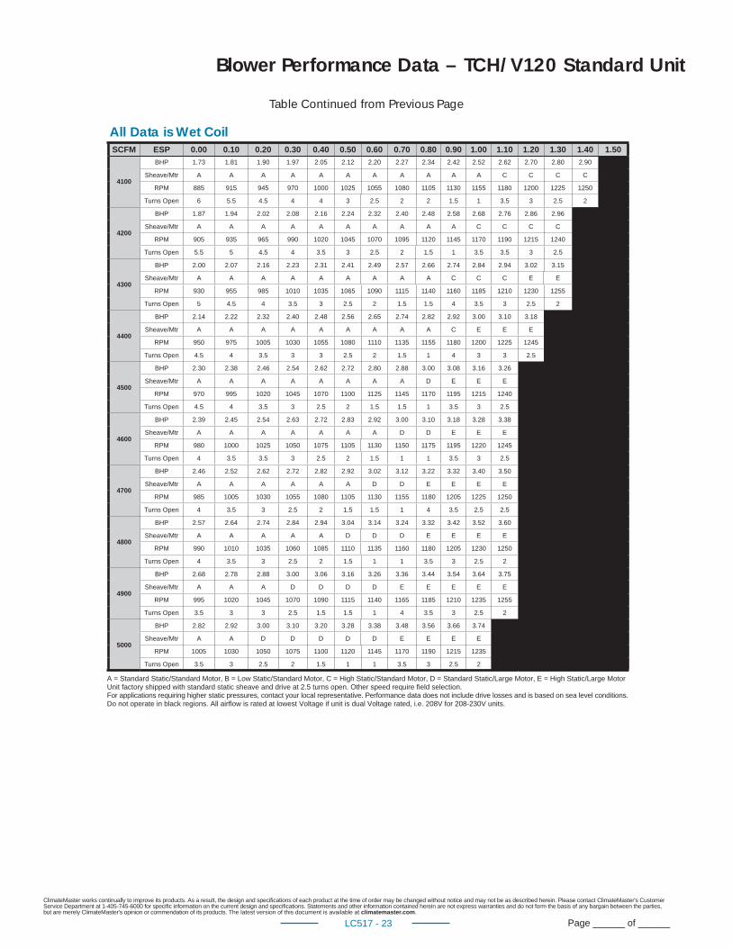
Blower Performance Data – TCH/V120 Standard Unit
All Data is Wet Coil
Table Continued from Previous Page
SCFM ESP 0.00 0.10 0.20 0.30 0.40 0.50 0.60 0.70 0.80 0.90 1.00 1.10 1.20 1.30 1.40 1.50
4100
BHP 1.73 1.81 1.90 1.97 2.05 2.12 2.20 2.27 2.34 2.42 2.52 2.62 2.70 2.80 2.90
Sheave/Mtr A A A A A A A A A A A C C C C
RPM 885 915 945 970 1000 1025 1055 1080 1105 1130 1155 1180 1200 1225 1250
Turns Open 6 5.5 4.5 4 4 3 2.5 2 2 1.5 1 3.5 3 2.5 2
4200
BHP 1.87 1.94 2.02 2.08 2.16 2.24 2.32 2.40 2.48 2.58 2.68 2.76 2.86 2.96
Sheave/Mtr A A A A A A A A A A C C C C
RPM 905 935 965 990 1020 1045 1070 1095 1120 1145 1170 1190 1215 1240
Turns Open 5.5 5 4.5 4 3.5 3 2.5 2 1.5 1 3.5 3.5 3 2.5
4300
BHP 2.00 2.07 2.16 2.23 2.31 2.41 2.49 2.57 2.66 2.74 2.84 2.94 3.02 3.15
Sheave/Mtr A A A A A A A A A C C C E E
RPM 930 955 985 1010 1035 1065 1090 1115 1140 1160 1185 1210 1230 1255
Turns Open 5 4.5 4 3.5 3 2.5 2 1.5 1.5 4 3.5 3 2.5 2
4400
BHP 2.14 2.22 2.32 2.40 2.48 2.56 2.65 2.74 2.82 2.92 3.00 3.10 3.18
Sheave/Mtr A A A A A A A A A C E E E
RPM 950 975 1005 1030 1055 1080 1110 1135 1155 1180 1200 1225 1245
Turns Open 4.5 4 3.5 3 3 2.5 2 1.5 1 4 3 3 2.5
4500
BHP 2.30 2.38 2.46 2.54 2.62 2.72 2.80 2.88 3.00 3.08 3.16 3.26
Sheave/Mtr A A A A A A A A D E E E
RPM 970 995 1020 1045 1070 1100 1125 1145 1170 1195 1215 1240
Turns Open 4.5 4 3.5 3 2.5 2 1.5 1.5 1 3.5 3 2.5
4600
BHP 2.39 2.45 2.54 2.63 2.72 2.83 2.92 3.00 3.10 3.18 3.28 3.38
Sheave/Mtr A A A A A A A D D E E E
RPM 980 1000 1025 1050 1075 1105 1130 1150 1175 1195 1220 1245
Turns Open 4 3.5 3.5 3 2.5 2 1.5 1 1 3.5 3 2.5
4700
BHP 2.46 2.52 2.62 2.72 2.82 2.92 3.02 3.12 3.22 3.32 3.40 3.50
Sheave/Mtr A A A A A A D D E E E E
RPM 985 1005 1030 1055 1080 1105 1130 1155 1180 1205 1225 1250
Turns Open 4 3.5 3 2.5 2 1.5 1.5 1 4 3.5 2.5 2.5
4800
BHP 2.57 2.64 2.74 2.84 2.94 3.04 3.14 3.24 3.32 3.42 3.52 3.60
Sheave/Mtr A A A A A D D D E E E E
RPM 990 1010 1035 1060 1085 1110 1135 1160 1180 1205 1230 1250
Turns Open 4 3.5 3 2.5 2 1.5 1 1 3.5 3 2.5 2
4900
BHP 2.68 2.78 2.88 3.00 3.06 3.16 3.26 3.36 3.44 3.54 3.64 3.75
Sheave/Mtr A A A D D D D E E E E E
RPM 995 1020 1045 1070 1090 1115 1140 1165 1185 1210 1235 1255
Turns Open 3.5 3 3 2.5 1.5 1.5 1 4 3.5 3 2.5 2
5000
BHP 2.82 2.92 3.00 3.10 3.20 3.28 3.38 3.48 3.56 3.66 3.74
Sheave/Mtr A A D D D D D E E E E
RPM 1005 1030 1050 1075 1100 1120 1145 1170 1190 1215 1235
Turns Open 3.5 3 2.5 2 1.5 1 1 3.5 3 2.5 2
A = Standard Static/Standard Motor, B = Low Static/Standard Motor, C = High Static/Standard Motor, D = Standard Static/Large Motor, E = High Static/Large MotorUnit factory shipped with standard static sheave and drive at 2.5 turns open. Other speed require fi eld selection.For applications requiring higher static pressures, contact your local representative. Performance data does not include drive losses and is based on sea level conditions.Do not operate in black regions. All airfl ow is rated at lowest Voltage if unit is dual Voltage rated, i.e. 208V for 208-230V units.
ClimateMaster works continually to improve its products. As a result, the design and specifi cations of each product at the time of order may be changed without notice and may not be as described herein. Please contact ClimateMaster's Customer Service Department at 1-405-745-6000 for specifi c information on the current design and specifi cations. Statements and other information contained herein are not express warranties and do not form the basis of any bargain between the parties, but are merely ClimateMaster's opinion or commendation of its products. The latest version of this document is available at climatemaster.com.
Page ______ of ______LC517 - 24
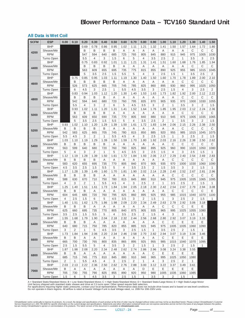
Blower Performance Data – TCV160 Standard Unit
SCFM ESP 0.00 0.10 0.20 0.30 0.40 0.50 0.60 0.70 0.80 0.90 1.00 1.10 1.20 1.30 1.40 1.50
4200
BHP 0.69 0.78 0.86 0.95 1.02 1.11 1.21 1.32 1.41 1.50 1.57 1.64 1.72 1.80Sheave/Mtr B B B B A A A A A A A C C C
RPM 547 594 640 685 725 765 805 845 880 915 945 975 1005 1030Turns Open 5.5 4 3 1.5 6 5 4 3.5 2.5 2 1 3.5 3 2.5
4400
BHP 0.75 0.83 0.92 1.01 1.11 1.21 1.31 1.41 1.51 1.60 1.68 1.76 1.85 1.94Sheave/Mtr B B B B A A A A A A A C C C
RPM 563 609 655 695 735 775 815 855 890 925 955 985 1015 1045Turns Open 5 3.5 2.5 1.5 5.5 5 4 3 2.5 1.5 1 3.5 2.5 2
4600
BHP 0.75 0.85 0.95 1.03 1.11 1.19 1.30 1.40 1.50 1.60 1.70 1.78 1.89 2.00 2.10Sheave/Mtr B B B B B A A A A A A C C C C
RPM 526 573 625 665 705 745 785 825 860 895 930 960 995 1025 1050Turns Open 6 4.5 3 2.5 1 5.5 4.5 3.5 3 2.5 1.5 4 3 2.5 2
4800
BHP 0.83 0.94 1.03 1.12 1.20 1.30 1.40 1.53 1.63 1.73 1.82 1.92 2.00 2.12 2.22Sheave/Mtr B B B B A A A A A A A C C C C
RPM 542 594 640 680 720 760 795 835 870 905 935 970 1000 1030 1055Turns Open 5.5 4 3 2 6 5 4.5 3.5 3 2 1 3.5 3 2 1.5
5000
BHP 0.93 1.02 1.11 1.20 1.31 1.41 1.52 1.64 1.76 1.85 1.95 2.03 2.12 2.24 2.36Sheave/Mtr B B B B A A A A A A A C C C C
RPM 563 609 650 690 735 770 805 840 880 910 945 975 1005 1035 1065Turns Open 5 3.5 2.5 1.5 5.5 5 4 3.5 2.5 2 1 3.5 3 2 1.5
5200
BHP 0.93 1.02 1.10 1.20 1.29 1.39 1.50 1.61 1.72 1.83 1.94 2.06 2.15 2.26 2.38 2.50Sheave/Mtr B B B B B A A A A A A A C C C C
RPM 542 583 625 665 705 745 780 815 850 885 920 955 985 1015 1045 1075Turns Open 5.5 4.5 3 2 1 5.5 4.5 4 3 2.5 1.5 1 3 2.5 2 1.5
5400
BHP 1.03 1.10 1.19 1.29 1.39 1.50 1.59 1.70 1.80 1.92 2.03 2.16 2.26 2.38 2.50 2.62Sheave/Mtr B B B B B A A A A A A C C C C C
RPM 563 599 640 680 720 760 790 825 860 895 925 960 990 1020 1050 1080Turns Open 5 4 3 2 1 5 4.5 3.5 3 2.5 1.5 4 3 2.5 1.5 1
5600
BHP 1.12 1.19 1.28 1.39 1.50 1.61 1.72 1.84 1.93 2.06 2.17 2.29 2.40 2.54 2.69 2.83Sheave/Mtr B B B B A A A A A A A C C C C C
RPM 583 620 655 695 735 770 805 840 870 905 935 970 1000 1030 1060 1090Turns Open 4.5 3.5 2.5 1.5 5.5 5 4 3.5 2.5 2 1.5 3.5 3 2 1.5 1
5800
BHP 1.17 1.28 1.39 1.49 1.60 1.70 1.81 1.90 2.02 2.14 2.28 2.40 2.52 2.67 2.81 2.96Sheave/Mtr B B B B A A A A A A A C C C C C
RPM 588 630 670 710 750 780 815 845 880 910 945 975 1005 1035 1065 1095Turns Open 4 3 2 1 5.5 4.5 4 3 2.5 2 1 3.5 2.5 2 1.5 1
6000
BHP 1.25 1.40 1.51 1.61 1.73 1.84 1.94 2.05 2.18 2.30 2.42 2.54 2.67 2.79 2.94 3.08Sheave/Mtr B B B A A A A A A A A C C C C E
RPM 604 645 685 720 760 795 825 860 895 925 955 985 1015 1040 1070 1100Turns Open 4 2.5 1.5 6 5 4.5 3.5 3 2 1.5 1 3 2.5 2 1.5 1
6200
BHP 1.40 1.51 1.62 1.75 1.86 1.98 2.09 2.20 2.34 2.49 2.63 2.78 2.92 3.06 3.18Sheave/Mtr B B B A A A A A A A C C C E E
RPM 625 660 695 735 770 805 840 875 905 935 965 995 1025 1055 1080Turns Open 3.5 2.5 1.5 5.5 5 4 3.5 2.5 2 1.5 4 3 2 1.5 1
6400
BHP 1.55 1.68 1.79 1.90 2.04 2.18 2.32 2.44 2.56 2.68 2.80 2.92 3.07 3.19 3.33Sheave/Mtr B B B A A A A A A A C C E E E
RPM 640 680 715 750 785 820 855 885 915 945 975 1005 1035 1060 1090Turns Open 3 2 1 5 4.5 3.5 3 2.5 1.5 1 3.5 2.5 2 1.5 1
6600
BHP 1.73 1.84 1.94 2.06 2.20 2.34 2.46 2.58 2.70 2.82 2.94 3.07 3.19 3.34 3.46Sheave/Mtr B B A A A A A A A A C E E E E
RPM 665 700 730 765 800 835 865 895 925 955 985 1015 1040 1070 1095Turns Open 2.5 1.5 5.5 5 4 3.5 3 2 1.5 1 3 2.5 2 1.5 1
6800
BHP 1.87 1.98 2.08 2.20 2.34 2.48 2.62 2.74 2.86 2.96 3.08 3.24 3.38 3.55Sheave/Mtr B B A A A A A A A C E E E E
RPM 685 715 745 775 810 845 880 910 940 965 995 1025 1050 1080Turns Open 2 1 5.5 4.5 4 3 2.5 2 1 4 3 2.5 2 1
7000
BHP 2.03 2.13 2.22 2.36 2.50 2.62 2.76 2.88 3.00 3.12 3.22 3.37 3.49 3.61Sheave/Mtr B A A A A A A A D E E E E E
RPM 705 730 755 790 825 855 890 920 950 980 1005 1035 1060 1085Turns Open 1.5 6 5 4.5 3.5 3 2.5 1.5 1 3.5 3 2 1.5 1
A = Standard Static/Standard Motor, B = Low Static/Standard Motor, C = High Static/Standard Motor, D = Standard Static/Large Motor, E = High Static/Large MotorUnit factory shipped with standard static sheave and drive at 2.5 turns open. Other speed require fi eld selection.For applications requiring higher static pressures, contact your local representative. Performance data does not include drive losses and is based on sea level conditions.Do not operate in black regions. All airfl ow is rated at lowest Voltage if unit is dual Voltage rated, i.e. 208V for 208-230V units.
All Data is Wet Coil
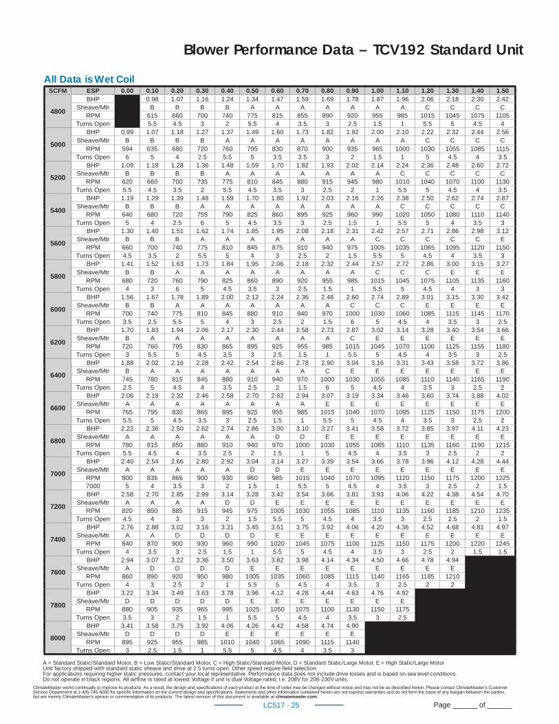
ClimateMaster works continually to improve its products. As a result, the design and specifi cations of each product at the time of order may be changed without notice and may not be as described herein. Please contact ClimateMaster's Customer Service Department at 1-405-745-6000 for specifi c information on the current design and specifi cations. Statements and other information contained herein are not express warranties and do not form the basis of any bargain between the parties, but are merely ClimateMaster's opinion or commendation of its products. The latest version of this document is available at climatemaster.com.
Page ______ of ______LC517 - 25
Blower Performance Data – TCV192 Standard Unit
A = Standard Static/Standard Motor, B = Low Static/Standard Motor, C = High Static/Standard Motor, D = Standard Static/Large Motor, E = High Static/Large MotorUnit factory shipped with standard static sheave and drive at 2.5 turns open. Other speed require fi eld selection.For applications requiring higher static pressures, contact your local representative. Performance data does not include drive losses and is based on sea level conditions.Do not operate in black regions. All airfl ow is rated at lowest Voltage if unit is dual Voltage rated, i.e. 208V for 208-230V units.
SCFM ESP 0.00 0.10 0.20 0.30 0.40 0.50 0.60 0.70 0.80 0.90 1.00 1.10 1.20 1.30 1.40 1.50
4800
BHP 0.98 1.07 1.16 1.24 1.34 1.47 1.59 1.69 1.78 1.87 1.96 2.06 2.18 2.30 2.42Sheave/Mtr B B B B A A A A A A A C C C C
RPM 615 660 700 740 775 815 855 890 920 955 985 1015 1045 1075 1105Turns Open 5.5 4.5 3 2 5.5 4 3.5 3 2.5 1.5 1 5.5 5 4.5 4
5000
BHP 0.99 1.07 1.18 1.27 1.37 1.49 1.60 1.73 1.82 1.92 2.00 2.10 2.22 2.32 2.44 2.56Sheave/Mtr B B B B A A A A A A A A C C C C
RPM 594 635 680 720 760 795 830 870 900 935 965 1000 1030 1055 1085 1115Turns Open 6 5 4 2.5 5.5 5 3.5 3.5 3 2 1.5 1 5 4.5 4 3.5
5200
BHP 1.09 1.18 1.28 1.36 1.48 1.59 1.70 1.82 1.93 2.02 2.14 2.24 2.36 2.48 2.60 2.72Sheave/Mtr B B B B A A A A A A A C C C C C
RPM 620 660 700 735 775 810 845 880 915 945 980 1010 1040 1070 1100 1130Turns Open 5.5 4.5 3.5 2 5.5 4.5 3.5 3 2.5 2 1 5.5 5 4.5 4 3.5
5400
BHP 1.19 1.29 1.39 1.48 1.59 1.70 1.80 1.92 2.03 2.16 2.26 2.38 2.50 2.62 2.74 2.87Sheave/Mtr B B B A A A A A A A A C C C C C
RPM 640 680 720 755 790 825 860 895 925 960 990 1020 1050 1080 1110 1140Turns Open 5 4 2.5 6 5 4.5 3.5 3 2.5 1.5 1 5.5 5 4 3.5 3
5600
BHP 1.30 1.40 1.51 1.62 1.74 1.85 1.95 2.08 2.18 2.31 2.42 2.57 2.71 2.86 2.98 3.12Sheave/Mtr B B B A A A A A A A C C C C C E
RPM 660 700 740 775 810 845 875 910 940 975 1005 1035 1065 1095 1120 1150Turns Open 4.5 3.5 2 5.5 5 4 3 2.5 2 1.5 5.5 5 4.5 4 3.5 3
5800
BHP 1.41 1.52 1.63 1.73 1.84 1.95 2.06 2.18 2.32 2.44 2.57 2.72 2.86 3.00 3.15 3.27Sheave/Mtr B B A A A A A A A A C C C E E E
RPM 680 720 760 790 825 860 890 920 955 985 1015 1045 1075 1105 1135 1160Turns Open 4 3 6 5 4.5 3.5 3 2.5 1.5 1 5.5 5 4.5 4 3 3
6000
BHP 1.56 1.67 1.78 1.89 2.00 2.12 2.24 2.36 2.48 2.60 2.74 2.89 3.01 3.15 3.30 3.42Sheave/Mtr B B A A A A A A A C C C E E E E
RPM 700 740 775 810 845 880 910 940 970 1000 1030 1060 1085 1115 1145 1170Turns Open 3.5 2.5 5.5 5 4 3 2.5 2 1.5 6 5 4.5 4 3.5 3 2.5
6200
BHP 1.70 1.83 1.94 2.06 2.17 2.30 2.44 2.58 2.73 2.87 3.02 3.14 3.28 3.40 3.54 3.66Sheave/Mtr B A A A A A A A A C E E E E E E
RPM 720 760 795 830 865 895 925 955 985 1015 1045 1070 1100 1125 1155 1180Turns Open 3 5.5 5 4.5 3.5 3 2.5 1.5 1 5.5 5 4.5 4 3.5 3 2.5
6400
BHP 1.88 2.02 2.16 2.28 2.42 2.54 2.66 2.78 2.90 3.04 3.16 3.31 3.43 3.58 3.72 3.86Sheave/Mtr B A A A A A A A C E E E E E E E
RPM 745 780 815 845 880 910 940 970 1000 1030 1055 1085 1110 1140 1165 1190Turns Open 2.5 5 4.5 4 3.5 2.5 2 1.5 6 5 4.5 4 3.5 3 2.5 2
6600
BHP 2.06 2.18 2.32 2.46 2.58 2.70 2.82 2.94 3.07 3.19 3.34 3.46 3.60 3.74 3.88 4.02Sheave/Mtr A A A A A A A A E E E E E E E E
RPM 765 795 830 865 895 925 955 985 1015 1040 1070 1095 1125 1150 1175 1200Turns Open 5.5 5 4.5 3.5 3 2.5 1.5 1 5.5 5 4.5 4 3.5 3 2.5 2
6800
BHP 2.22 2.36 2.50 2.62 2.74 2.86 3.00 3.10 3.27 3.41 3.58 3.72 3.85 3.97 4.11 4.23Sheave/Mtr A A A A A A D D E E E E E E E E
RPM 780 815 850 880 910 940 970 1000 1030 1055 1085 1110 1135 1160 1190 1215Turns Open 5.5 4.5 4 3.5 2.5 2 1.5 1 5 4.5 4 3.5 3 2.5 2 2
7000
BHP 2.40 2.54 2.66 2.80 2.92 3.04 3.14 3.27 3.39 3.54 3.66 3.78 3.96 4.12 4.28 4.44Sheave/Mtr A A A A A D D E E E E E E E E E
RPM 800 835 865 900 930 960 985 1015 1040 1070 1095 1120 1150 1175 1200 12257000 5 4 3.5 3 2 1.5 1 5.5 5 4.5 4 3.5 3 2.5 2 1.5
7200
BHP 2.58 2.70 2.85 2.99 3.14 3.28 3.42 3.54 3.66 3.81 3.93 4.06 4.22 4.38 4.54 4.70Sheave/Mtr A A A A D D E E E E E E E E E E
RPM 820 850 885 915 945 975 1005 1030 1055 1085 1110 1135 1160 1185 1210 1235Turns Open 4.5 4 3 3 2 1.5 5.5 5 4.5 4 3.5 3 2.5 2.5 2 1.5
7400
BHP 2.76 2.88 3.02 3.16 3.31 3.45 3.61 3.75 3.92 4.06 4.20 4.36 4.52 4.68 4.81 4.97Sheave/Mtr A A D D D D E E E E E E E E E E
RPM 840 870 900 930 960 990 1020 1045 1075 1100 1125 1150 1175 1200 1220 1245Turns Open 4 3.5 3 2.5 1.5 1 5.5 5 4.5 4 3.5 3 2.5 2 1.5 1.5
7600
BHP 2.94 3.07 3.22 3.36 3.50 3.63 3.82 3.98 4.14 4.34 4.50 4.66 4.78 4.94Sheave/Mtr A D D D D E E E E E E E E E
RPM 860 890 920 950 980 1005 1035 1060 1085 1115 1140 1165 1185 1210Turns Open 4 3 2.5 2 1 5.5 5 4.5 4 3.5 3 2.5 2 2
7800
BHP 3.22 3.34 3.49 3.63 3.78 3.96 4.12 4.28 4.44 4.63 4.76 4.92Sheave/Mtr D D D D D E E E E E E E
RPM 880 905 935 965 995 1025 1050 1075 1100 1130 1150 1175Turns Open 3.5 3 2 1.5 1 5.5 5 4.5 4 3.5 3 2.5
8000
BHP 3.41 3.58 3.75 3.92 4.06 4.26 4.42 4.58 4.74 4.90Sheave/Mtr D D D D E E E E E E
RPM 895 925 955 985 1010 1040 1065 1090 1115 1140Turns Open 3 2.5 1.5 1 5.5 5 4.5 4 3.5 3
All Data is Wet Coil
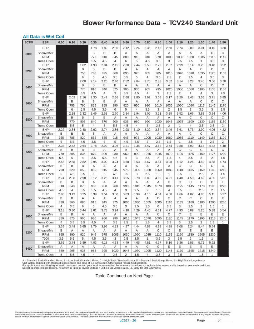
ClimateMaster works continually to improve its products. As a result, the design and specifi cations of each product at the time of order may be changed without notice and may not be as described herein. Please contact ClimateMaster's Customer Service Department at 1-405-745-6000 for specifi c information on the current design and specifi cations. Statements and other information contained herein are not express warranties and do not form the basis of any bargain between the parties, but are merely ClimateMaster's opinion or commendation of its products. The latest version of this document is available at climatemaster.com.
Page ______ of ______LC517 - 26
Blower Performance Data – TCV240 Standard Unit
All Data is Wet CoilSCFM ESP 0.00 0.10 0.20 0.30 0.40 0.50 0.60 0.70 0.80 0.90 1.00 1.10 1.20 1.30 1.40 1.50
6000
BHP 1.78 1.89 2.00 2.12 2.24 2.36 2.48 2.60 2.74 2.89 3.01 3.15 3.30
Sheave/Mtr B B B A A A A A A A A C CRPM 775 810 845 880 910 940 970 1000 1030 1060 1085 1115 1145
Turns Open 5.5 4.5 4 6 5 4.5 3.5 3 2.5 1.5 1 3.5 3
6200
BHP 1.82 1.93 2.04 2.15 2.30 2.44 2.58 2.73 2.87 2.99 3.14 3.26 3.40 3.52Sheave/Mtr B B B B A A A A A A A C C C
RPM 755 790 825 860 895 925 955 985 1015 1040 1070 1095 1125 1150Turns Open 6 5 4.5 3.5 5.5 5 4 3.5 2.5 2 1.5 4 3.5 3
6400
BHP 2.00 2.14 2.26 2.40 2.52 2.64 2.76 2.88 3.02 3.14 3.28 3.40 3.56 3.70Sheave/Mtr B B B B A A A A A A A C C C
RPM 775 810 840 875 905 935 965 995 1025 1050 1080 1105 1135 1160Turns Open 5.5 4.5 4 3 5.5 4.5 4 3 2.5 2 1 4 3 2.5
6600
BHP 2.02 2.16 2.30 2.42 2.56 2.68 2.80 2.92 3.05 3.17 3.29 3.43 3.55 3.71 3.85Sheave/Mtr B B B B A A A A A A A A C C C
RPM 755 790 825 855 890 920 950 980 1010 1035 1060 1090 1115 1145 1170Turns Open 6 5.5 4.5 3.5 6 5 4 3.5 3 2 1.5 1 3.5 3 2.5
6800
BHP 2.18 2.32 2.46 2.58 2.70 2.84 2.94 3.06 3.21 3.35 3.52 3.66 3.82 3.94 4.06Sheave/Mtr B B B B A A A A A A A C C C C
RPM 770 805 840 870 900 935 960 990 1020 1045 1075 1100 1130 1155 1180Turns Open 5.5 5 4 3 5.5 4.5 4 3 2.5 2 1 4 3.5 2.5 2
7000
BHP 2.22 2.34 2.48 2.62 2.74 2.86 2.98 3.10 3.22 3.34 3.49 3.61 3.73 3.90 4.06 4.22Sheave/Mtr B B B B A A A A A A A A C C C C
RPM 755 785 820 855 885 915 945 975 1005 1030 1060 1085 1110 1140 1165 1190Turns Open 6 5.5 4.5 3.5 6 5 4.5 3.5 3 2.5 1.5 1 3.5 3 2.5 2
7200
BHP 2.38 2.52 2.64 2.78 2.92 3.06 3.21 3.35 3.47 3.62 3.74 3.88 4.00 4.16 4.32 4.48Sheave/Mtr B B B B A A A A A A A C C C C C
RPM 770 805 835 870 900 930 960 990 1015 1045 1070 1100 1125 1150 1175 1200Turns Open 5.5 5 4 3.5 5.5 4.5 4 3 2.5 2 1.5 4 3.5 3 2 1.5
7400
BHP 2.56 2.68 2.82 2.95 3.09 3.24 3.38 3.53 3.67 3.84 3.98 4.12 4.26 4.42 4.58 4.74Sheave/Mtr B B B A A A A A A A A C C C C C
RPM 790 820 855 885 915 945 975 1005 1030 1060 1085 1110 1135 1160 1185 1210Turns Open 5 4.5 3.5 6 5 4.5 3.5 3 2.5 1.5 1 3.5 3 2.5 2 1.5
7600
BHP 2.74 2.86 2.98 3.12 3.26 3.41 3.55 3.70 3.89 4.05 4.21 4.40 4.53 4.69 4.85 5.01Sheave/Mtr B B B A A A A A A A C C C C C E
RPM 810 840 870 900 930 960 990 1015 1045 1070 1095 1125 1145 1170 1195 1220Turns Open 4.5 4 3.5 5.5 4.5 4 3 2.5 2 1.5 4 3.5 3 2.5 2 1.5
7800
BHP 2.98 3.13 3.25 3.39 3.54 3.68 3.83 3.99 4.15 4.34 4.50 4.66 4.82 4.95 5.11 5.27Sheave/Mtr B B A A A A A A A C C C C C E E
RPM 830 860 885 915 945 975 1005 1030 1055 1085 1110 1135 1160 1180 1205 1230Turns Open 4 3.5 6 5 4.5 3.5 3 2.5 1.5 0 3.5 3 2.5 2 1.5 1
8000
BHP 3.18 3.30 3.44 3.61 3.78 3.94 4.10 4.29 4.45 4.61 4.77 4.93 5.09 5.25 5.38 5.54Sheave/Mtr B B A A A A A A A C C C E E E E
RPM 850 875 900 930 960 990 1015 1045 1070 1095 1120 1145 1170 1195 1215 1240Turns Open 4 3.5 5.5 4.5 4 3.5 2.5 2 1.5 4 3.5 3 2.5 2 1.5 1
8200
BHP 3.35 3.48 3.65 3.79 3.96 4.13 4.27 4.44 4.58 4.72 4.88 5.08 5.24 5.44 5.64Sheave/Mtr B A A A A A A A A C C E E E E
RPM 865 890 920 945 975 1005 1030 1060 1085 1110 1135 1160 1180 1205 12307000 3.5 5.5 5 4.5 3.5 3 2.5 1.5 1 3.5 3 2.5 2 1.5 1
8400
BHP 3.62 3.74 3.89 4.03 4.18 4.33 4.49 4.65 4.81 4.97 5.16 5.36 5.56 5.72 5.92Sheave/Mtr A A A A A A A A C C E E E E E
RPM 880 905 935 965 995 1020 1045 1070 1095 1120 1145 1170 1195 1215 1240Turns Open 6 5.5 4.5 4 3 2.5 2 1.5 4 3.5 3 2.5 2 1.5 1
Table Continued on Next Page
A = Standard Static/Standard Motor, B = Low Static/Standard Motor, C = High Static/Standard Motor, D = Standard Static/Large Motor, E = High Static/Large MotorUnit factory shipped with standard static sheave and drive at 2.5 turns open. Other speed require fi eld selection.For applications requiring higher static pressures, contact your local representative. Performance data does not include drive losses and is based on sea level conditions.Do not operate in black regions. All airfl ow is rated at lowest Voltage if unit is dual Voltage rated, i.e. 208V for 208-230V units.
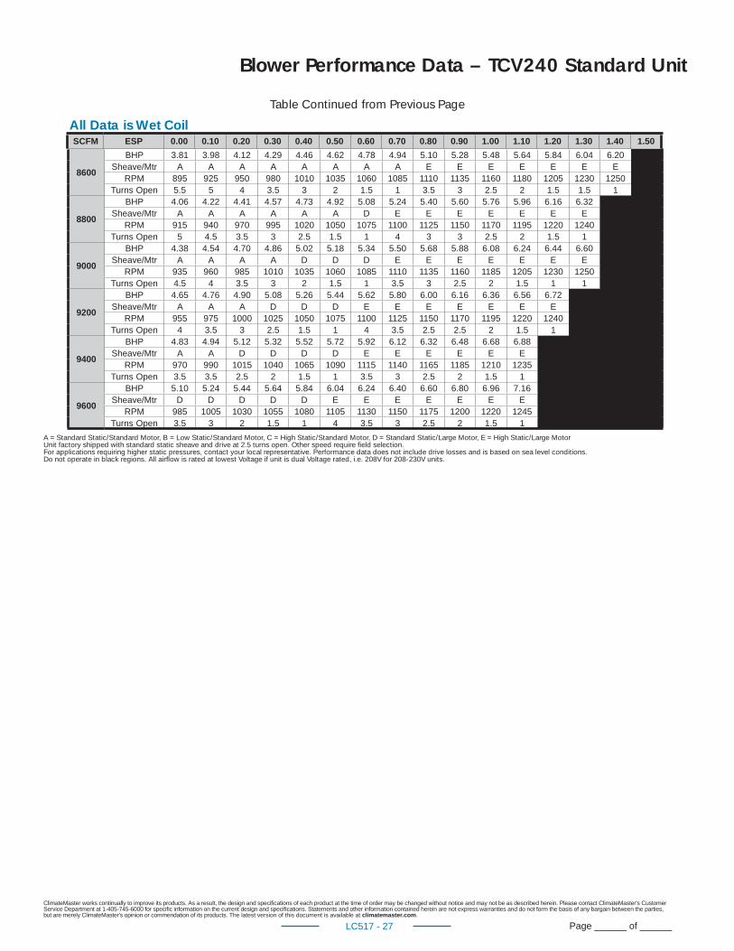
ClimateMaster works continually to improve its products. As a result, the design and specifi cations of each product at the time of order may be changed without notice and may not be as described herein. Please contact ClimateMaster's Customer Service Department at 1-405-745-6000 for specifi c information on the current design and specifi cations. Statements and other information contained herein are not express warranties and do not form the basis of any bargain between the parties, but are merely ClimateMaster's opinion or commendation of its products. The latest version of this document is available at climatemaster.com.
Page ______ of ______LC517 - 27
Blower Performance Data – TCV240 Standard Unit
8600
BHP 3.81 3.98 4.12 4.29 4.46 4.62 4.78 4.94 5.10 5.28 5.48 5.64 5.84 6.04 6.20Sheave/Mtr A A A A A A A A E E E E E E E
RPM 895 925 950 980 1010 1035 1060 1085 1110 1135 1160 1180 1205 1230 1250Turns Open 5.5 5 4 3.5 3 2 1.5 1 3.5 3 2.5 2 1.5 1.5 1
8800
BHP 4.06 4.22 4.41 4.57 4.73 4.92 5.08 5.24 5.40 5.60 5.76 5.96 6.16 6.32Sheave/Mtr A A A A A A D E E E E E E E
RPM 915 940 970 995 1020 1050 1075 1100 1125 1150 1170 1195 1220 1240Turns Open 5 4.5 3.5 3 2.5 1.5 1 4 3 3 2.5 2 1.5 1
9000
BHP 4.38 4.54 4.70 4.86 5.02 5.18 5.34 5.50 5.68 5.88 6.08 6.24 6.44 6.60Sheave/Mtr A A A A D D D E E E E E E E
RPM 935 960 985 1010 1035 1060 1085 1110 1135 1160 1185 1205 1230 1250Turns Open 4.5 4 3.5 3 2 1.5 1 3.5 3 2.5 2 1.5 1 1
9200
BHP 4.65 4.76 4.90 5.08 5.26 5.44 5.62 5.80 6.00 6.16 6.36 6.56 6.72Sheave/Mtr A A A D D D E E E E E E E
RPM 955 975 1000 1025 1050 1075 1100 1125 1150 1170 1195 1220 1240Turns Open 4 3.5 3 2.5 1.5 1 4 3.5 2.5 2.5 2 1.5 1
9400
BHP 4.83 4.94 5.12 5.32 5.52 5.72 5.92 6.12 6.32 6.48 6.68 6.88Sheave/Mtr A A D D D D E E E E E E
RPM 970 990 1015 1040 1065 1090 1115 1140 1165 1185 1210 1235Turns Open 3.5 3.5 2.5 2 1.5 1 3.5 3 2.5 2 1.5 1
9600
BHP 5.10 5.24 5.44 5.64 5.84 6.04 6.24 6.40 6.60 6.80 6.96 7.16Sheave/Mtr D D D D D E E E E E E E
RPM 985 1005 1030 1055 1080 1105 1130 1150 1175 1200 1220 1245Turns Open 3.5 3 2 1.5 1 4 3.5 3 2.5 2 1.5 1
A = Standard Static/Standard Motor, B = Low Static/Standard Motor, C = High Static/Standard Motor, D = Standard Static/Large Motor, E = High Static/Large MotorUnit factory shipped with standard static sheave and drive at 2.5 turns open. Other speed require fi eld selection.For applications requiring higher static pressures, contact your local representative. Performance data does not include drive losses and is based on sea level conditions.Do not operate in black regions. All airfl ow is rated at lowest Voltage if unit is dual Voltage rated, i.e. 208V for 208-230V units.
All Data is Wet CoilTable Continued from Previous Page
SCFM ESP 0.00 0.10 0.20 0.30 0.40 0.50 0.60 0.70 0.80 0.90 1.00 1.10 1.20 1.30 1.40 1.50
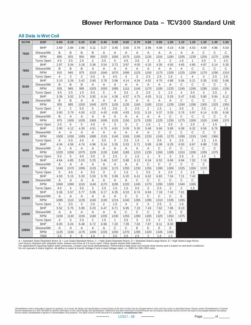
ClimateMaster works continually to improve its products. As a result, the design and specifi cations of each product at the time of order may be changed without notice and may not be as described herein. Please contact ClimateMaster's Customer Service Department at 1-405-745-6000 for specifi c information on the current design and specifi cations. Statements and other information contained herein are not express warranties and do not form the basis of any bargain between the parties, but are merely ClimateMaster's opinion or commendation of its products. The latest version of this document is available at climatemaster.com.
Page ______ of ______LC517 - 28
Blower Performance Data – TCV300 Standard Unit
SCFM ESP 0.00 0.10 0.20 0.30 0.40 0.50 0.60 0.70 0.80 0.90 1.00 1.10 1.20 1.30 1.40 1.50
7500
BHP 2.69 2.84 2.96 3.11 3.27 3.45 3.60 3.78 3.96 4.08 4.23 4.38 4.53 4.69 4.86 5.03
Sheave/Mtr B B B B A A A A A A A A A C C CRPM 890 925 955 990 1020 1050 1075 1105 1135 1155 1180 1205 1230 1255 1275 1295
Turns Open 4.5 3.5 2.5 2 5.5 5 4.5 3.5 3 3 2 1.5 1 3.5 3 2.5
7800
BHP 2.87 3.04 3.18 3.36 3.54 3.72 3.87 4.05 4.20 4.35 4.50 4.65 4.80 4.97 5.14 5.30Sheave/Mtr B B B A A A A A A A A A C C C C
RPM 910 945 975 1010 1040 1070 1095 1125 1150 1175 1200 1225 1250 1270 1290 1310Turns Open 4 3 2 5.5 5 4.5 4 3 2.5 2.5 1.5 1 4 3 2.5 2.5
8100
BHP 3.10 3.26 3.42 3.60 3.78 3.96 4.14 4.34 4.52 4.70 4.88 5.06 5.21 5.35 5.53 5.68Sheave/Mtr B B B A A A A A A A A C C C C C
RPM 935 965 995 1025 1055 1085 1115 1145 1170 1195 1220 1245 1265 1285 1310 1330Turns Open 3.5 2.5 1.5 5.5 5 4 3.5 3 2.5 2 1.5 4 3.5 3 2.5 2
8400
BHP 3.36 3.52 3.74 3.92 4.14 4.36 4.57 4.75 4.93 5.11 5.29 5.47 5.62 5.80 5.94 6.12Sheave/Mtr B B A A A A A A A A A C C C C C
RPM 955 985 1020 1045 1075 1105 1135 1160 1185 1210 1235 1260 1280 1305 1325 1350Turns Open 3 2 5.5 5 4.5 3.5 3 2.5 2 1.5 1 3.5 3 2.5 2 1.5
8700
BHP 3.60 3.79 4.00 4.22 4.43 4.65 4.83 5.01 5.19 5.37 5.55 5.76 5.97 6.14 6.35 6.56Sheave/Mtr B A A A A A A A A A C C C C C C
RPM 975 1005 1035 1065 1095 1125 1150 1175 1200 1225 1250 1275 1300 1320 1345 1370Turns Open 2.5 6 5 4.5 4 3 3 2 1.5 1 3.5 3 2.5 2 1.5 1
9000
BHP 3.90 4.12 4.30 4.51 4.73 4.91 5.09 5.30 5.48 5.66 5.89 6.08 6.32 6.56 6.76Sheave/Mtr A A A A A A A A A C C C C C C
RPM 1000 1030 1055 1085 1115 1140 1165 1195 1220 1245 1270 1290 1315 1340 1360Turns Open 6 5.5 4.5 4 3.5 3 2.5 1.5 1 3.5 3 2.5 2 1.5 1.5
9300
BHP 4.34 4.56 4.74 4.96 5.14 5.35 5.53 5.71 5.89 6.08 6.29 6.50 6.67 6.88 7.05Sheave/Mtr A A A A A A A A A C C C C C C
RPM 1020 1050 1075 1105 1130 1160 1185 1210 1235 1260 1285 1310 1330 1355 1375Turns Open 5.5 5 4.5 3.5 3 2.5 2 1.5 1 3 3 2.5 2 1.5 1
9600
BHP 4.64 4.85 5.03 5.25 5.46 5.67 5.88 6.13 6.34 6.52 6.66 6.84 7.02 7.16Sheave/Mtr A A A A A A A A C C C C C C
RPM 1040 1070 1095 1125 1150 1175 1200 1230 1255 1280 1300 1325 1350 1370Turns Open 5 4.5 4 3.5 3 2 1.5 1 3.5 3 2.5 2 1.5 1
9900
BHP 4.93 5.15 5.33 5.53 5.78 5.99 6.20 6.41 6.62 6.83 7.04 7.21 7.42Sheave/Mtr A A A A A A A C C C C C C
RPM 1060 1090 1115 1140 1170 1195 1220 1245 1270 1295 1320 1340 1365Turns Open 4.5 4 3.5 3 2.5 1.5 1.5 3.5 3 2.5 2 2 1.5
10200
BHP 5.36 5.57 5.77 5.95 6.17 6.35 6.53 6.74 6.94 7.18 7.42 7.61Sheave/Mtr A A A A A A C C C C C E
RPM 1085 1110 1135 1160 1190 1215 1240 1265 1285 1310 1335 1355Turns Open 4 3.5 3 2.5 2 1.5 4 3 3 2.5 2 1.5
10500
BHP 5.52 5.75 5.99 6.23 6.47 6.71 6.95 7.19 7.43 7.62 7.86 8.10Sheave/Mtr A A A A A A C C C E E E
RPM 1100 1130 1155 1180 1205 1230 1255 1280 1305 1325 1350 1375Turns Open 4 3 2.5 2 1.5 1 3.5 3 2.5 2 1.5 1
10800
BHP 6.00 6.24 6.48 6.72 6.96 7.20 7.39 7.63 7.87 8.11 8.30Sheave/Mtr A A A A A C C E E E E
RPM 1125 1150 1175 1200 1225 1250 1270 1295 1320 1345 13657000 3.5 3 5 1.5 1 3.5 3.5 2.5 2 1.5 1.5
All Data is Wet Coil
A = Standard Static/Standard Motor, B = Low Static/Standard Motor, C = High Static/Standard Motor, D = Standard Static/Large Motor, E = High Static/Large MotorUnit factory shipped with standard static sheave and drive at 2.5 turns open. Other speed require fi eld selection.For applications requiring higher static pressures, contact your local representative. Performance data does not include drive losses and is based on sea level conditions.Do not operate in black regions. All airfl ow is rated at lowest Voltage if unit is dual Voltage rated, i.e. 208V for 208-230V units.
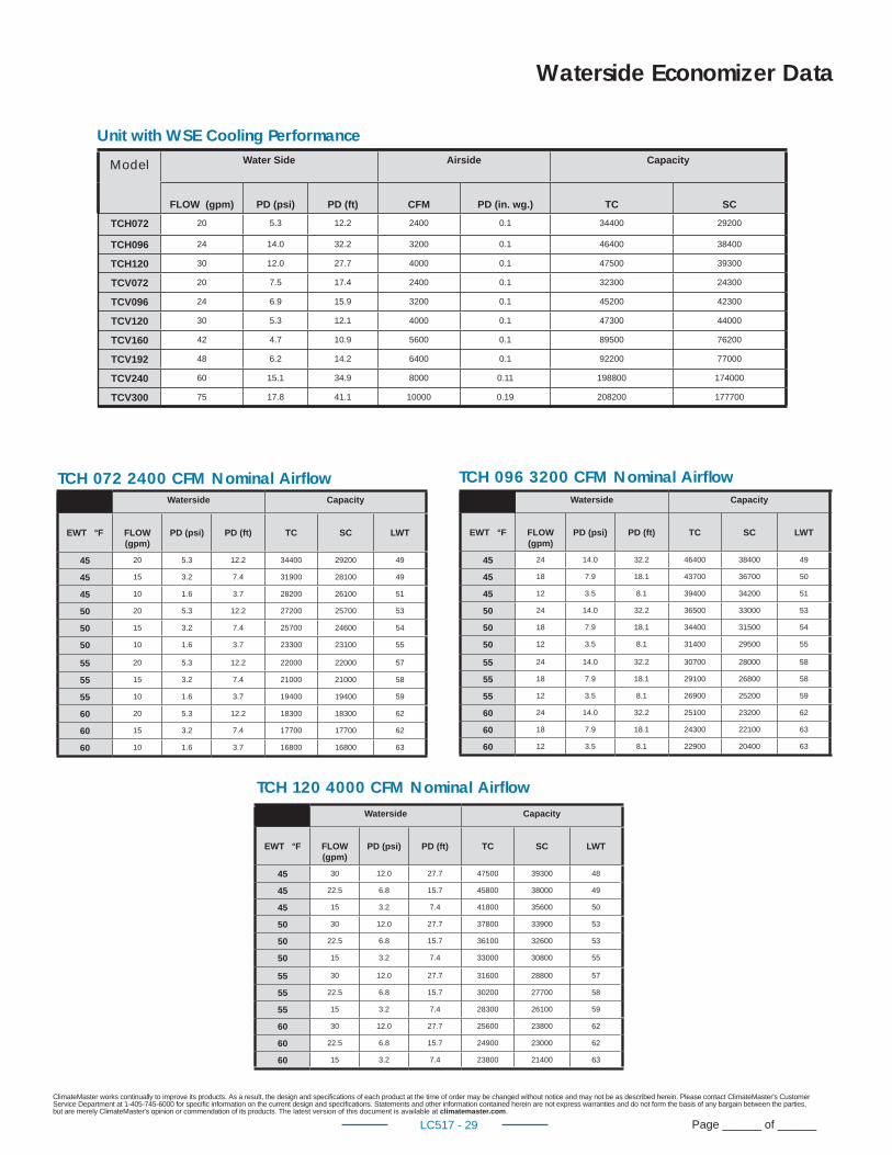
ClimateMaster works continually to improve its products. As a result, the design and specifi cations of each product at the time of order may be changed without notice and may not be as described herein. Please contact ClimateMaster's Customer Service Department at 1-405-745-6000 for specifi c information on the current design and specifi cations. Statements and other information contained herein are not express warranties and do not form the basis of any bargain between the parties, but are merely ClimateMaster's opinion or commendation of its products. The latest version of this document is available at climatemaster.com.
Page ______ of ______LC517 - 29
Waterside Capacity
EWT °F FLOW (gpm)
PD (psi) PD (ft) TC SC LWT
45 24 14.0 32.2 46400 38400 49
45 18 7.9 18.1 43700 36700 50
45 12 3.5 8.1 39400 34200 51
50 24 14.0 32.2 36500 33000 53
50 18 7.9 18.1 34400 31500 54
50 12 3.5 8.1 31400 29500 55
55 24 14.0 32.2 30700 28000 58
55 18 7.9 18.1 29100 26800 58
55 12 3.5 8.1 26900 25200 59
60 24 14.0 32.2 25100 23200 62
60 18 7.9 18.1 24300 22100 63
60 12 3.5 8.1 22900 20400 63
Model Water Side Airside Capacity
FLOW (gpm) PD (psi) PD (ft) CFM PD (in. wg.) TC SC
TCH072 20 5.3 12.2 2400 0.1 34400 29200
TCH096 24 14.0 32.2 3200 0.1 46400 38400
TCH120 30 12.0 27.7 4000 0.1 47500 39300
TCV072 20 7.5 17.4 2400 0.1 32300 24300
TCV096 24 6.9 15.9 3200 0.1 45200 42300
TCV120 30 5.3 12.1 4000 0.1 47300 44000
TCV160 42 4.7 10.9 5600 0.1 89500 76200
TCV192 48 6.2 14.2 6400 0.1 92200 77000
TCV240 60 15.1 34.9 8000 0.11 198800 174000
TCV300 75 17.8 41.1 10000 0.19 208200 177700
Unit with WSE Cooling Performance
Waterside Economizer Data
Waterside Capacity
EWT °F FLOW (gpm)
PD (psi) PD (ft) TC SC LWT
45 20 5.3 12.2 34400 29200 49
45 15 3.2 7.4 31900 28100 49
45 10 1.6 3.7 28200 26100 51
50 20 5.3 12.2 27200 25700 53
50 15 3.2 7.4 25700 24600 54
50 10 1.6 3.7 23300 23100 55
55 20 5.3 12.2 22000 22000 57
55 15 3.2 7.4 21000 21000 58
55 10 1.6 3.7 19400 19400 59
60 20 5.3 12.2 18300 18300 62
60 15 3.2 7.4 17700 17700 62
60 10 1.6 3.7 16800 16800 63
TCH 072 2400 CFM Nominal Airfl ow TCH 096 3200 CFM Nominal Airfl ow
Waterside Capacity
EWT °F FLOW (gpm)
PD (psi) PD (ft) TC SC LWT
45 30 12.0 27.7 47500 39300 48
45 22.5 6.8 15.7 45800 38000 49
45 15 3.2 7.4 41800 35600 50
50 30 12.0 27.7 37800 33900 53
50 22.5 6.8 15.7 36100 32600 53
50 15 3.2 7.4 33000 30800 55
55 30 12.0 27.7 31600 28800 57
55 22.5 6.8 15.7 30200 27700 58
55 15 3.2 7.4 28300 26100 59
60 30 12.0 27.7 25600 23800 62
60 22.5 6.8 15.7 24900 23000 62
60 15 3.2 7.4 23800 21400 63
TCH 120 4000 CFM Nominal Airfl ow
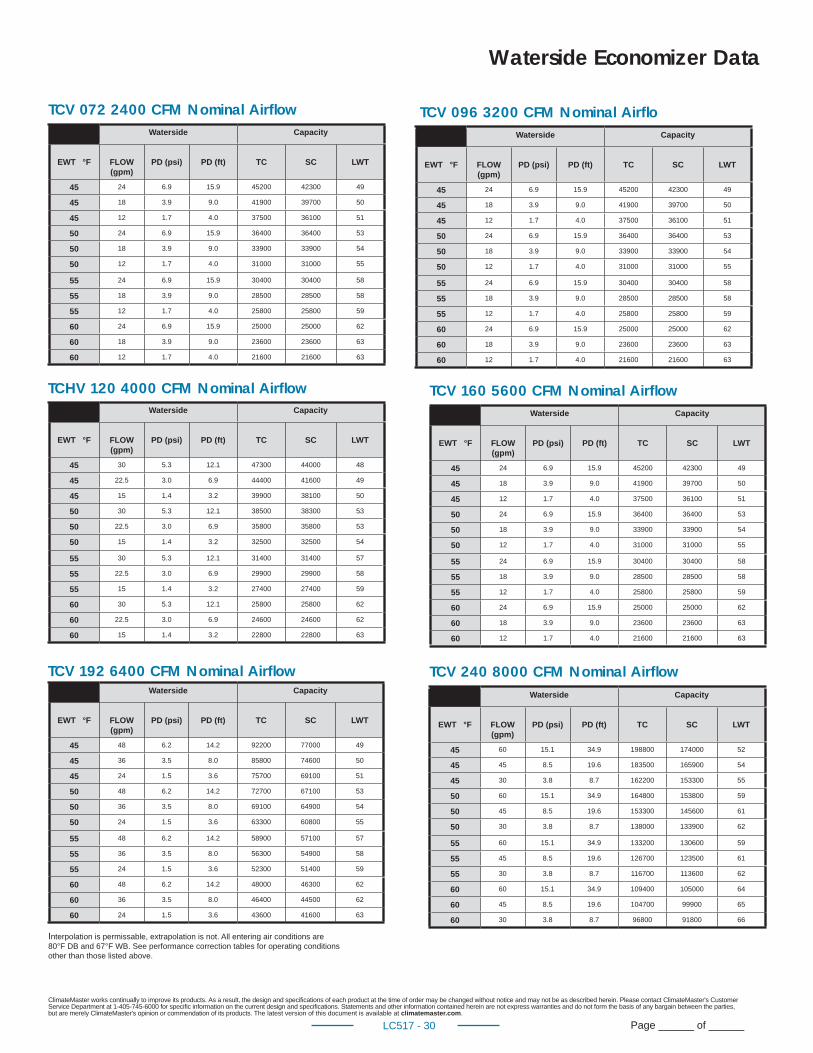
ClimateMaster works continually to improve its products. As a result, the design and specifi cations of each product at the time of order may be changed without notice and may not be as described herein. Please contact ClimateMaster's Customer Service Department at 1-405-745-6000 for specifi c information on the current design and specifi cations. Statements and other information contained herein are not express warranties and do not form the basis of any bargain between the parties, but are merely ClimateMaster's opinion or commendation of its products. The latest version of this document is available at climatemaster.com.
Page ______ of ______LC517 - 30
Waterside Capacity
EWT °F FLOW (gpm)
PD (psi) PD (ft) TC SC LWT
45 24 6.9 15.9 45200 42300 49
45 18 3.9 9.0 41900 39700 50
45 12 1.7 4.0 37500 36100 51
50 24 6.9 15.9 36400 36400 53
50 18 3.9 9.0 33900 33900 54
50 12 1.7 4.0 31000 31000 55
55 24 6.9 15.9 30400 30400 58
55 18 3.9 9.0 28500 28500 58
55 12 1.7 4.0 25800 25800 59
60 24 6.9 15.9 25000 25000 62
60 18 3.9 9.0 23600 23600 63
60 12 1.7 4.0 21600 21600 63
Waterside Capacity
EWT °F FLOW (gpm)
PD (psi) PD (ft) TC SC LWT
45 60 15.1 34.9 198800 174000 52
45 45 8.5 19.6 183500 165900 54
45 30 3.8 8.7 162200 153300 55
50 60 15.1 34.9 164800 153800 59
50 45 8.5 19.6 153300 145600 61
50 30 3.8 8.7 138000 133900 62
55 60 15.1 34.9 133200 130600 59
55 45 8.5 19.6 126700 123500 61
55 30 3.8 8.7 116700 113600 62
60 60 15.1 34.9 109400 105000 64
60 45 8.5 19.6 104700 99900 65
60 30 3.8 8.7 96800 91800 66
Waterside Capacity
EWT °F FLOW (gpm)
PD (psi) PD (ft) TC SC LWT
45 30 5.3 12.1 47300 44000 48
45 22.5 3.0 6.9 44400 41600 49
45 15 1.4 3.2 39900 38100 50
50 30 5.3 12.1 38500 38300 53
50 22.5 3.0 6.9 35800 35800 53
50 15 1.4 3.2 32500 32500 54
55 30 5.3 12.1 31400 31400 57
55 22.5 3.0 6.9 29900 29900 58
55 15 1.4 3.2 27400 27400 59
60 30 5.3 12.1 25800 25800 62
60 22.5 3.0 6.9 24600 24600 62
60 15 1.4 3.2 22800 22800 63
Waterside Economizer Data
TCHV 120 4000 CFM Nominal Airfl ow TCV 160 5600 CFM Nominal Airfl ow
Interpolation is permissable, extrapolation is not. All entering air conditions are 80°F DB and 67°F WB. See performance correction tables for operating conditionsother than those listed above.
Waterside Capacity
EWT °F FLOW (gpm)
PD (psi) PD (ft) TC SC LWT
45 48 6.2 14.2 92200 77000 49
45 36 3.5 8.0 85800 74600 50
45 24 1.5 3.6 75700 69100 51
50 48 6.2 14.2 72700 67100 53
50 36 3.5 8.0 69100 64900 54
50 24 1.5 3.6 63300 60800 55
55 48 6.2 14.2 58900 57100 57
55 36 3.5 8.0 56300 54900 58
55 24 1.5 3.6 52300 51400 59
60 48 6.2 14.2 48000 46300 62
60 36 3.5 8.0 46400 44500 62
60 24 1.5 3.6 43600 41600 63
TCV 192 6400 CFM Nominal Airfl ow TCV 240 8000 CFM Nominal Airfl ow
TCV 072 2400 CFM Nominal Airfl ow TCV 096 3200 CFM Nominal Airfl o
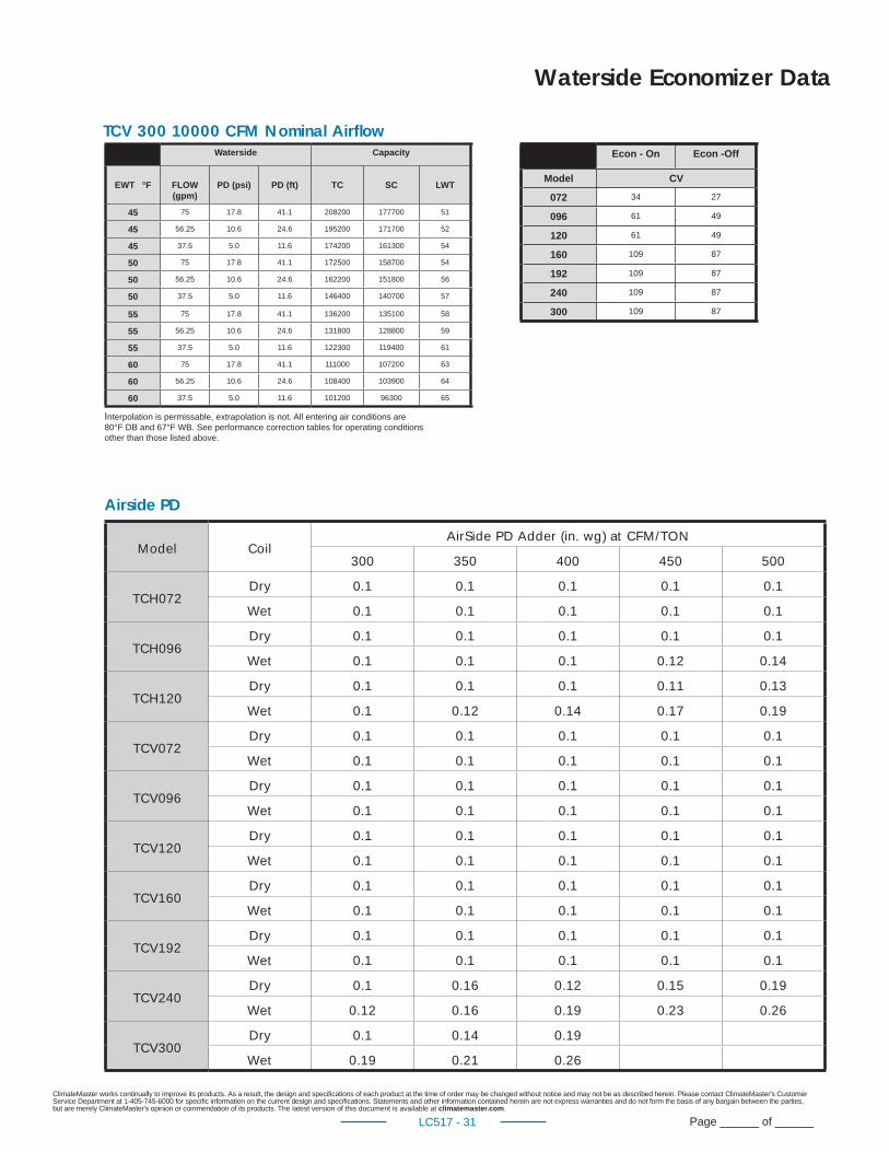
ClimateMaster works continually to improve its products. As a result, the design and specifi cations of each product at the time of order may be changed without notice and may not be as described herein. Please contact ClimateMaster's Customer Service Department at 1-405-745-6000 for specifi c information on the current design and specifi cations. Statements and other information contained herein are not express warranties and do not form the basis of any bargain between the parties, but are merely ClimateMaster's opinion or commendation of its products. The latest version of this document is available at climatemaster.com.
Page ______ of ______LC517 - 31
Waterside Capacity
EWT °F FLOW (gpm)
PD (psi) PD (ft) TC SC LWT
45 75 17.8 41.1 208200 177700 51
45 56.25 10.6 24.6 195200 171700 52
45 37.5 5.0 11.6 174200 161300 54
50 75 17.8 41.1 172500 158700 54
50 56.25 10.6 24.6 162200 151800 56
50 37.5 5.0 11.6 146400 140700 57
55 75 17.8 41.1 136200 135100 58
55 56.25 10.6 24.6 131800 128800 59
55 37.5 5.0 11.6 122300 119400 61
60 75 17.8 41.1 111000 107200 63
60 56.25 10.6 24.6 108400 103900 64
60 37.5 5.0 11.6 101200 96300 65
Waterside Economizer Data
TCV 300 10000 CFM Nominal Airfl ow
Interpolation is permissable, extrapolation is not. All entering air conditions are 80°F DB and 67°F WB. See performance correction tables for operating conditionsother than those listed above.
Econ - On Econ -Off
Model CV
072 34 27
096 61 49
120 61 49
160 109 87
192 109 87
240 109 87
300 109 87
Airside PD
Model CoilAirSide PD Adder (in. wg) at CFM/TON
300 350 400 450 500
TCH072Dry 0.1 0.1 0.1 0.1 0.1
Wet 0.1 0.1 0.1 0.1 0.1
TCH096Dry 0.1 0.1 0.1 0.1 0.1
Wet 0.1 0.1 0.1 0.12 0.14
TCH120Dry 0.1 0.1 0.1 0.11 0.13
Wet 0.1 0.12 0.14 0.17 0.19
TCV072Dry 0.1 0.1 0.1 0.1 0.1
Wet 0.1 0.1 0.1 0.1 0.1
TCV096Dry 0.1 0.1 0.1 0.1 0.1
Wet 0.1 0.1 0.1 0.1 0.1
TCV120Dry 0.1 0.1 0.1 0.1 0.1
Wet 0.1 0.1 0.1 0.1 0.1
TCV160Dry 0.1 0.1 0.1 0.1 0.1
Wet 0.1 0.1 0.1 0.1 0.1
TCV192Dry 0.1 0.1 0.1 0.1 0.1
Wet 0.1 0.1 0.1 0.1 0.1
TCV240Dry 0.1 0.16 0.12 0.15 0.19
Wet 0.12 0.16 0.19 0.23 0.26
TCV300Dry 0.1 0.14 0.19
Wet 0.19 0.21 0.26
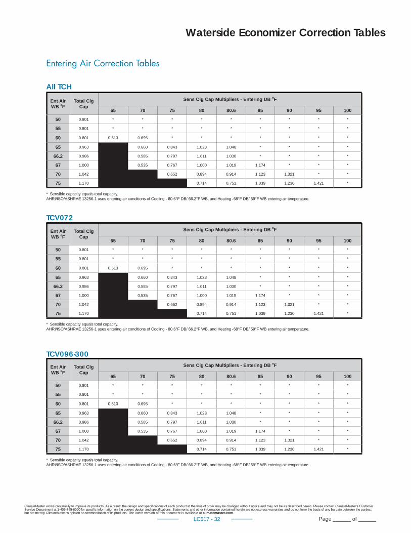
ClimateMaster works continually to improve its products. As a result, the design and specifi cations of each product at the time of order may be changed without notice and may not be as described herein. Please contact ClimateMaster's Customer Service Department at 1-405-745-6000 for specifi c information on the current design and specifi cations. Statements and other information contained herein are not express warranties and do not form the basis of any bargain between the parties, but are merely ClimateMaster's opinion or commendation of its products. The latest version of this document is available at climatemaster.com.
Page ______ of ______LC517 - 32
Entering Air Correction Tables
Ent Air WB ºF
Total Clg Cap
Sens Clg Cap Multipliers - Entering DB ºF
65 70 75 80 80.6 85 90 95 100
50 0.801 * * * * * * * * *
55 0.801 * * * * * * * * *
60 0.801 0.513 0.695 * * * * * * *
65 0.963 0.660 0.843 1.028 1.048 * * * *
66.2 0.986 0.585 0.797 1.011 1.030 * * * *
67 1.000 0.535 0.767 1.000 1.019 1.174 * * *
70 1.042 0.652 0.894 0.914 1.123 1.321 * *
75 1.170 0.714 0.751 1.039 1.230 1.421 *
* Sensible capacity equals total capacity.AHRI/ISO/ASHRAE 13256-1 uses entering air conditions of Cooling - 80.6°F DB/ 66.2°F WB, and Heating - 68°F DB/ 59°F WB entering air temperature.
Waterside Economizer Correction Tables
All TCH
TCV072
TCV096-300
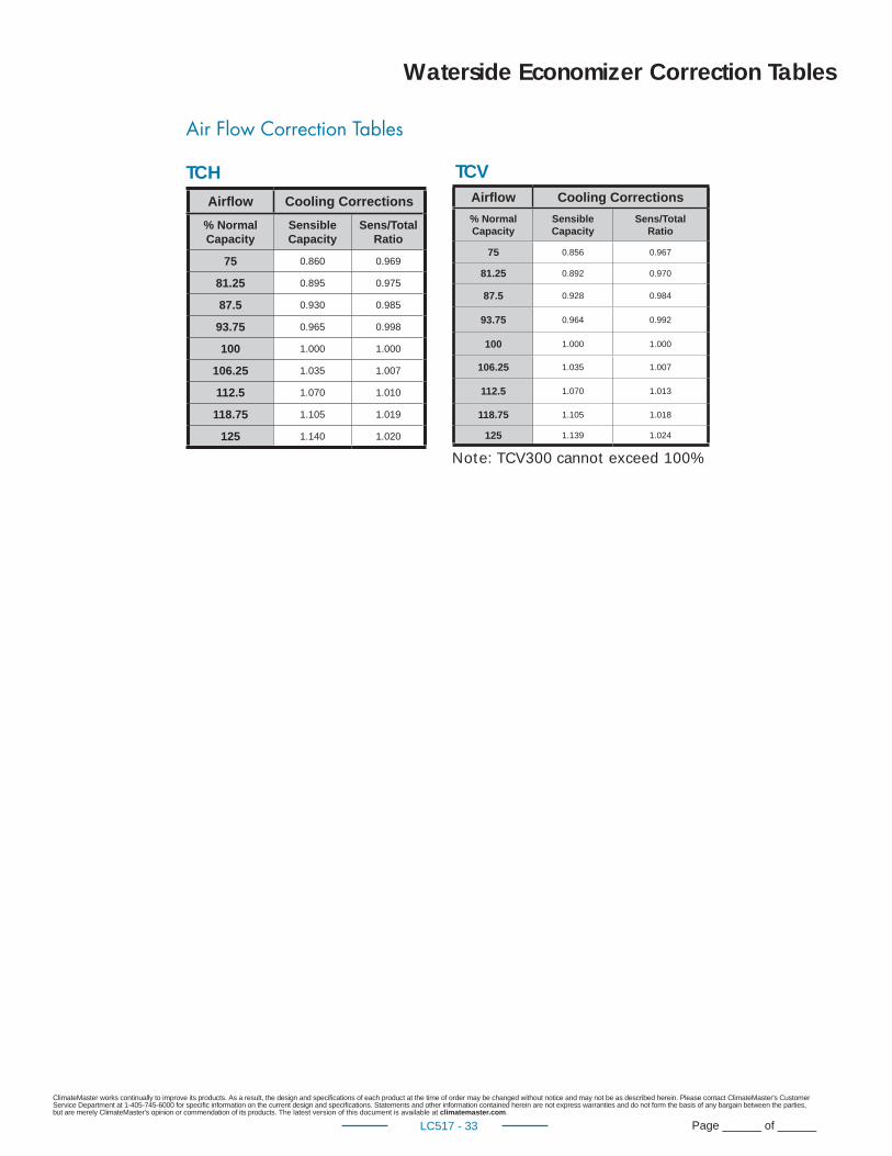
ClimateMaster works continually to improve its products. As a result, the design and specifi cations of each product at the time of order may be changed without notice and may not be as described herein. Please contact ClimateMaster's Customer Service Department at 1-405-745-6000 for specifi c information on the current design and specifi cations. Statements and other information contained herein are not express warranties and do not form the basis of any bargain between the parties, but are merely ClimateMaster's opinion or commendation of its products. The latest version of this document is available at climatemaster.com.
Page ______ of ______LC517 - 33
Air Flow Correction Tables
TCH TCVAirfl ow Cooling Corrections
% NormalCapacity
Sensible Capacity
Sens/TotalRatio
75 0.860 0.969
81.25 0.895 0.975
87.5 0.930 0.985
93.75 0.965 0.998
100 1.000 1.000
106.25 1.035 1.007
112.5 1.070 1.010
118.75 1.105 1.019
125 1.140 1.020
Note: TCV300 cannot exceed 100%
Waterside Economizer Correction Tables
Airfl ow Cooling Corrections
% NormalCapacity
Sensible Capacity
Sens/TotalRatio
75 0.856 0.967
81.25 0.892 0.970
87.5 0.928 0.984
93.75 0.964 0.992
100 1.000 1.000
106.25 1.035 1.007
112.5 1.070 1.013
118.75 1.105 1.018
125 1.139 1.024
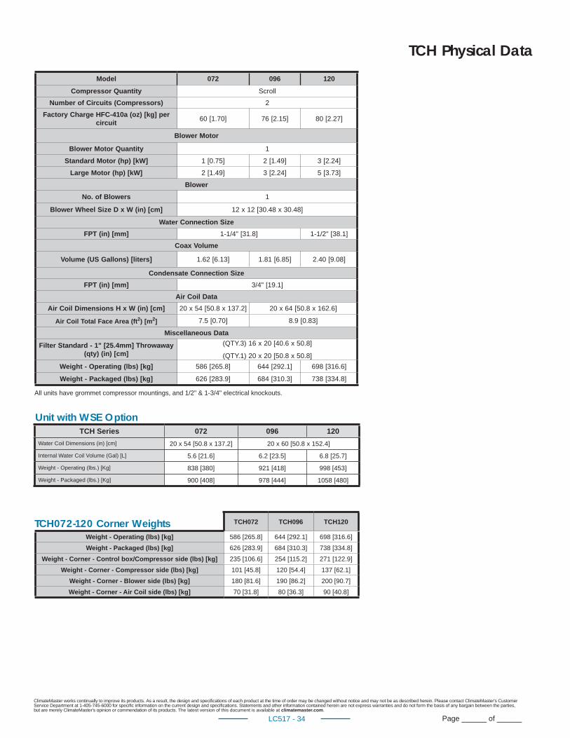
ClimateMaster works continually to improve its products. As a result, the design and specifi cations of each product at the time of order may be changed without notice and may not be as described herein. Please contact ClimateMaster's Customer Service Department at 1-405-745-6000 for specifi c information on the current design and specifi cations. Statements and other information contained herein are not express warranties and do not form the basis of any bargain between the parties, but are merely ClimateMaster's opinion or commendation of its products. The latest version of this document is available at climatemaster.com.
Page ______ of ______LC517 - 34
TCH Physical Data
TCH072 TCH096 TCH120
Weight - Operating (lbs) [kg] 586 [265.8] 644 [292.1] 698 [316.6]Weight - Packaged (lbs) [kg] 626 [283.9] 684 [310.3] 738 [334.8]
Weight - Corner - Control box/Compressor side (lbs) [kg] 235 [106.6] 254 [115.2] 271 [122.9]Weight - Corner - Compressor side (lbs) [kg] 101 [45.8] 120 [54.4] 137 [62.1]
Weight - Corner - Blower side (lbs) [kg] 180 [81.6] 190 [86.2] 200 [90.7]Weight - Corner - Air Coil side (lbs) [kg] 70 [31.8] 80 [36.3] 90 [40.8]
TCH072-120 Corner Weights
Unit with WSE Option
Model 072 096 120
Compressor Quantity Scroll
Number of Circuits (Compressors) 2
Factory Charge HFC-410a (oz) [kg] per circuit
60 [1.70] 76 [2.15] 80 [2.27]
Blower Motor
Blower Motor Quantity 1
Standard Motor (hp) [kW] 1 [0.75] 2 [1.49] 3 [2.24]
Large Motor (hp) [kW] 2 [1.49] 3 [2.24] 5 [3.73]
Blower
No. of Blowers 1
Blower Wheel Size D x W (in) [cm] 12 x 12 [30.48 x 30.48]
Water Connection Size
FPT (in) [mm] 1-1/4" [31.8] 1-1/2" [38.1]
Coax Volume
Volume (US Gallons) [liters] 1.62 [6.13] 1.81 [6.85] 2.40 [9.08]
Condensate Connection Size
FPT (in) [mm] 3/4" [19.1]
Air Coil Data
Air Coil Dimensions H x W (in) [cm] 20 x 54 [50.8 x 137.2] 20 x 64 [50.8 x 162.6]
Air Coil Total Face Area (ft2) [m2] 7.5 [0.70] 8.9 [0.83]
Miscellaneous Data
Filter Standard - 1" [25.4mm] Throwaway (qty) (in) [cm]
(QTY.3) 16 x 20 [40.6 x 50.8]
(QTY.1) 20 x 20 [50.8 x 50.8]
Weight - Operating (lbs) [kg] 586 [265.8] 644 [292.1] 698 [316.6]
Weight - Packaged (lbs) [kg] 626 [283.9] 684 [310.3] 738 [334.8]
All units have grommet compressor mountings, and 1/2" & 1-3/4" electrical knockouts.
TCH Series 072 096 120
Water Coil Dimensions (in) [cm] 20 x 54 [50.8 x 137.2] 20 x 60 [50.8 x 152.4]
Internal Water Coil Volume (Gal) [L] 5.6 [21.6] 6.2 [23.5] 6.8 [25.7]
Weight - Operating (lbs.) [Kg] 838 [380] 921 [418] 998 [453]
Weight - Packaged (lbs.) [Kg] 900 [408] 978 [444] 1058 [480]
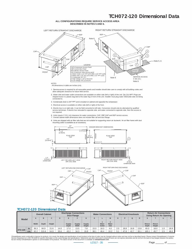
ClimateMaster works continually to improve its products. As a result, the design and specifi cations of each product at the time of order may be changed without notice and may not be as described herein. Please contact ClimateMaster's Customer Service Department at 1-405-745-6000 for specifi c information on the current design and specifi cations. Statements and other information contained herein are not express warranties and do not form the basis of any bargain between the parties, but are merely ClimateMaster's opinion or commendation of its products. The latest version of this document is available at climatemaster.com.
Page ______ of ______LC517 - 35
HANGER BRACKET DIMENSIONS87”[221cm]
1.0”[2.54cm]
PLAN VIEWTOP
4.3”[10.8cm]
34.1”[86.6cm]
FRO
NT
CONTROL BOX
U
T
S V
1.3”[3.3cm]
condensate LEFT RETURN LEFT VIEW-AIR COIL SIDE
LEFT RETURN END DISCHARGE
CBP
EAP
BSP
CAP
CAP
FRONT
ED
F
G
CAP
CBP
CAP
EAP
BSP
FRONT
FRO
NT
CONTROL BOX
PLAN VIEWTOP
V S U
RIGHT RETURN RIGHT VIEW-AIR COIL SIDE
RIGHT RETURN END DISCHARGE
1.3”[3.3cm]
condensate drain
3
TCH072-120 Dimensional Data
LEFT RETURN STRAIGHT DISCHARGE
CAP
CAP
FRONT
BSPA
EAP
CBP
BC
O
PQRK
M
F
G E
D
BSP
RIGHT RETURN STRAIGHT DISCHARGE
1EAP
2 CAP
CAP 2
FRONT
CBP1
5
4
LEGENDCAP=Compressor Access PanelCBP=Control Box PanelBSP=Blower Service PanelEAP=Expansion Valve Access panel1=Water Outlet 1-1/4” FPT (072-096) 1-1/2” FPT (120)2=Water Inlet 1-1/4” FPT (072-096) 1-1/2” FPT (120)3=Condensate 3/4” FPT4=High Voltage 1-1/8” [2.9cm] KO5=Low Voltage 7/8” [2.2cm] KO
SERVICE ACCESS3’ (91 cm.)
Note 5, 6
Note 6
Note 6
Note 6
ALL CONFIGURATIONS REQUIRE SERVICE ACCESS AREADESCRIBED IN NOTES 5 AND 6.
NOTES:- All dimensions in table are inches (cm).
ccess is required for all removable panels and installer should take care to comply with all building codes and allow adequate clearance for future field service.
Water inlet and water outlet connections are available on either side (left or right) of the unit. Qty (2x) MPT Plugs areshipped loose in a plastic bag tied to the water leg in front of the unit. Installer must plug water inlet/outlet side not beingconnected to.
Electrical access is available on either side (left or right) of the front.
Electric box is on right side. It can be field converted to left side. Conversion should only be attempted by qualifiedservice technician. If electric box relocated to opposite side, and water connected to opposite side, then this access isnot required.
Units require 3’ (9.1 cm) clearance for water connections, CAP, C P, EAP and BSP service access.Overall cabinet width dimensions does not include filter rail and duct flange.
TCH072-120 Dimensional Data
Model
Overall Cabinet Discharge ConnectionsDuct Flange Water Connections Electrical Knockouts Return Air Connections
Using Return Air OpeningA
Width
B
Depth
C
Height
D E
Supply Depth
F
Supply Width
G
Supply Height
K L
1WaterOutlet
M
2WaterInlet
O P Q R S
ReturnDepth
T
ReturnHeight
U V
072-120 in. 36.3 84.9 21.6 14.0 17.0 13.5 7.8 15.0 18.3 4.0 2.0 18.8 16.8 13.8 65.0 18.0 1.0 18.9
cm. 92.2 215.6 54.9 35.6 43.2 34.3 19.8 38.1 46.4 10.2 5.1 47.8 42.7 35.1 165.1 45.7 2.5 48.0
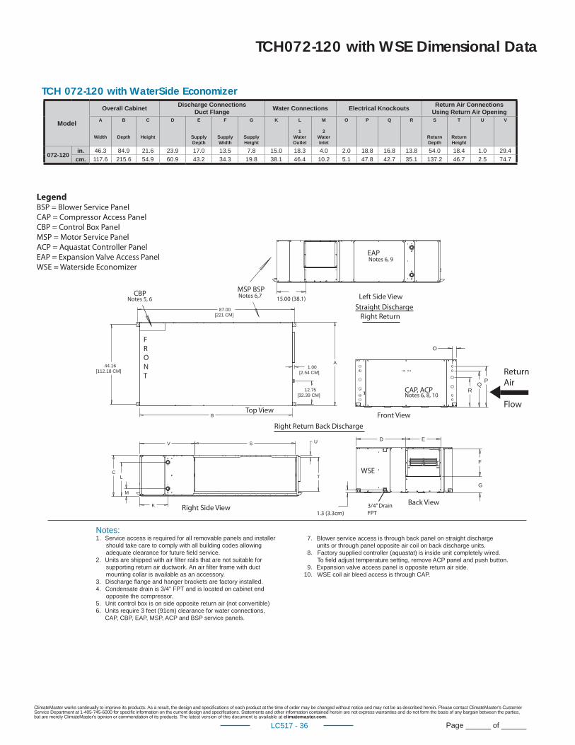
ClimateMaster works continually to improve its products. As a result, the design and specifi cations of each product at the time of order may be changed without notice and may not be as described herein. Please contact ClimateMaster's Customer Service Department at 1-405-745-6000 for specifi c information on the current design and specifi cations. Statements and other information contained herein are not express warranties and do not form the basis of any bargain between the parties, but are merely ClimateMaster's opinion or commendation of its products. The latest version of this document is available at climatemaster.com.
Page ______ of ______LC517 - 36
SV U
TC
K
M
L
87.00[221 CM]
44.16[112.18 CM]
B
A1.00
[2.54 CM]
12.75[32.39 CM]
RQ
P
O
F
G
ED
Notes:1. Service access is required for all removable panels and installer should take care to comply with all building codes allowing adequate clearance for future field service.2. Units are shipped with air filter rails that are not suitable for supporting return air ductwork. An air filter frame with duct mounting collar is available as an accessory.3. Discharge flange and hanger brackets are factory installed.4. Condensate drain is 3/4” FPT and is located on cabinet end opposite the compressor.5. Unit control box is on side opposite return air (not convertible) 6. Units require 3 feet (91cm) clearance for water connections, CAP, CBP, EAP, MSP, ACP and BSP service panels.
7. Blower service access is through back panel on straight discharge units or through panel opposite air coil on back discharge units. 8. Factory supplied controller (aquastat) is inside unit completely wired. To field adjust temperature setting, remove ACP panel and push button. 9. Expansion valve access panel is opposite return air side.10. WSE coil air bleed access is through CAP.
15.00 (38.1)
1.3 (3.3cm)
Notes 5, 6
3/4” Drain
FPT
Left Side View
Right Return
Right Return Back Discharge
F
R
O
N
T
Top ViewFront View
Back ViewRight Side View
WSE
CBP
Notes 6, 8, 10CAP, ACP
Notes 6,7MSP BSP
Notes 6, 9EAP
Straight Discharge
Return
Air
Flow
Legend BSP = Blower Service Panel
CAP = Compressor Access Panel
CBP = Control Box Panel
MSP = Motor Service Panel
ACP = Aquastat Controller Panel
EAP = Expansion Valve Access Panel
WSE = Waterside Economizer
TCH 072-120 with WaterSide Economizer
TCH072-120 with WSE Dimensional Data
Model
Overall Cabinet Discharge ConnectionsDuct Flange Water Connections Electrical Knockouts Return Air Connections
Using Return Air OpeningA
Width
B
Depth
C
Height
D E
Supply Depth
F
Supply Width
G
Supply Height
K L
1WaterOutlet
M
2WaterInlet
O P Q R S
ReturnDepth
T
ReturnHeight
U V
072-120 in. 46.3 84.9 21.6 23.9 17.0 13.5 7.8 15.0 18.3 4.0 2.0 18.8 16.8 13.8 54.0 18.4 1.0 29.4
cm. 117.6 215.6 54.9 60.9 43.2 34.3 19.8 38.1 46.4 10.2 5.1 47.8 42.7 35.1 137.2 46.7 2.5 74.7
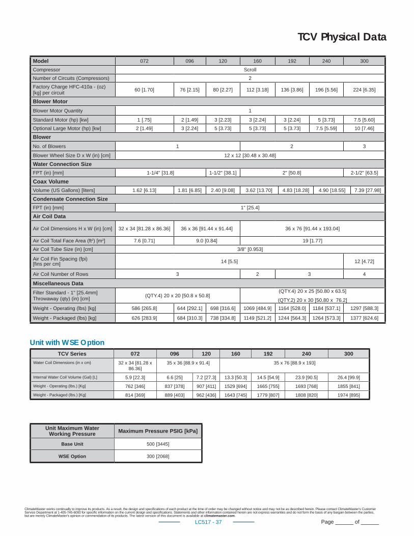
ClimateMaster works continually to improve its products. As a result, the design and specifi cations of each product at the time of order may be changed without notice and may not be as described herein. Please contact ClimateMaster's Customer Service Department at 1-405-745-6000 for specifi c information on the current design and specifi cations. Statements and other information contained herein are not express warranties and do not form the basis of any bargain between the parties, but are merely ClimateMaster's opinion or commendation of its products. The latest version of this document is available at climatemaster.com.
Page ______ of ______LC517 - 37
TCV Physical Data
Model 072 096 120 160 192 240 300
Compressor Scroll
Number of Circuits (Compressors) 2
Factory Charge HFC-410a - (oz) [kg] per circuit
60 [1.70] 76 [2.15] 80 [2.27] 112 [3.18] 136 [3.86] 196 [5.56] 224 [6.35]
Blower Motor
Blower Motor Quantity 1
Standard Motor (hp) [kw] 1 [.75] 2 [1.49] 3 [2.23] 3 [2.24] 3 [2.24] 5 [3.73] 7.5 [5.60]
Optional Large Motor (hp) [kw] 2 [1.49] 3 [2.24] 5 [3.73] 5 [3.73] 5 [3.73] 7.5 [5.59] 10 [7.46]
Blower
No. of Blowers 1 2 3
Blower Wheel Size D x W (in) [cm] 12 x 12 [30.48 x 30.48]
Water Connection Size
FPT (in) [mm] 1-1/4" [31.8] 1-1/2" [38.1] 2" [50.8] 2-1/2" [63.5]
Coax Volume
Volume (US Gallons) [liters] 1.62 [6.13] 1.81 [6.85] 2.40 [9.08] 3.62 [13.70] 4.83 [18.28] 4.90 [18.55] 7.39 [27.98]
Condensate Connection Size
FPT (in) [mm] 1" [25.4]
Air Coil Data
Air Coil Dimensions H x W (in) [cm] 32 x 34 [81.28 x 86.36] 36 x 36 [91.44 x 91.44] 36 x 76 [91.44 x 193.04]
Air Coil Total Face Area (ft2) [m2] 7.6 [0.71] 9.0 [0.84] 19 [1.77]
Air Coil Tube Size (in) [cm] 3/8" [0.953]
Air Coil Fin Spacing (fpi) [fi ns per cm] 14 [5.5] 12 [4.72]
Air Coil Number of Rows 3 2 3 4
Miscellaneous Data
Filter Standard - 1" [25.4mm] Throwaway (qty) (in) [cm]
(QTY.4) 20 x 20 [50.8 x 50.8](QTY.4) 20 x 25 [50.80 x 63.5]
(QTY.2) 20 x 30 [50.80 x 76.2]
Weight - Operating (lbs) [kg] 586 [265.8] 644 [292.1] 698 [316.6] 1069 [484.9] 1164 [528.0] 1184 [537.1] 1297 [588.3]
Weight - Packaged (lbs) [kg] 626 [283.9] 684 [310.3] 738 [334.8] 1149 [521.2] 1244 [564.3] 1264 [573.3] 1377 [624.6]
TCV Series 072 096 120 160 192 240 300
Water Coil Dimensions (in x cm) 32 x 34 [81.28 x 86.36]
35 x 36 [88.9 x 91.4] 35 x 76 [88.9 x 193]
Internal Water Coil Volume (Gal) [L] 5.9 [22.3] 6.6 [25] 7.2 [27.3] 13.3 [50.3] 14.5 [54.9] 23.9 [90.5] 26.4 [99.9]
Weight - Operating (lbs.) [Kg] 762 [346] 837 [378] 907 [411] 1529 [694] 1665 [755] 1693 [768] 1855 [841]
Weight - Packaged (lbs.) [Kg] 814 [369] 889 [403] 962 [436] 1643 [745] 1779 [807] 1808 [820] 1974 [895]
Unit with WSE Option
Unit Maximum WaterWorking Pressure Maximum Pressure PSIG [kPa]
Base Unit 500 [3445]
WSE Option 300 [2068]
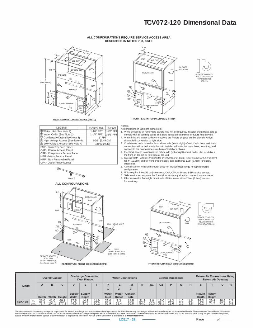
ClimateMaster works continually to improve its products. As a result, the design and specifi cations of each product at the time of order may be changed without notice and may not be as described herein. Please contact ClimateMaster's Customer Service Department at 1-405-745-6000 for specifi c information on the current design and specifi cations. Statements and other information contained herein are not express warranties and do not form the basis of any bargain between the parties, but are merely ClimateMaster's opinion or commendation of its products. The latest version of this document is available at climatemaster.com.
Page ______ of ______LC517 - 38
Model
Overall CabinetDischarge Connection
Duct FlangeWater Connections Electric Knockouts
Return Air Connections Using Return Air Opening
A B C D E F K L M N O1 O2 P Q R S T U V
Depth Width Height Supply Width
Supply Depth
1
Water Inlet
2
Water Outlet
3
Conden-sate
Return Depth
Return Height
072-120 in. 29.0 41.0 69.8 17.5 14.8 11.9 22.0 7.3 14.5 21.3 8.0 15.0 11.3 1.0 1.5 36.3 29.4 30.6 2.7cm. 73.7 104.1 177.2 44.5 37.5 30.2 55.9 18.4 36.8 54.0 20.3 38.1 28.6 2.5 3.8 96.2 74.7 77.8 6.9
TCV072-120 Dimensional Data
AIR OUT
AIR OUT AIR OUT
NRP
BLOWER ROTATION
NRP
NRP
NRP
RETURN AIR
RETURN AIR
BLOWER TO AIR COIL RELATIONSHIP FOR
REAR OR FRONT DISCHARGE 072-120
RETURN AIR
UPABSP
BSP
2
2
2
3
4
4
5
CSP+CAP+MSP
1
1
1
CSP+CAP+MSPCSP+CAP+MSP
44 5
7.6
F
L
K
M
SIDE SERVICE ACCESS(See Notes 8 and 9)
SERVICE ACCESS
FRONT AND BACK
1.7
E
FD
F
LEGEND TCV072-096 TCV120Water Inlet (See Note 2)Water Outlet (See Note 2)Condensate Drain (See Note 3)High Voltage Access (See Note 4)Low Voltage Access (See Note 4)
1-1/4” FPT1-1/4” FPT
1-1/2” FPT1-1/2” FPT
1” FPT1-3/8” [3.49 CM]
7/8” [2.2 CM]BSP - Blower Service Panel CAP - Control Access PanelCSP - Compressor Access PanelMSP - Motor Service PanelNRP - Non Removable PanelUPA - Upper Pulley Access
12345
FRONT RETURN REAR DISCHARGE (FR/RD)REAR RETURN FRONT DISCHARGE (RR/FD)
REAR RETURN TOP DISCHARGE (RR/TD) FRONT RETURN TOP DISCHARGE (FR/TD)
NOTES:All dimensions in table are inches (cm)1. While access to all removable panels may not be required, installer should take care to
comply with all building codes and allow adequate clearance for future field service.2. Water inlet and water outlet connections are factory shipped on the left side. Union
allows field conversion to right side. 3. Condensate drain is available on either side (left or right) of unit. Drain hose and drain
connection will be tied inside the unit. Installer will untie the drain hose, form trap, and
4. Electrical access is available on either side (left or right) of unit and is also available in the front on the left or right side of the unit.
5. Overall width - Add 3.12” (8cm) for 1“ (2.5cm) or 2” (5cm) Filter Frame; or 5.12” (13cm) for 4” (10.2cm) and for front or rear supply add additional 1.06” (2.7cm) for supply duct collar.
6. Overall cabinet height dimension does not include duct flange for top discharge configuration.
7. Units require 3 feet(91 cm) clearance, CAP, CSP, MSP and BSP service access.8. Side service access must be 2 feet (9.4cm) on any side that connections are made. 9. Filter removal is from right or left side of filter frame, allow 2 feet (9.4cm) access
for servicing.
BSPUPA
ALL CONFIGURATIONS REQUIRE SERVICE ACCESS AREADESCRIBED IN NOTES 7, 8, and 9
(See Notes 1 and 7)
(See Notes 1 and 7)
Note 2
ALL CONFIGURATIONS
BLOWER TO AIR COIL RELATIONSHIP FOR
TOP DISCHARGE 072-120
BSP+MSP
CSP
(See Note 6)
Control Box
Control Box
Control Box
Control Box
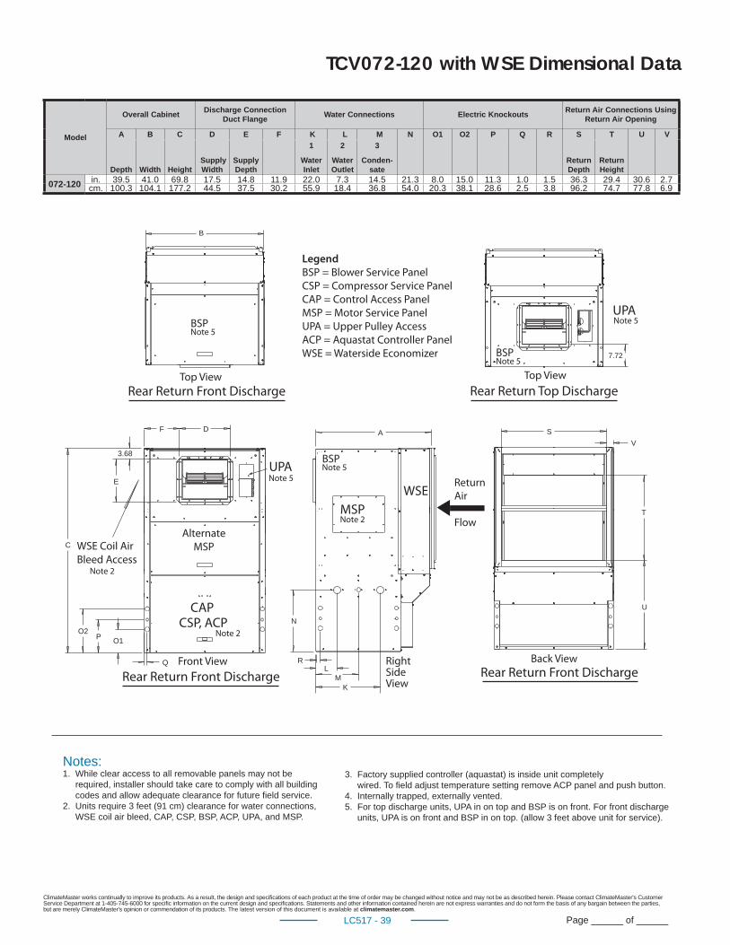
ClimateMaster works continually to improve its products. As a result, the design and specifi cations of each product at the time of order may be changed without notice and may not be as described herein. Please contact ClimateMaster's Customer Service Department at 1-405-745-6000 for specifi c information on the current design and specifi cations. Statements and other information contained herein are not express warranties and do not form the basis of any bargain between the parties, but are merely ClimateMaster's opinion or commendation of its products. The latest version of this document is available at climatemaster.com.
Page ______ of ______LC517 - 39
S
T
U
V
B
A
R
MK
N
L
D
E
C
3.68
O1PO2
Q
F
Notes:1. While clear access to all removable panels may not be required, installer should take care to comply with all building codes and allow adequate clearance for future field service. 2. Units require 3 feet (91 cm) clearance for water connections, WSE coil air bleed, CAP, CSP, BSP, ACP, UPA, and MSP.
3. Factory supplied controller (aquastat) is inside unit completely wired. To field adjust temperature setting remove ACP panel and push button.4. Internally trapped, externally vented.5. For top discharge units, UPA in on top and BSP is on front. For front discharge units, UPA is on front and BSP in on top. (allow 3 feet above unit for service).
CAP
UPA
CSP, ACP
WSE
Front View Back View
Top View
Rear Return Front DischargeRear Return Front Discharge
Legend BSP = Blower Service Panel
CSP = Compressor Service Panel
CAP = Control Access Panel
MSP = Motor Service Panel
UPA = Upper Pulley Access
ACP = Aquastat Controller Panel
WSE = Waterside Economizer
Note 2
Note 2
Right Side View
Note 5
MSPNote 2
BSPNote 5
BSPNote 5
WSE Coil Air
Bleed Access
Alternate
MSP
Return
Air
Flow
7.72
Rear Return Top Discharge
BSPNote 5
UPANote 5
Rear Return Front Discharge
Top View
TCV072-120 with WSE Dimensional Data
Model
Overall CabinetDischarge Connection
Duct FlangeWater Connections Electric Knockouts
Return Air Connections Using Return Air Opening
A B C D E F K L M N O1 O2 P Q R S T U V
Depth Width Height Supply Width
Supply Depth
1
Water Inlet
2
Water Outlet
3
Conden-sate
Return Depth
Return Height
072-120 in. 39.5 41.0 69.8 17.5 14.8 11.9 22.0 7.3 14.5 21.3 8.0 15.0 11.3 1.0 1.5 36.3 29.4 30.6 2.7cm. 100.3 104.1 177.2 44.5 37.5 30.2 55.9 18.4 36.8 54.0 20.3 38.1 28.6 2.5 3.8 96.2 74.7 77.8 6.9
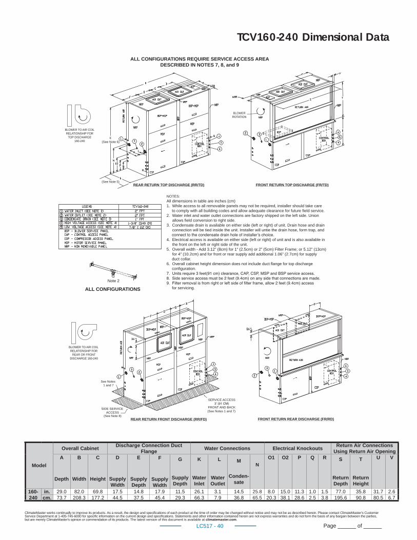
ClimateMaster works continually to improve its products. As a result, the design and specifi cations of each product at the time of order may be changed without notice and may not be as described herein. Please contact ClimateMaster's Customer Service Department at 1-405-745-6000 for specifi c information on the current design and specifi cations. Statements and other information contained herein are not express warranties and do not form the basis of any bargain between the parties, but are merely ClimateMaster's opinion or commendation of its products. The latest version of this document is available at climatemaster.com.
Page ______ of ______LC517 - 40
TCV160-240 Dimensional Data
REAR RETURN TOP DISCHARGE (RR/TD)
FRONT RETURN REAR DISCHARGE (FR/RD)REAR RETURN FRONT DISCHARGE (RR/FD)
FRONT RETURN TOP DISCHARGE (FR/TD)
ALL CONFIGURATIONS REQUIRE SERVICE ACCESS AREADESCRIBED IN NOTES 7, 8, and 9
ALL CONFIGURATIONS
SIDE SERVICE ACCESS
(See Note 8)
See Notes 1 and 7
SERVICE ACCESS
FRONT AND BACK(See Notes 1 and 7)
BLOWER TO AIR COIL RELATIONSHIP FOR
REAR OR FRONT DISCHARGE 160-240
NOTES:All dimensions in table are inches (cm)1. While access to all removable panels may not be required, installer should take care
to comply with all building codes and allow adequate clearance for future field service.2. Water inlet and water outlet connections are factory shipped on the left side. Union
allows field conversion to right side. 3. Condensate drain is available on either side (left or right) of unit. Drain hose and drain
connection will be tied inside the unit. Installer will untie the drain hose, form trap, and
4. Electrical access is available on either side (left or right) of unit and is also available in the front on the left or right side of the unit.
5. Overall width - Add 3.12” (8cm) for 1“ (2.5cm) or 2” (5cm) Filter Frame; or 5.12” (13cm) for 4” (10.2cm) and for front or rear supply add additional 1.06” (2.7cm) for supply duct collar.
6. Overall cabinet height dimension does not include duct flange for top discharge configuration.
for servicing.
BLOWER TO AIR COIL RELATIONSHIP FOR
TOP DISCHARGE 160-240
BLOWER ROTATION
(See Note 6)
(See Note 5)
Note 2
Model
Overall CabinetDischarge Connection Duct
FlangeWater Connections Electrical Knockouts
Return Air Connections Using Return Air Opening
A
Depth
B
Width
C
Height
D
Supply Width
E
Supply Depth
F
Supply Width
G
Supply Depth
K
Water Inlet
L
Water Outlet
M
Conden-sate
N
O1 O2 P Q R S
Return Depth
T
Return Height
U V
160-240
in. 29.0 82.0 69.8 17.5 14.8 17.9 11.5 26.1 3.1 14.5 25.8 8.0 15.0 11.3 1.0 1.5 77.0 35.8 31.7 2.6cm. 73.7 208.3 177.2 44.5 37.5 45.4 29.3 66.3 7.9 36.8 65.5 20.3 38.1 28.6 2.5 3.8 195.6 90.8 80.5 6.7
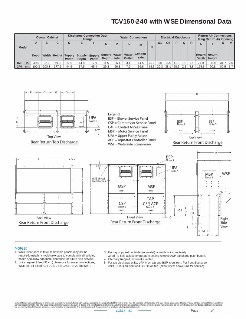
ClimateMaster works continually to improve its products. As a result, the design and specifi cations of each product at the time of order may be changed without notice and may not be as described herein. Please contact ClimateMaster's Customer Service Department at 1-405-745-6000 for specifi c information on the current design and specifi cations. Statements and other information contained herein are not express warranties and do not form the basis of any bargain between the parties, but are merely ClimateMaster's opinion or commendation of its products. The latest version of this document is available at climatemaster.com.
Page ______ of ______LC517 - 41
N
A
O1PO2
RL
M
K
3.64
C
Q
T
U
VS
F D G D
6.70
E
WSE
Front View
Rear Return Front DischargeRear Return Front Discharge
B
Top ViewTop View
Right Side View
WSE air coilbleed acces
Back View
Legend BSP = Blower Service Panel
CSP = Compressor Service Panel
CAP = Control Access Panel
MSP = Motor Service Panel
UPA = Upper Pulley Access
ACP = Aquastat Controller Panel
WSE = Waterside EconomizerRear Return Top Discharge Rear Return Front Discharge
Notes:1. While clear access to all removable panels may not be required, installer should take care to comply with all building codes and allow adequate clearance for future field service. 2. Units require 3 feet (91 cm) clearance for water connections, WSE coil air bleed, CAP, CSP, BSP, ACP, UPA, and MSP.
3. Factory supplied controller (aquastat) is inside unit completely wired. To field adjust temperature setting remove ACP panel and push button.4. Internally trapped, externally vented.5. For top discharge units, UPA in on top and BSP is on front. For front discharge units, UPA is on front and BSP in on top. (allow 3 feet above unit for service).
BSPNote 5
BSPNote 5
BSPNote 5
UPANote 5
UPANote 5
MSP
MSPMSP
Note 2
CAPCSP, ACPCSP
Note 2Note 2
TCV160-240 with WSE Dimensional Data
Model
Overall CabinetDischarge Connection Duct
FlangeWater Connections Electrical Knockouts
Return Air Connections Using Return Air Opening
A
Depth
B
Width
C
Height
D
Supply Width
E
Supply Depth
F
Supply Width
G
Supply Depth
K
Water Inlet
L
Water Outlet
M
Conden-sate
N
O1 O2 P Q R S
Return Depth
T
Return Height
U V
160-240
in. 39.5 82.0 69.8 17.5 14.8 17.9 11.5 26.1 3.1 14.5 25.8 8.0 15.0 11.3 1.0 1.5 77.0 35.8 31.7 2.6cm. 100.3 208.3 177.2 44.5 37.5 45.4 29.3 66.3 7.9 36.8 65.5 20.3 38.1 28.6 2.5 3.8 195.6 90.8 80.5 6.7
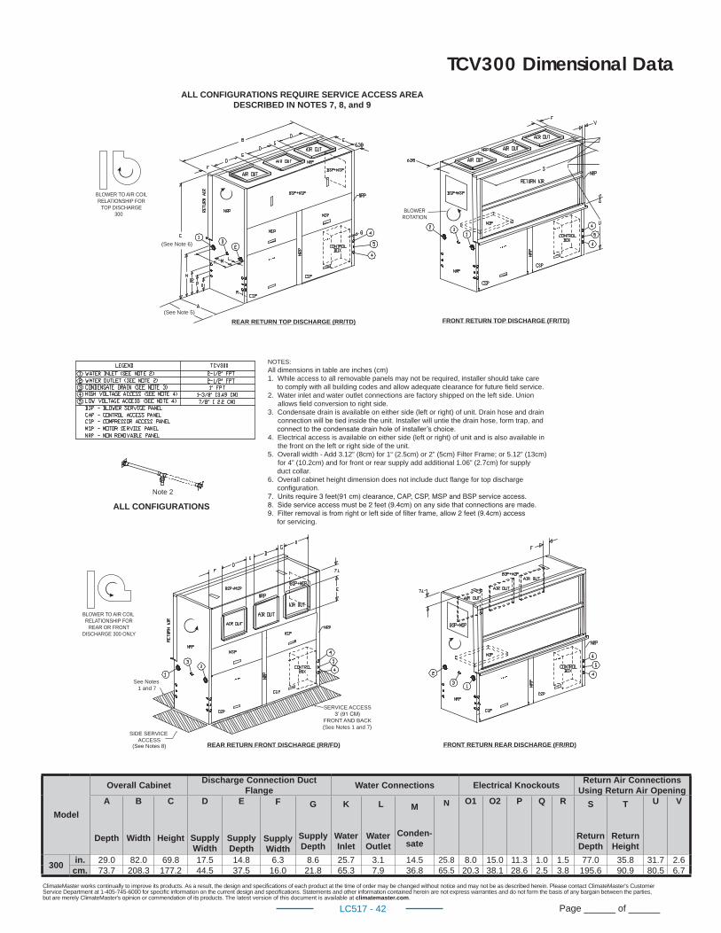
ClimateMaster works continually to improve its products. As a result, the design and specifi cations of each product at the time of order may be changed without notice and may not be as described herein. Please contact ClimateMaster's Customer Service Department at 1-405-745-6000 for specifi c information on the current design and specifi cations. Statements and other information contained herein are not express warranties and do not form the basis of any bargain between the parties, but are merely ClimateMaster's opinion or commendation of its products. The latest version of this document is available at climatemaster.com.
Page ______ of ______LC517 - 42
TCV300 Dimensional Data
REAR RETURN TOP DISCHARGE (RR/TD)
FRONT RETURN REAR DISCHARGE (FR/RD)REAR RETURN FRONT DISCHARGE (RR/FD)
FRONT RETURN TOP DISCHARGE (FR/TD)
ALL CONFIGURATIONS REQUIRE SERVICE ACCESS AREADESCRIBED IN NOTES 7, 8, and 9
SIDE SERVICE ACCESS
(See Notes 8)
See Notes 1 and 7
SERVICE ACCESS
FRONT AND BACK(See Notes 1 and 7)
(See Note 5)
ALL CONFIGURATIONSNote 2
(See Note 6)
BLOWER ROTATION
BLOWER TO AIR COIL RELATIONSHIP FOR
TOP DISCHARGE 300
BLOWER TO AIR COIL RELATIONSHIP FOR
REAR OR FRONT DISCHARGE 300 ONLY
NOTES:All dimensions in table are inches (cm)1. While access to all removable panels may not be required, installer should take care
to comply with all building codes and allow adequate clearance for future field service.2. Water inlet and water outlet connections are factory shipped on the left side. Union
allows field conversion to right side. 3. Condensate drain is available on either side (left or right) of unit. Drain hose and drain
connection will be tied inside the unit. Installer will untie the drain hose, form trap, and
4. Electrical access is available on either side (left or right) of unit and is also available in the front on the left or right side of the unit.
5. Overall width - Add 3.12” (8cm) for 1“ (2.5cm) or 2” (5cm) Filter Frame; or 5.12” (13cm) for 4” (10.2cm) and for front or rear supply add additional 1.06” (2.7cm) for supply duct collar.
6. Overall cabinet height dimension does not include duct flange for top discharge configuration.
for servicing.
Model
Overall CabinetDischarge Connection Duct
FlangeWater Connections Electrical Knockouts
Return Air Connections Using Return Air Opening
A
Depth
B
Width
C
Height
D
Supply Width
E
Supply Depth
F
Supply Width
G
Supply Depth
K
Water Inlet
L
Water Outlet
M
Conden-sate
N O1 O2 P Q R S
Return Depth
T
Return Height
U V
300in. 29.0 82.0 69.8 17.5 14.8 6.3 8.6 25.7 3.1 14.5 25.8 8.0 15.0 11.3 1.0 1.5 77.0 35.8 31.7 2.6
cm. 73.7 208.3 177.2 44.5 37.5 16.0 21.8 65.3 7.9 36.8 65.5 20.3 38.1 28.6 2.5 3.8 195.6 90.9 80.5 6.7
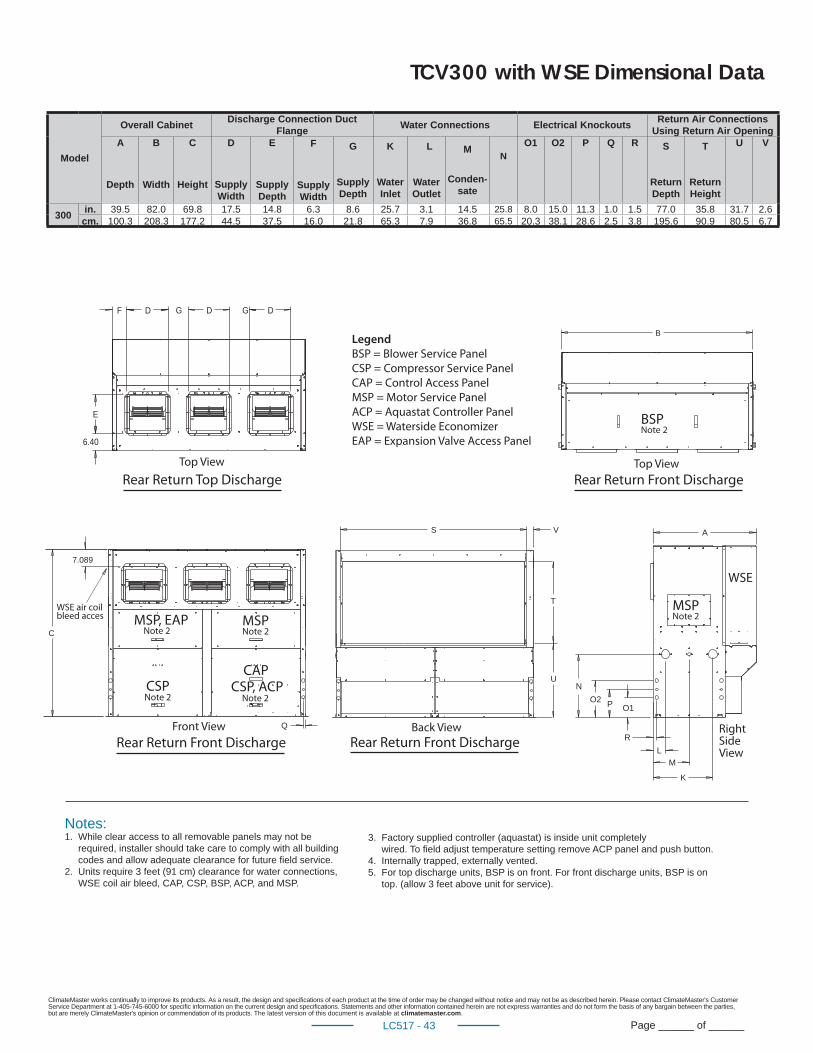
ClimateMaster works continually to improve its products. As a result, the design and specifi cations of each product at the time of order may be changed without notice and may not be as described herein. Please contact ClimateMaster's Customer Service Department at 1-405-745-6000 for specifi c information on the current design and specifi cations. Statements and other information contained herein are not express warranties and do not form the basis of any bargain between the parties, but are merely ClimateMaster's opinion or commendation of its products. The latest version of this document is available at climatemaster.com.
Page ______ of ______LC517 - 43
C
Q
7.089
S V
T
U
B
DF G D G
6.40
E
D
WSE
Top View
R
L
M
K
O1PO2
N
A
Front View Back View
Legend BSP = Blower Service Panel
CSP = Compressor Service Panel
CAP = Control Access Panel
MSP = Motor Service Panel
ACP = Aquastat Controller Panel
WSE = Waterside Economizer
EAP = Expansion Valve Access Panel
Notes:1. While clear access to all removable panels may not be required, installer should take care to comply with all building codes and allow adequate clearance for future field service. 2. Units require 3 feet (91 cm) clearance for water connections, WSE coil air bleed, CAP, CSP, BSP, ACP, and MSP.
3. Factory supplied controller (aquastat) is inside unit completely wired. To field adjust temperature setting remove ACP panel and push button.4. Internally trapped, externally vented.5. For top discharge units, BSP is on front. For front discharge units, BSP is on top. (allow 3 feet above unit for service).
Right Side View
Rear Return Front Discharge
Top View
Rear Return Top Discharge
BSPNote 2
WSE air coilbleed acces MSP, EAP
Note 2
MSPNote 2 MSP
Note 2
CSPNote 2
CAPCSP, ACP
Note 2
Rear Return Front Discharge Rear Return Front Discharge
TCV300 with WSE Dimensional Data
Model
Overall CabinetDischarge Connection Duct
FlangeWater Connections Electrical Knockouts
Return Air Connections Using Return Air Opening
A
Depth
B
Width
C
Height
D
Supply Width
E
Supply Depth
F
Supply Width
G
Supply Depth
K
Water Inlet
L
Water Outlet
M
Conden-sate
N
O1 O2 P Q R S
Return Depth
T
Return Height
U V
300in. 39.5 82.0 69.8 17.5 14.8 6.3 8.6 25.7 3.1 14.5 25.8 8.0 15.0 11.3 1.0 1.5 77.0 35.8 31.7 2.6
cm. 100.3 208.3 177.2 44.5 37.5 16.0 21.8 65.3 7.9 36.8 65.5 20.3 38.1 28.6 2.5 3.8 195.6 90.9 80.5 6.7
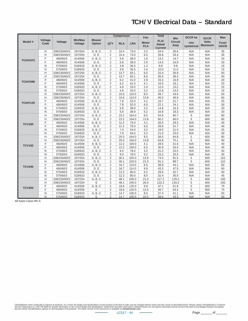
ClimateMaster works continually to improve its products. As a result, the design and specifi cations of each product at the time of order may be changed without notice and may not be as described herein. Please contact ClimateMaster's Customer Service Department at 1-405-745-6000 for specifi c information on the current design and specifi cations. Statements and other information contained herein are not express warranties and do not form the basis of any bargain between the parties, but are merely ClimateMaster's opinion or commendation of its products. The latest version of this document is available at climatemaster.com.
Page ______ of ______LC517 - 44
Model #Voltage Code
VoltageMin/Max Voltage
Blower Option
CompressorFan
Motor FLA
Total
FLA/Rated
Current
Min Circuit Amp
SCCR ka
rms symetrical
SCCR Volts
Maximum
Max
Fuse/HACR
QTY RLA LRA
TCH/V072
H 208/230/60/3 197/254 A, B, C 2 10.4 73.0 3.2 24.0 26.6 N/A N/A 35H 208/230/60/3 197/254 D, E 2 10.4 73.0 6.0 26.8 29.4 N/A N/A 35F 460/60/3 414/506 A, B, C 2 5.8 38.0 1.6 13.2 14.7 N/A N/A 20F 460/60/3 414/506 D, E 2 5.8 38.0 2.9 14.5 16.0 N/A N/A 20N 575/60/3 518/633 A, B, C 2 3.8 36.5 1.2 8.8 9.8 N/A N/A 15N 575/60/3 518/633 D, E 2 3.8 36.5 2.4 10.0 11.0 N/A N/A 15
TCH/V096
H 208/230/60/3 197/254 A, B, C 2 13.7 83.1 6.0 33.4 36.8 N/A N/A 50H 208/230/60/3 197/254 D, E 2 13.7 83.1 8.5 35.9 39.3 N/A N/A 50F 460/60/3 414/506 A, B, C 2 6.2 41.0 2.9 15.3 16.9 N/A N/A 20F 460/60/3 414/506 D, E 2 6.2 41.0 4.1 16.5 18.1 N/A N/A 20N 575/60/3 518/633 A, B, C 2 4.8 33.0 2.4 12.0 13.2 N/A N/A 15N 575/60/3 518/633 D, E 2 4.8 33.0 3.2 12.8 14.0 N/A N/A 15
TCH/V120
H 208/230/60/3 197/254 A, B, C 2 15.6 110.0 8.5 39.7 43.6 N/A N/A 50H 208/230/60/3 197/254 D, E 2 15.6 110.0 13.8 45.0 48.9 N/A N/A 60F 460/60/3 414/506 A, B, C 2 7.8 52.0 4.1 19.7 21.7 N/A N/A 25F 460/60/3 414/506 D, E 2 7.8 52.0 6.5 22.1 24.1 N/A N/A 30N 575/60/3 518/633 A, B, C 2 5.8 38.9 3.2 14.8 16.3 N/A N/A 20N 575/60/3 518/633 D, E 2 5.8 38.9 5.2 16.8 18.3 N/A N/A 20
TCV160
H 208/230/60/3 197/254 A, B, C 2 23.2 164.0 8.5 54.9 60.7 5 600 80H 208/230/60/3 197/254 D, E 2 23.2 164.0 13.8 60.2 66.0 5 600 80F 460/60/3 414/506 A, B, C 2 11.2 75.0 4.1 26.5 29.3 N/A N/A 40F 460/60/3 414/506 D, E 2 11.2 75.0 6.5 28.9 31.7 N/A N/A 40N 575/60/3 518/633 A, B, C 2 7.9 54.0 3.2 19.0 21.0 N/A N/A 25N 575/60/3 518/633 D, E 2 7.9 54.0 5.2 21.0 23.0 N/A N/A 30
TCV192
H 208/230/60/3 197/254 A, B, C 2 25.0 164.0 8.5 58.5 64.8 5 600 80H 208/230/60/3 197/254 D, E 2 25.0 164.0 13.8 63.8 70.1 5 600 90F 460/60/3 414/506 A, B, C 2 12.2 100.0 4.1 28.5 31.6 N/A N/A 40F 460/60/3 414/506 D, E 2 12.2 100.0 6.5 30.9 34.0 N/A N/A 45N 575/60/3 518/633 A, B, C 2 9.0 78.0 3.2 21.2 23.5 N/A N/A 30N 575/60/3 518/633 D, E 2 9.0 78.0 5.2 23.2 25.5 N/A N/A 30
TCV240
H 208/230/60/3 197/254 A, B, C 2 30.1 225.0 13.8 74.0 81.5 5 600 110H 208/230/60/3 197/254 D, E 2 30.1 225.0 21.0 81.2 88.7 5 600 110F 460/60/3 414/506 A, B, C 2 16.7 114.0 6.5 39.9 44.1 N/A N/A 60F 460/60/3 414/506 D, E 2 16.7 114.0 9.9 43.3 47.5 N/A N/A 60N 575/60/3 518/633 A, B, C 2 12.2 80.0 5.2 29.6 32.7 N/A N/A 40N 575/60/3 518/633 D, E 2 12.2 80.0 8.0 32.4 35.5 N/A N/A 45
TCV300
H 208/230/60/3 197/254 A, B, C 2 48.1 245.0 21.0 117.2 129.2 5 600 150H 208/230/60/3 197/254 E 2 48.1 245.0 26.0 122.2 134.2 5 600 150F 460/60/3 414/506 A, B, C 2 18.6 125.0 9.9 47.1 51.8 5 600 70F 460/60/3 414/506 E 2 18.6 125.0 12.5 49.7 54.4 5 600 70N 575/60/3 518/633 A, B, C 2 14.7 100.0 8.0 37.4 41.1 N/A N/A 50N 575/60/3 518/633 E 2 14.7 100.0 10.2 39.6 43.3 N/A N/A 50
TCH/V Electrical Data – Standard
All fuses Class RK-5
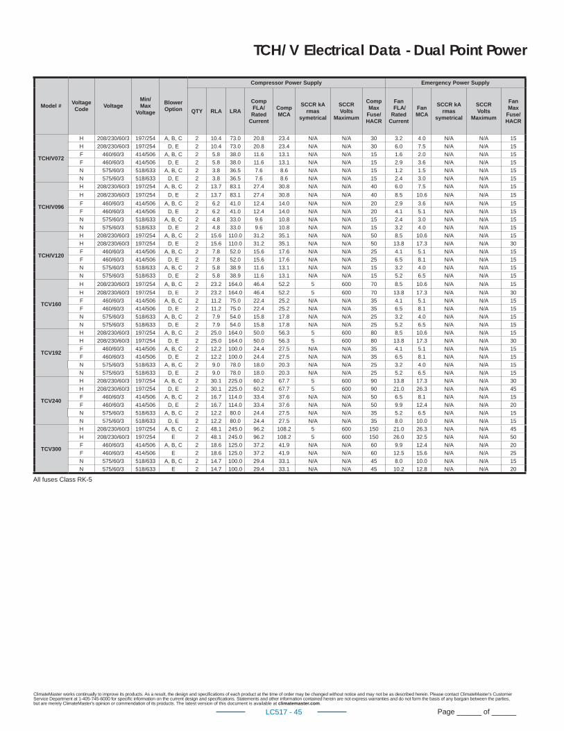
ClimateMaster works continually to improve its products. As a result, the design and specifi cations of each product at the time of order may be changed without notice and may not be as described herein. Please contact ClimateMaster's Customer Service Department at 1-405-745-6000 for specifi c information on the current design and specifi cations. Statements and other information contained herein are not express warranties and do not form the basis of any bargain between the parties, but are merely ClimateMaster's opinion or commendation of its products. The latest version of this document is available at climatemaster.com.
Page ______ of ______LC517 - 45
TCH/V Electrical Data - Dual Point Power
Model #Voltage Code
VoltageMin/Max
Voltage
Blower Option
Compressor Power Supply Emergency Power Supply
QTY RLA LRA
Comp FLA/
Rated Current
Comp MCA
SCCR kA rmas
symetrical
SCCR Volts
Maximum
Comp Max
Fuse/ HACR
Fan FLA/ Rated
Current
Fan MCA
SCCR kA rmas
symetrical
SCCR Volts
Maximum
Fan Max
Fuse/ HACR
TCH/V072
H 208/230/60/3 197/254 A, B, C 2 10.4 73.0 20.8 23.4 N/A N/A 30 3.2 4.0 N/A N/A 15
H 208/230/60/3 197/254 D, E 2 10.4 73.0 20.8 23.4 N/A N/A 30 6.0 7.5 N/A N/A 15
F 460/60/3 414/506 A, B, C 2 5.8 38.0 11.6 13.1 N/A N/A 15 1.6 2.0 N/A N/A 15
F 460/60/3 414/506 D, E 2 5.8 38.0 11.6 13.1 N/A N/A 15 2.9 3.6 N/A N/A 15
N 575/60/3 518/633 A, B, C 2 3.8 36.5 7.6 8.6 N/A N/A 15 1.2 1.5 N/A N/A 15
N 575/60/3 518/633 D, E 2 3.8 36.5 7.6 8.6 N/A N/A 15 2.4 3.0 N/A N/A 15
TCH/V096
H 208/230/60/3 197/254 A, B, C 2 13.7 83.1 27.4 30.8 N/A N/A 40 6.0 7.5 N/A N/A 15
H 208/230/60/3 197/254 D, E 2 13.7 83.1 27.4 30.8 N/A N/A 40 8.5 10.6 N/A N/A 15
F 460/60/3 414/506 A, B, C 2 6.2 41.0 12.4 14.0 N/A N/A 20 2.9 3.6 N/A N/A 15
F 460/60/3 414/506 D, E 2 6.2 41.0 12.4 14.0 N/A N/A 20 4.1 5.1 N/A N/A 15
N 575/60/3 518/633 A, B, C 2 4.8 33.0 9.6 10.8 N/A N/A 15 2.4 3.0 N/A N/A 15
N 575/60/3 518/633 D, E 2 4.8 33.0 9.6 10.8 N/A N/A 15 3.2 4.0 N/A N/A 15
TCH/V120
H 208/230/60/3 197/254 A, B, C 2 15.6 110.0 31.2 35.1 N/A N/A 50 8.5 10.6 N/A N/A 15
H 208/230/60/3 197/254 D, E 2 15.6 110.0 31.2 35.1 N/A N/A 50 13.8 17.3 N/A N/A 30
F 460/60/3 414/506 A, B, C 2 7.8 52.0 15.6 17.6 N/A N/A 25 4.1 5.1 N/A N/A 15
F 460/60/3 414/506 D, E 2 7.8 52.0 15.6 17.6 N/A N/A 25 6.5 8.1 N/A N/A 15
N 575/60/3 518/633 A, B, C 2 5.8 38.9 11.6 13.1 N/A N/A 15 3.2 4.0 N/A N/A 15
N 575/60/3 518/633 D, E 2 5.8 38.9 11.6 13.1 N/A N/A 15 5.2 6.5 N/A N/A 15
TCV160
H 208/230/60/3 197/254 A, B, C 2 23.2 164.0 46.4 52.2 5 600 70 8.5 10.6 N/A N/A 15
H 208/230/60/3 197/254 D, E 2 23.2 164.0 46.4 52.2 5 600 70 13.8 17.3 N/A N/A 30
F 460/60/3 414/506 A, B, C 2 11.2 75.0 22.4 25.2 N/A N/A 35 4.1 5.1 N/A N/A 15
F 460/60/3 414/506 D, E 2 11.2 75.0 22.4 25.2 N/A N/A 35 6.5 8.1 N/A N/A 15
N 575/60/3 518/633 A, B, C 2 7.9 54.0 15.8 17.8 N/A N/A 25 3.2 4.0 N/A N/A 15
N 575/60/3 518/633 D, E 2 7.9 54.0 15.8 17.8 N/A N/A 25 5.2 6.5 N/A N/A 15
TCV192
H 208/230/60/3 197/254 A, B, C 2 25.0 164.0 50.0 56.3 5 600 80 8.5 10.6 N/A N/A 15
H 208/230/60/3 197/254 D, E 2 25.0 164.0 50.0 56.3 5 600 80 13.8 17.3 N/A N/A 30
F 460/60/3 414/506 A, B, C 2 12.2 100.0 24.4 27.5 N/A N/A 35 4.1 5.1 N/A N/A 15
F 460/60/3 414/506 D, E 2 12.2 100.0 24.4 27.5 N/A N/A 35 6.5 8.1 N/A N/A 15
N 575/60/3 518/633 A, B, C 2 9.0 78.0 18.0 20.3 N/A N/A 25 3.2 4.0 N/A N/A 15
N 575/60/3 518/633 D, E 2 9.0 78.0 18.0 20.3 N/A N/A 25 5.2 6.5 N/A N/A 15
TCV240
H 208/230/60/3 197/254 A, B, C 2 30.1 225.0 60.2 67.7 5 600 90 13.8 17.3 N/A N/A 30
H 208/230/60/3 197/254 D, E 2 30.1 225.0 60.2 67.7 5 600 90 21.0 26.3 N/A N/A 45
F 460/60/3 414/506 A, B, C 2 16.7 114.0 33.4 37.6 N/A N/A 50 6.5 8.1 N/A N/A 15
F 460/60/3 414/506 D, E 2 16.7 114.0 33.4 37.6 N/A N/A 50 9.9 12.4 N/A N/A 20
N 575/60/3 518/633 A, B, C 2 12.2 80.0 24.4 27.5 N/A N/A 35 5.2 6.5 N/A N/A 15
N 575/60/3 518/633 D, E 2 12.2 80.0 24.4 27.5 N/A N/A 35 8.0 10.0 N/A N/A 15
TCV300
H 208/230/60/3 197/254 A, B, C 2 48.1 245.0 96.2 108.2 5 600 150 21.0 26.3 N/A N/A 45
H 208/230/60/3 197/254 E 2 48.1 245.0 96.2 108.2 5 600 150 26.0 32.5 N/A N/A 50
F 460/60/3 414/506 A, B, C 2 18.6 125.0 37.2 41.9 N/A N/A 60 9.9 12.4 N/A N/A 20
F 460/60/3 414/506 E 2 18.6 125.0 37.2 41.9 N/A N/A 60 12.5 15.6 N/A N/A 25
N 575/60/3 518/633 A, B, C 2 14.7 100.0 29.4 33.1 N/A N/A 45 8.0 10.0 N/A N/A 15
N 575/60/3 518/633 E 2 14.7 100.0 29.4 33.1 N/A N/A 45 10.2 12.8 N/A N/A 20
All fuses Class RK-5
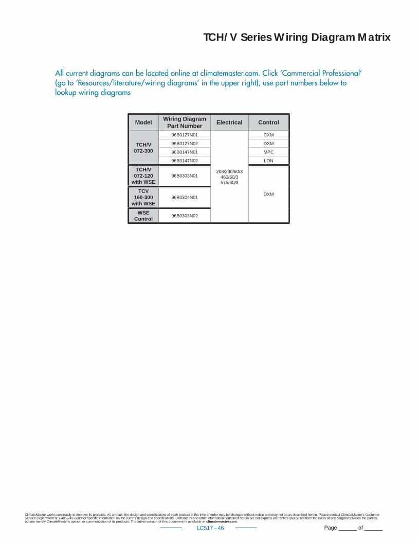
ClimateMaster works continually to improve its products. As a result, the design and specifi cations of each product at the time of order may be changed without notice and may not be as described herein. Please contact ClimateMaster's Customer Service Department at 1-405-745-6000 for specifi c information on the current design and specifi cations. Statements and other information contained herein are not express warranties and do not form the basis of any bargain between the parties, but are merely ClimateMaster's opinion or commendation of its products. The latest version of this document is available at climatemaster.com.
Page ______ of ______LC517 - 46
TCH/V Series Wiring Diagram Matrix
Model Wiring DiagramPart Number Electrical Control
TCH/V072-300
96B0127N01
208/230/60/3460/60/3575/60/3
CXM
96B0127N02 DXM
96B0147N01 MPC
96B0147N02 LON
TCH/V 072-120
with WSE96B0303N01
DXMTCV160-300
with WSE96B0304N01
WSE Control 96B0303N02
All current diagrams can be located online at climatemaster.com. Click ‘Commercial Professional’ (go to ‘Resources/literature/wiring diagrams’ in the upper right), use part numbers below to lookup wiring diagrams
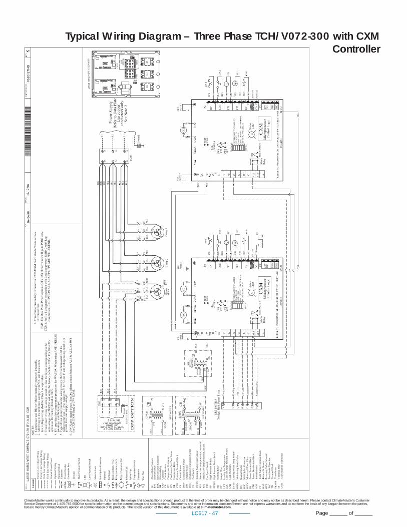
ClimateMaster works continually to improve its products. As a result, the design and specifi cations of each product at the time of order may be changed without notice and may not be as described herein. Please contact ClimateMaster's Customer Service Department at 1-405-745-6000 for specifi c information on the current design and specifi cations. Statements and other information contained herein are not express warranties and do not form the basis of any bargain between the parties, but are merely ClimateMaster's opinion or commendation of its products. The latest version of this document is available at climatemaster.com.
Page ______ of ______LC517 - 47
Typical Wiring Diagram – Three Phase TCH/V072-300 with CXM Controller
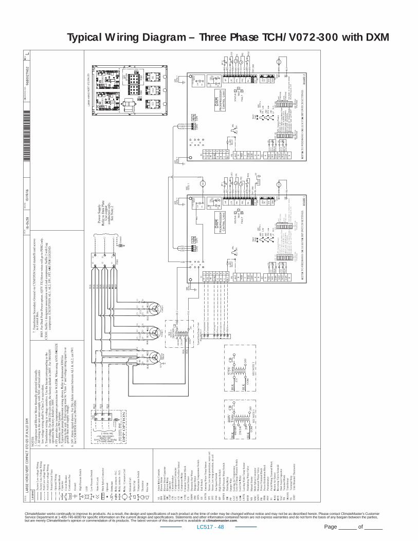
ClimateMaster works continually to improve its products. As a result, the design and specifi cations of each product at the time of order may be changed without notice and may not be as described herein. Please contact ClimateMaster's Customer Service Department at 1-405-745-6000 for specifi c information on the current design and specifi cations. Statements and other information contained herein are not express warranties and do not form the basis of any bargain between the parties, but are merely ClimateMaster's opinion or commendation of its products. The latest version of this document is available at climatemaster.com.
Page ______ of ______LC517 - 48
Typical Wiring Diagram – Three Phase TCH/V072-300 with DXM
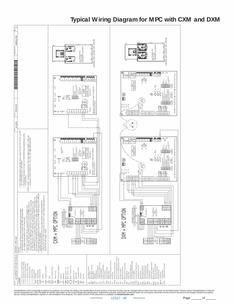
ClimateMaster works continually to improve its products. As a result, the design and specifi cations of each product at the time of order may be changed without notice and may not be as described herein. Please contact ClimateMaster's Customer Service Department at 1-405-745-6000 for specifi c information on the current design and specifi cations. Statements and other information contained herein are not express warranties and do not form the basis of any bargain between the parties, but are merely ClimateMaster's opinion or commendation of its products. The latest version of this document is available at climatemaster.com.
Page ______ of ______LC517 - 49
Typical Wiring Diagram for MPC with CXM and DXM
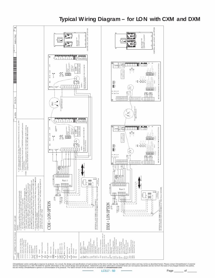
ClimateMaster works continually to improve its products. As a result, the design and specifi cations of each product at the time of order may be changed without notice and may not be as described herein. Please contact ClimateMaster's Customer Service Department at 1-405-745-6000 for specifi c information on the current design and specifi cations. Statements and other information contained herein are not express warranties and do not form the basis of any bargain between the parties, but are merely ClimateMaster's opinion or commendation of its products. The latest version of this document is available at climatemaster.com.
Page ______ of ______LC517 - 50
Typical Wiring Diagram – for LON with CXM and DXM
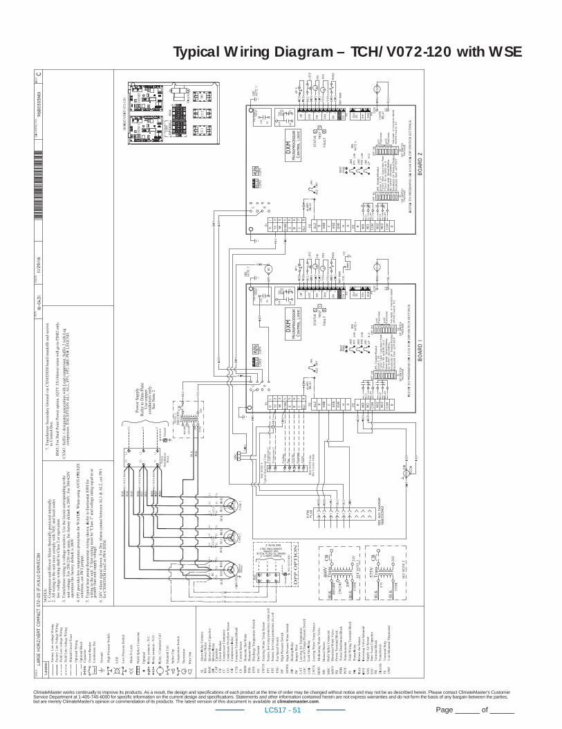
ClimateMaster works continually to improve its products. As a result, the design and specifi cations of each product at the time of order may be changed without notice and may not be as described herein. Please contact ClimateMaster's Customer Service Department at 1-405-745-6000 for specifi c information on the current design and specifi cations. Statements and other information contained herein are not express warranties and do not form the basis of any bargain between the parties, but are merely ClimateMaster's opinion or commendation of its products. The latest version of this document is available at climatemaster.com.
Page ______ of ______LC517 - 51
Typical Wiring Diagram – TCH/V072-120 with WSE
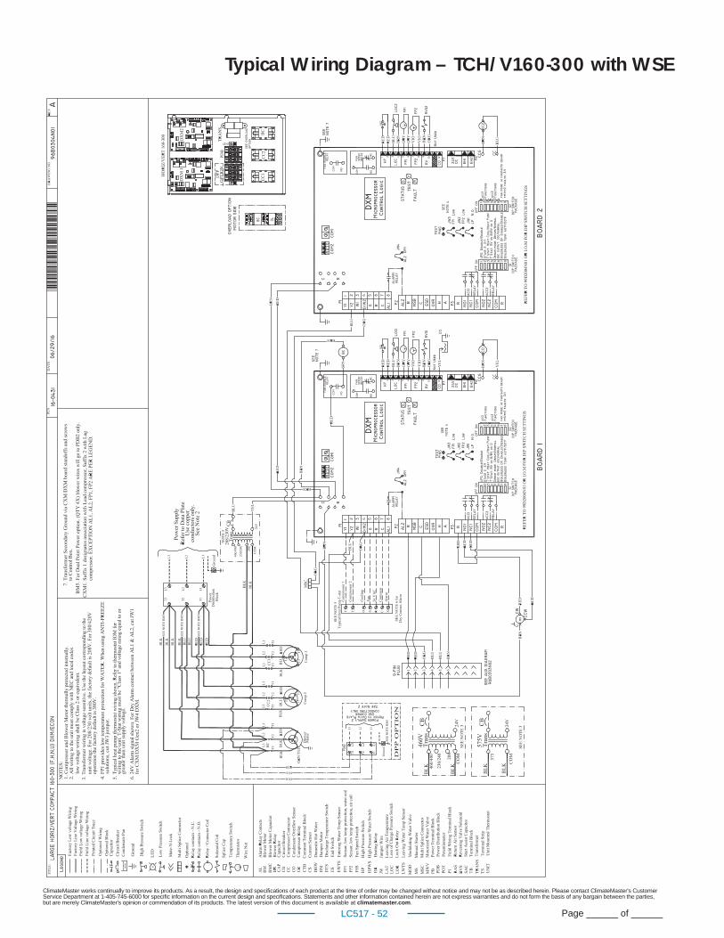
ClimateMaster works continually to improve its products. As a result, the design and specifi cations of each product at the time of order may be changed without notice and may not be as described herein. Please contact ClimateMaster's Customer Service Department at 1-405-745-6000 for specifi c information on the current design and specifi cations. Statements and other information contained herein are not express warranties and do not form the basis of any bargain between the parties, but are merely ClimateMaster's opinion or commendation of its products. The latest version of this document is available at climatemaster.com.
Page ______ of ______LC517 - 52
Typical Wiring Diagram – TCH/V160-300 with WSE
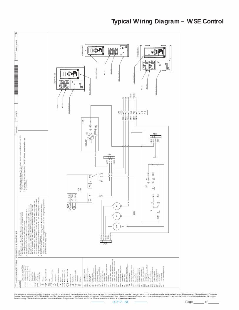
ClimateMaster works continually to improve its products. As a result, the design and specifi cations of each product at the time of order may be changed without notice and may not be as described herein. Please contact ClimateMaster's Customer Service Department at 1-405-745-6000 for specifi c information on the current design and specifi cations. Statements and other information contained herein are not express warranties and do not form the basis of any bargain between the parties, but are merely ClimateMaster's opinion or commendation of its products. The latest version of this document is available at climatemaster.com.
Page ______ of ______LC517 - 53
Typical Wiring Diagram – WSE Control
ClimateMaster works continually to improve its products. As a result, the design and specifi cations of each product at the time of order may be changed without notice and may not be as described herein. Please contact ClimateMaster's Customer Service Department at 1-405-745-6000 for specifi c information on the current design and specifi cations. Statements and other information contained herein are not express warranties and do not form the basis of any bargain between the parties, but are merely ClimateMaster's opinion or commendation of its products. The latest version of this document is available at climatemaster.com.
Page ______ of ______LC517 - 54
Tranquility® Compact Belt Drive (TCH/V) Series 60HzEngineering Specifi cations – Page 1
General:Furnish and install ClimateMaster Tranquility® TC Water Source Heat Pumps, as indicated on the plans. Equipment shall be completely
assembled, piped and internally wired. Capacities and characteristics as listed in the schedule and the specifi cations that follow.
Units shall be supplied completely factory built capable of operating over an entering water temperature range from 20° to 120°F
(-6.7° to 48.9°C) as standard. Equivalent units from other manufacturers may be proposed provided approval to bid is given 10 days
prior to bid closing. All equipment listed in this section must be rated and certifi ed in accordance with Air-Conditioning, Heating and
Refrigeration Institute/International Standards Organization (AHRI/ISO 13256-1). All equipment must be tested, investigated, and
determined to comply with the requirements of the standards for Heating and Cooling Equipment UL-1995 for the United States and
CAN/CSA-C22.2 NO.236 for Canada, by Intertek Testing Laboratories (ETL). The units shall have AHRI/ISO and ETL-US-C labels.
All units shall pass a factory acceptance test. The quality control system shall automatically perform the factory acceptance test via
computer. A detailed report card from the factory acceptance test shall ship with each unit. (Note: If unit fails the factory acceptance
test it shall not be allowed to ship. Unit serial number will be recorded by factory acceptance test and furnished on report card
for ease of unit warranty status.)
Basic Construction: Horizontal units shall have one of the following air fl ow arrangements: Left Return/Back Discharge, Left Return/Straight Discharge,
Right Return/Back Discharge, Right Return/Straight Discharge as shown on the plans. Units can be fi eld converted without requiring
new panels or belts. Units that cannot be fi eld converted shall not be acceptable.
Vertical units shall have one of the following air fl ow arrangements: rear return/top discharge, front return/top discharge, rear return/
front discharge, front return/rear discharge as shown on plans.Units can be fi eld converted without requiring new panels or belts.
Units that cannot be fi eld converted shall not be acceptable.
If units with these arrangements are not used, the contractor is responsible for any extra costs incurred by other trades. All units
must have a minimum of two access panels for serviceability of compressor compartment. Units having only one access panel to compressor/heat exchangers/expansion device/refrigerant piping shall not be acceptable.
Compressor section interior surfaces shall be lined with 1/2 inch (12.7mm) thick, 1-1/2 lb/ft3 (24 kg/m3) acoustic type glass fi ber
insulation. Air handling section interior surfaces shall be lined with 1/2 in (12.7mm) thick, 1-3/4 lb/ft3 (28 kg/m3) foil backed fi ber
insulation for ease of cleaning. Insulation placement shall be designed in a manner that will eliminate any exposed edges to prevent
the introduction of glass fi bers into the air stream. Units without foil faced insulation in the air handling section will not be accepted.
Units shall be fabricated from heavy gauge galvanized steel.
Standard insulation must meet NFPA Fire Hazard Classifi cation requirements 25/50 per ASTM E84, UL 723, CAN/ULC S102-M88 and
NFPA 90A requirements; air erosion and mold growth limits of UL-181; stringent fungal resistance test per ASTM-C1071 and ASTM
G21; and shall meet zero level bacteria growth per ASTM G22. Unit insulation must meet these stringent requirements or unit(s) will not be accepted.
ClimateMaster works continually to improve its products. As a result, the design and specifi cations of each product at the time of order may be changed without notice and may not be as described herein. Please contact ClimateMaster's Customer Service Department at 1-405-745-6000 for specifi c information on the current design and specifi cations. Statements and other information contained herein are not express warranties and do not form the basis of any bargain between the parties, but are merely ClimateMaster's opinion or commendation of its products. The latest version of this document is available at climatemaster.com.
Page ______ of ______LC517 - 55
Tranquility® Compact Belt Drive (TCH/V) Series 60HzEngineering Specifi cations – Page 2
Horizontal units to have discharge air duct collar, 1” (25.4mm) or 2”(50.8mm) fi lter rails with fi lters factory installed, and factory
installed hanger brackets. Vertical units to have discharge air duct collar shipped loose, and 1”(25.4mm) 2”(50.8mm) or 4”(101.6mm)
full fi lter frame with fi lters factory installed [1”(25.4mm) frame is fi eld convertible for 2”(50.8mm) fi lters]. If units with these factory installed provisions are not used, the contractor is responsible for any extra costs to fi eld install these provisions, and/or the extra costs for his sub-contractor to install these provisions.
All units must have an insulated panel separating the fan compartment from the compressor compartment. Units with the compressor in the air stream are not acceptable. Horizontal units shall have factory installed fi lter rails with fi lter removal from either
side. Vertical units shall have factory installed full fi lter frame with fi lter removal from bottom. The contractor shall purchase one spare
set of fi lters and replace factory shipped fi lters on completion of start-up. Filters shall be standard sizes. If units utilize non-standard
fi lter sizes then the contractor shall provide 12 spare fi lter sets for each unit.
Cabinets shall have separate knockouts on front and sides for entrance of line voltage and low voltage control wiring. All factory-
installed wiring passing through factory knockouts and openings shall be protected from sheet metal edges at openings by plastic
ferrules. Supply and return water connections shall be copper FPT fi ttings, connections on both sides (installer to choose side and plug
opposite) and shall be securely mounted fl ush to the cabinet side allowing for connection of a fl exible hose without the use of a back-
up wrench. Water connections that protrude through the cabinet or require the use of a backup wrench shall not be allowed. Water connections on only one side will not be accepted. All water connections and electrical knockouts must not interfere with the
serviceability of unit. Contractor shall be responsible for any extra costs involved in the installation of units that do not have this feature. Contractor must ensure that units can be easily removed for servicing and coordinate locations of electrical conduit and lights
with the electrical contractor.
Option: Dual-point power.
Option: UltraQuiet package shall consist of high technology sound attenuating material that is strategically applied to the compressor and air handling compartment casings and fan scroll in addition to the standard ClimaQuiet system design, to further dampen and attenuate sound transmissions. Compressor is mounted on specially engineered sound-tested isolators.
Fan and Motor Assembly:All units shall have belt-driven single centrifugal fan. Fan motor shall be premium duty, VFD compatible, permanently lubricated with
thermal overload protection. Units supplied without permanently lubricated motors must provide external oilers for easy service.
The fan and motor assembly must be capable of overcoming the external static pressures as shown on the schedule. Airfl ow/Static
pressure rating of the unit shall be based on a wet coil and a clean fi lter in place. Ratings based on a dry coil and/or no fi lter, or on an ESP less than 0.25” (6.35 mm w.g.) shall NOT be acceptable.
Option: Various blower drive packages for selectable static pressure/airfl ow.
Refrigerant Circuit: All units shall contain an EarthPure® (HFC-410A) sealed refrigerant circuit including a high effi ciency scroll compressor designed for
heat pump operation, a thermostatic expansion valve for refrigerant metering, an enhanced corrugated aluminum lanced fi n and
rifl ed copper tube refrigerant to air heat exchanger, reversing valve, coaxial (tube in tube) refrigerant to water heat exchanger, and
safety controls including a high pressure switch, low pressure switch (loss of charge), water coil low temperature sensor, and air coil
low temperature sensor. Access fi ttings shall be factory installed on high and low pressure refrigerant lines to facilitate fi eld service.
Activation of any safety device shall prevent compressor operation via a microprocessor lockout circuit. The lockout circuit shall be
reset at the thermostat or at the contractor supplied disconnect switch. Units that cannot be reset at the thermostat shall not be acceptable.
ClimateMaster works continually to improve its products. As a result, the design and specifi cations of each product at the time of order may be changed without notice and may not be as described herein. Please contact ClimateMaster's Customer Service Department at 1-405-745-6000 for specifi c information on the current design and specifi cations. Statements and other information contained herein are not express warranties and do not form the basis of any bargain between the parties, but are merely ClimateMaster's opinion or commendation of its products. The latest version of this document is available at climatemaster.com.
Page ______ of ______LC517 - 56
Tranquility® Compact Belt Drive (TCH/V) Series 60HzEngineering Specifi cations – Page 3
Hermetic compressors shall be internally sprung. The scroll compressors shall have a dual level vibration isolation system. The
compressor(s) will be mounted on specially engineered sound-tested EPDM vibration isolation grommets to a large heavy gauge
compressor mounting plate, which is then isolated from the cabinet base with rubber grommets for maximized vibration attenuation.
Compressor shall have thermal overload protection. Compressor shall be located in an insulated compartment isolated from air stream
to minimize sound transmission.
Refrigerant to air heat exchangers shall utilize enhanced corrugated lanced aluminum fi ns and rifl ed copper tube construction rated to
withstand 625 PSIG (4309 kPa) refrigerant working pressure. Refrigerant to water heat exchangers shall be of copper inner water tube
and steel refrigerant outer tube design, rated to withstand 625 PSIG (4309 kPa) working refrigerant pressure and 500 PSIG (3445 kPa)
working water pressure. The refrigerant to water heat exchanger shall be “electro-coated” with a low cure cathodic epoxy material a
minimum of 0.4 mils thick (0.4 – 1.5 mils range) on all surfaces. The black colored coating shall provide a minimum of 1000 hours salt
spray protection per ASTM B117-97 on all external steel and copper tubing. The material shall be formulated without the inclusion of
any heavy metals and shall exhibit a pencil hardness of 2H (ASTM D3363-92A), crosshatch adhesion of 4B-5B (ASTM D3359-95), and
impact resistance of 160 in-lbs (184 kg-cm) direct (ASTM D2794-93).
The unit water circuit is protected by two high pressure switches set at 300 PSI [2067 kPa]. Switches will reset automatically when
pressure is reduced. Units that do not have auto-reset water high pressure switches are not acceptable.
Refrigerant metering shall be accomplished by thermostatic expansion valve only. Expansion valves shall be dual port balanced type
with external equalizer for optimum refrigerant metering. Units shall be designed and tested for operating ranges of entering water
temperatures from 20° to 120°F (-6.7° to 48.9°C). Reversing valve shall be four-way solenoid activated refrigerant valve, which shall
default to heating mode should the solenoid fail to function. If the reversing valve solenoid defaults to cooling mode, an additional
low temperature thermostat must be provided to prevent over-cooling an already cold room.
Option: The unit shall be supplied with cupro-nickel coaxial water to refrigerant heat exchanger.
Option: The unit shall be supplied with extended range Insulation option, which adds closed cell insulation to internal water lines, and provides insulation on suction side refrigeration tubing including refrigerant to water heat exchanger.
Option: The refrigerant to air heat exchanger shall be coated.
Option: The unit shall be supplied with Waterside Economizer (WSE). The WSE will consist of hydroniccoil, 3 way valve, and aquastat. Aquastat will be adjustable type and factory set at 45° F (72° C).Units with WSE will require heat pump thermostat with 2 stages of cooling. (DXM Required).
Drain Pan:The drain pan shall be constructed of galvanized steel and have a powder coat paint application to further inhibit corrosion. This
corrosion protection system shall meet the stringent 1000 hour salt spray test per ASTM B117. If plastic type material is used, it must
be HDPE (High Density Polyethylene) to avoid thermal cycling shock stress failure over the lifetime of the unit. Drain pan shall be fully
insulated. Drain outlet shall be located at pan as to allow unobstructed drainage of condensate. Drain outlet for horizontal units shall
be connected from pan directly to 3/4” FPT fi tting. For vertical units drain pan hose assembly can be connected to either side, drain
outlet to be 1”FPT fi tting. The unit as standard will be supplied with solid-state electronic condensate overfl ow protection. Mechanical
fl oat switches will NOT be accepted.
Option: The unit shall be supplied with stainless steel drain pan.
ClimateMaster works continually to improve its products. As a result, the design and specifi cations of each product at the time of order may be changed without notice and may not be as described herein. Please contact ClimateMaster's Customer Service Department at 1-405-745-6000 for specifi c information on the current design and specifi cations. Statements and other information contained herein are not express warranties and do not form the basis of any bargain between the parties, but are merely ClimateMaster's opinion or commendation of its products. The latest version of this document is available at climatemaster.com.
Page ______ of ______LC517 - 57
Tranquility® Compact Belt Drive (TCH/V) Series 60HzEngineering Specifi cations – Page 4
Electrical: A control box shall be located within the unit compressor compartment and shall contain a 75VA transformer with load side circuit
breaker protection, 24 volt activated, 2 or 3 pole compressor contactor, terminal block for thermostat wiring and solid-state controller
for complete unit operation. Reversing valve and fan motor wiring shall be routed through this electronic controller. Units shall be
name-plated for use with time delay fuses or HACR circuit breakers. Unit controls shall be 24 Volt and provide heating or cooling as
required by the remote thermostat/sensor. Two compressor units shall have a solid-state time delay relay and random start to prevent
both compressors from starting simultaneously.
Solid State Control System (CXM): Units shall have a solid-state control system. Units utilizing electro-mechanical control shall not be acceptable. The control system
microprocessor board shall be specifi cally designed to protect against building electrical system noise contamination, EMI, and
RFI interference. The control system shall interface with a heat pump type thermostat. The control system shall have the following
features:
a. Anti-short cycle time delay on compressor operation.
b. Random start on power up mode.
c. Low voltage protection.
d. High voltage protection.
e. Unit shutdown on high or low refrigerant pressures.
f. Unit shutdown on low water temperature.
g. Condensate overfl ow electronic protection.
h. Option to reset unit at thermostat or disconnect.
i. Automatic intelligent reset. Unit shall automatically reset the unit 5 minutes after trip if the fault has cleared. If a fault occurs 3
times sequentially without thermostat meeting temperature, then lockout requiring manual reset will occur.
j. Ability to defeat time delays for servicing.
k. Light emitting diode (LED) on circuit board to indicate high pressure, low pressure, low voltage, high voltage, low water/air
temperature cut-out, condensate overfl ow, and control voltage status.
l. The low-pressure switch shall not be monitored for the fi rst 120 seconds after a compressor start command to prevent nuisance
safety trips.
m. 24V output to cycle a motorized water valve or other device with compressor contactor.
n. Unit Performance Sentinel (UPS). The UPS warns when the heat pump is running ineffi ciently.
o. Water coil low temperature sensing (selectable for water or anti-freeze).
p. Air coil low temperature sensing.
NOTE: Units not providing the 8 safety protections of anti-short cycle, low voltage, high voltage, high refrigerant pressure, low pressure (loss of charge), air coil low temperature cut-out, water coil low temperature cut-out, and condensate overfl ow protections will not be accepted.
Option: Enhanced solid state control system (DXM)This control system features two stage control of cooling and two stage control of heating modes for exacting temperature and
dehumidifi cation purposes.
Control shall have all of the above mentioned features of the CXM control system along with the following expanded features:
a. Removable thermostat connector.
b. Night setback control.
c. Random start on return from night setback.
d. Minimized reversing valve operation (Unit control logic shall only switch the reversing valve when cooling is demanded for the fi rst
ClimateMaster works continually to improve its products. As a result, the design and specifi cations of each product at the time of order may be changed without notice and may not be as described herein. Please contact ClimateMaster's Customer Service Department at 1-405-745-6000 for specifi c information on the current design and specifi cations. Statements and other information contained herein are not express warranties and do not form the basis of any bargain between the parties, but are merely ClimateMaster's opinion or commendation of its products. The latest version of this document is available at climatemaster.com.
Page ______ of ______LC517 - 58
Tranquility® Compact Belt Drive (TCH/V) Series 60HzEngineering Specifi cations – Page 5
time. The reversing valve shall be held in this position until the fi rst call for heating, ensuring quiet operation and
increased valve life.).
e. Override temperature control with 2-hour timer for room occupant to override setback temperature at the thermostat.
f. Dry contact night setback output for digital night setback thermostats.
g. Ability to work with heat pump or heat/cool (Y, W) type thermostats.
h. Ability to work with heat pump thermostats using O or B reversing valve control.
i. Emergency shutdown contacts.
j. Boilerless system heat control at low loop water temperature.
k. Ability to allow up to 3 units to be controlled by one thermostat.
l. Relay to operate an external damper.
m. Ability to automatically change fan speed from multistage thermostat.
n. Relay to start system pump.
o. 75 VA control transformer. Control transformer shall have load side short circuit and overload protection via a built in
circuit breaker.
Digital Night Setback with Pump Restart (DXM w/ ATP32U03/04)The unit will be provided with a Digital Night Setback feature using an accessory relay on the DXM controller with an ATP32U03/04
thermostat and an external, fi eld-provided time clock. The external time clock will initiate and terminate the night setback period. The
thermostat will have a night setback override feature with a programmable override time period.
An additional accessory relay on the unit DXM controller will energize the building loop pump control for the duration of the override
period. (Note: this feature requires additional low voltage wiring. Consult Application Drawings for details.)
Remote Service Sentinel (CXM/DXM):Solid state control system shall communicate with thermostat to display (at the thermostat) the unit status, fault status, and specifi c
fault condition, as well as retrieve previously stored fault that caused unit shutdown. The Remote Service Sentinel allows building
maintenance personnel or service personnel to diagnose unit from the wall thermostat. The control board shall provide a signal to
the thermostat fault light, indicating a lockout. Upon cycling the G (fan) input 3 times within a 60 second time period, the fault light
shall display the specifi c code as indicated by a sequence of fl ashes. A detailed fl ashing code shall be provided at the thermostat
LED to display unit status and specifi c fault status such as over/under voltage fault, high pressure fault, low pressure fault, low water
temperature fault, condensate overfl ow fault, etc. Units that do not provide this remote service sentinel shall not be acceptable.
Option: Lonworks interface systemUnits shall have all the features listed above (either CXM or DXM) and the control board will be supplied with a LONWORKS interface
board, which is LONMark certifi ed. This will permit all units to be daisy chained via a 2-wire twisted pair shielded cable. The following
points must be available at a central or remote computer location:
a. Space temperature
b. Leaving water temperature
c. Discharge air temperature
d. Command of space temperature setpoint
e. Cooling status
f. Heating status
g. Low temperature sensor alarm
h. Low pressure sensor alarm
i. High pressure switch alarm
j. Condensate sensor alarm
k. Hi/low voltage alarm
ClimateMaster works continually to improve its products. As a result, the design and specifi cations of each product at the time of order may be changed without notice and may not be as described herein. Please contact ClimateMaster's Customer Service Department at 1-405-745-6000 for specifi c information on the current design and specifi cations. Statements and other information contained herein are not express warranties and do not form the basis of any bargain between the parties, but are merely ClimateMaster's opinion or commendation of its products. The latest version of this document is available at climatemaster.com.
Page ______ of ______LC517 - 59
Tranquility® Compact Belt Drive (TCH/V) Series 60HzEngineering Specifi cations – Page 6
l. Fan “ON/AUTO” position of space thermostat as specifi ed above
m. Unoccupied/occupied command
n. Cooling command
o. Heating command
p. Fan “ON/AUTO” command
q. Fault reset command
r. Itemized fault code revealing reason for specifi c shutdown fault (any one of 7)
This option also provides the upgraded 75VA control transformer with load side short circuit and overload protection via a built in
circuit breaker.
Option: MPC (Multiple Protocol Control) interface system Units shall have all the features listed above (either CXM or DXM) and the control board will be supplied with a Multiple Protocol
interface board. Available protocols are BACnet MS/TP, Modbus, or Johnson Controls N2. The choice of protocol shall be fi eld
selectable/changeable via the use of a simple selector switch. Protocol selection shall not require any additional programming or
special external hardware or software tools. This will permit all units to be daisy chain connected by a 2-wire twisted pair shielded
cable. The following points must be available at a central or remote computer location:
a. Space temperature
b. Leaving water temperature
c. Discharge air temperature
d. Command of space temperature setpoint
e. Cooling status
f. Heating status
g. Low temperature sensor alarm
h. Low pressure sensor alarm
i. High pressure switch alarm
j. Condensate overfl ow alarm
k. Hi/low voltage alarm
l. Fan “ON/AUTO” position of space thermostat as specifi ed above
m. Unoccupied/occupied command
n. Cooling command
o. Heating command
p. Fan “ON/AUTO” command
q. Fault reset command
r. Itemized fault code revealing reason for specifi c shutdown fault (any one of 7)
This option also provides the upgraded 75VA control transformer with load side short circuit and overload protection via a built in
circuit breaker.
Warranty:Climate Master shall warranty equipment for a period of 12 months from start up or 18 months from shipping (which ever occurs fi rst).
Option: Extended 4-year compressor warranty covers compressor for a total of 5 years.
Option: Extended 4-year refrigeration circuit warranty covers coils, reversing valve, expansion valve and compressor for a total of 5 years.

ClimateMaster works continually to improve its products. As a result, the design and specifi cations of each product at the time of order may be changed without notice and may not be as described herein. Please contact ClimateMaster's Customer Service Department at 1-405-745-6000 for specifi c information on the current design and specifi cations. Statements and other information contained herein are not express warranties and do not form the basis of any bargain between the parties, but are merely ClimateMaster's opinion or commendation of its products. The latest version of this document is available at climatemaster.com.
Page ______ of ______LC517 - 60
Tranquility® Compact Belt Drive (TCH/V) Series 60HzEngineering Specifi cations – Page 7
Option: Extended 4-year control board warranty covers the CXM/DXM control board for a total of 5 years.
FIELD INSTALLED OPTIONS
Hose Kits: All units 120000 BTUH (35 kW) and below shall be connected with hoses. The hoses shall be 2 feet (61cm) long, braided stainless
steel; fi re rated hoses complete with adapters. Only fi re rated hoses will be accepted.
Valves:The following valves are available and will be shipped loose:
a. Ball valve; bronze material, standard port full fl ow design, FPT connections.
b. Ball valve with memory stop and PT port.
c. “Y” strainer with blowdown valve; bronze material, FPT connections.
d. Motorized water valve; slow acting, 24v, FPT connections.
Hose Kit Assemblies:The following assemblies ship with the valves already assembled to the hose described:
a. Supply and return hoses having ball valve with PT port.
b. Supply hose having ball valve with PT port; return hose having automatic fl ow regulator valve with PT ports, and ball valve.
c. Supply hose having “Y” strainer with blowdown valve, and ball valve with PT port; return hose having automatic fl ow regulator with
PT ports, and ball valve.
d. Supply hose having “Y” strainer with blowdown valve, and ball valve with PT port; return hose having ball valve with PT port.
Thermostats:The thermostat shall be a ClimateMaster mechanical or electronic type thermostat as selected below with the described features:
a. Single Stage Standard Manual Changeover (ATM11C11)
Thermostat shall be a single-stage, horizontal mount, manual changeover with HEAT-OFF-COOL system switch and fan ON-AUTO
switch. Thermostat shall have a mechanical temperature set point indicator. Thermostat shall only require 4 wires for connection.
Mercury bulb thermostats are not acceptable.
b. Single Stage Digital Auto or Manual Changeover (ATA11U01)
Thermostat shall be a single-stage, digital, auto or manual changeover with HEAT-OFF-COOL-AUTO system switch and fan ON-
AUTO switch. Thermostat shall have an LCD display with temperature and setpoint(s) in ºF or ºC. The Thermostat shall provide
permanent memory of setpoint(s) without batteries. A fault LED shall be provided to display specifi c fault condition. Thermostat
shall provide temperature display offset for custom applications.
c. Multistage Digital Automatic Changeover (ATA22U01)
Thermostat shall be multi-stage (2H/2C), manual or automatic changeover with HEAT-OFF-COOL-AUTO-EM HEAT system settings
and fan ON-AUTO settings. Thermostat shall have an LCD display with temperature, setpoint(s), mode, and status indication. The
temperature indication shall be selectable for ºF or ºC. The thermostat shall provide permanent memory of setpoint(s) without
batteries. A fault LED shall be provided to indicate specifi c fault condition(s). Thermostat shall provide temperature display
offset for custom applications. Thermostat shall allow unit to provide better dehumidifi cation with optional DXM controller by
automatically using lower fan speed on stage 1 cooling (higher latent cooling) as main cooling mode, and automatically shifting to
high speed fan on stage 2 cooling.
d. Multistage Manual Changeover Programmable 5/2 Day (ATP21U01)
Thermostat shall be 5 day/2 day programmable (with up to 4 setpoints per day), multi-stage (2H/1C), manual changeover with
ClimateMaster works continually to improve its products. As a result, the design and specifi cations of each product at the time of order may be changed without notice and may not be as described herein. Please contact ClimateMaster's Customer Service Department at 1-405-745-6000 for specifi c information on the current design and specifi cations. Statements and other information contained herein are not express warranties and do not form the basis of any bargain between the parties, but are merely ClimateMaster's opinion or commendation of its products. The latest version of this document is available at climatemaster.com.
Page ______ of ______LC517 - 61
HEAT-OFF-COOL-EM HEAT system settings and fan ON-AUTO settings. Thermostat shall have an LCD display with temperature,
setpoint(s), mode, and status indication. The temperature indication shall be selectable for ºF or ºC. The thermostat shall provide
permanent memory of setpoint(s) without batteries. Thermostat shall provide convenient override feature to temporarily change
setpoint.
e. Multistage Automatic or Manual Changeover Programmable 7 Day (ATP32U03)
Thermostat shall be 7 day programmable (with up to 4 setpoints per day), multi-stage (3H/2C), automatic or manual changeover
with HEAT-OFF-COOL-AUTO-EM HEAT system settings and fan ON-AUTO settings. Thermostat shall have a blue backlit dot
matrix LCD display with temperature, setpoints, mode, and status indication. The temperature indication shall be selectable for ºF
or ºC. Time display shall be selectable for 12 or 24-hour clock. Fault identifi cation shall be provided (when used with ClimateMaster
CXM or DXM controls) to simplify troubleshooting by providing specifi c unit fault at the thermostat with red backlit LCD during unit
lockout. The thermostat shall provide permanent memory of setpoints without batteries. Thermostat shall provide heating setpoint
range limit, cooling setpoint range limit, temperature display offset, keypad lockout, dead-band range setting, and inter-stage
differential settings. Thermostat shall provide progressive recovery to anticipate time required to bring space temperature to the
next programmed event. Thermostat shall provide an installer setup for confi guring options and for setup of servicing contractor
name and contact information. Thermostat shall allow the use of an accessory remote and/or outdoor temperature sensor
(AST008). Thermostat navigation shall be accomplished via fi ve buttons (up/down/right/left/select) with menu-driven selections for
ease of use and programming.
f. Multistage Automatic or Manual Changeover Programmable 7 Day with Humidity Control (ATP32U04)
Thermostat shall be 7 day programmable (with up to 4 setpoints per day), multi-stage (3H/2C), automatic or manual
changeover with HEAT-OFF-COOL-AUTO-EM HEAT system settings and fan ON-AUTO settings. Separate dehumidifi cation and
humidifi cation setpoints shall be confi gurable for discreet outputs to a dehumidifi cation option and/or an external humidifi er.
Installer confi guration mode shall allow thermostat dehumidifi cation mode to operate with ClimaDry reheat or with ECM fan
dehumidifi cation mode via settings changes. Thermostat shall have a blue backlit dot matrix LCD display with temperature, relative
humidity, setpoints, mode, and status indication. The temperature indication shall be selectable for ºF or ºC. Time display shall be
selectable for 12 or 24 hour clock. Fault identifi cation shall be provided (when used with ClimateMaster CXM or DXM controls) to
simplify troubleshooting by providing specifi c unit fault at the thermostat with red backlit LCD during unit lockout. The thermostat
shall provide permanent memory of setpoints without batteries. Thermostat shall provide heating setpoint range limit, cooling
setpoint range limit, temperature display offset, keypad lockout, dead-band range setting, and inter-stage differential settings.
Thermostat shall provide progressive recovery to anticipate time required to bring space temperature to the next programmed
event. Thermostat shall provide an installer setup for confi guring options and for setup of servicing contractor name and contact
information. Thermostat shall allow the use of an accessory remote and/or outdoor temperature sensor (AST008). Thermostat
navigation shall be accomplished via fi ve buttons (up/down/right/left/select) with menu-driven selections for ease of use and
programming.
DDC Sensors:ClimateMaster wall mounted DDC sensor to monitor room temperature and interfaces with optional interface system described above.
Several types as described below:
a. Sensor only with no display (LON and MPC).
b. Sensor with override (LON only).
c. Sensor with setpoint adjustment and override (MPC only).
d. Sensor with setpoint adjustment and override, LCD display, status/fault indication (LON and MPC).
Tranquility® Compact Belt Drive (TCH/V) Series 60HzEngineering Specifi cations – Page 8
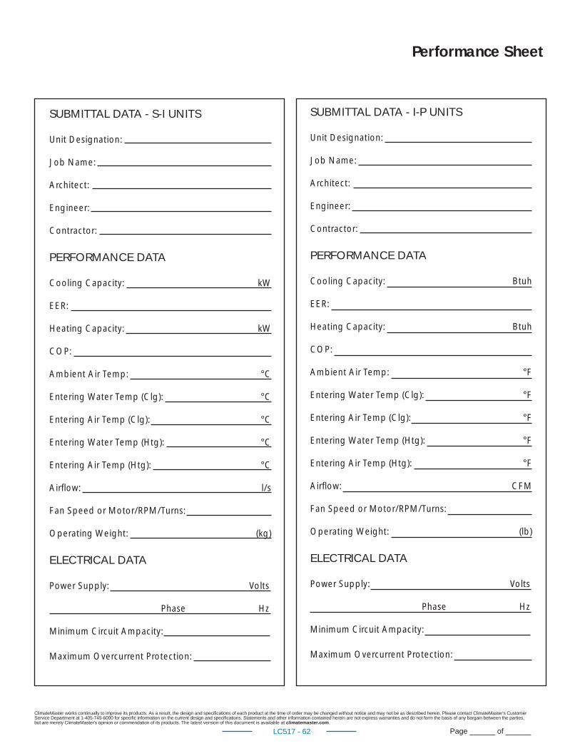
ClimateMaster works continually to improve its products. As a result, the design and specifi cations of each product at the time of order may be changed without notice and may not be as described herein. Please contact ClimateMaster's Customer Service Department at 1-405-745-6000 for specifi c information on the current design and specifi cations. Statements and other information contained herein are not express warranties and do not form the basis of any bargain between the parties, but are merely ClimateMaster's opinion or commendation of its products. The latest version of this document is available at climatemaster.com.
Page ______ of ______LC517 - 62
SUBMITTAL DATA - S-I UNITS
Unit Designation:
Job Name:
Architect:
Engineer:
Contractor:
PERFORMANCE DATA
Cooling Capacity: kW
EER:
Heating Capacity: kW
COP:
Ambient Air Temp: °C
Entering Water Temp (Clg): °C
Entering Air Temp (Clg): °C
Entering Water Temp (Htg): °C
Entering Air Temp (Htg): °C
Airfl ow: l/s
Fan Speed or Motor/RPM/Turns:
Operating Weight: (kg)
ELECTRICAL DATA
Power Supply: Volts
Phase Hz
Minimum Circuit Ampacity:
Maximum Overcurrent Protection:
Performance Sheet
SUBMITTAL DATA - I-P UNITS
Unit Designation:
Job Name:
Architect:
Engineer:
Contractor:
PERFORMANCE DATA
Cooling Capacity: Btuh
EER:
Heating Capacity: Btuh
COP:
Ambient Air Temp: °F
Entering Water Temp (Clg): °F
Entering Air Temp (Clg): °F
Entering Water Temp (Htg): °F
Entering Air Temp (Htg): °F
Airfl ow: CFM
Fan Speed or Motor/RPM/Turns:
Operating Weight: (lb)
ELECTRICAL DATA
Power Supply: Volts
Phase Hz
Minimum Circuit Ampacity:
Maximum Overcurrent Protection:

ClimateMaster works continually to improve its products. As a result, the design and specifi cations of each product at the time of order may be changed without notice and may not be as described herein. Please contact ClimateMaster's Customer Service Department at 1-405-745-6000 for specifi c information on the current design and specifi cations. Statements and other information contained herein are not express warranties and do not form the basis of any bargain between the parties, but are merely ClimateMaster's opinion or commendation of its products. The latest version of this document is available at climatemaster.com.
Page ______ of ______LC517 - 63
Notes
ClimateMaster works continually to improve its products. As a result, the design and specifi cations of each product at the time of order may be changed without notice and may not be as described herein. Please contact ClimateMaster's Customer Service Department at 1-405-745-6000 for specifi c information on the current design and specifi cations. Statements and other information contained herein are not express warranties and do not form the basis of any bargain between the parties, but are merely ClimateMaster's opinion or commendation of its products. The latest version of this document is available at climatemaster.com.
Page ______ of ______LC517 - 64
Date: Item: Action:05/16/17 Pages 38,41,42,43 Update 'A' dimensions
5/2717 All Updated demensional and wiiring diagram pages
1/13/17 All Updated TCV fi lter frame description
11/1/16 Document Design Update Updated
06/22/16 All Update Cabinet Description and Photo
4/5/16 Page 31 Update standard motor HP for 096
03/8/16 Page 42 Edit Engineering specs
02/10/15 Physical Data Table Updated Filter Sizes
09/30/14 Physical Data Table - Large Motor; Text Edit - Page 44 Added/Updated
05/05/14Physical Data Table - Page 29 & 31, Engineering Specifi cations - Page 44
Updated
03/24/14 Dimensional Data Table - Page 33 & 34 Corrected Depth, Width designation
02/07/14 Dimensional Data Table - Page 30 Corrected Depth, Width designation
09/30/13 Edit Text - Page 44 Updated
09/18/13 Updated Electrical Tables - Pages 35 & 36 Updated
02/06/13 Engineering Specifi cations Updated
11/28/12 TCV 072-120 Dimensional Data Updated
06/12/12 Engineering Specifi cations Updated
04/26/12 Engineering Specifi cations Updated
04/17/12 TCV Physical Data Updated
04/13/12 All Pages Added TCV sizes 160-300
04/02/12 Engineering Specifi cations Updated
02/16/12Dimensional DataEngineering Specifi cations
Updated
02/09/12 TC Physical Data Table Updated
10/07/11Dimensional DataPhysical Data Table
Corrected S/R and drain diametersCorrected TCV drain diameter
08/09/11 Unit Maximum Working Water Pressure Updated to Refl ect New Safeties
08/03/11 Engineering Specifi cationsAdded Digital Night Setback with Pump Restart (DXM w/ ATP32U03/04)
06/29/11 All Pages Added TCV072-120
06/09/11 Engineering Specifi cations Updated
04/07/11 Engineering Specifi cation NOTICE Updated
02/11/11 Performance Data Selection Notes Updated
01/03/11 Format - All Pages Updated
10/15/10 S-I Performance Data Table Updated
10/15/10 Physical Data Table Updated
09/14/10 Unit Features Added
07/29/10 Dimensional Data Updated
07/26/10 Wiring Diagrams Updated
07/26/10Compressor Mounting Information and Graphics Engineering Specifi cations
Updated to Refl ect Spring/Grommet Change
06/11/10 Format - All Pages Updated
06/11/10 Engineering Specifi ations Updated
06/11/10 Wiring Diagrams Updated All
10/15/09 Created
Revision History
ClimateMaster works continually to improve its products. As a result, the design and specifi cations of each product at the time of order may be changed without notice and may not be as described herein. Please contact ClimateMaster's Customer Service Depapp rtment at 1-405-745-6000 for spepp cifi c information on the current design gg and specpp ifi cations. Statements and other information contained herein are not exprespp s warranties and do not form the basis of any bayy rgaigg n between the papp rties, ,,but are merely ClimateMaster's opinion or commendation of its products. The latest version of this document is available at climatemaster.com.
Page ______ of ______LC517 - 64
gg gg p p
06/11/10 Wiring Diagrams Updated All
10/15/09 Created
7300 S.W. 44th StreetOklahoma City, OK 73179
Phone: 405-745-6000climatemaster.com


