Embed Size (px)
Citation preview
Towards QoS Provisioning in a Heterogeneous
Carrier-Grade Wireless Mesh Access NetworksUsing Unidirectional Overlay Cells
M. Kretschmer1, C. Niephaus1, and G. Ghinea2
1 Fraunhofer FOKUS, Sankt Augustin, Germany{mathias.kretschmer,christian.niephaus}@fokus.fraunhofer.de
2 Brunel University, London, [email protected]
Abstract. The visibility and success of Wireless Mesh Network (WMN)deployments has raised interest among commercial operators in this tech-nology. Compared to traditional operator access networks WMNs havethe potential to offer easier deployment and flexible self-reconfigurationat lower costs. A WMN-type architecture considered as an alternativefor an operator access network must meet similar requirements such ashigh availability and guaranteed QoS in order to support triple-play con-tent provisioning. In this paper we introduce an architecture of such aCarrier-grade Wireless Mesh Access Network (CG-WMAN). We thenpresent our contribution, an approach to seamlessly integrate unidirec-tional broadcast cells (i.e. DVB-T) into such a CG-WMAN. This allowshigher layer protocols to utilize broadcast cells like regular mesh links,where beneficial for a given payload and receiver distribution. We thenpresent a typical use case and discuss for which combinations of traffictype, user distribution and QoS requirements the use of longer rangebroadcast technologies can help to improve the overall CG-WMAN per-formance in terms of throughput and reliability.
1 Introduction
WMNs have attracted the attention of network operators due to their increaseddeployment flexibility and potentially lower operational costs compared to reg-ular rather fixed wireless operator networks. The work presented in this pa-per has been done within the context of the CARrier grade wireless MEshNetwork (CARMEN)[2] project, which aims at studying and specifying a WMNsupporting carrier grade triple-play services in future heterogeneous mobile/fixednetwork operator environments. A CARMEN access network can complementexisting access technologies by exploiting low costs mesh networking techniques.A key component of this CG-WMAN is an abstraction layer based on and extend-ing IEEE 802.21 to allow the integration of heterogeneous wireless technologiessuch as IEEE 802.11, IEEE 802.16 as well as Digital Video Broadcast (DVB)and 3rd Generation Partnership Project (3GPP) technologies) in a multi-hopfashion in order to provide ubiquitous Internet access in a scalable and efficient
1
manner. On the control plane, the abstraction layer maps technology specificprimitives onto a common set of events and commands. Upper layer modulessuch as self-configuration, routing, mobility management and monitoring areimplemented on top of those abstract primitives and can therefore operate withany technology that provides a proper MAC adaptor. The concept of TrafficEngineering (TE) using Path Computation Elements (PCEs) as specified in [4]is adapted by the routing module to perform inter and intra area routing. Ourwork focuses of the seamless integration of unidirectional technologies so thatthey can be utilized when beneficial for a specific content or user distribution.
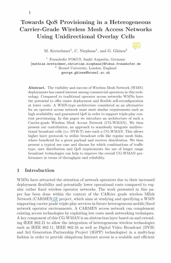
Fig. 1. Typical CG-WMAN scenario
Figure 1 depicts a typical CG-WMAN scenario with dedicated gateways, meshforwarder as well as access point nodes and various links interconnecting them.The links might have been establish using heterogeneous technologies such asIEEE 802.11 or 802.16, chosen to optimally fit the deployment scenario withregards to financial constraints, range, spectrum availability and robustness.
Delivering triple-play services within a CG-WMAN is a challenging task sincethe delivery of high-bandwidth multimedia traffic substantially increases the loadon the affected individual mesh links, the link groups or broadcast domains theybelong to and therefore the CG-WMAN as a whole. We therefore propose theseamless integration of broadcast technologies as an efficient delivery mediumespecially for, but not limited to, broadcast and multicast content.
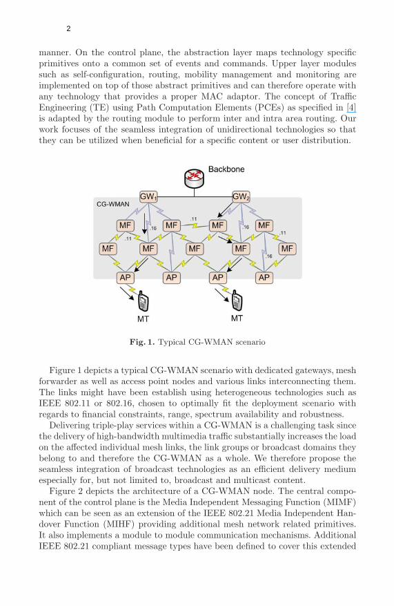
Figure 2 depicts the architecture of a CG-WMAN node. The central compo-nent of the control plane is the Media Independent Messaging Function (MIMF)which can be seen as an extension of the IEEE 802.21 Media Independent Han-dover Function (MIHF) providing additional mesh network related primitives.It also implements a module to module communication mechanisms. AdditionalIEEE 802.21 compliant message types have been defined to cover this extended
2
Fig. 2. The CG-WMAN Architecture is based on 802.21++ and MPLS
functionality. Messages are forwarded within the CG-WMAN using either adedicated management Multi Protocol Label Switching (MPLS) Label-SwitchedPaths (LSPs) or via hop-by-hop data link layer forwarding. The latter can choosebetween controlled flooding or explicit source routing. The CG-WMAN inter-nally uses EUI-64 addresses, to allow for the incorporation of non-IEEE 802technologies. Depending on the capabilities of the technology used, the wirelessinterfaces are operated in a promiscuous mode so that all frames received bythe wireless network adapter can be analyzed by the Frame Analyzer compo-nent. This component is crucial to the proper operation of the CG-WMAN sinceit extracts and derives information from the received frames and their headersin order to allow the monitoring component to provide this information in astandardized manner to the other CG-WMAN modules.
Logically below the MIMF component, the MAC adaptors are located. Theyprovide the adaptation of technology specific features to the common set ofprimitives provided by MIMF to the upper layer modules via the AI SAP.
The higher layer modules combined provide the functionality of a traditionalrouting protocol - and beyond. The functionality of a module varies dependingon the function of a node. Our CG-WMAN design is based on a centralizedapproach, where the centralized management nodes maintain the state of theirarea following the concept of a centralized and stateful PCE[4]. In the centralizedapproach unicast or multicast path computation as well as resource accountingand allocation can be performed optimally according to TE policies set forthby the operator. Due to the centralized management, it is crucial for the properoperation of the CG-WMAN that the state maintained at the management entityclosely reflects the actual state of the physical mesh links.
The forwarding component is designed based on the MPLS[17] specificationand will be described in more detail in the next section. The so-called link groupconcept has been introduced to address the issue of wireless channel resourcesbeing shared by more than one transmitting node. This concept takes into ac-count medium access protocol characteristics, the resources allocated as well as
3
the modulation being used in order to accurately compute and distribute thechannel resources thus avoiding overbooking or contention. For infrastructure-based technologies such as IEEE 802.16 or 802.11 in managed mode, the nodesconnected to the base station form a link group with the base station being thelink group leader. In the case of a multicast LSP with multiple receivers in alink group, the datagrams need to be sent and accounted for with the smallestcommon modulation between the sending or relaying node, which is usually thebase station, and the set of receivers.
The self configuration component is responsible for proper configuration ofthe mesh nodes, in particular it performs on-line radio planning to configure thewireless interfaces minimizing the possibility of interferences and maximizing theoverall mesh network throughput. The main task is located at the managemententity where it maintains a table of all possible physical links between nodes andtheir radios. A subset of those physical links is exported as a table of logical linkswhich can be used for actual datagram forwarding. Physical and logical links aredescribed as unidirectional resources. This table of logical links is similar toa link state table of traditional routing protocols such as Open Shortest PathFirst (OSPF)[12] and forms the basis of the TE path computation function. Thedetails of self configuration module are out of the scope of this paper.
The mobility component provides Mobile Terminal (MT) mobility similar tothe Proxy Mobile IP (PMIP)[5] concept, but is outside of the scope of this work.
1.1 Overlay Cells
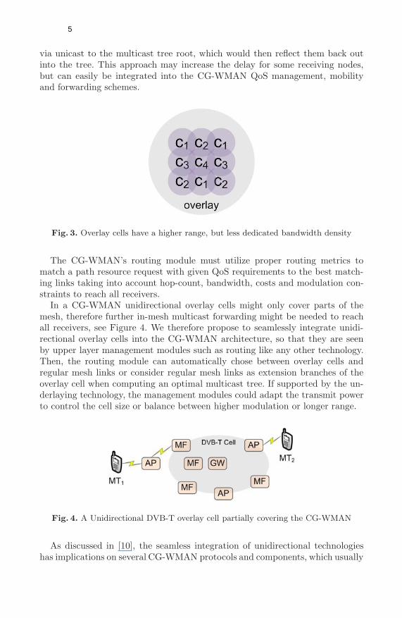
Overlay cells have been studied in the literature for cellular networks wherethey might increase the system capacity[19] [8] [3], but also in the context ofWMNs[16] [20] [11] [6]. Here mostly with the focus to break with the single-radio-per-node ad-hoc forwarding paradigm and its limitations regarding throughputand predictable Quality of Service (QoS) support. In our CG-WMAN, bidirec-tional overlay cells are natively supported by our architecture since to our routingmodule they simply appear as longer distance links between mesh nodes in thelink-state table, see Figure 1. The advantage of such links, the direct link lo-cal connection between nodes needs to be balanced against the lower bandwidthper area density compared to smaller mesh cells which can exploit Space-divisionmultiple access (SDMA) and frequency re-use, see Figure 3. Smaller cells allowfor higher unicast throughput via multiple hops, while larger cells can reach alarge group of receivers with a single isochronous transmission. They are there-fore well suited for the distribution of multicast traffic or specific mesh networkmanagement or synchronization tasks. Hence, we propose the use of overlay cellsprovided via robust unidirectional broadcast technologies such as Digital VideoBroadcast - Terrestrial (DVB-T), which allow for one single sending node only.Hence, complicated Media Access Control (MAC) protocols can be omitted,thus freeing up more wireless channel resources for the actual data transmission,which yields a higher physical channel utilization efficiency.
Most multicast use cases can be addressed using 1-to-N trees. Where multipleor mobile senders are required, they could be configured to send their datagrams
4
via unicast to the multicast tree root, which would then reflect them back outinto the tree. This approach may increase the delay for some receiving nodes,but can easily be integrated into the CG-WMAN QoS management, mobilityand forwarding schemes.
Fig. 3. Overlay cells have a higher range, but less dedicated bandwidth density
The CG-WMAN’s routing module must utilize proper routing metrics tomatch a path resource request with given QoS requirements to the best match-ing links taking into account hop-count, bandwidth, costs and modulation con-straints to reach all receivers.
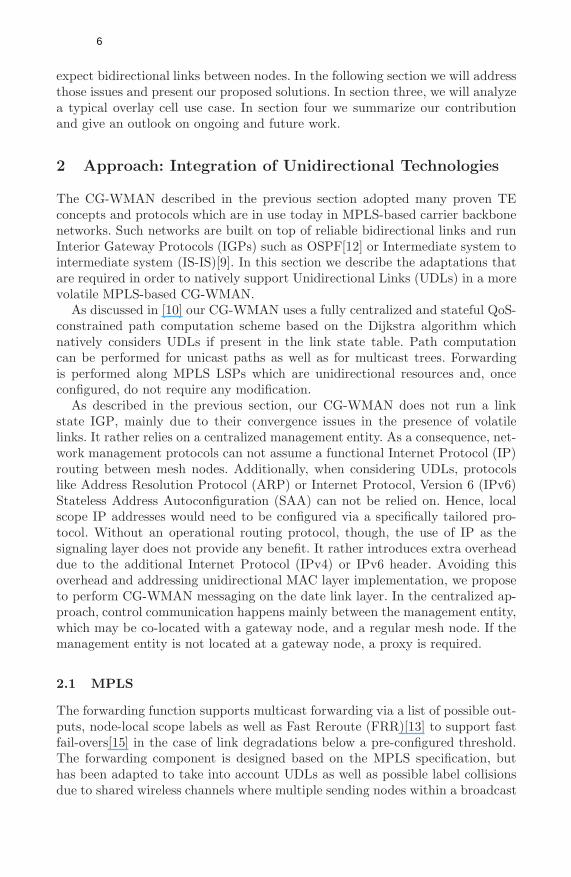
In a CG-WMAN unidirectional overlay cells might only cover parts of themesh, therefore further in-mesh multicast forwarding might be needed to reachall receivers, see Figure 4. We therefore propose to seamlessly integrate unidi-rectional overlay cells into the CG-WMAN architecture, so that they are seenby upper layer management modules such as routing like any other technology.Then, the routing module can automatically chose between overlay cells andregular mesh links or consider regular mesh links as extension branches of theoverlay cell when computing an optimal multicast tree. If supported by the un-derlaying technology, the management modules could adapt the transmit powerto control the cell size or balance between higher modulation or longer range.
Fig. 4. A Unidirectional DVB-T overlay cell partially covering the CG-WMAN
As discussed in [10], the seamless integration of unidirectional technologieshas implications on several CG-WMAN protocols and components, which usually
5
expect bidirectional links between nodes. In the following section we will addressthose issues and present our proposed solutions. In section three, we will analyzea typical overlay cell use case. In section four we summarize our contributionand give an outlook on ongoing and future work.
2 Approach: Integration of Unidirectional Technologies
The CG-WMAN described in the previous section adopted many proven TEconcepts and protocols which are in use today in MPLS-based carrier backbonenetworks. Such networks are built on top of reliable bidirectional links and runInterior Gateway Protocols (IGPs) such as OSPF[12] or Intermediate system tointermediate system (IS-IS)[9]. In this section we describe the adaptations thatare required in order to natively support Unidirectional Links (UDLs) in a morevolatile MPLS-based CG-WMAN.
As discussed in [10] our CG-WMAN uses a fully centralized and stateful QoS-constrained path computation scheme based on the Dijkstra algorithm whichnatively considers UDLs if present in the link state table. Path computationcan be performed for unicast paths as well as for multicast trees. Forwardingis performed along MPLS LSPs which are unidirectional resources and, onceconfigured, do not require any modification.
As described in the previous section, our CG-WMAN does not run a linkstate IGP, mainly due to their convergence issues in the presence of volatilelinks. It rather relies on a centralized management entity. As a consequence, net-work management protocols can not assume a functional Internet Protocol (IP)routing between mesh nodes. Additionally, when considering UDLs, protocolslike Address Resolution Protocol (ARP) or Internet Protocol, Version 6 (IPv6)Stateless Address Autoconfiguration (SAA) can not be relied on. Hence, localscope IP addresses would need to be configured via a specifically tailored pro-tocol. Without an operational routing protocol, though, the use of IP as thesignaling layer does not provide any benefit. It rather introduces extra overheaddue to the additional Internet Protocol (IPv4) or IPv6 header. Avoiding thisoverhead and addressing unidirectional MAC layer implementation, we proposeto perform CG-WMAN messaging on the date link layer. In the centralized ap-proach, control communication happens mainly between the management entity,which may be co-located with a gateway node, and a regular mesh node. If themanagement entity is not located at a gateway node, a proxy is required.
2.1 MPLS
The forwarding function supports multicast forwarding via a list of possible out-puts, node-local scope labels as well as Fast Reroute (FRR)[13] to support fastfail-overs[15] in the case of link degradations below a pre-configured threshold.The forwarding component is designed based on the MPLS specification, buthas been adapted to take into account UDLs as well as possible label collisionsdue to shared wireless channels where multiple sending nodes within a broadcast
6
domain or link group might be upstream neighbors which independently assignthe same label. An upstream label negotiation, as described in RFC3031 is notpossible in the presence UDLs. To address this issue, the forwarding componentswitches based on so-called Point-to-Multipoint Labels (PMPLabels) on the in-coming side which consist of the EUI64 address of the sending interface and theactual MPLS label, effectively turning the PMPLabel into a unique 84bit label.Due to the larger label size, a label can no longer be used as an index into atable. But, even a regular 20bit label would require a table with 1048576 entries,which might not fit into the memory of a small footprint mesh node. Hence,instead our forwarding module uses a simple hash function and stores its LSPstate in a hash map. An alternative solution would be a centralized label assign-ment at the management entity. This approach has not been followed since itwould increase the complexity of the management function even more.
While the setup and tear down protocol is related to Resource ReSerVationProtocol - Traffic Engineering (RSVP-TE), it does not need to allocate linkresources, since this is handled centrally at the management entity. It mighthowever carry additional information about the LSP’s QoS requirements so thateach node can configure it’s traffic shapers or MAC schedulers accordingly. Thisinformation also has to be cleared on a tear down.
Regarding FRR, in the current IEEE 802.21 compatible design, a Point of Lo-cal Repair (PLR) would subscribe to LSP REROUTE events of all downstreamnodes that are allowed to trigger an FRR action. This could lead to a storm ofevents since all nodes downstream of a possible link breakage will detect andsignal this event at almost the same time. To address this issue, a more efficient,probably hierarchical, delivery mechanisms suppressing identical messages fromdownstream nodes should be investigated.
2.2 Monitoring
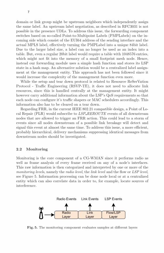
Monitoring is the core component of a CG-WMAN since it performs radio aswell as frame analysis of every frame received on any of a node’s interfaces.This raw information is then categorized and interpreted by one or more of themonitoring levels, namely the radio level, the link level and the flow or LSP level,see Figure 5. Information processing can be done node local or at a centralizedentity which can also correlate data in order to, for example, locate sources ofinterference.
Fig. 5. The monitoring component evaluates samples at different layers
7
The monitoring component can create a set of events when the state of themonitored object has changed. These events trigger most actions of the otherCG-WMAN management components, such as:
– Change of Neighboring mesh node statistics– Mobile Terminal (MT) presence detection and hand-over indications– Indication of interference or intrusion– Change of link state, i.e. up, down or underperforming– Provision of LSP end-to-end performance statistics– Creation of QoS & network state aware LSP events to support i.e. FRR– Network reconfiguration based on long term link analysis
Detailed wireless monitoring is a difficult task due to the dynamic nature ofwireless links caused by temporary fading and interferences, but also due to oftenvery dynamic per-frame transmitter configurations. The wireless technologiesconsidered in our CG-WMAN range from satellite (i.e. DVB-S) over 3GPP toIEEE 802.16 and 802.11. Therefore the nominal characteristics, as well as theparameters that can be analyzed may vary.
As suggested in RFC 3272[1] our LSP level monitoring performs end-to-endmonitoring of individual LSP statistics. In addition to the actual bandwidth uti-lization, we also maintain PHY status, loss, signal quality, delay and activitystatistics which can indicate wireless link stability with a varying significancedepending on the QoS requirements of the payload. This receiving side moni-toring measures the actual end-to-end characteristics of an LSP and is thereforemandatory to verify that an LSP receives the agreed end-to-end QoS handling.The per-LSP QoS requirements are installed at each node on the path during theLSP setup procedure together with the LSP forwarding state. This monitoringapproach can be implemented by passive and feedback-free analysis of receiveddatagrams which makes it therefore also suitable for UDLs.
2.3 Link Layer Message Forwarding
Similar to IEEE 802.11s, forwarding mechanisms for control traffic are imple-mented at the data link layer. User traffic is forwarded exclusively via LSPs andis therefore not affected by this design decision. Since all control communicationtakes place among MIMF entities, but with different forwarding requirements,we provide multiple generic message forwarding schemes to the NET SAP whichcan than utilize the most appropriate one for each CG-WMAN control commu-nication. The following messaging schemes are being provided:
– Management LSP– Controlled flooding towards the destination, mainly the management entity– Explicit source routing
Messaging via the management LSP is the preferred mechanism and is commonlyrelied upon unless the LSP has not yet been established or is down due to a linkfailure or network partitioning.
8
The most basic hop-by-hop data link layer forwarding scheme is implementedvia a controlled broadcast flooding towards the destination node. In the central-ized approach, this destination node is in most cases the management entity,which by itself periodically floods mesh info messages into the mesh network.Using this information, the controlled flooding scheme can therefore direct theflooding towards the management entity. The controlled flooding approach isrelated to distance vector routing as it is used by many WMN routing protocolssuch as Ad hoc On-Demand Distance Vector Routing Protocol (AODV)[14]. Inthe presence of UDLs, the flooding control mechanism is by-passed to ensure for-warding to the destination. This mechanism is not expected to perform highlyefficient forwarding, it is rather a last resort if all other means to forward controlmessages fail.
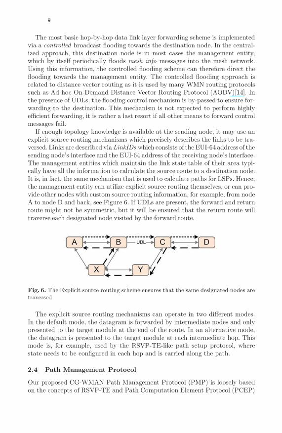
If enough topology knowledge is available at the sending node, it may use anexplicit source routing mechanisms which precisely describes the links to be tra-versed. Links are described via LinkIDs which consists of the EUI-64 address of thesending node’s interface and the EUI-64 address of the receiving node’s interface.The management entities which maintain the link state table of their area typi-cally have all the information to calculate the source route to a destination node.It is, in fact, the same mechanism that is used to calculate paths for LSPs. Hence,the management entity can utilize explicit source routing themselves, or can pro-vide other nodes with custom source routing information, for example, from nodeA to node D and back, see Figure 6. If UDLs are present, the forward and returnroute might not be symmetric, but it will be ensured that the return route willtraverse each designated node visited by the forward route.
Fig. 6. The Explicit source routing scheme ensures that the same designated nodes aretraversed
The explicit source routing mechanisms can operate in two different modes.In the default mode, the datagram is forwarded by intermediate nodes and onlypresented to the target module at the end of the route. In an alternative mode,the datagram is presented to the target module at each intermediate hop. Thismode is, for example, used by the RSVP-TE-like path setup protocol, wherestate needs to be configured in each hop and is carried along the path.
2.4 Path Management Protocol
Our proposed CG-WMAN Path Management Protocol (PMP) is loosely basedon the concepts of RSVP-TE and Path Computation Element Protocol (PCEP)
9
[18] and is realized via MIMF messaging. PMP features a public interface whichprovides primitives for any CG-WMAN mesh node to
– request a path computation from a one or a set of PCEs– set up an LSP and associated QoS and MAC layer state– tear down an LSP and associated QoS and MAC layer state
PATH REQUEST: To request the computation of a new path, this message is sentto the routing module specifying the source and destination node IDs of the pathas well as the QoS requirements. Via the Response message, the routing modulecan return none, one or multiple possible paths to choose from. No resources arereserved at this point.
PATH SETUP: The requesting node may then send a message to the routing func-tion specifying the chosen path. The routing function will then try to allocatethe resources and signal the setup of the associated LSP. Once completed, aResponse message will be returned indicating the result of the setup procedure.
PATH TEAR DOWN: An established LSP may be torn down using this message. AResponse message is returned when the procedure has completed indicating theresult of the procedure.
Additionally, PMP provides a set of internal primitives which are used by therouting module to
– signal the setup of an LSP using explicit source routing– signal the tear down of an LSP using explicit source routing– configure FRR backup LSPs– manage FRR event triggers– retrieve LSP label and statistics for debugging purposes
When the routing function receives a PATH SETUP message, it sends an explicitlysource routed LSP setup message using the MIMF link layer forwarding servicewhich is forwarded hop-by-hop along the path to be set up. Each node will assigna local outgoing label for this new LSP and store this label in the setup packet,so that it can be signaled to the next downstream node as incoming label. Inthe presence of UDLs, data link layer addresses of link local neighbors can notbe learned. However, the LinkID consists exactly of this information, the EUI-64 address of the outgoing interface and the EUI-64 address of the destinationinterface. A new LSP is identified at the ingress node using that nodes outgoinglabel.
A PATH TEAR DOWN message triggers a similar procedure to tear down an LSPidentified by its ingress node’s label.
For debugging purpose, a PATH COLLECT STATS message can be sent along thepath of an LSP to collect the local labels associated with this LSP as well asrelated performance statistics.
FRR backup LSPs are signaled similarly to regular LSPs. The decision whichLSP or segments thereof are to be protected with a backup is based on operatorpolicies. After the backup LSP has been signaled, the nodes along the protected
10
segments can be configured with multiple specific source routes towards thePLR. If no specific source routes have been configured, the controlled broadcastdelivery mechanism is used. In the event of a link breakage, signaling might beimpacted, as well. Hence, multiple paths and forwarding mechanisms could beused in parallel.
3 Use Case: Multicast
In the previous section we have presented our approach to seamlessly integrateUDLs into a CG-WMAN so that they can be utilized when beneficial for givenpayload characteristics or receiver distributions. We envisage a number of differ-ent use case where UDLs can increase the overall network efficiency, throughputor reliability.
UDLs based on, for example, DVB-T offer a very robust transport, a highspectral efficiency and are not impacted by any channel access protocol overhead.Hence, they are suitable for any kind of feedback-free content delivery frombroadcast multimedia content to network topology updates. The latter one canbenefit from the fact that a datagram is received at all nodes isochronously.Properly implemented, even network timing or synchronization tasks could berealized.
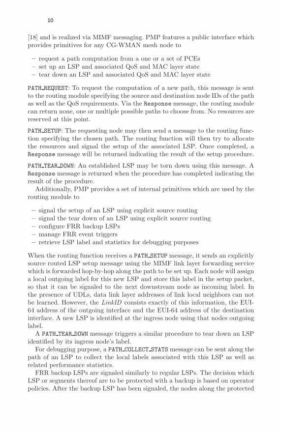
Single source 1-to-N multicast routing within a CG-WMAN with overlay cellscan be configured in different ways depending on operator policies, receiver dis-tribution and QoS requirements:
– In-mesh hop-by-hop multicast tree forwarding– Single hop broadcast via an overlay cell– Using a combination of the above
Fig. 7. Multicast routing can use in-mesh hop-by-hop forwarding or overlay cells
In order for the routing module to calculate the optimal multicast forwardingtree, a cost function is required which combines the information provided by thelink group model, the link state table and the path database of established LSPs.From the link state table of logical links and the path database the topologicalreceiving node distribution of a multicast tree can be determined. The resultis a set of hop-by-hop forwarding trees, since in most cases multiple options
11
will exist to form a tree covering all nodes, see Figure 7. Taking the link groupinformation into account, the algorithm can determine which links belong tothe same link group and if the nodes could be reached with a single link localbroadcast transmission and which Modulation and Coding Scheme (MCS) mustbe used to reach the node with the weakest link conditions in the group. Alower MCS yields a lower spectral efficiency (E). To calculate the costs of theresources to be allocated for an LSP segment in a link group, the number ofnodes (N) in this link group, the costs of its resources (C), i.e. bandwidth, andthe scheduling or channel access overhead (O) are required. The latter variesheavily depending on the technology, its MAC layer design and the payloadcharacteristics. For example, the IEEE 802.11 MAC is very inefficient whensmall (i.e. Voice-over-IP (VoIP)) datagrams are sent, since before sending eachdatagram the contention-based channel access procedure must be executed. Thisoften requires more time than the actual datagram transmission.
Hence, the costs of LSP resources in a link group CLSP can be expressed as:
CLSP =C · OE · N
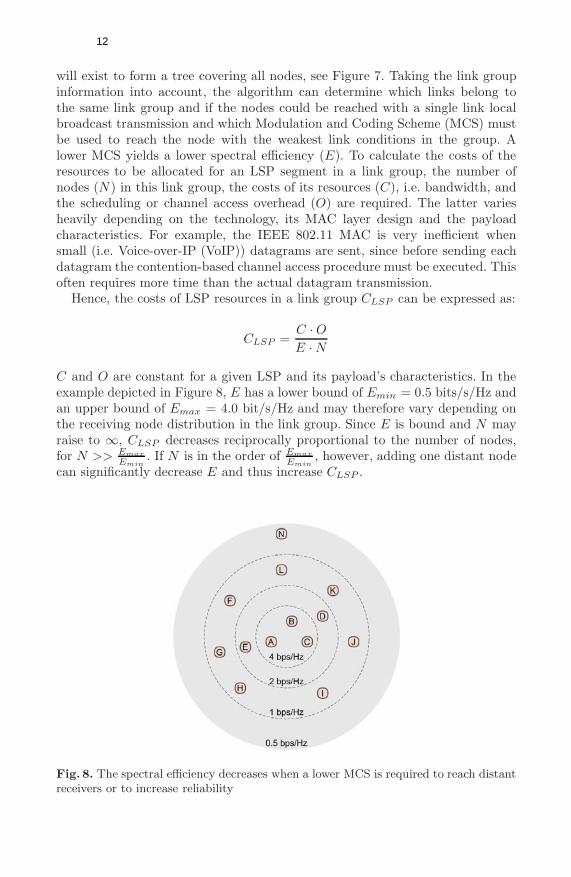
C and O are constant for a given LSP and its payload’s characteristics. In theexample depicted in Figure 8, E has a lower bound of Emin = 0.5 bits/s/Hz andan upper bound of Emax = 4.0 bit/s/Hz and may therefore vary depending onthe receiving node distribution in the link group. Since E is bound and N mayraise to ∞, CLSP decreases reciprocally proportional to the number of nodes,for N >> Emax
Emin. If N is in the order of Emax
Emin, however, adding one distant node
can significantly decrease E and thus increase CLSP .
Fig. 8. The spectral efficiency decreases when a lower MCS is required to reach distantreceivers or to increase reliability
12
For example, in Figure 8, if only node A is present, E = Emax. If nodes B andC are added, E remains constant and due the the increased number of nodes,the costs CLSP decrease. Let’s assume, node N should be added. In this caseE would decrease significantly to Emin, while the number of nodes would justincrease by one. It is now up to provider policies if node N would be allowed tojoin the link group (i.e. for premium customers), would be offered the payloadvia other links, or be denied access (i.e. for low-cost resale customers).
The above considerations need to be applied to each link group of the multicasttree. The total costs of a multicast tree Ctree can then be expressed as the sumof the costs of the n link groups traversed:
Ctree =n∑
i=1
CLSPi
Here, we assume that the individual local link group costs consideration do notaffect other links or link groups which are part of the multicast tree or eventhe mesh network as a whole. A simple multicast tree computation algorithmtherefore has to consider two optimization criteria, meeting the end-to-end QoSrequirements of the payload while minimizing the total costs Ctree of the result-ing multicast tree.
A more complex algorithm might be required to take into account dependen-cies between local link group optimization, provider policies, detailed payloadcharacteristics and estimations of usage or receiver distribution pattern vari-ations. The above approach could serve as a base line to quantify potentialoptimization gains of more complex algorithms.
Summarizing the above, we have shown that for large sets of nodes overlaycells offer a viable solution to keep multicast traffic off the regular mesh links. Incases of smaller sets of nodes, multiple trade-offs need to be considered to findthe optimal multicast tree.
4 Conclusion and Future Work
We have presented our proposal to seamlessly integrate unidirectional technolo-gies at the data link layer into a CG-WMAN. We have shown that given theconstraints of a CG-WMAN, this is a suitable approach. In order to optimallyutilize overlay cells, we have discussed which requirements routing algorithmsneed to fulfill and which trade-offs to consider.
Future work will look into autonomous adjustments of link group costs ac-cording to operator policies and a more advanced multicast group computationalgorithm taking into account dependencies between local link group optimiza-tion. We will also evaluate additional use cases such as the (temporary) increaseof downstream bandwidth or the use of overlay cells to transmit mesh networkmanagement messages.
The work described in this paper is a work in progress. At the time of writing,the described CG-WMAN is being implemented using our C++ Simple and Ex-tensible Network Framework (SENF)[7] and its network emulator which allows
13
for a mixed-mode validation of our design as well as an algorithm evaluationusing real and emulated network interfaces. A multi-core Linux PC can emu-late about 250 nodes, which allows us to evaluate, and optimize our proposedmulticast routing algorithm.
Acknowledgment
The research leading to these results has received funding from the EuropeanCommunity’s Seventh Framework Programme (FP7/2007-2013) under grantagreement n� 214994. The views and conclusions contained here are those ofthe authors and should not be interpreted as necessarily representing the officialpolicies or endorsements, either expressed or implied, of the CARMEN projector the European Commission.
References
[1] Awduche, D., Chiu, A., Elwalid, A., Widjaja, I., Xiao, X.: Overview and Principlesof Internet Traffic Engineering. RFC 3272 (Informational). Updated by RFC 5462(May 2002)
[2] Banchs, A., Bayer, N., Chieng, D., de la Oliva, A., Gloss, B., Kretschmer, M.,Murphy, S., Natkaniec, M., Zdarsky, F.: Carmen: Delivering carrier grade servicesover wireless mesh networks. In: Proc. IEEE 19th International Symposium onPersonal, Indoor and Mobile Radio Communications, PIMRC 2008, September15-18, pp. 1–6 (2008)
[3] Deissner, J., Fettweis, G.P.: Increased capacity through hierarchical cellular struc-tures with inter-layer reuse in an enhanced gsm radio network. Mob. Netw.Appl. 6(5), 471–480 (2001)
[4] Farrel, A., Vasseur, J.-P., Ash, J.: A Path Computation Element (PCE)-BasedArchitecture. RFC 4655, Informational (August 2006)
[5] Gundavelli, S., Leung, K., Devarapalli, V., Chowdhury, K., Patil, B.: Proxy MobileIPv6. RFC 5213 (Proposed Standard) (August 2008)
[6] Haddad, E., Gregoire, J.-C.: Implementation issues for the deployment of a wmnwith a hybrid fixed/cellular backhaul network in emergency situations. In: Proc.1st International Conference on Wireless Communication, Vehicular Technology,Information Theory and Aerospace & Electronic Systems Technology Wireless,VITAE 2009, pp. 525–529 (2009)
[7] http://senf.berlios.de (accessed 22-April-2009)[8] Huang, Q., Ko, K.-T., Chan, S., Iversen, V.B.: Loss performance evaluation in
heterogeneous hierarchical networks. In: Mobility 2008: Proceedings of the Inter-national Conference on Mobile Technology, Applications, and Systems, pp. 1–7.ACM, New York (2008)
[9] Kompella, K., Rekhter, Y.: IS-IS Extensions in Support of Generalized Multi-Protocol Label Switching (GMPLS). RFC 5307 (Proposed Standard) (October2008)
[10] Kretschmer, M., Ghinea, G.: Seamless integration of unidirectional broadcast linksinto qos-constrained broadband wireless mesh access networks. In: Proc. The 4thInternational Conference for Internet Technology and Secured Transactions (2009)
14
[11] Liu, B., Thiran, P., Towsley, D.: Capacity of a wireless ad hoc network with infras-tructure. In: MobiHoc 2007: Proceedings of the 8th ACM international symposiumon Mobile ad hoc networking and computing, pp. 239–246. ACM, New York (2007)
[12] Moy, J.: OSPF Version 2. RFC 2328 (Standard) (April 1998)[13] Pan, P., Swallow, G., Atlas, A.: Fast Reroute Extensions to RSVP-TE for LSP
Tunnels. RFC 4090 (Proposed Standard) (May 2005)[14] Perkins, C., Belding-Royer, E., Das, S.: Ad hoc On-Demand Distance Vector
(AODV) Routing. RFC 3561 (Experimental) (July 2003)[15] Raj, A., Ibe, O.C.: A survey of ip and multiprotocol label switching fast reroute
schemes. Comput. Netw. 51(8), 1882–1907 (2007)[16] Reaz, A., Ramamurthi, V., Ghosal, D., Benko, J., Li, W., Dixit, S., Mukherjee,
B.: Enhancing multi-hop wireless mesh networks with a ring overlay. In: Proc.5th IEEE Annual Communications Society Conference on Sensor, Mesh and AdHoc Communications and Networks Workshops SECON Workshops 2008, pp. 1–6(2008)
[17] Rosen, E., Viswanathan, A., Callon, R.: Multiprotocol Label Switching Architec-ture. RFC 3031 (Proposed Standard) (January 2001)
[18] Vasseur, J., Roux, J.L.: Path Computation Element (PCE) Communication Pro-tocol (PCEP). RFC 5440 (Proposed Standard) (March 2009)
[19] Yu, J.Y., Chong, P.H.J., Yang, M.: Performance of microcell/macrocell cellularsystems with reuse partitioning. In: Mobility 2006: Proceedings of the 3rd in-ternational conference on Mobile technology, applications & systems, p. 51.ACM, New York (2006)
[20] Zhou, P., Manoj, B.S., Rao, R.: A gateway placement algorithm in wireless meshnetworks. In: WICON 2007: Proceedings of the 3rd international conference onWireless internet, Brussels, Belgium, pp. 1–9. ICST (Institute for Computer Sci-ences, Social-Informatics and Telecommunications Engineering) (2007)
15