Embed Size (px)
Citation preview
Towards effective modeling and programming multi-core tiledreconfigurable architectures
Kenneth C. Rovers, Marcel D. van de Burgwal, Jan Kuper, and Gerard J.M. SmitComputer Architecture for Embedded Systems group,
CTIT, Department of EEMCS, University of Twente, Enschede, The [email protected], http://caes.cs.utwente.nl/Research/?project=BeamForce
Abstract— For a generic flexible efficient array antennareceiver platform a hierarchical reconfigurable tiled ar-chitecture has been proposed. The architecture providesa flexible reconfigurable solution, but partitioning, map-ping, modeling and programming such systems remainsan issue. We will advocate a model-based design approachand propose a single semantic (programming) model forrepresenting the specification, design and implementation.This approach tackles these problems at a higher concep-tual level, thereby exploiting the inherent composabilityand parallelism available in the formalism. A case studyillustrates the use of the semantic model with examplesfrom analogue/digital co-design and hardware/softwareco-design.
Keywords: Phased array beamforming, reconfigurable tiledarchitecture, semantic programming model, model-based design
1. IntroductionWhen designing a mixed signal system the traditional
approach uses mathematics for analysis, SysML/UML for(system) modelling, Simulink for hardware simulationsand SystemC for software simulations/implementations[1], [2], [3], [4]. This means a number of tools areused, each of which has it’s own model. This complicatesholistic iterative system design and makes the trade-offof what to do in the analogue domain and what to doin the digital domain more difficult. A single model andtool would be beneficial. Simulink is the de-facto stan-dard for block-diagrams models based on mathematics.However, as we will discuss, Simulink is less suitablefor digital hardware, in our case a tiled multi-processorarchitecture, where architecture definition, reconfigurationand programming come into play. For a reconfigurablesystem, the architecture must support multiple applicationsor configurations and the models must aid in their design.
System design is greatly aided by the use of models,which provide an abstraction at different levels of detailor functionality. The models can also complement eachother by providing different views of the system. Inhardware, model-based design uses building blocks todefine functional characteristics of the system at variousdegrees of sophistication, allowing simulation, testing andverification of systems [1]. In software, this approach
This research is partly funded by Thales Netherlands and STW projectsCMOS Beamforming (07620) and NEST (10346).
is called the model-driven architecture approach [2]. Inorder to decouple the system design from an architecture,a high level model should be architecture independentand a model transformation can be applied to create anarchitecture dependent model.
We will advocate a model-based design approach andpropose a single semantic (programming) model based onmathematics. This model can be evaluated for example forsimulation purposes. Effectively using and programmingMPSoCs is difficult [5]. We will show how to develop asemantic model for a simple beamforming application intoan implementation for a reconfigurable tiled MPSoC, andhow to evaluate different architecture alternatives with it.
After an introduction to the application domain andthe used platform for our case study, the commonly useddesign approach for such systems and its limitations ispresented. Next the “semantic (programming) model” isproposed for representing the specification, design, andimplementation with a single model. Finally, a case studyis presented in which we will compare the traditionalapproach (in the form of a mathematical analysis with aSimulink model) with the semantic model approach.
1.1 Application DomainTo illustrate the model-based design approach, we use
a phased array receiver platform as an example of a highperformance digital signal processing (DSP) application.The current design of these systems is mainly drivenby functional requirements (e.g., resolution, sensitivity,response time) where non-functional requirements (e.g.,costs, power consumption) are of secondary concern [6].In areas like radio astronomy and for satellite receivers,phased array antennas show great promise. For example, acheaper or higher resolution SKA (square kilometer array[7]) or a flat less obstructive electronically steered multi-satellite receiver. However, their large scale introductionhas been obstructed by the high costs involved. The goalis thus to develop a low-cost, low-power flexible phasedarray receiver system.
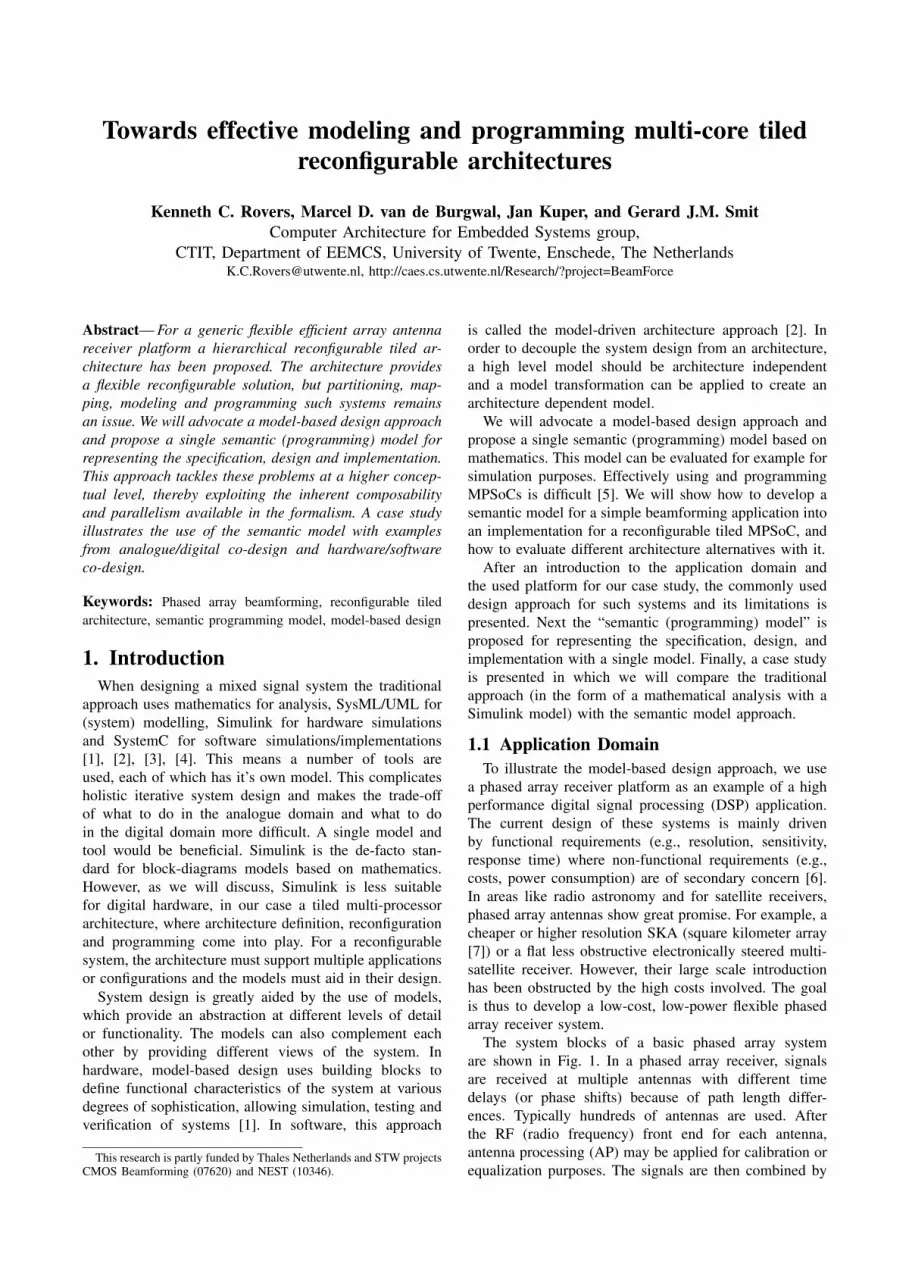
The system blocks of a basic phased array systemare shown in Fig. 1. In a phased array receiver, signalsare received at multiple antennas with different timedelays (or phase shifts) because of path length differ-ences. Typically hundreds of antennas are used. Afterthe RF (radio frequency) front end for each antenna,antenna processing (AP) may be applied for calibration orequalization purposes. The signals are then combined by
+
Beamformer
DOA BS
Beam-control
RF AP ψc
RF AP ψc
RF AP ψc
wave front
d
∆l
Fig. 1: Phased array receiver and angular sensitivity
the beamforming processing (beamformer). Beamsteering(BS) refers to changing the shape and direction of theformed beam by changing the gain and delay of theantenna signals to create a certain angular sensitivity orradiation pattern as shown in Fig. 1. Note that multiplebeams in different directions can be formed by re-using theantennas signals and applying the beamforming for eachbeam with different correction parameters. To calculate theparameters, the beamsteerer needs to know in which angle(direction) to point the beam. This information is providedby the beam control process.
1.2 Reconfigurable Tiled ArchitecturesPhased array processing can be characterised as a
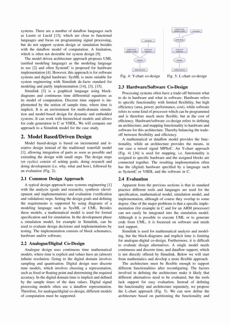
streaming application with high data rates and processingrequirements, but a regular processing structure. Becauseof costs, complexity, dependability, and scalability reasons,a design with mostly identical components is preferred,but because of functionality with different requirementsand use, it will be heterogeneous. We would like to limitthe data rate as soon as possible through beamforming,because I/O is expensive. This implies that the processingis moved closer to the antennas. However, combined datacannot be separated later on, so we loose flexibility. Fur-thermore, the distributed processing must be synchronised.Because a scalable and dependable solution is needed, atiled architecture is proposed with reconfigurable cores toregain flexibility. Processing tiles are combined on multi-ple hierarchical levels. A multi-processor system-on-chip(MPSoC) can be extended to multiple chips on a board(MCoB) and multiple boards in a system (MBiS) giving aheterogeneous hierarchical tiled architecture (Fig. 3). Weaim at a processing architecture which is flexible enoughto support multiple methods of beamforming, as well asbeamsteering and beam-control. [8]
A reconfigurable hierarchical processing array can pro-vide flexibility and has a number of advantages. We canuse only part of the array or create multiple sub-arrays
anal
ys
is
mat
hem
atical
mod
el
synthesis
functional m
odel &im
plem
entation
evaluationsimulation model
to
p-down
incr
emen
tal iterativegoal
sre
se
arch
requ
irem
ents
speci
fication
developmen
t
developm
entim
plemen
tation
evaluationverification validation
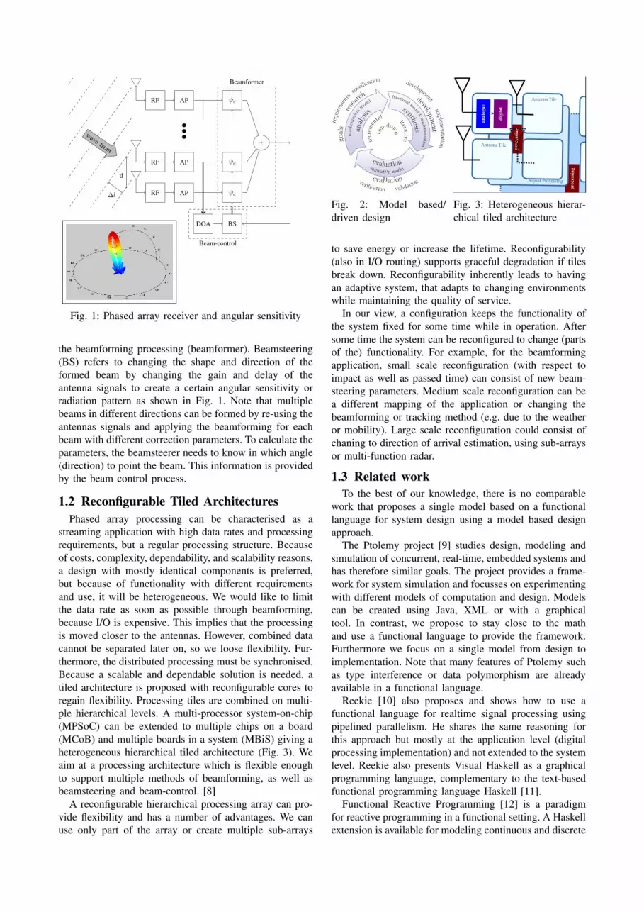
Fig. 2: Model based/driven design
• Any radio (RF) system! Satellite receivers
! Radar
! Radio Astronomy
! Mobile
! Wireless (WLAN/WiMax)
BeamForce
Phased Array Beamforming
Beamforming
http://caes.cs.utwente.nl/Research/?project=Beamforce
•Cheap generic flexible efficient
array antenna transceiver platform! Converging solution for telecom,
military and consumer products
! Multi-standard, adaptable to future
• Implications/choices! Functionality, size, cost " CMOS
! Multi-standard, flexible, generic "
Software defined radio
! Flexible, efficient, SDR, adaptable "
Reconfigurable hardware
• Multi-core reconfigurable processing on a (single)
CMOS chip (MPSoC)
• Processing close to antenna
• Multiple hierarchical levels ! distributed processing
! fail safety
! scalability
! partitioning
• Streaming data processing! large amount of data from each
antenna (100 Msamples/s)
! Low latency / real-time
• Multiple beams! Scanning
! Tracking
! “Null” interferers
• Multi-hierarchical distributed
processing! Processing tiles
! Multiple feedback loops
• Dependable! Quality of Service
! Graceful degradation
• Dynamic reconfiguration
Kenneth C. Rovers, Marcel D. van de Burgwal, Gerard J.M. SmitComputer Architecture for Embedded Systems group, University of Twente
Characteristics
Conclusion
Approach
Model
ApplicationsTECHNISCHE WETENSCHAPPEN
"CMOS Beamforming Techniques" STW Project Proposal Page 2
Interfering
GSM
basestation
Satellite 1
Phased Array
Antenna Roof
Multiple programmable
Antenna beams
“null”
Fixedbeam
Satellite 2
Single mechanically
fixed beam (1 satelite)
Figure 1: Comparison of satellite reception via a traditional mechanically fixed dish antenna and a Phased
Array antenna with smart beamforming. When using smart beamforming, satellite signals in the beam
directions of the antennas are received, while the interfering GSM signal is rejected via a "null" in the beam
pattern. Electronic beamforming also allows for adapting the beam pattern dynamically, e.g. to track the
satellite position when a vehicle is moving.
Figure 2: Principle of beamforming via an array of antenna elements and receivers with variable gain Gi and
variable time-delay Ti: by tuning Ti and Gi appropriately, signals from specific directions add up
constructively (resulting in a beam), while signals from other directions are cancelled (resulting in a null).
• Make the transceiver directional! Form an EM beam using
constructive interference
• Multiple (thousands of) antennas! Fields arrive at different times
! Correlate for a direction by adjusting
(gain and) delay
! Time delay !T gives a phase shift for
a single frequency
• Each antenna has its own
channel for each transmitter! Channel matrix can model coupling
• Multi-stage beamforming! Possibly mixed analogue/digital
Information Processing
pro
cess
ing
Signal Processing
pro
cess
ing
Antenna Tile
Antenna Tile
an
alo
gu
e
dig
ital
bea
mfo
rmer
sig
na
l
pro
cess
or
info
rma
tio
n
pro
cess
or
adaptive
control
an
ten
na
an
ten
na
an
ten
na
rece
iver
an
ten
na
an
ten
na
an
ten
na
filt
er
an
ten
na
an
ten
na
an
ten
na
freq
uen
cy
con
ver
sio
n
an
ten
na
an
ten
na
an
ten
na
bea
mfo
rmer
an
ten
na
bea
mfo
rmer
RF
Fig. 3: Heterogeneous hierar-chical tiled architecture
to save energy or increase the lifetime. Reconfigurability(also in I/O routing) supports graceful degradation if tilesbreak down. Reconfigurability inherently leads to havingan adaptive system, that adapts to changing environmentswhile maintaining the quality of service.
In our view, a configuration keeps the functionality ofthe system fixed for some time while in operation. Aftersome time the system can be reconfigured to change (partsof the) functionality. For example, for the beamformingapplication, small scale reconfiguration (with respect toimpact as well as passed time) can consist of new beam-steering parameters. Medium scale reconfiguration can bea different mapping of the application or changing thebeamforming or tracking method (e.g. due to the weatheror mobility). Large scale reconfiguration could consist ofchaning to direction of arrival estimation, using sub-arraysor multi-function radar.
1.3 Related workTo the best of our knowledge, there is no comparable
work that proposes a single model based on a functionallanguage for system design using a model based designapproach.
The Ptolemy project [9] studies design, modeling andsimulation of concurrent, real-time, embedded systems andhas therefore similar goals. The project provides a frame-work for system simulation and focusses on experimentingwith different models of computation and design. Modelscan be created using Java, XML or with a graphicaltool. In contrast, we propose to stay close to the mathand use a functional language to provide the framework.Furthermore we focus on a single model from design toimplementation. Note that many features of Ptolemy suchas type interference or data polymorphism are alreadyavailable in a functional language.
Reekie [10] also proposes and shows how to use afunctional language for realtime signal processing usingpipelined parallelism. He shares the same reasoning forthis approach but mostly at the application level (digitalprocessing implementation) and not extended to the systemlevel. Reekie also presents Visual Haskell as a graphicalprogramming language, complementary to the text-basedfunctional programming language Haskell [11].
Functional Reactive Programming [12] is a paradigmfor reactive programming in a functional setting. A Haskellextension is available for modeling continuous and discrete
systems. There are a number of dataflow languages suchas Lustre or Lucid [13], which are close to functionallanguages and focus on programming signal processing,but do not support system design or simulation besideswith the dataflow model of computation. A limitation,which is often not desirable for system design [9].
The model driven architecture approach proposes UML(unified modeling language) as the modeling languageto use [2] and often SystemC is proposed for hardwareimplementation [4]. However, this approach is for softwaresystems and digital hardware. SysML is more suitable forsystem engineering with Simulink de-facto standard formodeling and partly implementation [14], [3], [15].
Simulink [3] is a graphical language using block-diagrams and continuous time differential equations asits model of computation. Discrete time support is im-plemented by the notion of sample time, where time isimplicit. It is an environment for multi-domain simula-tion and model-based design for dynamic and embeddedsystems. It can work with hierarchical models and allowsfor code generation in C or VHDL. We will compare ourapproach to a Simulink model for the case study.
2. Model Based/Driven DesignModel based-design is based on incremental and it-
erative design instead of the traditional waterfall model[1], allowing integration of parts as soon as possible andextending the design with small steps. The design steps(or cycles) consist of setting goals, doing research anddoing development (i.e. why, what and how), followed byan evaluation (Fig. 2).
2.1 Common Design ApproachA typical design approach uses systems engineering [1]
with the analysis (goals and research), synthesis (devel-opment and implementation) and evaluation (verificationand validation) steps. Setting the design goals and definingthe requirements is supported by using diagrams of amodeling language such as SysML or UML. Besidesthese models, a mathematical model is used for formalspecification and for simulation. In the development phasea simulation model, for example in Simulink, can beused to evaluate design decisions and implementations bytesting. The implementation consists of block schematics,hardware and/or software.
2.2 Analogue/Digital Co-DesignAnalogue design uses continuous time mathematical
models, where time is explicit and values have an (almost)infinite resolution. Going to the digital domain involvessampling and quantisation. Digital design uses discretetime models, which involves choosing a representation,such as fixed or floating point and determining the requiredaccuracy. In the digital domain time is implicit and definedby the sample times of the data values. Digital signalprocessing models often use a dataflow representation.Therefore, for analogue/digital co-design, different modelsof computation must be supported.
implementation
mapping
mathematical/dataflow model
architecturedefinition
constraints
Fig. 4: Y-chart co-design
implementation
mapping
architecturedefinition
partitioning
mathematical/dataflow model constraints
Fig. 5: L-chart co-design
2.3 Hardware/Software Co-DesignProcessing systems often have a trade-off between what
to do in hardware and what in software. Hardware refersto specific functionality with limited flexibility, but highefficiency (area, power, performance, cost), while softwarerefers to some kind of processor which can be programmedand is therefore much more flexible, but at the cost ofefficiency. Hardware/software co-design refers to definingan architecture, and mapping functionality to hardware andsoftware for this architecture. Thereby balancing the trade-off between flexibility and efficiency.
A mathematical or dataflow model provides the func-tionality, while an architecture provides the means, inour case a mixed signal MPSoC. An Y-chart approach(Fig. 4) [16] is used for mapping, i.e. functionality isassigned to specific hardware and the assigned blocks areconnected together. The resulting implementation oftenhas the (digital) hardware specified by a language suchas SystemC or VHDL and the software in C.
2.4 EvaluationApparent from the previous sections is that in standard
practice different tools and languages are used for thespecification, mathematical model, simulation model, andimplementation, although of course they overlap to somedegree. One of the major problems is that a specific imple-mentation (for example in C and for an ARM processor)can not easily be integrated into the simulation model.Although it is possible to execute UML or to generatecode from UML, it is focussed on software and needstool support.
Simulink is used for mathematical analysis and model-ing, but the block-diagrams and implicit time is limitingfor analogue-digital co-design. Furthermore, it is difficultto evaluate design alternatives. A single model needscontinuous and discrete time, and dataflow support, whichis not directly offered by Simulink. Below we will startfrom mathematics and develop a more flexible approach.
The architecture must be flexible enough to supportdifferent functionalities after reconfiguring. The factorsinvolved in defining the architecture make it likely thatdifferent alternatives need to be evaluated, but the toolslack support for easy evaluation. Instead of definingthe functionality and architecture separately, we proposethe L-chart approach (Fig. 5). We can now define thearchitecture based on partitioning the functionality and
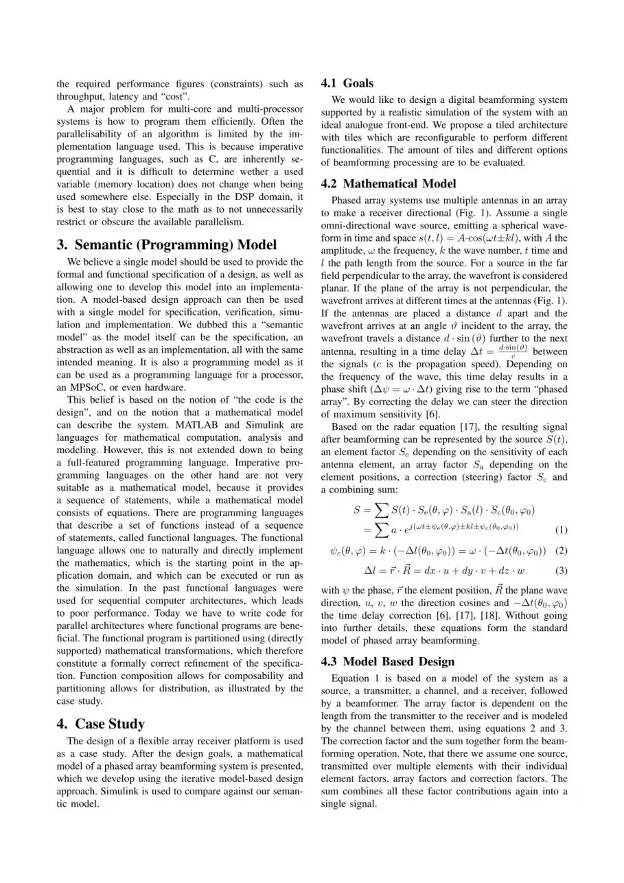
the required performance figures (constraints) such asthroughput, latency and “cost”.
A major problem for multi-core and multi-processorsystems is how to program them efficiently. Often theparallelisability of an algorithm is limited by the im-plementation language used. This is because imperativeprogramming languages, such as C, are inherently se-quential and it is difficult to determine wether a usedvariable (memory location) does not change when beingused somewhere else. Especially in the DSP domain, itis best to stay close to the math as to not unnecessarilyrestrict or obscure the available parallelism.
3. Semantic (Programming) ModelWe believe a single model should be used to provide the
formal and functional specification of a design, as well asallowing one to develop this model into an implementa-tion. A model-based design approach can then be usedwith a single model for specification, verification, simu-lation and implementation. We dubbed this a “semanticmodel” as the model itself can be the specification, anabstraction as well as an implementation, all with the sameintended meaning. It is also a programming model as itcan be used as a programming language for a processor,an MPSoC, or even hardware.
This belief is based on the notion of “the code is thedesign”, and on the notion that a mathematical modelcan describe the system. MATLAB and Simulink arelanguages for mathematical computation, analysis andmodeling. However, this is not extended down to beinga full-featured programming language. Imperative pro-gramming languages on the other hand are not verysuitable as a mathematical model, because it providesa sequence of statements, while a mathematical modelconsists of equations. There are programming languagesthat describe a set of functions instead of a sequenceof statements, called functional languages. The functionallanguage allows one to naturally and directly implementthe mathematics, which is the starting point in the ap-plication domain, and which can be executed or run asthe simulation. In the past functional languages wereused for sequential computer architectures, which leadsto poor performance. Today we have to write code forparallel architectures where functional programs are bene-ficial. The functional program is partitioned using (directlysupported) mathematical transformations, which thereforeconstitute a formally correct refinement of the specifica-tion. Function composition allows for composability andpartitioning allows for distribution, as illustrated by thecase study.
4. Case StudyThe design of a flexible array receiver platform is used
as a case study. After the design goals, a mathematicalmodel of a phased array beamforming system is presented,which we develop using the iterative model-based designapproach. Simulink is used to compare against our seman-tic model.
4.1 GoalsWe would like to design a digital beamforming system
supported by a realistic simulation of the system with anideal analogue front-end. We propose a tiled architecturewith tiles which are reconfigurable to perform differentfunctionalities. The amount of tiles and different optionsof beamforming processing are to be evaluated.
4.2 Mathematical ModelPhased array systems use multiple antennas in an array
to make a receiver directional (Fig. 1). Assume a singleomni-directional wave source, emitting a spherical wave-form in time and space s(t, l) = A·cos(ωt±kl), with A theamplitude, ω the frequency, k the wave number, t time andl the path length from the source. For a source in the farfield perpendicular to the array, the wavefront is consideredplanar. If the plane of the array is not perpendicular, thewavefront arrives at different times at the antennas (Fig. 1).If the antennas are placed a distance d apart and thewavefront arrives at an angle ϑ incident to the array, thewavefront travels a distance d · sin (ϑ) further to the nextantenna, resulting in a time delay ∆t = d·sin(ϑ)
c betweenthe signals (c is the propagation speed). Depending onthe frequency of the wave, this time delay results in aphase shift (∆ψ = ω ·∆t) giving rise to the term “phasedarray”. By correcting the delay we can steer the directionof maximum sensitivity [6].
Based on the radar equation [17], the resulting signalafter beamforming can be represented by the source S(t),an element factor Se depending on the sensitivity of eachantenna element, an array factor Sa depending on theelement positions, a correction (steering) factor Sc anda combining sum:
S =∑
S(t) · Se(θ, ϕ) · Sa(l) · Sc(θ0, ϕ0)
=∑
a · ej(ωt±ψe(θ,ϕ)±kl±ψc(θ0,ϕ0)) (1)
ψc(θ, ϕ) = k · (−∆l(θ0, ϕ0)) = ω · (−∆t(θ0, ϕ0)) (2)
∆l = ~r · ~R = dx · u+ dy · v + dz · w (3)
with ψ the phase, ~r the element position, ~R the plane wavedirection, u, v, w the direction cosines and −∆t(θ0, ϕ0)the time delay correction [6], [17], [18]. Without goinginto further details, these equations form the standardmodel of phased array beamforming.
4.3 Model Based DesignEquation 1 is based on a model of the system as a
source, a transmitter, a channel, and a receiver, followedby a beamformer. The array factor is dependent on thelength from the transmitter to the receiver and is modeledby the channel between them, using equations 2 and 3.The correction factor and the sum together form the beam-forming operation. Note, that there we assume one source,transmitted over multiple elements with their individualelement factors, array factors and correction factors. Thesum combines all these factor contributions again into asingle signal.

Fig. 6: Simulink phased array functional model
4.3.1 Simulink modelThe functional model implemented in Simulink is
shown in Fig. 6. The single signal of the source is multi-plied with a vector of the gain of each antenna element.Note that we have multiple receivers, each having its ownchannel from the source with a different path length, takencare of by the data structure between each block, whichis not directly evident from the model. In essence, a newmatrix dimension is added to the data going through themodel for the time, the elements, and the beams.
4.3.2 Semantic ModelThe semantic model consists of a functional program (in
Haskell [11]). The functions can model the component or(sub-) blocks of a design, connected by function compo-sition and allowing composability. Functions are definedby a name followed by the arguments of the function. Byusing higher order functions, functions themselves can beused as arguments. The type of the arguments is definedafter the :: operator. New types are defined with thedata keyword.
Equation 1 can be implemented straightforward (seelisting 1 and 3); the function names correspond to theblock names of the Simulink model. Furthermore, thechain, frontend and systm model compositions (ex-plained below), which in Simulink are hidden in the data-structure send from block to block. We defined types torepresent a signal (Sig), a direction of arrival (DOA), anelement position (Pos), and a beam-steer direction (BSt).The map function applies a function to each argumentof a list. By mapping the source signal over a list oftime instants, we create a list of the signal over time,which we can use as input to the system to perform asimulation. The listing can be run, thereby performing asimulation with results as expected. A single source goesto a separate transmitter, channel, and receiverchain for each element. All chains together form thefrontend, which uses the map function to create sucha chain for each element. The mapf function is used toprovide the same source signal (s::Sig) to each chainby mapping the list of frontend chains over the sourcefunction. The output of the frontend is provided as inputto the beamformer block with the pipe operator (», seelisting 2), which simply performs a function composition.The frontend and the beamformer form the systm,which expects a signal as input and gives a beamformedresult for each beamsteering vector provided.
data Sig = S ( F l o a t −> F l o a t −> F l o a t ) F l o a t F l o a tdata DOA = D ( Float , Float , F l o a t )data Pos = P ( Float , Float , F l o a t )data BSt = B ( Float , F l o a t )
s o u r c e t = S ( s i n e f a ) g ts i m u l a t i o n = map sys tm (map s o u r c e t s )
sys tm : : S ig −> [ F l o a t ]sys tm s = ( f r o n t e n d d ps >> beamformer bs ps ) sf r o n t e n d : : DOA −> [ Pos ] −> Sig −> [ F l o a t ]f r o n t e n d d ps s = mapf (map ( c h a i n d ) ps ) s
c h a i n : : DOA −> Pos −> Sig −> F l o a tc h a i n d p s = ( t r a n s m i t t e r d p >> c h a n n e l d p >>
r e c e i v e r d p >> adc ) s
Listing 1: Phased array semantic model
( f >> g ) x = ( g . f ) x = g ( f ( x ) )
Listing 2: Pipe operator
c h a n n e l : : DOA −> Pos −> Sig −> Sigc h a n n e l (D ( r , a , e ) ) ( P ( x , y , z ) ) ( S s g t ) = ( S s g ( t +d )
)where
d = s q r t ( ( x* s i n a ) ^2+( y* s i n e ) ^2+( z / c ) ^2 )
adc : : S ig −> F l o a tadc ( S s a t ) = ( s a t )
Listing 3: Channel and ADC implementation
4.3.3 ComparisonThe semantic model is implemented quite naturally
with function applications and concatenation modelingsystem components and math for the implementation. Thelanguage can model the composability of the system. Asystem consists of a piped frontend and beamformer block.The frontend is a collection of chain blocks. A single chainblock consists of a pipe of transmitter, channel, receiverand adc blocks. Also interesting is that the flow of datacan be seen by the parameters passed from block to blocksuch as Sig, while other parameters are fixed parameters,which are directly provided as function arguments suchas Pos. The Simulink model is more intuitive as it is agraphical block-diagram representation, which has simplesemantics, but is much more difficult to implement. Thesemantic model thus improves productivity.
4.4 Analogue/Digital Co-DesignIn the design continuous time is used up to the ADC
block. Beamforming is performed in discrete time/digital.In Simulink, the channel is modeled with a variable time
delay block and a delay vector, which implements the timedelay caused by different path lengths between the sourceand the antenna. Simulink uses numerical algorithms tocompute the dynamic behaviour. One problem with thisapproach is that for each block a sample-rate (simulationrate) is determined and the equations are evaluated for eachof these sample time. At this time the model is thus dis-cretized. Although Simulink supports multi-rate models,this is problematic in case of very different sample rates,such as for example down-conversion in an RF front-end.The lower sample rate blocks need to be evaluated with amuch higher sample rate than otherwise needed, making

the simulation slow. Another problem is a variable timedelay, such as needed for the channel. The variable timedelay block buffers values for each simulation time stepuntil the delay. If the delay is not exactly at a sample time,the value is interpolated between two point, thus resultingin inaccuracies for the channel block implementation. Thisis detrimental for example for the nulls of the beamformer.Also, the ADC is implemented with a sample and holdblock, operating at the ADC sample rate, even thoughthe sample rate of Simulink might be different/higher.Saturation and quantization are not taken into account.
For the semantic model, listing 3 shows how a signalgoing through the channel is changed according toequation 2. For each channel, the path length from sourceto antenna is different, depending on the element position(P (x,y,x)) and source location (D (r,a,e)), andresulting in a time delay for the signal. The calculationof the delay (d) is provided by the where clause of thechannel. It is then simply added to the time parametert of the signal (S s g (t+d) :: Sig). The variabletime delay is thus just a change of time argument t andis therefore exact. The adc explicitly evaluates the sourcefunction by applying the function to a time argument.
Higher order functions allow the explicit modeling oftime as a parameter of signal functions instead of implicittime modeling in a tool such as Simulink, where signal val-ues at a time instance are used. The channel function alsoillustrates the ideal functional behaviour of the channelmodeled by a mathematical equation. The whole frontendmodel operates by making changes to the source signalparameters. The signal is passed from block to block bythe semantic model, until it is explicitly evaluated by theadc to a value at a specific time (specified by the list oftime values ts). After the adc block, time is thus implicit.
4.5 Hardware/Software Co-DesignAs an example of Hardware/Software Co-Design, we
implement the correction and sum of the beamformingblock using the L-chart approach (Section 2.3). We willfirst discuss a direct implementation, followed by a par-titioning into multiple tiles and a partitioning with con-straints. We compare on processing and communicationcosts. Multiplication has a cost of 10 and addition of 1. Thecommunication cost is the number of inputs and outputs.
4.5.1 Single TileA direct implementation of the beamforming block con-
sists of multiplying each input element with a correctionfactor followed by a sum. This is shown in listing 4, wherethe correction factors cs are assumed known and the listss contains the samples of the antennas at a certain sampletime. The function zipwith performs a element-wisemultiplication of the lists cs and ss and sum sums theresults. The operator # gives the length of a list.
If we assume a single tile for the architecture, with 64antennas and suppose we want to determine one beam,then the tile has a processing cost of 64∗10+63∗1 = 703and a communication cost of 64 + 1 = 65.
beamform : : [ F l o a t ] −> [ F l o a t ] −> F l o a tbeamform cs s s = sum ( zipWith ( * ) c s s s ) / # s s
Listing 4: Single tile - Multiply and sum implementation
sumn n xs | # xs <=n = sum xs| o t h e r w i s e = sumn (# s s ) (map ( sumn n ) s s )where s s = s p l i t n n xs
s p l i t n n [ ] = [ ]s p l i t n n s s = as : s p l i t n n bs
where ( as , bs ) = s p l i t A t n s s
beamform cs s s = sumn 2 ( zipWith ( * ) c s s s ) / # s s
Listing 5: Many tiles - Distributed sum
macn n cs s s | # s s n ==1 = sum ( zipWith ( * ) csn s s n )| o t h e r w i s e = macn (# s s n ) csn s s nwhere
x s s = s p l i t n n csy s s = s p l i t n n s sr s s = zipWith ( zipWith ( * ) ) (map
n o r m a l i s e x s s ) y s scsn = map head x s ss s n = map sum r s s
n o r m a l i s e ( x : xs ) = 1 : ( map ( / x ) xs )
beamform cs s s = ( macn 2 cs s s ) / # s s
Listing 6: Constrained tiles - Distributed mac
4.5.2 Many tilesA single tile architecture is not very scalable, so we
want to distribute the beamforming over multiple tiles.As the multiplication is element-wise it can directly beassigned to different tiles, however the sum is a monolithicoperation. Let’s say, we want to split the elements of thesum into different parts which are summed individually,after which the results are summed. This corresponds to anadder tree, a different approach would be an accumulator.The distributed sum sumn is shown in listing 5, withn the maximum number of inputs summed for one tile.If the number of inputs #xs is less than n the sum ofxs is returned, otherwise the input list is split into n-sized parts by splitn. Each part is summed individuallyand the list of results is recursively given to the sumnfunction again. Therefore this implementation matches ahierarchical adder tree. This distribution of the sum can begeneralised for any associative function and is an exampleof a program transformation of which it’s correctness isguaranteed by it’s mathematical properties.
If we split the beamforming into the largest numberof tiles possible, then each tile adds two values (n= 2).We then have 64 tiles performing a multiplication witha processing cost of 10 and a communication cost of 2each, and 63 tiles performing addition with a processingcost of 1 and a communication cost of 3 each, totalling64 ∗ 10 + 63 ∗ 1 = 703 and 64 ∗ 2 + 63 ∗ 3 = 317.
4.5.3 Constrained architecture definitionThe tiles of the previous section are not very nicely
balanced. We can of course perform more additions pertile, but it would be nice if the tiles could be moreregular, such that each tile performs the same operation.We can make the tiles more regular by distributing the

multiplication. Next, we set constraints to the tile size anduse these to get the partitioning.
We can distribute the multiplication by also splitting thecorrection factors into n-sized parts and by normalisingeach parts. This is shown in listing 6. In each tile we thenperform a multiply-accumulate (mac), so we implement adistributed mac macn. The parameter n is the maximumnumber of macs for one tile, cs the correction factorsand ss the signal values. Again, the inputs are split intoxss and yss if more than n. Each list of lists xssis normalised by it’s first element with the normalisefunction. Then each part is element-wise multiplied withthe split input values, so we zip the two lists of lists withzipwith (*). Because of the normalisation the firstelement of each part becomes 1 and needs no multiplier.Each part of the resulting list of lists rss is summed.The macn function is recursively called with the newcorrection factors csn from the normalisation and thesummed results ssn. Note that this distribution of the mul-tiplication can by generalised to any distributive function.
Assume we constrain each tile to a processing capacityof 40 and a communication capacity of 6, this would allowfor processing of four inputs with a processing cost of3∗10+3∗1 = 33 and a communication cost of 4+1 = 5.The function macn with n= 4 and 64 inputs then resultsin 21 tiles, totalling 21 ∗ 33 = 693 and 21 ∗ 5 = 105.
4.5.4 EvaluationIn this section we evaluated three implementations of
beamforming, which differ because of architectural con-siderations. The wish to distribute processing leads toa hierarchical tree summation, while the wish for moreregular larger tiles leads to a four input mac solution.These three options are very cumbersome in Simulink asit requires one to draw each tile of the solutions, becausethey are not easily captured in block-diagrams. This is ofcourse a consequence of the semantic model being textbased, with allows a much more powerful manipulationand representation than a block-diagram. Furthermore, byreplacing the sum and the mac by parameterisable dis-tributed functions by exploiting their mathematical proper-ties, we can transform the solution from one with a singletile (with n= 64), to one with many tiles (with n= 2) oranything in between and for any number of antenna inputs.This transformation is simply not possible in Simulink.
4.6 ReconfigurationThe beamforming method above is implemented by
multiplying with correction factors. This corresponds toperforming a phase shift on the received signals, which isonly suitable for small-band signals. A method suitable forwide-band signals is implementing a time delay. Recon-figuring the system for the time delay method correspondsto changing the distributed multiply-sum to a distributeddelay-sum. To keep the architecture the same, each tileof the delay-sum must process four inputs. Due to lackof space, this solution is not presented further, but isanalogous to the case of section 4.5.3.
5. ConclusionIn this paper we have shown that a single “semantic
(programming) model” based on mathematics is suitablefor a model-based design approach and as a programminglanguage for implementation. We developed a model of thephased array beamforming application for a reconfigurabletiled architecture to illustrate its advantages. The model-based design approach allows one to simulate and verifythe design and implementation continuously during theincremental and iterative design process.
The semantic model can effectively model system com-ponents with different levels of implementation. Ana-logue/digital co-design is enabled by supporting differentmodels of computations, which allows explicit time inthe analogue domain and implicit time or explicit eval-uation to data values for going the digital domain. Designspace exploration is performed, aiding hardware/softwareco-design. By evaluating results and setting constrainsthe architecture is defined. The application is partitionedand implemented in the same model by transformingthe implementations with the use of math. Referentialtransparency in the language ensures a function has noside-effects and parallelism is not unnecessarily restrictedor obscured, making the semantic model very well suitedfor programming MPSoCs or distributed systems.
References[1] B. S. Blanchard and W. J. Fabrycky, Systems Engineering and
Analysis, 3rd ed. Upper Saddle River, USA: Prentice Hall, 1998.[2] Architecture Board ORMSC, “Model Driven Architecture (MDA),”
Object Management Group, Tech. Rep. ormsc/2001-07-01, 2001.[3] “MATLAB and Simulink for Technical Computing,”
http://www.mathworks.com/.[4] W. Mueller et al., “UML for ESL design: basic principles, tools,
and applications,” in ICCAD ’06. USA: ACM, 2006, pp. 73–80.[5] K. Asanovic et al., “The landscape of parallel computing research:
A view from Berkeley,” U. of California, Berkeley, Tech. Rep.UCB/EECS-2006-183, 2006.
[6] H. J. Visser, Array and phased array antenna basics. Wiley, 2005.[7] “SKA - Square Kilometre Array,” http://www.skatelescope.org/.[8] K. C. Rovers, M. D. van de Burgwal, A. B. J. Kokkeler, and G. J. M.
Smit, “Rationale for and design of a generic tiled hierarchicalphased array beamforming architecture,” in ProRISC 2007. TheNetherlands: Technology Foundation, 2007, pp. 160–168.
[9] J. Eker and other, “Taming heterogeneity - the ptolemy approach,”Proceedings of the IEEE, vol. 91, no. 1, pp. 127–144, Jan 2003.
[10] H. J. Reekie, “Realtime signal processing: Dataflow, visual, andfunctional programming,” Ph.D. dissertation, 1995.
[11] “Haskell,” http://www.haskell.org/.[12] Z. Wan and P. Hudak, “Functional Reactive Programming from first
principles,” in Proc. ACM SIGPLAN’00 Conference on Program-ming Language Design and Implementation (PLDI’00), 2000.
[13] P. Caspi and M. Pouzet, “Lucid Synchrone, a functional extensionof Lustre,” Université Pierre et Marie Curie, Tech. Rep., 2000.
[14] Object Management Group, Inc. (OMG), “OMG Systems ModelingLanguage (OMG SysML) Version 1.1,” Object Management Group,Tech. Rep. formal/2008-11-02, 2008.
[15] F. O. Hansen and P. G. Larsen, “An introduction to SysML.”[16] A. Kienhuis, “Design space exploration of stream-based dataflow
architectures: Methods and tools,” Ph.D. dissertation, Delft U. ofTechnology, The Netherlands, 1999.
[17] M. I. Skolnik, Introduction to Radar Systems, 3rd ed. New York,NY, USA: McGraw-Hill, 2001.
[18] H. L. van Trees, Optimum array processing. New York: Wiley,2002, vol. Detection, estimation and modulation theory.


