Embed Size (px)
Citation preview

4th semester elective subject report on
Topology optimization for reinforced concrete structure using large-scale rapid
prototyping technology
Author: Kristiana SprogeSupervisor: Erling Buus Olsen
VIA University College,Horsens Denmark
Bachelor of Architectural Technology and Construction Management
May, 2013

Title: Topology optimization for reinforced concrete structure using large-scale rapid prototyping technology4th semester elective subject report
Author: Kristiana SprogeSupervisor: Erling Buus OlsenDate of handing in: 13. 05. 13.
Font: Calibri (Regular, Light, Bold)Number of pages: 10Number of characters: 24’423
I do not claim ownership of the images and some quoted texts used in this report .The content belongs solely to the authors which are stated in the reference list.
Preface
A fourth semester elective self-study report on “Topology optimization for reinforced concrete structures using large-scale rapid prototyping technology”.Exploration and comparison of most common used rapid prototyping processes by collecting information from various internet sources given by companies working in the field of large-scale rapid prototyping, but mainly based on case studies and reports by research teams specialized in engineering. All the images used in this report are taken from the internet.
Acknowledgements
Great acknowledge goes to Erling Buus Olsen for guidance in formulating the problem statement and argumentation, connecting introduction, analysis and conclusion of this report.

Abstract
Rapid prototyping techniques are able to build physical objects directly from computer generat-ed instructions, by this having the ability to create complicated and also optimized shapes that cannot be manufactured by conventional processes. Through optimization of form for concrete structure a significant amount of material can be saved, as a result reducing the amount of CO2, which is a substantial problem for the global environment. This paper will look at the three most common large-scale rapid prototyping machines and if they are applicable for efficient realization of optimized reinforced concrete structures. By comparison of all three techniques physical prop-erties a proposal of the most suitable one will be presented. This work is based on reports done by European and US research teams specialized in civil and building engineering.
Keywords: Rapid prototyping; Topology optimization; Additive manufacturing; Concrete printing; Contour crafting; D-shape
TABLE OF CONTENTS
1. Introduction 7
2. Topology optimization for concrete structures 7
2.1. Interview 7
3. Rapid prototyping in large scale 9
3.1. D-Shape 9
3.2. Contour crafting 10
3.3. Concrete Printing 10
4. Comparison of the tree rapid prototyping techniques 11
4.1. Accuracy according to CAD model 12
4.2. Dimensions 12
4.3. Strength 13
4.4. Other significant advantages 13
5. Conclusion 14
6. References 15
7. Bibliography 15
8. Image list 16
9. Appendix 17
7
1. Introduction
According to IPCC* assessment report in climate change 2007, the concrete industry emits 5% of the total global emission of C02. “There is potential in reducing the quantity of materials used through optimization of form and implementation of the necessary engi-neering function within the components.” [1] Automation in Construction (2011). Optimizing concrete structures so that it would reduce material amount could significantly reduce the global emission of CO2. Making these types of optimized concrete structures is almost impos-sible with conventional building tools, instead computerized machinery has to be used. To-day complex shapes are made with formwork which is most commonly created with CNC* milling machines. The milling machines robotic arm mills a special formwork that is filled with concrete and reinforcement bars. This meth-od is not efficient due to the consumption of time, energy and material used in creation of formwork. If economy is based on satisfying unlimited wants with limited resources, then large-scale prototyping might be yet another solution on how to do so. Having unlimited architectur-al design possibilities and limiting emission of CO2; using less material, but maintaining the same strength properties. This could also mean spending less money and time on pro-ducing a better quality product. Rapid proto-typing can provide both architectural freedom and engineering functionality. While small-scale prototyping technology is getting more and more widely used, large-scale prototyping is more of a concept, but still worth of consideration, since it reveals the potential in production of building compo-nents, meanwhile presenting the idea of what the future of building industry might become. Optimized concrete structures have the
requirements that could be fulfilled by rapid prototyping, at the same time being more ef-ficient in the usage of time, energy and mate-rial. In this particular case the focus will be on criteria like accuracy according to CAD model; compressive/tensile strength; the possibilities of dimensions and some essential advantages. However, this paper includes very little or no information on costs, time of production or safety factors.
2. Topology optimization for concrete struc-tures
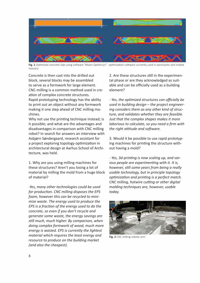
Topology optimization of concrete structures can provide required strength properties and minimization of material amount. It is achieved by simulating an optimized design using a computational program [Fig. 1]. Such optimization software calculates the forces in a static problem, which is divided in de-sign spaces – finite elements that are partly filled with virtual material. Then the program analyzes the stresses within the design space and distributes the virtual material only to the areas where forces are active. As a result the element has been transformed so that it needs minimum material, but maintains maxi-mum stiffness. Case studies at Danish Institute of Technology for topology optimization in concrete structures have proven to be success-ful in saving up to 70% of material. Optimized building elements not only save material, but also make the structure cheaper, lighter and give freeform architectural opportunities with structural functionality.
2.1. Interview
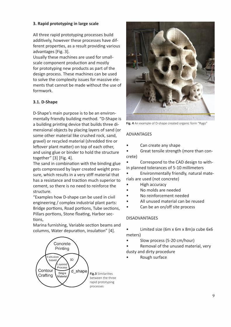
“CNC-milling is a production process in which a computer controlled robotic arm mills out a negative shape digital 3D-model in physical material by stepwise drilling off substance from a material block (typically polystyrene, steel or wood) using a cutting device” [2] [Fig. [2] Three-dimensional topology optimization in architectural and structural design of concrete structures (2009) .
IPCC - Intergovernmental Panel on Climate Change.
CNC - Computer Numerically Controlled. Milling machines automatically cut materials, using a cutting spindle, which can move to different positions and depths as directed by the computer instructions.
8
Concrete is then cast into the drilled outblock, several blocks may be assembled to serve as a formwork for large element. CNC-milling is a common method used in cre-ation of complex concrete structures.Rapid prototyping technology has the ability to print out an object without any formwork making it one step ahead of CNC milling ma-chines. Why not use the printing technique instead; is it possible; and what are the advantages and disadvantages in comparison with CNC milling robot? In search for answers an interview with Asbjørn Søndergaard, research assistant for a project exploring topology optimization in architectural design at Aarhus School of Archi-tecture, was held.
1. Why are you using milling machines for these structures? Aren’t you losing a lot of material by milling the mold from a huge block of material?
-Yes, many other technologies could be used for production. CNC milling disposes the EPS foam, however this can be recycled to mini-mize waste. The energy used to produce the EPS is a fraction of the energy used to do the concrete, so even if you don’t recycle and generate some waste, the energy savings are still much, much higher. By comparison, when doing complex formwork of wood, much more energy is wasted. EPS is currently the lightest material which requires the least energy and resource to produce on the building market (and also the cheapest).
2. Are these structures still in the experimen-tal phase or are they acknowledged as suit-able and can be officially used as a building element?
- Yes, the optimized structures can officially be used in building design – the project engineer-ing considers them as any other kind of struc-ture, and validates whether they are feasible. Just that the complex shapes makes it more laborious to calculate, so you need a firm with the right attitude and software.
3. Would it be possible to use rapid prototyp-ing machines for printing the structure with-out having a mold?
- Yes, 3d-printing is now scaling up, and var-ious people are experimenting with it. It is, however, still some years from being a really usable technology, but in principle topology optimization and printing is a perfect match. CNC milling, hotwire cutting or other digital molding techniques are, however, usable today.
Fig. 2 CNC milling robotic arm
Fig. 1 Optimized concrete slab using software “Altairs Optistruct” - optimization software currently used in aeronautic and mobile industry
9
3. Rapid prototyping in large scale
All three rapid prototyping processes build additively, however these processes have dif-ferent properties, as a result providing various advantages [Fig. 3]. Usually these machines are used for small-scale component production and mostly for prototyping new products as part of the design process. These machines can be used to solve the complexity issues for massive ele-ments that cannot be made without the use of formwork.
3.1. D-Shape
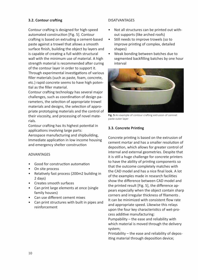
D-Shape’s main purpose is to be an environ-mentally friendly building method. “D-Shape is a building printing device that builds three di-mensional objects by placing layers of sand (or some other material like crushed rock, sand, gravel) or recycled material (shredded tire or leftover plant matter) on top of each other, and using glue or binder to hold the structure together” [3] [Fig. 4]. The sand in combination with the binding glue gets compressed by layer created weight pres-sure, which results in a very stiff material that has a resistance and traction much superior to cement, so there is no need to reinforce the structure. “Examples how D-shape can be used in civil engineering / complex industrial plant parts: Bridge portions, Road portions, Tube sections, Pillars portions, Stone floating, Harbor sec-tions, Marina furnishing, Variable section beams and columns, Water depuration, insulation” [4].
Fig. 4 An example of D-shape created organic form “Rygo”
ADVANTAGES
• Can create any shape• Great tensile strength (more than con-crete)• Correspond to the CAD design to with-in planned tolerances of 5-10 millimeters • Environmentally friendly, natural mate-rials are used (not concrete)• High accuracy• No molds are needed• No reinforcement needed• All unused material can be reused• Can be an on/off site process DISADVANTAGES
• Limited size (6m x 6m x 8m)a cube 6x6 meters)• Slow process (5-20 cm/hour)• Removal of the unused material, very dusty and dirty procedure• Rough surface
Fig.3 Similarities between the three rapid prototyping processes
10
3.2. Contour crafting
Contour crafting is designed for high-speed automated construction [Fig. 5]. Contour crafting is based on extruding a cement-based paste against a trowel that allows a smooth surface finish, building the object by layers and is capable of creating a full width structural wall with the minimum use of material. A high strength material is recommended after curing of the contour layer in order to support it. Through experimental investigations of various filler materials (such as paste, foam, concrete, etc.) rapid concrete seems to have high poten-tial as the filler material.Contour crafting technology has several major challenges, such as coordination of design pa-rameters, the selection of appropriate trowel materials and designs, the selection of appro-priate prototyping materials and the control of their viscosity, and processing of novel mate-rials.Contour crafting has its highest potential in applications involving large parts: Aerospace manufacturing and shipbuilding,Immediate application in low income housing and emergency shelter construction
ADVANTAGES
• Good for construction automation• On site process• Relatively fast process (200m2 building in
2 days)• Creates smooth surfaces• Can print large elements at once (single
family houses)• Can use different cement mixes• Can print structures with built in pipes and
reinforcement
DISATVANTAGES
• Not all structures can be printed out with-out supports (like arched roofs)
• Still needs to improve trowels (so to improve printing of complex, detailed shapes)
• Weak bonding between batches due to segmented backfilling batches by one hour interval
Fig. 5 An example of contour crafting extrusion of cemnet paste outer layer
3.3. Concrete Printing
Concrete printing is based on the extrusion of cement mortar and has a smaller resolution of deposition, which allows for greater control of internal and external geometries. Despite that it is still a huge challenge for concrete printers to have the ability of printing components so that the outcome completely matches with the CAD model and has a nice final look. A lot of the examples made in research facilities show the difference between CAD model and the printed result [Fig. 5], the difference ap-pears especially when the object contain sharp corners and irregular thickness of filaments . It can be minimized with consistent flow rate and appropriate speed. Likewise this relays upon the four key characteristics of wet-pro-cess additive manufacturing: Pumpability – the ease and reliability with which material is moved through the delivery system;Printability – the ease and reliability of depos-iting material through deposition device;
11
Buildability – the resistance of deposited wet material to deformation under load;Open time – the period where the above prop-erties are consistent within acceptable toler-ances [5] Automation in Construction (2011).
The ease of workability depends on the ce-ment mixture, so that it would be possible to create really complex and detailed construc-tions, but also maintain its form while the next layers load applies upon it.
ADVANTAGES
• High strength• Needs only to use minimum amount of
material• No need for molds• Can easily print artifacts that has voids, to
reduce the weight of the structure, which can be utilized for acoustics, thermal insu-lation or building services
• Relatively fast process
DISATVANTAGES
• Still an emerging technology• Hard to transport elements• Material can be more expensive• Flexural strength is dependent on the
orientation of the printing (the parts are weaker when the load axis is perpendicu-lar to the printed surface while parallel to the filament)
• Ribbed surface finish• Hard to print accurate when it comes to
sharp edges• Limited printing dimensios
Fig.6 An example of concrete printined roof element
4. Comparison of the tree rapid prototyping techniques
Since this research is about how to incor-porate rapid prototyping into production of optimized concrete structures, criteria will be more focused on strength, size, accuracyaccording to CAD model and other advantages that might be important for optimized con-crete structures, however, this research will not study the common issues like construction time, costs or safety, but only take them into account as secondary aspects. Taking into account that rapid prototyping use for construction is a relatively new method, therefore the costs may be more expensive due to special substances or other content like the quantity of technical installations; ma-chinery rent, and the fact that this is not mass production business, making the procedure more luxurious.
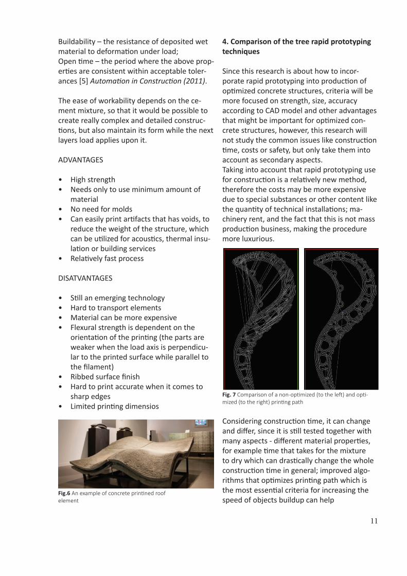
Fig. 7 Comparison of a non-optimized (to the left) and opti-mized (to the right) printing path
Considering construction time, it can change and differ, since it is still tested together with many aspects - different material properties, for example time that takes for the mixture to dry which can drastically change the whole construction time in general; improved algo-rithms that optimizes printing path which is the most essential criteria for increasing the speed of objects buildup can help
12
save time [Fig. 6], but has to be custom made for every new object, according to its complex-ity and dimensions.As for safety, one of the intentions for integrat-ing large scale rapid prototyping in building industry is to increase safety on building sites, letting machines take control over the unsafe building processes at the same time increasing efficiency and reducing failures.
4.1. Accuracy according to CAD model*
Accuracy for each of the techniques differs, since each of them uses different nozzle di-ameters and layer thicknesses. In theory the smaller the extrusion of the material layers the higher resolution. It also depends on the method used itself. D-Shape technique starts by dividing a CAD model into layers, a blanket of sand is laid down where a printer head equipped with multiple nozzles drops down ink on the designed area repeating this procedure for each layer. When the process is finished and the material has solidified it can then be dug out by removal of the unused material. The finished result has a quite high accuracy since the sand bed serves as a mold by surrounding the ink droplets and prevent-ing them from deformation. However, when looking at examples of the printed objects, it is seen that the surface is rough, unlike examples of contour crafting. This method does not use concrete, but sand and stone powder as the build material. Material choice can give a great impact on the final look of the element.This method does not use concrete, but sand and stone powder as the build material. Mate-rial choice can give a great impact on the final look of the element.Contour crafting starts with firstly extruding a cement paste for the outer layer of the object, using two trowels, which act as two solid
* For a better understanding see images in appendix
planar surfaces, to create smooth and accu-rate finishes. Afterwards this shape has to be filled with a material of higher compressive strength. Although contour crafting develop-ers claim that with this method any shape is possible, there are no examples of very com-plex shapes, but more common geometrical shapes, like squares and ovals, unlike d-shape, that has examples of very complex organic shapes. Because of a lack on research ex-amples, it is hard to estimate whether or not this technique is fully capable of creating high resolution irregular and very complex shapes.
Concrete printing is a simple extrusion-based method; a certain layer thickness is laid with a material that can be easily deposited through depositions device that does not exceed ac-ceptable tolerances in changing its form after it has been laid, and that can withstand load from next layers to come. Since this method does not use any formwork it is much harder to achieve the same surface smoothness andaccuracy as d-shape and contour crafting. The surface is ribbed, but can be transformed by applying finishes such as plaster or by grinding back the ribbed finish into a smooth surface. Despite that it is not exceeding far too much tolerance and is still comparable with the designed CAD model. For production of optimized concrete ele-ments the accuracy is very crucial, but the smoothness of surface is more of an architec-tural choice. D-shape has a very high accuracy as well as contour crafting, but d-shape does not use concrete, that is why I only consider it as an alternative method, but for concrete structures I would rather decide upon using contour crafting for its speed of production and possibility to create large elements or con-crete printing for its ability to use a very high compressive strength material mix.
4.2. Dimensions
D-shape has the option of creating any shape within dimensions of 6m x 6m x 8m.Contour crafting print area may differ by using
13
multiple gantries at the same time, because the purpose of contour crafting is to print large scale objects like houses and office buildings. Concrete printing has a limited dimension frame of only 5.4 m x 4.4 m x 5.4 m. All three methods provide suitable dimensions for construction elements in most cases, if the printed object is a beam, column or any other elements which are not too extensive.
4.3. Strength
Each method uses its own preferred build ma-terial for whichever functionality reasons. D-Shape is using materials like sand, rock, gravel and materials that can be recycled like tires and plant leftovers, making this an environmentally friendly solution. The most common is sand or stone powder in combina-tion with chorline based liquid. Through the process of layering sand settles at the bottom and the pressure and time eventually solid-ify the printed area into a rock like material. This material has no need for reinforcement since it has very high compressive and tensile strength. Contour crafting uses two materials for exter-nal and internal layer. External layer is build up with a special cement paste, with that forming a mold which afterwards becomes a part of the structure. The outer layer has to be filled with a substance that has higher compressive strength and since the uncured ceramics used in the contour crafting process has 5 to 6 % shrinkage after the first curing, the ideal filler material must have the same shrinkage ratio. One of the potential materials is rapid con-crete.Concrete printing uses single material throughout the process including reinforce-ment and additional voids for different in-stallations. Concrete printing also requires a material that would maintain a high compres-sive and flexural strength - a high performance cement – based mortar made out of 54% sand, 36% reactive cementitious compounds and 10% water by mass is one of the options.
D-shape and concrete printing use materials that have higher strength properties than con-tour crafting. Contour crafting also may have weak bonding between the outer and inner material if the inner material does not have the necessary shrinkage ratio and faster curing time than the outer material. Nevertheless, all three methods could be used in production of optimized concrete elements. In the matter of what strength properties are demanded the most suitable material and technique could be selected.
4.4. Other significant advantages
D-shape’s key feature is to be an environmen-tally friendly solution by using materials locally found and fully recyclable, which would make great impact on reduction of CO2 emission and serve as a solution for many different sus-tainability aspects. Contour crafting’s development is intended for building construction automation, that is why this technique has greater speed and opportu-nity in creating really large structures withouthaving to assemble numerous components together. Also contour crafting outstands with an architectural advantage of a very smooth finish, far greater than any other of the two methods, without having to spend extra time and money on covering the surface, allowing the printed concrete elements have a raw finish look if it is desired.Concrete printing has a good reinforcement strategy leaving voids in the element for placement of reinforcement bars, also printing a structure with voids makes it lighter and as a perfect solution for the optimized concrete structures on the account of computed de-signs that would contain materialess voids where the forces are not active. Concrete printing does not require any formwork, this way optimizing the production expenses of complex concrete structures with not having to spend extra time and material.
14
5. Conclusion
By optimization of concrete structures it is possible to save up to 70% of concrete mate-rial and achieve significant reduction of CO2 emission, according to case studies at Danish Institute of Technology. So far it is done by different milling machines; therefore this re-search material was exploring potentially new and more efficient methods of manufacturing optimized concrete structures. Three large-scale rapid prototyping processes have been examined and compared. Taking into consideration many different criteria and dividing them according to what is more crucial for successful production of optimized concrete elements. Likewise, consulting about the compatibility of rapid prototyping and optimized concrete structure production, with researchers in the field of topology optimiza-tion of concrete structures. As it occurs that in theory rapid prototyping creates an excellent match for printing opti-mized structures, but since this technology is relatively new it is still developing and improv-ing, it will take time until this technology is complete and approved to be a valid building method. Each of the techniques has distinct advantages and disadvantages. All of the processes show research examples on what the rapid prototyping technology is capable of, meanwhile indicating that all three methods are emerging new technologies, which will be fully accepted among other methods only in the future. All three rapid prototyping technologies can be used for optimized concrete structures, taking into account that d-shape is an alter-native option, for the reason that it does not use concrete in the process, but instead uses gravel materials or stone powder. Selection of the most suitable technology depends on the necessary properties, which in each case may differ.
Understanding the three possibilities given, building industry can look towards what the future might provide it with. Large-scale proto-typing could be a bright future for those in the field of construction and science, where engi-neers, constructing architects and architects would have to adapt to a completely revolu-tionized system of building planning. Architec-ture would have been taken to a higher level in complexity with no extra cost for it. Crafts-manship would reduce and increase safety on building sites. Engineers could finally adjust to the many different desired shapes and forms created by architects. Scientists could experi-ment with new materials and their properties, so to reduce the amount of CO2 and increase usage of sustainable solutions. As a result constructing architects could plan very accu-rate time period and calculate the necessary material usage already in the phase of outline proposal, making the work process more prof-itable and having to consider fewer errors that might occur.
15
6. References
[1] S. Lim, R.A. Buswell , T.T. Le, S.A. Austin, A.G.F. Gibb, T. Thorpe, Automation in Con-struction, Developments in construction-scale additive manufacturing processes, Elsevier B.V., pp 262, Loughborough University, UK, 2011
[2] Per DOMBERNOWSKY, Asbjørn Sønder-gaard, Three-dimensional topology optimiza-tion in architectural and structural design of concrete structures, fluxstructures.net, pp 10, Aarhus School of Architecture, Denmark, 2009
[3], [4] http://www.dshape.ca/how-it-works/ [5] S. Lim, R.A. Buswell , T.T. Le, S.A. Austin, A.G.F. Gibb, T. Thorpe, Automation in Con-struction, Developments in construction-scale additive manufacturing processes, Elsevier B.V., pp 266, Loughborough University, UK, 2011
7. Bibliography
D. Dlmitrov, W. van Wilck, K. Schrevel, N. de Bee$ J J. Meller, An investigation of the Capa-bility Profile of the Three Dimensional Printing Process with an Emphasis on the Achievable Accuracy, University of Stellenbosch, South Africa
Charles V. Camp, Farah Huq, Engineering Structures, CO2 and cost optimization of re-inforced concrete frames using a big bang-big crunch algorithm, Elsevier Ltd., The University of Memphis, United States, 2012
Ignacio Paya-Zaforteza, Víctor Yepes, Anto-nio Hospitaler, Fernando González-Vidosa, Engineering Structures, CO2-optimization of reinforced concrete frames by simulated an-nealing, Elsevier Ltd., Universidad Politécnica de Valencia, Spain, 2009
D.T. Pham, R.S. Gault, A comparison of rapid prototyping technologies, Elsevier Science Ltd., Cardiff Rapid Prototyping Centre, Sys-tems Division, School of Engineering, Universi-ty of Wales Cardiff, UK, 1998
Jing Zhang, Behrokh Khoshnevis , Automation in Construction, Optimal machine operation planning for construction by Contour Crafting, Elsevier B.V., University of Sothern California, UM-Road Construction Materials, United States, 2012
Behrokh Khoshnevis, Automated construction by contour crafting – related robotics and information technologies, Journal of Automa-tion in Construction – Special Issue: The best of ISARC 2002, Vol 13, Issue 1, pp 5-19., Uni-versity of Southern California, United States, 2004
Khoshevis B., Hwang D., Yao K-T and Yeh Z., Mega –scale fabrication by contour crafting, Int. J. Industrial and Systems Engineering. Vol.1, No. 3., 2006
Sungwoo Lim, Richard Buswell, Thanh Le, Rene Wackrow, Simon Austin, Alistair Gibb, and Tony Thorpe, Development of a viable concrete printing process, Loughborough University, UK
16
8. Image list
Fig.1 http://fluxstructures.net/_artikler/ar-tikel_iass.pdf
Fig. 2 http://www.dyvikdesign.com/site/re-search/fablab/cnc-milling-and-3d-scanning-at-the-icehotel.html
Fig. 3 Lim, R.A. Buswell , T.T. Le, S.A. Austin, A.G.F. Gibb, T. Thorpe, Automation in Con-struction, Developments in construction-scale additive manufacturing processes, Elsevier B.V., pp 264, Loughborough University, UK, 2011
Fig. 4 http://www.dshape.ca/dshape-ry-go-at-makerfaire/
Fig. 5 Jing Zhang, Behrokh Khoshnevis , Au-tomation in Construction, Optimal machine operation planning for construction by Con-tour Crafting, Elsevier B.V., pp 51, University of Sothern California, UM-Road Construction Materials, United States, 2012
Fig. 6 http://www.3ders.org/arti-cles/20120316-a-second-generation-3d-con-crete-printing-is-under-development.html
Fig. 7 Lim, R.A. Buswell , T.T. Le, S.A. Austin, A.G.F. Gibb, T. Thorpe, Automation in Con-struction, Developments in construction-scale additive manufacturing processes, Elsevier B.V., pp 265, Loughborough University, UK, 2011
17
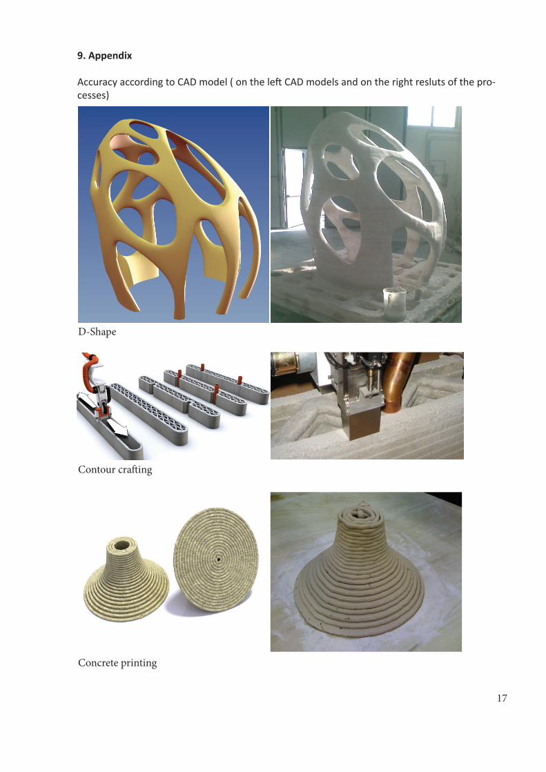
9. Appendix
Accuracy according to CAD model ( on the left CAD models and on the right resluts of the pro-cesses)
D-Shape
Contour crafting
Concrete printing


![Prototyping Model [ bagus ]](https://img.dokumen.tips/doc/110x75/631b0b6b68e6f36d03045394/prototyping-model-bagus-.jpg)


