Embed Size (px)
Citation preview

RISIIN CITY COUNCIL
BRI ANE WATER
SEWA UMP STATION
BA GENERATOR
OPER TION & AINTENANCE MANUAL
SP0494KIAN WAH ROAD
'Priam 1,
SP049 Kianawah Road Wynnum West SPS Backup Generator OM Manual
Q-Pulse Id TMS1080 Active 10/12/2014 Page 1 of 402

.
|
/
|
SP049 Kianawah Road Wynnum West SPS Backup Generator OM Manual
Q-Pulse Id TMS1080 Active 10/12/2014 Page 2 of 402
1
CA)
22
19
30
5
4
8
7
3
2
12
9 35 31
10
11
J.
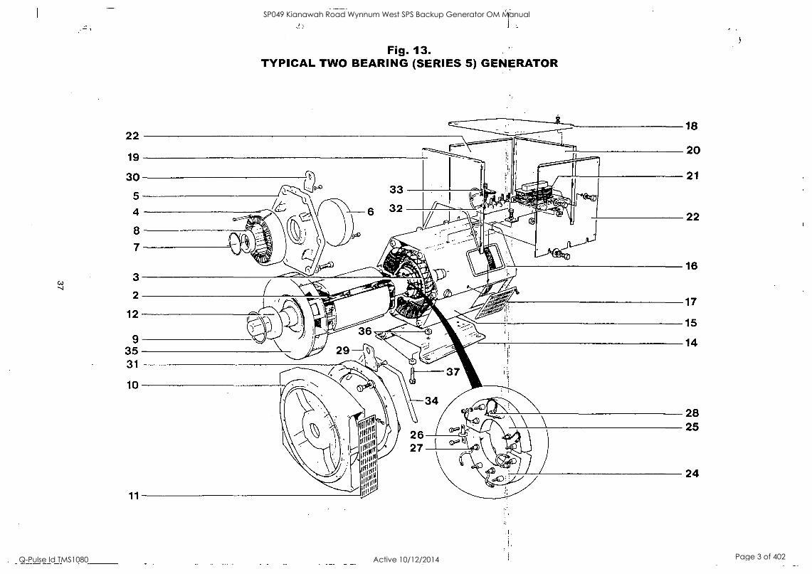
Fig. 13. TYPICAL TWO BEARING (SERIES 5) GENERATOR
18
20
21
22
16
17
15
14
28 25
24
SP049 Kianawah Road Wynnum West SPS Backup Generator OM Manual
Q-Pulse Id TMS1080 Active 10/12/2014 Page 3 of 402

Diode Leads & Exciter Rotor Leads fitted as shown on assembly
Fig. 14. ROTATING RECTIFIER ASSEMBLY
r-r - Exciter Rotor Leads
; ;
jrApAdin MOM/ --OM :4_1111iggii=smi UPlitarifr---/Kr
416
Diode Lead Assembly
Scrap Section A-A
Plate Ref. Description Qty
1 Hub 1
2 Fin 2
3 Diode (fwd) 3
4 Diode (rev) 3
5 Hx. Screw 6
6 Hx. Nut 6 7 PI. Washer 8
8 SC. UWasher 8
9 Varistor 1
10 Hx. Screw 2
NOTES: Fitting of Diodes.
1. Underside of diodes to be smeared with Midland Silicone 'Heat Sink' compound type MS2623. This compound must not be applied to the diode threads.
2. Diodes to be tightened to a torque of 2.03 - 2.37 Nm.
For Nupart rectifier service kit see page 28.
1 SP049 Kianawah Road Wynnum West SPS Backup Generator OM Manual
Q-Pulse Id TMS1080 Active 10/12/2014 Page 4 of 402

39
SP049 Kianawah Road Wynnum West SPS Backup Generator OM Manual
Q-Pulse Id TMS1080 Active 10/12/2014 Page 5 of 402

This manual is available in the following languages on request: English, French, German, Italian and Spanish.
Denne manual er til radighed pa folgende sprog: engelsk, fransk, tysk, italiensk og spansk.
Denne handboken er tilgjengelig pa de folgende sprakene: engelsk, fransk, tysk, italiensk og spansk.
Sur simple demande, ce manuel vous sera fourni dans Tune des langues suivantes: anglais, francais, allemand, italien, espagnol.
Dieses Handbuch ist auf Ant rage in den folgenden Sprachen erhaltlich: Englisch, Franzesisch, Deutsch, ltalienisch, Spanisch.
Deze handleiding is op verzoek Ieverbaar in de volgende talen: Engels, Frans, Duits, Ita !leans, Spaans.
Este manual pode tambem ser obtido nas seguintes linguas: ingles, trances, alemao, italiano e espanhol.
Tama kasikirja on saatavissa pyynnosta seuraavilla kielilla: Englanti, ranska, saksa, italia, espanja.
II presente manuale a disponibile, su richiesta, nelle seguenti lingue: inglese, francese, tedesco, italiano e spagnolo.
Este manual tambien puede solicitarse en los siguientes idiomas: ingles, trances, aleman, italiano e espanol.
AUTO TO eyxetpiOto obnyt(i)v xpnoewc 61aTiOciat aric akoXouOcc yliocrocc KCIToTTIV CUTT)OEVq- AyyAIKO, FQXALKa
rEplICIVLKel, vramica,
40
SP049 Kianawah Road Wynnum West SPS Backup Generator OM Manual
Q-Pulse Id TMS1080 Active 10/12/2014 Page 6 of 402

A.C. GENERATOR WARRANTY
'/ARRANTY PERIOD
A.C. Generators In respect of a.c. generators the Warranty Period is eighteen months from the date when the goods have been notified as ready for despatch by N.I. or twelve months from the date of first commissioning (whichever is the shorter period).
DEFECTS AFTER DELIVERY
We will make good by repair or, at our option, by the supply of a replacement, any fault which under proper use appears in the goods within the period specified on Clause 12, and is found on examination by us to be solely due to defective material and workmanship; provided that the defective part is promptly returned, carriage paid, with all identification numbers and marks intact, or our works or, if appropriate to the Dealer who supplied the goods.
Any part repaired or replaced, under warranty, will be returned by N.I. free of charge (via sea freight if outside the UK).
We shall not be liable for any expenses which may be incurred in removing or replacing any part ent to us for inspection or in fitting any replacement supplied by us. We shall be under no ability for defects in any goods which have not been_properly installedjn accordance with N.I. --
recommended -installation practices as detailed in the publications 'N.I. Iristallalion, Service and --
Maintenance Manual' and 'N.I. Application Guidelines', or which have been improperly stored or which have been repaired, adjusted or altered by any person except ourselves or our authorised agents, or in any second-hand goods, proprietary articles or goods not of our own manufacture although supplied by us, such articles and goods being covered by the warranty (if any) given by the separate manufacturers.
Any claim under this clause must contain fully particulars of the alleged defect, the description of the goods, the date of purchase, and the name and address of the Vendor, the Serial Number (as shown on the manufacturers identification plate) or for Spares the order reference under which the goods were supplied.
Our judgement in all cases of claims shall be final and conclusive and the claimant shall accept our decision on all questions as to defects and the exchange of a part or parts.
Our liability shall be fully discharged by either repair or replacement as above, and in any event shall not exceed the current list price of the defective goods.
Our liability under this clause shall be in lieu of any warranty or condition implied by law as to the uality or fitness for any particular purpose of the goods, and save as expressly provided in this lause we shall not be under any liability, whether in contract, tort or otherwise, in respect of
defects in goods delivered or for any injury, damages or loss resulting from such defects or from any work undone in connection therewith.
MACHINE SERIAL NUMBER
SP049 Kianawah Road Wynnum West SPS Backup Generator OM Manual
Q-Pulse Id TMS1080 Active 10/12/2014 Page 7 of 402

r
NEWAGE INTERNATIONAL LIMITED REGISTERED OFFICE AND ADDRESS: PO BOX 17
BARNACK ROAD STAMFORD LINCOLNSHIRE PE9 2NB ENGLAND
Telephone: 44 (0) 1780 484000 Fax: 44 (0) 1780 484100 Web site: www.newagestamford.com
SUBSIDIARY COMPANIES
1 AUSTRALIA:
2 CHINA:
3 GERMANY:
4 INDIA:
5 ITALY:
6 JAPAN:
NEWAGE ENGINEERS PTY. LIMITED PO Box 6027, Baulkham Hills Business Centre, Baulkham Hills NSW 2153. Telephone: Sydney (61) 2 9680 2299 Fax: (61) 2 9680 1545
WUXI NEWAGE ALTERNATORS LIMITED Plot 49-A, Xiang Jiang Road Wuxi High - Technical Industrial Dev. Zone Wuxi, Jiangsu 214028 PR of China Tel: (86) 510 5216212 Fax: (86) 510 5217673
NEWAGE ENGINEERS G.m.b.H. RotenbrOckenweg 14, D-22113 Hamburg. Telephone: Hamburg (49) 40 714 8750 Fax: (49) 4f) 714 AMP()
C.G. NEWAGE ELECTRICAL LIMITED C33 Midc, Ahmednagar 414111, Maharashtra. Telephone: (91) 241 778224 Fax: (91) 241 777494
NEWAGE ITALIA S.r.l. Via Triboniano, 20156 Milan. Telephone: Milan (39) 02 380 00714 Fax: (39) 02 380 03664
NEWAGE INTERNATIONALJAPAN 8 - 5 - 302 Kashima Hachioji-shi Tokyo, 192-03 Telephone: (81) 426 77 2881 Fax: (81) 426 77 2884
7 NORWAY:
8 SINGAPORE:
9 SPAIN:
10 U.S.A.:
NEWAGE NORGE NS Okem Naeringspark, Kabeigt. 5
Postboks 28, (kern, 0508 Oslo Telephone: Oslo (47) 22 97 44 44 Fax: (47) 22 97 44 45
NEWAGE ASIA PACIFIC PTE LIMITED 10 Toh Guan Road #05-03 TT International Tradepark Singapore 608838 Telephone: Singapore (65) 794 3730 Fax: (65) 898 9065 Telex: RS 33404 NEWAGE
STAMFORD IBERICA S.A. Ctra. Fuenlabrada-Humanes, km.2 Poligono Industrial "Los Linares" C/Pico de Almanzor, 2
E-28970 HUMANES DE MADRID (Madrid) Telephone: Madrid (34) 91 604 8987/8928 Fax: (34) 91 604 81 66
NEWAGE LIMITED 4700 Main St, N.E. Fridley Minnesota 55421 Telephone: (1) 800 367 2764 Fax: (1) 800 863 9243
©1998 Newage International Limited. Printed in Eng Ian,
SP049 Kianawah Road Wynnum West SPS Backup Generator OM Manual
Q-Pulse Id TMS1080 Active 10/12/2014 Page 8 of 402

Maintenance/2500 hours/3 years DRAIN AND FLUSH COOLING SYSTEM
NOTE: Drain and flush cooling system every 2500 hours/3 years when John Deere COOL-GARD coolant is used. Otherwise every 2000 hours/2 years.
ACAUTION: Explosive release of fluids from pressurized cooling system can cause serious burns.
Shut off engine. Only remove filler cap when cool enough to touch with bare hands. Slowly loosen cap to first stop to relieve pressure before removing completely.
Slowly open the radiator cap.
2. Remove engine block drain plug (A).
3. On POWERTech engines, remove oil cooler houSing drain plug (B).
4. Open radiator drain valve (C). Drain all coolant from radiator.
5. Close all drain orifices after coolant has drained.
6. Fill the cooling system with clean water. Run engine until water passes through the thermostat to stir up possible rust or sediment.
7. Stop engine and immediately drain the water from system before rust and sediment settle.
8. After draining water, close all drain orifices and fill the cooling system with clean water and TY15979 John Deere Heavy Duty Cooling System Cleaner or equivalent cleaner. Follow manufacturer's directions on label.
9. After cleaning the cooling system, drain cleaner and fill with water to flush the system. Run engine until water passes through the thermostat, then drain out flushing water.
ZX016192
Continued on next page OPSG,C003523,41 -19-13JUL99-1/3
45-1 112699
PN=61
SP049 Kianawah Road Wynnum West SPS Backup Generator OM Manual
Q-Pulse Id TMS1080 Active 10/12/2014 Page 9 of 402

Maintenance/2500 hours/3 years
10. Check cooling system hoses for proper condition. Replace as necessary.
11. Close all drain orifices and fill the cooling system with specified coolant (see DIESEL ENGINE COOLANT).
Cooling system capacity-Specification
CD3029DF128 14.5 L (15.5 qt)
CD4039DF008 16.5 L (17.5 qt)
CD4039TF008 16.5 L (17.5 qt)
CD4045DF158 20 L (21 qt) CD4045HF158 25 L (26.5 qt) CD4045TF158 25 L (26.5 qt) CD4045TF258 25 L (26.5 qt)
CD6068HF158 29 L (30.5 qt)
CD6068TF158 26 L (27.5 qt)
CD6068TF258 26 L (27.5 qt)
DPSG,C003523,41 -19-13JUL99-2/3
12. When refilling cooling system, loosen temperature sensor (B) or plug at the rear of cylinder head to allow air to escape.
13. Run engine until it reaches operating temperature then check coolant level and entire cooling system for leaks.
OPSG,CD03523,41 -19-13JUL99-3/3
45-2 112699
PN=62
SP049 Kianawah Road Wynnum West SPS Backup Generator OM Manual
Q-Pulse Id TMS1080 Active 10/12/2014 Page 10 of 402

Maintenance/As required ADDITIONAL SERVICE INFORMATION
This manual does not allow a complete repair of your engine. If you want want more detailled service information the following publications are available from your regular parts channel.
PC2451 - Parts Catalog, CTM3274 - Component Technical Manual for 300-Series engines (English) CTM104 - Component Technical Manual for POWERTech engines (English) CTM67 - Component Technical Manual for OEM Engine accessories (English only) CTM77 - Component Technical Manual for Alternators and Starter Motors (English only)
DPSG,CD03523,42 -19-15JUL99-1/1
DO NOT MODIFY FUEL SYSTEM
IMPORTANT: Modification or alteration of the injection pump, the injection pump timing, or the fuel injectors in ways not recommended by the manufacturer will terminate the warranty obligation to the purchaser.
Do not attempt to service injection pump or fuel injectors yourself. Special training and special tools are required (see your authorized servicing dealer or engine distributor). 1'0
0
DPSG,CD03523,43 -19-15JUL99-1/1
50-1 112699
PN=63
SP049 Kianawah Road Wynnum West SPS Backup Generator OM Manual
Q-Pulse Id TMS1080 Active 10/12/2014 Page 11 of 402

r
Maintenance/As required
CLEAN OR REPLACE AIR FILTER (ONE-PIECE)
Clean air filter when restriction indicator (A) is red. Air filter can be cleaned up to six times. Thereafter, or at least once a year, it must be replaced.
Proceed as follows:
1. Thoroughly clean all dirt around air filter area.
2. Loosen clamp (B) then remove air filter.
IMPORTANT: Never reinstall an air filter which shows evidence of bad condition (punched, dented...) allowing no filtered air to enter the engine.
3. Clean air filter with compressed air working from "clean" to "dirty" side.
NOTE: Compressed air must not exceed 600 kPa (6 bar; 88 psi).
4. Mark air filter to keep track of each cleaning operation.
5. Fully depress air restriction indicator reset button and release to reset indicator.
6. Check air system entirely for proper condition (see CHECKING AIR INTAKE SYSTEM).
DPSG,CD03523,44 -19-I5JUL99-1
50-2 112699
P N=64
SP049 Kianawah Road Wynnum West SPS Backup Generator OM Manual
Q-Pulse Id TMS1080 Active 10/12/2014 Page 12 of 402

Maintenance/As required
CLEAN OR REPLACE AIR FILTER ELEMENT
A-Primary element B-Secondary (safety)
element
C-Air restriction indicator D-Wing nut
Clean air filter when restriction indicator (C) is red. Replace both primary (A) and secondary (B) filter elements every 6 primary element cleaning or at least once a year.
Proceed as follows:
1. Thoroughly clean all dirt around air filter area.
Remove wing nut (D) and remove primary element (A) from canister.
IMPORTANT: Do not attempt to clean the secondary (safety) element (B). It must be only replaced as recommended.
3. Thoroughly clean all dirt from inside canister.
IMPORTANT: If primary element shows evidence of bad condition (punched,
dented...), replace both the primary and the secondary elements.
4. Clean primary element with compressed air working from "clean" to "dirty" side.
NOTE: Compressed air must not exceed 600 kPa (6 bar; 88 psi).
5. Mark air filter to keep track of each cleaning operation.
6. Fully depress air restriction indicator reset button and release to reset indicator.
7. Check air system entirely for proper condition (see CHECKING AIR INTAKE SYSTEM).
DPSG,CD03523,58 -19-16AUG99-1/1
50-3 112699
PN=65
SP049 Kianawah Road Wynnum West SPS Backup Generator OM Manual
Q-Pulse Id TMS1080 Active 10/12/2014 Page 13 of 402

Maintenance/As required
REPLACING FAN AND ALTERNATOR BELT (POWERTECH ENGINES)
NOTE: Refer to CHECKING BELT TENSIONER SPRING TENSION AND BELT WEAR for additional information on the belt tensioner.
1. Inspect belts for cracks, fraying, or stretched out areas. Replace if necessary.
2. On engines with automatic belt tensioner, release tension on belt using a breaker bar and socket on tension arm.
On engines with manual tensioner, loosen cap screws holding the alternator.
3. Remove poly-vee belt from pulleys and discard belt.
4. Install new belt, making sure belt is correctly seated in
all pulley grooves. Refer to belt routing at right for your application.
5. Apply tension to belt (see CHECKING BELT).
6. Start engine and check belt alignment.
Installation on 4 cyl. engines
Installation on 6 cyl. engines
ALT-Alternator CP-Crankshaft Pulley FD-Fan Drive I-Idler Pulley T-Tensioner WP-Water Pump
OPSG,C D03523.45 -19-15JU199-1/1
50-4 112699
PN=66
SP049 Kianawah Road Wynnum West SPS Backup Generator OM Manual
Q-Pulse Id TMS1080 Active 10/12/2014 Page 14 of 402

Maintenance/As required
CHECKING FUEL FILTER
Periodically the fuel filter should be checked for water or debris.
IMPORTANT: Drain water into a suitable container and dispose of properly.
1. Loosen drain plug (B) at bottom of fuel filter two or three turns.
2. Loosen air bleed plug two full turns (A) on fuel filter base and drain water from bottom until fuel starts to drain out.
3. When fuel starts to drain out, tighten drain plug securely.
After draining water from the fuel filter, the filter must be primed by bleeding all air from the fuel system. Operate primer lever of the fuel supply pump (C) until fuel flow is free from air bubbles.
5. Tighten bleed plug securely, continue operating hand primer until pumping action is not felt. Push hand primer inward (toward engine) as far as it will go.
If the fuel system needs further bleeding of air, see BLEEDING THE FUEL SYSTEM.
DPSG,C003523,28 -19-12JUL99-111
50-5 112699
PN=67
SP049 Kianawah Road Wynnum West SPS Backup Generator OM Manual
Q-Pulse Id TMS1080 Active 10/12/2014 Page 15 of 402

Maintenance/As required
BLEEDING THE FUEL SYSTEM
Ak CAUTION: Escaping fluid under pressure can penetrate the skin causing serious injury. Relieve pressure before disconnecting fuel or other lines. Tighten all connections before applying pressure. Keep hands and body away from pinholes and nozzles which eject fluids under high pressure. Use a piece of cardboard or paper to search for leaks. Do not use your hand.
If ANY fluid is injected into the skin, it must be surgically removed within a few hours by a
doctor familiar with this type injury or gangrene may result. Doctors unfamiliar with this type of injury may call the Deere & Company Medical Department in Moline, Illinois, or other knowledgeable medical source.
Whenever the fuel system has been opened up for service (lines disconnected or filters removed), it will be necessary to bleed air from the system.
1. Loosen the air bleed screw (A) two full turns by hand on fuel filter base.
2. Operate supply pump primer lever (B) until fuel flow is free from air bubbles.
3. Tighten bleed plug securely, continue operating hand primer until pumping action is not felt. Push hand primer inward (toward engine) as far as it will go.
4. Start engine and check for leaks.
If engine will not start, it may be necessary to bleed air from fuel system at fuel injection pump or injection nozzles as explained next.
I
Continued on next page DPSG.CD03523,46 -19-10AUG99-1/2
50-6 112699
PN=68
1
SP049 Kianawah Road Wynnum West SPS Backup Generator OM Manual
Q-Pulse Id TMS1080 Active 10/12/2014 Page 16 of 402

Maintenance/As required
At Fuel Injection Pump: a. Slightly loosen fuel return line connector (C) at fuel
injection pump. b. Operate fuel supply pump primer lever until fuel,
without air bubbles, flows from fuel return line connection.
c. Tighten return line connector to 16 11m (12 lb-ft). d. Leave hand primer in the inward position toward
cylinder block.
At Fuel Injection Nozzles: a. Using two open-end wrenches, loosen fuel line
connection at injection nozzle. b. Crank engine over with starting motor (but do not
start engine), until fuel free from bubbles flows out of loosened connection. Retighten connection to 27 Nrn (20 lb-ft). Repeat procedure for remaining injection nozzles (if
necessary) until all air has been removed from fuel system.
If engine still will not start, see your authorized servicing dealer or engine distributor.
0 0
DPSG,CD03523,46 -19-10AUG99-2/2
50-7 112688
PN=69
SP049 Kianawah Road Wynnum West SPS Backup Generator OM Manual
Q-Pulse Id TMS1080 Active 10/12/2014 Page 17 of 402

Troubleshooting ENGINE TROUBLESHOOTING
Symptom
Engine cranks but will not start
Engine hard to start or will not start
Problem
Incorrect starting procedure.
No fuel.
Solution
Verify correct starting procedure.
Check fuel in tank and manual shut-off valve.
Exhaust restricted. Check and correct exhaust restriction.
Fuel filter plugged or full of water. Replace fuel filter or drain water from filter.
Injection pump not getting fuel or air Check fuel flow at supply pump or in fuel system. bleed fuel system.
...Faulty injection pump or nozzles. Consultauthorized diesel repair station for repair or replacement...
Engine starting under load. Remove load.
Improper starting procedure. Review starting procedure.
No fuel. Check fuel tank.
Air in fuel line. Bleed fuel line.
Cold weather. Use cold weather starting aids.
Slow starter speed. See "Starter Cranks Slowly".
Crankcase oil too heavy. Use oil of correct viscosity.
Improper type of fuel. Consult fuel supplier; use proper type fuel for operating conditions.
Water, dirt or air in fuel system. Drain, flush, fill and bleed system.
Clogged fuel filter. Replace filter element.
Dirty or faulty injection nozzles. Have authorized servicing dealer or engine distributor check injectors.
Continued on next page DPSG,C D03523,49 -19-10AUG99-1/5
55-1 112699
PN=70
SP049 Kianawah Road Wynnum West SPS Backup Generator OM Manual
Q-Pulse Id TMS1080 Active 10/12/2014 Page 18 of 402

Troubleshooting
Symptom
Engine knocks
Problem
Injection pump shut-off not reset.
Low engine oil level.
Injection pump out of time.
Low coolant temperature.
Engine overheating.
Engine runs irregularly or stalls Low coolant temperature. frequently
Below normal engine temperature
Lack of power
Clogged fuel filter:
Water, dirt or air in fuel system.
Dirty or faulty injection nozzles.
Defective thermostat.
Defective temperature gauge or sender.
Engine overloaded.
Intake air restriction.
Clogged fuel filter.
Improper type of fuel.
Overheated engine.
Below normal engine temperature.
Improper valve clearance.
Dirty or faulty injection nozzles.
Continued on next page
Solution
Turn key switch to "OFF" then to "ON".
Add oil to engine crankcase.
See your authorized servicing dealer or engine distributor.
Remove and check thermostat.
See "Engine Overheats".
Remove and check thermostat.
Replace fuel filter element.
Drain, flush, fill and bleed sysfeiri.
Have authorized servicing dealer or engine distributor check injectors.
Remove and check thermostat.
Check gauge, sender and connections.
Reduce load.
Service air cleaner.
Replace filter element.
Use proper fuel.
See "Engine Overheats".
Remove and check thermostat.
See your authorized servicing dealer or engine distributor.
Have authorized servicing dealer or engine distributor check injectors.
DPSG,CD03523,49 -19-10AUG99-2/5
55-2 112699
PN=71
SP049 Kianawah Road Wynnum West SPS Backup Generator OM Manual
Q-Pulse Id TMS1080 Active 10/12/2014 Page 19 of 402

Troubleshooting
Symptom
Low oil pressure
High oil consumption
Engine emits white smoke
Problem
Injection pump out of time.
Turbocharger not functioning.
Leaking exhaust manifold gasket.
Defective aneroid control line.
Restricted fuel hose.
Low fast idle speed.
Low oil level.
Improper type of oil.
Crankcase oil too light.
Oil leaks.
Restricted crankcase vent tube.
Defective turbocharger.
Improper type of fuel.
Low engine temperature.
Defective thermostat.
Defective injection nozzles.
Engine out of time.
Continued on next page
Solution
See your authorized or engine distributor.
See your authorized or engine distributor.
See your authorized or engine distributor.
See your authorized or engine distributor.
servicing dealer
servicing dealer
servicing dealer
servicing dealer
Clean or replace fuel hose.
See your authorized servicing dealer or engine distributor.
Add oil.
Drain and fill crankcase with oil of proper viscosity and quality.
Use oil of correct viscosity.
Check for leaks in lines, gaskets, and drain plug.
Clean vent tube.
See your authorized servicing dealer or engine distributor.
Use proper fuel.
Warm up engine to normal operating temperature.
Remove and check thermostat.
See your authorized servicing dealer or engine distributor.
See your authorized servicing dealer or engine distributor.
DPSG,CD03523,49 -19-10AUG99-3/5
55-3 112699
PN=72
SP049 Kianawah Road Wynnum West SPS Backup Generator OM Manual
Q-Pulse Id TMS1080 Active 10/12/2014 Page 20 of 402

Troubleshooting
Symptom Problem
Engine emits black or grey Improper type of fuel. exhaust smoke
..igine_overheats
High fuel consumption
Clogged or dirty air cleaner.
Engine overloaded.
Injection nozzles dirty.
Engine out of time.
Turbocharger not functioning.
Engine overloaded.
Low coolant level.
Faulty radiator cap.
Stretched poly-vee belt or defective belt tensioner.
Low engine oil level.
Cooling system needs flushing.
Defective thermostat.
Defective temperature gauge or sender.
Incorrect grade of fuel.
Improper type of fuel.
Clogged or dirty air cleaner.
Continued on next page
Solution
Use proper fuel.
Service air cleaner.
Reduce load.
See your authorized servicing dealer or engine distributor.
See your authorized servicing dealer or engine distributor.
See your authorized servicing dealer or engine distributor.
Reduce load._
Fill radiator to proper level, check radiator and hoses for loose connections or leaks.
Have serviceman check.
Check automatic belt tensioner and check belts for stretching. Replace as required.
Check oil level. Add oil as required.
Flush cooling system.
Remove and check thermostat.
Check coolant temperature with thermometer and replace, if
necessary.
Use correct grade of fuel.
Use proper type of fuel.
Service air cleaner.
DPSG,CD03523,49 -19-10AUG99-4/5
55-4 112699
PN=73
SP049 Kianawah Road Wynnum West SPS Backup Generator OM Manual
Q-Pulse Id TMS1080 Active 10/12/2014 Page 21 of 402

Troubleshooting
Symptom Problem
Engine overloaded.
Improper valve clearance.
Injection nozzles dirty.
Engine out of time.
Defective turbocharger.
Low engine temperature.
Solution
Reduce load.
See your authorized or engine distributor.
See your authorized or engine distributor.
See your authorized or engine distributor.
See your authorized or engine distributor.
Check thermostat.
servicing dealer
servicing dealer
servicing dealer
servicing dealer
DPSG,CD03523,49 -19-10AUG99-5/5
55-5 112699
PN=74
SP049 Kianawah Road Wynnum West SPS Backup Generator OM Manual
Q-Pulse Id TMS1080 Active 10/12/2014 Page 22 of 402

Troubleshooting
ELECTRICAL TROUBLESHOOTING
Symptom
Undercharged system
ttery uses too much water
Battery will not charge
Starter will not crank
Problem
Excessive electrical load from added accessories.
Excessive engine idling.
Poor electrical connections on battery, ground strap, starter or alternator.
Defective battery.
Defective alternator.
Cracked battery case.
Defective battery.
Battery charging rate too high.
Loose or corroded connections.
Sulfated or worn-out battery.
Stretched poly-vee belt or defective belt tensioner.
Engine under load
Loose or corroded connections.
Low battery output voltage.
Faulty start circuit relay.
Blown fuse.
Continued on next page
Solution
Remove accessories or install higher output alternator.
Increase engine rpm when heavy electrical load is used.
Inspect and clean as necessary.
Test battery.
Test charging system.
Check for moisture and replace as necessary:
Test battery.
Test charging system.
Clean and tighten connections.
See your authorized servicing dealer or engine distributor.
Adjust belt tension or replace belts.
Remove load
Clean and tighten loose connections.
See your authorized servicing dealer or engine distributor.
See your authorized servicing dealer or engine distributor.
Replace fuse.
DPSG,CD03523,50 -19-10AUG99-1/2
55-6 712699
PN=75
SP049 Kianawah Road Wynnum West SPS Backup Generator OM Manual
Q-Pulse Id TMS1080 Active 10/12/2014 Page 23 of 402

Troubleshooting
Symptom Problem
Starter cranks slowly
Entire electrical system
Solution
Low battery output. See your authorized servicing dealer or engine distributor.
Crankcase oil too heavy. Use proper viscosity oil.
Loose or corroded connections. Clean and tighten loose connections.
Faulty battery connection. Clean and tighten connections.
Sulfated or worn-out battery. See your authorized servicing dealer or engine distributor.
Blown fuse. Replace fuse.
D PS G ,C 003523,50 -19-10AUG 99-2/2
55-7 112699
PN=76
SP049 Kianawah Road Wynnum West SPS Backup Generator OM Manual
Q-Pulse Id TMS1080 Active 10/12/2014 Page 24 of 402

Storage ENGINE STORAGE GUIDELINES
1. John Deere engines can be stored outside for up to three (3) months with no long term preparation IF COVERED BY WATERPROOF COVERING.
2. John Deere engines can be stored in a standard overseas shipping container for up to three (3) months with no long term preparation.
3. John Deere engines can be stored inside, warehoused, for up to six (6) months with no long term preparation.
4. John Deere engines expected to be stored more than six (6) months, long term storage preparation
MUST BE taken. (See PREPARING ENGINE FOR LONG TERM STORAGE).
5. For John Deere engines not yet installed in
machines, run a line from a container of AR41937 Nucle Oil (from AR41785 Engine Storage Kit) to the fuel transfer pump intake, and another line from the fuel return manifold to the tank, so that Nucle Oil is circulated through the injection system during cranking.
DPSG,CD03523,51 -19-10AUG99-1/1
USE AR41785 ENGINE STORAGE KIT
See your John Deere servicing dealer or engine distributor for an AR41785 Engine Storage Kit. Closely follow instructions provided with this kit.
IMPORTANT: Inhibitors can easily change to gas. Seal or tape each opening immediately after adding inhibitor.
DPSG,CD03523.52 -19-10AUG99-1/1
60-1 112699
PN=77
SP049 Kianawah Road Wynnum West SPS Backup Generator OM Manual
Q-Pulse Id TMS1080 Active 10/12/2014 Page 25 of 402

Storage
PREPARING ENGINE FOR LONG TERM STORAGE
The following storage preparations are good for long term engine storage up to one year. After that, the engine should be started, warmed up, and retreated for an extended storage period.
IMPORTANT: Any time your engine will not be used for over six (6) months, the following recommendations for storing it and removing it from storage will help to minimize corrosion and deterioration. Use the AR41785 Engine Storage Kit. Follow recommended service procedure included with storage kit.
1. Change engine oil and replace filter. Used oil will not give adequate protection. (See CHANGING ENGINE OIL AND FILTER).
2. Service air cleaner. (See CLEAN OR REPLACE AIR FILTER).
3. Draining and flushing of cooling system is not necessary if engine is to be stored only for several months. However, for extended storage periods of a year or longer, it is recommended that the cooling system be drained, flushed, and refilled. Refill with appropriate coolant. (See DIESEL ENGINE COOLANT).
4. Drain fuel tank and add 30 ml (1 oz) of inhibitor to the fuel tank for each 15 L (4 U.S. gal) of tank capacity. Completely drain fuel filter and close fuel valve, if equipped.
5. Add 30 ml (1 oz) of inhibitor to the engine crankcase for each 0.95 L (1 qt) of crankcase oil.
6. Disconnect air intake piping from the manifold. Pour 90 ml (3 oz) of inhibitor into intake system and reconnect the piping.
7. Crank the engine several revolutions with starter (do not allow the engine to start).
8. Remove fan/alternator belt, if desired.
9. Remove and clean battery. Store them in a cool, dry place and keep them fully charged.
10. Clean the exterior of the engine with salt-free water and touchup any scratched or chipped painted surfaces with a good-quality paint.
11. Coat all exposed (machined) metal surfaces with grease or corrosion inhibitor if not feasible to paint.
12. Seal all openings on engine with plastic bags and tape supplied in storage kit. Follow instructions supplied in kit.
13. Store the engine in a dry protected place. If
engine must be stored outside, cover it with a waterproof canvas or other suitable protective material and use a strong waterproof tape.
DPSG,C D03523.53 -19- 1OAUG99 -1/1
60-2 112699
P N=78
SP049 Kianawah Road Wynnum West SPS Backup Generator OM Manual
Q-Pulse Id TMS1080 Active 10/12/2014 Page 26 of 402

141
O
SP049 Kianawah Road Wynnum West SPS Backup Generator OM Manual
Q-Pulse Id TMS1080 Active 10/12/2014 Page 27 of 402

S
SP049 Kianawah Road Wynnum West SPS Backup Generator OM Manual
Q-Pulse Id TMS1080 Active 10/12/2014 Page 28 of 402

FANUC
Fanuc Automation
The Series 90T747.30'PLCs are a family of
controllers,-1/0 systems and, specialty
modules designed to meet the demand for
versatile industrial solutions. With its
single overall control architecture, the
Series 90-30 has been the PLC of record in
over 200,000 applications, such as high-
speed packaging, material handling,
---.complex motion control, water-treatment,
continuous emissions monitoring, mining,
food processing, elevator control,
injection molding and many more.
Series 9r-30 Pas
Thanks to its modular design, the Series 90-30 offers unmatched versatility. Configure just the system you need, saving critical space and reducing cost.
With over 100 I/O modules, the Series 90-30 PLC can be adapted to a wide range of applications.
Digital interfaces for push buttons, switches, proximity sensors, relays, contactors and many other devices
Analog modules with varying degrees of resolution for flow, temperature or pressure applications
Direct connect wiring or remote termination
Local or remote I/O systems
Series 90-30 Ethernet communications provide a real-time link between the plant floor and the boardroom. You can begin with an
Ethernet-enabled CPU, or at a later date, choose from our selection of rack-mounted Ethernet modules. The Series 90-30 Ethernet
module supports both SRTP and Modbus TCP/IP application protocols.
The scaleable processing power in the Series 90-30 CPU creates a clear upgrade path. Create the system that's":ideal today, while *"*".- 7
leaving open the option of creating a more powerful system tomorrow - without having to change your applicetion:softyvare.
Motion control integrated into the Series 90-30 fosters high performance point-to-point applications, , . - ,
k A variety of Series 90-30 field bus interfaces enables distributed control and/or I/O. Cholise frotiEtherriet EGp>PrOlibUs-DP,Tit'.
Genius ®, Dev,ceNetTM and Interbus -STM modules. Field Bus interface modules are easyjto install -and quick to configu e Plug them ,,,' 'I:: '
into an existing system or design a new system around them. / -. . :-., .. ;yr/ / n i
,i, .. ,...-: I i
Ease of programming is a strong suit of the Series 90-30. Choose the programminVoptions,that.rneetyoUr needs'. WindovVe-based - 4
- ,--'-`,:, IEC programming, advanced C or State Logic ®. Floating point math, PID, indirect addressing, array'rnoves and sequencing areljiist a
! ' .
few of the over 200 instructions available. \., i ),,- vi are) lust
a / i ,o. ;`) The Series 90-30 stands out among small controls for offering redundancy options: The' eries 90=30,is.tre-low-ocisesolutionfor
.
,
..... ,..,. , .,..., ...- ./
v- ;
I I
i , ''', ' ,,, ". i \, ...- 7 ..,- '
Easy trouble shooting and machine setup using a handheld PDA. CIMPLICITY"t Machine Edition,Logic Developer'PBA softvitarie / allows you to interface a Palms handheld device to your Series 90-30 controllei'l. With Logic Developer P9K, you,cani ; , i monitor/change data, view diagnostics, force ON/OFF, and configure machine sekull, saving you timeand,iriCreasing productivitI y.
,' J
high availability applications, with redundant CPUs and power supplies.
SP049 Kianawah Road Wynnum West SPS Backup Generator OM Manual
Q-Pulse Id TMS1080 Active 10/12/2014 Page 29 of 402

Ordering Information i'DAARtiPIRIJI-CiaTORNOvibiLl Discrete Input 10693M01230 120 VAC Isolated Input (8 Points)
Modules 1:k 693MQL2317,..1(2-40--,5C !so 1 arert n pu(1867Ms1,.._
IC693M01240 120 VAC Input 116 Points)
56693431/4-1-
16693MDL632 125 VDC Input lo Points) .
[IC153A4_171.834,324..V.K,InthrtNe9/1!06...1-991C18Peints). ........- 10693MD1.645 24 VDC Input. Neg/Pos Logic 116 P ' '
; Discrete Out-u: D1310 4120 VAC DIthut, 0.5Amp (12 Pearts) . . .,
Modules .," 'IC693MDL330 120/240 VAC, ouiput2 rtn1p 1.
riC693MDL340-=.1120 VACQinput 0.5 AmO116 Points) '
`; IC693M01330:.'. 120,740 VAC !sclatie Output; 2 Amp )5 Points);_: . .
ricrAMD1.40....j it 2:24 VDU:fp:it. 2 IknpPosithiologic.,18Dims! -
IC693MDL731 X1274 VDC Ouzo , 2 Amp, Negative Logic.IB,Pointsi
106 6;-212t ot put,0 5 Arp P3Sih,LSthtSPOti .
-1C693MDL733 1224 VDC.Output, 0.5 Amp, Negative:ix* (8 Poits) .
Relay Output 10693740(930. _ 'Relay Output isoloted4 ArOp:
(Catelogr_kmfeed
IC693MOL545 24 VDC Input Neg/Pos logic, 1 msec Filter 116 Points)
Logic,116 Points)._ . ,
IC69340106 24 VDC Input, Neg/Pos Logic,2msec Filter (32 Points)
logic 132 Po
IC593MOL655 24 VDC Input Neg/Pos Logic, 1 ms, 132 Pdints)
.
- 02/24 VDC Output 0.5'Ainp Positive Logic 116 Points) '" '
IC693M0.1741 '112/24 VDC Outp1it 0.5 Amp, Negative Logic (16 Poinis).
'11C6931ADL7Lit_IF-2/24,VDC Outhirt; I Amp,PositiveLogie(16...pohis),Posed ,.
.i,16693Mti iiii ' 48 VC C otiipikt, 0.5 .tritpi, Posiii4Ldfic18.-poensi .
fif.693Ma.75o.D.12;74 QC OUthirt, Negative Logic 132 Points) ' ; :. .,--1 , IC693MOL751 ' 1124 V' C..0 mut Paiitive Logic 132 Faints)
_itIC523mr.t1.752:1 5MY.11D.1131.).0.utpet.,NegativeLogi.e(32 Points)....-....--. .
Module IC693MDL931 ...,..IERelairQutput, 8 tuitP,Porrit,l3/CsOntaCis,'Isolated m 2 Grotipsol 4 13 Points)
+ Mixed Discrete .1,1C693MDR390 Mixed I/Q 24 VDC Input 18 pointal;RelayQutput is porr.s1
+ Module -
Analog Input :1C593ALQ720 A-nelog Input Vp ifage/Current 4 Channels ,
Modules ,IC693ALG.211 1A.-.469,1nOittOgrent,1Chinni% ' '
1?111aiO0 0140" -;1143+340:41.......A4OgSlutout,Yekage2PlaPnels... ,...... .
2Channels
Mixed Analog OG59346442 , Analog CornboModule 41N/20117
Modules ...
'IC593M.01.753 ": 12124 VD1Orliput, Positive logic
....... Jr . ,
ic693mc.:.9ia Rda iOr;tpUt. 2 Arnp( IR Points) ' - , :. . , .
I .. - . l'"', .,
ID693MAP.590 Fixer. 1 1,120 VAC Input 18 points1Reloibthom ;8 Fein:
16633AIG222 :_Analog. Input Voltage 16 §ingtei8 bilierenitaiChataletc _...:-.---drt--- .
itC59211.6zz..1,...itAnalog Input, CUrreht, 16 Single Channels . .
iC,533ALD392 sign DensitY,Analog Copin:18Channms; , 74,14,,
1,.'.41, ,,--:,:x.-..........--X-',..- ',.... - ...:
,
- -- 'Lt. - - ...;:e-..1 - "' '1C693APU365 High Speed Co;drer withGrii.Cridelhaolterorah'AQUAD:QEneoderinPiii:-.;;;;;;;;
" - ' 111C693APU301 ?)Axis Module IAPM) 1 As - .. . . :(1C693DSM302': ifiiiiii Serve Motion Controller 2 Axis .-".." ,:, *. .... ... .....: , , .-. ,.., y
.
IC693ApU302 Axis PosAioning Module (ApiA),-.2 Auris1 ....., . rIC6530SM314.: 'Digital Ser9 Moon Contr011er,,-1-2'Axis of Dinka; Serve, or 1-4 Axis.Anakig Servi, .
Specialty R693M017b0 ,FdirToid yaiveOUtritk111 Pointe1/34 voCOofout...0.5 Atli, POSARre trigi,(15 Points' LIFC76.93PTM1(711,:jt-P,oxierTransdtrior Module' CtandPTloterfaCe1213/740 VACIlmoehlel.' i
Modules 7 IC69.3PCM10, Pr 3O'cattoiOle CoUrocesso!Module.1S? KB 147 KB DesiO or C Plop*, 2 Ports :i4(633TCMj02 ' i Terppetaiuce comr.ol mod*, 01 TC In artiltei 24 vig SoiidAtateOtROdiS . , Control . -ix+
riar3FSM311 .; Pr zgraamaNiCeprOcessotAodule, 640M3(64.0 KB Besioor.CProgram),2Seria; Pcts ; 1 IC693TCM303 Temperature Control Module E ;dead ed 'QIN:mature Renge, ;8; TC In and
IC650.770100 Power Transducer Module, CT, and PT intorto,ceizo?40Vg (0.srn Cable) ',, (-,.;;;....-..,,,, ,..,.,_;i 18).2.4 VbC Solid State Outputs ... .
3r-ComrtiOnicetiOns ),1.1C65,3PER.4331_1Genius.,13.osS,ontroller,13Oppritts_1/6),aridDategrorOs),_ .....,:53.3p44200,,,,_11trotibus 0_17.,Master Module . , .+..
i Modulei ' :,'.. -1 t;IC693CIAM3.12 Communicatien Module; GeOlus l! Kbyte) GCM+ (No DatagramSupport):... ... ;16693PBM201 -,1ProfibUs01; Stkve Module, - - . .. . . . .
. . ... '',IIC693CMM311' ii..Cammunications Module; CCM, Rill SNP and SNPx Protocols . . ., 11106930NM200 geviceNet Master Module .. ' .':....-'f...:-.1...- .:.
r ,.,.=,iC59iCMMiii . ;Ethernet interace TCP/P_ Module, tOAhs (Suneorts iRTP and Modthrs i6P/IP No EGO). 11C693ONS201 '3eviceNetslave Module
Controllers
. . . .
1 iC693CPU3I 1 : 11.5-Slot Base wM CPU in Base 16KBytes User Programl.Not ExPencla1.:le ... ..,:.., . "..1113C693CPU360 1 CPU 360 Module 1240Ktlytes Configurable User Memory. 4K I ... I. k Racks!.
; Backplattes-'
Power Supptes
Accessories
,;, . NO QuiltIn Serial Ports Logic EXecutieri is..22rnset/K ,;_., ,,_. . ''
1CC93CPL:3; 3. '5 -Slot Base with.Turbo CPO inljeseilogic Exei..,:ion is 5 ros'eil:114 Rrrgisters ' .;C693CP03.53 CPU 363 mocitiefiiiiiiyt eec:oetiOureblejisti Mer;O cry '4111 /O c, Sac ksi.7 -
:112KBytes UserPrOgrerM;Not Expandable . ' :. , .. .2 Built-163eriel Ports, Logic Execution is .thnsec/K
FIE693CPU323 110Slat Base with Turbo CPU in Base (Logic Execution is .6 msec) I2Kbytes ' :fir.6936P113647 IrePii364 Module 1240KBykes Configurable User MemOiyiiiRlflecis), No Built -In Sena 1c.1;'
L..," . %User Program, Not 6paridable -. ." . ....-- , . :. - - .........' .. L.. '''' ' . -ILBuittIn IOMhi Ethernet Supports STOP Channels and EGO Logic EAeCuiicin is .27,nser.Y
iC693CPU350 CPU 886.84odVie 132:KB xies User Memory, 4K Vii; 8 Nee ICC), No Built -In Serial ;km-. i 16693C P(1374;.- ..1'CPU374 Module iiiakijiies Configurable User Memory), No Built -In Ports,
Logic Execution is .Z2msec/li . , ' : ' Built-In 10/100Mbs with buillIn Switch, Ethernet Supports SRTP, EGD and t.iOcila...,:ei . .
' ''Support Logic ExeCution is .22M:sec/K.' .L. -
.
6 S 39
.
.; . , _
-1_._-,...
..
r ,---:
7
.
1.
. -.....
..-F.
.
p- 1 fieSe,GPO, 0SOts, ie h Li3314.3E37i and above .1.1C593C+S397[ 3eie;CPU, 531qtauwitiCulit/C3E331aid.aboreliax-, - "
.IC693CHS392 3;s;oExpansion,:13 Slots 1069363338 . 'Base, Expansion, 5 SiotS
(icsiCTT3::i_ii81i894448Aps7n,110 8oli/o.trL..::: .1iC6i3c1838TI.4;7, 848;4ki.;;isro5ii848(ioi;ft2__. 1C693PWR321 , Power Supply 120/240 VAC,125voc, Grandard, 30 Wes ;',1C693PWl332 ,Poier Supply 12 VDC, High Capacity 30
F E9 3 P W R 3 Z2 i io i e i Supplyms VDC Standard, 30 Wats . j54314CC340..15idulittiffrStitkaaR,Ifa3).*th01,ne*Y:PP hlnhC110?OwilStPtk t!TLPde R. I
=1C653PVi328 ' PorSu . i-4
r
Ci yV ri3 .,c69 41 .RdudanPoier SppyBese Wth IS meter aahle to connect to Pcver SuppevAdaptir Mao:e
jzokpyAr25,VQc,thohCepacty.30 Waits _ 111C693ACC350 .71113Jdu;dare Power Supply Adapter)BPSA) Module. The RpSA replaces the power
'1C693PWR331., Power Supply, 24 VDC, High Capacity, 30 Wads - f.L...1_,.,.. ._;....;lona,CPU,Oesesr,..expensjonbaSoandoonnecis.toe Pecundam,Power SuppfY.Rese .. ---- . ---: .
11-E6-934C63lii.11.RePiecement Qattery,,Cpb.,8 KRIctty.2),,,,..2.... - ......._ ..._ , ... .. . fit693C81.312124 Rack is Rack Orpensien Cabli; 2 Meiets ' '.' ..' '. --: ' .... ' ' , .... .., . . .. . . ._ .... .
.. . _
..;:IC593ACC302 ...Righ Capacity Battery Pack , , ., . . _ ' . ,IC693,CD1.302- :: Rack toRack Gmaansion Collie: 15 Meters ... l1C200ACC0133"....11EZ.PsOgrifit Store Rash Device (for CPU374 only) Te69303L3iiliffrack toTack Gx'-:-.7-p.arlsionCable., 0.1514, eter's, -Shielcie7.17--:: . ,
ic693Acc810 ':.'Flier Module, Blank Slot ' ': ..: .. . ' . . . '.1C693Clii.313 I. Back to Rack EXeansiOnCapio,i:Meirs : 7
,-....--,..;... ..-.4-' .- . . ---. .- -- 31.1C693CBL320,....ittiack to Rack 4pension Cable, 1Meter .., ...1.1.0.830.1.4.14 .:iiDa.c!t.kOileCItg,!ion*DPalt10:15 Relets...3.17ieided.: . ' . -
Prnmsulg and , ic64884Pk01 Logic Developer_ PLC PMieSkrdral -.. 2--- 1564EMP/Q01.. Log Drs PDA Scitwarh1.001 w h Cciiittiaptei ' --i---- .
Trouble Shootmg nES46MFSpprillogicieieloperff"; Pic Standa:d ' ',I "
., .
, , .
Tools 12::::.:.,,...L,:Jr,..:L.L.2::::._...L.:LL..:....,.. i
FANUC
GE Fanuc Automation GE Fanuc Automation Information Centers
USA and the Americas 1-800-648-2001 or (434) 978 -5100
Europe and Middle East 63521 727979-1
Asia Pacific 86-21-3222-4555
®2003 GE Fanuc Automation Americas, Inc. All Rights Reserved.
Series SO, VersaPro and LogicMaster are trademarks and Genius is a registered trademark of GE Fanuc Automation Americas, Inc. Profibus-DP is a trademark of Profibus International. DeviceNet is a
trademark of the Open DeviceNet Vendor Association, Inc. Interbus- S is a trademark of Phoenix Contact Windows is a registered trademark of Microsoft Corporation. Stare Logic is a registered trademark of Adatek, Inc. Patin s n tradv,ork of Palm, Or
Additional Resoulses
3. P.); cetaded td6hn.cal specdicatinns and :.:r.odu6tOrdering information, vi the dE Fanuc e-cataltig at:
www.gefanuc.com GFA-148J 10M 06/03
SP049 Kianawah Road Wynnum West SPS Backup Generator OM Manual
Q-Pulse Id TMS1080 Active 10/12/2014 Page 30 of 402

SP049 Kianawah Road Wynnum West SPS Backup Generator OM Manual
Q-Pulse Id TMS1080 Active 10/12/2014 Page 31 of 402

SP049 Kianawah Road Wynnum West SPS Backup Generator OM Manual
Q-Pulse Id TMS1080 Active 10/12/2014 Page 32 of 402

GE Fanuc Automation
Programmable Control Products
Series 90TH -30 PLC
Installation and Hardware Manual
GFK-0356Q August 2002
SP049 Kianawah Road Wynnum West SPS Backup Generator OM Manual
Q-Pulse Id TMS1080 Active 10/12/2014 Page 33 of 402

GFL-002
Warnings, Cautions, and Notes as Used in this Publication
Warning
Warning notices are used in this publication to emphasize that hazardous voltages, currents, temperatures, or other conditions that could cause personal injury exist in this equipment or may be associated with its use.
In situations where inattention could cause either personal injury or damage to equipment, a Warning notice is used.
_Caution
Caution notices are used where equipment might be damaged if care is not taken.
Note
Notes merely call attention to information that is especially significant to understanding and operating the equipment.
This document is based on information available at the time of its publication. While efforts have been made to be accurate, the information contained herein does not purport to cover all details or variations in hardware or software, nor to provide for every possible contingency in connection with installation, operation, or maintenance. Features may be described herein which are not present in all hardware and software systems. GE Fanuc Automation assumes no obligation of notice to holders of this document with respect to changes subsequently made.
GE Fanuc Automation makes no representation or warranty, expressed, implied, or statutory with respect to, and assumes no responsibility for the accuracy, completeness, sufficiency, or usefulness of the information contained herein. No warranties of merchantability or fitness for purpose shall apply.
The following are trademarks of GE Fanuc Automation North America, Inc.
Alarm Master Field Control Modelmaster Series 90 CIMPLICITY GEnet Motion Mate Series One CIMPLICITY Control Genius PowerMotion Series Six CIMPLICITY PowerTRAC Genius PowerTRAC ProLoop Series Three CIMPLICITY 90ADS Helpmate PROMACRO VuMaster CIMSTAR Logicmaster Series Five Workmaster
©Copyright 1998-2002 GE Fanuc Automation North America, Inc. All Rights Reserved.
SP049 Kianawah Road Wynnum West SPS Backup Generator OM Manual
Q-Pulse Id TMS1080 Active 10/12/2014 Page 34 of 402

RFI Standards
The Series 90-30 PLC and its associated modules have been tested and found to meet or exceed the requirements of FCC Rule, Part 15, Subpart J. The Federal Communications Commission (FCC) requires the following note to be published according to FCC guidelines.
NOTE
This equipment generates, uses, and can radiate radio frequency energy and if not installed in
accordance with this instruction manual, may cause harmful interference to radio communications. It has been tested and found to comply with the limits for a Class A digital device pursuant to Part 15 of the FCC Rules, which are designed to provide reasonable protection against harmful
- interference when operated in a commercial environment. Operation of this equipment in a -
residential area is likely to cause harmful interference, in which case the user will be required to correct the interference at his own expense.
The following note is required to be published by the Canadian Department of Communications.
NOTE
This digital apparatus does not exceed the Class A limits for radio noise emissions from digital apparatus set out in the radio interference regulations of the Canadian Department of Communications.
The following statements are required to appear in the Series 90_-30 Installation Manual and the Series 90_-30 I/O Specifications Manual for Class I Div 2 Hazardous Locations.
1. EQUIPMENT LABELED WITH REFERENCE TO CLASS I, GROUPS A, B, C, and D, DIV. 2 HAZARDOUS LOCATIONS IS SUITABLE FOR USE IN CLASS I, DIVISION 2,
GROUPS A, B, C, D OR NON-HAZARDOUS LOCATIONS ONLY.
2. WARNING - EXPLOSION HAZARD - SUBSTITUTION OF COMPONENTS MAY IMPAIR SUITABILITY FOR CLASS I, DIVISION 2:
3. WARNING - EXPLOSION HAZARD - DO NOT DISCONNECT EQUIPMENT UNLESS POWER HAS BEEN SWITCHED OFF OR THE AREA IS KNOWN TO BE NON-HAZARDOUS.
4. ALL UNUSED SLOTS IN ALL BASEPLATES MUST BE POPULATED WITH FILLER MODULES, IC693ACC310, OR EQUIVALENT.
GFK-0356Q
SP049 Kianawah Road Wynnum West SPS Backup Generator OM Manual
Q-Pulse Id TMS1080 Active 10/12/2014 Page 35 of 402

...
_
I
SP049 Kianawah Road Wynnum West SPS Backup Generator OM Manual
Q-Pulse Id TMS1080 Active 10/12/2014 Page 36 of 402

Preface
This manual describes the GE Fanuc Series 90-30 Programmable Logic Controller (PLC). It
contains a description of hardware components and provides basic hardware installation procedures. The Series 90-30 PLC is a member of the Series 90_ family of Programmable Logic Controllers from GE Fanuc.
For a list of product standards, refer to data sheet GFK-0867B or later, GE Fanuc Approvals, Standards, General Specifications which lists all of the standards for GE Fanuc products. Installation instructions in this manual are provided for installations that do not require special procedures for noisy or hazardous environments. For installations that must conform to more stringent requirements (such as CE Mark), see GFK-1179, Installation Requirements for - Conformance to Standards:
What's New in This Manual
Added the model 374 CPU, which supports connection to an Ethernet network through two
built-in 10BaseT/100BaseTx auto-negotiating full-duplex Ethernet ports. Models 364 (release 9.10 and later) and 374 are the only Series 90-30 CPUs that support Ethernet Global Data. Note that the CPU374 is supported only by the Windows® -based programmers.
Other corrections and clarifications as necessary.
Related Publications
For more information on Series 90-30 products, refer to these publications. (For a publication to
product catalog number cross-reference refer to Appendix G):
GFK-0255 - Series 9OTM PCM and Support Software User's Manual
GFK-0256 - MegaBasicTM Programming Reference Manual
GFK-0293 - Series 90T" -30 High Speed Counter User's Manual
GFK-0401 - Workmaster® II PLC Programming Unit Guide to Operation
GFK-0402 - Series 90T" -30 and 90-20 PLC Hand-Held Programmer User's Manual
GFK-0412 - Genius® Communications Module User's Manual
GFK-0466 - Logicmaster 90T" Series 9ØTM -30/20/Micro Programming Software User's Manual
GFK-0467 - Series 9ØTM -30/20/Micro Programmable Controllers Reference Manual
GFK-0487 - Series 90T" PCM Development Software (PCOP) User's Manual
GFK-0499 - CIMPLICITY® 90-ADS Alphanumeric Display System User's Manual
GFK-0356Q
SP049 Kianawah Road Wynnum West SPS Backup Generator OM Manual
Q-Pulse Id TMS1080 Active 10/12/2014 Page 37 of 402

Preface
vi
GFK-0582 - Series 90T" PLC Serial Communications User's Manual
GFK-0631 - Series 90T" -30 I/O LINK Interface User's Manual
GFK-0641 - CIMPLICITY® 90-ADS Alphanumeric Display System Reference Manual
GFK-0664 - Series 90T"-30 PLC Axis Positioning Module Programmer's Manual
GFK-0685 - Series 9OTM Programmable Controllers Flow Computer User's Manual
GFK-0695 - Series 90TH -30 Enhanced Genius) Communications Module User's Manual
GFK-0726 - Series 90Tm-30 PLC State Logic Processor User's Guide
GFK-0732 - Series 90Tm-30 PLC ECLiPS User's Manual
GFK-0747 - Series 90TH -30 PLC OnTOP User's Guide
GFK-0750 - On Top for Series 90TH -30 (State Logic) Program User's Manual
GFK-0781 - Motion MateTM APM300 for Series 90TH -30 PLC Follower Mode User's Manual
GFK-0823 - Series 9ØTM -30 I/O LINK Master Module User's Manual
GFK-0828 - Series 90Tm -30 Diagnostic System User's Manual
GFK-0840 - Motion MateTM APM300 for Series 9ØTM -30 PLC Standard Mode User's Manual
GFK-0867 - GE Fanuc Product Agency Approvals, Standards, General Specifications
GFK-0898 - Series 9OTM -30 PLC I/O Module Specifications
GFK-1028 - Series 90T" -30 I/O Processor Module User's Manual
GFK-1034 - Series 9OTM -30 Genius® Bus Controller User's Manual
GFK-1037 - Series 9OTM -30 FIP Remote I/O Scanner User's Manual
GFK-1056 - Series 9ØTM -30 State Logic Control System User's Manual
GFK-1186 - TCP/IP Ethernet Communications for the Series 90_-30 PLC Station Manager Manual
GFK-1179 - Series 90Tm PLC Installation Requirements for Conformance to Standards
GFK-1464 - Motion Mate DSM302 for Series 90TH -30 PLCs User's Manual
GFK-1466 - Temperature Control Module for the Series 90TH -30 PLC User's Manual
GFK-1541 - TCP/IP Ethernet Communications for the Series 9ØTM PLC User's Manual
Series 90T"-30 PLC Installation and Hardware Manual - August 2002 GFK-0356Q
SP049 Kianawah Road Wynnum West SPS Backup Generator OM Manual
Q-Pulse Id TMS1080 Active 10/12/2014 Page 38 of 402

Contents
Chapter 1 Overview of the Series 90-30 PLC 1-1
The Basic Parts of a Series 90-30 PLC 1-1
Assembling a Basic Series 90-30 PLC System 1-2
What else would be needed to make this basic system functional? 1-6
What if the application requires more than five modules? 1-6
What if the application requires more than ten modules? 1-7
What is the Difference Between Expansion and Remote baseplates? 1-8
What if I need to cover more than 700 feet (213 meters)? 1-9
Chapter 2 Installation 2-1
Receiving your Products - Visual Inspection 2-1
Pre-installation Check 2-1
Warranty Claims 2-1
Wo-rking with Series 90-30 Modules Module Features 2-2 Installing a Module 2-3 Removing a Module 2-4 Installing a Module's Terminal Board 2-5 Removing a Module's Terminal Board 2-6 I/0 Module Terminal Board Posts 2-7 Installing and Removing Terminal Boards with Holding Screws 2-7
Baseplate Mounting 2-8
Mounting a Baseplate to a Panel 2-8
Mounting a Baseplate to a 19" Rack 2-8
Grounding Procedures 2-11
System Grounding Procedures 2-11 Ground Conductors 2-11
Series 90-30 PLC Equipment Grounding 2-12 Baseplate Safety Grounding 2-12 Grounding 19" Rack-Mounted Baseplates 2-13 Programmer Grounding 2-13
Module Shield Grounding 2-14 Shield Grounding Information for CPUs with External Port Connections 2-14 CPU351 and 352 Shield Grounding 2-14 CPU363, CPU364, and CPU374 Shield Grounding 2-16 Additional Modules with Shield Grounding Requirements 2-16
General Wiring Guidelines 2-17
Discrete I/O Module Connection Methods 2-18 Connections to I/O Module Terminal Boards 2-18
Terminal Block Quick Connect Installation for 16-Point Discrete Modules 2-19 Installation of 32-Point Discrete, 50-Pin Connector Modules 2-19
Using Weidmuller #912263 Terminal Block 2-19 Using a Generic Terminal Block or Strip 2-20 Direct Method 2-20
Installation of Discrete 32-Point, Dual 24-Pin Connector Modules 2-20 Using a TBQC 2-20
GFK-0356Q vii
SP049 Kianawah Road Wynnum West SPS Backup Generator OM Manual
Q-Pulse Id TMS1080 Active 10/12/2014 Page 39 of 402

Contents
With a Generic Terminal Block/Strip 2-20 Direct Method 2-21
General Wiring Methods for Analog Modules 2-21 Analog Input Module Wiring Methods 2-21
Using a Generic Terminal Block or Strip 2-21 Direct Method 2-21 TBQC not Recommended for Analog Modules 2-22
Analog Output Module Wiring 2-22 General 2-22 Using a Generic Terminal Block or Strip 2-22 Direct Method 2-22 TBQC not Recommended for Analog Modules 2-22
AC Power Source Connections 2-23 AC Input Wiring to AC/DC Power Supplies 2-23 Power Supply Overvoltage Protection Devices 2-24
Special Installation Instructions for Floating Neutral (IT) Systems 2-25 Definition of Floating Neutral Systems 2-25 Use These Special Installation Instructions for Floating Neutral Systems 2-26
DC Power Source Connections 2-27 DC Input Wiring to AC/DC and DC-Only Power Supplies 2-27 +24 VDC Output (All Supplies) 2-27
Basic Installation Procedure 2-28
Chapter 3 Baseplates 3-1
Baseplate Types 3-1
Common Baseplate Features 3-1
Two Baseplate Sizes 3-2 Baseplate Terms 3-3
CPU Baseplates 3-4 Embedded CPU Baseplates (Figures 3-2 and 3-3) 3-4 Modular CPU Baseplates (Figures 3-4 and 3-5) 3-6 Expansion Baseplates (Figures 3-6 and 3-7) 3-7 Remote Baseplates (Figures 3-8 and 3-9) 3-8 I/O Bus Expansion Cables 3-10 Differences Between Remote and Expansion Racks 3-11
Mixing Expansion and Remote Baseplates in a System 3-11
Termination Requirement for Expansion or Remote System 3-12 Powering Down Individual Expansion or Remote Baseplates 3-12 Series 90-30 PLC Backplane 3-12 Rack Number DIP Switch on Expansion and Remote Baseplates 3-13 Expansion and Remote Baseplates Connection Example 3-15 Baseplate Mounting Dimensions 3-16
Embedded CPU (311, 313, and 323) Baseplate Dimensions 3-16 Modular CPU, Expansion, and Remote Baseplate Dimensions 3-18
viii Series 9O -30 PLC Installation and Hardware Manual - August 2002 GFK-0356Q
SP049 Kianawah Road Wynnum West SPS Backup Generator OM Manual
Q-Pulse Id TMS1080 Active 10/12/2014 Page 40 of 402

Contents
Load Ratings, Temperature, and Mounting Position 3-19 Baseplate Adapter Brackets for 19" Rack Mounting 3-20
Baseplate Comparison Table 3-22
Chapter 4 Power Supplies 4-1
Power Supply Categories 4-1
Power Supply Feature Comparison 4-1
AC/DC Input Power Supplies 4-2
IC693PWR321 Standard Power Supply, 120/240 VAC or 125 VDC Input 4-2
IC693PWR330 High Capacity Power Supply, 120/240 VAC/125 VDC Input 4-4 Field Wiring Connections for the AC/DC Input Power Supplies 4-5
Isolated 24 VDC Supply Output Connections 4-6
DC Input Only Power Supplies 4-7
IC693PWR322 Standard Power Supply, 24/48 VDC Input -4-7 --
Calculating Input Power Requirements for IC693PWR322 4-8
IC693PWR328 Standard Power Supply, 48 VDC Input 4-10 Calculating Input Power Requirements for IC693PWR328 4-11
Input Power/Current Calculation for IC693PWR328 Power Supply 4-12
IC693PWR331 High Capacity Power Supply, 24 VDC Input 4-13
Current Derating for Higher Temperatures 4-14 Calculating Input Power Requirements for IC693PWR331 4-15
Field Wiring Connections to the DC Input-Only Power Supplies 4-15
Common Series 90-30 Power Supply Features 4-16 Status Indicator Lights on all Power Supplies 4-16 Input Overvoltage Protection Devices 4-16 Output Voltage Connections to Backplane (All Supplies) 4-17
Overcurrent Protection (all Supplies) 4-18
Timing Diagram 4-18
CPU Serial Port Connector on Power Supply (All Supplies) 4-19
CPU Serial Port Information 4-19
Backup Battery for RAM Memory (All Supplies) 4-20
Chapter 5 CPUs 5-1
CPU Types for Series 90-30 PLCs 5-1
Embedded CPUs 5-1
Modular CPUs 5-2
General CPU Features 5-3 Microprocessor 5-3 CPU Serial Port (Connector on Power Supply) 5-3 Memory Volatility 5-4 RAM Memory 5-5 RAM Memory Backup/Backup Battery Information 5-5 Programmable Read-Only Memory (PROM) Types 5-5 Uses of PROM devices in the 90-30 CPUs 5-5
GFK-0356Q Contents ix
SP049 Kianawah Road Wynnum West SPS Backup Generator OM Manual
Q-Pulse Id TMS1080 Active 10/12/2014 Page 41 of 402

Contents
CPU Firmware 5-6 Determining CPU Revision Levels (Versions) 5-7
EPROM and EEPROM User Program Storage Options 5-8
Comparing EPROM and EEPROM Features 5-8
Procedure for Creating an EPROM 5-9
Flash Memory 5-9
Series 90-30 CPU Capacities 5-10
User Memory Addresses (References) 5-10
Difference Between a Memory Address and a Nickname 5-10
User Memory Reference Types 5-11 Application Program Compatibility 5-12 CPU Time-of-Day (TOD) Clock Accuracy 5-12 Breakfree SNP Protocol 5-13
350-374 CPUs 5-13 - Compatibility With Hand-Held Programmer (HHP) and Memory Card-- 5-13
350-374 CPU Advanced Features 5-14 Details of 350 - 374 CPU Advanced Features 5-14
Hardware Features of the 350-364 CPUs 5-18
CPU350 and CPU360 Hardware Features 5-18 CPU Firmware Upgrade 5-18
CPU351, CPU352, and CPU363 Hardware Features 5-19 CPU Firmware Upgrade 5-19 Keyswitch 5-19 Shield Ground Connection Tab 5-20 Serial Ports 5-20 Serial Port Front Panel Connectors 5-20 Serial Port Status LEDs 5-20 Protocols Supported 5-21 PM Assignments for CPU351, CPU352, and CPU363 Serial Ports 1 & 2 5-22
CPU364 Hardware Features 5-23 LED Indicators 5-23 Ethernet Restart Pushbutton 5-23 Keyswitch 5-24 Front Panel Connectors 5-24 Shield Ground Connection Tab 5-24 Firmware Upgrade 5-24
CPU374 Hardware Features 5-25 LED Indicators 5-25 Ethernet Restart Pushbutton 5-25 Keyswitch 5-26 Front Panel Connectors 5-26 Shield Ground Connection Tab 5-26 Firmware Upgrade 5-26
CPU Data Sheets 5-27
CPU311 Catalog Number IC693CPU311 5-28
CPU313 Catalog Number IC693CPU313 5-29
CPU323 Catalog Number IC693CPU323 5-30
CPU331 Catalog Number IC693CPU331 5-31
x Series 90TK-30 PLC Installation and Hardware Manual - August 2002 GFK-0356Q
SP049 Kianawah Road Wynnum West SPS Backup Generator OM Manual
Q-Pulse Id TMS1080 Active 10/12/2014 Page 42 of 402

Contents
CPU340 Catalog Number IC693CPU340 5-32
CPU341 Catalog Number IC693CPU341 5-33
CPU350 Catalog Number IC693CPU350 5-34
CPU351 Catalog Number IC693CPU351 5-35
CPU352 Catalog Number IC693CPU352 5-36
CPU360 Catalog Number IC693CPU360 5-37
CPU363 Catalog Number IC693CPU363 5-38
CPU364 Catalog Number IC693CPU364 5-39
CPU374 Catalog Number IC693CPU374 5-40
Chapter 6 Memory Backup/Battery Backup 6-1
Backup Battery for RAM Memory (All Supplies) 6-1
Battery Replacement Instructions 6-2
Battery Replac-emerit/Memory, Protection Factors The Importance of Backing up Your Program 6-3
Factors Affecting Battery Life 6-4
Low Battery Warning Methods 6-4
Operating Without a Memory Backup Battery 6-6
RAM Memory Battery Backup Connection Path 6-8
Super Capacitor Memory Backup 6-8
Maintaining RAM Memory During Storage or Shipment of a CPU 6-9 Modular CPUs 6-9 Embedded CPUs 6-9 Battery Accessory Kit (IC693ACC315) 6-9 Battery Accessory Kit Installation 6-10
External Battery Module (IC693ACC302) 6-10
Batteries in Power Supplies on Expansion or Remote Racks 6-11
Chapter 7 Input/Output Modules 7-1
GFK-0356Q
Basic 1/0 Module Types 7-1
Discrete I/0 Modules 7-2
Discrete I/O Module Point Density 7-2
Standard Density Discrete I/0 Module Features 7-2
Wiring Standard Density (16-Point or Less) Discrete Modules 7-4
Discrete Relay Output Module Protection 7-4
High Density (32-Point) Discrete Module Features 7A Wiring Methods for 32-Point Discrete I/0 Modules 7-6
Modules with Single 50-Pin Connector 7-6 Modules with Dual 24-Pin Connectors 7-7
Analog Module Features 7-8
Wiring Methods for Analog Modules 7-9 Analog Input Module Wiring Methods 7-9 Analog Output Module Wiring 7-10
I/O Module Power Supply Current Draw 7-10
Contents xi
SP049 Kianawah Road Wynnum West SPS Backup Generator OM Manual
Q-Pulse Id TMS1080 Active 10/12/2014 Page 43 of 402

Contents
Chapter 8
xii
I/O Module Wire Routing 7-11
Grouping Modules to Keep Wires Segregated 7-11
IC693DVM300 Digital Valve Driver Module 7-12
Indicator LEDs 7-12
DVM Specifications 7-13
Fuses 7-13
Option Modules 8-1
Third-Party Option Modules and the Accompany Program 8-1
Option Modules Discussed in this Chapter 8-1
IC693CMM301 Genius Communications Module (GCM) 8-2
Status LEDs 8-3
GCM Documentation 8-3
IC693CMM302Enhanced Genius Communications Module (GCM+) 8-4-
Status LEDs 8-5
GCM+ Documentation 8-5
IC693BEM331 Genius Bus Controller (GBC) 8-6
Number of Genius Bus Controllers 8-7
Status LEDs 8-7
Compatibility 8-7 Series 90-30 PLC 8-7 Series Six PLC 8-7 Genius Hand-Held Monitor 8-8 Hand-Held Programmer 8-8 Genius I/O Blocks 8-8
Genius Bus 8-8
Diagnostics 8-8
Datagrams 8-9
Global Data 8-9 Sending Global Data 8-9 Receiving Global Data 8-9 Genius Bus Controller Documentation 8-9
IC693BEM340 FIP Bus Controller (FBC) Module 8-10
Status LEDs 8-11
Serial Port 8-11
FIP Bus Connectors 8-11
IC693BEM330 FIP Remote I/0 Scanner Module 8-12
Features of the Remote I/0 Scanner 8-12
FIP Bus Interface 8-13
Module Description 8-13
Connectors 8-14
LEDs 8-14
FIP Remote I/O Scanner Documentation: 8-14
IC693APU301/302 Motion Mate Axis Positioning Module (APM) 8-15
Series 90Tm-30 PLC Installation and Hardware Manual - August 2002 GFK-0356Q
SP049 Kianawah Road Wynnum West SPS Backup Generator OM Manual
Q-Pulse Id TMS1080 Active 10/12/2014 Page 44 of 402

Contents
APM Cables 8-16
Motion Mate APM Module Documentation 8-16
IC693DSM302 Motion Mate Digital Servo Module (DSM302) 8-17
Features. 8-18
IC693DSM302 Documentation 8-18
IC693DSM314 Motion Mate Digital Servo Module (DSM314) 8-20 Features 8-21 IC693DSM314 Documentation 8-22
IC693APU300 High Speed Counter (HSC) Module 8-23
IC693BEM320 I/O LINK Interface (Slave) Module 8-24
IC693BEM321 I/O LINK Master Module 8-25 Compatibility 8-26
IC693APU305 I/O Processor Module 8-27 Module Features 8-28
IC693CMM321 Ethernet Inferfge Module 8-29
IC693PCM300/301/311 Programmable Coprocessor Module (PCM) 8-31
IC693CMM311 Communications Coprocessor Module (CMM) 8-34
IC693ADC311 Alphanumeric Display Coprocessor (ADC) 8-35
IC693TCM302/303 Temperature Control Modules (TCM) 8-37 Connections 8-37 LED Indicators 8-38 Internal Fuse 8-38 Automatic Data Transfers Between TCM and PLC 8-38 Comparison of TCM302 and TCM303 Modules 8-39
IC693PTM100/101 Power Transducer (PTM) 8-40
Difference Between PTM100 and PTM101 8-40
Capabilities 8-40
Operating Modes 8-40
Automatic Data Transfers Between PTMPM and PLC 8-41
Compatibility 8-41
Dimensions 8-42
PTMPM Indicator LEDs 8-42
General Mounting Information 8-42
Baseplate Type and Allowable Number of PTMPM Modules 8-43
Power Supply Requirement 8-43
Memory Requirement 8-43
Configuration 8-43
Ordering Information 8-43 Documentation 8-43
Chapter 9 State Logic Products 9-1
State Logic Overview 9-1
State Logic Products 9-1
Baseplates and Power Supply, I/O, and Option Modules 9-1
GFK-0356Q Contents xiii
SP049 Kianawah Road Wynnum West SPS Backup Generator OM Manual
Q-Pulse Id TMS1080 Active 10/12/2014 Page 45 of 402

Contents
Chapter 10
xiv
AD693CMM301 State Logic Serial Communications Module (SCM) 9-2
Description 9-2 OK LED 9-2 Reset Button 9-2 Serial Connector 9-3
Cable Information 9-3
State Logic SCM Documentation 9-3
IC693SLP300 State Logic Processor Module 9-4 Description 9-4
SLP Features 9-5
Memory 9-5
Installation 9-5
Status Light 9-6 Pushbutton 9-6 Battery 9-7
Cable Information 9-7
Hardware Specifications 9-7
State Logic Processor (SLP) Documentation 9-7
State Logic CPUs 9-8
Features of State Logic CPUs 9-8
Model CSE311, CSE313 and CSE323 Embedded CPU Baseplates 9-9
Model CSE331 and CSE340 Modular CPUs 9-10 CPU Serial Port Connector on Power Supply 9-11
Configuring the State Logic CPUs 9-11
State Logic CPU Firmware and PROM Configurations 9-13
State Logic CPU Data Sheets 9-13
CSE311 Catalog Number IC693CSE311 9-14 CSE313 Catalog Number IC693CSE313 9-15 CSE323 Catalog Number IC693CSE323 9-16
CSE331 Catalog Number IC693CSE331 9-17 CSE340 Catalog Number IC693CSE340 9-18
Cables 10-1
Cable Data Sheets 10-7
Ir647rm 704 Workstation Interface to Series 90 CPU (SNP Port) Cable 10-8 Function of cable 10-8
IC690CBL701 PCM, ADC, CMM to Workmaster (PC-XT) Cable 10-12 Function of cable 10-12 Cable Specifications 10-12 Wiring Diagram 10-12
PCM to Programmer Cable Installation 10-13
IC690CBL702 PC-AT to PCM, ADC, CMM Cable 10-14 Function of cable 10-14 Cable Specifications 10-14
Series 901N-30 PLC Installation and Hardware Manual - August 2002 GFK-0356Q
SP049 Kianawah Road Wynnum West SPS Backup Generator OM Manual
Q-Pulse Id TMS1080 Active 10/12/2014 Page 46 of 402

Contents
GFK-0356Q
Wiring Diagram 10-14
PCM to Programmer Cable Installation 10-15
IC690CBL705 Worlcmaster II (PS/2) to PCM, ADC, CMM Cable 10-16 Function of cable 10-16 Cable Specifications 10-16 Wiring Diagram 10-16
PCM to Programmer Cable Installation 10-17
IC690CBL714A Multidrop Cable 10-18 Purpose 10-18 Specifications 10-18 IC690CBL714A Multi-Drop Cable Wiring Diagram 10-19
Connection Diagrams for IC690CBL714A Cable 10-20
IC693CBL300/301/302/312/313/314 I/O Bus Expansion Cables 10-22 Description 10-22 Cable Lengths 10-22
- --- -Function of Cables 10-22 "-
Connecting the Cables 10-23 Important Notes About I/O Bus Expansion Cables 10-23 Cable Application Suggestions 10-23 Using Standard Cables 10-23 Using Custom Built cables 10-24
Building Custom Length I/0 Bus Expansion Cables 10-24 Two Types of Custom Built Cables 10-24 Components Needed to Build Custom Length I/O Bus Expansion Cables 10-24 Expansion Port Pin Assignments 10-25 I/O Expansion Bus Termination 10-25 Shield Treatment 10-26 Alert for Users of Early Remote Baseplate Versions 10-26 Making a 100% Shielded Cable 10-27 Wiring Diagrams 10-28 Application Examples 10-31 Expansion System Cable Connections 10-31 Remote and Expansion System Cable Connection Example 10-31
IC693CBL303 Hand-Hand Programmer and Converter (IC690ACC900) Cable 10-33
Function of cable 10-33
Cable Specifications 10-33
Wiring Diagram 10-34
Connecting the Cable 10-34
IC693CBL304/305 Port Expansion (WYE) Cables for PCM, ADC, and CMM 10-35
Function of cable 10-35
Cable Specifications 10-35
Wiring Information 10-36
IC693CBL306/307 Extension Cables (50-Pin) for 32 Point Modules 10-38
Function of cable 10-38
Cable Specifications 10-38
IC693CBL308/309 I/O Cables (50-Pin) for 32 Point Modules 10-40
Specifications 10-40
Wiring Information 10-40
Contents xv
SP049 Kianawah Road Wynnum West SPS Backup Generator OM Manual
Q-Pulse Id TMS1080 Active 10/12/2014 Page 47 of 402

Contents
Chapter 11
IC693CBL310 I/O Interface Cable (24-Pin) for 32 Point Modules 10-42 Function of cable 10-42 Replacement/Obsolescence Information 10-43
Connector Depth for Cable IC693CBL310 10-43 IC693CBL311/317/319/320 I/O Interface Cables for Power Mate APM Modules 10-45
Function of cable 10-45 Specifications 10-45 Wiring Information 10-46
IC693CBL315 I/O Interface Cable (24-Pin) for 32 Point Modules 10-49 Function of cable 10-49 Building Custom Length Cables for 24-Pin Connectors 10-49 Replacement/Obsolescence Information 10-51
Connector Depth for IC693CBL315 10-51 IC69303L316 Serial Cable, 9-Pin D-Shell to RJ-11 Connector. 10-53
Description 10-53 Typical Applications 10-53
IC693CBL321/322/323 I/O Faceplate Connector to Terminal Block Connector, 24-Pin10-54 Function of cable 10-54 Cable Specifications 10-54
Connector Depth 10-55 IC693CBL327/328 I/O Interface Cables with Right Angle 24-Pin Connector 10-57
Description 10-57 Applications 10-57 Specifications 10-58
Connector Depth for Cables 1C693CBL327/328 10-58 Building Custom Length 24-pin Connector Cables 10-59
Connector Depth for Custom Built Cables 10-60 Possible Uses for These Cables (Factory or Custom Built) 10-61
IC693CBL329/330/331/332/333/334 Cables 24-Pin I/O Faceplate Connector to Terminal Block Connector 10-62
Description 10-62 Connector Depth 10-63
Applications 10-64 IC693CBL340/341 PTM Interface Cables 10-65
Documentation 10-67
Programmer Hardware Products 11-1
Products Discussed in this Chapter 11-1
IC640WMI310/320 Work Station Interface Boards 11-2 Replacing Workmaster Computers 11-3
IC690ACC900 RS-422/RS-485 to RS-232 Converter 11-3 IC690ACC901 Miniconverter Kit 11-4 IC693PRG300 Hand-Held Programmer (HHP) 11-5
HHP Features 11-6
xvi Series 90Tm-30 PLC Installation and Hardware Manual - August 2002 GFK-0356Q
SP049 Kianawah Road Wynnum West SPS Backup Generator OM Manual
Q-Pulse Id TMS1080 Active 10/12/2014 Page 48 of 402

Contents
HHP Memory Card (IC693ACC303) 11-6 H-IP Modes of Operation 11-6 Documentation 11-6
IC693P1F301/400 Personal Computer Interface (PCIF) Cards 11-7
IC655CCM590 Isolated Repeater/Converter 11-8
IC690ACC903 Port Isolator 11-8
Chapter 12 System Design 12-1
Introduction 12-1
Step 1: Planning Your System 12-1
Step 2: Determining I/0 Requirements 12-1
Additional I/O Module Selection Factors 12-2
Step 3: Selecting Option Modules 12-2
Step 4: Selecting a CPU 12-4
Step 5: Selecting Baseites 12-5
Step 6: Selecting Power Supplies 12-6
Reducing PLC Module Count by Using Other GE Fanuc Products 12-7
Designing For Safety 12-8
Protection From Electrical Shock 12-8
Fire Prevention 12-8
Protection From Mechanical Hazards 12-8
Protection From Electrical Failure 12-8 Protection From Design Changes or Overrides 12-9 Safety Documentation 12-10 Guarding Against Unauthorized Operation 12-10 Labeling, Guarding, and Lighting Issues 12-10 Equipment Accessibility Issues 12-10
Number of Modules Per Series 90-30 PLC System 12-11
Calculating Power Supply Loading 12-12
Load Requirements for Hardware Components 12-12 Power Supply Loading Calculation Examples 12-14
Scan (Sweep) Time Calculation 12-15
Major Design Factors Affecting Scan Time 12-16
Where to Find Scan Time Information 12-16
Calculating PLC Heat Dissipation 12-17
System Layout Guidelines 12-17
Benefits of a Good Layout - Safe, Reliable, and Accessible 12-17
PLC Rack Location and Clearance Requirement 12-17
Location of Modules in the PLC Racks 12-18
Allowable Module Locations 12-19
Series 90-30 PLC Layout Example 12-20
PLC Mounting Position 1.2-21
Recommended Upright Mounting Orientation 12-21
Derated Horizontal Mounting Orientation 12-21
GFK-0356Q Contents xvii
SP049 Kianawah Road Wynnum West SPS Backup Generator OM Manual
Q-Pulse Id TMS1080 Active 10/12/2014 Page 49 of 402

Contents
Chapter 13 Maintenance and Troubleshooting 13-1
Troubleshooting Features of Series 90-30 Hardware 13-1
Indicator Lights (LEDs) and Terminal Board 13-1
Module LED Indicators 13-2
Troubleshooting Features of Programming Software 13-3
Ladder Screens 13-3
Configuration Screens 13-3
Fault Tables 13-3
System Status References 13-3
Reference Tables 13-4
Override feature 13-4
Sequential Event Recorder (SER), DOIO functional instruction 13-4
_Replacing Modules _
13-5
'Series 90-30 Product Repair 13-5
Module Fuse List 13-6
Spare/Replacement Parts 13-7
Preventive Maintenance Suggestions 13-8
Getting Additional Help and Information 13-9
Appendix A Serial Ports and Cables A-1
RS-422 Interface A-1
Cable and Connector Specifications A-2
Series 90 PLC Serial Port A-3
Worlcmaster Serial Port A-4
RS-232/RS-485 Converter A-7
IC690ACC901 Miniconverter Kit A-7
IC690ACC900 Obsolete Converter A-7
Serial Cable Diagrams A-8
RS-232 Point-to-Point Connections A-8
RS-422 Point-to-Point Connection A-10
Multidrop Connections A-10
Appendix B IC690ACC900 Converter B-1
Fpni-nrpc B-1
Functions B-1
Location in System B-2
Installation B-2
Cable Description B-3 RS-232 Interface Pin Assignments B-4 RS-422/RS-485 Interface Pin Assignments B-5
Logic Diagram B-6
Jumper Configuration B-7
xviii Series 90T"-30 PLC Installation and Hardware Manual - August 2002 GFK-0356Q
SP049 Kianawah Road Wynnum West SPS Backup Generator OM Manual
Q-Pulse Id TMS1080 Active 10/12/2014 Page 50 of 402

Contents
Example of Cable Configurations B-9
Appendix C IC655CCM690 Isolated Repeater/Converter C-1
Description of the Isolated Repeater/Converter C-1
Logic Diagram of the Isolated Repeater/Converter C-3
Pin Assignments for the Isolated Repeater/Converter C-4
System Configurations C-5
Simple Multidrop Configuration C-6
Complex Multidrop Configuration C-6
Rules for Using Repeater/Converters in Complex Networks C-7
Cable Diagrams C-8
Appendix D IC690ACC901 Miniconverter Kit D-1
Description of Miniconverter -
Pin Assignments D-2
Pin Assignments, RS-232 Port D-2
Pin Assignments, RS-422 Port D-2
System Configurations D-3
Cable Diagrams (Point-To-Point) D-3
Appendix E IC690ACC903 Port Isolator E-1
Connectors E-2
Logic Diagram E-3
Installation E-4
Specifications E-7
Appendix F Calculating Series 90-30 Heat Dissipation F-1
Overview F-1
Information Required F-1
Procedure F-2
Step 1: Basic Method to Calculate Module Dissipation F-2
Step 2: Calculation for PLC Power Supplies F-3
Step 3: Output Calculations for Discrete Output Modules F-3
Step 4: Input Calculations for Discrete Input Modules F-4
Step 5: Final Calculation F-6
Other Information Related to Enclosure Sizing F-6
Appendix G Catalog Number to Publication Cross-Reference G-1
General System Information G-2
Analog I/0 Modules G-2 Baseplates G-2
Communications Modules G-3
GFK-0356Q Contents xix
SP049 Kianawah Road Wynnum West SPS Backup Generator OM Manual
Q-Pulse Id TMS1080 Active 10/12/2014 Page 51 of 402

Contents
XX
CPU Modules, CPU311-CPU341 G-3 CPU Modules, CPU350 - CPU374 G-4 Digital Valve Driver Module G-5
Discrete I/O Modules G-5
Genius Modules G-6 Motion Modules G-6 Other Option Modules G-6 Power Supply Modules G-7 Programming Device G-7 State Logic Products G-7 Publication Revision Letters G-8
Other Sources of Information G-8
Appendix H !Terminal Block Quick Connect Components _
Terminal Block Quick Connect Components for 16-Point Modules H-2 Terminal Blocks H-2 Cable Current Rating H-2 Cable Selection and Cross-Reference H-3 I/O Face Plate for 16-Point Modules H-3
I/O Face Plate Installation H-3 Module Wiring Information H-4 Cable Information H-4 Connector Pin Orientation and Connection to Module Terminal H-5
Terminal Block Information H-5 IC693ACC329 TBQC Terminal Block H-6 IC693ACC330 TBQC Terminal Block H-7 IC693ACC331 TBQC Terminal Block H-8 IC693ACC332 TBQC Terminal Block H-9 IC693ACC333 TBQC Terminal Block H-10
Terminal Block Quick Connect Components for 32-Point Modules H-11
Terminal Block H-12 Cable Selection and Cross-Reference H-12 Cable Current Rating H-12
Cable Data H-13 Terminal Block Data H-13
1C693ACC337 TBQC Terminal Block H-13
Appendix I SNP Multidrop
SNP Multidrop Overview I-1
Multidrop Cables 1-2
Limitations 1-2
Cable and Connector Specifications 1-2
Multi Drop Cable Wiring Diagram 1-3
Series 90Tm-30 PLC Installation and Hardware Manual - August 2002 GFK-0356Q
SP049 Kianawah Road Wynnum West SPS Backup Generator OM Manual
Q-Pulse Id TMS1080 Active 10/12/2014 Page 52 of 402

Contents
SNP Multidrop Examples 1-4
Configuring and Connecting a Programmer to a Multidrop Network 1-5
Assigning a PLC SNP ID to a PLC with Logicmaster 1-6
Connecting your Logicmaster Programmer to a PLC on a Multidrop System 1-6
SNP Multidrop Troubleshooting 1-7
Appendix J Ethernet Transceivers J-1
IC649AEA102 Ethernet 10BASE-T Transceiver J-1
Power Requirement J-1
LED Indicator Lights J-1
IC649AEA103 Ethernet 10BASE2 Transceiver J-2
Power Requirement J-2
LED Indicator Light J-2
Appendix K Tables and Formulas K-1
AWG to Metric Wire Size Conversion K-2
Temperature Conversion K-3 Formulas K-3
Conversion Information K-4
English and Metric Equivalents K-5
Appendix L 44A420084-001 EMI Line Filter L-1
44A720084-001 Optional EMI Line Filter L-1
44A720084-001 Line Filter Mounting Dimensions L-3
GFK-0356Q Contents xxi
SP049 Kianawah Road Wynnum West SPS Backup Generator OM Manual
Q-Pulse Id TMS1080 Active 10/12/2014 Page 53 of 402

Contents
Figure 1-1. Five-Slot CPU Baseplate 1-3
Figure 1-2. Power Supply Module 1-3
Figure 1-3. CPU Module 1-4
Figure 1-4. I/O Module 1-4
Figure 1-5. Assembling the System 1-5
Figure 1-6. A Basic System 1-6
Figure 1-7. Ten-Slot Rack 1-6
Figure 1-8. I/O Bus Expansion Cable 1-7
Figure 1-9. Connecting Expansion and Remote Baseplates 1-8
Figure 1-10. Connecting PLCs Using GBC or CMM Modules 1-9
Figurg2,-,L Features of Series 90 -30 Module 2-2_
Figure 2-2. Installing a Module 2-3
Figure 2-3. Removing a Module 2-4
Figure 2-4. Installing an I/O Module's Terminal Board 2-5
Figure 2-5. Removing a Module's Terminal Board 2-6
Figure 2-6. Terminal Board with Holding Screws 2-7
Figure 2-7. IC693ACC308 Front Mount Adapter Bracket Installation 2-9
Figure 2-8. Dimensions for 19-inch Rack Mounting Using IC693ACC308 Adapter Bracket 2-9
Figure 2-9. IC693ACC313 Recessed Mount Adapter Bracket 2-10
Figure 2-10. Recommended System Grounding 2-11
Figure 2-11. Baseplate Grounding 2-12
Figure 2-12. CPU 351 or 352 - Attaching Shield Ground Wire 2-14
Figure 2-13. CPU 351 or 352 - Mounting the Shield Grounding Bracket and Wire 2-15
Figure 2-14. CPU 363, CPU364, or CPU374 - Attaching Ground Wire 2-16
Figure 2-15. Power Supply Terminal Boards 2-24
Figure 2-16. Overvoltage Protection Devices and Jumper Strap 2-24
Figure 3-1. Common Baseplate Features 3-2
Figure 3-2. Models IC693CPU311 and IC693CPU313 (5-Slot) Embedded CPU Baseplates 3-5
Figure 3-3. Model IC693CPU323 (10-slot) Embedded CPU Baseplate 3-5
Figure 3-4. IC693CHS397 5-Slot Modular CPU Baseplate 3-6
Figure 3-5. IC693CHS391 10-Slot Modular CPU Baseplate 3-6
Figure 3-6. IC693CHS398 5-Slot Expansion Baseplate 3-7
Figure 3-7. IC693CHS392 10-Slot Expansion Baseplate 3-8
Figure 3-8. IC693CHS399 5-Slot Remote Baseplate 3-9
Figure 3-9. IC693CHS393 10-Slot Remote Baseplate 3-9
Figure 3-10. I/O Bus Expansion Cables 3-10
xxii Series 90114-30 PLC Installation and Hardware Manual - August 2002 GFK-0356Q
SP049 Kianawah Road Wynnum West SPS Backup Generator OM Manual
Q-Pulse Id TMS1080 Active 10/12/2014 Page 54 of 402

Contents
Figure 3-11. Rack Number Selection Switch (Shown with Rack 2 Selected) 3-13
Figure 3-12. Example of Connecting Expansion Baseplates 3-14
Figure 3-13. Example of Connecting Expansion and Remote Baseplates 3-15
Figure 3-14. Model 311 and 313 5-Slot Baseplate Dimensions and Spacing Requirements 3-16
Figure 3-15. Model 323 10-Slot Baseplate Dimensions and Spacing Requirements 3-17
Figure 3-16. Modular CPU, Expansion, and Remote 5-Slot Baseplate Dimensions and Spacing Requirements 3-18
Figure 3-17. Modular CPU, Expansion, and Remote 10-Slot Baseplate Dimensions and Spacing Requirements 3-18
Figure 3-18. IC693ACC308 Front Mount Adapter Bracket Installation 3-20
Figure 3-19. Dimensions for 19" Rack Mounting Using IC693ACC308 Adapter Bracket 3-21
Figure 3-20. IC693ACC313 Recessed Mount Adapter Bracket 3-21
Figure 4- 1.7Srandird-AC/DC Input -SUN IC693PWR21
Figure 4-2. High Capacity AC/DC Input Power Supply - IC693PWR330 4-4
Figure 4-3. Overvoltage Protection Devices and Jumper Strap 4-6
Figure 4-4. Series 90-30 24/48 VDC Input Power Supply - IC693PWR322 4-7
Figure 4-5. Typical Efficiency Curve for 24/48 VDC Power Supply 4-8
Figure 4-6. Series 90-30 48 VDC Input Power Supply - IC693PWR328 4-10
Figure 4-7. Typical Efficiency Curve for IC693PWR328 Power Supply 4-11
Figure 4-8. Series 90-30 24 VDC Input High Capacity Power Supply -.IC693PWR331 4-13
Figure 4-9. 5 VDC Current Output Derating for Temperatures above 50°C (122°F) 4-14
Figure 4-10. Overvoltage Protection Devices and Jumper Strap 4-17
Figure 4-11. Interconnection of Power Supplies 4-17
Figure 4-12. Timing Diagram for all Series 90-30 Power Supplies 4-18
Figure 4-13. Serial Port Connector 4-19
Figure 4-14. Backup Battery for RAM Memory 4-20
Figure 5-1. Models 311 and 313 (5-Slot) Embedded CPU Baseplates 5-2
Figure 5-2. IC693CHS397 5-Slot Modular CPU Baseplate 5-3
Figure 5-3. CPU Serial Port Connector on Power Supply 5-4
Figure 5-4. CPUs 351, 352, and 363 5-19
Figure 6-1. Backup Battery for RAM Memory 6-1
Figure 6-2. Installing the Battery Accessory Kit 6-10
Figure 7-1. Example of Series 90-30 Standard Density Discrete Output Module 7-3
Figure 7-2. Example of 32-Point I/O Module (IC693MDL654) With Dual Connectors 7-5
Figure 7-3. Example of 32-Point I/O Module (IC693MDL653) With Single Connector 7-5
Figure 7-4. 50 -PIN, 32 Point I/O Module Connection Method 7-6
Figure 7-5. Example of Series 90-30 Analog Current Output Module 7-9
Figure 7-6. IC693DVM300 Digital Valve Driver Module 7-12
GFK-0356Q Contents xxiii
SP049 Kianawah Road Wynnum West SPS Backup Generator OM Manual
Q-Pulse Id TMS1080 Active 10/12/2014 Page 55 of 402

Contents
Figure 8-1. The IC693CMM301 GCM Module 8-2
Figure 8-2. Genius Bus Wiring Schematic 8-3
Figure 8-3. Example of Genius Communications Network 8-3
Figure 8-4. Enhanced Genius Communications Module 8-4
Figure 8-5. Genius Bus Controller Module 8-6
Figure 8-6. Example of FIP I/0 System Configuration 8-10
Figure 8-7. Series 90-30 FIP Bus Controller 8-11
Figure 8-8. Example of FIP Remote I/O Scanner System Configuration 8-12
Figure 8-9. FIP Bus Interface Module 8-13
Figure 8-10. Motion Mate APM Module 8-15
Figure 8-11. Example of Motion Mate APM Servo System 8-16
Figure 8-12. Motion Mate DSM302 Module 8-17
Figure 8-13. Motion Mate DSM314 Module 8-20
Figure 8-14. High Speed Counter (HSC) 8-23
Figure 8-15. Example of a Series 90-30 PLC in a Fanuc I/O LINK Configuration 8-24
Figure 8-16. Example of I/O LINK Master System Configuration 8-25
Figure 8-17. I/O Processor Module 8-27
Figure 8-18. Ethernet Interface Module 8-29
Figure 8-19. Programmable Coprocessor Module (PCM) 8-31
Figure 8-20. Communications Control Module 8-34
Figure 8-21. Alphanumeric Display Coprocessor Module (ADC) 8-35
Figure 8-22. IC693TCM302/303 Temperature Control Module (TCM) 8-37
Figure 8-23. IC693PTM100/101 Components 8-41
Figure 8-24. IC693PTM100/101 Component Mounting 8-42
Figure 9-1. AD693CMM301 State Logic Serial Communications Module 9-2
Figure 9-2. IC693CBL305 WYE Cable 9-3
Figure 9-3. IC693SLP300 State Logic Processor Module for Series 90-30 9-4
Figure 9-4. State Logic Processor Module User Details 9-6
Figure 9-5. Model CSE311 or CSE313 5-Slot Embedded CPU Baseplate 9-9
Figure 9-6. Model CSE323 10-Slot Embedded CPU Baseplate 9-9
Figure 9-7. CPU Models CSE 331 or CSE 340 9-10
Figure 9-8. Serial Port Connector 9-11
Figure 10-1. Serial Port to Work Station Interface Board Cable Connection 10-8
Figure 10-2. Series 90 PLC to Workmaster II Serial Cable 10-9
Figure 10-3. Example of Multidrop Configuration with Converter 10-10
Figure 10-4. Series 90 PLC to Programmer 8-Wire Multidrop, Serial Data Configuration 10-11
Figure 10-5. PCM, ADC, or CMM to Workmaster or PC-XT Serial Cable 10-12
xxiv Series 901-m-30 PLC Installation and Hardware Manual - August 2002 GFK-0356Q
SP049 Kianawah Road Wynnum West SPS Backup Generator OM Manual
Q-Pulse Id TMS1080 Active 10/12/2014 Page 56 of 402

Contents
Figure 10-6. PCM to Workmaster Computer or PC-XT Personal Computer 10-13
Figure 10-7. PCM, ADC, or CMM to Workmaster or PC-AT Serial Cable 10-14
Figure 10-8. PCM to PC-AT Personal Computer 10-15
Figure 10-9. PCM, ADC, or CMM to Workmaster II or PS/2 Serial Cable 10-16
Figure 10-10. PCM to Workmaster H Computer or PS/2 Computer 10-17
Figure 10-11. Connecting Diagram for Multidrop Cable IC690CBL714A 10-19
Figure 10-12. Multidrop Arrangement for Series 90-30 Redundant System 10-20
Figure 10-13. Connecting CPU and APM to Programmer with IC690CBL714A Cable 10-20
Figure 10-14. Multidrop Arrangement for Series 90-70 TMR Redundant System 10-21
Figure 10-15. Detail of I/O Bus Expansion Cables 10-22
Figure 10-16. How to use Split-Ring Ferrules for Foil and Braided Cable Shield 10-26
Figure_J0-17. Point:To-Point Cable Wiring for Continuous Shield Custom Length Cable_s -
Figure 10-18. Point-To-Point Cable Wiring Diagram for Applications Requiring Less Noise Immunityl 0-28
Figure 10-19. Earlier Versions of Remote Baseplate Custom WYE Cable Wiring Diagram 10-29
Figure 10-20. Current Remote baseplate (IC693CHS393/399) Custom Wye Cable Wiring Diagram 10-30
Figure 10-21. Example of Connecting Expansion Baseplates 10-31
Figure 10-22. Example of Connecting Expansion and Remote Baseplates 10-32
Figure 10-23. Wiring Connections for IC693CBL303 and Custom-Built Cables 10-34
Figure 10-24. Hand-Held Programmer Cable Connection to a Series 90-30 PLC 10-34
Figure 10-25. Wye Cable 10-35
Figure 10-26. Wye Cable Connections 10-36
Figure 10-27. 32 Point I/O Module to Weidmuller Terminal Block Assembly 10-39
Figure 10-28. IC693CBL310 Cable 10-42
Figure 10-29. Dimensions for Depth of Connector in front of PLC 10-44
Figure 10-30. I/O Connector Cable Specifications 10-45
Figure 10-31. IC693CBL315 Cable 10-49
Figure 10-32. Dimensions for Depth of Connector in front of PLC 10-52
Figure 10-33. IC693CBL316A Serial Cable Illustration and Connector Pinouts 10-53
Figure 10-34. Connector Orientation on I/O Faceplate 10-55
Figure 10-35. I/O Faceplate to Terminal Block Cable 10-55
Figure 10-36. Dimensions for Depth of Connector in front of PLC 10-56
Figure 10-37. C693CBL327/328 Cables 10-57
Figure 10-38. Dimension for Depth of Connector for IC693CBL327/328 10-58
Figure 10-39. Dimensions for Depth of Connector in front of PLC for Custom Built Cables 10-61
Figure 10-40. IC693CBL329/330/331/332/333/334 Cables 10-62
Figure 10-41. Dimension for Depth of Connector 10-63
Figure 10-42. Figure IC693CBL340/341 PTM Interface Cables 10-65
GFK-0356Q Contents xxv
SP049 Kianawah Road Wynnum West SPS Backup Generator OM Manual
Q-Pulse Id TMS1080 Active 10/12/2014 Page 57 of 402

Contents
Figure 10-43 . PTM Component Mounting and Cable Connection 10-65
Figure 11-1. WSI Board for the Worlanaster II Computer 11-2
Figure 11-2. Location of WSI in a Series II 90-30 PLC System 11-2
Figure 11-3. Example of IC690ACC900 Converter Connection 11-3
Figure 11-4. IC690ACC901 Series 90 SNP Port to RS-232 Adapter 11-4
Figure 11-5. Hand-Held Programmer for the Series 90-30 PLC 11-5
Figure 11-6. Example of PCIF Interface to Series 90 -301/0 11-7
Figure 12-1. Hard-Wired MCR Circuit Example 12-9
Figure 12-2. Allowable Location of Modules 12-19
Figure 12-3. Series 90-30 Example Layout 12-20
Figure 12-4. Recommended PLC Mounting Orientation 12-21
Figure 12-5. Derated_PLCMounting Orientation 12:21_
Figure 13-1. Relationship of Indicator Lights to Terminal Board Connections 13-1
Figure A-1. Series 90 PLC, RS-422 Serial Port Connector Configuration A-3
Figure A-2. Workmaster RS-232 Serial Port Connector Configuration A-4
Figure A-3. IBM-AT/XT Serial Port A-5
Figure A-4. IBM -AT (compatibles) Personal Computer to Series 90 PLCs A-9
Figure A-5. Workmaster or IBM-XT (compatibles) Personal Computer to Series 90 PLCs A-9
Figure A-6. Typical RS-422, Host to PLC Connection, with Handshaking A-10
Figure A-7. Workmaster II/Series 90 PLC Multidrop Connection A-11
Figure A-8. Workmaster /Series 90 PLC Multidrop Connection A-12
Figure A-9. IBM-AT/Series 90 PLC Multidrop Connection A-12
Figure A-10. IBM-XT/Series 90 PLC Multidrop Connection A-13
Figure B-1.
Figure B-2.
Figure B-3.
Figure B-4.
Figure B-5.
Figure C-1.
Figure C-2.
Figure C-3.
Figure C-4.
Figure C-5.
Figure C-6.
Figure C-7.
Figure C-8.
Figure C-9.
Front and Rear View of Converter
Typical Configuration with Series 90-70 PLC
Typical Configuration with Series 90-30 PLC
RS-422/RS-485 to RS-232 Converter Logic Diagram
Location of Jumpers for User Options
Isolated/Repeater Converter
RS-422 Isolated Repeater/RS-232 Converter Logic Diagram
Example RS-422 Isolated Repeater/RS-232 Converter Connection
Simple System Configuration Using the Isolated Repeater/Converter
Complex System Configuration Using the Isolated Repeater/Converter
Cable A; RS-232 CMM To Converter
Cable B; RS-422 CMM To Converter
Cable C; RS422 Twisted Pair
Cable D; RS-422 Twisted Pair
xrvi Series 90Tm-30 PLC Installation and Hardware Manual - August 2002
B-2
B-3
B-4
B-6
B-7
C-2
C-3
C-5
C-6
C-6
C-8
C-8
C-9
C-10
GFK-0356Q
SP049 Kianawah Road Wynnum West SPS Backup Generator OM Manual
Q-Pulse Id TMS1080 Active 10/12/2014 Page 58 of 402

Contents
Figure C-10. Cable E; RS-232 Converter to CMM C-10
Figure D-1. Series 90 SNP to RS-232 Miniconverter D-1
Figure D-2. Miniconverter to PC-AT D-3
Figure D-3. Miniconverter to Workmaster II, PC-XT, PS/2 D-3
Figure D-4. Miniconverter to 9-Pin Workmaster or PC-XT Computer D-4
Figure E-2. IC690ACC903 Block Diagram E-3
Figure E-3. RS-485 Port Isolator in PLC Network E-4
Figure E-4. Mounting Port Isolator to Panel E-4
Figure E-5. Multidrop Configuration Connecting Devices with 15-Pin Ports and 25-Pin Ports E-5
Figure E-6. Cable for Supplying External Power Through the Port Isolator E-6
Figure H-1. Typical TBQC Terminal Block H-1
Figure H-2. TBQC Faceplate H-5
Figure H-3. IC693ACC329 TBQC Terminal Block H-6
Figure H-4. IC693ACC330 TBQC Terminal Block H-7
Figure H-5. IC693ACC331 TBQC Terminal Block H-8
Figure H-6. IC693ACC332 TBQC Terminal Block H-9
Figure H-7. IC693ACC333 TBQC Terminal Block H-10
Figure H-8. IC693MDL654 32-Point Module H-11
Figure H-9. IC693ACC337 TBQC Terminal Block H-13
Figure I-1. Series 90-30 Multidrop Example I-1
Figure 1-2. Multidrop Cable Wiring Diagram 1-3
Figure 1-3. Connecting CPU and APM to Programmer with IC690CBL714A Cable 1-4
Figure 1-4. Multidrop Arrangement for Series 90-70 TMR Redundant System 1-4
Figure I-5. Multidrop Arrangement for Series 90-30 Redundant System I-5
Figure J-1. IC649AEA102 Ethernet 10BASE-T Transceiver J-1
Figure J-2. IC649AEA103 Ethernet 10BASE2 Transceiver J-2
Figure L-1. 44A720084-001 Line Filter Connections to Series 90-30 Power Supply L-2
Figure L-2. Equivalent Circuit for 44A720084-001 Line Filter L-2
Figure L-3. 44A720084-001 Line Filter Mounting Dimensions L-3
GFK-0356Q Contents xxvii
SP049 Kianawah Road Wynnum West SPS Backup Generator OM Manual
Q-Pulse Id TMS1080 Active 10/12/2014 Page 59 of 402

Contents
Table 3-1. Rack Number Selection Switch Settings 3-13
Table 3-2. Series 90-30 Baseplate Comparison 3-22
Table 4-1. Power Supply Comparison 4-1
Table 4-2. IC693PWR321 Power Supply Capacities 4-2
Table 4-3. Specifications for IC693PWR321 Standard AC/DC Input Power Supply 4-3
Table 4-4. IC693PWR330 Power Supply Capacities 4-4
Table 4-5. Specifications for IC693PWR330 High Capacity AC/DC Input Power Supply 4-5
Table 4-6. IC693PWR322 Power Supply Capacities 4-7
Table 4-7. Specifications for IC693PWR322 Power Supply 4-8
Table 4-8. IC693PWR328 Power Supply Capacities 4-10
Table 4-9._ Specifications for IC693PWR328 Power Supply 4-11
Table 4-10. IC693PWR331 Power Supply Capacities 4-13
Table 4-11. Specifications for IC693PWR331 Power Supply 4-14
Table 5-1. CPU Firmware and PROM Configurations 5-6
Table 5-2. EPROM and EEPROM Catalog Numbers 5-9
Table 5-3. Series 90-30 CPU Capacities 5-10
Table 5-4. Range and Size of User References for CPU Models 311-341 5-11
Table 5-5. Range and Size of User References for CPU Models 350 through 374 5-12
Table 5-6. Port 1 (RS-232) 5-22
Table 5-7. Port 2 (RS-485) 5-22
Table 7-1. IC693DVM300 Specifications 7-13
Table 7-2. IC693DVM300 Connections 7-14
Table 7-3. Series 90-30 Discrete I/0 Modules 7-15
Table 7-4. Series 90-30 Analog I/0 Modules 7-16
Table 8-1. Comparison of TCM302 and TCM303 8-39
Table 9-1. System Specifications for Series 90-30 State Logic CPUs 9-12
Table 10-1. Series 90-30 Cable Cross-Reference 10-1
Table 10-2. Expansion Port Pin Assignments 10-25
Table 10-3. Wire List for 32 Point I/0 Cables 10-40
Table 10-4. Wire List for 24-Pin Connectors 10-43
Table 10-5. Catalog Numbers for 24-Pin Connector Kits 10-46
Table 10-6. I/O Cable Wire Coding for IC693CBL311 and IC693CBL319 10-47
Table 10-7. I/O Cable Wire Coding for IC693CBL317 and IC693CBL320 10-48
Table 10-8. Catalog Numbers for 24-Pin Connector Kits 10-50
Table 10-9. Wire List for 24-Pin Connectors 10-51
Table 10-10. Catalog Numbers for 24-Pin Connector Kits 10-59
xxviii Series 90Tm-30 PLC Installation and Hardware Manual -August 2002 GFK-0356Q
SP049 Kianawah Road Wynnum West SPS Backup Generator OM Manual
Q-Pulse Id TMS1080 Active 10/12/2014 Page 60 of 402

Contents
Table 10-11. Wire List for 24-Pin Connectors 10-60
Table 10-12. TBQC Cable Cross-Reference Table 10-63
Table 11-1. Personal Computer Interface Card Comparison Table 11-7
Table 12-1. Power Supply Feature Comparison Table 12-6
Table 12-2. Maximum Number of Modules Per System 12-11
Table 12-3. Load Requirements (in milliamps) 12-12
Table 13-1. Fuse List for Series 90-30 Modules 13-6
Table 13-2. Spare/Replacement Parts 13-7
Table A-1. Connector/Cable Specifications A-2
Table A-2. Series 90 PLC, RS-422 Serial Port Pin-out A-4
Table A-3. Workmaster RS-232 Serial Port Pins-out A-5
Table A-4. IBM- AT/XT. Serial Port. Pins-out A-6
Table B-1. RS-232 Interface for Converter B-4
Table B-2. RS-422/RS-485 Interface for Converter B-5
Table B-3. Jumper Configuration for RS-422/RS-485 to RS-232 Converter B-8
Table B-4. Specifications for IC690AdC900 Converter B-9
Table C-1. Isolated Repeater/Converter Pin Assignments C-4
Table D-1. Miniconverter RS-232 Port D-2
Table D-2. Miniconverter RS-422 Port D-2
Table D-3. Miniconverter Specifications D-4
RS-485 Connectors E-2
Table H-1. TBQC Terminal Block Selection Table H-2
Table I-1. Connector and Cable Specifications 1-2
Table K-1. Standard ASCII (American Standard Code for Information Interchange) Codes K-1
Table K-2. AWG to Metric Wire Size Conversion K-2
Table K-3. Celsius to Fahrenheit Conversion K-3
Table K-4. General Conversions K-4
Table K-5. Length Equivalents K-5
Table K-6. Area Equivalents K-5
Table K-7. Volume Equivalents I K-6
Table K-8. Volume Equivalents II K-6
GFK-0356Q Contents xxix
SP049 Kianawah Road Wynnum West SPS Backup Generator OM Manual
Q-Pulse Id TMS1080 Active 10/12/2014 Page 61 of 402

Chapter
1
Overview of the Series 90-30 PLC
The Series 90TH -30 Programmable Logic Controller (PLC) is a member of the GE Fanuc Series 90 PLC family.
The. Basic Parts-of-a-Series 90-30 PLC
The Series 90-30 PLC is very versatile because (1) it is programmable, and (2) it is assembled from a wide variety of modular, plug-together components. Therefore, by choosing the correct components and developing an appropriate program, the PLC can be used for an almost unlimited variety of applications. Although there are many choices of individual hardware components to use in a system, there are just a few basic categories. Each of these component categories is covered in
detail in a separate chapter in this manual. They are introduced in this chapter so you can see how they fit together:
Baseplates
Power Supplies
CPUs
I/O Modules
Option Modules
Cables
Baseplates
The baseplates are the foundation of the PLC system because most other components mount on them. As a basic minimum, every system has at least one baseplate, which usually contains the CPU (in which case, it is referred to as "the CPU Baseplate"). Many systems require more modules than can be mounted on one baseplate, so there are also Expansion and Remote baseplates that connect together. The three categories of baseplates, CPU, Expansion, and Remote, are available in
two sizes, 5-slot and 10-slot, named according to the number of modules they can hold.
Power Supply Modules
Every baseplate must have its own power supply. The power supply always mounts in a baseplate's left -most slot. There are several power supply models available to meet a variety of requirements.
GFK-0356Q 1-1
SP049 Kianawah Road Wynnum West SPS Backup Generator OM Manual
Q-Pulse Id TMS1080 Active 10/12/2014 Page 62 of 402

CPUs
The CPU is the manager of the PLC. Every PLC system must have one. A CPU uses the instructions in its firmware and application program to direct the PLC's operation and to monitor the system to make sure there are no basic faults. Some Series 90-30 CPUs are built into baseplates, but most are contained in plug-in modules. In some cases, the CPU resides in a
Personal Computer using a Personal Computer Interface Card that interfaces to Series 90-30 Input, Output, and Option modules.
Input and Output (I /O) Modules
These modules enable the PLC to interface with input and output field devices such as switches, sensors, relays, and solenoids. They are available in both discrete and analog types.
Option Modules
These modules extend the capability of the PLC-beyond the-basic functions. These provide-such things as communications and networking options, motion control, high speed counting, temperature control, interfacing to operator interface stations, etc.
Cables
These connect the PLC components together or to other systems. Many standard prefabricated cables are available from GE Fanuc. They are primarily used to:
Interconnect baseplates
Connect a programmer to the CPU or to an option module
Connect option modules to field devices or other systems.
Assembling a Basic Series 90-30 PLC System
Let's assemble, on paper, a basic system using the following components:
Baseplate
Power Supply module
CPU module
Some 110 modules
We'll start with the baseplate. To keep it simple, we'll use a 5-slot size. Note that a 5-slot baseplate actually has six slots, but the power supply slot is not numbered. Note also, that this baseplate has a CPU slot, which is slot number 1, and it has an expansion connector on the right end, which is used for connecting to another baseplate if the system has more than one baseplate.
1-2 Series 90-30 PLC Installation and Hardware Manual - August 2002 GFK-0356Q
SP049 Kianawah Road Wynnum West SPS Backup Generator OM Manual
Q-Pulse Id TMS1080 Active 10/12/2014 Page 63 of 402

GFK-0356Q
Memory Backup Warning Label
PROGRAMMABLE CONTROLLER
BASE 5-SLOT
I CAUTION I
USER PROGRAM AND REGISTER VALUES MAY BE LOST W POWER SUPPLY IS
REMOVED FOR LONGER TSAR
I HOUR.
_a
!F.
ci gg
EE
41-
gi
41-
X P A
I/O
N S
O
Figure 1-1. Five-Slot CPU Baseplate
3 0
f"--1
4 0 II o
5
CPU Slot (Slot 1)
Bus Expansion Connector
Next, we'll add a power supply module. It mounts in the unnumbered slot on the left end of the baseplate. This slot has a unique connector that will only fit a power supply module:-
Figure 1-2. Power Supply Module
GE Fanuc Series 90-30
o PWR
o OK O RUN
O BATT
101
0I
0 10
I0
HIGH CAPACITY POWER SUPPLY
PROGRAMMABLE CONTROLLER
1011-210 VAC 50,4112.12r4
_72.3101C-101!_
1+ 24 VD7 JOUTPUT BSA MAX
B A T
R
I
Chapter 1 Overview of the Series 90-30 PLC 1-3
SP049 Kianawah Road Wynnum West SPS Backup Generator OM Manual
Q-Pulse Id TMS1080 Active 10/12/2014 Page 64 of 402

1-4
Then add a CPU module. A CPU module can only mount in baseplate slot 1, next to the power
supply. Slot 1 has a unique connector that will only fit CPU or special Option modules.
CPU331
Figure 1-3. CPU Module
To finish, we will add some I/O modules to baseplate slots 2 through 5.
Figure 1-4. I/O Module
Series 90-30 PLC Installation and Hardware Manual - August 2002 GFK-0356Q
SP049 Kianawah Road Wynnum West SPS Backup Generator OM Manual
Q-Pulse Id TMS1080 Active 10/12/2014 Page 65 of 402

GFK-0356Q
4445134A
PROGRAMMABLE CONTROLLER
110.0T
CPU/ 0
J iie 110 e pie pi0 pie
GE Fano. Sod. 90-30
o - O tot o NM (;) aLrr
High Capacity Power Supply
Power Supply CPU
Figure 1-5. Assembling the System
I/O Modules
Chapter 1 Overview of the Series 90-30 PLC 1-5
SP049 Kianawah Road Wynnum West SPS Backup Generator OM Manual
Q-Pulse Id TMS1080 Active 10/12/2014 Page 66 of 402

When assembled, the system will look like this:
0...9 GE Fanuc Oa IIER10311230 0 MAI
Own
w 450 0
912345575 Al2 sas11% 015345171
A1 51171i 13123151171
2 45 711, 13123154711
;411
HIGH CAPACITY POWER SUPPLY wwwwwkasoronmous*
1,
0 0 II I
ZOI Iel I
ren I
WI
141.111111Z
In ED
CO
OITA F..... 1
1 I I . . Figure 1-6. A Basic System
An assembly of baseplate and modules such as this one is called a "Rack."
What else would be needed to make this basic system functional?
To make this basic system functional, you would need:
Mounting. Safe, secure mounting for the PLC in a protective enclosure.
Wiring. This includes properly installed incoming power to the power supply, as well as
wiring from the I/O modules to field devices such as switches, sensors, solenoids, relays, etc.
Program. An application program for the PLC to run. This is developed with GE Fanuc PLC programming software.
What if the application requires more than five modules?
You could use a 10-slot baseplate, shown in the next picture:
Figure 1-7. Ten-Slot Rack
1-6 Series 90-30 PLC Installation and Hardware Manual - August 2002
I/O Bus Expansion Connector
GFK-0356Q
SP049 Kianawah Road Wynnum West SPS Backup Generator OM Manual
Q-Pulse Id TMS1080 Active 10/12/2014 Page 67 of 402

What if the application requires more than ten modules?
GFK-0356Q
You can add one or more Expansion or Remote racks to this system. Some CPUs can support up to seven additional racks. If you added seven additional 10-slot racks, you could have 70 more modules.
Racks are interconnected in a "daisy-chain" cabling arrangement. This interconnection system is
called the "I /O Expansion Bus." The connections are made from one baseplate's I/O Bus Expansion Connector (shown in the figure above) to the next one's. The I/O Bus Expansion Cables, shown below, have a double connector on one end to facilitate these connections.
Female Connector
Male Connector
Figure 1-8. I/O Bus Expansion Cable
Male Connector
Chapter 1 Overview of the Series 90-30 PLC 1-7
SP049 Kianawah Road Wynnum West SPS Backup Generator OM Manual
Q-Pulse Id TMS1080 Active 10/12/2014 Page 68 of 402

The next figure shows a system that has a CPU baseplate, one Expansion rack and three Remote racks. Notice that the last rack, the one at the end of the I/O Expansion Bus, must be terminated. A convenient way of terminating the bus is with an IC693ACC307 I/O Bus Terminator Plug, as
shown.
CPU BASEPLATE
EXPANSION BASEPLATE
MAXIMUM DISTANCE FROM CPU = 50 FEET
(15 METERS)
REMOTE BASEPLATE
REMOTE BASEPLATE
REMOTE BASEPLATE
MAXIMUM DISTANCE FROM CPU = 700 FEET
(213 METERS)
J
In C P U
11-1
lIPTSFPLATE
I
Figure 1-9. Connecting Expansion and Remote Baseplates
1- I/O BUS
TERMINATOR PLUG
IC693ACC307
What is the Difference Between Expansion and Remote baseplates?
The main factor to consider is distance. How far will the baseplate be from the CPU baseplate? If the cabling distance from the CPU baseplate is 50 feet (15 meters) or less, use an Expansion baseplate. The Expansion baseplate is preferable because of its higher communication speed with the CPU baseplate. However, if a baseplate must be located where it requires a cabling distance from the CPU rack in excess of 50 feet, an Expansion baseplate will not work - a Remote baseplate must be used. The limit for a Remote baseplate is a cabling distance of 700 feet (213 meters) from the CPU baseplate to the farthest Remote baseplate.
1-8 Series 90-30 PLC Installation and Hardware Manual - August 2002 GFK-0356Q
SP049 Kianawah Road Wynnum West SPS Backup Generator OM Manual
Q-Pulse Id TMS1080 Active 10/12/2014 Page 69 of 402

What if I need to cover more than 700 feet (213 meters)?
GFK-0356Q
You can cover much greater distances by using Series 90-30 communications option modules. For example, Genius Bus Controller Modules (GBC) can communicate at distances up to 7,500 feet (2,286 meters) over a shielded twisted-pair cable, as shown in Example 1 below. Or, serial communications with Communications Coprocessor Modules (CMM) using the RS-485 standard can cover up to 4,000 feet (1,219 meters), as shown in Example 2 below. And virtually unlimited communication distances can be attained with modems and telephone lines or radio transmitters. Also, there are numerous networking options available such as Ethernet or WorldFJP.
Example 1 - GBC
Series 90-30 PLC
OIMMI.IIMIIIPITMIIIMM .
1111111111
Shielded, Twisted-Pair Cable, 7,500 Feet (2,286 Meters) Maximum Length
Series 90-30 PLC
0
Example 2 - CMM
Series 90-30 PLC
A111111111 0
Serial Cable, 4,000 Feet (1,219 Meters) Maximum Length
Series 90-30 PLC mom Figure 1.10. Connecting PLCs Using GBC or CMM Modules
Chapter 1 Overview of the Series 90-30 PLC 1-9
SP049 Kianawah Road Wynnum West SPS Backup Generator OM Manual
Q-Pulse Id TMS1080 Active 10/12/2014 Page 70 of 402

Chapter
2 Installation
This, chapter discusses installation details only. Other information about the products such as hardware descriptions and specifications, is covered in the applicable chapters.
Important Note
Series 90-30 PLCs must be mounted in a protective enclosure. -
The installation instructions described in this chapter apply to PLC installations that do not require special procedures for noisy or hazardous environments. For installations that must conform to more stringent requirements (such as CE Mark), see GFK-1179, Installation Requirements for Conformance to Standards. Also see GFK-0867, GE Fanuc Product Agency Approvals, Standards, General Specifications.
Receiving your Products - Visual Inspection
When you receive your Series 90-30 PLC system, carefully inspect all shipping containers for damage that may have occurred during shipping. If any part of the system is damaged, notify the carrier immediately. The damaged shipping container should be saved as evidence for inspection by the carrier.
As the consignee, it is your responsibility to register a claim with the carrier for damage incurred during shipment. However, GE Fanuc will fully cooperate with you if such action is necessary.
Pre-installation Check
After unpacking Series 90-30 PLC racks, cables, modules, etc., record all serial numbers. Serial numbers are printed on the module packaging. Serial numbers are required to make a claim during the warranty period of the equipment. All software product registration cards should be completed and returned to GE Fanuc. See "Module Features" in this chapter for location of module serial numbers. See "Common Baseplate Features" in chapter 3 for location of baseplate serial numbers.
You should verify that all components of the system have been received and that they agree with your order. If the parts received do not agree with your order, call Programmable Control Customer Service at 1-800-432-7521. A Customer Service representative will provide further instructions.
If you require assistance with your installation, GE Fanuc's Technical Support department offers expert help. Call the support number for your area from the list in Chapter 13, "Maintenance and Troubleshooting." The GE Fanuc web site support address is www.gefanuc.com/support/plc.
Warranty Claims
Record the serial number of the defective item and contact your distributor for instructions.
GFK-0356Q 2-1
SP049 Kianawah Road Wynnum West SPS Backup Generator OM Manual
Q-Pulse Id TMS1080 Active 10/12/2014 Page 71 of 402

2-2
Working with Series 90-30 Modules
Module Features
lO 0 G 10
111121111111111111
)1! 1C693CP1J2quc CPU MODULE 25 MHZ
0>. LISTED 0 XXXXXXX
123456789
1111 111111
123456789
I 000 ® Figure 2.1. 2-1. Features of Series 90.30 Module
1. Pivot hook 2. Circuit board holding tabs (two on each side of module) 3. Catalog number and description section of label (Includes MAC address for CPU374.) 4. Certification (UL, CE, etc.) section of label 5. Module connector - plugs into baseplate backplane connector 6. Release lever - spring loaded 7. Ventilation openings in module case (top and bottom) 8. Front cover holding tabs (two on each side of module) 9. Front cover (shown) or terminal board (for I/O modules). 10. Front cover faceplate or hinged cover for terminal board. 11. Lens cap (some modules do not have). 12. Lens cap holding tabs (one on each side of module) 13. Module label 14. Serial Number - used to determine module warranty status. (On some modules, the Serial
Number may be on a small tag on the back of the module.)
Series 90-30 PLC Installation and Hardware Manual - August 2002 GFK-0356Q
SP049 Kianawah Road Wynnum West SPS Backup Generator OM Manual
Q-Pulse Id TMS1080 Active 10/12/2014 Page 72 of 402

Storage
REMOVING ENGINE FROM LONG TERM STORAGE
Refer to the appropriate section for detailed services listed below or have your authorized servicing dealer or engine distributor perform services that you may not be familiar with.
1. Remove all protective coverings from engine. Unseal all openings in engine and remove covering from electrical systems.
2. Remove the battery from storage. Install battery (fully charged) and connect the terminals.
3. Install fan/alternator belt if removed.
4. Fill fuel tank.
Perform all appropriate prestarting checks. (See DAILY PRESTARTING CHECKS).
IMPORTANT: DO NOT operate starter more than 30 seconds at a time. Wait at least 2 minutes for starter to cool before trying again.
6. Crank engine for 20 seconds with starter (do not allow the engine to start). Wait 2 minutes and crank engine an additional 20 seconds to assure bearing surfaces are adequately lubricated.
7. Start engine and run at no load for several minutes. Warm up carefully and check all gauges before placing engine under load.
8. On the first day of operation after storage, check overall engine for leaks and check all gauges for correct operation.
DPSG,C D03523,54 -19-10AUG99-1 /1
60-3 112699
PN=79
SP049 Kianawah Road Wynnum West SPS Backup Generator OM Manual
Q-Pulse Id TMS1080 Active 10/12/2014 Page 73 of 402

Specifications GENERAL ENGINE SPECIFICATIONS
ITEM UNIT OF MEASURE 3029DF128 4039DF008 4039TF008
Number of Cylinders 3 4 4
Fuel Diesel Diesel Diesel
Bore mm 106.5 106.5 106.5
Stroke mm 110
Displacement L 2.9
Compression Ratio 17.8:1
POWER' © kW (hp) 26 (35) 1500 rpm (Prime)
110
3.9
17.8:1
35 (48)
POWER' © kW (hp) 30 (41) 38 (52) 1500 rpm (Standby)
110
3.9
17.8:1
55 (75)
61 (83)
POWER' kW (hp) ' 30 (41) 41 (56). 67 (91)
1800 rpm (Prime)
POWER° © kW (hp) 34 (46) 47 (64) 73 (99)
1800 rpm (Standby)
Width (overall) mm 582 588 588
Length (overall) mm 888 1016 1016
Height (overall) mm 931 960 979
Weight (dry)" kg 345 410 455
Engine oil quantity L 6 12 12
Engine coolant L 14.5 16.5 16.5
quantity
With Fan 'Approximate
Continued on next page DPSG,CD03523,55 -19-10AUG99-1/3
65-1 112699
PN=80
SP049 Kianawah Road Wynnum West SPS Backup Generator OM Manual
Q-Pulse Id TMS1080 Active 10/12/2014 Page 74 of 402

Specifications
ITEM
Number of Cylinders
UNIT OF MEASURE 4045HF158
4
4045TF158
4
4045TF258
4
4045DF158
4
Fuel Diesel Diesel Diesel Diesel
Bore mm 106.5 106.5 106.5 106.5
Stroke mm 127 127 127 127
Displacement L 4.5 4.5 4.5 4.5
Compression Ratio 17.0:1 17.0:1 17.0:1 17.6:1
POWERS © kW (hp) 88 (120) 61 (83) 72 (98) 41 (56)
1500 rpm (Prime)
POWERS © kW (hp) 96 (131) 68 (92) 80 (109) 42 (57)
1500 rpm (Standby)
- DWERs © kW (hp) 108 (147) 72 (98) 80 (109) 48 (65)
300 rpm (Prime)
POWERS © kW (hp)- - 120 (163) 79 (107) -- 88 (120) 51 (69)
1800 rpm (Standby)
Width (overall) mm 798 668 668 668
Length (overall) mm 1356 1219 1219 1219
Height (overall) mm 1136 1010 1010 1010
Weight (dry)b kg 446 436 436 391
Engine oil quantity L 12 12 12 8
Engine coolant quantity
L 25 25 25 20
With Fan 'Approximate
Continued on next page DPSG,CD03523,55 -19-10AUG99-2/3
65-2 112699
PN=81
SP049 Kianawah Road Wynnum West SPS Backup Generator OM Manual
Q-Pulse Id TMS1080 Active 10/12/2014 Page 75 of 402

Specifications
ITEM
Number of Cylinders
UNIT OF MEASURE
6068HF158
6
6068TF158
6
6068TF258
6
Fuel Diesel Diesel Diesel
Bore mm 106.5 106.5 106.5
Stroke mm 127 127 127
Displacement L 6.8 6.8 6.8
Compression Ratio 17.0:1 17.0:1 17.0:1
POWER' 1 1500 rpm kW (hp) 134 (182) 92 (125) 105 (143)
(Prime)
POWER' @ 1500 rpm kW (hp) 148 (201) 101 (137) 116 (158)
(Standby)
POWERS @ 1800 rpm kW (hp) 164 (223) 108 (147) 124 (169) (Prime)
POWER' @1800 rpm kW (hp) 187 (254) 119 (162) 137 (186)
(Standby)
Width (overall) mm 798 668 668
Length (overall) mm 1476 1383 1383
Height (overall) mm 1136 1032 1032
Weight (dry)b kg 613 593 593
Engine oil quantity L 19.5 19.5 19.5
Engine coolant quantity
L 29 26 26
With Fan 'Approximate
DPSG,CD03523,55 -19-10AUG99-3/3
65-3 112699
PN=82
SP049 Kianawah Road Wynnum West SPS Backup Generator OM Manual
Q-Pulse Id TMS1080 Active 10/12/2014 Page 76 of 402

Specifications
UNIFIED INCH BOLT AND CAP SCREW TORQUE VALUES
SAE Grade and Head Markings
1 or 2°
NO MARK 0 5 5.1 5.2
0 0 0 8 8.2 * e
2 5 8 SAE Grade and
NO MARK 0 0 0 Nut Markings
Size
Grade 1 Grade 2° Grade 5, 5.1, or 5.2 Grade 8 or 8.2
Lubricated° Drya Lubricateda Drya Lubricateda Drya Lubricateda Drya
Nm lb-ft lb-ft lb-ft lbft lb-ft lb-ft lb-ft lb-ft
1/4 3.7 2.8 4.7 3.5 6 4.5 7.5 5.5 9.5 7 12 9 13.5 10 17 12.5 5/16 7.7 5.5 10 7 12 9 15 11 20 15 25 18 28 21 35 26 3/8 14 10 17 13 22 16 27 20 35 26 44 33 50 36 63 46
7/16 22 16 28 20 35 26 44 32 55 41 70 52 80 58 100 75 1/2 33 25 42 31 53 39 67 50 85 63 110 80 120 90 150 115
9/16 48 36 60 45 75 56 95 70 125 90 155 115 175 130 225 160
5/8 67 50 85 62 105 78 135 100 170 125 215 160 240 175 300 225 3/4 120 87 150 110 190 140 240 175 300 225 375 280 425 310 550 400 7/8 190 140 240 175 190 140 240 175 490 360 625 450 700 500 875 650
1 290 210 360 270 290 210 360 270 725 540 925 675 1050 750 . 1300 975 1-1/8 400 300 510 375 400 300 510 375 900 675 1150 850 1450 1075 1850 1350 1-1/4 570 425 725 530 570 425 725 530 1300 950 1650 1200 2050 1500 2600 1950
1-3/8 750 550 950 700 750 550 950 700 1700 1250 2150 1550 2700 2000 3400 2550 1-1/2 1000 725 1250 925 990 725 1250 930 2250 1650 2850 2100 3600 2650 4550 3350
nO NOT use these values if a different torque value r tightening procedure is given for a specific
application. Torque values listed are for general use
only. Check tightness of fasteners periodically.
Shear bolts are designed to fail under predetermined loads. Always replace shear bolts with identical grade.
a "Lubricated" means coated with a lubricant such as engine oil, or fasteners with phosphate and oil coatings. "Dry" means plain or zinc plated without any lubrication.
b Grade 2 applies for hex cap screws (not hex bolts) up to 152 mm
(6-in.) long. Grade 1 applies for hex cap screws over 152 mm (6-in.) long, and for all other types of bolts and screws of any length.
Fasteners should be replaced with the same or higher grade. If higher grade fasteners are used, these should only be tightened to the strength of the original.
Make sure fasteners threads are clean and that you properly start thread engagement. This will prevent them from failing when tightening.
Tighten plastic insert or crimped steel-type lock nuts to approximately 50 percent of the dry torque shown in the chart, applied to the nut, not to the bolt head. Tighten toothed or serrated-type lock nuts to the full torque value.
DX,TORQ1 -19-20JUL94-1/1 0)
65-4 112699
PN=83
SP049 Kianawah Road Wynnum West SPS Backup Generator OM Manual
Q-Pulse Id TMS1080 Active 10/12/2014 Page 77 of 402

Specifications
METRIC BOLT AND CAP SCREW TORQUE VALUES
Properly Class and Head Markings
4.8
'
8.8 9.8 . 10.9
10.9
12.9
Q 12.9 1 8.8 1 1 9.8 11 11 10 9 1
OPT
11 4.8 11 1 12 9 1 WI MI IP! IP! WI
Property Class and
Markings "
5
9 10
in a o 10
ali 12
9 0 9 o o 9 0 - - - Class 4.8 Class 8.8 or 9.8 Class 10.9 Class 12.9
Size Lubricated° Dry" - Lubricated' Dry Lubricated' Dry' Lubricated' Dry"
Nm lb-ft lb-ft N-m lb-ft lb-ft Nm lb-ft Nm lb-ft Nrn lb-ft Nm lb-ft
M6 4.8 3.5 6 4.5 9 6.5 11 8.5 13 9.5 17 12 15 11.5 19 14.5 M8 12 8.5 15 11 22 16 28 20 32 24 40 30 37 28 47 35 M10 23 17 29 21 43 32 55 40 63 47 80 60 75 55 95 70
M12 40 . 29 50 37 75 55 95 70 110 80 140 105 130 95 165 120 M14 63 47 80 60 120 88 150 110 175 130 225 165 205 150 260 190 M16 100 73 125 92 190 140 240 175 275 200 350 255 320 240 400 300
M18 135 100 175 125 260 195 330 250 375 275 475 350 440 325 560 410 M20 190 140 240 180 375 275 475 350 530 400 675 500 625 460 800 580 M22 260 190 330 250 510 375 650 475 725 540 925 675 850 625 1075 800
M24 330 250 425 310 650 475 825 600 925 675 1150 850 1075 800 - 1350 1000 M27 490 360 625 450 950 700 1200 875 1350 1000 1700 1250 1600 1150 2000 1500 M30 675 490 850 625 1300 950 1650 1200 1850 1350 2300 1700 2150 1600 2700 2000
M33 900 675 1150 850 1750 1300 2200 1650 2500 1850 3150 2350 2900 2150 3700 2750 M36 1150 850 1450 1075 2250 1650 2850 2100 3200 2350 4050 3000 3750 2750 4750 3500
DO NOT use these values if a different torque value or tightening procedure is given for a specific application. Torque values listed are for general' use only. Check tightness of fasteners periodically.
Shear bolts are designed to fail under predetermined loads. Always replace shear bolts with identical property class.
Fasteners should be replaced with the same or higher property class. If higher property class fasteners are used, these should only be tightened to the strength of the original.
"Lubricated" means coated with a lubricant such as engine oil, or fasteners with phosphate and oil coatings. "Dry" means plain or zinc elated without any lubrication.
Make sure fasteners threads are clean and that you properly start thread engagement. This will prevent them from failing when tightening.
Tighten plastic insert or crimped steel-type lock nuts to approximately 50 percent of the dry torque shown in the chart, applied to the nut, not to the bolt head. Tighten toothed or serrated-type lock nuts to the full torque value.
DX,TORO2 -19-20JUL94-1/1
CC
U)
65-5 112699
PN=84
SP049 Kianawah Road Wynnum West SPS Backup Generator OM Manual
Q-Pulse Id TMS1080 Active 10/12/2014 Page 78 of 402

Index
A
Page
Fuel system
Page
Bleeding 50-6 Air filter Fuel
Clean or replace (one-piece) 50-2 Diesel 10-1
Clean or replace element 50-3 Handling and storing 10-1
Air intake system Checking 35-1
B Identification views, 01-1
Inch torque values 65-4 Belt
Check automatic tensioner 35-2 Check tension 30-4 Replace (POWERTech) 50-4 L
_reak-in engine oil 10-2
Lubricant Mixing 10-4
C Storage 10-3
Coolant Diesel engine 10-4 M Drain and flush cooling system 45-1 Warm temperature climates 10-5
Maintenance records 02-1 Crankcase vent tube
Cleaning 03-1, 35-1 Maintenance
1000 hours/1 year Check and adjust valve clearance
(300-Series) 35-3
D Checking air intake system 35-1 Checking automatic belt tensioner
Damper 40-4 (POWERTech) 35-2
Diesel engine oil 10-3 Cleaning crankcase vent tube 03-1, 35-1
r`iesel fuel 10-1 2000 hours/2 years Adjut speed droop governor 40-3 Adjust valve clearance (POWERTech) 40-1 Check engine speed 40-3
E Damper check 40-4 2500 hours/3 years
Engine oil Drain and flush cooling system 45-1
Break-In 10-2 50 hours/2 weeks
Diesel 10-3 Checking fuel filter 50-5
Draining 30-1 500 hours
Engine speed 40-3 Changing engine oil and filter 30-1 Checking belt 30-4 Replace fuel filter 30-3
As required F Additional service information 50-1
Clean or replace air filter (one-piece) 50-2 Fuel filter Clean or replace air filter element 50-3
Replacement 30-3 Do not modify fuel system 50-1
Index-1 112699
PN=1
SP049 Kianawah Road Wynnum West SPS Backup Generator OM Manual
Q-Pulse Id TMS1080 Active 10/12/2014 Page 79 of 402

Index
Replace fan and alternator belts
Page
V
Page
(POWERTech) 50-4 Daily or every 10 hours 25-1 Valve clearance Observe service intervals 20-1 Adjust (300-Series) 35-3 Use correct fuel, lubricant and coolant 20-1 Adjust (POWERTech) 40-1
Metric torque values 65-5 Mixing lubricants 10-4
Operating the engine Break-in period 15-1 Engine operation 15-4 Standby power units 15-4
...Starting..the.engine . 1571 Stopping the engine . .. . .. ... 15=5
Using a booster battery or charger 15-3
R
Record keeping Engine option codes 03-3 Engine serial number plate 03-1 POWERTech medallion 03-1 Record engine serial number 03-2 Record fuel injection pump model number ... 03-5
S
Specifications Engine 65-1
Storage Engine 60-1
Storing fuel 10-1 Storing lubricants 10-3
T
Torque values Inch 65-4 Metric 65-5
Troubleshooting Electrical 55-6 Engine 55-1
Index-2 112699
PN =2
SP049 Kianawah Road Wynnum West SPS Backup Generator OM Manual
Q-Pulse Id TMS1080 Active 10/12/2014 Page 80 of 402

pv
SP049 Kianawah Road Wynnum West SPS Backup Generator OM Manual
Q-Pulse Id TMS1080 Active 10/12/2014 Page 81 of 402

1
II
SP049 Kianawah Road Wynnum West SPS Backup Generator OM Manual
Q-Pulse Id TMS1080 Active 10/12/2014 Page 82 of 402

1.1
SPARE PARTS
The spare parts catalogue is too extensive for hard copy presentation.
Please refer to copy on enclosed CD.
SP049 Kianawah Road Wynnum West SPS Backup Generator OM Manual
Q-Pulse Id TMS1080 Active 10/12/2014 Page 83 of 402

SP049 Kianawah Road Wynnum West SPS Backup Generator OM Manual
Q-Pulse Id TMS1080 Active 10/12/2014 Page 84 of 402

SP049 Kianawah Road Wynnum West SPS Backup Generator OM Manual
Q-Pulse Id TMS1080 Active 10/12/2014 Page 85 of 402

SP049 Kianawah Road Wynnum West SPS Backup Generator OM Manual
Q-Pulse Id TMS1080 Active 10/12/2014 Page 86 of 402

NEWAGE INTERNATIONAL
Publication No: UCH-027 27th Edition
2/001
Installation, Service & Maintenance Manual
for AC generators with the following prefixes:
UCI; UCM; UCD 224 & 274 .
SP049 Kianawah Road Wynnum West SPS Backup Generator OM Manual
Q-Pulse Id TMS1080 Active 10/12/2014 Page 87 of 402

SAFETY PRECAUTIONS Before operating the generating set, read the generating set operation manual and this generator manual and become familiar with it and the equipment.
SAFE AND EFFICIENT OPERATION CAN ONLY BE ACHIEVED IF THE EQUIPMENT IS CORRECTLY OPERATED AND MAINTAINED.
Many accidents occur because of failure to follow fundamental rules and precautions.
ELECTRICAL SHOCK CAN CAUSE SEVERE PERSONAL INJURY OR DEATH.
Ensure installation meets all applicable safety and local electrical codes. Have all installations performed by a qualified electrician.
. Do not operate the generator with protective covers, access covers br terminal box covers removed: '' Disable engine starting circuits before carrying out maintenance.
Disable closing circuits and/or place warning notices on any circuit breakers normally used for connection to the mains or other generators, to avoid accidental closure.
Observe all IMPORTANT, CAUTION, WARNING, and DANGER notices, defined as:
Important ! Important refers to hazard or unsafe method or practice which can result in product damage or related equipment damage.
Caution ! Caution refers to hazard or unsafe method or practice which can result in product damage or personal injury.
Warning !
Warning refers to a hazard or unsafe method or practice which CAN result in severe personal injury or possible death.
Danger refers to immediate hazards which WILL result in severe personal injury or death.
Danger !
Due to our policy of continuous improvement, details in this manual which were correct at time of printing, may now be due for amendment. Information included must therefore not be regarded as binding.
SP049 Kianawah Road Wynnum West SPS Backup Generator OM Manual
Q-Pulse Id TMS1080 Active 10/12/2014 Page 88 of 402

FOREWORD the function of this book is to provide the user of the Stamford generator with an understanding of the principles of operation, the criteria for which the generator has been designed, and the installation and maintenance procedures. Specific areas where the lack f care or use of incorrect procedures could lead to equipment damage and/or personal injury are highlighted, with WARNING and/or CAUTION notes, and it is IMPORTANT that the contents of this book are read and understood before proceeding to fit or use the generator.
ELECTROMAGNETIC COMPATIBILITY
Additional Information
European Union Council Directive 89/336/EEC
The Service, Sales and technical staff of Newage International are always ready to assist and reference to the company for advice is welcomed.
Warning !
Incorrect installation, operation, servicing or replacement of parts can result in severe personal injury or death, and/or equipment damage. Service personnel must be qualified to perform electrical and mechanical service.
Ed:DECLARATION OF INCORPORATION -
All Stamford generators are supplied with a declaration of incorporation for the relevant EC legislation, typically in the form of a label as below.
O EC DECLARATION OF INCORPORATION
IN ACCORDANCE WITH THE SUPPLY OF MACHINERY (SAFETY) REGULATIONS 1992 AND THE SUPPLY OF MACHINERY (SAFETY) (AMENDMENT) REGULATIONS 1994
IMPLEMENTING THE EC MACHINERY DIRECTIVE 89/392/EEC AS AMENDED BY 91/368/EEC.
THIS STAMFORD A.C. GENERATOR WAS MANUFACTURED BY OR ON BEHALF OF
NEWAGE INTERNATIONAL LTD BARNACK ROAD STAMFORD LINCOLNSHIRE ENGLAND.
THIS COMPONENT MACHINERY MUST NOT BE PUT INTO SERVICE UNTIL THE MACHINERY INTO WHICH IT IS TO BE INCORPORATED HAS BEEN DECLARED IN
CONFORMITY WITH THE PROVISIONS OF THE SUPPLY OF MACHINERY (SAFETY) REGULATIONS 1995/MACHINERY DIRECTIVE.
FOR AND ON BEHALF OF NEWAGE INTERNATIONAL LIMITED
NAME: LAWRENCE HAYDOCK
POSITION: TECHNICAL DIRECTOR
SIGNATURE:
THIS COMPONENT MACHINERY CARRIES THE CE MARK FOR COMPLIANCE WITH THE STATUTORY REQUIREMENTS FOR THE IMPLEMENTATION OF THE FOLLOWING DIRECTIVES
The EMC Directive 89/336/EEC This Component Machinery shall not be used in the Residential, Commercial and
WARNING! Light Industrial environment unless it also conforms to the relevant standard (EN 50081 - 1) REFER TO FACTORY FOR DETAILS
ii) The Low Voltage Directive 73/23/EEC as amended by 93/68/EEC
Under the EC Machinery Directive section 1.7.4. It is the responsibility of the generator set builder to ensure the generator identity is clearly displayed on the front cover of this book.
CE 1
For installations within the European Union, electrical products must meet the requirements of the above directive, and Newage ac generators are supplied on the basis that:
They are to be used for power-generation or related function.
They are to be applied in one of the following environments:
Portable (open construction - temporary site supply) Portable (enclosed - temporary site supply)
Containerised (temporary or permanent site supply) Ship-borne below decks (marine auxiliary power)
Commercial vehicle (road transport / refrigeration etc)
Rail transport (auxiliary power) Industrial vehicle.(earthmoving, cranes etc)
Fixed in-Stallatiorf(inatisiriarzlattotYlproCerth'plant Fixed installation (residential, commercial and light industrial -
home / office / health)
Energy management (Combined heat and power and/or peak .
lopping) Alternative energy schemes
The standard generators are designed to meet the 'industrial' emissions and immunity standards. Where the generator is required to meet the residential, commercial and light industrial emissions and immunity standards reference should be made to Newage document reference N4/X/011, as additional equipment may be required.
The installation earthing scheme involves connection of the generator frame to the site protective earth conductor using a
minimum practical lead length.
Maintenance and servicing with anything other than factory supplied or authorised parts will invalidate any Newage liability for EMC compliance.
Installation, maintenance and servicing is carried out by adequately trained personnel fully aware of the requirements
of the relevant EC directives.
SP049 Kianawah Road Wynnum West SPS Backup Generator OM Manual
Q-Pulse Id TMS1080 Active 10/12/2014 Page 89 of 402
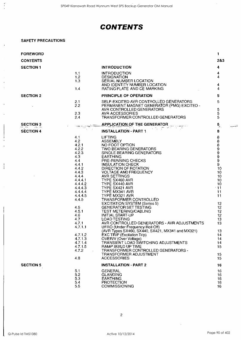
CONTENTS
SAFETY PRECAUTIONS
FOREWORD 1
CONTENTS 2&3
SECTION 1 INTRODUCTION 4
1.1 INTRODUCTION 4 1.2 DESIGNATION 4 1.3 SERIAL NUMBER LOCATION
AND IDENTITY NUMBER LOCATION 4 1.4 RATING PLATE AND CE MARKING 4
SECTION 2 PRINCIPLE OF OPERATION 5
2.1 SELF-EXCITED AVR CONTROLLED GENERATORS 5 2.2 PERMANENT MAGNET GENERATOR (PMG) EXCITED -
AVR CONTROLLED GENERATORS 5 2.3 AVR ACCESSORIES 5 2.4 TRANSFORMER CONTROLLED GENERATORS 5
SECTION 3 ..,-.. APPLICATION OF THE GENERATOR. 6
SECTION 4 INSTALLATION - PART 1 8
4.1 LIFTING 8 4.2 ASSEMBLY 8 4.2.1 NO FOOT OPTION 8 4.2.2 TWO BEARING GENERATORS 9 4.2.3 SINGLE BEARING GENERATORS 9 4.3 EARTHING 9 4.4 PRE-RUNNING CHECKS 9 4.4.1 INSULATION CHECK 9 4.4.2 DIRECTION OF ROTATION 10 4.4.3 VOLTAGE AND FREQUENCY 10 4.4.4 AVR SETTINGS 10 4.4.4.1 TYPE SX460 AVR 10 4.4.4.2 TYPE SX440 AVR 10 4.4.4.3 TYPE SX421 AVR 11 4.4.4.4 TYPE MX341 AVR 11 4.4.4.5 TYPE MX321 AVR 11 4.4.5 TRANSFORMER CONTROLLED
EXCITATION SYSTEM (Series 5) 12 4.5 GENERATOR SET TESTING 12 4.5.1 TEST METERING/CABLING 12 4.6 INITIAL START-UP 12 4.7 LOAD TESTING 13 4.7.1 AVR CONTROLLED GENERATORS - AVR ADJUSTMENTS 13 4.7.1.1 UFRO (Under Frequency Roll Off)
(AVR Types SX460, SX440, SX421, MX341 and MX321) 13 4.7.1.2 EXC TRIP (Excitation Trip) 14 4.7.1.3 OVERN (Over Voltage) 14 4.7.1.4 TRANSIENT LOAD SWITCHING ADJUSTMENTS 14 4.7.1.5 RAMP BUILD UP TIME 15 4.7.2 TRANSFORMER CONTROLLED GENERATORS -
TRANSFORMER ADJUSTMENT 15 4.8 ACCESSORIES 15
SECTION 5 INSTALLATION - PART 2 16
5.1 GENERAL 16 5.2 GLANDING 16 5.3 EARTHING 16 5.4 PROTECTION 16 5.5 COMMISSIONING 16
2
SP049 Kianawah Road Wynnum West SPS Backup Generator OM Manual
Q-Pulse Id TMS1080 Active 10/12/2014 Page 90 of 402

CONTENTS
SECTION 6
6.1 6 2
ACCESSORIES
REMOTE VOLTAGE ADJUST (ALL AVR TYPES) PARALLEL OPERATION
17
17 17
6.2.1 DROOP 17 6.2.1.1 SETTING PROCEDURE 18 6.2.2 ASTATIC CONTROL 18 6.3 MANUAL VOLTAGE REGULATOR (MVR) -
MX341 and MX321 AVR 18 6.4 OVERVOLTAGE DE-EXCITATION BREAKER
SX421 and MX321 AVR 18 6.4.1 RESETTING THE BREAKER 19 6.5 CURRENT LIMIT - MX321 AVR 19 6.5.1 SETTING PROCEDURE 19 6.6 POWER FACTOR CONTROLLER (PFC3) 20
SECTION 7 SERVICE AND MAINTENANCE 21
7.1 WINDING CONDITION 21 7.1.1 WINDING CONDITION ASSESSMENT 21
7.1.2 METHODS OF DRYING OUT GENERATORS 21
7.2 BEARINGS 23 7.3 AIR FILTERS 23 7.3.1 CLEANING PROCEDURE__ -__ 23 7.4 FAULTFINDING - 23 7.4.1 SX460 AVR - FAULT FINDING 23 7.4.2 SX440 AVR - FAULT FINDING 24 7.4.3 SX421 AVR - FAULT FINDING 24 7.4.4 TRANSFORMER CONTROL- FAULT FINDING 24 7.4.5 MX341 AVR - FAULT FINDING 25 7.4.6 MX321 AVR -FAULTFINDING 25 7.4.7 RESIDUAL VOLTAGE CHECK 26 7.5 SEPARATE EXCITATION TEST PROCEDURE 26 7.5.1 GENERATOR WINDINGS, ROTATING DIODES and
PERMANENT MAGNET GENERATOR (PMG) 26 7.5.1.1 BALANCED MAIN TERMINAL VOLTAGES 26 7.5.1.2 'UNBALANCED MAIN TERMINAL VOLTAGES 27 7.5.2 EXCITATION CONTROL TEST 27 7.5.2.1 AVR FUNCTION TEST 27 7.5.2.2 TRANSFORMER CONTROL 28 7.5.3 REMOVAL AND REPLACEMENT OF COMPONENT
ASSEMBLIES 28 7.5.3.1 REMOVAL OF PERMANENT MAGNET GENERATOR (PMG) 28 7.5.3.2 REMOVAL OF BEARINGS 28 7.5.3.3 REMOVAL OF ENDBRACKET AND EXCITER STATOR 28 7.5.3.4 REMOVAL OF THE ROTOR ASSEMBLY 29 7.6 RETURNING TO SERVICE 29
SECTION 8 SPARES AND AFTER SALES SERVICE 30
8.1 RECOMMENDED SPARES 30 8.2 AFTER SALES SERVICE 30
SECTION 9 PARTS IDENTIFICATION 32
TYPICAL SINGLE BEARING GENERATOR (Fig. 11) 33 TYPICAL TWO BEARING GENERATOR (Fig. 12) 35 TYPICAL TWO BEARING (SERIES 5) GENERATOR (Fig. 13) 37 ROTATING RECTIFIER ASSEMBLY (Fig. 14) 38
3
SP049 Kianawah Road Wynnum West SPS Backup Generator OM Manual
Q-Pulse Id TMS1080 Active 10/12/2014 Page 91 of 402

r-
SECTION 1 INTRODUCTION
1.1 INTRODUCTION
The UC22/27 range of generators is of brushless rotating field design, available up to 660V/50Hz (1500 rpm) or 60Hz (1800 rpm), and built to meet BS5000 Part 3 and international standards.
All the UC22/27 range are self-excited with excitation power derived from the main output windings, using either the SX460/ SX440/SX421 AVR. The UC22 is also available with specific windings and a transformer controlled excitation system.
A permanent magnet generator (PMG) powered excitation system is available as an option using either the MX341 or MX321 AVR.
Detailed specification sheets are available on request.
1.2 DESIGNATION
U C I 2 2 4 C 2
M 2 7 4 C 2
GENERATOR TYPE UC
SPECIFIC TYPE
INDUSTRIAL = (I) OR MARINE = (M)
SHAFT HEIGHT IN CM ON BC/UC
NUMBER OF POLES 2, 4, OR 6
CORE LENGTH
NUMBER OF BEARINGS 1 OR 2
1.3 SERIAL NUMBER LOCATION AND IDENTITY NUMBER LOCATION
Each generator is metal stamped with it's own unique serial number, the location of this number is described below.
UCI and UCM generators have their serial number stamped into the upper section of the drive end frame to end bracket adaptor ring, shown as item 31 in the parts lists at the back of this book.
UCD generators have their serial number stamped into the top of the drive end adaptor /fan shroud casting. If for any reason this casting is removed, it is imperative that care is taken to refit it to the correct generator to ensure correct identification is retained.
Inside the terminal box two adhesive rectangular labels have been fixed, each carrying the generators unique identity number. One label has been fixed to the inside of the terminal box sheet metal work, and the second label fixed to the main frame of the generator.
4
1.4 RATING PLATE
The generator has been supplied with a self adhesive rating plate label to enable fitting after final assembly and painting.
It is intended that this label will be stuck to the outside of the terminal box on the left hand side when viewed from the N.D.E. To assist with squarely positioning the label, location protrusions have been made in the sheet metalwork.
A CE Mark label is also supplied loose for fitment after final assembly and painting. This should be attached to an external surface of the Generator at a suitable location where it will not be obscured by the customer's wiring or other fittings.
The surface in the area where a label is to be stuck must be flat, clean, and any paint finish be fully dry before attempting to attach label. Recommended method for attaching label is peel and fold back sufficient of the backing paper to expose some 20 mm of labeladhesive-along the_edge which is to be locatedagainst.the sheet metal protrusions. Once this firit section of label has been-- carefully located and stuck into position the backing paper can be progressively removed, as the label is pressed down into position. The adhesive will achieve a permanent bond in 24 hours.
SP049 Kianawah Road Wynnum West SPS Backup Generator OM Manual
Q-Pulse Id TMS1080 Active 10/12/2014 Page 92 of 402
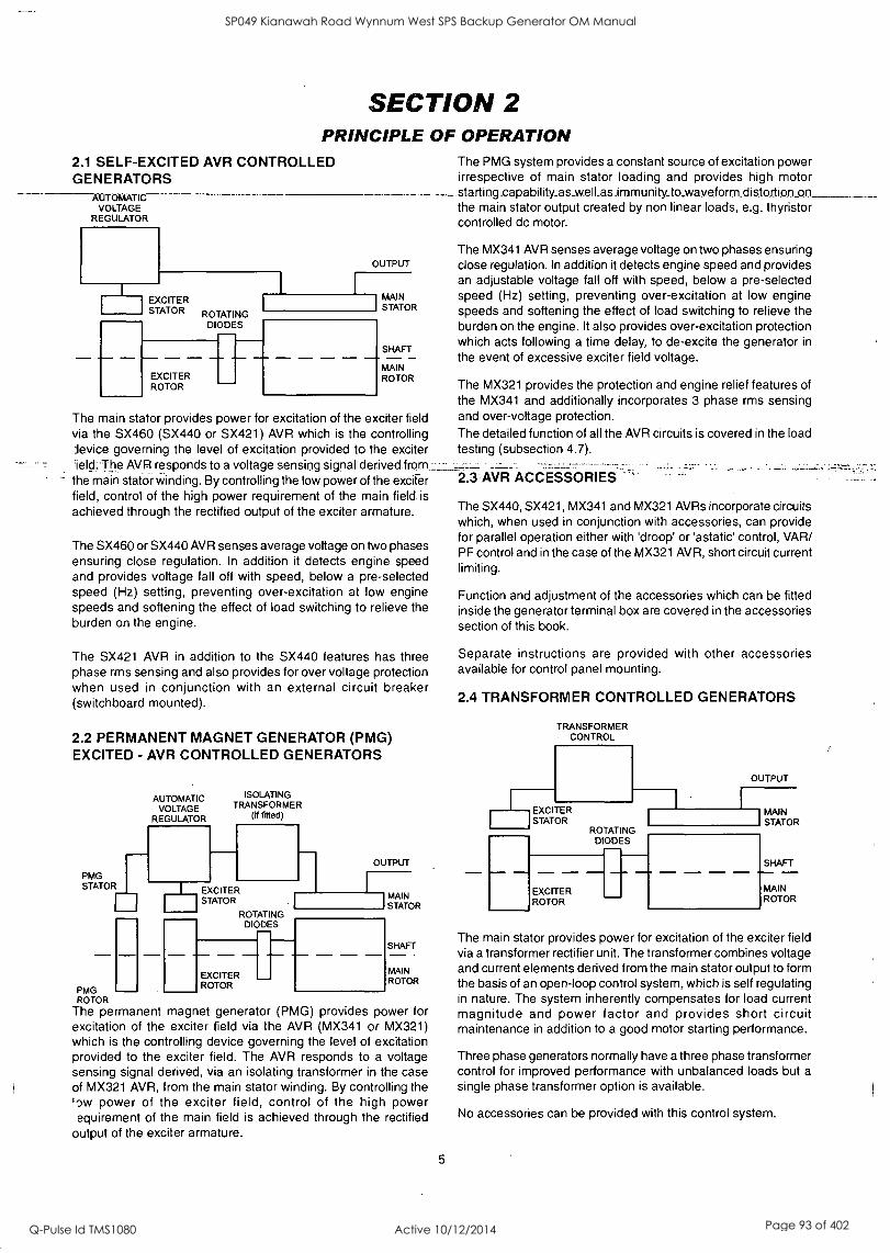
SECTION 2 PRINCIPLE OF OPERATION
2.1 SELF-EXCITED AVR CONTROLLED GENERATORS
AUTOMATIC VOLTAGE
REGULATOR
EXCITER STATOR ROTATING
DIODES
EXCITER ROTOR
OUTPUT
MAIN STATOR
SHAFT
MAIN ROTOR
The main stator provides power for excitation of the exciter field via the SX460 (SX440 or SX421) AVR which is the controlling Jevice governing the level of excitation provided to the exciter Meld: The AVR responds to a voltage sensing signal derived from_-_:._
the main stator winding. By controlling the low power of the exciter field, control of the high power requirement of the main field. is achieved through the rectified output of the exciter armature.
The SX460 or SX440 AVR senses average voltage on two phases ensuring close regulation. In addition it detects engine speed and provides voltage fall off with speed, below a pre-selected speed (Hz) setting, preventing over-excitation at low engine speeds and softening the effect of load switching to relieve the burden on the engine.
The SX421 AVR in addition to the SX440 features has three phase rms sensing and also provides for over voltage protection when used in conjunction with an external circuit breaker (switchboard mounted).
2.2 PERMANENT MAGNET GENERATOR (PMG) EXCITED - AVR CONTROLLED GENERATORS
PMG STATOR
PMG ROTOR
The permanent magnet generator (PMG) provides power for excitation of the exciter field via the AVR (MX341 or MX321) which is the controlling device governing the level of excitation provided to the exciter field. The AVR responds to a voltage sensing signal derived, via an isolating transformer in the case of MX321 AVR, from the main stator winding. By controlling the 'ow power of the exciter field, control of the high power equirement of the main field is achieved through the rectified
output of the exciter armature.
AUTOMATIC VOLTAGE
REGULATOR
ISOLATING TRANSFORMER
(if fitted)
EXCITER STATOR
ROTATING DIODES
OUTPUT
I MAIN I STATOR
SHAFT
EXCITER ROTOR
MAIN ROTOR
5
The PMG system provides a constant source of excitation power irrespective of main stator loading and provides high motor starting capability_as_w.ell_asimmunity_to_waveform distortion on the main stator output created by non linear loads, e.g. thyristor controlled dc motor.
The MX341 AVR senses average voltage on two phases ensuring close regulation. In addition it detects engine speed and provides an adjustable voltage fall off with speed, below a pre-selected speed (Hz) setting, preventing over-excitation at low engine speeds and softening the effect of load switching to relieve the burden on the engine. It also provides over-excitation protection which acts following a time delay, to de-excite the generator in
the event of excessive exciter field voltage.
The MX321 provides the protection and engine relief features of the MX341 and additionally incorporates 3 phase rms sensing and over-voltage protection. The detailed function of all the AVR circuits is covered in the load testing (subsection 4.7).
2 .3: AVR ACCESSORIES
The SX440, SX421, MX341 and MX321 AVRs incorporate circuits which, when used in conjunction with accessories, can provide for parallel operation either with 'droop' or 'astatic' control, VAR/ PF control and in the case of the MX321 AVR, short circuit current limiting.
Function and adjustment of the accessories which can be fitted inside the generator terminal box are covered in the accessories section of this book.
Separate instructions are provided with other accessories available for control panel mounting.
2.4 TRANSFORMER CONTROLLED GENERATORS
TRANSFORMER CONTROL
EXCITER STATOR
ROTATING DIODES
EXCITER ROTOR
OUTPUT
LI MAIN STATOR
.1._ SHAFT
MAIN ROTOR
The main stator provides power for excitation of the exciter field via a transformer rectifier unit. The transformer combines voltage and current elements derived from the main stator output to form the basis of an open-loop control system, which is self regulating in nature. The system inherently compensates for load current magnitude and power factor and provides short circuit maintenance in addition to a good motor starting performance.
Three phase generators normally have a three phase transformer control for improved performance with unbalanced loads but a
single phase transformer option is available.
No accessories can be provided with this control system.
SP049 Kianawah Road Wynnum West SPS Backup Generator OM Manual
Q-Pulse Id TMS1080 Active 10/12/2014 Page 93 of 402

SECTION 3 APPLICATION OF THE GENERATOR
The generator is supplied as a component part for installation in a generating set. It is not, therefore, practicable to fit all the necessary warning/hazard labels during generator manufacture. The additional labels required are packaged with this Manual, together with a drawing identifying their locations. (See below).
LABEL'S' ALL ACCESS COVERS
LABEL 'A' TERMINAL BOX LID OR ALTERNATIVELY APPROPRIATE VISIBLE TERMINAL BOX ACCESS
LABELLC' P.M. &COVER LABEL 'C'
.
ADJACENT TO ALL COVERS'- -- -.
POSITIONS FOR WARNING LABELS UC
SIDE'
LABEL 'N
REFER TO SERVICE MANUAL BEFORE REMOVING COVERS
ABNEHMEN DER ABDECKUNGEN NUR EERINESS HANDBUCH ANWEISUNG
LEGGERE IL MANUALE DI ASSISTENZA PREMA DI RIMUOVERE I COPERCHI
CONSULTAR MANUAL ANTES DE RETIRAR TAPAS
VOIR IAANUEL DE SERVICE AVANT IYENLEVER LES COUVERCLES
It is the responsibility of the generating set manufacturer to ensure that the correct labels are fitted, and are clearly visible.
The generators have been designed for use in a maximum ambient temperature of 40°C and altitude less than 1000m above sea level in accordance with BS5000.
Ambients in excess of 40°C and altitudes above 1000m can be tolerated with reduced ratings - refer to the generator nameplate for rating and ambient. In the event that the generator is required to operate in an ambient in excess of the nameplate value or at altitudes in excess of 1000 metres above sea level, refer to the factory.
6
The generators are of air-ventilated screen protected drip-proof design and are not suitable for mounting outdoors unless adequately protected by the use of canopies. Anti-condensation heaters are recommended during storage and for standby duty to ensure winding insulation is maintained in good condition.
When installed in a closed canopy it must be ensured that the ambient temperature of the cooling air to the generator does not exceed that for which the generator has been rated.
The canopy should be designed such that the engine air intake to the canopy is separated from the generator intake, particularly where the radiator cooling fan is required to draw air into the canopy. In addition the generator air intake to the canopy should be designed such that the ingress of moisture is prohibited, preferably by use of a 2 stage filter.
The air intake/outlet must be suitable for the air flow given in the following table with additional pressure drops less than or equal to those given below:
Frame
Air Flow Additional (intake/outlet) Pressure Drop 50Hz 60Hz
UC22
0.216m3 /sec 0.281m3/sec 6mm water gauge
458cfm 595cfm 0.25"
UCD22
0.25m3/sec 0.31m3/sec 6mm water gauge
530cfm 657cfm 0.25"
UC27
0.514m3/sec 0.617m3/sec 6mm water gauge
1090cfm 1308cfm 0.25"
UCD27 0.58m3/sec 0.69m3/sec 6mm water gauge
1230cfm 1463cfm 0.25"
Important ! Reduction in cooling air flow or inadequate protection to the generator can result in damage and/or failure of windings.
Dynamic balancing of the generator rotor assembly has been carried out during manufacture in accordance with BS 6861 Part 1 Grade 2.5 to ensure vibration limits of the generator are in accordance with BS 4999 Part 142.
The main vibration frequencies produced by the generator are as follows:-
4 pole 1500 rpm 25 Hz 4 pole 1800 rpm 30 Hz
However, vibrations induced by the engine are complex and contain frequencies of 1.5, 3, 5 or more times the fundamental frequency of vibration. These induced vibrations can result in generator vibration levels higher than those derived from the generator itself. It is the responsibility of the generating set designer to ensure that the alignment and stiffness of the bedplate and mountings are such that the vibration limits of BS5000 Par 3 are not exceeded.
SP049 Kianawah Road Wynnum West SPS Backup Generator OM Manual
Q-Pulse Id TMS1080 Active 10/12/2014 Page 94 of 402

In standby applications where the running time is limited and -educed life expectancy is accepted, higher levels than specified
BS5000 can be tolerated, up to a maximum of 18mm/sec.
Two bearing generators open coupled require a substantial bedplate with engine/generator mounting pads to ensure a good base for accurate alignment. Close coupling of engine to generator can increase the overall rigidity of the set. For the purposes of establishing set design the bending moment at the engine flywheel housing to generator adaptor interface should not exceed 1000ft.lb. (140 kgm). A flexible coupling, designed to suit the specific engine/generator combination, is recommended to minimise torsional effects.
Belt driven applications of two bearing generators require the pulley diameter and design to be such that the side load or force applied to the shaft is central to the extension and does not exceed the values given in the table below:-
Frame Side Load Shaft
extension mm
kgf N
7--..... UC22.: .._,. ________408_______ ._ ..:.4000._:..-.._:.. 110
UC27 510 5000 140
In instances where shaft extensions greater than specified in the table have been supplied reference must be made to the factory for appropriate loadings.
Alignment of single bearing generators is critical and vibration can occur due to the flexing of the flanges between the engine and generator. As far as the generator is concerned the maximum bending moment at this point must not exceed 1000ft.lb. (140 kgm). A substanial bedplate with engine/generator mounting pads is required.
It is expected that the generator will be incorporated into a
generating set operating in an environment, where the maximum shock load experienced by the generator will not exceed 3g. in
any plane. If shock loads in excess of 3g are to be encountered, anti-vibration mountings must be incorporated into the generating ;et to ensure they absorb the excess.
The maximum bending moment of the engine flange must be checked with the engine manufacturer.
Generators can be supplied without a foot, providing the option for customers own arrangement. See SECTION 4.2.1 for assembly procedure.
Torsional vibrations occur in all engine-driven shaft systems and may be of a magnitude to cause damage at certain critical speeds. It is therefore necessary to consider the torsional vibration effect on the generator shaft and couplings.
It is the responsibility of the generator set manufacturer to ensure compatibility, and for this purpose drawings showing the shaft dimensions and rotor inertias are available for customers to forward to the engine supplier. In the case of single bearing generators coupling details are included.
mportant ! Torsional incompatibility and/or excessive vibration levels can cause damage or failure of generator and/or engine components. 7
The terminal box is constructed with removable panels for easy adaptation to suit specific glanding requirements. Within the terminal box there are insulated terminals for line and neutral connections and provision for earthing. Additional earthing points are provided on the generator feet.
The neutral is NOT connected to the frame
The main stator winding has leads brought out to the terminals in
the terminal box.
Warning !
No earth connections are made on the generator and reference to site regulations for earthing must be made. Incorrect earthing or protection arrangements can result in personal injury or death.
Fault current curves (decrement curves), together with generator reactance data, are available on request to assist the system designer to select circuit breakers, calculate fault currents and ensure discrimination within the load network.
Incorrect installation, service or replacement of parts can result in severe personal injury or death, and/or equipment damage. Service personnel
Warning ! must be qualified to perform electrical and mechanical service.
SP049 Kianawah Road Wynnum West SPS Backup Generator OM Manual
Q-Pulse Id TMS1080 Active 10/12/2014 Page 95 of 402

4.1 LIFTING
SECTION 4 INSTALLATION - PART I
Once the bar is removed, to couple the rotor to engine, the rotor is free to move in the frame, and care is needed during coupling and alignment to ensure the frame is kept in the horizontal plane.
Warning !
Incorrect lifting or inadequate lifting capacity can result in severe personal injury or equipment damage. MINIMUM LIFTING CAPACITY REQUIRED IS 750Kg. Generator lifting lugs should NOT be used for lifting the complete generator set.
Two lifting lugs are provided for use with a shackle and pin type
lifting aid. Chains of suitable length and lifting capacity must be
used. Lifting points are designed to be as close to the centre of
gravity of the generator as possible, but due to design restrictions
it is not possible to guarantee that the generator frame will remain
horizontal while lifting. Care is therefore needed to avoid personal
injury or equipment damage. The correct lifting arrangement is
shown on the label attached to the lifting lug. (See sample below).
IMPORTANT
REFER TO SERVICE MANUAL
BEFORE REMOVING COVERS.
IT IS THE GENERATOR SET
MANUFACTURER'S
RESPONSIBILITY TO FIT
THE SELF ADHESIVE WARNING
LABELS SUPPLIED WITH THE
GENERATOR. THE LABEL SHEET
CAN BE FOUND WITH THE
INSTRUCTION BOOK.
Single bearing generators are supplied fitted with a rotor retaining bar at the non-drive end of the shaft.
To remove retaining bar:
1. Remove the four screws holding the sheet metal cover at the non drive end and remove cover
2. Remove central bolt holding the retaining bar to the shaft
3. Refit sheet metal cover.
8
Generators fitted with a PMG excitation system are not fitted with retaining bar. Refer to frame designation to verify generator type (subsection 1.2)
4.2 ASSEMBLY
During the assembly of the generator to the engine it will be necessary firstly to carefully align, then rotate, the combined generator rotor - engine crankshaft assembly, as part of the construction process, to allow location, insertion and tightening of the coupling bolts. This requirement to rotate the combined assemblies exists for both single and two bearing units.
During the assembly of single bearing units it is necessary to align the generator's ,coupling_ holes' With,the- engine flywheel holes; it is suggestdd that Mb-diametrically opposite location dowel pins are fitted to the engine flywheel, over which the generator coupling can slide into final location into the engine flywheel spigot recess. The dowels must be removed and replaced by coupling bolts before the final bolt tightening sequence.
While fitting and tightening the coupling bolts it will be necessary to rotate the engine crankshaft - generator rotor assembly. Care should be taken to ensure that rotation is carried out in an approved manner that ensures safe working practice when reaching inside the machine to insert or tighten coupling bolts, and that no component of the assembly is damaged by non- approved methods of assembly rotation.
Engine manufacturers have available a proprietary tool or facility designed to enable manual rotation of the crankshaft assembly. This must always be used, having been engineered as an approved method of assembly rotation, engaging the manually driven pinion with the engine flywheel starter ring-gear.
Caution ! Before working inside the generator, during the aligning and fitting of coupling bolts, care should be taken to lock the assembly to ensure there is no possibility of rotational movement.
4.2.1 NO FOOT OPTION
Generators can be supplied without a foot providing the option for customers own arrangement.
For details of mounting this arrangement, see the general arrangement drawing supplied with the generator. Alternatively refer to Newage International for a copy of the latest general arrangement drawing showing the 'NO FOOT OPTION' appropriate to your generator.
SP049 Kianawah Road Wynnum West SPS Backup Generator OM Manual
Q-Pulse Id TMS1080 Active 10/12/2014 Page 96 of 402

4.2.2 TWO BEARING GENERATORS
A flexible coupling should be fitted and aligned in accordance with the coupling manufacturer's instruction.
3. Remove covers from the drive end of the generator to gain access to coupling and adaptor bolts.
4. Check that coupling discs are concentric with adaptor spigot. This can be adjusted by the use of tapered wooden wedges between the fan and adaptor. Alternatively the rotor can be suspended by means of a rope sling through the adaptor opening.
If a close coupling adaptor is used the alignment of machined faces must be checked by offering the generator up to the engine. Shim the generator feet if necessary. Ensure adaptor guards are fitted after generator/engine assembly is complete. Open coupled sets require a suitable guard, to be provided by the set builder.
In the case of belt driven generators, ensure alignment of drive and driven pulleys to avoid axial load on the bearings. Screw type tensioning devices are recommended to allow accurate adjustment of belt tension whilst maintaining pully alignment. Side
loads should not exceed values given in SECTION 3.
Belt and pulley guards must be provided by the set builder.
Important ! Incorrect belt tensioning will result in excessive bearing wear.
Caution ! Incorrect guarding and/or generator alignment can result in personal injury and/or equipment damage.
4.2.3 SINGLE BEARING GENERATORS
Alignment of single bearing generators is critical. If necessary shim the generator feet to ensure alignment of the machined surfaces.
For transit and storage purposes the generator frame spigot and rotor coupling plates have been coated with a rust preventative. This MUST BE removed before assembly to engine.
A practical method for removal of this coating is to clean the mating surface areas with a de-greasing agent based on a petroleum solvent.
Care should be taken not to allow any cleaning agent to come into prolonged contact with skin.
The sequence of assembly to the engine should generally be as follows:
1. On the engine check the distance from the coupling mating face on the flywheel to the flywheel housing mating face. This should be within +/-0.5mm of nominal dimension. This is necessary to ensure that a thrust is not applied to the a.c. generator bearing or engine bearing.
2. Check that the bolts securing the flexible plates to the coupling hub are tight and locked into position. Torque tightening is 24.9kgfm (244Nm; 180 lb ft).
2a. UCD224 Only Torque tightening is 15.29 kgfm (150Nm; 110 lb ft).
9
5. Offer the a.c. generator to engine and engage both coupling discs and housing spigots at the same time,' finally pulling home by using the housing and coupling bolts. Use heavy gauge washers between bolt head and discs on disc to flywheel bolts.
6. Tighten coupling disc to flywheel. Refer to engine manual for torque setting of disc to flywheel bolts.
7. Remove wooden wedges.
Caution ! Incorrect guarding and/or generator alignment can result in personal injury and/or equipment damage.
EARTHING
The generator frame should be solidly bonded to the generating set bedplate. If antivibration mounts are fitted between the generator frame and its bedplate a suitably rated earth conductor (normally one half of the cross sectional area of the main line cables) should bridge across the antivibration mount.
Warning !
Refer to local regulations to ensure that the correct earthing procedure has been followed.
4.4 PRE-RUNNING CHECKS 4.4.1 INSULATION CHECK
Before starting the generating set, both after completing assembly and after installation of the set, test the insulation resistance of windings.
The AVR should be disconnected during this test.
A 500V Megger or similar instrument should be used. Disconnect any earthing conductor connected between neutral and earth and megger an output lead terminal U, V or W to earth. The insulation resistance reading should be in excess of 5MQ to earth. Should the insulation resistance be less than 5MQ the winding must be dried out as detailed in the Service and Maintenance section of this Manual.
Important ! The windings have been H.V. tested during manufacture and further H.V. testing may degrade the insulation with consequent reduction in operating life. Should it be necessary to demonstrate H.V. testing, for customer acceptance, the tests must be carried out at reduced voltage levels i.e. Test Voltage= 0.8 (2 X Rated Voltage + 1000)
SP049 Kianawah Road Wynnum West SPS Backup Generator OM Manual
Q-Pulse Id TMS1080 Active 10/12/2014 Page 97 of 402

4.4.2 DIRECTION OF ROTATION
The generator is supplied to give a phase sequence of U V W with the generator running clockwise looking at the drive end (unless otherwise specified at the time of ordering). If the generator phase rotation has to be reversed after the generator has been despatched apply to factory for appropriate wiring diagrams.
UCI224, UC1274, UCM224, UCM274
Machines are fitted with bi-directional fans and are suitable for running in either direction of rotation.
UCD224, UCD274
Machines are fitted with uni-directional fans and are suitable for running in one direction only.
4.4.3 VOLTAGE AND FREQUENCY
Check that the voltage and frequency levels required for the generating set application are as indicated on the generator nameplate.
Three phase generators normally have a 12 ends out reconnectable winding. If it is necessary to reconnect the stator for the- voltage- required, refer to diagrams_ jn;the_babk_of -this. manual.
4.4.4 AVR SETTINGS
To make AVR selections and adjustments remove the AVR cover and refer to 4.4.4.1, 4.4.4.2, 4.4.4.3, 4.4.4.4 or 4.4.4.5 depending upon type of AVR fitted. Reference to the generator nameplate will indicate AVR type (SX460, SX440, SX421, MX341 or MX321).
Most of the AVR adjustments are factory set in positions which will give satisfactory performance during initial running tests. Subsequent adjustment may be required to achieve optimum performance of the set under operating conditions. Refer to 'Load Testing' section for details.
4.4.4.1 TYPE SX460 AVR
The following 'jumper' connections on the AVR should be checked to ensure they are correctly set for the generating set application.
Refer to Fig. 1 for location of selection links.
1. Frequency selection 50Hz operation LINK C-50 60Hz operation LINK C-60
2. External hand trimmer selection No external hand trimmer LINK 1-2
External hand trimmer required - REMOVE LINK 1-2 and connect trimmer across terminals 1 and 2.
3. AVR Input Selection High voltage (220/240V) Input NO LINK Low voltage (110/120V) Input LINK 3-4
Refer to diagram in the back of this manual to determine wiring.
10
HAND TRIMMER CONNECTIONS
INPUT SELECTION CONNECTIONS
-C
csi
e XX X 6 7 8
VOLTS
AVR INPUT SX460 o SELECTION
UFRO
0 INDICATOR LED
FREQUENCY tr,
e
SELECTION
STABILITY
e 0
Fig. 1
4.4.4.2 TYPE SX440 AVR
The following 'jumper' connections on the AVR should be checkec to ensure-they are correctly set for th&generating set application
Refer to Fig. 2 for location of selection links.
1. Frequency selection terminals 50Hz operation LINK C-50 60Hz operation LINK C-60
2. Stability selection terminals Frame UC22 LINK A-C Frame UC27 LINK B-C
3. Sensing selection terminals LINK 2-3 LINK 4-5 LINK 6-7
4. Excitation Interruption Link LINK K1-K2
K1 -K2 Linked tar
normal operation.
A A
0 r-
1K2 K1 P2 P3 P4 XX X 3 1112
2 1
-1 L J L _ _1
SX440
INDICATOR LED
0 UFRO
0 lel r r
L 150C6011tei IC B AI J
TRIM
DROOP
VOLTS
FREQUENCY SELECTION
I I
0 rAT1-1
A2
St
S2,
STABILITY SELECTION
2
3
4
5
6
7
0
501-1zY__Y
60Hz
Fig. 2
90kW -550kW
y__y OVER 55OkW
SP049 Kianawah Road Wynnum West SPS Backup Generator OM Manual
Q-Pulse Id TMS1080 Active 10/12/2014 Page 98 of 402

4.4.4.3 TYPE SX421 AVR
The following 'jumper connections on the AVR should be checked to ensure they are correctly set for the generating set application.
Refer to Fig. 3 for location of selection links.
1. Frequency selection terminals 50Hz operation LINK C-50 60Hz operation LINK C-60
2. Stability selection terminals Depending upon kW output LINK B-D
or LINK A-C or LINK B-C
3. Terminals K1 - K2 Excitation circuit breaker closed
0
0
K2 K1 P2 P;I: 0 VOLTS
P4 XX X 6 r7 8 1 2 Fel J
0
- -
INDICATOR '
LED \ UFRO A--), 50Hz cl 60Hz
SX421 0 1°1 FREQUENCY P-"" C °' SELECTION
OVERN
trq: E0 El BO Bi] 0
DIP
STABILITY SELECTION
DCBA
a
rD
RMS
STABILITY
TRIM
DROOP/ SI S2A1A2 a 0
Y Y UNDER 40kW Y Y 40kW - 90kW
'U 90kW - 550kW
Fig. 3
4.4.4.4 TYPE MX341 AVR
The following jumper' connections on the AVR should be checked to ensure they are correctly set for the generating set application.
Refer to Fig. 4 for location of setting links.
1. Frequency selection terminals 50Hz operation LINK 2-3 60Hz operation LINK 1-3
2. Stability selection terminals Frame UC22 LINK A-C Frame UC27 LINK B-C
3. Sensing selection terminals * LINK 2-3 LINK 4-5 LINK 6-7
4. Excitation Interruption Link LINK K1-K2
K I .K2 Linked for normal operation.
0 r- - r
ILK2 K1 P2 P3 P4 XX X 31 12 2 1 r
I I- -J
TRIM
DROOP
MX341
INDICATOR LED
0 UFRO r- r
01 e L3 2 11e [c B A]
/STABILITY SELECTION
VOLTS
EXC TRIP
FREQUENCY SELECTION
D
0
:A21 S1
1LS2:
1
2
3 4
5
6
7
L8_
0
Y y 4P/60Hz Y-Y 4P/50Hz sL_Y
'i 6P/60Hz
NO LINK 6P/50Hz
Fig. 4
-4.4.4.5 TYPE MX321
11
90kW -550kW
OVER 550kW
The following jumper' connections on the AVR should be checked to ensure they are correctly set for the generating set application.
Refer to Fig. 5 for location of setting links.
. 0
i AUTOMATIC VOLTAGE REGULATOR MX321-'
LINKING AND ADJUSTMENTS
VOLTS
O - e I T < 2 - K - 1 F 2 P S 1 0 F P 4 - X - X - X C I FT 8- 71 -2-' e 0 RAMP NO UNK 6P/50Hz 8
INDICATOR 6P/60Hz ,
LED -..,,..0 UFRO A--)A-A 1 4P/, 50Hz I/ LIMIT A-A 4P/60Hz
I- - 7 FREQUENCY 0 3 2 1 I3? _ SELECTION _1
DIP re- RMS e
DWELL I e I
STABILITY FFISTABILITY SELEC11ON
EXC /OVER /V TRIP U V w DROOP TRIM
0 I e 1'1(7E1 T3o-ei L J o e Ec -8 TO,
rsts\2 sit - ielel o L. - _1 1... _ S.LU._ _A192J
Y Y UNDER 90KW
Y__Y 90KW - 550KW
L'-,' OVER 550KW
Fig. 5
1. Frequency selection terminals 50Hz operation LINK 2-3 60Hz operation LINK 1-3
2. Stability selection terminals Frame UC22 LINK A-C Frame UC27 LINK B-C
3. Terminals K1 - K2 Excitation circuit breaker closed. If this option not fitted, K1 - K2 linked at auxiliary terminal block.
SP049 Kianawah Road Wynnum West SPS Backup Generator OM Manual
Q-Pulse Id TMS1080 Active 10/12/2014 Page 99 of 402

4.4.5 TRANSFORMER CONTROLLED EXCITATION SYSTEM (Series 5)
This control system is identified with the digit 5 as the last digit of the frame size quoted on the nameplate.
The excitation control is factory set for the specific voltage shown on the nameplate and requires no adjustment.
4.5 GENERATOR SET TESTING
Warning !
During testing it may be necessary to remove covers to adjust controls exposing 'live' terminals or components. Only personnel qualified to perform electrical service should carry out testing and/or adjustments.
4.5.1 TEST METERING/CABLING
Connect any instrument wiring and cabling required for initial test purposes with permanent or spring-clip type connectors.
Minimum instrumentation for testing should be line - line or line to-neutral-Voltmeter, Hz .meter' load current metering.. and- klAl-
meter. !f reactive load is used a power factor meter is desirable.
Important ! When fitting power cables for load testing purposes, ensure cable voltage rating is at least equal to the genrator rated voltage. The load cable termination should be placed on top of the winding lead termination and clamped with the nut provided.
Caution ! Check that all wiring terminations for internal or external wiring are secure, and fit all terminal box covers and guards. Failure to secure wiring and/or covers may result in personal injury and/or equipment failure.
4.6 INITIAL START-UP
During testing it may be necessary to remove covers to adjust controls exposing 'live' terminals or components. Only personnel qualified to perform
Warning ! electrical service should carry out testing and/or adjustments. Refit all access covers after adjustments are completed.
On completion of generating set assembly and before starting the generating set ensure that all engine manufacturer's pre- running procedures have been completed, and that adjustment of the engine governor is such that the generator will not be subjected to speeds in excess of 125% of the rated speed.
Important ! Overspeeding of the generator during initial setting of the speed governor can result in damage to the generator rotating components.
In addition remove the AVR access cover (on AVR controlled generators) and turn VOLTS control fully anti-clockwise. Start the generating set and run on no-load at nominal frequency. Slowly turn VOLTS control potentiometer clockwise until rated voltage is
reached. Refer to Fig. 6a, 6b, 6c, 6d or 6e for control potentiometer location.
12
Important ! Do not increase the voltage above the rated generator voltage shown on the generator nameplate.
The STABILITY control potentiometer will have been pre-set and should normally not require adjustment, but should this be required, usually identified by oscillation of the voltmeter, refer to Fig. 6a, 6b, 6c, 6d or 6e for control potentiometer location and proceed as follows: -
1. Run the generating set on no-load and check that speed is correct and stable
2. Turn the STABILITY control potentiometer clockwise, then turn slowly anti-clockwise until the generator voltage starts to become unstable.
The correct setting is slightly clockwise from this position (i.e. where the machine volts are stable but close to the unstable region).
50Hz
60Hz
r
N
,r
UFRO
B O
0
0
e
VOLTS
SX460
0 INDICATOR LED
FREQUENCY
SELECTION
STABILITY
e 0
K1 -K2 Linked for normal operation.
Fig. 6a
0 K2 L
r" K1 P2 P3 P4 XX X 31 112 2 1
J L _
SX440
INDICATOR LED
0 UFRO
Q rel L50 C 60]
TRIM
DROOP
VOLTS
FREQUENCY SELECTION
ID
6
I ®'
0
A2
S1
LS2.
1
2
3
4
5
6
7
L8_
STABILITY SELECTION
IC B 9 0
50Hz t_Y 60Hz
Fig. 6b
90kW - 550kW
y__y OVER 550kW
SP049 Kianawah Road Wynnum West SPS Backup Generator OM Manual
Q-Pulse Id TMS1080 Active 10/12/2014 Page 100 of 402

0 TK2 K1 P2 P3' L J
VOLTS r . P4 )0( X 6 1 1 7 8 1 2'
L a 0
INDICATOR , 60Hz LED UFRO
1--) 50Hz
SX421 "0 a) C FREQUENCY
150 60 L____' SELECTION
OVERN r -t I EO El BO Ell 0 B 0
DIP
STABILITY SELECTION
DROOP TRIM
FD C B A. .51 52A1A2 a e
a RMS
STABILITY
0
Y Y
Y__Y
Fig. 6c K 1-K2 Linked for
norm al operation.
UNDER 40kW 40kW - 90kW
90kW - 550kW
r- 2 1 0 K2 K2 K1 P2 P3 P4 XX X 2 31 I
A2: DROOP 1S11
MX341. LS21
-T VOLTS I 2
3 4
5
6
7
TRIM (1)
e I
DIP
ID
INDICATOR
LED \UFRO
0 e L 3 0
1 I)
EXC TRIP
OJ
FREQUENCY L8_
STABILITY SELECTION
2 1 11 8 1 " C B A _I, 0
Y y 4P/60Hz Y-Y 90kW -550kW
4P/50Hz yy OVER 550kW
6P/60Hz
NO LINK 6P/50Hz
Fig. 6d
AUTOMATIC VOLTAGE REGULATOR MX321-2
LINKING AND ADJUSTMENTS
° 8 I( 2- K-1 P-2 -P 3- lj
RAMP
INDICATOR LED
OVER/V
0 El 110E-1 130-8p "" L ..... _ ___ -1
VOLTS
0 17f 4- X_ X --X 16-1 Er a- -1
_V 2- i 8 0
NO LINK 6P/50HZ CI 6P/60Hz
,L-J, I 4R/60Hz I/LIMIT "---.....0 UFRO 1-1 4P/60Hz
r- - ,FREQUENCY 3 2 1 L SELECTION J
DIP 0 RMS 8
DWELL e
STABILITY ID STABILITY SELECTION
EXC / TRIP / LU_, V DROOP TRIM
0 rIFE -6 ;,11-SIS2 S1S2 - 1 8 a 0 No L.- - __IL _ 53,52_ __Atzt
Y__Y uNos 900 Y__Y 900* - 550KW
Y__.Y OVER 550KY1
Fig. 6e
13
4.7 LOAD TESTING
Warning !
During testing it may be necessary to remove covers to adjust controls exposing 'live' terminals or components. Only personnel qualified to perform electrical_service should_carry_ouLtesting and/or adjustments. Refit all access covers after adjustments are completed.
4.7.1 AVR CONTROLLED GENERATORS - AVR ADJUSTMENTS
Refer to Fig. 6a, 6b, 6c, 6d or 6e for control potentiometer locations.
Having adjusted VOLTS and STABILITY during the initial start- up procedure, other AVR control functions should not normally need adjustment.
If however, poor voltage regulation on-load or voltage collapse is experienced, refer to the following paragraphs on each function to a) check that the symptoms observed do indicate adjustment is necessary, and b) to make the adjustment correctly.
4.7.1.1 UFRO (Under Frequency Roll Off) (AVR Types SX460, SX440, SX421, MX341 and MX321)
The AVR incorporates an underspeed protection circuit which gives a voltage/speed (Hz) characteristic as shown:
100
95
90
85
80
Clockwise Anticlockwise Adjustment Knee Adjustment
Point
Slope shown is typical
75 80 85 90 95 100
% Speed (Hz)
Fig. 7
The UFRO control potentiometer sets the "knee point".
Symptoms of incorrect setting are a) the light emitting diode (LED) indicator, just above the UFRO Control potentiometer, being permanently lit when the generator is on load, and b) poor voltage regulation on load, i.e. operation on the sloping part of the characteristic.
Clockwise adjustment lowers the frequency (speed) setting of the "knee point" and extinguishes the LED. For Optimum setting the LED should illuminate as the frequency falls just below nominal frequency, i.e. 47Hz on a 50Hz generator or 57Hz on a
60Hz generator.
Important ! With AVR Types MX341 and MX321. If the LED is illuminated and no output voltage is present, refer to EXC TRIP and/or
OVERN sections below.
SP049 Kianawah Road Wynnum West SPS Backup Generator OM Manual
Q-Pulse Id TMS1080 Active 10/12/2014 Page 101 of 402

4.7.1.2 EXC TRIP (Excitation Trip) DIP AVR Types MX341 and MX321
An AVR supplied from a permanent magnet generator inherently delivers maximum excitation power on a line to line or line to neutral short circuit or large overload. In order to protect the generator windings the AVR incorporates an over excitation circuit which detects high excitation and removes it
after a pre-determined time, i.e. 8-10 seconds.
Symptoms of incorrect setting are the generator output collapses on load or small overload, and the LED is permanently illuminated.
The correct setting is 70 volts +/-5% between terminals X and XX.
4.7.1.3 OVERN (Over Voltage) AVR Type SX421, MX321
Over voltage protection circuitry is included in the AVR to remove generator excitation in the event of loss of AVR sensing input.
The MX321 has both internal electronic de-excitation and provision of a signal to operate an external circuit breaker.
The SX421 only provides a signal to operate an external breaker, which MUST be fitted if over voltage protection is required.
Incorrect setting would cause the generator output voltage to collapse at no-load or on,removal of load, and the LED to be illuminated.
The correct setting is 300 volts +/-5% across terminals E1, E0.
Clockwise adjustment of the OVERN control potentiometer will increase the voltage at which the circuit operates.
4.7.1.4 TRANSIENT LOAD SWITCHING ADJUSTMENTS AVR Types SX421, MX341 and MX321
The additional function controls of DIP and DWELL are provided to enable the load acceptance capability of the generating set to be optimised. The overall generating set performance depends upon the engine capability and governor response, in
conjunction with the generator characteristics.
It is not possible to adjust the level of voltage dip or recovery independently from the engine performance, and there will always be a 'trade off between frequency dip and voltage dip.
14
AVR Types SX421, MX341 and MX321
AVR Types SX421, MX341 and MX321 The dip function control potentiometer adjusts the slope of the voltage/speed (Hz) characteristic below the knee point as shown below:
z
100
95
90
85
80 75
Knee Point
Anticlockw'se A
-V Adjustable
Slope
Clockwise Adjustment
80 85 90 95 100
% Speed (Hz) _
Fig. 8 DWELL AVR Type MX321
The dwell function introduces a time delay between the recovery of voltage and recovery of speed.
The purpose of the time delay is to reduce the generator kW below the available engine kW during the recovery period, thus allowing an improved speed recovery.
Again this control is only functional below the "knee point", i.e. if
the speed stays above the knee point during load switching there is no effect from the DWELL function setting.
Clockwise adjustment gives increased recovery time.
Adjustable Slope
100
95
90
85
80
Anticlockwise Ad ustment
111.11V" OTOPP:lockwise
Adjustment
t
Instant of Load Application
Fig. 9
Time
The graphs shown above are representations only, since it is impossible to show the combined effects of voltage regulator and engine governor performance.
SP049 Kianawah Road Wynnum West SPS Backup Generator OM Manual
Q-Pulse Id TMS1080 Active 10/12/2014 Page 102 of 402

4.7.1.5 RAMP AVR Type MX321
The RAMP potentiometer enables adjustment of the time taken for the generator's initial build up to normal rated voltage during each start and run up to speed. The potentiometer is factory set to-give a -ramp time of three seconds, which is considered to be suitable for most applications. This time can be reduced to one second by turning the pot. fully counter clockwise, and increased to eight seconds by turning the pot. fully clockwise.
4.7.2 TRANSFORMER CONTROLLED GENERA- TORS - TRANSFORMER ADJUSTMENT
Normally no adjustment is required but should the no-load voltage and/or on-load voltage be unacceptable, adjustment of the transformer air gap can be made as follows.
Stop the generator. Remove transformer cover box. (Normally left hand side of the terminal box when viewed from the non drive end).
Slacken the three transformer mounting bolts along the top of - tririgfarner.
Start the set with a voltmeter connected across the main output terminals.
Adjust the air gap between the transformer top lamination section and the transformer limbs to obtain required voltage on no-load. Slightly tighten the three mounting bolts. Switch load 'on' and 'off two or three times. Application of load will normally raise the voltage setting slightly. With the load 'off' recheck the no-load voltage. Readjust air gap and finally tighten mounting bolts.
Refit the access cover.
Warning !
Failure to refit covers can result in operator personal injury or death.
4.8 ACCESSORIES
Refer to the "ACCESSORIES" - Section 6 of this Manual for setting up procedures related to generator mounted accessories.
If there are accessories for control panel mounting supplied with the generator refer to the specific accessory fitting procedures inserted inside the back cover of this book.
15
SP049 Kianawah Road Wynnum West SPS Backup Generator OM Manual
Q-Pulse Id TMS1080 Active 10/12/2014 Page 103 of 402

5.1 GENERAL
SECTION 5 INSTALLATION - PART 2
5.4 PROTECTION
The extent of site installation will depend upon the generating set build, e.g. if the generator is installed in a canopied set with integral switchboards and circuit breaker, on site installation will be limited to connecting up the site load to the generating set output terminals . In this case reference should be made to the generating set manufacturers instruction book and any pertinent local regulations.
If the generator has been installed on a set without switchboard or circuit breaker the following points relating to connecting up the generator should be noted.
5.2 GLANDING
The terminal box is most conveniently glanded on either the right or left hand side. Both panels are removable for drilling/punching to suit glands/or glanding boxes. If single core cables are taken through the terminal box side panel an insulated or non-magnetic gland plate should be fitted.
. . .
Incoming cables should be supported from either below or above the box level and at a sufficient distance from the centre line of the generating set so as to avoid a tight radius at the point of entry into the terminal box panel, and allow movement of the generator set on its anti-vibration mountings without excessive stress on the cable.
Before making final connections, test the insulation resistance of the windings. The AVR should be disconnected during this test.
A 500V Megger or similar instrument should be used. Should the insulation resistance be less than 5MQ the windings must be dried out as detailed in the Service and Maintenance section of this manual.
When making connections to the terminals the incoming cable termination should be placed on top of the winding lead termination(s) and clamped with the nut provided.
Important ! To avoid the possibility of swarf entering any electrical components in the terminal box, panels must be removed for drilling.
5.3 EARTHING
The neutral of the generator is not bonded to the generator frame as supplied from the factory. An earth terminal is provided inside the terminal box adjacent to the main terminals. Should it be required to operate with the neutral earthed a substantial earth conductor (normally equivalent to one half of the section of the line conductors) must be connected between the neutral and the earth terminal inside the terminal box. Additional earth terminals are provided on the generator feet. These should be already bonded to the generating set bedplate by the generating set builder, but will normally be required to be connected to the site earth system.
Caution ! Reference to local electricity regulations or safety rules should be made to ensure correct earthing procedures have been followed.
16
It is the responsibility of the end user and his contractors/sub- contractors to ensure that the overall system protection meets the needs of any inspectorate, local electricity authority or safety rules, pertaining to the site location.
To enable the system designer to achieve the necessary protection and/or discrimination, fault current curves are available on request from the factory, together with generator reactance values to enable fault current calculations to be made.
Warning !
Incorrect installation and/or protective systems can result in personal injury and/or equipment damage. Installers must be qualified to perform electrical installation work.
5.5 COMMISSIONING
Ensure that all external cabling is correct and that all the generating set manufacturers pre-running checks have been carried out before starting the set.
The generator AVR controls will have been adjusted during the generating set manufacturer's tests and should normally not require further adjustment.
Should malfunction occur during commissioning refer to Service and Maintenance section 'Fault Finding' procedure (subsection 7.4).
SP049 Kianawah Road Wynnum West SPS Backup Generator OM Manual
Q-Pulse Id TMS1080 Active 10/12/2014 Page 104 of 402

SECTION 6 ACCESSORIES
Generator control accessories may be fitted, as an option, in the generator terminal box. If fitted at the time of supply, the wiring diagram(s) in the back of this book shows the connections When the options are supplied separately, fitting instructions are provided with the accessory.
The following matrix indicates availability of accessories with the differing AVRs.
Note the SX460 is not suitable for operation with accessories.
AVR Model
Parallel -ing Droop or Astatic
Manual Voltage
Regulator VAr/PF Control
Current Limit
SX440 X X
SX421 X X
MX34.1. . -;----'"'-- --- ---- X
MX321
6.1 REMOTE VOLTAGE ADJUST (ALL AVR TYPES)
A remote voltage adjust (hand trimmer) can be fitted.
SX460 Remove link 1-2 on the AVR and connect adjuster to terminals 1 and 2.
SX440, SX421 Remove link 1-2 at the auxiliary terminals MX341 and MX321 and connect adjuster to terminals 1 and 2.
6.2 PARALLEL OPERATION
It is important to recognise that:
Understanding of the following notes on parallel operation is useful before attempting the fitting or setting of the droop kit accessory. When operating in parallel with other generators or the mains, it s essential that the phase sequence of the incoming generator -natches that of the busbar and also that all of the following conditions are met before the circuit breaker of the incoming generator is closed on to the busbar (or operational generator).
1. True kW are derived from the engine, and speed governor characteristics determine the kW sharing between sets
and
2. kVAr are derived from the generator, and excitation control characteristics determine the kVAr sharing.
Reference should be made to the generating set manufacturer's instructions for setting the governor controls.
6.2.1 DROOP
The most commonly used method of kVAr sharing is to create a generator voltage characteristic which falls with decreasing power factor (increasing kVAr). This is achieved with a current transformer (C.T.) which provides a signal dependent on current
- phase anglg..0.e. power factor) to the AVR.
The current transformer has a burden resistor on the AVR board, and a percentage of the burden resistor voltage is summed into the AVR circuit. Increasing droop is obtained by turning the DROOP control potentiometer clockwise.
The diagrams below indicate the effect of droop in a simple two generator system:-
Load at pf cos 0
Gen No. 1 Gen No. 2
kw
kVAr
No. 1 Droop Greater than No. 2 Droop
1.
2.
3.
Frequency must match within close limits.
Voltages must match within close limits.
Phase angle of voltages must match within close limits. A variety of techniques, varying from simple synchronising lamps to fully automatic synchronisers, can be used to ensure these conditions are met.
kW
No. 2
No. 1
/ kVAr
No. 1 and No. 2
Droop Equal
Important ! Failure to meet conditions 1, 2, and 3 when closing the cricuit breaker, will generate excessive mechanical and electrical stresses, resulting in equipment damage.
Once connected in parallel a minimum instrumentation level per generator of voltmeter, ammeter, wattmeter (measuring total tower per generator), and frequency meter is required in order
.o adjust the engine and generator controls to share kW in relation to engine ratings and kVAr in relation to generator ratings.
17
kW
kVAr
No. 1 Droop less than No. 2 Droop
SP049 Kianawah Road Wynnum West SPS Backup Generator OM Manual
Q-Pulse Id TMS1080 Active 10/12/2014 Page 105 of 402

Generally 5% droop at full load current zero p.f. is sufficient to ensure kVAr sharing.
If the droop accessory has been supplied with the generator it
will have been tested to ensure correct polarity and set to a
nominal level of droop. The final level of droop will be set during generating set commissioning.
The following setting procedure will be found to be helpful.
6.2.1.1 SETTING PROCEDURE
Depending upon available load the following settings should be used - all are based on rated current level.
0.8 P.F. LOAD (at full load current) SET DROOP TO 3% Zero P.F. LOAD (at full load current) SET DROOP TO 5%
Setting the droop with low power factor load is the most accurate. Run each generator as a single unit at rated frequency or rated frequency + 4% depending upon type of governor and nominal voltage. Apply available load to rated current of the generator. Adjust 'DROOP' control potentiometer to give droop in line with above table. Clockwiserdtatibn increases amount of droop. Refer- to Fig 9a, 9b, 9c or 9d for potentiometer locations.
Note 1)
Reverse polarity of the C.T. will raise the generator voltage with load. The polarities S1-S2 shown on the wiring diagrams are correct for clockwise rotation of the generator looking at the drive end. Reversed rotation requires S1-S2 to be reversed.
Note 2)
The most important aspect is to set all generators equal. The precise level of droop is less critical.
Note 3)
A generator operated as a single unit with a droop circuit set at rated load 0.8 power factor is unable to maintain the usual +/- 0.5% regulation. A shorting switch can be connected across S1- S2 to restore regulation for single running.
Important ! LOSS OF FUEL to an engine can cause its generator to motor with consequent damage to the generator windings. Reverse power relays should be fitted to trip main circuit breaker. LOSS OF EXCITATION to the generator can result in large current oscillations with consequent damage to generator windings. Excitation loss detection equipment should be fitted on trip main circuit breaker.
6.2.2 ASTATIC CONTROL
The 'droop' current transformer can be used in a connection arrangement which enables the normal regulation of the generator to be maintained when operating in parallel.
This feature is only supplied from the factory as a fitted droop kit, however, if requested at the time of order, the diagrams inside the back cover of this book will give the necessary site connections. The end user is required to provide a shorting switch for the droop current transformer secondary.
18
Should the generator be required to be converted from standard droop to 'astatic' control, diagrams are available on request.
The setting procedure is exactly the same as for DROOP. (Subsection 6.2.1.1)
Important ! When using this connection arrangement a
shorting switch is required across each C.T. burden (terminals S1 and S2.)The switch must be closed a) when a
generating set is not running and b) when a generating set is selected for single running.
6.3 MANUAL VOLTAGE REGULATOR (MVR) - MX341 and MX321 AVR
This accessory is provided as an 'emergency' excitation system, in the event of an AVR failure.
Powered from the PMG output the unit is manually set, but automatically controls the excitation current, independent of generator voltage or frequency.
.
The unit is provided with 'MANUAL', 'OFF', 'AUTO' switching facility.
'MANUAL' - position connects the exciter field to the MVR output. Generator output is then controlled by the operator adjusting the excitation current.
'OFF' - disconnects the exciter field from both MVR and the normal AVR.
'AUTO' - connects the exciter field to the normal AVR and the generator output is controlled at the pre-set voltage under AVR control.
Switching mode of operation should be carried out with the generator set stationary to avoid voltage surges on the connected load, although neither the MVR nor AVR will be damaged should the switching be carried out with the set running.
6.4 OVERVOLTAGE DE-EXCITATION BREAKER SX421 and MX321 AVR
This accessory provides positive interuption of the excitation power in the event of overvoltage due to loss of sensing or internal AVR faults including the output power device.
With the MX321 AVR this accessory is supplied loose for fitting in the control panel.
In the case of the SX421 the cricuit breaker is always supplied and will normally be fitted in the generator.
Important ! When the circuit breaker is supplied loose, the AVR is fitted with a link on terminals K1-K2 to enable operation of the AVR. When connecting the circuit breaker this link must be removed.
SP049 Kianawah Road Wynnum West SPS Backup Generator OM Manual
Q-Pulse Id TMS1080 Active 10/12/2014 Page 106 of 402

6.4.1 RESETTING THE BREAKER
In the event of operation of the circuit breaker, indicated by loss of generator output voltage, manual resetting is required. When in the "tripped" state the circuit breaker switch lever shows "OFF". To reset move the switch lever to the position showing "ON".
When fitted in the generator, access to the breaker is gained by removal of the AVR access cover.
Danger !
Terminals which are LIVE with the generating set running are exposed when the AVR access cover is removed. Resetting of the circuit breaker MUST be carried out with the generating set stationary, and engine starting circuits disabled.
The circuit breaker is mounted on the AVR mounting bracket either to the left or to the right of the AVR depending upon AVR poistion. After resetting the circuit breaker replace the AVR access cover before restarting the generating set. Should resetting of the circuit breaker not restore the generator to normal operation, refer to- subsection 7.5.
K1-K2 Linked for
normal operation.
O r 1 r- IK2 K1 P2 P3 P4 XX X 3112 2 1
L_
SX440
INDICATOR LED
0 UFRO
e I 0 e L50 C 60,1 ILC B A]
TRIM
DROOP
VOLTS
e
I ad
0 ri1" A2
S1
LS2,
1
2
3
4
5
6
7
L8_ FREQUENCY SELECTION
/ STABILITY SELECTION
0
y_y 90kW 550kW
60Hz YY y_y OVER 550kW
Fig. 9a
0
0
KI P2 P3' 0 VOLTS
1rP 4 X< X 6117 8 1 2 L I
a 0
INDICATOR FRO
60Hz
SX421 LED ',..,,c)
ID
Jr -A 50Hz
r - - FREQUENCY 60 C 6 L __ _J SELECTION
OVERN r 1 E0 El B0 B11 L a 0
DIP
STABILITY SELECTION
DC8A
a
ID
RMS a STABILITY
TRIM
DROOP/ r IS1S2A1A2i a a 0
Y Y UNDER 40kW 40kW - 90kW 90kW - 550kW
Fig. 9b
K1 -K 2 Linked for
norm al operation.
0 [K2 K1 P2 P3 P4 XX X [2 2
TRIM I8 DROOP
ci FAl :A2: :51
MX341 Lszt ril VOLTS III) 2
3 4
5
6 DIP EXC TRIP 7
ID 8
INDICATOR LED
0 UFRO
lelr
L 3 2 11
FREQUENCY SELECTION
STABILITY SELECTION
B A I 0
Y 4P/60Hz Y__Y 30kW-550kW
y_y 4p/50Hz y__y OVER 550kW
y_ _y 6P/60Hz
NO LINK 6P/50Hz
Fig. 9c
El
?
AUTOMATIC VOLTAGE REGULATOR MX321' LINKING AND ADJUSTMENTS
VOLTS
° FETIrl-Q-K-1 -P2-Pil 0 rP4-X-X -X -6-I 1-7- 8- -I -2-1 e 0 RAMP NO UM( 6P/50Hz 8
A-A INDICATOR - 4P/00 I/LIMIT LED --.......0 UFRO A--A 4P/6011.
I- - -1 FREQUENCY CD 3 2 1 I_ _ _J SELECTION
DIP 9 RMS e
DWELL e
STABILITY cp STABILITY SELECTION
EXC / OVER/V TRIP 2,2,A. DROOP TRIM
0 FETE 0- E-I -13 08 P 0 9 rE Bf;/ rS1S2 51152 - 1 8 9 0 I_ _ J L ..... 5.152... _A162J
Y__Y UNDER 9001. 'LT 900V - 550KW
1__Y OVER 550KW
Fig. 9d
6.5 CURRENT LIMIT - MX321 AVR
These accessories work in conjunction with the AVR circuits to provide an adjustment to the level of current delivered into a
fault. One current transformer (CT) per phase is fitted to provide current limiting on any line to line or line to neutral fault..
Note: The W phase CT can also provide "DROOP". Refer to 6.2.1.1 for setting droop independent of current limit.
Adjustment means is provided with the "I/LIMIT" control potentiometer on the AVR. Refer to Fig. 9d for location. If current limit transformers are supplied with the generator the limit will be set in accordance with the level specified at the time of order, and no further adjustment will be necessary. However, should the level need to be adjusted, refer to the setting procedure given in 6.5.1.
6.5.1 SETTING PROCEDURE
Run the generating set on no-load and check that engine governor
19 is set to control nominal speed.
SP049 Kianawah Road Wynnum West SPS Backup Generator OM Manual
Q-Pulse Id TMS1080 Active 10/12/2014 Page 107 of 402

Stop the generating set. Remove the link between terminals K1-K2 at the auxiliary terminal block and connect a 5A switch across the terminals K1-K2.
Turn the "I/LIMIT" control potentiometer fully anticlockwise. Short circuit the stator winding with a bolted 3 phase short at the main terminals. An AC current clip-on ammeter is required to measure the winding lead current.
With the switch across K1-K2 open start the generating set.
Close the switch across K1-K2 and turn the "I/LIMIT" control potentiometer clockwise until required current level is observed on the clip-on ammeter. As soon as correct setting is achieved open the K1-K2 switch.
Should the current collapse during the setting procedure, the internal protective circuits of the AVR will have operated. In this event shut down the set and open the K1-K2 switch. Restart the set and run for 10 minutes with K1-K2 switch open, to cool the generator windings, before attempting to resume the setting procedure.
" Important ! Failure to carry out the correct COOLING_ proceduie, may cause overheating and consequent damage to the generator windings.
6.6 POWER FACTOR CONTROLLER (PFC3)
This accessory is primarily designed ,for those generator applications where operation in parallel with the mains supply is required.
Protection against loss of mains voltage or generator excitation is not included in the unit and the system designer must incorporate suitable protection.
The electronic control unit requires both droop and kVAr current transformers. When supplied with the generator, wiring diagrams inside the back cover of this manual show the conections and the additional instruction leaflet provided gives details of setting procedures for the power factor controller (PFC3).
The unit monitors the power factor of the generator current and adjusts excitation to maintain the power factor constant.
This mode can also be used to control the power factor of the mains if the point of current monitoring is moved to the mains cables. Refer to the factory for appropriate details.
It is also possible to operate the unit to control kVAr of the generator if required. Refer to the factory for appropriate details.
20
SP049 Kianawah Road Wynnum West SPS Backup Generator OM Manual
Q-Pulse Id TMS1080 Active 10/12/2014 Page 108 of 402

SECTION 7 SERVICE AND MAINTENANCE
As part of routine maintenance procedures, periodic attention to winding condition (particularly when generators have been idle for a long period) and bearings is recommended. (Refer to subsections 7.1 and 7.2 respectively).
When generators are fitted with air filters regular inspection and filter maintenance is required. (Refer to subsection 7.3).
7.1 WINDING CONDITION
Warning !
Service and fault finding procedures present hazards which can result in severe personal injury or death. Only personnel qualified to perform electrical and mechanical service should carry out these procedures. Ensure engine starting circuits are disabled before commencing service or maintenance procedures. Isolate any anti-condensation heater supply.
Guidance of Typical Insulation Resistance [11:11Malues - - -
The following is offered as general information about IR values and is aimed at providing guidance about the typical IR values for generators from new through to the point of refurbishment.
New Machines
The generators Insulation Resistance, along with many other critical factors, will have been measured during the alternator manufacturing process. The generator will have been transported with an appropriate packaging suitable for the method of delivery to the Generating Set assemblers works. Where we expect it to be stored in a suitable location protected from adverse environmental conditions.
However, absolute assurance that the generator will arrive at the Gen-set production line with IR values still at the factory test levels of above 100 MQ cannot be guaranteed.
At Generating Set Manufacturers Works
The generator should have been transported and stored such that it will be delivered to the assembly area in a clean dry condition. If held in appropriate storage conditions the generator IR value should typically be 25 MCI.
If the unused/new generators IR values fall below 10 MQ then a drying out procedure should be implemented by one of the processes outlined below before being despatched to the end customer's site. Some investigation should be undertaken into the storage conditions of the generator while on site.
Generators in Service
Whilst It is known that a generator will give reliable service with an IR value of just 1.0 MQ. For a relatively new generator to be so low it must have been subjected to inappropriate operating or storage conditions.
Any temporarily reduction in IR values can be restored to expected values by following one of the drying out procedures.
21
7.1.1 WINDING CONDITION ASSESSMENT
Caution ! Th-e-AVR should-b-e-disconnecta and the Resistance Temperature Detector (R.T.D.) leads grounded during this test.
The condition of the windings can be assessed by measurement of insulation resistance [IR] between phase to phase, and phase to earth.
Measurement of winding insulation should be carried out: -
1. As part of a periodic maintenance plan.
2. After prolonged periods of shutdown.
3. When low insulation is suspected, e.g. damp or wet windings.
Care should_be taken when-dealing-with -windings-that- are suspected of being 'excessively da "or dirty.- The initial measurement of the [IR] Insulation Resistance should be established using a low voltage (500V) megger type instrument. If manually powered the handle should initially be turned slowly so that the full test voltage will not be applied, and only applied for long enough to very quickly assess the situation if low values are suspected or immediately indicated.
Full megger tests or any other form of high voltage test should not be applied until the windings have been dried out and if necessary cleaned.
Procedure for Insulation Testing
Disconnect all electronic components, AVR, electronic protection equipment etc. Ground the [RTD's] Resistance Temperature Detection devices if fitted. Short out the diodes on the rotating diode assembly. Be aware of all components connected to the system under test that could cause false readings or be damaged by the test voltage.
Carry out the insulation test in accordance with the 'operating instructions for the test equipment.
The measured value of insulation resistance for all windings to earth and phase to phase should be compared with the guidance given above for the various 'life stages' of a generator. The minimum acceptable value must be greater than 1.0 MQ.
If low winding insulation is confirmed use one or more of the methods, given below, for drying the winding should be carried out.
7.1.2 METHODS OF DRYING OUT GENERATORS
Cold Run
Consider a good condition generator that has not been run for some time, and has been standing in damp, humid conditions. It is possible that simply running the gen set unexcited - AVR terminals K1 K2 open circuit - for a period of say 10 minutes will sufficiently dry the surface of the windings and raise the IR sufficiently, to greater than 1.0 MQ , and so allow the unit to be put into service.
SP049 Kianawah Road Wynnum West SPS Backup Generator OM Manual
Q-Pulse Id TMS1080 Active 10/12/2014 Page 109 of 402

Blown Air Drying
Remove the covers from all apertures to allow the escape of the water-laden air. During drying, air must be able to flow freely through the generator in order to carry off the moisture.
Direct hot air from two electrical fan heaters of around 1 -3 kW into the generator air inlet apertures. Ensure the heat source is at least 300mm away from the windings to avoid over heating and damage to the insulation.
Apply the heat and plot the insulation value at half hourly intervals. The process is complete when the parameters covered in the section entitled, 'Typical Drying Out Curve', are met.
Remove the heaters, replace all covers and re-commission as appropriate.
If the set is not to be run immediately ensure that the anti- condensation heaters are energised, and retest prior to running.
Short Circuit Method
NOTE: This process should only be performed by a competent engineer familiar with safe operating practices within and around generator sets of the type in question.
Ensure the generator is safe to work on, initiate all mechanical and electrical safety procedures pertaining to the genset and the site.
Bolt a short circuit of adequate current carrying capacity, across the main terminals of the generator. The shorting link should be capable of taking full load current.
Disconnect the cables from terminals "X" and "XX" of the AVR.
Connect a variable dc supply to the "X" (positive) and "XX" (negative) field cables. The dc supply must be able to provide a current up to 2.0 Amp at 0 - 24 Volts.
Position a suitable ac ammeter to measure the shorting link current.
Set the dc supply voltage to zero and start the generating set. Slowly increase the dc voltage to pass current through the exciter field winding. As the excitation current increases, so the stator current in the shorting link will increase. This stator output current level must be monitored, and not allowed to exceed 80% of the generators rated output current.
After every 30 minutes of this exercise:
Stop the generator and switch off the separate excitation supply, and measure and record the stator winding IR values, and plot the results. The resulting graph should be compared with the classic shaped graph. This drying out procedure is complete when the parameters covered in the section entitled 'Typical Drying Out Curve' are met.
Once the Insulation Resistance is raised to an acceptable level - minimum value 1.0 Mf2- the dc supply may be removed and the exciter field leads "X" and "XX" re-connected to their terminals on the AVR.
Rebuild the genset, replace all covers and re-commission as appropriate.
If the set is not to be run immediately ensure that the anti- condensation heaters are energised, and retest the generator prior to running.
22
TYPICAL DRYING OUT CURVE
Whichever method is used to dry out the generator the resistance should be measured every half-hour and a curve plotted as shown. (fig 6.)
co
15.CD
A
Minimum reading 1.0 M12
Time
Fig. 9
The illustration shows a typical curve for a machine that has absorbed a considerable amount of moisture. The curve indicates a temporary increase in resistance, a fall and then a gradual rise to a steady state. Point 'A', the steady state, must be greater than 1.0 Ma (If the windings are only slightly damp the dottd_pb-etio qf the curve may not
_ .
For general guidance expect that the typical time to reach point 'A' will be:
1 hour for a BC16/18, 2 hours for a UC22/27 3 hours for an HC4,5,6&7 Drying should be continued after point "A" has been reached for at least one hour.
It should be noted that as winding temperature increases, values of insulation resistance may significantly reduce. Therefore, the reference values for insulation resistance can only be established with windings at a temperature of approximately 20°C.
If the IR value remains below 1.0 Mf2, even after the above drying methods have been properly conducted, then a Polarisation Index test [PI] should be carried out.
If the minimum value of 1.0 M12 for all components cannot be achieved rewinding or refurbishment of the generator will be necessary.
The generator must not be put into service until the minimum values can be achieved.
Important ! The short circuit must not be applied with the AVR connected in circuit. Current in excess of the rated generator current will cause damage to the windings.
After drying out, the insulation resistances should be rechecked to verify minimum resistances quoted above are achieved. On re-testing it is recommended that the main stator insulation resistance is checked as follows: - Separate the neutral leads
Ground V and W phase and megger U phase to ground Ground U and W phase and megger V phase to ground Ground U and V phase and megger W phase to ground
If the minimum value of 1.0M0 is not obtained, drying out must be continued and the test repeated.
SP049 Kianawah Road Wynnum West SPS Backup Generator OM Manual
Q-Pulse Id TMS1080 Active 10/12/2014 Page 110 of 402

7.2 BEARINGS
. UI bearings are supplied sealed for life and are, therefore, not regreasable.
Important !
Important !
Important !
The life of a bearing in service is subject to the working conditions and the environment.
7.4 FAULT FINDING
Important ! Before commencing any fault finding procedure examine all wiring for broken or loose conections.
Long stationary periods in an environment where there is vibration can cause false brinnelling which puts flats on the ball and grooves on the races. Very humid atmospheres or wet conditions can emulsify the grease and cause corrosion.
High axial vibration from the engine or misalignment of the set will stress the bearing.
The bearing, in service, is affected by a variety of factors that together will determine the bearing life. We recommend that the leaffh of the bearings be monitored, using `spike energy' vibration__ niariitoin'g equipment. This- will -allow -theilim'elFer31-abemefit of bearings, that exhibit a deteriorating trend, during a major engine overhaul.
If excessive heat, noise or vibration is detected, change the bearing as soon as practicable. Failure to do so could result in
bearing failure.
In the event that 'spike energy' vibration monitoring equipment is
not available, it is strongly recommend that consideration be given to changing the bearing during each 'major engine overhaul'.
Belt driven application will impose an additional load on bearings. The bearing life will therefore be significantly affected. It is important that the side load limits given in SECTION 3 are not exceeded and the health of the bearing is monitored more closely.
7.3 AIR FILTERS
The frequency of filter maintenance will depend upon the severity )f the site conditions. Regular inspection of the elements will be required to establish when cleaning is necessary.
7.3.1 CLEANING PROCEDURE
Danger !
Removal of filter elements enables access to LIVE parts. Only remove elements with the generator out of service.
Remove the filter elements from the filter frames. Immerse or flush the element with a suitable detergent until the element is
clean. Dry elements thoroughly before refitting.
23
Four types of excitation control system, involving four types of AVR, can be fitted to the range of generators covered by this manual. The systems can be identified by a combination of AVR type, where applicable, and the last digit of the generator frame size designation. Refer to the generator nameplate then proceed to the appropriate subsection as indicated below:-
DIGIT
6
4
4
5
3
3
EXCITATION CONTROL SX460 AVR
SX440 AVR
SX421 AVR
Transformer control MX341 AVR
MX321 AVR
7.4.1 SX460 AVR - FAULT FINDING
SUBSECTION
7.4.1
7.4.2 7.4.3
7.4.4 7.4.5
7.4.6
No voltage build-up when
starting set
1. Check speed 2. Check residual voltage. Refer to
subsection 7.4.7. 3. Follow Separate Excitation Test
Procedure to check generator and
AVR.
Unstable voltage either on no-load
or with load
1. Check speed stability. 2. Check stability setting. Refer to
subsection 4.6.
High voltage
either on no-load or with load
1. Check speed. 2. Check that generator load is not
capacitive (leading power factor).
Low voltage no-load
1. Check speed. 2. Check link 1-2 or external hand
trimmer leads for continuity.
Low voltage on-load
1. Check speed. 2. Check UFRO setting. Refer to
subsection 4.7.1.1. 3. Follow Separate Excitation
Procedure to check generator and AVR. Refer to subsection 7.5.
SP049 Kianawah Road Wynnum West SPS Backup Generator OM Manual
Q-Pulse Id TMS1080 Active 10/12/2014 Page 111 of 402

7.4.2 SX440 AVR - FAULT FINDING
No voltage build-up when starting set.
1. Check link K1 -K2 on auxiliary terminals.
2. Check speed. 3. Check residual voltage. Refer to
subsection 7.4.7. 4. Follow Separate Excitation Test
Procedure to check generator and AVR. Refer to subsection 7.5.
Unstable voltage either on no-load
or with load.
1. Check speed stability. 2. Check stability setting. Refer to
subsection 4.6.
High voltage either on no-load
or with load
1. Check speed. 2. Check that generator load is not
capacitive (leading power factor).
Low voltage no-load. -- --
1. Check speed. 2. Check link 1-2 or external hand
- trimmer leads for continuity.
Low voltage on-load
1. Check speed. 2. Check UFRO setting. Refer to
subsection 4.7.1.1. 3. Follow Separate Excitation
Procedure to check generator and AVR. Refer tosubsection 7.5.
7.4.3 SX421 AVR - FAULT FINDING
No voltage build-up when
starting set
1. Check circuit breaker 'ON'. Refer to subsection.6.4.1.
2. Check speed. 3. Check residual voltage. Refer to
subsection 7.4.7. 4. Follow Separate Excitation
Procedure to check generator and AVR. Refer to subsection 7.5.
Unstable voltage either on no-load
or with load
1. Check speed stability. 2. Check stability setting. Refer to
subsection 4.6.
High voltage either on no-load
or with load
1. Check speed. 2. Check link 1-2 or external hand
trimmer leads for continuity. Check continuity of leads 7-8 and P3-P2 for continuity.
3. Check that generator load is not capacitive (leading power factor).
Low voltage no-load
1. Check speed. 2. Check link 1-2 or external hand
trimmer leads for continuity.
24
Low voltage on-load
1. Check speed. 2. Check UFRO setting. Refer to
subsection 4.7.1.1. 3. Follow Separate Excitation to
check generator and AVR. Refer to subsectiori7.5.
Excessive voltage/speed
dip on-load switching
1. Check governor response. 2. Refer to generating set
manual. Check 'DIP' setting. Refer to subsection 4.7.1.4.
7.4.4 TRANSFORMER CONTROL - FAULT FINDING
No voltage build-up when starting set
1. Check transformers rectifiers. 2. Check transformer secondary
winding for open circuit.
Low volatge- --. 1. Check_speed--: 2. Check transforMer air gap
setting. Refer to subsection 4.7.2.
High voltage 1. Check speed. 2. Check transformer air gap
setting. Refer to subsection 4.7.2.
3. Check transformer secondary winding for short circuited turns.
Excessive voltage drop
on-load
1. Check speed drop on-load. 2. Check transformer rectifiers.
Check transformer air gap setting. Refer to subsection 4.7.2.
SP049 Kianawah Road Wynnum West SPS Backup Generator OM Manual
Q-Pulse Id TMS1080 Active 10/12/2014 Page 112 of 402

7.4.5 MX341 AVR - FAULT FINDING
No voltage build-up when starting set
1. Check link K1-K2 on auxiliary terminals.
2. Follow Separate Excitation Test Procedure to check
AVR. Refer-to machine and subsection 7.5.
Loss of voltage when set running
1. First stop and re-start set. If no voltage or voltage collapses after short time, follow Separate Excitation Test Procedure. Refer to subsection 7.5.
Generator voltage high followed by collapse
1. Check sensing leads to AVR. 2. Refer to Separate Excitation
Test Procedure. Refer to subsection 7.5.
Voltage unstable either on no-load
- or-will-Hoed.- -
1. Check speed stability. 2. Check "STAB" setting. Refer - to Load Testing section for
procedure. Refer to subsection 4.6.
Low voltage on-load
1. Check speed. 2. If correct check "UFRO"
setting. Refer to subsection 4.7.1.1.
Excessive voltage/speed dip on load switching
1. Check governor response. Refer to generating set manual. Check "DIP" setting. Refer to subsection 4.7.1.4.
Sluggish recovery on load
switching
1. Check governor response. Refer to generating set manual.
25
7.4.6 MX321 AVR - FAULT FINDING
No voltage build-up when
starting set
1. Check link K1-K2 on auxiliary terminals. Follow Separate Excitation Test Procedure to check machine and AVR. Refer to 7.5. subsection
Voltage very slow to build up
1. Check setting of ramp potentiometer. Refer to 4.7.1.5.
Loss of voltage when set running
1. First stop and re-start set. If no voltage or voltage collapses after short time, follow Separate Excitation Test Procedure. Refer to subsection 7.5.
Generator voltage
high followed by collapse
1. Check sensing leads to AVR. 2. Refer to Separate Excitation
Test Procedure. Refer to
subsection 7.5.
__:Voltage unstable -
either on'no-load or with load
1. Check..speed stability. _ .._
2. Check "STAB.' setting. Refer to Load Testing section for procedure. Refer to subsection 4.6.
Low voltage on-load
1. Check speed. 2. If correct check "UFRO"
setting. Refer to subsection 4.7.1.1.
Excessive voltage /speed dip on load switching
1. Check governor responses. Refer to generating set manual. Check "DIP" setting. Refer to subsection 4.7.1.4.
Sluggish recovery on load
switching
1. Check governor response. Refer to generating set manual. Check "DWELL" setting. Refer to Load Testing section 4.7.1.4.
SP049 Kianawah Road Wynnum West SPS Backup Generator OM Manual
Q-Pulse Id TMS1080 Active 10/12/2014 Page 113 of 402

7.4.7 RESIDUAL VOLTAGE CHECK
This procedure is applicable to generators with either SX460 or SX440 or SX421 AVR.
With the generator set stationary remove AVR access cover and leads X and XX from the AVR.
Start the set and measure voltage across AVR terminals 7-8 on SX460 AVR or P2-P3 on SX440 or SX421 AVR.
Stop the set, and replace leads X and XX on the AVR terminals.lf the measured voltage was above 5V the generator should operate normally.
If the measured voltage was under 5V follow the proceedure below.
Using a 12 volt d. c. battery as a supply clip leads from battery negative to AVR terminal XX, and from battery positive through a
diode to AVR terminal X. See Fig. 10.
Important ! A diode must be used as shown below,jo ensure the AVR is not damaged.
0 AVR 0
F2 I
L_J F1 1000V
1A DIODE tl
0 0
+( 0 0 0 0 0 0
12 Volt Battery
Fig. 11 Important ! If the generating set battery is used for field
flashing the generator main stator neutral must be disconnected from earth.
Restart the set and note output voltage from main stator, which should be approximately nominal voltage, or voltage at AVR terminals 7 and 8 on SX460, P2-P3 on SX440 or SX421 which should be between 170 and 250 volts.
Stop the set and unclip battery supply from terminals X and XX. Restart the set. The generator should now operate normally. If
no voltage build-up is obtained it can be assumed a fault exists in
either the generator or the AVR circuits. Follow the SEPARATE EXCITATION TEST PROCEDURE to check generator windings, rotating diodes and AVR. Refer to subsection 7.5.
7.5 SEPARATE EXCITATION TEST PROCEDURE
The generator windings, diode assembly and AVR can be checked using the appropriate following section.
7.5.1 GENERATOR WINDINGS, ROTATING DIODES and PERMANENT MAGNET GENERATOR (PMG)
7.5.2 EXCITATION CONTROL TEST.
7.5.1 GENERATOR WINDINGS, ROTATING DIODES and PERMANENT MAGNET GENERATOR (PMG)
Important ! The resistances quoted apply to a standard winding. For generators having windings or voltages other than those specified refer to factory for details. Ensure all disconnected leads are isolated and free from earth.
Important ! Incorrect speed setting will give proportional error in voltage output.
CHECKING PMG
Start the set and run at rated speed.
Measure the voltages at the AVR terminals P2, P3 and P4. These should be balanced and within the following ranges:-
50Hz generators - 170-180 volts 60Hz generators - 200-216 volts
Should_ the vpItages be unbalanced stop.the set, remove the PMG sheet metal cover from the non drive endbrecket-e-nd disconnect the multipin plug in the PMG output leads. Check leads P2, P3, P4 for continuity. Check the PMG stator resistances betWeen output leads. These should be balanced and within +/-10% of 2.3 ohms. If resistances are unbalanced and/or incorrect the PMG stator must be replaced. If the voltages are balanced but low and the PMG stator winding resistances are correct - the PMG rotor must be replaced.
CHECKING GENERATOR WINDINGS AND ROTATING DIODES
This procedure is carried out with leads X and XX disconnected at the AVR or transformer control rectifier bridge and using a 12
volt d.c. supply to leads X and XX.
Start the set and run at rated speed.
Measure the voltages at the main output terminals U, V and W. If
voltages are balanced and within +/-10% of the generator nominal voltage, refer to 7.5.1.1.
Check voltages at AVR terminals 6, 7 and 8. These should be balanced and between 170-250 volts.
If voltages at main terminals are balanced but voltage at 6, 7 and 8 are unbalanced, check continuity of leads 6, 7 and 8. Where an isolating transformer is fitted (MX321 AVR) check transformer windings. If faulty the transformer unit must be replaced.
If voltages are unbalanced, refer to 7.5.1.2.
7.5.1.1 BALANCED MAIN TERMINAL VOLTAGES
If all voltages are balanced within 1% at the main terminals, it
can be assumed that all exciter windings, main windings and main rotating diodes are in good order, and the fault is in the AVR or transformer control. Refer to subsection 7.5.2 for test procedure.
If voltages are balanced but low, there is a fault in the main excitation windings or rotating diode assembly. Proceed as follows to identify: -
26
SP049 Kianawah Road Wynnum West SPS Backup Generator OM Manual
Q-Pulse Id TMS1080 Active 10/12/2014 Page 114 of 402

Rectifier Diodes
The diodes on the main rectifier assembly can be checked with a multimeter. The flexible leads connected to each diode should be disconnected at the terminal end, and the forward and reverse resistance checked. A healthy diode will indicate a very high resistance (infinity) in the reverse direction, and a low resistance in the-forward direction7A-faulty diode-will-give a full deflection reading in both directions with the test meter on the 10,000 ohms scale, or an infinity reading in both directions.
On an electronic digital meter a healthy diode will give a low reading in one direction, and a high reading in the other.
Replacement of Faulty Diodes The rectifier assembly is split into two plates, the positive and negative, and the main rotor is connected across these plates. Each plate. carries 3 diodes, the negative plate carrying negative biased diodes and the positive plate carrying positive biased diodes. Care must be taken to ensure that the correct polarity diodes are fitted to each respective plate. When fitting the diodes to the plates they must be tight enough to ensure a good mechanical and electrical contact, but should not be overtightened. The recommended torque tightening is 4.06
(36 -421b in).
Surge_Suppressor- _
The surge suppressor is a metal-oxide varistor connected across the two rectifier plates to prevent high transient reverse voltages in the field winding from damaging the diodes. This device is not polarised and will show a virtually infinite reading in both directions with an ordinary resistance meter. If defective this will be visible by inspection, since it will normally fail to short circuit and show signs of disintegration. Replace if faulty.
Main Excitation Windings If after establishing and correcting any fault on the rectifier assembly the output is still low when separately excited, then the main rotor, exciter stator and exciter rotor winding resistances should be checked (see Resistance Charts), as the fault must be in one of these windings. The exciter stator resistance is measured across leads X and XX. The exciter rotor is connected to six studs which also carry the diode lead terminals. The main rotor winding is connected across the two rectifier plates. The respective leads must be disconnected before taking the readings.
Resistance values should be within +/-10% of the values given in the table below:-
Frame Size
Main Rotor
Exciter Stator Exciter Rotor
Type 1 Type 2* Type 3- UC22C 0.59 21 28 138 0.142
UC22D 0.64 21 28 138 0.142
UC22E 0.69 20 30 155 0.156
UC22F 0.83 20 30 155 0.156
UC22G 0.94 20 30 155 0.156
UC27C 1.12 20 - - 0.156
UC27D 1.26 20 - - 0.156
UC27E 1.34 20 - - 0.182
UC27F 1.52 20 - - 0.182
UC27G 1.69 20 - - 0.182
UC27H 1.82 20 - 0.182
UCD27J 2.08 20 0.182
UCD27K 2.08 20 - 0.182
' Used wi h 1 phase transformer controlled 3 phase or 1 phase generators.
** Used with 3 phase transformer controlled 3 phase generators.
7.5.1.2 UNBALANCED MAIN TERMINAL VOLTAGES
If voltages are unbalanced, this indicates a fault on the main stator winding or main cables to the circuit breaker. NOTE: Faults on the stator winding or cables may also cause noticeable load increase on the engine when excitation is applied. Disconnect the main cables and separate the winding leads U1-U2, U5-U6, V1-V2, V5-V6, W1-W2, W5-W6 to isolate each winding section. (U1-L1, U2-L4 on single phase generators).
Measure each section resistance - values should be balanced and within +/-10% of the value given below:-
AVR CONTROLLED GENERATORS
Frame Size
SECTION RESISTANCES
Winding 311 Winding 17 Winding 05 Winding 06
UC22C 0.09 0.14 0.045 0.03
UC22D 0.065 0.1 0.033 0.025
UC22E 0.05 0.075 0.028 0.02
UC22F 0.033 0.051 0.018 0.012
UC22G 0.028 0.043 0.014 0.01
UC27C 0.03 0.044 0.016 0.011
.-_-___UC27t):.:.: -0.01 a,. ...;:-LP426.::._. L:..7......0.0.3:.-,.. 0.007
UC27E 0.016 0.025 0.009 0.008
UC27F 0.012 0.019 0.007 0.005
UC27G 0.01 0.013 0.006 0.004
UC27H 0.008 0.014 0.004 0.004
UCD27J 0.006 0.009 - -
UCD27K 0.006 0.009 - -
TRANSFORMER CONTROLLED GENERATORS
Frame Size
SECTION RESISTANCES, 3 PHASE WINDINGS
380V 400V 415V 416V 460V
50Hz 50Hz 50Hz 60Hz 60Hz
UC22C 0.059 0.078 0.082 0.055 0.059
UC22D 0.054 0.056 0.057 0.049 0.054
UC22E 0.041 0.05 0.053 0.038 0.041
UC22F 0.031 0.032 0.033 0.025 0.031
UC22G 0.022 0.026 0.028 0.021 0.022
Measure insulation resistance between sections and each section to earth.
Unbalanced or incorrect winding resistances and/or low insulation resistances to earth indicate rewinding of the stator will be necessary. Refer to removal and replacement of component assemblies subsection 7.5.3.
7.5.2 EXCITATION CONTROL TEST 7.5.2.1 AVR FUNCTION TEST
All types of AVR's can be tested with this procedure:
1. Remove exciter field leads X & XX (F1 & F2) from the AVR terminals X & XX (F1 & F2).
2. Connect a 60W 240V household lamp to AVR terminals X & XX (F1 & F2).
3. Set the AVR VOLTS control potentiometer fully clockwise.
4. Connect a 12V, 1.0A DC supply to the exciter field leads X & XX (F1 & F2) with X (F1) to the positive.
SP049 Kianawah Road Wynnum West SPS Backup Generator OM Manual
Q-Pulse Id TMS1080 Active 10/12/2014 Page 115 of 402

5. Start the generating set and run at rated speed.
6. Check that the generator output voltage is within +/-10% of rated voltage.
Voltages at AVR terminals 7-8 on SX460 AVR or P2-P3 on SX440 or SX421 AVR should be between 170 and 250 volts. If the generator output voltage is correct but the voltage on 7-8 (or P2- P3) is low, check auxiliary leads and connections to main terminals.
Voltages at P2, P3, P4 terminals on MX341 and MX321 should be as given in 7.5.1.
The lamp connected across X-XX should glow. In the case of the SX460, SX440 and SX421 AVRs the lamp should glow continuously. In the case of the MX341 and MX321 AVRs the lamp should glow for approximately 8 secs. and then turn off. Failure to turn off indicates faulty protection circuit and the AVR should be replaced. Turning the "VOLTS" control potentiometer fully anti-clockwise should turn off the lamp with all AVR types.
Should the lamp fail to light the AVR is faulty and should be -2: replaced. - -
Important ! After this test turn VOLTS control potentiometer fully anti-clockwise.
7.5.2.2 TRANSFORMER CONTROL
The transformer rectifier unit can only be checked by continuity, resistance checks and insulation resistance measurement.
Two phase transformer Separate primary leads T1-T2-T3-T4 and secondary leads 10-11. Examine windings for damage. Measure resistances across T1-T3 and T2-T4. These will be a low value but should be balanced. Check that there is resistance in the order of 8 ohms between leads 10 and 11. Check insulation resistance of each winding section to earth and to other winding sections.
Low insulation resistance, unbalanced primary resistance, open or short circuited winding sections, indicates the transformer unit should be replaced.
Three phase transformer Separate primary leads Ti -T2-T3 and secondary leads 6-7-8 and 10-11-12.
Examine windings for damage. Measure resistances across T1- T2, T2-T3, T3-T1. These will be low but should be balanced. Check that resistances are balanced across 6-10, 7-11 and 8-12 and in the order of 18 ohms.
Check insulation resistance of each winding section to earth and to other winding sections.
Low insulation resistance, unbalanced primary or secondary winding resistances, open or short circuited winding sections indicates the transformer unit should be replaced.
Rectifier units - Three phase and single phase With the leads 10-11-12-X and XX removed from the rectifier unit (lead 12 is not fitted on single phase transformer rectifier units), check forward and reverse resistances between terminals 10-X, 11-X, 12-X, 10-XX, 11-XX and 12-XX with a multimeter.
A low forward resistance and high reverse resistance should be read between each pair of terminals. If this is not the case the unit is faulty and should be replaced.
28
7.5.3 REMOVAL AND REPLACEMENT OF COMPONENT ASSEMBLIES METRIC THREADS ARE USED THROUGHOUT
Caution ! When lifting single bearing generators, care is needed to ensure the generator frame is kept in the horizontal plane. The rotor is free to move in the frame and can slide out if not correctly lifted. Incorrect lifting can cause serious personal injury.
7.5.3.1 REMOVAL OF PERMANENT MAGNET GENERATOR (PMG)
1. Remove 4 screws holding the sheet metal cylindrical cover at the non-drive end and remove the cover.
2. Disconnect the in line connector from the PMG stator (3 wires go to this connector). It may be necessary to cut off the nylon cable tie first.
3. Remove the 4 threaded pillars and clamps holding the PMG stator onto the end bracket.
. _ .
- - .
4. Tap the stator out of the 4 spigots and withdraw. The highly magnetic rotor will attract the stator. Take care to avoid contact which may damage the windings.
5. Remove the bolt in the centre from the rotor shaft and pull off the rotor. It may be necessary to gently tap the rotor away. Take care to tap gently and evenly - the rotor has ceramic magnets which are easily broken by shock.
Important ! The rotor assembly must not be dismantled.
Replacement is a reversal of the above procedure.
7.5.3.2 REMOVAL OF BEARINGS
Important ! Position the main rotor so that a full pole face of the main rotor core is at the bottom of the stator bore.
NOTE: Removal of the bearings may be effected either after the rotor assembly has been removed OR more simply by removal of endbracket(s). Refer to 7.5.3.3. and 7.5.3.4.
The bearings are pre-packed with grease and sealed for life.
The bearing(s) are a press fit and can be removed from the shaft with 3 leg or 2 leg manual or hydraulic bearing pullers.
SINGLE BEARING ONLY: Before trying to pull off the bearing remove the small circlip retaining it.
When fitting new bearings use a bearing heater to expand the bearing before fitting to the shaft. Tap the bearing into place ensuring that it contacts the shoulder on the shaft.
Refit the retaining circlip on single bearing generators.
7.5.3.3 REMOVAL OF ENDBRACKET AND EXCITER STATOR
1. Remove exciter leads X+, XX- at the AVR.
2. Slacken 4 bolts (2 each side) situated on horizontal centre line holding the terminal box.
3. Remove 2 bolts holding lifting lug, at the non-drive end, and remove lug.
SP049 Kianawah Road Wynnum West SPS Backup Generator OM Manual
Q-Pulse Id TMS1080 Active 10/12/2014 Page 116 of 402

4. Remove sheet metal cylindrical cover (4 screws) over PMG (if fitted) Or
Remove shallow sheet metal cover (4 screws) at the non- drive end.
5. Ease -up- the -terminal -box- and- support -clear of the non drive endbracket.
6. Remove 6 bolts holding the non-drive endbracket to the stator bar assembly. The endbracket is now ready for removal.
7. Replace the lifting lug onto the endbracket and sling the endbracket on a hoist to facilitate lifting.
8. Tap the endbracket around its perimeter to release from the generator. The endbracket and exciter stator will come away as a single assembly.
9. Remove the 4 screws holding the exciter stator to the endbracket and gently tap the exciter stator to release it.
Replacement is a reversal of the above procedure.
7.5.3.4 REMOVAL OF THE ROTOR ASSEMBLY _ -
-14emove the permanent magnet generator. Refer to 7.5.3.1 Or
Remove the four screws holding the sheet metal cover at the non drive end and remove cover.
Caution ! With the PMG rotor removed single bearing generator rotors are free to move in the frame. Ensure frame is kept in the horizontal plane when lifting.
TWO BEARING GENERATORS
1. Remove 2 screws holding the sheet metal cover around the adaptor at the drive end and remove the cover.
2. Remove the bolts holding the adaptor to the endbracket at the drive end.
3. Tap off the adaptor. It may be preferred to sling the adaptor first depending on its size and weight.
4. Remove the screens and louvres (if fitted) at each side on the drive end.
Now ensure that the rotor is positioned with a full pole face at the bottom centre line. This is to avoid damage to the bearing exciter, or rotor winding, by limiting the possible rotor downward movement to the air gap length.
5. Remove 6 bolts holding drive endbracket onto adaptor ring DE. The boltheads face towards the non-drive end. The top bolt passes through the centre of the lifting lug.
6. Tap the drive endbracket away from the adaptor ring DE and withdraw the endbracket.
7. Ensure the rotor is supported at the drive end on a sling.
8. Tap the rotor from the non-drive end to push the bearing clear of the endbracket and its position within an '0' ring.
9. Continue to push the rotor out of the stator bore, gradually working the sling along the rotor as it is withdrawn, to ensure that it is fully supported all the time.
29
SINGLE BEARING GENERATORS
1. Remove the screws, screens and louvres (if fitted) at each side on drive end adaptor.
2. UCI224, UCI274, UCM224, UCM274, UCD274 Only
Remove-6-bolts-holding- the -adaptor- at-the-drive end. It may be preferred to sling the adaptor on a hoist. The bolt heads face towards the non-drive end. The top bolt passes through the centre of the lifting lug.
2a. UCD224 Only
Remove 6 bolts holding the adaptor at the drive end. It may be preferred to sling the adaptor on a hoist.
3. UCI224, UCI274, UCM224, UCM274, UCD274 Only
Tap the adaptor away from stator bar adaptor ring.
3a. UCD224 Only
Tap the adaptor away from stator bar assembly.
ALL SINGLE BEARING GENERATORS
4. Ensure the rotor is"supported at drive end on a sling.
5. Tap the rotor from the non-drive end to push the bearing clear of the endbracket and its position within an '0' ring.
6. Continue to push the rotor out of the stator bore, gradually working the sling along the rotor as it is withdrawn, to ensure that it is fully supported at all times.
Replacement of rotor assemblies is a reversal of the procedures above.
Before commencing re-assembly, components should be checked for damage and bearing(s) examined for loss of grease.
Fitting of new bearing(s) is recommended during major overhaul.
Before replacement of a single bearing rotor assembly, check that the drive discs are not damaged, cracked or showing other signs of fatigue. Also check that the holes in the discs for drive fixing screws are not elongated.
Damaged or worn components must be replaced.
Caution ! When major components have been replaced, ensure that all covers and guards are securely fitted, before the generator is put into service.
7.6 RETURNING TO SERVICE
After rectification of any faults found, remove all test connections and reconnect all control system leads. Restart the set and adjust VOLTS control potentiometer on AVR controlled generators by slowly turning clockwise until rated voltage is obtained.
Refit all terminal box covers/access covers and reconnect heater supply.
Caution ! Failure to refit all guards, access covers and terminal box covers can result in personal injury of death.
SP049 Kianawah Road Wynnum West SPS Backup Generator OM Manual
Q-Pulse Id TMS1080 Active 10/12/2014 Page 117 of 402

SECTION 8 SPARES AND AFTER SALES SERVICE
8.1 RECOMMENDED SPARES
Service parts are conveniently packaged for easy identification. Genuine parts may be recognised by the Nupart name.
We recommend the following for Service and Maintenance. In critical applications a set of these service spares should be held with the generator.
AVR Controlled Generators
1. Diode Set (6 diodes with surge suppressor) RSK 2001
2. AVR SX440 E000 24030 AVR SX460 E000 24602 AVR SX421 E000 24210 AVR MX321 E000 23212 AVR MX341 E000 23410
3. Non drive end Bearing UC22 051 01032 UC27 051 01049
4.. .....Drive.end,Bearing UC22 051 01044 UC27 051 01050
Transformer Controlled Generators (UC22 Only)
1. Diode Set (6 diodes with surge suppressor) RSK 2001
2. Diode Assembly E000 22006 3. Non drive end Bearing UC22 051 01032 4. Drive end Bearing UC22 051 01044
When ordering parts the machine serial number or machine identity number and type should be quoted, together with the part description. For location of these numbers see paragraph 1.3.
Orders and enquiries for parts should be addressed to:
Newage International Limited Nupart Department PO Box 17, Barnack Road
STAMFORD Lincolnshire PE9 2NB
ENGLAND
Telephone: 44 (0) 1780 484000 Fax: 44 (0) 1780 766074
Or any of our subsidiary companies listed on the back cover.
8.2 AFTER SALES SERVICE
A full technical advice and on-site service facility is available from our Service Department at Stamford or through our Subsidiary Companies. A repair facility is also available at our Stamford Works.
SP049 Kianawah Road Wynnum West SPS Backup Generator OM Manual
Q-Pulse Id TMS1080 Active 10/12/2014 Page 118 of 402

Record Keeping
RECORD ENGINE SERIAL NUMBER
Record all of the numbers and letters found on your engine serial number plate in the spaces provided below.
This information is very important for repair parts or warranty information.
Engine Serial Number (B)
Engine Model Number (C)
Coefficient of Absorption Value (D)
C 1141 °I A
A l ISO
C
I
300- Series engine plate
- -
.411J
-
BAIA -
-
POWERTech engine plate
D
B
DPSG,CD03523,13 -19-05JUL99-1/1
03-2 112699
PN=19
SP049 Kianawah Road Wynnum West SPS Backup Generator OM Manual
Q-Pulse Id TMS1080 Active 10/12/2014 Page 119 of 402

Record Keeping
ENGINE OPTION CODES
JOHN DEERE NUMBER CD6068H123456
6068HF158 6.8 L 171EC 1100 1200 1300 1400 1500 1600 1700 1800 1900 2100 2300 2400 2500 2700 2800 2900 3000 3100 3500 4000 4300 5200 5500 5600 5700 6000 6200 6400 6500 6600 7500 7600 8600 8700 8800
000000 OPTION CODES
Engine option code label
In addition to the serial number plate, OEM engines have an engine option code label affixed to the rocker arm cover. These codes indicate which of the engine options were installed-on your engine at the factory. --
When in need of parts or service, furnish your authorized servicing dealer or engine distributor with these numbers.
An additional sticker may be also delivered (in a plastic bag attached to the engine or inserted in the machine documentation). It is recommended to stick this option code list sticker either:
On this page of your Operator's manual below this section.
or On the "Engine Owner's Warranty" booklet under the title OPTION CODES (Engine manufacturing configuration).
NOTE: The Machine Manufacturer may have already stuck it at a specific accessible place (inside the enclosure or close to a maintenance area).
The engine option code label includes an engine base code (A). This base code must also be recorded along with the option codes. At times it will be necessary to furnish this base code to differentiate two identical option codes for the same engine model.
The first two digits of each code identify a specific group, such as alternators. The last two digits of each code identify one specific option provided on your engine, such as a 12-volt,-55-amp alternator.--
NOTE: These option codes are based on the latest information available at the time of publication. The right is reserved to make changes at any time without notice.
If an engine is ordered without a particular component, the last two digits of that functional group option code will be 99, 00, or XX. The list on the next page shows only the first two digits of the code numbers. For future reference such as ordering repair parts, it is important to have these code numbers available. To ensure this availability, enter the third and fourth digits shown on your engine option code label in the spaces provided on the following page.
NOTE: Your engine option code label may not contain all option codes if an option has been added after the engine left the producing factory.
If option code label is lost or destroyed, consult your servicing dealer or engine distributor selling the engine for a replacement.
Continued on next page DPSG,CD03523,14 -19-05JUL99-1/2
03-3 112699
P N=20
SP049 Kianawah Road Wynnum West SPS Backup Generator OM Manual
Q-Pulse Id TMS1080 Active 10/12/2014 Page 120 of 402

Record Keeping
Option Codes
Description Option Codes
Description
Engine Base Code:
11 Rocker Arm Cover 45 Balancer Shaft 12 ON Filler Neck 46 Cylinder Block With Liners and Camshaft 13 Crankshaft Pulley 47 Crankshaft and Bearings 14 Flywheel Housing 48 Connecting Rods and Pistons 15 Flywheel 49 Valve Actuating Mechanisms 16 Fuel Injection Pump 50 Oil Pump 17 Air inlet 51 Cylinder Head With Valves 18 Air cleaner 52 Auxiliary Gear Drive 19 Oil pan 54 Oil heater 20 Coolant pump 55 Shipping stand 21 Thermostat Cover 56 Paint Option 22 Thermostat 57 Coolant Inlet 23 Fan Drive 59 Oil Cooler 24 Fan Belt 60 Add-on Auxiliary Drive Pulley 25 Fan 62 Alternator Mounting
Engine Coolant Heater 64 Exhaust Elbow Radiator 65 Turbocharger
213 Exhaust_ Manifofd 66 Temperature Switch 29 VentilatorSystem 67 EleCtrohic Tachometer Sensor 30 Starting Motor 68 Damper 31 Alternator 69 Engine Serial Number Plate 32 Instrument Panel 74 Air Conditioning System Compressor Mounting 35 Fuel Filter 75 Air Restriction Indicator 36 Front Plate 76 Oil Pressure Switch 37 Fuel Transfer Pump 86 Fan Pulley 39 Thermostat Housing 87 Automatic Belt Tensioner 40 Oil Dipstick 88 Oil Filter 41 Belt Driven Front Auxiliary Drive 91 Special Equipment (Factory Installed) 43 Starting Aid 97 Special Equipment (Field Installed) 44 Timing Gear Cover with Gears 98 Shipping
DPSG,CD03523.14 -19-05JUL99-2/2
03-4 1126129
PN=21
SP049 Kianawah Road Wynnum West SPS Backup Generator OM Manual
Q-Pulse Id TMS1080 Active 10/12/2014 Page 121 of 402

r
Record Keeping
RECORD FUEL INJECTION PUMP MODEL NUMBER
Record the fuel injection pump model and serial information found on the serial number plate (A).
Model No. RPM
Manufacturer's No.
Serial No.
DPSG,C D03523,15 -19-07JUL99-1/1
03-5 112699
PN=22
SP049 Kianawah Road Wynnum West SPS Backup Generator OM Manual
Q-Pulse Id TMS1080 Active 10/12/2014 Page 122 of 402

Safety RECOGNIZE SAFETY INFORMATION
This is a safety-alert symbol. When you see this symbol on your machine or in this manual, be alert to the potential for personal injury.
Follow recommended precautions and safe operating practices.
DX,ALERT -19-29SEP98-1/1
UNDERSTAND SIGNAL WORDS
A signal word-DANGER, WARNING, or CAUTION-is ed with the safety-alert symbol. DANGER identifies the
most-serious hazards-
DANGER or WARNING safety signs are located near specific hazards. General precautions are listed on CAUTION safety signs. CAUTION also calls attention to safety messages in this manual.
10 A
A WARNING
A CAUTION
DX,SIGNAL -19-03MAR93-1/1
05-1 112699
PN=23
SP049 Kianawah Road Wynnum West SPS Backup Generator OM Manual
Q-Pulse Id TMS1080 Active 10/12/2014 Page 123 of 402

Safety
ENGINE LIFTING PROCEDURE
CAUTION: The only recommended method for lifting the engine is with JDG23 Engine Lifting Sling (A) and safety approved lifting straps (B) that come with engine. Use extreme caution when lifting and NEVER permit any part of the body to be positioned under an engine being lifted or suspended.
Lift engine with longitudinal loading on lifting sling and lifting straps only. Angular loading greatly reduces lifting capacity of sling and straps.
NOTE: If engine does not have lifting straps, universal straps can be procured through service parts under part numbers JD-244-1 and JD-244-2.
1. If not equipped, install lifting straps and torque to 200 Nlrn (145 lb-ft).
2. Attach JDG23 Engine Lifting Sling (A) to engine lifting straps (B) and overhead hoist.
IMPORTANT: Lifting straps are designed to lift the engine and accessories such as radiator, air filter and other small components. If larger components, such as power take-off, transmission, generator air compressor... etc, are attached to engine, the lifting straps provided with engine or through parts channel are not intended for this purpose. Technician is responsible for providing adequate lifting devices under these situations. See machine manuals for additional information on removing engine from machine.
3. Carefully move engine to desired location.
DPSG,C003523,95 -19-060CT99-1/1
05-2 112699
PN=24
SP049 Kianawah Road Wynnum West SPS Backup Generator OM Manual
Q-Pulse Id TMS1080 Active 10/12/2014 Page 124 of 402

Safety
FOLLOW SAFETY INSTRUCTIONS
Carefully read all safety messages in this manual and on your machine safety signs. Keep safety signs in good condition. Replace missing or damaged safety signs. Be sure new equipment components and repair parts include the current safety signs. Replacement safety signs are available from your John Deere dealer.
tn cst
Learn how to operate the machine and how to use controls properly. Do not let anyone operate without 3 . instruction. co ,-
Keep your machine in proper working condition. Unauthorized modifications to the machine may impair the function and/or safety and affect machine life.
you do not understand any part of this manual and need assistance, contact your John Deere dealer.
DX,READ -19-03MAR93-1/1
PREVENT MACHINE RUNAWAY
Avoid possible injury or death from machinery runaway.
Do not start engine by shorting across starter terminals. Machine will start in gear if normal circuitry is bypassed.
NEVER start engine while standing on ground. Start lgine only from operator's seat, with transmission in ?utral or park.
DX,BYPASI -19-29SEP98-1/1
05-3 112699
PN=25
SP049 Kianawah Road Wynnum West SPS Backup Generator OM Manual
Q-Pulse Id TMS1080 Active 10/12/2014 Page 125 of 402

Safely
HANDLE FUEL SAFELY-AVOID FIRES
Handle fuel with care: it is highly flammable. Do not refuel the machine while smoking or when near open flame or sparks.
Always stop engine before refueling machine. Fill fuel tank outdoors.
Prevent fires by keeping machine clean of accumulated trash, grease, and debris. Always clean up spilled fuel.
DX,FIRE1 -19-03MAR93-1/1
PREPARE FOR EMERGENCIES
Be prepared if a fire starts.
Keep a first aid kit and fire extinguisher handy.
Keep emergency numbers for doctors, ambulance service, hospital, and fire department near your telephone.
N
DX,FIRE2 -19-03MAR93-1/1
HANDLE STARTING FLUID SAFELY
Starting fluid is highly flammable.
Keep all sparks and flame away when using it. Keep starting fluid away from batteries and cables.
To prevent accidental discharge when storing the pressurized can, keep the cap on the container, and store in a cool, protected location.
Do not incinerate or puncture a starting fluid container.
OX,FIRE3 -19-16APR92-1/1
05-4 112699
PN=26
SP049 Kianawah Road Wynnum West SPS Backup Generator OM Manual
Q-Pulse Id TMS1080 Active 10/12/2014 Page 126 of 402

Safety
WEAR PROTECTIVE CLOTHING
Wear close fitting clothing and safety equipment appropriate to the job.
Prolonged exposure to loud noise can cause impairment or loss of hearing.
Wear a suitable hearing protective device such as earmuffs or earplugs to protect against objectionable or uncomfortable loud noises.
Operating equipment safely requires the full attention of the operator. Do not wear radio or music headphones while operating machine.
rep
DX,WEAR -19-10SEP90-1/1
PROTECT AGAINST NOISE
Prolonged exposure to loud noise can cause impairment or loss of hearing.
Wear a suitable hearing protective device such as earmuffs or earplugs to protect against objectionable or uncomfortable loud noises.
DX,NOISE -19-03MAR93-1/1
05-5 112699
PN=27
SP049 Kianawah Road Wynnum West SPS Backup Generator OM Manual
Q-Pulse Id TMS1080 Active 10/12/2014 Page 127 of 402

Safety
HANDLE CHEMICAL PRODUCTS SAFELY
Direct exposure to hazardous chemicals can cause serious injury. Potentially hazardous chemicals used with John Deere equipment include such items as lubricants, coolants, paints, and adhesives.
A Material Safety Data Sheet (MSDS) provides specific details on chemical products: physical and health hazards, safety procedures, and emergency response techniques.
Check the MSDS before you start any job using a
hazardous chemical. That way you will know exactly what the risks are and how to do the job safely. Then follow procedures and recommended equipment.
(See your John Deere dealer for MSDS's on chemical products used with John Deere equipment.)
DX,MSDS,NA -19-03MAR93-1/1
STAY CLEAR OF ROTATING DRIVELINES
Entanglement in rotating driveline can cause serious injury or death.
Keep master shield and driveline shields in place at all times. Make sure rotating shields turn freely.
Wear close fitting clothing. Stop the engine and be sure the PTO driveline is stopped before making adjustments or performing any type service on the engine or PTO-driven equipment.
ANO
41111.11111, Ak _ um z ISM
CD,PTO -19-12SEP95-1/1
05-6 112699
PN=28
SP049 Kianawah Road Wynnum West SPS Backup Generator OM Manual
Q-Pulse Id TMS1080 Active 10/12/2014 Page 128 of 402

Safety
PRACTICE SAFE MAINTENANCE
Understand service procedure before doing work. Keep area clean and dry.
Never lubricate, service, or adjust machine while it is moving. Keep hands, feet , and clothing from power-driven parts. Disengage all power and operate controls to relieve pressure. Lower equipment to the ground. Stop the engine. Remove the key. Allow machine to cool.
Securely support any machine elements that must be raised for service work.
Keep all parts in good condition and properly installed. Fix
damage immediately. Replace worn or broken parts. move any buildup of grease, oil, or debris.
On self-propelled equipment, disconnect battery ground cable (-) before making adjustments on electrical systems or welding on machine.
On towed implements, disconnect wiring harnesses from tractor before servicing electrical system components or welding on machine.
DX,SERV -19-17FEB99-1/1
WORK IN VENTILATED AREA
gine exhaust fumes can cause sickness or death. If it is necessary to run an engine in an enclosed area, remove the exhaust fumes from the area with an exhaust pipe extension.
If you do not have an exhaust pipe extension, open the doors and get outside air into the area
DX,AIR -19-17FEB99-1/1
05-7 112899
PN=29
SP049 Kianawah Road Wynnum West SPS Backup Generator OM Manual
Q-Pulse Id TMS1080 Active 10/12/2014 Page 129 of 402

Safety
AVOID HIGH-PRESSURE FLUIDS
Escaping fluid under pressure can penetrate the skin causing serious injury.
Avoid the hazard by relieving pressure before disconnecting hydraulic or other lines. Tighten all connections before applying pressure.
Search for leaks with a piece of cardboard. Protect hands and body from high pressure fluids.
If an accident occurs, see a doctor immediately. Any fluid injected into the skin must be surgically removed within a few hours or gangrene may result. Doctors unfamiliar with this type of injury should reference a knowledgeable medical source. Such information is available from Deere & Company Medical Department in Moline, Illinois, U.S.A.
DX,FLU ID -19-03MAR93-1/1
AVOID HEATING NEAR PRESSURIZED FLUID LINES
Flammable spray can be generated by heating near pressurized fluid lines, resulting in severe burns to yourself and bystanders. Do not heat by welding, soldering, or using a torch near pressurized fluid lines or other flammable materials. Pressurized lines can be accidentally cut when heat goes beyond the immediate flame area.
4
DX,TORCH -19-03MAR93-1/1
05-8 112699
PN=30
SP049 Kianawah Road Wynnum West SPS Backup Generator OM Manual
Q-Pulse Id TMS1080 Active 10/12/2014 Page 130 of 402

Safety
REMOVE PAINT BEFORE WELDING OR HEATING
Avoid potentially toxic fumes and dust.
Hazardous fumes can be generated when paint is heated by welding, soldering, or using a torch.
Do all work outside or in a well ventilated area. Dispose of paint and solvent properly.
Remove paint before welding or heating:
If you sand or grind paint, avoid breathing the dust. Wear an approved respirator. If you use solvent or paint stripper, remove stripper with soap and water before welding. Remove solvent or paint stripper containers and other flammable material from area. Allow fumes to disperse at.least 15 minutes before welding or heating.
DX,PAINT -19-03MAR93-1 /1
SERVICE COOLING SYSTEM SAFELY
Explosive release of fluids from pressurized cooling system can cause serious burns.
Shut off engine. Only remove filler cap when cool enough to touch with bare hands. Slowly loosen cap to first stop to relieve pressure before removing completely.
DX,RCAP -19-04JUN90-1/1
05-9 112699
PN=31
SP049 Kianawah Road Wynnum West SPS Backup Generator OM Manual
Q-Pulse Id TMS1080 Active 10/12/2014 Page 131 of 402
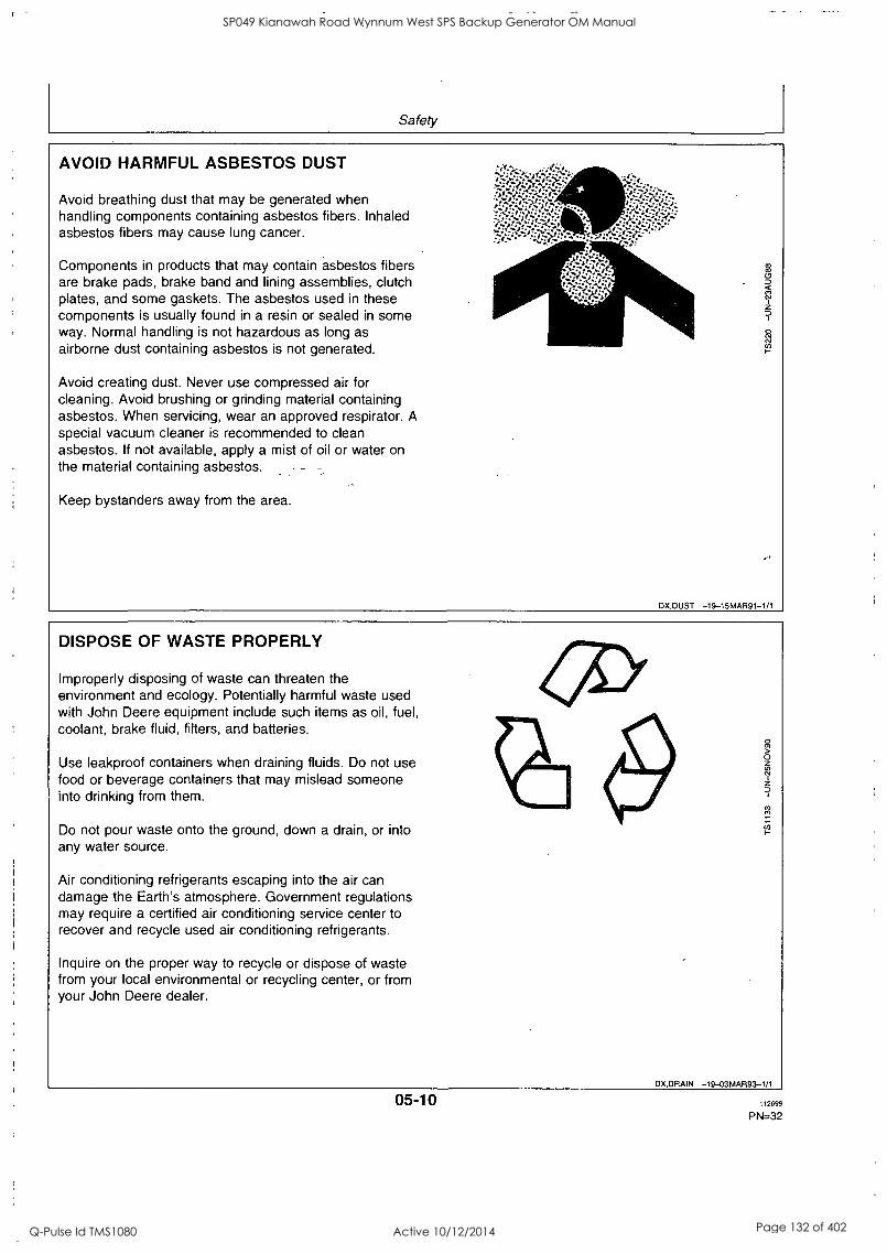
Safely
AVOID HARMFUL ASBESTOS DUST
Avoid breathing dust that may be generated when handling components containing asbestos fibers. Inhaled asbestos fibers may cause lung cancer.
Components in products that may contain asbestos fibers are brake pads, brake band and lining assemblies, clutch plates, and some gaskets. The asbestos used in these components is usually found in a resin or sealed in some way. Normal handling is not hazardous as long as airborne dust containing asbestos is not generated.
Avoid creating dust. Never use compressed air for cleaning. Avoid brushing or grinding material containing asbestos. When servicing, wear an approved respirator. A special vacuum cleaner is recommended to clean asbestos. If not available, apply a mist of oil or water on the material containing asbestos.
Keep bystanders away from the area.
DX,DUST -19-15MAR91-1/1
DISPOSE OF WASTE PROPERLY
Improperly disposing of waste can threaten the environment and ecology. Potentially harmful waste used with John Deere equipment include such items as oil, fuel, coolant, brake fluid, filters, and batteries.
Use leakproof containers when draining fluids. Do not use food or beverage containers that may mislead someone into drinking from them.
Do not pour waste onto the ground, down a drain, or into any water source.
Air conditioning refrigerants escaping into the air can damage the Earth's atmosphere. Government regulations may require a certified air conditioning service center to recover and recycle used air conditioning refrigerants.
Inquire on the proper way to recycle or dispose of waste from your local environmental or recycling center, or from your John Deere dealer.
OX,DRAIN -19-03MAR93-1/1
05-10 112694
PN=32
SP049 Kianawah Road Wynnum West SPS Backup Generator OM Manual
Q-Pulse Id TMS1080 Active 10/12/2014 Page 132 of 402

Fuels, Lubricants and Coolant DIESEL FUEL
Consult your local fuel distributor for properties of the diesel fuel available in your area.
In general, diesel fuels are blended to satisfy the low temperature requirements of the geographical area in which they are marketed.
Diesel fuels specified to EN 590 or ASTM D975 are recommended.
In all cases, the fuel shall meet the following properties:
Cetane number of 40 minimum. Cetane number areater than 50 is preferred, especially for
riperatures below -20°C (-4°F) or elevations above 1 X00 m (5,000 f-t).
Cold Filter Plugging Point (CFPP) below the expected low temperature OR Cloud Point at least 5°C (9°F) below the expected low temperature.
Fuel lubricity should pass a minimum of 3100 gram load level as measured by the BOCLE scuffing test.
Sulfur content:
Sulfur content should not exceed 0.5%. Sulfur content less than 0.05% is preferred. If diesel fuel with sulfur content greater than 0.5% sulfur content is used, reduce the service interval for engine oil and filter by 50%. DO NOT use diesel fuel with sulfur content greater than 1.0%.
Bio-diesel fuels may be used ONLY if the fuel properties meet DIN 51606 or equivalent specification.
DO NOT mix used engine oil or any other type of lubricant with diesel fuel.
DX,FUEL1 -19-17FE1399-1/1
HANDLING AND STORING DIESEL FUEL
CAUTION: Handle fuel carefully. Do not fill the fuel tank when engine is running.
DO NOT smoke while you fill the fuel tank or service the fuel system.
Fill the fuel tank at the end of each day's operation to prevent condensation and freezing during cold weather.
IMPORTANT: The fuel tank is vented through the filler cap. If a new filler cap is required, always replace it with an original vented cap.
When fuel is stored for an extended period or if there is a slow turnover of fuel, add a fuel conditioner to stabilize the fuel and prevent water condensation. Contact your fuel supplier for recommendations.
DX,FUEL4 -19-18MAR96-1/1
10-1 12699
PN=33
SP049 Kianawah Road Wynnum West SPS Backup Generator OM Manual
Q-Pulse Id TMS1080 Active 10/12/2014 Page 133 of 402

Fuels, Lubricants and Coolant
ENGINE BREAK-IN OIL
New engines are filled at the factory with John Deere ENGINE BREAK-IN OIL. During the break-in period, add John Deere ENGINE BREAK-IN OIL as needed to maintain the specified oil level.
Change the oil and filter after the first 100 hours of operation of a new or rebuilt engine.
After engine overhaul, fill the engine with John Deere ENGINE BREAK-IN OIL.
If John Deere ENGINE BREAK-IN OIL is not available, use a diesel engine oil meeting one of the following during the first 100 hours of operation:
API Service Classification CE
PLUS-50 is a registered trademark of Deere & Company.
ACEA Specification El
After the break-in period, use John Deere PLUS-50® or other diesel engine oil as recommended in this manual.
IMPORTANT: Do not use PLUS-50 oil or engine oils meeting API CG4, API CF4, ACEA E3, or ACEA E2 performance levels during the first 100 hours of operation of a new or rebuilt engine. These oils will not allow the engine to break-in properly.
DX,ENOIL4 -19-100CT97-1/1
10-2 112699
PN=34
SP049 Kianawah Road Wynnum West SPS Backup Generator OM Manual
Q-Pulse Id TMS1080 Active 10/12/2014 Page 134 of 402

Fuels, Lubricants and Coolant
DIESEL ENGINE OIL
Use oil viscosity based on the expected air temperature range during the period between oil changes.
The following oil is preferred:
John Deere PLUS-50®
The following oil is also recommended:
John Deere TORQ -GARD SUPREME TORQ-GARD SUPREME®
Other oils may be used if they meet one or more of the following:
API Service Classification CG-4 - API Service Classification CF-4-
ACEA Specification E3 ACEA Specification E2
Multi-viscosity diesel engine oils are preferred.
If diesel fuel with sulfur content greater than 0.5% is used, reduce the service interval by 50%.
PLUS-50 is a registered trademark of Deere & Company. TORQ -GARD SUPREME is a trademark of Deere & Company
; cl
11
50°C 122°F
40°C 104°F
30°C 86°F
20°C 68°F CO
10°C 50°F
g 0°C 32°F
-10°C 14°F
-20°C -4°F
-30°C -22°F
-40°C -40°F
CD,ENOIL -19-100CT97-1/1
LUBRICANT STORAGE
>ur equipment can operate at top efficiency only when clean lubricants are used.
Use clean containers to handle all lubricants.
Whenever possible, store lubricants and containers in an area protected from dust, moisture, and other contamination. Store containers on their side to avoid water and dirt accumulation.
Make certain that all containers are properly marked to identify their contents.
Properly dispose of all old containers and any residual lubricant they may contain.
DX,LUBST -19-18MAR96-1/1
10-3 112699
PN=35
SP049 Kianawah Road Wynnum West SPS Backup Generator OM Manual
Q-Pulse Id TMS1080 Active 10/12/2014 Page 135 of 402

Fuels, Lubricants and Coolant
MIXING OF LUBRICANTS
In general, avoid mixing different brands or types of oil. Oil manufacturers blend additives in their oils to meet certain specifications and performance requirements.
Mixing different oils can interfere with the proper functioning of these additives and degrade lubricant performance.
Consult your John Deere dealer to obtain specific information and recommendations.
DX,LUBMIX -19-18MAR96-1/1
DIESEL ENGINE COOLANT
The engine cooling system is filled to provide year-round protection against corrosion and cylinder liner pitting, and winter freeze protection to -37°C (-34°F).
John Deere COOL-GARD is preferred for service.
If John Deere COOL-GARD is not available, use a low silicate ethylene glycol base coolant concentrate in a
50% mixture of concentrate with quality water.
The coolant concentrate shall be of a quality that provides cavitation protection to cast iron and aluminum parts in the cooling system. John Deere COOL-GARD meets this requirement.
A 50% mixture of ethylene glycol engine coolant in
water provides freeze protection to -37°C (-34°F). If
protection at lower temperatures is required, consult your John Deere dealer for recommendations.
Water quality is important to the performance of the cooling system. Distilled, deionized, or demineralized
water is recommended for mixing with ethylene glycol base engine coolant concentrate.
IMPORTANT: Do not use cooling system sealing additives or antifreeze that contains sealing additives.
COOLANT DRAIN INTERVALS
Drain the factory fill engine coolant, flush the cooling system, and refill with new coolant after the first 3
years or 3000 hours of operation. Subsequent drain intervals are determined by the coolant used for service. At each interval, drain the coolant, flush the cooling system, and refill with new coolant.
When John Deere COOL-GARD is used, the coolant drain interval is 3 years or 3000 hours of operation.
If COOL-GARD is not used, the drain interval is reduced to 2 years or 2000 hours of operation.
DX,COOL8 -19-12FEB99-1/1
10-4 112699
PN=36
SP049 Kianawah Road Wynnum West SPS Backup Generator OM Manual
Q-Pulse Id TMS1080 Active 10/12/2014 Page 136 of 402

Fuels, Lubricants and Coolant
OPERATING IN WARM TEMPERATURE CLIMATES
John Deere engines are designed to operate using glycol base engine coolants.
Always use a recommended glycol base engine coolant, even when operating in geographical areas where freeze protection is not required.
IMPORTANT: Water may be used as coolant in emergency situations only.
Foaming, hot surface aluminum and iron corrosion, scaling, and cavitation will occur when water is used as the coolant, even when coolant conditioners are added.
Drain cooling system and refill with recommended glycol base engine coolant as soon as possible.
DX,COOL6 -19-18MAR96-1 /1
10-5 112694
PN=37
SP049 Kianawah Road Wynnum West SPS Backup Generator OM Manual
Q-Pulse Id TMS1080 Active 10/12/2014 Page 137 of 402

Operating the Engine BREAK-IN PERIOD
Within first 100 hours of operation During the first 100 hours of operation, avoid overloading, excessive idling and no-load operation.
See ENGINE BREAK-IN OIL for eventual addition of oil.
NOTE: During the break-in period a higher-than-usual oil consumption should be considered as normal.
After first 100 hours of operation After the first 100 hours, drain the crankcase and
change the oil filter (see CHANGING ENGINE OIL AND FILTER). Fill crankcase with seasonal viscosity grade oil (see DIESEL ENGINE OIL).
Check tension of alternator belt.
Check connections of air intake hoses.
Check for proper tightening of cap screws all around the engine.
DPSG,CD03523,17 -19-09JUL99-1/1
STARTING THE ENGINE
ACAUTION: Before starting engine in a
confined building, install proper outlet exhaust ventilation equipment. Always use safety approved fuel storage and piping.
NOTE: If temperature is below 0°C (32°F), it may be necessary to use cold weather starting aids (See COLD WEATHER OPERATION).
1. Perform all prestarting checks outlined in
Maintenance/Daily Section.
2. Open the fuel supply shut-off valve, if equipped.
3. Activate the starter motor switch to crank the engine and release it as soon as engine starts.
NOTE: Do not operate the starter motor more than 20 seconds at a time.
DPSG,CD03523,18 -19-09JUL99-1/1
COLD WEATHER OPERATION
Depending on equipment, various cold weather starting aids are available to assist in starting the engine at temperatures below 0°C (32°F).
Continued on next page DPSG,CD03523,19 -19-09JUL99-1/4
15-1 112699
PN=38
SP049 Kianawah Road Wynnum West SPS Backup Generator OM Manual
Q-Pulse Id TMS1080 Active 10/12/2014 Page 138 of 402

Operating the Engine
Air intake heater
Air intake heater is either a grid-type (A) for POWERTech engines or a glow plug-type (B) for 300-Series engines installed in the air intake channel.
ACAUTION: NEVER use Ether Starting Fluid when air intake heater is used to start the engine.
Activate the heating element (preheater position) for 30 seconds maximum then start the engine.
A
A
DPSG,CD03523,19 -19-09JUL99-2/4
Coolant heater
Connect plug of coolant heater (A) to a power source (110 or 220 V).
At an ambient temperature of -15°C (5°F), the heating process takes approximatively 2 hours. Extend heating period if ambient temperature is lower.
DPSG,CD03523,19 -19-09JUL99-3/4
Fuel preheater
_.el preheater (A) switches ON and OFF automatically in
relation to the ambient temperature.
715al, 6S% LX1017708
DPSG.0 D03523,19 -19-09JUL99-4/4
15-2 112699
PN=39
SP049 Kianawah Road Wynnum West SPS Backup Generator OM Manual
Q-Pulse Id TMS1080 Active 10/12/2014 Page 139 of 402

Operating the Engine
USING A BOOSTER BATTERY OR CHARGER
A 12-volt booster battery can be connected in parallel with battery(ies) on the unit to aid in cold weather starting. ALWAYS use heavy duty jumper cables.
aCAUTION: Gas given off by batteries is explosive. Keep sparks and flames away from batteries. Before connecting or disconnecting a
battery charger, turn charger off. Make last connection and first disconnection at a point away from battery. Always connect NEGATIVE (-) cable last and disconnect this cable first.
IMPORTANT: Be sure polarity is correct before making connections. Reversed polarity will damage electrical system. Always connect positive to positive and negative to ground. Always use 12-volt booster battery for 12-volt electrical systems and 24-volt booster battery/ batteries for 24-volt electrical systems.
1. Connect booster battery or batteries to produce the required system voltage for your engine application.
NOTE: To avoid sparks, DO NOT allow the free ends of jumper cables to touch the engine.
2. Connect one end of jumper cable to the POSITIVE (+) post of the booster battery.
3. Connect the other end of the jumper cable to the POSITIVE (+) post of battery connected to starter.
4. Connect one end of the other jumper cable to the NEGATIVE (-) post of the booster battery.
5. ALWAYS complete the hookup by making the last connection of the NEGATIVE (-) cable to a good ground on the engine frame and away from the battery(ies).
6. S'Lart the ; ei ly.ile. Diw..01111eut uables immediately after engine starts. Disconnect NEGATIVE (-) cable first.
12-Volt System
24-Volts System
A-12-Volt Machine battery/batteries B-12-Volt Booster battery/batteries C-Booster cable D-Cable to starter motor
DPSG.0003523,20 -19-09JUL99-1/1
15-3 112699
PN=40
SP049 Kianawah Road Wynnum West SPS Backup Generator OM Manual
Q-Pulse Id TMS1080 Active 10/12/2014 Page 140 of 402

Operating the Engine
ENGINE OPERATION
Warming engine Operate engine at high idle for 1 to 2 minutes before applying the load.
NOTE: This procedure does not apply to standby generator sets where the engine is loaded immediately upon reaching rated speed.
Normal engine operation Compare engine coolant temperature and engine oil pressure with specifications below:
Minimum oil pressure at full load rated speed'-Specification
Pressure 275 kPa (2.75 bar; 40 psi)
Coolant temperature range-Specification
Temperature 82°-94°C (180°-202°F)
Stop engine immediately if coolant temperature is above or oil pressure below specifications or if there are any signs of part failure. Symptoms that may be early signs of engine problems could be:
Sudden loss of power
'Oil at normal operating temperature of 115°C (240'F).
Unusual noise or vibration Excessive black exhaust fumes Excessive fuel consumption Excessive oil consumption Fluid leaks
Recommendation for turbocharger engines Should the engine stall when operating under load, IMMEDIATELY restart it to prevent overheating of turbocharger components.
Idling engine Avoid excessive engine idling. Prolonged idling may cause the engine coolant temperature to fall below its normal range. This, in turn, causes crankcase oil dilution, due to incomplete fuel combustion, and permits formation of gummy deposits on valves, pistons and piston rings. It also promotes rapid accumulation of engine sludge and unburned fuel in
the exhaust system. If an engine will be idling for more than 5 minutes, stop and restart later.
NOTE: Generator set applications have the governor locked at a specified speed and do not have a
slow idle function. These engines idle at no load governed speed (fast idle).
DPSG,CD03523,21 -19-09JUL99-1/1
STANDBY POWER UNITS
To assure that your engine will deliver efficient standby operation when needed, start engine and run at rated speed (with 50°k-70% load) for 30 minutes every- -
2 weeks. DO NOT allow engine to run an extended period of time with no load.
D PSG,C D03523,22 -19-09JUL99-1/1
15-4 I i2699
PN=41
SP049 Kianawah Road Wynnum West SPS Backup Generator OM Manual
Q-Pulse Id TMS1080 Active 10/12/2014 Page 141 of 402

Operating the Engine
STOPPING THE ENGINE
1. Before stopping, run engine for at least 2 minutes at fast idle and no load.
2. Stop the engine.
OPSG,CD03523,23 -19-09JUL99-1/1
15-5 112699
PN=42
SP049 Kianawah Road Wynnum West SPS Backup Generator OM Manual
Q-Pulse Id TMS1080 Active 10/12/2014 Page 142 of 402

Maintenance OBSERVE SERVICE INTERVALS
Using hour meter as a guide, perform all services at the hourly intervals indicated on following pages. At each scheduled maintenance interval, perform all previous maintenance operations in addition to the ones specified. Keep a record of hourly intervals and services performed using charts provided in
Maintenance Records Section.
IMPORTANT: Recommended service intervals are for normal operating conditions. Service MORE OFTEN if engine is operated under adverse conditions. Neglecting maintenance can result in failures or permanent damage to the engine.
DPSG,CD03523,24 -19-09JUL99-1/1
USE CORRECT FUELS, LUBRICANTS AND COOLANT
PORTANT: Use only fuels, lubricants, and coolants meeting specifications-outlined in - -
Fuels, Lubricants, and Coolant Secticih when servicing your John Deere Engine.
Consult your John Deere engine distributor, servicing dealer or your nearest John Deere Parts Network for recommended fuels, lubricants, and coolant. Also available are necessary additives for-use when operating engines in tropical, arctic, or any other adverse conditions.
DPSG,CD03523,25 -19-09JUL99-1/1
20-1 112699
PN=43
SP049 Kianawah Road Wynnum West SPS Backup Generator OM Manual
Q-Pulse Id TMS1080 Active 10/12/2014 Page 143 of 402

Maintenance
MAINTENANCE INTERVAL CHART
Item 10 H / daily
500 I-I 1000 H / 1 year
2000 H / 2 years
2500 H / 3 years
As required
Check engine oil and coolant level
Check air filter restriction indicators
Change engine oil and filter'
Replace fuel filter element
Check belt tension and automatic tensioner
Check and adjust valve clearance°
Clean crankcase vent tube
Check air intake hoses, connections and system
Check vibration damper (6 cyl.)°
Check engine speed and speed droop governor
Drain and flush cooling system'
Drain water and sediment from fuel filter
Clean filter element (see note a)
Test thermostat and injection nozzles (see your dealer)9 -
°Clean air filter element when restriction indicator is red. Replace filter element after 6 cleanings or once a year.
'Change oil and filter after the first 100 hours of operation, then every 500 hours thereafter. Change oil and filter at least once a year.
'Check belt tension every 500 hours on 300-Series engines and on POWERTech engines with manual tensioner. Check automatic belt tensioner every 1000 hours/1 year on POWERTech engines when equipped.
'Have your authorized servicing dealer or engine distributor adjust valve clearance as follows. After the first 500 hours of operation then every 1000 hours thereafter on 300-Series engines. Every 2000 hours on POWERTech engines.
Have your authorized dealer or engine distributor replace the vibration damper every 4500 hours/5 years.
'Drain and flush cooling.system every 2500 hours/3 years when John Deere COOL-GARD coolant is used. Otherwise every 2000 hours/2 years.
9Contact your dealer when thermostat or injection nozzles are suspected to be defective. Replace injection nozzles every 5000 hours and thermostat every 10000 hours.
DPSG,CD03523,26 -19-09JUL99-1/1
20-2 112699
PN=44
SP049 Kianawah Road Wynnum West SPS Backup Generator OM Manual
Q-Pulse Id TMS1080 Active 10/12/2014 Page 144 of 402
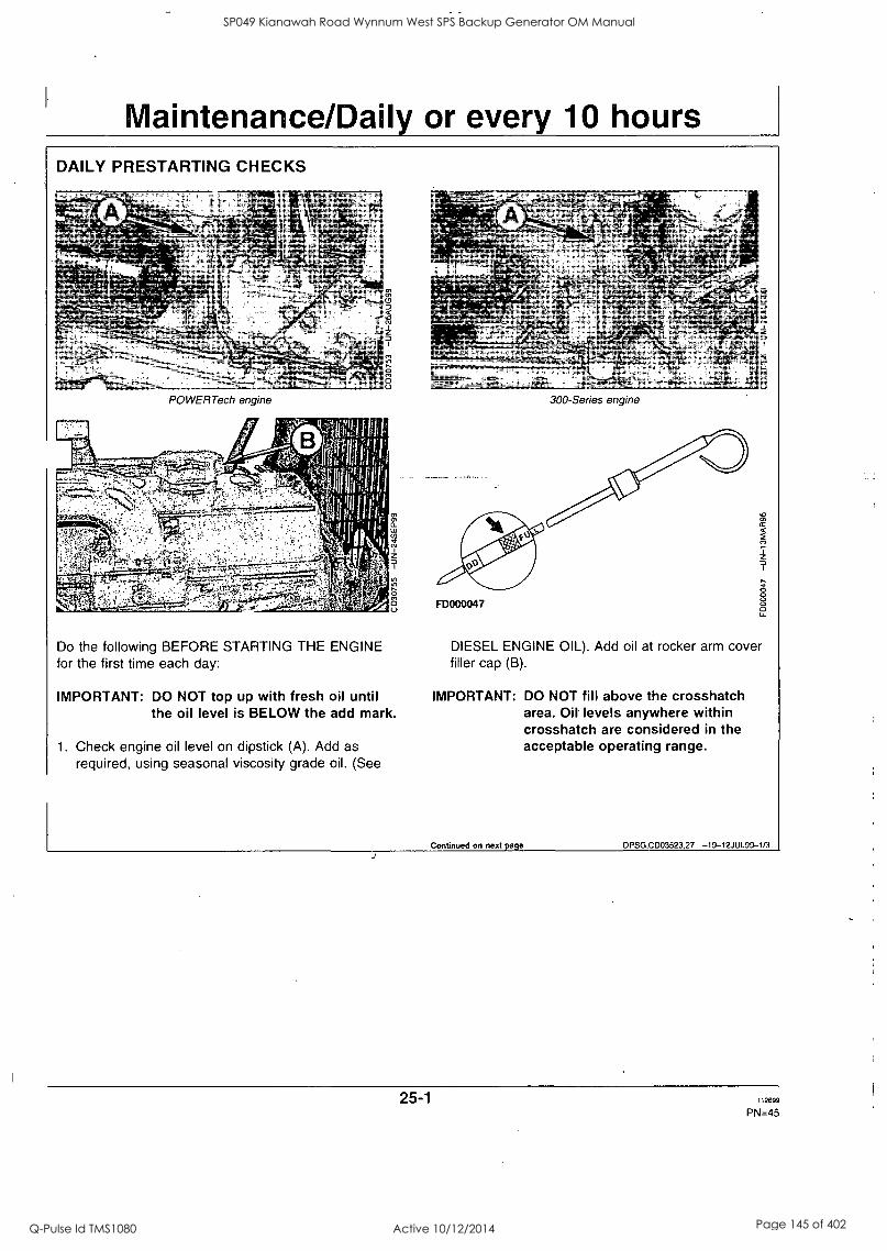
Maintenance/Daily or every 10 hours DAILY PRESTARTING CHECKS
T .
POWERTech engine
cr,
2
0
300-Series engine
Do the following BEFORE STARTING THE ENGINE for the first time each day:
Cl. LL1
7
0 0
IMPORTANT: DO NOT top up with fresh oil until the oil level is BELOW the add mark.
1. Check engine oil level on dipstick (A). Add as required, using seasonal viscosity grade oil. (See
FD000047
DIESEL ENGINE OIL). Add oil at rocker arm cover filler cap (B).
IMPORTANT: DO NOT fill above the crosshatch area. Oil levels anywhere within crosshatch are considered in the acceptable operating range.
Continued on next page DPSG,CD03523,27 -19-12JUL99-1/3
25-1 112699
PN=45
SP049 Kianawah Road Wynnum West SPS Backup Generator OM Manual
Q-Pulse Id TMS1080 Active 10/12/2014 Page 145 of 402

Maintenance/Daily or every 10 hours
2. ACAUTION: Explosive release of fluids from 1°1oressurized cooling system can cause
serious burns.
Only remove filler cap when engine is cold- or when cool enough to touch with bare hands. Slowly loosen cap to first stop to relieve pressure before removing completely.
Remove radiator cap (E) and check coolant level which should be at bottom of filler neck. Fill radiator with proper coolant solution if level is low. (See DIESEL ENGINE COOLANT). Check overall cooling system for leaks.
DPSG,C003523,27 -19-12JUL99-2/3
3. If air filter has a dust unloading valve (C), squeeze valve tip to release any trapped dirt particles.
4. Check air intake restriction indicator (D). When indicator is red, air filter needs to be cleaned.
IMPORTANT: Maximum air intake restriction is 6.25 kPa (0.06 bar; 1.0 psi) (25 in. H2O).
A clogged air cleaner element will cause excessive intake restriction and a
reduced air supply to the engine.
5. Make a thorough inspection of the engine compartment.
NOTE: Wipe all fittings, caps and plugs before performing any maintenance to reduce the chance of system contamination.
DPSG,CD03523,27 -19-12JUL99-3/3
25-2 112699
PN=46
SP049 Kianawah Road Wynnum West SPS Backup Generator OM Manual
Q-Pulse Id TMS1080 Active 10/12/2014 Page 146 of 402

Maintenance/500 hours CHANGING ENGINE OIL AND FILTER
NOTE: Change engine oil and filter for the first time after 100 hours maximum of operation, then every 500 hours thereafter. Change oil and filter at least once a year.
1. Run engine approximately 5 minutes to warm up oil. Shut engine off.
2. Open oil pan drain valve (A).
3. Drain crankcase oil from engine while warm.
4. Remove and discard oil filter element (B) using a
suitable filter wrench.
Remove oil filter packing and clean filter mounting pad.
IMPORTANT: Filtration of oils is critical to proper - -
lubrication. Always change filter regularly. Use filters meeting John Deere performance specifications.
6. Oil the new packing and install a new filter element. Hand tighten element according to values printed on filter element. If values are not provided, tighten element approximately 3/4 - 1-1/4 turn after packing contacts filter housing. DO NOT overtighten filter element.
7. Close oil pan drain valve.
0 0
POWERTEch engine
0 0
300-Series engine
0 0
Continued on next page DPSG,CD03523,29 -19-12JUL99-1/2
30-1 112699
PN=47
SP049 Kianawah Road Wynnum West SPS Backup Generator OM Manual
Q-Pulse Id TMS1080 Active 10/12/2014 Page 147 of 402

Maintenance/500 hours
8. Fill engine crankcase with correct John Deere engine oil through rocker arm cover opening (C); see DIESEL ENGINE OIL.
To determine the correct oil fill quantity for your engine, see "Engine Oil Quantities" in Specifications Section.
NOTE: Crankcase oil capacity may vary slightly. ALWAYS fill crankcase to full mark or within crosshatch on dipstick, whichever is present. DO NOT overfill.
IMPORTANT: Immediately after completing any oil change, crank engine for 30 seconds without permitting engine to start. This will help insure adequate lubrication to engine components before engine starts.
9. Start engine and run to check for possible leaks.
10. Stop engine and check oil level after 10 minutes. If
necessary, top up.
30-2 112699
PN=48
SP049 Kianawah Road Wynnum West SPS Backup Generator OM Manual
Q-Pulse Id TMS1080 Active 10/12/2014 Page 148 of 402

Maintenance/500 hours
REPLACING FUEL FILTER ELEMENT
j 1k
A-Retaining ring B-Filter element
CAUTION: CAUTION: Escaping fluid under pressure can penetrate the skin- causing- -
serious injury. Relieve pressure before disconnecting fuel or other lines. Tighten all connections before applying pressure. Keep hands and body away from pinholes and nozzles which eject fluids under high pressure. Use a piece of cardboard or paper to search for leaks. Do not use your hand.
If any fluid is injected into the skin, it must be surgically removed within a few hours by a doctor familiar with this type injury or gangrene may result. Doctors unfamiliar with this type of injury may call the Deere & Company Medical Department in Moline, Illinois, or other knowledgeable medical source.
1 Thoroughly clean fuel filter assembly and surrounding area.
2. Loosen drain plug (C) and drain fuel into a suitable container.
NOTE: Lifting up on retaining ring as it is rotated helps to get it past raised locators.
3. Firmly grasp the retaining ring (A) and rotate it clockwise 1/4 turn. Remove ring with filter element (B).
C-Drain plug D-Bleed plug
IMPORTANT: Do not dump the old fuel into the new filter element. This could cause fuel injection pr-obleiii:-
A plug is provided with the new element for plugging the used element.
4. Inspect filter mounting base for cleanliness. Clean as required.
NOTE: Raised locators on fuel filter canister must be indexed properly with slots in mounting base for correct installation.
5. Install new filter element dry onto mounting base. Be sure-element is properly indexed and firmly seated on base. It may be necessary to rotate filter for correct alignment.
6. Install retaining ring onto mounting base making certain dust seal is in place on filter base. Hand tighten ring (about 1/3 turn) until it "snaps" into the detent. DO NOT overtighten retaining ring.
NOTE: The proper installation is indicated when a "click" is heard and a release of the retaining ring is felt.
7. Bleed the fuel system.
DPS G,C D03523,30 -19-12JUL99-1/1
30-3 112699
PN=49
SP049 Kianawah Road Wynnum West SPS Backup Generator OM Manual
Q-Pulse Id TMS1080 Active 10/12/2014 Page 149 of 402

Maintenance/500 hours
CHECKING BELT (300-SERIES ENGINES)
1. Inspect belt for cracks, fraying, or stretched out areas. Replace as necessary.
2. Check belt tension using one of following methods:
a) Use of JDG529 Tension Gauge (A)
Belt tension-Specification
New belt 578-622 N (130-140 lb-force) Used belt 378-423 N (85-94 lb-force)
NOTE: Belt is considered used after 10 minutes of operation.
b) Use of tension tester (B) and straight edge (C) A 89 N (20 lb) force applied halfway between pulleys should deflect -belt by 19 mm (0.75 in.).
3. If adjustment is necessary, loosen alternator nuts (D) and (E). Pull alternator frame outward until belt is correctly tensioned.
IMPORTANT: Do not pry against the alternator rear frame. Do not tighten or loosen belts while they are hot.
4. Tighten alternator bracket nuts firmly.
5. Run engine for 10 minutes then recheck belt tension.
DPSG,CD03523,31 -19-12JUL99-1/1
30-4 112699
PN=50
SP049 Kianawah Road Wynnum West SPS Backup Generator OM Manual
Q-Pulse Id TMS1080 Active 10/12/2014 Page 150 of 402

Maintenance/500 hours
CHECKING BELT (POWERTECH ENGINES WITH MANUAL TENSIONER)
Inspect belt for cracks, fraying, or stretched out areas. Replace if necessary.
NOTE: Belt adjustment is measured using a gauge stamped on the top edge of the alternator bracket.
1. Loosen cap screws (B) and (C).
2. Slide alternator in slot by hand to remove all excess slack in belt.
IMPORTANT: Do not pry against alternator rear frame.
n Using the gauge (A) on the alternator bracket, stretch belt by prying outward on alternator front frame. Stretch the belt 1 gauge unit for a used belt and 1.5 gauge units for a new belt.
4. Tighten cap screws (B) and (C).
A-Belt gauge B-Cap screw C-Cap screw
0
zz 9,
0
DPSG,CD03523,57 -19-16AUG99-1/1
30-5 112699
PN=51
SP049 Kianawah Road Wynnum West SPS Backup Generator OM Manual
Q-Pulse Id TMS1080 Active 10/12/2014 Page 151 of 402

Maintenance/1000 hours/1 year CLEANING CRANKCASE VENT TUBE
If you operate the engine in dusty conditions, clean the tube at shorter intervals.
1. Remove and clean crankcase vent tube (A).
2. Install the vent tube. Be sure the 0-ring fits correctly in
the rocker arm cover bore for elbow adapter. Tighten hose clamp securely.
_ .. DPSG,CD03523,32 -19-12JUL99-1/1
CHECKING AIR INTAKE SYSTEM
IMPORTANT: The air intake system must not leak. Any leak, no matter how small, may result in engine failure due to abrasive dirt and dust entering the intake system.
1. Inspect all intake hoses (piping) for cracks. Replace as necessary.
2. Check clamps on piping (A) which connect the air filter, engine and, if present, turbocharger and air-to-air radiator. Tighten clamps as necessary.
3. Test air restriction indicator (B) for proper operation. Replace indicator as necessary.
Continued on next page DPSG,CD03523,33 -19-12JUL99-1/2
35-1 112699
PN=52
SP049 Kianawah Road Wynnum West SPS Backup Generator OM Manual
Q-Pulse Id TMS1080 Active 10/12/2014 Page 152 of 402

Maintenance/1000 hours/1 year
4. If engine has a rubber dust unloading valve (C), inspect the valve on bottom-of air filter for cracks or plugging. Replace as necessary.
5. Service air filter as necessary.
0
DPSG,C D03523,33 -19-12JUL99-2/2
CHECKING AUTOMATIC BELT TENSIONER (POWERTECH ENGINES)
It drive systems equipped with automatic (spring) belt -tenSioners'cannOt be-adjusted or repaired. The automatio-
belt tensioner is designed to maintain proper belt tension over the life of the belt. If tensioner spring tension is not within specification, replace tensioner assembly.
Checking belt wear The belt tensioner is designed to operate within the limit of arm movement provided by the cast stops (A) and (B) when correct belt length and geometry is used. If
the tensioner stop on swing arm (A) is hitting the fixed stop (B), check mounting brackets (alternator, belt tensioner, idler pulley, etc.) and the belt length. Replace belt as needed (see REPLACING FAN AND ALTERNATOR BELTS).
Continued on next page DPSG,C D03523,34 -19-13JUL99-1/2
35-2 112699
PN=53
SP049 Kianawah Road Wynnum West SPS Backup Generator OM Manual
Q-Pulse Id TMS1080 Active 10/12/2014 Page 153 of 402

Maintenance/1000 hours/1 year
Checking tensioner spring tension A belt tension gauge will not give an accurate measure of the belt tension when automatic spring tensioner is
used. Measure tensioner spring tension using a torque wrench and procedure outlined below: a. Release tension on belt using a breaker bar and
socket on tension arm. Remove belt from pulleys. b. Release tension on tension arm and remove breaker
bar. c. Put a mark (A) on swing arm of tensioner as shown. d. Measure 21 mm (0.83 in.) from (A) and put a mark
(B) on tensioner mounting base. e. Rotate the swing arm using a torque wrench until
marks (A) and (B) are aligned. f. Record torque wrench measurement and compare
with specification below. Replace tensioner assembly as required.
Spring-Specification
Force 18-22 Nm (13-16 lb-ft)
DPSG,CD03523,34 -19-13JUL99-2/2
CHECK AND ADJUST ENGINE VALVE CLEARANCE (300-SERIES ENGINES)
NOTE: Valve clearance must be adjusted after the first 500 hours of operation, then every 1000 hours thereafter.
Adjust engine valve clearance as follows or have your authorized servicing dealer or engine distributor adjust the engine valve clearance.
1. Remove rocker arm cover and crankcase vent tube.
2. Using JDE83 or JDG820 Flywheel Turning Tool (A), rotate engine flywheel in running direction (clockwise viewed from water pump) until No.1 piston (front) has reached top dead center (TDC) on compression stroke. Insert timing pin JDE81-4 (B) into flywheel bore.
Continued on next page DPSG,CD03523,35 -19-13JUL99-1/4
35-3 ft2699
PN=54
SP049 Kianawah Road Wynnum West SPS Backup Generator OM Manual
Q-Pulse Id TMS1080 Active 10/12/2014 Page 154 of 402

Maintenance/1000 hours/1 year
3. Check and adjust valve clearance to specifications - according to following procedures.
Valve clearance (engine cold)-Specification
Intake 0.35 mm (0.014 in.) Exhaust 0.45 mm (0.018 in.)
NOTE: If rocker arm is equipped with adjusting screw and lock nut (A), tighten lock nut to 27 Mtn (20 lb-ft) after adjusting valve clearance.
4. Reinstall rocker arm cover and crankcase vent tube.
3-Cylinder Engine:
NOTE: Firing order is 1-2-3.
a. Lock No. 1 piston at TDC compression stroke (D). b. Adjust valve clearance on No. 1 and 2 exhaust
valves and No.1 and 3 intake valves. c. Rotate flywheel 360°. Lock No. 1 piston at TDC
exhaust stroke (E). d. Adjust valve clearance on No. 3 exhaust valve and
No. 2 intake valve.
DPSG,CD03523,35 -19-13JUL99-2/4
3 2 1
B C
A-Front of engine B-Exhaust valve C-Intake valve D-No.1 Piston at TDC compression stroke E-No.1 Piston at TDC exhaust stroke
Continued on next pogo DPSG,CD03523,35 -19-13JUL99-3/4
35-4 112699
PN=55
SP049 Kianawah Road Wynnum West SPS Backup Generator OM Manual
Q-Pulse Id TMS1080 Active 10/12/2014 Page 155 of 402

Maintenance/1000 hours/1 year
4-Cylinder Engine:
NOTE: Firing order is 1-3-4-2. 110,1
a. Lock No. 1 piston at TDC compression stroke (B). b. Adjust valve clearance on No. 1 and 3 exhaust
valves and No.1 and 2 intake valves. c. Rotate flywheel 360°. Lock No. 4 piston at TDC
compression stroke (C). d. Adjust valve clearance on No. 2 and 4 exhaust
valves and No. 3 and 4 intake valves.
4 E
4 E
6 '6
I
III
E
'
E3l
111111N1
3
0 I
I
'c5 '
2 E
Ilu 11
2 E
I
1 Wit
I
'W411411 6
1 E I
I
+ +
ELI I
b 6
A-Front of engine B-No.1 Piston at TDC compression stroke C-No.4 Piston at TDC compression stroke E-Exhaust valve I-Intake valve
DPSG,CD03523,35 -19-13JUL99-4/4
35-5 112699
P N=56
SP049 Kianawah Road Wynnum West SPS Backup Generator OM Manual
Q-Pulse Id TMS1080 Active 10/12/2014 Page 156 of 402

Maintenance/2000 hours/2 years CHECK AND ADJUST ENGINE VALVE CLEARANCE (POWERTECH ENGINE)
Adjust engine valve clearance as follows or have your authorized servicing dealer or engine distributor adjust the engine valve clearance.
1. Remove rocker arm cover and crankcase vent tube.
2. Using JDE83 or JDG820 Flywheel Turning Tool (A), rotate engine flywheel in running direction (clockwise viewed from water pump) until No.1 piston (front) has reached top dead center (TDC) on compression stroke. Insert timing pin JDE81-4 (B) into flywheel bore.
DPSG,C D03523.36 -19-13JUL99-1/4
3. Check and adjust valve clearance to specifications according to following procedures.
Valve clearance (engine cold)-Specification
Intake 0.35 mm (0.014 in.) Exhaust 0.45 mm (0.018 in.)
4. If valves need adjusting, loosen the lock nut on rocker arm adjusting screw. Turn adjusting screw until feeler gauge slips with a slight drag. Hold the adjusting screw from turning with screwdriver and tighten lock nut to 27 Nm (20 lb-ft). Recheck clearance again after tightening lock nut. Readjust clearance as necessary
5. Reinstall rocker arm cover and crankcase vent tube.
Continued on next page DPSG,CD03523,36 -19-13JUL99-2/4
40-1 112699
PN=57
SP049 Kianawah Road Wynnum West SPS Backup Generator OM Manual
Q-Pulse Id TMS1080 Active 10/12/2014 Page 157 of 402

Maintenance/2000 hours/2 years
4-Cylinder Engine:
NOTE: Firing order is 1-3-4-2.
a. Lock No. 1 piston at TDC compression stroke (B). b. Adjust valve clearance on No. 1 and 3 exhaust
valves and No.1 and 2 intake valves. c. Rotate flywheel 360°. Lock No. 4 piston at TDC
compression stroke (C). d. Adjust valve clearance on No. 2 and 4 exhaust
valves and No. 3 and 4 intake valves.
4 3 2 E E I E1
111610411641 *0101441. di 0 0
3 2 1
E 4 El El
II i1
d b iiA1 i Ili11110"iiii
d
A-Front of engine B-No.1 Piston at TDC compression stroke C-No.4 Piston at TDC compression stroke E-Exhaust valve I-Intake valve
DPSG,CD03523,36 -19-13JUL99-3/4
6-Cylinder Engine:
NOTE: Firing order is 1-5-3-6-2-4.
a. Lock No. 1 piston at TDC compression stroke (B). b. Adjust valve clearance on No. 1, 3, and 5 exhaust
valves and No. 1, 2, and 4 intake valves. c. Rotate flywheel 360°. Lock No. 6 piston at TDC
compression stroke (C). d. Adjust valve clearance on No. 2, 4, and 6 exhaust
valves and No. 3, 5, and 6 intake valves.
6 5 4 3 El El El /?, 11 ill 1,i :II
1111111A*11111111M1111111411',1111111NATI 0111111 s 6 0 0 8 o 0 6 6 6 6
®4 4 f 4
O Eli
E I
4 E I E I
3 2 1
E I E I E I
.,
IIIIIINVI:411111\q#1111111ilMtillIjilk111111111111.M.11111;1 6 '6 6 6 '6 '6 6 6 6 6 8
4
A-Front of engine B-No.1 Piston at TDC compression stroke C-No.6 Piston at TDC compression stroke E-Exhaust valve I-Intake valve
DPSG,CD03523,36 -19-13JUL99-4/4
40-2 112699
PN=58
SP049 Kianawah Road Wynnum West SPS Backup Generator OM Manual
Q-Pulse Id TMS1080 Active 10/12/2014 Page 158 of 402

Maintenance/2000 hours/2 years
CHECKING ENGINE SPEED
NOTE: Most engines for generator set application (1500 rpm. for 50 Hz or 1800 rpm for 60 Hz) run only at fast idle and therefore they do not have slow idle.
Fast idle-Specification
50 Hz Generator set 1550-1580 rpm 60 Hz Generator set 1865-1890 rpm
NOTE: Fast idle is settled by the factory then the idle adjusting screw (A) is sealed to prevent from tampering. Fast idle adjustment can only be done by an authorized fuel system agent.
DPSG,CD03523,38 -19-13JUL99-1/1
ADJUST SPEED DROOP GOVERNOR
1. Warm engine to normal operating temperature.
2. Run engine at fast idle.
3. Apply full load.
4. If specified power cannot be obtained, turn screw (B) to adjust droop until the requested power is reached.
NOTE: If surging exists upon removing the load, turn screw (B) clockwise to eliminate.
0 0
DPSG,CD03523,39 -19-13JUL99-1/1
40-3 112699
PN=59
SP049 Kianawah Road Wynnum West SPS Backup Generator OM Manual
Q-Pulse Id TMS1080 Active 10/12/2014 Page 159 of 402

Maintenance/2000 hours/2 years
CHECKING CRANKSHAFT VIBRATION DAMPER (6-CYLINDER ENGINE ONLY)
1. Remove belts (shown removed).
2. Grasp vibration damper with both hands and attempt to turn it in both directions. If rotation is felt, damper is defective and should be replaced.
IMPORTANT: The vibration damper assembly is not repairable and should be replaced every 4500 hours or 5 years, whichever occurs first.
3. Check vibration damper radial runout by positioning a dial indicator so probe contacts damper outer circumference.
4. With engine at operating temperature, rotate crankshaft using JDG820 or JDE83 Flywheel Turning Tool.
5. Note dial indicator reading. If runout exceeds specifications given below, replace vibration damper.
Damper-Specification
Maximum radial runout 1.50 mm (0.060 in.)
DPSG,CD03523,40 -19-13JUL99-1/1
40-4 112699
PN=60
SP049 Kianawah Road Wynnum West SPS Backup Generator OM Manual
Q-Pulse Id TMS1080 Active 10/12/2014 Page 160 of 402

PARTS LIST TYPICAL TWO BEARING (SERIES 5) GENERATOR
Plate Ref. Description Plate Ref. Description
1 Stator 25 Main Rectifier Assembly - Reverse 2 Rotor 26 Varistor 3 Exciter Rotor 27 Diode - Forward Polarity 4 Exciter Stator 28 Diode - Reverse Polarity 5 N.D.E. Bracket 29 Lifting Lug - D.E. 6 Cover N.D.E. 30 Lifting Lug - N.D.E. 7 Bearing '0' Ring N.D.E. 31 Frame to Endbracket Adaptor Ring Frame 8 Bearing N.D.E. 32 Main Terminal Panel 9 Bearing Wave Washer D.E. 33 Terminal Link 10 D.E. Bracket 34 Edging Strip 11 D.E. Screen 35 Fan 12 Bearing D.E. 36 Foot Mounting Spacer 13 37 Cap Screw 14 Foot 15 Frame Cover Bottom 16 Frame Cover Top 17 Air Inlet Cover 18 Terminal Box Lid 19 Endpanel D.E. 20 Endpanel N.D.E. 21 Series 5 Control Gear 22 Side Panel 23 24 Main Rectifier Assembly - Forward
N.D.E. D.E.
Non Drive End Drive End
SP049 Kianawah Road Wynnum West SPS Backup Generator OM Manual
Q-Pulse Id TMS1080 Active 10/12/2014 Page 161 of 402

Fig. 12. TYPICAL TWO BEARING GENERATOR
SP049 Kianawah Road Wynnum West SPS Backup Generator OM Manual
Q-Pulse Id TMS1080 Active 10/12/2014 Page 162 of 402

PARTS LIST TYPICAL TWO BEARING GENERATOR
Plate Ref. Description Plate Ref. Description
1 Stator 25 Main Rectifier Assembly - Reverse 2 Rotor 26 Varistor 3 Exciter Rotor 27 Diode - Forward Polarity 4 Exciter Stator 28 Diode - Reverse Polarity 5 N.D.E. Bracket 29 Lifting Lug - D.E. 6 Cover N.D.E. 30 Lifting Lug - N.D.E. 7 Bearing '0' Ring N.D.E. 31 Frame to Endbracket Adaptor Ring 8 Bearing N.D.E. 32 Main Terminal Panel 9 Bearing Wave Washer D.E. 33 Terminal Link 10 D.E. Bracket 34 Edging Strip 11 D.E. Screen 35 Fan 12 Bearing D.E. 36 Foot Mounting Spacer 14 Foot 37 Cap Screw 15 Frame Cover Bottom 38 AVR Access Cover 16 Frame Cover Top 39 AVR Anti-Vibration Mount 17 Air Inlet Cover 40 Auxiliary Terminal Assembly 18 Terminal Box Lid 42 PMG Exciter Rotor 19 Endpanel D.E. 43 PMG Exciter Stator 20 Endpanel N.D.E. 44 PMG Bolt 21 AVR 45 PMG Pillar 22 Side Panel 46 PMG Clamp 23 AVR Mounting Bracket 47 PMG Dowel 24 Main Rectifier Assembly - Forward
N.D.E. D.E. PMG AVR
Non Drive End Drive End Permanent Magnet Generator Automatic Voltage Regulator
SP049 Kianawah Road Wynnum West SPS Backup Generator OM Manual
Q-Pulse Id TMS1080 Active 10/12/2014 Page 163 of 402

18
22
19
30
5
4
8 7
9
3
2
35 31
10
12
13
11
Fig. 11. TYPICAL SINGLE BEARING GENERATOR
20
32 22
16
40
39
21
38
28 25
24
SP049 Kianawah Road Wynnum West SPS Backup Generator OM Manual
Q-Pulse Id TMS1080 Active 10/12/2014 Page 164 of 402

PARTS LIST TYPICAL SINGLE BEARING GENERATOR
Plate Ref. Description Plate Ref. Description
1 Stator 25 Main Rectifier Assembly - Reverse 2 Rotor 26 Varistor 3 Exciter Rotor 27 Diode - Forward Polarity 4 Exciter Stator 28 Diode - Reverse Polarity 5. N.D.E. Bracket 29 Lifting Lug - D.E. 6 Cover N.D.E. 30 Lifting Lug - N.D.E. 7 Bearing '0' Ring N.D.E. 31 Frame to Endbracket Adaptor Ring 8 Bearing N.D.E. 32 Main Terminal Panel 9 . Bearing Circlip N.D.E. 33 Terminal Link
10 D.E. Bracket/Engine Adaptor 34 Edging Strip 11 D.E. Screen 35 Fan 12 Coupling Disc 36 Foot Mounting Spacer 13 Coupling Bolt 37 Cap Screw 14 Foot 38 AVR Access Cover 15 Frame Cover Bottom 39 AVR Anti-Vibration Mounting Assembly 16 Frame Cover Top 40 Athxiliary Terminal Assembly 17 Air Inlet Cover 18 Terminal Box Lid 19 Endpanel D.E. 20 Endpanel N.D.E. 21 AVR 22 Side Panel 23 AVR Mounting Bracket 24 Main Rectifier Assembly - Forward
N.D.E. D.E. PMG AVR
Non Drive End Drive End Permanent Magnet Generator Automatic Voltage Regulator
SP049 Kianawah Road Wynnum West SPS Backup Generator OM Manual
Q-Pulse Id TMS1080 Active 10/12/2014 Page 165 of 402

1.6
SP049 Kianawah Road Wynnum West SPS Backup Generator OM Manual
Q-Pulse Id TMS1080 Active 10/12/2014 Page 166 of 402

Maintenance Records
9500 HOURS OF OPERATION
0 Engine oil, replace
O Engine oil filter, replace
0 Fuel filter, replace
0 Belt, check tension and wear (300-Series and POWERTech with manual tensioner)
O Valve clearance, adjust (300-Series)
Number of hours:
Date:
)b done by:
Comments: Dealer or distributor stamp
DPSG,CD03523,74 -19-16AUG99-1/1
10000 HOURS OF OPERATION
0 Engine oil, replace
0 Engine oil filter, replace
O Fuel filter, replace
0 Check belt and tensioning system
I Crankcase vent tube, clean
O Air intake system, check
0 Cooling system, drain and flush
0 Valve clearance, adjust (POWERTech)
0 Thermostat, replace
0 Vibration damper, check
0 Injection nozzles, replace
Number of hours:
Date:
Job done by:
Comments: Dealer or distributor stamp
DPSG,CD03523,75 -19-16AUG99-1/1
02-11 unw PN=17
SP049 Kianawah Road Wynnum West SPS Backup Generator OM Manual
Q-Pulse Id TMS1080 Active 10/12/2014 Page 167 of 402

Record Keeping POWERTECH® MEDALLION
A medallion is located on the rocker arm cover which identifies each engine as a John Deere POWERTECH® engine.
POWERTECH is a trademark of Deere & Company
1 -
POWMTECH 4c 45 Ofter ,
i 7r o c o (2 It
DPSG,C D03523,11 -19-05JUL99-1/1
ENGINE SERIAL NUMBER PLATE
POWERTech engine
Each engine has a 13-digit John Deere serial number. The first two digits identify the factory that produced the engine:
"CD" indicates the engines was built in Saran, France.
300-Series engine
Your engine's serial number plate (A) is located on the right-hand side of cylinder block behind the fuel filter for POWERTech engines and near the fuel supply pump on 300-Series engines.
DPSG,CD03523,12 -19-05JUL99-1/1
03-1 112699
PN.18
SP049 Kianawah Road Wynnum West SPS Backup Generator OM Manual
Q-Pulse Id TMS1080 Active 10/12/2014 Page 168 of 402

I I
I e
1
SP049 Kianawah Road Wynnum West SPS Backup Generator OM Manual
Q-Pulse Id TMS1080 Active 10/12/2014 Page 169 of 402

1
I
1
I
I
SP049 Kianawah Road Wynnum West SPS Backup Generator OM Manual
Q-Pulse Id TMS1080 Active 10/12/2014 Page 170 of 402

Maintenance Records
7500 HOURS OF OPERATION
CI Engine oil, replace 0 Cooling system, drain and flush (if COOL-GARD is used)
CI Engine oil filter, replace
CI Fuel filter, replace
0 Belt, check tension and wear (300-Series and POWERTech with manual tensioner)
0 Valve clearance, adjust (300-Series)
Number of hours:
Date:
lb done by:
.._._ ._
Comments: Dealer or distributor stamp
DPSG,CD03523,70 -19-16AUG99-1/1
8000 HOURS OF OPERATION
O Engine oil, replace 0 Cooling system, drain and flush (if COOL-GARD is not used)
0 Engine oil filter, replace CI Valve clearance, adjust (POWERTech)
0 Fuel filter, replace 0 Air intake system, check
0 Check belt and tensioning system CI Vibration damper, check
Crankcase vent tube, clean
Number of hours:
Date:
Job done by:
Comments: Dealer or distributor stamp
DPSG,C003523,71 -19-16AUG99-1/1
02-9 112699
PN=15
SP049 Kianawah Road Wynnum West SPS Backup Generator OM Manual
Q-Pulse Id TMS1080 Active 10/12/2014 Page 171 of 402

Maintenance Records
8500 HOURS OF OPERATION
O Engine oil, replace
O Engine oil filter, replace
0 Fuel filter, replace
0 Belt, check tension and wear (300-Series and POWERTech with manual tensioner)
O Valve clearance, adjust (300-Series)
Number of hours: Comments: Dealer or distributor stamp
Date:
Job done by:
DPSG,C D03523,72 -19-16AUG99-1/1
9000 HOURS OF OPERATION
O Engine oil, replace
O Engine oil filter, replace
O Fuel filter, replace
O Check belt and tensioning system
0 Crankcase vent tube, clean
0 Air intake system, check
CI Vibration damper, replace (6 cyl.)
Number of hours: Comments: Dealer or distributor stamp
Date:
Job done by:
OPSG,CD03523,73 -19-16AUG99-1/1
02-10 112699
PN=16
SP049 Kianawah Road Wynnum West SPS Backup Generator OM Manual
Q-Pulse Id TMS1080 Active 10/12/2014 Page 172 of 402

SP049 Kianawah Road Wynnum West SPS Backup Generator OM Manual
Q-Pulse Id TMS1080 Active 10/12/2014 Page 173 of 402

S
SP049 Kianawah Road Wynnum West SPS Backup Generator OM Manual
Q-Pulse Id TMS1080 Active 10/12/2014 Page 174 of 402

OPERATION and MAINTENANCE MANUALS
INSTRUCTIONS FOR USE
1. Units placed on site using "Hook Truck" (Cleanaway Type) over cable pit.
2. Cable pit to be under switchboard section of unit (rear).
3. Attach hold down / anti-theft chains to location points at rear of unit (beside switchboard).
4. Check engine lube oil level.
5. Check engine coolant level.
6. Check the battery is connected and the electrolyte level is correct.
7. Connect cables to plugs via colour-coded sequence.
8. Connect power inlet socket (240V).
9. Connect communication socket.
10. Connect pump station control socket.
11. Check fuel level (mechanical gauge beside fill point).
12. Refer to section 6, Functional Description for start/run and connection procedure.
13. Remember SAFETY is important ALWAYS wear your Personal Protection Equipment (PPE)
14291_Brisbane_Water_O&M_SP049_Manual.doc
SP049 Kianawah Road Wynnum West SPS Backup Generator OM Manual
Q-Pulse Id TMS1080 Active 10/12/2014 Page 175 of 402

1
SP049 Kianawah Road Wynnum West SPS Backup Generator OM Manual
Q-Pulse Id TMS1080 Active 10/12/2014 Page 176 of 402

44? EQUI ESTABLISHED 1981
OPERATION and MAINTENANCE MANUALS
For
BRISBANE CITY COUNCIL
At
BRISBANE WATER
SEWAGE PUMP STATION
SP049 KIANAWAH ROAD
Manuals Prepared by:
S E Power Equipment 47 Proprietary Street Tingalpa, Qld 4173
Phone No. 07 3890 1744
Copyright 2002 All Rights Reserved
REVISION B: July 2003
SP049 Kianawah Road Wynnum West SPS Backup Generator OM Manual
Q-Pulse Id TMS1080 Active 10/12/2014 Page 177 of 402

;L
SP049 Kianawah Road Wynnum West SPS Backup Generator OM Manual
Q-Pulse Id TMS1080 Active 10/12/2014 Page 178 of 402

41111,411 Mt
OPERATION and MAINTENANCE MANUALS
Revision Status
Revision Date Initials Comments
A 26/05/03 JP Issued for approval
B 30/07/03 JP
Prepared by: Jim Pringle Date: / /
Reviewed Project Manager: Date: / /
14291_Brisbane_Water_O&M_SP049_Manual.doc
SP049 Kianawah Road Wynnum West SPS Backup Generator OM Manual
Q-Pulse Id TMS1080 Active 10/12/2014 Page 179 of 402

- -J
SP049 Kianawah Road Wynnum West SPS Backup Generator OM Manual
Q-Pulse Id TMS1080 Active 10/12/2014 Page 180 of 402

OPERATION and MAINTENANCE MANUALS
TABLE OF CONTENTS
Section 1. Instructions for use
Section 2. John Deere Operation Manual
Section 3. John Deere Spare Parts Catalogue
Section 4. Stamford Installation, Service & Maintenance Manual
Section 5. PLC - GE Fanuc
Section 6. Functional Description
Section 7. Drawings
Section 8. Test Reports
14291_Brisbane_Water_O&M_SP049_Manualdoc
SP049 Kianawah Road Wynnum West SPS Backup Generator OM Manual
Q-Pulse Id TMS1080 Active 10/12/2014 Page 181 of 402

SP049 Kianawah Road Wynnum West SPS Backup Generator OM Manual
Q-Pulse Id TMS1080 Active 10/12/2014 Page 182 of 402

Installing a Module
Warning
Do not insert or remove modules with power applied. This could cause the PLC to stop or malfunction. Injury to personnel and damage to the module or baseplate may result. Also, attempts to force a module into an improper slot type will result in damage to the module and/or the baseplate. Modules will mount in the correct slot type easily, with a minimum of force.
Use the following instructions as a guide when inserting a module into a baseplate slot.
Check that module catalog number matches slot configuration. Each slot is, or will be, assigned a particular module type during configuration. A Power Supply module must be installed in the left end unnumbered slot only, and a CPU module and some special Option modules can only be installed in Slot 1 of a CPU baseplate. I/O Modules end most Option modules install in slots numbered 2 and higher.
Grasp the module firmly with terminal board toward you and with rear pivot hook facing away from you.
Align the module with the desired baseplate slot and connector. Tilt the module upwards so that top rear pivot hook of the module engages the baseplate's top module retainer.
Swing the module downward until the module's connector engages the baseplate's backplane connector, and the release lever on the bottom of the module snaps into place in the baseplate's bottom module retainer.
Visually inspect the module to be sure that it properly seated.
BACKPLANE CONNECTOR
PIVOT HOOK
a41055A
BOTTOM RETAINER
Figure 2-2. Installing a Module
GFK-0356Q Chapter 2 Installation 2-3
SP049 Kianawah Road Wynnum West SPS Backup Generator OM Manual
Q-Pulse Id TMS1080 Active 10/12/2014 Page 183 of 402

Removing a Module
Warning
Do not insert or remove modules with power applied. This could cause the PLC to stop or malfunction. Injury to personnel and damage to the module or baseplate may result. Also potentially dangerous voltages from user devices may be present on a module's screw terminals even though power to the rack is turned off. Care must be taken any time that you are handling the module's removable terminal board or any wires connected to it.
If the module has wiring, remove the module's terminal board (NOTE: You do not have to
unwire the terminal board) or cables. The procedure for removing a terminal board is
described later in this section.
Locate the release lever at the bottom of the module and firmly press it up, towards the - -module.
While holding the module firmly at its top and fully depressing release lever, swing (pivot) the module upward (release lever must be free of its retaining slot).
Disengage pivot hook at the top rear of the module by moving the module up and away from the baseplate.
PIVOT HOOK a43056
Figure 2-3. Removing a Module
PRESS RELEASE LEVER
Note
Modules in expansion or remote baseplates can be added, removed, or replaced while the PLC is in RUN mode if power is first removed from the expansion or remote baseplate. I/O data to/from this baseplate will not be updated while power is removed.
2-4 Series 90-30 PLC Installation and Hardware Manual - August 2002 GFK-0356Q
SP049 Kianawah Road Wynnum West SPS Backup Generator OM Manual
Q-Pulse Id TMS1080 Active 10/12/2014 Page 184 of 402

GFK-0356Q
Installing a Module's Terminal Board
Note: Modules IC693MDL730F (and later) and IC693MDL731F (and later) have special terminal boards that are equipped with holding screws. For Installation and Removal instructions, please see the section "Installing and Removing Terminal Boards with Holding Screws" later in this chapter.
To install a terminal board (circled numbers refer to drawing below):
Hook the pivot hook CI, located on the bottom of the terminal board, to the lower slot on the module.
Push the terminal board toward the module 0 until it snaps into place.
Open the terminal board cover OO and ensure that the latch on the module is securely holding the terminal board in place.
Caution
Compare the module catalog number on the label on the back of the hinged door (see Figure 2-6) and the label on the side of the module (see below) to ensure that they match. If a wired terminal board is installed on the wrong module type, damage to the module may occur when the system is powered up.
a43062
Module Label
REFER TO TEXT FOR INSTALLATION PROCEDURE
Figure 2-4. Installing an I/O Module's Terminal Board
Chapter 2 Installation 2-5
SP049 Kianawah Road Wynnum West SPS Backup Generator OM Manual
Q-Pulse Id TMS1080 Active 10/12/2014 Page 185 of 402

Removing a Module's Terminal Board
To remove a terminal board:
Open the plastic terminal board cover.
Push up on the jacking lever to release the terminal block.
JACKING LEVER
tionlion
Grasp pull-tab and pull it towards you until contacts have separated from module housing and bottom pivot hook has disengaged.
Figure 2.5. Removing a Module's Terminal Board
2-6 Series 90-30 PLC Installation and Hardware Manual - August 2002 GFK-0356Q
SP049 Kianawah Road Wynnum West SPS Backup Generator OM Manual
Q-Pulse Id TMS1080 Active 10/12/2014 Page 186 of 402

GFK-0356Q
I/O Module Terminal Board Posts
The terminal board has three posts on the left side. The top and bottom posts hold the terminal board cover in place. The middle post keeps the terminal board wiring in place. If you do not require it to hold the wiring in place, the middle post can be easily snapped oft (Be careful that you do not inadvertently snap it off if you need it to keep your wiring in place.)
Installing and Removing Terminal Boards with Holding Screws
Discrete output modules IC693MDL730F (and later) and IC693MDL731F (and later) have a
special terminal board that is equipped with holding screws, shown in the figure below. These screws prevent the terminal board-to-module connections from deteriorating in applications where the PLC is subjected to severe vibration .
Holding Screw
A12345678 F
B1234 5678
r
Romoveable Terminal Board
Holding Screw
i1
0
0 0 0 0
-L
® 0
II 0 0
0 0 PN1
L
11 1-j
1 mnqimni 71nF
-4-- Hinged Cover
Module Catalog Number
Figure 2-6. Terminal Board with Holding Screws
Removing: To Remove these terminal boards, first loosen the two holding screws on the front of the terminal board, then follow the standard removal instructions in the section "Removing an I/O Module's Terminal Board." The holding screws are held captive in the terminal board and do not have to be completely removed.
Installing: To install these terminal boards, follow the standard installation instructions in the section "Installing an I/0 Module's Terminal Board," then tighten the two.holding screws to 8
to 10 inch-pounds (1 Newton-meter) of torque.
Chapter 2 Installation 2-7
SP049 Kianawah Road Wynnum West SPS Backup Generator OM Manual
Q-Pulse Id TMS1080 Active 10/12/2014 Page 187 of 402

r
Baseplate Mounting
Warning
Be sure to follow baseplate grounding instructions in this chapter. Failure to properly ground the PLC can result in improper operation, damage to equipment, and injury to personnel.
Mounting a Baseplate to a Panel
Use four good-quality 8-32 x 1/2 (4 x 12mm) machine screws, lock washers and flat washers. Install the screws in four tapped holes. The "Baseplates" chapter has the applicable dimensions and mounting clearancei. Alternately, 10-slot baseplates can be mounted in
standard 19-inch racks by using the appropriate adapter. This is also discussed in the --"Baseplates" chapter.
A vertical mounting orientation is preferred for maximum heat dissipation. Other mounting orientations will require derating the Power Supply current capabilities. See Chapter 12,
"System Design," for details.
All baseplates must be grounded. The "Baseplate Safety Grounding" section of this chapter has details.
The Rack Number Selection switch must be set on each Expansion or Remote baseplate. A CPU baseplate does not require this switch. Rack numbers should be assigned by the system designer. Failure to set the Rack Number Selection switches properly will result in system malfunction. See the "Baseplates" chapter for details on setting these switches.
Mounting a Baseplate to a 19" Rack
Two optional Baseplate Adapter Brackets allow a 10-slot baseplate to be mounted in a 19 inch rack. Each baseplate installation requires only one of the adapter brackets.
IC693ACC308 Front Mount Adapter Bracket. Used to mount a baseplate to the front face of a 19" rack. Install the adapter bracket by inserting the tabs at the top and bottom of the adapter bracket into the corresponding slots at the top and bottom of the plastic baseplate cover. NOTE: Although Figure 2-7 shows the plastic baseplate cover removed, this is for illustration purposes only. It is not necessary to remove the cover to install the bracket. With the bracket in place, insert and tighten the two screws (included with the bracket) through the back of the baseplate holes into the threaded holes in the bracket.
2-8 Series 90-30 PLC Installation and Hardware Manual - August 2002 GFK-0356Q
SP049 Kianawah Road Wynnum West SPS Backup Generator OM Manual
Q-Pulse Id TMS1080 Active 10/12/2014 Page 188 of 402

GFK-0356Q
-14
IC693ACC313 Recessed Mount Adapter Bracket. Used to recess mount a baseplate inside a 19" rack. A baseplate mounts on the rear panel of this adapter bracket using four 8-32 (4mm) screws, nuts, lock washers, and flat washers. The Adapter Bracket bolts through its four slotted holes to the face of the 19" rack using applicable hardware (lock washers recommended).
IGHT SIDE OF BASEPLATE
Insert hvo screws (1 at top; 1 at bottom) from back of base unit through base unit and bracket Tighten screws to secure bracket to base unit.
Note: Baseplate is shown with cover removed for illustration purposes. It is not necessary to remove the baseplate cover to Install the bracket.
Figure 2-7. IC693ACC308 Front Mount Adapter Bracket Installation
Dimensions for rack mounting a 10-slot baseplate with the IC693ACC308 Front Mount Adapter Bracket are shown in the following figure.
18.89 (480)
(469)
L L
r
L
r
L
r
L
r
L
r
L
r
L
r
L
r
L
r
C
r II
DIMENSIONS IN INCHES (MILLIMETERS IN PARENTHESES)
Figure 2-8. Dimensions for 19-inch Rack Mounting Using IC693ACC308 Adapter Bracket
J
Chapter 2 Installation 2-9
SP049 Kianawah Road Wynnum West SPS Backup Generator OM Manual
Q-Pulse Id TMS1080 Active 10/12/2014 Page 189 of 402

LLLLTT DIMENSIONS IN INCHES (MILLIMETERS IN PARENTHESES)
Figure 2-9. IC693ACC313 Recessed Mount Adapter Bracket
2-10 Series 90-30 PLC Installation and Hardware Manual - August 2002 GFK-0356Q
SP049 Kianawah Road Wynnum West SPS Backup Generator OM Manual
Q-Pulse Id TMS1080 Active 10/12/2014 Page 190 of 402

Grounding Procedures
System Grounding Procedures
GFK-0356Q
Warning
In addition to the following grounding information, we strongly urge that you follow all applicable codes that apply to your area. For example, in the United States, most areas have adopted the National Electrical Code standard and specify that all wiring conform to its requirements. In other countries, different codes will apply. For maximum safety to personnel and property you must follow these codes. Failure to do so can mean injury or death to personnel, damage to property, or both.
All components of a programmable logic control system and the devices it is controlling must be properly grounded. This is particularly important for the following reasons.
A low resistance path from all parts of a system to earth minimizes exposure to shock in the event of short circuits or equipment malfunction.
The Series 90-30 PLC system requires proper grounding for correct operation.
Ground Conductors
Ground conductors should be connected in a tree fashion with branches routed to a central earth ground point, shown in the figure below. This ensures that no ground conductor carries current from any other branch. This method is shown in the following figure.
Ground conductors should be as short and as large in size as possible. Braided straps or ground cables (typically green insulation with a yellow tracer - AWG #12 (3.3 mm2) or larger) can be used to minimize resistance. Conductors must always be large enough to carry the maximum short circuit current of the path being considered.
PROGRAMMING DEVICE
0
SERIES 90-30 PLC CABINET
RACK H RACK
MOTOR DRIVES AND OTHER ELECTRICAL
CONTROL EQUIPMENT
EARTH GROUND
Figure 2-10. Recommended System Grounding
CENTRAL GROUND POINT
NOTE SIGNAL AND POWER
CONNECTIONS ARE NOT SHOWN
Chapter 2 Installation 2-11
SP049 Kianawah Road Wynnum West SPS Backup Generator OM Manual
Q-Pulse Id TMS1080 Active 10/12/2014 Page 191 of 402

T
Series 90-30 PLC Equipment Grounding
Equipment grounding recommendations and procedures are listed below. These grounding procedures must be properly followed for safe, proper operation of your Series 90-30 PLC system.
Baseplate Safety Grounding
The following recommendations are offered, but applicable safety codes for your area or equipment type should also be consulted. The baseplate's metal back must be grounded using a separate conductor; the baseplate mounting screws are not considered to an acceptable ground connection by themselves. Use a minimum AWG #12 (3.3 mm2) wire with a ring terminal and star lock washer under the head of one of the baseplate's two lower mounting holes. These two holes have openings to the side to allow connecting a wire and ring terminal under the head of a mounting screw. Connect the other end of this ground wire to a tapped hole in the panel that the baseplate is
mounted to, using a machine screw, star lock washer, and flat washer. Alternately, if your panel has a ground stud, it is recommended you use a nut and star lock washer for each wire on the ground stud to ensure adequate grounding. Where connections are made to a painted panel, the paint should be removed so clean, bare metal is exposed at the connection point. Terminals and hardware used should be rated to work with the aluminum baseplate material.
PROGRAIDLOILE CONTROLLER
RASE 5-SLOT
NON-CPU SLOTS
AWG #12 or Larger Wire
USER PROGRAM ARO REGISTER VALUES WAY GE
LOST IF POWER SUPPLY IS
REMOVED FOR LONGER TRAM
1 HOUR
IL 00
IL IL
Oo
POWER SUPPLY 0 1-1
110-2 110-3 110.5
Screw, Star Lock washer, Flat Washer, Ring Terminal, Installed in tapped hole.
Paint Removed From Panel Here
Figure 2-11. Baseplate Grounding
Alternate location for Ground connection
Warning
All baseplates must be grounded to minimize electrical shock hazard. Failure to do so can result in severe personal injury.
2-12 Series 90-30 PLC Installation and Hardware Manual - August 2002 GFK-0356Q
SP049 Kianawah Road Wynnum West SPS Backup Generator OM Manual
Q-Pulse Id TMS1080 Active 10/12/2014 Page 192 of 402

All baseplates grouped together in a Series 90-30 PLC system must have a common ground connection. This is especially important for baseplates that are not mounted in the same control cabinet.
Grounding 19" Rack-Mounted Baseplates
There are two Adapter Brackets used for mounting a 10-slot Series 90-30 baseplate to a 19" Rack. Regardless of which of the two Adapter Brackets is used, the 19" Rack should be grounded as per the instructions in "System Grounding Procedures," including Figure 2-10. (For details on the
Adapter Brackets, see the "Mounting a Baseplate to a 19" Rack" section earlier in this chapter.)
Nineteen-Inch Rack-mounted PLC baseplates should be grounded according to the guidelines in
the "Baseplate Safety Grounding" section, using a separate ground wire from the PLC baseplate as
shown in the previous figure (Fig. 2-11).
If using the Recessed Mount Adapter Bracket (IC693ACC313), the ground wire can be installed as shown in Figure-2-11' with the ground attached to the Recessed Mount Adapter Bracket. An additional ground wire connecting the Adapter Bracket to a solid chassis ground on the 19" Rack should be installed. Use the same or equivalent hardware and paint removal scheme as shown in Figure 2-11.
If using the Surface Mount Adapter Bracket (1C693ACC308), the ground wire should be run from the baseplate as shown in Figure 2-11, to a solid chassis ground on the 19" Rack. Use the same or equivalent hardware and paint removal scheme as shown in Figure 2-11.
Programmer Grounding
For proper operation, the computer (programmer) running the PLC software must have a ground connection in common with the CPU baseplate. Normally, this common ground connection is
provided by ensuring that the programmer's power cord is connected to the same power source (with the same ground reference point) as the baseplate. If it is not possible to ensure this common ground scheme, use a port isolator (IC690ACC903) between the programmer and PLC serial connection. If the programmer ground is at a different potential than the PLC ground, a shock hazard could exist. Also, damage to the ports or converter (if used) could occur when the
programmer serial cable is connected between the two.
Warning
Failure to follow programmer grounding recommendations could result in personal injury, equipment damage, or both.
GFK-0356Q Chapter 2 Installation 2-13
SP049 Kianawah Road Wynnum West SPS Backup Generator OM Manual
Q-Pulse Id TMS1080 Active 10/12/2014 Page 193 of 402

Module Shield Grounding
In general, the aluminum PLC baseplate is used for module shield grounding. On some Series 90-30 modules, shield connections to the user terminal connector on the module are routed to the baseplate through the module's backplane connector. Other modules, such as CPUs 351, 352, 363, 364, and 374 require a separate shield ground. These are discussed in the next several sections.
Shield Grounding Information for CPUs with External Port Connections
CPUs with external port connections, the 351, 352, 363, 364, and 374 must have a separate shield ground connection to provide shielding for these ports. Because the design of the ground connection for the CPU351 and 352 is different from that of the CPU363, 364, and 374, each grounding method is discussed in a separate section.
CPU351 and 352 Shield Grounding
The CPU 351 or 352 module must be connected to frame ground at the slot where it is installed. Two methods are provided for making this ground connection. Each CPU comes with an EMC Grounding Kit (44A737591-G01) that contains a ground wire, grounding bracket, and screws.
1. The connection from the CPU to frame ground can be made using the ground wire (part number 44A735970-001R01) that comes with the module in the EMC Grounding Kit. This wire has a stab-on connector on one end for connection to a mating terminal on the bottom of the CPU, and a ring terminal on the other end for connection to a grounded enclosure. Where the ring terminal contacts a painted enclosure panel, either a star lock washer can be installed between the terminal and the panel to cut through the paint, or the paint can be scraped away down to clean, bare metal to ensure a good contact. Note: The star lock washer method is
suitable for a shield ground, but not suitable for a safety around.
efg STAB-ON
CONNECTOR
BOTTOM OF CPU MODULE
CPU351 or 352
USE IN MACHINE SCREW
44A715970-001R01
Figure 2-12. CPU 351 or 352 - Attaching Shield Ground Wire
2-14 Series 90-30 PLC Installation and Hardware Manual - August 2002
MOUNT ON GROUNDED ENCLOSURE
N TAPPED HOLE
REMOVE PAINT UNDER RING TERMINAL OR INSTALL STAR LOCK WASHER BETWEEN TERMINAL AND PANEL
GFK-0356Q
SP049 Kianawah Road Wynnum West SPS Backup Generator OM Manual
Q-Pulse Id TMS1080 Active 10/12/2014 Page 194 of 402

GFK-0356Q
2. The second method, which can be used for systems in noisy environments consists of installing the green ground wire and the optional grounding bracket (part number 44C715646-001R01). This bracket attaches to the CPU using two #4 thread-rolling screws (part number N666P9004B6) and to the grounded enclosure using two #6 thread-rolling screws (part number N666P13006B6). Two holes must be drilled in the enclosure for mounting this bracket. Also, if the bracket will be attached to a painted surface, the paint should be removed down to bare metal under the bracket to ensure good contact between the bracket and the surface. See the
next figure.
USE 214 THREAD ROLUNG SCREWS
(N66EPS00486)
USE 216 THREAD ROLLING SCREWS
(14666P1300686
MOUNT ON GROUNDED
ENCLOSURE
PAINT REMOVED WHERE BRACKET MOUNTS TO PANEL
Figure 2-13. CPU 351 or 352 - Mounting the Shield Grounding Bracket and Wire
Note: When the grounding bracket is used, pin 1 of the cable connector that plugs into the Port 2
connector should not be connected. A metal connector shell must be used on the cable for this port, and the cable shield must be terminated at the metal shell instead of pin 1 of the connector.
Chapter 2 Installation 2-15
SP049 Kianawah Road Wynnum West SPS Backup Generator OM Manual
Q-Pulse Id TMS1080 Active 10/12/2014 Page 195 of 402

CPU363, CPU364, and CPU374 Shield Grounding
The CPU363, CPU364, and CPU374 modules must be connected to frame ground at the slot where they are installed. Each module comes with a grounding wire for this purpose. These modules do not support or require the use of a grounding bracket. If the ring terminal on the grounding wire is
to be mounted to a painted surface, remove the paint under the ring terminal to ensure good contact, or place a star lock washer between the ring terminal and the painted surface. See the next figure. Note: The star lock washer method is suitable for a shield ground, but not suitable for a safety around.
STABON CONNECTOR
c1C
CPU363, CPU364, or CPU374
Figure 2.14. CPU 363, CPU364, or CPU374 - Attaching Ground Wire
Additional Modules with Shield Grounding Requirements
M TAPPED HOLE
REMOVE PAINT UNDER RING TERMINAL OR INSTALL STAR LOCK WASHER BETWEEN RING TERMINAL AND PANEL
Some of the Series 90-30 Option modules, such as the FIP Remote I/O Scanner (IC693BEM330), and DSM modules (IC693DSM302 and IC693DSM314) also have shield grounding requirements. These modules come equipped with suitable grounding hardware. Please refer to each module's user's manual for grounding instructions. Appendix G contains a product to publication cross- reference to help you identify the correct manual.
2-16 Series 90-30 PLC Installation and Hardware Manual - August 2002 GFK-0356Q
SP049 Kianawah Road Wynnum West SPS Backup Generator OM Manual
Q-Pulse Id TMS1080 Active 10/12/2014 Page 196 of 402

General Wiring Guidelines
GFK-0356Q
Warning
In addition to the following wiring suggestions, we strongly urge that you follow all wiring and safety codes that apply to your area or your type of equipment. For example, in the United States, most areas have adopted the National Electrical Code standard and specify that all wiring conform to its requirements. In other countries, different codes will apply. For maximum safety to personnel and property you must follow these codes. Failure to do so can lead to personal injury or death, property damage or destruction, or both.
Color Coding Wires
-These color codes-are-commonly used in industrial equipment manufactured in the United States: They are cited here as a reference. Where they are in conflict with codes that apply to your area or your type of equipment, you should follow your applicable codes instead. Besides satisfying code requirements, wire color coding makes testing and troubleshooting safer, faster, and easier.
Green or green with stripe- Ground
Black - Primary AC
Red - Secondary AC
Blue - DC
White - Common or neutral
Yellow - Secondary power source not controlled by the main disconnect. Alerts maintenance personnel that there may be power present (from an external source) even if the equipment is disconnected from its main power source.
Wire Routing
To reduce noise coupling among PLC wires, it is recommended you keep electrically noisy wiring, such as AC power wiring and Discrete Output Module wiring, physically separated from low-level signal wiring such as DC and Analog Input module wiring or communications cables. This can be accomplished by grouping separately, where practical, the following categories of wiring:
AC power wiring. This includes the AC input to the PLC power supply, as well as other AC devices in the control cabinet.
Analog Input or Output Module wiring. This should be shielded to further reduce noise coupling. See the Series 90-30 I/O Module Specifications Manual, GFK-0898 for details.
Discrete Output Module wiring. These often switch inductive loads that produce noise spikes when switched off.
DC Input Module wiring. Although suppressed internally, these low-level inputs should be further protected against noise coupling by observing these wiring practices.
Communications Cables. Wiring such as Genius Bus or serial cables should be kept away from noise-producing wiring.
Chapter 2 Installation 2-17
SP049 Kianawah Road Wynnum West SPS Backup Generator OM Manual
Q-Pulse Id TMS1080 Active 10/12/2014 Page 197 of 402

Where AC or Output wiring bundles must pass near noise-sensitive signal wiring bundles, avoid running them beside each other. Route them so that, if they have to cross, they do so at a right angle. This will minimize coupling between them.
Grouping Modules to Keep Wires Segregated
If practical, grouping similar modules together in the PLC racks can help keep wiring segregated. For example, one rack could contain only AC modules, and a different rack only DC modules, with further grouping in each rack by input and output types. For smaller systems, as an example, the left end of a rack could contain Analog modules, the middle could contain DC modules, and the right end could contain AC modules.
Discrete I/O Module Connection Methods
For modules with 16 points or less, the standard method is to use the removable terminal board which comes with these modules.- - The removable terminal boardmakes it easy to prewire field wiring to the user supplied input and output devices, and to replace modules in the field without disturbing existing field wiring.
Some discrete 16-point I/O modules can be used with an optional Terminal Block Quick Connect (TBQC) assembly. This assembly contains a module faceplate, with built-in connector, that replaces the removable terminal board. The assembly also contains a DIN-rail mounted terminal block and a cable to connect the module to the terminal block. The advantage of this method is that it saves about two hours of wiring time per module compared with hand wiring from a module's removable terminal board to a user-supplied, panel-mounted terminal block or strip.
Older 32-point I/O modules have one 50-pin connector on the front of the module that is either connected by a cable with a connector on each end to a Weidmuller panel-mounted terminal block (Weidmuller catalog no. 912263), or is connected by a cable with stripped, tinned leads to a user-supplied terminal block or strip.
Newer 32-point I/O modules have two 24-pin connectors on the front of the module. These module may be wired in one of three ways. (1) Use a pair of cables (IC693CBL327/328 - see
data sheet in "Cables" chapter) to connect the module to a user-supplied, panel-mounted terminal block or strip. These cables have a 24-pin connector on one end, and stripped, tinned leads with wire markers on the other end. (2) Use a pair of dual-connector cables to connect the module to a Terminal Block Quick Connect (TBQC) terminal block (IC693ACC377). See Appendix H for details. (3) Make your own custom cables. Instructions are found in the IC693CBL327/328 data sheet in Chapter 10.
Connections to I/O Module Terminal Boards
Series 90-30 PLC I/O terminal boards have either 10 or 20 screw terminals that will accept from two AWG #22 (0.36 mm2) to two AWG #16 (1.3 mm2), or one AWG #14 (2.1 mm2) copper 90°C (194°F) wire(s). Each terminal can accept solid or stranded wires, but the wires into any given terminal should be the same type (both solid or both stranded) to ensure a good connection. Wires are routed to and from the terminals out of the bottom of the terminal board cavity. The suggested torque for the I/O terminal board connection screws is from 9.6 in-lbs to 11.5 in-lbs (1.1-1.3 Newton-meters).
2-18 Series 90-30 PLC Installation and Hardware Manual August 2002 GFK-0356Q
SP049 Kianawah Road Wynnum West SPS Backup Generator OM Manual
Q-Pulse Id TMS1080 Active 10/12/2014 Page 198 of 402

For 24 volt DC input modules, an internal 24 volt power connection is provided on the terminal board to supply a limited number of input devices. Also, a 24 volt DC output is available on the power supply module's terminal board to supply a limited number of output devices.
Terminal Block Quick Connect Installation for 16-Point Discrete Modules
The Terminal Block Quick Connect (TBQC) Assembly is an option for certain Series 90-30 discrete I/O modules. See Appendix H for more information.
Remove standard terminal board from module.
Install TBQC faceplate (it has a 24-pin connector).
Mount the TBQC terminal block. It has a 24-pin connector and a terminal strip, and mounts on a standard 35 mm DIN-rail.
Connect a TBQC cable between the TBQC faceplate connector on the module and the connector on the TBQC- terminal bloat.
Wire I/O devices to the terminal block.
Installation of 32-Point Discrete, 50-Pin Connector Modules
GFK-0356Q
These 50-Pin modules are an older design and are not generally used on new systems, unless to
fulfill standardization requirements. They are mainly used as replacements for existing installations. For new installations, we recommend the dual 24-pin connector style because they have additional features not found on the older modules (LED indicators, TBQC), and it is much easier to fabricate custom-length cables for them. Installation information is provided here for the
convenience of those still using these modules.
Using Weidmuller #912263 Terminal Block
Note: The TBQC is not available for these modules, but you may purchase a Weidmuller #912263 from your electronics distributor for this application.
Mount the Weidmuller#912263 terminal block. It has a 50-pin connector and a terminal strip, and mounts on a standard 35 mm DIN-rail.
Connect an IC693CBL306/307 cable between the module's faceplate connector and the connector on the Weidmuller terminal block. See Chapter 10 for cable data.
Wire I/O devices to the terminal block. See the Series 90-30 PLC I/O Module Specifications Manual, GFK-0898, for pin-out information.
Chapter 2 Installation 2 -19
SP049 Kianawah Road Wynnum West SPS Backup Generator OM Manual
Q-Pulse Id TMS1080 Active 10/12/2014 Page 199 of 402

Using a Generic Terminal Block or Strip
Mount terminal block/strip to the enclosure panel.
Connect an IC693CBL308 or 309 cable, or a custom made cable, to the module's faceplate connector and wire the stripped ends of the cable to the terminal block/strip. See Chapter 10
for cable data.
Wire I/O devices to the terminal block/strip.
Direct Method
Connect an IC693CBL308 or 309 cable, or a custom made cable, to the module's faceplate connector and wire the stripped ends of the cable directly to the field devices. See Chapter 10 for cable data. See the Series 90-30 PLC I/O Module Specifications Manual, GFK-0898, for
Installation of Discrete 32-Point, Dual 24-Pin Connector Modules
Using a TBQC
Mount two TBQC terminal blocks. Each has a 24-pin connector and a terminal strip, and mounts on a standard 35 mm DIN-rail.
Connect a pair of TBQC cables (IC693CBL329 - 334) between the module's faceplate connector and the connectors on the two TBQC terminal blocks. Note that both a right side and left side cable is required. See Appendix H for a list of cables.
Wire I/O devices to the terminal blocks. See the Series 90-30 PLC I/O Module Specifications Manual, GFK-0898, for pin-out information.
The Terminal Block Quick Connect (TBQC) Assembly is an option for certain Series 90-30 discrete I/O modules. See Appendix H for more information.
With a Generic Terminal Block/Strip
Mount terminal block/strip to the enclosure panel.
Connect an IC693CBL327/328 cables, or a custom made cables, to the module's faceplate connectors, and wire the stripped ends of the cables to the terminal block/strip. Note that both a right side and left side cable is required. See Appendix H for a list of cables. See Chapter 10 for cable data sheets.
Wire I/O devices to the terminal block/strip. See the Series 90-30 PLC I/O Module Specifications Manual, GFK-0898, for pin-out information.
2-20 Series 90-30 PLC Installation and Hardware Manual - August 2002 GFK-0356Q
SP049 Kianawah Road Wynnum West SPS Backup Generator OM Manual
Q-Pulse Id TMS1080 Active 10/12/2014 Page 200 of 402

Direct Method
Connect an IC693CBL327/328 cable, or a custom made cable, to the module's faceplate connectors, and wire the stripped ends of the cable directly to the field devices. See Chapter 10 for cable data. See the Series 90-30 PLC I/O Module Specifications Manual, GFK-0898, for pin-out information.
General Wiring Methods for Analog Modules
Twisted, shielded instrumentation cable is strongly recommended for analog module input or output signal connections. Proper grounding of the shield is also important. For maximum electrical noise suppression, the cable shield should only be grounded at one end of the cable. For Input modules, ground the end that is in the noisiest environment (which often is at the field device end). For Output modules, ground at the module end. See GFK-0898, Series 90-30 PLC I/O Module Specifications, for more shield grounding information.
Analog Input Module Wiring Methods
GFK-0356Q
Correcting electrical noise problems can sometimes be a trial-and-error routine. However, in
general, it is generally best to ground the cable shield as close to the source of the noise as possible, which is usually at the device end. In troubleshooting noise problems, sometimes it is beneficial to experiment with the shield grounding point location. Remember, the cable shield should be grounded at one end only. Also, it is best to keep the length of stripped cable leads as short as possible to minimize the length of unshielded conductors that will be exposed to the noisy environment. See the Series 90-30 PLC I/O Module Specifications Manual, GFK-0898 for additional details.
Using a Generic Terminal Block or Strip
Mount a terminal strip inside the control enclosure and run a shielded cable from the terminal strip to each input circuit on the module's terminal board terminals.
Connect each cable's shield to the metal panel next to the terminal strip. Do not connect the shields at the module end (cut shield off at module end of cable and insulate with shrink tubing).
Wire the field device to the terminal strip with a shielded cable, grounding the shield at the device end only (cut shield off at terminal strip end of cable and insulate with shrink tubing). Also, keep the length of exposed (outside of shield) leads at the terminal strip and device ends as short as possible.
Direct Method
Run a shielded cable from the field device (transducer, potentiometer, etc.) directly to the module.
Connect the conductors to the applicable screws on the module's terminal board.
Chapter 2 Installation 2-21
SP049 Kianawah Road Wynnum West SPS Backup Generator OM Manual
Q-Pulse Id TMS1080 Active 10/12/2014 Page 201 of 402

Ground the shield at the field device end, exposing a minimum amount of conductor to the noisy environment. Do not connect the shield at the module end (cut shield off at module end of cable and insulate with shrink tubing).
TBQC not Recommended for Analog Modules
The Terminal Block Quick Connect (TBQC) Assembly is not recommended for use with analog modules due to cable shielding requirements.
Analog Output Module Wiring
General
Each-output-should be connected-using a good quality shielded-wire--with-the cable shield grounded-- at the module end. See GFK-0898, Series 90-30 PLC I/O Module Specifications, for more information.
Using a Generic Terminal Block or Strip
Mount a terminal strip inside the control enclosure and run a shielded cable from the terminal strip to each output circuit on the module's terminal board terminals.
Ground each cable's shield at the module end only. Do not connect the shields at the terminal strip end (cut shields off at terminal strip end of cables and insulate with shrink tubing).
Wire the field device to the terminal strip with shielded cables, grounding the shields at the terminal strip end only (cut shields off at field device end of cables and insulate with shrink tubing). Also, keep the length of exposed (outside of shield) leads at the terminal strip and device ends as short as possible.
Direct Method
Run a shielded cable from each field device (transducer, potentiometer, etc.) directly to the module.
Connect the conductors to the applicable screws on the module's terminal board.
Ground the shield at the module end only, exposing a minimum amount of conductor to the noisy environment. Do not connect the shield at the device end (cut shield off at device end of cable and insulate with shrink tubing).
TBQC not Recommended for Analog Modules
The Terminal Block Quick Connect (TBQC) Assembly is not recommended for use with analog modules due to cable shielding requirements.
2-22 Series 90-30 PLC Installation and Hardwarellanual - August 2002 GFK-0356Q
SP049 Kianawah Road Wynnum West SPS Backup Generator OM Manual
Q-Pulse Id TMS1080 Active 10/12/2014 Page 202 of 402

AC Power Source Connections
AC Input Wiring to AC/DC Power Supplies
GFK-0356Q
Warning
If the same AC power source is used to provide AC power to other baseplates in a Series 90-30 PLC System, ensure that all AC input connections are identical at each rack. Do not cross Line 1 (L1) and Line 2 (L2). A resulting difference in potential can injure personnel or cause damage to equipment. Each baseplate must be connected to a common ground.
Ensure that the protective cover is installed over all terminal boards. During normal operation with an AC power source either 120 VAC or 240 VAC is present on the AC Power Supply. The cover protects against accidental shock,,hazard-which could cause severe or fatal_ injury to-the operator or maintenance personnel.
Both the Standard (IC693PWR321) and High Capacity (IC693PWR330) AC/DC power supplies currently have six terminals for user connections. Early versions of some Series 90-30 power supplies had five terminals (see next figure). The wiring methods for both five-terminal and six- terminal types is similar, except that step 3 below does not apply to the five-terminal type.
The power supply terminal boards will accept one AWG #14 (2.1 mm2) or two AWG #16 (1.3 mm2) copper 75_ C (167_ F) wires. Each terminal can accept solid or stranded wires, but the wires in any given terminal should be the same type. The suggested torque for the power supply terminal board is 12 in-lbs (1.36 Newton-meters). Open the door protecting the terminal board and make the following connections from the AC power source, and ground connections (system grounding requirements are described in detail later in this chapter).
1. These are wide range supplies that can operate from an AC power source within the nominal range of 100 VAC to 240 VAC at 50/60 Hz. This may vary -15% to +10% for a total maximum range of 85 VAC to 264 VAC. These are auto-ranging supplies that do not require jumper or switch settings for selection of power source voltage.
2. Connect the hot and neutral wires or lines Ll and L2 to the upper two terminals on the
terminal board. Connect the safety ground wire to the ground terminal, which is the third terminal from the top, and is marked with a ground symbol.
3. For power supplies with six terminals, the factory jumper between the 3rd and 4th terminals (see figure below), should be left in place for normal installations. However, this jumper must be removed and external surge suppressors installed in installations with a "Floating Neutral" input. Please see the section "Special Instructions for Floating Neutral (IT) Systems" later in this chapter for details.
4. After all connections to Power Supply terminal board have been completed, the protective cover plate should be carefully reinstalled.
Chapter 2 Installation 2-23
SP049 Kianawah Road Wynnum West SPS Backup Generator OM Manual
Q-Pulse Id TMS1080 Active 10/12/2014 Page 203 of 402

Input Power
Factory Jumper
24 VDC Output For I/O Modules
0 0 0 0 0 0
INPUT
100-240 VAC
50/60112 90VA
125 VOC, 50W
1+ 24 VDC
OUTPUT
0.11A MAX. J_
Six-Terminal Board
Figure 2.15. Power Supply Terminal Boards
Power Supply Overvoltage Protection Devices
Input Power
24 VDC Output For I/O Modules {
0 0 0
I 0 I
0
INPUT
100-240 VAC
50100942 90VA
125 VDC, SOW
O
Five-Terminal Board
24 VOC
OUTPUT
0.8A MAX.
The overvoltage protection devices for this power supply are connected internally to pin 4 on the user terminal board. This pin is normally connected to frame ground (pin 3) with the supplied jumper strap which is installed at the factory. If overvoltage protection is not required or is
supplied upstream, this feature can be disabled by leaving pin 4 unconnected by removing the jumper strap. Also, this jumper must be removed and external surge suppressors installed in
installations with a "Floating Neutral" input, please see the following section "Special Instructions for Floating Neutral (IT) Systems" later in this chapter.
If you want to Hi-pot test this supply, overvoltage protection must be disabled during the test by removing the terminal board strap. Re-enable overvoltage protection after testing by reinstalling the strap.
Jumper Strap Connects Overvoltage Protection
Devices to Frame Ground
a47086
Screw Terminals on Terminal Board
Figure 2-16. Overvoltage Protection Devices and Jumper Strap
2-24 Series 90-30 PLC Installation and Hardware Manual - August 2002 GFK-0356Q
SP049 Kianawah Road Wynnum West SPS Backup Generator OM Manual
Q-Pulse Id TMS1080 Active 10/12/2014 Page 204 of 402

Special Installation Instructions for Floating Neutral (IT) Systems
When the AC input power supplies listed below are installed in a system where the Neutral line is
not referenced to Protective Earth Ground, these special installation instructions must be followed to prevent damage to the power supply.
IC693PWR32IS (or later version) IC693PWR330A (or later version)
Definition of Floating Neutral Systems
GFK-0356Q
A Floating Neutral System is a system of power distribution wiring where Neutral and Protective Earth Ground are not tied together by a negligible impedance. In Europe this is referred to as an IT system (see IEC950). In a Floating Neutral System, voltages measured from input terminals to protective earth ground_may-exceed the 264 Volts AC maximunt.input voltage.specified power supply specifications in Chapter 24in this manual.
Example of Floating Neutral System
Ll
N
PE
This system must be installed using the special installation instructions on the following page.
Systems in which one leg of the power distribution wiring is tied to Protective Earth or a tap between two legs of the power distribution wiring is tied to Protective Earth are not Floating Neutral Systems.
Examples of Non-Floating Neutral System
L
N/PE
Ll
L2
PE
These non-floating neutral systems do not require these special installation instructions.
Chapter 2 Installation 2-25
SP049 Kianawah Road Wynnum West SPS Backup Generator OM Manual
Q-Pulse Id TMS1080 Active 10/12/2014 Page 205 of 402

r
Use These Special Installation Instructions for Floating Neutral Systems
1. The input power terminals should be wired according to the instructions in the "AC Power Source Connections" section of this chapter.
2. The factory installed jumper between terminals 3 and 4 of the Power Supply module must be removed if using one of the Power Supplies that have this feature. See the "Overvoltage Protection Devices" section of the "Power Supplies" chapter for details.
3. Voltage surge protection devices, such as MOVs, MUST be installed between the following terminals:
From Ll to earth ground
From L2 (Neutral) to earth ground
The voltage surge devices must be rated such that the system is protected from power line transients that exceed Line voltage +'100V +(N-PE)mAx '
The expression N-PE refers to the voltage potential between neutral and Protective Earth (PE) ground.
For example, in a 240 Volt AC system with neutral floating 50V above earth ground, the transient protection should be rated at:
240V + 100V +50V = 390V
2-26 Series 90-30 PLC Installation and Hardware Manual - August 2002 GFK-0356Q
SP049 Kianawah Road Wynnum West SPS Backup Generator OM Manual
Q-Pulse Id TMS1080 Active 10/12/2014 Page 206 of 402

DC Power Source Connections
DC Input Wiring to AC/DC and DC-Only Power Supplies
DC Input power can range from 12 to 30 VDC for the 24 VDC supply, 18 to 56 VDC for the 24/48 VDC supply or 100 to 150 VDC for the 125 VDC supply. All Series 90-30 power supplies have DC input capabilities. The following connection information applies to all of them:
Connect the + and - wires from the power source to the top terminals on the terminal board (+ to
the top terminal, - to the second terminal). Connect the third terminal from the top to system ground.
+24 VDC Output (All Supplies)
GFK-0356Q
The bottom two terminals are connected to the isolated 24 volt DC output that can be used to
supply power to input circuits (within power limitations of the supply).
Warning
If the same DC input power source is used to provide power to two or more power supplies in a Series 90-30 PLC System, ensure that connection polarity is identical at each rack (top terminal + and second terminal -). Do not cross the Positive (+) and Negative (-) lines. A resulting difference in potential can injure personnel or cause damage to equipment. Also, each baseplate must be connected to a common system ground, described earlier in this chapter.
Chapter 2 Installation 2-27
SP049 Kianawah Road Wynnum West SPS Backup Generator OM Manual
Q-Pulse Id TMS1080 Active 10/12/2014 Page 207 of 402

Basic Installation Procedure
Note: Series 90-30 PLCs must be mounted in a protective enclosure. The enclosure should be capable of properly dissipating the heat produced by all of the devices mounted inside it. For details on calculating heat dissipation, refer to Appendix F.
The system design, which includes producing the layout and wiring drawings, should be completed before beginning the installation procedure. This section offers a basic step-by-step approach to
installing a Series 90-30 PLC system. Some steps refer to earlier sections of this chapter for additional details. An attempt was made to place the steps in an order that will make the process as
efficient as possible. However, due to the wide variance in system designs, this order may not be the most efficient for your system, so you may wish modify this procedure to fit your needs.
1. Gather the schematics, layouts, prints, and other information for the job.
Warning
To avoid the possibility of electrical shock to personnel or damage to your PLC, we recommend that you shut off all power to the system before mounting and wiring the PLC. Also, keep all electronic components away from the area while drilling and tapping to keep metal chips and filings out of these sensitive components.
2. From the layout drawing, determine where the baseplate(s) will be mounted. Lay out the hole locations, either using the dimensions given on your layout drawing or from the "Baseplates" chapter of this manual.
3. Mark the hole locations for the baseplate safety ground wire (see "Baseplate Safety Ground" in
this chapter).
4. Mark the hole locations for module shield ground connections (if any). See "Module Shield Ground" (and accompanying sections) in this chapter for instructions.
5. Finish laying (marking hole locations) out the rest of the system. This includes any terminal blocks you will be using. DIN-rail mounted terminal blocks for some of the 32-point I/O modules are manufactured by Weidmuller. DIN-rail mounted GE Fanuc Terminal Block Quick Connect (TBQC) assemblies are optional for some of the 16-point and 32-point discrete I/O modules. If using these TBQCs, refer to Appendix H for data. Also, APM and DSM modules use DIN-rail mounted terminal blocks.
Note
We recommend drilling and tapping all holes before mounting any components. This will avoid getting chips and filings in the components.
6. Drill and tap the marked holes. For baseplate mounting, use 8-32 or 4mm size.
7. Mount the baseplates. Use good quality 8-32 x 1/2 inch or 4 x 12mm size screws. We recommend using star lock washers and flat washers under the screw heads (star lock washer should be located between screw head and flat washer) to ensure a tight baseplate ground connection, and to keep the screws from loosening. Connect each baseplate ground wire as shown in the "Baseplate Safety Ground" section of this chapter.
8. If you have Expansion or Remote racks, determine the correct rack number for each one, then set the rack numbers using the Rack Number Selection dual in-line package (DIP) switch on
2-28 Series 90-30 PLC Installation and Hardware Manual - August 2001 GFK-0356Q
SP049 Kianawah Road Wynnum West SPS Backup Generator OM Manual
Q-Pulse Id TMS1080 Active 10/12/2014 Page 208 of 402

Vnits. for Gensets ($:0ron)
40:3 128/008/158/258)
Is
John Deere .Usine de Saran OMCD16564 (03JAN00)
Printed in Germany '
ENGLISH
illiiilL JOHN DEERE MIN P =r WER
SP049 Kianawah Road Wynnum West SPS Backup Generator OM Manual
Q-Pulse Id TMS1080 Active 10/12/2014 Page 209 of 402

Introduction THIS MANUAL COVERS the following engines for generator sets:
ENGINE FAMILY 300-SERIES
POWERTECH
ENGINE MODEL CD3029DF128 CD4039DF008 CD4039TF008 CD4045DF158 CD4045HF158 CD4045TF1 58 CD4045TF258 CD6068HF1 58 CD6068TF158 CD6068TF258
READ THIS MANUAL carefully to learn how to operate and service your engine correctly. Failure to do so could result in personal injury or equipment damage.
THIS MANUAL SHOULD BE CONSIDERED a permanent part of your engine and should remain with the engine when you sell it.
MEASUREMENTS IN THIS MANUAL are given in
metric. Use only correct replacement parts and fasteners. Metric and inch fasteners may require a specific metric or inch wrench.
WRITE ENGINE SERIAL NUMBERS and option codes in the spaces indicated in the Record Keeping Section. Accurately record all the numbers. Your dealer also needs these numbers when you order parts. File the identification numbers in a secure place off the engine or machine.
RIGHT-HAND AND LEFT-HAND sides are determined by standing at the drive or flywheel end (rear) of the engine and facing toward the front of the engine.
SETTING FUEL DELIVERY beyond published factory specifications or otherwise overpowering will result in
loss of warranty protection for this engine.
POWERTECH is a trademark of Deere & Company
Information relative to emissions regulations Depending on final destination, this engine can meet the emissions regulations according to the US Environmental Protection Agency (EPA), California Air Resources Board (CARB) and for Europe, the Directive 97/68/EC relating the measures against the emissions of gaseous and particulates pollutants from internal combustion engines. In this case an emission label is stuck on the engine.
Emission regulations prohibit tampering with the emission-related components listed below which would render that component inoperative or to make any adjustment on the engine beyond published specifications. It is also illegal to install a part or component where the principal effect of that component is to bypass, defeat, or render inoperative any engine component or device which would affect the engine conformance to the emissions regulations. To summarize, it is illegal to do anything except return the engine to its original published specifications.
List of emission-related components:
Fuel injection pump Intake manifold Turbocharger Charge air cooling system Piston
CALIFORNIA PROPOSITION 65 WARNING Diesel engine exhaust and some of its constituents are known to
the State of California to cause cancer, birth defects and other reproductive harm.
DPSG,CD03523,1 -19-01JUL99-1/1
112699
PN=2
SP049 Kianawah Road Wynnum West SPS Backup Generator OM Manual
Q-Pulse Id TMS1080 Active 10/12/2014 Page 210 of 402

Contents
Identification Views
Page
Diesel Engine Coolant
Page
10-4 Identification views 01-1 Operating in Warm Temperature Climates 10-5
Maintenance Records Operating the Engine Using maintenance records 02-1 Break-in period 15-1 100 Hours of operation 02-1 Starting the engine 15-1 500 Hours of operation 02-2 Cold weather operation 15-1 1000 Hours of operation 02-2 Using a booster battery or charger 15-3 1500 Hours of operation 02-3 Engine operation 15-4 2000 Hours of operation 02-3 Standby power units 15-4 2500 Hours of operation 02-4 Stopping the engine 15-5 3000 Hours of operation 02-4 3500 Hours of operation 4000 Hours of operation 4500 Hours of operation
)00 Hours of operation 0500 Hours otoperation
02-5 02-5 02-6 02-6 02-7
Maintenance Observe service intervals Use correct fuels, lubricants and coolant Maintenance interval chart
20-1 20-1 20-2
6000 Hours of operation 02-7 6500 Hours of operation 02-8 Maintenance/Daily or every 10 hours 7000 Hours of operation 02-8 Daily prestarting checks 25-1
7500 Hours of operation 02-9 8000 Hours of operation 02-9 Maintenance/500 hours 8500 Hours of operation 02-10 Changing engine oil and filter 30-1 9000 Hours of operation 02-10 Replacing fuel filter element 30-3 9500 Hours of operation 02-11 Checking belt (300-SERIES ENGINES) 30-4 10000 Hours of operation 02-11 Checking belt (POWERTech ENGINES with
manual tensioner) 30-5
Record Keeping POWERTech® medallion 03-1 Maintenance/1000 hours/1 year Engine serial number plate 03-1 Cleaning crankcase vent tube 35-1 Record engine serial number 03-2 Checking air intake system 35-1 Engine option codes 03-3 Checking automatic belt tensioner Record fuel injection pump model number 03-5 (POWERTech ENGINES) 35-2
Check and adjust engine valve clearance °3fety 05-1 (300-SERIES ENGINES) 35-3
Fuels, Lubricants and Coolant Maintenance/2000 hours/2 years Diesel Fuel 10-1 Check and adjust engine valve clearance Handling and Storing Diesel Fuel 10-1 (POWERTech ENGINE) 40-1 Engine Break-In Oil 10-2 Checking engine speed 40-3 Diesel Engine Oil 10-3 Adjust speed droop governor 40-3 Lubricant Storage 10-3 Mixing of Lubricants 10-4 Continued on next page
All information, illustrations and specifications in this manual are based on the latest information available at the time of publication. The right is re- served to make changes at any time without notice.
COPYRIGHT ° 1999 DEERE & COMPANY
European Office Mannheim All rights reserved
A John Deere ILLUSTRUCTION Manual
112699
PN=1
SP049 Kianawah Road Wynnum West SPS Backup Generator OM Manual
Q-Pulse Id TMS1080 Active 10/12/2014 Page 211 of 402

;
Contents
Page
Checking crankshaft vibration damper (6-CYLINDER ENGINE ONLY) 40-4
Maintenance/2500 hours/3 years Drain and flush cooling system 45-1
Maintenance/As required Additional service information 50-1 Do not modify fuel system 50-1 Clean or replace air filter (one-piece) 50-2 Clean or replace air filter element 50-3 Replacing fan and alternator belt
(POWERTech ENGINES) 50-4 Checking fuel filter 50-5 Bleeding the fuel system 50-6
Troubleshooting Engine troubleshooting 55-1 Electrical troubleshooting 55-6
Storage Engine storage guidelines 60-1 Use AR41785 engine storage kit 60-1 Preparing engine for long term storage 60-2 Removing engine from long term storage 60-3
Specifications General engine specifications 65-1 Unified Inch Bolt and Cap Screw Torque
Values 65-4 Metric Bolt and Cap Screw Torque Values 65-5
112699
PN=2
SP049 Kianawah Road Wynnum West SPS Backup Generator OM Manual
Q-Pulse Id TMS1080 Active 10/12/2014 Page 212 of 402

Identification Views
SP049 Kianawah Road Wynnum West SPS Backup Generator OM Manual
Q-Pulse Id TMS1080 Active 10/12/2014 Page 213 of 402

-
II
SP049 Kianawah Road Wynnum West SPS Backup Generator OM Manual
Q-Pulse Id TMS1080 Active 10/12/2014 Page 214 of 402

Maintenance Records USING MAINTENANCE RECORDS
To obtain the best performance, economy and service life from your engine, ensure service is carried out according to this present manual and recorded in the following pages. It is recommended that your engine Distributor or your Dealer carry out this service work and stamp the appropriate case.
Keeping an accurate account of all service performed on your engine will give more value to the machine when you resell it.
John Deere oils and coolants have been formulated to give maximum protection and performance to your engine. We recommend only genuine John Deere service products and replacement parts.
To protect your rights under the warranty ensure all scheduled services are carried out and recorded. If
your engine is covered by extended warranty, it is important to maintain this record for the duration of the warranty.
DPSG,CD03523,6 -19-05JUL99-1/1
100 HOURS OF OPERATION
0 Engine oil, replace
0 Engine oil filter, replace
O Hose connections, check
Number of hours:
Date:
Job done by:
Comments: Dealer or distributor stamp
DPSG,CD03523,7 -19-05JUL99-1/1
02-1 112699
PN=7
SP049 Kianawah Road Wynnum West SPS Backup Generator OM Manual
Q-Pulse Id TMS1080 Active 10/12/2014 Page 215 of 402

Maintenance Records
500 HOURS OF OPERATION
O Engine oil, replace O Engine oil filter, replace
O Fuel filter, replace
0 Belt, check tension and wear (300-Series and POWERTech with manual tensioner)
0 Valve clearance, adjust (300-Series)
Number of hours:
Date:
Job done by:
_._.
Comments: Dealer or distributor stamp
DPSG,CD03523,8 -19-05JUL99-1/1
1000 HOURS OF OPERATION
0 Engine oil, replace
0 Engine oil filter, replace
0 Fuel filter, replace
0 Check belt and tensioning system
0 Crankcase vent tube, clean
0 Air intake system, check
Number of hours:
Date:
Job done by:
Comments: Dealer or distributor stamp
I
DPSG,CD03523,9 -19-05JUL99-1/1
02-2 112699
PN =8
SP049 Kianawah Road Wynnum West SPS Backup Generator OM Manual
Q-Pulse Id TMS1080 Active 10/12/2014 Page 216 of 402

Maintenance Records
1500 HOURS OF OPERATION
0 Engine oil, replace
0 Engine oil filter, replace
0 Fuel filter, replace
0 Belt, check tension and wear (300-Series and POWERTech with manual tensioner)
O Valve clearance, adjust (300-Series)
Number of hours:
Date:
dot) done by:
Comments: Dealer or distributor stamp
DPSG,CD03523,10 -19-05JUL99-1/1
2000 HOURS OF OPERATION
0 Engine oil, replace 0 Cooling system, drain and flush (if COOL-GARD is not used)
0 Engine oil filter, replace 0 Valve clearance, adjust (POWERTech)
0 Fuel filter, replace 0 Air intake system, check
O Check belt and tensioning system 0 Vibration damper, check
Crankcase vent tube, clean
Number of hours:
Date:
Job done by:
Comments: Dealer or distributor stamp
DPSG,CD03523,59 -19-16AUG99-1/1
02-3 112699
PN =9
SP049 Kianawah Road Wynnum West SPS Backup Generator OM Manual
Q-Pulse Id TMS1080 Active 10/12/2014 Page 217 of 402

Maintenance Records
2500 HOURS OF OPERATION
0 Engine oil, replace 0 Cooling system, drain and flush (if COOL-GARD is used)
0 Engine oil filter, replace
O Fuel filter, replace
0 Belt, check tension and wear (300-Series and POWERTech with manual tensioner)
O Valve clearance, adjust (300-Series)
Number of hours:
Date:
Job done by:
Comments: Dealer or distributor stamp
DPSG,CD03523,60 -19-16AUG99-1/1
3000 HOURS OF OPERATION
0 Engine oil, replace
0 Engine oil filter, replace
O Fuel filter, replace
O Check belt and tensioning system
0 Crankcase vent tube, clean
0 Air intake system, check
Number of hours:
Date:
Job done by:
Comments: Dealer or distributor stamp
opso,coo3523,61 -19-16AUG99-1/1
02-4 112699
PN=10
SP049 Kianawah Road Wynnum West SPS Backup Generator OM Manual
Q-Pulse Id TMS1080 Active 10/12/2014 Page 218 of 402

Maintenance Records
3500 HOURS OF OPERATION
0 Engine oil, replace
0 Engine oil filter, replace
O Fuel filter, replace
0 Belt, check tension and wear (300-Series and POWERTech with manual tensioner)
0 Valve clearance, adjust (300-Series)
Number of hours:
Date:
11, done by:
Comments: Dealer or distributor stamp
1
' DPSG,CD03523,62 -19-16AUG99-1/1
4000 HOURS OF OPERATION
O Engine oil, replace 0 Cooling system, drain and flush (if COOL-GARD is not used)
0 Engine oil filter, replace El Valve clearance, adjust (POWERTech)
0 Fuel filter, replace 0 Air intake system, check
O Check belt and tensioning system 0 Vibration damper, check
Crankcase vent tube, clean
Number of hours:
Date:
Job done by:
Comments: ' Dealer or distributor stamp
DPSG,CD03523,63 -19-16AUG99-1/1
02-5 112699
PN=11
SP049 Kianawah Road Wynnum West SPS Backup Generator OM Manual
Q-Pulse Id TMS1080 Active 10/12/2014 Page 219 of 402

Maintenance Records
4500 HOURS OF OPERATION
0 Engine oil, replace 0 Vibration damper, replace (6 cyl.)
0 Engine oil filter, replace
0 Fuel filter, replace
0 Belt, check tension and wear (300-Series and POWERTech with manual tensioner)
0 Valve clearance, adjust (300-Series)
Number of hours:
Date:
Job done by:
Comments: Dealer or distributor stamp
DPSG.CD03523,64 -19-16AUG99-1/1
5000 HOURS OF OPERATION
O Engine oil, replace 0 Injection nozzles, replace
0 Engine oil filter, replace 0 Air intake system, check
0 Fuel filter, replace 0 Cooling system, drain and flush (if COOL-GARD is used)
0 Check belt and tensioning system
0 Crankcase vent tube, clean
Number of hours:
Date:
Job done by:
Comments: Dealer or distributor stamp
DPSG,C003523,65 -19-16AUG99-1/1
02-6 112699
PN=12
SP049 Kianawah Road Wynnum West SPS Backup Generator OM Manual
Q-Pulse Id TMS1080 Active 10/12/2014 Page 220 of 402

Maintenance Records
5500 HOURS OF OPERATION
0 Engine oil, replace
0 Engine oil filter, replace
El Fuel filter, replace
0 Belt, check tension and wear (300-Series and POWERTech with manual tensioner)
O Valve clearance, adjust (300-Series)
Number of hours:
Date:
b done by:
Comments: Dealer or distributor stamp
DPSG,CD03523,66 -19-16AUG99-1/1
6000 HOURS OF OPERATION
El Engine oil, replace 0 Cooling system, drain and flush (if COOL-GARD is not used)
0 Engine oil filter, replace 0 Valve clearance, adjust (POWERTech)
0 Fuel filter, replace 0 Air intake system, check
0 Check belt and tensioning system 0 Vibration damper, check
Crankcase vent tube, clean
Number of hours:
Date:
Job done by:
Comments: Dealer or distributor stamp
DPSG,CD03523,67 -19-16AUG99-1/1
02-7 112699
PN=13
SP049 Kianawah Road Wynnum West SPS Backup Generator OM Manual
Q-Pulse Id TMS1080 Active 10/12/2014 Page 221 of 402

Maintenance Records
6500 HOURS OF OPERATION
0 Engine oil, replace
0 Engine oil filter, replace
O Fuel filter, replace
0 Belt, check tension and wear (300-Series and POWERTech with manual tensioner)
0 Valve clearance, adjust (300-Series)
Number of hours:
Date:
Job done by:
Comments: Dealer or distributor stamp
DPSG,CD03523,68 -19-16AUG99-1/1
7000 HOURS OF OPERATION
0 Engine oil, replace
0 Engine oil filter, replace
0 Fuel filter, replace
O Check belt and tensioning system
O Crankcase vent tube, clean
0 Air intake system, check
Number of hours:-
Date:
Job done by:
Comments: - Dealer or distributor stamp
OPSG,C003523,69 -19-16AUG99-1/1
02-8 112699
PN=14
SP049 Kianawah Road Wynnum West SPS Backup Generator OM Manual
Q-Pulse Id TMS1080 Active 10/12/2014 Page 222 of 402

1
GFK-0356Q
the baseplate. Please refer to the "Baseplates" chapter for details on setting these DIP switches. Rack numbers should be assigned by the system programmer because they correspond to system configuration settings and program memory addressing.
9. If you have more than one baseplate (rack), connect the I/O Bus Expansion Cables between the I/O Bus Expansion Connectors, which are located on the right end of the baseplates. The cables are connected in a "daisy-chain" arrangement from one baseplate to the other. This is
made possible by the fact that the cables have a dual connector on one end. Therefore, when the cable is plugged into a baseplate connector, the second connector on that end of the cable provides a socket for connecting to the next cable. The data sheet for the I/O Bus Expansion cables (IC693CBL300 etc.) in the "Cables" chapter has sample wiring figures.
10. On the last I/O Bus Expansion Connector, plug in an I/O Bus Expansion Terminator, Catalog Number IC693ACC307 (unless using a cable with built-in terminator resistors, which would either be GE Fanuc cable IC693CBL302, or your own custom-built cable).
11. Install the modules in their correct slots using your system layout drawings. (The label on the
side of each module identifies the module type and catalog number.) Refer to the section "Installing Modules" if you are not familiar with hOw to -do this.
_
12. Connect cables to Option modules. Route cables away from noise-producing wires. See the
"Wire Routing" section of this chapter.
13. Be sure to follow the information in the "Wiring Guidelines" section of this chapter to protect the system from electrical noise. Install the power wires to the Power Supply and I/O modules:
110 modules with removable terminal boards. You can wire the terminal boards in-
place on the modules or remove them from the modules before wiring. Although removing them may help make wiring easier (a previous section "Working with Removable Terminal Boards" shows how to remove a terminal board), care should be taken to avoid mixing them (each terminal board has the catalog number of the module printed on it, and the hinged cover has a wiring diagram for that module type). If you are using wire duct, routing each module's wires through the opening in the duct directly under the module will help to keep each terminal board in its correct position.
I/O Modules with terminal blocks. Some modules use terminal blocks that mount to the enclosure panel. This includes all 32-point modules and, can include other I/O modules if they are fitted with the optional Terminal Block Quick Connect Assembly. Connect the
terminal blocks to the connectors on the modules with the provided cables.
14. Connect the signal (switches, sensors, solenoids, etc.) wires to the terminal boards, or terminal blocks/strips. If wiring to terminal boards, these can be removed for ease of wiring, if desired. See the section "Removing a Module's Terminal Board."
15. When finished wiring the I/O terminal boards (if used and if you removed them for ease of wiring), re-install them on the modules, being careful to match each one with the correct module.
Chapter 2 Installation 2-29
SP049 Kianawah Road Wynnum West SPS Backup Generator OM Manual
Q-Pulse Id TMS1080 Active 10/12/2014 Page 223 of 402

--,
SP049 Kianawah Road Wynnum West SPS Backup Generator OM Manual
Q-Pulse Id TMS1080 Active 10/12/2014 Page 224 of 402

SP049 Kianawah Road Wynnum West SPS Backup Generator OM Manual
Q-Pulse Id TMS1080 Active 10/12/2014 Page 225 of 402

SP049 Kianawah Road Wynnum West SPS Backup Generator OM Manual
Q-Pulse Id TMS1080 Active 10/12/2014 Page 226 of 402

GE Fanuc Automation
P.O. Box 8106 Charlottesville, VA 22906
G FZ-0085
GE Fanuc Automation
Programmable Control Products
Series 90TM-30
Programmable Controller
Troubleshooting Guide
SP049 Kianawah Road Wynnum West SPS Backup Generator OM Manual
Q-Pulse Id TMS1080 Active 10/12/2014 Page 227 of 402

GE Fanuc Automation
Programmable Control Products
Series 90 TM -30 Programmable Controller
Troubleshooting Guide
G FZ-0085 August 1993
SP049 Kianawah Road Wynnum West SPS Backup Generator OM Manual
Q-Pulse Id TMS1080 Active 10/12/2014 Page 228 of 402

Notice
This document is based on information available at the time of its publication. While efforts have been made to be accurate, the in- formation contained in this document does not purport to cover all details or variations in hardware and software, nor to provide for every contingency in connection with installation, operation and maintenance. This document may describe features not present in
all hardware and software systems. GE Fanuc Automation as- sumes no obligation of notice to holders of this document with re- spect to changes subsequently made.
GE Fanuc Automation makes no representation or warranty, ex- pressed, implied, or statutory with respect to, and assumes no re- sponsibility for the accuracy, completeness or usefulness of the in- formation contained in this document. No warranties of merchantability of fitness for purpose shall apply.
The following America, Inc.
Alarm Master PROMACRO GEnet Series 90
Modelmaster Pro Loop
Workmaster
© Copyright
are trademarks of GE Fanuc Automation North
CIMSTAR
Series Six
Logicmaster CIMPLICITY 90-ADS Series Three
CIMPLICITY PowerTRAC Genius Power TRAC
Helpmate CIMPLICITY Series One
Genius VuMaster Series Five
1993 GE Fanuc Automation North America, Inc.
All Rights Reserved.
Safety Con-"ierations
General Warnings When Troubleshooting
Stand clear of controlled equipnient when power is applied. If the problem is intermittent, sudden unexpected machine motion could occur, causing injury. Also refefence NFPA 70E Part II for addi- tional guidelines for safety praCtices.
Never reach into a machine to operate a switch since unexpected motion could occur, causing injury.
i.
Remove all electrical power at the Main Power Disconnect to en- sure total power removal.
Always remove power before inserting or removing modules, or before connecting I/O cabling.
SP049 Kianawah Road Wynnum West SPS Backup Generator OM Manual
Q-Pulse Id TMS1080 Active 10/12/2014 Page 229 of 402

Preface This guide describes a logical sequence for troubleshooting your Series 90-30 programmable controller. It includes the procedure for changing or adding a EPROM or EEPROM to your CPU. The Series 90-30 PLC is a member of the Series 90TH family of pro- grammable logic controllers from GE Fanuc Automation.
Revisions to this Troubleshooting Guide This is the first release of this Troubleshooting Guide. Included are models CPU 311, 313, 321, 323, 331 and 341.
Related Publications Series 907m-30 Programmable Controller Installation Manu- al (GFK-0356).
Series 907X--30 and 90-20 PLC Hand-Held Programmer User's Manual (GFK-0402)
LogicmasterTM 90 Series 90-30 and 90-20 Programming Software User's Manual (GFK-0466)
Series 90TM-30/90-20 Programmable Controllers Reference Manual (GFK-0467)
We Welcome Your Comments and Suggestions
At GE Fanuc Automation, we strive to produce quality technical documentation. After you have., used this troubleshooting guide, please take a few moments to write us with your comments and suggestions. Our address is: Manager Technical Publications, GE Fanuc Automation. PO Box 8106, Charlottesville, VA 22906
Drake C. Fink
Sr. Staff Systems Engineer
SP049 Kianawah Road Wynnum West SPS Backup Generator OM Manual
Q-Pulse Id TMS1080 Active 10/12/2014 Page 230 of 402

(START I 1.)MLJ III I flI UUILJIC
BEGIN AT THIS SYMBOL ON THE FIRST CHART.
FOLLOW THE PATH WITH THE CORRECT ANSWER IN
THE DIRECTION OF THE ARROW
SYMBOLS USED THROUGHOUT THE GUIDE ARE GEOMETRICALLY CODED
O A DIAMOND ASKS A QUESTION
A RECTANGLE TELLS YOU TO DO SOMETHING
A NUMBERED BUBBLE WITH AN ARROW INTO THE BUBBLE INDICATES THAT THE PROCEDURE IS CONTINUED
5 AT A CORRESPONDINGLY
(PAGE 6) NUMBERED BUBBLE ON THE INDICATED PAGE NUMBER.
A NUMBERED BUBBLE WITH AN ARROW OUT OF THE BUBBLE INDICATES THE START OF A PROCEDURE ON THAT PAGE.'
SP049 Kianawah Road Wynnum West SPS Backup Generator OM Manual
Q-Pulse Id TMS1080 Active 10/12/2014 Page 231 of 402

Adding or Changing the EEPROM in the 90TH -30
Application programs are normally developed in the CPU's RAM memory and executed from RAM memory. If additional program integrity is desired, or operation of the PLC with- out a battery is desired, an optional EEPROM[ or EPROM can be installed in a spare socket (labeled PROGRAM PROM) on the Model 311/313 backplane or in a socket on the model 331/341 CPU module. EEPROMs can be written to and read from. EPROMs can be read when installed in the PLC; however, they must be written to using an external PROM pro- gramming device.
Following is the procedure for adding or changing the EEPROM or EPROM. For clarity, the term PROM is used to refer to either an EEPROM or an EPROM.
1. Remove power from the system.
2. If 311/313
Remove all modules, including the power supply.
Remove the plastic cover.
3. If 331/341:
Remove CPU from backplane.
Remove front plate and bezel. Unsnap circuit board and remove from case.
4. If the socket is the type which has a screw near the top edge (some versions of 311/331), loosen screw at top of PROM socket (CCW twist;).
5. If present, remove old PROM from socket. Replace with or install new PROM. Orient the PROM so the end with a notch (the top of the prom) is toward the top edge of the backplane. Pin 1 of the prom is the first pin on the left as you move counter-clockwise from the notch. On the 311/331, correct installation orients the notch toward the screw.
6. When present, tighten screw at top of PROM socket (CW twist).
7. If 311/313:
Replace the plastic cover.
Replace all modules, including the power supply.
8. If 331 CPU:
Assure jumper JP1, located at the bottom of the PROM socket, is in the 1-2 position for EPROM and the 3-2 position for EEPROM. This informs the CPU firmware which type of device is present.
9. If 331/341 CPU:
Replace circuit board in case.
Reinstall faint plate and bezel.
Replace CPU in backplane.
SP049 Kianawah Road Wynnum West SPS Backup Generator OM Manual
Q-Pulse Id TMS1080 Active 10/12/2014 Page 232 of 402

Changing the EEPROM (continued)
10. Apply power. The PLC follows the flowchart found in the "Power-Up Sequence" figure in the Power-Up and Power-Down Section of the Series 90-30/90-20 Programmable Controllers Reference Manual (GFK-0467) to determine if a program will be loaded from PROM to RAM.
I I. For the EEPROM to be used by the CPU, the CPU configuration must be set to use EE- PROM as the "Program Source". You may use the LM90 Configuration software or the HHP to accomplish this.
12. To store the program in RAM, you may use either the Hand-Held Programmer or Logic- master 90-30, Rev 3.5 or higher. Refer to the instructions in the HHP User's Manual (GFK-0402) for HHP. To use Logicmaster 90-30, follow these instructions:
Start the LM90-30 Programmer Package
Activate the Utilities Menu (F9)
Select the EEPROM function (F10)
Select the WRITE operation
Verify the items you want to write to EEPROM are selected.
Press ENTER to start the operation. Refer to the Logicmaster 90 Series 90-30 and 90-20 Programming Software User's Manual (GFK-0466) for more information.
SP049 Kianawah Road Wynnum West SPS Backup Generator OM Manual
Q-Pulse Id TMS1080 Active 10/12/2014 Page 233 of 402

Notes and Precautions
1. WARNING: Do not discard the lithium -- manganese dioxide battery in fire. Do not at-
tempt to discharge the battery. The battery may burst or burn or release hazardous mate- rials. Dispose of the battery as you would any hazardous material.
2. CAUTION: After a power fault, the system will come back on in the mode (STOP, RUN/ ENABLED, RUN /DISABLED) in which it was operating before power loss, unless the power up configuration specifies a particular mode.
3. Not having a battery installed will not prevent the PLC from running. It will generate a
PLC fault on power cycle that prevents the PLC from entering RUN mode automatically. Clearing this fault will enable the PLC to be placed in RUN mode.
4. To short the 'super cap' on a 311/321 PLC:
Remove power from the system.
Remove all modules, including the power supply.
Remove the plastic face plate.
Find component C20 along the left edge of the module. This is the 'super cap'. Short the positive (+) and negative (-) leads of this device.
Replace the plastic face plate.
Replace all modules.
Restore power to the system.
5. Supply (input) voltage tolerances for Series 90-30 power supplies:
IC693PWR321: 100 to 240 VAC 100 to 250 VDC (125 VDC nominal)
IC693PWR322: 18 to 56 VDC, 21 VDC minimum to start 24 VDC OR 48 VDC nominal
6. Total cable length must not exceed 50 feet between a CPU rack and an expansion rack. Length must not exceed 700 feet between a CPU rack and a remote rack. No termination plug is needed on a one-rack system.
SP049 Kianawah Road Wynnum West SPS Backup Generator OM Manual
Q-Pulse Id TMS1080 Active 10/12/2014 Page 234 of 402

REPLACE OR INSTALL BATTERY.
. VERIFY LOGIC & CONFIG ARE PRESENT IN THE CPU
6 7 (PAGE.5) (PAGE 9)
X X
PAGE 1
PROBLEM SOLVED!
(Refer to the Preface for information on DIA30AL safety considerations, related publications GFZ-0085 and the symbols used in this guide.)
SP049 Kianawah Road Wynnum West SPS Backup Generator OM Manual
Q-Pulse Id TMS1080 Active 10/12/2014 Page 235 of 402
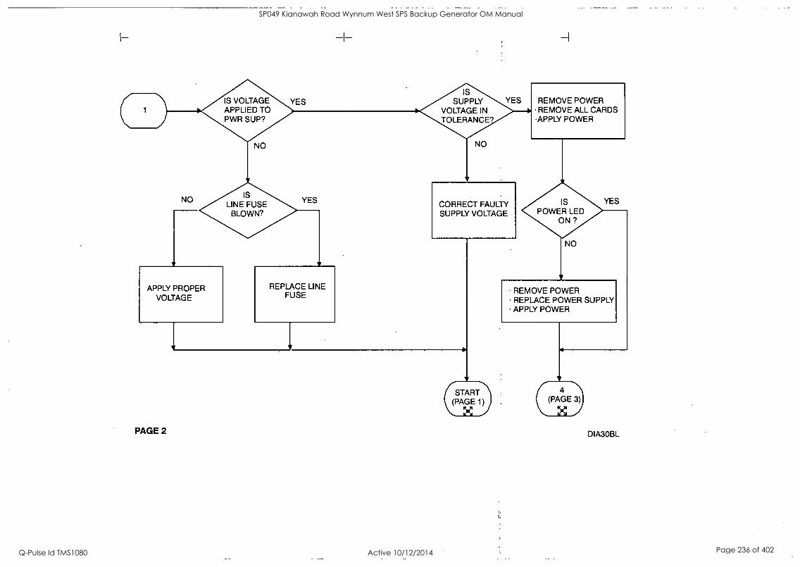
IS VOLTAGE APPLIED TO PWR SUP?
YES IS
SUPPLY VOLTAGE IN TOLERANCE?
YES REMOVE POWER REMOVE ALL CARDS
APPLY POWER
NO IS
LINE FUSE BLOWN?
CORRECT FAULTY SUPPLY VOLTAGE
IS POWER LED
ON ?
APPLY PROPER VOLTAGE
REPLACE LINE FUSE
NO
YES
REMOVE POWER REPLACE POWER SUPPLY APPLY POWER
(START (PAGE 1)
PAGE 2
4 (PAGE 3)
DIA3OBL
SP049 Kianawah Road Wynnum West SPS Backup Generator OM Manual
Q-Pulse Id TMS1080 Active 10/12/2014 Page 236 of 402

( 4 )
REMOVE POWER INSTALL NEXT CARD APPLY POWER
IS POWER LED
ON ?
REMOVE POWER REPLACE FAULTY MODULE APPLY POWER
IS POWER LED
YES
ON?
YES NO
ARE ALL MODULES NSTALLED?
PAGE 3
YES
REMOVE POWER REPLACE POWER SUPPLY
(STAR1) (PAX GE 1)
DIA3OCL
SP049 Kianawah Road Wynnum West SPS Backup Generator OM Manual
Q-Pulse Id TMS1080 Active 10/12/2014 Page 237 of 402

3
2
CAN CPU COMMUNICAT
WITH LM90?
NO (PAGE X
8
YES
CPU IN STOP/FLT OR
STOP/HALT
NO CONFIG SHOW PWR
P IN STOP
YES CONSIDER CHANGING CONFIG TO
POWER UP IN RUN MODE.
USE LM90 OR HHP TO PLACE PLC IN
RUN MODE.
IS FAULT SYS CONFIG
ISMATCH?
USE LM90 OR HHP TO CLEAR PLC & I/O FAULT TABLES
IS RUN LED ON?
NO
YES
YES IS SYSTEM OPERATIN
OK?
(PAX GE PROBLEM START SOLVED! (PAGE
X )
1)
PAGE 4 DIA3ODL
SP049 Kianawah Road Wynnum West SPS Backup Generator OM Manual
Q-Pulse Id TMS1080 Active 10/12/2014 Page 238 of 402

PAGE 5
331/341: REMOVE POWER REMOVE CPU REMOVE & REPLACE SYSTEM PROM REPLACE CPU APPLY POWER
(START\ (PAGE 1)
*COLD START DELETES THE CONTENTS OF THE CPU'S MEMORY AND RESTORES COMMUNICATION PARAMETERS (BAUD RATE, PARITY, ETC.) TO THEIR DEFAULT VALUES.
311/313/321/323. REMOVE POWER REMOVE ALL CARDS & BACK PLANE COVER SHORT SUPER CAP (SEE NOTE 4) REPLACE ALL CARDS & BACK PLANE COVER APPLY POWER
(START. (PAGE 1)
X
DIA30EL
SP049 Kianawah Road Wynnum West SPS Backup Generator OM Manual
Q-Pulse Id TMS1080 Active 10/12/2014 Page 239 of 402

RACK GND EQUAL
PROGRAMME GND?
YES
NO VERIFY RACK AND PROGRAMMER GROUND ARE THE SAME.
PAGE 6
REMOVE POWER FROM CPU APPLY POWER TO CPU
CAN CPU COMMUNICAT
ITH LM90?
YES
NO
CHECK SERIAL PORT SETTINGS. 'CHECK CABLE CONNECTIONS FROM PC TO CPU. 'CHECK CONVERTER IF USING SERIAL
LOGICMASTER 90-30 'ENSURE PC WILL WORK WITH ANOTHER 90/30 CPL REMOVE ANY MOUSE DRIVER OR CONFLICTING TERMINATE-AND-STAY-RESIDENT PROGRAM.
'VERIFY CPU WILL WORK WITH ANOTHER PC.
YES CAN CPU COMMUNICATE WITH LM90?
7-(PAGE 1))
START
X ( 6 (PAGE 5) DIA30FL
NO
SP049 Kianawah Road Wynnum West SPS Backup Generator OM Manual
Q-Pulse Id TMS1080 Active 10/12/2014 Page 240 of 402

( 5 ) THE RACK AND SLOT OF THE MISMATCHED MODULE ARE GIVEN IN THE FAULT TABLE AS A DECIMAL NUMBER (EG, 0.1, 1.3, ETC.) AT THE FAR LEFT SIDE OF THE TABLE.
YES
SELECT LM90 CONFIG SELECT I/O CONFIG
PAGE 7
EXIT I/O CONFIG SELECT & CLEAR PLC FAULT TABLE SELECT & CLEAR 110 FAULT TABLE. SELECT UTILITIES STORE CONFIGURATION TO PLC
NO
CHANGE LM90 CONFIG OR
HARDWARE SO BOTH ARE THE
SAME.
START (PAGE 1)$
X (
NO
YES
USE LM90 OR HHP TO PLACE PLC IN
RUN MODE.
REPLACE MISMATCHING
BOARD
DIA3OGL
SP049 Kianawah Road Wynnum West SPS Backup Generator OM Manual
Q-Pulse Id TMS1080 Active 10/12/2014 Page 241 of 402

C =)
YES ARE LM90 LOGIC & CONFIG
EQUAL TO
PLC?
NO
NO
E(PA8GE 6)
YES
VERIFY: ALL RACKS ARE PROPERLY GROUNDED ALL LOADS ARE PROPERLY SURPRESSED LAST RACK IS PROPERLY TERMINATED CABLES DO NOT EXCEED MAX LENGTH (SEE NOTE 6)
SELECT UTILITIES IN LM90 STOP PLC STORE CONFIGURATION TO PLC START PLC
USE LM90 OR HHP TO PLACE PLC IN
RUN MODE.
YE YES
PAGE 8
NO NO
VERIFY: INPUTS APPEAR IN REF TABLES FORCED OUTPUTS ENERGIZE FIELD DEVICES
PROGRAM LOGIC DIA3OHL
SP049 Kianawah Road Wynnum West SPS Backup Generator OM Manual
Q-Pulse Id TMS1080 Active 10/12/2014 Page 242 of 402

REMOVE POWER REPLACE CPU APPLY POWER
IS POWER LED ON?
NO
(PAGE 2) (
YES IS OK LED TEADY ON?
YES CAN CPU COMMUNICAT
WITH LM90?
YES
* REMOVE ALL MODULES EXCEPT POWER SUPPLY AND 331/341 CPU
REMOVE POWER REMOVE MODULES '
FROM RACK* APPLY POWER
IS OK LED STEADY ON
CAN CPU COMMUNICAT WITH LM90?
NO
11 (-START (PAGE 10) (PAGE 1)
X X PAGE 9 DIA30JL
SP049 Kianawah Road Wynnum West SPS Backup Generator OM Manual
Q-Pulse Id TMS1080 Active 10/12/2014 Page 243 of 402

C) REMOVE POWER REPLACE BACK PLANE REPLACE POWER SUPPLY REPLACE 331/341 CPU APPLY POWER
PAGE 10
6(START PAGE 1)j
YOUR PROBLEM IS BEYOND THE SCOPE OF THIS TROUBLESHOOTING GUIDE. CALL THE GE FANUC HOTLINE OR YOUR GE FANUC DISTRIBUTOR FOR ASSISTANCE.
DIA3OKL
SP049 Kianawah Road Wynnum West SPS Backup Generator OM Manual
Q-Pulse Id TMS1080 Active 10/12/2014 Page 244 of 402

I I
6
I
SP049 Kianawah Road Wynnum West SPS Backup Generator OM Manual
Q-Pulse Id TMS1080 Active 10/12/2014 Page 245 of 402

SP049 Kianawah Road Wynnum West SPS Backup Generator OM Manual
Q-Pulse Id TMS1080 Active 10/12/2014 Page 246 of 402

DIESEL STANDBY GENERATOR
LOCAL CONTROL PANEL
FUNCTIONAL DESCRIPTION
FOR
Brisbane City Council
19th May 2003
SP049 Kianawah Road Wynnum West SPS Backup Generator OM Manual
Q-Pulse Id TMS1080 Active 10/12/2014 Page 247 of 402

ABBREVIATIONS
G1 Generator 1 Diesel
SP049 Kianawah Road Wynnum West SPS Backup Generator OM Manual
Q-Pulse Id TMS1080 Active 10/12/2014 Page 248 of 402

1. GENERAL
1.1. The PLC for the above operation is a GE Fanuc IC693CPU350. This program has been designed for the use on G1. The operation below controls G1
1.2. A mode selector switch selects how G1 shall operate :
1.2.1. Off
1.2.2. Manual Mode
1.2.3. Test Mode.
1.2.4. Automatic Mode.
2. MANUAL MODE
2.1. To operate G1 in MANUAL Mode.
2.2. Select this operation by turning the AUTO -*TEST - MAN- OFF selector switch to the MANUAL position.
2.3. Press the MANUAL START push button to start the generator.
2.4. The generator will begin to crank.
2.4.1. If it fails to start within the 10 seconds, the starter motor is stopped and a delay of 10 seconds before it will attempt to restart.
2.4.2. The generator set is allowed 3 attempts to start.
2.4.3. If it fails to start on the third attempt, the generator is locked out on FAIL TO START Alarm.
2.4.4. When the generator starts, the starter motor is stopped by a stop cranking input which measures the speed of the generator.
2.4.5. Once the generator has started, there is a 10 second time delay for the oil pressure to stabilise.
2.4.6. If the oil pressure is not up to pressure after the 10 second time delay, the generator shall shut down on LOW OIL PRESS Alarm.
2.4.7. Once the generator is running there is a 5 second warm up time before it is ready to accept load.
SP049 Kianawah Road Wynnum West SPS Backup Generator OM Manual
Q-Pulse Id TMS1080 Active 10/12/2014 Page 249 of 402

2.5. To Manual Transfer to Generator in the MANUAL Mode.
2.5.1. Start the generator and wait for the generator to run up to speed and voltage and ready to accept load.
2.5.2. Press the MANUAL TRANSFER TO GEN push button.
2.5.3. The MAINS ATS shall Open.
2.5.4. After a 30 second delay the GEN ATS shall Close.
2.5.5. If the MAINS ATS fails to Open.
2.5.5.1. After a 5 second delay an Alarm shall be generated and the MAINS CONNECTED indicator shall flash to indicate the Alarm.
2.5.5.2. The system shall return back to MAINS ATS operation.
2.5.6. If the GEN ATS fails to Close.
2.5.6.1. After a 5 second delay an Alarm shall be generated and the GENERATOR CONNECTED indicator shall flash to indicate the Alarm.
2.5.6.2. The system shall return back to MAINS ATS operation.
2.6. To Manual Transfer to Mains in the MANUAL Mode.
2.6.1. The GENERATOR ATS is Closed.
2.6.2. Press the MAN TRANSFER TO MAINS push button.
2.6.3. The GEN ATS shall Open.
2.6.4. After a 30 second delay the MAINS ATS shall Close.
2.6.5. If the GEN ATS fails to Open.
2.6.5.1. After a 5 second delay an Alarm shall be generated and the GENERATOR CONNECTED indicator shall flash to indicate the Alarm.
2.6.5.2. The system shall return back to GEN ATS operation.
2.6.6. If the MAINS ATS fails to Close.
SP049 Kianawah Road Wynnum West SPS Backup Generator OM Manual
Q-Pulse Id TMS1080 Active 10/12/2014 Page 250 of 402

2.6.6.1. After a 5 second delay an Alarm shall be generated and the MAINS CONNECTED indicator shall flash to indicate the Alarm.
2.6.6.2. The system shall return back to GEN ATS operation.
2.7. To stop the generator in the MANUAL Mode.
2.7.1. When the generator is running, it may be stopped by pressing the MANUAL STOP push button.
2.7.2. If the generator is still GEN ATS operation. The MANUAL TRANSFER TO MAINS is initiated.
2.7.3. When the GEN ATS is Open, the generator will enter the cool down time of 1 second.
2.7.4. After the cool down time, the generator will shut down.
2.7.5. Once the generator has shut down there is a 15 second delay before it may be restarted. This is to ensure the engine has mechanically stopped.
SP049 Kianawah Road Wynnum West SPS Backup Generator OM Manual
Q-Pulse Id TMS1080 Active 10/12/2014 Page 251 of 402

3. NON-PERMANENT SITE, MANUAL MODE
3.1. To operate G1 in a Non-Permanent Site Location in MANUAL Mode.
3.2. Connect the generator cables to the site generator CB ensuring the site generator CB is OFF. See BCC procedures.
3.3. A plug with shorting links is required to be installed. It is required to be plugged into the 27 Pin Station Plug.
3.3.1. Pins 11 and 12 are required to be connected. This is to indicate that the Mains ATS is Closed. If they are not connected a MAINS ATS Alarm shall be indicated.
3.4. Select from the AUTO - TEST - MAN- OFF selector switch to the MANUAL position.
3.5. Press the MANUAL START push button to start the generator.
3.6. The generator will begin to crank.
3.6.1. If it fails to start within the 10 seconds, the starter motor is stopped and a delay of 10 seconds before it will attempt to restart.
3.6.2. The generator set is allowed 3 attempts to start.
3.6.3. If it fails to start on the third attempt, the generator is locked out on FAIL TO START Alarm.
3.6.4. When the generator starts, the starter motor is stopped by a stop cranking input which measures the speed of the generator.
3.6.5. Once the generator has started, there is a 10 second time delay for the oil pressure to stabilise.
3.6.6. If the oil pressure is not up to pressure after the 10 second time delay, the generator shall shut down on LOW OIL PRESS Alarm.
3.6.7. Once the generator is running there is a 5 second warm up time before it is ready to accept load.
3.7. To connect the generator to the site load.
3.7.1. Manually switch over to the generator supply via the site CB's. See BCC procedures.
3.7.2. Do not use the MANUAL TRANSFER TO GEN or the MAN TRANSFER TO MAINS push buttons.
SP049 Kianawah Road Wynnum West SPS Backup Generator OM Manual
Q-Pulse Id TMS1080 Active 10/12/2014 Page 252 of 402

3.8. To disconnect the generator from the site load.
3.8.1. Manually switch over to the mains supply via the site CB's. See BCC procedures.
3.8.2. Do not use the MANUAL TRANSFER TO GEN or the MAN TRANSFER TO MAINS push buttons.
3.9. To stop the generator in the MANUAL Mode.
3.9.1. When the generator is running, it may be stopped by pressing the MANUAL STOP push button.
3.9.2. The generator will enter the cool down time of 1 second.
3.9.3. After the cool down time, the generator will shut down.
3.9.4. Once the generator has shut down there is a 15 second delay before it may be restarted. This is to ensure the engine has mechanically stopped.
SP049 Kianawah Road Wynnum West SPS Backup Generator OM Manual
Q-Pulse Id TMS1080 Active 10/12/2014 Page 253 of 402

4. TEST OPERATION
4.1. To operate the generator in the TEST Mode.
4.2. Select this operation by turning the AUTO - TEST - MAN- OFF selector switch to the TEST position.
4.3. If the selector is changed to MAN while the generator is operating on TEST, the system shall change to MANUAL TRANSFER TO GEN.
4.4. The generator shall begin to crank.
4.4.1. If it fails to start within the 10 seconds, the starter motor is stopped and a delay of 10 seconds before it will attempt to restart.
4.4.2. The generator is allowed 3 attempts to start.
4.4.3. If it fails to start on the third attempt, the generator is faulted on FAIL TO START Alarm.
4.5. When the generator starts, the starter motor is stopped by a stop cranking input which measures the speed of the generator.
4.6. The MAINS ATS shall Open.
4.7. Once the generator has started, there is a 10 second time delay for the oil pressure to stabilise.
4.8. If the oil pressure is not up to pressure after the 10 second time delay, the generator shall shut down on LOW OIL PRESS Alarm.
4.9. Once the generator is running there is a 5 second warm up time before it is ready to accept load.
4.10. After the warm up time has expired and the MAINS ATS has been open for 30 seconds the GEN ATS shall Close.
4.11. If the MAINS ATS fails to Open.
4.11.1. After a 5 second delay an Alarm shall be generated and the MAINS CONNECTED indicator shall flash to indicate the Alarm.
4.11.2. The system shall shut down and return back to MAINS ATS operation.
4.12. If the GEN ATS fails to Close.
SP049 Kianawah Road Wynnum West SPS Backup Generator OM Manual
Q-Pulse Id TMS1080 Active 10/12/2014 Page 254 of 402

4.12.1. After a 5 second delay an Alarm shall be generated and the GENERATOR CONNECTED indicator shall flash to indicate the Alarm.
4.12.2. The system shall shut down and return back to MAINS ATS operation.
4.13. To stop the generator in the TEST Mode.
4.13.1. Select this operation by turning the AUTO - TEST - MAN- OFF selector switch to the AUTO or OFF position.
4.13.2. The GEN ATS shall Open.
4.13.3. After a 30 second delay the MAINS ATS shall Close.
4.13.4. If the GEN ATS fails to Open.
4.13.4.1.After a 5 second delay an Alarm shall be generated and the GENERATOR CONNECTED indicator shall flash to indicate the Alarm.
4.13.4.2.The system shall return back to GEN ATS operation.
4.13.5. If the MAINS ATS fails to Close.
4.13.5.1.After a 5 second delay an Alarm shall be generated and the MAINS CONNECTED indicator shall flash to indicate the Alarm.
4.13.5.2.The system shall return back to GEN ATS operation.
4.13.6. When the GEN ATS is Open, the generator will enter the cool down time of 5 minutes.
4.13.7. After the cool down time, the generator will shut down.
4.13.8. If a Mains Failure occurs during the cool down period the generator shall transfer back to the GENERATOR ATS without shutting down.
4.13.9. Once the generator has shut down there is a 15 second delay before it may be restarted. This is to ensure the engine has mechanically stopped.
SP049 Kianawah Road Wynnum West SPS Backup Generator OM Manual
Q-Pulse Id TMS1080 Active 10/12/2014 Page 255 of 402

5. AUTOMATIC OPERATION
5.1. To operate the generator in the AUTO Mode.
5.2. Select this operation by turning the AUTO - TEST - MAN- OFF selector switch to the AUTO position.
5.3. The Phase Failure Relay from the clients switch board shall give a Start Signal for the generators to run.
5.4. The Remote Start Command.
5.4.1. The generator shall begin to crank.
5.4.1.1. If it fails to start within the 10 seconds, the starter motor is stopped and a delay of 10 seconds before it will attempt to restart.
5.4.1.2. The generator is allowed 3 attempts to start.
5.4.1.3. If it fails to start on the third attempt, the generator is faulted on FAIL TO START Alarm.
5.4.2. When the generator starts, the starter motor is stopped by a stop cranking input which measures the speed of the generator.
5.4.3. The MAINS ATS shall Open.
5.4.4. Once the generator has started, there is a 10 second time delay for the oil pressure to stabilise.
5.4.5. If the oil pressure is not up to pressure after the 10 second time delay, the generator shall shut down on LOW OIL PRESS Alarm.
5.4.6. Once the generator is running there is a 5 second warm up time before it is ready to accept load.
5.4.7. After the warm up time has expired and the MAINS ATS has been open for 30 seconds the GEN ATS shall Close.
5.4.8. If the MAINS ATS fails to Open.
5.4.8.1. After a 5 second delay an Alarm shall be generated and the MAINS CONNECTED indicator shall flash to indicate the Alarm.
SP049 Kianawah Road Wynnum West SPS Backup Generator OM Manual
Q-Pulse Id TMS1080 Active 10/12/2014 Page 256 of 402

5.4.8.2. The system shall shut down and return back to MAINS ATS operation.
5.4.9. If the GEN ATS fails to Close.
5.4.9.1. After a 5 second delay an Alarm shall be generated and the GENERATOR CONNECTED indicator shall flash to indicate the Alarm.
5.4.9.2. The system shall shut down and return back to MAINS ATS operation.
5.5. To stop the generator in the AUTO Mode.
5.5.1. The Phase Failure Relay from the clients switch board shall give a Stop Signal for the generators to run.
5.5.2. The Remote Stop Command.
5.5.3. There is a 2 minute proving time for the Phase Failure Relay.
5.5.4. After the 2 minute proving time the GEN ATS shall Open.
5.5.5. After a 30 second delay the MAINS ATS shall Close.
5.5.6. If the GEN ATS fails to Open.
5.5.6.1. After a 5 second delay an Alarm shall be generated and the GENERATOR CONNECTED indicator shall flash to indicate the Alarm.
5.5.6.2. The system shall return back to GEN ATS operation.
5.5.7. If the MAINS ATS fails to Close.
5.5.7.1. After a 5 second delay an Alarm shall be generated and the MAINS CONNECTED indicator shall flash to indicate the Alarm.
5.5.7.2. The system shall return back to GEN ATS operation.
5.5.8. When the GEN ATS is Open, the generator will enter the cool down time of 5 minutes.
5.5.9. After the cool down time, the generator will shut down.
5.5.10.1f a Mains Failure occurs during the cool down period the generator shall transfer back to the GENERATOR ATS without shutting down.
SP049 Kianawah Road Wynnum West SPS Backup Generator OM Manual
Q-Pulse Id TMS1080 Active 10/12/2014 Page 257 of 402

5.5.11. Once the generator has shut down there is a 15 second delay before it may be restarted. This is to ensure the engine has mechanically stopped.
i
SP049 Kianawah Road Wynnum West SPS Backup Generator OM Manual
Q-Pulse Id TMS1080 Active 10/12/2014 Page 258 of 402

6. FAULT OPERATION
6.1. Emergency Stop Operation.
6.1.1. Operation of the Emergency Stop push button immediately shuts down the generator and Opens the Generator CB. The Emergency Stop is latched, and requires manual resetting to release the Emergency Stop push button.
6.1.2. After the Emergency Stop push button is released, a fault reset will need to be initiated to reset the PLC.
6.2. HIGH HIGH Alarm Operation.
6.2.1. The Generator CB is Opened immediately.
6.2.2. The generator is shut down immediately.
6.2.3. The following alarms will initiate a HIGH HIGH Alarm condition :-
6.2.3.1. Emergency Stop Fault
6.2.3.2. MEN Fault
6.2.3.3. Low Oil Pressure Shutdown Fault, 10 Seconds Startup Delay
6.2.3.4. High Engine Temperature Shutdown Fault, 30 Second Startup Delay
6.2.3.5. Low Radiator Level Fault, 5 Second Delay
6.2.3.6. Over Speed Fault
6.3. HIGH Alarm Operation
6.3.1. The Generator CB is Opened immediately.
6.3.2. Once the generator circuit breaker is opened, the generator will run through its normal cool down time and shut down.
6.3.3. The following alarms will initiate a HIGH Alarm condition: -
6.3.3.1. Generator Under Speed Fault, 5 Second Delay
6.3.3.2. Alternator Under Voltage Fault, 5 Second Delay
6.3.3.3. Alternator Over Voltage Fault, 5 Second Delay
SP049 Kianawah Road Wynnum West SPS Backup Generator OM Manual
Q-Pulse Id TMS1080 Active 10/12/2014 Page 259 of 402

6.3.3.4. Generator CB Tripped Fault
6.3.3.5. Alternator High Temperature Fault, 30 Second Startup Delay
6.4. MEDIUM Alarm Operation.
6.4.1. A Normal Shutdown shall be Initiated.
6.4.2. If the GEN ATS does not Open then the Generator CB is Opened.
6.4.3. The following alarms will initiate a MEDIUM Alarm condition :-
6.4.3.1. Fuel Empty Level Fault, 5 Second Delay
6.4.3.2. Fail To Start Fault, 3 Attempts
6.5. LOW Alarm Operation.
6.5.1. A Warning has occurred on the generator. The generator will not shut down.
6.5.2. The following alarms will initiate a LOW Alarm condition :-
6.5.2.1. Low Oil Pressure Warning Alarm, 10 Seconds Startup Delay
6.5.2.2. High Engine Temperature Warning Alarm, 30 Second Startup Delay
6.5.2.3. Fuel Low Level Alarm, 5 Second Delay
6.5.2.4. Battery Charger AC Supply Failed Alarm, 60 Second Delay
6.5.2.5. Control Battery Low Volts Alarm, 30 Second Delay
6.5.2.6. Start Battery Low Volts Alarm, 60 Second Delay
SP049 Kianawah Road Wynnum West SPS Backup Generator OM Manual
Q-Pulse Id TMS1080 Active 10/12/2014 Page 260 of 402

SP049 Kianawah Road Wynnum West SPS Backup Generator OM Manual
Q-Pulse Id TMS1080 Active 10/12/2014 Page 261 of 402

SP049 Kianawah Road Wynnum West SPS Backup Generator OM Manual
Q-Pulse Id TMS1080 Active 10/12/2014 Page 262 of 402

11/06/04 3:02 BCC 4000 4 Page: A
Table of Contents
Overview Main Rack: Base 10 Slot (IC693CHS391)
Detailed View IC693PWR331 Power Supply 24 VDC 30W.
Power Consumption Settings
IC693CP0350 Series 90-30 CPU Model 350 Settings Scan Memory Power Consumption
IC693CMM311 Communications Coprocessor Settings Port 1
Port 2
Power Consumption IC693MDL645 16 Circuit Input 24 VDC Positive / Negative Logic
Settings Wiring Power Consumption
IC693MDL645 16 Circuit Input 24 VDC Positive / Negative Logic Settings Wiring Power Consumption 4
IC693MDL645 16 Circuit Input 24 VDC Positive / Negative Logic 4
Settings 4
Wiring 4'
Power Consumption IC693MDL940 16 Circuit Output Relay 2A 4
Settings 4
Wiring 4
Power Consumption 4
IC693MDL940 16 Circuit Output Relay 2A 5
Settings 5
Wiring 5
Power Consumption 5
IC693MDL940 16 Circuit Output Relay 2A 5
2
2
2
2
2
2
2
2
3
3
3
3
3
3
3
3
3
3
4
4
4
Settings. Wiring Power- Consumption.
Reference Details %I References %Q References
Table of Contents
5
5
5
6
6
GE Fanuc Hardware Configuration Series 90-30
SP049 Kianawah Road Wynnum West SPS Backup Generator OM Manual
Q-Pulse Id TMS1080 Active 10/12/2014 Page 263 of 402

11/06/04 3:02 BCC 4000 4 Page:
Main Rack: Base 10 Slot (_IC693CHS391)
Overview GE Fantle Hardware Configuration Series 90-30
SP049 Kianawah Road Wynnum West SPS Backup Generator OM Manual
Q-Pulse Id TMS1080 Active 10/12/2014 Page 264 of 402

11/06/04 3:02 BCC 4000 4 Page: 2
Main Rack: Slot 0 IC693PWR331 Power Supply 24 VDC 30W Power Consumption
Voltages / Supplied +5VDC (Watts) 30
+24VDC Relay Power (Watts) 15
+24VDC Isolated (Watts) 20
Total System: 30
Settings Parameters / Values Hand Held Programmer: No
Converter: 0.
Main Rack: Slot 1
IC693CPU350 Series 90-30 CPU Model 350 Settings
Pa rameters / Values I/O Scan-Stop: No Power Up Mode: Run
Logic / Configuration From: RAM
Registers: RAM Passwords: Disabled Checksum Words: 8
Data Rate (bps): 19200
Parity: Odd Stop Bits: 1
Modem Turnaround Time (-01 Sec / Count): 0
Idle Time (Sec): 10
Timer Faults: Disabled SNP ID:
Key Switch Run/Stop: Enabled Memory Protect: Disabled Ignore Fatal Faults: Disabled
Scan Pa rameters / Values Sweep Mode: Normal Sweep Timer (mSec): N/A
Memory Parameters / Values %I Discrete Input: 2048
%Q Discrete Output: 2048
%S System Use: 128 %M Internal Discrete: 4096
%T Temporary Status: 256 %G Genius® Global: 1280 %AI Analog Input: 2048
%AQ Analog Output: 512 %R Register Memory: 9999
Detailed View GE Fanuc Hardware Configuration Series 90-30
SP049 Kianawah Road Wynnum West SPS Backup Generator OM Manual
Q-Pulse Id TMS1080 Active 10/12/2014 Page 265 of 402

11/06/04 3:02 BCC 4000 4 Page:
Power Consumption Parameters / Values +5VDC (Watts) 3.35
+29VDC Relay Power (Watts) 0
+24VDC Isolated (Watts) 0
Main Rack: Slot 2 IC693CMM311 Communications Coprocessor Settings
Parameters / Values Configuration Mode: RTU Only
Port 1
Parameters / Values RTU Enable: Yes
Data Rate (bps): 9600
Flow Control: None Parity: None
Station Address: 1
Port 2 Parameters / Values RTU Enable: Yes Interface: RS485 Data Rate (bps): 9600
Flow Control: None
Parity: None
Station Address: 1
Power Consumption Parameters / Values +5VDC (Watts) 2.00 +24VDC Relay Power (Watts) 0
+29VDC Isolated (Watts) 0
Main Rack: Slot 3 IC6931VIDL645 16 Circuit Input 24 VDC Positive / Negative Logic Settings
Parameters / Values Reference Address: %I00001 Length: 16
Wiring Terminal / Wiring Information From Terminal 1 to Terminal 20 : No wiring information.
Power Consumption Parameters / Values +5VDC (Watts) 0.40 +24VDC Relay Power (Watts) 0
Detailed View GE Fanuc Hardware Configuration Series 90-30
SP049 Kianawah Road Wynnum West SPS Backup Generator OM Manual
Q-Pulse Id TMS1080 Active 10/12/2014 Page 266 of 402

11/06/04 3:02
+24VDC Isolated (Watts) 0.6
BCC 4000 4
Main Rack: Slot 4 IC693MDL645 16 Circuit Input 24 VDC Positive / Negative Logic Settings -
Parameters / Values Reference Address: %I00017
Length: 16
Wiring Terminal / Wiring Information From Terminal 1 to Terminal 20 : No wiring information.
Power Consumption Parameters / Values +5VDC (Watts) 0.40 +29VDC Relay Power (Watts) 0.
+24VDC Isolated (Watts) 0.6
Main Rack: Slot 5 IC693MDL645 16 Circuit Input 24 VDC Positive / Negative Logic Settings,
Parameters / Values Reference Address: %100033 Length: 16
Wiring Terminal / Wiring Information From Terminal 1 to Terminal 20 : No wiring information.
Power Consumption Parameters / Values +5VDC (Watts) 0.90 +24VDC Relay Power (Watts) 0
+24VDC Isolated (Watts) 0.6
Main Rack: Slot 7 1C6931VIDL940 16 Circuit Output Relay 2A Settings
Pa rameters / Values Reference Address: %Q00001 Length: 16
Wiring Terminal / Wiring Information From Terminal 1 to Terminal 20 : No wiring information.
Power Consumption
Detailed View
Page: 4
GE Fanuc Hardware Configuration Series 90-30
SP049 Kianawah Road Wynnum West SPS Backup Generator OM Manual
Q-Pulse Id TMS1080 Active 10/12/2014 Page 267 of 402

11/06/04 3:02
Parameters / Values +5VDC (Watts) 0.04
+24VDC Relay Power (Watts) 3.24
+24VDC Isolated (Watts) 0
BCC 4000 4 Page: 5
Main Rack: Slot 8 IC693MDL940 16 Circuit Output Relay 2A Settings
Parameters /Values Reference Address: %Q00017
Length: 16
Wiring Terminal / Wiring Information From Terminal 1 to Terminal 20 : No wiring information.
Power Consumption Parameters / Values +5VDC (Watts) 0.04
+24VDC Relay Power (Watts) 3.24
+24VDC Isolated (Watts) 0
Main Rack: Slot 9 IC693MDL940 16 Circuit Output Relay 2A Settings
Parameters / Values Reference- Address: %Q00033 Length: 16
Wiring Terminal / Wiring Information From Terminal 1 to Terminal 20 : No wiring information.
Power Consumption Parameters / Values +5VDC (Watts) 0.04
+24VDC Relay Power (Watts) 3.24
+24VDC Isolated (Watts) 0
Detailed View GE Fanue Hardware Configuration Series 90
SP049 Kianawah Road Wynnum West SPS Backup Generator OM Manual
Q-Pulse Id TMS1080 Active 10/12/2014 Page 268 of 402

11/06/04 3:02
%I References Overlap Start End
1 16
17 32
33 48
Total %I: 48
Add r (0.3)
(0.4)
(0.5)
Highest Reference: 48
BCC 4000 4 Page: 6
Mem Type Consumed Consumed Consumed
%Q References Overlap Start End Add r
1 16 (0.7)
17 32 (0.8)
33 48 (0.9)
Total %Q: 48
Reference Details
Highest
Mem Type Produced Produced Produced
Reference: 48
Cat Num IC693MDL645
IC693MDL645 IC693MDL645
Cat Num IC693MDL940
IC693MDL940
IC693MDL940
GE Fantle Hardware Configuration Series 90-30
SP049 Kianawah Road Wynnum West SPS Backup Generator OM Manual
Q-Pulse Id TMS1080 Active 10/12/2014 Page 269 of 402

r Name Type Len Address Description Stored Val Scope Ret Ovr SEL_AUTO BIT 1 %I00001 Selector Switch Auto Global SEL TEST BIT 1 %l00002 Selector Switch Test Global SEL_MAN BIT 1 %100003 Selector Switch Manual . Global EM STOP_PB BIT 1 %100004 Emergency Stop PB Global LAkTiP TEST_PB BIT 1 %100005 Lamp Test PB Global ALM ESET_PB BIT 1 %I00006 Alarm Reset PB Global ALM-l'MUTE PB BIT 1 %100007 Alarm Mute PB Global MANZSTR i313
MAN_STP:PB BIT BIT
1
1
%100008 .%100009
Manaul Start PB Manual Stop PB
Global Global
MAN TRF MAINS_PB BIT 1 %100010 Manual Transfer to Mains PB Global MANITRFIGEN_PB BIT 1 %100011 Manual Transfer to Generator Global
PB SPD_STP_CRK BIT 1 %100017 Crank Cutout Relay Global R
SPD UNDER BIT 1 %I00018 Under Speed Relay Global SPD-OVER BIT - 1 %I00019 Over Speed Relay Global
-VOLTS_UNDER BIT 1 %100020 Under Voltage Relay Global VOLTS OVER BIT 1 %100021 Over Voltage Relay Global ALT_TEMP BET 1 %100022 Alternator High Temperature Global
Relay GEN_CB_TR1P BIT 1 %100023 Generator CB Tripped Global MEN FLT BIT 1 %I00024 MEN Fault Relay Global BAT -CHG_AC BIT 1 %100025 Battery Charger AC Relay Global BAT:CONT_LOW_V BIT 1 %100026 Control Battery Charger Low Global
Voltage BAT_STR_LOW_V BIT 1 %I00027 Start Battery Charger Low Global
Voltage MAINS FAILED BIT 1 %I00033 BCC Mains Failed Global MAINS:ATS_CLS BIT 1 %l00034 BCC Mains ATS Closed Global GEN ATS CLS BIT 1 %l00035 BCC Generator ATS Closed Global REM-STR- BIT 1 %100036 BCC Remote Start Global REM-STP BIT 1 %100037 BCC Remote Stop Global OIL_15_LOW SD BIT 1 %100041 Low Oil. Pressure Shutdown Global OIL_P LOW:W BIT 1 %100042 Low Oil Pressure Warning Global ENGf HI SD BIT 1 %I00043 High Engine Temperature Global
Shutdown ENG BIT 1. %100044 High Engine Temperature Global _T_HI_W
Warning RAD_WATER Low BIT 1 %I00045 Low Radiator Water Level Global FUEL_LEV_LOW BIT 1 %100046 Low Fuel Level Global FUEL_LEV_EMPTY BIT 1 %100047 Fuel Empty Global CAN DOORS_OPEN BIT 1 %100048 Canopy Doors Open Global STEP- 1 BIT 1 %M00001 Step Sequence No.1 Global STEP 2_E BIT 1 %M00002 Step Sequence No.2 Global STEP 3 BIT 1 %M00003 Step Sequence No.3 Global STEP:4 BIT 1 %M00004 Step Sequence No.4 Global STEP 5 BIT 1 %M00005 Step Sequence No.5 Global STEP:6 BIT 1 %M00006 Step Sequence No.6 Global STEP_? BIT 1 %M00007 Step Sequence No.7 Global STEP_8 BIT 1 %M00008 Step Sequence No.8 Global STEP_9 BIT 1 %M00009 Step Sequence No.9 Global STEP 2 GE BIT 1 %M00022 Step Sequence No.2 GE Global GEN -0-F BIT 1 '%M00101 Generator OFF Global AUT5_TEST_STR BIT 1 %M00102 Auto Test Start / Stop Global REMOTE_STR BIT 1 %M00103 Remote Start Global MAINS FAIL STP BIT 1 %M00104 Mains Failed Stop Global REMOTh ST-P BIT 1 %M00105 Remote Stop Global TEST_STA BIT 1 %M00106 Test Start Global TEST_STP BIT 1 %M00107 Test Stop Global GEN RUN OFF BIT. 1 %M00108 Generator Run Off Global ENAffLE_O-FFLINE BIT 1 %M00109 Enable Generator to go Global
Offline HH_ALM_OS1 BIT 1 %M00110 High High Alarm One Shot Global H_ALM_OS1 BIT 1 %M00111 High Alarm One. Shot Global H_ALM_OS2 BIT 1 %M00112 High Alarm One Shot Global M_ALM_OS1 BIT 1 %M00113 Medium Alarm One Shot Global M_ALM 0S2 BIT 1 %M00114 Medium Alarm One Shot Global M_ATS:ALM_OS1 BIT 1 %M00115 Mains ATS Alarm One Shot Global M_ATS_ALM_OS2 BIT 1 %M00116 Mains ATS Alarm One Shot Global MAINS_FAIL_STR BIT 1 %M00117 Mains Fail Start Global GEN_RUNNING BIT 1 %M00201 Generator Running Global FAIL_STR_TM BIT 1 %M00202 Failed to Start Time Global FAIL_STR_DLY BIT 1 %M00203 Failed to Start Pulse Delay Global
Program: BCC_4000_4 A: GLOBAL VP BI
SP049 Kianawah Road Wynnum West SPS Backup Generator OM Manual
Q-Pulse Id TMS1080 Active 10/12/2014 Page 270 of 402

Name Type Len Address Description Stored Val Scope FAI L_STR_CNT BIT 1 %M00204 Failed to Start Counter Global
CRK_CUTOUT BIT 1 %M00205 Generator Crank Cutout Global ENB_STR_DLY BIT 1 - %M00206 Enable Start Delay for Global
Alarms _ P DLY BIT 1 %M00207 Oil Pressure Alarm Delay Global
(IP DLY BIT 1 %M00208 Startup Alarm Delay Global ATS=OPN 1 BIT 1, %M00209 Mains ATS Open Command Global
GTATS_CLS BIT 1.' %M00210 Generator ATS Close Global Command
G ATS_OPN_1 BIT 1 %M00211 Generator ATS Open Global Command
M ATS_CLS_1 BIT 1 %M00212 Mains ATS Close Command Global CLSENB BIT 1 %M00213 Mains ATS Close Enable Global
G_ATS_CLS_ENB BIT 1 %M00214 Generator ATS Close Enable Global
HIGH HIGH -ALM BIT 1 %M00300 High High Alarm Global
EM_S-i13 ACM BIT 1 %M00301 Emergency Stop Alarm Global MEN AL_ BIT 1 %M00302 MEN Alarm Global OIL J5_SD_ALM BIT 1 %M00303 Low Oil Pressure Shutdown Global
Alarm ENG_T_SD_ALM BIT 1 %M00304 High Engine Temperature Global
Shutdown Alarm RAD_WATER_LOW_ALM BIT 1 %M00305 Low Radiator Water Level Global
Alarm SPD OVER_ALM BIT 1 %M00306 Over Speed Alarm Global RADIWATER_LOW_DLY BIT 1 %M00315 Radiator Water Level Low Global
Delay .
OVER_DLY BIT 1 %M00316 Over Speed Delay Timer Global 1:i- ALM BIT 1 %M00320 High Alarm Global
E BIT 1 %M00321 Under Speed Alarm Global _UNDER_ALM VOLTS_UNDERALM BIT 1 %M00322 Alternator Voltage Under Global
Alarm VOLTS_OVER_ALM BIT 1 %M00323 Alternator Voltage Over Global
Alarm GEN_CB_TRIP_ALM BIT 1 .%M00324 Generator CB Tripped Alarm Global ALT TEMP_ALM BIT 1 %M00325 Alternator High Temperature Global
Alarm SPD_UNDER_DLY BIT 1. %M00331 Under Speed Alarm Delay Global VOLTS_UNDER_DLY BIT 1 %M00332 Under Voltage Alarm Delay Global VOLTS_OVER_DLY BIT 1 %M00333 Over Voltage Alarm Delay Global MEDIUM_ALM BIT 1 %M00340 Medium Alarm Global FUEL_LEV_EMPTY_ALM BIT 1 %M00341 Fuel Empty Alarm Global FAIL_TO_STR_ALM BIT 1 %M00342 Fail to Start Alarm Global FUEL_LEV_EMPTYDLY BIT 1 %M00351 Fuel Level Empty Alarm Global
Delay LOW_ALM BIT 1 %,M00360 Low Alarm Global 0! L_PWALM BIT 1 %M00361 Low Oil Pressure Warning Global
Alarm ENGTWALM BIT 1 %M00362 High Engine Temperature Global
Warning Alarm F . LEV LOW_ALM BIT 1 %M00363 Low Fuel Level Alarm Global f EHG_AC_ALM BIT 1 %M00364 -Battery Charger AC Alarm Global Bf 3ONT_LOW V ALM BIT 1 %M00365 Control Battery Charger Low Global
Voltage Alarm BAT_STR_LOWV_ALNI BIT 1 %M00366 Start Battery Charger Low Global
Voltage Alarm FUEL_LEV_LOW_DLY BIT 1 %M00373 Fuel Level Low Alarm Delay Global BAT_CHG_AC_DLY BIT 1 %M00374 Battery Charger AC Failure Global
Delay BAT_CONT_LOW VDLY BIT 1 %M00375 Control Battery Low Voltage Global
Delay BAT_STR_LOW_V_DLY BIT 1 %M00376 Start Battery Low Voltage Global
Delay MAINS_ATS_OPN_ALM BIT 1 %M00381 Mains ATS Failed to Open Global
Alarm MAINS ATS_CLS_ALN1 BIT 1 %M00382 Mains ATS Failed to Close Global
Alarm GEN_ATS_OPNALM BIT 1 %M00383 Generator ATS Failed to Global
Open Alarm GEN_ATS_CLS_ALM BIT 1 %M00384 Generator ATS Failed to Global
Close Alarm NEW_ALM BIT 1 %M00400 New Alarm Global %rAon401 BIT 1 %M00401 "*No Description's" Global
( Pt rt: BCC_4000_4 A:
Ret Ow
GLOBAL VARIABI
SP049 Kianawah Road Wynnum West SPS Backup Generator OM Manual
Q-Pulse Id TMS1080 Active 10/12/2014 Page 271 of 402

I--- Name Type %M00402 BIT
Len 1
Address %M00402
Description *-*No Description**
Stored VA Scope Globa
Ret Ovr R
% M00403 BIT
%M00404 BIT 1
1
%M00403 %M00404
"`No Description' **No Description"
Globa Globa
R R
%Tv100405 BIT 1 %M00405 **No Description" Globa R
%M00406 BIT 1 %M00406 **No Description" Globa R
%Iv100421 BIT %M00422 BIT
1
1
%M00421 %M00422
No Description** **No Description**
Globa Globa
R R
%M00423 BIT 1 %M00423 No Description" Globa R
%M00424 BIT 1 %M00424 **No Description" Globa R %M00425 BIT 1 %M00425 *"No Description' Globa R
%IN/100441 BIT 1 %M00441 **No Description" Globa R
%M00442 BIT 1 %M00442 **No Description" Globa R %M00461 BIT 1 %M00461 **No Description" Globa R
%M00462 BIT 1 %M00462 **No Description" Globa R
%M00463 BIT 1 %M00463 "'No Description** Globa R
%M00464 BIT 1 %M00464 **No Description" Globa R %M00465 BIT 1 %M00465 'No Description" Globa R %M00466 BIT 1 %M00466 '"No Description" Globa R
%M00481 BIT %M00482 BIT
1
1
%M00481 %M00482
**No Descriptions' **No Description**
Globa Globa
R R
%M00483 BIT %M00484 BIT
1
1
%M00483 %M00484
Description" **No Description**
Globa Globa
R
AUTO IND BIT 1 %Q00001 Controls in Auto Indicator Globa TEST -IND BIT 1 %000002 Controls in Test Indicator Globa MAN -IND BIT 1 %000003. Controls in Manual Indicator Globa REM_STR_IND BIT 1 %000004 Remote Start Indicator Globa MAINS AVAILIND BIT 1 %Q00005 Mains Available Indicator Globa MAINS-CON IND BIT 1 '%000006 Mains Connected Indicator Globa GEN_RUN_IND BIT 1 %Q00007 Generator Running Indicator Globa GEN_CONIND BIT 1 %Q00008 Generator Connected Globa
Indicated MAINS FAILEDIND BIT 1 %000009 Mains Failed Indicator Globa EM ST-OP IND BIT 1 %000010 Emergency Stop Indicator Globa MENi-1 FLT -IND BIT 1 %Q00011 MEN Fault Indicator Globa OILPLOWSDIND BIT 1 %Q00012 Low Oil Pressure Shutdown Globa
Indicator OIL_P_LOW_WIND BIT 1 %000013 Low Oil Pressure Warning Globa
Indicator ENGT_HI_SD_IND BIT %Q00014 High Engine Temperature Globa
Shutdown Indicator ENG T HI WIND BIT 1 %000015 High Engine Temperature Globa
Warning Indicator RAD_WATER_LOWIND BIT 1 %Q00016 Low Radiator Water Level Globa
Indicator FUEL_LEV_EMPTY IND BIT 1 %Q00017 Fuel Empty Indicator Globa FUEL LEV LOW_Ilb BIT 1 %Q00018 Low Fuel Level Indicator Globa SPD OVEFT IND BIT 1 %Q00019 Over Speed Indicator Globa SPD UNDER_IND BIT 1 %000020 Under Speed Indicator Globa FAIL-TO STRIND BIT 1 %Q00021. Fail to Start Indicator Globa VOLTS UNDER _IND BIT 1 %000022 Alternator Voltage Under Globa
Indicator VOLTS_OVERIND BIT 1 %Q00023 Alternator Voltage Over Globa
Indicator ALT_TEMP _IND BIT 1 %000024 Alternator High Temperature Globa
Indicator GEN_CB_TRIP_IND BIT 1 %000025 Generator CB Tripped Globa
Indicator BAT_CHG AC IND RIT 1 %000026 Battery Charger AC Indicator Globa BAT_CONf LaW_V_IND BIT 1 %Q00027 Control Battery Charger Low Globa
Voltage Indicator BAT_STR_LOW_V_IND BIT 1 %Q00028 Start Battery Charger Low Globa
Voltage Indicator CAN_DOORS_OPENIND BIT 1 %000029 Canopy Doors Open Globa
Indicator MAINS_ATS_OPN_CMD BIT 1 %000033 BCC Mains ATS Open Globa
Command GEN_ATS_CLS_CMD BIT 1 %Q00034 BCC Generator ATS Close Globa
Command GEN_SD_ALM BIT 1 %Q00035 BCC Generator Shutdown Globa
Alarm GEN_W_ALM BIT 1 %000036 BCC Generator Warning Globa
Alarm Program: BCC_4000_4 A: GLOBAL W... BI
SP049 Kianawah Road Wynnum West SPS Backup Generator OM Manual
Q-Pulse Id TMS1080 Active 10/12/2014 Page 272 of 402

Name Type Len Address Description Stored Val Scope Ret FUEL_LOW BIT i %Q00037 BCC Low Fuel Globa G EN_RUN . BIT 1 %Q00038 BCC Generator Running Globa GEN_CON BIT 1 %Q00039 BCC Generator Connected Globa
AR BIT 1 %000040 Starter Motor Relay Globe 1-', R BIT 1 %Q00041 rn Governor Control Relay Globe
NR BIT 1 %000042 Audible Alarm Relay Globe _ JAR DOORS_OPEN
BIT BIT
1
1
%Q00043 %Q00044
Generator Shunt Trip Relay BCC Doors Open Alarm
Globs
GEN_AUTO BIT 1 %Q00045 Generator Auto Mode Globe
SEQ_CNT WORD 1 %R00001 Sequence Counter Globe R
MODBUS_INPUTS WORD 1 %R00002 Modbus Digital Inputs Globa R
MODBUS_OUTPUTS WORD 1 %R00005 Modbus Digital Outputs Globe R
MODBUS_STATUS_1 WORD 1 %R00008 Modbus Status 1 Globa R
MODBUS_STATUS_2 WORD 1 %R00009 Modbus Status 2 Globe R
MODBUS_ALARMS WORD 1 %R00010 Modbus Alarms Globe R
%R00100 WORD. 3 %R00100 **No Description** Globa R
%R00103 WORD 3 %R00103 No Description" Globe R
%R00106 WORD 3 %R00106 **No Description' Globa R
%R00109 WORD 3 %R00109 No Description" Globa R
%R00112 WORD 3 %R00112 No Description" Globe R
%R00115 WORD 3 %R00115 No Description" Globe R
%R00118 WORD 3 %R00118 No Description" Globa R
%R00121 WORD 3 %R00121 "No Description" Globa R
%R00124 WORD 3 %R00124 **No Description' Globe R
%R00127 WORD 3 %R00127 No Description' Globa R
° "300130 WORD 3 %R00130 **No Description" Globe R
:00133 WORD 3 %R00133 "No Description*" Globa R
7--100136 WORD 3 %R00136 **No Description" Globa R
)0139 WORD 3 %R00139 No Description" Globa R
%rt00200 WORD 3 %R00200 **No Description" Globe R
%R00203 WORD 3 %R00203 No Description*** Globa R
%R00206 WORD 3 %R00206 "No Description" Globa R
%R00209 WORD 3 %R00209 "No Description" Globa R
%R00212 WORD 3 %R00212 "No Description" Globe R
%R00215 WORD 3 %R00215 No Description" Globe R
%R00218 WORD 3 %R00218 **No Description** Globe R
%R00221 WORD 3 %R00221 "No Description" Globa R
%R00224 WORD 3 %R00224 **No Description' Globe R
%R00227 WORD 3 %R00227 "No Description''' Globa R
%R00230 WORD 3 %R00230 **No Description" Globe R
%R00300 WORD 3 %R00300 *"*No Description" Globa R
%R00303 WORD 3 %R00303 "No Description" Globe R
%R00306 WORD 3 %R00306 **No Description** Globe R
%R00309 WORD 3 %R00309 **No Description' Globe R
%R00312 WORD 3 %R00312 **No Description** Globe R
%R00315 WORD 3 %R00315 **No Description** Globa R
%R00318 WORD 3 %R00318 '''`No Description" Globa -R
%R00321 WORD 3 %R00321 "No Description' Globa R
W^ r:200324 WORD 3 %R00324 No Description" Globe R
)0327 WORD 3 %R00327 **No Description" Globa R
... J0330 WORD 3 %R00330 . **No Description" Globa R
°A. )333 WORD 3 %R00333 "No Description*" Globa R
%h00336 WORD 3 %R00336 No Description" Globa R
%R00339 WORD 3 %R00339 No Description" Globa R
FST_SCN BIT 1 %S00001 Set to 1 when the current sweep is the first sweep
Globe R
LST_SCAN BIT 1 %S00002 Reset from 1 to 0 when the current sweep is the last sweep
Globe R
T_10MS BIT 1 %S00003 0.01 Second Timer Contact Global R
T_100MS T 1S
BIT. BIT
1
1
%S00004- %S00005
Contact 0.1 Second Timer Conta 1 Second Timer Contact
Global R Global R _
T_1M BIT 1 %S00006 1 Minute Timer Contact Global R
ALW_ON BIT 1 %S00007 Always ON Global R
ALW_OFF BIT 1 %S00008 Always OFF Global R
PLC BAT BIT 1 %S00014 Set to indicate a bad battery in the CPU
Global R
%R00400 WORD 1 %R00400 -*No Description" Global R
rri: BCC_4000_4
--,
Ovr E
- A: GLOBAL VARIABL
SP049 Kianawah Road Wynnum West SPS Backup Generator OM Manual
Q-Pulse Id TMS1080 Active 10/12/2014 Page 273 of 402

Name Type Len Address Description Stored Val Scope Ret Ovr E
FSTSCN BIT 1 %S00001 Set to 1 when the current sweep is the first sweep
System R
LST_SCN BIT 1 %S00002 Reset from 1 to 0 when the current sweep is the last sweep
System R
T__1 OMS BIT 1 %S00003 0.01 second timer contact System R
Ti 00MS BIT 1 %S00004 0.1 second timer contact System R
T__SEC BIT 1 %S00005 1.0 second timer contact System R
T__MIN BIT 1 %S00006 1.0 minute timer contact System R
ALMON BIT 1 %S00007 Always ON System R
ALW_OFF BIT 1 %S00008 Always OFF System R
SY FULL BIT 1 %S00009 Set when the PLC fault table fills up
System R
IO_FULL BIT 1 %S00010 Set when the I/O fault table fills up
System R
OVR PRE BIT 1 %S00011 Set when an override exists in %I, %Q, %M or %G memory
System R
PRG_CHK BIT 1 %S00013 Set when background program check is active
System R
PLC_BAT - BIT 1 %S00014 Set to indicate a bad battery in a Release 4 or later CPU
System R
SNPXACT BIT 1 %S00017 SNP-X host is actively attached to the CPU
System R
SNPX_RD BIT 1 %S00018 SNP-X host has read data from the CPU
System R
SNPX WT BIT 1 %S00019 SNP-X host has written data to the CPU
System R
RLTNOK BIT 1 %S00020 Set ON when a relational function using REAL data is success
System R
CONTCON BIT 1 %S00032 Reserved for use by the programming software for cont contact
System R
PB_SUM BIT 1 %SA0001 Set when PLC checksum does not match app checksum
System R
OV_SWP BIT 1 %SA0002 Set when PLC sweep time is longer than user specified sweep time
System
APL_FLT BIT 1 %SA0003 Set when an application fault System R MOMS
CFG_MM BIT 1 %SA0009 Set when a config mismatch is detected during system powerup -
System R
HRD_CPU BIT 1 %SA0010 Set when the diagnostics detects a problem with the
System R
CPU hardware LOW_BAT BIT 1 %SA0011 Set when a low battery fault
occurs System R
LOS_RCK BIT 1 MA0012 Set when an expansion rack stops communicating with the
System R
CPU LOS _IOM BIT 1 %SA0014 Set when an I/O module
stops communicating with the System R
PLC CPU LOS_SIO BIT 1 %SA0015 Set when an option module
stops communicating with the System R
PLC CPU ADD__RCK BIT 1 %SA0017 Set when an expansion rack
is added to the system System R
ADD _IOM BIT 1 %SA0019 Set when an I/O module is added to a rack
System R
ADD_SIO - BIT 1 %SA0020 Set when an option module is added to a rack
System R
HRD_SIO BIT 1 %SA0027 Set when a hardware failure is detected in an option module
System R
SFT_SIO BIT 1 %SA0031 Set when an unrecoverable fault is detected in an option module
System R
BAD_RAM BIT 1 %SEI0010 Set when the CPU detects System R
Program: BCC_4000_4 A: SYSTEM V. \B1
SP049 Kianawah Road Wynnum West SPS Backup Generator OM Manual
Q-Pulse Id TMS1080 Active 10/12/2014 Page 274 of 402

Name Type Len Address
PED_PWD BIT 1 %SB0011
,_.. T_CPU BIT , 1 %SB0013
STOR_ER BIT 1 %SB0014
ANY_FLT BIT 1 %SC0009 SY_FLT BIT 1 %SC0010
10 FLT BIT 1 %SCOW 1
SY_PRES BIT 1 %SC0012
10_PRES BIT 1 %SC0013
HRD_FLT BIT 1 %SC0014
- -T_F LT BIT 1 %SC0015
BCC_4000_4
Description Stored Val Scope Ret Ovr 6 corrupted RAM memory at powerup Set when a password System R violation occurs Set when the CPU detects an System unrecoverable error in the software Set when an error occurs System R during a programmer store operation Set when any fault occurs System R Set when fault occurs where System R an entry is put in the PLC fault tbl Set when fault occurs where System R an entry is put in the I/O fault tbl .
Set as long as there is at System R least one entry in the PLC fault tbl Set as long as there is at System R
least one entry in the I/O fault tbl Set when a hardware fault System °CCU IS Set when a software fault System R
occurs
A: SYSTEM VARIAB.
SP049 Kianawah Road Wynnum West SPS Backup Generator OM Manual
Q-Pulse Id TMS1080 Active 10/12/2014 Page 275 of 402

2
IdWritten for EPAC.
Project: Brisbane City Council, Standby Generator Program. FST_SCN PRESETS
3
4
5
6
7
%S00001 Set to 1 when the current sweep is
the first sweep
SEQ
[CA
MAIN
CALL)
ALARM
[CALU
AUD_ALM
MODBUS
Program: BCC_4000_4 A: Ml
SP049 Kianawah Road Wynnum West SPS Backup Generator OM Manual
Q-Pulse Id TMS1080 Active 10/12/2014 Page 276 of 402

1
2
3
Iffrenerator Sequence No.1
1 Generator Stopped ALW_ON
4
5
Generator Sequence No.2 Generator Starting
ALW_ON EQ INT
%S00007 Always ON
sEQ_ctir-IN1 %ROGOW.
Sequence Counter
. 2-1N2
ALW_ON
%S00007 Always ON
GE INT
SEQ_CNT --1N1
%R00001 Sequence Counter
STEP_1
%/t100001 Step Sequence
No.1
STEP_2_E
%M00002 Step Sequence
No.2
STEP_2_GE
%M00022 Step Sequence .
No.2 GE
6
7
eGenerator Running Logic GCR
9(Q00041 Governor
Control Relay
SPD_UNDER
vi
%100018 Under Speed
Relay
VOLTS_UNDER
-1/1- %100020
Under Voltage Relay
am: BCC_4000_4 A:
GEN_RUNNING
%M00201 Generator Running
Mi
SP049 Kianawah Road Wynnum West SPS Backup Generator OM Manual
Q-Pulse Id TMS1080 Active 10/12/2014 Page 277 of 402

8
9
10
11
12
13
14
15
If/Generator Starter Motor and Governor Logic
STEP_2_E SPD_STP_CRK FAIL_STR_TM CRK_CUTOUT SMR
H V1 IA 1/1 )---1 %M00002 %100017 %M00202 %M00205 %Q00040
Step Sequence Crank Cutout Failed to Start Generator Crank Starter Motor No.2 Relay Time Cutout Relay
STEP_2_GE HIGH_HIGH_A... GCR
%M00022 %M00300 %Q00041 Step Sequence High High Alarm Governor
No.2 GE Control Relay
larGenerator Fail To Start Timers and Counters STEP_2_E SPD_STP_CRK FAIL_STR_DLY
%M00002 %100017 %,M00203 Step Sequence Crank Cutout Failed to Start
No.2 Relay Pulse Delay
FAlt_STR_TM
1------ %M00202
Failed to Start Time
TMR TENTHS
%R00203
100 -'PV
FAIL_STR_TM
F---- %M00202
Failed to Start Time
%R00203
UPCTR
STEP_2_E -0-41 ,R00206
%,M00002 Step Sequence
No.2
3-9V
TMR TENTHS
%R00200
100 - PV %R00200
STEP_2_E GCR SPD_STP_CRK FAIL_STR_TM
%M00002 Step Sequence
No.2
11 I I I/1- %Q00041 %100017 %M00202 Governor Crank Cutout Failed to Start
Control Relay Relay Time
CRK_CUTOUT
%M00205 Generator Crank
Cutout
Program: BCC_4000_4
TMR TENTHS
%R00209
10-PV %R00209
FAIL_STR_TM
%M00202 Failed to Start
Time
FAIL_STR_DLY
%M00203 Failed to Start
Pulse Delay
FAILSTR_cwr
%M00204 Failed to Start
Counter
CRK_CUTOUT
}-1 %M00205
Generator Crank Cutout
A: Mi
SP049 Kianawah Road Wynnum West SPS Backup Generator OM Manual
Q-Pulse Id TMS1080 Active 10/12/2014 Page 278 of 402

16
17
18
19
20
21
STEP_2_GE CRK_CUTOUT STEP _1 ENB_STR_DLY
I .1 1m-14 ( %M00022 %M00205 %M00001 %M00206
Step Sequence Generator Step Sequence Usable Start No.2 GE Crank Cutout No.1 Delay for Alarms
ENEI_STR_DLY
II
%M00206 Enable Start
Delay for Alarms
ENB_STR DLY
%M00206 Enable Start
Delay for Alarms
TMR TENTHS
.%R00212
100-9V %R00212
ENB_STR_DLY
%M00206 Enable Start
Delay for Alarms
TMR TENTHS
%R00215
300 -(1'*V
%R00215
OIL_P_DLY
%M00207 Oil Pressure Alarm Delay
STR_UP_DLY
(
%M00208 Startup Alarm
Delay .
FiGenerator Sequence No.3 Generator Running
ALW_ON EQ INT
%S00007 Always ON
SEQ_CNT -'IN1
%R00001 Sequence Counter
3-1N2
STEP_3
%M00003 Step Sequence
No.3
Generator Sequence No.4 Transfer to Generator ATS
am: BCC_4000_4 A: MI
SP049 Kianawah Road Wynnum West SPS Backup Generator OM Manual
Q-Pulse Id TMS1080 Active 10/12/2014 Page 279 of 402

22
23
24
25
26
27
ALVV_UN
%S00007 Always ON
STEP_4
STEP_4
HH %M00004
Step Sequence No.4
M_ATS_OPN_1
%M00004 Step Sequence
No.4
STEP_4 MAINS_ATS_O...
II VI 1,M00004 %Q00033
Step Sequence BCC Mains ATS No.4 Open Command
TMR TENTHS
%R00218
20 -PV %R00218
miC.enerator Sequence No.5 Generator Running Online
ALW_ON
ErGenerator Sequence No.7 Transfer to Mains ATS
Program: BCC_4000_4
%M00209 Mains ATS Open
Command
G_ATS_CLS_1
)""--1 %M00210
Generator ATS Close Command
STEP _5
%M00005 Step Sequence
No.5
SP049 Kianawah Road Wynnum West SPS Backup Generator OM Manual
Q-Pulse Id TMS1080 Active 10/12/2014 Page 280 of 402

28
29
ALW_ON
%S00007 Always ON
SEQCNT
%R00001 Sequence Counter
STEP_7
%M00007 Step Sequence
No.7
STEP_9
%M00009 Step Sequence
No.9
STEP _1
I I
%M00001 Step Sequence
No.1
STEP 2_E
I I
%M00002 Step Sequence
No.2
STEP_3
%M00003 Step Sequence
No.3
STEP_7
%M00007 Step Sequence
No.7
GATS_OPN_1
L BCC_4000_4 A:
%M00211 Generator ATS
Open Command
Mt
SP049 Kianawah Road Wynnum West SPS Backup Generator OM Manual
Q-Pulse Id TMS1080 Active 10/12/2014 Page 281 of 402

30
33
34
J I trf
%M00007 Step Sequence
No.7
STEP_1
F- %M00001
Step Sequence No.1
STEP_9 GEN_ATS_CLS
%M00009 Step Sequence
No.9
STEP_2_E
I I
%M00002 Step Sequence
No.2
STEP 3
%M00003 Step Sequence
No.3
%100035 BCC Generator
ATS Closed
TMR TENTHS
%R00221
20 - PV %R00221
ATS_CLS_1
%M03212 Mains ATS Close
Command
WGenerator Sequence No.9 Generator Offline Generator Cool Down
ALW_ON EQ INT
I I
%S00007 Always ON
SEQ_CNT I N1
%R00001 Sequence Counter
9 -1N2
STEP_9
%M00009 Step Sequence
No.9
stMains ATS Control Logic M_ATS_OPN_l M_ATS_CLS_1
%M00209 Mains ATS
OPen Command
MAINS_ATS__.
I I
%Q00033 BCC Mains ATS Open Command
M_ATS_CLS_E_.
%M00213 Mains ATS Close
Enable
%M00212 Mains ATS Close
Command
Program BCC_4000_4 A:
MAINS_ATS_O....
%Q00033 BCC Mains ATS Open Command
SP049 Kianawah Road Wynnum West SPS Backup Generator OM Manual
Q-Pulse Id TMS1080 Active 10/12/2014 Page 282 of 402

Manual
150-
SEL_MAN
I I-
1
N %R00400
%R00400
%100003 Selector Switch
Manual
5-
35
36
37
, 38
39
GEN_ATS_CLS...
%Q00034 BCC Generator
ATS Close Command
TMR TENTHS
%R00224
%R00400 %R00224
%R00400
M_ATS_CLS_E...
%M00213 Mains ATS Close
Enable
IWGenerator ATS Control Logic G_ATS_CLS_1 G_ATS_CLS_E.. G_ATS_OPN_1
I I I 1-1---V1 GEN_ATS_CLS...
Y-1 %M00210 %M00214 %M00211 %Q00034
Generator ATS Generator ATS Generator ATS BCC Generator Close Command Close Enable Open Command ATS Close
Command
GEN_ATS_CLS...
I I
%Q00034 BCC Generator
ATS Close Command
MAINS_ATS_O... TMR TENTHS
%Q00033 BCC Mains ATS Open Command
%R00227
%R00400 %
%R00400 %R00227
(
%M00214 Generator ATS Close Enable
WATS Control Delay Setpoint Logic
40 SELMAN MOVE INT
%100003 Selector Switch
42
MOVE INT
1
IN -%R00400
%R00400
Isrenerator CB Shunt Trip Control Logic
ant BCC_4000_4 A: Mi
SP049 Kianawah Road Wynnum West SPS Backup Generator OM Manual
Q-Pulse Id TMS1080 Active 10/12/2014 Page 283 of 402

r
43
44
45
46
47
48
49
50
%M00300 High High
Alarm
HIGH_ALM
%M00320 High Alarm
UtP4 b_uLb
F-- %100035
BCC Gem, etor ATS Closed
TMR TENTHS
%R00230
20 - PV %R00230
SOAR
%Q00043 Generator Shunt
Trip Relay
WBCC Interface Relay Outputs
GEN_SD_ALM
%M00300 High High
Alarm
HIGH_ALM
%M00320 High Alarm
MEDIUM_ALM
I 1-
'0100340 Medium Alarm
LOW_ALM
%M00360 Low Alarm
FUEL_LEV_EM...
%M00341 Fuel Empty
Alarm
FUEL_LEV_L...
%M00363 LOw Fuel Level
Alarm
GEN_RUNNING
ToM00201 Generator Running
GEN_ATS_CLS
( H . %Q30035 BCC Generator
Shutdown Alarm
GEN_W_ALM
%Q00036 BCC Generator Warning Alarm
FUEL_LOW
%Q00037 BCC Low Fuel
GEN_RUN
%Q00038 BCC Generator
Running
GEN_CON
itin35 BCC Generator
ATS Posed
cAN_DooRs_...
%100048 Canopy Doors
Open
(
%Q00039 BCC Generator
Connected
DOORS_OPEN
Program: BCC_4000_4
96Q00044 BCC Doors Open
Alarm
MI
SP049 Kianawah Road Wynnum West SPS Backup Generator OM Manual
Q-Pulse Id TMS1080 Active 10/12/2014 Page 284 of 402

51
55
56
57
SELAUTO GEN_AUTO
%100001 %Q00045 Selector Switch Generator Auto
Auto Mode
IF/Local Control Panel Indicators SEL AUTO
%100001 Selector Switch
Auto
LAMP_TEST_...
1
%100005 Lamp Test PB
SEL_TEST
I I
%100002 Selector Switch
Test
LAMP TEST ...
%100005 Lamp Test PB
SELMAN
7.100003 Selector Switch
Manual
AUTO_IND
)777-1
%Q00001 Controls in Auto
Indicator
TEST_IND
)7-1 %Q00002
Controls in Test Indicator
%100005 Lamp Test PB
REMOTE_STR
%M00103 Remote Start
LAMP_TEST_...
1 I
%l00005 Lamp Test PB
MAINS_FAILED
-7-V1- %100033
BCC Mains Failed
LAMP_TEST_...
I 1- %100005
Lamp Test PB
BCC 4000 4 A:
MAN_IND
)-7-1 %Q00003
Controls in Manual
Indicator
REM_STR_I ND
)--71 %Q00004
Remote Start Indicator
MAINS_AVAIL...
)77-71
%Q00005 Mains Available
Indicator
SP049 Kianawah Road Wynnum West SPS Backup Generator OM Manual
Q-Pulse Id TMS1080 Active 10/12/2014 Page 285 of 402

11/U6/04 Z.:41:Jo CAN_DOORS__. 62
V CLJill LV V.119
%moats Canopy Doors
Wen
LAMP TEST_...
%100005 Lamp Test PB
Program: BCC_4000_4 A:
CAN _ODORS__
M00029 Canopy Doors
Open Indicator
SP049 Kianawah Road Wynnum West SPS Backup Generator OM Manual
Q-Pulse Id TMS1080 Active 10/12/2014 Page 286 of 402

1-
1
2
FdPresets Routine Move 1 to the Sequence Counter ALW_ON
I I
%S00007 Always ON
rn: BCC_4000_4
MOVE INT
1
IN - SEQ_CNT
%R00001 Sequence Counter
A:
SP049 Kianawah Road Wynnum West SPS Backup Generator OM Manual
Q-Pulse Id TMS1080 Active 10/12/2014 Page 287 of 402

1
2
3
5
iffuenerator Modbus K I U Slave Interface L 40001 - Generator Sequence Number
ALW_ON
I I
%S00007 Always ON
SEL_AUTO-
V00001 Selector Switch
Auto
ALW_ON
I
%S00007 Always ON
AUTO_IND-
%Q00001 Controls in Auto
Indicator
ALW ON
II
MOVE BOOL
48
IN
MOVE BOOL
48
IN
%S00007 Always ON
GEN_OFF-
%M00101 Generator OFF
ALW_ON
I I
%S00007 Always ON
MOVE BOOL
16
IN
MOVE BOOL
16
MODBUS_INP...
%R00002 Modbus Digital
Inputs
-MODBUS_OUT...
%R00005 Modbus Digital
Outputs
-MODBUS_STA...
%R00008 Modbus Status 1
GEN_RUNNING IN MODBUS_STA...
%M00201 %R00009 GeneratOr Modbus Status 2 Running
Program: BCC_4000_4 A: ' --)131
SP049 Kianawah Road Wynnum West SPS Backup Generator OM Manual
Q-Pulse Id TMS1080 Active 10/12/2014 Page 288 of 402

ALW_ON
%S00007 Always ON
HIGH_HIGH ALM - %M00300
High High Alarm
am BCC_4000_4
MOVE BOOL
100
IN -MODBUS ALA..
%R00010 Modbus Alarms
A: MOD]
SP049 Kianawah Road Wynnum West SPS Backup Generator OM Manual
Q-Pulse Id TMS1080 Active 10/12/2014 Page 289 of 402

6
heGenerator OFF State SELAUTO SEL_TEST SELMAN
%100001 %100002 %100003 Selector Switch Selector Switch Selector Switch
Auto Test Manual
GEN_OFF
%M00101. Generator OFF
SEQ_CNT
%R00001 Sequence Counter
TMR TENTHS
%R00100
25-PV %R00100
iffGenerator Automatic Start and Stop Logic MAINS_FAIL_S... MAINS_FAILS...
1 1
%M00117 Mains Fail Start
REmOTE_STR
I I
%M00103 Remote Start
TEST_STR
%M00106 Test Start
%M00104 Mains Failed
Stop
REMOTE_STR REMOTE_STP
I
%M00103 %M00105 Remote Start Remote Stop
AUTO_TEST__.
%M00102 Auto &. Test Start / Stop
MAINS_FAILED
%l00033 BCC Mains
Failed
Program: BCC_4000_4
TEST_STP
V %M00107 Test Stop
GEN_OFF
%M00101 Generator OFF
GEN_OFF HIGH_ALM MEDIUM_ALM
1/1
%M00101 %M00300 %M00320 %M00340 Generator OFF High High Alarm High Alarm Medium Alarm
300-
TMR TENTHS
%R00139
PV %,R00139
TMR TENTHS
%R00103
--PV %R00103
A:
AUTO_TEST_S...
%M00102 Auto & Test Start / Stop
MAINS_FAIL_S...
%M00117 Mains Fail Start
SP049 Kianawah Road Wynnum West SPS Backup Generator OM Manual
Q-Pulse Id TMS1080 Active 10/12/2014 Page 290 of 402

10
v1 %100033
BCC Mains Failed
SEL_AUTO
TMR TENTHS
%R00106
1200 -.PV %R00106
REM_STR. REMOTE_STP
7,100001 Selector Switch
Auto
SEL_AUTO
F
7,100001 Selector Switch
Auto
SEL_TEST
II
%100036 %M00105 BCC Remote Remote Stop
Start
MAINS_ATS C... GEN_RUNNING
11 1
%M003132 %M00201 Mains ATS Generator
Failed to Close Running Alarm
REMOTE_STR
70M00103 Remote Start
REM_STP
70100037 BCC Remote
Stop
HIGH_HIGH_...
1
%M00300 High High
Alarm
H1GH_ALM
.70M03320 High Alarm
MED1UM_ALM
%M00340 Medium Alarm
%100002 Selector Switch
Test
I an: BCC_4000_4
10-
TMR TENTHS
70R00115
PV %R00115
MA I NS_IFA1L_S...
%M00104 Mains Failed
Stop
REMOTE_STR
9400103 Remote Start
REMOTE_STP
%A400105 Remote Stop
A:
TEST_STR
%M00106 Test Start
Si
SP049 Kianawah Road Wynnum West SPS Backup Generator OM Manual
Q-Pulse Id TMS1080 Active 10/12/2014 Page 291 of 402

11
12
13
14
15
16
17
SEL_TEST
V %100002
Selector Switch Test
10
TMR TENTHS
%R00118
%R00118
rffGenerator Sequence 1 -- 2 Starting the Generator
GEN_RUN_OFF HIGH_HIGH_A... HIGH_ALM MEDIUM_ALM
V V V V %M00108 %M00300 %M00320 %M00340
Generator Run High High Alarm High Alarm Medium Alarm Off
SPO_STP_CRK
%100017 Crank Cutout
Relay
OFDT TENTHS
V00121 150 -PV
%R00121
TEST_STP
%M00107 Test Stop
SEL_AUTO AUTO_TEST_S... STEP_1
I I I I
%100001 %M00102 Selector Switch Auto & Test
Auto Start / Stop
SELTEST AUTO TEST
1
%100002 %M00102 Selector Switch Auto & Test
Test Start / Stop
SELMAN MAN_STR_P8
II II
%K)0003 %100008 Selector Switch 'Manaul Start PS
Manual
SEQ_CNT
%R00001 Sequence Counter
GEN_RUN_OFF
}-1 %M00108
Generator Run Off
STEP _1 ENABLE_OFFL..
%M00001 %M00109 Step Sequence
No.1 Enable Generator to go
Offline
WGenerator Sequence 2 -- 3 Generator Running at Rated Speed Generator Warmup Time
SF_LAUTO GEN_RUNNING STEP_2_E
'7.100001 Selector Switch
Auto
SELTEST
II
%100002 Selector Switch
Test
Program: BCC_4000_4
I I
%M00201 %M00002 Generator . Step Sequence Running No -2
A:
SEQCNT
%R00001 Sequence Counter
SP049 Kianawah Road Wynnum West SPS Backup Generator OM Manual
Q-Pulse Id TMS1080 Active 10/12/2014 Page 292 of 402

I / v-r 4.....1MJ
18
19
SEL_MAN GEN_RUNN1NG
I I
STEP_2_E
%100003 %M00201 %M00002 Selector Switch Generator Step Sequence
Manual Running No.2
.1
SELAUTO SPE) STP_CRK AUTO_TEST_S... STEP_2_E
H VI I/1
%100001 %100017 %M00102 %M00002 Selector Switch Crank Cutout Auto & Test Step Sequence
Auto Relay Start / Stop No.2
SELTEST
20
21
92
23
%100002 Selector Switch
Test
SELAUTO
I
SRO STP_CRK AUTO TEST S...
I I
STEP 2_E
%100001 %100017 %M00102 %M00002 Selector Switch Crank Cutout Auto & Test Step Sequence
Auto Relay Start / Stop No.2
SELTEST
%100002 Selector Switch
Test
SEL_MAN SPO_STP_CRK MAN_STP_PB STEP_2_E-
-
9 -1
%100003 %100017 %100009 %M00002 Selector Switch Crank Cutout Manual Stop PB Step Sequence
Manual Relay No.2
SELMAN SPE> STP CRK MAN STP_PB STEP 2_E
%100003 %100017 1.100009 %M00002 Selector Switch Crank Cutout Manual Stop PB Step Sequence
Manual Relay No.2
MOVE INT
1
N Q
1-J
MOVE INT
1
N Q
IBIGenerator Sequence 3 -- 4 Generator Running at Rated Speed Transfer to Generator ATS
rarn: BCC4000_4
-SEQ_CJfT
, %R00001 Sequence Counter
- SEQ_CNT
%R30001 Sequence Counter
SEQ_CNT
%R00001 Sequence Counter
A:
SEQ_CNT
%R00001 Sequence Counter
SP049 Kianawah Road Wynnum West SPS Backup Generator OM Manual
Q-Pulse Id TMS1080 Active 10/12/2014 Page 293 of 402

4-
24
25
26
27
28
29
SEL_AUTO GEN_RUNNING STEP_3
II I I
10100001 %M00201 %M00003 Selector Switch Generator Step Sequence
Auto Running No.3
SEL_TEST
I f
70100002 Selector Switch
Test
MOVE INT
1
IN
SELMAN GEN_RUNNING STEP_3
I I II I I
SEQ_CNT
%R00001 Sequence Counter
%100003 %M00201 10103011 %M00003 Selector Switch Generator Manual Transfer Step Sequence
Manual Running to Generator PB No.3
SEL_AUTO AUTO_TEST_S... STEP_3
1/1
%100001 Selector Switch
Auto
SEL_TEST
%100002 Selector switch
Test
%M00102 %M00003 Auto & Test Step Sequence Start / Stop No.3
SEL_MAN MAN_STP_PB STEP_3
II V}
%100003 %100009 %M00003 Selector Switch Manual Stop PB Step Sequence
Manual No.3
SEQ_CNT
%R00001 Sequence Counter
SEQ_CNT
7.1100001
Sequence Counter
SEQ_CNT
%R00001 Sequence Counter
WGenerator Sequence 4 -- 5 Generator Running Online
SEL_AUTO GEN_RUNNING MAINS_ATS_C... GEN_ATS CIS STEP 4
"I I IA II v00001 040020i 7,100034 /.100035 . %M00004
Selector Swit Generator BCC Mains ATE BCC Generator Step Sequence Auto Running Closed ATS Closed No.4
SELJEST
%100002 Selector Switch
Test
Program: BCC_4000_4 A:
SEQ_CNT
%R00001 Sequence Counter
SP049 Kianawah Road Wynnum West SPS Backup Generator OM Manual
Q-Pulse Id TMS1080 Active 10/12/2014 Page 294 of 402

11 / UV/ V't SEL_MAN GEN_RUNNING MAINS_ATS_C... GEN_ATS_CLS 30
31
32
_
33
34
V1
4.104 11 IA, STEP_4
%100003 %M00201 %100034 %100035 %M00004 Selector Switch Generator BCC Mains ATS BCC Generator Step Sequence
Manual Running Closed ATS Closed No.4
SEL_AUTO AUTO TEST S... STEP_4
T0100001 %M00102 %M00004 Selector Switch Auto & Test Step Sequence
Auto Start / Stop No.4
SEL_TEST
II
%100002 Selector Switch
Test
SEL_MAN MAN TRF_MAL:. STEP 4
%100003 X100010 %M00004 Selector Switch Manual Transfer Step Sequence
Manual to Mains P8 No.4
SELMAN MAN_STP_PB STEP_4
II V1
%100003 %100009 %M00004 Selector Switch Manual Stop P8 Step Sequence
Manual No.4
9-
SEQ_CNT
%R00001 Sequence Counter
SEQ_CNT
%1200001
Sequence Counter
SEQ_CNI
%R00001 Sequence Counter
5-
MOVE INT
1
IN -SEQ_CNT
%R00001 Sequence Counter
-c
mirGenerator Sequence 5 -- 7
Generator Running Online Transfer to Mains ATS
SEL_AUTO AUTO_TEST_S... STEP_5
%100001 Selector Switch
Auto
SEt_TEST
EI
%t00002 Selector Switch
Test
%M00102 %M00005 Auto & Test Step Sequence Start / Stop No.5
SEQ_CNT
%R00001 Sequence Counter
72.m: BCC_4000_4 A:
SP049 Kianawah Road Wynnum West SPS Backup Generator OM Manual
Q-Pulse Id TMS1080 Active 10/12/2014 Page 295 of 402

36
37
38
39
40
41
42
43
SEL_MAN MAN_TRf_MAI... STEP_5 ENABLE_OFFL...
s)-H %100003 %100010 %M00005 %.M00109
Selector Switch Manual Transfer Step Sequence Enable Manual to Mains PB No.5 Generator to go
Offline
SEL_MAN MAN STP PB STEP_5
%100003 %100009 %M00005 Selector Switch Manual Stop PB Step Sequence
Manual No.5
SEQ_CNT
%R00001 Sequence Counter
SEQ_CNT
%R00001 Sequence Counter
WGenerator Sequence 7 -- 9 Generator Running Mains ATS Closed
fAAINS_ATS_C... GEN_ATS_CLS ENABLE_OFFL.. STEP_7
%100034 %100035 %M00109 %M00007 BCC Mains ATS BCC Generator Enable Step Sequence
Closed ATS Closed Generator to go No.7 Offline
9-4
ErGenerator Sequence 7 -- 3 Generator Running Mains ATS Closed Return to Stet) 3
GEN_ATS_CLS ENABLE_OFFL.. STEP_7
II VI II I
. %100034 %100035 %M00109 %M00007 BCC Mains ATS BCC Generator Enable Step Sequence
Closed ATS Closed Generator to go No.7
MOVE INT
1
N Q - SEQCNT
%R00001 Sequence Counter
Offline
leGenerator Sequence 9 -- 1
Generator Cool Down se_AuTo STEP 9
I I
%100001 Selector Switch
Auto
SEL_TEST
%100002 Selector Switch
Test
Program: BCC_4000_4
%M00009 Step Sequence
No.9
ENABLE_OFFL..
%M00109 Enable
Generator to go Offline
SEQ_CNT
%R00001 Sequence Counter
SEQ_CNT
%R00001 Sequence Counter
SP049 Kianawah Road Wynnum West SPS Backup Generator OM Manual
Q-Pulse Id TMS1080 Active 10/12/2014 Page 296 of 402

-44
....,..
sti_MAN STEP., TMR TENTHS
%R00133
%R00133
MOVE INT
1
Q -SEQ_CNT
V200001 Sequence Counter
I
%100003 %M00009 Selector Switch Step Sequence
Manual No.9
10-9V 1-AN
isfGenerator Sequence 9 - 2 Generator Restart
45
46
7
_ o
SEL_AUTO AUTO_TEST_S... STEP 9
I I
TMR TENTHS
%R00136
%R00136
MOVE INT
1
Q-SEQ_CNT
_
Sequence Counter
%100001 Selector Switch
Auto
SEL_TEST
I I I
%M00102 %M00009 Auto & Test Step Sequence Start / Stop No.9
2-IN I 10 -.1"v
%100002 Selector Switch
Test
ifGenerator High High Alarm Generator Shut Down
HIGH_HIGH_k.. HH ALM_OSI
1)-1 %M00300 %M00110
High High Alarm .
High High Alarm One Shot
49 HH_ALM_0S1 MOVE INT
1
Q-SEQ_CNT
- "
-
%R00001 Sequence Counter
%M00110 High High Alarm
One Shot
1 -IN
50 garGenerator High Alarm Generator Not Running. Move to Stop Mode. Step 1
51 HIGH_ALM SPO STP_CRK H_ALM_OS1
H I/1 V---I va00320 le100017 %M00111 High Alarm Crank Cutout High Alarm One
Relay ' Shot
52 H_ALM_OS1 MOVE INT
1
,N Q SEQ_CNT
%R00001 Sequence Counter
%M00111 High Alarm One
Shot
1
forGenerator High Alarm Generator Running. Move to Cool Down Mode. Sten 9
53
BCC_4000_4 A:
SP049 Kianawah Road Wynnum West SPS Backup Generator OM Manual
Q-Pulse Id TMS1080 Active 10/12/2014 Page 297 of 402

ti_ALM_U'S2 .
%M00320 %100017 High Alarm Crank Cutout
Relay
%M00112 High Alarm One
Shot
55 11-111-1"u4 MOVE INT
1
N SEQCNT
%R00001 Sequence Counter
%M00112 High Alarm One
Shot
9
56 i srenerator Medium Alarm Generator Not Running. Move to Stop Mode. Step 1
57 MED1UM_ALM SPO_STP_CRK M_ALM_OS1
IA 1 (1)---1 %M00340 %100017 %M00113
Medium Alarm Crank Cutout Medium Alarm Relay One Shot
58 PLAI-M-°S1 MOVE INT
1
N SEQCNT
%R00001 Sequence Counter
I
%M00113 Medium Alarm
One Shot
1
59 it Generator Medium Alarm Generator Running. Move to Transfer to Mains ATS, Step 7
60 MEDIUM_ALM SPD STP_CRK M_ALMOS2
I [ I (1)-1 %M00340 %100017 %M00114
Medium Alarm Crank Cutout Medium Alarm Relay One Shot
61 M-ALM-°S2 MOVE INT
1
N SEQCNT
%R00001 Sequence Counter
VottX/114 Medium Mann
One Shot
7
OL 62 1-0C1.-,.....e. ATC r...:1 -r.... ni- AL._ If rnaill n 1 ,..) rail to k.nise Aiarm I Generator Not Running. Move to Generator Stopped. Step 1 __ _........._ ......_ .__ _
63
%M00201 %M00382 Generator Mains ATS Running Failed to Close
Alarm
Program: BCC_4000_4 A:
M_ATS_ALM_...
(T)--1 %M00115
. Mains ATS Alarm One Shot
SP049 Kianawah Road Wynnum West SPS Backup Generator OM Manual
Q-Pulse Id TMS1080 Active 10/12/2014 Page 298 of 402

64
65
66
67
68
0t00115 Mains ATS
Alarm One Shot
1-1
MOVE INT
1
N Q - SEQ_CNT
%R00001 Sequence Counter
wiMains ATS Fail To Close Alarm Generator Running. Move to Transfer to Generator ATS. Step 4
GEN_RUNNING MAINS_ATS_C... AUTO_TEST_S... MATS_ALM_...
TY-1 %M00201 %M00382 %M00102 %M00116
Generator Mains ATS Auto & Test Mains ATS
Running Failed to Close Start / Stop Alarm One Shot
Alarm
69
ALM_...
0100116 Mains ATS
Alarm One Shot
SEQ_CNT
%R00001 Sequence Counter
ImfGenerator Sequence Counter is Out of Range.
Reset to Step 1 ALW_ON
%500007 Always ON
SEQ_CNT N1
%R00001 Sequence Counter
ALIN ON
%S00007 Always ON
SEQ_CNT
%R00001 Sequence Counter
o: BCC_4000_4
SEQCHT
%R00001 Sequence Counter
SEQ_CNT
%R00001 Sequence Counter
A: SI
SP049 Kianawah Road Wynnum West SPS Backup Generator OM Manual
Q-Pulse Id TMS1080 Active 10/12/2014 Page 299 of 402

1
71
72
ALIN ON
%S00007 Always ON
SEQCNT
%R00001 Sequence Counter
Program: BCC_4000_4
SEQ_CNT
%R00001 Sequence Counter
SEQ_CNT
%R00001 Sequence Counter
. A:
SP049 Kianawah Road Wynnum West SPS Backup Generator OM Manual
Q-Pulse Id TMS1080 Active 10/12/2014 Page 300 of 402

1
2
3
4
air Generator High High Alarms EM_STP_ALM
%M00301 Emergency Stop Alarm
MEN_ALM
0400302 MEN Alarm
OIL_P_SD_ALM
I I
%M00303 Low Oil
Pressure Shutdown
Alarm ENG_T_SD_A...
I
%M00304 High Engine
Temperature Shutdown
Alarm RAD_WATER_...
%M00305 Low Radiator Water Level
Alarm
%M00306 Over Speed
Alarm
IdGenerator High Alarms SPD_UNDER_...
I I
%M00321 Under Speed
Alarm
VOLTS_UNDE..
%M00322 Alternator
Voltage Under Alarm
VOLTS_OVER...
%M00323 Alternator
Voltage Over Alarm
GEN_CB_TRI...
%M00324 Generator CB Tripped Alarm
ALT_TEMP_A...
%M00325 Alternator High
Temperature Alarm
5 IdGenerator Medium Alarms
BCC_4000_4 A:
SP049 Kianawah Road Wynnum West SPS Backup Generator OM Manual
Q-Pulse Id TMS1080 Active 10/12/2014 Page 301 of 402

6
7
FUEL_LEV_EM...
-H %M00341 Fuel Empty
Alarm
va,taa
FAILTO_STR..
I I
%M00342 . Fail to Start
Alarm
MAINS_ATS_...
%M00381 Mains ATS
Failed to Open Alarm
GENATS_CL..
%M00384 Generator ATS Failed to Close
Alarm
MEDIUM_ALM
%M00340 Medium Alarm
' °5
arenerator Low Alarms
Program: BCC_4000_4 A:
SP049 Kianawah Road Wynnum West SPS Backup Generator OM Manual
Q-Pulse Id TMS1080 Active 10/12/2014 Page 302 of 402

OIL_P_W_ALM LOW_ALM
%M00360 Low Alarm
%M00361 Low Oil
Pressure Warning Alarm
ENG_T_W_ALM
%M00362 High Engine
Temperature Warning Alarm
FUEL_LEV_L...
%M00363 Low Fuel Level
Alarm
BAT_CHG_AC...
%M00364 Battery Charg
AC Alarm
BAT_CONT_L_
%M00365 Control Batt
Charger Low Voltage Alarm
BAT_STR_LO...
%1400366 Start Battery Charger Low
Voltage Alarm
MAINS ATS__.
%M00382 Mains ATS .
Failed to Close Alarm
GEN ATS_OP...
%M00383 Generator ATS Failed to Open
Alarm
lErGenerator Emergency Stop Alarm EM_STOP_PB
%100004 Emergency Stop
PB
EM_STP_ALM ALM_YESET_...
H VI %m00301 %100006
Emergency Stop Alarm Reset PB Alarm
EM_STP_ALM
%M00301 Emergency Stop
Alarm
SP049 Kianawah Road Wynnum West SPS Backup Generator OM Manual
Q-Pulse Id TMS1080 Active 10/12/2014 Page 303 of 402

11
12
13
14
15
16
17
18
EM_STP ALM
%M00301 Emergency Stop Alarm
LAMP_TEST_...
%100005 Lamp Test PB
EM_STOP_I ND
%Q00010 Emergency Stop
Indicator
EGenerator MEN Alarm MEN_FLT
I I
%100024 MEN Fault Relay
MEN_ALM
%M00302 MEN Alarm
MEN_ALM
%M00302 MEN Alarm
LAMP_TEST_...
I
%100005 Lamp Test PB
ALM_RESET
%100006 Alarm Reset PB
MEN_ALM
%M00302 MEN Alarm
M EN_FLT_I ND
%Q00011 MEN Fault Indicator '
se'Generator Low Oil Pressure Shut Down Alarm OIL_P LOW SD 04L_P_DLY
V
%100041 %M00207 Low Oil Pressure Oil Pressure
Shutdown Alarm Delay
OIL_P SO_ALM ALM_RESET_...
H .
%M00303 %100006 Low Oil Pressure Alarm Reset PB Shutdown Alarm
OIL_P_SO ALM
%M00303 Low Oil Pressure
Shutdown Alarm
LAMP_TEST_...
%100005 Lamp Test PB
OIL_P_SD_ALM
%M00303 Low Oil Pressure Shutdown Alarm
01L_P_LOW_S...
(
%Q00012 Low Oil Pressure
Shutdown Indicator
EfGenerator High Engine Temperature Shut Down Alarm
Program: BCC_4000_4 A:
SP049 Kianawah Road Wynnum West SPS Backup Generator OM Manual
Q-Pulse Id TMS1080 Active 10/12/2014 Page 304 of 402

19
20
21
9.2
23
25
ENG_T_HI_SD STR_UP_DLY
I i II %100043 %M00208
High Engine Startup Alarm Temperature Delay
Shutdown
ENG_T_SD_ALM ALM_RESET_...
. V I
%M00304 %100005 High Engine Alarm Reset PB Temperature
Shutdown Alarm
ENG_T_SD_ALM
%M00304 High Engine Temperature
Shutdown Alarm
ENG_T_SD_ALM ENG_T_H1_SD...
%M00304 High Engine
Temperature Shutdown
Alarm LAMP_TEST_...
%100005 Lamp Test PB
%Q00014 High Engine Temperature
Shutdown Indicator
WGenerator Low Radiator Water Level Alarm RAD_WATER_...
I H--- %100045
Low Radiator Water Level
50
RAD_WATER_
TMR TENTHS
%R00300
%R00300
RADWATER_...
%M00315 Radiator Water Level Low Delay
RAD_WATER...
%M00315 Radiator Water Level Low Delay
RAD_WATER_... ALM_RESET_...
fri %M00305 %100006
Low Radiator Alarm Reset PB Water Level
Alarm
(
%M00305 -
Low Radiator Water Level
Alarm
RAD_WATER_... RAD_WATER_...
%M00305 Low Radiator Water Level
Alarm
LAMP_TEST_...
I I
%100005 Lamp Test PB
(- %Q00016
Low Radiator Water Level
Indicator
EfGenerator Over Speed Alarm
r
I 13CC_4000_4 A: ALA
SP049 Kianawah Road Wynnum West SPS Backup Generator OM Manual
Q-Pulse Id TMS1080 Active 10/12/2014 Page 305 of 402

26
27
28
29
30
31
GCR
I I
%Q00041 Governor
Control Relay
TMR TENTHS
%R00339
50--PV %R00339
SPD_OVER SPDOVER_DLY
SPD_OVER_DLY
%M00316 Over Speed Delay Timer
SPD_OVER_ALM
%100019 %M00316 Over Speed Over Speed
Relay Delay Timer
SPD OVER ALM ALM_RESET_...
IF 1/1
%M00306 %100006 Over Speed Alarm Reset PEI '
Alarm
SPD OVER...ALM
IF
%M00306 Over Speed
Alarm
LAMP TEST..
II
%100005 Lamp Test PR
{
%M00306 Over Speed
Alarm
SPD_OVER_IND
geGenerator Under Speed Alarm SPD UNDER STR_UP_DLY
I 1
%Q00019 Over Speed
Indicator
I I- %100018 %M00208
Under Speed Startup Alarm Relay Delay
SPD_UNDER_...
II
TMR TENTHS
%R00303
50 --,PV %ROD303
SPD_UNDER_...
%M00331 Under Speed Alarm Delay
SPO_UNDER_...
%M00331 Under Speed. Alarm Delay
SPD_UNDER_... ALM_RESET_...
%M00321 %100006 Under Speed Alarm Reset Pt3
Alarm
Program: BCC_4000_4
%M00321 Under Speed
Alarm
A: A
SP049 Kianawah Road Wynnum West SPS Backup Generator OM Manual
Q-Pulse Id TMS1080 Active 10/12/2014 Page 306 of 402

32
33
34
35
36
SPO_UNDER_...
%M00321 . Under Speed
Alarm
LAMP_TEST__.
%100005 Lamp Test PB
SPD_UNDER
%Q00020 Under Speed
Indicator
meGenerator Under Voltage Alarm VOLTS_UNDER STR_UP_OLY
%100020 %M00208 Under Voltage Startup Alarm
Relay Delay
VOLTS_UNDE..
I I
TMR VOLTS_UNDE...
TENTHS
%R00306
60 -PV %R00306
%M00332 Under Voltage
Alarm Delay
VOLTS_UNDE.. ALM_RESET_...
%M00322 %100006 Alternator Alarm Reset PB
Voltage Under Alarm
VOLTS_UNDE..
%M00322 Alternator
Voltage Under Alarm
LAMP_TEST
%I00005 Lamp Test PB
%M00332 Under Voltage Alarm Delay
VOLTS_UNDE...
. %M00322 Alternator
Voltage Under Alarm
VOLTS_UNDE...
%Q00022 Alternator
Voltage Under Indicator
IiirGenerator Over Voltage Alarm VOLTS_OVER STR_UP_DLY
II %100021 %M00208
Over Voltage Startup Alarm Relay Delay
an: 13CC_4000_4
TMR TENTHS
%R00309
50 -,pv 'X,R00309
A:
VOLTS_OVER_...
%M00333 Over Voltage Alarm Del ay
ALA;
SP049 Kianawah Road Wynnum West SPS Backup Generator OM Manual
Q-Pulse Id TMS1080 Active 10/12/2014 Page 307 of 402

39
40
41
42
43
44
45
VOLTS OVER_..
%M00333 Over Voltage Alarm Delay
VOLTS OVER__ ALM_RESET_...
I I 14-- %M00323 %100006 Alternator Alarm Reset PB'
Voltage Over Alarm
VOL TS_OVER_..:
%M00323 Alternator
Voltage Over Alarm
tAMP_TEST_...
%100005 Lamp Test PB
VOLTS OVER__
%M00323 Alternator
Voltage Over Alarm
VOLTS_OVER_...
%Q00023 Alternator
Voltage Over Indicator
liGenerator CB Tripped Alarm GEN_CB_TRIP
%l00023 Generator CB
Tripped
GEN_CB_TRIP... ALM_RESET_..
H 7,71000324 %100006
Generator CB Alarm Reset PB Tripped Alarm
GEN_CB_TRIP...
%M00324 Generator CB Tripped Alarm
LAMP_TEST_...
%100005 Lamp Test PB
GEN_CB_TRIP...
(
%M00324 Generator CB
Tripped Alarm
GEN_CB_TRIP...
%Q00025 Generator CB
Tripped Indicator
urenerator High Alternator Temperature Alarm ALT_TEMP STR_UP_DLY
I I I
%100022 %M00208 Alternator High Startup Alarm Temperature Delay
Relay
ALMALM_RESET_..II RESET_...
%M00325 %100006 Alternator High Alarm Reset PB
Temperature Alarm
ALT_TEMP_ALM
( Y-1 %M00325
Alternator High Temperature
Alarm
SP049 Kianawah Road Wynnum West SPS Backup Generator OM Manual
Q-Pulse Id TMS1080 Active 10/12/2014 Page 308 of 402

46
47
48
49
50
ALT_TEMP_ALM
%M00325 Alternator High Temperature
Alarm
LAMP_TEST__
%100005 Lamp Test PB
ALT_TEMP_IND
(Y-1 %Q00024
Alternator High Temperature
Indicator
luGenerator Fuel Level Empty Alarm FUEL_LEV_EM...
I I
%100047 Fuel Empty
FUEL_LEV_EM...
TMR TENTHS
%R00312
50--PV %R00312
%M00351 Fuel Level Empty
Alarm Delay
FUEL_LEV_EM... ALM_RESET__
%M00341 %100006 Fuel Empty Alarm Reset PB
Alarm
FUEL_LEV_EM...
%M00341 Fuel Empty
Alarm
LAMP_TEST_...
%100005 Lamp Test PB
FUEL_LEV_EM...
(
%M00351 Fuel Level Empty
Alarm Delay
FUEL_LEV_EM...
(
%M00341 Fuel Empty
Alarm
FUEL_LEV_EM...
(
%Q00017 Fuel Empty Indicator
EfGenerator Fail To Start Alarm FAll_STR_CNT
%M06204 Failed to Start
Counter
FAILTO_STR__ ALM_RESET_...
H %M00342 %100006
Fail to Start Alarm Reset PB Alarm
FAIL_TO_STR__
%1400342 Fail to Start
Alarm
SP049 Kianawah Road Wynnum West SPS Backup Generator OM Manual
Q-Pulse Id TMS1080 Active 10/12/2014 Page 309 of 402

53
54
55
56
57
58
59
60
FAIL_TO_STR_... FAIL_TO_STR_...
%M00342 %Q00021 Fail to Start Fail to Start
Alarm Indicator
LAMP_TEST_...
fI
%I00005 Lamp Test PB
larGenerator Low Oil Pressure Warning Alarm OIL_P_LOW W OIL_P_DLY
I I I
%100042 %M00207 Low Oil Pressure Oil Pressure
Warning Alarm Delay
OIL_P_W_ALM ALM_RESET_...
II VF
%M00361 %100006 low Oil Pressure Alarm Reset PB Warning Alarm
OIL_P_W_ALM
II
%M00361 Low Oil
Pressure Warning Alarm
LAMP_TEST_...
II
%100005 Lamp Test PB
OIL_P_W_ALM
%M00361 Low Oil Pressure Warning Alarm
OIL_P_LOW W...
%Q00013 Low Oil Pressure
Warning Indicator
reGenerator High Engine Temperature Warning Alarm ENG_T_HI_W STR_UP_DLY
II II .
%100044 %M00208 High Engine Startup Alarm
Temperature Delay Warning
ENG_T_W ALM ALM_RESET__.
/1-1 %M00362 %100006 :
High Engine Alarm Reset PB Temperature
Warning Alarm
ENG_T W_ALM
ENG_T_W_ALM
%M00362 High Engine Temperature
Warning Alarm
%M00362 %Q00015 High Engine High Engine Temperature Temperature
Warning Alarm Warning Indicator
LAMP_TEST_...
%I00005 Lamp Test PB
yr/Generator Fuel Level Low Alarm
Program: BCC_4000_4 A:
SP049 Kianawah Road Wynnum West SPS Backup Generator OM Manual
Q-Pulse Id TMS1080 Active 10/12/2014 Page 310 of 402

b 1
62
63
65
I I
%100046 Low Fuel Level
FUEL_LEV_LO...
MK TENTHS
%R00315
50-PV %R00315
%M00373 Fuel Level Low Alarm Delay
FUEL_LEV_LO... ALM_RESET_...
I I V %M00363 %100006
Low Fuel Level Alarm Reset PD Alarm
FUEL_LEV_LO...
I I
%M00363 Low Fuel Level
Alarm
tAMP_TEST_...
%100005 Lamp Test PB
VGL_LCV_LIJ.--
%M00373 Fuel Level Low Alarm Delay
FUELLEV LO...
%M00363 Low Fuel Level
Alarm
FUEL_LEV_LO...
%Q00018 Low Fuel Level
Indicator
liGenerator Battery Charger AC Fail Alarm BAT CHG_AC 7MR
II TENTHS
%100025 Battery Charger
AC Relay
BAT_CHG_AC_...
I I
%R00318
1200 -PV %R00318
%,400374 Battery Charger
AC Failure Delay
BAT CHG_AC_... ALM_RESET_...
I I
%M00364 %100006 Battery Charger Alarm Reset PB
AC Alarm
am: BCC 40004
BALCHG_AC_...
%M00374 Battery Charger AC Failure Delay
BAT_CHG_AC_...
%M00364 Battery Charger
AC Alarm
SP049 Kianawah Road Wynnum West SPS Backup Generator OM Manual
Q-Pulse Id TMS1080 Active 10/12/2014 Page 311 of 402

1
67
68 69
70
71
72
73
BAT_CHG_AC_...
1,000364 Battery Charger
AC Alarm
LAMP_TEST_...
-I I
%l00005 Lamp Test PB
%Q00026 Battery Charger
AC Indicator
WGenerator Control Battery Low Voltage Alarm
BAT_CONT_10...
%100026 Control Battery
Charger Low Voltage
BAT_CONT_LO...
%M00375 Control Battery
Low Voltage Delay
TMR TENTHS
%R00321
300 -(pV %R00321
BAT_CONT_LO...ALM_RESEr_...
I
%M00365 %l00006 Control Battery Alarm Reset PB
Charger Low Voltage Alarm
BAT_CONT LO...
%M00365 Control Battery
Charger Low Voltage Alarm
LAMP TEST
%/00005 Lamp Test PB
BAT_CONT_LO...
H-7-1 %M00375
Control Battery Low Voltage
Delay
BAT CONT_LO
%M00365 Control Battery
Charger Low Voltage Alarm
BAT_CONT_LO...
%Q00027 Control Battery
Charger Low Voltage
Indicator
"(Generator Start Battery Low Voltage Alarm 'BAT STR_LO...
%l00027 Start Battery Charger Low
Voltage
Program: BCC_4000_4
600
TMR TENTHS
%R00324
%R00324
A:
BAT_STFLLO...
%M00376 Start Battery Low Voltage
Delay
SP049 Kianawah Road Wynnum West SPS Backup Generator OM Manual
Q-Pulse Id TMS1080 Active 10/12/2014 Page 312 of 402

74 BAT_STR_LO...
75
76
77
78
79
0
81
82
BATSTR_LO...
I I
%M00376 Start Battery Low Voltage
Delay
BAT_STR_LO... ALM_RESET__.
IA %100006
Alarm Reset PB
l /---1 %M00366
Start Battery Charger Low
Voltage Alarm
BAT_STR_LO...
I I
%M00366 Start Battery Charger Low
Voltage Alarm
BAT_STR_LO...
I I
%M00366 Start Battery
. Charger Low Voltage Alarm
LAMP_TEST__r
H--I %Q00028
Start Battery Charger Low
Voltage Indicator
I
%100005 Lamp Test PB
liefMains ATS Fail to Open Alarm MAINS_ATS_O... GEN_ATS CLS... IAAINS_ATS C... GEN_RUNNING
TMR TENTHS
%R00327
%R00327
MAINS_ATS_O...
IA I I I I I I
%Q00033 %Q00034 %l00034 %M00201 BCC Mains ATS BCC Generator BCC Mains ATS Generator Open Command ATS Close Closed Running
Command
MAINS_ATS_O...ALM_RESET_PB
loo --Ps/
( )---I %M00381 Mains AT5
Failed to Open Alarm
I I IA %M00381 %100006 Mains ATS Alarm Reset PB
Failed to Open Alarm
lierMains ATS Fail to Close Alarm MAINS_ATS_O... GEN ATS_CLS... MAINS_ATS_C.... MAINS_FAILED TMR
TENTHS
%R00330
%R00330
MAINS_ATS_C...
I I
%000033 BCC Mains ATS Open Command
MAINS_ATS_C...
141 IA IA %Q00034 %l00034 %100033
BCC Generator BCC Mains ATS BCC Mains ATS Close Closed Failed Command
ALM_RESET_PB
IA %100006
Alarm Reset PB
100 ---41,V
H--I %M00382 Mains ATS
Failed to Close Alarm
I
%M00382 Mains ATS
Failed to Close Alarm
WGenerator ATS Fail to Open Alarm GEN_ATS_CLS... MAINS_ATS_O... GF_N_ATS_CtS MAINS_FAILED
100 -
TMR TENTHS
%R00333
PV %R00333
GEN_ATS_OP...
1/1 H I I IA %Q00034 %Q00033 %100035 %100033
BCC Generator BCC Mains ATS BCC Generator BCC Mains ATS Close Open Command ATS Closed Failed Command
GEN_ATS_OP... ALM_RESET_PB
( )--1 %M00383
Generator ATS Failed to Open
Alarm
I I/I - %M00383 %100006
Generator ATS Alarm Reset PB Failed to Open
Alarm
iniftGenerator ATS Fail to Close Alarm
ram: BCC_4000_4 A: AL/
SP049 Kianawah Road Wynnum West SPS Backup Generator OM Manual
Q-Pulse Id TMS1080 Active 10/12/2014 Page 313 of 402

r
83 GEN_ATS_CLS... MAINS_ATS_O... GEN_ATS_CLS GEN_RUNNING
I I I I I
%Q00034 %Q00033 %100035 %M00201 BCC Generator BCC Mains ATS BCC ator Generator
ATS Close Open Command ATS Closed Running Command
GEN_ATS_CLS... ALM_RESET_PB
%M00384 %100006 Generator ATS Alarm Reset PB Failed to Close
Alarm
Program: BCC_4000_4
TMR TENTHS
%R00336
100 -PV %R00336
A:
GEN_ATS_CLS...
%M00384 Generator ATS Failed to Close
Alarm
Cd
SP049 Kianawah Road Wynnum West SPS Backup Generator OM Manual
Q-Pulse Id TMS1080 Active 10/12/2014 Page 314 of 402

1
2
r 3
4
5
6
9
10
11
12
13
14
1st Audible Alarm Control Logic NEW_ALM MR
%M00400 %Q00042 New Alarm Audible Alarm
Relay
WMutes the New Audible Alarm ALM_MUTE_PB
-H %100007
Alarm Mute PB
NEW_ALM
%M00400 New Alarm
WSets the New Alarm Bit EM_STP_ALM
%M00301 Emergency Stop
Alarm
.%M00401
%M00401
%M00401
%M00401
NEW _AIM
%M00400 New Alarm
MEN_ALM %M00402
%M00302 %M00402 MEN Alarm
%M00402
-I
%M00402
OIL_P_SD_ALM
%M00303 Low Oil Pressure Shutdown Alarm
NEW_ALM
S)--{ %M00400 New Alarm
%M00403
1)--1 %M00403
%M00403 NEW_ALM
II %M00403 %M00400
New Alarm
ENG_T_SD_ALM
%M00304 High Engine Temperature
Shutdown Alarm
%M00404
%M00404
RAD_WATER__.
%M00305 Low Radiator Water Level
Alarm
s-arn: BCC_4000_4
NEW ALM
%M00400 New Alarm
%M00405
%M00405
A: AUD_.
SP049 Kianawah Road Wynnum West SPS Backup Generator OM Manual
Q-Pulse Id TMS1080 Active 10/12/2014 Page 315 of 402

15 %M00405 nic
%M00405 Vol New
1 6 SPD_OVER_ALM
II %M
%M00306 %A
Over Speed Alarm
.
.
17 %M00406 NEV
I
%M00406 %MI New
18 SPD_UNDER..... %MI
%M00321 Under Speed
Alarm
ToM1
19 %M00421 .
HEN
( %M00421
%h4( New
20 vous_uNDE... V I I
4(
%M00322 Alternator
Voltage Under Alarm
%MC
21 %M00422 NEW
I
%M00422 !
%MO New 4
22 VOLTS OVER_--. %MO
I I (1 %M00323 -
Alternator Voltage Over
Alarm
%MO
23 V.400423 NEW
I E
%M00423 %.MOI Newt
24 GEN_CB_TRIP... %%M01
I 1
%M00324 Generator CB %MO(
Tripped Alarm
25 %M00424 NEW
(S %M00424 %MO(
New A
26 ALT_TEMP_ALM %m0(
I (1'
%M00325 Alternator High
%,
Temperature Alarm
%MO(
Program: BCC_4000_4 A:
JALIVI
00400 Alarm
00406
1)--1
_ALM
Alarm
21
1421
_ALM
Alarm
22
422
ALM
1400
23
23
ALM
larm
24
24
ALM
larm
25
1425
SP049 Kianawah Road Wynnum West SPS Backup Generator OM Manual
Q-Pulse Id TMS1080 Active 10/12/2014 Page 316 of 402

2 7
-7--'' ,.;,' , 3
%M00425 no
%,M00425
FUEL_LEV_EM...
%Po
Nen
XM
v400341 Fuel Empty
Alarm
%M00441
"I I
I
NEV 29
%M00441
FAIL_TOSTR__.
%m New
%Mi 30
%M00342 Fail to Start
Alarm
%M00442.
I
%M(
. NEVI 31
%M00442
OIL_P_WALM
I
(
M( New
%MC
,
32
%M00361 Low Oil Pressure .
Warning Alarm
%M00461 .
I I
%MC
NEW 33
%M00461
ENG_T_W_ALM
I
%MC New
%MC
.
34
.%M00362 High Engine
Temperature Warning Alarm
vnoc.462 .
I
- %mo
NEW
(! %MO New l
%M0
(1
%MO
NEW
35
%M00462
FUEL_LEV_LO... 36
%M00363 Low Fuel Level
Alarm
%M00463 37
%M00463
BAT_CHG_AC_...
I
.5
%M0 Newt
%MCA ,
(1
%,M01
38
%M00364 Battery Charger
AC Alarm
am: BCC_4000_4 A:
MUM
S/
00400 Alarm
00441
_ALM
Alarm
2
2
ALM
Alarm
61
1
ALM
larm
2
ALM
t
0400 Alarm
)463
3
ALM
farm
64
64
SP049 Kianawah Road Wynnum West SPS Backup Generator OM Manual
Q-Pulse Id TMS1080 Active 10/12/2014 Page 317 of 402

39
40
41
42
I 43
44
45
46
47
48
49
50
%M00464
%M00464
BAT_CONT_LO...
%M00365 Control Battery
Charger Low Voltage Alarm
%M00465
%M00465
BAT_STR_LO...
%M00366 Start Battery Charger Low
Voltage Alarm
%M00466
%M00466
MAINS_ATS_O...
%M00381 Mains ATS
Failed to Open Alarm
%M00481
I I
%M00481
MAINS_ATS_C...
%M00382 Mains ATS
Failed to Close Alarm
%M00482
%M00482
GEN_ATS_OP...
%M00383 Geoetator ATS Failed to Open
Alarm
NEW_ALM
(SY-I %M00400 New Alarm
%M00465
)1 %M00465
NEW_ALM
%M00400 New Alarm
%M00466
1)-1 %M00466
NEW ALM.
%M00400 New Alarm
%M00481
%M00481
NEW_ALM
(S
%M00400 New Alarm
%M00482
(11-1 %M00482
NEW_ALM
%M00400 New Alarm
%M00483
ToM00483
NEW_ALM
GEN_ATS_CLS...
%M00384 Generator ATS Failed to Close
Alarm
Program: BCC_4000_4
( s
%M00400 New Alarm
%M00484
1)-1 %M00484
SP049 Kianawah Road Wynnum West SPS Backup Generator OM Manual
Q-Pulse Id TMS1080 Active 10/12/2014 Page 318 of 402

51 %M00484
%M00484
1 1m: BCC_4000_4
L___ _ _ _ _
NEW_ALM.
%M00400 New Alarm
A: AUDI
SP049 Kianawah Road Wynnum West SPS Backup Generator OM Manual
Q-Pulse Id TMS1080 Active 10/12/2014 Page 319 of 402

SP049 Kianawah Road Wynnum West SPS Backup Generator OM Manual
Q-Pulse Id TMS1080 Active 10/12/2014 Page 320 of 402

NTB Design
Folder Name BCC_4000_2 Nickname C4000_2 Location C: \Program Files\GE Fanuc Automation \VersaPro
\Project\BCC_4000_2 Created 27-Jun-03, 16:36:03 Modified 03-Jul-03, 18:02:02 Description BCC, Standby Generator, 4000
SP049 Kianawah Road Wynnum West SPS Backup Generator OM Manual
Q-Pulse Id TMS1080 Active 10/12/2014 Page 321 of 402

03-Jul-03 18:02:05
Program: BCC_4000_2
NTB Design Versa Pro (tm) Page: 2
Block Name. AUD_ALM.blk Description. Control Logic for the Audiable Alarm Logic. Block Type. Ladder
C: \Program Files \ GE Fanuc Automation \VersaPro \ Project \ BCC_4000_2 AUD_ALM.blk
SP049 Kianawah Road Wynnum West SPS Backup Generator OM Manual
Q-Pulse Id TMS1080 Active 10/12/2014 Page 322 of 402

03-Jul-03 18:02:05
2
3
4
5
6
7
9
10
11
13
14
15
NTB Design Versa Pro (tm) Page: 3 Audible Alarm Control Logic
NEW_ALM AAR
%M00400 New Alarm
%C00042 Audible Alarm
Relay
dMutes the New Audible Alarm
ALM_MUTE_PB NEW_ALM
%100007
Alarm Mute PB
%M00400 New Alarm
dSets the New Alarm Bit
EM_STP_ALM %1J.00401
%M00301 Emergency Stop
Alarm
%M00401
%MC0401
NEW_ALM
%M00401
MEN_ALM
s)-1 WC0400
New Alarm
%A00402
U4013302 MEN Alarm
%M00402
%mock*
%M03402
NEW_ALM
OIL_P_SD_ALM
s)---1 %1,400400
New Alarm
%M013403
%M00303 Low 00 Pressure Shutdown Alarm
1')-1 1.1,103403
%M00403 NEW_ALM
1.0400403 %1003400
New Alarm
ENG_T_SO_ALM %M00404
I
%M00304 %10133404
High Engine Temperature
Shutdown Alum
%M00404 NEW_ALM
s) I
%M00404 %M00400 New Alarm
RAD_WATERLOW %M00405 _ALM
%1000305 %1000405
Low Radiator Water Level Alarm
%1000405 NEW_ALM
%M00405
s
%M03400 New Alarm
SPD_OVER_ALM %M01406
%M00306
Over Speed Alarm
Program: BCC_4000_2 C: \Program Files \ GE Fanuc AutomationWersaPro \ Project \ BCC_4000_2 AUD_ALM.blk
SP049 Kianawah Road Wynnum West SPS Backup Generator OM Manual
Q-Pulse Id TMS1080 Active 10/12/2014 Page 323 of 402

03-1u 17
18
19
20
21
22
23
24
25
26
27
28
29
30
-03 18:02:05 N'113 Design Versal'ro (trn) %M123406 ND
------I
SPO_UNDER_ALM
%hi
New
%lid
( II %M00321
Under Speed Alarm
%M00421
%hi
NEV
%M00421
VOLTS_UNDEP_AL M
%Iv
Nev.
%/y
-----1 %M00322
Alternator Voltage Under Alarm
%M00422
Vid
NEN
----1
VOLTS_OVER,ALM
N.
%Iv
---1 %M.013323
Alternator Voltage Over Alarm
%M00423
%Iv
NE\
II %M00423 .
GEN_CELTRIP_AL...
%hi
Neu
%h
I I
W00324 Generator CB Tripped Alarm
%M00024
%I6
NE \
----1 l
%M00424
ALTTEMPALM
%h
Nen,
%16
-1 I
961030325
Alternator High Temperature
Alarm
%MOWS
%A
NE1 -I 1
%M00425
FUEL_LEV_EMPPLA UN
%h
Nee
%Is
I
%M00341 Fuel Empty Alarm
%M034 A 1
%h
N0
%WW1
FAILTOSTR_ALM
%h
Net
%Pi
II %M03342
Fail to Start Alarm %A
Program: BCC_4000_2
Page: 4 _ALM
S
Alarm
21
21
ALM
S
Alarm
22
22
_ALM
SI
Alarm
23
23
_ALM
S
Alarm
24
11 00424
_ALM
Alarm
25
v-1 25
_ALM
s) I
Alarm
2441
00441
ALM
s)
Alarm
2
00442
C: \ Program files \GG Fanuc Automation \ VersaPro \ Project\ BCC_4000_2 AUD_ALM.blk
SP049 Kianawah Road Wynnum West SPS Backup Generator OM Manual
Q-Pulse Id TMS1080 Active 10/12/2014 Page 324 of 402

03-1u1-03 18:02:05 31
%M0 l442
%M00442
32
33
34
35
37
38
39
41
42
43
OIL_P_W_ALM
NTB Design VersaPro (tm) Page: 5 NEW_ALM
%MOM° New Alarm
BLM00361
Low Oil Pressure Warning Nam
%M00461
II %M00461
%MC0461
1)-1 %MC0461
NEW_ALM
ENG_T_W_ALM
S)--I %M00400
New Alarm
%M03362 High Engine Temperature
Warning Alarm
%M/C0462
%MC0462
%M00462 NEW_ALM
II %M00462
S
%A.403400
New Alarm
rUEL_LEV_LOWAL %Mi00463 M
I
%M00363 %Mn0463
Low Fuel Level Alarm
%M00463 NEW_ALM
I
%M00463 %M00400 New Alarm
BATCHGAC _AL %M00464 M
%M00364 %M00464
Battery Charger AC Alarm
%M00464 NEW_ALM
I
%M00464 %M00400 New Alarm
BAT_CONT_LOW_ %M03465
V_ALM
II %M0036.5
Coritrol Battery Charger Low Voltage Alarm
(i)-1 %MC0465
%M00465 NEW_ALM
(s)
BAT_STP_LOW_V_A LM
fl %M00366
Start Battery Charger Low
Voltage Alarm
%M00466
%MC0400 New Alarm
%M03466
%MC0466
NEW_ALM
-I I
( s )-1 96M00466 %M00400
New Alarm
AAINSATSOPN_ W00481 LLM
%M03381 %M03481
Moira ATS Failed to Open Alarm
Program: BCC_4000_2 C: \Program Files \ GE Fanuc Automation \ VersaPro \ Project \BCC_4000_2 AUD_ALM.blk
SP049 Kianawah Road Wynnum West SPS Backup Generator OM Manual
Q-Pulse Id TMS1080 Active 10/12/2014 Page 325 of 402

03-J9 45
46
47
48
49
51
-03 18:02:05 wow,
NTB Design Versa Pro (tm) NE,
----1 %M00481
MAINS_ATSCLS_A IM
%A
Nes
%Is
%M03382 Mains ATS Foiled to Close Alarm
%M00482
%A
ND
%M00482
GEN_ATS_OPN_AL M
%A
Neu
%A
Generator ATS
Failed to Open Alarm
%M00483
%A
ND
%M03483
GENATSCLS_AL
Vs Neu
%A
%M00384 Generator ATS
Failed to Close Alarm
9W03484
%A
ND
%M03484 %A
No,.
Program: BCC_4000_2
Page: 6 ALM
S
xuoo Alarm
82
2
_ALM
S
Alarm
3
_ALM
S
Alarm
A00484
_ALM
S
Xwoo Alarm
C: \Program Files\ GE Fanuc Automation \ VersaPro \ Project \BCC_4000_2 A UD_ALM.blk
SP049 Kianawah Road Wynnum West SPS Backup Generator OM Manual
Q-Pulse Id TMS1080 Active 10/12/2014 Page 326 of 402

03-Jul-03 18:02:05
Program: BCC_4000_2
NTB Design Versa Pro (tm) Page: 7
Block Name. ALARM.blk Description. Control Logic for the Generator Alarms. Block Type. Ladder
C: \Program Hes\ GB, Fanuc Automation \VersaPro \ Project \BCC_4000_2 ALARM.blk
SP049 Kianawah Road Wynnum West SPS Backup Generator OM Manual
Q-Pulse Id TMS1080 Active 10/12/2014 Page 327 of 402

03-Jul-03 18:02:05
2
3
4
5
N113 Design VersaPro (tm) Page: 8 ,-?)Generator High High Alarms
EM_STP_AUN HIGH_HIGH_ALM
%M0030l Emergency Stop
Alarm
MEN_ALM
%M00302 MEN Alarm
OILP_SDALM
%M00303 Low Oil Pressure Shutdown Alarm
ENG_TSD_ALM
%M00304 High Engine Temperature
Shutdown Alarm
RAD WATER LO W_AiM
%M00305
Low Radiator Water Level
Alarm
SPD_OVER_ALM
%M00306 neer mri Al"rrn
%M00300 High High Alarm
Generator High Alarms
SPD_UNDER_ALM
%M00321
Under Speed Alarm
VOLTS_UNDER_AL M
%M00322
Alternator Voltage Under
Alarm
VOLTS_OVER_AL M
%M00323 Alternator
Voltage Over Alarm
GEN_CB_IRIP_AL M
-I I
%tv500324
Generator CB Trrppeu ttiorin
ALT_TEMP_ALM
---1 %M00325
Alternator High Temperature
Alarm
HIGH_ALM
)
%/103320 High Alarm
dGenerator Medium Alarms
Program: BCC_4000_2 C: \ Program Files \GE Fanuc Automation \VersaPro \ Project \ BCC_4000_2 ALARM.blk
SP049 Kianawah Road Wynnum West SPS Backup Generator OM Manual
Q-Pulse Id TMS1080 Active 10/12/2014 Page 328 of 402

03-j_u1-03 18:02:05 N 173 Design Versa Pro (tm) Page: 9 6 FIUMEL 1V LEV_EMP_A
%M0034 I
Fuel Empty Alarm
rAIL_TO_STR_ALM
%M03342 Foil to Start Alarm
MAINS_ATS_OPN ALM
%M0038 I
Mains ATS Foiled to Open Alarm
GENATS_CLS_AL M
7
8
9
ILM00384 Generator ATS Failed to Close
Alarm
MEDIUM ALM
) 1
%M40340 Medium Alarm
dGenerator Low Alarms
OIL_P_W_ALM
%M03361 ow Oil Pressure Warning Alarm
ENG_T_WALM
%MoC0362
High Engine Temperature
Warning Alarm
FUEL_LEV_LOW LM
%M00363 Low Fuel Level
Alarm
BAT_CHG_AC_ M
%M00364 Battery Charger
AC Alarm
BAT_CONT_LOW V_ALM
%M00365 Control Battery Charger Low Voltage Alarm
BAT_STR_LOWV_ ALM
W00366 Start Battery Charger Low Voltage Alarm
MAINS_ATS_CLS_ ALM
%M00382 Mains ATS Failed to Close Alarm
GENATSOPN_A LM
%MC0383 Generator ATS Foiled to Open
Alarm
LOW_ALM
%MC0360
low Alarm
Generator Emergency Stop Alarm
Program: BCC_4000_2 C: \Program Files \ GE Fanuc Automation \ VersaPro \ Project \ BCC_4000_2 ALA RM.blk
SP049 Kianawah Road Wynnum West SPS Backup Generator OM Manual
Q-Pulse Id TMS1080 Active 10/12/2014 Page 329 of 402

03-Jul-03 18:02:05 10 EM_STOP_PB
11
12
13
14
15
16
17
18
NTB Design Versa Pro (tm) EMSTP_ALM
Page: 10
-V I %100004
Emergency Stop P8
EMSTP_ALM ALMRESET_PB
\ /1 %M00301
Emergency Stop Alarm
EM STOP IND
I I-V %M00301
Emergency Stop Alarm
EMSTPALM
Alarm Reset PB
%M00301 Emergency Stop
Alarm
LAMP_TEST_PB
() 1
%900010 Emergency Stop
Indicator
Lamp Test PB
Generator MEN Alarm
MEN FLT MEN_AIM
-1 %100024
MEN Fault Relay
MENALM ALMRESETPB
Alarm Reset PB
)---I %M00302
MEN /dorm
MEN_FLT_IND
1-/1- %M00302
MEN Norm
MEN_ALM
%M00302 MEN Alarm
LAMP_TEST_PB
() I
%Q00011
MEN Fault Indicator
Lamp Test PB
dGenerator Low Oil Pressure Shut Down Alarm
OIL_P_LOWSD OIL_P_DLY OIL_PSD_ALM
( )-----I %manna
Low Oil Pressure Shutdown Alarm
OIL_P_LOWSD_IN D
II II %100041 %M00207
Low Oil Pressure Oil Pressure Shutdown Alarm Delay
OIL_PSD_ALM ALM_RESET_PB
I IA %MO0.'iO3 %100006
Low Oil Pressure Alarm Reset PB
Shuta:r.vn Alam
OIL_P_SD_ALM -I %MSE1303
Low Oil Pressure Shutdown Alarm
LAMP_TEST_PB
I
%6:00012 Low Oil Pressure
Shutdown Indicator
fl %100005
Lamp Test PB
i7Generator High Engine Temperature Shut Down Alarm
Program: BCC_4000_2 C: \Program Files \ GE Fanuc Automation \VersaPro \ Project \BCC_4000_2 ALARM.blk
SP049 Kianawah Road Wynnum West SPS Backup Generator OM Manual
Q-Pulse Id TMS1080 Active 10/12/2014 Page 330 of 402

03-Jul-03 18:02:05 19 ENG_T_HI_SD STR_UP_DLY
I I 1- %100043 %M00208
High Engine Startup Alarm Temperature Delay
Shutdown
20
21
22
23
24
25
26
ENG_TSD_ALM ALM_RESETPB
I I/1 %M00304 %=006
High Engine Alarm Reset PB
Temperature Shutdown Alarm
ENG_T_SD_ALM
NTB Design VersaPro (tm) Page: 11 ENG_T_SD_ALM
%M00304
High Engine Temperature
Shutdown Alarm
ENG T HI SD IND
%M00304 High Engine Temperature
Shutdown Alarm
LAMP_TEST_PB
%100005
Lamp Test PB
( %0000 I 4
High Engine Temperature
Shutdown Indicator
dGenerator Low Radiator Water Level Alarm
RAD_WATER_LOW
%1C0045
Low Radiator Water Level
TMR TENTHS
%R00300
50 -pv %R00300
RAD_WATER_LOW DLY
RAD_WATER_LOW DLV
%MC0315
Radiator Water Level Low Delay
RADWATERLOW _ALM
%M00315 Radiator Water Level Low Delay
RAD WATER LOW ALM RESET PB
_ALM
I 1/1 unnuArts %100306
Low Radiator Alarm Reset PB
Water Level Alarm
RAD_WATER_LOW ALM
%M00305 Low Radiator Water Level
Alarm
%M00305 Low Radiator
Water Level Alarm
RAD_WATER_LOW ND
LAMP_TEST_PB
II
%I00005 Lamp Test PB
( ) I
%003016 Low Radiator Water Level
Indicator
!Generator Over Speed Alarm
GCR
-1I %000041
Governor Control Relay
TMR TENTHS
%R00339
-PV %/700339
SPD_OVER_DLY
( ) %M0C1316
Over Speed Delay Timer
Program: BCC_4000_2 C: \ Program Files \ GE; Fanuc Automation \ VersaPro \ Project \ BCC_4000_2 ALARM.blk
SP049 Kianawah Road Wynnum West SPS Backup Generator OM Manual
Q-Pulse Id TMS1080 Active 10/12/2014 Page 331 of 402

03-1u1-03 18:02:05 NTB Design Versa Pro (tm) Page: 12 ,
27 SPD OVER SPD_OVERDLY
II II %100019 %M00316
Over Speed Relay Over Speed Delay Toner
28
29
30
31
32
33
34
SPDOVER_ALM ALMRESET_P8
%M00306 %100006
Over Speed Alarm Alarm Reset PB
SPO_OVERALM
II %/v100306
Over Speed Alarm
SPD_OVER_ALM
) I
%M00306
Over Speed Alarm
LAMPtEST_P8
%100005
lamp Test PB
SPO_OVER_IND
%ocooio Over Speed
Indicator
Generator Under Speed Alarm
SPD_UNDER
II
%100018
Under Speed Relay
STR_UP_DLY
SPD_UNDER_DLY
-Ii
%M00208 Startup Alarm
Delay
IMP TENTHS
%R00303
SO -PV %P00303
SPD_UNDER_DLY
) I
%M00331
Under Speed Alarm Delay
SPD_UNDER_ALM
%M00331 Under Speed Alarm Delay
SPD_UNDERALM ALMRESET_PB
II IA 1.1.400321 %100006
Under Speed Alarm Reset PB
Alarm
SPD_UNDER_ALM
%M00321 Under Speed
Alarm
SPD_UNDER_IND
%M00321 Under Speed
Alarm
LAMPJEST_PB
%100005
Lamp Test PB
Generator Under Voltage Alarm
VOLTS_UNDER
WC0020 Under Speed
Indicator
STR_UP_DLY
II II %1110020 %M00208
Under Voltage Startup Alarm Relay Delay
Program: BCC_4000_2
TMR TENTHS
%R00306
SO -PV %R00306
VOITS_UNDER_D...
( %M00332
Under Voltage Alarm Delay
C: \Program Files \GE Fanuc Automation \ VersaPro \ Project \BCC_4000_2 ALARM.blk
SP049 Kianawah Road Wynnum West SPS Backup Generator OM Manual
Q-Pulse Id TMS1080 Active 10/12/2014 Page 332 of 402

03-Jul-03 18:02:05 VOLTS_UNDER_D
I
36
37
38
39
40
41
42
%M00332
Under Voltage Alarm Delay
NTB Design VersaPro (tm) Page: 13 VOLTS_UNDER_AL M
VOLTS_UNDER_AL ALM_RESET_PB M
----I %M00322 %100006
Alternator Voltage Alarm Reset PB Under Alarm
VOLTS_UNDER_AL M
) I
%M03322 Alternator Voltage
Under Alarm
VOLTS_UNDER_IND
%M00322 Alternator
Voltage Under Alarm
LAMP_TEST_PB
%IC0005
Lamp Test PB
%000022 Alternator Voltage
Under Indicator
Generator Over Voltage Alarm
VOLTS OVER STR_UPDLY
%100021 %M00208 Over Voltage Startup Alarm
Relay Delay
VOLTS_OVER_DLY
TMR TENTHS
%R00309
50 -PV %T00309
VOLTS_OVER_DLY
( ) I
%MOD3S3
Over Voltage Alarm Delay
VOLTS_OVER_ALM
%M00333 Over Voltage Alarm Delay
VOLTS_OVER_ALM ALM_RESET_PB
A %M00323 %100006
Alternator Voltage Alarm Reset PB
Over Alarm
VOLTS_OVER_ALM
)- %M03323
Alternator Voltage Over Alarm
VOLTS_OVER_IND
%M00323 Alternator'
Voltage Over Alarm
LAMP_TEST_PB
%IC0005
Lamp Test PB
%Q00023 Alternator Voltage
Over Indicator
7Generator CB Tripped Alarm
GEN_CB_TRIP GEN_CB_TRIP_AL...
%100023 Generator CB
Tripped
GENCB_TRIP_AL... ALM_RESET_PB
A %M00324 1.100006
Generator CB Alarm Reset PB
Tripped Alarm
) I
%M03324 Generator CB Tripped Alarm
Program: BCC_4000_2 C: \ Program Files \ GE Fanuc Automation \ VcrsaPro \ Project \BCC_4000_2 ALARM.blk
SP049 Kianawah Road Wynnum West SPS Backup Generator OM Manual
Q-Pulse Id TMS1080 Active 10/12/2014 Page 333 of 402

03-Jul-03 18:02:05 43 GENCBTRIP_AL
44
45
46
47
48
49
51
NTB Design VersaPro (tm) GEN_CB_MtP_IND
Page: 14
I
%M00324
Generator CB Tripped Alarm
LAMP_TEST_PB
\ / I
%030025 Generator CB
Tripped Indicator
I
Lamp Test PB
dGenerator High Alternator Temperature Alarm
ALT TEMP STR_UPDLY ALTTEMPALM
( ) I
%100022
Alternator High Temperature Relay
ALT_TEMPALM
1
Startup Alarm Delay
ALM_RESET PB
%M00325 Alternator High
Temperature Alarm
1-/1- %M00325
Alternator High Temperature
Alarm
ALT_TEMP_ALM
Alarm Reset PB
ALT TEMP IND
( ) I I
%M00325
Alternator High Temperature
Alarm
LAMP_TEST_PB
%00002d Alternator High Temperature
Indicator
II %IC0005
Lamp Test PB
[!Generator Fuel Level Empty Alarm
FUEL_LEV_EMPTY TMR TENTHS
%R00312
%R00312
FUEL_LEV_EMPTY_C LY
( Y-I H %100047
Fuel Empty
50 -PV
%M00351
Fuel Level Empty Alarm Delay
FUEL_LEV_EMPTY_C FUEL_LEV_EMPTY_A
LY LM
) I II
%M00351 Fuel Level Empty
Alarm Delay
NEL _LEV_EMPTYA ALMRESET_P8 LM
%M00341
Fuel Empty Alarm
II/1- %M00.14 l
Fuel Empty Alarm Alarm Reset PB
FUEL_LEV_EMPTY_A FUEL_LEV_EMPTY_1
IA ND
(
%M00.341
Fuel Empty Alarm
LAMP_TEST_PB
%000017 Fuel Empty Indicator
Lamp Test PB
dGenerator Fail To Start Alarm
Program: BCC_4000_2 C: \ Program Files \ GE Fanuc Automation \ VersaPro \ Project \BCC_4000_2 ALARM.blk
SP049 Kianawah Road Wynnum West SPS Backup Generator OM Manual
Q-Pulse Id TMS1080 Active 10/12/2014 Page 334 of 402

03-Jul-03 18:02:05 52 FAILSTRCNT
II
53
54
55
56
57
58
59
60
%M00204
Foiled to Start Counter
FAIL_TO_STR_ALM ALM_RESET PEI
%M00342 %MOS Fat to Start Alarm Alarm Reset PB
FAIL_TO_STR_AI.M
%M00.142
Foil to Stat Alarm
LAMP_TEST_PB
II %IC0005
Lamp Test PB
NTB Design VersaPro (tm) Page: 15 FAIL_TOSTR_ALM
) I
%M00342 Foil to Start Alarm
FAIL_TO_STR_IND
%CiC0021
Fail to Start Inacator
Generator Low Oil Pressure Warning Alarm
oa_P_Low_w OIL_P_DLY
%100042 %M00207
Low Ott Pressure Oil Pressure Warning Alarm Delay
OIL_P_W_ALM
OIL_PW_ALM ALMRESETPB
I VI %M00361 %100005
Low Oil Pressure Alarm Reset PB
Warning Alarm
oa_p_w_ALIA
%MOW Low Oil Pressure Warning Alarm
LAMP_TEST_PB
II %100005
Lamp Test PB
) I
%M00361
low Oil Pressure Warning Alarm
OIL_P_LOW_W_IN D
%9000l3 Low Oil Pressure
Warning indicator
Generator High Engine Temperature Warning Alarm
ENG_T_HI_W STR_UP_DLY ENG_T_W_ALM
%103344 %M00208 High Engine Startup Alarm Temperature Delay
Warning
ENG_TW_ALM ALMRESET PB
1I -1/1- %M00362 %I00006
High Engine Alarm Reset PB
Temperature Warning Alarm
ENG_TWALM
%M00362 High Engine Temperature
Warning Alarm
ENG_T_HI_W_IND
%M00562 High Engine Temperature
Warning Alarm
LAMP_TEST_PB
%1C0005
Lamp Test PB
%CX0015 High Engine Temperature
Warning Indicator
dGenerator Fuel Level Low Alarm
Program: BCC_4000_2 C: \ Program Files \ GE Fanuc Automation \ VersaPro \ Project \ BCC_4000_2 ALA RM.blk
SP049 Kianawah Road Wynnum West SPS Backup Generator OM Manual
Q-Pulse Id TMS1080 Active 10/12/2014 Page 335 of 402

03 Jul -03 18:02:05 61 FUEL_LEV_LOW
62
63
64
65
66
67
68
I I
%103086
Low Fuel Level
FUELLEV_LOW DL V
II %M00373
Fuel Level Low Alarm Delay
1MR TENTHS
%R00315
-PV %R00315
NTB Design VersaPro (tm) Page: 16 FUEL_LEV_LOW_DL
(
%M03373 Fuel Level Low Alarm Delay
FUEL_LEV_LOW_AL
FUEL_LEV_LOW_AL ALM_RESET_PB
%M03363 %100306
Low Fuel Level Alarm Reset PB
Alarm
FUEL_LEV_LOW_AL M
%M00363 Low Fuel Level
Alarm
LAMP_TEST_PB
II %MOOS
Lamp Test PB
%M00363 Low Fuel Level
Alarm
FUELLEV_LOW_IN D
) I
%003018 Low Fuel Level
Indicator
dGenerator Battery Charger AC Fail Alarm
BAT_CHG_AC
%100025
Battery Charger AC Relay
BAT_CHG_ACDLY
1MR TENTHS
%1830318
" -PV %R00318
BAT_CHG_ACDLY
( %M00374
Battery Charger AC Failure Delay
BAT_CHG_AC_AL M
%M00374
Battery Charger AC Failure Delay
BATCHG_AC_AL ALM_RESET_PB
I
%M00364 %100006
Battery Charger Alarm Reset PB
AC Alarm
BAT_CHG_AC_AL M -II
%M03364
Battery Charger AC Alarm
BAT_CHG_AC_IND
%M00364 Battery Charger
AC Alarm
LAMP_TEST_PB
%100005
Lamp Test PB
%000026 Battery Charger
AC Indicator
dGenerator Control Battery Low Voltage Alarm
Program: BCC_4000_2 C: \ Program Files \GIY, Fanuc Automation \VersaPro \ Project\BCC_4000_2 ALARM.blk
SP049 Kianawah Road Wynnum West SPS Backup Generator OM Manual
Q-Pulse Id TMS1080 Active 10/12/2014 Page 336 of 402

03-Jul-03 18:02:05 69 ii.AT_CONT_LOW_
70
71
72
73
74
75
76
%100026
Control Battery Charger Low
Voltage,
BATCONT_LOW_ V_IDLY
TMR TENTHS
%R00321
300_6v %R00321
NIB Design VersaPro (trn) Page: 17 BAT CONTLOW V_DLY
(
%1,403375
Conttol Battery Low Voltage
Delay
BAT_CONT_LOW_ V_ALM
%M00375 Control Battery
Low Voltage Delay
BATCONT LOW_ ALM_RESET_PB V_ALM
A Wo00365 %103006
Control Battery Alarm Reset PB
Charger Low Voltage Alarm
BATCONT_LOW_ V_ALM
( VOrs116.5
Control Battery Charger Low
Voltage Alarm
BATCONT_LOW V_IND
%M00365 Control Battery
Charger Low Voltage Alarm
LAMP_TEST_PB
%100005
Lamp Test P8
I
%003027 Control Battery
Charger Low Voltage Indicator
dGenerator Start Battery Low Voltage Alarm
BAT_STR_LOW_V TMR TENTHS
%1C0027
Start Battery Charger Low
Voltage
BAT_STR_LOW_V_D LY
%M00376 Start Battery Low Voltage Delay
%R00324
600 - PV %P00324
BAT_STR_LOW_V_D LV
%MO)376 Start Battery Low
Voltage Delay
BAT_STR_LOW_V_A LM
ElATSTR_LOW_VA ALM_RESETPB LM
I VI %M00366 %100006
Start Battery Alarm Reset PB
Charger Low Voltage Alarm
EtAT_STR_LOW_V_A LM
%M00366 Start Battery Charger Low
Voltage Alarm
LAMP_TEST_PB
---II %100005
Lamp Ted PB
)-1 %M00366
Start Battery Charger Low
Voltage Alarm
BAT_STR_LOW_V_I ND
%000028 Start Battery Charger Low
Voltage Indicator
Mains ATS Fail to Open Alarm
Program: BCC_4000_2 C: \Program Files \ GE Fanuc Automation \VersaPro \ Project \BCC_4000_2 ALARM.blk
SP049 Kianawah Road Wynnum West SPS Backup Generator OM Manual
Q-Pulse Id TMS1080 Active 10/12/2014 Page 337 of 402

03-Jul-03 18:02:05 77
78
79
80
81
82
83
NTB Design VersaPro (tm) Page: 18 mrseraanua_vrex_ ivu-art,roo,,I, VC11_11V1Y11.1107
CMD
I 1 I I I I
50 -w
TMR TENTHS
%R00327
%R00327
MAINS jilb_OVN_ ALM
%603033 %100034 %M0020 I
BCC Mains ASS BCC Mains ASS Generator Open Command Closed Running
MAINS ATS_OPN_ ALM_RESET_PEI
ALM
( ) I
%M03381 Mains ASS Foiled to Open Alarm
-I VI %M00381 V100006
Morns ATS Failed Alarm Reset PB
to Open Alarm
dMains ATS Fail to Close Alarm
MAJNS_ATSOPN_ MAINS_ATS_CLS MAINS_FALED CMD SP TENTHS TA
%R00330
%R00330
MAINS_ATS_CLS_A LM
%000333 %100034 %100033
BCC Mains ATS BCC Mains ATS BCC Mains Failed Open Command Closed
MAINS ATS_CLS_A ALM_RESET_PEI
LM
al
(
%M03382
Mains ATS Failed to Close Alarm
-----1 1-1/1 %M00382 %100306
Mains ATS Failed Alarm Reset PB
to Close Alarm
dGenerator ATS Fail to Open Alarm
GEN_ATS_CLS_CM GEN_ATSCLS MAINS_FAILED D
A 1------1/1-- IMP TENTHS
U00333
pv %P00333
GEN_ATSCPN_AL . I
%000334 %100335 %100333 BCC Generator BCC Generator BCC Mains Failed
ASS Close ATS Closed Command
GEN_ASS_OPN_AL ALM_RESET_PB M
I 50 -
( )--I %M003133
Generator ASS
Failed to Open Alarm
i IA %M00383 %100006
Generator ATS Alarm Reset PB
Failed to Open Alarm
aGenerator ATS Fail to Close Alarm
GENASS_CLS_CM GENATSCLS GEN_RUNNING D
IMP TENTHS
%R03330
pv %R00336
GEN_ATSCLS_AL M
I
%000034 w5a5 %M00231 BCC Generator BCC Generator Generator
AlS Close ATS Closed Running
gl -
( )--1 IM00384
Generator ATS
Failed to Close Akron Command
GENATS_CLS_AL ALM_RESET_PB M -II A
%M00384 %100005
Generator ASS Alarm Reset PB
Faied to Close Alarm
Program: BCC_4000_2 C: \Program Files \ GE, Fanuc Automation \VersaPro \ Project \BCC_4000_2 ALARM.blk
SP049 Kianawah Road Wynnum West SPS Backup Generator OM Manual
Q-Pulse Id TMS1080 Active 10/12/2014 Page 338 of 402

03-Jul-03 18:02:05 NTB Design Versa Pro (trn) Page: 19
Block Name. SEQ.blk Description. Control Logic for the Generator Operation Sequences. Block Type. Ladder
Program: BCC_4000_2 C: \Program Files \ GE Fanuc Automation \ VcrsaPro \ Project \BCC_4000_2 SEQ.blk
SP049 Kianawah Road Wynnum West SPS Backup Generator OM Manual
Q-Pulse Id TMS1080 Active 10/12/2014 Page 339 of 402

03-Jul-03 18:02:05 NTB Design Versa Pro (tm) Page: 20
2
3
4
5
6
dGenerator OFF State
SEL_AUTO SEL_TEST SEL_MAN
A %100001 %100002 %100003
Selector Ssuttch Selector Switch Selector Switch Auto Test Manual
GEN_OFF
%M00101
Generator OFF
MOVE INT
-IN o-SEQCNT
%R00031
Sequence Counter
IMP TENTHS
%R00100
25 - pv %R00100
GEN_OFF
%MC0101 Generator OFF
Generator Automatic Start and Stop Logic
MAINS_FAILED MAINS_FAIL_STP GEN_OFF HIGH_HIGH_ALM HIGH_ALM MEDIUM_ALM
%100333 %M00104 %M00101 %M03300 %M00320 %M03340 BCC Mains Rolle Mains Failed Stop Generator OFF High High Alarm High Alarm Medium Alarm
REMOTESTR REMOTE_STR REMOTESTP
TMR TENTHS
%M00103 %M00103 %M0010.5 Remote Start Remote Start Remote Stop
PV %230103
IEST_SIR IEST_STP
I I-- %M00106 %1N00107
Test Start Test Stop
AUTO_TEST_STR
%M00102 Auto & Test Start /
Stop
MAINS_FAILED
VI %100033
BCC Mains Failed
SEL_AUTO REM_SIR
%100001
Selector Switch Auto
I I
TMR TENTHS
%R00106
1200 -PV %R00106
%100036
BCC Remote Start
M,AINS_ATS_CLS_A GENRUNNING LM
II I I-- %M00382 %M00201
Mains ATS Foiled Generator to Close Alarm Running
REMOTESTR
II %M00103
Remote Start
AUTQTEST SIR
%MC0102
Auto & Test Start / Stop
MAINS_FAIL_STP
REMOTE_STP
%M00105 Remote Stop
%MC0104
Mains Foiled Stop
TMR TENTHS
%R00109
5 -PV V,R00109
REMOTE SIR
) %MC0103
Remote Start
Program: BCC_4000_2 C: \ Program Files \ GE Fanuc Automation \ VcrsaPro \ Project \BCC_4000_2 SEQ.blk
SP049 Kianawah Road Wynnum West SPS Backup Generator OM Manual
Q-Pulse Id TMS1080 Active 10/12/2014 Page 340 of 402

03-Jul-03 18:02:05 8 SELAUTO REM STP
9
10
11
12
13
II %100001
Selector Switch Auto
SELTEST
-II
I I- %100097
BCC Remote Stop
HIGH_HIGH_ALM
%M00300 High High Alarm
HIGH AIM
II %M00320
High Alarm
MEDIUMALM
%M00340 Medium Alarm
TMP TENTHS
%R00112
s_pv %R00112
NTB Design VersaPro (tm) Page: 21 REMOTE_STP
%100002
Selector Switch Test
SEL_TEST
TMR TENTHS
%R00115
10-pv %R00115
( )
%M00105
Remote Stop
%100002
Selector Switch Test
TMR TENTHS
%R00118
10-pv %R00118
TEST_STR
%M00105 Test Start
TEST_STP
%M03107 Test Stop
E4Generator Sequence 1 -- 2 Starting the Generator
GEN_RUN_OFF HIGH_HIGH_ALM HIGH_ALM MEDIUMALM SELAUTO AUTO_TEST_STR STEP_1
%M00108 %M00300 %M00320 %M00340 ;enactor Run Off High High Alarm High Alarm Medium PJarrn
SPD_STP_CRK
-II %103017
Crank Cutout Relay
OFDT TENTHS
%R00121
150 -pr %R00121
%100001 %M00102 Selector Switch Auto & Test Start
Auto / Stop
SELJEST AUTO_TEST_STR
I I I
%100002 %M00102 Selector Switch Auto & Test Start
Test / Stop
SEL MAN MAN STR_PB
II If %100003 %100008
Selector Switch Monad Start PB
Manual
%M00001
Step Sequence No.1
2-
MOVE INT
N 0- SEQCNT
%R00001
Sequence Counter
GEN_PUN_OFF
%M00108 Generator Run Oft
Program: BCC_4000_2 C: \Program Files \ GE Fanuc Automation \ VcrsaPro\ Project\ BCC_4000_2 SEQ.blk
SP049 Kianawah Road Wynnum West SPS Backup Generator OM Manual
Q-Pulse Id TMS1080 Active 10/12/2014 Page 341 of 402

9-
03-Jul-03 18:02:05 14 STEP-1
---I I
15
16
17
18
19
20
21
22
NTB Design VersaPro (tm) Page: 22 ENABLE_OFFUNE
%M00301 %M00109
Step Sequence Enable Generotor No.1 to go Opine
E74Generator Sequence 2 -- 3 1=1 Generator Running at Rated Speed
Generator Warmup Time TEL GENRUNNING STEP_2_E
1.100001
Selector Switch Auto
SEL_TEST
%M00201 %M00002
Generator Step Sequence Running No.2
50_
%IC0002
Selector Switch Test
SELMAN GEN_RUNNING STEP_2_E
1I II II %100003 %M00201 %M00302
Selector Switch Generator Step Sequence Manual Running No.2
50
IMP TENTHS
%R00124
PV %R00124
TMR TENTHS
%1100127
PV
%R00127
3-
MOVE NT
IN - SEO_CNT
SELMA() SPD_STP_CRK AUTOJEST_STR STEP_2_E
%100001
Selector Switch Auto
SELTEST
%1C0302
Selector Switch Test
SEL_AUTO
II %100001
Selector Switch Auto
TEL
II %100002
Selector Switch Test
SEL_MAN
II %100003
Selector Switch Manual
A I I
5,400017 %M00102 %M00302
Crank Cutout Auto & Test Start / Step Sequence Relay Stop No.2
SPD_STPCRK AUTOJEST_SIR STEP_2_E
MOVE INT
3_
MOVE INT
P1 O
1 -N 0- SEQ_CNT
%100017 %M00102 %M00002
Crank Cutout Auto & Test Start / Step Sequence Relay Stop No.2
SPD_STP_CRK MAN_STP_PB STEPZE
IA IA II %100017 96100009 %M00032
Crank Cutout Manual Stop PB Step Sequence Relay No.2
SEL_MAN SPD_STP_CRK MAN_STP_PB STEP_2_E
MOVE INT
IN
%100003 %100017 %100009 %M00002 Selector Switch Crank Cutout Manual Stop PB Step Sequence
Manual Relay No.2
MOVE NT
IN
MOVE INT
%1700001
Sequence Counter
- SEQ_CNT
%1700001
Sequence Counter
-SEOCNT
%R00001
Sequence Counter
9 -N 0- SEO_CNT
%R00001
Sequence Counter
%R00001
Sequence Counter
_SEC CM
%R00001
Sequence Counter
F4Generator Sequence 3 -- 4 1=1' Generator Running at Rated Speed
Transfer to Generator ATS
Program: BCC_4000_2 C: \Program Files \ GE Fanuc Automation \ VersaPro \ Project\BCC_4000_2 SEQ.b11,
SP049 Kianawah Road Wynnum West SPS Backup Generator OM Manual
Q-Pulse Id TMS1080 Active 10/12/2014 Page 342 of 402

9-
MOVE INT
IN
9.-
NTB Design VersaPro (tm) Page: 23
%R00301 Sequence
Counter
4-
5_
03-Jul-03 18:02:05 23 SEL_AUTO GEN_RUNNING STEP_3
24
25
26
27
28
29
I
%.100001
Selector Switch Auto
SELJEST
%100002
Selector Switch Test
I I I I
%M00201 %M00003
Generator Step Sequence Running No.3
MOVE INT
4 -IN SE QCNT
SELMAN GEN_RUNNING MAN_TRFGEN_PB STEP_3
II II II II %100003 %M00201 %100011 %M00033
Selector Switch Generator Manual Transfer to Step Sequence Manual Running Generator PEI No.3
SEL_AUTO AUTOTESTSTR STEP_3
%100001
Selector Switch Auto
SELTEST
%IC0002
Selector Switch Test
%.M00102 %M00003 Auto & Test Start / Step Sequence
Stop No.3
SELMAN MAN_STP_PB STEP_3
VI I
%100003 %105009 %M03003 Selector Switch Manual Stop PB Step Sequence
Manual No.3
MOVE INT
IN
MOVE INT
IN
- SEO_CNT
%R00001
Sequence Counter
- SEO_CNT
%R00001 Sequence Counter
STEP _4
II
Fs74fr Generator Sequence 4 -- 5 1=1 Generator Running Online
GEN_RUNNING MAINS_ATS_CLS GEN_AIS_CLS SEL_AUTO
I
%100001
Selector Switch Auto
SEL_TEST
iI %10:1002
Selector Switch Test
I I
%M00201 %100034 %100035 %M00004 Generator BCC Mains ATS BCC Generator Step Sequence
Running Closed ATS Closed No.4
SEQ_CNT
%R03001
Sequence Counter
SELMAN GENRUNNING MAINS_ATSCLS GEN_ATS_CLS STEP_4
MOVE NT
5 -N - SEOSNT
%100003 %M00201 55)0034 %irrra5 l.m00304 Selector Switch Generator BCC Mains ATS BCC Generator Step Sequence
Manual Running Closed ATS Closed No.4
MOVE INT
IN
%R00001
Sequence Counter
SEO_CNT
5000001 Sequence Counter
Program: BCC_4000_2 C: \Program Files \ GE Fanuc Automation \ VersaPro \ Project \ BCC_4000_2 SEQ.blk
SP049 Kianawah Road Wynnum West SPS Backup Generator OM Manual
Q-Pulse Id TMS1080 Active 10/12/2014 Page 343 of 402

03-Jul-03 18:02:05 NTB Design Versa Pro (tm) .Page: 24 30 SO. ..AUTO AUTO_TEST_STR STEP 4
II V
31
32
33
34
35
36
37
%100001
Selector Switch Auto
SEE TEST
%1000O2
Selector Switch Test
%M00102 %M00004
Auto & Test Start / Step Sequence Stop No.4
SELMAN MAN_TRF_MA1NS_ STEP 4
PB
I I II
MOVE INT
9-IN 0- SEO_CNT
%100003 %100010 W00004 Selector Switch Manual Transfer to Step Sequence
Manual Mains PB No.4
SEL_MAN MAN STP_PB STEP_4
1---1A---1 I
%100003 %100009 %M00004
Selector Switch Manual Stop P8 Step Sequence Manual No.4
MOVE INT
%1700001
Sequence Counter
SEO_CNT
%1700001
Sequence Counter
9-IN - SEO_CNIT
%IT0000 1
Sequence Counter
FOGenerator Sequence 5 -- 7 =1 Generator Running Online
Transfer to Mains ATS SELAUTO
%700001
Selector Switch Auto
SELTEST
AUTO_TEST_STR STEP_5
%103002
Selector Switch Test
%M00102 1.1400005
Auto & Test Starr / Step Sequence Stop No.5
SELMAN MAN_TRF_WINS_ STEP 5
P8
%100083 %100010 %M00005
Selector Switch Manual Transfer to Step Sequence Manual Mains PB No.5
SELMAN MAN STP P8 STEP 5
MOVE INS
7-IN SEO_CNT
MOVE INT
7 -IN
%100003 1.100009 %1400005 Selector Switch Manual Stop PB Step Sequence
Manual No.5
%1700001
Sequence Counter
ENABLE_OFFUNE
SEO_CNT
%1200001
Sequence Counter
MOVE INT
7-IN SEO_CNT
%1200001
Sequence Counter
S 1-1 U400109
Enable Generator to go Offline
Fs4Generator Sequence 7 -- 9 1=1 Generator Running
Mains ATS Closed
Program: BCC_4000_2 C: \Program Files \ GE; Fanuc Automation \ VcrsaPro \ Project \ BCC_4000_2 SEQ.blk
SP049 Kianawah Road Wynnum West SPS Backup Generator OM Manual
Q-Pulse Id TMS1080 Active 10/12/2014 Page 344 of 402

03-jul-03 18:02:05 38 MAJNS_ATS_CLS GENATS_CIS ENABLE_OFFLINE STEP 7
3
41
43
45
46
47
-II VI Vl I I
%100034 %10003S %M00109 %M00007 BCC Mains AM BCC Generator Enable Generator Step Sequence
Closed ASS Closed to go Offline No.7
NTB Design VersaPro (tin) Page: 25
9-
Generator Sequence 7 -- 3 L=-1 Generator Running
Mains ATS Closed Return to Step 3
MAINS_ATS_CLS GEN_ATS_CLS ENABLE_OFFUNE STEP_?
MOVE INT
IN - SEO_CNT
%R00001
Sequence Counter
I I IA %100034 %MO35 %M00109 %M00007
BCC Mains AG BCC Generator Enable Generator Step Sequence Closed ATS Closed to go Offline No.7
MOVE INS ENABLE_OFFUNE
3 -IN -SEOCNT
%1100001
Sequence Counter
o I
%M00109 Enable Generator
to go Offline
IiseGenerator Sequence 9 -- 1
1=9 Generator Cool Down SELAUTO STEP 9
II %100001
Selector Switch Auto
SELTEST
U33002 Selector Switch
Test
II %M00009
Step Sequence No.9
SEL_MAN STEP 9
3030-
I II %100033 %M00009
Selector Switch Step Sequence Manual No.9
TSAR TENTHS
%R00130
PV %R00130
10_
IMP TENTHS
%R0013.3
PV %P00133
_
MOVE INT
IN
MOVE INT
IN
- SEO_CNT
%R00001
Sequence Counter
- SEQ_CNT
U03001 Sequence
Counter
F4Generator Sequence 9 -- 2
,L=3 Generator Restart SELAUTO AUTO_TEST_STR STEP 9
TMR TENTHS
1.900136
%1500136
MOVE Sit
1
Q- SEO_CNT
%900001
Sequence Counter
I
%100001
Selector Switch Auto
SELTEST
II %M03102 %M00009
Auto & Test Start / Step Sequence Stop No.9
3000 -pv 1-IN I
%100002
Selector Switch Test
is4Generator High High Alarm -13 Generator Shut Down HIGH_HIGH_ALM
%M00300 High High Alarm
HH_ALM_OS I
%M00110 High High Alarm
One Shot
Program: BCC_4000_2 C: \ Program Files \ GE Fanuc AutomationWersaPro\ Project \BCC_4000_2 SEQ.blk
SP049 Kianawah Road Wynnum West SPS Backup Generator OM Manual
Q-Pulse Id TMS1080 Active 10/12/2014 Page 345 of 402

03-Jul-03 18:02:05
49
50
51
52
53
54
55
so
57
58
59
N I B Design VersaPro (tm) Page: 26 ""--1'9.1-1-''' MOVE INT
1
0-
_
SEO_CNT
%1700001
Sequence Counter
--I I
%M00110 High High Alarm
Cr* Shot
1 -IN
[F74/r Generator High Alarm 1=3 Generator Not Running, Move to Stop Mode, Step 1
HIGH_ALM
I-M SPD_STP_CRX
%100317
Crank Cutout Relay
H_ALM_OS1
(V-I %MOW
High Alarm One Shot
%M03320 High Alarm
H_ALM_OS1 MOVE INT
1
0- SEO_CNT
961-430031
Sequence Counter
%M00111 High Alarm One
Shot
1-IN
Generator High Alarm 1=9 Generator Running, Move to Cool Down Mode, Step 9
HIGH_ALM SPD_STPCRK
I I
I
H_ALMOS2
%M00320 High Alarm
H_ALM_OS2
%100017
Crank Cutout Relay
%M00112 High Alarm One
Shot
MOVE INT
1
Q-
-
SEQCNT
%ROOM Sequence
Counter
%M00112 High Alarm One
Shot
9-IN
E.74,Generator Medium Alarm -- Generator Not Running, Move to Stop Mode, Step 1
MEDIUM_ALM SPD_STP_CRK M_ALM_OS1
-1-I I-V( '1)--I %M00340 %100017 %M00113
Medium Alarm Crank Cutout Medium Alarm Relay One Shot
M_ALM_OS1 MOVE INT
, 1
%K400113
Medium Alarm One Shot
1-IN
1
p-SECI_CNT
7.1K10001
Sequence Counter
FOGenerator Medium Alarm L=3 Generator Running, Move to Transfer to Mains ATS, Step 7
MEDIUM ALM SPD_S1P_CRK M_ALMOS2
9%00340 %102017 Medium Alarm Crank Cutout
Relay
Program: BCC_4000_2
%M03114 Medium Alarm
One 51st
C: \Program Files \ GE Fanuc Automation \VersaPro \ Project \ BCC_4000_2 SEQ.blk
SP049 Kianawah Road Wynnum West SPS Backup Generator OM Manual
Q-Pulse Id TMS1080 Active 10/12/2014 Page 346 of 402

03-Jul-03 18:02:05 60
61
62
63
64
65
66
67
NTB Design VersaPro (tm) Page: 27 IVIHUVI_Val
MOVE INT
1
N Q
-
- SEO_CNT
%1700001
Sequence Counter
I
%M00114 Medium Alarm
One Shot
7 -
FOMains ATS FAil To Close Alarm 1=3 Generator Not Running, Move to Generator Stopped, Step 1
MATS_ALMOS1 GENPUNNING MANS_ATS_CLS_A LM
%M00201 Generator Mains
Running to
M_ATS_ALM_OS1
I
%M00382 ATS Failed
Close Alarm
_
- SEO_CNT
`0700001
Sequence Counter
('I') --I %M00115
Mains ATS Alarm One Shot
MOVE INT
1
Q
I
%M00115 Mains ATS Alarm
One Shot
1-IN
/.74Mains ATS Fail To 1=5 Generator Running,
Close Alarm Move to Transfer to Generator ATS, Step 4
AUTOTESTST17 M_ATS_ALM_OS2
Cr )---I U400116
Mains ATS Alarm One Shot
GEN_RUNNING MAINS_ATS_CLS_A ISA
%M00201 Generator Marini
Running to
MATS_ALM_OS2
%M00382 ATS Failed
Close Alarm
%M00102 Auto & Test Start /
Stop
- SEQC NT
%1700301
Sequence Counter
MOVE INT
1
Q
I
%M00116 Mains ATS Alarm
One Shot
4-IN
dGenerator Sequence Counter is Out of Range. Reset to Step 1
ALW_ON
II
%00007 Always ON
LT INT
sEO_CNT
1800001 Sequence Counter
1 -1N2
MOVE INT
- SEC) CNT
%1700001
Sequence Counter
Program: BCC_4000_2 C: \Program Files \ GE Fanuc Automation \VcrsaPro \ Project \ BCC_4000_2 SEQ.blk
SP049 Kianawah Road Wynnum West SPS Backup Generator OM Manual
Q-Pulse Id TMS1080 Active 10/12/2014 Page 347 of 402

03-Jul-03 18:02:05 69 mw °N
70
71
-II %S00037
Always ON
SEQ_CNT
%R00001
Sequence Counter
6 -1N2
ALWON
%S00007
Always ON
SEQ_CNT
%1703031
Sequence Counter
ALWON
I I
%S00007
Always ON
EQ INT
8- 142
EQ INT
MOVE INT
1-IN -SEQCNT
GT INT
SEOSNT -IN I
%1700001
Sequence Counter
9 -IN2
MOVE INT
1-IN
NTB Design VersaPro (tm)
%R00031
Sequence Counter
Q- SEO_CNT
Program: BCC_4000_2
MOVE INT
1-IN
%1700001
Sequence Counter
Q- SEO_CNT
%P00001
Sequence Counter
Page: 28
C: \Program Files \GG Fanuc Automation \ VersaPro \ Project\ BCC_4000_2 SEQ.blk
SP049 Kianawah Road Wynnum West SPS Backup Generator OM Manual
Q-Pulse Id TMS1080 Active 10/12/2014 Page 348 of 402

03-Jul-03 18:02:05 N I B Design VersaPro (tm) Page: 29
Block Name. MAIN.blk Description. Control Logic for the Generator Sequence Steps. Block Type. Ladder
Program: BCC_4000_2 C: \Program Filcs \GE Fanuc Automation \VcrsaPro\ Project\BCC_4000_2 MAIN.blk
SP049 Kianawah Road Wynnum West SPS Backup Generator OM Manual
Q-Pulse Id TMS1080 Active 10/12/2014 Page 349 of 402

03-Ju
2
3
4
5
6
7
8
9
NTB Design VersaPro (tm Page: 30 Generator Sequence No.1
1=5 Generator Stopped ALW_ON E0 INT
im O
STEP _1
( )---1
%S00007
Always ON
SEO_CNT - %1200001
Sequence Counter
1 -1N2
%M00001
Step Sequence No.1
.
is4Generator Sequence No.2 1=5 Generator Starting
ALW_ON CO INT -II
%S00007
Always ON
SEO_CNT
STEP 2 E
( )--1 -1N1
%R00001
Sequence Counter
2 -
O
;42
%M00002 Step Sequence
No.2
ALW_ON GE INS
--rd I
%.930007
Always ON
SEO_CNT
STEP_2_GE
--IN1 O
%R00001
Sequence Counter
2 -1N2
( %M00022
Step Sequence No.2 GE
1
Generator Running Logic
Gat SPO_UNDER GEN_RUNN1NG
IA )-I i 1
%000041 Governor Contro
Relay
%100018
Under Speed Relay
VOLTS_UNDER
%M00201
Generator Running
1/- %100020
Under Voltage Relay
dGenerator Starter Motor and Governor Logic
STEP_2_E SPDSTP_CRK FAlL_STR_TM CRK_CUTOlIT SMR
-II %M00002 %100017 %M00202 %M00205 %000040
Step Sequence Crank Cutout Foiled to Start Time Generator Crank Starter Motor No.2 Relay Cutout Relay
Program: BCC_4000_2 C: \Program Files \ GE Fanuc Automation \ VersaPro \ Project \ BCC_4000_2 MAIN.blk
SP049 Kianawah Road Wynnum West SPS Backup Generator OM Manual
Q-Pulse Id TMS1080 Active 10/12/2014 Page 350 of 402

03-1u1-03 18:02:05 10 STEP_2_GE HIGH_HIGH_ALM
I---IA
11
12
13
14
15
16
%M00022 %M03300
Step Sequence High High Alarm No.2 GE
NIB Design VersaPro (tm) GCR
(
%000041 Governor Control
Relay
Page: 31
Generator Fail To Start Timers and Counters
STEP_2_E SPDSTP_CRX FAIL_STR_DLY
%M00302 %100017 I.M00203 Step Sequence Crank Cutout Failed to Start
No.2 Relay Pulse Delay
FA1L_STR_TM
I I--- %M03202
Fated to Start Time
TMR TENTHS
%R00203
100 -py %R00203
FAIL_STR_TM
%M00202 Fated to Start Time
STEP_2_E
%M00302 Step Sequence
No.2
STEP2_E
%M00002
Step Sequence No.2
IMP TENTHS
%R00200
PV %R00200
FAIL_STR_TM
( H %M00202
Foiled to Start Time
FAIL_STR_DLY
UPCTR
%R00206
%R00206
GCR SPD_STP_CRX FAIL_STIT_TM
%900041 %100017
Governor Control Crank Cutout Relay Relay
CRIC_CUTOUT
%M00205
Generator Crank Cutout
IA
1MR TENTHS
%M00202 Failed to Start Time
%1T130209
10 pv %R00209
(
%Iv100203
Failed to Start Pulse Delay
FA1L_STRCNT
%M00204 Fated to Start
Counter
CRK_CUTOUT
%M03205 Generator Crank
Cutout
STEP_2 GE CRK_CUTOUT SIEP_1 ENB_STR_DLY
%M00322 %M03205
Step Sequence Generator Cron No.2 GE Cutout
ENB_STR_DLY
%M00206 Enable Start Delay
for Alarms
)
%M00001 %M00206
Step Sequence Enable Start Delay No.1 for Alarms
Program: BCC_4000_2 C: \Program hilts \G13 Fanuc Automation \VcrsaPro \ Project\BCC_4000_2 MAIN.blk
SP049 Kianawah Road Wynnum West SPS Backup Generator OM Manual
Q-Pulse Id TMS1080 Active 10/12/2014 Page 351 of 402

03-Jul-03 18:02:05 17
18
19
20
21
22
23
24
25
NTB Design VersaPro (tm) Page: 32 tr113...11(jJ1. T IMP
%P00212
PV
%R00212
,./11._r_LN,
( H %M00206
Enable Start Delay for Alarms
103 -
ENB_STR_DLY
}---I %M00207
Oil Pressure Alarm Delay
STR_UP_DLY
( )----1
TMR TENTHS
%R00215
pv %PCO215
I
U400206 Enable Start Delay
for Alarms
WO -
%400208 Startup Alarm
Delay
L Generator Sequence No.3 Generator Running
ALW_ON CO INT
iNi 0
STEP _3
I
%S00007
Always ON
SEO_CNT - %POMO)
Sequence Counter
3 -1N2
( )-I %M10303 '
Step Sequence No.3
TE4Generator Sequence No.4 1=1 Transfer to Generator ATS
ALW_ON E0 INT
I
%.S00007
Always ON
SEQ_CNT -IN1
STEP _4
%500001
Sequence Counter
4 -1N2
o ( )---I %M03004
Step Sequence No.4
StEP_4 M_ATS_OPN_ 1
I ( )---I %M00004 %M00209
Step Sequence Mains AIS Open No.4 Command
STEP21 MA1NS_ATS_CLS Tm, TEND,
%1T00218
%800218
GATS_CLS_1 -I 1-1/1- W00304 %100034
Step Sequence BCC Mains ASS
No .d Closed
20-PV
( )---1 %M00210
Generator ATS
Close Command
Fr4Generator Sequence No.5 -1g Generator Running Online
Program: BCC_4000_2 C: \Program Files \ GE Fanuc Automation \VcrsaPro \ Project \BCC_4000_2 MAIN.blk
SP049 Kianawah Road Wynnum West SPS Backup Generator OM Manual
Q-Pulse Id TMS1080 Active 10/12/2014 Page 352 of 402

03-Jul-03 18:02:05 26 Al-wal
27
28
29
NTB Design VersaPro (tm) Page: 33
%.500007
Always ON
STEP _S
1=4, Generator Sequence No.7 1=3 Transfer to Mains ATS
ALW_ON
---I EO INT
%930007 Always ON
SEO_CNT
%11,00001
Sequence Counter
STEP _7 -I I
%M00007 Step Sequence
No.7
STEP _9
I I
%M00039 Step Sequence
No.9
STEP _1
I
%M00001 Step Sequence
No.1
STEP_2_E
%M00002 Step Sequence
No.2
STEP_3
7 - IN2
STEP _7
(
%M00007 Step Sequence
No.7
G_ATS_OPN_ I
%M00003 Step Sequence
No.3
( %MCO211
Generator ATS
Open Command
Program: BCC_4000_2 C: \ Program Files\ GE Fanuc Automation \ VersaPro \ Project \ BCC_4000_2 MA IN.blk
SP049 Kianawah Road Wynnum West SPS Backup Generator OM Manual
Q-Pulse Id TMS1080 Active 10/12/2014 Page 353 of 402

03-J.11-03 18:02:05
31
32
33
34
35
36
Program: BCC_4000_2
NTB Design VersaPro (tm) Page: 34 JI tr/ '''-''''-" IMP TENTHS
%800221
PV %800221
( )---1 "--I I
%M00037
Step Sequence No.7
STEP 9
VI %1000.95
BCC Generator ATS Closed
20 -
%M03212 Mains ATS Close
Command
I I
%M00309 Step Sequence
No.9
STEP -1
----I %M00001
Step Sequence No.1
STEP_2_E
II %M00002
Step Sequence No.2
STEP _3
%M00:03 Step Sequence
No.3
taGenerator Sequence No.9 4 1=-1 Generator Offline
Generator Cool Down ALW_ON
EC/ INT
NI 9
N2
STEP _9
( )-I
--I I
%S00007
Always ON
SCO_CNT _ %1100001
Sequence Counter
9-
%M00009 Step Sequence
No.9
dMains ATS Control Logic
M_ATS_OPNJ MATS_CLSJ MAWS_ATSOPN_ CMD
( ) l II %M00209
Mains ATS Open Command
MA1NS_ATSOPN
1
CMD
IA %M00212
Mains ATS Close Command
%GOO= BCC Mains ATS
Open Command
-II %csnnnta
BCC Maim ATS
Open Command
M_ATS_CLS_ENB
__HA %M00213
Mains ATS Close Enable
GEN_ATS_CIS IMP TENTHS
M_ATSCLS_ENB
-IA--- %100035
BCC Generator ATS Closed
300 -pv
%1700224
%17,03224
( )---I %M03213
Mains ATS Close Enable
dGenerator ATS Control Logic
C: \ Program Files \ GI-2; Fanuc Automation \ VersaPro \ Projcct\BCC_4000_2 MAIN.blk
SP049 Kianawah Road Wynnum West SPS Backup Generator OM Manual
Q-Pulse Id TMS1080 Active 10/12/2014 Page 354 of 402

03+11-03 18:02:05 37 GATSCLS_I G_ATS_CLS_ENB GATS_OPN _1
38
39
40
41
42
43
44
45
I I
%M00210 Generator ATS
Close Command
GEN_AlS_CLS_CM D
%000034 BCC Generator
MS Close Command
MA1NS_ATS_CLS
%100034
BCC Mains ATS
Closed
I I
%I.400214
Generator MS Close Enable
1MR TENTHS
961100227
300 -pv %R00227
IA %M00211
Generator ATS
Open Command
N I B Design VersaPro (tm) Page: 35 GEN_ATS_CLS_CM D
) %000334
BCC Generator ATS Close Command
G_ATS_CLS_ENB
( %A/40214
Generator ATS
Close Enable
Generator CB Shunt Trip Control Logic
HIGH_HIGH_ALM GEN_ATS_CLS
%M00300 High High Alarm
HIGH_ALM
%M00320 High Alarm
nrus BCC Generator
ATS Closed
1MR TENTHS
W-40230
20 -PV %M0230
SDAR
( %011X143
Generator Shunt Trip Relay
dBCC Interface Relay Outputs
HIGH_HIGH_ALM
II %M00300
High High Alarm
HIGH_ALM
%M00320 High Alarm
MED1UMALM
%M00340 Medium Alarm
LOW_ALM
I.
%M00360 Low Alarm
GEN_SD_ALM
( %000035
BCC Generator Shutdown Alarm
GEN_W_ALM
FUEL_LEV_EMPTY_A LM
(
%000036 BCC Generator Warning Alarm
FUEL_LOW
%MOONS
Fuel Empty Alarm
FUELLEV_LOW_A LM
}-1 %030037
BCC Low Fuel
%M00363 Low Fuel Level
Alarm
GEN_RUNNING GEN_RUN
%M00201 %000038 Generator BCC Generator
Running Running
Program: BCC_4000_2 C: \Program Filcs\ GE Fanuc Automation \VersaPro \ Project \BCC_4000_2 ?v[AIN.blk
SP049 Kianawah Road Wynnum West SPS Backup Generator OM Manual
Q-Pulse Id TMS1080 Active 10/12/2014 Page 355 of 402

03-1u1-03 18:02:05 46 GEN_ATS_CLS
47
48
49
50
51
52
I I
%100035
BCC Generator ATS Closed
NTB Design Versa Pro (trn) Page: 36 GEN_CON
%003039 BCC Generator
Connected
Local Control Panel Indicators
SEL_AUTO AUTO_IND
16100301
Selector Switch Auto
lAMP_TEST_PB
%IC0005
Lamp Test PB
SEL_TEST
( ) I
%033001 Controls in Auto
Indicator
16100002
Selector Switch Test
LAMP_TEST_PB
%100005
Lamp Test PB
SEL_MAN
TESTIND
U3C0002 Controls In Test
Indicator
MANIND
%100033
Selector Switch Manual
LAMP_TEST_PB
%100005
Lamp Test PB
REMOTESTR
( %600003
Controls in Manual Indicator
%M00103 Remote Start
LAMP_TEST_PB
%100005
Lamp Test PB
MAINS FAILED
-1/1- %ram
BCC Mains Failed
LAMP_TEST_PB
%100005
Lamp Test PB
REM_STR
%003004 Remote Start
Indicator
MAINSAVAIL_IND
%CC0005
Mains Available Indicator
Program: BCC_4000_2 C: \ Program Files \ GE Fanuc Automation \VersaPro \ Project \BCC_4000_2 MA IN.blk
SP049 Kianawah Road Wynnum West SPS Backup Generator OM Manual
Q-Pulse Id TMS1080 Active 10/12/2014 Page 356 of 402

03-Jul-03 18:02:05 53 MAINS_ATS_CLS MAINS_ATS_OPN_ MAINS_ATSCLS_A
ALM LM
54
55
56
%100034 %M00381 %N100382
BCC Mains ATS Mains ATS Foiled Mains ATS Failed Closed to Open Alarm to Close Alarm
MAINS_ATS_OPN_ T_1S
ALM
%M00381 %500005 Mains ATS Failed 1 Second Timer to Open Alarm Contact
MAINSATS_CLS_A T_1S
LM
%M00382 7,041r11115
Mains ATS Failed 1 Second Timer to Close Alarm Contact
LAMP_TEST_PB
%COCOS
Lamp Test PB
GEN_RUNNING
iI %M00201
Generator Winning
LAMP_TESTPB
%100005 Lamp Test P8
STEP_9
I/I %MC0309
Step Sequence No.9
T 1S
II %.5YIYIS
1 Second Timer Contact
GEN_ATS_CLS GEN_ATS_OPN_AL GEN_ATS_CLS_AL M M
A %1011115 %M00383 %M00384
8CC Generator Generator ATS Generator ATS
ATS Closed Failed to Open Foiled to Close Alarm Alarm
GEN_ATS_OPN_AL M
NIB Design Versa Pro (tm) Page: 37 MAINS_CON_IND
%003006 Mains Connected
Indicator
GEN_RUN_IND
( %Q00007
Generator Running Indicator
GEN_CON_IND
%M00383 96500005
Generator ATS 1 Second Timer Failed to Open Contact
Alarm
GEN_ATS_CLS_AL T_IS M
I I
%M00384 %affirms Generator ATS 1 Second Timer Failed to Close Contact
Alarm
LAMP_TEST_PB
%10:1005
Lamp Test P8
MAINS FAILED
( %Q00008
Generator ,
Connected Indicated
MAINS FAILED_I...
%100333
BCC Moires Folio
LAMP_TEST_PB
%I00005 Lamp Test PB
Program: BCC_4000_2 C: \ Program Files \ G E Fanuc Automation \VersaPro \ Project \BCC_4000_2
( %4203009
Mains Foiled Indicator
MAIN.blk j
SP049 Kianawah Road Wynnum West SPS Backup Generator OM Manual
Q-Pulse Id TMS1080 Active 10/12/2014 Page 357 of 402

03-Jul-03 18:02:05 N I B Design VersaPro (tm) Page: 38 57 2ANDOORS_OPE CANDOOPS_OPE
N_IND
I I )
Canopy Doom Open
LAMP_TEST_PB
%100005
Lamp Test PB
W03029 Canopy Doors Open Inclose°,
Program: BCC_4000 2 C: \Program Files \ GE Fanuc Automation \ VcrsaPro \ Project \BCC_4000_2 MAIN.blk
SP049 Kianawah Road Wynnum West SPS Backup Generator OM Manual
Q-Pulse Id TMS1080 Active 10/12/2014 Page 358 of 402

03-Jul-03 18:02:05 N 1B Design Versa Pro (tm) Page: 39
Block Name' _MAIN.blk Description. Control Logic for the Call for Sub Routines. Block Type. Ladder
Program: BCC_4000_2 C: \Program Filcs \ GE Fanuc Automation \ VersaPro \ Project \ BCC_4000_2
SP049 Kianawah Road Wynnum West SPS Backup Generator OM Manual
Q-Pulse Id TMS1080 Active 10/12/2014 Page 359 of 402

03-Jul-03 18:02:05 1
2
3
4
5
6
7
..1,7 4Written for EPAC. v-=-1 Project: Brisbane City Council, Standby Generator Program.
FST_SCN PRESETS
N1B Design VersaPro (tm) Page: 40
%S00001 Set to 1 when the current sweep is
the first sweep
SEQ
--{CAL
MAIN
--ICAL
ALARM
-- -ICALL
AUD_ALM
ICALLI
MODBUS
CALL
Program: BCC_4000_2 C: \Program Files \GF Fanuc Automation \VcrsaPro\ Project \BCC_4000_2 _MAIN.blk
SP049 Kianawah Road Wynnum West SPS Backup Generator OM Manual
Q-Pulse Id TMS1080 Active 10/12/2014 Page 360 of 402

03-Jul-03 18:02:05 NTB Design Versa Pro (tm) Page: 41
Block Name. PRESETS.blk Description. Control Logic Generator Presets. Block Type. Ladder
Program: BCC_4000_2 C: \Program Filcs \ GE Fanuc Automation \ VersaPro \ Project \BCC_4000_2 PRESETS.blk
SP049 Kianawah Road Wynnum West SPS Backup Generator OM Manual
Q-Pulse Id TMS1080 Active 10/12/2014 Page 361 of 402

03-Jul-03 18:02:05 1
2
N113 Design Versa Pro (tm) Page: 42 F.:4Presets Routine 1=-1- Move 1 to the Sequence Counter
ALW_ON
%S00007 Always ON
MOVE INT
1
1-IN Q-SEQ_CNT
%R00001 Sequence Counter
Program: BCC_4000_2 C: \Program Files \ GE Fanuc Automation \ VersaPro \Project\ BCC_40002 PRESETS.blk
SP049 Kianawah Road Wynnum West SPS Backup Generator OM Manual
Q-Pulse Id TMS1080 Active 10/12/2014 Page 362 of 402

03- Jul -03 18:02:05 NTB Design Versa Pro (tm) Page: 43
Program: BCC_4000_2 C: \ Program Files \ GE Fanuc Automation \ VersaPro \ Project \BCC_4000_2 PRESETS.blk
SP049 Kianawah Road Wynnum West SPS Backup Generator OM Manual
Q-Pulse Id TMS1080 Active 10/12/2014 Page 363 of 402

03-Jul-03 18:02:05
Program: BCC_4000_2
NTB Design VersaPro (tm) Page: 44
Block Name. MODBUS.blk Description. Control Logic for the Modbus RTU Communications Data. Block Type. Ladder
C: \ Program Files \ GE Fanuc Automation \ VersaPro \ Project \ BCC_4000_2 MODBUS.blk
SP049 Kianawah Road Wynnum West SPS Backup Generator OM Manual
Q-Pulse Id TMS1080 Active 10/12/2014 Page 364 of 402

03-Jul-03 18:02:05 1
2
3
4
NTB Design Versa Pro (tm) Page: 45 F=47Generator Modbus RTU Slave Interface L=3 40001 - Generator Sequence Number
ALW_ON
%S00007 Always ON
SEL_AUTO-
%100001
Selector Switch Auto
ALW_ON
%S00007 Always ON
MOVE BOOL
48
IN
MOVE BOOL
48
-MODBUS_INPUTS
%R00002 Modbus Digital
Inputs
AUTOIND -IN Q-MODBUS_OUTPUTS
%Q00001 Controls in Auto
Indicator
ALW_ON
%s00007
Always ON
MOVE BOOL
16
%R00005 Modbus Digital
Outputs
GEN_OFF-1N Q-MODBUS_STATUS...
%M00101 Generator OFF
ALW_ON
%S00007 Always ON
MOVE BOOL
16
%R00008 Modbus Status 1
GEN_RUNNING-IN Q-MODBUS_STATUS...
%M00201 Generator Running
%R00009 Modbus Status 2
Program: BCC_4000_2 C: \Program Files \GE Fanuc Automation \VcrsaPro \ Project \BCC_4000_2 MODBUS.blk
SP049 Kianawah Road Wynnum West SPS Backup Generator OM Manual
Q-Pulse Id TMS1080 Active 10/12/2014 Page 365 of 402

03-Jul-03 18:02:05 6 ALW_ON
%S00007 Always ON
HIGH_HIGH_ALM-
%M00300 High High Alarm
Program: BCC_4000_2
MOVE BOOL
100
IN
NUB Design Versa Pro (tm) Page: 46
-MODBUS_ALARMS
%R00010 Modbus Alarms
C: \Program Files\ GE Fanuc Automation \VcrsaPro\ Project\ BCC_4000_2 MODBUS.blk
SP049 Kianawah Road Wynnum West SPS Backup Generator OM Manual
Q-Pulse Id TMS1080 Active 10/12/2014 Page 366 of 402

03-Jul-03 18:02:05 NIB Design VersaPro (tm)
GLOBAL VARIABLES
Page: 47
Name Type Len Address Description Stored Val Scope Ret Ovr Ext SE JTO BIT 1 %100001 Selector Switch Auto Global SE EST BIT 1 %100002 Selector Switch Test Global SEL_MAN BIT 1 %100003 Selector Switch Manual Global EM_STOP_PB BIT 1 %100004 Emergency Stop PB Global LAMP_TEST_PB BIT 1 %100005 Lamp Test PB Global ALM_RESET_PB BIT 1 %100006 Alarm Reset PB Global ALM_MUTE_PB BIT 1 %100007 Alarm Mute PB Global MAN_STR_PB BIT 1 %100008 Manaul Start PB Global MAN_STP_PB BIT 1 %100009 Manual Stop PB Global MAN_TRF_MAINS_PB BIT 1 %100010 Manual Transfer to Mains PB Global MAN_TRF_GEN_PB BIT 1 %100011 Manual Transfer to Generator Global
PB SPD_STP_CRK BIT 1 %100017 Crank Cutout Relay Global SPD_UNDER BIT 1 %100018 Under Speed Relay Global SPD_OVER BIT 1 %100019 Over Speed Relay Global VOLTS_UNDER BIT 1 %100020 Under Voltage Relay Global VOLTS_OVER BIT 1 %100021 Over Voltage Relay Global ALT_TEMP BIT 1 %100022 Alternator High Temperature Global
Relay GEN_CB_TRIP BIT 1 %100023 Generator CB Tripped Global MEN_FLT BIT 1 %100024 MEN Fault Relay Global BAT_CHG_AC BIT 1 %100025 Battery Charger AC Relay Global BAT_CONT_LOW_V BIT 1 %100026 Control Battery Charger Low Global
Voltage BA TR_LOW_V BIT 1 %100027 Start Battery Charger Low Global
Voltage MAINS_FAILED BIT 1 %100033 BCC Mains Failed Global MAINS ATS CLS BIT 1 %100034 BCC Mains ATS Closed Global GEN_A-TS C-LS BIT 1 %100035 BCC Generator ATS Closed Global REM_STR- BIT 1 %100036 BCC Remote Start Global REM STP BIT 1 %100037 BCC Remote Stop Global OIL_P_LOW_SD BIT 1 %100041 Low Oil Pressure Shutdown Global OIL P LOW W BIT 1 %100042 Low Oil Pressure Warning Global ENd_f H1_§D BIT 1 %100043 High Engine Temperature Global
Shutdown ENG_T_HI_W BIT 1 %l00044 High Engine Temperature Global
Warning RAD WATER LOW BIT 1 %100045 Low Radiator Water Level Global FUEC EL_LEV_LOW BIT 1 %100046 Low Fuel Level Global FUEL LEV EMPTY BIT 1 %100047 Fuel Empty Global CAN b001=IS_OPEN BIT 1 %100048 Canopy Doors Open Global STEI3 1 BIT 1 %M00001 Step Sequence No.1 Global STEP_2_E BIT 1 %M00002 Step Sequence No.2 Global STEP_3 BIT 1 %M00003 Step Sequence No.3 Global STEP_4 BIT 1 %M00004 Step Sequence No.4 Global STEP_5 BIT 1 %M00005 Step Sequence No.5 Global STEP_6 BIT 1 %M00006 Step Sequence No.6 Global Si 7 BIT 1 %M00007 Step Sequence No.7 Global Si _8 BIT 1 %M00008 Step Sequence No.8 Global STEP_9 BIT 1 %M00009 Step Sequence No.9 Global STEP 2 GE
-0F7F BIT 1 %M00022 Step Sequence No.2 GE Global
GEN BIT 1 %M00101 Generator OFF Global AUT15 TEST STR BIT 1 %M00102 Auto _Test Start I Stop Global REMO-TE ST-R BIT 1 %M00103 Remote Start Global MAINS F-AIL STP BIT 1 %M00104 Mains Failed Stop Global REMO-FE ST-P TEST_ST-R
BIT BIT
1 %M00105 Remote Stop 1 %M00106 Test Start
Global Global
TEST STP -RUN
BIT 1 %M00107 Test Stop Global GEN OFF BIT 1 %M00108 Generator Run Off Global ENAEiLE_dFFLINE BIT 1 %M00109 Enable Generator to go Global
Offline HH_ALM_OS1 BIT 1 %M00110 High High Alarm One Shot Global H_ALM_OS1 BIT 1 %M00111 High Alarm One Shot Global H_ALM:0S2 BIT 1 %M00112 High Alarm One Shot Global M_ALM_OS1 BIT 1 %M00113 Medium Alarm One Shot Global M_ALM_OS2 BIT 1 %M00114 Medium Alarm One Shot Global M_ATS_ALM_OS1 BIT 1 %M00115 Mains ATS Alarm One Shot Global M_ATS_ALM_OS2 BIT 1 %M00116 Mains ATS Alarm One Shot Global GEN_RUNNING BIT 1 %M00201 Generator Running Global FAI L_STR_TM BIT 1 %M00202 Failed to Start Time Global FA TR_DLY BIT 1 %M00203 Failed to Start Pulse Delay Global FA TR_CNT BIT 1 %M00204 Failed to Start Counter Global CRK_CUTOUT BIT 1 %M00205 Generator Crank Cutout Global ENB_STR_DLY BIT 1 %M00206 Enable Start Delay for Alarms Global OI L_P_DLY BIT 1 %M00207 Oil Pressure Alarm Delay Global STR_UP_DLY BIT 1 %M00208 Startup Alarm Delay Global
Program: BCC_4000_2 C: \Program Filcs\ GE Fanuc Automation \ VersaPro \ Project \ BCC_4000_2
SP049 Kianawah Road Wynnum West SPS Backup Generator OM Manual
Q-Pulse Id TMS1080 Active 10/12/2014 Page 367 of 402

03-Jul-03 18:02:05 NTB Design VersaPro (tm) Page: 48
GLOBAL VARIABLES
Name Type Len Address Description Stored Val Scope Ret Ovr Ext M_ATS_OPN_1 BIT 1 %M00209 Mains ATS Open Command Global G_ATS_CLS_1 BIT 1 %M00210 Generator ATS Close Global
Command G_ATS_OPN_1 BIT 1 %M00211 Generator ATS Open Global
Command M_ATS_CLS_1 BIT 1 %M00212 Mains ATS Close Command Global M_ATS_CLS_ENB BIT 1 %M00213 Mains ATS Close Enable Global G_ATS_CLS_ENB BIT 1 %M00214 Generator ATS Close Enable Global HIGH_HIGH_ALM BIT 1 %M00300 High High Alarm Global EM_STP_ALM BIT 1 %M00301 Emergency Stop Alarm Global MEN_ALM BIT 1 %M00302 MEN Alarm Global OI L_P_SD_ALM BIT 1 %M00303 Low Oil Pressure Shutdown Global
Alarm ENG_T_SD_ALM BIT 1 %M00304 High Engine Temperature Global
Shutdown Alarm RAD_WATER_LOW_ALM BIT 1 %M00305 Low Radiator Water Level Global
Alarm SPD_OVER ALM BIT 1 %M00306 Over Speed Alarm Global RAD_WATEIR_LOW_DLY BIT 1 %M00315 Radiator Water Level Low Global
Delay SPD_OVER_DLY BIT 1 %M00316 Over Speed Delay Timer Global HIGH_ALM BIT 1 %M00320 High Alarm Global SPD_UNDER_ALM BIT 1 %M00321 Under Speed Alarm Global VOLTS_UNDER_ALM BIT 1 %M00322 Alternator Voltage Under Global
Alarm VOLTS_OVER_ALM BIT 1 %M00323 Alternator Voltage Over Global
Alarm GEN_CB_TRIP_ALM BIT 1 %M00324 Generator CB Tripped Alarm Global ALT_TEMP_ALM BIT 1 %M00325 Alternator High Temperature Global
Alarm SPD_UNDER_DLY BIT 1 %M00331 Under Speed Alarm Delay Global VOLTS_UNDER_DLY BIT 1 %M00332 Under Voltage Alarm Delay Global VOLTS_OVER_DLY BIT 1 %M00333 Over Voltage Alarm Delay Global MEDIUM_ALM BIT 1 %M00340 Medium Alarm Global FU EL_LEV_EMPTY_ALM BIT 1 %M00341 Fuel Empty Alarm Global FAIL_TO_STR_ALM BIT 1 %M00342 Fail to Start Alarm Global FUEL_LEV_EMPTY_DLY BIT 1 %M00351 Fuel Level Empty Alarm Global
Delay LOW_ALM BIT 1 %M00360 Low Alarm Global OIL_P_W_ALM BIT 1 %M00361 Low Oil Pressure Warning Global
Alarm ENG_T_W_ALM BIT 1 %M00362 High Engine Temperature Global
Warning Alarm FUEL_LEV_LOW_ALM BIT 1 %M00363 Low Fuel Level Alarm Global BAT_CHG_AC_ALM BIT 1 %M00364 Battery Charger AC Alarm Global BAT_CONT_LOW_V_ALM BIT 1 %M00365 Control Battery Charger Low Global
Voltage Alarm BAT_STR_LOW_V_ALM BIT 1 %M00366 Start Battery Charger Low Global
Voltage Alarm FUEL_LEV_LOW_DLY BIT 1 %M00373 Fuel Level Low Alarm Delay Global BAT_CHG_AC_DLY BIT 1 %M00374 Battery Charger AC Failure Global
Delay BAT_CONT_LOW_V_DLY BIT 1 %M00375 Control Battery Low Voltage Global
Delay BAT_STR_LOW_V_DLY BIT 1 %M00376 Start Battery Low Voltage Global
Delay MAINS_ATS_OPN_ALM BIT 1 %M00381 Mains ATS Failed to Open Global
Alarm MAI NS_ATS_CLS_ALM BIT 1 %M00382 Mains ATS Failed to Close Global
Alarm GEN_ATS_OPN_ALM BIT 1 %M00383 Generator ATS Failed to Global
Open Alarm GEN_ATS_CLS_ALM BIT 1 %M00384 Generator ATS Failed to Global
Close Alarm NEW_ALM %M00401 %M00402 %M00403 %M00404 %M00405 %M00406 %M00421 %M00422 %M00423 %M00424 %M00425
BIT BIT BIT BIT BIT BIT BIT BIT BIT BIT BIT BIT
1.
1
1
1
1
1
1
1
1
1
1
1
%M00400 %M00401 %M00402 %M00403 %M00404 %M00405 %M00406 %M00421 %M00422 %M00423 %M00424 %M00425
New Alarm **No Description** **No Description** **No Description** **No Description** **No Description** **No Description** **No Description** **No Description** **No Description** **No Description** **No Description**
Global Global Global Global Global Global Global Global Global Global Global Global
Program: BCC_4000_2 C: \ Program Files \ GE Fanuc Automation \ VersaPro \ Project \ BCC_4000_2
SP049 Kianawah Road Wynnum West SPS Backup Generator OM Manual
Q-Pulse Id TMS1080 Active 10/12/2014 Page 368 of 402

03-Jul-03 18:02:05 N 1B Design VersaPro (trn)
GLOBAL VARIABLES
Page: 49
Name %I 41 %I 42 %M00461 %M00462 %M00463 %M00464 %M00465 %M00466 %M00481 %M00482 %M00483 %M00484
Type BIT BIT BIT BIT BIT BIT BIT BIT BIT BIT BIT BIT
Len Address Description Stored Val 1 %M00441 **No Description** 1 %M00442 **No Description** 1 %M00461 **No Description** 1 %M00462 **No Description** 1 %M00463 **No Description** 1 %M00464 **No Description** 1 %M00465 **No Description** 1 %M00466 * *No Description** 1 %M00481 **No Description** 1 %M00482 **No Description**
**No Description** 1 %M00483 1 %M00484 **No Description**
Scope Global Global Global Global Global Global Global Global Global Global Global Global
Ret
R
R
R
R
Ovr Ext
AUTO_IND BIT 1 %000001 Controls in Auto Indicator Global TEST_IND BIT 1 %000002 Controls in Test Indicator Global MAN_IND BIT 1 %000003 Controls in Manual Indicator Global REM_STR_IND BIT 1 %000004 Remote Start Indicator Global MAINS_AVAILIND BIT 1 %000005 Mains Available Indicator Global MAINS_CON _IND BIT 1 %000006 Mains Connected Indicator Global GEN_RUN_IND BIT 1 %000007 Generator Running Indicator Global GEN_CON_IND BIT 1 %Q00008 Generator Connected Global
Indicated MAINS_FAILED_IND BIT 1 %Q00009 Mains Failed Indicator Global EM_STOP_IND BIT 1 %Q00010 Emergency Stop Indicator Global MI IT_IND BIT 1 %Q00011 MEN Fault Indicator Global 01 _LOW_SD_IND BIT 1 %Q00012 Low Oil Pressure Shutdown Global
Indicator OIL_P_LOW_W_IND BIT 1 %000013 Low Oil Pressure Warning Global
Indicator ENG_T_HI_SD_IND BIT 1 %000014 High Engine Temperature Global
Shutdown Indicator ENG_T_HI_W_IND BIT 1 %000015 High Engine Temperature Global
Warning Indicator RAD_WATER_LOW_IND BIT 1 %000016 Low Radiator Water Level Global
Indicator FUEL_LEV_EMPTY_IND BIT 1 %000017 Fuel Empty Indicator Global FUEL_LEV_LOW_IND BIT 1 %000018 Low Fuel Level Indicator Global SPD_OVER_IND BIT 1 %000019 Over Speed Indicator Global SPD_UNDER_IND BIT 1 %000020 Under Speed Indicator Global FAIL_TO_STRIND BIT 1 %000021 Fail to Start Indicator Global VOLTS_UNDER_IND BIT 1 %000022 Alternator Voltage Under Global
Indicator VOLTS_OVER_IND BIT 1 %000023 Alternator Voltage Over Global
Indicator ALT_TEMP_IND BIT 1 %Q00024 Alternator High Temperature Global
Indicator GEN_CB_TRIP_IND BIT 1 %000025 Generator CB Tripped Global
Indicator B/ HG_AC_IND BIT 1 %000026 Battery Charger AC Indicator Global BE ONT_LOW_V_IND BIT 1 %000027 Control Battery Charger Low Global
Voltage Indicator BAT_STR_LOW_V_IND BIT 1 %000028 Start Battery Charger Low Global
Voltage Indicator CAN_DOORS_OPEN_IND BIT 1 %000029 Canopy Doors Open Indicator Global MAINS_ATS_OPN_CMD BIT 1 %Q00033 BCC Mains ATS Open Global
Command GEN_ATS_CLS_CMD BIT 1 %000034 BCC Generator ATS Close Global
Command GEN_SD_ALM BIT 1 %000035 BCC Generator Shutdown Global
Alarm GEN_W_ALM BIT - 1 %000036 BCC Generator Warning Global
Alarm FUEL_LOW BIT 1 %000037 BCC Low Fuel Global GEN_RUN BIT 1 %Q00038 BCC Generator Running Global GEN_CON BIT 1 %000039 BCC Generator Connected Global SMR BIT 1 %Q00040 Starter Motor Relay Global GCR BIT 1 %Q00041 Governor Control Relay Global AAR BIT 1 %000042 Audible Alarm Relay Global SDAR BIT 1 %000043 Generator Shunt Trip Relay Global SEQ_CNT WORD 1 %R00001 Sequence Counter Global MODBUS_INPUTS WORD 1 %R00002 Modbus Digital Inputs Global
JS_OUTPUTS WORD 1 %R00005 Modbus Digital Outputs Global R
JS_STATUS_1 WORD 1 %R00008 Modbus Status 1 Global R
MODBUS_STATUS_2 WORD 1 %R00009 Modbus Status 2 Global MODBUS_ALARMS %R00100 %R00103
WORD WORD WORD
1 %R00010 Modbus Alarms 3 %R00100 **No Description** 3 %R00103 **No Description**
Global Global Global
R
Program: BCC_4000_2 C: \Program Files \ GE Fanuc Automation \VersaPro \ Project \BCC_4000_2
SP049 Kianawah Road Wynnum West SPS Backup Generator OM Manual
Q-Pulse Id TMS1080 Active 10/12/2014 Page 369 of 402

03-Jul-03 18:02:05 NTB Design Versa Pro (tm)
GLOBAL VARIABLES
Page: 50
Name Type Len Address Description Stored Val Scope Ret Ovr Ext %R00106 WORD 3 %R00106 **No Description** Global R %R00109 WORD 3 %R00109 * *No Description** Global R %R00112 WORD 3 %R00112 **No Description** Global R %R00115 WORD 3 %R00115 **No Description- Global R %R00118 WORD 3 %R00118 **No Description** Global R %R00121 WORD 3 %R00121 **No Description** Global R
%R00124 WORD 3 %R00124 **No Description** Global R %R00127 WORD 3 %R00127 **No Description** Global R %R00130 WORD 3 %R00130 **No Description** Global R %R00200 WORD 3 %R00200 **No Description** Global R %R00203 WORD 3 %R00203 **No Description** Global R %R00206 WORD 3 %R00206 **No Description** Global R %R00209 WORD 3 %R00209 **No Description** Global R %R00212 WORD 3 %R00212 **No Description** Global R
%R00215 WORD 3 %R00215 **No Description** Global R %R00218 WORD 3 %R00218 **No Description** Global R
%R00221 WORD 3 %R00221 **No Description** Global R %R00224 WORD 3 %R00224 **No Description** Global R %R00227 WORD 3 %R00227 **No Description** Global R %R00230 WORD 3 %R00230 **No Description- Global R %R00300 WORD 3 %R00300 * *No Description- Global R %R00303 WORD 3 %R00303 * *No Description** Global R
%R00306 WORD 3 %R00306 **No Description** Global R %R00309 WORD 3 %R00309 **No Description** Global R %R00312 WORD 3 %R00312 **No Description** Global R %R00315 WORD 3 %R00315 **No Description** Global R %R00318 WORD 3 %R00318 **No Description** Global R %R00321 WORD 3 %R00321 **No Description** Global R %R00324 WORD 3 %R00324 **No Description** Global R %R00327 WORD 3 %R00327 **No Description** Global R
%R00330 WORD 3 %R00330 **No Description** Global R %R00333 WORD 3 %R00333 * *No Description** Global R %R00336 WORD 3 %R00336 **No Description** Global R %R00339 WORD 3 %R00339 **No Description** Global R FST_SCN BIT 1 %S00001 Set to 1 when the current
sweep is the first sweep Global R
LST_SCAN BIT 1 %S00002 Reset from 1 to 0 when the current sweep is the last sweep
Global R
T_10MS BIT 1 %S00003 0.01 Second Timer Contact Global R T_100MS BIT 1 %500004 0.1 Second Timer Contact Global R. T_1S BIT 1 %500005 1 Second Timer Contact Global R T_1M BIT 1 %S00006 1 Minute Timer Contact Global R ALW_ON BIT 1 %S00007 Always ON Global R ALW_OFF BIT 1 %S00008 Always OFF Global R PLC_BAT BIT 1 %S00014 Set to indicate a bad battery
in the CPU Global R
%R00133 WORD 3 %R00133 **No Description** Global R %R00136 WORD 3 %R00136 **No Description** Global R
Program. BCC_4000_2 C: \Program Files \ GE Fanuc Automation \ VersaPro \ Project\ BCC_4000_2
SP049 Kianawah Road Wynnum West SPS Backup Generator OM Manual
Q-Pulse Id TMS1080 Active 10/12/2014 Page 370 of 402

03- Jul -03 18:02:05 NTB Design Versa Pro (tm)
GLOBAL SUMMARY OF HIGHEST USED REFERENCE ADDRESSES
MEMORY AREA Analog Input (%Al) Analog Output ( %AQ) Input (%I) Output (%Q) Internal Memory (%M) Register (%R) Genius Global (%G) Genius Global (%GA) Genius Global (%GB) Genius Global (%GC) Genius Global (%GD) Genius Global (%GE) Temporary (%T) System (%S) System (%SA) System ( %SB) System (%SC) Program (%P)
ADDRESS None Used None Used %100048 %Q00048 %M00484 %R00341 None Used None Used None Used None Used None Used None Used None Used %S00007 None Used None Used None Used None Used
Program: BCC_4000_2 C: \Program Files \GE Fanuc Automation \ VersaPro \ Project \BCC_4000_2
Page: 51
SP049 Kianawah Road Wynnum West SPS Backup Generator OM Manual
Q-Pulse Id TMS1080 Active 10/12/2014 Page 371 of 402

03-Jul-03 18:02:05 NTB Design Versa Pro (tm)
Table of Content:
Block: AUD_ALM.blk Properties 2 Logic 3
Block: ALARM.blk Properties 7
Logic 8
Block: SEQ.blk Properties 19 Logic 20
Block: MAIN.blk Properties 29 Logic 30
Block: _MAIN.blk Properties 39 Logic 40
Block: PRESETS.blk Properties 41
Logic A2
Block: MODBUS.blk Properties 44 Logic 45
Variable Declarations Table 47 Summary of Highest Used Reference Addresses 51
Program: BCC_4000_2 C: \Program Files\ GE Fanuc Automation \ VcrsaPro \Project \BCC_4000_2
SP049 Kianawah Road Wynnum West SPS Backup Generator OM Manual
Q-Pulse Id TMS1080 Active 10/12/2014 Page 372 of 402

I
e
I
SP049 Kianawah Road Wynnum West SPS Backup Generator OM Manual
Q-Pulse Id TMS1080 Active 10/12/2014 Page 373 of 402

S
s 6
SP049 Kianawah Road Wynnum West SPS Backup Generator OM Manual
Q-Pulse Id TMS1080 Active 10/12/2014 Page 374 of 402

°
17 4, 8 13
° ° 0 ®
I \ \ I / / / I I 1 I \ / N
/ -1-1
1\ 0 -1-
1
1
/ I
i
I.
I
iL
I 1-,
MI II
1 1 1
1--
II I
I
1
I I
I I
I I
I E
\ 1 I I 1
I I
I
2r.iiiiaL.
E -e- 1
r
d
. Zr(-1Mrt 1 ,
if;:irrifirtill_11-4-91 Iiir.;1..ii.:1=-Ia m...; . _.t.r...0.111 kauiiii..=iii. ....ivinefili tro--rm-
J-- at- -1ti___1.1
11 I
Iiii
/A LIC2i1=11 - -
1 - 1'
r / / / / II ' H. 1 i? ,- 14
/ - / / !
0 I / / / / / / /ii / I / 1 0) / / / / / / / / I I / 3700 /
/ / / / / / / / / /4500 / / / II /I
nu A:016 U. he plertj d SE Pwar
knistel dl to fit pp st iekttrL hossio d V loud los tol tory minis
ko *it f 1 pol le
ocdolot to objed Polls Vs. Vs. SA ;crisis It he Ord .A1 h sped, okiktistlio
Opt by to olfie 11 51. Pros isomeol
, 6(36(3666, d
/
0 2.6.03 ISSUE FOR CONSTRUCTION
A 2.5.03 APPROVAL ISSUE
\Rev. Dot. vz ,,z,z r,,,,.: Amendment i
SIDE ELEVATION
I
i
0.
r'
- --,-
L _,_
-I--4, i E
-
I-7
El
E _I
I - -
ri , V \
1
ell
1
i ,,,- .
,;(__e_ 'rice
I
--L---1-L,-__in P;
r _I
/
900
1600
APPROVED FOR
CONSTRUCTION
Division of Southside Engineering
47 PROPRIETARY ST. TINGALPA
BRISBANE, OLD. 4173 Eat Phone: 1071 3890 1744
Facsimile: (07) 3390 4631
ALTERNATOR END ELEVATION
/Client BRISBANE WATER
LEGEND
ITEM DESCRIPTION
ENGINE JOHN DEERE 4045H
2a ALTERNATOR STAMFORD UC274D
2b ALTERNATOR STAMFORD UC274E
3 CONTROL SWITCHBOARD
4 RADIATOR
5 A/V MOUNTS 14 OFFI
6 ENGINE DRIP TRAY
7 STARTING BATTERY 1382)
EXHAUST SILENCER (COWL TS3OPRI
9 EXHAUST PIPE FLEXIBLE 075 10 FUEL TANK BASE FRAME 400 L
11 FUEL GAUGE (MECHANICAL)
12 FUEL FILL POINT (INSIDE ENCLOSURE)
13 ACOUSTIC ENCLOSURE 170dbA @ 7m)
14 SIDE ACCESS DOORS 12 OFF)
15 AIR INLET GRILL
16 SWITCHBOARD ACCESS DOOR
17 PLENUM CHAMBER
18 AIR OUTLET GRILL-
19 CABLE ENTRY ZONE
20 ANCHOR POINT
21 LIFTING POINTS
22 TRANSPORT SKID
23 FUEL TANK DRAIN (LOCKABLE)
24 OIL DRAIN (LOCKABLE)
25 RADIATOR DRAIN HOSE
26 CATCHMENT TRAY DRAIN
27 CONTROL BATTERIES 2x12 VOLT
28 BATTERY CHARGING SOLAR PANEL
29 DRAIN POINT LOCKABLE COVER
30 INSECT SCREEN
31 OUTPUT 8 CONTROL SOCKETS T.B.A.
NOTE
ENCLOSURE COLOUR
BASE TANK COLOUR
SKID BASE COLOUR
SP019 CENTENARY HIGHWAY
SP081 WITTON ROAD
SP119 MACQUARIE STREET
S0049 KIANAWAH ROAD
SP040 SUNSET ROAD
P"j'dSEWAGE PUMP STATION BACKUP GENSETS
MIST GREEN
MIST GREEN
MIST GREEN
(USING ITEM 2)
(USING ITEM 21
(USING ITEM 21
(USING ITEM 2a) (USING ITEM 2a1
'Title SP019, SP081, SP119, SP049, SP040
ARRANGEMENT Drat ter RSL
Draft Check
Designed Design Review
Reviewed Project Manager
Approved Project Director Mt' Na in set SE SI,;rf No.l SE Job No
Engineer's Ref. No Client Ref No. 30140-02/03
S.E. Drawing No.
14291 -001 AMOT
0
SP049 Kianawah Road Wynnum West SPS Backup Generator OM Manual
Q-Pulse Id TMS1080 Active 10/12/2014 Page 375 of 402

e,
I
I
I
SP049 Kianawah Road Wynnum West SPS Backup Generator OM Manual
Q-Pulse Id TMS1080 Active 10/12/2014 Page 376 of 402

C87/1
GCR1
GAC GOVERNOR
CONTROL
UNIT
CB7/2
0 1.8.03 AS BUILT
ACTUATOR
MAGNETIC
PICK-UP
c EQUIPMENT DATA SHEET
REV No:
o
PROJECT No:
14291-605 DATE:
1.08.03
TITLE: BCC BRISBANE WATER
PUMP STATION BACKUP GENSET GAC GOVERNOR CONTROLS
\...._
REF: PREPARED
BY: HJR / RSL
CHECKED CBYE
APPROVED FOR ISSUE
JP
SCALE:
1:1 i
SP049 Kianawah Road Wynnum West SPS Backup Generator OM Manual
Q-Pulse Id TMS1080 Active 10/12/2014 Page 377 of 402

-J
SP049 Kianawah Road Wynnum West SPS Backup Generator OM Manual
Q-Pulse Id TMS1080 Active 10/12/2014 Page 378 of 402

START
BATTERY STARTER
41
FCRAci
42
C81/1 16A
LR1 /1
2-1
51
LR PANEL
e 'IMP We
LRT1
LR1
C81 /Z/ 16A
CB2
O.
CB2
6A
2-2
START
BATTERY
CHARGER
101 102
ono - 0
1
THIS MOE IS ONLY
FIIIEV TO GENERATORS
THAT HAVE A 24V START BAIILNY
CB3/2
112
TO ALT.
NEUTRAL
CONTROL
BATTERY
C88/1 6A 67
087/1 6A
C86/1 69
16A 16A 0812 301TIA CB11 30mA
/ \
C 14-03 AS NV 0 t5-05-03 MAC FIN020 A 03-06-03 Mr WRAC
/4* DAIS MAGA REVIEW
(MVO PAM
APPS PAR AMENDMENT /
1 6A
OUTLET
Division of Souffiside Engineering
47 PROPRIETARY ST. TINGALPA BRISBANE, QLD. 4173 Phone: (07) 3890 1744
15A
APPLIANCE
INLET SOCKET
. 1.4lt-74 I B.C.C. BRISBANE WATER
PROJECT
PUMP STATION GENERATOR DRAFTER
R CRAFTING CHECK ELACNumBER
4000
SE MB
POVER WEBER
- 28396 ._______J
DESIGNED
HJR DESIGN REVIEW
C86 2 A
2-6
C87 h 2-7
CB8er!!..--4 - 2-8
GENERATOR ELECTRICAL SCHEMATIC
SCALE
NTS I
DRAWING
11° 14291-02 No
romf SET ANDT
SP049 Kianawah Road Wynnum West SPS Backup Generator OM Manual
Q-Pulse Id TMS1080 Active 10/12/2014 Page 379 of 402

ft
..
SP049 Kianawah Road Wynnum West SPS Backup Generator OM Manual
Q-Pulse Id TMS1080 Active 10/12/2014 Page 380 of 402

67
SIREN
0
0
SEW
74
SPEED SWITCH
LSS USS OSS
15 16
06 07
MAGNETIC
PICK -UP
2-6
71 172
TACHOMETER
FORA I
IAENFR/1 VOLTAGE
REGULATOR
ELECTRONIC
GOVERNOR
SEE SHEET 5
SHUNT
TRIP
2-7 -7?
2-8
PLC
CPU
1-9-03 AS RAJ
A
15-C6-03
C6-05-03
01991NG MUSED ,u CRUM
\to DATE DESIGN REYIEW
ItCYD PAZ
AP9'0 _t_1141
AMENDMENT
76
03-A01
103-002
103403
EMERGENCY SNP
IMP TEST 103-005
-e AWN RESET
ADM MUTE
103-006
103-001
- MANUAL SORT 103408
WNW STOP 103-801
-n VAN TIMER 10 HMS 103-802
0_0911-- MN TRANSFER 10 GEN 103-803
CRAW CUTOUT
UNDER SPEED
OVER SPED
UNDER VOLTS
OVER VOLTS
NJ. HIGH tr.
MEN FAULT
104-A01
104-#472
104-A03
04-107
103
9
10
11
12
13
14
15
16
17
C1VRGER IC FMB
104-A08
04-601
CONTROL BATT. Mt VOLTS 04-802
START BATT. UAW WS 04-803
104
9
10
11
12
13
14
15
16
17
INN NS FAILED
MAYS ATS CLOSED
GEN ATS CLOSED
REMOTE START
REMOTE STOP
LOW OIL PRESS SOONN
LOW OIL PRESS %TARN.
27 HOH ENO TEMP SOONN
048 1401 DIG Tar WARN.
LOW
31 FUEL ElIFT(
37 CANOPY DOORS OPEN
105401
105
10
11
12
13
14
15
16
17
05-002
05-103
05-004
105-B01
D5-802
05-803
05-804
05-805
105-907
05-808
2-8
Division of South& Engineering
47 PROPRIETARY ST. TINGALPA BRISBANE, OLD. 4113 Phone: (07) 3890 1744
tAlt.111 B.C.C. BRISBANE WATER
PRCUECT
PUMP STATION GENERATOR
DRAFiTiT DRAFTING aim' ac
4000
sl.pruz.,
- 28396 I DESIGNED . HJR
DESIGN REVIEW
TITLE GENERATOR ELECTRICAL SCHEMATIC
sc,,E NTS I DRAVING 14291-02
No SET
MDT C
SP049 Kianawah Road Wynnum West SPS Backup Generator OM Manual
Q-Pulse Id TMS1080 Active 10/12/2014 Page 381 of 402

1
SP049 Kianawah Road Wynnum West SPS Backup Generator OM Manual
Q-Pulse Id TMS1080 Active 10/12/2014 Page 382 of 402

67
1,6,11,16
2
Q07 4
7
8
9
10
12
13
14
15
17
18
19
007401 CONTROLS IN AUTO
007402 CONTROLS IN TEST
Q07403 CONTROLS IN MANUAL
81
007404 REMOTE START
007405 MAINS AVAILABLE
007-406 MAINS CONNECTED
1,6,11,16
2
Q09 3
C8 AUX
NIGH
009401
CLOSES WHEN
C8 IS OFF OR
TRIPPED
009402
009 -03
Q09-A04
CO9405
G07407 GENERATOR RU11043
007408 GENERATOR CONNECTED
007 -801 VMS FAILED
Rd
007-B02 EMERGENCY STOP
007-803 MEN MILT
007-1304 LOW 01 PRESS. SIM
007-805 Mt OIL PRESS. WARNING
007-806 NCH ENGINE 1EIW. SIONN
007-807 ENGVE TEMP. TORNMG
10
12
13
14
15
009-446
C094,07
009-408 STARTER MOTOR RELAY
009-801 GOVERNOR CONTROL RELAY
009-802
009-803
SMR
I GCR
AMBLE AMA RElAY I I__to MR
SHUTDOWN HARM RELAY
009404
0.5A 18 QZ1 0.5A 19
0.5A 0 2 C32) 0.5A 21 QZ 0.5A n =21 0.5A 23 Q:6 0.5A 24
009 405
1,6,11,16
Q08
10
12
13
14
15
17
18
19
20
007-938 LOW RADLATOR LEVEL
FUEL EMPTY
008402 FUEL UM
(208 -006 ALTERNATOR UNDER VOLTAGE
008407 ALTERNATOR OVER VOLTAGE
Q084ce ALTERNATOR HIGH TEMP.
008-801 GENERATOR OVERLOAD
Rd
008-802 MARGIT AC SUPPLY MED
008403 CONTROL BOER( LOW VOLTS
008404 START BATTERY LOW VOLTS
006 -805 CANOPY DOORS OPEN
18
19
20
NOT RUED 10 ALL GENIYATORS
0.5E3A 2)42
OSA 43
PLC
OUTPUTS
27 PIN
STATION
PLUG
O
43 44
45
CV 0)8
0)20
422 0)21
23
24
CLOSE MAINS ATS
CLOSE GEN ATS
GEN SHUTDOWN AMA
GEN WARNING ALARM
LOW FUEL
GENERATOR RUNNING
GENERATOR CONNECTED
GEN CANOPY DOORS OPEN
GENERATOR IN AUTO
GENERATOR C8 OFF/TRIPPED
GENERATOR CONTROLS CONNECTED
MOOR CONTROLS CONNECTED
012 17
410
PHASE FAILURE
1 MAINS ON LANE
013 41 O- 0 PLC 017 0)
INPUTS 014 GEN ON LINE
SHEET 2 rn17
2-8
/ 1
E 10-05-04 V FM PUS ME 011160036 ERE OMR 10 NM DIE IOC II 01-01-43 AS MAI C 13-07-03 EWA Mat Ames WERE SCOW
10-46-63 CROW WAGED
A 0346-03 KW CANING
i4', DATE
CESIGN Kr() SEYEw_tica
AM) PMT AMENDMENT I
Division of Soulhside Engineering
47 PROPRIETARY ST. TINGALPA BRISBANE, QLD. 4173 Phone: (07) 3890 1744
414
015 0)-015 ®
17 0 16
16
017 118
17
"CLIENT B.C.C. BRISBANE WATER
PROJECT PUMP STATION GENERATOR
DRAFTER DRAFTING CHECK 5P0BACNueER
4000
SE POVER J® NUMBER
- 28396 . DESIGNED
HJR DESIGN REVIEW
REMOTE START
REMOTE STOP
24V NEGATIVE SUPPLY
TITLE GENERATOR ELECTRICAL SCHEMATIC
SCALE NTS I DRAVIMG 14° 14291-02 13 IctfsEril
SP049 Kianawah Road Wynnum West SPS Backup Generator OM Manual
Q-Pulse Id TMS1080 Active 10/12/2014 Page 383 of 402

_
1
i
SP049 Kianawah Road Wynnum West SPS Backup Generator OM Manual
Q-Pulse Id TMS1080 Active 10/12/2014 Page 384 of 402

433 VOLTS
3 PHASE
50 HERTZ
ALTRNATOR
V
R
W
W° B
N°
E
N
GENERATOR OUTPUT
CIRCUIT BREAKER
0( +D( (;,(
R
W
N
PLC
MODBUS
RS485
WEER COON LOO) PULSE CONTROL Ufa
11110 TO DEUTZ 912 MKS ONLY
( OM 10 SHEET 5 )
1
22 1
D25 PLUG
104
106
104A
107
1
9
D9 PLUG
38
A+
8-
ELECTREX FLASH
IT 485
POWER METER
109
110
111
AVSR 108
109
110
111
1%11 NI% MP% BiERIOSTORS
I C 14-03 AS AULT
A IS-05-03 CAPAM FINLEED
A 06-05-03 Id ORNIVC
\t4,7 DATE DEW( PIM
REV-D Pi/SR
AM; MGR_
AMENDMENT /
39
ATSR
* NOT FITTED TO
ALL ALTERNATORS
108
111
Division of Soufhside Engineering
47 PROPRIETARY ST. TINGALP A BRISBANE, QLD. 4173 Phone: 1071' 3890 1744
AF1-3 6A
U.ILN I B.C.C. BRISBANE WA IN
PROJECT
PUMP STATION GENERATOR DRAFTER
HI DRAFTING eicK 5PacK.E.R
4000
SE MYER ADD MAUER
_ 28396 .1
DESIGNED
v HJR DESIGN REvjEv
LOAD
ELECTRICAL SCHEMATIC
scALE NTS I DRA" No
14291-02 No IN SET MDT
4 of 5 C,
SP049 Kianawah Road Wynnum West SPS Backup Generator OM Manual
Q-Pulse Id TMS1080 Active 10/12/2014 Page 385 of 402

u -
%
SP049 Kianawah Road Wynnum West SPS Backup Generator OM Manual
Q-Pulse Id TMS1080 Active 10/12/2014 Page 386 of 402

CB7/1
GCR
68
82
E
GAC GOVERNOR
CONTROL
UNIT
A
2-7
CB7/2
V1AGNETIC
PICK-UP
,
Division of Southside Engineering
47 PROPRIETARY ST. TINGALPA BRISBANE, QLD. 4173 Phone: (07) 3890 1744
C )
G 1-9-03 AS BUILT
B 15-05-03 DRAWING FINALISED
A 08-05-03 NEW DRAWING
No DATE DESIGN REVIEW
REVD P.MGR AMENDMENT ./
k.Lll.11 b.L.L.. bRISIJANt WA I LH
PROJECT PUMP STATION GENERATOR
DRAFTER
HJR DRAFTING,CHECK EPAC
JOB NUMBER
4000
SE POWER JOB NUMBER
28396 2
DESIGNED
HJR DESIGN REVIEW
CTME CAC GOVER\3R
CO \TROLS SCALE
N T S DRAWING No 14291-02 No IN SET
5 of 5 AMDT
C ,/
SP049 Kianawah Road Wynnum West SPS Backup Generator OM Manual
Q-Pulse Id TMS1080 Active 10/12/2014 Page 387 of 402

;
1
SP049 Kianawah Road Wynnum West SPS Backup Generator OM Manual
Q-Pulse Id TMS1080 Active 10/12/2014 Page 388 of 402
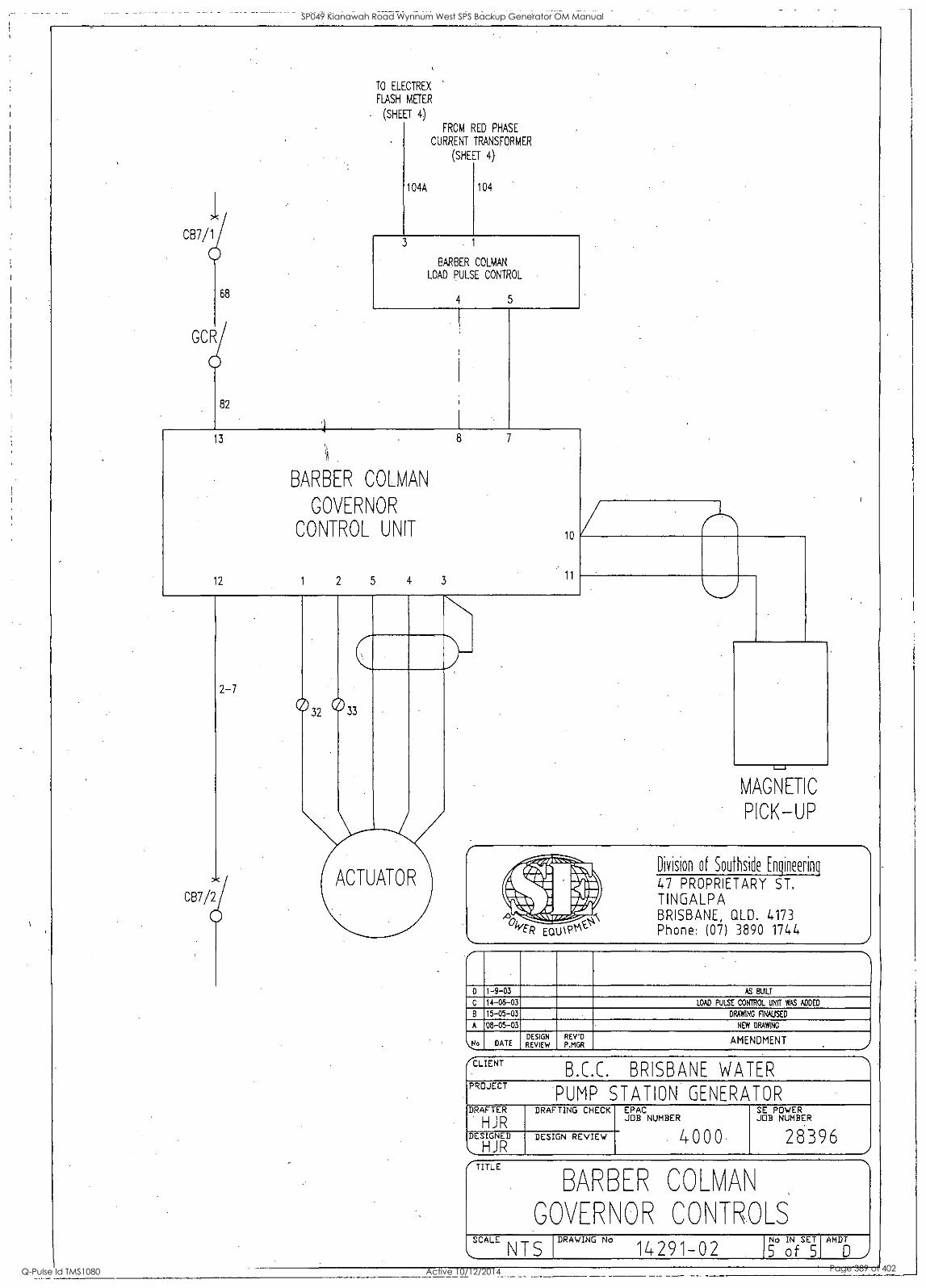
087/1
68
ccig
82
13
TO ELECTREX
FLASH METER
(SHEET 4)
104A
FROM RED PHASE
CURRENT TRANSFORMER
(SHEET 4)
104
BARBER COLMAN
LOAD PULSE CONTROL
4 5
BARBER COLvA\
GOVER\OR
CONTROL. UNIT
12 1 2 5 4 3
10
11
2-7
CB7/2
032 033
ACTUATOR
MAGNETIC
PICK-UP
Division of Southside Engineering
47 PROPRIETARY ST. TINGALPA BRISBANE, aLD. 4173 Phone: (07) 3890 1744
.)
D 1-9-03 AS BUILT
C 14-06-03 LOAD PULSE CONTROL UNIT WAS ADDED
15-05-03 DRAWING FlNAUSED
A 08-05-03 NEW DRAWING
No DATE DESIGN REVIEW
REVD P.MGR
AMENDMENT ../
1..L1L.1 I
Q.L.L. BRISUANL WA I Lk PROJECT
PUMP STATION GENERATOR DRAFTER
HJR DRAFTING CHECK EPAC
JOB NUMBER SE POWER JOB NUMBER
28396 ..
DESIGNED
HJR DESIGN REVIEW
/ 000
(TITLE
BARBER COLVA\
GCVER\OR COVROLS SCALE
N T S DRAWING No
14291-02 No IN SET
5 of 5 MN
SP049 Kianawah Road Wynnum West SPS Backup Generator OM Manual
Q-Pulse Id TMS1080 Active 10/12/2014 Page 389 of 402

i
SP049 Kianawah Road Wynnum West SPS Backup Generator OM Manual
Q-Pulse Id TMS1080 Active 10/12/2014 Page 390 of 402

RADIATOR
LEVEL
INTERPOSING
RELAY
44
2-8
TO SHEET
2 of 5
105-805
29
82
83
CIRUN/DIAGNOSE
PROGRAM SWITCH 84
GOVERNOR
FAULT
83 2-7
105-B01
105-803
REFER TO DEUTZ
MANUAL FOR DETAILS
CE37/2
ENGINE (MOTOR) ANCILLARIES
2-7
DIAGNOSTIC PLUG
25
0 27
SHEET 2 of 5
0
Division of Souths& Enginee6nq
47 PROPRIETARY ST. TINGALPA BRISBANE, QLD. 4173 Phone: (07) 3890 1744
i. ..
D 1-9-03 AS BUILT
C 15-08-03 RADIATOR LEVEL INTERPOSING RELAY WAS ADDED
B 15-05-03 DRAWING FINALISED
A 08-05-03 NEW DRAWING
4.:) DATE DESIGN REVIEW
REV'D , P.MGR AMENDMENT ./
__ b.l..L. bK131:5ANt WA I LK
PROJECT
PUMP STATION GENERATOR DRAFTER
HJR DRAFTING CHECK EPAC
JOB NUMBER SE POWER JOB NUMBER
28396 .i
DESIGNED
\., HJR DESIGN REVIEW 4000
(-TITLE
DEJZ EVR
GOVER\OR '0\TR:LS SCALE
NTS DRAWING No 14291-02 5
AMDT
D
SP049 Kianawah Road Wynnum West SPS Backup Generator OM Manual
Q-Pulse Id TMS1080 Active 10/12/2014 Page 391 of 402

SP049 Kianawah Road Wynnum West SPS Backup Generator OM Manual
Q-Pulse Id TMS1080 Active 10/12/2014 Page 392 of 402

S
9
II
I
SP049 Kianawah Road Wynnum West SPS Backup Generator OM Manual
Q-Pulse Id TMS1080 Active 10/12/2014 Page 393 of 402

SP049 Kianawah Road Wynnum West SPS Backup Generator OM Manual
Q-Pulse Id TMS1080 Active 10/12/2014 Page 394 of 402

.r
SE Power Equipment 47 Proprietary Street, Tingalpa, Qld 4173 Telephone: (07) 3890 1744
PO Box 3306 Tingalpa B.C. Qld 4173
DIESEL GENERATOR SET
CONTROLFUNC71ON. 7EST REPORT
CLIENT: BP-LSE:4W E WAre4 S Pot+9 SERIAL NO: 0301 oo ENGINE TYPE: Lk.cza-k-S .1/4
ALTERNATOR TYPE: a-NE
SB? 0091B
DATE: 2 /1743 JOB.NO: k if act I
ENG. SERIAL NO: G 35 a.
ALT. SERIAL NO: 0?00 .2 353/ f /
3ENSE.T. CONTROLFU.NCTIONS. FUNCTION Engine High Temp. Alarm .Engine. High .Temp: Shutdown. Low. Water: Level :Alarm
' LAMP REMARKS.
TriDped/Alt., Overload Low Oil Pressure Alarm LoW,Oil Pressure .:Shutdown z Emergency. Stop Start Fail Alarm :.lentet.Runriing MEN Fault Starter Motor Relay EirelLow 7uel EinptY. Engine Gauges Statustarrips/Controls inderSpeed.Shutdown
verspeed.Shutdown Remote Start/Stop. Lamp. Test. Narrn Shudown 41t,UndervoltS. Nt.OveiVolts Charger AC Failed Control Batt. Low.Volts StartBa ::Low:volts Canopy docirs:Open Audible,Alarin/MUte. lemote:ATSCOntrolS.: Alternator High Temperature NO .T 0") TH
rr-
CUSTOMER. 'TESTING OFFICER: TESTING OFFICER: , %Ic #444,711- 60t/A./ POP/
SP049 Kianawah Road Wynnum West SPS Backup Generator OM Manual
Q-Pulse Id TMS1080 Active 10/12/2014 Page 395 of 402

EQ
47 Proprietary Street Tingalpa Q 4173 BRISBANE AUSTRALIA
Mg GENERATOR SET SEP 0023/ D
SOUND PRESSURE LEVEL TEST REPORT
CLIENT: 113.w. SPo 'fig DATE:
SERIAL NO: 03o3 009 JOB NO: 1 Lt..a-q 1
ENGINE TYPE: 14-0g-f-5 11 ENG. SERIAL NO. "P 6 35A ALTERNATOR TYPE: D7LtE. ALT. SERIAL NO: 0700 a 3 531 i SOUND LEVEL INSTRUMENT:
4
7 8 9
ALT
ENG
RAD
2 1 12
Position Layout
10
Remarks:
Distance: 7 m
Height: I S m
POSITION SOUND LEVEL dB(A)
LOAD %
25 50 75 100 110
1 0 2 &8
3
4 6" 5 Of 6 6Q
7 6 4{-
8 6q
9 6
10 6 i 11 6 8
12 68 '
Average 66 -2 c QUALITY ASSURANCE OFFICER:
CUSTOMER TESTING OFFICER. W1- TESTING OFFICER: ( W (4(/(., WITNESS TESTING OFFICER:
SP049 Kianawah Road Wynnum West SPS Backup Generator OM Manual
Q-Pulse Id TMS1080 Active 10/12/2014 Page 396 of 402

0
1
SP049 Kianawah Road Wynnum West SPS Backup Generator OM Manual
Q-Pulse Id TMS1080 Active 10/12/2014 Page 397 of 402

47 Proprietary Street Tingalpa Qld 4173 PH: (07) 3890 1744
TRANSIENT LOAD RESPONSE TEST SHEET
Transient response for load changes: Load PF 0.8
SEP0084
% Change Electrical kW 0-25 0-50 0-75 0-100 100-0 75-0 50-0 25-0
Change in Electrical kW 4 a S 7 4 2 22 % Change HZ
. C 2.0 1 . .5" I 1 .5'- % Change Volts e 0
I 0 0 0 Recovery secs
1 2.3 2
Ct-Aelvt e 24S. kdoi-re4 Seoc+9
IfP- O 3o7o04 EINGIOC 404514
A-c-c a 4E
QUOviol- Ct A .c.
SP049 Kianawah Road Wynnum West SPS Backup Generator OM Manual
Q-Pulse Id TMS1080 Active 10/12/2014 Page 398 of 402

47 Proprietary Street Tingalpa Q 4173 BRISBANE AUSTRALIA
DIESEL GENERATOR SET LOAD TEST REPORT SE? oo 6rilb
CLIENT: Be,KB461 sPo9-9
SERIAL NO: ol 0 c:7
ENGINE TYPE:
ALTERNATOR TYPE:
1-t 045g a'1 4E
GOVERNOR TYPE:
OVERSPEED TYPE:
SHUTDOWN SOLENOID:
.A c. Pk
LOW. OIL PRESSURE SHUTDOWN: (4Q 'QS
A: 1 (O. (o14) KW: /1 e-
TECHNICAN:
DATE: 211-702 JOB NO/CONTRACT NO: 1 (1-.QCt
ENG. SERIAL NO: "la 6 3 ca..
ALT. SERIAL NO: 2002. 75 3 I
STARTER MOTOR: '311)
UNDERSPEED TYPE: ()Lc
HIGH WATER: 40611,5
INSPECTOR: P4V1-- KOWA
TIME lc tio tc-gc 1605' 1635 170S /73( 175 0 / 7-5-3-
OIL PRESSURE Soo ifs-0 300 loo 2q0 290 2,yo 2 ,y0
OIL TEMPERATURE
JACKET WATER TEMPERATURE 0 65" 8, SC 0,c gc 85-
/0/its 0 ec? I2((.5 /2(f-3 /2y- / 12 4 "&4 --3
VOLTS (4(6G
240 0 24 go
,r .,- ,v
..,- ..,- ..,-
../ ,-
,V
AMBIENT TEMPERATURE
22 22 t 20 20 20 20 20
HZ .co / -CO - i ,Cb- / 5-° 5-0 5-7,2 02
0 6/ 81. , 89. 1 09-C. 8,-4 `(-6 t9
LOAD%
/10 ' //0 ((o /, 1/0 ', /
,, _ ARKS
Gerierator_Load_Test_Report.doc
SP049 Kianawah Road Wynnum West SPS Backup Generator OM Manual
Q-Pulse Id TMS1080 Active 10/12/2014 Page 399 of 402

47 Proprietary Street Tinge Ipa 0 4173 BRISBANE AUSTRALIA
SEP 0013
'FINAL INSPECTION CHECKLIST
This form is to be completely filled out before any generating set leaves the factory.
It is to be signed by the person doing the inspection and by their immediate supervisor. In the case of a non-standard job it must also be signed by the Special Projects Manager 'or the Engineering Manager.
A copy of this form is to'be sent out with the plant concerned.
Please neatly tick in the IDOxes provided where applicable and note any comments in the space provided.
MODEL: SPo49
JOB NO: O'Ci DATE:
SERIAL NO: 0 307 00c1 ENGINE NO: 352
CUSTOMER: R.LU
BASE
(1)
(2)
(3) (4)
All welds continuous, neat and clean. All bolts tightened. Bearers completely secured. No sharp corners.
RADIATOR
Radiator correctly mounted. All pipework included and secure. Drain plugin place. Water removed fruit radiator. Clamps on hoses tight.
(1) Fan is correctly mounted. (2) All guards in place and secure. t3) Wiring loom is correct to draWing, securely fixed and'Marked and is
terminated in an appropriate terminal. box. (4) Battery leads attached and secure and long enough for termination to - battery. (5) Air cleaner is properly mounted. (6) Magnetic pickup is fitted and set to correct depth. (7) Exhaust pipe and silencer (where required) are fitted correctly. (8) Dip stick in place. (9') Oil removed fiLut engine. (10) All fuel and oil unions completely tightened. (11) Allorderedoptionsare fitted and function correctly. (12) All parts secure, no damage. (13) All earths less than 0.1 ohms. (14) Cablet and hoses secure for transport.
CONTROL SYSTEM (where applicable)
(1) Control functions as ordered. (2) Control is mounted correctly. (3) All leads, terminals, fuses, printed circuit boards and switchgear are
completely secure and marked correctly. (4) Dust seals are fitted around doors. (5) DoOrs hinged correctly. (6) All earths less than 0.1 Ohms. (7) Red Danger labels in cubicle.
SP049 Kianawah Road Wynnum West SPS Backup Generator OM Manual
Q-Pulse Id TMS1080 Active 10/12/2014 Page 400 of 402

FINAL INSPECTION CHECKLIST PAGE 2
CONTROL SYSTEM (cont)
(8)
(9)
(10)
Perspex shield secure, clean and no sharp corners: Cables correct, no damage.
Locks and keys satisfactory.
ALTERNATOR
(1). Alternator is correctly mounted. (2) .Alternator leads are correctly mounted inside terminal box and marked
correctly.
(3) A.V.R. is mounted, connected properly and set to correct setting.
(4) Coupling and adaptor are properly fastened between engine and alternator with correct size and tensile grade bolts.
(5) All options ordered are fitted and function properly. (6) Alternator is correctly wired for the appropriate voltage as per either
Order or Bills of Material.
(7) Earth stud fitted.
FINISH
(1) Plant is painted to correct colour. (2) All blemishes in finish, especially paint runs, are completely removed.
GENERAL INSPECTION
(1) Genset is manufactured to'correct engine/alternator/radiator/bases configuration as specified on Bill of Materials.
(2) All documents are in a sealed plastic bag and secured inside alternator terminal box.
(3) (4)
a) Engine Handbook b) Alternator Handbook c) Warranty Card d) Packing List e) Test Sheet
NoOil/No Water label is attached to positive battery lead. All labels are straight and in correct location.
SIGNED: 'co4D eet/Atit_i_h_A 004 INSPECTOR
QUALITY ASSURANCE
CCMMENTS:
SP049 Kianawah Road Wynnum West SPS Backup Generator OM Manual
Q-Pulse Id TMS1080 Active 10/12/2014 Page 401 of 402

SP049 Kianawah Road Wynnum West SPS Backup Generator OM Manual
Q-Pulse Id TMS1080 Active 10/12/2014 Page 402 of 402


