Embed Size (px)
Citation preview

BA00055D/06/EN/14.11
71136625
Valid as of version
PROFIBUS DP: V 3.06.XX
(device software)
PROFIBUS PA: V 3.06.XX
(device software)
Operating Instructions
Proline Promag 50
PROFIBUS DP/PA
Electromagnetic flow measuring system
8
Lobley St SPS SP331 General (Endress and Hauser Model 50W4F Magnetic Flowmeter) General
Q-Pulse Id VM349 Active 24/09/2013 Page 1 of 242

Lobley St SPS SP331 General (Endress and Hauser Model 50W4F Magnetic Flowmeter) General
Q-Pulse Id VM349 Active 24/09/2013 Page 2 of 242

Promag 50 PROFIBUS DP/PA Table of contents
Endress+Hauser 3
Table of contents
1 Safety instructions . . . . . . . . . . . . . . . . 5
1.1 Designated use . . . . . . . . . . . . . . . . . . . . . . . . . . . . 5
1.2 Installation, commissioning and operation . . . . . . . . 5
1.3 Operational safety . . . . . . . . . . . . . . . . . . . . . . . . . . 5
1.4 Return . . . . . . . . . . . . . . . . . . . . . . . . . . . . . . . . . . . 6
1.5 Notes on safety conventions and icons . . . . . . . . . . . 6
2 Identification . . . . . . . . . . . . . . . . . . . . 7
2.1 Device designation . . . . . . . . . . . . . . . . . . . . . . . . . 7
2.1.1 Nameplate of the transmitter . . . . . . . . . . . . 7
2.1.2 Nameplate of the sensor . . . . . . . . . . . . . . . 8
2.1.3 Nameplate, connections . . . . . . . . . . . . . . . 9
2.2 Certificates and approvals . . . . . . . . . . . . . . . . . . . 10
2.3 Registered trademarks . . . . . . . . . . . . . . . . . . . . . . 10
3 Installation . . . . . . . . . . . . . . . . . . . . . 11
3.1 Incoming acceptance, transport and storage . . . . . . 11
3.1.1 Incoming acceptance . . . . . . . . . . . . . . . . . 11
3.1.2 Transport . . . . . . . . . . . . . . . . . . . . . . . . . 11
3.1.3 Storage . . . . . . . . . . . . . . . . . . . . . . . . . . . 12
3.2 Installation conditions . . . . . . . . . . . . . . . . . . . . . . 13
3.2.1 Dimensions . . . . . . . . . . . . . . . . . . . . . . . . 13
3.2.2 Mounting location . . . . . . . . . . . . . . . . . . . 13
3.2.3 Orientation . . . . . . . . . . . . . . . . . . . . . . . . 15
3.2.4 Vibrations . . . . . . . . . . . . . . . . . . . . . . . . . 16
3.2.5 Foundations, supports . . . . . . . . . . . . . . . . 17
3.2.6 Adapters . . . . . . . . . . . . . . . . . . . . . . . . . . 17
3.2.7 Nominal diameter and flow rate . . . . . . . . 18
3.2.8 Length of connecting cable . . . . . . . . . . . . 20
3.3 Installation instructions . . . . . . . . . . . . . . . . . . . . . 21
3.3.1 Installing the Promag D sensor . . . . . . . . . . 21
3.3.2 Installing the Promag L sensor . . . . . . . . . . 24
3.3.3 Installing the Promag W sensor . . . . . . . . . 27
3.3.4 Installing the Promag P sensor . . . . . . . . . . 32
3.3.5 Installing the Promag H sensor . . . . . . . . . . 36
3.3.6 Turning the transmitter housing . . . . . . . . 39
3.3.7 Turning the onsite display . . . . . . . . . . . . . 40
3.3.8 Installing the wall-mount housing . . . . . . . 41
3.4 Post-installation check . . . . . . . . . . . . . . . . . . . . . . 43
4 Wiring . . . . . . . . . . . . . . . . . . . . . . . . 44
4.1 PROFIBUS cable specifications . . . . . . . . . . . . . . . . 44
4.1.1 PROFIBUS DP cable specifications . . . . . . . 44
4.1.2 PROFIBUS PA cable specifications . . . . . . . 45
4.1.3 Shielding and grounding . . . . . . . . . . . . . . 47
4.2 Connecting the remote version . . . . . . . . . . . . . . . 47
4.2.1 Connecting Promag D, L, W, P, H . . . . . . 47
4.2.2 Cable specifications . . . . . . . . . . . . . . . . . . 52
4.3 Connecting the measuring unit . . . . . . . . . . . . . . . 53
4.3.1 Connecting the transmitter . . . . . . . . . . . . 53
4.3.2 Terminal assignment . . . . . . . . . . . . . . . . . 57
4.4 Potential equalization . . . . . . . . . . . . . . . . . . . . . . 58
4.4.1 Potential equalization for Promag D . . . . . . 58
4.4.2 Potential equalization for Promag W, P, L . 58
4.4.3 Potential equalization for Promag H . . . . . . 58
4.4.4 Exampels for potential equalization
connections for Promag D . . . . . . . . . . . . . 58
4.4.5 Exampels for potential equalization connections
for Promag L, W, P . . . . . . . . . . . . . . . . . . 59
4.5 Degree of protection . . . . . . . . . . . . . . . . . . . . . . . 61
4.6 Post-connection check . . . . . . . . . . . . . . . . . . . . . . 62
5 Operation . . . . . . . . . . . . . . . . . . . . . . 63
5.1 Quick operation guide . . . . . . . . . . . . . . . . . . . . . . 63
5.2 Local display . . . . . . . . . . . . . . . . . . . . . . . . . . . . . 64
5.2.1 Display and operating elements . . . . . . . . . 64
5.2.2 Icons . . . . . . . . . . . . . . . . . . . . . . . . . . . . . 65
5.3 Brief operating instructions on the function matrix . 66
5.3.1 General notes . . . . . . . . . . . . . . . . . . . . . . 67
5.3.2 Enabling the programming mode . . . . . . . . 67
5.3.3 Disabling the programming mode . . . . . . . . 67
5.4 Displaying error messages . . . . . . . . . . . . . . . . . . . 68
5.4.1 Type of error . . . . . . . . . . . . . . . . . . . . . . . 68
5.4.2 Error message types . . . . . . . . . . . . . . . . . . 68
5.5 Operating options . . . . . . . . . . . . . . . . . . . . . . . . . 69
5.5.1 FieldCare . . . . . . . . . . . . . . . . . . . . . . . . . . 69
5.5.2 Operating program "SIMATIC PDM" (Siemens) . 69
5.5.3 Device description files for operating programs . 70
5.6 PROFIBUS DP hardware settings . . . . . . . . . . . . . . 72
5.6.1 Configuring the write protection . . . . . . . . 72
5.6.2 Configuring the device address . . . . . . . . . . 73
5.6.3 Configuring the terminating resistors . . . . . 74
5.7 PROFIBUS PA hardware settings . . . . . . . . . . . . . . 75
5.7.1 Configuring the write protection . . . . . . . . 75
5.7.2 Configuring the device address . . . . . . . . . . 76
6 Commissioning . . . . . . . . . . . . . . . . . . 77
6.1 Function check . . . . . . . . . . . . . . . . . . . . . . . . . . . 77
6.2 Switching on the measuring device . . . . . . . . . . . . 77
6.3 Quick Setup . . . . . . . . . . . . . . . . . . . . . . . . . . . . . . 78
6.3.1 "Commissioning" Quick Setup menu . . . . . 78
6.3.2 "Communication" Quick Setup menu . . . . . 79
6.4 Commissioning the PROFIBUS interface . . . . . . . . . 80
6.4.1 PROFIBUS DP/PA commissioning . . . . . . . 80
6.5 PROFIBUS DP/PA system integration . . . . . . . . . . 82
6.5.1 Device master file (GSD file) . . . . . . . . . . . 82
6.5.2 Selecting the GSD file in the measuring device 83
6.5.3 Example for selecting the GSD file . . . . . . . 83
6.5.4 Compatibility with previous
Promag 33 model (Profile Version 2.0) . . . 84
6.5.5 Maximum number of writes . . . . . . . . . . . 84
6.6 PROFIBUS DP/PA cyclic data transfer . . . . . . . . . . 85
6.6.1 Block model . . . . . . . . . . . . . . . . . . . . . . . 85
6.6.2 Modules for cyclic data transfer . . . . . . . . . 86
6.6.3 Description of the modules . . . . . . . . . . . 87
6.6.4 Configuration examples with Simatic S7 HW-
Konfig . . . . . . . . . . . . . . . . . . . . . . . . . . . . 91
6.7 Acyclic data transfer . . . . . . . . . . . . . . . . . . . . . . . . 93
6.7.1 Master Class 2 acyclic (MS2AC) . . . . . . . . . 93
Lobley St SPS SP331 General (Endress and Hauser Model 50W4F Magnetic Flowmeter) General
Q-Pulse Id VM349 Active 24/09/2013 Page 3 of 242

Promag 50 PROFIBUS DP/PA Table of contents
4 Endress+Hauser
6.7.2 Master Class 1 acyclic (MS1AC) . . . . . . . . 93
6.8 Adjustment . . . . . . . . . . . . . . . . . . . . . . . . . . . . . . 94
6.8.1 Empty-pipe/full-pipe adjustment . . . . . . . . 94
6.9 Data storage device (HistoROM) . . . . . . . . . . . . . . 95
6.9.1 HistoROM/S-DAT (sensor-DAT) . . . . . . . . 95
7 Maintenance . . . . . . . . . . . . . . . . . . . . 96
7.1 Exterior cleaning . . . . . . . . . . . . . . . . . . . . . . . . . . 96
7.2 Seals . . . . . . . . . . . . . . . . . . . . . . . . . . . . . . . . . . . 96
8 Accessories . . . . . . . . . . . . . . . . . . . . . 97
8.1 Device-specific accessories . . . . . . . . . . . . . . . . . . . 97
8.2 Measuring principle-specific accessories . . . . . . . . . 97
8.3 Service-specific accessories . . . . . . . . . . . . . . . . . . 98
9 Troubleshooting . . . . . . . . . . . . . . . . . 99
9.1 Troubleshooting instructions . . . . . . . . . . . . . . . . . 99
9.2 System error messages . . . . . . . . . . . . . . . . . . . . . 100
9.2.1 Displaying the device status on
PROFIBUS DP/PA . . . . . . . . . . . . . . . . . 101
9.2.2 List of system error messages . . . . . . . . . . 102
9.3 Process error messages . . . . . . . . . . . . . . . . . . . . . 105
9.3.1 Displaying the device status on
PROFIBUS DP/PA . . . . . . . . . . . . . . . . . . 105
9.3.2 List of process error messages . . . . . . . . . . 105
9.4 Process errors without messages . . . . . . . . . . . . . 106
9.5 Spare parts . . . . . . . . . . . . . . . . . . . . . . . . . . . . . 107
9.5.1 PROFIBUS DP . . . . . . . . . . . . . . . . . . . . . 107
9.5.2 PROFIBUS PA . . . . . . . . . . . . . . . . . . . . . 108
9.5.3 Removing and installing printed circuit boards . 109
9.5.4 Replacing the device fuse . . . . . . . . . . . . . 113
9.5.5 Replacing the exchangeable electrode . . . 114
9.6 Return . . . . . . . . . . . . . . . . . . . . . . . . . . . . . . . . . 116
9.7 Disposal . . . . . . . . . . . . . . . . . . . . . . . . . . . . . . . 116
9.8 Software history . . . . . . . . . . . . . . . . . . . . . . . . . 116
10 Technical data . . . . . . . . . . . . . . . . . . 118
10.1 Technical data at a glance . . . . . . . . . . . . . . . . . . 118
10.1.1 Application . . . . . . . . . . . . . . . . . . . . . . . 118
10.1.2 Function and system design . . . . . . . . . . . 118
10.1.3 Input . . . . . . . . . . . . . . . . . . . . . . . . . . . . 118
10.1.4 Output . . . . . . . . . . . . . . . . . . . . . . . . . . 118
10.1.5 Power supply . . . . . . . . . . . . . . . . . . . . . . 119
10.1.6 Performance characteristics . . . . . . . . . . . 119
10.1.7 Operating conditions: Installation . . . . . . . 120
10.1.8 Operating conditions: Environment . . . . . 120
10.1.9 Operating conditions: Process . . . . . . . . . 121
10.1.10 Mechanical construction . . . . . . . . . . . . . 126
10.1.11 Human interface . . . . . . . . . . . . . . . . . . . 136
10.1.12 Certificates and approvals . . . . . . . . . . . . 137
10.1.13 Ordering information . . . . . . . . . . . . . . . 139
10.1.14 Accessories . . . . . . . . . . . . . . . . . . . . . . . 139
10.1.15 Documentation . . . . . . . . . . . . . . . . . . . 139
Index . . . . . . . . . . . . . . . . . . . . . . . . . . . . . 140
Lobley St SPS SP331 General (Endress and Hauser Model 50W4F Magnetic Flowmeter) General
Q-Pulse Id VM349 Active 24/09/2013 Page 4 of 242

Promag 50 PROFIBUS DP/PA Safety instructions
Endress+Hauser 5
1 Safety instructions
1.1 Designated use
The measuring device described in this Operating Manual is to be used only for measuring the flow
rate of conductive fluids in closed pipes.
A minimum conductivity of 20 μS/cm is required for measuring demineralized water. Most liquids
can be measured as of a minimum conductivity of 5 μS/cm.
Examples:
• Acids, alkalis,
• Drinking water, wastewater, sewage sludge,
• Milk, beer, wine, mineral water, etc.
Resulting from incorrect use or from use other than that designated the operational safety of the
measuring devices can be suspended. The manufacturer accepts no liability for damages being
produced from this.
1.2 Installation, commissioning and operation
Please note the following:
• Installation, connection to the electricity supply, commissioning and maintenance of the device
must be carried out by trained, qualified specialists authorized to perform such work by the
facility's owner-operator. The specialist must have read and understood this Operating Manual
and must follow the instructions it contains.
• The device must be operated by persons authorized and trained by the facility's owner-operator.
Strict compliance with the instructions in the Operating Manual is mandatory.
• With regard to special fluids, including fluids used for cleaning, Endress+Hauser will be happy to
assist in clarifying the corrosion-resistant properties of wetted materials.
However, minor changes in temperature, concentration or in the degree of contamination in the
process may result in variations in corrosion resistance. For this reason, Endress+Hauser does not
accept any responsibility with regard to the corrosion resistance of wetted materials in a specific
application.
The user is responsible for the choice of suitable wetted materials in the process.
• If welding work is performed on the piping system, do not ground the welding appliance through
the Promag flowmeter.
• The installer must ensure that the measuring system is correctly wired in accordance with the
wiring diagrams. The transmitter must be grounded apart from when special protective measures
are taken (e.g. galvanically isolated SELV or PELV power supply)
• Invariably, local regulations governing the opening and repair of electrical devices apply.
1.3 Operational safety
Please note the following:
• Measuring systems for use in hazardous environments are accompanied by separate Ex
documentation, which is an integral part of this Operating Manual. Strict compliance with the
installation instructions and ratings as stated in this supplementary
documentation is mandatory. The symbol on the front of this Ex documentation indicates the
approval and the certification body (e.g. 0 Europe, 2 USA, 1 Canada).
• The measuring device complies with the general safety requirements in accordance with
EN 61010-1, the EMC requirements of IEC/EN 61326 and NAMUR Recommendations NE 21
and NE 43.
• Depending on the application, the seals of the process connections of the Promag H sensor require
periodic replacement.
Lobley St SPS SP331 General (Endress and Hauser Model 50W4F Magnetic Flowmeter) General
Q-Pulse Id VM349 Active 24/09/2013 Page 5 of 242
Safety instructions Promag 50 PROFIBUS DP/PA
6 Endress+Hauser
• When hot fluid passes through the measuring tube, the surface temperature of the housing
increases. In the case of the sensor, in particular, users should expect temperatures that can be
close to the fluid temperature. If the temperature of the fluid is high, implement sufficient
measures to prevent burning or scalding.
• The manufacturer reserves the right to modify technical data without prior notice. Your
Endress+Hauser distributor will supply you with current information and updates to these
Operating Instructions.
1.4 Return
• Do not return a measuring device if you are not absolutely certain that all traces of hazardous
substances have been removed, e.g. substances which have penetrated crevices or diffused
through plastic.
• Costs incurred for waste disposal and injury (burns, etc.) due to inadequate cleaning will be
charged to the owner-operator.
1.5 Notes on safety conventions and icons
The devices are designed to meet state-of-the-art safety requirements, have been tested, and left the
factory in a condition in which they are safe to operate. The devices comply with the applicable
standards and regulations in accordance with EN 61010-1 "Safety requirements for electrical
equipment for measurement, control and laboratory use".
The devices can, however, be a source of danger if used incorrectly or for anything other than the
designated use. Consequently, always pay particular attention to the safety instructions indicated in
this Operating Manual by the following icons:
# Warning!
"Warning" indicates an action or procedure which, if not performed correctly, can result in injury
or a safety hazard. Comply strictly with the instructions and proceed with care.
" Caution!
"Caution" indicates an action or procedure which, if not performed correctly, can result in incorrect
operation or destruction of the device. Comply strictly with the instructions.
! Note!
"Note" indicates an action or procedure which, if not performed correctly, can have an indirect
effect on operation or trigger an unexpected response on the part of the device.
Lobley St SPS SP331 General (Endress and Hauser Model 50W4F Magnetic Flowmeter) General
Q-Pulse Id VM349 Active 24/09/2013 Page 6 of 242
Promag 50 PROFIBUS DP/PA Identification
Endress+Hauser 7
2 Identification
2.1 Device designation
The flow measuring system consists of the following components:
• Promag 50 transmitter
• Promag D, Promag L, Promag W, Promag P or Promag H sensor
In the compact version, the transmitter and sensor form a single mechanical unit; in the remote
version they are installed separately.
2.1.1 Nameplate of the transmitter
A0005403
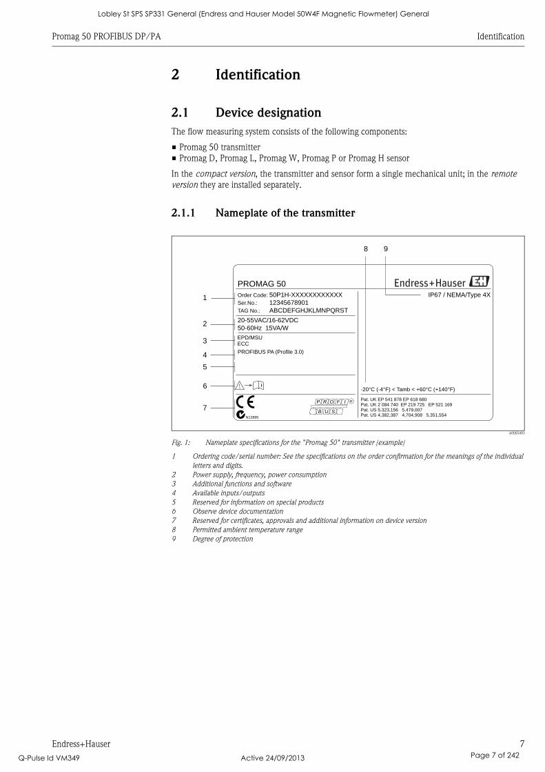
Fig. 1: Nameplate specifications for the "Promag 50" transmitter (example)
1 Ordering code/serial number: See the specifications on the order confirmation for the meanings of the individual
letters and digits.
2 Power supply, frequency, power consumption
3 Additional functions and software
4 Available inputs/outputs
5 Reserved for information on special products
6 Observe device documentation
7 Reserved for certificates, approvals and additional information on device version
8 Permitted ambient temperature range
9 Degree of protection
1
98
2
4
5
3
Order Code:
Ser.No.:
TAG No.:
50P1H-XXXXXXXXXXXX12345678901ABCDEFGHJKLMNPQRST
20-55VAC/16-62VDC50-60Hz 15VA/W
IP67 / NEMA/Type 4X
-20°C (-4°F) < Tamb < +60°C (+140°F)
B
P
U S
R O IF R
N12895
PROMAG 50
ii
PROFIBUS PA (Profile 3.0)
EPD/MSUECC
Pat. US 5,323,156 5,479,007Pat. US 4,382,387 4,704,908 5,351,554
Pat. UK 2 084 740 EP 219 725 EP 521 169Pat. UK EP 541 878 EP 618 680
6
7
Lobley St SPS SP331 General (Endress and Hauser Model 50W4F Magnetic Flowmeter) General
Q-Pulse Id VM349 Active 24/09/2013 Page 7 of 242
Identification Promag 50 PROFIBUS DP/PA
8 Endress+Hauser
2.1.2 Nameplate of the sensor
A0004374
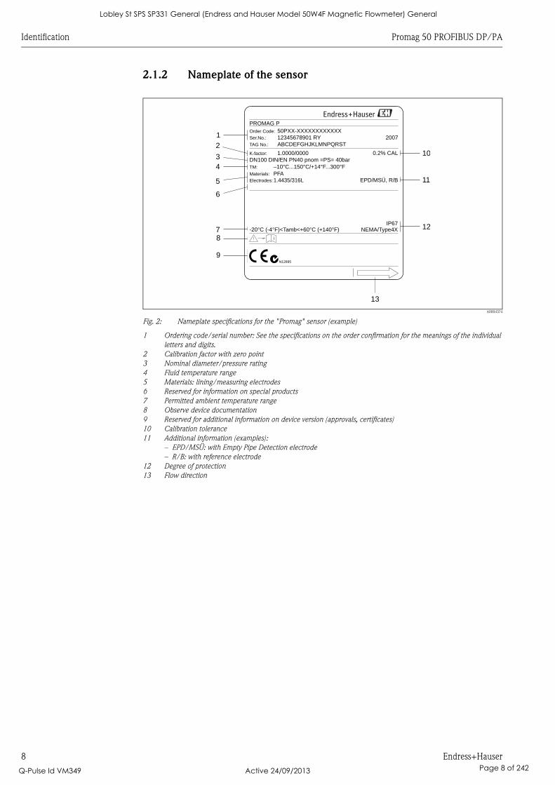
Fig. 2: Nameplate specifications for the "Promag" sensor (example)
1 Ordering code/serial number: See the specifications on the order confirmation for the meanings of the individual
letters and digits.
2 Calibration factor with zero point
3 Nominal diameter/pressure rating
4 Fluid temperature range
5 Materials: lining/measuring electrodes
6 Reserved for information on special products
7 Permitted ambient temperature range
8 Observe device documentation
9 Reserved for additional information on device version (approvals, certificates)
10 Calibration tolerance
11 Additional information (examples):
– EPD/MSÜ: with Empty Pipe Detection electrode
– R/B: with reference electrode
12 Degree of protection
13 Flow direction
-20°C (-4°F)<Tamb<+60°C (+140°F) NEMA/Type4X
50PXX-XXXXXXXXXXXX
1.0000/0000
–10 ...150°C/+14 ...300°F°C °FPFA
12345678901 RYABCDEFGHJKLMNPQRST
DN100 DIN EN PN40/ pnom =PS= 40bar
EPD/MSÜ, R/B
TM:
Order Code:
Materials:
K-factor:
Ser.No.:
TAG No.:
PROMAG P
1
2
3
7
13
12
1.4435/316LElectrodes:
0.2% CAL
4
5
6
10
11
i
9
8
IP67
2007
N12895
Lobley St SPS SP331 General (Endress and Hauser Model 50W4F Magnetic Flowmeter) General
Q-Pulse Id VM349 Active 24/09/2013 Page 8 of 242
Promag 50 PROFIBUS DP/PA Identification
Endress+Hauser 9
2.1.3 Nameplate, connections
A0006112
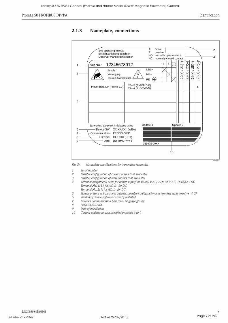
Fig. 3: Nameplate specifications for transmitter (example)
1 Serial number
2 Possible configuration of current output (not available)
3 Possible configuration of relay contact (not available)
4 Terminal assignment, cable for power supply: 85 to 260 V AC, 20 to 55 V AC, 16 to 62 V DC
Terminal No. 1: L1 for AC, L+ for DC
Terminal No. 2: N for AC, L– for DC
5 Signals present at inputs and outputs, possible configuration and terminal assignment ä 57
6 Version of device software currently installed
7 Installed communication type (incl. language group)
8 PROFIBUS ID No.
9 Date of installation
10 Current updates to data specified in points 6 to 9
26
(+)
/2
7(–
)
NC:
Versorgung /
Tension d'alimentation
Observer manuel d'instruction
See operating manualBetriebsanleitung beachten
Communication:
Drivers:
Device SW:
ID XXXX (HEX)
XX.XX.XX
PROFIBUS DP
26= B (RxD/TxD-P)27= A (RxD/TxD-N)
PROFIBUS DP Profile 3.0( )
12345678912Ser.No.:
Supply /
24
(+)
/2
5(–
)
22
(+)
/2
3(–
)
20
(+)
/2
1(–
)
N/L–
PE
A:
NO:P:
L1/L+
1 2
319475-00XX
X
activepassivenormally open contactnormally closed contact
Date: DD MMM YYYY
Update 1Ex-works / ab-Werk / réglages usine Update 2
(WEA)
1
4
5
2
3
10
6789
Lobley St SPS SP331 General (Endress and Hauser Model 50W4F Magnetic Flowmeter) General
Q-Pulse Id VM349 Active 24/09/2013 Page 9 of 242

Identification Promag 50 PROFIBUS DP/PA
10 Endress+Hauser
2.2 Certificates and approvals
The devices are designed to meet state-of-the-art safety requirements in accordance with sound
engineering practice. They have been tested and left the factory in a condition in which they are
safe to operate.
The devices comply with the applicable standards and regulations in accordance with EN 61010-1
"Safety requirements for electrical equipment for measurement, control and laboratory use", the
EMC requirements of IEC/EN 61326 and Namur Recommendations NE 21, NE 43 and NE 53.
The measuring system described in this Operating Manual is therefore in conformity with the
statutory requirements of the EC Directives. Endress+Hauser confirms successful testing of the
device by affixing to it the CE mark.
The measuring system meets the EMC requirements of the Australian Communications and Media
Authority (ACMA)
The flow measuring system has successfully passed all the test procedures carried out and is certified
and registered by the PNO (PROFIBUS User Organization).
The device thus meets all the requirements of the following specifications:
• Certified to PROFIBUS Specification, Profile Version 3.0
Device certification number: available on request
• The device can also be operated with certified devices of other manufacturers (interoperability)
2.3 Registered trademarks
KALREZ® and VITON®
Registered trademarks of E.I. Du Pont de Nemours & Co., Wilmington, USA
TRI-CLAMP®
Registered trademark of Ladish & Co., Inc., Kenosha, USA
PROFIBUS®
Registered trademark of the PROFIBUS User Organization, Karlsruhe, Germany
HistoROM™, S-DAT®, FieldCare®, Fieldcheck®, Applicator®
Registered or registration-pending trademarks of Endress+Hauser Flowtec AG, Reinach, CH
Lobley St SPS SP331 General (Endress and Hauser Model 50W4F Magnetic Flowmeter) General
Q-Pulse Id VM349 Active 24/09/2013 Page 10 of 242
Promag 50 PROFIBUS DP/PA Installation
Endress+Hauser 11
3 Installation
3.1 Incoming acceptance, transport and storage
3.1.1 Incoming acceptance
On receipt of the goods, check the following:
• Check the packaging and the contents for damage.
• Check the shipment, make sure nothing is missing and that the scope of supply matches your
order.
3.1.2 Transport
The following instructions apply to unpacking and to transporting the device to its final location:
• Transport the devices in the containers in which they are delivered.
• Do not remove the protective plates or caps on the process connections until you are ready to
install the device. This is particularly important in the case of sensors with PTFE linings.
Special notes on flanged devices
" Caution!
• The wooden covers mounted on the flanges from the factory protect the linings on the flanges
during storage and transportation. In case of Promag L they are additionally used to hold the lap
joint flanges in place. Do not remove these covers until immediately before the device in the
pipe.
• Do not lift flanged devices by the transmitter housing, or the connection housing in the case of
the remote version.
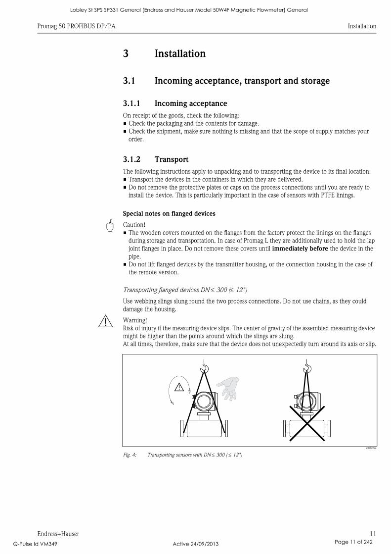
Transporting flanged devices DN 300 (12")
Use webbing slings slung round the two process connections. Do not use chains, as they could
damage the housing.
# Warning!
Risk of injury if the measuring device slips. The center of gravity of the assembled measuring device
might be higher than the points around which the slings are slung.
At all times, therefore, make sure that the device does not unexpectedly turn around its axis or slip.
a0004294
Fig. 4: Transporting sensors with DN 300 ( 12")
Lobley St SPS SP331 General (Endress and Hauser Model 50W4F Magnetic Flowmeter) General
Q-Pulse Id VM349 Active 24/09/2013 Page 11 of 242
Installation Promag 50 PROFIBUS DP/PA
12 Endress+Hauser
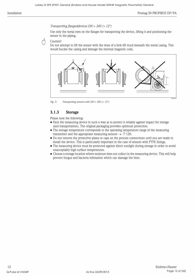
Transporting flangeddevices DN > 300 (> 12")
Use only the metal eyes on the flanges for transporting the device, lifting it and positioning the
sensor in the piping.
" Caution!
Do not attempt to lift the sensor with the tines of a fork-lift truck beneath the metal casing. This
would buckle the casing and damage the internal magnetic coils.
a0004295
Fig. 5: Transporting sensors with DN > 300 (> 12")
3.1.3 Storage
Please note the following:
• Pack the measuring device in such a way as to protect it reliably against impact for storage
(and transportation). The original packaging provides optimum protection.
• The storage temperature corresponds to the operating temperature range of the measuring
transmitter and the appropriate measuring sensors ä 120.
• Do not remove the protective plates or caps on the process connections until you are ready to
install the device. This is particularly important in the case of sensors with PTFE linings.
• The measuring device must be protected against direct sunlight during storage in order to avoid
unacceptably high surface temperatures.
• Choose a storage location where moisture does not collect in the measuring device. This will help
prevent fungus and bacteria infestation which can damage the liner.
Lobley St SPS SP331 General (Endress and Hauser Model 50W4F Magnetic Flowmeter) General
Q-Pulse Id VM349 Active 24/09/2013 Page 12 of 242
Promag 50 PROFIBUS DP/PA Installation
Endress+Hauser 13
3.2 Installation conditions
3.2.1 Dimensions
The dimensions and installation lengths of the sensor and transmitter can be found in the "Technical
Information" for the device in question. This document can be downloaded as a PDF file from
www.endress.com. A list of the "Technical Information" documents available is provided in the
"Documentation" section on ä 139.
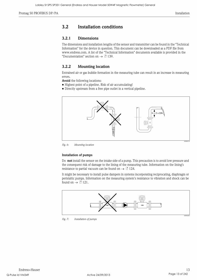
3.2.2 Mounting location
Entrained air or gas bubble formation in the measuring tube can result in an increase in measuring
errors.
Avoid the following locations:
• Highest point of a pipeline. Risk of air accumulating!
• Directly upstream from a free pipe outlet in a vertical pipeline.
A0008154
Fig. 6: Mounting location
Installation of pumps
Do not install the sensor on the intake side of a pump. This precaution is to avoid low pressure and
the consequent risk of damage to the lining of the measuring tube. Information on the lining's
resistance to partial vacuum can be found on ä 124.
It might be necessary to install pulse dampers in systems incorporating reciprocating, diaphragm or
peristaltic pumps. Information on the measuring system's resistance to vibration and shock can be
found on ä 121.
A0003203
Fig. 7: Installation of pumps
h 2 x DN�
Lobley St SPS SP331 General (Endress and Hauser Model 50W4F Magnetic Flowmeter) General
Q-Pulse Id VM349 Active 24/09/2013 Page 13 of 242
Installation Promag 50 PROFIBUS DP/PA
14 Endress+Hauser
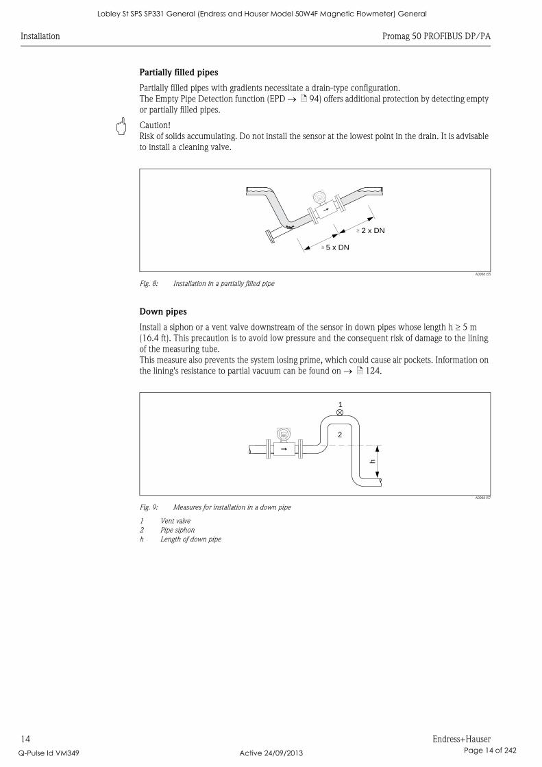
Partially filled pipes
Partially filled pipes with gradients necessitate a drain-type configuration.
The Empty Pipe Detection function (EPD ä 94) offers additional protection by detecting empty
or partially filled pipes.
" Caution!
Risk of solids accumulating. Do not install the sensor at the lowest point in the drain. It is advisable
to install a cleaning valve.
A0008155
Fig. 8: Installation in a partially filled pipe
Down pipes
Install a siphon or a vent valve downstream of the sensor in down pipes whose length h 5 m
(16.4 ft). This precaution is to avoid low pressure and the consequent risk of damage to the lining
of the measuring tube.
This measure also prevents the system losing prime, which could cause air pockets. Information on
the lining's resistance to partial vacuum can be found on ä 124.
A0008157
Fig. 9: Measures for installation in a down pipe
1 Vent valve
2 Pipe siphon
h Length of down pipe
5 x DN
2 x DN
�
�
h
2
1
Lobley St SPS SP331 General (Endress and Hauser Model 50W4F Magnetic Flowmeter) General
Q-Pulse Id VM349 Active 24/09/2013 Page 14 of 242
Promag 50 PROFIBUS DP/PA Installation
Endress+Hauser 15
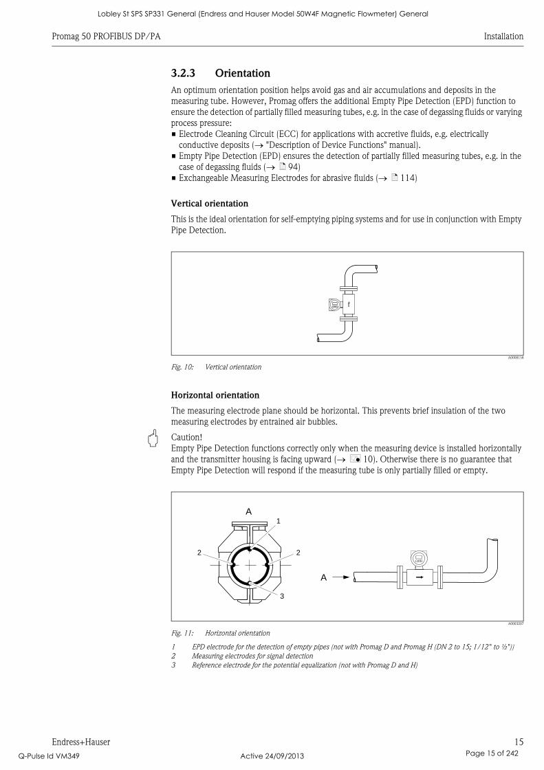
3.2.3 Orientation
An optimum orientation position helps avoid gas and air accumulations and deposits in the
measuring tube. However, Promag offers the additional Empty Pipe Detection (EPD) function to
ensure the detection of partially filled measuring tubes, e.g. in the case of degassing fluids or varying
process pressure:
• Electrode Cleaning Circuit (ECC) for applications with accretive fluids, e.g. electrically
conductive deposits ( "Description of Device Functions" manual).
• Empty Pipe Detection (EPD) ensures the detection of partially filled measuring tubes, e.g. in the
case of degassing fluids ( ä 94)
• Exchangeable Measuring Electrodes for abrasive fluids ( ä 114)
Vertical orientation
This is the ideal orientation for self-emptying piping systems and for use in conjunction with Empty
Pipe Detection.
A0008158
Fig. 10: Vertical orientation
Horizontal orientation
The measuring electrode plane should be horizontal. This prevents brief insulation of the two
measuring electrodes by entrained air bubbles.
" Caution!
Empty Pipe Detection functions correctly only when the measuring device is installed horizontally
and the transmitter housing is facing upward ( å 10). Otherwise there is no guarantee that
Empty Pipe Detection will respond if the measuring tube is only partially filled or empty.
A0003207
Fig. 11: Horizontal orientation
1 EPD electrode for the detection of empty pipes (not with Promag D and Promag H (DN 2 to 15; 1/12" to ½"))
2 Measuring electrodes for signal detection
3 Reference electrode for the potential equalization (not with Promag D and H)
A1
2 2
A
3
Lobley St SPS SP331 General (Endress and Hauser Model 50W4F Magnetic Flowmeter) General
Q-Pulse Id VM349 Active 24/09/2013 Page 15 of 242
Installation Promag 50 PROFIBUS DP/PA
16 Endress+Hauser
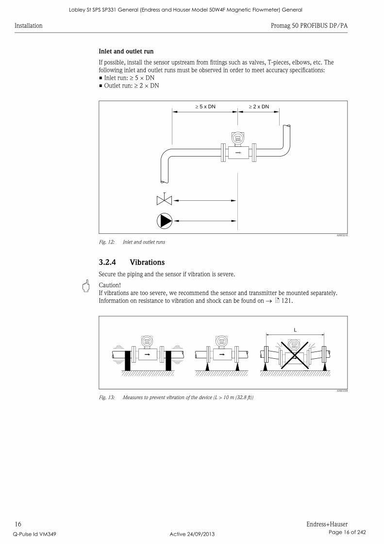
Inlet and outlet run
If possible, install the sensor upstream from fittings such as valves, T-pieces, elbows, etc. The
following inlet and outlet runs must be observed in order to meet accuracy specifications:
• Inlet run: 5 × DN
• Outlet run: 2 × DN
A0003210
Fig. 12: Inlet and outlet runs
3.2.4 Vibrations
Secure the piping and the sensor if vibration is severe.
" Caution!
If vibrations are too severe, we recommend the sensor and transmitter be mounted separately.
Information on resistance to vibration and shock can be found on ä 121.
A0003208
Fig. 13: Measures to prevent vibration of the device (L > 10 m (32.8 ft))
5 x DN� � 2 x DN
L
Lobley St SPS SP331 General (Endress and Hauser Model 50W4F Magnetic Flowmeter) General
Q-Pulse Id VM349 Active 24/09/2013 Page 16 of 242
Promag 50 PROFIBUS DP/PA Installation
Endress+Hauser 17
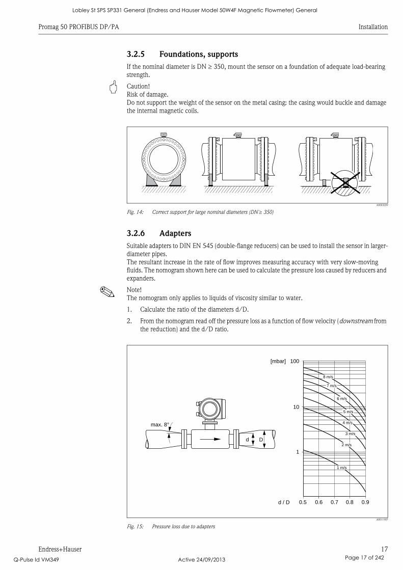
3.2.5 Foundations, supports
If the nominal diameter is DN 350, mount the sensor on a foundation of adequate load-bearing
strength.
" Caution!
Risk of damage.
Do not support the weight of the sensor on the metal casing: the casing would buckle and damage
the internal magnetic coils.
A0003209
Fig. 14: Correct support for large nominal diameters (DN 350)
3.2.6 Adapters
Suitable adapters to DIN EN 545 (double-flange reducers) can be used to install the sensor in larger-
diameter pipes.
The resultant increase in the rate of flow improves measuring accuracy with very slow-moving
fluids. The nomogram shown here can be used to calculate the pressure loss caused by reducers and
expanders.
! Note!
The nomogram only applies to liquids of viscosity similar to water.
1. Calculate the ratio of the diameters d/D.
2. From the nomogram read off the pressure loss as a function of flow velocity (downstream from
the reduction) and the d/D ratio.
A0011907
Fig. 15: Pressure loss due to adapters
100
10
0.5d / D
[mbar]
0.6 0.7 0.8 0.9
1 m/s
2 m/s
3 m/s
4 m/s
5 m/s
6 m/s
7 m/s
8 m/s
1
Dd
max. 8°
Lobley St SPS SP331 General (Endress and Hauser Model 50W4F Magnetic Flowmeter) General
Q-Pulse Id VM349 Active 24/09/2013 Page 17 of 242
Installation Promag 50 PROFIBUS DP/PA
18 Endress+Hauser
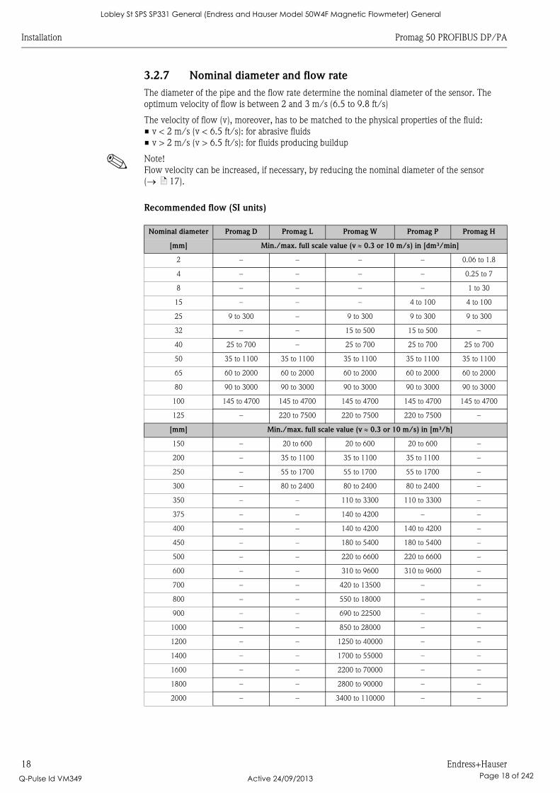
3.2.7 Nominal diameter and flow rate
The diameter of the pipe and the flow rate determine the nominal diameter of the sensor. The
optimum velocity of flow is between 2 and 3 m/s (6.5 to 9.8 ft/s)
The velocity of flow (v), moreover, has to be matched to the physical properties of the fluid:
• v < 2 m/s (v < 6.5 ft/s): for abrasive fluids
• v > 2 m/s (v > 6.5 ft/s): for fluids producing buildup
! Note!
Flow velocity can be increased, if necessary, by reducing the nominal diameter of the sensor
( ä 17).
Recommended flow (SI units)
Nominal diameter Promag D Promag L Promag W Promag P Promag H
[mm] Min./max. full scale value (v 0.3 or 10 m/s) in [dm³/min]
2 – – – – 0.06 to 1.8
4 – – – – 0.25 to 7
8 – – – – 1 to 30
15 – – – 4 to 100 4 to 100
25 9 to 300 – 9 to 300 9 to 300 9 to 300
32 – – 15 to 500 15 to 500 –
40 25 to 700 – 25 to 700 25 to 700 25 to 700
50 35 to 1100 35 to 1100 35 to 1100 35 to 1100 35 to 1100
65 60 to 2000 60 to 2000 60 to 2000 60 to 2000 60 to 2000
80 90 to 3000 90 to 3000 90 to 3000 90 to 3000 90 to 3000
100 145 to 4700 145 to 4700 145 to 4700 145 to 4700 145 to 4700
125 – 220 to 7500 220 to 7500 220 to 7500 –
[mm] Min./max. full scale value (v 0.3 or 10 m/s) in [m³/h]
150 – 20 to 600 20 to 600 20 to 600 –
200 – 35 to 1100 35 to 1100 35 to 1100 –
250 – 55 to 1700 55 to 1700 55 to 1700 –
300 – 80 to 2400 80 to 2400 80 to 2400 –
350 – – 110 to 3300 110 to 3300 –
375 – – 140 to 4200 – –
400 – – 140 to 4200 140 to 4200 –
450 – – 180 to 5400 180 to 5400 –
500 – – 220 to 6600 220 to 6600 –
600 – – 310 to 9600 310 to 9600 –
700 – – 420 to 13500 – –
800 – – 550 to 18000 – –
900 – – 690 to 22500 – –
1000 – – 850 to 28000 – –
1200 – – 1250 to 40000 – –
1400 – – 1700 to 55000 – –
1600 – – 2200 to 70000 – –
1800 – – 2800 to 90000 – –
2000 – – 3400 to 110000 – –
Lobley St SPS SP331 General (Endress and Hauser Model 50W4F Magnetic Flowmeter) General
Q-Pulse Id VM349 Active 24/09/2013 Page 18 of 242
Promag 50 PROFIBUS DP/PA Installation
Endress+Hauser 19
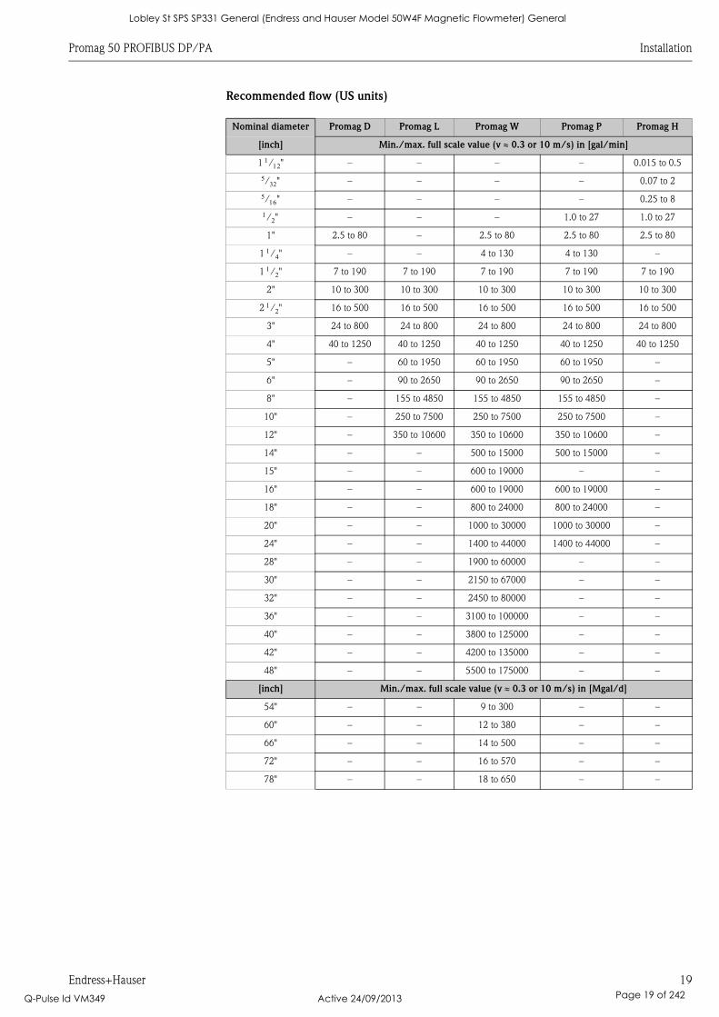
Recommended flow (US units)
Nominal diameter Promag D Promag L Promag W Promag P Promag H
[inch] Min./max. full scale value (v 0.3 or 10 m/s) in [gal/min]
1 /" – – – – 0.015 to 0.5
/" – – – – 0.07 to 2
/" – – – – 0.25 to 8
/" – – – 1.0 to 27 1.0 to 27
1" 2.5 to 80 – 2.5 to 80 2.5 to 80 2.5 to 80
1 /" – – 4 to 130 4 to 130 –
1 /" 7 to 190 7 to 190 7 to 190 7 to 190 7 to 190
2" 10 to 300 10 to 300 10 to 300 10 to 300 10 to 300
2 /" 16 to 500 16 to 500 16 to 500 16 to 500 16 to 500
3" 24 to 800 24 to 800 24 to 800 24 to 800 24 to 800
4" 40 to 1250 40 to 1250 40 to 1250 40 to 1250 40 to 1250
5" – 60 to 1950 60 to 1950 60 to 1950 –
6" – 90 to 2650 90 to 2650 90 to 2650 –
8" – 155 to 4850 155 to 4850 155 to 4850 –
10" – 250 to 7500 250 to 7500 250 to 7500 –
12" – 350 to 10600 350 to 10600 350 to 10600 –
14" – – 500 to 15000 500 to 15000 –
15" – – 600 to 19000 – –
16" – – 600 to 19000 600 to 19000 –
18" – – 800 to 24000 800 to 24000 –
20" – – 1000 to 30000 1000 to 30000 –
24" – – 1400 to 44000 1400 to 44000 –
28" – – 1900 to 60000 – –
30" – – 2150 to 67000 – –
32" – – 2450 to 80000 – –
36" – – 3100 to 100000 – –
40" – – 3800 to 125000 – –
42" – – 4200 to 135000 – –
48" – – 5500 to 175000 – –
[inch] Min./max. full scale value (v 0.3 or 10 m/s) in [Mgal/d]
54" – – 9 to 300 – –
60" – – 12 to 380 – –
66" – – 14 to 500 – –
72" – – 16 to 570 – –
78" – – 18 to 650 – –
Lobley St SPS SP331 General (Endress and Hauser Model 50W4F Magnetic Flowmeter) General
Q-Pulse Id VM349 Active 24/09/2013 Page 19 of 242
Installation Promag 50 PROFIBUS DP/PA
20 Endress+Hauser
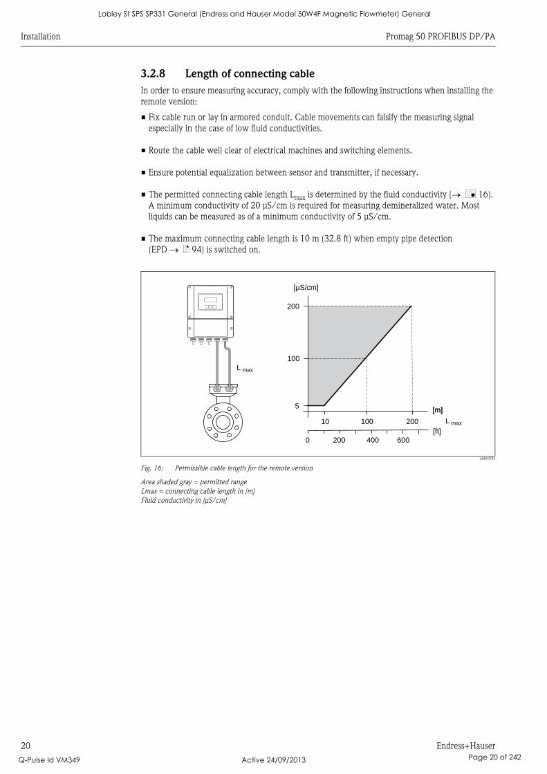
3.2.8 Length of connecting cable
In order to ensure measuring accuracy, comply with the following instructions when installing the
remote version:
• Fix cable run or lay in armored conduit. Cable movements can falsify the measuring signal
especially in the case of low fluid conductivities.
• Route the cable well clear of electrical machines and switching elements.
• Ensure potential equalization between sensor and transmitter, if necessary.
• The permitted connecting cable length Lmax is determined by the fluid conductivity ( å 16).
A minimum conductivity of 20 μS/cm is required for measuring demineralized water. Most
liquids can be measured as of a minimum conductivity of 5 μS/cm.
• The maximum connecting cable length is 10 m (32.8 ft) when empty pipe detection
(EPD ä 94) is switched on.
A0010734
Fig. 16: Permissible cable length for the remote version
Area shaded gray = permitted range
Lmax = connecting cable length in [m]
Fluid conductivity in [μS/cm]
200
100
5
10 100 200
L max
[m][m]
[µS/cm]
L max
[ft]200 6000 400
Lobley St SPS SP331 General (Endress and Hauser Model 50W4F Magnetic Flowmeter) General
Q-Pulse Id VM349 Active 24/09/2013 Page 20 of 242
Promag 50 PROFIBUS DP/PA Installation
Endress+Hauser 21
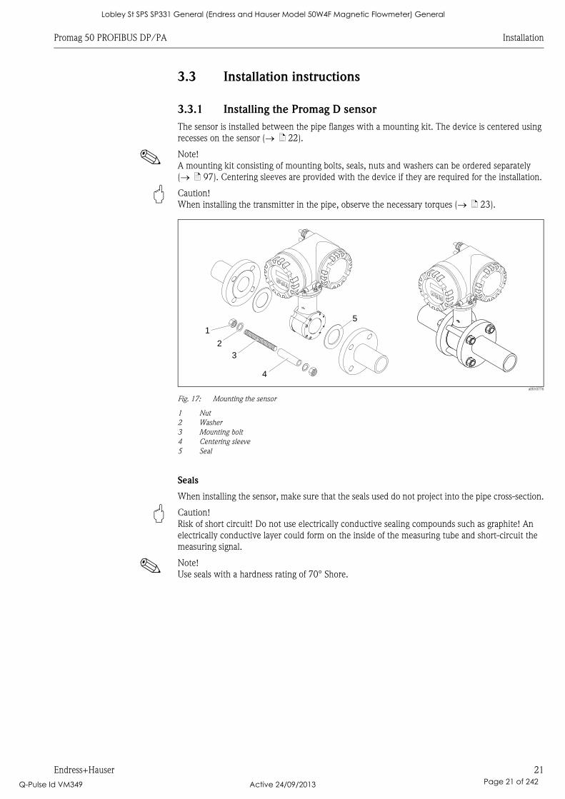
3.3 Installation instructions
3.3.1 Installing the Promag D sensor
The sensor is installed between the pipe flanges with a mounting kit. The device is centered using
recesses on the sensor ( ä 22).
! Note!
A mounting kit consisting of mounting bolts, seals, nuts and washers can be ordered separately
( ä 97). Centering sleeves are provided with the device if they are required for the installation.
" Caution!
When installing the transmitter in the pipe, observe the necessary torques ( ä 23).
a0010776
Fig. 17: Mounting the sensor
1 Nut
2 Washer
3 Mounting bolt
4 Centering sleeve
5 Seal
Seals
When installing the sensor, make sure that the seals used do not project into the pipe cross-section.
" Caution!
Risk of short circuit! Do not use electrically conductive sealing compounds such as graphite! An
electrically conductive layer could form on the inside of the measuring tube and short-circuit the
measuring signal.
! Note!
Use seals with a hardness rating of 70° Shore.
5
1
2
3
4
Lobley St SPS SP331 General (Endress and Hauser Model 50W4F Magnetic Flowmeter) General
Q-Pulse Id VM349 Active 24/09/2013 Page 21 of 242
Installation Promag 50 PROFIBUS DP/PA
22 Endress+Hauser
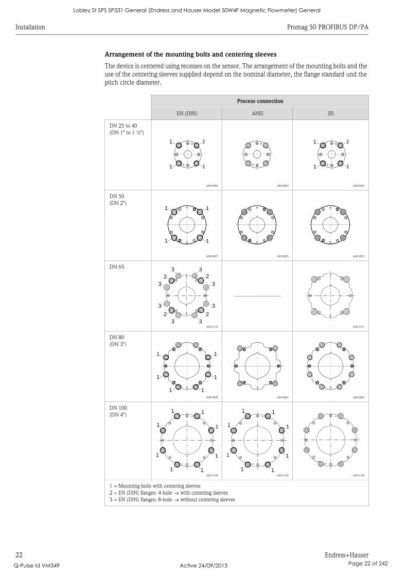
Arrangement of the mounting bolts and centering sleeves
The device is centered using recesses on the sensor. The arrangement of the mounting bolts and the
use of the centering sleeves supplied depend on the nominal diameter, the flange standard und the
pitch circle diameter.
Process connection
EN (DIN) ANSI JIS
DN 25 to 40
(DN 1" to 1 ½")
A0010896 A0010824 A0010896
DN 50
(DN 2")
A0010897 A0010825 A0010825
DN 65
A0012170
–––––––––––––––––
A0012171
DN 80
(DN 3")
A0010898 A0010827 A0010826
DN 100
(DN 4")
A0012168 A0012168 A0012169
1 = Mounting bolts with centering sleeves
2 = EN (DIN) flanges: 4-hole with centering sleeves
3 = EN (DIN) flanges: 8-hole without centering sleeves
1
1
1
1
1
1
1
1
1
1
1
1
22
2 2
33
33
3
3
3
3
1
1
1
1
1
1
1
1
1 1
1
1
1 1
1
1
1 1
1
1
1 1
Lobley St SPS SP331 General (Endress and Hauser Model 50W4F Magnetic Flowmeter) General
Q-Pulse Id VM349 Active 24/09/2013 Page 22 of 242
Promag 50 PROFIBUS DP/PA Installation
Endress+Hauser 23
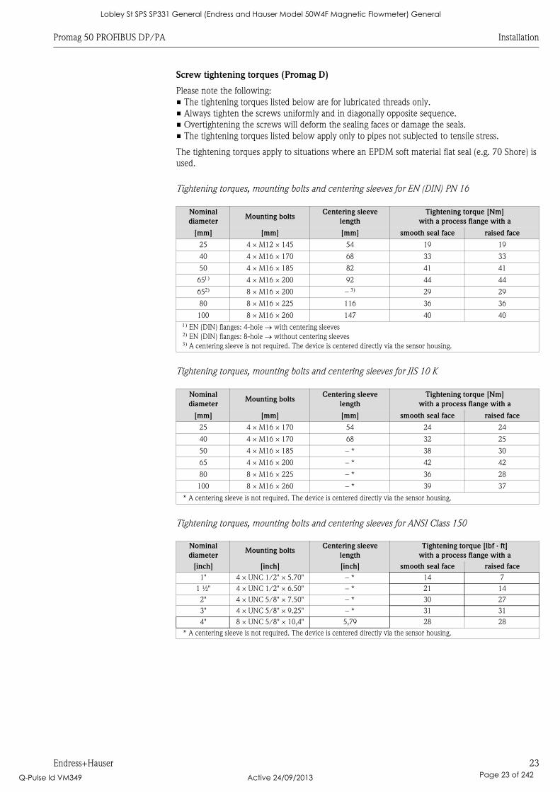
Screw tightening torques (Promag D)
Please note the following:
• The tightening torques listed below are for lubricated threads only.
• Always tighten the screws uniformly and in diagonally opposite sequence.
• Overtightening the screws will deform the sealing faces or damage the seals.
• The tightening torques listed below apply only to pipes not subjected to tensile stress.
The tightening torques apply to situations where an EPDM soft material flat seal (e.g. 70 Shore) is
used.
Tightening torques, mounting bolts and centering sleeves for EN (DIN) PN 16
Tightening torques, mounting bolts and centering sleeves for JIS 10 K
Tightening torques, mounting bolts and centering sleeves for ANSI Class 150
Nominal
diameterMounting bolts
Centering sleeve
length
Tightening torque [Nm]
with a process flange with a
[mm] [mm] [mm] smooth seal face raised face
25 4 × M12 × 145 54 19 19
40 4 × M16 × 170 68 33 33
50 4 × M16 × 185 82 41 41
65 4 × M16 × 200 92 44 44
65 8 × M16 × 200 – 29 29
80 8 × M16 × 225 116 36 36
100 8 × M16 × 260 147 40 40
EN (DIN) flanges: 4-hole with centering sleeves EN (DIN) flanges: 8-hole without centering sleeves A centering sleeve is not required. The device is centered directly via the sensor housing.
Nominal
diameterMounting bolts
Centering sleeve
length
Tightening torque [Nm]
with a process flange with a
[mm] [mm] [mm] smooth seal face raised face
25 4 × M16 × 170 54 24 24
40 4 × M16 × 170 68 32 25
50 4 × M16 × 185 – * 38 30
65 4 × M16 × 200 – * 42 42
80 8 × M16 × 225 – * 36 28
100 8 × M16 × 260 – * 39 37
* A centering sleeve is not required. The device is centered directly via the sensor housing.
Nominal
diameterMounting bolts
Centering sleeve
length
Tightening torque [lbf · ft]
with a process flange with a
[inch] [inch] [inch] smooth seal face raised face
1" 4 × UNC 1/2" × 5.70" – * 14 7
1 ½" 4 × UNC 1/2" × 6.50" – * 21 14
2" 4 × UNC 5/8" × 7.50" – * 30 27
3" 4 × UNC 5/8" × 9.25" – * 31 31
4" 8 × UNC 5/8" × 10,4" 5,79 28 28
* A centering sleeve is not required. The device is centered directly via the sensor housing.
Lobley St SPS SP331 General (Endress and Hauser Model 50W4F Magnetic Flowmeter) General
Q-Pulse Id VM349 Active 24/09/2013 Page 23 of 242
Installation Promag 50 PROFIBUS DP/PA
24 Endress+Hauser
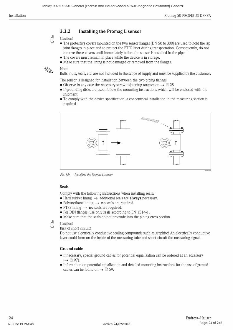
3.3.2 Installing the Promag L sensor
" Caution!
• The protective covers mounted on the two sensor flanges (DN 50 to 300) are used to hold the lap
joint flanges in place and to protect the PTFE liner during transportation. Consequently, do not
remove these covers until immediately before the sensor is installed in the pipe.
• The covers must remain in place while the device is in storage.
• Make sure that the lining is not damaged or removed from the flanges.
! Note!
Bolts, nuts, seals, etc. are not included in the scope of supply and must be supplied by the customer.
The sensor is designed for installation between the two piping flanges.
• Observe in any case the necessary screw tightening torques on ä 25
• If grounding disks are used, follow the mounting instructions which will be enclosed with the
shipment
• To comply with the device specification, a concentrical installation in the measuring section is
required
a0004296
Fig. 18: Installing the Promag L sensor
Seals
Comply with the following instructions when installing seals:
• Hard rubber lining additional seals are always necessary.
• Polyurethane lining no seals are required.
• PTFE lining no seals are required.
• For DIN flanges, use only seals according to EN 1514-1.
• Make sure that the seals do not protrude into the piping cross-section.
" Caution!
Risk of short circuit!
Do not use electrically conductive sealing compounds such as graphite! An electrically conductive
layer could form on the inside of the measuring tube and short-circuit the measuring signal.
Ground cable
• If necessary, special ground cables for potential equalization can be ordered as an accessory
( ä 97).
• Information on potential equalization and detailed mounting instructions for the use of ground
cables can be found on ä 59.
Lobley St SPS SP331 General (Endress and Hauser Model 50W4F Magnetic Flowmeter) General
Q-Pulse Id VM349 Active 24/09/2013 Page 24 of 242
Promag 50 PROFIBUS DP/PA Installation
Endress+Hauser 25
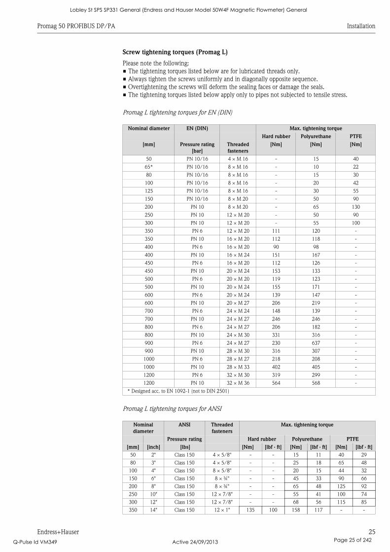
Screw tightening torques (Promag L)
Please note the following:
• The tightening torques listed below are for lubricated threads only.
• Always tighten the screws uniformly and in diagonally opposite sequence.
• Overtightening the screws will deform the sealing faces or damage the seals.
• The tightening torques listed below apply only to pipes not subjected to tensile stress.
Promag L tightening torques for EN (DIN)
Promag L tightening torques for ANSI
Nominal diameter EN (DIN) Max. tightening torque
Hard rubber Polyurethane PTFE
[mm] Pressure rating
[bar]
Threaded
fasteners
[Nm] [Nm] [Nm]
50 PN 10/16 4 × M 16 - 15 40
65* PN 10/16 8 × M 16 - 10 22
80 PN 10/16 8 × M 16 - 15 30
100 PN 10/16 8 × M 16 - 20 42
125 PN 10/16 8 × M 16 - 30 55
150 PN 10/16 8 × M 20 - 50 90
200 PN 10 8 × M 20 - 65 130
250 PN 10 12 × M 20 - 50 90
300 PN 10 12 × M 20 - 55 100
350 PN 6 12 × M 20 111 120 -
350 PN 10 16 × M 20 112 118 -
400 PN 6 16 × M 20 90 98 -
400 PN 10 16 × M 24 151 167 -
450 PN 6 16 × M 20 112 126 -
450 PN 10 20 × M 24 153 133 -
500 PN 6 20 × M 20 119 123 -
500 PN 10 20 × M 24 155 171 -
600 PN 6 20 × M 24 139 147 -
600 PN 10 20 × M 27 206 219 -
700 PN 6 24 × M 24 148 139 -
700 PN 10 24 × M 27 246 246 -
800 PN 6 24 × M 27 206 182 -
800 PN 10 24 × M 30 331 316 -
900 PN 6 24 × M 27 230 637 -
900 PN 10 28 × M 30 316 307 -
1000 PN 6 28 × M 27 218 208 -
1000 PN 10 28 × M 33 402 405 -
1200 PN 6 32 × M 30 319 299 -
1200 PN 10 32 × M 36 564 568 -
* Designed acc. to EN 1092-1 (not to DIN 2501)
Nominal
diameter
ANSI Threaded
fasteners
Max. tightening torque
Pressure rating Hard rubber Polyurethane PTFE
[mm] [inch] [lbs] [Nm] [lbf · ft] [Nm] [lbf · ft] [Nm] [lbf · ft]
50 2" Class 150 4 × 5/8" - - 15 11 40 29
80 3" Class 150 4 × 5/8" - - 25 18 65 48
100 4" Class 150 8 × 5/8" - - 20 15 44 32
150 6" Class 150 8 × ¾" - - 45 33 90 66
200 8" Class 150 8 × ¾" - - 65 48 125 92
250 10" Class 150 12 × 7/8" - - 55 41 100 74
300 12" Class 150 12 × 7/8" - - 68 56 115 85
350 14" Class 150 12 × 1" 135 100 158 117 - -
Lobley St SPS SP331 General (Endress and Hauser Model 50W4F Magnetic Flowmeter) General
Q-Pulse Id VM349 Active 24/09/2013 Page 25 of 242
Installation Promag 50 PROFIBUS DP/PA
26 Endress+Hauser
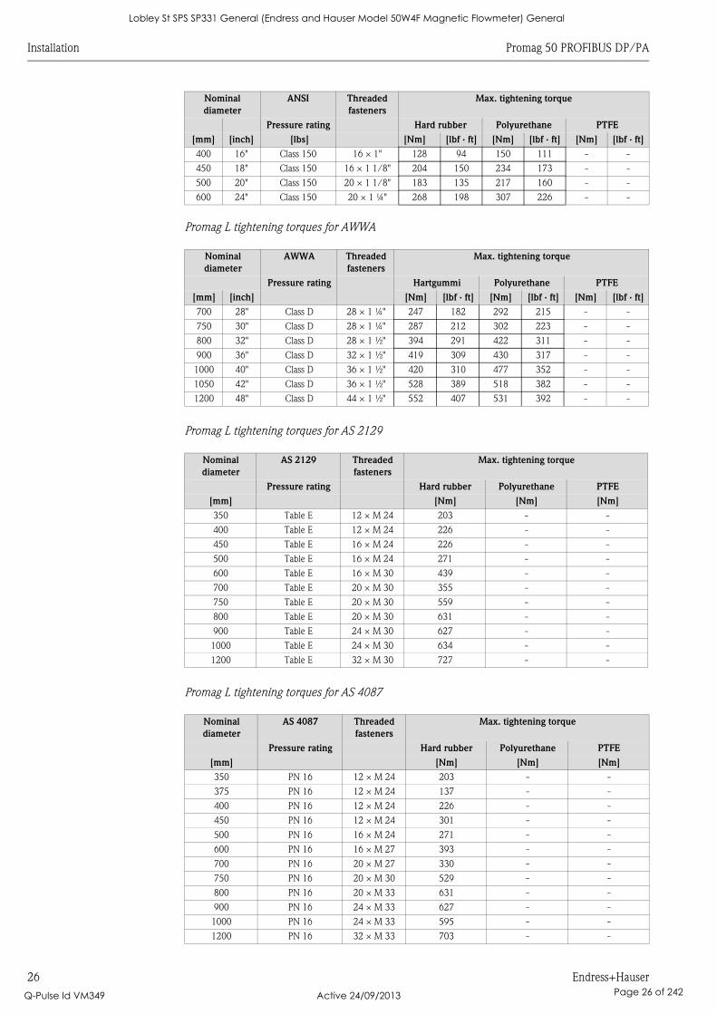
Promag L tightening torques for AWWA
Promag L tightening torques for AS 2129
Promag L tightening torques for AS 4087
400 16" Class 150 16 × 1" 128 94 150 111 - -
450 18" Class 150 16 × 1 1/8" 204 150 234 173 - -
500 20" Class 150 20 × 1 1/8" 183 135 217 160 - -
600 24" Class 150 20 × 1 ¼" 268 198 307 226 - -
Nominal
diameter
AWWA Threaded
fasteners
Max. tightening torque
Pressure rating Hartgummi Polyurethane PTFE
[mm] [inch] [Nm] [lbf · ft] [Nm] [lbf · ft] [Nm] [lbf · ft]
700 28" Class D 28 × 1 ¼" 247 182 292 215 - -
750 30" Class D 28 × 1 ¼" 287 212 302 223 - -
800 32" Class D 28 × 1 ½" 394 291 422 311 - -
900 36" Class D 32 × 1 ½" 419 309 430 317 - -
1000 40" Class D 36 × 1 ½" 420 310 477 352 - -
1050 42" Class D 36 × 1 ½" 528 389 518 382 - -
1200 48" Class D 44 × 1 ½" 552 407 531 392 - -
Nominal
diameter
AS 2129 Threaded
fasteners
Max. tightening torque
Pressure rating Hard rubber Polyurethane PTFE
[mm] [Nm] [Nm] [Nm]
350 Table E 12 × M 24 203 - -
400 Table E 12 × M 24 226 - -
450 Table E 16 × M 24 226 - -
500 Table E 16 × M 24 271 - -
600 Table E 16 × M 30 439 - -
700 Table E 20 × M 30 355 - -
750 Table E 20 × M 30 559 - -
800 Table E 20 × M 30 631 - -
900 Table E 24 × M 30 627 - -
1000 Table E 24 × M 30 634 - -
1200 Table E 32 × M 30 727 - -
Nominal
diameter
AS 4087 Threaded
fasteners
Max. tightening torque
Pressure rating Hard rubber Polyurethane PTFE
[mm] [Nm] [Nm] [Nm]
350 PN 16 12 × M 24 203 - -
375 PN 16 12 × M 24 137 - -
400 PN 16 12 × M 24 226 - -
450 PN 16 12 × M 24 301 - -
500 PN 16 16 × M 24 271 - -
600 PN 16 16 × M 27 393 - -
700 PN 16 20 × M 27 330 - -
750 PN 16 20 × M 30 529 - -
800 PN 16 20 × M 33 631 - -
900 PN 16 24 × M 33 627 - -
1000 PN 16 24 × M 33 595 - -
1200 PN 16 32 × M 33 703 - -
Nominal
diameter
ANSI Threaded
fasteners
Max. tightening torque
Pressure rating Hard rubber Polyurethane PTFE
[mm] [inch] [lbs] [Nm] [lbf · ft] [Nm] [lbf · ft] [Nm] [lbf · ft]
Lobley St SPS SP331 General (Endress and Hauser Model 50W4F Magnetic Flowmeter) General
Q-Pulse Id VM349 Active 24/09/2013 Page 26 of 242
Promag 50 PROFIBUS DP/PA Installation
Endress+Hauser 27
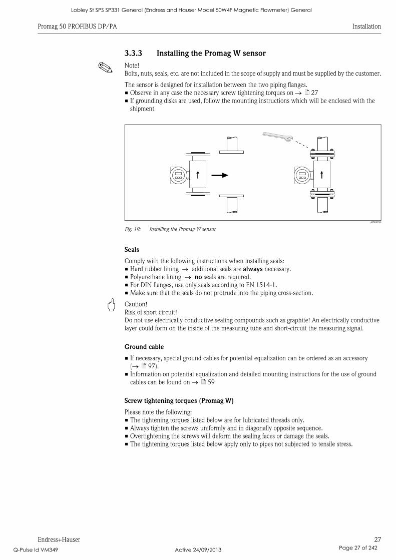
3.3.3 Installing the Promag W sensor
! Note!
Bolts, nuts, seals, etc. are not included in the scope of supply and must be supplied by the customer.
The sensor is designed for installation between the two piping flanges.
• Observe in any case the necessary screw tightening torques on ä 27
• If grounding disks are used, follow the mounting instructions which will be enclosed with the
shipment
a0004296
Fig. 19: Installing the Promag W sensor
Seals
Comply with the following instructions when installing seals:
• Hard rubber lining additional seals are always necessary.
• Polyurethane lining no seals are required.
• For DIN flanges, use only seals according to EN 1514-1.
• Make sure that the seals do not protrude into the piping cross-section.
" Caution!
Risk of short circuit!
Do not use electrically conductive sealing compounds such as graphite! An electrically conductive
layer could form on the inside of the measuring tube and short-circuit the measuring signal.
Ground cable
• If necessary, special ground cables for potential equalization can be ordered as an accessory
( ä 97).
• Information on potential equalization and detailed mounting instructions for the use of ground
cables can be found on ä 59
Screw tightening torques (Promag W)
Please note the following:
• The tightening torques listed below are for lubricated threads only.
• Always tighten the screws uniformly and in diagonally opposite sequence.
• Overtightening the screws will deform the sealing faces or damage the seals.
• The tightening torques listed below apply only to pipes not subjected to tensile stress.
Lobley St SPS SP331 General (Endress and Hauser Model 50W4F Magnetic Flowmeter) General
Q-Pulse Id VM349 Active 24/09/2013 Page 27 of 242
Installation Promag 50 PROFIBUS DP/PA
28 Endress+Hauser
Tightening torques for:
• EN (DIN) ä 28
• JIS ä 30
• ANSI ä 29
• AWWA ä 30
• AS 2129 ä 31
• AS 4087 ä 31
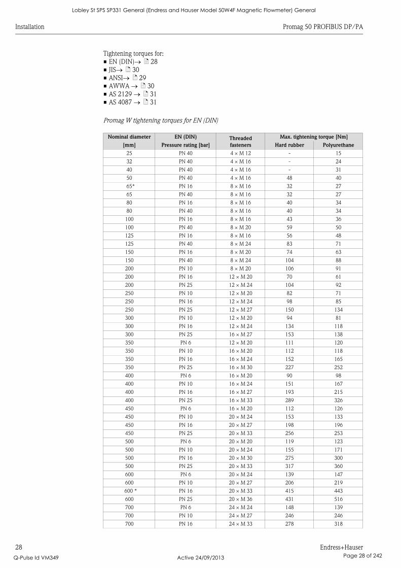
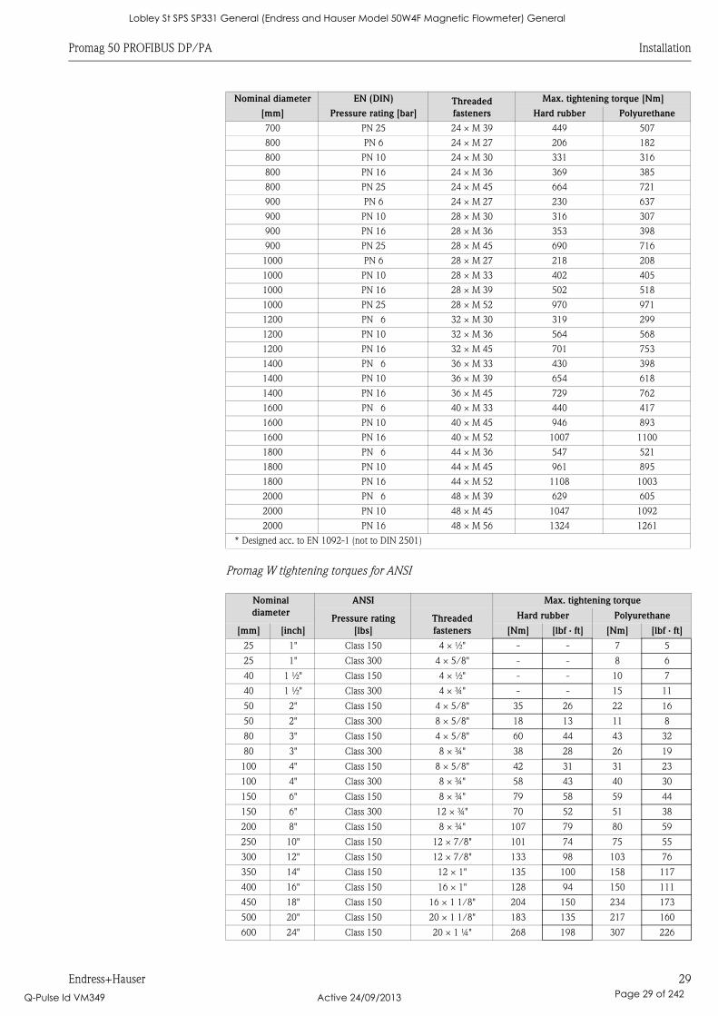
Promag W tightening torques for EN (DIN)
Nominal diameter EN (DIN) Threaded
fasteners
Max. tightening torque [Nm]
[mm] Pressure rating [bar] Hard rubber Polyurethane
25 PN 40 4 × M 12 - 15
32 PN 40 4 × M 16 - 24
40 PN 40 4 × M 16 - 31
50 PN 40 4 × M 16 48 40
65* PN 16 8 × M 16 32 27
65 PN 40 8 × M 16 32 27
80 PN 16 8 × M 16 40 34
80 PN 40 8 × M 16 40 34
100 PN 16 8 × M 16 43 36
100 PN 40 8 × M 20 59 50
125 PN 16 8 × M 16 56 48
125 PN 40 8 × M 24 83 71
150 PN 16 8 × M 20 74 63
150 PN 40 8 × M 24 104 88
200 PN 10 8 × M 20 106 91
200 PN 16 12 × M 20 70 61
200 PN 25 12 × M 24 104 92
250 PN 10 12 × M 20 82 71
250 PN 16 12 × M 24 98 85
250 PN 25 12 × M 27 150 134
300 PN 10 12 × M 20 94 81
300 PN 16 12 × M 24 134 118
300 PN 25 16 × M 27 153 138
350 PN 6 12 × M 20 111 120
350 PN 10 16 × M 20 112 118
350 PN 16 16 × M 24 152 165
350 PN 25 16 × M 30 227 252
400 PN 6 16 × M 20 90 98
400 PN 10 16 × M 24 151 167
400 PN 16 16 × M 27 193 215
400 PN 25 16 × M 33 289 326
450 PN 6 16 × M 20 112 126
450 PN 10 20 × M 24 153 133
450 PN 16 20 × M 27 198 196
450 PN 25 20 × M 33 256 253
500 PN 6 20 × M 20 119 123
500 PN 10 20 × M 24 155 171
500 PN 16 20 × M 30 275 300
500 PN 25 20 × M 33 317 360
600 PN 6 20 × M 24 139 147
600 PN 10 20 × M 27 206 219
600 * PN 16 20 × M 33 415 443
600 PN 25 20 × M 36 431 516
700 PN 6 24 × M 24 148 139
700 PN 10 24 × M 27 246 246
700 PN 16 24 × M 33 278 318
Lobley St SPS SP331 General (Endress and Hauser Model 50W4F Magnetic Flowmeter) General
Q-Pulse Id VM349 Active 24/09/2013 Page 28 of 242
Promag 50 PROFIBUS DP/PA Installation
Endress+Hauser 29
Promag W tightening torques for ANSI
700 PN 25 24 × M 39 449 507
800 PN 6 24 × M 27 206 182
800 PN 10 24 × M 30 331 316
800 PN 16 24 × M 36 369 385
800 PN 25 24 × M 45 664 721
900 PN 6 24 × M 27 230 637
900 PN 10 28 × M 30 316 307
900 PN 16 28 × M 36 353 398
900 PN 25 28 × M 45 690 716
1000 PN 6 28 × M 27 218 208
1000 PN 10 28 × M 33 402 405
1000 PN 16 28 × M 39 502 518
1000 PN 25 28 × M 52 970 971
1200 PN 6 32 × M 30 319 299
1200 PN 10 32 × M 36 564 568
1200 PN 16 32 × M 45 701 753
1400 PN 6 36 × M 33 430 398
1400 PN 10 36 × M 39 654 618
1400 PN 16 36 × M 45 729 762
1600 PN 6 40 × M 33 440 417
1600 PN 10 40 × M 45 946 893
1600 PN 16 40 × M 52 1007 1100
1800 PN 6 44 × M 36 547 521
1800 PN 10 44 × M 45 961 895
1800 PN 16 44 × M 52 1108 1003
2000 PN 6 48 × M 39 629 605
2000 PN 10 48 × M 45 1047 1092
2000 PN 16 48 × M 56 1324 1261
* Designed acc. to EN 1092-1 (not to DIN 2501)
Nominal
diameter
ANSI Max. tightening torque
Pressure rating
[lbs]
Threaded
fasteners
Hard rubber Polyurethane
[mm] [inch] [Nm] [lbf · ft] [Nm] [lbf · ft]
25 1" Class 150 4 × ½" - - 7 5
25 1" Class 300 4 × 5/8" - - 8 6
40 1 ½" Class 150 4 × ½" - - 10 7
40 1 ½" Class 300 4 × ¾" - - 15 11
50 2" Class 150 4 × 5/8" 35 26 22 16
50 2" Class 300 8 × 5/8" 18 13 11 8
80 3" Class 150 4 × 5/8" 60 44 43 32
80 3" Class 300 8 × ¾" 38 28 26 19
100 4" Class 150 8 × 5/8" 42 31 31 23
100 4" Class 300 8 × ¾" 58 43 40 30
150 6" Class 150 8 × ¾" 79 58 59 44
150 6" Class 300 12 × ¾" 70 52 51 38
200 8" Class 150 8 × ¾" 107 79 80 59
250 10" Class 150 12 × 7/8" 101 74 75 55
300 12" Class 150 12 × 7/8" 133 98 103 76
350 14" Class 150 12 × 1" 135 100 158 117
400 16" Class 150 16 × 1" 128 94 150 111
450 18" Class 150 16 × 1 1/8" 204 150 234 173
500 20" Class 150 20 × 1 1/8" 183 135 217 160
600 24" Class 150 20 × 1 ¼" 268 198 307 226
Nominal diameter EN (DIN) Threaded
fasteners
Max. tightening torque [Nm]
[mm] Pressure rating [bar] Hard rubber Polyurethane
Lobley St SPS SP331 General (Endress and Hauser Model 50W4F Magnetic Flowmeter) General
Q-Pulse Id VM349 Active 24/09/2013 Page 29 of 242
Installation Promag 50 PROFIBUS DP/PA
30 Endress+Hauser
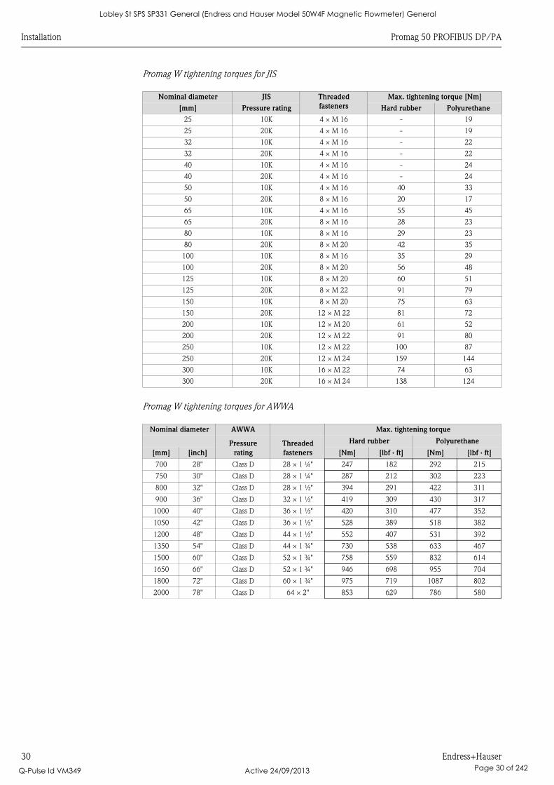
Promag W tightening torques for JIS
Promag W tightening torques for AWWA
Nominal diameter JIS Threaded
fasteners
Max. tightening torque [Nm]
[mm] Pressure rating Hard rubber Polyurethane
25 10K 4 × M 16 - 19
25 20K 4 × M 16 - 19
32 10K 4 × M 16 - 22
32 20K 4 × M 16 - 22
40 10K 4 × M 16 - 24
40 20K 4 × M 16 - 24
50 10K 4 × M 16 40 33
50 20K 8 × M 16 20 17
65 10K 4 × M 16 55 45
65 20K 8 × M 16 28 23
80 10K 8 × M 16 29 23
80 20K 8 × M 20 42 35
100 10K 8 × M 16 35 29
100 20K 8 × M 20 56 48
125 10K 8 × M 20 60 51
125 20K 8 × M 22 91 79
150 10K 8 × M 20 75 63
150 20K 12 × M 22 81 72
200 10K 12 × M 20 61 52
200 20K 12 × M 22 91 80
250 10K 12 × M 22 100 87
250 20K 12 × M 24 159 144
300 10K 16 × M 22 74 63
300 20K 16 × M 24 138 124
Nominal diameter AWWA Max. tightening torque
Pressure
rating
Threaded
fasteners
Hard rubber Polyurethane
[mm] [inch] [Nm] [lbf · ft] [Nm] [lbf · ft]
700 28" Class D 28 × 1 ¼" 247 182 292 215
750 30" Class D 28 × 1 ¼" 287 212 302 223
800 32" Class D 28 × 1 ½" 394 291 422 311
900 36" Class D 32 × 1 ½" 419 309 430 317
1000 40" Class D 36 × 1 ½" 420 310 477 352
1050 42" Class D 36 × 1 ½" 528 389 518 382
1200 48" Class D 44 × 1 ½" 552 407 531 392
1350 54" Class D 44 × 1 ¾" 730 538 633 467
1500 60" Class D 52 × 1 ¾" 758 559 832 614
1650 66" Class D 52 × 1 ¾" 946 698 955 704
1800 72" Class D 60 × 1 ¾" 975 719 1087 802
2000 78" Class D 64 × 2" 853 629 786 580
Lobley St SPS SP331 General (Endress and Hauser Model 50W4F Magnetic Flowmeter) General
Q-Pulse Id VM349 Active 24/09/2013 Page 30 of 242
Promag 50 PROFIBUS DP/PA Installation
Endress+Hauser 31
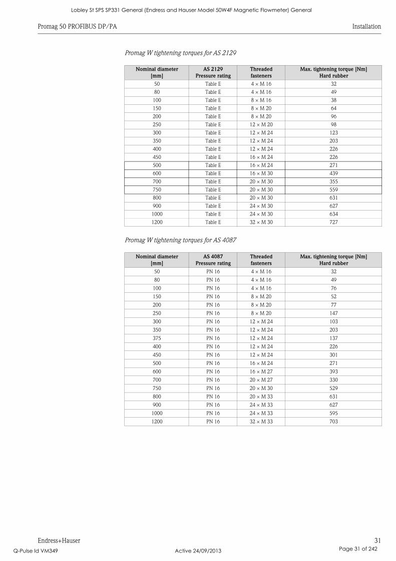
Promag W tightening torques for AS 2129
Promag W tightening torques for AS 4087
Nominal diameter
[mm]
AS 2129
Pressure rating
Threaded
fasteners
Max. tightening torque [Nm]
Hard rubber
50 Table E 4 × M 16 32
80 Table E 4 × M 16 49
100 Table E 8 × M 16 38
150 Table E 8 × M 20 64
200 Table E 8 × M 20 96
250 Table E 12 × M 20 98
300 Table E 12 × M 24 123
350 Table E 12 × M 24 203
400 Table E 12 × M 24 226
450 Table E 16 × M 24 226
500 Table E 16 × M 24 271
600 Table E 16 × M 30 439
700 Table E 20 × M 30 355
750 Table E 20 × M 30 559
800 Table E 20 × M 30 631
900 Table E 24 × M 30 627
1000 Table E 24 × M 30 634
1200 Table E 32 × M 30 727
Nominal diameter
[mm]
AS 4087
Pressure rating
Threaded
fasteners
Max. tightening torque [Nm]
Hard rubber
50 PN 16 4 × M 16 32
80 PN 16 4 × M 16 49
100 PN 16 4 × M 16 76
150 PN 16 8 × M 20 52
200 PN 16 8 × M 20 77
250 PN 16 8 × M 20 147
300 PN 16 12 × M 24 103
350 PN 16 12 × M 24 203
375 PN 16 12 × M 24 137
400 PN 16 12 × M 24 226
450 PN 16 12 × M 24 301
500 PN 16 16 × M 24 271
600 PN 16 16 × M 27 393
700 PN 16 20 × M 27 330
750 PN 16 20 × M 30 529
800 PN 16 20 × M 33 631
900 PN 16 24 × M 33 627
1000 PN 16 24 × M 33 595
1200 PN 16 32 × M 33 703
Lobley St SPS SP331 General (Endress and Hauser Model 50W4F Magnetic Flowmeter) General
Q-Pulse Id VM349 Active 24/09/2013 Page 31 of 242
Installation Promag 50 PROFIBUS DP/PA
32 Endress+Hauser
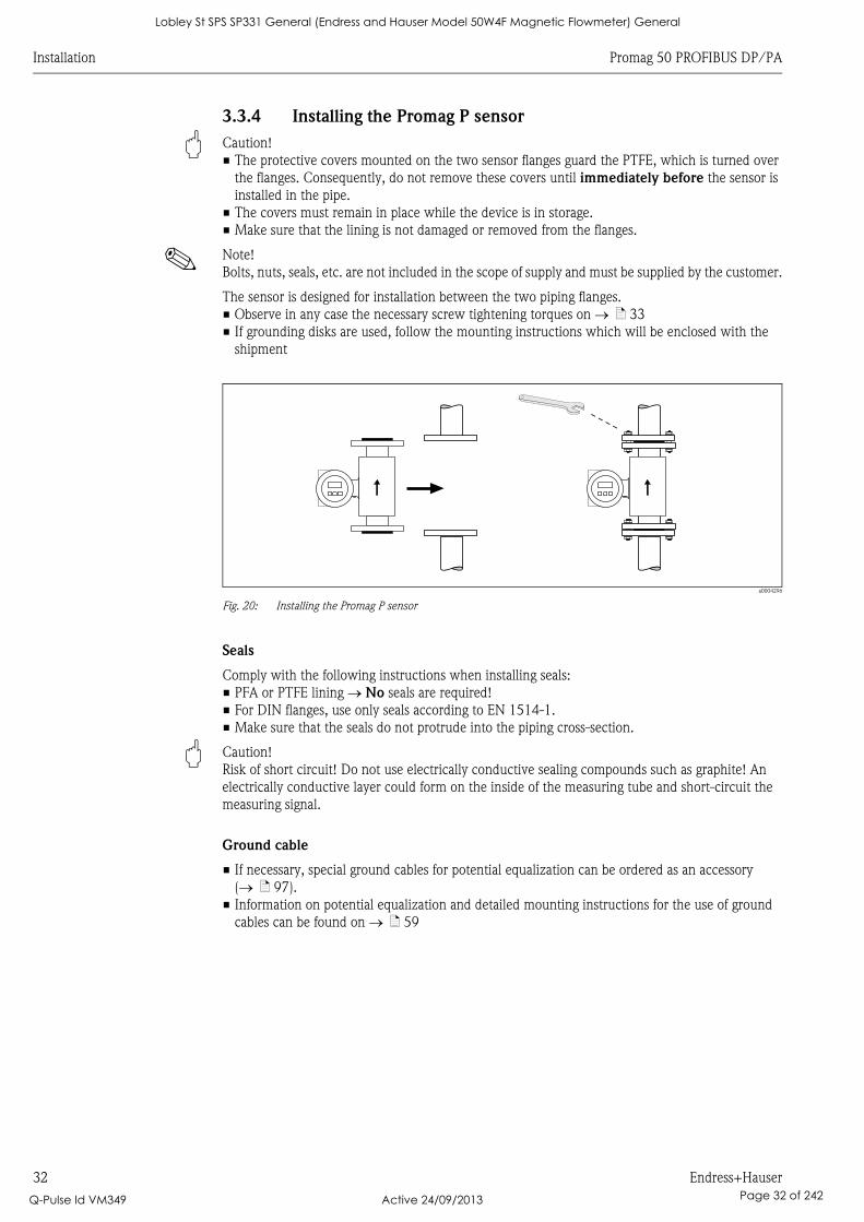
3.3.4 Installing the Promag P sensor
" Caution!
• The protective covers mounted on the two sensor flanges guard the PTFE, which is turned over
the flanges. Consequently, do not remove these covers until immediately before the sensor is
installed in the pipe.
• The covers must remain in place while the device is in storage.
• Make sure that the lining is not damaged or removed from the flanges.
! Note!
Bolts, nuts, seals, etc. are not included in the scope of supply and must be supplied by the customer.
The sensor is designed for installation between the two piping flanges.
• Observe in any case the necessary screw tightening torques on ä 33
• If grounding disks are used, follow the mounting instructions which will be enclosed with the
shipment
a0004296
Fig. 20: Installing the Promag P sensor
Seals
Comply with the following instructions when installing seals:
• PFA or PTFE lining No seals are required!
• For DIN flanges, use only seals according to EN 1514-1.
• Make sure that the seals do not protrude into the piping cross-section.
" Caution!
Risk of short circuit! Do not use electrically conductive sealing compounds such as graphite! An
electrically conductive layer could form on the inside of the measuring tube and short-circuit the
measuring signal.
Ground cable
• If necessary, special ground cables for potential equalization can be ordered as an accessory
( ä 97).
• Information on potential equalization and detailed mounting instructions for the use of ground
cables can be found on ä 59
Lobley St SPS SP331 General (Endress and Hauser Model 50W4F Magnetic Flowmeter) General
Q-Pulse Id VM349 Active 24/09/2013 Page 32 of 242
Promag 50 PROFIBUS DP/PA Installation
Endress+Hauser 33
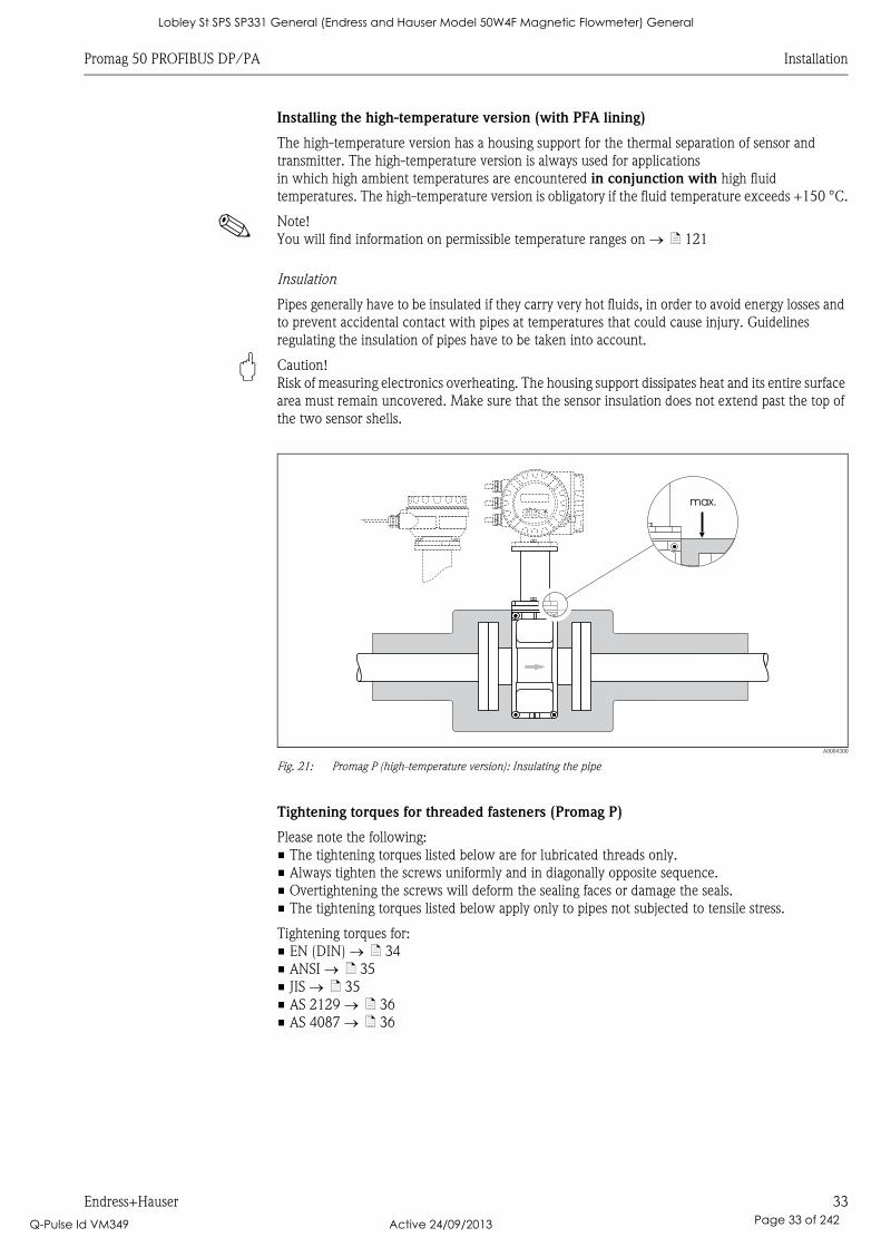
Installing the high-temperature version (with PFA lining)
The high-temperature version has a housing support for the thermal separation of sensor and
transmitter. The high-temperature version is always used for applications
in which high ambient temperatures are encountered in conjunction with high fluid
temperatures. The high-temperature version is obligatory if the fluid temperature exceeds +150 °C.
! Note!
You will find information on permissible temperature ranges on ä 121
Insulation
Pipes generally have to be insulated if they carry very hot fluids, in order to avoid energy losses and
to prevent accidental contact with pipes at temperatures that could cause injury. Guidelines
regulating the insulation of pipes have to be taken into account.
" Caution!
Risk of measuring electronics overheating. The housing support dissipates heat and its entire surface
area must remain uncovered. Make sure that the sensor insulation does not extend past the top of
the two sensor shells.
A0004300
Fig. 21: Promag P (high-temperature version): Insulating the pipe
Tightening torques for threaded fasteners (Promag P)
Please note the following:
• The tightening torques listed below are for lubricated threads only.
• Always tighten the screws uniformly and in diagonally opposite sequence.
• Overtightening the screws will deform the sealing faces or damage the seals.
• The tightening torques listed below apply only to pipes not subjected to tensile stress.
Tightening torques for:
• EN (DIN) ä 34
• ANSI ä 35
• JIS ä 35
• AS 2129 ä 36
• AS 4087 ä 36
Esc
E- +
max.
Lobley St SPS SP331 General (Endress and Hauser Model 50W4F Magnetic Flowmeter) General
Q-Pulse Id VM349 Active 24/09/2013 Page 33 of 242
Installation Promag 50 PROFIBUS DP/PA
34 Endress+Hauser
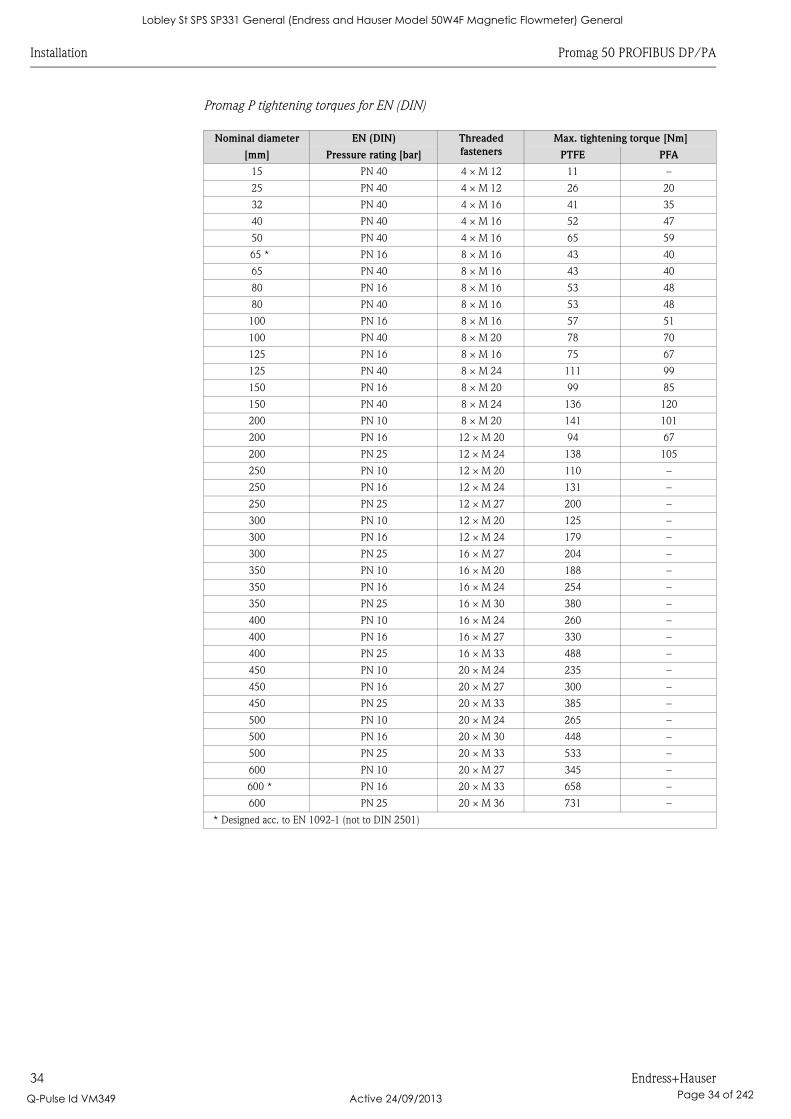
Promag P tightening torques for EN (DIN)
Nominal diameter EN (DIN) Threaded
fasteners
Max. tightening torque [Nm]
[mm] Pressure rating [bar] PTFE PFA
15 PN 40 4 × M 12 11 –
25 PN 40 4 × M 12 26 20
32 PN 40 4 × M 16 41 35
40 PN 40 4 × M 16 52 47
50 PN 40 4 × M 16 65 59
65 * PN 16 8 × M 16 43 40
65 PN 40 8 × M 16 43 40
80 PN 16 8 × M 16 53 48
80 PN 40 8 × M 16 53 48
100 PN 16 8 × M 16 57 51
100 PN 40 8 × M 20 78 70
125 PN 16 8 × M 16 75 67
125 PN 40 8 × M 24 111 99
150 PN 16 8 × M 20 99 85
150 PN 40 8 × M 24 136 120
200 PN 10 8 × M 20 141 101
200 PN 16 12 × M 20 94 67
200 PN 25 12 × M 24 138 105
250 PN 10 12 × M 20 110 –
250 PN 16 12 × M 24 131 –
250 PN 25 12 × M 27 200 –
300 PN 10 12 × M 20 125 –
300 PN 16 12 × M 24 179 –
300 PN 25 16 × M 27 204 –
350 PN 10 16 × M 20 188 –
350 PN 16 16 × M 24 254 –
350 PN 25 16 × M 30 380 –
400 PN 10 16 × M 24 260 –
400 PN 16 16 × M 27 330 –
400 PN 25 16 × M 33 488 –
450 PN 10 20 × M 24 235 –
450 PN 16 20 × M 27 300 –
450 PN 25 20 × M 33 385 –
500 PN 10 20 × M 24 265 –
500 PN 16 20 × M 30 448 –
500 PN 25 20 × M 33 533 –
600 PN 10 20 × M 27 345 –
600 * PN 16 20 × M 33 658 –
600 PN 25 20 × M 36 731 –
* Designed acc. to EN 1092-1 (not to DIN 2501)
Lobley St SPS SP331 General (Endress and Hauser Model 50W4F Magnetic Flowmeter) General
Q-Pulse Id VM349 Active 24/09/2013 Page 34 of 242
Promag 50 PROFIBUS DP/PA Installation
Endress+Hauser 35
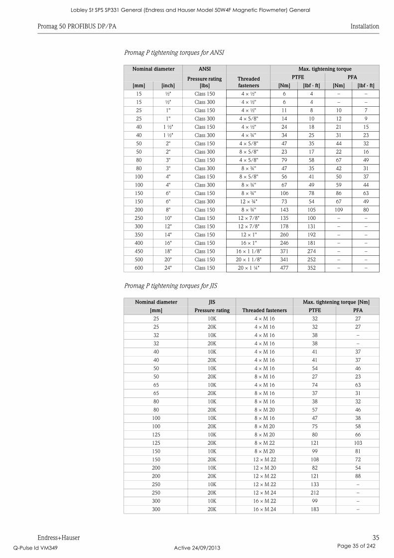
Promag P tightening torques for ANSI
Promag P tightening torques for JIS
Nominal diameter ANSI Max. tightening torque
Pressure rating
[lbs]
Threaded
fasteners
PTFE PFA
[mm] [inch] [Nm] [lbf · ft] [Nm] [lbf · ft]
15 ½" Class 150 4 × ½" 6 4 – –
15 ½" Class 300 4 × ½" 6 4 – –
25 1" Class 150 4 × ½" 11 8 10 7
25 1" Class 300 4 × 5/8" 14 10 12 9
40 1 ½" Class 150 4 × ½" 24 18 21 15
40 1 ½" Class 300 4 × ¾" 34 25 31 23
50 2" Class 150 4 × 5/8" 47 35 44 32
50 2" Class 300 8 × 5/8" 23 17 22 16
80 3" Class 150 4 × 5/8" 79 58 67 49
80 3" Class 300 8 × ¾" 47 35 42 31
100 4" Class 150 8 × 5/8" 56 41 50 37
100 4" Class 300 8 × ¾" 67 49 59 44
150 6" Class 150 8 × ¾" 106 78 86 63
150 6" Class 300 12 × ¾" 73 54 67 49
200 8" Class 150 8 × ¾" 143 105 109 80
250 10" Class 150 12 × 7/8" 135 100 – –
300 12" Class 150 12 × 7/8" 178 131 – –
350 14" Class 150 12 × 1" 260 192 – –
400 16" Class 150 16 × 1" 246 181 – –
450 18" Class 150 16 × 1 1/8" 371 274 – –
500 20" Class 150 20 × 1 1/8" 341 252 – –
600 24" Class 150 20 × 1 ¼" 477 352 – –
Nominal diameter JIS Max. tightening torque [Nm]
[mm] Pressure rating Threaded fasteners PTFE PFA
25 10K 4 × M 16 32 27
25 20K 4 × M 16 32 27
32 10K 4 × M 16 38 –
32 20K 4 × M 16 38 –
40 10K 4 × M 16 41 37
40 20K 4 × M 16 41 37
50 10K 4 × M 16 54 46
50 20K 8 × M 16 27 23
65 10K 4 × M 16 74 63
65 20K 8 × M 16 37 31
80 10K 8 × M 16 38 32
80 20K 8 × M 20 57 46
100 10K 8 × M 16 47 38
100 20K 8 × M 20 75 58
125 10K 8 × M 20 80 66
125 20K 8 × M 22 121 103
150 10K 8 × M 20 99 81
150 20K 12 × M 22 108 72
200 10K 12 × M 20 82 54
200 20K 12 × M 22 121 88
250 10K 12 × M 22 133 –
250 20K 12 × M 24 212 –
300 10K 16 × M 22 99 –
300 20K 16 × M 24 183 –
Lobley St SPS SP331 General (Endress and Hauser Model 50W4F Magnetic Flowmeter) General
Q-Pulse Id VM349 Active 24/09/2013 Page 35 of 242
Installation Promag 50 PROFIBUS DP/PA
36 Endress+Hauser
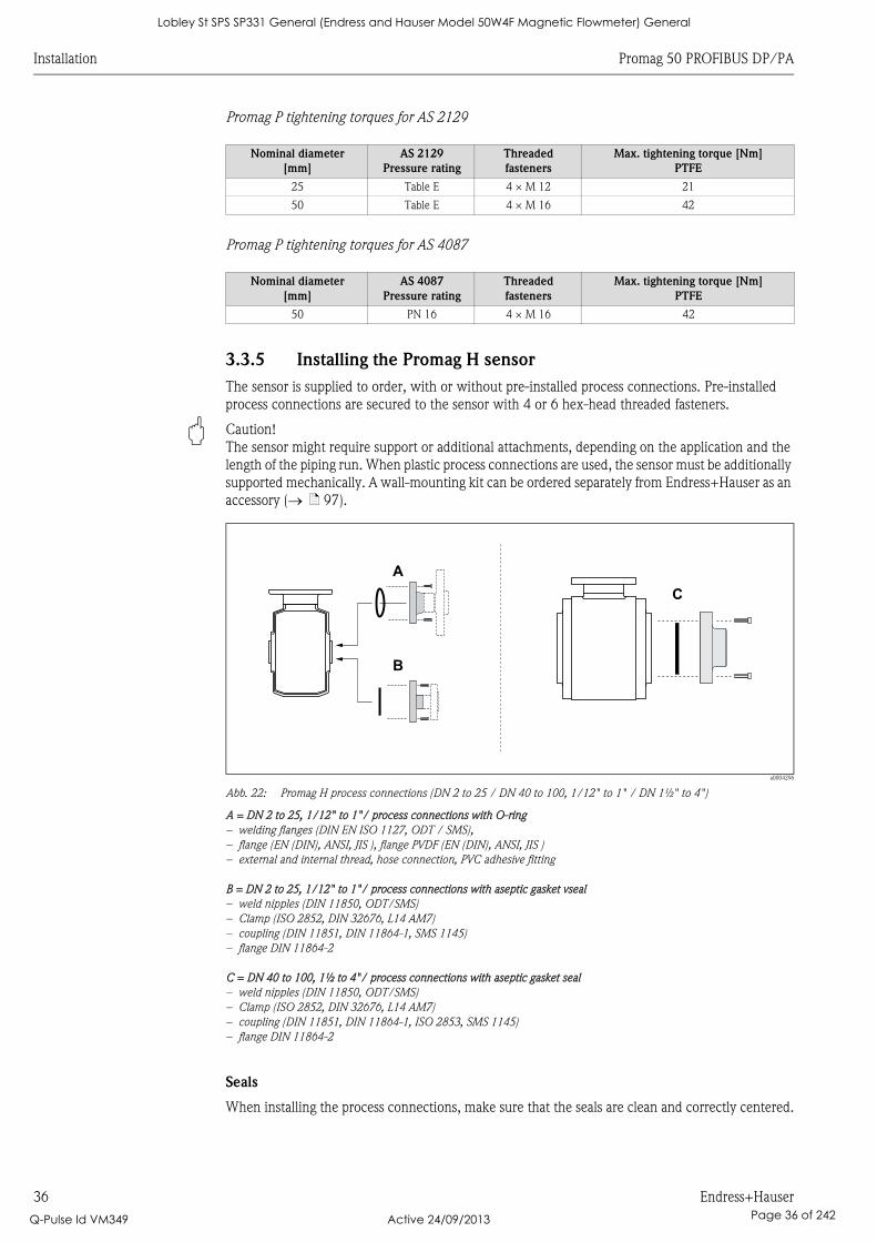
Promag P tightening torques for AS 2129
Promag P tightening torques for AS 4087
3.3.5 Installing the Promag H sensor
The sensor is supplied to order, with or without pre-installed process connections. Pre-installed
process connections are secured to the sensor with 4 or 6 hex-head threaded fasteners.
" Caution!
The sensor might require support or additional attachments, depending on the application and the
length of the piping run. When plastic process connections are used, the sensor must be additionally
supported mechanically. A wall-mounting kit can be ordered separately from Endress+Hauser as an
accessory ( ä 97).
a0004296
Abb. 22: Promag H process connections (DN 2 to 25 / DN 40 to 100, 1/12" to 1" / DN 1½" to 4")
A = DN 2 to 25, 1/12" to 1"/ process connections with O-ring
– welding flanges (DIN EN ISO 1127, ODT / SMS),
– flange (EN (DIN), ANSI, JIS ), flange PVDF (EN (DIN), ANSI, JIS )
– external and internal thread, hose connection, PVC adhesive fitting
B = DN 2 to 25, 1/12" to 1"/ process connections with aseptic gasket vseal
– weld nipples (DIN 11850, ODT/SMS)
– Clamp (ISO 2852, DIN 32676, L14 AM7)
– coupling (DIN 11851, DIN 11864-1, SMS 1145)
– flange DIN 11864-2
C = DN 40 to 100, 1½ to 4"/ process connections with aseptic gasket seal
– weld nipples (DIN 11850, ODT/SMS)
– Clamp (ISO 2852, DIN 32676, L14 AM7)
– coupling (DIN 11851, DIN 11864-1, ISO 2853, SMS 1145)
– flange DIN 11864-2
Seals
When installing the process connections, make sure that the seals are clean and correctly centered.
Nominal diameter
[mm]
AS 2129
Pressure rating
Threaded
fasteners
Max. tightening torque [Nm]
PTFE
25 Table E 4 × M 12 21
50 Table E 4 × M 16 42
Nominal diameter
[mm]
AS 4087
Pressure rating
Threaded
fasteners
Max. tightening torque [Nm]
PTFE
50 PN 16 4 × M 16 42
A
B
C
Lobley St SPS SP331 General (Endress and Hauser Model 50W4F Magnetic Flowmeter) General
Q-Pulse Id VM349 Active 24/09/2013 Page 36 of 242
Promag 50 PROFIBUS DP/PA Installation
Endress+Hauser 37
" Caution!
• With metal process connections, you must fully tighten the screws. The process connection forms
a metallic connection with the sensor, which ensures a defined compression of the seal.
• With plastic process connections, note the max. torques for lubricated threads (7 Nm / 5.2 lbf ft).
With plastic flanges, always use seals between connection and counter flange.
• The seals must be replaced periodically, depending on the application, particularly in the case of
gasket seals (aseptic version)!
The period between changes depends on the frequency of cleaning cycles, the cleaning
temperature and the fluid temperature. Replacement seals can be ordered as accessories ä 97.
Usage and assembly of ground rings (DN 2 to 25, 1/12" to 1")
In case the process connections are made of plastic (e.g. flanges or adhesive fittings), the potential
between the sensor and the fluid must be equalized using additional ground rings.
If the ground rings are not installed this can affect the accuracy of the measurements or cause the
destruction of the sensor through the electrochemical erosion of the electrodes.
" Caution!
• Depending on the option ordered, plastic disks may be installed at the process connections instead
of ground rings. These plastic disks serve only as spacers and have no potential equalization
function. In addition, they provide a sealing function at the interface between the sensor and
process connection. For this reason, with process connections without ground rings, these plastic
disks/seals must not be removed, or must always be installed.
• Ground rings can be ordered separately from Endress+Hauser as accessories ( ä 97). When
placing the order, make certain that the ground ring is compatible with the material used for the
electrodes. Otherwise, there is a risk that the electrodes may be destroyed by electrochemical
corrosion! Information about the materials can be found on ä 133.
• Ground rings, including the seals, are mounted within the process connections.
Therefore, the fitting length is not affected.
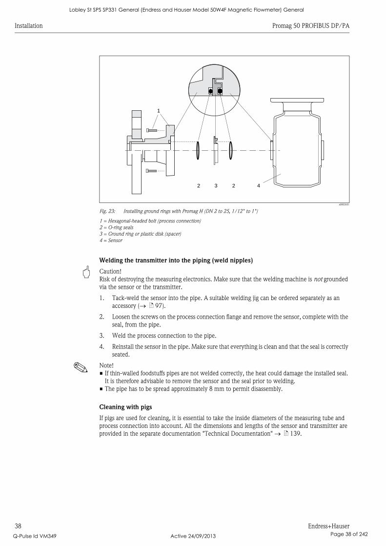
1. Loosen the four or six hexagonal headed bolts (1) and remove the process connection from the
sensor (4).
2. Remove the plastic disk (3), including the two O-ring seals (2).
3. Place one seal (2) in the groove of the process connection.
4. Place the metal ground ring (3) on the process connection.
5. Now place the second seal (2) in the groove of the ground ring.
6. Finally, mount the process connection on the sensor again.
With plastic process connections, note the max. torques for lubricated threads
(7 Nm / 5.2 lbf ft).
Lobley St SPS SP331 General (Endress and Hauser Model 50W4F Magnetic Flowmeter) General
Q-Pulse Id VM349 Active 24/09/2013 Page 37 of 242
Installation Promag 50 PROFIBUS DP/PA
38 Endress+Hauser
a0002651
Fig. 23: Installing ground rings with Promag H (DN 2 to 25, 1/12" to 1")
1 = Hexagonal-headed bolt (process connection)
2 = O-ring seals
3 = Ground ring or plastic disk (spacer)
4 = Sensor
Welding the transmitter into the piping (weld nipples)
" Caution!
Risk of destroying the measuring electronics. Make sure that the welding machine is not grounded
via the sensor or the transmitter.
1. Tack-weld the sensor into the pipe. A suitable welding jig can be ordered separately as an
accessory ( ä 97).
2. Loosen the screws on the process connection flange and remove the sensor, complete with the
seal, from the pipe.
3. Weld the process connection to the pipe.
4. Reinstall the sensor in the pipe. Make sure that everything is clean and that the seal is correctly
seated.
! Note!
• If thin-walled foodstuffs pipes are not welded correctly, the heat could damage the installed seal.
It is therefore advisable to remove the sensor and the seal prior to welding.
• The pipe has to be spread approximately 8 mm to permit disassembly.
Cleaning with pigs
If pigs are used for cleaning, it is essential to take the inside diameters of the measuring tube and
process connection into account. All the dimensions and lengths of the sensor and transmitter are
provided in the separate documentation "Technical Documentation" ä 139.
1
3 2 42
Lobley St SPS SP331 General (Endress and Hauser Model 50W4F Magnetic Flowmeter) General
Q-Pulse Id VM349 Active 24/09/2013 Page 38 of 242

Promag 50 PROFIBUS DP/PA Installation
Endress+Hauser 39
3.3.6 Turning the transmitter housing
Turning the aluminum field housing
# Warning!
The turning mechanism in devices with Ex d/de or FM/CSA Cl. I Div. 1 classification is not the
same as that described here. The procedure for turning these housings is described in the Ex-specific
documentation.
1. Loosen the two securing screws.
2. Turn the bayonet catch as far as it will go.
3. Carefully lift the transmitter housing:
– Promag D: approx. 10 mm (0.39 inch) above the securing screws
– Promag L, W, P, H: to the stop
4. Turn the transmitter housing to the desired position:
– Promag D: max. 180° clockwise or max. 180° counterclockwise
– Promag L, W, P, H: max. 280° clockwise or max. 20° counterclockwise
5. Lower the housing into position and re-engage the bayonet catch.
6. Retighten the two securing screws.
a0004302
Fig. 24: Turning the transmitter housing (aluminum field housing)
Turning the stainless-steel field housing
1. Loosen the two securing screws.
2. Carefully lift the transmitter housing as far as it will go.
3. Turn the transmitter housing to the desired position (max. 2 × 90° in either direction).
4. Lower the housing into position.
5. Retighten the two securing screws.
a0004303
Fig. 25: Turning the transmitter housing (stainless-steel field housing)
3
5
61
2 4
1 2
3
4
5
Lobley St SPS SP331 General (Endress and Hauser Model 50W4F Magnetic Flowmeter) General
Q-Pulse Id VM349 Active 24/09/2013 Page 39 of 242
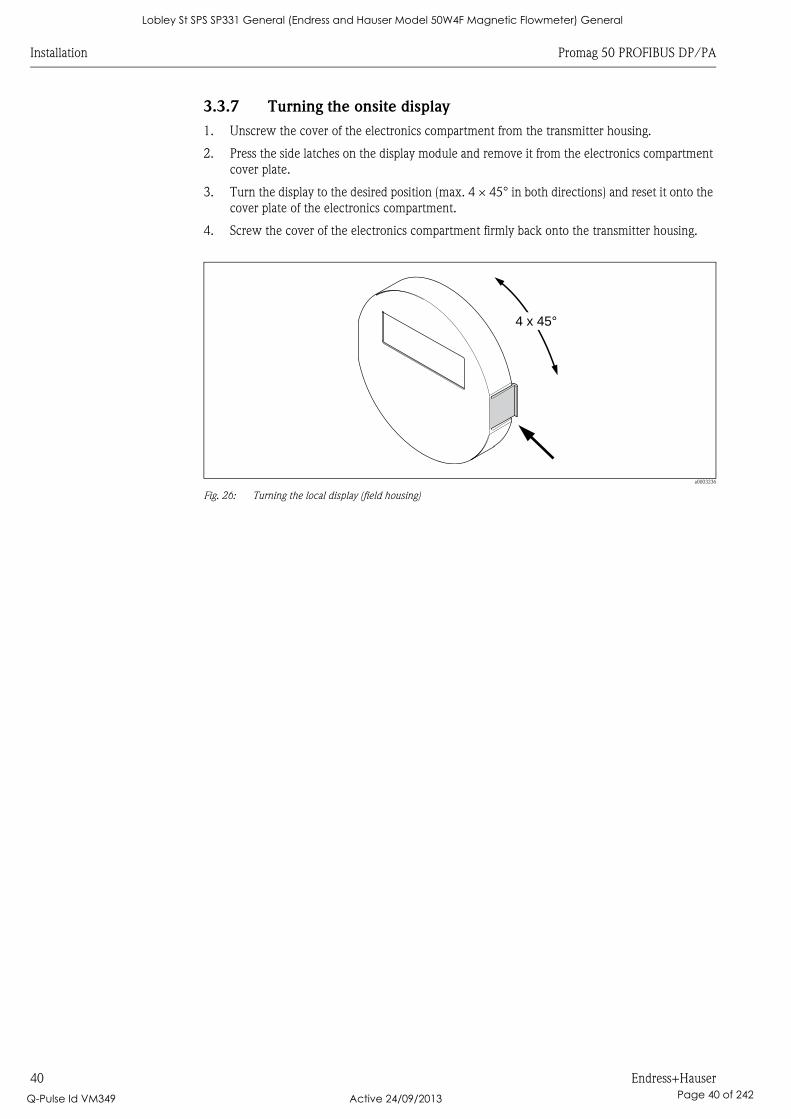
Installation Promag 50 PROFIBUS DP/PA
40 Endress+Hauser
3.3.7 Turning the onsite display
1. Unscrew the cover of the electronics compartment from the transmitter housing.
2. Press the side latches on the display module and remove it from the electronics compartment
cover plate.
3. Turn the display to the desired position (max. 4 × 45° in both directions) and reset it onto the
cover plate of the electronics compartment.
4. Screw the cover of the electronics compartment firmly back onto the transmitter housing.
a0003236
Fig. 26: Turning the local display (field housing)
4 x 45°
Lobley St SPS SP331 General (Endress and Hauser Model 50W4F Magnetic Flowmeter) General
Q-Pulse Id VM349 Active 24/09/2013 Page 40 of 242
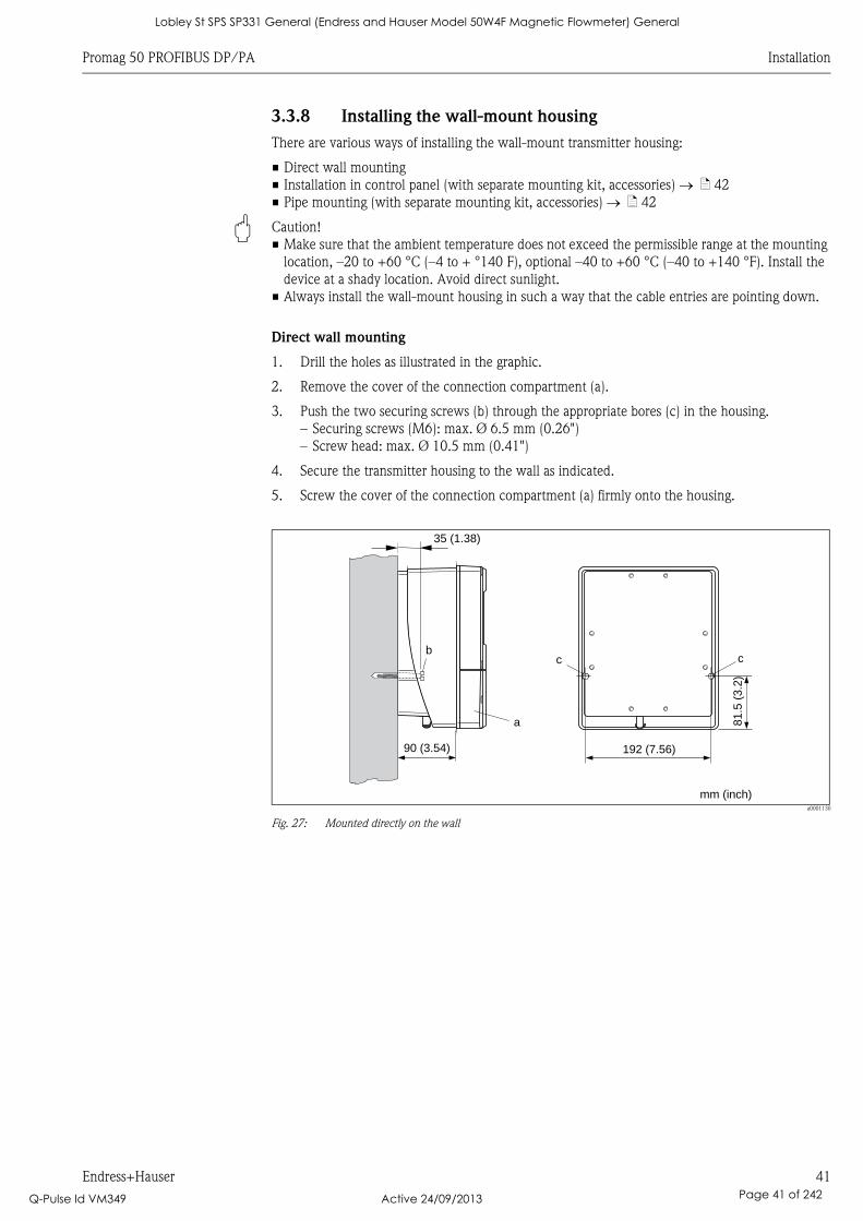
Promag 50 PROFIBUS DP/PA Installation
Endress+Hauser 41
3.3.8 Installing the wall-mount housing
There are various ways of installing the wall-mount transmitter housing:
• Direct wall mounting
• Installation in control panel (with separate mounting kit, accessories) ä 42
• Pipe mounting (with separate mounting kit, accessories) ä 42
" Caution!
• Make sure that the ambient temperature does not exceed the permissible range at the mounting
location, –20 to +60 °C (–4 to + °140 F), optional –40 to +60 °C (–40 to +140 °F). Install the
device at a shady location. Avoid direct sunlight.
• Always install the wall-mount housing in such a way that the cable entries are pointing down.
Direct wall mounting
1. Drill the holes as illustrated in the graphic.
2. Remove the cover of the connection compartment (a).
3. Push the two securing screws (b) through the appropriate bores (c) in the housing.
– Securing screws (M6): max. Ø 6.5 mm (0.26")
– Screw head: max. Ø 10.5 mm (0.41")
4. Secure the transmitter housing to the wall as indicated.
5. Screw the cover of the connection compartment (a) firmly onto the housing.
a0001130
Fig. 27: Mounted directly on the wall
a
bc c
90 (3.54)
35 (1.38)
192 (7.56)8
1.5
(3.2
)
mm (inch)
Lobley St SPS SP331 General (Endress and Hauser Model 50W4F Magnetic Flowmeter) General
Q-Pulse Id VM349 Active 24/09/2013 Page 41 of 242
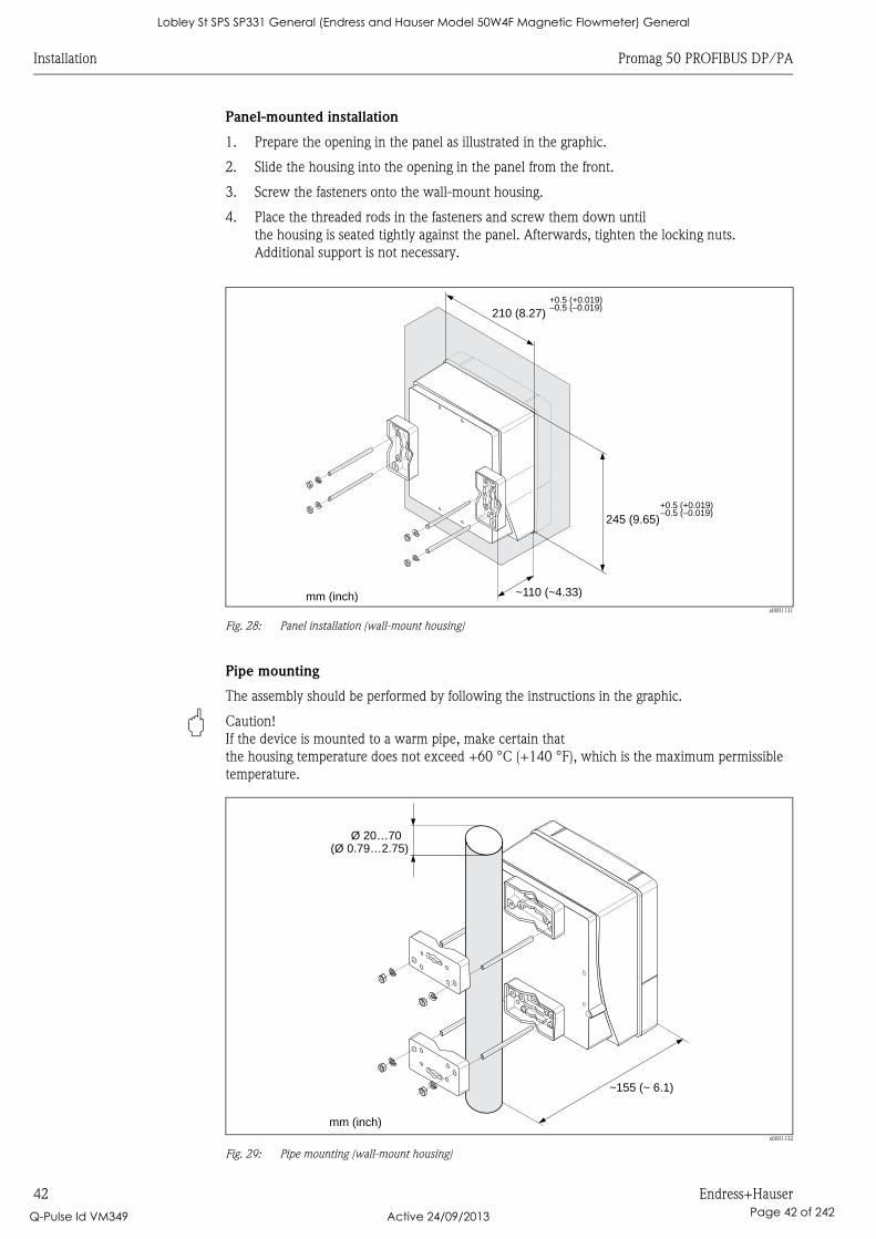
Installation Promag 50 PROFIBUS DP/PA
42 Endress+Hauser
Panel-mounted installation
1. Prepare the opening in the panel as illustrated in the graphic.
2. Slide the housing into the opening in the panel from the front.
3. Screw the fasteners onto the wall-mount housing.
4. Place the threaded rods in the fasteners and screw them down until
the housing is seated tightly against the panel. Afterwards, tighten the locking nuts.
Additional support is not necessary.
a0001131
Fig. 28: Panel installation (wall-mount housing)
Pipe mounting
The assembly should be performed by following the instructions in the graphic.
" Caution!
If the device is mounted to a warm pipe, make certain that
the housing temperature does not exceed +60 °C (+140 °F), which is the maximum permissible
temperature.
a0001132
Fig. 29: Pipe mounting (wall-mount housing)
245 (9.65)
~110 (~4.33)
210 (8.27)+0.5 (+0.019)–0.5 (–0.019)
+0.5 (+0.019)–0.5 (–0.019)
mm (inch)
Ø 20…70(Ø 0.79…2.75)
~ ~ 6.1)155 (
mm (inch)
Lobley St SPS SP331 General (Endress and Hauser Model 50W4F Magnetic Flowmeter) General
Q-Pulse Id VM349 Active 24/09/2013 Page 42 of 242
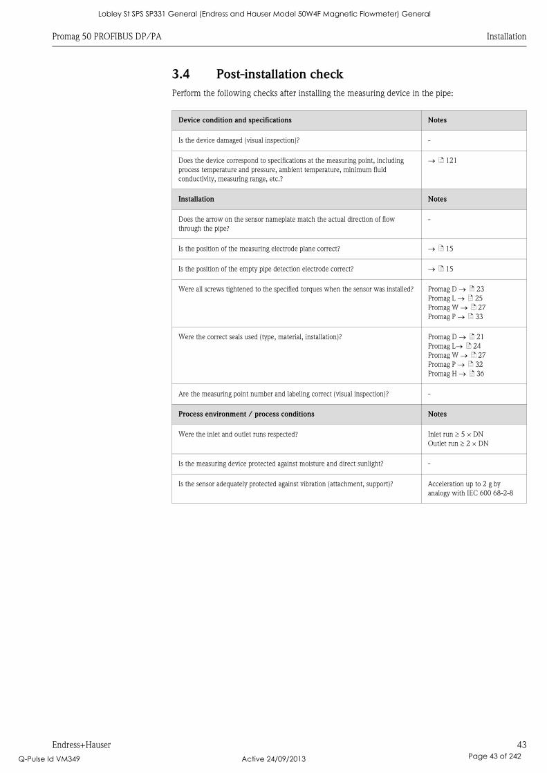
Promag 50 PROFIBUS DP/PA Installation
Endress+Hauser 43
3.4 Post-installation check
Perform the following checks after installing the measuring device in the pipe:
Device condition and specifications Notes
Is the device damaged (visual inspection)? -
Does the device correspond to specifications at the measuring point, including
process temperature and pressure, ambient temperature, minimum fluid
conductivity, measuring range, etc.?
ä 121
Installation Notes
Does the arrow on the sensor nameplate match the actual direction of flow
through the pipe?
-
Is the position of the measuring electrode plane correct? ä 15
Is the position of the empty pipe detection electrode correct? ä 15
Were all screws tightened to the specified torques when the sensor was installed? Promag D ä 23
Promag L ä 25
Promag W ä 27
Promag P ä 33
Were the correct seals used (type, material, installation)? Promag D ä 21
Promag L ä 24
Promag W ä 27
Promag P ä 32
Promag H ä 36
Are the measuring point number and labeling correct (visual inspection)? -
Process environment / process conditions Notes
Were the inlet and outlet runs respected? Inlet run 5 × DN
Outlet run 2 × DN
Is the measuring device protected against moisture and direct sunlight? -
Is the sensor adequately protected against vibration (attachment, support)? Acceleration up to 2 g by
analogy with IEC 600 68-2-8
Lobley St SPS SP331 General (Endress and Hauser Model 50W4F Magnetic Flowmeter) General
Q-Pulse Id VM349 Active 24/09/2013 Page 43 of 242
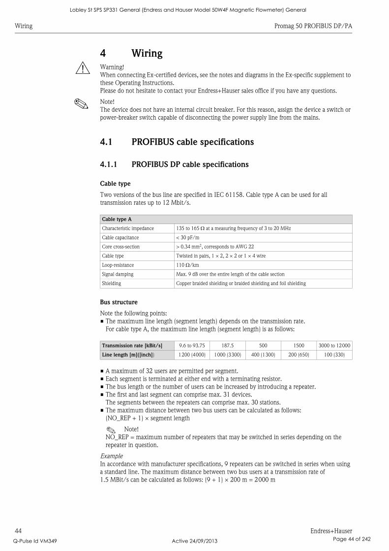
Wiring Promag 50 PROFIBUS DP/PA
44 Endress+Hauser
4 Wiring
# Warning!
When connecting Ex-certified devices, see the notes and diagrams in the Ex-specific supplement to
these Operating Instructions.
Please do not hesitate to contact your Endress+Hauser sales office if you have any questions.
! Note!
The device does not have an internal circuit breaker. For this reason, assign the device a switch or
power-breaker switch capable of disconnecting the power supply line from the mains.
4.1 PROFIBUS cable specifications
4.1.1 PROFIBUS DP cable specifications
Cable type
Two versions of the bus line are specified in IEC 61158. Cable type A can be used for all
transmission rates up to 12 Mbit/s.
Bus structure
Note the following points:
• The maximum line length (segment length) depends on the transmission rate.
For cable type A, the maximum line length (segment length) is as follows:
• A maximum of 32 users are permitted per segment.
• Each segment is terminated at either end with a terminating resistor.
• The bus length or the number of users can be increased by introducing a repeater.
• The first and last segment can comprise max. 31 devices.
The segments between the repeaters can comprise max. 30 stations.
• The maximum distance between two bus users can be calculated as follows:
(NO_REP + 1) × segment length
! Note!
NO_REP = maximum number of repeaters that may be switched in series depending on the
repeater in question.
Example
In accordance with manufacturer specifications, 9 repeaters can be switched in series when using
a standard line. The maximum distance between two bus users at a transmission rate of
1.5 MBit/s can be calculated as follows: (9 + 1) × 200 m = 2000 m
Cable type A
Characteristic impedance 135 to 165 at a measuring frequency of 3 to 20 MHz
Cable capacitance < 30 pF/m
Core cross-section > 0.34 mm, corresponds to AWG 22
Cable type Twisted in pairs, 1 × 2, 2 × 2 or 1 × 4 wire
Loop-resistance 110 /km
Signal damping Max. 9 dB over the entire length of the cable section
Shielding Copper braided shielding or braided shielding and foil shielding
Transmission rate [kBit/s] 9.6 to 93.75 187.5 500 1500 3000 to 12000
Line length [m]([inch]) 1200 (4000) 1000 (3300) 400 (1300) 200 (650) 100 (330)
Lobley St SPS SP331 General (Endress and Hauser Model 50W4F Magnetic Flowmeter) General
Q-Pulse Id VM349 Active 24/09/2013 Page 44 of 242
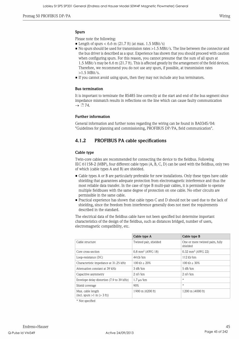
Promag 50 PROFIBUS DP/PA Wiring
Endress+Hauser 45
Spurs
Please note the following:
• Length of spurs < 6.6 m (21.7 ft) (at max. 1.5 MBit/s)
• No spurs should be used for transmission rates >1.5 MBit/s. The line between the connector and
the bus driver is described as a spur. Experience has shown that you should proceed with caution
when configuring spurs. For this reason, you cannot presume that the sum of all spurs at
1.5 MBit/s may be 6.6 m (21.7 ft). This is affected greatly by the arrangement of the field devices.
Therefore, we recommend you do not use any spurs, if possible, at transmission rates
>1.5 MBit/s.
• If you cannot avoid using spurs, then they may not include any bus terminators.
Bus termination
It is important to terminate the RS485 line correctly at the start and end of the bus segment since
impedance mismatch results in reflections on the line which can cause faulty communication
ä 74.
Further information
General information and further notes regarding the wiring can be found in BA034S/04:
"Guidelines for planning and commissioning, PROFIBUS DP/PA, field communication".
4.1.2 PROFIBUS PA cable specifications
Cable type
Twin-core cables are recommended for connecting the device to the fieldbus. Following
IEC 61158-2 (MBP), four different cable types (A, B, C, D) can be used with the fieldbus, only two
of which (cable types A and B) are shielded.
• Cable types A or B are particularly preferable for new installations. Only these types have cable
shielding that guarantees adequate protection from electromagnetic interference and thus the
most reliable data transfer. In the case of type B multi-pair cables, it is permissible to operate
multiple fieldbuses with the same degree of protection on one cable. No other circuits are
permissible in the same cable.
• Practical experience has shown that cable types C and D should not be used due to the lack of
shielding, since the freedom from interference generally does not meet the requirements
described in the standard.
The electrical data of the fieldbus cable have not been specified but determine important
characteristics of the design of the fieldbus, such as distances bridged, number of users,
electromagnetic compatibility, etc.
Cable type A Cable type B
Cable structure Twisted pair, shielded One or more twisted pairs, fully
shielded
Core cross-section 0.8 mm (AWG 18) 0.32 mm (AWG 22)
Loop-resistance (DC) 44 /km 112 /km
Characteristic impedance at 31.25 kHz 100 ± 20% 100 ± 30%
Attenuation constant at 39 kHz 3 dB/km 5 dB/km
Capacitive asymmetry 2 nF/km 2 nF/km
Envelope delay distortion (7.9 to 39 kHz) 1.7 s/km *
Shield coverage 90% *
Max. cable length
(incl. spurs >1 m (> 3 ft))
1900 m (6200 ft) 1200 m (4000 ft)
* Not specified
Lobley St SPS SP331 General (Endress and Hauser Model 50W4F Magnetic Flowmeter) General
Q-Pulse Id VM349 Active 24/09/2013 Page 45 of 242
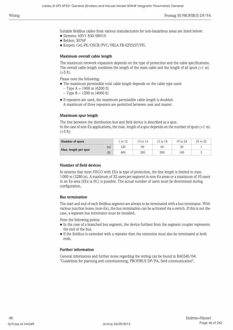
Wiring Promag 50 PROFIBUS DP/PA
46 Endress+Hauser
Suitable fieldbus cables from various manufacturers for non-hazardous areas are listed below:
• Siemens: 6XV1 830-5BH10
• Belden: 3076F
• Kerpen: CeL-PE/OSCR/PVC/FRLA FB-02YS(ST)YFL
Maximum overall cable length
The maximum network expansion depends on the type of protection and the cable specifications.
The overall cable length combines the length of the main cable and the length of all spurs (>1 m)
(>3 ft).
Please note the following:
• The maximum permissible total cable length depends on the cable type used:
– Type A = 1900 m (6200 ft)
– Type B = 1200 m (4000 ft)
• If repeaters are used, the maximum permissible cable length is doubled.
A maximum of three repeaters are permitted between user and master.
Maximum spur length
The line between the distribution box and field device is described as a spur.
In the case of non-Ex applications, the max. length of a spur depends on the number of spurs (>1 m)
(>3 ft):
Number of field devices
In systems that meet FISCO with EEx ia type of protection, the line length is limited to max.
1000 m (3280 in). A maximum of 32 users per segment in non-Ex areas or a maximum of 10 users
in an Ex-area (EEx ia IIC) is possible. The actual number of users must be determined during
configuration.
Bus termination
The start and end of each fieldbus segment are always to be terminated with a bus terminator. With
various junction boxes (non-Ex), the bus termination can be activated via a switch. If this is not the
case, a separate bus terminator must be installed.
Note the following points:
• In the case of a branched bus segment, the device furthest from the segment coupler represents
the end of the bus.
• If the fieldbus is extended with a repeater then the extension must also be terminated at both
ends.
Further information
General information and further notes regarding the wiring can be found in BA034S/04:
"Guidelines for planning and commissioning, PROFIBUS DP/PA, field communication".
Number of spurs 1 to 12 13 to 14 15 to 18 19 to 24 25 to 32
Max. length per spur[m] 120 90 60 30 1
[ft] 400 300 200 100 3
Lobley St SPS SP331 General (Endress and Hauser Model 50W4F Magnetic Flowmeter) General
Q-Pulse Id VM349 Active 24/09/2013 Page 46 of 242
Promag 50 PROFIBUS DP/PA Wiring
Endress+Hauser 47
4.1.3 Shielding and grounding
When planning the shielding and grounding for a fieldbus system, there are three important points
to consider:
• Electromagnetic compatibility (EMC)
• Explosion protection
• Safety of the personnel
To ensure the optimum electromagnetic compatibility of systems, it is important that the system
components and above all the cables, which connect the components, are shielded and that no
portion of the system is unshielded. Ideally, the cable shields are connected to the normally metal
housings of the connected field devices. Since these are generally connected to the protective
ground, the shield of the bus cable is grounded many times. Ensure that the stripped and twisted
lengths of cable shield to the ground terminal are as short as possible.
This approach, which provides the best electromagnetic compatibility and personnel safety, can be
used without restriction in systems with good potential matching.
In the case of systems without potential matching, a power supply frequency (50 Hz) equalizing
current can flow between two grounding points which, in unfavorable cases, e.g. when it exceeds
the permissible shield current, may destroy the cable.
To suppress the low frequency equalizing currents, it is therefore recommended - in the case of
systems without potential equalization - to connect the cable shield directly to the building ground
(or protective ground) at one end only and to use capacitive coupling to connect all other grounding
points.
" Caution!
The statutory EMC requirements are only met if the cable shield is grounded at both ends!
4.2 Connecting the remote version
4.2.1 Connecting Promag D, L, W, P, H
# Warning!
• Risk of electric shock! Switch off the power supply before opening the device. Do not install or
wire the device while it is connected to the power supply. Failure to comply with this precaution
can result in irreparable damage to the electronics.
• Risk of electric shock! Connect the protective conductor to the ground terminal on the housing
before the power supply is applied.
" Caution!
• Only sensors and transmitters with the same serial number can be connected to one another.
Communication problems can occur if the devices are not connected in this way.
• Risk of damaging the coil driver. Always switch off the power supply before connecting or
disconnecting the coil cable.
Procedure
1. Transmitter: Remove the cover from the connection compartment (a).
2. Sensor: Remove the cover from the connection housing (b).
3. Feed the signal cable (c) and the coil cable (d) through the appropriate cable entries.
" Caution!
Route the connecting cables securely (see "Connecting cable length" ä 47).
4. Terminate the signal and coil current cable as indicated in the table:
Promag D, L, W, P Refer to the table ä 50
Promag H Refer to the "Cable termination" table ä 51
5. Establish the wiring between the sensor and the transmitter.
The electrical wiring diagram that applies to your device can be found:
• In the corresponding graphic:
å 30 (Promag D) å 31 (Promag L, W, P); å 32 (Promag H)
• In the cover of the sensor and transmitter
Lobley St SPS SP331 General (Endress and Hauser Model 50W4F Magnetic Flowmeter) General
Q-Pulse Id VM349 Active 24/09/2013 Page 47 of 242
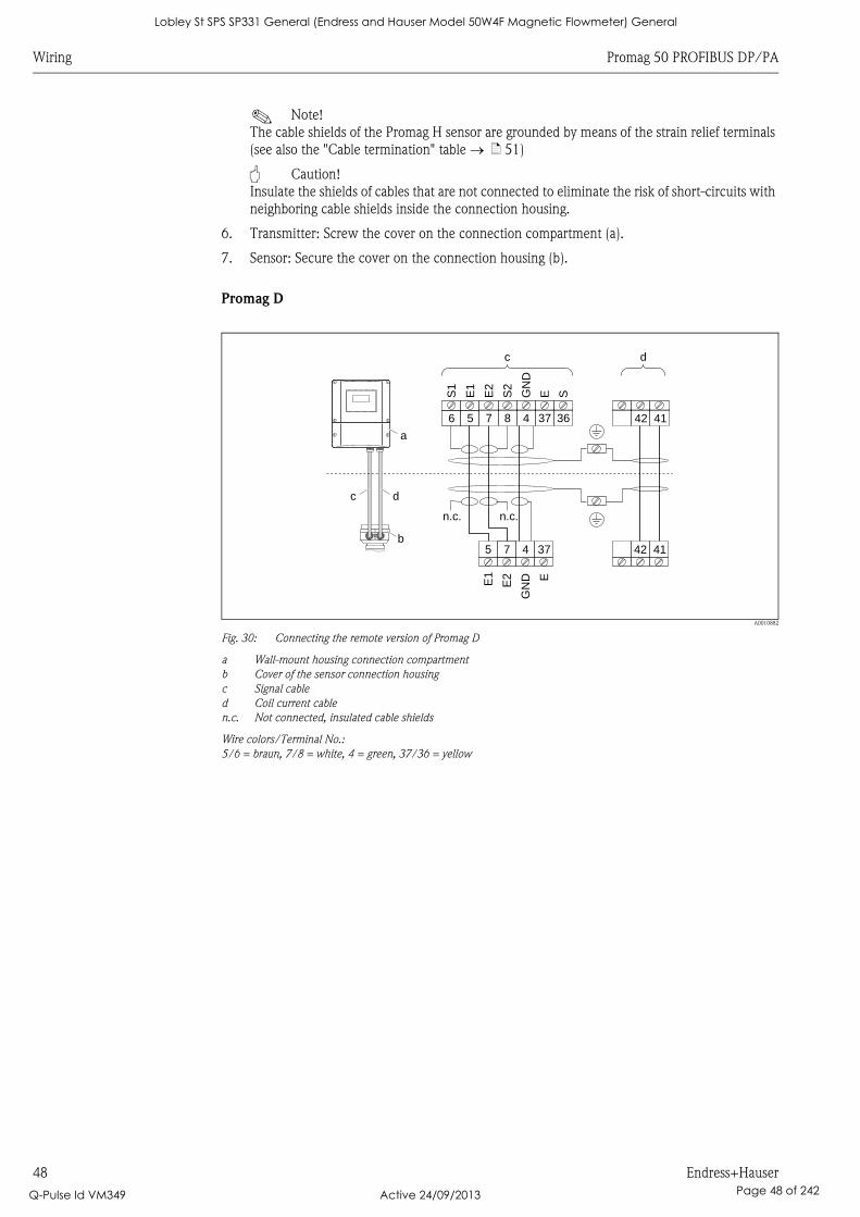
Wiring Promag 50 PROFIBUS DP/PA
48 Endress+Hauser
! Note!
The cable shields of the Promag H sensor are grounded by means of the strain relief terminals
(see also the "Cable termination" table ä 51)
" Caution!
Insulate the shields of cables that are not connected to eliminate the risk of short-circuits with
neighboring cable shields inside the connection housing.
6. Transmitter: Screw the cover on the connection compartment (a).
7. Sensor: Secure the cover on the connection housing (b).
Promag D
A0010882
Fig. 30: Connecting the remote version of Promag D
a Wall-mount housing connection compartment
b Cover of the sensor connection housing
c Signal cable
d Coil current cable
n.c. Not connected, insulated cable shields
Wire colors/Terminal No.:
5/6 = braun, 7/8 = white, 4 = green, 37/36 = yellow
E1
E2
GN
D E
S1
E1
E2
S2
GN
D
E S5 7 4 37 42 41
42 416 5 7 8 4 37 36
n.c. n.c.
dc
c d
a
b
Lobley St SPS SP331 General (Endress and Hauser Model 50W4F Magnetic Flowmeter) General
Q-Pulse Id VM349 Active 24/09/2013 Page 48 of 242
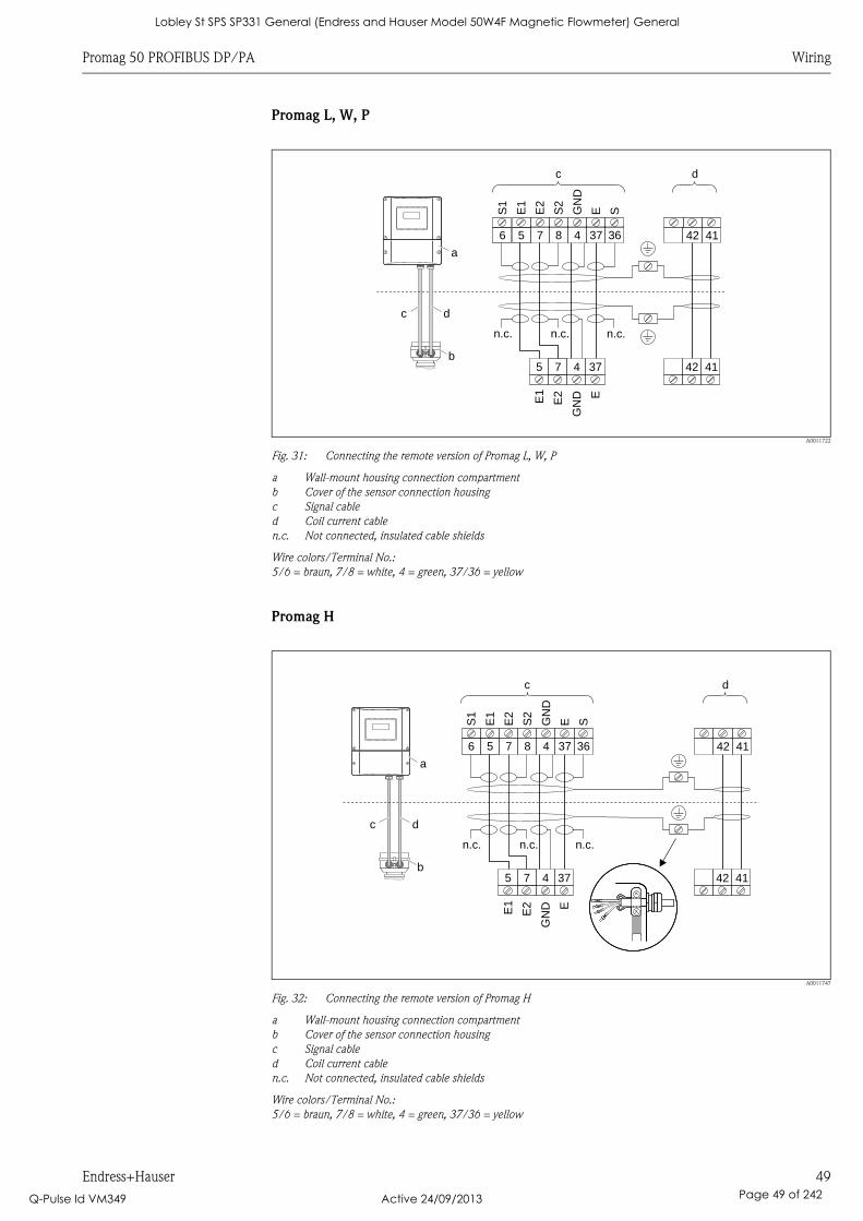
Promag 50 PROFIBUS DP/PA Wiring
Endress+Hauser 49
Promag L, W, P
A0011722
Fig. 31: Connecting the remote version of Promag L, W, P
a Wall-mount housing connection compartment
b Cover of the sensor connection housing
c Signal cable
d Coil current cable
n.c. Not connected, insulated cable shields
Wire colors/Terminal No.:
5/6 = braun, 7/8 = white, 4 = green, 37/36 = yellow
Promag H
A0011747
Fig. 32: Connecting the remote version of Promag H
a Wall-mount housing connection compartment
b Cover of the sensor connection housing
c Signal cable
d Coil current cable
n.c. Not connected, insulated cable shields
Wire colors/Terminal No.:
5/6 = braun, 7/8 = white, 4 = green, 37/36 = yellow
E1
E2
GN
D E
S1
E1
E2
S2
GN
D
E S
5 7 4 37 42 41
42 416 5 7 8 4 37 36
n.c. n.c.
dc
c d
a
b
n.c.
E1
E2
GN
D E
S1
E1
E2
S2
GN
D
E S
5 7 4 37 42 41
42 416 5 7 8 4 37 36
n.c. n.c.
dc
c d
a
b
n.c.
Lobley St SPS SP331 General (Endress and Hauser Model 50W4F Magnetic Flowmeter) General
Q-Pulse Id VM349 Active 24/09/2013 Page 49 of 242
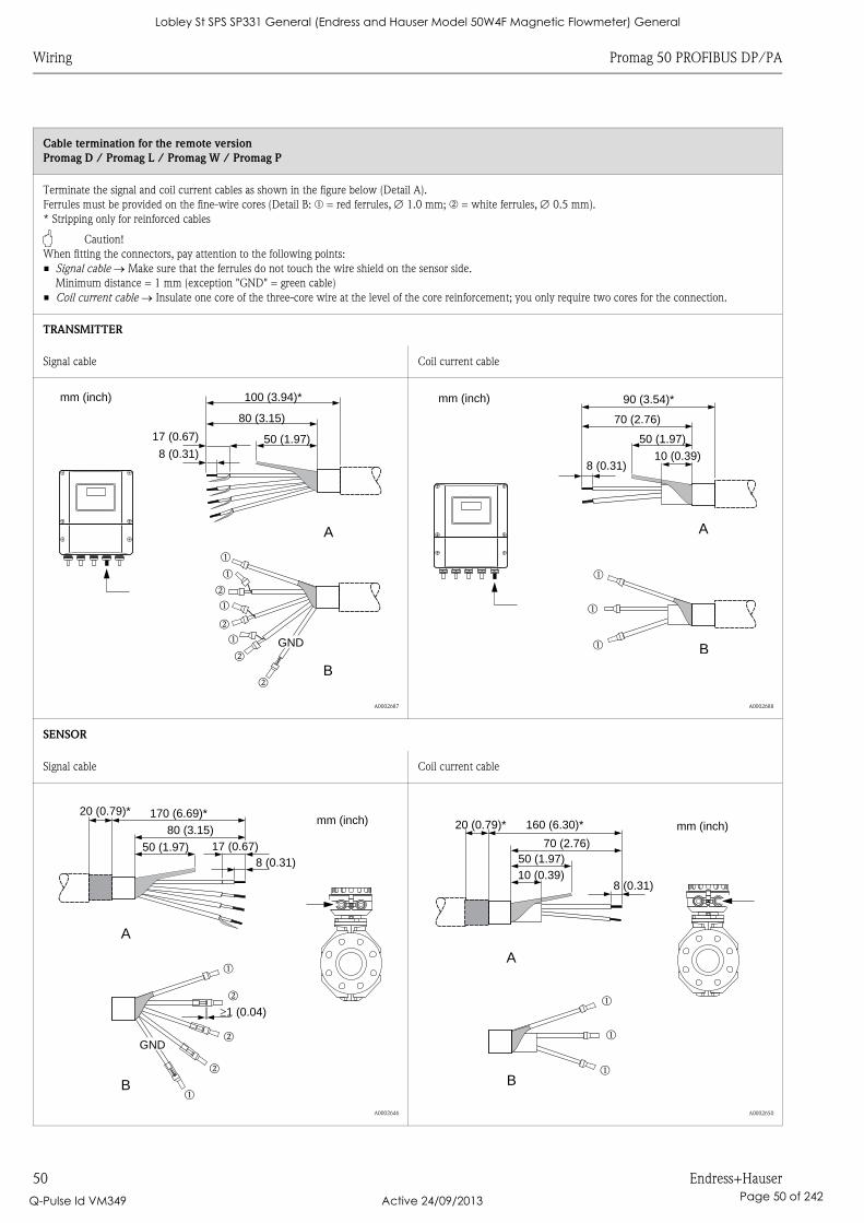
Wiring Promag 50 PROFIBUS DP/PA
50 Endress+Hauser
Cable termination for the remote version
Promag D / Promag L / Promag W / Promag P
Terminate the signal and coil current cables as shown in the figure below (Detail A).
Ferrules must be provided on the fine-wire cores (Detail B: m = red ferrules, 1.0 mm; n = white ferrules, 0.5 mm).
* Stripping only for reinforced cables
" Caution!
When fitting the connectors, pay attention to the following points:
• Signal cable Make sure that the ferrules do not touch the wire shield on the sensor side.
Minimum distance = 1 mm (exception "GND" = green cable)
• Coil current cable Insulate one core of the three-core wire at the level of the core reinforcement; you only require two cores for the connection.
TRANSMITTER
Signal cable Coil current cable
A0002687 A0002688
SENSOR
Signal cable Coil current cable
A0002646 A0002650
A
B
GND
m
m
m
m
n
n
n
n
80 (3.15)
50 (1.97)17 (0.67)
8 (0.31)
100 (3.94)*mm (inch)
A
B
m
m
m
90 (3.54)*
70 (2.76)
50 (1.97)
10 (0.39)8 (0.31)
mm (inch)
A
B
m
n
m
n
n
GND
mm (inch)80 (3.15)
50 (1.97)8 (0.31)
�1 (0.04)
170 (6.69)*20 (0.79)*
17 (0.67)
B
A
m
m
m
mm (inch)
70 (2.76)50 (1.97)
10 (0.39)8 (0.31)
160 (6.30)*20 (0.79)*
Lobley St SPS SP331 General (Endress and Hauser Model 50W4F Magnetic Flowmeter) General
Q-Pulse Id VM349 Active 24/09/2013 Page 50 of 242
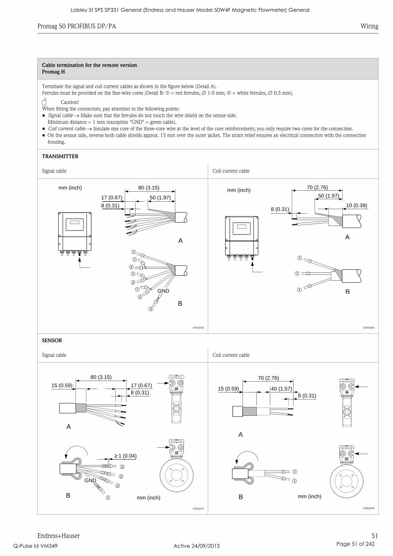
Promag 50 PROFIBUS DP/PA Wiring
Endress+Hauser 51
Cable termination for the remote version
Promag H
Terminate the signal and coil current cables as shown in the figure below (Detail A).
Ferrules must be provided on the fine-wire cores (Detail B: m = red ferrules, 1.0 mm; n = white ferrules, 0.5 mm).
" Caution!
When fitting the connectors, pay attention to the following points:
• Signal cable Make sure that the ferrules do not touch the wire shield on the sensor side.
Minimum distance = 1 mm (exception "GND" = green cable).
• Coil current cable Insulate one core of the three-core wire at the level of the core reinforcement; you only require two cores for the connection.
• On the sensor side, reverse both cable shields approx. 15 mm over the outer jacket. The strain relief ensures an electrical connection with the connection
housing.
TRANSMITTER
Signal cable Coil current cable
A0002686 A0002684
SENSOR
Signal cable Coil current cable
A0002647 A0002648
A
B
GND
m
m
m
m
n
n
n
n
80 (3.15)
50 (1.97)17 (0.67)
8 (0.31)
mm (inch)
A
B
m
m
m
70 (2.76)
50 (1.97)
8 (0.31)
mm (inch)
10 (0.39)
A
B
GND
m
n
n
n
mm (inch)
80 (3.15)
15 (0.59)
8 (0.31)
17 (0.67)
� 1 (0.04)�
A
B
m
m
70 (2.76)
15 ( )0.598 (0.31)
40 (1.57)
mm (inch)
Lobley St SPS SP331 General (Endress and Hauser Model 50W4F Magnetic Flowmeter) General
Q-Pulse Id VM349 Active 24/09/2013 Page 51 of 242
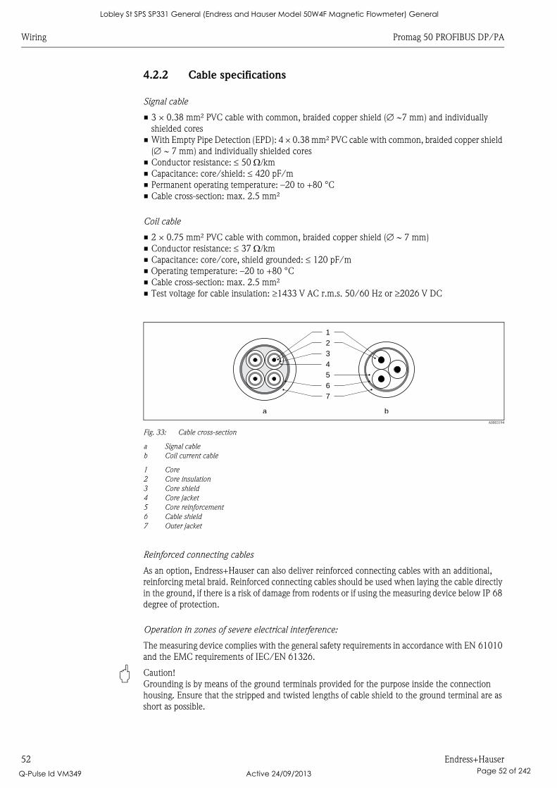
Wiring Promag 50 PROFIBUS DP/PA
52 Endress+Hauser
4.2.2 Cable specifications
Signal cable
• 3 × 0.38 mm² PVC cable with common, braided copper shield ( 7 mm) and individually
shielded cores
• With Empty Pipe Detection (EPD): 4 × 0.38 mm² PVC cable with common, braided copper shield
( 7 mm) and individually shielded cores
• Conductor resistance: 50 km
• Capacitance: core/shield: 420 pF/m
• Permanent operating temperature: –20 to +80 °C
• Cable cross-section: max. 2.5 mm²
Coil cable
• 2 × 0.75 mm² PVC cable with common, braided copper shield ( 7 mm)
• Conductor resistance: 37 km
• Capacitance: core/core, shield grounded: 120 pF/m
• Operating temperature: –20 to +80 °C
• Cable cross-section: max. 2.5 mm²
• Test voltage for cable insulation: 1433 V AC r.m.s. 50/60 Hz or 2026 V DC
A0003194
Fig. 33: Cable cross-section
a Signal cable
b Coil current cable
1 Core
2 Core insulation
3 Core shield
4 Core jacket
5 Core reinforcement
6 Cable shield
7 Outer jacket
Reinforced connecting cables
As an option, Endress+Hauser can also deliver reinforced connecting cables with an additional,
reinforcing metal braid. Reinforced connecting cables should be used when laying the cable directly
in the ground, if there is a risk of damage from rodents or if using the measuring device below IP 68
degree of protection.
Operation in zones of severe electrical interference:
The measuring device complies with the general safety requirements in accordance with EN 61010
and the EMC requirements of IEC/EN 61326.
" Caution!
Grounding is by means of the ground terminals provided for the purpose inside the connection
housing. Ensure that the stripped and twisted lengths of cable shield to the ground terminal are as
short as possible.
1
2
3
4
5
6
7
a b
Lobley St SPS SP331 General (Endress and Hauser Model 50W4F Magnetic Flowmeter) General
Q-Pulse Id VM349 Active 24/09/2013 Page 52 of 242

Promag 50 PROFIBUS DP/PA Wiring
Endress+Hauser 53
4.3 Connecting the measuring unit
4.3.1 Connecting the transmitter
# Warning!
• Risk of electric shock! Switch off the power supply before opening the device. Do not install or
wire the device while it is energized. Failure to comply with this precaution can result in
irreparable damage to the electronics.
• Risk of electric shock! Connect the protective conductor to the ground terminal on the housing
before the power supply is applied (not necessary if the power supply is galvanically isolated).
• Compare the specifications on the nameplate with the local voltage supply and frequency. Also
comply with national regulations governing the installation of electrical equipment.
1. Remove the cover of the connection compartment (f) from the transmitter housing.
2. Feed the power supply cable (a) and the signal cable (b) through the appropriate cable entries.
3. Perform the wiring:
– PROFIBUS DP å 34
– PROFIBUS PA å 35
4. Screw the cover of the connection compartment (f) firmly onto the transmitter housing.
Lobley St SPS SP331 General (Endress and Hauser Model 50W4F Magnetic Flowmeter) General
Q-Pulse Id VM349 Active 24/09/2013 Page 53 of 242
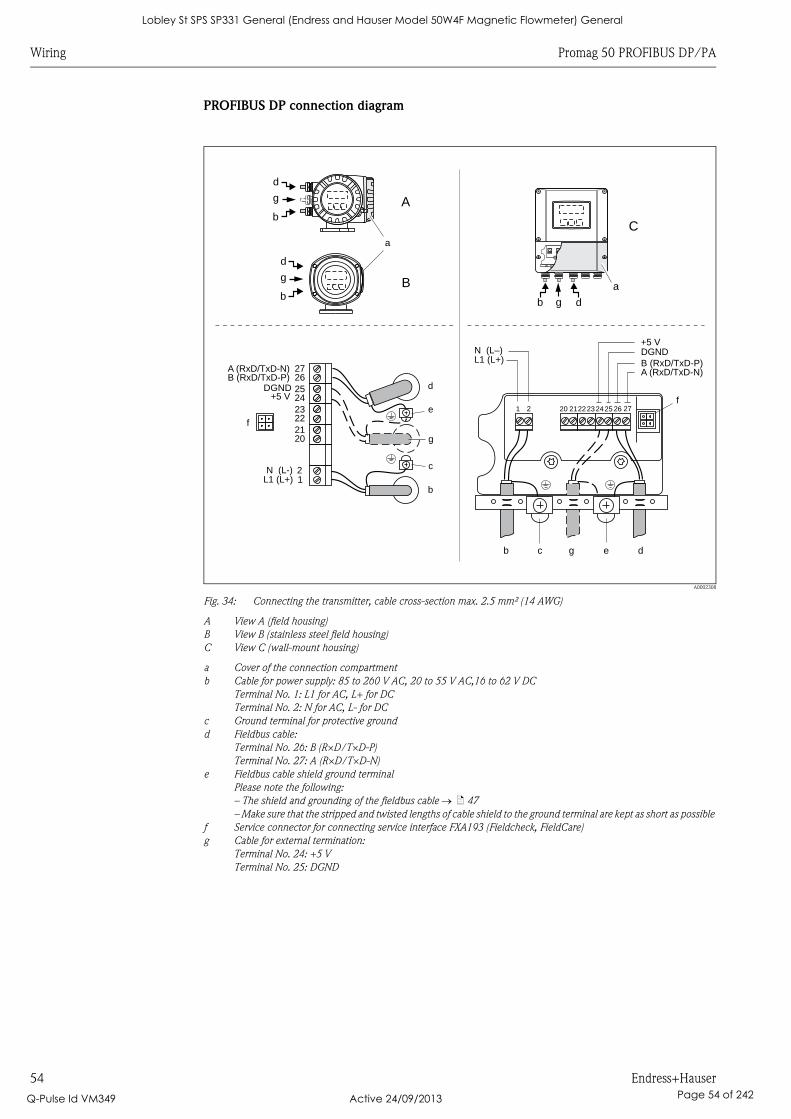
Wiring Promag 50 PROFIBUS DP/PA
54 Endress+Hauser
PROFIBUS DP connection diagram
A0002308
Fig. 34: Connecting the transmitter, cable cross-section max. 2.5 mm² (14 AWG)
A View A (field housing)
B View B (stainless steel field housing)
C View C (wall-mount housing)
a Cover of the connection compartment
b Cable for power supply: 85 to 260 V AC, 20 to 55 V AC,16 to 62 V DC
Terminal No. 1: L1 for AC, L+ for DC
Terminal No. 2: N for AC, L- for DC
c Ground terminal for protective ground
d Fieldbus cable:
Terminal No. 26: B (R×D/T×D-P)
Terminal No. 27: A (R×D/T×D-N)
e Fieldbus cable shield ground terminal
Please note the following:
– The shield and grounding of the fieldbus cable ä 47
– Make sure that the stripped and twisted lengths of cable shield to the ground terminal are kept as short as possible
f Service connector for connecting service interface FXA193 (Fieldcheck, FieldCare)
g Cable for external termination:
Terminal No. 24: +5 V
Terminal No. 25: DGND
C
a
db g
27
25
23
21
21
26
24
22
20
L1 (L+)N (L-)
B ( )RxD/TxD-PA (RxD/TxD-N)
d
c
e
b
g
f
DGND+5 V
1 2
c e
f
b d
222320 21 2425 26 27
DGND+5 V
g
L1 (L+)N (L–)
A (RxD/TxD-N)B ( )RxD/TxD-P
a
A
B
d
g
b
d
g
b
Lobley St SPS SP331 General (Endress and Hauser Model 50W4F Magnetic Flowmeter) General
Q-Pulse Id VM349 Active 24/09/2013 Page 54 of 242
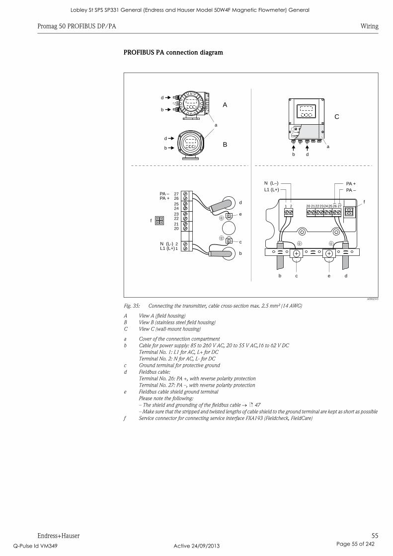
Promag 50 PROFIBUS DP/PA Wiring
Endress+Hauser 55
PROFIBUS PA connection diagram
A0002593
Fig. 35: Connecting the transmitter, cable cross-section max. 2.5 mm² (14 AWG)
A View A (field housing)
B View B (stainless steel field housing)
C View C (wall-mount housing)
a Cover of the connection compartment
b Cable for power supply: 85 to 260 V AC, 20 to 55 V AC,16 to 62 V DC
Terminal No. 1: L1 for AC, L+ for DC
Terminal No. 2: N for AC, L- for DC
c Ground terminal for protective ground
d Fieldbus cable:
Terminal No. 26: PA +, with reverse polarity protection
Terminal No. 27: PA –, with reverse polarity protection
e Fieldbus cable shield ground terminal
Please note the following:
– The shield and grounding of the fieldbus cable ä 47
– Make sure that the stripped and twisted lengths of cable shield to the ground terminal are kept as short as possible
f Service connector for connecting service interface FXA193 (Fieldcheck, FieldCare)
d
c
e
b
27
25
23
21
21
26
24
22
20
L1 (L+)
PA +
N (L-)
PA –
f
PA –
PA +
1 2
c e
f
b d
222320 21 2425 26 27
L1 (L+)
N (L–)
C
a
db
a
A
B
d
b
d
b
Lobley St SPS SP331 General (Endress and Hauser Model 50W4F Magnetic Flowmeter) General
Q-Pulse Id VM349 Active 24/09/2013 Page 55 of 242
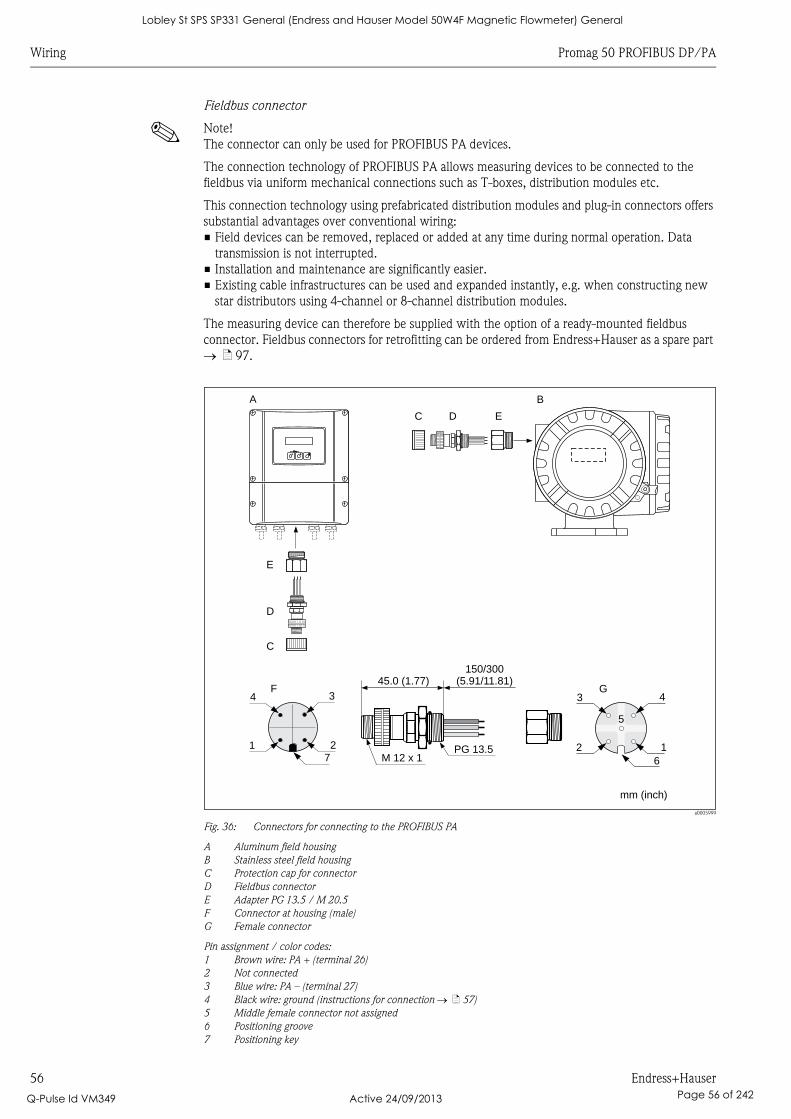
Wiring Promag 50 PROFIBUS DP/PA
56 Endress+Hauser
Fieldbus connector
! Note!
The connector can only be used for PROFIBUS PA devices.
The connection technology of PROFIBUS PA allows measuring devices to be connected to the
fieldbus via uniform mechanical connections such as T-boxes, distribution modules etc.
This connection technology using prefabricated distribution modules and plug-in connectors offers
substantial advantages over conventional wiring:
• Field devices can be removed, replaced or added at any time during normal operation. Data
transmission is not interrupted.
• Installation and maintenance are significantly easier.
• Existing cable infrastructures can be used and expanded instantly, e.g. when constructing new
star distributors using 4-channel or 8-channel distribution modules.
The measuring device can therefore be supplied with the option of a ready-mounted fieldbus
connector. Fieldbus connectors for retrofitting can be ordered from Endress+Hauser as a spare part
ä 97.
a0005999
Fig. 36: Connectors for connecting to the PROFIBUS PA
A Aluminum field housing
B Stainless steel field housing
C Protection cap for connector
D Fieldbus connector
E Adapter PG 13.5 / M 20.5
F Connector at housing (male)
G Female connector
Pin assignment / color codes:
1 Brown wire: PA + (terminal 26)
2 Not connected
3 Blue wire: PA – (terminal 27)
4 Black wire: ground (instructions for connection ä 57)
5 Middle female connector not assigned
6 Positioning groove
7 Positioning key
PG 13.5M 12 x 1
150/300(5.91/11.81)45.0 (1.77)
mm (inch)
C D E
3 4
2 1
G
5
6
4
1 2
F3
7
B
C
D
E
A
Esc
E- +
Lobley St SPS SP331 General (Endress and Hauser Model 50W4F Magnetic Flowmeter) General
Q-Pulse Id VM349 Active 24/09/2013 Page 56 of 242
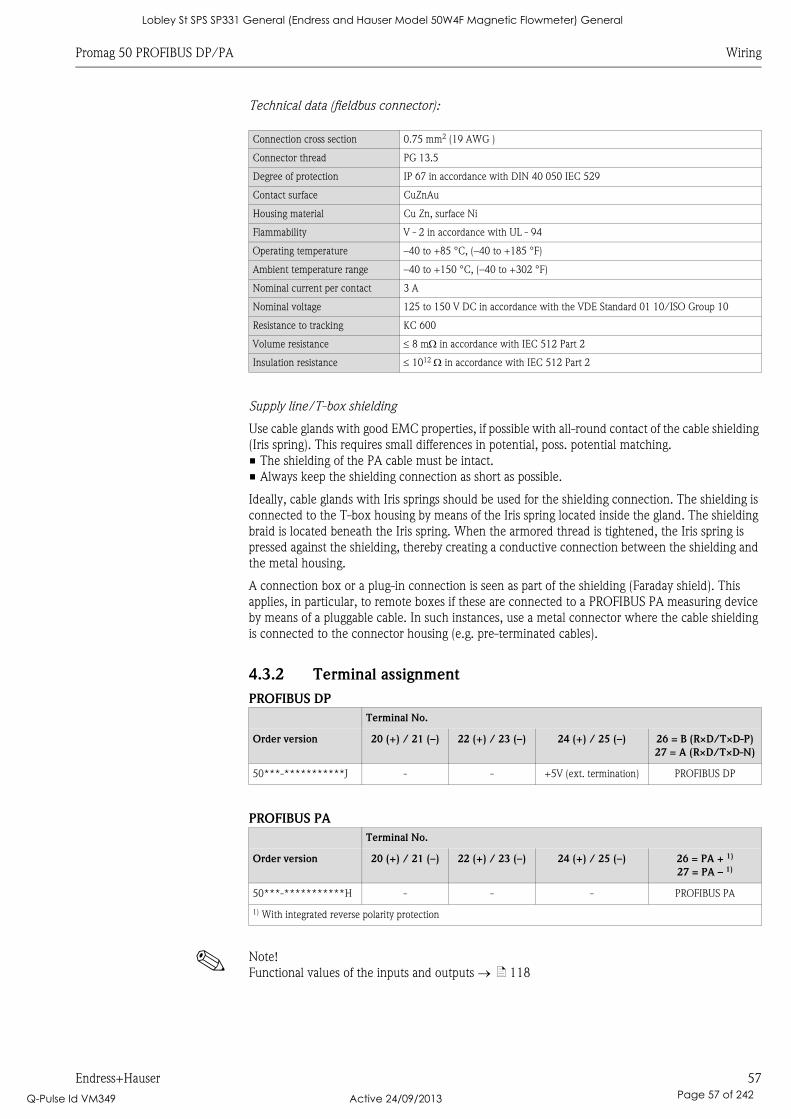
Promag 50 PROFIBUS DP/PA Wiring
Endress+Hauser 57
Technical data (fieldbus connector):
Supply line/T-box shielding
Use cable glands with good EMC properties, if possible with all-round contact of the cable shielding
(Iris spring). This requires small differences in potential, poss. potential matching.
• The shielding of the PA cable must be intact.
• Always keep the shielding connection as short as possible.
Ideally, cable glands with Iris springs should be used for the shielding connection. The shielding is
connected to the T-box housing by means of the Iris spring located inside the gland. The shielding
braid is located beneath the Iris spring. When the armored thread is tightened, the Iris spring is
pressed against the shielding, thereby creating a conductive connection between the shielding and
the metal housing.
A connection box or a plug-in connection is seen as part of the shielding (Faraday shield). This
applies, in particular, to remote boxes if these are connected to a PROFIBUS PA measuring device
by means of a pluggable cable. In such instances, use a metal connector where the cable shielding
is connected to the connector housing (e.g. pre-terminated cables).
4.3.2 Terminal assignment
PROFIBUS DP
PROFIBUS PA
! Note!
Functional values of the inputs and outputs ä 118
Connection cross section 0.75 mm2 (19 AWG )
Connector thread PG 13.5
Degree of protection IP 67 in accordance with DIN 40 050 IEC 529
Contact surface CuZnAu
Housing material Cu Zn, surface Ni
Flammability V - 2 in accordance with UL - 94
Operating temperature –40 to +85 °C, (–40 to +185 °F)
Ambient temperature range –40 to +150 °C, (–40 to +302 °F)
Nominal current per contact 3 A
Nominal voltage 125 to 150 V DC in accordance with the VDE Standard 01 10/ISO Group 10
Resistance to tracking KC 600
Volume resistance 8 m in accordance with IEC 512 Part 2
Insulation resistance 1012 in accordance with IEC 512 Part 2
Terminal No.
Order version 20 (+) / 21 (–) 22 (+) / 23 (–) 24 (+) / 25 (–) 26 = B (R×D/T×D-P)
27 = A (R×D/T×D-N)
50***-***********J - - +5V (ext. termination) PROFIBUS DP
Terminal No.
Order version 20 (+) / 21 (–) 22 (+) / 23 (–) 24 (+) / 25 (–) 26 = PA + 1)
27 = PA – 1)
50***-***********H - - - PROFIBUS PA
1) With integrated reverse polarity protection
Lobley St SPS SP331 General (Endress and Hauser Model 50W4F Magnetic Flowmeter) General
Q-Pulse Id VM349 Active 24/09/2013 Page 57 of 242
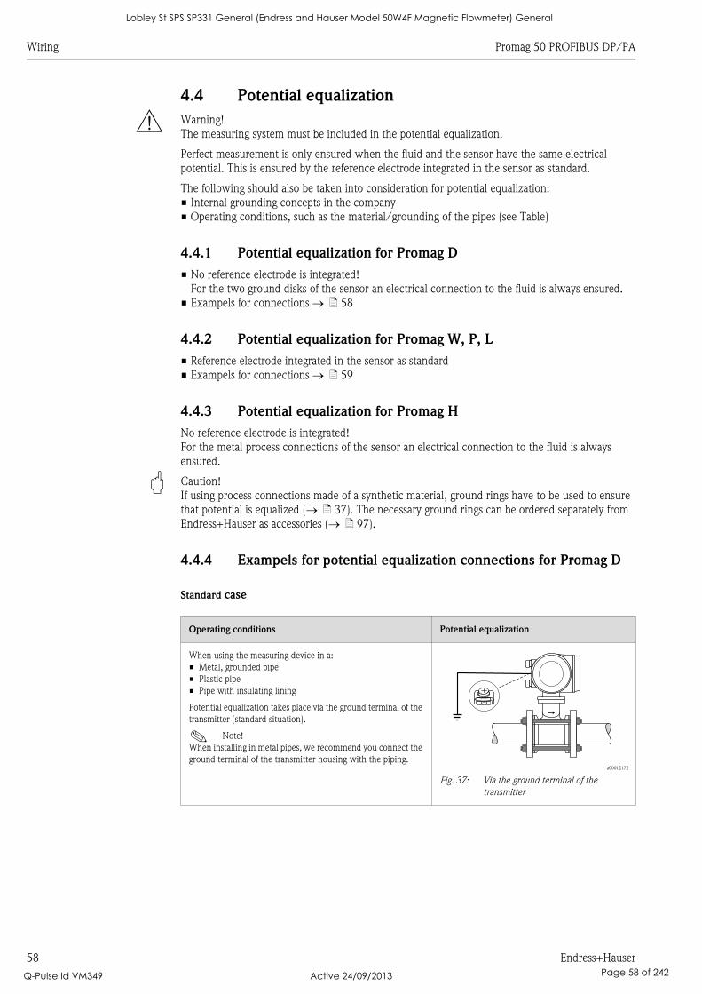
Wiring Promag 50 PROFIBUS DP/PA
58 Endress+Hauser
4.4 Potential equalization
# Warning!
The measuring system must be included in the potential equalization.
Perfect measurement is only ensured when the fluid and the sensor have the same electrical
potential. This is ensured by the reference electrode integrated in the sensor as standard.
The following should also be taken into consideration for potential equalization:
• Internal grounding concepts in the company
• Operating conditions, such as the material/grounding of the pipes (see Table)
4.4.1 Potential equalization for Promag D
• No reference electrode is integrated!
For the two ground disks of the sensor an electrical connection to the fluid is always ensured.
• Exampels for connections ä 58
4.4.2 Potential equalization for Promag W, P, L
• Reference electrode integrated in the sensor as standard
• Exampels for connections ä 59
4.4.3 Potential equalization for Promag H
No reference electrode is integrated!
For the metal process connections of the sensor an electrical connection to the fluid is always
ensured.
" Caution!
If using process connections made of a synthetic material, ground rings have to be used to ensure
that potential is equalized ( ä 37). The necessary ground rings can be ordered separately from
Endress+Hauser as accessories ( ä 97).
4.4.4 Exampels for potential equalization connections for Promag D
Standard case
Operating conditions Potential equalization
When using the measuring device in a:
• Metal, grounded pipe
• Plastic pipe
• Pipe with insulating lining
Potential equalization takes place via the ground terminal of the
transmitter (standard situation).
! Note!
When installing in metal pipes, we recommend you connect the
ground terminal of the transmitter housing with the piping.a00012172
Fig. 37: Via the ground terminal of the
transmitter
Lobley St SPS SP331 General (Endress and Hauser Model 50W4F Magnetic Flowmeter) General
Q-Pulse Id VM349 Active 24/09/2013 Page 58 of 242
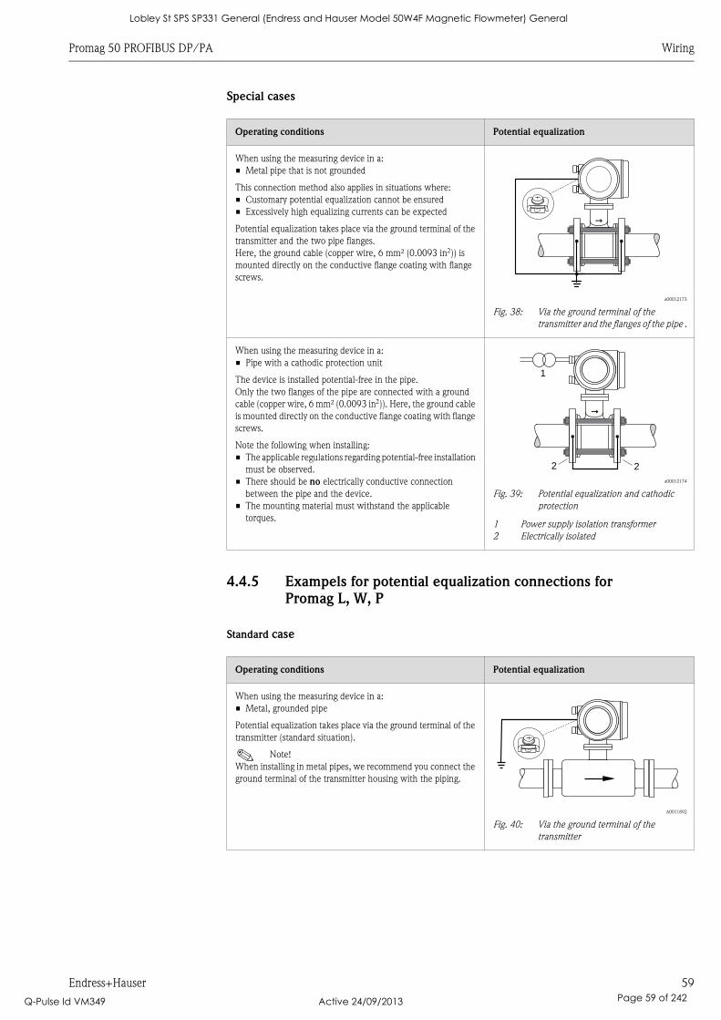
Promag 50 PROFIBUS DP/PA Wiring
Endress+Hauser 59
Special cases
4.4.5 Exampels for potential equalization connections for
Promag L, W, P
Standard case
Operating conditions Potential equalization
When using the measuring device in a:
• Metal pipe that is not grounded
This connection method also applies in situations where:
• Customary potential equalization cannot be ensured
• Excessively high equalizing currents can be expected
Potential equalization takes place via the ground terminal of the
transmitter and the two pipe flanges.
Here, the ground cable (copper wire, 6 mm² (0.0093 in)) is
mounted directly on the conductive flange coating with flange
screws.
a00012173
Fig. 38: Via the ground terminal of the
transmitter and the flanges of the pipe .
When using the measuring device in a:
• Pipe with a cathodic protection unit
The device is installed potential-free in the pipe.
Only the two flanges of the pipe are connected with a ground
cable (copper wire, 6 mm² (0.0093 in)). Here, the ground cable
is mounted directly on the conductive flange coating with flange
screws.
Note the following when installing:
• The applicable regulations regarding potential-free installation
must be observed.
• There should be no electrically conductive connection
between the pipe and the device.
• The mounting material must withstand the applicable
torques.
a00012174
Fig. 39: Potential equalization and cathodic
protection
1 Power supply isolation transformer
2 Electrically isolated
Operating conditions Potential equalization
When using the measuring device in a:
• Metal, grounded pipe
Potential equalization takes place via the ground terminal of the
transmitter (standard situation).
! Note!
When installing in metal pipes, we recommend you connect the
ground terminal of the transmitter housing with the piping.
A0011892
Fig. 40: Via the ground terminal of the
transmitter
2 2
1
Lobley St SPS SP331 General (Endress and Hauser Model 50W4F Magnetic Flowmeter) General
Q-Pulse Id VM349 Active 24/09/2013 Page 59 of 242
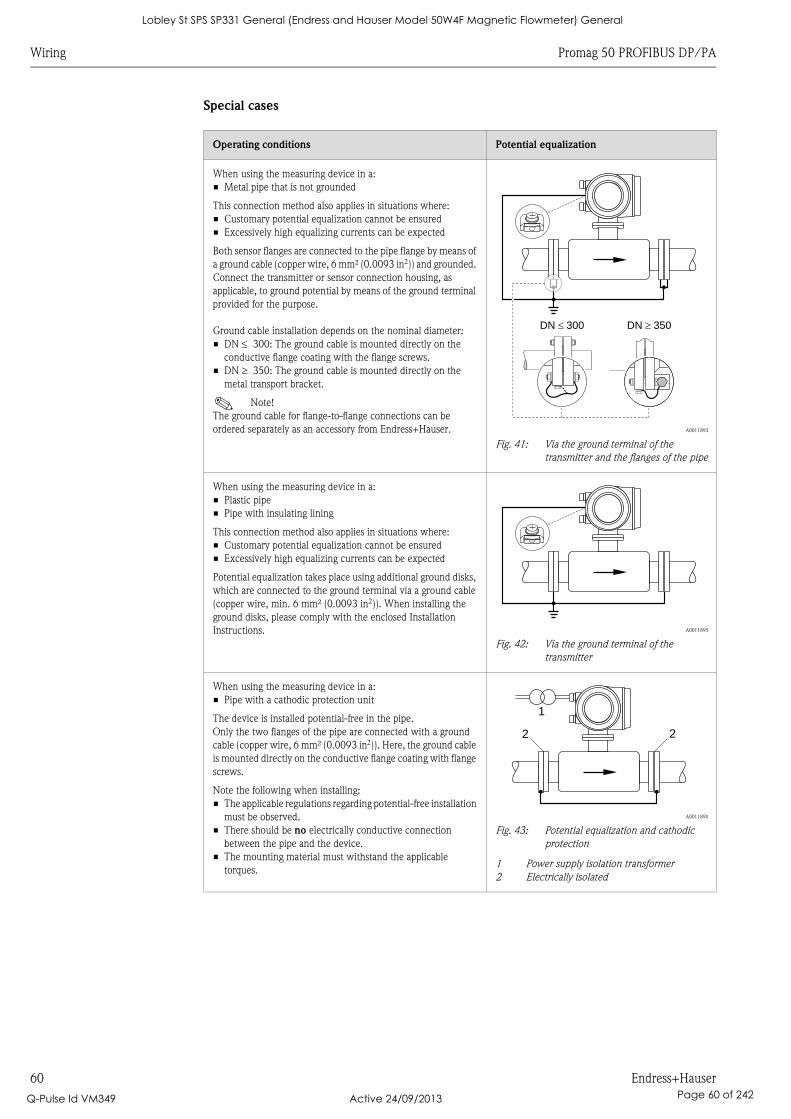
Wiring Promag 50 PROFIBUS DP/PA
60 Endress+Hauser
Special cases
Operating conditions Potential equalization
When using the measuring device in a:
• Metal pipe that is not grounded
This connection method also applies in situations where:
• Customary potential equalization cannot be ensured
• Excessively high equalizing currents can be expected
Both sensor flanges are connected to the pipe flange by means of
a ground cable (copper wire, 6 mm² (0.0093 in)) and grounded.
Connect the transmitter or sensor connection housing, as
applicable, to ground potential by means of the ground terminal
provided for the purpose.
Ground cable installation depends on the nominal diameter:
• DN 300: The ground cable is mounted directly on the
conductive flange coating with the flange screws.
• DN 350: The ground cable is mounted directly on the
metal transport bracket.
! Note!
The ground cable for flange-to-flange connections can be
ordered separately as an accessory from Endress+Hauser. A0011893
Fig. 41: Via the ground terminal of the
transmitter and the flanges of the pipe
When using the measuring device in a:
• Plastic pipe
• Pipe with insulating lining
This connection method also applies in situations where:
• Customary potential equalization cannot be ensured
• Excessively high equalizing currents can be expected
Potential equalization takes place using additional ground disks,
which are connected to the ground terminal via a ground cable
(copper wire, min. 6 mm² (0.0093 in)). When installing the
ground disks, please comply with the enclosed Installation
Instructions. A0011895
Fig. 42: Via the ground terminal of the
transmitter
When using the measuring device in a:
• Pipe with a cathodic protection unit
The device is installed potential-free in the pipe.
Only the two flanges of the pipe are connected with a ground
cable (copper wire, 6 mm² (0.0093 in)). Here, the ground cable
is mounted directly on the conductive flange coating with flange
screws.
Note the following when installing:
• The applicable regulations regarding potential-free installation
must be observed.
• There should be no electrically conductive connection
between the pipe and the device.
• The mounting material must withstand the applicable
torques.
A0011896
Fig. 43: Potential equalization and cathodic
protection
1 Power supply isolation transformer
2 Electrically isolated
DN 300� DN 350�
1
2 2
Lobley St SPS SP331 General (Endress and Hauser Model 50W4F Magnetic Flowmeter) General
Q-Pulse Id VM349 Active 24/09/2013 Page 60 of 242
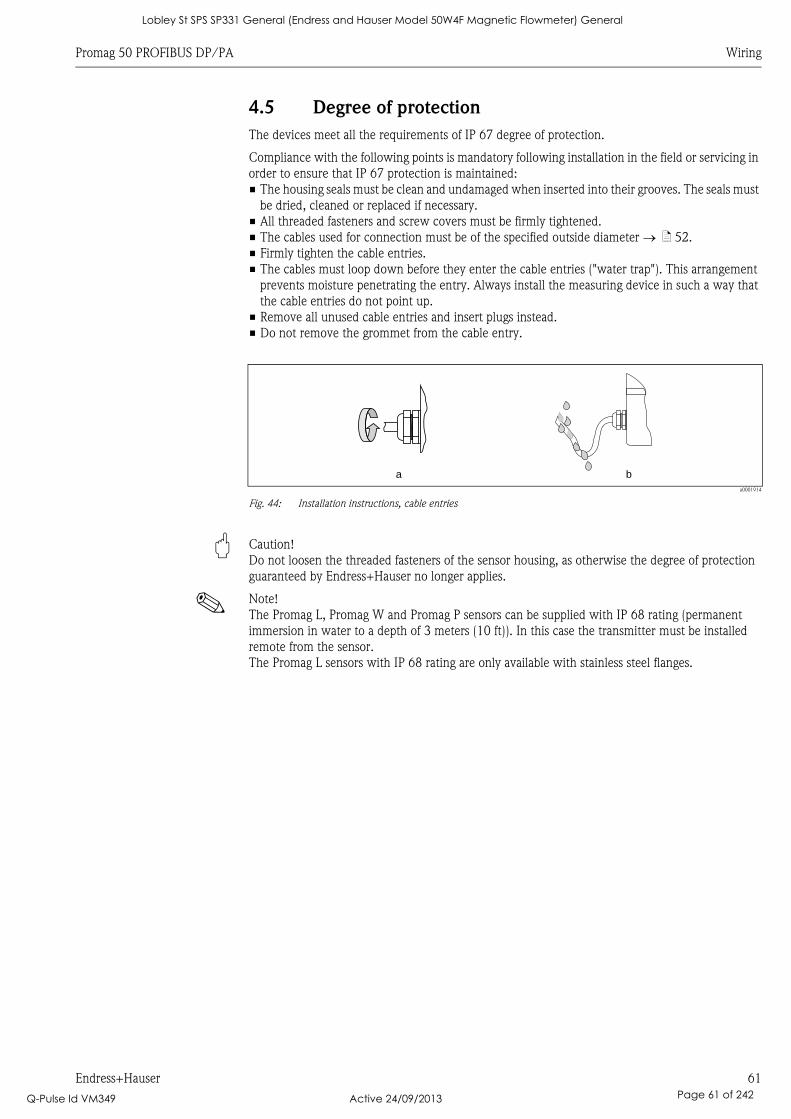
Promag 50 PROFIBUS DP/PA Wiring
Endress+Hauser 61
4.5 Degree of protection
The devices meet all the requirements of IP 67 degree of protection.
Compliance with the following points is mandatory following installation in the field or servicing in
order to ensure that IP 67 protection is maintained:
• The housing seals must be clean and undamaged when inserted into their grooves. The seals must
be dried, cleaned or replaced if necessary.
• All threaded fasteners and screw covers must be firmly tightened.
• The cables used for connection must be of the specified outside diameter ä 52.
• Firmly tighten the cable entries.
• The cables must loop down before they enter the cable entries ("water trap"). This arrangement
prevents moisture penetrating the entry. Always install the measuring device in such a way that
the cable entries do not point up.
• Remove all unused cable entries and insert plugs instead.
• Do not remove the grommet from the cable entry.
a0001914
Fig. 44: Installation instructions, cable entries
" Caution!
Do not loosen the threaded fasteners of the sensor housing, as otherwise the degree of protection
guaranteed by Endress+Hauser no longer applies.
! Note!
The Promag L, Promag W and Promag P sensors can be supplied with IP 68 rating (permanent
immersion in water to a depth of 3 meters (10 ft)). In this case the transmitter must be installed
remote from the sensor.
The Promag L sensors with IP 68 rating are only available with stainless steel flanges.
a b
Lobley St SPS SP331 General (Endress and Hauser Model 50W4F Magnetic Flowmeter) General
Q-Pulse Id VM349 Active 24/09/2013 Page 61 of 242
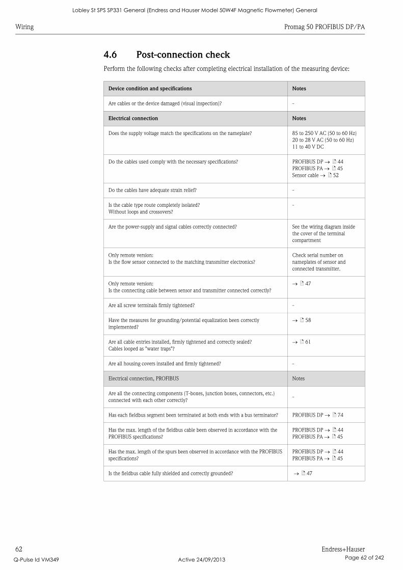
Wiring Promag 50 PROFIBUS DP/PA
62 Endress+Hauser
4.6 Post-connection check
Perform the following checks after completing electrical installation of the measuring device:
Device condition and specifications Notes
Are cables or the device damaged (visual inspection)? -
Electrical connection Notes
Does the supply voltage match the specifications on the nameplate? 85 to 250 V AC (50 to 60 Hz)
20 to 28 V AC (50 to 60 Hz)
11 to 40 V DC
Do the cables used comply with the necessary specifications? PROFIBUS DP ä 44
PROFIBUS PA ä 45
Sensor cable ä 52
Do the cables have adequate strain relief? -
Is the cable type route completely isolated?
Without loops and crossovers?
-
Are the power-supply and signal cables correctly connected? See the wiring diagram inside
the cover of the terminal
compartment
Only remote version:
Is the flow sensor connected to the matching transmitter electronics?
Check serial number on
nameplates of sensor and
connected transmitter.
Only remote version:
Is the connecting cable between sensor and transmitter connected correctly?
ä 47
Are all screw terminals firmly tightened? -
Have the measures for grounding/potential equalization been correctly
implemented?
ä 58
Are all cable entries installed, firmly tightened and correctly sealed?
Cables looped as "water traps"?
ä 61
Are all housing covers installed and firmly tightened? -
Electrical connection, PROFIBUS Notes
Are all the connecting components (T-boxes, junction boxes, connectors, etc.)
connected with each other correctly?-
Has each fieldbus segment been terminated at both ends with a bus terminator? PROFIBUS DP ä 74
Has the max. length of the fieldbus cable been observed in accordance with the
PROFIBUS specifications?
PROFIBUS DP ä 44
PROFIBUS PA ä 45
Has the max. length of the spurs been observed in accordance with the PROFIBUS
specifications?
PROFIBUS DP ä 44
PROFIBUS PA ä 45
Is the fieldbus cable fully shielded and correctly grounded? ä 47
Lobley St SPS SP331 General (Endress and Hauser Model 50W4F Magnetic Flowmeter) General
Q-Pulse Id VM349 Active 24/09/2013 Page 62 of 242
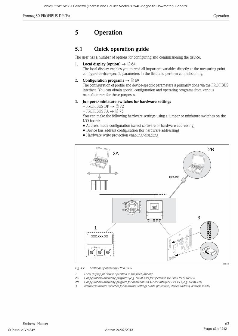
Promag 50 PROFIBUS DP/PA Operation
Endress+Hauser 63
5 Operation
5.1 Quick operation guide
The user has a number of options for configuring and commissioning the device:
1. Local display (option) ä 64
The local display enables you to read all important variables directly at the measuring point,
configure device-specific parameters in the field and perform commissioning.
2. Configuration programs ä 69
The configuration of profile and device-specific parameters is primarily done via the PROFIBUS
interface. You can obtain special configuration and operating programs from various
manufacturers for these purposes.
3. Jumpers/miniature switches for hardware settings
– PROFIBUS DP ä 72
– PROFIBUS PA ä 75
You can make the following hardware settings using a jumper or miniature switches on the
I/O board:
• Address mode configuration (select software or hardware addressing)
• Device bus address configuration (for hardware addressing)
• Hardware write protection enabling/disabling
a0001318
Fig. 45: Methods of operating PROFIBUS
1 Local display for device operation in the field (option)
2A Configuration/operating programs (e.g. FieldCare) for operation via PROFIBUS DP/PA
2B Configuration/operating program for operation via service interface FXA193 (e.g. FieldCare)
3 Jumper/miniature switches for hardware settings (write protection, device address, address mode)
2A
3
1
Esc
E- +
Esc
E+-
XXX.XXX.XX
Esc
E- +
FXA193
2B
Lobley St SPS SP331 General (Endress and Hauser Model 50W4F Magnetic Flowmeter) General
Q-Pulse Id VM349 Active 24/09/2013 Page 63 of 242
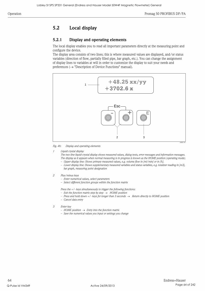
Operation Promag 50 PROFIBUS DP/PA
64 Endress+Hauser
5.2 Local display
5.2.1 Display and operating elements
The local display enables you to read all important parameters directly at the measuring point and
configure the device.
The display area consists of two lines; this is where measured values are displayed, and/or status
variables (direction of flow, partially filled pipe, bar graph, etc.). You can change the assignment
of display lines to variables at will in order to customize the display to suit your needs and
preferences ( "Description of Device Functions" manual).
A0001141
Fig. 46: Display and operating elements
1 Liquid crystal display
The two-line liquid-crystal display shows measured values, dialog texts, error messages and information messages.
The display as it appears when normal measuring is in progress is known as the HOME position (operating mode).
– Upper display line: Shows primary measured values, e.g. volume flow in [ml/min] or in [%].
– Lower display line: Shows supplementary measured variables and status variables, e.g. totalizer reading in [m3],
bar graph, measuring point designation
2 Plus/minus keys
– Enter numerical values, select parameters
– Select different function groups within the function matrix
Press the +/- keys simultaneously to trigger the following functions:
– Exit the function matrix step by step HOME position
– Press and hold down +/- keys for longer than 3 seconds Return directly to HOME position
– Cancel data entry
3 Enter key
– HOME position Entry into the function matrix
– Save the numerical values you input or settings you change
Esc
E+-
1
32
+48.25 xx/yy
+3702.6 x
Lobley St SPS SP331 General (Endress and Hauser Model 50W4F Magnetic Flowmeter) General
Q-Pulse Id VM349 Active 24/09/2013 Page 64 of 242
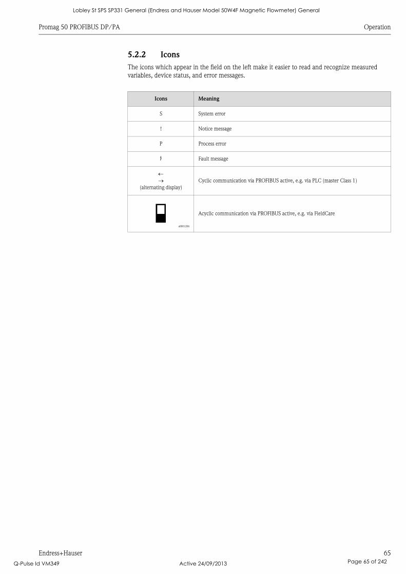
Promag 50 PROFIBUS DP/PA Operation
Endress+Hauser 65
5.2.2 Icons
The icons which appear in the field on the left make it easier to read and recognize measured
variables, device status, and error messages.
Icons Meaning
S System error
! Notice message
P Process error
$ Fault message
(alternating display)
Cyclic communication via PROFIBUS active, e.g. via PLC (master Class 1)
a0001206
Acyclic communication via PROFIBUS active, e.g. via FieldCare
Lobley St SPS SP331 General (Endress and Hauser Model 50W4F Magnetic Flowmeter) General
Q-Pulse Id VM349 Active 24/09/2013 Page 65 of 242
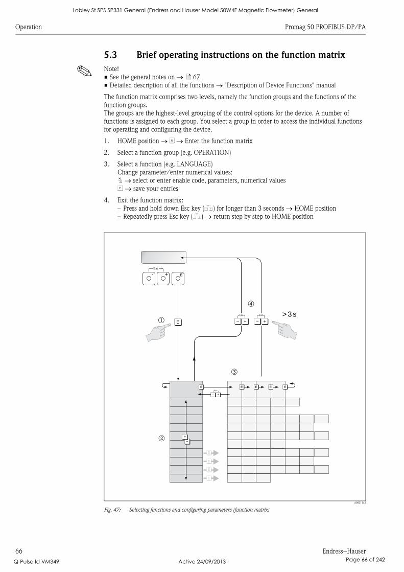
Operation Promag 50 PROFIBUS DP/PA
66 Endress+Hauser
5.3 Brief operating instructions on the function matrix
! Note!
• See the general notes on ä 67.
• Detailed description of all the functions "Description of Device Functions" manual
The function matrix comprises two levels, namely the function groups and the functions of the
function groups.
The groups are the highest-level grouping of the control options for the device. A number of
functions is assigned to each group. You select a group in order to access the individual functions
for operating and configuring the device.
1. HOME position F Enter the function matrix
2. Select a function group (e.g. OPERATION)
3. Select a function (e.g. LANGUAGE)
Change parameter/enter numerical values:
P select or enter enable code, parameters, numerical values
F save your entries
4. Exit the function matrix:
– Press and hold down Esc key (X) for longer than 3 seconds HOME position
– Repeatedly press Esc key (X) return step by step to HOME position
A0001142
Fig. 47: Selecting functions and configuring parameters (function matrix)
>3s
- + E
Esc
E
E
E
E
E E E E E
–
+
+
Esc
–+
Esc
–
+
Esc
–
Em
n
o
p
Lobley St SPS SP331 General (Endress and Hauser Model 50W4F Magnetic Flowmeter) General
Q-Pulse Id VM349 Active 24/09/2013 Page 66 of 242

Promag 50 PROFIBUS DP/PA Operation
Endress+Hauser 67
5.3.1 General notes
The Quick Setup menu ( ä 77) is adequate for commissioning in most instances. Complex
measuring operations on the other hand necessitate additional functions that you can configure as
necessary and customize to suit your process parameters. The function matrix, therefore, comprises
a multiplicity of additional functions which, for the sake of clarity, are arranged in a number of
function groups.
Comply with the following instructions when configuring functions:
• You select functions as described on ä 66.
• You can switch off certain functions (OFF). If you do so, related functions in other function groups
will no longer be displayed.
• Certain functions prompt you to confirm your data entries.
Press P to select "SURE [ YES ]" and press F again to confirm. This saves your setting or starts a
function, as applicable.
• Return to the HOME position is automatic if no key is pressed for 5 minutes.
! Note!
• The transmitter continues to measure while data entry is in progress, i.e. the current measured
values are output via the signal outputs in the normal way.
• If the power supply fails, all preset and configured values remain safely stored in the EEPROM.
" Caution!
All functions are described in detail, including the function matrix itself, in the "Description of
Device Functions" manual, which is a separate part of these Operating Instructions.
5.3.2 Enabling the programming mode
The function matrix can be disabled. Disabling the function matrix rules out the possibility of
inadvertent changes to device functions, numerical values or factory settings. A numerical code
(factory setting = 50) has to be entered before settings can be changed.
If you use a code number of your choice, you exclude the possibility of unauthorized persons
accessing data ( see the "Description of Device Functions" manual).
Comply with the following instructions when entering codes:
• If programming is disabled and the P operating elements are pressed in any function, a prompt
for the code automatically appears on the display.
• If "0" is specified as the customer's code, programming is always enabled.
• The Endress+Hauser service organization can be of assistance if you mislay your personal code.
" Caution!
Changing certain parameters such as all sensor characteristics, for example, influences numerous
functions of the entire measuring system, particularly measuring accuracy.
There is no need to change these parameters under normal circumstances and consequently, they
are protected by a special code known only to the Endress+Hauser service organization.
Please contact Endress+Hauser if you have any questions.
5.3.3 Disabling the programming mode
Programming is disabled if you do not press the operating elements within 60 seconds following
automatic return to the HOME position.
You can also disable programming in the "ACCESS CODE" function by entering any number
(other than the customer's code).
Lobley St SPS SP331 General (Endress and Hauser Model 50W4F Magnetic Flowmeter) General
Q-Pulse Id VM349 Active 24/09/2013 Page 67 of 242
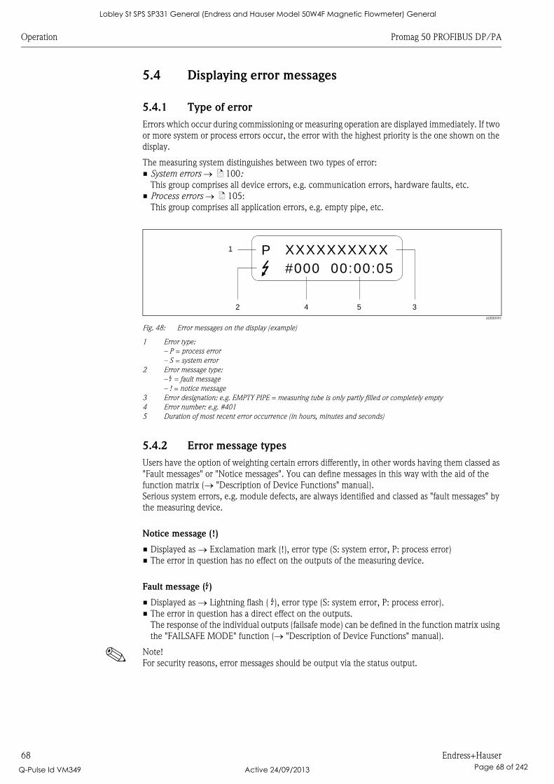
Operation Promag 50 PROFIBUS DP/PA
68 Endress+Hauser
5.4 Displaying error messages
5.4.1 Type of error
Errors which occur during commissioning or measuring operation are displayed immediately. If two
or more system or process errors occur, the error with the highest priority is the one shown on the
display.
The measuring system distinguishes between two types of error:
• System errors ä 100:
This group comprises all device errors, e.g. communication errors, hardware faults, etc.
• Process errors ä 105:
This group comprises all application errors, e.g. empty pipe, etc.
A0000991
Fig. 48: Error messages on the display (example)
1 Error type:
– P = process error
– S = system error
2 Error message type:
– $ = fault message
– ! = notice message
3 Error designation: e.g. EMPTY PIPE = measuring tube is only partly filled or completely empty
4 Error number: e.g. #401
5 Duration of most recent error occurrence (in hours, minutes and seconds)
5.4.2 Error message types
Users have the option of weighting certain errors differently, in other words having them classed as
"Fault messages" or "Notice messages". You can define messages in this way with the aid of the
function matrix ( "Description of Device Functions" manual).
Serious system errors, e.g. module defects, are always identified and classed as "fault messages" by
the measuring device.
Notice message (!)
• Displayed as Exclamation mark (!), error type (S: system error, P: process error)
• The error in question has no effect on the outputs of the measuring device.
Fault message ($)
• Displayed as Lightning flash ( $), error type (S: system error, P: process error).
• The error in question has a direct effect on the outputs.
The response of the individual outputs (failsafe mode) can be defined in the function matrix using
the "FAILSAFE MODE" function ( "Description of Device Functions" manual).
! Note!
For security reasons, error messages should be output via the status output.
1
2 4 5 3
XXXXXXXXXX
#000 00:00:05
P
Lobley St SPS SP331 General (Endress and Hauser Model 50W4F Magnetic Flowmeter) General
Q-Pulse Id VM349 Active 24/09/2013 Page 68 of 242

Promag 50 PROFIBUS DP/PA Operation
Endress+Hauser 69
5.5 Operating options
For the complete operation of the measuring device, including device-specific commands, there are
DD files available to the user to provide the following operating aids and programs:
5.5.1 FieldCare
FieldCare is Endress+Hauser’s FDT-based plant Asset Management Tool and allows the
configuration and diagnosis of intelligent field devices. By using status information, you also have a
simple but effective tool for monitoring devices.
5.5.2 Operating program "SIMATIC PDM" (Siemens)
SIMATIC PDM is a standardized, manufacturer-independent tool for the operation, configuration,
maintenance and diagnosis of intelligent field devices.
Lobley St SPS SP331 General (Endress and Hauser Model 50W4F Magnetic Flowmeter) General
Q-Pulse Id VM349 Active 24/09/2013 Page 69 of 242
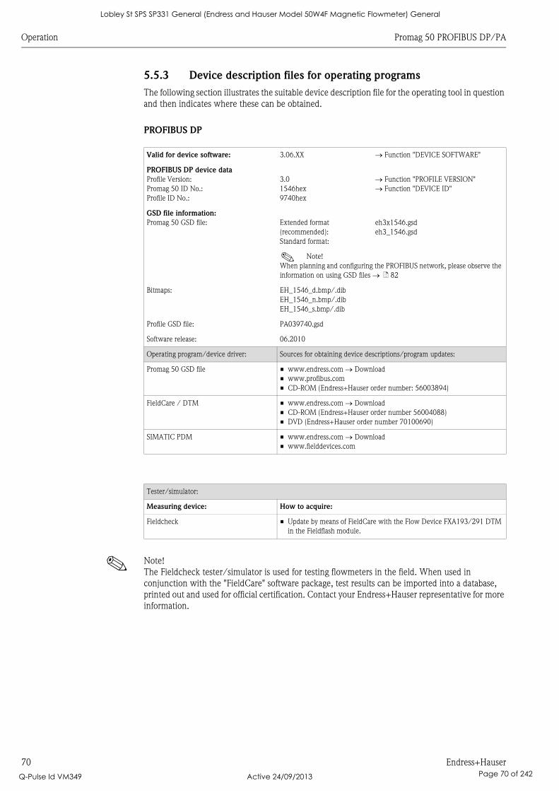
Operation Promag 50 PROFIBUS DP/PA
70 Endress+Hauser
5.5.3 Device description files for operating programs
The following section illustrates the suitable device description file for the operating tool in question
and then indicates where these can be obtained.
PROFIBUS DP
! Note!
The Fieldcheck tester/simulator is used for testing flowmeters in the field. When used in
conjunction with the "FieldCare" software package, test results can be imported into a database,
printed out and used for official certification. Contact your Endress+Hauser representative for more
information.
Valid for device software: 3.06.XX Function "DEVICE SOFTWARE"
PROFIBUS DP device data
Profile Version:
Promag 50 ID No.:
Profile ID No.:
3.0
1546hex
9740hex
Function "PROFILE VERSION"
Function "DEVICE ID"
GSD file information:
Promag 50 GSD file: Extended format
(recommended):
Standard format:
eh3x1546.gsd
eh3_1546.gsd
! Note!
When planning and configuring the PROFIBUS network, please observe the
information on using GSD files ä 82
Bitmaps: EH_1546_d.bmp/.dib
EH_1546_n.bmp/.dib
EH_1546_s.bmp/.dib
Profile GSD file: PA039740.gsd
Software release: 06.2010
Operating program/device driver: Sources for obtaining device descriptions/program updates:
Promag 50 GSD file • www.endress.com Download
• www.profibus.com
• CD-ROM (Endress+Hauser order number: 56003894)
FieldCare / DTM • www.endress.com Download
• CD-ROM (Endress+Hauser order number 56004088)
• DVD (Endress+Hauser order number 70100690)
SIMATIC PDM • www.endress.com Download
• www.fielddevices.com
Tester/simulator:
Measuring device: How to acquire:
Fieldcheck • Update by means of FieldCare with the Flow Device FXA193/291 DTM
in the Fieldflash module.
Lobley St SPS SP331 General (Endress and Hauser Model 50W4F Magnetic Flowmeter) General
Q-Pulse Id VM349 Active 24/09/2013 Page 70 of 242
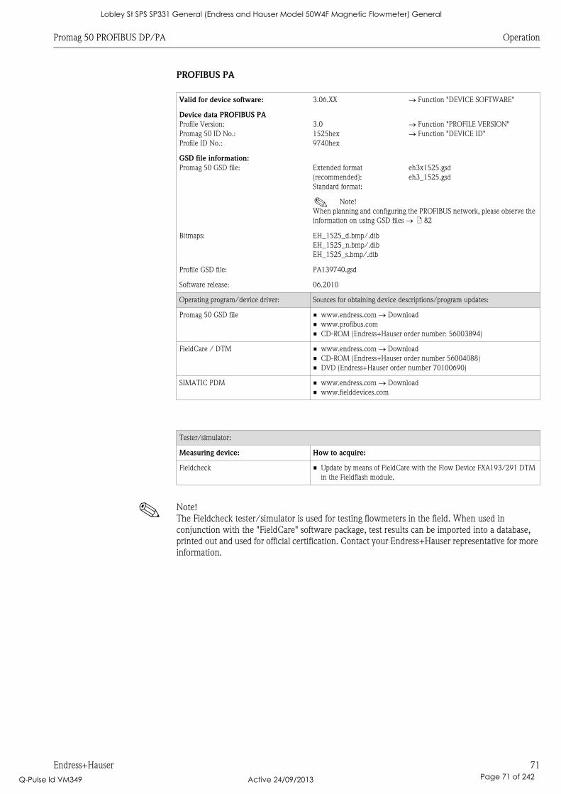
Promag 50 PROFIBUS DP/PA Operation
Endress+Hauser 71
PROFIBUS PA
! Note!
The Fieldcheck tester/simulator is used for testing flowmeters in the field. When used in
conjunction with the "FieldCare" software package, test results can be imported into a database,
printed out and used for official certification. Contact your Endress+Hauser representative for more
information.
Valid for device software: 3.06.XX Function "DEVICE SOFTWARE"
Device data PROFIBUS PA
Profile Version:
Promag 50 ID No.:
Profile ID No.:
3.0
1525hex
9740hex
Function "PROFILE VERSION"
Function "DEVICE ID"
GSD file information:
Promag 50 GSD file: Extended format
(recommended):
Standard format:
eh3x1525.gsd
eh3_1525.gsd
! Note!
When planning and configuring the PROFIBUS network, please observe the
information on using GSD files ä 82
Bitmaps: EH_1525_d.bmp/.dib
EH_1525_n.bmp/.dib
EH_1525_s.bmp/.dib
Profile GSD file: PA139740.gsd
Software release: 06.2010
Operating program/device driver: Sources for obtaining device descriptions/program updates:
Promag 50 GSD file • www.endress.com Download
• www.profibus.com
• CD-ROM (Endress+Hauser order number: 56003894)
FieldCare / DTM • www.endress.com Download
• CD-ROM (Endress+Hauser order number 56004088)
• DVD (Endress+Hauser order number 70100690)
SIMATIC PDM • www.endress.com Download
• www.fielddevices.com
Tester/simulator:
Measuring device: How to acquire:
Fieldcheck • Update by means of FieldCare with the Flow Device FXA193/291 DTM
in the Fieldflash module.
Lobley St SPS SP331 General (Endress and Hauser Model 50W4F Magnetic Flowmeter) General
Q-Pulse Id VM349 Active 24/09/2013 Page 71 of 242

Operation Promag 50 PROFIBUS DP/PA
72 Endress+Hauser
5.6 PROFIBUS DP hardware settings
5.6.1 Configuring the write protection
A jumper on the I/O board provides the means of switching hardware write protection on or off.
When the hardware write protection is switched on, it is not possible to write to the device
parameters via PROFIBUS (acyclic data transfer, e.g. via FieldCare).
# Warning!
Risk of electric shock! Exposed components carry dangerous voltages. Make sure that the power
supply is switched off before you remove the cover of the electronics compartment.
1. Switch off power supply.
2. Remove the I/O board.
3. Configure the hardware write protection accordingly with the aid of the jumpers (see Figure).
4. Installation is the reverse of the removal procedure.
A0005407
Fig. 49: Switching write protection on and off with the aid of a jumper on the I/O board
1 Jumper for switching write protection on and off
1.1 Write protection switched on = it is not possible to write to the device parameters via PROFIBUS (acyclic data
transfer, e.g. via FieldCare).
1.2 Write protection switched off (factory setting) = it is possible to write to the device parameters via PROFIBUS
(acyclic data transfer, e.g. via FieldCare).
LED Overview of LED status:
– Lit continuously Ready for operation
– Not lit Not ready for operation
– Flashing System or process error present ä 99
1234
WENO
1234
WENO
1234
WENO
1234
WENO
1.1
1.2
1LED
Lobley St SPS SP331 General (Endress and Hauser Model 50W4F Magnetic Flowmeter) General
Q-Pulse Id VM349 Active 24/09/2013 Page 72 of 242
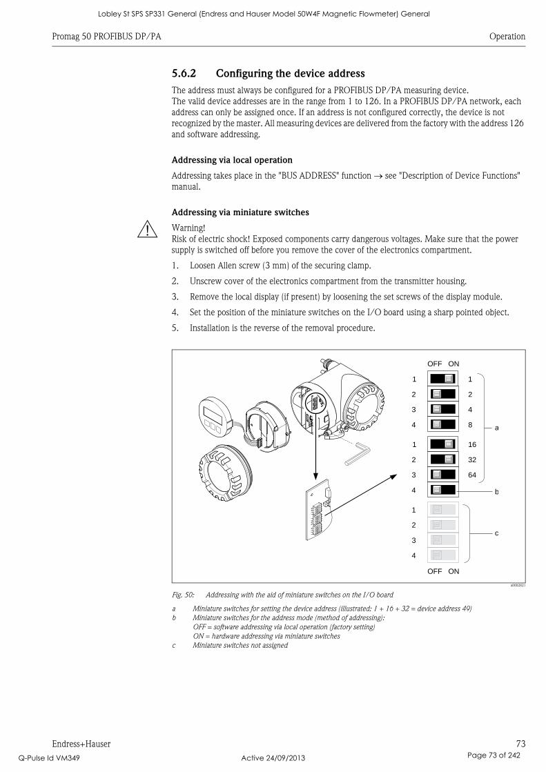
Promag 50 PROFIBUS DP/PA Operation
Endress+Hauser 73
5.6.2 Configuring the device address
The address must always be configured for a PROFIBUS DP/PA measuring device.
The valid device addresses are in the range from 1 to 126. In a PROFIBUS DP/PA network, each
address can only be assigned once. If an address is not configured correctly, the device is not
recognized by the master. All measuring devices are delivered from the factory with the address 126
and software addressing.
Addressing via local operation
Addressing takes place in the "BUS ADDRESS" function see "Description of Device Functions"
manual.
Addressing via miniature switches
# Warning!
Risk of electric shock! Exposed components carry dangerous voltages. Make sure that the power
supply is switched off before you remove the cover of the electronics compartment.
1. Loosen Allen screw (3 mm) of the securing clamp.
2. Unscrew cover of the electronics compartment from the transmitter housing.
3. Remove the local display (if present) by loosening the set screws of the display module.
4. Set the position of the miniature switches on the I/O board using a sharp pointed object.
5. Installation is the reverse of the removal procedure.
a0002821
Fig. 50: Addressing with the aid of miniature switches on the I/O board
a Miniature switches for setting the device address (illustrated: 1 + 16 + 32 = device address 49)
b Miniature switches for the address mode (method of addressing):
OFF = software addressing via local operation (factory setting)
ON = hardware addressing via miniature switches
c Miniature switches not assigned
1234
WENO
1234
WENO
1234
WENO
1234
WENO
1234
WENO
1234
WENO
161
3
322
4
643
4
1
2
b
OFF ON
11
22
43
84 a
OFF ON
c
Lobley St SPS SP331 General (Endress and Hauser Model 50W4F Magnetic Flowmeter) General
Q-Pulse Id VM349 Active 24/09/2013 Page 73 of 242
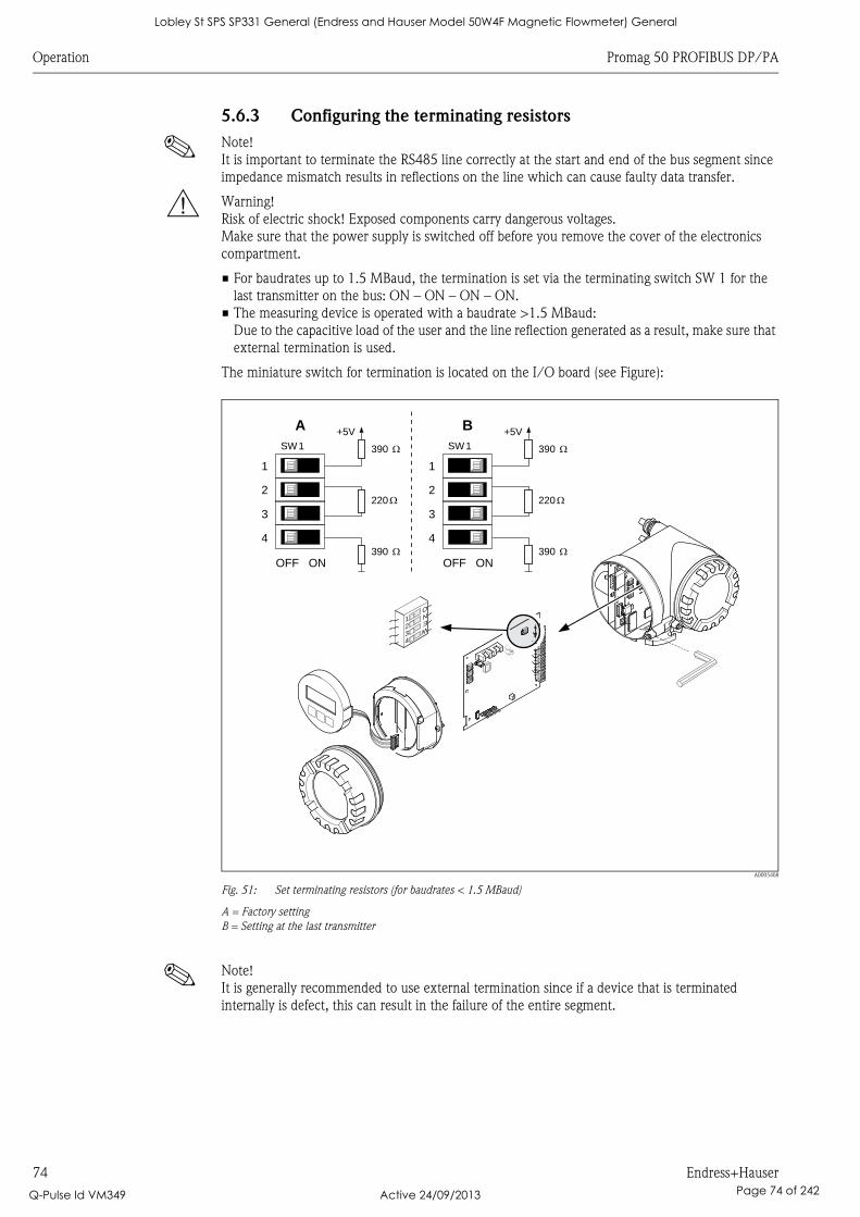
Operation Promag 50 PROFIBUS DP/PA
74 Endress+Hauser
5.6.3 Configuring the terminating resistors
! Note!
It is important to terminate the RS485 line correctly at the start and end of the bus segment since
impedance mismatch results in reflections on the line which can cause faulty data transfer.
# Warning!
Risk of electric shock! Exposed components carry dangerous voltages.
Make sure that the power supply is switched off before you remove the cover of the electronics
compartment.
• For baudrates up to 1.5 MBaud, the termination is set via the terminating switch SW 1 for the
last transmitter on the bus: ON – ON – ON – ON.
• The measuring device is operated with a baudrate >1.5 MBaud:
Due to the capacitive load of the user and the line reflection generated as a result, make sure that
external termination is used.
The miniature switch for termination is located on the I/O board (see Figure):
A0005408
Fig. 51: Set terminating resistors (for baudrates < 1.5 MBaud)
A = Factory setting
B = Setting at the last transmitter
! Note!
It is generally recommended to use external termination since if a device that is terminated
internally is defect, this can result in the failure of the entire segment.
1234
WENO
1234
WENO
1234
WENO
1234
WENO
1234
WENO
1234
WENO
1234
WENO
1234
WENO
1234
WENO
390 W
+5VA
3
4
1
2
OFF ON
220 W
390 W
SW1 390 W
+5VB
3
4
1
2
OFF ON
220 W
390 W
SW1
Lobley St SPS SP331 General (Endress and Hauser Model 50W4F Magnetic Flowmeter) General
Q-Pulse Id VM349 Active 24/09/2013 Page 74 of 242
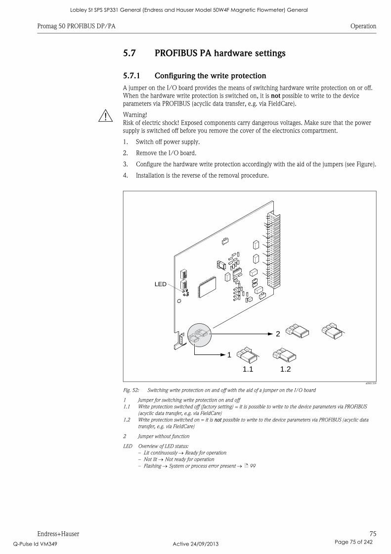
Promag 50 PROFIBUS DP/PA Operation
Endress+Hauser 75
5.7 PROFIBUS PA hardware settings
5.7.1 Configuring the write protection
A jumper on the I/O board provides the means of switching hardware write protection on or off.
When the hardware write protection is switched on, it is not possible to write to the device
parameters via PROFIBUS (acyclic data transfer, e.g. via FieldCare).
# Warning!
Risk of electric shock! Exposed components carry dangerous voltages. Make sure that the power
supply is switched off before you remove the cover of the electronics compartment.
1. Switch off power supply.
2. Remove the I/O board.
3. Configure the hardware write protection accordingly with the aid of the jumpers (see Figure).
4. Installation is the reverse of the removal procedure.
a0001359
Fig. 52: Switching write protection on and off with the aid of a jumper on the I/O board
1 Jumper for switching write protection on and off
1.1 Write protection switched off (factory setting) = it is possible to write to the device parameters via PROFIBUS
(acyclic data transfer, e.g. via FieldCare)
1.2 Write protection switched on = it is not possible to write to the device parameters via PROFIBUS (acyclic data
transfer, e.g. via FieldCare)
2 Jumper without function
LED Overview of LED status:
– Lit continuously Ready for operation
– Not lit Not ready for operation
– Flashing System or process error present ä 99
1
1.21.1
2
LED
Lobley St SPS SP331 General (Endress and Hauser Model 50W4F Magnetic Flowmeter) General
Q-Pulse Id VM349 Active 24/09/2013 Page 75 of 242
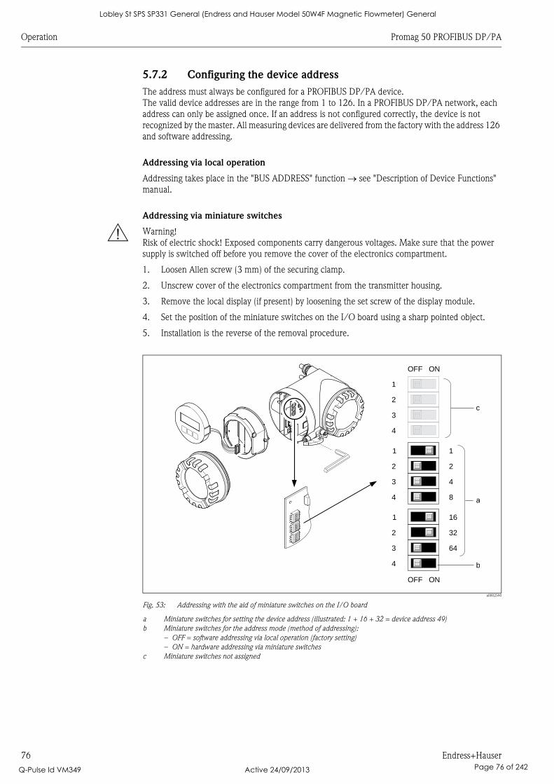
Operation Promag 50 PROFIBUS DP/PA
76 Endress+Hauser
5.7.2 Configuring the device address
The address must always be configured for a PROFIBUS DP/PA device.
The valid device addresses are in the range from 1 to 126. In a PROFIBUS DP/PA network, each
address can only be assigned once. If an address is not configured correctly, the device is not
recognized by the master. All measuring devices are delivered from the factory with the address 126
and software addressing.
Addressing via local operation
Addressing takes place in the "BUS ADDRESS" function see "Description of Device Functions"
manual.
Addressing via miniature switches
# Warning!
Risk of electric shock! Exposed components carry dangerous voltages. Make sure that the power
supply is switched off before you remove the cover of the electronics compartment.
1. Loosen Allen screw (3 mm) of the securing clamp.
2. Unscrew cover of the electronics compartment from the transmitter housing.
3. Remove the local display (if present) by loosening the set screw of the display module.
4. Set the position of the miniature switches on the I/O board using a sharp pointed object.
5. Installation is the reverse of the removal procedure.
a0002590
Fig. 53: Addressing with the aid of miniature switches on the I/O board
a Miniature switches for setting the device address (illustrated: 1 + 16 + 32 = device address 49)
b Miniature switches for the address mode (method of addressing):
– OFF = software addressing via local operation (factory setting)
– ON = hardware addressing via miniature switches
c Miniature switches not assigned
1234
WENO
1234
WENO
1234
WENO
161
3
322
4
643
4
1
2
b
OFF ON
11
22
43
84 a
OFF ON
c
1234
WENO
1234
WENO
1234
WENO
Lobley St SPS SP331 General (Endress and Hauser Model 50W4F Magnetic Flowmeter) General
Q-Pulse Id VM349 Active 24/09/2013 Page 76 of 242
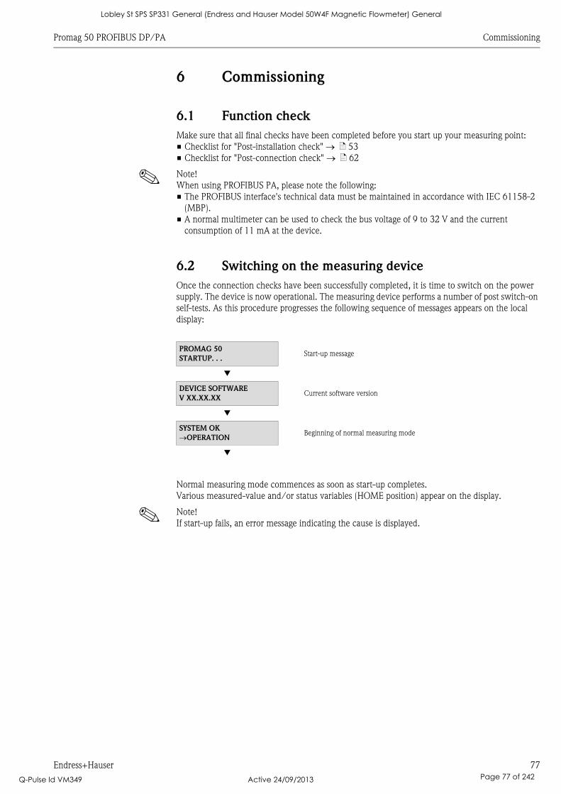
Promag 50 PROFIBUS DP/PA Commissioning
Endress+Hauser 77
6 Commissioning
6.1 Function check
Make sure that all final checks have been completed before you start up your measuring point:
• Checklist for "Post-installation check" ä 53
• Checklist for "Post-connection check" ä 62
! Note!
When using PROFIBUS PA, please note the following:
• The PROFIBUS interface's technical data must be maintained in accordance with IEC 61158-2
(MBP).
• A normal multimeter can be used to check the bus voltage of 9 to 32 V and the current
consumption of 11 mA at the device.
6.2 Switching on the measuring device
Once the connection checks have been successfully completed, it is time to switch on the power
supply. The device is now operational. The measuring device performs a number of post switch-on
self-tests. As this procedure progresses the following sequence of messages appears on the local
display:
Normal measuring mode commences as soon as start-up completes.
Various measured-value and/or status variables (HOME position) appear on the display.
! Note!
If start-up fails, an error message indicating the cause is displayed.
PROMAG 50
STARTUP. . .Start-up message
Æ
DEVICE SOFTWARE
V XX.XX.XXCurrent software version
Æ
SYSTEM OK
OPERATIONBeginning of normal measuring mode
Æ
Lobley St SPS SP331 General (Endress and Hauser Model 50W4F Magnetic Flowmeter) General
Q-Pulse Id VM349 Active 24/09/2013 Page 77 of 242
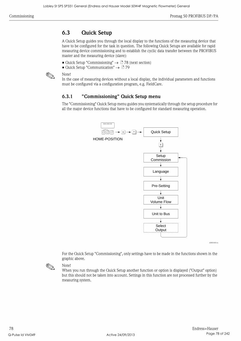
Commissioning Promag 50 PROFIBUS DP/PA
78 Endress+Hauser
6.3 Quick Setup
A Quick Setup guides you through the local display to the functions of the measuring device that
have to be configured for the task in question. The following Quick Setups are available for rapid
measuring device commissioning and to establish the cyclic data transfer between the PROFIBUS
master and the measuring device (slave):
• Quick Setup "Commissioning" ä 78 (next section)
• Quick Setup "Communication" ä 79
! Note!
In the case of measuring devices without a local display, the individual parameters and functions
must be configured via a configuration program, e.g. FieldCare.
6.3.1 "Commissioning" Quick Setup menu
The "Commissioning" Quick Setup menu guides you systematically through the setup procedure for
all the major device functions that have to be configured for standard measuring operation.
A0005404-en
For the Quick Setup "Commissioning", only settings have to be made in the functions shown in the
graphic above.
! Note!
When you run through the Quick Setup another function or option is displayed ("Output" option)
but this should not be taken into account. Settings in this function are not processed further by the
measuring system.
Esc
E+-
XXX.XXX.XX
F O
F
Quick Setup
SetupCommission
Language
Pre-Setting
UnitVolume Flow
Unit to Bus
SelectOutput
HOME-POSITION
Lobley St SPS SP331 General (Endress and Hauser Model 50W4F Magnetic Flowmeter) General
Q-Pulse Id VM349 Active 24/09/2013 Page 78 of 242
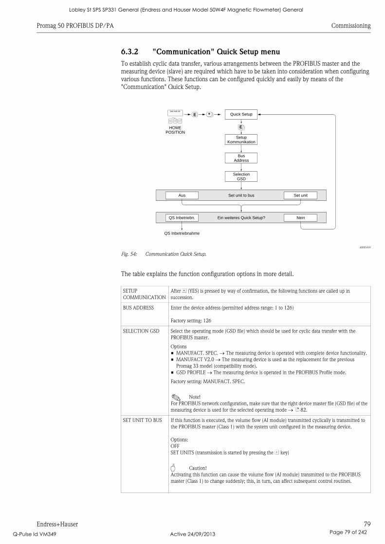
Promag 50 PROFIBUS DP/PA Commissioning
Endress+Hauser 79
6.3.2 "Communication" Quick Setup menu
To establish cyclic data transfer, various arrangements between the PROFIBUS master and the
measuring device (slave) are required which have to be taken into consideration when configuring
various functions. These functions can be configured quickly and easily by means of the
"Communication" Quick Setup.
A0005459
Fig. 54: Communication Quick Setup.
The table explains the function configuration options in more detail.
++EEsc
E+-
XXX.XXX.XX
+EHOMEPOSITION
SetupKommunikation
Quick Setup
Aus Set unitSet unit to bus
QS Inbetriebn. NeinEin weiteres Quick Setup?
BusAddress
SelectionGSD
QS Inbetriebnahme
SETUP
COMMUNICATION
After F (YES) is pressed by way of confirmation, the following functions are called up in
succession.
BUS ADDRESS Enter the device address (permitted address range: 1 to 126)
Factory setting: 126
SELECTION GSD Select the operating mode (GSD file) which should be used for cyclic data transfer with the
PROFIBUS master.
Options
• MANUFACT. SPEC. The measuring device is operated with complete device functionality.
• MANUFACT V2.0 The measuring device is used as the replacement for the previous
Promag 33 model (compatibility mode).
• GSD PROFILE The measuring device is operated in the PROFIBUS Profile mode.
Factory setting: MANUFACT. SPEC.
! Note!
For PROFIBUS network configuration, make sure that the right device master file (GSD file) of the
measuring device is used for the selected operating mode ä 82.
SET UNIT TO BUS If this function is executed, the volume flow (AI module) transmitted cyclically is transmitted to
the PROFIBUS master (Class 1) with the system unit configured in the measuring device.
Options:
OFF
SET UNITS (transmission is started by pressing the F key)
" Caution!
Activating this function can cause the volume flow (AI module) transmitted to the PROFIBUS
master (Class 1) to change suddenly; this, in turn, can affect subsequent control routines.
Lobley St SPS SP331 General (Endress and Hauser Model 50W4F Magnetic Flowmeter) General
Q-Pulse Id VM349 Active 24/09/2013 Page 79 of 242
Commissioning Promag 50 PROFIBUS DP/PA
80 Endress+Hauser
6.4 Commissioning the PROFIBUS interface
! Note!
• All functions required for commissioning are described in detail in the "Description of Device
Functions" manual which is a separate part of these Operating Instructions.
• A code (factory setting: 50) must be entered to change device functions, numerical values or
factory settings.
6.4.1 PROFIBUS DP/PA commissioning
The following steps must be carried out in the sequence specified:
1. Check the hardware write protection:
The "WRITE PROTECTION" parameter indicates whether write access to the device is possible
via PROFIBUS communication (e.g. via FieldCare).
! Note!
This check is not needed if operating via the local display.
COMMUNICATION WRITE PROTECTION...
... OFF display (factory setting): write access via PROFIBUS possible
... ON display: write access via PROFIBUS not possible
Deactivate the write protection if necessary:
– PROFIBUS DP ä 72
– PROFIBUS PA ä 75
2. Enter the tag name (optional):
COMMUNICATION TAG NAME
3. Configure the bus address:
Configure the bus address:
– Software addressing via the local display:
COMMUNICATION BUS ADDRESS
– Hardware addressing via miniature switches:
PROFIBUS DP ä 73; PROFIBUS PA ä 76
4. Select the system units:
• By means of the system units group:
SYSTEM UNITS UNIT VOL. FLOW UNIT VOLUME UNIT...
• Execute the SET UNITS function in the SET UNIT TO BUS parameter to transmit the
volume flow transmitted cyclically to the PROFIBUS master (Class 1) with the system unit
configured in the measuring device.
COMMUNICATION SET UNIT TO BUS
! Note!
– The configuration of the engineering units for the totalizers is described separately
see Point 6.
– If the system unit is changed by means of the local operation, this initially does not have any
effect on the unit which is used to transmit the volume flow to the automation system.
The altered system unit of the measured value is not transmitted to the automation system
until the SET UNIT TO BUS function is activated in the COMMUNICATION block.
5. Set the measuring mode:
SYSTEM PARAMETER MEASURING MODE
Select the flow components that should be recorded by the measuring device:
– UNIDIRECTIONAL (factory setting) = only the positive flow components
– BIDIRECTIONAL = the positive and negative flow components
Lobley St SPS SP331 General (Endress and Hauser Model 50W4F Magnetic Flowmeter) General
Q-Pulse Id VM349 Active 24/09/2013 Page 80 of 242

Promag 50 PROFIBUS DP/PA Commissioning
Endress+Hauser 81
6. Configuration of totalizers 1 to 2:
The measuring device has two totalizers. The following example describes the configuration of
the totalizer using totalizer 1 as an example.
• Using the CHANNEL function (6133), you can determine the measured variable (e.g.
volume flow) to be cyclically transmitted to the PROFIBUS master (Class 1) as a totalizer
value:
a. TOTALIZER SELECT TOTALIZER
… select TOTALIZER 1
b. TOTALIZER CHANNEL…
… VOLUME FLOW option (CHANNEL = 273), factory setting: the volume flow is
totalized as the measured variable.
… OFF option (CHANNEL = 0): no totalizing, the value 0 is displayed as the totalizer
value.
! Note!
If, when the PROFIBUS network configuration, the module or the function "TOTAL" was
integrated in slot 2 or 5, the measured variable selected in the CHANNEL function is
transmitted cyclically to the PROFIBUS master (Class 1) for the respective totalizer 1 to 2.
ä 87
• Enter the desired totalizer units:
TOTALIZER UNIT TOTALIZER (factory setting: m³)
• Configure totalizer status, e.g. totalize:
TOTALIZER SET TOTALIZER...
... Options: TOTALIZE
• Set the totalizer mode:
TOTALIZER TOTALIZER MODE...
... BALANCE option (factory setting): counts the positive and negative flow components
... POSITIVE option: only counts the positive flow components
... NEGATIVE option: only counts the negative flow components
... LAST VALUE option: totalizer stays at the last value
! Note!
The BIDIRECTIONAL option has to be active in the SYSTEM PARAMETER
MEASURING MODE function for the counting of the positive and negative flow
components (BALANCE) or of only the negative flow components (NEGATIVE) to be
executed correctly.
7. Select the operating mode:
Select the operating mode (GSD file) which should be used for cyclic data transfer to the
PROFIBUS master.
COMMUNICATION SELECTION GSD...
... MANUFACTURER SPEC. option (factory setting): the complete device functionality is
available
... MANUFACT V2.0 option: the measuring device is used as the replacement for the
previous model (Promag 33) (compatibility mode)
... GSD PROFILE option: the measuring device is operated in the PROFIBUS Profile mode.
! Note!
For PROFIBUS network configuration, make sure that the right device master file (GSD file) of
the measuring device is used for the selected operating mode ä 82.
8. Configuration of cyclic data transfer in the PROFIBUS master:
A detailed description of the system integration can be found on ä 82.
Lobley St SPS SP331 General (Endress and Hauser Model 50W4F Magnetic Flowmeter) General
Q-Pulse Id VM349 Active 24/09/2013 Page 81 of 242

Commissioning Promag 50 PROFIBUS DP/PA
82 Endress+Hauser
6.5 PROFIBUS DP/PA system integration
6.5.1 Device master file (GSD file)
For PROFIBUS network configuration, the device master file (GSD file) is needed for every bus user
(PROFIBUS slave). The GSD file contains a description of the properties of a PROFIBUS device, such
as supported data transmission rate and number of input and output data. Before configuration takes
place, a decision should be made as to which GSD file should be used to operate the measuring
device in the PROFIBUS DP master system.
The measuring device supports the following GSD files:
• Promag 50 GSD file (complete device functionality)
• PROFIBUS Profile GSD file
• Promag 33 GSD file (compatibility with previous Promag 33 model)
The following section contains detailed information on the GSD files supported:
Promag 50 GSD file (complete device functionality)
Use this GSD file to access the complete functionality of the measuring device. In this way, device-
specific measured variables and functionalities are thus completely available in the PROFIBUS
master system. An overview of the modules available (input and output data) can be found on
ä 86
GSD file with standard or extended format
The GSD file with either the standard or the extended format must be used depending on the
configuration software used. When installing the GSD file, the GSD file with the extended format
(EH3x15xx.gsd) should always be used first.
However, if the installation or the configuration of the device fails with this format, then use the
standard GSD (EH3_15xx.gsd). This differentiation is the result of different implementation of the
GSD formats in the master systems. Note the specifications of the configuration software.
Name of the Promag 50 GSD file
How to acquire:
• Internet (Endress+Hauser) www.endress.com ( Download)
• CD-ROM with all GSD files for Endress+Hauser devices Order No.: 56003894
Contents of the download file from the internet and CD-ROM:
• all Endress+Hauser GSD files (standard and extended format)
• Endress+Hauser type and bitmap files
• Useful information about the devices
ID No. Promag 50 GSD file Type file Bitmaps
PROFIBUS DP 1546
(Hex)
Extended format
(recommended):
Standard format:
EH3x1546.gsd
EH3_1546.gsd
EH_1546.200 EH_1546_d.bmp/.dib
EH_1546_n.bmp/.dib
EH_1546_s.bmp/.dib
PROFIBUS PA 1525
(Hex)
Extended format
(recommended):
Standard format:
EH3x1525.gsd
EH3_1525.gsd
EH_1525.200 EH_1525_d.bmp/.dib
EH_1525_n.bmp/.dib
EH_1525_s.bmp/.dib
Lobley St SPS SP331 General (Endress and Hauser Model 50W4F Magnetic Flowmeter) General
Q-Pulse Id VM349 Active 24/09/2013 Page 82 of 242

Promag 50 PROFIBUS DP/PA Commissioning
Endress+Hauser 83
PROFIBUS Profile GSD file
The function scope of the profile GSD file is defined by the PROFIBUS Profile Specification 3.0. The
function scope is restricted compared to the Promag 50 GSD file (complete device functionality).
However, similar devices from different manufacturers can be interchanged with the profile GSD
file without the need to reconfigure (interchangeability).
The following modules are supported with the Profile GSD file:
• "AI FLOW" module Analog Input function block 1 / Output variable: Volume flow
• "TOTALIZER" module Totalizer function block 1 / Output variable: Totalized volume flow
Name of the PROFIBUS Profile GSD file
Can be acquired from:
• Internet (GSD library of the PROFIBUS User Organization) www.PROFIBUS.com
Promag 33 GSD file
Promag 33 with Profile Version 2.0 is the precursor to Promag 50.
If Promag 33 is already being operated in the system and if the device has to be replaced, Promag 50
can be used as a replacement device without having to reconfigure the PROFIBUS DP network.
Further information ä 84.
6.5.2 Selecting the GSD file in the measuring device
Depending on which GSD file is used in the PROFIBUS master system, the corresponding GSD file
has to be selected in the device by means of COMMUNICATION SELECTION GSD.
• Promag 50 GSD file Select MANUFACT. SPEC. (factory setting)
• Profile GSD file Select: GSD PROFILE
• Promag 33 GSD file Select: MANUFACT V2.0
6.5.3 Example for selecting the GSD file
Before configuration takes place, a decision should be made as to which GSD file should be used to
configure the measuring device in the PROFIBUS master system. The following example describes
the use of the Promag 50 GSD file (complete functionality) for PROFIBUS PA:
Select the Promag 50 GSD file in the measuring device by means of the SELECTION GSD function.
COMMUNICATION SELECTION GSD Select: MANUFACT. SPEC.
1. Before configuring the network, load the Promag 50 GSD file into the configuration system/
master system.
! Note!
When installing the GSD file, always first use the GSD file with the extended format
(EH3x1525.gsd). However, if the installation or the configuration of the device fails with this
format, then use the standard GSD (EH3_1525.gsd).
Example for the configuration software Siemens STEP 7 of the Siemens PLC family
S7-300/400:
Use the Promag 50 GSD file with the extended format (EH3x1525.gsd).
Copy the file to the subdirectory ...\ siemens \ step7 \ s7data \ gsd.
The bitmap files also belong to the GSD files. These bitmap files are used to display the
measuring points in image form. The bitmap files must be saved to the directory "...\ siemens
\ step7 \ s7data \ nsbmp".
Profile 3.0 ID No. Profile GSD file
PROFIBUS DP 9740 (Hex) PA039740.gsd
PROFIBUS PA 9740 (Hex) PA139740.gsd
Lobley St SPS SP331 General (Endress and Hauser Model 50W4F Magnetic Flowmeter) General
Q-Pulse Id VM349 Active 24/09/2013 Page 83 of 242
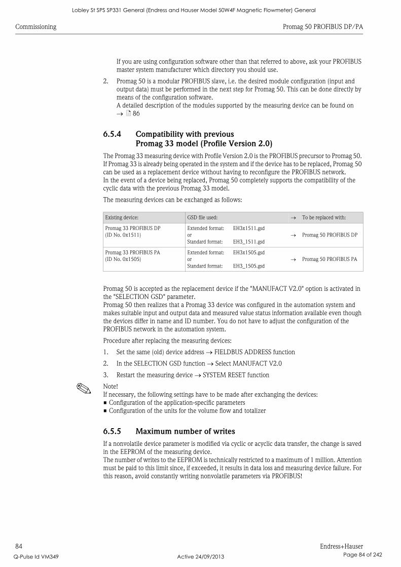
Commissioning Promag 50 PROFIBUS DP/PA
84 Endress+Hauser
If you are using configuration software other than that referred to above, ask your PROFIBUS
master system manufacturer which directory you should use.
2. Promag 50 is a modular PROFIBUS slave, i.e. the desired module configuration (input and
output data) must be performed in the next step for Promag 50. This can be done directly by
means of the configuration software.
A detailed description of the modules supported by the measuring device can be found on
ä 86
6.5.4 Compatibility with previous
Promag 33 model (Profile Version 2.0)
The Promag 33 measuring device with Profile Version 2.0 is the PROFIBUS precursor to Promag 50.
If Promag 33 is already being operated in the system and if the device has to be replaced, Promag 50
can be used as a replacement device without having to reconfigure the PROFIBUS network.
In the event of a device being replaced, Promag 50 completely supports the compatibility of the
cyclic data with the previous Promag 33 model.
The measuring devices can be exchanged as follows:
Promag 50 is accepted as the replacement device if the "MANUFACT V2.0" option is activated in
the "SELECTION GSD" parameter.
Promag 50 then realizes that a Promag 33 device was configured in the automation system and
makes suitable input and output data and measured value status information available even though
the devices differ in name and ID number. You do not have to adjust the configuration of the
PROFIBUS network in the automation system.
Procedure after replacing the measuring devices:
1. Set the same (old) device address FIELDBUS ADDRESS function
2. In the SELECTION GSD function Select MANUFACT V2.0
3. Restart the measuring device SYSTEM RESET function
! Note!
If necessary, the following settings have to be made after exchanging the devices:
• Configuration of the application-specific parameters
• Configuration of the units for the volume flow and totalizer
6.5.5 Maximum number of writes
If a nonvolatile device parameter is modified via cyclic or acyclic data transfer, the change is saved
in the EEPROM of the measuring device.
The number of writes to the EEPROM is technically restricted to a maximum of 1 million. Attention
must be paid to this limit since, if exceeded, it results in data loss and measuring device failure. For
this reason, avoid constantly writing nonvolatile parameters via PROFIBUS!
Existing device: GSD file used: To be replaced with:
Promag 33 PROFIBUS DP
(ID No. 0x1511)
Extended format:
or
Standard format:
EH3x1511.gsd
EH3_1511.gsd
Promag 50 PROFIBUS DP
Promag 33 PROFIBUS PA
(ID No. 0x1505)
Extended format:
or
Standard format:
EH3x1505.gsd
EH3_1505.gsd
Promag 50 PROFIBUS PA
Lobley St SPS SP331 General (Endress and Hauser Model 50W4F Magnetic Flowmeter) General
Q-Pulse Id VM349 Active 24/09/2013 Page 84 of 242
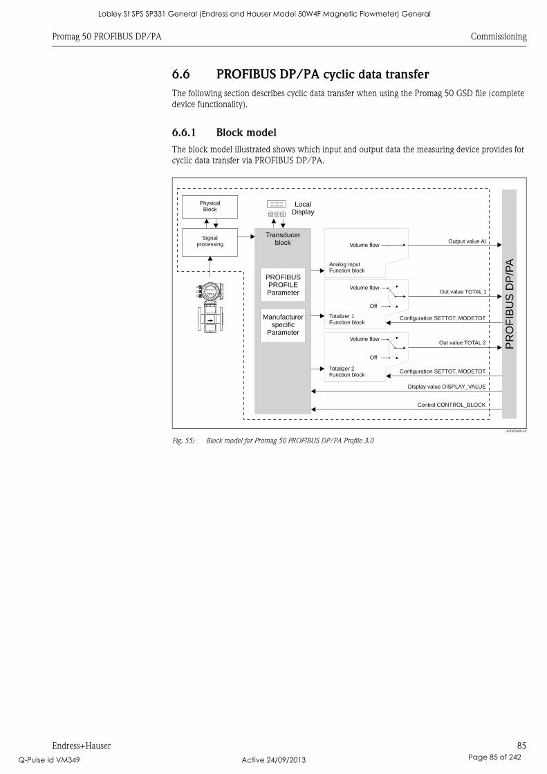
Promag 50 PROFIBUS DP/PA Commissioning
Endress+Hauser 85
6.6 PROFIBUS DP/PA cyclic data transfer
The following section describes cyclic data transfer when using the Promag 50 GSD file (complete
device functionality).
6.6.1 Block model
The block model illustrated shows which input and output data the measuring device provides for
cyclic data transfer via PROFIBUS DP/PA.
A0005406-en
Fig. 55: Block model for Promag 50 PROFIBUS DP/PA Profile 3.0
XXX.XXX.XX
XXX.XXX.XX
Esc
E- +
Output value AISignal
processing
PROFIBUSPROFILEParameter
Manufacturerspecific
Parameter
Control CONTROL_BLOCK
Display value DISPLAY_VALUE
Transducerblock
Configuration SETTOT, MODETOT
Out value TOTAL 1
LocalDisplay
PR
OF
IBU
SD
P/P
A
PhysicalBlock
Analog InputFunction block
Volume flow
Totalizer 1Function block
Volume flow
Off
Configuration SETTOT, MODETOT
Out value TOTAL 2
Totalizer 2Function block
Volume flow
Off
Lobley St SPS SP331 General (Endress and Hauser Model 50W4F Magnetic Flowmeter) General
Q-Pulse Id VM349 Active 24/09/2013 Page 85 of 242
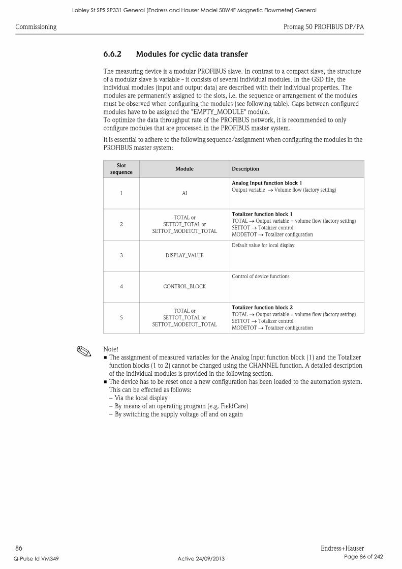
Commissioning Promag 50 PROFIBUS DP/PA
86 Endress+Hauser
6.6.2 Modules for cyclic data transfer
The measuring device is a modular PROFIBUS slave. In contrast to a compact slave, the structure
of a modular slave is variable - it consists of several individual modules. In the GSD file, the
individual modules (input and output data) are described with their individual properties. The
modules are permanently assigned to the slots, i.e. the sequence or arrangement of the modules
must be observed when configuring the modules (see following table). Gaps between configured
modules have to be assigned the "EMPTY_MODULE" module.
To optimize the data throughput rate of the PROFIBUS network, it is recommended to only
configure modules that are processed in the PROFIBUS master system.
It is essential to adhere to the following sequence/assignment when configuring the modules in the
PROFIBUS master system:
! Note!
• The assignment of measured variables for the Analog Input function block (1) and the Totalizer
function blocks (1 to 2) cannot be changed using the CHANNEL function. A detailed description
of the individual modules is provided in the following section.
• The device has to be reset once a new configuration has been loaded to the automation system.
This can be effected as follows:
– Via the local display
– By means of an operating program (e.g. FieldCare)
– By switching the supply voltage off and on again
Slot
sequenceModule Description
1 AI
Analog Input function block 1
Output variable Volume flow (factory setting)
2
TOTAL or
SETTOT_TOTAL or
SETTOT_MODETOT_TOTAL
Totalizer function block 1
TOTAL Output variable = volume flow (factory setting)
SETTOT Totalizer control
MODETOT Totalizer configuration
3 DISPLAY_VALUE
Default value for local display
4 CONTROL_BLOCK
Control of device functions
5
TOTAL or
SETTOT_TOTAL or
SETTOT_MODETOT_TOTAL
Totalizer function block 2
TOTAL Output variable = volume flow (factory setting)
SETTOT Totalizer control
MODETOT Totalizer configuration
Lobley St SPS SP331 General (Endress and Hauser Model 50W4F Magnetic Flowmeter) General
Q-Pulse Id VM349 Active 24/09/2013 Page 86 of 242
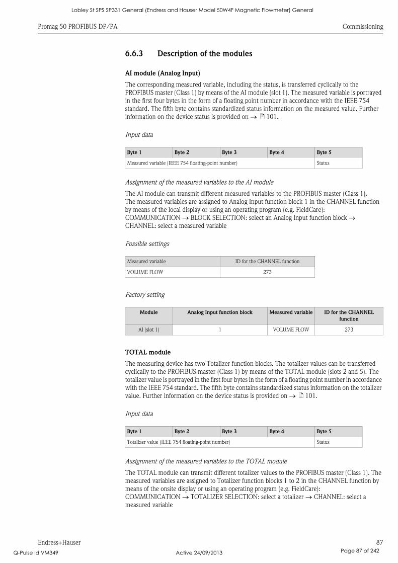
Promag 50 PROFIBUS DP/PA Commissioning
Endress+Hauser 87
6.6.3 Description of the modules
AI module (Analog Input)
The corresponding measured variable, including the status, is transferred cyclically to the
PROFIBUS master (Class 1) by means of the AI module (slot 1). The measured variable is portrayed
in the first four bytes in the form of a floating point number in accordance with the IEEE 754
standard. The fifth byte contains standardized status information on the measured value. Further
information on the device status is provided on ä 101.
Input data
Assignment of the measured variables to the AI module
The AI module can transmit different measured variables to the PROFIBUS master (Class 1).
The measured variables are assigned to Analog Input function block 1 in the CHANNEL function
by means of the local display or using an operating program (e.g. FieldCare):
COMMUNICATION BLOCK SELECTION: select an Analog Input function block
CHANNEL: select a measured variable
Possible settings
Factory setting
TOTAL module
The measuring device has two Totalizer function blocks. The totalizer values can be transferred
cyclically to the PROFIBUS master (Class 1) by means of the TOTAL module (slots 2 and 5). The
totalizer value is portrayed in the first four bytes in the form of a floating point number in accordance
with the IEEE 754 standard. The fifth byte contains standardized status information on the totalizer
value. Further information on the device status is provided on ä 101.
Input data
Assignment of the measured variables to the TOTAL module
The TOTAL module can transmit different totalizer values to the PROFIBUS master (Class 1). The
measured variables are assigned to Totalizer function blocks 1 to 2 in the CHANNEL function by
means of the onsite display or using an operating program (e.g. FieldCare):
COMMUNICATION TOTALIZER SELECTION: select a totalizer CHANNEL: select a
measured variable
Byte 1 Byte 2 Byte 3 Byte 4 Byte 5
Measured variable (IEEE 754 floating-point number) Status
Measured variable ID for the CHANNEL function
VOLUME FLOW 273
Module Analog Input function block Measured variable ID for the CHANNEL
function
AI (slot 1) 1 VOLUME FLOW 273
Byte 1 Byte 2 Byte 3 Byte 4 Byte 5
Totalizer value (IEEE 754 floating-point number) Status
Lobley St SPS SP331 General (Endress and Hauser Model 50W4F Magnetic Flowmeter) General
Q-Pulse Id VM349 Active 24/09/2013 Page 87 of 242
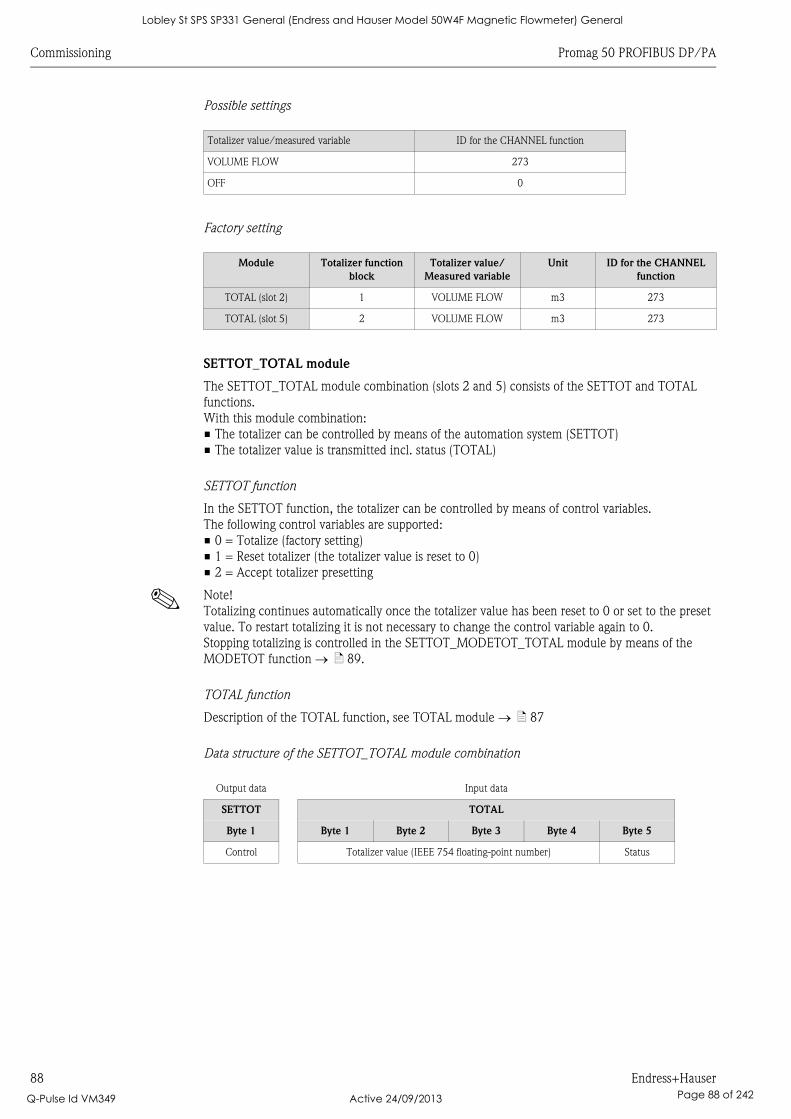
Commissioning Promag 50 PROFIBUS DP/PA
88 Endress+Hauser
Possible settings
Factory setting
SETTOT_TOTAL module
The SETTOT_TOTAL module combination (slots 2 and 5) consists of the SETTOT and TOTAL
functions.
With this module combination:
• The totalizer can be controlled by means of the automation system (SETTOT)
• The totalizer value is transmitted incl. status (TOTAL)
SETTOT function
In the SETTOT function, the totalizer can be controlled by means of control variables.
The following control variables are supported:
• 0 = Totalize (factory setting)
• 1 = Reset totalizer (the totalizer value is reset to 0)
• 2 = Accept totalizer presetting
! Note!
Totalizing continues automatically once the totalizer value has been reset to 0 or set to the preset
value. To restart totalizing it is not necessary to change the control variable again to 0.
Stopping totalizing is controlled in the SETTOT_MODETOT_TOTAL module by means of the
MODETOT function ä 89.
TOTAL function
Description of the TOTAL function, see TOTAL module ä 87
Data structure of the SETTOT_TOTAL module combination
Totalizer value/measured variable ID for the CHANNEL function
VOLUME FLOW 273
OFF 0
Module Totalizer function
block
Totalizer value/
Measured variable
Unit ID for the CHANNEL
function
TOTAL (slot 2) 1 VOLUME FLOW m3 273
TOTAL (slot 5) 2 VOLUME FLOW m3 273
Output data Input data
SETTOT TOTAL
Byte 1 Byte 1 Byte 2 Byte 3 Byte 4 Byte 5
Control Totalizer value (IEEE 754 floating-point number) Status
Lobley St SPS SP331 General (Endress and Hauser Model 50W4F Magnetic Flowmeter) General
Q-Pulse Id VM349 Active 24/09/2013 Page 88 of 242
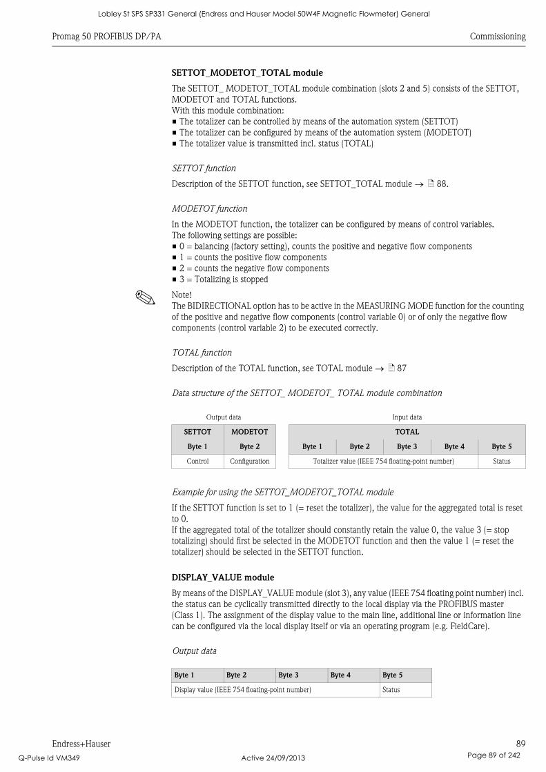
Promag 50 PROFIBUS DP/PA Commissioning
Endress+Hauser 89
SETTOT_MODETOT_TOTAL module
The SETTOT_ MODETOT_TOTAL module combination (slots 2 and 5) consists of the SETTOT,
MODETOT and TOTAL functions.
With this module combination:
• The totalizer can be controlled by means of the automation system (SETTOT)
• The totalizer can be configured by means of the automation system (MODETOT)
• The totalizer value is transmitted incl. status (TOTAL)
SETTOT function
Description of the SETTOT function, see SETTOT_TOTAL module ä 88.
MODETOT function
In the MODETOT function, the totalizer can be configured by means of control variables.
The following settings are possible:
• 0 = balancing (factory setting), counts the positive and negative flow components
• 1 = counts the positive flow components
• 2 = counts the negative flow components
• 3 = Totalizing is stopped
! Note!
The BIDIRECTIONAL option has to be active in the MEASURING MODE function for the counting
of the positive and negative flow components (control variable 0) or of only the negative flow
components (control variable 2) to be executed correctly.
TOTAL function
Description of the TOTAL function, see TOTAL module ä 87
Data structure of the SETTOT_ MODETOT_ TOTAL module combination
Example for using the SETTOT_MODETOT_TOTAL module
If the SETTOT function is set to 1 (= reset the totalizer), the value for the aggregated total is reset
to 0.
If the aggregated total of the totalizer should constantly retain the value 0, the value 3 (= stop
totalizing) should first be selected in the MODETOT function and then the value 1 (= reset the
totalizer) should be selected in the SETTOT function.
DISPLAY_VALUE module
By means of the DISPLAY_VALUE module (slot 3), any value (IEEE 754 floating point number) incl.
the status can be cyclically transmitted directly to the local display via the PROFIBUS master
(Class 1). The assignment of the display value to the main line, additional line or information line
can be configured via the local display itself or via an operating program (e.g. FieldCare).
Output data
Output data Input data
SETTOT MODETOT TOTAL
Byte 1 Byte 2 Byte 1 Byte 2 Byte 3 Byte 4 Byte 5
Control Configuration Totalizer value (IEEE 754 floating-point number) Status
Byte 1 Byte 2 Byte 3 Byte 4 Byte 5
Display value (IEEE 754 floating-point number) Status
Lobley St SPS SP331 General (Endress and Hauser Model 50W4F Magnetic Flowmeter) General
Q-Pulse Id VM349 Active 24/09/2013 Page 89 of 242
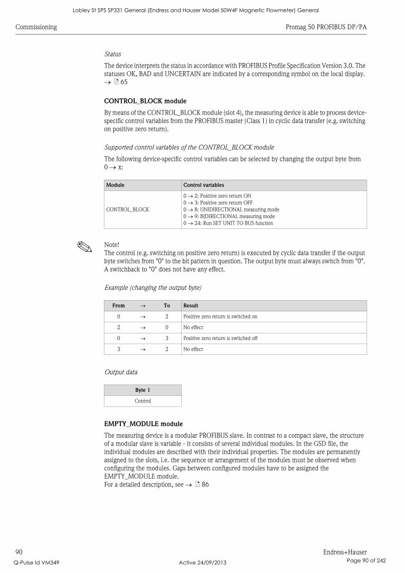
Commissioning Promag 50 PROFIBUS DP/PA
90 Endress+Hauser
Status
The device interprets the status in accordance with PROFIBUS Profile Specification Version 3.0. The
statuses OK, BAD and UNCERTAIN are indicated by a corresponding symbol on the local display.
ä 65
CONTROL_BLOCK module
By means of the CONTROL_BLOCK module (slot 4), the measuring device is able to process device-
specific control variables from the PROFIBUS master (Class 1) in cyclic data transfer (e.g. switching
on positive zero return).
Supported control variables of the CONTROL_BLOCK module
The following device-specific control variables can be selected by changing the output byte from
0 x:
! Note!
The control (e.g. switching on positive zero return) is executed by cyclic data transfer if the output
byte switches from "0" to the bit pattern in question. The output byte must always switch from "0".
A switchback to "0" does not have any effect.
Example (changing the output byte)
Output data
EMPTY_MODULE module
The measuring device is a modular PROFIBUS slave. In contrast to a compact slave, the structure
of a modular slave is variable - it consists of several individual modules. In the GSD file, the
individual modules are described with their individual properties. The modules are permanently
assigned to the slots, i.e. the sequence or arrangement of the modules must be observed when
configuring the modules. Gaps between configured modules have to be assigned the
EMPTY_MODULE module.
For a detailed description, see ä 86
Module Control variables
CONTROL_BLOCK
0 2: Positive zero return ON
0 3: Positive zero return OFF
0 8: UNIDIRECTIONAL measuring mode
0 9: BIDIRECTIONAL measuring mode
0 24: Run SET UNIT TO BUS function
From To Result
0 2 Positive zero return is switched on
2 0 No effect
0 3 Positive zero return is switched off
3 2 No effect
Byte 1
Control
Lobley St SPS SP331 General (Endress and Hauser Model 50W4F Magnetic Flowmeter) General
Q-Pulse Id VM349 Active 24/09/2013 Page 90 of 242
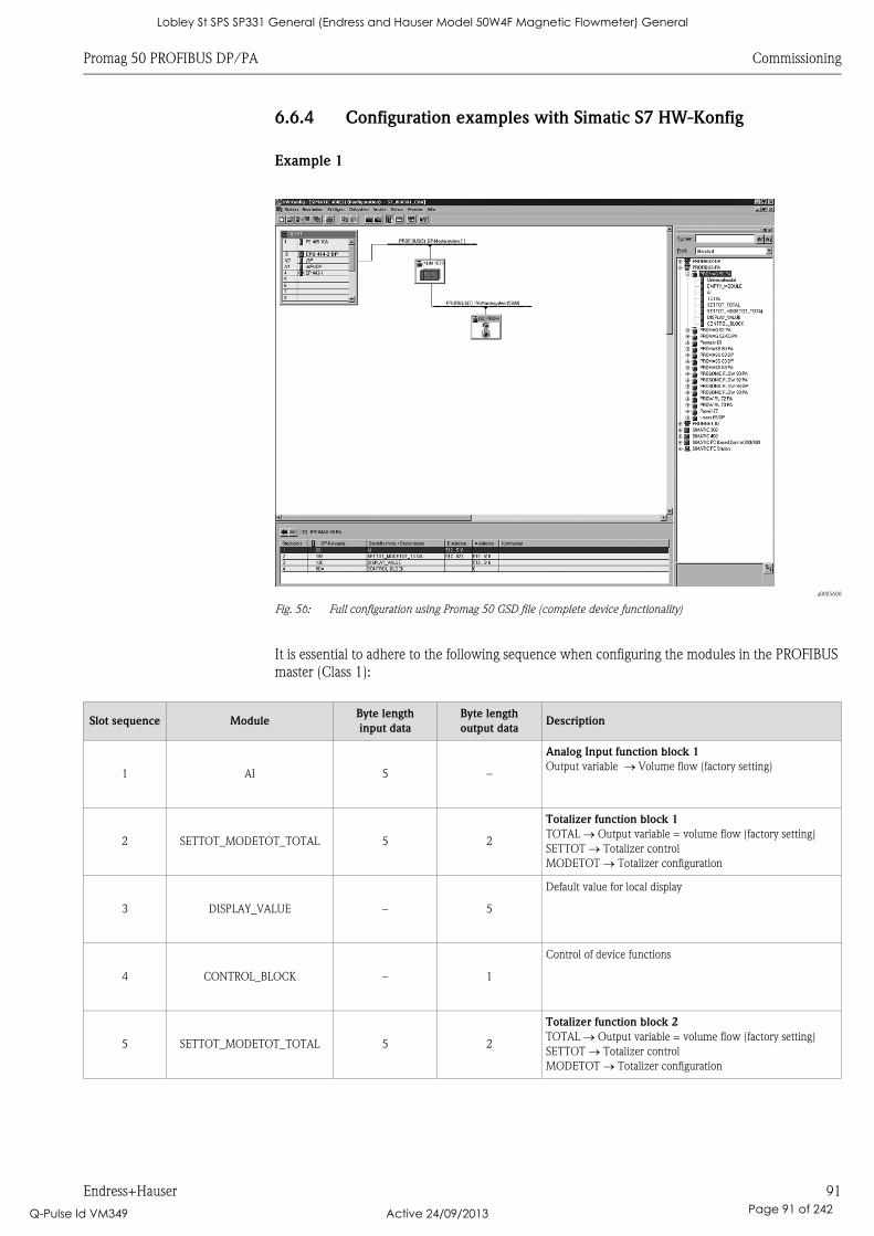
Promag 50 PROFIBUS DP/PA Commissioning
Endress+Hauser 91
6.6.4 Configuration examples with Simatic S7 HW-Konfig
Example 1
a0005600
Fig. 56: Full configuration using Promag 50 GSD file (complete device functionality)
It is essential to adhere to the following sequence when configuring the modules in the PROFIBUS
master (Class 1):
Slot sequence ModuleByte length
input data
Byte length
output dataDescription
1 AI 5 –
Analog Input function block 1
Output variable Volume flow (factory setting)
2 SETTOT_MODETOT_TOTAL 5 2
Totalizer function block 1
TOTAL Output variable = volume flow (factory setting)
SETTOT Totalizer control
MODETOT Totalizer configuration
3 DISPLAY_VALUE – 5
Default value for local display
4 CONTROL_BLOCK – 1
Control of device functions
5 SETTOT_MODETOT_TOTAL 5 2
Totalizer function block 2
TOTAL Output variable = volume flow (factory setting)
SETTOT Totalizer control
MODETOT Totalizer configuration
Lobley St SPS SP331 General (Endress and Hauser Model 50W4F Magnetic Flowmeter) General
Q-Pulse Id VM349 Active 24/09/2013 Page 91 of 242
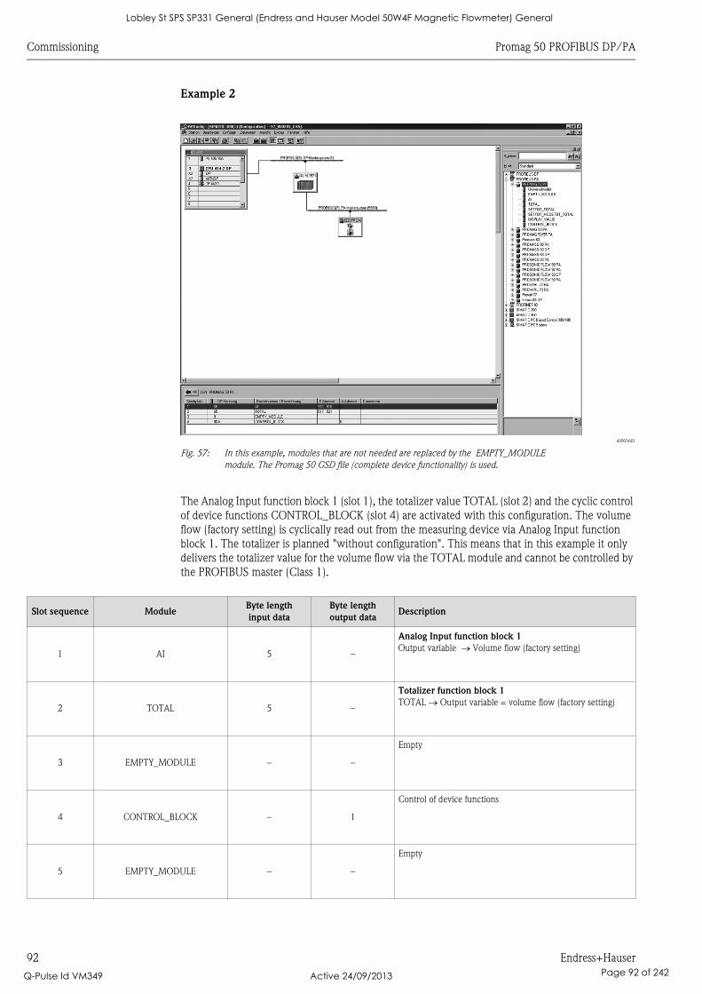
Commissioning Promag 50 PROFIBUS DP/PA
92 Endress+Hauser
Example 2
a0005601
Fig. 57: In this example, modules that are not needed are replaced by the EMPTY_MODULE
module. The Promag 50 GSD file (complete device functionality) is used.
The Analog Input function block 1 (slot 1), the totalizer value TOTAL (slot 2) and the cyclic control
of device functions CONTROL_BLOCK (slot 4) are activated with this configuration. The volume
flow (factory setting) is cyclically read out from the measuring device via Analog Input function
block 1. The totalizer is planned "without configuration". This means that in this example it only
delivers the totalizer value for the volume flow via the TOTAL module and cannot be controlled by
the PROFIBUS master (Class 1).
Slot sequence ModuleByte length
input data
Byte length
output dataDescription
1 AI 5 –
Analog Input function block 1
Output variable Volume flow (factory setting)
2 TOTAL 5 –
Totalizer function block 1
TOTAL Output variable = volume flow (factory setting)
3 EMPTY_MODULE – –
Empty
4 CONTROL_BLOCK – 1
Control of device functions
5 EMPTY_MODULE – –
Empty
Lobley St SPS SP331 General (Endress and Hauser Model 50W4F Magnetic Flowmeter) General
Q-Pulse Id VM349 Active 24/09/2013 Page 92 of 242

Promag 50 PROFIBUS DP/PA Commissioning
Endress+Hauser 93
6.7 Acyclic data transfer
Acyclic data transfer is used for transmitting parameters during commissioning, maintenance or for
displaying other measured variables that are not included in useful cyclic data traffic. In this way,
you can modify parameters for identifying, control or comparison in the various blocks (Physical
Block, Transducer Block, function block) while the device is involved in cyclic data transfer with a
PLC.
If acyclic data transfer has to be observed, a distinction is generally made between two types:
6.7.1 Master Class 2 acyclic (MS2AC)
MS2AC refers to acyclic data transfer between a field device and a Class 2 master (e.g. FieldCare,
Siemens PDM, etc. ä 69). Here, the master opens a communication channel by means of an
SAP (Service Access Point) to access the device.
A Class 2 master has to be aware of all the parameters that are to be exchanged with the device by
means of PROFIBUS. This assignment takes place either in a DD file (Device Description), a DTM
(Device Type Manager) or within a software component in the master by means of slot and index
addressing to each individual parameter.
Please note the following for MS2AC communication:
• As already explained, a Class 2 master accesses a device by means of special SAPs.
Thus, the number of Class 2 masters that can simultaneously communicate with a device is
restricted to the number of SAPs made available for this data transfer.
• The use of a Class 2 master increases the cycle time of the bus system. This should be taken into
consideration when programming the PCS/control system used.
6.7.2 Master Class 1 acyclic (MS1AC)
In MS1AC, a cyclic master that is already reading the cyclic data from the device or is writing to the
device opens the communication channel by means of SAP 0x33 (special Service Access Point for
MS1AC) and can then, just like a Class 2 master, acyclically read or write a parameter by means of
the slot and index (if supported).
Please note the following for MS1AC communication:
• Currently there are very few PROFIBUS masters on the market that support this data transfer.
• Not all PROFIBUS devices support MS1AC.
• In the user program, please note that the operating life of a device is dramatically reduced by
constantly writing parameters (e.g. with every cycle of the program). Parameters written
acyclically are stored in memory modules (EEPROM, Flash, etc.) with voltage resistance. These
memory modules are only designed for a limited number of writes. This number of writes is not
even remotely reached in normal operation without MS1AC (during parameterization). Incorrect
programming can mean that this maximum number is quickly reached, thereby dramatically
reducing the operating life of a device.
The measuring device supports MS2AC communication with 2 available SAPs.
MS1AC communication is supported by the device.
The memory module is designed for one million writes.
Lobley St SPS SP331 General (Endress and Hauser Model 50W4F Magnetic Flowmeter) General
Q-Pulse Id VM349 Active 24/09/2013 Page 93 of 242
Commissioning Promag 50 PROFIBUS DP/PA
94 Endress+Hauser
6.8 Adjustment
6.8.1 Empty-pipe/full-pipe adjustment
Flow cannot be measured correctly unless the measuring tube is completely full.
This status can be permanently monitored using the Empty Pipe Detection:
• EPD = Empty Pipe Detection (with the help of an EPD electrode)
• OED = Open Electrode Detection (Empty Pipe Detection with the help of the measuring
electrodes, if the sensor is not equipped with an EPD electrode or the orientation is not suitable
for using EPD).
" Caution!
Detailed information on the empty-pipe/full-pipe adjustment procedure can be found in the
"Description of Device Functions" manual:
• EPD/OED ADJUSTMENT (carrying out the adjustment).
• EPD (switching on and off EPD/OED).
• EPD RESPONSE TIME (input of the response time for EPD/OED).
! Note!
• The EPD function is not available unless the sensor is fitted with an EPD electrode.
• The devices are already calibrated at the factory with water (approx. 500 μS/cm).
If the fluid conductivity differs from this reference, empty-pipe/full-pipe adjustment has to be
performed again on site.
• The default setting for EPD when the devices are delivered is OFF; the function has to be activated
if required.
• The EPD process error can be output by means of the configurable relay output.
Performing empty-pipe and full-pipe adjustment (EPD)
1. Select the appropriate function in the function matrix:
HOME F R PROCESS PARAMETER F R EPD ADJUSTMENT
2. Empty the piping:
– The wall of the measuring tube should still be wet with fluid during EPD empty pipe
adjustment
– The wall of the measuring tube/the measuring electrodes should no longer be wet with
fluid during OED empty pipe adjustment
3. Start empty-pipe adjustment: Select "EMPTY PIPE ADJUST" or "OED EMPTY ADJUST" and
press F to confirm.
4. After empty-pipe adjustment, fill the piping with fluid.
5. Start full-pipe adjustment: Select "FULL PIPE ADJUST" or "OED FULL ADJUST" and press F
to confirm.
6. Having completed the adjustment, select the setting "OFF" and exit the function by pressing F.
7. Switch on empty pipe detection in the EPD function:
– EPD empty pipe adjustment: Select ON STANDARD or ON SPECIAL and press F to confirm
– OED empty pipe adjustment: Select OED and confirm with F .
" Caution!
The adjustment coefficients must be valid before you can activate the EPD function. If
adjustment is incorrect the following messages might appear on the display:
– FULL = EMPTY
The adjustment values for empty pipe and full pipe are identical. In cases of this nature you
must repeat empty-pipe or full-pipe adjustment!
– ADJUSTMENT NOT OK
Adjustment is not possible because the fluid’s conductivity is out of range.
Lobley St SPS SP331 General (Endress and Hauser Model 50W4F Magnetic Flowmeter) General
Q-Pulse Id VM349 Active 24/09/2013 Page 94 of 242

Promag 50 PROFIBUS DP/PA Commissioning
Endress+Hauser 95
6.9 Data storage device (HistoROM)
At Endress+Hauser, the term HistoROM refers to various types of data storage modules on which
process and measuring device data are stored. It is possible to plug these modules into other devices
to copy device configurations from one device to another, for example.
6.9.1 HistoROM/S-DAT (sensor-DAT)
The S-DAT is an exchangeable data storage device in which all sensor relevant parameters are
stored, i.e., diameter, serial number, calibration factor, zero point.
Lobley St SPS SP331 General (Endress and Hauser Model 50W4F Magnetic Flowmeter) General
Q-Pulse Id VM349 Active 24/09/2013 Page 95 of 242

Maintenance Promag 50 PROFIBUS DP/PA
96 Endress+Hauser
7 Maintenance
No special maintenance work is required.
7.1 Exterior cleaning
When cleaning the exterior of measuring devices, always use cleaning agents that do not attack the
surface of the housing and the seals.
7.2 Seals
The seals of the Promag H sensor must be replaced periodically, particularly in the case of gasket
seals (aseptic version).
The period between changes depends on the frequency of cleaning cycles, the cleaning temperature
and the fluid temperature.
Replacement seals (accessories) ä 97.
Lobley St SPS SP331 General (Endress and Hauser Model 50W4F Magnetic Flowmeter) General
Q-Pulse Id VM349 Active 24/09/2013 Page 96 of 242
Promag 50 PROFIBUS DP/PA Accessories
Endress+Hauser 97
8 Accessories
Various accessories, which can be ordered separately from Endress+Hauser, are available for the
transmitter and the sensor. Your Endress+Hauser service organization can provide detailed
information on the specific order codes on request.
8.1 Device-specific accessories
8.2 Measuring principle-specific accessories
Accessory Description Order code
Proline Promag 50
transmitter
Transmitter for replacement or storage. Use the order code to
define the following specifications:
• Approvals
• Degree of protection/version
• Cable for remote version
• Cable entry
• Display/power supply/operation
• Software
• Outputs/inputs
50XXX – XXXXX******
Accessory Description Order code
Mounting set for
Promag 50 transmitter
Mounting set for the transmitter (remote version). Suitable for:
• Wall mounting
• Pipe mounting
• Panel-mounted installation
Mounting set for aluminum field housing. Suitable for:
• Pipe mounting
DK5WM – *
Wall-mounting kit for
Promag H
Wall-mounting kit for the Promag H sensor. DK5HM – **
Cable for remote version Coil and signal cables, various lengths. DK5CA – **
Mounting kit for
Promag D, wafer version
Mounting kit consisting of:
• Mounting bolts
• Nuts incl. washers
• Flange seals
• Centering sleeves (if required for the flange)
DKD** – **
Set of seals for Promag D Set of seals consisting of two flange seals. DK5DD – ***
Mounting kit for
Promag H
Mounting kit consisting of:
• 2 process connections
• Threaded fasteners
• Seals
DKH** – ****
Set of seals for Promag H For regular replacement of the seals of the Promag H sensor. DK5HS – ***
Welding jig for Promag H Weld nipple as process connection:
welding jig for installation in pipe.
DK5HW – ***
Adapter connection for
Promag A, H
Adapter connections for installing a Promag H instead of a Promag
30/33 A or Promag 30/33 H DN 25.
DK5HA – *****
Ground rings for
Promag H
Ground rings for potential equalization. DK5HR – ***
Ground cable for
Promag W, P, L
Ground cable for potential equalization. DK5GC – ***
Lobley St SPS SP331 General (Endress and Hauser Model 50W4F Magnetic Flowmeter) General
Q-Pulse Id VM349 Active 24/09/2013 Page 97 of 242
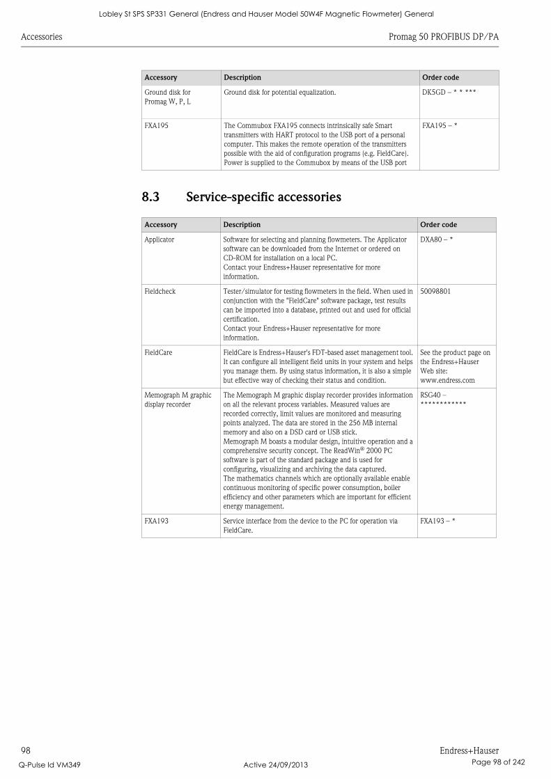
Accessories Promag 50 PROFIBUS DP/PA
98 Endress+Hauser
8.3 Service-specific accessories
Ground disk for
Promag W, P, L
Ground disk for potential equalization. DK5GD – * * ***
FXA195 The Commubox FXA195 connects intrinsically safe Smart
transmitters with HART protocol to the USB port of a personal
computer. This makes the remote operation of the transmitters
possible with the aid of configuration programs (e.g. FieldCare).
Power is supplied to the Commubox by means of the USB port
FXA195 – *
Accessory Description Order code
Applicator Software for selecting and planning flowmeters. The Applicator
software can be downloaded from the Internet or ordered on
CD-ROM for installation on a local PC.
Contact your Endress+Hauser representative for more
information.
DXA80 – *
Fieldcheck Tester/simulator for testing flowmeters in the field. When used in
conjunction with the "FieldCare" software package, test results
can be imported into a database, printed out and used for official
certification.
Contact your Endress+Hauser representative for more
information.
50098801
FieldCare FieldCare is Endress+Hauser's FDT-based asset management tool.
It can configure all intelligent field units in your system and helps
you manage them. By using status information, it is also a simple
but effective way of checking their status and condition.
See the product page on
the Endress+Hauser
Web site:
www.endress.com
Memograph M graphic
display recorder
The Memograph M graphic display recorder provides information
on all the relevant process variables. Measured values are
recorded correctly, limit values are monitored and measuring
points analyzed. The data are stored in the 256 MB internal
memory and also on a DSD card or USB stick.
Memograph M boasts a modular design, intuitive operation and a
comprehensive security concept. The ReadWin® 2000 PC
software is part of the standard package and is used for
configuring, visualizing and archiving the data captured.
The mathematics channels which are optionally available enable
continuous monitoring of specific power consumption, boiler
efficiency and other parameters which are important for efficient
energy management.
RSG40 –
************
FXA193 Service interface from the device to the PC for operation via
FieldCare.
FXA193 – *
Accessory Description Order code
Lobley St SPS SP331 General (Endress and Hauser Model 50W4F Magnetic Flowmeter) General
Q-Pulse Id VM349 Active 24/09/2013 Page 98 of 242
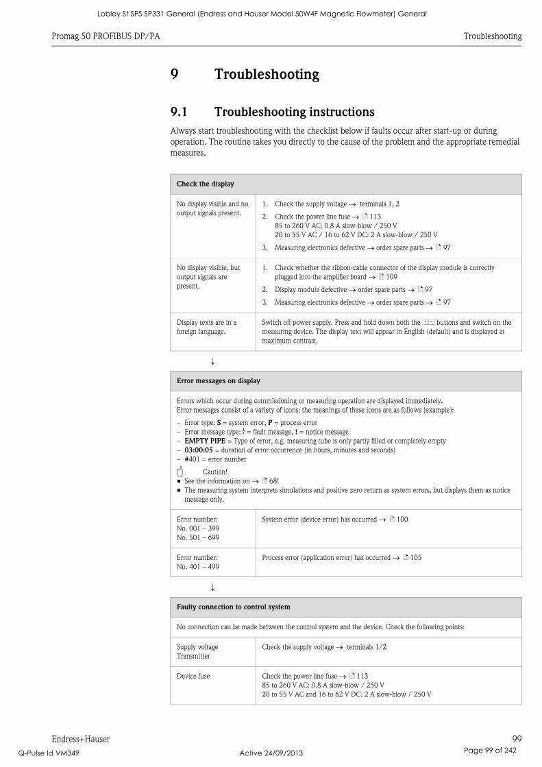
Promag 50 PROFIBUS DP/PA Troubleshooting
Endress+Hauser 99
9 Troubleshooting
9.1 Troubleshooting instructions
Always start troubleshooting with the checklist below if faults occur after start-up or during
operation. The routine takes you directly to the cause of the problem and the appropriate remedial
measures.
Check the display
No display visible and no
output signals present.
1. Check the supply voltage terminals 1, 2
2. Check the power line fuse ä 113
85 to 260 V AC: 0.8 A slow-blow / 250 V
20 to 55 V AC / 16 to 62 V DC: 2 A slow-blow / 250 V
3. Measuring electronics defective order spare parts ä 97
No display visible, but
output signals are
present.
1. Check whether the ribbon-cable connector of the display module is correctly
plugged into the amplifier board ä 109
2. Display module defective order spare parts ä 97
3. Measuring electronics defective order spare parts ä 97
Display texts are in a
foreign language.
Switch off power supply. Press and hold down both the OS buttons and switch on the
measuring device. The display text will appear in English (default) and is displayed at
maximum contrast.
Error messages on display
Errors which occur during commissioning or measuring operation are displayed immediately.
Error messages consist of a variety of icons: the meanings of these icons are as follows (example):
– Error type: S = system error, P = process error
– Error message type: $ = fault message, ! = notice message
– EMPTY PIPE = Type of error, e.g. measuring tube is only partly filled or completely empty
– 03:00:05 = duration of error occurrence (in hours, minutes and seconds)
– #401 = error number
" Caution!
• See the information on ä 68!
• The measuring system interprets simulations and positive zero return as system errors, but displays them as notice
message only.
Error number:
No. 001 – 399
No. 501 – 699
System error (device error) has occurred ä 100
Error number:
No. 401 – 499
Process error (application error) has occurred ä 105
Faulty connection to control system
No connection can be made between the control system and the device. Check the following points:
Supply voltage
Transmitter
Check the supply voltage terminals 1/2
Device fuse Check the power line fuse ä 113
85 to 260 V AC: 0.8 A slow-blow / 250 V
20 to 55 V AC and 16 to 62 V DC: 2 A slow-blow / 250 V
Lobley St SPS SP331 General (Endress and Hauser Model 50W4F Magnetic Flowmeter) General
Q-Pulse Id VM349 Active 24/09/2013 Page 99 of 242
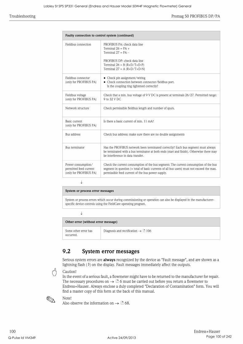
Troubleshooting Promag 50 PROFIBUS DP/PA
100 Endress+Hauser
9.2 System error messages
Serious system errors are always recognized by the device as "Fault message", and are shown as a
lightning flash ( $) on the display. Fault messages immediately affect the outputs.
" Caution!
In the event of a serious fault, a flowmeter might have to be returned to the manufacturer for repair.
The necessary procedures on ä 6 must be carried out before you return a flowmeter to
Endress+Hauser. Always enclose a duly completed "Declaration of Contamination" form. You will
find a master copy of this form at the back of this manual.
! Note!
Also observe the information on ä 68.
Faulty connection to control system (continued)
Fieldbus connection PROFIBUS PA: check data line
Terminal 26 = PA +
Terminal 27 = PA –
PROFIBUS DP: check data line
Terminal 26 = B (R×D/T×D-P)
Terminal 27 = A (R×D/T×D-N)
Fieldbus connector
(only for PROFIBUS PA)
• Check pin assignment/wiring
• Check connection between connector/fieldbus port.
Is the coupling ring tightened correctly?
Fieldbus voltage
(only for PROFIBUS PA)
Check that a min. bus voltage of 9 V DC is present at terminals 26/27. Permitted range:
9 to 32 V DC
Network structure Check permissible fieldbus length and number of spurs.
Basic current
(only for PROFIBUS PA)
Is there a basic current of min. 11 mA?
Bus address Check bus address: make sure there are no double assignments
Bus terminator Has the PROFIBUS network been terminated correctly? Each bus segment must always
be terminated with a bus terminator at both ends (start and finish). Otherwise there may
be interference in data transfer.
Power consumption/
permitted feed current
(only for PROFIBUS PA)
Check the current consumption of the bus segment: The current consumption of the bus
segment in question (= total of basic currents of all bus users) must not exceed the max.
permissible feed current of the bus power supply.
System or process error messages
System or process errors which occur during commissioning or operation can also be displayed in the manufacturer-
specific device controls using the FieldCare operating program.
Other error (without error message)
Some other error has
occurred.
Diagnosis and rectification ä 106
Lobley St SPS SP331 General (Endress and Hauser Model 50W4F Magnetic Flowmeter) General
Q-Pulse Id VM349 Active 24/09/2013 Page 100 of 242
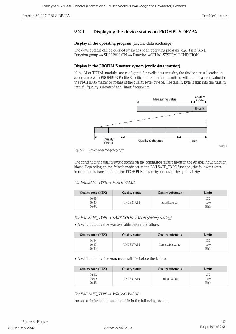
Promag 50 PROFIBUS DP/PA Troubleshooting
Endress+Hauser 101
9.2.1 Displaying the device status on PROFIBUS DP/PA
Display in the operating program (acyclic data exchange)
The device status can be queried by means of an operating program (e.g. FieldCare).
Function group SUPERVISION Function ACTUAL SYSTEM CONDITION.
Display in the PROFIBUS master system (cyclic data transfer)
If the AI or TOTAL modules are configured for cyclic data transfer, the device status is coded in
accordance with PROFIBUS Profile Specification 3.0 and transmitted with the measured value to
the PROFIBUS master by means of the quality byte (byte 5). The quality byte is split into the "quality
status", "quality substatus" and "limits" segments.
a0002707-en
Fig. 58: Structure of the quality byte
The content of the quality byte depends on the configured failsafe mode in the Analog Input function
block. Depending on the failsafe mode set in the FAILSAFE_TYPE function, the following stats
information is transmitted to the PROFIBUS master by means of the quality byte:
For FAILSAFE_TYPE FSAFE VALUE
For FAILSAFE_TYPE LAST GOOD VALUE (factory setting)
• A valid output value was available before the failure:
• A valid output value was not available before the failure:
For FAILSAFE_TYPE WRONG VALUE
For status information, see the table in the following section.
QualityCodeMeasuring value
LimitsQuality SubstatusQualityStatus
Byte 5
Quality code (HEX) Quality status Quality substatus Limits
0x48
0x49
0x4A
UNCERTAIN Substitute set
OK
Low
High
Quality code (HEX) Quality status Quality substatus Limits
0x44
0x45
0x46
UNCERTAIN Last usable value
OK
Low
High
Quality code (HEX) Quality status Quality substatus Limits
0x4C
0x4D
0x4E
UNCERTAIN Initial Value
OK
Low
High
Lobley St SPS SP331 General (Endress and Hauser Model 50W4F Magnetic Flowmeter) General
Q-Pulse Id VM349 Active 24/09/2013 Page 101 of 242
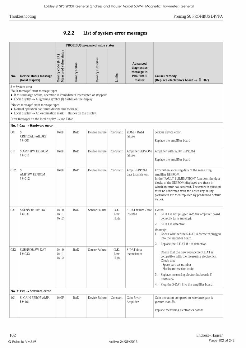
Troubleshooting Promag 50 PROFIBUS DP/PA
102 Endress+Hauser
9.2.2 List of system error messages
No. Device status message
(local display)
PROFIBUS measured value status
Advanced
diagnostics
message in
PROFIBUS
master
Cause/remedy
(Replace electronics board ä 107)Qu
ali
ty c
od
e (
HE
X)
Measu
red
valu
e s
tatu
s
Qu
ality
sta
tus
Qu
ality
subst
atu
s
Lim
its
S = System error
"Fault message" error message type:
• If this message occurs, operation is immediately interrupted or stopped!
• Local display A lightning symbol ($) flashes on the display
"Notice message" error message type:
• Normal operation continues despite this message!
• Local display An exclamation mark (!) flashes on the display.
Error messages on the local display see Table
No. # 0xx Hardware error
001 S
CRITICAL FAILURE
$ # 001
0x0F BAD Device Failure Constant ROM / RAM
failure
Serious device error.
Replace the amplifier board
011 S AMP HW EEPROM
$ # 011
0x0F BAD Device Failure Constant Amplifier EEPROM
failure
Amplifier with faulty EEPROM
Replace the amplifier board
012 S
AMP SW EEPROM
$ # 012
0x0F BAD Device Failure Constant Amp. EEPROM
data inconsistent
Error when accessing data of the measuring
amplifier EEPROM
In the "FAULT ELIMINATION" function, the data
blocks of the EEPROM displayed are those in
which an error has occurred. The errors in question
must be confirmed with the Enter-key; faulty
parameters are then replaced by predefined default
values.
031 S SENSOR HW DAT
$ # 031
0x10
0x11
0x12
BAD Sensor Failure O.K.
Low
High
S-DAT failure / not
inserted
Cause:
1. S-DAT is not plugged into the amplifier board
correctly (or is missing).
2. S-DAT is defective.
Remedy:
1. Check whether the S-DAT is correctly plugged
into the amplifier board.
2. Replace the S-DAT if it is defective.
Check that the new replacement DAT is
compatible with the measuring electronics.
Check the:
- Spare part set number
- Hardware revision code
3. Replace measuring electronics boards if
necessary.
4. Plug the S-DAT into the amplifier board.
032 S SENSOR SW DAT
$ # 032
0x10
0x11
0x12
BAD Sensor Failure O.K.
Low
High
S-DAT data
inconsistent
No. # 1xx Software error
101 S: GAIN ERROR AMP.
$ # 101
0x0F BAD Device Failure Constant Gain Error
Amplifier
Gain deviation compared to reference gain is
greater than 2%.
Replace measuring electronics boards.
Lobley St SPS SP331 General (Endress and Hauser Model 50W4F Magnetic Flowmeter) General
Q-Pulse Id VM349 Active 24/09/2013 Page 102 of 242
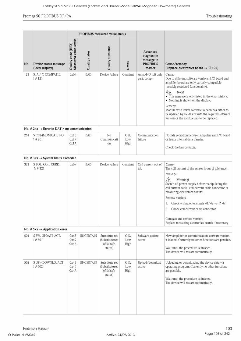
Promag 50 PROFIBUS DP/PA Troubleshooting
Endress+Hauser 103
121 S: A / C COMPATIB.
! # 121
0x0F BAD Device Failure Constant Amp.-I/O soft only
part. comp.
Cause:
Due to different software versions, I/O board and
amplifier board are only partially compatible
(possibly restricted functionality).
! Note!
• This message is only listed in the error history.
• Nothing is shown on the display.
Remedy:
Module with lower software version has either to
be updated by FieldCare with the required software
version or the module has to be replaced.
No. # 2xx Error in DAT / no communication
261 S COMMUNICAT. I/O
$ # 261
0x18
0x19
0x1A
BAD No
Communicati
on
O.K.
Low
High
Communication
failure
No data reception between amplifier and I/O board
or faulty internal data transfer.
Check the bus contacts.
No. # 3xx System limits exceeded
321 S TOL. COIL CURR.
$: # 321
0x0F BAD Device Failure Constant Coil current out of
tol.
Cause:
The coil current of the sensor is out of tolerance.
Remedy:
# Warning!
Switch off power supply before manipulating the
coil current cable, coil current cable connector or
measuring electronics boards!
Remote version:
1. Check wiring of terminals 41/42 ä 47
2. Check coil current cable connector.
Compact and remote version:
Replace measuring electronics boards if necessary
No. # 5xx Application error
501 S SW. UPDATE ACT.
! # 501
0x48
0x49
0x4A
UNCERTAIN Substitute set
(Substitute set
of failsafe
status)
O.K.
Low
High
Software update
active
New amplifier or communication software version
is loaded. Currently no other functions are possible.
Wait until the procedure is finished.
The device will restart automatically.
502 S UP-/DOWNLO. ACT.
! # 502
0x48
0x49
0x4A
UNCERTAIN Substitute set
(Substitute set
of failsafe
status)
O.K.
Low
High
Upload/download
active
Uploading or downloading the device data via
operating program. Currently no other functions
are possible.
Wait until the procedure is finished.
The device will restart automatically.
No. Device status message
(local display)
PROFIBUS measured value status
Advanced
diagnostics
message in
PROFIBUS
master
Cause/remedy
(Replace electronics board ä 107)Qu
ali
ty c
od
e (
HE
X)
Measu
red
valu
e s
tatu
s
Qu
ali
ty s
tatu
s
Qu
ali
ty s
ub
statu
s
Lim
its
Lobley St SPS SP331 General (Endress and Hauser Model 50W4F Magnetic Flowmeter) General
Q-Pulse Id VM349 Active 24/09/2013 Page 103 of 242
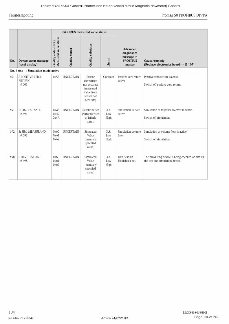
Troubleshooting Promag 50 PROFIBUS DP/PA
104 Endress+Hauser
No. # 6xx Simulation mode active
601 S POSITIVE ZERO
RETURN
! # 601
0x53 UNCERTAIN Sensor
conversion
not accurate
(measured
value from
sensor not
accurate)
Constant Positive zero return
active
Positive zero return is active.
Switch off positive zero return.
691 S: SIM. FAILSAFE
! # 691
0x48
0x49
0x4A
UNCERTAIN Substitute set
(Substitute set
of failsafe
status)
O.K.
Low
High
Simulation failsafe
active
Simulation of response to error is active.
Switch off simulation.
692 S: SIM. MEASURAND
! # 692
0x60
0x61
0x62
UNCERTAIN Simulated
Value
(manually
specified
value)
O.K.
Low
High
Simulation volume
flow
Simulation of volume flow is active.
Switch off simulation.
698 S DEV. TEST AKT.
! # 698
0x60
0x61
0x62
UNCERTAIN Simulated
Value
(manually
specified
value)
O.K.
Low
High
Dev. test via
Fieldcheck act.
The measuring device is being checked on site via
the test and simulation device.
No. Device status message
(local display)
PROFIBUS measured value status
Advanced
diagnostics
message in
PROFIBUS
master
Cause/remedy
(Replace electronics board ä 107)Qu
ali
ty c
od
e (
HE
X)
Measu
red
valu
e s
tatu
s
Qu
ali
ty s
tatu
s
Qu
ali
ty s
ub
statu
s
Lim
its
Lobley St SPS SP331 General (Endress and Hauser Model 50W4F Magnetic Flowmeter) General
Q-Pulse Id VM349 Active 24/09/2013 Page 104 of 242
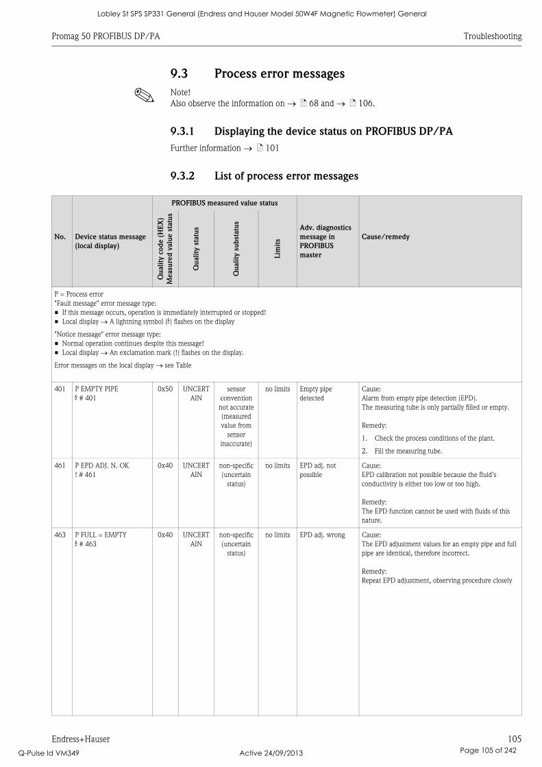
Promag 50 PROFIBUS DP/PA Troubleshooting
Endress+Hauser 105
9.3 Process error messages
! Note!
Also observe the information on ä 68 and ä 106.
9.3.1 Displaying the device status on PROFIBUS DP/PA
Further information ä 101
9.3.2 List of process error messages
No. Device status message
(local display)
PROFIBUS measured value status
Adv. diagnostics
message in
PROFIBUS
master
Cause/remedy
Qu
ali
ty c
od
e (
HE
X)
Measu
red
valu
e s
tatu
s
Qu
ality
sta
tus
Qu
ali
ty s
ub
statu
s
Lim
its
P = Process error
"Fault message" error message type:
• If this message occurs, operation is immediately interrupted or stopped!
• Local display A lightning symbol ($) flashes on the display
"Notice message" error message type:
• Normal operation continues despite this message!
• Local display An exclamation mark (!) flashes on the display.
Error messages on the local display see Table
401 P EMPTY PIPE
$ # 401
0x50 UNCERT
AIN
sensor
convention
not accurate
(measured
value from
sensor
inaccurate)
no limits Empty pipe
detected
Cause:
Alarm from empty pipe detection (EPD).
The measuring tube is only partially filled or empty.
Remedy:
1. Check the process conditions of the plant.
2. Fill the measuring tube.
461 P EPD ADJ. N. OK
! # 461
0x40 UNCERT
AIN
non-specific
(uncertain
status)
no limits EPD adj. not
possible
Cause:
EPD calibration not possible because the fluid's
conductivity is either too low or too high.
Remedy:
The EPD function cannot be used with fluids of this
nature.
463 P FULL = EMPTY
$ # 463
0x40 UNCERT
AIN
non-specific
(uncertain
status)
no limits EPD adj. wrong Cause:
The EPD adjustment values for an empty pipe and full
pipe are identical, therefore incorrect.
Remedy:
Repeat EPD adjustment, observing procedure closely
Lobley St SPS SP331 General (Endress and Hauser Model 50W4F Magnetic Flowmeter) General
Q-Pulse Id VM349 Active 24/09/2013 Page 105 of 242
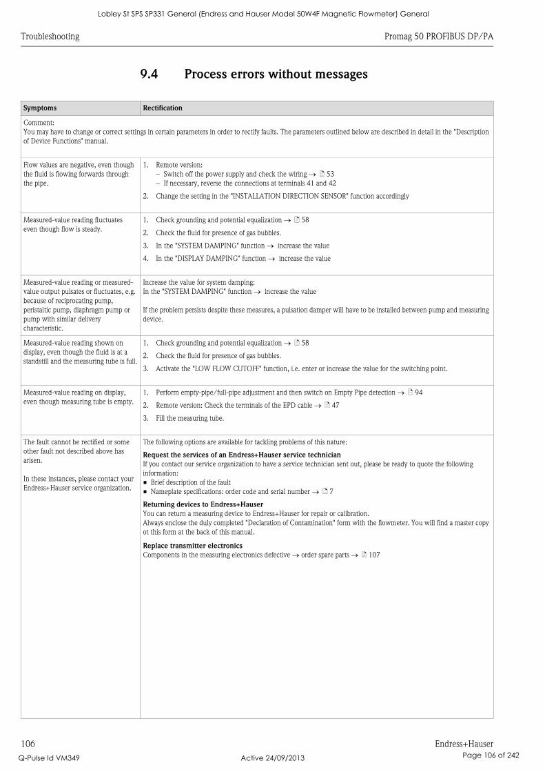
Troubleshooting Promag 50 PROFIBUS DP/PA
106 Endress+Hauser
9.4 Process errors without messages
Symptoms Rectification
Comment:
You may have to change or correct settings in certain parameters in order to rectify faults. The parameters outlined below are described in detail in the "Description
of Device Functions" manual.
Flow values are negative, even though
the fluid is flowing forwards through
the pipe.
1. Remote version:
– Switch off the power supply and check the wiring ä 53
– If necessary, reverse the connections at terminals 41 and 42
2. Change the setting in the "INSTALLATION DIRECTION SENSOR" function accordingly
Measured-value reading fluctuates
even though flow is steady.
1. Check grounding and potential equalization ä 58
2. Check the fluid for presence of gas bubbles.
3. In the "SYSTEM DAMPING" function increase the value
4. In the "DISPLAY DAMPING" function increase the value
Measured-value reading or measured-
value output pulsates or fluctuates, e.g.
because of reciprocating pump,
peristaltic pump, diaphragm pump or
pump with similar delivery
characteristic.
Increase the value for system damping:
In the "SYSTEM DAMPING" function increase the value
If the problem persists despite these measures, a pulsation damper will have to be installed between pump and measuring
device.
Measured-value reading shown on
display, even though the fluid is at a
standstill and the measuring tube is full.
1. Check grounding and potential equalization ä 58
2. Check the fluid for presence of gas bubbles.
3. Activate the "LOW FLOW CUTOFF" function, i.e. enter or increase the value for the switching point.
Measured-value reading on display,
even though measuring tube is empty.
1. Perform empty-pipe/full-pipe adjustment and then switch on Empty Pipe detection ä 94
2. Remote version: Check the terminals of the EPD cable ä 47
3. Fill the measuring tube.
The fault cannot be rectified or some
other fault not described above has
arisen.
In these instances, please contact your
Endress+Hauser service organization.
The following options are available for tackling problems of this nature:
Request the services of an Endress+Hauser service technician
If you contact our service organization to have a service technician sent out, please be ready to quote the following
information:
• Brief description of the fault
• Nameplate specifications: order code and serial number ä 7
Returning devices to Endress+Hauser
You can return a measuring device to Endress+Hauser for repair or calibration.
Always enclose the duly completed "Declaration of Contamination" form with the flowmeter. You will find a master copy
ot this form at the back of this manual.
Replace transmitter electronics
Components in the measuring electronics defective order spare parts ä 107
Lobley St SPS SP331 General (Endress and Hauser Model 50W4F Magnetic Flowmeter) General
Q-Pulse Id VM349 Active 24/09/2013 Page 106 of 242
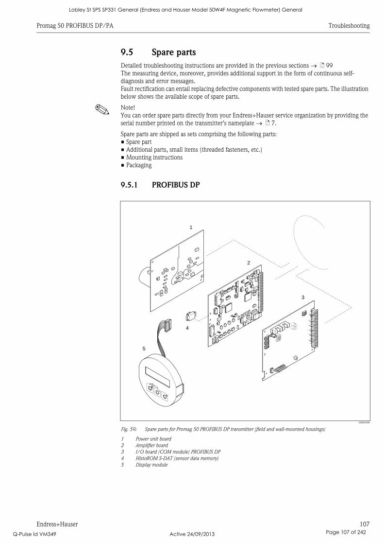
Promag 50 PROFIBUS DP/PA Troubleshooting
Endress+Hauser 107
9.5 Spare parts
Detailed troubleshooting instructions are provided in the previous sections ä 99
The measuring device, moreover, provides additional support in the form of continuous self-
diagnosis and error messages.
Fault rectification can entail replacing defective components with tested spare parts. The illustration
below shows the available scope of spare parts.
! Note!
You can order spare parts directly from your Endress+Hauser service organization by providing the
serial number printed on the transmitter's nameplate ä 7.
Spare parts are shipped as sets comprising the following parts:
• Spare part
• Additional parts, small items (threaded fasteners, etc.)
• Mounting instructions
• Packaging
9.5.1 PROFIBUS DP
A0005400
Fig. 59: Spare parts for Promag 50 PROFIBUS DP transmitter (field and wall-mounted housings)
1 Power unit board
2 Amplifier board
3 I/O board (COM module) PROFIBUS DP
4 HistoROM S-DAT (sensor data memory)
5 Display module
2
3
5
4
1234
1234
WENO
WENO
1234
1234
WENO
WENO
1234
1234
WENO
WENO
1234
1234
WENO
WENO
1
Lobley St SPS SP331 General (Endress and Hauser Model 50W4F Magnetic Flowmeter) General
Q-Pulse Id VM349 Active 24/09/2013 Page 107 of 242
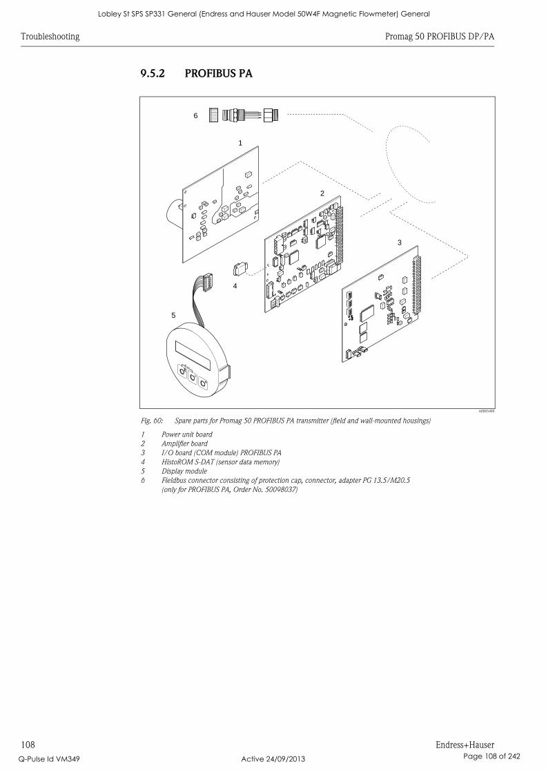
Troubleshooting Promag 50 PROFIBUS DP/PA
108 Endress+Hauser
9.5.2 PROFIBUS PA
A0005400
Fig. 60: Spare parts for Promag 50 PROFIBUS PA transmitter (field and wall-mounted housings)
1 Power unit board
2 Amplifier board
3 I/O board (COM module) PROFIBUS PA
4 HistoROM S-DAT (sensor data memory)
5 Display module
6 Fieldbus connector consisting of protection cap, connector, adapter PG 13.5/M20.5
(only for PROFIBUS PA, Order No. 50098037)
1
2
3
5
4
6
Lobley St SPS SP331 General (Endress and Hauser Model 50W4F Magnetic Flowmeter) General
Q-Pulse Id VM349 Active 24/09/2013 Page 108 of 242

Promag 50 PROFIBUS DP/PA Troubleshooting
Endress+Hauser 109
9.5.3 Removing and installing printed circuit boards
Field housing: removing and installing printed circuit boards å 61
# Warning!
• Risk of electric shock!
Exposed components carry dangerous voltages. Make sure that the power supply is switched off
before you remove the cover of the electronics compartment.
• Risk of damaging electronic components (ESD protection). Static electricity can damage electronic
components or impair their operability. Use a workplace with a grounded working surface
purpose-built for electrostatically sensitive devices!
• If you cannot guarantee that the dielectric strength of the device is maintained in the following
steps, then an appropriate inspection must be carried out in accordance with the manufacturer’s
specifications.
• When connecting Ex-certified devices, see the notes and diagrams in the Ex-specific supplement
to these Operating Instructions.
" Caution!
Use only original Endress+Hauser parts.
1. Switch off power supply.
2. Unscrew cover of the electronics compartment from the transmitter housing.
3. Remove the local display (1) as follows:
– Press in the latches (1.1) at the side and remove the display module.
– Disconnect the ribbon cable (1.2) of the display module from the amplifier board.
4. Remove the screws and remove the cover (2) from the electronics compartment.
5. Remove the boards (4, 6): Insert a suitable tool into the hole (3) provided for the purpose and
pull the board clear of its holder.
6. Remove amplifier board (5):
– Disconnect the plug of the electrode signal cable (5.1) including S-DAT (5.3) from the board.
– Loosen the plug locking of the coil current cable (5.2) and gently disconnect the plug from
the board, i.e. without moving it to and fro.
– Insert a thin pin into the hole (3) provided for the purpose and pull the board clear of its
holder.
7. Installation is the reverse of the removal procedure.
Lobley St SPS SP331 General (Endress and Hauser Model 50W4F Magnetic Flowmeter) General
Q-Pulse Id VM349 Active 24/09/2013 Page 109 of 242
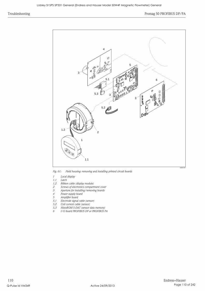
Troubleshooting Promag 50 PROFIBUS DP/PA
110 Endress+Hauser
A0005397
Fig. 61: Field housing: removing and installing printed circuit boards
1 Local display
1.1 Latch
1.2 Ribbon cable (display module)
2 Screws of electronics compartment cover
3 Aperture for installing/removing boards
4 Power supply board
5 Amplifier board
5.1 Electrode signal cable (sensor)
5.2 Coil current cable (sensor)
5.3 HistoROM S-DAT (sensor data memory)
6 I/O board PROFIBUS DP or PROFIBUS PA
4
5
6
3
3
3
2
1
1.2
5.1
5.3
5.2
1.1
Lobley St SPS SP331 General (Endress and Hauser Model 50W4F Magnetic Flowmeter) General
Q-Pulse Id VM349 Active 24/09/2013 Page 110 of 242

Promag 50 PROFIBUS DP/PA Troubleshooting
Endress+Hauser 111
Wall-mount housing: removing and installing printed circuit boards å 62
# Warning!
• Risk of electric shock!
Exposed components carry dangerous voltages. Make sure that the power supply is switched off
before you remove the cover of the electronics compartment.
• Risk of damaging electronic components (ESD protection). Static electricity can damage electronic
components or impair their operability. Use a workplace with a grounded working surface
purpose-built for electrostatically sensitive devices!
• If you cannot guarantee that the dielectric strength of the device is maintained in the following
steps, then an appropriate inspection must be carried out in accordance with the manufacturer’s
specifications.
• When connecting Ex-certified devices, see the notes and diagrams in the Ex-specific supplement
to these Operating Instructions.
" Caution!
Use only original Endress+Hauser parts.
1. Switch off power supply.
2. Remove the screws and open the hinged cover (1) of the housing. Remove screws of the
electronics module (2).
3. Then push up electronics module and pull it as far as possible out of the wall-mounted housing.
4. Disconnect the following cable plugs from amplifier board (7):
– Electrode signal cable plug (7.1) including S-DAT (7.3).
– Plug of coil current cable (7.2). To do so, loosen the plug locking of the coil current cable
and gently disconnect the plug from the board, i.e. without moving it to and fro.
– Ribbon cable plug (3) of the display module.
5. Remove the screws and remove the cover (4) from the electronics compartment.
6. Remove the boards (6, 7, 8): Insert a suitable tool into the hole (5) provided for the purpose
and pull the board clear of its holder.
7. Installation is the reverse of the removal procedure.
Lobley St SPS SP331 General (Endress and Hauser Model 50W4F Magnetic Flowmeter) General
Q-Pulse Id VM349 Active 24/09/2013 Page 111 of 242
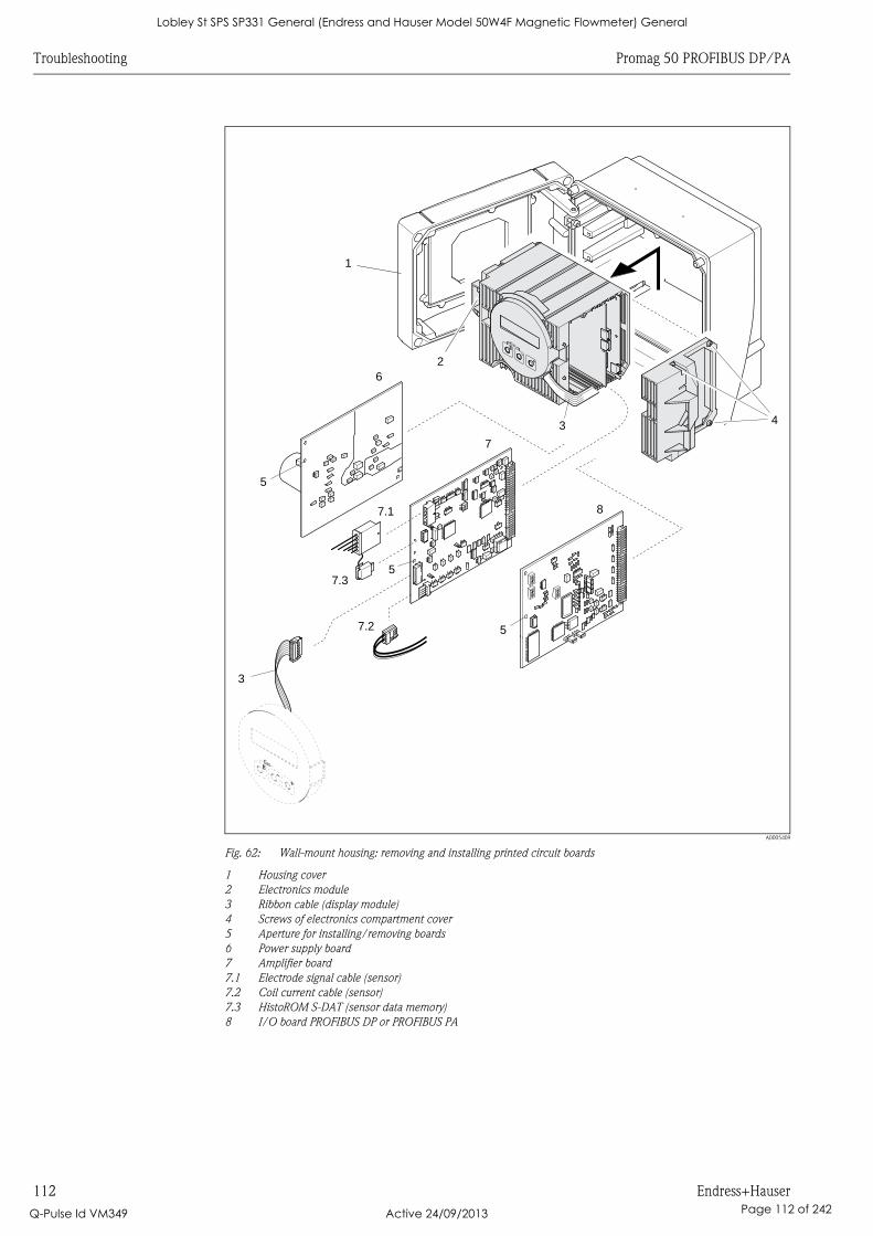
Troubleshooting Promag 50 PROFIBUS DP/PA
112 Endress+Hauser
A0005409
Fig. 62: Wall-mount housing: removing and installing printed circuit boards
1 Housing cover
2 Electronics module
3 Ribbon cable (display module)
4 Screws of electronics compartment cover
5 Aperture for installing/removing boards
6 Power supply board
7 Amplifier board
7.1 Electrode signal cable (sensor)
7.2 Coil current cable (sensor)
7.3 HistoROM S-DAT (sensor data memory)
8 I/O board PROFIBUS DP or PROFIBUS PA
6
7
8
5
5
3 4
7.1
7.3
7.2
1
2
3
5
Lobley St SPS SP331 General (Endress and Hauser Model 50W4F Magnetic Flowmeter) General
Q-Pulse Id VM349 Active 24/09/2013 Page 112 of 242
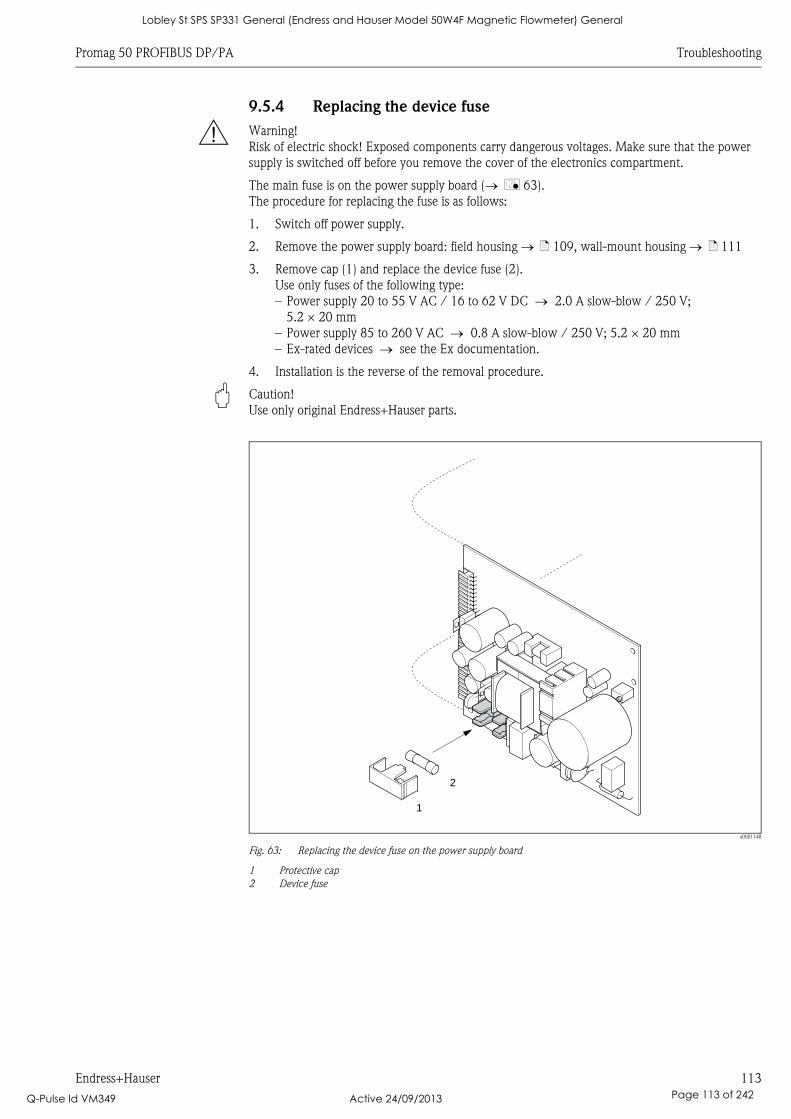
Promag 50 PROFIBUS DP/PA Troubleshooting
Endress+Hauser 113
9.5.4 Replacing the device fuse
# Warning!
Risk of electric shock! Exposed components carry dangerous voltages. Make sure that the power
supply is switched off before you remove the cover of the electronics compartment.
The main fuse is on the power supply board ( å 63).
The procedure for replacing the fuse is as follows:
1. Switch off power supply.
2. Remove the power supply board: field housing ä 109, wall-mount housing ä 111
3. Remove cap (1) and replace the device fuse (2).
Use only fuses of the following type:
– Power supply 20 to 55 V AC / 16 to 62 V DC 2.0 A slow-blow / 250 V;
5.2 × 20 mm
– Power supply 85 to 260 V AC 0.8 A slow-blow / 250 V; 5.2 × 20 mm
– Ex-rated devices see the Ex documentation.
4. Installation is the reverse of the removal procedure.
" Caution!
Use only original Endress+Hauser parts.
a0001148
Fig. 63: Replacing the device fuse on the power supply board
1 Protective cap
2 Device fuse
1
2
Lobley St SPS SP331 General (Endress and Hauser Model 50W4F Magnetic Flowmeter) General
Q-Pulse Id VM349 Active 24/09/2013 Page 113 of 242
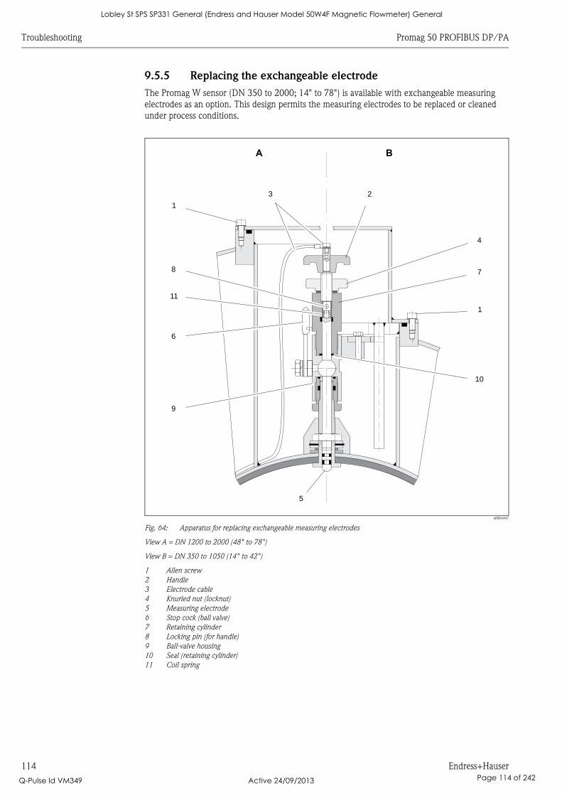
Troubleshooting Promag 50 PROFIBUS DP/PA
114 Endress+Hauser
9.5.5 Replacing the exchangeable electrode
The Promag W sensor (DN 350 to 2000; 14" to 78") is available with exchangeable measuring
electrodes as an option. This design permits the measuring electrodes to be replaced or cleaned
under process conditions.
a0004447
Fig. 64: Apparatus for replacing exchangeable measuring electrodes
View A = DN 1200 to 2000 (48" to 78")
View B = DN 350 to 1050 (14" to 42")
1 Allen screw
2 Handle
3 Electrode cable
4 Knurled nut (locknut)
5 Measuring electrode
6 Stop cock (ball valve)
7 Retaining cylinder
8 Locking pin (for handle)
9 Ball-valve housing
10 Seal (retaining cylinder)
11 Coil spring
A
3 2
1
4
8 7
11
1
6
10
9
5
B
Lobley St SPS SP331 General (Endress and Hauser Model 50W4F Magnetic Flowmeter) General
Q-Pulse Id VM349 Active 24/09/2013 Page 114 of 242
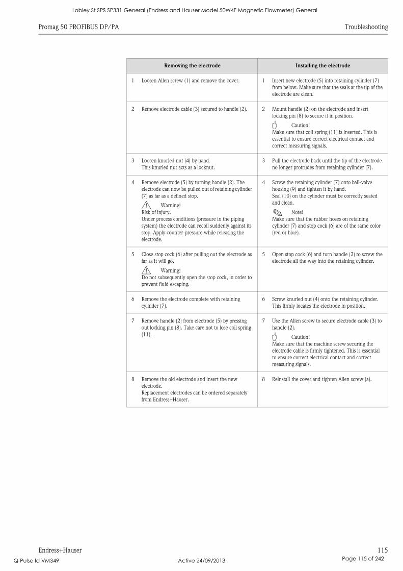
Promag 50 PROFIBUS DP/PA Troubleshooting
Endress+Hauser 115
Removing the electrode Installing the electrode
1 Loosen Allen screw (1) and remove the cover. 1 Insert new electrode (5) into retaining cylinder (7)
from below. Make sure that the seals at the tip of the
electrode are clean.
2 Remove electrode cable (3) secured to handle (2). 2 Mount handle (2) on the electrode and insert
locking pin (8) to secure it in position.
" Caution!
Make sure that coil spring (11) is inserted. This is
essential to ensure correct electrical contact and
correct measuring signals.
3 Loosen knurled nut (4) by hand.
This knurled nut acts as a locknut.
3 Pull the electrode back until the tip of the electrode
no longer protrudes from retaining cylinder (7).
4 Remove electrode (5) by turning handle (2). The
electrode can now be pulled out of retaining cylinder
(7) as far as a defined stop.
# Warning!
Risk of injury.
Under process conditions (pressure in the piping
system) the electrode can recoil suddenly against its
stop. Apply counter-pressure while releasing the
electrode.
4 Screw the retaining cylinder (7) onto ball-valve
housing (9) and tighten it by hand.
Seal (10) on the cylinder must be correctly seated
and clean.
! Note!
Make sure that the rubber hoses on retaining
cylinder (7) and stop cock (6) are of the same color
(red or blue).
5 Close stop cock (6) after pulling out the electrode as
far as it will go.
# Warning!
Do not subsequently open the stop cock, in order to
prevent fluid escaping.
5 Open stop cock (6) and turn handle (2) to screw the
electrode all the way into the retaining cylinder.
6 Remove the electrode complete with retaining
cylinder (7).
6 Screw knurled nut (4) onto the retaining cylinder.
This firmly locates the electrode in position.
7 Remove handle (2) from electrode (5) by pressing
out locking pin (8). Take care not to lose coil spring
(11).
7 Use the Allen screw to secure electrode cable (3) to
handle (2).
" Caution!
Make sure that the machine screw securing the
electrode cable is firmly tightened. This is essential
to ensure correct electrical contact and correct
measuring signals.
8 Remove the old electrode and insert the new
electrode.
Replacement electrodes can be ordered separately
from Endress+Hauser.
8 Reinstall the cover and tighten Allen screw (a).
Lobley St SPS SP331 General (Endress and Hauser Model 50W4F Magnetic Flowmeter) General
Q-Pulse Id VM349 Active 24/09/2013 Page 115 of 242
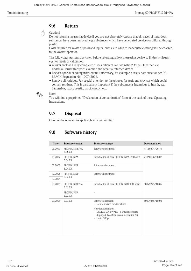
Troubleshooting Promag 50 PROFIBUS DP/PA
116 Endress+Hauser
9.6 Return
" Caution!
Do not return a measuring device if you are not absolutely certain that all traces of hazardous
substances have been removed, e.g. substances which have penetrated crevices or diffused through
plastic.
Costs incurred for waste disposal and injury (burns, etc.) due to inadequate cleaning will be charged
to the owner-operator.
The following steps must be taken before returning a flow measuring device to Endress+Hauser,
e.g. for repair or calibration:
• Always enclose a duly completed "Declaration of contamination" form. Only then can
Endress+Hauser transport, examine and repair a returned device.
• Enclose special handling instructions if necessary, for example a safety data sheet as per EC
REACH Regulation No. 1907/2006.
• Remove all residues. Pay special attention to the grooves for seals and crevices which could
contain residues. This is particularly important if the substance is hazardous to health, e.g.
flammable, toxic, caustic, carcinogenic, etc.
! Note!
You will find a preprinted "Declaration of contamination" form at the back of these Operating
Instructions.
9.7 Disposal
Observe the regulations applicable in your country!
9.8 Software history
Date Software version Software changes Documentation
06.2010 PROFIBUS DP/PA
3.06.XX
Software adjustment 71116494/06.10
08.2007 PROFIBUS PA
3.04.XX
Introduction of new PROFIBUS PA I/O board 71060108/08.07
07.2007 PROFIBUS DP
3.04.XX
Software adjustment
10.2006 PROFIBUS DP
3.02.XX
Software adjustment
12.2005
10.2005 PROFIBUS DP/PA
3.01.XX
Introduction of new PROFIBUS DP I/O board 50099245/10.05
PROFIBUS PA
2.03.XX
–
03.2005 2.03.XX Software expansion:
– New / revised functionalities
New functionalities:
– DEVICE SOFTWARE Device software
displayed (NAMUR Recommendation 53)
– Unit US Kgal
50099245/10.03
Lobley St SPS SP331 General (Endress and Hauser Model 50W4F Magnetic Flowmeter) General
Q-Pulse Id VM349 Active 24/09/2013 Page 116 of 242
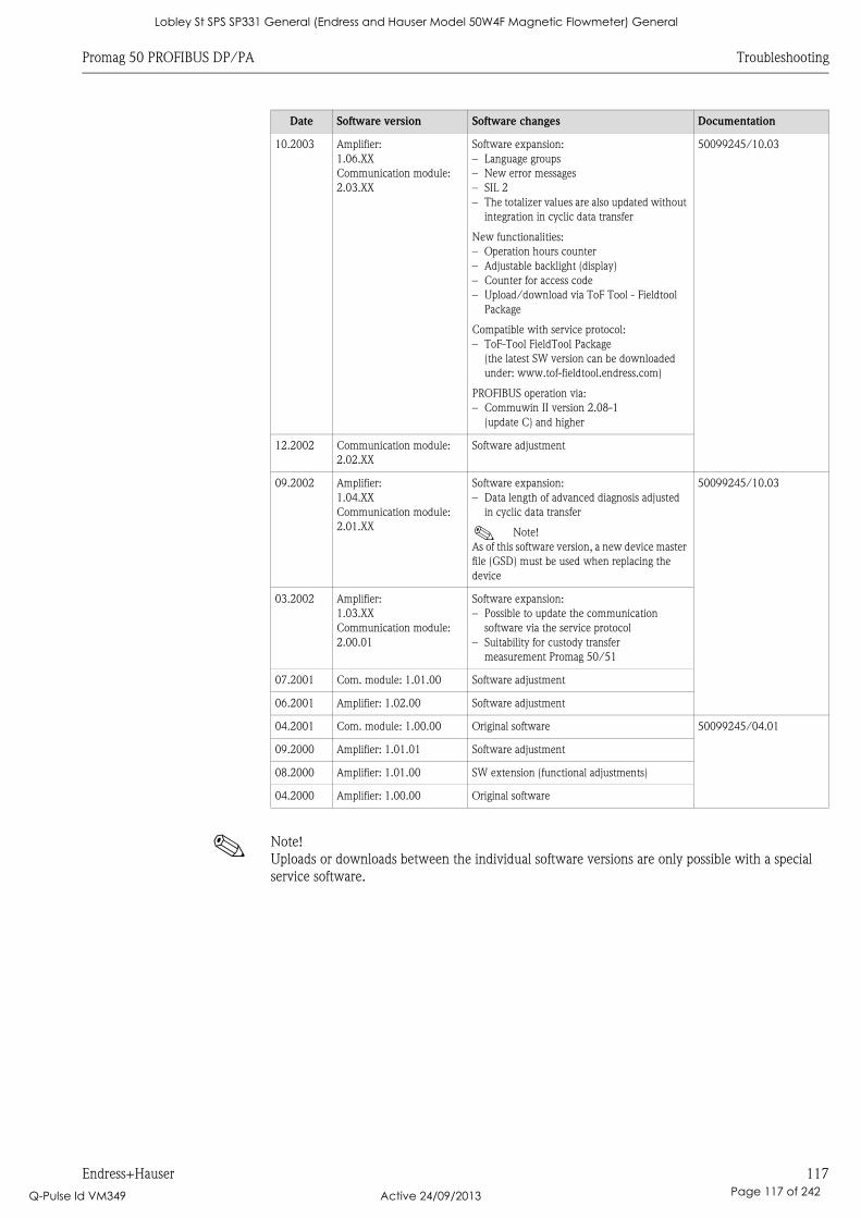
Promag 50 PROFIBUS DP/PA Troubleshooting
Endress+Hauser 117
! Note!
Uploads or downloads between the individual software versions are only possible with a special
service software.
10.2003 Amplifier:
1.06.XX
Communication module:
2.03.XX
Software expansion:
– Language groups
– New error messages
– SIL 2
– The totalizer values are also updated without
integration in cyclic data transfer
New functionalities:
– Operation hours counter
– Adjustable backlight (display)
– Counter for access code
– Upload/download via ToF Tool - Fieldtool
Package
Compatible with service protocol:
– ToF-Tool FieldTool Package
(the latest SW version can be downloaded
under: www.tof-fieldtool.endress.com)
PROFIBUS operation via:
– Commuwin II version 2.08-1
(update C) and higher
50099245/10.03
12.2002 Communication module:
2.02.XX
Software adjustment
09.2002 Amplifier:
1.04.XX
Communication module:
2.01.XX
Software expansion:
– Data length of advanced diagnosis adjusted
in cyclic data transfer
! Note!
As of this software version, a new device master
file (GSD) must be used when replacing the
device
50099245/10.03
03.2002 Amplifier:
1.03.XX
Communication module:
2.00.01
Software expansion:
– Possible to update the communication
software via the service protocol
– Suitability for custody transfer
measurement Promag 50/51
07.2001 Com. module: 1.01.00 Software adjustment
06.2001 Amplifier: 1.02.00 Software adjustment
04.2001 Com. module: 1.00.00 Original software 50099245/04.01
09.2000 Amplifier: 1.01.01 Software adjustment
08.2000 Amplifier: 1.01.00 SW extension (functional adjustments)
04.2000 Amplifier: 1.00.00 Original software
Date Software version Software changes Documentation
Lobley St SPS SP331 General (Endress and Hauser Model 50W4F Magnetic Flowmeter) General
Q-Pulse Id VM349 Active 24/09/2013 Page 117 of 242
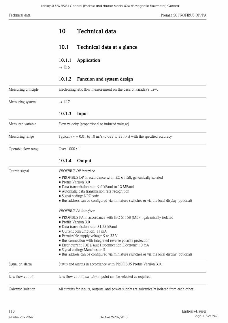
Technical data Promag 50 PROFIBUS DP/PA
118 Endress+Hauser
10 Technical data
10.1 Technical data at a glance
10.1.1 Application
ä 5
10.1.2 Function and system design
Measuring principle Electromagnetic flow measurement on the basis of Faraday’s Law.
Measuring system ä 7
10.1.3 Input
Measured variable Flow velocity (proportional to induced voltage)
Measuring range Typically v = 0.01 to 10 m/s (0.033 to 33 ft/s) with the specified accuracy
Operable flow range Over 1000 : 1
10.1.4 Output
Output signal PROFIBUS DP interface
• PROFIBUS DP in accordance with IEC 61158, galvanically isolated
• Profile Version 3.0
• Data transmission rate: 9.6 kBaud to 12 MBaud
• Automatic data transmission rate recognition
• Signal coding: NRZ code
• Bus address can be configured via miniature switches or via the local display (optional)
PROFIBUS PA interface
• PROFIBUS PA in accordance with IEC 61158 (MBP), galvanically isolated
• Profile Version 3.0
• Data transmission rate: 31.25 kBaud
• Current consumption: 11 mA
• Permissible supply voltage: 9 to 32 V
• Bus connection with integrated reverse polarity protection
• Error current FDE (Fault Disconnection Electronic): 0 mA
• Signal coding: Manchester II
• Bus address can be configured via miniature switches or via the local display (optional)
Signal on alarm Status and alarms in accordance with PROFIBUS Profile Version 3.0.
Low flow cut off Low flow cut off, switch-on point can be selected as required
Galvanic isolation All circuits for inputs, outputs, and power supply are galvanically isolated from each other.
Lobley St SPS SP331 General (Endress and Hauser Model 50W4F Magnetic Flowmeter) General
Q-Pulse Id VM349 Active 24/09/2013 Page 118 of 242
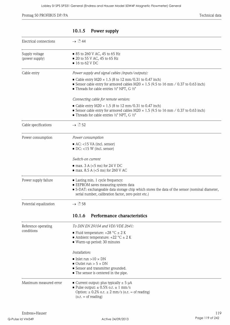
Promag 50 PROFIBUS DP/PA Technical data
Endress+Hauser 119
10.1.5 Power supply
Electrical connections ä 44
Supply voltage
(power supply)
• 85 to 260 V AC, 45 to 65 Hz
• 20 to 55 V AC, 45 to 65 Hz
• 16 to 62 V DC
Cable entry Power supply and signal cables (inputs/outputs):
• Cable entry M20 × 1.5 (8 to 12 mm/0.31 to 0.47 inch)
• Sensor cable entry for armored cables M20 × 1.5 (9.5 to 16 mm / 0.37 to 0.63 inch)
• Threads for cable entries ½" NPT, G ½"
Connecting cable for remote version:
• Cable entry M20 × 1.5 (8 to 12 mm/0.31 to 0.47 inch)
• Sensor cable entry for armored cables M20 × 1.5 (9.5 to 16 mm / 0.37 to 0.63 inch)
• Threads for cable entries ½" NPT, G ½"
Cable specifications ä 52
Power consumption Power consumption
• AC: <15 VA (incl. sensor)
• DC: <15 W (incl. sensor)
Switch-on current
• max. 3 A (<5 ms) for 24 V DC
• max. 8.5 A (<5 ms) for 260 V AC
Power supply failure • Lasting min. 1 cycle frequency:
• EEPROM saves measuring system data
• S-DAT: exchangeable data storage chip which stores the data of the sensor (nominal diameter,
serial number, calibration factor, zero point etc.)
Potential equalization ä 58
10.1.6 Performance characteristics
Reference operating
conditions
To DIN EN 29104 and VDI/VDE 2641:
• Fluid temperature: +28 °C ± 2 K
• Ambient temperature: +22 °C ± 2 K
• Warm-up period: 30 minutes
Installation:
• Inlet run >10 × DN
• Outlet run > 5 × DN
• Sensor and transmitter grounded.
• The sensor is centered in the pipe.
Maximum measured error • Current output: plus typically ± 5 μA
• Pulse output: ± 0.5% o.r. ± 1 mm/s
Option: ± 0.2% o.r. ± 2 mm/s (o.r. = of reading)
(o.r. = of reading)
Lobley St SPS SP331 General (Endress and Hauser Model 50W4F Magnetic Flowmeter) General
Q-Pulse Id VM349 Active 24/09/2013 Page 119 of 242
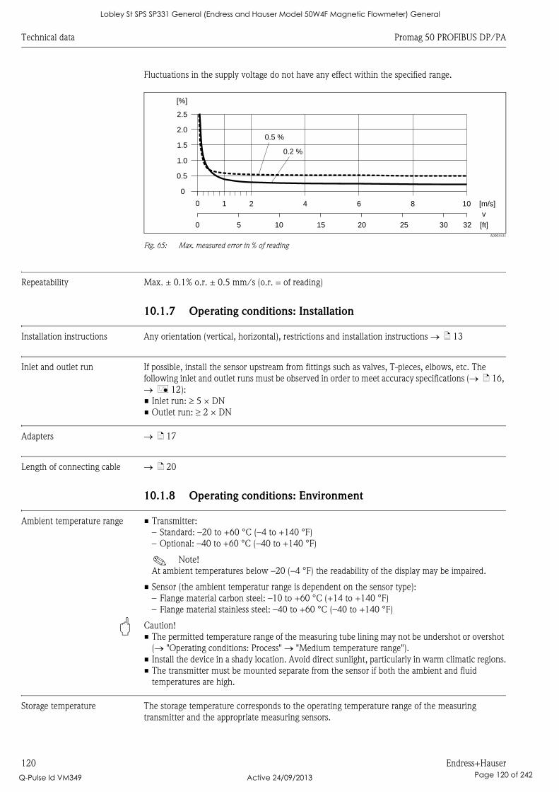
Technical data Promag 50 PROFIBUS DP/PA
120 Endress+Hauser
Fluctuations in the supply voltage do not have any effect within the specified range.
A0005531
Fig. 65: Max. measured error in % of reading
Repeatability Max. ± 0.1% o.r. ± 0.5 mm/s (o.r. = of reading)
10.1.7 Operating conditions: Installation
Installation instructions Any orientation (vertical, horizontal), restrictions and installation instructions ä 13
Inlet and outlet run If possible, install the sensor upstream from fittings such as valves, T-pieces, elbows, etc. The
following inlet and outlet runs must be observed in order to meet accuracy specifications ( ä 16,
å 12):
• Inlet run: 5 × DN
• Outlet run: 2 × DN
Adapters ä 17
Length of connecting cable ä 20
10.1.8 Operating conditions: Environment
Ambient temperature range • Transmitter:
– Standard: –20 to +60 °C (–4 to +140 °F)
– Optional: –40 to +60 °C (–40 to +140 °F)
! Note!
At ambient temperatures below –20 (–4 °F) the readability of the display may be impaired.
• Sensor (the ambient temperatur range is dependent on the sensor type):
– Flange material carbon steel: –10 to +60 °C (+14 to +140 °F)
– Flange material stainless steel: –40 to +60 °C (–40 to +140 °F)
" Caution!
• The permitted temperature range of the measuring tube lining may not be undershot or overshot
( "Operating conditions: Process" "Medium temperature range").
• Install the device in a shady location. Avoid direct sunlight, particularly in warm climatic regions.
• The transmitter must be mounted separate from the sensor if both the ambient and fluid
temperatures are high.
Storage temperature The storage temperature corresponds to the operating temperature range of the measuring
transmitter and the appropriate measuring sensors.
2.5
[%]
2.0
1.5
1.0
0.5
0
0.2 %
0.5 %
0 1 2 4 6 8 10 [m/s]
v
5 10 15 20 25 30 32 [ft]0
Lobley St SPS SP331 General (Endress and Hauser Model 50W4F Magnetic Flowmeter) General
Q-Pulse Id VM349 Active 24/09/2013 Page 120 of 242
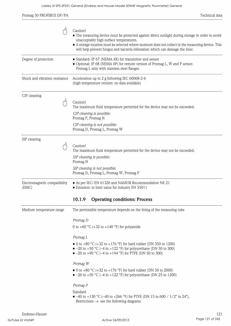
Promag 50 PROFIBUS DP/PA Technical data
Endress+Hauser 121
" Caution!
• The measuring device must be protected against direct sunlight during storage in order to avoid
unacceptably high surface temperatures.
• A storage location must be selected where moisture does not collect in the measuring device. This
will help prevent fungus and bacteria infestation which can damage the liner.
Degree of protection • Standard: IP 67 (NEMA 4X) for transmitter and sensor
• Optional: IP 68 (NEMA 6P) for remote version of Promag L, W and P sensor.
Promag L only with stainless steel flanges.
Shock and vibration resistance Acceleration up to 2 g following IEC 60068-2-6
(high-temperature version: no data available)
CIP cleaning
" Caution!
The maximum fluid temperature permitted for the device may not be exceeded.
CIP cleaning is possible:
Promag P, Promag H
CIP cleaning is not possible:
Promag D, Promag L, Promag W
SIP cleaning
" Caution!
The maximum fluid temperature permitted for the device may not be exceeded.
SIP cleaning is possible:
Promag H
SIP cleaning is not possible:
Promag D, Promag L, Promag W, Promag P
Electromagnetic compatibility
(EMC)
• As per IEC/EN 61326 and NAMUR Recommendation NE 21
• Emission: to limit value for industry EN 55011
10.1.9 Operating conditions: Process
Medium temperature range The permissible temperature depends on the lining of the measuring tube
Promag D
0 to +60 °C (+32 to +140 °F) for polyamide
Promag L
• 0 to +80 °C (+32 to +176 °F) for hard rubber (DN 350 to 1200)
• –20 to +50 °C (–4 to +122 °F) for polyurethane (DN 50 to 300)
• –20 to +90 °C (–4 to +194 °F) for PTFE (DN 50 to 300)
Promag W
• 0 to +80 °C (+32 to +176 °F) for hard rubber (DN 50 to 2000)
• –20 to +50 °C (–4 to +122 °F) for polyurethane (DN 25 to 1200)
Promag P
Standard
• –40 to +130 °C (–40 to +266 °F) for PTFE (DN 15 to 600 / 1/2" to 24"),
Restrictions see the following diagrams
Lobley St SPS SP331 General (Endress and Hauser Model 50W4F Magnetic Flowmeter) General
Q-Pulse Id VM349 Active 24/09/2013 Page 121 of 242
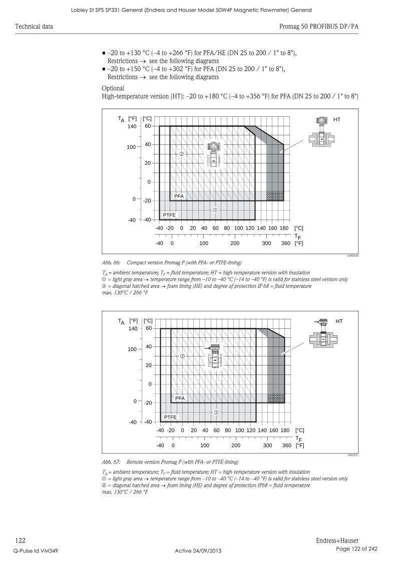
Technical data Promag 50 PROFIBUS DP/PA
122 Endress+Hauser
• –20 to +130 °C (–4 to +266 °F) for PFA/HE (DN 25 to 200 / 1" to 8"),
Restrictions see the following diagrams
• –20 to +150 °C (–4 to +302 °F) for PFA (DN 25 to 200 / 1" to 8"),
Restrictions see the following diagrams
Optional
High-temperature version (HT): –20 to +180 °C (–4 to +356 °F) for PFA (DN 25 to 200 / 1" to 8")
A0002660
Abb. 66: Compact version Promag P (with PFA- or PTFE-lining)
TA = ambient temperature; TF = fluid temperature; HT = high-temperature version with insulation
m = light gray area temperature range from –10 to –40 °C (–14 to –40 °F) is valid for stainless steel version only
n = diagonal hatched area foam lining (HE) and degree of protection IP 68 = fluid temperature
max. 130°C / 266 °F
a0002671
Abb. 67: Remote version Promag P (with PFA- or PTFE-lining)
TA = ambient temperature; TF = fluid temperature; HT = high-temperature version with insulation
m = light gray area temperature range from –10 to –40 °C (–14 to –40 °F) is valid for stainless steel version only
n = diagonal hatched area foam lining (HE) and degree of protection IP68 = fluid temperature
max. 130°C / 266 °F
PTFE
HT
m
PFA
n
0
0
0
0
-20-40
-40
20
20
40100
60140
[°F] [°C]TA
40 60 80
TF
100
100
120 140 160
200 300
180 [°C]
360 [°F]
-20
-40-40
HT
PTFEm
n
PFA
0
0
0
0
-20-40
-40
20
20
40100
60140
[°F] [°C]TA
40 60 80
TF
100
100
120 140 160
200 300
180 [°C]
360 [°F]
-20
-40-40
Lobley St SPS SP331 General (Endress and Hauser Model 50W4F Magnetic Flowmeter) General
Q-Pulse Id VM349 Active 24/09/2013 Page 122 of 242
Promag 50 PROFIBUS DP/PA Technical data
Endress+Hauser 123
Promag H
Sensor:
• DN 2 to 25: –20 to +150 °C (–4 to +302 °F)
• DN 40 to 100: –20 to +150 °C (–4 to +302 °F)
Seals:
• EPDM: –20 to +150 °C (–4 to +302 °F)
• Silicone: –20 to +150 °C (–4 to +302 °F)
• Viton: –20 to +150 °C (–4 to +302 °F)
• Kalrez: –20 to +150 °C (–4 to +302 °F)
Conductivity The minimum conductivity is 5 μS/cm ( 20 μS/cm for demineralized water)
! Note!
Note that in the case of the remote version, the requisite minimum conductivity is also influenced
by the length of the connecting cable ä 20
Medium pressure range
(nominal pressure)
Promag D
• EN 1092-1 (DIN 2501)
– PN 16
• ANSI B 16.5
– Class 150
• JIS B2220
– 10 K
Promag L
• EN 1092-1 (DIN 2501)
– PN 6 (DN 350 to 1200)
– PN 10 (DN 50 to 1200)
– PN 16 (DN 50 to 150)
• EN 1092-1, lap joint flange, stampel plate
– PN 10 (DN 50 to 300)
• ANSI B 16.5
– Class 150 (2" to 24")
• AWWA
– Class D (28" to 48")
• AS2129
– Table E (DN 350 to 1200)
• AS4087
– PN 16 (DN 350 to 1200)
Promag W
• EN 1092-1 (DIN 2501)
– PN 6 (DN 350 to 2000)
– PN 10 (DN 200 to 2000)
– PN 16 (DN 65 to 2000)
– PN 25 (DN 200 to 1000)
– PN 40 (DN 25 to 150)
• ANSI B 16.5
– Class 150 (1" to 24")
– Class 300 (1" to 6")
• AWWA
– Class D (28" to 78")
• JIS B2220
– 10 K (DN 50 to 300)
– 20 K (DN 25 to 300)
• AS 2129
– Table E (DN 80, 100, 150 to 1200)
Lobley St SPS SP331 General (Endress and Hauser Model 50W4F Magnetic Flowmeter) General
Q-Pulse Id VM349 Active 24/09/2013 Page 123 of 242
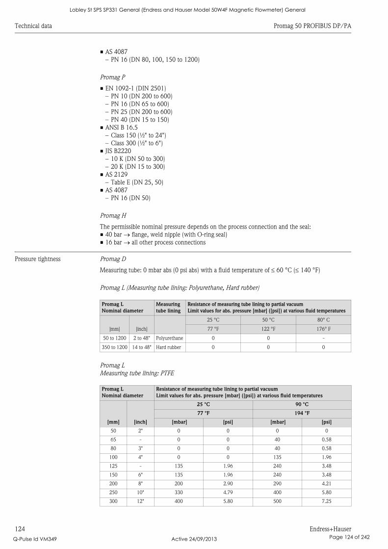
Technical data Promag 50 PROFIBUS DP/PA
124 Endress+Hauser
• AS 4087
– PN 16 (DN 80, 100, 150 to 1200)
Promag P
• EN 1092-1 (DIN 2501)
– PN 10 (DN 200 to 600)
– PN 16 (DN 65 to 600)
– PN 25 (DN 200 to 600)
– PN 40 (DN 15 to 150)
• ANSI B 16.5
– Class 150 (½" to 24")
– Class 300 (½" to 6")
• JIS B2220
– 10 K (DN 50 to 300)
– 20 K (DN 15 to 300)
• AS 2129
– Table E (DN 25, 50)
• AS 4087
– PN 16 (DN 50)
Promag H
The permissible nominal pressure depends on the process connection and the seal:
• 40 bar flange, weld nipple (with O-ring seal)
• 16 bar all other process connections
Pressure tightness Promag D
Measuring tube: 0 mbar abs (0 psi abs) with a fluid temperature of 60 °C ( 140 °F)
Promag L (Measuring tube lining: Polyurethane, Hard rubber)
Promag L
Measuring tube lining: PTFE
Promag L
Nominal diameter
Measuring
tube lining
Resistance of measuring tube lining to partial vacuum
Limit values for abs. pressure [mbar] ([psi]) at various fluid temperatures
[mm] [inch]
25 °C 50 °C 80° C
77 °F 122 °F 176° F
50 to 1200 2 to 48" Polyurethane 0 0 -
350 to 1200 14 to 48" Hard rubber 0 0 0
Promag L
Nominal diameter
Resistance of measuring tube lining to partial vacuum
Limit values for abs. pressure [mbar] ([psi]) at various fluid temperatures
[mm] [inch]
25 °C 90 °C
77 °F 194 °F
[mbar] [psi] [mbar] [psi]
50 2" 0 0 0 0
65 - 0 0 40 0.58
80 3" 0 0 40 0.58
100 4" 0 0 135 1.96
125 - 135 1.96 240 3.48
150 6" 135 1.96 240 3.48
200 8" 200 2.90 290 4.21
250 10" 330 4.79 400 5.80
300 12" 400 5.80 500 7.25
Lobley St SPS SP331 General (Endress and Hauser Model 50W4F Magnetic Flowmeter) General
Q-Pulse Id VM349 Active 24/09/2013 Page 124 of 242
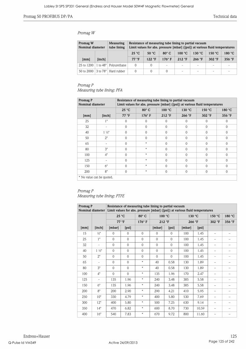
Promag 50 PROFIBUS DP/PA Technical data
Endress+Hauser 125
Promag W
Promag P
Measuring tube lining: PFA
Promag P
Measuring tube lining: PTFE
Promag W
Nominal diameter
Measuring
tube lining
Resistance of measuring tube lining to partial vacuum
Limit values for abs. pressure [mbar] ([psi]) at various fluid temperatures
[mm] [inch]
25 °C 50 °C 80° C 100 °C 130 °C 150 °C 180 °C
77 °F 122 °F 176° F 212 °F 266 °F 302 °F 356 °F
25 to 1200 1 to 48" Polyurethane 0 0 - - - - -
50 to 2000 3 to 78" Hard rubber 0 0 0 - - - -
Promag P
Nominal diameter
Resistance of measuring tube lining to partial vacuum
Limit values for abs. pressure [mbar] ([psi]) at various fluid temperatures
[mm] [inch]
25 °C 80° C 100 °C 130 °C 150 °C 180 °C
77 °F 176° F 212 °F 266 °F 302 °F 356 °F
25 1" 0 0 0 0 0 0
32 - 0 0 0 0 0 0
40 1 ½" 0 0 0 0 0 0
50 2" 0 0 0 0 0 0
65 - 0 * 0 0 0 0
80 3" 0 * 0 0 0 0
100 4" 0 * 0 0 0 0
125 - 0 * 0 0 0 0
150 6" 0 * 0 0 0 0
200 8" 0 * 0 0 0 0
* No value can be quoted.
Promag P
Nominal diameter
Resistance of measuring tube lining to partial vacuum
Limit values for abs. pressure [mbar] ([psi]) at various fluid temperatures
[mm] [inch]
25 °C 80° C 100 °C 130 °C 150 °C 180 °C
77 °F 176° F 212 °F 266 °F 302 °F 356 °F
[mbar] [psi] [mbar] [psi] [mbar] [psi]
15 ½" 0 0 0 0 0 100 1.45 – –
25 1" 0 0 0 0 0 100 1.45 – –
32 - 0 0 0 0 0 100 1.45 – –
40 1 ½" 0 0 0 0 0 100 1.45 – –
50 2" 0 0 0 0 0 100 1.45 – –
65 - 0 0 * 40 0.58 130 1.89 – –
80 3" 0 0 * 40 0.58 130 1.89 – –
100 4" 0 0 * 135 1.96 170 2.47 – –
125 - 135 1.96 * 240 3.48 385 5.58 – –
150 6" 135 1.96 * 240 3.48 385 5.58 – –
200 8" 200 2.90 * 290 4.21 410 5.95 – –
250 10" 330 4.79 * 400 5.80 530 7.69 – –
300 12" 400 5.80 * 500 7.25 630 9.14 – –
350 14" 470 6.82 * 600 8.70 730 10.59 – –
400 16" 540 7.83 * 670 9.72 800 11.60 – –
Lobley St SPS SP331 General (Endress and Hauser Model 50W4F Magnetic Flowmeter) General
Q-Pulse Id VM349 Active 24/09/2013 Page 125 of 242
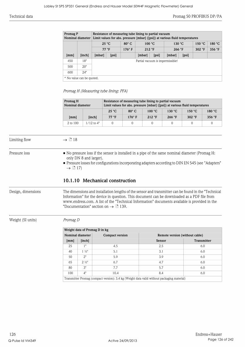
Technical data Promag 50 PROFIBUS DP/PA
126 Endress+Hauser
Promag H (Measuring tube lining: PFA)
Limiting flow ä 18
Pressure loss • No pressure loss if the sensor is installed in a pipe of the same nominal diameter (Promag H:
only DN 8 and larger).
• Pressure losses for configurations incorporating adapters according to DIN EN 545 (see "Adapters"
ä 17)
10.1.10 Mechanical construction
Design, dimensions The dimensions and installation lengths of the sensor and transmitter can be found in the "Technical
Information" for the device in question. This document can be downloaded as a PDF file from
www.endress.com. A list of the "Technical Information" documents available is provided in the
"Documentation" section on ä 139.
Weight (SI units) Promag D
450 18" Partial vacuum is impermissible!
500 20"
600 24"
* No value can be quoted.
Promag H
Nominal diameter
Resistance of measuring tube lining to partial vacuum
Limit values for abs. pressure [mbar] ([psi]) at various fluid temperatures
[mm] [inch]
25 °C 80° C 100 °C 130 °C 150 °C 180 °C
77 °F 176° F 212 °F 266 °F 302 °F 356 °F
2 to 100 1/12 to 4" 0 0 0 0 0 0
Promag P
Nominal diameter
Resistance of measuring tube lining to partial vacuum
Limit values for abs. pressure [mbar] ([psi]) at various fluid temperatures
[mm] [inch]
25 °C 80° C 100 °C 130 °C 150 °C 180 °C
77 °F 176° F 212 °F 266 °F 302 °F 356 °F
[mbar] [psi] [mbar] [psi] [mbar] [psi]
Weight data of Promag D in kg
Nominal diameter Compact version Remote version (without cable)
[mm] [inch] Sensor Transmitter
25 1" 4.5 2.5 6.0
40 1 ½" 5.1 3.1 6.0
50 2" 5.9 3.9 6.0
65 2 ½" 6.7 4.7 6.0
80 3" 7.7 5.7 6.0
100 4" 10.4 8.4 6.0
Transmitter Promag (compact version): 3.4 kg (Weight data valid without packaging material)
Lobley St SPS SP331 General (Endress and Hauser Model 50W4F Magnetic Flowmeter) General
Q-Pulse Id VM349 Active 24/09/2013 Page 126 of 242
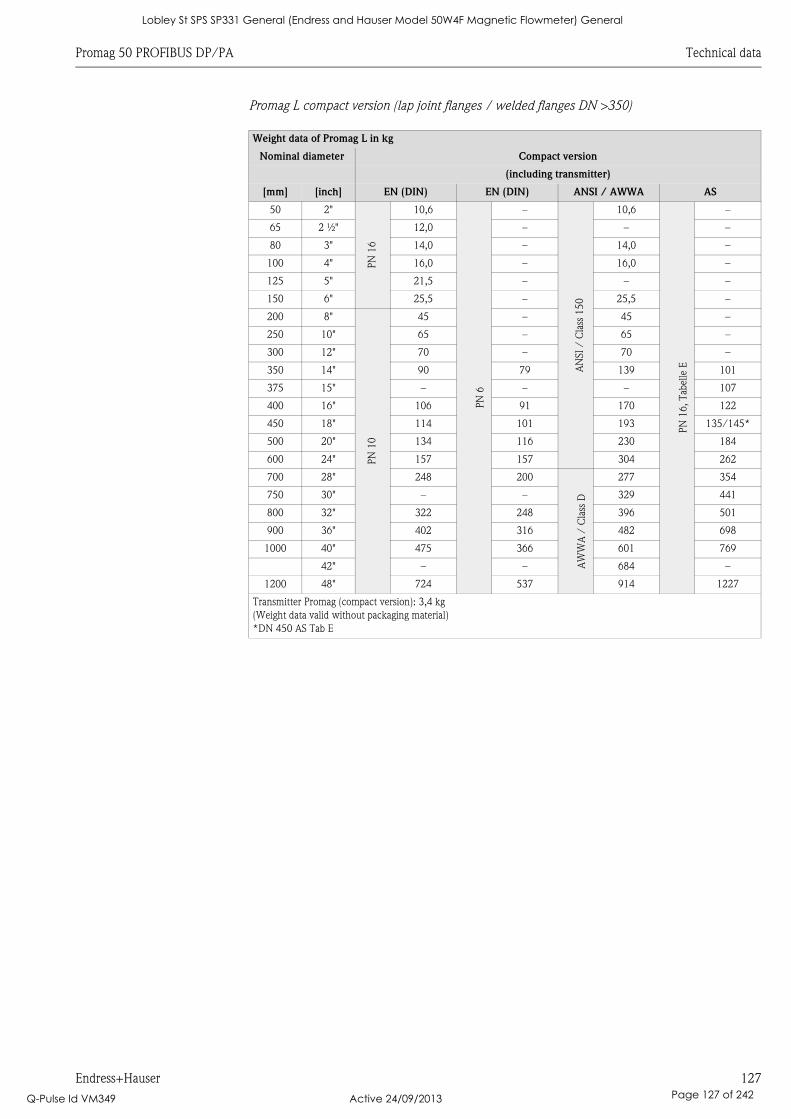
Promag 50 PROFIBUS DP/PA Technical data
Endress+Hauser 127
Promag L compact version (lap joint flanges / welded flanges DN >350)
Weight data of Promag L in kg
Nominal diameter Compact version
(including transmitter)
[mm] [inch] EN (DIN) EN (DIN) ANSI / AWWA AS
50 2"
PN
16
10,6
PN
6
–
AN
SI
/ C
lass
15
0
10,6
PN
16, T
abel
le E
–
65 2 ½" 12,0 – – –
80 3" 14,0 – 14,0 –
100 4" 16,0 – 16,0 –
125 5" 21,5 – – –
150 6" 25,5 – 25,5 –
200 8"
PN
10
45 – 45 –
250 10" 65 – 65 –
300 12" 70 – 70 –
350 14" 90 79 139 101
375 15" – – – 107
400 16" 106 91 170 122
450 18" 114 101 193 135/145*
500 20" 134 116 230 184
600 24" 157 157 304 262
700 28" 248 200
AW
WA
/ C
lass
D
277 354
750 30" – – 329 441
800 32" 322 248 396 501
900 36" 402 316 482 698
1000 40" 475 366 601 769
42" – – 684 –
1200 48" 724 537 914 1227
Transmitter Promag (compact version): 3,4 kg
(Weight data valid without packaging material)
*DN 450 AS Tab E
Lobley St SPS SP331 General (Endress and Hauser Model 50W4F Magnetic Flowmeter) General
Q-Pulse Id VM349 Active 24/09/2013 Page 127 of 242
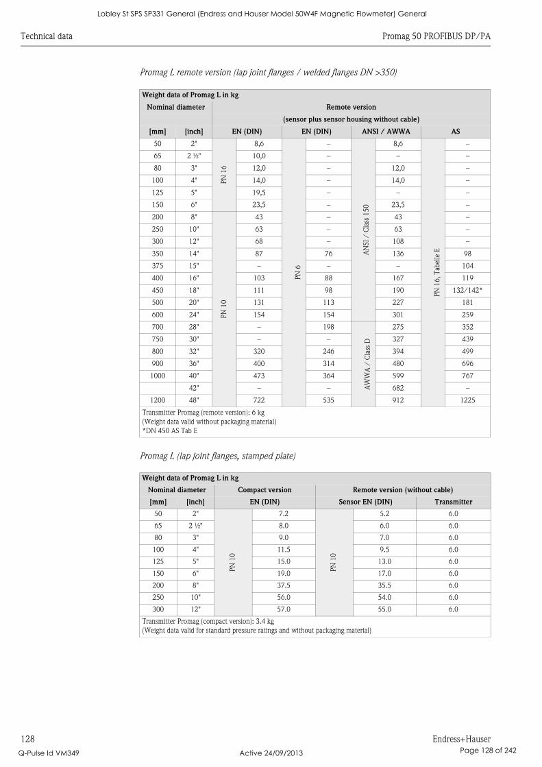
Technical data Promag 50 PROFIBUS DP/PA
128 Endress+Hauser
Promag L remote version (lap joint flanges / welded flanges DN >350)
Promag L (lap joint flanges, stamped plate)
Weight data of Promag L in kg
Nominal diameter Remote version
(sensor plus sensor housing without cable)
[mm] [inch] EN (DIN) EN (DIN) ANSI / AWWA AS
50 2"
PN
16
8,6
PN
6
–
AN
SI
/ C
lass
15
0
8,6
PN
16, T
abel
le E
–
65 2 ½" 10,0 – – –
80 3" 12,0 – 12,0 –
100 4" 14,0 – 14,0 –
125 5" 19,5 – – –
150 6" 23,5 – 23,5 –
200 8"P
N 1
043 – 43 –
250 10" 63 – 63 –
300 12" 68 – 108 –
350 14" 87 76 136 98
375 15" – – – 104
400 16" 103 88 167 119
450 18" 111 98 190 132/142*
500 20" 131 113 227 181
600 24" 154 154 301 259
700 28" – 198
AW
WA
/ C
lass
D
275 352
750 30" – – 327 439
800 32" 320 246 394 499
900 36" 400 314 480 696
1000 40" 473 364 599 767
42" – – 682 –
1200 48" 722 535 912 1225
Transmitter Promag (remote version): 6 kg
(Weight data valid without packaging material)
*DN 450 AS Tab E
Weight data of Promag L in kg
Nominal diameter Compact version Remote version (without cable)
[mm] [inch] EN (DIN) Sensor EN (DIN) Transmitter
50 2"
PN
10
7.2
PN
10
5.2 6.0
65 2 ½" 8.0 6.0 6.0
80 3" 9.0 7.0 6.0
100 4" 11.5 9.5 6.0
125 5" 15.0 13.0 6.0
150 6" 19.0 17.0 6.0
200 8" 37.5 35.5 6.0
250 10" 56.0 54.0 6.0
300 12" 57.0 55.0 6.0
Transmitter Promag (compact version): 3.4 kg
(Weight data valid for standard pressure ratings and without packaging material)
Lobley St SPS SP331 General (Endress and Hauser Model 50W4F Magnetic Flowmeter) General
Q-Pulse Id VM349 Active 24/09/2013 Page 128 of 242
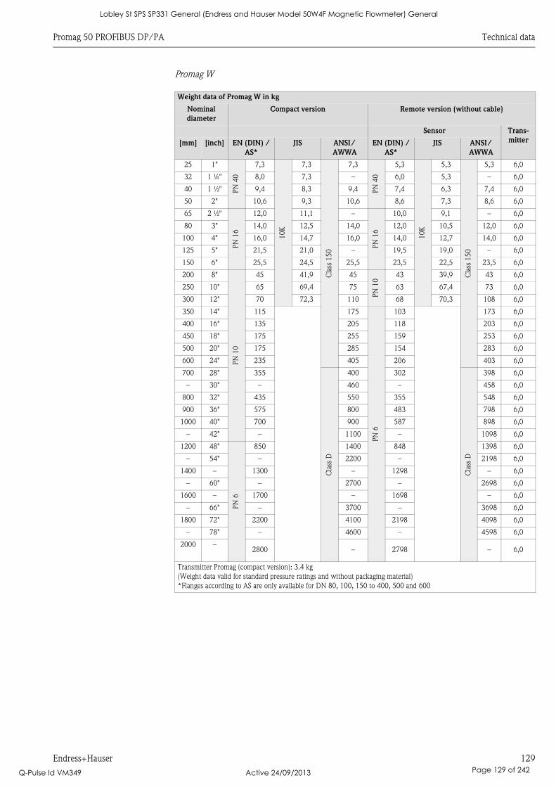
Promag 50 PROFIBUS DP/PA Technical data
Endress+Hauser 129
Promag W
Weight data of Promag W in kg
Nominal
diameter
Compact version Remote version (without cable)
Sensor Trans-
mitter[mm] [inch] EN (DIN) /
AS*
JIS ANSI/
AWWA
EN (DIN) /
AS*
JIS ANSI/
AWWA
25 1"
PN
40
7,3
10K
7,3
Cla
ss 1
50
7,3
PN
40
5,3
10K
5,3
Cla
ss 1
50
5,3 6,0
32 1 ¼" 8,0 7,3 – 6,0 5,3 – 6,0
40 1 ½" 9,4 8,3 9,4 7,4 6,3 7,4 6,0
50 2" 10,6 9,3 10,6 8,6 7,3 8,6 6,0
65 2 ½"
PN
16
12,0 11,1 –
PN
16
10,0 9,1 – 6,0
80 3" 14,0 12,5 14,0 12,0 10,5 12,0 6,0
100 4" 16,0 14,7 16,0 14,0 12,7 14,0 6,0
125 5" 21,5 21,0 – 19,5 19,0 – 6,0
150 6" 25,5 24,5 25,5 23,5 22,5 23,5 6,0
200 8"
PN
10
45 41,9 45
PN
10
43 39,9 43 6,0
250 10" 65 69,4 75 63 67,4 73 6,0
300 12" 70 72,3 110 68 70,3 108 6,0
350 14" 115 175
PN
6
103 173 6,0
400 16" 135 205 118 203 6,0
450 18" 175 255 159 253 6,0
500 20" 175 285 154 283 6,0
600 24" 235 405 206 403 6,0
700 28" 355
Cla
ss D
400 302
Cla
ss D
398 6,0
– 30" – 460 – 458 6,0
800 32" 435 550 355 548 6,0
900 36" 575 800 483 798 6,0
1000 40" 700 900 587 898 6,0
– 42" – 1100 – 1098 6,0
1200 48"
PN
6
850 1400 848 1398 6,0
– 54" – 2200 – 2198 6,0
1400 – 1300 – 1298 – 6,0
– 60" – 2700 – 2698 6,0
1600 – 1700 – 1698 – 6,0
– 66" – 3700 – 3698 6,0
1800 72" 2200 4100 2198 4098 6,0
– 78" – 4600 – 4598 6,0
2000 –2800 – 2798 – 6,0
Transmitter Promag (compact version): 3.4 kg
(Weight data valid for standard pressure ratings and without packaging material)
*Flanges according to AS are only available for DN 80, 100, 150 to 400, 500 and 600
Lobley St SPS SP331 General (Endress and Hauser Model 50W4F Magnetic Flowmeter) General
Q-Pulse Id VM349 Active 24/09/2013 Page 129 of 242
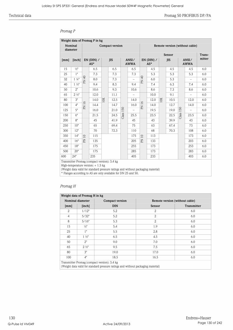
Technical data Promag 50 PROFIBUS DP/PA
130 Endress+Hauser
Promag P
Promag H
Weight data of Promag P in kg
Nominal
diameter
Compact version Remote version (without cable)
Sensor Trans-
mitter[mm] [inch] EN (DIN) /
AS*
JIS ANSI/
AWWA
EN (DIN) /
AS*
JIS ANSI/
AWWA
15 ½"
PN
40
6.5
10K
6.5
Cla
ss 1
50
6.5
PN
40
4.5
10K
4.5
Cla
ss 1
50
4.5 6.0
25 1" 7.3 7.3 7.3 5.3 5.3 5.3 6.0
32 1 ¼" 8.0 7.3 – 6.0 5.3 – 6.0
40 1 ½" 9.4 8.3 9.4 7.4 6.3 7.4 6.0
50 2" 10.6 9.3 10.6 8.6 7.3 8.6 6.0
65 2 ½"
PN
16
12.0 11.1 –
PN
16
10.0 9.1 – 6.0
80 3" 14.0 12.5 14.0 12.0 10.5 12.0 6.0
100 4" 14.4 14.7 16.0 14.0 12.7 14.0 6.0
125 5" 16.0 21.0 – 19.5 19.0 – 6.0
150 6" 21.5 24.5 25.5 23.5 22.5 23.5 6.0
200 8"
PN
10
45 41.9 45
PN
10
43 39.9 43 6.0
250 10" 65 69.4 75 63 67.4 73 6.0
300 12" 70 72.3 110 68 70.3 108 6.0
350 14" 115 175 113 173 6.0
400 16" 135 205 133 203 6.0
450 18" 175 255 173 253 6.0
500 20" 175 285 173 283 6.0
600 24" 235 405 233 403 6.0
Transmitter Promag (compact version): 3.4 kg
High-temperature version: + 1.5 kg
(Weight data valid for standard pressure ratings and without packaging material)
* Flanges according to AS are only available for DN 25 and 50.
Weight data of Promag H in kg
Nominal diameter Compact version Remote version (without cable)
[mm] [inch] DIN Sensor Transmitter
2 1/12" 5.2 2 6.0
4 5/32" 5.2 2 6.0
8 5/16" 5.3 2 6.0
15 ½" 5.4 1.9 6.0
25 1" 5.5 2.8 6.0
40 1 ½" 6.5 4.5 6.0
50 2" 9.0 7.0 6.0
65 2 ½" 9.5 7.5 6.0
80 3" 19.0 17.0 6.0
100 4" 18.5 16.5 6.0
Transmitter Promag (compact version): 3.4 kg
(Weight data valid for standard pressure ratings and without packaging material)
Lobley St SPS SP331 General (Endress and Hauser Model 50W4F Magnetic Flowmeter) General
Q-Pulse Id VM349 Active 24/09/2013 Page 130 of 242
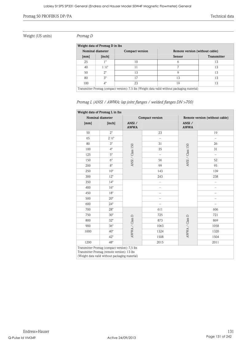
Promag 50 PROFIBUS DP/PA Technical data
Endress+Hauser 131
Weight (US units) Promag D
Promag L (ANSI / AWWA: lap joint flanges / welded flanges DN >700)
Weight data of Promag D in lbs
Nominal diameter Compact version Remote version (without cable)
[mm] [inch] Sensor Transmitter
25 1" 10 6 13
40 1 ½" 11 7 13
50 2" 13 9 13
80 3" 17 13 13
100 4" 23 19 13
Transmitter Promag (compact version): 7.5 lbs (Weight data valid without packaging material)
Weight data of Promag L in lbs
Nominal diameter Compact version Remote version (without cable)
[mm] [inch] ANSI /
AWWA
ANSI /
AWWA
50 2"A
NSI
/ C
lass
15
023
AN
SI
/ C
lass
15
0
19
65 2 ½" – –
80 3" 31 26
100 4" 35 31
125 5" – –
150 6" 56 52
200 8" 99 95
250 10" 143 139
300 12" 243 238
350 14" – –
400 16" – –
450 18" – –
500 20" – –
600 24" – –
700 28"
AW
WA
/ C
lass
D
611
AW
WA
/ C
lass
D
606
750 30" 725 721
800 32" 873 869
900 36" 1063 1058
1000 40" 1324 1320
42" 1508 1504
1200 48" 2015 2011
Transmitter Promag (compact version): 7,5 lbs
Transmitter Promag (remote version): 13 lbs
(Weight data valid without packaging material)
Lobley St SPS SP331 General (Endress and Hauser Model 50W4F Magnetic Flowmeter) General
Q-Pulse Id VM349 Active 24/09/2013 Page 131 of 242
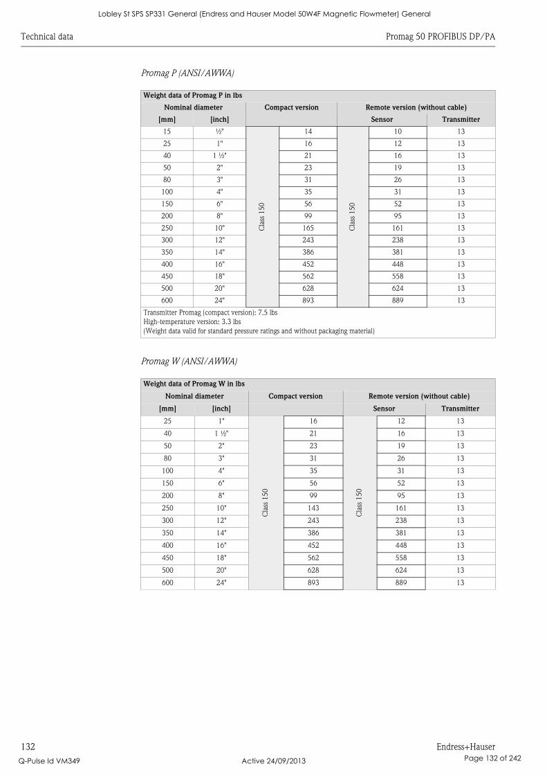
Technical data Promag 50 PROFIBUS DP/PA
132 Endress+Hauser
Promag P (ANSI/AWWA)
Promag W (ANSI/AWWA)
Weight data of Promag P in lbs
Nominal diameter Compact version Remote version (without cable)
[mm] [inch] Sensor Transmitter
15 ½"
Cla
ss 1
50
14
Cla
ss 1
50
10 13
25 1" 16 12 13
40 1 ½" 21 16 13
50 2" 23 19 13
80 3" 31 26 13
100 4" 35 31 13
150 6" 56 52 13
200 8" 99 95 13
250 10" 165 161 13
300 12" 243 238 13
350 14" 386 381 13
400 16" 452 448 13
450 18" 562 558 13
500 20" 628 624 13
600 24" 893 889 13
Transmitter Promag (compact version): 7.5 lbs
High-temperature version: 3.3 lbs
(Weight data valid for standard pressure ratings and without packaging material)
Weight data of Promag W in lbs
Nominal diameter Compact version Remote version (without cable)
[mm] [inch] Sensor Transmitter
25 1"
Cla
ss 1
50
16
Cla
ss 1
50
12 13
40 1 ½" 21 16 13
50 2" 23 19 13
80 3" 31 26 13
100 4" 35 31 13
150 6" 56 52 13
200 8" 99 95 13
250 10" 143 161 13
300 12" 243 238 13
350 14" 386 381 13
400 16" 452 448 13
450 18" 562 558 13
500 20" 628 624 13
600 24" 893 889 13
Lobley St SPS SP331 General (Endress and Hauser Model 50W4F Magnetic Flowmeter) General
Q-Pulse Id VM349 Active 24/09/2013 Page 132 of 242
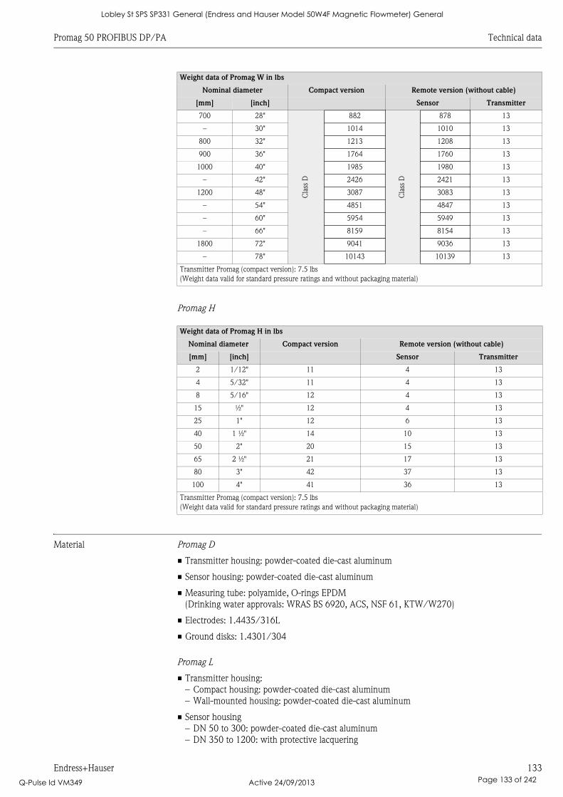
Promag 50 PROFIBUS DP/PA Technical data
Endress+Hauser 133
Promag H
Material Promag D
• Transmitter housing: powder-coated die-cast aluminum
• Sensor housing: powder-coated die-cast aluminum
• Measuring tube: polyamide, O-rings EPDM
(Drinking water approvals: WRAS BS 6920, ACS, NSF 61, KTW/W270)
• Electrodes: 1.4435/316L
• Ground disks: 1.4301/304
Promag L
• Transmitter housing:
– Compact housing: powder-coated die-cast aluminum
– Wall-mounted housing: powder-coated die-cast aluminum
• Sensor housing
– DN 50 to 300: powder-coated die-cast aluminum
– DN 350 to 1200: with protective lacquering
700 28"
Cla
ss D
882
Cla
ss D
878 13
– 30" 1014 1010 13
800 32" 1213 1208 13
900 36" 1764 1760 13
1000 40" 1985 1980 13
– 42" 2426 2421 13
1200 48" 3087 3083 13
– 54" 4851 4847 13
– 60" 5954 5949 13
– 66" 8159 8154 13
1800 72" 9041 9036 13
– 78" 10143 10139 13
Transmitter Promag (compact version): 7.5 lbs
(Weight data valid for standard pressure ratings and without packaging material)
Weight data of Promag H in lbs
Nominal diameter Compact version Remote version (without cable)
[mm] [inch] Sensor Transmitter
2 1/12" 11 4 13
4 5/32" 11 4 13
8 5/16" 12 4 13
15 ½" 12 4 13
25 1" 12 6 13
40 1 ½" 14 10 13
50 2" 20 15 13
65 2 ½" 21 17 13
80 3" 42 37 13
100 4" 41 36 13
Transmitter Promag (compact version): 7.5 lbs
(Weight data valid for standard pressure ratings and without packaging material)
Weight data of Promag W in lbs
Nominal diameter Compact version Remote version (without cable)
[mm] [inch] Sensor Transmitter
Lobley St SPS SP331 General (Endress and Hauser Model 50W4F Magnetic Flowmeter) General
Q-Pulse Id VM349 Active 24/09/2013 Page 133 of 242
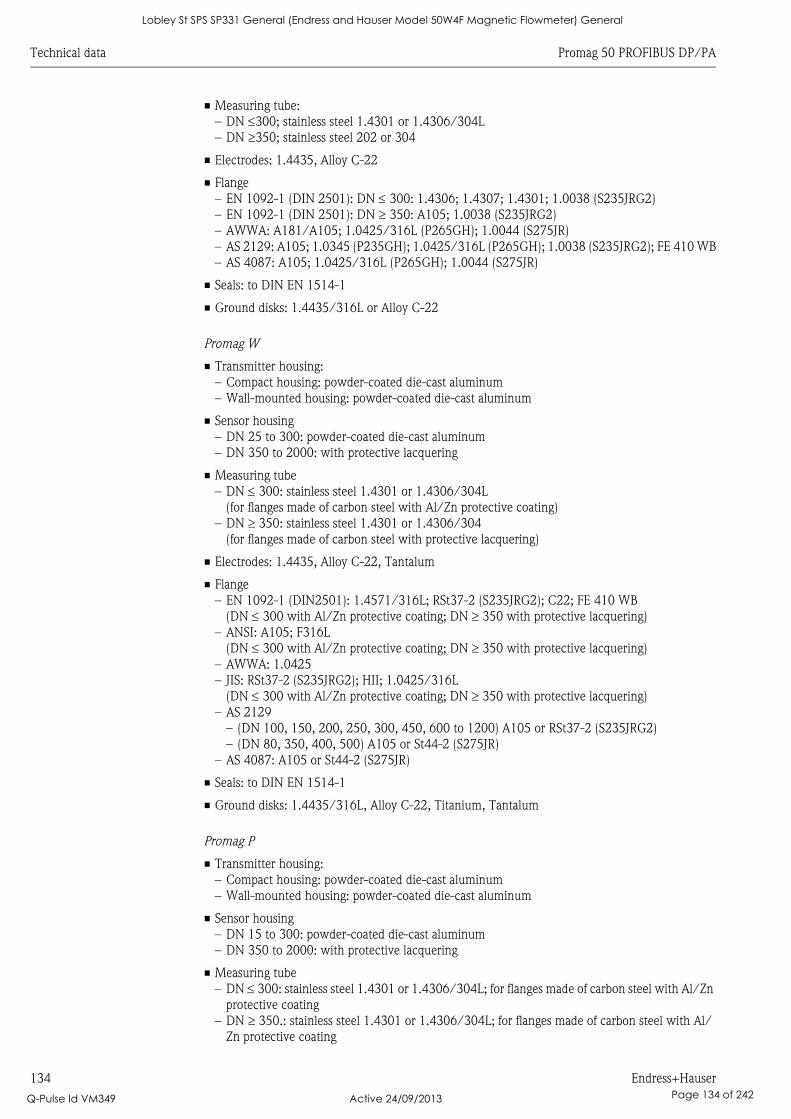
Technical data Promag 50 PROFIBUS DP/PA
134 Endress+Hauser
• Measuring tube:
– DN 300; stainless steel 1.4301 or 1.4306/304L
– DN 350; stainless steel 202 or 304
• Electrodes: 1.4435, Alloy C-22
• Flange
– EN 1092-1 (DIN 2501): DN 300: 1.4306; 1.4307; 1.4301; 1.0038 (S235JRG2)
– EN 1092-1 (DIN 2501): DN 350: A105; 1.0038 (S235JRG2)
– AWWA: A181/A105; 1.0425/316L (P265GH); 1.0044 (S275JR)
– AS 2129: A105; 1.0345 (P235GH); 1.0425/316L (P265GH); 1.0038 (S235JRG2); FE 410 WB
– AS 4087: A105; 1.0425/316L (P265GH); 1.0044 (S275JR)
• Seals: to DIN EN 1514-1
• Ground disks: 1.4435/316L or Alloy C-22
Promag W
• Transmitter housing:
– Compact housing: powder-coated die-cast aluminum
– Wall-mounted housing: powder-coated die-cast aluminum
• Sensor housing
– DN 25 to 300: powder-coated die-cast aluminum
– DN 350 to 2000: with protective lacquering
• Measuring tube
– DN 300: stainless steel 1.4301 or 1.4306/304L
(for flanges made of carbon steel with Al/Zn protective coating)
– DN 350: stainless steel 1.4301 or 1.4306/304
(for flanges made of carbon steel with protective lacquering)
• Electrodes: 1.4435, Alloy C-22, Tantalum
• Flange
– EN 1092-1 (DIN2501): 1.4571/316L; RSt37-2 (S235JRG2); C22; FE 410 WB
(DN 300 with Al/Zn protective coating; DN 350 with protective lacquering)
– ANSI: A105; F316L
(DN 300 with Al/Zn protective coating; DN 350 with protective lacquering)
– AWWA: 1.0425
– JIS: RSt37-2 (S235JRG2); HII; 1.0425/316L
(DN 300 with Al/Zn protective coating; DN 350 with protective lacquering)
– AS 2129
– (DN 100, 150, 200, 250, 300, 450, 600 to 1200) A105 or RSt37-2 (S235JRG2)
– (DN 80, 350, 400, 500) A105 or St44-2 (S275JR)
– AS 4087: A105 or St44-2 (S275JR)
• Seals: to DIN EN 1514-1
• Ground disks: 1.4435/316L, Alloy C-22, Titanium, Tantalum
Promag P
• Transmitter housing:
– Compact housing: powder-coated die-cast aluminum
– Wall-mounted housing: powder-coated die-cast aluminum
• Sensor housing
– DN 15 to 300: powder-coated die-cast aluminum
– DN 350 to 2000: with protective lacquering
• Measuring tube
– DN 300: stainless steel 1.4301 or 1.4306/304L; for flanges made of carbon steel with Al/Zn
protective coating
– DN 350.: stainless steel 1.4301 or 1.4306/304L; for flanges made of carbon steel with Al/
Zn protective coating
Lobley St SPS SP331 General (Endress and Hauser Model 50W4F Magnetic Flowmeter) General
Q-Pulse Id VM349 Active 24/09/2013 Page 134 of 242

Promag 50 PROFIBUS DP/PA Technical data
Endress+Hauser 135
• Electrodes: 1.4435, Platinum, Alloy C-22, Tantalum, Titanium
• Flange
– EN 1092-1 (DIN2501): 1.4571/316L; RSt37-2 (S235JRG2); C22; FE 410W B
(DN 300: with Al/Zn protective coating; DN 350 with protective lacquering)
– ANSI: A105; F316L
(DN 300 with Al/Zn protective coating; DN 350 with protective lacquering)
– AWWA: 1.0425
– JIS: RSt37-2 (S235JRG2); HII; 1.0425/316L
(DN 300 with Al/Zn protective coating; DN 350 with protective lacquering)
– AS 2129
– (DN 25) A105 or RSt37-2 (S235JRG2)
– (DN 40) A105 or St44-2 (S275JR)
– AS 4087: A105 or St44-2 (S275JR)
• Seals: to DIN EN 1514-1
• Ground disks: 1.4435/316L or Alloy C-22
Promag H
• Transmitter housing:
– Compact housing: powder-coated die-cast aluminum
or stainless steel field housing (1.4301/316L)
– Wall-mounted housing: powder-coated die-cast aluminum
– Window material: glas or polycarbonate
• Sensor housing: stainless steel 1.4301
• Wall mounting kit: stainless steel 1.4301
• Measuring tube: stainless steel 1.4301
• Liner: PFA (USP class VI; FDA 21 CFR 177.1550: 3A)
• Electrodes:
– Standard: 1.4435
– Option: Alloy C-22, Tantalum, Platinum
• Flange:
– All connections stainless-steel 1.4404/316L
– EN (DIN), ANSI, JIS made of PVDF
– Adhesive fitting made of PVC
• Seals
– DN 2 to 25: O-ring (EPDM, Viton, Kalrez), gasket seal (EPDM*, Viton, Silicone*)
– DN 40 to 100: gasket seal (EPDM*, Silicone*)
* = USP class VI; FDA 21 CFR 177.2600: 3A
• Ground rings: 1.4435/316L (optional: Tantalum, Alloy C-22)
Material load diagram The material load diagrams (pressure-temperature graphs) for the process connections are to be
found in the "Technical Information" documents of the device in question:
List of supplementary documentation ä 139.
Fitted electrodes Promag D
• 2 measuring electrodes for signal detection
Promag L, W and P
• 2 measuring electrodes for signal detection
• 1 EPD electrode for empty pipe detection
• 1 reference electrode for potential equalization
Lobley St SPS SP331 General (Endress and Hauser Model 50W4F Magnetic Flowmeter) General
Q-Pulse Id VM349 Active 24/09/2013 Page 135 of 242
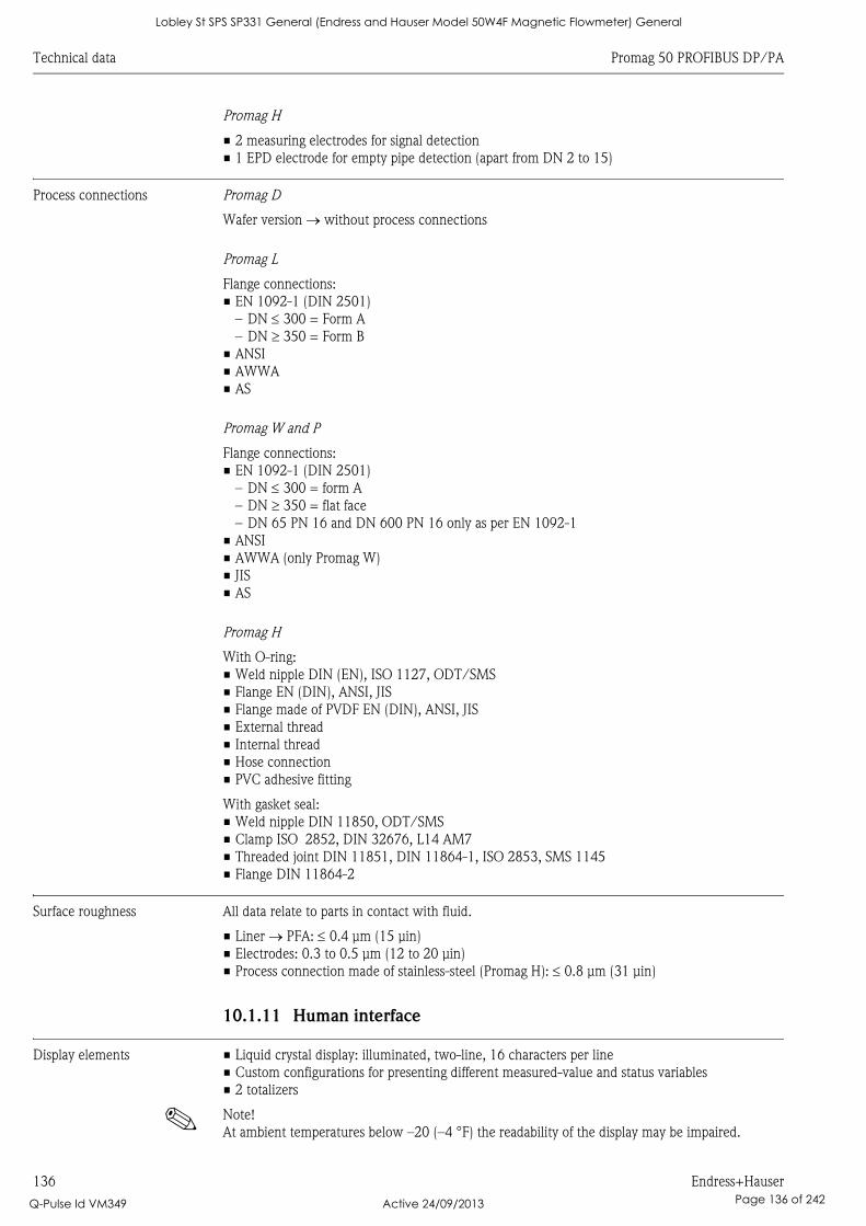
Technical data Promag 50 PROFIBUS DP/PA
136 Endress+Hauser
Promag H
• 2 measuring electrodes for signal detection
• 1 EPD electrode for empty pipe detection (apart from DN 2 to 15)
Process connections Promag D
Wafer version without process connections
Promag L
Flange connections:
• EN 1092-1 (DIN 2501)
– DN 300 = Form A
– DN 350 = Form B
• ANSI
• AWWA
• AS
Promag W and P
Flange connections:
• EN 1092-1 (DIN 2501)
– DN 300 = form A
– DN 350 = flat face
– DN 65 PN 16 and DN 600 PN 16 only as per EN 1092-1
• ANSI
• AWWA (only Promag W)
• JIS
• AS
Promag H
With O-ring:
• Weld nipple DIN (EN), ISO 1127, ODT/SMS
• Flange EN (DIN), ANSI, JIS
• Flange made of PVDF EN (DIN), ANSI, JIS
• External thread
• Internal thread
• Hose connection
• PVC adhesive fitting
With gasket seal:
• Weld nipple DIN 11850, ODT/SMS
• Clamp ISO 2852, DIN 32676, L14 AM7
• Threaded joint DIN 11851, DIN 11864-1, ISO 2853, SMS 1145
• Flange DIN 11864-2
Surface roughness All data relate to parts in contact with fluid.
• Liner PFA: 0.4 μm (15 μin)
• Electrodes: 0.3 to 0.5 μm (12 to 20 μin)
• Process connection made of stainless-steel (Promag H): 0.8 μm (31 μin)
10.1.11 Human interface
Display elements • Liquid crystal display: illuminated, two-line, 16 characters per line
• Custom configurations for presenting different measured-value and status variables
• 2 totalizers
! Note!
At ambient temperatures below –20 (–4 °F) the readability of the display may be impaired.
Lobley St SPS SP331 General (Endress and Hauser Model 50W4F Magnetic Flowmeter) General
Q-Pulse Id VM349 Active 24/09/2013 Page 136 of 242

Promag 50 PROFIBUS DP/PA Technical data
Endress+Hauser 137
Operating elements • Local operation with three keys (S, O, F)
• "Quick Setup" menus for straightforward commissioning
Language groups Language groups available for operation in different countries:
• Western Europe and America (WEA):
English, German, Spanish, Italian, French, Dutch and Portuguese
• Eastern Europe/Scandinavia (EES):
English, Russian, Polish, Norwegian, Finnish, Swedish and Czech
• Southeast Asia (SEA):
English, Japanese, Indonesian
! Note!
You can change the language group via the operating program "FieldCare."
Remote operation Operation via PROFIBUS DP or PROFIBUS PA
10.1.12 Certificates and approvals
CE mark The measuring system is in conformity with the statutory requirements of the EC Directives.
Endress+Hauser confirms successful testing of the device by affixing to it the CE mark.
C-tick mark The measuring system meets the EMC requirements of the Australian Communications and Media
Authority (ACMA)
Ex approval Information about currently available Ex versions (ATEX, FM, CSA, IECEx, NEPSI etc.) can be
supplied by your Endress+Hauser Sales Center on request. All explosion protection data are given
in a separate documentation which is available upon request.
Sanitary compatibility Promag D, L, W and P
No applicable approvals or certification
Promag H
• 3A authorization and EHEDG-tested
• Seals: in conformity with FDA (except Kalrez seals)
Drinking water approval Promag D, L and W
• WRAS BS 6920
• ACS
• NSF 61
• KTW/W270
Promag P and H
No drinking water approval
Lobley St SPS SP331 General (Endress and Hauser Model 50W4F Magnetic Flowmeter) General
Q-Pulse Id VM349 Active 24/09/2013 Page 137 of 242

Technical data Promag 50 PROFIBUS DP/PA
138 Endress+Hauser
Pressure Equipment Directive Promag D and L
No pressure measuring device approval
Promag W, P and H
The measuring devices can be ordered with or without PED (Pressure Equipment Directive). If a
device with PED is required, this must be ordered explicitly. For devices with nominal diameters
less than or equal to DN 25 (1"), this is neither possible nor necessary.
• With the identification PED/G1/III on the sensor nameplate, Endress+Hauser confirms
conformity with the "Basic safety requirements" of Appendix I of the Pressure Equipment
Directive 97/23/EC.
• Devices with this identification (with PED) are suitable for the following types of fluid:
– Fluids of Group 1 and 2 with a steam pressure of greater or less than 0.5 bar (7.3 psi)
– Unstable gases
• Devices without this identification (without PED) are designed and manufactured according to
good engineering practice. They correspond to the requirements of Art. 3, Section 3 of the
Pressure Equipment Directive 97/23/EC. Their application is illustrated in Diagrams 6 to 9 in
Appendix II of the Pressure Equipment Directive 97/23/EC.
PROFIBUS DP/PA
certification
The flow device has successfully passed all the test procedures carried out and is certified and
registered by the PNO (PROFIBUS User Organization). The device thus meets all the requirements
of the following specifications:
• Certified to PROFIBUS, profile version 3.0 (device certification number: on request)
• The device can also be operated with certified devices of other manufacturers (interoperability)
Other standards and
guidelines
• EN 60529:
Degrees of protection by housing (IP code).
• EN 61010-1
Safety requirements for electrical equipment for measurement, control and laboratory use
• IEC/EN 61326
Electromagnetic compatibility (EMC requirements)
• ANSI/ISA-S82.01
Safety Standard for Electrical and Electronic Test, Measuring, Controlling and related Equipment
- General Requirements. Pollution degree 2, Installation Category II.
• CAN/CSA-C22.2 (No. 1010.1-92)
Safety requirements for Electrical Equipment for Measurement and Control and Laboratory Use.
Pollution degree 2, Installation Category I.
• NAMUR NE 21
Electromagnetic compatibility (EMC) of industrial process and laboratory control equipment.
• NAMUR NE 43
Standardization of the signal level for the breakdown information of digital transmitters with
analog output signal.
• NAMUR NE 53
Software of field devices and signal-processing devices with digital electronics
Lobley St SPS SP331 General (Endress and Hauser Model 50W4F Magnetic Flowmeter) General
Q-Pulse Id VM349 Active 24/09/2013 Page 138 of 242

Promag 50 PROFIBUS DP/PA Technical data
Endress+Hauser 139
10.1.13 Ordering information
Your Endress+Hauser service organization can provide detailed ordering information and
information on the order codes on request.
10.1.14 Accessories
Various accessories, which can be ordered separately from Endress+Hauser, are available for the
transmitter and the sensor ä 97.
Your Endress+Hauser service organization can provide detailed information on the specific order
codes on request.
10.1.15 Documentation
• Flow measuring technology (FA005D/06)
• Technical Information Promag 50 D (TI082D/06)
• Technical Information Promag 50 L (TI00097D/06)
• Technical Information Promag 50/53 W (TI046D/06)
• Technical Information Promag 50/53 P (TI047D/06)
• Technical Information Promag 50/53 H (TI048D/06)
• Description of Device Functions Promag 50 PROFIBUS DP/PA (BA054D/06)
• Supplementary documentation on Ex-ratings: ATEX, FM, CSA, etc.
Lobley St SPS SP331 General (Endress and Hauser Model 50W4F Magnetic Flowmeter) General
Q-Pulse Id VM349 Active 24/09/2013 Page 139 of 242
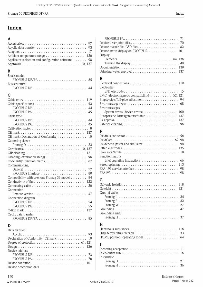
Promag 50 PROFIBUS DP/PA Index
140 Endress+Hauser
Index
AAccessories. . . . . . . . . . . . . . . . . . . . . . . . . . . . . . . . . . . . 97
Acyclic data transfer . . . . . . . . . . . . . . . . . . . . . . . . . . . . . 93
Adapters. . . . . . . . . . . . . . . . . . . . . . . . . . . . . . . . . . . . . . 17
Ambient temperature range . . . . . . . . . . . . . . . . . . . . . . 120
Applicator (selection and configuration software) . . . . . . . 98
Approvals . . . . . . . . . . . . . . . . . . . . . . . . . . . . . . . . . 10, 137
BBlock model
PROFIBUS DP/PA . . . . . . . . . . . . . . . . . . . . . . . . . . . 85
Bus structure
PROFIBUS DP . . . . . . . . . . . . . . . . . . . . . . . . . . . . . . 44
CCable entry . . . . . . . . . . . . . . . . . . . . . . . . . . . . . . . . . . 119
Cable specifications . . . . . . . . . . . . . . . . . . . . . . . . . . . . . 52
PROFIBUS DP . . . . . . . . . . . . . . . . . . . . . . . . . . . . . . 44
PROFIBUS PA. . . . . . . . . . . . . . . . . . . . . . . . . . . . . . . 45
Cable type
PROFIBUS DP . . . . . . . . . . . . . . . . . . . . . . . . . . . . . . 44
PROFIBUS PA. . . . . . . . . . . . . . . . . . . . . . . . . . . . . . . 45
Calibration factor . . . . . . . . . . . . . . . . . . . . . . . . . . . . . . . . 8
CE mark . . . . . . . . . . . . . . . . . . . . . . . . . . . . . . . . . . . . 137
CE mark (Declaration of Conformity) . . . . . . . . . . . . . . . . 10
Centering sleeve
Promag D . . . . . . . . . . . . . . . . . . . . . . . . . . . . . . . . . . 22
Certificates. . . . . . . . . . . . . . . . . . . . . . . . . . . . . . . . 10, 137
CIP cleaning. . . . . . . . . . . . . . . . . . . . . . . . . . . . . . . . . . 121
Cleaning (exterior cleaning) . . . . . . . . . . . . . . . . . . . . . . . 96
Code entry (function matrix) . . . . . . . . . . . . . . . . . . . . . . 67
Commissioning
General . . . . . . . . . . . . . . . . . . . . . . . . . . . . . . . . . . . 77
PROFIBUS interface . . . . . . . . . . . . . . . . . . . . . . . . . . 80
Compatibility with previous Promag 33 model . . . . . . . . . 84
Conductivity of fluid. . . . . . . . . . . . . . . . . . . . . . . . . . . . 123
Connecting cable . . . . . . . . . . . . . . . . . . . . . . . . . . . . . . . 20
Connection
Remote version. . . . . . . . . . . . . . . . . . . . . . . . . . . . . . 47
Connection diagram
PROFIBUS DP . . . . . . . . . . . . . . . . . . . . . . . . . . . . . . 54
PROFIBUS PA. . . . . . . . . . . . . . . . . . . . . . . . . . . . . . . 55
C-tick mark . . . . . . . . . . . . . . . . . . . . . . . . . . . . . . . . . . 137
Cyclic data transfer
PROFIBUS DP/PA . . . . . . . . . . . . . . . . . . . . . . . . . . . 85
DData transfer
Acyclic . . . . . . . . . . . . . . . . . . . . . . . . . . . . . . . . . . . . 93
Declaration of Conformity (CE mark) . . . . . . . . . . . . . . . . 10
Degree of protection. . . . . . . . . . . . . . . . . . . . . . . . . 61, 121
Design . . . . . . . . . . . . . . . . . . . . . . . . . . . . . . . . . . . . . . 126
Device address
PROFIBUS DP . . . . . . . . . . . . . . . . . . . . . . . . . . . . . . 73
PROFIBUS PA. . . . . . . . . . . . . . . . . . . . . . . . . . . . . . . 76
Device condition . . . . . . . . . . . . . . . . . . . . . . . . . . . . . . 101
Device description data
PROFIBUS PA . . . . . . . . . . . . . . . . . . . . . . . . . . . . . . . 71
Device description files . . . . . . . . . . . . . . . . . . . . . . . . . . . 70
Device master file (GSD file) . . . . . . . . . . . . . . . . . . . . . . . 82
Device status display on PROFIBUS. . . . . . . . . . . . . . . . . 101
Display
Elements. . . . . . . . . . . . . . . . . . . . . . . . . . . . . . . 64, 136
Turning the display . . . . . . . . . . . . . . . . . . . . . . . . . . . 40
Documentation. . . . . . . . . . . . . . . . . . . . . . . . . . . . . . . . 139
Drinking water approval . . . . . . . . . . . . . . . . . . . . . . . . . 137
EElectrical connections . . . . . . . . . . . . . . . . . . . . . . . . . . . 119
Electrodes
EPD electrode . . . . . . . . . . . . . . . . . . . . . . . . . . . . . . . 15
EMC (electromagnetic compatibility) . . . . . . . . . . . . 52, 121
Empty-pipe/full-pipe adjustment. . . . . . . . . . . . . . . . . . . . 94
Error message types . . . . . . . . . . . . . . . . . . . . . . . . . . . . . 68
Error messages
System errors (device errors) . . . . . . . . . . . . . . . . . . . 100
Europäische Druckgeräterichtlinie. . . . . . . . . . . . . . . . . . 137
Ex approval . . . . . . . . . . . . . . . . . . . . . . . . . . . . . . . . . . 137
Exterior cleaning . . . . . . . . . . . . . . . . . . . . . . . . . . . . . . . 96
FFieldbus connector . . . . . . . . . . . . . . . . . . . . . . . . . . . . . . 56
FieldCare . . . . . . . . . . . . . . . . . . . . . . . . . . . . . . . . . . 69, 98
Fieldcheck (tester and simulator). . . . . . . . . . . . . . . . . . . . 98
Fitted electrodes . . . . . . . . . . . . . . . . . . . . . . . . . . . . . . . 135
Flow rate/limits . . . . . . . . . . . . . . . . . . . . . . . . . . . . . . . . 18
Function matrix
Brief operating instructions . . . . . . . . . . . . . . . . . . . . . 66
Fuse, replacing . . . . . . . . . . . . . . . . . . . . . . . . . . . . . . . . 113
FXA 193 service interface . . . . . . . . . . . . . . . . . . . . . . . . . 98
FXA193 . . . . . . . . . . . . . . . . . . . . . . . . . . . . . . . . . . . . . . 98
GGalvanic isolation . . . . . . . . . . . . . . . . . . . . . . . . . . . . . . 118
Gewicht . . . . . . . . . . . . . . . . . . . . . . . . . . . . . . . . . . . . . 131
Ground cable
Promag L . . . . . . . . . . . . . . . . . . . . . . . . . . . . . . . . . . 24
Promag P . . . . . . . . . . . . . . . . . . . . . . . . . . . . . . . . . . 32
Promag W. . . . . . . . . . . . . . . . . . . . . . . . . . . . . . . . . . 27
Grounding . . . . . . . . . . . . . . . . . . . . . . . . . . . . . . . . . . . . 47
Grounding rings
Promag H . . . . . . . . . . . . . . . . . . . . . . . . . . . . . . . . . . 37
HHazardous substances . . . . . . . . . . . . . . . . . . . . . . . . . . . 116
High-temperature version . . . . . . . . . . . . . . . . . . . . . . . . . 33
HOME position (operating mode) . . . . . . . . . . . . . . . . . . . 64
IIncoming acceptance . . . . . . . . . . . . . . . . . . . . . . . . . . . . 11
Inlet/outlet run . . . . . . . . . . . . . . . . . . . . . . . . . . . . . . . . 16
Installation
Promag D . . . . . . . . . . . . . . . . . . . . . . . . . . . . . . . . . . 21
Promag H . . . . . . . . . . . . . . . . . . . . . . . . . . . . . . . . . . 36
Lobley St SPS SP331 General (Endress and Hauser Model 50W4F Magnetic Flowmeter) General
Q-Pulse Id VM349 Active 24/09/2013 Page 140 of 242
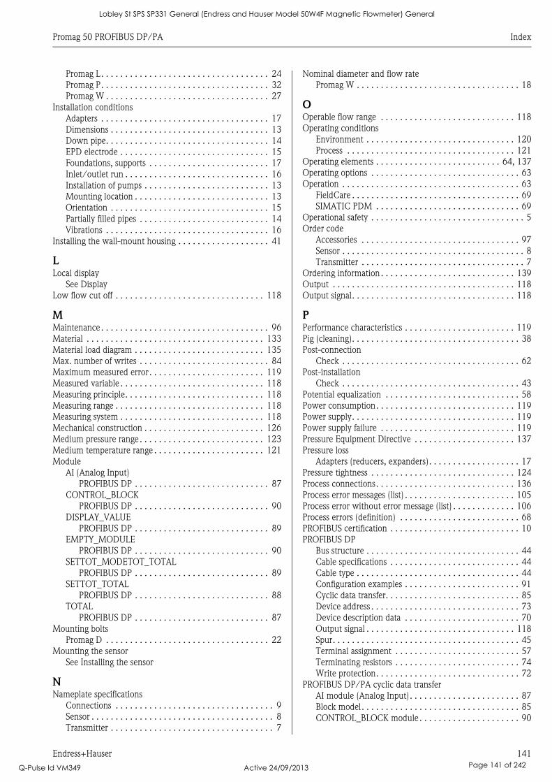
Promag 50 PROFIBUS DP/PA Index
Endress+Hauser 141
Promag L. . . . . . . . . . . . . . . . . . . . . . . . . . . . . . . . . . . 24
Promag P. . . . . . . . . . . . . . . . . . . . . . . . . . . . . . . . . . . 32
Promag W . . . . . . . . . . . . . . . . . . . . . . . . . . . . . . . . . . 27
Installation conditions
Adapters . . . . . . . . . . . . . . . . . . . . . . . . . . . . . . . . . . . 17
Dimensions . . . . . . . . . . . . . . . . . . . . . . . . . . . . . . . . . 13
Down pipe. . . . . . . . . . . . . . . . . . . . . . . . . . . . . . . . . . 14
EPD electrode . . . . . . . . . . . . . . . . . . . . . . . . . . . . . . . 15
Foundations, supports . . . . . . . . . . . . . . . . . . . . . . . . . 17
Inlet/outlet run . . . . . . . . . . . . . . . . . . . . . . . . . . . . . . 16
Installation of pumps . . . . . . . . . . . . . . . . . . . . . . . . . . 13
Mounting location . . . . . . . . . . . . . . . . . . . . . . . . . . . . 13
Orientation . . . . . . . . . . . . . . . . . . . . . . . . . . . . . . . . . 15
Partially filled pipes . . . . . . . . . . . . . . . . . . . . . . . . . . . 14
Vibrations . . . . . . . . . . . . . . . . . . . . . . . . . . . . . . . . . . 16
Installing the wall-mount housing . . . . . . . . . . . . . . . . . . . 41
LLocal display
See Display
Low flow cut off . . . . . . . . . . . . . . . . . . . . . . . . . . . . . . . 118
MMaintenance . . . . . . . . . . . . . . . . . . . . . . . . . . . . . . . . . . . 96
Material . . . . . . . . . . . . . . . . . . . . . . . . . . . . . . . . . . . . . 133
Material load diagram . . . . . . . . . . . . . . . . . . . . . . . . . . . 135
Max. number of writes . . . . . . . . . . . . . . . . . . . . . . . . . . . 84
Maximum measured error. . . . . . . . . . . . . . . . . . . . . . . . 119
Measured variable . . . . . . . . . . . . . . . . . . . . . . . . . . . . . . 118
Measuring principle. . . . . . . . . . . . . . . . . . . . . . . . . . . . . 118
Measuring range . . . . . . . . . . . . . . . . . . . . . . . . . . . . . . . 118
Measuring system . . . . . . . . . . . . . . . . . . . . . . . . . . . . . . 118
Mechanical construction . . . . . . . . . . . . . . . . . . . . . . . . . 126
Medium pressure range . . . . . . . . . . . . . . . . . . . . . . . . . . 123
Medium temperature range . . . . . . . . . . . . . . . . . . . . . . . 121
Module
AI (Analog Input)
PROFIBUS DP . . . . . . . . . . . . . . . . . . . . . . . . . . . . 87
CONTROL_BLOCK
PROFIBUS DP . . . . . . . . . . . . . . . . . . . . . . . . . . . . 90
DISPLAY_VALUE
PROFIBUS DP . . . . . . . . . . . . . . . . . . . . . . . . . . . . 89
EMPTY_MODULE
PROFIBUS DP . . . . . . . . . . . . . . . . . . . . . . . . . . . . 90
SETTOT_MODETOT_TOTAL
PROFIBUS DP . . . . . . . . . . . . . . . . . . . . . . . . . . . . 89
SETTOT_TOTAL
PROFIBUS DP . . . . . . . . . . . . . . . . . . . . . . . . . . . . 88
TOTAL
PROFIBUS DP . . . . . . . . . . . . . . . . . . . . . . . . . . . . 87
Mounting bolts
Promag D . . . . . . . . . . . . . . . . . . . . . . . . . . . . . . . . . . 22
Mounting the sensor
See Installing the sensor
NNameplate specifications
Connections . . . . . . . . . . . . . . . . . . . . . . . . . . . . . . . . . 9
Sensor . . . . . . . . . . . . . . . . . . . . . . . . . . . . . . . . . . . . . . 8
Transmitter . . . . . . . . . . . . . . . . . . . . . . . . . . . . . . . . . . 7
Nominal diameter and flow rate
Promag W . . . . . . . . . . . . . . . . . . . . . . . . . . . . . . . . . . 18
OOperable flow range . . . . . . . . . . . . . . . . . . . . . . . . . . . . 118
Operating conditions
Environment . . . . . . . . . . . . . . . . . . . . . . . . . . . . . . . 120
Process . . . . . . . . . . . . . . . . . . . . . . . . . . . . . . . . . . . 121
Operating elements . . . . . . . . . . . . . . . . . . . . . . . . . . 64, 137
Operating options . . . . . . . . . . . . . . . . . . . . . . . . . . . . . . . 63
Operation . . . . . . . . . . . . . . . . . . . . . . . . . . . . . . . . . . . . . 63
FieldCare . . . . . . . . . . . . . . . . . . . . . . . . . . . . . . . . . . . 69
SIMATIC PDM . . . . . . . . . . . . . . . . . . . . . . . . . . . . . . 69
Operational safety . . . . . . . . . . . . . . . . . . . . . . . . . . . . . . . . 5
Order code
Accessories . . . . . . . . . . . . . . . . . . . . . . . . . . . . . . . . . 97
Sensor . . . . . . . . . . . . . . . . . . . . . . . . . . . . . . . . . . . . . . 8
Transmitter . . . . . . . . . . . . . . . . . . . . . . . . . . . . . . . . . . 7
Ordering information . . . . . . . . . . . . . . . . . . . . . . . . . . . . 139
Output . . . . . . . . . . . . . . . . . . . . . . . . . . . . . . . . . . . . . . 118
Output signal. . . . . . . . . . . . . . . . . . . . . . . . . . . . . . . . . . 118
PPerformance characteristics . . . . . . . . . . . . . . . . . . . . . . . 119
Pig (cleaning). . . . . . . . . . . . . . . . . . . . . . . . . . . . . . . . . . . 38
Post-connection
Check . . . . . . . . . . . . . . . . . . . . . . . . . . . . . . . . . . . . . 62
Post-installation
Check . . . . . . . . . . . . . . . . . . . . . . . . . . . . . . . . . . . . . 43
Potential equalization . . . . . . . . . . . . . . . . . . . . . . . . . . . . 58
Power consumption. . . . . . . . . . . . . . . . . . . . . . . . . . . . . 119
Power supply. . . . . . . . . . . . . . . . . . . . . . . . . . . . . . . . . . 119
Power supply failure . . . . . . . . . . . . . . . . . . . . . . . . . . . . 119
Pressure Equipment Directive . . . . . . . . . . . . . . . . . . . . . 137
Pressure loss
Adapters (reducers, expanders). . . . . . . . . . . . . . . . . . . 17
Pressure tightness . . . . . . . . . . . . . . . . . . . . . . . . . . . . . . 124
Process connections. . . . . . . . . . . . . . . . . . . . . . . . . . . . . 136
Process error messages (list) . . . . . . . . . . . . . . . . . . . . . . . 105
Process error without error message (list) . . . . . . . . . . . . . 106
Process errors (definition) . . . . . . . . . . . . . . . . . . . . . . . . . 68
PROFIBUS certification . . . . . . . . . . . . . . . . . . . . . . . . . . . 10
PROFIBUS DP
Bus structure . . . . . . . . . . . . . . . . . . . . . . . . . . . . . . . . 44
Cable specifications . . . . . . . . . . . . . . . . . . . . . . . . . . . 44
Cable type . . . . . . . . . . . . . . . . . . . . . . . . . . . . . . . . . . 44
Configuration examples . . . . . . . . . . . . . . . . . . . . . . . . 91
Cyclic data transfer. . . . . . . . . . . . . . . . . . . . . . . . . . . . 85
Device address . . . . . . . . . . . . . . . . . . . . . . . . . . . . . . . 73
Device description data . . . . . . . . . . . . . . . . . . . . . . . . 70
Output signal . . . . . . . . . . . . . . . . . . . . . . . . . . . . . . . 118
Spur. . . . . . . . . . . . . . . . . . . . . . . . . . . . . . . . . . . . . . . 45
Terminal assignment . . . . . . . . . . . . . . . . . . . . . . . . . . 57
Terminating resistors . . . . . . . . . . . . . . . . . . . . . . . . . . 74
Write protection. . . . . . . . . . . . . . . . . . . . . . . . . . . . . . 72
PROFIBUS DP/PA cyclic data transfer
AI module (Analog Input). . . . . . . . . . . . . . . . . . . . . . . 87
Block model. . . . . . . . . . . . . . . . . . . . . . . . . . . . . . . . . 85
CONTROL_BLOCK module . . . . . . . . . . . . . . . . . . . . . 90
Lobley St SPS SP331 General (Endress and Hauser Model 50W4F Magnetic Flowmeter) General
Q-Pulse Id VM349 Active 24/09/2013 Page 141 of 242
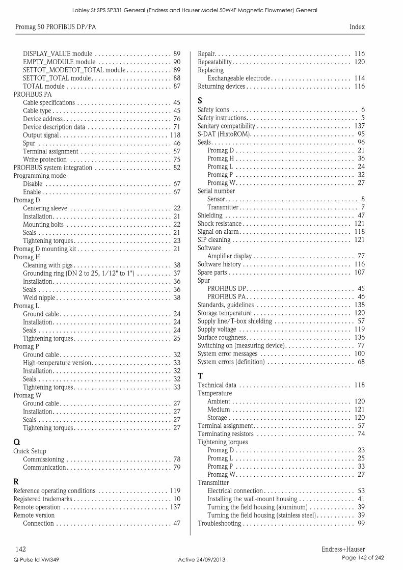
Promag 50 PROFIBUS DP/PA Index
142 Endress+Hauser
DISPLAY_VALUE module . . . . . . . . . . . . . . . . . . . . . . 89
EMPTY_MODULE module . . . . . . . . . . . . . . . . . . . . . 90
SETTOT_MODETOT_TOTAL module . . . . . . . . . . . . . 89
SETTOT_TOTAL module. . . . . . . . . . . . . . . . . . . . . . . 88
TOTAL module . . . . . . . . . . . . . . . . . . . . . . . . . . . . . . 87
PROFIBUS PA
Cable specifications . . . . . . . . . . . . . . . . . . . . . . . . . . . 45
Cable type . . . . . . . . . . . . . . . . . . . . . . . . . . . . . . . . . . 45
Device address. . . . . . . . . . . . . . . . . . . . . . . . . . . . . . . 76
Device description data . . . . . . . . . . . . . . . . . . . . . . . . 71
Output signal . . . . . . . . . . . . . . . . . . . . . . . . . . . . . . . 118
Spur . . . . . . . . . . . . . . . . . . . . . . . . . . . . . . . . . . . . . . 46
Terminal assignment . . . . . . . . . . . . . . . . . . . . . . . . . . 57
Write protection . . . . . . . . . . . . . . . . . . . . . . . . . . . . . 75
PROFIBUS system integration . . . . . . . . . . . . . . . . . . . . . . 82
Programming mode
Disable . . . . . . . . . . . . . . . . . . . . . . . . . . . . . . . . . . . . 67
Enable . . . . . . . . . . . . . . . . . . . . . . . . . . . . . . . . . . . . . 67
Promag D
Centering sleeve . . . . . . . . . . . . . . . . . . . . . . . . . . . . . 22
Installation. . . . . . . . . . . . . . . . . . . . . . . . . . . . . . . . . . 21
Mounting bolts . . . . . . . . . . . . . . . . . . . . . . . . . . . . . . 22
Seals . . . . . . . . . . . . . . . . . . . . . . . . . . . . . . . . . . . . . . 21
Tightening torques . . . . . . . . . . . . . . . . . . . . . . . . . . . . 23
Promag D mounting kit . . . . . . . . . . . . . . . . . . . . . . . . . . . 21
Promag H
Cleaning with pigs . . . . . . . . . . . . . . . . . . . . . . . . . . . . 38
Grounding ring (DN 2 to 25, 1/12" to 1") . . . . . . . . . . 37
Installation. . . . . . . . . . . . . . . . . . . . . . . . . . . . . . . . . . 36
Seals . . . . . . . . . . . . . . . . . . . . . . . . . . . . . . . . . . . . . . 36
Weld nipple . . . . . . . . . . . . . . . . . . . . . . . . . . . . . . . . . 38
Promag L
Ground cable . . . . . . . . . . . . . . . . . . . . . . . . . . . . . . . . 24
Installation. . . . . . . . . . . . . . . . . . . . . . . . . . . . . . . . . . 24
Seals . . . . . . . . . . . . . . . . . . . . . . . . . . . . . . . . . . . . . . 24
Tightening torques . . . . . . . . . . . . . . . . . . . . . . . . . . . . 25
Promag P
Ground cable . . . . . . . . . . . . . . . . . . . . . . . . . . . . . . . . 32
High-temperature version. . . . . . . . . . . . . . . . . . . . . . . 33
Installation. . . . . . . . . . . . . . . . . . . . . . . . . . . . . . . . . . 32
Seals . . . . . . . . . . . . . . . . . . . . . . . . . . . . . . . . . . . . . . 32
Tightening torques . . . . . . . . . . . . . . . . . . . . . . . . . . . . 33
Promag W
Ground cable . . . . . . . . . . . . . . . . . . . . . . . . . . . . . . . . 27
Installation. . . . . . . . . . . . . . . . . . . . . . . . . . . . . . . . . . 27
Seals . . . . . . . . . . . . . . . . . . . . . . . . . . . . . . . . . . . . . . 27
Tightening torques . . . . . . . . . . . . . . . . . . . . . . . . . . . . 27
QQuick Setup
Commissioning . . . . . . . . . . . . . . . . . . . . . . . . . . . . . . 78
Communication . . . . . . . . . . . . . . . . . . . . . . . . . . . . . . 79
RReference operating conditions . . . . . . . . . . . . . . . . . . . . 119
Registered trademarks . . . . . . . . . . . . . . . . . . . . . . . . . . . . 10
Remote operation . . . . . . . . . . . . . . . . . . . . . . . . . . . . . . 137
Remote version
Connection . . . . . . . . . . . . . . . . . . . . . . . . . . . . . . . . . 47
Repair. . . . . . . . . . . . . . . . . . . . . . . . . . . . . . . . . . . . . . . 116
Repeatability. . . . . . . . . . . . . . . . . . . . . . . . . . . . . . . . . . 120
Replacing
Exchangeable electrode . . . . . . . . . . . . . . . . . . . . . . . 114
Returning devices . . . . . . . . . . . . . . . . . . . . . . . . . . . . . . 116
SSafety icons . . . . . . . . . . . . . . . . . . . . . . . . . . . . . . . . . . . . 6
Safety instructions. . . . . . . . . . . . . . . . . . . . . . . . . . . . . . . . 5
Sanitary compatibility . . . . . . . . . . . . . . . . . . . . . . . . . . . 137
S-DAT (HistoROM). . . . . . . . . . . . . . . . . . . . . . . . . . . . . . 95
Seals. . . . . . . . . . . . . . . . . . . . . . . . . . . . . . . . . . . . . . . . . 96
Promag D . . . . . . . . . . . . . . . . . . . . . . . . . . . . . . . . . . 21
Promag H . . . . . . . . . . . . . . . . . . . . . . . . . . . . . . . . . . 36
Promag L . . . . . . . . . . . . . . . . . . . . . . . . . . . . . . . . . . 24
Promag P . . . . . . . . . . . . . . . . . . . . . . . . . . . . . . . . . . 32
Promag W. . . . . . . . . . . . . . . . . . . . . . . . . . . . . . . . . . 27
Serial number
Sensor. . . . . . . . . . . . . . . . . . . . . . . . . . . . . . . . . . . . . . 8
Transmitter . . . . . . . . . . . . . . . . . . . . . . . . . . . . . . . . . . 7
Shielding . . . . . . . . . . . . . . . . . . . . . . . . . . . . . . . . . . . . . 47
Shock resistance . . . . . . . . . . . . . . . . . . . . . . . . . . . . . . . 121
Signal on alarm. . . . . . . . . . . . . . . . . . . . . . . . . . . . . . . . 118
SIP cleaning . . . . . . . . . . . . . . . . . . . . . . . . . . . . . . . . . . 121
Software
Amplifier display . . . . . . . . . . . . . . . . . . . . . . . . . . . . . 77
Software history . . . . . . . . . . . . . . . . . . . . . . . . . . . . . . . 116
Spare parts . . . . . . . . . . . . . . . . . . . . . . . . . . . . . . . . . . . 107
Spur
PROFIBUS DP. . . . . . . . . . . . . . . . . . . . . . . . . . . . . . . 45
PROFIBUS PA . . . . . . . . . . . . . . . . . . . . . . . . . . . . . . . 46
Standards, guidelines . . . . . . . . . . . . . . . . . . . . . . . . . . . 138
Storage temperature . . . . . . . . . . . . . . . . . . . . . . . . . . . . 120
Supply line/T-box shielding . . . . . . . . . . . . . . . . . . . . . . . 57
Supply voltage . . . . . . . . . . . . . . . . . . . . . . . . . . . . . . . . 119
Surface roughness. . . . . . . . . . . . . . . . . . . . . . . . . . . . . . 136
Switching on (measuring device). . . . . . . . . . . . . . . . . . . . 77
System error messages . . . . . . . . . . . . . . . . . . . . . . . . . . 100
System errors (definition) . . . . . . . . . . . . . . . . . . . . . . . . . 68
TTechnical data . . . . . . . . . . . . . . . . . . . . . . . . . . . . . . . . 118
Temperature
Ambient . . . . . . . . . . . . . . . . . . . . . . . . . . . . . . . . . . 120
Medium . . . . . . . . . . . . . . . . . . . . . . . . . . . . . . . . . . 121
Storage . . . . . . . . . . . . . . . . . . . . . . . . . . . . . . . . . . . 120
Terminal assignment. . . . . . . . . . . . . . . . . . . . . . . . . . . . . 57
Terminating resistors . . . . . . . . . . . . . . . . . . . . . . . . . . . . 74
Tightening torques
Promag D . . . . . . . . . . . . . . . . . . . . . . . . . . . . . . . . . . 23
Promag L . . . . . . . . . . . . . . . . . . . . . . . . . . . . . . . . . . 25
Promag P . . . . . . . . . . . . . . . . . . . . . . . . . . . . . . . . . . 33
Promag W. . . . . . . . . . . . . . . . . . . . . . . . . . . . . . . . . . 27
Transmitter
Electrical connection . . . . . . . . . . . . . . . . . . . . . . . . . . 53
Installing the wall-mount housing . . . . . . . . . . . . . . . . 41
Turning the field housing (aluminum) . . . . . . . . . . . . . 39
Turning the field housing (stainless steel) . . . . . . . . . . . 39
Troubleshooting . . . . . . . . . . . . . . . . . . . . . . . . . . . . . . . . 99
Lobley St SPS SP331 General (Endress and Hauser Model 50W4F Magnetic Flowmeter) General
Q-Pulse Id VM349 Active 24/09/2013 Page 142 of 242

Promag 50 PROFIBUS DP/PA Index
Endress+Hauser 143
Types of error (system and process errors) . . . . . . . . . . . . . 68
VVibration resistance . . . . . . . . . . . . . . . . . . . . . . . . . . . . . 121
Vibrations . . . . . . . . . . . . . . . . . . . . . . . . . . . . . . . . . . . . . 16
WWall-mount housing, installing . . . . . . . . . . . . . . . . . . . . . 41
Weight . . . . . . . . . . . . . . . . . . . . . . . . . . . . . . . . . . . . . . 126
Wiring . . . . . . . . . . . . . . . . . . . . . . . . . . . . . . . . . . . . . . . 44
Write protection
PROFIBUS DP . . . . . . . . . . . . . . . . . . . . . . . . . . . . . . . 72
PROFIBUS PA . . . . . . . . . . . . . . . . . . . . . . . . . . . . . . . 75
Lobley St SPS SP331 General (Endress and Hauser Model 50W4F Magnetic Flowmeter) General
Q-Pulse Id VM349 Active 24/09/2013 Page 143 of 242

Promag 50 PROFIBUS DP/PA Index
144 Endress+Hauser
Lobley St SPS SP331 General (Endress and Hauser Model 50W4F Magnetic Flowmeter) General
Q-Pulse Id VM349 Active 24/09/2013 Page 144 of 242

Erklärung zur KontaminationP
/SF
/Kon
taV
IIIDeclaration of Contamination
Because of legal regulations and for the safety of our employees and operating equipment, we need the "declaration ofcontamination", with your signature, before your order can be handled. Please make absolutely sure to include it withthe shipping documents, or - even better - attach it to the outside of the packaging.Aufgrund der gesetzlichen Vorschriften und zum Schutz unserer Mitarbeiter und Betriebseinrichtungen, benötigen wir dieunterschriebene "Erklärung zur Kontamination", bevor Ihr Auftrag bearbeitet werden kann. Legen Sie diese unbedingt denVersandpapieren bei oder bringen Sie sie idealerweise außen an der Verpackung an.
Serial number
Seriennummer ___________________Type of instrument / sensor
Geräte-/Sensortyp _______________________________________
Process data/Prozessdaten Temperature / _________ [°C]
Conductivity / _________ [ S ]
Temperatur
Leitfähigkeit
Pressure / __________ [ Pa ]
Viscosity / __________ [mm /s]
Druck
Viskosität2
corrosiveätzend
harmlessunbedenklich
other *sonstiges*
toxicgiftig
Processmedium
IdentificationCAS No.
flammableentzündlich
harmful/irritant
gesundheits-schädlich/
reizend
Medium /concentrationMedium /Konzentration
Returned partcleaned with
Medium forprocess cleaning
Medium and warnings
Warnhinweise zum Medium
* explosive; oxidising; dangerous for the environment; biological risk; radioactive* explosiv; brandfördernd; umweltgefährlich; biogefährlich; radioaktiv
Please tick should one of the above be applicable, include security sheet and, if necessary, special handling instructions.Zutreffendes ankreuzen; trifft einer der Warnhinweise zu, Sicherheitsdatenblatt und ggf. spezielle Handhabungsvorschriften beilegen.
Reason for return / Grund zur Rücksendung _____________________________________________________________
__________________________________________________________________________________________________
__________________________________________________________________________________________________
We hereby certify that the returned parts have been carefully cleaned. To the best of our knowledge they are free from any residues indangerous quantities.Hiermit bestätigen wir, dass die zurückgesandten Teile sorgfältig gereinigt wurden, und nach unserem Wissen frei von Rückständen ingefahrbringender Menge sind.
_____________________________________________(place )Ort, Datum, date /
______________________________________________(Company stamp and legally binding signature)(Firmenstempel und rechtsverbindliche Unterschrift)
Company data /Angaben zum Absender
Company / ________________________________
______________________________________________
Address /
______________________________________________
______________________________________________
Firma
Adresse
Contact person / ______________________
Department / ______________________________
P ______________________________
Fax / E-Mail _______________________________________
Y _______________________
Ansprechpartner
Abteilung
Telefon
Ihre Auftragsnr.
hone number/
our order No. /
Medium zurEndreinigung
Medium zurProzessreinigung
Medium imProzess
Lobley St SPS SP331 General (Endress and Hauser Model 50W4F Magnetic Flowmeter) General
Q-Pulse Id VM349 Active 24/09/2013 Page 145 of 242

www.endress.com/worldwide
BA00055D/06/EN/14.11
71136625
FM+SGML6.0 ProMoDo
Lobley St SPS SP331 General (Endress and Hauser Model 50W4F Magnetic Flowmeter) General
Q-Pulse Id VM349 Active 24/09/2013 Page 146 of 242

TI046D/06/en/11.09
71106269
Technical Information
Proline Promag 50W, 53W
Electromagnetic Flow Measuring System
Flow measurement of liquids in water or wastewater applications
Application
Electromagnetic flowmeter for bidirectional
measurement of liquids with a minimum
conductivity of ≥ 5 μS/cm:
• Drinking water
• Wastewater
• Sewage sludge
• Flow measurement up to 110000 m³/h
(484315 gal/min)
• Fluid temperature up to +80 °C (+176 °F)
• Process pressures up to 40 bar (580 psi)
• Lengths in accordance with DVGW/ISO
Application-specific lining of the measuring pipe from
polyurethane or hard rubber with the following drinking
water permissions:
• KTW
• WRAS
• NSF
• ACS
Approvals for hazardous area:
• ATEX
• IECEx
• FM
• CSA
• NEPSI
Connection to process control system:
• HART
• PROFIBUS DP/PA
• FOUNDATION Fieldbus
• MODBUS RS485
Your benefits
Promag measuring devices offer you cost-effective flow
measurement with a high degree of accuracy for a wide
range of process conditions.
The uniform Proline transmitter concept comprises:
• Modular device and operating concept resulting in a
higher degree of efficiency
• Software options for batching, electrode cleaning and
for measuring pulsating flow
• High degree of reliability and measuring stability
• Uniform operating concept
The tried-and-tested Promag sensors offer:
• No pressure loss
• Not sensitive to vibrations
• Simple installation and commissioning
Lobley St SPS SP331 General (Endress and Hauser Model 50W4F Magnetic Flowmeter) General
Q-Pulse Id VM349 Active 24/09/2013 Page 147 of 242

Proline Promag 50W, 53W
2 Endress+Hauser
Table of contents
Function and system design. . . . . . . . . . . . . . . . . . . . . 3
Measuring principle . . . . . . . . . . . . . . . . . . . . . . . . . . . . . . . . . . . 3
Measuring system . . . . . . . . . . . . . . . . . . . . . . . . . . . . . . . . . . . . . 3
Input . . . . . . . . . . . . . . . . . . . . . . . . . . . . . . . . . . . . . . 4
Measured variable . . . . . . . . . . . . . . . . . . . . . . . . . . . . . . . . . . . . 4
Measuring ranges . . . . . . . . . . . . . . . . . . . . . . . . . . . . . . . . . . . . . 4
Operable flow range . . . . . . . . . . . . . . . . . . . . . . . . . . . . . . . . . . . 4
Input signal . . . . . . . . . . . . . . . . . . . . . . . . . . . . . . . . . . . . . . . . . 4
Output . . . . . . . . . . . . . . . . . . . . . . . . . . . . . . . . . . . . . 4
Output signal . . . . . . . . . . . . . . . . . . . . . . . . . . . . . . . . . . . . . . . . 4
Signal on alarm . . . . . . . . . . . . . . . . . . . . . . . . . . . . . . . . . . . . . . 6
Load . . . . . . . . . . . . . . . . . . . . . . . . . . . . . . . . . . . . . . . . . . . . . . 6
Low flow cutoff . . . . . . . . . . . . . . . . . . . . . . . . . . . . . . . . . . . . . . 6
Galvanic isolation . . . . . . . . . . . . . . . . . . . . . . . . . . . . . . . . . . . . . 6
Switching output . . . . . . . . . . . . . . . . . . . . . . . . . . . . . . . . . . . . . 6
Power supply. . . . . . . . . . . . . . . . . . . . . . . . . . . . . . . . 7
Electrical connection, measuring unit . . . . . . . . . . . . . . . . . . . . . . 7
Electrical connection, terminal assignment . . . . . . . . . . . . . . . . . . 8
Electrical connection, remote version . . . . . . . . . . . . . . . . . . . . . . 9
Supply voltage (power supply) . . . . . . . . . . . . . . . . . . . . . . . . . . . 9
Cable entry . . . . . . . . . . . . . . . . . . . . . . . . . . . . . . . . . . . . . . . . . 9
Remote version cable specifications . . . . . . . . . . . . . . . . . . . . . . . . 9
Power consumption . . . . . . . . . . . . . . . . . . . . . . . . . . . . . . . . . . 10
Power supply failure . . . . . . . . . . . . . . . . . . . . . . . . . . . . . . . . . . 10
Potential equalization . . . . . . . . . . . . . . . . . . . . . . . . . . . . . . . . . 11
Performance characteristics. . . . . . . . . . . . . . . . . . . . 13
Reference operating conditions . . . . . . . . . . . . . . . . . . . . . . . . . . 13
Maximum measured error . . . . . . . . . . . . . . . . . . . . . . . . . . . . . 13
Repeatability . . . . . . . . . . . . . . . . . . . . . . . . . . . . . . . . . . . . . . . . 13
Operating conditions: Installations . . . . . . . . . . . . . . 14
Installation instructions . . . . . . . . . . . . . . . . . . . . . . . . . . . . . . . . 14
Inlet and outlet run . . . . . . . . . . . . . . . . . . . . . . . . . . . . . . . . . . 18
Adapters . . . . . . . . . . . . . . . . . . . . . . . . . . . . . . . . . . . . . . . . . . . 18
Length of connecting cable . . . . . . . . . . . . . . . . . . . . . . . . . . . . . 19
Operating conditions: Environment. . . . . . . . . . . . . . 20
Ambient temperature range . . . . . . . . . . . . . . . . . . . . . . . . . . . . 20
Storage temperature . . . . . . . . . . . . . . . . . . . . . . . . . . . . . . . . . . 20
Degree of protection . . . . . . . . . . . . . . . . . . . . . . . . . . . . . . . . . . 20
Shock and vibration resistance . . . . . . . . . . . . . . . . . . . . . . . . . . 20
Electromagnetic compatibility (EMC) . . . . . . . . . . . . . . . . . . . . . 20
Operating conditions: Process . . . . . . . . . . . . . . . . . . 21
Medium temperature range . . . . . . . . . . . . . . . . . . . . . . . . . . . . 21
Conductivity . . . . . . . . . . . . . . . . . . . . . . . . . . . . . . . . . . . . . . . 21
Medium pressure range (nominal pressure) . . . . . . . . . . . . . . . . . 21
Pressure tightness . . . . . . . . . . . . . . . . . . . . . . . . . . . . . . . . . . . . 21
Limiting flow . . . . . . . . . . . . . . . . . . . . . . . . . . . . . . . . . . . . . . . 22
Pressure loss . . . . . . . . . . . . . . . . . . . . . . . . . . . . . . . . . . . . . . . . 23
Mechanical construction . . . . . . . . . . . . . . . . . . . . . . 24
Design, dimensions . . . . . . . . . . . . . . . . . . . . . . . . . . . . . . . . . . 24
Weight . . . . . . . . . . . . . . . . . . . . . . . . . . . . . . . . . . . . . . . . . . . 37
Measuring tube specifications . . . . . . . . . . . . . . . . . . . . . . . . . . . 39
Material . . . . . . . . . . . . . . . . . . . . . . . . . . . . . . . . . . . . . . . . . . . 40
Material load diagram . . . . . . . . . . . . . . . . . . . . . . . . . . . . . . . . 40
Fitted electrodes . . . . . . . . . . . . . . . . . . . . . . . . . . . . . . . . . . . . 43
Process connections . . . . . . . . . . . . . . . . . . . . . . . . . . . . . . . . . . 43
Surface roughness . . . . . . . . . . . . . . . . . . . . . . . . . . . . . . . . . . . 43
Human interface . . . . . . . . . . . . . . . . . . . . . . . . . . . . 44
Display elements . . . . . . . . . . . . . . . . . . . . . . . . . . . . . . . . . . . . 44
Operating elements . . . . . . . . . . . . . . . . . . . . . . . . . . . . . . . . . . 44
Language groups . . . . . . . . . . . . . . . . . . . . . . . . . . . . . . . . . . . . 44
Remote operation . . . . . . . . . . . . . . . . . . . . . . . . . . . . . . . . . . . . 44
Certificates and approvals . . . . . . . . . . . . . . . . . . . . . 45
CE mark . . . . . . . . . . . . . . . . . . . . . . . . . . . . . . . . . . . . . . . . . . 45
C-tick mark . . . . . . . . . . . . . . . . . . . . . . . . . . . . . . . . . . . . . . . 45
Pressure measuring device approval . . . . . . . . . . . . . . . . . . . . . . 45
Ex approval . . . . . . . . . . . . . . . . . . . . . . . . . . . . . . . . . . . . . . . . 45
Other standards and guidelines . . . . . . . . . . . . . . . . . . . . . . . . . . 45
FOUNDATION Fieldbus certification . . . . . . . . . . . . . . . . . . . . . 45
MODBUS RS485 certification . . . . . . . . . . . . . . . . . . . . . . . . . . 45
PROFIBUS DP/PA certification . . . . . . . . . . . . . . . . . . . . . . . . . 45
Ordering information. . . . . . . . . . . . . . . . . . . . . . . . . 46
Accessories . . . . . . . . . . . . . . . . . . . . . . . . . . . . . . . . 46
Documentation . . . . . . . . . . . . . . . . . . . . . . . . . . . . . 46
Registered trademarks. . . . . . . . . . . . . . . . . . . . . . . . 46
Lobley St SPS SP331 General (Endress and Hauser Model 50W4F Magnetic Flowmeter) General
Q-Pulse Id VM349 Active 24/09/2013 Page 148 of 242
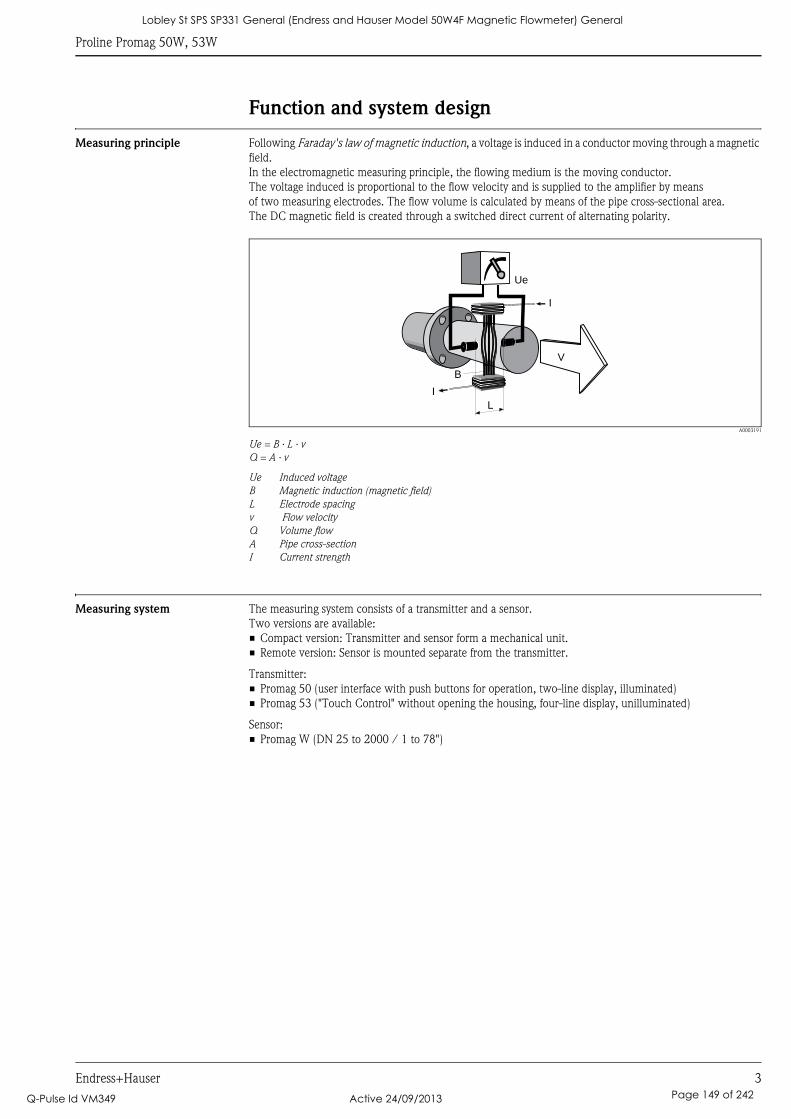
Proline Promag 50W, 53W
Endress+Hauser 3
Function and system design
Measuring principle Following Faraday's law of magnetic induction, a voltage is induced in a conductor moving through a magnetic
field.
In the electromagnetic measuring principle, the flowing medium is the moving conductor.
The voltage induced is proportional to the flow velocity and is supplied to the amplifier by means
of two measuring electrodes. The flow volume is calculated by means of the pipe cross-sectional area.
The DC magnetic field is created through a switched direct current of alternating polarity.
A0003191
Ue = B · L · v
Q = A · v
Ue Induced voltage
B Magnetic induction (magnetic field)
L Electrode spacing
v Flow velocity
Q Volume flow
A Pipe cross-section
I Current strength
Measuring system The measuring system consists of a transmitter and a sensor.
Two versions are available:
• Compact version: Transmitter and sensor form a mechanical unit.
• Remote version: Sensor is mounted separate from the transmitter.
Transmitter:
• Promag 50 (user interface with push buttons for operation, two-line display, illuminated)
• Promag 53 ("Touch Control" without opening the housing, four-line display, unilluminated)
Sensor:
• Promag W (DN 25 to 2000 / 1 to 78")
Ue
I
I
B
L
V
Lobley St SPS SP331 General (Endress and Hauser Model 50W4F Magnetic Flowmeter) General
Q-Pulse Id VM349 Active 24/09/2013 Page 149 of 242
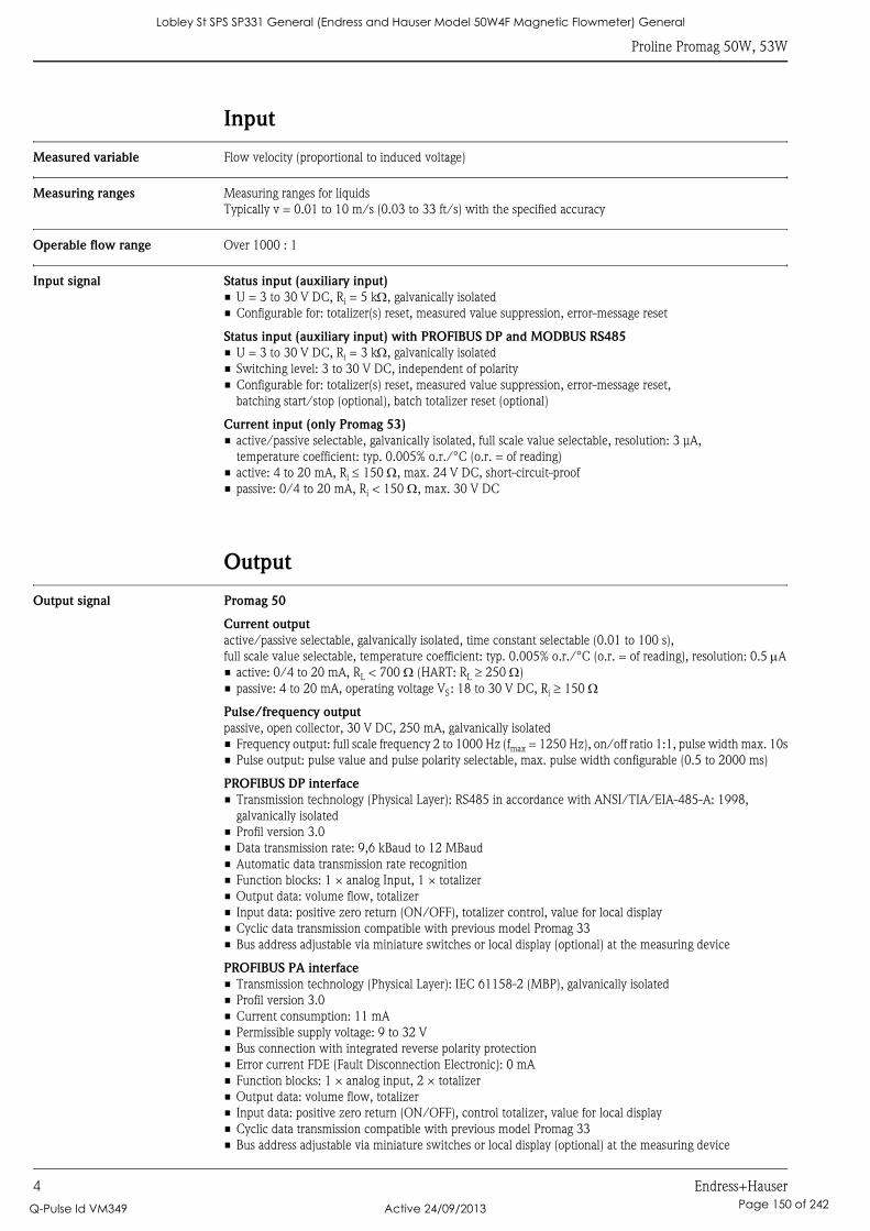
Proline Promag 50W, 53W
4 Endress+Hauser
Input
Measured variable Flow velocity (proportional to induced voltage)
Measuring ranges Measuring ranges for liquids
Typically v = 0.01 to 10 m/s (0.03 to 33 ft/s) with the specified accuracy
Operable flow range Over 1000 : 1
Input signal Status input (auxiliary input)
• U = 3 to 30 V DC, Ri = 5 kΩ, galvanically isolated
• Configurable for: totalizer(s) reset, measured value suppression, error-message reset
Status input (auxiliary input) with PROFIBUS DP and MODBUS RS485
• U = 3 to 30 V DC, Ri = 3 kΩ, galvanically isolated
• Switching level: 3 to 30 V DC, independent of polarity
• Configurable for: totalizer(s) reset, measured value suppression, error-message reset,
batching start/stop (optional), batch totalizer reset (optional)
Current input (only Promag 53)
• active/passive selectable, galvanically isolated, full scale value selectable, resolution: 3 μA,
temperature coefficient: typ. 0.005% o.r./°C (o.r. = of reading)
• active: 4 to 20 mA, Ri ≤ 150 Ω, max. 24 V DC, short-circuit-proof
• passive: 0/4 to 20 mA, Ri < 150 Ω, max. 30 V DC
Output
Output signal Promag 50
Current output
active/passive selectable, galvanically isolated, time constant selectable (0.01 to 100 s),
full scale value selectable, temperature coefficient: typ. 0.005% o.r./°C (o.r. = of reading), resolution: 0.5 μA
• active: 0/4 to 20 mA, RL < 700 Ω (HART: RL ≥ 250 Ω)
• passive: 4 to 20 mA, operating voltage VS: 18 to 30 V DC, Ri ≥ 150 Ω
Pulse/frequency output
passive, open collector, 30 V DC, 250 mA, galvanically isolated
• Frequency output: full scale frequency 2 to 1000 Hz (fmax = 1250 Hz), on/off ratio 1:1, pulse width max. 10s
• Pulse output: pulse value and pulse polarity selectable, max. pulse width configurable (0.5 to 2000 ms)
PROFIBUS DP interface
• Transmission technology (Physical Layer): RS485 in accordance with ANSI/TIA/EIA-485-A: 1998,
galvanically isolated
• Profil version 3.0
• Data transmission rate: 9,6 kBaud to 12 MBaud
• Automatic data transmission rate recognition
• Function blocks: 1 × analog Input, 1 × totalizer
• Output data: volume flow, totalizer
• Input data: positive zero return (ON/OFF), totalizer control, value for local display
• Cyclic data transmission compatible with previous model Promag 33
• Bus address adjustable via miniature switches or local display (optional) at the measuring device
PROFIBUS PA interface
• Transmission technology (Physical Layer): IEC 61158-2 (MBP), galvanically isolated
• Profil version 3.0
• Current consumption: 11 mA
• Permissible supply voltage: 9 to 32 V
• Bus connection with integrated reverse polarity protection
• Error current FDE (Fault Disconnection Electronic): 0 mA
• Function blocks: 1 × analog input, 2 × totalizer
• Output data: volume flow, totalizer
• Input data: positive zero return (ON/OFF), control totalizer, value for local display
• Cyclic data transmission compatible with previous model Promag 33
• Bus address adjustable via miniature switches or local display (optional) at the measuring device
Lobley St SPS SP331 General (Endress and Hauser Model 50W4F Magnetic Flowmeter) General
Q-Pulse Id VM349 Active 24/09/2013 Page 150 of 242
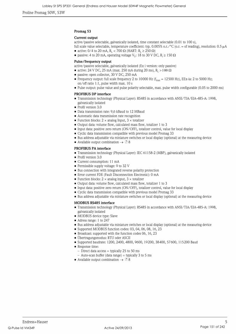
Proline Promag 50W, 53W
Endress+Hauser 5
Promag 53
Current output
active/passive selectable, galvanically isolated, time constant selectable (0.01 to 100 s),
full scale value selectable, temperature coefficient: typ. 0.005% o.r./°C (o.r. = of reading), resolution: 0.5 μA
• active: 0/4 to 20 mA, RL < 700 Ω (HART: RL ≥ 250 Ω)
• passive: 4 to 20 mA, operating voltage VS: 18 to 30 V DC, Ri ≥ 150 Ω
Pulse/frequency output
active/passive selectable, galvanically isolated (Ex i version: only passive)
• active: 24 V DC, 25 mA (max. 250 mA during 20 ms), RL > 100 Ω• passive: open collector, 30 V DC, 250 mA
• Frequency output: full scale frequency 2 to 10000 Hz (fmax = 12500 Hz), EEx-ia: 2 to 5000 Hz;
on/off ratio 1:1, pulse width max. 10 s
• Pulse output: pulse value and pulse polarity selectable, max. pulse width configurable (0.05 to 2000 ms)
PROFIBUS DP interface
• Transmission technology (Physical Layer): RS485 in accordance with ANSI/TIA/EIA-485-A: 1998,
galvanically isolated
• Profil version 3.0
• Data transmission rate: 9,6 kBaud to 12 MBaud
• Automatic data transmission rate recognition
• Function blocks: 2 × analog Input, 3 × totalizer
• Output data: volume flow, calculated mass flow, totalizer 1 to 3
• Input data: positive zero return (ON/OFF), totalizer control, value for local display
• Cyclic data transmission compatible with previous model Promag 33
• Bus address adjustable via miniature switches or local display (optional) at the measuring device
• Available output combination → ä 8
PROFIBUS PA interface
• Transmission technology (Physical Layer): IEC 61158-2 (MBP), galvanically isolated
• Profil version 3.0
• Current consumption: 11 mA
• Permissible supply voltage: 9 to 32 V
• Bus connection with integrated reverse polarity protection
• Error current FDE (Fault Disconnection Electronic): 0 mA
• Function blocks: 2 × analog input, 3 × totalizer
• Output data: volume flow, calculated mass flow, totalizer 1 to 3
• Input data: positive zero return (ON/OFF), totalizer control, value for local display
• Cyclic data transmission compatible with previous model Promag 33
• Bus address adjustable via miniature switches or local display (optional) at the measuring device
MODBUS RS485 interface
• Transmission technology (Physical Layer): RS485 in accordance with ANSI/TIA/EIA-485-A: 1998,
galvanically isolated
• MODBUS device type: Slave
• Adress range: 1 to 247
• Bus address adjustable via miniature switches or local display (optional) at the measuring device
• Supported MODBUS function codes: 03, 04, 06, 08, 16, 23
• Broadcast: supported with the function codes 06, 16, 23
• Übertragungsmodus: RTU oder ASCII
• Supported baudrate: 1200, 2400, 4800, 9600, 19200, 38400, 57600, 115200 Baud
• Response time:
– Direct data access = typically 25 to 50 ms
– Auto-scan buffer (data range) = typically 3 to 5 ms
• Available output combination → ä 8
Lobley St SPS SP331 General (Endress and Hauser Model 50W4F Magnetic Flowmeter) General
Q-Pulse Id VM349 Active 24/09/2013 Page 151 of 242
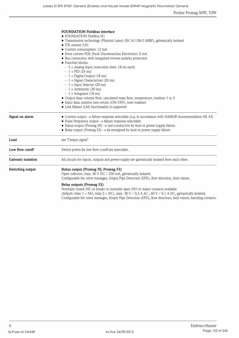
Proline Promag 50W, 53W
6 Endress+Hauser
FOUNDATION Fieldbus interface
• FOUNDATION Fieldbus H1
• Transmission technology (Physical Layer): IEC 61158-2 (MBP), galvanically isolated
• ITK version 5.01
• Current consumption: 12 mA
• Error current FDE (Fault Disconnection Electronic): 0 mA
• Bus connection with integrated reverse polarity protection
• Function blocks:
– 5 × Analog Input (execution time: 18 ms each)
– 1 × PID (25 ms)
– 1 × Digital Output (18 ms)
– 1 × Signal Characterizer (20 ms)
– 1 × Input Selector (20 ms)
– 1 × Arithmetic (20 ms)
– 1 × Integrator (18 ms)
• Output data: volume flow, calculated mass flow, temperature, totalizer 1 to 3
• Input data: positive zero return (ON/OFF), reset totalizer
• Link Master (LM) functionality is supported
Signal on alarm • Current output → failure response selectable (e.g. in accordance with NAMUR recommendation NE 43)
• Pulse/frequency output → failure response selectable
• Status output (Promag 50) → non-conductive by fault or power supply failure
• Relay output (Promag 53) → de-energized by fault or power supply failure
Load see "Output signal"
Low flow cutoff Switch points for low flow cutoff are selectable.
Galvanic isolation All circuits for inputs, outputs and power supply are galvanically isolated from each other.
Switching output Status output (Promag 50, Promag 53)
Open collector, max. 30 V DC / 250 mA, galvanically isolated.
Configurable for: error messages, Empty Pipe Detection (EPD), flow direction, limit values.
Relay outputs (Promag 53)
Normally closed (NC or break) or normally open (NO or make) contacts available
(default: relay 1 = NO, relay 2 = NC), max. 30 V / 0,5 A AC ; 60 V / 0,1 A DC, galvanically isolated.
Configurable for: error messages, Empty Pipe Detection (EPD), flow direction, limit values, batching contacts.
Lobley St SPS SP331 General (Endress and Hauser Model 50W4F Magnetic Flowmeter) General
Q-Pulse Id VM349 Active 24/09/2013 Page 152 of 242
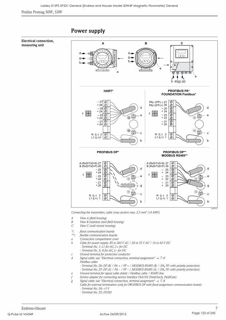
Proline Promag 50W, 53W
Endress+Hauser 7
Power supply
Electrical connection,
measuring unit
A0002441
Connecting the transmitter, cable cross-section max. 2.5 mm2 (14 AWG)
A View A (field housing)
B View B (stainless steel field housing)
C View C (wall-mount housing)
*) fixed communication boards
**) flexible communication boards
a Connection compartment cover
b Cable for power supply: 85 to 260 V AC / 20 to 55 V AC / 16 to 62 V DC
- Terminal No. 1: L1 for AC, L+ for DC
- Terminal No. 2: N for AC, L– for DC
c Ground terminal for protective conductor
d Signal cable: see "Electrical connection, terminal assignment" → ä 8
Fieldbus cable:
- Terminal No. 26: DP (B) / PA + / FF + / MODBUS RS485 (B) / (PA, FF: with polarity protection)
- Terminal No. 27: DP (A) / PA – / FF – / MODBUS RS485 (A) / (PA, FF: with polarity protection)
e Ground terminal for signal cable shield / Fieldbus cable / RS485 line
f Service adapter for connecting service interface FXA193 (Fieldcheck, FieldCare)
g Signal cable: see "Electrical connection, terminal assignment" → ä 8
Cable for external termination (only for PROFIBUS DP with fixed assignment communication board):
- Terminal No. 24: +5 V
- Terminal No. 25: DGND
aa
d
b
a
HART*
PROFIBUS DP**
MODBUS RS485**
27
25
23
21
21
26
24
22
20
L1 (L+)N (L-)
–
–
–
+
+
+
PROFIBUS PA*
FOUNDATION Fieldbus*
PA(–)/FF(–)
27
25
23
21
21
26
24
22
20
L1 (L+)N (L-)
–
–
–
+
+
+
A (RxD/TxD-N)B (RxD/TxD-P)
PA(+)/FF(+)d
c
e
b
– 27
– 25
– 23
– 21
+ 26
+ 24
+ 22
+ 20
N (L-) 2L1 (L+)1
25
23
21
21
24
22
20
L1 (L+)N (L-)
–
–
–
+
+
+
2726
A (RxD/TxD-N)B (RxD/TxD-P)
A B C
g
d
b
g
d
c
e
b
d
c
e
b
g
d
c
e
b
g
PROFIBUS DP*
(d)b d/(g)
f f
f f
Lobley St SPS SP331 General (Endress and Hauser Model 50W4F Magnetic Flowmeter) General
Q-Pulse Id VM349 Active 24/09/2013 Page 153 of 242
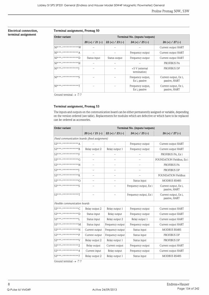
Proline Promag 50W, 53W
8 Endress+Hauser
Electrical connection,
terminal assignment
Terminal assignment, Promag 50
Terminal assignment, Promag 53
The inputs and outputs on the communication board can be either permanently assigned or variable, depending
on the version ordered (see table). Replacements for modules which are defective or which have to be replaced
can be ordered as accessories.
Order variant Terminal No. (inputs/outputs)
20 (+) / 21 (–) 22 (+) / 23 (–) 24 (+) / 25 (–) 26 (+) / 27 (–)
50***-***********W – – – Current output HART
50***-***********A – – Frequency output Current output HART
50***-***********D Status input Status output Frequency output Current output HART
50***-***********H – – – PROFIBUS PA
50***-***********J – – +5 V (external
termination)
PROFIBUS DP
50***-***********S – – Frequency output,
Ex i, passive
Current output, Ex i,
passive, HART
50***-***********T – – Frequency output,
Ex i, passive
Current output, Ex i,
passive, HART
Ground terminal → ä 7
Order variant Terminal No. (inputs/outputs)
20 (+) / 21 (–) 22 (+) / 23 (–) 24 (+) / 25 (–) 26 (+) / 27 (–)
Fixed communication boards (fixed assignment)
53***-***********A – – Frequency output Current output HART
53***-***********B Relay output 2 Relay output 1 Frequency output Current output HART
53***-***********F – – – PROFIBUS PA, Ex i
53***-***********G – – – FOUNDATION Fieldbus, Ex i
53***-***********H – – – PROFIBUS PA
53***-***********J – – – PROFIBUS DP
53***-***********K – – – FOUNDATION Fieldbus
53***-***********Q – – Status input MODBUS RS485
53***-***********S – – Frequency output, Ex i Current output, Ex i,
passive, HART
53***-***********T – – Frequency output, Ex i Current output, Ex i,
passive, HART
Flexible communication boards
53***-***********C Relay output 2 Relay output 1 Frequency output Current output HART
53***-***********D Status input Relay output Frequency output Current output HART
53***-***********L Status input Relay output 2 Relay output 1 Current output HART
53***-***********M Status input Frequency output Frequency output Current output HART
53***-***********N Current output Frequency output Status input MODBUS RS485
53***-***********P Current output Frequency output Status input PROFIBUS DP
53***-***********V Relay output 2 Relay output 1 Status input PROFIBUS DP
53***-***********2 Relay output Current output Frequency output Current output HART
53***-***********4 Current input Relay output Frequency output Current output HART
53***-***********7 Relay output 2 Relay output 1 Status input MODBUS RS485
Ground terminal → ä 7
Lobley St SPS SP331 General (Endress and Hauser Model 50W4F Magnetic Flowmeter) General
Q-Pulse Id VM349 Active 24/09/2013 Page 154 of 242
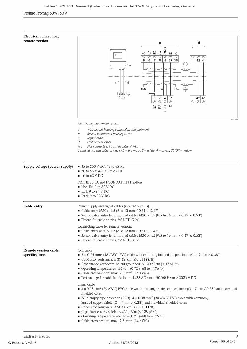
Proline Promag 50W, 53W
Endress+Hauser 9
Electrical connection,
remote version
A0011722
Connecting the remote version
a Wall-mount housing connection compartment
b Sensor connection housing cover
c Signal cable
d Coil current cable
n.c. Not connected, insulated cable shields
Terminal no. and cable colors: 6/5 = brown; 7/8 = white; 4 = green; 36/37 = yellow
Supply voltage (power supply) • 85 to 260 V AC, 45 to 65 Hz
• 20 to 55 V AC, 45 to 65 Hz
• 16 to 62 V DC
PROFIBUS PA and FOUNDATION Fieldbus
• Non-Ex: 9 to 32 V DC
• Ex i: 9 to 24 V DC
• Ex d: 9 to 32 V DC
Cable entry Power supply and signal cables (inputs/ outputs):
• Cable entry M20 × 1.5 (8 to 12 mm / 0.31 to 0.47")
• Sensor cable entry for armoured cables M20 × 1.5 (9.5 to 16 mm / 0.37 to 0.63")
• Thread for cable entries, ½" NPT, G ½"
Connecting cable for remote version:
• Cable entry M20 × 1.5 (8 to 12 mm / 0.31 to 0.47")
• Sensor cable entry for armoured cables M20 × 1.5 (9.5 to 16 mm / 0.37 to 0.63")
• Thread for cable entries, ½" NPT, G ½"
Remote version cable
specifications
Coil cable
• 2 × 0.75 mm2 (18 AWG) PVC cable with common, braided copper shield (∅ ∼ 7 mm / 0.28")
• Conductor resistance: ≤ 37 Ω/km (≤ 0.011 Ω/ft)
• Capacitance core/core, shield grounded: ≤ 120 pF/m (≤ 37 pF/ft)
• Operating temperature: –20 to +80 °C (–68 to +176 °F)
• Cable cross-section: max. 2.5 mm2 (14 AWG)
• Test voltage for cable insulation: ≤ 1433 AC r.m.s. 50/60 Hz or ≥ 2026 V DC
Signal cable
• 3 × 0.38 mm2 (20 AWG) PVC cable with common, braided copper shield (∅ ∼ 7 mm / 0.28") and individual
shielded cores
• With empty pipe detection (EPD): 4 × 0.38 mm2 (20 AWG) PVC cable with common,
braided copper shield (∅ ∼ 7 mm / 0.28") and individual shielded cores
• Conductor resistance: ≤ 50 Ω/km (≤ 0.015 Ω/ft)
• Capacitance core/shield: ≤ 420 pF/m (≤ 128 pF/ft)
• Operating temperature: –20 to +80 °C (–68 to +176 °F)
• Cable cross-section: max. 2.5 mm2 (14 AWG)
E1
E2
GN
D E
S1
E1
E2
S2
GN
D
E S
5 7 4 37 42 41
42 416 5 7 8 4 37 36
n.c. n.c.
dc
c d
a
b
n.c.
Lobley St SPS SP331 General (Endress and Hauser Model 50W4F Magnetic Flowmeter) General
Q-Pulse Id VM349 Active 24/09/2013 Page 155 of 242
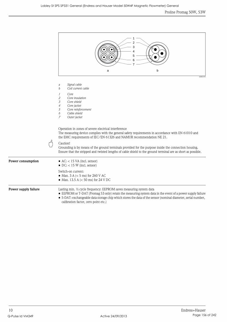
Proline Promag 50W, 53W
10 Endress+Hauser
A0003194
a Signal cable
b Coil current cable
1 Core
2 Core insulation
3 Core shield
4 Core jacket
5 Core reinforcement
6 Cable shield
7 Outer jacket
Operation in zones of severe electrical interference
The measuring device complies with the general safety requirements in accordance with EN 61010 and
the EMC requirements of IEC/EN 61326 and NAMUR recommendation NE 21.
" Caution!
Grounding is by means of the ground terminals provided for the purpose inside the connection housing.
Ensure that the stripped and twisted lengths of cable shield to the ground terminal are as short as possible.
Power consumption • AC: < 15 VA (incl. sensor)
• DC: < 15 W (incl. sensor)
Switch-on current:
• Max. 3 A (< 5 ms) for 260 V AC
• Max. 13.5 A (< 50 ms) for 24 V DC
Power supply failure Lasting min. ½ cycle frequency: EEPROM saves measuring system data
• EEPROM or T-DAT (Promag 53 only) retain the measuring system data in the event of a power supply failure
• S-DAT: exchangeable data storage chip which stores the data of the sensor (nominal diameter, serial number,
calibration factor, zero point etc.)
1
2
3
4
5
6
7
a b
Lobley St SPS SP331 General (Endress and Hauser Model 50W4F Magnetic Flowmeter) General
Q-Pulse Id VM349 Active 24/09/2013 Page 156 of 242
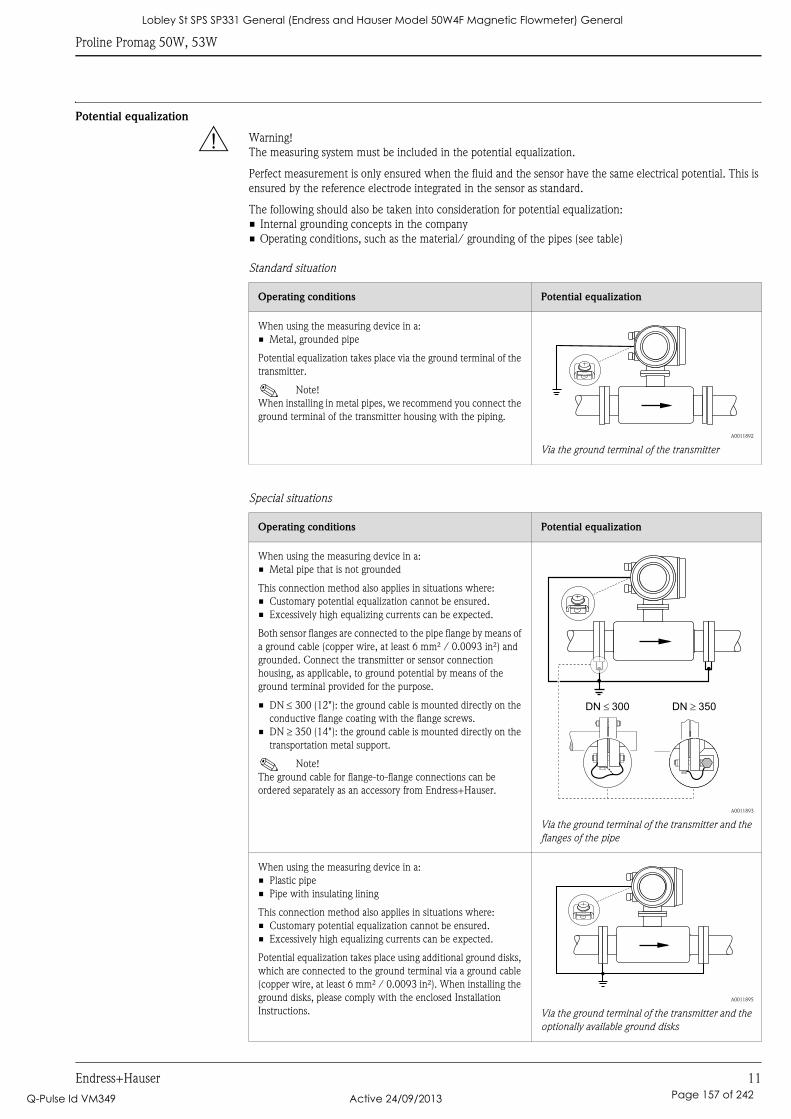
Proline Promag 50W, 53W
Endress+Hauser 11
Potential equalization
# Warning!
The measuring system must be included in the potential equalization.
Perfect measurement is only ensured when the fluid and the sensor have the same electrical potential. This is
ensured by the reference electrode integrated in the sensor as standard.
The following should also be taken into consideration for potential equalization:
• Internal grounding concepts in the company
• Operating conditions, such as the material/ grounding of the pipes (see table)
Standard situation
Special situations
Operating conditions Potential equalization
When using the measuring device in a:
• Metal, grounded pipe
Potential equalization takes place via the ground terminal of the
transmitter.
! Note!
When installing in metal pipes, we recommend you connect the
ground terminal of the transmitter housing with the piping.
A0011892
Via the ground terminal of the transmitter
Operating conditions Potential equalization
When using the measuring device in a:
• Metal pipe that is not grounded
This connection method also applies in situations where:
• Customary potential equalization cannot be ensured.
• Excessively high equalizing currents can be expected.
Both sensor flanges are connected to the pipe flange by means of
a ground cable (copper wire, at least 6 mm² / 0.0093 in²) and
grounded. Connect the transmitter or sensor connection
housing, as applicable, to ground potential by means of the
ground terminal provided for the purpose.
• DN ≤ 300 (12"): the ground cable is mounted directly on the
conductive flange coating with the flange screws.
• DN ≥ 350 (14"): the ground cable is mounted directly on the
transportation metal support.
! Note!
The ground cable for flange-to-flange connections can be
ordered separately as an accessory from Endress+Hauser.
A0011893
Via the ground terminal of the transmitter and the
flanges of the pipe
When using the measuring device in a:
• Plastic pipe
• Pipe with insulating lining
This connection method also applies in situations where:
• Customary potential equalization cannot be ensured.
• Excessively high equalizing currents can be expected.
Potential equalization takes place using additional ground disks,
which are connected to the ground terminal via a ground cable
(copper wire, at least 6 mm² / 0.0093 in²). When installing the
ground disks, please comply with the enclosed Installation
Instructions.
A0011895
Via the ground terminal of the transmitter and the
optionally available ground disks
DN 300� DN 350�
Lobley St SPS SP331 General (Endress and Hauser Model 50W4F Magnetic Flowmeter) General
Q-Pulse Id VM349 Active 24/09/2013 Page 157 of 242
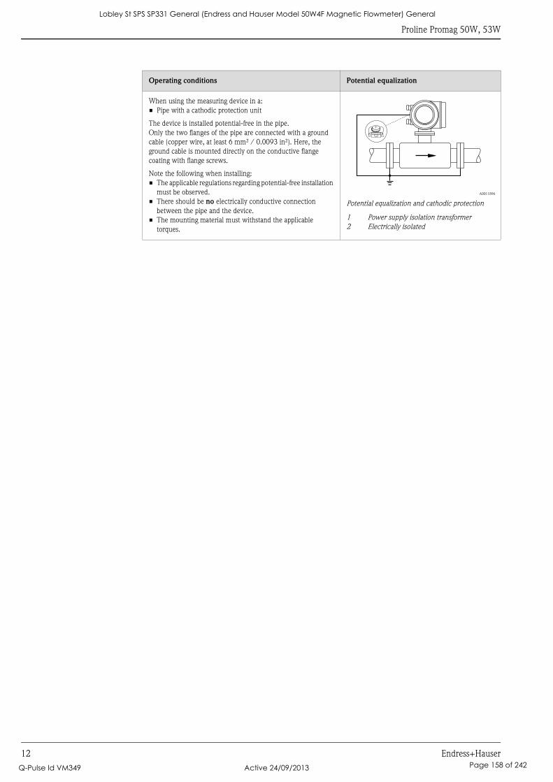
Proline Promag 50W, 53W
12 Endress+Hauser
When using the measuring device in a:
• Pipe with a cathodic protection unit
The device is installed potential-free in the pipe.
Only the two flanges of the pipe are connected with a ground
cable (copper wire, at least 6 mm² / 0.0093 in²). Here, the
ground cable is mounted directly on the conductive flange
coating with flange screws.
Note the following when installing:
• The applicable regulations regarding potential-free installation
must be observed.
• There should be no electrically conductive connection
between the pipe and the device.
• The mounting material must withstand the applicable
torques.
A0011896
Potential equalization and cathodic protection
1 Power supply isolation transformer
2 Electrically isolated
Operating conditions Potential equalization
Lobley St SPS SP331 General (Endress and Hauser Model 50W4F Magnetic Flowmeter) General
Q-Pulse Id VM349 Active 24/09/2013 Page 158 of 242
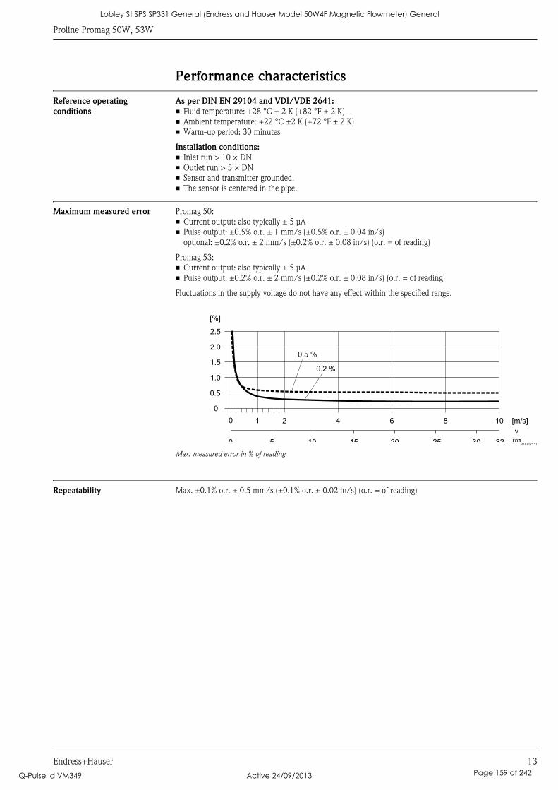
Proline Promag 50W, 53W
Endress+Hauser 13
Performance characteristics
Reference operating
conditions
As per DIN EN 29104 and VDI/VDE 2641:
• Fluid temperature: +28 °C ± 2 K (+82 °F ± 2 K)
• Ambient temperature: +22 °C ±2 K (+72 °F ± 2 K)
• Warm-up period: 30 minutes
Installation conditions:
• Inlet run > 10 × DN
• Outlet run > 5 × DN
• Sensor and transmitter grounded.
• The sensor is centered in the pipe.
Maximum measured error Promag 50:
• Current output: also typically ± 5 μA
• Pulse output: ±0.5% o.r. ± 1 mm/s (±0.5% o.r. ± 0.04 in/s)
optional: ±0.2% o.r. ± 2 mm/s (±0.2% o.r. ± 0.08 in/s) (o.r. = of reading)
Promag 53:
• Current output: also typically ± 5 μA
• Pulse output: ±0.2% o.r. ± 2 mm/s (±0.2% o.r. ± 0.08 in/s) (o.r. = of reading)
Fluctuations in the supply voltage do not have any effect within the specified range.
A0005531
Max. measured error in % of reading
Repeatability Max. ±0.1% o.r. ± 0.5 mm/s (±0.1% o.r. ± 0.02 in/s) (o.r. = of reading)
2.5
[%]
2.0
1.5
1.0
0.5
0
0.2 %
0.5 %
0 1 2 4 6 8 10 [m/s]
v
5 10 15 20 25 30 32 [ft]0
Lobley St SPS SP331 General (Endress and Hauser Model 50W4F Magnetic Flowmeter) General
Q-Pulse Id VM349 Active 24/09/2013 Page 159 of 242
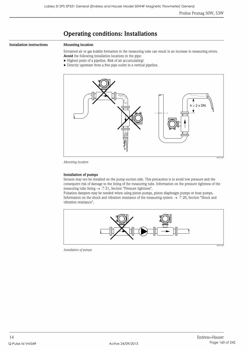
Proline Promag 50W, 53W
14 Endress+Hauser
Operating conditions: Installations
Installation instructions Mounting location
Entrained air or gas bubble formation in the measuring tube can result in an increase in measuring errors.
Avoid the following installation locations in the pipe:
• Highest point of a pipeline. Risk of air accumulating!
• Directly upstream from a free pipe outlet in a vertical pipeline.
A0011899
Mounting location
Installation of pumps
Sensors may not be installed on the pump suction side. This precaution is to avoid low pressure and the
consequent risk of damage to the lining of the measuring tube. Information on the pressure tightness of the
measuring tube lining → ä 21, Section "Pressure tightness".
Pulsation dampers may be needed when using piston pumps, piston diaphragm pumps or hose pumps.
Information on the shock and vibration resistance of the measuring system → ä 20, Section "Shock and
vibration resistance".
A0011900
Installation of pumps
h 2 x DN�
Lobley St SPS SP331 General (Endress and Hauser Model 50W4F Magnetic Flowmeter) General
Q-Pulse Id VM349 Active 24/09/2013 Page 160 of 242
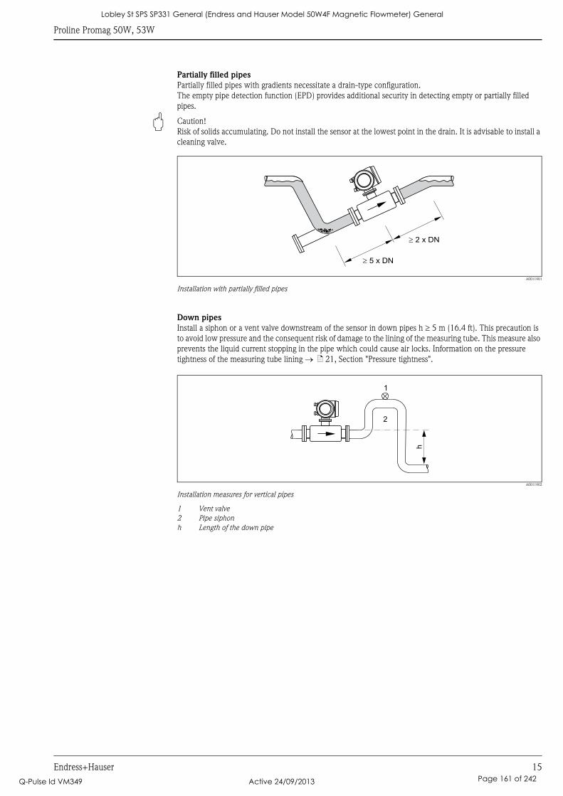
Proline Promag 50W, 53W
Endress+Hauser 15
Partially filled pipes
Partially filled pipes with gradients necessitate a drain-type configuration.
The empty pipe detection function (EPD) provides additional security in detecting empty or partially filled
pipes.
" Caution!
Risk of solids accumulating. Do not install the sensor at the lowest point in the drain. It is advisable to install a
cleaning valve.
A0011901
Installation with partially filled pipes
Down pipes
Install a siphon or a vent valve downstream of the sensor in down pipes h ≥ 5 m (16.4 ft). This precaution is
to avoid low pressure and the consequent risk of damage to the lining of the measuring tube. This measure also
prevents the liquid current stopping in the pipe which could cause air locks. Information on the pressure
tightness of the measuring tube lining → ä 21, Section "Pressure tightness".
A0011902
Installation measures for vertical pipes
1 Vent valve
2 Pipe siphon
h Length of the down pipe
� 5 x DN
� 2 x DN
h2
1
Lobley St SPS SP331 General (Endress and Hauser Model 50W4F Magnetic Flowmeter) General
Q-Pulse Id VM349 Active 24/09/2013 Page 161 of 242
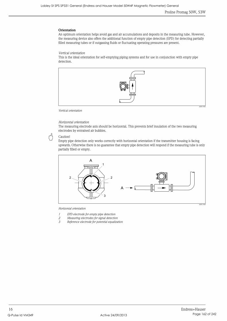
Proline Promag 50W, 53W
16 Endress+Hauser
Orientation
An optimum orientation helps avoid gas and air accumulations and deposits in the measuring tube. However,
the measuring device also offers the additional function of empty pipe detection (EPD) for detecting partially
filled measuring tubes or if outgassing fluids or fluctuating operating pressures are present.
Vertical orientation
This is the ideal orientation for self-emptying piping systems and for use in conjunction with empty pipe
detection.
A0011903
Vertical orientation
Horizontal orientation
The measuring electrode axis should be horizontal. This prevents brief insulation of the two measuring
electrodes by entrained air bubbles.
" Caution!
Empty pipe detection only works correctly with horizontal orientation if the transmitter housing is facing
upwards. Otherwise there is no guarantee that empty pipe detection will respond if the measuring tube is only
partially filled or empty.
A0011904
Horizontal orientation
1 EPD electrode for empty pipe detection
2 Measuring electrodes for signal detection
3 Reference electrode for potential equalization
A1
2 2
A
3
Lobley St SPS SP331 General (Endress and Hauser Model 50W4F Magnetic Flowmeter) General
Q-Pulse Id VM349 Active 24/09/2013 Page 162 of 242
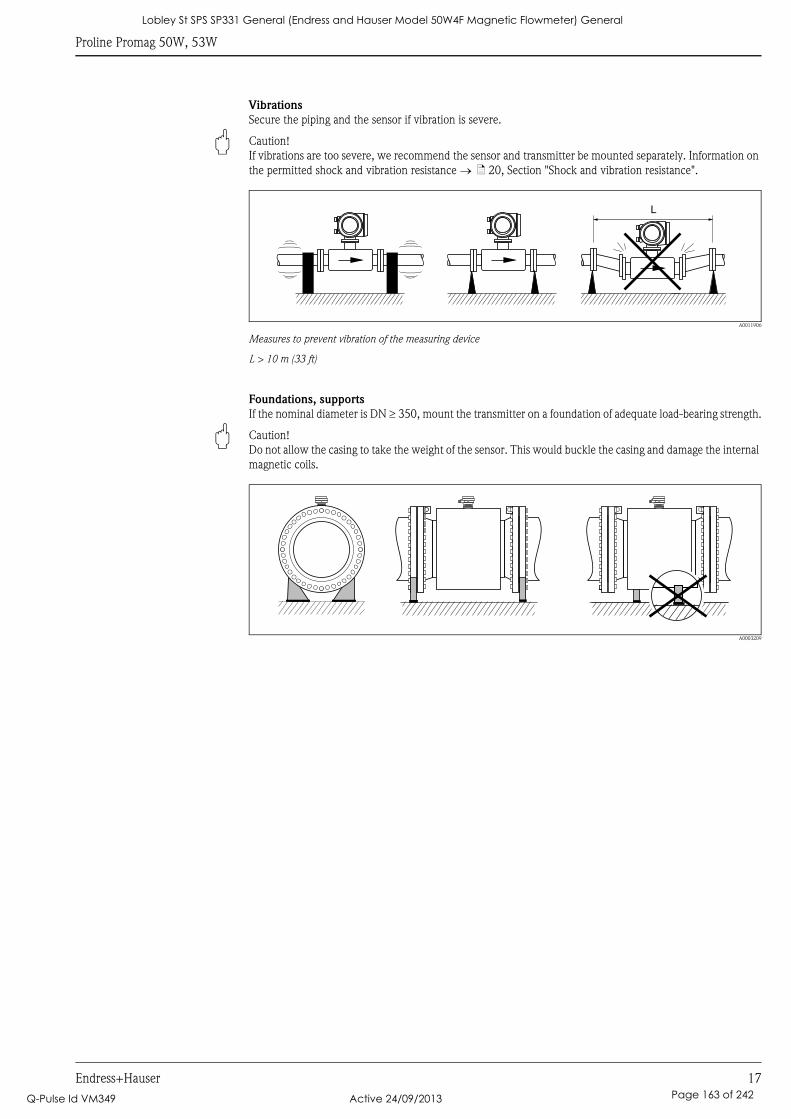
Proline Promag 50W, 53W
Endress+Hauser 17
Vibrations
Secure the piping and the sensor if vibration is severe.
" Caution!
If vibrations are too severe, we recommend the sensor and transmitter be mounted separately. Information on
the permitted shock and vibration resistance → ä 20, Section "Shock and vibration resistance".
A0011906
Measures to prevent vibration of the measuring device
L > 10 m (33 ft)
Foundations, supports
If the nominal diameter is DN ≥ 350, mount the transmitter on a foundation of adequate load-bearing strength.
" Caution!
Do not allow the casing to take the weight of the sensor. This would buckle the casing and damage the internal
magnetic coils.
A0003209
L
Lobley St SPS SP331 General (Endress and Hauser Model 50W4F Magnetic Flowmeter) General
Q-Pulse Id VM349 Active 24/09/2013 Page 163 of 242
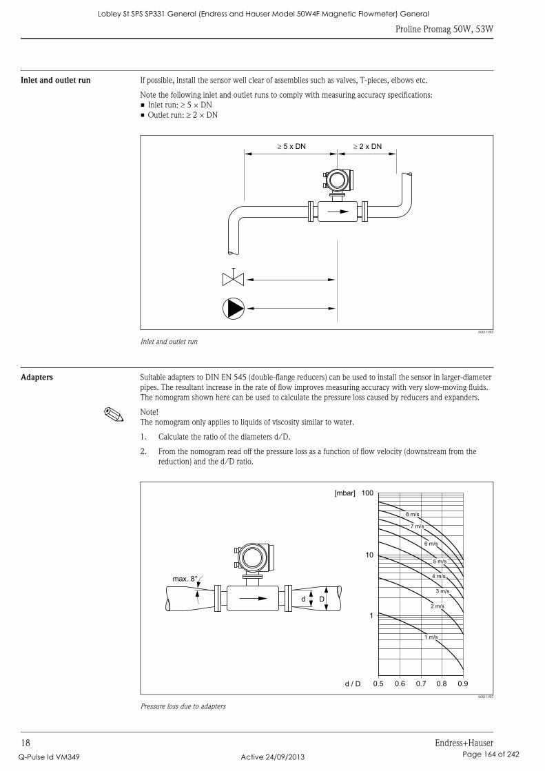
Proline Promag 50W, 53W
18 Endress+Hauser
Inlet and outlet run If possible, install the sensor well clear of assemblies such as valves, T-pieces, elbows etc.
Note the following inlet and outlet runs to comply with measuring accuracy specifications:
• Inlet run: ≥ 5 × DN
• Outlet run: ≥ 2 × DN
A0011905
Inlet and outlet run
Adapters Suitable adapters to DIN EN 545 (double-flange reducers) can be used to install the sensor in larger-diameter
pipes. The resultant increase in the rate of flow improves measuring accuracy with very slow-moving fluids.
The nomogram shown here can be used to calculate the pressure loss caused by reducers and expanders.
! Note!
The nomogram only applies to liquids of viscosity similar to water.
1. Calculate the ratio of the diameters d/D.
2. From the nomogram read off the pressure loss as a function of flow velocity (downstream from the
reduction) and the d/D ratio.
A0011907
Pressure loss due to adapters
5 x DN� � 2 x DN
100
10
0.5d / D
[mbar]
0.6 0.7 0.8 0.9
1 m/s
2 m/s
3 m/s
4 m/s
5 m/s
6 m/s
7 m/s
8 m/s
1
Dd
max. 8°
Lobley St SPS SP331 General (Endress and Hauser Model 50W4F Magnetic Flowmeter) General
Q-Pulse Id VM349 Active 24/09/2013 Page 164 of 242
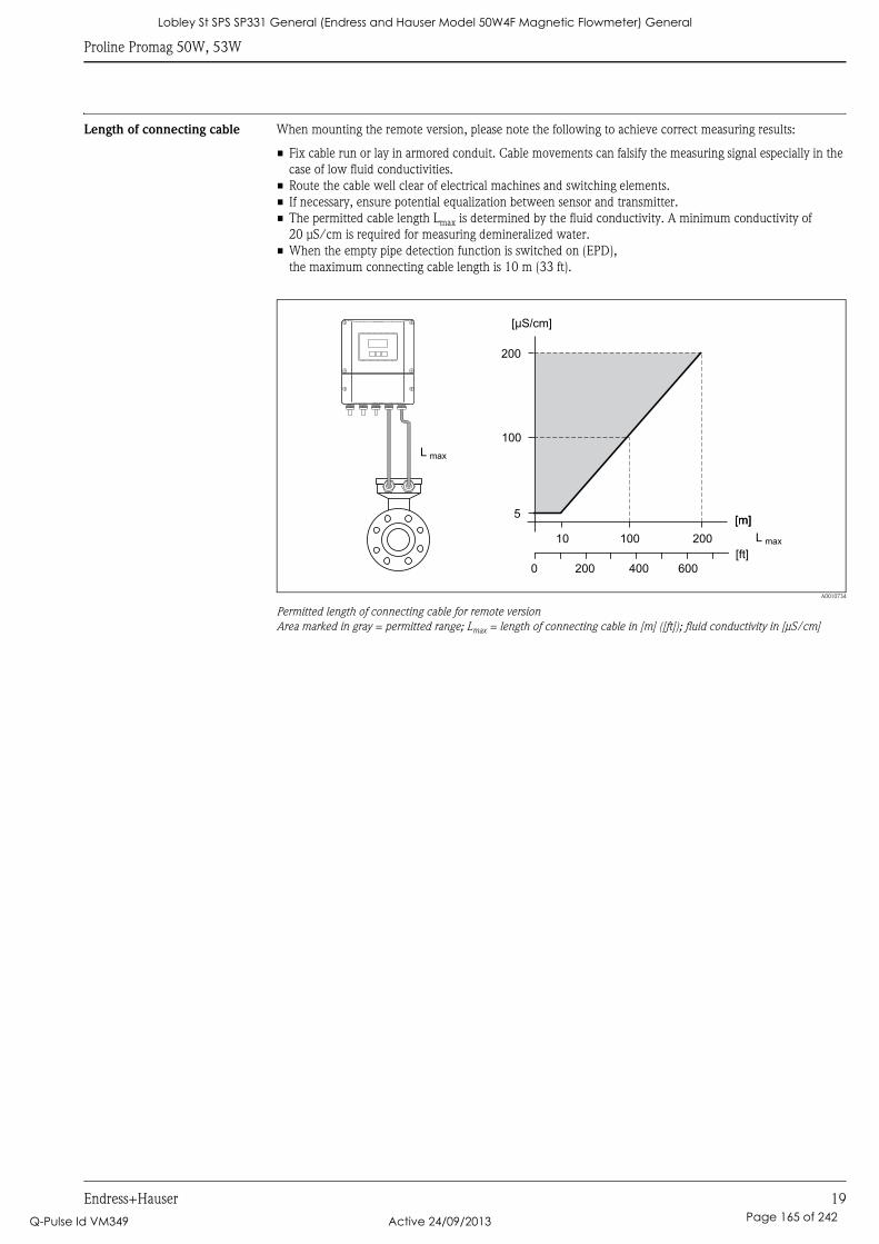
Proline Promag 50W, 53W
Endress+Hauser 19
Length of connecting cable When mounting the remote version, please note the following to achieve correct measuring results:
• Fix cable run or lay in armored conduit. Cable movements can falsify the measuring signal especially in the
case of low fluid conductivities.
• Route the cable well clear of electrical machines and switching elements.
• If necessary, ensure potential equalization between sensor and transmitter.
• The permitted cable length Lmax is determined by the fluid conductivity. A minimum conductivity of
20 μS/cm is required for measuring demineralized water.
• When the empty pipe detection function is switched on (EPD),
the maximum connecting cable length is 10 m (33 ft).
A0010734
Permitted length of connecting cable for remote version
Area marked in gray = permitted range; Lmax = length of connecting cable in [m] ([ft]); fluid conductivity in [μS/cm]
200
100
5
10 100 200
L max
[m][m]
[μS/cm]
L max
[ft]
200 6000 400
Lobley St SPS SP331 General (Endress and Hauser Model 50W4F Magnetic Flowmeter) General
Q-Pulse Id VM349 Active 24/09/2013 Page 165 of 242
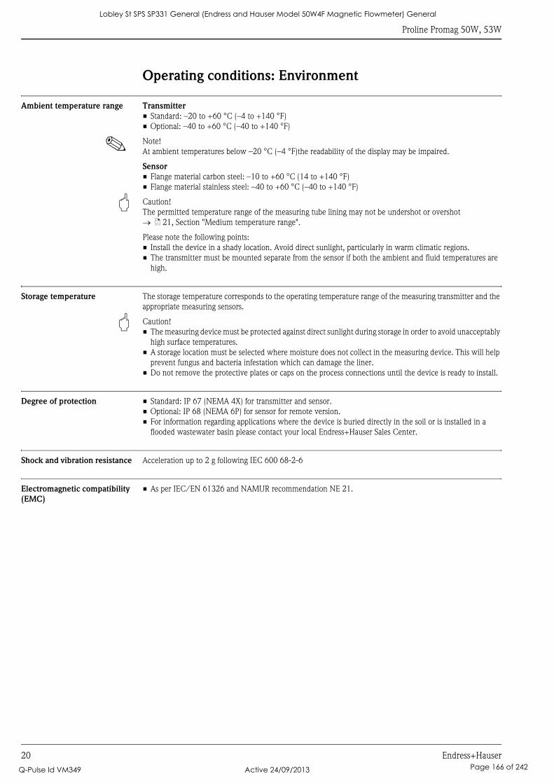
Proline Promag 50W, 53W
20 Endress+Hauser
Operating conditions: Environment
Ambient temperature range Transmitter
• Standard: –20 to +60 °C (–4 to +140 °F)
• Optional: –40 to +60 °C (–40 to +140 °F)
! Note!
At ambient temperatures below –20 °C (–4 °F)the readability of the display may be impaired.
Sensor
• Flange material carbon steel: –10 to +60 °C (14 to +140 °F)
• Flange material stainless steel: –40 to +60 °C (–40 to +140 °F)
" Caution!
The permitted temperature range of the measuring tube lining may not be undershot or overshot
→ ä 21, Section "Medium temperature range".
Please note the following points:
• Install the device in a shady location. Avoid direct sunlight, particularly in warm climatic regions.
• The transmitter must be mounted separate from the sensor if both the ambient and fluid temperatures are
high.
Storage temperature The storage temperature corresponds to the operating temperature range of the measuring transmitter and the
appropriate measuring sensors.
" Caution!
• The measuring device must be protected against direct sunlight during storage in order to avoid unacceptably
high surface temperatures.
• A storage location must be selected where moisture does not collect in the measuring device. This will help
prevent fungus and bacteria infestation which can damage the liner.
• Do not remove the protective plates or caps on the process connections until the device is ready to install.
Degree of protection • Standard: IP 67 (NEMA 4X) for transmitter and sensor.
• Optional: IP 68 (NEMA 6P) for sensor for remote version.
• For information regarding applications where the device is buried directly in the soil or is installed in a
flooded wastewater basin please contact your local Endress+Hauser Sales Center.
Shock and vibration resistance Acceleration up to 2 g following IEC 600 68-2-6
Electromagnetic compatibility
(EMC)
• As per IEC/EN 61326 and NAMUR recommendation NE 21.
Lobley St SPS SP331 General (Endress and Hauser Model 50W4F Magnetic Flowmeter) General
Q-Pulse Id VM349 Active 24/09/2013 Page 166 of 242
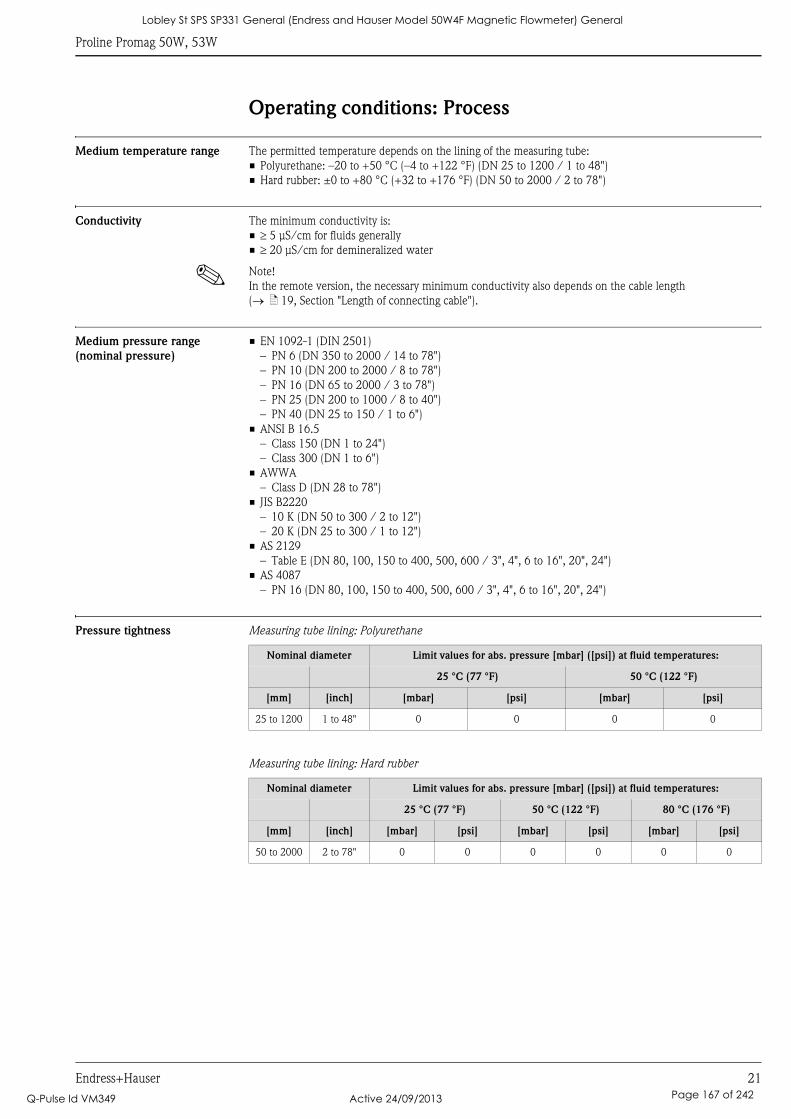
Proline Promag 50W, 53W
Endress+Hauser 21
Operating conditions: Process
Medium temperature range The permitted temperature depends on the lining of the measuring tube:
• Polyurethane: –20 to +50 °C (–4 to +122 °F) (DN 25 to 1200 / 1 to 48")
• Hard rubber: ±0 to +80 °C (+32 to +176 °F) (DN 50 to 2000 / 2 to 78")
Conductivity The minimum conductivity is:
• ≥ 5 μS/cm for fluids generally
• ≥ 20 μS/cm for demineralized water
! Note!
In the remote version, the necessary minimum conductivity also depends on the cable length
(→ ä 19, Section "Length of connecting cable").
Medium pressure range
(nominal pressure)
• EN 1092-1 (DIN 2501)
– PN 6 (DN 350 to 2000 / 14 to 78")
– PN 10 (DN 200 to 2000 / 8 to 78")
– PN 16 (DN 65 to 2000 / 3 to 78")
– PN 25 (DN 200 to 1000 / 8 to 40")
– PN 40 (DN 25 to 150 / 1 to 6")
• ANSI B 16.5
– Class 150 (DN 1 to 24")
– Class 300 (DN 1 to 6")
• AWWA
– Class D (DN 28 to 78")
• JIS B2220
– 10 K (DN 50 to 300 / 2 to 12")
– 20 K (DN 25 to 300 / 1 to 12")
• AS 2129
– Table E (DN 80, 100, 150 to 400, 500, 600 / 3", 4", 6 to 16", 20", 24")
• AS 4087
– PN 16 (DN 80, 100, 150 to 400, 500, 600 / 3", 4", 6 to 16", 20", 24")
Pressure tightness Measuring tube lining: Polyurethane
Measuring tube lining: Hard rubber
Nominal diameter Limit values for abs. pressure [mbar] ([psi]) at fluid temperatures:
25 °C (77 °F) 50 °C (122 °F)
[mm] [inch] [mbar] [psi] [mbar] [psi]
25 to 1200 1 to 48" 0 0 0 0
Nominal diameter Limit values for abs. pressure [mbar] ([psi]) at fluid temperatures:
25 °C (77 °F) 50 °C (122 °F) 80 °C (176 °F)
[mm] [inch] [mbar] [psi] [mbar] [psi] [mbar] [psi]
50 to 2000 2 to 78" 0 0 0 0 0 0
Lobley St SPS SP331 General (Endress and Hauser Model 50W4F Magnetic Flowmeter) General
Q-Pulse Id VM349 Active 24/09/2013 Page 167 of 242
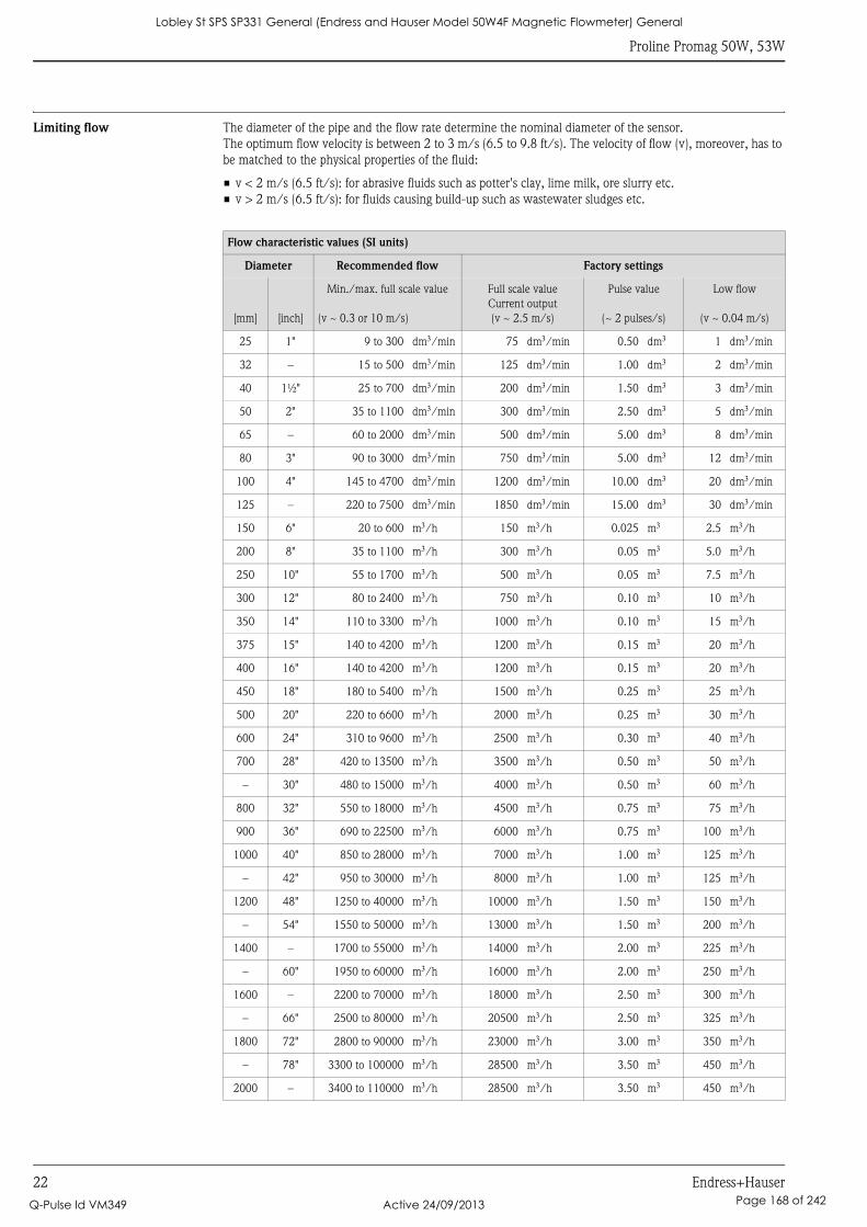
Proline Promag 50W, 53W
22 Endress+Hauser
Limiting flow The diameter of the pipe and the flow rate determine the nominal diameter of the sensor.
The optimum flow velocity is between 2 to 3 m/s (6.5 to 9.8 ft/s). The velocity of flow (v), moreover, has to
be matched to the physical properties of the fluid:
• v < 2 m/s (6.5 ft/s): for abrasive fluids such as potter's clay, lime milk, ore slurry etc.
• v > 2 m/s (6.5 ft/s): for fluids causing build-up such as wastewater sludges etc.
Flow characteristic values (SI units)
Diameter Recommended flow Factory settings
[mm] [inch]
Min./max. full scale value
(v ~ 0.3 or 10 m/s)
Full scale value
Current output
(v ~ 2.5 m/s)
Pulse value
(~ 2 pulses/s)
Low flow
(v ~ 0.04 m/s)
25 1" 9 to 300 dm3/min 75 dm3/min 0.50 dm3 1 dm3/min
32 – 15 to 500 dm3/min 125 dm3/min 1.00 dm3 2 dm3/min
40 1½" 25 to 700 dm3/min 200 dm3/min 1.50 dm3 3 dm3/min
50 2" 35 to 1100 dm3/min 300 dm3/min 2.50 dm3 5 dm3/min
65 – 60 to 2000 dm3/min 500 dm3/min 5.00 dm3 8 dm3/min
80 3" 90 to 3000 dm3/min 750 dm3/min 5.00 dm3 12 dm3/min
100 4" 145 to 4700 dm3/min 1200 dm3/min 10.00 dm3 20 dm3/min
125 – 220 to 7500 dm3/min 1850 dm3/min 15.00 dm3 30 dm3/min
150 6" 20 to 600 m3/h 150 m3/h 0.025 m3 2.5 m3/h
200 8" 35 to 1100 m3/h 300 m3/h 0.05 m3 5.0 m3/h
250 10" 55 to 1700 m3/h 500 m3/h 0.05 m3 7.5 m3/h
300 12" 80 to 2400 m3/h 750 m3/h 0.10 m3 10 m3/h
350 14" 110 to 3300 m3/h 1000 m3/h 0.10 m3 15 m3/h
375 15" 140 to 4200 m3/h 1200 m3/h 0.15 m3 20 m3/h
400 16" 140 to 4200 m3/h 1200 m3/h 0.15 m3 20 m3/h
450 18" 180 to 5400 m3/h 1500 m3/h 0.25 m3 25 m3/h
500 20" 220 to 6600 m3/h 2000 m3/h 0.25 m3 30 m3/h
600 24" 310 to 9600 m3/h 2500 m3/h 0.30 m3 40 m3/h
700 28" 420 to 13500 m3/h 3500 m3/h 0.50 m3 50 m3/h
– 30" 480 to 15000 m3/h 4000 m3/h 0.50 m3 60 m3/h
800 32" 550 to 18000 m3/h 4500 m3/h 0.75 m3 75 m3/h
900 36" 690 to 22500 m3/h 6000 m3/h 0.75 m3 100 m3/h
1000 40" 850 to 28000 m3/h 7000 m3/h 1.00 m3 125 m3/h
– 42" 950 to 30000 m3/h 8000 m3/h 1.00 m3 125 m3/h
1200 48" 1250 to 40000 m3/h 10000 m3/h 1.50 m3 150 m3/h
– 54" 1550 to 50000 m3/h 13000 m3/h 1.50 m3 200 m3/h
1400 – 1700 to 55000 m3/h 14000 m3/h 2.00 m3 225 m3/h
– 60" 1950 to 60000 m3/h 16000 m3/h 2.00 m3 250 m3/h
1600 – 2200 to 70000 m3/h 18000 m3/h 2.50 m3 300 m3/h
– 66" 2500 to 80000 m3/h 20500 m3/h 2.50 m3 325 m3/h
1800 72" 2800 to 90000 m3/h 23000 m3/h 3.00 m3 350 m3/h
– 78" 3300 to 100000 m3/h 28500 m3/h 3.50 m3 450 m3/h
2000 – 3400 to 110000 m3/h 28500 m3/h 3.50 m3 450 m3/h
Lobley St SPS SP331 General (Endress and Hauser Model 50W4F Magnetic Flowmeter) General
Q-Pulse Id VM349 Active 24/09/2013 Page 168 of 242
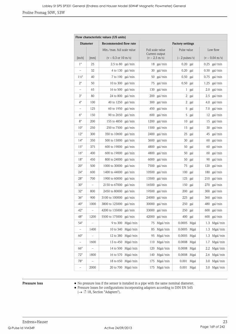
Proline Promag 50W, 53W
Endress+Hauser 23
Pressure loss • No pressure loss if the sensor is installed in a pipe with the same nominal diameter.
• Pressure losses for configurations incorporating adapters according to DIN EN 545
(→ ä 18, Section "Adapters").
Flow characteristic values (US units)
Diameter Recommended flow rate Factory settings
[inch] [mm]
Min./max. full scale value
(v ~ 0.3 or 10 m/s)
Full scale value
Current output
(v ~ 2.5 m/s)
Pulse value
(~ 2 pulses/s)
Low flow
(v ~ 0.04 m/s)
1" 25 2.5 to 80 gal/min 18 gal/min 0.20 gal 0.25 gal/min
– 32 4 to 130 gal/min 30 gal/min 0.20 gal 0.50 gal/min
1½" 40 7 to 190 gal/min 50 gal/min 0.50 gal 0.75 gal/min
2" 50 10 to 300 gal/min 75 gal/min 0.50 gal 1.25 gal/min
– 65 16 to 500 gal/min 130 gal/min 1 gal 2.0 gal/min
3" 80 24 to 800 gal/min 200 gal/min 2 gal 2.5 gal/min
4" 100 40 to 1250 gal/min 300 gal/min 2 gal 4.0 gal/min
– 125 60 to 1950 gal/min 450 gal/min 5 gal 7.0 gal/min
6" 150 90 to 2650 gal/min 600 gal/min 5 gal 12 gal/min
8" 200 155 to 4850 gal/min 1200 gal/min 10 gal 15 gal/min
10" 250 250 to 7500 gal/min 1500 gal/min 15 gal 30 gal/min
12" 300 350 to 10600 gal/min 2400 gal/min 25 gal 45 gal/min
14" 350 500 to 15000 gal/min 3600 gal/min 30 gal 60 gal/min
15" 375 600 to 19000 gal/min 4800 gal/min 50 gal 60 gal/min
16" 400 600 to 19000 gal/min 4800 gal/min 50 gal 60 gal/min
18" 450 800 to 24000 gal/min 6000 gal/min 50 gal 90 gal/min
20" 500 1000 to 30000 gal/min 7500 gal/min 75 gal 120 gal/min
24" 600 1400 to 44000 gal/min 10500 gal/min 100 gal 180 gal/min
28" 700 1900 to 60000 gal/min 13500 gal/min 125 gal 210 gal/min
30" – 2150 to 67000 gal/min 16500 gal/min 150 gal 270 gal/min
32" 800 2450 to 80000 gal/min 19500 gal/min 200 gal 300 gal/min
36" 900 3100 to 100000 gal/min 24000 gal/min 225 gal 360 gal/min
40" 1000 3800 to 125000 gal/min 30000 gal/min 250 gal 480 gal/min
42" – 4200 to 135000 gal/min 33000 gal/min 250 gal 600 gal/min
48" 1200 5500 to 175000 gal/min 42000 gal/min 400 gal 600 gal/min
54" – 9 to 300 Mgal/min 75 Mgal/min 0.0005 Mgal 1.3 Mgal/min
– 1400 10 to 340 Mgal/min 85 Mgal/min 0.0005 Mgal 1.3 Mgal/min
60" – 12 to 380 Mgal/min 95 Mgal/min 0.0005 Mgal 1.3 Mgal/min
– 1600 13 to 450 Mgal/min 110 Mgal/min 0.0008 Mgal 1.7 Mgal/min
66" – 14 to 500 Mgal/min 120 Mgal/min 0.0008 Mgal 2.2 Mgal/min
72" 1800 16 to 570 Mgal/min 140 Mgal/min 0.0008 Mgal 2.6 Mgal/min
78" – 18 to 650 Mgal/min 175 Mgal/min 0.001 Mgal 3.0 Mgal/min
– 2000 20 to 700 Mgal/min 175 Mgal/min 0.001 Mgal 3.0 Mgal/min
Lobley St SPS SP331 General (Endress and Hauser Model 50W4F Magnetic Flowmeter) General
Q-Pulse Id VM349 Active 24/09/2013 Page 169 of 242
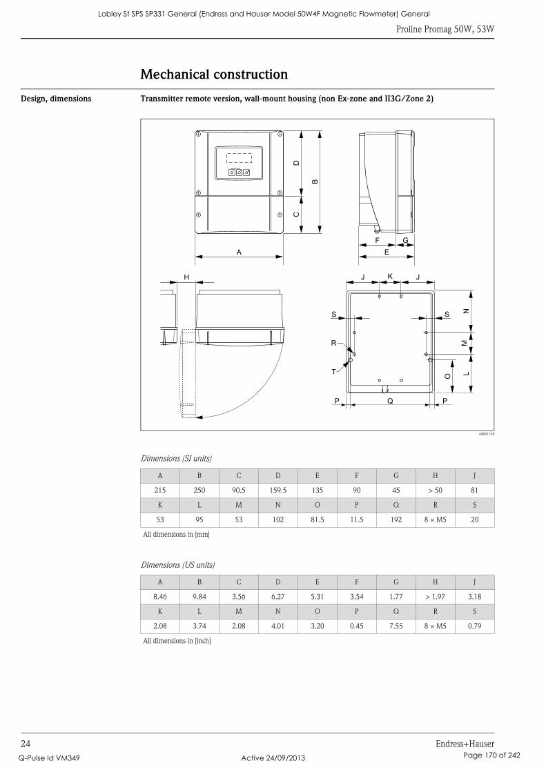
Proline Promag 50W, 53W
24 Endress+Hauser
Mechanical construction
Design, dimensions Transmitter remote version, wall-mount housing (non Ex-zone and II3G/Zone 2)
A0001150
Dimensions (SI units)
Dimensions (US units)
A B C D E F G H J
215 250 90.5 159.5 135 90 45 > 50 81
K L M N O P Q R S
53 95 53 102 81.5 11.5 192 8 × M5 20
All dimensions in [mm]
A B C D E F G H J
8.46 9.84 3.56 6.27 5.31 3.54 1.77 > 1.97 3.18
K L M N O P Q R S
2.08 3.74 2.08 4.01 3.20 0.45 7.55 8 × M5 0.79
All dimensions in [inch]
Esc
E- +
DC
B
A
F
E
G
KJ
Q
NLO
R
H J
M
P P
SS
T
Lobley St SPS SP331 General (Endress and Hauser Model 50W4F Magnetic Flowmeter) General
Q-Pulse Id VM349 Active 24/09/2013 Page 170 of 242
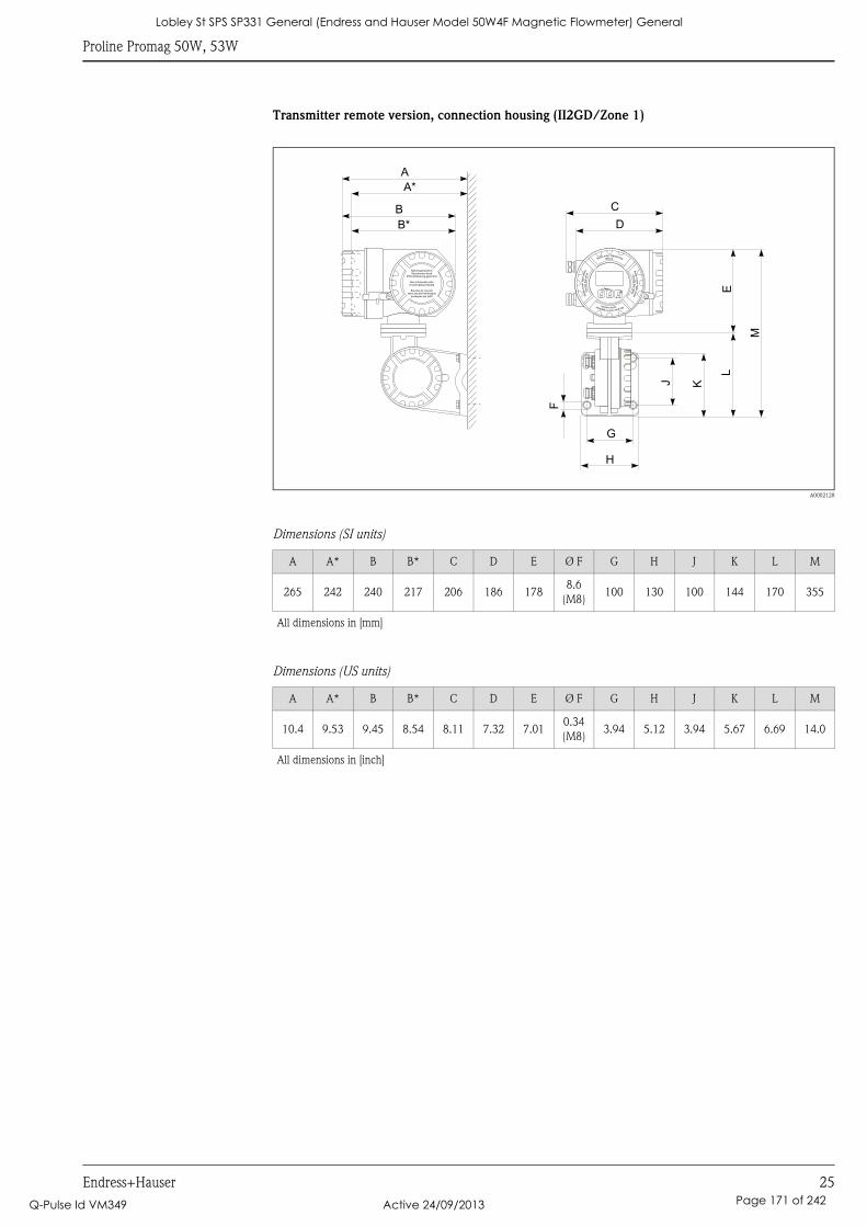
Proline Promag 50W, 53W
Endress+Hauser 25
Transmitter remote version, connection housing (II2GD/Zone 1)
A0002128
Dimensions (SI units)
Dimensions (US units)
A A* B B* C D E Ø F G H J K L M
265 242 240 217 206 186 1788.6
(M8)100 130 100 144 170 355
All dimensions in [mm]
A A* B B* C D E Ø F G H J K L M
10.4 9.53 9.45 8.54 8.11 7.32 7.010.34
(M8)3.94 5.12 3.94 5.67 6.69 14.0
All dimensions in [inch]
Esc
E- +
Nicht unter Spannungöffnen
Keep
cover
tightw
hile
circuit s
are
alive
Nepasouvrirl’appareil soustension
Keep
cove
rtightw
hile
circ
uits
are
aliv
e
Nicht-eigensichereStromkreise durch
IP40-Abdeckung geschützt
Non-intrinsically safecircuits Ip40 protected
Boucles de courantsans sécurité intrinsèque
protégées par Ip40
B*
B
A*
A
F
G
D
C
H
J K
L
M
E
Lobley St SPS SP331 General (Endress and Hauser Model 50W4F Magnetic Flowmeter) General
Q-Pulse Id VM349 Active 24/09/2013 Page 171 of 242
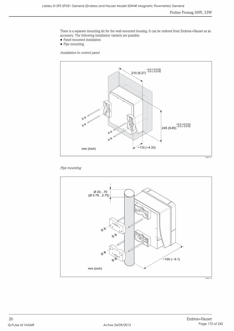
Proline Promag 50W, 53W
26 Endress+Hauser
There is a separate mounting kit for the wall-mounted housing. It can be ordered from Endress+Hauser as an
accessory. The following installation variants are possible:
• Panel-mounted installation
• Pipe mounting
Installation in control panel
A0001131
Pipe mounting
A0001132
245 (9.65)
~110 (~4.33)
210 (8.27)
+0.5 (+0.019)–0.5 (–0.019)
+0.5 (+0.019)–0.5 (–0.019)
mm (inch)
Ø 20…70(Ø 0.79…2.75)
~ ~ 6.1)155 (
mm (inch)
Lobley St SPS SP331 General (Endress and Hauser Model 50W4F Magnetic Flowmeter) General
Q-Pulse Id VM349 Active 24/09/2013 Page 172 of 242
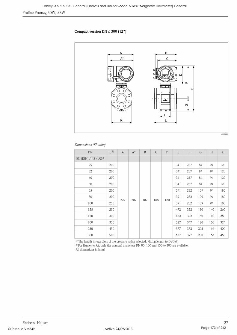
Proline Promag 50W, 53W
Endress+Hauser 27
Compact version DN ≤ 300 (12")
A0005423
Dimensions (SI units)
DN L 1) A A* B C D E F G H K
EN (DIN) / JIS / AS 2)
25 200
227 207 187 168 160
341 257 84 94 120
32 200 341 257 84 94 120
40 200 341 257 84 94 120
50 200 341 257 84 94 120
65 200 391 282 109 94 180
80 200 391 282 109 94 180
100 250 391 282 109 94 180
125 250 472 322 150 140 260
150 300 472 322 150 140 260
200 350 527 347 180 156 324
250 450 577 372 205 166 400
300 500 627 397 230 166 460
1) The length is regardless of the pressure rating selected. Fitting length to DVGW.2) For flanges to AS, only the nominal diameters DN 80, 100 and 150 to 300 are available.
All dimensions in [mm]
Esc
E- +
K
H
L
E
GF
A*
A B
C
D
Lobley St SPS SP331 General (Endress and Hauser Model 50W4F Magnetic Flowmeter) General
Q-Pulse Id VM349 Active 24/09/2013 Page 173 of 242
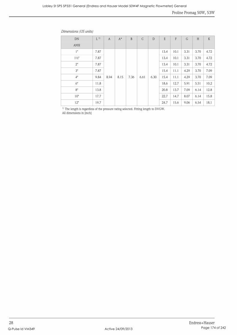
Proline Promag 50W, 53W
28 Endress+Hauser
Dimensions (US units)
DN L 1) A A* B C D E F G H K
ANSI
1" 7.87
8.94 8.15 7.36 6.61 6.30
13.4 10.1 3.31 3.70 4.72
1½" 7.87 13.4 10.1 3.31 3.70 4.72
2" 7.87 13.4 10.1 3.31 3.70 4.72
3" 7.87 15.4 11.1 4.29 3.70 7.09
4" 9.84 15.4 11.1 4.29 3.70 7.09
6" 11.8 18.6 12.7 5.91 5.51 10.2
8" 13.8 20.8 13.7 7.09 6.14 12.8
10" 17.7 22.7 14.7 8.07 6.14 15.8
12" 19.7 24.7 15.6 9.06 6.54 18.1
1) The length is regardless of the pressure rating selected. Fitting length to DVGW.
All dimensions in [inch]
Lobley St SPS SP331 General (Endress and Hauser Model 50W4F Magnetic Flowmeter) General
Q-Pulse Id VM349 Active 24/09/2013 Page 174 of 242
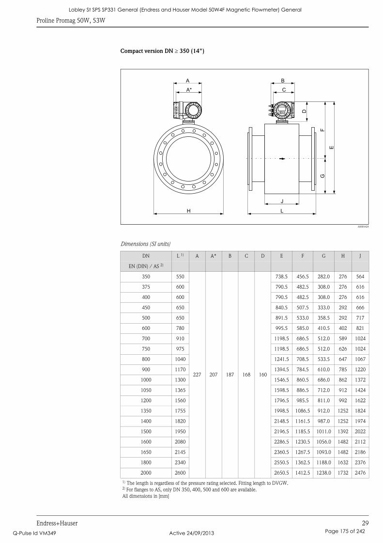
Proline Promag 50W, 53W
Endress+Hauser 29
Compact version DN ≥ 350 (14")
A0005424
Dimensions (SI units)
DN L 1) A A* B C D E F G H J
EN (DIN) / AS 2)
350 550
227 207 187 168 160
738.5 456.5 282.0 276 564
375 600 790.5 482.5 308.0 276 616
400 600 790.5 482.5 308.0 276 616
450 650 840.5 507.5 333.0 292 666
500 650 891.5 533.0 358.5 292 717
600 780 995.5 585.0 410.5 402 821
700 910 1198.5 686.5 512.0 589 1024
750 975 1198.5 686.5 512.0 626 1024
800 1040 1241.5 708.5 533.5 647 1067
900 1170 1394.5 784.5 610.0 785 1220
1000 1300 1546.5 860.5 686.0 862 1372
1050 1365 1598.5 886.5 712.0 912 1424
1200 1560 1796.5 985.5 811.0 992 1622
1350 1755 1998.5 1086.5 912.0 1252 1824
1400 1820 2148.5 1161.5 987.0 1252 1974
1500 1950 2196.5 1185.5 1011.0 1392 2022
1600 2080 2286.5 1230.5 1056.0 1482 2112
1650 2145 2360.5 1267.5 1093.0 1482 2186
1800 2340 2550.5 1362.5 1188.0 1632 2376
2000 2600 2650.5 1412.5 1238.0 1732 2476
1) The length is regardless of the pressure rating selected. Fitting length to DVGW.2) For flanges to AS, only DN 350, 400, 500 and 600 are available.
All dimensions in [mm]
L
J
E
GF
H
Esc
E- +
A B
A* C
D
Lobley St SPS SP331 General (Endress and Hauser Model 50W4F Magnetic Flowmeter) General
Q-Pulse Id VM349 Active 24/09/2013 Page 175 of 242
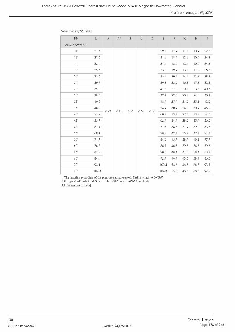
Proline Promag 50W, 53W
30 Endress+Hauser
Dimensions (US units)
DN L 1) A A* B C D E F G H J
ANSI / AWWA 2)
14" 21.6
8.94 8.15 7.36 6.61 6.30
29.1 17.9 11.1 10.9 22.2
15" 23.6 31.1 18.9 12.1 10.9 24.2
16" 23.6 31.1 18.9 12.1 10.9 24.2
18" 25.6 33.1 19.9 13.1 11.5 26.2
20" 25.6 35.1 20.9 14.1 11.5 28.2
24" 30.7 39.2 23.0 16.2 15.8 32.3
28" 35.8 47.2 27.0 20.1 23.2 40.3
30" 38.4 47.2 27.0 20.1 24.6 40.3
32" 40.9 48.9 27.9 21.0 25.5 42.0
36" 46.0 54.9 30.9 24.0 30.9 48.0
40" 51.2 60.9 33.9 27.0 33.9 54.0
42" 53.7 62.9 34.9 28.0 35.9 56.0
48" 61.4 71.7 38.8 31.9 39.0 63.8
54" 69.1 78.7 42.8 35.9 42.3 71.8
56" 71.7 84.6 45.7 38.9 49.3 77.7
60" 76.8 86.5 46.7 39.8 54.8 79.6
64" 81.9 90.0 48.4 41.6 58.4 83.2
66" 84.4 92.9 49.9 43.0 58.4 86.0
72" 92.1 100.4 53.6 46.8 64.2 93.5
78" 102.3 104.3 55.6 48.7 68.2 97.5
1) The length is regardless of the pressure rating selected. Fitting length to DVGW.2) Flanges ≤ 24" only to ANSI available, ≥ 28" only to AWWA available.
All dimensions in [inch]
Lobley St SPS SP331 General (Endress and Hauser Model 50W4F Magnetic Flowmeter) General
Q-Pulse Id VM349 Active 24/09/2013 Page 176 of 242
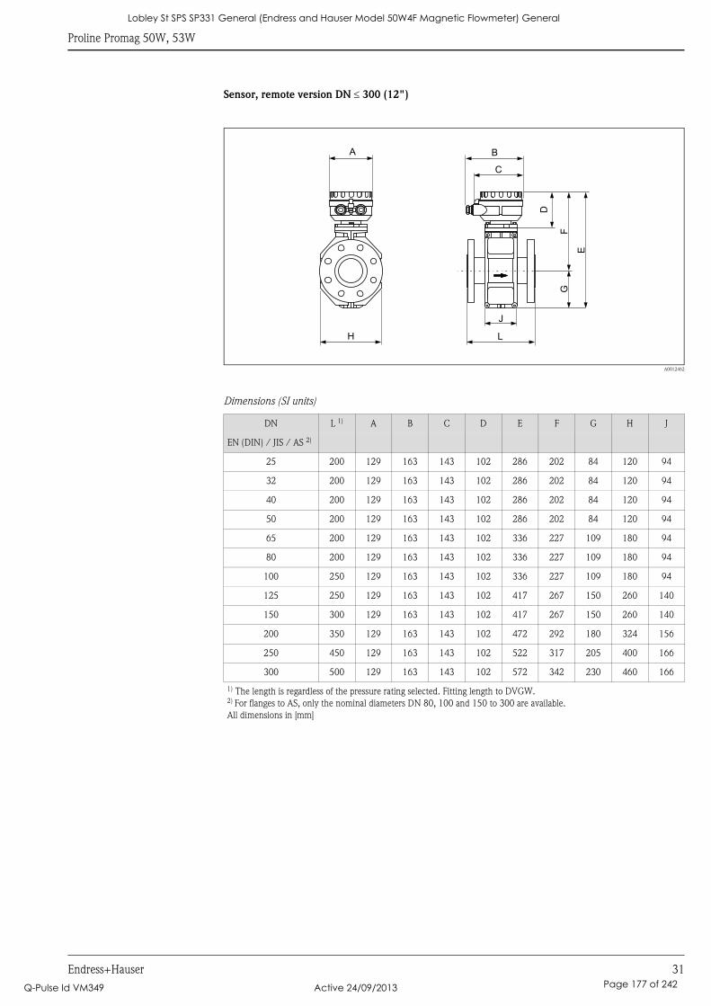
Proline Promag 50W, 53W
Endress+Hauser 31
Sensor, remote version DN ≤ 300 (12")
A0012462
Dimensions (SI units)
DN L 1) A B C D E F G H J
EN (DIN) / JIS / AS 2)
25 200 129 163 143 102 286 202 84 120 94
32 200 129 163 143 102 286 202 84 120 94
40 200 129 163 143 102 286 202 84 120 94
50 200 129 163 143 102 286 202 84 120 94
65 200 129 163 143 102 336 227 109 180 94
80 200 129 163 143 102 336 227 109 180 94
100 250 129 163 143 102 336 227 109 180 94
125 250 129 163 143 102 417 267 150 260 140
150 300 129 163 143 102 417 267 150 260 140
200 350 129 163 143 102 472 292 180 324 156
250 450 129 163 143 102 522 317 205 400 166
300 500 129 163 143 102 572 342 230 460 166
1) The length is regardless of the pressure rating selected. Fitting length to DVGW.2) For flanges to AS, only the nominal diameters DN 80, 100 and 150 to 300 are available.
All dimensions in [mm]
J
L
E
GF
H
B
C
A
D
Lobley St SPS SP331 General (Endress and Hauser Model 50W4F Magnetic Flowmeter) General
Q-Pulse Id VM349 Active 24/09/2013 Page 177 of 242
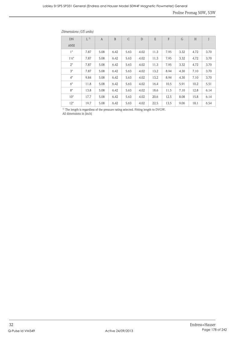
Proline Promag 50W, 53W
32 Endress+Hauser
Dimensions (US units)
DN L 1) A B C D E F G H J
ANSI
1" 7.87 5.08 6.42 5.63 4.02 11.3 7.95 3.32 4.72 3.70
1½" 7.87 5.08 6.42 5.63 4.02 11.3 7.95 3.32 4.72 3.70
2" 7.87 5.08 6.42 5.63 4.02 11.3 7.95 3.32 4.72 3.70
3" 7.87 5.08 6.42 5.63 4.02 13.2 8.94 4.30 7.10 3.70
4" 9.84 5.08 6.42 5.63 4.02 13.2 8.94 4.30 7.10 3.70
6" 11.8 5.08 6.42 5.63 4.02 16.4 10.5 5.91 10.2 5.51
8" 13.8 5.08 6.42 5.63 4.02 18.6 11.5 7.10 12.8 6.14
10" 17.7 5.08 6.42 5.63 4.02 20.6 12.5 8.08 15.8 6.14
12" 19.7 5.08 6.42 5.63 4.02 22.5 13.5 9.06 18.1 6.54
1) The length is regardless of the pressure rating selected. Fitting length to DVGW.
All dimensions in [inch]
Lobley St SPS SP331 General (Endress and Hauser Model 50W4F Magnetic Flowmeter) General
Q-Pulse Id VM349 Active 24/09/2013 Page 178 of 242
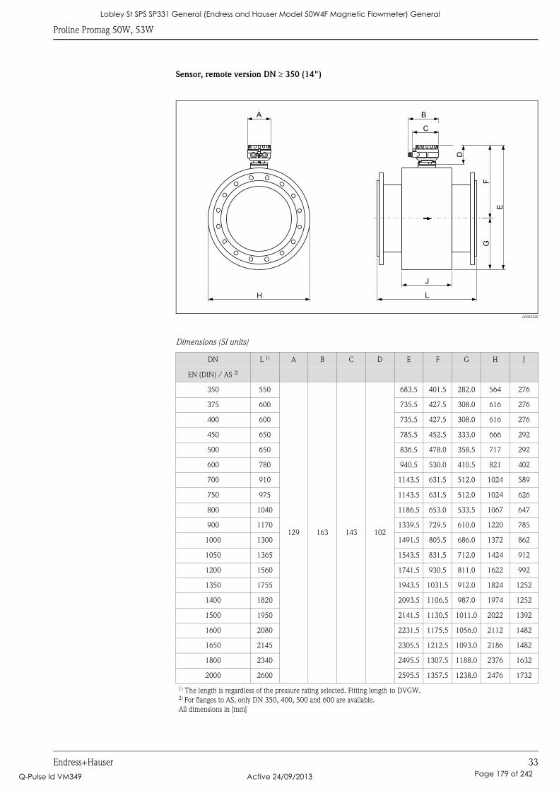
Proline Promag 50W, 53W
Endress+Hauser 33
Sensor, remote version DN ≥ 350 (14")
A0003220
Dimensions (SI units)
DN L 1) A B C D E F G H J
EN (DIN) / AS 2)
350 550
129 163 143 102
683.5 401.5 282.0 564 276
375 600 735.5 427.5 308.0 616 276
400 600 735.5 427.5 308.0 616 276
450 650 785.5 452.5 333.0 666 292
500 650 836.5 478.0 358.5 717 292
600 780 940.5 530.0 410.5 821 402
700 910 1143.5 631.5 512.0 1024 589
750 975 1143.5 631.5 512.0 1024 626
800 1040 1186.5 653.0 533.5 1067 647
900 1170 1339.5 729.5 610.0 1220 785
1000 1300 1491.5 805.5 686.0 1372 862
1050 1365 1543.5 831.5 712.0 1424 912
1200 1560 1741.5 930.5 811.0 1622 992
1350 1755 1943.5 1031.5 912.0 1824 1252
1400 1820 2093.5 1106.5 987.0 1974 1252
1500 1950 2141.5 1130.5 1011.0 2022 1392
1600 2080 2231.5 1175.5 1056.0 2112 1482
1650 2145 2305.5 1212.5 1093.0 2186 1482
1800 2340 2495.5 1307.5 1188.0 2376 1632
2000 2600 2595.5 1357.5 1238.0 2476 1732
1) The length is regardless of the pressure rating selected. Fitting length to DVGW.2) For flanges to AS, only DN 350, 400, 500 and 600 are available.
All dimensions in [mm]
H
E
GF
L
J
A B
C
D
Lobley St SPS SP331 General (Endress and Hauser Model 50W4F Magnetic Flowmeter) General
Q-Pulse Id VM349 Active 24/09/2013 Page 179 of 242
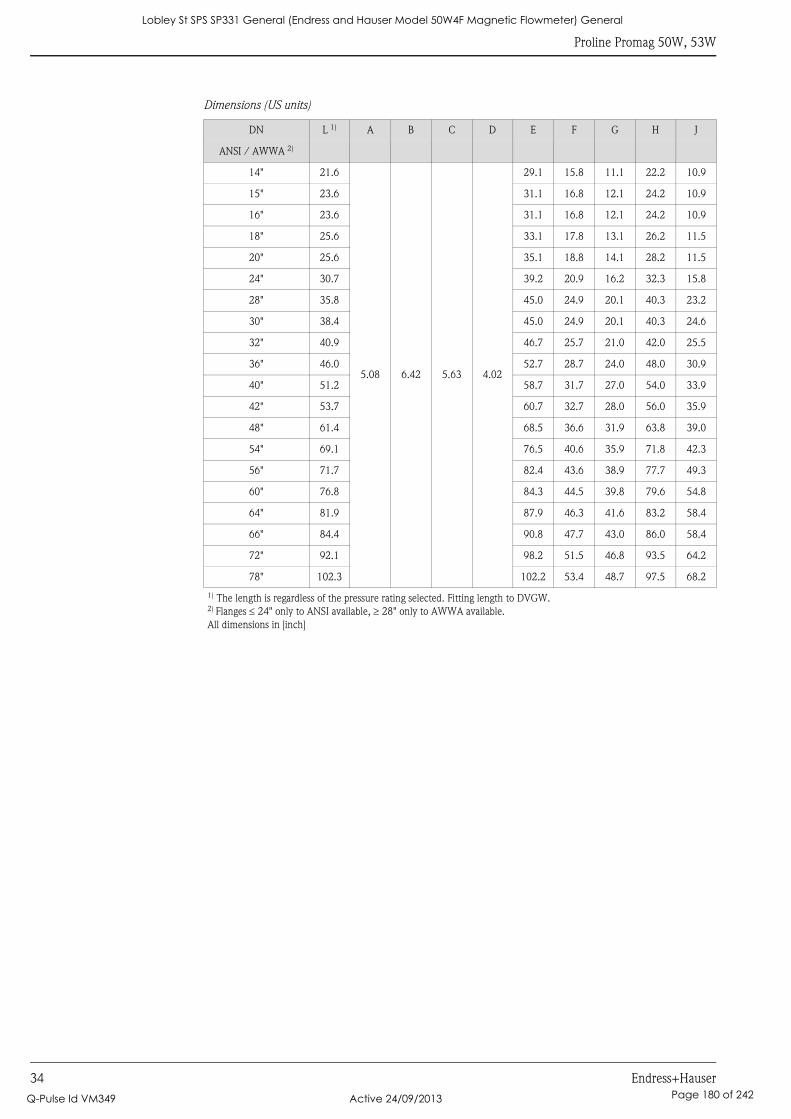
Proline Promag 50W, 53W
34 Endress+Hauser
Dimensions (US units)
DN L 1) A B C D E F G H J
ANSI / AWWA 2)
14" 21.6
5.08 6.42 5.63 4.02
29.1 15.8 11.1 22.2 10.9
15" 23.6 31.1 16.8 12.1 24.2 10.9
16" 23.6 31.1 16.8 12.1 24.2 10.9
18" 25.6 33.1 17.8 13.1 26.2 11.5
20" 25.6 35.1 18.8 14.1 28.2 11.5
24" 30.7 39.2 20.9 16.2 32.3 15.8
28" 35.8 45.0 24.9 20.1 40.3 23.2
30" 38.4 45.0 24.9 20.1 40.3 24.6
32" 40.9 46.7 25.7 21.0 42.0 25.5
36" 46.0 52.7 28.7 24.0 48.0 30.9
40" 51.2 58.7 31.7 27.0 54.0 33.9
42" 53.7 60.7 32.7 28.0 56.0 35.9
48" 61.4 68.5 36.6 31.9 63.8 39.0
54" 69.1 76.5 40.6 35.9 71.8 42.3
56" 71.7 82.4 43.6 38.9 77.7 49.3
60" 76.8 84.3 44.5 39.8 79.6 54.8
64" 81.9 87.9 46.3 41.6 83.2 58.4
66" 84.4 90.8 47.7 43.0 86.0 58.4
72" 92.1 98.2 51.5 46.8 93.5 64.2
78" 102.3 102.2 53.4 48.7 97.5 68.2
1) The length is regardless of the pressure rating selected. Fitting length to DVGW.2) Flanges ≤ 24" only to ANSI available, ≥ 28" only to AWWA available.
All dimensions in [inch]
Lobley St SPS SP331 General (Endress and Hauser Model 50W4F Magnetic Flowmeter) General
Q-Pulse Id VM349 Active 24/09/2013 Page 180 of 242
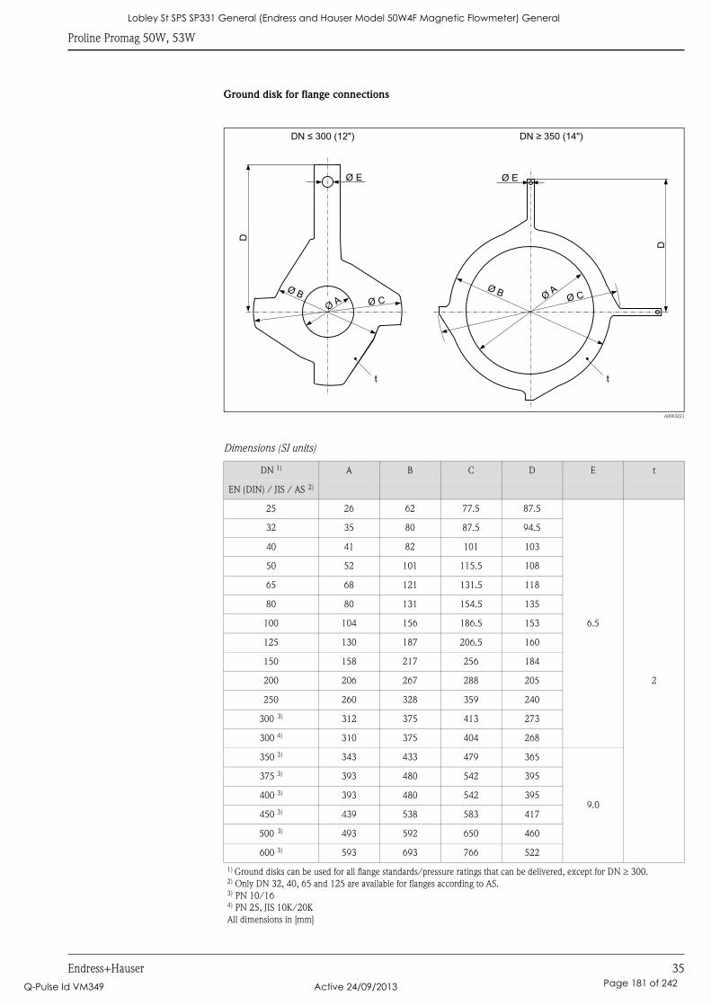
Proline Promag 50W, 53W
Endress+Hauser 35
Ground disk for flange connections
A0003221
Dimensions (SI units)
DN 1) A B C D E t
EN (DIN) / JIS / AS 2)
25 26 62 77.5 87.5
6.5
2
32 35 80 87.5 94.5
40 41 82 101 103
50 52 101 115.5 108
65 68 121 131.5 118
80 80 131 154.5 135
100 104 156 186.5 153
125 130 187 206.5 160
150 158 217 256 184
200 206 267 288 205
250 260 328 359 240
300 3) 312 375 413 273
300 4) 310 375 404 268
350 3) 343 433 479 365
9.0
375 3) 393 480 542 395
400 3) 393 480 542 395
450 3) 439 538 583 417
500 3) 493 592 650 460
600 3) 593 693 766 522
1) Ground disks can be used for all flange standards/pressure ratings that can be delivered, except for DN ≥ 300.2) Only DN 32, 40, 65 and 125 are available for flanges according to AS.3) PN 10/164) PN 25, JIS 10K/20K
All dimensions in [mm]
D
D
Ø BØ B
ØA
Ø C Ø CØ
A
DN 300 (12")≤ DN 350 (14")≥
Ø E Ø E
t t
Lobley St SPS SP331 General (Endress and Hauser Model 50W4F Magnetic Flowmeter) General
Q-Pulse Id VM349 Active 24/09/2013 Page 181 of 242
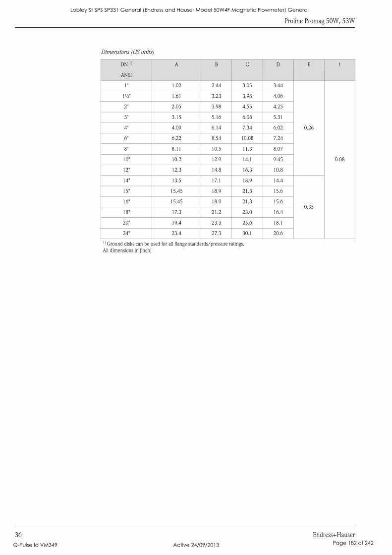
Proline Promag 50W, 53W
36 Endress+Hauser
Dimensions (US units)
DN 1) A B C D E t
ANSI
1" 1.02 2.44 3.05 3.44
0.26
0.08
1½" 1.61 3.23 3.98 4.06
2" 2.05 3.98 4.55 4.25
3" 3.15 5.16 6.08 5.31
4" 4.09 6.14 7.34 6.02
6" 6.22 8.54 10.08 7.24
8" 8.11 10.5 11.3 8.07
10" 10.2 12.9 14.1 9.45
12" 12.3 14.8 16.3 10.8
14" 13.5 17.1 18.9 14.4
0.35
15" 15.45 18.9 21.3 15.6
16" 15.45 18.9 21.3 15.6
18" 17.3 21.2 23.0 16.4
20" 19.4 23.3 25.6 18.1
24" 23.4 27.3 30.1 20.6
1) Ground disks can be used for all flange standards/pressure ratings.
All dimensions in [inch]
Lobley St SPS SP331 General (Endress and Hauser Model 50W4F Magnetic Flowmeter) General
Q-Pulse Id VM349 Active 24/09/2013 Page 182 of 242
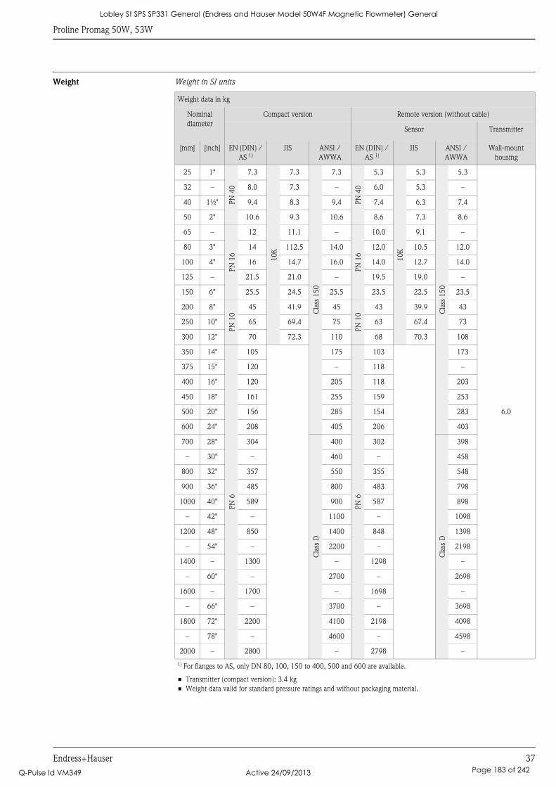
Proline Promag 50W, 53W
Endress+Hauser 37
Weight Weight in SI units
Weight data in kg
Nominal
diameter
Compact version Remote version (without cable)
Sensor Transmitter
[mm] [inch] EN (DIN) /
AS 1)
JIS ANSI /
AWWA
EN (DIN) /
AS 1)
JIS ANSI /
AWWA
Wall-mount
housing
25 1"
PN
40
7.3
10K
7.3
Cla
ss 1
50
7.3
PN
40
5.3
10K
5.3
Cla
ss 1
50
5.3
6.0
32 – 8.0 7.3 – 6.0 5.3 –
40 1½" 9.4 8.3 9.4 7.4 6.3 7.4
50 2" 10.6 9.3 10.6 8.6 7.3 8.6
65 –P
N 1
612 11.1 –
PN
16
10.0 9.1 –
80 3" 14 112.5 14.0 12.0 10.5 12.0
100 4" 16 14.7 16.0 14.0 12.7 14.0
125 – 21.5 21.0 – 19.5 19.0 –
150 6" 25.5 24.5 25.5 23.5 22.5 23.5
200 8"
PN
10
45 41.9 45
PN
10
43 39.9 43
250 10" 65 69.4 75 63 67.4 73
300 12" 70 72.3 110 68 70.3 108
350 14"
PN
6
105 175P
N 6
103 173
375 15" 120 – 118 –
400 16" 120 205 118 203
450 18" 161 255 159 253
500 20" 156 285 154 283
600 24" 208 405 206 403
700 28" 304
Cla
ss D
400 302C
lass
D398
– 30" – 460 – 458
800 32" 357 550 355 548
900 36" 485 800 483 798
1000 40" 589 900 587 898
– 42" – 1100 – 1098
1200 48" 850 1400 848 1398
– 54" – 2200 – 2198
1400 – 1300 – 1298 –
– 60" – 2700 – 2698
1600 – 1700 – 1698 –
– 66" – 3700 – 3698
1800 72" 2200 4100 2198 4098
– 78" – 4600 – 4598
2000 – 2800 – 2798 –
1) For flanges to AS, only DN 80, 100, 150 to 400, 500 and 600 are available.
• Transmitter (compact version): 3.4 kg
• Weight data valid for standard pressure ratings and without packaging material.
Lobley St SPS SP331 General (Endress and Hauser Model 50W4F Magnetic Flowmeter) General
Q-Pulse Id VM349 Active 24/09/2013 Page 183 of 242
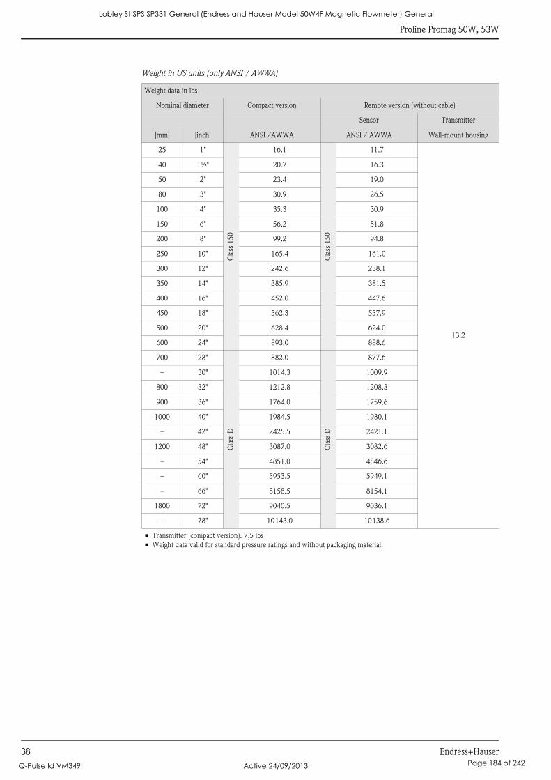
Proline Promag 50W, 53W
38 Endress+Hauser
Weight in US units (only ANSI / AWWA)
Weight data in lbs
Nominal diameter Compact version Remote version (without cable)
Sensor Transmitter
[mm] [inch] ANSI /AWWA ANSI / AWWA Wall-mount housing
25 1"
Cla
ss 1
50
16.1
Cla
ss 1
50
11.7
13.2
40 1½" 20.7 16.3
50 2" 23.4 19.0
80 3" 30.9 26.5
100 4" 35.3 30.9
150 6" 56.2 51.8
200 8" 99.2 94.8
250 10" 165.4 161.0
300 12" 242.6 238.1
350 14" 385.9 381.5
400 16" 452.0 447.6
450 18" 562.3 557.9
500 20" 628.4 624.0
600 24" 893.0 888.6
700 28"
Cla
ss D
882.0
Cla
ss D
877.6
– 30" 1014.3 1009.9
800 32" 1212.8 1208.3
900 36" 1764.0 1759.6
1000 40" 1984.5 1980.1
– 42" 2425.5 2421.1
1200 48" 3087.0 3082.6
– 54" 4851.0 4846.6
– 60" 5953.5 5949.1
– 66" 8158.5 8154.1
1800 72" 9040.5 9036.1
– 78" 10143.0 10138.6
• Transmitter (compact version): 7,5 lbs
• Weight data valid for standard pressure ratings and without packaging material.
Lobley St SPS SP331 General (Endress and Hauser Model 50W4F Magnetic Flowmeter) General
Q-Pulse Id VM349 Active 24/09/2013 Page 184 of 242
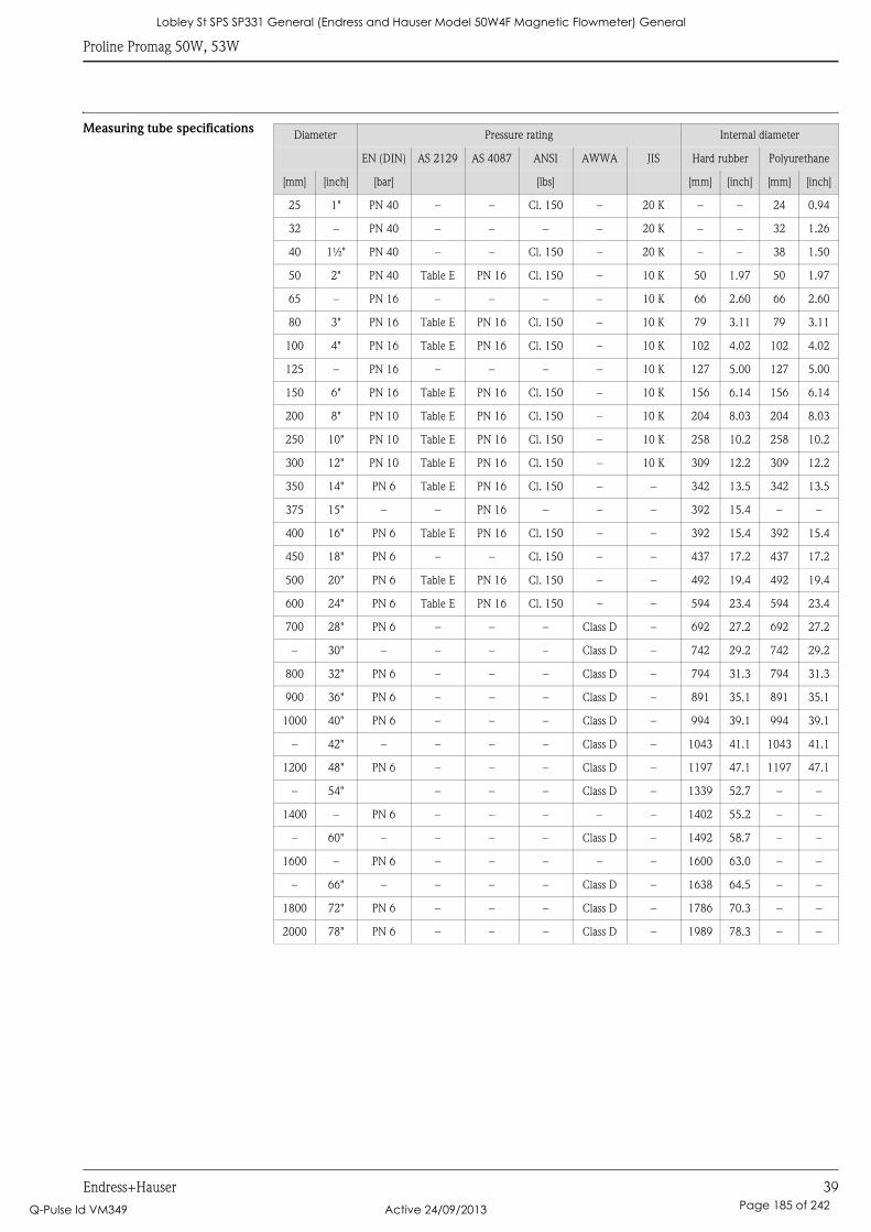
Proline Promag 50W, 53W
Endress+Hauser 39
Measuring tube specificationsDiameter Pressure rating Internal diameter
EN (DIN) AS 2129 AS 4087 ANSI AWWA JIS Hard rubber Polyurethane
[mm] [inch] [bar] [lbs] [mm] [inch] [mm] [inch]
25 1" PN 40 – – Cl. 150 – 20 K – – 24 0.94
32 – PN 40 – – – – 20 K – – 32 1.26
40 1½" PN 40 – – Cl. 150 – 20 K – – 38 1.50
50 2" PN 40 Table E PN 16 Cl. 150 – 10 K 50 1.97 50 1.97
65 – PN 16 – – – – 10 K 66 2.60 66 2.60
80 3" PN 16 Table E PN 16 Cl. 150 – 10 K 79 3.11 79 3.11
100 4" PN 16 Table E PN 16 Cl. 150 – 10 K 102 4.02 102 4.02
125 – PN 16 – – – – 10 K 127 5.00 127 5.00
150 6" PN 16 Table E PN 16 Cl. 150 – 10 K 156 6.14 156 6.14
200 8" PN 10 Table E PN 16 Cl. 150 – 10 K 204 8.03 204 8.03
250 10" PN 10 Table E PN 16 Cl. 150 – 10 K 258 10.2 258 10.2
300 12" PN 10 Table E PN 16 Cl. 150 – 10 K 309 12.2 309 12.2
350 14" PN 6 Table E PN 16 Cl. 150 – – 342 13.5 342 13.5
375 15" – – PN 16 – – – 392 15.4 – –
400 16" PN 6 Table E PN 16 Cl. 150 – – 392 15.4 392 15.4
450 18" PN 6 – – Cl. 150 – – 437 17.2 437 17.2
500 20" PN 6 Table E PN 16 Cl. 150 – – 492 19.4 492 19.4
600 24" PN 6 Table E PN 16 Cl. 150 – – 594 23.4 594 23.4
700 28" PN 6 – – – Class D – 692 27.2 692 27.2
– 30" – – – – Class D – 742 29.2 742 29.2
800 32" PN 6 – – – Class D – 794 31.3 794 31.3
900 36" PN 6 – – – Class D – 891 35.1 891 35.1
1000 40" PN 6 – – – Class D – 994 39.1 994 39.1
– 42" – – – – Class D – 1043 41.1 1043 41.1
1200 48" PN 6 – – – Class D – 1197 47.1 1197 47.1
– 54" – – – Class D – 1339 52.7 – –
1400 – PN 6 – – – – – 1402 55.2 – –
– 60" – – – – Class D – 1492 58.7 – –
1600 – PN 6 – – – – – 1600 63.0 – –
– 66" – – – – Class D – 1638 64.5 – –
1800 72" PN 6 – – – Class D – 1786 70.3 – –
2000 78" PN 6 – – – Class D – 1989 78.3 – –
Lobley St SPS SP331 General (Endress and Hauser Model 50W4F Magnetic Flowmeter) General
Q-Pulse Id VM349 Active 24/09/2013 Page 185 of 242
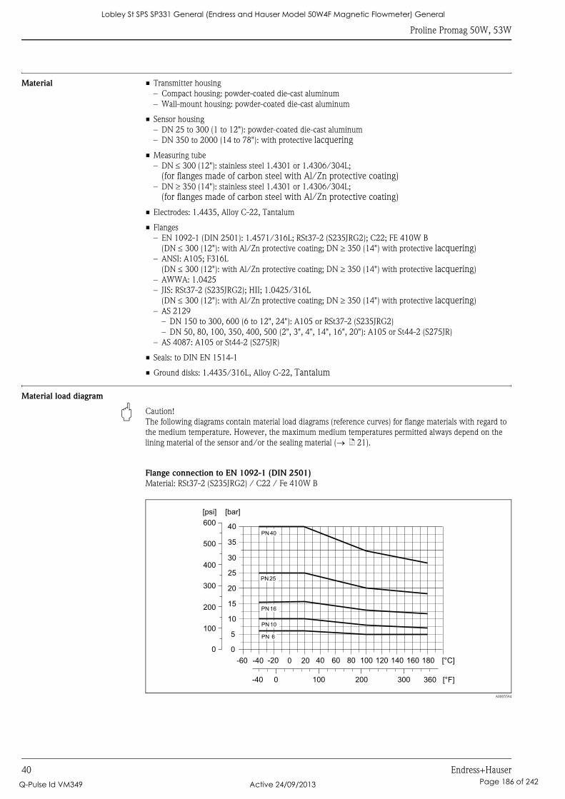
Proline Promag 50W, 53W
40 Endress+Hauser
Material • Transmitter housing
– Compact housing: powder-coated die-cast aluminum
– Wall-mount housing: powder-coated die-cast aluminum
• Sensor housing
– DN 25 to 300 (1 to 12"): powder-coated die-cast aluminum
– DN 350 to 2000 (14 to 78"): with protective lacquering
• Measuring tube
– DN ≤ 300 (12"): stainless steel 1.4301 or 1.4306/304L;
(for flanges made of carbon steel with Al/Zn protective coating)– DN ≥ 350 (14"): stainless steel 1.4301 or 1.4306/304L;
(for flanges made of carbon steel with Al/Zn protective coating)
• Electrodes: 1.4435, Alloy C-22, Tantalum
• Flanges
– EN 1092-1 (DIN 2501): 1.4571/316L; RSt37-2 (S235JRG2); C22; FE 410W B
(DN ≤ 300 (12"): with Al/Zn protective coating; DN ≥ 350 (14") with protective lacquering)
– ANSI: A105; F316L
(DN ≤ 300 (12"): with Al/Zn protective coating; DN ≥ 350 (14") with protective lacquering)
– AWWA: 1.0425
– JIS: RSt37-2 (S235JRG2); HII; 1.0425/316L
(DN ≤ 300 (12"): with Al/Zn protective coating; DN ≥ 350 (14") with protective lacquering)
– AS 2129
– DN 150 to 300, 600 (6 to 12", 24"): A105 or RSt37-2 (S235JRG2)
– DN 50, 80, 100, 350, 400, 500 (2", 3", 4", 14", 16", 20"): A105 or St44-2 (S275JR)
– AS 4087: A105 or St44-2 (S275JR)
• Seals: to DIN EN 1514-1
• Ground disks: 1.4435/316L, Alloy C-22, Tantalum
Material load diagram
" Caution!
The following diagrams contain material load diagrams (reference curves) for flange materials with regard to
the medium temperature. However, the maximum medium temperatures permitted always depend on the
lining material of the sensor and/or the sealing material (→ ä 21).
Flange connection to EN 1092-1 (DIN 2501)
Material: RSt37-2 (S235JRG2) / C22 / Fe 410W B
A0005594
PN 25
PN 16
PN 10
PN 6
PN 40
0
5
10
15
20
25
35
30
40
[bar][psi]
-60 -40 -20 0 20 40 60 80 100 120 140 160 180 [°C]
360 [°F]0-40 100 200 300
200
100
400
300
500
600
0
Lobley St SPS SP331 General (Endress and Hauser Model 50W4F Magnetic Flowmeter) General
Q-Pulse Id VM349 Active 24/09/2013 Page 186 of 242
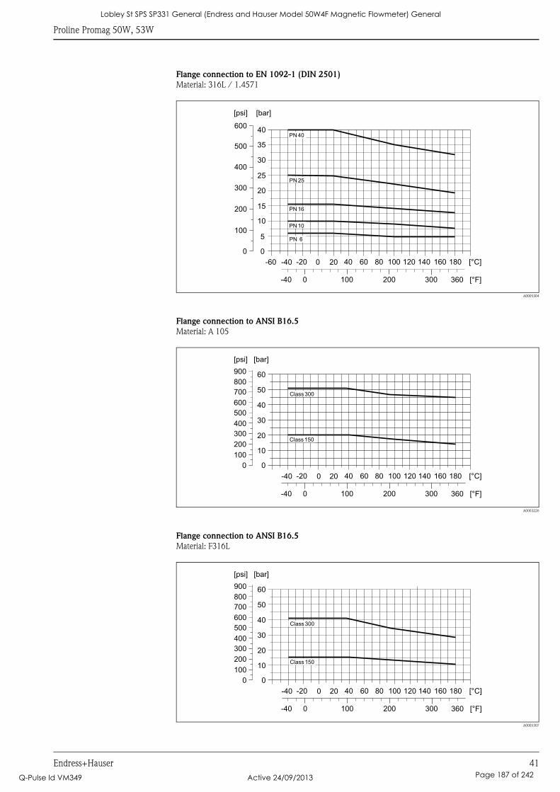
Proline Promag 50W, 53W
Endress+Hauser 41
Flange connection to EN 1092-1 (DIN 2501)
Material: 316L / 1.4571
A0005304
Flange connection to ANSI B16.5
Material: A 105
A0003226
Flange connection to ANSI B16.5
Material: F316L
A0005307
PN 25
PN 16
PN 10
PN 40
PN 6
0
5
10
15
20
25
35
30
40
[bar][psi]
-60 -40 -20 0 20 40 60 80 100 120 140 160 180 [°C]
360 [°F]0-40 100 200 300
200
100
400
300
500
600
0
Class 300
Class 150
0
10
20
30
40
50
[bar][psi]
-40 -20 0 20 40 60 80 100 120 140 160 180 [°C]
360 [°F]0-40 100 200 300
200
100
400
300
500
600
700
800
900
0
60
Class 300
Class 150
0
10
20
30
40
50
[bar][psi]
-40 -20 0 20 40 60 80 100 120 140 160 180 [°C]
360 [°F]0-40 100 200 300
200
100
400
300
500
600
700
800
900
0
60
Lobley St SPS SP331 General (Endress and Hauser Model 50W4F Magnetic Flowmeter) General
Q-Pulse Id VM349 Active 24/09/2013 Page 187 of 242
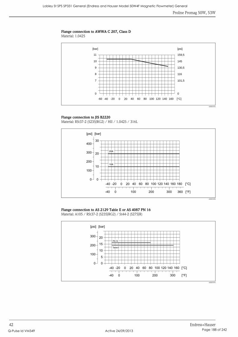
Proline Promag 50W, 53W
42 Endress+Hauser
Flange connection to AWWA C 207, Class D
Material: 1.0425
A0005592
Flange connection to JIS B2220
Material: RSt37-2 (S235JRG2) / HII / 1.0425 / 316L
A0003228
Flange connection to AS 2129 Table E or AS 4087 PN 16
Material: A105 / RSt37-2 (S235JRG2) / St44-2 (S275JR)
A0005595
0
7
8
9
10
11
[bar]
0
101,5
116
130,5
145
159,5
[psi]
-60 -40 -20 0 20 40 60 80 100 120 140 160 [°C]
10K
20K
-40 -20 0 20 40 60 80 100 120 140 160 180 [°C]
0
10
20
30
[bar]
360 [°F]0-40 100 200 300
[psi]
200
100
400
300
0
-40 -20 0 20 40 60 80 100 120 140 160 [°C]
0
10
5
20
15
[bar]
0-40 100 200 300 [°F]
[psi]
200
100
300
0
Table E
PN16
Lobley St SPS SP331 General (Endress and Hauser Model 50W4F Magnetic Flowmeter) General
Q-Pulse Id VM349 Active 24/09/2013 Page 188 of 242

Proline Promag 50W, 53W
Endress+Hauser 43
Fitted electrodes Measuring electrodes, reference electrodes and empty pipe detection electrodes:
• Standard available with 1.4435, Alloy C-22, tantalum
• Optional: exchangeable measuring electrodes made of 1.4435 (DN 350 to 2000 / 14 to 78")
Process connections Flange connection:
• EN 1092-1 (DIN 2501), DN ≤ 300 (12") form A, DN ≥ 350 (14") form B
(Dimensions to DIN 2501, DN 65 PN 16 and DN 600 (24") PN 16 exclusively to EN 1092-1)
• ANSI B16.5
• AWWA C 207, Class D
• JIS B2220
• AS 2129 Table E
• AS 4087 PN 16
Surface roughness • Elektroden
– 1.4435, Alloy C-22, tantal: ≤ 0.3 to 0.5 μm (≤ 11.8 to 19.7 μin)
(all data refer to parts in contact with medium)
Lobley St SPS SP331 General (Endress and Hauser Model 50W4F Magnetic Flowmeter) General
Q-Pulse Id VM349 Active 24/09/2013 Page 189 of 242

Proline Promag 50W, 53W
44 Endress+Hauser
Human interface
Display elements • Liquid crystal display: backlit, two lines (Promag 50) or four lines (Promag 53) with 16 characters per line
• Custom configurations for presenting different measured-value and status variables
• Totalizer
– Promag 50: 2 totalizers
– Promag 53: 3 totalizers
Operating elements Unified operation concept for both types of transmitter:
Promag 50:
• Local operation via three keys (S, O, F)
• Quick Setup menus for straightforward commissioning
Promag 53:
• Local operation via three keys (S, O, F)
• Application-specific Quick Setup menus for straightforward commissioning
Language groups Language groups available for operation in different countries:
Promag 50, Promag 53:
• Western Europe and America (WEA):
English, German, Spanish, Italian, French, Dutch, Portuguese
• Eastern Europe and Scandinavia (EES):
English, Russian, Polish, Norwegian, Finnish, Swedish, Czech
• South and east Asia (SEA):
English, Japanese, Indonesian
Promag 53:
• China (CN):
English, Chinese
You can change the language group via the operating program "FieldCare".
Remote operation • Promag 50: Remote control via HART, PROFIBUS DP/PA
• Promag 53: Remote control via HART, PROFIBUS DP/PA, MODBUS RS485, FOUNDATION Fieldbus
Lobley St SPS SP331 General (Endress and Hauser Model 50W4F Magnetic Flowmeter) General
Q-Pulse Id VM349 Active 24/09/2013 Page 190 of 242
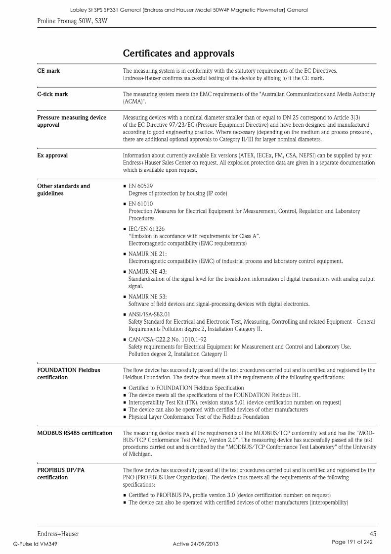
Proline Promag 50W, 53W
Endress+Hauser 45
Certificates and approvals
CE mark The measuring system is in conformity with the statutory requirements of the EC Directives.
Endress+Hauser confirms successful testing of the device by affixing to it the CE mark.
C-tick mark The measuring system meets the EMC requirements of the "Australian Communications and Media Authority
(ACMA)".
Pressure measuring device
approval
Measuring devices with a nominal diameter smaller than or equal to DN 25 correspond to Article 3(3)
of the EC Directive 97/23/EC (Pressure Equipment Directive) and have been designed and manufactured
according to good engineering practice. Where necessary (depending on the medium and process pressure),
there are additional optional approvals to Category II/III for larger nominal diameters.
Ex approval Information about currently available Ex versions (ATEX, IECEx, FM, CSA, NEPSI) can be supplied by your
Endress+Hauser Sales Center on request. All explosion protection data are given in a separate documentation
which is available upon request.
Other standards and
guidelines
• EN 60529
Degrees of protection by housing (IP code)
• EN 61010
Protection Measures for Electrical Equipment for Measurement, Control, Regulation and Laboratory
Procedures.
• IEC/EN 61326
“Emission in accordance with requirements for Class A”.
Electromagnetic compatibility (EMC requirements)
• NAMUR NE 21:
Electromagnetic compatibility (EMC) of industrial process and laboratory control equipment.
• NAMUR NE 43:
Standardization of the signal level for the breakdown information of digital transmitters with analog output
signal.
• NAMUR NE 53:
Software of field devices and signal-processing devices with digital electronics.
• ANSI/ISA-S82.01
Safety Standard for Electrical and Electronic Test, Measuring, Controlling and related Equipment - General
Requirements Pollution degree 2, Installation Category II.
• CAN/CSA-C22.2 No. 1010.1-92
Safety requirements for Electrical Equipment for Measurement and Control and Laboratory Use.
Pollution degree 2, Installation Category II
FOUNDATION Fieldbus
certification
The flow device has successfully passed all the test procedures carried out and is certified and registered by the
Fieldbus Foundation. The device thus meets all the requirements of the following specifications:
• Certified to FOUNDATION Fieldbus Specification
• The device meets all the specifications of the FOUNDATION Fieldbus H1.
• Interoperability Test Kit (ITK), revision status 5.01 (device certification number: on request)
• The device can also be operated with certified devices of other manufacturers
• Physical Layer Conformance Test of the Fieldbus Foundation
MODBUS RS485 certification The measuring device meets all the requirements of the MODBUS/TCP conformity test and has the “MOD-
BUS/TCP Conformance Test Policy, Version 2.0”. The measuring device has successfully passed all the test
procedures carried out and is certified by the “MODBUS/TCP Conformance Test Laboratory” of the University
of Michigan.
PROFIBUS DP/PA
certification
The flow device has successfully passed all the test procedures carried out and is certified and registered by the
PNO (PROFIBUS User Organisation). The device thus meets all the requirements of the following
specifications:
• Certified to PROFIBUS PA, profile version 3.0 (device certification number: on request)
• The device can also be operated with certified devices of other manufacturers (interoperability)
Lobley St SPS SP331 General (Endress and Hauser Model 50W4F Magnetic Flowmeter) General
Q-Pulse Id VM349 Active 24/09/2013 Page 191 of 242

Proline Promag 50W, 53W
46 Endress+Hauser
Ordering informationYour Endress+Hauser service organization can provide detailed ordering information and information on the
order codes on request.
AccessoriesVarious accessories, which can be ordered separately from Endress+Hauser, are available for the transmitter
and the sensor. Your Endress+Hauser service organization can provide detailed information on the order codes
in question.
Documentation• Flow Measurement (FA005D/06)
• Operating Instructions Promag Promag 50 (BA046D/06 and BA049D/06)
• Operating Instructions Promag Promag 50 PROFIBUS PA (BA055D/06 and BA056D/06)
• Operating Instructions Promag Promag 53 (BA047D/06 and BA048D/06)
• Operating Instructions Promag Promag 53 FOUNDATION Fieldbus (BA051D/06 and BA052D/06)
• Operating Instructions Promag Promag 53 MODBUS RS485 (BA117D/06 and BA118D/06)
• Operating Instructions Promag Promag 53 PROFIBUS DP/PA (BA053D/06 and BA054D/06)
• Supplementary documentation on Ex-ratings: ATEX, IECEx, FM, CSA, NEPSI
Registered trademarksHART®
Registered trademark of the HART Communication Foundation, Austin, USA
PROFIBUS®
Registered trademark of the PROFIBUS Nutzerorganisation e.V., Karlsruhe, D
FOUNDATION™ Fieldbus
Registered trademark of the Fieldbus Foundation, Austin, USA
MODBUS®
Registered trademark of the MODBUS Organisation
HistoROM™, S-DAT®, T-DAT™, F-CHIP®, FieldCare®, Fieldcheck®, FieldXpert™, Applicator®
Registered or registration-pending trademarks of Endress+Hauser Flowtec AG, Reinach, CH
Lobley St SPS SP331 General (Endress and Hauser Model 50W4F Magnetic Flowmeter) General
Q-Pulse Id VM349 Active 24/09/2013 Page 192 of 242

Proline Promag 50W, 53W
Endress+Hauser 47
Lobley St SPS SP331 General (Endress and Hauser Model 50W4F Magnetic Flowmeter) General
Q-Pulse Id VM349 Active 24/09/2013 Page 193 of 242

Instruments International
Endress+HauserInstruments International AGKaegenstrasse 24153 ReinachSwitzerland
Tel. +41 61 715 81 00Fax +41 61 715 25 [email protected]
TI046D/06/en/11.09
71106269
FM+SGML6.0 ProMoDo
Lobley St SPS SP331 General (Endress and Hauser Model 50W4F Magnetic Flowmeter) General
Q-Pulse Id VM349 Active 24/09/2013 Page 194 of 242

Sicherheitshinweise / Safety Instructions / Conseils de sécurité
Ex-Dokumentation / Ex documentation / Documentation Ex
XA103D/06/a3/07.10
71114914
Proline Promag 50, 51HART, PROFIBUS DP/PA
ATEX II2G, II2(1)G, II2D; IECEx Zone 1, Zone 21
0 de Sicherheitshinweise für elektrische Betriebsmittel für explosionsgefährdete Bereiche gemäß Richtlinie 94/9/EG (ATEX) und IEC 60079-0 ➙ Seite 5
en Safety instructions for electrical apparatus for explosion-hazardous areas according to Directive 94/9/EC (ATEX) and IEC 60079-0 ➙ Page 19
fr Conseils de sécurité pour matériels électriques destinés aux zones explosibles selon Directive 94/9/CE (ATEX) et IEC 60079-0 ➙ page 33
Lobley St SPS SP331 General (Endress and Hauser Model 50W4F Magnetic Flowmeter) General
Q-Pulse Id VM349 Active 24/09/2013 Page 195 of 242
0ATEX II2G, II2(1)G, II2D; IECEx Zone 1, Zone 21 Proline Promag 50, 51
2 Endress+Hauser
Istruzioni di sicurezza per apparecchiature elettriche certificate perl'utilizzo in aree con pericolo di esplosione. Se il presente manuale nonrisulta comprensibile potete ordinarcene una copia tradotta nellavostra lingua.
it -
Con questa dichiarazione e con l'applicazione del marchio CE, il costruttoreEndress+Hauser, assicura che il prodotto è conforme alle direttive europeevigenti. Prova della conformità è fornita dall'osservanza delle direttive, dellenorme e dei documenti elencati.
Dichiarazione di conformità CE
Veiligheidsinstructies voor elektrisch materieel in explosiegevaarlijkeomgeving. Wanneer u deze handleiding niet kunt lezen, kunt u een inuw landstaal vertaalde handleiding bij ons bestellen.
nl -
De leverancier Endress+Hauser waarborgt met deze verklaring en hetaanbrengen van het CE-teken, dat dit product overeenstemt met degeldende Europese richtlijnen. De geldende richtlijnen, normen endocumenten zijn aangegeven in de conformiteitsverklaring.
EG Conformiteitsverklaring
Turvallisuusohjeita sähkölaitteille, jotka on vahvistettu käytettäväksiräjähdysvaarallisilla alueilla. Jos et ymmärrä tätä käsikirjaa, voit tilatameiltä käännöksen omalla kansallisella kielelläsi.
fi -
Valmistaja Endress+Hauser vakuuttaa tällä vaatimustenmukaisuustodistuksellaja CE-merkin kiinnittämisellä, että tämä tuote täyttää sovellettavienEU-direktiivien määräykset. Sovellettavat direktiivit, normit ja dokumentit onmerkitty vaatimustenmukaisuustodistukseen.
EU-vaatimustenmukaisuustodistus
Wskazówki dot. bezpieczeństwa dla urządzeń elektrycznych stosowanychw obszarze zagrożonym wybuchem. Jeśli niniejsza instrukcja napisanajest w języku, którym się nie posługujesz, możesz zamówić u nasprzetłumaczony dokument.
pl -
Producent Endress+Hauser w niniejszej deklaracji zgodności wraz znadaniem znaku CE oświadcza, że produkt ten jest zgodny z obowiązującąEuropejską Dyrektywą. Zastosowane wytyczne, normy oraz dukumentypodane są w deklaracji zgodnoś
Deklaracja zgodności WE
ci.
Säkerhetsföreskrifter för elektrisk utrustning certifierad för användning iexplosionsfarliga områden. Om du inte förstår denna manual, kan enöversatt kopia på ditt eget språk beställas från oss.
sv -
Endress+Hauser försäkrar med vidstående försäkran om överensstämmelseoch med CE-märkningen att denna produkt överensstämmer med detillämpbara europeiska riktlinjerna. De tillämpade riktlinjerna, normernaoch dokumenten anges i försäkran om överensstämmelse.
EG-försäkran om överensstämmelse
Bezpečnostné pokyny pre elektrické zariadenie prevádzkované vs nebezpečenstvom výbuchu. Ak nemáte možnost’ prečítat’ si
tento si u nás objednat’ návod preložený do svojho jazyka.priestoroch
návod, môžete
sk -
Spoločnosť Endress+Hauser vyhlasuje prostredníctvom tohto vyhláseniao konformite a použitím značky CE, že tento výrobok
Zmieňované smernice
Vyhlásenie o konformite s ES
vyhovuje príslušnýmeurópskym smerniciam. , normy a dokumenty súuvedené vo Vyhlásení o konformite.
Sikkerhedsforskrifter for elektriske apparater certificeret til brug ieksplosionsfarlige områder. Hvis du ikke forstår denne manual,kan en oversat kopi af den på dit eget sprog bestilles fra os.
da -
Med denne overensstemmelseserklæring og tilføjelsen af CE-mærket sikrerproducenten Endress+Hauser, at produktet er i overensstemmelse medrelevante europæiske direktiver. Dokumentation for overensstemmelsengives i de anførte direktiver, standarder og dokumenter.
EF-overensstemmelseserklæring
Varnostni napotki glede električne opreme, namenjene za uporabo veksplozivnih območjih. Če teh navodil ne morete razumeti, lahko pri nasnaročite prevod v vaš jezik.
sl -
Pojasnilo glede potrdila o skladnosti EUProizvajalec Endress+Hauser s to izjavo o skladnosti in navedbo oznakeCE izjavlja, da je ta izdelek skladen s predpisanimi evropskimi smernicami.Upoštevane smernice, standardi in dokumenti so navedeni v izjavi o skladnosti.
Instruções de segurança para dispositivos eléctricos certificados parautilização em áreas de risco de incêndio. Se não compreender estemanual, pode encomendar-nos directamente uma cópia na sua língua.
pt -
Com esta declaração de conformidade e a aplicação da marca CE, ofabricante Endress+Hauser, garante que o produto obedece às directivaseuropeias a aplicar. As directivas, normas e documentos são apresentadasna declaração de conformidade.
Declaração de conformidade CE
Bezpečnostní pokyny pro elektrické přístroje v místech s nebezpečímvýbuchu. Pokud nemáte možnost přečíst si tento návod, můžete si u násobjednat návod přeložený do svého jazyka.
cs -
Společnost Endress+Hauser prohlašuje prostřednictvím tohoto prohlášenía použitím značky CE, že tento výrobek vyhovuje příslušným evropskýmsměrnicím Zmíněné směrnice jsou uvedeny vProhlášení o shodě.
Prohlášení o shodě s ES
. , normy a dokumenty
Biztonsági információk robbanásveszélyes területre való elektromoseszközökhöz. Amennyiben nem tudja elolvasni ezt az útmutatót, akkormegrendelheti az Ön anyanyelvére lefordítva is.
hu -
Az Endress+Hauser mint gyártó jelen megfelelőségi nyilatkozattal és aCE-jelzés felhelyezésével kijelenti, hogy ez a termék megfelel az alkalmazandóeurópai irányelveknek. szabványok ésdokumentumok a megfelelőségi nyilatkozatban fel vannak tüntetve.
EK-megfelelőségi nyilatkozat
Az alkalmazott irányelvek,
Instrucciones de seguridad de aparatos eléctricos homologados para suutilización en áreas expuestas a riesgos de deflagración. Si no entiendeeste manual, puede pedir un ejemplar en su idioma.
es -
Por la presente declaración y la inclusión de la marca CE, el fabricanteEndress+Hauser, declara que el producto cumple con las directivaseuropeas pertinentes. Las directivas, normas y documentos de aplicaciónse indican en la declaración de conformidad.
Declaración de conformidad CE
Ohutusjuhised plahvatusohtlikus keskkonnas kasutatavateelektriseadmete kohta. Kui Te ei saa käesolevast juhendist aru, võitemeilt tellida Teie riigikeelde tõlgitud juhendi.
et -
EL vastavusdeklaratsioonTootja Endress+Hauser kinnitab juurdelisatud vastavusdeklaratsiooniesitamisega ja CE-märgise kandmisega tootele, et käesolev toode vastabkohaldatavate Euroopa Liidu direktiivide nõuetele.Kohaldatavad direktiivid, standardid ja dokumendid on ära toodudvastavusdeklaratsioonis.
el -
Δήλωση πιστότητας ΕΚΜε αυτή τη δήλωση πιστότητας και την τοποθέτηση του σήματος
ο κατασκευαστής δηλώνει, ότι αυτό το προϊόνσυμορφώνεται με τις ευρωπαϊκές οδηγίες που πρέπει να εφαρμοστούν.Οι οδηγίες, τα πορότυπα και τα έγγραφα που εφαρμόστηκαναναφέρονται στη δήλωση πιστότητας.
CE Endress+Hauser
Οδηγίες ασφαλείας ηλεκτρικών συσκευών για επικίνδυνες για έκρηξηπεριοχές.
αντίτυπο μεταφρασμένοστη γλώσσα σας.
Σε περίπτωση που δεν μπορείτε να διαβάσετε αυτές τιςοδηγίες, τότε μπορείτε να παραγγείλετε ένα
lt - Elektros įrenginio saugumo nurodymai, susiję su sprogimo zonomis.Jeigu negalite perskaityti šios instrukcijos, kreipkitės į mus, kadužsisakytumėte į jūsų gimtąją kalbą išverstą instrukciją.
Gamintojas Endress+Hauser šia atitikties deklaracija ir CE ženklinimupatvirtina, kad gaminys atitinka taikytinas ES direktyvas. Taikomosdirektyvos, normos ir dokumentai yra pateikiami atitikties deklaracijoje.
EB atitikties deklaracija
lv - Dro bas nor d jumi elektrisko darba instrumentu lieto anai apgabalos,kas pak auti spr dzienb stam bai. Ja Jums nav iesp ju izlas t osnor d jumus, J s varat pas t t pie mums tulkojumu J su valsts valod .
šī ā ī šļ ā ī ī ē ī š
ā ī ū ū ī ū ā
Ražotājs Endress+Hauser ar šo atbilstības apliecinājumu un CE zīmolalietojumu apstiprina, ka produkts izgatavots sakaņā ar atbilstošajāmEiropas vadlīnijām. iemērotās vadlīnijas, normas un dokumenti atrunātiatbilstības apliecinājumā.
ES atbilstības apliecinājums
P
Indicaţii de siguranţă pentru mijloacele de producţie electrice pentru zonelepericlitate de explozie. Dacă nu puteţi citi aceste instrucţiuni, atunci puteţicomanda la noi instrucţiunile traduse în limba ţării dumneavoastră.
ro -
Producătorul Endress+Hauser declară prin declaraţia de conformitate alăturatăşi prin aplicarea semnului CE că acest produs corespunde directivelor europeneaplicabile. Directivele, normele aplicate şi documentele sunt menţionate îndeclaraţia de conformitate.
Declaraţie de conformitate CE
Правила за техниката на безопасност за електрически средства запроизводство във взривоопасни зони. Ако не разбирате езика натова ръководство има възможност да си поръчате при нас едноръководство, преведено на езика на Вашата страна.
bg -
.
Заявление за съответствие с EGПроизводителят Endress+Hauser декларира с това заявление засъответствие и с предявяването на сертификата CE, че този продуктотговаря на изискванията на съответните европейски директиви.Прилаганите директиви, норми и документи са указани в заявлението
за съответствие
Lobley St SPS SP331 General (Endress and Hauser Model 50W4F Magnetic Flowmeter) General
Q-Pulse Id VM349 Active 24/09/2013 Page 196 of 242
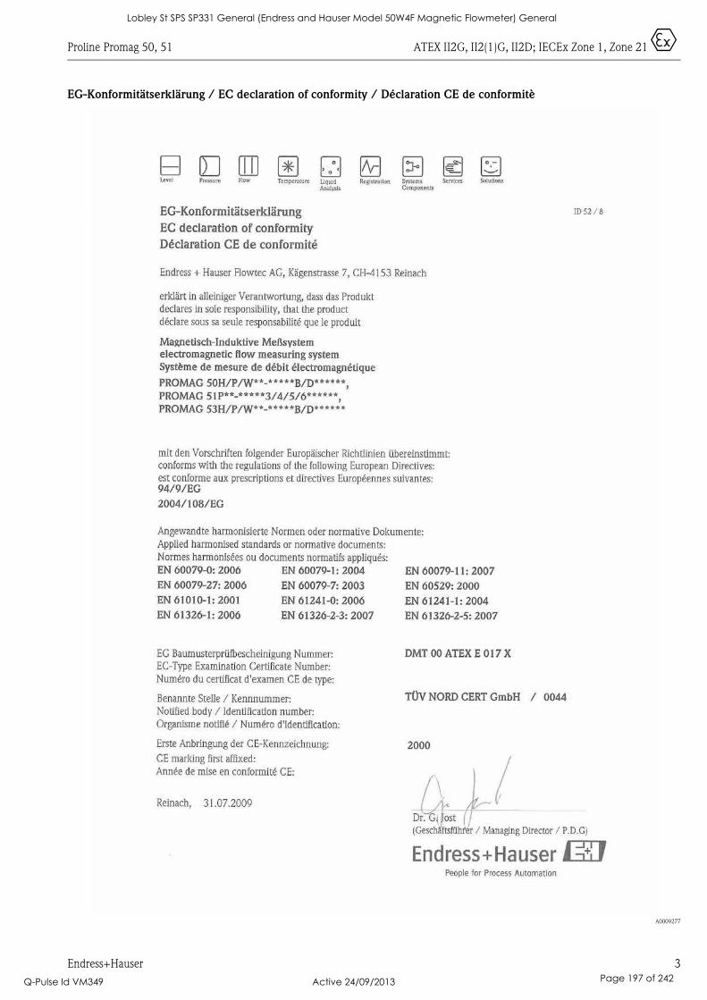
Proline Promag 50, 51 ATEX II2G, II2(1)G, II2D; IECEx Zone 1, Zone 21 0
Endress+Hauser 3
EG-Konformitätserklärung / EC declaration of conformity / Déclaration CE de conformitè
A0009277
Lobley St SPS SP331 General (Endress and Hauser Model 50W4F Magnetic Flowmeter) General
Q-Pulse Id VM349 Active 24/09/2013 Page 197 of 242
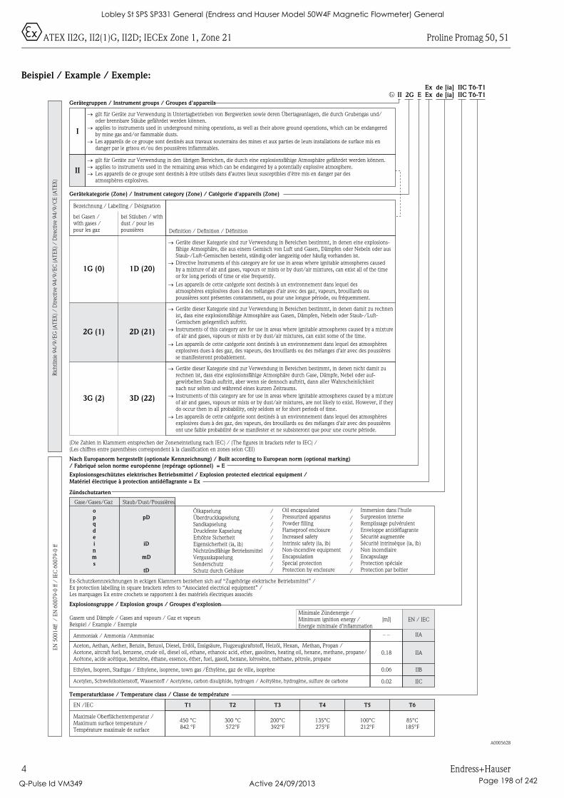
0ATEX II2G, II2(1)G, II2D; IECEx Zone 1, Zone 21 Proline Promag 50, 51
4 Endress+Hauser
Beispiel / Example / Exemple:
A0005628
I
Ex de [ia] IIC T6-T1
EN
50
01
4ff
/E
N6
00
79
-0ff
/IE
C6
00
79
-0ff
applies to instruments used in the remaining areas which can be endangered by a potentially explosive atmosphere.
Ric
htl
inie
94
/9
/E
G(A
TE
X)
/D
irec
tive
94
/9
/E
C(A
TE
X)
/D
irec
tive
94
/9
/C
E(A
TE
X)
Geräte dieser Kategorie sind zur Verwendung in Bereichen bestimmt, in denen eine explosions-fähige Atmosphäre, die aus einem Gemisch von Luft und Gasen, Dämpfen oder Nebeln oder ausStaub-/Luft-Gemischen besteht, ständig oder langzeitig oder häufig vorhanden ist.
Gerätekategorie (Zone) / Instrument category (Zone) / Catégorie d'appareils (Zone)
gilt für Geräte zur Verwendung in Untertagbetrieben von Bergwerken sowie deren Übertageanlagen, die durch Grubengas und/oder brennbare Stäube gefährdet werden können.
Gerätegruppen / Instrument groups / Groupes d'appareils
Explosionsgruppe / Explosion groups / Groupes d'explosion
Nach Europanorm hergestellt (optionale Kennzeichnung) / Built according to European norm (optional marking)/ Fabriqué selon norme européenne (repérage optionnel) = E
(Die Zahlen in Klammern entsprechen der Zoneneinteilung nach IEC) / (The figures in brackets refer to IEC) /(Les chiffres entre parenthèses correspondent à la classification en zones selon CEI)
ÖlkapselungÜberdruckkapselungSandkapselungDruckfeste KapselungErhöhte SicherheitEigensicherheit (ia, ib)Nichtzündfähige BetriebsmittelVergusskapselungSonderschutzSchutz durch Gehäuse
Zündschutzarten
Explosionsgeschütztes elektrisches Betriebsmittel / Explosion protected electrical equipment /Matériel électrique à protection antidéflagrante = Ex
Ex-Schutzkennzeichnungen in eckigen Klammern beziehen sich auf “Zugehörige elektrische Betriebsmittel” /Ex protection labelling in square brackets refers to “Associated electrical equipment” /Les marquages Ex entre crochets se rapportent à des matériels électriques associés
Bezeichnung / Labelling / Désignation
bei Gasen /wîth gases /pour les gaz
bei Stäuben / wîthdust / pour lespoussières
applies to instruments used in underground mining operations, as well as their above ground operations, which can be endangeredby mine gas and/or flammable dusts.
Les appareils de ce groupe sont destinés aux travaux souterrains des mines et aux parties de leurs installations de surface mis endanger par le grisou et/ou des poussières inflammables.
�
�
�
gilt für Geräte zur Verwendung in den übrigen Bereichen, die durch eine explosionsfähige Atmosphäre gefährdet werden können.
Les appareils de ce groupe sont destinés à être utilisés dans d'autres lieux susceptibles d'être mis en danger par desatmosphères explosives.
�
�
�II
Definition / Definition / Définition
1G (0) 1D (20)
�
Directive Instruments of this category are for use in areas where ignitable atmospheres causedby a mixture of air and gases, vapours or mists or by dust/air mixtures, can exist all of the timeor for long periods of time or else frequently.
�
Les appareils de cette catégorie sont destinés à un environnement dans lequel desatmosphères explosives dues à des mélanges d'air avec des gaz, vapeurs, brouillards oupoussières sont présentes constamment, ou pour une longue période, ou fréquemment.
�
Geräte dieser Kategorie sind zur Verwendung in Bereichen bestimmt, in denen damit zu rechnenist, dass eine explosionsfähige Atmosphäre aus Gasen, Dämpfen, Nebeln oder Staub-/Luft-Gemischen gelegentlich auftritt.
2G (1) 2D (21)
�
Instruments of this category are for use in areas where ignitable atmospheres caused by a mixtureof air and gases, vapours or mists or by dust/air mixtures, can exist some of the time.
�
Les appareils de cette catégorie sont destinés à un environnement dans lequel des atmosphèresexplosives dues à des gaz, des vapeurs, des brouillards ou des mélanges d'air avec des poussièresse manifesteront probablement.
�
Geräte dieser Kategorie sind zur Verwendung in Bereichen bestimmt, in denen nicht damit zurechnen ist, dass eine explosionsfähige Atmosphäre durch Gase, Dämpfe, Nebel oder auf-gewirbelten Staub auftritt, aber wenn sie dennoch auftritt, dann aller Wahrscheinlichkeitnach nur selten und während eines kurzen Zeitraums.
3G (2) 3D (22)
�
Instruments of this category are for use in areas where ignitable atmospheres caused by a mixtureof air and gases, vapours or mists or by dust/air mixtures, are not likely to exist. However, if theydo occur then in all probability, only seldom or for short periods of time.
�
Les appareils de cette catégorie sont destinés à un environnement dans lequel des atmosphèresexplosives dues à des gaz, des vapeurs, des brouillards ou des mélanges d'air avec des poussièresont une faible probabilité de se manifester et ne subsisteront que pour une courte période.
�
Immersion dans l'huileSurpression interneRemplissage pulvérulentEnveloppe antidéflagranteSécurité augmentéeSécurité intrinsèque (ia, ib)
EncapsulageProtection spécialeProtection par boîtier
Non incendiaire
//////////
Oil encapsulatedPressurized apparatusPowder fillingFlameproof enclosureIncreased safetyIntrinsic safety (ia, ib)
EncapsulationSpecial protectionProtection by enclosure
Non-incendive equipment
//////////
Ammoniak / Ammonia /Ammoniac
Gasem und Dämpfe / Gases and vapours / Gaz et vapeursBeispiel / Example / Exemple
Ethylen, Isopren, Stadtgas / Ethylene, isoprene, town gas /Éthylène, gaz de ville, isoprène
Aceton, Aethan, Aether, Benzin, Benzol, Diesel, Erdöl, Essigsäure, Flugzeugkraftstoff, Heizöl, Hexan, Methan, Propan /Acetone, aircraft fuel, benzene, crude oil, diesel oil, ethane, ethanoic acid, ether, gasolines, heating oil, hexane, methane, propane/Acétone, acide acétique, benzène, éthane, essence, éther, fuel, gasoil, hexane, kérosène, méthane, pétrole, propane
Acetylen, Schwefelkohlenstoff, Wasserstoff / Acetylene, carbon disulphide, hydrogen / Acétylène, hydrogène, sulfure de carbone
Minimale Zündenergie /Minimum ignition energy /Energie minimale d'inflammation
[mJ]
– –
0.18
0.06
0.02
IIA
IIA
IIB
IIC
EN / IEC
Temperaturklasse / Temperature class / Classe de température
EN /IEC
Maximale Oberflächentemperatur /Maximum surface temperature /Température maximale de surface
450 °C842 °F
T1
300 °C572°F
T2
200°C392°F
T3
135°C275°F
T4
100°C212°F
T5
85°C185°F
T6
Gase/Gases/Gaz Staub/Dust/Poussières
opD
iD
mD
tD
pqdeinms
II 2G E Ex IIC T6-T1de [ia]0
Lobley St SPS SP331 General (Endress and Hauser Model 50W4F Magnetic Flowmeter) General
Q-Pulse Id VM349 Active 24/09/2013 Page 198 of 242

Dieses Dokument ist ein fester Bestandteil der folgenden Betriebsanleitung:
Sicherheitshinweise
XA103D/06/a3/07.10
71114914
Ex-Dokumentation / Ex documentation / Documentation Ex
Proline Promag 50, 51HART, PROFIBUS DP/PA
ATEX II2G, II2(1)G, II2D; IECEx Zone 1, Zone 21
• BA046D, Proline Promag 50 HART• BA055D, Proline Promag 50 PROFIBUS DP/PA• BA080D, Proline Promag 51 HART
InhaltsverzeichnisAllgemeine Warnhinweise. . . . . . . . . . . . . . . . . . . . . . . . . . . . . . . . . . . . . . . . . . . . . . . . . . . . . . . . . . . . . . . . . 6
Besondere Bedingungen . . . . . . . . . . . . . . . . . . . . . . . . . . . . . . . . . . . . . . . . . . . . . . . . . . . . . . . . . . . . . . . . . . 6
Installationshinweise. . . . . . . . . . . . . . . . . . . . . . . . . . . . . . . . . . . . . . . . . . . . . . . . . . . . . . . . . . . . . . . . . . . . . 6
EG Baumusterprüfbescheinigung, Richtlinie 94/9/EG und IEC-Konformitätsbescheinigung. . . . . . . . . . . . . . . . 7
Beschreibung Messsystem. . . . . . . . . . . . . . . . . . . . . . . . . . . . . . . . . . . . . . . . . . . . . . . . . . . . . . . . . . . . . . . . . 8
Typenschilder . . . . . . . . . . . . . . . . . . . . . . . . . . . . . . . . . . . . . . . . . . . . . . . . . . . . . . . . . . . . . . . . . . . . . . . . . . 8
Typenschlüssel . . . . . . . . . . . . . . . . . . . . . . . . . . . . . . . . . . . . . . . . . . . . . . . . . . . . . . . . . . . . . . . . . . . . . . . . . 9
Temperaturtabelle Kompaktausführung . . . . . . . . . . . . . . . . . . . . . . . . . . . . . . . . . . . . . . . . . . . . . . . . . . . . . . 11
Temperaturtabelle Getrenntausführung . . . . . . . . . . . . . . . . . . . . . . . . . . . . . . . . . . . . . . . . . . . . . . . . . . . . . . 11
Gas und Staubexplosionsschutz. . . . . . . . . . . . . . . . . . . . . . . . . . . . . . . . . . . . . . . . . . . . . . . . . . . . . . . . . . . . 12
Aufbau Messsystem . . . . . . . . . . . . . . . . . . . . . . . . . . . . . . . . . . . . . . . . . . . . . . . . . . . . . . . . . . . . . . . . . . . . 12
Kabeleinführungen . . . . . . . . . . . . . . . . . . . . . . . . . . . . . . . . . . . . . . . . . . . . . . . . . . . . . . . . . . . . . . . . . . . . . 13
Kabelspezifikation . . . . . . . . . . . . . . . . . . . . . . . . . . . . . . . . . . . . . . . . . . . . . . . . . . . . . . . . . . . . . . . . . . . . . . 13
Potenzialausgleich. . . . . . . . . . . . . . . . . . . . . . . . . . . . . . . . . . . . . . . . . . . . . . . . . . . . . . . . . . . . . . . . . . . . . . 13
Anschluss Verbindungskabel Getrenntausführung . . . . . . . . . . . . . . . . . . . . . . . . . . . . . . . . . . . . . . . . . . . . . . 14
Elektrische Anschlüsse . . . . . . . . . . . . . . . . . . . . . . . . . . . . . . . . . . . . . . . . . . . . . . . . . . . . . . . . . . . . . . . . . . 15
Klemmenbelegung und Anschlusswerte Hilfsenergie . . . . . . . . . . . . . . . . . . . . . . . . . . . . . . . . . . . . . . . . . . . . 15
Klemmenbelegung und Anschlusswerte für Signalstromkreise (eigensichere Stromkreise) . . . . . . . . . . . . . . . . . 16
Klemmenbelegung und Anschlusswerte für Signalstromkreise (nicht eigensichere Stromkreise) . . . . . . . . . . . . 17
Servicestecker. . . . . . . . . . . . . . . . . . . . . . . . . . . . . . . . . . . . . . . . . . . . . . . . . . . . . . . . . . . . . . . . . . . . . . . . . 18
Gerätesicherung . . . . . . . . . . . . . . . . . . . . . . . . . . . . . . . . . . . . . . . . . . . . . . . . . . . . . . . . . . . . . . . . . . . . . . . 18
Technische Daten . . . . . . . . . . . . . . . . . . . . . . . . . . . . . . . . . . . . . . . . . . . . . . . . . . . . . . . . . . . . . . . . . . . . . . 18
Lobley St SPS SP331 General (Endress and Hauser Model 50W4F Magnetic Flowmeter) General
Q-Pulse Id VM349 Active 24/09/2013 Page 199 of 242

0ATEX II2G, II2(1)G, II2D; IECEx Zone 1, Zone 21 Proline Promag 50, 51
6 Endress+Hauser
Allgemeine Warnhinweise • Bestehende, nationale Vorschriften bezüglich der Montage, elektrischen Installation, Inbetriebnahme und Wartung von Geräten im explosionsgefährdeten Bereich müssen eingehalten werden (z.B. EN/IEC 60079-14).
• Montage, elektrische Installation, Inbetriebnahme und Wartung der Geräte dürfen nur durch Fachpersonal erfolgen, welches im Explosionsschutz ausgebildet ist.
• Alle technischen Daten des Messgerätes (siehe Typenschild) müssen eingehalten werden.
• Das Messgerät darf grundsätzlich nur in spannungslosem Zustand (nach Berücksichtigung einer Wartezeit von 10 Minuten nach Abschalten der Hilfsenergie) oder einem Bereich frei von explosionsfähiger Atmos-phäre geöffnet werden.
• Der Servicestecker darf nicht bei vorhandener explosionsfähiger Atmosphäre angeschlossen werden.
• Das Öffnen des Messumformergehäuses und der Anschlussgehäuse der Getrenntausführung ist nur für kurze Zeit zulässig. Während dieser Zeit ist darauf zu achten, daß weder Staub noch Feuchtigkeit in das Gehäuse eintritt.
• Um die Staubdichtheit zu gewährleisten sind das Messumformergehäuse, die Anschlussgehäuse der Getrenntausführung und die Kabeleinführungen fest zu verschließen.
• Die Messgeräte dürfen nur für solche Messstoffe eingesetzt werden, gegen welche die prozessberührenden Materialien hinreichend beständig sind.
• Die Eignung des Messgerätes bei gleichzeitigem Auftreten von Gas-Luft-und Staub-Luft-Gemischen bedarf einer zusätzlichen Beurteilung.
Besondere Bedingungen • Das Messgerät muss in den Potenzialausgleich einbezogen werden. Entlang der eigensicheren Sensor-stromkreise muss ein Potenzialausgleich bestehen. Weitere Informationen finden Sie im Kapitel "Potenzial-ausgleich" auf Seite 13.
Installationshinweise • An die Anschlussklemmen Nr. 20 bis 27 des Messumformers dürfen nur Geräte mit Um ≤ 260 V und Im ≤ 500 mA angeschlossen werden (gilt nicht für eigensichere Stromkreise).
• Das Messgerät darf nur innerhalb der zulässigen Temperaturklasse eingesetzt werden. Die Werte der einzelnen Temperaturklassen finden Sie in den Temperaturabellen auf Seite 11.
Für Zone 21:Die Oberflächentemperatur des Messgerätes darf 2/3 der Zündtemperatur einer Staubwolke nicht überschreiten. Die maximale Oberflächentemperatur muss zur Glimmtemperatur einer Staubschicht von 5 mm einen Sicherheitsabstand von 75 °C einhalten.
Beispiel:Ein Einsatz in Temperaturklasse T4 (135 °C) ist demnach für einen Staub mit einer Zündtemperatur von 202,5 °C (1,5 × 135 °C bzw. 135 °C = 2/3 von 202,5 °C) und einer Glimmtemperatur von 210 °C (135 °C + 75 °C) geeignet.
• Für Anschluss des Elektronikgehäuses in Ex d gilt: Es dürfen nur gesondert bescheinigte Kabel- und Leitungseinführungen (Ex d IIC) verwendet werden, wel-che für eine Betriebstemperatur bis 80 °C geeignet sind. Bei Verwendung von Rohrleitungseinführungen müssen die zugehörigen Abdichtungsvorrichtungen unmittelbar am Gehäuse angeordnet sein.
• Für Anschluss des Elektronikgehäuses in Ex e gilt:Es dürfen nur gesondert bescheinigte Kabel- und Leitungseinführungen, Verschlussstopfen (Ex e II) verwendet werden, welche für eine Betriebstemperatur bis 80 °C geeignet und für die Schutzart IP 67 tauglich sind. Die Kabel sind fest zu verlegen, es ist eine ausreichende Zugentlastung sicher zu stellen.
• Für Messgeräte, die bei Temperaturen unter –20 °C eingesetzt werden, müssen geeignete Kabel und geeignete, zertifizierte Kabelverschraubungen, Kabeleinführungen und Verschlussstopfen verwendet werden.
• Die Kabeleinführungen bzw. nicht verwendeten Öffnungen sind mit geeigneten Komponenten dicht zu verschließen.
• Messumformergehäuse drehen: Das Gehäuse des Messumformers kann in 90°-Schritten gedreht werden. Dies geschieht über ein Gewinde anstelle eines Bajonettverschlusses (Nicht-Ex-Ausführung). Unerwünschtes Drehen des Messumformergehäuses wird verhindert durch Vertiefungen zur Zentrierung des Gewindestifts. Es ist erlaubt, das Messumformergehäuse während des Betriebes um max. 180° zu drehen (unabhängig von der Drehrichtung), ohne dass der Explosionsschutz dadurch verletzt wird. Nach dem Drehen des Gehäuses muss der Gewindestift wieder angezogen werden.
• Vor-Ort-Anzeige drehen: Der Elektronikraumdeckel darf nur im spannungslosen Zustand (nach Berück-sichtigung einer Wartezeit von 10 Minuten nach Abschalten der Hilfsenergie) abgeschraubt werden.
• Bei Zusammenschaltung der eigensicheren Stromkreise der Zündschutzart Kategorie "ia" des Messgerätes mit bescheinigten eigensicheren Stromkreisen der Zündschutzart Kategorie "ib" mit der Explosionsgruppe IIC bzw. IIB, ändert sich die Zündschutzart in Ex ib IIC bzw. Ex ib IIB. Eigensichere Stromkreise der Zünd-schutzart Kategorie "ib" sind für Bereiche geeignet, welche Kategorie 2 Betriebsmittel erfordern.
Lobley St SPS SP331 General (Endress and Hauser Model 50W4F Magnetic Flowmeter) General
Q-Pulse Id VM349 Active 24/09/2013 Page 200 of 242

Proline Promag 50, 51 ATEX II2G, II2(1)G, II2D; IECEx Zone 1, Zone 21 0
Endress+Hauser 7
• Werden die aktiven eigensicheren Kommunikationskreise (Ein-/Ausgangsoption S, Klemmen 26/27) in Bereiche geführt, die 2D-Betriebsmittel erfordern, müssen die angeschlossenen Betriebsmittel entspre-chend geprüft und bescheinigt sein.
• In der Zone 0 dürfen explosionsfähige Dampf-/Luftgemische nur unter atmosphärischen Bedingungen auf-treten. Liegen keine explosionsfähigen Gemische vor oder wurden Zusatzmaßnahmen gemäß EN 1127-1 getroffen, dürfen die Geräte auch außerhalb der atmosphärischen Bedingungen gemäß ihrer Herstellerspe-zifikation betrieben werden.
EG Baumuster-
prüfbescheinigung,
Richtlinie 94/9/EG
und IEC-Konformitäts-
bescheinigung
EG-Baumusterprüfbescheinigung, Richtlinie 94/9/EG
Das System erfüllt die grundlegenden Sicherheits- und Gesundheitsanforderungen für die Konzeption und
den Bau von Geräten und Schutzsystemen zur bestimmungsgemäßen Verwendung in explosionsgefährdeten
Bereichen gemäß Anhang II der Richtlinie 94/9/EG.
Bescheinigungsnummer: DMT 00 ATEX E 017 X
IEC-Konformitätsbescheinigung
Mit dem Anbringen der Bescheinigungsnummer wird die Konformität mit den folgenden Normen (abhängig von der Geräteausführung) bescheinigt:
Bescheinigungsnummer: IECEx BVS 07.0011 X
PrüfstelleDEKRA EXAM GmBH (ehemals Deutsche Montan Technologie GmbH, Fachstelle für Sicherheit elektrischer
Betriebsmittel, Bergbau-Versuchsstrecke)
Kennzeichnung
Siehe Seite 10
Aufgrund der Fusion von TÜV NORD und RWTÜV ändert die Kennnummer der benannten Stelle von 0032 auf 0044.
" Achtung!
Die Explosionsgruppe des Messgerätes ist IIC. Sie wird jedoch auf IIB reduziert wenn die zulässigen, äußeren Kapazitäten/Induktivitäten für die eigensicheren Kommunikationsstromkreise erhöht werden (siehe Seite 16).
• IEC 60079-0 : 2004 • IEC 60079-11 : 2006 • IEC 61241-0 : 2004
• IEC 60079-1 : 2003 • IEC 60079-26 : 2006 • IEC 61241-1 : 2004
• IEC 60079-7 : 2001 • IEC 60079-27 : 2005
Lobley St SPS SP331 General (Endress and Hauser Model 50W4F Magnetic Flowmeter) General
Q-Pulse Id VM349 Active 24/09/2013 Page 201 of 242
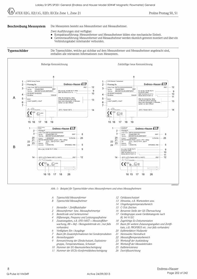
0ATEX II2G, II2(1)G, II2D; IECEx Zone 1, Zone 21 Proline Promag 50, 51
8 Endress+Hauser
Beschreibung Messsystem Die Messsystem besteht aus Messumformer und Messaufnehmer.
Zwei Ausführungen sind verfügbar:• Kompaktausführung: Messumformer und Messaufnehmer bilden eine mechanische Einheit.• Getrenntausführung: Messumformer und Messaufnehmer werden räumlich getrennt montiert und über ein
Verbindungskabel miteinander verbunden.
Typenschilder Die Typenschilder, welche gut sichtbar auf dem Messumformer und Messaufnehmer angebracht sind, enthalten alle relevanten Informationen zum Messsystem.
A0005624
Abb. 1: Beispiel für Typenschilder eines Messumformers und eines Messaufnehmers
Promag 5x
–20°C <Tamb<+50°C
IP67Order Code:
Ser.No.:
TAG No.:
5XP1H-XXXXXXXXXXXX
12345678901
ABCDEFGHJKLMNPQRST
20-55VAC/16-62VDC
50-60Hz
I-OUT (HART), f-OUT
15VA/W
EEx de [ia] IIC/IIB T6-T1 IP6XDMT 00 ATEX E 017 X
ECC
-20°C (-4°F)<Tamb<+60°C (+140°F) IP67
5XP1H-XXXXXXXXXXXX
1.0000/0000
PFA-10°C...150°C/+14°F...300°F
12345678901 RYABCDEFGHJKLMNPQRST
DN100 DIN/EN PN40 / pnom = PS = 40bar
EPD/MSÜ, R/BMaterals:
Order Code:
TM:
K-factor:
Ser.No.:
TAG No.:
Promag P
1.4435/316LElectrode:
0.2%CAL
68700 Cernay France
After de-energizing, delay10 Minutes before opening!Nach dem Abschalten 10 Minutenwarten vor dem Öffnen!
XAxxxD/06/../....
2007
68700 CernayFrance
2007
EEx e [ia] IIC/IIB T6-T1 IP6X
Promag 5x
–20°C <Tamb<+50°C
IP67Order Code:
Ser.No.:
TAG No.:
5xP1H-XXXXXXXXXXXX
12345678901
ABCDEFGHJKLMNPQRST
20-55VAC/16-62VDC
50-60Hz
I-OUT (HART), f-OUT
15VA/W
Ex de [ia] IIC/IIB T6-T1Ex tD A21 IP6XDMT 00 ATEX E 017 XIECEx BVS 07.0011 X
N12895
ECC
-20°C (-4°F)<Tamb<+60°C (+140°F) IP67
5XP1H-XXXXXXXXXXXX
1.0000/0000
PFA-10°C...150°C/+14°F...300°F
12345678901 RYABCDEFGHJKLMNPQRST
DN100 DIN/EN PN40 / pnom = PS = 40bar
EPD/MSÜ, R/BMaterals:
Order Code:
TM:
K-factor:
Ser.No.:
TAG No.:
Promag P
1.4435/316LElectrode:
0.2%CAL
N12895
4153 Reinach Switzerland
After de-energizing, delay10 Minutes before opening!Nach dem Abschalten 10 Minutenwarten vor dem Öffnen!
XAxxxD/06/../....
II2G0044
2007
4153 ReinachSwitzerland
2007
Ex e [ia] IIC/IIB T6-T1Ex tD A21 IP6XDMT 00 ATEX E 017 XIECEx BVS 07.0011 X
II2D
0044
N12895
II2GD0032
N12895
II2GD0032
iXAxxxD/06/../....
iXAxxxD/06/../....
II2GII2D
A
B
12
3
4
5
67
15
i
16 17 18 19
8
14
13
910
12
12
3
4
5
67
14
13
910
12
11
i
15 16 17 18 19
8
12
20
3
2223
24
2125
8
5
12
16 15 17 18 26
14
9101112
25
8
5
9
14
16 15 17 18 26
12
20
3
2223
24
21
Bisherige Kennzeichnung Zukünftige/neue Kennzeichnung
A Typenschild Messumformer
B Typenschild Messaufnehmer
1 Hersteller / Zertifikatshalter
2 Messumformer- bzw. Messaufnehmertyp
3 Bestellcode und Serienummer
4 Hilfsenergie, Frequenz und Leistungsaufnahme
5 Zusatzangaben, z.B. EPD/MSÜ = Messstoffüber-
wachung, RB = Ref.-/Bezugselektrode etc. (nur falls
vorhanden)
6 Verfügbare Ein-/Ausgänge
7 Raum für Zusatzinformationen bei Sonderprodukten
8 Herstellungsjahr
9 Kennzeichnung der Zündschutzart, Explosions-
gruppe, Temperaturklasse, Schutzart
10 Nummer der EG-Baumusterbescheinigung
11 Nummer der IECEx-Konformitätsbescheinigung
12 Gehäuseschutzart
13 Hinweise, z.B. Wartezeiten usw.
14 Umgebungstemperaturbereich
15 C-Tick Zeichen
16 Benannte Stelle der QS-Überwachung
17 Gerätegruppe sowie Gerätekategorie nach
RL 94/9/EG
18 Zugehörige Ex-Dokumentation
19 Raum für weitere Zulassungsangaben und Zertifi-
kate, z.B. PROFIBUS etc. (nur falls vorhanden)
20 Kalibrierfaktor/Nullpunkt
21 Nennweite/Nenndruck
22 Messstofftemperaturbereich
23 Werkstoff der Auskleidung
24 Werkstoff der Messelektroden
25 Kalibriertoleranz
26 Durchflussrichtung
Lobley St SPS SP331 General (Endress and Hauser Model 50W4F Magnetic Flowmeter) General
Q-Pulse Id VM349 Active 24/09/2013 Page 202 of 242
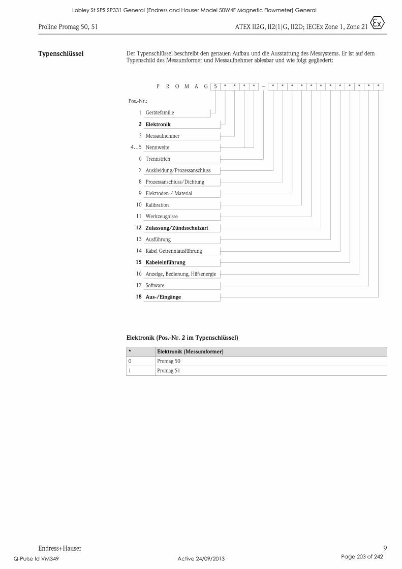
Proline Promag 50, 51 ATEX II2G, II2(1)G, II2D; IECEx Zone 1, Zone 21 0
Endress+Hauser 9
Typenschlüssel Der Typenschlüssel beschreibt den genauen Aufbau und die Ausstattung des Messystems. Er ist auf dem Typenschild des Messumformer und Messaufnehmer ablesbar und wie folgt gegliedert:
Elektronik (Pos.-Nr. 2 im Typenschlüssel)
P R O M A G 5 * * * * – * * * * * * * * * * * *
Pos.-Nr.:
1 Gerätefamilie
2 Elektronik
3 Messaufnehmer
4…5 Nennweite
6 Trennstrich
7 Auskleidung/Prozessanschluss
8 Prozessanschluss/Dichtung
9 Elektroden / Material
10 Kalibration
11 Werkzeugnisse
12 Zulassung/Zündsschutzart
13 Ausführung
14 Kabel Getrenntausführung
15 Kabeleinführung
16 Anzeige, Bedienung, Hilfsenergie
17 Software
18 Aus-/Eingänge
* Elektronik (Messumformer)
0 Promag 50
1 Promag 51
Lobley St SPS SP331 General (Endress and Hauser Model 50W4F Magnetic Flowmeter) General
Q-Pulse Id VM349 Active 24/09/2013 Page 203 of 242
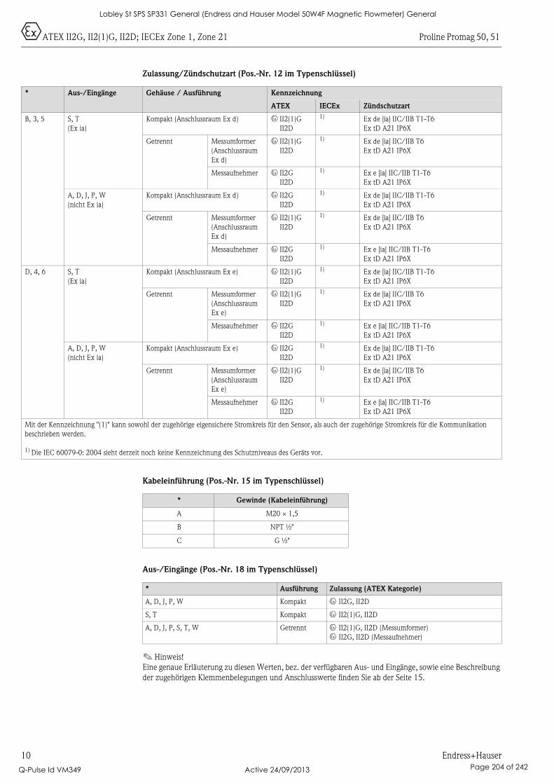
0ATEX II2G, II2(1)G, II2D; IECEx Zone 1, Zone 21 Proline Promag 50, 51
10 Endress+Hauser
Zulassung/Zündschutzart (Pos.-Nr. 12 im Typenschlüssel)
Kabeleinführung (Pos.-Nr. 15 im Typenschlüssel)
Aus-/Eingänge (Pos.-Nr. 18 im Typenschlüssel)
! Hinweis!
Eine genaue Erläuterung zu diesen Werten, bez. der verfügbaren Aus- und Eingänge, sowie eine Beschreibung
der zugehörigen Klemmenbelegungen und Anschlusswerte finden Sie ab der Seite 15.
* Aus-/Eingänge Gehäuse / Ausführung Kennzeichnung
ATEX IECEx Zündschutzart
B, 3, 5 S, T
(Ex ia)
Kompakt (Anschlussraum Ex d) 0 II2(1)G
II2D
1) Ex de [ia] IIC/IIB T1-T6
Ex tD A21 IP6X
Getrennt Messumformer
(Anschlussraum
Ex d)
0 II2(1)G
II2D
1) Ex de [ia] IIC/IIB T6
Ex tD A21 IP6X
Messaufnehmer 0 II2G
II2D
1) Ex e [ia] IIC/IIB T1-T6
Ex tD A21 IP6X
A, D, J, P, W
(nicht Ex ia)
Kompakt (Anschlussraum Ex d) 0 II2G
II2D
1) Ex de [ia] IIC/IIB T1-T6
Ex tD A21 IP6X
Getrennt Messumformer
(Anschlussraum
Ex d)
0 II2(1)G
II2D
1) Ex de [ia] IIC/IIB T6
Ex tD A21 IP6X
Messaufnehmer 0 II2G
II2D
1) Ex e [ia] IIC/IIB T1-T6
Ex tD A21 IP6X
D, 4, 6 S, T
(Ex ia)
Kompakt (Anschlussraum Ex e) 0 II2(1)G
II2D
1) Ex de [ia] IIC/IIB T1-T6
Ex tD A21 IP6X
Getrennt Messumformer
(Anschlussraum
Ex e)
0 II2(1)G
II2D
1) Ex de [ia] IIC/IIB T6
Ex tD A21 IP6X
Messaufnehmer 0 II2G
II2D
1) Ex e [ia] IIC/IIB T1-T6
Ex tD A21 IP6X
A, D, J, P, W
(nicht Ex ia)
Kompakt (Anschlussraum Ex e) 0 II2G
II2D
1) Ex de [ia] IIC/IIB T1-T6
Ex tD A21 IP6X
Getrennt Messumformer
(Anschlussraum
Ex e)
0 II2(1)G
II2D
1) Ex de [ia] IIC/IIB T6
Ex tD A21 IP6X
Messaufnehmer 0 II2G
II2D
1) Ex e [ia] IIC/IIB T1-T6
Ex tD A21 IP6X
Mit der Kennzeichnung "(1)" kann sowohl der zugehörige eigensichere Stromkreis für den Sensor, als auch der zugehörige Stromkreis für die Kommunikation
beschrieben werden.
1) Die IEC 60079-0: 2004 sieht derzeit noch keine Kennzeichnung des Schutzniveaus des Geräts vor.
* Gewinde (Kabeleinführung)
A M20 × 1,5
B NPT ½"
C G ½"
* Ausführung Zulassung (ATEX Kategorie)
A, D, J, P, W Kompakt 0 II2G, II2D
S, T Kompakt 0 II2(1)G, II2D
A, D, J, P, S, T, W Getrennt 0 II2(1)G, II2D (Messumformer)
0 II2G, II2D (Messaufnehmer)
Lobley St SPS SP331 General (Endress and Hauser Model 50W4F Magnetic Flowmeter) General
Q-Pulse Id VM349 Active 24/09/2013 Page 204 of 242
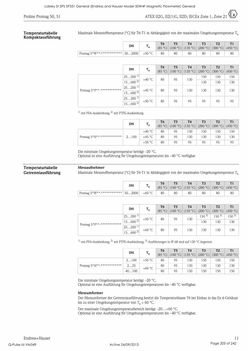
Proline Promag 50, 51 ATEX II2G, II2(1)G, II2D; IECEx Zone 1, Zone 21 0
Endress+Hauser 11
Temperaturtabelle Kompaktausführung
Maximale Messstofftemperatur [°C] für T6-T1 in Abhängigkeit von der maximalen Umgebungstemperatur Ta
1) mit PFA-Auskleidung; 2) mit PTFE-Auskleidung
Die minimale Umgebungstemperatur beträgt –20 °C. Optional ist eine Ausführung für Umgebungstemperaturen bis –40 °C verfügbar
Temperaturtabelle
Getrenntausführung
Messaufnehmer
Maximale Messstofftemperatur [°C] für T6-T1 in Abhängigkeit von der maximalen Umgebungstemperatur Ta
1) mit PFA-Auskleidung; 2) mit PTFE-Auskleidung; 3) Ausführungen in IP 68 sind auf 130 °C begrenzt.
Die minimale Umgebungstemperatur beträgt –20 °C. Optional ist eine Ausführung für Umgebungstemperaturen bis –40 °C verfügbar.
Messumformer
Der Messumformer der Getrenntausführung besitzt die Temperaturklasse T6 bei Einbau in das Ex d-Gehäuse
bis zu einer Umgebungstemperatur von Ta = 60 °C.
Der maximale Umgebungstemperaturbereich beträgt –20…+60 °C. Optional ist eine Ausführung für Umgebungstemperaturen bis –40 °C verfügbar.
DN TaT6
(85 °C)
T5
(100 °C)
T4
(135 °C)
T3
(200 °C)
T2
(300 °C)
T1
(450 °C)
Promag 5*W**-************ 50…2000 +50 °C 80 80 80 80 80 80
DN TaT6
(85 °C)
T5
(100 °C)
T4
(135 °C)
T3
(200 °C)
T2
(300 °C)
T1
(450 °C)
Promag 5*P**-************
25…200 1)
+40 °C 80 95 130150 150 150
15…600 2) 130 130 130
25…200 1)
+45 °C 80 95 130 130 130 13015…600 2)
25…200 1)
+50 °C 80 95 95 95 95 9515…600 2)
DN TaT6
(85 °C)
T5
(100 °C)
T4
(135 °C)
T3
(200 °C)
T2
(300 °C)
T1
(450 °C)
Promag 5*H**-************ 2…100
+40 °C 80 95 130 150 150 150
+45 °C 80 95 130 130 130 130
+50 °C 80 95 95 95 95 95
DN TaT6
(85 °C)
T5
(100 °C)
T4
(135 °C)
T3
(200 °C)
T2
(300 °C)
T1
(450 °C)
Promag 5*W**-************ 50…2000 +60 °C 80 80 80 80 80 80
DN TaT6
(85 °C)
T5
(100 °C)
T4
(135 °C)
T3
(200 °C)
T2
(300 °C)
T1
(450 °C)
Promag 5*P**-************
25…200 1)
+50 °C 80 95 130150 3) 150 3) 150 3)
15…600 2) 130 130 130
25…200 1)
+60 °C 80 95 130 130 130 13015…600 2)
DN TaT6
(85 °C)
T5
(100 °C)
T4
(135 °C)
T3
(200 °C)
T2
(300 °C)
T1
(450 °C)
Promag 5*H**-************
2…100 +50 °C 80 95 130 150 150 150
2…25+60 °C
80 95 130 130 130 130
40…100 80 95 130 150 150 150
Lobley St SPS SP331 General (Endress and Hauser Model 50W4F Magnetic Flowmeter) General
Q-Pulse Id VM349 Active 24/09/2013 Page 205 of 242
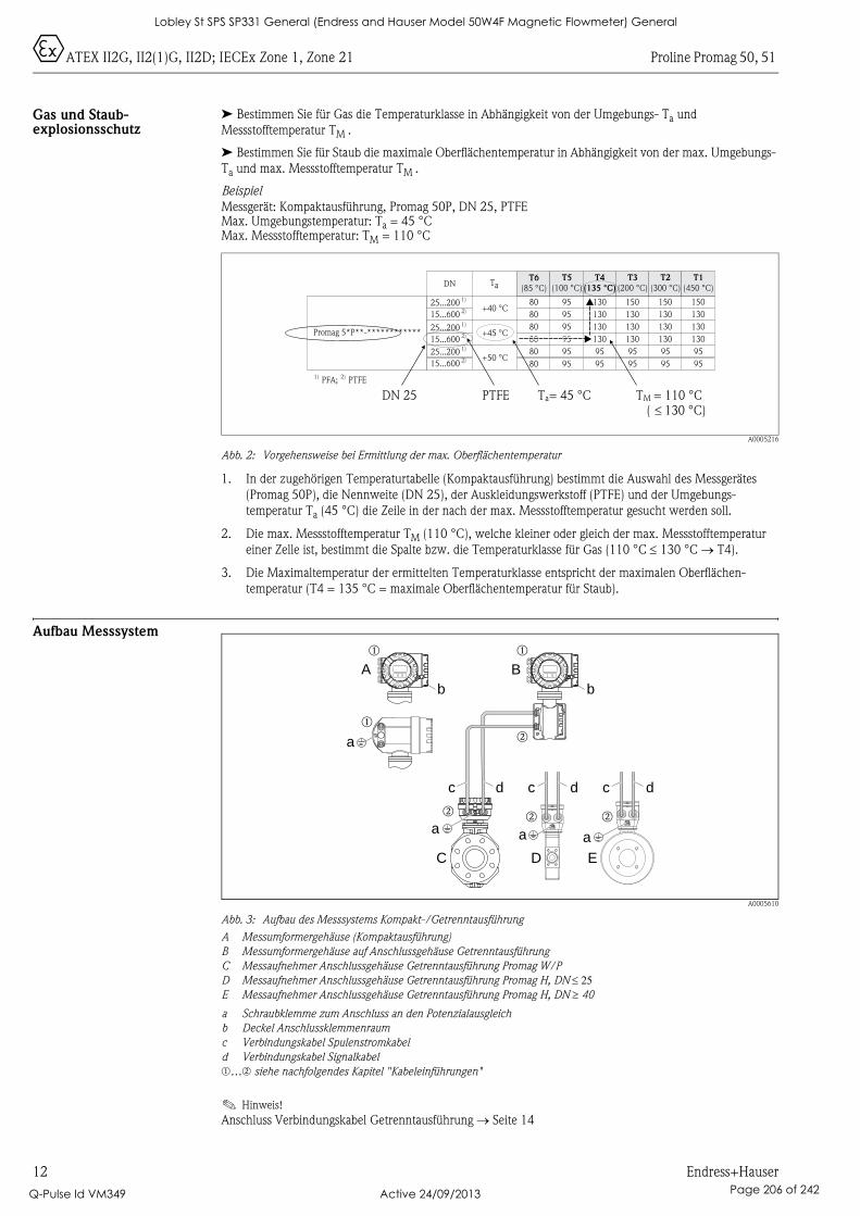
0ATEX II2G, II2(1)G, II2D; IECEx Zone 1, Zone 21 Proline Promag 50, 51
12 Endress+Hauser
Gas und Staub-explosionsschutz
➤ Bestimmen Sie für Gas die Temperaturklasse in Abhängigkeit von der Umgebungs- Ta und
Messstofftemperatur TM .
➤ Bestimmen Sie für Staub die maximale Oberflächentemperatur in Abhängigkeit von der max. Umgebungs-
Ta und max. Messstofftemperatur TM .
Beispiel
Messgerät: Kompaktausführung, Promag 50P, DN 25, PTFEMax. Umgebungstemperatur: Ta = 45 °CMax. Messstofftemperatur: TM = 110 °C
A0005216
Abb. 2: Vorgehensweise bei Ermittlung der max. Oberflächentemperatur
1. In der zugehörigen Temperaturtabelle (Kompaktausführung) bestimmt die Auswahl des Messgerätes
(Promag 50P), die Nennweite (DN 25), der Auskleidungswerkstoff (PTFE) und der Umgebungs-
temperatur Ta (45 °C) die Zeile in der nach der max. Messstofftemperatur gesucht werden soll.
2. Die max. Messstofftemperatur TM (110 °C), welche kleiner oder gleich der max. Messstofftemperatur
einer Zelle ist, bestimmt die Spalte bzw. die Temperaturklasse für Gas (110 °C ≤ 130 °C → T4).
3. Die Maximaltemperatur der ermittelten Temperaturklasse entspricht der maximalen Oberflächen-
temperatur (T4 = 135 °C = maximale Oberflächentemperatur für Staub).
Aufbau Messsystem
A0005610
Abb. 3: Aufbau des Messsystems Kompakt-/Getrenntausführung
A Messumformergehäuse (Kompaktausführung)
B Messumformergehäuse auf Anschlussgehäuse Getrenntausführung
C Messaufnehmer Anschlussgehäuse Getrenntausführung Promag W/P
D Messaufnehmer Anschlussgehäuse Getrenntausführung Promag H, DN ≤ 25E Messaufnehmer Anschlussgehäuse Getrenntausführung Promag H, DN ≥ 40
a Schraubklemme zum Anschluss an den Potenzialausgleich
b Deckel Anschlussklemmenraum
c Verbindungskabel Spulenstromkabel
d Verbindungskabel Signalkabel
m…n siehe nachfolgendes Kapitel "Kabeleinführungen"
! Hinweis!
Anschluss Verbindungskabel Getrenntausführung → Seite 14
Promag 5*P**-************
DN T T6
(85 °C)aT5
(100 °C)T4
(135 °C)
T3
(200 °C)T2
(300 °C)T1
(450 °C)1)25...2002)15...6001)25...2002)15...6001)25...2002)15...600
+40 °C
+45 °C
+50 °C
808080808080
959595959595
1301301301309595
1501301301309595
1501301301309595
1501301301309595
PFA;1) PTFE2)
DN 25 PTFE Ta= 45 °C TM = 110 °C130 °C)�(
A B
C
b
D E
a
b b
aa
a
c dc dc d
Nicht unter Spannungöffnen
Keep
cover
tightw
hile
circ
uits
are
aliv
e
Nepasouvrirl’appareil soustension
Keep
cove
rtightw
hile
circ
uits
are
aliv
e
Nicht unter Spannungöffnen
Keep
cove
rtig
htw
hile
circ
uits
are
aliv
e
Nepasouvrirl’appareil soustension
Keep
cover
tig
htw
hile
circ
uits
are
aliv
e
m m
n
m
nn n
Lobley St SPS SP331 General (Endress and Hauser Model 50W4F Magnetic Flowmeter) General
Q-Pulse Id VM349 Active 24/09/2013 Page 206 of 242
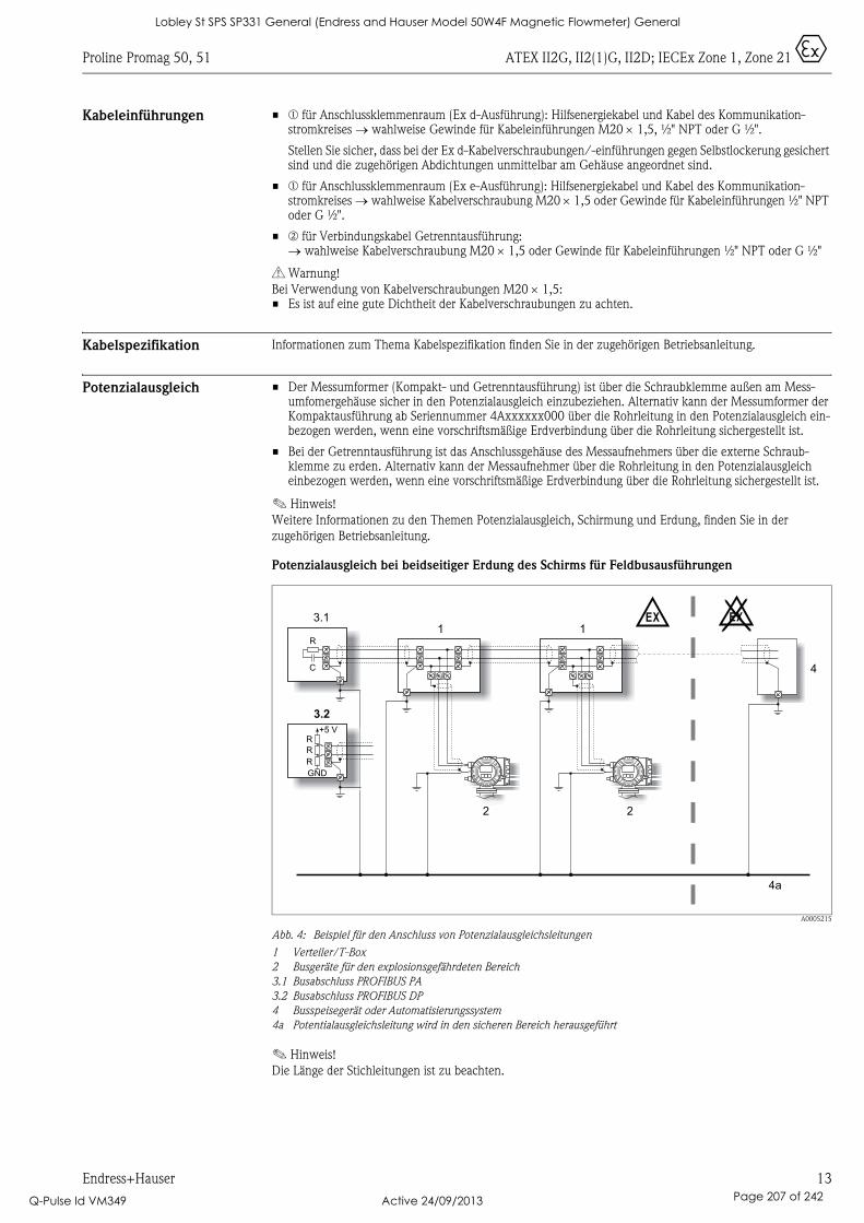
Proline Promag 50, 51 ATEX II2G, II2(1)G, II2D; IECEx Zone 1, Zone 21 0
Endress+Hauser 13
Kabeleinführungen • m für Anschlussklemmenraum (Ex d-Ausführung): Hilfsenergiekabel und Kabel des Kommunikation-stromkreises → wahlweise Gewinde für Kabeleinführungen M20 × 1,5, ½" NPT oder G ½".
Stellen Sie sicher, dass bei der Ex d-Kabelverschraubungen/-einführungen gegen Selbstlockerung gesichert sind und die zugehörigen Abdichtungen unmittelbar am Gehäuse angeordnet sind.
• m für Anschlussklemmenraum (Ex e-Ausführung): Hilfsenergiekabel und Kabel des Kommunikation-stromkreises → wahlweise Kabelverschraubung M20 × 1,5 oder Gewinde für Kabeleinführungen ½" NPT oder G ½".
• n für Verbindungskabel Getrenntausführung:→ wahlweise Kabelverschraubung M20 × 1,5 oder Gewinde für Kabeleinführungen ½" NPT oder G ½"
# Warnung!
Bei Verwendung von Kabelverschraubungen M20 × 1,5:• Es ist auf eine gute Dichtheit der Kabelverschraubungen zu achten.
Kabelspezifikation Informationen zum Thema Kabelspezifikation finden Sie in der zugehörigen Betriebsanleitung.
Potenzialausgleich • Der Messumformer (Kompakt- und Getrenntausführung) ist über die Schraubklemme außen am Mess-umfomergehäuse sicher in den Potenzialausgleich einzubeziehen. Alternativ kann der Messumformer der Kompaktausführung ab Seriennummer 4Axxxxxx000 über die Rohrleitung in den Potenzialausgleich ein-bezogen werden, wenn eine vorschriftsmäßige Erdverbindung über die Rohrleitung sichergestellt ist.
• Bei der Getrenntausführung ist das Anschlussgehäuse des Messaufnehmers über die externe Schraub-klemme zu erden. Alternativ kann der Messaufnehmer über die Rohrleitung in den Potenzialausgleich einbezogen werden, wenn eine vorschriftsmäßige Erdverbindung über die Rohrleitung sichergestellt ist.
! Hinweis!
Weitere Informationen zu den Themen Potenzialausgleich, Schirmung und Erdung, finden Sie in der
zugehörigen Betriebsanleitung.
Potenzialausgleich bei beidseitiger Erdung des Schirms für Feldbusausführungen
A0005215
Abb. 4: Beispiel für den Anschluss von Potenzialausgleichsleitungen
1 Verteiler/T-Box
2 Busgeräte für den explosionsgefährdeten Bereich
3.1 Busabschluss PROFIBUS PA
3.2 Busabschluss PROFIBUS DP
4 Busspeisegerät oder Automatisierungssystem
4a Potentialausgleichsleitung wird in den sicheren Bereich herausgeführt
! Hinweis!
Die Länge der Stichleitungen ist zu beachten.
1 1
2 2
3.1
4
4a
EX EX
R
C
3.2
R
GND
+5 V
R
R
Lobley St SPS SP331 General (Endress and Hauser Model 50W4F Magnetic Flowmeter) General
Q-Pulse Id VM349 Active 24/09/2013 Page 207 of 242
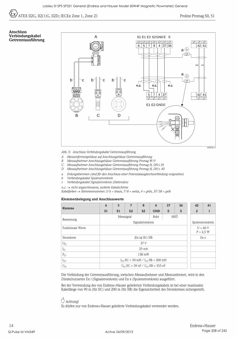
0ATEX II2G, II2(1)G, II2D; IECEx Zone 1, Zone 21 Proline Promag 50, 51
14 Endress+Hauser
Anschluss Verbindungskabel Getrenntausführung
A0005614
Abb. 5: Anschluss Verbindungskabel Getrenntausführung
A Messumformergehäuse auf Anschlussgehäuse Getrenntausführung
B Messaufnehmer Anschlussgehäuse Getrenntausführung Promag W/P
C Messaufnehmer Anschlussgehäuse Getrenntausführung Promag H, DN ≤ 25D Messaufnehmer Anschlussgehäuse Getrenntausführung Promag H, DN ≥ 40
a Erdungsklemmen (sind für den Anschluss einer Potenzialausgleichsverbindung vorgesehen)
b Verbindungskabel Spulenstromkreis
c Verbindungskabel Signalstromkreis (Elektroden)
n.c. → nicht angeschlossene, isolierte Kabelschirme
Kabelfarben → Klemmennummer: 5/6 = braun, 7/8 = weiss, 4 = grün, 37/38 = gelb
Klemmenbelegung und Anschlusswerte
Die Verbindung der Getrenntausführung, zwischen Messaufnehmer und Messumformer, wird in den
Zündschutzarten Ex i (Signalstromkreis) und Ex e (Spulenstromkreis) ausgeführt.
Bei der Verwendung des von Endress+Hauser gelieferten Verbindungskabels ist bei einer maximalen Kabellänge von 90 m (für IIC) und 200 m (für IIB) die Eigensicherheit des Stromkreises sichergestellt.
" Achtung!
Es dürfen nur von Endress+Hauser gelieferte Verbindungskabel verwendet werden.
Klemme6 5 7 8 4 37 36 42 41
S1 E1 E2 S2 GND E S 2 1
BenennungMesssignal Rohr MSÜ
Signalstromkreis Spulenstromkreis
Funktionale Werte U = 60 V
P = 2,5 W
Stromkreis [Ex ia] IIC/IIB Ex e
UO 37 V
IO 25 mA
PO 138 mW
LO LO IIC = 50 mH / LO IIB = 200 mH
CO CO IIC = 39 nF / CO IIB = 353 nF
A
B
b
C D
c b c
a
b b c
6 5
5
7
7
8 4
4
37
37
36 42
42
41
41
E1 E2 GNDE
2 1
S1 E1 E2 S2GND E S
n.c. n.c.n.c.n.c. n.c.n.c.
a
Nicht unter Spannungöffnen
Keep
cover
tightw
hile
circ
uits
are
aliv
e
Nepasouvrirl’appareil soustension
Keep
cove
rtightw
hile
circ
uits
are
aliv
e
Lobley St SPS SP331 General (Endress and Hauser Model 50W4F Magnetic Flowmeter) General
Q-Pulse Id VM349 Active 24/09/2013 Page 208 of 242
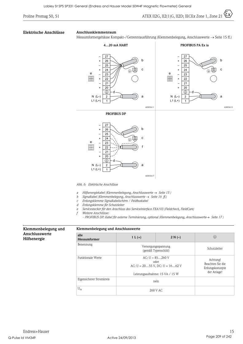
Proline Promag 50, 51 ATEX II2G, II2(1)G, II2D; IECEx Zone 1, Zone 21 0
Endress+Hauser 15
Elektrische Anschlüsse Anschlussklemmenraum
Messumformergehäuse Kompakt-/Getrenntausführung (Klemmenbelegung, Anschlusswerte → Seite 15 ff.)
Abb. 6: Elektrische Anschlüsse
a Hilfsenergiekabel (Klemmenbelegung, Anschlusswerte → Seite 15 )
b Signalkabel (Klemmenbelegung, Anschlusswerte → Seite 16 ff.)
c Erdungsklemme Signalkabelschirm / Feldbuskabel
d Erdungsklemme für Schutzleiter
e Servicestecker für den Anschluss des Serviceinterface FXA193 (Fieldcheck, FieldCare)
f Weitere Anschlüsse:
– PROFIBUS DP: Kabel für externe Terminierung, optional (Klemmenbelegung, Anschlusswerte→ Seite 17 )
Klemmenbelegung und
Anschlusswerte
Hilfsenergie
Klemmenbelegung und Anschlusswerte
4…20 mA HART
A0005611
PROFIBUS PA Ex ia
A0005613
PROFIBUS DP
A0005617
1
2
L1 (L+)
N (L–)
20
21
22
23
24
25
26
27
e
b
c
a
+
–
+
–
+
–
+
–
d
1
2
L1 (L+)
N (L–)
20
21
22
23
24
25
26
27
e
3
b
c
a
+
–
+
–
+
–
+
–
d
1
2
L1 (L+)
N (L–)
20
21
22
23
24
25
26
27
e
3
b
c
a
+
–
+
–
+
–
+
–
f
d
alle
Messumformer1 L (+) 2 N (–) *
BenennungVersorgungsspannung
(gemäß Typenschild)Schutzleiter
Funktionale Werte AC: U = 85…260 V
oder
AC: U = 20…55 V, DC: U = 16…62 V
Leistungsaufnahme: 15 VA / 15 W
Achtung!
Beachten Sie die
Erdungskonzepte
der Anlage!
Eigensicherer Stromkreisnein
Um 260 V AC
Lobley St SPS SP331 General (Endress and Hauser Model 50W4F Magnetic Flowmeter) General
Q-Pulse Id VM349 Active 24/09/2013 Page 209 of 242
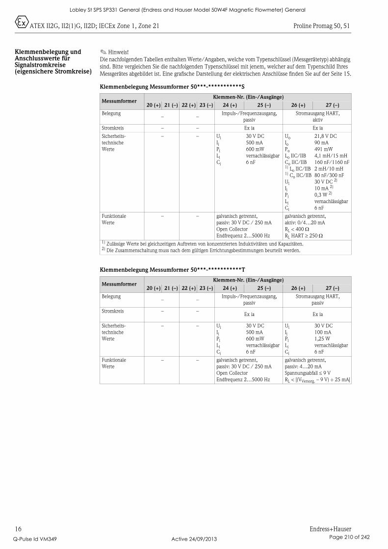
0ATEX II2G, II2(1)G, II2D; IECEx Zone 1, Zone 21 Proline Promag 50, 51
16 Endress+Hauser
Klemmenbelegung und Anschlusswerte für Signalstromkreise (eigensichere Stromkreise)
! Hinweis!
Die nachfolgenden Tabellen enthalten Werte/Angaben, welche vom Typenschlüssel (Messgerätetyp) abhängig
sind. Bitte vergleichen Sie die nachfolgenden Typenschlüssel mit jenem, welcher auf dem Typenschild Ihres
Messgerätes abgebildet ist. Eine grafische Darstellung der elektrischen Anschlüsse finden Sie auf der Seite 15.
Klemmenbelegung Messumformer 50***-***********S
Klemmenbelegung Messumformer 50***-***********T
MessumformerKlemmen-Nr. (Ein-/Ausgänge)
20 (+) 21 (–) 22 (+) 23 (–) 24 (+) 25 (–) 26 (+) 27 (–)
Belegung– –
Impuls-/Frequenzausgang,
passiv
Stromausgang HART,
aktiv
Stromkreis – – Ex ia Ex ia
Sicherheits-
technische
Werte
– – Ui
IiPi
Li
Ci
30 V DC
500 mA
600 mW
vernachlässigbar
6 nF
Uo
IoPo
Lo IIC/IIB
Co IIC/IIB1) Lo IIC/IIB1) Co IIC/IIB
Ui
IiPi
Li
Ci
21,8 V DC
90 mA
491 mW
4,1 mH/15 mH
160 nF/1160 nF
2 mH/10 mH
80 nF/300 nF
30 V DC 2)
10 mA 2)
0,3 W 2)
vernachlässigbar
6 nF
Funktionale
Werte
– – galvanisch getrennt,
passiv: 30 V DC / 250 mA
Open Collector
Endfrequenz 2…5000 Hz
galvanisch getrennt,
aktiv: 0/4…20 mA
RL < 400 ΩRL HART ≥ 250 Ω
1) Zulässige Werte bei gleichzeitigen Auftreten von konzentrierten Induktivitäten und Kapazitäten.2) Die Zusammenschaltung muss nach dem gültigen Errichtungsbestimmungen beurteilt werden.
MessumformerKlemmen-Nr. (Ein-/Ausgänge)
20 (+) 21 (–) 22 (+) 23 (–) 24 (+) 25 (–) 26 (+) 27 (–)
Belegung– –
Impuls-/Frequenzausgang,
passiv
Stromausgang HART,
passiv
Stromkreis – –Ex ia Ex ia
Sicherheits-
technische
Werte
– – Ui
IiPi
Li
Ci
30 V DC
500 mA
600 mW
vernachlässigbar
6 nF
Ui
IiPi
Li
Ci
30 V DC
100 mA
1,25 W
vernachlässigbar
6 nF
Funktionale
Werte
– – galvanisch getrennt,
passiv: 30 V DC / 250 mA
Open Collector
Endfrequenz 2…5000 Hz
galvanisch getrennt,
passiv: 4…20 mA
Spannungsabfall ≤ 9 V
RL < [(VVersorg. – 9 V) ÷ 25 mA]
Lobley St SPS SP331 General (Endress and Hauser Model 50W4F Magnetic Flowmeter) General
Q-Pulse Id VM349 Active 24/09/2013 Page 210 of 242
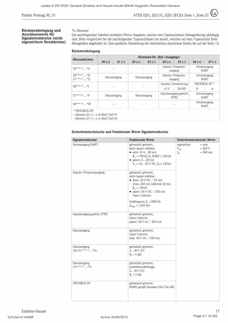
Proline Promag 50, 51 ATEX II2G, II2(1)G, II2D; IECEx Zone 1, Zone 21 0
Endress+Hauser 17
Klemmenbelegung und Anschlusswerte für Signalstromkreise (nicht eigensichere Stromkreise)
! Hinweis!
Die nachfolgenden Tabellen enthalten Werte/Angaben, welche vom Typenschlüssel (Messgerätetyp) abhängig
sind. Bitte vergleichen Sie die nachfolgenden Typenschlüssel mit jenem, welcher auf dem Typenschild Ihres
Messgerätes abgebildet ist. Eine grafische Darstellung der elektrischen Anschlüsse finden Sie auf der Seite 15.
Klemmenbelegung
Sicherheitstechnische und Funktionale Werte Signalstromkreise
MessumformerKlemmen-Nr. (Ein-/Ausgänge)
20 (+) 21 (–) 22 (+) 23 (–) 24 (+) 25 (–) 26 (+) 27 (–)
50***-*…*A – –Impuls-/Frequenz-
ausgang
Stromausgang
HART
50***-*…*D
51***-*…*DStatuseingang Statusausgang
Impuls-/Frequenz-
ausgang
Stromausgang
HART
50***-*…*J – –Externe Terminierung PROFIBUS DP *
+5 V DGND B A
51***-*…*P Statuseingang StatusausgangImpulsausgang geeicht
(PTB)
Stromausgang
HART
50***-*…*W – – –Stromausgang
HART
* PROFIBUS DP:
– Klemme 26 (+) → B (RxD/TxD-P)
– Klemme 27 (–) → A (RxD/TxD-N)
Signalstromkreise Funktionale Werte Sicherheitstechnische Werte
Stromausgang HART galvanisch getrennt,
aktiv/passiv wählbar:
• aktiv: 0/4…20 mA
RL < 700 Ω, RL HART ≥ 250 Ω• passiv: 4…20 mA
Vs = 18…30 V DC, Ri ≥ 150 Ω
eigensicher
Um
Im
= nein
= 260 V
= 500 mA
Impuls-/Frequenzausgang galvanisch getrennt,
aktiv/passiv wählbar:
• aktiv: 24 V DC / 25 mA
(max. 250 mA während 20 ms)
RL > 100 Ω• passiv: 30 V DC / 250 mA
Open Collector
Endfrequenz 2…1000 Hz
(fmax = 1250 Hz)
Impulsausgang geeicht (PTB) galvanisch getrennt,
Open Collector
passiv: 30 V AC / 250 mA
Statusausgang galvanisch getrennt,
Open Collector
max. 30 V AC / 250 mA
Statuseingang
(50/51***-*…*D)
galvanisch getrennt,
3…30 V DC
Ri = 5 kΩ
Statuseingang
(51***-*…*P)
galvanisch getrennt,
polaritätsunabhängig
3…30 V DC
Ri = 3 kΩ
PROFIBUS DP galvanisch getrennt,
RS485 gemäß Standard EIA/TIA-485
Lobley St SPS SP331 General (Endress and Hauser Model 50W4F Magnetic Flowmeter) General
Q-Pulse Id VM349 Active 24/09/2013 Page 211 of 242

0ATEX II2G, II2(1)G, II2D; IECEx Zone 1, Zone 21 Proline Promag 50, 51
18 Endress+Hauser
Servicestecker Der Servicestecker dient ausschließlich zum Anschluss von Endress+Hauser freigegebenen Service-Interfaces.
# Warnung!
Der Servicestecker darf nicht bei vorhandener explosionsfähiger Atmosphäre angeschlossen werden.
Gerätesicherung # Warnung!
Verwenden Sie nur die folgenden Sicherungstypen, welche auf der Netzteilplatine montiert sind:
• Spannung 20…55 V AC / 16…62 V DC:Sicherung 2,0 A träge, Abschaltvermögen 1500 A(Schurter, 0001.2503 oder Wickmann, Standard Type 181 2,0 A)
• Spannung 85…260 V AC: Sicherung 0,8 A träge, Abschaltvermögen 1500 A(Schurter, 0001.2507 oder Wickmann, Standard Type 181 0,8 A)
Technische Daten Abmessungen
Bitte entnehmen Sie diese Maße der jeweiligen Technischen Information:• Promag 50W, 53W → TI046D• Promag 50P, 53P → TI047D• Promag 50H, 53H → TI048D• Promag 51 → TI058D
Gewicht
Das Gewicht der Ex d-Ausführung erhöht sich gegenüber der Standardausführung um ca. 2 kg.
Lobley St SPS SP331 General (Endress and Hauser Model 50W4F Magnetic Flowmeter) General
Q-Pulse Id VM349 Active 24/09/2013 Page 212 of 242

This document is an integral part of the following Operating Instructions:
Safety Instructions
XA103D/06/a3/07.10
71114914
Ex-Dokumentation / Ex documentation / Documentation Ex
Proline Promag 50, 51HART, PROFIBUS DP/PA
ATEX II2G, II2(1)G, II2D; IECEx Zone 1, Zone 21
• BA046D, Proline Promag 50 HART• BA055D, Proline Promag 50 PROFIBUS DP/PA• BA080D, Proline Promag 51 HART
ContentsGeneral warnings . . . . . . . . . . . . . . . . . . . . . . . . . . . . . . . . . . . . . . . . . . . . . . . . . . . . . . . . . . . . . . . . . . . . . . 20
Special conditions . . . . . . . . . . . . . . . . . . . . . . . . . . . . . . . . . . . . . . . . . . . . . . . . . . . . . . . . . . . . . . . . . . . . . . 20
Installation instructions . . . . . . . . . . . . . . . . . . . . . . . . . . . . . . . . . . . . . . . . . . . . . . . . . . . . . . . . . . . . . . . . . . 20
EC type-examination certificate, directive 94/9/EC and COC certificates of conformity (IEC) . . . . . . . . . . . . . 21
Description of measuring system . . . . . . . . . . . . . . . . . . . . . . . . . . . . . . . . . . . . . . . . . . . . . . . . . . . . . . . . . . . 22
Nameplates. . . . . . . . . . . . . . . . . . . . . . . . . . . . . . . . . . . . . . . . . . . . . . . . . . . . . . . . . . . . . . . . . . . . . . . . . . . 22
Type code. . . . . . . . . . . . . . . . . . . . . . . . . . . . . . . . . . . . . . . . . . . . . . . . . . . . . . . . . . . . . . . . . . . . . . . . . . . . 23
Temperature table compact version . . . . . . . . . . . . . . . . . . . . . . . . . . . . . . . . . . . . . . . . . . . . . . . . . . . . . . . . . 25
Temperature table remote version . . . . . . . . . . . . . . . . . . . . . . . . . . . . . . . . . . . . . . . . . . . . . . . . . . . . . . . . . . 25
Gas and dust explosion protection . . . . . . . . . . . . . . . . . . . . . . . . . . . . . . . . . . . . . . . . . . . . . . . . . . . . . . . . . . 26
Design of measuring system . . . . . . . . . . . . . . . . . . . . . . . . . . . . . . . . . . . . . . . . . . . . . . . . . . . . . . . . . . . . . . 26
Cable entries. . . . . . . . . . . . . . . . . . . . . . . . . . . . . . . . . . . . . . . . . . . . . . . . . . . . . . . . . . . . . . . . . . . . . . . . . . 27
Cable specification . . . . . . . . . . . . . . . . . . . . . . . . . . . . . . . . . . . . . . . . . . . . . . . . . . . . . . . . . . . . . . . . . . . . . 27
Potential equalization . . . . . . . . . . . . . . . . . . . . . . . . . . . . . . . . . . . . . . . . . . . . . . . . . . . . . . . . . . . . . . . . . . . 27
Connection of remote version connecting cable . . . . . . . . . . . . . . . . . . . . . . . . . . . . . . . . . . . . . . . . . . . . . . . . 28
Electrical connection. . . . . . . . . . . . . . . . . . . . . . . . . . . . . . . . . . . . . . . . . . . . . . . . . . . . . . . . . . . . . . . . . . . . 29
Terminal assignment and connection data, power supply . . . . . . . . . . . . . . . . . . . . . . . . . . . . . . . . . . . . . . . . . 29
Terminal assignment and connection data for signal circuits (intrinsically safe circuits) . . . . . . . . . . . . . . . . . . . 30
Terminal assignment and connection data for signal circuits (non-intrinsically safe circuits) . . . . . . . . . . . . . . . 31
Service adapter . . . . . . . . . . . . . . . . . . . . . . . . . . . . . . . . . . . . . . . . . . . . . . . . . . . . . . . . . . . . . . . . . . . . . . . . 32
Device fuse. . . . . . . . . . . . . . . . . . . . . . . . . . . . . . . . . . . . . . . . . . . . . . . . . . . . . . . . . . . . . . . . . . . . . . . . . . . 32
Technical Data . . . . . . . . . . . . . . . . . . . . . . . . . . . . . . . . . . . . . . . . . . . . . . . . . . . . . . . . . . . . . . . . . . . . . . . . 32
Lobley St SPS SP331 General (Endress and Hauser Model 50W4F Magnetic Flowmeter) General
Q-Pulse Id VM349 Active 24/09/2013 Page 213 of 242
0ATEX II2G, II2(1)G, II2D; IECEx Zone 1, Zone 21 Proline Promag 50, 51
20 Endress+Hauser
General warnings • Compliance with national regulations relating to the installation, connection to the electricity supply, commissioning and maintenance of devices in potentially explosive atmospheres is mandatory, if such regulations exist (e.g. EN/IEC 60079-14).
• Installation, connection to the electricity supply, commissioning and maintenance of the devices must be carried out by qualified specialists trained to work on Ex-rated devices.
• Compliance with all of the technical data of the device (see nameplate) is mandatory.
• Open the device only when it is de-energized (and after a delay of at least 10 minutes following shutdown of the power supply) or in an area free of explosive atmospheres.
• It is not permissible to connect the service adapter whilst the atmosphere is considered to be explosive.
• Opening the transmitter housing and the connection housing of the remote version is only permitted for a brief time. During this time, ensure that no dust or moisture enters the housing.
• To guarantee resistance to dust, the transmitter housing, the connection housing of the remote version and the cable entries must be tightly sealed.
• Use of the devices is restricted to mediums against which the process-wetted materials are adequately resistant.
• The suitability of the device in the event of simultaneous occurrence of gas-air and dust-air mixtures requires an additional assessment.
Special conditions • The device must be integrated into the potential equalization system. Potential must be equalized along the intrinsically safe sensor circuits. Further information can be found in the "Potential equalization" chapter on page 27.
Installation instructions • For terminals No. 20 to No. 27 of the transmitter, only devices with ratings Um ≤ 260 V and Im ≤ 500 mA are allowed to be connected (does not apply to intrinsically safe circuits).
• The measuring device must only be used in the permitted temperature class. The values of the individual temperature classes can be found in the temperature tables on page 25.
For Zone 21:The surface temperature of the measuring device must not exceed 2/3 of the ignition temperature of a dust cloud. The maximum surface temperature must maintain a safe distance of 75 °C to the smolder temperature of a dust layer of 5 mm.
Example:Operation in temperature class T4 (135 °C) is, therefore, suitable for dust with an ignition temperature of 202.5 °C (1.5 × 135 °C or 135 °C = 2/3 of 202.5 °C) and a smolder temperature of 210 °C (135 °C + 75 °C).
• The following applies when connecting the electronics housing in Ex d: Only separately certified cable and pipe entries (Ex d IIC) must be used, which are suitable for an operating temperature of up to 80 °C. When using pipe entries, the associated sealing equipment must be fitted directly at the housing.
• The following applies when connecting the electronics housing in Ex e:Only separately certified cable and pipe entries, drain plugs (Ex e II) must be used, which are suitable for an operating temperature of up to 80 °C and for an Ingress protection of IP 67. The cables must be installed such that they are fixed in place. Adequate strain relief must be ensured.
• Suitable cables and suitable, certified cable glands, cable entries and drain plugs must be used for measuring devices operated at temperatures below –20 °C.
• The cable entries and openings not used must be sealed tight with suitable components.
• Turning the transmitter housing: the housing of the Ex-rated transmitter can be turned in 90° steps. Whe-reas the non-Ex version has a bayonet adapter, however, the Ex version has a thread. Recesses for centering the worm screw are provided to prevent inadvertent movement of the transmitter housing. It is permissible to turn the transmitter housing through a maximum of 180° during operation (in either direction), without compromising explosion protection. After turning the housing the worm screw must be tightened again.
• Turning the local display: the screw cap has to be removed before the local display can be turned, and this must be done with the device de-energized (and after a delay of at least 10 minutes following shutdown of the power supply).
• When connecting the intrinsically safe circuits of explosion protection category "ia" of the measuring device to certified intrinsically safe circuits of explosion protection category "ib" with the explosion group IIC and IIB respectively, the explosion protection changes to Ex ib IIC and Ex ib IIB respectively. Intrinsically safe circuits of explosion protection category "ib" are suitable for areas which require category 2 apparatus.
• If the active intrinsically safe communication circuits (input/output option S, terminals 26/27) are fed into areas that require 2D apparatus, the connected apparatus must be tested and certified accordingly.
Lobley St SPS SP331 General (Endress and Hauser Model 50W4F Magnetic Flowmeter) General
Q-Pulse Id VM349 Active 24/09/2013 Page 214 of 242

Proline Promag 50, 51 ATEX II2G, II2(1)G, II2D; IECEx Zone 1, Zone 21 0
Endress+Hauser 21
• In Zone 0, potentially explosive vapor/air mixtures may only occur under atmospheric conditions. If no potentially explosive mixtures are present, or if additional protective measures have been taken according to EN 1127-1, the devices may be operated under other atmospheric conditions in accordance with the manufacturer’s specifications.
EC type-examination
certificate,
directive 94/9/EC
and COC certificates of
conformity (IEC)
EC type-examination certificate, directive 94/9/EC
The system meets the fundamental health and safety requirements for the design and construction of devices
and protective systems intended for use in potentially explosive atmospheres in accordance with appendix II
of directive 94/9/EC.
Certification number: DMT 00 ATEX E 017 X
COC certificates of conformity (IEC)
By affixing the certification number the conformity with the following standards (depending on the device version) is certificated:
Certification number: IECEx BVS 07.0011 X
Inspection bodyDEKRA EXAM GmbH (previously Deutsche Montan Technologie GmbH, institute for the safety of electrical
apparatus, mining test facility)
Identification
See Page 24
As TÜV NORD and RWTÜV have merged, the number of the notified body has changed from 0032 to 0044.
" Caution!
The explosion group of the measuring device is IIC. However, it is reduced to IIB if the permitted, external capacitances/inductances for the intrinsically safe communication circuits are increased (see Page 30).
• IEC 60079-0 : 2004 • IEC 60079-11 : 2006 • IEC 61241-0 : 2004
• IEC 60079-1 : 2003 • IEC 60079-26 : 2006 • IEC 61241-1 : 2004
• IEC 60079-7 : 2001 • IEC 60079-27 : 2005
Lobley St SPS SP331 General (Endress and Hauser Model 50W4F Magnetic Flowmeter) General
Q-Pulse Id VM349 Active 24/09/2013 Page 215 of 242
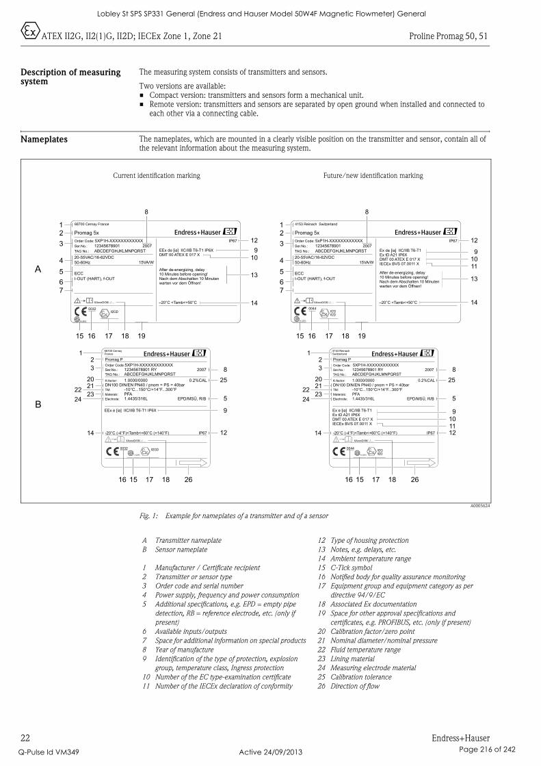
0ATEX II2G, II2(1)G, II2D; IECEx Zone 1, Zone 21 Proline Promag 50, 51
22 Endress+Hauser
Description of measuring system
The measuring system consists of transmitters and sensors.
Two versions are available:• Compact version: transmitters and sensors form a mechanical unit.• Remote version: transmitters and sensors are separated by open ground when installed and connected to
each other via a connecting cable.
Nameplates The nameplates, which are mounted in a clearly visible position on the transmitter and sensor, contain all of the relevant information about the measuring system.
A0005624
Fig. 1: Example for nameplates of a transmitter and of a sensor
Current identification marking Future/new identification marking
Promag 5x
–20°C <Tamb<+50°C
IP67Order Code:
Ser.No.:
TAG No.:
5XP1H-XXXXXXXXXXXX
12345678901
ABCDEFGHJKLMNPQRST
20-55VAC/16-62VDC
50-60Hz
I-OUT (HART), f-OUT
15VA/W
EEx de [ia] IIC/IIB T6-T1 IP6XDMT 00 ATEX E 017 X
ECC
-20°C (-4°F)<Tamb<+60°C (+140°F) IP67
5XP1H-XXXXXXXXXXXX
1.0000/0000
PFA-10°C...150°C/+14°F...300°F
12345678901 RYABCDEFGHJKLMNPQRST
DN100 DIN/EN PN40 / pnom = PS = 40bar
EPD/MSÜ, R/BMaterals:
Order Code:
TM:
K-factor:
Ser.No.:
TAG No.:
Promag P
1.4435/316LElectrode:
0.2%CAL
68700 Cernay France
After de-energizing, delay10 Minutes before opening!Nach dem Abschalten 10 Minutenwarten vor dem Öffnen!
XAxxxD/06/../....
2007
68700 CernayFrance
2007
EEx e [ia] IIC/IIB T6-T1 IP6X
Promag 5x
–20°C <Tamb<+50°C
IP67Order Code:
Ser.No.:
TAG No.:
5xP1H-XXXXXXXXXXXX
12345678901
ABCDEFGHJKLMNPQRST
20-55VAC/16-62VDC
50-60Hz
I-OUT (HART), f-OUT
15VA/W
Ex de [ia] IIC/IIB T6-T1Ex tD A21 IP6XDMT 00 ATEX E 017 XIECEx BVS 07.0011 X
N12895
ECC
-20°C (-4°F)<Tamb<+60°C (+140°F) IP67
5XP1H-XXXXXXXXXXXX
1.0000/0000
PFA-10°C...150°C/+14°F...300°F
12345678901 RYABCDEFGHJKLMNPQRST
DN100 DIN/EN PN40 / pnom = PS = 40bar
EPD/MSÜ, R/BMaterals:
Order Code:
TM:
K-factor:
Ser.No.:
TAG No.:
Promag P
1.4435/316LElectrode:
0.2%CAL
N12895
4153 Reinach Switzerland
After de-energizing, delay10 Minutes before opening!Nach dem Abschalten 10 Minutenwarten vor dem Öffnen!
XAxxxD/06/../....
II2G0044
2007
4153 ReinachSwitzerland
2007
Ex e [ia] IIC/IIB T6-T1Ex tD A21 IP6XDMT 00 ATEX E 017 XIECEx BVS 07.0011 X
II2D
0044
N12895
II2GD0032
N12895
II2GD0032
iXAxxxD/06/../....
iXAxxxD/06/../....
II2GII2D
A
B
12
3
4
5
67
15
i
16 17 18 19
8
14
13
910
12
12
3
4
5
67
14
13
910
12
11
i
15 16 17 18 19
8
12
20
3
2223
24
2125
8
5
12
16 15 17 18 26
14
9101112
25
8
5
9
14
16 15 17 18 26
12
20
3
2223
24
21
A Transmitter nameplate
B Sensor nameplate
1 Manufacturer / Certificate recipient
2 Transmitter or sensor type
3 Order code and serial number
4 Power supply, frequency and power consumption
5 Additional specifications, e.g. EPD = empty pipe
detection, RB = reference electrode, etc. (only if
present)
6 Available inputs/outputs
7 Space for additional information on special products
8 Year of manufacture
9 Identification of the type of protection, explosion
group, temperature class, Ingress protection
10 Number of the EC type-examination certificate
11 Number of the IECEx declaration of conformity
12 Type of housing protection
13 Notes, e.g. delays, etc.
14 Ambient temperature range
15 C-Tick symbol
16 Notified body for quality assurance monitoring
17 Equipment group and equipment category as per
directive 94/9/EC
18 Associated Ex documentation
19 Space for other approval specifications and
certificates, e.g. PROFIBUS, etc. (only if present)
20 Calibration factor/zero point
21 Nominal diameter/nominal pressure
22 Fluid temperature range
23 Lining material
24 Measuring electrode material
25 Calibration tolerance
26 Direction of flow
Lobley St SPS SP331 General (Endress and Hauser Model 50W4F Magnetic Flowmeter) General
Q-Pulse Id VM349 Active 24/09/2013 Page 216 of 242
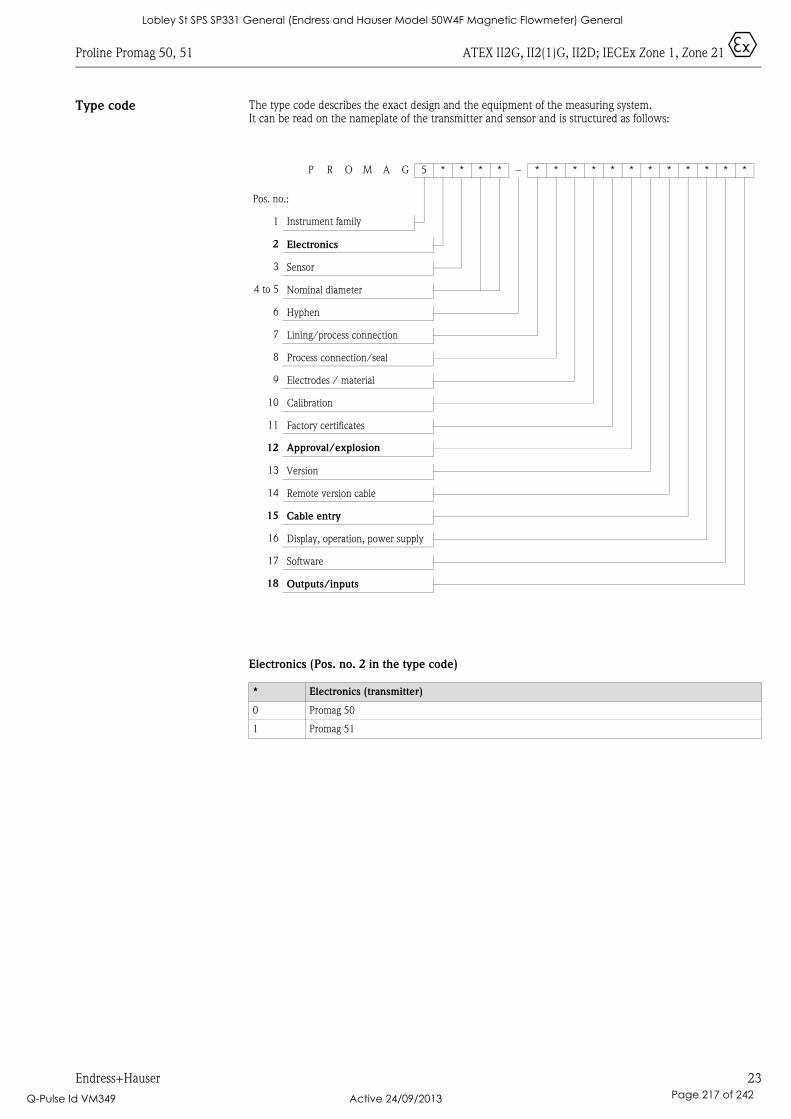
Proline Promag 50, 51 ATEX II2G, II2(1)G, II2D; IECEx Zone 1, Zone 21 0
Endress+Hauser 23
Type code The type code describes the exact design and the equipment of the measuring system. It can be read on the nameplate of the transmitter and sensor and is structured as follows:
Electronics (Pos. no. 2 in the type code)
P R O M A G 5 * * * * – * * * * * * * * * * * *
Pos. no.:
1 Instrument family
2 Electronics
3 Sensor
4 to 5 Nominal diameter
6 Hyphen
7 Lining/process connection
8 Process connection/seal
9 Electrodes / material
10 Calibration
11 Factory certificates
12 Approval/explosion
13 Version
14 Remote version cable
15 Cable entry
16 Display, operation, power supply
17 Software
18 Outputs/inputs
* Electronics (transmitter)
0 Promag 50
1 Promag 51
Lobley St SPS SP331 General (Endress and Hauser Model 50W4F Magnetic Flowmeter) General
Q-Pulse Id VM349 Active 24/09/2013 Page 217 of 242
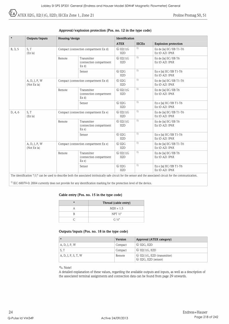
0ATEX II2G, II2(1)G, II2D; IECEx Zone 1, Zone 21 Proline Promag 50, 51
24 Endress+Hauser
Approval/explosion protection (Pos. no. 12 in the type code)
Cable entry (Pos. no. 15 in the type code)
Outputs/inputs (Pos. no. 18 in the type code)
! Note!
A detailed explanation of these values, regarding the available outputs and inputs, as well as a description of
the associated terminal assignments and connection data can be found from page 29 onwards.
* Outputs/inputs Housing/design Identification
ATEX IECEx Explosion protection
B, 3, 5 S, T
(Ex ia)
Compact (connection compartment Ex d) 0 II2(1)G
II2D
1) Ex de [ia] IIC/IIB T1-T6
Ex tD A21 IP6X
Remote Transmitter
(connection compartment
Ex d)
0 II2(1)G
II2D
1) Ex de [ia] IIC/IIB T6
Ex tD A21 IP6X
Sensor 0 II2G
II2D
1) Ex e [ia] IIC/IIB T1-T6
Ex tD A21 IP6X
A, D, J, P, W
(Not Ex ia)
Compact (connection compartment Ex d) 0 II2G
II2D
1) Ex de [ia] IIC/IIB T1-T6
Ex tD A21 IP6X
Remote Transmitter
(connection compartment
Ex d)
0 II2(1)G
II2D
1) Ex de [ia] IIC/IIB T6
Ex tD A21 IP6X
Sensor 0 II2G
II2D
1) Ex e [ia] IIC/IIB T1-T6
Ex tD A21 IP6X
D, 4, 6 S, T
(Ex ia)
Compact (connection compartment Ex e) 0 II2(1)G
II2D
1) Ex de [ia] IIC/IIB T1-T6
Ex tD A21 IP6X
Remote Transmitter
(connection compartment
Ex e)
0 II2(1)G
II2D
1) Ex de [ia] IIC/IIB T6
Ex tD A21 IP6X
Sensor 0 II2G
II2D
1) Ex e [ia] IIC/IIB T1-T6
Ex tD A21 IP6X
A, D, J, P, W
(Not Ex ia)
Compact (connection compartment Ex e) 0 II2G
II2D
1) Ex de [ia] IIC/IIB T1-T6
Ex tD A21 IP6X
Remote Transmitter
(connection compartment
Ex e)
0 II2(1)G
II2D
1) Ex de [ia] IIC/IIB T6
Ex tD A21 IP6X
Sensor 0 II2G
II2D
1) Ex e [ia] IIC/IIB T1-T6
Ex tD A21 IP6X
The identification "(1)" can be used to describe both the associated intrinsically safe circuit for the sensor and the associated circuit for the communication.
1) IEC 60079-0: 2004 currently does not provide for any identification marking for the protection level of the device.
* Thread (cable entry)
A M20 × 1.5
B NPT ½"
C G ½"
* Version Approval (ATEX category)
A, D, J, P, W Compact 0 II2G, II2D
S, T Compact 0 II2(1)G, II2D
A, D, J, P, S, T, W Remote 0 II2(1)G, II2D (transmitter)
0 II2G, II2D (sensor)
Lobley St SPS SP331 General (Endress and Hauser Model 50W4F Magnetic Flowmeter) General
Q-Pulse Id VM349 Active 24/09/2013 Page 218 of 242
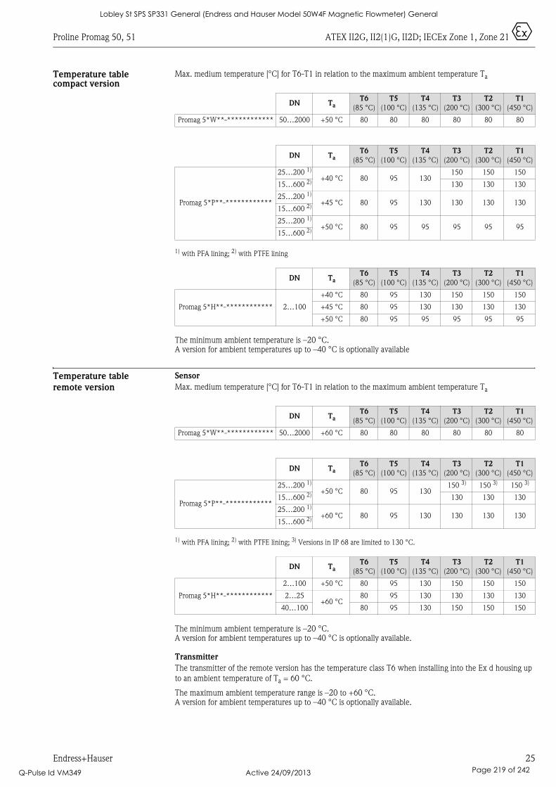
Proline Promag 50, 51 ATEX II2G, II2(1)G, II2D; IECEx Zone 1, Zone 21 0
Endress+Hauser 25
Temperature table compact version
Max. medium temperature [°C] for T6-T1 in relation to the maximum ambient temperature Ta
1) with PFA lining; 2) with PTFE lining
The minimum ambient temperature is –20 °C. A version for ambient temperatures up to –40 °C is optionally available
Temperature table
remote version
Sensor
Max. medium temperature [°C] for T6-T1 in relation to the maximum ambient temperature Ta
1) with PFA lining; 2) with PTFE lining; 3) Versions in IP 68 are limited to 130 °C.
The minimum ambient temperature is –20 °C. A version for ambient temperatures up to –40 °C is optionally available.
Transmitter
The transmitter of the remote version has the temperature class T6 when installing into the Ex d housing up
to an ambient temperature of Ta = 60 °C.
The maximum ambient temperature range is –20 to +60 °C. A version for ambient temperatures up to –40 °C is optionally available.
DN TaT6
(85 °C)
T5
(100 °C)
T4
(135 °C)
T3
(200 °C)
T2
(300 °C)
T1
(450 °C)
Promag 5*W**-************ 50…2000 +50 °C 80 80 80 80 80 80
DN TaT6
(85 °C)
T5
(100 °C)
T4
(135 °C)
T3
(200 °C)
T2
(300 °C)
T1
(450 °C)
Promag 5*P**-************
25…200 1)
+40 °C 80 95 130150 150 150
15…600 2) 130 130 130
25…200 1)
+45 °C 80 95 130 130 130 13015…600 2)
25…200 1)
+50 °C 80 95 95 95 95 9515…600 2)
DN TaT6
(85 °C)
T5
(100 °C)
T4
(135 °C)
T3
(200 °C)
T2
(300 °C)
T1
(450 °C)
Promag 5*H**-************ 2…100
+40 °C 80 95 130 150 150 150
+45 °C 80 95 130 130 130 130
+50 °C 80 95 95 95 95 95
DN TaT6
(85 °C)
T5
(100 °C)
T4
(135 °C)
T3
(200 °C)
T2
(300 °C)
T1
(450 °C)
Promag 5*W**-************ 50…2000 +60 °C 80 80 80 80 80 80
DN TaT6
(85 °C)
T5
(100 °C)
T4
(135 °C)
T3
(200 °C)
T2
(300 °C)
T1
(450 °C)
Promag 5*P**-************
25…200 1)
+50 °C 80 95 130150 3) 150 3) 150 3)
15…600 2) 130 130 130
25…200 1)
+60 °C 80 95 130 130 130 13015…600 2)
DN TaT6
(85 °C)
T5
(100 °C)
T4
(135 °C)
T3
(200 °C)
T2
(300 °C)
T1
(450 °C)
Promag 5*H**-************
2…100 +50 °C 80 95 130 150 150 150
2…25+60 °C
80 95 130 130 130 130
40…100 80 95 130 150 150 150
Lobley St SPS SP331 General (Endress and Hauser Model 50W4F Magnetic Flowmeter) General
Q-Pulse Id VM349 Active 24/09/2013 Page 219 of 242
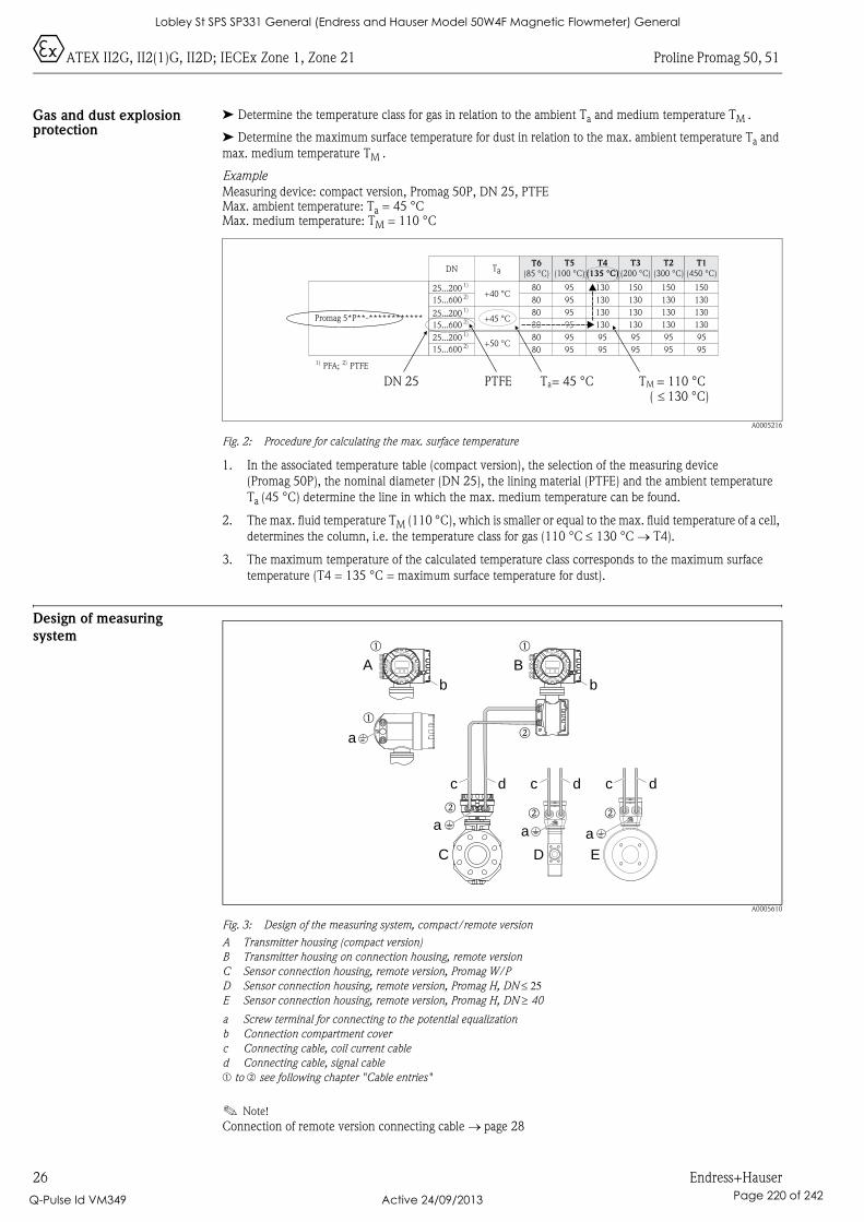
0ATEX II2G, II2(1)G, II2D; IECEx Zone 1, Zone 21 Proline Promag 50, 51
26 Endress+Hauser
Gas and dust explosion protection
➤ Determine the temperature class for gas in relation to the ambient Ta and medium temperature TM .
➤ Determine the maximum surface temperature for dust in relation to the max. ambient temperature Ta and
max. medium temperature TM .
Example
Measuring device: compact version, Promag 50P, DN 25, PTFEMax. ambient temperature: Ta = 45 °CMax. medium temperature: TM = 110 °C
A0005216
Fig. 2: Procedure for calculating the max. surface temperature
1. In the associated temperature table (compact version), the selection of the measuring device
(Promag 50P), the nominal diameter (DN 25), the lining material (PTFE) and the ambient temperature
Ta (45 °C) determine the line in which the max. medium temperature can be found.
2. The max. fluid temperature TM (110 °C), which is smaller or equal to the max. fluid temperature of a cell,
determines the column, i.e. the temperature class for gas (110 °C ≤ 130 °C → T4).
3. The maximum temperature of the calculated temperature class corresponds to the maximum surface
temperature (T4 = 135 °C = maximum surface temperature for dust).
Design of measuring
system
A0005610
Fig. 3: Design of the measuring system, compact/remote version
A Transmitter housing (compact version)
B Transmitter housing on connection housing, remote version
C Sensor connection housing, remote version, Promag W/P
D Sensor connection housing, remote version, Promag H, DN ≤ 25E Sensor connection housing, remote version, Promag H, DN ≥ 40
a Screw terminal for connecting to the potential equalization
b Connection compartment cover
c Connecting cable, coil current cable
d Connecting cable, signal cable
m to n see following chapter "Cable entries"
! Note!
Connection of remote version connecting cable → page 28
Promag 5*P**-************
DN T T6
(85 °C)aT5
(100 °C)T4
(135 °C)
T3
(200 °C)T2
(300 °C)T1
(450 °C)1)25...2002)15...6001)25...2002)15...6001)25...2002)15...600
+40 °C
+45 °C
+50 °C
808080808080
959595959595
1301301301309595
1501301301309595
1501301301309595
1501301301309595
PFA;1) PTFE2)
DN 25 PTFE Ta= 45 °C TM = 110 °C130 °C)�(
A B
C
b
D E
a
b b
aa
a
c dc dc d
Nicht unter Spannungöffnen
Keep
cover
tightw
hile
circ
uits
are
aliv
e
Nepasouvrirl’appareil soustension
Keep
cove
rtightw
hile
circ
uits
are
aliv
e
Nicht unter Spannungöffnen
Keep
cove
rtig
htw
hile
circ
uits
are
aliv
e
Nepasouvrirl’appareil soustension
Keep
cover
tig
htw
hile
circ
uits
are
aliv
e
m m
n
m
nn n
Lobley St SPS SP331 General (Endress and Hauser Model 50W4F Magnetic Flowmeter) General
Q-Pulse Id VM349 Active 24/09/2013 Page 220 of 242
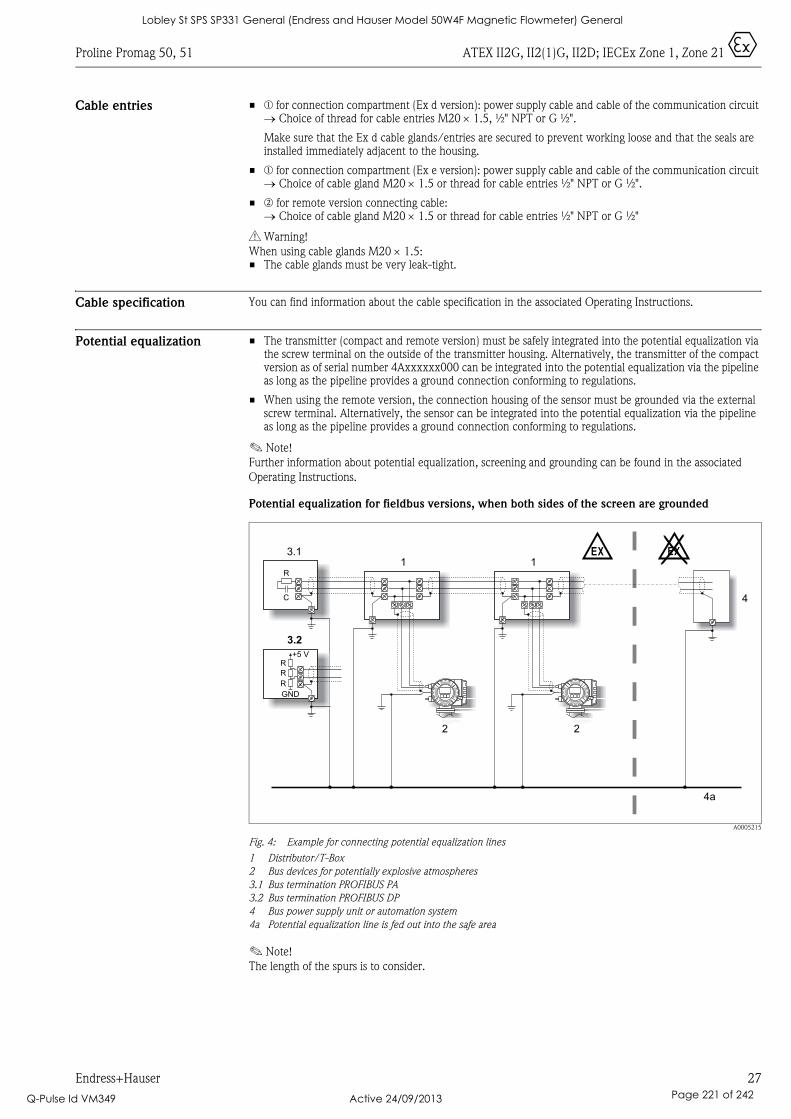
Proline Promag 50, 51 ATEX II2G, II2(1)G, II2D; IECEx Zone 1, Zone 21 0
Endress+Hauser 27
Cable entries • m for connection compartment (Ex d version): power supply cable and cable of the communication circuit → Choice of thread for cable entries M20 × 1.5, ½" NPT or G ½".
Make sure that the Ex d cable glands/entries are secured to prevent working loose and that the seals are installed immediately adjacent to the housing.
• m for connection compartment (Ex e version): power supply cable and cable of the communication circuit → Choice of cable gland M20 × 1.5 or thread for cable entries ½" NPT or G ½".
• n for remote version connecting cable:→ Choice of cable gland M20 × 1.5 or thread for cable entries ½" NPT or G ½"
# Warning!
When using cable glands M20 × 1.5:• The cable glands must be very leak-tight.
Cable specification You can find information about the cable specification in the associated Operating Instructions.
Potential equalization • The transmitter (compact and remote version) must be safely integrated into the potential equalization via the screw terminal on the outside of the transmitter housing. Alternatively, the transmitter of the compact version as of serial number 4Axxxxxx000 can be integrated into the potential equalization via the pipeline as long as the pipeline provides a ground connection conforming to regulations.
• When using the remote version, the connection housing of the sensor must be grounded via the external screw terminal. Alternatively, the sensor can be integrated into the potential equalization via the pipeline as long as the pipeline provides a ground connection conforming to regulations.
! Note!
Further information about potential equalization, screening and grounding can be found in the associated
Operating Instructions.
Potential equalization for fieldbus versions, when both sides of the screen are grounded
A0005215
Fig. 4: Example for connecting potential equalization lines
1 Distributor/T-Box
2 Bus devices for potentially explosive atmospheres
3.1 Bus termination PROFIBUS PA
3.2 Bus termination PROFIBUS DP
4 Bus power supply unit or automation system
4a Potential equalization line is fed out into the safe area
! Note!
The length of the spurs is to consider.
1 1
2 2
3.1
4
4a
EX EX
R
C
3.2
R
GND
+5 V
R
R
Lobley St SPS SP331 General (Endress and Hauser Model 50W4F Magnetic Flowmeter) General
Q-Pulse Id VM349 Active 24/09/2013 Page 221 of 242
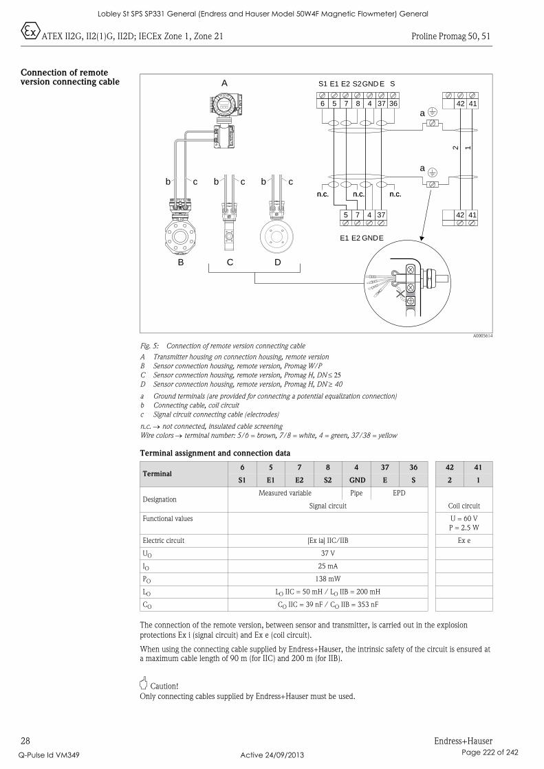
0ATEX II2G, II2(1)G, II2D; IECEx Zone 1, Zone 21 Proline Promag 50, 51
28 Endress+Hauser
Connection of remote version connecting cable
A0005614
Fig. 5: Connection of remote version connecting cable
A Transmitter housing on connection housing, remote version
B Sensor connection housing, remote version, Promag W/P
C Sensor connection housing, remote version, Promag H, DN ≤ 25D Sensor connection housing, remote version, Promag H, DN ≥ 40
a Ground terminals (are provided for connecting a potential equalization connection)
b Connecting cable, coil circuit
c Signal circuit connecting cable (electrodes)
n.c. → not connected, insulated cable screening
Wire colors → terminal number: 5/6 = brown, 7/8 = white, 4 = green, 37/38 = yellow
Terminal assignment and connection data
The connection of the remote version, between sensor and transmitter, is carried out in the explosion
protections Ex i (signal circuit) and Ex e (coil circuit).
When using the connecting cable supplied by Endress+Hauser, the intrinsic safety of the circuit is ensured at a maximum cable length of 90 m (for IIC) and 200 m (for IIB).
" Caution!
Only connecting cables supplied by Endress+Hauser must be used.
Terminal6 5 7 8 4 37 36 42 41
S1 E1 E2 S2 GND E S 2 1
DesignationMeasured variable Pipe EPD
Signal circuit Coil circuit
Functional values U = 60 V
P = 2.5 W
Electric circuit [Ex ia] IIC/IIB Ex e
UO 37 V
IO 25 mA
PO 138 mW
LO LO IIC = 50 mH / LO IIB = 200 mH
CO CO IIC = 39 nF / CO IIB = 353 nF
A
B
b
C D
c b c
a
b b c
6 5
5
7
7
8 4
4
37
37
36 42
42
41
41
E1 E2 GNDE
2 1
S1 E1 E2 S2GND E S
n.c. n.c.n.c.n.c. n.c.n.c.
a
Nicht unter Spannungöffnen
Keep
cover
tightw
hile
circ
uits
are
aliv
e
Nepasouvrirl’appareil soustension
Keep
cove
rtightw
hile
circ
uits
are
aliv
e
Lobley St SPS SP331 General (Endress and Hauser Model 50W4F Magnetic Flowmeter) General
Q-Pulse Id VM349 Active 24/09/2013 Page 222 of 242
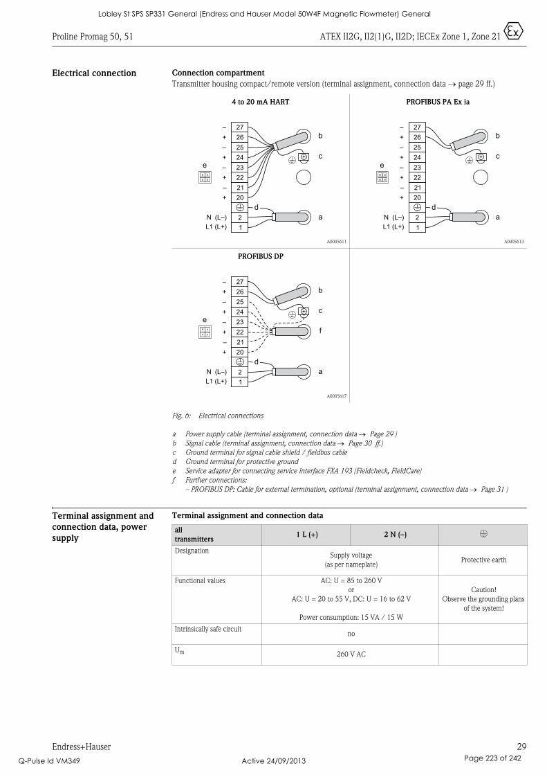
Proline Promag 50, 51 ATEX II2G, II2(1)G, II2D; IECEx Zone 1, Zone 21 0
Endress+Hauser 29
Electrical connection Connection compartment
Transmitter housing compact/remote version (terminal assignment, connection data → page 29 ff.)
Fig. 6: Electrical connections
a Power supply cable (terminal assignment, connection data → Page 29 )
b Signal cable (terminal assignment, connection data → Page 30 ff.)
c Ground terminal for signal cable shield / fieldbus cable
d Ground terminal for protective ground
e Service adapter for connecting service interface FXA 193 (Fieldcheck, FieldCare)
f Further connections:
– PROFIBUS DP: Cable for external termination, optional (terminal assignment, connection data → Page 31 )
Terminal assignment and
connection data, power
supply
Terminal assignment and connection data
4 to 20 mA HART
A0005611
PROFIBUS PA Ex ia
A0005613
PROFIBUS DP
A0005617
1
2
L1 (L+)
N (L–)
20
21
22
23
24
25
26
27
e
b
c
a
+
–
+
–
+
–
+
–
d
1
2
L1 (L+)
N (L–)
20
21
22
23
24
25
26
27
e
3
b
c
a
+
–
+
–
+
–
+
–
d
1
2
L1 (L+)
N (L–)
20
21
22
23
24
25
26
27
e
3
b
c
a
+
–
+
–
+
–
+
–
f
d
all
transmitters1 L (+) 2 N (–) *
DesignationSupply voltage
(as per nameplate)Protective earth
Functional values AC: U = 85 to 260 V
or
AC: U = 20 to 55 V, DC: U = 16 to 62 V
Power consumption: 15 VA / 15 W
Caution!
Observe the grounding plans
of the system!
Intrinsically safe circuitno
Um 260 V AC
Lobley St SPS SP331 General (Endress and Hauser Model 50W4F Magnetic Flowmeter) General
Q-Pulse Id VM349 Active 24/09/2013 Page 223 of 242
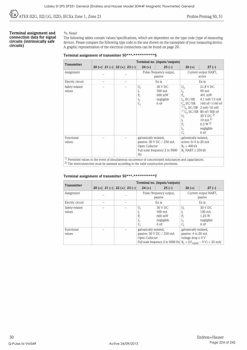
0ATEX II2G, II2(1)G, II2D; IECEx Zone 1, Zone 21 Proline Promag 50, 51
30 Endress+Hauser
Terminal assignment and connection data for signal circuits (intrinsically safe circuits)
! Note!
The following tables contain values/specifications, which are dependent on the type code (type of measuring
device). Please compare the following type code to the one shown on the nameplate of your measuring device.
A graphic representation of the electrical connections can be found on page 29.
Terminal assignment of transmitter 50***-***********S
Terminal assignment of transmitter 50***-***********T
TransmitterTerminal no. (inputs/outputs)
20 (+) 21 (–) 22 (+) 23 (–) 24 (+) 25 (–) 26 (+) 27 (–)
Assignment– –
Pulse/frequency output,
passive
Current output HART,
active
Electric circuit – – Ex ia Ex ia
Safety-related
values
– – Ui
IiPi
Li
Ci
30 V DC
500 mA
600 mW
negligible
6 nF
Uo
IoPo
Lo IIC/IIB
Co IIC/IIB1) Lo IIC/IIB1) Co IIC/IIB
Ui
IiPi
Li
Ci
21.8 V DC
90 mA
491 mW
4.1 mH/15 mH
160 nF/1160 nF
2 mH/10 mH
80 nF/300 nF
30 V DC 2)
10 mA 2)
0.3 W 2)
negligible
6 nF
Functional
values
– – galvanically isolated,
passive: 30 V DC / 250 mA
Open Collector
Full scale frequency 2 to 5000
Hz
galvanically isolated,
active: 0/4 to 20 mA
RL < 400 ΩRL HART ≥ 250 Ω
1) Permitted values in the event of simultaneous occurrence of concentrated inductances and capacitances.2) The interconnection must be assessed according to the valid construction provisions.
TransmitterTerminal no. (inputs/outputs)
20 (+) 21 (–) 22 (+) 23 (–) 24 (+) 25 (–) 26 (+) 27 (–)
Assignment– –
Pulse/frequency output,
passive
Current output HART,
passive
Electric circuit – – Ex ia Ex ia
Safety-related
values
– – Ui
IiPi
Li
Ci
30 V DC
500 mA
600 mW
negligible
6 nF
Ui
IiPi
Li
Ci
30 V DC
100 mA
1.25 W
negligible
6 nF
Functional
values
– – galvanically isolated,
passive: 30 V DC / 250 mA
Open Collector
Full scale frequency 2 to 5000 Hz
galvanically isolated,
passive: 4 to 20 mA
voltage drop ≤ 9 V
RL < [(Vsupply – 9 V) ÷ 25 mA]
Lobley St SPS SP331 General (Endress and Hauser Model 50W4F Magnetic Flowmeter) General
Q-Pulse Id VM349 Active 24/09/2013 Page 224 of 242
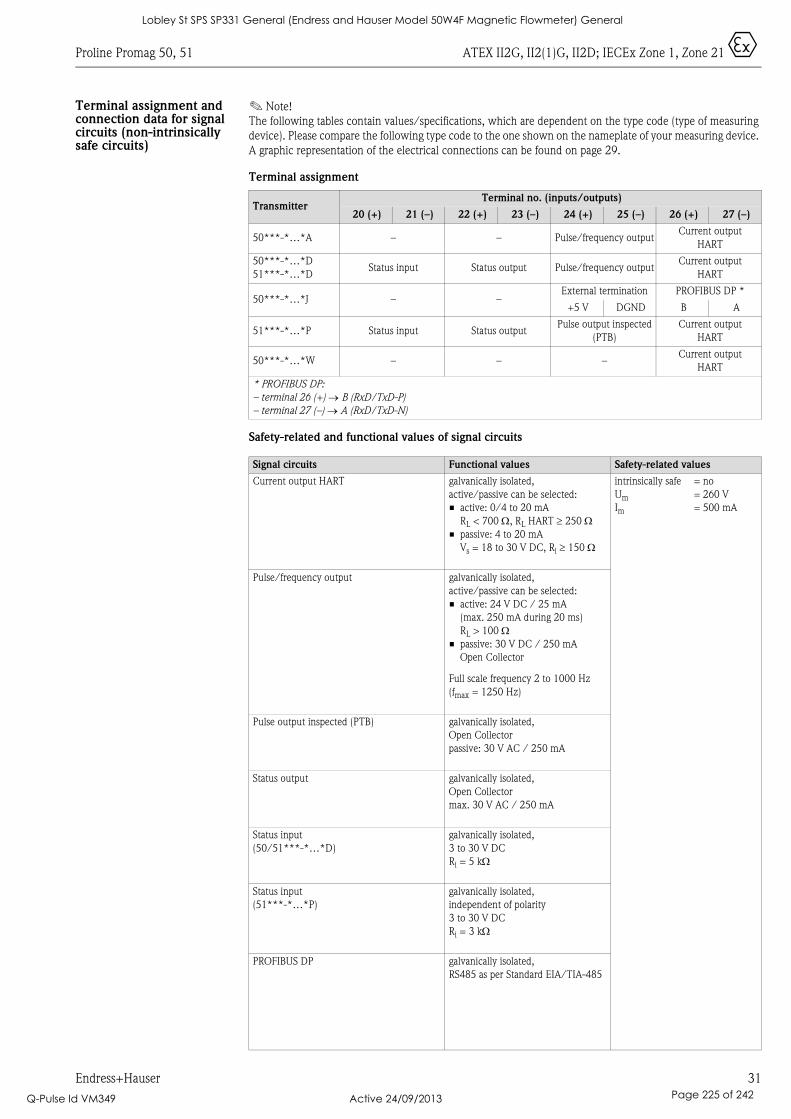
Proline Promag 50, 51 ATEX II2G, II2(1)G, II2D; IECEx Zone 1, Zone 21 0
Endress+Hauser 31
Terminal assignment and connection data for signal circuits (non-intrinsically safe circuits)
! Note!
The following tables contain values/specifications, which are dependent on the type code (type of measuring
device). Please compare the following type code to the one shown on the nameplate of your measuring device.
A graphic representation of the electrical connections can be found on page 29.
Terminal assignment
Safety-related and functional values of signal circuits
TransmitterTerminal no. (inputs/outputs)
20 (+) 21 (–) 22 (+) 23 (–) 24 (+) 25 (–) 26 (+) 27 (–)
50***-*…*A – – Pulse/frequency outputCurrent output
HART
50***-*…*D
51***-*…*DStatus input Status output Pulse/frequency output
Current output
HART
50***-*…*J – –External termination PROFIBUS DP *
+5 V DGND B A
51***-*…*P Status input Status outputPulse output inspected
(PTB)
Current output
HART
50***-*…*W – – –Current output
HART
* PROFIBUS DP:
– terminal 26 (+) → B (RxD/TxD-P)
– terminal 27 (–) → A (RxD/TxD-N)
Signal circuits Functional values Safety-related values
Current output HART galvanically isolated,
active/passive can be selected:
• active: 0/4 to 20 mA
RL < 700 Ω, RL HART ≥ 250 Ω• passive: 4 to 20 mA
Vs = 18 to 30 V DC, Ri ≥ 150 Ω
intrinsically safe
Um
Im
= no
= 260 V
= 500 mA
Pulse/frequency output galvanically isolated,
active/passive can be selected:
• active: 24 V DC / 25 mA
(max. 250 mA during 20 ms)
RL > 100 Ω• passive: 30 V DC / 250 mA
Open Collector
Full scale frequency 2 to 1000 Hz
(fmax = 1250 Hz)
Pulse output inspected (PTB) galvanically isolated,
Open Collector
passive: 30 V AC / 250 mA
Status output galvanically isolated,
Open Collector
max. 30 V AC / 250 mA
Status input
(50/51***-*…*D)
galvanically isolated,
3 to 30 V DC
Ri = 5 kΩ
Status input
(51***-*…*P)
galvanically isolated,
independent of polarity
3 to 30 V DC
Ri = 3 kΩ
PROFIBUS DP galvanically isolated,
RS485 as per Standard EIA/TIA-485
Lobley St SPS SP331 General (Endress and Hauser Model 50W4F Magnetic Flowmeter) General
Q-Pulse Id VM349 Active 24/09/2013 Page 225 of 242
0ATEX II2G, II2(1)G, II2D; IECEx Zone 1, Zone 21 Proline Promag 50, 51
32 Endress+Hauser
Service adapter The service adapter is only used for connecting service interfaces approved by Endress+Hauser.
# Warning!
It is not permissible to connect the service adapter whilst the atmosphere is considered to be explosive.
Device fuse # Warning!
Use only fuses of the following types; the fuses are installed on the power supply board:
• Voltage 20 to 55 V AC / 16 to 62 V DC:fuse 2.0 A slow-blow, disconnect capacity 1500 A(Schurter, 0001.2503 or Wickmann, Standard Type 181 2.0 A)
• Voltage 85 to 260 V AC: fuse 0.8 A slow-blow, disconnect capacity 1500 A(Schurter, 0001.2507 or Wickmann, Standard Type 181 0.8 A)
Technical Data Dimensions
Please refer to the respective Technical Information for these dimensions:• Promag 50W, 53W → TI046D• Promag 50P, 53P → TI047D• Promag 50H, 53H → TI048D• Promag 51 → TI058D
Weight
The weight of the Ex d version is approx. 2 kg greater than that of the standard version.
Lobley St SPS SP331 General (Endress and Hauser Model 50W4F Magnetic Flowmeter) General
Q-Pulse Id VM349 Active 24/09/2013 Page 226 of 242

Le présent document fait partie intégrante du manuel de mise en service suivant:
Conseils de sécurite
XA103D/06/a3/07.10
71114914
Ex-Dokumentation / Ex documentation / Documentation Ex
Proline Promag 50, 51HART, PROFIBUS DP/PA
ATEX II2G, II2(1)G, II2D; IECEx Zone 1, Zone 21
• BA046D, Proline Promag 50 HART• BA055D, Proline Promag 50 PROFIBUS DP/PA• BA080D, Proline Promag 51 HART
SommaireAvertissements généraux. . . . . . . . . . . . . . . . . . . . . . . . . . . . . . . . . . . . . . . . . . . . . . . . . . . . . . . . . . . . . . . . . 34
Conditions particulières. . . . . . . . . . . . . . . . . . . . . . . . . . . . . . . . . . . . . . . . . . . . . . . . . . . . . . . . . . . . . . . . . . 34
Instructions d'installation . . . . . . . . . . . . . . . . . . . . . . . . . . . . . . . . . . . . . . . . . . . . . . . . . . . . . . . . . . . . . . . . 34
Attestation d’exament CE de type, directive 94/9/CE et Déclaration CEI de conformité . . . . . . . . . . . . . . . . . 35
Description du système de mesure . . . . . . . . . . . . . . . . . . . . . . . . . . . . . . . . . . . . . . . . . . . . . . . . . . . . . . . . . 36
Plaques signalétiques. . . . . . . . . . . . . . . . . . . . . . . . . . . . . . . . . . . . . . . . . . . . . . . . . . . . . . . . . . . . . . . . . . . . 36
Structure de commande . . . . . . . . . . . . . . . . . . . . . . . . . . . . . . . . . . . . . . . . . . . . . . . . . . . . . . . . . . . . . . . . . 37
Tableau des températures version compacte . . . . . . . . . . . . . . . . . . . . . . . . . . . . . . . . . . . . . . . . . . . . . . . . . . 39
Tableau des températures version séparée . . . . . . . . . . . . . . . . . . . . . . . . . . . . . . . . . . . . . . . . . . . . . . . . . . . . 39
Protection contre les gaz et poussières inflammables . . . . . . . . . . . . . . . . . . . . . . . . . . . . . . . . . . . . . . . . . . . . 40
Construction du système de mesure . . . . . . . . . . . . . . . . . . . . . . . . . . . . . . . . . . . . . . . . . . . . . . . . . . . . . . . . 40
Entrées de câble . . . . . . . . . . . . . . . . . . . . . . . . . . . . . . . . . . . . . . . . . . . . . . . . . . . . . . . . . . . . . . . . . . . . . . . 41
Spécification de câble . . . . . . . . . . . . . . . . . . . . . . . . . . . . . . . . . . . . . . . . . . . . . . . . . . . . . . . . . . . . . . . . . . . 41
Compensation de potentiel . . . . . . . . . . . . . . . . . . . . . . . . . . . . . . . . . . . . . . . . . . . . . . . . . . . . . . . . . . . . . . . 41
Connexion câble de raccordement version séparée . . . . . . . . . . . . . . . . . . . . . . . . . . . . . . . . . . . . . . . . . . . . . 42
Raccordements électriques . . . . . . . . . . . . . . . . . . . . . . . . . . . . . . . . . . . . . . . . . . . . . . . . . . . . . . . . . . . . . . . 43
Affectation des bornes et valeurs de raccordement alimentation . . . . . . . . . . . . . . . . . . . . . . . . . . . . . . . . . . . . 43
Affectation des bornes et valeurs de raccordement pour circuits de signal (circuits à sécurité intrinsèque) . . . . . 44
Affectation des bornes et valeurs de raccordement pour circuits de signal (circuits sans sécurité intrinsèque). . . 45
Connecteur de service . . . . . . . . . . . . . . . . . . . . . . . . . . . . . . . . . . . . . . . . . . . . . . . . . . . . . . . . . . . . . . . . . . 46
Fusibles de l'appareil . . . . . . . . . . . . . . . . . . . . . . . . . . . . . . . . . . . . . . . . . . . . . . . . . . . . . . . . . . . . . . . . . . . . 46
Caractéristiques techniques . . . . . . . . . . . . . . . . . . . . . . . . . . . . . . . . . . . . . . . . . . . . . . . . . . . . . . . . . . . . . . . 46
Lobley St SPS SP331 General (Endress and Hauser Model 50W4F Magnetic Flowmeter) General
Q-Pulse Id VM349 Active 24/09/2013 Page 227 of 242
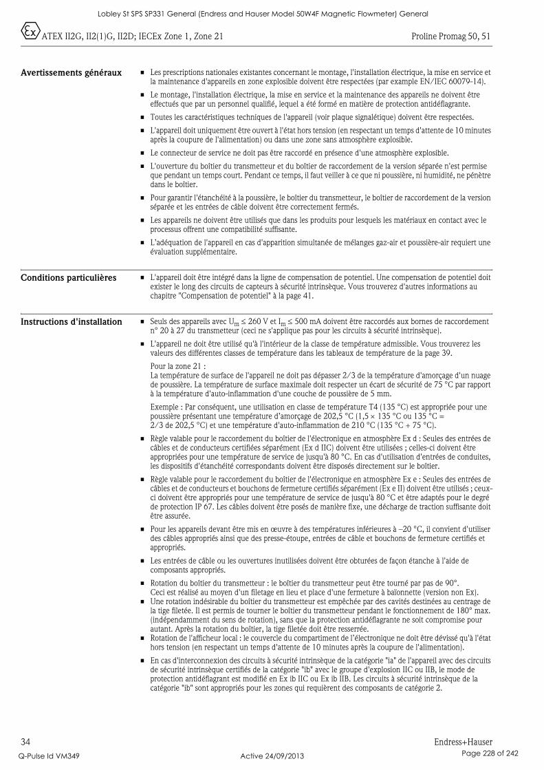
0ATEX II2G, II2(1)G, II2D; IECEx Zone 1, Zone 21 Proline Promag 50, 51
34 Endress+Hauser
Avertissements généraux • Les prescriptions nationales existantes concernant le montage, l'installation électrique, la mise en service et la maintenance d'appareils en zone explosible doivent être respectées (par example EN/IEC 60079-14).
• Le montage, l'installation électrique, la mise en service et la maintenance des appareils ne doivent être effectués que par un personnel qualifié, lequel a été formé en matière de protection antidéflagrante.
• Toutes les caractéristiques techniques de l'appareil (voir plaque signalétique) doivent être respectées.
• L'appareil doit uniquement être ouvert à l'état hors tension (en respectant un temps d'attente de 10 minutes après la coupure de l'alimentation) ou dans une zone sans atmosphère explosible.
• Le connecteur de service ne doit pas être raccordé en présence d'une atmosphère explosible.
• L'ouverture du boîtier du transmetteur et du boîtier de raccordement de la version séparée n'est permise que pendant un temps court. Pendant ce temps, il faut veiller à ce que ni poussière, ni humidité, ne pénètre dans le boîtier.
• Pour garantir l'étanchéité à la poussière, le boîtier du transmetteur, le boîtier de raccordement de la version séparée et les entrées de câble doivent être correctement fermés.
• Les appareils ne doivent être utilisés que dans les produits pour lesquels les matériaux en contact avec le processus offrent une compatibilité suffisante.
• L’adéquation de l'appareil en cas d'apparition simultanée de mélanges gaz-air et poussière-air requiert une évaluation supplémentaire.
Conditions particulières • L'appareil doit être intégré dans la ligne de compensation de potentiel. Une compensation de potentiel doit exister le long des circuits de capteurs à sécurité intrinsèque. Vous trouverez d'autres informations au chapitre "Compensation de potentiel" à la page 41.
Instructions d'installation • Seuls des appareils avec Um ≤ 260 V et Im ≤ 500 mA doivent être raccordés aux bornes de raccordement n° 20 à 27 du transmetteur (ceci ne s'applique pas pour les circuits à sécurité intrinsèque).
• L'appareil ne doit être utilisé qu'à l'intérieur de la classe de température admissible. Vous trouverez les valeurs des différentes classes de température dans les tableaux de température de la page 39.
Pour la zone 21 :La température de surface de l'appareil ne doit pas dépasser 2/3 de la température d'amorçage d'un nuage de poussière. La température de surface maximale doit respecter un écart de sécurité de 75 °C par rapport à la température d'auto-inflammation d'une couche de poussière de 5 mm.
Exemple : Par conséquent, une utilisation en classe de température T4 (135 °C) est appropriée pour une poussière présentant une température d’amorçage de 202,5 °C (1,5 × 135 °C ou 135 °C = 2/3 de 202,5 °C) et une température d'auto-inflammation de 210 °C (135 °C + 75 °C).
• Règle valable pour le raccordement du boîtier de l'électronique en atmosphère Ex d : Seules des entrées de câbles et de conducteurs certifiées séparément (Ex d IIC) doivent être utilisées ; celles-ci doivent être appropriées pour une température de service de jusqu'à 80 °C. En cas d'utilisation d'entrées de conduites, les dispositifs d'étanchéité correspondants doivent être disposés directement sur le boîtier.
• Règle valable pour le raccordement du boîtier de l'électronique en atmosphère Ex e : Seules des entrées de câbles et de conducteurs et bouchons de fermeture certifiés séparément (Ex e II) doivent être utilisés ; ceux-ci doivent être appropriés pour une température de service de jusqu'à 80 °C et être adaptés pour le degré de protection IP 67. Les câbles doivent être posés de manière fixe, une décharge de traction suffisante doit être assurée.
• Pour les appareils devant être mis en œuvre à des températures inférieures à –20 °C, il convient d'utiliser des câbles appropriés ainsi que des presse-étoupe, entrées de câble et bouchons de fermeture certifiés et appropriés.
• Les entrées de câble ou les ouvertures inutilisées doivent être obturées de façon étanche à l'aide de composants appropriés.
• Rotation du boîtier du transmetteur : le boîtier du transmetteur peut être tourné par pas de 90°. Ceci est réalisé au moyen d'un filetage en lieu et place d'une fermeture à baïonnette (version non Ex).
• Une rotation indésirable du boîtier du transmetteur est empêchée par des cavités destinées au centrage de la tige filetée. Il est permis de tourner le boîtier du transmetteur pendant le fonctionnement de 180° max. (indépendamment du sens de rotation), sans que la protection antidéflagrante ne soit compromise pour autant. Après la rotation du boîtier, la tige filetée doit être resserrée.
• Rotation de l'afficheur local : le couvercle du compartiment de l’électronique ne doit être dévissé qu'à l'état hors tension (en respectant un temps d'attente de 10 minutes après la coupure de l'alimentation).
• En cas d'interconnexion des circuits à sécurité intrinsèque de la catégorie "ia" de l'appareil avec des circuits de sécurité intrinsèque certifiés de la catégorie "ib" avec le groupe d'explosion IIC ou IIB, le mode de protection antidéflagrant est modifié en Ex ib IIC ou Ex ib IIB. Les circuits à sécurité intrinsèque de la catégorie "ib" sont appropriés pour les zones qui requièrent des composants de catégorie 2.
Lobley St SPS SP331 General (Endress and Hauser Model 50W4F Magnetic Flowmeter) General
Q-Pulse Id VM349 Active 24/09/2013 Page 228 of 242

Proline Promag 50, 51 ATEX II2G, II2(1)G, II2D; IECEx Zone 1, Zone 21 0
Endress+Hauser 35
• Si les circuits de communication à sécurité intrinsèque actifs (option d’entrée/sortie S, bornes 26/27) sont amenés dans des zones, qui requièrent des composants 2D, les composants raccordés doivent être vérifiés et certifiés en conséquence.
• En zone 0 les mélanges explosifs vapeur/air ne sont autorisés à se produire que sous conditions atmosphériques. En l’absence de mélanges explosifs ou si des mesures complémentaires selon EN 1127-1 ont été prises, les appareils peuvent être utilisés en dehors des conditions atmosphériques, selon leurs spécifications.
Attestation d’exament CE
de type, directive 94/9/CE
et Déclaration CEI de
conformité
Attestation d’examen CE de type, directive 94/9/CE
Le système satisfait aux exigences fondamentales de sécurité et de santé en matière de conception et de construction d'appareils et de systèmes de protection pour une utilisation conforme à l’objet en zones explosibles selon l'Annexe II de la directive 94/9/CE.
Numéro de certification: DMT 00 ATEX E 017 X
Déclaration CEI de conformité
En apposant le numéro de certification, on certifie la conformité aux normes suivantes (en fonction de l'exécution de l'appareil) :
Numéro de certification : IECEx BVS 07.0011 X
Organisme de contrôleDEKRA EXAM GmBH (anciennement Deutsche Montan Technologie GmbH, service spécialisé pour la sécurité de composants électriques, galerie de reconnaissance minière)
Marquage
Voir page 38
En raison de la fusion du TÜV NORD et du RWTÜV, le numéro d’identification de l’organisme nommé est modifié de 0032 en 0044.
" Attention !
Le groupe d'explosion de l'appareil est IIC. Il est toutefois réduit à IIB si les capacités/inductances extérieures admissibles pour les circuits de communication à sécurité intrinsèque sont augmentées (voir page 44).
• CEI 60079-0 : 2004 • CEI 60079-11 : 2006 • CEI 61241-0 : 2004
• CEI 60079-1 : 2003 • CEI 60079-26 : 2006 • CEI 61241-1 : 2004
• CEI 60079-7 : 2001 • CEI 60079-27 : 2005
Lobley St SPS SP331 General (Endress and Hauser Model 50W4F Magnetic Flowmeter) General
Q-Pulse Id VM349 Active 24/09/2013 Page 229 of 242
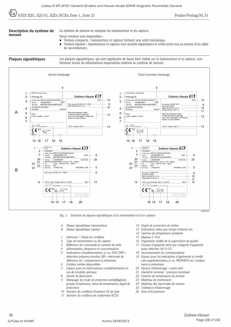
0ATEX II2G, II2(1)G, II2D; IECEx Zone 1, Zone 21 Proline Promag 50, 51
36 Endress+Hauser
Description du système de mesure
Le système de mesure se compose du transmetteur et du capteur.
Deux versions sont disponibles :• Version compacte : transmetteur et capteur forment une unité mécanique.• Version séparée : transmetteur et capteur sont montés séparément et reliés entre eux au moyen d'un câble
de raccordement.
Plaques signalétiques Les plaques signalétiques, qui sont appliquées de façon bien visible sur le transmetteur et le capteur, con-tiennent toutes les informations importantes relatives au système de mesure.
A0005624
Fig. 1: Exemple de plaques signalétiques d'un transmetteur et d'un capteur
Ancien marquage Futur/nouveau marquage
Promag 5x
–20°C <Tamb<+50°C
IP67Order Code:
Ser.No.:
TAG No.:
5XP1H-XXXXXXXXXXXX
12345678901
ABCDEFGHJKLMNPQRST
20-55VAC/16-62VDC
50-60Hz
I-OUT (HART), f-OUT
15VA/W
EEx de [ia] IIC/IIB T6-T1 IP6XDMT 00 ATEX E 017 X
ECC
-20°C (-4°F)<Tamb<+60°C (+140°F) IP67
5XP1H-XXXXXXXXXXXX
1.0000/0000
PFA-10°C...150°C/+14°F...300°F
12345678901 RYABCDEFGHJKLMNPQRST
DN100 DIN/EN PN40 / pnom = PS = 40bar
EPD/MSÜ, R/BMaterals:
Order Code:
TM:
K-factor:
Ser.No.:
TAG No.:
Promag P
1.4435/316LElectrode:
0.2%CAL
68700 Cernay France
After de-energizing, delay10 Minutes before opening!Nach dem Abschalten 10 Minutenwarten vor dem Öffnen!
XAxxxD/06/../....
2007
68700 CernayFrance
2007
EEx e [ia] IIC/IIB T6-T1 IP6X
Promag 5x
–20°C <Tamb<+50°C
IP67Order Code:
Ser.No.:
TAG No.:
5xP1H-XXXXXXXXXXXX
12345678901
ABCDEFGHJKLMNPQRST
20-55VAC/16-62VDC
50-60Hz
I-OUT (HART), f-OUT
15VA/W
Ex de [ia] IIC/IIB T6-T1Ex tD A21 IP6XDMT 00 ATEX E 017 XIECEx BVS 07.0011 X
N12895
ECC
-20°C (-4°F)<Tamb<+60°C (+140°F) IP67
5XP1H-XXXXXXXXXXXX
1.0000/0000
PFA-10°C...150°C/+14°F...300°F
12345678901 RYABCDEFGHJKLMNPQRST
DN100 DIN/EN PN40 / pnom = PS = 40bar
EPD/MSÜ, R/BMaterals:
Order Code:
TM:
K-factor:
Ser.No.:
TAG No.:
Promag P
1.4435/316LElectrode:
0.2%CAL
N12895
4153 Reinach Switzerland
After de-energizing, delay10 Minutes before opening!Nach dem Abschalten 10 Minutenwarten vor dem Öffnen!
XAxxxD/06/../....
II2G0044
2007
4153 ReinachSwitzerland
2007
Ex e [ia] IIC/IIB T6-T1Ex tD A21 IP6XDMT 00 ATEX E 017 XIECEx BVS 07.0011 X
II2D
0044
N12895
II2GD0032
N12895
II2GD0032
iXAxxxD/06/../....
iXAxxxD/06/../....
II2GII2D
A
B
12
3
4
5
67
15
i
16 17 18 19
8
14
13
910
12
12
3
4
5
67
14
13
910
12
11
i
15 16 17 18 19
8
12
20
3
2223
24
2125
8
5
12
16 15 17 18 26
14
9101112
25
8
5
9
14
16 15 17 18 26
12
20
3
2223
24
21
A Plaque signalétique transmetteur
B Plaque signalétique capteur
1 Fabricant / Dépôt du certificat
2 Type de transmetteur ou de capteur
3 Référence de commande et numéro de série
4 Alimentation, fréquence et consommation
5 Indications complémentaires, p. ex. EPD/DPP =
détection présence produit, RB = électrode de
référence etc. (uniquement si présentes)
6 Entrées/sorties disponibles
7 Espace pour les informations complémentaires en
cas de produits spéciaux
8 Année de fabrication
9 Marquage du mode de protection antidéflagrant,
groupe d'explosion, classe de température, degré de
protection
10 Numéro du certificat d’examen CE de type
11 Numéro du certificat de conformité IECEx
12 Degré de protection du boîtier
13 Indications telles que temps d'attente etc.
14 Gamme de température ambiante
15 Marque C-Tick
16 Organisme notifié de la supervision de qualité
17 Groupe d'appareils ainsi que catégorie d'appareils
selon directive 94/9/CE
18 Documentation Ex correspondante
19 Espace pour les indications d’agréments et certifi-
cats supplémentaires, p. ex. PROFIBUS etc. (unique-
ment si présentes)
20 Facteur d'étalonnage / point zéro
21 Diamètre nominal / pression nominale
22 Gamme de température du produit
23 Matériau du revêtement
24 Matériau des électrodes de mesure
25 Tolérance d'étalonnage
26 Sens d'écoulement
Lobley St SPS SP331 General (Endress and Hauser Model 50W4F Magnetic Flowmeter) General
Q-Pulse Id VM349 Active 24/09/2013 Page 230 of 242
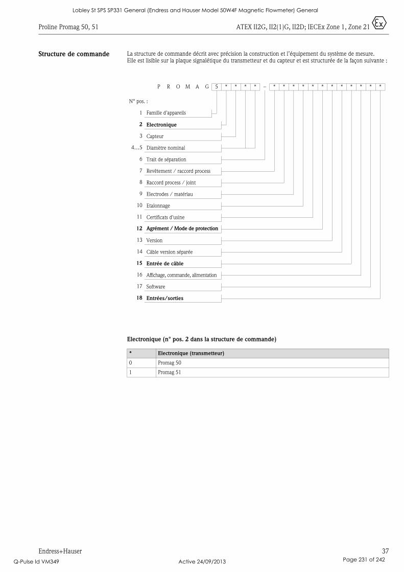
Proline Promag 50, 51 ATEX II2G, II2(1)G, II2D; IECEx Zone 1, Zone 21 0
Endress+Hauser 37
Structure de commande La structure de commande décrit avec précision la construction et l’équipement du système de mesure. Elle est lisible sur la plaque signalétique du transmetteur et du capteur et est structurée de la façon suivante :
Electronique (n° pos. 2 dans la structure de commande)
P R O M A G 5 * * * * – * * * * * * * * * * * *
N° pos. :
1 Famille d'appareils
2 Electronique
3 Capteur
4…5 Diamètre nominal
6 Trait de séparation
7 Revêtement / raccord process
8 Raccord process / joint
9 Electrodes / matériau
10 Etalonnage
11 Certificats d'usine
12 Agrément / Mode de protection
13 Version
14 Câble version séparée
15 Entrée de câble
16 Affichage, commande, alimentation
17 Software
18 Entrées/sorties
* Electronique (transmetteur)
0 Promag 50
1 Promag 51
Lobley St SPS SP331 General (Endress and Hauser Model 50W4F Magnetic Flowmeter) General
Q-Pulse Id VM349 Active 24/09/2013 Page 231 of 242
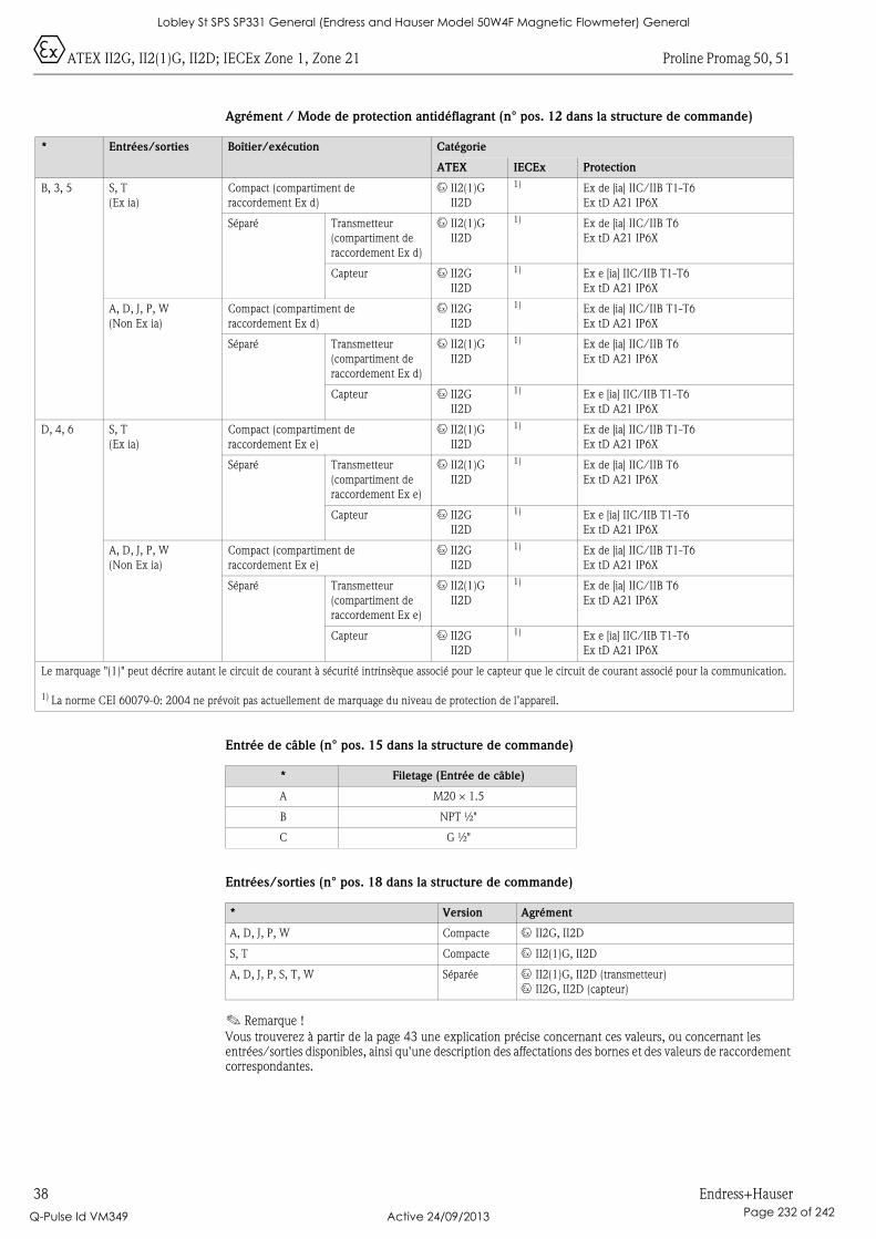
0ATEX II2G, II2(1)G, II2D; IECEx Zone 1, Zone 21 Proline Promag 50, 51
38 Endress+Hauser
Agrément / Mode de protection antidéflagrant (n° pos. 12 dans la structure de commande)
Entrée de câble (n° pos. 15 dans la structure de commande)
Entrées/sorties (n° pos. 18 dans la structure de commande)
! Remarque !
Vous trouverez à partir de la page 43 une explication précise concernant ces valeurs, ou concernant les entrées/sorties disponibles, ainsi qu'une description des affectations des bornes et des valeurs de raccordement correspondantes.
* Entrées/sorties Boîtier/exécution Catégorie
ATEX IECEx Protection
B, 3, 5 S, T
(Ex ia)
Compact (compartiment de
raccordement Ex d)
0 II2(1)G
II2D
1) Ex de [ia] IIC/IIB T1-T6
Ex tD A21 IP6X
Séparé Transmetteur
(compartiment de
raccordement Ex d)
0 II2(1)G
II2D
1) Ex de [ia] IIC/IIB T6
Ex tD A21 IP6X
Capteur 0 II2G
II2D
1) Ex e [ia] IIC/IIB T1-T6
Ex tD A21 IP6X
A, D, J, P, W
(Non Ex ia)
Compact (compartiment de
raccordement Ex d)
0 II2G
II2D
1) Ex de [ia] IIC/IIB T1-T6
Ex tD A21 IP6X
Séparé Transmetteur
(compartiment de
raccordement Ex d)
0 II2(1)G
II2D
1) Ex de [ia] IIC/IIB T6
Ex tD A21 IP6X
Capteur 0 II2G
II2D
1) Ex e [ia] IIC/IIB T1-T6
Ex tD A21 IP6X
D, 4, 6 S, T
(Ex ia)
Compact (compartiment de
raccordement Ex e)
0 II2(1)G
II2D
1) Ex de [ia] IIC/IIB T1-T6
Ex tD A21 IP6X
Séparé Transmetteur
(compartiment de
raccordement Ex e)
0 II2(1)G
II2D
1) Ex de [ia] IIC/IIB T6
Ex tD A21 IP6X
Capteur 0 II2G
II2D
1) Ex e [ia] IIC/IIB T1-T6
Ex tD A21 IP6X
A, D, J, P, W
(Non Ex ia)
Compact (compartiment de
raccordement Ex e)
0 II2G
II2D
1) Ex de [ia] IIC/IIB T1-T6
Ex tD A21 IP6X
Séparé Transmetteur
(compartiment de
raccordement Ex e)
0 II2(1)G
II2D
1) Ex de [ia] IIC/IIB T6
Ex tD A21 IP6X
Capteur 0 II2G
II2D
1) Ex e [ia] IIC/IIB T1-T6
Ex tD A21 IP6X
Le marquage "(1)" peut décrire autant le circuit de courant à sécurité intrinsèque associé pour le capteur que le circuit de courant associé pour la communication.
1) La norme CEI 60079-0: 2004 ne prévoit pas actuellement de marquage du niveau de protection de l’appareil.
* Filetage (Entrée de câble)
A M20 × 1.5
B NPT ½"
C G ½"
* Version Agrément
A, D, J, P, W Compacte 0 II2G, II2D
S, T Compacte 0 II2(1)G, II2D
A, D, J, P, S, T, W Séparée 0 II2(1)G, II2D (transmetteur)
0 II2G, II2D (capteur)
Lobley St SPS SP331 General (Endress and Hauser Model 50W4F Magnetic Flowmeter) General
Q-Pulse Id VM349 Active 24/09/2013 Page 232 of 242
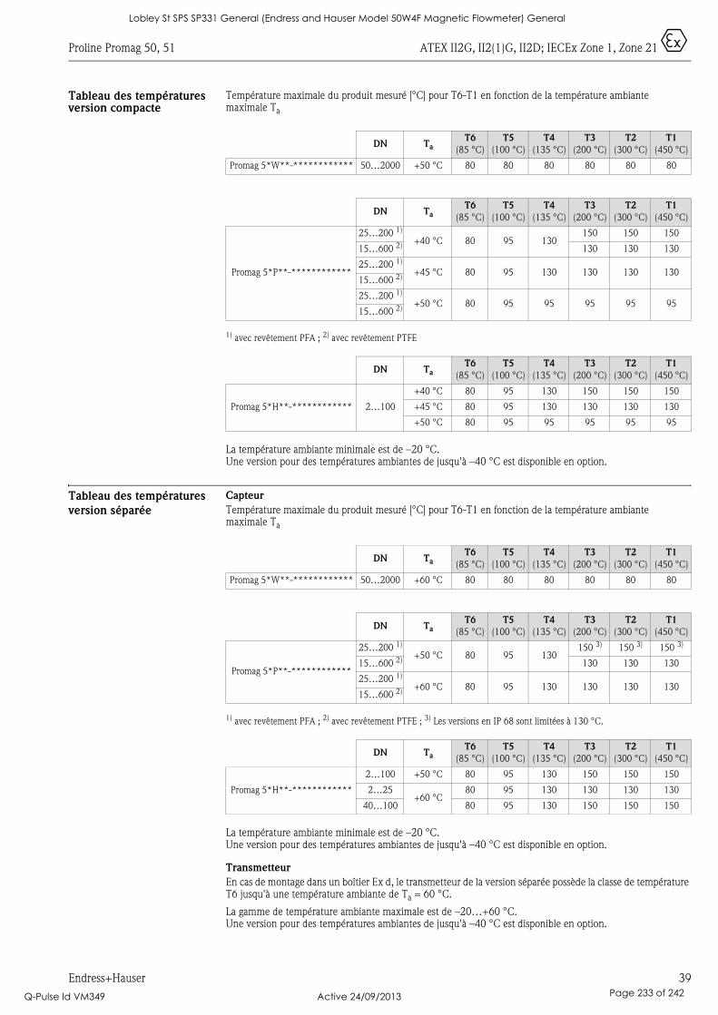
Proline Promag 50, 51 ATEX II2G, II2(1)G, II2D; IECEx Zone 1, Zone 21 0
Endress+Hauser 39
Tableau des températures version compacte
Température maximale du produit mesuré [°C] pour T6-T1 en fonction de la température ambiante maximale Ta
1) avec revêtement PFA ; 2) avec revêtement PTFE
La température ambiante minimale est de –20 °C. Une version pour des températures ambiantes de jusqu'à –40 °C est disponible en option.
Tableau des températures
version séparée
Capteur
Température maximale du produit mesuré [°C] pour T6-T1 en fonction de la température ambiante maximale Ta
1) avec revêtement PFA ; 2) avec revêtement PTFE ; 3) Les versions en IP 68 sont limitées à 130 °C.
La température ambiante minimale est de –20 °C. Une version pour des températures ambiantes de jusqu'à –40 °C est disponible en option.
Transmetteur
En cas de montage dans un boîtier Ex d, le transmetteur de la version séparée possède la classe de température T6 jusqu'à une température ambiante de Ta = 60 °C.
La gamme de température ambiante maximale est de –20…+60 °C. Une version pour des températures ambiantes de jusqu'à –40 °C est disponible en option.
DN TaT6
(85 °C)
T5
(100 °C)
T4
(135 °C)
T3
(200 °C)
T2
(300 °C)
T1
(450 °C)
Promag 5*W**-************ 50…2000 +50 °C 80 80 80 80 80 80
DN TaT6
(85 °C)
T5
(100 °C)
T4
(135 °C)
T3
(200 °C)
T2
(300 °C)
T1
(450 °C)
Promag 5*P**-************
25…200 1)
+40 °C 80 95 130150 150 150
15…600 2) 130 130 130
25…200 1)
+45 °C 80 95 130 130 130 13015…600 2)
25…200 1)
+50 °C 80 95 95 95 95 9515…600 2)
DN TaT6
(85 °C)
T5
(100 °C)
T4
(135 °C)
T3
(200 °C)
T2
(300 °C)
T1
(450 °C)
Promag 5*H**-************ 2…100
+40 °C 80 95 130 150 150 150
+45 °C 80 95 130 130 130 130
+50 °C 80 95 95 95 95 95
DN TaT6
(85 °C)
T5
(100 °C)
T4
(135 °C)
T3
(200 °C)
T2
(300 °C)
T1
(450 °C)
Promag 5*W**-************ 50…2000 +60 °C 80 80 80 80 80 80
DN TaT6
(85 °C)
T5
(100 °C)
T4
(135 °C)
T3
(200 °C)
T2
(300 °C)
T1
(450 °C)
Promag 5*P**-************
25…200 1)
+50 °C 80 95 130150 3) 150 3) 150 3)
15…600 2) 130 130 130
25…200 1)
+60 °C 80 95 130 130 130 13015…600 2)
DN TaT6
(85 °C)
T5
(100 °C)
T4
(135 °C)
T3
(200 °C)
T2
(300 °C)
T1
(450 °C)
Promag 5*H**-************
2…100 +50 °C 80 95 130 150 150 150
2…25+60 °C
80 95 130 130 130 130
40…100 80 95 130 150 150 150
Lobley St SPS SP331 General (Endress and Hauser Model 50W4F Magnetic Flowmeter) General
Q-Pulse Id VM349 Active 24/09/2013 Page 233 of 242
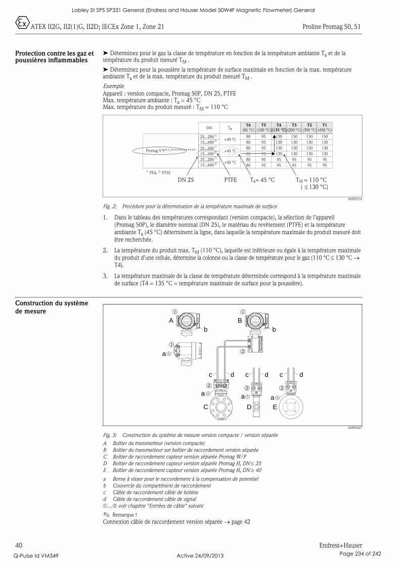
0ATEX II2G, II2(1)G, II2D; IECEx Zone 1, Zone 21 Proline Promag 50, 51
40 Endress+Hauser
Protection contre les gaz et poussières inflammables
➤ Déterminez pour le gaz la classe de température en fonction de la température ambiante Ta et de la température du produit mesuré TM .
➤ Déterminez pour la poussière la température de surface maximale en fonction de la max. température ambiante Ta et de la max. température du produit mesuré TM .
Exemple
Appareil : version compacte, Promag 50P, DN 25, PTFEMax. température ambiante : Ta = 45 °CMax. température du produit mesuré : TM = 110 °C
A0005216
Fig. 2: Procédure pour la détermination de la température maximale de surface
1. Dans le tableau des températures correspondant (version compacte), la sélection de l'appareil
(Promag 50P), le diamètre nominal (DN 25), le matériau du revêtement (PTFE) et la température
ambiante Ta (45 °C) déterminent la ligne, dans laquelle la température maximale du produit mesuré doit
être recherchée.
2. La température du produit max. TM (110 °C), laquelle est inférieure ou égale à la température maximale
du produit d’une cellule, détermine la colonne ou la classe de température pour le gaz (110 °C ≤ 130 °C → T4).
3. La température maximale de la classe de température déterminée correspond à la température maximale
de surface (T4 = 135 °C = température maximale de surface pour la poussière).
Construction du système
de mesure
A0005627
Fig. 3: Construction du système de mesure version compacte / version séparée
A Boîtier du transmetteur (version compacte)
B Boîtier du transmetteur sur boîtier de raccordement version séparée
C Boîtier de raccordement capteur version séparée Promag W/P
D Boîtier de raccordement capteur version séparée Promag H, DN ≤ 25
E Boîtier de raccordement capteur version séparée Promag H, DN ≥ 40
a Borne à visser pour le raccordement à la compensation de potentiel
b Couvercle du compartiment de raccordement
c Câble de raccordement câble de bobine
d Câble de raccordement câble de signal
m…n voir chapitre "Entrées de câble" suivant
! Remarque !
Connexion câble de raccordement version séparée → page 42
Promag 5*P**-************
DN T T6
(85 °C)aT5
(100 °C)T4
(135 °C)
T3
(200 °C)T2
(300 °C)T1
(450 °C)1)25...2002)15...6001)25...2002)15...6001)25...2002)15...600
+40 °C
+45 °C
+50 °C
808080808080
959595959595
1301301301309595
1501301301309595
1501301301309595
1501301301309595
PFA;1) PTFE2)
DN 25 PTFE Ta= 45 °C TM = 110 °C130 °C)�(
A B
C
b
D E
a
b b
aa
a
c dc dc d
Nicht unter Spannungöffnen
Keep
cover
tightw
hile
circ
uits
are
aliv
e
Nepasouvrirl’appareil soustension
Keep
cove
rtightw
hile
circ
uits
are
aliv
e
Nicht unter Spannungöffnen
Keep
cove
rtig
htw
hile
circ
uits
are
aliv
e
Nepasouvrirl’appareil soustension
Keep
cover
tig
htw
hile
circ
uits
are
aliv
e
m m
n
m
nn n
Lobley St SPS SP331 General (Endress and Hauser Model 50W4F Magnetic Flowmeter) General
Q-Pulse Id VM349 Active 24/09/2013 Page 234 of 242
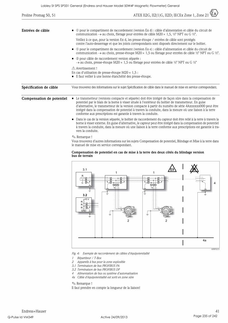
Proline Promag 50, 51 ATEX II2G, II2(1)G, II2D; IECEx Zone 1, Zone 21 0
Endress+Hauser 41
Entrées de câble • m pour le compartiment de raccordement (version Ex d) : câble d'alimentation et câble du circuit de communication → au choix, filetage pour entrées de câble M20 × 1,5, ½" NPT ou G ½".
Veillez à ce que, pour la version Ex d, les presse-étoupe / entrées de câble sont protégés contre l'auto-desserrage et que les joints correspondants sont disposés directement sur le boîtier.
• m pour le compartiment de raccordement (version Ex e) : câble d'alimentation et câble du circuit de communication → au choix, presse-étoupe M20 × 1,5 ou filetage pour entrées de câble ½" NPT ou G ½".
• n pour câble de raccordement version séparée :→ au choix, presse-étoupe M20 × 1,5 ou filetage pour entrées de câble ½" NPT ou G ½"
# Avertissement !
En cas d'utilisation de presse-étoupe M20 × 1,5 :• Il faut veiller à une bonne étanchéité des presse-étoupe.
Spécification de câble Vous trouverez des informations sur le sujet Spécification de câble dans le manuel de mise en service correspondant.
Compensation de potentiel • Le transmetteur (versions compacte et séparée) doit être intégré de façon sûre dans la compensation de potentiel par le biais de la borne à visser située à l'extérieur du boîtier de transmetteur. En guise d'alternative, le transmetteur de la version compacte à partir du numéro de série 4Axxxxxx000 peut être intégré dans la compensation de potentiel à travers la conduite, dans la mesure où une liaison à la terre conforme aux prescriptions est garantie à travers la conduite.
• Dans le cas de la version séparée, le boîtier de raccordement du capteur doit être relié à la terre à travers la borne à visser externe. En guise d'alternative, le capteur peut être intégré dans la compensation de potentiel à travers la conduite, dans la mesure où une liaison à la terre conforme aux prescriptions est garantie à tra-vers la conduite.
! Remarque !
Vous trouverez d'autres informations sur les sujets Compensation de potentiel, Blindage et Mise à la terre dans le manuel de mise en service correspondant.
Compensation de potentiel en cas de mise à la terre des deux côtés du blindage version bus de terrain
A0005215
Fig. 4: Exemple de raccordement de câbles d'équipotentialité
1 Répartiteur / T-Box
2 Appareils à bus pour la zone explosible
3.1 Terminaison de bus PROFIBUS PA
3.2 Terminaison de bus PROFIBUS DP
4 Alimentation de bus ou système d'automatisation
4a Câble d'équipotentialité est sorti en zone sûre
! Remarque !
Il faut prendre en compte la longueur de la liaison!
1 1
2 2
3.1
4
4a
EX EX
R
C
3.2
R
GND
+5 V
R
R
Lobley St SPS SP331 General (Endress and Hauser Model 50W4F Magnetic Flowmeter) General
Q-Pulse Id VM349 Active 24/09/2013 Page 235 of 242
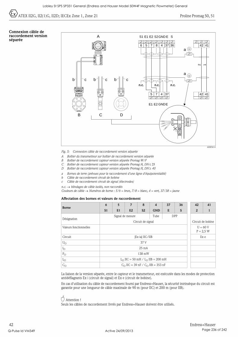
0ATEX II2G, II2(1)G, II2D; IECEx Zone 1, Zone 21 Proline Promag 50, 51
42 Endress+Hauser
Connexion câble de raccordement version séparée
A0005614
Fig. 5: Connexion câble de raccordement version séparée
A Boîtier du transmetteur sur boîtier de raccordement version séparée
B Boîtier de raccordement capteur version séparée Promag W/P
C Boîtier de raccordement capteur version séparée Promag H, DN ≤ 25D Boîtier de raccordement capteur version séparée Promag H, DN ≥ 40
a Bornes de terre (prévues pour le raccordement d'une ligne d'équipotentialité)
b Câble de raccordement circuit de bobine
c Câble de raccordement circuit de signal (électrodes)
n.c. → blindages de câble isolés, non raccordés
Couleurs de câble → Numéros de borne : 5/6 = brun, 7/8 = blanc, 4 = vert, 37/38 = jaune
Affectation des bornes et valeurs de raccordement
La liaison de la version séparée, entre le capteur et le transmetteur, est exécutée dans les modes de protection antidéflagrants Ex i (circuit de signal) et Ex e (circuit de bobine).
En cas d'utilisation du câble de raccordement fourni par Endress+Hauser, la sécurité intrinsèque du circuit est garantie pour une longueur de câble maximale de 90 m (pour IIC) et 200 m (pour IIB).
" Attention !
Seuls les câbles de raccordement livrés par Endress+Hauser doivent être utilisés.
Borne6 5 7 8 4 37 36 42 41
S1 E1 E2 S2 GND E S 2 1
DésignationSignal de mesure Tube DPP
Circuit de signal Circuit de bobine
Valeurs fonctionnelles U = 60 V
P = 2,5 W
Circuit [Ex ia] IIC/IIB Ex e
UO 37 V
IO 25 mA
PO 138 mW
LO LO IIC = 50 mH / LO IIB = 200 mH
CO CO IIC = 39 nF / CO IIB = 353 nF
A
B
b
C D
c b c
a
b b c
6 5
5
7
7
8 4
4
37
37
36 42
42
41
41
E1 E2 GNDE
2 1
S1 E1 E2 S2GND E S
n.c. n.c.n.c.n.c. n.c.n.c.
a
Nicht unter Spannungöffnen
Keep
cover
tightw
hile
circ
uits
are
aliv
e
Nepasouvrirl’appareil soustension
Keep
cove
rtightw
hile
circ
uits
are
aliv
e
Lobley St SPS SP331 General (Endress and Hauser Model 50W4F Magnetic Flowmeter) General
Q-Pulse Id VM349 Active 24/09/2013 Page 236 of 242
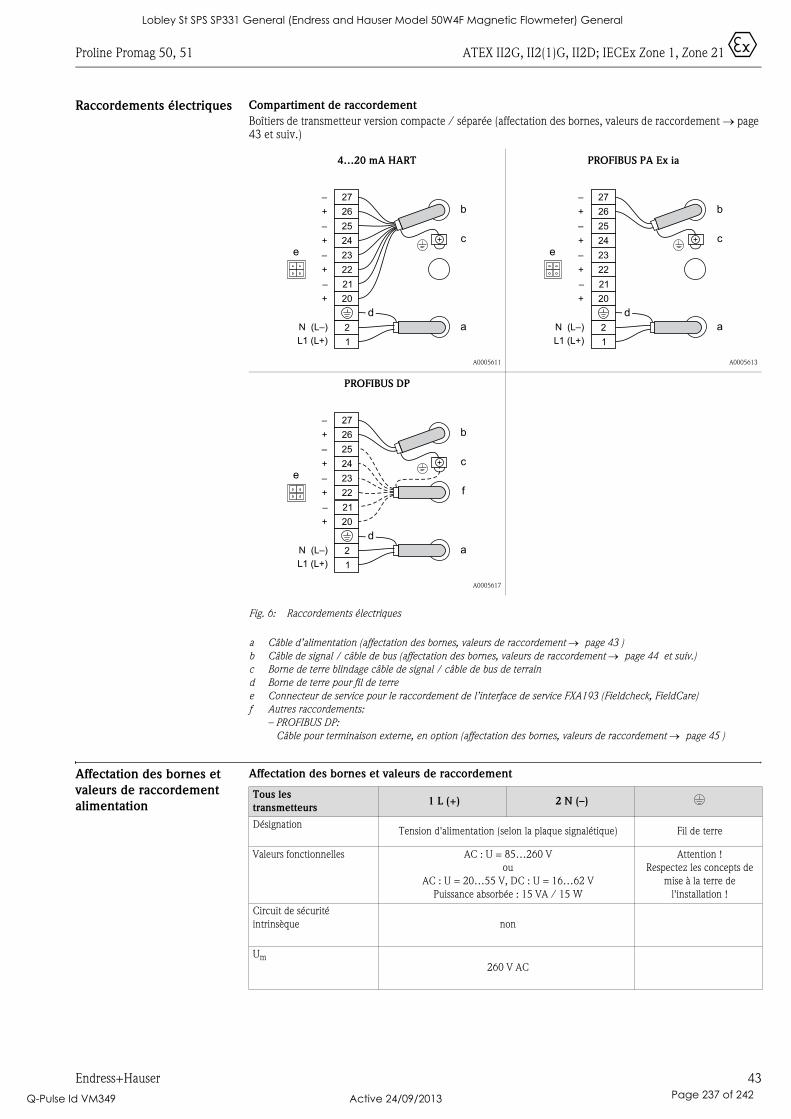
Proline Promag 50, 51 ATEX II2G, II2(1)G, II2D; IECEx Zone 1, Zone 21 0
Endress+Hauser 43
Raccordements électriques Compartiment de raccordement
Boîtiers de transmetteur version compacte / séparée (affectation des bornes, valeurs de raccordement → page 43 et suiv.)
Fig. 6: Raccordements électriques
a Câble d’alimentation (affectation des bornes, valeurs de raccordement → page 43 )
b Câble de signal / câble de bus (affectation des bornes, valeurs de raccordement → page 44 et suiv.)
c Borne de terre blindage câble de signal / câble de bus de terrain
d Borne de terre pour fil de terre
e Connecteur de service pour le raccordement de l’interface de service FXA193 (Fieldcheck, FieldCare)
f Autres raccordements:
– PROFIBUS DP:
Câble pour terminaison externe, en option (affectation des bornes, valeurs de raccordement → page 45 )
Affectation des bornes et
valeurs de raccordement
alimentation
Affectation des bornes et valeurs de raccordement
4…20 mA HART
A0005611
PROFIBUS PA Ex ia
A0005613
PROFIBUS DP
A0005617
1
2
L1 (L+)
N (L–)
20
21
22
23
24
25
26
27
e
b
c
a
+
–
+
–
+
–
+
–
d
1
2
L1 (L+)
N (L–)
20
21
22
23
24
25
26
27
e
3
b
c
a
+
–
+
–
+
–
+
–
d
1
2
L1 (L+)
N (L–)
20
21
22
23
24
25
26
27
e
3
b
c
a
+
–
+
–
+
–
+
–
f
d
Tous les
transmetteurs1 L (+) 2 N (–) *
DésignationTension d'alimentation (selon la plaque signalétique) Fil de terre
Valeurs fonctionnelles AC : U = 85…260 V
ou
AC : U = 20…55 V, DC : U = 16…62 V
Puissance absorbée : 15 VA / 15 W
Attention !
Respectez les concepts de
mise à la terre de
l'installation !
Circuit de sécurité
intrinsèque non
Um
260 V AC
Lobley St SPS SP331 General (Endress and Hauser Model 50W4F Magnetic Flowmeter) General
Q-Pulse Id VM349 Active 24/09/2013 Page 237 of 242
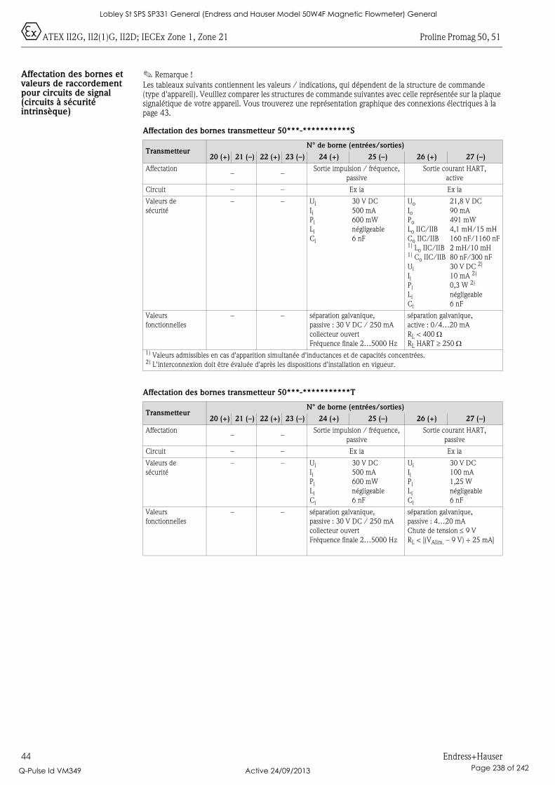
0ATEX II2G, II2(1)G, II2D; IECEx Zone 1, Zone 21 Proline Promag 50, 51
44 Endress+Hauser
Affectation des bornes et valeurs de raccordement pour circuits de signal (circuits à sécurité intrinsèque)
! Remarque !
Les tableaux suivants contiennent les valeurs / indications, qui dépendent de la structure de commande (type d'appareil). Veuillez comparer les structures de commande suivantes avec celle représentée sur la plaque signalétique de votre appareil. Vous trouverez une représentation graphique des connexions électriques à la page 43.
Affectation des bornes transmetteur 50***-***********S
Affectation des bornes transmetteur 50***-***********T
TransmetteurN° de borne (entrées/sorties)
20 (+) 21 (–) 22 (+) 23 (–) 24 (+) 25 (–) 26 (+) 27 (–)
Affectation– –
Sortie impulsion / fréquence,
passive
Sortie courant HART,
active
Circuit – – Ex ia Ex ia
Valeurs de
sécurité
– – Ui
IiPi
Li
Ci
30 V DC
500 mA
600 mW
négligeable
6 nF
Uo
IoPo
Lo IIC/IIB
Co IIC/IIB1) Lo IIC/IIB1) Co IIC/IIB
Ui
IiPi
Li
Ci
21,8 V DC
90 mA
491 mW
4,1 mH/15 mH
160 nF/1160 nF
2 mH/10 mH
80 nF/300 nF
30 V DC 2)
10 mA 2)
0,3 W 2)
négligeable
6 nF
Valeurs
fonctionnelles
– – séparation galvanique,
passive : 30 V DC / 250 mA
collecteur ouvert
Fréquence finale 2…5000 Hz
séparation galvanique,
active : 0/4…20 mA
RL < 400 ΩRL HART ≥ 250 Ω
1) Valeurs admissibles en cas d'apparition simultanée d'inductances et de capacités concentrées.2) L'interconnexion doit être évaluée d'après les dispositions d'installation en vigueur.
TransmetteurN° de borne (entrées/sorties)
20 (+) 21 (–) 22 (+) 23 (–) 24 (+) 25 (–) 26 (+) 27 (–)
Affectation– –
Sortie impulsion / fréquence,
passive
Sortie courant HART,
passive
Circuit – – Ex ia Ex ia
Valeurs de
sécurité
– – Ui
IiPi
Li
Ci
30 V DC
500 mA
600 mW
négligeable
6 nF
Ui
IiPi
Li
Ci
30 V DC
100 mA
1,25 W
négligeable
6 nF
Valeurs
fonctionnelles
– – séparation galvanique,
passive : 30 V DC / 250 mA
collecteur ouvert
Fréquence finale 2…5000 Hz
séparation galvanique,
passive : 4…20 mA
Chute de tension ≤ 9 V
RL < [(VAlim. – 9 V) ÷ 25 mA]
Lobley St SPS SP331 General (Endress and Hauser Model 50W4F Magnetic Flowmeter) General
Q-Pulse Id VM349 Active 24/09/2013 Page 238 of 242
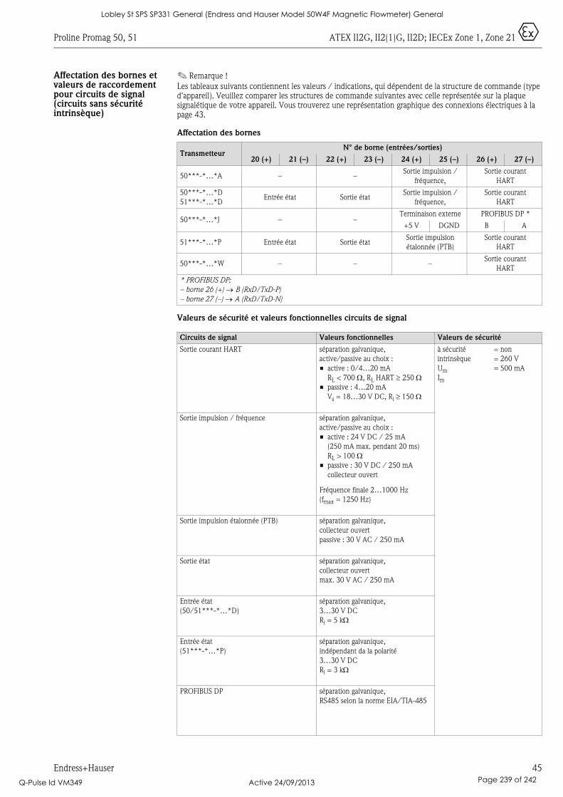
Proline Promag 50, 51 ATEX II2G, II2(1)G, II2D; IECEx Zone 1, Zone 21 0
Endress+Hauser 45
Affectation des bornes et valeurs de raccordement pour circuits de signal (circuits sans sécurité intrinsèque)
! Remarque !
Les tableaux suivants contiennent les valeurs / indications, qui dépendent de la structure de commande (type d'appareil). Veuillez comparer les structures de commande suivantes avec celle représentée sur la plaque signalétique de votre appareil. Vous trouverez une représentation graphique des connexions électriques à la page 43.
Affectation des bornes
Valeurs de sécurité et valeurs fonctionnelles circuits de signal
TransmetteurN° de borne (entrées/sorties)
20 (+) 21 (–) 22 (+) 23 (–) 24 (+) 25 (–) 26 (+) 27 (–)
50***-*…*A – –Sortie impulsion /
fréquence,
Sortie courant
HART
50***-*…*D
51***-*…*DEntrée état Sortie état
Sortie impulsion /
fréquence,
Sortie courant
HART
50***-*…*J – –Terminaison externe PROFIBUS DP *
+5 V DGND B A
51***-*…*P Entrée état Sortie étatSortie impulsion
étalonnée (PTB)
Sortie courant
HART
50***-*…*W – – –Sortie courant
HART
* PROFIBUS DP:
– borne 26 (+) → B (RxD/TxD-P)
– borne 27 (–) → A (RxD/TxD-N)
Circuits de signal Valeurs fonctionnelles Valeurs de sécurité
Sortie courant HART séparation galvanique,
active/passive au choix :
• active : 0/4…20 mA
RL < 700 Ω, RL HART ≥ 250 Ω• passive : 4…20 mA
Vs = 18…30 V DC, Ri ≥ 150 Ω
à sécurité
intrinsèque
Um
Im
= non
= 260 V
= 500 mA
Sortie impulsion / fréquence séparation galvanique,
active/passive au choix :
• active : 24 V DC / 25 mA
(250 mA max. pendant 20 ms)
RL > 100 Ω• passive : 30 V DC / 250 mA
collecteur ouvert
Fréquence finale 2…1000 Hz
(fmax = 1250 Hz)
Sortie impulsion étalonnée (PTB) séparation galvanique,
collecteur ouvert
passive : 30 V AC / 250 mA
Sortie état séparation galvanique,
collecteur ouvert
max. 30 V AC / 250 mA
Entrée état
(50/51***-*…*D)
séparation galvanique,
3…30 V DC
Ri = 5 kΩ
Entrée état
(51***-*…*P)
séparation galvanique,
indépendant da la polarité
3…30 V DC
Ri = 3 kΩ
PROFIBUS DP séparation galvanique,
RS485 selon la norme EIA/TIA-485
Lobley St SPS SP331 General (Endress and Hauser Model 50W4F Magnetic Flowmeter) General
Q-Pulse Id VM349 Active 24/09/2013 Page 239 of 242

0ATEX II2G, II2(1)G, II2D; IECEx Zone 1, Zone 21 Proline Promag 50, 51
46 Endress+Hauser
Connecteur de service Le connecteur de service sert exclusivement au raccordement d'interfaces de service validées par Endress+Hauser.
# Avertissement !
Le connecteur de service ne doit pas être raccordé en présence d'une atmosphère explosible.
Fusibles de l'appareil # Avertissement !
Utilisez exclusivement les types de fusibles suivants, qui sont montés sur la platine alimentation :
• Tension 20…55 V AC / 16…62 V DC :Fusible 2,0 A lent, pouvoir de coupure 1500 A(Schurter, 0001.2503 ou Wickmann, type standard 181 2,0 A)
• Tension 85…260 V AC : Fusible 0,8 A lent, pouvoir de coupure 1500 A(Schurter, 0001.2507 ou Wickmann, type standard 181 0,8 A)
Caractéristiques
techniques
Dimensions
Ces dimensions figurent dans l'Information technique respective :• Promag 50W, 53W → TI046D• Promag 50P, 53P → TI047D• Promag 50H, 53H → TI048D• Promag 51 → TI058D
Poids
Le poids de la version Ex d est supérieur d'env. 2 kg à celui de la version standard.
Lobley St SPS SP331 General (Endress and Hauser Model 50W4F Magnetic Flowmeter) General
Q-Pulse Id VM349 Active 24/09/2013 Page 240 of 242

Proline Promag 50, 51
Endress+Hauser 47
Lobley St SPS SP331 General (Endress and Hauser Model 50W4F Magnetic Flowmeter) General
Q-Pulse Id VM349 Active 24/09/2013 Page 241 of 242

www.endress.com/worldwide
XA103D/06/a3/07.10
71114914
FM+SGML 6.0
Lobley St SPS SP331 General (Endress and Hauser Model 50W4F Magnetic Flowmeter) General
Q-Pulse Id VM349 Active 24/09/2013 Page 242 of 242


