Embed Size (px)
Citation preview
Closed-loop control of magnetic fluid deformable mirrors
Azhar Iqbal, Zhizheng Wu and Foued Ben Amara*
Department of Mechanical and Industrial Engineering, University of Toronto, Toronto, ON, Canada M5S 3G8 *[email protected]
Abstract: This paper presents the first-ever experimental evaluation of a closed-loop adaptive optics system based on a magnetic fluid deformable mirror (MFDM). MFDMs are a new type of wavefront correctors used in adaptive optics systems to compensate for complex optical aberrations. They have been found particularly suitable for ophthalmic imaging systems where they can be used to compensate for the aberrations in the eye that lead to blurry retinal images. However, their practical implementation in clinical devices requires effective methods to control the shape of their deformable surface. This paper presents one such control method which is based on an innovative technique used to linearize the response of the MFDM surface shape. The design of the controller is based on a DC-decoupled model of the multi-input multi-output system and on considering a decentralized PI controller. Experimental results showing the performance of the closed-loop system comprising the developed controller and a 19-channel prototype MFDM are presented.
©2009 Optical Society of America
OCIS codes: (220.1080) Adaptive optics; (220.1000) Aberration compensation.
References and links
1. R. K. Tyson, Introduction to Adaptive Optics (SPIE Press, Bellingham WA, 2000). 2. J. W. Hardy, Adaptive Optics for Astronomical Telescopes (Oxford University Press Inc., New York, 1998). 3. M. C. Roggemann, and B. M. Welsh, Imaging Through Turbulence (CRC-Press, 1996). 4. H. W. Babcock, “The possibility of compensating astronomical seeing,” Publ. Astron. Soc. Pac. 65, 229–236
(1953). 5. J. Porter, H. Queener, L. Julianna, K. Thorn, and A. Awwal, Adaptive Optics for Vision Science: Principles,
Practices, Design and Applications (John Wiley & Sons Inc., New York, 2006). 6. A. Tuantranont, and V. M. Bright, “Segmented silicon-micromachined microelectromechanical deformable
mirrors for adaptive optics,” IEEE J. Sel. Top. Quantum Electron. 8(1), 33–45 (2002). 7. R. K. Tyson, M. Scipioni, and J. Viegas, “Generation of an optical vortex with a segmented deformable mirror,”
Appl. Opt. 47(33), 6300–6306 (2008). 8. P. A. Piers, S. Manzanera, P. M. Prieto, N. Gorceix, and P. Artal, “Use of adaptive optics to determine the
optimal ocular spherical aberration,” J. Cataract Refract. Surg. 33(10), 1721–1726 (2007). 9. I. W. Jung, Y. A. Peter, E. Carr, J. S. Wang, and O. Solgaard, “Single-crystal-silicon continuous membrane
deformable mirror array for adaptive optics in space-based telescopes,” IEEE J. Sel. Top. Quantum Electron. 13(2), 162–167 (2007).
10. J. A. Perreault, T. G. Bifano, B. M. Levine, and M. N. Horenstein, “Adaptive optic correction using microelectromechanical deformable mirrors,” Opt. Eng. 41(3), 561–566 (2002).
11. D. C. Dayton, J. D. Mansell, J. D. Gonglewski, and S. R. Restino, “Novel micromachined membrane mirror characterization and closed-loop demonstration,” Opt. Commun. 200(1-6), 99–105 (2001).
12. P. Kurczynski, G. Bogart, W. Lai, V. Lifton, W. Mansfield, J. Tyson, B. Sadoulet, and D. R. Williams, “Electrostatically actuated membrane mirrors for adaptive optics,” Proc. SPIE 4983, 250–258 (2003).
13. N. Doble, G. Yoon, L. Chen, P. Bierden, B. Singer, S. Olivier, and D. R. Williams, “Use of a microelectromechanical mirror for adaptive optics in the human eye,” Opt. Lett. 27(17), 1537–1539 (2002).
14. E. Dalimier, and C. Dainty, “Comparative analysis of deformable mirrors for ocular adaptive optics,” Opt. Express 13(11), 4275–4285 (2005).
15. P. Laird, R. Bergamasco, V. Berube, E. F. Borra, A. R. Ritcey, M. Rioux, N. Robitaille, S. Thibault, L. V. da Silva, Jr., and H. Yockell-Lelivre, “Ferrofluid-based deformable mirrors: a new approach to adaptive optics using liquid mirrors,” Proc. SPIE 4839, 733–740 (2003).
16. P. Laird, N. Caron, M. Rioux, E. F. Borra, and A. R. Ritcey, “Ferrofluidic adaptive mirrors,” Appl. Opt. 45(15), 3495–3500 (2006).
#115408 - $15.00 USD Received 6 Aug 2009; revised 25 Sep 2009; accepted 28 Sep 2009; published 6 Oct 2009
(C) 2009 OSA 12 October 2009 / Vol. 17, No. 21 / OPTICS EXPRESS 18957
17. D. Brousseau, E. F. Borra, and S. Thibault, “Wavefront correction with a 37-actuator ferrofluid deformable mirror,” Opt. Express 15(26), 18190–18199 (2007).
18. P. Laird, “Theory and Application of Magnetically Shaped Liquid Optical Surfaces,” PhD Dissertation, (Laval University, Quebec, 2005).
19. S. Thibault, D. Brousseau, M. Rioux, S. Senkow, J. P. Dery, E. F. Borra, and A. R. Ritcey, “Nanoengineered ferrofluid deformable mirror: A progress report,” Proc. SPIE 6272, 627231 (2006).
20. A. Iqbal, and F. Ben Amara, “Modeling and experimental evaluation of a circular magnetic-fluid deformable mirror,” Int. J. Optomechatronics 2(2), 126–143 (2008).
21. A. Liotard, S. Muraret, F. Zamkotsian, and J. Y. Fourniols, “Static and dynamic microdeformable mirror characterization by phase-shifting and time-averaged interferometry,” Proc. SPIE 5716, 207–217 (2005).
22. D. A. Horsleya, H. Parka, S. P. Lautb, and J. S. Wernerb, “Characterization of a bimorph deformable mirror using stroboscopic phase-shifting interferometry,” Sensor. Actuat, A-Phys. 134, 221–230 (2007).
23. L. Baudouin, C. Prieur, F. Guignard, and D. Arzelier, “Robust control of a bimorph mirror for adaptive optics systems,” Appl. Opt. 47(20), 3637–3645 (2008).
24. D. P. Looze, “Minimum variance control structure for adaptive optics systems,” J. Opt. Soc. Am. A 23(3), 603–612 (2006).
25. F. Roddier, Adaptive Optics in Astronomy (Cambridge University Press, Cambridge, 1999). 26. C. L. Phillips, Feedback Control Systems (Prentice-Hall Inc, New Jersey, 2000).
1. Introduction
Adaptive optics (AO) systems make use of active optical elements called wavefront correctors (WFC) to compensate for the complex optical aberrations that limit the resolution of high-performance imaging systems. The WFCs improve the resolution of these imaging systems by dynamically rectifying the defects in the wavefront of the light that is projected from the object to be imaged onto the imaging plane [ 1- 3]. AO systems were first introduced in astronomy where they are used to improve the quality of images of celestial bodies taken through the turbulent atmosphere [ 4]. Improvements in AO technology led to their introduction in other imaging applications such as retinal imaging in the human eye [ 5].
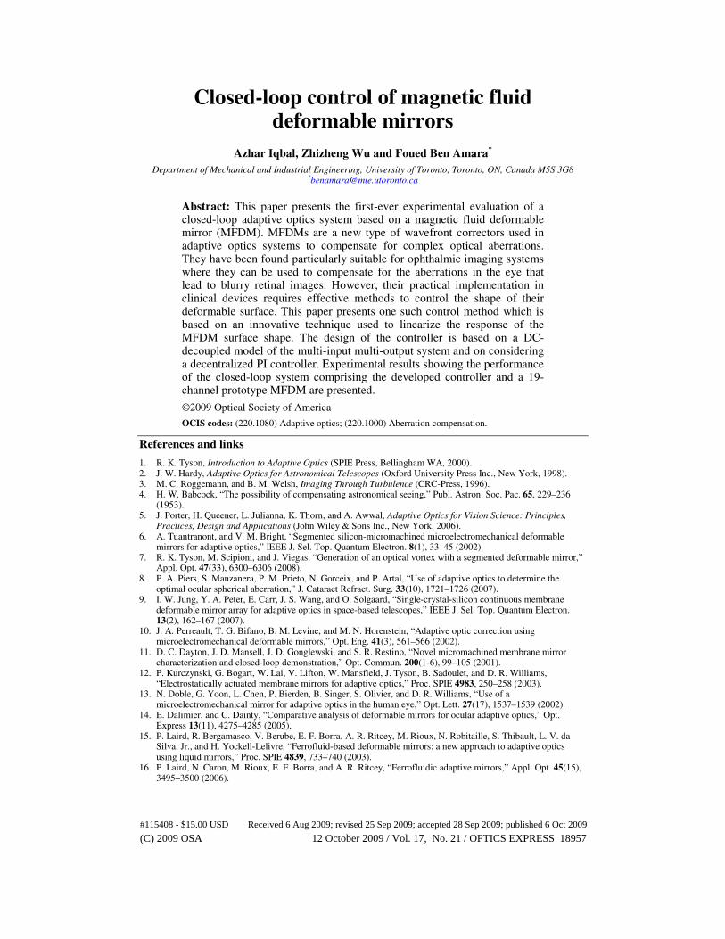
An AO system typically consists of three main components: a wavefront sensor (WFS), a wavefront corrector (WFC) - usually a deformable mirror (DM) - and a controller. As shown in Fig. 1, the aberrated light from the source or the object to be imaged is collected and is directed to the WFS via the DM. The WFS measures the aberrations in the wavefront of the incident light. The wavefront aberration information is fed to a control system. The control system analyses the information and computes the necessary commands for the actuators in the DM. When these commands are applied to the actuators, the surface shape of the DM is adjusted, which results in the cancellation of the aberrations in the incident wavefront. Normally the process of measuring the wavefront and applying the commands to the DM is iterative in nature. When a specified degree of correction is achieved, the imaging system is activated to obtain images with enhanced quality.
A WFC is the principal component of an AO system, which adjusts the incident aberrated wavefront shape and cancels out the aberrations. Deformable mirrors are the most widely used type of WFCs. These mirrors are characterized by a reflective surface that can be locally deformed hence providing a means to change the wavefront shape of the reflected light. Based on the type of the reflective surface, DMs may be classified as segmented [ 6- 8] or continuous type [ 9- 12] mirrors. Comparative studies of these mirrors can be found in [ 13, 14].
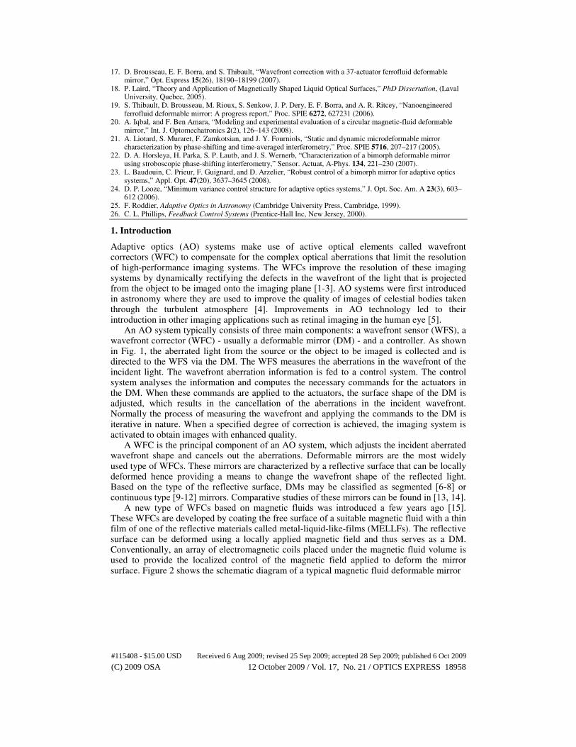
A new type of WFCs based on magnetic fluids was introduced a few years ago [ 15]. These WFCs are developed by coating the free surface of a suitable magnetic fluid with a thin film of one of the reflective materials called metal-liquid-like-films (MELLFs). The reflective surface can be deformed using a locally applied magnetic field and thus serves as a DM. Conventionally, an array of electromagnetic coils placed under the magnetic fluid volume is used to provide the localized control of the magnetic field applied to deform the mirror surface. Figure 2 shows the schematic diagram of a typical magnetic fluid deformable mirror
#115408 - $15.00 USD Received 6 Aug 2009; revised 25 Sep 2009; accepted 28 Sep 2009; published 6 Oct 2009
(C) 2009 OSA 12 October 2009 / Vol. 17, No. 21 / OPTICS EXPRESS 18958
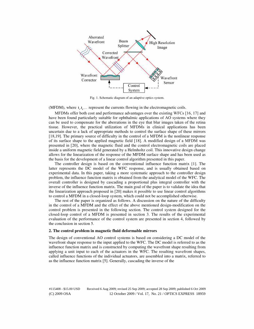
Fig. 1. Schematic diagram of an adaptive optics system.
(MFDM), where 1 2I I, ,… represent the currents flowing in the electromagnetic coils.
MFDMs offer both cost and performance advantages over the existing WFCs [ 16, 17] and have been found particularly suitable for ophthalmic applications of AO systems where they can be used to compensate for the aberrations in the eye that blur images taken of the retina tissue. However, the practical utilization of MFDMs in clinical applications has been uncertain due to a lack of appropriate methods to control the surface shape of these mirrors [ 18, 19]. The primary source of difficulty in the control of a MFDM is the nonlinear response of its surface shape to the applied magnetic field [ 18]. A modified design of a MFDM was presented in [ 20], where the magnetic fluid and the control electromagnetic coils are placed inside a uniform magnetic field generated by a Helmholtz coil. This innovative design change allows for the linearization of the response of the MFDM surface shape and has been used as the basis for the development of a linear control algorithm presented in this paper.
The controller design is based on the conventional influence function matrix [1]. The latter represents the DC model of the WFC response, and is usually obtained based on experimental data. In this paper, taking a more systematic approach to the controller design problem, the influence function matrix is obtained from the analytical model of the WFC. The overall controller is designed by cascading a proportional plus integral controller with the inverse of the influence function matrix. The main goal of the paper is to validate the idea that the linearization approach proposed in [ 20] makes it possible to use linear control algorithms to control a MFDM in a closed-loop system, which could not be accomplished otherwise.
The rest of the paper is organized as follows. A discussion on the nature of the difficulty in the control of a MFDM and the effect of the above mentioned design-modification on the control problem is presented in the following section. The control system designed for the closed-loop control of a MFDM is presented in section 3. The results of the experimental evaluation of the performance of the control system are presented in section 4, followed by the conclusion in section 5.
2. The control problem in magnetic fluid deformable mirrors
The design of conventional AO control systems is based on considering a DC model of the wavefront shape response to the input applied to the WFC. The DC model is referred to as the influence function matrix and is constructed by computing the wavefront shape resulting from applying a unit input to each of the actuators in the WFC. The resulting wavefront shapes, called influence functions of the individual actuators, are assembled into a matrix, referred to as the influence function matrix [ 5]. Generally, cascading the inverse of the
#115408 - $15.00 USD Received 6 Aug 2009; revised 25 Sep 2009; accepted 28 Sep 2009; published 6 Oct 2009
(C) 2009 OSA 12 October 2009 / Vol. 17, No. 21 / OPTICS EXPRESS 18959
Fig. 2. Schematic diagram of a typical MFDM.
Fig. 3. Schematic diagram of the modified MFDM.
influence function matrix with a suitably tuned integral controller provides actuator input updates for the closed-loop operation of the WFC [ 2]. The assumption behind this method is that the WFC is a linear system i.e., the wavefront shape at any point can be obtained using a linear combination of the influence functions of the individual actuators [ 21, 22].
Difficulties in the control of the MFDM surface were first highlighted in [ 18], which revealed that the deflections of the MFDM surface could not be obtained using a linear superposition of the influence functions of the individual actuator coils. As it was discovered that the assumption of linearity did not hold true in the case of MFDMs, the conventional linear control methods used in AO systems were rendered inapplicable to these WFCs. In this backdrop, the closed-loop operation of MFDMs is yet to be seen.
A modified design of a MFDM, which superimposes a uniform vertical magnetic field on the magnetic field of the array of electromagnetic coils conventionally used in the WFC, was presented in [ 20]. A schematic diagram of the modified design is given in Fig. 3. The design modification allows for the linearization of the response of the WFC and is thus expected to resolve the problems resulting from the nonlinearity. It follows that linear controllers designed based on a DC model of the response of a MFDM can be used to control the surface shape of the MFDM in a closed loop adaptive optics system. In the following, the proposition is tested and validated using a controller featuring a proportional-integral structure and designed based on a DC model of the plant.
#115408 - $15.00 USD Received 6 Aug 2009; revised 25 Sep 2009; accepted 28 Sep 2009; published 6 Oct 2009
(C) 2009 OSA 12 October 2009 / Vol. 17, No. 21 / OPTICS EXPRESS 18960
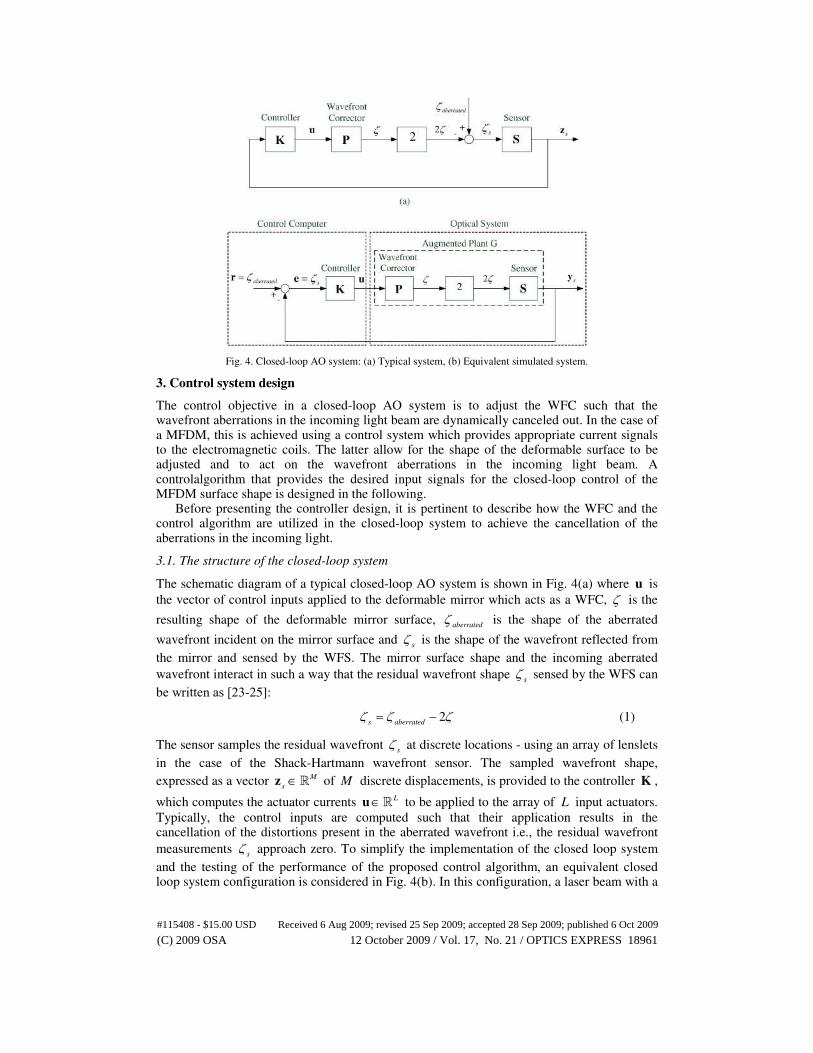
Fig. 4. Closed-loop AO system: (a) Typical system, (b) Equivalent simulated system.
3. Control system design
The control objective in a closed-loop AO system is to adjust the WFC such that the wavefront aberrations in the incoming light beam are dynamically canceled out. In the case of a MFDM, this is achieved using a control system which provides appropriate current signals to the electromagnetic coils. The latter allow for the shape of the deformable surface to be adjusted and to act on the wavefront aberrations in the incoming light beam. A controlalgorithm that provides the desired input signals for the closed-loop control of the MFDM surface shape is designed in the following.
Before presenting the controller design, it is pertinent to describe how the WFC and the control algorithm are utilized in the closed-loop system to achieve the cancellation of the aberrations in the incoming light.
3.1. The structure of the closed-loop system
The schematic diagram of a typical closed-loop AO system is shown in Fig. 4(a) where u is
the vector of control inputs applied to the deformable mirror which acts as a WFC, ζ is the
resulting shape of the deformable mirror surface, aberrated
ζ is the shape of the aberrated
wavefront incident on the mirror surface and s
ζ is the shape of the wavefront reflected from
the mirror and sensed by the WFS. The mirror surface shape and the incoming aberrated
wavefront interact in such a way that the residual wavefront shape s
ζ sensed by the WFS can
be written as [ 23- 25]:
2s aberrated
ζ ζ ζ= − (1)
The sensor samples the residual wavefront s
ζ at discrete locations - using an array of lenslets
in the case of the Shack-Hartmann wavefront sensor. The sampled wavefront shape,
expressed as a vector M
s∈z R of M discrete displacements, is provided to the controller K ,
which computes the actuator currents L∈u R to be applied to the array of L input actuators.
Typically, the control inputs are computed such that their application results in the cancellation of the distortions present in the aberrated wavefront i.e., the residual wavefront
measurements s
ζ approach zero. To simplify the implementation of the closed loop system
and the testing of the performance of the proposed control algorithm, an equivalent closed loop system configuration is considered in Fig. 4(b). In this configuration, a laser beam with a
#115408 - $15.00 USD Received 6 Aug 2009; revised 25 Sep 2009; accepted 28 Sep 2009; published 6 Oct 2009
(C) 2009 OSA 12 October 2009 / Vol. 17, No. 21 / OPTICS EXPRESS 18961
planar wavefront is directed towards the deformable mirror with surface shape ζ . The
wavefront shape in the reflected beam is given by 2s
ζ ζ= − . The negative of the measured
wavefront shape, s s= −y z is then subtracted from a hypothetical aberrated wavefront shape
M∈r R , which is sampled at the same locations at which the measured wavefront shape
vector s
y is sampled. The sign change has been introduced only for consistency with the
standard negative feedback loop. The MFDM surface is required to track half the aberrated wavefront shape r . The wavefront shape r is generated inside the control computer and serves as a reference wavefront shape in the closed-loop operation of the system. The
wavefront shape error M∈e R fed to the controller K can be written as:
s
= −e r y (2)
In this configuration, the controller K is required to provide inputs u such that the
magnitude of the wavefront shape error e is minimized (i.e. the signal s
y (representing twice
the shape of the MFDM surface) tracks the reference wavefront shape signal r (representing
the aberrated wavefront shape aberrated
ζ )). The main advantage in considering the feedback
system shown in Fig. 4(b) is that any aberrated wavefront shape can be easily considered and analytically generated as opposed to physically generating it as in the closed loop system shown in Fig. 4(a).
3.2. The plant model
Let ( )K z , ( )P z and ( )G z denote the discrete-time transfer functions of the closed-loop
system components K , P and G as shown in Fig. 4 (b). The transfer function ( )P z of the
MFDM, which represents the WFC model, can be obtained by discretizing the WFC analytical model presented in [ 20]. Considering that the magnitude of the wavefront shape as measured by the sensor is twice the magnitude of the mirror shape and assuming that the
WFS introduces a unit step delay in the closed-loop, the augmented plant G as shown in Fig.
4(b) can be represented using the transfer function 1
( ) 2 ( )=G Pz zz
. A state-space
representation of the augmented plant G can then be written as [ 26]:
( 1) ( ) ( )
( ) ( )
g g
s g
k k k
k k
+ = +
=
x A x B u
y C x (3)
where ( ) gNk ∈x R is the vector of state variables at any discrete-time instant k ,
gN is the
order of the plant model, and g gN N
g
×∈A R , gN L
g
×∈B R and gM N
g
×∈C R are matrices with
appropriate dimensions. It is assumed that the wavefront surface deflections s
y have been
sampled at the locations corresponding to each of the input electromagnetic coils
, 1, 2,...,l l L= and that M L= .
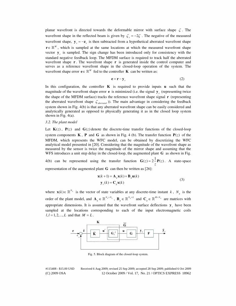
Fig. 5. Block diagram of the closed-loop system.
#115408 - $15.00 USD Received 6 Aug 2009; revised 25 Sep 2009; accepted 28 Sep 2009; published 6 Oct 2009
(C) 2009 OSA 12 October 2009 / Vol. 17, No. 21 / OPTICS EXPRESS 18962
3.3. Decoupling using DC gain
The influence function matrix associated with the augmented plant G is actually its DC gain
0G , which can be obtained using (3), and is given as follows:
1
0( )
g g g
−= −G C I A B (4)
Cascading the inverse of the DC gain with the augmented plant G yields a system G given
by
1
0( ) ( ) −=G G Gz z (5)
and satisfying 1
0( (
j Jsj Jse
e=
−
== ≈G G G Iz) z)
ww
zz
, 0
0 ω ω≤ ≤ , where s
T is the sampling period
and 0
ω is an upper bound on the low frequency range of the aberrations of interest. Hence,
G is a decoupled system with a unit DC gain associated with each of the decoupled channels.
This decoupling effect can be incorporated in a closed loop system by simply cascading the
gain 1
0
−G with the plant G as shown in Fig. 5. To mitigate the high frequency noise in the
actual plant, a low pass filter F , where f=F I and f is a scalar transfer function, is
introduced in the closed-loop system. Since G and F are both diagonal matrices, a
decentralized type controller K can be designed such that k=K I , where k is a single-input,
single-output (SISO) controller. Given K , the overall controller K is given by:
1 1
0 0k− −= =K G K G (6)
3.4. Controller design
In the following, a decentralized proportional plus integral (PI) type controller k=K I is
considered for the system G where:
( )1
p ik k k= +
−
zz
z (7)
and where p
k and i
k are, respectively, the proportional and integral gains of the controller. It
is assumed that the plant G can be represented by its DC gain, which allows it to be written
as =G I . Hence the overall plant controlled by K can be written as f=FG I . Since K and
FG are diagonal transfer matrices, it follows that the resulting closed loop system is
decoupled. Hence the gains p
k and i
k in k can be designed using standard
#115408 - $15.00 USD Received 6 Aug 2009; revised 25 Sep 2009; accepted 28 Sep 2009; published 6 Oct 2009
(C) 2009 OSA 12 October 2009 / Vol. 17, No. 21 / OPTICS EXPRESS 18963
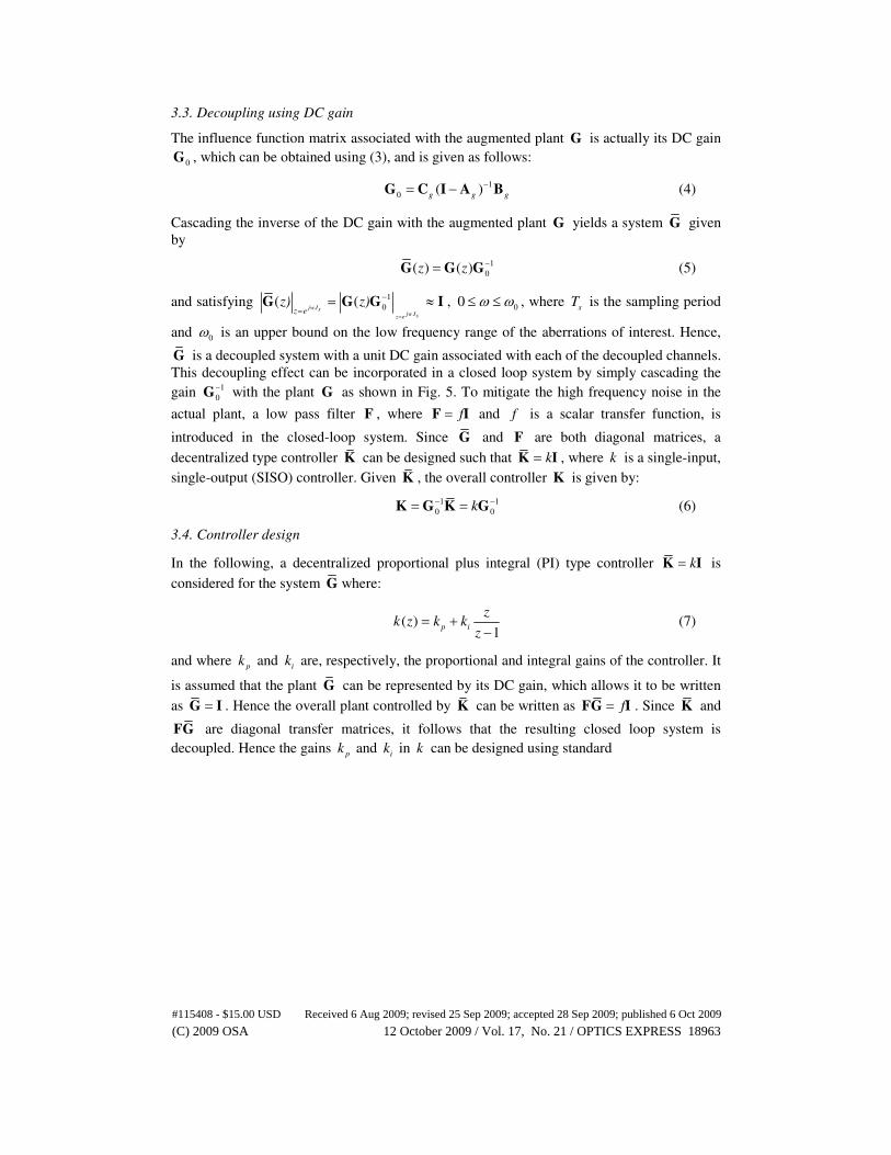
Fig. 6. Optical side of the experimental setup.
controller design techniques for single-input single-output systems [ 26]. The overall
controller 1
0k −=K G thus obtained can be used to control the output of the augmented plant
G in the closed-loop system. Experimental results of the closed-loop system response are
presented in the following section.
4. Experimental results
This section presents experimental results on the cancellation of the wavefront aberrations in an adaptive optics setup involving the proposed MFDM and the developed controller. The experimental setup is presented first, followed by a discussion of the experimental results.
4.1. Experimental setup
In order to demonstrate the effectiveness of the designed control system in controlling a MFDM, an experimental system comprising a 19-channel prototype MFDM and an AO system built around the mirror has been developed. A snapshot of the system is shown in Fig. 6. The system is designed to be used as a platform for the testing, characterization and evaluation of the MFDM in the first stage, and will be subsequently complemented with a science camera and auxiliary components that will render it a complete solution for high-resolution imaging of the retina in the human eye. The prototype MFDM comprises a 60mm diameter layer of EFH1 (Ferrofluid for Education - Hydrocarbon type) which is a commercially available oil-based magnetic fluid (Ferrotec (USA) Corporation, NH, USA). The thickness of the magnetic fluid layer used is 0.5 mm. The mirror surface is deformed using an array of 19 electromagnetic coils arranged in a circular pattern. The air-cored coils (PCRC 408-006) obtained off-the-shelf from Dia-netics Inc. provide the local magnetic field. A locally fabricated Helmholtz coil with a nominal diameter of 88 mm is used and where each of the two constituent coils comprises 625 turns of AWG 26 copper wires. A Shack-
#115408 - $15.00 USD Received 6 Aug 2009; revised 25 Sep 2009; accepted 28 Sep 2009; published 6 Oct 2009
(C) 2009 OSA 12 October 2009 / Vol. 17, No. 21 / OPTICS EXPRESS 18964
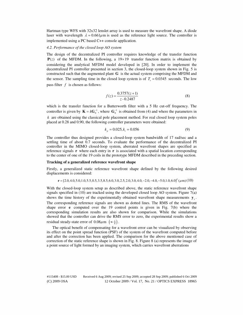
Hartman type WFS with 32x32 lenslet array is used to measure the wavefront shape. A diode laser with wavelength 0.661 mλ µ= is used as the reference light source. The controller is
implemented using a PC based C++ console application.
4.2. Performance of the closed loop AO system
The design of the decentralized PI controller requires knowledge of the transfer function
( )P z of the MFDM. In the following, a 19 19× transfer function matrix is obtained by
considering the analytical MFDM model developed in [ 20]. In order to implement the decentralized PI controller presented in section 3, the closed-loop system shown in Fig. 5 is
constructed such that the augmented plant G is the actual system comprising the MFDM and
the sensor. The sampling time in the closed loop system is of 0.0345s
T = seconds. The low
pass filter f is chosen as follows:
0.3757( 1)
( )- 0.2487
f+
=z
zz
(8)
which is the transfer function for a Butterworth filter with a 5 Hz cut-off frequency. The
controller is given by 1
0k −=K G , where 1
0
−G is obtained from (4) and where the parameters in
k are obtained using the classical pole placement method. For real closed loop system poles
placed at 0.28 and 0.90, the following controller parameters were obtained:
0.025, 0.056p i
k k= = (9)
The controller thus designed provides a closed-loop system bandwidth of 17 rad/sec and a settling time of about 0.7 seconds. To evaluate the performance of the decentralized PI controller in the MIMO closed-loop system, aberrated wavefront shapes are specified as reference signals r where each entry in r is associated with a spatial location corresponding to the center of one of the 19 coils in the prototype MFDM described in the preceding section.
Tracking of a generalized reference wavefront shape
Firstly, a generalized static reference wavefront shape defined by the following desired displacements is considered:
[2.0,4.0,5.0,1.0,5.5,0.5,3.5,8.5,6.0,3.0,2.5,2.0,3.0,4.0, 2.0, 4.0, 5.0,1.0,6.0] ( m)T µ= − − −r (10)
With the closed-loop system setup as described above, the static reference wavefront shape signals specified in (10) are tracked using the developed closed loop AO system. Figure 7(a)
shows the time history of the experimentally obtained wavefront shape measurements s
y .
The corresponding reference signals are shown as dotted lines. The RMS of the wavefront shape error e computed over the 19 control points is given in Fig. 7(b) where the
corresponding simulation results are also shown for comparison. While the simulations showed that the controller can drive the RMS error to zero, the experimental results show a
residual steady-state error of 0.08 mµ ( )8
λ≈ .
The optical benefit of compensating for a wavefront error can be visualized by observing its effect on the point spread function (PSF) of the system of the wavefront computed before and after the correction has been applied. The comparison for the above mentioned case of correction of the static reference shape is shown in Fig. 8. Figure 8 (a) represents the image of a point source of light formed by an imaging system, which carries wavefront aberrations
#115408 - $15.00 USD Received 6 Aug 2009; revised 25 Sep 2009; accepted 28 Sep 2009; published 6 Oct 2009
(C) 2009 OSA 12 October 2009 / Vol. 17, No. 21 / OPTICS EXPRESS 18965
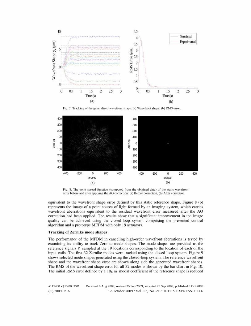
Fig. 7. Tracking of the generalized wavefront shape: (a) Wavefront shape, (b) RMS error.
Fig. 8. The point spread function (computed from the obtained data) of the static wavefront error before and after applying the AO correction: (a) Before correction, (b) After correction.
equivalent to the wavefront shape error defined by this static reference shape. Figure 8 (b) represents the image of a point source of light formed by an imaging system, which carries wavefront aberrations equivalent to the residual wavefront error measured after the AO correction had been applied. The results show that a significant improvement in the image quality can be achieved using the closed-loop system comprising the presented control algorithm and a prototype MFDM with only 19 actuators.
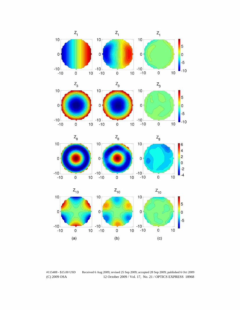
Tracking of Zernike mode shapes
The performance of the MFDM in canceling high-order wavefront aberrations is tested by examining its ability to track Zernike mode shapes. The mode shapes are provided as the reference signals r sampled at the 19 locations corresponding to the location of each of the input coils. The first 32 Zernike modes were tracked using the closed loop system. Figure 9 shows selected mode shapes generated using the closed-loop system. The reference wavefront shape and the wavefront shape error are shown along side the generated wavefront shapes. The RMS of the wavefront shape error for all 32 modes is shown by the bar chart in Fig. 10. The initial RMS error defined by a 10 mµ modal coefficient of the reference shape is reduced
#115408 - $15.00 USD Received 6 Aug 2009; revised 25 Sep 2009; accepted 28 Sep 2009; published 6 Oct 2009
(C) 2009 OSA 12 October 2009 / Vol. 17, No. 21 / OPTICS EXPRESS 18966

to the magnitudes shown in the figure. Figure 10 shows the RMS computed at the 19 control points as well as over the whole surface. The average RMS error computed over 19 control
points is 0.11 mµ ( )6
λ≈ . It should be noted that the steady state RMS computed over the
whole surface is affected by two main factors, namely the performance of the control system at the control points and the density of the actuators. The experimental results indicate that the RMS computed over the control points is good, which implies that the control system performance is as expected. However, with only 19 actuators in use, the RMS computed over the whole surface does not yield an accurate measure of the performance of the control system. It is therefore expected that using a larger number of actuators (i.e. higher actuator density) will allow the RMS computed over the whole surface to be much smaller as compared to what is shown for the case of 19 actuators only. Therefore, it can be concluded that successful tracking at the control points of up to 32 Zernike mode shapes has been achieved, and that effective cancellation of the wavefront aberrations can be achieve using a higher actuator density in this WFC.
#115408 - $15.00 USD Received 6 Aug 2009; revised 25 Sep 2009; accepted 28 Sep 2009; published 6 Oct 2009
(C) 2009 OSA 12 October 2009 / Vol. 17, No. 21 / OPTICS EXPRESS 18967
#115408 - $15.00 USD Received 6 Aug 2009; revised 25 Sep 2009; accepted 28 Sep 2009; published 6 Oct 2009
(C) 2009 OSA 12 October 2009 / Vol. 17, No. 21 / OPTICS EXPRESS 18968
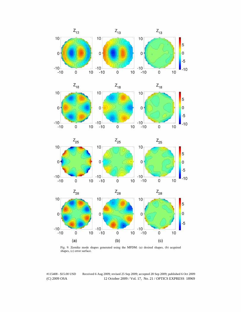
Fig. 9. Zernike mode shapes generated using the MFDM: (a) desired shapes, (b) acquired shapes, (c) error surface.
#115408 - $15.00 USD Received 6 Aug 2009; revised 25 Sep 2009; accepted 28 Sep 2009; published 6 Oct 2009
(C) 2009 OSA 12 October 2009 / Vol. 17, No. 21 / OPTICS EXPRESS 18969
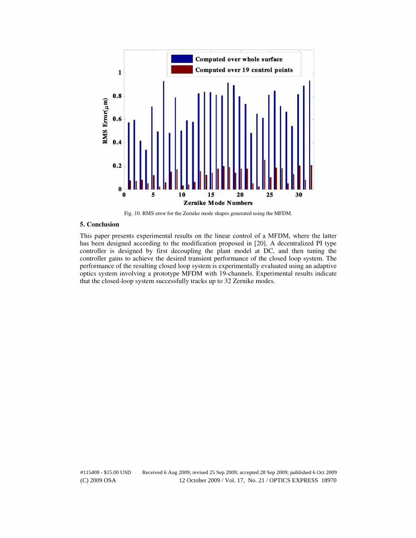
Fig. 10. RMS error for the Zernike mode shapes generated using the MFDM.
5. Conclusion
This paper presents experimental results on the linear control of a MFDM, where the latter has been designed according to the modification proposed in [ 20]. A decentralized PI type controller is designed by first decoupling the plant model at DC, and then tuning the controller gains to achieve the desired transient performance of the closed loop system. The performance of the resulting closed loop system is experimentally evaluated using an adaptive optics system involving a prototype MFDM with 19-channels. Experimental results indicate that the closed-loop system successfully tracks up to 32 Zernike modes.
#115408 - $15.00 USD Received 6 Aug 2009; revised 25 Sep 2009; accepted 28 Sep 2009; published 6 Oct 2009
(C) 2009 OSA 12 October 2009 / Vol. 17, No. 21 / OPTICS EXPRESS 18970


