Embed Size (px)
Citation preview
20th International Conference on Composite Materials Copenhagen, 19-24th July 2015
PROGRESSIVE DAMAGE SIMULATION OF COMPOSITE STRUCTURES USING A COMBINED CONTINUUM AND DISCRETE
MODELLING APPROACH
Ofir Shor1, Mina Shahbazi1 and Reza Vaziri1*
1Department of Civil Engineering, The University of British Columbia 6250 Applied Science Lane, Vancouver, B.C. Canada V6T 1Z4
*Email: [email protected]
Keywords: Continuum Damage Model, Adaptive Local Cohesive Zone Model, Tube Crush Simulation, Explicit Finite Element Analysis
ABSTRACT
A combined discrete and continuum damage modelling methodology is utilized to simulate the progression of inter- and intra-laminar damage modes in composite materials. For intra-laminar damage, the UBC Composite Damage Model (CODAM2) implemented as a built-in material model (MAT219) in the explicit finite element software, LS-DYNA, is adopted. In its local form, and through appropriately determined scaling laws this continuum damage model addresses the issue of strain localization and mesh size dependency observed in modelling strain-softening materials. In its non-local form, the model is capable of capturing the correct path for damage growth in orthotropic media, one that is insensitive to the orientation of the finite element mesh and instead, follows the most energetically favourable path. For inter-laminar damage mode, a new adaptive through-thickness element-splitting technique is employed which allows efficient simulation of delamination damage in large-scale structures. Accordingly, during the transient analysis, continuum elements are split through their thickness where and when needed, and cohesive elements are introduced only in local regions where delamination has the potential to initiate and grow. This adaptive local placement of cohesive zones (LCZ) eliminates the need for a priori introduction of cohesive elements at all possible locations in the finite element mesh – a procedure that is computationally costly and has the undesirable consequence of artificially reducing the overall structural stiffness. The capabilities of the above mentioned methodology will be demonstrated using a numerical case study involving the dynamic axial crushing of a composite tube. 1 INTRODUCTION
With the rapidly increasing adoption of composite materials in large-scale structural components that are being designed for various industrial applications including automotive and aerospace, there is a need for reliable and efficient computational tools that can readily be used to simulate the nonlinear response of these structures when subjected to loads that can inflict significant damage. The multitude of damage mechanisms such as fibre breakage, matrix cracking and delamination that occur in laminated composite materials and the complexity of their interactions that depends on a host of material and geometrical variables, poses considerable challenges to the analyst who attempts to simulate the structural behaviour within a computational framework that is efficient and robust while it captures the correct physics faithfully.
Fracture mechanics and progressive damage analysis are integral components of numerical analysis tools used for predicting the strength of composite structures. In computational damage/fracture mechanics, cracks are either explicitly represented in the geometry model of the structure (e.g., cohesive crack model, tie-break contact interface, virtual crack closure technique) or are implicitly accounted for in the constitutive model. The use of cohesive crack models for modelling delamination has been popular. They have also been employed to resolve the details of discrete matrix cracks and splits that occur in certain laminates and loading configurations [1]. In these methods, all the damage is restricted to a discrete, zero-thickness layer obeying special traction-relative displacement curves with the area under such curves representing the critical fracture energy. By definition, the cohesive
Ofir Shor, Mina Shahbazi and Reza Vaziri
crack interface has to run along stacks of elements. Since delamination sites, in general, cannot be determined a priori this may lead to the requirement for a rather fine mesh of elements through the thickness of the composite structure. Such a detailed ply-by-ply discretization is not only computationally intensive but also is tedious and time consuming for the analyst thus rendering it impractical for analyses of large-scale structures. Furthermore, inserting pre-assigned cohesive elements/interfaces in wide regions of the model will artificially reduce the structural stiffness [2].
When a continuum modelling approach is used, damage is treated in a smeared manner over the continuum finite element domain. The effect of micro-crack evolution within the material is captured by means of stiffness degradation, which is a function of the damage accumulated within the element. This modelling approach is used extensively in finite element analysis due to its straightforward implementation and numerical efficiency ([3], [4], [5]). It has been shown to enable reasonably accurate modelling of damage in quasi-brittle materials, for cases where damage is not localized and dominated by discrete failure modes. The damage variables for each loading direction are usually stored as history variables in the finite element solver, and can be easily accessed by the user for post-processing purposes.
Continuum damage models in their classical local form suffer from the well-known localization problem [6]. Forghani et al. ([6], [7]) introduced a nonlocal regularizing scheme for orthotropic materials, in which damage is considered to be a function of the non-local (averaged) equivalent strain. This formulation has been implemented in the second generation of the continuum damage models (CODAM2) developed at the UBC Composites Group and is used here to simulate the intra-laminar or in-plane damage behaviour of composites.
For cases where failure is governed by discrete crack propagation, continuum damage models often fail to correctly describe the propagation of damage through the structure. This is due to the fact that in such models these cracks are “smeared” as part of the damage homogenization process. However, in reality, discrete cracks alter the loading paths within the structure and in some cases the cracks’ surfaces need to be explicitly modelled within the finite element mesh in order to capture the correct stress and strain distributions. 2 METHODOLOGY
2.1 Continuum modelling (intra-laminar damage)
The intra-laminar damage consisting of fibre breakage and matrix cracking is modelled using a sub-laminate based continuum damage mechanics model developed at the University of British Columbia and known as CODAM2 [7]. The original version of this material model, developed by Williams et al. [8], has been successfully used in a variety of applications including the dynamic axial crush simulation of composite tubes, a problem that will be studied again in this paper in order to demonstrate the capability and efficiency of the current combined continuum and discrete damage modelling methodology.
Although CODAM2 is a sub-laminate based model, it acknowledges the existence of orthotropic layers within the sub-laminate and casts the damage formulation in terms of the strain components in those directions. Another feature of this material model, compared to its predecessor, is its non-local averaging capability. This is to alleviate the problem of mesh size and orientation dependency which is common in continuum damage models that involve a strain softening response. Furthermore, the orthotropic non-local formulation allows the correct path of crack growth to be captured in simulations of damage in strongly orthotropic media; a feat that is difficult to achieve in smeared modelling of damage using either local models (with appropriate crack band scaling to maintain the objectivity of the numerical simulation) or non-local models that are based on isotropic averaging schemes. The ability to model intra-laminar cracks that grow in distinct directions (such as splits) using a continuum damage modelling approach enhanced with orthotropic non-local averaging is particularly desirable as it eliminates the need to introduce discrete elements in-plane to capture the growth of such cracks.
In CODAM2 the damage behaviour of the sub-laminate is defined in terms of the directionally dependent effective strain of its constituent layers using a proper characterization of the damage properties of the sub-laminate. CODAM2 has been implemented as a built-in material model (MAT219) in the commercial finite element code, LS-DYNA. Being integrated into LS-DYNA, the
20th International Conference on Composite Materials Copenhagen, 19-24th July 2015
model can take advantage of the efficiencies that come with all of the built-in features of the code such as its contact algorithms.
2.2 Discrete modelling (inter-laminar damage)
Delamination is an inherently discrete mode of damage that can be modelled effectively using the cohesive crack (zone) approach. The cohesive zone method, allows modelling crack propagation without introducing cracks into the model prior to the analysis. Using this method, the need to calculate the non-physical singular stress field at the crack tip is eliminated by using a force-displacement relation between the nodes in the finite element mesh (traction-separation law) [9]. This law is the basis for computing the crack initiation, propagation, and opening. Thus, cohesive zone models can deal with the nonlinear zone ahead of the crack tip, due to plasticity or micro-cracking present in many materials, without necessitating the use of a refined mesh around the crack-tip region. The cohesive zone method incorporates fracture mechanics principles, as the area under the traction-separation curve is equal to the critical strain energy release rate of the material (Gc). Numerous papers demonstrating the use of the cohesive method can be found in the literature. Camacho and Ortiz [10] used the cohesive zone method to predict crack propagation during a steel/rock impact. The method was proven to be capable of predicting delamination growth in composite materials under static ([11], [12]) as well as dynamic loading and impact conditions ([5], [10], [13], [14], [15]), and using a cohesive contact interface ([16], [17]).
Since the use of the cohesive zone method in its standard form requires introduction of a large number of cohesive elements or interfaces for all possible crack paths, using this method to predict crack growth in large structures is not practical from the numerical standpoint. Furthermore, using cohesive elements in wide regions of the model will artificially render the structure more compliant [8].
A new method termed the local cohesive zone (LCZ) method described in [18], allows adaptive through-thickness element splitting and insertion of cohesive elements into the structure, to simulate delamination damage in large-scale composite structures more efficiently. The method enables delamination modelling without having to introduce cohesive elements at all possible locations in the finite element mesh. During the transient analysis, continuum elements are locally and adaptively split through their thickness only where and when needed, and cohesive elements are introduced solely in those regions where delamination has the potential to initiate and grow. The application of the algorithm to structural problems results in the formation of a narrow band of cohesive elements which is sufficiently wide to capture the fracture phenomena and allow the propagation of delamination through the structure.
In the LCZ method, the original shell-like continuum elements (thick-shell elements in this case) that are used to discretize the structure are split through their thickness and cohesive elements are introduced whenever the value of a user-defined element splitting criterion S, reaches a critical value, Sc. The criterion used in the analysis is an interactive stress-based criterion given by:
2 2
max max
n scS Ss s
s τ
= + ≥
(1)
where sn and ss are the through-thickness normal and shear stress components with smax and τmax being the respective maximum values of these quantities. A user-defined radius, R, determines the planar size of a circular region which will undergo splitting once the value of S in a given generic thick-shell element, e, reaches the critical value, Sc. Accordingly, the algorithm splits all neighbouring thick-shell elements with centroids that lie within a distance, R from the centroid of the element, e. In most applications, the splitting process will result in the formation of a “cohesive band” - a narrow region of cohesive elements seeded into the model that propagates through the structure during the transient analysis. More information regarding the effect of the various parameters on the splitting operation can be found in [18].
Ofir Shor, Mina Shahbazi and Reza Vaziri
3 TUBE CRUSH SIMULATION
To demonstrate the capability of the combined CODAM2 / LCZ approach to model progressive damage in composite structures, a test case involving axial crush simulation of composite tubes will be investigated. This problem has been tackled before using the previous version of the continuum damage model, CODAM, implemented as a user-defined material model, UMAT, in LS-DYNA in tandem with the built-in cohesive based tie-break contact interface in LS-DYNA for modelling delamination.
3.1 Material and test specimens
Two inch (51 mm) square tubes of braided composite material having two plies each with [0/±45] braid architecture are considered here. The triaxial braid consisted of Fortafil #556 80k2 carbon axial tows and Grafil 34-700 12k carbon biaxial tows. The matrix resin was an Ashland Hetron 922 vinyl ester resin. The tubes had a nominal length of 355 mm.
Dynamic tube crushing tests were conducted with a 10 kJ drop tower with a drop mass of 535 kg and maximum drop height of 2.0 m. The test results corresponding to two impact velocities of 2.5 m/s and 2.9 m/s are considered for the purposes of this study. In order to induce a stable and progressive crushing process, the edges of the tubes were chamfered at a 45° angle. A metallic plug was also inserted at the bottom of the tube prior to the experiment for initiating the fracture and to prevent the accumulation of the debris between the tube and the impact plane. The details of the tube crush experiments are described in [19].
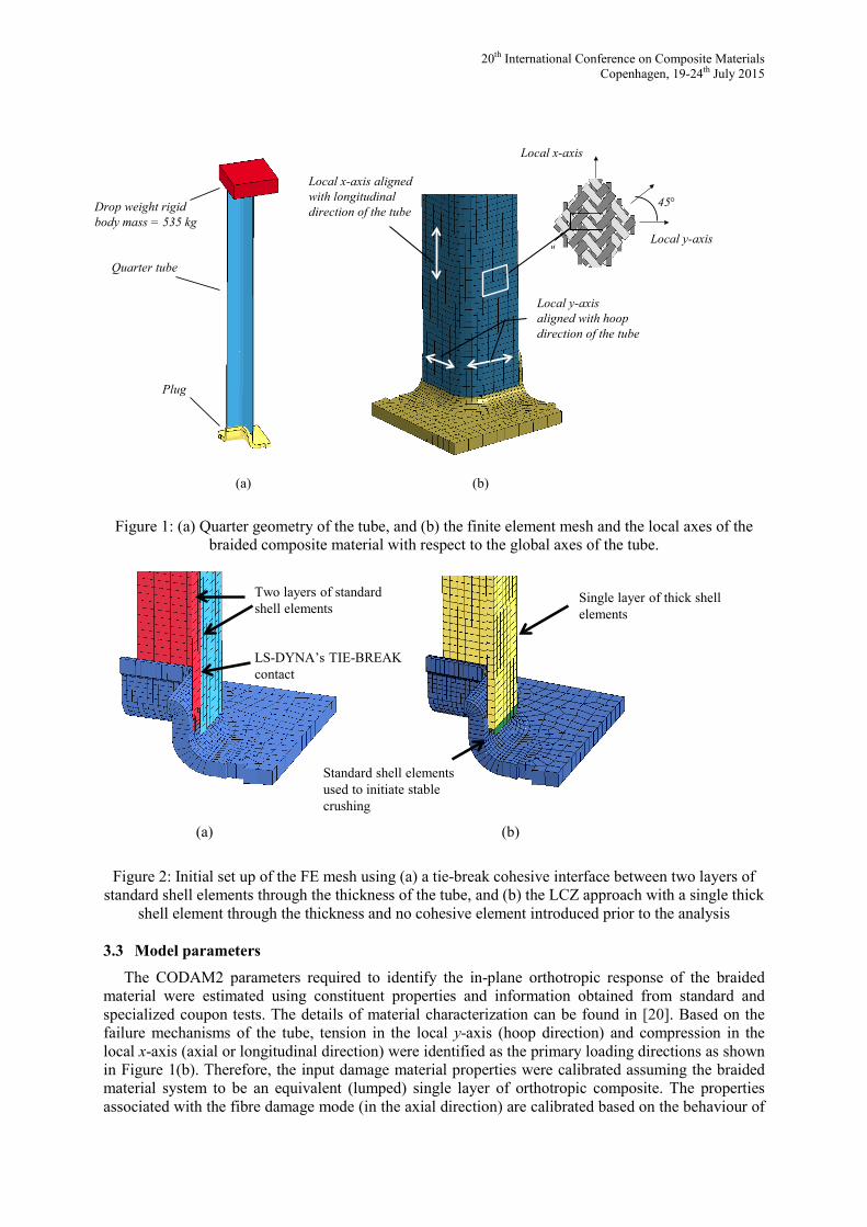
3.2 Numerical model
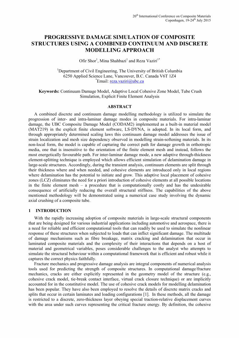
The tube crush event modeled in LS-DYNA consists of 3 main components: a drop weight, a tube and a plug to initiate the crushing process. Only a quarter of each component is modelled as shown in Figure 1(a), and the required symmetry boundary conditions are enforced accordingly. In the numerical simulations, the drop weight is modelled as a rigid body using solid elements with a mass of a quarter of the total mass (i.e. 134 kg). The tube is modelled with the CODAM2 material model and is rigidly attached to the bottom of the drop weight. The plug initiator is modelled as a rigid body using solid elements and is fixed in space. An initial velocity of 2.7 m/s (corresponding to the average velocity used in the two tests) is assigned to the drop weight causing the tube to impact the plug. The three modes of failure associated with the majority of energy absorption during the crushing process of the tubes can be described as being transverse (to the axial tows) tensile fracture at the four corners of the tubes, longitudinal (axial) compressive failure, and delamination.
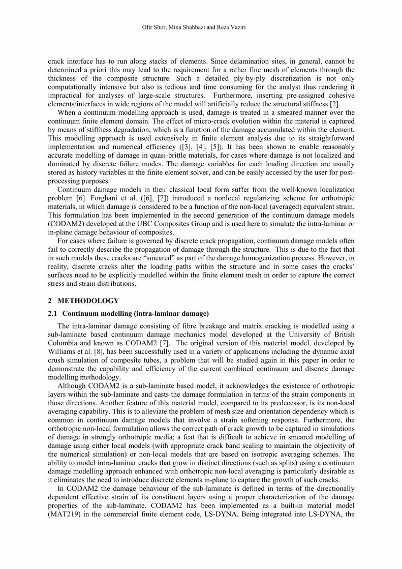
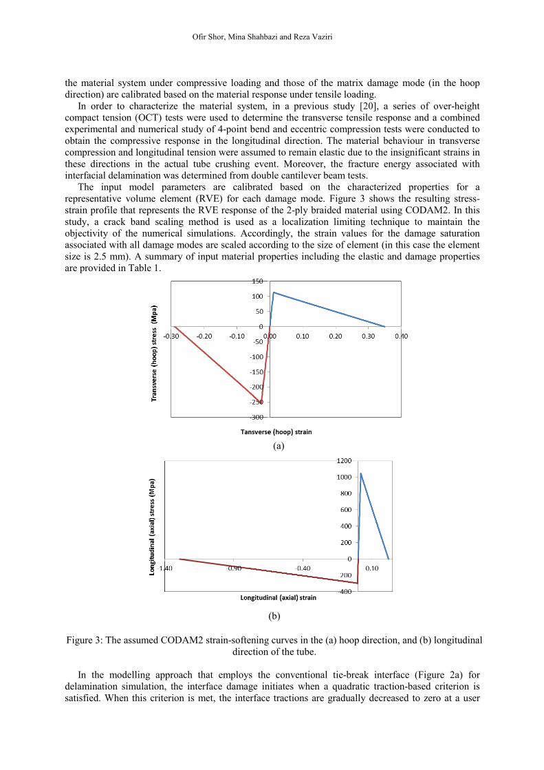
In order to provide an alternate and comparative numerical solution to the one that uses the combination of CODAM2 and LCZ, two simulation approaches are used. In the first approach (see Figure 2a), the braided composite is represented by two layers of regular shell elements tied together using a conventional cohesive type tie-break contact interface available in LS-DYNA. The material behaviour of each shell element is governed by CODAM2 or MAT219 in LS-DYNA.
In the second approach where the adaptive LCZ algorithm is applied, a single layer of thick-shell elements (ELFORM=5) is used through the thickness of the tube (see Figure 2b). No cohesive elements are introduced in the model prior to the analysis, as they are added adaptively to the structure during the transient simulation. In order to model the chamfer at the end of the tube, which is required to enable a stable crushing process, a row of shell elements with a thickness equal to half the thickness of the tube wall are connected to the end of the tube. These shell elements are the first to come in contact with the plug initiator. The in-plane behaviour of the thick shell elements and that of the standard shells that result from its subsequent through-thickness splitting is again governed by the CODAM2 material model.
20th International Conference on Composite Materials Copenhagen, 19-24th July 2015
Figure 1: (a) Quarter geometry of the tube, and (b) the finite element mesh and the local axes of the braided composite material with respect to the global axes of the tube.
Figure 2: Initial set up of the FE mesh using (a) a tie-break cohesive interface between two layers of standard shell elements through the thickness of the tube, and (b) the LCZ approach with a single thick
shell element through the thickness and no cohesive element introduced prior to the analysis
3.3 Model parameters
The CODAM2 parameters required to identify the in-plane orthotropic response of the braided material were estimated using constituent properties and information obtained from standard and specialized coupon tests. The details of material characterization can be found in [20]. Based on the failure mechanisms of the tube, tension in the local y-axis (hoop direction) and compression in the local x-axis (axial or longitudinal direction) were identified as the primary loading directions as shown in Figure 1(b). Therefore, the input damage material properties were calibrated assuming the braided material system to be an equivalent (lumped) single layer of orthotropic composite. The properties associated with the fibre damage mode (in the axial direction) are calibrated based on the behaviour of
Two layers of standard shell elements
LS-DYNA’s TIE-BREAK contact
Standard shell elements used to initiate stable crushing
Single layer of thick shell elements
(a) (b)
Local x-axis aligned with longitudinal direction of the tube
Local y-axis aligned with hoop direction of the tube
Local x-axis
Local y-axis
45°
(a) (b)
Drop weight rigid body mass = 535 kg
Plug
Quarter tube
Ofir Shor, Mina Shahbazi and Reza Vaziri
the material system under compressive loading and those of the matrix damage mode (in the hoop direction) are calibrated based on the material response under tensile loading.
In order to characterize the material system, in a previous study [20], a series of over-height compact tension (OCT) tests were used to determine the transverse tensile response and a combined experimental and numerical study of 4-point bend and eccentric compression tests were conducted to obtain the compressive response in the longitudinal direction. The material behaviour in transverse compression and longitudinal tension were assumed to remain elastic due to the insignificant strains in these directions in the actual tube crushing event. Moreover, the fracture energy associated with interfacial delamination was determined from double cantilever beam tests.
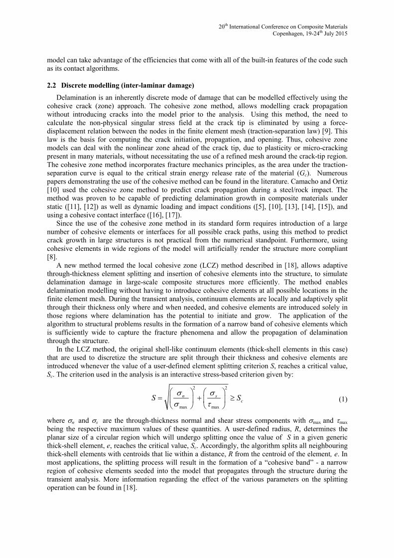
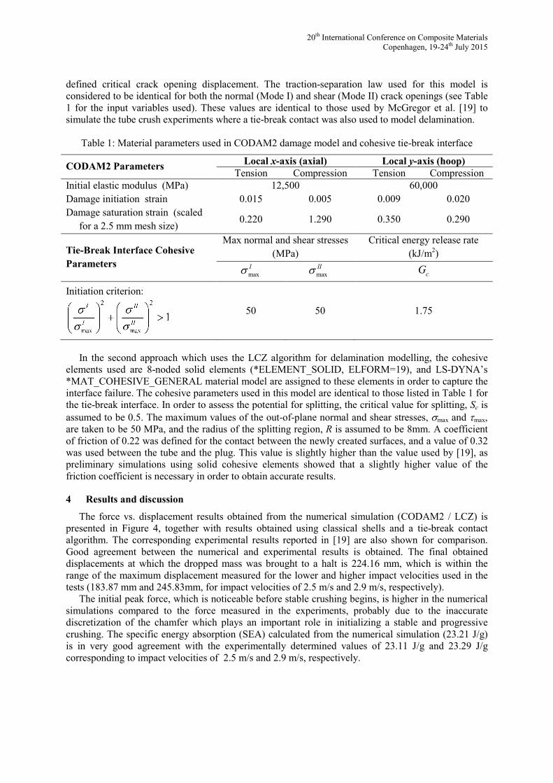
The input model parameters are calibrated based on the characterized properties for a representative volume element (RVE) for each damage mode. Figure 3 shows the resulting stress-strain profile that represents the RVE response of the 2-ply braided material using CODAM2. In this study, a crack band scaling method is used as a localization limiting technique to maintain the objectivity of the numerical simulations. Accordingly, the strain values for the damage saturation associated with all damage modes are scaled according to the size of element (in this case the element size is 2.5 mm). A summary of input material properties including the elastic and damage properties are provided in Table 1.
(a)
(b)
Figure 3: The assumed CODAM2 strain-softening curves in the (a) hoop direction, and (b) longitudinal
direction of the tube.
In the modelling approach that employs the conventional tie-break interface (Figure 2a) for delamination simulation, the interface damage initiates when a quadratic traction-based criterion is satisfied. When this criterion is met, the interface tractions are gradually decreased to zero at a user
20th International Conference on Composite Materials Copenhagen, 19-24th July 2015
defined critical crack opening displacement. The traction-separation law used for this model is considered to be identical for both the normal (Mode I) and shear (Mode II) crack openings (see Table 1 for the input variables used). These values are identical to those used by McGregor et al. [19] to simulate the tube crush experiments where a tie-break contact was also used to model delamination.
Table 1: Material parameters used in CODAM2 damage model and cohesive tie-break interface
CODAM2 Parameters Local x-axis (axial) Local y-axis (hoop) Tension Compression Tension Compression
Initial elastic modulus (MPa) 12,500 60,000 Damage initiation strain 0.015 0.005 0.009 0.020 Damage saturation strain (scaled
for a 2.5 mm mesh size) 0.220 1.290 0.350 0.290
Tie-Break Interface Cohesive Parameters
Max normal and shear stresses (MPa)
Critical energy release rate (kJ/m2)
maxIs max
IIs cG
Initiation criterion:
50 50 1.75
In the second approach which uses the LCZ algorithm for delamination modelling, the cohesive
elements used are 8-noded solid elements (*ELEMENT_SOLID, ELFORM=19), and LS-DYNA’s *MAT_COHESIVE_GENERAL material model are assigned to these elements in order to capture the interface failure. The cohesive parameters used in this model are identical to those listed in Table 1 for the tie-break interface. In order to assess the potential for splitting, the critical value for splitting, Sc is assumed to be 0.5. The maximum values of the out-of-plane normal and shear stresses, smax and τmax, are taken to be 50 MPa, and the radius of the splitting region, R is assumed to be 8mm. A coefficient of friction of 0.22 was defined for the contact between the newly created surfaces, and a value of 0.32 was used between the tube and the plug. This value is slightly higher than the value used by [19], as preliminary simulations using solid cohesive elements showed that a slightly higher value of the friction coefficient is necessary in order to obtain accurate results.
4 Results and discussion
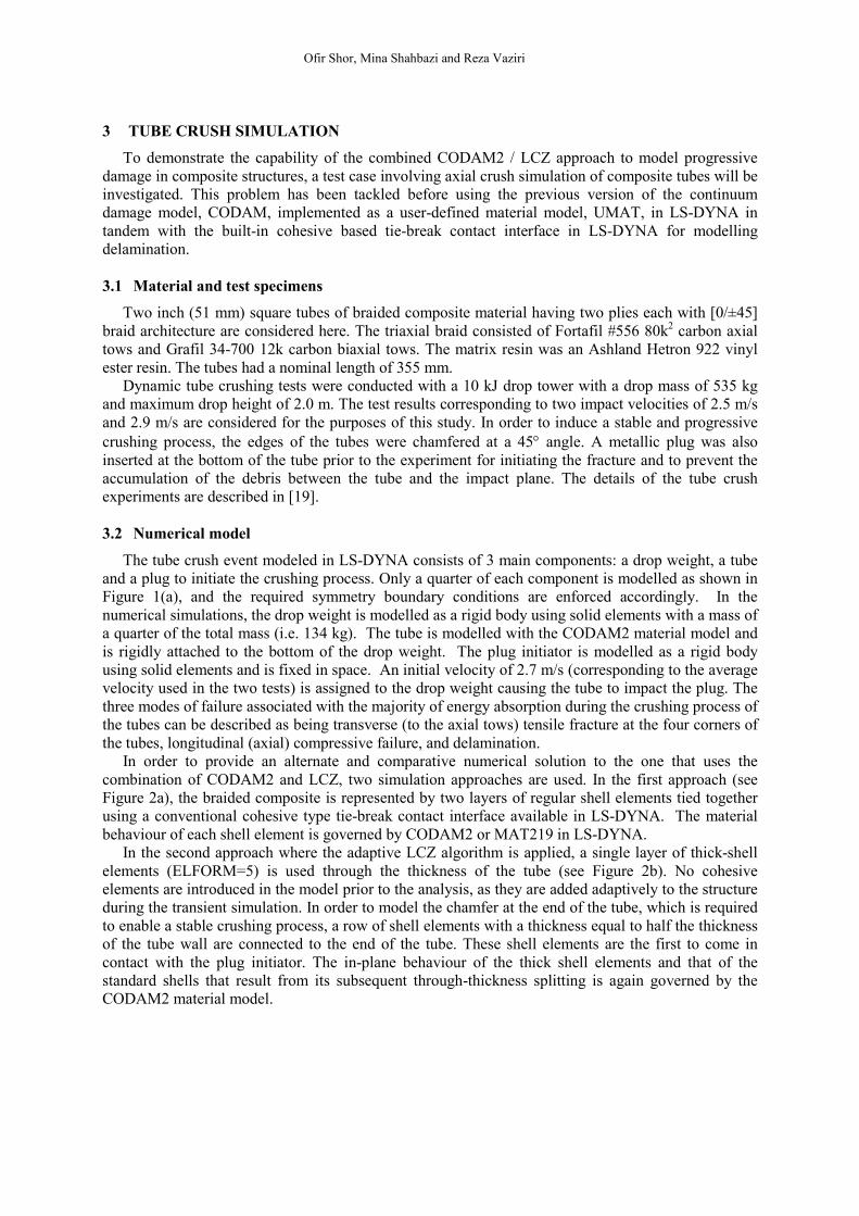
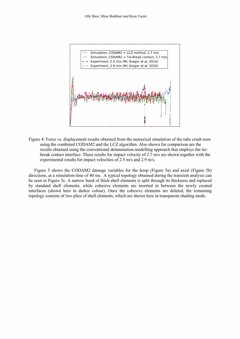
The force vs. displacement results obtained from the numerical simulation (CODAM2 / LCZ) is presented in Figure 4, together with results obtained using classical shells and a tie-break contact algorithm. The corresponding experimental results reported in [19] are also shown for comparison. Good agreement between the numerical and experimental results is obtained. The final obtained displacements at which the dropped mass was brought to a halt is 224.16 mm, which is within the range of the maximum displacement measured for the lower and higher impact velocities used in the tests (183.87 mm and 245.83mm, for impact velocities of 2.5 m/s and 2.9 m/s, respectively).
The initial peak force, which is noticeable before stable crushing begins, is higher in the numerical simulations compared to the force measured in the experiments, probably due to the inaccurate discretization of the chamfer which plays an important role in initializing a stable and progressive crushing. The specific energy absorption (SEA) calculated from the numerical simulation (23.21 J/g) is in very good agreement with the experimentally determined values of 23.11 J/g and 23.29 J/g corresponding to impact velocities of 2.5 m/s and 2.9 m/s, respectively.
Ofir Shor, Mina Shahbazi and Reza Vaziri
Figure 4: Force vs. displacement results obtained from the numerical simulation of the tube crush tests
using the combined CODAM2 and the LCZ algorithm. Also shown for comparison are the results obtained using the conventional delamination modelling approach that employs the tie-break contact interface. These results for impact velocity of 2.7 m/s are shown together with the experimental results for impact velocities of 2.5 m/s and 2.9 m/s.
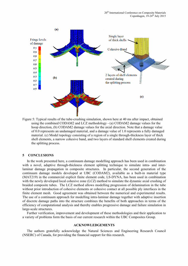
Figure 5 shows the CODAM2 damage variables for the hoop (Figure 5a) and axial (Figure 5b)
directions, at a simulation time of 40 ms. A typical topology obtained during the transient analysis can be seen in Figure 5c. A narrow band of thick-shell elements is split through its thickness and replaced by standard shell elements, while cohesive elements are inserted in between the newly created interfaces (shown here in darker colour). Once the cohesive elements are deleted, the remaining topology consists of two plies of shell elements, which are shown here in transparent shading mode.
20th International Conference on Composite Materials Copenhagen, 19-24th July 2015
Figure 5: Typical results of the tube-crushing simulation, shown here at 40 ms after impact, obtained
using the combined CODAM2 and LCZ methodology - (a) CODAM2 damage values for the hoop direction, (b) CODAM2 damage values for the axial direction. Note that a damage value of 0.0 represents an undamaged material, and a damage value of 1.0 represents a fully damaged material. (c) Model topology consisting of a region of a single through-thickness layer of thick shell elements, a narrow cohesive band, and two layers of standard shell elements created during the splitting process.
5 CONCLUSIONS
In the work presented here, a continuum damage modelling approach has been used in combination with a novel, adaptive through-thickness element splitting technique to simulate intra- and inter-laminar damage propagation in composite structures. In particular, the second generation of the continuum damage models developed at UBC (CODAM2), available as a built-in material type (MAT219) in the commercial explicit finite element code, LS-DYNA, has been used in combination with the newly developed local cohesive zone (LCZ) method to simulate the dynamic axial crushing of braided composite tubes. The LCZ method allows modelling progression of delamination in the tube without prior introduction of cohesive elements or cohesive contact at all possible ply interfaces in the finite element mesh. Good agreement was obtained between the numerical and experimental results. The use of a continuum approach for modelling intra-laminar damage together with adaptive insertion of discrete damage paths into the structure combines the benefits of both approaches in terms of the efficiency of computational analysis and thereby enables progressive damage and failure simulation in large-scale structures.
Further verification, improvement and development of these methodologies and their application to a variety of problems form the basis of our current research within the UBC Composites Group.
ACKNOWLEDGEMENTS
The authors gratefully acknowledge the Natural Sciences and Engineering Research Council (NSERC) of Canada, for providing the financial support for this research.
Ofir Shor, Mina Shahbazi and Reza Vaziri
REFERENCES
[1] S. R. Hallett and M. R. Wisnom, Numerical Investigation of Progressive Damage and the Effect of Layup in Notched Tensile Tests, Journal of Composite Materials, 40, 2006, pp. 1229-1245.
[2] G. Geiler, C. Netzker and M. Kaliske, Discrete crack path prediction by an adaptive cohesive crack model, Engineering Fracture Mechanics, 77, 2010, pp. 3541-3557.
[3] C. J. McGregor, R. Vaziri, A. Poursartip and X. Xiao, Simulation of progressive damage development in braided composite tubes under axial compression, Composites Part A: Applied Science and Manufacturing, 38, 2007, pp. 2247-2259.
[4] L. Maio, E. Monaco, F. Ricci and L. Lecce, Simulation of low velocity impact on composite laminates with progressive failure analysis, Composite Structures, 103, 2013, pp. 75-85.
[5] V. S. Sokolinsky, K. C. Indermuehle and J. A. Hurtado, Numerical simulation of the crushing process of a corrugated composite plate, Composites Part A: Applied Science and Manufacturing, 42, 2011, pp. 1119-1126.
[6] A. Forghani, A Non-Local Approach to Simulation of Damage in Composite Structures, PhD thesis, Department of Civil Engineering, The University of British Columbia, 2011.
[7] A. Forghani, N. Zobeiry, A. Poursartip and R. Vaziri, A Structural Modelling Framework for Prediction of Damage Development and Failure of Composite Laminates, J. Composite Materials, 47, No. 20-21, 2013, pp. 2553-2574.
[8] K.V. Williams, R. Vaziri and A. Poursartip, A Physically Based Continuum Damage Mechanics Model for Thin Laminated Composite Structures, Int. J. Solids & Structures, 40(9), 2003, pp. 2267-2300.
[9] M. Elices, G. V. Guinea, J. Gomez and J. Planas, The cohesive zone model: Advantages, limitations and challenges, Engineering Fracture Mechanics, 69, 2002, pp. 137-163.
[10] G. T. Camacho and M. Ortiz, Computational modelling of impact damage in brittle materials, International Journal of Solids and Structures, 33, 1996, pp. 2899-2938.
[11] X. Liu, R. Duddu and H. Waisman, Discrete damage zone model for fracture initiation and propagation, Engineering Fracture Mechanics, 92, 2012, pp. 1-18.
[12] Q. Yang and B. Cox, Cohesive models for damage evolution in laminated composites, International Journal of Fracture, 133, 2005, pp. 107-137.
[13] R. Olsson, R. Juntikka and L. Asp, High velocity hail impact on composite laminates- modelling and testing, in: S. Abrate, B . Castanie and Y. D. S. Rajapakse, Dynamic Failure of Composite and Sandwich Structures, Springer Netherlands, 2013, pp. 393-426.
[14] E. V. González, P. Maimí, P. P. Camanho, A. Turon and J. A. Mayugo, Simulation of drop-weight impact and compression after impact tests on composite laminates, Composite Structures, 94, 2012, pp. 3364-3378.
[15] D. Feng and F. Aymerich, Finite element modelling of damage induced by low-velocity impact on composite laminates, Composite Structures, 108, 2014, pp. 161-171.
[16] A. Forghani and R. Vaziri, Computational modelling of damage development in composite laminates subjected to transverse dynamic loading, Journal of Applied Mechanics, Transactions ASME, 76, 2009, pp. 1-11.
[17] C. Menna, D. Asprone, G. Caprino, V. Lopresto and A. Prota, Numerical simulation of impact tests on GFRP composite laminates, Int. J. Impact Engineering, 38, 2011, pp. 677-685.
[18] O. Shor and R. Vaziri, Adaptive insertion of cohesive elements for simulation of delamination in laminated composite materials, submitted to Engng. Fracture Mechanics, February 2015.
[19] C. McGregor, R. Vaziri and X. Xiao, Finite element modelling of the progressive crushing of braided composite tubes under axial impact, Int. J. Impact Engineering, 37, 2010, pp. 662-672.
[20] C. J. McGregor, R. Vaziri, A. Poursartip and X. Xiao, Calibration and validation of a continuum damage mechanics model in aid of axial crush simulation of braided composite tubes, to be submitted to Composite Structures, 2015.


