Embed Size (px)
Citation preview

© Copyright by International OCSCO World Press. All rights reserved. 2009 Research paper 115
VOLUME 36
ISSUE 2
October
2009of Achievements in Materialsand Manufacturing Engineeringof Achievements in Materialsand Manufacturing Engineering
Thermovision systems used to improve a technological process for hot-rolled copper and brass strips
Z. Rdzawski, B. Krupińska*, M. MusztyfagaDivision of Materials Processing Technology, Management and Computer Techniques in Materials Science, Institute of Engineering Materials and Biomaterials, Silesian University of Technology, ul. Konarskiego 18a, 44-100 Gliwice, Poland*E-mail address: [email protected]
Received 03.08.2009; published in revised form 01.10.2009
Materials
AbstrActPurpose: This paper contains description made on thermovision testing with the use of Inframetrics 760B system. Measurements were executed on the surface of a heat furnace and also on the surface of material heated before and hot-rolled. The results of the investigations in a form of thermograpic pictures were taken down in working environment.Design/methodology/approach: The purpose of this research was to evaluate technological process of heating cooper and brass cakes, and hot-rolled strip in special passes assessment of the temperature modification. For basic criterion estimation of these processes, the maintenance at the demanded final rolling temperature in order to keep up adequate structure and narrow range of mechanical properties variation was accepted.Findings: The process of heating charge material is carried through in order to facilitate its machining in a rolling process. When the material does not obtain the adequate temperature or does not become uniformly heated, internal stresses which cause appearance of the rims of fracture and occurrence of other defects in structure appear in cold rolling, as the next. Because of this there is a need of temperature controlling. Research limitations/implications: If a temperature profile on heated to a hot-rolled cakes is not uniform and does not reach a given level, this can mean forming some defects, which can be revealed during a hot-rolled process, relatively during following technological operations leading to a quality decrease and in a consequence to product disqualificationOriginality/value: The use of thermovision system in processes of heating cakes evolution and also hot-rolling. These research enable a condition control of thermal furnace and hot-roll processes.Keywords: Metallic Alloys, Copper, Brass, Cake, Hot-rolled, Furnace, Thermovision, Thermograms, Infrared
Reference to this paper should be given in the following way: Z. Rdzawski, B. Krupińska, M. Musztyfaga, Thermovision systems used to improve a technological process for hot-rolled copper and brass strips, Journal of Achievements in Materials and Manufacturing Engineering 36/2 (2009) 115-125.
Research paper116
Journal of Achievements in Materials and Manufacturing Engineering
Z. Rdzawski, B. Krupińska, M. Musztyfaga
Volume 36 Issue 2 October 2009
1. Introduction The contemporary achievements in a material engineering
domain and quality engineering enable designing, conducting and a control of flexible technological processes. The ability to introduce a new production technology and quality inspection in accordance with demands, presents a basis to keep up the market. Dynamic changes in production extort the necessity of applying some tools and technologies assuring the fastest adaptation to new realities [1-3].
Obtaining a high quality and competitiveness products production is connected with a necessity of continuous controlling and basic technological strip improvement as well as the entire manufacturing process. The analysis and limitation of energy loss is one of essential problems. Nowadays, there is a variety of systems and technique measurements applied to check technological process parameters, however each of them due to their own characteristics (construction) has application restrictions.
It is different about thermovision systems, which for the sake of their versatility (a passive and active method) and possibility to measure from further distance, let a considerably wider spectrum of use [4-7].
Thermography utilization in different technique fields becomes more common nowadays [8-10]. It is applied in ecology, medicine, rescue operations, building engineering with observation of thermal processes, for instance in quality and quantity assessment, as well as in material research or monitoring productive processes, where heat is produced or received [11-13].
Application of thermovision methods with considerable limiting outline devices and manufactured products is highly universal, because all measurement activities can be conducted during a continuous device operation, without stopping a production cycle.
2. Description of the approach, work methodology, materials for research, assumptions, experiments etc.
The purpose of this paper is to present a possibility to
estimate industrial of technological heat processes and consequently, hot-rolled cakes applying thermovision system.
2.1. Research methodology
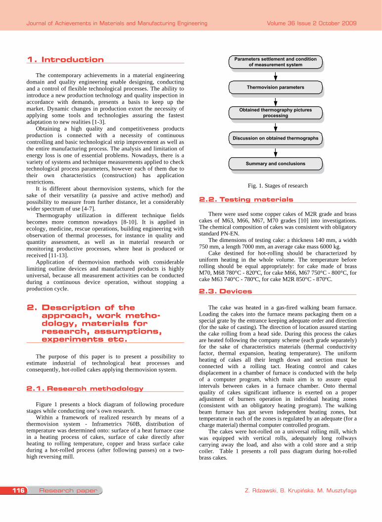
Figure 1 presents a block diagram of following procedure stages while conducting one’s own research.
Within a framework of realized research by means of a thermovision system - Inframetrics 760B, distribution of temperature was determined onto: surface of a heat furnace case in a heating process of cakes, surface of cake directly after heating to rolling temperature, copper and brass surface cake during a hot-rolled process (after following passes) on a two-high reversing mill.
Parameters settlement and conditionof measurement system
Thermovision parameters
Obtained thermography picturesprocessing
Summary and conclusions
Discussion on obtained thermographs
Fig. 1. Stages of research 2.2. Testing materials
There were used some copper cakes of M2R grade and brass cakes of M63, M66, M67, M70 grades [10] into investigations. The chemical composition of cakes was consistent with obligatory standard PN-EN.
The dimensions of testing cake: a thickness 140 mm, a width 750 mm, a length 7000 mm, an average cake mass 6000 kg.
Cake destined for hot-rolling should be characterized by uniform heating in the whole volume. The temperature before rolling should be equal appropriately: for cake made of brass M70, M68 780°C - 820ºC, for cake M66, M67 750°C - 800°C, for cake M63 740°C - 780ºC, for cake M2R 850°C - 870ºC. 2.3. Devices
The cake was heated in a gas-fired walking beam furnace.
Loading the cakes into the furnace means packaging them on a special grate by the entrance keeping adequate order and direction (for the sake of casting). The direction of location assured starting the cake rolling from a head side. During this process the cakes are heated following the company scheme (each grade separately) for the sake of characteristics materials (thermal conductivity factor, thermal expansion, heating temperature). The uniform heating of cakes all their length down and section must be connected with a rolling tact. Heating control and cakes displacement in a chamber of furnace is conducted with the help of a computer program, which main aim is to assure equal intervals between cakes in a furnace chamber. Onto thermal quality of cakes significant influence is exerted on a proper adjustment of burners operation in individual heating zones (consistent with an obligatory heating program). The walking beam furnace has got seven independent heating zones, but temperature in each of the zones is regulated by an adequate (for a charge material) thermal computer controlled program.
The cakes were hot-rolled on a universal rolling mill, which was equipped with vertical rolls, adequately long rollways carrying away the load, and also with a cold store and a strip coiler. Table 1 presents a roll pass diagram during hot-rolled brass cakes.
Table 1. Diagram of roll passes for brass cakes
Deformation Roll pass number Thickness [mm] [mm] [%]
Rolling speed [m/min.]
Strip length [m]
0 140.0 1 114.0 26.0 18.6 75 8.3 2 90.0 24.0 21.0 75 10.5 3 70.0 20.0 22.2 75 13.5 4 55.0 15.0 21.5 75 17.3 5 42.5 12.5 22.7 90 22.3 6 32.5 10.0 23.5 90 29.2 7 25.5 7.0 21.5 100 37.5 8 20.5 5.0 19.6 120 46.2 9 16.5 4.0 19.5 135 57.5 10 13.5 3.0 18.2 145 70.0 11 11.5 2.0 14.8 145 82.5
The diagram of rolling passes for cooper cakes is characterized by different steps of deformation in following rolling passes, this is a subject to whether rolls are hot or cold.
For hot rolls apply a diagram of roll passes: 140 - 109 - 84 - 63 - 47 - 35.2 - 26.4 - 19.8 - 14.5 - 11.5 mm applies.
In a case of cold rolls: 140 - 114 - 90.0 - 70 - 55 - 42.5 - 32.5 – 25.5 - 20.5 - 16.5 - 13.5 - 11.5 mm.
The product, being a result of rolling is a copper or brass strip with dimensions: a thickness 10 – 11.5 mm, a width 700 - 780 mm, a maximum length 95060 mm
2.4. Measurement apparatus When conducting a thermovision system Inframetrics 76B
research was used, consisting of a thermovision camera and interception modulus (control and setting measurement parameters). The essential was to use a limitation of the applied thermovision system - Inframetrics 760B to dynamic research, it is a character of performing measurements, i.e. a picture is scanned (a bundle is sent, and next it goes back into a camera, which records that), what allows to get a picture recording 30 frames per second. Research results were worked out by a computer program - ThermaGRAM95Pro. This software allows to achieve distribution of temperature onto a particular picture field or in a point of our special interest, or along determined line of measurement.
2.5. Heat parameters In practice it is necessary to determine the heat time to realize
operation of heat treatment. To achieve this aim empirical dependence can be used [3] (1):
4)100
(
)1(
TE
RCpt
ttp
p
n
(1)
where:
n - the heat time [hours], R - a roller thickness [mm], tp – the furnace temperature [ºC], T - difference between a furnace
temperature and a target temperature, 4
100T - Stefan-Boltzmana’s
equation element for a given furnace temperature, E – constant of radiation, Cp - a proper heat of cake, - a material density
The A temperature of cake heated for heat-rolling can be easily calculated using this relationship (1).
Accepting any of that assumptions equivalent for given furnace temperature and a kind of charge material, for instance: a cake from brass M66 with dimensions 140 mm x 700 mm x 7000 mm and a mass 6000 kg, arranged 19 cakes in one row, one after another, at a furnace temperature: tp = 850ºC (1123K), a specific heat Cp = 0.09 [kcal/kgK], a density d = 8600 [kg/m3], a constant of radiation E = 2.5 [kcal/m2hK].
Value of Stefan-Boltzmana equation element at 850ºC is accepted as 15*103 K4) calculated heating time is 140 minutes.
2.6. Course of measurements
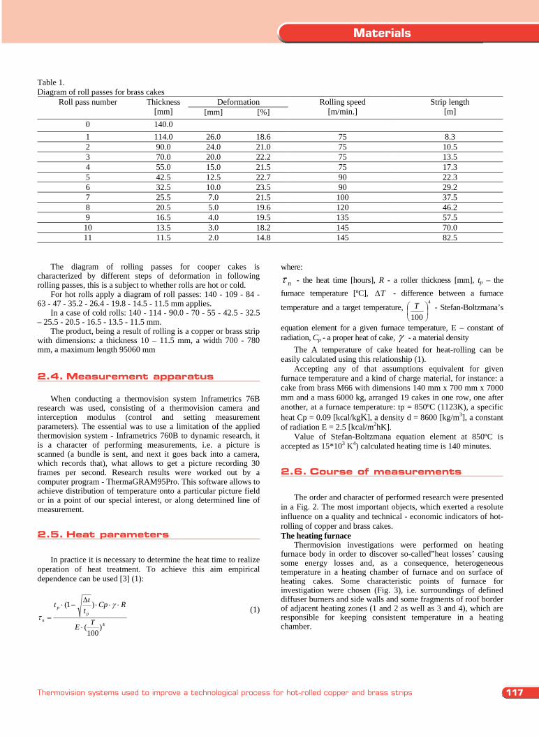
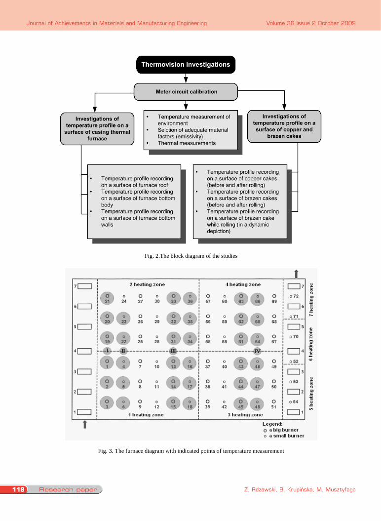
The order and character of performed research were presented in a Fig. 2. The most important objects, which exerted a resolute influence on a quality and technical - economic indicators of hot-rolling of copper and brass cakes. The heating furnace
Thermovision investigations were performed on heating furnace body in order to discover so-called”heat losses’ causing some energy losses and, as a consequence, heterogeneous temperature in a heating chamber of furnace and on surface of heating cakes. Some characteristic points of furnace for investigation were chosen (Fig. 3), i.e. surroundings of defined diffuser burners and side walls and some fragments of roof border of adjacent heating zones (1 and 2 as well as 3 and 4), which are responsible for keeping consistent temperature in a heating chamber.
2.1. research methodology
2. Description of the approach, work metho-dology, materials for research, assumptions, experiments etc.
1. Introduction
2.2. testing materials
2.3. Devices
117
Materials
Thermovision systems used to improve a technological process for hot-rolled copper and brass strips
1. Introduction The contemporary achievements in a material engineering
domain and quality engineering enable designing, conducting and a control of flexible technological processes. The ability to introduce a new production technology and quality inspection in accordance with demands, presents a basis to keep up the market. Dynamic changes in production extort the necessity of applying some tools and technologies assuring the fastest adaptation to new realities [1-3].
Obtaining a high quality and competitiveness products production is connected with a necessity of continuous controlling and basic technological strip improvement as well as the entire manufacturing process. The analysis and limitation of energy loss is one of essential problems. Nowadays, there is a variety of systems and technique measurements applied to check technological process parameters, however each of them due to their own characteristics (construction) has application restrictions.
It is different about thermovision systems, which for the sake of their versatility (a passive and active method) and possibility to measure from further distance, let a considerably wider spectrum of use [4-7].
Thermography utilization in different technique fields becomes more common nowadays [8-10]. It is applied in ecology, medicine, rescue operations, building engineering with observation of thermal processes, for instance in quality and quantity assessment, as well as in material research or monitoring productive processes, where heat is produced or received [11-13].
Application of thermovision methods with considerable limiting outline devices and manufactured products is highly universal, because all measurement activities can be conducted during a continuous device operation, without stopping a production cycle.
2. Description of the approach, work methodology, materials for research, assumptions, experiments etc.
The purpose of this paper is to present a possibility to
estimate industrial of technological heat processes and consequently, hot-rolled cakes applying thermovision system.
2.1. Research methodology
Figure 1 presents a block diagram of following procedure stages while conducting one’s own research.
Within a framework of realized research by means of a thermovision system - Inframetrics 760B, distribution of temperature was determined onto: surface of a heat furnace case in a heating process of cakes, surface of cake directly after heating to rolling temperature, copper and brass surface cake during a hot-rolled process (after following passes) on a two-high reversing mill.
Parameters settlement and conditionof measurement system
Thermovision parameters
Obtained thermography picturesprocessing
Summary and conclusions
Discussion on obtained thermographs
Fig. 1. Stages of research 2.2. Testing materials
There were used some copper cakes of M2R grade and brass cakes of M63, M66, M67, M70 grades [10] into investigations. The chemical composition of cakes was consistent with obligatory standard PN-EN.
The dimensions of testing cake: a thickness 140 mm, a width 750 mm, a length 7000 mm, an average cake mass 6000 kg.
Cake destined for hot-rolling should be characterized by uniform heating in the whole volume. The temperature before rolling should be equal appropriately: for cake made of brass M70, M68 780°C - 820ºC, for cake M66, M67 750°C - 800°C, for cake M63 740°C - 780ºC, for cake M2R 850°C - 870ºC. 2.3. Devices
The cake was heated in a gas-fired walking beam furnace.
Loading the cakes into the furnace means packaging them on a special grate by the entrance keeping adequate order and direction (for the sake of casting). The direction of location assured starting the cake rolling from a head side. During this process the cakes are heated following the company scheme (each grade separately) for the sake of characteristics materials (thermal conductivity factor, thermal expansion, heating temperature). The uniform heating of cakes all their length down and section must be connected with a rolling tact. Heating control and cakes displacement in a chamber of furnace is conducted with the help of a computer program, which main aim is to assure equal intervals between cakes in a furnace chamber. Onto thermal quality of cakes significant influence is exerted on a proper adjustment of burners operation in individual heating zones (consistent with an obligatory heating program). The walking beam furnace has got seven independent heating zones, but temperature in each of the zones is regulated by an adequate (for a charge material) thermal computer controlled program.
The cakes were hot-rolled on a universal rolling mill, which was equipped with vertical rolls, adequately long rollways carrying away the load, and also with a cold store and a strip coiler. Table 1 presents a roll pass diagram during hot-rolled brass cakes.
Table 1. Diagram of roll passes for brass cakes
Deformation Roll pass number Thickness [mm] [mm] [%]
Rolling speed [m/min.]
Strip length [m]
0 140.0 1 114.0 26.0 18.6 75 8.3 2 90.0 24.0 21.0 75 10.5 3 70.0 20.0 22.2 75 13.5 4 55.0 15.0 21.5 75 17.3 5 42.5 12.5 22.7 90 22.3 6 32.5 10.0 23.5 90 29.2 7 25.5 7.0 21.5 100 37.5 8 20.5 5.0 19.6 120 46.2 9 16.5 4.0 19.5 135 57.5 10 13.5 3.0 18.2 145 70.0 11 11.5 2.0 14.8 145 82.5
The diagram of rolling passes for cooper cakes is characterized by different steps of deformation in following rolling passes, this is a subject to whether rolls are hot or cold.
For hot rolls apply a diagram of roll passes: 140 - 109 - 84 - 63 - 47 - 35.2 - 26.4 - 19.8 - 14.5 - 11.5 mm applies.
In a case of cold rolls: 140 - 114 - 90.0 - 70 - 55 - 42.5 - 32.5 – 25.5 - 20.5 - 16.5 - 13.5 - 11.5 mm.
The product, being a result of rolling is a copper or brass strip with dimensions: a thickness 10 – 11.5 mm, a width 700 - 780 mm, a maximum length 95060 mm
2.4. Measurement apparatus When conducting a thermovision system Inframetrics 76B
research was used, consisting of a thermovision camera and interception modulus (control and setting measurement parameters). The essential was to use a limitation of the applied thermovision system - Inframetrics 760B to dynamic research, it is a character of performing measurements, i.e. a picture is scanned (a bundle is sent, and next it goes back into a camera, which records that), what allows to get a picture recording 30 frames per second. Research results were worked out by a computer program - ThermaGRAM95Pro. This software allows to achieve distribution of temperature onto a particular picture field or in a point of our special interest, or along determined line of measurement.
2.5. Heat parameters In practice it is necessary to determine the heat time to realize
operation of heat treatment. To achieve this aim empirical dependence can be used [3] (1):
4)100
(
)1(
TE
RCpt
ttp
p
n
(1)
where:
n - the heat time [hours], R - a roller thickness [mm], tp – the furnace temperature [ºC], T - difference between a furnace
temperature and a target temperature, 4
100T - Stefan-Boltzmana’s
equation element for a given furnace temperature, E – constant of radiation, Cp - a proper heat of cake, - a material density
The A temperature of cake heated for heat-rolling can be easily calculated using this relationship (1).
Accepting any of that assumptions equivalent for given furnace temperature and a kind of charge material, for instance: a cake from brass M66 with dimensions 140 mm x 700 mm x 7000 mm and a mass 6000 kg, arranged 19 cakes in one row, one after another, at a furnace temperature: tp = 850ºC (1123K), a specific heat Cp = 0.09 [kcal/kgK], a density d = 8600 [kg/m3], a constant of radiation E = 2.5 [kcal/m2hK].
Value of Stefan-Boltzmana equation element at 850ºC is accepted as 15*103 K4) calculated heating time is 140 minutes.
2.6. Course of measurements
The order and character of performed research were presented in a Fig. 2. The most important objects, which exerted a resolute influence on a quality and technical - economic indicators of hot-rolling of copper and brass cakes. The heating furnace
Thermovision investigations were performed on heating furnace body in order to discover so-called”heat losses’ causing some energy losses and, as a consequence, heterogeneous temperature in a heating chamber of furnace and on surface of heating cakes. Some characteristic points of furnace for investigation were chosen (Fig. 3), i.e. surroundings of defined diffuser burners and side walls and some fragments of roof border of adjacent heating zones (1 and 2 as well as 3 and 4), which are responsible for keeping consistent temperature in a heating chamber.
2.4. Measurement apparatus
2.5. Heat parameters
2.6. course of measurements
Research paper118
Journal of Achievements in Materials and Manufacturing Engineering
Z. Rdzawski, B. Krupińska, M. Musztyfaga
Volume 36 Issue 2 October 2009
Thermovision investigations
Meter circuit calibration
Temperature measurement ofenvironmentSelction of adequate materialfactors (emissivity)Thermal measurements
Temperature profile recordingon a surface of copper cakes(before and after rolling)Temperature profile recordingon a surface of brazen cakes(before and after rolling)Temperature profile recordingon a surface of brazen cakewhile rolling (in a dynamicdepiction)
Temperature profile recordingon a surface of furnace roofTemperature profile recordingon a surface of furnace bottombodyTemperature profile recordingon a surface of furnace bottomwalls
Investigations oftemperature profile on asurface of copper and
brazen cakes
Investigations oftemperature profile on a
surface of casing thermalfurnace
Fig. 2.The block diagram of the studies
Fig. 3. The furnace diagram with indicated points of temperature measurement
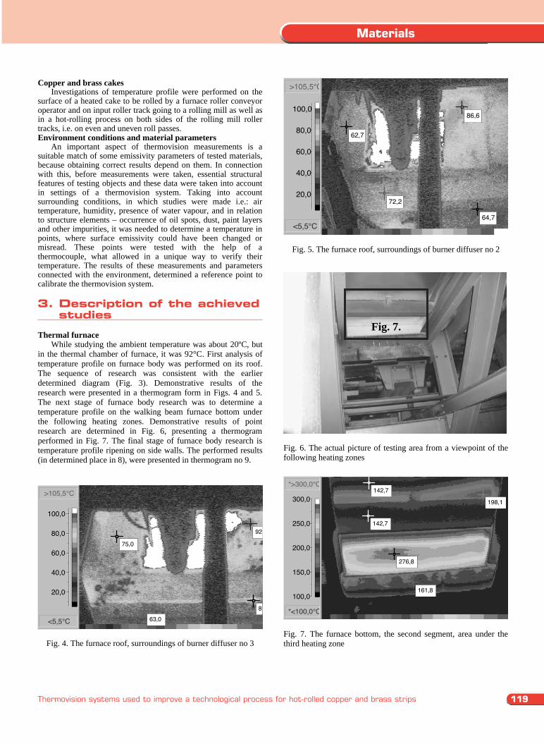
Copper and brass cakes Investigations of temperature profile were performed on the surface of a heated cake to be rolled by a furnace roller conveyor operator and on input roller track going to a rolling mill as well as in a hot-rolling process on both sides of the rolling mill roller tracks, i.e. on even and uneven roll passes. Environment conditions and material parameters An important aspect of thermovision measurements is a suitable match of some emissivity parameters of tested materials, because obtaining correct results depend on them. In connection with this, before measurements were taken, essential structural features of testing objects and these data were taken into account in settings of a thermovision system. Taking into account surrounding conditions, in which studies were made i.e.: air temperature, humidity, presence of water vapour, and in relation to structure elements – occurrence of oil spots, dust, paint layers and other impurities, it was needed to determine a temperature in points, where surface emissivity could have been changed or misread. These points were tested with the help of a thermocouple, what allowed in a unique way to verify their temperature. The results of these measurements and parameters connected with the environment, determined a reference point to calibrate the thermovision system.
3. Description of the achieved studies Thermal furnace
While studying the ambient temperature was about 20ºC, but in the thermal chamber of furnace, it was 92°C. First analysis of temperature profile on furnace body was performed on its roof. The sequence of research was consistent with the earlier determined diagram (Fig. 3). Demonstrative results of the research were presented in a thermogram form in Figs. 4 and 5. The next stage of furnace body research was to determine a temperature profile on the walking beam furnace bottom under the following heating zones. Demonstrative results of point research are determined in Fig. 6, presenting a thermogram performed in Fig. 7. The final stage of furnace body research is temperature profile ripening on side walls. The performed results (in determined place in 8), were presented in thermogram no 9.
92
88
75,0
63,0
>105,5°C
<5,5°C
20,0
40,0
60,0
80,0
100,0
Fig. 4. The furnace roof, surroundings of burner diffuser no 3
86,6
62,7
64,7
72,2
>105,5°C
<5,5°C
20,0
40,0
60,0
80,0
100,0
Fig. 5. The furnace roof, surroundings of burner diffuser no 2
Fig. 6. The actual picture of testing area from a viewpoint of the following heating zones
142,7
198,1
276,8
161,8
142,7*>300,0°C
*<100,0°C
100,0
150,0
200,0
250,0
300,0
Fig. 7. The furnace bottom, the second segment, area under the third heating zone
Fig. 7.
119
Materials
Thermovision systems used to improve a technological process for hot-rolled copper and brass strips
Thermovision investigations
Meter circuit calibration
Temperature measurement ofenvironmentSelction of adequate materialfactors (emissivity)Thermal measurements
Temperature profile recordingon a surface of copper cakes(before and after rolling)Temperature profile recordingon a surface of brazen cakes(before and after rolling)Temperature profile recordingon a surface of brazen cakewhile rolling (in a dynamicdepiction)
Temperature profile recordingon a surface of furnace roofTemperature profile recordingon a surface of furnace bottombodyTemperature profile recordingon a surface of furnace bottomwalls
Investigations oftemperature profile on asurface of copper and
brazen cakes
Investigations oftemperature profile on a
surface of casing thermalfurnace
Fig. 2.The block diagram of the studies
Fig. 3. The furnace diagram with indicated points of temperature measurement
Copper and brass cakes Investigations of temperature profile were performed on the surface of a heated cake to be rolled by a furnace roller conveyor operator and on input roller track going to a rolling mill as well as in a hot-rolling process on both sides of the rolling mill roller tracks, i.e. on even and uneven roll passes. Environment conditions and material parameters An important aspect of thermovision measurements is a suitable match of some emissivity parameters of tested materials, because obtaining correct results depend on them. In connection with this, before measurements were taken, essential structural features of testing objects and these data were taken into account in settings of a thermovision system. Taking into account surrounding conditions, in which studies were made i.e.: air temperature, humidity, presence of water vapour, and in relation to structure elements – occurrence of oil spots, dust, paint layers and other impurities, it was needed to determine a temperature in points, where surface emissivity could have been changed or misread. These points were tested with the help of a thermocouple, what allowed in a unique way to verify their temperature. The results of these measurements and parameters connected with the environment, determined a reference point to calibrate the thermovision system.
3. Description of the achieved studies Thermal furnace
While studying the ambient temperature was about 20ºC, but in the thermal chamber of furnace, it was 92°C. First analysis of temperature profile on furnace body was performed on its roof. The sequence of research was consistent with the earlier determined diagram (Fig. 3). Demonstrative results of the research were presented in a thermogram form in Figs. 4 and 5. The next stage of furnace body research was to determine a temperature profile on the walking beam furnace bottom under the following heating zones. Demonstrative results of point research are determined in Fig. 6, presenting a thermogram performed in Fig. 7. The final stage of furnace body research is temperature profile ripening on side walls. The performed results (in determined place in 8), were presented in thermogram no 9.
92
88
75,0
63,0
>105,5°C
<5,5°C
20,0
40,0
60,0
80,0
100,0
Fig. 4. The furnace roof, surroundings of burner diffuser no 3
86,6
62,7
64,7
72,2
>105,5°C
<5,5°C
20,0
40,0
60,0
80,0
100,0
Fig. 5. The furnace roof, surroundings of burner diffuser no 2
Fig. 6. The actual picture of testing area from a viewpoint of the following heating zones
142,7
198,1
276,8
161,8
142,7*>300,0°C
*<100,0°C
100,0
150,0
200,0
250,0
300,0
Fig. 7. The furnace bottom, the second segment, area under the third heating zone
Fig. 7.
3. Description of the achieved studies
Research paper120
Journal of Achievements in Materials and Manufacturing Engineering
Z. Rdzawski, B. Krupińska, M. Musztyfaga
Volume 36 Issue 2 October 2009
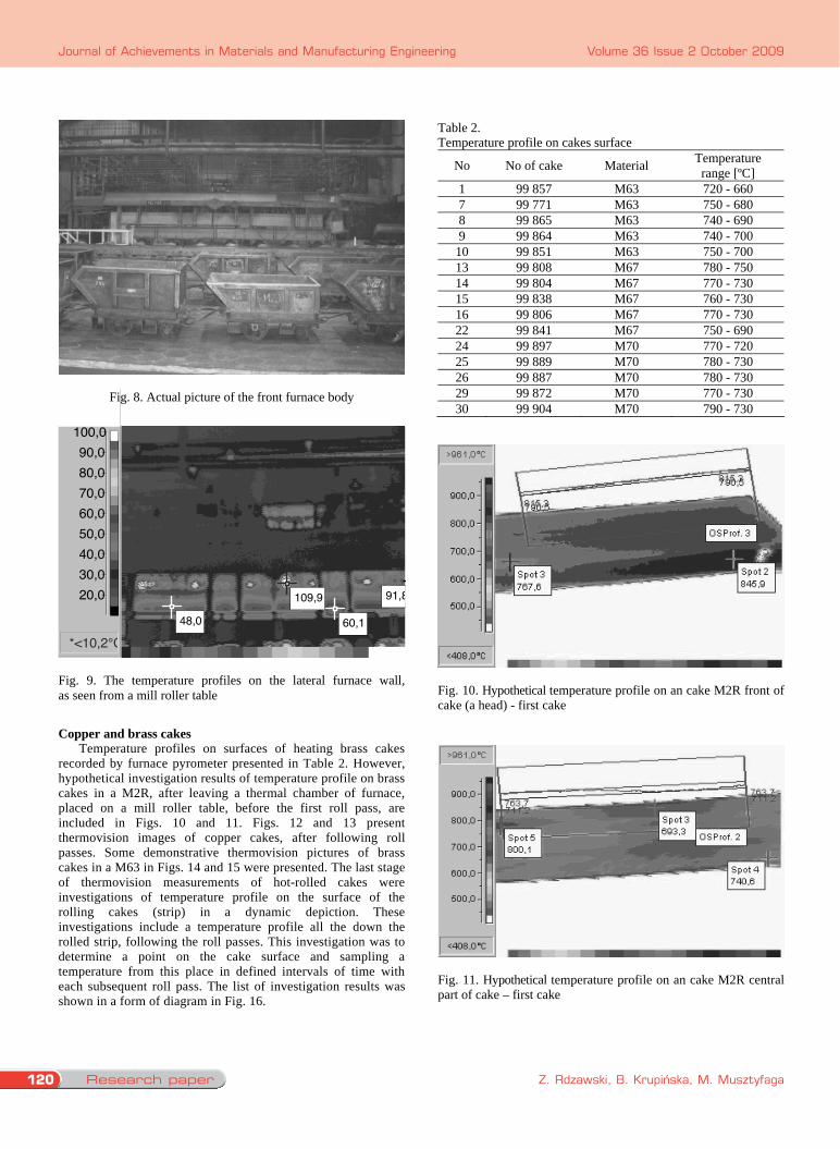
Fig. 8. Actual picture of the front furnace body
109,9
60,148,0
91,8
*<10,2°C
20,030,040,050,060,070,080,090,0
100,0
Fig. 9. The temperature profiles on the lateral furnace wall, as seen from a mill roller table
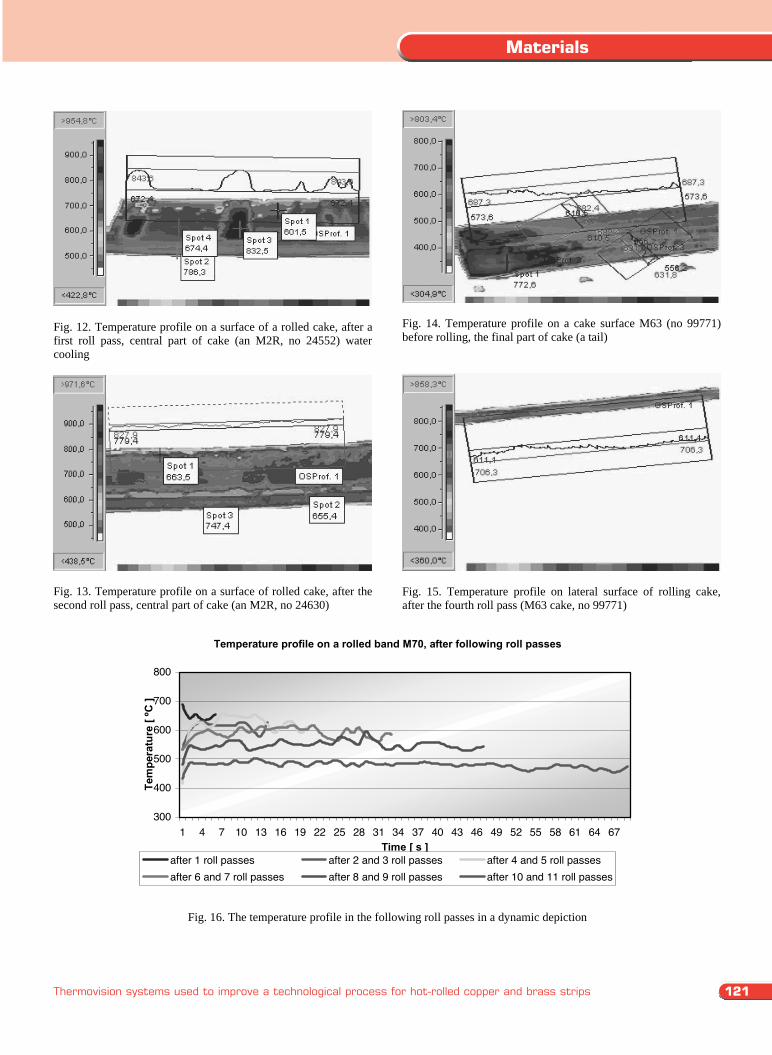
Copper and brass cakes Temperature profiles on surfaces of heating brass cakes recorded by furnace pyrometer presented in Table 2. However, hypothetical investigation results of temperature profile on brass cakes in a M2R, after leaving a thermal chamber of furnace, placed on a mill roller table, before the first roll pass, are included in Figs. 10 and 11. Figs. 12 and 13 present thermovision images of copper cakes, after following roll passes. Some demonstrative thermovision pictures of brass cakes in a M63 in Figs. 14 and 15 were presented. The last stage of thermovision measurements of hot-rolled cakes were investigations of temperature profile on the surface of the rolling cakes (strip) in a dynamic depiction. These investigations include a temperature profile all the down the rolled strip, following the roll passes. This investigation was to determine a point on the cake surface and sampling a temperature from this place in defined intervals of time with each subsequent roll pass. The list of investigation results was shown in a form of diagram in Fig. 16.
Table 2. Temperature profile on cakes surface
No No of cake Material Temperature range [ºC]
1 99 857 M63 720 - 660 7 99 771 M63 750 - 680 8 99 865 M63 740 - 690 9 99 864 M63 740 - 700
10 99 851 M63 750 - 700 13 99 808 M67 780 - 750 14 99 804 M67 770 - 730 15 99 838 M67 760 - 730 16 99 806 M67 770 - 730 22 99 841 M67 750 - 690 24 99 897 M70 770 - 720 25 99 889 M70 780 - 730 26 99 887 M70 780 - 730 29 99 872 M70 770 - 730 30 99 904 M70 790 - 730
Fig. 10. Hypothetical temperature profile on an cake M2R front of cake (a head) - first cake
Fig. 11. Hypothetical temperature profile on an cake M2R central part of cake – first cake
Fig. 12. Temperature profile on a surface of a rolled cake, after a first roll pass, central part of cake (an M2R, no 24552) water cooling
Fig. 13. Temperature profile on a surface of rolled cake, after the second roll pass, central part of cake (an M2R, no 24630)
Fig. 14. Temperature profile on a cake surface M63 (no 99771) before rolling, the final part of cake (a tail)
Fig. 15. Temperature profile on lateral surface of rolling cake, after the fourth roll pass (M63 cake, no 99771)
Temperature profile on a rolled band M70, after following roll passes
300
400
500
600
700
800
1 4 7 10 13 16 19 22 25 28 31 34 37 40 43 46 49 52 55 58 61 64 67Time [ s ]
Tem
pera
ture
[ ºC
]
after 1 roll passes after 2 and 3 roll passes after 4 and 5 roll passesafter 6 and 7 roll passes after 8 and 9 roll passes after 10 and 11 roll passes
Fig. 16. The temperature profile in the following roll passes in a dynamic depiction
121
Materials
Thermovision systems used to improve a technological process for hot-rolled copper and brass strips
Fig. 8. Actual picture of the front furnace body
109,9
60,148,0
91,8
*<10,2°C
20,030,040,050,060,070,080,090,0
100,0
Fig. 9. The temperature profiles on the lateral furnace wall, as seen from a mill roller table
Copper and brass cakes Temperature profiles on surfaces of heating brass cakes recorded by furnace pyrometer presented in Table 2. However, hypothetical investigation results of temperature profile on brass cakes in a M2R, after leaving a thermal chamber of furnace, placed on a mill roller table, before the first roll pass, are included in Figs. 10 and 11. Figs. 12 and 13 present thermovision images of copper cakes, after following roll passes. Some demonstrative thermovision pictures of brass cakes in a M63 in Figs. 14 and 15 were presented. The last stage of thermovision measurements of hot-rolled cakes were investigations of temperature profile on the surface of the rolling cakes (strip) in a dynamic depiction. These investigations include a temperature profile all the down the rolled strip, following the roll passes. This investigation was to determine a point on the cake surface and sampling a temperature from this place in defined intervals of time with each subsequent roll pass. The list of investigation results was shown in a form of diagram in Fig. 16.
Table 2. Temperature profile on cakes surface
No No of cake Material Temperature range [ºC]
1 99 857 M63 720 - 660 7 99 771 M63 750 - 680 8 99 865 M63 740 - 690 9 99 864 M63 740 - 700
10 99 851 M63 750 - 700 13 99 808 M67 780 - 750 14 99 804 M67 770 - 730 15 99 838 M67 760 - 730 16 99 806 M67 770 - 730 22 99 841 M67 750 - 690 24 99 897 M70 770 - 720 25 99 889 M70 780 - 730 26 99 887 M70 780 - 730 29 99 872 M70 770 - 730 30 99 904 M70 790 - 730
Fig. 10. Hypothetical temperature profile on an cake M2R front of cake (a head) - first cake
Fig. 11. Hypothetical temperature profile on an cake M2R central part of cake – first cake
Fig. 12. Temperature profile on a surface of a rolled cake, after a first roll pass, central part of cake (an M2R, no 24552) water cooling
Fig. 13. Temperature profile on a surface of rolled cake, after the second roll pass, central part of cake (an M2R, no 24630)
Fig. 14. Temperature profile on a cake surface M63 (no 99771) before rolling, the final part of cake (a tail)
Fig. 15. Temperature profile on lateral surface of rolling cake, after the fourth roll pass (M63 cake, no 99771)
Temperature profile on a rolled band M70, after following roll passes
300
400
500
600
700
800
1 4 7 10 13 16 19 22 25 28 31 34 37 40 43 46 49 52 55 58 61 64 67Time [ s ]
Tem
pera
ture
[ ºC
]
after 1 roll passes after 2 and 3 roll passes after 4 and 5 roll passesafter 6 and 7 roll passes after 8 and 9 roll passes after 10 and 11 roll passes
Fig. 16. The temperature profile in the following roll passes in a dynamic depiction
Research paper122
Journal of Achievements in Materials and Manufacturing Engineering
Z. Rdzawski, B. Krupińska, M. Musztyfaga
Volume 36 Issue 2 October 2009
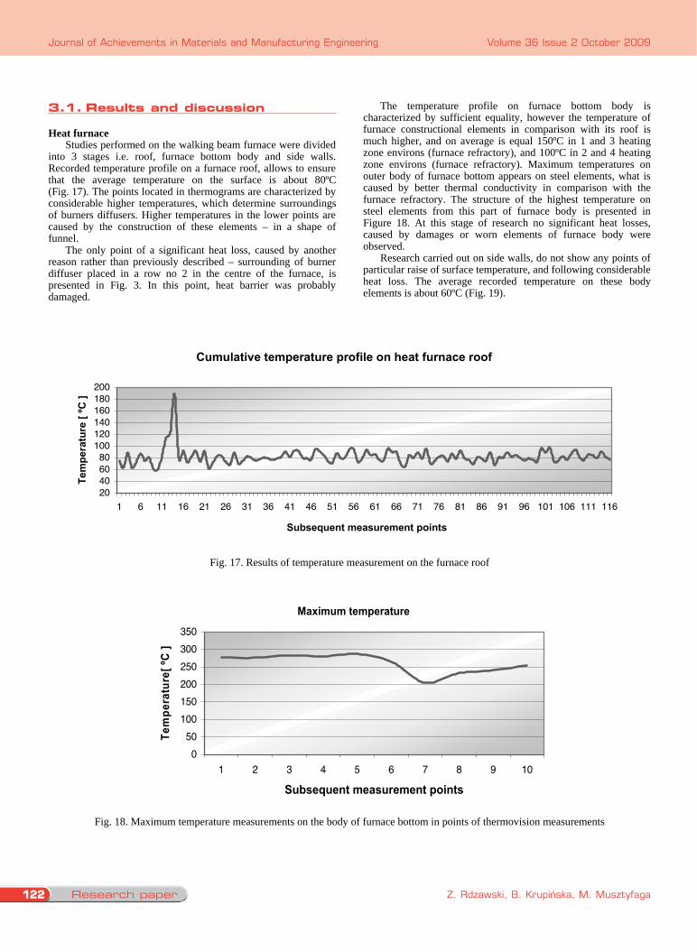
3.1. Results discussion Heat furnace
Studies performed on the walking beam furnace were divided into 3 stages i.e. roof, furnace bottom body and side walls. Recorded temperature profile on a furnace roof, allows to ensure that the average temperature on the surface is about 80ºC (Fig. 17). The points located in thermograms are characterized by considerable higher temperatures, which determine surroundings of burners diffusers. Higher temperatures in the lower points are caused by the construction of these elements – in a shape of funnel. The only point of a significant heat loss, caused by another reason rather than previously described – surrounding of burner diffuser placed in a row no 2 in the centre of the furnace, is presented in Fig. 3. In this point, heat barrier was probably damaged.
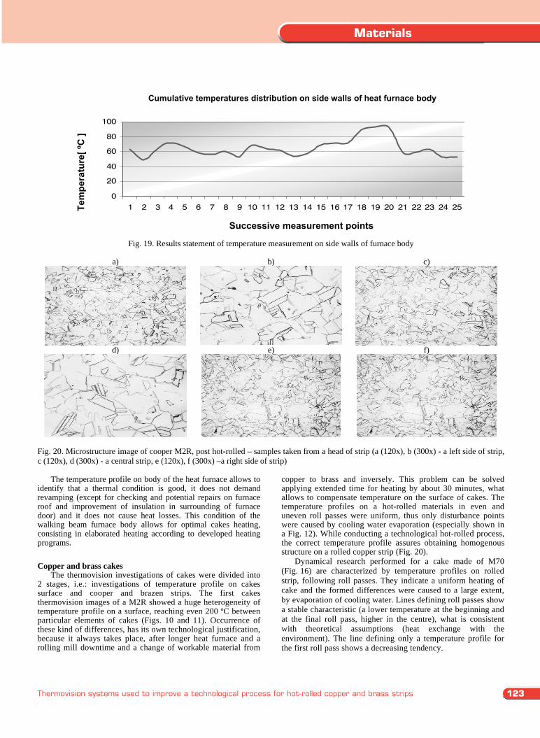
The temperature profile on furnace bottom body is characterized by sufficient equality, however the temperature of furnace constructional elements in comparison with its roof is much higher, and on average is equal 150ºC in 1 and 3 heating zone environs (furnace refractory), and 100ºC in 2 and 4 heating zone environs (furnace refractory). Maximum temperatures on outer body of furnace bottom appears on steel elements, what is caused by better thermal conductivity in comparison with the furnace refractory. The structure of the highest temperature on steel elements from this part of furnace body is presented in Figure 18. At this stage of research no significant heat losses, caused by damages or worn elements of furnace body were observed. Research carried out on side walls, do not show any points of particular raise of surface temperature, and following considerable heat loss. The average recorded temperature on these body elements is about 60ºC (Fig. 19).
Cumulative temperature profile on heat furnace roof
20406080
100120140160180200
1 6 11 16 21 26 31 36 41 46 51 56 61 66 71 76 81 86 91 96 101 106 111 116
Subsequent measurement points
Tem
pera
ture
[ ºC
]
Fig. 17. Results of temperature measurement on the furnace roof
Maximum temperature
050
100150200250300350
1 2 3 4 5 6 7 8 9 10
Subsequent measurement points
Tem
pera
ture
[ ºC
]
Fig. 18. Maximum temperature measurements on the body of furnace bottom in points of thermovision measurements
Zbiorczy rozk ad temperatur na cianach bocznych obudowy pieca grzewczego
0
20
40
60
80
100
1 2 3 4 5 6 7 8 9 10 11 12 13 14 15 16 17 18 19 20 21 22 23 24 25
Kolejne punkty pomiaru
Tem
pera
tura
[ ºC
]
Fig. 19. Results statement of temperature measurement on side walls of furnace body
a)
b)
c)
d)
e)
f)
Fig. 20. Microstructure image of cooper M2R, post hot-rolled – samples taken from a head of strip (a (120x), b (300x) - a left side of strip, c (120x), d (300x) - a central strip, e (120x), f (300x) –a right side of strip) The temperature profile on body of the heat furnace allows to identify that a thermal condition is good, it does not demand revamping (except for checking and potential repairs on furnace roof and improvement of insulation in surrounding of furnace door) and it does not cause heat losses. This condition of the walking beam furnace body allows for optimal cakes heating, consisting in elaborated heating according to developed heating programs. Copper and brass cakes
The thermovision investigations of cakes were divided into 2 stages, i.e.: investigations of temperature profile on cakes surface and cooper and brazen strips. The first cakes thermovision images of a M2R showed a huge heterogeneity of temperature profile on a surface, reaching even 200 ºC between particular elements of cakes (Figs. 10 and 11). Occurrence of these kind of differences, has its own technological justification, because it always takes place, after longer heat furnace and a rolling mill downtime and a change of workable material from
copper to brass and inversely. This problem can be solved applying extended time for heating by about 30 minutes, what allows to compensate temperature on the surface of cakes. The temperature profiles on a hot-rolled materials in even and uneven roll passes were uniform, thus only disturbance points were caused by cooling water evaporation (especially shown in a Fig. 12). While conducting a technological hot-rolled process, the correct temperature profile assures obtaining homogenous structure on a rolled copper strip (Fig. 20).
Dynamical research performed for a cake made of M70 (Fig. 16) are characterized by temperature profiles on rolled strip, following roll passes. They indicate a uniform heating of cake and the formed differences were caused to a large extent, by evaporation of cooling water. Lines defining roll passes show a stable characteristic (a lower temperature at the beginning and at the final roll pass, higher in the centre), what is consistent with theoretical assumptions (heat exchange with the environment). The line defining only a temperature profile for the first roll pass shows a decreasing tendency.
Cumulative temperatures distribution on side walls of heat furnace body
Successive measurement points
Tem
pera
ture
[ ºC
]
3.1. results and discussion
123
Materials
Thermovision systems used to improve a technological process for hot-rolled copper and brass strips
3.1. Results discussion Heat furnace
Studies performed on the walking beam furnace were divided into 3 stages i.e. roof, furnace bottom body and side walls. Recorded temperature profile on a furnace roof, allows to ensure that the average temperature on the surface is about 80ºC (Fig. 17). The points located in thermograms are characterized by considerable higher temperatures, which determine surroundings of burners diffusers. Higher temperatures in the lower points are caused by the construction of these elements – in a shape of funnel. The only point of a significant heat loss, caused by another reason rather than previously described – surrounding of burner diffuser placed in a row no 2 in the centre of the furnace, is presented in Fig. 3. In this point, heat barrier was probably damaged.
The temperature profile on furnace bottom body is characterized by sufficient equality, however the temperature of furnace constructional elements in comparison with its roof is much higher, and on average is equal 150ºC in 1 and 3 heating zone environs (furnace refractory), and 100ºC in 2 and 4 heating zone environs (furnace refractory). Maximum temperatures on outer body of furnace bottom appears on steel elements, what is caused by better thermal conductivity in comparison with the furnace refractory. The structure of the highest temperature on steel elements from this part of furnace body is presented in Figure 18. At this stage of research no significant heat losses, caused by damages or worn elements of furnace body were observed. Research carried out on side walls, do not show any points of particular raise of surface temperature, and following considerable heat loss. The average recorded temperature on these body elements is about 60ºC (Fig. 19).
Cumulative temperature profile on heat furnace roof
20406080
100120140160180200
1 6 11 16 21 26 31 36 41 46 51 56 61 66 71 76 81 86 91 96 101 106 111 116
Subsequent measurement points
Tem
pera
ture
[ ºC
]
Fig. 17. Results of temperature measurement on the furnace roof
Maximum temperature
050
100150200250300350
1 2 3 4 5 6 7 8 9 10
Subsequent measurement points
Tem
pera
ture
[ ºC
]
Fig. 18. Maximum temperature measurements on the body of furnace bottom in points of thermovision measurements
Zbiorczy rozk ad temperatur na cianach bocznych obudowy pieca grzewczego
0
20
40
60
80
100
1 2 3 4 5 6 7 8 9 10 11 12 13 14 15 16 17 18 19 20 21 22 23 24 25
Kolejne punkty pomiaru
Tem
pera
tura
[ ºC
]
Fig. 19. Results statement of temperature measurement on side walls of furnace body
a)
b)
c)
d)
e)
f)
Fig. 20. Microstructure image of cooper M2R, post hot-rolled – samples taken from a head of strip (a (120x), b (300x) - a left side of strip, c (120x), d (300x) - a central strip, e (120x), f (300x) –a right side of strip) The temperature profile on body of the heat furnace allows to identify that a thermal condition is good, it does not demand revamping (except for checking and potential repairs on furnace roof and improvement of insulation in surrounding of furnace door) and it does not cause heat losses. This condition of the walking beam furnace body allows for optimal cakes heating, consisting in elaborated heating according to developed heating programs. Copper and brass cakes
The thermovision investigations of cakes were divided into 2 stages, i.e.: investigations of temperature profile on cakes surface and cooper and brazen strips. The first cakes thermovision images of a M2R showed a huge heterogeneity of temperature profile on a surface, reaching even 200 ºC between particular elements of cakes (Figs. 10 and 11). Occurrence of these kind of differences, has its own technological justification, because it always takes place, after longer heat furnace and a rolling mill downtime and a change of workable material from
copper to brass and inversely. This problem can be solved applying extended time for heating by about 30 minutes, what allows to compensate temperature on the surface of cakes. The temperature profiles on a hot-rolled materials in even and uneven roll passes were uniform, thus only disturbance points were caused by cooling water evaporation (especially shown in a Fig. 12). While conducting a technological hot-rolled process, the correct temperature profile assures obtaining homogenous structure on a rolled copper strip (Fig. 20).
Dynamical research performed for a cake made of M70 (Fig. 16) are characterized by temperature profiles on rolled strip, following roll passes. They indicate a uniform heating of cake and the formed differences were caused to a large extent, by evaporation of cooling water. Lines defining roll passes show a stable characteristic (a lower temperature at the beginning and at the final roll pass, higher in the centre), what is consistent with theoretical assumptions (heat exchange with the environment). The line defining only a temperature profile for the first roll pass shows a decreasing tendency.
Cumulative temperatures distribution on side walls of heat furnace body
Successive measurement points
Tem
pera
ture
[ ºC
]
Research paper124
Journal of Achievements in Materials and Manufacturing Engineering
Z. Rdzawski, B. Krupińska, M. Musztyfaga
Volume 36 Issue 2 October 2009
4. Conclusions
We can obtain some beneficial set of mechanical properties, with keeping up adequate technological parameters of heating process and hot-rolling for brass in a M66 grade, for instance [10]: Beginning of strip: Rm in ranges from 339.7 to 344.2 MPa R0.2 in ranges from 131.1 to 143.5 MPa A5 in ranges from 60.7 to 64.6 % HV in ranges from 95.6 to 112.7
End of strip: Rm in ranges from 342.8 to 349.9 MPa R0.2 in ranges from 136.0 to 156.6 MPa A5 in ranges from 57.9 to 64.0 % HV in ranges from 93.6 to 118.4
Comparing medium values of these properties from the beginning to the end of the strip (Table 3), we can say that they differ from themselves insignificantly.
Table 3. Comparison of average values Rm, R0.2, A5, HV of the beginning and the end of the strip
Strip beginning Strip end Rm [MPa] 341.3 345.0 R0.2 [MPa] 137.8 141.1 A5 [%] 63.0 61.4 HV 104.4 107.9
Standard deviation of mechanical properties can be any
homogeneity measurement for these properties (Table 4). Table 4. Standard deviation of mean values Rm, R0.2, A5, HV beginning and the end of the strip
Strip beginning Strip end Rm [MPa] 1.2 2.0 R0.2 [MPa] 3.5 4.3 A5 [%] 1.1 1.6 HV 4.0 6.4
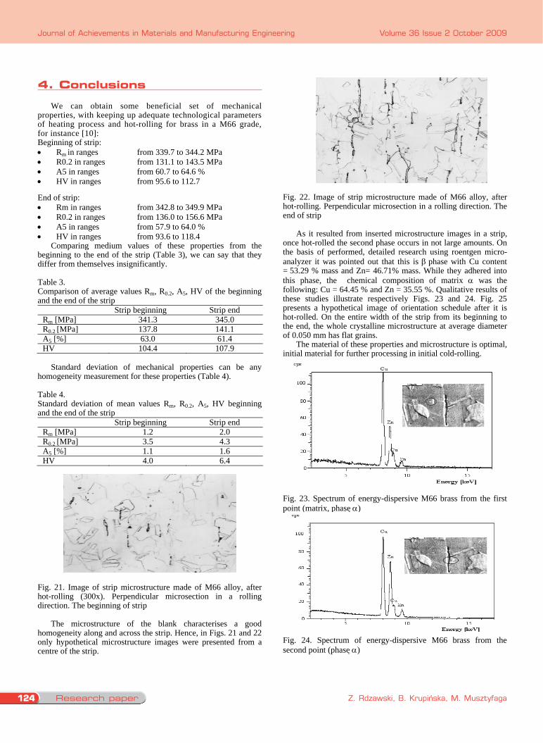
Fig. 21. Image of strip microstructure made of M66 alloy, after hot-rolling (300x). Perpendicular microsection in a rolling direction. The beginning of strip
The microstructure of the blank characterises a good
homogeneity along and across the strip. Hence, in Figs. 21 and 22 only hypothetical microstructure images were presented from a centre of the strip.
Fig. 22. Image of strip microstructure made of M66 alloy, after hot-rolling. Perpendicular microsection in a rolling direction. The end of strip
As it resulted from inserted microstructure images in a strip,
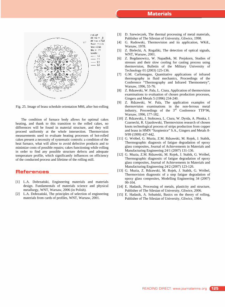
once hot-rolled the second phase occurs in not large amounts. On the basis of performed, detailed research using roentgen micro-analyzer it was pointed out that this is phase with Cu content = 53.29 % mass and Zn= 46.71% mass. While they adhered into this phase, the chemical composition of matrix was the following: Cu = 64.45 % and Zn = 35.55 %. Qualitative results of these studies illustrate respectively Figs. 23 and 24. Fig. 25 presents a hypothetical image of orientation schedule after it is hot-rolled. On the entire width of the strip from its beginning to the end, the whole crystalline microstructure at average diameter of 0.050 mm has flat grains.
The material of these properties and microstructure is optimal, initial material for further processing in initial cold-rolling.
Fig. 23. Spectrum of energy-dispersive M66 brass from the first point (matrix, phase )
Fig. 24. Spectrum of energy-dispersive M66 brass from the second point (phase )
Fig. 25. Image of brass schedule orientation M66, after hot-rolling
The condition of furnace body allows for optimal cakes heating, and thank to this transition to the rolled cakes, no differences will be found in material structure, and they will proceed uniformly at the whole intersection. Thermovision measurements used to evaluate heating processes of hot-rolled cakes present a necessity of systematic controls: a condition of the heat furnace, what will allow to avoid defective products and to minimize costs of possible repairs; cakes functioning while rolling in order to find any possible structure defects and adequate temperature profile, which significantly influences on efficiency of the conducted process and lifetime of the rolling mill.
References [1] L.A. Dobrzański, Engineering materials and materials
design. Fundamentals of materials science and physical metallurgy, WNT, Warsaw, 2006 (in Polish).
[2] L.A. Dobrzański, The principles of selection of engineering materials from cards of profiles, WNT, Warsaw, 2001.
[3] D. Szewieczek, The thermal processing of metal materials, Publisher of The Silesian of University, Gliwice, 1998.
[4] G. Rudowski, Thermovision and its application, WKiŁ, Warsaw, 1978.
[5] Z. Bielecki, A. Rogaliki, The detection of optical signals, WNT, Warsaw, 2001.
[6] Z. Bogdanowicz, W. Napadłek, M. Prejskorn, Studies of stresses and their slow cooling for casting process using thermovision, Bulletin of the Military University of Technology 01 (2003) 125-136.
[7] G.M. Carlomagno, Quantitative applications of infrared thermography in fluid mechanics, Proceedings of the Conference “Thermography and Infrared Thermometry”, Warsaw, 1996, 55-76.
[8] Z. Rdzawski, W. Pala, L. Ciura, Application of thermovision examinations to evaluation of chosen production processes, Gingers and Metals 5 (1996) 234-240.
[9] Z. Rdzawski, W. Pala, The application examples of thermovision examinations in the non-ferrous metal industry, Proceedings of the 3rd Conference TTP’96, Warsaw, 1996, 177-182.
[10] Z. Rdzawski, J. Stobrawa, L. Ciura, W. Dyrda, A. Płonka, J. Czarnecki, R. Ujazdowski, Thermovision research of chosen knots technological process of strips production from copper and brass in HMN “Szopienice” S.A., Gingers and Metals 8-9/99 (1999) 437-442.
[11] G. Wróbel, G. Muzia, Z.M. Rdzawski, M. Rojek, J. Stabik, Thermographic diagnosis of fatigue degradation of epoxy glass composites, Journal of Achievements in Materials and Manufacturing Engineering 24/1 (2007) 131-136.
[12] G. Muzia, Z.M. Rdzawski, M. Rojek, J. Stabik, G. Wróbel, Thermographic diagnostic of fatigue degradation of epoxy glass composites, Journal of Achievements in Materials and Manufacturing Engineering 24/2 (2007) 123-126.
[13] G. Muzia, Z. Rdzawski, M. Rojek, J. Stabik, G. Wróbel, Thermovision diagnostic of a step fatigue degradation of epoxy glass composites, Modelling Engineering 34 (2007) 99-104.
[14] E. Hadasik, Processing of metals, plasticity and structure, Publisher of The Silesian of University, Gliwice, 2006.
[15] E. Hadasik, A. Sobański, Basics on the theory of rolling, Publisher of The Silesian of University, Gliwice, 1984.
4. conclusions
125READING DIRECT: www.journalamme.org
Materials
4. Conclusions
We can obtain some beneficial set of mechanical properties, with keeping up adequate technological parameters of heating process and hot-rolling for brass in a M66 grade, for instance [10]: Beginning of strip: Rm in ranges from 339.7 to 344.2 MPa R0.2 in ranges from 131.1 to 143.5 MPa A5 in ranges from 60.7 to 64.6 % HV in ranges from 95.6 to 112.7
End of strip: Rm in ranges from 342.8 to 349.9 MPa R0.2 in ranges from 136.0 to 156.6 MPa A5 in ranges from 57.9 to 64.0 % HV in ranges from 93.6 to 118.4
Comparing medium values of these properties from the beginning to the end of the strip (Table 3), we can say that they differ from themselves insignificantly.
Table 3. Comparison of average values Rm, R0.2, A5, HV of the beginning and the end of the strip
Strip beginning Strip end Rm [MPa] 341.3 345.0 R0.2 [MPa] 137.8 141.1 A5 [%] 63.0 61.4 HV 104.4 107.9
Standard deviation of mechanical properties can be any
homogeneity measurement for these properties (Table 4). Table 4. Standard deviation of mean values Rm, R0.2, A5, HV beginning and the end of the strip
Strip beginning Strip end Rm [MPa] 1.2 2.0 R0.2 [MPa] 3.5 4.3 A5 [%] 1.1 1.6 HV 4.0 6.4
Fig. 21. Image of strip microstructure made of M66 alloy, after hot-rolling (300x). Perpendicular microsection in a rolling direction. The beginning of strip
The microstructure of the blank characterises a good
homogeneity along and across the strip. Hence, in Figs. 21 and 22 only hypothetical microstructure images were presented from a centre of the strip.
Fig. 22. Image of strip microstructure made of M66 alloy, after hot-rolling. Perpendicular microsection in a rolling direction. The end of strip
As it resulted from inserted microstructure images in a strip,
once hot-rolled the second phase occurs in not large amounts. On the basis of performed, detailed research using roentgen micro-analyzer it was pointed out that this is phase with Cu content = 53.29 % mass and Zn= 46.71% mass. While they adhered into this phase, the chemical composition of matrix was the following: Cu = 64.45 % and Zn = 35.55 %. Qualitative results of these studies illustrate respectively Figs. 23 and 24. Fig. 25 presents a hypothetical image of orientation schedule after it is hot-rolled. On the entire width of the strip from its beginning to the end, the whole crystalline microstructure at average diameter of 0.050 mm has flat grains.
The material of these properties and microstructure is optimal, initial material for further processing in initial cold-rolling.
Fig. 23. Spectrum of energy-dispersive M66 brass from the first point (matrix, phase )
Fig. 24. Spectrum of energy-dispersive M66 brass from the second point (phase )
Fig. 25. Image of brass schedule orientation M66, after hot-rolling
The condition of furnace body allows for optimal cakes heating, and thank to this transition to the rolled cakes, no differences will be found in material structure, and they will proceed uniformly at the whole intersection. Thermovision measurements used to evaluate heating processes of hot-rolled cakes present a necessity of systematic controls: a condition of the heat furnace, what will allow to avoid defective products and to minimize costs of possible repairs; cakes functioning while rolling in order to find any possible structure defects and adequate temperature profile, which significantly influences on efficiency of the conducted process and lifetime of the rolling mill.
References [1] L.A. Dobrzański, Engineering materials and materials
design. Fundamentals of materials science and physical metallurgy, WNT, Warsaw, 2006 (in Polish).
[2] L.A. Dobrzański, The principles of selection of engineering materials from cards of profiles, WNT, Warsaw, 2001.
[3] D. Szewieczek, The thermal processing of metal materials, Publisher of The Silesian of University, Gliwice, 1998.
[4] G. Rudowski, Thermovision and its application, WKiŁ, Warsaw, 1978.
[5] Z. Bielecki, A. Rogaliki, The detection of optical signals, WNT, Warsaw, 2001.
[6] Z. Bogdanowicz, W. Napadłek, M. Prejskorn, Studies of stresses and their slow cooling for casting process using thermovision, Bulletin of the Military University of Technology 01 (2003) 125-136.
[7] G.M. Carlomagno, Quantitative applications of infrared thermography in fluid mechanics, Proceedings of the Conference “Thermography and Infrared Thermometry”, Warsaw, 1996, 55-76.
[8] Z. Rdzawski, W. Pala, L. Ciura, Application of thermovision examinations to evaluation of chosen production processes, Gingers and Metals 5 (1996) 234-240.
[9] Z. Rdzawski, W. Pala, The application examples of thermovision examinations in the non-ferrous metal industry, Proceedings of the 3rd Conference TTP’96, Warsaw, 1996, 177-182.
[10] Z. Rdzawski, J. Stobrawa, L. Ciura, W. Dyrda, A. Płonka, J. Czarnecki, R. Ujazdowski, Thermovision research of chosen knots technological process of strips production from copper and brass in HMN “Szopienice” S.A., Gingers and Metals 8-9/99 (1999) 437-442.
[11] G. Wróbel, G. Muzia, Z.M. Rdzawski, M. Rojek, J. Stabik, Thermographic diagnosis of fatigue degradation of epoxy glass composites, Journal of Achievements in Materials and Manufacturing Engineering 24/1 (2007) 131-136.
[12] G. Muzia, Z.M. Rdzawski, M. Rojek, J. Stabik, G. Wróbel, Thermographic diagnostic of fatigue degradation of epoxy glass composites, Journal of Achievements in Materials and Manufacturing Engineering 24/2 (2007) 123-126.
[13] G. Muzia, Z. Rdzawski, M. Rojek, J. Stabik, G. Wróbel, Thermovision diagnostic of a step fatigue degradation of epoxy glass composites, Modelling Engineering 34 (2007) 99-104.
[14] E. Hadasik, Processing of metals, plasticity and structure, Publisher of The Silesian of University, Gliwice, 2006.
[15] E. Hadasik, A. Sobański, Basics on the theory of rolling, Publisher of The Silesian of University, Gliwice, 1984.
references