Embed Size (px)
Citation preview
This article was downloaded by: [UAE University]On: 15 April 2014, At: 08:12Publisher: Taylor & FrancisInforma Ltd Registered in England and Wales Registered Number: 1072954 Registeredoffice: Mortimer House, 37-41 Mortimer Street, London W1T 3JH, UK
International Journal of SustainableEnergyPublication details, including instructions for authors andsubscription information:http://www.tandfonline.com/loi/gsol20
Thermal performance analysis ofplate heat exchanger with differentconfigurations for the heat recoverysystem in buildingsMohamed Sakra
a Civil Engineering, Architecture and Building (CAB), Faculty ofEngineering and Computing, Coventry University, Coventry CV15FB, UKPublished online: 14 Apr 2014.
To cite this article: Mohamed Sakr (2014): Thermal performance analysis of plate heat exchangerwith different configurations for the heat recovery system in buildings, International Journal ofSustainable Energy, DOI: 10.1080/14786451.2014.905580
To link to this article: http://dx.doi.org/10.1080/14786451.2014.905580
PLEASE SCROLL DOWN FOR ARTICLE
Taylor & Francis makes every effort to ensure the accuracy of all the information (the“Content”) contained in the publications on our platform. However, Taylor & Francis,our agents, and our licensors make no representations or warranties whatsoever as tothe accuracy, completeness, or suitability for any purpose of the Content. Any opinionsand views expressed in this publication are the opinions and views of the authors,and are not the views of or endorsed by Taylor & Francis. The accuracy of the Contentshould not be relied upon and should be independently verified with primary sourcesof information. Taylor and Francis shall not be liable for any losses, actions, claims,proceedings, demands, costs, expenses, damages, and other liabilities whatsoever orhowsoever caused arising directly or indirectly in connection with, in relation to or arisingout of the use of the Content.
This article may be used for research, teaching, and private study purposes. Anysubstantial or systematic reproduction, redistribution, reselling, loan, sub-licensing,systematic supply, or distribution in any form to anyone is expressly forbidden. Terms &

Conditions of access and use can be found at http://www.tandfonline.com/page/terms-and-conditions
Dow
nloa
ded
by [U
AE
Uni
vers
ity] a
t 08:
12 1
5 A
pril
2014
International Journal of Sustainable Energy, 2014http://dx.doi.org/10.1080/14786451.2014.905580
Thermal performance analysis of plate heat exchanger withdifferent configurations for the heat recovery system in buildings
Mohamed Sakr∗
Civil Engineering, Architecture and Building (CAB), Faculty of Engineering and Computing, CoventryUniversity, Coventry CV1 5FB, UK
(Received 22 December 2013; final version received 27 February 2014)
Due to the scarcity of conventional energy sources, a lot of efforts need to be taken regarding energyconservation in the buildings, including heat recovery of air ventilation systems. The present paper focuseson new methods to improve the thermal performance of the heat recovery system by investigating the heattransfer characteristics and the flow development in a flat-plate heat exchanger (FPHE) using three differentrib-grooved surfaces (trapezoidal, triangle and semi-circular), the numerical simulations were carried outfor uniform wall heat flux equal to 290 W/m2 for air as the working fluid, the Reynolds number varies from500 to 2000 for three different channel heights. The numerical results indicated that, rib-grooved surfaceshave a significant impact on heat transfer enhancement with an increase in the pressure drop through thechannel. The effect of rib-grooved patterns on the heat transfer and the fluid flow is more significant in anarrow channel especially for trapezoidal and triangle corrugated surfaces, because they have sharp edges.Based on the present research, the FPHEs with the added rib-grooved surfaces are recommended to providean efficient and compact heat recovery system. Moreover, it was found that by applying the new design, aconsiderable amount of energy and power could be saved.
Keywords: compact heat exchanger; energy conservation; heat recovery; heat transfer augmentation
1. Introduction
In the current era of sustainable and environmental construction, engineers and building servicesdesigners are looking for more compact size and higher performance heat exchangers to meet theheat and energy recovery ventilation requirements of a commercial building; when it comes toheat/energy recovery, the plate heat exchangers core is the crucial component to ensure higherefficiencies and peak performance.
For various reasons, mechanical ventilation systems with heat recovery are virtually mandatoryfor low-energy buildings in regions with cold winters and, as a result, are attracting increasinginterest. With these systems, fresh air is preheated in a heat exchanger by extract air (Manz, Huber,and Helfenfinger 2001). The air-to-air energy recovery exchangers commonly used in HVACsystems may be split into two main categories. One category comprises the rotating energy wheelregenerators, also called heat wheels or energy wheels. The other category is the flat-plate heatexchangers (FPHEs) (Fernández-Seara et al. 2011). The traditional heat exchangers are usingFPHEs due to their simplicity, low cost and low needs of maintenance but they have relatively low
∗Emails: [email protected], [email protected]
© 2014 Taylor & Francis
Dow
nloa
ded
by [U
AE
Uni
vers
ity] a
t 08:
12 1
5 A
pril
2014
2 M. Sakr
heat recovery efficiency and are unable to meet the ever increasing cooling or heating demandsof the building services. One promising solution to that problem is using a corrugated plate heatexchanger to improve its thermal performance because fluid flowing through a channel witha corrugated surface has a significant effect on heat transfer enhancement due to breaking thethermal boundary layer Naphon (2010). Heat transfer enhancements by modifying the channel ortube surfaces have gained attention by scientists and researchers over the past few decades.
Sui et al. (2010) carried out 3D numerical simulation for laminar liquid water flow in a cor-rugated micro-channel, the results showed that, flowing of a liquid coolant in a wavy channelgenerated a secondary flow (Dean vortices), the quantity and the location of the vortices changeralong the flow direction also generating a chaotic advection, which lead to enhance convectiveflow mixing and heat transfer performance.
The effect of different geometry configurations of wavy plate under constant wall heat flux wasnumerically studied by Naphon (2009), the results indicated that the sharp edge wavy plate has asignificant effect on the flow structure and heat transfer enhancement.
Fabbri (2000) used a finite element model to predict heat transfer in both smooth and corrugatedwalls under laminar flow condition; the numerical results were utilised in a genetic algorithm tomaximise heat transfer by optimising the corrugated profile.
In a low Reynolds number regime,Yin et al. (2011) investigated the fluid flow and heat transferin a sinusoidal wavy channel with a uniform surface temperature; the numerical results indicatedthat the friction and average Nusselt number increased with an increase in both wave severity andplate spacing.
Sunden and Karlsson (1991) experimentally studied heat transfer and pressure drop in a trape-zoidal channel under constant wall temperature, they found that the corrugated channel with largewaving provides the best enhancement in heat transfer but the pressure drop penalty also was verylarge.
The effect of phase shift on heat transfer and fluid flow in a corrugated channel was studiedby Yin, Yang, and Li (2012), they found that values of the Nusselt number and the frictionfactor decrease with an increase in the corrugated phase shift. Using a naphthalene sublimationtechnique that was used by Hwang, Jang, and Cho (2006), the visualisation was shown as a complexsecondary flow and the transfer process was found to take place inside the corrugated duct leadingto non-uniform distribution of the heat/mass transfer coefficient on the duct side walls.
In a turbulent flow region, Mohammed, Abbas, and Sheriff (2013a) investigated the effect ofusing a transversely corrugated circular tube on flow fields and thermal performance. On the otherhand, different numerical and experimental works have been carried out by many researchersto investigate heat transfer and pressure drop in corrugated channel with different geometries(Sparrow 1977; Ali and Ramadhyani 1992; Yuan, Tao, and Wang 1998; Zhang, Kundu, andManglik 2004; Gradeck, Hoareau, and Lebouché 2005; Naphon 2007, 2008, 2009; Elshafei et al.2008; Zhang and Chen 2011; Mohammed, Abed, and Wahid 2013b); they reported that the heattransfer rate in corrugated channels was increased but with an increase in the pressure drop ascompared with the results of smooth channels.
Based on the above review, it is noted that using corrugated surfaces with various configurations(square, rectangular, triangle and semi-circular shapes) improves energy performance of the plateheat exchanger and reduces the size of the heat exchanger, but also causes a sharp increasein pressure drop and hence the pumping power, so selecting the optimal method for highestperformances is complicated because it depends upon the height, the length and pitch of the ribs.
The use of computational fluid dynamics (CFD) to obtain the whole picture of the flow structurebetween the corrugated plates so as to evaluate their performance is considered to be an effectivetool because the flow passage between corrugation plates is complex in the geometry and thepassage spaces are relatively small dimensions so to get an accurate detailed description of thecomplete temperature and flow filed is difficult to be achieved experimentally.
Dow
nloa
ded
by [U
AE
Uni
vers
ity] a
t 08:
12 1
5 A
pril
2014
International Journal of Sustainable Energy 3
The objective of this study is to investigate the effect of using different rib-grooved surfaces(trapezoidal, triangle and semi-circular) to enhance the heat transfer rate in the FPHE underconstant wall heat flux numerically by using the finite volume method, for Reynolds numberranging from 500 to 2000 and different channel spacings Smax (12.5, 15.0 and 17.5 mm). Theeffects of various relevant parameters on the pressure drop and heat transfer characteristics arealso investigated.
The numerical results are expected to contribute and provide guidelines for designing FPHEfor air heat recovery systems.
2. Problem statement
2.1. Corrugation geometry
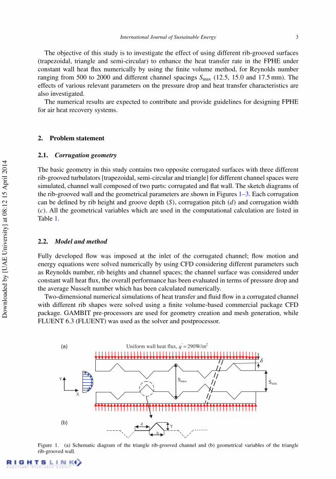
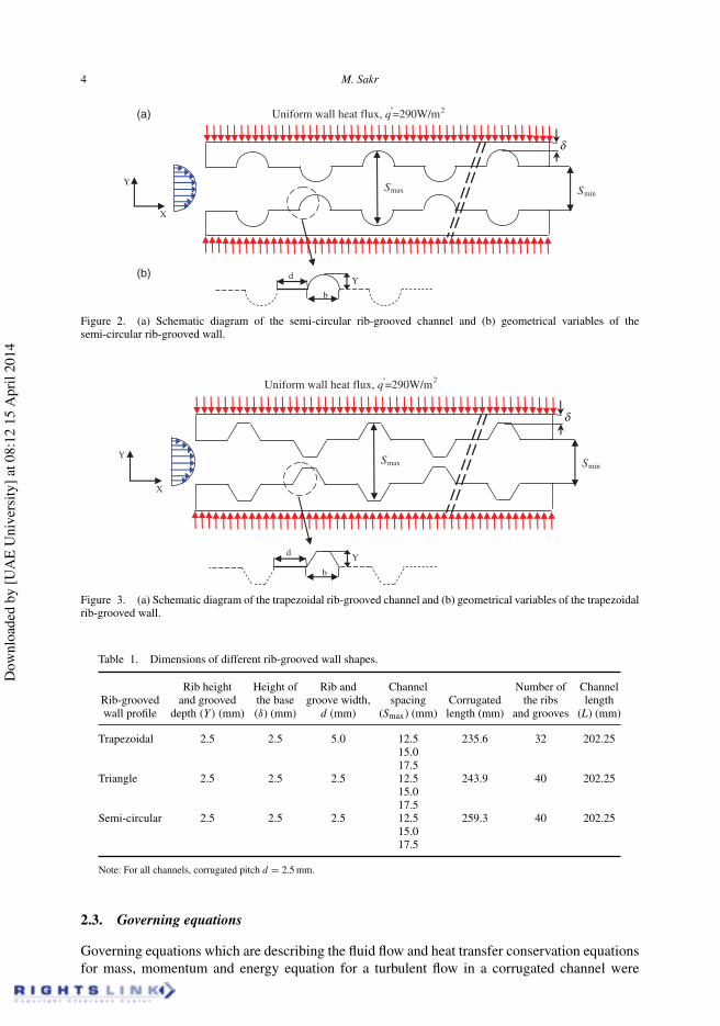
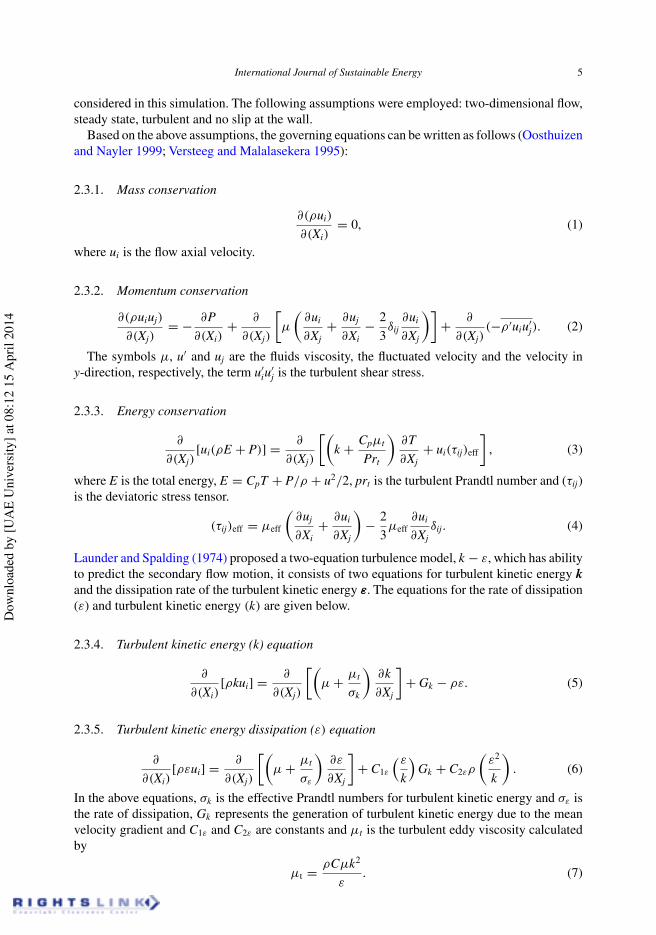
The basic geometry in this study contains two opposite corrugated surfaces with three differentrib-grooved turbulators [trapezoidal, semi-circular and triangle] for different channel spaces weresimulated, channel wall composed of two parts: corrugated and flat wall. The sketch diagrams ofthe rib-grooved wall and the geometrical parameters are shown in Figures 1–3. Each corrugationcan be defined by rib height and groove depth (S), corrugation pitch (d) and corrugation width(c). All the geometrical variables which are used in the computational calculation are listed inTable 1.
2.2. Model and method
Fully developed flow was imposed at the inlet of the corrugated channel; flow motion andenergy equations were solved numerically by using CFD considering different parameters suchas Reynolds number, rib heights and channel spaces; the channel surface was considered underconstant wall heat flux, the overall performance has been evaluated in terms of pressure drop andthe average Nusselt number which has been calculated numerically.
Two-dimensional numerical simulations of heat transfer and fluid flow in a corrugated channelwith different rib shapes were solved using a finite volume-based commercial package CFDpackage. GAMBIT pre-processors are used for geometry creation and mesh generation, whileFLUENT 6.3 (FLUENT) was used as the solver and postprocessor.
SminSmax
Uniform wall heat flux, q'' = 290W/m2
X
Y
(a)
(b)Yd
b
d
Figure 1. (a) Schematic diagram of the triangle rib-grooved channel and (b) geometrical variables of the trianglerib-grooved wall.
Dow
nloa
ded
by [U
AE
Uni
vers
ity] a
t 08:
12 1
5 A
pril
2014
4 M. Sakr
X
YSmin
Smax
Uniform wall heat flux, q''=290W/m2
Yd
b
d
(a)
(b)
Figure 2. (a) Schematic diagram of the semi-circular rib-grooved channel and (b) geometrical variables of thesemi-circular rib-grooved wall.
Uniform wall heat flux, q''=290W/m2
SminSmax
X
Y
Yd
b
d
Figure 3. (a) Schematic diagram of the trapezoidal rib-grooved channel and (b) geometrical variables of the trapezoidalrib-grooved wall.
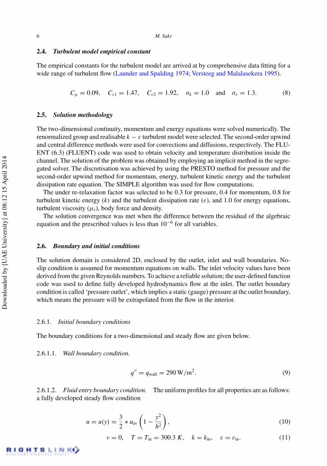
Table 1. Dimensions of different rib-grooved wall shapes.
Rib height Height of Rib and Channel Number of ChannelRib-grooved and grooved the base groove width, spacing Corrugated the ribs lengthwall profile depth (Y) (mm) (δ) (mm) d (mm) (Smax) (mm) length (mm) and grooves (L) (mm)
Trapezoidal 2.5 2.5 5.0 12.5 235.6 32 202.2515.017.5
Triangle 2.5 2.5 2.5 12.5 243.9 40 202.2515.017.5
Semi-circular 2.5 2.5 2.5 12.5 259.3 40 202.2515.017.5
Note: For all channels, corrugated pitch d = 2.5 mm.
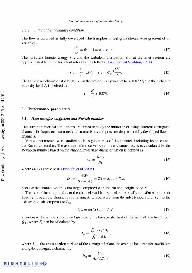
2.3. Governing equations
Governing equations which are describing the fluid flow and heat transfer conservation equationsfor mass, momentum and energy equation for a turbulent flow in a corrugated channel were
Dow
nloa
ded
by [U
AE
Uni
vers
ity] a
t 08:
12 1
5 A
pril
2014
International Journal of Sustainable Energy 5
considered in this simulation. The following assumptions were employed: two-dimensional flow,steady state, turbulent and no slip at the wall.
Based on the above assumptions, the governing equations can be written as follows (Oosthuizenand Nayler 1999; Versteeg and Malalasekera 1995):
2.3.1. Mass conservation
∂(ρui)
∂(Xi)= 0, (1)
where ui is the flow axial velocity.
2.3.2. Momentum conservation
∂(ρuiuj)
∂(Xj)= − ∂P
∂(Xi)+ ∂
∂(Xj)
!µ
"∂ui
∂Xj+ ∂uj
∂Xi− 2
3δij
∂ui
∂Xj
#$+ ∂
∂(Xj)(−ρ ′uiu′
j). (2)
The symbols µ, u′ and uj are the fluids viscosity, the fluctuated velocity and the velocity iny-direction, respectively, the term u′
iu′j is the turbulent shear stress.
2.3.3. Energy conservation
∂
∂(Xj)[ui(ρE + P)] = ∂
∂(Xj)
!"k + Cpµt
Prt
#∂T∂Xj
+ ui(τij)eff
$, (3)
where E is the total energy, E = CpT + P/ρ + u2/2, prt is the turbulent Prandtl number and (τij)is the deviatoric stress tensor.
(τij)eff = µeff
"∂uj
∂Xi+ ∂ui
∂Xj
#− 2
3µeff
∂ui
∂Xjδij. (4)
Launder and Spalding (1974) proposed a two-equation turbulence model, k − ε, which has abilityto predict the secondary flow motion, it consists of two equations for turbulent kinetic energy kand the dissipation rate of the turbulent kinetic energy ε. The equations for the rate of dissipation(ε) and turbulent kinetic energy (k) are given below.
2.3.4. Turbulent kinetic energy (k) equation
∂
∂(Xi)[ρkui] = ∂
∂(Xj)
!"µ + µt
σk
#∂k∂Xj
$+ Gk − ρε. (5)
2.3.5. Turbulent kinetic energy dissipation (ε) equation
∂
∂(Xi)[ρεui] = ∂
∂(Xj)
!"µ + µt
σε
#∂ε
∂Xj
$+ C1ε
%ε
k
&Gk + C2ερ
"ε2
k
#. (6)
In the above equations, σk is the effective Prandtl numbers for turbulent kinetic energy and σε isthe rate of dissipation, Gk represents the generation of turbulent kinetic energy due to the meanvelocity gradient and C1ε and C2ε are constants and µt is the turbulent eddy viscosity calculatedby
µt = ρCµk2
ε. (7)
Dow
nloa
ded
by [U
AE
Uni
vers
ity] a
t 08:
12 1
5 A
pril
2014
6 M. Sakr
2.4. Turbulent model empirical constant
The empirical constants for the turbulent model are arrived at by comprehensive data fitting for awide range of turbulent flow (Launder and Spalding 1974; Versteeg and Malalasekera 1995).
Cµ = 0.09, Cε1 = 1.47, Cε2 = 1.92, σk = 1.0 and σε = 1.3. (8)
2.5. Solution methodology
The two-dimensional continuity, momentum and energy equations were solved numerically. Therenormalized group and realisable k − ε turbulent model were selected. The second-order upwindand central difference methods were used for convections and diffusions, respectively. The FLU-ENT (6.3) (FLUENT) code was used to obtain velocity and temperature distribution inside thechannel. The solution of the problem was obtained by employing an implicit method in the segre-gated solver. The discretisation was achieved by using the PRESTO method for pressure and thesecond-order upwind method for momentum, energy, turbulent kinetic energy and the turbulentdissipation rate equation. The SIMPLE algorithm was used for flow computations.
The under re-relaxation factor was selected to be 0.3 for pressure, 0.4 for momentum, 0.8 forturbulent kinetic energy (k) and the turbulent dissipation rate (ε), and 1.0 for energy equations,turbulent viscosity (µt), body force and density.
The solution convergence was met when the difference between the residual of the algebraicequation and the prescribed values is less than 10−6 for all variables.
2.6. Boundary and initial conditions
The solution domain is considered 2D, enclosed by the outlet, inlet and wall boundaries. No-slip condition is assumed for momentum equations on walls. The inlet velocity values have beenderived from the given Reynolds numbers. To achieve a reliable solution; the user-defined functioncode was used to define fully developed hydrodynamics flow at the inlet. The outlet boundarycondition is called ‘pressure outlet’, which implies a static (gauge) pressure at the outlet boundary,which means the pressure will be extrapolated from the flow in the interior.
2.6.1. Initial boundary conditions
The boundary conditions for a two-dimensional and steady flow are given below.
2.6.1.1. Wall boundary condition.
q′′ = qwall = 290 W/m2. (9)
2.6.1.2. Fluid entry boundary condition. The uniform profiles for all properties are as follows:a fully developed steady flow condition
u = u(y) = 32
∗ uav
"1 − y2
h2
#, (10)
v = 0, T = Tin = 300.3 K , k = kin, ε = εin. (11)
Dow
nloa
ded
by [U
AE
Uni
vers
ity] a
t 08:
12 1
5 A
pril
2014
International Journal of Sustainable Energy 7
2.6.2. Fluid outlet boundary condition
The flow is assumed as fully developed which implies a negligible stream wise gradient of allvariables
∂∅∂n
= 0; ∅ = u, v, k and ε. (12)
The turbulent kinetic energy kin, and the turbulent dissipation, εin, at the inlet section areapproximated from the turbulent intensity I as follows (Launder and Spalding 1974):
kin = 32(uinI)2, εin = C3/4
µ
k3/2
L. (13)
The turbulence characteristic length, L, in the present study was set to be 0.07 Dh and the turbulentintensity level I , is defined as
I = u′
u∗ 100%. (14)
3. Performance parameters
3.1. Heat transfer coefficient and Nusselt number
The current numerical simulations are aimed to study the influence of using different corrugatedchannel rib shapes on heat transfer characteristics and pressure drop for a fully developed flow inchannels.
Various parameters were studied such as geometries of the channel, including its space andthe Reynolds number. The average reference velocity in the channel, uav was calculated by theReynolds number based on the channel hydraulic diameter which is defined as
uav = Re υ
Dh, (15)
where Dh is expressed as (Elshafei et al. 2008)
Dh = 4SW2(S + W)
= 2S = Smax + Smin (16)
because the channel width is too large compared with the channel height W ≫ S.The rate of heat input, Qin, to the channel wall is assumed to be totally transferred to the air
flowing through the channel path, raising its temperature from the inlet temperature, Ta,i, to theexit average air temperature Ta,o
Qin = mCp(Ta,o − Ta,i), (17)
where m is the air mass flow rate kg/s, and Cp is the specific heat of the air, with the heat input,Qin, where Ta can be calculated by
Ta =' Ac
0 uTa dAcr' Ac
0 u dAcr
, (18)
where Ac is the cross-section surface of the corrugated plate, the average heat transfer coefficientalong the corrugated channel hm.
hm = Qin
Aw((Tm), (19)
Dow
nloa
ded
by [U
AE
Uni
vers
ity] a
t 08:
12 1
5 A
pril
2014
8 M. Sakr
where Aw is the surface area of the corrugated plate and the logarithmic temperature differencebetween the wall and the fluid was calculated as
(Tm = (Tw − Ta,i) − (Tw − Ta,o)
ln[(Tw − Ta,i) − (Tw − Ta,o)], (20)
where Tw is the average wall temperature.
Tw = 1σ
( σ
0Tw,x dx. (21)
The average heat transfer coefficient is given in terms of the mean Nusselt Number (Ali andRamadhyani 1992; Fernández-Seara et al. 2011) as follows:
Nu = hcHσ
kLt, (22)
where k is the thermal conductivity of the fluid, hc is the half distance of the channel height andσ is the distance from the leading edge of the corrugated plate along the corrugated surface.
σ = Lt
cos(θ), (23)
(pL
= (pav,0 − pav,i)
Lt, (24)
where pav,o and pav,i are the surface average pressures on the inlet and outlet of the channel.To achieve the performance assessment of such narrow channels based on their heat transfercharacteristics and pressure drop, Performance factor is almost considered, defined as (Elshafeiet al. 2008)
PE = (Nuc/Nus)
(fc/fs)1/3, (25)
where f is the friction factor which is calculated by
f = (p(Dh/Lt)
(1/2)ρu2av
. (26)
3.2. Grid generation
Computational mesh was created using GAMBIT, different structured and unstructured mesh withseveral cell sizes are employed considering the simulation time needed for specific number ofiterations and the accuracy of the solution. The local Reynolds number near any wall becomes verysmall owing to viscous influence; to overcome this issue, a special near-wall modelling approachwas applied to possess the accuracy of the stander boundary layer approach for fine near-wallmesh, so the first cell is placed in the laminar boundary layer, though the laminar sub layer is validup to y+ < 5, the nearest nodes from the wall are located within the interval y+ = 1.5–4, wherey+ is the dimensional distance from the wall. The grid independence is carried out in the analysisby adopting different grid distributions of 1 × 10⁵, 1.3 × 10⁵, 2 × 10⁵ and 2.5 × 10⁵; the gridindependence test indicated that the grid systems of 1.5 × 10⁵ ensure a satisfactory solution, thisis verified by the fact that the difference of the computed results of an average Nusselt numberwith a grid finer of 1.5 × 10⁵ is within 2%.
Dow
nloa
ded
by [U
AE
Uni
vers
ity] a
t 08:
12 1
5 A
pril
2014
International Journal of Sustainable Energy 9
4. Result and discussion
Heat transfer and pressure drop characteristics of the flow in corrugated channels are discussedin the present study considering the effect of different channel heights (Smax = 12.5. 15.0 and17.5 mm), and different corrugated wall configurations using air as the working fluid were carriedout to study these effects on the temperature and the airflow structure. The side walls of simulatedchannels were uniform heat flux exposed to air flow over a range of 500 < Re < 2000. Theoptimal performances for using different rib-grooved shapes in the compact heat exchanger wereobtained by using a performance evaluation plot.
4.1. Model validation
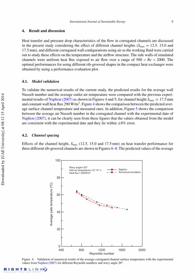
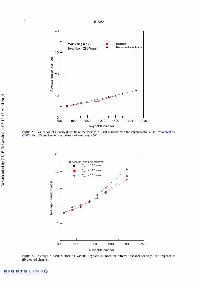
To validate the numerical results of the current study, the predicted results for the average wallNusselt number and the average outlet air temperature were compared with the previous experi-mental results of Naphon (2007) as shown in Figures 4 and 5; for channel height Smax = 17.5 mmand constant wall heat flux 290 W/m2. Figure 4 shows the comparison between the predicted aver-age surface channel temperature and measured ones. In addition, Figure 5 shows the comparisonbetween the average air Nusselt number in the corrugated channel with the experimental date ofNaphon (2007), it can be clearly seen from these figures that the values obtained from the modelare consistent with the experimental date and they lie within ±8% error.
4.2. Channel spacing
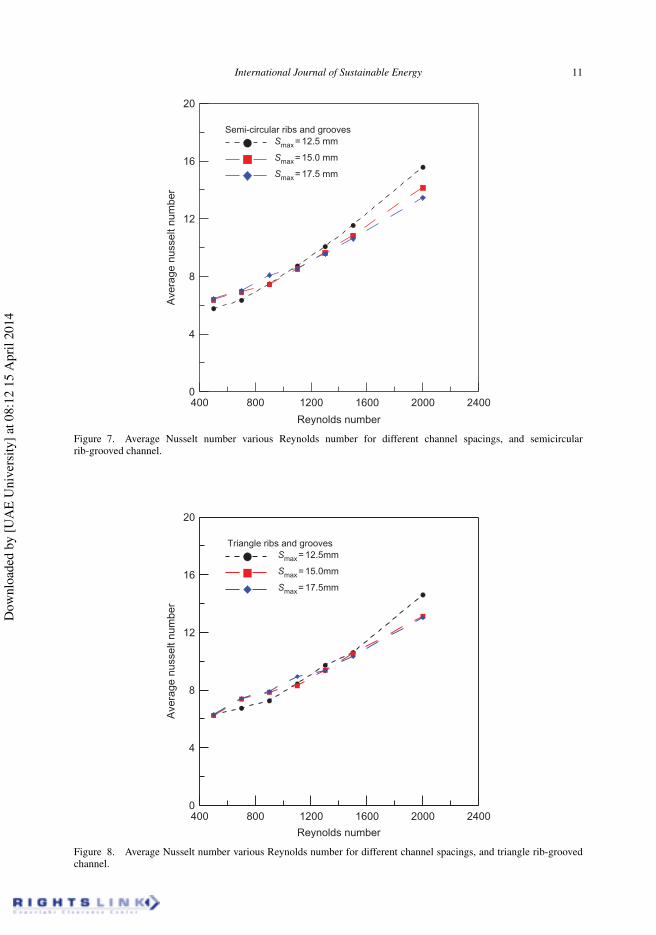
Effects of the channel height, Smax (12.5, 15.0 and 17.5 mm) on heat transfer performance forthree different rib-grooved channels are shown in Figures 6–8. The predicted values of the average
400 800 1200 1600 2000Reynolds number
0
20
40
60
80
100
Ave
rage
pat
e te
mpe
ratu
re (
ºC)
Wavy angle = 20ºInlet air temperature = 27.15 °cHeat flux = 290W/m2
NaphonNumerical simulation
Figure 4. Validation of numerical results of the average corrugated channel surface temperature with the experimentalvalues from Naphon (2007) for different Reynolds numbers and wavy angle 20◦.
Dow
nloa
ded
by [U
AE
Uni
vers
ity] a
t 08:
12 1
5 A
pril
2014
10 M. Sakr
600 800 1000 1200 1400 1600 1800
Reynolds number
0
10
20
30
40
Ave
rage
nus
selt
num
ber
Wavy angle = 20°heat flux = 290 W/m2
NaphonNumerical simulation
Figure 5. Validation of numerical results of the average Nusselt Number with the experimental values from Naphon(2007) for different Reynolds numbers and wavy angle 20◦.
400 800 1200 1600 2000 2400
Reynolds number
0
4
8
12
16
20
Ave
rage
nus
selt
num
ber
Trapezoidal ribs and groovesSmax= 12.5 mm
Smax= 15.0 mm
Smax= 17.5 mm
Figure 6. Average Nusselt number for various Reynolds number for different channel spacings, and trapezoidalrib-grooved channel.
Dow
nloa
ded
by [U
AE
Uni
vers
ity] a
t 08:
12 1
5 A
pril
2014
International Journal of Sustainable Energy 11
400 800 1200 1600 2000 2400
Reynolds number
0
4
8
12
16
20
Ave
rage
nus
selt
num
ber
Semi-circular ribs and groovesSmax= 12.5 mm
Smax= 15.0 mm
Smax= 17.5 mm
Figure 7. Average Nusselt number various Reynolds number for different channel spacings, and semicircularrib-grooved channel.
400 800 1200 1600 2000 2400
Reynolds number
0
4
8
12
16
20
Ave
rage
nus
selt
num
ber
Triangle ribs and groovesSmax= 12.5mm
Smax= 15.0mm
Smax= 17.5mm
Figure 8. Average Nusselt number various Reynolds number for different channel spacings, and triangle rib-groovedchannel.
Dow
nloa
ded
by [U
AE
Uni
vers
ity] a
t 08:
12 1
5 A
pril
2014
12 M. Sakr
surface Nusselt number were plotted against various Reynolds number, these figures show thatthe values of the average surface Nusselt number increase with a decrease in channel spacing andincrease with the increase in the values of Reynolds number.
In addition, the effects of channel spacing on average values of the Nusselt number are notnotable until the value of the Reynolds number equals 1200; after that value, both effects of thechannel height and the Reynolds number are more significant on enhancement of the Nusselt num-ber; in the same time the trapezoidal rib-grooved channel has a higher average Nusselt number incomparison with both semi-circular and triangle rib-grooved channels; high values of the averageNusselt number in the small hydraulic diameter plate heat exchanger can be explained by (1) astrong interaction between the flow inside the channel and over the corrugation crest, accompaniedby the secondary flows (Shah and Sekulíc 2003; Dovíc, Palm, and Švaíc 2009), (2) increasingfluid advection and turbulence from the centre of the channel to the near-wall region; (3) break-up and separation of the boundary layer and its new formation and reattachment (Mohammed,Abbas, and Sheriff (2013a)) and (4) decrease the probability of appearance of stagnation areas(Li et al. 2011).
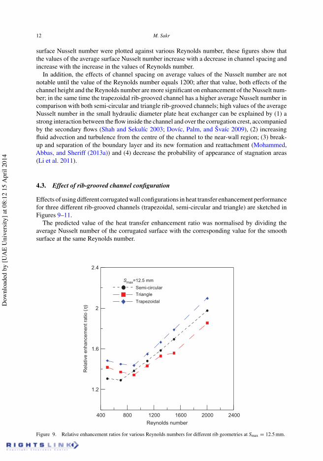
4.3. Effect of rib-grooved channel configuration
Effects of using different corrugated wall configurations in heat transfer enhancement performancefor three different rib-grooved channels (trapezoidal, semi-circular and triangle) are sketched inFigures 9–11.
The predicted value of the heat transfer enhancement ratio was normalised by dividing theaverage Nusselt number of the corrugated surface with the corresponding value for the smoothsurface at the same Reynolds number.
400 800 1200 1600 2000 2400Reynolds number
1.2
1.6
2
2.4
Rel
ativ
e en
hanc
emen
t rat
io (
h)
Smax=12.5 mm
Semi-circularTriangle
Trapezoidal
Figure 9. Relative enhancement ratios for various Reynolds numbers for different rib geometries at Smax = 12.5 mm.
Dow
nloa
ded
by [U
AE
Uni
vers
ity] a
t 08:
12 1
5 A
pril
2014
International Journal of Sustainable Energy 13
400 800 1200 1600 2000 2400
Reynolds number
1.2
1.6
2
2.4
Smax=15.0 mmSemi-circularTriangleTrapezoidal
Rel
ativ
e en
hanc
emen
t rat
io (
h)
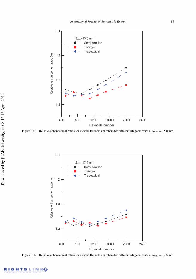
Figure 10. Relative enhancement ratios for various Reynolds numbers for different rib geometries at Smax = 15.0 mm.
400 800 1200 1600 2000 2400
Reynolds number
1.2
1.6
2
2.4
Smax=17.5 mmSemi-circularTriangleTrapezoidal
Rel
ativ
e en
hanc
emen
t rat
io (
h)
Figure 11. Relative enhancement ratios for various Reynolds numbers for different rib geometries at Smax = 17.5 mm.
Dow
nloa
ded
by [U
AE
Uni
vers
ity] a
t 08:
12 1
5 A
pril
2014
14 M. Sakr
For channel spacing, Smax = 12.5 mm as shown in Figure 9, for three different rib-grooved chan-nel configurations, it is clear that the effects of corrugated surfaces on heat transfer enhancementare significant especially at a high Reynolds number.
At a low Reynolds number, the enhancement ratio approximately is very low and varied from30% to 50% for semi-circular and both trapezoidal and triangle rib-grooved walls, respectively;the enhancement value approximately is constant until Re = 1000, after that the enhancementratio was increased sharply with an increase in the Reynolds number and reached to 220% forboth trapezoidal and triangle rib-grooved channels and reached around 180% for the semi-circularrib-grooved channel.
At higher channel spacing, Smax = 15.0 and 17.5 mm, as shown in Figures 10 and 11, theenhancement ratio started to decrease in all rib-grooved channel configurations and becamecloser in values. For Smax = 15.0, the enhancement ratio varied from 130% to 180%, and forhigher channel spacing, Smax = 17.5 mm, the enhancement ratio decreased to 120% dependingon the rib-grooved channel configuration. Naphon (2009) concluded that, in general when the flowis through corrugated plates, it attributed to flow blocking and higher surface area, also destabil-ising and breaking in the thermal boundary layer were promoted, and sharp rib-grooved channelconfigurations (in the present study semi-circular, trapezoidal and triangle) have a significantimpact on heat transfer enhancement.
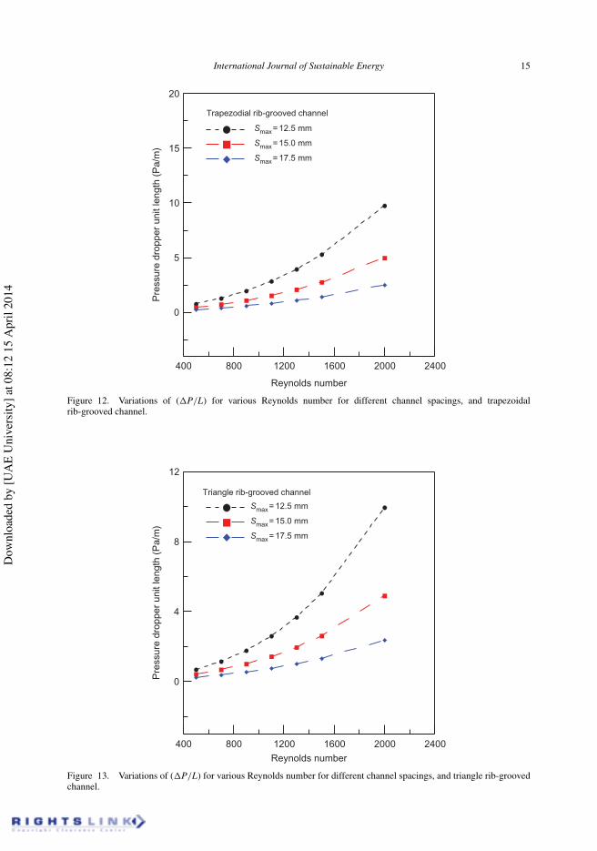
4.4. Pressure drop
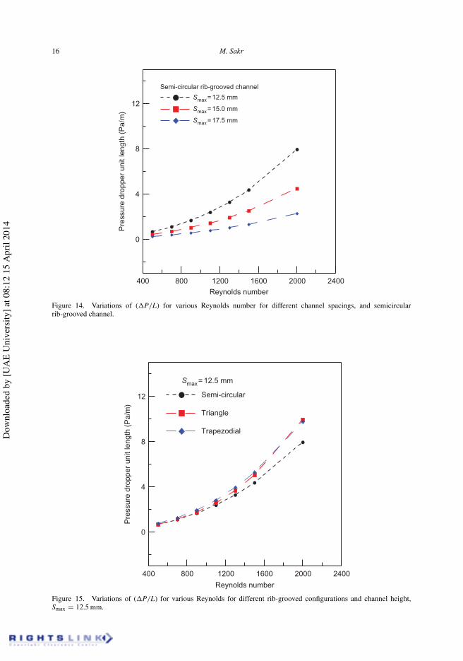
Variations of pressure drop per unit length ((P/L) with the Reynolds number for different channelheights and rib-grooved geometries are shown in Figures 12– 15. In general, characteristics ofthe flow through a corrugated surface channel are quite complex in comparison with a smoothsurface channel (Heggs et al. 1997). Higher pressure drop in a corrugated channel is generatedbecause corrugated surfaces (1) produce rotational flow and (2) exerted drag force on the flowfield which leads to turbulence augmentation.
Based on the discussion above, as expected, it is clear that the pressure drop tends to increasewith the increase in the Reynolds number and decreases with the increase in the channel spacing.
As shown in Figure 15, for channel spacing, Smax = 12.5 mm, pressure drops for trapezoidaland triangle rib-grooved channels are higher compared with semi-circular rib-grooved channelsespecially at a high Reynolds number, the variation of the pressure drop between the differentrib-grooved surfaces is almost small at a low Reynolds number.
4.5. Evaluation of the thermal enhancement factor
Based on the previous analysis and discussion, it could be clear that to design and manufacturecompact heat exchanger depends on a higher heat transfer coefficient between the working fluidthrough the channel and the channel wall. It can be said that thermal boundary layers in corru-gated channels with different rib-grooved geometries become thinner than the case of the smoothchannel, and secondary vortices inside the corrugation contributed to enhancement of the heattransfer but all of that with pressure drop penalty, and based on the previous studies, it is com-mon that the pressure drop penalty is often higher than the values of heat transfer enhancement(Li et al. 2011).
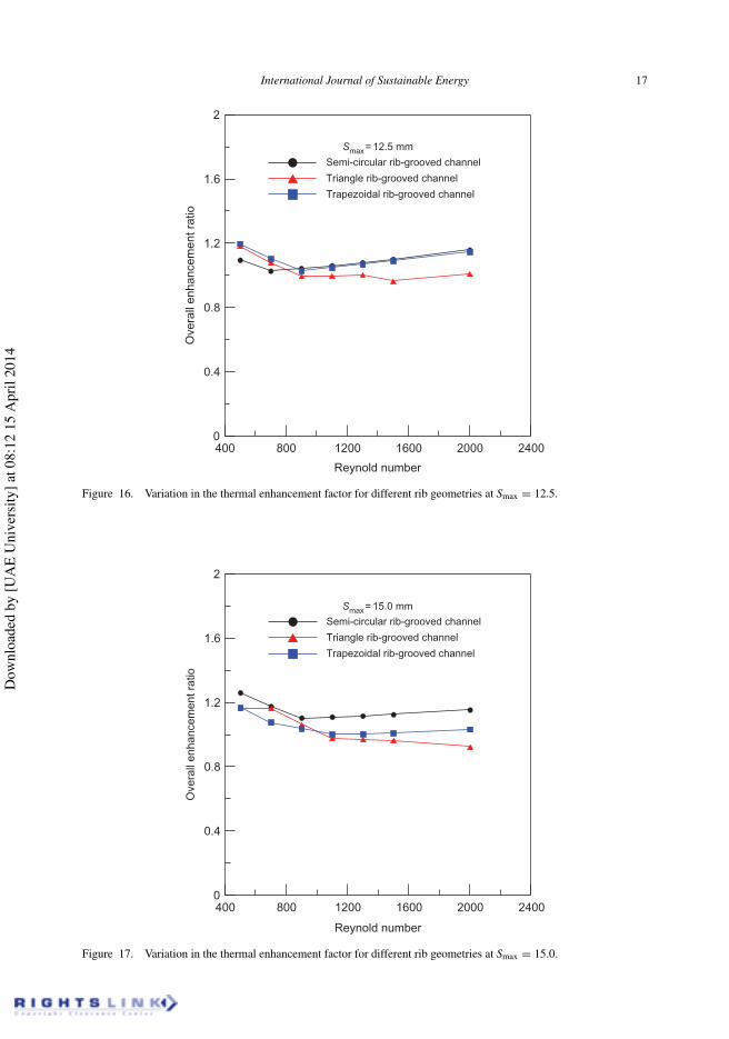
The calculation results for the thermal enhancement ratio for different corrugated surfaces withdifferent rib geometries and channel spacing are illustrated in Figures 16–18.
It is clear from these figures that the thermal enhancement ratio is slightly high at a low Reynoldsnumber and decreased with an increasing Reynolds number until Re = 1000, after that the thermalenhancement is approximately constant for a Reynolds number over 1200, also it is obvious that
Dow
nloa
ded
by [U
AE
Uni
vers
ity] a
t 08:
12 1
5 A
pril
2014
International Journal of Sustainable Energy 15
400 800 1200 1600 2000 2400
Reynolds number
0
5
10
15
20
Pre
ssur
e dr
oppe
r un
it le
ngth
(P
a/m
)
Trapezodial rib-grooved channel
Smax= 12.5 mm
Smax= 15.0 mm
Smax= 17.5 mm
Figure 12. Variations of ((P/L) for various Reynolds number for different channel spacings, and trapezoidalrib-grooved channel.
400 800 1200 1600 2000 2400Reynolds number
0
4
8
12
Pre
ssur
e dr
oppe
r un
it le
ngth
(P
a/m
)
Triangle rib-grooved channel
Smax= 12.5 mm
Smax= 15.0 mm
Smax= 17.5 mm
Figure 13. Variations of ((P/L) for various Reynolds number for different channel spacings, and triangle rib-groovedchannel.
Dow
nloa
ded
by [U
AE
Uni
vers
ity] a
t 08:
12 1
5 A
pril
2014
16 M. Sakr
400 800 1200 1600 2000 2400Reynolds number
0
4
8
12
Pre
ssur
e dr
oppe
r un
it le
ngth
(P
a/m
)
Semi-circular rib-grooved channel
Smax= 12.5 mm
Smax= 15.0 mm
Smax= 17.5 mm
Figure 14. Variations of ((P/L) for various Reynolds number for different channel spacings, and semicircularrib-grooved channel.
400 800 1200 1600 2000 2400Reynolds number
0
4
8
12
Smax= 12.5 mm
Semi-circular
Triangle
Trapezodial
Pre
ssur
e dr
oppe
r un
it le
ngth
(P
a/m
)
Figure 15. Variations of ((P/L) for various Reynolds for different rib-grooved configurations and channel height,Smax = 12.5 mm.
Dow
nloa
ded
by [U
AE
Uni
vers
ity] a
t 08:
12 1
5 A
pril
2014
International Journal of Sustainable Energy 17
400 800 1200 1600 2000 2400
Reynold number
0
0.4
0.8
1.2
1.6
2
Ove
rall
enha
ncem
ent r
atio
Semi-circular rib-grooved channel
Triangle rib-grooved channel
Trapezoidal rib-grooved channel
Smax= 12.5 mm
Figure 16. Variation in the thermal enhancement factor for different rib geometries at Smax = 12.5.
400 800 1200 1600 2000 2400
Reynold number
0
0.4
0.8
1.2
1.6
2
Ove
rall
enha
ncem
ent r
atio
Semi-circular rib-grooved channel
Triangle rib-grooved channel
Trapezoidal rib-grooved channel
Smax= 15.0 mm
Figure 17. Variation in the thermal enhancement factor for different rib geometries at Smax = 15.0.
Dow
nloa
ded
by [U
AE
Uni
vers
ity] a
t 08:
12 1
5 A
pril
2014
18 M. Sakr
400 800 1200 1600 2000 2400
Reynold number
0
0.4
0.8
1.2
1.6
2
Ove
rall
enha
ncem
ent r
atio
Smax= 17.5 mm
Semi-circular rib-grooved channel
Triangle rib-grooved channel
Trapezoidal rib-grooved channel
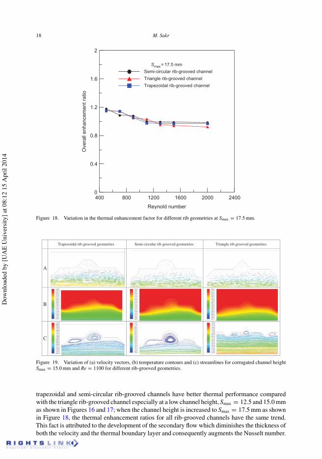
Figure 18. Variation in the thermal enhancement factor for different rib geometries at Smax = 17.5 mm.
Trapezoidal rib-grooved geometries Semi-circular rib-grooved geometries Triangle rib-grooved geometries
A
B
C
Figure 19. Variation of (a) velocity vectors, (b) temperature contours and (c) streamlines for corrugated channel heightSmax = 15.0 mm and Re = 1100 for different rib-grooved geometries.
trapezoidal and semi-circular rib-grooved channels have better thermal performance comparedwith the triangle rib-grooved channel especially at a low channel height, Smax = 12.5 and 15.0 mmas shown in Figures 16 and 17; when the channel height is increased to Smax = 17.5 mm as shownin Figure 18, the thermal enhancement ratios for all rib-grooved channels have the same trend.This fact is attributed to the development of the secondary flow which diminishes the thickness ofboth the velocity and the thermal boundary layer and consequently augments the Nusselt number.
Dow
nloa
ded
by [U
AE
Uni
vers
ity] a
t 08:
12 1
5 A
pril
2014
International Journal of Sustainable Energy 19
Figure 19 shows different variables’ distribution, including the velocity vector, temperaturecouture and velocity stream lines for the corrugated channel height, Smax = 15.0 mm and differentrib geometries for the same Re = 1100.
Figure 19(a)–(c) shows the effect of various rib-grooved configurations on the dynamicbehaviour of the flow filed and temperature distribution in the corrugated channel; it can beseen that the geometry configurations on the wavy plates have a significant effect on the flowstructure, and due to the sharp edge of the wavy surface, the size of the swirl flows in the wavyplate depends on one rib-grooved configuration, also the growth of the swirl flow near the cor-rugated wall promotes the mixing of the main stream with the hot fluid near the wall, the swirland turbulence intensity change with change in corrugated geometries, recirculation region andmore separation bubble regions are formed for trapezoidal and triangle rib-grooved surfaces ratherthan semi-circular ones, which means that the influence of the wall on the main stream becomesgreater, thus generating more swirl flow in the wavy wall due to transfer vortices of the bulk flowfield in the wavy wall trough, these results induced a higher temperature gradient near the wavywall. The net heat transfer rate from the wavy wall to the fluid is shown in Figure 19(b).
5. Conclusions
Wavy channels are one of the popular techniques that are extensively used in compacted heatexchanger manufacturing. Two-dimensional numerical predictions were carried out to study theeffect of rib-grooved arrangement, channel heights and Reynolds number on the thermal perfor-mance of the fluid flow and heat transfer in a corrugated channel for a low Reynolds number flow.The governing equations were solved using finite volume methods with a certain assumption toprovide a clear environment for the case study target. The results of the average Nusselt numberand pressure drop for different corrugated configurations and channel heights’ (S) channels arepresented; also the flow characteristics have been visualised using streamlines. The followingconclusions may be drawn:
(1) The rib-grooved channels have a significant effect on heat transfer enhancement comparedwith the similar parallel plate channel due to causing thinner boundary layer.
(2) Fluid flow and heat transfer performance are strongly dependent on the rib-groovedconfiguration.
(3) Compared with the smooth surface, the mean Nusselt number in the rib-grooved channelincreased by 30–220% depending on the height of the corrugated channel and the rib-groovedarrangement.
(4) The performance of the narrow channel is relatively good in comparison with a wider channel.(5) Sharp geometries such as trapezoidal and triangle rib-grooved configurations have a sig-
nificant impact on heat transfer enhancement rather than the semi-circular rib-groovedsurface.
Nomenclature
Cp specific heat (J/kg K)Cε turbulent model constantCµ turbulent model constantDh hydraulic diameter (mm)f friction factorh heat transfer coefficient (W/m2K)
Dow
nloa
ded
by [U
AE
Uni
vers
ity] a
t 08:
12 1
5 A
pril
2014
20 M. Sakr
I turbulent intensityρ air density (kg/m3)k thermal conductivity of the fluid (W/m K)L length of the domain (mm)m Mass flow rate (kg/s)p pressure (Pa)Q heat transfer rate (kW)w width (mm)S channel spacing (mm)y+ dimensionless distance from the cell centre to the nearest wall
Greek symbols
δ height of the base (mm)ε dissipation kinetic energy (m2/s3)µ dynamic viscosity of the fluid (pa s)σ length of corrugated (mm)σk diffusion Prandtl number for kτs wall shear stressν kinematic viscosity of the fluid (m2/s)
Subscript
a airq heat flux (W/m2)Pr Prandtl number, Pr = Cpµ/kQin heat input rate (W)Re Reynolds number, Re = ρuavDh/µT temperature (K)u velocity component at x-direction (m/s)v velocity component at y-direction (m/s)av averagei inletm mean valuemax maximummin minimumo outlett totalw wall
References
Ali, M. M., and S. Ramadhyani. 1992. “Experiments on Convective Heat Transfer in Corrugated Channels.” ExperimentalHeat Transfer 5 (3): 175–193. http://www.tandfonline.com/doi/abs/10.1080/08916159208946440#.UzSIeihXuc0
Dovic, D., B. Palm, and S. Švaic. 2009. “Generalized Correlations for Predicting Heat Transfer and Pressure Drop in PlateHeat Exchanger Channels of Arbitrary Geometry.” International Journal of Heat and Mass Transfer 52 (19–20):4553–4563.
Elshafei, E. A. M., M. Awad, E. El-Negiry, and A. G. Ali. 2008. “Heat Transfer and Pressure Loss in Narrow Channels withCorrugated Walls.” Second International Conference on Thermal Issues in Emerging Technologies, 2008. ThETA‘08, Cairo, Egypt, 279–290.
Fabbri, G. 2000. “Heat Transfer Optimization in Corrugated Wall Channels.” International Journal of Heat and MassTransfer 43 (23): 4299–4310.
Dow
nloa
ded
by [U
AE
Uni
vers
ity] a
t 08:
12 1
5 A
pril
2014
International Journal of Sustainable Energy 21
Fernández-Seara, J., R. Diz, F. J. Uhía, A. Dopazo, and J. M. Ferro. 2011. “Experimental Analysis of an Air-to-Air HeatRecovery Unit for Balanced Ventilation Systems in Residential Buildings.” Energy Conversion and Management52 (1): 635–640.
FLUENT, User’s Guide 6.3, Fluent Inc., USA.Gradeck, M., B. Hoareau, and M. Lebouché. 2005. “Local Analysis of Heat Transfer Inside Corrugated Channel.”
International Journal of Heat and Mass Transfer 48 (10): 1909–1915.Heggs, P. J., P. Sandham, R. A. Hallam, and C. Walton. 1997. “Local Transfer Coefficients in Corrugated Plate Heat
Exchanger Channels.” Chemical Engineering Research and Design 75 (7): 641–645.Hwang, S. D., I. H. Jang, and H. H. Cho. 2006. “Experimental Study on Flow and Local Heat/Mass Transfer Characteristics
Inside Corrugated Duct. International Journal of Heat and Fluid Flow 27 (1): 21–32.Launder, B. E., and D. B. Spalding. 1974. “The Numerical Computation of Turbulent Flows.” Computer Methods in
Applied Mechanics and Engineering 3 (2): 269–289.Li, Q., G. Flamant, X. Yuan, P. Neveu, and L. Luo. 2011. “Compact Heat Exchangers: A Review and Future Applications
for a New Generation of High Temperature Solar Receivers.” Renewable and Sustainable Energy Reviews 15 (9):4855–4875.
Manz, H., H. Huber, and D. Helfenfinger. 2001. “Impact of Air Leakages and Short Circuits in Ventilation Units withHeat Recovery on Ventilation Efficiency and Energy Requirements for Heating.” Energy Buildings 33 (2): 133–139.
Mohammed, H. A., A. K. Abbas, and J. M. Sheriff. 2013a. “Influence of Geometrical Parameters and Forced ConvectiveHeat Transfer in Transversely Corrugated Circular Tubes.” International Communications in Heat and Mass Transfer44: 116–126.
Mohammed, H. A., A. M. Abed, and M. A. Wahid. 2013b. “The Effects of Geometrical Parameters of a CorrugatedChannel with in Out-of-Phase Arrangement.” International Communications in Heat and Mass Transfer 40: 47–57.
Naphon, P. 2007. “Laminar Convective Heat Transfer and Pressure Drop in the Corrugated Channels.” InternationalCommunications in Heat and Mass Transfer 34 (1): 62–71.
Naphon, P. 2008. “Effect of Corrugated Plates in an In-Phase Arrangement on the Heat Transfer and Flow Developments.”Internatinal Journal of Heat and Mass Transfer 51 (15–16): 3963–3971.
Naphon P. 2009. “Effect of Wavy Plate Geometry Configurations on the Temperature and Flow Distributions.”International Communications in Heat and Mass Transfer 36 (9): 942–946.
Naphon P. 2010. “Study on the Heat-Transfer Characteristics and Pressure Drop in Channels with Arc-Shaped WavyPlates.” Journal of Engineering Physics and Thermophysics 3 (5): 1061–1069.
Oosthuizen, P. H., and D. Nayler. 1999. An Introduction to Convective Heat Transfer Analysis. NewYork: WCB/McGraw-Hill.
Shah, R. K., and D. P. Sekulic. 2003. Fundamentals of Heat Exchanger Design, 9–39. New York: John Wiley & Sons.Sparrow, E. M. 1977. “Heat/Mass Transfer Characteristics for Flow in a Corrugated Wall Channel.” Journal of Heat
Transfer 99 (2): 187–195.Sui, Y., C. J. Teo, P. S. Lee, Y. T. Chew, and C. Shu. 2010. “Fluid Flow and Heat Transfer in Wavy Microchannels.”
International Journal of Heat and Mass Transfer 53: 2760–2772.Sunden, B., and I. Karlsson. 1991. “Enhancement of Heat Transfer in Rotary Heat Exchangers by Streamwise-Corrugated
Flow Channels.” Experimental Thermal and Fluid Science 4 (3): 305–316.Versteeg, H. K., and W. Malalasekera. 1995. An Introduction to Computational Fluid Dynamics: The Finite Volume
Method. Harlow: Longman Group.Yin, J., G. Yang, G. Hao, and P. Lv. 2011. “Numerical Investigation of Flow and Heat Transfer in Corrugated Sinusoidal
Wavy Channel.” Power and Energy Engineering Conference (APPEEC), 2011, Asia-Pacific, Bangkok, Thailand,1–5.
Yin, J., G. Yang, and Y. Li. 2012. “The Effects of Wavy Plate Phase Shift on Flow and Heat Transfer Characteristics inCorrugated Channel.” Energy Procedia 14: 1566–1573.
Yuan, Z., W. Tao, and Q. Wang. 1998. “Numerical Prediction for Laminar Forced Convection Heat Transfer in Parallel-plate Channels with Stream Wise-Periodic ROD Disturbances.” International Journal for Numerical Methods inFluids 28 (9): 1371–1387.
Zhang, L., and Z. Chen. 2011. “Convective Heat Transfer in Cross-Corrugated Triangular Ducts under Uniform Heat FluxBoundary Conditions.” International Journal of Heat and Mass Transfer 54 (1–3): 597–605.
Zhang, J., J. Kundu, and R. M. Manglik. 2004. “Effect of Fin Waviness and Spacing on the Lateral Vortex Structureand Laminar Heat Transfer in Wavy-Plate-Fin Cores.” International Journal of Heat and Mass Transfer 47 (8–9):1719–1730.
Dow
nloa
ded
by [U
AE
Uni
vers
ity] a
t 08:
12 1
5 A
pril
2014


