Embed Size (px)
Citation preview
International Communications in Heat and Mass Transfer 39 (2012) 1584–1594
Contents lists available at SciVerse ScienceDirect
International Communications in Heat and Mass Transfer
j ourna l homepage: www.e lsev ie r .com/ locate / ichmt
Thermal and hydraulic characteristics of turbulent nanofluids flow in arib–groove channel☆
H.A. Mohammed ⁎, A.N. Al-Shamani, J.M. SheriffDepartment of Thermofluids, Faculty of Mechanical Engineering, Universiti Teknologi Malaysia, 81310 UTM Skudai, Johor Bahru, Malaysia
☆ Communicated by W.J. Minkowycz.⁎ Corresponding author.
E-mail address: [email protected] (H.A. Moh
0735-1933/$ – see front matter © 2012 Elsevier Ltd. Allhttp://dx.doi.org/10.1016/j.icheatmasstransfer.2012.10.0
a b s t r a c t
a r t i c l e i n f oAvailable online 24 October 2012
Keywords:Turbulent flowHeat transfer enhancementRib–groove channelNanofluidsNanoparticles
Thermal and hydraulic characteristics of turbulent nanofluids flow in a rib–groove channel are numericallyinvestigated. The continuity, momentum and energy equations were solved by means of a finite volumemethod (FVM). The top and bottom walls of the channel are heated at a constant temperature. Nine differentrib–groove shapes are considered in this study, which are three different rib shapes with three differentgroove shapes including rectangular, triangular and trapezoidal and they are interchanged with each other.Four different types of nanoparticles Al2O3, CuO, SiO2, and ZnO with different volume fractions in the rangeof 1% to 4% and different nanoparticle diameters in the range of 25 nm to 80 nm, are dispersed in differentbase fluids (water, glycerin, engine oil) are used. In this study, several parameters such as different Reynoldsnumbers in the range of 5000bReb20000, and different rib–groove aspect ratios in the range of 0.5≤AR≤4are also examined to identify their effects on the heat transfer and fluid flow characteristics. The results indi-cate that the rectangular rib–triangular groove has the highest Nusselt number among other rib–grooveshapes. The SiO2 nanofluid has the highest Nusselt number compared with other nanofluid types. The Nusseltnumber increased as the nanoparticle volume fraction, Reynolds number and aspect ratio increased; how-ever, it decreased as the nanoparticle diameter increased. It is found that the glycerin–SiO2 shows the bestheat transfer enhancement compared with other tested base fluids.
© 2012 Elsevier Ltd. All rights reserved.
1. Introduction
Forced convection heat transfer in a rib–groove channel had been asubject of interest in many research studies. There are needs to improvethe convective heat transfer in thermal systems in the application of en-gineering with view to reduce size, weight and cost of heat exchangers.Attempts to enhance the heat transfer in the heat exchangers have beenmade by using roughen surfaces or turbulators such as rib, groove andhelical rib in disturbing the flow and in providing transverse/longitudinalvortices or three dimensional mixing. There are many geometric shapesof the rib–groove channel that had been studied in the past decadesconsidering various combinations of the imposed temperature gradientsand cavity configurations. The common geometric rib shapes includerectangular, triangular, square, and circular. All these types of rib–groovechannel were used in many engineering applications such as cross-flowheat exchanger, gas turbine airfoil cooling design, solar air heater bladecooling system, and gas cooled nuclear reactor [1]. One of theways to en-hance the heat transfer in rib–groove channel is to employ nanofluids.Nanofluids arefluids that contain suspendednanoparticles such asmetalsand oxides. These nano-scale particles keep suspended in the base fluid.Thus, it does not cause an increase in pressure drop in the flow field.
ammed).
rights reserved.20
Past studies showed that nanofluids exhibit enhanced thermal properties,such as higher thermal conductivity and convective heat transfer coeffi-cients compared to the base fluid [2–5].
Review of heat transfer coefficient and pressure loss for variousrib–groove channel configurations on both experimental and numericalworks have been examined by many researchers [6–33]. Eiamsa-ardand Promvonge [6] studied the combined effects of rib–groovedturbulators on turbulent air flow forced convection heat transfer andfriction characteristics in a rectangular duct under a uniform heat fluxboundary condition (UHF). It was found that the TR–TG duct performsthe highest enhancement index at low Reynolds number. The heattransferwas promoted by increasing the turbulence degree with reduc-ing the pitch ratio (PR). The pressure loss increasewas found at the low-est pitch ratio (PR=6.6). Promvonge and Thianpong [7] assessed theturbulent forced convection heat transfer and friction loss behaviorsfor air flow through a constant heat flux channel (CHF) fitted with dif-ferent shaped ribs. The rib cross-sections used were triangular(isosceles), wedge (right-triangular) and rectangular shapes. It wasconcluded that the enhancement factors (η) of the staggered ribswere higher than those with the in-line one for all Reynolds numbervalues.
Pingan et al. [8] employed standard k–ε turbulence model and en-hanced wall treatment to investigate the air flow-field, heat transferand resistance coefficient in two-dimensional channels with differentribs shapes. The average Nusselt number of the channel heated wall
Nomenclature
A convection heat transfer area of rectangular channel,(m2)
AR aspect ratio, w/eCp specific heat at constant pressure, (J/kg·K)Dh hydraulic diameter, m; (Dh=4WH/2(W+H))dp diameter of nanofluid particles, (nm)d depth of grooved surface, (m)e rib height, (m)f friction factor, (f=(2ΔPDh)/(Lρ∗uav2 ))H channel height, (m)h convective heat transfer coefficient, (W/m2 K)k thermal conductivity of the fluid, (W/m·K)L length of channel, (m)Nu Nusselt number, (Nu=hDh/k)Pr Prandtl number, (Pr=Cpμ/k)q heat flux, (W/m2)Re Reynolds number, (Re=uavDh/v)T temperature, (K)TR triangular ribTG triangular grooveu velocity component at x-direction, (m/s)v velocity component at y-direction, (m/s)w width of rib–groove, (m)W width of the channel, (m)x distance along the x-coordinate, (m)X distance along the non-dimensional x-coordinate (x/W)Y distance along the non-dimensional y-coordinate (y/W)
Greek symbolsβ modeling functionμ dynamic viscosity of the fluid, (Pa s)ν kinematic viscosity of the fluid, (m2/s)ρ density of the fluid, (kg/m2)ϕ volume fraction (%)η thermal enhancement factor
1585H.A. Mohammed et al. / International Communications in Heat and Mass Transfer 39 (2012) 1584–1594
with triangular ribs was the largest, and was smallest in the channelwith rectangular ribs. The resistance coefficient of the channel heatedwall with triangular ribs was the largest, and was the smallest in thechannel with semicircular ribs. Bilen et al. [9] presented an experi-mental study of surface heat transfer and friction characteristics ofturbulent air flow in different grooved tubes. Tests were performedfor different geometric groove shapes (circular, trapezoidal and rect-angular). The thermal performance for all grooved pipes wasobtained up 1.24–1.28 for circular groove, 1.22–1.25 for trapezoidalgroove and 1.13–1.26 for rectangular groove.
Kamali and Binesh [10] studied turbulent heat transfer and frictioncharacteristics in a square duct with various-shaped ribs mounted onone wall. It was found that the heat transfer coefficients seem to beless sensitive to the rib spacing in the recirculating region just behindthe upstream rib. Tanda [11] investigated the effect of repeated hori-zontal square protrusions on free-convection heat transfer in a verti-cal channel. It was concluded that the inter-rib distance has to beproperly selected in order to prevent the local heat transfer enhance-ment in the inter-rib region from being offset by the decrease in thestagnation zones immediately upstream and downstream of each rib.
Eiamsa-ard and Promvonge [12] investigated numerically turbu-lent forced convection in a two-dimensional channel with periodictransverse grooves on the lower channel wall. The friction factor forair flowing in the grooved channel with larger width ratio (B/H)
was found to be higher than that with smaller width ratio. Mancaet al. [13] presented a numerical investigation on air forced convec-tion in a rectangular channel with constant heat flux applied on thebottom and upper external walls. The heat transfer rate was 1.34times higher than the smooth duct at Re=20,000. The friction factorwas the highest at the largest considered angles and, in particular, itsvalue was 3.5 times greater at most.
Thinapong et al. [14] presented an experimental investigation onturbulent heat transfer and friction loss behaviors of airflow througha constant heat flux (CHF) channel fitted with different heights oftriangular ribs. It is inferred that the staggered triangular rib withe/H=0.13 should be applied to obtain higher thermal performance,leading to more compact heat exchanger. Jansangsuk et al. [15]presented an experimental study on heat transfer and pressure dropcharacteristics in a rectangular channel fitted with periodic triangularv-pattern ribs. The maximum thermal enhancement factor was foundat e/H=0.20, PR=3. The usage of the wavy baffles with e/H=0.4,PR=3 causes a very high pressure drop increase and also providesconsiderable heat transfer augmentations, Nua/Nuo=3.45.
Jaurker et al. [16] presented the heat transfer and friction charac-teristics of rib-grooved artificial roughness on one broad heated wallof a large aspect ratio duct. The optimum heat transfer occurs at agroove position to pitch ratio of 0.4, while on the either side of thisratio, both Nusselt number and friction factor decreased. Kim andKim [17] presented a numerical procedure to optimize the shape oftwo-dimensional channel with periodic ribs mounted on both of thewalls to enhance the turbulent heat transfer. In the weighting factorrange, both of pitch-to-rib height ratio and distance between oppositeribs to rib pitch ratio reach almost constant values. Liou et al. [18] in-vestigated the turbulent heat transfer augmentation and friction inperiodic fully developed channel flow using laser holographic inter-ferometer. The rate of increase in Nusselt number with Reynoldsnumber is less for the ribbed duct compared with the smoothduct, which decreases the Nusselt number ratio with the increase ofReynolds number. Chandra et al. [19] investigated the heat transferand friction behaviors in rectangular channel with varying numberof ribbed walls. The friction factor ratio increased with the increaseof Reynolds number. The results indicate a significant decrease inthe heat transfer performance with the increase of ribbed walls andReynolds number.
Olsson and Sunden [20] investigated experimentally the pressuredrop and heat transfer in rib-roughened rectangular channels. Thegeometries tested consist of channels having cross ribs, parallel ribs,cross V-ribs, parallel V-ribs, and multiple V-ribs. The highest j/f ratioof all channels tested was provided with the V-ribs pointing up-stream, while the lowest j/f ratio was provided with the V-ribspointing downstream. Ryu et al. [21] investigated numerically byfinite-volume method the heat-transfer characteristics of a turbulentflow in channels with two-dimensional ribs and three-dimensionalblocks in the context of surface roughness effects. The space-averaged temperature profile varies logarithmically in a region be-yond the roughness layer when the distance was measured from avirtual origin and the corresponding velocity profile has a logarithmicregion.
Peng et al. [22] studied experimentally and numerically convec-tion heat transfer in a channel with 90° ribs and V-shaped ribs. Theexperimental and numerical results show that the V-shaped rib bedplates have better thermal/hydraulic performance than the 90° ribbed plates. The results indicate that the 45° V-shaped continuousribs have the best thermal/hydraulic performance. Liu et al. [23] in-vestigated the flow field and heat transfer in a channel with onesquare rib on upper wall and two on lower walls. The maximumlocal Nusselt number appears at the windward side sharp corner ofthe rib surface while the minimum one appears at the root. The aver-age Nusselt number of the Rib3 was the largest while the averageNusselt number of the Rib2 was the smallest. Fedele et al. [24]
1586 H.A. Mohammed et al. / International Communications in Heat and Mass Transfer 39 (2012) 1584–1594
presented a numerical investigation on air forced convection in achannel with constant flux applied on the external walls having rect-angular and square ribs. The highest Nusselt number was obtained for(p/e=10), while the maximum values of friction coefficients wereobtained for (p/e=7 and p/e=9), respectively, for rectangular andsquare ribs.
Lorenz et al. [25] presented experimentally the distributions of theheat transfer coefficient and the pressure drop along the wall insidean asymmetrically ribbed channel at 104≤Re≤ l05. The Nusselt num-ber distribution indicates a secondary transverse vortex in the cornerbetween the bottom of the groove and the front flank of the ribbut none at the opposite corner of the groove. Rallabandi et al. [26]presented turbulent heat transfer and pressure loss characteristicsof a high aspect ratio duct under both, jet impingement and channelflow conditions. For both cases, roughness elements in considerationwere staggered and inline axial ribs. Staggered ribs offer a higherfriction factor than inline ribs. Impinging jets provide a much higherheat transfer coefficient than the corresponding channel flow casesfor axial ribs. San and Huang [27] investigated experimentally turbu-lent heat transfer enhancement of transverse ribs in circular tubeswith a length-to-diameter ratio of 87. For the rib-roughened tubes,the influence of Re number on the f was quite weak. The f only slight-ly varies with Re number. For the e/d greater than 0.057, the f wasproportional to (e/d) of 2.55; for the e/d less than 0.057, the f wasdirectly proportional to the e/d.
Karmare and Tikekar [28] presented an experimental investiga-tion of heat transfer of airflow in a rectangular duct of an aspectratio 10:1. The top wall surface made rough with metal ribs of circularcross section in staggered manner. The presence of metal grit ribs onthe collector surface of the duct yields up to two-fold enhancement inthe Nusselt number and three-fold enhancement in the friction factor,for Re number ranged from 4000 to17,000. Buchlin [29] presented anexperimental study of turbulent convective heat transfer in a channelwith perforated ribs immersed in a turbulent boundary layer. Theaverage heat transfer coefficient results indicate that the increase ofthe open-area ratio of the perforated rib up to 36% and for Reynoldsnumber higher than 20,000, improve significantly the heat exchange.
Kim et al. [30] investigated an optimal design for enhancement ofheat transfer for a stationary channel with angled rib turbulators tofind the most suitable rib geometry. The high regions of heat transferand thermal performance induced by two design variables (α and p/e)appeared in ranges of 50°≤α≤60° and 6.0≤p/e≤7.0. Chang et al.[31] studied the effects of rib configuration and channel cross-sectional shape on the effectiveness of surface ribs on heat transfer aug-mentation. The ranges of rib geometry examined are typical of ribangles: 90°, ±60°, and ±45°, rib configurations: continuous, brokenand V shaped ribs with inline. The selection of channel w/b ratio thatprovides the maximum heat transfer augmentation for the rib-floorgeometry dependsmainly on Reynolds number. Lu and Jiang [32] inves-tigated forced convection heat transfer of air in a rectangular channelwith 45° ribs on one wall experimentally and numerically. Geometrywith ribs of 4 mm apart on one wall, the channel with 60° ribs had thebest heat transfer performance. The channel with 0° ribs had the leastpressure drop, and the channel with 20° ribs had the best thermal/hydraulic performance.
Pimsarn et al. [33] carried out experiments on the design of thesuitable ribs used for enhancing the heat transfer in a rectangularduct heat exchanger. The Z-shaped ribs were set on the rectangularduct at 30°, 45° and 60° and flat rib was set at 90° relative to the airflow direction. The 45° Z-ribs can increase the thermal enhancementfactor more than that of smooth channel, flat rib, 30° and 60° Z-ribswith e/H=0.2 and P/H=3. There is only one study available usednanofluids in rib–groove channel done by Manca et al. [1] who inves-tigated numerically turbulent forced convection using Al2O3/waternanofluid in a channel. The Nusselt number values, heat transferrates and pumping power increase and their values were 2.4, 2.66
and 31 times the ones calculated for pure water in a smooth channelin the case of rectangular ribs with w/e=2.0 and ϕ=0.04 at most.
It is obvious from the above literature review that the case offorced convective heat transfer in a horizontal channel having differ-ent rib–groove shapes utilizing nanofluids seems not to have beeninvestigated in details in the past and this has motivated the presentstudy. In addition, most of the previous research on rib–groove chan-nel involved conventional fluids (not nanofluids) and there is a verylittle work reported in the open literature that involved nanofluidsin such geometry. The present study examines 2D turbulent forcedconvective flow in a horizontal channel having different rib–grooveshapes by using different types of nanofluids, different nanoparticlevolume fractions, and different nanoparticle diameters, are dispersedin different base fluids (water, glycerin, engine oil) over Reynoldsnumber in the range of 5000bReb20,000, and different rib–grooveaspect ratios in the range of 0.5≤AR≤4. Results of interests such asNusselt number, skin friction coefficient and performance evaluationcriterion for turbulent forced convective in a horizontal channel arereported to illustrate the effects of rib–groove shape and nanofluidson these parameters.
2. Numerical model
2.1. Physical model
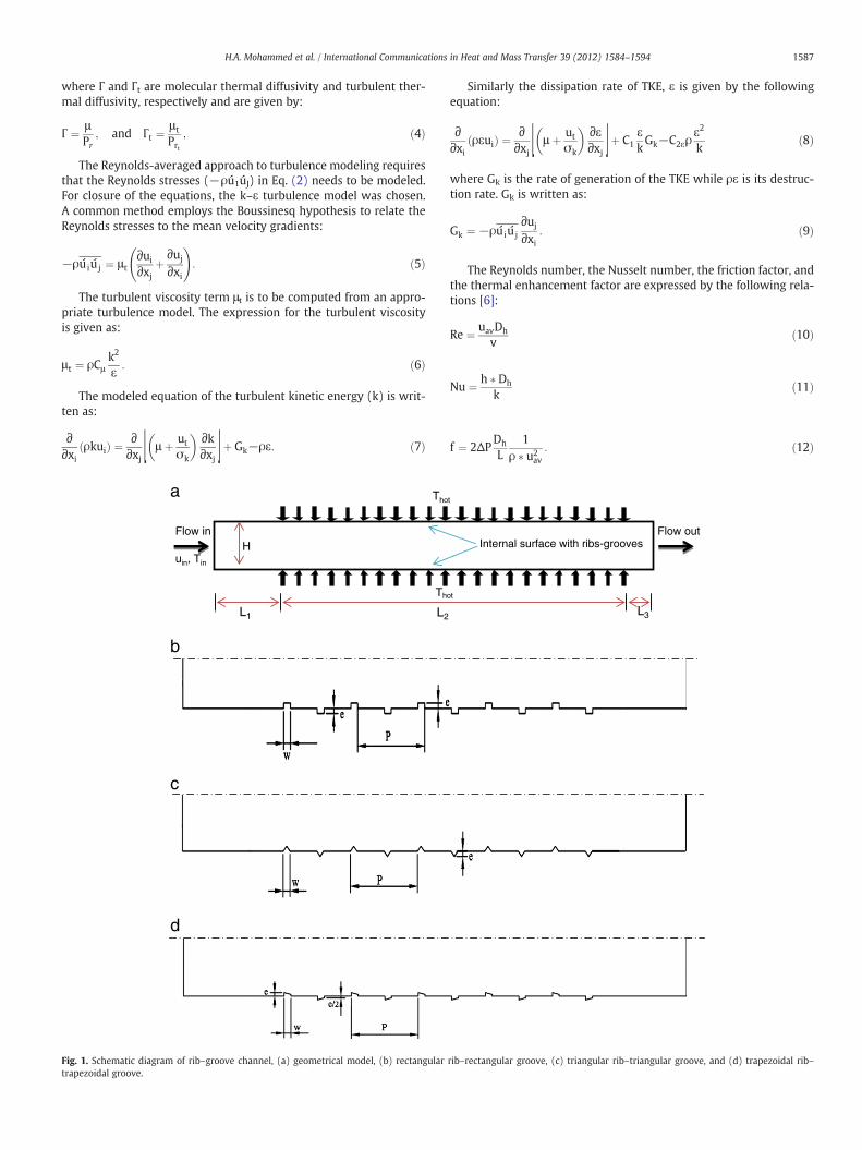
Schematic diagrams of rib–groove channel for geometrical modeland three cases are shown in Fig. 1a–d. The first case is rectangularrib–rectangular groove shown in Fig. 1b and the second case is trian-gular rib–triangular groove shown in Fig. 1c and the third case is trap-ezoidal rib–trapezoidal groove shown in Fig. 1d. A horizontal planechannel having five ribs and five grooves with a test section lengthof L2=110 mm (11 H) is considered as shown in Fig. 1a–d. Thechannel height is set to be H=10 mm while the channel rib widthis w=2 mm, the rib height is e=1 mm, and the groove width isw=2 mm, and the groove height e=1 mm. Both the height andlength of the rib–groove channel are fixed and the shapes of rib andgroove were interchanged with constant aspect ratio. To ensure afully developed flow, an entrance section was proceeded with thetest section having L1=20 H, and an exit was also installed havingL3=3 H. The left side of the channel is subjected to velocity inletbased on Reynolds number and the exit side of the channel issubjected to pressure outlet, the top and bottomwalls are maintainedat uniform wall temperature of 450 °C.
2.2. Governing equations
The phenomenon under consideration is governed by the steadytwo-dimensional formof the continuity, the time-averaged incompress-ible Navier–Stokes equations and energy equation. In the Cartesiantensor system these equations can be written as [12]:
Continuity equation:
∂∂xi
ρuið Þ ¼ 0: ð1Þ
Momentum equation:
∂ ρuiuj
� �∂xi
¼ − ∂p∂xi
þ ∂∂xj ⌊μ ∂ui
∂xjþ ∂uj
∂xi
!⌋þ ∂
∂xj−ρuiu j
� �: ð2Þ
Energy equation:
∂∂xi
ρuiTð Þ ¼ ∂∂xj
Γþ Γtð Þ ∂T∂xj
!ð3Þ
1587H.A. Mohammed et al. / International Communications in Heat and Mass Transfer 39 (2012) 1584–1594
where Γ and Γt are molecular thermal diffusivity and turbulent ther-mal diffusivity, respectively and are given by:
Γ ¼ μPr
; and Γt ¼μ t
Prt; ð4Þ
The Reynolds-averaged approach to turbulence modeling requiresthat the Reynolds stresses (−ρú1úJ) in Eq. (2) needs to be modeled.For closure of the equations, the k–ε turbulence model was chosen.A common method employs the Boussinesq hypothesis to relate theReynolds stresses to the mean velocity gradients:
−ρuiu j ¼ μt∂ui
∂xjþ ∂uj
∂xi
!: ð5Þ
The turbulent viscosity term μt is to be computed from an appro-priate turbulence model. The expression for the turbulent viscosityis given as:
μ t ¼ ρCμk2
ε: ð6Þ
The modeled equation of the turbulent kinetic energy (k) is writ-ten as:
∂∂xi
ρkuið Þ ¼ ∂∂xj ⌊ μ þ ut
σk
� � ∂k∂xj ⌋þ Gk−ρε: ð7Þ
a
b
c
d
L1 L2
Flow in
uin, Tin
Th
Tho
H
Fig. 1. Schematic diagram of rib–groove channel, (a) geometrical model, (b) rectangulartrapezoidal groove.
Similarly the dissipation rate of TKE, ε is given by the followingequation:
∂∂xi
ρεuið Þ ¼ ∂∂xj ⌊ μ þ ut
σk
� � ∂ε∂xj ⌋þ C1
εkGk−C2ερ
ε2
kð8Þ
where Gk is the rate of generation of the TKE while ρε is its destruc-tion rate. Gk is written as:
Gk ¼ −ρuiu j∂uj
∂xi: ð9Þ
The Reynolds number, the Nusselt number, the friction factor, andthe thermal enhancement factor are expressed by the following rela-tions [6]:
Re ¼ uavDh
vð10Þ
Nu ¼ h � Dh
kð11Þ
f ¼ 2ΔPDh
L1
ρ � u2av: ð12Þ
L3
Flow out
ot
t
Internal surface with ribs-grooves
rib–rectangular groove, (c) triangular rib–triangular groove, and (d) trapezoidal rib–
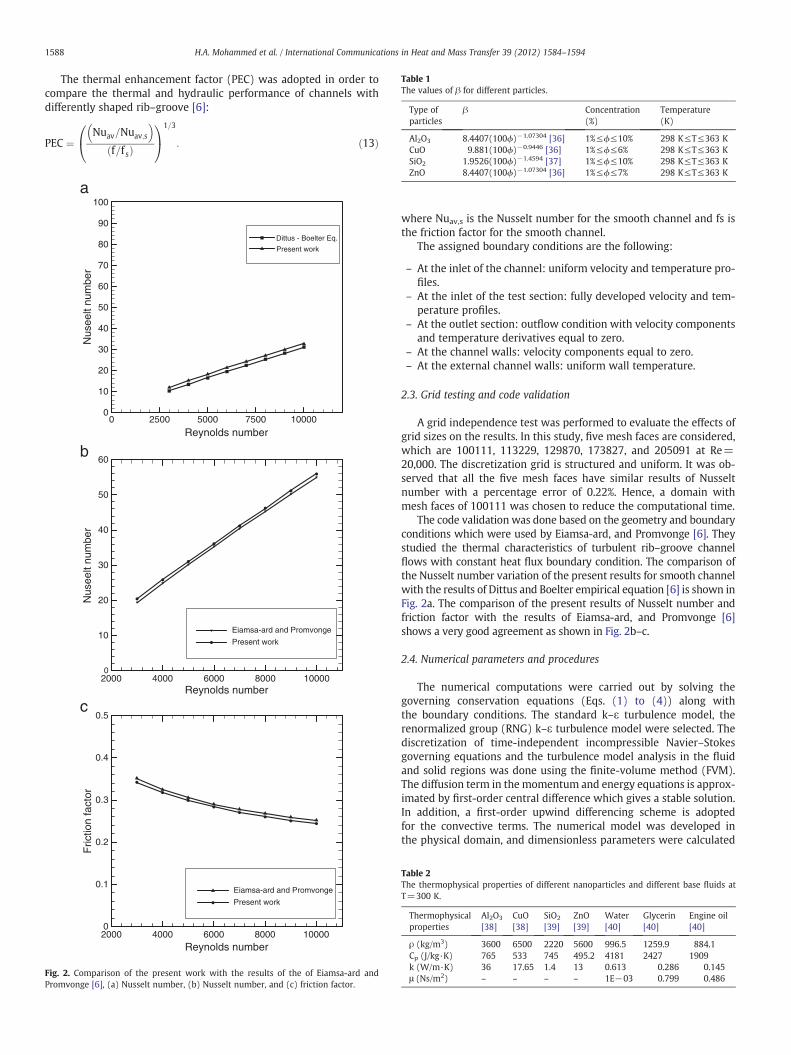
Table 1The values of β for different particles.
Type ofparticles
β Concentration(%)
Temperature(K)
Al2O3 8.4407(100ϕ)−1.07304 [36] 1%≤ϕ≤10% 298 K≤T≤363 KCuO 9.881(100ϕ)−0.9446 [36] 1%≤ϕ≤6% 298 K≤T≤363 KSiO2 1.9526(100ϕ)−1.4594 [37] 1%≤ϕ≤10% 298 K≤T≤363 K
1588 H.A. Mohammed et al. / International Communications in Heat and Mass Transfer 39 (2012) 1584–1594
The thermal enhancement factor (PEC) was adopted in order tocompare the thermal and hydraulic performance of channels withdifferently shaped rib–groove [6]:
PEC ¼Nuav=Nuav;s
� �f=f sð Þ
0@
1A
1=3
: ð13Þ
Reynolds number
Nus
eelt
num
ber
0 2500 5000 7500 100000
10
20
30
40
50
60
70
80
90
100
Dittus - Boelter Eq.
Present work
Reynolds number
Nus
eelt
num
ber
2000 4000 6000 8000 100000
10
20
30
40
50
60
Eiamsa-ard and Promvonge
Present work
a
b
c
Reynolds number
Fric
tion
fact
or
2000 4000 6000 8000 100000
0.1
0.2
0.3
0.4
0.5
Eiamsa-ard and Promvonge
Present work
Fig. 2. Comparison of the present work with the results of the of Eiamsa-ard andPromvonge [6], (a) Nusselt number, (b) Nusselt number, and (c) friction factor.
ZnO 8.4407(100ϕ)−1.07304 [36] 1%≤ϕ≤7% 298 K≤T≤363 K
where Nuav,s is the Nusselt number for the smooth channel and fs isthe friction factor for the smooth channel.
The assigned boundary conditions are the following:
– At the inlet of the channel: uniform velocity and temperature pro-files.
– At the inlet of the test section: fully developed velocity and tem-perature profiles.
– At the outlet section: outflow condition with velocity componentsand temperature derivatives equal to zero.
– At the channel walls: velocity components equal to zero.– At the external channel walls: uniform wall temperature.
2.3. Grid testing and code validation
A grid independence test was performed to evaluate the effects ofgrid sizes on the results. In this study, five mesh faces are considered,which are 100111, 113229, 129870, 173827, and 205091 at Re=20,000. The discretization grid is structured and uniform. It was ob-served that all the five mesh faces have similar results of Nusseltnumber with a percentage error of 0.22%. Hence, a domain withmesh faces of 100111 was chosen to reduce the computational time.
The code validation was done based on the geometry and boundaryconditions which were used by Eiamsa-ard, and Promvonge [6]. Theystudied the thermal characteristics of turbulent rib–groove channelflows with constant heat flux boundary condition. The comparison ofthe Nusselt number variation of the present results for smooth channelwith the results of Dittus and Boelter empirical equation [6] is shown inFig. 2a. The comparison of the present results of Nusselt number andfriction factor with the results of Eiamsa-ard, and Promvonge [6]shows a very good agreement as shown in Fig. 2b–c.
2.4. Numerical parameters and procedures
The numerical computations were carried out by solving thegoverning conservation equations (Eqs. (1) to (4)) along withthe boundary conditions. The standard k–ε turbulence model, therenormalized group (RNG) k–ε turbulence model were selected. Thediscretization of time-independent incompressible Navier–Stokesgoverning equations and the turbulence model analysis in the fluidand solid regions was done using the finite-volume method (FVM).The diffusion term in the momentum and energy equations is approx-imated by first-order central difference which gives a stable solution.In addition, a first-order upwind differencing scheme is adoptedfor the convective terms. The numerical model was developed inthe physical domain, and dimensionless parameters were calculated
Table 2The thermophysical properties of different nanoparticles and different base fluids atT=300 K.
Thermophysicalproperties
Al2O3
[38]CuO[38]
SiO2
[39]ZnO[39]
Water[40]
Glycerin[40]
Engine oil[40]
ρ (kg/m3) 3600 6500 2220 5600 996.5 1259.9 884.1Cp (J/kg·K) 765 533 745 495.2 4181 2427 1909k (W/m·K) 36 17.65 1.4 13 0.613 0.286 0.145μ (Ns/m2) – – – – 1E−03 0.799 0.486
1589H.A. Mohammed et al. / International Communications in Heat and Mass Transfer 39 (2012) 1584–1594
from the computed velocity and temperature distributions. The flowfield was solved using the SIMPLE algorithm [34]. This is an iterativesolution procedure where the computation is initialized by guessingthe pressure field. Then, the momentum equation is solved to deter-mine the velocity components. The pressure is updated using the
Reynolds number
Nus
selt
num
ber
5000 10000 15000 20000
Reynolds number5000 10000 15000 20000
Reynolds number5000 10000 15000 20000
0
50
100
150
200
250
300
350
400
Rect. R - Rect. GRect. R - Trap. GRect. R - Tri. GTri. R - Tri. GTri. R - Rect. GTri. R - Trap. GTrap. R - Trap. GTrap. R - Rect. GTrap. R - Tri. GSmooth channel
Fric
tion
fact
or
0
0.02
0.04
0.06
0.08
0.1
0.12
0.14
0.16
0.18
0.2
Rect. R - Rect. GRect. R - Trap. GRect. R - Tri. GTri. R - Tri. GTri. R - Rect. GTri. R - Trap. GTrap. R - Trap. GTrap. R - Rect. GTrap. R - Tri. GSmooth channel
a
b
c
The
rmal
Enh
ance
men
t
0.5
0.6
0.7
0.8
0.9
1
1.1
1.2
1.3
1.4
1.5
1.6
1.7
1.8
Rect. R - Rect. GRect. R - Trap. GRect. R - Tri. GTri. R - Tri. GTri. R - Rect. GTri. R - Trap. GTrap. R - Trap. GTrap. R - Rect. GTrap. R - Tri. G
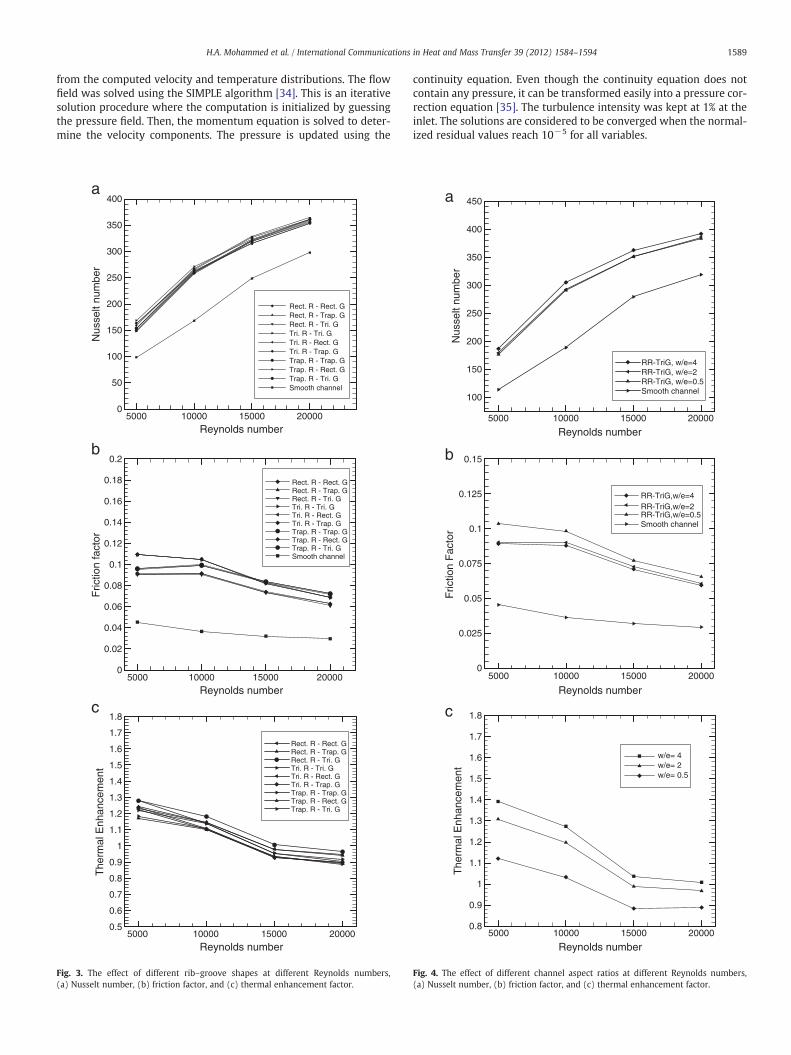
Fig. 3. The effect of different rib–groove shapes at different Reynolds numbers,(a) Nusselt number, (b) friction factor, and (c) thermal enhancement factor.
continuity equation. Even though the continuity equation does notcontain any pressure, it can be transformed easily into a pressure cor-rection equation [35]. The turbulence intensity was kept at 1% at theinlet. The solutions are considered to be converged when the normal-ized residual values reach 10−5 for all variables.
Reynolds number
Nus
selt
num
ber
5000 10000 15000 20000
100
150
200
250
300
350
400
450
RR-TriG, w/e=4RR-TriG, w/e=2RR-TriG, w/e=0.5Smooth channel
Reynolds number
Fric
tion
Fac
tor
5000 10000 15000 200000
0.025
0.05
0.075
0.1
0.125
0.15
RR-TriG,w/e=4RR-TriG,w/e=2RR-TriG,w/e=0.5Smooth channel
a
b
c
Reynolds number
The
rmal
Enh
ance
men
t
5000 10000 15000 200000.8
0.9
1
1.1
1.2
1.3
1.4
1.5
1.6
1.7
1.8
w/e= 4w/e= 2w/e= 0.5
Fig. 4. The effect of different channel aspect ratios at different Reynolds numbers,(a) Nusselt number, (b) friction factor, and (c) thermal enhancement factor.
1590 H.A. Mohammed et al. / International Communications in Heat and Mass Transfer 39 (2012) 1584–1594
2.5. Thermophysical properties of nanofluids
The thermophysical properties of nanofluids used in this studywere obtained using the following equations:
The density of nanofluid, ρnf can be obtained from the followingequation [36]:
ρnf ¼ 1−ϕð Þρf þ ϕρnp ð14Þ
where ρf and ρnp are the mass densities of the based fluid and thesolid nanoparticles, respectively.
The effective heat capacity at constant pressure of nanofluid,(ρCp)nf can be calculated from the following equation [36]:
ρCp
� �nf
¼ 1−ϕð Þ ρCp
� �fþ ϕ ρCp
� �np
ð15Þ
w/e=0
w/e=
w/e=
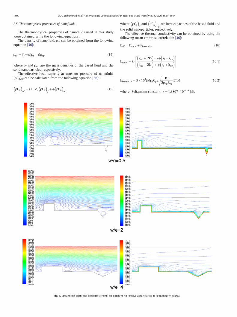
Fig. 5. Streamlines (left) and isotherms (right) for differ
where ρCp
� �fand ρCp
� �np
are heat capacities of the based fluid and
the solid nanoparticles, respectively.The effective thermal conductivity can be obtained by using the
following mean empirical correlation [36]:
keff ¼ kstatic þ kBrownian ð16Þ
kstatic ¼ kfknp þ 2kf� �
−2ϕ kf−knp� �
knp þ 2kf� �
þ ϕ kf þ knp� �
24
35 ð16:1Þ
kBrownian ¼ 5 � 104βϕρf Cp;f
ffiffiffiffiffiffiffiffiffiffiffiffiffiffiffiffiffiffiKT
2ρnpRnp
sf T;ϕð Þ ð16:2Þ
where: Boltzmann constant: k=1.3807∗10−23 J/K.
.5
2
4
ent rib–groove aspect ratios at Re number=20,000.
Reynolds number
Nus
selt
num
ber
5000 10000 15000 20000100
150
200
250
300
350
400
450
500
SiO2Al2O3ZnOCuOWater
Reynolds number
Fric
tion
fact
or
5000 10000 15000 200000
0.03
0.06
0.09
0.12
0.15
SiO2Al2O3ZnOCuOWater
a
b
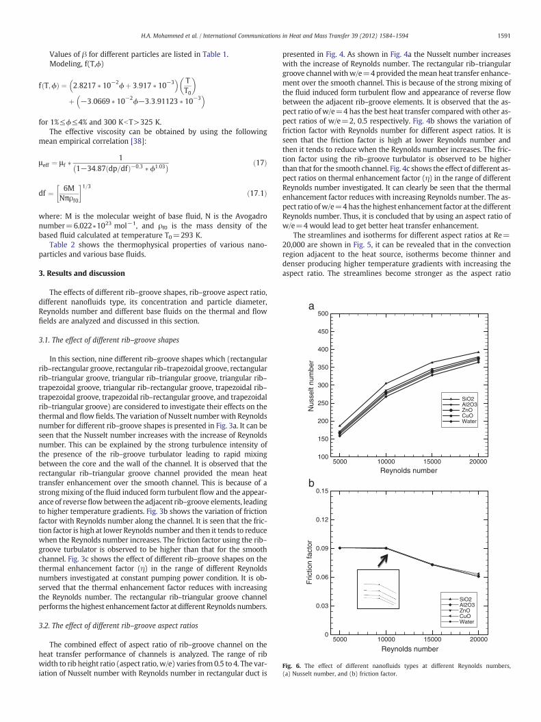
Fig. 6. The effect of different nanofluids types at different Reynolds numbers,(a) Nusselt number, and (b) friction factor.
1591H.A. Mohammed et al. / International Communications in Heat and Mass Transfer 39 (2012) 1584–1594
Values of β for different particles are listed in Table 1.Modeling, f(T,ϕ)
f T;ϕð Þ ¼ 2:8217 � 10−2ϕþ 3:917 � 10−3� � T
T0
� �þ −3:0669 � 10−2ϕ−3:3:91123 � 10−3� �
for 1%≤ϕ≤4% and 300 KbT>325 K.The effective viscosity can be obtained by using the following
mean empirical correlation [38]:
μeff ¼ μ f �1
1−34:87 dp=dfð Þ−0;3 � ϕ1:03� � ð17Þ
df ¼ 6MNπρf0
1=3ð17:1Þ
where: M is the molecular weight of base fluid, N is the Avogadronumber=6.022∗1023 mol−1, and ρf0 is the mass density of thebased fluid calculated at temperature T0=293 K.
Table 2 shows the thermophysical properties of various nano-particles and various base fluids.
3. Results and discussion
The effects of different rib–groove shapes, rib–groove aspect ratio,different nanofluids type, its concentration and particle diameter,Reynolds number and different base fluids on the thermal and flowfields are analyzed and discussed in this section.
3.1. The effect of different rib–groove shapes
In this section, nine different rib–groove shapes which (rectangularrib–rectangular groove, rectangular rib–trapezoidal groove, rectangularrib–triangular groove, triangular rib–triangular groove, triangular rib–trapezoidal groove, triangular rib–rectangular groove, trapezoidal rib–trapezoidal groove, trapezoidal rib–rectangular groove, and trapezoidalrib–triangular groove) are considered to investigate their effects on thethermal and flow fields. The variation of Nusselt number with Reynoldsnumber for different rib–groove shapes is presented in Fig. 3a. It can beseen that the Nusselt number increases with the increase of Reynoldsnumber. This can be explained by the strong turbulence intensity ofthe presence of the rib–groove turbulator leading to rapid mixingbetween the core and the wall of the channel. It is observed that therectangular rib–triangular groove channel provided the mean heattransfer enhancement over the smooth channel. This is because of astrong mixing of the fluid induced form turbulent flow and the appear-ance of reverseflowbetween the adjacent rib–groove elements, leadingto higher temperature gradients. Fig. 3b shows the variation of frictionfactor with Reynolds number along the channel. It is seen that the fric-tion factor is high at lower Reynolds number and then it tends to reducewhen the Reynolds number increases. The friction factor using the rib–groove turbulator is observed to be higher than that for the smoothchannel. Fig. 3c shows the effect of different rib–groove shapes on thethermal enhancement factor (η) in the range of different Reynoldsnumbers investigated at constant pumping power condition. It is ob-served that the thermal enhancement factor reduces with increasingthe Reynolds number. The rectangular rib–triangular groove channelperforms the highest enhancement factor at different Reynolds numbers.
3.2. The effect of different rib–groove aspect ratios
The combined effect of aspect ratio of rib–groove channel on theheat transfer performance of channels is analyzed. The range of ribwidth to rib height ratio (aspect ratio, w/e) varies from 0.5 to 4. The var-iation of Nusselt number with Reynolds number in rectangular duct is
presented in Fig. 4. As shown in Fig. 4a the Nusselt number increaseswith the increase of Reynolds number. The rectangular rib–triangulargroove channel withw/e=4 provided themean heat transfer enhance-ment over the smooth channel. This is because of the strong mixing ofthe fluid induced form turbulent flow and appearance of reverse flowbetween the adjacent rib–groove elements. It is observed that the as-pect ratio of w/e=4 has the best heat transfer compared with other as-pect ratios of w/e=2, 0.5 respectively. Fig. 4b shows the variation offriction factor with Reynolds number for different aspect ratios. It isseen that the friction factor is high at lower Reynolds number andthen it tends to reduce when the Reynolds number increases. The fric-tion factor using the rib–groove turbulator is observed to be higherthan that for the smooth channel. Fig. 4c shows the effect of different as-pect ratios on thermal enhancement factor (η) in the range of differentReynolds number investigated. It can clearly be seen that the thermalenhancement factor reduces with increasing Reynolds number. The as-pect ratio ofw/e=4has the highest enhancement factor at the differentReynolds number. Thus, it is concluded that by using an aspect ratio ofw/e=4 would lead to get better heat transfer enhancement.
The streamlines and isotherms for different aspect ratios at Re=20,000 are shown in Fig. 5, it can be revealed that in the convectionregion adjacent to the heat source, isotherms become thinner anddenser producing higher temperature gradients with increasing theaspect ratio. The streamlines become stronger as the aspect ratio
1592 H.A. Mohammed et al. / International Communications in Heat and Mass Transfer 39 (2012) 1584–1594
increases. This is due to the fact that the cavity volume increases withthe aspect ratio and more volume of cooling fluid in involved incooling that source leading to better cooling effect.
3.3. The effect of different types of nanoparticles
Four different types of nanoparticles such as Al2O3, CuO, SiO2 andZnO and pure water as a base fluid are used. The Nusselt number fordifferent nanofluids and different values of Reynolds number areshown in Fig. 6a. It can be clearly seen that SiO2 nanofluid has thehighest average Nusselt number, followed by Al2O3, ZnO, and CuOrespectively. This is because SiO2 has the lowest thermal conductivitythan other nanofluids, but higher than water and has the highest av-erage velocity among other fluids due to its lowest density comparedwith the others. The fluid velocity plays an important role on the heattransfer in case of forced convection and it represents the main rea-son to give high heat transfer coefficient. As shown in Fig. 6b the fric-tion factor decreases with the increase of the Reynolds number fordifferent nanofluid types.
3.4. The effect of different nanoparticles volume fractions
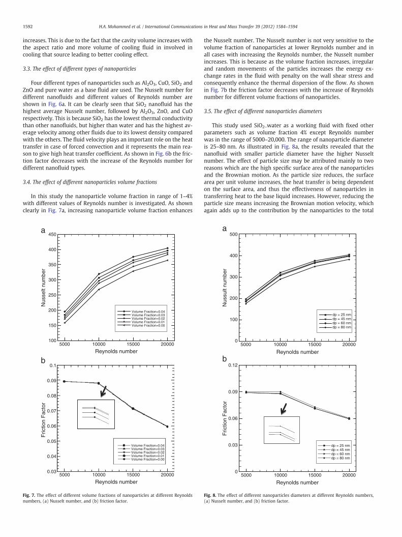
In this study the nanoparticle volume fraction in range of 1–4%with different values of Reynolds number is investigated. As shownclearly in Fig. 7a, increasing nanoparticle volume fraction enhances
Reynolds number
Nus
selt
num
ber
Fric
tion
Fac
tor
5000 10000 15000 20000
Reynolds number5000 10000 15000 20000
100
150
200
250
300
350
400
450a
b0.1
0.09
0.08
0.07
0.06
0.05
0.04
0.03
Volume Fraction=0.04Volume Fraction=0.03Volume Fraction=0.02Volume Fraction=0.01Volume Fraction=0.00
Volume Fraction=0.04Volume Fraction=0.03Volume Fraction=0.02Volume Fraction=0.01Volume Fraction=0.00
Fig. 7. The effect of different volume fractions of nanoparticles at different Reynoldsnumbers, (a) Nusselt number, and (b) friction factor.
the Nusselt number. The Nusselt number is not very sensitive to thevolume fraction of nanoparticles at lower Reynolds number and inall cases with increasing the Reynolds number, the Nusselt numberincreases. This is because as the volume fraction increases, irregularand random movements of the particles increases the energy ex-change rates in the fluid with penalty on the wall shear stress andconsequently enhance the thermal dispersion of the flow. As shownin Fig. 7b the friction factor decreases with the increase of Reynoldsnumber for different volume fractions of nanoparticles.
3.5. The effect of different nanoparticles diameters
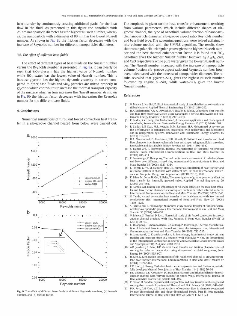
This study used SiO2–water as a working fluid with fixed otherparameters such as volume fraction 4% except Reynolds numberwas in the range of 5000–20,000. The range of nanoparticle diameteris 25–80 nm. As illustrated in Fig. 8a, the results revealed that thenanofluid with smaller particle diameter have the higher Nusseltnumber. The effect of particle size may be attributed mainly to tworeasons which are the high specific surface area of the nanoparticlesand the Brownian motion. As the particle size reduces, the surfacearea per unit volume increases, the heat transfer is being dependenton the surface area, and thus the effectiveness of nanoparticles intransferring heat to the base liquid increases. However, reducing theparticle size means increasing the Brownian motion velocity, whichagain adds up to the contribution by the nanoparticles to the total
Reynolds number
Reynolds number
Nus
sult
num
ber
5000 10000 15000 200000
100
200
300
400
500
dp = 25 nmdp = 45 nmdp = 60 nmdp = 80 nm
Fric
tion
Fac
tor
5000 10000 15000 200000
0.03
0.06
0.09
0.12
dp = 25 nmdp = 45 nmdp = 60 nmdp = 80 nm
a
b
Fig. 8. The effect of different nanoparticles diameters at different Reynolds numbers,(a) Nusselt number, and (b) friction factor.
1593H.A. Mohammed et al. / International Communications in Heat and Mass Transfer 39 (2012) 1584–1594
heat transfer by continuously creating additional paths for the heatflow in the fluid. As presented in this figure the nanofluid with25 nm nanoparticle diameter has the highest Nusselt number, where-as, the nanoparticle with a diameter of 80 nm has the lowest Nusseltnumber. As shown in Fig. 8b the friction factor decreases with theincrease of Reynolds number for different nanoparticles diameters.
3.6. The effect of different base fluids
The effect of different types of base fluids on the Nusselt numberversus the Reynolds number is presented in Fig. 9a. It can clearly beseen that SiO2–glycerin has the highest value of Nusselt numberwhile SiO2–water has the lowest value of Nusselt number. This isbecause glycerin has the highest dynamic viscosity in nature com-pared to other base fluids and SiO2 particles are mixed properly inglycerin which contributes to increase the thermal transport capacityof the mixture which in turn increases the Nusselt number. As shownin Fig. 9b the friction factor decreases with increasing the Reynoldsnumber for the different base fluids.
4. Conclusions
Numerical simulations of turbulent forced convection heat trans-fer in a rib–groove channel heated from below were carried out.
Reynolds number
Nus
selt
num
ber
5000 10000 15000 20000
400
800
1200
1600
2000
Glycerin-SiO2Engine Oil-SiO2Water-SiO2
Reynolds number
Fric
tion
Fac
tor
5000 10000 15000 200000.05
0.06
0.07
0.08
0.09
0.1
Water+SiO2Engine Oil+SiO2Glycerin+SiO2
a
b
Fig. 9. The effect of different base fluids at different Reynolds numbers, (a) Nusseltnumber, and (b) friction factor.
The emphasis is given on the heat transfer enhancement resultingfrom various parameters, which include different shapes of rib–groove channel, the type of nanofluid, volume fraction of nanoparti-cle, nanoparticle diameter, rib–groove aspect ratio, Reynolds numberand base fluid type. The governing equations were solved utilizing fi-nite volume method with the SIMPLE algorithm. The results showthat rectangular rib–triangular groove gives the highest Nusselt num-ber and the best thermal enhancement factor. It is found that SiO2
nanofluid gives the highest Nusselt number followed by Al2O3, ZnO,and CuO respectively while pure water gives the lowest Nusselt num-ber. The Nusselt number increased with the increase of nanoparticlevolume fraction, rib–groove aspect ratio and Reynolds number; how-ever, it decreased with the increase of nanoparticles diameter. The re-sults revealed that glycerin–SiO2 gives the highest Nusselt numberfollowed by engine oil–SiO2 while water–SiO2 gives the lowestNusselt number.
References
[1] O. Manca, S. Nardini, D. Ricci, A numerical study of nanofluid forced convection inribbed channel, Applied Thermal Engineering 37 (2012) 280–292.
[2] H.A. Mohammed, A.A. Al-Aswadi, N.H. Shuaib, R. Saidur, Convective heat transferand fluid flow study over a step using nanofluids: a review, Renewable and Sus-tainable Energy Reviews 15 (2011) 2921–2939.
[3] R. Saidur, K.Y. Leong, H.A. Mohammed, A review on application and challenges ofnanofluids, Renewable and Sustainable Energy Reviews 15 (2011) 1646–1668.
[4] R. Saidur, S.N. Kazi, M.S. Hossain, M.M. Rahman, H.A. Mohammed, A review onthe performance of nanoparticles suspended with refrigerants and lubricatingoils in refrigeration systems, Renewable and Sustainable Energy Reviews 15(2011) 310–323.
[5] H.A. Mohammed, G. Bhaskaran, N.H. Shuaib, R. Saidur, Heat transfer and fluidflow characteristics in microchannels heat exchanger using nanofluids: a review,Renewable and Sustainable Energy Reviews 15 (2011) 1502–1512.
[6] S. Eiamsa-ard, P. Promvonge, Thermal characteristics of turbulent rib–groovedchannel flows, International Communications in Heat and Mass Transfer 36(2009) 705–711.
[7] P. Promvonge, C. Thianpong, Thermal performance assessment of turbulent chan-nel flows over different shaped ribs, International Communications in Heat andMass Transfer 35 (2008) 1327–1334.
[8] L. Pingan, G. Ye, M. Hairong, Han Liu, Numerical simulation of heat transfer andresistance pattern in channels with different ribs, in: 2010 International Confer-ence on Computer Design and Applications (ICCDA 2010), 2010.
[9] K. Bilen, M. Cetin, H. Gul, T. Balta, The investigation of groove geometry effect onheat transfer for internally grooved tubes, Applied Thermal Engineering 29(2009) 753–761.
[10] R. Kamali, A.R. Binesh, The importance of rib shape effects on the local heat trans-fer and flow friction characteristics of square ducts with ribbed internal surfaces,International Communications in Heat and Mass Transfer 35 (2008) 1032–1040.
[11] G. Tanda, Natural convective heat transfer in vertical channels with low thermalconductivity ribs, International Journal of Heat and Fluid Flow 29 (2008)1319–1325.
[12] S. Eiamsa-ard, P. Promvonge, Numerical study on heat transfer of turbulent chan-nel flow over periodic grooves, International Communications in Heat and MassTransfer 35 (2008) 844–852.
[13] O. Manca, S. Nardini, D. Ricci, Numerical study of air forced convection in a rect-angular channel provided with ribs, Frontiers in Heat Mass Transfer (FHMT) 2(2011) 30–40.
[14] C. Thianpong, T. Chompookham, S. Skullong, P. Promvonge, Thermal characteriza-tion of turbulent flow in a channel with isosceles triangular ribs, InternationalCommunications in Heat and Mass Transfer 36 (2009) 712–717.
[15] D. Jansangsuk, C. Khanoknaiyakarn, P. Promvonge, Experimental study on heattransfer and pressure drop in a channel with triangular v-ribs, in: Proceedingsof the International Conference on Energy and Sustainable Development: Issuesand Strategies (ESD), 2–4 June, 2010, 2010.
[16] A.R. Jaurker, J.S. Saini, B.K. Gandhi, Heat transfer and friction characteristics ofrectangular solar air heater duct using rib–grooved artificial roughness, SolarEnergy 80 (2006) 895–907.
[17] H. Kim, K. Kim, Design optimization of rib-roughened channel to enhance turbu-lent heat transfer, International Communications in Heat and Mass Transfer 47(2004) 5159–5168.
[18] T.M. Liou, J.J. Hwang, Turbulent heat transfer augmentation and friction in periodicfully developed channel flow, Journal of Heat Transfer 114 (1992) 56–64.
[19] P.R. Chandra, C.R. Alexander, J.C. Han, Heat transfer and friction behavior in rect-angular channel with varying number of ribbed walls, International Journal ofHeat and Mass Transfer 46 (2003) 481–495.
[20] C. Olsson, B. Sunden, Experimental study of flow and heat transfer in rib-roughenedrectangular channels, Experimental Thermal and Fluid Science 16 (1998) 349–365.
[21] D.N. Ryu, D.H. Choi, V.C. Patel, Analysis of turbulent flow in channels roughenedby two-dimensional ribs and three-dimensional blocks. Part II: heat transfer,International Journal of Heat and Fluid Flow 28 (2007) 1112–1124.
1594 H.A. Mohammed et al. / International Communications in Heat and Mass Transfer 39 (2012) 1584–1594
[22] W. Peng, P.X. Jiang, Y.P. Wang, B.Y. Wei, Experimental and numerical investiga-tion of convection heat transfer in channels with different types of ribs, AppliedThermal Engineering 31 (2011) 2702–2708.
[23] P. Liu, Y. Gao, Numerical simulation of fluid–solid coupled flow field and heattransfer in a channel with square ribs, in: International Conference on Computa-tional Intelligence and Software Engineering, (CiSE), 11–13 Dec. 2009, 2009.
[24] G. Fedele, O. Manca, S. Nardini, D. Ricci, G. Masullo, Numerical investigation of airforced convection in channel with transverse ribs, in: ASME InternationalMechanical Engineering Congress and Exposition, October 31-November 6,2008, Boston, Massachusetts, USA, 2008.
[25] S. Lorenz, D. Mukomilow, W. Leiner, Distribution of the heat transfer coefficient ina channel with periodic transverse grooves, Experimental Thermal and Fluid Sci-ence l (1) (1995) 234–242.
[26] A.P. Rallabandi, D.H. Rhee, Z. Gao, J.C. Han, Heat transfer enhancement in rectan-gular channels with axial ribs or porous foam under through flow and impingingjet conditions, International Journal of Heat and Mass Transfer 53 (2010)4663–4671.
[27] J.Y. San, W.C. Huang, Heat transfer enhancement of transverse ribs in circulartubes with consideration of entrance effect, International Journal of Heat andMass Transfer 49 (2006) 2965–2971.
[28] S.V. Karmare, A.N. Tikekar, Heat transfer and friction factor correlation for artifi-cially roughened duct with metal grit ribs, International Journal of Heat andMass Transfer 50 (2007) 4342–4351.
[29] J.M. Buchlin, Convective heat transfer in a channel with perforated ribs, Interna-tional Journal of Thermal Sciences 41 (4) (2002) 332–340.
[30] K.M. Kim, H. Lee, B.S. Kim, S. Shin, D.H. Lee, H.H. Cho, Optimal design of angled ribturbulators in a cooling channel, Heat and Mass Transfer 45 (2009) 1617–1625.
[31] S.W. Chang, T.M. Liou, W.C. Juan, Influence of channel height on heat transferaugmentation in rectangular channels with two opposite rib-roughened walls,International Journal of Heat and Mass Transfer 48 (2005) 2806–2813.
[32] B. Lu, P.X. Jiang, Experimental and numerical investigation of convection heattransfer in a rectangular channel with angled ribs, Experimental Thermal andFluid Science 30 (2006) 513–521.
[33] M. Pimsarn, P. Sriromreun, P. Promvonge, Augmented heat transfer in rectangularduct with angled z-shaped ribs, in: Proceedings of the International Conferenceon Energy and Sustainable Development: Issues and Strategies (ESD), 2–4 June,2010, 2010.
[34] J.D. Anderson, Computational Fluid Dynamics: The Basics with Applications,McGraw-Hill, 1995.
[35] S.V. Patankar, Numerical Heat Transfer and Fluid Flow, Hemisphere PublishingCorporation, Taylor and Francis Group, 1980.
[36] R.S. Vajjha, D.K. Das, Experimental determination of thermal conductivity of threenanofluids and development of new correlations, International Journal of Heatand Mass Transfer 52 (2009) 4675–4682.
[37] R.S. Vajjha, D.K. Das, D.P. Kulkarni, Development of new correlations for convec-tive heat transfer and friction factor in turbulent regime for nanofluids, Interna-tional Journal of Heat and Mass Transfer 53 (2010) 4607–4618.
[38] M. Corcione, Heat transfer features of buoyancy-driven nanofluids inside rectan-gular enclosures differentially heated at the sidewalls, International Journal ofThermal Sciences 49 (2010) 1536–1546.
[39] I.V. Lienhard, V. Lienhard, A Heat Transfer Textbook, Third Edition PhlogistonPress, 2006.
[40] F.P. Incropera, D.P. Dewitt, T.L. Bergma, A.S. Lavine, Fundamentals of Heat andMass Transfer, 6th Edition Wiley, 2007.


