Embed Size (px)
Citation preview
Torque MotorsRIB Series

3
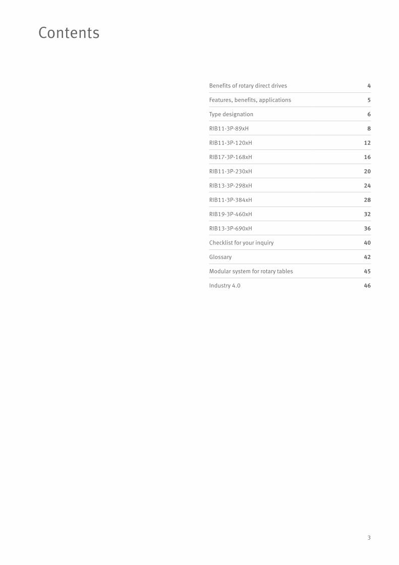
Contents
Benefits of rotary direct drives 4
Features, benefits, applications 5
Type designation 6
RIB11-3P-89xH 8
RIB11-3P-120xH 12
RIB17-3P-168xH 16
RIB11-3P-230xH 20
RIB13-3P-298xH 24
RIB11-3P-384xH 28
RIB19-3P-460xH 32
RIB13-3P-690xH 36
Checklist for your inquiry 40
Glossary 42
Modular system for rotary tables 45
Industry 4.0 46
4
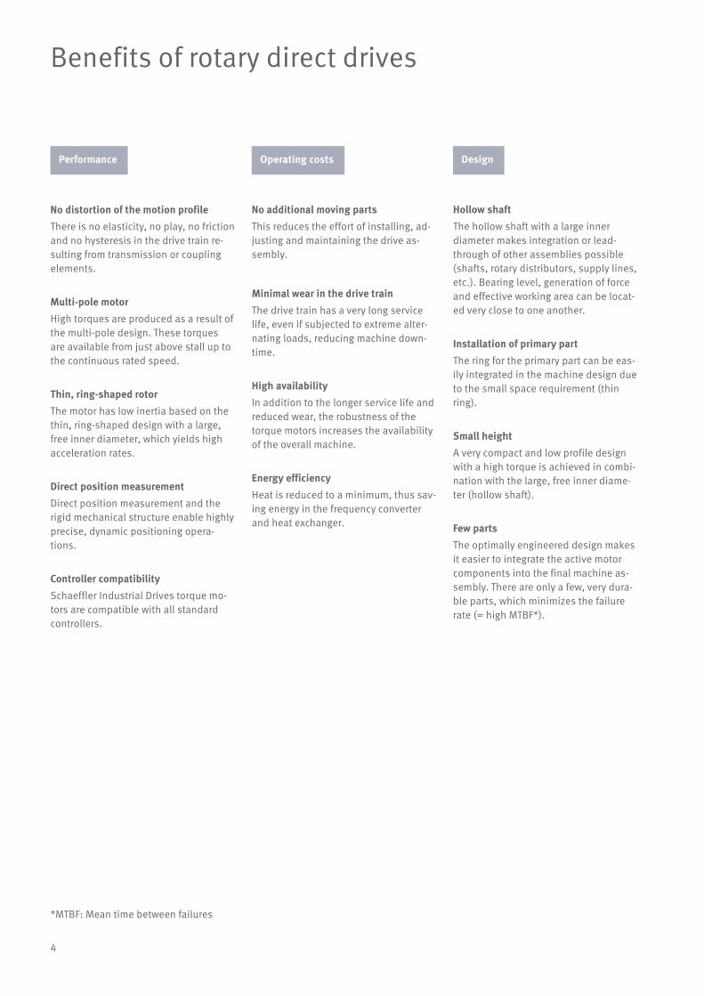
Benefits of rotary direct drives
No distortion of the motion profileThere is no elasticity, no play, no friction and no hysteresis in the drive train re-sulting from transmission or coupling elements.
Multi-pole motorHigh torques are produced as a result of the multi-pole design. These torques are available from just above stall up to the continuous rated speed.
Thin, ring-shaped rotorThe motor has low inertia based on the thin, ring-shaped design with a large, free inner diameter, which yields high acceleration rates.
Direct position measurementDirect position measurement and the rigid mechanical structure enable highly precise, dynamic positioning opera-tions.
Controller compatibilitySchaeffler Industrial Drives torque mo-tors are compatible with all standard controllers.
No additional moving partsThis reduces the effort of installing, ad-justing and maintaining the drive as-sembly.
Minimal wear in the drive trainThe drive train has a very long service life, even if subjected to extreme alter-nating loads, reducing machine down-time.
High availabilityIn addition to the longer service life and reduced wear, the robustness of the torque motors increases the availability of the overall machine.
Energy efficiencyHeat is reduced to a minimum, thus sav-ing energy in the frequency converter and heat exchanger.
*MTBF: Mean time between failures
Hollow shaftThe hollow shaft with a large inner diameter makes integration or lead-through of other assemblies possible (shafts, rotary distributors, supply lines, etc.). Bearing level, generation of force and effective working area can be locat-ed very close to one another.
Installation of primary partThe ring for the primary part can be eas-ily integrated in the machine design due to the small space requirement (thin ring).
Small heightA very compact and low profile design with a high torque is achieved in combi-nation with the large, free inner diame-ter (hollow shaft).
Few partsThe optimally engineered design makes it easier to integrate the active motor components into the final machine as-sembly. There are only a few, very dura-ble parts, which minimizes the failure rate (= high MTBF*).
Performance Operating costs Design

5
Features, benefits, applications
Applications• Machine tools (direct drive, CNC axis)
• NC rotary tables (direct drive)
• Indexing tables (cycle)
• Radial precision tracking units
• Automation technology
• Printing and packaging machines
• Servo presses
Benefits• Optimised for low power loss
• High dynamic response and system rigidity
• Compact design
• Maintenance-free
• Good synchronisation characteristics
• Reduced energy consumption with customised winding designs
• Cost savings through downsizing
• Higher machine accuracy due to reduced heat from the motor
RIB torque motors are offered:
• with stator heights in increments of 25 mm
• with various standard windings for different speeds
• in standard sizes
FeaturesRIB torque motors are slotted, perma-nent magnet excited AC synchronous di-rect drive motors with an internal rotor. The primary part is a fully cast stator with external liquid cooling. The sec-ondary part comprises an interference ring with a large internal diameter and permanent magnets attached on the outside.
This motor series is optimised for maxi-mum efficiency, which means: maxi-mum torque in the available installation space at continuous speed and low power losses. The usable torque is available over a very large range. RIB motors are designed for high circumfer-ential speeds in the air gap. The low torque fluctuations allow the motors to be used for precision applications.
Standard: axial cable outlet Option: tangential cable outlet Option: radial cable outlet
6
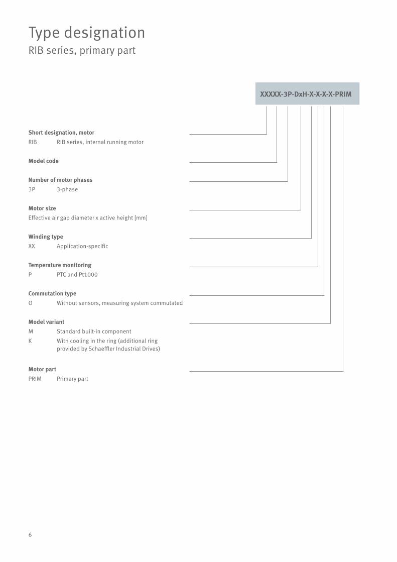
Type designationRIB series, primary part
Short designation, motorRIB RIB series, internal running motor
Model code
Number of motor phases3P 3-phase
Motor sizeEffective air gap diameter x active height [mm]
Winding typeXX Application-specific
Temperature monitoringP PTC and Pt1000
Commutation typeO Without sensors, measuring system commutated
Model variantM Standard built-in component
K With cooling in the ring (additional ring provided by Schaeffler Industrial Drives)
Motor partPRIM Primary part
XXXXX-3P-DxH-X-X-X-X-PRIM
7
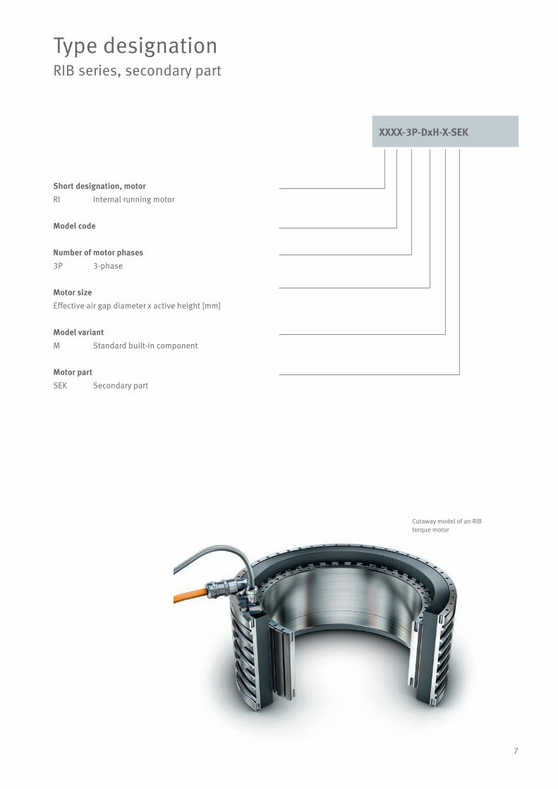
Type designationRIB series, secondary part
Short designation, motorRI Internal running motor
Model code
Number of motor phases3P 3-phase
Motor sizeEffective air gap diameter x active height [mm]
Model variantM Standard built-in component
Motor partSEK Secondary part
XXXX-3P-DxH-X-SEK
Cutaway model of an RIB torque motor
8
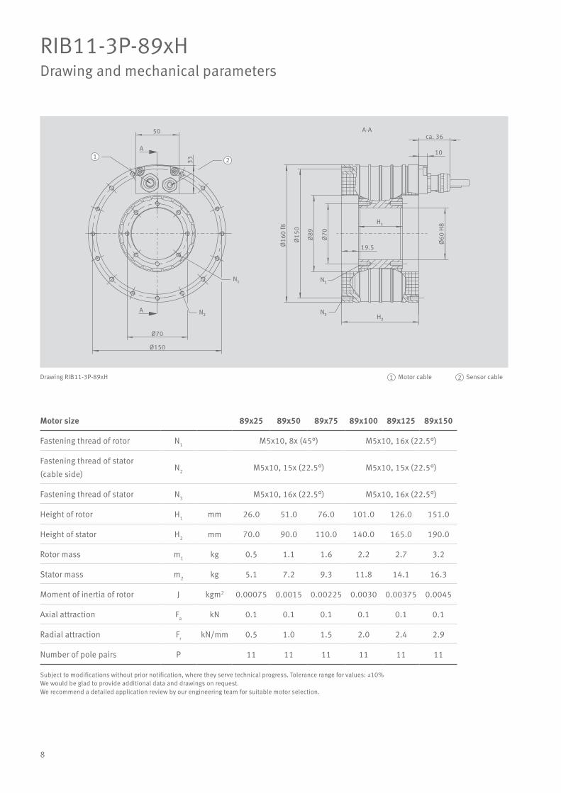
RIB11-3P-89xHDrawing and mechanical parameters
Motor size 89x25 89x50 89x75 89x100 89x125 89x150
Fastening thread of rotor N1 M5x10, 8x (45°) M5x10, 16x (22.5°)
Fastening thread of stator
(cable side)N2 M5x10, 15x (22.5°) M5x10, 15x (22.5°)
Fastening thread of stator N3 M5x10, 16x (22.5°) M5x10, 16x (22.5°)
Height of rotor H1 mm 26.0 51.0 76.0 101.0 126.0 151.0
Height of stator H2 mm 70.0 90.0 110.0 140.0 165.0 190.0
Rotor mass m1 kg 0.5 1.1 1.6 2.2 2.7 3.2
Stator mass m2 kg 5.1 7.2 9.3 11.8 14.1 16.3
Moment of inertia of rotor J kgm2 0.00075 0.0015 0.00225 0.0030 0.00375 0.0045
Axial attraction Fa kN 0.1 0.1 0.1 0.1 0.1 0.1
Radial attraction Fr kN/mm 0.5 1.0 1.5 2.0 2.4 2.9
Number of pole pairs P 11 11 11 11 11 11
50
33
N₁
Ø70
Ø150
Ø15
0
Ø16
0 f8
Ø89
Ø60
H8
Ø70
19.5
10
ca. 36
H₁
A
H₂
1 2
A-A
A N₂
N₁
N₃
Drawing RIB11-3P-89xH
Subject to modifications without prior notification, where they serve technical progress. Tolerance range for values: ±10%We would be glad to provide additional data and drawings on request.We recommend a detailed application review by our engineering team for suitable motor selection.
Motor cable Sensor cable1 2

9
RIB11-3P-89xHPerformance data
Motor size 89x25 89x25 89x50 89x50 89x75 89x75
Winding variant Z0.9 Z1.7 Z0.9 Z1.7 Z0.9 Z1.7
Ultimate torque (1 s) at Iu Tu Nm 33 33 72 72 110 110
Peak torque (saturation range) at Ip Tp Nm 30 30 67 67 102 102
Continuous torque, cooled at Icw Tcw Nm 19 19 42 42 62 62
Continuous torque, not cooled at Ic Tc Nm 7 7 15 15 23 23
Stall torque, cooled at Isw Tsw Nm 14.4 14.4 31.6 31.6 46.4 46.4
Cogging torque at I = 0 Tcog Nm 0.10 0.10 0.21 0.21 0.32 0.32
Knee speed at Icw and UDCL nlw rpm 1668 3419 790 1647 512 1091
Continuous speed (S1), cooled at Icw nlwS1 rpm 682 682 682 682 512 682
Ultimate current (1 s) Iu Arms 21.1 42.2 21.1 42.2 21.1 42.2
Peak current (saturation range) Ip Arms 16.9 33.8 16.9 33.8 16.9 33.8
Continuous current, cooled at Plw Icw Arms 7.7 15.4 8.4 16.9 8.3 16.5
Continuous current, not cooled at Plc Ic Arms 2.5 5.1 2.9 5.8 3.0 5.9
Stall current, cooled Isw Arms 5.6 11.1 6.1 12.1 5.9 11.9
Power loss at Tp (25°C) Plp W 1971 1971 2957 2957 4337 4337
Power loss at Tcw Plw W 556 556 995 995 1401 1401
Power loss at Tc (25°C) Plc W 44 44 89 89 133 133
Motor constant (25°C) km Nm/√W 0.99 0.99 1.61 1.61 2.00 2.00
Torque constant kT Nm/Arms 2.6 1.3 5.2 2.6 7.8 3.9
Back EMF constant, phase to phase ku V/(rad/s) 2.1 1.1 4.2 2.1 6.4 3.2
Electrical resistance, phase to phase R25 Ω 4.6 1.2 6.9 1.7 10.1 2.5
Inductance, phase to phase L mH 25.0 6.3 47.5 11.9 71.3 17.8
Cooling water flow dV/dt l/min 1.6 1.6 2.9 2.9 4.0 4.0
Cooling water temperature difference ∆J K 5.0 5.0 5.0 5.0 5.0 5.0
Motor temperature switch-off threshold J °C 110 110 110 110 110 110
DC link voltage UDCL V 600 600 600 600 600 600
Subject to modifications without prior notification, where they serve technical progress. Tolerance range for values: ±10%We would be glad to provide additional data and drawings on request.We recommend a detailed application review by our engineering team for suitable motor selection.
10
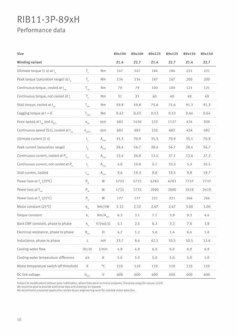
RIB11-3P-89xHPerformance data
Size 89x100 89x100 89x125 89x125 89x150 89x150
Winding variant Z1.4 Z2.7 Z1.4 Z2.7 Z1.4 Z2.7
Ultimate torque (1 s) at Iu Tu Nm 147 147 184 184 221 221
Peak torque (saturation range) at Ip Tp Nm 134 134 167 167 200 200
Continuous torque, cooled at Icw Tcw Nm 79 79 100 100 121 121
Continuous torque, not cooled at Ic Tc Nm 31 31 40 40 49 49
Stall torque, cooled at Isw Tsw Nm 59.8 59.8 75.6 75.6 91.3 91.3
Cogging torque at I = 0 Tcog Nm 0.43 0.43 0.53 0.53 0.64 0.64
Knee speed at Icw and UDCL nlw rpm 682 1430 532 1127 434 928
Continuous speed (S1), cooled at Icw nlwS1 rpm 682 682 532 682 434 682
Ultimate current (1 s) Iu Arms 35.5 70.9 35.5 70.9 35.5 70.9
Peak current (saturation range) Ip Arms 28.4 56.7 28.4 56.7 28.4 56.7
Continuous current, cooled at Plw Icw Arms 13.4 26.8 13.5 27.1 13.6 27.3
Continuous current, not cooled at Plc Ic Arms 5.0 10.0 5.1 10.3 5.3 10.5
Stall current, cooled Isw Arms 9.6 19.3 9.8 19.5 9.8 19.7
Power loss at Tp (25°C) Plp W 5723 5723 6783 6783 7737 7737
Power loss at Tcw Plw W 1725 1725 2090 2090 2419 2419
Power loss at Tc (25°C) Plc W 177 177 221 221 266 266
Motor constant (25°C) km Nm/√W 2.32 2.32 2.67 2.67 3.00 3.00
Torque constant kT Nm/Arms 6.2 3.1 7.7 3.9 9.3 4.6
Back EMF constant, phase to phase ku V/(rad/s) 5.1 2.5 6.3 3.2 7.6 3.8
Electrical resistance, phase to phase R25 Ω 4.7 1.2 5.6 1.4 6.4 1.6
Inductance, phase to phase L mH 33.7 8.4 42.1 10.5 50.5 12.6
Cooling water flow dV/dt l/min 4.9 4.9 6.0 6.0 6.9 6.9
Cooling water temperature difference ∆J K 5.0 5.0 5.0 5.0 5.0 5.0
Motor temperature switch-off threshold J °C 110 110 110 110 110 110
DC link voltage UDCL V 600 600 600 600 600 600
Subject to modifications without prior notification, where they serve technical progress. Tolerance range for values: ±10%We would be glad to provide additional data and drawings on request.We recommend a detailed application review by our engineering team for suitable motor selection.

11
More performance and precision thanks to a mod-ular system for rotary tables and swivel-type axes
In directly driven rotary tables and swivel-type axes, the torque motor, the rotary table bearing and the angular measuring system constitute a complex system with a large number of interac-tions regarding heat flow, cogging, speed and ac-celeration capability, rigidity, frictional torque and positioning accuracy. It is therefore highly benefi-cial if all three components are provided by a sin-gle source and are perfectly matched to each other in one modular system.
Schaeffler Industrial Drives offers torque motor series for an extremely wide range of applications, while Schaeffler offers bearing series and an angu-lar measuring system integrated into the bearing.
Modular system for rotary tables (OBR)

12
RIB11-3P-120xHDrawing and mechanical parameters
Motor size 120x25 120x50 120x75 120x100 120x125 120x150
Fastening thread of rotor N1 M5x10, 16x (22.5°) M6x10, 16x (22.5°)
Fastening thread of stator
(cable side)N2 M5x10, 8x (45°) M5x10, 15x (22.5°)
Fastening thread of stator N3 M5x10, 8x (45°) M5x10, 16x (22.5°)
Height of rotor H1 mm 26.0 51.0 76.0 101.0 126.0 151.0
Height of stator H2 mm 80.0 100.0 120.0 150.0 175.0 200.0
Rotor mass m1 kg 0.9 1.7 2.6 3.4 4.3 5.1
Stator mass m2 kg 7.9 10.8 13.7 17.2 20.4 23.6
Moment of inertia of rotor J kgm2 0.0046 0.0092 0.0138 0.0184 0.0230 0.0276
Axial attraction Fa kN 0.16 0.16 0.16 0.16 0.16 0.16
Radial attraction Fr kN/mm 0.5 0.9 1.4 1.8 2.2 2.7
Number of pole pairs P 11 11 11 11 11 11
A
50
Ø100
33.5
N₁
N₂
A
Ø185
ca. 358
24.5 H₁
H₂
N₁
N₃
Ø10
0
Ø12
0
Ø90
H80 -0.1
2Ø
198
A-A12
Drawing RIB11-3P-120xH Motor cable Sensor cable1 2
Subject to modifications without prior notification, where they serve technical progress. Tolerance range for values: ±10%We would be glad to provide additional data and drawings on request.We recommend a detailed application review by our engineering team for suitable motor selection.
13
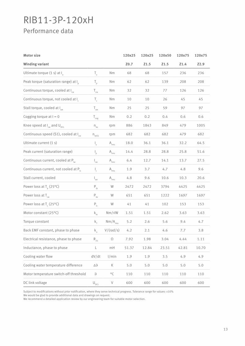
RIB11-3P-120xHPerformance data
Motor size 120x25 120x25 120x50 120x75 120x75
Winding variant Z0.7 Z1.5 Z1.5 Z1.4 Z2.9
Ultimate torque (1 s) at Iu Tu Nm 68 68 157 236 236
Peak torque (saturation range) at Ip Tp Nm 62 62 139 208 208
Continuous torque, cooled at Icw Tcw Nm 32 32 77 126 126
Continuous torque, not cooled at Ic Tc Nm 10 10 26 45 45
Stall torque, cooled at Isw Tsw Nm 25 25 59 97 97
Cogging torque at I = 0 Tcog Nm 0.2 0.2 0.4 0.6 0.6
Knee speed at Icw and UDCL nlw rpm 886 1843 849 479 1005
Continuous speed (S1), cooled at Icw nlwS1 rpm 682 682 682 479 682
Ultimate current (1 s) Iu Arms 18.0 36.1 36.1 32.2 64.5
Peak current (saturation range) Ip Arms 14.4 28.8 28.8 25.8 51.6
Continuous current, cooled at Plw Icw Arms 6.4 12.7 14.1 13.7 27.5
Continuous current, not cooled at Plc Ic Arms 1.9 3.7 4.7 4.8 9.6
Stall current, cooled Isw Arms 4.8 9.6 10.6 10.3 20.6
Power loss at Tp (25°C) Plp W 2472 2472 3794 4425 4425
Power loss at Tcw Plw W 651 651 1222 1697 1697
Power loss at Tc (25°C) Plc W 41 41 102 153 153
Motor constant (25°C) km Nm/√W 1.51 1.51 2.62 3.63 3.63
Torque constant kT Nm/Arms 5.2 2.6 5.6 9.4 4.7
Back EMF constant, phase to phase ku V/(rad/s) 4.2 2.1 4.6 7.7 3.8
Electrical resistance, phase to phase R25 Ω 7.92 1.98 3.04 4.44 1.11
Inductance, phase to phase L mH 51.37 12.84 23.51 42.81 10.70
Cooling water flow dV/dt l/min 1.9 1.9 3.5 4.9 4.9
Cooling water temperature difference ∆J K 5.0 5.0 5.0 5.0 5.0
Motor temperature switch-off threshold J °C 110 110 110 110 110
DC link voltage UDCL V 600 600 600 600 600
Subject to modifications without prior notification, where they serve technical progress. Tolerance range for values: ±10%We would be glad to provide additional data and drawings on request.We recommend a detailed application review by our engineering team for suitable motor selection.

14
RIB11-3P-120xHPerformance data
Motor size 120x100 120x100 120x125 120x125 120x150 120x150
Winding variant Z1.4 Z2.9 Z1.4 Z2.9 Z1.5 Z2.9
Ultimate torque (1 s) at Iu Tu Nm 314 314 393 393 471 471
Peak torque (saturation range) at Ip Tp Nm 277 277 346 346 416 416
Continuous torque, cooled at Icw Tcw Nm 171 171 219 219 250 264
Continuous torque, not cooled at Ic Tc Nm 62 62 80 80 92 98
Stall torque, cooled at Isw Tsw Nm 131 131 167 167 191 202
Cogging torque at I = 0 Tcog Nm 0.8 0.8 1.0 1.0 1.3 1.3
Knee speed at Icw and UDCL nlw rpm 356 758 276 598 260 495
Continuous speed (S1), cooled at Icw nlwS1 rpm 356 682 276 598 260 495
Ultimate current (1 s) Iu Arms 32.2 64.5 32.2 64.5 36.1 64.5
Peak current (saturation range) Ip Arms 25.8 51.6 25.8 51.6 28.8 51.6
Continuous current, cooled at Plw Icw Arms 13.9 27.9 14.3 28.6 15.2 28.8
Continuous current, not cooled at Plc Ic Arms 5.0 10.0 5.1 10.2 5.5 10.4
Stall current, cooled Isw Arms 10.5 20.9 10.7 21.4 11.4 21.6
Power loss at Tp (25°C) Plp W 5454 5454 6483 6483 8393 7512
Power loss at Tcw Plw W 2153 2153 2688 2688 3158 3158
Power loss at Tc (25°C) Plc W 205 205 256 256 307 307
Motor constant (25°C) km Nm/√W 4.36 4.36 5.00 5.00 5.28 5.58
Torque constant kT Nm/Arms 12.5 6.2 15.6 7.8 16.8 9.4
Back EMF constant, phase to phase ku V/(rad/s) 10.2 5.1 12.8 6.4 13.7 7.7
Electrical resistance, phase to phase R25 Ω 5.47 1.37 6.50 1.62 6.72 1.88
Inductance, phase to phase L mH 54.13 13.53 66.20 16.55 62.07 19.42
Cooling water flow dV/dt l/min 6.2 6.2 7.7 7.7 9.0 9.0
Cooling water temperature difference ∆J K 5.0 5.0 5.0 5.0 5.0 5.0
Motor temperature switch-off threshold J °C 110 110 110 110 110 110
DC link voltage UDCL V 600 600 600 600 600 600
Subject to modifications without prior notification, where they serve technical progress. Tolerance range for values: ±10%We would be glad to provide additional data and drawings on request.We recommend a detailed application review by our engineering team for suitable motor selection.

15
The ideal bearing for every applicationThe rotary table bearings from Schaeffler en able rotary table designs for every field of application. The focus is always on maximising customer bene-fits in terms of productivity and component quality. With maximum rigidity and the lowest possible frictional torques, they are also ideal for use with direct drives.
High precision bearings for combined loads (TPI 120)
Rotary table bearings YRTC-XL, YRTS & ZKLDF (ORY)
16
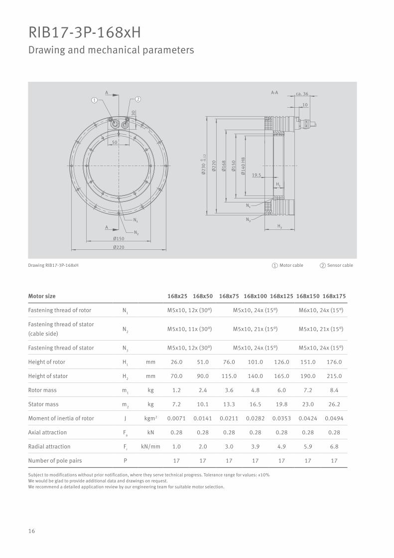
RIB17-3P-168xHDrawing and mechanical parameters
Motor size 168x25 168x50 168x75 168x100 168x125 168x150 168x175
Fastening thread of rotor N1 M5x10, 12x (30°) M5x10, 24x (15°) M6x10, 24x (15°)
Fastening thread of stator
(cable side)N2 M5x10, 11x (30°) M5x10, 21x (15°) M5x10, 21x (15°)
Fastening thread of stator N3 M5x10, 12x (30°) M5x10, 24x (15°) M5x10, 24x (15°)
Height of rotor H1 mm 26.0 51.0 76.0 101.0 126.0 151.0 176.0
Height of stator H2 mm 70.0 90.0 115.0 140.0 165.0 190.0 215.0
Rotor mass m1 kg 1.2 2.4 3.6 4.8 6.0 7.2 8.4
Stator mass m2 kg 7.2 10.1 13.3 16.5 19.8 23.0 26.2
Moment of inertia of rotor J kgm2 0.0071 0.0141 0.0211 0.0282 0.0353 0.0424 0.0494
Axial attraction Fa kN 0.28 0.28 0.28 0.28 0.28 0.28 0.28
Radial attraction Fr kN/mm 1.0 2.0 3.0 3.9 4.9 5.9 6.8
Number of pole pairs P 17 17 17 17 17 17 17
50
N₁
N₂
Ø220
Ø150
19.5
H₁
Ø14
0 H
8
Ø16
8
Ø22
00 -0.1
2Ø
230
Ø15
0
A
A
30
10
ca. 361 2
N₁
N₃H₂
A-A
Drawing RIB17-3P-168xH Motor cable Sensor cable1 2
Subject to modifications without prior notification, where they serve technical progress. Tolerance range for values: ±10%We would be glad to provide additional data and drawings on request.We recommend a detailed application review by our engineering team for suitable motor selection.
17
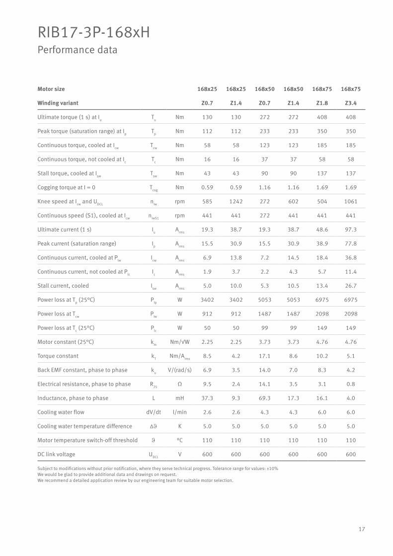
RIB17-3P-168xHPerformance data
Motor size 168x25 168x25 168x50 168x50 168x75 168x75
Winding variant Z0.7 Z1.4 Z0.7 Z1.4 Z1.8 Z3.4
Ultimate torque (1 s) at Iu Tu Nm 130 130 272 272 408 408
Peak torque (saturation range) at Ip Tp Nm 112 112 233 233 350 350
Continuous torque, cooled at Icw Tcw Nm 58 58 123 123 185 185
Continuous torque, not cooled at Ic Tc Nm 16 16 37 37 58 58
Stall torque, cooled at Isw Tsw Nm 43 43 90 90 137 137
Cogging torque at I = 0 Tcog Nm 0.59 0.59 1.16 1.16 1.69 1.69
Knee speed at Icw and UDCL nlw rpm 585 1242 272 602 504 1061
Continuous speed (S1), cooled at Icw nlwS1 rpm 441 441 272 441 441 441
Ultimate current (1 s) Iu Arms 19.3 38.7 19.3 38.7 48.6 97.3
Peak current (saturation range) Ip Arms 15.5 30.9 15.5 30.9 38.9 77.8
Continuous current, cooled at Plw Icw Arms 6.9 13.8 7.2 14.5 18.4 36.8
Continuous current, not cooled at Plc Ic Arms 1.9 3.7 2.2 4.3 5.7 11.4
Stall current, cooled Isw Arms 5.0 10.0 5.3 10.5 13.4 26.7
Power loss at Tp (25°C) Plp W 3402 3402 5053 5053 6975 6975
Power loss at Tcw Plw W 912 912 1487 1487 2098 2098
Power loss at Tc (25°C) Plc W 50 50 99 99 149 149
Motor constant (25°C) km Nm/√W 2.25 2.25 3.73 3.73 4.76 4.76
Torque constant kT Nm/Arms 8.5 4.2 17.1 8.6 10.2 5.1
Back EMF constant, phase to phase ku V/(rad/s) 6.9 3.5 14.0 7.0 8.3 4.2
Electrical resistance, phase to phase R25 Ω 9.5 2.4 14.1 3.5 3.1 0.8
Inductance, phase to phase L mH 37.3 9.3 69.3 17.3 16.1 4.0
Cooling water flow dV/dt l/min 2.6 2.6 4.3 4.3 6.0 6.0
Cooling water temperature difference ∆J K 5.0 5.0 5.0 5.0 5.0 5.0
Motor temperature switch-off threshold J °C 110 110 110 110 110 110
DC link voltage UDCL V 600 600 600 600 600 600
Subject to modifications without prior notification, where they serve technical progress. Tolerance range for values: ±10%We would be glad to provide additional data and drawings on request.We recommend a detailed application review by our engineering team for suitable motor selection.
18
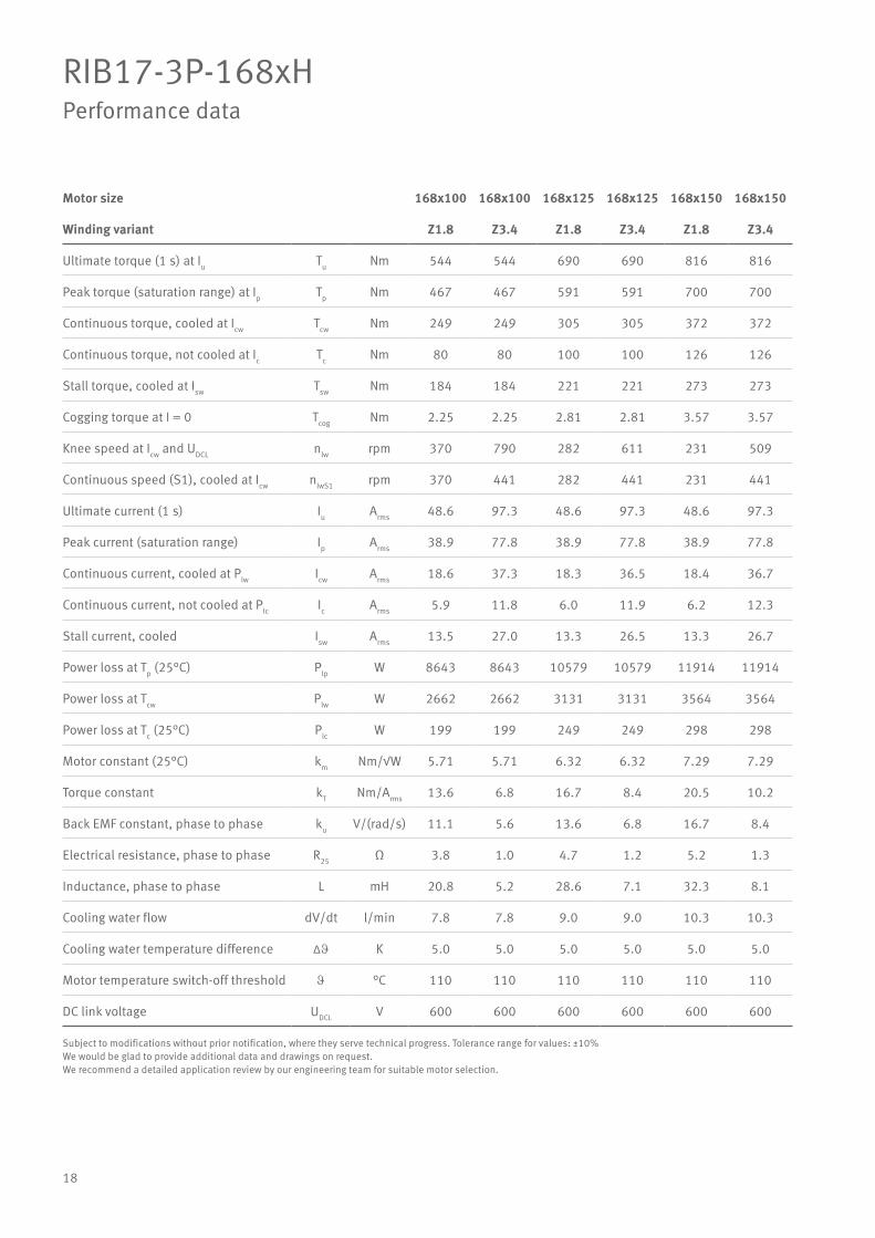
RIB17-3P-168xHPerformance data
Motor size 168x100 168x100 168x125 168x125 168x150 168x150
Winding variant Z1.8 Z3.4 Z1.8 Z3.4 Z1.8 Z3.4
Ultimate torque (1 s) at Iu Tu Nm 544 544 690 690 816 816
Peak torque (saturation range) at Ip Tp Nm 467 467 591 591 700 700
Continuous torque, cooled at Icw Tcw Nm 249 249 305 305 372 372
Continuous torque, not cooled at Ic Tc Nm 80 80 100 100 126 126
Stall torque, cooled at Isw Tsw Nm 184 184 221 221 273 273
Cogging torque at I = 0 Tcog Nm 2.25 2.25 2.81 2.81 3.57 3.57
Knee speed at Icw and UDCL nlw rpm 370 790 282 611 231 509
Continuous speed (S1), cooled at Icw nlwS1 rpm 370 441 282 441 231 441
Ultimate current (1 s) Iu Arms 48.6 97.3 48.6 97.3 48.6 97.3
Peak current (saturation range) Ip Arms 38.9 77.8 38.9 77.8 38.9 77.8
Continuous current, cooled at Plw Icw Arms 18.6 37.3 18.3 36.5 18.4 36.7
Continuous current, not cooled at Plc Ic Arms 5.9 11.8 6.0 11.9 6.2 12.3
Stall current, cooled Isw Arms 13.5 27.0 13.3 26.5 13.3 26.7
Power loss at Tp (25°C) Plp W 8643 8643 10579 10579 11914 11914
Power loss at Tcw Plw W 2662 2662 3131 3131 3564 3564
Power loss at Tc (25°C) Plc W 199 199 249 249 298 298
Motor constant (25°C) km Nm/√W 5.71 5.71 6.32 6.32 7.29 7.29
Torque constant kT Nm/Arms 13.6 6.8 16.7 8.4 20.5 10.2
Back EMF constant, phase to phase ku V/(rad/s) 11.1 5.6 13.6 6.8 16.7 8.4
Electrical resistance, phase to phase R25 Ω 3.8 1.0 4.7 1.2 5.2 1.3
Inductance, phase to phase L mH 20.8 5.2 28.6 7.1 32.3 8.1
Cooling water flow dV/dt l/min 7.8 7.8 9.0 9.0 10.3 10.3
Cooling water temperature difference ∆J K 5.0 5.0 5.0 5.0 5.0 5.0
Motor temperature switch-off threshold J °C 110 110 110 110 110 110
DC link voltage UDCL V 600 600 600 600 600 600
Subject to modifications without prior notification, where they serve technical progress. Tolerance range for values: ±10%We would be glad to provide additional data and drawings on request.We recommend a detailed application review by our engineering team for suitable motor selection.
19
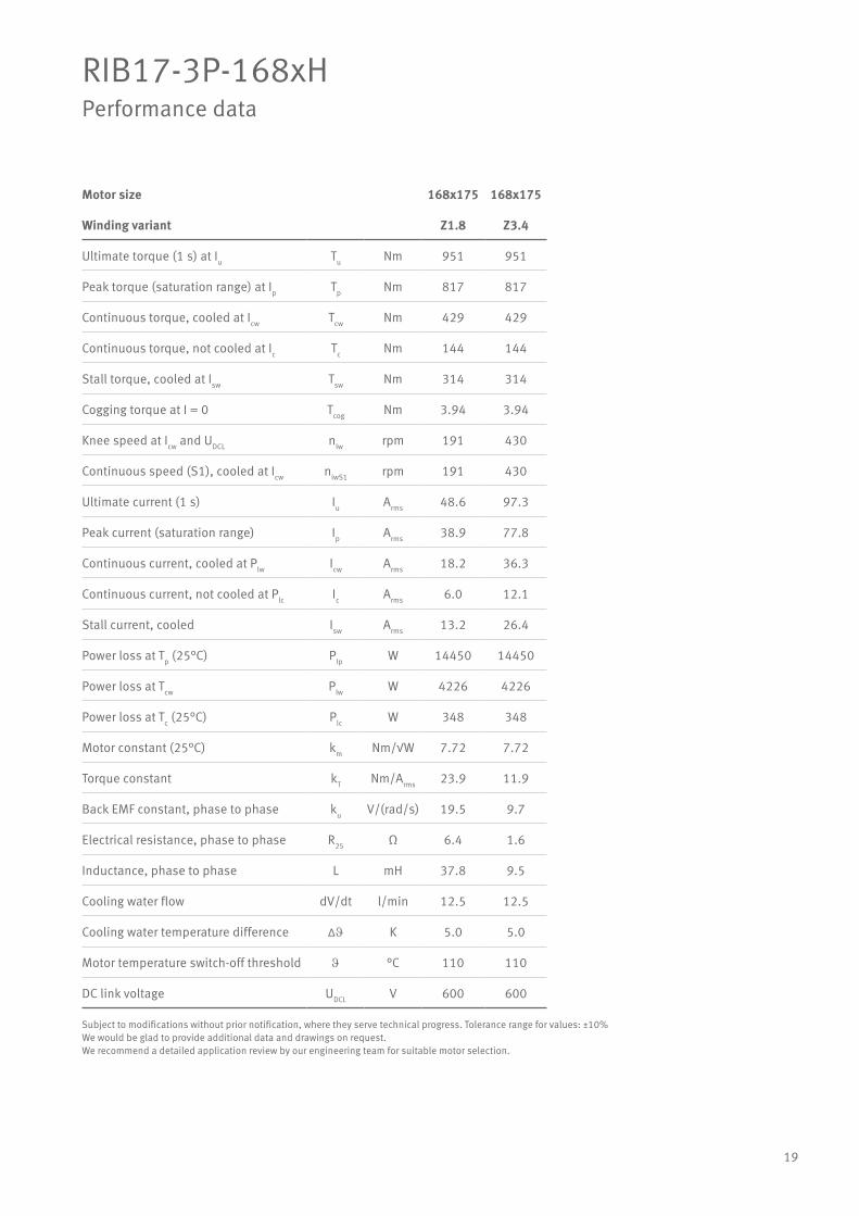
RIB17-3P-168xHPerformance data
Motor size 168x175 168x175
Winding variant Z1.8 Z3.4
Ultimate torque (1 s) at Iu Tu Nm 951 951
Peak torque (saturation range) at Ip Tp Nm 817 817
Continuous torque, cooled at Icw Tcw Nm 429 429
Continuous torque, not cooled at Ic Tc Nm 144 144
Stall torque, cooled at Isw Tsw Nm 314 314
Cogging torque at I = 0 Tcog Nm 3.94 3.94
Knee speed at Icw and UDCL nlw rpm 191 430
Continuous speed (S1), cooled at Icw nlwS1 rpm 191 430
Ultimate current (1 s) Iu Arms 48.6 97.3
Peak current (saturation range) Ip Arms 38.9 77.8
Continuous current, cooled at Plw Icw Arms 18.2 36.3
Continuous current, not cooled at Plc Ic Arms 6.0 12.1
Stall current, cooled Isw Arms 13.2 26.4
Power loss at Tp (25°C) Plp W 14450 14450
Power loss at Tcw Plw W 4226 4226
Power loss at Tc (25°C) Plc W 348 348
Motor constant (25°C) km Nm/√W 7.72 7.72
Torque constant kT Nm/Arms 23.9 11.9
Back EMF constant, phase to phase ku V/(rad/s) 19.5 9.7
Electrical resistance, phase to phase R25 Ω 6.4 1.6
Inductance, phase to phase L mH 37.8 9.5
Cooling water flow dV/dt l/min 12.5 12.5
Cooling water temperature difference ∆J K 5.0 5.0
Motor temperature switch-off threshold J °C 110 110
DC link voltage UDCL V 600 600
Subject to modifications without prior notification, where they serve technical progress. Tolerance range for values: ±10%We would be glad to provide additional data and drawings on request.We recommend a detailed application review by our engineering team for suitable motor selection.
20
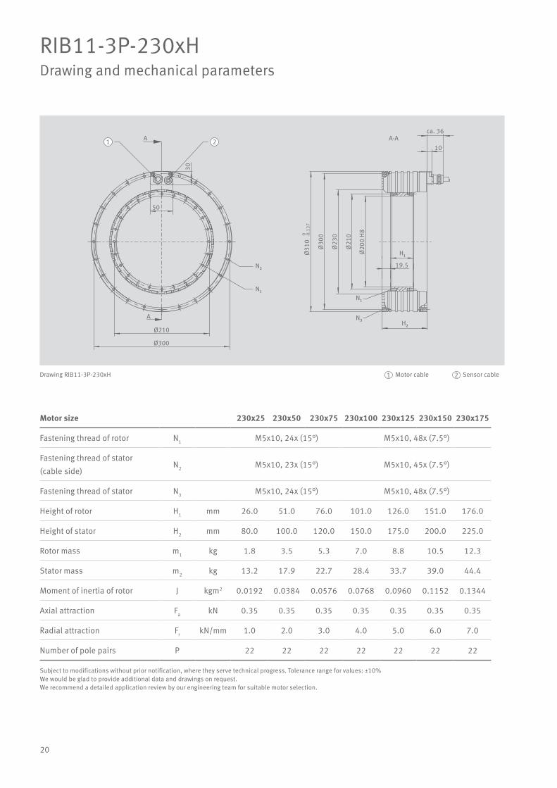
RIB11-3P-230xHDrawing and mechanical parameters
Motor size 230x25 230x50 230x75 230x100 230x125 230x150 230x175
Fastening thread of rotor N1 M5x10, 24x (15°) M5x10, 48x (7.5°)
Fastening thread of stator
(cable side)N2 M5x10, 23x (15°) M5x10, 45x (7.5°)
Fastening thread of stator N3 M5x10, 24x (15°) M5x10, 48x (7.5°)
Height of rotor H1 mm 26.0 51.0 76.0 101.0 126.0 151.0 176.0
Height of stator H2 mm 80.0 100.0 120.0 150.0 175.0 200.0 225.0
Rotor mass m1 kg 1.8 3.5 5.3 7.0 8.8 10.5 12.3
Stator mass m2 kg 13.2 17.9 22.7 28.4 33.7 39.0 44.4
Moment of inertia of rotor J kgm2 0.0192 0.0384 0.0576 0.0768 0.0960 0.1152 0.1344
Axial attraction Fa kN 0.35 0.35 0.35 0.35 0.35 0.35 0.35
Radial attraction Fr kN/mm 1.0 2.0 3.0 4.0 5.0 6.0 7.0
Number of pole pairs P 22 22 22 22 22 22 22
Ø300
Ø210
N₂
50
Ø20
0 H
8
Ø21
0
H₂
H₁
19.5
A
A
30
10
ca. 36
Ø23
0
Ø30
0
Ø31
00 -0
.137
1 2
N₁N₁
N₃
A-A
Drawing RIB11-3P-230xH Motor cable Sensor cable1 2
Subject to modifications without prior notification, where they serve technical progress. Tolerance range for values: ±10%We would be glad to provide additional data and drawings on request.We recommend a detailed application review by our engineering team for suitable motor selection.

21
RIB11-3P-230xHPerformance data
Motor size 230x25 230x25 230x50 230x50 230x75 230x75
Winding variant Z1.8 Z3.3 Z1.8 Z3.3 Z1.8 Z3.3
Ultimate torque (1 s) at Iu Tu Nm 239 239 501 501 774 774
Peak torque (saturation range) at Ip Tp Nm 219 219 457 457 703 703
Continuous torque, cooled at Icw Tcw Nm 130 130 277 277 422 422
Continuous torque, not cooled at Ic Tc Nm 39 39 92 92 147 147
Stall torque, cooled at Isw Tsw Nm 106 106 225 225 342 342
Cogging torque at I = 0 Tcog Nm 0.42 0.42 0.83 0.83 1.25 1.25
Knee speed at Icw and UDCL nlw rpm 555 1143 255 534 166 355
Continuous speed (S1), cooled at Icw nlwS1 rpm 341 341 255 341 166 341
Ultimate current (1 s) Iu Arms 42.7 85.4 42.7 85.4 42.7 85.4
Peak current (saturation range) Ip Arms 34.2 68.3 34.2 68.3 34.2 68.3
Continuous current, cooled at Plw Icw Arms 16.3 32.6 16.8 33.6 17.1 34.2
Continuous current, not cooled at Plc Ic Arms 4.3 8.7 5.0 10.1 5.4 10.7
Stall current, cooled Isw Arms 12.4 24.8 12.8 25.5 13.0 26.0
Power loss at Tp (25°C) Plp W 4252 4252 6336 6336 8379 8379
Power loss at Tcw Plw W 1337 1337 2114 2114 2891 2891
Power loss at Tc (25°C) Plc W 69 69 137 137 206 206
Motor constant (25°C) km Nm/√W 4.66 4.66 7.87 7.87 10.25 10.25
Torque constant kT Nm/Arms 8.9 4.4 18.3 9.2 27.5 13.7
Back EMF constant, phase to phase ku V/(rad/s) 7.3 3.6 15.0 7.5 22.4 11.2
Electrical resistance, phase to phase R25 Ω 2.4 0.6 3.6 0.9 4.8 1.2
Inductance, phase to phase L mH 16.5 4.1 34.6 8.7 49.9 12.5
Cooling water flow dV/dt l/min 3.9 3.9 6.1 6.1 8.3 8.3
Cooling water temperature difference ∆J K 5.0 5.0 5.0 5.0 5.0 5.0
Motor temperature switch-off threshold J °C 120 120 120 120 120 120
DC link voltage UDCL V 600 600 600 600 600 600
Subject to modifications without prior notification, where they serve technical progress. Tolerance range for values: ±10%We would be glad to provide additional data and drawings on request.We recommend a detailed application review by our engineering team for suitable motor selection.

22
RIB11-3P-230xHPerformance data
Motor size 230x100 230x100 230x125 230x125 230x150 230x150
Winding variant Z1.8 Z3.3 Z3.0 Z4.5 Z3.0 Z4.5
Ultimate torque (1 s) at Iu Tu Nm 1032 1032 1289 1289 1550 1550
Peak torque (saturation range) at Ip Tp Nm 938 938 1172 1172 1409 1409
Continuous torque, cooled at Icw Tcw Nm 567 567 702 702 852 852
Continuous torque, not cooled at Ic Tc Nm 202 202 254 254 312 312
Stall torque, cooled at Isw Tsw Nm 460 460 569 569 691 691
Cogging torque at I = 0 Tcog Nm 1.67 1.67 2.08 2.08 2.50 2.50
Knee speed at Icw and UDCL nlw rpm 122 266 182 386 148 317
Continuous speed (S1), cooled at Icw nlwS1 rpm 122 266 182 341 148 317
Ultimate current (1 s) Iu Arms 42.7 85.4 74.7 149.4 74.7 149.4
Peak current (saturation range) Ip Arms 34.2 68.3 59.8 119.6 59.8 119.6
Continuous current, cooled at Plw Icw Arms 17.2 34.4 29.8 59.6 30.1 60.2
Continuous current, not cooled at Plc Ic Arms 5.5 11.1 9.7 19.5 9.9 19.9
Stall current, cooled Isw Arms 13.1 26.2 22.7 45.3 22.9 45.8
Power loss at Tp (25°C) Plp W 10463 10463 12941 12941 14916 14916
Power loss at Tcw Plw W 3668 3668 4445 4445 5222 5222
Power loss at Tc (25°C) Plc W 274 274 343 343 411 411
Motor constant (25°C) km Nm/√W 12.22 12.22 13.74 13.74 15.39 15.39
Torque constant kT Nm/Arms 36.6 18.3 26.1 13.1 31.4 15.7
Back EMF constant, phase to phase ku V/(rad/s) 29.9 14.9 21.3 10.7 25.7 12.8
Electrical resistance, phase to phase R25 Ω 6.0 1.5 2.4 0.6 2.8 0.7
Inductance, phase to phase L mH 63.4 15.8 25.3 6.3 30.5 7.6
Cooling water flow dV/dt l/min 10.5 10.5 12.7 12.7 15.0 15.0
Cooling water temperature difference ∆J K 5.0 5.0 5.0 5.0 5.0 5.0
Motor temperature switch-off threshold J °C 120 120 120 120 120 120
DC link voltage UDCL V 600 600 600 600 600 600
Subject to modifications without prior notification, where they serve technical progress. Tolerance range for values: ±10%We would be glad to provide additional data and drawings on request.We recommend a detailed application review by our engineering team for suitable motor selection.

23
RIB11-3P-230xHPerformance data
Motor size 230x175 230x175
Winding variant Z3.0 Z4.5
Ultimate torque (1 s) at Iu Tu Nm 1809 1809
Peak torque (saturation range) at Ip Tp Nm 1644 1644
Continuous torque, cooled at Icw Tcw Nm 997 997
Continuous torque, not cooled at Ic Tc Nm 368 368
Stall torque, cooled at Isw Tsw Nm 808 808
Cogging torque at I = 0 Tcog Nm 2.92 2.92
Knee speed at Icw and UDCL nlw rpm 124 269
Continuous speed (S1), cooled at Icw nlwS1 rpm 124 269
Ultimate current (1 s) Iu Arms 74.7 149.4
Peak current (saturation range) Ip Arms 59.8 119.6
Continuous current, cooled at Plw Icw Arms 30.2 60.4
Continuous current, not cooled at Plc Ic Arms 10.0 20.1
Stall current, cooled Isw Arms 23.0 45.9
Power loss at Tp (25°C) Plp W 17017 17017
Power loss at Tcw Plw W 5999 5999
Power loss at Tc (25°C) Plc W 480 480
Motor constant (25°C) km Nm/√W 16.81 16.81
Torque constant kT Nm/Arms 36.7 18.3
Back EMF constant, phase to phase ku V/(rad/s) 29.9 15.0
Electrical resistance, phase to phase R25 Ω 3.2 0.8
Inductance, phase to phase L mH 35.6 8.9
Cooling water flow dV/dt l/min 17.2 17.2
Cooling water temperature difference ∆J K 5.0 5.0
Motor temperature switch-off threshold J °C 120 120
DC link voltage UDCL V 600 600
Subject to modifications without prior notification, where they serve technical progress. Tolerance range for values: ±10%We would be glad to provide additional data and drawings on request.We recommend a detailed application review by our engineering team for suitable motor selection.

24
RIB13-3P-298xHDrawing and mechanical parameters
Motor size 298x25 298x50 298x75 298x100 298x125 298x150 298x175
Fastening thread of rotor N1 M6x12, 24x (15°) M6x12, 48x (7.5°)
Fastening thread of stator
(cable side)N2 M6x12, 23x (15°) M6x12, 45x (7.5°)
Fastening thread of stator N3 M6x12, 24x (15°) M6x12, 48x (7.5°)
Height of rotor H1 mm 26.0 51.0 76.0 101.0 126.0 151.0 176.0
Height of stator H2 mm 90.0 110.0 130.0 160.0 185.0 210.0 235.0
Rotor mass m1 kg 2.6 5.1 7.7 10.2 12.8 15.3 17.9
Stator mass m2 kg 20.9 28.2 35.2 44.2 51.9 59.7 67.6
Moment of inertia of rotor J kgm2 0.05 0.10 0.15 0.20 0.25 0.30 0.35
Axial attraction Fa kN 0.48 0.48 0.48 0.48 0.48 0.48 0.48
Radial attraction Fr kN/mm 1.3 2.6 3.8 5.1 6.4 7.6 8.9
Number of pole pairs P 26 26 26 26 26 26 26
A
A
7042
N₁
Ø370
Ø277
H₁29
Ø26
5 H
8
Ø27
7
Ø29
8
Ø38
5 f8
Ø37
0
10
ca. 40
1 2
N₂H₂
N₁
N₃
A-A
Drawing RIB13-3P-298xH Motor cable Sensor cable1 2
Subject to modifications without prior notification, where they serve technical progress. Tolerance range for values: ±10%We would be glad to provide additional data and drawings on request.We recommend a detailed application review by our engineering team for suitable motor selection.

25
RIB13-3P-298xHPerformance data
Motor size 298x25 298x25 298x25 298x50 298x50 298x50
Winding variant Z1.7 Z2.9 Z3.8 Z1.7 Z2.9 Z3.8
Ultimate torque (1 s) at Iu Tu Nm 353 353 353 754 754 754
Peak torque (saturation range) at Ip Tp Nm 312 312 312 664 664 664
Continuous torque, cooled at Icw Tcw Nm 177 183 180 421 434 427
Continuous torque, not cooled at Ic Tc Nm 60 62 61 144 148 146
Stall torque, cooled at Isw Tsw Nm 140 144 142 332 343 337
Cogging torque at I = 0 Tcog Nm 0.4 0.4 0.4 0.8 0.8 0.8
Knee speed at Icw and UDCL nlw rpm 393 644 1097 181 300 516
Continuous speed (S1), cooled at Icw nlwS1 rpm 288 288 288 189 288 288
Ultimate current (1 s) Iu Arms 37.1 60.0 100.0 37.1 60.0 100.0
Peak current (saturation range) Ip Arms 29.7 48.0 80.0 29.7 48.0 80.0
Continuous current, cooled at Plw Icw Arms 15.3 25.5 41.8 17.2 28.7 47.1
Continuous current, not cooled at Plc Ic Arms 5.0 8.3 13.6 5.6 9.3 15.3
Stall current, cooled Isw Arms 11.5 19.1 31.4 12.9 21.5 35.3
Power loss at Tp (25°C) Plp W 3770 3542 3654 4795 4506 4647
Power loss at Tcw Plw W 1350 1350 1350 2178 2178 2178
Power loss at Tc (25°C) Plc W 105 105 105 170 170 170
Motor constant (25°C) km Nm/√W 5.90 6.09 6.00 11.03 11.38 11.20
Torque constant kT Nm/Arms 12.2 7.5 4.5 25.7 15.9 9.5
Back EMF constant, phase to phase ku V/(rad/s) 10.0 6.2 3.7 21.0 13.0 7.8
Electrical resistance, phase to phase R25 Ω 2.85 1.02 0.38 3.62 1.30 0.48
Inductance, phase to phase L mH 20.16 7.73 2.78 37.64 14.43 5.19
Cooling water flow dV/dt l/min 3.9 3.9 3.9 6.4 6.4 6.4
Cooling water temperature difference ∆J K 5.0 5.0 5.0 5.0 5.0 5.0
Motor temperature switch-off threshold J °C 110 110 110 110 110 110
DC link voltage UDCL V 600 600 600 600 600 600
Subject to modifications without prior notification, where they serve technical progress. Tolerance range for values: ±10%We would be glad to provide additional data and drawings on request.We recommend a detailed application review by our engineering team for suitable motor selection.
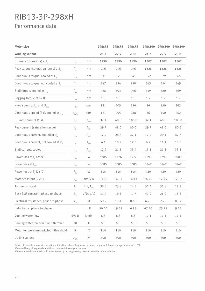
26
RIB13-3P-298xHPerformance data
Motor size 298x75 298x75 298x75 298x100 298x100 298x100
Winding variant Z1.7 Z2.9 Z3.8 Z1.7 Z2.9 Z3.8
Ultimate torque (1 s) at Iu Tu Nm 1130 1130 1130 1507 1507 1507
Peak torque (saturation range) at Ip Tp Nm 996 996 996 1328 1328 1328
Continuous torque, cooled at Icw Tcw Nm 631 651 641 852 879 865
Continuous torque, not cooled at Ic Tc Nm 247 254 250 343 354 349
Stall torque, cooled at Isw Tsw Nm 488 503 496 659 680 669
Cogging torque at I = 0 Tcog Nm 1.3 1.3 1.3 1.7 1.7 1.7
Knee speed at Icw and UDCL nlw rpm 121 205 356 86 150 262
Continuous speed (S1), cooled at Icw nlwS1 rpm 121 205 288 86 150 262
Ultimate current (1 s) Iu Arms 37.1 60.0 100.0 37.1 60.0 100.0
Peak current (saturation range) Ip Arms 29.7 48.0 80.0 29.7 48.0 80.0
Continuous current, cooled at Plw Icw Arms 17.2 28.7 47.1 17.5 29.1 47.7
Continuous current, not cooled at Plc Ic Arms 6.4 10.7 17.5 6.7 11.1 18.3
Stall current, cooled Isw Arms 12.9 21.5 35.4 13.1 21.8 35.8
Power loss at Tp (25°C) Plp W 6785 6376 6577 8293 7793 8083
Power loss at Tcw Plw W 3085 3085 3085 3867 3867 3867
Power loss at Tc (25°C) Plc W 315 315 315 420 420 420
Motor constant (25°C) km Nm/√W 13.90 14.33 14.11 16.76 17.29 17.02
Torque constant kT Nm/Arms 38.5 23.8 14.3 51.4 31.8 19.1
Back EMF constant, phase to phase ku V/(rad/s) 31.4 19.5 11.7 41.9 26.0 15.6
Electrical resistance, phase to phase R25 Ω 5.12 1.84 0.68 6.26 2.25 0.84
Inductance, phase to phase L mH 50.40 19.31 6.95 67.20 25.75 9.27
Cooling water flow dV/dt l/min 8.8 8.8 8.8 11.1 11.1 11.1
Cooling water temperature difference ∆J K 5.0 5.0 5.0 5.0 5.0 5.0
Motor temperature switch-off threshold J °C 110 110 110 110 110 110
DC link voltage UDCL V 600 600 600 600 600 600
Subject to modifications without prior notification, where they serve technical progress. Tolerance range for values: ±10%We would be glad to provide additional data and drawings on request.We recommend a detailed application review by our engineering team for suitable motor selection.
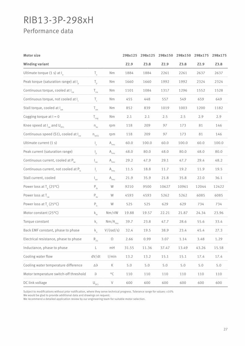
27
RIB13-3P-298xHPerformance data
Motor size 298x125 298x125 298x150 298x150 298x175 298x175
Winding variant Z2.9 Z3.8 Z2.9 Z3.8 Z2.9 Z3.8
Ultimate torque (1 s) at Iu Tu Nm 1884 1884 2261 2261 2637 2637
Peak torque (saturation range) at Ip Tp Nm 1660 1660 1992 1992 2324 2324
Continuous torque, cooled at Icw Tcw Nm 1101 1084 1317 1296 1552 1528
Continuous torque, not cooled at Ic Tc Nm 455 448 557 549 659 649
Stall torque, cooled at Isw Tsw Nm 852 839 1019 1003 1200 1182
Cogging torque at I = 0 Tcog Nm 2.1 2.1 2.5 2.5 2.9 2.9
Knee speed at Icw and UDCL nlw rpm 118 209 97 173 81 146
Continuous speed (S1), cooled at Icw nlwS1 rpm 118 209 97 173 81 146
Ultimate current (1 s) Iu Arms 60.0 100.0 60.0 100.0 60.0 100.0
Peak current (saturation range) Ip Arms 48.0 80.0 48.0 80.0 48.0 80.0
Continuous current, cooled at Plw Icw Arms 29.2 47.9 29.1 47.7 29.4 48.2
Continuous current, not cooled at Plc Ic Arms 11.5 18.8 11.7 19.2 11.9 19.5
Stall current, cooled Isw Arms 21.9 35.9 21.8 35.8 22.0 36.1
Power loss at Tp (25°C) Plp W 9210 9500 10627 10961 12044 12422
Power loss at Tcw Plw W 4593 4593 5262 5262 6085 6085
Power loss at Tc (25°C) Plc W 525 525 629 629 734 734
Motor constant (25°C) km Nm/√W 19.88 19.57 22.21 21.87 24.34 23.96
Torque constant kT Nm/Arms 39.7 23.8 47.7 28.6 55.6 33.4
Back EMF constant, phase to phase ku V/(rad/s) 32.4 19.5 38.9 23.4 45.4 27.3
Electrical resistance, phase to phase R25 Ω 2.66 0.99 3.07 1.14 3.48 1.29
Inductance, phase to phase L mH 31.55 11.36 37.47 13.49 43.26 15.58
Cooling water flow dV/dt l/min 13.2 13.2 15.1 15.1 17.4 17.4
Cooling water temperature difference ∆J K 5.0 5.0 5.0 5.0 5.0 5.0
Motor temperature switch-off threshold J °C 110 110 110 110 110 110
DC link voltage UDCL V 600 600 600 600 600 600
Subject to modifications without prior notification, where they serve technical progress. Tolerance range for values: ±10%We would be glad to provide additional data and drawings on request.We recommend a detailed application review by our engineering team for suitable motor selection.
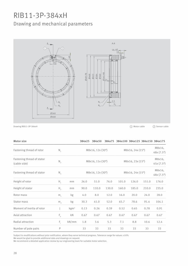
28
RIB11-3P-384xHDrawing and mechanical parameters
Motor size 384x25 384x50 384x75 384x100 384x125 384x150 384x175
Fastening thread of rotor N1 M8x16, 12x (30°) M8x16, 24x (15°)M8x16,
48x (7.5°)
Fastening thread of stator
(cable side)N2 M8x16, 11x (30°) M8x16, 23x (15°)
M8x16,
45x (7.5°)
Fastening thread of stator N3 M8x16, 12x (30°) M8x16, 24x (15°)M8x16,
48x (7.5°)
Height of rotor H1 mm 26.0 51.0 76.0 101.0 126.0 151.0 176.0
Height of stator H2 mm 90.0 110.0 130.0 160.0 185.0 210.0 235.0
Rotor mass m1 kg 4.0 8.0 12.0 16.0 20.0 24.0 28.0
Stator mass m2 kg 30.3 41.0 52.0 65.7 78.6 91.4 104.1
Moment of inertia of rotor J kgm2 0.13 0.26 0.39 0.52 0.65 0.78 0.91
Axial attraction Fa kN 0.67 0.67 0.67 0.67 0.67 0.67 0.67
Radial attraction Fr kN/mm 1.8 3.6 5.3 7.1 8.8 10.6 12.4
Number of pole pairs P 33 33 33 33 33 33 33
A-AA
Ø360
Ø468
70
48
ca. 4010
2.5
21Ø48
5 f8
Ø46
8
Ø45
3
Ø38
4
Ø36
0
Ø34
5 H
8N₁
N₂
N₁
N₃
1 2
H₁
H₂
A
Drawing RIB11-3P-384xH Motor cable Sensor cable1 2
Subject to modifications without prior notification, where they serve technical progress. Tolerance range for values: ±10%We would be glad to provide additional data and drawings on request.We recommend a detailed application review by our engineering team for suitable motor selection.

29
RIB11-3P-384xHPerformance data
Motor size 384x25 384x25 384x25 384x50 384x50 384x50
Winding variant Z1.7 Z2.5 Z3.7 Z1.7 Z2.5 Z3.7
Ultimate torque (1 s) at Iu Tu Nm 573 573 573 1182 1182 1182
Peak torque (saturation range) at Ip Tp Nm 512 512 512 1057 1057 1057
Continuous torque, cooled at Icw Tcw Nm 307 307 302 655 655 645
Continuous torque, not cooled at Ic Tc Nm 97 97 95 233 233 229
Stall torque, cooled at Isw Tsw Nm 233 233 230 498 498 490
Cogging torque at I = 0 Tcog Nm 1.54 1.54 1.54 3.07 3.07 3.07
Knee speed at Icw and UDCL nlw rpm 213 328 599 108 169 313
Continuous speed (S1), cooled at Icw nlwS1 rpm 213 227 227 108 169 227
Ultimate current (1 s) Iu Arms 40.7 61.1 108.4 40.7 61.1 108.4
Peak current (saturation range) Ip Arms 32.6 48.9 86.7 32.6 48.9 86.7
Continuous current, cooled at Plw Icw Arms 16.3 24.5 42.7 16.9 25.3 44.2
Continuous current, not cooled at Plc Ic Arms 4.7 7.0 12.3 5.5 8.2 14.3
Stall current, cooled Isw Arms 11.8 17.6 30.8 12.2 18.2 31.8
Power loss at Tp (25°C) Plp W 5163 5163 5327 7599 7599 7840
Power loss at Tcw Plw W 1737 1737 1737 2735 2735 2735
Power loss at Tc (25°C) Plc W 107 107 107 213 213 213
Motor constant (25°C) km Nm/√W 9.38 9.38 9.23 15.95 15.95 15.71
Torque constant kT Nm/Arms 20.7 13.8 7.8 42.7 28.4 16.0
Back EMF constant, phase to phase ku V/(rad/s) 16.9 11.3 6.3 34.8 23.2 13.1
Electrical resistance, phase to phase R25 Ω 3.2 1.4 0.5 4.8 2.1 0.7
Inductance, phase to phase L mH 30.8 13.7 4.3 50.4 22.4 7.1
Cooling water flow dV/dt l/min 5.0 5.0 5.0 7.8 7.8 7.8
Cooling water temperature difference ∆J K 5.0 5.0 5.0 5.0 5.0 5.0
Motor temperature switch-off threshold J °C 110 110 110 110 110 110
DC link voltage UDCL V 600 600 600 600 600 600
Subject to modifications without prior notification, where they serve technical progress. Tolerance range for values: ±10%We would be glad to provide additional data and drawings on request.We recommend a detailed application review by our engineering team for suitable motor selection.

30
RIB11-3P-384xHPerformance data
Motor size 384x75 384x75 384x75 384x100 384x100
Winding variant Z1.7 Z2.5 Z3.7 Z2.5 Z3.7
Ultimate torque (1 s) at Iu Tu Nm 1828 1828 1828 2462 2462
Peak torque (saturation range) at Ip Tp Nm 1634 1634 1634 2201 2201
Continuous torque, cooled at Icw Tcw Nm 1022 1022 1006 1372 1351
Continuous torque, not cooled at Ic Tc Nm 384 384 378 536 527
Stall torque, cooled at Isw Tsw Nm 776 776 764 1042 1026
Cogging torque at I = 0 Tcog Nm 4.61 4.61 4.61 6.14 6.14
Knee speed at Icw and UDCL nlw rpm 69 111 207 81 154
Continuous speed (S1), cooled at Icw nlwS1 rpm 69 111 207 81 154
Ultimate current (1 s) Iu Arms 40.7 61.1 108.4 61.1 108.4
Peak current (saturation range) Ip Arms 32.6 48.9 86.7 48.9 86.7
Continuous current, cooled at Plw Icw Arms 17.0 25.5 44.6 25.5 44.5
Continuous current, not cooled at Plc Ic Arms 5.8 8.7 15.2 9.0 15.8
Stall current, cooled Isw Arms 12.3 18.4 32.1 18.3 32.0
Power loss at Tp (25°C) Plp W 10034 10034 10353 12469 12865
Power loss at Tcw Plw W 3671 3671 3671 4539 4539
Power loss at Tc (25°C) Plc W 320 320 320 427 427
Motor constant (25°C) km Nm/√W 21.47 21.47 21.14 25.93 25.53
Torque constant kT Nm/Arms 66.0 44.0 24.8 59.2 33.4
Back EMF constant, phase to phase ku V/(rad/s) 53.9 35.9 20.2 48.4 27.3
Electrical resistance, phase to phase R25 Ω 6.3 2.8 0.9 3.5 1.1
Inductance, phase to phase L mH 70.1 31.2 9.9 39.9 12.7
Cooling water flow dV/dt l/min 10.5 10.5 10.5 13.0 13.0
Cooling water temperature difference ∆J K 5.0 5.0 5.0 5.0 5.0
Motor temperature switch-off threshold J °C 110 110 110 110 110
DC link voltage UDCL V 600 600 600 600 600
Subject to modifications without prior notification, where they serve technical progress. Tolerance range for values: ±10%We would be glad to provide additional data and drawings on request.We recommend a detailed application review by our engineering team for suitable motor selection.

31
RIB11-3P-384xHPerformance data
Motor size 384x125 384x125 384x150 384x150 384x175 384x175
Winding variant Z2.5 Z3.7 Z2.5 Z4.0 Z2.5 Z4.0
Ultimate torque (1 s) at Iu Tu Nm 3077 3077 3692 3692 4308 4308
Peak torque (saturation range) at Ip Tp Nm 2751 2751 3301 3301 3852 3852
Continuous torque, cooled at Icw Tcw Nm 1738 1711 2106 2106 2473 2473
Continuous torque, not cooled at Ic Tc Nm 685 674 835 835 985 985
Stall torque, cooled at Isw Tsw Nm 1320 1300 1599 1599 1879 1879
Cogging torque at I = 0 Tcog Nm 7.68 7.68 9.21 9.21 10.75 10.75
Knee speed at Icw and UDCL nlw rpm 63 122 51 114 42 96
Continuous speed (S1), cooled at Icw nlwS1 rpm 63 122 51 114 42 96
Ultimate current (1 s) Iu Arms 61.1 108.4 61.1 122.2 61.1 122.2
Peak current (saturation range) Ip Arms 48.9 86.7 48.9 97.8 48.9 97.8
Continuous current, cooled at Plw Icw Arms 25.8 45.1 26.0 52.1 26.2 52.4
Continuous current, not cooled at Plc Ic Arms 9.3 16.2 9.4 18.8 9.5 19.0
Stall current, cooled Isw Arms 18.6 32.4 18.7 37.5 18.9 37.8
Power loss at Tp (25°C) Plp W 14905 15378 17340 17340 19776 19776
Power loss at Tcw Plw W 5570 5570 6602 6602 7633 7633
Power loss at Tc (25°C) Plc W 534 534 640 640 747 747
Motor constant (25°C) km Nm/√W 29.65 29.19 32.99 32.99 36.04 36.04
Torque constant kT Nm/Arms 74.0 41.7 88.8 44.4 103.7 51.8
Back EMF constant, phase to phase ku V/(rad/s) 60.5 34.1 72.5 36.3 84.6 42.3
Electrical resistance, phase to phase R25 Ω 4.2 1.4 4.8 1.2 5.5 1.4
Inductance, phase to phase L mH 48.7 15.5 57.4 14.3 66.1 16.5
Cooling water flow dV/dt l/min 16.0 16.0 18.9 18.9 14.6 14.6
Cooling water temperature difference ∆J K 5.0 5.0 5.0 5.0 7.5 7.5
Motor temperature switch-off threshold J °C 110 110 110 110 110 110
DC link voltage UDCL V 600 600 600 600 600 600
Subject to modifications without prior notification, where they serve technical progress. Tolerance range for values: ±10%We would be glad to provide additional data and drawings on request.We recommend a detailed application review by our engineering team for suitable motor selection.

32
RIB19-3P-460xHDrawing and mechanical parameters
Motor size 460x25 460x50 460x75 460x100 460x125 460x150 460x175
Fastening thread of rotor N1 M8x16, 12x (30°) M8x16, 24x (15°) M8x16, 48x (7.5°)
Fastening thread of stator
(cable side)N2 M8x16, 11x (30°) M8x16, 23x (15°) M8x16, 45x (7.5°)
Fastening thread of stator N3 M8x16, 12x (30°) M8x16, 24x (15°) M8x16, 48x (7.5°)
Height of rotor H1 mm 26.0 51.0 76.0 101.0 126.0 151.0 176.0
Height of stator H2 mm 90.0 110.0 130.0 160.0 185.0 210.0 235.0
Rotor mass m1 kg 4.9 9.8 14.6 19.5 24.4 29.3 34.2
Stator mass m2 kg 37.6 50.4 63.4 79.1 93.5 107.8 122.1
Moment of inertia of rotor J kgm2 0.24 0.47 0.71 0.94 1.18 1.41 1.65
Axial attraction Fa kN 0.74 0.74 0.74 0.74 0.74 0.74 0.74
Radial attraction Fr kN/mm 1.9 3.8 5.7 7.5 9.4 11.3 13.2
Number of pole pairs P 38 38 38 38 38 38 38
Ø435Ø548
70
50
5
ca. 4010
29Ø
565
f8Ø
548
Ø53
1Ø
460
Ø43
5Ø
420
H8
N₁
H₁
1 2
N₂H₂
N₁N₃
A
A
A-A
Drawing RIB19-3P-460xH Motor cable Sensor cable1 2
Subject to modifications without prior notification, where they serve technical progress. Tolerance range for values: ±10%We would be glad to provide additional data and drawings on request.We recommend a detailed application review by our engineering team for suitable motor selection.

33
RIB19-3P-460xHPerformance data
Motor size 460x25 460x25 460x25 460x50 460x50 460x50
Winding variant Z1.7 Z2.5 Z3.8 Z1.7 Z2.5 Z3.8
Ultimate torque (1 s) at Iu Tu Nm 888 888 888 1813 1813 1813
Peak torque (saturation range) at Ip Tp Nm 755 755 755 1541 1541 1541
Continuous torque, cooled at Icw Tcw Nm 447 436 434 977 953 950
Continuous torque, not cooled at Ic Tc Nm 137 134 134 335 327 326
Stall torque, cooled at Isw Tsw Nm 334 326 325 731 713 711
Cogging torque at I = 0 Tcog Nm 1.97 1.97 1.97 3.95 3.95 3.95
Knee speed at Icw and UDCL nlw rpm 143 226 419 69 112 211
Continuous speed (S1), cooled at Icw nlwS1 rpm 143 197 197 70 112 197
Ultimate current (1 s) Iu Arms 41.2 62.3 112.4 41.2 62.3 112.4
Peak current (saturation range) Ip Arms 30.4 46.0 83.0 30.4 46.0 83.0
Continuous current, cooled at Plw Icw Arms 15.7 23.2 41.8 16.9 24.9 44.8
Continuous current, not cooled at Plc Ic Arms 4.6 6.9 12.3 5.5 8.2 14.7
Stall current, cooled Isw Arms 11.4 16.9 30.3 12.2 18.1 32.5
Power loss at Tp (25°C) Plp W 5349 5623 5658 7508 7892 7941
Power loss at Tcw Plw W 1927 1927 1927 3103 3103 3103
Power loss at Tc (25°C) Plc W 125 125 125 250 250 250
Motor constant (25°C) km Nm/√W 12.28 11.98 11.94 21.17 20.65 20.58
Torque constant kT Nm/Arms 29.6 19.5 10.8 60.3 39.9 22.1
Back EMF constant, phase to phase ku V/(rad/s) 24.1 15.9 8.8 49.3 32.6 18.0
Electrical resistance, phase to phase R25 Ω 3.9 1.8 0.5 5.4 2.5 0.8
Inductance, phase to phase L mH 39.5 17.3 5.3 68.9 30.1 9.2
Cooling water flow dV/dt l/min 5.5 5.5 5.5 8.9 8.9 8.9
Cooling water temperature difference ∆J K 5.0 5.0 5.0 5.0 5.0 5.0
Motor temperature switch-off threshold J °C 110 110 110 110 110 110
DC link voltage UDCL V 600 600 600 600 600 600
Subject to modifications without prior notification, where they serve technical progress. Tolerance range for values: ±10%We would be glad to provide additional data and drawings on request.We recommend a detailed application review by our engineering team for suitable motor selection.
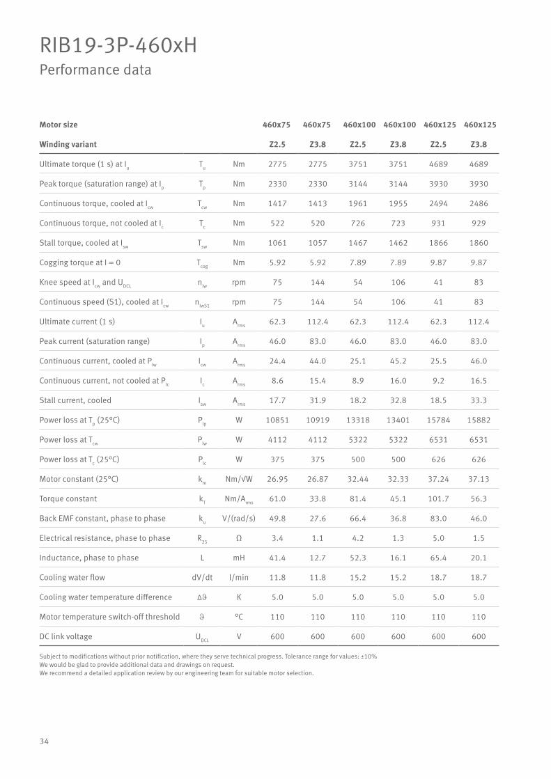
34
RIB19-3P-460xHPerformance data
Motor size 460x75 460x75 460x100 460x100 460x125 460x125
Winding variant Z2.5 Z3.8 Z2.5 Z3.8 Z2.5 Z3.8
Ultimate torque (1 s) at Iu Tu Nm 2775 2775 3751 3751 4689 4689
Peak torque (saturation range) at Ip Tp Nm 2330 2330 3144 3144 3930 3930
Continuous torque, cooled at Icw Tcw Nm 1417 1413 1961 1955 2494 2486
Continuous torque, not cooled at Ic Tc Nm 522 520 726 723 931 929
Stall torque, cooled at Isw Tsw Nm 1061 1057 1467 1462 1866 1860
Cogging torque at I = 0 Tcog Nm 5.92 5.92 7.89 7.89 9.87 9.87
Knee speed at Icw and UDCL nlw rpm 75 144 54 106 41 83
Continuous speed (S1), cooled at Icw nlwS1 rpm 75 144 54 106 41 83
Ultimate current (1 s) Iu Arms 62.3 112.4 62.3 112.4 62.3 112.4
Peak current (saturation range) Ip Arms 46.0 83.0 46.0 83.0 46.0 83.0
Continuous current, cooled at Plw Icw Arms 24.4 44.0 25.1 45.2 25.5 46.0
Continuous current, not cooled at Plc Ic Arms 8.6 15.4 8.9 16.0 9.2 16.5
Stall current, cooled Isw Arms 17.7 31.9 18.2 32.8 18.5 33.3
Power loss at Tp (25°C) Plp W 10851 10919 13318 13401 15784 15882
Power loss at Tcw Plw W 4112 4112 5322 5322 6531 6531
Power loss at Tc (25°C) Plc W 375 375 500 500 626 626
Motor constant (25°C) km Nm/√W 26.95 26.87 32.44 32.33 37.24 37.13
Torque constant kT Nm/Arms 61.0 33.8 81.4 45.1 101.7 56.3
Back EMF constant, phase to phase ku V/(rad/s) 49.8 27.6 66.4 36.8 83.0 46.0
Electrical resistance, phase to phase R25 Ω 3.4 1.1 4.2 1.3 5.0 1.5
Inductance, phase to phase L mH 41.4 12.7 52.3 16.1 65.4 20.1
Cooling water flow dV/dt l/min 11.8 11.8 15.2 15.2 18.7 18.7
Cooling water temperature difference ∆J K 5.0 5.0 5.0 5.0 5.0 5.0
Motor temperature switch-off threshold J °C 110 110 110 110 110 110
DC link voltage UDCL V 600 600 600 600 600 600
Subject to modifications without prior notification, where they serve technical progress. Tolerance range for values: ±10%We would be glad to provide additional data and drawings on request.We recommend a detailed application review by our engineering team for suitable motor selection.

35
RIB19-3P-460xHPerformance data
Motor size 460x125 460x150 460x150 460x175 460x175
Winding variant Z4.9 Z3.8 Z4.9 Z3.8 Z4.9
Ultimate torque (1 s) at Iu Tu Nm 4689 5739 5739 6695 6695
Peak torque (saturation range) at Ip Tp Nm 3930 4811 4811 5612 5612
Continuous torque, cooled at Icw Tcw Nm 2557 3081 3169 3628 3731
Continuous torque, not cooled at Ic Tc Nm 955 1158 1191 1369 1408
Stall torque, cooled at Isw Tsw Nm 1913 2305 2371 2714 2791
Cogging torque at I = 0 Tcog Nm 9.87 11.84 11.84 13.82 13.82
Knee speed at Icw and UDCL nlw rpm 125 67 103 56 86
Continuous speed (S1), cooled at Icw nlwS1 rpm 125 67 103 56 86
Ultimate current (1 s) Iu Arms 164.6 112.4 164.6 112.4 164.6
Peak current (saturation range) Ip Arms 121.6 83.0 121.6 83.0 121.6
Continuous current, cooled at Plw Icw Arms 69.2 46.5 70.1 47.0 70.7
Continuous current, not cooled at Plc Ic Arms 24.8 16.8 25.3 17.0 25.6
Stall current, cooled Isw Arms 50.2 33.8 50.8 34.1 51.3
Power loss at Tp (25°C) Plp W 15016 18364 17362 20846 19708
Power loss at Tcw Plw W 6531 7740 7740 8950 8950
Power loss at Tc (25°C) Plc W 626 751 751 876 876
Motor constant (25°C) km Nm/√W 38.18 42.26 43.46 46.28 47.59
Torque constant kT Nm/Arms 38.5 69.0 47.1 80.5 55.0
Back EMF constant, phase to phase ku V/(rad/s) 31.4 56.3 38.5 65.7 44.9
Electrical resistance, phase to phase R25 Ω 0.7 1.8 0.8 2.0 0.9
Inductance, phase to phase L mH 9.4 23.1 10.8 27.0 12.6
Cooling water flow dV/dt l/min 18.7 14.8 14.8 17.1 17.1
Cooling water temperature difference ∆J K 5.0 7.5 7.5 7.5 7.5
Motor temperature switch-off threshold J °C 110 110 110 110 110
DC link voltage UDCL V 600 600 600 600 600
Subject to modifications without prior notification, where they serve technical progress. Tolerance range for values: ±10%We would be glad to provide additional data and drawings on request.We recommend a detailed application review by our engineering team for suitable motor selection.

36
RIB13-3P-690xHDrawing and mechanical parameters
Motor size 690x25 690x50 690x75 690x100 690x125 690x150 690x175
Fastening thread of rotor N1
M8x16,
16x (22.5°)
M8x16,
32x (11.25°)
M8x16,
64x (5.625°)
Fastening thread of stator
(cable side)N2
M8x16,
15x (22.5°)
M8x16,
31x (11.25°)
M8x16,
61x (5.625°)
Fastening thread of stator N3
M8x16,
16x (22.5°)
M8x16,
32x (11.25°)
M8x16,
64x (5.625°)
Height of rotor H1 mm 26.0 51.0 76.0 101.0 126.0 151.0 176.0
Height of stator H2 mm 110.0 130.0 150.0 180.0 205.0 230.0 255.0
Rotor mass m1 kg 7.6 15.2 22.8 30.4 38.0 45.6 53.2
Stator mass m2 kg 62.9 81.6 99.8 122.9 143.2 163.7 184.1
Moment of inertia of rotor J kgm2 0.85 1.70 2.55 3.40 4.25 5.10 5.95
Axial attraction Fa kN 1.11 1.11 1.11 1.11 1.11 1.11 1.11
Radial attraction Fr kN/mm 3.3 6.6 9.9 13.1 16.4 19.7 23.0
Number of pole pairs P 65 65 65 65 65 65 65
Ø665
Ø778
70 50
ca. 4010
H₂
5
H₁
39
Ø79
5 f8
Ø77
8
Ø76
1
Ø69
0
Ø66
5
Ø65
0 H
8
N₁
A
1 2
N₂A
N₁
N₃
A-A
Drawing RIB13-3P-690xH Motor cable Sensor cable1 2
Subject to modifications without prior notification, where they serve technical progress. Tolerance range for values: ±10%We would be glad to provide additional data and drawings on request.We recommend a detailed application review by our engineering team for suitable motor selection.
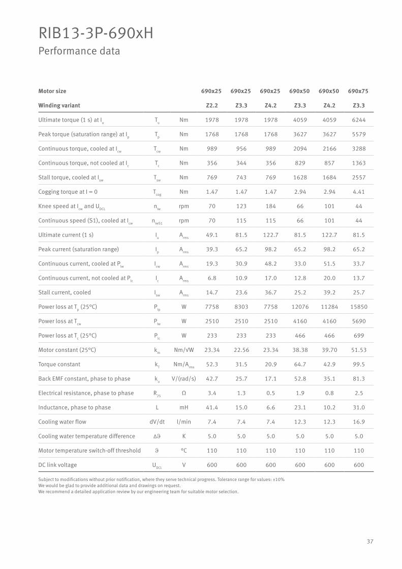
37
RIB13-3P-690xHPerformance data
Motor size 690x25 690x25 690x25 690x50 690x50 690x75
Winding variant Z2.2 Z3.3 Z4.2 Z3.3 Z4.2 Z3.3
Ultimate torque (1 s) at Iu Tu Nm 1978 1978 1978 4059 4059 6244
Peak torque (saturation range) at Ip Tp Nm 1768 1768 1768 3627 3627 5579
Continuous torque, cooled at Icw Tcw Nm 989 956 989 2094 2166 3288
Continuous torque, not cooled at Ic Tc Nm 356 344 356 829 857 1363
Stall torque, cooled at Isw Tsw Nm 769 743 769 1628 1684 2557
Cogging torque at I = 0 Tcog Nm 1.47 1.47 1.47 2.94 2.94 4.41
Knee speed at Icw and UDCL nlw rpm 70 123 184 66 101 44
Continuous speed (S1), cooled at Icw nlwS1 rpm 70 115 115 66 101 44
Ultimate current (1 s) Iu Arms 49.1 81.5 122.7 81.5 122.7 81.5
Peak current (saturation range) Ip Arms 39.3 65.2 98.2 65.2 98.2 65.2
Continuous current, cooled at Plw Icw Arms 19.3 30.9 48.2 33.0 51.5 33.7
Continuous current, not cooled at Plc Ic Arms 6.8 10.9 17.0 12.8 20.0 13.7
Stall current, cooled Isw Arms 14.7 23.6 36.7 25.2 39.2 25.7
Power loss at Tp (25°C) Plp W 7758 8303 7758 12076 11284 15850
Power loss at Tcw Plw W 2510 2510 2510 4160 4160 5690
Power loss at Tc (25°C) Plc W 233 233 233 466 466 699
Motor constant (25°C) km Nm/√W 23.34 22.56 23.34 38.38 39.70 51.53
Torque constant kT Nm/Arms 52.3 31.5 20.9 64.7 42.9 99.5
Back EMF constant, phase to phase ku V/(rad/s) 42.7 25.7 17.1 52.8 35.1 81.3
Electrical resistance, phase to phase R25 Ω 3.4 1.3 0.5 1.9 0.8 2.5
Inductance, phase to phase L mH 41.4 15.0 6.6 23.1 10.2 31.0
Cooling water flow dV/dt l/min 7.4 7.4 7.4 12.3 12.3 16.9
Cooling water temperature difference ∆J K 5.0 5.0 5.0 5.0 5.0 5.0
Motor temperature switch-off threshold J °C 110 110 110 110 110 110
DC link voltage UDCL V 600 600 600 600 600 600
Subject to modifications without prior notification, where they serve technical progress. Tolerance range for values: ±10%We would be glad to provide additional data and drawings on request.We recommend a detailed application review by our engineering team for suitable motor selection.

38
RIB13-3P-690xHPerformance data
Motor size 690x75 690x100 690x100 690x100 690x125 690x125
Winding variant Z4.2 Z3.3 Z4.2 Z5.9 Z3.3 Z4.2
Ultimate torque (1 s) at Iu Tu Nm 6244 8366 8366 8366 10457 10457
Peak torque (saturation range) at Ip Tp Nm 5579 7475 7475 7475 9343 9343
Continuous torque, cooled at Icw Tcw Nm 3401 4504 4659 4504 5712 5909
Continuous torque, not cooled at Ic Tc Nm 1410 1895 1960 1895 2425 2508
Stall torque, cooled at Isw Tsw Nm 2645 3502 3623 3502 4441 4595
Cogging torque at I = 0 Tcog Nm 4.41 2.94 2.94 2.94 7.35 7.35
Knee speed at Icw and UDCL nlw rpm 68 32 51 90 25 40
Continuous speed (S1), cooled at Icw nlwS1 rpm 68 32 51 90 25 40
Ultimate current (1 s) Iu Arms 122.7 81.5 122.7 203.7 81.5 122.7
Peak current (saturation range) Ip Arms 98.2 65.2 98.2 163.0 65.2 98.2
Continuous current, cooled at Plw Icw Arms 52.5 34.5 53.7 86.2 35.0 54.5
Continuous current, not cooled at Plc Ic Arms 21.3 14.2 22.1 35.5 14.5 22.7
Stall current, cooled Isw Arms 40.0 26.3 40.9 65.7 26.6 41.5
Power loss at Tp (25°C) Plp W 14811 19624 18337 19624 23398 21864
Power loss at Tcw Plw W 5690 7364 7364 7364 9037 9037
Power loss at Tc (25°C) Plc W 699 932 932 932 1165 1165
Motor constant (25°C) km Nm/√W 53.30 62.05 64.19 62.05 71.03 73.48
Torque constant kT Nm/Arms 66.1 133.3 88.5 53.3 166.7 110.6
Back EMF constant, phase to phase ku V/(rad/s) 53.9 108.9 72.3 43.5 136.1 90.3
Electrical resistance, phase to phase R25 Ω 1.0 3.1 1.3 0.5 3.7 1.5
Inductance, phase to phase L mH 13.7 37.6 16.6 6.0 46.1 20.3
Cooling water flow dV/dt l/min 16.9 14.6 14.6 14.6 17.9 17.9
Cooling water temperature difference ∆J K 5.0 7.5 7.5 7.5 7.5 7.5
Motor temperature switch-off threshold J °C 110 110 110 110 110 110
DC link voltage UDCL V 600 600 600 600 600 600
Subject to modifications without prior notification, where they serve technical progress. Tolerance range for values: ±10%We would be glad to provide additional data and drawings on request.We recommend a detailed application review by our engineering team for suitable motor selection.

39
RIB13-3P-690xHPerformance data
Motor size 690x125 690x150 690x150 690x150 690x175 690x175
Winding variant Z5.9 Z3.3 Z4.2 Z5.9 Z4.2 Z5.9
Ultimate torque (1 s) at Iu Tu Nm 10457 12549 12549 12549 14640 14640
Peak torque (saturation range) at Ip Tp Nm 9343 11212 11212 11212 13081 13081
Continuous torque, cooled at Icw Tcw Nm 5712 6924 7163 6924 8421 8140
Continuous torque, not cooled at Ic Tc Nm 2425 2958 3060 2958 3613 3493
Stall torque, cooled at Isw Tsw Nm 4441 5384 5570 5384 6548 6329
Cogging torque at I = 0 Tcog Nm 7.35 4.41 4.41 4.41 10.30 10.30
Knee speed at Icw and UDCL nlw rpm 71 19 32 58 27 47
Continuous speed (S1), cooled at Icw nlwS1 rpm 71 19 32 58 27 47
Ultimate current (1 s) Iu Arms 203.7 81.5 122.7 203.7 122.7 203.7
Peak current (saturation range) Ip Arms 163.0 65.2 98.2 163.0 98.2 163.0
Continuous current, cooled at Plw Icw Arms 87.4 35.3 55.1 88.3 55.5 89.0
Continuous current, not cooled at Plc Ic Arms 36.4 14.8 23.0 37.0 23.3 37.4
Stall current, cooled Isw Arms 66.6 26.9 42.0 67.3 42.3 67.8
Power loss at Tp (25°C) Plp W 23398 27172 25390 27172 28916 30946
Power loss at Tcw Plw W 9037 10711 10711 10711 12384 12384
Power loss at Tc (25°C) Plc W 1165 1399 1399 1399 1632 1632
Motor constant (25°C) km Nm/√W 71.03 79.09 81.82 79.09 89.45 86.47
Torque constant kT Nm/Arms 66.7 200.0 132.8 80.0 154.9 93.3
Back EMF constant, phase to phase ku V/(rad/s) 54.4 163.3 108.4 65.3 126.5 76.2
Electrical resistance, phase to phase R25 Ω 0.6 4.3 1.8 0.7 2.0 0.8
Inductance, phase to phase L mH 7.4 55.3 24.4 8.8 28.4 11.5
Cooling water flow dV/dt l/min 17.9 15.9 15.9 15.9 18.4 18.4
Cooling water temperature difference ∆J K 7.5 10.0 10.0 10.0 10.0 10.0
Motor temperature switch-off threshold J °C 110 110 110 110 110 110
DC link voltage UDCL V 600 600 600 600 600 600
Subject to modifications without prior notification, where they serve technical progress. Tolerance range for values: ±10%We would be glad to provide additional data and drawings on request.We recommend a detailed application review by our engineering team for suitable motor selection.

40
Checklist for your inquiryTorque motors
Please fill out the following checklist so we can answer your inquiry as quickly and precisely as possible.
Do not hesitate to contact the Schaeffler sales team if you have any questions.
Company Contact name Sector · Project name
Phone E-mail
Application
Predominant operating mode
Operating several motors in parallel
Motor type (if known)
Any required compatibility to
Installation space
Continuous operation
(S1, e.g. in NC axes)
Yes
Tandem arrangement
Janus arrangement
Intermittent operation
(S6, e.g. in cycled applications)
No
Continuous operation (S1)
Continuous operation (S1)
DC link voltage [VDC]
Intermittent operation (S6)
Intermittent operation (S6)
Peak current
Standstill
Standstill
Manufacturer Type
Min. internal diameter / max. external diameter / max. height [mm]
Required operating points Operating point 1
Torque
Operating point 2
Torque
Speed
Speed
/ /
Frequency converter Manufacturer Type
Continuous operation
current (S1)
41
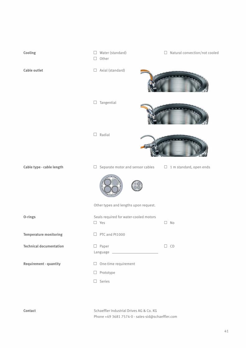
Cooling Water (standard) Natural convection/not cooled
Other
Temperature monitoring PTC and Pt1000
Paper
Language
Schaeffler Industrial Drives AG & Co. KG
Phone +49 3681 7574-0 · [email protected]
Cable outlet Axial (standard)
Tangential
Radial
Cable type · cable length Separate motor and sensor cables 1 m standard, open ends
Other types and lengths upon request.
O-rings Seals required for water-cooled motors
Yes No
Contact
Technical documentation CD
Requirement · quantity One-time requirement
Prototype
Series

42
Glossary
Symbol Meaning Unit Explanation
Tu Ultimate torque Nm
Torque at high saturation in the magnetic circuit resulting from the
ultimate current. May be approached briefly (<1 s) only if the stator is
cold (approx. 60 °C) and magnet temperatures are below 60 °C. At
higher temperatures, there is a risk of demagnetisation of the rotor
and thermal destruction of the stator within a very short period of
time. The ultimate torque should not be used as a dimensioning vari-
able, but must be observed in the case of short-circuit braking.
Tp Peak torque Nm
Short duration (1 – 3 s) torque at Ip which is reliably attained in the
saturation range and at all operating temperatures. With magnet tem-
peratures up to 60 °C and in pulsed mode, Tp can be increased up to
the value of Tu.
Tcw
Continuous torque,
cooledNm
Motor torque at Icw which is available as a continuous torque in nomi-
nal operation with water cooling and a maximum temperature gradi-
ent of approx. 100 K between the winding and cooling fluid.
Tc
Continuous torque,
not cooledNm
Continuous motor torque at continuous current Ic which the motor can
be operated at for thermally stable operation without external cool-
ing, but is heated up in doing so.
Tsw Stall torque, cooled NmTorque that can be produced when the motor is stationary and with
pole change frequencies up to approx. 0.1 Hz.
Tcog Cogging torque Nm
Torque which acts in a pulsating manner depending on the rotor
position. The specified value is the peak value in the de-energized
state.
nlw Knee speed rpm
Winding-dependent speed limit without taking the dynamic heat loss-
es into account when operating at Icw and without field weakening.
The torque drops significantly after this point.
nlwS1
Continuous speed (S1),
cooledrpm
Speed limit up to which the motor can be continuously operated at
Icw.
Iu Ultimate current Arms
Effective current at which the magnetic circuit has high saturation. It
is determined either by the maximum current density in the winding
or by the incipient risk of demagnetisation at a magnet temperature
of 80 °C.
Ip Peak current Arms
Effective current in the iron saturation range which should be used as
the dimensioning variable (see also Tp). When the rotor is only moder-
ately warm (magnet temperature max. 60 °C) and pulsed mode is
used (max. 1 – 3 s), Ip can be increased to the limit value Iu.
Icw Continuous current, cooled Arms
Effective current which is permissible during continuous operation
with water cooling above a pole change frequency of 0.1 Hz.
43
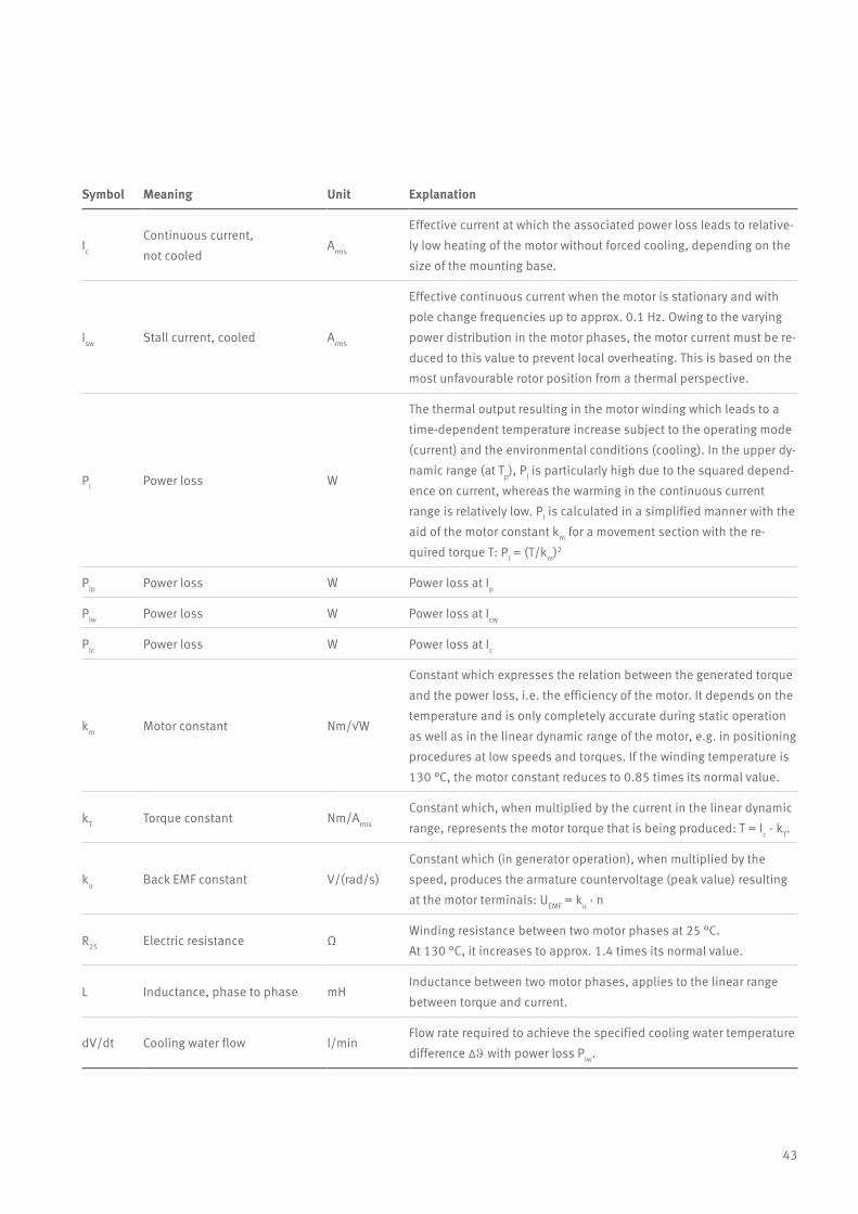
Symbol Meaning Unit Explanation
Ic
Continuous current,
not cooledArms
Effective current at which the associated power loss leads to relative-
ly low heating of the motor without forced cooling, depending on the
size of the mounting base.
Isw Stall current, cooled Arms
Effective continuous current when the motor is stationary and with
pole change frequencies up to approx. 0.1 Hz. Owing to the varying
power distribution in the motor phases, the motor current must be re-
duced to this value to prevent local overheating. This is based on the
most unfavourable rotor position from a thermal perspective.
Pl Power loss W
The thermal output resulting in the motor winding which leads to a
time-dependent temperature increase subject to the operating mode
(current) and the environmental conditions (cooling). In the upper dy-
namic range (at Tp), Pl is particularly high due to the squared depend-
ence on current, whereas the warming in the continuous current
range is relatively low. Pl is calculated in a simplified manner with the
aid of the motor constant km for a movement section with the re-
quired torque T: Pl = (T/km)2
Plp Power loss W Power loss at Ip
Plw Power loss W Power loss at Icw
Plc Power loss W Power loss at Ic
km Motor constant Nm/√W
Constant which expresses the relation between the generated torque
and the power loss, i.e. the efficiency of the motor. It depends on the
temperature and is only completely accurate during static operation
as well as in the linear dynamic range of the motor, e.g. in positioning
procedures at low speeds and torques. If the winding temperature is
130 °C, the motor constant reduces to 0.85 times its normal value.
kT Torque constant Nm/Arms
Constant which, when multiplied by the current in the linear dynamic
range, represents the motor torque that is being produced: T = Ic · kT.
ku Back EMF constant V/(rad/s)
Constant which (in generator operation), when multiplied by the
speed, produces the armature countervoltage (peak value) resulting
at the motor terminals: UEMF = ku · n
R25 Electric resistance ΩWinding resistance between two motor phases at 25 °C.
At 130 °C, it increases to approx. 1.4 times its normal value.
L Inductance, phase to phase mHInductance between two motor phases, applies to the linear range
between torque and current.
dV/dt Cooling water flow l/minFlow rate required to achieve the specified cooling water temperature
difference ∆J with power loss Plw.
44
Glossary
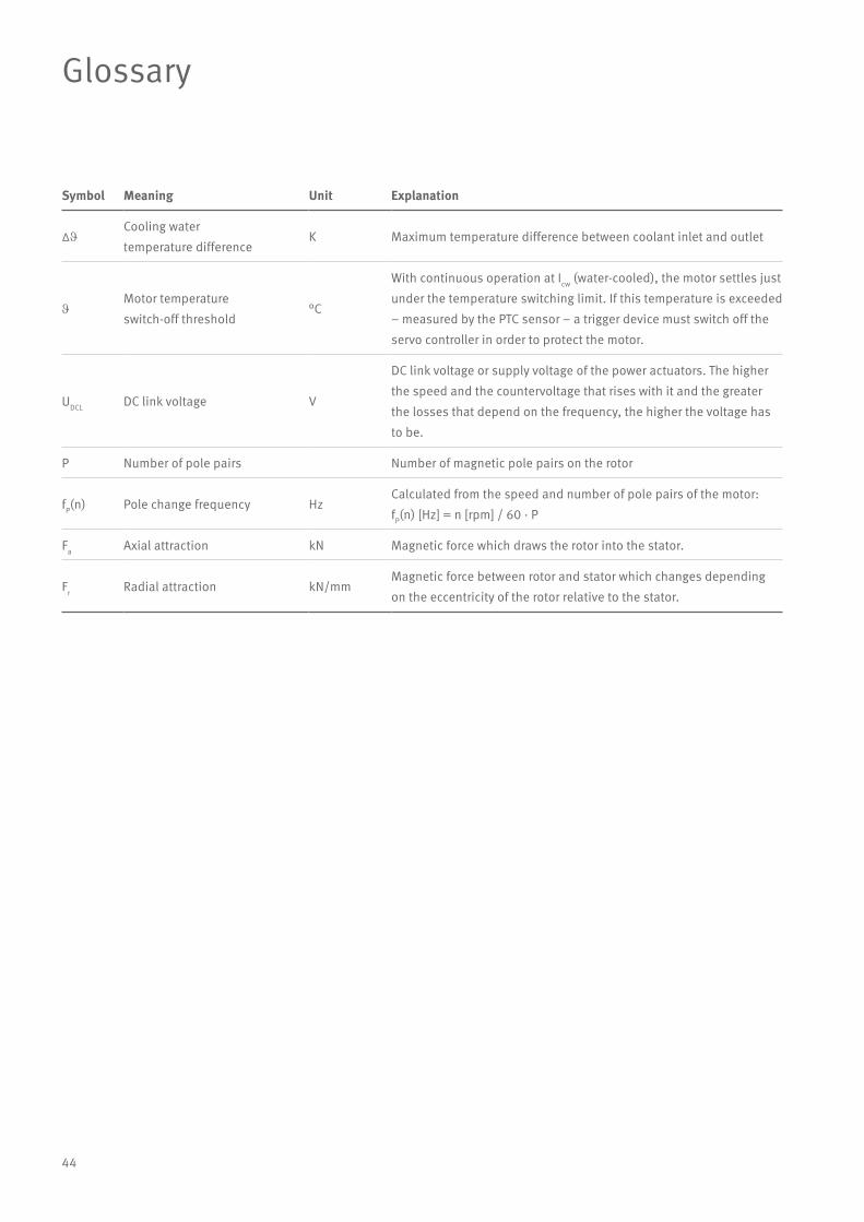
Symbol Meaning Unit Explanation
∆JCooling water
temperature differenceK Maximum temperature difference between coolant inlet and outlet
JMotor temperature
switch-off threshold°C
With continuous operation at Icw (water-cooled), the motor settles just
under the temperature switching limit. If this temperature is exceeded
– measured by the PTC sensor – a trigger device must switch off the
servo controller in order to protect the motor.
UDCL DC link voltage V
DC link voltage or supply voltage of the power actuators. The higher
the speed and the countervoltage that rises with it and the greater
the losses that depend on the frequency, the higher the voltage has
to be.
P Number of pole pairs Number of magnetic pole pairs on the rotor
fP(n) Pole change frequency HzCalculated from the speed and number of pole pairs of the motor:
fP(n) [Hz] = n [rpm] / 60 · P
Fa Axial attraction kN Magnetic force which draws the rotor into the stator.
Fr Radial attraction kN/mmMagnetic force between rotor and stator which changes depending
on the eccentricity of the rotor relative to the stator.

45
Modular system for rotary tables
Schaeffler offers a highly-specialized modular system that allows cus-tomers to select exactly the right components for their rotary tables and rotary axes – that includes high-speed, high-performance and high-preci-sion designs.
Three standard torque motor series from Schaeffler Industrial Drives and three series of rotary table and rotary axis bearings from Schaeffler can be combined in any way desired. This means that the best solution can be assembled for every possible machine used for machining processes.
This optimum combination of components is adjusted by Schaeffler’s engineers to perfectly match each individual customer’s process and deliver exactly the required precision and dynamics.
Rotary table bearing YRTC-XL
Frictional torque ++
Speed +
Rigidity +++
Axial/radial runout +++
YRTS
Frictional torque ++
Speed ++
Rigidity ++
Axial/radial runout ++
ZKLDF
Frictional torque +++
Speed +++
Rigidity +
Axial/radial runout ++
RIB
Torque density +++
Speed +
Accuracy ++
Positioning axes,
simultaneous machining
Positioning axes,
simultaneous machining
Positioning axes,
simultaneous machining
RKI
Torque density +++
Speed ++
Accuracy +(+)
Gear machining
(plane milling)
Combined machining (turn-milling), gear machin-ing (plane milling)
Combined machining (turning/milling)
SRV
Torque density +
Speed +++
Accuracy +++
Ultra-precision machining, positioning table and swiv-el-type axes
Combined machining (turn-ing/milling), gear grinding
Turning, combined machining (turning/ milling, grinding/hard turning), spindle applications
Torque motor
Unbeatable variety: Perfect coordination of motor and bearing
“+” Suitable “++” Very suitable “+++” Extremely suitable
46
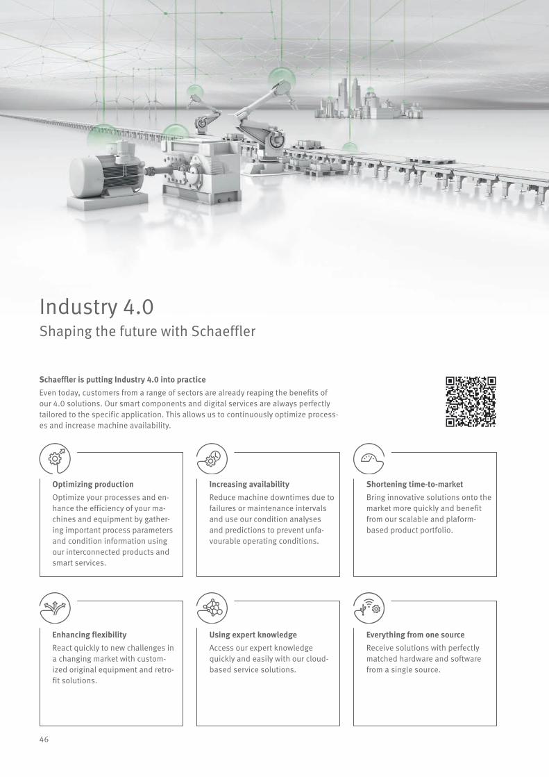
Industry 4.0Shaping the future with Schaeffler
Schaeffler is putting Industry 4.0 into practiceEven today, customers from a range of sectors are already reaping the benefits of our 4.0 solutions. Our smart components and digital services are always perfectly tailored to the specific application. This allows us to continuously optimize process-es and increase machine availability.
Optimizing productionOptimize your processes and en-hance the efficiency of your ma-chines and equipment by gather-ing important process parameters and condition information using our interconnected products and smart services.
Increasing availabilityReduce machine downtimes due to failures or maintenance intervals and use our condition analyses and predictions to prevent unfa-vourable operating conditions.
Shortening time-to-marketBring innovative solutions onto the market more quickly and benefit from our scalable and plaform- based product portfolio.
Enhancing flexibilityReact quickly to new challenges in a changing market with custom-ized original equipment and retro-fit solutions.
Using expert knowledgeAccess our expert knowledge quickly and easily with our cloud-based service solutions.
Everything from one sourceReceive solutions with perfectly matched hardware and software from a single source.
47
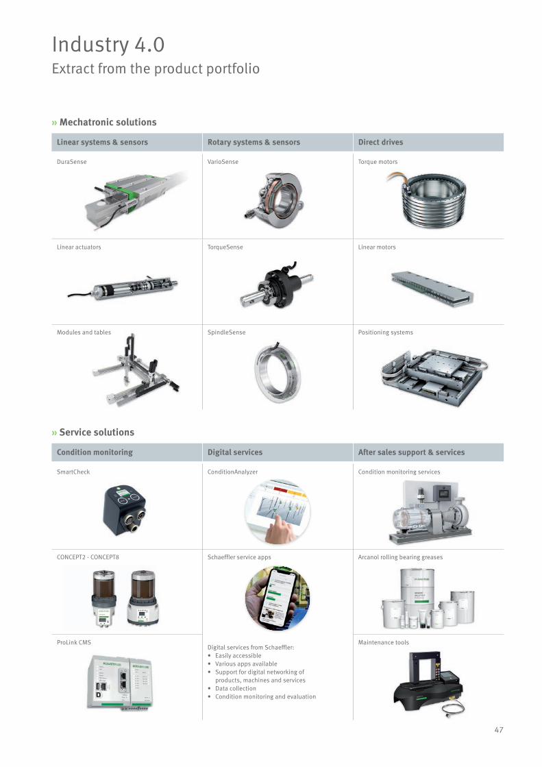
Industry 4.0Extract from the product portfolio
Linear systems & sensors Rotary systems & sensors Direct drives
Condition monitoring Digital services After sales support & services
» Mechatronic solutions
» Service solutions
DuraSense VarioSense Torque motors
Linear actuators TorqueSense Linear motors
Modules and tables SpindleSense Positioning systems
SmartCheck ConditionAnalyzer Condition monitoring services
CONCEPT2 · CONCEPT8 Schaeffler service apps
Digital services from Schaeffler:• Easily accessible • Various apps available • Support for digital networking of products, machines and services• Data collection• Condition monitoring and evaluation
Arcanol rolling bearing greases
ProLink CMS Maintenance tools
2276
64 /
US-
D /
202
002.
5 /
Prin
ted
in G
erm
any
by m
ultic
olor
Schaeffler Industrial Drives AG & Co. KGMittelbergstrasse 2 98527 Suhl Germany www.schaeffler-industrial-drives.com [email protected]
In Germany: Phone 03681 7574-0 From other countries: Phone +49 3681 7574-0
Every care has been taken to ensure thecorrectness of the information containedin this publication but no liability can beaccepted for any errors or omissions.We reserve the right to make technicalchanges.© Schaeffler Industrial Drives AG & Co. KGIssued: 2020, FebruaryThis publication or parts thereof may notbe reproduced without our permission.


