Embed Size (px)
Citation preview
Citation: Machado, L.H.J.; Sandoval,
O.R.; Pereira, J.V.M.C.; de Souza,
J.P.B.; Caetano, B.C.; Hanriot, V.M.;
Pujatti, F.J.P.; de Faria, M.T.C.
Influence of Fluid Film Bearings with
Different Axial Groove Shapes on
Automotive Turbochargers: An
Experimental Study. Lubricants 2022,
10, 92. https://doi.org/10.3390/
lubricants10050092
Received: 21 April 2022
Accepted: 7 May 2022
Published: 11 May 2022
Publisher’s Note: MDPI stays neutral
with regard to jurisdictional claims in
published maps and institutional affil-
iations.
Copyright: © 2022 by the authors.
Licensee MDPI, Basel, Switzerland.
This article is an open access article
distributed under the terms and
conditions of the Creative Commons
Attribution (CC BY) license (https://
creativecommons.org/licenses/by/
4.0/).
lubricants
Article
Influence of Fluid Film Bearings with Different Axial GrooveShapes on Automotive Turbochargers: An Experimental StudyLuiz Henrique Jorge Machado 1,2,*, Oscar Ricardo Sandoval 1,2,3, José Victor Matos Carvalho Pereira 2,Juliana Primo Basílio de Souza 1,3,4 , Bryan Castro Caetano 1,2,5, Vítor Mourão Hanriot 2,6 ,Fabrício José Pacheco Pujatti 1,2,3 and Marco Tulio Correa de Faria 1,3
1 Graduate Program in Mechanical Engineering, Universidade Federal de Minas Gerais,Belo Horizonte 31270-901, Brazil; [email protected] (O.R.S.); [email protected] (J.P.B.d.S.);[email protected] (B.C.C.); [email protected] (F.J.P.P.); [email protected] (M.T.C.d.F.)
2 Mobility Technology Center, Universidade Federal de Minas Gerais, Belo Horizonte 31270-901, Brazil;[email protected] (J.V.M.C.P.); [email protected] (V.M.H.)
3 Department of Mechanical Engineering, Universidade Federal de Minas Gerais, Belo Horizonte 31270-901, Brazil4 Graduate Program in Mechanical Engineering and Materials Technology, Centro Federal de Educação
Tecnológica Celso Suckow da Fonseca, Rio de Janeiro 20271-110, Brazil5 Centro Federal de Educação Tecnológica de Minas Gerais, Campus Nepomuceno, Nepomuceno 37250-000, Brazil6 Graduate Program in Electrical Engineering, Universidade Federal de Minas Gerais,
Belo Horizonte 31270-901, Brazil* Correspondence: [email protected]
Abstract: Most commercial automotive turbochargers (TC) employ semi-floating ring bearings(SFRB) with axial groove shapes. In order to bring some insights into the role played by theaxial groove geometry on the dynamics of TC, this work deals with an experimental studyof the rotordynamic behavior of a stock automotive turbocharger operating on SFRB withtwo different groove shapes, which have the same volume and width, and with the samenumber of grooves. The rotating machine behavior has been evaluated under different operatingconditions using a test bench specially designed to analyze turbochargers. Rotordynamic (RD)characteristics of automotive turbochargers are estimated to evaluate the influence of the axialgroove geometry on the machine vibratory behavior. Frequency spectra and orbital plots ofthe rotor are obtained from accelerometers and proximity probes mounted on the turbocharger.The comparative analysis of the vibrational behavior of automotive turbochargers running ondifferent supporting systems allows the identification of the role played by the axial grooves onthe machine rotordynamic performance. The experimental results rendered in this work permitto classify the influence of the axial groove geometry on the turbocharger rotordynamic behaviorfor several speed and flow conditions.
Keywords: turbocharger; floating ring bearing; axial groove bearing; vibration analysis
1. Introduction
Several thermohydrodynamic experimental studies of turbochargers (TCs) havebrought important data about their dynamic behavior that have led to the expansionof their operating characteristics, such as the operating limits of pressure, flow rate, andtemperature. The design of new fluid film journal bearings is vital to increase the rotatingspeed of the rotors used in turbochargers (TCs), since appropriate bearing characteristicscan reduce the rotor vibratory response [1] and enhance the response to imbalances andinstabilities. The analysis of semi-floating ring journal bearings (SFRBs) is an importantresearch topic in the technological development of small turbomachinery, since SFRBs arethe most used bearing type for TCs. The analysis of high speed turbochargers supportedon SFRBs and on other bearing types has been presented in several works. However,in the vast technical literature on the dynamics of automotive turbochargers, there are
Lubricants 2022, 10, 92. https://doi.org/10.3390/lubricants10050092 https://www.mdpi.com/journal/lubricants

Lubricants 2022, 10, 92 2 of 16
very few works on the analysis on the influence of the oil feed grooves in the behaviorof supporting systems for turbomachines [2]. It can also be noticed that there are someworks on the rotordynamic analysis of turbochargers supported on SFRBs that do notconcern the bearing geometry [3]. Recently, experimental and numerical studies of theinfluence of the micro-textures [4–10] and herringbone [11–13] groove shape have beenpresented. However, experimental studies that associate the vibratory response of automo-tive turbochargers with the difference of axial groove shape of journal bearing are almostnon-existent in the literature.
Axial grooves in fluid film journal bearings are of fundamental importance forthe lubrication efficiency [14] and hydrodynamic pressure generation, improvingthe lubricant capability of carrying away the friction heat and the oil film pressurefield [2], which can generate an increase in the oil film stiffness and damping for therotating system [15,16]. Several studies have provided support for the design of axialgrooves in journal bearings, such as the bearing analysis under different operatingconditions [17], the analysis of variable loads [2], and the analysis of oil type onthe bearing behavior [18]. The analysis of roughness [19] and nanoparticles [20] inthe manufacturing of axial grooved journal bearings as different types of lubricantfluids [21–27] are also studied.
Experimental studies on the geometric characteristics of bearing axial grooves and theirinfluence on the dynamic behavior of small turbomachinery are rare. On the other hand,some studies performed on the influence of axial groove parameters on the behavior ofjournal bearings used in several turbomachines, such as the groove location [28], the groovelength and width [29], quantity of grooves [16,30,31], the bearing surface texture [32,33], thebearing surface roughness [34], bearing clearance [35], and the groove angle difference [36],can be found in the technical literature.
Brito et al. [2] described that one of the greatest difficulties during axial groovedesign is to obtain the adequate values for the number, geometry, and location, amongother factors related to the oil feed grooves. The existence of multiple locations alongthe fluid film bearing surface may be desirable to provide uniform cooling and lubricantdistribution, thus avoiding the starvation of the lubricant film flow. On the other hand,grooves can interfere with hydrodynamic pressure generation if the hydrodynamicpressure increase zone is too close to the lubricant feed grooves and they start to act aspressure reducers rather than pressure sources. Some associated phenomena are themixing of hot lubricant coming from upstream of the groove with fresh lubricant [37,38]and the occurrence of reverse flow of lubricant re-entering the groove from downstreamor the backflow of groove lubricant flowing upstream in the direction opposite to thejournal rotation [39,40].
In order to analyze the influence of the axial groove shapes of SFRBs in the ro-tordynamic (RD) response of TCs, this work describes an experimental investigationperformed on a hot-flow workbench using a stock automotive turbocharger, which isoriginally mounted on bearings with triangular groove shapes. Comparative resultsfor the TCs orbits and frequency spectra are obtained for the turbocharger supportedon bearings with two different axial groove geometries—triangular and half-ellipsegroove shape. The tests performed at several operating conditions for the turbochargersupported on SFRBs with two axial groove geometries indicate that the novel half-ellipse groove shape can provide a slightly better THD performance than the originaltriangular groove shape.
2. Materials and Methods
This section describes the experimental test apparatus employed to develop the exper-imental investigation about turbochargers with different bearings.
The design of the turbocharger test workbench used in this work meets the require-ments of the standards currently established by the international institutions [41–43]. Theworkbench operates at several different working regimes, simulating the exhaust gases of
Lubricants 2022, 10, 92 3 of 16
an internal combustion engine. The apparatus has interconnected instruments and devicesfor the measurement of independent variables in order to obtain orbits, and steady-stateand transient frequency spectra throughout the working regime, as well as thermohydro-dynamics performance and efficiency graphs of the TC.
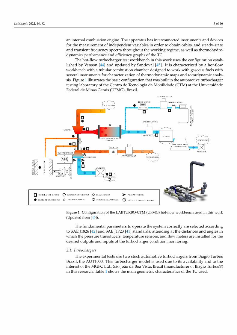
The hot-flow turbocharger test workbench in this work uses the configuration estab-lished by Venson [44] and updated by Sandoval [45]. It is characterized by a hot-flowworkbench with a tubular combustion chamber designed to work with gaseous fuels withseveral instruments for characterization of thermodynamic maps and rotordynamic analy-sis. Figure 1 illustrates the basic configuration that was built in the automotive turbochargertesting laboratory of the Centro de Tecnologia da Mobilidade (CTM) at the UniversidadeFederal de Minas Gerais (UFMG), Brazil.
Lubricants 2022, 10, x FOR PEER REVIEW 3 of 16
The design of the turbocharger test workbench used in this work meets the requirements of the standards currently established by the international institutions [41–43]. The workbench operates at several different working regimes, simulating the exhaust gases of an internal combustion engine. The apparatus has interconnected instruments and devices for the measurement of independent variables in order to obtain orbits, and steady-state and transient frequency spectra throughout the working regime, as well as thermohydrodynamics performance and efficiency graphs of the TC.
The hot-flow turbocharger test workbench in this work uses the configuration established by Venson [44] and updated by Sandoval [45]. It is characterized by a hot-flow workbench with a tubular combustion chamber designed to work with gaseous fuels with several instruments for characterization of thermodynamic maps and rotordynamic analysis. Figure 1 illustrates the basic configuration that was built in the automotive turbocharger testing laboratory of the Centro de Tecnologia da Mobilidade (CTM) at the Universidade Federal de Minas Gerais (UFMG), Brazil.
Figure 1. Configuration of the LABTURBO-CTM (UFMG) hot-flow workbench used in this work (Updated from [45]).
The fundamental parameters to operate the system correctly are selected according to SAE J1826 [42] and SAE J1723 [41] standards, attending at the distances and angles in which the pressure transducers, temperature sensors, and flow meters are installed for the desired outputs and inputs of the turbocharger condition monitoring.
2.1. Turbochargers The experimental tests use two stock automotive turbochargers from Biagio Turbos
Brazil, the AUT1000. This turbocharger model is used due to its availability and to the interest of the MGFC Ltd., São João da Boa Vista, Brazil (manufacturer of Biagio Turbos®) in this research. Table 1 shows the main geometric characteristics of the TC used.
Table 1. Technical data of the Biagio® AUT1000 Turbocharger.
Data Turbocharger Manufacturer MGFC Ltd. (Biagio Turbos®)
Model AUT1000 Type of ICE 1 used 1000 cc four-stroke ICE 1
Figure 1. Configuration of the LABTURBO-CTM (UFMG) hot-flow workbench used in this work(Updated from [45]).
The fundamental parameters to operate the system correctly are selected accordingto SAE J1826 [42] and SAE J1723 [41] standards, attending at the distances and angles inwhich the pressure transducers, temperature sensors, and flow meters are installed for thedesired outputs and inputs of the turbocharger condition monitoring.
2.1. Turbochargers
The experimental tests use two stock automotive turbochargers from Biagio TurbosBrazil, the AUT1000. This turbocharger model is used due to its availability and to theinterest of the MGFC Ltd., São João da Boa Vista, Brazil (manufacturer of Biagio Turbos®)in this research. Table 1 shows the main geometric characteristics of the TC used.

Lubricants 2022, 10, 92 4 of 16
Table 1. Technical data of the Biagio®AUT1000 Turbocharger.
Data Turbocharger
Manufacturer MGFC Ltd. (Biagio Turbos®)Model AUT1000
Type of ICE 1 used 1000 cc four-stroke ICE 1
Part number 5827109101Compressor Area/Radius 0.48
Compressor Impeller Diameter 49 [mm]Compressor Inducer Diameter 32.5 [mm]
Compressor Blades 6 full + 6 splitterCompressor Housing Blades N/A
Turbine Area/Radius 0.35Turbine Impeller Diameter 45.5 [mm]Turbine Inducer Diameter 35.5 [mm]
Turbine Blades 10 fullTurbine Housing Blades N/A
Shaft diameter at bearing assembly 8 ± 0.002 [mm]Weight 9 [kg]
1 ICE: Internal Combustion Engine.
The selection of these TCs is performed because of the possibility of using bearingswith different geometries, which permit evaluate the thermal and dynamic behaviors ofthe rotating machine running on different supporting systems. The difference betweeneach TC tested in this work is only the shape of the axial grooves etched on the fluid filmjournal bearing. All the other components, such as thrust bearing, shaft, volutes, blades,internal lubrication system, and others, are the same part numbers. The TCs are tested andbalanced at the MGFC facilities before they are assembled in the testing bench.
In the original version, the journal bearing uses a triangular shape for the internalaxial grooves (the interaction area of rotor-bearing assembly). Figure 2 illustrates a journalbearing schematic drawing.
Lubricants 2022, 10, x FOR PEER REVIEW 4 of 16
Part number 5827109101 Compressor Area/Radius 0.48
Compressor Impeller Diameter 49 [mm] Compressor Inducer Diameter 32.5 [mm]
Compressor Blades 6 full + 6 splitter Compressor Housing Blades N/A
Turbine Area/Radius 0.35 Turbine Impeller Diameter 45.5 [mm] Turbine Inducer Diameter 35.5 [mm]
Turbine Blades 10 full Turbine Housing Blades N/A
Shaft diameter at bearing assembly 8 ± 0.002 [mm] Weight 9 [kg]
1 ICE: Internal Combustion Engine.
The selection of these TCs is performed because of the possibility of using bearings with different geometries, which permit evaluate the thermal and dynamic behaviors of the rotating machine running on different supporting systems. The difference between each TC tested in this work is only the shape of the axial grooves etched on the fluid film journal bearing. All the other components, such as thrust bearing, shaft, volutes, blades, internal lubrication system, and others, are the same part numbers. The TCs are tested and balanced at the MGFC facilities before they are assembled in the testing bench.
In the original version, the journal bearing uses a triangular shape for the internal axial grooves (the interaction area of rotor-bearing assembly). Figure 2 illustrates a journal bearing schematic drawing.
(a) (b)
Figure 2. Journal bearing front view: (a) bearing; (b) original triangular axial groove detail.
2.2. Modified Journal Bearings The new journal bearings are manufactured with the same original journal bearing
manufacturing process, except for the final triangular axial broaching. To produce the new bearings with different groove shapes, the wire EDM (Electrical Discharge Machining) is chosen due to the adequate finish for the groove geometry, as indicated by Smolík et al. [46]. This manufacturing process not only presents low cost but also does not need changes in the machine calibration, which can reduce the manufacturing time. Moreover, the wire EDM used in this work achieves accuracies of ±0.0025 mm, instead of CNC ma-chining broaching with a ±0.005 mm accuracy. However, the roughness of grooves with broaching would be smaller.
The new axial groove shape is chosen considering a smooth profile across the entire width, following procedures indicated by some references [47–49].
Figure 2. Journal bearing front view: (a) bearing; (b) original triangular axial groove detail.
2.2. Modified Journal Bearings
The new journal bearings are manufactured with the same original journal bearingmanufacturing process, except for the final triangular axial broaching. To produce the newbearings with different groove shapes, the wire EDM (Electrical Discharge Machining) ischosen due to the adequate finish for the groove geometry, as indicated by Smolík et al. [46].This manufacturing process not only presents low cost but also does not need changes inthe machine calibration, which can reduce the manufacturing time. Moreover, the wireEDM used in this work achieves accuracies of ±0.0025 mm, instead of CNC machining

Lubricants 2022, 10, 92 5 of 16
broaching with a ±0.005 mm accuracy. However, the roughness of grooves with broachingwould be smaller.
The new axial groove shape is chosen considering a smooth profile across the entirewidth, following procedures indicated by some references [47–49].
To avoid geometrical variations on the axial grooves that could affect the TC bearingbehavior, the same adjustments of the wire EDM are used for the five axial grooves for eachjournal bearing, with 72◦ axial distance from each other, as well as the same 1.0897 mmperimeter and 0.1714 mm2 area. The ellipse major axis is equal to the perimeter projectionand the semi-minor axis equals triangle height.
After the machining, all the grooves were analyzed in the microscope in the MetrologyLab at UFMG. Figure 3 shows the drawings of the axial groove shapes for each journalbearing and photos with 150 times magnification obtained by the microscope. Due to wirediameter used (0.1 mm) during machining, the corners of each groove are rounded.
Lubricants 2022, 10, x FOR PEER REVIEW 5 of 16
To avoid geometrical variations on the axial grooves that could affect the TC bearing behavior, the same adjustments of the wire EDM are used for the five axial grooves for each journal bearing, with 72° axial distance from each other, as well as the same 1.0897 mm perimeter and 0.1714 mm2 area. The ellipse major axis is equal to the perimeter pro-jection and the semi-minor axis equals triangle height.
After the machining, all the grooves were analyzed in the microscope in the Metrol-ogy Lab at UFMG. Figure 3 shows the drawings of the axial groove shapes for each journal bearing and photos with 150 times magnification obtained by the microscope. Due to wire diameter used (0.1 mm) during machining, the corners of each groove are rounded.
Groove Shape Groove Drawing Zoom Groove Photos (150×)
Half-ellipse
Triangular
Figure 3. Drawings of the bearings with axial grooves and magnified photos of the grooves.
2.3. Tests Performed The thermohydrodynamic SAE standard methodology to obtain the main parame-
ters, as stabilization of the centrifugal compressor (i.e., the continuous rotor speed during different air flows), criteria for detection of surge threshold points, warm-up criteria, and compressor data acquisition points, is part of the experimental routine of LABTURBO-CTM [35].
The fundamental parameters to achieve the correct TC state to obtain rotordynamic responses are monitored according to SAE J1826 and SAE J1723 standards following the recommendations for the thermal insulation, and distances and angles in which the pres-sure transducers, temperature sensors, and flow meters are installed for each output and input of the turbocharger. The RD tests are performed after a warm-up sequence of dif-ferent rotating speeds and total compression ratios of the turbocharger defined by SAE J1723. Then, a thermal stability defined by SAE J1826 is used to verify the pressure, flowrate, temperature, and rotating speeds data as presented by Romero [50], when all RD data are obtained with proximity probes and accelerometers.
Both turbochargers were tested at six operating points in each speed line in order to decrease the interpolation interval of the compressor map, where 67, 89, 105, 121, and 135 krpm speed lines are controlled by a PID algorithm developed in LabVIEW, obtaining 30 points for each TC.
Figure 3. Drawings of the bearings with axial grooves and magnified photos of the grooves.
2.3. Tests Performed
The thermohydrodynamic SAE standard methodology to obtain the main parameters, asstabilization of the centrifugal compressor (i.e., the continuous rotor speed during different airflows), criteria for detection of surge threshold points, warm-up criteria, and compressor dataacquisition points, is part of the experimental routine of LABTURBO-CTM [35].
The fundamental parameters to achieve the correct TC state to obtain rotordynamicresponses are monitored according to SAE J1826 and SAE J1723 standards following therecommendations for the thermal insulation, and distances and angles in which the pressuretransducers, temperature sensors, and flow meters are installed for each output and inputof the turbocharger. The RD tests are performed after a warm-up sequence of differentrotating speeds and total compression ratios of the turbocharger defined by SAE J1723.
Lubricants 2022, 10, 92 6 of 16
Then, a thermal stability defined by SAE J1826 is used to verify the pressure, flowrate,temperature, and rotating speeds data as presented by Romero [50], when all RD data areobtained with proximity probes and accelerometers.
Both turbochargers were tested at six operating points in each speed line in orderto decrease the interpolation interval of the compressor map, where 67, 89, 105, 121, and135 krpm speed lines are controlled by a PID algorithm developed in LabVIEW, obtaining30 points for each TC.
The change in each speed line was done by gradually increasing the exhaust gasesdischarge from the combustion chamber. When the target speed line was reached, the airvalve at the outlet of the centrifugal compressor was gradually closed in order to decreasethe air mass flow and increase the compression ratio, obtaining the necessary point forthat speed line. Compressor valve closing conditions are defined as a number of points (n)that are tested for each rotation curve, i.e., each speed line, in order to reduce the need forinterpolations, where a (n + 1)th test point is characterized by instability in the compressorto present the surge condition.
For the tests developed in this work, data was collected at five speed line and, foreach of them, temperature, pressure, and mass flow data were measured at five differentpoints (combinations of corrected mass flow and compression or expansion ratio). A sixthpoint for each speed line (surge point) was induced by the lack of flow at the compressorinlet. Once the surge line point is reached, the valve at the compressor outlet returns tofull opening and, from that point, registers the next speed line to be tested in the controller.This process must be repeated until all the intended speed lines are tested.
During the experiments, the supervisory system was used to establish the operatingconditions and provide information for the control of the tested thermodynamic parameters.To identify the surge thresholds, the detection technique by sinusoidal variation of thecentrifugal compressor discharge pressure [51] was applied. The data acquisition frequencyfor pressure, flowrate, and temperature transistors/sensors are 2 kHz during 1 s for eachmeasurement point performed, once per turbocharger.
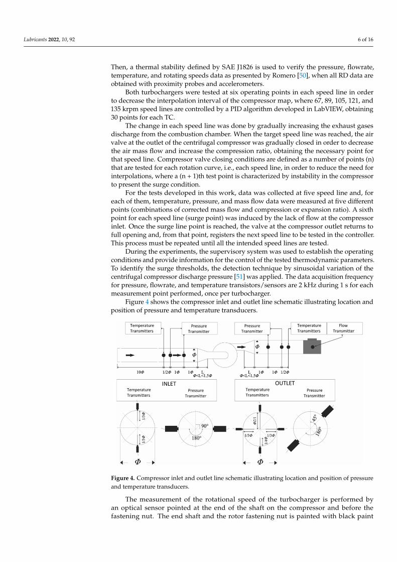
Figure 4 shows the compressor inlet and outlet line schematic illustrating location andposition of pressure and temperature transducers.
Lubricants 2022, 10, x FOR PEER REVIEW 6 of 16
The change in each speed line was done by gradually increasing the exhaust gases discharge from the combustion chamber. When the target speed line was reached, the air valve at the outlet of the centrifugal compressor was gradually closed in order to decrease the air mass flow and increase the compression ratio, obtaining the necessary point for that speed line. Compressor valve closing conditions are defined as a number of points (n) that are tested for each rotation curve, i.e., each speed line, in order to reduce the need for interpolations, where a (n + 1)th test point is characterized by instability in the com-pressor to present the surge condition.
For the tests developed in this work, data was collected at five speed line and, for each of them, temperature, pressure, and mass flow data were measured at five different points (combinations of corrected mass flow and compression or expansion ratio). A sixth point for each speed line (surge point) was induced by the lack of flow at the compressor inlet. Once the surge line point is reached, the valve at the compressor outlet returns to full opening and, from that point, registers the next speed line to be tested in the controller. This process must be repeated until all the intended speed lines are tested.
During the experiments, the supervisory system was used to establish the operating conditions and provide information for the control of the tested thermodynamic parame-ters. To identify the surge thresholds, the detection technique by sinusoidal variation of the centrifugal compressor discharge pressure [51] was applied. The data acquisition fre-quency for pressure, flowrate, and temperature transistors/sensors are 2 kHz during 1 s for each measurement point performed, once per turbocharger.
Figure 4 shows the compressor inlet and outlet line schematic illustrating location and position of pressure and temperature transducers.
Figure 4. Compressor inlet and outlet line schematic illustrating location and position of pressure and temperature transducers.
The measurement of the rotational speed of the turbocharger is performed by an op-tical sensor pointed at the end of the shaft on the compressor and before the fastening nut. The end shaft and the rotor fastening nut is painted with black paint with low reflectivity (phosphatizing base paint) and a strip of reflective paint, as shown in Figure 5b. The optical sensor data acquisition frequency is 10 kHz, which is more than four times the rotation frequency of the highest speed reached in the tests, which is approximately 142,000 rpm.
Table 2 shows the characteristics and measuring points of the pressure transducers, temperature transducers, flowrate meters, and rotating speed sensor used on the work-bench to monitor the steady-state operating conditions.
Figure 4. Compressor inlet and outlet line schematic illustrating location and position of pressureand temperature transducers.
The measurement of the rotational speed of the turbocharger is performed byan optical sensor pointed at the end of the shaft on the compressor and before thefastening nut. The end shaft and the rotor fastening nut is painted with black paint

Lubricants 2022, 10, 92 7 of 16
with low reflectivity (phosphatizing base paint) and a strip of reflective paint, as shownin Figure 5b. The optical sensor data acquisition frequency is 10 kHz, which is morethan four times the rotation frequency of the highest speed reached in the tests, which isapproximately 142,000 rpm.
Lubricants 2022, 10, x FOR PEER REVIEW 7 of 16
(a) (b)
Figure 5. Vibration transducers mounted on the turbocompressor: (a) three uniaxial accelerome-ters; (b) two proximity probes.
Table 2. Technical data for the instrumentation used to control the workbench.
Data Pressure Transducers Measuring point Turbine inlet/outlet Oil inlet Compressor inlet Compressor outlet Measuring range 0 to 1000 kPa 0 to 600 kPa −50 to 50 kPa 0 to 1000 kPa
Type of measurement Gauge Gauge Gauge Gauge Precision ≤0.5% ≤2% ≤0.25% ≤0.5%
Data Thermocouples
Measuring point
Compressor inlet; Compressor output;
Environment; Oil inlet;
Oil reservoir.
Oil outlet; Gas inlet.
Measuring range 0–1200 °C 0–1080 °C Type/Element Cromel–Alumel (K)/Simple, 1 thermocouple measurement
Precision 0.75% of the final scale 0.75% of the final scale Data Flowrate Transducer
Measuring point Compressor outlet Measuring range 51 to 1869 m3/h
Type Turbine flow with amplifier Precision 0.2%
Data Rotating speed sensor Rotating speed signal converter Application Rotating speed of turbocharger rotor Modulation for the computer
Measuring range 6000 to 200,000 rpm -
Exit signal - 0…10 V 2.5 V ± 10% pulses
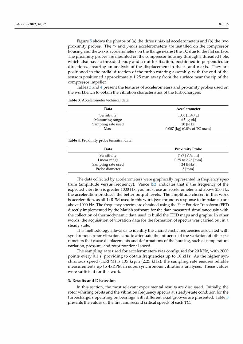
Figure 5 shows the photos of (a) the three uniaxial accelerometers and (b) the two proximity probes. The x- and y-axis accelerometers are installed on the compressor hous-ing and the z-axis accelerometers on the flange nearest the TC due to the flat surface. The proximity probes are mounted on the compressor housing through a threaded hole, which also have a threaded body and a nut for fixation, positioned in perpendicular directions, ensuring an analysis of the displacement in the x- and y-axis. They are positioned in the radial direction of the turbo rotating assembly, with the end of the sensors positioned ap-proximately 1.25 mm away from the surface near the tip of the compressor impeller.
Figure 5. Vibration transducers mounted on the turbocompressor: (a) three uniaxial accelerometers;(b) two proximity probes.
Table 2 shows the characteristics and measuring points of the pressure transducers,temperature transducers, flowrate meters, and rotating speed sensor used on the workbenchto monitor the steady-state operating conditions.
Table 2. Technical data for the instrumentation used to control the workbench.
Data Pressure Transducers
Measuring point Turbine inlet/outlet Oil inlet Compressor inlet Compressor outletMeasuring range 0 to 1000 kPa 0 to 600 kPa −50 to 50 kPa 0 to 1000 kPa
Type of measurement Gauge Gauge Gauge GaugePrecision ≤0.5% ≤2% ≤0.25% ≤0.5%
Data Thermocouples
Measuring point
Compressor inlet;Compressor output;
Environment;Oil inlet;
Oil reservoir.
Oil outlet;Gas inlet.
Measuring range 0–1200 ◦C 0–1080 ◦CType/Element Cromel–Alumel (K)/Simple, 1 thermocouple measurement
Precision 0.75% of the final scale 0.75% of the final scale
Data Flowrate Transducer
Measuring point Compressor outletMeasuring range 51 to 1869 m3/h
Type Turbine flow with amplifierPrecision 0.2%
Data Rotating speed sensor Rotating speed signal converter
Application Rotating speed of turbocharger rotor Modulation for the computerMeasuring range 6000 to 200,000 rpm -
Exit signal - 0 . . . 10 V2.5 V ± 10% pulses
Lubricants 2022, 10, 92 8 of 16
Figure 5 shows the photos of (a) the three uniaxial accelerometers and (b) the twoproximity probes. The x- and y-axis accelerometers are installed on the compressorhousing and the z-axis accelerometers on the flange nearest the TC due to the flat surface.The proximity probes are mounted on the compressor housing through a threaded hole,which also have a threaded body and a nut for fixation, positioned in perpendiculardirections, ensuring an analysis of the displacement in the x- and y-axis. They arepositioned in the radial direction of the turbo rotating assembly, with the end of thesensors positioned approximately 1.25 mm away from the surface near the tip of thecompressor impeller.
Tables 3 and 4 present the features of accelerometers and proximity probes used onthe workbench to obtain the vibration characteristics of the turbochargers.
Table 3. Accelerometer technical data.
Data Accelerometer
Sensitivity 1000 [mV/g]Measuring range ±5 [g pk]
Sampling rate used 20 [kHz]Mass 0.007 [kg] (0.8% of TC mass)
Table 4. Proximity probe technical data.
Data Proximity Probe
Sensitivity 7.87 [V/mm]Linear range 0.25 to 2.25 [mm]
Sampling rate used 24 [kHz]Probe diameter 5 [mm]
The data collected by accelerometers were graphically represented in frequency spec-trum (amplitude versus frequency). Vance [52] indicates that if the frequency of theexpected vibration is greater 1000 Hz, you must use an accelerometer, and above 250 Hz,the acceleration produces the better output levels. The amplitude chosen in this workis acceleration, as all 1xRPM used in this work (synchronous response to imbalance) areabove 1000 Hz. The frequency spectra are obtained using the Fast Fourier Transform (FFT)directly implemented by the Matlab software for the data measured simultaneously withthe collection of thermodynamic data used to build the THD maps and graphs. In otherwords, the acquisition of vibration data for the formation of spectra was carried out in asteady state.
This methodology allows us to identify the characteristic frequencies associated withsynchronous rotor vibrations and to attenuate the influence of the variation of other pa-rameters that cause displacements and deformations of the housing, such as temperaturevariation, pressure, and rotor rotational speed.
The sampling rate used for accelerometers was configured for 20 kHz, with 2000points every 0.1 s, providing to obtain frequencies up to 10 kHz. As the higher syn-chronous speed (1xRPM) is 135 krpm (2.25 kHz), the sampling rate ensures reliablemeasurements up to 4xRPM in supersynchronous vibrations analyses. These valueswere sufficient for this work.
3. Results and Discussion
In this section, the most relevant experimental results are discussed. Initially, therotor whirling orbits and the vibration frequency spectra at steady-state condition for theturbochargers operating on bearings with different axial grooves are presented. Table 5presents the values of the first and second critical speeds of each TC.

Lubricants 2022, 10, 92 9 of 16
Table 5. First and second critical speeds for each TC.
Turbocharger (GrooveShape) First Critical Speed Second Critical Speed
TC (triangular) 94.5 krpm 138.5 krpmTC (half ellipse) 97 krpm 138.5 krpm
3.1. Vibration Frequency Spectra
For the frequency spectra of each TC, the vibration amplitudes are obtained at fivespeed lines (SL) and five compressor outlet air valve closing positions (VC). The thresholdcondition of surge is an additional measuring point during the tests. The frequency spectraare obtained for three orthogonal directions (for six valve closing positions) at five speedlines plus the surge condition, totaling 25 spectra per direction, 75 for each turbocharger,which is a total of 150 steady-state vibration spectra.
Table 6 indicates the relationship between each SL selected and the critical speedsindicated in Table 5.
Table 6. Relationship between Speed Lines and Critical Speeds.
Speed Lines First Critical Speed Second Critical Speed
SL 1 (67 krpm) Far Very farSL 2 (89 krpm) Very close/Close Very far
SL 3 (105 krpm) Close/Very close FarSL 4 (121 krpm) Far CloseSL 5 (135 krpm) Very far Very close
Table 7 presents the test points based on VC position for the TCs.
Table 7. Test points based on VC position for the TCs.
SpeedCompressor Valve Closing Percentage
Point 1 Point 2 Point 3 Point 4 Point 5
67 krpm 0% (fullyopen) 36% 63% 81% 90%
89 krpm 0% (fullyopen) 31% 55% 70% 78%
105 krpm 0% (fullyopen) 31% 54% 69% 77%
121 krpm 0% (fullyopen) 30% 53% 68% 75%
135 krpm 0% (fullyopen) 28% 49% 63% 75%
Figures 6 and 7 show the TCs synchronous and subsynchronous vibration amplituderesponses for the x-axis, respectively. The spectra for the radial axes (x- and y-) presentsimilar patterns, and for the axial axe (z-) there are no significant differences betweeneach TC.
The use of THD TC compressor efficiency map to present several other results in TC ispresented by [53]. THD studies were carried out to provide input in the creation of heatmaps of RD results. However, these data were not presented because it is not in the scopeof this work.
It is possible to observe that for the first speed line (67 krpm, below and far fromthe first critical speed), the turbochargers supported on bearings with triangular andhalf ellipse present low vibrational amplitude in the synchronous response and goodsubsynchronous stability.

Lubricants 2022, 10, 92 10 of 16
Lubricants 2022, 10, x FOR PEER REVIEW 9 of 16
spectra are obtained for three orthogonal directions (for six valve closing positions) at five speed lines plus the surge condition, totaling 25 spectra per direction, 75 for each turbo-charger, which is a total of 150 steady-state vibration spectra.
Table 6 indicates the relationship between each SL selected and the critical speeds indicated in Table 5.
Table 6. Relationship between Speed Lines and Critical Speeds.
Speed Lines First Critical Speed Second Critical Speed SL 1 (67 krpm) Far Very far SL 2 (89 krpm) Very close/Close Very far
SL 3 (105 krpm) Close/Very close Far SL 4 (121 krpm) Far Close SL 5 (135 krpm) Very far Very close
Table 7 presents the test points based on VC position for the TCs.
Table 7. Test points based on VC position for the TCs.
Speed Compressor Valve Closing Percentage
Point 1 Point 2 Point 3 Point 4 Point 5 67 krpm 0% (fully open) 36% 63% 81% 90% 89 krpm 0% (fully open) 31% 55% 70% 78% 105 krpm 0% (fully open) 31% 54% 69% 77% 121 krpm 0% (fully open) 30% 53% 68% 75% 135 krpm 0% (fully open) 28% 49% 63% 75%
Figures 6 and 7 show the TCs synchronous and subsynchronous vibration amplitude responses for the x-axis, respectively. The spectra for the radial axes (x- and y-) present similar patterns, and for the axial axe (z-) there are no significant differences between each TC.
(a) (b)
Figure 6. Synchronous response map for each TC with: (a) Triangular axial groove shape; (b) Half-ellipse axial groove shape. Figure 6. Synchronous response map for each TC with: (a) Triangular axial groove shape;(b) Half-ellipse axial groove shape.
Lubricants 2022, 10, x FOR PEER REVIEW 10 of 16
(a) (b)
Figure 7. Subsynchronous response map for each TC with: (a) Triangular axial groove shape; (b) Half-ellipse axial groove shape.
The use of THD TC compressor efficiency map to present several other results in TC is presented by [53]. THD studies were carried out to provide input in the creation of heat maps of RD results. However, these data were not presented because it is not in the scope of this work.
It is possible to observe that for the first speed line (67 krpm, below and far from the first critical speed), the turbochargers supported on bearings with triangular and half el-lipse present low vibrational amplitude in the synchronous response and good subsyn-chronous stability.
In the second speed line (89 krpm, below the two critical speeds, but very close to the first), the turbocharger that uses journal bearings with half ellipse axial groove shape is slightly superior in synchronous response compared to triangular only in VC @ 70%. For the subsynchronous responses, the turbocharger with journal bearing with axial half el-lipse groove shape shows better results in all VC positions.
When entering the third speed line (105 krpm, above but very close to the first critical velocity, and below and far from the second critical velocity), there is no change in relation to the synchronous responses of the speed line 2 of each shape. However, greater subsyn-chronous responses were observed in turbochargers with half-ellipse axial groove shape in the journal bearing, highlighting the first three VCs @ 0%, 31%, and 54%.
At the fourth speed line (121 krpm, above and far from the first critical velocity, but close to and below the second critical velocity), the new synchronous responses have high vibration peaks for both TCs, but the triangular presents better values in all VCs positions. Similar results are obtained for subsynchronous vibrations, where the half-ellipse shape has good results compared to the triangular shape only in VC @75%.
The fifth and last speed line (135 krpm, above and far from the first critical velocity, but very close to and below the second critical velocity) presents the same results pre-sented at the fourth speed line in synchronous and subsynchronous response.
3.2. Rotor Whirling Orbits The vibratory displacements captured by the proximity probes allow us to visualize
the rotor motion at several operating conditions. The rotor whirling orbits are obtained at constant speed, i.e., at steady-state conditions with various air mass flow rates. The orbital
Figure 7. Subsynchronous response map for each TC with: (a) Triangular axial groove shape;(b) Half-ellipse axial groove shape.
In the second speed line (89 krpm, below the two critical speeds, but very close to thefirst), the turbocharger that uses journal bearings with half ellipse axial groove shape isslightly superior in synchronous response compared to triangular only in VC @ 70%. Forthe subsynchronous responses, the turbocharger with journal bearing with axial half ellipsegroove shape shows better results in all VC positions.
When entering the third speed line (105 krpm, above but very close to the first criticalvelocity, and below and far from the second critical velocity), there is no change in relationto the synchronous responses of the speed line 2 of each shape. However, greater subsyn-chronous responses were observed in turbochargers with half-ellipse axial groove shape inthe journal bearing, highlighting the first three VCs @ 0%, 31%, and 54%.
Lubricants 2022, 10, 92 11 of 16
At the fourth speed line (121 krpm, above and far from the first critical velocity, butclose to and below the second critical velocity), the new synchronous responses have highvibration peaks for both TCs, but the triangular presents better values in all VCs positions.Similar results are obtained for subsynchronous vibrations, where the half-ellipse shapehas good results compared to the triangular shape only in VC @75%.
The fifth and last speed line (135 krpm, above and far from the first critical velocity,but very close to and below the second critical velocity) presents the same results presentedat the fourth speed line in synchronous and subsynchronous response.
3.2. Rotor Whirling Orbits
The vibratory displacements captured by the proximity probes allow us to visualizethe rotor motion at several operating conditions. The rotor whirling orbits are obtained atconstant speed, i.e., at steady-state conditions with various air mass flow rates. The orbitalgeometry is affected by several sources, such as unbalance, inner and outer oil ring whirls,oil whip, aerodynamics effects (Alford’s effect), and rub between shaft and bearing.
The whirling orbits for the TC rotors supported on semi-floating ring journal bear-ings with two different axial groove shapes are rendered for several speed lines andvalve conditions.
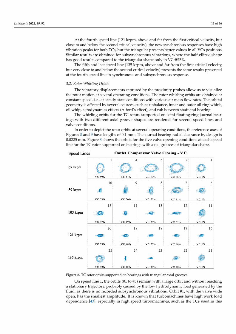
In order to depict the rotor orbits at several operating conditions, the reference axes ofFigures 8 and 9 have lengths of 0.1 mm. The journal bearing radial clearance by design is0.0225 mm. Figure 8 shows the orbits for the five valve opening conditions at each speedline for the TC rotor supported on bearings with axial grooves of triangular shape.
Lubricants 2022, 10, x FOR PEER REVIEW 11 of 16
geometry is affected by several sources, such as unbalance, inner and outer oil ring whirls, oil whip, aerodynamics effects (Alford’s effect), and rub between shaft and bearing.
The whirling orbits for the TC rotors supported on semi-floating ring journal bear-ings with two different axial groove shapes are rendered for several speed lines and valve conditions.
In order to depict the rotor orbits at several operating conditions, the reference axes of Figures 8 and 9 have lengths of 0.1 mm. The journal bearing radial clearance by design is 0.0225 mm. Figure 8 shows the orbits for the five valve opening conditions at each speed line for the TC rotor supported on bearings with axial grooves of triangular shape.
Figure 8. TC rotor orbits supported on bearings with triangular axial grooves.
On speed line 1, the orbits (#1 to #5) remain with a large orbit and without reaching a stationary trajectory, probably caused by the low hydrodynamic load generated by the fluid, as there is no recorded subsynchronous vibrations. Orbit #1, with the valve wide open, has the smallest amplitude. It is known that turbomachines have high work load dependence [43], especially in high speed turbomachines, such as the TCs used in this work. Low speeds, as shown in speed line 1, make the rotor work more off-center than at high speeds, providing larger orbits, as observed.
The speed line 2 with orbits #6 to #10 have generally smaller amplitudes than those compared to the speed line 1, showing a greater stability of the system response. It is note-worthy that with the closing of the valve from 31% to 55%, a phase change of approxi-mately 90° of the orbit is observed, which continues with the decrease in mass flow, but decreases the mean amplitude, that is, without presenting relevant instability. This phase change in machines with variation in the air mass flow in compressors is presented in several works, such as Alford [54], and suggests that, if it occurs, the machine operation should be close to its work load, due to the sensitivity of the set in presenting high levels of instability. It can be seen in the five orbits that there is no stationary trajectory, corrob-orating what was presented in subsynchronous vibration and with the orbit shape pre-sented by Nguyen-Schäfer [55] for inner and outer oil whirls.
On speed line 3, very close to the first critical speed, non-stationary circular orbits are observed for the wide open valve (#11) and orbit phase shift from #13 to #14 and from #14 to #15. Orbits, in general, presented smaller amplitude than speed line 2.
Figure 8. TC rotor orbits supported on bearings with triangular axial grooves.
On speed line 1, the orbits (#1 to #5) remain with a large orbit and without reachinga stationary trajectory, probably caused by the low hydrodynamic load generated by thefluid, as there is no recorded subsynchronous vibrations. Orbit #1, with the valve wideopen, has the smallest amplitude. It is known that turbomachines have high work loaddependence [43], especially in high speed turbomachines, such as the TCs used in this

Lubricants 2022, 10, 92 12 of 16
work. Low speeds, as shown in speed line 1, make the rotor work more off-center than athigh speeds, providing larger orbits, as observed.
Lubricants 2022, 10, x FOR PEER REVIEW 12 of 16
Smaller amplitude orbits without phase shift occur on speed line 4 when the rotor is between the first and second critical speeds. Great variations are not observed between the different valve closures.
The speed line 5 again presents a non-stationary orbit with the valve wide open (0% closing), but with stability starting at 28% valve closing (#22) and phase change with sta-bility between #23 and #24. With the last closing step of 70%, a non-stationary orbit is observed again, characteristic of inner and outer oil whirls.
As presented in the figure above, Figure 9 presents the orbits for the five valve open-ing conditions at each speed line for the TC rotor supported on bearings with axial grooves of half-ellipse shape.
Figure 9. TC rotor orbits supported on bearings with half-ellipse axial grooves.
Speed line 1 shows different characteristics. The orbit #1 (valve wide open) presents a large orbit without reaching a stationary trajectory. As explained in the TC1, as no in-stability was presented, it probably happened due to the low hydrodynamic load gener-ated by the fluid. Orbits #2 to #5 have similar orbits to each other, with an elliptical orbit with maximum deflection in x (horizontal axis). Nguyen-Schäfer [55] describes elliptical orbits as normal cases in turbochargers, due to stiffness in the y (vertical) direction being greater than in the x (horizontal) direction, caused by the cross-couple stiffness effect known in turbomachines [53].
On speed line 2, it is possible to observe orbits that are also ellipse, but with smaller deflections, except for valve closing of 55% (#8), which has a large deflection in the hori-zontal direction. Another interesting feature is the valve closing of 31% (#7) which pre-sents a variation around 45° in this maximum deflection. As it is just a mass flow change, it is another sample of Alford’s forces in turbochargers already discussed in the literature [56,57].
On speed line 3, it is possible to see a non-stationary orbit at half aperture (#13, VC @ 54%), and with #11 (VC @ 0%), #14, and #15 being the same elliptical orbits, but of smaller amplitudes than the previous speed lines. The #12 has a small ellipse with greater deflec-tion that is not horizontal like the others, but vertical (same previous discussion on speed line 2).
Figure 9. TC rotor orbits supported on bearings with half-ellipse axial grooves.
The speed line 2 with orbits #6 to #10 have generally smaller amplitudes than thosecompared to the speed line 1, showing a greater stability of the system response. Itis noteworthy that with the closing of the valve from 31% to 55%, a phase change ofapproximately 90◦ of the orbit is observed, which continues with the decrease in mass flow,but decreases the mean amplitude, that is, without presenting relevant instability. Thisphase change in machines with variation in the air mass flow in compressors is presentedin several works, such as Alford [54], and suggests that, if it occurs, the machine operationshould be close to its work load, due to the sensitivity of the set in presenting high levels ofinstability. It can be seen in the five orbits that there is no stationary trajectory, corroboratingwhat was presented in subsynchronous vibration and with the orbit shape presented byNguyen-Schäfer [55] for inner and outer oil whirls.
On speed line 3, very close to the first critical speed, non-stationary circular orbits areobserved for the wide open valve (#11) and orbit phase shift from #13 to #14 and from #14to #15. Orbits, in general, presented smaller amplitude than speed line 2.
Smaller amplitude orbits without phase shift occur on speed line 4 when the rotor isbetween the first and second critical speeds. Great variations are not observed between thedifferent valve closures.
The speed line 5 again presents a non-stationary orbit with the valve wide open (0%closing), but with stability starting at 28% valve closing (#22) and phase change withstability between #23 and #24. With the last closing step of 70%, a non-stationary orbit isobserved again, characteristic of inner and outer oil whirls.
As presented in the figure above, Figure 9 presents the orbits for the five valve openingconditions at each speed line for the TC rotor supported on bearings with axial grooves ofhalf-ellipse shape.
Speed line 1 shows different characteristics. The orbit #1 (valve wide open) presents alarge orbit without reaching a stationary trajectory. As explained in the TC1, as no instability

Lubricants 2022, 10, 92 13 of 16
was presented, it probably happened due to the low hydrodynamic load generated bythe fluid. Orbits #2 to #5 have similar orbits to each other, with an elliptical orbit withmaximum deflection in x (horizontal axis). Nguyen-Schäfer [55] describes elliptical orbitsas normal cases in turbochargers, due to stiffness in the y (vertical) direction being greaterthan in the x (horizontal) direction, caused by the cross-couple stiffness effect known inturbomachines [53].
On speed line 2, it is possible to observe orbits that are also ellipse, but with smaller de-flections, except for valve closing of 55% (#8), which has a large deflection in the horizontaldirection. Another interesting feature is the valve closing of 31% (#7) which presents a vari-ation around 45◦ in this maximum deflection. As it is just a mass flow change, it is anothersample of Alford’s forces in turbochargers already discussed in the literature [56,57].
On speed line 3, it is possible to see a non-stationary orbit at half aperture (#13, VC@ 54%), and with #11 (VC @ 0%), #14, and #15 being the same elliptical orbits, but ofsmaller amplitudes than the previous speed lines. The #12 has a small ellipse with greaterdeflection that is not horizontal like the others, but vertical (same previous discussionon speed line 2).
When moving away from the first critical speed and approaching the second criticalspeed, the speed line 4 presents a tendency to normalize the orbits as the valve closes(see #16 to #19), with a reduction in the maximum amplitude, but all of them show non-stationary orbits. In the last case (#20 @ V.C. 75%, before the surge), the orbit returns toshow the previously observed elliptical behavior.
Finally, speed line 5 shows the best overall situation of all, with elliptical orbits ofsmall deflection in all directions, except #24 (@V.C. 63%), which has amplitudes as seen inother speed lines.
3.3. Overall TC Performance and Efficiency
In this work, only the bearing axial groove shape is expected to affect the overall TCrotordynamic responses. The frequency spectra and orbit plots at steady-state conditionsare important tools for the RD analysis. Therefore, the evaluation of TC vibration by mea-surement on rotating parts (proximity probes) and on non-rotating parts (accelerometers)are considered to have the same importance in the analysis.
The results indicate that half ellipse groove shape can lead to better rotordynamicperformance in speed lines below and close to the first critical speed, i.e., at SLs 67 and89 krpm comparison with the triangular groove shape for synchronous and subsyn-chronous responses.
Conversely, the triangular groove shape presents better rotordynamic performance forimbalance and instabilities below and close to the second critical speed at SL 121 and 135krpm. Although the 121 krpm SL is below second critical speed, it is much closer to secondcritical speed than the first critical speed. It is observed that the influence of the secondcritical speed in this SL is clear.
The SL 105 krpm, above and closer to the first critical speed, presents the better syn-chronous results for the half-ellipse shape. However, the better subsynchronous responsesat this SL are obtained by the triangular shape in general.
These results show how the shape of the groove affects the destabilizing forces in thebearing in an experimental way. Experimental studies on the influence of the profile are notcurrently presented in academia. These effects are already observed in numerical works,showing that the axial groove shape of the bearing has a direct influence on the dynamicresponse of rotor-bearing systems [58].
4. Conclusions
This work presents an experimental study on the rotordynamic behavior of automo-tive turbochargers (TCs) supported on semi-floating journal bearings (SFRBs) with twodifferent axial groove geometries. Comparative orbit plots and frequency spectra for TCsrunning on bearings with triangular and half ellipse groove shapes are obtained at several
Lubricants 2022, 10, 92 14 of 16
operating conditions, allowing the evaluation of the feasibility of introducing differentgroove configuration on the supporting systems of TCs.
The TCs indicate small differences in the performance characteristics. However, thehalf ellipse groove shape shows overall better rotordynamic behavior below and next to thefirst critical speed, and similar results compared to triangular groove shape are presentedbelow and next to the second critical speed. The rotor orbits obtained by the proximityprobes corroborate to the frequency spectra data obtained by the accelerometers.
Some important complementary studies can be done with new experimental analyzesof other axial groove shapes and a joint evaluation involving important areas for TC design,such as thermohydrodynamics, presenting better choices of axial groove shapes in TC fluidfilm journal bearings for different operating speeds.
Numerical simulations of rotordynamic responses of TCs could be better analyzedwith the novel results presented in this work.
Author Contributions: Conceptualization, L.H.J.M.; methodology, L.H.J.M., O.R.S., M.T.C.d.F.;software, L.H.J.M., O.R.S., V.M.H.; validation, L.H.J.M., O.R.S.; formal analysis, L.H.J.M., O.R.S.,J.V.M.C.P., F.J.P.P., M.T.C.d.F.; investigation, L.H.J.M.; resources, L.H.J.M., O.R.S., B.C.C.; data cu-ration, O.R.S., V.M.H.; writing—original draft preparation, L.H.J.M., O.R.S., J.P.B.d.S., M.T.C.d.F.;writing—review and editing, L.H.J.M., J.V.M.C.P., J.P.B.d.S., B.C.C., F.J.P.P., M.T.C.d.F.; visualization,L.H.J.M., O.R.S., J.V.M.C.P.; supervision, L.H.J.M., O.R.S., M.T.C.d.F.; project administration, L.H.J.M.;funding acquisition, L.H.J.M., O.R.S. All authors have read and agreed to the published version ofthe manuscript.
Funding: This research was funded by Coordenação de Aperfeiçoamento de Pessoal de NívelSuperior—Brasil (CAPES)—Finance Code 001 and by Conselho Nacional de DesenvolvimentoCientífico e Tecnológico—Brasil (CNPq)—great number 141316/2015-2. The APC was funded byConselho Nacional de Desenvolvimento Científico e Tecnológico—Brasil (CNPq)—great number142080/2019-5.
Institutional Review Board Statement: Not applicable.
Informed Consent Statement: Not applicable.
Data Availability Statement: Not applicable.
Acknowledgments: The authors are thankful to Centro de Tecnologia da Mobilidade-CTM UFMGfor providing the laboratory structure for this research. They also thank to the Brazilian federalagencies CAPES (Finance Code 001) and CNPq (141316/2015-2 and 1420280/2019-5) for the financialaid to this research.
Conflicts of Interest: The authors declare no conflict of interest.
References1. Bernhauser, L.; Heinisch, M.; Schörgenhumer, M.; Nader, M. The effect of non-circular bearing shapes in hydrodynamic journal
bearings on the vibration behavior of turbocharger structures. Lubricants 2017, 5, 6. [CrossRef]2. Brito, F.P.; Miranda, A.S.; Fillon, M. Analysis of the effect of grooves in single and twin axial groove journal bearings under
varying load direction. Tribol. Int. 2016, 103, 609–619. [CrossRef]3. Andrés, L.S.; Rivadeneira, J.C.; Chinta, M.; Gjika, K.; LaRue, G. Nonlinear rotordynamics of automotive turbochargers: Predictions
and comparisons to test data. J. Eng. Gas Turbines Power 2007, 129, 488–493. [CrossRef]4. Sharma, S.C.; Tomar, A.K. Study on MR fluid hybrid hole-entry spherical journal bearing with micro-grooves. Int. J. Mech. Sci.
2021, 202, 106504. [CrossRef]5. Kumar, V.; Sharma, S.C. Effect of geometric shape of micro-grooves on the performance of textured hybrid thrust pad bearing.
J. Braz. Soc. Mech. Sci. Eng. 2019, 41, 508. [CrossRef]6. Xiang, G.; Han, Y.; Chen, R.; Wang, J.; Ni, X.; Xiao, K. A hydrodynamic lubrication model and comparative analysis for coupled
microgroove journal-thrust bearings lubricated with water. Proc. Inst. Mech. Eng. Part J J. Eng. Tribol. 2020, 234, 1755–1770.[CrossRef]
7. Kumar, V.; Sharma, S.C.; Narwat, K. Influence of micro-groove attributes on frictional power loss and load-carrying capacity ofhybrid thrust bearing. Ind. Lubr. Tribol. 2019, 72, 589–598. [CrossRef]
8. Dai, H.; Xiang, G.; Wang, J.; Guo, J.; Wang, C.; Jia, H. Study on time-varying mixed lubrication performance of microgroovejournal-thrust coupled bearing under water lubrication. Ind. Lubr. Tribol. 2022, 74, 265–273. [CrossRef]

Lubricants 2022, 10, 92 15 of 16
9. Jin, D.; Xiao, K.; Xiang, G.; Wang, Y.; Wang, C.; Jia, H. A simulation model to comparative analysis the effect of texture bottomshape on wear and lubrication performances for micro-groove water lubricated bearings. Surf. Topogr. Metrol. Prop. 2021,9, 025009. [CrossRef]
10. Xiang, G.; Han, Y.; Wang, J.; Xiao, K.; Li, J. A transient hydrodynamic lubrication comparative analysis for misaligned micro-grooved bearing considering axial reciprocating movement of shaft. Tribol. Int. 2019, 132, 11–23. [CrossRef]
11. Sahu, K.; Sharma, S.C. A simulation study on the behavior of magnetorheological fluid on Herringbone-grooved hybrid slot-entrybearing. Tribol. Trans. 2019, 62, 1099–1118. [CrossRef]
12. Liu, X.; Chen, W. Structural Design and Optimization of Herringbone Grooved Journal Bearings Considering Turbulent. Appl. Sci.2022, 12, 485. [CrossRef]
13. Dong, Z.; Cheng, C.; Xu, F. Theoretical Study on Static Performance of Herringbone Grooved Aerodynamics Foil Bearing. In TurboExpo: Power Land Sea Air; American Society of Mechanical Engineers: New York, NY, USA, 2020; Volume 84218, p. V10AT25A030.
14. Wang, C.; Wang, M.; Zhu, L. Analysis of Grooves Used for Bearing Lubrication Efficiency Enhancement under Multiple ParameterCoupling. Lubricants 2022, 10, 39. [CrossRef]
15. Roy, L.; Laha, S.K. Steady state and dynamic characteristics of axial grooved journal bearings. Tribol. Int. 2009, 42, 754–761.[CrossRef]
16. Kirk, R.G. Experimental evaluation of hydrodynamic bearings for a high speed turbocharger. J. Eng. Gas Turbines Power 2014,136, 072501. [CrossRef]
17. Chatterton, S.; Dang, P.V.; Pennacchi, P.; De Luca, A.; Flumian, F. Experimental evidence of a two-axial groove hydrodynamicjournal bearing under severe operation conditions. Tribol. Int. 2017, 109, 416–427. [CrossRef]
18. McCarthy, D.M.C.; Glavatskih, S.B.; Byheden, Å. Influence of oil type on the performance characteristics of a two-axial groovejournal bearing. Lubr. Sci. 2009, 21, 366–377. [CrossRef]
19. Roy, B.; Roy, L.; Dey, S. Effect of Eccentricity and Surface Roughness on Probabilistic Performance of Two Axial Groove Bearing.J. Eng. Gas Turbines Power 2021, 143, 101013. [CrossRef]
20. Yathish, K.; Binu, K.G.; Shenoy, B.S.; Rao, D.S.; Pai, R. Study of TiO2 nanoparticles as lubricant additive in two-axial groovejournal bearing. Int. J. Mech. Aerosp. Ind. Mechatron. Eng. 2014, 8, 1723–1729.
21. Gong, J.; Jin, Y.; Liu, Z.; Jiang, H.; Xiao, M. Study on influencing factors of lubrication performance of water-lubricated micro-groove bearing. Tribol. Int. 2019, 129, 390–397. [CrossRef]
22. Das, B.J.; Roy, L. Analysis and comparison of steady-state performance characteristics of two-axial groove and multilobe hydro-dynamic bearings lubricated with non-Newtonian fluids. Proceedings of the Institution of Mechanical Engineers. J. Eng. Tribol.2018, 232, 1581–1596.
23. Mallya, R.; Shenoy, S.B.; Pai, R. Static characteristics of misaligned multiple axial groove water-lubricated bearing in the turbulentregime. Proceedings of the Institution of Mechanical Engineers. J. Eng. Tribol. 2017, 231, 385–398.
24. Abass, B.A.; Muneer, M.A.A. Static and Dynamic Performance of Journal Bearings lubricated With Nano-Lubricant. Associationof Arab Universities. J. Eng. Sci. 2018, 25, 201–212.
25. Shooroki, A.R.; Rahmatabadi, A.D.; Mehrjardi, M.Z. Effect of using hybrid nano lubricant on the thermo-hydrodynamicperformance of two lobe journal bearings. Proceedings of the Institution of Mechanical Engineers. J. Eng. Tribol. 2021,236, 13506501211053089.
26. Zulhanafi, P.; Syahrullail, S.; Ahmad, M.A. The Tribological Performance of Hydrodynamic Journal Bearing Using Bio-basedLubricant. Tribol. Ind. 2020, 42, 278. [CrossRef]
27. Feng, H.; Jiang, S.; Ji, A. Investigations of the static and dynamic characteristics of water-lubricated hydrodynamic journal bearingconsidering turbulent, thermohydrodynamic and misaligned effects. Tribol. Int. 2019, 130, 245–260. [CrossRef]
28. Roy, L.; Majumdar, B.C. Effect of the location of axial groove on the steady state and dynamic characteristics of oil journal bearings.In Proceedings of the National conference on Machines and Mechanisms, Guwahati, India, 16–17 December 2005; pp. 261–268.
29. Dwivedi, V.K.; Pathak, P. Effect of axial groove location, length, and width ratio on bearing properties and stability. J. Comput.Appl. Res. Mech. Eng. 2021, 10, 525–537.
30. Pai, R.S.; Pai, R. Stability of four-axial and six-axial grooved water-lubricated journal bearings under dynamic load. Proceedingsof the Institution of Mechanical Engineers. J. Eng. Tribol. 2008, 222, 683–691.
31. Brito, F.P.; Miranda, A.S.; Claro, J.C.P.; Fillon, M. Experimental comparison of the performance of a journal bearing with a singleand a twin axial groove configuration. Tribol. Int. 2012, 54, 1–8. [CrossRef]
32. Guo, B. Optimal surface texture design of journal bearing with axial grooves. Int. J. Heat Technol. 2017, 35, 267–272. [CrossRef]33. Rao, T.V.V.L.N.; A Rani, A.M.; Mohamed, N.M.; Ya, H.H.; Awang, M.; M Hashim, F. Static and stability analysis of partial slip
texture multi-lobe journal bearings. Proceedings of the Institution of Mechanical Engineers. J. Eng. Tribol. 2020, 234, 567–587.34. Li, B.; Sun, J.; Zhu, S.; Fu, Y.; Zhao, X.; Wang, H.; Teng, Q.; Ren, Y.; Li, Y.; Zhu, G. Thermohydrodynamic lubrication analysis of
misaligned journal bearing considering the axial movement of journal. Tribol. Int. 2019, 135, 397–407. [CrossRef]35. Cao, J.; Dousti, S.; Allaire, P.; Dimond, T. Nonlinear transient modeling and design of turbocharger rotor/semi-floating bush
bearing system. Lubricants 2017, 5, 16. [CrossRef]36. Kadam, K.R.; Banwait, S.S. Performance characteristics of two-axial groove journal bearing for different groove angles.
Ind. Lubr. Tribol. 2018, 70, 432–443. [CrossRef]
Lubricants 2022, 10, 92 16 of 16
37. Kosasih, P.B.; Tieu, A.K. An investigation into the thermal mixing in journal bearings. Proceedings of the Institution of MechanicalEngineers. J. Eng. Tribol. 2004, 218, 379–389.
38. Jeddi, L.; Khlifi, M.E.; Bonneau, D. Thermohydrodynamic analysis for a hydrodynamic journal bearing groove. Proceedings ofthe Institution of Mechanical Engineers. J. Eng. Tribol. 2005, 219, 263–274.
39. Groper, M.; Etsion, I. Reverse flow as a possible mechanism for cavitation pressure build-up in a submerged journal bearing.J. Trib. 2002, 124, 320–326. [CrossRef]
40. Pinkus, O. Thermal Aspects of Fluid Film Tribology; ASME Press: New York, NY, USA, 1990.41. SAE J1723; Supercharger Testing Standard. SAE: Warrendale, PA, USA, 1995.42. SAE J1826; Turbocharger Gas Stand Test Code. SAE: Warrendale, PA, USA, 1995.43. SAE J922; Turbocharger Nomenclature And Terminology. SAE: Warrendale, PA, USA, 1995; pp. 1–8.44. Venson, G.G. Desenvolvimento de um Banco de Ensaios e da Metodologia Experimental Para o Levantamento das Características
Operacionais de Turbocompressores Utilizando Gás Quente. Master Dissertation, Universidade Federal de Minas Gerais, BeloHorizonte, Brazil, 2007. Repositório Institucional UFMG. Available online: https://repositorio.ufmg.br/handle/1843/SBPS-7B5LX6 (accessed on 18 December 2021).
45. Sandoval, O.R. Metodologias de Caracterização de Falhas no Compressor Centrífugo de Turbocompressores Automotivos. Ph.D.Thesis, Universidade Federal de Minas Gerais, Belo Horizonte, Brazil, 2019. Repositório Institucional UFMG. Available online:https://repositorio.ufmg.br/handle/1843/30170 (accessed on 18 December 2021).
46. Smolík, L.; Polach, P.; Hajžman, M. Effects of Imperfect Grooves in Full-Floating Ring Bearings on Dynamics of a Turbocharger Rotor;Poznan University of Technology: Poznan, Poland, 2020.
47. Khonsari, M.; Booser, E.R. Parasitic Power Losses in Hydrodynamic Bearings. Mach. Lubr. 2006, 33, 157–162. Available online:https://www.machinerylubrication.com/Read/862/parasitic-power-bearings (accessed on 28 January 2022).
48. Sawicki, J.T.; Rao, T.V.V.L.N. A Nonlinear Model for Prediction of Dynamic Coefficients in a Hydrodynamic Journal Bearing.Int. J. Rotating Mach. 2004, 10, 507–513. [CrossRef]
49. Shoup, T.P.; Lawrence, J. Five-Axial Groove Cylindrical Journal Bearing with Pressure Dams for Bi-Directional Rotation. U.S.Patent US20150323000A1, 9 August 2016. Available online: https://patentimages.storage.googleapis.com/64/21/ad/58ecf41ad2e009/US20150323000A1.pdf (accessed on 22 March 2022).
50. Romero, C.C. Contribución a la Caracterización Experimental y al Modelado de Turbinas de Geometría Variable en Grupos deSobrealimentación. Ph.D. Thesis, Universitat Politècnica de València, Valencia, Spain, January 2005.
51. Zheng, X.; Sun, Z.; Kawakubo, T.; Tamaki, H. Experimental investigation of surge and stall in a turbocharger centrifugalcompressor with a vaned diffuser. Exp. Therm. Fluid Sci. 2017, 82, 493–506. [CrossRef]
52. Vance, J.M. Rotordynamics of Turbomachinery; John Wiley Sons: Hoboken, NJ, USA, 1991.53. Broatch, A.; Galindo, J.; Navarro, R.; García-Tíscar, J.; Daglish, A.; Sharma, R.K. Simulations and measurements of automotive
turbocharger compressor whoosh noise. Eng. Appl. Comput. Fluid Mech. 2015, 9, 12–20. [CrossRef]54. Alford, J.S. Protecting turbomachinery from self-excited rotor whirl. J. Eng. Power 1965, 87, 333–343. [CrossRef]55. Nguyen-Schäfer, H. Rotordynamics of Automotive Turbochargers; Springer International Publishing: Cham, Switzerland, 2015.56. Gunter, E.J.; Chen, W.J. Dynamic Analysis of a Turbocharger in Floating Bushing Bearings; ISCORMA-3: Cleveland, OH, USA, 2005;
pp. 19–23.57. Alsaeed, A.; Kirk, G.; Bashmal, S. Effects of radial aerodynamic forces on rotor-bearing dynamics of high-speed turbochargers.
Proc. Inst. Mech. Eng. J. Mech. Eng. Sci. 2014, 228, 2503–2519. [CrossRef]58. Xie, Z.; Wang, X.; Zhu, W. Theoretical and experimental exploration into the fluid structure coupling dynamic behaviors towards
water-lubricated bearing with axial asymmetric grooves. Mech. Syst. Signal Processing 2022, 168, 108624. [CrossRef]