Embed Size (px)
Citation preview
1The UlTimaTe GUide To ResisToRs
www.riedon.com xx xx
The Ultimate Guide to
Resistors

3The UlTimaTe GUide To ResisToRs
www.riedon.com xx xx
The Ultimate Guide to Resistors
Chapter 1Resistor Characteristics and their Definitions
Chapter 2Wirewound Resistors
Chapter 3 Thick and Thin Film Chip Resistors
Chapter 4Metal Foil Resistors
Chapter 5Power and Heat Sink Dimensioning
> Chapter 6Using Resistors in Medical Applications
Chapter 7Using Resistors in LED Lighting Applications
Chapter 8Using Resistors in Power Supplies
Chapter 9Using Resistors as Heaters
AppendixA Resistor Primer
IntroductionResistors are probably the most common and well known of all electrical components. This guide to precision and power resistors answers all your questions about the four main resistor technologies and their performance. In these pages, you’ll find a glossary of the most used terms in resistor specifications and data sheets, along with a discussion of wirewound, thick and thin film and metal foil resistor technologies, a guide to selecting resistor heat sinks, and application guides for medical devices, LED lighting, power supplies and heating applications. There’s also an appendix giving the absolute basics, for resistor beginners.
Resistors are often designated as precision or power. Precision resistors are designed for applications where tight resistance tolerance and stability are primary considerations, and they generally have restricted operating temperature limits and power dissipation ratings. Power resistors can also have tight tolerance and be quite stable, but their design emphasis is to optimize power dissipation – these resistors generally
have extended operating temperature limits. A very wide variety of resistor technologies are available in both the precision and power categories and the success of your design may rest on your choice.
Applying a resistor to a circuit requires calculation of the nominal values needed in the circuit application (resistance, value, power rating, etc.), then selection of acceptable tolerances for the resistor that ensure it will function properly in all extremes of the application. The first design consideration is relatively simple, typically based on straightforward theory and linear calculations. The second design task can be more difficult, because resistors have several characteristics that alter their nominal resistance value when used in a practical circuit. This guide is intended to help you through the process of selection.
This eBook is brought to you by Riedon, a leading manufacturer of power and precision resistors.
For more on Riedon, visit riedon.com
Contents
4 The UlTimaTe GUide To ResisToRs
www.riedon.com xx
Here’s a brief glossary of the most important terms used when describing resistors’ characteristics.
ToleranceResistor tolerance is the deviation from the nominal value. It is expressed as a ±%, measured at 25°C with no load applied. Some resistor designs have extremely tight tolerances. For example, precision wirewound resistors are made with tolerances as tight as ±0.005%. Film resistors typically have tolerances of ±1% to ±5%. In applications like precision voltage dividers and networks, the designer should consider resistor sets matched for resistance or ratio tolerances. Often, these matched sets save cost over buying individual resistors with very tight resistance tolerances.
AccuracyResistor accuracy is not the same as tolerance. Accuracy is the resolution (or number of digits) from the mantissa of the nominal resistor value. For example, 5.045Kohm would be 4 digits accuracy.
StabilityStability is defined as the repeatability of resistance of a resistor over time when measured at a referenced temperature and subjected to a variety of operating and environmental conditions. It’s normally expressed in percent from the absolute resistor value (the reference value) at t=0.
Stability is difficult to specify and measure since it is application dependent. Experience with practical circuits has given us some guidelines: bulk metal and wirewound designs are typically most stable, while designs using composition materials are less stable. For highest resistance stability, it is best to operate critical resistors well within their power limits, with limited temperature rise.
ReliabilityReliability is the statistical probability that a resistor will perform its function. Normally, it is specified as failure rate per 1,000 hours of operation. Various statistical studies are used at arriving at these failure rates by
testing large samples. Reliability is seldom defined for commercial products, but is a common requirement for critical designs such as in aerospace and medical applications.
Frequency Response and Rise TimeFrequency response relates to the resistor’s change in impedance with frequency, caused by reactive components from its inductance and capacitance. Rise time is an associated parameter, relating the resistor’s response to a step or pulse input.
Some wirewound designs use special winding techniques to minimize reactive components. Typical reactive values for these special designs are less than 1μh inductance for a 500Ω resistor, and less than 0.8pf capacitance for a 1MΩ resistor. A typical fast rise time resistor has a rise time of 20nsec or less.
Voltage CoefficientVoltage coefficient is the change in resistance with applied voltage. It is a function of the resistor’s value and its composition.
NoiseNoise does not affect the resistor’s value, but can generate circuit errors in high gain and sensitive circuits. Wirewound and metal film resistors have the best noise performance: carbon composition and thick film have higher noise characteristics.
Thermocouple EffectThe thermocouple effect generates a thermal electro-motive force (EMF) at the junction of two dissimilar metals. In resistors, it is caused by the materials used in leads and the resistive element. It is normally insignificant, but may be important in high gain or critically balanced circuits and low ohm resistors. Thermal EMF is minimized by keeping the resistor leads and body at the same temperature.
Temperature RatingTemperature rating is usually the maximum operating temperature of the resistor. An operating temperature range is often specified: for example, -55°C to +275°C.
Chapter 1 Resistor Characteristics and their Definitions
5The UlTimaTe GUide To ResisToRs
www.riedon.com xx xx
Thermal Resistance Thermal resistance is the factor of proportionality between power dissipation and over-temperature and is usually expressed as
where Rth is the thermal resistance, dT is the temperature change and P is the power dissipated.
Temperature Coefficient of ResistanceThe absolute ohmic value of a resistor depends on temperature. A resistor’s Temperature Coefficient of Resistance (TCR) tells how much its resistance value changes as its temperature changes, and is expressed in parts per million per degree Centigrade (ppm/°C). A wide range of TCRs are available to the designer (typically from ±1 ppm/°C to ±6700 ppm/°C) for specific applications.
Specifying TCR is important in applications where the change in resistance with temperature changes must be small. Equally important may be applications where a specific TCR is required (temperature compensation circuits and temperature-sensing applications for example). Typically, there are two contributors to temperature-related resistance changes; the resistor’s temperature increase as it dissipates power, and ambient temperature changes.
Often matching TCRs for pairs or sets of resistors is more important than the actual TCR itself. In these cases, matched sets are available which assure that resistance values of the set track in the same magnitude and direction as operating temperature changes. In this case, the TCR matching is the maximum allowed TC difference of different resistors in the network.
Special wire alloys are formulated to have special temperature coefficients. For example, “Evenohm” (a trade name for a low TCR wire alloy) is formulated to have a small TCR of 5 to 20ppm/°C. Pure nickel has a much larger TCR of 6700ppm/°C. Copper has a TCR of 3900ppm/°C. These, and other alloys allow tailoring
of the resistor to desired characteristics in applications where temperatures change.
As a practical example, a resistor with a resistance of 1000 ohms, made from pure nickel wire, would have a new resistance of 1670 ohms if we increase its temperature from 20°C to 120°C. In the same application, a resistor made with Evenohm wire would increase to only 1001 ohms.
Power Rating When applying an electric voltage in a resistor, the energy is converted into heat. The result of the energy per unit time is the power dissipation. Depending on the heat removal, there is a temperature rise of the resistance element under steady state conditions.
Power ratings are normally specified at +25°C and must be reduced as the resistor’s temperature increases. A derating chart is often used to specify the rated power vs. ambient temperature. Since these parameters are application dependent, power derating curves or charts should be considered general rather than absolute. Power ratings are based on many factors. The most stable designs use the largest physical size operating at conservative temperatures and power ratings.
Nominal power dissipationThe maximum permanent allowed power dissipation without exceeding the limiting temperature of the resistor. The nominal power dissipation in Riedon specifications is measured under the following conditions: free standing assembly, ambient temperature of 70°C without additional cooling, or assembled on a heat sink with optimal fixed mounting.
U-Characteristic for Wirewound Resistors Standard silicone-coated, wirewound resistors (such as the Riedon UT-series) are rated under two load/power characteristics to allow more flexibility to meet user’s application requirements.
Chapter 1
6 The UlTimaTe GUide To ResisToRs
www.riedon.com xx
The standard maximum power ratings are called U-characteristic ratings and define the maximum power to be applied to the resistor to ensure that the tolerance of the part would be maintained under normal usage for a period of one year. Drift in a wirewound resistor is a function of temperature, and operating a resistor within this U-characteristic power level limits the maximum operating temperature of the resistor (250°C) within a range which ensures the tolerance specification is correct.
V-Characteristic for Wirewound ResistorsA second, higher power rating is also assigned to a resistor which allows the same resistor (same physical size) to be operated at a higher power level and higher temperature range (up to 350°C), but which also requires that the environmental performance tolerances of the part be increased to reflect the higher operating temperatures. This V-characteristic power level is little-used, but if a customer requires higher power capability in the same size package and is willing to accept degraded environmental performance specifications, the V-characteristic part offers a solution.
Some Other Typically Specified Parameters• Impulse strength is the maximum allowed short-
duration (impulse) electric electric energy that the resistor can withstand without exceeding the limiting temperature.
• Limiting voltage, also referred to as dielectric strength, is the maximum allowable voltage that can be applied to the resistor.
• Limiting current is the maximum allowable current through the resistor.
• Insulation strength, also known as breakdown rating, is the maximum allowable voltage between the resistance element and the environment (chassis or heat sink).
• Standard conditions are the measurement conditions for defining the resistor value, tolerance and stability. In Riedon laboratory and production processes, the reference temperature is 25degC +/- 2degC.
Aryton-Perry WindingsIn Aryton-Perry windings, a layer is first wound in one direction. After a layer of insulation, the next winding is wound in the opposite direction with the turns crossing every 180 degrees. This configuration minimizes the inductance of the resistor.
Low Value Resistors for Shunt and Current SensingSpecial low ohm power resistors are often used for measurement shunts, and for current sensing applications. The value of these resistors is low, generally less than 0.1 ohm. Some special considerations apply.
Lead material should be of good conductivity to prevent the lead resistance from becoming a significant portion of the total resistance. Measurement points should be specified for critical applications; a point 3/8” from the end of the resistor body is universally accepted.
Four-Terminal (Kelvin) ConnectionsFour terminal leads are often specified for low ohm current sensing applications where lead resistance is a significant factor in total resistance. The Kelvin connection eliminates the error voltage due to IR-drop that would be present in the leads of a two terminal resistor.
Chapter 1
7The UlTimaTe GUide To ResisToRs
www.riedon.com xx xx
Like every component, the fabrication technology used in resistor manufacture has changed over time and resistive films, for example, have made a significant contribution in allowing the cost-effective mass production of devices that are increasingly miniaturized.
Yet the traditional wirewound resistor, despite a substantial decline in the number of manufacturers of this component in recent decades, remains the best solution for many specialized applications.
Construction One reason for the survival of wirewound resistors is that all of the alternative fabrication techniques have drawbacks. For example, the use of conductive inks to produce carbon film or thick film resistors can produce very low-cost components but the resulting devices have limited pulse handling, no better than 0.1% initial tolerance and poor long-term stability, typically 500 to 1000ppm/year.
The temperature coefficient of resistance (TCR) of carbon and thick film resistors is high, around 50 to 100ppm/°C.
Moreover, relatively high current noise of -18 dB to -10 dB is typical, where:
Carbon composition resistors, made by binding conductive carbon powder and an insulating material (usually ceramic) in a resin are some of the earliest resistor types. The proportions of carbon and insulating material determine the desired resistance value. It’s difficult to achieve accurate values so ±5% is often the best initial tolerance available and they exhibit poor temperature stability with a TCR of some 1000ppm/°C. These resistors also have high current noise (-12dB to +6dB ) and suffer from poor stability over time.
Metal film types perform better. They deliver improved tolerance (as good as 0.01%), TCR of 10 to 200ppm/°C and stability of 200 to 600ppm/yr. However, these figures still cannot match those of wirewound alternatives, and their pulse handling capability is significantly lower.
As a result of the limitations of other technologies, wirewound components continue to be used in many applications. They can handle high level pulses and transients, can dissipate substantial amounts of power (some are rated at up to 2.5kW), and they can be made with great precision – some have initial tolerances down to 0.005%. Just as importantly, they are stable (15 to 50ppm/yr), maintaining their precision over time because they are made with stable materials. Wirewound resistors are also among the lowest current noise resistors available at -38dB.
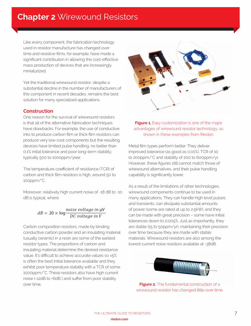
Chapter 2 Wirewound Resistors
Figure 1. Easy customization is one of the major advantages of wirewound resistor technology, as
shown in these examples from Riedon.
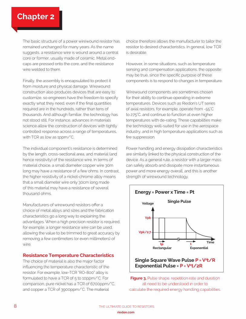
Figure 2. The fundamental construction of a wirewound resistor has changed little over time.
8 The UlTimaTe GUide To ResisToRs
www.riedon.com xx
The basic structure of a power wirewound resistor has remained unchanged for many years. As the name suggests, a resistance wire is wound around a central core or former, usually made of ceramic. Metal end-caps are pressed onto the core, and the resistance wire welded to them.
Finally, the assembly is encapsulated to protect it from moisture and physical damage. Wirewound construction also produces devices that are easy to customize, so engineers have the freedom to specify exactly what they need, even if the final quantities required are in the hundreds, rather than tens of thousands. And although familiar, the technology has not stood still. For instance, advances in materials science allow the construction of devices with tightly controlled response across a range of temperatures, with TCR as low as 1ppm/°C.
The individual component’s resistance is determined by the length, cross-sectional area, and material (and hence resistivity) of the resistance wire. In terms of material choice, a small diameter copper wire 30m long may have a resistance of a few ohms. In contrast, the higher resistivity of a nickel-chrome alloy means that a small diameter wire only 30cm long made of this material may have a resistance of several thousand ohms.
Manufacturers of wirewound resistors offer a choice of metal alloys and sizes and the fabrication characteristics go a long way to explaining the advantages. When a high precision resistor is required, for example, a longer resistance wire can be used, allowing the value to be trimmed to great accuracy by removing a few centimeters (or even millimeters) of wire.
Resistance Temperature CharacteristicsThe choice of material is also the major factor influencing the temperature characteristic of the resistor. For example, low-TCR “RO-800” alloy is formulated to have a TCR of 5 to 10ppm/°C. For comparison, pure nickel has a TCR of 6700ppm/°C, and copper a TCR of 3900ppm/°C. The material
choice therefore allows the manufacturer to tailor the resistor to desired characteristics. In general, low TCR is desirable.
However, in some situations, such as temperature sensing and compensation applications, the opposite may be true, since the specific purpose of these components is to respond to changes in temperature.
Wirewound components are sometimes chosen for their ability to continue operating in extreme temperatures. Devices such as Riedon’s UT series of axial resistors, for example, operate from -55°C to 275°C, and continue to function at even higher temperatures with de-rating. These capabilities make the technology well-suited for use in the aerospace industry, and in high temperature applications such as fire suppression.
Power handling and energy dissipation characteristics are similarly linked to the physical construction of the device. As a general rule, a resistor with a larger mass can safely absorb and dissipate more instantaneous power and more energy overall, and this is another strength of wirewound technology.
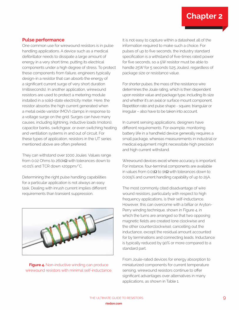
Figure 3. Pulse shape, repetition rate and duration all need to be understood in order to
calculate the required energy handling capabilities.
Energy = Power x Time = Pt
Single PulseVoltage
Rectangular Exponential
Time
Vpk
Vpk/2.7
tp t
Single Square Wave Pulse P = V2t/RExponential Pulse = P = V2t/2R
Chapter 2
9The UlTimaTe GUide To ResisToRs
www.riedon.com xx xx
Pulse performance One common use for wirewound resistors is in pulse handling applications. A device such as a medical defibrillator needs to dissipate a large amount of energy in a very short time, putting its electrical components under a high degree of stress. To protect these components from failure, engineers typically design-in a resistor that can absorb the energy of a significant current surge of very short duration (milliseconds). In another application, wirewound resistors are used to protect a metering module installed in a solid-state electricity meter. Here, the resistor absorbs the high current generated when a metal oxide varistor (MOV) clamps in response to a voltage surge on the grid. Surges can have many causes, including lightning, inductive loads (motors), capacitor banks, switchgear, or even switching heating and ventilation systems in and out of circuit. For these types of application, resistors in the UT series mentioned above are often prefered.
They can withstand over 1000 Joules. Values range from 0.02 Ohms to 260kΩ with tolerances down to ±0.01% and TCR down ±20ppm/°C.
Determining the right pulse handling capabilities for a particular application is not always an easy task. Dealing with inrush current implies different requirements than transient suppression.
It is not easy to capture within a datasheet all of the information required to make such a choice. For pulses of up to five seconds, the industry standard specification is a withstand of five-times rated power for five seconds, so a 5W resistor must be able to handle 25W for 5 seconds (125 Joules), regardless of package size or resistance value.
For shorter pulses, the mass of the resistance wire determines the Joule rating, which is then dependent upon resistor value and package type, including its size and whether it’s an axial or surface mount component. Repetition rate and pulse shape - square, triangular or irregular – also have to be taken into account.
In current sensing applications, designers have different requirements. For example, monitoring battery life in a handheld device generally requires a small package, whereas measurements in industrial or medical equipment might necessitate high precision and high current withstand.
Wirewound devices excel where accuracy is important. For instance, four-terminal components are available in values from 0.01Ω to 1kΩ with tolerances down to 0.005% and current handling capability of up to 25A.
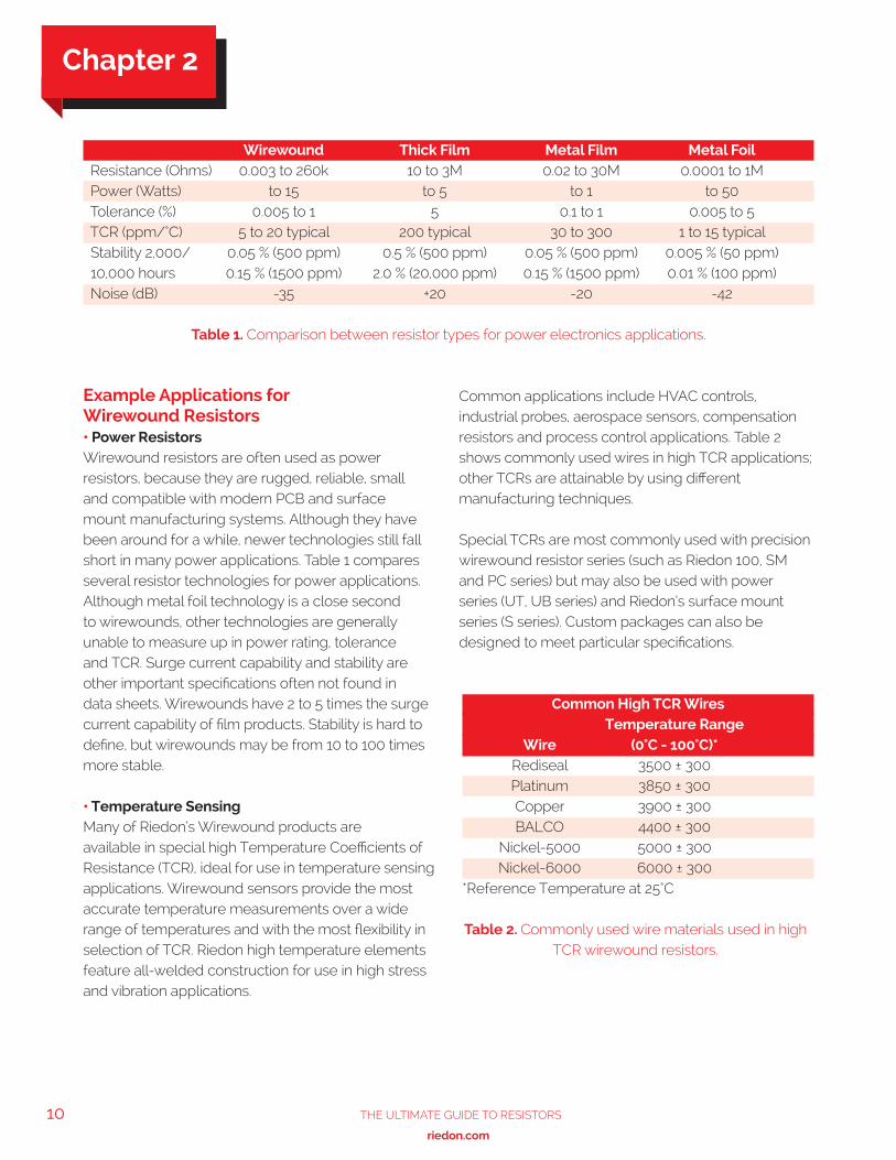
The most commonly cited disadvantage of wire wound resistors, particularly with respect to high frequency applications, is their self-inductance. However, this can overcome with a bifilar or Aryton-Perry winding technique, shown in Figure 4, in which the turns are arranged so that two opposing magnetic fields are created (one clockwise and the other counterclockwise), cancelling out the inductance, except the residual amount accounted for by terminations and connecting leads. Inductance is typically reduced by 90% or more compared to a standard part.
From Joule-rated devices for energy absorption to miniaturized components for current temperature sensing, wirewound resistors continue to offer significant advantages over alternatives in many applications, as shown in Table 1.
Figure 4. Non-inductive winding can produce wirewound resistors with minimal self-inductance.
Chapter 2
10 The UlTimaTe GUide To ResisToRs
www.riedon.com xx
Example Applications for Wirewound Resistors• Power ResistorsWirewound resistors are often used as power resistors, because they are rugged, reliable, small and compatible with modern PCB and surface mount manufacturing systems. Although they have been around for a while, newer technologies still fall short in many power applications. Table 1 compares several resistor technologies for power applications. Although metal foil technology is a close second to wirewounds, other technologies are generally unable to measure up in power rating, tolerance and TCR. Surge current capability and stability are other important specifications often not found in data sheets. Wirewounds have 2 to 5 times the surge current capability of film products. Stability is hard to define, but wirewounds may be from 10 to 100 times more stable. • Temperature SensingMany of Riedon’s Wirewound products are available in special high Temperature Coefficients of Resistance (TCR), ideal for use in temperature sensing applications. Wirewound sensors provide the most accurate temperature measurements over a wide range of temperatures and with the most flexibility in selection of TCR. Riedon high temperature elements feature all-welded construction for use in high stress and vibration applications.
Common applications include HVAC controls, industrial probes, aerospace sensors, compensation resistors and process control applications. Table 2 shows commonly used wires in high TCR applications; other TCRs are attainable by using different manufacturing techniques.
Special TCRs are most commonly used with precision wirewound resistor series (such as Riedon 100, SM and PC series) but may also be used with power series (UT, UB series) and Riedon’s surface mount series (S series). Custom packages can also be designed to meet particular specifications.
Wirewound Thick Film Metal Film Metal Foil Resistance (Ohms) 0.003 to 260k 10 to 3M 0.02 to 30M 0.0001 to 1M Power (Watts) to 15 to 5 to 1 to 50 Tolerance (%) 0.005 to 1 5 0.1 to 1 0.005 to 5 TCR (ppm/°C) 5 to 20 typical 200 typical 30 to 300 1 to 15 typical Stability 2,000/ 0.05 % (500 ppm) 0.5 % (500 ppm) 0.05 % (500 ppm) 0.005 % (50 ppm) 10,000 hours 0.15 % (1500 ppm) 2.0 % (20,000 ppm) 0.15 % (1500 ppm) 0.01 % (100 ppm) Noise (dB) -35 +20 -20 -42
Table 1. Comparison between resistor types for power electronics applications.
Common High TCR Wires Temperature Range Wire (0°C - 100°C)* Rediseal 3500 ± 300 Platinum 3850 ± 300 Copper 3900 ± 300 BALCO 4400 ± 300 Nickel-5000 5000 ± 300 Nickel-6000 6000 ± 300*Reference Temperature at 25°C
Table 2. Commonly used wire materials used in high TCR wirewound resistors.
Chapter 2
11The UlTimaTe GUide To ResisToRs
www.riedon.com xx xx
Film technology products have developed sufficiently to replacing older carbon resistors. There are two common film types, thick film and metal or thin film, with thick film being the most prolific type of resistor used in electronic devices. These devices may look similar, but they are constructed differently and have different properties.
Thick Film Construction and PropertiesThick film resistors have many carbon resistor characteristics; they can be made small and are very low cost in high quantities. Their resistance tolerance, TCR and stability over time is not as favorable as wirewound or foil types, but they have other benefits. Thick film resistors offer high resistance values, up to 10TΩ (tera-ohm), very high temperature performance and high voltage capability and are inherently non-inductive. They are suitable for the demanding requirements of medical, aerospace and downhole (oil and gas) applications. Riedon’s range includes precision high value chip resistors, power chip resistors and trimmable chip resistors alongside standard models.
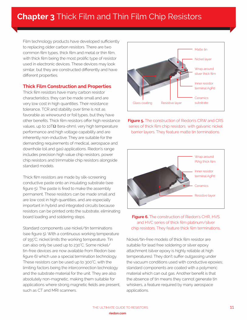
Thick film resistors are made by silk-screening conductive paste onto an insulating substrate (see figure 5). The paste is fired to make the assembly permanent. These resistors can be made small and are low cost in high quantities, and are especially important in hybrid and integrated circuits because resistors can be printed onto the substrate, eliminating board loading and soldering steps.
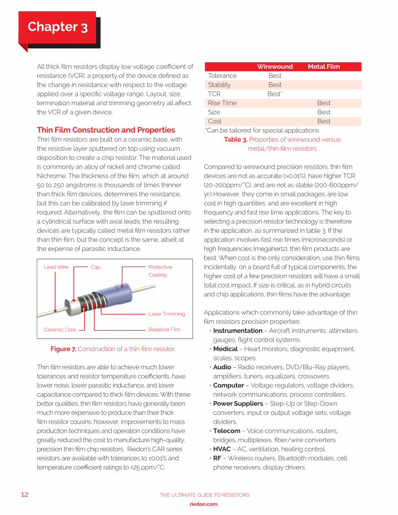
Standard components use nickel/tin terminations (see figure 5). With a continuous working temperature of 155°C; nickel limits the working temperature. Tin can also only be used up to 230°C. Some nickel/tin-free devices are now available from Riedon (see figure 6) which use a special termination technology. These resistors can be used up to 300°C, with the limiting factors being the interconnection technology and the substrate material for the unit. They are also absolutely non-magnetic, making them suitable for applications where strong magnetic fields are present, such as CT and MRI scanners.
Nickel/tin-free models of thick film resistor are suitable for lead free soldering or silver epoxy attachment (silver epoxy is highly reliable at high temperatures). They don’t suffer outgassing under the vacuum conditions used with conductive epoxies; standard components are coated with a polymeric material which can out gas. Another benefit is that the absence of tin means they cannot generate tin whiskers, a feature required by many aerospace applications.
Figure 5. The construction of Riedon’s CRW and CRS series of thick film chip resistors with galvanic nickel
barrier layers. They feature matte tin terminations.
Figure 6. The construction of Riedon’s CHR, HVS and HVC series of thick film platinum/silver
chip resistors. They feature thick film terminations.
Matte tin
Nickel layer
Wrap around
silver thick film
Inner resistor
terminal AgPd
Ceramics
substrateGlass coating Resistive layer
Wrap around
PtAg thick film
Inner resistor
terminal AgPd
Ceramics
Resistive layer
Chapter 3 Thick Film and Thin Film Chip Resistors
12 The UlTimaTe GUide To ResisToRs
www.riedon.com xx
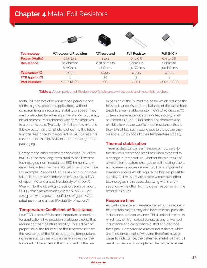
All thick film resistors display low voltage coefficient of resistance (VCR), a property of the device defined as the change in resistance with respect to the voltage applied over a specific voltage range. Layout, size, termination material and trimming geometry all affect the VCR of a given device. Thin Film Construction and Properties Thin film resistors are built on a ceramic base, with the resistive layer sputtered on top using vacuum deposition to create a chip resistor. The material used is commonly an alloy of nickel and chrome called Nichrome. The thickness of the film, which at around 50 to 250 angstroms is thousands of times thinner than thick film devices, determines the resistance, but this can be calibrated by laser trimming if required. Alternatively, the film can be sputtered onto a cylindrical surface with axial leads; the resulting devices are typically called metal film resistors rather than thin film, but the concept is the same, albeit at the expense of parasitic inductance.
Thin film resistors are able to achieve much lower tolerances and resistor temperature coefficients, have lower noise, lower parasitic inductance, and lower capacitance compared to thick film devices. With these better qualities, thin film resistors have generally been much more expensive to produce than their thick film resistor cousins, however, improvements to mass production techniques and operation conditions have greatly reduced the cost to manufacture high-quality, precision thin film chip resistors. Riedon’s CAR series resistors are available with tolerances to ±0.01% and temperature coefficient ratings to ±25 ppm/°C.
Compared to wirewound precision resistors, thin film devices are not as accurate (>0.01%), have higher TCR (20-200ppm/°C), and are not as stable (200-600ppm/yr.) However, they come in small packages, are low cost in high quantities, and are excellent in high frequency and fast rise time applications. The key to selecting a precision resistor technology is therefore in the application, as summarized in table 3. If the application involves fast rise times (microseconds) or high frequencies (megahertz), thin film products are best. When cost is the only consideration, use thin films. Incidentally, on a board full of typical components, the higher cost of a few precision resistors will have a small total cost impact. If size is critical, as in hybrid circuits and chip applications, thin films have the advantage.
Applications which commonly take advantage of thin film resistors precision properties:
• Instrumentation – Aircraft instruments, altimeters, gauges, flight control systems.
• Medical – Heart monitors, diagnostic equipment, scales, scopes.
• Audio – Radio receivers, DVD/Blu-Ray players, amplifiers, tuners, equalizers, crossovers.
• Computer – Voltage regulators, voltage dividers, network communications, process controllers.
• Power Suppliers – Step-Up or Step-Down converters, input or output voltage sets, voltage dividers.
• Telecom – Voice communications, routers, bridges, multiplexes, fiber/wire converters.
• HVAC – AC, ventilation, heating control.• RF – Wireless routers, Bluetooth modules, cell
phone receivers, display drivers.
Wirewound Metal Film Tolerance Best Stability Best TCR Best* Rise Time Best Size Best Cost Best*Can be tailored for special applications
Table 3. Properties of wirewound versus metal/thin film resistors
Figure 7. Construction of a thin film resistor.
Protective
Coating
Laser Trimming
Resistive Film
Lead Wire Cap
Ceramic Core
Chapter 3
13The UlTimaTe GUide To ResisToRs
www.riedon.com xx xx
Metal foil resistors offer unmatched performance for the highest precision applications, without compromising on accuracy, stability or speed. They are constructed by adhering a metal alloy foil, usually nickel/chromium (Nichrome) with some additives, to a ceramic base. Typically this foil is a few microns thick. A pattern is then photo-etched into the foil to trim the resistance to the correct value. Foil resistors can be made in chip/SMD or leaded/through-hole packaging.
Compared to other resistor technologies, foil offers low TCR, the best long-term stability of all resistor technologies, non-inductance, ESD immunity, low capacitance, fast thermal stabilization, and low noise. For example, Riedon’s UHPL series of through-hole foil resistors achieves tolerance of ±0.005%, a TCR of ±2ppm/°C and a load life stability of ±0.005%. Meanwhile, the ultra-high precision, surface mount UHPC series achieves an extremely low TCR of ±0.05ppm with a power coefficient of 5ppm/W at rated power and a load life stability of ±0.005%.
Temperature Coefficient of ResistanceLow TCR is one of foil’s most important properties for applications like precision analogue circuits that require tight temperature stability. This is down to properties of the foil itself; as the temperature rises, the resistance of the foil rises, but the temperature increase also causes a compressive stress on the foil (due to differences in the coefficient of thermal
expansion of the foil and the base), which reduces the foil’s resistance. Overall, the balance of the two effects leads to a very stable resistor. TCRs of ±0.05ppm/°C or less are available with today’s technology, such as Riedon’s USR 2-0808 series. Foil products also exhibit a low power coefficient of resistance, that is, they exhibit low self-heating due to the power they dissipate, which adds to their temperature stability.
Thermal stabilizationThermal stabilization is a measure of how quickly the device’s resistance stabilizes when exposed to a change in temperature, whether that’s a result of ambient temperature changes or self-heating due to an increase in power dissipation. This is important in precision circuits which require the highest possible stability. Foil resistors are a clear winner over other technologies in this case, stabilizing within a few seconds, while other technologies’ response is in the order of minutes.
Response timeAs well as temperature-related effects, the nature of foil resistors means they also have minimal parasitic inductance and capacitance. This is critical in circuits which rely on high speed signals as any unwanted inductance and capacitance distort and degrade the signal. Compared to wirewound resistors, which are in essence a coil of wire and therefore have a parasitic inductance, the patterned metal foil that foil resistors use is all in one plane. The foil patterns are
Technology Wirewound Precision Wirewound Foil Resistor Foil (NiCr) Power (Watts) 0.05 to 2 1 to 2 0 to 0.6 0.4 to 0.6 Resistance 0.1 ohms to 0.01 ohms to 1 ohms to 1 ohms to 6 MOhms 1 KOhms 150 KOhms 300 KOhms Tolerance (%) 0.005 0.005 0.005 0.005 TCR (ppm/°C) 1 20 2 1 Part Number 100, SM, PC SC UHPL USR 2-0808
Table 4. A comparison of Riedon 0.005% tolerance wirewound and metal foil resistors
Chapter 4 Metal Foil Resistors
14 The UlTimaTe GUide To ResisToRs
www.riedon.com xx
also specially designed to mitigate any parasitic reactance; S-shaped or zig zag patterns mean current in adjacent wires flows in different directions. A good design can replicate pulses as short as a few nanoseconds on the output. Foil resistors are therefore suitable for high frequency applications.
Applications Applications for foil resistors include anywhere that high precision and excellent long-term stability is required, including high precision instrumentation and differential amplifiers. They are popular in audio circuits since the increasing demand for sound integrity places noise restrictions on components in order to preserve signal integrity. Medical devices, automated test equipment, current sensing and weighing systems commonly use foil resistors. They also suit military and aerospace applications, extreme environments such as downhole drilling and the industrial sector.
Chapter 4
15The UlTimaTe GUide To ResisToRs
www.riedon.com xx xx
In any system where heat dissipation could affect the components’ performance, understanding power dissipation for the purposes of selecting the right heat sink is very important. Let’s take a closer look at the power dissipation of resistors.
Standard Conditions for SpecificationsThe first thing to understand is the manufacturer’s specification for the resistor in question. In Riedon data sheets, the nominal power dissipation is mentioned for all resistors. The data is valid for a free standing assembly, that is, an SMD assembled on a PCB. The ambient temperature is always 70°C. This means that the inherent temperature of the resistance element (the sum of the ambient temperature and the temperature through the power dissipation) will reach the limiting temperature if additional cooling is not used.
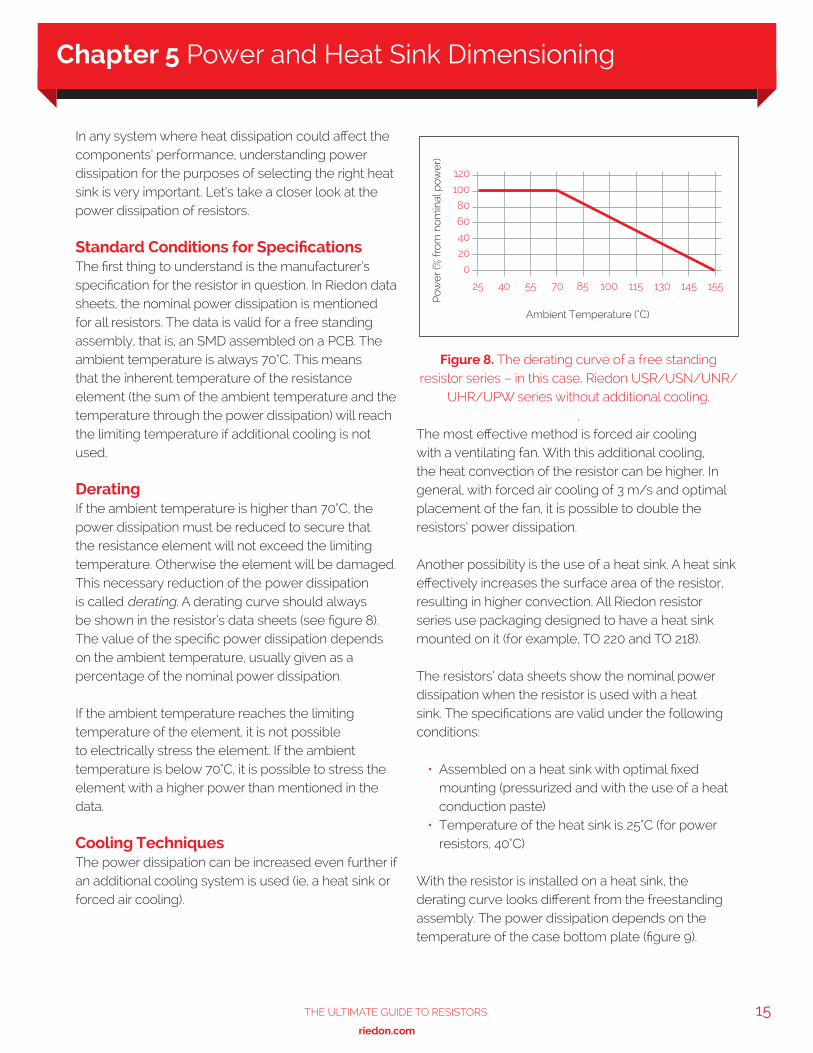
DeratingIf the ambient temperature is higher than 70°C, the power dissipation must be reduced to secure that the resistance element will not exceed the limiting temperature. Otherwise the element will be damaged. This necessary reduction of the power dissipation is called derating. A derating curve should always be shown in the resistor’s data sheets (see figure 8). The value of the specific power dissipation depends on the ambient temperature, usually given as a percentage of the nominal power dissipation.
If the ambient temperature reaches the limiting temperature of the element, it is not possible to electrically stress the element. If the ambient temperature is below 70°C, it is possible to stress the element with a higher power than mentioned in the data.
Cooling TechniquesThe power dissipation can be increased even further if an additional cooling system is used (ie, a heat sink or forced air cooling).
The most effective method is forced air cooling with a ventilating fan. With this additional cooling, the heat convection of the resistor can be higher. In general, with forced air cooling of 3 m/s and optimal placement of the fan, it is possible to double the resistors’ power dissipation.
Another possibility is the use of a heat sink. A heat sink effectively increases the surface area of the resistor, resulting in higher convection. All Riedon resistor series use packaging designed to have a heat sink mounted on it (for example, TO 220 and TO 218).
The resistors’ data sheets show the nominal power dissipation when the resistor is used with a heat sink. The specifications are valid under the following conditions:
• Assembled on a heat sink with optimal fixed mounting (pressurized and with the use of a heat conduction paste)
• Temperature of the heat sink is 25°C (for power resistors, 40°C)
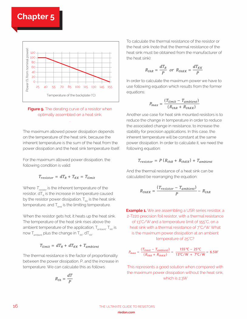
With the resistor is installed on a heat sink, the derating curve looks different from the freestanding assembly. The power dissipation depends on the temperature of the case bottom plate (figure 9).
Figure 8. The derating curve of a free standing resistor series – in this case, Riedon USR/USN/UNR/
UHR/UPW series without additional cooling..
120
100
80
60
40
20
0
25 40 55 70 85 100 115 130 145 155
Pow
er (%
fro
m n
om
inal
pow
er)
Ambient Temperature (°C)
Chapter 5 Power and Heat Sink Dimensioning
16 The UlTimaTe GUide To ResisToRs
www.riedon.com xx
The maximum allowed power dissipation depends on the temperature of the heat sink, because the inherent temperature is the sum of the heat from the power dissipation and the heat sink temperature itself.
For the maximum allowed power dissipation, the following condition is valid:
Where Tresistor is the inherent temperature of the resistor, dTR is the increase in temperature caused by the resistor power dissipation, TKK is the heat sink temperature, and Tlimit is the limiting temperature.
When the resistor gets hot, it heats up the heat sink. The temperature of the heat sink rises above the ambient temperature of the application, Tambient. TKK is now Tambient plus the change in TKK, dTKK.
The thermal resistance is the factor of proportionality between the power dissipation, P, and the increase in temperature. We can calculate this as follows:
To calculate the thermal resistance of the resistor or the heat sink (note that the thermal resistance of the heat sink must be obtained from the manufacturer of the heat sink):
In order to calculate the maximum power we have to use following equation which results from the former equations:
Another use case for heat sink mounted resistors is to reduce the change in temperature in order to reduce the associated change in resistance, to increase the stability for precision applications. In this case, the inherent temperature will be constant at the same power dissipation. In order to calculate it, we need the following equation:
And the thermal resistance of a heat sink can be calculated be rearranging the equation:
Figure 9. The derating curve of a resistor when optimally assembled on a heat sink.
.
120
100
80
60
40
20
0
25 40 55 70 85 100 115 130 145 155
Temperature of the backplate (°C)
Pow
er (%
fro
m n
om
inal
pow
er)
Example 1. We are assembling a USR series resistor, a 2-T220 precision foil resistor, with a thermal resistance
of 13°C/W and a temperature limit of 155°C, on a heat sink with a thermal resistance of 7°C/W. What is the maximum power dissipation at an ambient
temperature of 25°C?
This represents a good solution when compared with the maximum power dissipation without the heat sink,
which is 2.3W
Chapter 5
17The UlTimaTe GUide To ResisToRs
www.riedon.com xx xx
Real World AccuracyAlthough data sheets state the thermal resistance for heat sink-mounted resistors in K/W or °C/W, this data is for a pressurized assembly with a heat conduction paste. Also, the nominal power dissipation quoted is related to applications where the heat sink temperature is 25°C or 40°C. To get a more accurate real world figure for the heat sink temperature, we must also consider the sum of all power dissipation from the parts assembled to the heat sink, and the ambient temperature.
The thermal resistance of the resistor RthR is the result of the thermal resistance between the resistance element and the mounting plate (Rthj-c), inherent in design, and the thermal resistance between the mounting plate and the heat sink (RthRAppl), depending on the application. The Rthj-c is fixed by the manufacturer of the resistor. The RthRAppl depends on how the heat sink is mounted, the size of the mounting plate, the type of fixing (number of the location holes or fixing strap), the force used to assemble the resistor to the heat sink and the specialized experience of the customer for the application.
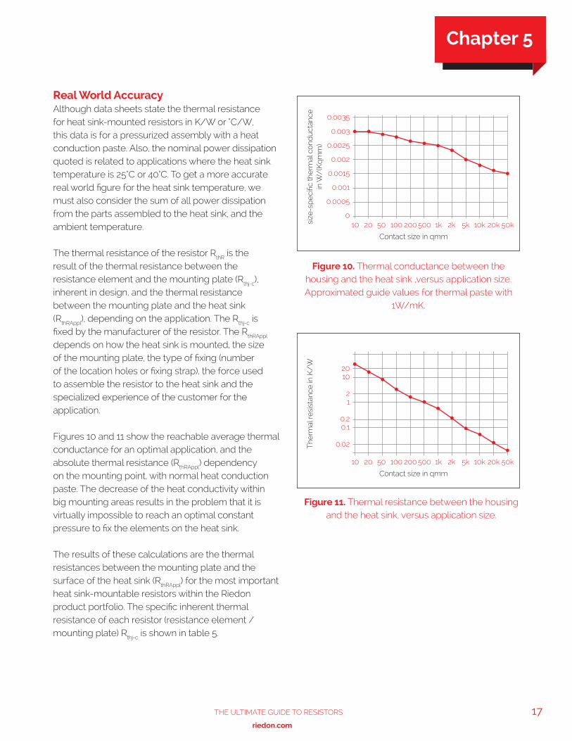
Figures 10 and 11 show the reachable average thermal conductance for an optimal application, and the absolute thermal resistance (RthRAppl) dependency on the mounting point, with normal heat conduction paste. The decrease of the heat conductivity within big mounting areas results in the problem that it is virtually impossible to reach an optimal constant pressure to fix the elements on the heat sink.
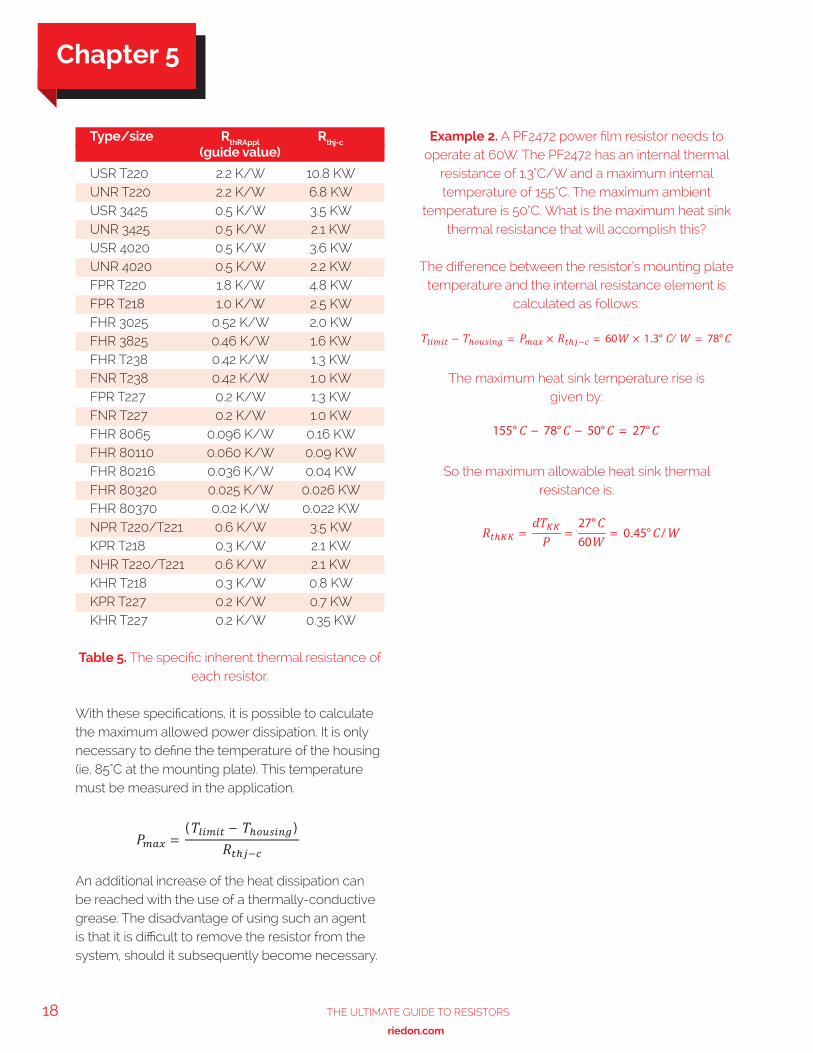
The results of these calculations are the thermal resistances between the mounting plate and the surface of the heat sink (RthRAppl) for the most important heat sink-mountable resistors within the Riedon product portfolio. The specific inherent thermal resistance of each resistor (resistance element / mounting plate) Rthj-c is shown in table 5.
Figure 10. Thermal conductance between the housing and the heat sink ,versus application size. Approximated guide values for thermal paste with
1W/mK.
0.0035
0.003
0.0025
0.002
0.0015
0.001
0.0005
010 20 50 100 200 500 1k 2k 5k 10k 20k 50ksi
ze-s
pec
ific
ther
mal
co
nduc
tanc
e
in W
/(K
qm
m)
Contact size in qmm
Figure 11. Thermal resistance between the housing and the heat sink, versus application size.
2010
21
0.20.1
0.02
10 20 50 100 200 500 1k 2k 5k 10k 20k 50k
The
rmal
res
ista
nce
in K
/W
Contact size in qmm
Chapter 5
18 The UlTimaTe GUide To ResisToRs
www.riedon.com xx
With these specifications, it is possible to calculate the maximum allowed power dissipation. It is only necessary to define the temperature of the housing (ie, 85°C at the mounting plate). This temperature must be measured in the application.
An additional increase of the heat dissipation can be reached with the use of a thermally-conductive grease. The disadvantage of using such an agent is that it is difficult to remove the resistor from the system, should it subsequently become necessary.
Table 5. The specific inherent thermal resistance of each resistor.
Type/size RthRAppl Rthj-c
(guide value)
USR T220 2.2 K/W 10.8 KW UNR T220 2.2 K/W 6.8 KW USR 3425 0.5 K/W 3.5 KW UNR 3425 0.5 K/W 2.1 KW USR 4020 0.5 K/W 3.6 KW UNR 4020 0.5 K/W 2.2 KW FPR T220 1.8 K/W 4.8 KW FPR T218 1.0 K/W 2.5 KW FHR 3025 0.52 K/W 2.0 KW FHR 3825 0.46 K/W 1.6 KW FHR T238 0.42 K/W 1.3 KW FNR T238 0.42 K/W 1.0 KW FPR T227 0.2 K/W 1.3 KW FNR T227 0.2 K/W 1.0 KW FHR 8065 0.096 K/W 0.16 KW FHR 80110 0.060 K/W 0.09 KW FHR 80216 0.036 K/W 0.04 KW FHR 80320 0.025 K/W 0.026 KW FHR 80370 0.02 K/W 0.022 KW NPR T220/T221 0.6 K/W 3.5 KW KPR T218 0.3 K/W 2.1 KW NHR T220/T221 0.6 K/W 2.1 KW KHR T218 0.3 K/W 0.8 KW KPR T227 0.2 K/W 0.7 KW KHR T227 0.2 K/W 0.35 KW
Example 2. A PF2472 power film resistor needs to operate at 60W. The PF2472 has an internal thermal
resistance of 1.3°C/W and a maximum internal temperature of 155°C. The maximum ambient
temperature is 50°C. What is the maximum heat sink thermal resistance that will accomplish this?
The difference between the resistor’s mounting plate temperature and the internal resistance element is
calculated as follows:
The maximum heat sink temperature rise is given by:
So the maximum allowable heat sink thermal resistance is:
.
Chapter 5
19The UlTimaTe GUide To ResisToRs
www.riedon.com xx xx
Medical electronics equipment is no longer just found in hospitals, clinics and doctors’ surgeries. Neither is its use restricted to qualified practitioners. Instead designs have become smaller, more portable and easier to use to the point where now appliances like defibrillators are deployed in many public places such as sports venues, schools, airports, health and fitness clubs and many commercial and government offices.
Other devices such as blood glucose meters are today considered essential in the care of patients with diabetes and have evolved to be personal, pocket-sized units that can be carried everywhere. There is also equipment for patient monitoring, diagnostics and medication delivery that has been designed for in-home use, which often includes portable, body-worn elements.
Medical equipment generally demands the highest quality components to ensure safe and dependable operation; and portable equipment poses the additional challenges of compact size, the ruggedness needed to cope with harsh operating conditions, and usually needing to be battery-powered.
This chapter will explore two of these applications for portable medical electronics, looking at the specific requirements of the resistor technology used in their circuit designs.
Automatic External Defibrillators (AEDs) Automatic external defibrillators operate on the same principle as the external defibrillators found in hospitals. They are used to treat victims of life-threatening cardiac arrhythmia (irregular heartbeat), which may lead to cardiac arrest, by administering an electrical shock to re-establish a normal heart rhythm. Note that external defibrillators are those where the charge is delivered via paddles placed on the chest whereas internal defibrillators, usually only found in operating theatres, use electrodes in direct contact with the heart.
The difference with hospital-type defibrillators is that they are designed for manual operation by trained doctors, paramedics and nursing staff who can diagnose the cardiac condition and will know what level of shock to apply. Also, while these defibrillators may have inbuilt electrocardiogram (ECG) readers, many hospital patients, especially those at risk of cardiac arrest, are likely to already be connected to comprehensive diagnostic monitoring equipment, which provides the clinician with all the information they require.
By contrast, AEDs are more portable devices, primarily intended for use by people who are not healthcare professionals, although ideally their operators will be first responders who have been trained in their use. Some ambulances may carry AEDs in addition to manual defibrillators. AEDs, as their name implies, automate the analysis and diagnosis of the patient’s heart rhythm and either administer a shock automatically or will clearly advise the user whether a shock is required and how to deliver it. Consequently AEDs are more limited in their capabilities and can only treat the common shockable types of arrhythmia (often referred to as VT and VF) and will not work with a ‘flatline’ condition after the heart has arrested.
AEDs are commonly considered as ‘public access’ devices, prominently located in shopping centers, railway stations and similar locations, but body-worn and other personal AEDs are becoming popular for vulnerable people and are even being promoted as essential home safety equipment.
Figure 12. Simplified defibrillator circuit schematic.
V DC
R1
R2
R3
C
R4
RT
RS
CS
I
Paddles
Chapter 6 Using Resistors in Medical Applications
20 The UlTimaTe GUide To ResisToRs
www.riedon.com xx
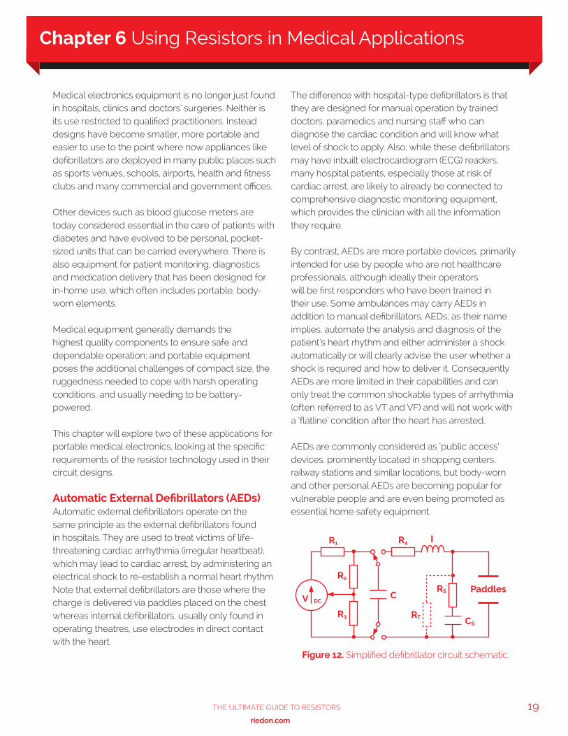
The basic electrical design of a defibrillator is relatively simple (shown in figure 12). The key element is the storage capacitor C, which is charged to a level sufficient to deliver a predetermined dose of electrical energy as a shock to the heart.
This schematic only shows the essential charge/discharge circuitry and not the controls that drive the switches and automatically determine correct operation. The charging circuit comprises a DC supply and series resistor R1 , which limits the charging current and determines the charging time. Depending on the capacitor’s value and the required shock energy, the supply may well need to provide upward of 1000V, perhaps even as high as 5000V. So, in the case of a battery-powered portable AED, this will come from a DC-DC converter. The potential divider, formed by R2 and R3 , monitors the capacitor voltage and provides a lower voltage signal that is used to disconnect the supply once the required charge level is reached.
Discharge is via an inductor I, which in combination with resistor R4 produces a heavily damped pulse that typically delivers 100 joules of energy over a period of around 5ms. The system as shown provides a fixed polarity pulse whereas most defibrillator designs are now biphasic so as to reverse the polarity of alternate pulses. Biphasic defibrillators achieve higher success rates and operate at reduced energy levels. RS and CS form a snubber circuit while RT may be included to provide a means of testing the defibrillator output.
The performance requirements of the resistors used in AEDs, including the associated cardiac monitoring circuits, are quite demanding. Resistors R1, R2 and R4 in figure 11 must all be able to withstand high voltages but R1 is carrying the charging current so while its exact value (perhaps 100kΩ), and hence accuracy, is not so important, it will probably need to be capable of dissipating around 10W of power. R4 is used to shape the charge pulse delivered to the paddles so its value (e.g. 10Ω) and surge handling capacity (around 300 Joules) are key. The ratio of the values of R2 and R3 might be in the order of 500:1 to divide
a supply voltage of say 1000V down to a level of 2V, compatible with the comparator input range of a typical microcontroller. Hence if R2 were 10MΩ then R3 would need to be around 20kΩ. Assuming the system can be calibrated, then again the exact values and tolerance of these devices are not important. However, temperature stability and voltage linearity are critical performance characteristics, defined by the parameters of TCR (temperature coefficient of resistivity) and VCR (voltage coefficient of resistivity). Suitable values would be ±100ppm/°C for TCR and between -1 to -5ppm/V for VCR, which has a negative coefficient.
Riedon offers various types of resistor that address these requirements. For R1 its HTE thick-film range provides a non-inductive, axial-leaded design with a voltage rating up to 48kV, power ratings from 0.7 to 17W and resistances from 1kΩ to 100MΩ . With a ±100ppm/°C TCR specification the HTE series is also suitable for R2 and R3. For R4 and also to protect any sensitive monitor inputs that may be connected to the paddles, suitable pulse-withstanding resistors are required. For these Riedon recommends its UT series of wirewound resistor, which is capable of handling over 1000 Joules. A suitable value for RS would be 50Ω while RT might be around 5kΩ and again, the UT type provides the necessary pulse handling capability. R4, RS, and RT should all be non-inductive.
Blood Glucose Meters Blood glucose monitoring enables diabetics to monitor their condition and respond to high or low blood sugar levels. Understanding how and why these levels change helps those affected manage their diet, exercise and medication regime. This is particularly important for sufferers of Type 1 diabetes (and some Type 2s) whose treatment requires insulin injections – regular blood glucose testing allows them to check the effectiveness of their last insulin dose and plan the next one.
Chapter 6

21The UlTimaTe GUide To ResisToRs
www.riedon.com xx xx
A blood glucose meter is an electronic device that provides a relatively simple means of measuring blood glucose levels. And advances in technology have provided pocketsize battery-powered units that are convenient to carry and easy to use so that testing can be carried out several times a day, helping patients maintain closer to normal blood glucose levels throughout the day.
Most blood glucose testing is performed by obtaining a small blood sample, typically by pricking a finger, and applying the blood to a test strip that contains chemicals that react with the glucose. Early measurements relied on a reaction that changed the color of the strip, which could either be crudely compared to a color reference chart or, more accurately, measured with a colorimeter. The alternative measurement method uses an electrochemical reaction and it is the combination of this technology with an appropriate electrical metering circuit that forms the basis of most blood glucose meters today.
Such blood glucose meters, or ‘glucometers’ as they are frequently called, use test strips that absorb a defined amount of blood. The glucose in the blood is oxidized using an enzyme electrode as a catalyst; it is then re-oxidized with a mediator reagent, which in turn reacts with the electrode and generates an electrical current. The total charge (current times time) produced is then proportional to the amount of glucose in the blood sample. This charge can either be measured over a period of time or, knowing the timing characteristic of the chemical reaction, the current can be measured after a predefined interval to provide an equivalent estimate of the glucose concentration.
The accuracy of glucometers is vitally important and is therefore defined by ISO standards. Accuracy is affected by many factors including the size and quality of the blood sample, ambient temperature and humidity, calibration and aging of the test strips and ultimately the accuracy of the electrical measurement. The latter is something that is readily addressed by appropriate current measurement techniques using precision components.
Current sensing resistors provide the ideal solution. Like the shunt resistors used in traditional ammeters, the current is actually measured as a voltage drop across an accurately known, low-value resistor, placed in series with the load. In devices like glucometers that have digital displays, the voltage will be measured by an analog to digital converter (ADC), which will typically be an integrated function of the microcontroller used to process and output the glucose readings and provide overall control for the operation of the device.
Aside from their low resistance value, the key requirements for a current sensing resistor are accuracy and stability, across all operating conditions and over time. Riedon offers a number of different types of current sensing and shunt resistors for various applications. For this type of medical application, it particularly recommends either its CSR surface mount series or its through-hole mounting MSR series.
Figure 13. A typical blood glucose meter.
Chapter 6

22 The UlTimaTe GUide To ResisToRs
www.riedon.com xx
Riedon’s CSR series are ultra low Ohm metal strip chip resistors with values from 0.5 to 15 mΩ, a tolerance of ±1% and a TCR of ±50ppm/ oC. Three package sizes are offered, supporting power ratings from 1 to 3 Watts over a wide -55oC to +170oC operating temperature range. Its MSR resistors are available in values from 5 to 100 mΩ with a tolerance of ±1%, a TCR of ±20ppm/°C and power ratings of 1, 3 or 5W. Their bare metal element design and welded construction provides a low inductance solution that is also very economical.
Current sensing, using the same principles as above, is also very important in portable medical devices for monitoring battery life. Resistors of the type described above, or perhaps similar specification but higher power resistors from Riedon, will provide the right solution for this task.
Chapter 6
23The UlTimaTe GUide To ResisToRs
www.riedon.com xx xx
Efficient and reliable operation of LED lighting is dependent on the right choice of current-limiting resistor. Not all resistors are the same and growth in new markets like high-power LED lighting is serving to highlight the importance of understanding all aspects of an application in order to correctly and safely specify the right type of resistor.
Consequently, this chapter will first return to basics to understand the operating principles of LEDs and how they need to be correctly biased to achieve the optimum light output performance specified by the manufacturers. This chapter will also look at the electrical, optical and thermal characteristics of LEDs to appreciate why driving several LEDs in series can be more efficient than overdriving single LEDs, and why keeping temperatures in check is not just key to maximizing output but also to maintaining the desired color tone and ensuring reliability and long life.
Having understood the biasing calculations for some typical lighting scenarios, it quickly becomes apparent that in many applications the necessary ballast resistor is likely to dissipate several Watts of power. This not only dictates the need for a suitable high-power resistor type but may call for a design suitable for mounting on a heat sink, to help carry heat away from the LED rather than contribute to an already challenging design requirement.
All these considerations and more will be explored in the context of potential design solutions from specialist resistor manufacturer and supplier, Riedon, whose product line includes its UT series of wirewound power resistor for up to 13W dissipation, its PF series of power film resistor with ratings up to 20W and other series that allow for additional heatsinking and surface mount options.
Understanding LED operation and biasing requirements A light emitting diode (LED) is a type of semiconductor diode that emits light when a current flows from anode to cathode across the P-N junction of the device. Hence, in normal operation, an LED requires a direct current (DC) supply to provide the necessary positive bias (forward voltage) across this junction.
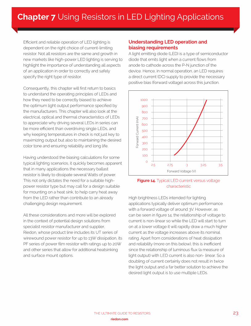
High brightness LEDs intended for lighting applications typically deliver optimum performance with a forward voltage of around 3V. However, as can be seen in figure 14, the relationship of voltage to current is non-linear so while the LED will start to turn on at a lower voltage it will rapidly draw a much higher current as the voltage increases above its nominal rating. Apart from considerations of heat dissipation and reliability (more on this below), this is inefficient since the relationship of luminous flux (a measure of light output) with LED current is also non- linear. So a doubling of current certainly does not result in twice the light output and a far better solution to achieve the desired light output is to use multiple LEDs.
Figure 14. Typical LED current versus voltage characteristic
1000
900
800
700
600
500
400
300
200
100
02.5 2.75 3 3.25 3.5
Forw
ard
Cur
rent
(mA
)
Forward Voltage (V)
Chapter 7 Using Resistors in LED Lighting Applications
24 The UlTimaTe GUide To ResisToRs
www.riedon.com xx
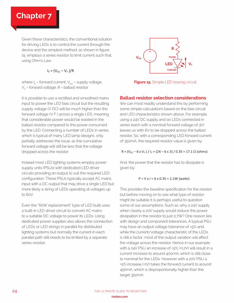
Given these characteristics, the conventional solution for driving LEDs is to control the current through the device and the simplest method, as shown in figure 15, employs a series resistor to limit current such that, using Ohm’s Law:
where IF = forward current, VDC = supply voltage, VF = forward voltage, R = ballast resistor.
It is possible to use a rectified and smoothed mains input to power the LED bias circuit but the resulting supply voltage (V DC) will be much higher than the forward voltage (V F ) across a single LED, meaning that considerable power would be wasted in the ballast resistor compared to the power consumed by the LED. Connecting a number of LEDs in series, which is typical of many LED lamp designs, only partially addresses the issue, as the cumulative forward voltage will still be less that the voltage dropped across the resistor.
Instead most LED lighting systems employ power supply units (PSUs) with dedicated LED driver circuits providing an output to suit the required LED configuration. These PSUs typically accept AC mains input with a DC output that may drive a single LED but more likely a string of LEDs operating at voltages up to 60V.
Even the “60W replacement” type of LED bulb uses a built-in LED driver circuit to convert AC mains to a suitable DC voltage to power its LEDs. Using dedicated power supplies also allows the connection of LEDs or LED strings in parallel for distributed lighting systems but normally the current in each parallel path still needs to be limited by a separate series resistor.
Ballast resistor selection considerations We can most readily understand this by performing some simple calculations based on the bias circuit and LED characteristics shown above. For example, using a 24V DC supply and six LEDs connected in series (each with a nominal forward voltage of 3V) leaves us with 6V to be dropped across the ballast resistor. So, with a corresponding LED forward current of 350mA, the required resistor value is given by:
And, the power that the resistor has to dissipate is given by:
This provides the baseline specification for the resistor but before moving on to see what type of resistor might be suitable it is perhaps useful to question some of our assumptions. Such as, why a 24V supply when clearly a 20V supply would reduce the power dissipation in the resistor to just 0.7W? One reason lies with design and component tolerances. A typical PSU may have an output voltage tolerance of ±5% and, while the current/voltage characteristic of the LEDs is still a factor, most of the output variation will affect the voltage across the resistor. Hence in our example with a 24V PSU an increase of +5% (+1.2V) will result in a current increase to around 400mA, which is still close to nominal for the LEDs. However with a 20V PSU a +5% increase (+1V) takes the forward current to around 450mA, which is disproportionally higher than the target 350mA.
Figure 15. Simple LED biasing circuit.
VDC
R+
-Anode
Cathode
LED VF
Chapter 7
25The UlTimaTe GUide To ResisToRs
www.riedon.com xx xx
Similar effects on the forward current will result if the resistor value itself deviates significantly from the design target value or if the LEDs vary from their nominal characteristics. Although there are no absolute rules for the design of LED bias circuits, all these factors need to be taken into account. The penalty, as noted earlier, is that the increased power dissipation from operating at higher currents leads to higher LED junction temperatures. This results in reduced relative light output, which partly negates any increase from operating at a higher current, but more importantly impacts on the device’s reliability and expected lifetime.
The relative chromaticity, i.e. color tone, of an LED is also affected by variations in current and temperature and is another reason for keeping both under control. This raises the issue of LED dimming since, although it is possible to achieve analog dimming of LEDs over a limited brightness range by varying the drive current, sometimes even beyond its nominal rating, this comes with the same problem of color variations. Instead the preferred method is pulse-width modulation (PWM) of the bias current. This approach typically drives the LEDs with a rectangular waveform, effectively switching the LEDs on and off at a rate (100kHz+ ) which is too high to be noticed. In this way the LEDs see the ideal nominal forward current during the ‘on’ part of the cycle and there is negligible power dissipation during the ‘off’ phase. The potential requirement for PWM dimming does however impose another constraint on the choice of ballast resistor; namely that it needs to be a non-reactive load i.e. with minimal inductance or capacitance.
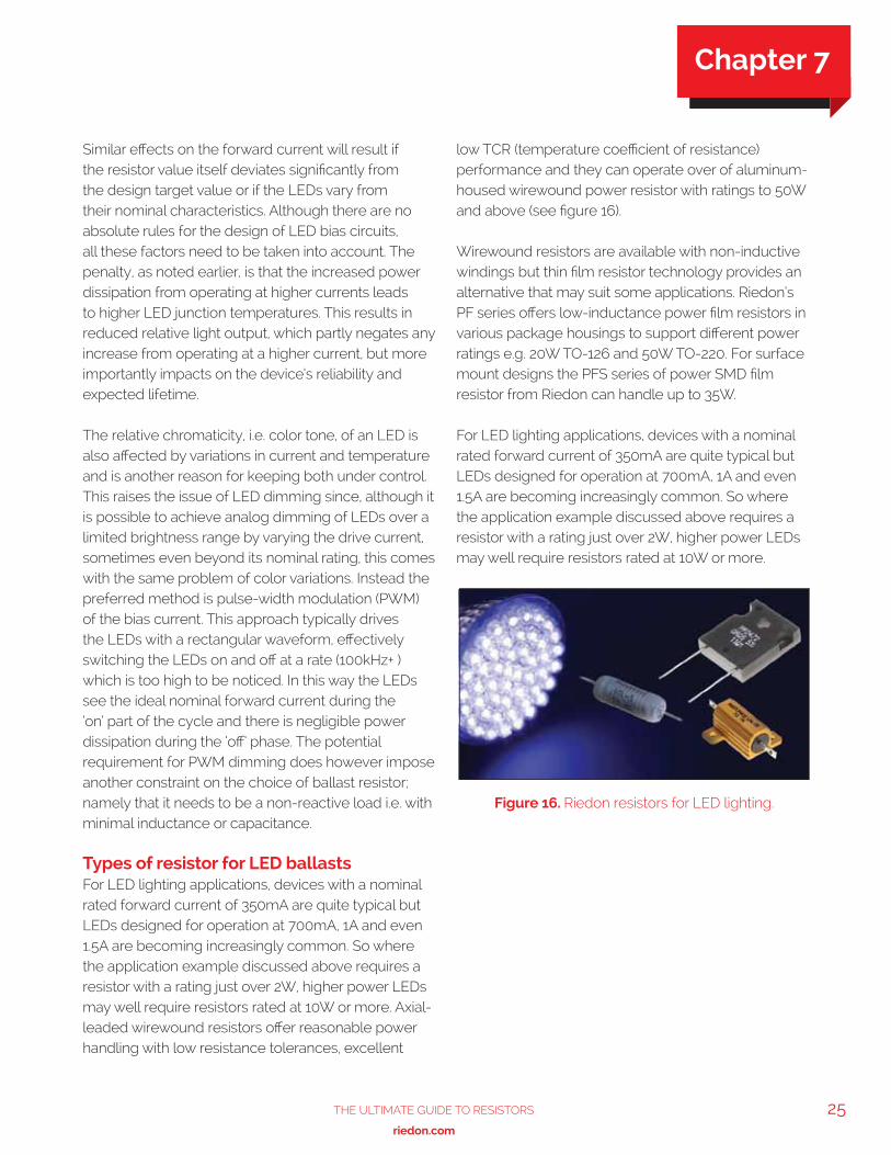
Types of resistor for LED ballasts For LED lighting applications, devices with a nominal rated forward current of 350mA are quite typical but LEDs designed for operation at 700mA, 1A and even 1.5A are becoming increasingly common. So where the application example discussed above requires a resistor with a rating just over 2W, higher power LEDs may well require resistors rated at 10W or more. Axial-leaded wirewound resistors offer reasonable power handling with low resistance tolerances, excellent
low TCR (temperature coefficient of resistance) performance and they can operate over of aluminum-housed wirewound power resistor with ratings to 50W and above (see figure 16).
Wirewound resistors are available with non-inductive windings but thin film resistor technology provides an alternative that may suit some applications. Riedon’s PF series offers low-inductance power film resistors in various package housings to support different power ratings e.g. 20W TO-126 and 50W TO-220. For surface mount designs the PFS series of power SMD film resistor from Riedon can handle up to 35W.
For LED lighting applications, devices with a nominal rated forward current of 350mA are quite typical but LEDs designed for operation at 700mA, 1A and even 1.5A are becoming increasingly common. So where the application example discussed above requires a resistor with a rating just over 2W, higher power LEDs may well require resistors rated at 10W or more.
Figure 16. Riedon resistors for LED lighting.
Chapter 7
26 The UlTimaTe GUide To ResisToRs
www.riedon.com xx
The subject of power supplies is potentially very broad and the application of resistors in power supplies is quite diverse. Here we will focus on power supply units (PSUs) designed for use in electronic appliances that nominally require fixed DC outputs ranging from just a few volts up to a few kV.
Whether such end-equipment is destined for consumer, commercial or industrial markets, the PSU designer will need to pay heed to stringent safety, environment and other regulations in addition to meeting the basic electrical performance requirements. As well as considering the role of resistors in regulating a power supply’s output voltage (or current), we will examine how resistors protect a supply from potential fault conditions, such as output overload, output short- or open-circuit and input surge currents, which can result in a fire or present a shock hazard to users.
Power supplies are often defined by their input source, AC or DC, and whether they use linear or switched mode regulation to achieve the desired DC output. AC-DC supplies are typically line powered but a DC in, DC out supply could just be a linear circuit that regulates the output from a battery or other DC source to produce a lower DC level. The term DC-DC converter is usually reserved for supplies that use switched-mode techniques, which can support both step-down (buck) and step-up (boost) conversion for lower and higher voltages respectively.
While most power supply manufacturers offer a range of standard units to satisfy various end- equipment requirements, some applications demand a custom solution. As a manufacturer and supplier of high performance resistors, Riedon has the experience to help designers choose the right component.
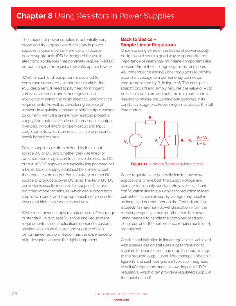
Back to Basics – Simple Linear Regulators Understanding some of the basics of power supply design would seem a good way to appreciate the importance of seemingly mundane components like resistors. From their college days, most engineers will remember designing Zener regulators to provide a constant voltage to a permanently connected load, represented by R2 in figure 16. The principle is straightforward and simply requires the value of R1 to be calculated to provide both the minimum current needed to ensure the Zener diode operates in its constant voltage breakdown region, as well as the full load current.
Zener regulators are generally fine for low power applications where both the supply voltage and load are reasonably constant. However, in a shunt configuration like this, a significant reduction in load current or increase in supply voltage may result in an increased current through the Zener diode that exceeds its maximum power dissipation. From the resistor perspective though, other than the power rating needed to handle the combined load and Zener currents, the performance requirements on R1 are minimal.
Greater sophistication in linear regulation is achieved with a series design that uses a pass transistor to regulate the load current and drop the input voltage to the required output level. This concept is shown in figure 18 and such designs are typical of integrated circuit (IC) regulators and also low drop-out (LDO) regulators, which often provide a regulated supply at the “point of load”.
Figure 17. A simple Zener regulator circuit.
R1
VZVSR2 R2 =
VS - VS
IZ + IR2
Chapter 8 Using Resistors in Power Supplies
27The UlTimaTe GUide To ResisToRs
www.riedon.com xx xx
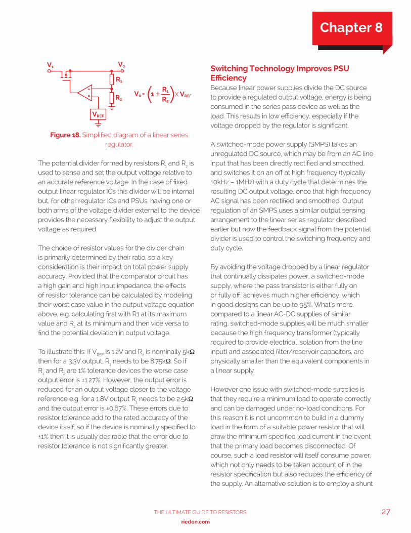
The potential divider formed by resistors R1 and R2 is used to sense and set the output voltage relative to an accurate reference voltage. In the case of fixed output linear regulator ICs this divider will be internal but, for other regulator ICs and PSUs, having one or both arms of the voltage divider external to the device provides the necessary flexibility to adjust the output voltage as required.
The choice of resistor values for the divider chain is primarily determined by their ratio, so a key consideration is their impact on total power supply accuracy. Provided that the comparator circuit has a high gain and high input impedance, the effects of resistor tolerance can be calculated by modeling their worst case value in the output voltage equation above, e.g. calculating first with R1 at its maximum value and R2 at its minimum and then vice versa to find the potential deviation in output voltage.
To illustrate this: If VREF is 1.2V and R2 is nominally 5kΩ then for a 3.3V output, R1 needs to be 8.75kΩ. So if R1 and R2 are 1% tolerance devices the worse case output error is ±1.27%. However, the output error is reduced for an output voltage closer to the voltage reference e.g. for a 1.8V output R1 needs to be 2.5kΩ and the output error is ±0.67%. These errors due to resistor tolerance add to the rated accuracy of the device itself, so if the device is nominally specified to ±1% then it is usually desirable that the error due to resistor tolerance is not significantly greater.
Switching Technology Improves PSU Efficiency Because linear power supplies divide the DC source to provide a regulated output voltage, energy is being consumed in the series pass device as well as the load. This results in low efficiency, especially if the voltage dropped by the regulator is significant.
A switched-mode power supply (SMPS) takes an unregulated DC source, which may be from an AC line input that has been directly rectified and smoothed, and switches it on an off at high frequency (typically 10kHz – 1MHz) with a duty cycle that determines the resulting DC output voltage, once that high frequency AC signal has been rectified and smoothed. Output regulation of an SMPS uses a similar output sensing arrangement to the linear series regulator described earlier but now the feedback signal from the potential divider is used to control the switching frequency and duty cycle.
By avoiding the voltage dropped by a linear regulator that continually dissipates power, a switched-mode supply, where the pass transistor is either fully on or fully off, achieves much higher efficiency, which in good designs can be up to 95%. What’s more, compared to a linear AC-DC supplies of similar rating, switched-mode supplies will be much smaller because the high frequency transformer (typically required to provide electrical isolation from the line input) and associated filter/reservoir capacitors, are physically smaller than the equivalent components in a linear supply.
However one issue with switched-mode supplies is that they require a minimum load to operate correctly and can be damaged under no-load conditions. For this reason it is not uncommon to build in a dummy load in the form of a suitable power resistor that will draw the minimum specified load current in the event that the primary load becomes disconnected. Of course, such a load resistor will itself consume power, which not only needs to be taken account of in the resistor specification but also reduces the efficiency of the supply. An alternative solution is to employ a shunt
Figure 18. Simplified diagram of a linear series regulator.
R2
R1
VREF
V0V1
+-
V0 =R1
R2
1 +( )x VREF
Chapter 8
28 The UlTimaTe GUide To ResisToRs
www.riedon.com xx
resistor that can be connected across the output to divert current should the power supply detect that the intended load has gone open circuit. Switched-mode supplies usually include other safety features such as current limiting to protect against output short-circuit and shut down the supply. Low ohmic value, high-power shunt resistors can also be used in a similar crowbar fashion to protect users from over-voltage conditions.
DC-DC converters also use switching technology to convert from one DC voltage to another. Indeed the step-down form of DC-DC converter (often referred to as a “buck” converter) essentially operates in the same way as a SMPS. Step-up, or “boost”, DC-DC converters use charge pump techniques to raise the input voltage to a higher output level. In general though, the same methods of regulating the output voltage still apply along with similar techniques for protecting against fault conditions.
Further roles for resistors in power supplies In addition to their use for voltage sensing/setting and as dummy loads or shunts, resistors can play a number of other important roles in power supply designs:
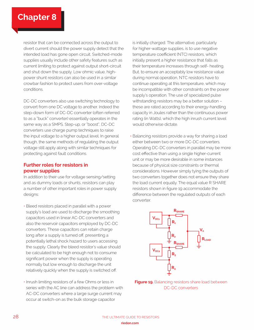
• Bleed resistors placed in parallel with a power supply’s load are used to discharge the smoothing capacitors used in linear AC-DC converters and also the reservoir capacitors employed by DC-DC converters. These capacitors can retain charge long after a supply is turned off, presenting a potentially lethal shock hazard to users accessing the supply. Clearly the bleed resistor’s value should be calculated to be high enough not to consume significant power when the supply is operating normally but low enough to discharge the unit relatively quickly when the supply is switched off.
• Inrush limiting resistors of a few Ohms or less in series with the AC line can address the problem with AC-DC converters where a large surge current may occur at switch-on as the bulk storage capacitor
is initially charged. The alternative, particularly for higher-wattage supplies, is to use negative temperature coefficient (NTC) resistors, which initially present a higher resistance that falls as their temperature increases through self- heating. But, to ensure an acceptably low resistance value during normal operation, NTC resistors have to continue operating at this temperature, which may be incompatible with other constraints on the power supply’s operation. The use of specialized pulse withstanding resistors may be a better solution – these are rated according to their energy-handling capacity in Joules rather than the continuous power rating (in Watts), which the high inrush current level would otherwise dictate.
• Balancing resistors provide a way for sharing a load either between two or more DC-DC converters. Operating DC-DC converters in parallel may be more cost effective than using a single higher-current unit or may be more desirable in some instances because of physical size constraints or thermal considerations. However simply tying the outputs of two converters together does not ensure they share the load current equally. The equal value R SHARE resistors shown in figure 19 accommodate the difference between the regulated outputs of each converter.
Figure 19. Balancing resistors share load between DC-DC converters
R2
R1
R4
R3
RSHARE
RSHARE
VDC1
VDC2
RLOAD
V0
Chapter 8
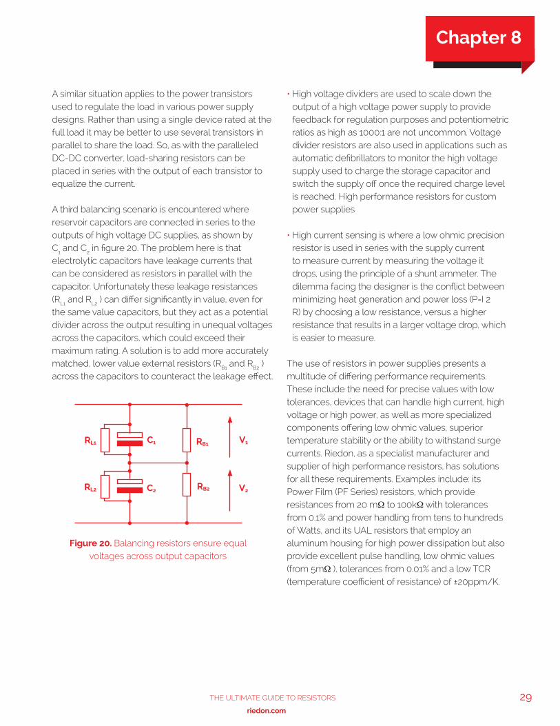
29The UlTimaTe GUide To ResisToRs
www.riedon.com xx xx
A similar situation applies to the power transistors used to regulate the load in various power supply designs. Rather than using a single device rated at the full load it may be better to use several transistors in parallel to share the load. So, as with the paralleled DC-DC converter, load-sharing resistors can be placed in series with the output of each transistor to equalize the current.
A third balancing scenario is encountered where reservoir capacitors are connected in series to the outputs of high voltage DC supplies, as shown by C1 and C2 in figure 20. The problem here is that electrolytic capacitors have leakage currents that can be considered as resistors in parallel with the capacitor. Unfortunately these leakage resistances (RL1 and RL2 ) can differ significantly in value, even for the same value capacitors, but they act as a potential divider across the output resulting in unequal voltages across the capacitors, which could exceed their maximum rating. A solution is to add more accurately matched, lower value external resistors (RB1 and RB2 ) across the capacitors to counteract the leakage effect.
• High voltage dividers are used to scale down the output of a high voltage power supply to provide feedback for regulation purposes and potentiometric ratios as high as 1000:1 are not uncommon. Voltage divider resistors are also used in applications such as automatic defibrillators to monitor the high voltage supply used to charge the storage capacitor and switch the supply off once the required charge level is reached. High performance resistors for custom power supplies
• High current sensing is where a low ohmic precision resistor is used in series with the supply current to measure current by measuring the voltage it drops, using the principle of a shunt ammeter. The dilemma facing the designer is the conflict between minimizing heat generation and power loss (P=I 2 R) by choosing a low resistance, versus a higher resistance that results in a larger voltage drop, which is easier to measure.
The use of resistors in power supplies presents a multitude of differing performance requirements. These include the need for precise values with low tolerances, devices that can handle high current, high voltage or high power, as well as more specialized components offering low ohmic values, superior temperature stability or the ability to withstand surge currents. Riedon, as a specialist manufacturer and supplier of high performance resistors, has solutions for all these requirements. Examples include: its Power Film (PF Series) resistors, which provide resistances from 20 mΩ to 100kΩ with tolerances from 0.1% and power handling from tens to hundreds of Watts, and its UAL resistors that employ an aluminum housing for high power dissipation but also provide excellent pulse handling, low ohmic values (from 5mΩ ), tolerances from 0.01% and a low TCR (temperature coefficient of resistance) of ±20ppm/K.
Figure 20. Balancing resistors ensure equal voltages across output capacitors
RL1
RL2
C1
C2
RB1
RB2
V1
V2
Chapter 8
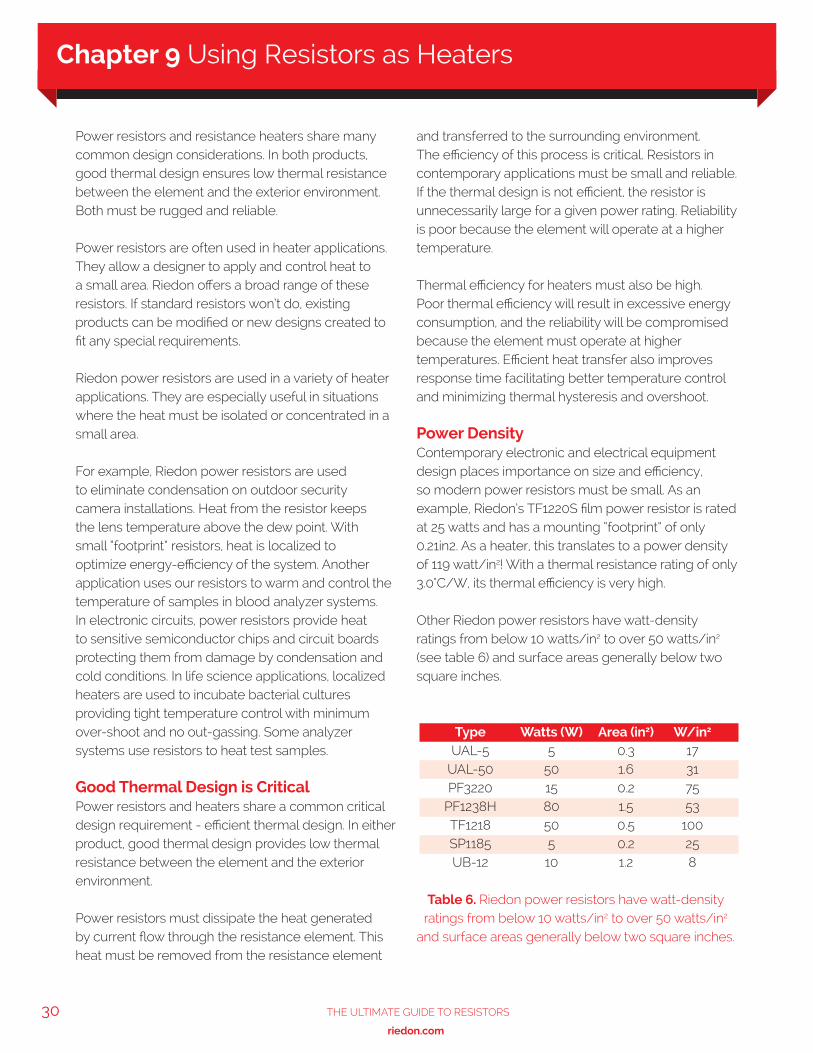
30 The UlTimaTe GUide To ResisToRs
www.riedon.com xx
Power resistors and resistance heaters share many common design considerations. In both products, good thermal design ensures low thermal resistance between the element and the exterior environment. Both must be rugged and reliable.
Power resistors are often used in heater applications. They allow a designer to apply and control heat to a small area. Riedon offers a broad range of these resistors. If standard resistors won’t do, existing products can be modified or new designs created to fit any special requirements.
Riedon power resistors are used in a variety of heater applications. They are especially useful in situations where the heat must be isolated or concentrated in a small area.
For example, Riedon power resistors are used to eliminate condensation on outdoor security camera installations. Heat from the resistor keeps the lens temperature above the dew point. With small “footprint” resistors, heat is localized to optimize energy-efficiency of the system. Another application uses our resistors to warm and control the temperature of samples in blood analyzer systems.In electronic circuits, power resistors provide heat to sensitive semiconductor chips and circuit boards protecting them from damage by condensation and cold conditions. In life science applications, localized heaters are used to incubate bacterial cultures providing tight temperature control with minimum over-shoot and no out-gassing. Some analyzer systems use resistors to heat test samples.
Good Thermal Design is CriticalPower resistors and heaters share a common critical design requirement - efficient thermal design. In either product, good thermal design provides low thermal resistance between the element and the exterior environment.
Power resistors must dissipate the heat generated by current flow through the resistance element. This heat must be removed from the resistance element
and transferred to the surrounding environment. The efficiency of this process is critical. Resistors in contemporary applications must be small and reliable. If the thermal design is not efficient, the resistor is unnecessarily large for a given power rating. Reliability is poor because the element will operate at a higher temperature.
Thermal efficiency for heaters must also be high. Poor thermal efficiency will result in excessive energy consumption, and the reliability will be compromised because the element must operate at higher temperatures. Efficient heat transfer also improves response time facilitating better temperature control and minimizing thermal hysteresis and overshoot.
Power DensityContemporary electronic and electrical equipment design places importance on size and efficiency, so modern power resistors must be small. As an example, Riedon’s TF1220S film power resistor is rated at 25 watts and has a mounting “footprint” of only 0.21in2. As a heater, this translates to a power density of 119 watt/in2! With a thermal resistance rating of only 3.0°C/W, its thermal efficiency is very high.
Other Riedon power resistors have watt-density ratings from below 10 watts/in2 to over 50 watts/in2 (see table 6) and surface areas generally below two square inches.
Table 6. Riedon power resistors have watt-density ratings from below 10 watts/in2 to over 50 watts/in2
and surface areas generally below two square inches.
Type Watts (W) Area (in2) W/in2
UAL-5 5 0.3 17 UAL-50 50 1.6 31 PF3220 15 0.2 75 PF1238H 80 1.5 53 TF1218 50 0.5 100 SP1185 5 0.2 25 UB-12 10 1.2 8
Chapter 9 Using Resistors as Heaters
31The UlTimaTe GUide To ResisToRs
www.riedon.com xx xx
ReliabilityResistors are designed for ruggedness and reliability. These features are also important in heaters, but often ignored in standard heater designs. For high reliability, resistors (and heaters) must be electrically stable and structurally sound.
Elements run cooler in low thermal resistance designs, lengthening life. Film elements are normally bonded to anodized substrates. Wire elements are wound on cores that are centerless ground for uniformity, preventing hot spots and ensuring uniform heat distribution.
Resistance wire and leads are welded to stainless steel end caps, and elements are protected with molded epoxy cases or silicone coatings. Dielectric strength is typically 1000 VAC or higher.
Custom DesignsRiedon can modify existing power resistor designs to fit many special applications. For example, it is relatively easy to imbed one of our standard wire-wound power resistors into a custom case. This approach provides a low-cost alternative to special cast-in heater designs. Our custom capability is somewhat unique. Riedon focuses on small to moderate volume resistor requirements, as contrasted to the high volume “commodity” business. This allows our manufacturing system to easily accommodate customized designs and short run requirements while still providing a high level of customer service at economical prices. Prototypes are delivered quickly at minimal cost, and early production delivery is fast. We provide these same advantages for our resistance heater and RTD business segment customers.
Chapter 9
32 The UlTimaTe GUide To ResisToRs
www.riedon.com xx
ResistanceResistance is one of three basic quantities in electrical or electronic circuits:
Current is the flow of electrons through a circuit. It is the principle quantity because it does work, and accomplishes the desired results. We measure current in Amperes. (See “UNITS”)
Voltage is the force that causes current to flow in a circuit. In fact, we sometimes call voltage “electromotive force” or “EMF.” We measure it in Volts.
Resistance controls the flow of current. We measure it in Ohms.
These three quantities are so basic to electrical and electronic circuits, a simple equation called Ohms Law relates them. Ohms law states that the current flowing in a circuit is proportional to the voltage applied to the circuit, and inversely proportional to the resistance of the circuit. In other words, for a given voltage, the current in the circuit will decrease as the resistance increases.
Mathematically, Ohms Law is: I = E/R, or current equals voltage divided by resistance. This simple equation can be transformed to find voltage or resistance, given the other two quantities. (For example, if you know the voltage and current in a circuit, you can calculate the circuit resistance by dividing the voltage by the current.)
Ohms Law is truly fundamental. Every electrical or electronic circuit design begins here!
Conductors and InsulatorsAll materials are either conductors or insulators; a material will either conduct electrical current, or impede its flow.
Not all conductors are equally capable of supporting current flow. Copper is a better conductor than nickel. Silver is a better conductor than copper. Gold is a better conductor than Silver. Carbon is a poor conductor.
Similarly, insulators are not perfect. Wood is an insulator if dry, but becomes a conductor when wet. The best insulators are glasses and ceramics. Plastics, such as epoxy, are generally good insulators.
There also are materials that are neither conductors nor insulators. Called “semiconductors,” they are used to make transistors. We will not discuss transistors here, but it is interesting that they are really only resistors that electronic circuits can control. This again shows that Ohms Law is fundamental to circuit design.
ResistorsThere are several ways to make resistors for electrical or electronic circuits. Carbon resistors are made by attaching leads to a bar or rod of carbon material. The material is usually made by suspending carbon particles in a plastic material. The material mix determines resistance.
Carbon resistors have some serious limitations. They cannot dissipate much power, and are difficult to make with small resistance tolerances. However, automated manufacturing makes them in large quantities, so their cost is low.
Some resistors are made with metal films or oxides. These resistors are small and can be manufactured with good tolerances. But, they cannot handle higher power levels. Another type of film resistor is made with conductive inks. They are inexpensive, but are unstable and have limited power dissipation and poor resistance tolerances.
Wirewound resistors are made by winding a length of wire on an insulating core. They can dissipate large power levels compared to other types, and can be made with extremely tight resistance tolerances and controlled temperature characteristics.
Appendix A Resistor Primer
33The UlTimaTe GUide To ResisToRs
www.riedon.com xx xx
Its length, cross-section area, and material determine the resistance of a wire. Copper is a good conductor, but has some resistance (to current flow.) A small diameter copper wire, 100 feet long, may have a resistance of a few ohms. However, a small diameter nickel alloy wire only one foot long may have a resistance of several thousand ohms.
Riedon makes wire wound resistors using wire of several metal alloys and sizes. The selection of wire depends on several factors. For example, a high resistance design would require a long copper wire and the resistor would be large. The same resistor could be made with a short length of nickel alloy wire, resulting in a much smaller device. However, when a high precision resistor is required, it is easier to trim resistance by removing a few inches of a low resistance wire, than by trimming millimeters of high resistance wire.
PowerWe measure electrical power in Watts. In a resistive circuit, power is calculated by squaring the current and multiplying that value by the resistance (P = I x R). Wirewound resistors excel in higher power rating applications.
Because resistors impede the flow of current, they generate heat. If the resistor operates within its power rating, the heat is harmlessly dissipated into the surrounding environment. But, if we exceed the wattage rating, the resistor cannot dissipate the excess heat, and its temperature rises. The resistor will fail, usually by acting as a fuse and breaking the circuit. If the resistor is used in a high temperature environment, its power rating must be lowered, or “derated.”
Temperature CoefficientIn wirewound resistors, another selection factor is the temperature characteristic of the wire.
The resistance of all materials changes as their temperature changes. If the temperature is lowered, resistance (typically) declines. In fact, if cooled sufficiently, the material becomes a superconductor with no significant resistance. Increasing the temperature (typically) increases resistance.
The temperature coefficient of resistance (TCR) of wire or a resistor relates the change in resistance to the change in temperature. It is usually expressed as “parts per million per degree Centigrade” (ppm/°C.) The temperature coefficient of resistance tells you how much the resistance changes (ppm) if the temperature changes one degree Centigrade.
InductanceThere is another quantity that is similar to resistance. It is called reactance. Like resistance, we measure reactance in ohms, and it follows the rule of Ohms Law.
Reactance only occurs in electrical or electronic circuits if the current flow is changing rapidly. It is usually important in alternating current (AC) circuits where the current periodically changes direction and amplitude at some rate called frequency. However, reactance does not exist in direct current (DC) circuits where current flows in one direction and its amplitude is not changing rapidly.
Reactance occurs because all circuit elements have inductance and capacitance. In AC circuits, the capacitance of wire wound resistors is seldom large enough to be considered, so we will ignore it in this discussion. However, the inductance of wire wound resistors can be critical!
All conductors have some inductance. When the conductor is coiled, as it usually is in wire wound resistors, this inductance becomes larger. In AC circuits, inductance causes inductive reactance. Inductive reactance and resistance add, increasing the resistor’s value.
Appendix

34 The UlTimaTe GUide To ResisToRs
www.riedon.com xx
Inductive reactance increases as the frequency of the alternating current increases. For example, a resistor might have enough inductance to create one ohm of reactance at a frequency of 60Hz (cycles per second.) If we increase the frequency to 6,000Hz (an audio frequency), the reactance would increase to 100 ohms. Increasing the frequency to 6,000,000Hz (a radio frequency), increases the resistor’s reactance is 10,000 ohms.
Obviously, the inductance of wirewound resistors can be significant in AC circuits! When reactance is important in AC circuit applications, Riedon can wind the wire in a special way to eliminate or reduce the resistor’s inductance.
UnitsAmperes: (“Amps”) milliamp = 1/1,000 amp microamp = 1/1,000,000 amp
Volts:millivolt = 1/1,000 voltsmicrovolt = 1/1,000,000 volts
Ohms:kilo ohm (“K ohm” ) = 1,000 ohmsmegohm = 1,000,000 ohms
Appendix
The Ultimate Guide to
ResistorsFurther Informationwww.riedon.com


