Embed Size (px)
Citation preview
59
The twin-saddle support of horizontal multi-layered GRP vessels-theoretical analysis, experimental work and a design approach
A s Tooth, BScTech, MScTech, PhD, CEng, FIMechE, AMCT, W M Banks, BSc, MSc, PhD, CEng, FIMechE, FIM, C P %ah, BEng, MPhil and B A Tolson,* BEng, PhD Department of Mechanical Engineering, University of Strathclyde, Glasgow, Scotland
The maximum stress in a storage vessel generally occurs in the region of the support. In the case of lwin-saddle-supported horizontal vessels used for liquid storage under modest operational pressure, the strain on the inside suflace of the vessel, at the top of the support, is tensile. This can create problems in glass-reinforced plastic (GRP) composite vessels since local cracking of the inner surface may allow liquid ingress to the glass through the matrix with consequent premature local failure. This paper extends the earlier work done at the University of Strathclyde, Glasgow, on metallic vessels (assumed isotropic) and outlines a thin-shell analysis, appropriate for the layered GRP vessel, to derive the strain levels in the support region. Over several years experimental work has been carried out on a range of GRP vessels of various sizes. Of particular note three full-size GRP vessels have been extensively strain gauged and hydrauli- cally tested to provide experimental results to validate the theoretical analysis. Using this analysis, a parametric survey has been conducted and a design approach presented, to enable the maximum strain to be determined for the symmetric laminated horizontal vessel.
NA, NC
NOTATION
distance of saddle centre profile from vessel end (see Fig. 2) saddle width [BS 5500 (l)] (see Fig. 2) mean diameter of the cylindrical vessel tensile, coupling and flexure moduli [BS 4994 (2)] tensile moduli in the circumferential and axial directions circumferential stress at the horn [BS 5500 (l)] correction factor = shear modulus discrete areas in the 8 and x direc- tions general discrete areas in the 8 and x directions length of vessel (barrel length) integers, denoting number of terms used in Fourier series in circum- ferential and axial directions respec- tively
stress resultants (see Fig. 1) modified stress resultants maximum number of layers (that is laminae) in the wall of the vessel total number of discrete areas in the x and 8 directions externally applied loading in the x, 0 and radial directions loading and displacement coeficients in the x, 8 and radial directions
The MS was received on 22 September 1993 and was accepted fur publication on 25 January 1994. * Present address: Department of Marine Technuloyy, University of Newcastle- upon-Tyne.
E02293 @ IMechE 1994
stiffness matrix for the generally orthotropic and specially orthotropic lamina respectively; defined in refer- ence (3) radius at top of saddle mean radius of the cylindrical vessel overall wall thickness of vessel mid-surface displacements in the x, 8 and radial directions (see Fig. 1) coordinates in the axial, circum- ferential and radial directions (see Fig. 1) total reaction at one of the saddles [BS 5500 (l)] angle subtended by half discrete area size in the 8 direction half discrete area size in the x direc- tion maximum strain calculated from rig- orous analysis maximum strain calculated using a British Standard approach mid-surface strains in the axial and circumferential directions total saddle angle curvatures and twist for axial and circumferential directions coeflicient of friction between saddle and vessel Poisson's ratio in the 8x plane rotations about the x, 0 and z axes
1 INTRODUCTION
The correct choice of tankage for the storage of hazard- ous liquids in the process plant environment requires assiduous consideration. A barrier is necessary to protect the vessel to ensure its long-term structural integrity. In the case of carbon steel vessels this is often
Proc Instn Mech Engrs Vol 208
at PENNSYLVANIA STATE UNIV on February 18, 2016pie.sagepub.comDownloaded from
60 A S TOOTH, W M BANKS, C P SEAH AND B A TOLSON
provided by using a rubber or glass lining. However, in recent years, glass-reinforced plastic (GRP) vessels have found general acceptance since they are more eco- nomical to manufacture than lined steel vessels. The development of new resins and types of glass has enabled the designer to tailor the material properties to the process conditions and thereby to further improve integrity. Also, the introduction of automated lay-up manufacturing procedures has led to an improvement in the quality, reliability and integrity of these components
Although vertical GRP vessels are common, horizon- tal vessels are used when there is a restriction on height or when there is a modest operational pressure. Their comparative lightness means they are ideal for storage at an elevated height. The length/diameter ratio is usually in the range 1-4, although the most common ratio in use is at the lower end of the range, namely LID = 2. The relatively short length of these vessels means that they could be supported on a pair of longi- tudinal beams running the full length of the vessel (2,5). However, the more widely used practice is to support the vessel by using a twin-saddle arrangement, located symmetrically some distance from the dished ends of the vessel. Two supports are preferred since this avoids the transference of load which occurs if differential set- tlement takes place in the multi-support vessel. When saddles are employed and the vessel is used for liquid storage, high values of radial interface pressure occur at the uppermost point of the support, known as the saddle horn. These interface forces can be reduced by introducing radial flexibility into the saddle design or by providing a flexible interface, such as a Iayer of rubber or other low modulus cushioning material, between the vessel and the steel fabricated support. This evens out any surface irregularities and produces a more uniform distribution of the radial pressure, which in turn reduces the high stress in the vessel at the horn.
Polypropylene is sometimes used at the vessel/ support interface for vessels used in process plant. It is more rigid and less accommodating than rubber. However, it possesses a low coefficient of friction and therefore allows the vessel to slide in the saddle when temperature changes occur, thus avoiding thermally induced effects. Alternatively, the support may be made from reinforced concrete which is cast in situ with the vessel in place. This provides a ‘perfect-fit’ at the vessel/ support interface. It does, however, lead to a very rigid support and high strains in the vessel horn region.
Where the resulting strain values are thought to be excessive, reinforcement of the vessel can be provided in the saddle region. This may consist of using stcel rings overlaid with GRP or, alternatively, of providing addi- tional circumferential filament windings extending across and somewhat beyond the width of the saddle (6). The aim of this reinforcement is to improve the cir- cularity of the vessel in the support region and thus reduce the ‘secondary’ circumferential bending stresses (and the corresponding strains) which occur at the saddle horn.
Similar guidance is also provided in BS 4994 (2) and in the ASME Boiler and Pressure Vessel Code, Section X (7). However, the information given in these Stan- dards is only qualitative, with the exception of a refer- ence in BS 4994 to Appendix G of BS 5500 (1). This
(4)-
Part E : Journal of Process Mechanical Engineering
indicates that the detailed analysis given in BS 5500 for metallic vessels may be used for GRP vessels, providing caution is exercised in view of the strain limitation. The analysis given in BS 5500 is essentially based on the work of Zick (8). More recent experimental work by Tooth and co-workers (9, 10) on steel vessels indicated that Zick‘s treatment for the vessel full of fluid under- estimates the maximum stresses in the vessel when a ‘rigid’ saddle is employed.
It was therefore considered by the authors that the Zick approach, given in BS 5500 (l), could well predict unconservative strain values when a rigid-saddle arrangement is employed, and furthermore is only appropriate for the isotropic vessel (that is a chopped strand mat lay-up). To improve the accuracy of these predictions it is necessary to develop a rigorous theo- retical analysis. The value of such an approach would be that the lay-up of the vessel laminate can be designed with confidence to provide an optimum lay-up arrange- ment to carry the stress resultants which occur at the critical sections of the vessel. In this the properties of the individual laminae can be so arranged to ensure that the strain limitation, or the stress criteria, is imposed. This analysis should ideally handle the multi- layered vessel, where the lay-up is either symmetrical or non-symmetrical with respect to the vessel wall centre- line. The approach adopted in this paper is an extension of the earlier work developed by Tooth and co-workers (11) for horizontal metallic vessels (that is vessels which are isotropic).
As a preliminary to the work of this paper the authors have examined the behaviour of the end- supported GRP layered vessel subjected to local loads and fluid fill (12-15). In this work the lay-up, which is in the circumferential and axial directions, can be woven roving (WR) or unidirectional filament fibres (FW), in addition to the essentially isotropic chopped strand mat (CSM). This earlier work [that is references (11) to (15)] is used as ‘building blocks’ to provide an analysis for the GRP layered vessel on saddles.
2 THEORETICAL ANALYSIS
The analysis presented here has been developed using laminate theory for lay-ups that are both symmetrical and non-symmetrical through the wall thickness. The non-symmetric lay-up is sometimes used, on an other- wise symmetric layered vessel to provide local stiffening on the outside surface in the region of the support. The laminate theory is combined with the shell analysis developed by Sanders (16) which neglects the effect of transverse shear distortion. It is considered that this is a reasonable assumption for this type of shell when the ratio of the in-plane elastic moduli in the axial and cir- cumferential directions E , , / E , , falls within &J and 10, that is within values commonly used for vessel and pipe designs in the chemical process industry [see reference (17)~
2.1 The governing differential equation Using Sanders’ shell theory and the principle of virtual work, both the equilibrium and compatibility relations can be obtained for a circular cylindrical shell (16). The equilibrium equations may be reduced to three and
Q IMechE 1994
at PENNSYLVANIA STATE UNIV on February 18, 2016pie.sagepub.comDownloaded from
THE TWIN-SADDLE SUPPORT OF HORIZONTAL MULTI-LAYERED GRP VESSELS 61
stated as follows
aN, 1 am,, 1 an?,, + P , = O
ax R ae 2 ~ 2 ae aR,, 1 aN, 3 aMxe 1 aM, ax R ae 2~ ax ~2 ae
a2M, 2 a2MXe 1 a2Me 1 -+-- +---- N , + P, = o ax, R i?x ae RZ 802 R
-+--+-- +--+Pp,=O (1)
where
Nxe = 3WXo + NeA axe = tWX, + Mex)
A consistent set of mid-surface strains, curvatures and rotations can be written as
au 1 av w av ax &:=-, & g o = - - + - , Rae R y:,=-- ax 4*
The general constitutive equation for a laminated com- posite, which may be non-symmetrical through the wall thickness, can be expressed as
where N
= 1 (Qij)k(zk - z k - 1) k = 1
= extensional stiffness matrix
l N Bij = 5 (Qij)k(zk" - 1 )
k=l
= coupling stiffness matrix
(3)
(4)
= bending stiffness matrix
In these expressions the z values are measured posi- tively radially inwards from the middle vessel surface to the inner surface of the layer in question. The layers are identified as k = 1 to k = N , and the generally ortho- tropic lamina stiffness matrix Qij values are defined in reference (3).
The complexity of the terms in equation (3) depends on the laminate lay-up. When the B-matrix is present there is coupling between the in-plane and out-of-plane effects. However, for laminates with specially ortho- tropic laminae the general equation (3) can be simpli- fied. In particular, when a laminate has a lay-up of specially orthotropic laminae which is symmetric about the mid-wall thickness, all coupling stiffness terms are @ IMechE 1994
equal to zero. These terms are present when the lay-up is non-symmetric.
The expressions for the force and moment stress resultants are obtained by substitution of the mid- surface strains and curvatures, equations (2), into equa- tion (3). If these expressions are substituted into the equilibrium equations ( I ) , the governing differential equations can be written in matrix form:
where the terms F,, are differential operators, associated with the extensional, coupling and bending stiffnesses, A, , B , and D,. The operators Fij are fully defined in reference (18).
2.2 Fourier expansion solution Particular solutions of equation ( 5 ) can be obtained by expressing the applied loading components P, , P , and P, and the displacement functions u, and w in the double Fourier series form shown below:
m m
P , = c c P&" cos(n0) cos m = O n = O
m m
p , = c c Porn" sin(n0) sin(?) m = l n = l \ b /
m m
P, = 1 1 Prm cos(n0) sin
u = 1 1 urn, cos(n0) cos
v = 1 1 om,, sin(&) sin
m = l n = O
m m
m = O n = O
m m
m = l n = l
m m
w = C C w,, cos(n0) sin m = l n = O
The choice of the expansions for P , , P, and P, imply that the loading system is symmetric with respect to the generator passing through 6 = 0" (see Fig. 1). The expansions for u, u and w imply that the displacements also have a symmetrical distribution.
On substituting equations (6) into the governing equation (3, differentiating and using the orthogonality condition the following equation is obtained :
where the terms G l l , G , , , etc., are functions of the har- monic orders n and m and the stiffnesses A,, Bij and D , . They are fully defined in reference (18).
Using Cramer's rule for third-order determinants, the above equation can be solved to give expressions for urn,,, urn, and wmn in terms of the loading terms P,,, the harmonic orders and the stiffnesses. Using these values and equations (6) the series forms of the expressions for u, v and w can be obtained. From these the stress result- ants N , , M , , etc., can be written in series form in terms
Proc Instn Mech Engrs Vol 208
at PENNSYLVANIA STATE UNIV on February 18, 2016pie.sagepub.comDownloaded from
62 A S TOOTH, W M BANKS, C P SEAH AND B A TOLSON
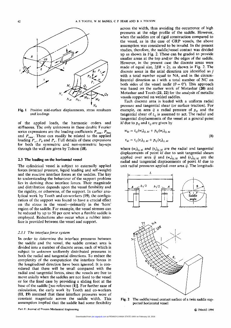
across the width, thus avoiding the occurrence of high pressures at the edge profile of the saddle. However, when the saddles are of rigid construction compared to the vessel, as in the case of GRP vessels, the above assumption was considered to be invalid. In the present studies, therefore, the saddle/vessel contact was divided up as shown in Fig. 2. These can be graded to provide smaller areas at the top and/or the edges of the saddle. However, in the present case the discrete areas were made of equal size, 2/3R x 2y, as shown in Fig. 2. The discrete areas in the axial direction are identified as j with a total number equal to NA, and in the circum- ferential direction as i with a total number of NC on both sides of the vessel nadir (0 = 00). This approach was based on the earlier work of Motashar (20) and Motashar and Tooth (21,22) for the analysis of metallic vessels supported on welded saddles.
Each discrete area is loaded with a uniform radial pressure and tangential shear (or surface traction). For example, on area i j a radial pressure of p i j and the tangential shear of t i j is assumed to act. The radial and tangential displacements of the vessel at a general point kl due to p i j and t i j are given by
n \.
I
W x / :"
Fig. 1 Positive mid-surface displacements, stress resultants and loadings
of the applied loads, the harmonic orders and stiffnesses. The only unknowns in these double Fourier series expressions are the loading coefficients P,,, , Po,, and P,,,. These can readily be related to the applied loading P,, P, and P, . Full details of these expressions for both the symmetric and non-symmetric lay-ups through the wall are given by Tolson (18).
2.3 The loading on the horizontal vessel The cylindrical vessel is subject to externally applied forces (internal pressure, liquid loading and self-weight) and the reactive interface forces at the saddles. The key to understanding the behaviour of the support problem lies in deriving these interface forces. Their magnitude and distribution depends upon the vessel flexibility and the rigidity, or otherwise, of the support. In earlier ana- lytical work by Tooth and co-workers (19), the configu- ration of the support was found to have a crucial effect on the stress in the vessel-primarily in the 'horn' region of the saddle. For example, the vessel stresses can be reduced by up to 50 per cent when a flexible saddle is employed. Reductions also occur when a rubber inter- face is provided between the vessel and support.
2.3.1 The interface force system
In order to determine the interface pressures between the saddle and the vessel, the saddle contact area is divided into a number of discrete areas, each of which is subject to unknown uniformly distributed pressures in both the radial and tangential directions. To reduce the complexity of the computation the interface forces in the longitudinal direction have been ignored. It is con- sidered that these will be small compared with the radial and tangential forces, since the vessels are free to move axially when the saddles are not fixed to the vessel or for the fixed case by providing a sliding foot at the base of the saddle [see reference (l)]. For further ease of calculation, the early work by Tooth and co-workers (11, 19) assumed that these interface pressures were of constant magnitude across the saddle width. This assumption implied that the saddle had some flexibility Part E: Journal of Process Mechanical Engineering
where (wJij , kl and (vJij, kl are the radial and tangential displacements of point kl due to unit tangential shears applied over area i j and ( w , ) ~ ~ , ~ ~ and ( u , ) ~ ~ . ~ ! are the radial and tangential displacements of point kl due to unit radial pressures applied over area ij. The longitudi-
L A i
N
ported horizontal vessel Fig. 2 The saddle/vessel contact surface of a twin saddle sup-
Q IMechE 1994
at PENNSYLVANIA STATE UNIV on February 18, 2016pie.sagepub.comDownloaded from
THE TWINSADDLE SUPPORT OF HORIZONTAL MULTL-LAYERED GRP VESSELS 63
nal displacement ukl produced by the unit tangential shears and unit radial pressures applied over area z j is considered to be small and is ignored in the present analysis.
The total radial and tangential displacements of point kl on the surface of the vessel due to all the interface forces are then given by
These expressions are valid for the NA discrete areas along the saddle width and the NC areas around each half saddle about 0 = 0". They can be rewritten in matrix form :
CWl = CwTlCTl+ CWRICPI
CVl = CVTlCTI + CVRI[Pl (10)
The elements of the flexibility matrices [WR] , [VR] , [ W T ] and [ V T ] are given by the series forms of the displacements w and u in terms of the loading functions. As discussed in Section 2.2, these are obtained from equations ( 5 ) and (6) in terms of the extensional, coup- ling and bending stiffnesses, A, , Bij and Dij. The matrices [TI and [PI are the interface pressure values in the tangential and radial directions respectively.
The loading coefficients P,,,,, and Porn,, can be found for the four areas detailed above (that is an area each side of the two saddles), where P, and P , = 1 in the loaded region and zero elsewhere. These loading coeffi- cients can be found by multiplying both sides of the loading terms contained in equations (6) by suitable orthogonal functions such that integration over the surface of the cylinder eliminates all but one of the terms in each Fourier expansion. Details of the pro- cedure are given in reference (23). In addition to the reactive interface forces the vessel is subjected to the applied loading which is a combination of hydraulic pressure, internal pressure surcharge and the self-weight of the vessel. The loading coefficients for these can also be derived and used to obtain the radial and tangential displacements at the centres of the discrete areas of the support. These are written in matrix form as [WHSW] and [VHSW] respectively.
2.3.2 Compatibility
The unknown interfacial forces p i j and t i j which act at the various discrete areas will in general cause radial and tangential displacements of the saddle and/or the saddle interface material, that is the rubber material. The form of these displacements is similar to those for the vessel given in equations (8) and (10):
[WS] = - [ W T S ] [ T ] - [WRS][P]
[VS] = - [ V T S ] [ T ] - [VRS][P] (1 1)
where [WTSI, [WRS], [VTS] and [VRS] are the flex- ibility matrices of the saddle and/or interface material. The elements of these matrices can be obtained for a particular support arrangement using a suitable finite element model. @ IMechE 1994
To enforce compatibility, the vessel displacements at the centres of the discrete area, due to the interface forces [7'l and [PI, that is [ W ] and [ VJ% given in equa- tions (lo), and the applied loading [WHSWJ and [VHSW], are equated to the displacements of the cor- responding points on the support, that is [WSl and [Va, given in equations (1 1) to give the folIowing :
[WRICP] + [WTJCT] + ACCSI + [WHSWl
C~RICPI + cvIc7'l - ACSnrl+ [VHSWI
= -[WTS-J[T] - [WRS)[P] (12)
= - [ V T S ] [ T ] - [VRS][P]
where A is a rigid body movement in the vertical direc- tion of the saddles with reference to the vessel end pro- files. [CSI is the vector of elements CSi = cos O i , [ S N ] is the vector of elements S N , = sin Bi and Qi is the angle to the centre of area i (see Fig. 2).
2.3.3 Vertical equilibrium
In the saddle region it is possible, by using the sign con- vention of Fig. 1, to write
[Slv]T[T] = s + [CS]T[P] (13) where [I' is the transpose of [ I and S = (total of vessel weight + contents)/( 16PRy).
2.3.4 Determination of the unknown interface forces
In the case of GRP vessels it is unlikely that the vessel and support interface are rigidly fixed together-as in the case of a steel containment/pressure vessel where the support is welded to the vessel. The saddle may there- fore be considered to be loose. In this case the vessel must be allowed freedom to move inwards, that is away from the saddle, so that contact between the saddle and vessel may be lost. This condition occurs at those dis- crete areas where the analysis predicts an outward force on the vessel. Since a non-bonded interface cannot apply such forces it follows that the outward forces should be zero. This condition was incorporated into the analysis of these cases by Gxamining the values of the [PI matrix and deleting the columns and rows in the [WR] and [WRS] matrices corresponding to the positive pressures. The [PI matrix was then recalculated and the procedure repeated several times until only inward radial forces were predicted by the analysis.
In addition to the above, a tangential or traction surface force will exist at the interface. By examining the magnitude of the tangential force that is present at the interface for the totally 'bonded' case, it was found that these values were always greater than AP), where p is the coefficient of friction taken to have a maximum value equal to 0.9. It was therefore assumed that, for the loose case, slip would occur at all the discrete areas and that the simple relationship [TI = - p [ P ] was valid at all points of contact over the interface surface. The only exception to the above relationship occurs at the nadir where, because of symmetry, tangential movement is impossible. The limit of the above case is when the surface is assumed frictionless; then [TI = 0.
Using the above relationship between [TI and [PI , the compatibility equations (12) and the equilibrium
Proc Instn Mech Engrs Vol 208
at PENNSYLVANIA STATE UNIV on February 18, 2016pie.sagepub.comDownloaded from
64 A S TOOTH. W M BANKS, C P SEAH AND B A TOLSON
equation (13) can be simplified. After some matrix manipulation it is possible to determine the [PI matrix in terms of the known applied loading. The full details of this analysis is given by Tooth and co-workers (11, 24) and by Tolson (18).
As indicated earlier, the value of the interface forces [TI and [PI are influenced by the flexibility of the support and the interface material. In this investigation it is assumed that the support itself is fabricated either from concrete or steel and may thus be assumed to be rigid compared to the GRP vessel. Flexibility, however, was introduced by using a rubber layer between the vessel and the support. A range of samples of neoprene rubber was tested in compression to determine the load- dislacement characteristics of the rubber. On the basis of this work the modulus of the rubber was taken as 11.4 N/mm2.
The flexibility matrices for the rubber insert were examined using a finite element model of the rubber layer, of modulus 11.4 N/mm2, fixed at the lower surface to a rigid saddle. Unit radial and tangential forces were applied to the upper surface of the rubber, at the centres of the discrete areas. It was found that only the radial displacement due to unit radial pressure was significant, that is matrix [WRS]. The other flex- ibility matrices [WTS], [ V T q and [VRS] were there- fore neglected in equations (11) and (12).
2.4 Values of strain and stress in the layered vessel Once the unknown interface forces [TI and [PI are obtained they are combined with the vessel self-weight, fluid contents weight and pressure loadings to obtain the total loading coefficients P,,, and Porn, . These may be used in equation (7) to determine the displacements u,,, v,, and w,, . Then using equations (6) to determine u, u and w the strains and stress resultants may be found from equations (2) and (3). In view of the Kirchoff-Love hypothesis, the strain values are linear across the wall thickness. The stress values in the kth layer can be obtained by substituting the strain values for the kth layer obtained from the strain variation through the thickness into the constitutive relationship for the spe- cially orthotropic lamina:
(14)
2.5 Computer programs The analytical approach developed above was written for the computer in FORTRAN 77. In the first instance the interface pressure values are computed. These are later used for derivation of the stress and strain values. Certain element coding and stepping techniques are provided to reduce calculation time. Details of these are given by Motashar (20), Wilson (15) and Tolson (18).
3 EXPERIMENTAL INVESTIGATIONS
3.1 The vessel details Three GRP horizontal cylindrical vessels were tested in these investigations. They were all of the same overall size, viz. 2000 mm diameter and 4000 mm barrel length. The dished ends were semi-ellipsoidal with an overall Part E: Journal of Process Mechanical Engineering
height of 500 mm. The details of the lay-up of these vessels were as follows :
Vessel 1 was of CSM construction. The overall thick- ness t = 16.5 mm.
Vessel 2 was a three-layered construction of CSM and FW. On investigation it was found that the lay-up for this vessel was quite different from specification. From the inside surface the lay-up was 2.15 mm CSM, 4.57 mm FW and 4.01 mm CSM, that is it was non-symmetrical with respect to the wall centre. The overall thickness t = 10.7 mm. In all other respects the vessel was satisfactory and provided an unplanned opportunity for extending the test pro- gramme to examine a non-symmetric lay-up.
Vessel 3 was a replacement for vessel 2. It was a five- layered construction of CSM and FW essentially symmetrically located with respect to the wall centre. The FW was located near the surface to provide resistance to local bending. The details were found to be, from the inside surface, 1.71 mm CSM, 2.01 mm FW, 2.74 mm CSM, 2.09 mm FW and 1.41 mm CSM. The overall thickness t = 10.0 mm.
Vessel 1 was constructed using a hand lay-up pro- cedure and a collapsible mandrel. Vessels 2 and 3 were manufactured on a steel mandrel using an automated spray and filament winding system. The lay-up pro- cedures employed for the manufacture of these cylin- drical vessels [see reference (4)] were such that it was unlikely that localized problems, like glass/resin-rich layers, would occur in the support regions. This was confirmed by later 'burn-off tests.
3.2 Saddle design Two basic saddles of rigid construction were fabricated from mild steel with a saddle angle of 180". These saddles were made with an inside radius 12 mm greater than the outside radius of the vessel. This allowed differ- ent insert plates of 200 mm width to be fitted between the vessel and the basic saddle to investigate the behav- iour of different interface materials and geometries. Both steel and neoprene rubber (12 mm thick) inserts were used with saddle angles of 120", 140", 160" and 180". For these angles, inserts were supplied with differ- ent top corner radii r (see Fig. 4) from square to semi- circular, that is 0,25, 50,75 and 100 mm. To accommo- date the surface irregularities of the vessel profile, a polyester resin was used between the insert and vessel just prior to the test. The two saddles were symmetrically located 750 mm from the end of the parallel length of the vessel.
3.3 Strain gauging
Strain gauges were located on both the inside and out- side surfaces in the saddle centre profile, across and around the saddle in the horn region and in the mid- span profile of the vessel. From previous experience gauge pairs in the axial and circumferential directions were employed. Encapsulated gauges were used on the inside surface of the vessel to avoid damage due to water leakage. Approximately 160 gauges were employed on each vessel. A pulsed data-logger and computer system was used to retrieve and record the data during testing.
0 IMechE 1994
at PENNSYLVANIA STATE UNIV on February 18, 2016pie.sagepub.comDownloaded from
THE TWIN-SADDLE SUPPORT OF HORIZONTAL MULTI-LAYERED GRP VESSELS 65
1 o o o ' ' , , . , . . . ,
500-
-4h
-1oOo-J
-1500 - A Experiment - Theory
-2000 -
-2500 - r -3000 """"""" ' " ' 8 I ' I 8 8 3 ' 1 * 8 ' ' 8 8 I
0 20 40 60 80 100 120 140 160 180
3.4 Procedure for testing
In the case of vessel 1 (CSM) hydraulic tests were undertaken for 40 separate saddle configurations, that is steel and rubber interfaces, four different saddle angles and five different saddle corner radii. On the basis of these results the 50 mm corner radius was selected for the tests on vessels 2 and 3. Using this radius in each case, both steel and rubber interfaces and four different saddle angles (that is eight separate saddle configu- rations in all) were examined for both vessels 2 and 3. The same testing procedure was adopted for all cases. In this the vessel was gradually filled with water at near ambient temperature from the reservoir beneath the test floor. The strain gauge values were recorded at every 10 per cent increment of volume both during filling and emptying. At least two tests were carried out for each configuration. The first test provided a bedding-down of the vessel. The values of strain on the second test, which were always within f5 per cent of the first, were accepted as authentic and recorded for analysis. 200
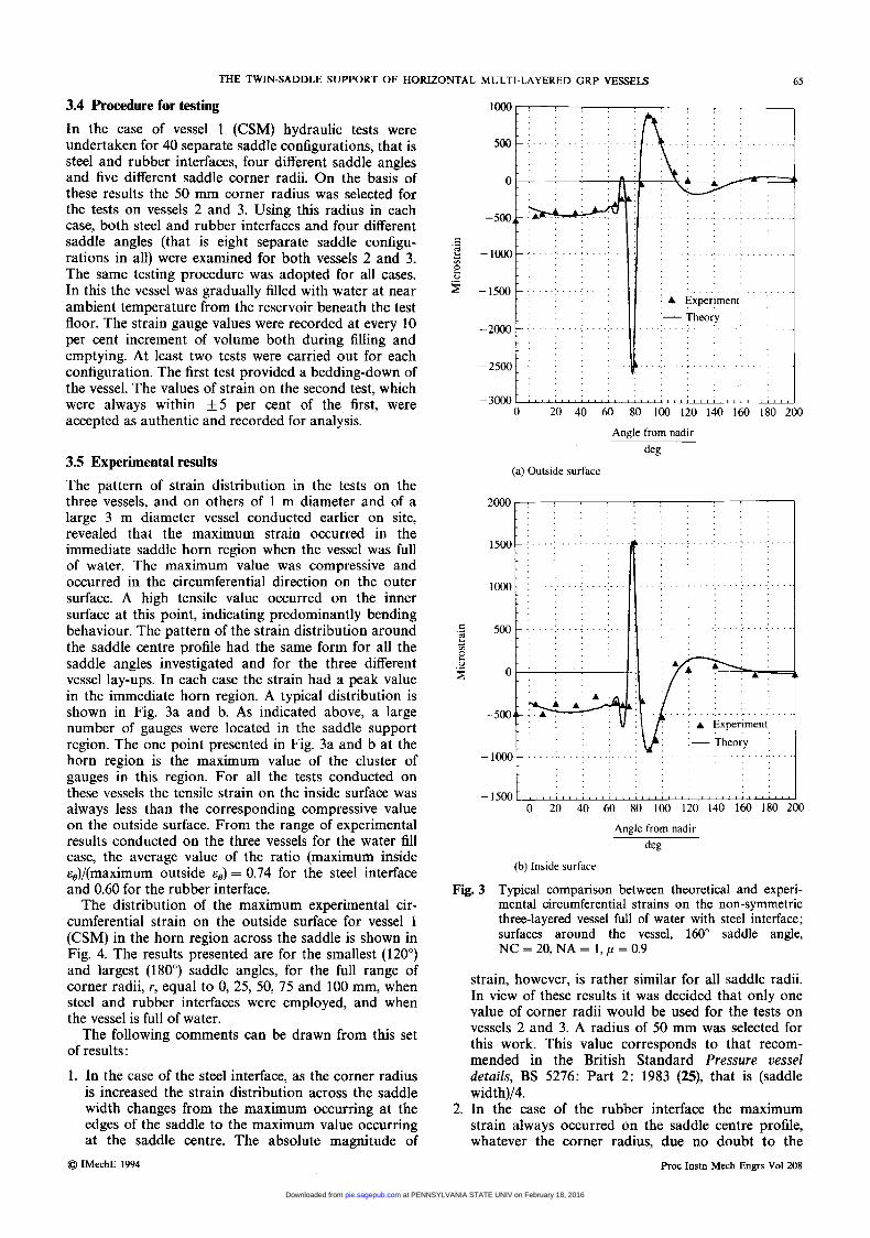
3.5 Experimental results The pattern of strain distribution in the tests on the three vessels, and on others of 1 m diameter and of a large 3 m diameter vessel conducted earlier on site, revealed that the maximum strain occurred in the immediate saddle horn region when the vessel was full of water. The maximum value was compressive and occurred in the circumferential direction on the outer surface. A high tensile value occurred on the inner surface at this point, indicating predominantly bending behaviour. The pattern of the strain distribution around the saddle centre profile had the same form for all the saddle angles investigated and for the three different vessel lay-ups. In each case the strain had a peak value in the immediate horn region. A typical distribution is shown in Fig. 3a and b. As indicated above, a large number of gauges were located in the saddle support region. The one point presented in Fig. 3a and b at the horn region is the maximum value of the cluster of gauges in this region. For all the tests conducted on these vessels the tensile strain on the inside surface was always less than the corresponding compressive value on the outside surface. From the range of experimental results conducted on the three vessels for the water fill case, the average value of the ratio (maximum inside &,)/(maximum outside 8,) = 0.74 for the steel interface and 0.60 for the rubber interface.
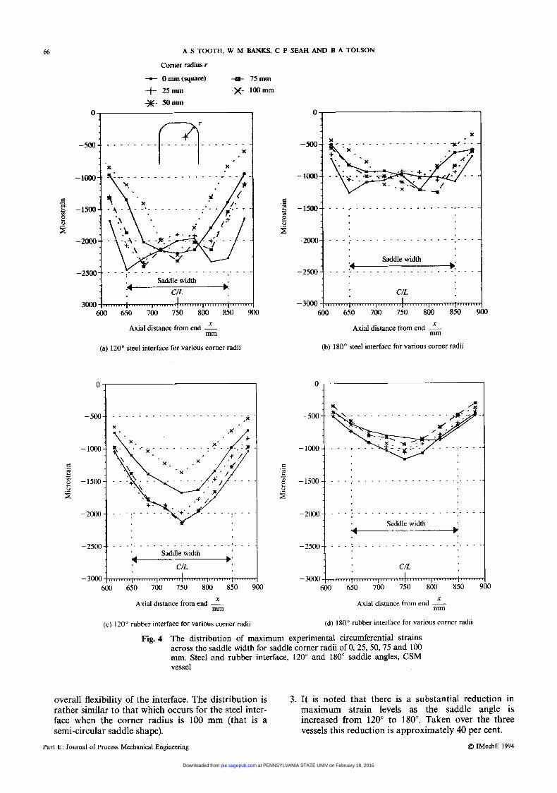
The distribution of the maximum experimental cir- cumferential strain on the outside surface for vessel 1 (CSM) in the horn region across the saddle is shown in Fig. 4. The results presented are for the smallest (120") and largest (180") saddle angles, for the full range of corner radii, r, equal to 0, 25, 50, 75 and 100 mm, when steel and rubber interfaces were employed, and when the vessel is full of water.
The following comments can be drawn from this set of results:
1. In the case of the steel interface, as the corner radius is increased the strain distribution across the saddle width changes from the maximum occurring at the edges of the saddle to the maximum value occurring at the saddle centre. The absolute magnitude of
@ IMechE 1994
Angle from nadir
deg
(a) Outside surface
0 20 40 60 80 100 120 140 160 180 200
Angle from nadir
deg
(b) h i d e surface
Fig. 3 Typical comparison between theoretical and experi- mental circumferential strains on the non-symmetric three-layered vessel full of water with steel interface; surfaces around the vessel, 160" saddle angle, NC = 20, NA = 1, p = 0.9
strain, however, is rather similar for all saddle radii. In view of these results it was decided that only one value of corner radii would be used for the tests on vessels 2 and 3. A radius of 50 mm was selected for this work. This value corresponds to that recom- mended in the British Standard Pressure vessel details, BS 5276: Part 2: 1983 (25), that is (saddle width)/4.
2. In the case of the rubber interface the maximum strain always occurred on the saddle centre profile, whatever the corner radius, due no doubt to the
Proc Instn Mech Engrs Vol 208
at PENNSYLVANIA STATE UNIV on February 18, 2016pie.sagepub.comDownloaded from
66
J
-2OOo-.
-2500-.
-3000-
A S TOOTH, W M BANKS, C P SEAH AND B A TOLSON
. . . I . . . . . . . . . . . . . . . . . . . Saddle width
. . . .. . . . . . . . . . . . . . . . ' - . . .
C/L
Comer radius c - Omm(Sq-) -a- 75mm -+ 25mm -x- l o o m *- 5omm
0 , 1
. . . . . . . . . . . . . . . . . . . . .
.- c 2 e &
f
Saddle width
-3000 600 650 700 750 800 850 900
Axial distance from end mm
(a) 120" steel interface for various corner radii
- 1000 - .
- 1500 -.
-2000 -.
Saddle width -: - 3000
600 650 700 750 800 850 900
Axial distance from end mm
(c) 120" rubber interface for various corner radii
0 1
. . . . . . . . . . . . . . . . . . . . . . . .
-2000
Saddle width -2500
i
1 . C/L -3000 1
600 650 700 750 800 850 900
Axial distance from end -!!- mm
(b) 180" steel interface for various corner radii
-1500 . . . . . . . . . . . . . . . . _ ' _ . . .
Fig. 4 The distribution of maximum experimental circumferential strains across the saddle width for saddle corner radii of 0,2S, SO, 75 and 100 mm. Steel and rubber interface, 120" and 180" saddle angles, CSM vessel
overall flexibility of the interface. The distribution is 3. It is noted that there is a substantial reduction in rather similar to that which occurs for the steel inter- maximum strain levels as the saddle angle is face when the corner radius is 100 mm (that is a increased from 120" to 180". Taken over the three semi-circular saddle shape). vessels this reduction is approximately 40 per cent.
Q IMechE 1994 Part E: Journal of Process Mechanical Engineering
at PENNSYLVANIA STATE UNIV on February 18, 2016pie.sagepub.comDownloaded from
THE TWIN-SADDLE SUPPORT OF HORIZONTAL MULTI-LAYERED GRP VESSELS 67
4. The use of a rubber interface introduces radial flex- ibility into the saddle design. In earlier tests on a 1 m diameter vessel a reduction of 25 per cent in the maximum strain levels was recorded when a rubber interface was used. In the case of these large-diameter vessels the reduction in strain levels was more modest and averaged only 15 per cent. Although this is not a dramatic reduction it is considered that there is an overall benefit of using a rubber insert, between the vessel and saddle support, since it reduces local high spots over the contact surface and provides a more uniform interface pressure across the saddle width, as shown by the strain results given in Fig. 4. The graphs presented here are a representative frag-
ment of those obtained in this work. A complete record of all the experimental results for these three vessels is presented by Tolson (18) and Seah (26).
4 VALIDITY OF THE THEORETICAL ANALYSIS
The experimental results obtained from the hydraulic tests on the three GRP vessels were used to examine the validity of the theoretical analysis presented in Section 2.
4.1 The elastic moduli of the layers As a first step it was necessary to model the wall lay-up of each vessel by providing the exact numerical value for the moduli of the individual layers as laid down. These values were determined experimentally, from accurate measurements of the wall cross-section, from 'burn-off' tests of vessel wall samples and the use of the basic lamina equations. The details of the procedure used is presented by Seah (26).
4.2 Coefficient of friction The influence of the coefficient of friction between the vessel and the support was examined theoretically by varying the p value from 0.9, 0.6, 0.3, to 0.0. It was noted that the strain level at the horn increased slightly, while the maximum strain at the nadir and beneath the saddle support area increased considerably, as p was reduced from 0.9 to 0.0. The details are given by Tolson (18). The measured strain values in the region under the saddle, for all vessels and saddle angles, more closely agreed with the predictions for p = 0.9 than p = 0.0. A typical set of experimental results is shown in Fig. 3a and b compared with the theoretical analysis where /.i = 0.9.
4.3 Number of discrete areas across the width (NA) The influence of the number of discrete areas across the saddle width (NA) was also examined theoretically for these vessels. In the case of the steel interface when NA = 1 the theoretical value of strain increased contin- uously across the saddle width to a maximum value at the saddle centre-line profile. When NA = 5 the peak strain value occurred near the saddle edge profile, with a lower value at the saddle centre-line profile. Compar- ing the three values NA = 1, 3 and 5, it was found that the maximum strain was predicted for NA = 1. The variation of these strains was similar to the experimen- tal values for the steel interface shown in Fig. 4. The Q IMechE 1994
results for the square corner (that is corner radius equal to zero) correspondings to the values predicted by NA = 5 and for the rounded corner to NA = 1.
In the case of the rubber interface, the strain values for NA = 1, 3 and 5 all predicted a continuously increasing strain across the width to a maximum at the saddle centre-line. Similar curves were predicted for all NA values. These variations were also similar to the experimental values for the rubber interface shown in Fig. 4. The interface pressure values predicted by the analysis for this case were almost exactly uniform across the width.
4.4 Number of discrete areas around the saddle (NC) The influence of the number of discrete areas (NC) around the saddle was also examined using the theoreti- cal analysis. The predicted maximum strain levels were obtained for both the steel interface (that is for an infi- nitely rigid saddle) and the rubber interface for a range of values of NC from 10 to 25 in the half saddle region.
It was found that with the steel interface pressures had a peak value over the discrete area located nearest the horn. The pressure on the adjoining discrete area was zero, since the vessel over this region tends to leave the support. As the number of discrete areas was increased, that is the discrete area arc length was decreased, the magnitude of the peak pressure increased and with it the value of the maximum strain.
However, in the case of the rubber interface, the inter- face pressures were almost exactly uniform over the saddle contact area. Therefore the value of the interface pressures, and thus the maximum strain values, did not change as the number of NC discrete areas was increased over the range considered. This prediction was similar to that obtained in earlier work, by Wilson and Tooth (19), for the case of a welded flexible saddle.
With regard to the steel rigid interface it was clear that the 'rigid saddle' assumption led to a singularity condition in the interface pressure result at the horn of the saddle. In reality this would not occur since the vessel would deform in such a way that the interface pressure at the horn was distributed more uniformly over a finite arc length. To follow these changing pat- terns in the interface pressure would require the use of a 'large displacement' analysis, which was considered to be outside the scope of the present work.
In an effort to incorporate the behaviour of an actual vessel an appropriate value for NC was obtained by comparing the measured experimental strain results with those predicted by various NC values for each saddle angle and for each vessel. It was found that good agreement was achieved in all cases by using a discrete area subtended angle of approximately 3.6". From this the corresponding NC values were :
120", NC = 17, 140", NC = 19
160", NC = 22 180", NC = 25
4.5 Convergence of the series solutions Tests were carried out to establish the number of terms required for convergence of the circumferential strain values. It was found that the series had adequately con- verged when 250 terms were employed, in both the n
F'roc Instn Mech Engrs Vol 208
at PENNSYLVANIA STATE UNIV on February 18, 2016pie.sagepub.comDownloaded from
68 A S TOOTH, W M BANKS, C P SEAH AND B A TOLSON
and m series, for NC = 25 (that is for a saddle angle of 18W). Although less terms were required for smaller values of NC, 250 terms were used throughout the study.
5 A DESIGN APPROACH
The introduction of automatic computer-controlled lay-up procedures for the manufacture of GRP pipes and vessels has led to an improvement in the quality, reliability and integrity of these components. In order to make full use of this facility it is essential to be able to predict the distribution and magnitude of the strain in the component and thereby design an optimum wall ‘lay-up’. The analysis presented in this paper, and vali- dated with reference to extensive experimental studies, provides such an approach.
It was considered that to make this work available to designers who do not have immediate access to the computer programs, a design approach should be devel- oped at least for the symmetric laminate. The method presented here makes use of the existing design approach for isotropic (metallic) vessels given in BS 5500 (l), with the introduction of a ‘correction factor’. The BS 5500 approach was not selected on the basis of it being a rigorous treatment of the problem, but because it is readily available and widely used by designers of these components.
5.1 The BS 5500 approach
The British Standard BS 5500 approach to the horizon- tal vessel problem is essentially based on the work of Zick (8), who used a modified beam and ring analysis so that the mathematical model for the vessel predicted values that agreed with the experimental results he had available. More recent work by Tooth and co-workers (9, 10) has indicated that Zick‘s treatment for the vessel full of fluid predicts maximum stresses, which occur at the horn (uppermost point of the saddle support) in the circumferential direction, to be in reasonable agreement with the experimental values when a radially flexible saddle is employed. However, when the saddle is rigid the treatment underestimated the maximum stresses in the vessel, sometimes by a factor or two.
Although this matter is not addressed in detail in this paper, it is worth noting that wherever possible a radi- ally flexible saddle design is to be preferred to one that is of rigid design-such as a concrete plinth type. This is particularly the case with GRP vessels which have a low stiffness compared with a steel or concrete saddle. The optimum design would no doubt be a GRP saddle where the stiffness of vessel and saddle are carefully matched to avoid the high interface pressure values at the horn.
Despite the semi-empirical nature of the Zick treat- ment it predicts values of the maximum stress which vary in a consistent manner when compared to those obtained using the more rigorous analysis (9, 10). For that reason and because the approach is widely used by designers, it is used as a basis for the design approach for the multi-layered vessel set out in this paper.
Although the rigorous ‘shell/composite’ analysis is capable of predicting strains for both symmetric and non-symmetric laminates, the design approach given in this paper is limited to symmetric laminates.
Two expressions for the stress at the horn of the vessel, f6 , are given in BS 5500 (1). The one is for a vessel of L/R 2 8 and the other for a vessel of L/R < 8. Since most GRP vessels are relatively short, that is L/R < 8, the expression for that case is used here, viz.
12K, W I R Lt2
w1 -
f6 = - 4t(b1 f lot)
where W, = total reaction at one of the saddles K , = design factor [see Table 1 taken from reference
b, = width of the saddle The background to the derivation of equation (15) may be found in Tooth (27).
Equation (15) consists of two parts. The first term is the membrane stress, which in this case is always com- pressive. The second term is the across-the-wall bending at the horn. This is compressive on the outside and tensile on the inside surfaces. The expression quoted for f, provides the maximum compressive stress (that is on the outside surface). In view of the above it is possible to express equation (1 5) in the form :
(111
N , 6M t t 2
f,=-fL
where the circumferential direct stress and moment resultants can be written as
(17) -2K6 WIR
L M , =
WI N e = - 4(b1 + lot)’
The strain can be obtained from these stress result- ants using the simplified constitutive equations given in BS 4994 (2). For an orthotropic material these are written as
where
/I\ N
E T = - Eiti = tensile (or in plane) modulus (I) k = l
Ei tjzi = coupling modulus (19)
E, = - Ei(12tizZ + ti’) = flexural modulus ( t i ) ,rl
These moduli, used in BS 4994 (2), are essentially the overall moduli for the laminate. They are related to the expressions for the extensional, coupling and bending stiffnesses A,, Bij and D,, presented earlier in the paper in equations (4). However in equations (19) z is mea-
Part E: Journal of Process Mechanical Engineering @ IMechE 1994
at PENNSYLVANIA STATE UNIV on February 18, 2016pie.sagepub.comDownloaded from
THE TWIN-SADDLE SUPPORT OF HORIZONTAL MULTI-LAYERED GRP VESSELS 69
Table 1 Design factor K ,
e Total saddle angle -
dee
AIR 120 135 150 165 180
G0.50 0.0132 0.0103 0.0079 0.0059 0.0044 31.00 0.0528 0.0413 0.0316 0.0238 0.0174
Nore: for 0.50 < A/r < 1.00 values of K , should be obtained by linear interpolation of the values in this table.
sured positively radially outwards and to the centre-line of the layer in question and ti is the thickness of the lamina considered. These definitions are different to those normally given for A,,, B, and D, (see Section 2.1 of this paper).
The result of the different definitions is, for a laminate consisting of specially orthotropic laminae, given by the following expressions :
A , , = 4 x 4 A, , = ETOt
B11 = - Ec,t2, B,, = - E,, t Z
EFO t 3 D z z =- EFX t3 D,, =-
12 ’ 12
Using equations (19) to calculate the moduli for the laminate, the maximum strain cBs for a particular hori- zontal vessel may be derived from equations (17) and (18). In the light of the earlier work on steel vessels it was not expected that these values would compare well with the rigorous analysis presented. However, the values obtained were used with a correction factor to determine the rigorous strain values E ~ . The way this was done is set out below for a range of different lay- ups.
5.2 A typical range of lay-ups To illustrate the approach a vessel of 2000 mm diam- eter, 4000 mm barrel length and 10 mm wall thickness is ‘built up’ in various ways using chopped strand mat (CSM) and filament winding (FW) with a symmetric lay-up about the centre wall thickness. The dimensions chosen for this vessel were similar to those of the experi- mental vessels. The filament winding is assumed to be in the 90” direction, that is circumferentially wound. The same glass content i s used in each case-only the dis- position about the wall centre-line of the CSM and FW changes in the lay-ups given below. The thicknesses quoted are measured from the vessel wall centre-line. They are ‘mirror imaged’ on the other side of the vessel wall.
S1 S2 S3 S4 S5 S6 S7
5.0 mm CSM (that is entirely CSM) 2.5 mm FW, 2.5 mm CSM 0.5 mm CSM, 2.5 mm FW, 2.0 mm CSM 1.0 mm CSM, 2.5 mm FW, 1.5 mm CSM 1.5 mm CSM, 2.5 mm FW, 1.0 mm CSM 2.0 mm CSM 2.5 mm FW, 0.5 mm CSM 2.5 mm CSM, 2.5 mm FW
The lay-up S7 is unlikely to be used in practice since layers of CSM are usually provided on the outer and
@ 1MechE 1994
inner vessel surfaces for protection. It is included here to complete the sequence.
In addition to the above a further symmetrical lay-up, S8, has been examined. This was suggested by a vessel manufacturer. It is made using woven roving (WR) in the following way, measured as before from the vessel wall centre-line :
S8 0.5 mm WR, 1.0 mm CSM, 1.0 mm WR, 2.5 mm CSM
5.3 Analytical results In the case of composites it is important to appreciate that the most critical region may not be where the strain is maximum. This is particularly the case where filament windings predominate and axial strengths may be comparatively low. However, in the case of the GRP cylindrical vessel the axial strains are relatively low since the vessels are short (LID < 4). Nevertheless, it is important that the laminate contains adequate axial reinforcement to cope with the strains caused by the overall bending of the vessel. These may be designed using the expressions given in BS 5500 (1) and do not constitute a problem. It is the circumferential strain in the horn region which, if of a high value could cause premature failure of the vessel by cracking and therefore requires particular attention.
The theoretical analysis presented earlier was used to predict values of the maximum strain, in the horn region, for vessels containing one of the eight different laminates S1 to S8. Since this approach will form the basis of a design method an element of conservatism is introduced so that the highest possible strains are calcu- lated from the analysis. To do this those effects dis- cussed in Section 4 of the paper, which are seen to increase the circumferential strain at the horn, are all assumed to occur together. Thus frictionless contact (p = 0) was assumed and one patch across the width was considered. A steel interface was also assumed, thus neglecting the benefits of interface and saddle flexibility. The number of circumferential discrete areas NC was considered in accordance with the values derived earlier and noted in Section 4.4 of the paper. The number of terms in the series was taken as 250 in both the x and 0 directions.
As indicated earlier for the hydraulic case, the maximum strains were compressive and occurred on the outer surface at the horn. In this treatment they are referred to as E ~ . The strains using the approach based on the British Standard, cBS, were obtained as indicated above.
The moduli values and Poisson’s ratio assumed in the analyses were obtained from Tsai (28):
Filament winding (FW):
E , = 38.60 GN/m2, Ex = 8.27 GN/m2
vex = 0.26 GOr = 4.14 GN/m2,
Chopped strand mat (CSM):
E = 6.16 GN/m2, G = 2.33 GN/m2, v = 0.32 Proc Instn Mech Engrs Vol208
at PENNSYLVANIA STATE UNIV on February 18, 2016pie.sagepub.comDownloaded from
70 A S TOOTH, W M BANKS, C P SEAH AND B A TOLSON
Woven roving (WR):
E , = 15.00 GN/mZ, E , = 15.00 GN/m2
Go, = 5.77 GN/mZ, vex = 0.30
The above material constants reflect the fact that the three different lay-ups have different glass contents [see BS 4994 (2)].
and E~~ for the 2000 mm diameter, 4000 mm long, 10 mm wall thickness vessel, placed on a saddle of embracing angle 120", and width 200 mm, located 750 mm from the end with different lay-ups, are given in Table 2. [It is appreciated that the strain values for a 120" saddle are in excess of that permitted by the code (2), but they are illustrative of all saddle angles. The values of the strain for the larger saddle angles are of course smaller.]
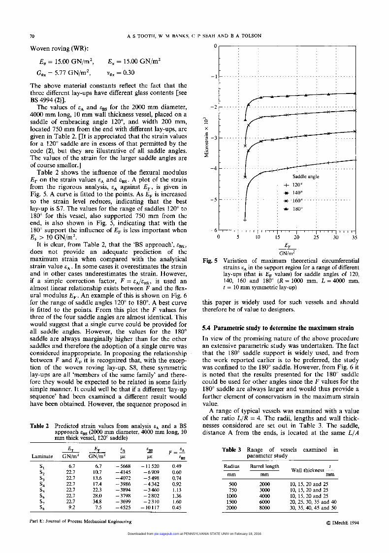
Table 2 shows the influence of the flexural modulus E , on the strain values and E ~ ~ . A plot of the strain from the rigorous analysis, against EF, is given in Fig. 5. A curve is fitted to the points. As E , is increased so the strain level reduces, indicating that the best lay-up is S7. The values for the range of saddles 120" to 180" for this vessel, also supported 750 mm from the end, is also shown in Fig. 5, indicating that with the 180" support the influence of E , is less important when E , > 10 GN/m2.
It is clear, from Table 2, that the 'BS approach', eBS, does not provide an adequate prediction of the maximum strain when compared with the analytical strain value eA. In some cases it overestimates the strain and in other cases underestimates the strain. However, if a simple correction factor, F = is used an almost linear relationship exists between F and the flex- ural modulus EF. An example of this is shown on Fig. 6 for the range of saddle angles 120" to 180". A best curve is fitted to the points. From this plot the F values for three of the four saddle angles are almost identical. This would suggest that a single curve could be provided for all saddle angles. However, the values for the 180" saddle are always marginally higher than for the other saddles and therefore the adoption of a single curve was considered inappropriate. In proposing the relationship between F and E , it is recognized that, with the excep- tion of the woven roving lay-up, S8, these symmetric lay-ups are all 'members of the same family' and there- fore they would be expected to be related in some fairly simple manner. It could well be that if a different 'lay-up sequence' had been examined a different result would have been obtained. However, the sequence proposed in
The values of
Table 2 Predicted strain values from analysis and a BS approach E~~ (2000 mm diameter, 4OOO mm long, 10 mm thick vessel. 120" saddle)
0 ,
I - 1
L t C._
....l......
Saddle angle I + 120"
: u- 140"
10 15 20 25 30 : EF
G N h Z
-6 0 5
Fig. 5 Variation of maximum theoretical circumferential strains in the support region for a range of different lay-ups (that is E , values) for saddle angles of 120, 140, 160 and 180" (R = 1000 mm, L = 4000 mm, t = 10 mm symmetric lay-up)
this paper is widely used for such vessels and should therefore be of value to designers.
5.4 Parametric study to determine the maximum strain In view of the promising nature of the above procedure an extensive parametric study was undertaken. The fact that the 180" saddle support is widely used, and from the work reported earlier is to be preferred, the study was confined to the 180" saddle. However, from Fig. 6 it is noted that the results presented for the 180" saddle could be used for other angles since the F values for the 180" saddle are always larger and would thus provide a further element of conservatism in the maximum strain value.
A range of typical vessels was examined with a value of the ratio L/R = 4. The radii, lengths and wall thick- nesses considered are set out in Table 3. The saddle, distance A from the ends, is located at the same L/A
Table 3 Range of vessels examined in parameter study
6.7 6.7 22.7 10.7 22.7 13.6 22.7 17.4 22.7 22.3 22.7 28.0 22.7 34.8 9.2 7.5
- 5668 -4145 -4072 - 3986 - 3894
- 3699 - 3798
- 4525
-11520 - 6 909 - 5 498 - 4 342 - 3 460 - 2 802 -2310 -10117
0.49 0.60 0.74 0.92 1.13 1.36 1.60 0.45
Radius Barrel length t Wall thickness -
mm mm mm
500 2000 10, 15, 20 and 25 750 3000 10, 15, 20 and 25 loo0 4Ooo 10, 15, 20 and 25 1500 6Ooo 20, 25, 30, 35 and 40 2000 8OOO 30, 35,40, 45 and 50
Part E: Journal of Process Mechanical Engineering Q IMechE 1994
at PENNSYLVANIA STATE UNIV on February 18, 2016pie.sagepub.comDownloaded from
THE TWIN-SADDLE SUPPORT OF HORIZONTAL MULTI-LAYERED GRP VESSELS 71
2
0 5 10 15 20 25 30 35
EF GNlm' -__
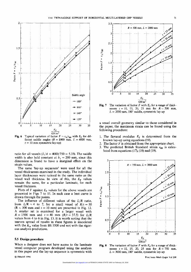
Fig. 6 Typical variation of factor F = with E, for dif- ferent saddle angles ( R = 1000 mm, L = 4000 mm, t = 10 mm symmetric lay-up)
ratio for all vessels (L/A = 4000/750 = 5.33). The saddle width is also held constant at b , = 200 mm, since this dimension is found to have a marginal effect on the strain values.
The same 'lay-up sequences' were used for all the vessel thicknesses examined in the study. The individual layer thicknesses were ratioed in the same ratio as the vessel wall thickness. In view of this, the E , values remain the same, for a particular laminate, for each vessel thickness.
Plots of F against EF values for the above vessels are presented in Figs 7 to 11. In each case a best curve is drawn through the points.
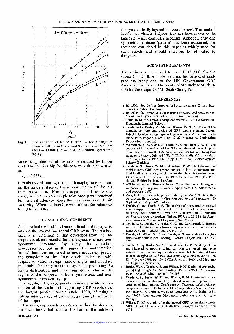
The influence of different values of the L/R ratio, from L/R = 4 to 7, for a small vessel of R/t = 50 (R = 500 mm and t = 10 mm) are presented in Fig. 12. A similar set is examined for a larger vessel with R = 1500 mm and t = 40 mm (R / t = 37.5) for L/R values from 4 to 6 in Fig. 13. It is worth noting that the uneven spread of results in these figures is associated with the K , value from BS 5500 and not with the rigor- ous analysis predictions.
v1
W . d
II 4
W
L c
d
3.5 I
~. o t ~ ~ ~ ~ l ~ ~ ~ ~ l ~ ~ ~ ~ l ~ ~ ~ ~ i ~ ~ ~ ~ l ~ ~ ~ , l , , , , l 0 5 10 15 20 25 30 35
EF GN/m2
Fig. 7 The variation of factor F with E , for a range of thick- nesses t = 10, 15, 20, 25 mm for R = 500 mm, L = 2000 mm, 180" saddle, symmetric lay-up
a vessel overall geometry similar to those considered in the paper, the maximum strain can be found using the following procedure:
1. The flexural modulus EF is determined from the
2. The factor F is obtained from the appropriate chart. 3. The predicted British Standard strain E~~ is calcu-
known lay-up using equations (19).
lated from equations (17), (18) and (19).
3 , 1
5.5 Design procedure
When a designer does not have access to the laminate vessel computer program developed using the analysis in this paper and the lay-up sequence is symmetric with 0 IMechE 1994
EF GN/m2
Fig. 8 The variation of factor F with E , for a range of thick- nesses t = 10, 15, 20, 25 mm for R = 750 mm, L = 3000 mm, 180" saddle, symmetric lay-up
Proc Instn Mech Engrs Vol 208
at PENNSYLVANIA STATE UNIV on February 18, 2016pie.sagepub.comDownloaded from
72 A S TOOTH, W 51 BANKS, C P SEAH AND B A TOLSON
in
w . i
II 4
w
s 2 .d
3.5 R = IOOOrnm,L=4000rnrn
0 5 10 15 20 25 30 35
EF
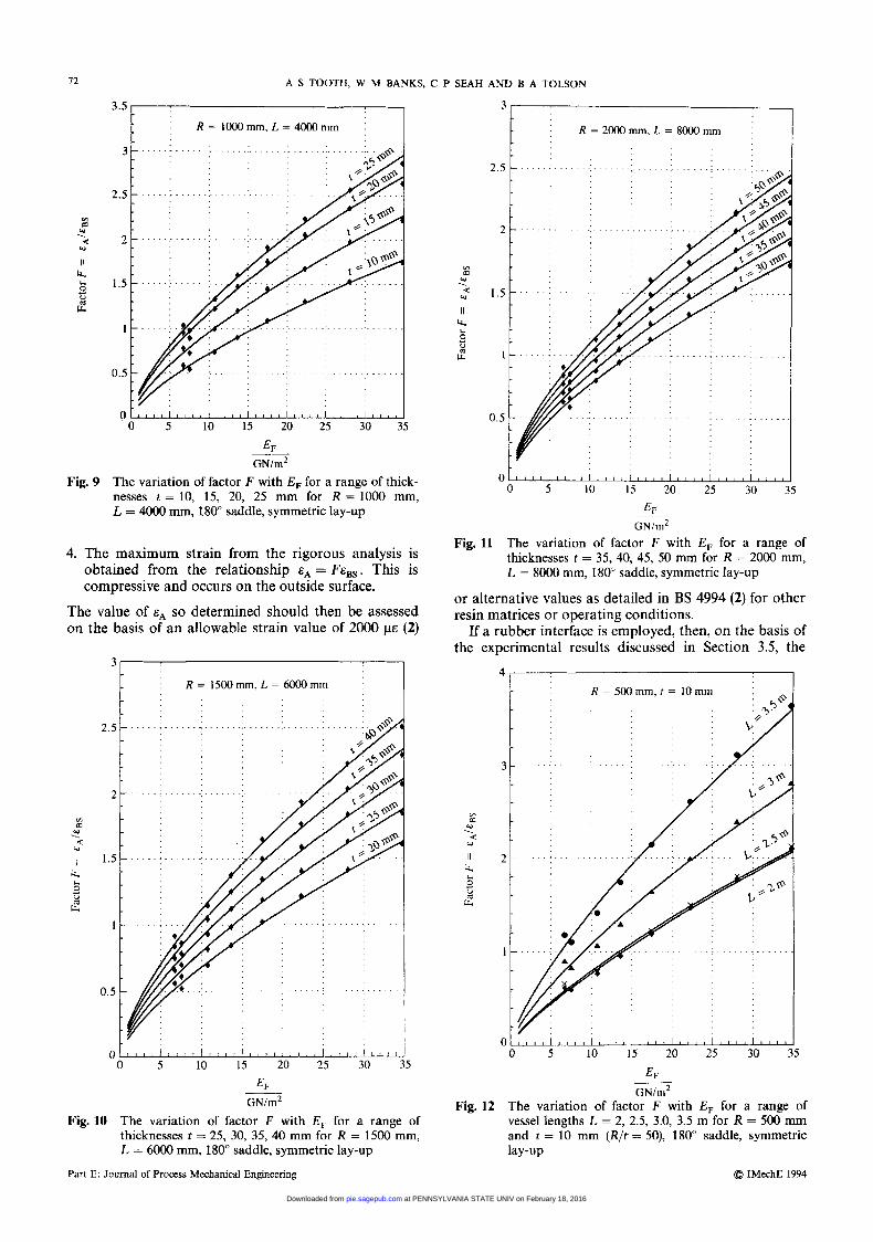
Fig. 9 The variation of factor F with E , for a range of thick- nesses t = 10, 15, 20, 25 mm for R = 1000 mm, L = 4000 mm, 180" saddle, symmetric lay-up
_- GN/rn2
4. The maximum strain from the rigorous analysis is obtained from the relationship eA = FE,,. This is compressive and occurs on the outside surface.
The value of so determined should then be assessed on the basis of an allowable strain value of 2000 pe (2)
3
R = ISOOrnrn, L. = 6000rnm
0)
W . W 4
I 1 4 L
.d 0
U P
G N h 2
Fig. 10 The variation of factor F with E, for a range of thicknesses t = 25, 30, 35, 40 mm for R = 1500 mm, L = 6000 mm, 180" saddle, symmetric lay-up
Part E: Journal of Process Mechanical Engineering
3 ,
2.5
2
I .s
I
0.5
0 5 0 5 10 15 20 25 30 35
EF G N ~
The variation of factor F with E , for a range of thicknesses t = 35,40, 45, 50 mm for R = 2000 mm, L = 8000 mm, 180' saddle, symmetric lay-up
or alternative values as detailed in BS 4994 (2) for other resin matrices or operating conditions.
If a rubber interface is employed, then, on the basis of the experimental results discussed in Section 3.5, the
Fig. 11
4
R=SOOrnm,t= 10mm
GNlrn2 Fig. 12 The variation of factor F with E , for a range of
vessel lengths L = 2, 2.5, 3.0, 3.5 m for R = 500 mm and t = 10 mm (R/t = 50), 180" saddle, symmetric lay-up
@ IMechE 1994
at PENNSYLVANIA STATE UNIV on February 18, 2016pie.sagepub.comDownloaded from
THE TWIN-SADDLE SuPPoRr OF HORIZONTAL MULTI-LAYERED GRP VESSELS 73
R = 15COmm, f = 40mm I
GN/m2
Fig. 13 The variation of factor F with E, for a range of vessel lengths L = 6, 7, 8 and 9 m for R = 1500 mm and t = 40 mm (R/t = 37.3, 180" saddle, symmetric lay-up
value of eA obtained above may be reduced by 15 per cent. The relationship for this case may thus be written as
CA = 0.85Ft;Bs
It is also worth noting that the damaging tensile strain on the inside surface in the support region will be less than the value e A . From the experimental results dis- cussed in Section 3.5 a simple relationship was obtained for the steel interface where the maximum inside strain = 0 . 7 4 ~ ~ . When the interface was rubber, the value was
found to be 0 . 6 0 ~ ~ .
6 CONCLUDING COMMENTS
A theoretical method has been outlined in this paper to analyse the layered horizontal GRP vessel. The method used is an extension of that developed from the iso- tropic vessel, and handles both the symmetric and non- symmetric laminates. By using the validation procedures set out in the paper, the mathematical 'model' has been improved to more accurately predict the behaviour of the GRP vessels under test with respect to vessel lay-ups, saddle angles and interface materials. The analysis is thus capable of predicting the strain distribution and maximum strain value in the region of the support, for both symmetrical and non- symmetrical disposed lay-ups.
In addition, the experimental studies provide confir- mation of the wisdom of supporting GRP vessels over the largest possible saddle angle (180"), of using a rubber interface and of providing a radius at the corner of the support.
The design approach provides a method for deriving the strain levels that occur at the horn of the saddle in @ IMechE 1994
the symmetrically layered horizontal vessel. The method is of value when a designer does not have access to the laminate vessel computer program. Although only one symmetric laminate 'pattern' has been examined, the sequence considered in this paper is widely used for such vessels and should therefore be of value to designers.
ACKNOWLEDGEMENTS
The authors are indebted to the SERC (UK) for the support of Dr B. A. Tolson during her period of post- graduate study and to the UK Government ORS Award Scheme and a University of Strathclyde Student- ship for the support of Mr Seah Chong Poh.
REFERENCES
1 BS 5500: 1991 Unfiredfusion welded pressure vessels (British Stan- dards Institution, London).
2 BS 4994: 1987 Design and construction of vessels and tanks in rein- forced plastics (British Standards Institution, London).
3 Jones, R. M. Mechanics of composite materials, 1975 (McGraw-Hill Kogakusha Limited, Tokyo).
4 Tooth, A. S., Banks, W. M. and Wilson, P. M. A review of the manufacture, use and design of GRP piping systems. Second IMechE Conference on Pipework engineering and operation, Feb- ruary 1989, Paper (33761034, pp. 13-22 (Mechanical Engineering Publications, London).
5 Warrender, A. J., Wood, J., Tooth, A. S. and Banks, W. M. The support of horizontal cylindrical GRP vessels-saddles or longitu- dinal beams? Fourth International Conference on Composite structures, Paisley, July 1987 (Ed. 1. H. Marshall), Vol. 1, Analysis and design studies, 1987, Ch. 17, pp. 1.235-1.252 (Elsevier Applied Science, Barking).
6 Tooth, A. S., Banks, W. M. and Wilson, P. W. The behaviour of multi-layered GRP pipes when subject to local attachment and fluid loading-strain decay characteristics. Seventh Conference on Plastic pipes, University of Bath, 19-22 September 1988 (The Plas- tics and Rubber Institute, London).
7 ASME Boiler and Pressure Vessel Code, Section X, Fiberglass- reinforced plastic pressure vessels, Appendices 1-5, Attachments and supports, 1986.
8 Zick, L. P. Stresses in large horizontal cylindrical pressure vessels on two saddle supports. Welded Research Journal Supplement, 30 September 1951, pp. 4358-445s.
9 Duthie, G. and Tooth, A. S. The analysis of horizontal cylindrical vessels supported by saddles welded to the vessel-a comparison of theory and experiment. Third ASME International Conference on Pressure vessel technology, Tokyo, 1977, pp. 25-38 (The Amer- ican Society of Mechanical Engineers, New York).
10 Tooth, A. S., Duthie, G., White, G. C. and Carmichael, J. Stresses in horizontal storage vessels-a comparison of theory and experi- ment. J . Strain Analysis, 1982,17, 169-176.
11 Duthie, G., White, G. C and Tooth, A. S. An analysis for cylin- drical vessels under local loading, J . Strain Analysis, 1982, 17, 157- 168.
12 Tooth, A. S., Banks, W. M. and Wilson, P. M. A study of the multi-layered composite cylindrical pressure vessel and pipe subject to various loading conditions. Seventh International Con- ference on Offshore mechanics and arctic engineering (OMAE)), Vol. 111, February 1988, pp. 13-18 (The American Society of Mechani- cal Engineers, New York).
13 Banks, W. M., Tooth, A. S. and Wilson, P. M. Design of composite cylindrical vesssels for fluid loading. Trans. ASME, J . Pressure Vessel Technol., May 1989,111, 102- 108.
14 Tooth, A. S., Banks, W. M. and Wilson, P. M. Laminate analysis as applied to the design of cylindrical vessels and pipes. Pro- ceedings of International Conference on Computer aided design in composite materials, Technical CAD Computations, Southampton, 1988 (Eds C. A. Brebbia, W. P. de Wilde and W. R. Blain), 1988, pp. 49-64 (Computation Mechanical Publishers and Springer- Verlag).
15 Wilson, P. M. A study of multi-layered GRP cylindrical vessels. MPhil thesis, University of Strathclyde, Glasgow, Scotland, June 1991.
Proc Instn Mech Engrs Vol 208
at PENNSYLVANIA STATE UNIV on February 18, 2016pie.sagepub.comDownloaded from
74 A S TOOTH, W M BANKS, C P SEAH A N D B A TOLSON
16 Sanders, Jr, J. L. An improved first approximation theory for thin shells. NASA TR24, 1959.
17 Rahman, D. H. A., Banks, W. M. and Tooth, A. S. Behaviour of GRP pipes under a variety of load conditions. Sixth International Conference on Plastic pipes, York, 1985, pp. 13.1-13.6 (The Plas- tics and Rubber Institute, London).
18 Tolson, B. A. The support of horizontal multi-layered GRP cylin- drical vessels. PhD thesis, University of Strathclyde, Glasgow, Scotland, September 1991.
19 Wilson, J. D. and Tooth, A. S. The support of unstiffened cylin- drical vessels. Second International Conference on Pressure vessel technofogy, San Antonio, 1973, pp. 67-83 (The American Society of Mechanical Engineers, New York).
20 Motashar, F. A. The analysis of horizontal cylindrical vessels- supports, local attachments and diaphragms. PhD thesis, Uni- versity of Strathclyde, Glasgow, Scotland, March 1988.
21 Motashar, F. A. and Tooth, A. S. An improved analysis for cylin- drical vessels supported on rigid saddles. In Applied stress analysis (Eds T. H. Hyde and E. Ollerton), 1990, pp. 39&410 (Elsevier Applied Science, Barking).
22 Motashar, F. A. and Tooth, A. S, The support of cylindrical vessels on rigid and flexible saddles-an improved analysis. Proceedings
of 1990 IUTAM Symposium on Contact loading and local effects in thin-walled plated and shell structures, Prague, 1992, pp. 62-69 (Academa, Prague).
23 Duthie, G. and Tooth, A. S. Local loads on cylindrical vessels. In The behauiour of thin-walled structures (Eds J. Rhodes and J. Spence) 1984, pp. 235-272 (Elsevier Applied Science, Barking).
24 Tooth, A. S. and Duthie, G. The elastic analysis of horizontal cylindrical vessels supported by saddles. Archiwum Budowy Maszyn, 1981,28(3), 235-252.
25 BS 5276: Part 2: 1983 Pressure vessel details (dimensions), Part 2. Specification for saddle supports for horizontal cylindrical pressure vessels (British Standards Institution, London).
26 Seah, C. P. An experimental study of the support of laminated GRP horizontal vessels. MPhil thesis, University of Strathclyde, Glasgow, Scotland, May 1993.
27 Tooth, A. S. Local loads, supports and mounting. In Pressure vessel design concepts and principles (Eds J. Spence and A. S. Tooth), 1994, pp. 125-187 (E&FN Spon-an imprint of Chapman and Hall, London).
28 Tsai, S. W. Composites design. In Thick composites, 1985 (Dayton, Ohio).
Part E: Journal of Process Mechanical Engineering @ IMechE 1994
at PENNSYLVANIA STATE UNIV on February 18, 2016pie.sagepub.comDownloaded from


