Embed Size (px)
Citation preview
W W W. I P L E X . C O M . A U • E M A I L I N F O @ I P L E X P I P E L I N E S . C O M . A U
P L U M B I N G , E L E C T R I C A L A N D I R R I G AT I O N 1 3 0 0 0 I P L E X ( 1 3 0 0 0 4 7 5 3 9 ) • C I V I L 1 3 1 0 8 6
The information contained in this document should serve as a guide only and is subject to change without notice. For more information please contact Iplex Pipelines Australia Pty Ltd.
1
V1 2019
FLOWTITE® GRPPIPE AND FITTINGS
T E C H N I C A L I N F O R M A T I O N
STRUCTURAL DESIGN
R
W W W. I P L E X . C O M . A U • E M A I L I N F O @ I P L E X P I P E L I N E S . C O M . A U
P L U M B I N G , E L E C T R I C A L A N D I R R I G AT I O N 1 3 0 0 0 I P L E X ( 1 3 0 0 0 4 7 5 3 9 ) • C I V I L 1 3 1 0 8 6
The information contained in this document should serve as a guide only and is subject to change without notice. For more information please contact Iplex Pipelines Australia Pty Ltd.
ALLOWABLE COVER HEIGHTS
In engineering terminology FLOWTITE® pipes are considered to be “flexible” pipes. This means they are designed to
deform or deflect diametrically within specified limits without structural damage.
The external soil and live loadings above flexible pipes may cause a decrease in the vertical diameter and an increase
in the horizontal diameter of the pipe or cause ring instability. The horizontal movement of the pipe walls in the soil
material at the sides develops a passive resistance within the soil to support the external load. That is, the pipeline
performance at a given cover height is influenced by the native soil type, its stiffness, the pipe embedment material,
its compaction, the height of water table, vacuum conditions, live loading such as vehicular loads, and hydrostatic
operating pressures. The higher the effective soil modulus at pipe depth, the less the pipe will deflect and the ring
stability will be improved.
Initial deflections of up to 3% are permissible and will not affect the pressure rating of the pipe. Software for the
complete design procedure can be downloaded from www.iplex.com.au. Contact Iplex Pipelines for further details or
refer to AS/NZS 2566.1 “Buried flexible pipelines” Part 1 Structural design.
To properly assess the effect of site conditions on a proposed installation, specific information is needed for design
including:
• Pipe diameter (mm)
• Cover height (m)
• Properties of native soil
• Width of embedment (mm)
• Properties of embedment material
The appropriate value of the effective soil deformation modulus for a particular installation will depend on the native
soil type and condition, the pipe embedment material, its degree of compaction and its geometry (e.g. trench width/
embedment width). Geotechnical surveys giving soil types and properties, including soil-bearing capacities, SPT
values at pipe depth and embedment compaction, will be relevant to the design.
The following notation is used in this Section:
1
V1 2019
a = the radius of loaded circular plate (m)
b = embedment width each side of pipe at spring-line (m)
B = trench width at pipe spring-line (m)
D = overall outside diameter of pipe (m)
Ee’ = embedment soil deformation modulus (MPa)
En’ = native soil deformation modulus (MPa)
E/ = combined soil deformation modulus (MPa)
H = cover height (m)
h = bedding thickness (m)
k = overlay thickness (m)
p = presumptive (allowable) bearing pressure (kPa)
Δ = displacement or settlement (m)
ξ = Leonhardt correction factor
• Height of water table (m)
• Traffic loading
• Special requirements, such as concrete encasement
or grouting
W W W. I P L E X . C O M . A U • E M A I L I N F O @ I P L E X P I P E L I N E S . C O M . A U
P L U M B I N G , E L E C T R I C A L A N D I R R I G AT I O N 1 3 0 0 0 I P L E X ( 1 3 0 0 0 4 7 5 3 9 ) • C I V I L 1 3 1 0 8 6
The information contained in this document should serve as a guide only and is subject to change without notice. For more information please contact Iplex Pipelines Australia Pty Ltd.
2
V1 2019
FLOWTITE® GRPPIPE AND FITTINGS
T E C H N I C A L I N F O R M A T I O N
STRUCTURAL DESIGN
R
W W W. I P L E X . C O M . A U • E M A I L I N F O @ I P L E X P I P E L I N E S . C O M . A U
P L U M B I N G , E L E C T R I C A L A N D I R R I G AT I O N 1 3 0 0 0 I P L E X ( 1 3 0 0 0 4 7 5 3 9 ) • C I V I L 1 3 1 0 8 6
The information contained in this document should serve as a guide only and is subject to change without notice. For more information please contact Iplex Pipelines Australia Pty Ltd.
GEOTECHNICAL INVESTIGATION
The conventional approach to a pipeline route investigation has been to assess the soil conditions at pipe depth by
carrying out a drilling and soil sampling program along the alignment. While the intention in the past was often to
determine the presence of rock and to estimate trench stability for construction purposes, this investigation is now
used for more detailed geotechnical reporting with additional information readily obtained from routine surveys. It
includes design data such as the Standard Penetration Test (SPT) blow counts (at pipe depth), identification of native
soil type and density, and depth of water table. The designer will need to assess the embedment material chosen to
surround the pipe and its compaction.
DERIVATION OF SOIL DEFORMATION MODULUS VALUES
The correct choice of soil moduli will have significant effects on design decisions. An approximate conversion of SPT
blow counts to soil moduli is given in Table 1.0 of AS/NZS 2566.1. However many designers may have more confidence
in basing their assessment on the widely available data on foundation design. Often this is contained in records
obtained over many years and frequently gives correlations between SPT and allowable soil bearing pressures.
If SPT values are not known for the soils in the pipe zone and the soil has already been exposed by excavation, the
Clegg impact hammer can be used to obtain Impact Values (CIVs). These are numerically similar to SPT blow counts
and can be substituted in Table 1.1 to obtain an estimate of En’.
The soil deformation moduli stated in AS/NZS 2566.1 were originally derived from European design practice using
soil bearing plate tests. These moduli can be nearly half the value of deformation moduli measured using standard
laboratory tri-axial tests so the two should not be confused. Using allowable foundation bearing pressures, it is
possible to derive the plate load or pipe design soil moduli from the Boussinesq’s plate bearing theory for an elastic,
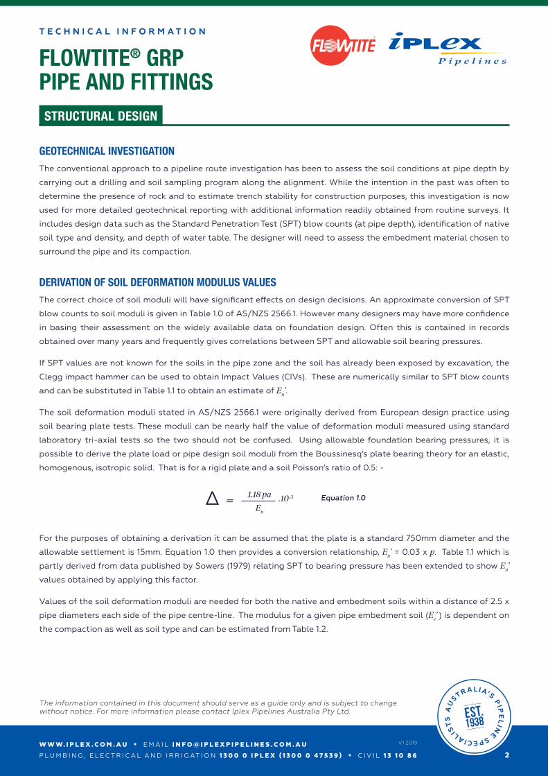
homogenous, isotropic solid. That is for a rigid plate and a soil Poisson’s ratio of 0.5: -
2
V1 2019
1.18 pa .10-3
En=Δ
For the purposes of obtaining a derivation it can be assumed that the plate is a standard 750mm diameter and the
allowable settlement is 15mm. Equation 1.0 then provides a conversion relationship, En’ = 0.03 x p. Table 1.1 which is
partly derived from data published by Sowers (1979) relating SPT to bearing pressure has been extended to show En’
values obtained by applying this factor.
Values of the soil deformation moduli are needed for both the native and embedment soils within a distance of 2.5 x
pipe diameters each side of the pipe centre-line. The modulus for a given pipe embedment soil (Ee’ ) is dependent on
the compaction as well as soil type and can be estimated from Table 1.2.
Equation 1.0
W W W. I P L E X . C O M . A U • E M A I L I N F O @ I P L E X P I P E L I N E S . C O M . A U
P L U M B I N G , E L E C T R I C A L A N D I R R I G AT I O N 1 3 0 0 0 I P L E X ( 1 3 0 0 0 4 7 5 3 9 ) • C I V I L 1 3 1 0 8 6
The information contained in this document should serve as a guide only and is subject to change without notice. For more information please contact Iplex Pipelines Australia Pty Ltd.
3
V1 2019
FLOWTITE® GRPPIPE AND FITTINGS
T E C H N I C A L I N F O R M A T I O N
STRUCTURAL DESIGN
R
Page 60
Compaction – standard dry density ratio
Methods for measurement of compaction are given in AS 1289-E3. The actual dry density ratio (previously known as Proctor ratio) of a soil is defined as a percentage of the maximum dry density determined in the laboratory at the optimum moisture content. Then the dry density is derived from the following equation:
....................Equation 6.2
Where
ρ = wet field density
w = percentage moisture content
The dry density ratio is the field dry density divided by the maximum dry density determined in the laboratory for the soil (expressed as a percentage) when compacted at the optimum moisture content.
Figure 6.1 – Typical dry densities for different soils
Figure 6.1 shows the effect of compacting at different moisture contents on the dry densities of various soil types. It should be noted that the curve for gravel is relatively flat as water content has minimal effect on the achievable compaction. Therefore these materials are preferred for embedment. The curve shown for sand is concave over the intermediate range of moisture contents. With some fine sands at these moisture contents the density can be more than 20% less than for the compaction achievable at higher moisture levels. Because of this property these “bulking sands” are highly unsuitable as embedment material. The convex curves for cohesive soils such as silt and clay are particularly sensitive with respect to moisture and are difficult to compact adequately in a pipe trench.
The dry density may be determined in the laboratory by either the ‘Standard’ method or the ‘Modified’ test method each giving signifi-cantly different results. The compaction energy for the ‘Modified’ is 4.5 times higher than for ‘Standard’ and the resultant maximum dry density ratio will be lower for a given field test sample. For granular soils the difference is about 5% (less for uniformly graded sand) and about 10% for cohesive soils. AS/NZS 2566.2 refers to standard dry density ratio only.
Figure 6.2 – Standard Compaction - 2.7kg rammer is dropped from a height of 300mm - 25 blows per layers (left hand side) and Modified Compaction - 4.9kg rammer is dropped from a height of 450mm - 25 blows per 5 layers (right hand side)
Compaction - density index
An alternative method of evaluating the degree of compaction, which is faster and less expensive for granular soils, is the density index (or relative density). With this method the ‘loosest’ and ‘densest’ densities are determined in the laboratory as follows.
A container filled with the soil is vibrated on a vibratory table for 10 minutes or until the settlement ceases to determine a value for the maximum dry density ρmax. The minimum dry density ρmin is determined by gently pouring the soil into the container and measur-ing the density. Combined with the dry density ρd, which has been measured on site, the density index ID for site compaction can then be determined from equation 6.3.
..............Equation 6.3
These two compaction methods give unrelated percentages that are quite different in magnitude and must not be interchanged. For example in broad terms a compacted soil with a density index of 65% may have a standard dry density ratio of 90%.
Figure 6.3 – Critical dimensions for design and installation
2.2
2.1
2.0
1.9
1.8
1.7
1.6
1.5
1.40 5 10 15 20 25 30
Dry
den
sity
- t/m
3
Water content - %
Gravel
Sand
Silt
Clay
Zeroairvoids
105 105
115.5 115.5
Section 6 STRUCTURAL DESIGN
ρ max (ρ D ρ min )
ρ D (ρ max ρ min ) ID = x 100%
H
h
D
K
h
D
H
K
b
B
b B
Trench Embankment
W W W. I P L E X . C O M . A U • E M A I L I N F O @ I P L E X P I P E L I N E S . C O M . A U
P L U M B I N G , E L E C T R I C A L A N D I R R I G AT I O N 1 3 0 0 0 I P L E X ( 1 3 0 0 0 4 7 5 3 9 ) • C I V I L 1 3 1 0 8 6
COMPACTION – STANDARD DRY DENSITY RATIO
Methods for measurement of compaction are given in AS 1289-E3. The actual dry density ratio (previously known as
Proctor ratio) of a soil is defined as a percentage of the maximum dry density determined in the laboratory at the
optimum moisture content. Then the dry density is derived from the following equation:
3
V1 2019
Where
ρ = wet field density
w = percentage moisture content
The dry density ratio is the field dry density divided by the maximum dry density determined in the laboratory for the
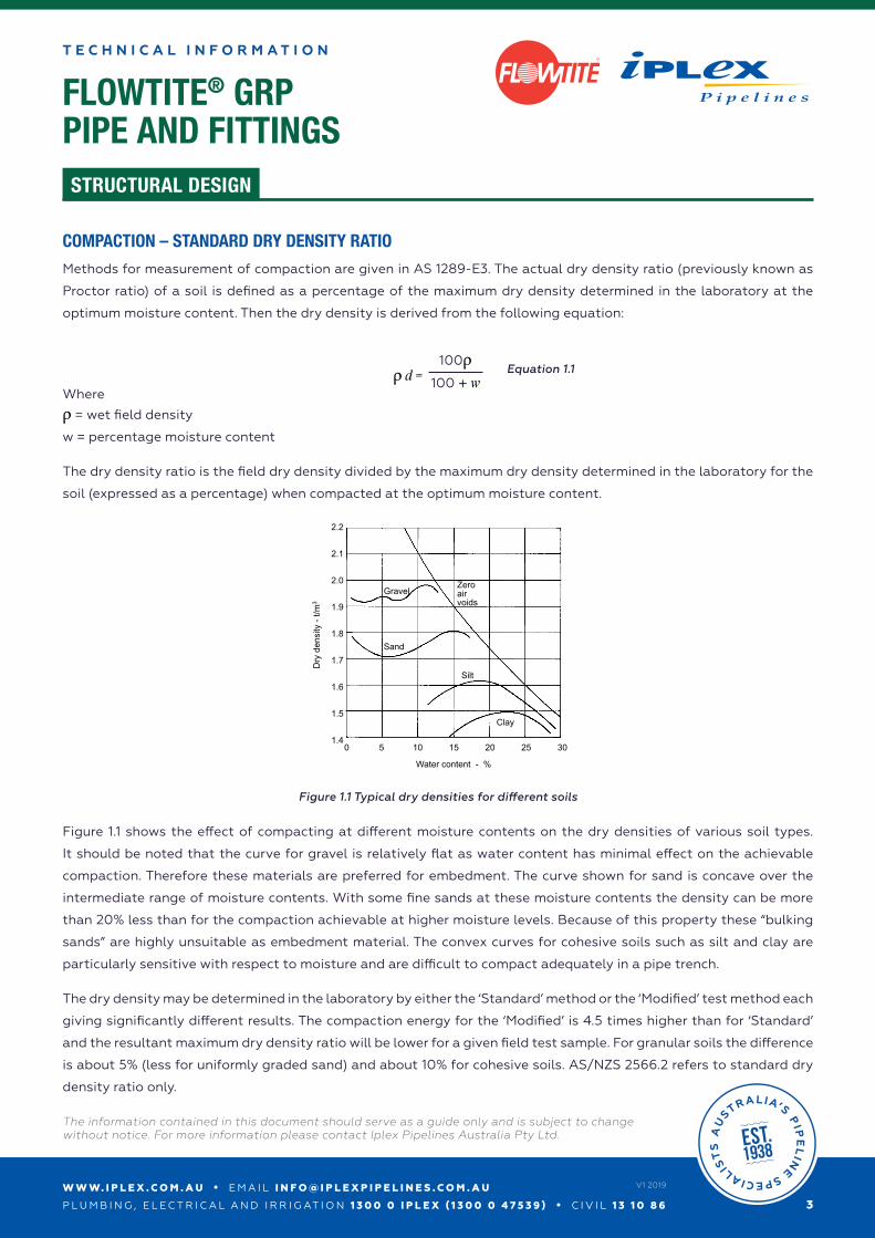
soil (expressed as a percentage) when compacted at the optimum moisture content.
Figure 1.1 shows the effect of compacting at different moisture contents on the dry densities of various soil types.
It should be noted that the curve for gravel is relatively flat as water content has minimal effect on the achievable
compaction. Therefore these materials are preferred for embedment. The curve shown for sand is concave over the
intermediate range of moisture contents. With some fine sands at these moisture contents the density can be more
than 20% less than for the compaction achievable at higher moisture levels. Because of this property these “bulking
sands” are highly unsuitable as embedment material. The convex curves for cohesive soils such as silt and clay are
particularly sensitive with respect to moisture and are difficult to compact adequately in a pipe trench.
The dry density may be determined in the laboratory by either the ‘Standard’ method or the ‘Modified’ test method each
giving significantly different results. The compaction energy for the ‘Modified’ is 4.5 times higher than for ‘Standard’
and the resultant maximum dry density ratio will be lower for a given field test sample. For granular soils the difference
is about 5% (less for uniformly graded sand) and about 10% for cohesive soils. AS/NZS 2566.2 refers to standard dry
density ratio only.
ρ d =100ρ
100 + wEquation 1.1
Figure 1.1 Typical dry densities for different soils
W W W. I P L E X . C O M . A U • E M A I L I N F O @ I P L E X P I P E L I N E S . C O M . A U
P L U M B I N G , E L E C T R I C A L A N D I R R I G AT I O N 1 3 0 0 0 I P L E X ( 1 3 0 0 0 4 7 5 3 9 ) • C I V I L 1 3 1 0 8 6
The information contained in this document should serve as a guide only and is subject to change without notice. For more information please contact Iplex Pipelines Australia Pty Ltd.
4
V1 2019
FLOWTITE® GRPPIPE AND FITTINGS
T E C H N I C A L I N F O R M A T I O N
STRUCTURAL DESIGN
R
Page 60
Compaction – standard dry density ratio
Methods for measurement of compaction are given in AS 1289-E3. The actual dry density ratio (previously known as Proctor ratio) of a soil is defined as a percentage of the maximum dry density determined in the laboratory at the optimum moisture content. Then the dry density is derived from the following equation:
....................Equation 6.2
Where
ρ = wet field density
w = percentage moisture content
The dry density ratio is the field dry density divided by the maximum dry density determined in the laboratory for the soil (expressed as a percentage) when compacted at the optimum moisture content.
Figure 6.1 – Typical dry densities for different soils
Figure 6.1 shows the effect of compacting at different moisture contents on the dry densities of various soil types. It should be noted that the curve for gravel is relatively flat as water content has minimal effect on the achievable compaction. Therefore these materials are preferred for embedment. The curve shown for sand is concave over the intermediate range of moisture contents. With some fine sands at these moisture contents the density can be more than 20% less than for the compaction achievable at higher moisture levels. Because of this property these “bulking sands” are highly unsuitable as embedment material. The convex curves for cohesive soils such as silt and clay are particularly sensitive with respect to moisture and are difficult to compact adequately in a pipe trench.
The dry density may be determined in the laboratory by either the ‘Standard’ method or the ‘Modified’ test method each giving signifi-cantly different results. The compaction energy for the ‘Modified’ is 4.5 times higher than for ‘Standard’ and the resultant maximum dry density ratio will be lower for a given field test sample. For granular soils the difference is about 5% (less for uniformly graded sand) and about 10% for cohesive soils. AS/NZS 2566.2 refers to standard dry density ratio only.
Figure 6.2 – Standard Compaction - 2.7kg rammer is dropped from a height of 300mm - 25 blows per layers (left hand side) and Modified Compaction - 4.9kg rammer is dropped from a height of 450mm - 25 blows per 5 layers (right hand side)
Compaction - density index
An alternative method of evaluating the degree of compaction, which is faster and less expensive for granular soils, is the density index (or relative density). With this method the ‘loosest’ and ‘densest’ densities are determined in the laboratory as follows.
A container filled with the soil is vibrated on a vibratory table for 10 minutes or until the settlement ceases to determine a value for the maximum dry density ρmax. The minimum dry density ρmin is determined by gently pouring the soil into the container and measur-ing the density. Combined with the dry density ρd, which has been measured on site, the density index ID for site compaction can then be determined from equation 6.3.
..............Equation 6.3
These two compaction methods give unrelated percentages that are quite different in magnitude and must not be interchanged. For example in broad terms a compacted soil with a density index of 65% may have a standard dry density ratio of 90%.
Figure 6.3 – Critical dimensions for design and installation
2.2
2.1
2.0
1.9
1.8
1.7
1.6
1.5
1.40 5 10 15 20 25 30
Dry
den
sity
- t/m
3
Water content - %
Gravel
Sand
Silt
Clay
Zeroairvoids
105 105
115.5 115.5
Section 6 STRUCTURAL DESIGN
ρ max (ρ D ρ min )
ρ D (ρ max ρ min ) ID = x 100%
H
h
D
K
h
D
H
K
b
B
b B
Trench Embankment
W W W. I P L E X . C O M . A U • E M A I L I N F O @ I P L E X P I P E L I N E S . C O M . A U
P L U M B I N G , E L E C T R I C A L A N D I R R I G AT I O N 1 3 0 0 0 I P L E X ( 1 3 0 0 0 4 7 5 3 9 ) • C I V I L 1 3 1 0 8 6
The information contained in this document should serve as a guide only and is subject to change without notice. For more information please contact Iplex Pipelines Australia Pty Ltd.
COMPACTION - DENSITY INDEX
An alternative method of evaluating the degree of compaction, which is faster and less expensive for granular soils,
is the density index (or relative density). With this method the ‘loosest’ and ‘densest’ densities are determined in the
laboratory as follows.
A container filled with the soil is vibrated on a vibratory table for 10 minutes or until the settlement ceases to determine
a value for the maximum dry density ρmax. The minimum dry density ρmin is determined by gently pouring the soil
into the container and measuring the density. Combined with the dry density ρd, which has been measured on site, the
density index ID for site compaction can then be determined from equation 1.2.
These two compaction methods give unrelated percentages that are quite different in magnitude and must not be
interchanged. For example in broad terms a compacted soil with a density index of 65% may have a standard dry
density ratio of 90%.
4
V1 2019
Id = x 100%ρmax (ρD ρmin )
ρD (ρmax ρmin )
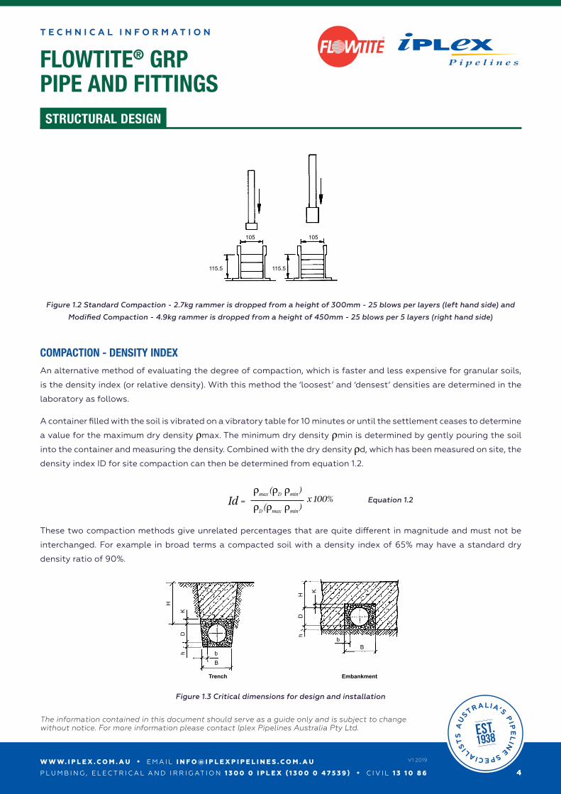
Figure 1.2 Standard Compaction - 2.7kg rammer is dropped from a height of 300mm - 25 blows per layers (left hand side) and
Modified Compaction - 4.9kg rammer is dropped from a height of 450mm - 25 blows per 5 layers (right hand side)
Figure 1.3 Critical dimensions for design and installation
Equation 1.2
W W W. I P L E X . C O M . A U • E M A I L I N F O @ I P L E X P I P E L I N E S . C O M . A U
P L U M B I N G , E L E C T R I C A L A N D I R R I G AT I O N 1 3 0 0 0 I P L E X ( 1 3 0 0 0 4 7 5 3 9 ) • C I V I L 1 3 1 0 8 6
The information contained in this document should serve as a guide only and is subject to change without notice. For more information please contact Iplex Pipelines Australia Pty Ltd.
5
V1 2019
FLOWTITE® GRPPIPE AND FITTINGS
T E C H N I C A L I N F O R M A T I O N
STRUCTURAL DESIGN
R
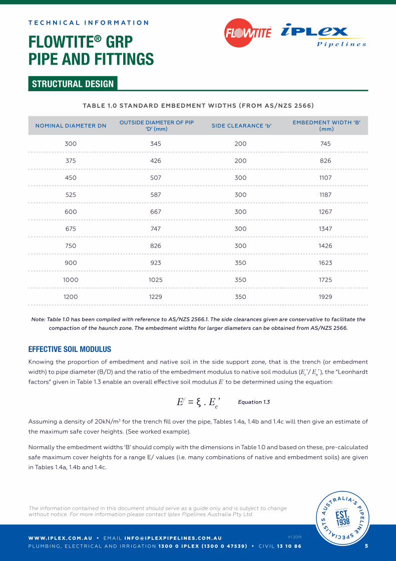
TABLE 1.0 STANDARD EMBEDMENT WIDTHS (FROM AS/NZS 2566)
NOMINAL DIAMETER DNOUTSIDE DIAMETER OF PIP
‘D’ (mm)SIDE CLEARANCE ‘b’
EMBEDMENT WIDTH ‘B’ (mm)
300 345 200 745
375 426 200 826
450 507 300 1107
525 587 300 1187
600 667 300 1267
675 747 300 1347
750 826 300 1426
900 923 350 1623
1000 1025 350 1725
1200 1229 350 1929
Note: Table 1.0 has been compiled with reference to AS/NZS 2566.1. The side clearances given are conservative to facilitate the
compaction of the haunch zone. The embedment widths for larger diameters can be obtained from AS/NZS 2566.
EFFECTIVE SOIL MODULUS
Knowing the proportion of embedment and native soil in the side support zone, that is the trench (or embedment
width) to pipe diameter (B/D) and the ratio of the embedment modulus to native soil modulus (Ee’ / En’ ), the “Leonhardt
factors” given in Table 1.3 enable an overall effective soil modulus E/ to be determined using the equation:
E/ = ξ . Ee’
Assuming a density of 20kN/m3 for the trench fill over the pipe, Tables 1.4a, 1.4b and 1.4c will then give an estimate of
the maximum safe cover heights. (See worked example).
Normally the embedment widths ‘B’ should comply with the dimensions in Table 1.0 and based on these, pre-calculated
safe maximum cover heights for a range E/ values (i.e. many combinations of native and embedment soils) are given
in Tables 1.4a, 1.4b and 1.4c.
Equation 1.3
W W W. I P L E X . C O M . A U • E M A I L I N F O @ I P L E X P I P E L I N E S . C O M . A U
P L U M B I N G , E L E C T R I C A L A N D I R R I G AT I O N 1 3 0 0 0 I P L E X ( 1 3 0 0 0 4 7 5 3 9 ) • C I V I L 1 3 1 0 8 6
The information contained in this document should serve as a guide only and is subject to change without notice. For more information please contact Iplex Pipelines Australia Pty Ltd.
6
V1 2019
FLOWTITE® GRPPIPE AND FITTINGS
T E C H N I C A L I N F O R M A T I O N
STRUCTURAL DESIGN
R
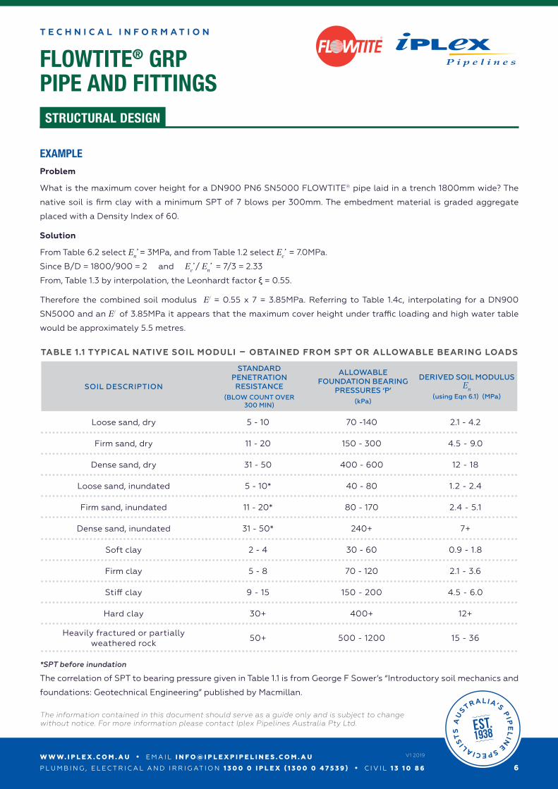
EXAMPLE
Problem
What is the maximum cover height for a DN900 PN6 SN5000 FLOWTITE® pipe laid in a trench 1800mm wide? The
native soil is firm clay with a minimum SPT of 7 blows per 300mm. The embedment material is graded aggregate
placed with a Density Index of 60.
Solution
From Table 6.2 select En’ = 3MPa, and from Table 1.2 select Ee’ = 7.0MPa.
Since B/D = 1800/900 = 2 and Ee’ / En’ = 7/3 = 2.33
From, Table 1.3 by interpolation, the Leonhardt factor ξ = 0.55.
Therefore the combined soil modulus E/ = 0.55 x 7 = 3.85MPa. Referring to Table 1.4c, interpolating for a DN900
SN5000 and an E/ of 3.85MPa it appears that the maximum cover height under traffic loading and high water table
would be approximately 5.5 metres.
TABLE 1.1 TYPICAL NATIVE SOIL MODULI – OBTAINED FROM SPT OR ALLOWABLE BEARING LOADS
SOIL DESCRIPTION
STANDARD PENETRATION RESISTANCE
(BLOW COUNT OVER300 MIN)
ALLOWABLE FOUNDATION BEARING
PRESSURES ‘P’(kPa)
DERIVED SOIL MODULUS En
(using Eqn 6.1) (MPa)
Loose sand, dry 5 - 10 70 -140 2.1 - 4.2
Firm sand, dry 11 - 20 150 - 300 4.5 - 9.0
Dense sand, dry 31 - 50 400 - 600 12 - 18
Loose sand, inundated 5 - 10* 40 - 80 1.2 - 2.4
Firm sand, inundated 11 - 20* 80 - 170 2.4 - 5.1
Dense sand, inundated 31 - 50* 240+ 7+
Soft clay 2 - 4 30 - 60 0.9 - 1.8
Firm clay 5 - 8 70 - 120 2.1 - 3.6
Stiff clay 9 - 15 150 - 200 4.5 - 6.0
Hard clay 30+ 400+ 12+
Heavily fractured or partially weathered rock
50+ 500 - 1200 15 - 36
*SPT before inundation
The correlation of SPT to bearing pressure given in Table 1.1 is from George F Sower’s “Introductory soil mechanics and
foundations: Geotechnical Engineering” published by Macmillan.
W W W. I P L E X . C O M . A U • E M A I L I N F O @ I P L E X P I P E L I N E S . C O M . A U
P L U M B I N G , E L E C T R I C A L A N D I R R I G AT I O N 1 3 0 0 0 I P L E X ( 1 3 0 0 0 4 7 5 3 9 ) • C I V I L 1 3 1 0 8 6
The information contained in this document should serve as a guide only and is subject to change without notice. For more information please contact Iplex Pipelines Australia Pty Ltd.
7
V1 2019
FLOWTITE® GRPPIPE AND FITTINGS
T E C H N I C A L I N F O R M A T I O N
STRUCTURAL DESIGN
R
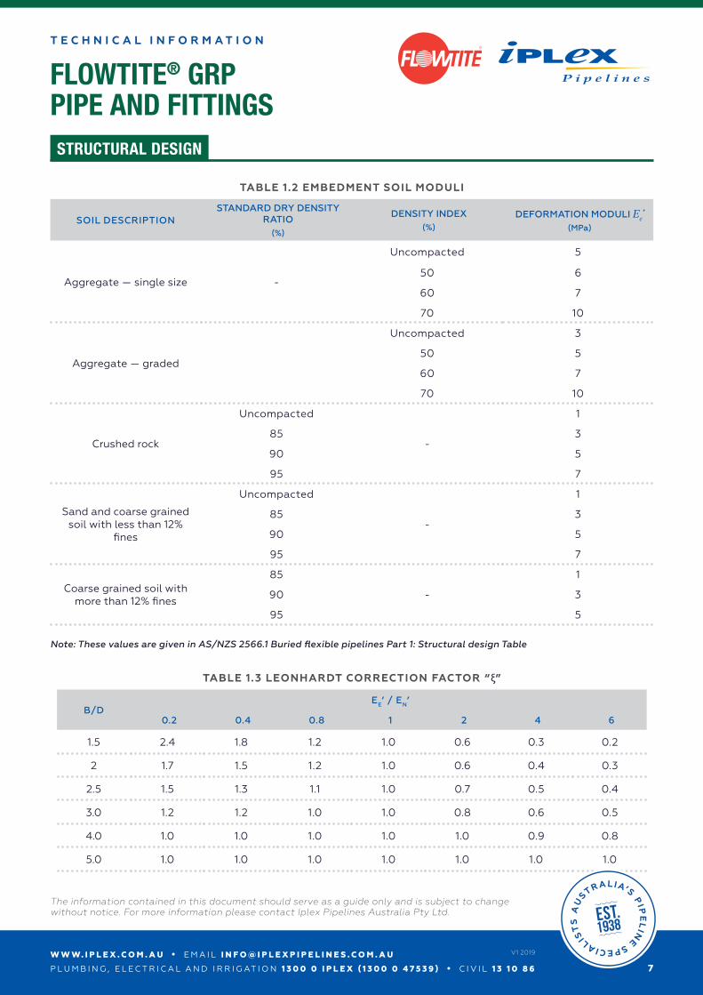
TABLE 1.2 EMBEDMENT SOIL MODULI
SOIL DESCRIPTIONSTANDARD DRY DENSITY
RATIO(%)
DENSITY INDEX(%)
DEFORMATION MODULI Ee’(MPa)
Aggregate — single size -
Uncompacted 5
50 6
60 7
70 10
Aggregate — graded
Uncompacted 3
50 5
60 7
70 10
Crushed rock
Uncompacted
-
1
85 3
90 5
95 7
Sand and coarse grained soil with less than 12%
fines
Uncompacted
-
1
85 3
90 5
95 7
Coarse grained soil with more than 12% fines
85
-
1
90 3
95 5
Note: These values are given in AS/NZS 2566.1 Buried flexible pipelines Part 1: Structural design Table
TABLE 1.3 LEONHARDT CORRECTION FACTOR “ξ”
B/DEE’ / EN’
0.2 0.4 0.8 1 2 4 6
1.5 2.4 1.8 1.2 1.0 0.6 0.3 0.2
2 1.7 1.5 1.2 1.0 0.6 0.4 0.3
2.5 1.5 1.3 1.1 1.0 0.7 0.5 0.4
3.0 1.2 1.2 1.0 1.0 0.8 0.6 0.5
4.0 1.0 1.0 1.0 1.0 1.0 0.9 0.8
5.0 1.0 1.0 1.0 1.0 1.0 1.0 1.0
W W W. I P L E X . C O M . A U • E M A I L I N F O @ I P L E X P I P E L I N E S . C O M . A U
P L U M B I N G , E L E C T R I C A L A N D I R R I G AT I O N 1 3 0 0 0 I P L E X ( 1 3 0 0 0 4 7 5 3 9 ) • C I V I L 1 3 1 0 8 6
The information contained in this document should serve as a guide only and is subject to change without notice. For more information please contact Iplex Pipelines Australia Pty Ltd.
8
V1 2019
FLOWTITE® GRPPIPE AND FITTINGS
T E C H N I C A L I N F O R M A T I O N
STRUCTURAL DESIGN
R
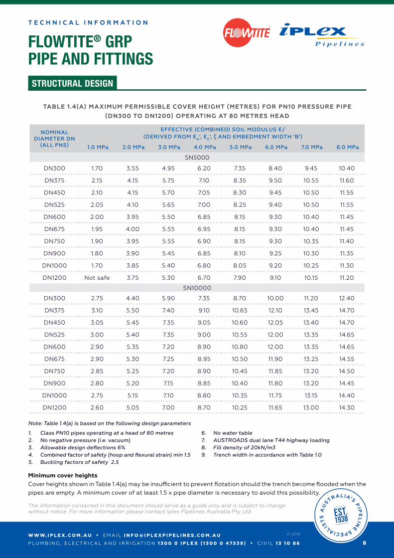
TABLE 1.4(A) MAXIMUM PERMISSIBLE COVER HEIGHT (METRES) FOR PN10 PRESSURE PIPE
(DN300 TO DN1200) OPERATING AT 80 METRES HEAD
NOMINAL DIAMETER DN
(ALL PNS)
EFFECTIVE (COMBINED) SOIL MODULUS E/(DERIVED FROM EN’, EE’, ξ AND EMBEDMENT WIDTH ‘B’)
1.0 MPa 2.0 MPa 3.0 MPa 4.0 MPa 5.0 MPa 6.0 MPa 7.0 MPa 8.0 MPa
SN5000
DN300 1.70 3.55 4.95 6.20 7.35 8.40 9.45 10.40
DN375 2.15 4.15 5.75 7.10 8.35 9.50 10.55 11.60
DN450 2.10 4.15 5.70 7.05 8.30 9.45 10.50 11.55
DN525 2.05 4.10 5.65 7.00 8.25 9.40 10.50 11.55
DN600 2.00 3.95 5.50 6.85 8.15 9.30 10.40 11.45
DN675 1.95 4.00 5.55 6.95 8.15 9.30 10.40 11.45
DN750 1.90 3.95 5.55 6.90 8.15 9.30 10.35 11.40
DN900 1.80 3.90 5.45 6.85 8.10 9.25 10.30 11.35
DN1000 1.70 3.85 5.40 6.80 8.05 9.20 10.25 11.30
DN1200 Not safe 3.75 5.30 6.70 7.90 9.10 10.15 11.20
SN10000
DN300 2.75 4.40 5.90 7.35 8.70 10.00 11.20 12.40
DN375 3.10 5.50 7.40 9.10 10.65 12.10 13.45 14.70
DN450 3.05 5.45 7.35 9.05 10.60 12.05 13.40 14.70
DN525 3.00 5.40 7.35 9.00 10.55 12.00 13.35 14.65
DN600 2.90 5.35 7.20 8.90 10.80 12.00 13.35 14.65
DN675 2.90 5.30 7.25 8.95 10.50 11.90 13.25 14.55
DN750 2.85 5.25 7.20 8.90 10.45 11.85 13.20 14.50
DN900 2.80 5.20 7.15 8.85 10.40 11.80 13.20 14.45
DN1000 2.75 5.15 7.10 8.80 10.35 11.75 13.15 14.40
DN1200 2.60 5.05 7.00 8.70 10.25 11.65 13.00 14.30
1. Class PN10 pipes operating at a head of 80 metres2. No negative pressure (i.e. vacuum)3. Allowable design deflections 6%4. Combined factor of safety (hoop and flexural strain) min 1.55. Buckling factors of safety 2.5
6. No water table7. AUSTROADS dual lane T44 highway loading8. Fill density of 20kN/m39. Trench width in accordance with Table 1.0
Note: Table 1.4(a) is based on the following design parameters
Minimum cover heights Cover heights shown in Table 1.4(a) may be insufficient to prevent flotation should the trench become flooded when the pipes are empty. A minimum cover of at least 1.5 x pipe diameter is necessary to avoid this possibility.
W W W. I P L E X . C O M . A U • E M A I L I N F O @ I P L E X P I P E L I N E S . C O M . A U
P L U M B I N G , E L E C T R I C A L A N D I R R I G AT I O N 1 3 0 0 0 I P L E X ( 1 3 0 0 0 4 7 5 3 9 ) • C I V I L 1 3 1 0 8 6
The information contained in this document should serve as a guide only and is subject to change without notice. For more information please contact Iplex Pipelines Australia Pty Ltd.
9
V1 2019
FLOWTITE® GRPPIPE AND FITTINGS
T E C H N I C A L I N F O R M A T I O N
STRUCTURAL DESIGN
R
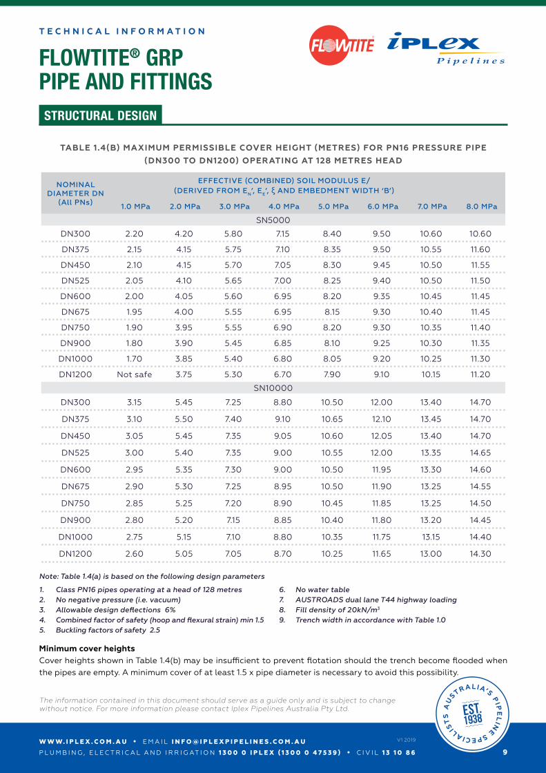
TABLE 1.4(B) MAXIMUM PERMISSIBLE COVER HEIGHT (METRES) FOR PN16 PRESSURE PIPE
(DN300 TO DN1200) OPERATING AT 128 METRES HEAD
NOMINAL DIAMETER DN
(All PNs)
EFFECTIVE (COMBINED) SOIL MODULUS E/(DERIVED FROM EN’, EE’, ξ AND EMBEDMENT WIDTH ‘B’)
1.0 MPa 2.0 MPa 3.0 MPa 4.0 MPa 5.0 MPa 6.0 MPa 7.0 MPa 8.0 MPa
SN5000
DN300 2.20 4.20 5.80 7.15 8.40 9.50 10.60 10.60
DN375 2.15 4.15 5.75 7.10 8.35 9.50 10.55 11.60
DN450 2.10 4.15 5.70 7.05 8.30 9.45 10.50 11.55
DN525 2.05 4.10 5.65 7.00 8.25 9.40 10.50 11.50
DN600 2.00 4.05 5.60 6.95 8.20 9.35 10.45 11.45
DN675 1.95 4.00 5.55 6.95 8.15 9.30 10.40 11.45
DN750 1.90 3.95 5.55 6.90 8.20 9.30 10.35 11.40
DN900 1.80 3.90 5.45 6.85 8.10 9.25 10.30 11.35
DN1000 1.70 3.85 5.40 6.80 8.05 9.20 10.25 11.30
DN1200 Not safe 3.75 5.30 6.70 7.90 9.10 10.15 11.20
SN10000
DN300 3.15 5.45 7.25 8.80 10.50 12.00 13.40 14.70
DN375 3.10 5.50 7.40 9.10 10.65 12.10 13.45 14.70
DN450 3.05 5.45 7.35 9.05 10.60 12.05 13.40 14.70
DN525 3.00 5.40 7.35 9.00 10.55 12.00 13.35 14.65
DN600 2.95 5.35 7.30 9.00 10.50 11.95 13.30 14.60
DN675 2.90 5.30 7.25 8.95 10.50 11.90 13.25 14.55
DN750 2.85 5.25 7.20 8.90 10.45 11.85 13.25 14.50
DN900 2.80 5.20 7.15 8.85 10.40 11.80 13.20 14.45
DN1000 2.75 5.15 7.10 8.80 10.35 11.75 13.15 14.40
DN1200 2.60 5.05 7.05 8.70 10.25 11.65 13.00 14.30
1. Class PN16 pipes operating at a head of 128 metres2. No negative pressure (i.e. vacuum)3. Allowable design deflections 6%4. Combined factor of safety (hoop and flexural strain) min 1.55. Buckling factors of safety 2.5
6. No water table7. AUSTROADS dual lane T44 highway loading8. Fill density of 20kN/m3
9. Trench width in accordance with Table 1.0
Note: Table 1.4(a) is based on the following design parameters
Minimum cover heights Cover heights shown in Table 1.4(b) may be insufficient to prevent flotation should the trench become flooded when the pipes are empty. A minimum cover of at least 1.5 x pipe diameter is necessary to avoid this possibility.
W W W. I P L E X . C O M . A U • E M A I L I N F O @ I P L E X P I P E L I N E S . C O M . A U
P L U M B I N G , E L E C T R I C A L A N D I R R I G AT I O N 1 3 0 0 0 I P L E X ( 1 3 0 0 0 4 7 5 3 9 ) • C I V I L 1 3 1 0 8 6
The information contained in this document should serve as a guide only and is subject to change without notice. For more information please contact Iplex Pipelines Australia Pty Ltd.
1 0
V1 2019
FLOWTITE® GRPPIPE AND FITTINGS
T E C H N I C A L I N F O R M A T I O N
STRUCTURAL DESIGN
R
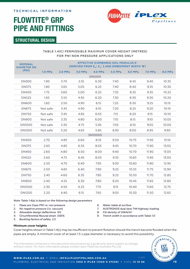
TABLE 1.4(C) PERMISSIBLE MAXIMUM COVER HEIGHT (METRES)
FOR PN1 NON PRESSURE APPLICATIONS ONLY
NOMINAL DIAMETER DN
(PN1)
EFFECTIVE (COMBINED) SOIL MODULUS E/
(DERIVED FROM EN’, EE’, ξ AND EMBEDMENT WIDTH ‘B’)
1.0 MPa 2.0 MPa 3.0 MPa 4.0 MPa 5.0 MPa 6.0 MPa 7.0 MPa 8.0 MPa
SN5000
DN300 1.90 3.70 5.10 6.30 7.40 8.45 9.40 10.35
DN375 1.80 3.65 5.05 6.25 7.40 8.40 9.35 10.30
DN450 1.75 3.60 5.00 6.25 7.35 8.35 9.35 10.25
DN525 1.65 3.55 4.95 6.20 7.30 8.30 9.30 10.20
DN600 1.60 3.50 4.90 6.15 7.25 8.30 9.25 10.15
DN675 Not safe 3.45 4.90 6.10 7.20 8.25 9.20 10.10
DN750 Not safe 3.45 4.85 6.05 7.15 8.20 9.15 10.10
DN900 Not safe 3.35 4.80 6.00 7.10 8.15 9.10 10.05
DN1000 Not safe 3.30 4.75 5.95 7.05 8.10 9.05 10.00
DN1200 Not safe 3.20 4.65 5.85 6.95 8.00 8.95 9.90
SN10000
DN300 2.70 4.85 6.60 8.10 9.50 10.75 11.95 13.10
DN375 2.65 4.85 6.55 8.05 9.45 10.70 11.90 13.05
DN450 2.60 4.80 6.50 8.00 9.40 10.70 11.90 13.05
DN525 2.60 4.75 6.45 8.05 9.35 10.65 11.85 13.00
DN600 2.50 4.70 6.40 7.95 9.30 10.60 11.80 12.95
DN675 2.50 4.65 6.40 7.90 9.25 10.55 11.75 12.90
DN750 2.45 4.60 6.35 7.85 9.25 10.50 11.70 12.85
DN900 2.40 4.55 6.30 7.80 9.20 10.45 11.65 12.80
DN1000 2.30 4.50 6.25 7.75 9.15 10.40 11.60 12.75
DN1200 2.20 4.40 6.15 7.65 9.05 10.30 11.50 12.65
1. Pipes are Class PN1 i.e. non pressure2. No negative pressure (i.e. vacuum)3. Allowable design deflections 6%4. Circumferential flexural strain 0.65%5. Buckling factors of safety 2.5
6. Water table at surface7. AUSTROADS dual lane T44 highway loading8. Fill density of 20kN/m3
9. Trench width in accordance with Table 1.0
Note: Table 1.4(a) is based on the following design parameters
Minimum cover heights Cover heights shown in Table 1.4(c) may be insufficient to prevent flotation should the trench become flooded when the pipes are empty. A minimum cover of at least 1.5 x pipe diameter is necessary to avoid this possibility.
W W W. I P L E X . C O M . A U • E M A I L I N F O @ I P L E X P I P E L I N E S . C O M . A U
P L U M B I N G , E L E C T R I C A L A N D I R R I G AT I O N 1 3 0 0 0 I P L E X ( 1 3 0 0 0 4 7 5 3 9 ) • C I V I L 1 3 1 0 8 6
The information contained in this document should serve as a guide only and is subject to change without notice. For more information please contact Iplex Pipelines Australia Pty Ltd.
1 1
V1 2019
FLOWTITE® GRPPIPE AND FITTINGS
T E C H N I C A L I N F O R M A T I O N
STRUCTURAL DESIGN
R
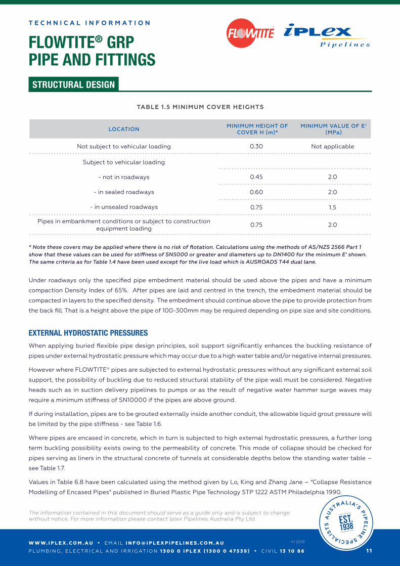
TABLE 1.5 MINIMUM COVER HEIGHTS
LOCATIONMINIMUM HEIGHT OF
COVER H (m)*MINIMUM VALUE OF E/
(MPa)
Not subject to vehicular loading 0.30 Not applicable
Subject to vehicular loading
- not in roadways
- in sealed roadways
- in unsealed roadways
0.45 2.0
0.60 2.0
0.75 1.5
Pipes in embankment conditions or subject to construction equipment loading
0.75 2.0
* Note these covers may be applied where there is no risk of flotation. Calculations using the methods of AS/NZS 2566 Part 1 show that these values can be used for stiffness of SN5000 or greater and diameters up to DN1400 for the minimum E’ shown. The same criteria as for Table 1.4 have been used except for the live load which is AUSROADS T44 dual lane.
Under roadways only the specified pipe embedment material should be used above the pipes and have a minimum
compaction Density Index of 65%. After pipes are laid and centred in the trench, the embedment material should be
compacted in layers to the specified density. The embedment should continue above the pipe to provide protection from
the back fill. That is a height above the pipe of 100-300mm may be required depending on pipe size and site conditions.
EXTERNAL HYDROSTATIC PRESSURES
When applying buried flexible pipe design principles, soil support significantly enhances the buckling resistance of
pipes under external hydrostatic pressure which may occur due to a high water table and/or negative internal pressures.
However where FLOWTITE® pipes are subjected to external hydrostatic pressures without any significant external soil
support, the possibility of buckling due to reduced structural stability of the pipe wall must be considered. Negative
heads such as in suction delivery pipelines to pumps or as the result of negative water hammer surge waves may
require a minimum stiffness of SN10000 if the pipes are above ground.
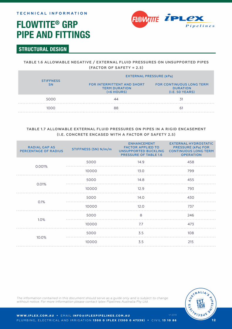
If during installation, pipes are to be grouted externally inside another conduit, the allowable liquid grout pressure will
be limited by the pipe stiffness - see Table 1.6.
Where pipes are encased in concrete, which in turn is subjected to high external hydrostatic pressures, a further long
term buckling possibility exists owing to the permeability of concrete. This mode of collapse should be checked for
pipes serving as liners in the structural concrete of tunnels at considerable depths below the standing water table –
see Table 1.7.
Values in Table 6.8 have been calculated using the method given by Lo, King and Zhang Jane – “Collapse Resistance
Modelling of Encased Pipes” published in Buried Plastic Pipe Technology STP 1222 ASTM Philadelphia 1990.
W W W. I P L E X . C O M . A U • E M A I L I N F O @ I P L E X P I P E L I N E S . C O M . A U
P L U M B I N G , E L E C T R I C A L A N D I R R I G AT I O N 1 3 0 0 0 I P L E X ( 1 3 0 0 0 4 7 5 3 9 ) • C I V I L 1 3 1 0 8 6
The information contained in this document should serve as a guide only and is subject to change without notice. For more information please contact Iplex Pipelines Australia Pty Ltd.
1 2
V1 2019
FLOWTITE® GRPPIPE AND FITTINGS
T E C H N I C A L I N F O R M A T I O N
STRUCTURAL DESIGN
R
TABLE 1.6 ALLOWABLE NEGATIVE / EXTERNAL FLUID PRESSURES ON UNSUPPORTED PIPES
(FACTOR OF SAFETY = 2.5)
STIFFNESSSN
EXTERNAL PRESSURE (kPa)
FOR INTERMITTENT AND SHORT TERM DURATION
(<6 HOURS)
FOR CONTINUOUS LONG TERM DURATION
(I.E. 50 YEARS)
5000 44 31
1000 88 61
TABLE 1.7 ALLOWABLE EXTERNAL FLUID PRESSURES ON PIPES IN A RIGID ENCASEMENT
(I.E. CONCRETE ENCASED WITH A FACTOR OF SAFETY 2.5)
RADIAL GAP AS PERCENTAGE OF RADIUS
STIFFNESS (SN) N/m/m
ENHANCEMENT FACTOR APPLIED TO
UNSUPPORTED BUCKLING PRESSURE OF TABLE 1.6
EXTERNAL HYDROSTATIC PRESSURE (kPa) FOR
CONTINUOUS LONG TERM OPERATION
0.001%5000 14.9 458
10000 13.0 799
0.01%5000 14.8 455
10000 12.9 793
0.1%5000 14.0 430
10000 12.0 737
1.0%5000 8 246
10000 7.7 473
10.0%5000 3.5 108
10000 3.5 215
W W W. I P L E X . C O M . A U • E M A I L I N F O @ I P L E X P I P E L I N E S . C O M . A U
P L U M B I N G , E L E C T R I C A L A N D I R R I G AT I O N 1 3 0 0 0 I P L E X ( 1 3 0 0 0 4 7 5 3 9 ) • C I V I L 1 3 1 0 8 6
The information contained in this document should serve as a guide only and is subject to change without notice. For more information please contact Iplex Pipelines Australia Pty Ltd.
1 3
V1 2019
FLOWTITE® GRPPIPE AND FITTINGS
T E C H N I C A L I N F O R M A T I O N
STRUCTURAL DESIGN
R
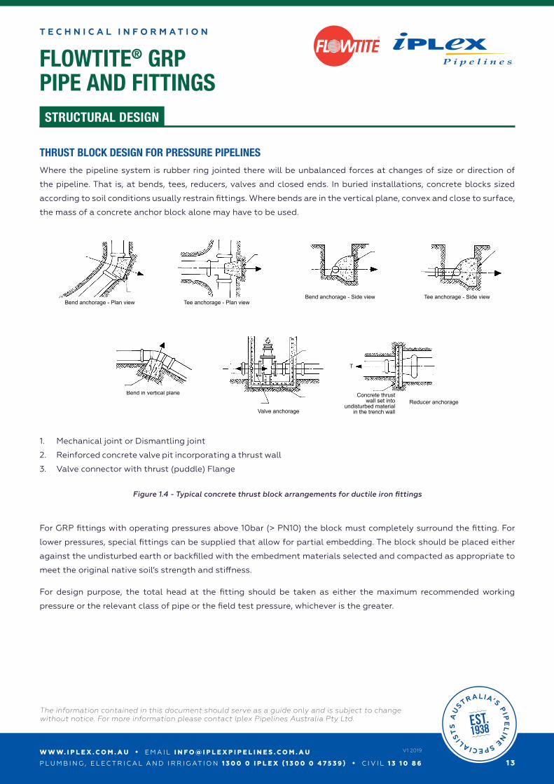
THRUST BLOCK DESIGN FOR PRESSURE PIPELINES
Where the pipeline system is rubber ring jointed there will be unbalanced forces at changes of size or direction of
the pipeline. That is, at bends, tees, reducers, valves and closed ends. In buried installations, concrete blocks sized
according to soil conditions usually restrain fittings. Where bends are in the vertical plane, convex and close to surface,
the mass of a concrete anchor block alone may have to be used.
Bend anchorage - Plan view Tee anchorage - Plan view
Bend anchorage - Side view Tee anchorage - Side view
T
Bend in vertical plane
Valve anchorage
TT
1
23
T
Reducer anchorageConcrete thrust
wall set intoundisturbed material
in the trench wall
1 - Mechanical joint or Dismantling joint2 - Reinforced concrete valve pit incorporating a thrust wall3 - Valve connector with thrust (puddle) Flange
1. Mechanical joint or Dismantling joint
2. Reinforced concrete valve pit incorporating a thrust wall
3. Valve connector with thrust (puddle) Flange
For GRP fittings with operating pressures above 10bar (> PN10) the block must completely surround the fitting. For
lower pressures, special fittings can be supplied that allow for partial embedding. The block should be placed either
against the undisturbed earth or backfilled with the embedment materials selected and compacted as appropriate to
meet the original native soil’s strength and stiffness.
For design purpose, the total head at the fitting should be taken as either the maximum recommended working
pressure or the relevant class of pipe or the field test pressure, whichever is the greater.
Figure 1.4 - Typical concrete thrust block arrangements for ductile iron fittings
W W W. I P L E X . C O M . A U • E M A I L I N F O @ I P L E X P I P E L I N E S . C O M . A U
P L U M B I N G , E L E C T R I C A L A N D I R R I G AT I O N 1 3 0 0 0 I P L E X ( 1 3 0 0 0 4 7 5 3 9 ) • C I V I L 1 3 1 0 8 6
The information contained in this document should serve as a guide only and is subject to change without notice. For more information please contact Iplex Pipelines Australia Pty Ltd.
1 4
V1 2019
FLOWTITE® GRPPIPE AND FITTINGS
T E C H N I C A L I N F O R M A T I O N
STRUCTURAL DESIGN
R
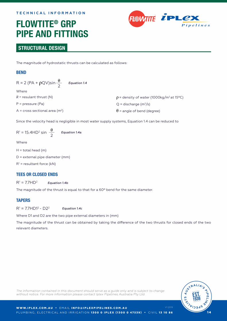
The magnitude of hydrostatic thrusts can be calculated as follows:
BEND
Where
R = resulant thrust (N)
P = pressure (Pa)
A = cross sectional area (m2)
ρ = density of water (1000kg/m3 at 15ºC)
Q = discharge (m3/s)
θ = angle of bend (degree)
Since the velocity head is negligible in most water supply systems, Equation 1.4 can be reduced to
Where
H = total head (m)
D = external pipe diameter (mm)
R1 = resultant force (kN)
TEES OR CLOSED ENDS
R1 = 7.7HD2
The magnitude of the thrust is equal to that for a 60º bend for the same diameter.
TAPERS
R1 = 7.7HD12 - D22
Where D1 and D2 are the two pipe external diameters in (mm)
The magnitude of the thrust can be obtained by taking the difference of the two thrusts for closed ends of the two
relevant diameters.
R = 2 (PA + ρQV)sin θ2
R1 = 15.4HD2 sin θ2
Equation 1.4
Equation 1.4a
Equation 1.4b
Equation 1.4c
FLOWTITE® GRPPIPE AND FITTINGS
T E C H N I C A L I N F O R M A T I O N
STRUCTURAL DESIGN
R
W W W. I P L E X . C O M . A U • E M A I L I N F O @ I P L E X P I P E L I N E S . C O M . A U
P L U M B I N G , E L E C T R I C A L A N D I R R I G AT I O N 1 3 0 0 0 I P L E X ( 1 3 0 0 0 4 7 5 3 9 ) • C I V I L 1 3 1 0 8 6
The information contained in this document should serve as a guide only and is subject to change without notice. For more information please contact Iplex Pipelines Australia Pty Ltd.
1 5
V1 2019
Section A-A
Tee
A
A
Section A-A
Tee
A
AReducer
Band 31-60º
Bend up to 30º
Band 61-90º
A
A
A
A
A
A
A
A
Reducer
Band 31-60º
Bend up to 30º
Band 61-90º
A
A
A
A
A
A
A
A
Reducer
Band 31-60º
Bend up to 30º
Band 61-90º
A
A
A
A
A
A
A
A
Reducer
Band 31-60º
Bend up to 30º
Band 61-90º
A
A
A
A
A
A
A
A
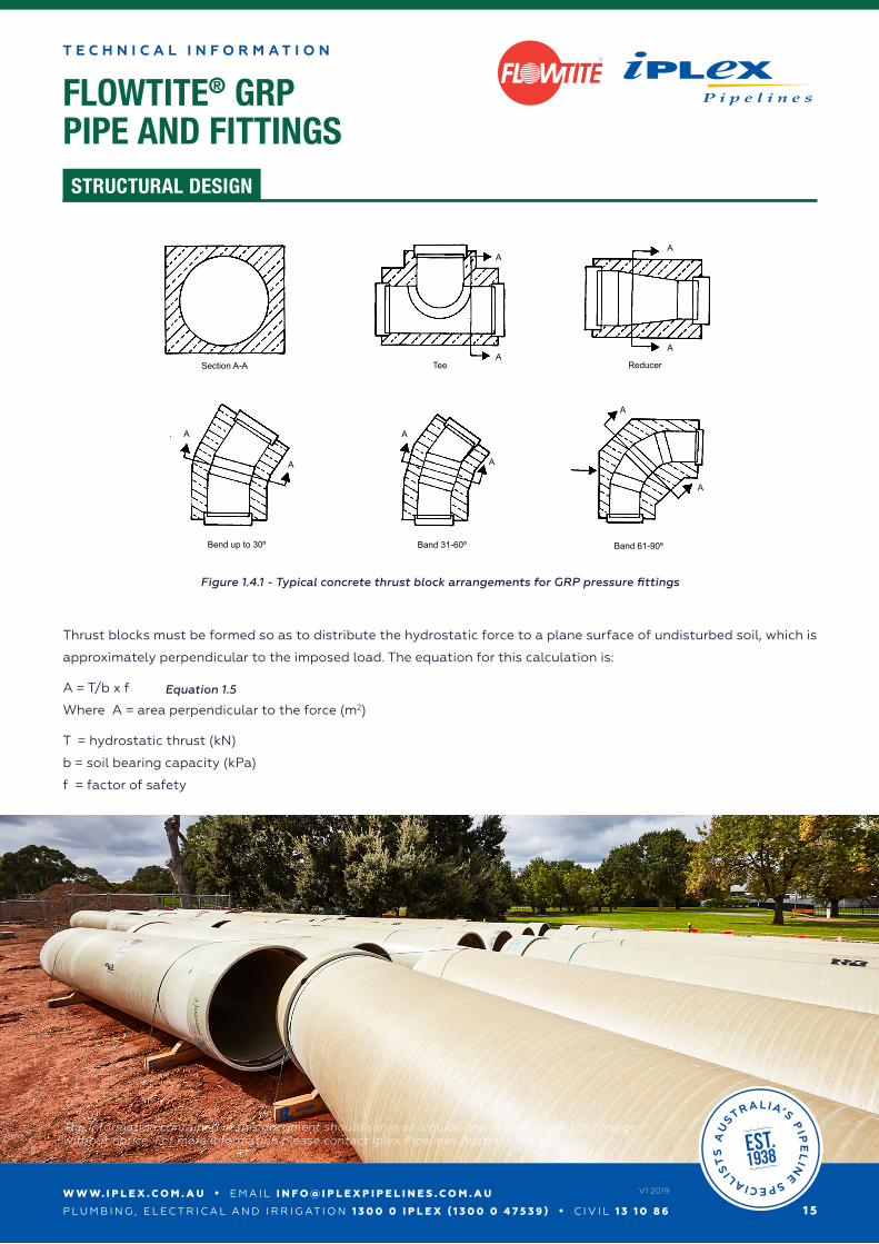
Thrust blocks must be formed so as to distribute the hydrostatic force to a plane surface of undisturbed soil, which is
approximately perpendicular to the imposed load. The equation for this calculation is:
A = T/b x f
Where A = area perpendicular to the force (m2)
T = hydrostatic thrust (kN)
b = soil bearing capacity (kPa)
f = factor of safety
Figure 1.4.1 - Typical concrete thrust block arrangements for GRP pressure fittings
Equation 1.5
W W W. I P L E X . C O M . A U • E M A I L I N F O @ I P L E X P I P E L I N E S . C O M . A U
P L U M B I N G , E L E C T R I C A L A N D I R R I G AT I O N 1 3 0 0 0 I P L E X ( 1 3 0 0 0 4 7 5 3 9 ) • C I V I L 1 3 1 0 8 6
The information contained in this document should serve as a guide only and is subject to change without notice. For more information please contact Iplex Pipelines Australia Pty Ltd.
1 6
V1 2019
FLOWTITE® GRPPIPE AND FITTINGS
T E C H N I C A L I N F O R M A T I O N
STRUCTURAL DESIGN
R
EXAMPLE
Problem
A DN750 PN10 SN5000 pipe laid at a cover height of 1000mm will be subjected to an internal pressure of 1100kPa during
the field testing of the pipeline. A design check is required for a thrust block to support a 90-degree Bend that has been
constructed against the undisturbed soil. The soils estimated to have a safe horizontal bearing capacity of 100kPa.
Solution
From Table 1.7; the thrust from a 90-degree bend under 100kPa pressure equals 75.78kN.
Therefore the outwards thrust along the axis symmetry of the bend at a test pressure of 1100kPa will be
T = 11 x 75.78 = 833.6kN.
To check the area of the concrete/soil interface perpendicular to the line of thrust use Equation 1.5
A = 833.6/100 x 1.1 = 9.17 square metres
Problem
A DN1200 x 1000 PN16 SN10000 Taper is to be installed in a pipeline. What is required for resisting the unbalanced
thrusts on this fitting assuming the maximum test / operating pressure is 1500kPa? The fitting will have a cover height
of 1200mm. The native soil has an estimated horizontal bearing capacity of 75kPa.
Solution
For an internal pressure of 1500kPa the axial thrust shown on Table 1.7 on the DN1200 “closed” end of the fitting will
be 118.63kN x 15 and on the DN1000 end will be 82.52kN x15. The difference between the two closed ends will be the
thrust to be supported by the thrust block i.e. 541.65kN.
Therefore the area of the thrust block at the concrete / native undisturbed soil interface perpendicular to the line of
thrust (i.e. parallel to the axis of the fitting - refer to Figure 1.4) can be calculated using Equation 1.5.
A = 542/75 x 1.1 = 7.95 square metres.
W W W. I P L E X . C O M . A U • E M A I L I N F O @ I P L E X P I P E L I N E S . C O M . A U
P L U M B I N G , E L E C T R I C A L A N D I R R I G AT I O N 1 3 0 0 0 I P L E X ( 1 3 0 0 0 4 7 5 3 9 ) • C I V I L 1 3 1 0 8 6
The information contained in this document should serve as a guide only and is subject to change without notice. For more information please contact Iplex Pipelines Australia Pty Ltd.
1 7
V1 2019
FLOWTITE® GRPPIPE AND FITTINGS
T E C H N I C A L I N F O R M A T I O N
STRUCTURAL DESIGN
R
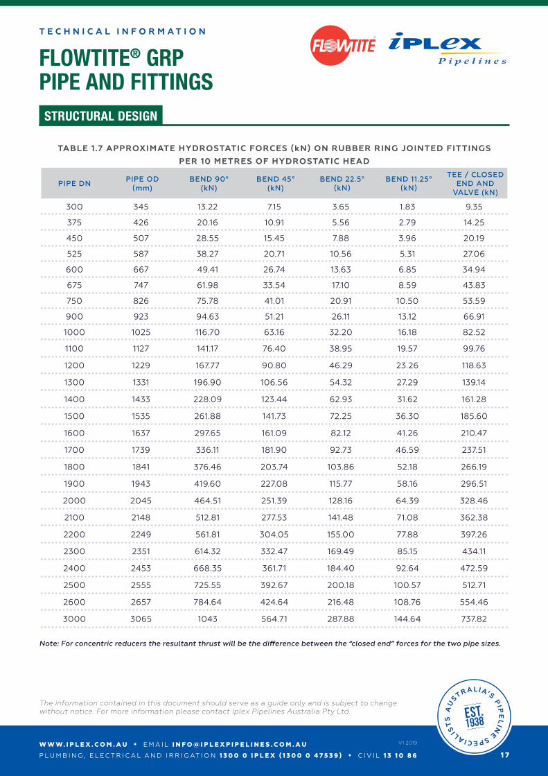
TABLE 1.7 APPROXIMATE HYDROSTATIC FORCES (kN) ON RUBBER RING JOINTED FITTINGS
PER 10 METRES OF HYDROSTATIC HEAD
PIPE DNPIPE OD
(mm)BEND 90°
(kN)BEND 45°
(kN)BEND 22.5°
(kN)BEND 11.25°
(kN)
TEE / CLOSED END AND
VALVE (kN)
300 345 13.22 7.15 3.65 1.83 9.35
375 426 20.16 10.91 5.56 2.79 14.25
450 507 28.55 15.45 7.88 3.96 20.19
525 587 38.27 20.71 10.56 5.31 27.06
600 667 49.41 26.74 13.63 6.85 34.94
675 747 61.98 33.54 17.10 8.59 43.83
750 826 75.78 41.01 20.91 10.50 53.59
900 923 94.63 51.21 26.11 13.12 66.91
1000 1025 116.70 63.16 32.20 16.18 82.52
1100 1127 141.17 76.40 38.95 19.57 99.76
1200 1229 167.77 90.80 46.29 23.26 118.63
1300 1331 196.90 106.56 54.32 27.29 139.14
1400 1433 228.09 123.44 62.93 31.62 161.28
1500 1535 261.88 141.73 72.25 36.30 185.60
1600 1637 297.65 161.09 82.12 41.26 210.47
1700 1739 336.11 181.90 92.73 46.59 237.51
1800 1841 376.46 203.74 103.86 52.18 266.19
1900 1943 419.60 227.08 115.77 58.16 296.51
2000 2045 464.51 251.39 128.16 64.39 328.46
2100 2148 512.81 277.53 141.48 71.08 362.38
2200 2249 561.81 304.05 155.00 77.88 397.26
2300 2351 614.32 332.47 169.49 85.15 434.11
2400 2453 668.35 361.71 184.40 92.64 472.59
2500 2555 725.55 392.67 200.18 100.57 512.71
2600 2657 784.64 424.64 216.48 108.76 554.46
3000 3065 1043 564.71 287.88 144.64 737.82
Note: For concentric reducers the resultant thrust will be the difference between the “closed end” forces for the two pipe sizes.
W W W. I P L E X . C O M . A U • E M A I L I N F O @ I P L E X P I P E L I N E S . C O M . A U
P L U M B I N G , E L E C T R I C A L A N D I R R I G AT I O N 1 3 0 0 0 I P L E X ( 1 3 0 0 0 4 7 5 3 9 ) • C I V I L 1 3 1 0 8 6
The information contained in this document should serve as a guide only and is subject to change without notice. For more information please contact Iplex Pipelines Australia Pty Ltd.
1 8
V1 2019
FLOWTITE® GRPPIPE AND FITTINGS
T E C H N I C A L I N F O R M A T I O N
STRUCTURAL DESIGN
R
Figure 6.8 – Typical valve restraint for direct buried socketed valves (Illustration only, not to scale)
Flow (Thrust in one
direction)
Flowtitecoupling
‘Rocker pipe’
Thrust in onedirection.
Locate thrustagainst socket
Thrust in bothdirections. Use puddle flange
Steel or DIflange x socketconnector
Flange gate valve
Thrust block to extend into side walls
max. larger of 2m or 2 x DNmin. larger of 1m or 1 x DN
Thrust areabase and walls
Figure 6.7 – Typical valve restraint for direct buried flanged valves (Illustration only, not to scale)
‘Rocker pipe’
Flowtitecoupling
Thrust areabase and walls
max. larger of 2m or 2 x DNmin. larger of 1m or 1 x DN
Thrust block to extendinto side walls
max. larger of 2m or 2 x DNmin. larger of 1m or 1 x DN
‘Rocker pipe’
Flowtitecoupling
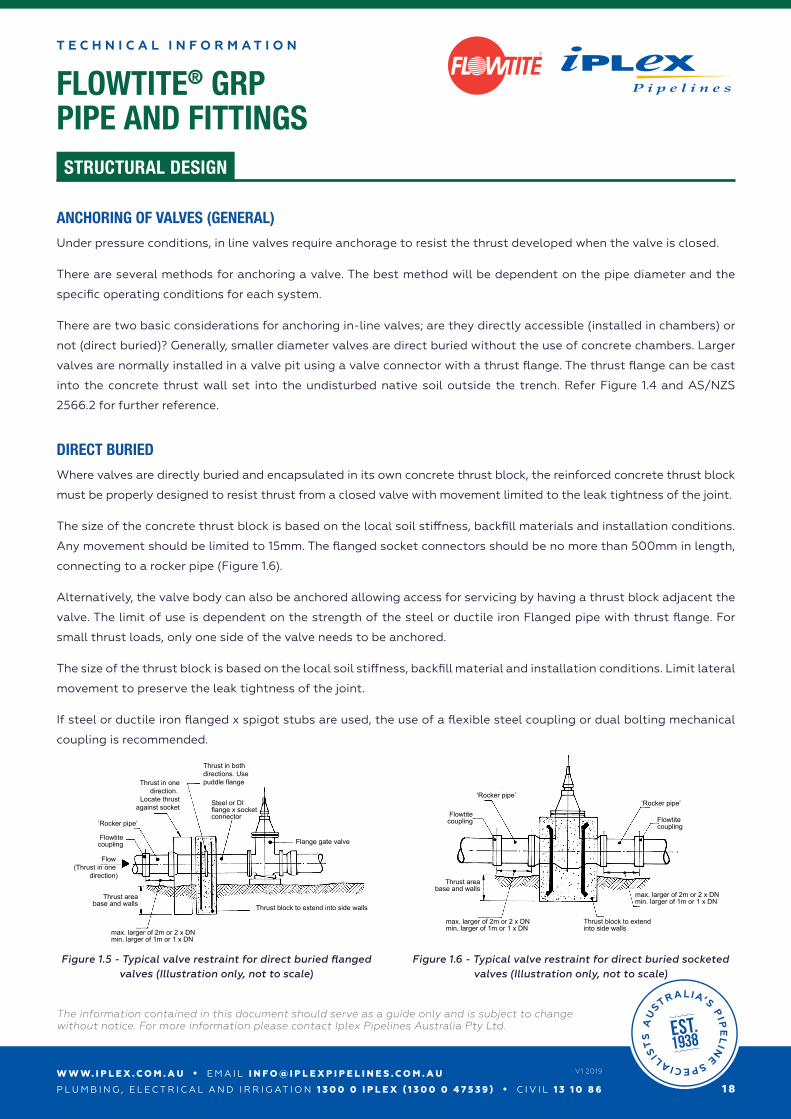
ANCHORING OF VALVES (GENERAL)
Under pressure conditions, in line valves require anchorage to resist the thrust developed when the valve is closed.
There are several methods for anchoring a valve. The best method will be dependent on the pipe diameter and the
specific operating conditions for each system.
There are two basic considerations for anchoring in-line valves; are they directly accessible (installed in chambers) or
not (direct buried)? Generally, smaller diameter valves are direct buried without the use of concrete chambers. Larger
valves are normally installed in a valve pit using a valve connector with a thrust flange. The thrust flange can be cast
into the concrete thrust wall set into the undisturbed native soil outside the trench. Refer Figure 1.4 and AS/NZS
2566.2 for further reference.
DIRECT BURIED
Where valves are directly buried and encapsulated in its own concrete thrust block, the reinforced concrete thrust block
must be properly designed to resist thrust from a closed valve with movement limited to the leak tightness of the joint.
The size of the concrete thrust block is based on the local soil stiffness, backfill materials and installation conditions.
Any movement should be limited to 15mm. The flanged socket connectors should be no more than 500mm in length,
connecting to a rocker pipe (Figure 1.6).
Alternatively, the valve body can also be anchored allowing access for servicing by having a thrust block adjacent the
valve. The limit of use is dependent on the strength of the steel or ductile iron Flanged pipe with thrust flange. For
small thrust loads, only one side of the valve needs to be anchored.
The size of the thrust block is based on the local soil stiffness, backfill material and installation conditions. Limit lateral
movement to preserve the leak tightness of the joint.
If steel or ductile iron flanged x spigot stubs are used, the use of a flexible steel coupling or dual bolting mechanical
coupling is recommended.
Figure 1.5 - Typical valve restraint for direct buried flanged valves (Illustration only, not to scale)
Figure 1.6 - Typical valve restraint for direct buried socketed valves (Illustration only, not to scale)
W W W. I P L E X . C O M . A U • E M A I L I N F O @ I P L E X P I P E L I N E S . C O M . A U
P L U M B I N G , E L E C T R I C A L A N D I R R I G AT I O N 1 3 0 0 0 I P L E X ( 1 3 0 0 0 4 7 5 3 9 ) • C I V I L 1 3 1 0 8 6
The information contained in this document should serve as a guide only and is subject to change without notice. For more information please contact Iplex Pipelines Australia Pty Ltd.
1 9
V1 2019
FLOWTITE® GRPPIPE AND FITTINGS
T E C H N I C A L I N F O R M A T I O N
STRUCTURAL DESIGN
R
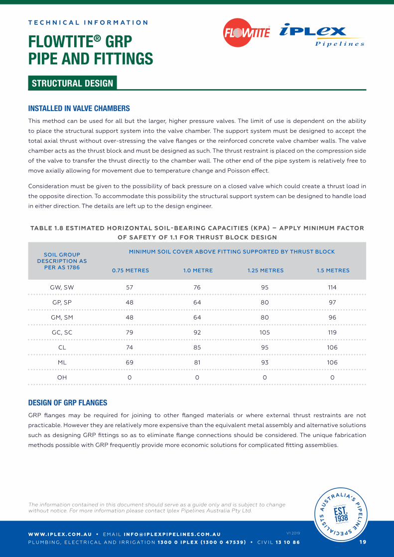
INSTALLED IN VALVE CHAMBERS
This method can be used for all but the larger, higher pressure valves. The limit of use is dependent on the ability
to place the structural support system into the valve chamber. The support system must be designed to accept the
total axial thrust without over-stressing the valve flanges or the reinforced concrete valve chamber walls. The valve
chamber acts as the thrust block and must be designed as such. The thrust restraint is placed on the compression side
of the valve to transfer the thrust directly to the chamber wall. The other end of the pipe system is relatively free to
move axially allowing for movement due to temperature change and Poisson effect.
Consideration must be given to the possibility of back pressure on a closed valve which could create a thrust load in
the opposite direction. To accommodate this possibility the structural support system can be designed to handle load
in either direction. The details are left up to the design engineer.
DESIGN OF GRP FLANGES
GRP flanges may be required for joining to other flanged materials or where external thrust restraints are not
practicable. However they are relatively more expensive than the equivalent metal assembly and alternative solutions
such as designing GRP fittings so as to eliminate flange connections should be considered. The unique fabrication
methods possible with GRP frequently provide more economic solutions for complicated fitting assemblies.
TABLE 1.8 ESTIMATED HORIZONTAL SOIL-BEARING CAPACITIES (KPA) – APPLY MINIMUM FACTOR
OF SAFETY OF 1.1 FOR THRUST BLOCK DESIGN
SOIL GROUP DESCRIPTION AS
PER AS 1786
MINIMUM SOIL COVER ABOVE FITTING SUPPORTED BY THRUST BLOCK
0.75 METRES 1.0 METRE 1.25 METRES 1.5 METRES
GW, SW 57 76 95 114
GP, SP 48 64 80 97
GM, SM 48 64 80 96
GC, SC 79 92 105 119
CL 74 85 95 106
ML 69 81 93 106
OH 0 0 0 0
W W W. I P L E X . C O M . A U • E M A I L I N F O @ I P L E X P I P E L I N E S . C O M . A U
P L U M B I N G , E L E C T R I C A L A N D I R R I G AT I O N 1 3 0 0 0 I P L E X ( 1 3 0 0 0 4 7 5 3 9 ) • C I V I L 1 3 1 0 8 6
The information contained in this document should serve as a guide only and is subject to change without notice. For more information please contact Iplex Pipelines Australia Pty Ltd.
2 0
V1 2019
FLOWTITE® GRPPIPE AND FITTINGS
T E C H N I C A L I N F O R M A T I O N
STRUCTURAL DESIGN
R
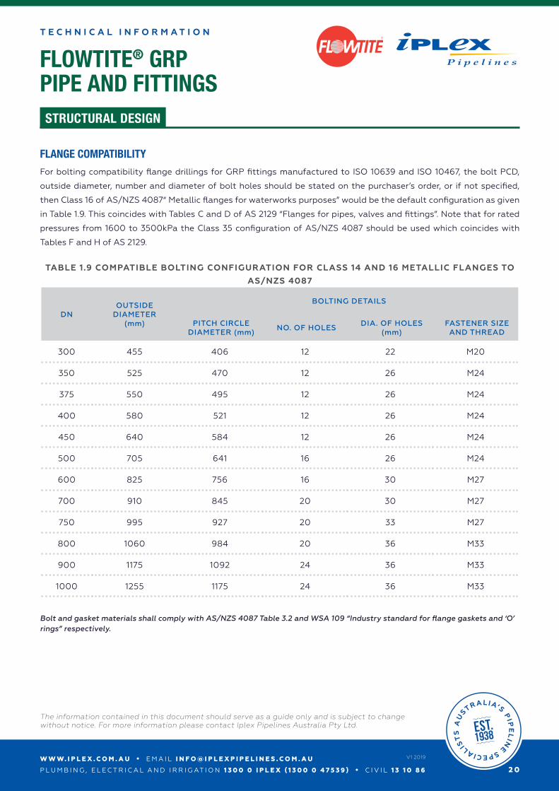
FLANGE COMPATIBILITY
For bolting compatibility flange drillings for GRP fittings manufactured to ISO 10639 and ISO 10467, the bolt PCD,
outside diameter, number and diameter of bolt holes should be stated on the purchaser’s order, or if not specified,
then Class 16 of AS/NZS 4087“ Metallic flanges for waterworks purposes” would be the default configuration as given
in Table 1.9. This coincides with Tables C and D of AS 2129 “Flanges for pipes, valves and fittings”. Note that for rated
pressures from 1600 to 3500kPa the Class 35 configuration of AS/NZS 4087 should be used which coincides with
Tables F and H of AS 2129.
TABLE 1.9 COMPATIBLE BOLTING CONFIGURATION FOR CLASS 14 AND 16 METALLIC FLANGES TO
AS/NZS 4087
DNOUTSIDE
DIAMETER(mm)
BOLTING DETAILS
PITCH CIRCLE DIAMETER (mm)
NO. OF HOLESDIA. OF HOLES
(mm)FASTENER SIZE
AND THREAD
300 455 406 12 22 M20
350 525 470 12 26 M24
375 550 495 12 26 M24
400 580 521 12 26 M24
450 640 584 12 26 M24
500 705 641 16 26 M24
600 825 756 16 30 M27
700 910 845 20 30 M27
750 995 927 20 33 M27
800 1060 984 20 36 M33
900 1175 1092 24 36 M33
1000 1255 1175 24 36 M33
Bolt and gasket materials shall comply with AS/NZS 4087 Table 3.2 and WSA 109 “Industry standard for flange gaskets and ‘O’ rings” respectively.
W W W. I P L E X . C O M . A U • E M A I L I N F O @ I P L E X P I P E L I N E S . C O M . A U
P L U M B I N G , E L E C T R I C A L A N D I R R I G AT I O N 1 3 0 0 0 I P L E X ( 1 3 0 0 0 4 7 5 3 9 ) • C I V I L 1 3 1 0 8 6
The information contained in this document should serve as a guide only and is subject to change without notice. For more information please contact Iplex Pipelines Australia Pty Ltd.
2 1
V1 2019
FLOWTITE® GRPPIPE AND FITTINGS
T E C H N I C A L I N F O R M A T I O N
STRUCTURAL DESIGN
R
GRP FLANGE CHARACTERISTICS
The jointing procedures for flanged connections including one or more GRP flanges as compared with all metal-flanged
joints are not significantly different. However Iplex recommends that the following points unique to GRP should be
observed.
a) Because GRP flanges are pressure rated (e.g. PN6, PN16, etc) in the same way as GRP pipes, the required rating
shall be specified by the purchaser. The flange thicknesses will vary accordingly and typically will be substantially
thicker than metallic flanges of similar pressure rating.
b) GRP flanges may be either;
1) Flat faced with a full faced gasket (includes flanges with concentric ribbing on the flange or gasket surface),
2) Flat faced with an “O” ring seal,
3) Stub flange with metal backing plate and a matching flat gasket.
“O” ring seals and groove dimensions shall comply with AS/NZS 4087 Appendix B.
c) For higher pressure/torque values, flat face flanges will require a full metal backing plate to avoid risk of crushing
the GRP under washers. Alternatively “O” ring seals may be used to reduce torques required at high pressures.
i.e. greater than PN12 for larger than DN500. For the maximum allowable torque values see Table 1.10.
d) Flat faced GRP flanges mated with raised face flanges require an insertion plate to support the GRP flange with
minimum thicknesses shown in Table 1.12. A second gasket and longer bolts will be required. (The nominated bolt
torques are unaffected)
e) GRP stub flanges (with steel backing plate) can be used with raised face flanges without an insertion plate.
The torque values of Table 1.10 apply.
f) Metal washers of similar material to the fasteners shall be used with all GRP flanges.
g) Fastener bearing surfaces on GRP flanges are machined all over or spot faced depending on size.
h) Appropriate bolt torques for GRP flange fasteners are listed in Table 1.10. These vary depending on the operating
and rated pressure of the flange system and values for intermediate pressures may be interpolated.
i) Flat gaskets 3 mm thick complying with WSA 109 for flanges rated up to PN16 shall be used within a hardness range
of 56 to 75 IRHD.
j) If the flange requires an “O” ring seal it shall comply with WSA 109 within hardness range 36 to 55 IRHD.
k) Grade 4.6 galvanised steel or Grade 316 property Class 50 stainless steel fasteners are recommended for GRP
flanges. Higher strength bolts are also acceptable i.e. Grade 8.8 galvanised steel and Grade 316 Class 80 stainless
steel.
W W W. I P L E X . C O M . A U • E M A I L I N F O @ I P L E X P I P E L I N E S . C O M . A U
P L U M B I N G , E L E C T R I C A L A N D I R R I G AT I O N 1 3 0 0 0 I P L E X ( 1 3 0 0 0 4 7 5 3 9 ) • C I V I L 1 3 1 0 8 6
The information contained in this document should serve as a guide only and is subject to change without notice. For more information please contact Iplex Pipelines Australia Pty Ltd.
2 2
V1 2019
FLOWTITE® GRPPIPE AND FITTINGS
T E C H N I C A L I N F O R M A T I O N
STRUCTURAL DESIGN
R
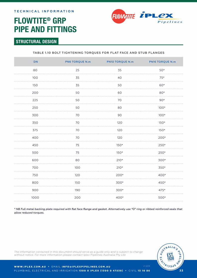
TABLE 1.10 BOLT TIGHTENING TORQUES FOR FLAT FACE AND STUB FLANGES
DN PN6 TORQUE N.m PN10 TORQUE N.m PN16 TORQUE N.m
80 25 35 50*
100 35 40 75*
150 35 50 60*
200 50 60 80*
225 50 70 90*
250 50 80 100*
300 70 90 100*
350 70 120 150*
375 70 120 150*
400 70 120 200*
450 75 150* 250*
500 75 150* 250*
600 80 210* 300*
700 100 210* 350*
750 120 200* 400*
800 150 300* 450*
900 190 300* 475*
1000 200 400* 500*
* NB Full metal backing plate required with flat face flange and gasket. Alternatively use “O” ring or ribbed reinforced seals that allow reduced torques.
FLOWTITE® GRPPIPE AND FITTINGS
T E C H N I C A L I N F O R M A T I O N
STRUCTURAL DESIGN
R
W W W. I P L E X . C O M . A U • E M A I L I N F O @ I P L E X P I P E L I N E S . C O M . A U
P L U M B I N G , E L E C T R I C A L A N D I R R I G AT I O N 1 3 0 0 0 I P L E X ( 1 3 0 0 0 4 7 5 3 9 ) • C I V I L 1 3 1 0 8 6
The information contained in this document should serve as a guide only and is subject to change without notice. For more information please contact Iplex Pipelines Australia Pty Ltd.
2 3
V1 2019
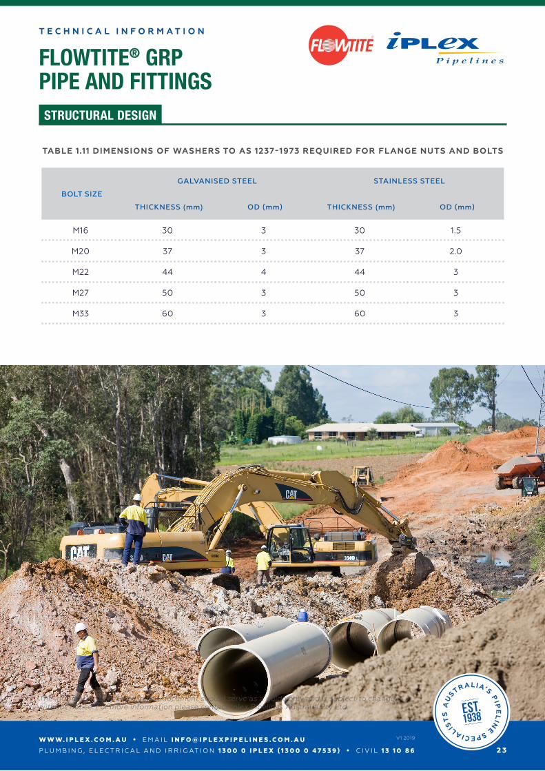
TABLE 1.11 DIMENSIONS OF WASHERS TO AS 1237-1973 REQUIRED FOR FLANGE NUTS AND BOLTS
BOLT SIZE
GALVANISED STEEL STAINLESS STEEL
THICKNESS (mm) OD (mm) THICKNESS (mm) OD (mm)
M16 30 3 30 1.5
M20 37 3 37 2.0
M22 44 4 44 3
M27 50 3 50 3
M33 60 3 60 3
W W W. I P L E X . C O M . A U • E M A I L I N F O @ I P L E X P I P E L I N E S . C O M . A U
P L U M B I N G , E L E C T R I C A L A N D I R R I G AT I O N 1 3 0 0 0 I P L E X ( 1 3 0 0 0 4 7 5 3 9 ) • C I V I L 1 3 1 0 8 6
The information contained in this document should serve as a guide only and is subject to change without notice. For more information please contact Iplex Pipelines Australia Pty Ltd.
2 4
V1 2019
FLOWTITE® GRPPIPE AND FITTINGS
T E C H N I C A L I N F O R M A T I O N
STRUCTURAL DESIGN
R
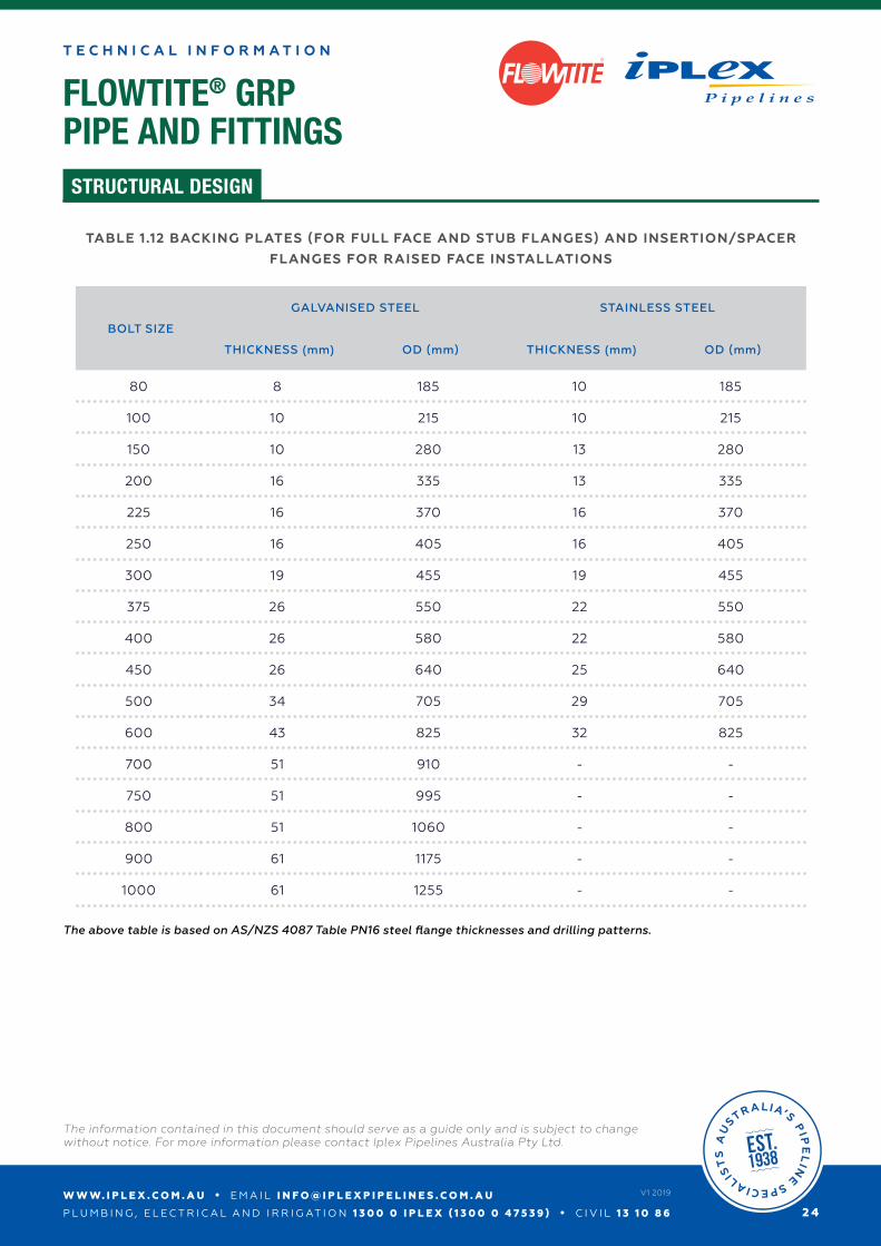
TABLE 1.12 BACKING PLATES (FOR FULL FACE AND STUB FLANGES) AND INSERTION/SPACER
FLANGES FOR RAISED FACE INSTALLATIONS
BOLT SIZE
GALVANISED STEEL STAINLESS STEEL
THICKNESS (mm) OD (mm) THICKNESS (mm) OD (mm)
80 8 185 10 185
100 10 215 10 215
150 10 280 13 280
200 16 335 13 335
225 16 370 16 370
250 16 405 16 405
300 19 455 19 455
375 26 550 22 550
400 26 580 22 580
450 26 640 25 640
500 34 705 29 705
600 43 825 32 825
700 51 910 - -
750 51 995 - -
800 51 1060 - -
900 61 1175 - -
1000 61 1255 - -
The above table is based on AS/NZS 4087 Table PN16 steel flange thicknesses and drilling patterns.


