Embed Size (px)
Citation preview

The multilayer advantage
Handbook 2015
multilayer pipe system
®
Index
Approval and registration 3Design of the pipes and quality assurance 4–5Insulated and un-insulated multilayer pipes 6–7Joining technology – press connection 8Joining technology – push connection 9Joining technology – screw connection 10 Compatibility of the screw fittings 11
Installation guidelines• Installation of the screw fitting 12–13• Installation of the press fitting 14–15• Development of the PROtec fitting 16• Installation of push fitting 17• 5 seconds to make a safe joint 18–19• Concealed manifold housing 20• Surface mounted manifold housing 21
Radiator heating• Types of heating systems 22• Heat insulation for radiator and hotwater systems 23• Pipe sizing and pressure loss for heating systems 24• Pressure testing for heating systems 25
Drinking water installations• References to ÖNORM B 5019 26• Methods of installation for drinking water systems 27• Pipe sizing and pressure loss: EN 806-3 28–29• Guidelines for pipe sizing: DIN 1988-300 30–31• Pipe sizing: DIN 1988-300 32–33• Pipe sizing and pressure loss for hot/cold water systems 34• Heat insulation for cold water systems 35 • Pressure testing for hot and cold water systems 36–39 • Heat expansion and force of expansion 40–42• Rinsing the piping and sound insulation 43Important installation guidelines 44–45• Product range 46–69 • Representative offices and headquarters 70–71
Please read the information contained in this handbook before you use KELOX for the first time, especially the information about how to make the joints.
32
m u lt i l ay e r p i p e s y s t e m
®
m u lt i l ay e r p i p e s y s t e m
®
Approval Registration
ÖVGW registration:W 1.235W 1.647
DVGW registration:DW-8501CM0535
ÖNORM registration according to EN ISO 21003
No: 96345No: 97500
EU registered designAustrian trademarks 580 881
Certified Quality Assurance System by ÖQS
ÖNORM EN ISO 9001:2000Reg. No. 366/0
KE KELIT s quality targets
1. Our quality targets are not confined to the product. They include all areas cove-red by ÖNORM EN ISO 9001:2000
2. Suppliers and customers are integrated into the quality assurance system to ensu-re that mistakes are prevented.
3. Every employee is responsible for the quality of his own work and should be highly motivated to continually assess his work.
4. Customer satisfaction can only be achie-ved by responding to the requirements of the customer and the market.
5. A responsible attitude to the environment can be achieved by manufacturing long- life products by environment-friendly processes.
Senator Karl Egger eh. Managing Director
54
m u lt i l ay e r p i p e s y s t e m
®
m u lt i l ay e r p i p e s y s t e m
®
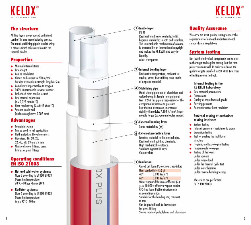
The structureAll five layers are produced and joined „online“ in one manufacturing process.The metal stabilising pipe is welded using a process which takes care to ease the thermal burden.
Properties l Minimal internal stressl Low weightl Can be modulated l Almost endless (up to 200 m/coil)
but also available in straight lengths (5 m) l Completely impermeable to oxygenl 100% impermeable to water vapourl Embedded pipes can be locatedl Low thermal expansion
(a = 0,025 mm/m°C)l Heat conductivity (λ= 0,45 W/m°C)l Smooth inside wall
(surface roughness: 0.007 mm)
Advantagesl Complete systeml Can be used for all applicationsl Held in stock at the wholesalersl Pipe sizes: 16, 20, 25,
32, 40, 50, 63 and 75 mml Choice of screw fittings, press
fittings or push fittings
Operating conditions EN ISO 21003
l Hot and cold water systems: Class 2 according to EN ISO 21003 Operating temperature: 70°C –10 bar /t max 80°C
l Radiator systems: Class 5 according to EN ISO 21003 Operating temperature t max 90°C - 10 bar
Inside layerPE-RT Resistant to all water contents; fulfils hygienic standards; smooth and seamless. The unmistakable combination of colours is protected by an international copyright and makes the KE KELIT pipe easy to identify.color: transparent
Internal bonding layerResistant to temperature, resistant to ageing, power transmitting layer made of a special material
Stabilising pipeMetal sheet pipe made of aluminium and welded along its length (elongation at tear: 12%) This pipe is responsible for the exceptional resistance to pressure.Low thermal expansion, mechanical stability (E module: 7.104 N/mm2, imper-meable to gas (oxygen and water vapour)
External bonding layerSame material as
External protective layerIdentical material to the internal pipe. Resistant to all building chemicals. High mechanical resistance. Stabilised against UV raysColour: white
InsulationClosed cell foam PE electron cross-linkedHeat conductivity (λ) at40°: 0.038 W/m°C60°: 0.039 W/m°CWater vapour diffusion coefficient (λ):μ = 10.000 : effective vapour barrierCFC-free foam Bubble structure acts as sound insulation Suitable for the building site; resistant to tearCan be pushed back to leave room for press fittingSleeve made of polyolefines and aluminium
1
2
4
5
6
7
Quality AssuranceWe carry out strict quality testing to meet the requirements of national and international standards and regulations
System testingNot just the individual components are subject to thorough and regular testing, but the com-plete system as well. In order to achieve the quality targets specified in ISO 9001 two types of testing are carried out.
Internal testing in the KE KELIT Laboratory
l Raw material parametersl Dimensionsl Quality of manufactured goodsl Bursting pressurel Behaviour under heat conditions
External testing at authorised testing institutes
l System testingl Internal pressure – resistance to creepl Expansion testingl Test for peeling the multilayer
structurel Hygienic and toxicological testingl Impermeable to oxygenl Testing of the joints:
under vacuum under tensile load under the thermal cyclic test under water hammer under reverse bending testing These tests are performed to EN ISO 21003
2
76
m u lt i l ay e r p i p e s y s t e m
®
m u lt i l ay e r p i p e s y s t e m
®
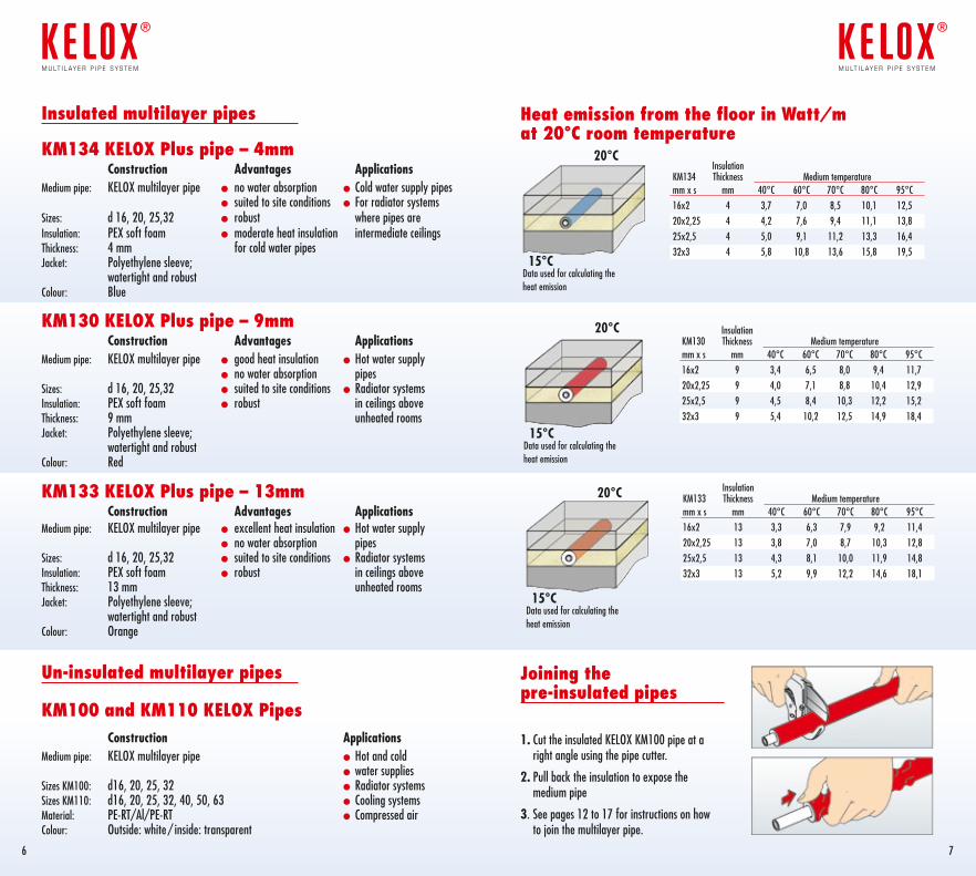
Heat emission from the floor in Watt/m at 20°C room temperature
Joining the pre-insulated pipes 1. Cut the insulated KELOX KM100 pipe at a
right angle using the pipe cutter.
2. Pull back the insulation to expose the medium pipe
3. See pages 12 to 17 for instructions on how to join the multilayer pipe.
Insulation KM134 Thickness Medium temperatur e mm x s mm 40°C 60°C 70°C 80°C 95°C16x2 4 3,7 7,0 8,5 10,1 12,520x2,25 4 4,2 7,6 9,4 11,1 13,825x2,5 4 5,0 9,1 11,2 13,3 16,432x3 4 5,8 10,8 13,6 15,8 19,5
Data used for calculating the heat emission
Data used for calculating the heat emission
20°C
20°C
15°C
15°C
Insulated multilayer pipes
KM134 KELOX Plus pipe – 4mm Construction Advantages ApplicationsMedium pipe: KELOX multilayer pipe l no water absorption l Cold water supply pipes l suited to site conditions l For radiator systems Sizes: d 16, 20, 25,32 l robust where pipes are Insulation: PEX soft foam l moderate heat insulation intermediate ceilings Thickness: 4 mm for cold water pipesJacket: Polyethylene sleeve; watertight and robustColour: Blue
KM130 KELOX Plus pipe – 9mm Construction Advantages ApplicationsMedium pipe: KELOX multilayer pipe l good heat insulation l Hot water supply l no water absorption pipesSizes: d 16, 20, 25,32 l suited to site conditions l Radiator systems Insulation: PEX soft foam l robust in ceilings aboveThickness: 9 mm unheated rooms Jacket: Polyethylene sleeve; watertight and robustColour: Red
KM133 KELOX Plus pipe – 13mm Construction Advantages ApplicationsMedium pipe: KELOX multilayer pipe l excellent heat insulation l Hot water supply l no water absorption pipesSizes: d 16, 20, 25,32 l suited to site conditions l Radiator systems Insulation: PEX soft foam l robust in ceilings aboveThickness: 13 mm unheated rooms Jacket: Polyethylene sleeve; watertight and robustColour: Orange
Un-insulated multilayer pipes
KM100 and KM110 KELOX Pipes Construction ApplicationsMedium pipe: KELOX multilayer pipe l Hot and cold l water suppliesSizes KM100: d16, 20, 25, 32 l Radiator systemsSizes KM110: d16, 20, 25, 32, 40, 50, 63 l Cooling systemsMaterial: PE-RT/Al/PE-RT l Compressed airColour: Outside: white / inside: transparent
Data used for calculating the heat emission
20°C
15°C
InsulationKM130 Thickness Medium temperature mm x s mm 40°C 60°C 70°C 80°C 95°C16x2 9 3,4 6,5 8,0 9,4 11,720x2,25 9 4,0 7,1 8,8 10,4 12,925x2,5 9 4,5 8,4 10,3 12,2 15,232x3 9 5,4 10,2 12,5 14,9 18,4
InsulationKM133 Thickness Medium temperature mm x s mm 40°C 60°C 70°C 80°C 95°C16x2 13 3,3 6,3 7,9 9,2 11,420x2,25 13 3,8 7,0 8,7 10,3 12,825x2,5 13 4,3 8,1 10,0 11,9 14,832x3 13 5,2 9,9 12,2 14,6 18,1
1 2 3 4 5
6
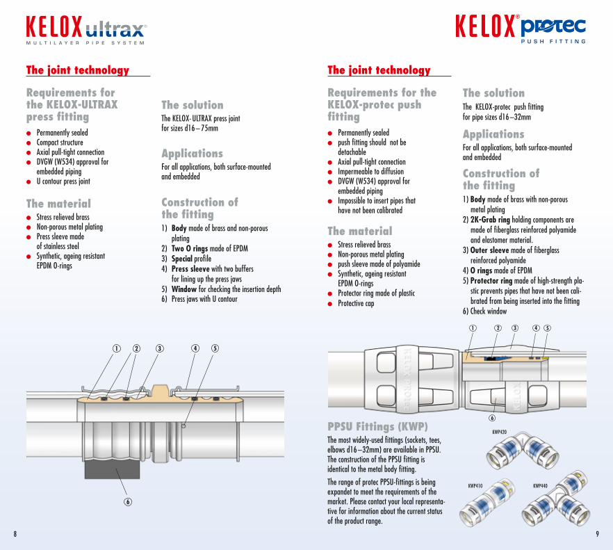
PPSU Fittings (KWP)The most widely-used fittings (sockets, tees, elbows d16 –32mm) are available in PPSU. The construction of the PPSU fitting is identical to the metal body fitting.
The range of protec PPSU-fittings is beingexpandet to meet the requirements of the market. Please contact your local representa-tive for information about the current status of the product range.
KWP420
KWP410 KWP440
The joint technology
Requirements for the KELOX-protec push fittingl Permanently sealedl push fitting should not be
detachablel Axial pull-tight connection l Impermeable to diffusionl DVGW (W534) approval for
embedded piping l Impossible to insert pipes that
have not been calibrated
The materiall Stress relieved brassl Non-porous metal plating l push sleeve made of polyamidel Synthetic, ageing resistant
EPDM O-ringsl Protector ring made of plasticl Protective cap
The solutionThe KELOX-protec push fitting for pipe sizes d16 –32mm
ApplicationsFor all applications, both surface-mounted and embedded
Construction of the fitting1) Body made of brass with non-porous
metal plating 2) 2K-Grab ring holding components are
made of fiberglass reinforced polyamide and elastomer material.
3) Outer sleeve made of fiberglass reinforced polyamide
4) O rings made of EPDM5) Protector ring made of high-strength pla-
stic prevents pipes that have not been cali-brated from being inserted into the fitting
6) Check window
98
The solutionThe KELOX- ULTRAX press joint for sizes d16 – 75mm
ApplicationsFor all applications, both surface-mounted and embedded
Construction of the fitting1) Body made of brass and non-porous
plating2) Two O rings made of EPDM3) Special profile4) Press sleeve with two buffers
for lining up the press jaws 5) Window for checking the insertion depth6) Press jaws with U contour
The joint technology
Requirements for the KELOX-ULTRAX press fittingl Permanently sealedl Compact structurel Axial pull-tight connection l DVGW (W534) approval for
embedded pipingl U contour press joint
The materiall Stress relieved brassl Non-porous metal plating l Press sleeve made
of stainless steell Synthetic, ageing resistant
EPDM O-rings
p u s H F i t t i N Gm u l t i l a y e r p i p e s y s t e m
6
32 4 51
Dim: d16–25
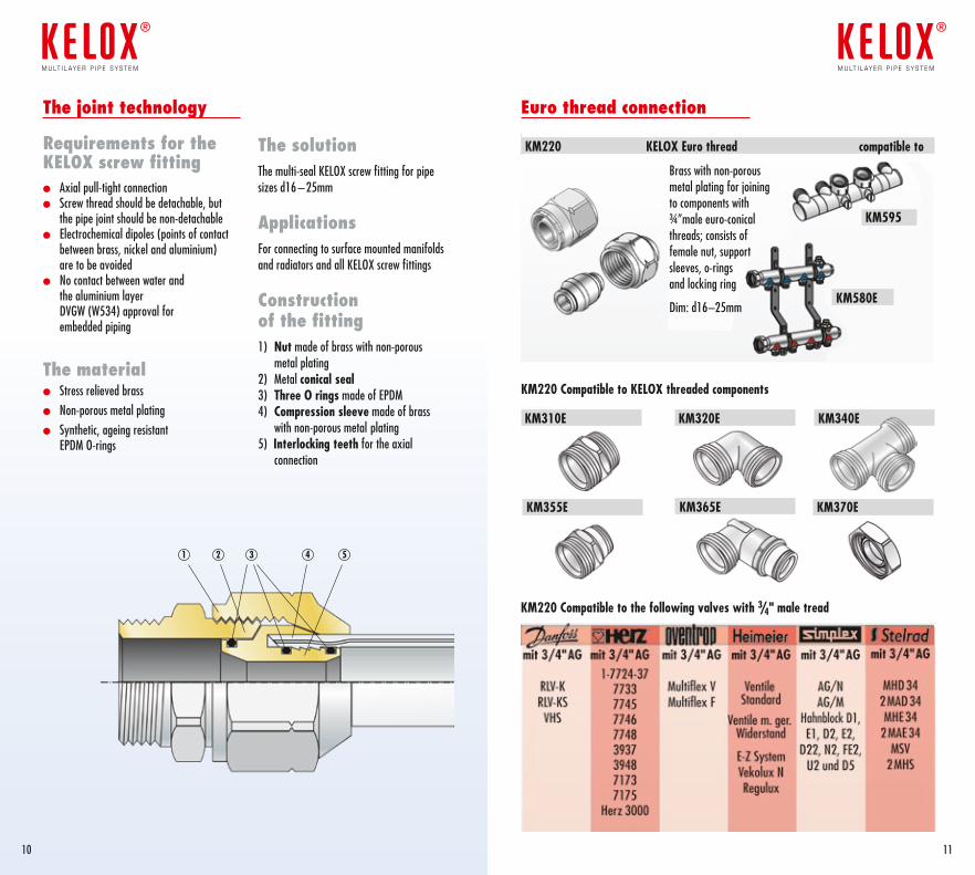
KM220 Compatible to the following valves with 3/4" male tread
KM220 Compatible to KELOX threaded components
Euro thread connection
KM220 KELOX Euro thread compatible to
The joint technology
Requirements for the KELOX screw fitting l Axial pull-tight connection l Screw thread should be detachable, but
the pipe joint should be non-detachablel Electrochemical dipoles (points of contact
between brass, nickel and aluminium) are to be avoided
l No contact between water and the aluminium layer DVGW (W534) approval for embedded piping
The materiall Stress relieved brassl Non-porous metal plating l Synthetic, ageing resistant
EPDM O-rings
The solutionThe multi-seal KELOX screw fitting for pipe sizes d16 – 25mm
ApplicationsFor connecting to surface mounted manifolds and radiators and all KELOX screw fittings
Construction of the fitting1) Nut made of brass with non-porous
metal plating2) Metal conical seal3) Three O rings made of EPDM4) Compression sleeve made of brass
with non-porous metal plating5) Interlocking teeth for the axial
connection
1 53 42
1110
m u lt i l ay e r p i p e s y s t e m
®
m u lt i l ay e r p i p e s y s t e m
®
KM310E KM320E
KM355E KM370E
KM580E
KM340E
KM595
KM365E
Brass with non-porous metal plating for joining to components with ¾”male euro-conical threads; consists of female nut, support sleeves, o-rings and locking ring
Dim: d16–25mm
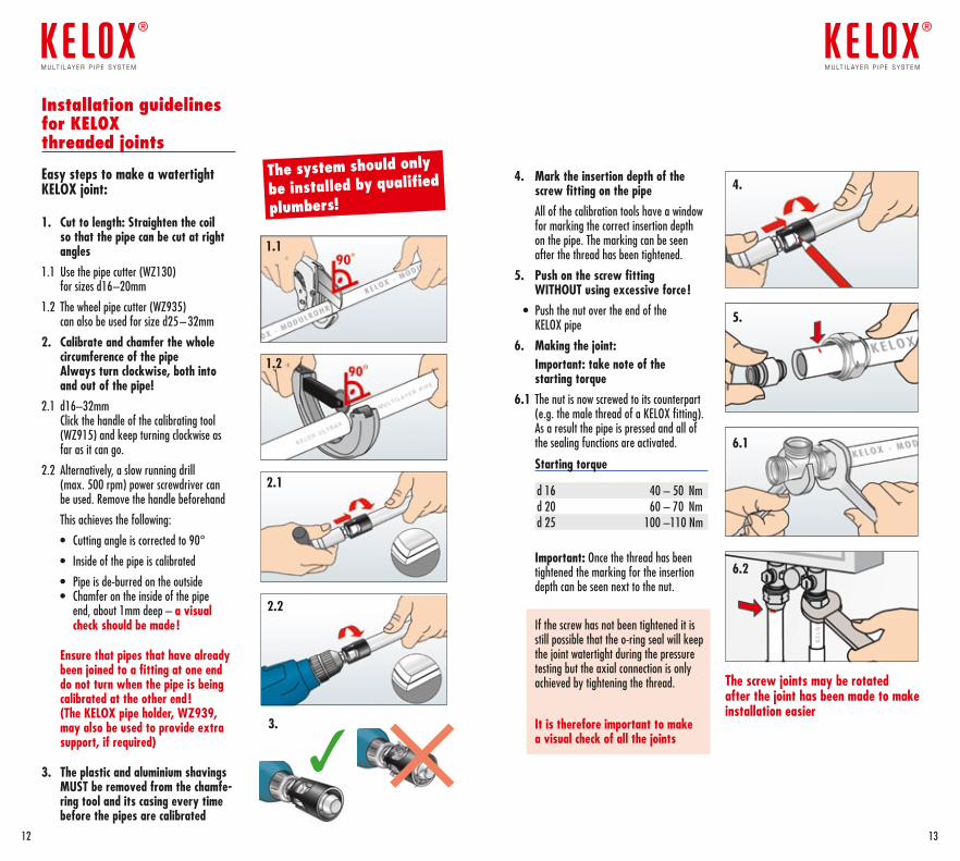
Installation guidelines for KELOX threaded joints Easy steps to make a watertight KELOX joint:
1. Cut to length: Straighten the coil so that the pipe can be cut at right angles
1.1 Use the pipe cutter (WZ130) for sizes d16–20mm
1.2 The wheel pipe cutter (WZ935) can also be used for size d25 – 32mm
2. Calibrate and chamfer the whole circumference of the pipe Always turn clockwise, both into and out of the pipe!
2.1 d16–32mm Click the handle of the calibrating tool (WZ915) and keep turning clockwise as far as it can go.
2.2 Alternatively, a slow running drill (max. 500 rpm) power screwdriver can be used. Remove the handle beforehand
This achieves the following:
• Cutting angle is corrected to 90°
• Inside of the pipe is calibrated
• Pipe is de-burred on the outside • Chamfer on the inside of the pipe
end, about 1mm deep – a visual check should be made !
Ensure that pipes that have already been joined to a fitting at one end do not turn when the pipe is being calibrated at the other end ! (The KELOX pipe holder, WZ939, may also be used to provide extra support, if required)
3. The plastic and aluminium shavings MUST be removed from the chamfe-ring tool and its casing every time before the pipes are calibrated
The screw joints may be rotated after the joint has been made to make installation easier
2.1
2.2
5.
6.1
6.2
4.
3.
1.2
1.1
4. Mark the insertion depth of the screw fitting on the pipe
All of the calibration tools have a window for marking the correct insertion depth on the pipe. The marking can be seen after the thread has been tightened.
5. Push on the screw fitting WITHOUT using excessive force !
• Push the nut over the end of the KELOX pipe
6. Making the joint: Important: take note of the
starting torque6.1 The nut is now screwed to its counterpart
(e.g. the male thread of a KELOX fitting). As a result the pipe is pressed and all of the sealing functions are activated.
Starting torque
d 16 40 – 50 Nmd 20 60 – 70 Nmd 25 100 –110 Nm
Important: Once the thread has been tightened the marking for the insertion depth can be seen next to the nut.
If the screw has not been tightened it is still possible that the o-ring seal will keep the joint watertight during the pressure testing but the axial connection is only achieved by tightening the thread.
It is therefore important to make a visual check of all the joints
The system should only
be installed by qualified
plumbers!
1312
m u lt i l ay e r p i p e s y s t e m
®
m u lt i l ay e r p i p e s y s t e m
®
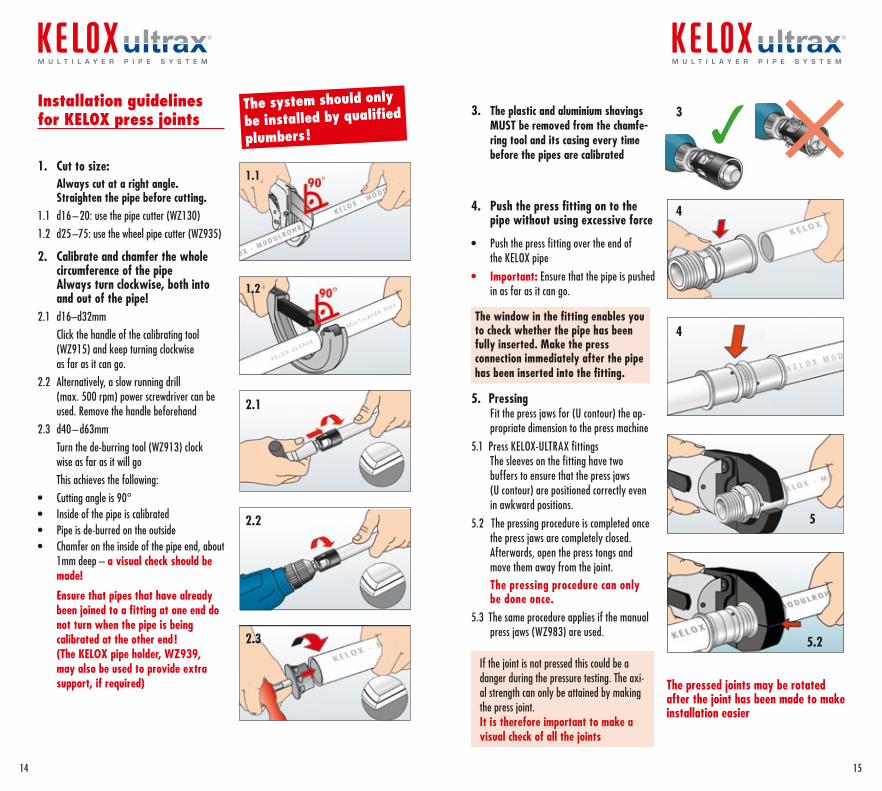
Installation guidelines for KELOX press joints
1. Cut to size: Always cut at a right angle.
Straighten the pipe before cutting.1.1 d16 – 20: use the pipe cutter (WZ130)1.2 d25 –75: use the wheel pipe cutter (WZ935)
2. Calibrate and chamfer the whole circumference of the pipe Always turn clockwise, both into and out of the pipe!
2.1 d16–d32mm Click the handle of the calibrating tool
(WZ915) and keep turning clockwise as far as it can go.
2.2 Alternatively, a slow running drill (max. 500 rpm) power screwdriver can be used. Remove the handle beforehand
2.3 d40 – d63mm Turn the de-burring tool (WZ913) clock
wise as far as it will go This achieves the following:• Cutting angle is 90°• Inside of the pipe is calibrated• Pipe is de-burred on the outside• Chamfer on the inside of the pipe end, about
1mm deep – a visual check should be made!
Ensure that pipes that have already been joined to a fitting at one end do not turn when the pipe is being calibrated at the other end ! (The KELOX pipe holder, WZ939, may also be used to provide extra support, if required)
3. The plastic and aluminium shavings MUST be removed from the chamfe-ring tool and its casing every time before the pipes are calibrated
4. Push the press fitting on to the pipe without using excessive force
• Push the press fitting over the end of the KELOX pipe
• Important: Ensure that the pipe is pushed in as far as it can go.
The window in the fitting enables you to check whether the pipe has been fully inserted. Make the press connection immediately after the pipe has been inserted into the fitting.
5. Pressing Fit the press jaws for (U contour) the ap-propriate dimension to the press machine
5.1 Press KELOX-ULTRAX fittings The sleeves on the fitting have two buffers to ensure that the press jaws (U contour) are positioned correctly even in awkward positions.
5.2 The pressing procedure is completed once the press jaws are completely closed. Afterwards, open the press tongs and move them away from the joint.
The pressing procedure can only be done once.
5.3 The same procedure applies if the manual press jaws (WZ983) are used.
The pressed joints may be rotated after the joint has been made to make installation easier
The system should only
be installed by qualified
plumbers!
2.2
2.1
2.3
4
3
4
5
5.2
1.2
1.1
If the joint is not pressed this could be a danger during the pressure testing. The axi-al strength can only be attained by making the press joint. It is therefore important to make a visual check of all the joints
1514
m u l t i l a y e r p i p e s y s t e m m u l t i l a y e r p i p e s y s t e m
Our product principles – your advantages
l Simple No requirement for expensive machinery Complete range of fittings from d16 to d32
l Secure A NON-detachable joint The sealing of the joint is the highest priority The pipe is fixed by a grab ring on the inside The protector ring protects the O rings by blocking
the insertion of non-chamfered pipes into the fitting. The result is a watertight joint where the pipe
cannot be pulled out of the fitting. The window in the fitting provides extra security.
l Easy to handle Body of the fitting is the perfect size No problem for embedded piping Slim joint makes it easy to insulate
l Robust The materials used reflect the latest technology: Non-porous metal-plated brass Grilamide, PA-GF, EPDM nano-coated
l Suited to site conditions The joint is sealed on the inside surface of the
KELOX pipe where it is clean and calibrated Grease-free EPDM O rings No problems with dirt Little force required (do not add any lubrication) Joint can be turned or adjusted after installation
l Tested Subject to extensive testing: Water hammer, temperature change,
high pressure, tensile strength Certified by DVGW and ÖVGW
l KE KELIT Patent All the relevant components in
the fitting are protected by patent. Licences have been granted to
renowned European partners
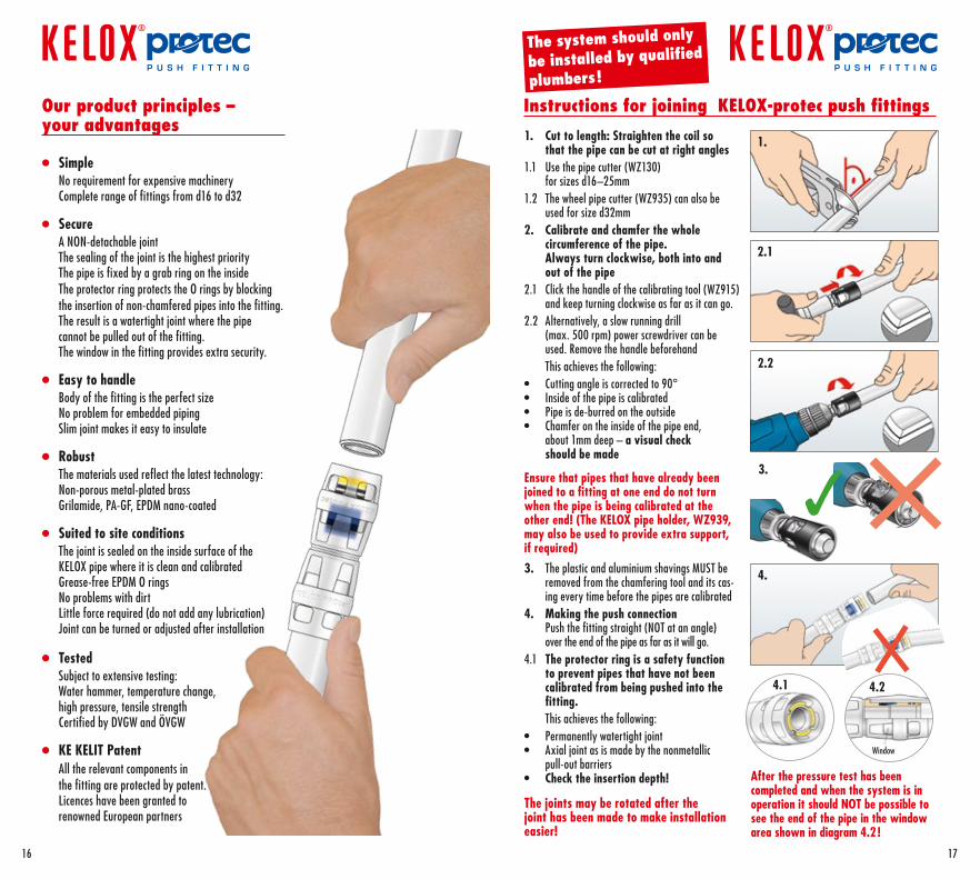
1. Cut to length: Straighten the coil so that the pipe can be cut at right angles
1.1 Use the pipe cutter (WZ130) for sizes d16–25mm
1.2 The wheel pipe cutter (WZ935) can also be used for size d32mm
2. Calibrate and chamfer the whole circumference of the pipe. Always turn clockwise, both into and out of the pipe
2.1 Click the handle of the calibrating tool (WZ915) and keep turning clockwise as far as it can go.
2.2 Alternatively, a slow running drill (max. 500 rpm) power screwdriver can be used. Remove the handle beforehand
This achieves the following:• Cutting angle is corrected to 90°• Inside of the pipe is calibrated• Pipe is de-burred on the outside• Chamfer on the inside of the pipe end,
about 1mm deep – a visual check should be made
Ensure that pipes that have already been joined to a fitting at one end do not turn when the pipe is being calibrated at the other end! (The KELOX pipe holder, WZ939, may also be used to provide extra support, if required)
3. The plastic and aluminium shavings MUST be removed from the chamfering tool and its cas-ing every time before the pipes are calibrated
4. Making the push connection Push the fitting straight (NOT at an angle) over the end of the pipe as far as it will go.
4.1 The protector ring is a safety function to prevent pipes that have not been calibrated from being pushed into the fitting.
This achieves the following:• Permanently watertight joint• Axial joint as is made by the nonmetallic
pull-out barriers• Check the insertion depth!
The joints may be rotated after the joint has been made to make installation easier!
Instructions for joining KELOX-protec push fittings
After the pressure test has been com pleted and when the system is in operation it should NOT be possible to see the end of the pipe in the window area shown in diagram 4.2 !
4.1
1.
2.1
2.2
Window
4.2
3.
The system should only
be installed by qualified
plumbers!
4.
16 17
p u s H F i t t i N G p u s H F i t t i N G
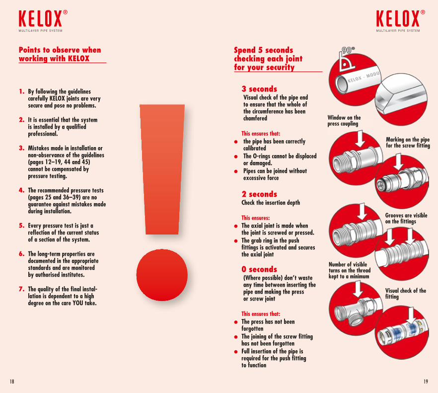
Points to observe when working with KELOX
1. By following the guidelines carefully KELOX joints are very secure and pose no problems.
2. It is essential that the system is installed by a qualified professional.
3. Mistakes made in installation or non-observance of the guidelines (pages 12–19, 44 and 45) cannot be compensated by pressure testing.
4. The recommended pressure tests (pages 25 and 36–39) are no guarantee against mistakes made during installation.
5. Every pressure test is just a reflection of the current status of a section of the system.
6. The long-term properties are documented in the appropriate standards and are monitored by authorised institutes.
7. The quality of the final instal- lation is dependent to a high degree on the care YOU take.
Spend 5 seconds checking each joint for your security
3 seconds Visual check of the pipe end
to ensure that the whole of the circumference has been chamfered
This ensures that:l the pipe has been correctly
calibratedl The O-rings cannot be displaced
or damaged.l Pipes can be joined without
excessive force
2 seconds Check the insertion depth
This ensures:l The axial joint is made when
the joint is screwed or pressed.l The grab ring in the push
fittings is activated and secures the axial joint
0 seconds (Where possible) don’t waste
any time between inserting the pipe and making the press or screw joint
This ensures that:l The press has not been
forgottenl The joining of the screw fitting
has not been forgottenl Full insertion of the pipe is
required for the push fitting to function
Visual check of the fitting
Window on the press coupling
Marking on the pipe for the screw fitting
Grooves are visible on the fittings
Number of visible turns on the thread kept to a minimum
1918
m u lt i l ay e r p i p e s y s t e m
®
m u lt i l ay e r p i p e s y s t e m
®
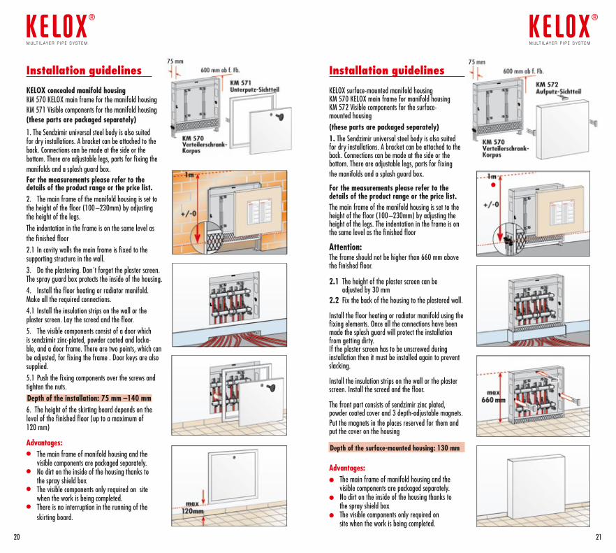
Installation guidelines
KELOX concealed manifold housingKM 570 KELOX main frame for the manifold housing KM 571 Visible components for the manifold housing (these parts are packaged separately)
1. The Sendzimir universal steel body is also suited for dry installations. A bracket can be attached to the back. Connections can be made at the side or the bottom. There are adjustable legs, parts for fixing the manifolds and a splash guard box.For the measurements please refer to the details of the product range or the price list. 2. The main frame of the manifold housing is set to the height of the floor (100 –230mm) by adjusting the height of the legs.The indentation in the frame is on the same level as the finished floor 2.1 In cavity walls the main frame is fixed to the supporting structure in the wall.3. Do the plastering. Don´t forget the plaster screen. The spray guard box protects the inside of the housing.4. Install the floor heating or radiator manifold. Make all the required connections.4.1 Install the insulation strips on the wall or the plaster screen. Lay the screed and the floor.5. The visible components consist of a door which is sendzimir zinc-plated, powder coated and locka-ble, and a door frame. There are two points, which can be adjusted, for fixing the frame . Door keys are also supplied.5.1 Push the fixing components over the screws and tighten the nuts.Depth of the installation: 75 mm –140 mm6. The height of the skirting board depends on the level of the finished floor (up to a maximum of 120 mm)
Advantages:• The main frame of manifold housing and the
visible components are packaged separately.• No dirt on the inside of the housing thanks to
the spray shield box• The visible components only required on site
when the work is being completed.• There is no interruption in the running of the
skirting board.
Installation guidelines
KELOX surface-mounted manifold housing KM 570 KELOX main frame for manifold housing KM 572 Visible components for the surface- mounted housing (these parts are packaged separately)1. The Sendzimir universal steel body is also suited for dry installations. A bracket can be attached to the back. Connections can be made at the side or the bottom. There are adjustable legs, parts for fixing the manifolds and a splash guard box.
For the measurements please refer to the details of the product range or the price list. The main frame of the manifold housing is set to the height of the floor (100 –230mm) by adjusting the height of the legs. The indentation in the frame is on the same level as the finished floor
Attention:The frame should not be higher than 660 mm above the finished floor.
2.1 The height of the plaster screen can be adjusted by 30 mm2.2 Fix the back of the housing to the plastered wall.
Install the floor heating or radiator manifold using the fixing elements. Once all the connections have been made the splash guard will protect the installation from getting dirty.If the plaster screen has to be unscrewed during installation then it must be installed again to prevent slacking.
Install the insulation strips on the wall or the plaster screen. Install the screed and the floor.
The front part consists of sendzimir zinc plated, powder coated cover and 3 depth-adjustable magnets.Put the magnets in the places reserved for them and put the cover on the housing
Depth of the surface-mounted housing: 130 mm
Advantages:l The main frame of manifold housing and the
visible components are packaged separately.l No dirt on the inside of the housing thanks to
the spray shield boxl The visible components only required on
site when the work is being completed.
l
2120
m u lt i l ay e r p i p e s y s t e m
®
m u lt i l ay e r p i p e s y s t e m
®

The classic two pipe system
Design criteria for an efficient system
Taking into account the total length of the piping and the extra losses at the system com-ponents (e.g. valves) the pressure loss can be assumed to be 100–200 Pa/m
The standard optiontried and trusted
Advantagesl Same temperature for all of the radiators
(source of comfort)l Recognised system for calculating heat costsl Typical system for renovation of old
buildingsl Well suited for skirting boards
The one pipe system
Design criteria for an efficient system
Taking into account the total length of the main riser in one pipe systems and the extra losses at the system components (pipes branching off from the riser, Z values of 4 way valves …) the pressure loss can be assumed to be 100–200 Pa/m
The “savings option”Quick and value for money
AdvantagesUsing 4-way valvesl No connections in the floorl Very quick installationl Only one pipe size after the riser
Insulation for heating and hot water systems under ÖNORM H 5155
ÖNORM H 5155 is the standard applied for insulating domestic systems. It simplifies and unifies the procedures for planning, installing and maintenance of insulation systems.
l The purpose of ÖNORM H 5155 is to spe-cify the insulation thickness required to mi-nimise the transfer of heat from medium to surroundings and vice versa.
l ÖNORM H 5155 applies for the insulation of all components in heating and drinking water systems
l The insulation thickness varies according to the type of installation and its location wi-thin the building (e.g. whether the pipes are concealed or located in an intermediate ceiling or in a heated room etc ….)
l KELOX Plus pipes are available in sizes d16 – 32mm, in three different thicknesses
l Please also follow KE KELIT´s recommenda-tions with regard to comfort considerations and noise insulation.
l Insulation for coldwater pipe (page 35)
ÖNORM H 5155 allows a lambda value of 0.047 W/m.K for KELOX heating and hot water pipes at an average temperature of 50°C and an external coefficient of heat transfer of 9 W/m2.K
The lambda value of pre-insulated KELOX Plus pipes, 0.038 W/m.K at 40°C fulfils the requirements of the standard. The KELOX equivalents are shown below:
Required thickness 5 mm = KM134 KELOX Plus pipe with 4 mm insulation
Required thickness 10 mm = KM130 KELOX Plus pipe with 9mm insulation
Required thickness 15 mm = KM133 KELOX Plus pipe with 13mm insulation
Attention should be paid to the laws and standards regarding insulation which are specific to the country where the products are being installed
Excerpt from ÖNORM H 5155, table 2. The DN/OD values are identical to the ones given for the KELOX pipes Size DN/OD (outside diameter) Location of the piping
Dimension DN/OD (outside diameter) 16 20 25 32 40 50 63 75Piping location Minimum insulation thickness (mm)Utility room 20 20 25 30 40 55 70 70Unheated room 20 20 25 30 40 55 70 70Heated room 10 10 15 15 20 30 35 35Installation shaft, installation passage bordering mostly unheated areas 20 20 25 30 40 55 70 70
Suspended ceiling, double floors, installation shafts bordering mostly heated areas 10 10 15 15 20 30 35 35
Flush-mounting, floor in unheated rooms 10 10 10 10 10 10 10 10Flush-mounting, floor in heated rooms 5 5 5 5 10 10 10 10
2322
m u lt i l ay e r p i p e s y s t e m
®
m u lt i l ay e r p i p e s y s t e m
®
Two pipe heating system with a central manifold
Design criteria for an efficient system
As a result of the short runs from the manifold to the individual radiators but also taking into account the extra losses at the system compon-ents (e.g. valves), the pressure loss can be assumed to be 250–400 Pa/m
The “spaghetti system” The ideal solution both for installing and for comfort
Advantagesl Only one pipe size from the manifoldl No connections in the floorl Every pipe to the radiator can be managed
separatelyl If a radiator is defect energy is saved
because there is no circulation in the pipe system
Pressure testing report for heating systemsKE KELIT recommends carrying out the pressure testing according to the guidelines in DIN18380Please note that a pressure test is an assessment of how the system is functioning at the time of the test. It is not a guarantee against any mistakes made during installation.Check all the points concerning the installation of the system (pages 12 –19) before starting the pressure test.
Pressure testThe test pressure is equal to 1.3 times the operating pressure or a minimum of 1 bar above the operating temperature at every point. Only manometers which can read a change of pressure of 0.1 bar should be used. The manometer should be located at the lowest possible point in the system.
Time should be allocated to allow for the equalisation of the temperature between the ambient temperature and the medium temperature after the test pressure has been set. When this period has elapsed the test pressure should be re-set.
All tanks, components and faucets which are unsuited to pressure testing should be separated from the system during the pressure testing. The system is then filled with filtered water and the air removed. During the testing a visual check should be made at all the joints.
The testing pressure must be maintained for 2 hours and should not drop more than 0.2 bar. There should be no leaking at the joints during the test.
Testing pressure: ……. bar
Testing time: ……. hours
The pressure did not fall by ≥ 0.2 during testing
The system contains ……….. . . . . . . . . . . . .…………….. antifreeze
The system contains no antifreeze and was completely emptied for safety reasons.
Location: . . . . . . . . . . . . . . . . . . . . . . . . . . . . . . . . . . . . . . . . . . . . . . . . . . . . . . . . . . . . . . . . . . . . . . . . . . . . . . . . . . . . . . . . . . . . . . . . . . . . . .
Building: . . . . . . . . . . . . . . . . . . . . . . . . . . . . . . . . . . . . . . . . . . . . . . . . . . . . . . . . . . . . . . . . . . . . . . . . . . . . . . . . . . . . . . . . . . . . . . . . . . . . . .
System pressure: . . . . . . . . . . . . . . . . . . . . . . . . . . . . . . . . . . . . . . . . . . . . . . . . . . . . . . . . . . . . . . . . . . . . . . . . . . . . . . . . . . . . . . . . . . . . . .
Confirmation
Person in charge: . . . . . . . . . . . . . . . . . . . . . . . . . . . . . . . . . . . . . . . . . . . . . . . . . . . . . . . . . . . . . . . . . . . . . . . . . . . . . . . . . . . . . . . . . . . . .
Date: . . . . . . . . . . . . . . . . . . . . . . Time from: . . . . . . . . . . . . . . . . . . . . . . . . . . . . . . . to: . . . . . . . . . . . . . . . . . . . . . . . . . . . . . . .
Contractor . . . . . . . . . . . . . . . . . . . . . . . . . . . . . . . . . . . . . . . . . . . . . . . . . . . . . . . . . . . . . . . . . . . . . . . . . . . . . . . . . . . . . . . . . . . . . . . . . . . . . signature/stamp
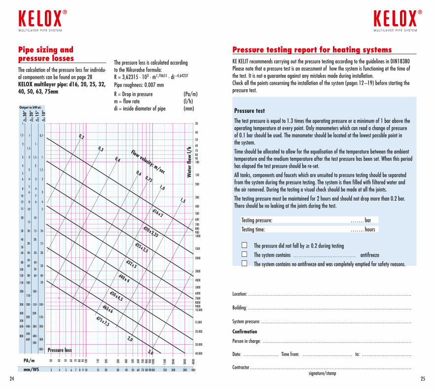
Pipe sizing and pressure lossesThe calculation of the pressure loss for individu-al components can be found on page 28KELOX multilayer pipe: d16, 20, 25, 32, 40, 50, 63, 75mm
The pressure loss is calculated according to the Nikuradse formula:R = 3,62315 · 103 · m· 1,70651 · di –4,64237
Pipe roughness: 0.007 mm
R = Drop in pressure (Pa/m)m = flow rate (l/h)di = inside diameter of pipe (mm)
900600 700 80015
150020
6000
7000
8000
9000
500
9000800070006000
5000
4000
3000
2000
1000900800700600
500
400
300
200
10090807060
50
40
30
30.000
20.000
10.000
40.000
150
1500
15.000
PA/m
mm/WS
Output in kWat:
4000
3000
Δt 3
0°Δ
t 20°
Δt 1
5°Δ
t 10°
Wat
er fl
ow l/
h
Pressure loss
0,2
0,3
0,4
0,60,75
1,0
1,5
2,0
3,0
d16x2
d20x2,25
d25x2,5
d32x3
d40x 4
d50x4,5
d63x6d75x7,5
Flow velocity: m/sec
1
1
10
0,5
5
1,5
15
1,5
15
150
1
10
100
3
30
300
2
20
200
1,5
15
150
1
10
100
4
40
400
2
20
200
5
50
500
6
60
600
4
40
400
5
50
500
5
50
500
50
3
30
300
1,5
15
150
3
30
300
2
20
200
3
30
300
6
60
600
8
80
800
4
40
400
10
100
12
120
8
80
100150
6
60
4
40
400
2
20
200
2524
m u lt i l ay e r p i p e s y s t e m
®
m u lt i l ay e r p i p e s y s t e m
®
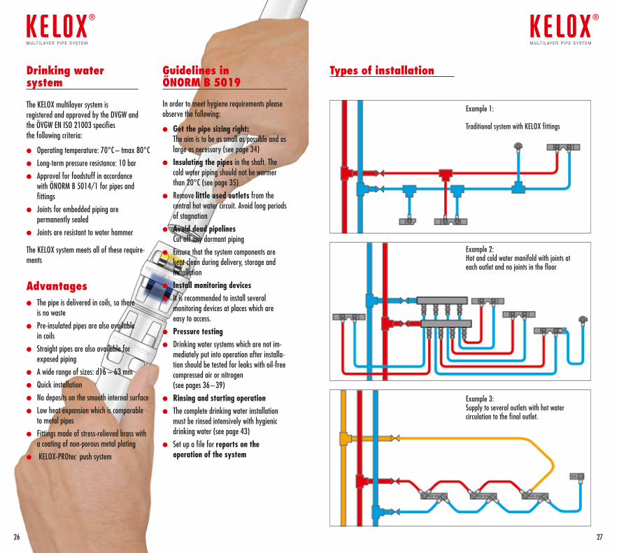
Types of installation
2726
m u lt i l ay e r p i p e s y s t e m
®
m u lt i l ay e r p i p e s y s t e m
®
Example 1:
Traditional system with KELOX fittings
Drinking water system
The KELOX multilayer system is registered and approved by the DVGW and the ÖVGW EN ISO 21003 specifies the following criteria:
l Operating temperature: 70°C – tmax 80°C
l Long-term pressure resistance: 10 bar
l Approval for foodstuff in accordance with ÖNORM B 5014/1 for pipes and fittings
l Joints for embedded piping are permanently sealed
l Joints are resistant to water hammer
The KELOX system meets all of these require-ments
Advantages l The pipe is delivered in coils, so there
is no waste
l Pre-insulated pipes are also available in coils
l Straight pipes are also available for exposed piping
l A wide range of sizes: d16 – 63 mm
l Quick installation
l No deposits on the smooth internal surface
l Low heat expansion which is comparable to metal pipes
l Fittings made of stress-relieved brass with a coating of non-porous metal plating
l KELOX-PROtec push system
Guidelines in ÖNORM B 5019
In order to meet hygiene requirements please observe the following:
l Get the pipe sizing right: The aim is to be as small as possible and as large as necessary (see page 34)
l Insulating the pipes in the shaft. The cold water piping should not be warmer than 20°C (see page 35)
l Remove little used outlets from the central hot water circuit. Avoid long periods of stagnation
l Avoid dead pipelines Cut off any dormant piping
l Ensure that the system components are kept clean during delivery, storage and installation
l Install monitoring devicesl It is recommended to install several
monitoring devices at places which are easy to access.
l Pressure testingl Drinking water systems which are not im-
mediately put into operation after installa-tion should be tested for leaks with oil-free compressed air or nitrogen (see pages 36 – 39)
l Rinsing and starting operationl The complete drinking water installation
must be rinsed intensively with hygienic drinking water (see page 43)
l Set up a file for reports on the operation of the system
Example 2:Hot and cold water manifold with joints at each outlet and no joints in the floor
Example 3:Supply to several outlets with hot water circulation to the final outlet.

Pipe sizing pressure loss in KELOX multilayer pipes
The total pressure loss (Dp) in the KELOX pipe system is calculated by multiplying the friction loss (R) by the length of the piping (l) plus the sum (S) of the friction losses for the individu-al fittings (Z).
Total pressure loss Dp:
Dp = (l . R + S Z) in Pa
The choice of pipe size for the water supply is dependent on the following factors:
l The available water pressurel Geodetic difference in heightl Pressure losses through system componentsl Minimum flow pressure through faucetsl Pressure losses in the pipesl The individual pressure losses of the fittingsl Type, number and simultaneous use of the draw-off pointsl Flow velocity
Note:For the purpose of pipe sizing it is assumed that there will be no reduction in theinternal diameter caused by incrustation since the surface structure of the pipe is amorphous and the surface roughness of the pipe is mini-mal (0.007)
Maximum flow velocity according to EN 806-3
Main supply, Riser and max 2.0 m/sDistribution pipes
}Pipes to the outlets max 4.0 m/s
Pipe sizing to ÖNORM EN 806/3The calculation procedure mentioned below is to determine the pipe size for normal installations. For special categories such as hospitals, spas, hotels, schools etc the pipe size is usually determined by the method in the standard DIN 1988/300. This method is applied for hot and cold water pipes.1 loading unit (LU) is equivalent to a draw-off flow rate of 0.1 l/s.
Draw-off point QA l/s LU
Wash basin, hand basin, bidet, WC cistern 0,1 1Domestic kitchen sink – washing machine a , Dish washing machine, sink, shower head 0,2 2
Urinal flush valve 0,3 3Bath domestic 0,4 4Taps/garden/garage 0,5 5Non domestic kitchen sink, 0,8 8DN 20 bath non domestic Flush valve DN 20 1,5 15a For non domestic appliances check with manufacturer
Size Inside diameter Water flow Loading unit Highest single value Max. pipe length d x s di LU LU l max. mm mm l/m m
16 x 2 12,0 0,113 3 9 16 x 2 12,0 0,113 4 5 16 x 2 12,0 0,113 5 4 4 20 x 2,25 15,5 0,189 10 5 25 x 2,5 20,0 0,314 20 8 32 x 3 26,0 0,531 55 40 x 4 32,0 0,804 180 50 x 4,5 41,0 1,32 540 63 x 6 51,0 2,042 1100 75 x 7,5 60,0 2,826 2200
2928
m u lt i l ay e r p i p e s y s t e m
®
m u lt i l ay e r p i p e s y s t e m
®
Calculation of the pressure loss (Z) for the standard fittings.
Z = z · v2
2
With regard to economic efficiency the flow velocity should be at least 1m/s. Taking into account flow sound the maximum velocity should not exceed 2m/s. For individual pipes running to the draw-off point a maximum velocity of 4m/s is permissible.
After adding up the loading units the diameter of the pipe can be read off the following table
Example:The following outlets need to be served by the riser pipe:4 domestic baths 4 x LU 4 = 164 showers 4 x LU 2 = 84 wash basins 4 x LU 1 = 44 wc cisterns 4 x LU 1 = 44 kitchen sinks 4 x LU 2 = 84 dish washing machines 4 x LU 2 = 82 washing machines 2 x LU 2 = 4
Total number of loading units: 52Result: In accordance with ÖNORM EN 806-3 the following table shows that ad32 x 3 mm KELOX pipe is required.
Guidelines for circulating pipe systems (DIN 1988–300)For hygienic reasons the circulating system should be designed so that the temperature at any point in the system is no lower than 5K below the ope-rating temperature. The power of the pump and the regulation of the temperature are designed so that the temperature does not fall below 55°C at any point in the system. For economic reasons the flow velocity in circulating systems should be approx. 0.2–0.5 m/s and in exceptional circum-stances up to a maximum of 1.0 l/s.
= density kg/m3
v = flow velocityz = Coefficient
Fitting Dimension z Dimension z Symbol KELOX KELOX Coupling equal (K) 16 4,3 20/16 5,4Coupling reducer (RED) 20 2,4 25/20 3,2 25 1,7 32/25 2,6 32 0,7 40/32 1,2 40 0,6 50/40 1,2 50 0,4 63–75 0,5
Elbow 90° (W90) 16 17,3 40 3,3 20 10,1 50 2,5 25 7,1 63–75 2,4 32 4,5 – –
Elbow 45° (W45) 25 2,0 50 1,0 32 1,5 63–75 1,0 40 1,3 – –
Tee - straight flow (TD) 16 5,9 40 0,8 20 3,3 50 0,4 25 2,3 63–75 1,1 32 1,1 – –
Tee - flow separation (TA) 16 17,9 40 3,4 20 10,0 50 2,5 25 8,4 63–75 2,5 32 4,8 – –
Tee - reverse flow (TG) 16 17,2 40 3,6 20 10,8 50 2,5 25 7,5 63–75 2,6 32 4,7 – –
Wall bracket 90° (WS) 16 12,9 – – 20 9,8 – –
Screw fitting 16 3,4 – – 20 2,8 – – 25 5,0 – –
The above table shows the coefficients for KELOX fittings
Guidelines for pipe sizing (DIN 1988/300)
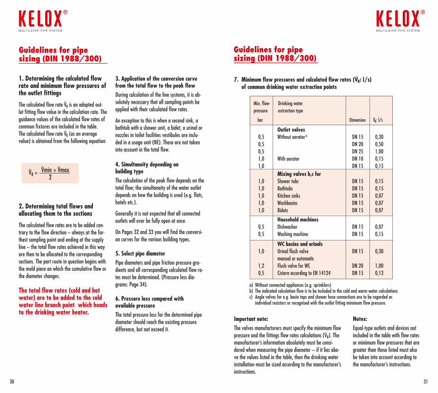
1. Determining the calculated flow rate and minimum flow pressures of the outlet fittings
The calculated flow rate VR is an adopted out-let fitting flow value in the calculation rate. The guidance values of the calculated flow rates of common fixtures are included in the table. The calculated flow rate VR (as an average value) is obtained from the following equation:
VR = Vmin + Vmax 2
2. Determining total flows and allocating them to the sections
The calculated flow rates are to be added con-trary to the flow direction – always at the far-thest sampling point and ending at the supply line – the total flow rates achieved in this way are then to be allocated to the corresponding sections. The part route in question begins with the mold piece on which the cumulative flow or the diameter changes.
The total flow rates (cold and hot water) are to be added to the cold water line branch point which heads to the drinking water heater.
3. Application of the conversion curve from the total flow to the peak flowDuring calculation of the line systems, it is ab-solutely necessary that all sampling points be applied with their calculated flow rates.
An exception to this is when a second sink, a bathtub with a shower unit, a bidet, a urinal or nozzles in toilet facilities vestibules are inclu-ded in a usage unit (NE). These are not taken into account in the total flow.
4. Simultaneity depending on building type The calculation of the peak flow depends on the total flow; the simultaneity of the water outlet depends on how the building is used (e.g. flats, hotels etc.).
Generally it is not expected that all connected outlets will ever be fully open at once.
On Pages 32 and 33 you will find the conversi-on curves for the various building types.
5. Select pipe diameter Pipe diameters and pipe friction pressure gra-dients and all corresponding calculated flow ra-tes must be determined. (Pressure loss dia-grams: Page 34).
6. Pressure loss compared with available pressure The total pressure loss for the determined pipe diameter should reach the existing pressure difference, but not exceed it.
Guidelines for pipe sizing (DIN 1988/300)
7. Minimum flow pressures and calculated flow rates (VR: l/s) of common drinking water extraction points
Important note:The valves manufacturers must specify the minimum flow pressure and the fittings flow rates calculations (VR). The manufacturer’s information absolutely must be consi-dered when measuring the pipe diameter – if it lies abo-ve the values listed in the table, then the drinking water installation must be sized according to the manufacturer’s instructions.
Notes:Equal-type outlets and devices not included in the table with flow rates or minimum flow pressures that are greater than those listed must also be taken into account according to the manufacturer’s instructions.
Min. flow- Drinking water pressure extraction type
bar Dimension VR: l/s
Outlet valves 0,5 Without aerator a DN 15 0,30 0,5 DN 20 0,50 0,5 DN 25 1,00 1,0 With aerator DN 10 0,15 1,0 DN 15 0,15 Mixing valves b,c for 1,0 Shower tubs DN 15 0,15 1,0 Bathtubs DN 15 0,15 1,0 Kitchen sinks DN 15 0,07 1,0 Washbasins DN 15 0,07 1,0 Bidets DN 15 0,07
Household machines 0,5 Dishwasher DN 15 0,07 0,5 Washing machine DN 15 0,15
WC basins and urinals 1,0 Urinal flush valve DN 15 0,30 manual or automatic 1,2 Flush valve for WC DN 20 1,00 0,5 Cistern according to EN 14124 DN 15 0,13 a) Without connected appliances (e.g. sprinklers) b) The indicated calculation flow is to be included in the cold and warm water calculationsc) Angle valves for e.g. basin taps and shower hose connections are to be regarded as individual resistors or recognised with the outlet fitting minimum flow pressure.
3130
m u lt i l ay e r p i p e s y s t e m
®
m u lt i l ay e r p i p e s y s t e m
®
0
1
2
3
4
5
0 10 20 30 40 50
Zusammenstellung
Pflegeheim Wohngebäude Seniorenheim Krankenhaus Hotel Schule/Verwaltung
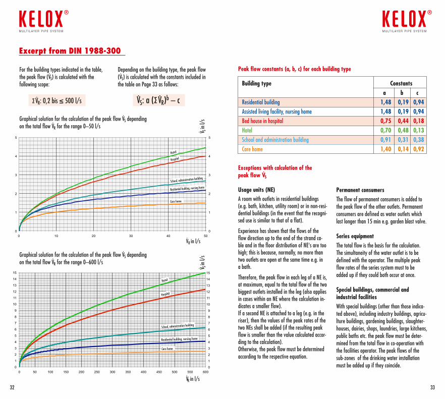
Depending on the building type, the peak flow (VS) is calculated with the constants included in the table on Page 33 as follows:
VS: a (Σ VR)b – c
For the building types indicated in the table, the peak flow (VS) is calculated with the following scope:
Σ VR: 0,2 bis ≤ 500 l/s
Graphical solution for the calculation of the peak flow VS depending on the total flow VR for the range 0–600 l/s
Peak flow constants (a, b, c) for each building type
Graphical solution for the calculation of the peak flow VS depending on the total flow VR for the range 0–50 l/s
0
1
2
3
4
5
6
7
8
9
10
11
12
13
14
15
0 50 100 150 200 250 300 350 400 450 500 550 600
Zusammenstellung
Pflegeheim Wohngebäude Seniorenheim Krankenhaus Hotel Schule/Verwaltung
0
1
2
3
4
5
6
7
8
9
10
11
12
13
14
15
0 50 100 150 200 250 300 350 400 450 500 550 600
Zusammenstellung
Pflegeheim Wohngebäude Seniorenheim Krankenhaus Hotel Schule/Verwaltung
Hotel
Hospital
School, administration building
Residential building, nursing home
Care home
VR in l/s
VR in l/s
V S in
l/s
V S in
l/s
Exceptions with calculation of the peak flow VS
Usage units (NE)A room with outlets in residential buildings (e.g. bath, kitchen, utility room) or in non-resi-dential buildings (in the event that the recogni-sed use is similar to that of a flat).
Experience has shown that the flows of the flow direction up to the end of the strand ca-ble and in the floor distribution of NE‘s are too high; this is because, normally, no more than two outlets are open at the same time e.g. in a bath.
Therefore, the peak flow in each leg of a NE is, at maximum, equal to the total flow of the two biggest outlets installed in the leg (also applies in cases within an NE where the calculation in-dicates a smaller flow). If a second NE is attached to a leg (e.g. in the riser), then the values of the peak rates of the two NEs shall be added (if the resulting peak flow is smaller than the value calculated accor-ding to the calculation). Otherwise, the peak flow must be determined according to the respective equation.
Permanent consumersThe flow of permanent consumers is added to the peak flow of the other outlets. Permanent consumers are defined as water outlets which last longer than 15 min e.g. garden blast valve.
Series equipmentThe total flow is the basis for the calculation. The simultaneity of the water outlet is to be defined with the operator. The multiple peak flow rates of the series system must to be added up if they could both occur at once.
Special buildings, commercial and industrial facilitiesWith special buildings (other than those indica-ted above), including industry buildings, agricu-lture buildings, gardening buildings, slaughter-houses, dairies, shops, laundries, large kitchens, public baths etc. the peak flow must be deter-mined from the total flow in co-operation with the facilities operator. The peak flows of the sub-zones of the drinking water installation must be added up if they coincide.
Excerpt from DIN 1988-300
0
1
2
3
4
5
0 10 20 30 40 50
Zusammenstellung
Pflegeheim Wohngebäude Seniorenheim Krankenhaus Hotel Schule/Verwaltung
Hotel
Hospital
School, administration building
Residential building, nursing home
Care home
3332
m u lt i l ay e r p i p e s y s t e m
®
m u lt i l ay e r p i p e s y s t e m
®
Building type Constants a b c Residential building 1,48 0,19 0,94Assisted living facility, nursing home 1,48 0,19 0,94Bed house in hospital 0,75 0,44 0,18
Hotel 0,70 0,48 0,13
School and administration building 0,91 0,31 0,38
Care home 1,40 0,14 0,92
Dimensionierungund Druckverlust fürKELOX-Modulrohre
Die Berechnung der Einzelwiderständefinden Sie im KELOX-Handbuch.
©
KE K
ELIT
12/
06
KELOX-Modulrohr d14, 16, 18, 20, 25, 32, 40, 50, 63, 75
Die Berechnung der Druckverluste für Wasser(80ϒC) erfolgt gemäß der Formel „Nikuradse”:R = 3,62315 . 103 . m1,70651 . di -4,64237
Rohrrauhigkeit: 0,007 mm
900600 700 80010 50 60 70 80 901004020 30 200
150
15
1500
150
9876
5
4
3
2
10,90,80,70,6
0,5
0,4
0,3
0,2
0,10,090,080,070,06
0,05
0,04
0,03
30
20
10
40
1,5
15
2000
0
1000
0
1500
0
1000 1500 2000
0,5
1,0
1,5
2,02,5
3,0
d75x7,5
d16x2
d20x2,25
d25x2,5
d32x3
d40x4
d50x4,5d63x6
4,0
Flow
rat
e (L
itre/
sec)
Water velocity (m/sec)
PA/m
mm/WS300 400 500
2000
1000
5000
4000
3000
6000
7000
8000
9000900
800
700
600
500
400
300
200
100
Water velocity (m/sec)
Flow rate (Litre/sec)
Pressure loss PA/m
Pressure loss PA/m
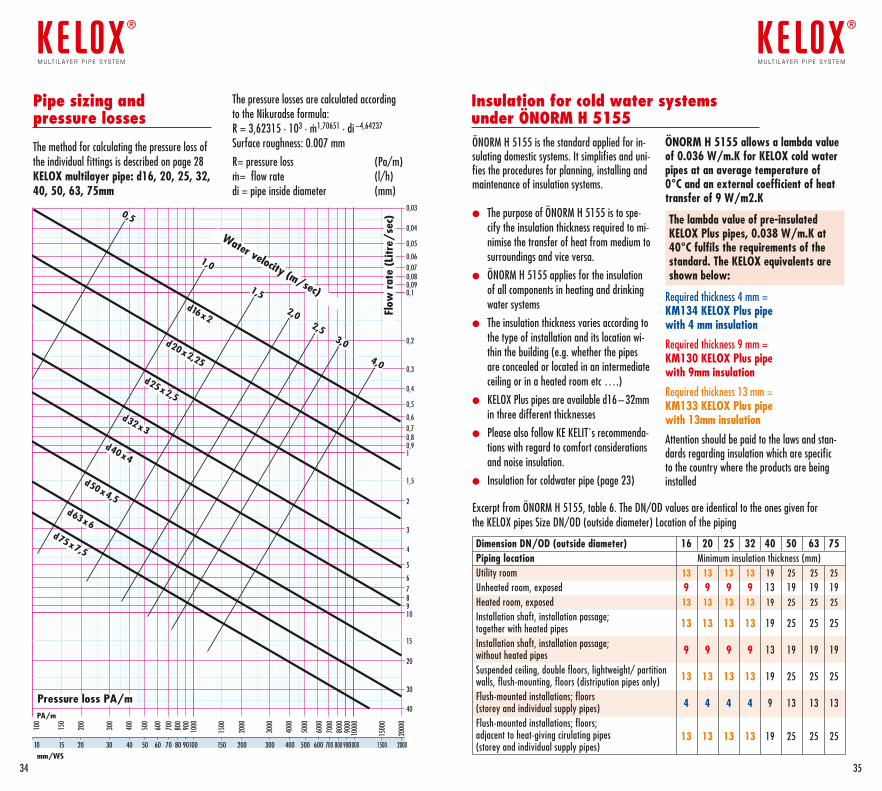
The pressure losses are calculated according to the Nikuradse formula: R = 3,62315 · 103 · m· 1,70651 · di –4,64237
Surface roughness: 0.007 mm
R= pressure loss (Pa/m)m· = flow rate (l/h)di = pipe inside diameter (mm)
Pipe sizing and pressure losses
The method for calculating the pressure loss of the individual fittings is described on page 28KELOX multilayer pipe: d16, 20, 25, 32, 40, 50, 63, 75mm
3534
m u lt i l ay e r p i p e s y s t e m
®
m u lt i l ay e r p i p e s y s t e m
®
ÖNORM H 5155 is the standard applied for in-sulating domestic systems. It simplifies and uni-fies the procedures for planning, installing and maintenance of insulation systems.
l The purpose of ÖNORM H 5155 is to spe-cify the insulation thickness required to mi-nimise the transfer of heat from medium to surroundings and vice versa.
l ÖNORM H 5155 applies for the insulation of all components in heating and drinking water systems
l The insulation thickness varies according to the type of installation and its location wi-thin the building (e.g. whether the pipes are concealed or located in an intermediate ceiling or in a heated room etc ….)
l KELOX Plus pipes are available d16–32mm in three different thicknesses
l Please also follow KE KELIT´s recommenda-tions with regard to comfort considerations and noise insulation.
l Insulation for coldwater pipe (page 23)
ÖNORM H 5155 allows a lambda value of 0.036 W/m.K for KELOX cold water pipes at an average temperature of 0°C and an external coefficient of heat transfer of 9 W/m2.K
The lambda value of pre-insulated KELOX Plus pipes, 0.038 W/m.K at 40°C fulfils the requirements of the standard. The KELOX equivalents are shown below:
Required thickness 4 mm = KM134 KELOX Plus pipe with 4 mm insulation
Required thickness 9 mm = KM130 KELOX Plus pipe with 9mm insulation
Required thickness 13 mm = KM133 KELOX Plus pipe with 13mm insulation
Attention should be paid to the laws and stan-dards regarding insulation which are specific to the country where the products are being installed
Excerpt from ÖNORM H 5155, table 6. The DN/OD values are identical to the ones given for the KELOX pipes Size DN/OD (outside diameter) Location of the piping
Insulation for cold water systems under ÖNORM H 5155
Dimension DN/OD (outside diameter) 16 20 25 32 40 50 63 75Piping location Minimum insulation thickness (mm)Utility room 13 13 13 13 19 25 25 25Unheated room, exposed 9 9 9 9 13 19 19 19Heated room, exposed 13 13 13 13 19 25 25 25Installation shaft, installation passage;together with heated pipes 13 13 13 13 19 25 25 25
Installation shaft, installation passage; without heated pipes 9 9 9 9 13 19 19 19
Suspended ceiling, double floors, lightweight/ partition walls, flush-mounting, floors (distripution pipes only) 13 13 13 13 19 25 25 25
Flush-mounted installations; floors (storey and individual supply pipes) 4 4 4 4 9 13 13 13
Flush-mounted installations; floors; adjacent to heat-giving cirulating pipes(storey and individual supply pipes)
13 13 13 13 19 25 25 25
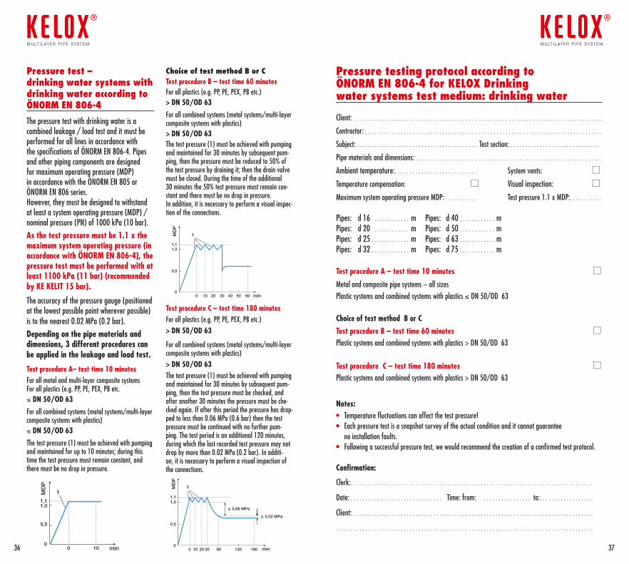
Pressure test – drinking water systems with drinking water according to ÖNORM EN 806-4 The pressure test with drinking water is a combined leakage / load test and it must be performed for all lines in accordance with the specifications of ÖNORM EN 806-4. Pipes and other piping components are designed for maximum operating pressure (MDP) in accordance with the ÖNORM EN 805 or ÖNORM EN 806 series. However, they must be designed to withstand at least a system operating pressure (MDP) / nominal pressure (PN) of 1000 kPa (10 bar). As the test pressure must be 1.1 x the maximum system operating pressure (in accordance with ÖNORM EN 806-4), the pressure test must be performed with at least 1100 kPa (11 bar) (recommended by KE KELIT 15 bar).
The accuracy of the pressure gauge (positioned at the lowest possible point wherever possible) is to the nearest 0.02 MPa (0.2 bar). Depending on the pipe materials and dimensions, 3 different procedures can be applied in the leakage and load test.
Test procedure A– test time 10 minutes For all metal and multi-layer composite systems For all plastics (e.g. PP, PE, PEX, PB etc.≤ DN 50/OD 63 For all combined systems (metal systems/multi-layer composite systems with plastics) ≤ DN 50/OD 63 The test pressure (1) must be achieved with pumping and maintained for up to 10 minutes; during this time the test pressure must remain constant, and there must be no drop in pressure.
Choice of test method B or C Test procedure B – test time 60 minutes For all plastics (e.g. PP, PE, PEX, PB etc.) > DN 50/OD 63
For all combined systems (metal systems/multi-layer composite systems with plastics) > DN 50/OD 63 The test pressure (1) must be achieved with pumping and maintained for 30 minutes by subsequent pum-ping, then the pressure must be reduced to 50% of the test pressure by draining it; then the drain valve must be closed. During the time of the additional 30 minutes the 50% test pressure must remain con-stant and there must be no drop in pressure. In addition, it is necessary to perform a visual inspec-tion of the connections.
Test procedure C – test time 180 minutes For all plastics (e.g. PP, PE, PEX, PB etc.) > DN 50/OD 63
For all combined systems (metal systems/multi-layer composite systems with plastics) > DN 50/OD 63 The test pressure (1) must be achieved with pumping and maintained for 30 minutes by subsequent pum-ping, then the test pressure must be checked, and after another 30 minutes the pressure must be che-cked again. If after this period the pressure has drop-ped to less than 0.06 MPa (0.6 bar) then the test pressure must be continued with no further pum-ping. The test period is an additional 120 minutes, during which the last recorded test pressure may not drop by more than 0.02 MPa (0.2 bar). In additi-on, it is necessary to perform a visual inspection of the connections.
MD
P
1
1
1,1
1,1
1,0
1,0
0,5
0,5
0
0
0
0 10 20 30 40 50 60
10
min
1
1,11,0
0,5
00 10 20 30 60 120
≤ 0,06 MPa
≤ 0,02 MPa
180
min
min
MD
PM
DP
MD
P
1
1
1,1
1,1
1,0
1,0
0,5
0,5
0
0
0
0 10 20 30 40 50 60
10
min
1
1,11,0
0,5
00 10 20 30 60 120
≤ 0,06 MPa
≤ 0,02 MPa
180
min
min
MD
PM
DP
MD
P
1
1
1,1
1,1
1,0
1,0
0,5
0,5
0
0
0
0 10 20 30 40 50 60
10
min
1
1,11,0
0,5
00 10 20 30 60 120
≤ 0,06 MPa
≤ 0,02 MPa
180
min
min
MD
PM
DP
Pressure testing protocol according to ÖNORM EN 806-4 for KELOX Drinking water systems test medium: drinking water
Client: . . . . . . . . . . . . . . . . . . . . . . . . . . . . . . . . . . . . . . . . . . . . . . . . . . . . . . . . . . . . . . . . . . . . . . . . . . . . . . . . . . . .
Contractor: . . . . . . . . . . . . . . . . . . . . . . . . . . . . . . . . . . . . . . . . . . . . . . . . . . . . . . . . . . . . . . . . . . . . . . . . . . . . . . . .
Subject: . . . . . . . . . . . . . . . . . . . . . . . . . . . . . . . . . . . . . . . . . Test section: . . . . . . . . . . . . . . . . . . . . . . . . . . . . . .
Pipe materials and dimensions: . . . . . . . . . . . . . . . . . . . . . . . . . . . . . . . . . . . . . . . . . . . . . . . . . . . . . . . . . . . . . . .
Ambient temperature: . . . . . . . . . . . . . . . . . . . . . . . . . . . . System vents:
Temperature compensation: Visual inspection:
Maximum system operating pressure MDP: . . . . . . . . . . Test pressure 1.1 x MDP: . . . . . . . . . . .
Pipes: d 16 . . . . . . . . . . . . m Pipes: d 40 . . . . . . . . . . . . mPipes: d 20 . . . . . . . . . . . . m Pipes: d 50 . . . . . . . . . . . . m Pipes: d 25 . . . . . . . . . . . . . m Pipes: d 63 . . . . . . . . . . . . mPipes: d 32 . . . . . . . . . . . . . m Pipes: d 75 . . . . . . . . . . . . m
Test procedure A – test time 10 minutes
Metal and composite pipe systems – all sizesPlastic systems and combined systems with plastics ≤ DN 50/OD 63
Choice of test method B or CTest procedure B – test time 60 minutes Plastic systems and combined systems with plastics > DN 50/OD 63
Test procedure C – test time 180 minutes Plastic systems and combined systems with plastics > DN 50/OD 63
Notes:• Temperature fluctuations can affect the test pressure!• Each pressure test is a snapshot survey of the actual condition and it cannot guarantee
no installation faults.• Following a successful pressure test, we would recommend the creation of a confirmed test protocol.
Confirmation:
Clerk: . . . . . . . . . . . . . . . . . . . . . . . . . . . . . . . . . . . . . . . . . . . . . . . . . . . . . . . . . . . . . . . . . . . . . . . . . . . . . . . . . .
Date: . . . . . . . . . . . . . . . . . . . . . . . . . . . . . . . Time: from: . . . . . . . . . . . . . . . . to: . . . . . . . . . . . . . . . . . .
Client: . . . . . . . . . . . . . . . . . . . . . . . . . . . . . . . . . . . . . . . . . . . . . . . . . . . . . . . . . . . . . . . . . . . . . . . . . . . . . . . . .
. . . . . . . . . . . . . . . . . . . . . . . . . . . . . . . . . . . . . . . . . . . . . . . . . . . . . . . . . . . . . . . . . . . . . . . . . . . . . . . . . . . . . . .
3736
m u lt i l ay e r p i p e s y s t e m
®
m u lt i l ay e r p i p e s y s t e m
®
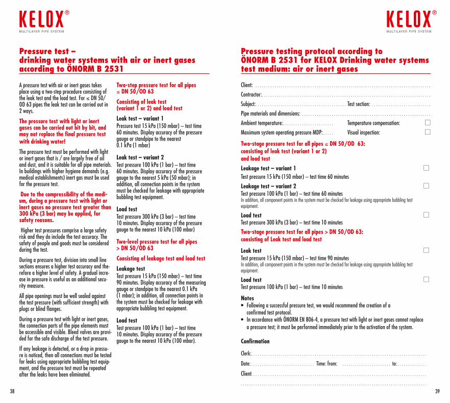
A pressure test with air or inert gases takes place using a two-step procedure consisting of the leak test and the load test. For ≤ DN 50/ OD 63 pipes the leak test can be carried out in 2 ways.
The pressure test with light or inert gases can be carried out bit by bit, and may not replace the final pressure test with drinking water!
The pressure test must be performed with light or inert gases that is / are largely free of oil and dust, and it is suitable for all pipe materials. In buildings with higher hygiene demands (e.g. medical establishments) inert gas must be used for the pressure test.
Due to the compressibility of the medi-um, during a pressure test with light or inert gases no pressure test greater than 300 kPa (3 bar) may be applied, for safety reasons.
Higher test pressures comprise a large safety risk and they do include the test accuracy. The safety of people and goods must be considered during the test.
During a pressure test, division into small line sections ensures a higher test accuracy and the-refore a higher level of safety. A gradual incre-ase in pressure is useful as an additional secu-rity measure.
All pipe openings must be well sealed against the test pressure (with sufficient strength) with plugs or blind flanges.
During a pressure test with light or inert gases, the connection parts of the pipe elements must be accessible and visible. Bleed valves are provi-ded for the safe discharge of the test pressure.
If any leakage is detected, or a drop in pressu-re is noticed, then all connections must be tested for leaks using appropriate bubbling test equip-ment, and the pressure test must be repeated after the leaks have been eliminated.
Two-step pressure test for all pipes ≤ DN 50/OD 63
Consisting of leak test (variant 1 or 2) and load test
Leak test – variant 1 Pressure test 15 kPa (150 mbar) – test time 60 minutes. Display accuracy of the pressure gauge or standpipe to the nearest 0.1 kPa (1 mbar)
Leak test – variant 2 Test pressure 100 kPa (1 bar) – test time 60 minutes. Display accuracy of the pressure gauge to the nearest 5 kPa (50 mbar); in addition, all connection points in the system must be checked for leakage with appropriate bubbling test equipment.
Load testTest pressure 300 kPa (3 bar) – test time 10 minutes. Display accuracy of the pressure gauge to the nearest 10 kPa (100 mbar)
Two-level pressure test for all pipes > DN 50/OD 63
Consisting of leakage test and load test
Leakage testTest pressure 15 kPa (150 mbar) – test time 90 minutes. Display accuracy of the measuring gauge or standpipe to the nearest 0.1 kPa (1 mbar); in addition, all connection points in the system must be checked for leakage with appropriate bubbling test equipment.
Load testTest pressure 100 kPa (1 bar) – test time 10 minutes. Display accuracy of the pressure gauge to the nearest 10 kPa (100 mbar).
Pressure testing protocol according to ÖNORM B 2531 for KELOX Drinking water systems test medium: air or inert gases
Client: . . . . . . . . . . . . . . . . . . . . . . . . . . . . . . . . . . . . . . . . . . . . . . . . . . . . . . . . . . . . . . . . . . . . . . . . . . . . . . . . . . .
Contractor: . . . . . . . . . . . . . . . . . . . . . . . . . . . . . . . . . . . . . . . . . . . . . . . . . . . . . . . . . . . . . . . . . . . . . . . . . . . . . . . .
Subject: . . . . . . . . . . . . . . . . . . . . . . . . . . . . . . . . . . . . . . . . . . . Test section: . . . . . . . . . . . . . . . . . . . . . . . . . . . .
Pipe materials and dimensions: . . . . . . . . . . . . . . . . . . . . . . . . . . . . . . . . . . . . . . . . . . . . . . . . . . . . . . . . . . . . .
Ambient temperature: . . . . . . . . . . . . . . . . . . . . . . . . Temperature compensation:
Maximum system operating pressure MDP: . . . . . Visual inspection:
Two-stage pressure test for all pipes ≤ DN 50/OD 63: consisting of leak test (variant 1 or 2) and load testLeakage test – variant 1 Test pressure 15 kPa (150 mbar) – test time 60 minutes
Leakage test – variant 2 Test pressure 100 kPa (1 bar) – test time 60 minutesIn addition, all component points in the system must be checked for leakage using appropriate bubbling test equipment.
Load test Test pressure 300 kPa (3 bar) – test time 10 minutes
Two-stage pressure test for all pipes > DN 50/OD 63: consisting of Leak test and load test
Leak test Test pressure 15 kPa (150 mbar) – test time 90 minutesIn addition, all component points in the system must be checked for leakage using appropriate bubbling test equipment.
Load test Test pressure 100 kPa (1 bar) – test time 10 minutes
Notes• Following a successful pressure test, we would recommend the creation of a
confirmed test protocol.• In accordance with ÖNORM EN 806-4, a pressure test with light or inert gases cannot replace
a pressure test; it must be performed immediately prior to the activation of the system.
Confirmation
Clerk: . . . . . . . . . . . . . . . . . . . . . . . . . . . . . . . . . . . . . . . . . . . . . . . . . . . . . . . . . . . . . . . . . . . . . . . . . . . . . . . . . . .
Date: . . . . . . . . . . . . . . . . . . . . . . . . . . . . . . Time: from: . . . . . . . . . . . . . . . . . . . . . . . to: . . . . . . . . . . . . . .
Client. . . . . . . . . . . . . . . . . . . . . . . . . . . . . . . . . . . . . . . . . . . . . . . . . . . . . . . . . . . . . . . . . . . . . . . . . . . . . . . . . . .
. . . . . . . . . . . . . . . . . . . . . . . . . . . . . . . . . . . . . . . . . . . . . . . . . . . . . . . . . . . . . . . . . . . . . . . . . . . . . . . . . . . . . . . .
Pressure test – drinking water systems with air or inert gases according to ÖNORM B 2531
3938
m u lt i l ay e r p i p e s y s t e m
®
m u lt i l ay e r p i p e s y s t e m
®
Expansion of KELOX pipes
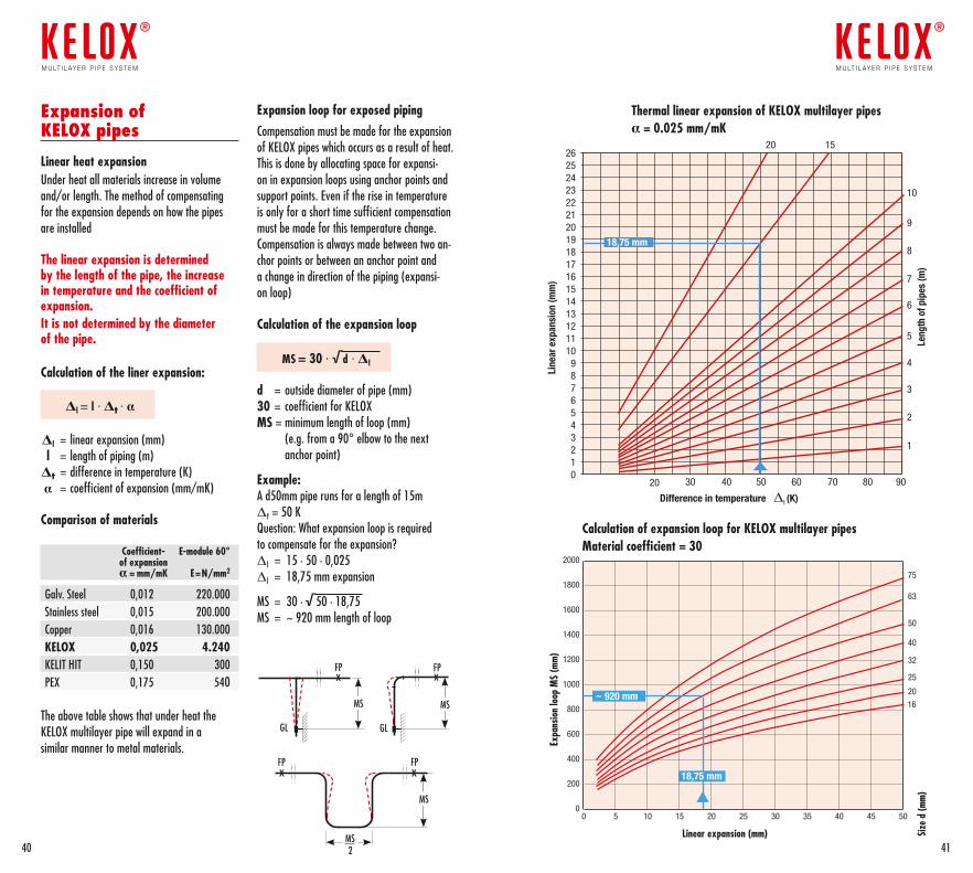
Linear heat expansionUnder heat all materials increase in volume and/or length. The method of compensating for the expansion depends on how the pipes are installed
The linear expansion is determined by the length of the pipe, the increase in temperature and the coefficient of expansion.It is not determined by the diameter of the pipe.
Calculation of the liner expansion:
Δl = l · Δt · α
Δl = linear expansion (mm) l = length of piping (m) Δt = difference in temperature (K) α = coefficient of expansion (mm/mK)
Comparison of materials
Coefficient- E-module 60° of expansion α = mm/mK E=N/mm2
Galv. Steel 0,012 220.000Stainless steel 0,015 200.000Copper 0,016 130.000KELOX 0,025 4.240KELIT HIT 0,150 300PEX 0,175 540
The above table shows that under heat the KELOX multilayer pipe will expand in asimilar manner to metal materials.
x
xx
xFP FP
MS MS
MS
MS2
GL GL
FP FP
Expansion loop for exposed piping
Compensation must be made for the expansion of KELOX pipes which occurs as a result of heat. This is done by allocating space for expansi-on in expansion loops using anchor points and support points. Even if the rise in temperature is only for a short time sufficient compensation must be made for this temperature change.Compensation is always made between two an-chor points or between an anchor point and a change in direction of the piping (expansi-on loop)
Calculation of the expansion loop
MS = 30 · √d · Δl
d = outside diameter of pipe (mm)30 = coefficient for KELOXMS = minimum length of loop (mm) (e.g. from a 90° elbow to the next anchor point)
Example:A d50mm pipe runs for a length of 15m Δt = 50 K Question: What expansion loop is required to compensate for the expansion?Δl = 15 · 50 · 0,025Δl = 18,75 mm expansion
MS = 30 · √50 · 18,75MS = ~ 920 mm length of loop
4140
m u lt i l ay e r p i p e s y s t e m
®
m u lt i l ay e r p i p e s y s t e m
®
020 30 40 50 60 70 80 90
123456789
1011121314151617181920212223242526
Line
ar e
xpan
sion
(mm
)
Leng
th o
f pip
es (m
)
Difference in temperature Δt (K)
1
2
3
4
5
6
7
8
9
10
1520
18,75 mm
Thermal linear expansion of KELOX multilayer pipesα = 0.025 mm/mK
Calculation of expansion loop for KELOX multilayer pipesMaterial coefficient = 30
0 5 10 15 20 25 30 35 40 45 50
75
63
50
40
32
25
20
16
0
200
400
600
800
1000
1200
1400
1600
1800
2000
Size
d (m
m)
Linear expansion (mm)
~ 920 mm
18,75 mm
Expa
nsio
n lo
op M
S (m
m)
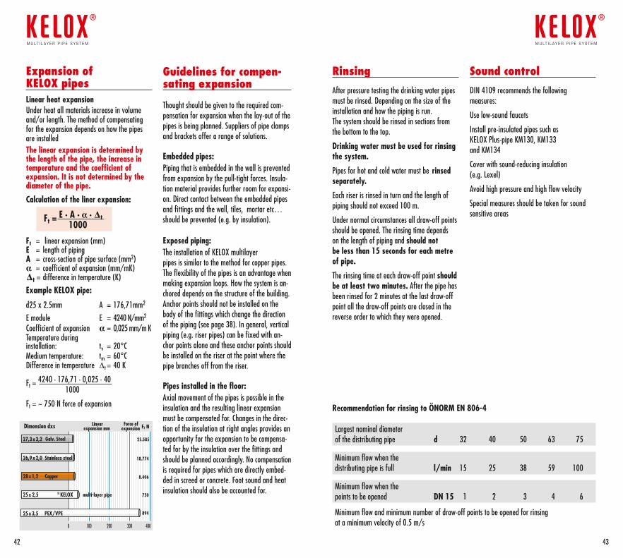
Expansion of KELOX pipesLinear heat expansionUnder heat all materials increase in volume and/or length. The method of compensating for the expansion depends on how the pipes are installedThe linear expansion is determined by the length of the pipe, the increase in temperature and the coefficient of expansion. It is not determined by the diameter of the pipe.
Calculation of the liner expansion:
Ft = E · A · α · ∆ t 1000
Ft = linear expansion (mm) E = length of piping A = cross-section of pipe surface (mm2) α= coefficient of expansion (mm/mK) ∆ t = difference in temperature (K)
Example KELOX pipe:
d25 x 2.5mm A = 176,71mm2
E module E = 4240 N/mm2
Coefficient of expansion α = 0,025 mm/m KTemperature during installation: tv = 20°CMedium temperature: tm = 60°CDifference in temperature Dt = 40 K
Ft = 4240 · 176,71 · 0,025 · 40 1000
Ft = ~ 750 N force of expansion
0 100 200 300 400
Dimension dxs
PEX/VPE25x3,5
Copper28x1,2
Stainless steel26,9x2,0
KELOX® multi-layer pipe25x 2,5
Galv. Steel27,3x3,2
894
8.406
18.774
750
25.585
Linear expansion mm
Force of expansion tF N
Guidelines for compen-sating expansion
Thought should be given to the required com-pensation for expansion when the lay-out of the pipes is being planned. Suppliers of pipe clamps and brackets offer a range of solutions.
Embedded pipes:Piping that is embedded in the wall is prevented from expansion by the pull-tight forces. Insula-tion material provides further room for expansi-on. Direct contact between the embedded pipes and fittings and the wall, tiles, mortar etc… should be prevented (e.g. by insulation).
Exposed piping:The installation of KELOX multilayer pipes is similar to the method for copper pipes. The flexibility of the pipes is an advantage when making expansion loops. How the system is an-chored depends on the structure of the building. Anchor points should not be installed on the body of the fittings which change the direction of the piping (see page 38). In general, vertical piping (e.g. riser pipes) can be fixed with an-chor points alone and these anchor points should be installed on the riser at the point where the pipe branches off from the riser.
Pipes installed in the floor: Axial movement of the pipes is possible in the insulation and the resulting linear expansion must be compensated for. Changes in the direc-tion of the insulation at right angles provides an opportunity for the expansion to be compensa-ted for by the insulation over the fittings and should be planned accordingly. No compensation is required for pipes which are directly embed-ded in screed or concrete. Foot sound and heat insulation should also be accounted for.
Rinsing
After pressure testing the drinking water pipes must be rinsed. Depending on the size of the installation and how the piping is run.The system should be rinsed in sections from the bottom to the top.
Drinking water must be used for rinsing the system.
Pipes for hot and cold water must be rinsed separately.
Each riser is rinsed in turn and the length of piping should not exceed 100 m.
Under normal circumstances all draw-off points should be opened. The rinsing time depends on the length of piping and should not be less than 15 seconds for each metre of pipe.
The rinsing time at each draw-off point should be at least two minutes. After the pipe has been rinsed for 2 minutes at the last draw-off point all the draw-off points are closed in the reverse order to which they were opened.
Recommendation for rinsing to ÖNORM EN 806-4
Largest nominal diameterof the distributing pipe d 32 40 50 63 75
Minimum flow when the distributing pipe is full l/min 15 25 38 59 100
Minimum flow when the points to be opened DN 15 1 2 3 4 6
Minimum flow and minimum number of draw-off points to be opened for rinsingat a minimum velocity of 0.5 m/s
Sound control
DIN 4109 recommends the following measures:
Use low-sound faucets
Install pre-insulated pipes such as KELOX Plus-pipe KM130, KM133 and KM134
Cover with sound-reducing insulation (e.g. Lexel)
Avoid high pressure and high flow velocity
Special measures should be taken for sound sensitive areas
4342
m u lt i l ay e r p i p e s y s t e m
®
m u lt i l ay e r p i p e s y s t e m
®
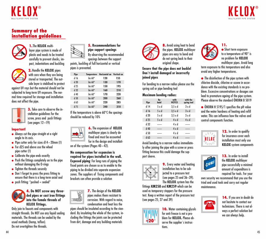
5. Recommendations for pipe support spacingsBy observing the recommended spacings between the support
points, buckling of full horizontal or vertical pipes is prevented.
Pipe Temperature Horizontal cm Vertical cm
d 16 bis 60° 120 155 d 20 bis 60° 130 170 d 25 bis 60° 150 195 d 32 bis 60° 160 210 d 40 bis 60° 170 220 d 50 bis 60° 200 260 d 63 bis 60° 220 285 d 75 bis 60° 240 310
If the temperature is above 60°C the spacings should be reduced by 10%
6. The expansion of KELOXmultilayer pipes is clearly de-fined and must be accounted for in the design and installati-
on of the system (Pages 40 – 42).
No compensation for expansion is required for pipes installed in the wall. Exposed piping: For long runs of piping the fixed points are chosen so as to enable to the piping to be divided into separate expansion zones. The suppliers of fixing components and brackets can often provide a solution
7. The design of the KELOXpipes makes them resistant to corrosion. With regard to noise, condensation and heat loss the
pipes should be insulated according to the stan-dard. By insulating the whole of the system, in-cluding the fittings the joints can be protected from dirt, damage and any building materials
Summary of the installation guidelines
1. The KELOX multi- layer pipe system is made of plastic and needs to be treated carefully to prevent shocks, im-pact, indentations and buckling
2. Handle the KELOX pipes with care when they are being stored or transported. The out-side layer is stabilised to protect
against UV rays but the material should not be subjected to long-term UV exposure. The nor-mal time required for storage and installation does not affect the pipe.
3. Take care to observe the in-stallation guidelines for the screw, press and push fittings (see pages 12 –19)
Important!l Always cut the pipe straight at a right
angle to its axis.l Pipe cutter only for sizes d14 – 20mm (!)l For d25 and above use the wheel
pipe cutter (!)l Calibrate the pipe ends exactlyl Push the fittings completely on to the pipe
without damaging the O-ringsl Tighten the threads securelyl Don´t forget to press the press fitting to
ensure that there is a long-term axial seall push fitting: “pushed = sealed”
4. Do NOT screw any threa-ded pipes or cast iron fittings into the female threads of KELOX fittings.
Only join to faucets and components with straight threads. Do NOT use any liquid sealing materials. The threads can be sealed by the usual methods (hemp, teflon). Do not overtighten the threads.
8. Avoid using heat to bend the pipes. KELOX multilayer pipes are easy to bend and do not spring back to their original shape.
Ensure that the pipe does not buckle! Don´t install damaged or incorrectly joined pipes
For bending to a narrow radius please use the spring coil or pipe bending tool
Maximum bending radius: By with with the Pipe hand WZ925 spring tool
d 14 5 x d 3,5 x d 3 x dd 16 5 x d 3,5 x d 3 x dd 20 5 x d 3,5 x d 3 x dd 25 5 x d 4 x d 4 x dd 32 ––– 4 x d –––d 40 ––– 4 x d –––d 50 ––– 4 x d –––d 63 ––– 4 x d –––
Avoid bending to a narrow radius immediate-ly after joining the pipe with a screw or press fitting because this could damage the sup-port sleeve.
9. Every water and heating installation has to be sub-jected to a pressure test (see pages 25 and 36–39). The KELOX system has the
fittings KM258 and KM259 which can be used as temporary stoppers for the pressure test. Keep a written report of the pressure test (see pages 25, 27 and 39)
10. Water containing glycols for anti-freeze is not a pro-blem for KELOX. Please ob-serve the supplier´s instruc-tions.
11. l Short term exposure to a temperature of 90° is no problem for KELOXmultilayer pipes. Avoid long
term exposure to this temperature and also avoid any higher temperatures.
l The disinfection of the pipe system with chlorine dioxide, chlorine or ozone in accor-dance with the existing standards is no pro-blem. Excessive concentrations or dosages can lead to premature ageing of the pipe system. Please observe the standard ÖNORM B 5019
l ÖNORM H 5195/1 specifies the pH value and the water hardness of heating and refill water. This can influence how the valves and control components function.
12. In order to qualify for insurance cover each installation must only use KELOX system components
13. In order to install the KELOX multilayer pipe successfully a minimal amount of expenditure is required for tools. For your
own security we recommend that you use the tried and used tools and carry out regular maintenance.
14. If you are in doubt do not hesitate to contact our technicians. There is not al-ways a perfect solution but we can always help.
4544
m u lt i l ay e r p i p e s y s t e m
®
m u lt i l ay e r p i p e s y s t e m
®
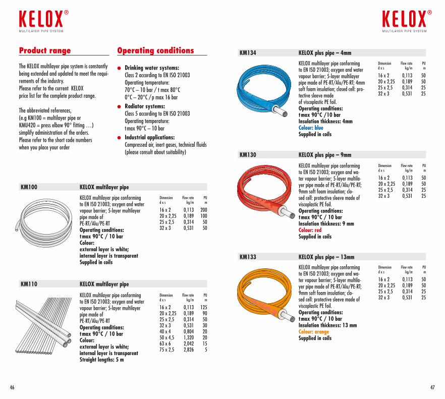
Product range
The KELOX multilayer pipe system is constantly being extended and updated to meet the requi-rements of the industry.Please refer to the current KELOX price list for the complete product range.
The abbreviated references, (e.g KM100 = multilayer pipe or KMU420 = press elbow 90° fitting …)simplify administration of the orders.Please refer to the short code numbers when you place your order
Operating conditions
l Drinking water systems: Class 2 according to EN ISO 21003 Operating temperature: 70°C – 10 bar / t max 80°C 0°C – 20°C / p max 16 bar
l Radiator systems: Class 5 according to EN ISO 21003 Operating temperature: t max 90°C – 10 bar
l Industrial applications: Compressed air, inert gases, technical fluids (please consult about suitability)
KELOX multilayer pipe conforming to EN ISO 21003; oxygen and water vapour barrier; 5-layer multilayer pipe made of PE-RT/Alu/PE-RTOperating conditions:tmax 90°C / 10 bar Colour: external layer is white; internal layer is transparentSupplied in coils
KELOX multilayer pipe conforming to EN ISO 21003; oxygen and water vapour barrier; 5-layer multilayer pipe made of PE-RT/Alu/PE-RTOperating conditions:tmax 90°C / 10 bar Colour: external layer is white; internal layer is transparent Straight lengths: 5 m
Dimension Flow rate PUd x s kg/m m
16 x 2 0,113 20020 x 2,25 0,189 10025 x 2,5 0,314 5032 x 3 0,531 50
Dimension Flow rate PUd x s kg/m m
16 x 2 0,113 12520 x 2,25 0,189 9025 x 2,5 0,314 5032 x 3 0,531 3040 x 4 0,804 2050 x 4,5 1,320 2063 x 6 2,042 1575 x 2,5 2,826 5
Dimension Flow rate PUd x s kg/m m
16 x 2 0,113 5020 x 2,25 0,189 5025 x 2,5 0,314 2532 x 3 0,531 25
Dimension Flow rate PUd x s kg/m m
16 x 2 0,113 5020 x 2,25 0,189 5025 x 2,5 0,314 2532 x 3 0,531 25
KELOX multilayer pipe conforming to EN ISO 21003; oxygen and wa-ter vapour barrier; 5-layer multila-yer pipe made of PE-RT/Alu/PE-RT; 9mm soft foam insulation; clo-sed cell: protective sleeve made of viscoplastic PE foil.Operating conditions:tmax 90°C / 10 bar Insulation thickness: 9 mmColour: redSupplied in coils
KELOX multilayer pipe conforming to EN ISO 21003; oxygen and wa-ter vapour barrier; 5-layer multila-yer pipe made of PE-RT/Alu/PE-RT; 9mm soft foam insulation; clo-sed cell: protective sleeve made of viscoplastic PE foil.Operating conditions:tmax 90°C / 10 bar Insulation thickness: 13 mmColour: orangeSupplied in coils
KELOX multilayer pipe conforming to EN ISO 21003; oxygen and water vapour barrier; 5-layer multilayer pipe made of PE-RT/Alu/PE-RT; 4mm soft foam insulation; closed cell: pro-tective sleeve made of viscoplastic PE foil.Operating conditions:tmax 90°C /10 bar Insulation thickness: 4mmColour: blueSupplied in coils
Dimension Flow rate PUd x s kg/m m
16 x 2 0,113 5020 x 2,25 0,189 5025 x 2,5 0,314 2532 x 3 0,531 25
KM134 KELOX plus pipe – 4mm
KM130 KELOX plus pipe – 9mm
KM133 KELOX plus pipe – 13mm
KM110 KELOX multilayer pipe
KM100 KELOX multilayer pipe
4746
m u lt i l ay e r p i p e s y s t e m
®
m u lt i l ay e r p i p e s y s t e m
®
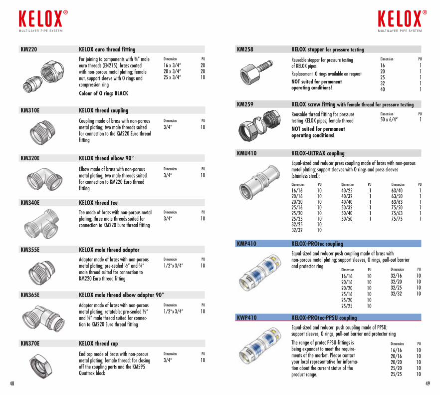
KM340E KELOX thread tee
KM355E KELOX male thread adaptor
KM365E KELOX male thread elbow adaptor 90°
KM370E KELOX thread cap
Tee made of brass with non-porous metal plating; three male threads suited for connection to KM220 Euro thread fitting
Dimension PU
3/4“ 10
Adaptor made of brass with non-porous metal plating; pre-sealed ½” and ¾” male thread suited for connection to KM220 Euro thread fitting
Dimension PU
1/2“x 3/4“ 10
Adaptor made of brass with non-porous metal plating; rotatable; pre-sealed ½” and ¾” male thread suited for connec-tion to KM220 Euro thread fitting
Dimension PU
1/2“x 3/4“ 10
End cap made of brass with non-porous metal plating; female thread; for closing off the coupling parts and the KM595 Quattrox block
Dimension PU
3/4“ 10
KMU410 KELOX-ULTRAX coupling
Dimension PU
40/25 140/32 140/40 150/32 150/40 150/50 1
Dimension PU
63/40 163/50 163/63 175/50 175/63 175/75 1
Dimension PU
16/16 1020/16 1020/20 1025/16 1025/20 1025/25 1032/25 10 32/32 10
Equal-sized and reducer press coupling made of brass with non-porous metal plating; support sleeves with O rings and press sleeves (stainless steel);
For joining to components with ¾” male euro threads (EN215); brass coated with non-porous metal plating; female nut, support sleeve with O rings and compression ring
Colour of O ring: BLACK
Dimension PU
16 x 3/4“ 2020 x 3/4“ 2025 x 3/4“ 10
Dimension PU
3/4“ 10
Coupling made of brass with non-porous metal plating; two male threads suited for connection to the KM220 Euro thread fitting
KM310E KELOX thread coupling
KM220 KELOX euro thread fitting
KM320E KELOX thread elbow 90°
Elbow made of brass with non-porous metal plating; two male threads suited for connection to KM220 Euro thread fitting
Dimension PU
3/4“ 10
KMP410 KELOX-PROtec coupling
KWP410 KELOX-PROtec-PPSU coupling
Equal-sized and reducer push coupling made of brass with non-porous metal plating; support sleeves, O rings, pull-out barrier and protector ring
Equal-sized and reducer push coupling made of PPSU; support sleeves, O rings, pull-out barrier and protector ring
The range of protec PPSU-fittings is being expandet to meet the require-ments of the market. Please contact your local representative for informa-tion about the current status of the product range.
Dimension PU
32/16 1032/20 1032/25 1032/32 10
Dimension PU
16/16 1020/16 1020/20 1025/20 1025/25 10
Dimension PU
16/16 1020/16 1020/20 1025/16 1025/20 1025/25 10
Reusable stopper for pressure testing of KELOX pipesReplacement O rings available on requestNOT suited for permanent operating conditions !
Dimension PU
16 120 125 132 140 1
KM258 KELOX stopper for pressure testing
KM259 KELOX screw fitting with female thread for pressure testing
Reusable thread fitting for pressure testing KELOX pipes; female threadNOT suited for permanent operating conditions!
Dimension PU 50 x 6/4“ 1
4948
m u lt i l ay e r p i p e s y s t e m
®
m u lt i l ay e r p i p e s y s t e m
®
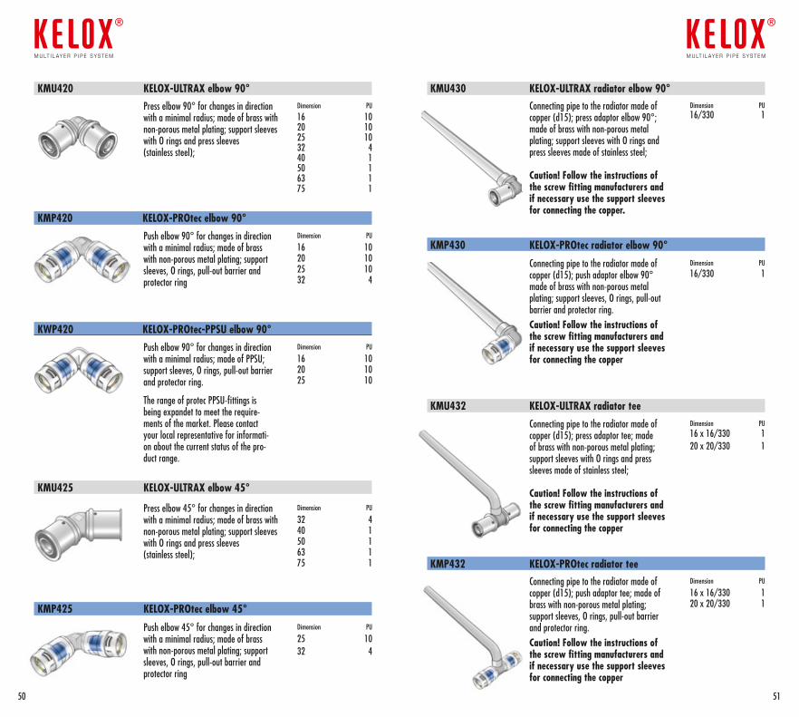
KMP420 KELOX-PROtec elbow 90°
KWP420 KELOX-PROtec-PPSU elbow 90°
Push elbow 90° for changes in direction with a minimal radius; made of brass with non-porous metal plating; support sleeves, O rings, pull-out barrier and protector ring
Push elbow 90° for changes in direction with a minimal radius; made of PPSU; support sleeves, O rings, pull-out barrier and protector ring.
The range of protec PPSU-fittings is being expandet to meet the require-ments of the market. Please contact your local representative for informati-on about the current status of the pro-duct range.
Dimension PU
16 1020 1025 1032 4
Dimension PU
16 1020 1025 10
KMU425 KELOX-ULTRAX elbow 45°
Press elbow 45° for changes in direction with a minimal radius; made of brass with non-porous metal plating; support sleeves with O rings and press sleeves (stainless steel);
Dimension PU
32 440 1 50 163 175 1
KMP430 KELOX-PROtec radiator elbow 90°
KMU432 KELOX-ULTRAX radiator tee
KMU430 KELOX-ULTRAX radiator elbow 90°Connecting pipe to the radiator made of copper (d15); press adaptor elbow 90°; made of brass with non-porous metal plating; support sleeves with O rings and press sleeves made of stainless steel;
Caution! Follow the instructions of the screw fitting manufacturers and if necessary use the support sleeves for connecting the copper.
Dimension PU 16/330 1
Connecting pipe to the radiator made of copper (d15); push adaptor elbow 90° made of brass with non-porous metal plating; support sleeves, O rings, pull-out barrier and protector ring. Caution! Follow the instructions of the screw fitting manufacturers and if necessary use the support sleeves for connecting the copper
Dimension PU
16/330 1
Connecting pipe to the radiator made of copper (d15); press adaptor tee; made of brass with non-porous metal plating; support sleeves with O rings and press sleeves made of stainless steel;
Caution! Follow the instructions of the screw fitting manufacturers and if necessary use the support sleeves for connecting the copper
Dimension PU 16 x 16/330 120 x 20/330 1
Push elbow 45° for changes in direction with a minimal radius; made of brass with non-porous metal plating; support sleeves, O rings, pull-out barrier and protector ring
Dimension PU
25 1032 4
KMP425 KELOX-PROtec elbow 45°
KMP432 KELOX-PROtec radiator teeConnecting pipe to the radiator made of copper (d15); push adaptor tee; made of brass with non-porous metal plating; support sleeves, O rings, pull-out barrier and protector ring. Caution! Follow the instructions of the screw fitting manufacturers and if necessary use the support sleeves for connecting the copper
Dimension PU
16 x 16/330 120 x 20/330 1
Press elbow 90° for changes in direction with a minimal radius; made of brass with non-porous metal plating; support sleeves with O rings and press sleeves (stainless steel);
Dimension PU
16 10 20 10 25 1032 440 150 163 175 1
KMU420 KELOX-ULTRAX elbow 90°
5150
m u lt i l ay e r p i p e s y s t e m
®
m u lt i l ay e r p i p e s y s t e m
®
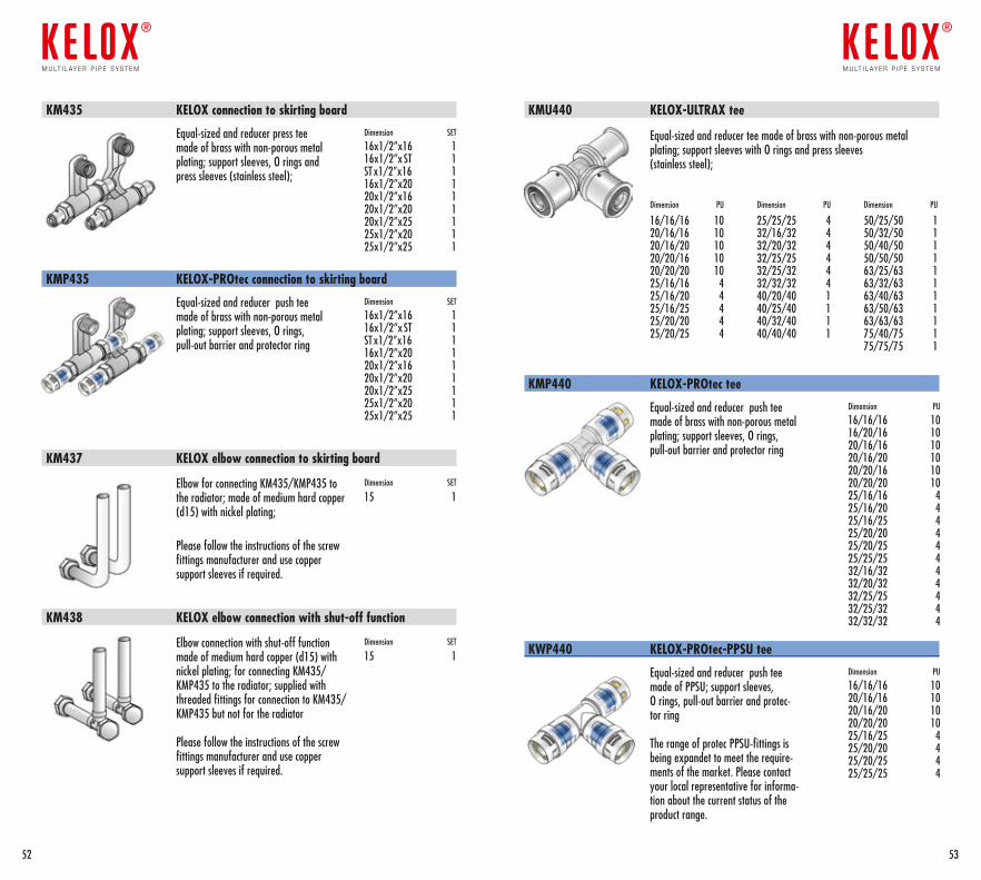
KMU440 KELOX-ULTRAX tee
Dimension PU
16/16/16 1020/16/16 1020/16/20 1020/20/16 1020/20/20 1025/16/16 425/16/20 425/16/25 425/20/20 425/20/25 4
Dimension PU
25/25/25 432/16/32 432/20/32 432/25/25 432/25/32 432/32/32 440/20/40 140/25/40 140/32/40 140/40/40 1
Dimension PU
50/25/50 150/32/50 150/40/50 150/50/50 163/25/63 163/32/63 163/40/63 163/50/63 163/63/63 175/40/75 175/75/75 1
Equal-sized and reducer tee made of brass with non-porous metal plating; support sleeves with O rings and press sleeves (stainless steel);
Equal-sized and reducer push tee made of brass with non-porous metal plating; support sleeves, O rings, pull-out barrier and protector ring
Equal-sized and reducer press tee made of brass with non-porous metal plating; support sleeves, O rings and press sleeves (stainless steel);
Equal-sized and reducer push tee made of brass with non-porous metal plating; support sleeves, O rings, pull-out barrier and protector ring
Equal-sized and reducer push tee made of PPSU; support sleeves, O rings, pull-out barrier and protec-tor ring
The range of protec PPSU-fittings is being expandet to meet the require-ments of the market. Please contact your local representative for informa-tion about the current status of the product range.
Dimension PU
16/16/16 1016/20/16 1020/16/16 1020/16/20 1020/20/16 1020/20/20 1025/16/16 425/16/20 4 25/16/25 425/20/20 425/20/25 425/25/25 432/16/32 432/20/32 4 32/25/25 4 32/25/32 432/32/32 4
Dimension SET
16x1/2”x16 116x1/2”x ST 1ST x1/2”x16 116x1/2”x20 120x1/2”x16 120x1/2”x20 120x1/2”x25 125x1/2”x20 125x1/2”x25 1
Dimension SET
16x1/2”x16 116x1/2”x ST 1ST x1/2”x16 116x1/2”x20 120x1/2”x16 120x1/2”x20 120x1/2”x25 125x1/2”x20 125x1/2”x25 1
Dimension PU
16/16/16 1020/16/16 1020/16/20 1020/20/20 1025/16/25 425/20/20 425/20/25 425/25/25 4
KMP440 KELOX-PROtec tee
KM435 KELOX connection to skirting board
KMP435 KELOX-PROtec connection to skirting board
KWP440 KELOX-PROtec-PPSU tee
KM438 KELOX elbow connection with shut-off function
KM437 KELOX elbow connection to skirting board
Elbow connection with shut-off function made of medium hard copper (d15) with nickel plating; for connecting KM435/KMP435 to the radiator; supplied with threaded fittings for connection to KM435/KMP435 but not for the radiator
Please follow the instructions of the screw fittings manufacturer and use copper support sleeves if required.
Elbow for connecting KM435/KMP435 to the radiator; made of medium hard copper (d15) with nickel plating;
Please follow the instructions of the screw fittings manufacturer and use copper support sleeves if required.
Dimension SET
15 1
Dimension SET
15 1
5352
m u lt i l ay e r p i p e s y s t e m
®
m u lt i l ay e r p i p e s y s t e m
®
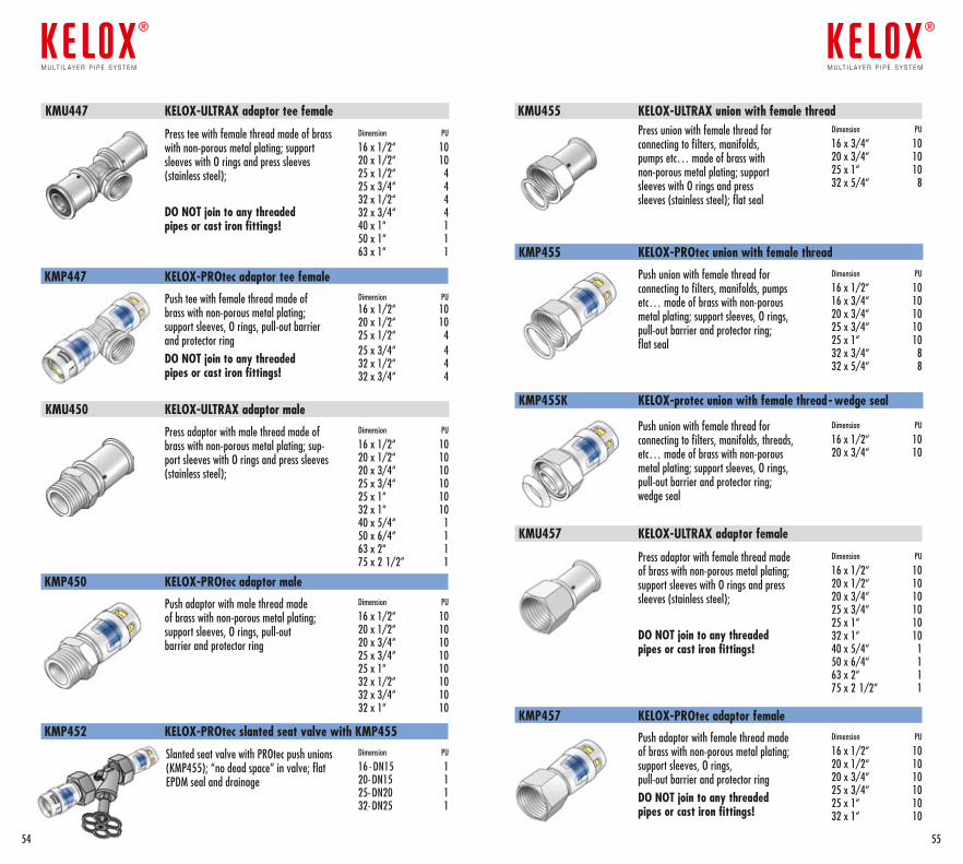
Press tee with female thread made of brass with non-porous metal plating; support sleeves with O rings and press sleeves (stainless steel);
DO NOT join to any threaded pipes or cast iron fittings!
Dimension PU
16 x 1/2“ 1020 x 1/2“ 1025 x 1/2“ 425 x 3/4“ 432 x 1/2“ 432 x 3/4“ 440 x 1“ 150 x 1“ 163 x 1“ 1
KMU447 KELOX-ULTRAX adaptor tee female
Push tee with female thread made of brass with non-porous metal plating; support sleeves, O rings, pull-out barrier and protector ringDO NOT join to any threaded pipes or cast iron fittings!
Dimension PU 16 x 1/2“ 10 20 x 1/2“ 10 25 x 1/2“ 425 x 3/4“ 432 x 1/2“ 432 x 3/4“ 4
KMP447 KELOX-PROtec adaptor tee female
Press adaptor with male thread made of brass with non-porous metal plating; sup-port sleeves with O rings and press sleeves (stainless steel);
Dimension PU
16 x 1/2“ 1020 x 1/2“ 1020 x 3/4“ 1025 x 3/4“ 1025 x 1“ 1032 x 1“ 1040 x 5/4“ 150 x 6/4“ 163 x 2“ 175 x 2 1/2” 1
KMU450 KELOX-ULTRAX adaptor male
Push adaptor with male thread made of brass with non-porous metal plating; support sleeves, O rings, pull-out barrier and protector ring
Dimension PU
16 x 1/2“ 1020 x 1/2“ 1020 x 3/4“ 1025 x 3/4“ 10 25 x 1“ 10 32 x 1/2“ 1032 x 3/4“ 1032 x 1“ 10
KMP450 KELOX-PROtec adaptor male
Press union with female thread for connecting to filters, manifolds, pumps etc… made of brass with non-porous metal plating; support sleeves with O rings and press sleeves (stainless steel); flat seal
Dimension PU
16 x 3/4“ 1020 x 3/4“ 1025 x 1“ 1032 x 5/4“ 8
KMU455 KELOX-ULTRAX union with female thread
Push union with female thread for connecting to filters, manifolds, pumps etc… made of brass with non-porous metal plating; support sleeves, O rings, pull-out barrier and protector ring; flat seal
Dimension PU
16 x 1/2“ 1016 x 3/4“ 10 20 x 3/4“ 1025 x 3/4“ 1025 x 1“ 1032 x 3/4“ 832 x 5/4“ 8
KMP455 KELOX-PROtec union with female thread
Press adaptor with female thread made of brass with non-porous metal plating; support sleeves with O rings and press sleeves (stainless steel);
DO NOT join to any threaded pipes or cast iron fittings!
Dimension PU
16 x 1/2“ 1020 x 1/2“ 1020 x 3/4“ 1025 x 3/4“ 1025 x 1“ 1032 x 1“ 1040 x 5/4“ 150 x 6/4“ 163 x 2“ 175 x 2 1/2” 1
KMU457 KELOX-ULTRAX adaptor female
Push adaptor with female thread made of brass with non-porous metal plating; support sleeves, O rings, pull-out barrier and protector ringDO NOT join to any threaded pipes or cast iron fittings!
Dimension PU
16 x 1/2“ 1020 x 1/2“ 1020 x 3/4“ 1025 x 3/4“ 1025 x 1“ 1032 x 1“ 10
KMP457 KELOX-PROtec adaptor female
Slanted seat valve with PROtec push unions (KMP455); “no dead space” in valve; flat EPDM seal and drainage
Dimension PU
16 - DN15 120- DN15 125- DN20 132- DN25 1
KMP452 KELOX-PROtec slanted seat valve with KMP455
Push union with female thread for connecting to filters, manifolds, threads, etc… made of brass with non-porous metal plating; support sleeves, O rings, pull-out barrier and protector ring; wedge seal
Dimension PU
16 x 1/2“ 10 20 x 3/4“ 10
KMP455K KELOX-protec union with female thread- wedge seal
5554
m u lt i l ay e r p i p e s y s t e m
®
m u lt i l ay e r p i p e s y s t e m
®
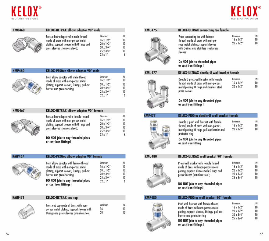
Push elbow adaptor with male thread made of brass with non-porous metal plating; support sleeves, O rings, pull-out barrier and protector ring
Dimension PU 16 x 1/2“ 1020 x 1/2“ 1020 x 3/4“ 1025 x 3/4“ 1032 x 1“ 6
KMP460 KELOX-PROtec elbow adaptor 90° male
Press elbow adaptor with female thread made of brass with non-porous metal plating; support sleeves with O rings and press sleeves (stainless steel);
DO NOT join to any threaded pipes or cast iron fittings!
Dimension PU
16 x 1/2“ 1020 x 1/2“ 1020 x 3/4“ 1025 x 3/4“ 1032 x 1“ 6
Push elbow adaptor with female thread made of brass with non-porous metal plating; support sleeves, O rings, pull-out barrier and protector ring
DO NOT join to any threaded pipes or cast iron fittings !
Press end cap made of brass with non- porous metal plating; support sleeves with O rings and press sleeves (stainless steel)
Dimension PU
16 x 1/2“ 1020 x 1/2“ 1020 x 3/4“ 1025 x 3/4“ 1032 x 1“ 6
Dimension PU
16 1020 10
KMP467 KELOX-PROtec elbow adaptor 90° female
KMU471 KELOX-ULTRAX end cap
KMU467 KELOX-ULTRAX elbow adaptor 90° female
KMU480 KELOX-ULTRAX wall bracket 90° female
KMP480 KELOX-PROtec wall bracket 90° female
Press wall bracket with female thread made of brass with non-porous metal plating; support sleeves with O rings and press sleeves (stainless steel); DO NOT join to any threaded pipes or cast iron fittings!
Dimension PU
16 x 1/2“ 1020 x 1/2“ 1020 x 3/4“ 1025 x 3/4“ 10
Push wall bracket with female thread made of brass with non-porous metal plating; support sleeves, O rings, pull-out barrier and protector ringDO NOT join to any threaded pipes or cast iron fittings !
Dimension PU
16 x 1/2“ 1020 x 1/2“ 1020 x 3/4“ 1025 x 3/4“ 10
KMP477 KELOX-PROtec double-U wall bracket female
Double U push wall bracket with female thread, made of brass with non-porous metal plating; O rings, pull-out barrier and protector ring
Do NOT join to any threaded pipes or cast iron fitting
Dimension PU
16 x 1/2“ 1020 x 1/2“ 10
Press elbow adaptor with male thread made of brass with non-porous metal plating; support sleeves with O rings and press sleeves (stainless steel);
Dimension PU
16 x 1/2“ 1020 x 1/2“ 1020 x 3/4“ 1025 x 3/4“ 1032 x 1“ 6
KMU460 KELOX-ULTRAX elbow adaptor 90° male KMU475 KELOX-ULTRAX connecting tee female
Press connecting tee with female thread, made of brass with non-po-rous metal plating; support sleeves with O-rings and stainless steel press sleeves
Do NOT join to threaded pipes or cast iron fittings !
Dimension PU16 x 1/2“ 1020 x 1/2“ 10
Double U press wall bracket with female thread, made of brass with non-porous metal plating; O rings and stainless steel press sleeves
Do NOT join to any threaded pipes or cast iron fittings !
Dimension PU
16 x 1/2“ 1020 x 1/2“ 10
KMU477 KELOX-ULTRAX double-U wall bracket female
5756
m u lt i l ay e r p i p e s y s t e m
®
m u lt i l ay e r p i p e s y s t e m
®
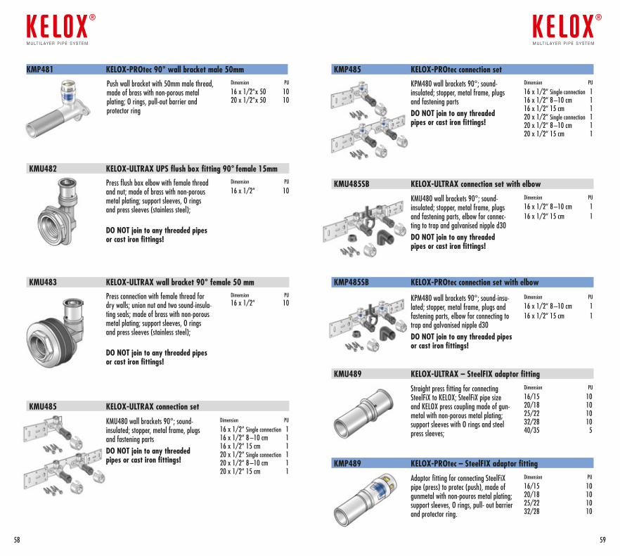
KMU483 KELOX-ULTRAX wall bracket 90° female 50 mm
KMU485 KELOX-ULTRAX connection set
Press connection with female thread for dry walls; union nut and two sound-insula-ting seals; made of brass with non-porous metal plating; support sleeves, O rings and press sleeves (stainless steel);
DO NOT join to any threaded pipes or cast iron fittings!
Dimension PU 16 x 1/2“ 10
Dimension PU
16 x 1/2“ Single connection 1 16 x 1/2“ 8 –10 cm 116 x 1/2“ 15 cm 120 x 1/2“ Single connection 1 20 x 1/2“ 8 –10 cm 120 x 1/2“ 15 cm 1
KPM480 wall brackets 90°; sound- insulated; stopper, metal frame, plugs and fastening partsDO NOT join to any threaded pipes or cast iron fittings!
Dimension PU
16 x 1/2“ Single connection 1 16 x 1/2“ 8 –10 cm 116 x 1/2“ 15 cm 120 x 1/2“ Single connection 1 20 x 1/2“ 8 –10 cm 120 x 1/2“ 15 cm 1
KMP485 KELOX-PROtec connection set
KMU480 wall brackets 90°; sound- insulated; stopper, metal frame, plugs and fastening parts, elbow for connec-ting to trap and galvanised nipple d30DO NOT join to any threaded pipes or cast iron fittings!
Straight press fitting for connecting SteelFiX to KELOX; SteelFiX pipe size and KELOX press coupling made of gun-metal with non-porous metal plating; support sleeves with O rings and steel press sleeves;
Dimension PU
16 x 1/2“ 8 –10 cm 116 x 1/2“ 15 cm 1
Dimension PU
16/15 1020/18 1025/22 1032/28 1040/35 5
KMU485SB KELOX-ULTRAX connection set with elbow
KMU489 KELOX-ULTRAX – SteelFIX adaptor fitting
KPM480 wall brackets 90°; sound-insu-lated; stopper, metal frame, plugs and fastening parts, elbow for connecting to trap and galvanised nipple d30DO NOT join to any threaded pipes or cast iron fittings!
Dimension PU
16 x 1/2“ 8 –10 cm 116 x 1/2“ 15 cm 1
KMP485SB KELOX-PROtec connection set with elbow
KMP481 KELOX-PROtec 90° wall bracket male 50mm
Push wall bracket with 50mm male thread, made of brass with non-porous metal plating; O rings, pull-out barrier and protector ring
Dimension PU
16 x 1/2“x 50 1020 x 1/2“x 50 10
KMU482 KELOX-ULTRAX UPS flush box fitting 90° female 15mm
Press flush box elbow with female thread and nut; made of brass with non-porous metal plating; support sleeves, O rings and press sleeves (stainless steel);
DO NOT join to any threaded pipes or cast iron fittings!
Dimension PU
16 x 1/2“ 10
KMP489 KELOX-PROtec – SteelFIX adaptor fitting
Adaptor fitting for connecting SteelFiX pipe (press) to protec (push), made of gunmetal with non-pouros metal plating; support sleeves, O rings, pull- out barrier and protector ring.
Dimension PU
16/15 1020/18 1025/22 1032/28 10
5958
m u lt i l ay e r p i p e s y s t e m
®
m u lt i l ay e r p i p e s y s t e m
®
KMU480 wall brackets 90°; sound- insulated; stopper, metal frame, plugs and fastening partsDO NOT join to any threaded pipes or cast iron fittings!
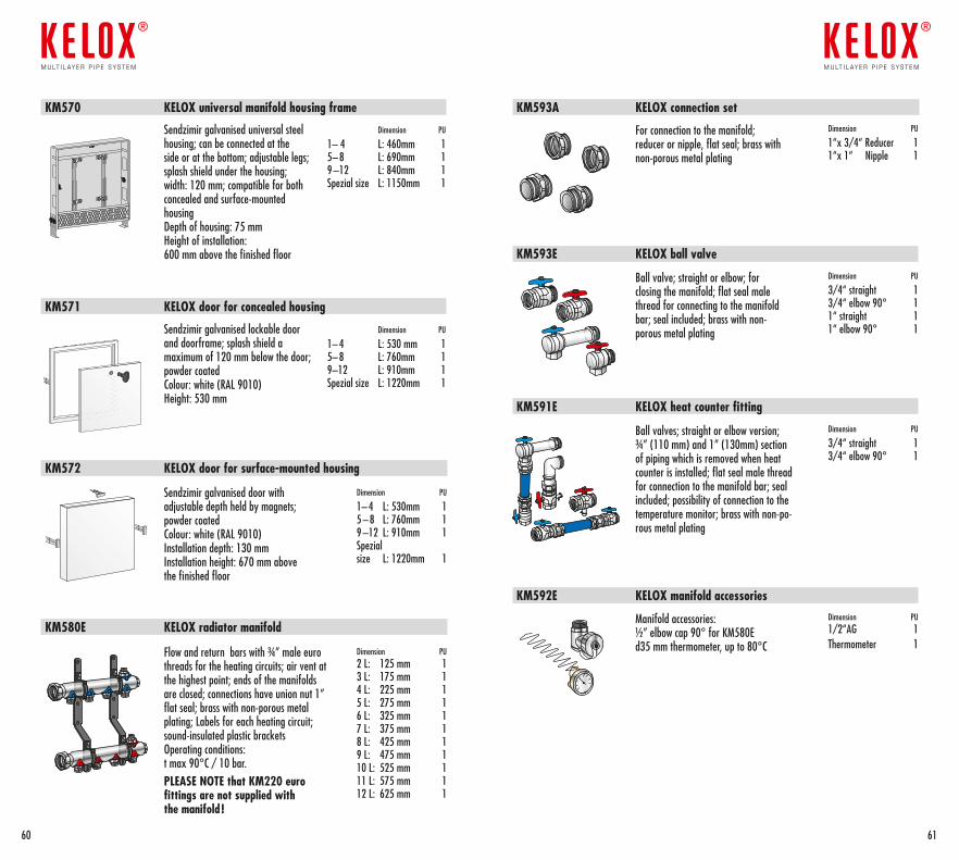
Sendzimir galvanised door with adjustable depth held by magnets; powder coatedColour: white (RAL 9010)Installation depth: 130 mm Installation height: 670 mm above the finished floor
Dimension PU
1– 4 L: 530mm 15 – 8 L: 760mm 19 –12 L: 910mm 1Spezial size L: 1220mm 1
KM572 KELOX door for surface-mounted housing
KM580E KELOX radiator manifold
Flow and return bars with ¾” male euro threads for the heating circuits; air vent at the highest point; ends of the manifolds are closed; connections have union nut 1” flat seal; brass with non-porous metal plating; Labels for each heating circuit; sound-insulated plastic bracketsOperating conditions: t max 90°C / 10 bar.PLEASE NOTE that KM220 euro fittings are not supplied with the manifold !
Dimension PU 2 L: 125 mm 13 L: 175 mm 14 L: 225 mm 15 L: 275 mm 16 L: 325 mm 17 L: 375 mm 18 L: 425 mm 19 L: 475 mm 110 L: 525 mm 111 L: 575 mm 112 L: 625 mm 1
For connection to the manifold; reducer or nipple, flat seal; brass with non-porous metal plating
Dimension PU
1“x 3/4“ Reducer 11“x 1“ Nipple 1
KM593A KELOX connection set
Ball valve; straight or elbow; for closing the manifold; flat seal male thread for connecting to the manifold bar; seal included; brass with non- porous metal plating
Dimension PU
3/4“ straight 13/4“ elbow 90° 11“ straight 11“ elbow 90° 1
KM593E KELOX ball valve
Ball valves; straight or elbow version; ¾” (110 mm) and 1” (130mm) section of piping which is removed when heat counter is installed; flat seal male thread for connection to the manifold bar; seal included; possibility of connection to the temperature monitor; brass with non-po-rous metal plating
Dimension PU
3/4“ straight 13/4“ elbow 90° 1
KM591E KELOX heat counter fitting
KM592E KELOX manifold accessories
Manifold accessories:½” elbow cap 90° for KM580Ed35 mm thermometer, up to 80°C
Dimension PU 1/2“AG 1Thermometer 1
KM570 KELOX universal manifold housing frame
Sendzimir galvanised universal steel housing; can be connected at the side or at the bottom; adjustable legs; splash shield under the housing; width: 120 mm; compatible for both concealed and surface-mounted housingDepth of housing: 75 mmHeight of installation: 600 mm above the finished floor
Dimension PU
1– 4 L: 460mm 15– 8 L: 690mm 19 –12 L: 840mm 1Spezial size L: 1150mm 1
Sendzimir galvanised lockable door and doorframe; splash shield a maximum of 120 mm below the door; powder coatedColour: white (RAL 9010)Height: 530 mm
Dimension PU
1– 4 L: 530 mm 15– 8 L: 760mm 19–12 L: 910mm 1Spezial size L: 1220mm 1
KM571 KELOX door for concealed housing
6160
m u lt i l ay e r p i p e s y s t e m
®
m u lt i l ay e r p i p e s y s t e m
®
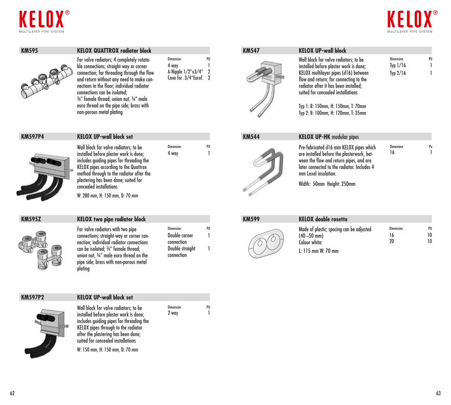
Wall block for valve radiators; to be installed before plaster work is done; KELOX multilayer pipes (d16) between flow and return; for connecting to the radiator after it has been installed; suited for concealed installations
Typ 1: B: 150mm, H: 150mm, T: 70mmTyp 2: B: 100mm, H: 120mm, T: 35mm
Dimension PU
Typ 1/16 1Typ 2/16 1
KM547 KELOX UP-wall block
KM597P2 KELOX UP-wall block set
KM597P4 KELOX UP-wall block set
Wall block for valve radiators; to be installed before plaster work is done; includes guiding pipes for threading the KELOX pipes through to the radiator after the plastering has been done; suited for concealed installations
W: 150 mm, H: 150 mm, D: 70 mm
Dimension PU 2-way 1
Wall block for valve radiators; to be installed before plaster work is done; includes guiding pipes for threading the KELOX pipes according to the Quattrox method through to the radiator after the plastering has been done; suited for concealed installations
W: 280 mm, H: 150 mm, D: 70 mm
Dimension PU
4-way 1
Made of plastic; spacing can be adjusted (40 –50 mm)Colour white:L: 115 mm W: 70 mm
Dimension PU
16 1020 10
KM599 KELOX double rosette
For valve radiators; 4 completely rotata-ble connections; straight-way or corner connection; for threading through the flow and return without any need to make con-nections in the floor; individual radiator connections can be isolated; ¾” female thread; union nut, ¾” male euro thread on the pipe side; brass with non-porous metal plating
Dimension PU
4-way 1A-Nipple 1/2“x3/4“ 2Cone for . 3/4“Eurof. 2
KM595 KELOX QUATTROX radiator block
For valve radiators with two pipe connections; straight-way or corner con-nection; individual radiator connections can be isolated; ¾” female thread; union nut, ¾” male euro thread on the pipe side; brass with non-porous metal plating
Dimension PU
Double corner 1 connection Double straight 1connection
KM595Z KELOX two pipe radiator block
KM544 KELOX UP-HK modular pipes
Pre-fabricated d16 mm KELOX pipes which are installed before the plasterwork, bet-ween the flow and return pipes, and are later connected to the radiator. Includes 4 mm Lexel insulation.
Width: 50mm Height: 250mm
Dimension Pu 16 1
6362
m u lt i l ay e r p i p e s y s t e m
®
m u lt i l ay e r p i p e s y s t e m
®
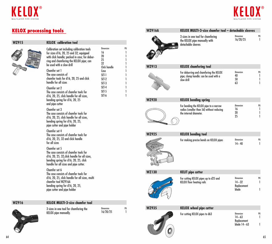
WZ920 KELOX bending spring
WZ925 KELOX bending tool
For bending the KELOX pipe to a narrow radius (smaller than 5d) without reducing the internal diameter.
Dimension PU 16 120 125 1
For making precise bends on KELOX pipes Dimension PU
14– 40 1
For cutting KELOX pipes up to d25 and KELOX floor heating rails
Dimension PU
14 – 32 1Replacement blade 1
WZ130 KELIT pipe cutter
WZ935 KELOX wheel pipe cutterFor cutting KELOX pipes to d63 Dimension PU
14 – 63 1 Replacement blade 14 – 63 1
WZ913 KELOX chamfering toolFor deburring and chamfering the KELOX pipe; clamp handle: can be used with a slow drill
Dimension PU40 150 163 1
WZ916 KELOX MULTI-3-size chamfer tool
WZ916A KELOX MULTI-3-size chamfer tool – detachable sleeves
3 sizes in one tool for chamfering the KELOX pipe manually.
3 sizes in one tool for chamfering the KELOX pipe manually with detachable sleeves
Dimension PU 16/20/25 1
Dimension PU 16/20/25 1
KELOX processing tools
WZ915 KELOX calibration tool
Calibration set including calibration tools for sizes d16, 20, 25 and 32; equipped with click handle; packed in case; for debur-ring and chamfering the KELOX pipe; can be used with a slow drill
Chamfer set 1 The case consists of chamfer tools for d16, 20, 25 and click handle for all sizes
Chamfer set 2 The case consists of chamfer tools for d16, 20, 25, click handle for all sizes, bending spring for d16, 20, 25 and pipe cutter
Chamfer set 3 The case consists of chamfer tools for d16, 20, 25, click handle for all sizes, bending spring for d16, 20, 25, pipe cutter and pipe holder
Chamfer set 4 The case consists of chamfer tools for d16, 20, 25, 32 and click handle for all sizes
Chamfer set 5 The case consists of chamfer tools for d16, 20, 25, 32,click handle for all sizes, bending spring for d16, 20, 25, click handle for all sizes and pipe cutter.
Chamfer set 6 The case consists of chamfer tools for d16, 20, 25, click handle for all sizes, multi chamfer tool WZ916A bending spring for d16, 20, 25, pipe cutter and pipe holder
Dimension PU
16 120 125 132 1Click handle 1Case 1SET-1 1 SET-2 1SET-3 1SET-4 1SET-5 1SET-6 1
6564
m u lt i l ay e r p i p e s y s t e m
®
m u lt i l ay e r p i p e s y s t e m
®
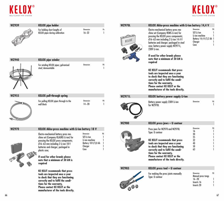
WZ970L KELOX Akku-press machine with Li-ion battery 14,4 V
WZ970 KELOX Akku-press machine with Li-ion battery 18 V
WZ971L KELOX battery power supply Li-ion
WZ980 KELOX press jaws – U contour
WZ983 KELOX press tool – U contour
Electro-mechanical battery press ma-chine set (Company REMS-Li-ion) for pressing the KELOX press components; d16–63 mm including 2 Li-ion 14.4 V batteries and charger; packaged in steel case; battery power supply WZ971L, 230V Li-ion.
If used for other brands please note that a minimum of 30 kN is required
KE KELIT recommends that press tools are inspected once a year to check that they are functioning correctly and to fulfil the condi-tions for the warranty. Please contact KE KELIT or the manufacturer of the tools directly.
Electro-mechanical battery press ma-chine set (Company KLAUKE-Li-ion) for pressing the KELOX press components; d16–63 mm including 2 Li-ion 18 V batteries and charger; packaged in plastic case;
If used for other brands please note that a minimum of 30 kN is required
KE KELIT recommends that press tools are inspected once a year to check that they are functioning correctly and to fulfil the condi-tions for the warranty. Please contact KE KELIT or the manufacturer of the tools directly.
Dimension PU
SET-Li-Ion 1 Li-ion machine 1 Battery 14,4 V/3,2 Ah 1 Charger 1 Case 1
Dimension PU
SET-Li-Ion 1 Li-ion machine 1 Battery 18 V/3,0 Ah 1 Charger 1 Case 1
Battery power supply 230V Li-ion for WZ970L
Dimension PU 1
Press jaws for WZ970 and WZ970LType: U contour
KE KELIT recommends that press tools are inspected once a year to check that they are functioning correctly and to fulfil the condi-tions for the warranty. Please contact KE KELIT or the manufacturer of the tools directly.
Dimension PU 16 1 20 1 25 1 32 1 40 1 50 1 63 1
For making the press joints manuallyType: U contour
Dimension PU Manual press tongs 16 –20 1 Inserts 16 1 Inserts 20 1
WZ939 KELOX pipe holder
WZ940 KELOX VerlegehaspelWZ940 KELOX pipe winder
WZ955 KELOX pull-through spring
For holding short lengths of KELOX pipes during calibration
Dimension Pu
16–32 1
For winding KELOX pipes; galvanised steel; demountable
Dimension PU
1
For pulling KELOX pipes through to the wall block
Dimension PU
14 –20 1
6766
m u lt i l ay e r p i p e s y s t e m
®
m u lt i l ay e r p i p e s y s t e m
®
6968
m u lt i l ay e r p i p e s y s t e m
®
m u lt i l ay e r p i p e s y s t e m
®
7170
KE KELIT KunststoffwerkGesellschaft m.b.H.
Ignaz-Mayer-Straße 17A-4020 LinzAustria – Europe
Tel. +43 (0)5 0779 Fax +43 (0)5 0779 118
Please note that for technical printingreasons the numbers are written accordingto the common practice in the German speaking countries (i.e. the number and the decimals are separated by a comma).
Full technical back-up and support for theKELOX-Multilayer pipe system is provided by KE KELIT-Austria/Europe.
The network of sales partners, subsidiariesand agents is constantly being expanded.Please ask at the Austrian headquartersfor the current status.
The technical contents in this brochure are for your information and consultation. We are not liable for thecontents. The application and installation of the products should be adapted to the individual requirements of each project. KE KELIT is constantly improving its products a nd retains the right to make technical changes in the course of these improvements. We are not liable for printing and spelling errors. © by KE KELIT KELOX Handbook 02/2015 engl.

Certified Quality Assurance System by ÖQS
ÖNORM EN ISO 9001:2000 Reg.Nr.366/0
��������
����������������������������
�������� �������������
Member of theAustrian Working Group
PLASTIC PIPERECYCLING
ARA-Lizenz Nr.9087
mult i layer p ipe system
®
KE KELITKunststoffwerk GesmbH. Ignaz-Mayer-Straße 17A-4020 LinzAustria – Europe
Tel. +43 (0)5 0779 Fax +43 (0)5 0779 118
[email protected] www.kekelit.com