Embed Size (px)
Citation preview

BOKARO POWER SUPPLY COMPANY LTD.
BOKARO STEEL CITY
INSTALLATION OF SIDE STREAM FILTRATION SYSTEM
IN COOLING WATER CIRCUIT OF RCPH
TENDER SPECIFICATION
STEEL AUTHORITY OF INDIA LIMITED CENTRE FOR ENGINEERING & TECHNOLOGY
RANCHI
JULY 2015 CET/23/RN/4060/TS/UT/01/R=0


BPSCL CONTENTS CET/23/RN/4060/TS/UT/01/R=0 SIDE STREAM FILTRATION SYSTEM Page 1 of 4
CONTENTS - CHAPTERS
Chapter no. Description Page no.
1. Introduction 1.1
2. Scope of Work 2.1 – 2.11
3. Technical Specifications 3.1 – 3.36
4. Performance Guarantee 4.1 – 4.2
5. Special Instructions to Bidders 5.1 – 5.3
Annexures
Schedules
Drawings
Package Leader (PL) Task Force Leader (TFL) HOD of PL
S. Chakravarty Dy. Manager (U&S)
S. Chakravarty Dy. Manager (U&S)
A.N. Bhagat DGM I/c (U&S)

BPSCL CONTENTS CET/23/RN/4060/TS/UT/01/R=0 SIDE STREAM FILTRATION SYSTEM Page 2 of 4
CONTENTS – ANNEXURES
Annexure - No. Description No. of
pages
2.1.13-1 List of Acceptable Makes of Equipment & Supplies
29

BPSCL CONTENTS CET/23/RN/4060/TS/UT/01/R=0 SIDE STREAM FILTRATION SYSTEM Page 3 of 4
CONTENTS – SCHEDULES
Schedule- No. Description No. of pages
2.1.2-1 Declaration for Site Visit 1
2.1.6-1 List of Recommended Spares for two years Operation and Maintenance
1
2.1.8-1 List of Consumables 1
2.1.9-1 List of Initial Fill 1
2.1.10-1 List of Special Tools and Tackles 1
2.1.11-1 List of Exclusions 1
2.1.11-2 List of Deviations 1

BPSCL CONTENTS CET/23/RN/4060/TS/UT/01/R=0 SIDE STREAM FILTRATION SYSTEM Page 4 of 4
CONTENTS - DRAWINGS
S. No. Drawing No. Description
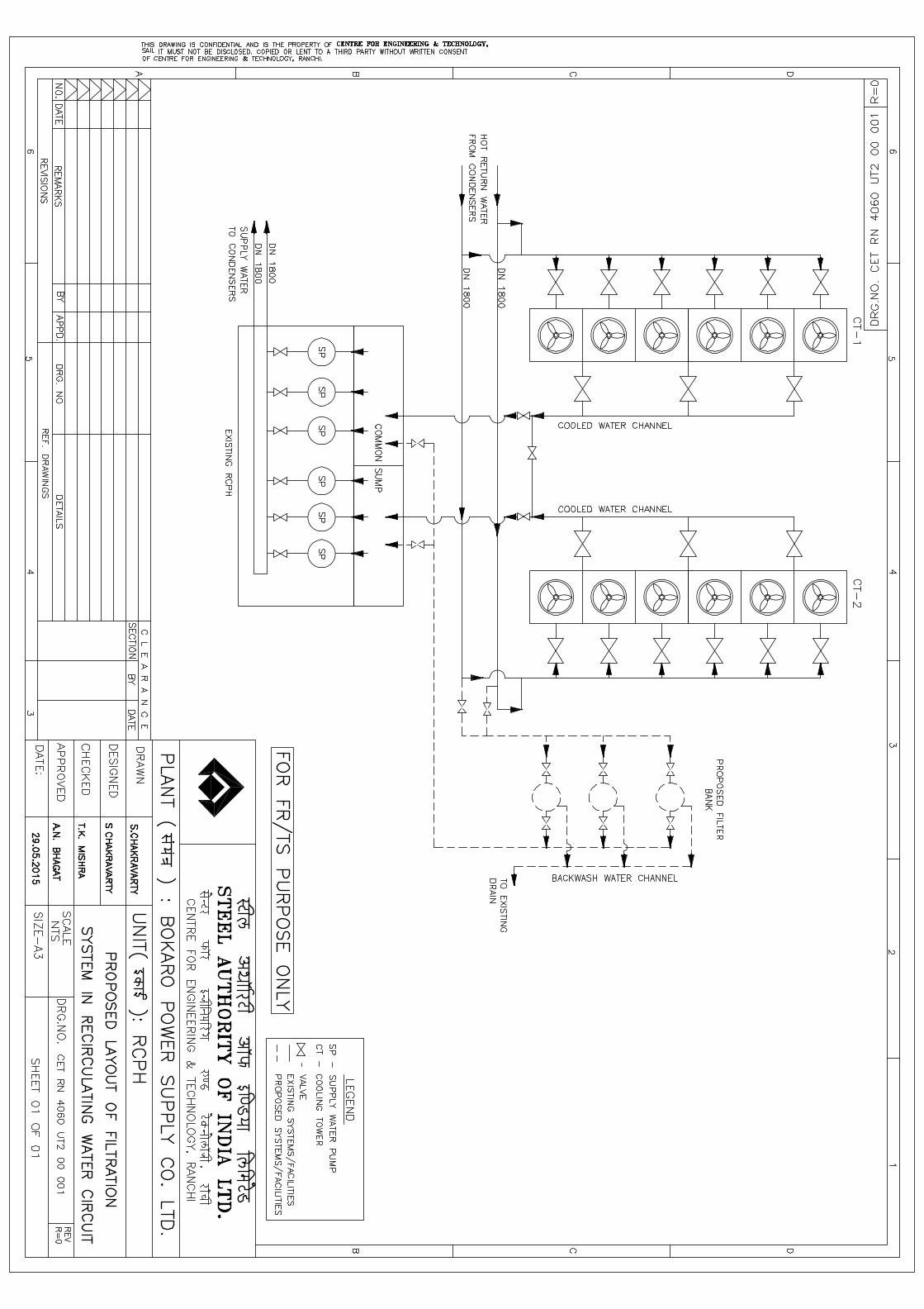
1 CET RN 4060 UT2 00 001, R=0 Proposed Layout of Filtration System in Recirculating Water Circuit
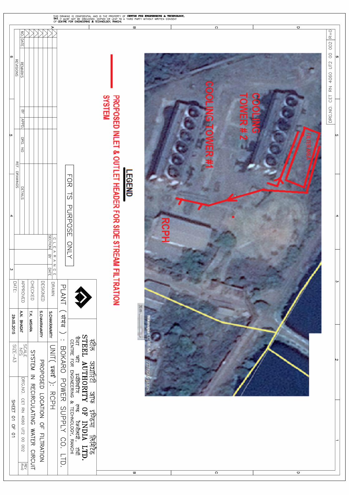
2 CET RN 4060 UT2 00 002, R=0 Proposed Location of Filtration System in Recirculating Water Circuit


BPSCL CET/23/RN/4060/TS/UT/01/R=0 SIDE STREAM FILTRATION SYSTEM Page 1.1
1.0 INTRODUCTION
1.1 Bokaro Power Supply Company Limited (BPSCL) is located in the premises of Bokaro Steel Limited (BSL) of Steel Authority of India Limited (SAIL) at Bokaro Steel City, in the heart of coal belt region of Jharkhand.
1.2 BPSCL is a JV company of SAIL and DVC and has an aggregate installed capacity to generate 338 MW of power besides 2180 tph steam.
1.3 BPSCL is having a Re-circulating Pump House (RCPH) for supplying cooling water to condensers of its TG unit nos. 6, 7 & 8. The recirculating cooling water volume is 30000 m3/h capacity. The total system make-up requirement is around 500 m3/h, which is met from pump house no. 1 of BSL. Presently, there is no filtration system in the recirculating cooling water circuit.
1.4 BPSCL is facing problem of frequent condenser tube choking of its TG units. This in turn results in low vacuum generation in condensers impacting steam consumption / MW generation and decreases efficiency. This necessitates frequent cleaning of the condenser tubes by high pressure jet cleaning increasing turbine downtime.
Due to increased concentration of total suspended solids (TSS), deposits are formed in seats of the isolation valves in the circuit thus creating improper valve operation during isolation. Also, the nozzles in the cooling towers get choked affecting its performance.
Accordingly, it is proposed to install a filtration system in the recirculating cooling water circuit at RCPH on turn-key basis.
1.5 INTENT OF SPECIFICATION
1.5.1 The intent of this Tender Specification is to furnish required details for enabling the Bidder to submit their best offers (technical & techno-commercial) for “Installation of Filtration System in RCPH Cooling Water Circuit”, as per the scope of work mentioned at Chapter 2.0, technical specifications at Chapter 3.0, performance guarantee at Chapter 4.0 and special instructions to Bidder at Chapter 5.0.
1.5.2 This Tender Specification shall be read in conjunction with Standard Bidding Document (SBD) along with other documents enclosed with the Tender.

BPSCL CET/23/RN/4060/TS/UT/01/R=0 SIDE STREAM FILTRATION SYSTEM Page 2.1
2.0 SCOPE OF WORK
2.1 GENERAL
2.1.1 The scope of work for this package shall cover design, engineering, preparation of fabrication / erection drawings, fabrication, manufacturing / procurement, inspection, supply and transportation of plant and equipment to site, dismantling, necessary insurance, handling, painting, erection, testing, commissioning and performance guarantee test for mechanical, electrical, structural, civil and instrumentation & automation areas of the project including all auxiliaries, technological structures, electrics etc. as elaborated in the subsequent clauses to be executed on Turnkey basis.
2.1.2 The Bidder shall survey the site, study available drawings / documents and discuss with the Employer/ Consultant, if required, regarding any further technical clarification and satisfy himself with respect to the nature and extent of work involved. The Bidder shall also obtain first hand information regarding location, work terrain, climatic condition, railways, roads, airports, communication etc. The Bidder shall confirm the visit to the site by filling the Schedule-2.1.2-1.
2.1.3 The Successful Bidder shall submit drawings / documents for approval and reference of the Employer / Consultant as detailed in subsequent clauses. Engineering meetings are to be routinely held every 2 to 4 weeks for clearing of drawings across the table for sorting out issues between the Contractor/Vendor, plant and CET. These regular meetings are to be held during the entire engineering phase of a project.
2.1.4 The technical specifications covering the details of equipment and drawings of this specification shall be taken for the purpose of tendering and basic design concept and shall not be taken as final and firm for the completion of the project. However, rated capacity of different equipment including other technical parameters shall be as per TS. In the event, ratings of machine furnished in the TS are not falling in the standard product range of the manufacturer, next higher size of machine shall be offered.
2.1.5 Any item / services, which might not have been specifically mentioned in this document but are necessary for the design, engineering, erection, successful commissioning, performance guarantee and/ or completeness of the work, shall be provided by the Bidder without any extra cost to the Employer and within the time schedule.
2.1.6 Spares, Consumables
The Bidder shall furnish item wise list of spares for two years normal operation & maintenance of the offered equipment as per Schedule- 2.1.6-1. Price of such spares shall be quoted separately.
2.1.7 Commissioning Spares
The Bidder shall, within the Contract Price, supply adequate commissioning spares required during start up and commissioning along with the plant & equipment
2.1.8 Consumables
BPSCL CET/23/RN/4060/TS/UT/01/R=0 SIDE STREAM FILTRATION SYSTEM Page 2.2
The Bidder shall confirm supply of all consumables required for erection, testing and successful commissioning of the system. List shall be furnished as per Schedule- 2.1.8-1.
2.1.9 Initial Fill
The Bidder shall confirm the supply of all initial fill required for the equipment supplied for successful commissioning of the equipment. The Bidder shall also furnish information with respect to initial fill as per Schedule- 2.1.9-1.
2.1.10 Special Tools & Tackles
The Bidder shall confirm the supply of all special tools and tackles required for operation and maintenance of the equipment. List of special tools and tackles for the operation and maintenance of the equipment shall be furnished as per Schedule- 2.1.10-1.
2.1.11 Exclusions & Deviations
Exclusions as well as deviations from the Tender Specification, if any, shall be clearly stated under separate heads marked as “List of Exclusions” as per Schedule- 2.1.11-1 and “List of Deviations” as per Schedule- 2.1.11-2 respectively quoting the index and serial reference of Tender Specification.
2.1.12 Any statutory approval, wherever required, shall be taken by the Successful Bidder for the equipment being supplied by them from relevant state / central authorities.
2.1.13 All bought out items shall be procured from the manufacturers as per the “List of Acceptable Makes of Equipment & Supplies” furnished in the Annexure-2.1.13-1 of this document. For items not listed in this, prior approval from Employer / Consultant shall be taken before order placement.
2.2 MECHANICAL & UTILITIES
The scope of work for the Bidder regarding mechanical and utility works consists of the following facilities/equipment:
2.2.1 Tapping of return water from the existing 2 nos DN 1800 headers alongwith isolation valves and laying of supply water header to filters.
2.2.2 Supply and installation of automatic backwash valve less gravity type filters (NW+1S) alongwith all piping, valves, fittings, accessories and instrumentation.
2.2.3 Construction of civil drain pits and drain channel from the backwash outlet of the filters to existing nearest drain line in the area.
2.2.4 Supply and laying of filtered water pipeline to existing 2 nos. sumps of RCPH alongwith isolation valves.
2.2.5 Clearing of site before and after completion of work.
2.2.6 The proposed layout and location of side stream filtration system are shown in Drg. Nos. CET RN 4060 UT2 00 001 and CET RN 4060 UT2 00 001.
2.3 ELECTRICAL
2.3.1 The scope of work of the Bidder shall cover the following:
Tapping of power from existing lighting distribution board with new, 415
BPSCL CET/23/RN/4060/TS/UT/01/R=0 SIDE STREAM FILTRATION SYSTEM Page 2.3
V, 3 phase LT cable.
Provision of 1 no. new SLDB.
Area illumination through pole mounted 250 W HPSV lamps.
Earthing system. 2.3.2 BATTERY LIMIT
The scope of work for electrical system under this Tender Specification starts with tapping of power supply from LT substation transformer approx. 100 m from electrical room.
Onward scope of work for power supply, distribution, cabling, earthing as explained in the various clauses of this TS shall be within the scope of work of the Bidder.
2.4 INSTRUMENTATION & AUTOMATION
2.4.1 The scope of work for Instrumentation & Control System shall include design & engineering, manufacture & procurement, assembly, inspection, supply, transportation to site, unloading, storage, insurance, handling, calibration, erection, testing, trial run and commissioning of the Instrumentation & control systems along with all associated equipment and facilities within battery limit in a fully coordinated & integrated manner on turnkey basis.
2.4.2 The system will be provided with latest Instrumentation & Control system adequate for efficient monitoring of the process parameter.
2.4.3 Minor civil works such as chipping / cutting of floor for making grooves or laying pipes / cables, making holes / openings through walls, ceilings or floors, drilling of holes through steel structures and frames, grouting of frames, hooks on walls / ceiling etc. required for execution of work shall be included in the scope. After erection the surfaces shall be made good by plastering / painting to their original shapes and finish.
2.4.4 The scope of engineering, supply, erection, testing, commissioning, etc. shall include but not limited to the following:
1) The instrumentation & Control system will be field mounted system consisting of pressure gauge, DP pressure transmitter, digital indicator and flow meter/flow transmitter. All digital display shall be installed in wall mounted panel located at pump house preferably
2) Provision of required power supply for instrumentation & Control system shall be in the scope of bidder. Purchaser shall only provide suitable feeder.
3) Power and control cables (FRLS), cable laying accessories like trays, G.I. protection pipes, supporting structures, clamps and other cable laying accessories, identification ferrules, etc.
4) Supply, laying and termination of all cables. The Bidder shall include in his scope, any excavation work required for laying of cables, etc. All cables shall be of FRLS grade.
BPSCL CET/23/RN/4060/TS/UT/01/R=0 SIDE STREAM FILTRATION SYSTEM Page 2.4
5) Provision of maintenance platforms with suitable approach / approach ladder for all instruments / sensors / tapping points, etc., at inaccessible locations.
6) System engineering, configuration complete with detailed engineering, drawing preparation and documentation.
7) Erection, testing, calibration and commissioning of overall instrumentation & Control system, handing over of the same to the satisfaction of plant after successful guarantee tests, PAT and FAT. Successful Bidder shall arrange tools, tackles, and consumables as may be required for erection, testing, calibration and commissioning activities.
8) Arrangement of and participation in inspection of Instrumentation & Control equipment with Purchaser (if required). Inspection and Testing shall be carried out in compliance with Quality Assurance Plans, to be approved during detail engineering stage.
9) Insurance spares, commissioning spares, etc., required during commissioning.
10) List of two years maintenance spares.
11) List of commissioning spares and consumables..
2.4.5 The Bidder shall submit along with the tender the drawings/ documents/ data as per the following details:
1) List of measurements & Schedule of quantity of equipment
2) Technical literature, Catalogues, application note, etc., for all items.
2.5 CIVIL
2.5.1 General
The scope of work for the Bidder covers design, engineering, supply of labour & materials, transportation, construction and commissioning of the civil engineering works detailed under the clauses below, complete on Turnkey Basis.
2.5.1.1 The following are major civil engineering jobs pertaining to the project:
a) Construction of RCC foundations for the equipments as per technology and process requirement.
b) Construction of RCC supports for water pipelines.
c) Construction of RCC supports for structural walkovers, platforms etc as per technology, process and serviceability requirement.
d) Construction of floor around the filters as per technology, process & serviceability requirement.
e) Providing Adequate drainage facility for the area
f) Protection of nearby existing underground and over ground units and structures
BPSCL CET/23/RN/4060/TS/UT/01/R=0 SIDE STREAM FILTRATION SYSTEM Page 2.5
g) Dismantling of exiting floor and making good the same to its original condition, as per requirement.
h) Other Miscellaneous jobs like dismantling of RCC / PCC / Brickwork at various places, excavation in earth and cleaning etc., as per requirement.
2.5.2 The scope also includes necessary geodetic surveying work for transferring reference lines & bench marks from the established reference lines and bench marks inside the plant & fixing the same to the location of proposed works to facilitate set up of layout. Further, construction / erection works shall also be part of the scope.
2.5.3 The scope of work will also include sampling & testing of construction material on the specimens taken during execution of the work. The testing shall be performed by a separate agency, approved by the Purchaser and the cost towards the same shall be borne by the successful Bidder.
2.5.4 During the course of execution of the job, transportation of dismantled serviceable items to the designated storage area, as per the instructions of the site engineer, will also be under the scope of work. Further, the transportation and disposal of dismantled waste materials and debris up to a distance of 1 km, as per the instructions of the site engineer will also be under the scope of work.
2.5.5 The bidder shall be responsible for protection and diversion of all existing underground services, wherever required and / or diversion of the underground services which are indicated in the drawings made available to the bidder. In case there are underground services which need to be protected and / or diverted but are not shown in the drawing, the bidder shall be responsible to execute the same at extra price, if any, to be mutually agreed in advance between the bidder and the employer.
2.5.6 Temporary approach road, site office, cement & other construction material storage go-downs and fabrication yard for reinforcement, inserts etc. shall be constructed by the successful Bidder at his cost. Only land area will be shown by Purchaser.
2.6 SCOPE OF SERVICES
2.6.1 Scope of work shall also include the following services, from issue of Letter of Acceptance (LOA) up to installation and commissioning of the project:
1) Design, Engineering and supply of drawings, documents including pipes, cables etc. and getting Purchaser's approval. Approval of drawings by Purchaser / Consultant shall not relieve the Supplier of his contractual obligation and responsibility for correct engineering, design, workmanship and materials.
All necessary site measurements and study of available existing drawings as may be required for developing the aforesaid design and drawings shall also be deemed to be under the Scope of the Successful Bidder. The available existing drawings are to be collected from the Purchaser.
2) Liaisoning with local authorities and government bodies and getting all statutory approval from statutory authority as per requirement. However, necessary fees and assistance shall be given by BPSCL.
BPSCL CET/23/RN/4060/TS/UT/01/R=0 SIDE STREAM FILTRATION SYSTEM Page 2.6
3) Shop testing, shop painting, pre shipment inspection. To offer the equipment to Purchaser or his authorized representative for inspection before shipment from the shop. To provide all the material test certificate, inspection reports.
4) To take necessary safety clearance from plant authorities / government bodies before starting of erection work.
5) Two coats of final painting.
6) All packing & transportation.
7) Storage and handling at site.
8) Erection.
9) Final painting at site.
10) Testing and Commissioning.
11) Performance guarantee test.
12) Administering first fill of oils/lubricants/coolant and thereafter another fill of oil/lubricants/coolant after commissioning /PG Test.
2.6.2 The Successful Bidder shall have to provide his own personnel, labour, equipment, consumables, tools & tackles for timely implementation of the job. He has to arrange for any statutory approval, if required, from Governmental Agencies.
2.6.3 The Successful Bidder shall arrange on-site training for Employers’ personnel in Operation and Maintenance of the system in 2 batches (minimum 10 persons / batch) for one day each before handing over the system to the Employer. Successful Bidder shall provide adequate training manuals, handouts, etc., to each participant.
2.7 GENERAL WORKS
2.7.1 Supply and application of all paints, primers and finish paints to the equipment and other services as per IS 5:2007.
2.7.2 Conducting performance guarantee tests to establish the operating parameters for the individual equipment and in combination.
2.7.3 Any rectification / modification required for interface work during erection of equipment / technological structures shall be within the scope of work of the Bidder.
2.7.4 Supply of all holding down bolts and nuts for all equipment, blank plates, hangers, etc. and other services.
2.7.5 Supply of all other fasteners, washers, screws, packing plates, machined packing plates, shims, etc. required for fabrication and erection.
2.7.6 Supply of all erection consumables like oil, kerosene, cotton waste, oxygen and acetylene gas cylinders, electrodes, asbestos sheets, asbestos ropes, sealing compounds, etc.
BPSCL CET/23/RN/4060/TS/UT/01/R=0 SIDE STREAM FILTRATION SYSTEM Page 2.7
2.7.7 Loading and unloading of equipment at site, storage, transportation, erection of all items including connecting up and completion at site including supervision, labour, materials, consumables, construction equipment and tools.
2.8 REQUIREMENT OF DRAWINGS AND TECHNICAL DOCUMENT
2.8.1 Following drawings/ data/ documents shall be submitted in 10 (ten) copies and in soft to the Employer for approval / reference by the Successful Bidder after placement of order and prior to commencement of manufacturing /fabrication:
1) General arrangement drawing showing sections of equipment and systems with overall dimension along with valves, drives and other items as applicable.
2) Detailed Drawings/ calculations / technical specifications/ data sheets/ characteristic curves of important components / equipment, weight and mounting arrangement of equipment, equipment with part list, safety interlocks, etc.
3) Equipment schedule with Billing Schedule.
4) Manufacturer's technical catalogues.
5) Test & calibration certificates for individual equipment.
6) Operation, Instruction & Maintenance Manuals, etc.
2.8.2 In addition to the above, the Employer reserve the right to insist on submission of calculation/ drawings/ data of any item as required.
2.8.3 General arrangement drawings shall be submitted for approval. The Bidder shall not make any change in the approved design/drawings without the prior approval of the Employer.
2.8.4 The Bidder shall prepare fabrication/manufacturing drawings based on approved design drawings by the Employer or its authorized representatives.
2.8.5 The fabrication, supply, testing, inspection and erection shall be carried out only in accordance with the drawings / details finally approved by the Employer.
2.8.6 Existing available drawings shall be collected by the Bidder from plant archives after taking necessary permissions from competent authorities of plant.
2.8.7 If required, across table discussion and clearance of drawings shall be done at CET Ranchi.
2.9 QUALITY ASSURANCE
2.9.1 The Bidder shall furnish a Quality Assurance Plan (QAP) both in respect of site work as well as manufacture of equipment, which he proposes to follow for the purpose of ensuring the quality of equipment and workmanship at various stages.
2.9.2 The QAP shall include details of all tests proposed during manufacturing, assembly at works & at site and after erection for all offered items. QAP shall be approved by the Employer.
BPSCL CET/23/RN/4060/TS/UT/01/R=0 SIDE STREAM FILTRATION SYSTEM Page 2.8
2.10 INSPECTION AND TESTING
2.10.1 Inspection and testing of all offered items shall be in the scope of the Successful Bidder and shall be carried out as detailed in subsequent clauses of this TS/ approved QAP.
2.10.2 Erection & Site Testing
2.10.2.1 Successful Bidder shall submit a detail site erection plan along with checklist for approval by the Employer. The site erection plan should clearly spell out the duration of shutdown, if required, for erection and commissioning of equipment.
2.10.2.2 The successful Bidder shall have to arrange all tools, tackles, instruments, accessories, etc. and qualified personnel required for erection and testing.
2.10.2.3 The successful Bidder shall take note of the working conditions, practices and arrangements prevailing in the area. The erection work shall be carried out in such a manner that normal operation of the shop/unit is not hampered.
2.10.2.4 After erection, the storage room, if any, constructed during erection by the successful Bidder in the premises of plant shall be removed and the place shall be left clean.
2.10.2.5 Site Testing
Bidder shall furnish all procedures & details of tests to be carried out at site, which are necessary for testing and successful commissioning of the equipment after installation. Special tools and accessories if any required, for these tests shall be indicated and provided by the successful Bidder
2.10.3 Preliminary Acceptance Test (PAT)
2.10.3.1 As soon as the erection of section of plants / equipment / machineries is completed with auxiliary facilities the successful Bidder shall conduct trial runs for individual equipment / units to prove that the facilities have been supplied and erected as per contract and after erection, facilities are fit for start-up and commissioning.
2.10.3.2 The successful Bidder shall then give notice for Preliminary Acceptance Test (PAT) to the Employer and the Employer jointly with the Bidder’s representative shall proceed with the preliminary acceptance tests. The successful Bidder shall carry out Preliminary Acceptance Test on the system as per standard test procedures to establish functioning of the system as whole and independent equipment as part of the system.
2.10.3.3 Acceptance test shall include testing of the system in no-load condition and all other tests as necessary to avoid any failure in the operation of the system, during integrated mode of trial run and commissioning.
2.10.3.4 Employer shall issue the Preliminary Acceptance Certificate (PAC) after completion of above tests. In case of any defects / deficiencies arising during PAT, the same shall be complied by the Bidder within a jointly agreed time frame, before issue of PAC.
2.10.4 System Commissioning
2.10.4.1 After the issue of PAC, the successful Bidder shall start up and commission the installed facilities. The successful Bidder shall give a notice to the Employer in
BPSCL CET/23/RN/4060/TS/UT/01/R=0 SIDE STREAM FILTRATION SYSTEM Page 2.9
this regard. System commissioning shall be carried out during 3 consecutive general shifts in the plant/office.
2.10.4.2 The successful Bidder shall actively participate in all commissioning activities by providing necessary manpower to ensure reliable and trouble free performance of the system supplied by him.
2.10.4.3 The system shall be considered successfully commissioned when trouble free performance of the system in integrated mode under load condition is established during entire commissioning period. During operations of the equipment at no load and at load, performance of all the drive shall be checked in respect of current drawn by the motors, vibrations, noise, etc. with respective rated values. During the test, the entire system shall be checked for dimensional accuracy, workmanship and alignment.
2.10.4.4 In case of any defects / deficiencies arising in system during commissioning, the same shall be successfully complied by the Bidder within a jointly agreed time frame.
2.10.4.5 If during the test runs, there is an interruption exceeding 2 hours due to any cause other than power failure, the commissioning activities shall be discontinued and fresh date for system commissioning shall be decided mutually by both the parties.
2.10.4.6 Employer shall issue the Commissioning Certificate after successful completion of above tests. In case of any defects / deficiencies arising during commissioning, the same shall be successfully complied by the Bidder within a jointly agreed time frame, before issue of Commissioning Certificate.
2.10.5 Performance Guarantee (P.G) Test
P.G. Test shall be conducted as detailed in Chapter 4.0
2.10.6 Final Acceptance Certificate (FAC)
2.10.6.1 Final Acceptance Certificate (FAC) shall be issued by the Employer after completion of the following by the Successful Bidder:
1) Successful completion of commissioning and PG. test by compliance of all defects / deficiencies of the tests and the meeting of designed PG parameter.
2) Submission of final / as-built drawings, operation and maintenance manuals of the installed system and completion of site training as per contract.
3) Successful fulfillment of all other contractual agreements.
BPSCL CET/23/RN/4060/TS/UT/01/R=0 SIDE STREAM FILTRATION SYSTEM Page 2.10
2.11 IMPLEMENTATION PERIOD
2.11.1 The Successful Bidder shall be required to complete the whole work including commissioning of the system within 09 months from the effective date of contract.
2.11.2 The Bidder shall submit the overall implementation schedule of the project in the form of a bar chart along with his offer. The implementation schedule shall cover major activities like:
1) Design & Engineering
2) Shop Inspection and Testing
3) Transportation and Supply of equipment
4) Erection, Testing & Integrated Trial
5) Final Testing & Commissioning
2.11.3 Successful Bidder shall be required to submit Level-1 PERT Network (Activity on Arrow Diagram) based on the agreed Overall Implementation Schedule as well as Milestones within three weeks of placement of order for the approval of the Employer.
2.11.4 PERT Network, mutually agreed to between the Employer and the Successful Bidder shall form a part of the contract and shall not be arbitrarily changed.
2.11.5 The entire job is to be carried out in phased manner with proper shut down planning. The implementation strategy and shutdown planning is to be made after discussion with ISP for smooth execution of the job without hampering the normal working.
2.12 BATTERY LIMIT
Refer Drg. Nos. CET RN 4060 UT2 00 001 and CET RN 4060 UT2 00 001 for battery limit of the proposed system:
Inlet water From the return water header of the Cooling towers of RCPH (at approx. 30 m from the proposed location)
Outlet filtered water To individual sumps of RCPH (at approx. 100 m from the proposed location)
Backwash Water To nearest drain to cooling pond (at approx. 40 m from the proposed location)
2.13 EMPLOYER’S OBLIGATION
2.13.1 The Employer shall provide tapping within 250 m of proposed work site for electricity and water for construction job to the Successful Bidder as per the terms and conditions indicated in the commercial part of the Tender Document / SBD. The successful Bidder shall make his own arrangement to lay and maintain necessary distribution lines and wiring at his own cost.
2.13.2 The Employer shall also provide site shutdown for installation / erection of equipment as per mutually agreed date so as to enable completion of the facility within the shortest possible time.

BPSCL CET/23/RN/4060/TS/UT/01/R=0 SIDE STREAM FILTRATION SYSTEM Page 2.11
2.13.3 The Employer will provide the following:
1) Required drawing / data of the existing equipment to the extent available with the Employer, on request of the Successful Bidder.
(Note: Where drawings/data are not available, the necessary site measurements shall be taken by the Bidder.)

BPSCL CET/23/RN/4060/TS/UT/01/R=0 SIDE STREAM FILTRATION SYSTEM Page 3.1
3.0 TECHNICAL SPECIFICATION
3.1 BASIC DESIGN AND SITE CONDITIONS
BPSCL is situated in state of Jharkhand. The nearest railway station is Bokaro on the Gomoh – Tata broad gauge line. The plant site is about 5 km from Bokaro Steel City Railway Station.
The nearest airport is Ranchi, which is about 125 km from the plant site.
3.1.2 General Climatic Condition
1) Ambient temperature
i) Maximum : 50oC
ii) Minimum : 4oC
2) Relative Humidity
i) Maximum : 100 %
ii) Minimum : 25 %
Maximum temperature and maximum humidity do not occur simultaneously.
3.1.3 Standards & Codes
3.1.3.1 Equipment materials to be used in the construction of this package shall conform to relevant Indian Standard specifications.
3.1.3.2 All equipment and their associated system, accessories covered under this specification shall comply with all currently applicable statutory regulations and safety codes. All equipment and its components shall be designed and tested in accordance with the latest Indian Standard specification/ other International Standards established to be equivalent or superior to the Indian Standard codes unless stated otherwise/ agreed to.
3.1.3.3 The basic design and site conditions described above are aimed to appraise the Bidder about the consideration and criteria adopted while designing the proposed system.
3.1.4 Proposed System
It is proposed to install an automatic backwash, valve-less, gravity type filter system complete with accessories, piping, valves, etc. in the recirculation cooling water circuit of RCPH to reduce the TSS levels in the recirculating water.
The raw water quality is given as follows:
Table 3.1.4-1: Raw Water Quality
S. No.
Parameter Unit Present Value
1. pH - 7.8-8.57 2. Conductivity S /cm 202-469 3. Chloride ppm 34 4. Total Hardness ppm as CaCO3 158
BPSCL CET/23/RN/4060/TS/UT/01/R=0 SIDE STREAM FILTRATION SYSTEM Page 3.2
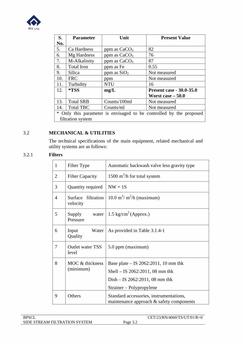
S. No.
Parameter Unit Present Value
5. Ca Hardness ppm as CaCO3 82 6. Mg Hardness ppm as CaCO3 76 7. M-Alkalinity ppm as CaCO3 87 8. Total Iron ppm as Fe 0.55 9. Silica ppm as SiO2 Not measured 10. FRC ppm Not measured 11. Turbidity NTU 16 12. *TSS mg/L Present case - 30.0-35.0
Worst case – 50.0 13. Total SRB Counts/100ml Not measured 14. Total TBC Counts/ml Not measured * Only this parameter is envisaged to be controlled by the proposed
filtration system
3.2 MECHANICAL & UTILITIES
The technical specifications of the main equipment, related mechanical and utility systems are as follows:
3.2.1 Filters
1 Filter Type Automatic backwash valve less gravity type
2 Filter Capacity 1500 m3/h for total system
3 Quantity required NW + 1S
4 Surface filtration velocity
10.0 m3/ m2/h (maximum)
5 Supply water Pressure
1.5 kg/cm2 (Approx.)
6 Input Water Quality
As provided in Table 3.1.4-1
7 Outlet water TSS level
5.0 ppm (maximum)
8 MOC & thickness (minimum)
Base plate – IS 2062:2011, 10 mm thk
Shell – IS 2062:2011, 08 mm thk
Dish – IS 2062:2011, 08 mm thk
Strainer – Polypropylene
9 Others Standard accessories, instrumentations, maintenance approach & safety components
BPSCL CET/23/RN/4060/TS/UT/01/R=0 SIDE STREAM FILTRATION SYSTEM Page 3.3
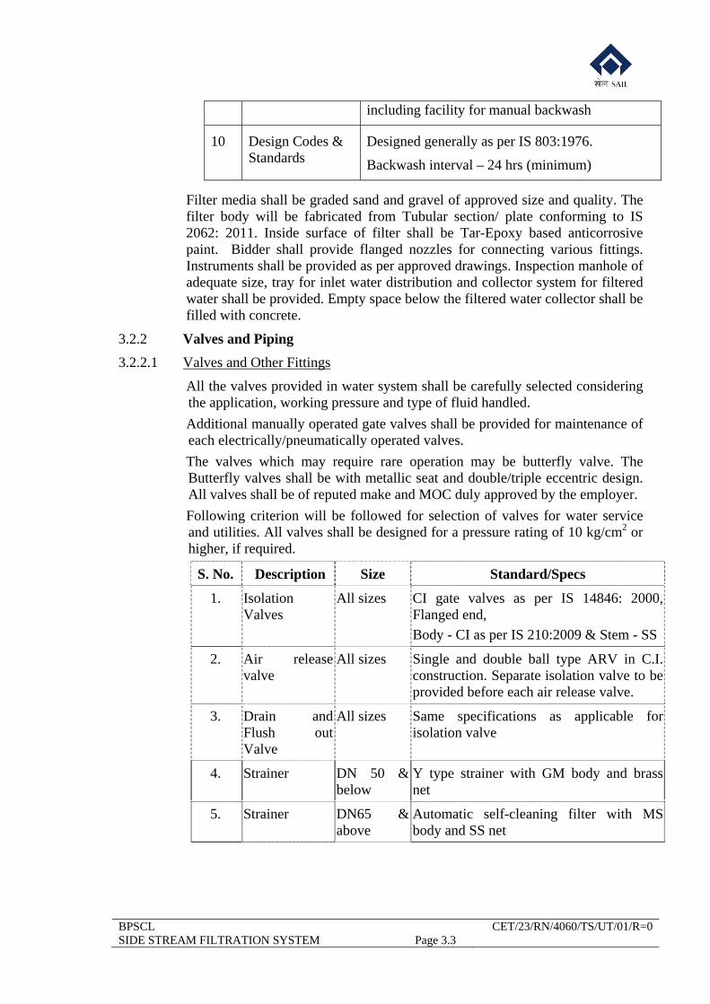
including facility for manual backwash
10 Design Codes & Standards
Designed generally as per IS 803:1976.
Backwash interval – 24 hrs (minimum)
Filter media shall be graded sand and gravel of approved size and quality. The filter body will be fabricated from Tubular section/ plate conforming to IS 2062: 2011. Inside surface of filter shall be Tar-Epoxy based anticorrosive paint. Bidder shall provide flanged nozzles for connecting various fittings. Instruments shall be provided as per approved drawings. Inspection manhole of adequate size, tray for inlet water distribution and collector system for filtered water shall be provided. Empty space below the filtered water collector shall be filled with concrete.
3.2.2 Valves and Piping
3.2.2.1 Valves and Other Fittings
All the valves provided in water system shall be carefully selected considering the application, working pressure and type of fluid handled.
Additional manually operated gate valves shall be provided for maintenance of each electrically/pneumatically operated valves.
The valves which may require rare operation may be butterfly valve. The Butterfly valves shall be with metallic seat and double/triple eccentric design. All valves shall be of reputed make and MOC duly approved by the employer.
Following criterion will be followed for selection of valves for water service and utilities. All valves shall be designed for a pressure rating of 10 kg/cm2 or higher, if required.
S. No. Description Size Standard/Specs
1. Isolation Valves
All sizes CI gate valves as per IS 14846: 2000, Flanged end,
Body - CI as per IS 210:2009 & Stem - SS
2. Air release valve
All sizes Single and double ball type ARV in C.I. construction. Separate isolation valve to be provided before each air release valve.
3. Drain and Flush out Valve
All sizes Same specifications as applicable for isolation valve
4. Strainer DN 50 & below
Y type strainer with GM body and brass net
5. Strainer DN65 & above
Automatic self-cleaning filter with MS body and SS net
BPSCL CET/23/RN/4060/TS/UT/01/R=0 SIDE STREAM FILTRATION SYSTEM Page 3.4
General Notes for all Valves:
Valve testing shall be as per DIN: 3230, Pt.3. Leak Rate 2.
Bolting for companion flanges shall be as per IS 1364 (Part-1): 2002.
Flanges shall be raised faced type.
Valves shall be painted with two coats of primer and two coats of finish paint. The dry film thickness shall not be less than 50 per coat.
Marking shall be as per manufacturing standard.
3.2.2.2 Technical Specification for Pipelines
Detailed Engineering of piping for the water facilities shall be done by the Successful Bidder with the consideration of following specific points:
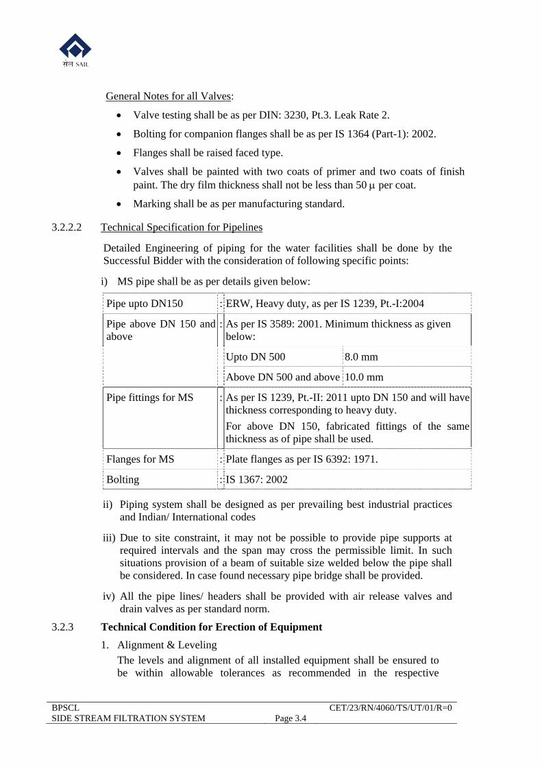
i) MS pipe shall be as per details given below:
Pipe upto DN150 : ERW, Heavy duty, as per IS 1239, Pt.-I:2004
Pipe above DN 150 and above
: As per IS 3589: 2001. Minimum thickness as given below:
Upto DN 500 8.0 mm
Above DN 500 and above 10.0 mm
Pipe fittings for MS : As per IS 1239, Pt.-II: 2011 upto DN 150 and will have thickness corresponding to heavy duty.
For above DN 150, fabricated fittings of the same thickness as of pipe shall be used.
Flanges for MS : Plate flanges as per IS 6392: 1971.
Bolting : IS 1367: 2002
ii) Piping system shall be designed as per prevailing best industrial practices and Indian/ International codes
iii) Due to site constraint, it may not be possible to provide pipe supports at required intervals and the span may cross the permissible limit. In such situations provision of a beam of suitable size welded below the pipe shall be considered. In case found necessary pipe bridge shall be provided.
iv) All the pipe lines/ headers shall be provided with air release valves and drain valves as per standard norm.
3.2.3 Technical Condition for Erection of Equipment
1. Alignment & Leveling
The levels and alignment of all installed equipment shall be ensured to be within allowable tolerances as recommended in the respective

BPSCL CET/23/RN/4060/TS/UT/01/R=0 SIDE STREAM FILTRATION SYSTEM Page 3.5
manufacturer’s instructions or as specified in the manufacturer’s drawings. The levels, alignment of equipment shall be carefully re-checked jointly with the Employer after trial operation. All required adjustments shall be made by the Bidder as directed by the Employer.
After the Equipment has been installed, leveled and aligned, the foundation bolts shall be tightened and the equipment shall be grouted. When the grout has thoroughly cured, the alignment shall be rechecked.
2. Clean up and Painting
Bidder shall do cleaning and painting of all equipment which shall include all connection materials and devices such as piping, exposed conduits, etc. Items, which have been supplied with, finish coat before delivery but surfaces have damaged then these surfaces shall be cleaned, primed and finish coated to match to original color. The painting shall be inclusive of the cost of paint.
3. Erection Drawings
Approved erection drawings and general arrangement drawings, specifications or instructions accompanying them shall be followed in erecting fabricated items and bought out equipment items throughout the project.
Erection marks as shown in erection drawings shall appear on the fabricated items and these shall be erected with marks in the same relative positions as shown on the plan or elevation.
4. Tolerance and surface finish in workmanship
Relevant tolerances and surface finish in the fabrication work shall be followed as per relevant Indian Standard unless otherwise shown in approved detail drawings.
3.2.3.1 Erection of Valves
Before erection of valves, Bidder shall ensure that:
All grit and foreign materials are removed from the inside of the valves.
All machined faces are thoroughly cleaned and coated with a thin layer of mineral grease before erection.
Installation of valve shall be carried out as per drawing. Clearance between the top of stuffing box and underside of gland shall be uniform on all the sides.
Gland shall not be tightened hard. Hemp packing shall be adequately soaked in grease and shall not be allowed to remain dry (except valves for oxygen service).
The valves shall be tightly closed when being installed, as this keeps the valve rigid and prevents any foreign material from getting in between the working parts of the valves.
While installing flanged valves, diametrically opposite nuts shall be tightened slowly and proper care shall be taken to tighten them alternately. The practice of fully tightening the nuts one after another is not permitted.
After installation of the valves, the pipeline shall be flushed with water/
BPSCL CET/23/RN/4060/TS/UT/01/R=0 SIDE STREAM FILTRATION SYSTEM Page 3.6
compressed air/ nitrogen, as the case may be, to remove any foreign material that may be present in them. If any leak is detected at the valve-seat, the same shall be examined and rectified by scrapping or replacing wherever necessary.
All valves shall be operated a few times to check free movement and operation of various limit switches/ inter locks.
3.2.3.2 Erection, Testing and Commissioning of Pipelines
All pipelines shall be laid by the Bidder as per detailed drawings and instruction to be given by the Employer. The interfacing and joining of the proposed pipeline with the existing pipeline/equipment /facility are in the scope of work. Following technical condition apply for erection, testing and commissioning of all pipe work:
1. Mitre fittings and shaped parts shall be fabricated from the pipes of same specifications as that of pipes. All bends will be provided with bend radius of 1.5d unless specified otherwise in detailed engineering drawing.
2. Before erection, pipes, valves, fittings etc. shall be thoroughly cleaned and scales, rust, dirt, oil, grease etc. shall be completely removed from inside as well as outside. The Bidder shall provide all cleaning materials required for this purpose.
3. Contacting surfaces of flanges shall be strictly perpendicular to pipes and shaped parts axes. Insertion of gaskets of unusual thickness shall not be allowed.
4. In case of pipes running horizontally, all the flanges and flanged fittings, etc. shall be installed in such a way that top bolt holes are displaced by half pitch from the vertical axis.
5. Flanges shall be fabricated from steel plates and shall be machined. Un machined flanges shall not be used.
Rotary flanges shall freely rotate without any jamming and closely fit with flange rings.
6. While laying several pipelines parallel to each other, flanged joints shall be staggered suitably.
7. Gasket materials and dimensions shall conform to the instructions given in the relevant working / erection drawings, unless specified otherwise.
8. Slope of pipelines, drainage, vents, and arrangement of pipe-connections for inlet and outlet of various services etc. shall be in conformity with the drawings.
9. Valves with spindles, location of that is not provided in the erection drawings shall be installed in such a way as to ensure easy access from the ground level or nearest working platform.
3.2.3.3 Joining
All pipes shall be butt-welded, socket welded, flanged or other type of joints as specified in detailed engineering drawings.
Construction materials of flanges for pipelines shall conform to the standards indicated in the drawings.
For mitre bends on the pipelines, welded butts shall be located at a distance
BPSCL CET/23/RN/4060/TS/UT/01/R=0 SIDE STREAM FILTRATION SYSTEM Page 3.7
equal to the pipelines' diameters but not less than 100 mm from the beginning of the curve.
Tapping and re-tapping of pipeline threads shall be carried out wherever necessary.
3.2.3.4 Welding
General welding shall confirm to IS 816:1969, IS 9595:1996. However, the followings are to be followed.
Assembly of elements shall be carried out with devices that ensure correct mutual location of such elements. Assembled elements are kept fixed during welding by the use of suitable clamps.
Clamps shall not be considered as secondary butt elements. They shall be made, if possible, by the same welders who weld butt joints or by welders of the same skill. Electrodes and welding wires shall also be of the same quality as used for butt-welding.
Pipeline welding shall be carried out by using horizontal, vertical or overhead welding positions.
As a rule, butt-welding shall be carried out without interruptions. No interruption shall be allowed until at least 50% of welding thickness is completed.
If there is an unscheduled interruption in such work, it is necessary to ensure slow and uniform cooling of material by covering it with asbestos or other similar material for eliminating the possibility of sharp zone cooling of metal. Before starting the welding work again, it is necessary to heat the butt weld up to required temperature and maintain this temperature until the end of welding.
Welding of flanges, tees and other shaped parts to pipes shall be carried out under the same conditions as specified for welding of pipes.
Following material shall be used for welding of steel pipelines.
a) For gas welding – welding wire as per IS 1278:1972.
b) For arc welding – Electrode as per IS 814:2004.
Welding Quality
All field welding of carbon steel shall be executed by qualified welders using standard welding procedure.
a) Besides systematic operational control in the process of pipeline erection, the quality of welded joints shall also be checked by visual inspection and non-destructive testing.
b) All the welded joints shall be subjected to visual inspection with the aim of detecting the following possible defects.
Cracks that come out on the joint surface of base metal located in the zone of thermal influence of welding.
Weld fuses or cuts in spots where joint passes over the parent metal.
Sponginess and porosity of the other surface of the joint.
Irregular width and height of a joint and its possible deviation from axis.
Deviation from joint-dimensions shown in the drawing or in the specification.
BPSCL CET/23/RN/4060/TS/UT/01/R=0 SIDE STREAM FILTRATION SYSTEM Page 3.8
c) Defective spots found by such visual inspection shall be chipped off and re-welded.
d) Non-destructive test shall be carried out by radiographic method as specified elsewhere in the TS.
3.2.3.5 Erection of Underground Pipelines
i) Pipes shall be laid 2m (top of pipe) below ground level (+0.00).
ii) Unless otherwise specified in the layout drawings, laying of pipelines shall be as per IS: 5822: 1994.
ii) Buried steel pipes shall be wrapped with protective wrappings as per IS 10221:2008. The anticorrosive protection of pipelines shall consists of the application of one coat of tar primer (cold), application of one flood coat of coal tar enamel, one wrap of fibre glass resin polyester tissue, impregnated with coal tar enamel confirming to IS : 7193 -1994, application of final coat of a water resistant white wash. The total thickness of the complete coating shall not be less than 4.5 mm.
iii) All wrapped pipe shall be carefully handled at all times with equipment such as wide belt slings and wide padded skids, designed to prevent damage to the wrapping. The underside of the pipe should be inspected while lowering and any damage shall be repaired before the wrapped pipe is laid in position. All wrapped pipes shall be tested by flaw detector for any insulation damage prior to erection.
iv) 100 mm thick sand cushion shall be provided under pipes upto DN 300 and 150 mm thick under pipes above DN 300.
v) Back filling of trenches shall be carried out with the excavated earth in layers of 150 mm thoroughly watered and compacted. Earth used for backfilling shall not have any hard pieces of debris like stone, brick or metal.
vi) Hume pipe class NP3 of suitable size or as shown in detailed engineering drawing should be provided as casing pipe for each pipeline crossing the road and hume pipe class NP4 should be used for pipeline under railway tracks.
3.2.3.6 Inspection, Testing and Acceptance of Pipelines
i) General
a) Manufactured / Fabricated pipelines/ducts or details shall be presented for acceptance in unpainted and non-insulated state.
b) Testing of pipelines and ducts shall be carried out in presence of the Employer.
c) Prior to testing, pipes shall be cleaned up by metal swab in order to remove the grit, sand and other solids deposited on the inner pipe surfaces followed by blowing air through pipes.
ii) Acceptance:
Acceptance shall be carried out as follows
a) Documentary checking of the materials according to the drawings / specifications / contract.
BPSCL CET/23/RN/4060/TS/UT/01/R=0 SIDE STREAM FILTRATION SYSTEM Page 3.9
b) Checking of documents attesting the satisfactory results of mechanical tests.
c) Visual examination of the welding quality and checking of the result of radiographic tests (wherever carried out).
d) Checking of the dimensions and other technical details as per the project drawings & specifications.
iii) Ultrasound Weld Test
a) Ultrasound test for 10% of butt welds of CO gas pipeline shall be carried out.
iv) Unless otherwise specified in the working drawings, the hydrostatic test pressure for water and slurry pipelines shall be as follows:
a) For working pressure up to 6 kg/cm2 test pressure shall be equal to 1.5 times the working pressure, but not less than 2 kg/cm2.
b) For working pressure above 6 kg/cm2, test pressure shall be equal to 1.25 times the working pressure.
c) Hydrostatic test pressure shall be maintained for 30 minutes. At this pressure, the pipelines shall be inspected for leakage etc. Welded joints shall be tapped by 1.5-kg hand hammer. Hydrostatic test results are considered satisfactory, if during tests, manometric pressure does not decrease and leakage or mist is not observed on the welded joints, fittings, body etc.
d) The hydrostatic test shall be repeated after elimination of defects.
e) Hydrostatic tests of Steam Lines shall be carried out strictly in accordance with IBR.
v) Pneumatic Test
All Gas pipelines shall be tested with dry Compressed Air at a test pressure of 1.5 times the designed pressure for duration of 2 hrs, if not specified otherwise in the detailed drawings
vi) Retest
a) Should the result of random weld and leakage tests above, indicate any doubt about the quality of weld, then additional tests shall be conducted as per the instructions of Employer.
b) Defective spots on welded joints shall be chipped off and re-welded. Caulking is not allowed for repairing leaky spot in welded joints. Any other defects including leakage in connections shall be eliminated. After rectification the joint will be retested.
vii) Special Requirements of Testing
a) The Bidder shall furnish the result of all ultrasound test for all the pipelines to the Employer along with the certificates of acceptance / approval of the experts who conducted the tests. All the testing materials and equipment shall be provided by Bidder and a set of drawings/ schemes duly identifying the joint locations shall be maintained. All costs to this account shall be borne by the Bidder.
BPSCL CET/23/RN/4060/TS/UT/01/R=0 SIDE STREAM FILTRATION SYSTEM Page 3.10
b) Equipment shall be disconnected before the test. Combined test of the pipelines with equipment is not allowed.
c) Details in which same defects are found during repeated tests (after rectification) shall be rejected and replaced by new ones. The hydrostatic test shall be conducted again in such cases.
d) Representatives of the Employer and the erecting Bidder shall make a statement regarding the pipeline acceptance mentioning defects found during tests, nature of the defects and method of their elimination. Pipelines shall be identified in the statement as per the project drawings.
3.2.3.7 Painting
i) After testing and acceptance all the outside surfaces of M.S. pipes, fittings and ducts including supports shall be cleared of loose substance and foreign material i.e. dirt, rust, oil, grease, slag etc so that primer coat adheres to the original metal surface. Thereafter Red Oxide Zinc Chromate as per IS 2074:1992 shall be applied in two coats and dry final paint with synthetic enamel of approved quality shall be applied in two coats with dry film thickness of each coat of 50 micron.
ii) The scheme for painting shall be submitted by the Bidder for the approval of the Employer.
iii) The painting shall be done in accordance with manufacturer’s recommendations in respect of application of primer and/ or paints with the approval of the Employer.
iv) Paint may be applied by brush. Spray painting is however preferred.
v) For paints, which dry by chemical reaction, the temperature requirements specified by the manufacturer shall be met with.
vi) Paint shall not be applied in rain, wind, and fog and when the surface temperature is below 10oC resulting in condensation of moisture.
vii) Each coat of paint shall be continuous, free of pores and of even film thickness.
viii) After satisfactory erection and commissioning, all spots on the pipelines, ducts, supply structural or equipment where the painting is damaged during commissioning shall be touched up with same type of primer / finish paint as that already used.
3.3 ELECTRICAL
3.3.1 Sub Lighting Distribution Board (SLDB)
SLDB shall receive power at 415 V, 3 phase, 4 wire from Employers’ LDB and distribute it into 240 V, 1 phase circuits for connection to the lighting fixtures. SLDB shall be located in the existing MCC rooms (to be indicated by employer). It shall be steel clad, dust & vermin proof design. It shall have Day light features.
1.0 Type - Metal clad - Shall be suitable for 415/240V, 3 phase and neutral. 2.0 Construction - Totally enclosed.
BPSCL CET/23/RN/4060/TS/UT/01/R=0 SIDE STREAM FILTRATION SYSTEM Page 3.11
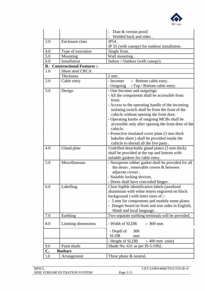
- Dust & vermin proof. - Welded back and sides . 3.0 Enclosure class IP54 . IP 55 (with canopy) for outdoor installation . 4.0 Type of execution Single front. 5.0 Mounting Wall mounting . 6.0 Installation Indoor / Outdoor (with canopy). B. Constructional Features :- 1.0 Sheet steel CRCA Thickness 2 mm . 2.0 Cable entry - Incomer :- Bottom cable entry. - Outgoing :-Top / Bottom cable entry. 3.0 Design - One Incomer and outgoings. - All the components shall be accessible from front. - Access to the operating handle of the incoming isolating switch shall be from the front of the cubicle without opening the front door. - Operating knobs of outgoing MCBs shall be accessible only after opening the front door of the cubicle. - Protective insulated cover plate (3 mm thick bakelite sheet ) shall be provided inside the cubicle to shroud all the live parts . 4.0 Gland plate Undrilled detachable gland plates (3 mm thick) shall be provided at the top and bottom with suitable gaskets for cable entry. 5.0 Miscellaneous - Neosprene rubber gasket shall be provided for all the doors , removable covers & between adjacent covers . - Suitable locking devices. - Doors shall have concealed hinges . 6.0 Labelling Clear legible identification labels (anodized aluminium with white letters engraved on black background ) with letter sizes of :- - 5 mm for components and module name plates. - Danger board on front and rear sides in English, Hindi and local language . 7.0 Earthing Two separate earthing terminals will be provided.
8.0 Limiting dimensions - Width of SLDB :- 800 mm
- Depth of SLDB
300 mm
- Height of SLDB :- 400 mm (min) 9.0 Paint shade Shade No. 631 as per IS-5:1992. C. Busbars 1.0 Arrangement Three phase & neutral.
BPSCL CET/23/RN/4060/TS/UT/01/R=0 SIDE STREAM FILTRATION SYSTEM Page 3.12
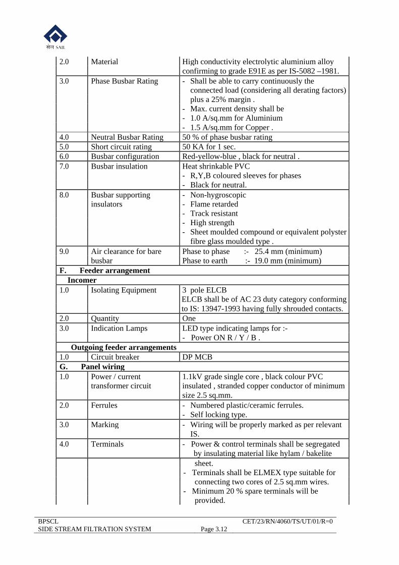
2.0 Material High conductivity electrolytic aluminium alloy confirming to grade E91E as per IS-5082 –1981. 3.0 Phase Busbar Rating - Shall be able to carry continuously the connected load (considering all derating factors) plus a 25% margin . - Max. current density shall be - 1.0 A/sq.mm for Aluminium - 1.5 A/sq.mm for Copper . 4.0 Neutral Busbar Rating 50 % of phase busbar rating 5.0 Short circuit rating 50 KA for 1 sec. 6.0 Busbar configuration Red-yellow-blue , black for neutral . 7.0 Busbar insulation Heat shrinkable PVC - R,Y,B coloured sleeves for phases - Black for neutral. 8.0 Busbar supporting - Non-hygroscopic insulators - Flame retarded - Track resistant - High strength - Sheet moulded compound or equivalent polyster fibre glass moulded type . 9.0 Air clearance for bare Phase to phase :- 25.4 mm (minimum) busbar Phase to earth :- 19.0 mm (minimum) F. Feeder arrangement Incomer 1.0 Isolating Equipment 3 pole ELCB ELCB shall be of AC 23 duty category conforming to IS: 13947-1993 having fully shrouded contacts. 2.0 Quantity One 3.0 Indication Lamps LED type indicating lamps for :- - Power ON R / Y / B . Outgoing feeder arrangements 1.0 Circuit breaker DP MCB G. Panel wiring 1.0 Power / current 1.1kV grade single core , black colour PVC transformer circuit insulated , stranded copper conductor of minimum size 2.5 sq.mm. 2.0 Ferrules - Numbered plastic/ceramic ferrules. - Self locking type. 3.0 Marking - Wiring will be properly marked as per relevant IS. 4.0 Terminals - Power & control terminals shall be segregated by insulating material like hylam / bakelite
sheet. - Terminals shall be ELMEX type suitable for connecting two cores of 2.5 sq.mm wires. - Minimum 20 % spare terminals will be provided.

BPSCL CET/23/RN/4060/TS/UT/01/R=0 SIDE STREAM FILTRATION SYSTEM Page 3.13
- The minimum rating of control terminal shall be 10 Amps.
5.0 Cable glands Double compression cable glands for receiving cables.
3.3.2 Miniature Circuit Breakers (MCBs)
1.0 Type Heat resistant plastic moulded type
2.0 Ref. Standard IS: 8828 –1978
3.0 Protections MCBs shall be provided with quick break trip-free
mechanism and direct acting thermal overload and
short circuit trip elements.
4.0 Short circuit capacity Not less than 9kA/1 sec
5.0 Mounting DIN Channel mounting.
Single phase MCBs mounted adjacent to each
other and connected to different phases will be
provided with adequate insulated phase barriers.
6.0 Current Rating The MCBs shall be selected from standard current
ratings MCB shall confirm to curve C.
3.3.3 LT Power Cables
Specific aspect of Cable Employer's Specification
1. Grade 1.1 kV earthed for aluminium and copper power cable.
2. Type Heavy duty PVC
3. Conductor Circular conductor made of stranded and compacted electrical grade aluminium/copper wires as per IS 8130- 1984
4. Maximum conductor 70oC
temperature with rated current
5. Insulation Extruded XLPE as per IS 5831- 1984
6. Inner Sheath Extruded PVC inner sheath with non-
BPSCL CET/23/RN/4060/TS/UT/01/R=0 SIDE STREAM FILTRATION SYSTEM Page 3.14
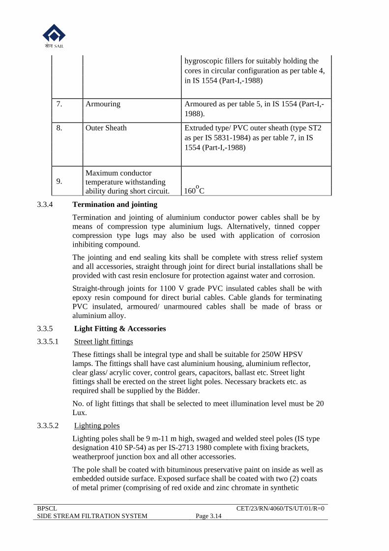
hygroscopic fillers for suitably holding the cores in circular configuration as per table 4, in IS 1554 (Part-I,-1988)
7. Armouring Armoured as per table 5, in IS 1554 (Part-I,-
1988).
8. Outer Sheath Extruded type/ PVC outer sheath (type ST2 as per IS 5831-1984) as per table 7, in IS 1554 (Part-I,-1988)
9. Maximum conductor temperature withstanding ability during short circuit. 160
oC
3.3.4 Termination and jointing
Termination and jointing of aluminium conductor power cables shall be by means of compression type aluminium lugs. Alternatively, tinned copper compression type lugs may also be used with application of corrosion inhibiting compound.
The jointing and end sealing kits shall be complete with stress relief system and all accessories, straight through joint for direct burial installations shall be provided with cast resin enclosure for protection against water and corrosion.
Straight-through joints for 1100 V grade PVC insulated cables shall be with epoxy resin compound for direct burial cables. Cable glands for terminating PVC insulated, armoured/ unarmoured cables shall be made of brass or aluminium alloy.
3.3.5 Light Fitting & Accessories
3.3.5.1 Street light fittings
These fittings shall be integral type and shall be suitable for 250W HPSV lamps. The fittings shall have cast aluminium housing, aluminium reflector, clear glass/ acrylic cover, control gears, capacitors, ballast etc. Street light fittings shall be erected on the street light poles. Necessary brackets etc. as required shall be supplied by the Bidder.
No. of light fittings that shall be selected to meet illumination level must be 20 Lux.
3.3.5.2 Lighting poles
Lighting poles shall be 9 m-11 m high, swaged and welded steel poles (IS type designation 410 SP-54) as per IS-2713 1980 complete with fixing brackets, weatherproof junction box and all other accessories.
The pole shall be coated with bituminous preservative paint on inside as well as embedded outside surface. Exposed surface shall be coated with two (2) coats of metal primer (comprising of red oxide and zinc chromate in synthetic
BPSCL CET/23/RN/4060/TS/UT/01/R=0 SIDE STREAM FILTRATION SYSTEM Page 3.15
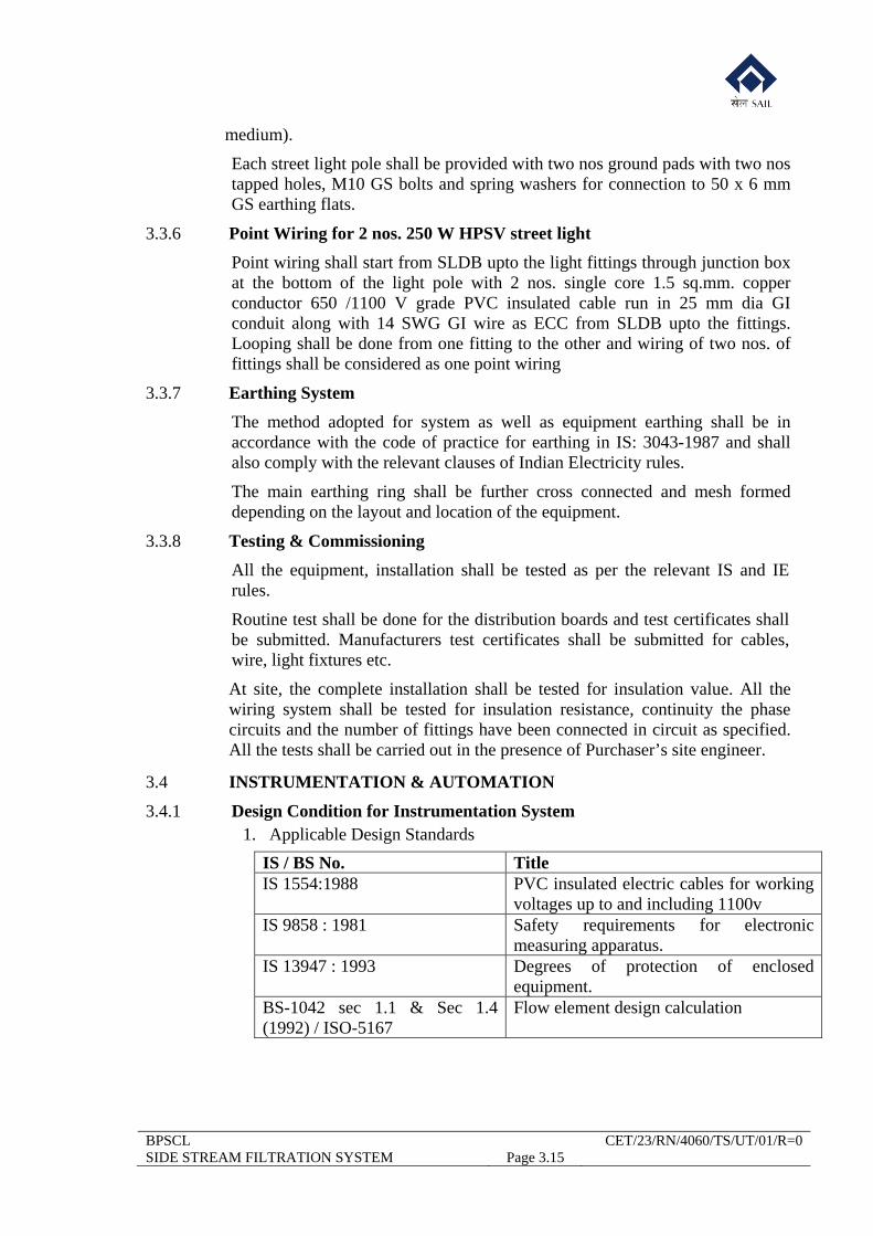
medium).
Each street light pole shall be provided with two nos ground pads with two nos tapped holes, M10 GS bolts and spring washers for connection to 50 x 6 mm GS earthing flats.
3.3.6 Point Wiring for 2 nos. 250 W HPSV street light
Point wiring shall start from SLDB upto the light fittings through junction box at the bottom of the light pole with 2 nos. single core 1.5 sq.mm. copper conductor 650 /1100 V grade PVC insulated cable run in 25 mm dia GI conduit along with 14 SWG GI wire as ECC from SLDB upto the fittings. Looping shall be done from one fitting to the other and wiring of two nos. of fittings shall be considered as one point wiring
3.3.7 Earthing System
The method adopted for system as well as equipment earthing shall be in accordance with the code of practice for earthing in IS: 3043-1987 and shall also comply with the relevant clauses of Indian Electricity rules.
The main earthing ring shall be further cross connected and mesh formed depending on the layout and location of the equipment.
3.3.8 Testing & Commissioning
All the equipment, installation shall be tested as per the relevant IS and IE rules.
Routine test shall be done for the distribution boards and test certificates shall be submitted. Manufacturers test certificates shall be submitted for cables, wire, light fixtures etc.
At site, the complete installation shall be tested for insulation value. All the wiring system shall be tested for insulation resistance, continuity the phase circuits and the number of fittings have been connected in circuit as specified. All the tests shall be carried out in the presence of Purchaser’s site engineer.
3.4 INSTRUMENTATION & AUTOMATION
3.4.1 Design Condition for Instrumentation System 1. Applicable Design Standards
IS / BS No. TitleIS 1554:1988 PVC insulated electric cables for working
voltages up to and including 1100v IS 9858 : 1981 Safety requirements for electronic
measuring apparatus. IS 13947 : 1993 Degrees of protection of enclosed
equipment. BS-1042 sec 1.1 & Sec 1.4 (1992) / ISO-5167
Flow element design calculation
BPSCL CET/23/RN/4060/TS/UT/01/R=0 SIDE STREAM FILTRATION SYSTEM Page 3.16
2. Design Conditions
i) Planning, design, manufacture, supply, installation, testing inspection and commissioning of the electrical equipment and facilities shall comply with latest versions of IEEE/ IEC/ IPSS/ IS, Indian Electricity Rules, laws and regulations in force in the state of Jharkhand.
ii) If relevant IPSS/ IS is not available for a particular application, the IEC (International Electro-technical Commission) standards shall be applicable.
iii) All plans, design, manufacture, installation and cabling work shall be based on the ISO metric system.
iv) System shall be designed with inbuilt safety system for operating and maintenance personnel. Facilities for inspection, testing, maintenance and adjustment at site shall be provided without disrupting process.
v) All the instrumentation & control equipment shall be brand new & supplied from the latest product ranges of reputed manufacturers as per the List of Preferred Makes. The instrumentation equipment shall be generally sourced from India. For imported equipment, if any, availability of spares & service facility from India shall be ensured by the Bidder.
vi) System shall be of modular design for future expandability / modification. Necessary redundancy shall be considered, as spelled out in this T.S, for reducing extent of abnormality and Mean Time To Repair (MTTR).
vii) All field instruments and equipments shall be suitable for hazardous area application and intrinsically safe design as per classification IEC Zone viz. Zone 1, Group IIA & IIB as applicable. All field instruments & accessories also shall be weather and corrosion proof and suitable for Chemical Plant application.
viii) Wetted parts of the instrumentation equipment shall be selected so as to withstand physical and chemical properties of the service fluid coming in direct contact with the instrument.
ix) Whenever corrosive atmosphere is present, all instruments and associated equipment exposed to such a medium shall be designed & protected to withstand the adverse effects
x) Equipment noise limitation shall be as per IEC-179 (generally not exceeding 85 dB at 1-meter distance).
xi) All pressure gauges will be provided with built-in diaphragm separator.
xii) All orifice plates / nozzle/ venturi tubes will be provided with two sets of tapping assembly.
xiii) For local flow rate indication, generally rotameter / by-pass rotameter type instruments will be used with fluid flowing in vertically upwards direction. For line sizes up to 50 mm line size, direct on line
BPSCL CET/23/RN/4060/TS/UT/01/R=0 SIDE STREAM FILTRATION SYSTEM Page 3.17
rotameters will be used. For line size above 50 mm and up to 400 mm line size, by-pass type rotameter with built-in orifice plate will be used.
xiv) Power supply to individual instrument with AC power supply will be through individual MCB of adequate rating.
xv) The instrumentation items shall be supplied by the Bidder based on the finalized specification data sheets as will be approved during detailed engineering stage. These specification sheets shall be in standard format (e.g. ISA) or approved format.
xvi) For corrosive fluid application wetted parts of all field instruments shall be made of corrosive resistant material.
xvii) All instruments / transmitters shall have local display facility. All transmitters shall have suitable lightning protection device.
xviii) Guidelines for selection of erection materials: SS tube Compression Fittings & Fittings shall be as per ISA RP 42.1.
3. Proposed System
The proposed Instrumentation & control system shall consist of primary sensor & field instruments for efficient monitoring of process parameters. Suitable digital display shall be considered for differential pressure measurement across filter sand bed and flow measurement at outlet of each filter shall be housed in a wall mount panel located preferably in the existing pump house. All the transmitters shall have external surge protection.
Major measurement parameters considered are as per the following:
i) Flow measurement at filter inlet header. ii) Flow measurement at filter outlet header. iii) Differential pressure measurement across filter sand bed. iv) Pressure measurement at inlet and outlet of filter. v) Flow measurement at outlet of each filter.
3.4.2 Technical Specifications
1. Pressure / Flow transmitter
The pressure / flow transmitters shall be of smart type with variable capacitance / solid state type sensor. Transmitters shall be with built in local indicator, two / three way manifold and mounting accessories etc. For flow transmitters square root extractor shall be provided. One set of Hand Held Calibrator shall be provided for calibration. The transmitters shall have the following specifications:
Range As required Electronics Microprocessor based smart Power Supply 12-48 VDC Output 4-20 mA & superimposed digital signal on HART
BPSCL CET/23/RN/4060/TS/UT/01/R=0 SIDE STREAM FILTRATION SYSTEM Page 3.18
protocol Accuracy ± 0.25% of span Load limit 600 Ohms Over pressure limit
200% of upper range limit
Linearity ± 0.1% of span Repeatability ± 0.05% of span Sensitivity ± 0.05% of span Dead band ± 0.05% of span Zero adjustment Continuously adjustable Transient protection
Inbuilt lightning protection shall be provided
Damping Shall be step or continuously adjustable, so that the time constant varies from 0-3 sec or 0-6 sec.
2. Digital Indicator
Display Red LED seven segment digits in 3 1/2 digital display.
Accuracy 0.5 % Alarm High and low alarm indicator and selectable for each
channel Alarm setting 0-100 % range Alarm output 2 points/input Digit Height 15 mm Input 4-20 m A dc analog, isolated
Impedance - 1Mohm Output Alarm output of 0.1 A at 220V ac , isolated dry contact
with NO or NC contact selectable internally. Power supply 24 DC
3. Pressure / Differential Pressure Gauge
Type Bourdon Tube Application Gauge pressure Sensing element Diaphragm + Bourdon Tube Sensing element material AISI 316 L Socket/adaptor material AISI 316 SS Case material Cast Aluminium Bazel ring material AISI 304 SS Window Shatterproof glass Dial AISI 316 SS Pointer AISI 316 SS Dial size 150 mm Dial colour White Scale Black lettering on white background Housing Enclosure IP 67 Mounting Installation on the post Over range 125% of full scale
BPSCL CET/23/RN/4060/TS/UT/01/R=0 SIDE STREAM FILTRATION SYSTEM Page 3.19
Ambient temperature limit 60 deg C Humidity limit Maximum Zero adjustment Micrometer Process connection Diaphragm seal Diaphragm Maximum pressure Class 150 Hydraulic filling Silicon oil Diaphragm material AISI SS 316L Isolation gauge cock (3 way) Required Socket for gauge cock mounting with PG
Required
4. Orifice Plate
The orifice plate shall specifically be designed as per B.S. 1042 section 1.1: 1981, 1.2 & 1.4: 1992. The orifice plate shall in general be of square edge concentric type with flange tapping. All orifice plates shall be supplied with matching flanges of suitable rating not less than three times the maximum line pressure. All tapping arrangements shall be complete with a piece of impulse pipe line and a shut off valve of adequate pressure rating.
Material of orifice plate assembly shall be of SS 316. The matching flange shall be of carbon steel. For line sizes above 50 mm the diameter ratio (d/D ratio) shall preferably be selected between 0.548 to 0.775. Base of the orifice plate shall be parallel within 0.5 degree. Other details as well as design guidelines will be as per BS 1042 section 1.1: 1981, 1.2 & 1.4: 1992.
5. Cables and Cable laying
i) All control cables shall be conforming to IS:1554, 1988 or relevant Indian Standards as applicable.
ii) The power wiring within the cubicles shall be done with minimum 2.5 Sq. mm Copper Conductor.
iii) Cable entry to the panels / junction boxes shall be through suitable removable gland plates and glands.
iv) Parallel run of instrument cables and power cables shall normally be avoided but where parallel run must be made, suitable cable spacing shall be provided.
v) Crossing of power and control cables shall be done at right angles. All cables must be laid on GI trays mounted on rigid supports at suitable interval to avoid sagging.
vi) Signal, power and compensating cables shall be laid on separate G.I. trays with minimum separation as per relevant standard.
vii) G.I. trays shall be mounted with their breadth in Vertical plane to protect cables from falling objects, accumulation of dust. If plates are provided horizontally these shall be provided with removable covers and shall be supported to avoid sagging.
BPSCL CET/23/RN/4060/TS/UT/01/R=0 SIDE STREAM FILTRATION SYSTEM Page 3.20
viii) Multicore cables shall not be bent to radius less then manufacturer's recommendation. Intermediate joints shall be avoided.
ix) Clips and saddles securing cables to steelworks or tray shall preferably be plastic covered materials and shall be spaced at 0.5 mtr interval.
x) All cables shall be suitably identified with their tag numbers duly clamped at an interval of 5 meters.
xi) Unarmoured or flexible cables shall be laid in conduits, individually or in groups with removable plates and tag identification at an interval of 5 meters.
xii) All cables shall be FRLS type.
6. General
i) The equipment shall conform to the safety requirements of IS 8495-1977-specification for electrical instruments for hazardous atmospheres, IS:9858-1981-Safety requirements for electronic measuring apparatus etc. Wherever Indian Standards do not exist, ISA, IEEE or NEEMA Standards or the ones laid down hereafter be followed. Devices should be intrinsically safe.
ii) All instrumentation power supply system shall be through isolation transformers and system voltage shall be 220 V + 10%; -15%, 50 Hz ± 4%. Instrumentation system working on unified current signal of 4 - 20 mA DC only shall be used.
iii) All instrument cut outs and drilling shall be straight and through. All panels shall be supported on suitably sized vibration isolators, designed for bolting to panel frame and flooring. Access doors on enclosed panels shall be 750 mm wide by 1800 mm high, single sheet with suitable latch, hooks, knobs on inside and outside and shall open forward.
v) The panels shall be free standing type and of welded / bolted construction. All welds shall be ground smooth, all corners be rounded and all weld spatters shall be cleared. Surface of panels shall be free from all mars & defects. The finished panel shall be flat with in 2 mm in any 2 meter radius and shall be smooth. Removable eye-bolt lifting lugs shall be furnished and installed in all panels.
vi) Power supply to individual instrument having A.C. power supply shall be through separate MCB. Power supply to transmitters having 24V DC supply shall be through two nos. 24 V regulated power supply units connected in parallel (Each having capacity to supply all transmitters) with diode protection against each loop current flow. A 24 V DC bus will be drawn at the output side of regulated DC power supply units. Individual transmitters shall be connected to the DC bus through MCB and LEDS
viii) Any signal duplicated to more than one point will be through signal isolator only.
BPSCL CET/23/RN/4060/TS/UT/01/R=0 SIDE STREAM FILTRATION SYSTEM Page 3.21
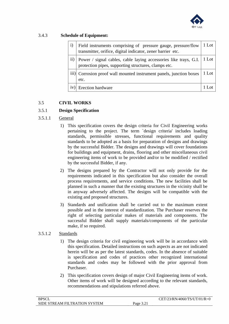
3.4.3 Schedule of Equipment:
i) Field instruments comprising of pressure gauge, pressure/flow transmitter, orifice, digital indicator, zener barrier etc.
1 Lot
ii) Power / signal cables, cable laying accessories like trays, G.I. protection pipes, supporting structures, clamps etc.
1 Lot
iii) Corrosion proof wall mounted instrument panels, junction boxes etc.
1 Lot
iv) Erection hardware 1 Lot
3.5 CIVIL WORKS
3.5.1 Design Specification
3.5.1.1 General
1) This specification covers the design criteria for Civil Engineering works pertaining to the project. The term `design criteria' includes loading standards, permissible stresses, functional requirements and quality standards to be adopted as a basis for preparation of designs and drawings by the successful Bidder. The designs and drawings will cover foundations for buildings and equipment, drains, flooring and other miscellaneous civil engineering items of work to be provided and/or to be modified / rectified by the successful Bidder, if any.
2) The designs prepared by the Contractor will not only provide for the requirements indicated in this specification but also consider the overall process requirements, and service conditions. The new facilities shall be planned in such a manner that the existing structures in the vicinity shall be in anyway adversely affected. The designs will be compatible with the existing and proposed structures.
3) Standards and unification shall be carried out to the maximum extent possible and in the interest of standardization. The Purchaser reserves the right of selecting particular makes of materials and components. The successful Bidder shall supply materials/components of the particular make, if so required.
3.5.1.2 Standards
1) The design criteria for civil engineering work will be in accordance with this specification. Detailed instructions on such aspects as are not indicated herein will be as per the latest standards, codes. In the absence of suitable is specification and codes of practices other recognized international standards and codes may be followed with the prior approval from Purchaser.
2) This specification covers design of major Civil Engineering items of work. Other items of work will be designed according to the relevant standards, recommendations and stipulations referred above.
BPSCL CET/23/RN/4060/TS/UT/01/R=0 SIDE STREAM FILTRATION SYSTEM Page 3.22
3) In case anything mentioned in this specification is at variance with IS or other codes of specification mentioned herein, the provisions of this specification will prevail.
3.5.1.3 Setting Out and Leveling
The Bidder shall set out and level the work and shall be responsible for the accuracy of the same. He has to provide all instruments and qualified staffs with labour for getting his work checked by Engineer-in-Charge, if so desired by the Purchaser. Such checking, if any, shall not, however, relieve the Bidder in anyway, of his responsibility for correct setting out.
3.5.1.4 Safety
The Bidder shall take adequate precautions to ensure complete safety and prevention of accidents at site and shall be responsible for the same. The safety precautions shall conform to the safety regulations prescribed by the safety code for constructions and relevant Indian Standard Codes, some of which are listed below:
IS: 3764-1992 : Safety code for excavation work.
IS: 4014-1967 : Safety regulations for scaffolding work.
IS: 4081-1986 : Safety code for drilling and blasting operations.
IS: 4138-1977 : Safety code for working with compressed air.
IS: 7923-1985 : Safety code for working with construction machinery.
3.5.1.5 Keeping Work free from Water
The Bidder shall provide and maintain at his cost, pumps and other equipments to keep the works free from water and shall continue to do so until the handing over of the works.
3.5.1.6 Cleaning of Site
The Bidder shall keep the site clear on a continuous basis, from muck, rubbish etc., which may arise out of the work executed by him and dispose them suitably in allotted areas.
3.5.1.7 Bench Marks, Reference Pillars etc.
The Bidder shall protect all benchmarks, and reference pillars /lines including ground water gauges from damage or movement during working. In case of any damage the Bidder shall have to restore the same to its original condition at his own cost.
3.5.2 Concrete & Reinforced Concrete for Structures & Foundations
3.5.2.1 General
(i) Concrete work shall secure a dense, homogeneous, smooth mass including required finishes, possessing required strength and resistance to weathering and abrasion for the structures and foundations.
(ii) Design of all reinforced concrete structures shall be as per IS: 456-2000.
BPSCL CET/23/RN/4060/TS/UT/01/R=0 SIDE STREAM FILTRATION SYSTEM Page 3.23
The structural safety of all foundations on soil shall, in general be based on IS: 1904-1986.
(iii) All reinforced cement concrete including those for water retaining structures shall be in minimum grade of M-25 (with 20 mm and downgraded aggregates).
(iv) Plain cement concrete shall be M-10B (with 40 mm and downgraded aggregates). However, for mass filling plain cement concrete of grade M-5B shall be used.
(v) Grouting below machine/equipment bases and pockets shall be of ready-mix non-shrinking grout (SHRINKOMP-30 or equivalent) of adequate thickness and strength. Grouting below structural column bases shall be with concrete of minimum grade M-30 (with 10 mm and downgraded aggregates).
(vi) For calculations purpose ‘Limit State Design’ methods shall be adopted.
(vii) The minimum grade of RCC shall be M25 and PCC shall be M10.
3.5.2.2 Permissible Stresses
Allowable stresses for all reinforced concrete structures shall be as per IS: 456 – 2000.
3.5.2.3 Foundations
(i) Selection of type of foundation shall be based on the recommendations of soil investigation & survey report, supported loads, system requirements and site constraints.
(ii) Open foundations for structures and equipment shall be proportioned to resist the worst conditions of loading and shall be generally designed as per the provisions of IS:1904-1986.
(iii) The depth of foundation shall be determined based on loading on foundations and bearing capacity at the founding level, constructional and technological requirements. The maximum allowable bearing pressure for design of foundation shall correspond to values indicated in detailed soil investigation report taking into account limits of allowable settlement considered for design of structures. However, in no case shall be the foundation is taken down to less than 600 mm below natural ground level in case of soil and 200 mm in case of rocky strata. In no case foundation shall be placed on the filled up soil and the depth of the foundation shall be taken upto the depths where the virgin soil strata is found and extra depth shall be filled with PCC 1:5:10 (cement: sand: aggregate).
(iv) The foundation of the new structure /facility shall be taken at least to the depth of the foundation of adjoining existing structure/ facility, if any. In no case the loads from the new foundations shall be transferred to the existing foundation. However in exceptional circumstances, if it is required to be done, then the existing foundation shall be checked for
BPSCL CET/23/RN/4060/TS/UT/01/R=0 SIDE STREAM FILTRATION SYSTEM Page 3.24
the additional load transferred and shall be supported with design calculation.
(v) All faces of concrete or plastered surfaces in contact with earth shall be provided with two coats of bituminous protective coatings of approved make. Ground floor slab shall be cast on a layer of building paper of approved make on boulder/ Blast Furnace slag soling with moorum binding.
3.5.2.4 Soil Conditions
(i) The net allowable bearing capacity shall be considered as 15 Ton/m2 which is likely to be at 2 m below ground level.
(ii) Less important foundations of minor structures carrying low loads can be laid on backfilled soil with 250mm thick compacted boulder soling, and the allowable bearing capacity shall be considered as 5 Ton/m2.
(iii) During execution, in case of any doubt regarding the reported bearing capacity & actual site condition by Engineer-In-Charge, the scope of Successful Contractors also include the collection of soil samples, performing tri-axial test and sieve analysis on samples and calculating safe bearing capacity of founding strata to confirm the assumed bearing capacity in design. The water table will be assumed at existing ground level and correction factors will be applied accordingly.
3.5.3 Floors
3.5.3.1 In general, all floors on ground for the production buildings, including pump houses, stores and electrical buildings shall be made of minimum M20 RCC of 150mm minimum thickness. The design of floor shall be done taking into consideration technological requirements, imposed loading and other service conditions etc.
3.5.3.2 For areas where the loading is high (more than 5T/Sqm), like Mill floor, SMS floor etc, the floor shall be designed for actual loads. The computation of edge and corner stress can be done using IRC 58:1988 or other accepted analysis procedures including finite element modeling of the structure in Structural analysis software. The design of RCC floor shall be done as per IS:456-2000.
3.5.3.3 The sub-grade below the floor slab shall be minimum 250 mm thick stone boulder soling blinded with moorum. Building paper shall be provided on top of sub-grade before casting the concrete slab.
3.5.3.4 All sub-grade shall be laid on compacted soil.
In specific areas of production buildings where concrete floor is not required at ground floor level, the flooring shall consist of minimum 250mm thick stone boulder soiling blinded with moorum and compacted.
3.5.3.5 Floor Finishes
Floor finishes for the rooms and buildings shall be according to the technological, process and functional requirements and service conditions.
BPSCL CET/23/RN/4060/TS/UT/01/R=0 SIDE STREAM FILTRATION SYSTEM Page 3.25
3.5.4 Storm Water Drainage
3.5.4.1 The design of storm water drainage system shall be based on maximum hourly precipitation for a storm of duration of 20 minutes. Roof drainage system shall be designed on the basis of an hourly precipitation for storm duration of 5 minutes.
3.5.4.2 Gully, traps, inspection pits, junction pits, collecting pits etc. As well as other facilities shall be located suitably and designed considering easy access, maintenance and safety.
3.5.4.3 For the purpose of calculation of run-off from catchments area of any drainage line, the contractor shall estimate areas of buildings, paved area, roadways, parking areas and open areas within tree catchments area. Run-off coefficients for design shall be as follows:
1) Open areas : 0.50
2) Roads and paved/parking areas : 0.70
3) Roof surface : 1.00
3.5.4.4 The pipes shall be so designed as to give a velocity of flow not less than one metre per second when running half full. The maximum velocity shall not exceed 2.5m per second.
3.5.5 Design Calculations, Drawings and Documents
3.5.5.1 Design Calculations /data sheet
The design calculations to be submitted by successful Bidder for approval, prior to submission of construction drawings shall include, but not be limited to, the following:
(i) Architectural design
The successful Bidder shall follow the norms and basic schemes indicated in the Technical Specification. The successful Bidder shall submit all catalogues/ specifications for various floor and wall finishes, painting, sanitary and plumbing fixtures and fittings, doors and windows, etc.
(ii) Structures and foundations design
The design calculations for all the buildings and foundations including storage, underground foundations, tunnels, miscellaneous structures, all equipment foundations etc. shall include static design calculations for all structures and foundations.
Building data sheet showing specifications of materials, design standards followed, loading norms adopted, including the loading on roof, walkways, different floors, bulk material density, crane and hoist loading, wind and seismic loading, wind thrusts and vibration considerations, deflection, rainfall and run-off data assumed and type of framework, etc. Also, type of flooring, roofing & sheeting and type of construction shall be indicated. The loading combinations and other design assumptions made in design are to be furnished.
BPSCL CET/23/RN/4060/TS/UT/01/R=0 SIDE STREAM FILTRATION SYSTEM Page 3.26
3.5.5.2 Drawings
The Successful Bidder shall prepare general layout drawings giving salient levels and dimensions of the whole area showing all over ground and underground services and facilities, buildings, roadways, railways etc., provided for co-ordination with the other areas of the Steel Plant. Detailed working drawings shall be prepared on the basis of the general layout drawings considering overall foundation layout for the equipment, building, services, etc., space requirement and clearances as necessary. The Successful Bidder shall ensure that no further drawing shall be required by any other agency for successful implementation of the project. The successful Bidder shall submit a comprehensive and complete unit wise classified list of drawings in reproducible form.
The Successful Bidder shall submit for approval of the Purchaser/Consultant General Arrangement and detailed working drawings for all concrete, reinforced concrete and other civil works, as follows:
i. Architectural drawings for office / rest room / stores, toilets etc.
ii. Excavation drawings.
iii. Foundation plans and sections for building columns and equipment incorporating services, utility tunnels, trenches, pipes, etc.
iv. Loading drawings indicating superstructure loading, equipment loading, floor loading, etc.
v. Comprehensive anchor hole plan along with complete details of anchor bolts and anchor pockets for foundation for building columns and equipment, etc., including schedule for bolts and anchor plates. Design of anchor bolts should be such that it should be possible for any replacement of the same in case they get damaged.
vi. Detailed structural drawings for floors Reinforcement details with bar bending schedules for all reinforced concrete works.
vii. Drawings for all types of bolts, inserts, embedments, covers, miscellaneous steelworks, etc.
viii. All drawings for masonry work, flooring, floor finishes, false ceiling, false floor, wall panelling, etc.
ix. Underground storm water drainage drawings for areas and buildings within the battery limit.
x. Drawings/catalogues for doors, windows, ventilators, louvres, and miscellaneous equipments
xi. Drawings for outdoor utility service lines
xii. Detailed bill of materials of all items of work.
BPSCL CET/23/RN/4060/TS/UT/01/R=0 SIDE STREAM FILTRATION SYSTEM Page 3.27
3.5.6 Material & Workmanship Specifications
3.5.6.1. General
a. Local conditions
The Bidder, before submitting his tender, shall visit the site and ascertain the local conditions, labour rules, availability of construction materials, traffic restrictions, all obstructions in the area and also ascertain all site conditions including the sub-soil conditions and shall allow for any extras likely to be incurred due to all such conditions in his quoted prices. After the award of work no additional claims will be entertained on these accounts under any circumstances, whatsoever, from the successful Bidder.
b. Setting out and levelling
The successful Bidder shall set out and level the work and will be responsible for the accuracy of the same. He is to provide all instruments and proper qualified staff with labour for getting his work checked by Engineer, if so desired by the Engineer. Such checking, if any, shall not, however, relieve the successful Bidder in any way, of his responsibility for correct setting out.
c. Safety
The Bidder shall take adequate precautions to ensure complete safety and preventions of accidents at site and shall be responsible for the same. The safety precautions shall conform to the safety regulations prescribed by the Safety Code for constructions and relevant Indian Standard Codes, some of which are slated below:
IS 4081-1986 : Safety Code for drilling and blasting operations
IS 4138-1977 : Safety Code for working with compressed air
IS 7923-1985 : Safety Code for working with Constructions machinery
d. Keeping work free from water
The Bidder shall provide and maintained at his own cost, pumps and other equipments to keep the works free from water and continued to do so until the handing over of the works
BPSCL CET/23/RN/4060/TS/UT/01/R=0 SIDE STREAM FILTRATION SYSTEM Page 3.28
e. Rubbish
The successful Bidder shall keep the site clear on a continuous basis of all rubbish etc. which may arise out of the work executed by him and dispose them suitably in allotted areas.
f. Bench Marks, Reference Pillars etc.
The successful Bidder shall protect all bench marks and reference pillars /lines including ground water gauges from damage or movement during working. In case of any damage the Bidder shall have to restore the same to its original condition at his own cost.
g. Standards
Unless otherwise mentioned in the specifications, all applicable codes /standards as published by the Bureau of Indian Standards on the date of award of contract shall governed the work in respect of design, workmanship, quality and properties of materials, method of testing and other pertinent features. In case of variance between this specifications and IS Codes /Standards, the provisions of this specification shall prevail upto the extent of such variance.
3.5.6.2. Dismantling
a. The dismantling of civil works shall be carried out with utmost care so that the adjacent structures, which are not to be dismantled, do not get damaged. However, if any existing structures get damaged during dismantling, the successful Bidder shall carry out the rectification and restoring of the entire structures without any extra cost.
b. The successful Bidder shall assess the entire dismantling work and decide accordingly the resource to be employed by him so that the work can be executed in the stipulated time frame.
c. The successful Bidder shall obtain the necessary clearance certificates from Safety department of BSL for the arrangement of dismantling work at every stage.
d. The dismantled material shall be first stacked near site within a lead of 100 m and thereafter disposed off up to 5 Km within the Plant boundary.
e. Dismantling shall be done preferably in such piece size length as will facilitate easy transportation and disposal of those items to dumping yard /storage yard.
f. Dismantling of all RCC and PCC work shall be done as per detailed dismantling drawing.
g. Pneumatic hammer / breaker in general shall be used for dismantling of RCC slabs, beams, columns, foundations etc.
h. Earthwork required for exposing the foundations for expediting the dismantling of the foundations shall be measured separately and paid under relevant items.
BPSCL CET/23/RN/4060/TS/UT/01/R=0 SIDE STREAM FILTRATION SYSTEM Page 3.29
3.5.6.3. Excavation and Back Filling
a. Stripping
The successful Bidder shall strip the surface of the site prior to the commencement of excavation to remove vegetable soil and carry such soil to separate spoil dumps in the allotted site/areas.
b. Excavation for foundations and Trenches
i. The successful Bidder shall grub roots of bushes, shrubs etc. and excavate at various levels including hard rock to remove materials of any nature or description, which may be encountered including steel plant waste, slag, fly ash, cinders, iron ore fines etc. Side slopes, benching and/or shoring/strutting for excavation work shall be as directed by the Engineer-in-Charge and prior approval from him shall be obtained for a suitable method of protection before excavation work commences. The bed of the excavation shall be properly dressed and made level. All mud and slush shall be removed before taking up concreting work. The last 150 mm of excavation shall be done just prior to laying of concrete. The excavated materials shall not be placed within 5.0 m from the edge of any excavation. The successful Bidder shall take suitable precautions to prevent ingress of water into the excavated pit / trenches during construction.
ii. The successful Bidder shall account for all excavated rock, if any. He shall stack excavated rock and if the successful Bidder for his works requires serviceable boulders, it may be issued based on stack measurement less 40% for voids at the rate to be decided by the Employer.
iii. The surplus excavated materials and excavated unserviceable materials from rock excavation shall be transported and disposed off by the successful Bidder in spoil dumps or fill areas as directed by the Engineer-in-Charge within a lead upto 5 km.
iv. Should the bottom of any excavation appear to be soft, unsound or unstable, the successful Bidder shall excavate the same to required depths and the extra depth shall be filled up by the successful Bidder with lean concrete of grade M-5B or such other materials as in writing.
v. Every precaution shall be taken by the successful Bidder against slips and falls in the excavation. No extra payment will be made for removal of slips and falls and for back filling the space with the materials as directed by the purchaser.
vi. The excavation shall be kept free from water by pumping. Water may be bailed out from small pits with buckets. However, pumping of water shall be carried out from bigger excavation pits either directly from the excavation or from sumps made outside the excavation as directed. Adequate care shall be taken to prevent movement of water through freshly laid concrete or masonry work.
BPSCL CET/23/RN/4060/TS/UT/01/R=0 SIDE STREAM FILTRATION SYSTEM Page 3.30
vii. If any excavation for foundation gets filled up with water due to rain, seepage or for any reason, the water shall be removed and bottom of the excavation shall be completely cleared of all silt/slush by the Bidder at his own expense.
viii. All water pumped or bailed out during de-watering of pits and trenches shall be disposed off suitably through properly laid channels or pipes. Disposal of water shall be carried out in such a way that no inconvenience or nuisance is caused to the work in progress in the area or to other agencies working in the area or cause damage to property and structures nearby.
c. Back Filling
i. Materials
Suitable materials obtained from excavation of foundations shall be used as far as possible for back filling. If sufficient amount of suitable materials are not available at site to complete filling work, then earth shall be brought to site from outside by the successful Bidder as directed by the Engineer-in-Charge.
ii. Filling around foundations with earth
Before commencement of back filling, the successful Bidder shall remove from the space around foundations all accumulated water and slush, shoring and formwork, all debris, brickbats, bits of timber, cement bags and all other foreign materials. Filling shall be carried out in uniform horizontal layers, each layer not exceeding 200 mm in thickness. Each layer shall be watered, rammed, and thoroughly compacted before the next layer is deposited.
iii. Plinth filling and special compaction with earth
Plinth filling or filling where special compaction is required shall be carried out in uniform horizontal layers, each layer not exceeding 150 mm in thickness. Each layer shall be well watered and compacted by mechanical means. The successful Bidder shall take core samples for each layer, determine the dry density and maintain logs. The minimum dry density to be achieved shall be 95% of maximum dry density as obtained by Standard Proctor Test. Tests shall be conducted by the successful Bidder as directed by the Engineer-in-Charge at his own cost.
iv. Removal of heaps & Mounds
Immediately upon completion of each phase of work, the successful Bidder shall at his own cost clear the mounds or heaps of earth which may have been raised or made and remove all earth and rubbish which may have become surplus in the execution of works, as directed.
v. Filling with sand
Filling with sand shall be carried out in uniform horizontal layers, each layer not exceeding 200 mm in thickness with approved river sand and each layer to be watered and compacted mechanically to a well compacted
BPSCL CET/23/RN/4060/TS/UT/01/R=0 SIDE STREAM FILTRATION SYSTEM Page 3.31
mass.
3.5.6.4. Plain And Reinforced Concrete Work
a. Materials
i. Cement
Ordinary Portland cement shall conform to IS:8112-1989 and Portland blast furnace slag cement shall conform to IS:455-1989. Soundness test is to be carried out on cement samples from time to time. Frequency of these tests shall be increased during monsoon period as per direction of engineers.
ii. Aggregates
All aggregates shall conform to IS: 383-1970. Fine aggregates shall be approved river or pit sand. Coarse aggregates shall be approved crushed stone. Aggregates shall be clean and free from any foreign material. Test on aggregate shall be carried out from time to time to ascertain the suitability of the aggregates. The frequency of such test shall be as per direction of engineer.
iii. Reinforcement
Reinforcement in general shall be of tested quality. Thermo-mechanically treated steel bars conforming to IS: 1786-1985 shall be free from oil paint and rust coatings. The binding wire shall be 20 SWG approved annealed iron wire.
iv. Jointing materials
All rubber and PVC water stops joint fillers, sealing materials etc. used in concrete work shall be of standard manufacture as per relevant IS codes and/or as approved by the Engineer. Usage of these materials shall be in accordance with the manufacturer's instructions.
v. Admixtures
Admixtures, if permitted to be used, shall be of approved quality and make and shall conform to relevant IS codes. The extent, type, method of use and control shall be subject to approval of the Engineer-in-Charge in all cases.
vi. Water
Water shall be clean and of potable quality as per provisions of IS: 456-2000.
b. Workmanship
i. Concrete
Production and control of concrete shall be as per IS: 456-2000. The grades of concrete shall be as indicated in the drawing. The successful Bidder shall at his own cost, grade the aggregates and control the water cement ratio, design the different mixes to required strength and workability, and obtain Engineer's approval for the same. The designed
BPSCL CET/23/RN/4060/TS/UT/01/R=0 SIDE STREAM FILTRATION SYSTEM Page 3.32
mix shall conform to the requirement of IS: 456-2000 and recommended guidelines in SP: 23-1982. The minimum cement content and maximum water cement ratio of concrete work shall conform to the requirements of durability of concrete for moderate exposure as indicated in Table-5 of IS: 456-2000. All concrete shall be machine mixed, and no hand mixing shall be permitted.
The maximum size of aggregates used shall be as indicated in the drawings and IS: 456-2000. Where reinforcement is too closely spaced for the maximum size of stone in a range, the largest suitable range shall be used. Before commencement of work, the Bidder shall submit to the Purchaser for his approval complete details of the tests for design mixes together with the grading analysis and mix design calculations. No concrete shall be placed on site until the Purchaser has approved the mix design.
Where nominal mixed concrete as defined by IS: 456-2000 is permitted by the Engineer-in-Charge for any specific reason, the proportion of the materials shall be as indicated in IS:456-2000. The water cement ratio shall not exceed those specified in IS: 456-2000. If the quantity of water is required to be increased for better workability, the cement content also shall be increased proportionately so that the water cement ratio as specified in IS: 456-2000 is not exceeded.
ii. Mixing
Except where nominal mix concrete as defined in IS:456-2000 is permitted by the Engineer to be used, all components of concrete shall be proportioned by weight using weigh batches for each grade of concrete. Mixing shall be carried out in mechanical mixers and preferably a batch mixing plant shall be used. Batches shall not exceed the capacity which can be mixed efficiently as determined by the mixer efficiency test and peripheral speed shall conform to the manufacturer's recommended rate but should not vary by more than +10%. Mixing shall continue until the mass is uniform in colour and consistency but in no case net minimum mixing time shall be less than 1.5 minutes. Net minimum mixing time shall begin when all ingredients including water is in the mixer. Excessive mixing shall be avoided. Mixers shall be operated only by trained operators. Weigh batches shall be placed level during use and the hoppers shall be loaded evenly.
iii. Consistency
Consistency of concrete shall be controlled as per IS: 456-2000 and the successful Bidder shall carry out slump tests in accordance with IS: 1199-1959.
c. Work tests
Over the full period of construction, the successful Bidder shall carry out works tests of concrete cubes at his own cost. Sampling, making up, curing and testing of specimen shall conform to IS: 456-2000, IS: 516-1959 and IS:1199 -1959. The number of specimen to be tested and their criteria for
BPSCL CET/23/RN/4060/TS/UT/01/R=0 SIDE STREAM FILTRATION SYSTEM Page 3.33
acceptance shall be according to IS: 456-2000. Frequency of work tests shall be as indicated below:
d. Frequency of tests
i. The frequency of tests shall be as per IS:456-2000.
ii. The test cubes shall be taken in presence of the Engineer/Employer's representative, who will also sign the record of testing in a pro-forma to be agreed between purchaser & successful Bidder.
iii. For testing of cube specimens, successful Bidder shall transport the specimen to the testing laboratory and the cost of testing of cubes will be fully borne by him.
e. Reinforcement
i. Workmanship shall conform to IS: 2502-1963. All reinforcement shall be free from loose mill scale, rust, oil, grease and paint, etc. Reinforcement shall not be bent or straightened in a manner that will injure the material, and all bars shall be bent cold.
ii. Reinforcement bars shall be placed and maintained accurately in the position as shown in the drawings. The correct cover to the reinforcement shall be maintained by use of pre-cast concrete blocks.
iii. All intersections of longitudinal and transverse bars of stirrups and all laps shall be securely tied together with approved binding wire. The binding wire shall be so placed that it touches all the four corners of the intersection and the two ends shall be looped with pliers and the end should be turned into the body of the concrete.
iv. Welded joints may be used with prior approval of the Engineer-in-Charge, but in all cases of important connections tests shall be made at the cost of the successful Bidder to prove that the joints have reached the strength of the bars connected. Welding shall be done in accordance with IS: 2751-1979 and special precautions shall be adopted for cold worked bars. Butt-welding between the ends of a rod in line, whereby stress is transferred across the section may be adopted only for mild steel bars. In case of tack welding for fixing reinforcements in their position, no special precautions need to be taken.
f. Embedments
i. All embedment shall be accurately set and rigidly fastened. Anchor bolts shall be set to template and firmly secured in vertical and horizontal line at required positions. Water stops shall be secured against displacement during the placing of concrete. The joints for G.S. sheet water stops shall be soldered watertight and those of PVC and rubber shall be joined by cementing and vulcanizing. Expansion joint fillers shall be for the full depth of slabs or full width in walls and shall be cemented with bituminous cement against previously placed concrete. The ends shall be butted tight and the upper edge set flush with finished slabs.
ii. Anchor holes and anchor bolts shall be protected by covering suitably
BPSCL CET/23/RN/4060/TS/UT/01/R=0 SIDE STREAM FILTRATION SYSTEM Page 3.34
with brickwork in lean cement mortar after thorough cleaning.
g. Placing of concrete
i. Transporting concrete
Concrete shall be transported from the mixing plant to the forms as rapidly as possible by means that will prevent segregation or flash set in the concrete during hot weather. The containers shall be such as to prevent large evaporation.
ii. Placing
Concrete shall be placed within a maximum period of 25 minutes of its removal from mixer.
iii. Curing
Curing of concrete with water shall comply with IS: 456-2000. The successful Bidder shall keep the exposed surfaces of concrete in a constantly wet condition for at least 7 days from the date of placing the concrete. Curing compound may be used subject to approval by the Engineer. Finished floor and concrete shall be protected carefully until completely set. Protection of concrete against extreme weather conditions shall comply with the Code.
h. Construction joints
Construction joints shall be located such that they do not impair the strength of the structure and prior approval of the Engineer shall be taken. In walls and columns, height of each lift shall not generally exceed 1.5 m unless otherwise specified in the drawings or directed by the Engineer. Method of forming all construction joints shall conform to the provision of IS: 456-2000. All construction joints in the underground structures shall be provided with rubber or PVC water bars. The surface of previously placed concrete at the construction joint shall be thoroughly hacked to expose the coarse aggregates of previously placed concrete and cleaned with wire brush and water to remove all laitance. Immediately before placing fresh concrete, such prepared surface shall be coated with a thin layer of cement slurry.
i. Expansion joints
Expansion joints shall be provided at locations as shown in drawings or as per IS code. Details of expansion joints shall be as shown in the drawing and all materials like bitumen impregnated fiber board, PVC water bar, aluminum foil etc. shall be of approved make and quality. The successful Bidder shall ensure that all expansion joints are 100% watertight.
j. Compaction
Concrete in general shall be consolidated by vibration using high frequency mechanically driven vibrators. Concrete shall be placed in layers at least 300 mm deep in walls and approximately 450 mm in mass pours. Vibrators shall not penetrate more than 50 mm into the surface of previously placed layer but shall completely vibrate the working layer. Care shall be taken not to over vibrate any concrete and especially those with higher slumps. Under

BPSCL CET/23/RN/4060/TS/UT/01/R=0 SIDE STREAM FILTRATION SYSTEM Page 3.35
no circumstances vibrator shall be attached to or allowed to touch reinforcement. Spare vibrators in good operating condition shall be in hand during placing operations.
k. Grouting bases of machine, columns, foundation bolts, etc.
i. Level pads
For preparing the level pads, the top of the foundation concrete shall be chipped off to remove laitance formed on the concrete surface, and all loose materials shall be thoroughly cleaned and the surface wetted before the grouting. In case level pads are constructed they shall be of cement concrete with one grade higher than the mother concrete with 6mm nominal size stone aggregates in conformity with the grouting requirements with 6 mm size ballast. The top of the level pads shall be finished & fine and true to level.
ii. Grouting
Before placing the grout, the concrete surface shall be thoroughly cleaned, preferably with compressed air and the surface shall be thoroughly wetted with water for several hours. Grout concrete shall be of non-shrink stranded ready mixed cement based grout of approved make as per item of work/drawing. The grouting shall be prepared and placed as per manufacturers’ instructions. Before placing the grout all free water shall be removed and the flat surface shall be coated with thin cement slurry.
The quantity of mixing water shall be minimum commensurate with the workability, compaction, and filling of the grout in all corners and crevices. The grout shall be evenly spread and compacted by rodding or a vibrator until the whole of the space is completely filled with concrete. The grout shall be carefully observed for initial settlement. If any settlement is observed, further grout is to be poured and rodded.
For base plate having ribs underside the base plate, proper care is to be taken to ensure filling of the cavities between the ribs.
In case of wide base plates or bedplates having ribs underside, it may be necessary to do pressure grouting.
iii. Curing
The grout must not dry out after it is placed in position. The surface shall be kept moist with wet sacks for at least seven days.
l. Repairing and patching
Pockets, honey combing and other defects which may be formed due to segregation, improper vibration and any other reason whatsoever shall be completely repaired to the satisfaction of the Engineer. The voids, if any, shall be properly keyed and reinforced, if necessary. The face shall be tightly formed and arranged for providing a head in the concrete. The cavities shall be filled with the same concrete as used for the structure and thoroughly rodded or vibrated where possible. The filled hopper shall be left
BPSCL CET/23/RN/4060/TS/UT/01/R=0 SIDE STREAM FILTRATION SYSTEM Page 3.36
in place until shrinkage has taken place and the concrete sets sufficiently to stay in place. While still `alive', the upper part of form hopper shall be removed and excess concrete struck off and finished with wooden flat or trowel to match existing concrete. Any fins or unsightly grout runs or bulges shall be removed from the surfaces exposed to view. The rod holes shall be finished with cement or grouted to match the existing surface as closely as possible. No cement wash shall be used unless particularly called for in the drawings.
m. Tolerances
Tolerance is a specified permissible variation from lines, grades or dimensions given in drawings. No tolerances specified for horizontal or vertical building lines or footings shall be construed to permit encroachment beyond the legal boundaries. Unless otherwise specified, the tolerances as per IS:456-2000 shall be followed.
BPSCL CET/23/RN/4060/TS/UT/01/R=0 SIDE STREAM FILTRATION SYSTEM Page 4.1
4.0 PERFORMANCE GUARANTEE TEST 4.1 GENERAL
The chapter should be read along with SBD (Standard Bidding Document), other tender documents and all relevant clauses in different chapters pertaining to Performance Guarantee.
4.2 PERFORMANCE GUARANTEE TEST
4.2.1 After successful commissioning, the Bidder shall give a notice to the Employer for conducting Performance Guarantee (PG) Tests. PG Tests shall be conducted after putting the integrated system into operation for at least 15 (fifteen) consecutive days for observing its performance for its capacity and trouble free operation.
4.2.2 In case there is no fault observed in the system operation during this period, PG tests will be conducted as stipulated in subsequent clauses of this tender document.
4.2.3 PG tests shall be carried out during 3 consecutive general shifts in the plant/unit.
4.2.4 Pre-conditions
4.2.4.1 The Successful Bidder will arrange necessary instruments, tools, tackles, consumables, personnel and other facilities required for conducting PG tests and supervise operations from the start until end of PG tests and shall take full responsibility of the operations.
4.2.4.2 The Employer shall make available necessary utility, power, etc. for conduction of P.G Test.
4.2.5 Test Methodology & Performance Guarantee Values
4.2.5.1 Protocol for conducting the PG test shall be prepared by the Successful Bidder in consultation with Employer and approval of the same shall be obtained before start of the PG test.
4.2.5.2 The Successful Bidder shall provide, install and calibrate all measuring instruments required for checking the PG parameters except those which are included among the permanent measuring instruments of the unit / sub-units. Evaluation report shall be prepared jointly in the agreed format and signed by the Employer and the Bidder.
4.2.5.3 The Successful Bidder shall demonstrate and achieve the performance guarantee (technological) parameters as specified in subsequent clauses.
4.2.5.4 The performance values to be guaranteed, maximum deviations from guaranteed values acceptable with LD and the percentage of LD in case of applicability are indicated in the table below:
BPSCL CET/23/RN/4060/TS/UT/01/R=0 SIDE STREAM FILTRATION SYSTEM Page 4.2
S. No PG Parameter PG value
Acceptable limit with LD Rate of LD (% of contract
value)
1. TSS level in filtered water
5.0 ppm N/a.
Plant will be rejected if PG value exceeds 5.0 ppm
N/A
4.2.6 Evaluation of PG parameters
PG parameters, as listed in the table above, shall be measured during the PG test. The data shall be compiled and analyzed for calculating actual values. These values shall be obtained from 3 consecutive shifts and the average of them taken which shall be compared with the PG values given as in Clause No. 4.2.5.4.
The methodology of measurement and calculation of actual values shall be agreed upon beforehand between the Successful Bidder and Employer.
Non achievement of PG parameters shall be dealt with as per contract provisions stipulated in SBD and this tender document.
4.2.7 The points which have not been covered in this chapter, but found necessary to conduct PGT, shall be mutually agreed before start of the PGT between Employer and Successful Bidder.
4.2.8 If for reasons for which the Successful Bidder is responsible and is unable to achieve the PG parameters as a whole or in part during the performance test, the test will be repeated. Before repeating the test, the Successful Bidder shall take any and all measures as may be needed at his own cost in order that the PG parameters can be achieved.
4.2.9 All the defects noticed during PGT shall be rectified by the Successful Bidder to the full satisfaction of the Employer without any extra cost to the Employer. The work shall not be taken to be finally accepted till all the defects are rectified by the Successful Bidder within one month to the satisfaction of the Employer.
4.2.10 If, even with repetitive tests and if necessary, by using additional operating personnel from the Bidder at his own expense, the PG parameters are not achieved for reasons within the Bidder’s scope / responsibility, the Bidder shall undertake at his own cost such modification or replacement as are considered necessary to achieve the PG parameters. The responsibility to achieve PG parameters shall continue to remain with the Bidder till these are established. For carrying out rectification work for achieving the PG parameters, the Bidder shall do so without hampering the normal production/work. The rectification work will be carried out on a mutually agreed basis.
BPSCL CET/23/RN/4060/TS/UT/01/R=0 SIDE STREAM FILTRATION SYSTEM Page 5.1
5.0 SPECIAL INSTRUCTIONS TO BIDDERS
5.1 GENERAL
5.1.1 1 no. soft copy of complete offer shall be submitted alongwith hard copies of the Bid.
5.1.2 All materials / equipment / machinery / fabricated items used in the subject package shall be according to the specification given herein and any deviation should be clearly brought-out in the offer. No mention of deviation will mean that the Bidder has accepted the specification given herein.
5.1.3 The Bidder shall include in his supply a complete new and unused set of all special tools & tackles required for operation and maintenance of the plant/ equipment offered.
5.1.4 The equipment broadly described under the scope of work shall be located generally as per Drawing enclosed with the bid. The scope of TS as described in Chapter 2 & 3 covers mainly principal items for the guidance of the Bidder. The specifications given in Chapter-3 are for indicative purposes only.
5.1.5 The plant and equipment supplied shall be new and best of its kind and of latest technology. All materials and equipment shall comply with latest codes and standards, applicable nationally / internationally. A consolidated list of all codes and standards followed or adopted for design, manufacture and testing shall be submitted. Preferably, all equipment and accessories shall confirm to the latest Indian Standards and IPSS wherever applicable. All electrical equipment supplied shall be designed, manufactured, tested & erected as per the latest revision of Indian Electricity Rules, Statutory requirements of the Govt. of India, Govt. of State. In the event of requirement of TS exceeding the requirement of corresponding standards, regulations & safety codes, the specification provided in the TS shall govern. In the event of conflict between standard regulation & TS, the most stringent shall be applied.
5.1.6 All equipment as may be necessary shall conform to the provision of Statutory and other Regulations in force such as Indian explosives Act, Indian Factories Act, Indian Boiler Regulation, State Factories Act, Central Pollution Control Board, Indian Weights & Measures Act, etc. The Successful Bidder shall take necessary steps to get all the installations within his scope of supply approved by the concerned legal authorities.
5.1.7 The Bidder shall use new, good and tested quality materials. The workmanship shall be of high quality.
5.1.8 Layout of plant and equipment shall have provision for easy and safe movement of operation / maintenance personnel for operation / inspection of the running plant. Adequate space for dismantling / removal of equipment / parts for repair shall also be built in the layout. All working parts of the equipment shall be easily accessible and maintainable. There should be a proper arrangement for convenience of operation, inspection, maintenance, replacement & repair. Fast wearing parts shall be accessible for replacement/maintenance without necessitating removal of other parts. All like parts of the equipment supplied shall be inter-changeable.
5.1.9 After erection, all equipment, pipes, structures, etc., shall be thoroughly cleaned and painted with one coat of primer and two coats of approved colour
BPSCL CET/23/RN/4060/TS/UT/01/R=0 SIDE STREAM FILTRATION SYSTEM Page 5.2
paints. Paints shall be of good quality and shall be strictly as per instructions and recommendations of the paint manufacturer and to the approval of Employer. Painting in damp or foggy weather shall not be resorted to. Painting specification and procedure shall be subject to the Employer's approval.
5.1.10 Execution of entire work shall be carried out in such a manner that normal working of the existing plant is not interrupted. Shut downs, for mutually agreed periods shall be arranged by the Employer for interconnections / modifications / extensions of existing facilities.
5.1.11 Testing shall be done as per relevant latest Indian Standards/ International codes or practices and shall include electrical, mechanical and chemical tests including performance tests and test certificates for the same shall be submitted for Employer's approval prior to dispatch.
5.1.12 The Successful Bidder shall obtain written approval/clearance from the Employer at each stage or before start of the next stage of site work. The Bidder with the approval of the Employer shall decide the stages.
5.1.13 The Successful Bidder shall ensure deputation of well experienced engineers and technical staff from various disciplines including mechanical, technology, refractory electrical, instrumentation, automation and process control (as per requirement) for erection, testing and commissioning of plant and equipment.
5.1.14 All the manufacturing / fabrication works shall be carried out only on the basis of approved drawings and arrangements or as directed by the Employer. It is solely the responsibility of the Successful Bidder to ensure that all working drawings prepared by him bear the stamp of approval of the Employer / his consultants prior to start of work. All other drawings shall bear the acceptance stamp of Employer / his consultant for execution of the project.
5.2 DRAWING/DOCUMENTS/DATA TO BE FURNISHED
5.2.1 The offer shall be accompanied with various layout drawings showing the major equipment and auxiliaries, details of services & facilities.
5.2.2 The Bidder shall submit along with the bid, 10 sets of the drawings / documents / data and 1 no. soft copy as per the following details:
1 General arrangement drawings of all units, equipment and systems showing sections of equipment and systems with overall and relevant dimensions.
2 All schedules duly filled in as mentioned in this TS and enclosed herewith 3 Manufacturers' catalogues/ brief technical descriptions of offered
equipment and bought-out items. 4 Delivery/ commissioning schedule (Bar chart/PERT Network). 5 Details of technical capability of Bidder. 6 SLD of LT power distribution giving full details of drive list, connected
load and maximum demand of offered system. 7 Any other details which may be felt necessary. 8 The Bidder shall note that above drawings & documents listed are
minimum requirement only. The Bidder shall ensure that all other necessary write-ups, graphs and information, required to fully describe the equipment and system offered, are submitted with this offer.

BPSCL CET/23/RN/4060/TS/UT/01/R=0 SIDE STREAM FILTRATION SYSTEM Page 5.3
5.2.3 The drawings/ document submitted by the Successful Bidder shall be reviewed & commented (or approved) by Employer within 15 days of receipt of such drawings/ document. Successful Bidder shall incorporate all the comments and resubmit in 10 copies to the Employer within 10 days time from the date of Employer's comments.
5.2.4 Approval given by the Employer shall not relieve the Bidder of his obligations under the contract.
5.2.5 Drawings/Document submitted by the Successful Bidder shall be thoroughly checked and signed by him before submission. All reference drawing numbers, including Employer's existing drawing number if any, must be mentioned in each drawing submitted for approval. The drawings shall be complete with Bill of Material.
5.2.6 Editable format soft copies on CD/DVD of all approved drawings, “As-Built” drawings and manufacturing drawings of critical parts, spares and fast wearing parts shall be supplied.
5.3 TIME SCHEDULE/PROJECT COMPLETION
Level-II Network (to be submitted as activity on arrow) shall be updated by the Successful Bidder every month and detail status/ delay analysis shall be submitted to the Employer along with the Monthly Progress Report. The software for preparation of network shall be discussed and decided mutually.

STEEL AUTHORITY OF INDIA LIMITED
CENTRE FOR ENGINEERING & TECHNOLOGY
LIST OF ACCEPTABLE MAKES
OF EQUIPMENT & SUPPLIES
STEEL AUTHORITY OF INDIA LIMITED CENTRE FOR ENGINEERING & TECHNOLOGY
RANCHI - 834002
SEPTEMBER 2014
PREAMBLE
This document “ACCEPTABLE MAKES OF EQUIPMENT AND SUPPLIES” is only for indigenous supplies only and is a part of the Tender Specification for various packages.
The ‘Makes’ of various equipment and supplies are listed out in this document. It is essential that the equipment/component/materials to be supplied indigenously by the Bidder will be of any one of the makes listed against that particular equipment/component/material in this document.

PAGE 1 OF 24
A. ELECTRICAL SL.NO. ITEMS MAKE
I HIGH VOLTAGE (33 kV & above)
1. 33 kV Indoor Switchgear ABB, SIEMENS, SCHNEIDER(ALSTOM), CGL 2. 33 kV/ 132 kV/ 220 kV Gas
Insulated Switchgear ABB, SIEMENS, ALSTOM, CGL
3. 33kV/ 132kV/ 220 kV outdoor Isolator/ Disconnecting Switch
CGL, HIVELM, SIEMENS (ELPRO), AREVA, ALLIANCE, GR POWER
4. 33kV/ 132kV/ 220 kV outdoor Switchgear
ABB, SIEMENS, BHEL, SCHNEIDER(ALSTOM), CGL
5. 33kV/ 132kV/ 220 kV outdoor CT/ PT
BHEL, AREVA, CGL, SIEMENS, ABB, MEHRU(AE), ECS
6. 33kV/ 132kV/ 220 kV outdoor Lightning Arrestor
AREVA, BHEL, CGL, SIEMENS (ELPRO), OBLUM
7. 33kV/ 132kV/ 220 kV outdoor Insulator & Bushing
WSI, MODERN, AREVA, BHEL, CGL, ADITYA-NUO, CJI
8. 33kV/ 132kV/ 220 kV ACSR Conductor
APAR, CABCON, STERLITE
9. 33kV/66kV/132kV/ 220 kV cable XLPE
KEC (RPG), KEI, CCI (Cable Corporation of India), UNIVERSAL, GLOSTER (only 33 kV), NICCO (only 33 kV)
10. 33kV/ 132kV/ 220 kV STJ/ Termination kit
RAYCHEM, CCI (Cable Corporation of India), KABELDON
II
MEDIUM VOLTAGE – INDOOR (3.3 kV to 11kV)
1. Switchgear
ABB, ANDREW YULE, AREVA, BHEL, CGL, JYOTI, SIEMENS
2. CT & PT
ABB, AEL, INTRAVIDYUT, JYOTI, KAPPA, PRAGATI, PRAYOG, PRAGATI, SIEMENS, A BONDSTRAND, ABB, DRESCHER PANICKER, SIEMENS
3. Isolator
A BONDSTRAND, ABB, DRESCHER PANICKER SIEMENS, MEGAWIN
4. Vacuum Contactor AB B, SCHNEIDER(ALSTOM), ANDREW YULE, GE, JYOTI, SIEMENS
5. Peterson coil/ Earth fault monitoring system
E BEARLEY, TRENCH

PAGE 2 OF 24
SL.NO. ITEMS MAKE 6. HT Bus duct ECC, STAR DRIVE, L&T
III PROTECTION & METERING
1 Protective Relays with SCADA ABBSCHNEIDER(ALSTOM), SIEMENS, GE IV LT SWITCHGEAR 1. Power control centre (PCC): ABB. GE, L&T, SCHNEIDER, SIEMENS 2. Motor control centre (MCC) up
to 1000 a ABB, GE, L&T, SCHNEIDER, SIEMENS, BCH, C&S, MEDITRON, SEN & SINGH, SWITCHING CIRCUITS HAVELLS
3. Motor control centre (MCC) above 1000 a
ABB, GE, L&T, SCHNEIDER, SIEMENS, C&S, BCH
4. Air circuit breaker (ACB):
ABB, GE, L&T, SCHNEIDER, SIEMENS
5. Moulded case circuit breaker (MCCB): (with positive isolation)
ABB, BCH, GE, L&T, SCHNEIDER, SIEMENS, C&S, HAVELLS
6. Contactor:
ABB. GE, BCH, L&T, SCHNEIDER, SIEMENS, C&S
7. Control switches
ABB, BCH, EPCC, KAYCEE, L&T, SIEMENS, GE POWER
8. Overload relays
ABB, ANDREW YULE, BCH, L&T, SIEMENS, SCHNEIDER, GE, ROCKWELL, C&S
9. IT bus duct ECC, STAR DRIVE,LOTUS POWER, L&T V Illumination 1. Lighting fixtures
BAJAJ, CROMPTON GREAVES, GE LIGHTING, HAVELLS, PHILIP S, SURYA, WIPRO
2. Socket outlet
BCH, BEST & CROMPTON, CGL, SCHNEIDER, HAVELLS
3. Miniature circuit breaker (MCB)
HAVELLS, INDO KUPP, LEGRAND(MDS), S&S, SCHNEIDER, STANDARD, C&S
VI (A) TRANSFORMER 1. Upto 33 kV
ABB, SCHNEIDER, BHARAT BIJLEE, BHEL, CGL, EMCO, KIRLOSKAR ELEC.COMPANY, SUDHIR TRANSFORMERS(INTRA, VIDYUT), VOLTAMP, SIEMENS
2. Above 33 kV
SCHNEIDER(ALSTOM), BHARAT BIJLEE, BHEL, CGL, TELK, SIEMENS
3. Dry type
CGL, KIRLOSKAR ELECTRIC COMPANY, SUDHIR TRANSFORMERS(INTRAVIDYUT), VOLTAMP, ABB, BHEL
VI (B) REACTOR PS ELECTRICALS, QUALITY POWER, ALSTOM

PAGE 3 OF 24
SL.NO. ITEMS MAKE VII AUTOMATION
1. Programmable logic controller (PLC)
ABB, GE, ROCKWELL AUTOMATION, SCHNEIDER SIEMENS
2. Variable frequency drive (VFD)
ABB, DANFOSS, HITACHI-HIREL, ROCKWELL, AUTOMATION, SCHNEIDER, SIEMENS, L&T, (YASKAWA), VACON
3. Thyristor Converter:
ABB, L&T, SIEMENS, ROCKWELL AUTOMATION
4. Soft starter
ABB, ROCKWELL AUTOMATION, SCHNEIDER, SIEMENS
5. FCMA /series reactor type softstarter
INNOVATIVE TECHNOMICS, JAYSHREE
6. Un-interruptible power supply (UPS):
EMERSION (DB POWER ELECTRONICS), HITACHI-HIREL, SIEMENS,GE, SCHNEIDER(APC)
VIII MOTORS 1. HT – AC ABB, MARATHON, BHEL, CGL, GE, KIRLOSKAR,
ELEC.COMPANY, SIEMENS, WEG 2. LT – AC
ABB, AREVA, BHARAT BIJLEE, CROMPTON, KIRLOSKAR, SIEMENS, MARATHON
3. DC
BHEL, IEC, KIRLOSKAR ELEC. COMPANY
IX CABLES 1. HT(up to 11kv) CCI, GLOSTER, NICCO, RPG CABLES (ASIAN),
UNIVERSAL, KEI, HAVELLS
2. LT power & control: CCI, GLOSTER, NICCO, POLYCAB, RPG CABLES (ASIAN), UNIVERSAL, KEI, HAVELLS
X MISCELLANEOUS 1. Battery charger AEL, AMAR RAJA, APLAB, CALDYNE, CHABI,
ELECTRICALS, NELCO, SABNIFE(HBNIFE POWER SYSTEM), STANDARD
2. Battery bank
AMAR RAJA, AMCO, CHLORIDE (EXIDE), SABNIFE STANDARD
3. Master controller
AG MECH, EPCC, KAYCEE, L&T, SIEMENS, STROMKRAFT
XI GENERATOR BHEL, TOYO DENKI, ABB, SIEMENS XII AVR BHEL, TOYO DENKI, ABB, SIEMENS

PAGE 4 OF 24
SL.NO. ITEMS MAKE B. INSTRUMENTATION & AUTOMATION
I. FIELD INSTRUMENTATION 1. Capacitance type Smart
Transmitter EMERSON, IL, FUJI, E&H, HONEYWELL, SIEMENS, YOKOGAWA
2. Solid State/ Silicon Resonant type Smart Transmitter
ENDRESS & HOUSER, YOKOGAWA, FUZI, HONEYWELL, IL, SIEMENS, ABB, EMERSON
3. RTD / Thermocouple TEMPSEN, PYROELECTRIC, NAGMAN, DETRIV, TOSHNIWAL
4. Temperature Transmitter EMERSON, HONEYWELL, ABB, FUJI, YOKOGAWA, SIEMENS, E&H
5. Pressure / DP switch SWITZER, DANFOSS, ASHCROFT, INDFOSS, WIKA 6. Tuning Fork type Level Switch ENDRESS & HOUSER, VEGA 7. RF Capacitance type Level
Switch ENDRESS & HOUSER, VEGA, NIVO CONTROL
8. Float type Level Switch LEVCON, TRAC, ENDRESS & HOUSER, NIVO CONTROL, WAREE
9. Ultrasonic / Radar Type Level Instrument
ENDRESS & HOUSER, VEGA, SIEMENS, EMERSON, KROHNE MARSHALL
10. Electro Magnetic Flow meter EMERSON, YOKOGAWA, ENDRESS & HOUSER, SIEMENS, KROHNE MARSHALL
11. Rotameter ROTA INSTRUMENTS, PLACKA, FORBES MARSHALL, KROHNE MARSHALL
12. Flow Elements IL, ENGG SPECIALTIES, EMERSON, UNICONTROL 13. Annubar ENGG SPECIALTIES, EMERSON, SWITZER 14. Radiation Pyrometer (Spot &
Scanning) LAND, IRCON, CHINO, RAYTEK, NAGMAN
15. Orifice Plate, Venturi, Flow Nozzle
IL, EMERSON, ENGINEERING SPECIALITIES, MICRO PRECISION, UNI CONTROL
16. Pressure Gauge BUDENBERG, ANI, WIKA, FIEBIG, WAREE, SWITZER, ASHEROFT,FORBES MARSHALL
17. Temperature Gauge ANI, WAREE, WIKA, FIEBIG, SWITZER, GE, FORBES MARSHALL
II. CONTROL VALVES 1. Globe Valve IL, FISHER, KOSO, SAMSON, FORBES MARSHALL 2. Butterfly Valve IL, FISHER, KOSO, DELVAL 3. Pneumatic Actuator IL, KOSO, SAMSON, OM CONTROL, ROTEX, FORBES
MARSHALL, DELVAL 4. Electro-hydraulic Actuator REINEKE, VOITH, REXA 5. Electrical Motor Actuator
BHEL, BERNARD, ROTORK, AUMA
6. I/P Converters FORBES MARSHALL, ABB, FISHER, EMERSON, HONEYWELL, MARSH BELLOFRAM, YOKOGAWA,
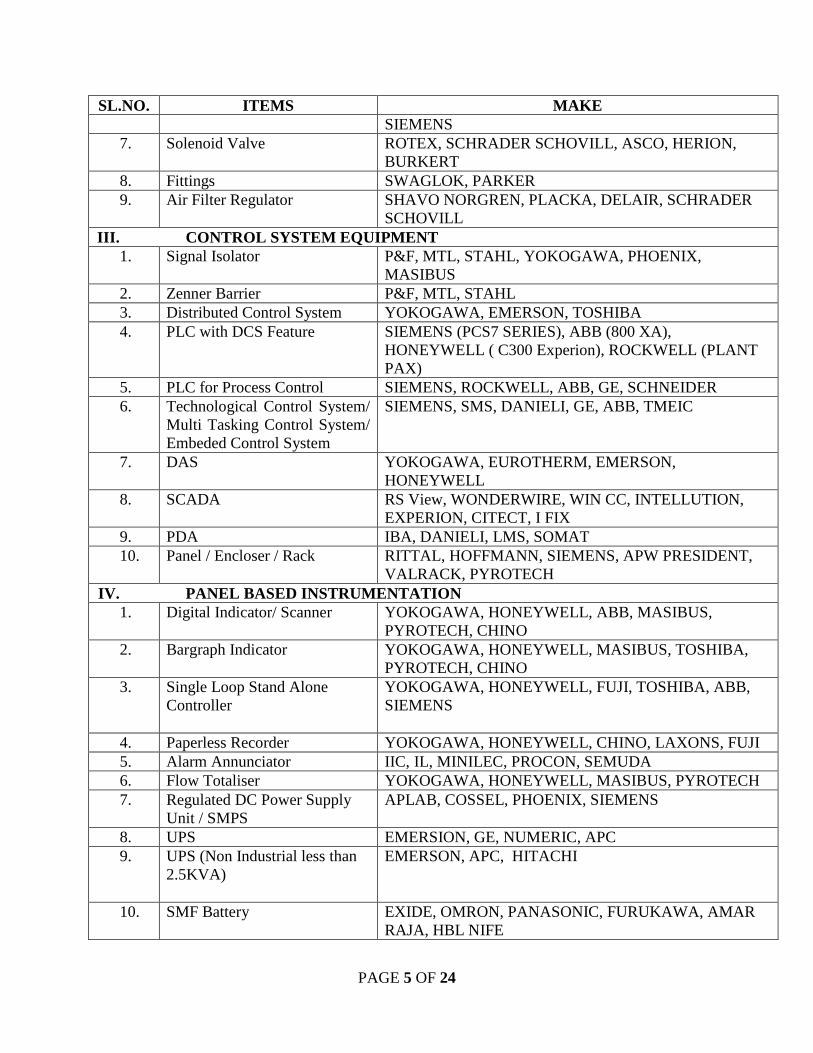
PAGE 5 OF 24
SL.NO. ITEMS MAKE SIEMENS
7. Solenoid Valve ROTEX, SCHRADER SCHOVILL, ASCO, HERION, BURKERT
8. Fittings SWAGLOK, PARKER 9. Air Filter Regulator SHAVO NORGREN, PLACKA, DELAIR, SCHRADER
SCHOVILL III. CONTROL SYSTEM EQUIPMENT
1. Signal Isolator P&F, MTL, STAHL, YOKOGAWA, PHOENIX, MASIBUS
2. Zenner Barrier P&F, MTL, STAHL 3. Distributed Control System YOKOGAWA, EMERSON, TOSHIBA 4. PLC with DCS Feature SIEMENS (PCS7 SERIES), ABB (800 XA),
HONEYWELL ( C300 Experion), ROCKWELL (PLANT PAX)
5. PLC for Process Control SIEMENS, ROCKWELL, ABB, GE, SCHNEIDER 6. Technological Control System/
Multi Tasking Control System/ Embeded Control System
SIEMENS, SMS, DANIELI, GE, ABB, TMEIC
7. DAS YOKOGAWA, EUROTHERM, EMERSON, HONEYWELL
8. SCADA RS View, WONDERWIRE, WIN CC, INTELLUTION, EXPERION, CITECT, I FIX
9. PDA IBA, DANIELI, LMS, SOMAT 10. Panel / Encloser / Rack RITTAL, HOFFMANN, SIEMENS, APW PRESIDENT,
VALRACK, PYROTECH IV. PANEL BASED INSTRUMENTATION
1. Digital Indicator/ Scanner YOKOGAWA, HONEYWELL, ABB, MASIBUS, PYROTECH, CHINO
2. Bargraph Indicator YOKOGAWA, HONEYWELL, MASIBUS, TOSHIBA, PYROTECH, CHINO
3. Single Loop Stand Alone Controller
YOKOGAWA, HONEYWELL, FUJI, TOSHIBA, ABB, SIEMENS
4. Paperless Recorder YOKOGAWA, HONEYWELL, CHINO, LAXONS, FUJI 5. Alarm Annunciator IIC, IL, MINILEC, PROCON, SEMUDA 6. Flow Totaliser YOKOGAWA, HONEYWELL, MASIBUS, PYROTECH 7. Regulated DC Power Supply
Unit / SMPS APLAB, COSSEL, PHOENIX, SIEMENS
8. UPS EMERSION, GE, NUMERIC, APC 9. UPS (Non Industrial less than
2.5KVA)
EMERSON, APC, HITACHI
10. SMF Battery EXIDE, OMRON, PANASONIC, FURUKAWA, AMAR RAJA, HBL NIFE
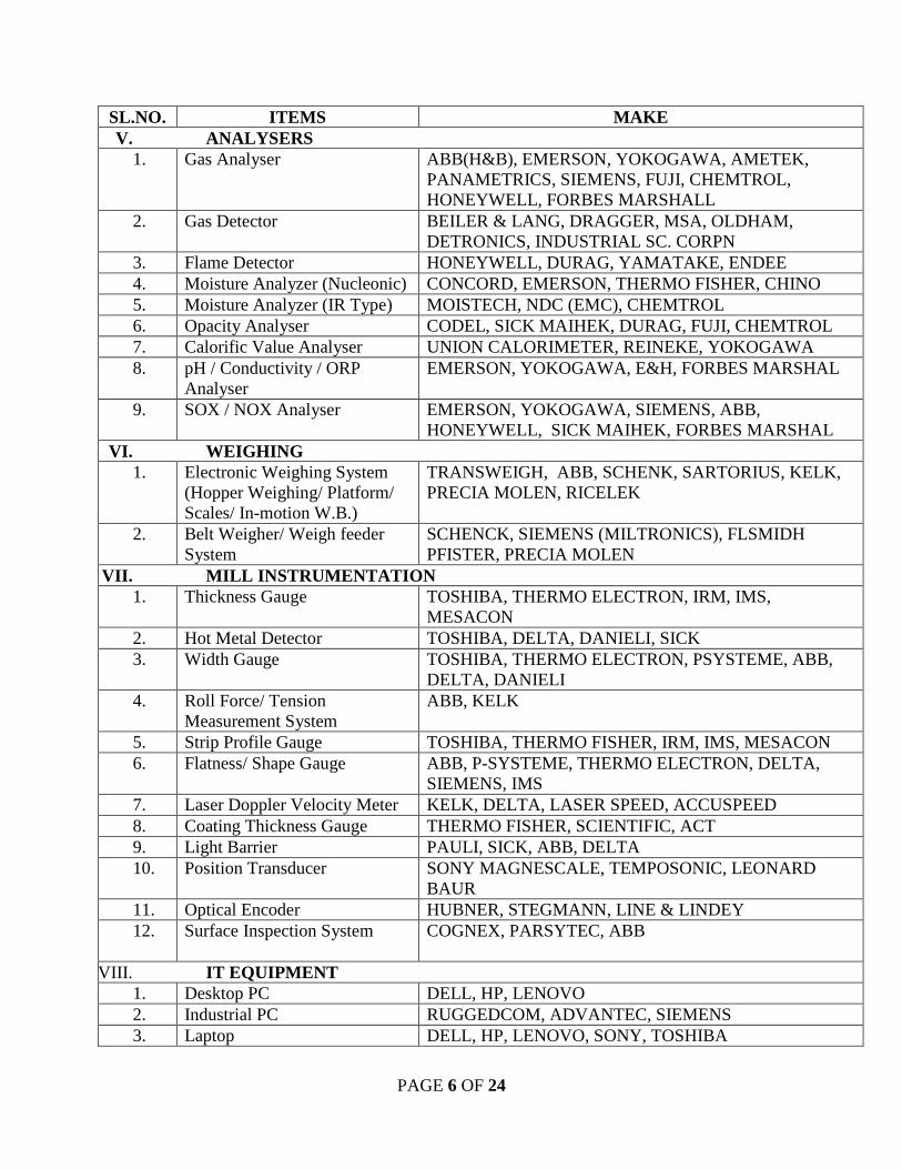
PAGE 6 OF 24
SL.NO. ITEMS MAKE V. ANALYSERS
1. Gas Analyser ABB(H&B), EMERSON, YOKOGAWA, AMETEK, PANAMETRICS, SIEMENS, FUJI, CHEMTROL, HONEYWELL, FORBES MARSHALL
2. Gas Detector BEILER & LANG, DRAGGER, MSA, OLDHAM, DETRONICS, INDUSTRIAL SC. CORPN
3. Flame Detector HONEYWELL, DURAG, YAMATAKE, ENDEE 4. Moisture Analyzer (Nucleonic) CONCORD, EMERSON, THERMO FISHER, CHINO 5. Moisture Analyzer (IR Type) MOISTECH, NDC (EMC), CHEMTROL 6. Opacity Analyser CODEL, SICK MAIHEK, DURAG, FUJI, CHEMTROL 7. Calorific Value Analyser UNION CALORIMETER, REINEKE, YOKOGAWA 8. pH / Conductivity / ORP
Analyser EMERSON, YOKOGAWA, E&H, FORBES MARSHAL
9. SOX / NOX Analyser EMERSON, YOKOGAWA, SIEMENS, ABB, HONEYWELL, SICK MAIHEK, FORBES MARSHAL
VI. WEIGHING 1. Electronic Weighing System
(Hopper Weighing/ Platform/ Scales/ In-motion W.B.)
TRANSWEIGH, ABB, SCHENK, SARTORIUS, KELK, PRECIA MOLEN, RICELEK
2. Belt Weigher/ Weigh feeder System
SCHENCK, SIEMENS (MILTRONICS), FLSMIDH PFISTER, PRECIA MOLEN
VII. MILL INSTRUMENTATION 1. Thickness Gauge TOSHIBA, THERMO ELECTRON, IRM, IMS,
MESACON 2. Hot Metal Detector TOSHIBA, DELTA, DANIELI, SICK 3. Width Gauge TOSHIBA, THERMO ELECTRON, PSYSTEME, ABB,
DELTA, DANIELI 4. Roll Force/ Tension
Measurement System ABB, KELK
5. Strip Profile Gauge TOSHIBA, THERMO FISHER, IRM, IMS, MESACON 6. Flatness/ Shape Gauge ABB, P-SYSTEME, THERMO ELECTRON, DELTA,
SIEMENS, IMS 7. Laser Doppler Velocity Meter KELK, DELTA, LASER SPEED, ACCUSPEED 8. Coating Thickness Gauge THERMO FISHER, SCIENTIFIC, ACT 9. Light Barrier PAULI, SICK, ABB, DELTA 10. Position Transducer SONY MAGNESCALE, TEMPOSONIC, LEONARD
BAUR 11. Optical Encoder HUBNER, STEGMANN, LINE & LINDEY 12. Surface Inspection System
COGNEX, PARSYTEC, ABB
VIII . IT EQUIPMENT 1. Desktop PC DELL, HP, LENOVO 2. Industrial PC RUGGEDCOM, ADVANTEC, SIEMENS 3. Laptop DELL, HP, LENOVO, SONY, TOSHIBA
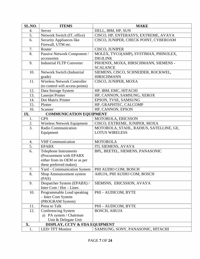
PAGE 7 OF 24
SL.NO. ITEMS MAKE 4. Server DELL, IBM, HP, SUN 5. Network Switch (IT, office) CISCO, HP, ENTERASYS, EXTREME, AVAYA 6. Security Appliances like
Firewall, UTM etc. CISCO, JUNIPER, CHECK POINT, CYBEROAM
7. Router CISCO, JUNIPER 8. Passive Network Component /
accessories MOLEX, TYCO(AMP), SYSTIMAX, PHINOLEX, DIGILINK
9. Industrial FLTP Converter PHOENIX, MOXA, HIRSCHMANN, SIEMENS -SCALANCE
10. Network Switch (Industrial grade)
SIEMENS, CISCO, SCHNEIDER, ROCKWEL, HIRSCHMANN
11. Wireless Network Controller (to control wifi access points)
CISCO, JUNIPER, MOXA
12. Data Storage System HP, IBM, EMC, HITACHI 13. Laserjet Printer HP, CANNON, SAMSUNG, XEROX 14. Dot Matrix Printer EPSON, TVSE, SAMSUNG 15. Plotter HP, GRAPHTEC, CALCOMP 16. Scanner HP, CANNON, EPSON
IX. COMMUNICATION EQUIPMENT 1. GPS MOTOROLA, ERICSSON 2. Wireless Network Equipment CISCO, EXTREME, JUNIPER, MOXA 3. Radio Communication
Equipment MOTOROLA, STAHL, RADIUS, SATELLINE, GE, LOTUS WIRELESS
4. VHF Communication MOTOROLA 5. EPABX ITI, SIEMENS, AVAYA 6. Telephone Instruments
(Procurement with EPABX either from its OEM or as per these preferred makes)
BPL, BEETEL, SIEMENS, PANASONIC
7. Yard – Communication System PHI AUDIO COM, BOSCH 8. Shop Announcement system
(PAS) AHUJA, PHI AUDIO COM, BOSCH
9. Despatcher System (EPABX) / Inter Com / Hot – Lines
SIEMSNS, ERICSSION, AVAYA
10. Programmable Loud speaking – Inter Com System (PROGRAM System)
PHI – AUDICOM, BYTE
11. Press to Talk PHI – AUDICOM, BYTE 12. Conferencing System
a) PA system / Chairman Unit & Delegate Unit
BOSCH, AHUJA
X. DISPLAY, CCTV & FDA EQUIPMENT 1. LED/ TFT Monitor SAMSUNG, SONY, PANASONIC, HITACHI
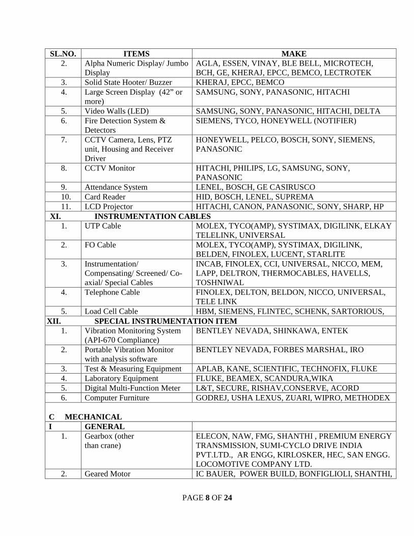
PAGE 8 OF 24
SL.NO. ITEMS MAKE 2. Alpha Numeric Display/ Jumbo
Display AGLA, ESSEN, VINAY, BLE BELL, MICROTECH, BCH, GE, KHERAJ, EPCC, BEMCO, LECTROTEK
3. Solid State Hooter/ Buzzer KHERAJ, EPCC, BEMCO 4. Large Screen Display (42” or
more) SAMSUNG, SONY, PANASONIC, HITACHI
5. Video Walls (LED) SAMSUNG, SONY, PANASONIC, HITACHI, DELTA 6. Fire Detection System &
Detectors SIEMENS, TYCO, HONEYWELL (NOTIFIER)
7. CCTV Camera, Lens, PTZ unit, Housing and Receiver Driver
HONEYWELL, PELCO, BOSCH, SONY, SIEMENS, PANASONIC
8. CCTV Monitor HITACHI, PHILIPS, LG, SAMSUNG, SONY, PANASONIC
9. Attendance System LENEL, BOSCH, GE CASIRUSCO 10. Card Reader HID, BOSCH, LENEL, SUPREMA 11. LCD Projector HITACHI, CANON, PANASONIC, SONY, SHARP, HP
XI. INSTRUMENTATION CABLES 1. UTP Cable MOLEX, TYCO(AMP), SYSTIMAX, DIGILINK, ELKAY
TELELINK, UNIVERSAL 2. FO Cable MOLEX, TYCO(AMP), SYSTIMAX, DIGILINK,
BELDEN, FINOLEX, LUCENT, STARLITE 3. Instrumentation/
Compensating/ Screened/ Co-axial/ Special Cables
INCAB, FINOLEX, CCI, UNIVERSAL, NICCO, MEM, LAPP, DELTRON, THERMOCABLES, HAVELLS, TOSHNIWAL
4. Telephone Cable FINOLEX, DELTON, BELDON, NICCO, UNIVERSAL, TELE LINK
5. Load Cell Cable HBM, SIEMENS, FLINTEC, SCHENK, SARTORIOUS, XII. SPECIAL INSTRUMENTATION ITEM
1. Vibration Monitoring System (API-670 Compliance)
BENTLEY NEVADA, SHINKAWA, ENTEK
2. Portable Vibration Monitor with analysis software
BENTLEY NEVADA, FORBES MARSHAL, IRO
3. Test & Measuring Equipment APLAB, KANE, SCIENTIFIC, TECHNOFIX, FLUKE 4. Laboratory Equipment FLUKE, BEAMEX, SCANDURA,WIKA 5. Digital Multi-Function Meter L&T, SECURE, RISHAV,CONSERVE, ACORD 6. Computer Furniture GODREJ, USHA LEXUS, ZUARI, WIPRO, METHODEX
C MECHANICAL I GENERAL
1. Gearbox (other than crane)
ELECON, NAW, FMG, SHANTHI , PREMIUM ENERGY TRANSMISSION, SUMI-CYCLO DRIVE INDIA PVT.LTD., AR ENGG, KIRLOSKER, HEC, SAN ENGG. LOCOMOTIVE COMPANY LTD.
2. Geared Motor IC BAUER, POWER BUILD, BONFIGLIOLI, SHANTHI,
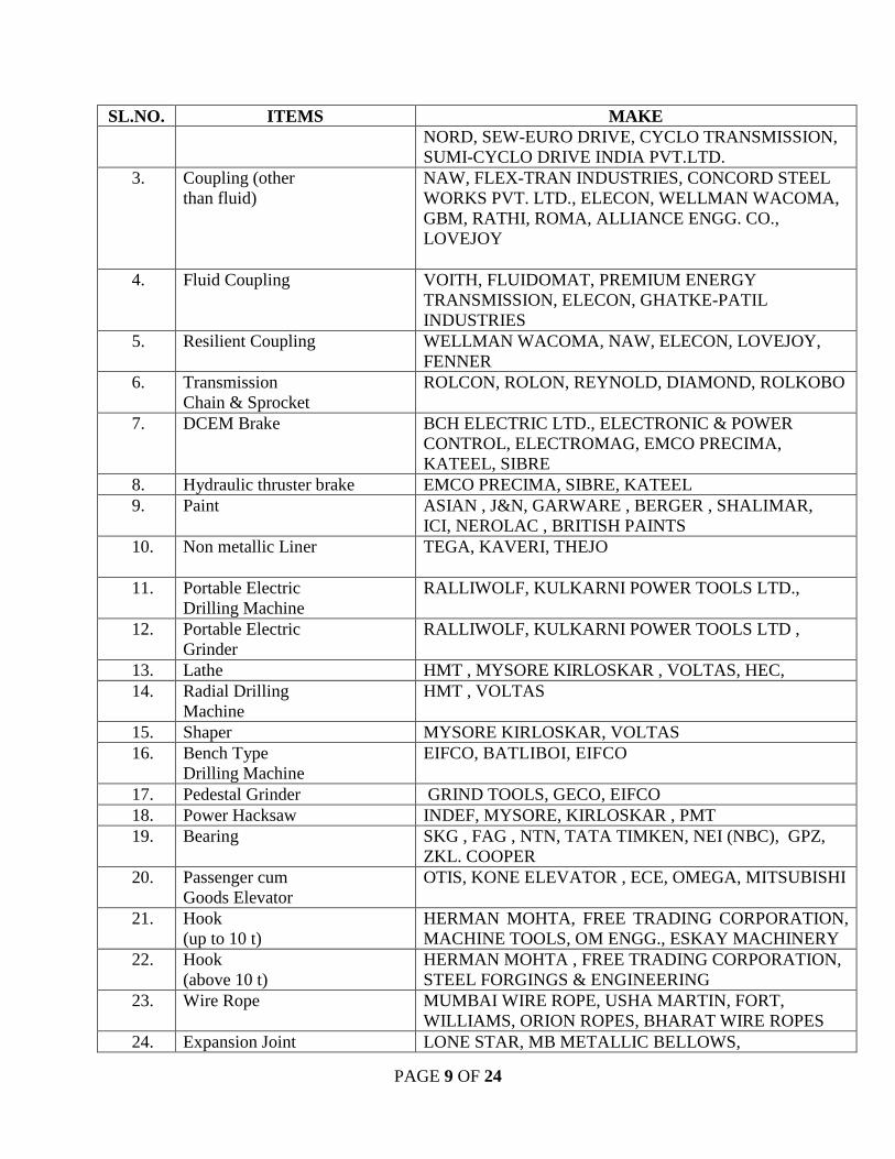
PAGE 9 OF 24
SL.NO. ITEMS MAKE NORD, SEW-EURO DRIVE, CYCLO TRANSMISSION, SUMI-CYCLO DRIVE INDIA PVT.LTD.
3. Coupling (other than fluid)
NAW, FLEX-TRAN INDUSTRIES, CONCORD STEEL WORKS PVT. LTD., ELECON, WELLMAN WACOMA, GBM, RATHI, ROMA, ALLIANCE ENGG. CO., LOVEJOY
4. Fluid Coupling VOITH, FLUIDOMAT, PREMIUM ENERGY TRANSMISSION, ELECON, GHATKE-PATIL INDUSTRIES
5. Resilient Coupling WELLMAN WACOMA, NAW, ELECON, LOVEJOY, FENNER
6. Transmission Chain & Sprocket
ROLCON, ROLON, REYNOLD, DIAMOND, ROLKOBO
7. DCEM Brake BCH ELECTRIC LTD., ELECTRONIC & POWER CONTROL, ELECTROMAG, EMCO PRECIMA, KATEEL, SIBRE
8. Hydraulic thruster brake EMCO PRECIMA, SIBRE, KATEEL 9. Paint ASIAN , J&N, GARWARE , BERGER , SHALIMAR,
ICI, NEROLAC , BRITISH PAINTS 10. Non metallic Liner
TEGA, KAVERI, THEJO
11. Portable Electric Drilling Machine
RALLIWOLF, KULKARNI POWER TOOLS LTD.,
12. Portable Electric Grinder
RALLIWOLF, KULKARNI POWER TOOLS LTD ,
13. Lathe HMT , MYSORE KIRLOSKAR , VOLTAS, HEC, 14. Radial Drilling
Machine HMT , VOLTAS
15. Shaper MYSORE KIRLOSKAR, VOLTAS 16. Bench Type
Drilling Machine EIFCO, BATLIBOI, EIFCO
17. Pedestal Grinder GRIND TOOLS, GECO, EIFCO 18. Power Hacksaw INDEF, MYSORE, KIRLOSKAR , PMT 19. Bearing SKG , FAG , NTN, TATA TIMKEN, NEI (NBC), GPZ,
ZKL. COOPER 20. Passenger cum
Goods Elevator OTIS, KONE ELEVATOR , ECE, OMEGA, MITSUBISHI
21. Hook (up to 10 t)
HERMAN MOHTA, FREE TRADING CORPORATION, MACHINE TOOLS, OM ENGG., ESKAY MACHINERY
22. Hook (above 10 t)
HERMAN MOHTA , FREE TRADING CORPORATION, STEEL FORGINGS & ENGINEERING
23. Wire Rope MUMBAI WIRE ROPE, USHA MARTIN, FORT, WILLIAMS, ORION ROPES, BHARAT WIRE ROPES
24. Expansion Joint LONE STAR, MB METALLIC BELLOWS,
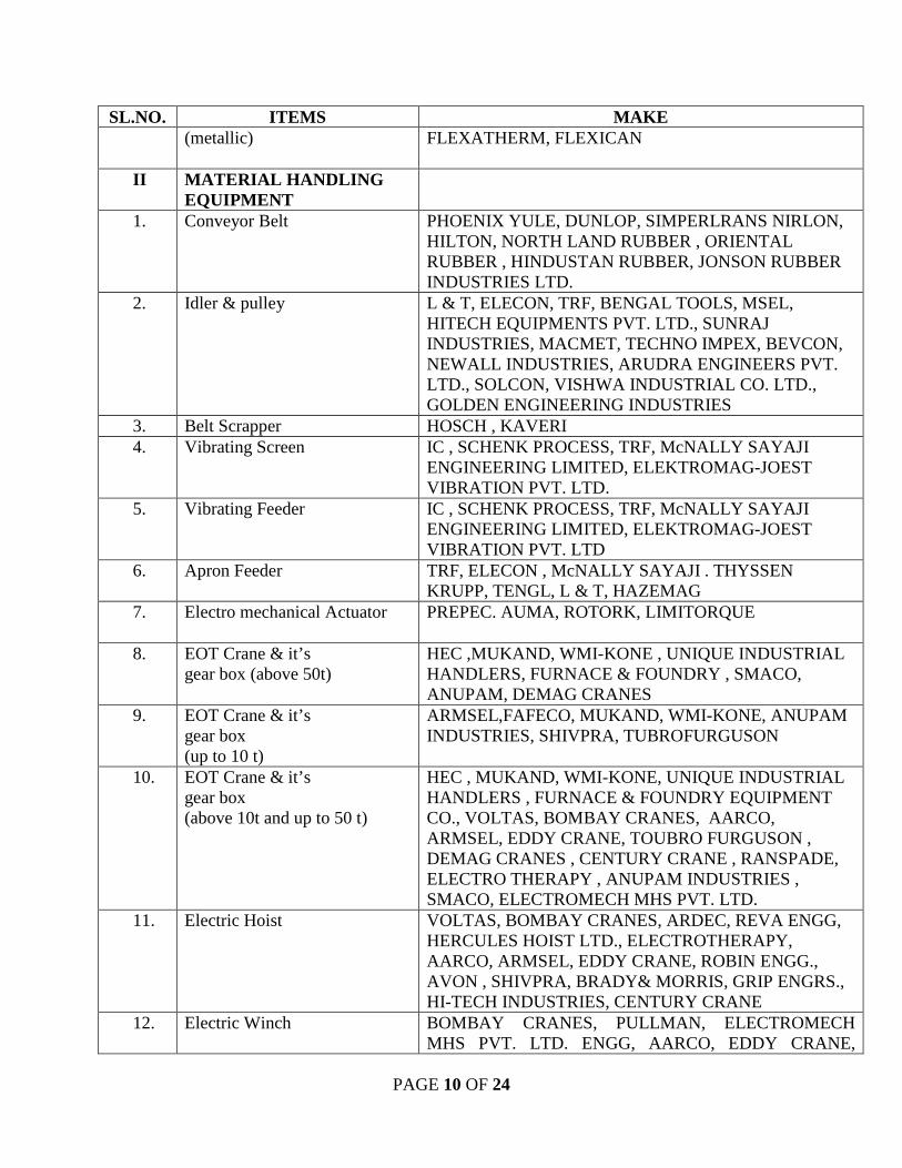
PAGE 10 OF 24
SL.NO. ITEMS MAKE (metallic)
FLEXATHERM, FLEXICAN
II MATERIAL HANDLING EQUIPMENT
1. Conveyor Belt
PHOENIX YULE, DUNLOP, SIMPERLRANS NIRLON, HILTON, NORTH LAND RUBBER , ORIENTAL RUBBER , HINDUSTAN RUBBER, JONSON RUBBER INDUSTRIES LTD.
2. Idler & pulley L & T, ELECON, TRF, BENGAL TOOLS, MSEL, HITECH EQUIPMENTS PVT. LTD., SUNRAJ INDUSTRIES, MACMET, TECHNO IMPEX, BEVCON, NEWALL INDUSTRIES, ARUDRA ENGINEERS PVT. LTD., SOLCON, VISHWA INDUSTRIAL CO. LTD., GOLDEN ENGINEERING INDUSTRIES
3. Belt Scrapper HOSCH , KAVERI 4. Vibrating Screen IC , SCHENK PROCESS, TRF, McNALLY SAYAJI
ENGINEERING LIMITED, ELEKTROMAG-JOEST VIBRATION PVT. LTD.
5. Vibrating Feeder IC , SCHENK PROCESS, TRF, McNALLY SAYAJI ENGINEERING LIMITED, ELEKTROMAG-JOEST VIBRATION PVT. LTD
6. Apron Feeder TRF, ELECON , McNALLY SAYAJI . THYSSEN KRUPP, TENGL, L & T, HAZEMAG
7. Electro mechanical Actuator PREPEC. AUMA, ROTORK, LIMITORQUE
8. EOT Crane & it’s gear box (above 50t)
HEC ,MUKAND, WMI-KONE , UNIQUE INDUSTRIAL HANDLERS, FURNACE & FOUNDRY , SMACO, ANUPAM, DEMAG CRANES
9. EOT Crane & it’s gear box (up to 10 t)
ARMSEL,FAFECO, MUKAND, WMI-KONE, ANUPAM INDUSTRIES, SHIVPRA, TUBROFURGUSON
10. EOT Crane & it’s gear box (above 10t and up to 50 t)
HEC , MUKAND, WMI-KONE, UNIQUE INDUSTRIAL HANDLERS , FURNACE & FOUNDRY EQUIPMENT CO., VOLTAS, BOMBAY CRANES, AARCO, ARMSEL, EDDY CRANE, TOUBRO FURGUSON , DEMAG CRANES , CENTURY CRANE , RANSPADE, ELECTRO THERAPY , ANUPAM INDUSTRIES , SMACO, ELECTROMECH MHS PVT. LTD.
11. Electric Hoist VOLTAS, BOMBAY CRANES, ARDEC, REVA ENGG, HERCULES HOIST LTD., ELECTROTHERAPY, AARCO, ARMSEL, EDDY CRANE, ROBIN ENGG., AVON , SHIVPRA, BRADY& MORRIS, GRIP ENGRS., HI-TECH INDUSTRIES, CENTURY CRANE
12. Electric Winch BOMBAY CRANES, PULLMAN, ELECTROMECH MHS PVT. LTD. ENGG, AARCO, EDDY CRANE,
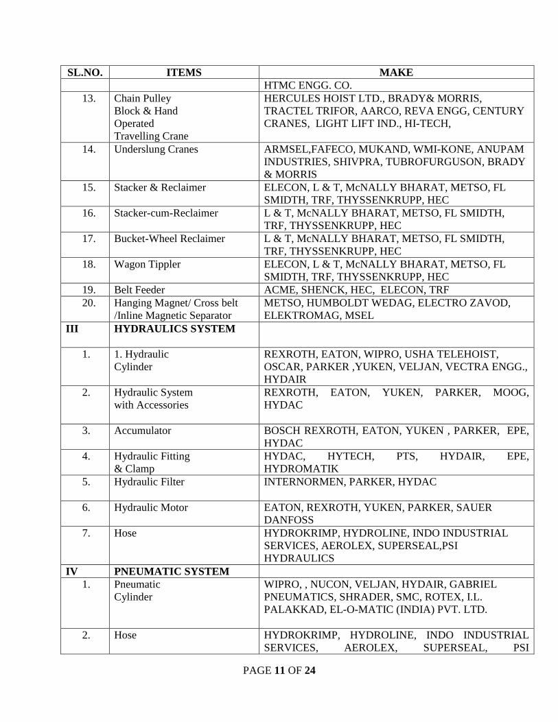
PAGE 11 OF 24
SL.NO. ITEMS MAKE HTMC ENGG. CO.
13. Chain Pulley Block & Hand Operated Travelling Crane
HERCULES HOIST LTD., BRADY& MORRIS, TRACTEL TRIFOR, AARCO, REVA ENGG, CENTURY CRANES, LIGHT LIFT IND., HI-TECH,
14. Underslung Cranes ARMSEL,FAFECO, MUKAND, WMI-KONE, ANUPAM INDUSTRIES, SHIVPRA, TUBROFURGUSON, BRADY & MORRIS
15. Stacker & Reclaimer ELECON, L & T, McNALLY BHARAT, METSO, FL SMIDTH, TRF, THYSSENKRUPP, HEC
16. Stacker-cum-Reclaimer L & T, McNALLY BHARAT, METSO, FL SMIDTH, TRF, THYSSENKRUPP, HEC
17. Bucket-Wheel Reclaimer L & T, McNALLY BHARAT, METSO, FL SMIDTH, TRF, THYSSENKRUPP, HEC
18. Wagon Tippler ELECON, L & T, McNALLY BHARAT, METSO, FL SMIDTH, TRF, THYSSENKRUPP, HEC
19. Belt Feeder ACME, SHENCK, HEC, ELECON, TRF 20. Hanging Magnet/ Cross belt
/Inline Magnetic Separator METSO, HUMBOLDT WEDAG, ELECTRO ZAVOD, ELEKTROMAG, MSEL
III HYDRAULICS SYSTEM
1. 1. Hydraulic Cylinder
REXROTH, EATON, WIPRO, USHA TELEHOIST, OSCAR, PARKER ,YUKEN, VELJAN, VECTRA ENGG., HYDAIR
2. Hydraulic System with Accessories
REXROTH, EATON, YUKEN, PARKER, MOOG, HYDAC
3. Accumulator BOSCH REXROTH, EATON, YUKEN , PARKER, EPE, HYDAC
4. Hydraulic Fitting & Clamp
HYDAC, HYTECH, PTS, HYDAIR, EPE, HYDROMATIK
5. Hydraulic Filter
INTERNORMEN, PARKER, HYDAC
6. Hydraulic Motor EATON, REXROTH, YUKEN, PARKER, SAUER DANFOSS
7. Hose HYDROKRIMP, HYDROLINE, INDO INDUSTRIAL SERVICES, AEROLEX, SUPERSEAL,PSI HYDRAULICS
IV PNEUMATIC SYSTEM 1. Pneumatic
Cylinder
WIPRO, , NUCON, VELJAN, HYDAIR, GABRIEL PNEUMATICS, SHRADER, SMC, ROTEX, I.L. PALAKKAD, EL-O-MATIC (INDIA) PVT. LTD.
2. Hose HYDROKRIMP, HYDROLINE, INDO INDUSTRIAL SERVICES, AEROLEX, SUPERSEAL, PSI
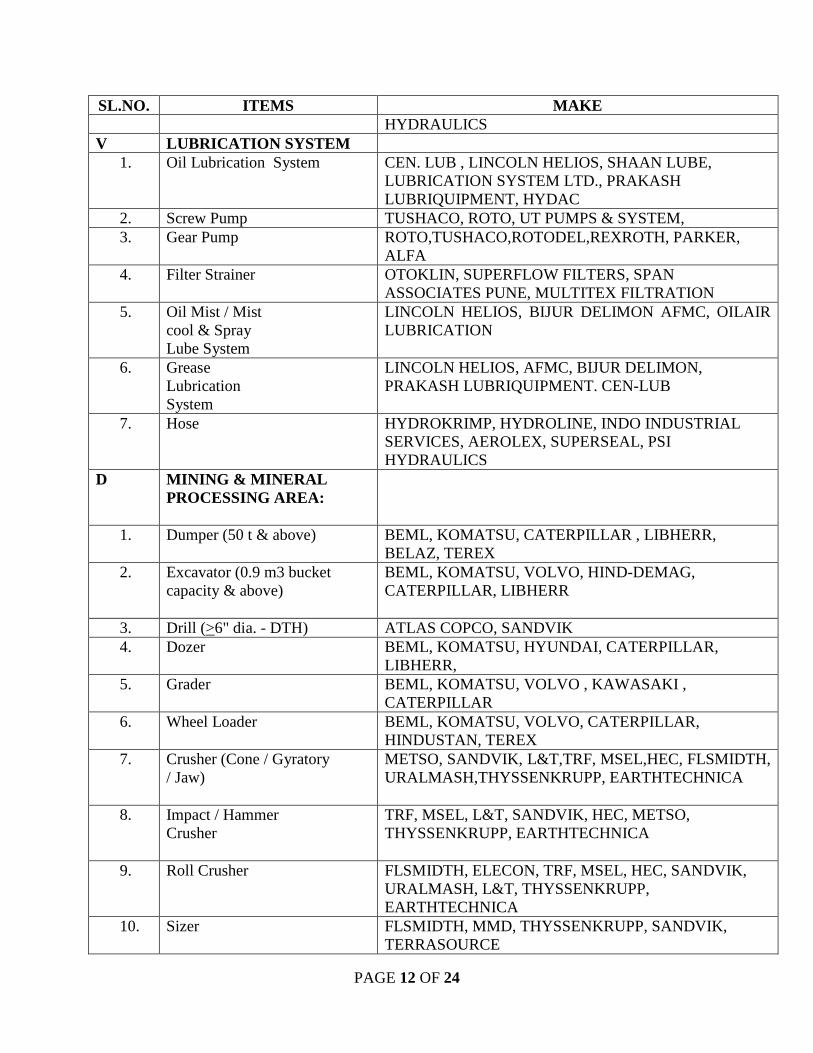
PAGE 12 OF 24
SL.NO. ITEMS MAKE HYDRAULICS
V LUBRICATION SYSTEM 1. Oil Lubrication System
CEN. LUB , LINCOLN HELIOS, SHAAN LUBE, LUBRICATION SYSTEM LTD., PRAKASH LUBRIQUIPMENT, HYDAC
2. Screw Pump TUSHACO, ROTO, UT PUMPS & SYSTEM, 3. Gear Pump ROTO,TUSHACO,ROTODEL,REXROTH, PARKER,
ALFA 4. Filter Strainer OTOKLIN, SUPERFLOW FILTERS, SPAN
ASSOCIATES PUNE, MULTITEX FILTRATION 5. Oil Mist / Mist
cool & Spray Lube System
LINCOLN HELIOS, BIJUR DELIMON AFMC, OILAIR LUBRICATION
6. Grease Lubrication System
LINCOLN HELIOS, AFMC, BIJUR DELIMON, PRAKASH LUBRIQUIPMENT. CEN-LUB
7. Hose HYDROKRIMP, HYDROLINE, INDO INDUSTRIAL SERVICES, AEROLEX, SUPERSEAL, PSI HYDRAULICS
D MINING & MINERAL PROCESSING AREA:
1. Dumper (50 t & above) BEML, KOMATSU, CATERPILLAR , LIBHERR, BELAZ, TEREX
2. Excavator (0.9 m3 bucket capacity & above)
BEML, KOMATSU, VOLVO, HIND-DEMAG, CATERPILLAR, LIBHERR
3. Drill (>6" dia. - DTH) ATLAS COPCO, SANDVIK 4. Dozer BEML, KOMATSU, HYUNDAI, CATERPILLAR,
LIBHERR, 5. Grader BEML, KOMATSU, VOLVO , KAWASAKI ,
CATERPILLAR 6. Wheel Loader BEML, KOMATSU, VOLVO, CATERPILLAR,
HINDUSTAN, TEREX 7. Crusher (Cone / Gyratory
/ Jaw)
METSO, SANDVIK, L&T,TRF, MSEL,HEC, FLSMIDTH, URALMASH,THYSSENKRUPP, EARTHTECHNICA
8. Impact / Hammer Crusher
TRF, MSEL, L&T, SANDVIK, HEC, METSO, THYSSENKRUPP, EARTHTECHNICA
9. Roll Crusher FLSMIDTH, ELECON, TRF, MSEL, HEC, SANDVIK, URALMASH, L&T, THYSSENKRUPP, EARTHTECHNICA
10. Sizer FLSMIDTH, MMD, THYSSENKRUPP, SANDVIK, TERRASOURCE
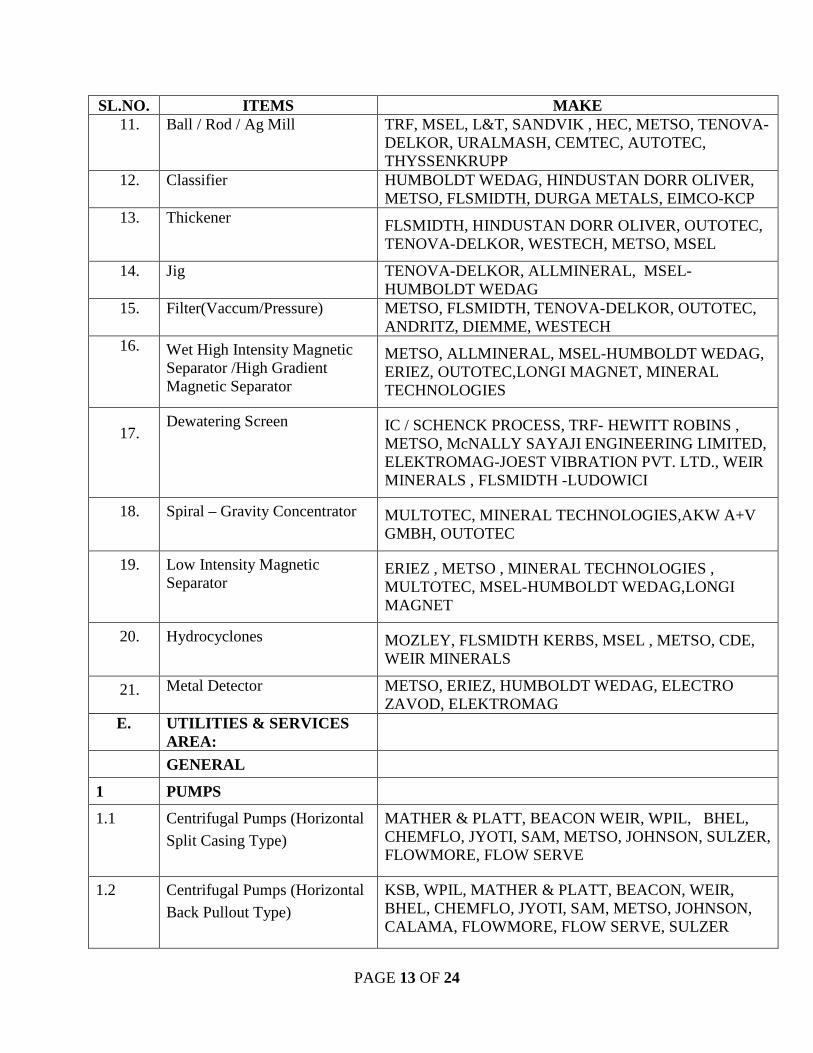
PAGE 13 OF 24
SL.NO. ITEMS MAKE 11. Ball / Rod / Ag Mill TRF, MSEL, L&T, SANDVIK , HEC, METSO, TENOVA-
DELKOR, URALMASH, CEMTEC, AUTOTEC, THYSSENKRUPP
12. Classifier HUMBOLDT WEDAG, HINDUSTAN DORR OLIVER, METSO, FLSMIDTH, DURGA METALS, EIMCO-KCP
13. Thickener FLSMIDTH, HINDUSTAN DORR OLIVER, OUTOTEC, TENOVA-DELKOR, WESTECH, METSO, MSEL
14. Jig TENOVA-DELKOR, ALLMINERAL, MSEL-HUMBOLDT WEDAG
15. Filter(Vaccum/Pressure) METSO, FLSMIDTH, TENOVA-DELKOR, OUTOTEC, ANDRITZ, DIEMME, WESTECH
16. Wet High Intensity Magnetic Separator /High Gradient Magnetic Separator
METSO, ALLMINERAL, MSEL-HUMBOLDT WEDAG, ERIEZ, OUTOTEC,LONGI MAGNET, MINERAL TECHNOLOGIES
17. Dewatering Screen IC / SCHENCK PROCESS, TRF- HEWITT ROBINS ,
METSO, McNALLY SAYAJI ENGINEERING LIMITED, ELEKTROMAG-JOEST VIBRATION PVT. LTD., WEIR MINERALS , FLSMIDTH -LUDOWICI
18. Spiral – Gravity Concentrator MULTOTEC, MINERAL TECHNOLOGIES,AKW A+V GMBH, OUTOTEC
19. Low Intensity Magnetic Separator
ERIEZ , METSO , MINERAL TECHNOLOGIES , MULTOTEC, MSEL-HUMBOLDT WEDAG,LONGI MAGNET
20. Hydrocyclones MOZLEY, FLSMIDTH KERBS, MSEL , METSO, CDE, WEIR MINERALS
21. Metal Detector METSO, ERIEZ, HUMBOLDT WEDAG, ELECTRO ZAVOD, ELEKTROMAG
E. UTILITIES & SERVICES AREA:
GENERAL
1 PUMPS
1.1 Centrifugal Pumps (Horizontal
Split Casing Type)
MATHER & PLATT, BEACON WEIR, WPIL, BHEL, CHEMFLO, JYOTI, SAM, METSO, JOHNSON, SULZER, FLOWMORE, FLOW SERVE
1.2 Centrifugal Pumps (Horizontal
Back Pullout Type)
KSB, WPIL, MATHER & PLATT, BEACON, WEIR, BHEL, CHEMFLO, JYOTI, SAM, METSO, JOHNSON, CALAMA, FLOWMORE, FLOW SERVE, SULZER
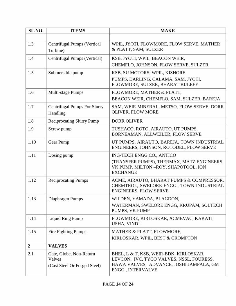
PAGE 14 OF 24
SL.NO. ITEMS MAKE
1.3 Centrifugal Pumps (Vertical
Turbine)
WPIL, JYOTI, FLOWMORE, FLOW SERVE, MATHER & PLATT, SAM, SULZER
1.4 Centrifugal Pumps (Vertical) KSB, JYOTI, WPIL, BEACON WEIR,
CHEMFLO, JOHNSON, FLOW SERVE, SULZER
1.5 Submersible pump KSB, SU MOTORS, WPIL, KISHORE
PUMPS, DARLING, CALAMA, SAM, JYOTI, FLOWMORE, SULZER, BHARAT BIJLEEE
1.6 Multi-stage Pumps FLOWMORE, MATHER & PLATT,
BEACON WEIR, CHEMFLO, SAM, SULZER, BAREJA
1.7 Centrifugal Pumps For Slurry
Handling
SAM, WEIR MINERAL, METSO, FLOW SERVE, DORR OLIVER, FLOW MORE
1.8 Reciprocating Slurry Pump DORR OLIVER
1.9 Screw pump TUSHACO, ROTO, AIRAUTO, UT PUMPS, BORNEAMAN, ALLWEILER, FLOW SERVE
1.10 Gear Pump UT PUMPS, AIRAUTO, BAREJA, TOWN INDUSTRIAL ENGINEERS, JOHNSON, ROTODEL, FLOW SERVE
1.11 Dosing pump ING-TECH ENGG CO., ANTICO
(TRANSFER PUMPS), THERMAX, MATZ ENGINEERS, VK PUMP, MILTON –ROY, SHAPOTOOL, ION EXCHANGE
1.12 Reciprocating Pumps ACME, AIRAUTO, BHARAT PUMPS & COMPRESSOR, CHEMTROL, SWELORE ENGG., TOWN INDUSTRIAL ENGINEERS, FLOW SERVE
1.13 Diaphragm Pumps WILDEN, YAMADA, BLAGDON,
WATERMAN, SWELORE ENGG, KRUPAM, SOLTECH PUMPS, VK PUMP
1.14 Liquid Ring Pump FLOWMORE, KIRLOSKAR, ACMEVAC, KAKATI, USHA, VINDI
1.15 Fire Fighting Pumps MATHER & PLATT, FLOWMORE,
KIRLOSKAR, WPIL, BEST & CROMPTON
2 VALVES
2.1 Gate, Globe, Non-Return Valves (Cast Steel Or Forged Steel)
BHEL, L & T, KSB, WEIR-BDK, KIRLOSKAR, LEVCON, IVC, TYCO VALVES, NSSL, FOURESS, HAWA VALVES, ADVANCE, JOSHI JAMPALA, GM ENGG., INTERVALVE
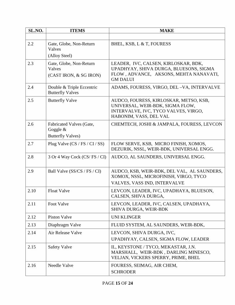
PAGE 15 OF 24
SL.NO. ITEMS MAKE
2.2 Gate, Globe, Non-Return Valves
(Alloy Steel)
BHEL, KSB, L & T, FOURESS
2.3 Gate, Globe, Non-Return Valves
(CAST IRON, & SG IRON)
LEADER, IVC, CALSEN, KIRLOSKAR, BDK, UPADHYAY, SHIVA DURGA, BLUESONS, SIGMA FLOW , ADVANCE, AKSONS, MEHTA NANAVATI, GM DALUI
2.4 Double & Triple Eccentric Butterfly Valves
ADAMS, FOURESS, VIRGO, DEL –VA, INTERVALVE
2.5 Butterfly Valve AUDCO, FOURESS, KIRLOSKAR, METSO, KSB, UNIVERSAL, WEIR-BDK, SIGMA FLOW, INTERVALVE, IVC, TYCO VALVES, VIRGO, HABONIM, VASS, DEL VAL
2.6 Fabricated Valves (Gate, Goggle &
Butterfly Valves)
CHEMTECH, JOSHI & JAMPALA, FOURESS, LEVCON
2.7 Plug Valve (CS / FS / CI / SS) FLOW SERVE, KSB, MICRO FINISH, XOMOS, DEZURIK, NSSL, WEIR-BDK, UNIVERSAL ENGG.
2.8 3 Or 4 Way Cock (CS/ FS / CI)
AUDCO, AL SAUNDERS, UNIVERSAL ENGG.
2.9 Ball Valve (SS/CS / FS / CI) AUDCO, KSB, WEIR-BDK, DEL VAL, AL SAUNDERS, XOMOX, NSSL, MICROFINISH, VIRGO, TYCO
VALVES, VASS IND, INTERVALVE
2.10 Float Valve LEVCON, LEADER, IVC, UPADHAYA, BLUESON, CALSEN, SHIVA DURGA,
2.11 Foot Valve LEVCON, LEADER, IVC, CALSEN, UPADHAYA, SHIVA DURGA, WEIR-BDK
2.12 Piston Valve UNI KLINGER
2.13 Diaphragm Valve FLUID SYSTEM, AL SAUNDERS, WEIR-BDK,
2.14 Air Release Valve LEVCON, SHIVA DURGA, IVC,
UPADHYAY, CALSEN, SIGMA FLOW, LEADER
2.15 Safety Valve IL, KEYSTONE / TYCO, MEKASTAR, J.N. MARSHALL, WEIR-BDK , DARLING MINESCO, VELJAN, VICKERS SPERRY, PRIME, BHEL
2.16 Needle Valve FOURESS, SEIMAG, AIR CHEM,
SCHRODER
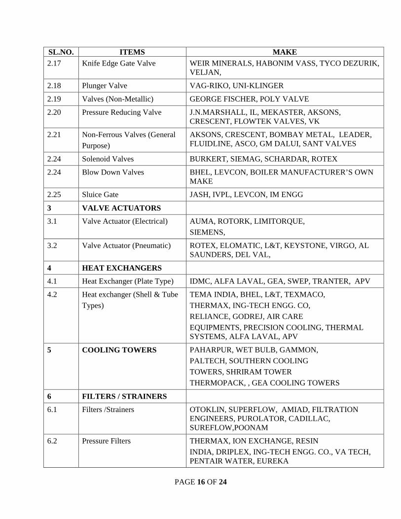
PAGE 16 OF 24
SL.NO. ITEMS MAKE 2.17 Knife Edge Gate Valve WEIR MINERALS, HABONIM VASS, TYCO DEZURIK,
VELJAN,
2.18 Plunger Valve VAG-RIKO, UNI-KLINGER
2.19 Valves (Non-Metallic) GEORGE FISCHER, POLY VALVE
2.20 Pressure Reducing Valve J.N.MARSHALL, IL, MEKASTER, AKSONS, CRESCENT, FLOWTEK VALVES, VK
2.21 Non-Ferrous Valves (General
Purpose)
AKSONS, CRESCENT, BOMBAY METAL, LEADER, FLUIDLINE, ASCO, GM DALUI, SANT VALVES
2.24 Solenoid Valves BURKERT, SIEMAG, SCHARDAR, ROTEX
2.24 Blow Down Valves BHEL, LEVCON, BOILER MANUFACTURER’S OWN MAKE
2.25 Sluice Gate JASH, IVPL, LEVCON, IM ENGG
3 VALVE ACTUATORS
3.1 Valve Actuator (Electrical)
AUMA, ROTORK, LIMITORQUE,
SIEMENS,
3.2 Valve Actuator (Pneumatic) ROTEX, ELOMATIC, L&T, KEYSTONE, VIRGO, AL SAUNDERS, DEL VAL,
4 HEAT EXCHANGERS
4.1 Heat Exchanger (Plate Type) IDMC, ALFA LAVAL, GEA, SWEP, TRANTER, APV
4.2 Heat exchanger (Shell & Tube
Types)
TEMA INDIA, BHEL, L&T, TEXMACO,
THERMAX, ING-TECH ENGG. CO,
RELIANCE, GODREJ, AIR CARE
EQUIPMENTS, PRECISION COOLING, THERMAL SYSTEMS, ALFA LAVAL, APV
5 COOLING TOWERS
PAHARPUR, WET BULB, GAMMON,
PALTECH, SOUTHERN COOLING
TOWERS, SHRIRAM TOWER
THERMOPACK, , GEA COOLING TOWERS
6 FILTERS / STRAINERS
6.1 Filters /Strainers OTOKLIN, SUPERFLOW, AMIAD, FILTRATION ENGINEERS, PUROLATOR, CADILLAC, SUREFLOW,POONAM
6.2 Pressure Filters THERMAX, ION EXCHANGE, RESIN
INDIA, DRIPLEX, ING-TECH ENGG. CO., VA TECH, PENTAIR WATER, EUREKA
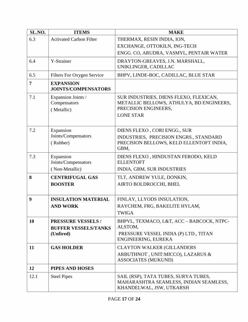
PAGE 17 OF 24
SL.NO. ITEMS MAKE 6.3 Activated Carbon Filter THERMAX, RESIN INDIA, ION,
EXCHANGE, OTTOKILN, ING-TECH
ENGG. CO, ARUDRA, VASMYL, PENTAIR WATER
6.4 Y-Strainer DRAYTON-GREAVES, J.N. MARSHALL, UNIKLINGER, CADILLAC
6.5 Filters For Oxygen Service BHPV, LINDE-BOC, CADILLAC, BLUE STAR
7 EXPANSION JOINTS/COMPENSATORS
7.1 Expansion Joints / Compensators
( Metallic)
SUR INDUSTRIES, DIENS FLEXO, FLEXICAN, METALLIC BELLOWS, ATHULYA, BD ENGINEERS, PRECISION ENGINEERS,
LONE STAR
7.2 Expansion Joints/Compensators
( Rubber)
DIENS FLEXO , CORI ENGG., SUR
INDUSTRIES, PRECISION ENGRS., STANDARD PRECISION BELLOWS, KELD ELLENTOFT INDIA, GBM,
7.3 Expansion Joints/Compensators
( Non-Metallic)
DIENS FLEXO , HINDUSTAN FERODO, KELD ELLENTOFT
INDIA, GBM, SUR INDUSTRIES
8 CENTRIFUGAL GAS BOOSTER
TLT, ANDREW YULE, DONKIN,
AIRTO BOLDROCCHI, BHEL
9 INSULATION MATERIAL AND WORK
FINLAY, LLYODS INSULATION,
RAYCHEM, FRG, BAKELITE HYLAM,
TWIGA
10 PRESSURE VESSELS / BUFFER VESSELS/TANKS (Unfired)
BHPVL, TEXMACO, L&T, ACC – BABCOCK, NTPC-ALSTOM,
PRESSURE VESSEL INDIA (P) LTD., TITAN ENGINEERING, EUREKA
11 GAS HOLDER CLAYTON WALKER (GILLANDERS
ARBUTHNOT , UNIT:MICCO), LAZARUS & ASSOCIATES (MUKUND)
12 PIPES AND HOSES
12.1 Steel Pipes SAIL (RSP), TATA TUBES, SURYA TUBES, MAHARASHTRA SEAMLESS, INDIAN SEAMLESS, KHANDELWAL, JSW, UTKARSH
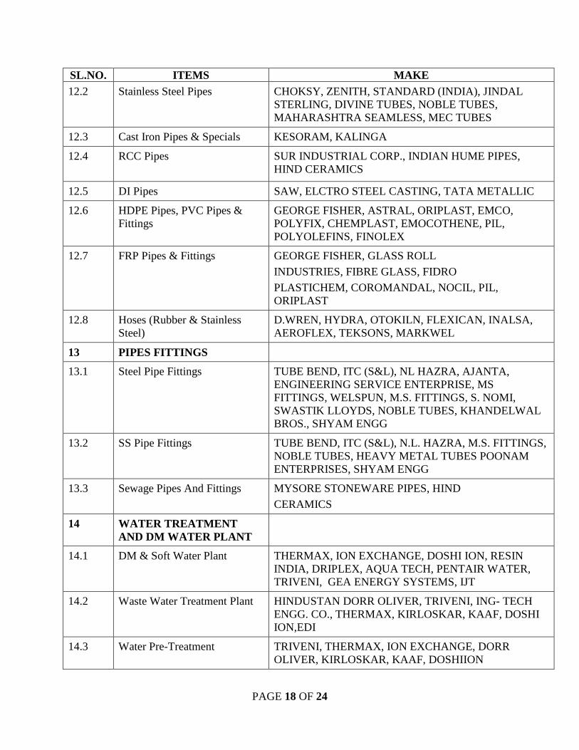
PAGE 18 OF 24
SL.NO. ITEMS MAKE 12.2 Stainless Steel Pipes CHOKSY, ZENITH, STANDARD (INDIA), JINDAL
STERLING, DIVINE TUBES, NOBLE TUBES, MAHARASHTRA SEAMLESS, MEC TUBES
12.3 Cast Iron Pipes & Specials KESORAM, KALINGA
12.4 RCC Pipes
SUR INDUSTRIAL CORP., INDIAN HUME PIPES, HIND CERAMICS
12.5 DI Pipes SAW, ELCTRO STEEL CASTING, TATA METALLIC
12.6 HDPE Pipes, PVC Pipes & Fittings
GEORGE FISHER, ASTRAL, ORIPLAST, EMCO, POLYFIX, CHEMPLAST, EMOCOTHENE, PIL, POLYOLEFINS, FINOLEX
12.7 FRP Pipes & Fittings GEORGE FISHER, GLASS ROLL
INDUSTRIES, FIBRE GLASS, FIDRO
PLASTICHEM, COROMANDAL, NOCIL, PIL, ORIPLAST
12.8 Hoses (Rubber & Stainless Steel)
D.WREN, HYDRA, OTOKILN, FLEXICAN, INALSA, AEROFLEX, TEKSONS, MARKWEL
13 PIPES FITTINGS
13.1 Steel Pipe Fittings TUBE BEND, ITC (S&L), NL HAZRA, AJANTA, ENGINEERING SERVICE ENTERPRISE, MS FITTINGS, WELSPUN, M.S. FITTINGS, S. NOMI, SWASTIK LLOYDS, NOBLE TUBES, KHANDELWAL BROS., SHYAM ENGG
13.2 SS Pipe Fittings TUBE BEND, ITC (S&L), N.L. HAZRA, M.S. FITTINGS, NOBLE TUBES, HEAVY METAL TUBES POONAM ENTERPRISES, SHYAM ENGG
13.3 Sewage Pipes And Fittings MYSORE STONEWARE PIPES, HIND
CERAMICS
14 WATER TREATMENT AND DM WATER PLANT
14.1 DM & Soft Water Plant THERMAX, ION EXCHANGE, DOSHI ION, RESIN INDIA, DRIPLEX, AQUA TECH, PENTAIR WATER, TRIVENI, GEA ENERGY SYSTEMS, IJT
14.2 Waste Water Treatment Plant HINDUSTAN DORR OLIVER, TRIVENI, ING- TECH ENGG. CO., THERMAX, KIRLOSKAR, KAAF, DOSHI ION,EDI
14.3 Water Pre-Treatment TRIVENI, THERMAX, ION EXCHANGE, DORR OLIVER, KIRLOSKAR, KAAF, DOSHIION

PAGE 19 OF 24
SL.NO. ITEMS MAKE 14.4 Clarifier HINDUSTAN DORR OLIVER, EIMCO-KCP, JORD
ENGINEERS,
14.5 Effluent Treatment Plant VA TECH, GEA ENERGY SYSTEM,
TRIVENI, UEM INDIA, DOSHIION
14.6 Drinking Water Treatment Plant
DRIPLEX, VA TECH, GEA ENERGY
SYSTEM, TRIVENI, UEM INDIA, THERMAX
14.7 Chemical Dosing System HINDUSTAN DORR OLIVER, TELLABS CHEMICALS, NALCO
15. EQUIPMENT & SYSTEM FOR AIR AND GAS
15.1 Turbo-Blower MAN TURBO, SIEMENS, BHEL
15.2 Compressor (Centrifugal) ATLAS COPCO, KIRLOSKAR, ELGI,
INGERSOLL RAND, SEIMENS
15.3 Compressors (Screw) KIRLOSKAR PNEUMATIC, ELGI, ATLAS COPCO, INGERSOLL RAND
15.4 Compressors (Reciprocating) KIRLOSKAR PNEUMATIC, INGERSOL RAND, ELGI, BURCKHARDT COMPRESSION
15.5 Portable Air Compressors HOLMAN CLIMAX, ELGI, ATLAS COPCO, KIRLOSKAR, INGERSOLL RAND
15.6 Blowers & Fans (General Purpose)
Capacity < 50,000 m3/h AEROTO BOLDROCCHI,
INGERSOL RAND, MAXFLOW,
KAY INT., TLT ENGG., BATLIBOI, ANDREW YULE, RIECO , FLAKTWOOD, REITZ, DUSTVEN, AIRLINK ,
Capacity > 50,000 m3/h BHEL, ANDREW YULE, AEROTO BOLDROCCHI, FLAKT WOOD, TLT, REITZ
15.7 Regulators NUCON, VELJAN, HYDAIR, SHAVO
NORGEN, IRON & METALS,
GABRIELPNEUMATICS, I.L.PALGHAT, SCHRADER, ROSS, SMC
15.8 Air Drier DELAIR, TRIDENT, SANPAR, ATLAS
COPCO, ROOS TEMPKOOL, EXAL, INGERSOL RAND
15.9 Air Trap DRAYTON GREAVES, UNI KLINGER, FORBES MARSHAL
15.10 Moisture Separator UNIKLINGER, NUCON, VELJAN, HYDAIR, FESTO
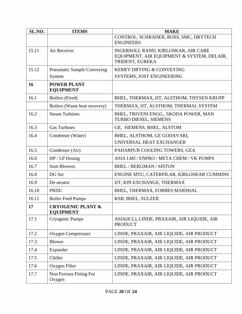
PAGE 20 OF 24
SL.NO. ITEMS MAKE CONTROL, SCHRADER, ROSS, SMC, DRYTECH ENGINEERS
15.11 Air Receiver INGERSOLL RAND, KIRLOSKAR, AIR CARE EQUIPMENT, AIR EQUIPMENT & SYSTEM, DELAIR, TRIDENT, EUREKA
15.12 Pneumatic Sample Conveying
System
KERRY DRYING & CONVEYING
SYSTEMS, JOST ENGINEERING
16 POWER PLANT EQUIPMENT
16.1 Boilers (Fired) BHEL, THERMAX, IJT, ALSTHOM, THYSEN KRUPP
Boilers (Waste heat recovery) THERMAX, IJT, ALSTHOM, THERMAL SYSTEM
16.2 Steam Turbines BHEL, TRIVENI ENGG., SKODA POWER, MAN TURBO DIESEL, SIEMENS
16.3 Gas Turbines GE, SIEMENS, BHEL, ALSTOM
16.4 Condenser (Water) BHEL, ALSTHOM, GE GODAVARI,
UNIVERSAL HEAT EXCHANGER
16.5 Condenser (Air) PAHARPUR COOLING TOWERS, GEA
16.6 HP / LP Dosing ASIA LMI / ENPRO / META CHEM / VK PUMPS
16.7 Soot Blowers BHEL / BERGMAN / SISTON
16.8 DG Set ENGINE MTU, CATERPILAR, KIRLOSKAR CUMMINS
16.9 De-aerator IJT, ION EXCHANGE, THERMAX
16.10 PRDU BHEL, THERMAX, FORBES MARSHAL
16.11 Boiler Feed Pumps KSB, BHEL, SULZER
17 CRYOGENIC PLANT & EQUIPMENT
17.1 Cryogenic Pumps
ASIA(ICL), LINDE, PRAXAIR, AIR LIQUIDE, AIR PRODUCT
17.2 Oxygen Compressors LINDE, PRAXAIR, AIR LIQUIDE, AIR PRODUCT
17.3 Blower LINDE, PRAXAIR, AIR LIQUIDE, AIR PRODUCT
17.4 Expander LINDE, PRAXAIR, AIR LIQUIDE, AIR PRODUCT
17.5 Chiller LINDE, PRAXAIR, AIR LIQUIDE, AIR PRODUCT
17.6 Oxygen Filter LINDE, PRAXAIR, AIR LIQUIDE, AIR PRODUCT
17.7 Non Ferrous Fitting For Oxygen
LINDE, PRAXAIR, AIR LIQUIDE, AIR PRODUCT
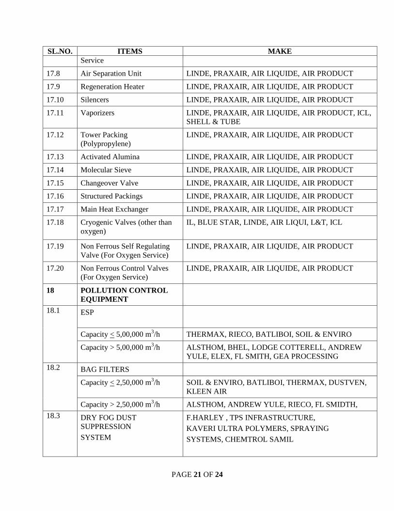
PAGE 21 OF 24
SL.NO. ITEMS MAKE Service
17.8 Air Separation Unit LINDE, PRAXAIR, AIR LIQUIDE, AIR PRODUCT
17.9 Regeneration Heater LINDE, PRAXAIR, AIR LIQUIDE, AIR PRODUCT
17.10 Silencers LINDE, PRAXAIR, AIR LIQUIDE, AIR PRODUCT
17.11 Vaporizers LINDE, PRAXAIR, AIR LIQUIDE, AIR PRODUCT, ICL, SHELL & TUBE
17.12 Tower Packing (Polypropylene)
LINDE, PRAXAIR, AIR LIQUIDE, AIR PRODUCT
17.13 Activated Alumina LINDE, PRAXAIR, AIR LIQUIDE, AIR PRODUCT
17.14 Molecular Sieve LINDE, PRAXAIR, AIR LIQUIDE, AIR PRODUCT
17.15 Changeover Valve LINDE, PRAXAIR, AIR LIQUIDE, AIR PRODUCT
17.16 Structured Packings LINDE, PRAXAIR, AIR LIQUIDE, AIR PRODUCT
17.17 Main Heat Exchanger LINDE, PRAXAIR, AIR LIQUIDE, AIR PRODUCT
17.18 Cryogenic Valves (other than oxygen)
IL, BLUE STAR, LINDE, AIR LIQUI, L&T, ICL
17.19 Non Ferrous Self Regulating Valve (For Oxygen Service)
LINDE, PRAXAIR, AIR LIQUIDE, AIR PRODUCT
17.20 Non Ferrous Control Valves (For Oxygen Service)
LINDE, PRAXAIR, AIR LIQUIDE, AIR PRODUCT
18 POLLUTION CONTROL EQUIPMENT
18.1 ESP
Capacity < 5,00,000 m3/h THERMAX, RIECO, BATLIBOI, SOIL & ENVIRO
Capacity > 5,00,000 m3/h ALSTHOM, BHEL, LODGE COTTERELL, ANDREW YULE, ELEX, FL SMITH, GEA PROCESSING
18.2 BAG FILTERS
Capacity < 2,50,000 m3/h SOIL & ENVIRO, BATLIBOI, THERMAX, DUSTVEN, KLEEN AIR
Capacity > 2,50,000 m3/h ALSTHOM, ANDREW YULE, RIECO, FL SMIDTH,
18.3 DRY FOG DUST SUPPRESSION
SYSTEM
F.HARLEY , TPS INFRASTRUCTURE,
KAVERI ULTRA POLYMERS, SPRAYING
SYSTEMS, CHEMTROL SAMIL
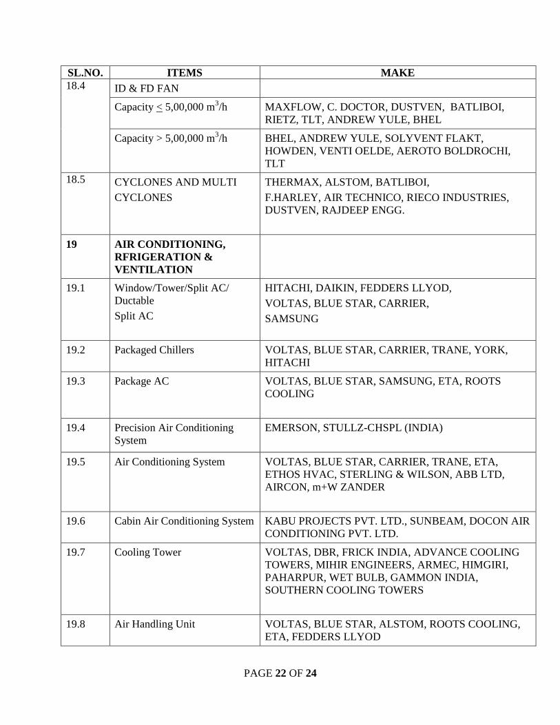
PAGE 22 OF 24
SL.NO. ITEMS MAKE 18.4 ID & FD FAN
Capacity < 5,00,000 m3/h MAXFLOW, C. DOCTOR, DUSTVEN, BATLIBOI, RIETZ, TLT, ANDREW YULE, BHEL
Capacity > 5,00,000 m3/h BHEL, ANDREW YULE, SOLYVENT FLAKT, HOWDEN, VENTI OELDE, AEROTO BOLDROCHI, TLT
18.5 CYCLONES AND MULTI
CYCLONES
THERMAX, ALSTOM, BATLIBOI,
F.HARLEY, AIR TECHNICO, RIECO INDUSTRIES, DUSTVEN, RAJDEEP ENGG.
19 AIR CONDITIONING, RFRIGERATION & VENTILATION
19.1 Window/Tower/Split AC/ Ductable
Split AC
HITACHI, DAIKIN, FEDDERS LLYOD,
VOLTAS, BLUE STAR, CARRIER,
SAMSUNG
19.2 Packaged Chillers VOLTAS, BLUE STAR, CARRIER, TRANE, YORK, HITACHI
19.3 Package AC
VOLTAS, BLUE STAR, SAMSUNG, ETA, ROOTS COOLING
19.4 Precision Air Conditioning System
EMERSON, STULLZ-CHSPL (INDIA)
19.5 Air Conditioning System VOLTAS, BLUE STAR, CARRIER, TRANE, ETA, ETHOS HVAC, STERLING & WILSON, ABB LTD, AIRCON, m+W ZANDER
19.6 Cabin Air Conditioning System KABU PROJECTS PVT. LTD., SUNBEAM, DOCON AIR CONDITIONING PVT. LTD.
19.7 Cooling Tower VOLTAS, DBR, FRICK INDIA, ADVANCE COOLING TOWERS, MIHIR ENGINEERS, ARMEC, HIMGIRI, PAHARPUR, WET BULB, GAMMON INDIA, SOUTHERN COOLING TOWERS
19.8 Air Handling Unit VOLTAS, BLUE STAR, ALSTOM, ROOTS COOLING, ETA, FEDDERS LLYOD
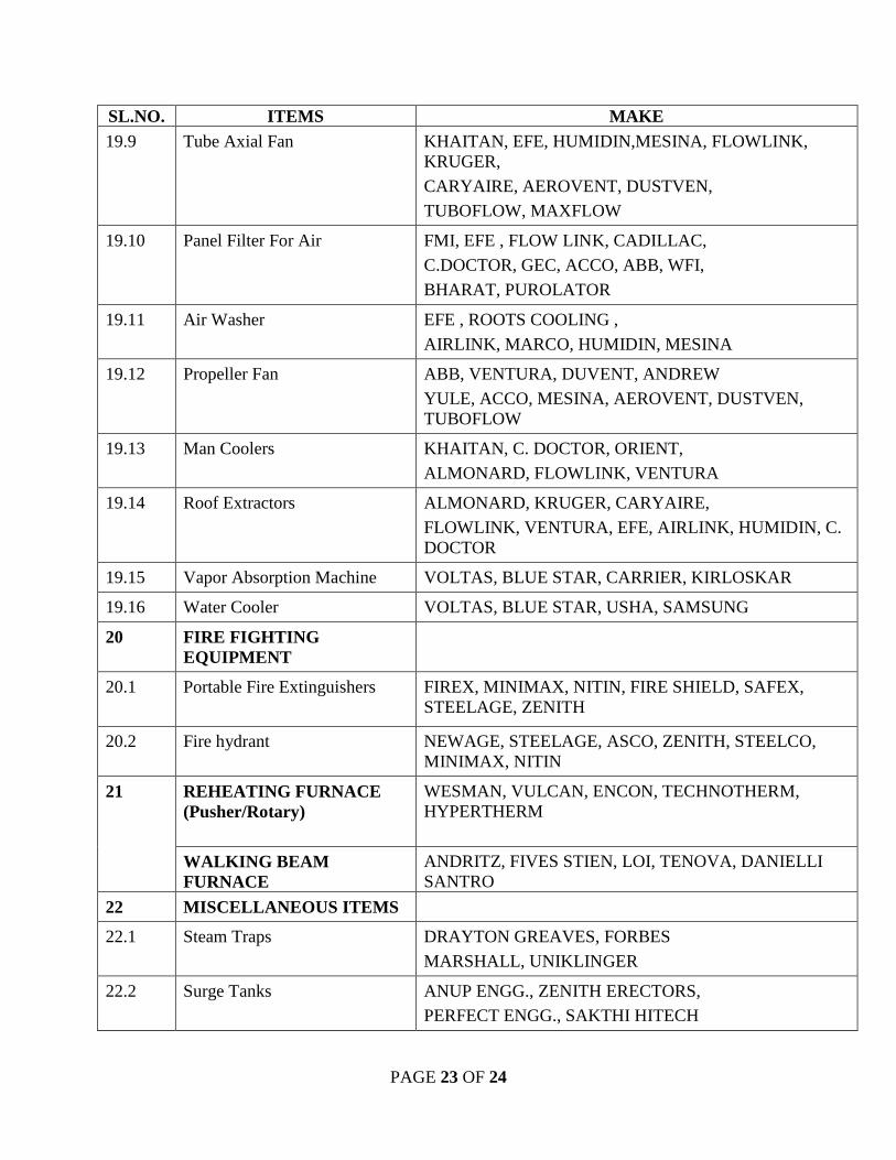
PAGE 23 OF 24
SL.NO. ITEMS MAKE 19.9 Tube Axial Fan
KHAITAN, EFE, HUMIDIN,MESINA, FLOWLINK, KRUGER,
CARYAIRE, AEROVENT, DUSTVEN,
TUBOFLOW, MAXFLOW
19.10 Panel Filter For Air FMI, EFE , FLOW LINK, CADILLAC,
C.DOCTOR, GEC, ACCO, ABB, WFI,
BHARAT, PUROLATOR
19.11 Air Washer EFE , ROOTS COOLING ,
AIRLINK, MARCO, HUMIDIN, MESINA
19.12 Propeller Fan ABB, VENTURA, DUVENT, ANDREW
YULE, ACCO, MESINA, AEROVENT, DUSTVEN, TUBOFLOW
19.13 Man Coolers KHAITAN, C. DOCTOR, ORIENT,
ALMONARD, FLOWLINK, VENTURA
19.14 Roof Extractors ALMONARD, KRUGER, CARYAIRE,
FLOWLINK, VENTURA, EFE, AIRLINK, HUMIDIN, C. DOCTOR
19.15 Vapor Absorption Machine VOLTAS, BLUE STAR, CARRIER, KIRLOSKAR
19.16 Water Cooler VOLTAS, BLUE STAR, USHA, SAMSUNG
20 FIRE FIGHTING EQUIPMENT
20.1 Portable Fire Extinguishers
FIREX, MINIMAX, NITIN, FIRE SHIELD, SAFEX, STEELAGE, ZENITH
20.2 Fire hydrant NEWAGE, STEELAGE, ASCO, ZENITH, STEELCO, MINIMAX, NITIN
21 REHEATING FURNACE (Pusher/Rotary)
WESMAN, VULCAN, ENCON, TECHNOTHERM, HYPERTHERM
WALKING BEAM FURNACE
ANDRITZ, FIVES STIEN, LOI, TENOVA, DANIELLI SANTRO
22 MISCELLANEOUS ITEMS
22.1 Steam Traps DRAYTON GREAVES, FORBES
MARSHALL, UNIKLINGER
22.2 Surge Tanks ANUP ENGG., ZENITH ERECTORS, PERFECT ENGG., SAKTHI HITECH
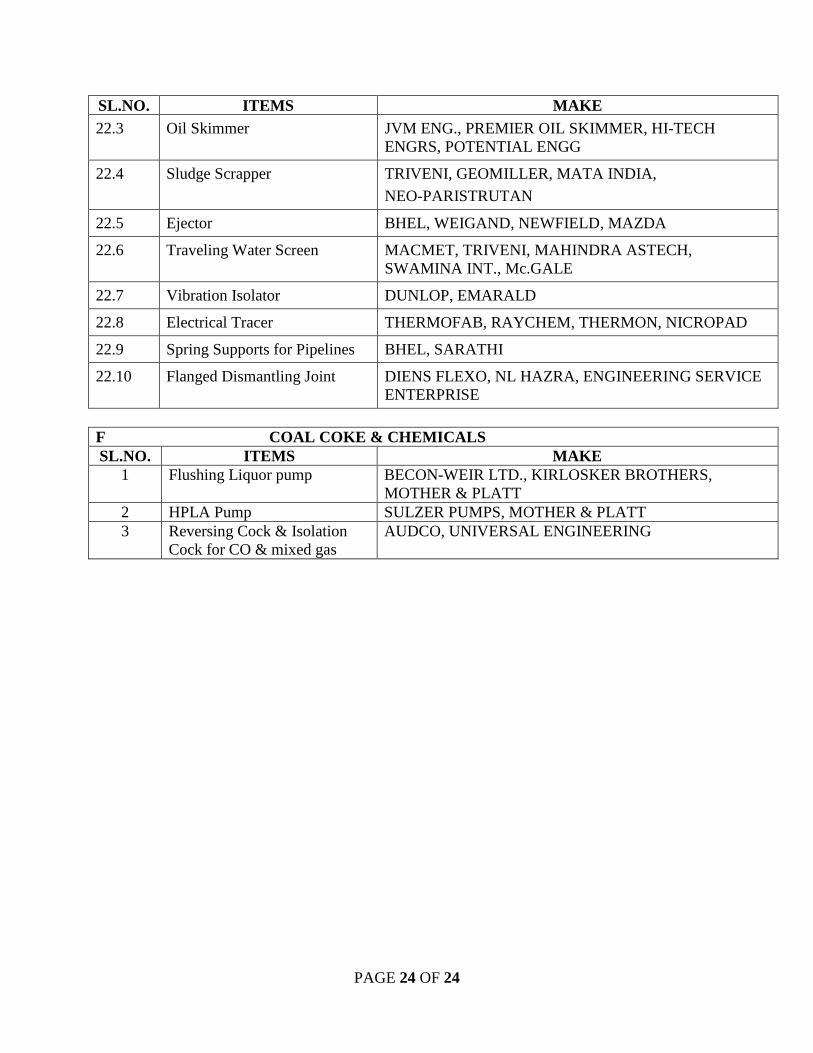
PAGE 24 OF 24
SL.NO. ITEMS MAKE 22.3 Oil Skimmer JVM ENG., PREMIER OIL SKIMMER, HI-TECH
ENGRS, POTENTIAL ENGG
22.4 Sludge Scrapper TRIVENI, GEOMILLER, MATA INDIA,
NEO-PARISTRUTAN
22.5 Ejector BHEL, WEIGAND, NEWFIELD, MAZDA
22.6 Traveling Water Screen MACMET, TRIVENI, MAHINDRA ASTECH, SWAMINA INT., Mc.GALE
22.7 Vibration Isolator DUNLOP, EMARALD
22.8 Electrical Tracer THERMOFAB, RAYCHEM, THERMON, NICROPAD
22.9 Spring Supports for Pipelines BHEL, SARATHI
22.10 Flanged Dismantling Joint DIENS FLEXO, NL HAZRA, ENGINEERING SERVICE ENTERPRISE
F COAL COKE & CHEMICALS SL.NO. ITEMS MAKE
1 Flushing Liquor pump BECON-WEIR LTD., KIRLOSKER BROTHERS, MOTHER & PLATT
2 HPLA Pump SULZER PUMPS, MOTHER & PLATT 3 Reversing Cock & Isolation
Cock for CO & mixed gas AUDCO, UNIVERSAL ENGINEERING

BPSCL Schedule 2.1.2-1 CET/23/RN/4060/TS/UT/01/R=0 SIDE STREAM FILTRATION SYSTEM Page 1 of 1
SCHEDULE-2.1.2-1 DECLARATION FOR SITE VISIT
(To be filled up by the Bidder)
We, hereby, declare that we have visited the site for the installation of proposed systems regarding “Installation of Filtration System in RCPH Cooling Water Circuit, BPSCL”, to understand the site conditions and acquaint ourselves with the extent of total works involved for present package as per TS No. CET/23/RN/4060/TS/UT/01/R=0.
Signature of the Bidder
Seal of company Name Designation

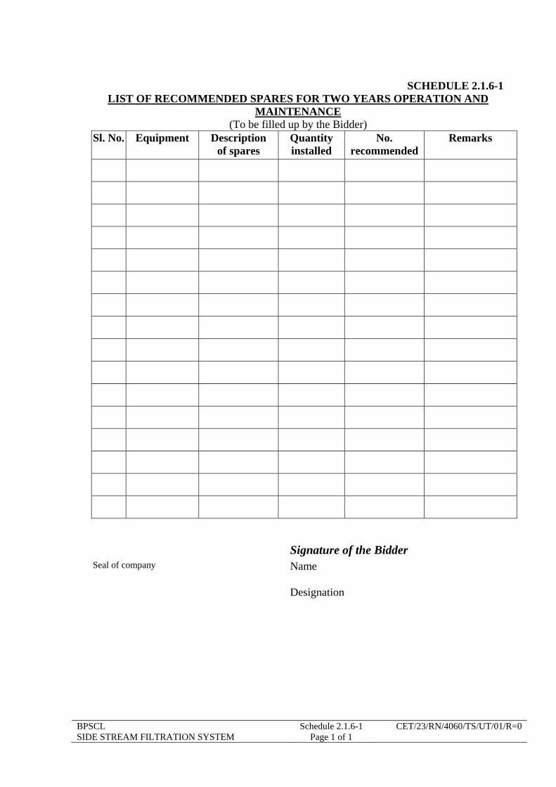
BPSCL Schedule 2.1.6-1 CET/23/RN/4060/TS/UT/01/R=0 SIDE STREAM FILTRATION SYSTEM Page 1 of 1
SCHEDULE 2.1.6-1 LIST OF RECOMMENDED SPARES FOR TWO YEARS OPERATION AND
MAINTENANCE (To be filled up by the Bidder)
Sl. No. Equipment Description of spares
Quantity installed
No. recommended
Remarks
Signature of the Bidder Seal of company Name
Designation

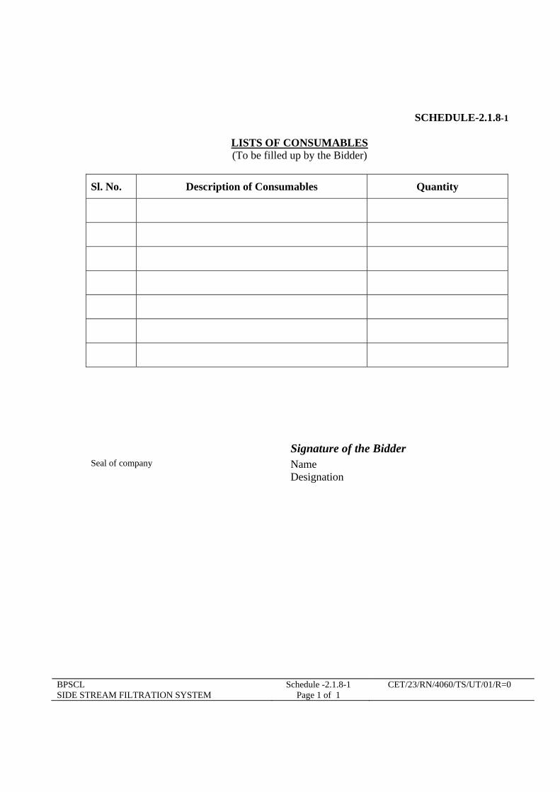
BPSCL Schedule -2.1.8-1 CET/23/RN/4060/TS/UT/01/R=0 SIDE STREAM FILTRATION SYSTEM Page 1 of 1
SCHEDULE-2.1.8-1
LISTS OF CONSUMABLES (To be filled up by the Bidder)
Sl. No. Description of Consumables Quantity
Signature of the Bidder Seal of company Name Designation

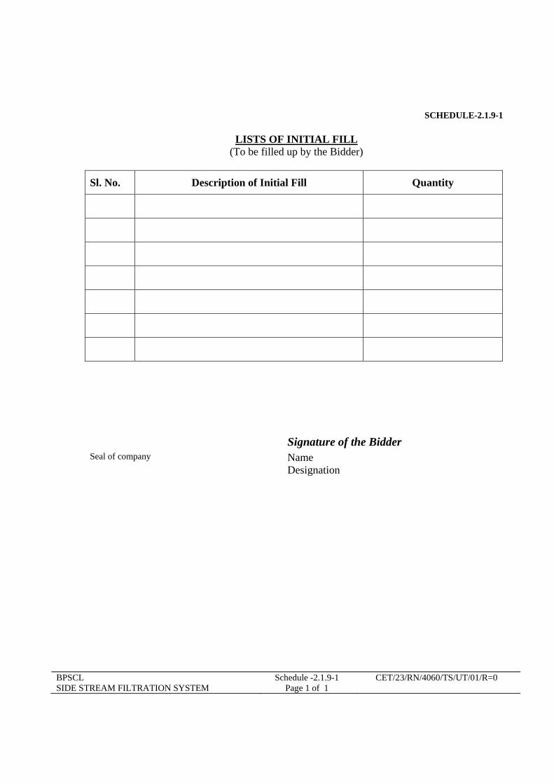
BPSCL Schedule -2.1.9-1 CET/23/RN/4060/TS/UT/01/R=0 SIDE STREAM FILTRATION SYSTEM Page 1 of 1
SCHEDULE-2.1.9-1
LISTS OF INITIAL FILL (To be filled up by the Bidder)
Sl. No. Description of Initial Fill Quantity
Signature of the Bidder Seal of company Name Designation


BPSCL Schedule -2.1.10-1 CET/23/RN/4060/TS/UT/01/R=0 SIDE STREAM FILTRATION SYSTEM Page 1 of 1
SCHEDULE-2.1.10-1
LISTS OF SPECIAL TOOLS AND TACKLES (To be filled up by the Bidder)
Sl. No. Description of Consumables Quantity
Signature of the Bidder Seal of company Name Designation

BPSCL Schedule -2.1.11-1 CET/23/RN/4060/TS/UT/01/R=0 SIDE STREAM FILTRATION SYSTEM Page 1 of 1
SCHEDULE-2.1.11-1
LIST OF EXCLUSIONS
(To be filled up by the Bidder)
Sl. No. Reference clause of TS Details of exclusions Reasons
Signature of the Bidder Seal of company Name Designation

BPSCL Schedule 2.1.11-2 CET/23/RN/4060/TS/UT/01/R=0 SIDE STREAM FILTRATION SYSTEM Page 1 of 1
SCHEDULE-2.1.11-2 LIST OF DEVIATIONS
(To be filled up by the Bidder)
Sl. No. Reference clause of TS Details of deviations Reasons
Signature of the Bidder Seal of company Name Designation