Embed Size (px)
Citation preview

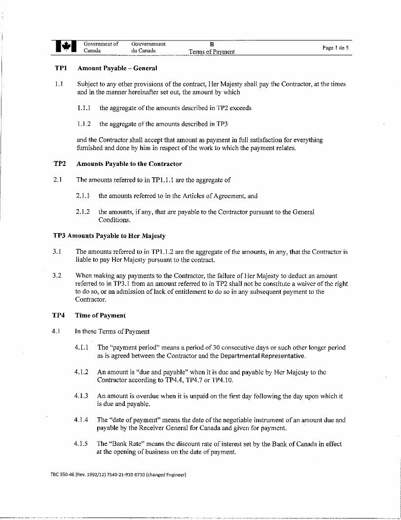
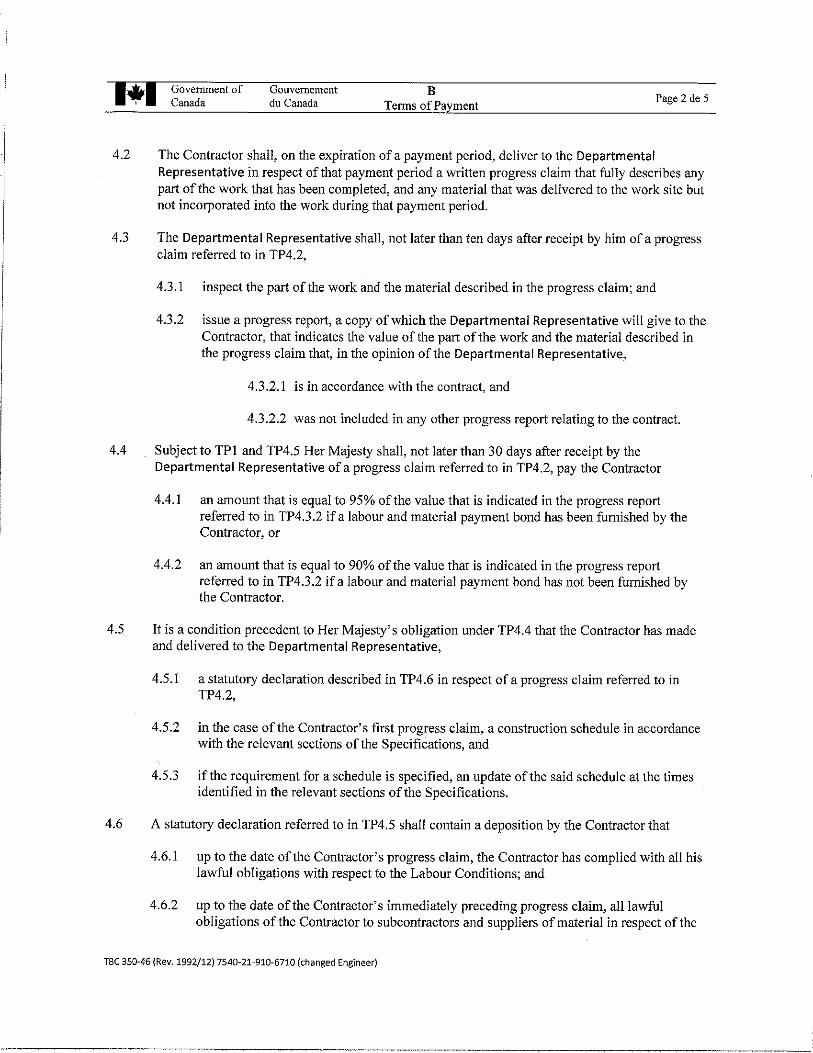
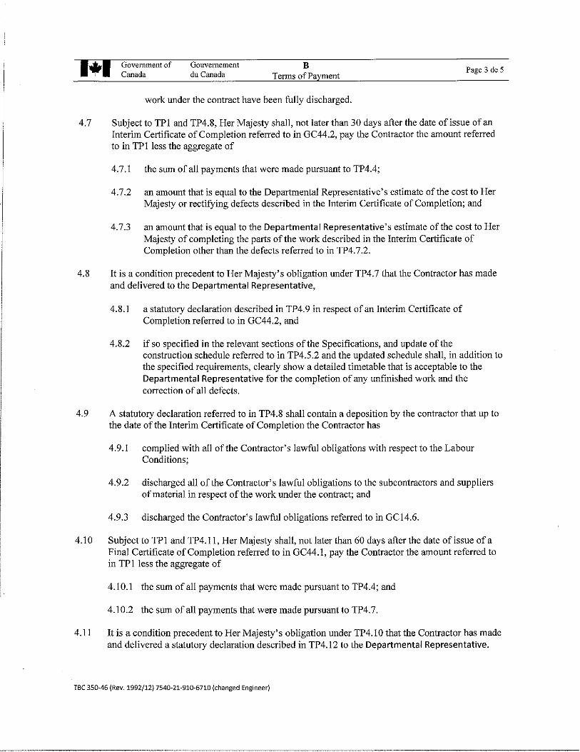
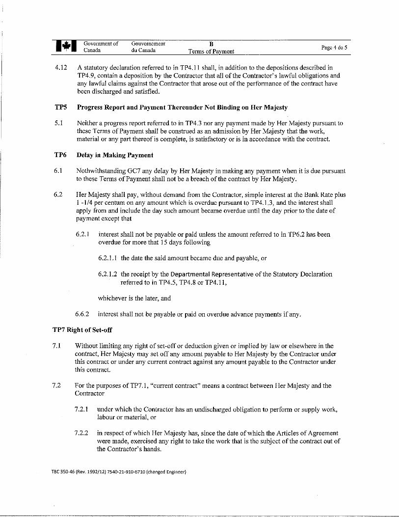
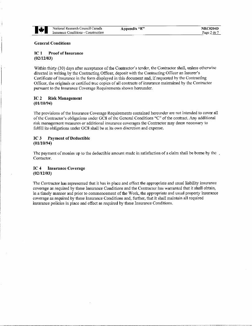
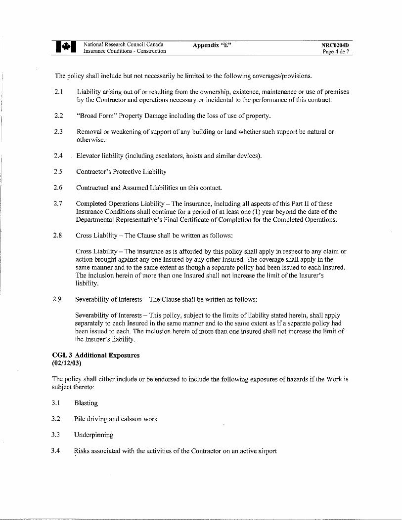
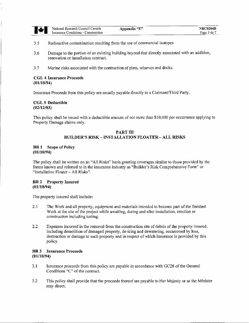
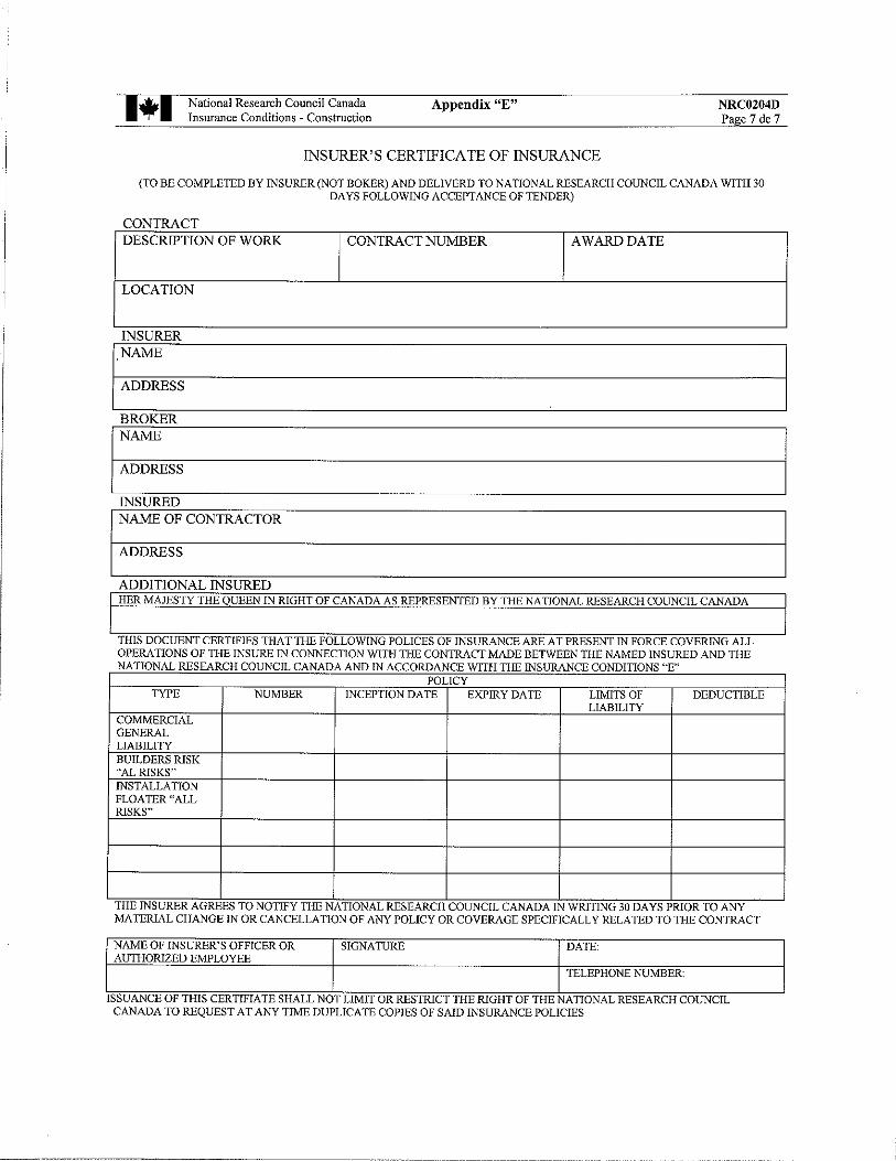
SPECIFICATION TABLE OF CONTENTS Construction Tender Form Buyandsell Notice Instructions to Bidders Ontario Sales Tax Acceptable Bonding Companies Articles of Agreement Plans and Specifications A Terms of Payment B General Conditions C Labour Conditions and Fair Wage Schedule D N/A Insurance Conditions E Contract Security Conditions F Security Requirement Check List G

Directions to the Ottawa Research Facilities — Uplands
NRC Institute for Aerospace Research (NRC-IAR)Research RoadOttawa, Ontario, Canada
Tel: 613-991-5738
NRC Centre for Surface Transportation Technology (NRC-CSTT)2320 Lester RoadOttawa, Ontario, Canada
Tel: 613-998-9639
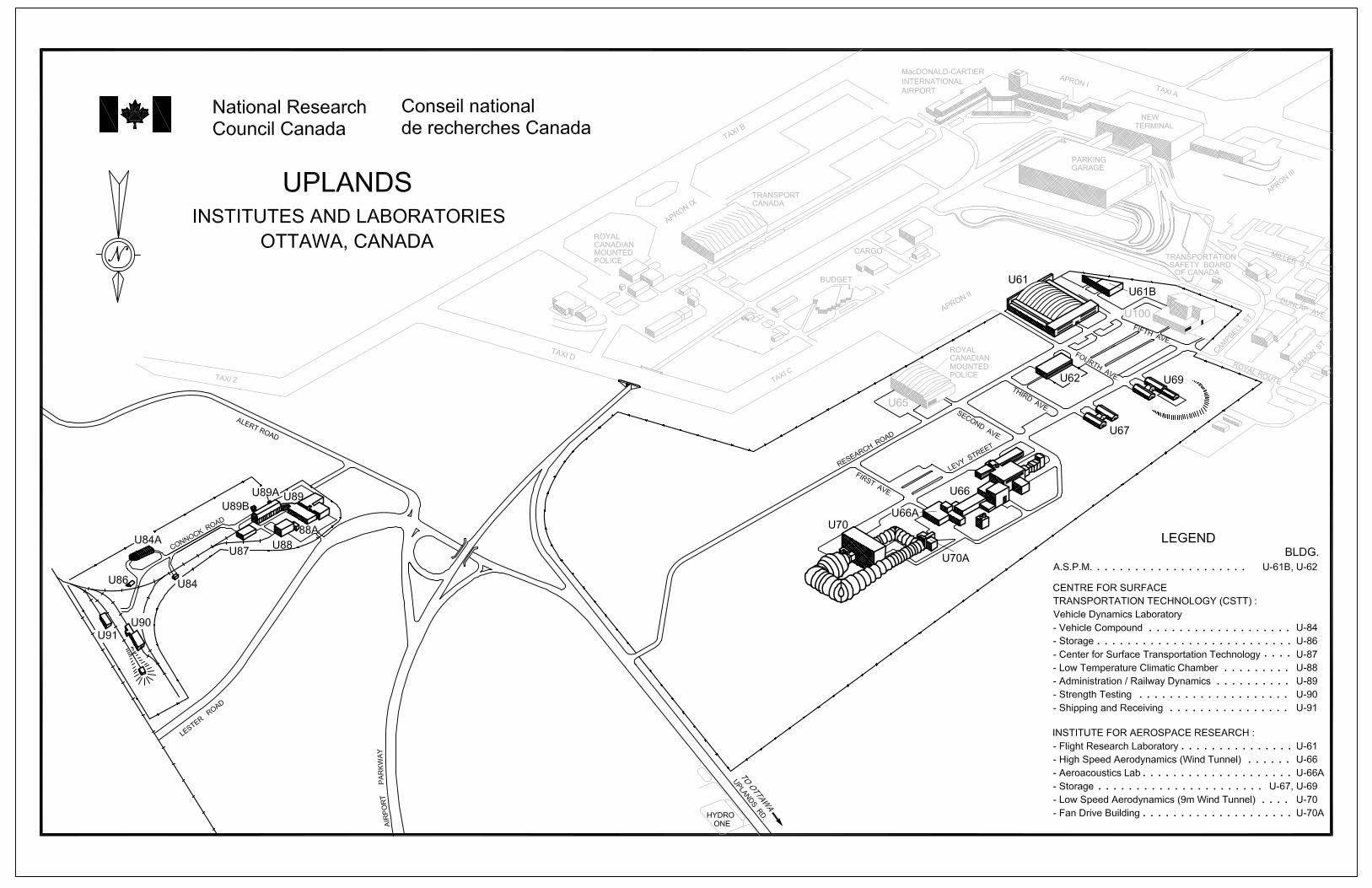
NRC Institutes/Branch/Program Buildings
NRC Administrative Services and Property Management (NRC-ASPM) U-62
NRC Institute For Aerospace Research (NRC-IAR) U-61, U-66, U-67, U-69, U-70
NRC Centre for Surface Transportation Technology (NRC-CSTT) U-84, U-86, U-87, U-88, U89, U-90, U-91
By Road, from the MONTREAL RD FACILITIES to NRC-CSTT, 2320 Lester Road
1. Drive EAST on MONTREAL RD
2. Turn RIGHT on BLAIR RD, cross OGILVIE RD
3. Take the ramp and follow Highway 174 WEST
4. Keep RIGHT and take first exit on ramp Highway 417 EAST towards Cornwall/Montreal
5. Exit at WALKLEY RD, merge RIGHT on WALKLEY
6. Turn LEFT at CONROY RD
7. Turn RIGHT at DAVIDSON RD, cross BANK ST – name changes to LESTER RD
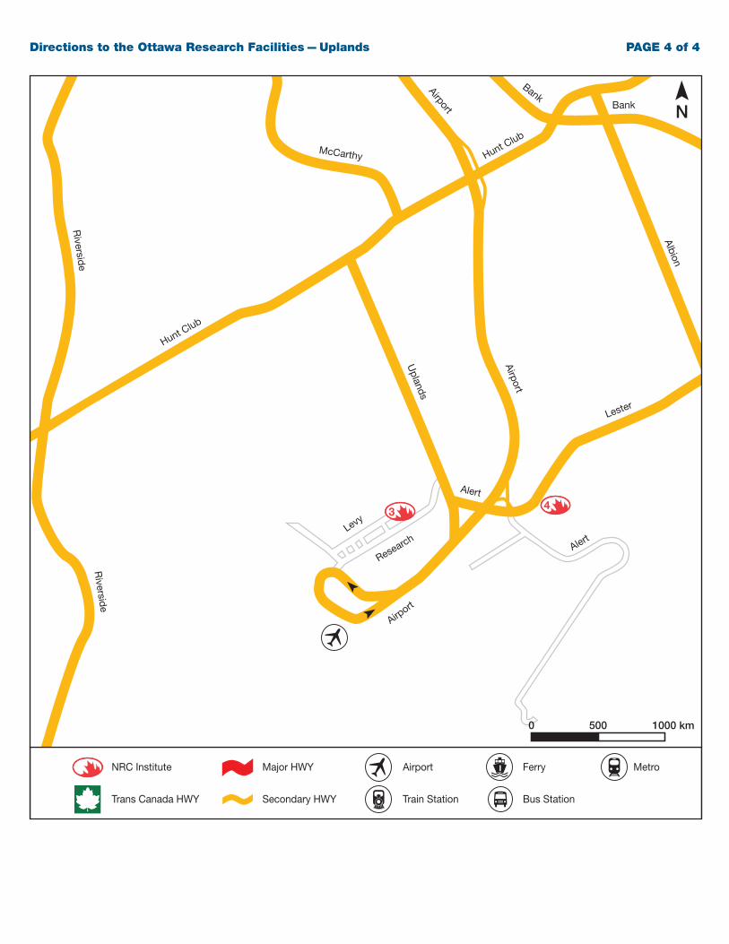
8. Continue on LESTER RD and watch for NRC Research Facilities signs
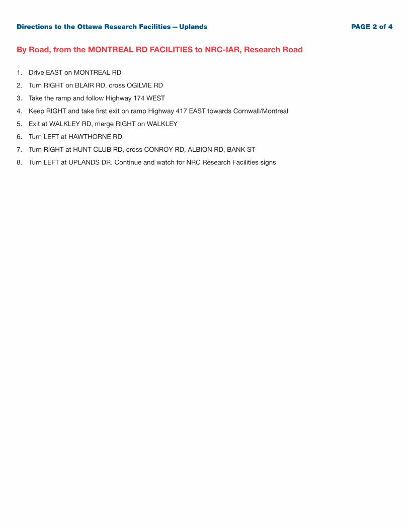
By Road, from the MONTREAL RD FACILITIES to NRC-IAR, Research Road
1. Drive EAST on MONTREAL RD
2. Turn RIGHT on BLAIR RD, cross OGILVIE RD
3. Take the ramp and follow Highway 174 WEST
4. Keep RIGHT and take first exit on ramp Highway 417 EAST towards Cornwall/Montreal
5. Exit at WALKLEY RD, merge RIGHT on WALKLEY
6. Turn LEFT at HAWTHORNE RD
7. Turn RIGHT at HUNT CLUB RD, cross CONROY RD, ALBION RD, BANK ST
8. Turn LEFT at UPLANDS DR. Continue and watch for NRC Research Facilities signs
Directions to the Ottawa Research Facilities — Uplands PAGE 2 of 4
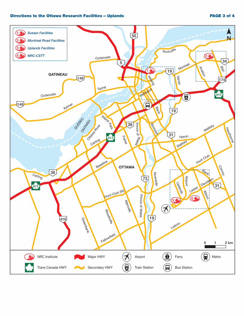
Directions to the Ottawa Research Facilities — Uplands PAGE 3 of 4
NRC Institute
Trans Canada HWY
Major HWY
Secondary HWY
Airport
Train Station
Ferry Metro
Bus Station
map-legend-eng.pdf 1 03/11/09 11:47 AM
2
1
0 1 2 km
N
Montréal
Rock cliffe
Aviation
Blair
Bank
Woodroffe
Greenbank
Merivale
Island
Park
Fisher
Prince of W
alesP
rinceof W
ales
Riversid
e Uplands
Airp
ort
Albion
Conroy
VanierSuss
exCarlin
g
Aylmer
Taché
Outaouais
Outaouais
Carling
Otta
wa
River
ON
TARI
O
QU
ÉBEC
Baseline
Heron
Hunt Club (W)
Fallowfield
Leitrim
Hunt Club
Walkley
Walkley
417
417
417
148
148
38
38
73
31
31
34
19
19
19
5
50
416
174
Bronson
Bank
Haw
thorne
3 4
Wellington
3
4
1
2
OTTAWA
GATINEAU
Sussex Facilities
Montreal Road Facilities
Uplands Facilities
NRC-CSTT
LesterDavidson
NRC Institute
Trans Canada HWY
Major HWY
Secondary HWY
Airport
Train Station
Ferry Metro
Bus Station
map-legend-eng.pdf 1 03/11/09 11:47 AMDirections to the Ottawa Research Facilities — Uplands PAGE 4 of 4
Hunt Club
Hunt Club
Lester
McCarthy
Bank
Bank
Uplands
Airport
Airport
Airport
Alert
AlertLevy
Research
Albion
Riversid
e
Riversid
e
3 4
0 500 1000 km
N
National Research Council Conseil national de recherches
Canada Canada
Administrative Services Direction des services
& Property management administratif et gestion
Branch (ASPM) de l’immobilier (SAGI)
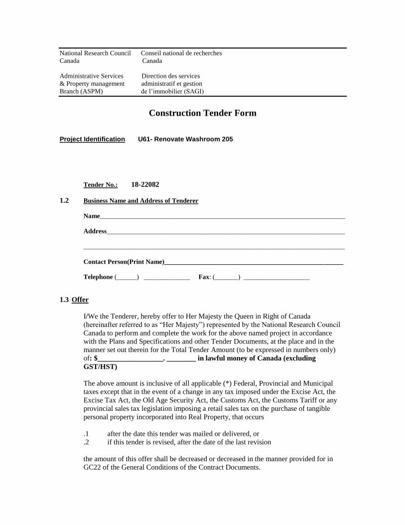
Construction Tender Form
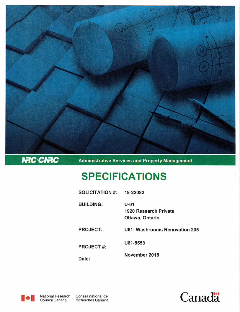
Project Identification U61- Renovate Washroom 205
Tender No.: 18-22082
1.2 Business Name and Address of Tenderer
Name__________________________________________________________________________
Address________________________________________________________________________
_______________________________________________________________________________
Contact Person(Print Name)______________________________________________________
Telephone (______) ______________ Fax: (_______) ____________________
1.3 Offer
I/We the Tenderer, hereby offer to Her Majesty the Queen in Right of Canada
(hereinafter referred to as “Her Majesty”) represented by the National Research Council
Canada to perform and complete the work for the above named project in accordance
with the Plans and Specifications and other Tender Documents, at the place and in the
manner set out therein for the Total Tender Amount (to be expressed in numbers only)
of: $__________________. ________ in lawful money of Canada (excluding
GST/HST)
The above amount is inclusive of all applicable (*) Federal, Provincial and Municipal
taxes except that in the event of a change in any tax imposed under the Excise Act, the
Excise Tax Act, the Old Age Security Act, the Customs Act, the Customs Tariff or any
provincial sales tax legislation imposing a retail sales tax on the purchase of tangible
personal property incorporated into Real Property, that occurs
.1 after the date this tender was mailed or delivered, or
.2 if this tender is revised, after the date of the last revision
the amount of this offer shall be decreased or decreased in the manner provided for in
GC22 of the General Conditions of the Contract Documents.
National Research Council Conseil national de recherches
Canada Canada
Administrative Services Direction des services
& Property management administratif et gestion
Branch (ASPM) de l’immobilier (SAGI)
1.3.1 Offer (continued)
(*) For the purpose of this tender, the Goods and Services Tax (GST) is not to be
considered as an applicable tax.
In the province of Quebec, the Quebec Sales Tax is not to be included in the tender
amount because the Federal Government is exempt from this tax. Tenderers shall make
arrangements directly with the provincial Revenue Department to recover any tax they
may pay on good and servives acquired in the performance of this contract. However,
tenderers should include in their tender amount Quebec Sales Tax for which an Input Tax
Refund is not available.
1.4 Acceptance and Entry into Contract
I/We undertake, within fourteen (14) days of notification of acceptance of my/our offer,
to sign a contract for the performance of the work provided I/we are notified, by the
Department, of the acceptance of my/our offer within 30 days of the tender closing date.
1.5 Construction Time
I/We Agree to complete the work within the time stipulated in the specification from the
date of notification of acceptance of my/our offer.
1.6 Bid Security
I/We herewith enclose tender security in accordance with Article 5 of the General
Instruction to Tenderers.
I/We understand that if a security deposit is furnished as tender security and if I/we refuse
to enter into a contract when called upon to do so, my/our security deposit shall be
forfeited but the Minister may, if it is in the public interest, waive the right of Her
Majesty to forfeit the security deposit.
I/We understand that if the security furnished is not in the approved from as described in
Article 5 of the General Instructions to Tenderers, my/our tender is subject to
disqualification.
National Research Council Conseil national de recherches
Canada Canada
Administrative Services Direction des services
& Property management administratif et gestion
Branch (ASPM) de l’immobilier (SAGI)
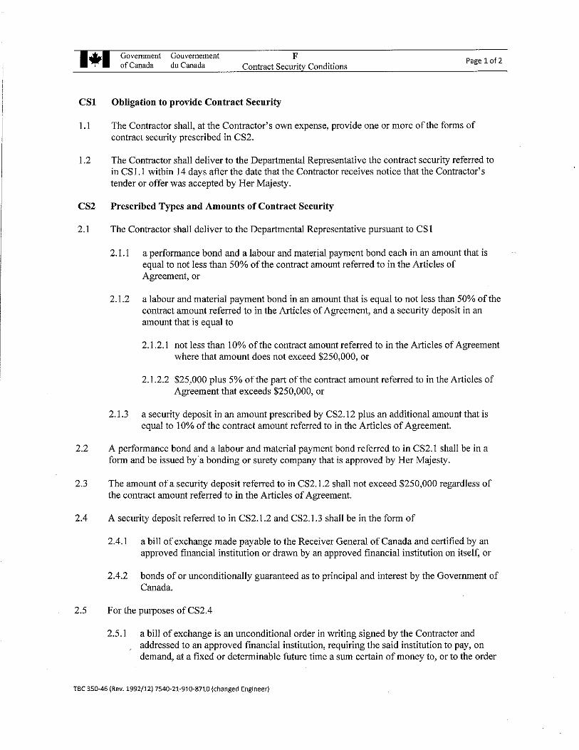
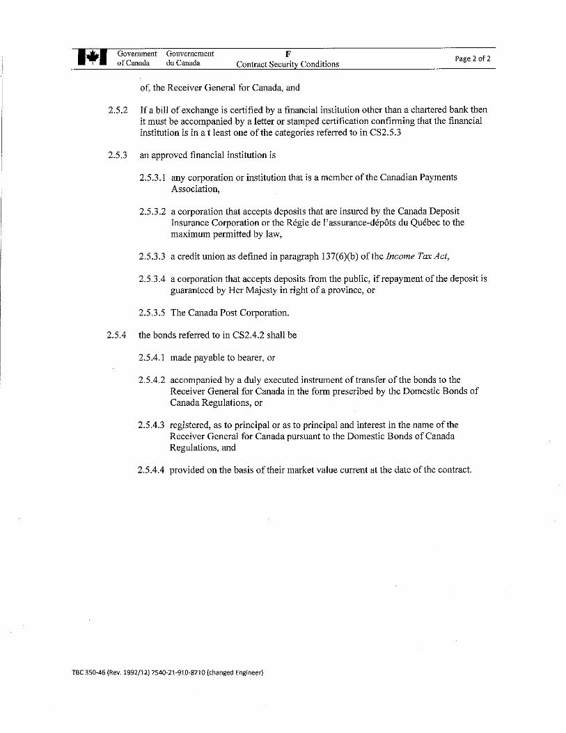
1.7 Contract Security
Within fourteen (14) days after receipt of written notification of the acceptance of my/our
offer, I/we will furnish contract security in accordance with the Contract Conditions “F”
of the Contract Documents.
I/We understand that the contract security referred to herein, if provided in the form of a
bill of exchange, will be deposited into the Consolidated Revenue Fund of Canada.
1.8 Appendices
This Tender Form includes Appendix No. _____N/A____________.
1.9 Addenda
The Total Tender Amount provides for the Work described in the following Addenda:
NUMBER DATE NUMBER DATE
(Tenderers shall enter numbers and dates of addenda)
National Research Council Conseil national de recherches
Canada Canada
Administrative Services Direction des services
& Property management administratif et gestion
Branch (ASPM) de l’immobilier (SAGI)
1.10 Execution of Tender
The Tenderer shall refer to Article 2 of the General Instructions to Tenderers.
SIGNED, ATTESTED TO AND DELIVERED on the ____________________day of
________________on behalf of
________________________________________________________________________
(Type or print the business name of the Tenderer)
AUTHORIZED SIGNATORY (IES)
______________________________________
(Signature of Signatory)
______________________________________
(Print name & Title of Signatory)
_____________________________________
(Signature of Signatory)
______________________________________
(Print name & Title of Signatory)
SEAL
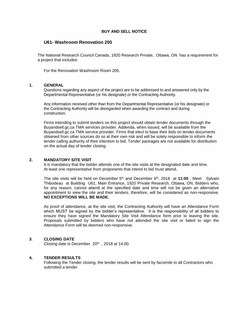
BUY AND SELL NOTICE U61- Washroom Renovation 205
The National Research Council Canada, 1920 Research Private, Ottawa, ON has a requirement for a project that includes:
For the Renovation Washroom Room 205.
1. GENERAL
Questions regarding any aspect of the project are to be addressed to and answered only by the Departmental Representative (or his designate) or the Contracting Authority. Any information received other than from the Departmental Representative (or his designate) or the Contracting Authority will be disregarded when awarding the contract and during construction. Firms intending to submit tenders on this project should obtain tender documents through the Buyandsell.gc.ca TMA services provider. Addenda, when issued, will be available from the Buyandsell.gc.ca TMA service provider. Firms that elect to base their bids on tender documents obtained from other sources do so at their own risk and will be solely responsible to inform the tender calling authority of their intention to bid. Tender packages are not available for distribution on the actual day of tender closing.
2. MANDATORY SITE VISIT
It is mandatory that the bidder attends one of the site visits at the designated date and time. At least one representative from proponents that intend to bid must attend. The site visits will be held on December 5th and December 6th, 2018 at 11:00 . Meet Sylvain Thibodeau at Building U61, Main Entrance, 1920 Private Research, Ottawa, ON. Bidders who, for any reason, cannot attend at the specified date and time will not be given an alternative appointment to view the site and their tenders, therefore, will be considered as non-responsive. NO EXCEPTIONS WILL BE MADE.
As proof of attendance, at the site visit, the Contracting Authority will have an Attendance Form which MUST be signed by the bidder’s representative. It is the responsibility of all bidders to ensure they have signed the Mandatory Site Visit Attendance form prior to leaving the site. Proposals submitted by bidders who have not attended the site visit or failed to sign the Attendance Form will be deemed non-responsive.
3. CLOSING DATE
Closing date is December 20th , 2018 at 14:00. 4. TENDER RESULTS
Following the Tender closing, the tender results will be sent by facsimile to all Contractors who submitted a tender
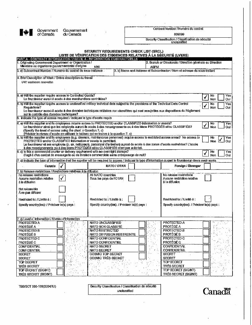
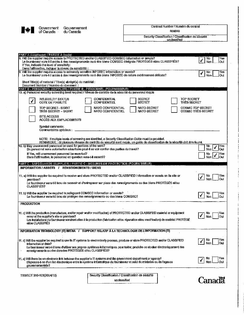
5. SECURITY REQUIREMENT FOR CANADIAN CONTRACTORS 5.1 MANDATORY SECURITY REQUIREMENT: This procurement contains a mandatory security requirement as follows: 1 The Contractor must, at all times during the performance of the Contract, hold a valid Designated
Organization Screening (DOS), issued by the Canadian Industrial Security Director (CISD), Public Works Government Services Canada.
2 The Contractor personnel requiring access to sensitive work site(s) must EACH hold a valid
RELIABILITY STATUS, granted or approved by CISD/PWGSC. 3 The Contractor must comply with the provisions of the:
a. Security Requirements Checklist attached at Appendix “D” b. Industrial Security Manual (Latest Edition) available at: http://ssi-iss.tpsgc-pwgsc.gc.ca/ssi-iss-
services/eso-oss-eng.html
5.2 VERIFICATION OF SECURITY CLEARANCE AT BID CLOSING 1 The Bidder must hold a valid Designated Organization Screening (DOS) issued by the Canadian
Industrial Security Directorate (CISD), Public Works and Government Services Canada (PWGSC), TO BE INCLUDED WITH THEIR TENDER OR PROVIDED WITHIN 48 HOURS FROM THE DATE AND TIME OF TENDER CLOSING. Verifications will be made through CISD to confirm the security clearance status of the Bidder. Failure to comply with this requirement will render the bid non-compliant and no further consideration will be given to the bid.
2 Within 72 hours of tender closing, the General Contractor must name all of his sub-contractors,
each of whom must hold a valid RELIABILITY STATUS, granted or approved by CISD/PWGSC, or any other Federal Department or Agency along with the names and birthdates or security clearance certificate numbers of all personnel who will be assigned to the project.
3 It is to be noted that any subcontractor required to perform any part of the work during the
performance of the subsequent contract must also adhere to the mandatory security requirement of the contract. As well, no personnel without the required level of security will be allowed on site. It will be the responsibility of the successful bidder to ensure that the security requirement is met throughout the performance of the contract. The Crown will not be held liable or accountable for any delays or additional costs associated with the contractor’s non-compliance to the mandatory security requirement. Failure to comply with the mandatory security requirement will be grounds for being declared in default of contract.
4 For any enquiries concerning the project security requirement during the bidding period, the
Bidder/Tenderer must contact the Security Officer @ 613-993-8956.

6.0 WSIB (WORKPLACE SAFETY AND INSURANCE BOARD)
1 All Bidders must provide a valid WSIB certificate with their Tender or prior to contract award. 7.0 OFFICE OF THE PROCUREMENT OMBUDSMAN 1 Dispute Resolution Services
The parties understand that the Procurement Ombudsman appointed pursuant to Subsection 22.1(1) of the Department of Public Works and Government Services Act will, on request or consent of the parties to participate in an alternative dispute resolution process to resolve any dispute between the parties respecting the interpretation or application of a term and condition of this contract and their consent to bear the cost of such process, provide to the parties a proposal for an alternative dispute resolution process to resolve their dispute. The Office of the Procurement Ombudsman may be contacted by telephone at 1-866-734-5169 or by e-mail at [email protected].
2 Contract Administration
The parties understand that the Procurement Ombudsman appointed pursuant to Subsection 22.1(1) of the Department of Public Works and Government Services Act will review a complaint filed by [the supplier or the contractor or the name of the entity awarded this contract] respecting administration of this contract if the requirements of Subsection 22.2(1) of the Department of Public Works and Government Services Act and Sections 15 and 16 of the Procurement Ombudsman Regulations have been met, and the interpretation and application of the terms and conditions and the scope of the work of this contract are not in dispute. The Office of the Procurement Ombudsman may be contacted by telephone at 1-866-734-5169 or by e-mail at [email protected].
3 The Office of the Procurement Ombudsman (OPO) was established by the Government of
Canada to provide an independent avenue for suppliers to raise complaints regarding the award of contracts under $25,000 for goods and under $100,000 for services. You have the option of raising issues or concerns regarding the solicitation, or the award resulting from it, with the OPO by contacting them by telephone at 1-866-734-5169 or by e-mail at [email protected]. You can also obtain more information on the OPO services available to you at their website at www.opo-boa.gc.ca.
The Departmental Representative or his designate for this project is: Sylvain Thibodeau Telephone: 613 301-3576. Contracting Authority for this project is: Alain Leroux [email protected] Telephone: 613 991-9980.
INSTRUCTIONS TO BIDDERS Article 1 – Receipt of Tender 1a) Tenders must be received not later than the specified tender closing time. Tenders received after
this time are invalid and shall not be considered, regardless of any reason for their late arrival. 1b) A letter of printed telecommunication from a bidder quoting a price shall not be considered as a
valid tender unless a formal tender has been received on the prescribed Tender Form. 1c) Bidders may amend their tenders by letter or printed telecommunication provided that such
amendments are received not later than the specified tender closing time. 1d) Any amendments to the tender which are transmitted by telefax must be signed and must clearly
identify the tenderer. All such amendments are to be addressed to: National Research Council of Canada Alain Leroux, Senior Contracting Officer Building M-58 Montreal Road, Ottawa, Ontario K1A 0R6 Fax: (613) 991-3297 Article 2 – Tender Form & Qualifications 1) All tenders must be submitted on the Construction Tender Form and the tender must be signed in
compliance with the following requirements:
a) Limited Company: The full names of the Company and the name(s) and status of the authorized signing officer(s) must be printed in the space provided for that purpose. The signature(s) of the authorized officer(s) and the corporate seal must be affixed.
b) Partnership: The firm name and the name(s) of the person(s) signing must be printed in the
space provided. One or more of the partners must sign in the presence of a witness who must also sign. An adhesive coloured seal must be affixed beside each signature.
c) Sole Proprietorship : The business name and the name of the sole proprietor must be printed in the space provided. The sole proprietor must sign in the presence of a witness who must also sign. An adhesive coloured seal must be affixed beside each signature.
2) Any alterations in the printed part of the Construction Tender Form or failure to provide the
information requested therein, may render the tender invalid. 3) All space in the Construction Tender Form must be completed and any handwritten or typewritten
corrections to the parts so completed must be initialed immediately to the side of the corrections by the person or persons executing the tender on behalf of the the tenderer.
4) Tenders must be based on the plans, specifications and tender documents provided.

Article 3 - Contract 1) The Contractor will be required to sign a contract similar to the Standard Contract Form for Fixed
Price Construction Contracts, a blank specimen of which is enclosed in the package for reference purposes.
Article 4 – Tender Destination 1a) Tenders are to be submitted in sealed envelopes to:
National Research Council Canada Administrative Services and Property Management Branch 1200 Montreal Road Building M-58 Ottawa, ON K1A 0R6 Endorsed “Tender for (insert title of work as it appears in the drawings and specifications)” and must bear the name and address of the tenderer.
1b) Unless otherwise specified, the only documents required to be submitted with the tender are the
Tender form and the Bid Security. Article 5 - Security 1a) Bid Security is required and must be submitted in one of the following forms:
i) a certified cheque payable to the Receiver General for Canada and drawn on a member of
the Canadian Payments Association or a local cooperative credit society that is a member of a central cooperative credit society having membership in the Canadian Payments Association; OR
ii) bonds of the Government of Canada, or bonds unconditionally guaranteed as to principal and
interest by the Government of Canada; OR iii) a bid bond.
1b) Regardless of the Bid Security submitted, it should never be more than $250,000 maximum, calculated at 10% of the first $250,000 of the tendered price, plus 5% of any amount in excess of $250,000.
2a) Bid Security shall accompany each tender or, if forwarded separately from the tender, shall be
provided not later than the specified tender closing time. Bid Security must be in the ORIGINAL form. Fax or photocopies and NOT acceptable. FAILURE TO PROVIDE THE REQUIRED BID SECURITY SHALL INVALIDATE THE TENDER.
2b) If the tender is not accepted, the Bid Security submitted pursuant to Article 8 shall be returned to
the tenderer. 3a) The successful tenderer is required to provide security within 14 days of receiving notice of tender
acceptance. The tenderer must furnish EITHER:
i) a Security Deposit as described in 1(b) above together with a Labour and Material Payment Bond in the amount of at least 50% of the amout payable under the contract, OR
ii) a Performance Bond and a Labour and Material Payment Bond – each in the amount of 50% of the amount payable under the contract.
3b) Should it not be possible to obtain a Labour Material Payment Bond as required under 3(a)
above, on making application thereof to at least two acceptable Bonding Companies, an additional Security Deposit of a straight 10% of the amount payable under the contract must be furnished.
3c) Where a tender has been accompanied by a Security Deposit, as described in 1(b) above, the
amount of the Security Deposit required under 3(a) above may be reduced by the amount of the Security Deposit which accompanied the tender.
3d) Bonds must be in an approved form and from the companies whose
bonds are acceptable to the Government of Canada. Samples of the approved form of Bid Bond, Performance Bond and Labour and Material Payment Bond and a list of acceptable Bonding Companies may be obtained from the Contracting Officer, National Research Council, Building M-58, Montreal Road, Ottawa, Ontario, K1A 0R6.
Article 6 – Interest On Security Deposits 1) Tenderers are notified that they must make their own arrangements with their bankers as to the
interest, if any, on the amount of the certified cheque accompanying their tender. The Council will not pay interest on said cheque pending the awarding of the contract nor be responsible for the payments of interest under any arrangement made by the tenderers.
Article 7 – Sales Tax 1) The amount of the tender shall include all taxes as levied under the Excise Act, the Excise Tax
Act, the Old Age Security Act, the Customs Act or the Customs Tariff, in force or applicable at the time.
2) In Quebec, the Provincial Sales Tax should not be included in the Tender Price as the Federal
Government is exempt. Tenderers should contact the Provincial Revenue Minister to recover all taxes paid for goods and services rendered under this contract.
Tenderers must include in their Tender Price the amount of Provincial Sales Tax for which the exemption does not apply.
Article 8 – Examination of Site 1) All parties tendering shall examine the sites of the proposed work before sending in their tender
and make themselves thoroughly acquainted with the same and obtain for themselves any and all information that may be necessary for the proper carrying out of the Contract. No after claim will be allowed or entertained for any work or material that may be requisite and necessary for the proper execution and completion of this Contract with the exception of that provided for under GC 35 in the General Conditions of the General Specification.
Article 9 – Discrepancies, Omissions, Etc. 1a) Bidders finding discrepancies in, or omissions from, drawings, specifications or other documents,
or having any doubt as to the meaning or intent of any part thereof, should at once notify the Engineer who will send written instructions or explanation to all bidders.
1b) Neither the Engineer nor the Council will be responsible for oral instructions. 1c) Addenda or corrections issued during the time of the bidding shall be covered in the proposal.
However, the contract supersedes all communications, negotiations and agreements, either written or oral, relating to the work and made prior to the date of the contract.
Article 10 – No additional Payments for Increased Costs
1) The only other adjustments in the contract price allowed are those specified in the General Conditions of the General Specification. The contract price will not be amended for change in freight rates, exchange rates, wage rates or cost of materials, plant or services.
Article 11 – Awards 1a) The Council reserves the power and right to reject tenders received from parties who cannot
show a reasonable acquaintance with and preparation for the proper performance of the class of work herein specified and shown on plans. Evidence of such competence must be furnished by the tenderers if required to do so.
1b) A tenderer may be required to furnish to the Contracting Office, National Research Council of
Canada, Building M-58, 1200 Montreal Road, Ottawa, Ontario, K1A 0R6, Canada, unsigned copies of the insurance requirements as covered by the Insurance Conditions of the General Specification.
1c) The Council does not bind itself to accept the lowest or any tender. Article 12 – Harmonized Sales Tax 1) The Harmonized Sales Tax (HST) which in now in effect shall be considered an applicable tax for
the purpose of this tender. However, the bidder shall NOT include any amount in the bid price for said HST. The successful contractor will indicate on each application for payment as a separate amount the appropriate HST the Owner is legally obliged to pay. This amount will be paid to the Contractor in addition to the amount certified for payment under the Contract in addition to the amount certified for payment under the Contract and will therefore not affect the Contract Price. The Contractor agrees to remit any HST collected or due to Revenue Canada.
Non-resident contractors RST guide 804 Published August 2006 ISBN: 1-4249-2007-8 (Print), 1-4249-2009-4 (PDF), 1-4249-2008-6 (HTML) Publication Archived Notice to the reader: For Retail Sales Tax (RST) – On July 1, 2010 the 13 per cent Harmonized Sales Tax (HST) took effect in Ontario replacing the existing provincial Retail Sales Tax (RST) and combining it with the federal Goods and Services Tax (GST). As a result, RST provisions described on this page and in other publications ended on June 30, 2010. Effective July 1, 2010 this publication was archived for RST purposes only. Use caution when you refer to it, since it reflects the law in force for RST at the time it was released and may no longer apply. The information in this Guide explains the Retail Sales Tax (RST) responsibilities of a non-resident
contractor who is awarded a construction contract to perform work in Ontario and their Ontario customers. Please note that this Guide replaces the previous version dated March 2001.
N o n - R e s i d e n t C o n t r a c t o r D e f i n e d A non-resident contractor is a contractor located outside Ontario who has been awarded a construction contract to perform work in Ontario, and who has not maintained a permanent place of business in Ontario continuously for twelve months immediately prior to signing the contract, or which is not a company incorporated under the laws of Ontario. A construction contract is a contract for the erection, remodelling or repair of a building or other structure on land. A contractor is a person who is in the business of constructing, altering, repairing or improving real property and includes, but is not limited to, 1. a general contractor and subcontractor, 2. a carpenter, bricklayer, stonemason, electrician, plasterer, plumber, painter, decorator, paver, and
bridge builder, 3. a sheet metal, tile and terrazzo, heating, air conditioning, insulation, ventilating, papering, road, roofing
and cement contractor, who installs or incorporates items into real property. (See RST Guide 206 - Real Property and Fixtures).
R e g i s t r a t i o n a n d G u a r a n t e e D e p o s i t Non-resident contractors who are awarded a construction contract in Ontario are required to register with the Ministry of Finance (ministry), Centralized Programs Unit and post a guarantee equal to 4 per cent of the total of each Ontario contract. The guarantee can be paid in cash, by certified cheque (payable to the Minister of Finance), letter of credit or by a guarantee bond. To register with the ministry and to obtain further information on posting a guarantee, contractors should contact the ministry's Centralized Programs Unit, 33 King Street West, PO Box 623, Oshawa, Ontario, L1H 8H7, toll-free 1 866 ONT-TAXS (1 866 668-8297) or fax to 905 435-3617. Non-resident contractors who sell taxable goods on a supply only basis to Ontario customers, or provide taxable services in Ontario, may obtain a regular Vendor Permit to collect and remit RST on their sales. Non-resident contractors who have been issued a regular Vendor Permit must still register separately with the ministry and post a guarantee if they are awarded a construction contract in Ontario.

L e t t e r o f C o m p l i a n c e After receiving the guarantee, the ministry mails out two copies of a "letter of compliance" to the contractor certifying the Retail Sales Tax (RST) requirements have been met. Contractors must give a copy of the letter to their customers. If a copy of the compliance letter is not provided, the customer must withhold 4 per cent of all amounts payable to the non resident contractor and pay the withheld amounts to the Minister of Finance (minister). Details relating to the contract should be sent along with the payments to the Centralized Programs Unit. Customers may give the minister a guarantee bond equal to 4 per cent of the total contract price instead of making the 4 per cent payments. Note: Customers who do not follow these requirements may be held liable for 4 per cent of all amounts payable to the non resident contractor or any other amount that the Ministry deems to be the RST payable resulting from the performance of the contract. C a l c u l a t i o n o f R S T Fair Value RST is payable on the "fair value" of materials, purchased or brought into Ontario, to be used for work performed in Ontario. "Fair value" includes: the purchase price in Canadian funds; all charges by the supplier for handling and delivery, and any federal customs duties and excise taxes paid (but not the federal Goods and Services Tax (GST)). Contractors are also required to pay RST to Ontario suppliers on the purchase, rental or lease of taxable services, materials, machinery, or equipment. Machinery and Equipment - Leased If machinery or equipment is leased from a supplier outside Ontario and brought into the province, RST is payable on the lease payments for the period the machinery or equipment is in Ontario. Machinery and Equipment - Owned by Contractor If machinery or equipment is owned by the contractor, RST may be calculated in one of the following ways: a. If a contractor brings machinery and equipment into Ontario for less than 12 months' use, RST is to be
calculated using the following formula: 1/36 × net book value at date of import × number of months in Ontario × tax rate
For the purpose of this formula, RST is payable for each month or part of a month that the goods are in Ontario. A month is considered 31 consecutive days and a part month is considered more than 12 days. The RST payable is based on the number of days the machinery and equipment are located in Ontario and not the number of days the items are actually used.
Example: Equipment is brought into Ontario on March 28 and taken out on May 8. The items were in the province for 41 days. RST is payable on the first 31 days' temporary stay in Ontario vs. use of the equipment. Since the remainder (10 days) is not considered part of a month, no RST is payable on this portion.
b. If, at the time the goods are brought into Ontario, it is expected that the machinery or equipment will be in Ontario for more than twelve months, contractors must pay Retail Sales Tax (RST) on the following basis: net book value at date of import × tax rate If, at the time of import, the length of time is not known, vendors may use the formula under (a). If they later find it necessary to keep the machinery and equipment in Ontario for more than 12 months, the RST paid under (a) may be deducted from the RST payable under (b).
Using formula (a) or (b) above, contractors will calculate and remit the RST payable on the return that is filed when the contract is finished. (See Completion of Contract section) M a n u f a c t u r i n g f o r O w n U s e Contractors may need to manufacture items, such as doors and windows, for their construction contracts. Manufacturing is work done in a factory away from a construction site, or in a mobile unit or workshop that is on or near the construction site. Manufacturing occurs when raw materials are changed into manufactured goods for use in real property contracts. Contractors are considered to be manufacturing contractors if they produce goods: 1. for their own use in real property contracts, and 2. the manufactured cost of the goods is more than $50,000 a year. (See RST Guide 401 - Manufacturing Contractors) C o n t r a c t s w i t h t h e F e d e r a l G o v e r n m e n t Where a non-resident contractor enters into a construction contract with the federal government, for the construction of a building and/or the installation of equipment, the nature of the equipment will determine whether the contract should be let on a tax-included or tax excluded basis. Contracts for the construction of a building and the installation of equipment that directly services that building (i.e., elevators, escalators, light fixtures, central heating and air conditioning, etc.) should be tendered on a tax -included basis. Contractors are the consumers of the materials used in fulfilling these contracts and must pay or account for RST on the materials used to complete the contracts. There is NO exemption just because the contract is with the federal government. Contracts for the installation of equipment that becomes a fixture and does not directly service a building (i.e., material handling equipment, production machinery, communication equipment, training equipment) may be tendered on a tax-excluded basis. Contractors engaged in contracts of this nature are permitted to make tax exempt purchases of such equipment by issuing a valid Purchase Exemption Certificate (PEC) to their supplier. Only non-resident contractors who have registered with the ministry and posted a guarantee may issue a PEC. E x e m p t i o n s Contractors may supply and install equipment or materials for certain customers that may be entitled to an exemption from RST (e.g., manufacturers, Indian band councils, farmers and diplomatic organizations). The equipment or materials, when installed, becomes real property if it is permanently attached to land, or a fixture if it is permanently attached to a building or real property structure. Since
contractors are liable for RST, they should contact the ministry to find out if the customer qualifies for exemption before tendering the contract on a tax-excluded basis. S t a t u s I n d i a n s , I n d i a n B a n d s a n d B a n d C o u n c i l s Non-resident contractors may purchase building materials exempt from Retail Sales Tax (RST) for certain buildings and structures situated on reserves. The cost of such projects must be paid by the band council, and the buildings must provide a community service for the reserve. Contracts for the construction of an exempt community building project should be made on an RST-excluded basis. Non-resident contractors may purchase the materials exempt from RST by providing suppliers with a valid Purchase Exemption Certificate (PEC). As noted previously, only non-resident contractors who have registered with the ministry and posted a guarantee may issue a PEC. (See RST Guide 204 - Purchase Exemption Certificates). Non-resident contractors must pay RST on items purchased for incorporation into a building or structure built for individual status Indians on a reserve. (See RST Guide 808 - Status Indians, Indian Bands and Band Councils). Completion of Contract When a contract is completed, non-resident contractors who were required to post a guarantee must complete a Non-Resident Contractor Retail Sales Tax Return [PDF - 92 KB] that is provided by the ministry. If a contractor's guarantee was given in cash or by certified cheque, the amount of the deposit can be deducted from the RST liability owed by the contractor. If the liability is greater than the deposit, the amount remaining must be paid by the contractor. If the deposit is more than the liability, the contractor will receive a refund. If a guarantee bond was posted instead of cash, the bond will be discharged once the RST liability is paid in full. All returns are subject to audit. L e g i s l a t i v e R e f e r e n c e s Retail Sales Tax Act, Subsections 19(2) and 39(3)(4) and (5) Regulation 1012 under the Act, Subsections 15.3(1)(2)(5)(6) and (7) Regulation 1013 under the Act, Sections 1 and 3 F o r M o r e I n f o r m a t i o n The information contained in this publication is only a guideline. For more information, please contact the Ontario Ministry of Finance at 1 866 ONT-TAXS (1 866 668-8297) or visit our website at ontario.ca/finance.

Acceptable Bonding Companies Published September 2010 The following is a list of insurance companies whose bonds may be accepted as security by the government. 1. Canadian Companies
ACE INA Insurance Allstate Insurance Company of Canada Ascentus Insurance Ltd. (Surety only) Aviva Insurance Company of Canada AXA Insurance (Canada) AXA Pacific Insurance Company Canadian Northern Shield Insurance Company Certas Direct Insurance Company (Surety only) Chartis Insurance Company of Canada (formerly AIG Commercial Insurance Company of Canada) Chubb Insurance Company of Canada Commonwealth Insurance Company Co-operators General Insurance Company CUMIS General Insurance Company The Dominion of Canada General Insurance Company Echelon General Insurance Company (Surety only) Economical Mutual Insurance Company Elite Insurance Company Everest Insurance Company of Canada Federated Insurance Company of Canada Federation Insurance Company of Canada Gore Mutual Insurance Company Grain Insurance and Guarantee Company The Guarantee Company of North America Industrial Alliance Pacific General Insurance Corporation Intact Insurance Company Jevco Insurance Company (Surety only) Lombard General Insurance Company of Canada Lombard Insurance Company Markel Insurance Company of Canada The Missisquoi Insurance Company The Nordic Insurance Company of Canada The North Waterloo Farmers Mutual Insurance Company (Fidelity only) Novex Insurance Company (Fidelity only) The Personal Insurance Company Pilot Insurance Company Quebec Assurance Company Royal & Sun Alliance Insurance Company of Canada Saskatchewan Mutual Insurance Company Scottish & York Insurance Co. Limited The Sovereign General Insurance Company TD General Insurance Company Temple Insurance Company Traders General Insurance Company
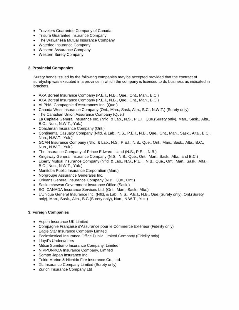
Travelers Guarantee Company of Canada Trisura Guarantee Insurance Company The Wawanesa Mutual Insurance Company Waterloo Insurance Company Western Assurance Company Western Surety Company
2. Provincial Companies
Surety bonds issued by the following companies may be accepted provided that the contract of suretyship was executed in a province in which the company is licensed to do business as indicated in brackets. AXA Boreal Insurance Company (P.E.I., N.B., Que., Ont., Man., B.C.) AXA Boreal Insurance Company (P.E.I., N.B., Que., Ont., Man., B.C.) ALPHA, Compagnie d'Assurances Inc. (Que.) Canada West Insurance Company (Ont., Man., Sask, Alta., B.C., N.W.T.) (Surety only) The Canadian Union Assurance Company (Que.) La Capitale General Insurance Inc. (Nfld. & Lab., N.S., P.E.I., Que.(Surety only), Man., Sask., Alta.,
B.C., Nun., N.W.T., Yuk.) Coachman Insurance Company (Ont.) Continental Casualty Company (Nfld. & Lab., N.S., P.E.I., N.B., Que., Ont., Man., Sask., Alta., B.C.,
Nun., N.W.T., Yuk.) GCAN Insurance Company (Nfld. & Lab., N.S., P.E.I., N.B., Que., Ont., Man., Sask., Alta., B.C.,
Nun., N.W.T., Yuk.) The Insurance Company of Prince Edward Island (N.S., P.E.I., N.B.) Kingsway General Insurance Company (N.S., N.B., Que., Ont., Man., Sask., Alta., and B.C.) Liberty Mutual Insurance Company (Nfld. & Lab., N.S., P.E.I., N.B., Que., Ont., Man., Sask., Alta.,
B.C., Nun., N.W.T., Yuk.) Manitoba Public Insurance Corporation (Man.) Norgroupe Assurance Générales Inc. Orleans General Insurance Company (N.B., Que., Ont.) Saskatchewan Government Insurance Office (Sask.) SGI CANADA Insurance Services Ltd. (Ont., Man., Sask., Alta.) L'Unique General Insurance Inc. (Nfld. & Lab., N.S., P.E.I., N.B., Que.(Surety only), Ont.(Surety
only), Man., Sask., Alta., B.C.(Surety only), Nun., N.W.T., Yuk.) 3. Foreign Companies
Aspen Insurance UK Limited Compagnie Française d'Assurance pour le Commerce Extérieur (Fidelity only) Eagle Star Insurance Company Limited Ecclesiastical Insurance Office Public Limited Company (Fidelity only) Lloyd's Underwriters Mitsui Sumitomo Insurance Company, Limited NIPPONKOA Insurance Company, Limited Sompo Japan Insurance Inc. Tokio Marine & Nichido Fire Insurance Co., Ltd. XL Insurance Company Limited (Surety only) Zurich Insurance Company Ltd
A r t i c l e s o f A g r e e m e n t
Standard Construction Contract – Articles of Agreement (23/01/2002) A1 Contract Documents A2 Date of Completion of Work and Description of Work A3 Contract Amount A4 Contractor’s Address A5 Unit Price Table
A r t i c l e s o f A g r e e m e n t
These Articles of Agreement made in duplicate this day of . Between Her Majesty the Queen, in right of Canada (referred to in the contract documents as “ Her Majesty”) represented by the National Research Council Canada (referred to in the contract documents as the “Council”) and (referred to in the contract documents as the “Contractor”) Witness that in consideration for the mutual promises and obligations contained in the contract, Her Majesty and the Contractor covenant and agree as follows: A1 Contract Documents (23/01/2002) 1.1 Subject to A1.4 and A1.5, the documents forming the contract between Her Majesty and the
Contractor, referred to herein as the contract documents, are 1.1.1 these Articles of Agreement, 1.1.2 the document attached hereto, marked “A” and entitled “Plans and Specifications”,
referred to herein as the Plans and Specifications, 1.1.3 the document attached hereto, marked “B” and entitled “Terms of Payment”, referred to
herein as the Terms of Payment,
1.1.4 the document attached hereto, marked “C” and entitled “General Conditions”, referred to herein as the General Conditions,
1.1.5 the document attached hereto, marked “D” and entitled “Labour Conditions”, referred to
herein as the Labour Conditions,
1.1.6 the document attached hereto, marked “E” and entitled “Insurance Conditions”, referred to herein as the Insurance Conditions,
1.1.7 the document attached hereto, marked “F” and entitled “Contract Security Conditions”,
referred to herein as the Contract Security Conditions, and
1.1.8 any amendment or variation of the contract documents that is made in accordance with the General Conditions.
1.1.9 the document entitled Fair Wage Schedules for Federal Construction Contracts referred
to herein as Fair Wage Schedules 1.1.10
A r t i c l e s o f A g r e e m e n t
The Council hereby designates of of the Government of Canada as the Engineer for the purposes of the contract, and for all purposes of or incidental to the contract, the Engineer’s address shall be deemed to be:
1.2 In the contract
1.3.1 “ Fixed Price Arrangement” means that part of the contract that prescribes a lump sum as payment for performance of the work to which it relates; and
1.3.2 “ Unit Price Arrangement” means that part of the contract that prescribes the product of a
price multiplied by a number of units of measurement of a class as payment for performance of the work to which it relates.
1.3 Any of the provisions of the contract that are expressly stipulated to be applicable only to a Unit
Price Arrangement are not applicable to any part of the work to which a Fixed Price Arrangement is applicable.
1.4 Any of the provisions of the contract that are expressly stipulated to be applicable only to a Fixed
Price Arrangement are not applicable to any part of the work to which a Unit Price Arrangement is applicable.
A2 Date of Completion of Work and Description of Work (23/01/2002) 2.1 The contractor shall, between the date of these Articles of Agreement and the ,
, in the careful and workmanlike manner, diligently perform and complete the following work:
which work is more particularly described in the Plans and Specifications.
A r t i c l e s o f A g r e e m e n t
A3 Contract Amount (23/01/2002) 3.1 Subject to any increase, decrease, deduction, reduction or set-off that may be made under the
Contract, Her Majesty shall pay the Contractor at the times and in the manner that is set out or referred to in the Terms of Payment 3.1.1 the sum of (GST/HST extra), in consideration for the performance of the
work or the part thereof that is subject to Fixed Price Arrangement, and 3.1.2 a sum that is equal to the aggregate of the products of the number of units of
Measurement of each class of labour, plant and material that is set out in a Final Certificate of Measurement referred to in GC44.8 multiplied in each case by the appropriate unit price that is set out in the Unit Price Table in consideration for the performance of the work or the part thereof that is subject to a Unit Price Arrangement.
3.2 For the information and guidance of the Contractor and the persons administering the contract on
behalf of Her Majesty, but not so as to constitute a warranty , representation or undertaking of any nature by either party, it is estimated that the total amount payable by Her Majesty to the Contractor for the part of the work to which a Unit Price Arrangement is applicable will be approximately $N/A
3.3 A3.1.1 is applicable only to a Fixed Price Arrangement. 3.4 A3.1.2 and A3.2 applicable only to a Unit Price Arrangement. A4 Contractor’s Address
(23/01/2002) 4.1 For all purposes of or incidental to the contract, the Contractor’s address shall be deemed to be:
A r t i c l e s o f A g r e e m e n t
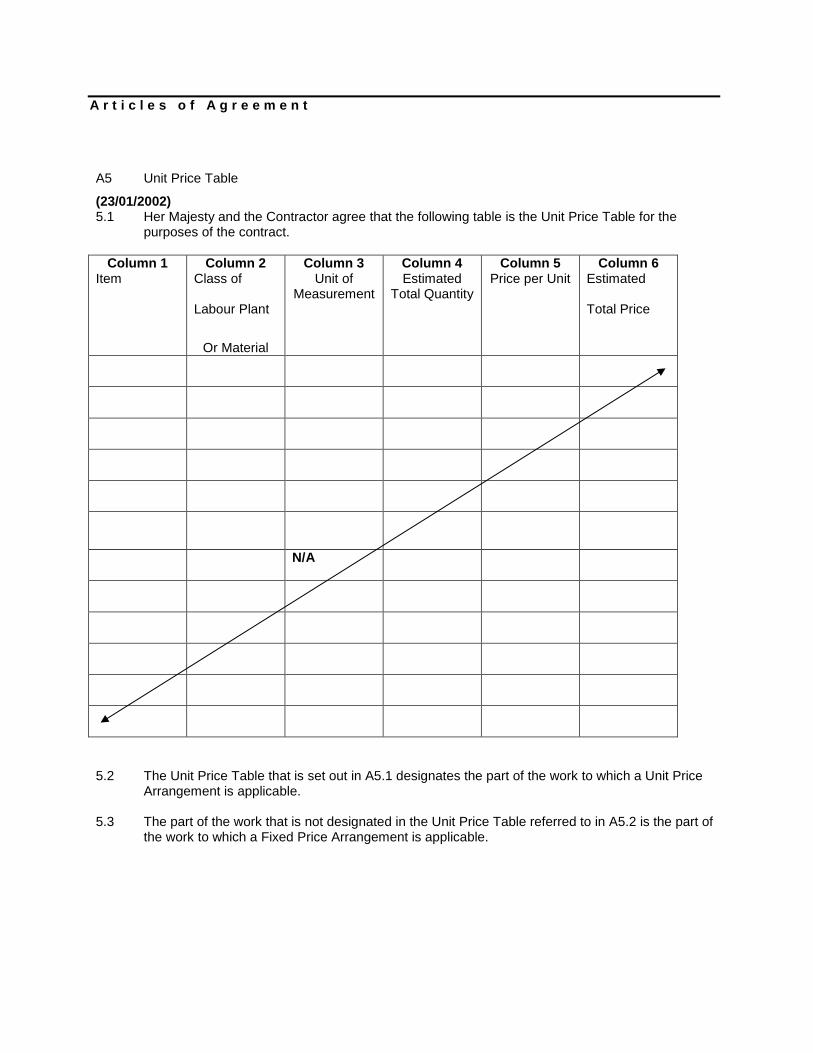
A5 Unit Price Table
(23/01/2002) 5.1 Her Majesty and the Contractor agree that the following table is the Unit Price Table for the
purposes of the contract.
Column 1 Item
Column 2 Class of
Labour Plant
Or Material
Column 3 Unit of
Measurement
Column 4 Estimated
Total Quantity
Column 5 Price per Unit
Column 6 Estimated
Total Price
N/A
5.2 The Unit Price Table that is set out in A5.1 designates the part of the work to which a Unit Price
Arrangement is applicable. 5.3 The part of the work that is not designated in the Unit Price Table referred to in A5.2 is the part of
the work to which a Fixed Price Arrangement is applicable.

A r t i c l e s o f A g r e e m e n t
Signed on behalf of Her Majesty by ___________________________________________________ as Senior Contracting Officer
and________________________________________________ as_________________________________________________ of the National Research Council Canada on the_______________________________ day of ______________________________ Signed, sealed and delivered by ___________________________________________________ as_______________________________________________and Position
by_________________________________________________ as_________________________________________________ Position Seal of on the______________________________________________ day of______________________________

National Research Council Section 00 01 10 Project No. TABLE OF CONTENTS U61 - 5553 Page 1
TABLE OF CONTENTS
Pages
Division 00 - PROCUREMENT AND CONTRACTING REQUIREMENTS
Section 00 01 10 - Table of Contents .................................................................................. 2
Section 00 10 00 - General Instructions ............................................................................ 13
Section 00 15 45 - General and Fire Safety Requirements ................................................. 6
Division 02 - EXISTING CONDITIONS
Section 02 07 50 - INTERIOR PROTECTION ......................................................................... 2
Division 05 - METALS
Section 05 05 00 - METAL FABRICATION ............................................................................ 3
Division 06 - WOOD AND PLASTICS
Section 06 10 00 - ROUGH CARPENTRY .............................................................................. 2
Division 08 - OPENINGS
Section 08 10 00 - STEEL DOORS AND FRAMES .................................................................. 3
Section 08 20 00 - INTERIOR WOOD DOORS ...................................................................... 2
Section 08 71 00 - FINISHED HARDWARE ........................................................................... 4
Division 09 - FINISHES
Section 09 11 10 - METAL STUDS SYSTEM .......................................................................... 2
Section 09 13 00 - SUSPENSION SYSTEM FOR ACOUSTICAL CEILINGS ............................... 3
Section 09 25 00 - GYPSUM BOARD .................................................................................... 3
Section 09 31 00 - CERAMIC TILE ........................................................................................ 3
Section 09 67 23 - RESINOUS HIGH BUILD EPOXY FLOOR COATING .................................. 8
Section 09 91 00 - Painting ............................................................................................... 13
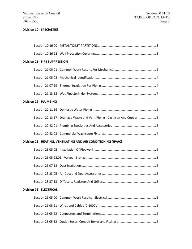
National Research Council Section 00 01 10 Project No. TABLE OF CONTENTS U61 - 5553 Page 2 Division 10 - SPECIALTIES
Section 10 16 00 - METAL TOILET PARTITIONS ................................................................... 3
Section 10 26 23 - Wall Protection Coverings ..................................................................... 3
Division 21 - FIRE SUPPRESSION
Section 21 05 01 - Common Work Results For Mechanical ................................................ 5
Section 21 05 02 - Mechanical Identification...................................................................... 4
Section 21 07 19 - Thermal Insulation For Piping ............................................................... 4
Section 21 13 13 - Wet Pipe Sprinkler Systems .................................................................. 7
Division 22 - PLUMBING
Section 22 11 16 - Domestic Water Piping ......................................................................... 5
Section 22 13 17 - Drainage Waste and Vent Piping - Cast Iron And Copper ..................... 3
Section 22 42 01 - Plumbing Specialties And Accessories .................................................. 5
Section 22 42 03 - Commercial Washroom Fixtures ........................................................... 4
Division 23 - HEATING, VENTILATING AND AIR CONDITIONING (HVAC)
Section 23 05 05 - Installation Of Pipework ........................................................................ 6
Section 23 05 23.01 - Valves - Bronze ................................................................................. 3
Section 23 07 13 - Duct Insulation ...................................................................................... 5
Section 23 33 05 - Air Duct and Duct Accessories .............................................................. 5
Section 23 37 13 - Diffusers, Registers And Grilles ............................................................. 3
Division 26 - ELECTRICAL
Section 26 05 00 - Common Work Results - Electrical ........................................................ 5
Section 26 05 21 - Wires and Cables (0-1000V) .................................................................. 2
Section 26 05 22 - Connectors and Terminations ............................................................... 2
Section 26 05 32 - Outlet Boxes, Conduit Boxes and Fittings ............................................. 2
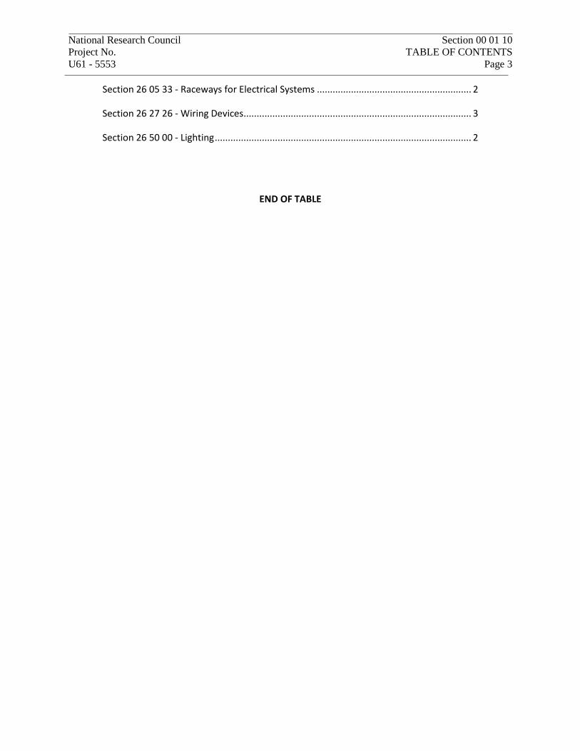
National Research Council Section 00 01 10 Project No. TABLE OF CONTENTS U61 - 5553 Page 3
Section 26 05 33 - Raceways for Electrical Systems ........................................................... 2
Section 26 27 26 - Wiring Devices ....................................................................................... 3
Section 26 50 00 - Lighting .................................................................................................. 2
END OF TABLE

NRC Section 00 10 00 Project No. GENERAL INSTRUCTIONS U61 - 5553 Page 1 of 13
1. SCOPE OF WORK
.1 Work under this contract covers the renovation of washroom 205 in the Council's Building U-61 of the National Research Council.
2. DRAWINGS
.1 The following drawings illustrate the work and form part of the contract documents:
.1 5553-A00
.2 5553-A01
.3 5553-A02
.4 5553-A03
.5 5553-A04
.6 5553-M01
.7 5553-E01
3. COMPLETION
.1 Complete all work by March 31, 2019.
4. GENERAL
.1 The word "provide" in this Specification means to supply and install.
.2 Provide items mentioned in either the drawings or the specification.
5. SPECIFIED ACCEPTABLE & ALTERNATIVE EQUIPMENT & MATERIALS
.1 Materials and equipment scheduled and/or specified on the drawings or in the specifications have been selected to establish a performance and quality standard. In most cases, acceptable manufacturers are stated for any material or equipment specified by manufacturer's name and model number. Contractors may base their tender price on materials and equipment supplied by any of the manufacturers' names as acceptable for the particular material or equipment.
.2 In addition to the manufacturers specified or named as acceptable, you may propose alternative manufacturers of materials or equipment to the Departmental Representative for acceptance. For a product to be considered as an alternative product substitute, make a written application to the Departmental Representative during the tender period, not later than ten (10) working days before tender closing.
.3 Certify in writing that the alternative meets all requirements of the specified material or equipment. In addition, it shall be understood that all costs required by or as a result of acceptance or proposed alternatives, will be borne by the contractor.
.4 Approval of alternatives will be signified by issue of an Addendum to the Tender Documents.
NRC Section 00 10 00 Project No. GENERAL INSTRUCTIONS U61 - 5553 Page 2 of 13
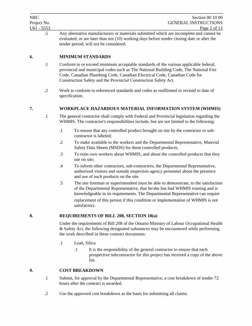
.5 Any alternative manufacturers or materials submitted which are incomplete and cannot be evaluated, or are later than ten (10) working days before tender closing date or after the tender period, will not be considered.
6. MINIMUM STANDARDS
.1 Conform to or exceed minimum acceptable standards of the various applicable federal, provincial and municipal codes such as The National Building Code, The National Fire Code, Canadian Plumbing Code, Canadian Electrical Code, Canadian Code for Construction Safety and the Provincial Construction Safety Act.
.2 Work to conform to referenced standards and codes as reaffirmed or revised to date of specification.
7. WORKPLACE HAZARDOUS MATERIAL INFORMATION SYSTEM (WHMIS)
.1 The general contractor shall comply with Federal and Provincial legislation regarding the WHMIS. The contractor's responsibilities include, but are not limited to the following:
.1 To ensure that any controlled product brought on site by the contractor or sub-contractor is labeled;
.2 To make available to the workers and the Departmental Representative, Material Safety Data Sheets (MSDS) for these controlled products;
.3 To train own workers about WHMIS, and about the controlled products that they use on site;
.4 To inform other contractors, sub-contractors, the Departmental Representative, authorized visitors and outside inspection agency personnel about the presence and use of such products on the site.
.5 The site foreman or superintendent must be able to demonstrate, to the satisfaction of the Departmental Representative, that he/she has had WHMIS training and is knowledgeable in its requirements. The Departmental Representative can require replacement of this person if this condition or implementation of WHMIS is not satisfactory.
8. REQUIREMENTS OF BILL 208, SECTION 18(a)
Under the requirements of Bill 208 of the Ontario Ministry of Labour Occupational Health & Safety Act, the following designated substances may be encountered while performing the work described in these contract documents:
.1 Lead, Silica .1 It is the responsibility of the general contractor to ensure that each
prospective subcontractor for this project has received a copy of the above list.
9. COST BREAKDOWN
.1 Submit, for approval by the Departmental Representative, a cost breakdown of tender 72 hours after the contract is awarded.
.2 Use the approved cost breakdown as the basis for submitting all claims.
NRC Section 00 10 00 Project No. GENERAL INSTRUCTIONS U61 - 5553 Page 3 of 13
.3 Request Departmental Representative's verbal approval to amount of claim prior to preparing and submitting the claim in its final form.
10. SUB-TRADES
.1 Submit no later than 72 hours after tender closing, a complete list of sub trades for the Departmental Representative's review.
11. PERSONNEL SECURITY AND IDENTIFICATION
.1 All persons employed by the contractor, or by any subcontractor and present on the site must be security cleared in accordance with the requirements of the Section entitled Special Instructions to Tenderers.
.2 All such persons must wear and keep visible identification badges as issued by the Security Office of NRC.
12. WORKING HOURS AND SECURITY
.1 Normal working hours on the NRC property are from 8:00 a.m. until 4:30 p.m., Monday to Friday inclusive, except statutory holidays.
.2 At all other times, special written passes are required for access to the building site.
.3 Before scheduling any work outside normal working hours, obtain permission from the Departmental Representative to perform the specific tasks.
.4 An escort may be required whenever working outside normal hours. Contractor to bear the associated costs.
13. SCHEDULE
.1 The contractor shall prepare a detailed schedule, fixing the date for commencement and completion of the various parts of the work and update the said schedule. Such schedule shall be made available to the Departmental Representative not later than two weeks after the award of the contract and prior to commencement of any work on site.
.2 Notify Departmental Representative in writing of any changes in the schedule.
.3 7 days before the scheduled completion date, arrange to do an interim inspection with the Departmental Representative.
14. PROJECT MEETINGS
.1 Hold regular project meetings at times and locations approved by the Departmental Representative.
.2 Notify all parties concerned of meetings to ensure proper coordination of work.
.3 Departmental Representative will set times for project meetings and assume responsibility for recording and distributing minutes.

NRC Section 00 10 00 Project No. GENERAL INSTRUCTIONS U61 - 5553 Page 4 of 13 15. SHOP DRAWINGS
.1 Submit to Departmental Representative for review, shop drawings, product data and samples specified within 2 weeks after contract award.
.2 Submit to Departmental Representative for review a complete list of all shop drawings, product data and samples specified and written confirmation of corresponding delivery dates within one (1) week after shop drawings, product data and samples approval date. This list shall be updated on a weekly basis and any changes to the list shall be immediately notified in writing to the Departmental Representative.
.3 Review shop drawings, data sheets and samples prior to submission.
.4 Submit electronic copy of all shop drawings and product data and samples for review, unless otherwise specified.
.5 Review of shop drawings and product data by the Departmental Representative does not relieve the contractor of the responsibility for errors and omissions and for the conformity with contract documents.
16. SAMPLES AND MOCK-UPS
.1 Submit samples in sizes and quantities as specified.
.2 Where colour, pattern or texture is criterion, submit full range of samples.
.3 Construct field samples and mock-ups at locations acceptable to Departmental Representative.
.4 Reviewed samples or mock-ups will become standards of workmanship and material against which installed work will be checked on the project.
17. MATERIALS AND WORKMANSHIP
.1 Install only new materials on this project unless specifically noted otherwise.
.2 Only first class workmanship will be accepted, not only with regard to safety, efficiency, durability, but also with regard to neatness of detail and performance.
18. WORK & MATERIALS SUPPLIED BY OWNER
.1 Work and materials not included in this contract are described on drawings and in this specification.
.2 Deliver to a storage place, as directed by the Departmental Representative, all materials returned to the Owner.
.3 Unless otherwise specified, accept owner-supplied materials at their storage location and provide all transportation as required.
.4 General Contractor's duties:
NRC Section 00 10 00 Project No. GENERAL INSTRUCTIONS U61 - 5553 Page 5 of 13
.1 Unload at site.
.2 Promptly inspect products and report damaged or defective items.
.3 Give written notification to the Departmental Representative for items accepted in good order.
.4 Handle at site, including uncrating and storage.
.5 Repair or replace items damaged on site.
.6 Install, connect finished products as specified.
19. SITE ACCESS
.1 Make prior arrangements with the Departmental Representative before starting work or moving materials and equipment on site.
.2 Obtain approval of Departmental Representative for regular means of access during the construction period.
.3 Obtain approval of Departmental Representative before temporarily suspending operations on site; before returning to the site and before leaving the site at the end of the job.
.4 Provide and maintain access to site.
.5 Build and maintain temporary roads and provide snow removal during period of work.
.6 Provide snow clearing and removal as required during the contract period.
.7 Make good any damage and clean up dirt, debris, etc., resulting from contractor's use of existing roads.
20. USE OF SITE
.1 Restrict operations on the site to the areas approved by the Departmental Representative
.2 Locate all temporary structures, equipment, storage, etc., to the designated areas.
.3 Restrict parking to the designated areas.
21. ACCEPTANCE OF SITE
.1 Inspect the site before commencing work, review any unexpected conditions with the Departmental Representative.
.2 Commencement of work will imply acceptance of existing conditions.
22. SITE OFFICE & TELEPHONE
.1 Contractor to erect a temporary site office at his own expense.
.2 Install and maintain a telephone, if necessary.
.3 Use of NRC phones is not permitted unless in the case of an emergency.
NRC Section 00 10 00 Project No. GENERAL INSTRUCTIONS U61 - 5553 Page 6 of 13 23. SANITARY FACILITIES
.1 Obtain permission from the Departmental Representative to use the existing washroom facilities in the building.
24. TEMPORARY SERVICES
.1 A source of temporary power will be made available in the area. Bear all costs to make connections to the power source and perform distribution on site.
.2 Provide all load centres, breakers, conduit, wiring, disconnects, extension cords, transformers, as required from the source of power.
.3 Power is to be used only for power tools, lighting, controls, motors, and not for space heating.
.4 A source of temporary water will be made available if required.
.5 Bear all costs associated with distributing the water to the required locations.
.6 Comply with NRC requirements when connecting to existing systems in accordance with the articles entitled "Co-operation" and "Service Interruptions" of this section.
25. DOCUMENTS REQUIRED AT WORK SITE
.1 The contractor shall keep on the site, one (1) up-to-date copy of all contract documents, including specifications, drawings, addenda, shop drawings, change notices, schedule and any reports or bulletins pertaining to the work, in good order, available to the Departmental Representative and to his / her representatives at all times.
.2 At least one (1) copy of specifications and drawings shall be marked by the contractor to show all work "As Built" and shall be provided to the Departmental Representative with the Application for Payment and for the Final Certificate of Completion.
26. CO-OPERATION
.1 Co-operate with NRC staff in order to keep disruption of normal research work to an absolute minimum.
.2 Work out in advance, a schedule for all work which might disrupt normal work in the building.
.3 Have schedule approved by the Departmental Representative.
.4 Notify the Departmental Representative in writing, 72 hours prior to any intended interruption of facilities, areas, corridors, mechanical or electrical services and obtain requisite permission.
27. PROTECTION AND WARNING NOTICES
.1 Provide all materials required to protect existing equipment.
NRC Section 00 10 00 Project No. GENERAL INSTRUCTIONS U61 - 5553 Page 7 of 13
.2 Erect dust barriers to prevent dust and debris from spreading through the building.
.3 Place dust protection in the form of cover sheets over equipment and furniture and tape these sheets to floors, to ensure no dust infiltration.
.4 Repair or replace any and all damage to Owner's property caused during construction, at no cost to the Owner and to the satisfaction of the Departmental Representative.
.5 Protect the buildings, roads, lawns, services, etc. from damage which might occur as a result of this work.
.6 Plan and co-ordinate the work to protect the buildings from the leakage of water, dust, etc.
.7 Ensure that all doors, windows, etc., that could allow transfer of dust, noise, fumes, etc., to other areas of the building are kept closed.
.8 Be responsible for security of all areas affected by the work under the Contract until acceptance by NRC. Take all necessary precautions to prevent entry to the work area by unauthorized persons and guard against theft, fire and damage by any cause. Secure working area at the end of each day’s work and be responsible for same.
.9 Provide and maintain adequate safety barricades around the work sites to protect NRC personnel and the public from injury during the construction.
.10 Post warnings, in all instances where possible injury could occur such as Work Overhead, Hard Hat Areas, etc. or as required by the Departmental Representative.
.11 Provide temporary protective enclosures over building entrances and exits to protect pedestrians. All enclosures to be structurally sound against weather and falling debris.
28. BILINGUALISM
.1 Ensure that all signs, notices, etc. are posted in both official languages.
.2 Ensure that all identification of services called for by under this contract are bilingual.
29. LAYOUT OF WORK
.1 Location of equipment, fixtures, outlets and openings indicated on drawings or specified are to be considered as approximate.
.2 Locate equipment, fixtures and distribution systems to provide minimum interference and maximum usable space and in accordance with the manufacturer’s recommendations for safety, access and maintenance.
.3 Employ competent person to lay out work in accordance with the contract documents.
30. DISCREPANCIES & INTERFERENCES
.1 Prior to the start of the work, examine drawings and specifications. Report at once to the Departmental Representative, any defects, discrepancies, omissions or interferences affecting the work.
NRC Section 00 10 00 Project No. GENERAL INSTRUCTIONS U61 - 5553 Page 8 of 13
.2 Contractor to immediately inform the Departmental Representative in writing, of any discrepancies between the plans and the physical conditions so the Departmental Representative may promptly verify same.
.3 Any work done after such a discovery, until authorized, is at the contractor's risk.
.4 Where minor interferences as determined by the Departmental Representative are encountered on the job and they have not been pointed out on the original tender or on the plans and specifications, provide offsets, bends or reroute the services to suit job conditions at no extra cost.
.5 Arrange all work so as not to interfere in any way with other work being carried out.
31. MANUFACTURER'S INSTRUCTIONS
.1 Unless otherwise specified, comply with manufacturer's latest printed instructions for materials and installation methods.
.2 Notify the Departmental Representative in writing of any conflict between these specifications and manufacturer's instruction. Departmental Representative will designate which document is to be followed.
32. TEMPORARY HEATING AND VENTILATING
.1 Bear the costs of temporary heat and ventilation during construction including costs of installation, fuel, operation, maintenance, and removal of equipment.
.2 Use of direct-fired heaters discharging waste products into the work areas will not be permitted unless prior approval is given by the Departmental Representative.
.3 Furnish and install temporary heat and ventilation in enclosed areas as required to:
.1 Facilitate progress of work.
.2 Protect work and products against dampness and cold.
.3 Reduce moisture condensation on surfaces to an acceptable level.
.4 Provide ambient temperature and humidity levels for storage, installation and curing of materials.
.5 Provide adequate ventilation to meet health regulations for a safe working environment.
.4 Maintain minimum temperature of 10 oC (50 oF) or higher where specified as soon as finishing work is commenced and maintain until acceptance by the Departmental Representative. Maintain ambient temperature and humidity levels as required for comfort of NRC personnel.
.5 Prevent hazardous or unhealthy accumulations of dust, fumes, mists, vapours or gases in areas occupied during construction including also, storage areas and sanitary facilities.
.1 Dispose of exhaust materials in a manner that will not result in a harmful or unhealthy exposure to persons.
NRC Section 00 10 00 Project No. GENERAL INSTRUCTIONS U61 - 5553 Page 9 of 13
.6 Maintain strict supervision of operation of temporary heating and ventilating equipment.
.1 Enforce conformance with applicable codes and standards.
.2 Comply with instructions of the Departmental Representative including provision of full-time watchman services when directed.
.3 Enforce safe practices.
.4 Vent direct-fired combustion units to outside.
.7 Submit tenders assuming existing or new equipment and systems will not be used for temporary heating and ventilating.
.8 After award of contract, Departmental Representative may permit use of the permanent system providing agreement can be reached on:
.1 Conditions of use, special equipment, protection, maintenance, and replacement of filters.
.2 Methods of ensuring that heating medium will not be wasted and in the case of steam, agreement on what is to be done with the condensate.
.3 Saving on contract price.
.4 Provisions relating to guarantees on equipment.
33. CONNECTIONS TO AND INTERRUPTIONS TO EXISTING SERVICES
.1 Where work involves breaking into or connecting to existing services, carry out work at times and in the manner agreed to by the Departmental Representative and by authorities having jurisdiction, with minimum disruption to NRC Personnel and vehicular traffic and minimum service interruption. Do not operate any NRC equipment or plant.
.2 Before commencing work, establish location and extent of service lines in area of work and notify Departmental Representative of findings.
.3 Submit a schedule to and obtain approval from the Departmental Representative for any shut-down or closure of active service or facility; allow minimum 72 hours notice. Adhere to approved schedule and provide notice to the Departmental Representative.
.4 Where unknown services are encountered, immediately advise Departmental Representative and confirm findings in writing.
.5 Provide detours, bridges, alternate feeds, etc., as required to minimize disruptions.
.6 Protect existing services as required and immediately make repairs if damage occurs.
.7 Remove any abandoned service lines as indicated on the contract documents and as approved by the Departmental Representative; cap or otherwise seal lines at cut-off points. Record and provide a copy to the Departmental Representative of locations of maintained, re-routed and abandoned service lines.
34. CUTTING AND PATCHING
.1 Cut existing surfaces as required to accommodate new work.
NRC Section 00 10 00 Project No. GENERAL INSTRUCTIONS U61 - 5553 Page 10 of 13
.2 Remove all items as shown or specified.
.3 Patch and make good with identical materials, the surfaces that have been disturbed, cut or damaged, to the satisfaction of the Departmental Representative.
.4 Where new pipes pass through existing construction, core drill an opening. Size openings to leave 12mm (1/2") clearance around the pipes or pipe insulation. Do not drill or cut any surface without the approval of the Departmental Representative.
.5 Obtain written approval of the Departmental Representative before cutting openings through existing or new structural members.
.6 Seal all openings where cables, conduits or pipes pass through walls with an acoustic sealant conforming to CAN/CGSB-19.21-M87.
.7 Where cables, conduits and pipes pass through fire rated walls and floors, pack space between with compressed glass fibres and seal with fire stop caulking in accordance with CAN/CGSB-19.13-M87 AND NBC 3.1.7.
35. FASTENING DEVICES
.1 Do not use explosive actuated tools, without first obtaining permission from the Departmental Representative.
.2 Comply with the requirements of CSA A-166 (Safety Code for Explosive Actuated Tools).
.3 Do not use any kind of impact or percussion tool without first obtaining permission from the Departmental Representative.
36. OVERLOADING
.1 Ensure that no part of the building or work is subjected to a load which will endanger safety or cause permanent deformation or structural damage.
37. DRAINAGE
.1 Provide temporary drainage and pumping as required to keep excavations and site free of water.
38. ENCLOSURE OF STRUCTURES
.1 Construct and maintain all temporary enclosures as required to protect foundations, sub-soil, concrete, masonry, etc., from frost penetration or damage.
.2 Maintain in place until all chances of damage are over and proper curing has taken place.
.3 Provide temporary weather tight enclosures for exterior openings until permanent sash and glazing and exterior doors are installed.
NRC Section 00 10 00 Project No. GENERAL INSTRUCTIONS U61 - 5553 Page 11 of 13
.4 Provide lockable enclosures as required to maintain the security of NRC facilities and be responsible for the same.
.5 Provide keys to NRC security personnel when required.
.6 Lay out the work carefully and accurately and verify all dimensions and be responsible for them. Locate and preserve general reference points.
.7 Throughout the course of construction, keep continuously acquainted with field conditions, and the work being developed by all trades involved in the project. Maintain an awareness of responsibility to avoid space conflict with other trades.
.8 Conceal all services, piping, wiring, ductwork, etc., in floors, walls or ceilings except where indicated otherwise.
39. STORAGE
.1 Provide storage as required to protect all tools, materials, etc., from damage or theft and be responsible for the same.
.2 Do not store flammable or explosive materials on site without the authorization of the Departmental Representative.
40. GENERAL REVIEW
.1 Periodic review of the contractor's work by the Departmental Representative does not relieve the contractor of the responsibility of making the work in accordance with contract documents. Contractor shall carry out his own quality control to ensure that the construction work is in accordance with contract documents.
.2 Inform the Departmental Representative of any impediments to the installation and obtain his / her approval for actual location.
41. INSPECTION OF BURIED OR CONCEALED SERVICES
.1 Prior to concealing any services that are installed, ensure that all inspection bodies concerned, including NRC, have inspected the work and have witnessed all tests. Failure to do so may result in exposing the services again at the contractor's expense.
42. TESTING
.1 On completion, or as required by local authority inspectors and/or Departmental Representative during progress of work and before any services are covered up and flushing is complete, test all installations in the presence of the Departmental Representative.
.2 Obtain and hand to the Departmental Representative all acceptance certificates or test reports from authority having jurisdiction. The project will be considered incomplete without the same.

NRC Section 00 10 00 Project No. GENERAL INSTRUCTIONS U61 - 5553 Page 12 of 13 43. PARTIAL OCCUPANCY
.1 NRC may request partial occupancy of the facility if the contract extends beyond the expected completion date.
.2 Do not restrict access to the building, routes, and services.
.3 Do not encumber the site with materials or equipment.
44. DISPOSAL OF WASTES
.1 Dispose of waste materials including volatiles, safely off NRC property. Refer to the section entitled "General and Fire Safety Requirements” included as part of this specification.
45. CLEAN-UP DURING CONSTRUCTION
.1 On a daily basis, maintain project site and adjacent area of campus including roofs, free from debris and waste materials.
.2 Provide on-site dump containers for collection of waste materials and rubbish.
46. FINAL CLEAN-UP
.1 Upon completion do a final clean-up to the satisfaction of the Departmental Representative.
.2 Clean all new surfaces, lights, existing surfaces affected by this work, replace filters, etc.
.3 Clean all resilient flooring and prepare to receive protective finish. Protective finish applied by NRC
47. WARRANTY AND RECTIFICATION OF DEFECTS IN WORK
.1 Refer to General Conditions "C", section GC32.
.2 Ensure that all manufacturers' guarantees and warranties are issued in the name of the General Contractor and the National Research Council.
48. MAINTENANCE MANUALS
.1 Provide two (2) bilingual copies of maintenance manuals or two English and two French maintenance manuals and one electronic copy of same immediately upon completion of the work and prior to release of holdbacks.
.2 Manuals to be neatly bound in hard cover loose leaf binders.
.3 Manuals to include operating and maintenance instructions, all guarantees and warranties, shop drawings, technical data, etc., for the material and apparatus supplied under this contract.

NRC Section 00 10 00 Project No. GENERAL INSTRUCTIONS U61 - 5553 Page 13 of 13
END OF SECTION
NRC Section 00 15 45 Project No. GENERAL AND FIRE SAFETY REQUIREMENTS U61 - 5553 Page 1 of 6
1. GENERAL CONSTRUCTION SAFETY REQUIREMENTS
.1 The Contractor shall take all necessary steps to protect personnel (workers, visitors, general public, etc.) and property from any harm during the course of the contract.
.2 The Contractor shall be solely responsible for the construction safety of both its employees and those of its sub-contractors at the work site, and for initiating, maintaining and supervising safety precautions, programs and procedures in connection with the performance of the work.
.3 The Contractor shall comply with all Federal, Provincial and Municipal safety codes and regulations and the Occupational Health and Safety Act and the Workplace Safety and Insurance Board. In the event of any conflict between any provisions in legislation or codes, the most stringent provisions shall apply.
.4 Periodic review of the contractor’s work by the Departmental Representative, using the criteria of the contract documents, does not relieve the contractor of his safety responsibilities in carrying out the work in accordance with the contract documents. The contractor shall consult with the Departmental Representative to ensure that this responsibility is carried out.
.5 The Contractor shall ensure that only competent personnel are permitted to work on site. Throughout the term of the contract, any person will be removed from the site who is not observing or complying with the safety requirements.
.6 All equipment shall be in safe operating condition and appropriate to the task.
.7 Following a project and site hazard assessment, the Contractor shall develop a Site Specific Safety Plan based on the following minimum requirements:
.1 Provide a safety board mounted in a visible location on the project site, with
the following information included thereon: .1 Notice of Project .2 Site specific Safety Policy .3 Copy of Ontario Health and Safety Act .4 Building Schematic showing emergency exits .5 Building emergency procedures .6 Contact list for NRC, Contractor and all involved sub-contractors .7 Any related MSDS sheets .8 NRC Emergency phone number
.8 The Contractor shall provide competent personnel to implement its safety program and those of any Health and Safety Act legislation applicable at this project location, and to ensure they are being complied with.
.9 The Contractor shall provide safety orientation to all its employees as well as those of any subcontractors under its jurisdiction.
NRC Section 00 15 45 Project No. GENERAL AND FIRE SAFETY REQUIREMENTS U61 - 5553 Page 2 of 6
.10 The Departmental Representative will monitor to ensure that safety requirements are met and that safety records are properly kept and maintained. Continued disregard for safety standards can cause the contract to be cancelled and the Contractor or sub-contractors removed from the site.
.11 The Contractor will report to the Departmental Representative and jurisdictional
authorities, any accident or incident involving Contractor or NRC personnel or the public and/or property arising from the Contractor’s execution of the work.
.12 If entry to a laboratory is required as part of the work of the Contractor, a safety orientation shall be provided to all his employees as well as those of any subcontractors regarding lab safety requirements and procedures, as provided by the Researcher or the Departmental Representative.
2. FIRE SAFETY REQUIREMENTS
.1 Authorities 1. The Fire Commissioner of Canada (FC) is the authority for fire safety at
NRC. 2. For the purpose of this document, "Departmental Representative" will be
deemed as the NRC person in charge of the project and who will enforce these Fire Safety Requirements.
3. Comply with the following standards as published by the Office of the Fire Commissioner of Canada:
a. Standard No. 301 - June 1982 "Standard for Construction Operations";
b. Standard No. 302 - June 1982 "Standard for Welding and Cutting".
.2 Smoking .1 Smoking is prohibited inside all NRC buildings, as well as roof areas. .2 Obey all "NO SMOKING" signs on NRC premises.
.3 Hot Work .1 Prior to commencement of any "Hot Work" involving welding, soldering,
burning, heating, use of torches or salamanders or any open flame, obtain a Hot Work Permit from the Departmental Representative.
.2 Prior to commencement of "Hot Work", review the area of hot work with the Departmental Representative to determine the level of fire safety precautions to be taken.
.4 Reporting Fires .1 Know the exact location of the nearest Fire Alarm Pull Station and
telephone, including the emergency phone number. .2 REPORT immediately, all fire incidents as follows: .1 Activate nearest fire alarm pull station and;

NRC Section 00 15 45 Project No. GENERAL AND FIRE SAFETY REQUIREMENTS U61 - 5553 Page 3 of 6
.2 Telephone the following emergency phone number as appropriate: FROM AN NRC PHONE 333 FROM ANY OTHER PHONE (613) 993-2411
4. When reporting a fire by phone, give the location of fire, building number
and be prepared to verify location. 5. The person activating fire alarm pull station must remain at a safe
distance from the scene of the fire but readily available to provide information and direction to the Fire Department personnel.
.5 Interior and Exterior Fire protection & Alarm Systems .1 DO NOT OBSTRUCT OR SHUT OFF FIRE PROTECTION EQUIPMENT OR
SYSTEMS, INCLUDING BUT NOT LIMITED TO FIRE ALARM SYSTEMS, SMOKE/HEAT DETECTORS, SPRINKLER SYSTEM, PULL STATIONS, EMERGENCY CALL BUTTONS AND PA SYSTEMS, WITHOUT AUTHORIZATION FROM THE DEPARTMENTAL REPRESENTATIVE.
.2 WHEN ANY FIRE PROTECTION EQUIPMENT IS TEMPORARILY SHUT DOWN, ALTERNATIVE MEASURES AS PRESCRIBED BY THE DEPARTMENTAL REPRESENTATIVE SHALL BE TAKEN TO ENSURE THAT FIRE PROTECTION IS MAINTAINED.
.3 DO NOT LEAVE FIRE PROTECTION OR ALARM SYSTEMS INACTIVE AT THE END OF A WORKING DAY WITHOUT NOTIFICATION AND AUTHORISATION FROM THE DEPARTMENTAL REPRESENTATIVE. THE DEPARTMENTAL REPRESENTATIVE WILL ADVISE THE (FPO) OF THE DETAILS OF ANY SUCH EVENT.
.4 DO NOT USE FIRE HYDRANTS, STANDPIPES AND HOSE SYSTEMS FOR OTHER THAN FIRE FIGHTING PURPOSES UNLESS AUTHORISED BY DEPARTMENTAL REPRESENTATIVE.
.6 Fire Extinguishers .1 Provide a minimum of 1-20 lb. ABC Dry Chemical Fire Extinguisher at each hot
work or open flame location.
.2 Provide fire extinguishers for hot asphalt and roofing operations as follows:
a. Kettle area - 1-20 lb. ABC Dry Chemical; b. Roof - 1-20 lb. ABC Dry Chemical at each open flame location.
.3 Provide fire extinguishers equipped as below:
c. Pinned and sealed; d. With a pressure gauge; e. With an extinguisher tag signed by a fire extinguisher servicing
company.
NRC Section 00 15 45 Project No. GENERAL AND FIRE SAFETY REQUIREMENTS U61 - 5553 Page 4 of 6
.4 Carbon Dioxide (C02) extinguishers will not be considered as substitutes for the above.
.7 Roofing Operations .1 Kettles:
.1 Arrange for the location of asphalt kettles and material storage with the Departmental Representative before moving on site. Do not locate kettles on any roof or structure and keep them at least 10m (30 feet) away from a building.
.2 Equip kettles with 2 thermometers or gauges in good working order; a hand held and a kettle-mounted model.
.3 Do not operate kettles at temperatures in excess of 232oC (450 oF).
.4 Maintain continuous supervision while kettles are in operation and provide metal covers for the kettles to smother any flames in case of fire. Provide fire extinguishers as required in article 2.6.
.5 Demonstrate container capacities to Departmental Representative prior to start of work.
.6 Store materials a minimum of 6m (20 feet) from the kettle.
.2 Mops:
.1 Use only glass fibre roofing mops.
.2 Remove used mops from the roof site at the end of each working day. .3 Torch Applied Systems:
.1 DO NOT USE TORCHES NEXT TO WALLS.
.2 DO NOT TORCH MEMBRANES TO EXPOSED WOOD OR CAVITY
.3 Provide a Fire Watch as required by article 2.9 of this section. .4 Store all combustible roofing materials at least 3m (10 feet) away from any
structure. .5 Keep compressed gas cylinders a minimum of 6m (20 feet) away from the kettle,
protected from mechanical damage and secured in an upright position.
.8 Welding / Grinding Operations
.1 Contractor to provide fire blankets, portable fume extraction devices, screens or similar equipment to prevent exposure to welding flash, or sparks from grinding.
.9 Fire Watch
.1 Provide a fire watch for a minimum of one hour after the termination of any hot work operation.
.2 For temporary heating, refer to General Instructions Section 00 010 00.
.3 Equip fire watch personnel with fire extinguishers as required by article 2.6.
NRC Section 00 15 45 Project No. GENERAL AND FIRE SAFETY REQUIREMENTS U61 - 5553 Page 5 of 6
.10 Obstruction of access/egress routes-roadways, halls, doors, or elevators
.1 Advise the Departmental Representative in advance of any work that would impede the response of Fire Department personnel and their apparatus. This includes violation of minimum overhead clearance, erection of barricades and the digging of trenches.
.2 Building exit routes must not be obstructed in any way without special permission from the Departmental Representative, who will ensure that adequate alternative routes are maintained.
.3 The Departmental Representative will advise the FPO of any obstruction that may warrant advanced planning and communication to ensure the safety of building occupants and the effectiveness of the Fire Department.
.11 Rubbish and Waste Materials
.1 Keep rubbish and waste materials to a minimum and a minimum distance of 6m (20 feet) from any kettle or torches.
.2 Do not burn rubbish on site.
.3 Rubbish Containers
.1 Consult with the Departmental Representative to determine an acceptable safe location for any containers and the arrangement of chutes etc. prior to bringing the containers on site.
.2 Do not overfill the containers and keep area around the perimeter free and clear of any debris.
.4 Storage
.1 Exercise extreme care when storing combustible waste materials in work areas. Ensure maximum possible cleanliness, ventilation and that all safety standards are adhered to when storing any combustible materials.
.2 Deposit greasy or oily rags or materials subject to spontaneous combustion in CSA or ULC approved receptacles and remove at the end of the work day or shift, or as directed.
.12 Flammable Liquids
.1 The handling, storage and use of flammable liquids is governed by the current National Fire Code of Canada.
.2 Flammable Liquids such as gasoline, kerosene and naphtha may be kept for ready use in quantities not exceeding 45 litres (10 imp gal), provided they are stored in approved safety cans bearing the ULC seal of approval and kept away from buildings, stockpiled combustible materials etc. Storage of quantities of flammable liquids exceeding 45 litres (10 imp gal) for work purposes, require the permission of the Departmental Representative.
NRC Section 00 15 45 Project No. GENERAL AND FIRE SAFETY REQUIREMENTS U61 - 5553 Page 6 of 6
.3 Flammable liquids are not to be left on any roof areas after normal working hours.
.4 Transfer of flammable liquids is prohibited within buildings.
.5 Do not transfer flammable liquids in the vicinity of open flames or any type of heat producing device.
.6 Do not use flammable liquids having a flash point below 38 oC (100 oF) such as naphtha or gasoline as solvents or cleaning agents.
.7 Store flammable waste liquids for disposal in approved container located in a safe, ventilated area. Waste flammable liquids are to be removed from the site on a regular basis.
.8 Where flammable liquids, such as lacquers or urethane are used, ensure proper ventilation and eliminate all sources of ignition. Inform the Departmental Representative prior to, and at the cessation of such work.
3. Questions and/or clarifications
.1 Direct any questions or clarification on Fire or General Safety, in addition to the above requirements, to the Departmental Representative.
END OF SECTION
NRC INTERIOR PROTECTION Section 02 07 50 Project No. Page 1 of 2 U61-5553 NOV 2018
Part 1 GENERAL
1.1 Scope of Work
.1 Provide interior protection prior to demolition work.
.2 Protection to be constructed in such a fashion so as to afford security, dust and weather resistance.
.3 [Barriers to be constructed continuously on the interior perimeter within corridor rm 201. Ensure walkthrough is maintain in hallway.
Part 2 PRODUCTS
2.1 Materials
.1 1/2" x 4'-0" x 8'-0" wood sheathing.
.2 3-5/8" metal studding.
.3 3-1/2" spruce wood, construction grade studding.
.4 6 mil. polyethylene.
.5 Vinyl reinforced tarps.
2.2 Erection
.1 Construct a solid barrier in all locations where window, A/C, or roof modifications are to occur.
.2 Construct barriers full height and line with polyethylene to ensure dust and water tightness.
.3 Have a mock-up assembly approved by the Departmental Representative prior to proceeding with the erection.
.4 Ensure that the barrier does not interfere with the building's overhead crane or the work operations of the building occupants.
NRC INTERIOR PROTECTION Section 02 07 50 Project No. Page 2 of 2 U61-5553 NOV 2018
Part 3 SECONDARY PROTECTION
3.1 Dust Walls
.1 As the work progresses and after all structural work and wall framing have been completed, remove the temporary interior protection walls and construct a 6 mill polyethylene dust wall in its place, to allow finish work to proceed.
.2 Install wood sheathing in the new window openings temporarily until the new glazing units have been received.
.3 Inspect walls on a regular basis to ensure integrity of the assembly and to avoid dust and water infiltration to the interior of the building.
.4 Remove interior protections only when approved by the Departmental Representative.
Part 4 REINSTATEMENTS
4.1 Finishes
.1 Reinstate the interior finishes affected by this work to the satisfaction of the Departmental Representative.
END OF SECTION
NRC METAL FABRICATON Section 05 50 00 Project No. Page 1 of 3 U61-5553 NOV 2018
Part 1 GENERAL
1.1 Reference Standard
.1 Do welding work in accordance with CSA W59-1982 unless specified otherwise.
1.2 Shop Drawings
.1 Submit to the Engineer for approval five (5) copies of erection drawings together with shop drawings of details, special connections, reinforced openings and other non-standard items. Shop drawings to bear the stamp of a registered professional Engineer.
.2 Indicate shop and erection details including cuts, copes, connections, holes, bolts and welds. Indicate welds by welding symbols defined in [CSA W59-M1984].
.3 Indicate materials, core thicknesses, finishes, connections, joints, method of anchorage, number of anchors, supports, reinforcement, details, and accessories.
Part 2 PRODUCTS
2.1 2.1 Materials
.1 Steel sections and plates: to CAN3-G40.21- M81, Grade 300W: Hollow steel sections to CAN3-G40.21-M81, Grade 350W.
.2 Steel pipe: to ASTM A53-82 extra strong finish.
.3 Welding materials: to CSA W59-1982.
.4 Bolts and anchor bolts: to ASTM A307-82a.
.5 Galvanizing: hot dipped galvanizing with zinc coating 600g/m² (0.12 lb/ft²) to CSA G164-M1981.
.6 Shop coat primer: to CGSB 1-GP-40M.
.7 Zinc primer: zinc rich, ready mix to CGSB 1-GP-181M.
.8 Grout: non-shrink, non-metallic, flowable, 24h, MPa 15 (2175 lbs/in2), pull-out strength 7.9 MPa (1145 lbs/in2).
NRC METAL FABRICATON Section 05 50 00 Project No. Page 2 of 3 U61-5553 NOV 2018
2.2 Fabrication
.1 Build work square, true, straight and accurate to required size, with joints closely fitted and properly secured.
.2 Fabricate items from steel unless otherwise noted.
.3 Use self-tapping shake-proof, flat, round, oval headed screws on items requiring assembly by screws or as indicated.
.4 Where possible, fit and shop assemble work, ready for erection.
.5 .Ensure exposed welds are continuous for length of each joint. File or grind exposed welds smooth and flush.
2.3 Shop Painting
.1 Apply one shop coat of primer to metal items, with exception of stainless steel, aluminum, galvanized or concrete encased items.
.2 Use primer unadulterated, as prepared by manufacturer. Paint on dry surfaces, free from rust, scale, grease. Do not paint when temperature is lower than 7°C (45°F).
.3 Clean surfaces to be field welded, do not paint.
2.4 Angle Lintels
.1 Steel angles: prime painted, and sizes as indicated for openings. Provide 150mm (6") minimum bearing at ends.
.2 Weld or bolt back-to-back angles to profiles as indicated.
2.5 Pipe Railings
.1 Steel Pipe: [] mm nominal outside diameter, formed to shapes and sizes as indicated.
.2 Galvanize external pipe railings after fabrication.
2.6 2.6 Access Ladders
.1 Stringers: [] mm thick, steel angle.
.2 Rungs: 20mm (3/4") diameter x x mm thick, angle, welded to stringers at mm o.c.
NRC METAL FABRICATON Section 05 50 00 Project No. Page 3 of 3 U61-5553 NOV 2018
.3 Brackets: sizes and shapes as indicated, weld to stringers at mm c.c., complete with fixing anchors.
.4 Galvanize finish for exterior, prime paint for interior.
.5 Galvanize exterior ladders after fabrication.
2.7 Trench Covers and Frames
.1 Fabricate from 6mm (1/4") thick raised pattern plate set in L55mm x 55mm x 6mm frame (2-3/16" x 2-3/16" x 1/4"). Include anchors at 1200 mm (4 ft) oc for embedding in concrete. Supply trench covers in 1200 mm (4 ft) removable lengths. Galvanized finish.
Part 3 EXECUTION
3.1 Erection
.1 Erect metalwork square, plumb, straight, and true, accurately fitted, with tight joints and intersections.
.2 Provide suitable means of anchorage acceptable to Engineer, Consultant such as dowels, anchor clips, bar anchors, expansion bolts and shields, and toggles.
.3 Make field connections, with bolts to CSA S16-1969 and CSA S1653-1981, or weld.
.4 Hand items over for casting into concrete or building into masonry to appropriate trades together with setting templates.
.5 Touch-up rivets, field welds, bolts and burnt or scratched surfaces after completion of erection with primer.
.6 Touch-up galvanized surfaces with zinc primer where burned by field welding and cutting.
END OF SECTION
NRC ROUGH CARPENTRY Section 06 10 00 Project No. Page 1 of 2 U61-5553 NOV 2018
Part 1 GENERAL
1.1 Source Quality Control
.1 Identify lumber and plywood by grade stamp of an agency certified by Canadian Lumber Standards Administration Board and in accordance with applicable CSA standards.
1.2 PRODUCTS
1.3 Lumber Material
.1 Except as indicated or specified otherwise lumber shall be softwood, S4S, moisture content (MC) not greater than 19% at time of installation, in accordance with following standards:
.2 CSA O141-91.
.3 NLGA Standard Grading Rules for Canadian Lumber.
.4 Furring, blocking, nailing strips, grounds, rough bucks:
.5 Use S2S or S4S material.
.6 Board sizes: C or D species, utility grade.
.7 Dimension sizes: C or D species, utility grade.
.8 Plywood, exterior quality, GIS to CSA O121-M1978.
1.4 Fastenings & Hardware
.1 In accordance with Part 9 of NBC 1977 as supplemented by following requirement except where specific type is indicated.
.2 Nails, spikes and staples to NBC 9.23.3 except:
.3 Use common spiral nails and spiral spikes except where indicated otherwise.
.4 Use hot galvanized finish steel for exterior work, interior high humidity areas and for pressure treated lumber except where indicated otherwise.
.5 Bolt, nut, washer, screw and pin type fasteners: with hot-dip galvanized finish to CSA G164-M92 for exterior work, interior high humidity areas and for pressure treated lumber.
NRC ROUGH CARPENTRY Section 06 10 00 Project No. Page 2 of 2 U61-5553 NOV 2018
.6 Use surface fastenings of following types, except where specific type is indicated.
.1 To hollow masonry, plaster and panel surfaces use toggle bolt.
.2 To solid masonry and concrete use expansion shield with lag screw, jute fibre or lead plug with wood screw.
.3 To structural steel use bolts through drilled hole, or welded stud-bolts or power driven self-drilling screws.
.4 Submit alternate fasteners for Engineer's approval.
Part 2 EXECUTION
2.1 Furring & Blocking
.1 Install furring and blocking as required to space-out and support surface applied materials or other work as indicated.
.2 Align and plumb faces of furring and blocking to tolerance of 1:600.
2.2 Nailers
.1 Install wood nailers as indicated.
.2 Except where indicated otherwise use material at least 40 mm (1-1/2") thick secured with 10 mm (3/8") bolts located within 300 mm (1 ft.) from ends of members and uniformly spaced at 1200 mm (4 ft.) between.
.3 Countersink bolts where necessary to provide clearance for other work.
END OF SECTION
NRC STEEL DOORS AND FRAMES Section 08 10 00 Project No. Page 1 of 3 U61-5553 NOV 2018
Part 1 GENERAL
1.1 Requirements of Regulatory Agencies
.1 Steel fire rated doors and frames: labelled and listed by an organization accredited by Standards Council of Canada in conformance with CAN4 S104M-80 revised 1985 and CAN4 S105M-1985 for ratings specified or indicated, for example ULC or Warnock-Hersey.
.2 Install labelled steel fire rated doors and frames to NFPA 80 except where specified otherwise.
1.2 Shop Drawings
.1 Submit shop drawings in accordance with Section 01000.
.2 Indicate each type of door, material, steel core thicknesses, mortises, reinforcements, location of exposed fasteners openings, glazed.
Part 2 PRODUCTS
2.1 Hollow Metal Doors
.1 Steel: zinc coated .25 oz zinc per square foot content to ASTM A527.
.2 Flat sheet: face and back skins to be 18 (1.0mm) gauge thickness.
.3 Door Core:
.1 Hollow steel: vertically stiffened with steel ribs and all voids filled with semi-rigid fibrous insulation minimum density [24] kg/m³ [polystyrene][polyurethane].
.2 Bonded core: urethane or isocyanurate board insulation to CGSB 51-GP-21M-78.
.4 Hardware reinforcement: hinges 7 (3.7mm) gauge, lock box, closer mounting, 14 (1.6mm) gauge.
.5 Top and bottom channels closures: 14 (1.6mm) gauge.
.6 Primer: for touch-up zinc chromate CAN/CGSB-1.132-M90.
2.2 Materials Pressed Steel Frames
.1 Steel; zinc coated .25 oz zinc per square foot content to ASTM A527.
.2 All components; headers, jambs, screen stiles to be 16 (1.3mm) gauge thickness.
.3 Hardware reinforcement; minimum 7 (3.7mm) gauge for hinge plates min. 16 (1.3mm) gauge for closer mounting, panic sets, cylindrical and mortised locksets.
NRC STEEL DOORS AND FRAMES Section 08 10 00 Project No. Page 2 of 3 U61-5553 NOV 2018
.4 Glazing stops: min. 20 (0.8mm) gauge.
.5 Temporary channel spreaders; min. 1.6mm (1/16").
.6 Guard and dust boxes; 0.8mm (0.031") thick.
.7 All anchors; drywall and masonry 18 (1.0mm) gauge, tube and screw 3/16" (5mm) dia. screws and 3/8" (10mm) dia. for labelled frames.
.8 Door bumpers; pressure fit black neoprene.
.9 Angle clips; min. 20 (0.8mm) gauge.
.10 Primer: for touch-up zinc chromate CAN/CGSB-1.132-M90.
Part 3 EXECUTION
3.1 Fabrication
.1 Prior to fabrication take critical measurements at site to facilitate installation and fitting of doors.
.2 Blank, drill, reinforce and tap frames to receive templated strikes, door closers and hinges.
.3 Cut frames, mitre accurately and form continuous invisible welds inside profile.
.4 Grind welded corners, fill exposed surface depressions and butted joints with metallic paste filler and sand to a smooth uniform finish.
.5 Protect strikes and hinges by guard boxes welded in place.
.6 Reinforce door transoms and heads for openings larger than 5'-0" (1500mm) with light structural section or as indicated.
.7 Fabricate doors as integral units, free from sag, distortion, wave or core ghosting, with slide interlocking edge seams.
.8 Bond steel sheets to approved core material. Fill voids in stiles with polyurethane.
.9 Exterior doors to have inverted top channel welded in place and filled with a metallic paste filler and sand to a smooth uniform finish.
.10 Glazing stops, zinc coat steel cut to suit glass opening sizes with butted corners for doors and frame screens. Secured in place with oval headed cadmium plated machine screws 8" o.c.
.11 Welding of door and frame components in accordance with CSA W59-M1989.
.12 Fabricate thermally broken frames for exterior doors using steel core, separating exterior portion of frame from interior portion with polyvinyl chloride thermal breaks.
3.2 Installation
.1 Provide each door frame with two rubber door silencers at head of each door, and three at the strike side.
NRC STEEL DOORS AND FRAMES Section 08 10 00 Project No. Page 3 of 3 U61-5553 NOV 2018
.2 Provide two channel or angle spreaders per frame to ensure proper alignment. Where frames terminate at finished floor, provide angle clips for anchorage to slab.
.3 Provide six adjustable anchors for seven feet height of frames.
.4 Obtain hardware templates. Cut, blank-out, reinforce and drill all members accurately to receive hardware. Provide locating clips for mortise locks.
.5 Secure physical metal fire label, by means of pop rivets on labelled fire doors and frames. Label to carry qualifications of rating in accordance to Underwriters or Warnock-Hersey standards. Locate labels on hinge rebate of frames and hinge end of doors.
END OF SECTION
NRC INTERIOR WOOD DOORS Section 08 20 00 Project No. Page 1 of 2 U61-5553 NOV 2018
Part 1 GENERAL
1.1 Protection & Storage
.1 Store doors in a dry temperature controlled room, laid face down on wood sleepers spaced not less than 12" (300mm) apart. Do not stack higher than eight doors per area.
.2 Provide scab wood corner strip protectors on all four corners of stack doors.
.3 Loose lay cardboard on face of top door in each stack.
1.2 Guarantee
.1 Written guarantee to be supplied against all defects for a period of not less than three (3) years.
1.3 Reference Standards
.1 Door material and construction in accordance with CAN/CSA-0132.2.
Part 2 PRODUCTS
2.1 Materials
.1 Core; solid particle in mat formed.
.2 Stiles; soft wood.
.3 Rails; softwood.
.4 Crossband 1/16" (1.5mm) fir veneer overlay.
.5 Faces; rotary cut birch, stain grade.
.6 Adhesive; water resistant.
.7 Edges; birch hardwood.
2.2 Fabrication
.1 All door components to be of first class composition with exposed components being of select grading of wood as per industry standards. Reinforced for openings and hardware.
.2 All doors to have finished dimensional thickness of 1 3/4" (45mm).
.3 Stiles and rails to be glued to particle core center.
.4 Hardwood edge strips to be glued to end stiles.
.5 Bond crossband sheets on faces of doors with grain running horizontal.
NRC INTERIOR WOOD DOORS Section 08 20 00 Project No. Page 2 of 2 U61-5553 NOV 2018
.6 Bond rotary cut face veneer to crossband with grain running vertically.
.7 Stiles to be not less than 4 1/2" (112mm).
.8 Top and bottom rails to be 2 3/4" (70mm).
.9 Crossband not less than 1/16" (1.5mm) thick veneered, sanded or bonding of face veneer.
.10 Edge strips not less than 5/8" (16mm) thick.
Part 3 EXECUTION
3.1 Installation
.1 Install plumb, level, straight, rigid and in accordance with manufacturer's instruction.
.2 Install no damaged material.
.3 Install all hardware supplied by hardware contractor.
END OF SECTION
NRC FINISH HARDWARE Section 08 71 00 Project No. Page 1 of 4 U61-5553 NOV 2018
Part 1 GENERAL
1.1 Reference Standards
.1 Standard hardware location dimensions in accordance with Canadian Metric Guide for Steel Doors and Frames (Modular Construction) prepared by Canadian Steel Door and Frame manufacturer's Association.
1.2 Hardware List
.1 Submit hardware schedule for Departmental Representative’s approval.
.2 Indicate hardware proposed, including make, model, material, function, finish and other pertinent information.
1.3 Maintenance
.1 Provide maintenance data, parts lists, and manufacturer's instruction for each type door
closers, locksets, door holders and fire exit hardware for incorporation into maintenance manual.
1.4 Maintenance Materials
.1 Supply two sets of wrenches for door closers, locksets and fire exit hardware.
1.5 Hardware Requirements
.1 NRC has a bonded locksmith for our keying system on standing contract. See contract
coordinator for information.
.2 Contractor will be responsible to have all cylinders keyed by NRC bonded locksmith on standing offer contract.
.3 Contractor will be responsible to carry all associated costs for cylinders and keying of same with N.R.C. bonded standing offer locksmith.
Part 2 PRODUCTS
2.1 Hardware Items
.1 Only door closers, locksets and latchsets and items listed below.
.2 Use one manufacturer's products only for all similar items.
NRC FINISH HARDWARE Section 08 71 00 Project No. Page 2 of 4 U61-5553 NOV 2018
2.2 Door Hardware Standards
.1 Hinges:
.1 Interior doors: Dorex 114.3mm x 101.6mm x 179 454 NRP X C15.
.2 Latching devices: Apply to all buildings other than buildings M-50 and M-55.
.1 Lockset "Yale" AU-5307LN x 626.
.2 Latchset "Yale" AU-5301LN x 626.
.3 Storeroom "Yale" AU-5305LN x 626, keyed on approach side for use with HES 4500 electric strike.
.3 Latching devices: Apply to building M-50 only.
.1 Lockset: "Corbin" CL-3651 X626 x NZD.
.2 Latchset: "Corbin" CL-3610 x 626 x NZD.
.4 Latching devices: Apply to building M-55 only.
.1 Lockset: "Sargent" 10G05LL x 26B.
.2 Latchset: "Sargent" 10U65LL x 26B.
.5 Cylinders: not required
.1 Medeco, keyed to NRC key plan M19CA5 by Lister Lock. Contractor to carry all costs associated with keying of doors.
.6 Electric Strikes: Not required
.1 Pre-wired by door supplier.
.2 Model: HES 4500.
.3 Model: HES 9600. (suface mounted for double door with exit device)
.7 Closers: Standard duty on:
.1 "LCN" 4040XP Rw/Pa-AL (regular arm/parallel arm bracket) .1 Include integral overhead stop.
.8 Astragal: Provide 5mm thk. clear anodized aluminum astragal c/w nylon brush sweep on active leaf.
.1 K.N.Crowder W24S clear anodized aluminum brush sweep.
.9 Single Door Exit devices: (not required)
.1 Von Duprin Exit Device 98L-NL (includes lever; for electric strike), 3’or 4’ length (to be chosen base on door width), 630 finish.
.2 Von Duprin Exit Device 98EO (lever not included), 3’ or 4’ length (to be chosen base on door width), 630 finish.
NRC FINISH HARDWARE Section 08 71 00 Project No. Page 3 of 4 U61-5553 NOV 2018
.10 Paired Door Exit devices: modern-narrow stile with exit trim.(not required)
.1 Sargent ASSA ABLOY 8300 Series 8315-F-xET-704-RHR-15-26D-36
.1 Auxiliary items: open back strike 815 with tamper proof plate.
.8 Door bottom seal: heavy duty, door seal of extruded aluminum frame and closed cell neoprene weather seal, closed ends, adjustable with automatic retract mechanism when door is open.
.1 K.N. Crowder CT-52 (surface mounted OR semi-mortised)
.9 Flush Bolt: lever action, with flat plate shoe on inactive leaf (top and bottom).
.1 Ives FB458 12” Manual 626.
.10 Threshold: Full length and width of opening, extruded aluminum, with thermal break of rigid PVC.
.1 K.N. Crowder CT45
.11 Door Holder: Provide "Hager" Kick down Door Holder 270C. S1-sprayed aluminum finish.
.12 Kick plates: 16 gauge stainless steel. Height: 8”(inside face), 8” (outside face). Width: to suit each door. To be adhered to inside face of each door.
.13 Above hardware is standard NRC requirements unless specified or listed on drawings to be otherwise.
2.3 Fastenings
.1 Supply screws, bolts, expansion shields and other fastening devices required for satisfactory installation and operation of hardware.
.2 Exposed fastening devices to match finish of hardware.
.3 Where pull is scheduled on one side of door and push plate on other side, supply fastening devices, and install so pull can be secured through door from reverse side. Install push plate to cover fasteners.
.4 Use fasteners compatible with material through which they pass.
NRC FINISH HARDWARE Section 08 71 00 Project No. Page 4 of 4 U61-5553 NOV 2018
Part 3 EXECUTION
3.1 Installation
.1 Furnish door and frame manufacturer with complete instructions and templates for preparation of their work to receive hardware.
.2 Furnish manufacturer's instructions for proper installation of each hardware component.
.3 Where door stop contacts door pulls, mount stop to strike bottom of pull.
.4 Weatherstripping and surface smoke seals shall not be installed until final coat of paint has been applied to door and frame and is completely dry.
.5 Only tradesmen competent in the installation of Finish Hardware shall be used for this purpose. The installer shall adjust, clean, and make good all installations of Finish Hardware to the satisfaction of the Engineer.
END OF SECTION
NRC METAL STUD SYSTEM Section 09 11 10 Project No. Page 1 of 2 U61-5553 NOV 2018
Part 1 GENERAL
Part 2 PRODUCTS
2.1 Materials
.1 Non-loadbearing channel stud framing: to ASTM C645-83; [38mm (1-5/8")][64mm (2-1/2")][92mm (3-5/8")][152mm (6")] stud sizes as indicated on drawings; roll formed from [0.53 mm (26 gauge)] [1.0mm (20 gauge)] electrogalvanized steel sheet; for screw attachment of gypsum board. Knock-out service holes at 460 mm (1'-6") centres.
.2 Floor and ceiling tracks: to ASTM C645-92b; in widths to suit stud sizes, 32 mm (1-1/4") flange height.
.3 Metal channel stiffener: 38 x 20mm (1-1/2" x 3/4") size, 1.52 mm (16 gauge) thick cold rolled steel, coated with rust inhibitive coating.
.4 Acoustical sealant: to CAN/CGSB-19.21-M87.
.5 Insulating strip: rubberized, moisture resistant 3 mm (1/8") thick cork strip, 12 mm (1/2") wide, with self sticking adhesive on one face, lengths as required.
Part 3 EXECUTION
3.1 Erection
.1 Align partition tracks at floor and ceiling and secure at 600 mm (2'-0") oc maximum.
.2 Place studs vertically at 600mm (24") oc and not more than 50 mm (2") from abutting walls and at each side of openings and corners. Position studs in tracks at floor and ceiling. Cross brace steel studs as required to provide rigid installation to manufacturer's instructions.
.3 Erect metal studding to tolerance of 1:1000.
.4 Attach studs to bottom using screws.
.5 Co-ordinate simultaneous erection of studs with installation of service lines. When erecting studs ensure web openings are aligned.
.6 Co-ordinate erection of studs with installation of door frames and special supports or anchorage for work specified in other Sections.
.7 Provide wood blocking secured between studs for attachment of:
.1 Fixtures behind lavatory basins, toilet and bathroom accessories, and other fixtures including grab bars and towel rails,etc,
.2 Base and upper cabinets,
.3 Door closures, automatic door openers and swing door operators. 38x140
NRC METAL STUD SYSTEM Section 09 11 10 Project No. Page 2 of 2 U61-5553 NOV 2018
.8 Provide two studs extending from floor to ceiling at each side of openings wider than stud centres specified. Secure studs together, using column clips or other approved means of fastening placed alongside frame anchor clips.
.9 Erect track at head of door openings and sills of sidelight/window openings to accommodate intermediate studs. Secure track to studs at each end, in accordance with manufacturer's instructions. Install intermediate studs above and below openings in same manner and spacing as wall studs.
.10 Install steel studs or furring channel between studs for attaching electrical and other boxes.
.11 Extend partitions to ceiling height except where noted otherwise on drawings.
.11 Maintain clearance under beams and structural slabs to avoid transmission of structural loads to studs. [Use double track slip joints.] [Use slotted deflection track.]
.12 Install continuous insulating strips to isolate studs from uninsulated surfaces. .13 Install two continuous beads of acoustical sealant behind studs and tracks around
perimeter of sound control partitions.
END OF SECTION
NRC ACOUSTIC TILE CEILINGS Section 09 13 00 Project No. U-66a-3869 Page 1 of 3 U-66a, ROOM 014 OFFICE RENOVATION UPLANDS CAMPUS February 2014
Part 1 GENERAL
1.1 Reference Standards
.1 Installation: to ASTM C636-92 except where specified otherwise.
.2 The work of this section, and related work specified in other sections shall comply with all requirements of Division 1.
1.2 Design Criteria
.1 Maximum deflection: 1/360th of span to ASTM C635-83 deflection test.
.2 Ceiling system to show basic construction and assembly, treatment at walls, recessed fixtures, splicing, interlocking, finishes, acoustical unit installation.
1.3 Section Includes
.1 Provision of all labour, materials, equipment and incidental services necessary to provide acoustic tile ceiling systems including:
.1 Acoustic ceiling tiles
.2 Suspension grid systems
.3 Hangers and inserts
.4 Accessories for system
1.4 Samples
.1 Submit one representative sample of ceiling tile in accordance with Section 00 10 00.
1.5 Closeout Submittals
.1 Provide twelve (12) ceiling tiles for each pattern and type on project. Extra materials shall be from same production run as installed materials, in unopened packages.
Part 2 PRODUCTS
2.1 Materials
.1 Intermediate duty suspension system to ASTM C635-91.
.2 Basic materials for suspension system: commercial quality cold rolled steel, conforming to ASTM A525-91b and ASTM A526/A526M-90, zinc coated to Z275.
.3
NRC ACOUSTIC TILE CEILINGS Section 09 13 00 Project No. U-66a-3869 Page 2 of 3 U-66a, ROOM 014 OFFICE RENOVATION UPLANDS CAMPUS February 2014
.4 Suspension system: non fire rated, made up as follows:
.1 Two directional exposed tee bar grid.
.5 Exposed tee bar grid components: shop painted satin sheen white. Components die cut. Main tee with double web, rectangular bulb and 25 mm (1") rolled cap on exposed face. Cross tee with rectangular bulb; web extended to form positive interlock with main tee webs: lower flange extended and offset to provide flush intersection.
.6 Hanger wire: galvanized soft annealed steel 3.0 mm (1/8") dia. (12 gauge).
.7 Hangers: self-drilling type anchors similar to Phillips "Red Head" T-32.
.8 Carrying channels: 38 x 25 mm (1-1/2" x 1") channel, of 1.2 mm thick galvanized steel.
.9 Ceiling tiles: to CAN/CGSB-92.1; 5/8” thick, 2’-0” x 2’-0” non-combustible mineral fibre lay-in panels, square edge, colour white, Armstrong KITCHEN ZONE (NO.672 FLAT WHITE).
.10 Accessories: splices, clips, wire ties, retainers and wall moulding, flush, to complement suspension system components, as recommended by system manufacturer.
Part 3 EXECUTION
3.1 Installation
.1 Install suspension system to manufacturer's instruction.
.2 Secure hangers to overhead structure using attachment methods acceptable to engineer. Install hangers spaced at maximum 1200 mm (4'-0") centres and within 150 mm (6") from ends of main tees.
.3 Do not erect ceiling suspension system until work above ceiling has been inspected by Designated Representative.
.4 Lay out system according to reflected ceiling plan.
.5 Suspension system and ceiling components to be installed continuous over walls of demountable office partitions. Coordinate installation to allow for installation of acoustic insulation over demountable wall locations.
.6 Ensure suspension system is co-ordinated with location of related components.
.7 Install wall mould to provide correct ceiling height. Finished ceiling system to be level within 1:1000.
.8 Completed suspension system to support superimposed loads, such as lighting fixtures, diffusers and grilles, etc.
NRC ACOUSTIC TILE CEILINGS Section 09 13 00 Project No. U-66a-3869 Page 3 of 3 U-66a, ROOM 014 OFFICE RENOVATION UPLANDS CAMPUS February 2014
.9 Support light fixtures, diffusers, with additional ceiling suspension hangers within 150 mm (6") of each corner and at 600 mm (2'-0") around perimeter of fixture, also install at splices.
.10 Interlock cross member to main runner to provide rigid assembly.
.11 Frame at openings for light fixtures, air diffusers, speakers and at changes in ceiling heights.
.12 Install ceiling tiles in correct seated position within suspended grid system.
3.2 Coordination
.1 Coordinate ceiling work to accommodate components of other sections, including light fixtures, diffusers, speakers, sprinkler heads, exposed mechanical and electrical installations, to be built into or above acoustical ceiling components.
3.3 Cleaning
.1 Touch up scratches, abrasions, voids and other defects in painted surfaces to the satisfaction of the Departmental Representative.
END OF SECTION
NRC GYPSUM BOARD Section 09 25 00 Project No. Page 1 of 3 U61-5553 NOV 2018
Part 1 GENERAL
1.1 Reference Standards
.1 Do work in accordance with CAN/CSA-A82.31-M91 except where specified otherwise.
Part 2 PRODUCTS
2.1 Gypsum Board
.1 CGC 1/2-inch SHEETROCK UltraLight Mold Tough: to CAN/CSA A82.27-M91 12.5mm (1/2") x 1200 mm (4'-0") wide x maximum practical length, edges tapered with round edge. (lightweight 1/2 in. moisture- and mold-resistant panels.)
2.2 Metal Furring
.1 Metal furring, runners, hangers, tie wires & suspension to CSA A82.30-M1980,
galvanized systems.
.2 Hangers: self-drilling type anchors similar to Phillips "Red Head" T-32.
.3 Drywall furring channels: 0.5 mm (0.02") core thickness galvanized steel channels for screw attachment of gypsum board.
2.3 Fastenings and Adhesives
.1 Nails, screws and staples: CAN/CSA- A82.31-M91.
.2 Laminating compound: to CAN/CSA-A82.31-M91, asbestos-free.
.3 Stud adhesive: to CAN/CGSB-71.25.
2.4 Accessories
.1 Casing beads, corner beads: 0.5 mm (0.02") base thickness commercial grade sheet steel
with Z275 zinc finish to ASTM A525-91b, perforated flanges; one piece length per location.
.2 Acoustic sealant: to CAN/CGSB-19.21-M87.
.3 Sealants acceptable for use on this project must be listed on CGSB Qualified Products List issued by CGSB Qualification Panel for joint sealants.
.4 Insulating strip: rubberized, moisture resistant, 3 mm (1/8") thick closed cell neoprene strip, 12 mm (1/2") wide, with self sticking permanent adhesive on one face; lengths as required.
.5 Joint compound: to CAN/CSA-A82.31-M91, asbestos-free.
NRC GYPSUM BOARD Section 09 25 00 Project No. Page 2 of 3 U61-5553 NOV 2018
Part 3 EXECUTION
3.1 Wall Furring
.1 Install wall furring for gypsum board wall finishes in accordance with CAN/CSA- A82.31-M91, except where specified otherwise.
.2 Frame openings and around built-in equipment, cabinets, access panels, on four sides. Extend furring into reveals. Check clearances with equipment suppliers.
.3 Furr duct shafts, beams, columns, pipes and exposed services where indicated.
3.2 Gypsum Board Application
.1 Do not apply gypsum board until bucks, anchors, blocking, electrical and mechanical
work are approved.
.2 Apply single layer gypsum board as indicated to metal furring or framing using screw fasteners. Maximum spacing of screws 300 mm (1'-0") oc.
3.3 Sound Attenuation Blanket
.1 N/a.
3.4 Control Joints
.1 N/a.
3.5 Access Doors
.1 Install access doors to electrical and mechanical fixtures specified in respective Sections.
.2 Rigidly secure frames to furring or framing systems.
3.6 Taping and Filling
.1 Finish face panel joints and internal angles with joint system consisting of joint compound, joint tape and taping compound installed according to manufacturer's directions and feathered out onto panel faces.
.2 Finish corner beads, control joints and trim as required with two coats of joint compound and one coat of taping compound, feathered out onto panel faces.
.3 Fill screw head depressions with joint and taping compounds to bring flush with adjacent surface of gypsum board so as to be invisible after painting is completed.
.4 Sand lightly to remove burred edges and other imperfections. Avoid sanding adjacent surface of board.
NRC GYPSUM BOARD Section 09 25 00 Project No. Page 3 of 3 U61-5553 NOV 2018
.5 Completed installation to be smooth, level or plumb, free from waves and other defects and ready for painting.
END OF SECTION
NRC CERAMIC TILE Section 09 31 00 Project No. Page 1 of 3 U61-5553 NOV 2018
Part 1 GENERAL
1.1 Reference Standards
.1 Do tile work in accordance with Installation Manual 200-1979, "Ceramic Tile", produced by Terrazzo Tile and Marble Association of Canada (TTMAC), except where specified otherwise.
1.2 Samples
.1 Submit duplicate of all types of ceramic tile as per architectural :50mm x50mm (2”x 2’) , 150mm x 450mm (6” x 17.5”), and 305mm x 610mm (1’-0” x 2’-0”) sample panels of each colour, texture, size, and pattern of tile, in accordance with Section 00 10 00.
1.3 Maintenance Materials
.1 Provide minimum 2.0m² of each type and colour of tile required for project for maintenance use.
1.4 Environmental Conditions
.1 Maintain air temperature and structural base temperature at ceramic tile installation area above 10°C (50°F) for 24h before, during and 24h after installation.
Part 2 PRODUCTS
2.1 Floor Tile
.1 Ceramic tile: CAN/CGSB-75.1-M88 = OLYMPIA - ONTARIO SERIES: SECURA (Anti-SLIP) – Snow White - 50mm x 50mm (2”x 2’), water absorption (ISO 10545-3), Co-Efficient of Friction (ASTM C-1028), Scratch Hardness (MOHs Avg.7), Chemical Resistance (ISO 10545-13), Frost Resistance (ISO 10545-12)
2.2 Wall Tile
.1 Ceramic Tile: CAN/CGSB-75.1-M88 = OLYMPIA - - ONTARIO SERIES: SECURA (Porcelain glazed surface) .GLOSS WHITE - 150mm x 450mm (6” x 17.5”) , water absorption (ISO 10545-3), Co-Efficient of Friction (ASTM C-1028), , Bending Strength (ASTM C-648), Deep Abrasion Resistance (ISO 10545-6), Scratch Hardness (MOHs 6), Chemical Resistance (ASTM C-650), Frost Resistance (ISO 10545-12)
.2 Ceramic Tile: CAN/CGSB-75.1-M88 = OLYMPIA - YURO NEW SERIES (Porcelain glazed surface) .LEAD GREY - 305mm x 610mm (1’-0” x 2’-0”), water absorption (ISO 10545-3), Co-Efficient of Friction (ASTM C-1028), , Bending Strength (ASTM C-648), Deep Abrasion Resistance (ISO 10545-6), Scratch Hardness (MOHs 6), Chemical Resistance (ASTM C-650), Frost Resistance (ISO 10545-12)
NRC CERAMIC TILE Section 09 31 00 Project No. Page 2 of 3 U61-5553 NOV 2018
2.3 Mortar , Grout and Adhesive
.1 Waterproof, Mold, Mildew Resistent Grout And Mortar
.2 Grout using flextile two part epoxy grout (color "bright WHITE") for floor and wall tiles to CAN3-A5-M1983.
.3 Mortar to be flextile #51 mixed with flextile #44
.4 Thin-set adhesive: latex modified high bond strength.
.5 Sand and cement grout additive: liquid latex.
2.4 Accessories
.1 Curb Thresholds: 140 mm (5.5”) wide CORIAN (or marble), 19 mm (3/4") thick, bevelled edges, honed finish to exposed surfaces, size to suit shower door opening and full frame height to u/s of ceiling tiles..
.2 Sealant: in accordance to manufacturer's specifications. Waterproof, Mold, Mildew Resistent = WHITE.
.3 Waterproof membrane (flextile wp-980 sealed at drain). See architectural for extent.
2.5 Mortar and Adhesive Mixes
.1 Mortar bed for floors to level surface prior to flooring installation: 1 part cement, 2 parts sharp sand, liquid polymer mortar additive mixed in accordance with manufacturer's instructions.
Part 3 EXECUTION
3.1 Workmanship
.1 Apply tile to clean and sound surfaces.
.2 Fit tile around corners, fitments, fixtures, drains and other built-in objects. Maintain uniform joint appearance. Cut edges smooth and even.
.3 Maximum surface tolerance 1:800 for walls and floors.
.4 Make joints between tile uniform and approximately 2.5 mm (3/16") wide, plumb, straight, true, even and flush with adjacent tile.
NRC CERAMIC TILE Section 09 31 00 Project No. Page 3 of 3 U61-5553 NOV 2018
.5 Lay out tiles so perimeter tiles are minimum ½ size.
.6 Sound tiles after setting and replace hollow-sounding units to obtain full bond.
.7 Make internal angles square, external angles rounded.
.8 Use round edged tiles at termination of wall tile panels, except where panel butts projecting surface of differing plane.
.9 Allow minimum 24h after installation of tiles, before grouting.
.10 Clean installed tile surfaces after installation and grouting cured.
3.2 Wall Tile
.1 Install tiles on walls in accordance with TTMAC detail 11.
3.3 Floor Tile
.1 Install tiles on floor substrate in accordance with TTMAC detail 15.
END OF SECTION
NRC RESINOUS HIGH BUILD ANTI-SLIP 09 67 23 Project No. EPOXY FLOOR COATING Page 1 of 8 U61-5553 November-18
Part 1 ENERAL
1.1 SUMMARY
.1 Definitions: Complete Resinous flooring system to include a durable flooring system with a decorative, slip resistant surface, impact resistant:
.1 HRI Epoxy Base : troweled mortar base consisting of epoxy resin, curing agent and finely graded silica aggregate,
.2 Epoxy Undercoat: high performance, three-component epoxy formulation consisting of high solids epoxy resin, curing agent and fine aggregates.
.3 Aggregates: Brightly coloured quartz broadcast aggregate
.4 Stonkote CE4: a two-component, high performance, UV resistant, clear epoxy sealer
.5 Texture: thickness to be applied to achieve slip resistant surface.
.2 Must comply with troweled mortar base with broadcast topping. Liquid rich, slurry type systems will not be accepted
1.2 SUBMITTALS
.1 Submittals in accordance with Section 00 10 00.
.2 Product Data: Submit manufacturer's technical data, installation instructions, and general recommendations for each resinous flooring material required. Include certification indicating compliance of materials with project requirements.
.3 Samples: Submit, for verification purposes, 150mm square samples of each type of resinous flooring material required, applied to a rigid backing, in color and finish indicated.
1. For initial selection of colors and finishes, submit manufacturer's color charts
showing full range of colors and finishes available. 2. For initial selection of texture, submit manufacturer’s texture samples showing full
range of slip resistant textures available.
1.3 QUALITY ASSURANCE
.1 Single Source Responsibility: Obtain primary resinous flooring materials including primers, resins, hardening agents, aggregates, finish or sealing coats from a single manufacturer with not less than ten years of successful experience in manufacturing and installing principal materials described in this section. Contractor shall have completed at least five projects of similar size and complexity; Stonhard or approved equal.
.2 Pre-Installation Conference
.1 Convene pre-installation meeting 5 days prior to beginning work of this Section and on-site installation, with Contractor's Representative, Manufacturer/Installer's Representative and NRC Departmental Representative to:
NRC RESINOUS HIGH BUILD ANTI-SLIP 09 67 23 Project No. EPOXY FLOOR COATING Page 2 of 8 U61-5553 November-18
.1 Verify project requirements.
.2 Review installation and substrate conditions.
.3 Review manufacturer's written installation instructions and warranty requirements.
.3 ISO 9001: All materials, including primers, resins, curing agents, finish coats, aggregates and
sealants are manufactured and tested under an ISO 9001 registered quality system.
1.4 DELIVERY, STORAGE AND HANDLING
.1 Material shall be delivered to job site and checked by flooring contractor for completeness and shipping damage prior to job start.
.2 Delivery and Acceptance Requirements: deliver materials to site in original factory packaging, labelled with manufacturer's name and address.
.3 All materials used shall be factory blended and packaged in single, easy to manage batches to eliminate on site blending errors. Only the on-site weighing of catalyst will be allowed.
.4 Material shall be stored in a dry, enclosed area protected from exposure to moisture. Temperature of storage area shall be maintained between 60 and 85oF/16 and 30oC.
.5 Safety: comply with requirements of Workplace Hazardous Materials Information System (WHMIS) regarding use, handling, storage, and disposal of hazardous materials.
.6 Replace defective or damaged materials with new.
1.5 PROJECT CONDITIONS
.1 Concrete or masonry substrates shall be properly prepared and shall be tested to ensure relative humidity or water vapour emission rates are in accordance with Manufacturer’s written instructions prior to the resinous flooring application. A vapor barrier or exterior applied waterproofing membrane must be present for concrete slabs below grade.
.2 Utilities, including electric, water, heat (air temperature between 32 and 85oF/0 and 30oC) and
finished lighting to be supplied by General Contractor.
.3 Job area to be free of other trades during, and for a period of 24 hours, after flooring system installation.
.4 Protection of finished flooring system from damage by subsequent trades shall be the
responsibility of the General Contractor.
NRC RESINOUS HIGH BUILD ANTI-SLIP 09 67 23 Project No. EPOXY FLOOR COATING Page 3 of 8 U61-5553 November-18 1.6 WARRANTY
.1 Manufacturer shall furnish a single, written warranty covering both material and workmanship for a period of (1) full years from date of installation, or provide a joint and several warranty signed on a single document by material manufacturer and applicator jointly and severally warranting the materials and workmanship for a period of (1) full year from date of installation.
Part 2 PRODUCTS
2.1 COLORS
.1 Colors:
.1 Floor: FLAGSTONE.
2.2 RESINOUS FLOORING SYSTEM
.1 STONESHIELD HRI as distributed by Stonhard division, RPM Canada, is a nominal 5-6mm (3/16in) thick durable flooring system with a decorative, slip resistant surface. Its troweled base provides superior impact resistant and allows to be applied over rough substrates. Integral texture will be determined on site by Departmental Representative with varying degrees non-slip properties depending on range chosen from 1 to 5 (100 grit to 24 grit). The colour quartz broadcast topshield layer textured for safety.
.1 Physical Properties: Provide flooring system in which minimum physical
properties of the complete system, including primers, fillers, aggregates, and sealers, and when tested in accordance with standards or procedures referenced below, are as follows:
Compressive Strength (ASTM C-579)(after 7 days)..…………………...10,000psi Tensile Strength (ASTM C-307)………….………………..…………... ..2,000psi Flexural Strength (ASTM C-580)………….………………..…………... ..4300psi Flexural Modulus of Elasticity (ASTM C-580)………….……………2.0 x 10psi Hardness (ASTM D-2240, Shore D)…………………………………………85-90 Impact Resistance (ASTM D-2794) …………………………………>160 in/lbs Abrasion Resistance (ASTM D-4060, CS-17) ................ 0.06 gm max. weight loss Flammability (ASTM E-648)……………………………………………….Class I Water Absorption (ASTM C-413)……………………………………………0.1% VOC Content (ASTM D-2369)………………………Stonshield HRI Base – 40g/l ……………………………………………………….Stonshield Undercoa – 34 g/l ……………………………………………………………….Stonkote CE4 – 34g/l Cure Rate (@ 77°F/25°C)…………………………………12 hours for foot traffic …………………………………………………...…24hours for normal operations
NRC RESINOUS HIGH BUILD ANTI-SLIP 09 67 23 Project No. EPOXY FLOOR COATING Page 4 of 8 U61-5553 November-18 2.3 SYSTEM COMPONENTS
.1 Primer:
.1 Material Basis: Stonhard Standard Primer
.2 Resin: Epoxy
.3 Formulation Description: (2) two component, 100 percent solids.
.4 Application Method: Squeegee and roller.
.5 Number of Coats: (1) one.
.2 Mortar Base:
.1 Material design basis: Stonshield HRI Base
.2 Resin: Epoxy.
.3 Formulation Description: (3) three component, 100 percent solids.
.4 Application Method: Metal Trowel. .1 Thickness of Coats: nominal 4mm. .2 Number of Coats: One.
.5 Aggregates: Pigmented Blended aggregate.
.3 Undercoat:
.1 Material design basis: Stonshield undercoat
.2 Resin: Epoxy.
.3 Formulation Description: (2) two component, 100% solids, UV Stable.
.4 Type: clear.
.5 Finish: gloss
.6 Number of Coats: one.
.4 Broadcast Media:
.1 Material Basis: Stonshield quartz aggregate
.2 Type: pigmented.
.3 Finish: standard.
.4 Number of Coats: one.
.5 Pattern: Tweed.
.5 Sealer:
.1 Material Basis: Stonshield Sealer.
.2 Resin: Epoxy
.3 Formulation Description: (2) two-component, 100% solids, UV Stable.
4 Type: Clear.
.5 Finish: Gloss.
.6 Number of Coats: one.
.7 Texture level: Standard or medium.
NRC RESINOUS HIGH BUILD ANTI-SLIP 09 67 23 Project No. EPOXY FLOOR COATING Page 5 of 8 U61-5553 November-18
note: Components listed above are the basis of design intent; all bids will be compared to this standard including resin chemistry, color, wearing surface, thickness, and installation procedures, including number of coats. Contractor shall be required to comply with all the requirements of the Specifications and all of the components required by the Specifications, whether or not such products are specifically listed above.
.6 System Physical Properties: Provide resinous flooring system with the following minimum physical property requirements when tested according to test methods indicated:
.1 Compressive Strength: 10,000 psi after 7 days per ASTM C 579.
.2 Tensile Strength: 2,000 psi per ASTM C 307.
.3 Flexural Strength: 4,300 psi per ASTM C 580.
.4 Water Absorption: < 1% per ASTM C 413.
.5 Impact Resistance: > 160 in. lbs. per ASTM D 2794.
.6 Flammability: Class 1 per ASTM E-648.
.7 Hardness: 85 to 90, Shore D per ASTM D 2240. .
2.4 ACCESSORY MATERIALS
.1 Patching and Fill Material: Resinous product of or approved by resinous flooring manufacturer and recommended by manufacturer for application indicated.
.2 Joint Sealant: Type recommended or produced by resinous flooring manufacturer for type of service and joint condition indicated. Allowances should be included for Stonflex MP7 joint fill material, and CT5 concrete crack treatment. Unit prices should be included if the extent of control joints and non-moving cracks are not quantifiable at time of bid.
Part 3 EXECUTION
3.1 PREPARATION .1 Concrete Substrate: Concrete preparation shall be by mechanical means and may
include use of diamond grinder, sander, shotblast method and / or other mechanical means for removal of bond inhibiting materials such as curing compounds, dust, form release agents or laitance. General contractor shall approve concrete preparation to ICRI Concrete Surface Profile 3 minimum prior to coating application.
.2 Mechanically prepare substrates as follows: .1 Shot-blast surfaces with an apparatus that abrades the concrete surface,
contains the dispensed shot within the apparatus, and recirculates the shot by vacuum pickup.
NRC RESINOUS HIGH BUILD ANTI-SLIP 09 67 23 Project No. EPOXY FLOOR COATING Page 6 of 8 U61-5553 November-18
.2 Comply with ASTM C 811 requirements, unless manufacturer's written instructions are more stringent.
.3 Repair damaged and deteriorated concrete according to resinous flooring manufacturer's written recommendations.
.4 Verify that concrete substrates are dry. .1 Perform in situ probe test, ASTM F 2170. Proceed with
application only after substrates do not exceed a maximum potential equilibrium relative humidity of 75 percent.
.2 Perform anhydrous calcium chloride test, ASTM F 1869. Proceed with application only after substrates have maximum moisture-vapor-emission rate of 5 lb of water/1000 sq. ft. of slab in 24 hours.
.3 Perform additional moisture tests recommended by manufacturer. Proceed with application only after substrates pass testing.
.5 Verify that concrete substrates have neutral Ph and that resinous flooring will adhere to them. Perform tests recommended by manufacturer. Proceed with application only after substrates pass testing.
.3 Resinous Materials: Mix components and prepare materials according to resinous flooring manufacturer's written instructions.
.4 Use patching and fill material to fill holes and depressions in substrates according to manufacturer's written instructions.
.5 Treat control joints and other nonmoving substrate cracks to prevent cracks from reflecting through resinous flooring according to manufacturer's written recommendations. Allowances should be included for Stonflex MP7 joint fill material, and CT5 concrete crack treatment.
3.2 APPLICATION
.1 General: Apply each component of resinous flooring system in compliance with manufacturer's directions to produce a uniform monolithic surface of thickness indicated, uninterrupted except at expansion joints or other types of joints (if any), indicated or required.
.2 Primer: Mix and apply primer over properly prepared substrate with strict adherence to manufacturer's installation procedures and coverage rates. Primer shall be applied in one coat at 6-8 mils thickness immediately after mixing using high quality medium nap rollers. Coordinate timing of primer application with application of flooring system to ensure optimum inter-coat adhesion. For a textured system, the selected aggregate is broadcasted into the primer layer to refusal. Excess aggregate not bonded to the primer layer is removed via broom or vacuum once the system is cured. (The total thickness of the system will be increased as a result of the added aggregate).
.3 Integral Cove Base: Stonclad GS mortar, apply cove base mix to wall surfaces before applying flooring. Apply according to manufacturer's written instructions and details including those for taping, mixing, priming, troweling, sanding, of cove base. Round internal and external corners.
.1 Integral Cove Base: 100 mm high.
.2 Continuous non-rust metal termination strip.
NRC RESINOUS HIGH BUILD ANTI-SLIP 09 67 23 Project No. EPOXY FLOOR COATING Page 7 of 8 U61-5553 November-18
.4 Apply metal trowel single mortar coat in thickness indicated for flooring system. Hand or power trowel and grout to fill voids. When cured, sand to remove trowel marks and roughness.
.5 Undercoat: Remove any surface irregularities by lightly abrading and vacuuming the floor surface. Mix and apply undercoat with strict adherence to manufacturer's installation procedures and coverage rates.
.6 Broadcast: Immediately broadcast quartz silica aggregate into the undercoat using manufacturer's specially designed spray caster. Strict adherence to manufacturer's installation procedures and coverage rates is imperative
.7 Topcoat: Mix material according to manufacturer's recommended procedures. Topcoat material shall be applied in two coats at 6-8 mils per coat immediately after mixing using high quality medium nap rollers. Strict adherence to manufacturer's coverage rates shall be maintained.
3.3 TERMINATIONS
.1 Chase edges to “lock” the flooring system into the concrete substrate along lines of termination.
.2 Penetration Treatment: Lap and seal resinous system onto the perimeter of the penetrating item by bridging over compatible elastomer at the interface to compensate for possible movement.
.3 Trenches: Continue flooring system into trenches to maintain monolithic protection. Treat cold joints to assure bridging of potential cracks.
.4 Treat floor drains by chasing the flooring system to lock in place at point of termination.
3.4 JOINT AND CRACKS
.1 Treat control joints to bridge potential cracks and to maintain monolithic protection.
.2 Treat cold joints and construction joints to bridge potential cracks and to maintain monolithic protection on horizontal and vertical surfaces as well as horizontal and vertical interfaces.
.3 Discontinue floor coating system at vertical and horizontal contraction and expansion joints by installing backer rod and compatible sealant after coating installation is completed. Provide sealant type recommended by manufacturer for traffic conditions and chemical exposures to be encountered.
3.5 FIELD QUALITY CONTROL
.1 The right is reserved to invoke the following material testing procedure(s) at any time, and any number of times during period of flooring application.
.2 The Owner will engage service of an independent testing laboratory to sample materials being used on the job site. Samples of material will be taken, identified and sealed, and certified in presence of Contractor.

NRC RESINOUS HIGH BUILD ANTI-SLIP 09 67 23 Project No. EPOXY FLOOR COATING Page 8 of 8 U61-5553 November-18
.3 Testing laboratory will perform tests for any of characteristics specified, using applicable testing procedures referenced herein, or if none referenced, in manufacturer's product data.
.4 The General Contractor shall engage service of an independent coating inspector to perform core tests to verify installation thickness meets the requirements of the specification. Installer shall repair to the Architect’s satisfaction any damage in the flooring system.
.5 If test results show materials being used do not comply with specified requirements, flooring contractor may be directed by Owner to stop work; remove non-complying materials; pay for testing; reapply flooring materials to properly prepared surfaces which had previously been coated with unacceptable materials.
3.6 CURING, PROTECTION AND CLEANING
.1 Cure resinous flooring materials in compliance with manufacturer's directions, taking care to prevent contamination during stages of application and prior to completion of curing process. Close area of application for a minimum of 4 hours after application.
.2 Protect flooring system from damage and wear during construction operation. Where temporary covering is required for this purpose, comply with manufacturer's recommendations for protective materials and method of application. General Contractor shall be responsible for protection and cleaning of surfaces after final coats.
.3 Cleaning: Remove temporary covering and clean resinous flooring system prior to final inspection. Use cleaning materials and procedures recommended by resinous flooring system manufacturer. General Contractor shall be responsible for cleaning of the surfaces prior to inspection.
END SECTION
NRC Painting 09 91 00 Project No. Page 1 of 13 U61-5553 NOV 2018
Part 1 General
1.1 SUMMARY
.1 Work of this Section includes surface preparation and paint finishes for all new and previously painted exposed and semi-concealed surfaces within the area under contract for which a paint formula is specified.
.1 Semi-concealed areas include inside of light troughs and valences, behind grilles, and projecting edges above and below sight lines.
.2 Moisture testing of substrates.
.3 Provision of safe and adequate ventilation as required where toxic and/or volatile/flammable materials are being used over and above temporary ventilation supplied by others.
.2 Re-painting previously painted surfaces also includes:
.1 Material and installation of site applied paint finishes painting pre-existing painted surfaces.
.2 Surface preparation of substrates as required for acceptance of paint, including cleaning, small crack repair, patching, caulking, and making good surfaces and areas to limits defined under MPI Repainting Maintenance Manual requirements.
.3 Specific pre-treatments noted herein or specified in the MPI Repainting Maintenance Manual.
.4 Sealing/touch-up, spot priming, and/or full priming surfaces for repainting in accordance with MPI Repainting Maintenance Manual requirements.
1.2 REFERENCES
.1 Environmental Protection Agency (EPA)
.1 EPA Test Method for Measuring Total Volatile Organic Compound Content of Consumer Products, Method 24 - 1995, (for Surface Coatings).
.2 Health Canada / Workplace Hazardous Materials Information System (WHMIS)
.1 Material Safety Data Sheets (MSDS).
.3 Master Painters Institute (MPI)
.1 MPI Architectural Painting Specifications Manual, 2005.
.2 MPI Maintenance Repainting Manual 2004
.4 Current National Fire Code of Canada
1.3 PERFORMANCE REQUIREMENTS
.1 Unless specified otherwise, provide materials and perform the work in accordance with the MPI Premium grade requirements for each system specified.
1.4 QUALITY ASSURANCE
.1 Qualifications and Experience:

NRC Painting 09 91 00 Project No. Page 2 of 13 U61-5553 NOV 2018
.1 Painting Subcontractor shall have a minimum of five years proven satisfactory experience. Submit list of last three comparable jobs including, job name and location, specifying authority, and project manager.
.2 Journeymen shall be qualified journeymen who have "Tradesman Qualification Certificate of Proficiency" engaged in painting work.
.3 Apprentices shall work under direct supervision of qualified trades person in accordance with trade regulations.
.2 Pre-Installation Meeting:
.1 Convene pre-installation meeting one week prior to beginning work of this Section and on-site installations. .1 Verify project requirements. .2 Review installation and substrate conditions. .3 Coordination with other building subtrades. .4 Review manufacturer's installation instructions and warranty
requirements.
.3 Retain purchase orders, invoices and other documents to prove conformance with specification requirements when requested by Departmental Representative.
1.5 SCHEDULING
.1 Submit work schedule for various stages of painting to Departmental Representative for review. Submit schedule minimum of 10 Working Days in advance of proposed operations.
.2 Paint occupied facilities in accordance with approved schedule.
.3 Obtain written authorization from Departmental Representative for changes in work schedule.
.4 Schedule painting operations to prevent disruption of occupants.
1.6 SUBMITTALS
.1 Submittals in accordance with submittal procedures of Section 01 10 00.
.2 Product Data:
.1 Submit product data and instructions for each paint and coating product to be used prior to ordering materials. Do not order materials until list has been accepted.
.2 Submit product data for the use and application of paint thinner.
.3 Submit two copies of Workplace Hazardous Materials Information System (WHMIS) Material Safety Data Sheets (MSDS) in accordance with Section 01 10 00 – General Instructions. Indicate VOCs during application and curing.
.3 Samples:
.1 Submit full range colour sample chips for review and selection. Indicate where colour availability is restricted.
NRC Painting 09 91 00 Project No. Page 3 of 13 U61-5553 NOV 2018
.2 Prepare samples with stepped application of finish system showing each separate coat, including primers and block fillers.
.3 Submit duplicate 200 x 300 mm sample panels of each paint, stain, clear coating, and special finish with specified paint or coating in colours, gloss/sheen and textures required to MPI Architectural Painting Specification Manual standards submitted on following substrate materials: .1 3 mm plate steel for finishes over primed ferrous metal surfaces. .2 3 mm wipe-coat galvanized plate steel for finishes over wipe-coated
galvanized metal surfaces such as hollow metal doors and frames. .3 3 mm galvanized plate steel for finishes over galvanized metal surfaces
other than hollow metal doors and frames. .4 13 mm birch plywood for finishes over wood surfaces. .5 50 mm concrete block for finishes over concrete or concrete masonry
surfaces. .6 13 mm gypsum board of each type specified for finishes over each type of
gypsum board specified and other smooth surfaces. .4 Include list of material and application for each coat of each sample. Label each
sample as to location and application. .5 Retain reviewed samples on-site to demonstrate acceptable standard of quality for
appropriate on-site surface.
.4 Test reports and Certificates:
.1 Submit certified test reports for paint from approved independent testing laboratories, indicating compliance with specifications for specified performance characteristics and physical properties. .1 Lead, cadmium and chromium: presence of and amounts. .2 Mercury: presence of and amounts. .3 Organochlorines and PCBs: presence of and amounts.
.2 Submit certificates signed by manufacturer certifying that materials comply with specified performance characteristics and physical properties.
.5 Closeout Submittals:
.1 Submit maintenance data for incorporation into manual specified in Section 01 10 00 include following: .1 Product name, type and use. .2 Manufacturer's product number. .3 Colour numbers. .4 MPI Environmentally Friendly classification system rating.
1.7 MOCK-UPS:
.1 Construct mock-ups in accordance with quality assurance requirements of Section 01 10 00
.1 Provide 3 000 mm x 3 000 mm mock-up.
.2 Prepare and paint designated surface, area, room or item (in each colour scheme) to specified requirements of each interior finish system listed, with specified paint or coating showing selected colours, gloss/sheen, textures.
NRC Painting 09 91 00 Project No. Page 4 of 13 U61-5553 NOV 2018
.3 Mock-up will be used: .1 To judge workmanship, substrate preparation, operation of equipment and
material application and workmanship to MPI Architectural Painting Specification Manual standards.
.4 Locate where directed where indicated.
.5 Allow 24 hours for inspection of mock-up before proceeding with work.
.6 When accepted, mock-up will demonstrate minimum standard of quality required for this work. Approved mock-up may not remain as part of finished work. Remove mock-up and dispose of materials when no longer required and when directed by Departmental Representative.
1.8 DELIVERY, STORAGE AND HANDLING
.1 Pack, ship, handle and unload materials in accordance with manufacturer's written instructions.
.2 Acceptance at Site:
.1 Identify products and materials with labels indicating: .1 Manufacturer's name and address. .2 Type of paint or coating. .3 Compliance with applicable standard. .4 Colour number in accordance with established colour schedule.
.3 Remove damaged, opened and rejected materials from site.
.4 Storage and Protection:
.1 Provide and maintain dry, temperature controlled, secure storage.
.2 Store materials and supplies away from heat generating devices.
.3 Store materials and equipment in well ventilated area with temperature range 7 degrees C to 30 degrees C.
.5 Store temperature sensitive products above minimum temperature as recommended by manufacturer.
.6 Keep areas used for storage, cleaning and preparation clean and orderly. After completion of operations, return areas to clean condition.
.7 Remove paint materials from storage only in quantities required for same day use.
.8 Fire Safety Requirements:
.1 Provide one 9 kg Type ABC dry chemical fire extinguisher adjacent to each storage area.
.2 Store oily rags, waste products, empty containers and materials subject to spontaneous combustion in ULC approved, sealed containers and remove from site on a daily basis.
.3 Handle, store, use and dispose of flammable and combustible materials in accordance with National Fire Code of Canada requirements.
NRC Painting 09 91 00 Project No. Page 5 of 13 U61-5553 NOV 2018 1.9 SITE CONDITIONS
.1 Heating, Ventilation and Lighting:
.1 Provide continuous ventilation for seven days after completion of application of paint.
.2 Coordinate use of existing ventilation system with Departmental Representative and ensure its operation during and after application of paint as required.
.3 Provide temporary ventilating and heating equipment where permanent facilities are not available or supplemental ventilating and heating equipment if ventilation and heating from existing system is inadequate to meet minimum requirements.
.4 Provide minimum lighting level of 323 Lux (30 foot candles) on surfaces to be painted.
.2 Temperature, Humidity and Substrate Moisture Content Levels:
.1 Perform painting work when maximum moisture content of the substrate is below: .1 12% for concrete, concrete masonry, clay masonry. .2 15% for wood. .3 12% for plaster and gypsum board.
.2 Test for moisture using calibrated electronic Tramex type moisture meter. Test concrete floors for moisture using "cover patch test".
.3 Allow new concrete and masonry to cure minimum of 28 days.
.4 Test concrete, masonry and plaster surfaces for alkalinity as required.
.3 Surface and Environmental Conditions:
.1 Apply paint finish in areas where dust is no longer being generated by related construction operations or when wind or ventilation conditions are such that airborne particles will not affect quality of finished surface.
.2 Apply paint to adequately prepared surfaces and to surfaces within moisture limits.
.3 Apply paint when previous coat of paint is dry or adequately cured.
1.10 EXTRA MATERIALS:
.1 Submit maintenance materials in accordance with closeout submittals requirements of Section 01 10 00.
.2 Deliver extra materials from same production run as products installed. Package products with protective covering and identify with descriptive labels.
.3 Quantity: provide one one-litre can of each type and colour of primer and finish coating. Identify colour and paint type in relation to established colour schedule and finish system.
.4 Delivery, storage and protection: comply with Departmental Representative requirements for delivery and storage of extra materials.
1.11 WARNING: .1 DO NOT USE SPRAY EQUIPMENT: Only paint brush and roller will be
accepted on this project.

NRC Painting 09 91 00 Project No. Page 6 of 13 U61-5553 NOV 2018 Part 2 Products
2.1 MATERIALS
.1 Paint materials listed in the MPI Approved Products List (APL) are acceptable for use on this project.
.2 Provide paint materials for paint systems from single manufacturer.
.3 Acceptable Paint: Sherwin Williams or approved equal.
2.2 COLOURS
.1 Submit proposed Colour Schedule to Departmental Representative for review..
.2 Colour schedule:
.1 WF-1: Sherwin Williams, Olympus White, SW 6253.
.2 WF-2: Sherwin Williams, WHITE, SW xxxx (to match existing corridor wall)
.3 CF-2: Sherwin Williams, Olympus White, SW 6253.
.4 DF-1: Sherwin Williams, Lazy Grey, SW 6254.
.5 DF-2: Sherwin Williams, Morning Fog, SW 6255.
2.3 MIXING AND TINTING
.1 Perform colour tinting operations prior to delivery of paint to site. Obtain written approval from Departmental Representative for tinting of painting materials on site.
.1 For re-painting, the first coat in a two coat (Premium) repaint system shall be tinted slightly lighter colour than top coat to show visible difference between coats.
.2 For painting new surfaces, the second coat in three coat system shall be tinted slightly lighter colour than top coat to show visible difference between coats.
.2 Mix paste, powder or catalyzed paint mixes in accordance with manufacturer's written instructions.
.3 Use and add thinner in accordance with paint manufacturer's recommendations. Do not use kerosene or similar organic solvents to thin water-based paints.
.4 Thin paint for spraying in accordance with paint manufacturer's instructions. If directions are not on container, obtain instructions in writing from manufacturer and provide copy of instructions to Departmental Representative.
.5 Re-mix paint in containers prior to and during application to ensure break-up of lumps, complete dispersion of settled pigment, and colour and gloss uniformity.
NRC Painting 09 91 00 Project No. Page 7 of 13 U61-5553 NOV 2018 2.4 GLOSS/SHEEN RATINGS
.1 Paint gloss is defined as sheen rating of applied paint, in accordance with following values:
Gloss @ 60 degrees Sheen @ 85 degrees Gloss Level 1 - Matte Finish (flat) Max. 5 Max. 10 Gloss Level 2 - Velvet-Like Finish Max.10 10 to 35 Gloss Level 3 - Eggshell Finish 10 to 25 10 to 35 Gloss Level 4 - Satin-Like Finish 20 to 35 min. 35 Gloss Level 5 - Traditional Semi-Gloss Finish
35 to 70
Gloss Level 6 - Traditional Gloss 70 to 85 Gloss Level 7 - High Gloss Finish More than 85
.2 Gloss level ratings of painted surfaces as indicated and as noted on Finish Schedule.
2.5 INTERIOR PAINTING AND RE-PAINTING SYSTEMS
.1 Galvanized metal: New interior doors, frames.
.1 INT 5.3M – Waterborne Light Industrial Coating, MPI gloss level 5 (semi-gloss) finish.
.2 Dressed lumber: including doors, door and window frames, casings, mouldings:
.1 INT 6.3BB - Waterborne alkyd MPI gloss level 5 (semi-gloss) finish for interior doors in non-humid locations only.
.3 Electrical backer boards.
.1 INT 6.4P – Intumescent fire retardant alkyd coating, gloss level 1 (flat) finish, ULC listed.
.4 Plaster and gypsum board walls: gypsum wallboard and textured finishes:
.1 INT 9.2B - High performance architectural latex, gloss level 5 (semi-gloss) finish.
.5 Plaster and gypsum board ceilings, soffits and bulkheads: plaster, gypsum wallboard and textured finishes:
.1 INT 9.2B - High performance architectural latex, gloss level 1 (flat) finish.
.6 Plastic laminate door trim and edges:
.1 INT 6.4E Polyurethane varnish over semi-transparent stain, gloss level 5.
.7 Concrete horizontal surfaces: Mechanical room floor and housekeeping pads:
.1 INT 3.2L - Waterborne epoxy floor finish.
2.6 EXISTING PAINTED STEEL SURFACES
.1 Paint system applicable to:
.1 Existing painted steel windows.
.2 Existing steel door frames to remain.
.2 Provide specified paint system products or approved equal:
NRC Painting 09 91 00 Project No. Page 8 of 13 U61-5553 NOV 2018
.1 De-greaser: non-flammable, biodegradable synthetic safety solvent based on N-methyl 2-pyrrolidone containing no methylene chloride, methanol or benzenes, in gel and liquid form. .1 Acceptable product and manufacturer: Green Solve as manufactured by
Cyndan Chemicals. .2 Primer: Pro-Cryl Universal Primer B66W00310 Off-White as manufactured by
Sherwin Williams. .3 Top coat: Water Based Catalyzed Epoxy Part A B73-300 Series (Gloss) with Part
B B73V300 Hardener as manufactured by Sherwin Williams. .4 Colour: as indicated on drawings.
.1 Tint first coat lighter than top finish coat.
Part 3 Execution
3.1 GENERAL
.1 Perform preparation and operations for interior painting in accordance with MPI Architectural Painting Specifications Manual except where specified otherwise.
.2 Perform preparation and operations for interior re-painting of existing surfaces in accordance with MPI Maintenance Repainting Manual requirements except where otherwise specified.
.3 Comply with manufacturer's written recommendations or specifications, including product technical bulletins, handling, storage and installation instructions, and data sheet.
3.2 EXAMINATION
.1 Investigate existing substrates for problems related to proper and complete preparation of surfaces to be painted. Report to Departmental Representative damages, defects, unsatisfactory or unfavourable conditions before proceeding with work.
.2 Conduct moisture testing of surfaces to be painted using properly calibrated electronic moisture meter, except test concrete floors for moisture using simple "cover patch test". Do not proceed with work until conditions fall within acceptable range as recommended by manufacturer.
.3 Maximum moisture content as follows:
.1 Stucco, plaster and gypsum board: 12%.
.2 Concrete: 12%.
.3 Clay and Concrete Block/Brick: 12 %.
.4 Wood: 15%.
3.3 INSPECTION REQUIREMENTS FOR RE-PAINTING WORK
.1 Inspect existing interior surfaces requiring repainting and notify Departmental Representative in writing of defects or problems, prior to commencing repainting work, or after surface preparation if unseen substrate damage is discovered.

NRC Painting 09 91 00 Project No. Page 9 of 13 U61-5553 NOV 2018
.2 Assume responsibility for preparation of surfaces with assessed degree of surface degradation up to and including DSD-2 as defined in MPI Maintenance Repainting Manual.
.3 Where an assessed degree of surface degradation of DSD-0 to DSD-2 before preparation of surfaces for repainting is revealed to be DSD-3 or DSD-4 after preparation, notify Departmental Representative Do not begin repainting until Departmental Representative issues instruction.
3.4 PREPARATION
.1 Protection:
.1 Protect existing building surfaces and adjacent structures from paint spatters, markings and other damage by suitable non-staining covers or masking. If damaged, clean and restore surfaces as directed by Departmental Representative.
.2 Protect items that are permanently attached such as Fire Labels on doors and frames.
.3 Protect factory finished products and equipment.
.4 Protect passing pedestrians, building occupants and general public in and about the building.
.2 Surface Preparation:
.1 Remove electrical cover plates, light fixtures, surface hardware on doors, bath accessories and other surface mounted equipment, fittings and fastenings prior to undertaking painting operations. Identify and store items in secure location and re-installed after painting is completed.
.2 Move and cover furniture and portable equipment as necessary to carry out painting operations. Replace as painting operations progress.
.3 Place "WET PAINT" signs in occupied areas as painting operations progress. Signs to approval of Departmental Representative.
.3 Clean and prepare surfaces in accordance with MPI Architectural Painting Specification Manual requirements. Refer to MPI Manual in regard to specific requirements and as follows:
.1 Remove dust, dirt, and other surface debris by vacuuming, wiping with dry, clean cloths or compressed air.
.2 Wash surfaces with a biodegradable detergent and bleach where applicable and clean warm water using a stiff bristle brush to remove dirt, oil and other surface contaminants.
.3 Rinse scrubbed surfaces with clean water until foreign matter is flushed from surface.
.4 Allow surfaces to drain completely and allow to dry thoroughly.
.5 Prepare surfaces for water-based painting, water-based cleaners should be used in place of organic solvents.
.6 Use trigger operated spray nozzles for water hoses.
.7 Many water-based paints cannot be removed with water once dried. Minimize use of mineral spirits or organic solvents to clean up water-based paints.
NRC Painting 09 91 00 Project No. Page 10 of 13 U61-5553 NOV 2018
.4 Prevent contamination of cleaned surfaces by salts, acids, alkalis, other corrosive chemicals, grease, oil and solvents before prime coat is applied and between applications of remaining coats. Apply primer, paint, or pretreatment as soon as possible after cleaning and before deterioration occurs.
.5 Sand and dust between coats as required to provide adequate adhesion for next coat and to remove defects visible from a distance up to 1000 mm.
.6 Clean metal surfaces to be painted by removing rust, loose mill scale, welding slag, dirt, oil, grease and other foreign substances in accordance with MPI requirements. Remove traces of blast products from surfaces, pockets and corners to be painted by brushing with clean brushes blowing with clean dry compressed air or vacuum cleaning.
.7 Touch up of shop primers with primer as specified.
.8 Do not apply paint until prepared surfaces have been accepted by Departmental Representative.
3.5 APPLICATION
.1 Apply paint by brush, roller, air sprayer, or airless sprayer. Conform to manufacturer's application instructions, including spreading rates, unless specified otherwise. Method of application shall be approved by Departmental Representative prior to commencement of work.
.2 Brush and Roller Application:
.1 Apply paint in uniform layer using brush and/or roller type suitable for application.
.2 Work paint into cracks, crevices and corners.
.3 Paint surfaces and corners not accessible to brush using spray, daubers and/or sheepskins. Paint surfaces and corners not accessible to roller using brush, daubers or sheepskins.
.4 Brush and/or roll out runs and sags, and over-lap marks. Rolled surfaces free of roller tracking and heavy stipple.
.5 Remove runs, sags and brush marks from finished work and repaint.
.3 Spray application is not permitted for standard paint products.
.4 Use dipping, sheepskins or daubers only when no other method is practical in places of difficult access.
.5 Apply each coat of paint in a continuous film of uniform thickness. Repaint thin spots or bare areas before next coat of paint is applied.
.6 Allow surfaces to dry and properly cure after cleaning and between subsequent coats for minimum time period as recommended by manufacturer.
.7 Sand and dust between coats to remove visible defects.
.8 Finish surfaces both above and below sight lines as specified for surrounding surfaces, including such surfaces as tops of interior cupboards and cabinets and projecting ledges.
NRC Painting 09 91 00 Project No. Page 11 of 13 U61-5553 NOV 2018
.9 Finish inside of cupboards and cabinets as specified for outside surfaces.
.10 Finish closets and alcoves as specified for adjoining rooms.
.11 Finish top, bottom, edges and cutouts of doors after fitting as specified for door surfaces.
3.6 EXISTING PAINTED STEEL SURFACES
.1 In addition to the requirements specified, prepare and apply coatings to the following surfaces:
.1 Stair railings, guardrails, stringers, risers and nosings.
.2 Hollow steel doors and frames to remain.
.3 Existing heat register louvered covers. .1 At option of Contractor, register covers may be removed from site to paint
shop for surface preparation and finish painting. .2 For materials taken off site:
.1 Prepare inventory of items removed and submit to Departmental Representative.
.2 Transport, store and handled all items taken off site protected from all loss, deterioration and damage.
.3 Re-finish as specified, including testing.
.4 Transport to site and re-install.
.2 Testing Requirements:
.1 Prior to complete application, prepare surfaces and apply coatings as specified, for three test areas.
.2 Allow paint to dry one week and test for adhesion in presence of Departmental Representative.
.3 If adhesion is poor, perform additional abrasion and re-test.
.4 Repeat until adhesion is acceptable.
.3 Abrade existing painted metal surfaces to provide required surface texture.
.4 Grind all weld burn marks down to smooth, clean, bare metal.
.5 Clean all particulate matter from surface.
.6 De-grease existing painted and new bare metal surfaces with specified de-greaser in liquid and/or gel form to suit surface.
.7 Apply specified primer to all painted and bare metal surfaces in strict accordance with manufacturer’s instructions.
.8 Apply two coats of specified top coat to primed surfaces in strict accordance with manufacturer’s instructions.
NRC Painting 09 91 00 Project No. Page 12 of 13 U61-5553 NOV 2018 3.7 MECHANICAL/ELECTRICAL EQUIPMENT
.1 Paint finished area exposed conduits, piping, hangers, ductwork and other mechanical and electrical equipment with colour and finish to match adjacent surfaces, except as indicated.
.2 Boiler room, mechanical and electrical rooms: paint exposed conduits, piping, hangers, ductwork and other mechanical and electrical equipment.
.3 Other unfinished areas: leave exposed conduits, piping, hangers, ductwork and other mechanical and electrical equipment in original finish and touch up scratches and marks.
.4 Touch up scratches and marks on factory painted finishes and equipment with paint as supplied by manufacturer of equipment.
.5 Do not paint over nameplates.
.6 Keep sprinkler heads free of paint.
.7 Paint inside of ductwork where visible behind grilles, registers and diffusers with primer and one coat of matt black paint.
.8 Paint fire protection piping red.
.9 Paint disconnect switches for fire alarm system and exit light systems in red enamel.
.10 Paint natural gas piping yellow.
.11 Paint both sides and edges of backboards for telephone and electrical equipment before installation. Leave equipment in original finish except for touch-up as required, and paint conduits, mounting accessories and other unfinished items.
.12 Do not paint interior transformers and substation equipment.
3.8 SITE TOLERANCES
.1 Walls: no defects visible from a distance of 1000 mm at 90 degrees to surface when viewed using final lighting source.
.2 Floors and ceilings: no defects visible from floor at 45 degrees to surface when viewed using final lighting source.
.3 Final coat shall exhibit uniformity of colour and uniformity of sheen across full surface area.
3.9 FIELD QUALITY CONTROL
.1 Advise Departmental Representative when surfaces and applied coating is ready for inspection. Do not proceed with subsequent coats until previous coat has been approved.
.2 Cooperate with inspection and provide access to areas of work.

NRC Painting 09 91 00 Project No. Page 13 of 13 U61-5553 NOV 2018
.3 Retain purchase orders, invoices and other documents to prove conformance with specified requirements when requested by Departmental Representative.
3.10 RESTORATION
.1 Clean and re-install hardware items removed before undertaken painting operations.
.2 Remove protective coverings and warning signs as soon as practical after operations cease.
.3 Remove paint splashings on exposed surfaces that were not painted. Remove smears and spatter immediately as operations progress, using compatible solvent.
.4 Protect freshly completed surfaces from paint droppings and dust to approval of Departmental Representative. Avoid scuffing newly applied paint.
.5 Restore areas used for storage, cleaning, mixing and handling of paint to clean condition as approved by Departmental Representative.
END OF SECTION
NRC METAL TOILET PARTITIONS Section 10 16 00 Project No. Page 1 of 3 U61-5553 NOV 2018
Part 1 GENERAL
1.1 Shop Drawings
.1 Submit shop drawings in accordance with Section 00 10 00.
.2 Clearly indicate fabrication details, plans, elevations, hardware, and installation details.
Part 2 PRODUCTS
2.1 Materials
.1 Sheet steel: commercial grade, stretcher levelled sheet steel to ASTM A526/A526M-90 with Z275 zinc coating to ASTM A525M-91b.
.2 Minimum base steel thickness:
.1 Panels and doors: 0.8 mm (20 gau.).
.2 Pilasters: 1.0 mm (18 gau.).
.3 Reinforcement: 3.0 mm (1/8").
.3 Stainless steel sheet: to ASTM A666-92 type 304 with No. 4 finish.
.4 Pilaster shoe: 0.8 mm (20 gau.) stainless steel, 75mm (3") high.
.5 Attachment: stainless steel tamperproof type screws and bolts.
.6 Hardware:
.1 Hinges: concealed heavy duty chrome plated non-ferrous casting, adjustable door-open angle.
.2 Latch set: built-in, combination latch, door stop, keeper and bumper chrome plated non-ferrous casting or extrusion.
.3 Wall and connecting brackets: anodized aluminum extrusion or casting.
.4 Coat hook: combination hook and door bumper, chrome plated non-ferrous casting. Vinyl reinforced tarps.
NRC METAL TOILET PARTITIONS Section 10 16 00 Project No. Page 2 of 3 U61-5553 NOV 2018
2.2 Fabrication
.1 Doors and panels: 25 mm (1") thick, two sheet steel faces pressure bonded to honeycomb core, 600 mm wide x 1473 mm (2'-0" x 4'-10") high.
.2 Pilasters: 32 mm (1-1/4") thick, constructed same as door, to sizes indicated.
.3 Headrails: 25 x 40 mm (1" x 1-1/2").
.4 Pilaster shoes: 75 mm (3") high, die formed stainless steel.
.5 Provide formed and closed edges for doors, panels and pilasters. Mitre and weld corners and grind smooth.
.6 Provide internal reinforcement at areas of attached hardware and fittings. Temporarily mark location of reinforcement for tissue holders.
.7 Provide 0.8 mm (20 gau.) thick type 316 stainless steel protective shields on urinal side of toilet partition panels next to urinals. Make protective shields 600 mm wide x 800 mm (2'-0" x 2'-8") high with top of shield 1200 mm (4'-0") above finished floor. Fasten with stainless steel screws.
2.3 Shop Finishing
.1 Clean, degrease and neutralize steel components with phosphate or chromate treatment.
.2 Spray apply primer to CAN/CGSB-1.81-M90, 1 coat.
.3 Spray apply finish enamel to CAN/CGSB-1.88-92, type 2 gloss, 1 coat and bake to smooth, hard finish.
.4 Finish: doors and pilaster/panels same colour as selected from manufacturer's custom colour by the Departmental Representative.
Part 3 EXECUTION
3.1 Partition Erection
.1 Install partitions secure, plumb and square.
.2 Leave 12 mm (1/2") space between wall and panel or end pilaster.
.3 Attach fixing brackets securely to masonry/ concrete surfaces using screws and shields: to hollow walls using bolts and toggle type anchors.
.4 Attach panel and pilaster to brackets with through type sleeve bolt and nut.
NRC METAL TOILET PARTITIONS Section 10 16 00 Project No. Page 3 of 3 U61-5553 NOV 2018
.5 Provide for adjustment of floor variations with screw jack through steel saddles made integral with pilaster. Conceal floor fixings with stainless steel shoes.
.6 Equip each door with hinges, latch set, and coat hook. Adjust and align hardware for easy, proper function. Set door open position at 30° to front, opening inward.
.7 Make good baked enamel surfaces damaged during shipment or installation.
END OF SECTION
NRC WALL PROTECTION COVERINGS 10 26 23 PROJECT Page 1 of 3 U61-5553 NOV2018
Part 1 GENERAL
1.1 Submittals
.1 Submittals in accordance with Section 010010.
.2 Samples: Submit duplicate 300 mm long samples of profiles and colours of each type of products including end cap and mounting hardware.
.3 Clearly indicate fabrication details, plans, elevations, hardware, and installation details.
.4 Shop Drawings: Indicate, by large scale details, all materials, finishes, dimensions, anchorage and assembly.
.5 Submit two copies of WHMIS MSDS - Material Safety Data Sheets Indicate VOC's:
.1 For caulking materials during application and curing.
.2 For adhesives.
1.2 DELIVERY STORAGE AND HANDLING
.1 Deliver materials in sealed cartons, clearly labelled.
.2 Store materials in cool, dry storage room minimum temperature 4oC.
.3 Store materials flat
Part 2 PRODUCTS
2.1 Rigid Panel - Hygienic Wall Covering
.1 Manufactures
.1 Trovex-Diamond, Bioclad or Altro Whiterock
.2 Product: Rigid PVC
.3 Thickness: 2.5 – 3 mm
.4 Size of sheet: extruded 2500 mm x 1220 mm. size of required sheets as noted on drawings.
.5 Colour: as noted on drawings.
Part 3 EXECUTION
3.1 Substrate Preparation
.1 Walls should be smooth and level. High points must be removed and low points filled with filler intended for the substrate and environmental conditions.
NRC WALL PROTECTION COVERINGS 10 26 23 PROJECT Page 2 of 3 U61-5553 NOV2018
.2 Wall tiles must be fixed firmly to the wall.
.1 Existing ceramic tiles to be thoroughly degreased rinsed and allowed to dry.
.2 Loose tiles to be removed and the area made good.
.3 As long as the tile edges do not protrude you do not have to skim grout joints.
.4 Voids to be filled with sand cement render using pva mix. Follow manufactures recommendations.
.3 Surfaces must be permanently dry and free from all substances that may contribute to adhesive bond failure.
.4 Remove loose paint and conduct an adhesive bond test with paint.
.5 Exterior walls must be adequately damp-proofed and insulated.
.6 Dry wall substrates should be paint ready.
3.2 Installation – Rigid Panel Wall Covering
.1 Install wall covering in accordance with the manufacturer’s instructions and the following specifications.
.1 All joints should be joined by approved methods as detailed on drawings.
.2 Ensure that walls to receive wall covering are smooth and straight to 3 mm in 3 m (1/8 inch in 10 feet).
.3 Testing of concrete walls: concrete including patching or levelling to have cured for minimum 28 days, Ensure that concrete is free of sealer, curing compounds, oil, grease and other agents detrimental to the test and Product performance. Locate test sites to cover representative installation areas. Do not proceed with work when concrete does not conform to the specified performance criteria:
.1 Moisture vapour transmission: To ASTM D4263 plastic sheet method, no visible
condensation or vapour allowed. Do one test for every 500 sq.ft. or fraction thereof.
.2 Surface moisture content: Maximum 2.5%, tested by Delhmorst moisture meter. Do one test for every 500 sq.ft. or fraction thereof.
.3 Surface temperature: Minimum 18 degrees C.
.4 Alkalinity: Acceptable range of 5 to 9 on the pH scale. Test floors using distilled water and pH paper. Provide 2 tests for every moisture vapour emission test.
.4 Thermoform all inside and outside corners.
.5 Dry-fit sheet prior to fixing. Cut sheet neatly to accommodate pipes, and electrical boxes. Provide 3 mm gap at door and window frames, and penetrations. Provide 19 mm gap above floor base.
.6 Extend sheets to ceiling line where suspended ceilings are indicated. In locations where hard surface ceilings as indicated, terminate wall panels within 3 mm of ceiling finish and seal with sealant to ceiling.
.7 Bevel leading edges of sheet prior to welding seams or fitting joint, transition, and cap strips.
.8 Apply adhesive to back of sheet using notched trowel. Allow adhesive to dry tacky to the touch.
.9 Apply sheet to wall. Tap sheet with white rubber mallet for initial contact with adhesive tape. Roll thoroughly to ensure full adhesion.
.10 Apply sealant to bottom edge of transition strip at flooring and all edges and at penetrations to create water-tight installation.
3.3 Cleaning
.1 Leave protective film in place until final inspection of the work.
.2 Perform cleaning after installation to remove construction and accumulated environmental dirt.
.3 Clean surfaces after installation using manufacturer's recommended cleaning procedures.
.4 Upon completion of installation, remove surplus materials, rubbish, tools and equipment barriers.
END OF SECTION

NRC Section 21 05 01 Project No. COMMON WORK RESULTS FOR MECHANICAL U-61- 5553 Page 1 of 5
Part 1 General
1.1 SUBMITTALS
.1 Submittals: in accordance with Section 00 10 00 – General Instructions.
.2 Shop drawings to show:
.1 Mounting arrangements.
.2 Operating and maintenance clearances.
.3 Shop drawings and product data accompanied by:
.1 Detailed drawings of bases, supports, and anchor bolts.
.2 Acoustical sound power data, where applicable.
.3 Points of operation on performance curves.
.4 Manufacturer to certify current model production.
.5 Certification of compliance to applicable codes.
.4 Closeout Submittals:
.1 Provide operation and maintenance data for incorporation into manual specified in Section 00 10 00 – General Instructions.
.2 Operation and maintenance manual approved by, and final copies deposited with, Departmental Representative before final inspection.
.3 Operation data to include: .1 Control schematics for systems including environmental controls. .2 Description of systems and their controls. .3 Description of operation of systems at various loads together with reset
schedules and seasonal variances. .4 Operation instruction for systems and component. .5 Description of actions to be taken in event of equipment failure. .6 Valves schedule and flow diagram. .7 Colour coding chart.
.4 Maintenance data to include: .1 Servicing, maintenance, operation and trouble-shooting instructions for
each item of equipment. .2 Data to include schedules of tasks, frequency, tools required and task
time. .5 Performance data to include:
.1 Equipment manufacturer's performance datasheets with point of operation as left after commissioning is complete.
.2 Equipment performance verification test results.
.3 Special performance data as specified.
.4 Testing, adjusting and balancing reports as specified in Section 23 05 93 - Testing, Adjusting and Balancing for HVAC.
.6 Approvals:
NRC Section 21 05 01 Project No. COMMON WORK RESULTS FOR MECHANICAL U-61- 5553 Page 2 of 5
.1 Submit 2 copies of draft Operation and Maintenance Manual to Departmental Representative for approval. Submission of individual data will not be accepted unless directed by Departmental Representative.
.2 Make changes as required and re-submit as directed by Departmental Representative.
.7 Additional data: .1 Prepare and insert into operation and maintenance manual additional data
when need for it becomes apparent during specified demonstrations and instructions.
.8 Site records: .1 Departmental Representative will provide 1 set of reproducible
mechanical drawings. Provide sets of white prints as required for each phase of work. Mark changes as work progresses and as changes occur. Include changes to existing mechanical systems, control systems and low voltage control wiring.
.2 Transfer information weekly to reproducibles, revising reproducibles to show work as actually installed.
.3 Use different colour waterproof ink for each service.
.4 Make available for reference purposes and inspection. .9 As-built drawings:
.1 Prior to start of Testing, Adjusting and Balancing for HVAC, finalize production of as-built drawings.
.2 Identify each drawing in lower right hand corner in letters at least 12 mm high as follows: - "AS BUILT DRAWINGS: THIS DRAWING HAS BEEN REVISED TO SHOW MECHANICAL SYSTEMS AS INSTALLED" (Signature of Contractor) (Date).
.3 Submit to Departmental Representative for approval and make corrections as directed.
.4 Perform testing, adjusting and balancing for HVAC using as-built drawings.
.5 Submit completed reproducible as-built drawings with Operating and Maintenance Manuals.
.10 Submit copies of as-built drawings for inclusion in final TAB report.
1.2 DEFINITIONS
.1 For purposes of this the Mechanical Division the following:
.1 "Concealed" - mechanical services and equipment in suspended ceilings and in chases and furred spaces.
.2 "Exposed" - will mean not concealed as defined above.
1.3 EXAMINATION OF THE SITE
.1 Carefully examine conditions at the site which the site will or may affect your work, and become familiar with both the new and existing construction, finishes, and other work associated with your work in order that your tender price includes for everything necessary for completion of your work within the proposed project schedule
NRC Section 21 05 01 Project No. COMMON WORK RESULTS FOR MECHANICAL U-61- 5553 Page 3 of 5 1.4 QUALITY ASSURANCE
.1 Quality Assurance: in accordance with Section 00 10 00 – General Instructions.
.2 Health and Safety Requirements: do construction occupational health and safety in accordance with Section 00 10 00 – General Instructions and 00 15 45 – General Safety Section and Fire Instructions.
1.5 MAINTENANCE
.1 Furnish spare parts in accordance with Section 00 10 00 – General Instructions.
1.6 DELIVERY, STORAGE, AND HANDLING
.1 Waste Management and Disposal:
.1 Construction/Demolition Waste Management and Disposal: in accordance with Section 00 10 00 – General Instructions and Section 00 15 45 – General Safety Section and Fire Instructions.
1.7 COORDINATION & COOPERATION WITH OTHER TRADES
.1 Co-ordinate your work with the work of all trades to ensure a proper and complete installation. Notify all trades concerned of the requirement for openings, sleeves, inserts and other hardware necessary in their work for the installation of your work.
.2 The exact locations and routing of mechanical and electrical services must be properly planned, coordinated and established with all affected trades prior to installation such that they will clear each other as well as any obstructions. Generally, piping requiring uniform pitch shall be given the right of way, with other services located and arranged to suit.
1.8 PERMITS, CERTIFICATES & FEES
.1 Display all required permits on worksite and include copies of inspection certificates in operating and maintenance instruction manuals.
.2 Obtain "Hot Work Permit" from the Engineer prior to commencement of soldering, welding or other high temperature work.
.3 Comply with all requirements of Section 00 10 00 – General Instructions.
1.9 FEDERAL HALOCARBON REGULATION
.1 Generate halocarbon records for work on equipment (cooling equipment with CFC's, HCFC's and HFC refrigerants; fire suppression systems; solvent cleaning systems)that may result in the release of a halocarbon.
.2 Tag equipment with duplicate of halocarbon record.
.3 Provide additional copy of halocarbon record to NRC for inclusion in the Zone Halocarbon Service File.
NRC Section 21 05 01 Project No. COMMON WORK RESULTS FOR MECHANICAL U-61- 5553 Page 4 of 5 1.10 CLEANING & FINAL ADJUSTMENT
.1 During construction, keep the site reasonably clear of rubbish and waste material resulting from your work on a daily basis to the satisfaction of the Engineer. Notify the general contractor of any requirements for a waste receptacle for disposal of waste materials.
.2 Clean and refurbish all equipment and leave in first class operating condition including replacement of all filters in all air and piping systems.
.3 Balance and adjust all systems and each piece of equipment to operate as designed.
1.11 PROTECTION OF EQUIPMENT & MATERIALS Properly protect all of your equipment and materials on site from damage due to the elements, your work and the work of other trades, to the approval of the Engineer.
.2 Wherever possible, coordinate equipment deliveries with the manufacturers and/or suppliers such that equipment is delivered to the site when it is required, or so that it can be suitably stored within the building and protected from the elements.
1.12 STORAGE OF EQUIPMENT & MATERIALS
.1 Arrange for sufficient storage facilities off the premises for the storage of equipment and materials which will not be allowed to stand in the open, nor to interfere with normal operations in the building.
.2 Bring prefabricated materials on the job site as and when required to be installed.
1.13 HOISTING & SCAFFOLDING
.1 Provide all necessary hoists and scaffolds required for your work.
.2 Design and construction of scaffolding to be in accordance with CSA S269.2
Part 2 Products
2.1 MATERIALS
.1 Materials and products in accordance with Section 00 10 00 – General Instructions.
Part 3 Execution
3.1 PAINTING REPAIRS AND RESTORATION
.1 Do painting in accordance with Section 09 91 23 - Interior Painting.
.2 Prime and touch up marred finished paintwork to match original.
.3 Restore to new condition, finishes which have been damaged.
NRC Section 21 05 01 Project No. COMMON WORK RESULTS FOR MECHANICAL U-61- 5553 Page 5 of 5 3.2 CLEANING
.1 As per section 00 10 00 – General Instructions, clean interior and exterior of all systems including but not limited to strainers, vacuum interior of ductwork and air handling units. to the satisfaction of NRC representative
3.3 FIELD QUALITY CONTROL
.1 Site Tests: conduct following tests in accordance with Section 00 10 00 – General Instructions and submit report as described in PART 1 - SUBMITTALS.
.2 Manufacturer's Field Services:
.1 Obtain written report from manufacturer verifying compliance of Work, in handling, installing, applying, protecting and cleaning of product and submit Manufacturer's Field Reports as described in PART 1 - SUBMITTALS.
.2 Provide manufacturer's field services consisting of product use recommendations and periodic site visits for inspection of product installation in accordance with manufacturer's instructions.
.3 Schedule site visits, to review Work, as directed in PART 1 - QUALITY ASSURANCE.
3.4 DEMONSTRATION (If Required)
.1 Departmental Representative will use equipment and systems for test purposes prior to acceptance. Supply labour, material, and instruments required for testing.
.2 Trial usage to apply to following equipment and systems:
.1 Fume hood and associated services.
.3 Supply tools, equipment and personnel to demonstrate and instruct operating and maintenance personnel in operating, controlling, adjusting, trouble-shooting and servicing of all systems and equipment during regular work hours, prior to acceptance.
.4 Use operation and maintenance manual, as-built drawings, and audio visual aids as part of instruction materials.
.5 Instruction duration time requirements as specified in appropriate sections.
.6 Determination of whether or not demonstration is required will be decided by Departmental Representative in consultation with end user (client).
3.5 PROTECTION
.1 Protect equipment and systems openings from dirt, dust, and other foreign materials with materials appropriate to system.
END OF SECTION
NRC Section 21 05 02 Project No. MECHANICAL INDENTIFICATION U-61- 5553 Page 1 of 4
PART 1 - GENERAL 1.1 RELATED
.1 Section 00 10 00 – General Instructions
.2 Section 00 15 45 – General Safety Section and Fire Instructions
.3 Section 21 05 01 – Common Work Results- Mechanical 1.2 REFERENCES
.1 Canadian General Standards Board (CGSB). .1 CAN/CGSB-1.60, Interior Alkyd Gloss Enamel. .2 CAN/CGSB-24.3, Identification of Piping Systems.
.2 Canadian Gas Association (CGA). .1 CAN/CGA B149.1. .2 CAN/CGA B149.2.
.3 National Fire Protection Association
.1 NFPA 13-1989, Installation of Sprinkler Systems.
.2 NFPA 14-1986, Standpipe and Systems. 1.3 PRODUCT DATA
.1 Submit product data in accordance with Section 00 10 00 – General Instructions.
.3 Product data to include paint colour chips, all other products specified in this section. 1.4 SAMPLES
.1 Submit samples in accordance with Section 00 10 00 – General Instructions.
.2 Samples to include nameplates, labels, tags, lists of proposed legends. PART 2 - PRODUCTS 2.1 MANUFACTURER'S EQUIPMENT NAMEPLATES
.1 Metal or plastic laminate nameplate mechanically fastened to each piece of equipment by manufacturer.
.2 Lettering and numbers to be raised or recessed.
.3 Information to include, as appropriate: .1 Equipment: Manufacturer's name, model, size, serial number, capacity. .2 Motor: voltage, Hz, phase, power factor, duty, frame size.
2.2 EXISTING IDENTIFICATION SYSTEMS
.1 Apply existing identification system to new work.
.2 Where existing identification system does not cover for new work, use identification system specified this section.
.3 Before starting work, obtain written approval of identification system from NRC representative.
2.3 PIPING SYSTEMS GOVERNED BY CODES
.1 Identification: .1 Natural gas: To CAN/CGA B149.1
NRC Section 21 05 02 Project No. MECHANICAL INDENTIFICATION U-61- 5553 Page 2 of 4
.2 Propane gas: To CAN/CGA B149.2
.3 Sprinklers: To NFPA 13.
.4 Standpipe and hose systems: To NFPA 14. 2.4 IDENTIFICATION OF PIPING SYSTEMS
.1 Identify contents by background colour, marking, pictogram (as necessary), legend; direction of flow by arrows. To CAN/CGSB 24.3 except where specified otherwise.
.2 Pictograms: .1 Where required, to Workplace Hazardous Materials Information System
(WHMIS) regulations. .3 Legend:
.1 Block capitals to sizes and colours listed in CAN/CGSB-24.3. .4 Arrows showing direction of flow:
.1 Outside diameter of pipe or insulation less than 75 mm: 100 mm long x 50 mm high.
.2 Outside diameter of pipe or insulation 75 mm and greater: 150 mm long x 50 mm high.
.3 Use double-headed arrows where flow is reversible. .5 Extent of background colour marking:
.1 To full circumference of pipe or insulation.
.2 Length to accommodate pictogram, full length of legend and arrows. .6 Materials for background colour marking, legend, arrows:
.1 Pipes and tubing 20 mm and smaller: Waterproof and heat-resistant pressure sensitive plastic marker tags.
.2 All other pipes: Pressure sensitive [plastic-coated cloth] [vinyl] with protective overcoating, waterproof contact adhesive undercoating, suitable for ambient of 100% RH and continuous operating temperature of 150øC and intermittent temperature of 200øC.
.7 Colours and Legends: .1 Where not listed, obtain direction from Departmental Representative. .2 Colours for legends, arrows: To following table:
Background colour: Yellow Legend, arrows: BLACK Green WHITE Red WHITE
.3 Background colour marking and legends for piping systems: Contents Background Legend
Colour ___________________________________________________________________ Domestic hot water supply Green DOM. HW SUPPLY Dom. HWS recirculation Green DOM. HW CIRC Domestic cold water supply Green DOM. CWS ___________________________________________________________________ Storm water Green STORM Sanitary Green SAN Plumbing vent Green SAN. VENT ___________________________________________________________________
NRC Section 21 05 02 Project No. MECHANICAL INDENTIFICATION U-61- 5553 Page 3 of 4
2.5 IDENTIFICATION DUCTWORK SYSTEMS .1 50 mm high stencilled letters and directional arrows 150 mm long x 50 mm high. .2 Colours: Black, or co-ordinated with base colour to ensure strong contrast.
2.6 VALVES, CONTROLLERS .1 Brass tags with 12 mm stamped identification data filled with black paint.
.2 Include flow diagrams for each system, of approved size, showing charts and schedules with identification of each tagged item, valve type, service, function, normal position, location of tagged item.
2.7 LANGUAGE
.1 Use one nameplate, label, etc. for both languages. PART 3 - EXECUTION 3.1 TIMING
.1 Provide identification only after all painting Interior Painting has been completed. 3.2 INSTALLATION
.1 Perform work in accordance with CAN/CGSB-24.3 except as specified otherwise.
.2 Provide ULC and/or CSA registration plates as required by respective agency.
3.3 NAMEPLATES .1 Locations:
.1 In conspicuous location to facilitate easy reading and identification from operating floor.
.2 Standoffs: .1 Provide for nameplates on hot and/or insulated surfaces.
.3 Protection .1 Do not paint, insulate or cover in any way.
3.4 LOCATION OF IDENTIFICATION ON PIPING AND DUCTWORK SYSTEMS
.1 On long straight runs in open areas in boiler rooms, equipment rooms, galleries, tunnels: At not more than 17 m intervals and more frequently if required to ensure that at least one is visible from any one viewpoint in operating areas and walking aisles.
.2 Adjacent to each change in direction.
.3 At least once in each small room through which piping or ductwork passes.
.4 On both sides of visual obstruction or where run is difficult to follow.
.5 On both sides of separations such as walls, floors, partitions.
.6 Where system is installed in pipe chases, ceiling spaces, galleries, other confined spaces, at entry and exit points, and at each access opening.
.7 At beginning and end points of each run and at each piece of equipment in run.
.8 At point immediately upstream of major manually operated or automatically controlled valves, dampers, etc. Where this is not possible, place identification as close as possible, preferably on upstream side.
.9 Identification to be easily and accurately readable from usual operating areas and from access points.

NRC Section 21 05 02 Project No. MECHANICAL INDENTIFICATION U-61- 5553 Page 4 of 4
.1 Position of identification to be approximately at right angles to most convenient line of sight, considering operating positions, lighting conditions, risk of physical damage or injury and reduced visibility over time due to dust and dirt.
3.5 VALVES, CONTROLLERS
.1 Valves and operating controllers, except at plumbing fixtures, radiation, or where in plain sight of equipment they serve: Secure tags with non-ferrous chains or closed "S" hooks.
.2 Install one copy of flow diagrams, valve schedules mounted in frame behind non-glare glass where directed by NRC representative. Provide one copy (reduced in size if required) in each operating and maintenance manual.
.3 Number valves in each system consecutively.
END OF SECTION
NRC Section 21 07 19 Project No. THERMAL INSULATION FOR PIPING U-61- 5553 Page 1 of 4 Part 1 General 1.1 SUMMARY
.1 Section Includes: .1 Thermal insulation for piping and piping accessories.
1.2 REFERENCES
.1 American Society of Heating, Refrigeration and Air Conditioning Engineers (ASHRAE) .1 ASHRAE Standard 90.1, Energy Standard for Buildings Except Low-Rise
Residential Buildings. .2 Health Canada/Workplace Hazardous Materials Information System (WHMIS)
.1 Material Safety Data Sheets (MSDS). .3 Manufacturer's Trade Associations
.1 Thermal Insulation Association of Canada (TIAC): National Insulation Standards (Revised 2004).
1.3 DEFINITIONS .1 For purposes of this section:
.1 "CONCEALED" - insulated mechanical services in suspended ceilings and non-accessible chases and furred-in spaces.
.2 "EXPOSED" - will mean "not concealed" as specified.
1.4 SUBMITTALS .1 Submittals: in accordance with Section 00 10 00 – General Instructions. .2 Product Data:
.1 Submit manufacturer's printed product literature, specifications and datasheet. Include product characteristics, performance criteria, and limitations. .1 Submit two copies of Workplace Hazardous Materials Information
System (WHMIS) Material Safety Data Sheets (MSDS). .3 Shop Drawings:
.1 Submit shop drawings in accordance with Section 00 10 00 – General Instructions. .1 Shop drawings: submit drawings stamped for review by NRC.
.4 Samples: .1 Samples: Not required.
1.5 QUALITY ASSURANCE
.1 Qualifications:
.2 Installer: specialist in performing work of this Section, and have at least 3 years successful experience in this size and type of project, member of TIAC.
.3 Health and Safety: .1 Do construction occupational health and safety in accordance with Section 00 10
00 – General Instructions.
1.6 DELIVERY, STORAGE AND HANDLING .1 Packing, shipping, handling and unloading:
.1 Deliver, store and handle materials in accordance with manufacturer's written instructions.
.2 Deliver materials to site in original factory packaging, labelled with manufacturer's name, address.
.2 Storage and Protection: .1 Protect from weather, theft, construction traffic. .2 Protect against damage.
NRC Section 21 07 19 Project No. THERMAL INSULATION FOR PIPING U-61- 5553 Page 2 of 4
.3 Store at temperatures and conditions required by manufacturer. .3 Waste Management and Disposal:
.1 Remove all material from NRC property and dispose, reuse and recycle excel material as per local good waste management practices.
.2 Place excess or unused insulation and insulation accessory materials in designated containers.
Part 2 Products 2.1 FIRE AND SMOKE RATING
.1 In accordance with CAN/ULC-S102. .1 Maximum flame spread rating: 25. .2 Maximum smoke developed rating: 50.
2.2 INSULATION
.1 TIAC Code A-3: rigid moulded mineral fibre with factory applied vapour retarder jacket. .1 Vapor retarder jacket includes a continuous longitudinal self-sealing closure lap. .2 Jacket shall be suitable to be painted with future latex paint. .3 Mineral fibre: CAN/ULC S102-M88 .4 Jacket: to CGSB 51-GP-9M, self-sealing lap. .5 Temperature Range: 0 to 538 °C .6 Maximum "k" factor: 0.033 W/m°C at 24°C to ASTM C 335.
2.3 INSULATION SECUREMENT
.1 Tape: self-adhesive, aluminum 50 mm wide minimum.
.2 Contact adhesive: quick setting.
.3 Canvas adhesive: washable.
.4 Single/double bands: stainless steel, 19 mm wide, 0.5 mm thick.
.5 Wire mesh: 25 mm hexagonal type 304 stainless steel wire mesh, tightly laced together at horizontal and circumferential mesh joints.
2.4 VAPOUR RETARDER LAP ADHESIVE .1 Water based, fire retardant type, compatible with insulation.
2.5 INDOOR VAPOUR RETARDER FINISH
.1 Vinyl emulsion type acrylic, compatible with insulation.
2.6 JACKETS .1 Polyvinyl Chloride (PVC):
.1 One-piece moulded type to CAN/CGSB-51.53 with pre-formed shapes as required.
.2 Colours: As indicated
.3 Minimum service temperatures: -20 °C
.4 Maximum service temperature: 65 °C
.5 Moisture vapour transmission: 0.02 perm.
.6 Thickness: 0.3 mm.
.7 Fastenings: .1 Use solvent weld adhesive compatible with insulation to seal laps and
joints. .2 Pressure sensitive vinyl tape of matching colour.
.8 Special requirements: .1 Indoor: As indicated.
NRC Section 21 07 19 Project No. THERMAL INSULATION FOR PIPING U-61- 5553 Page 3 of 4
.2 Outdoor: UV rated material at least 0.5 mm thick.
Part 3 Execution
3.1 MANUFACTURER'S INSTRUCTIONS
.1 Compliance: comply with manufacturer's written recommendations or specifications, including product technical bulletins, handling, storage and installation instructions, and datasheet.
3.2 PRE-INSTALLATION REQUIREMENT .1 Pressure testing of piping systems and adjacent equipment to be complete, witnessed and
certified by NRC. .2 Piping to be inspected and approved by NRC. .3 Surfaces clean, dry, free from foreign material.
3.3 INSTALLATION
.1 Install in accordance with TIAC National Standards.
.2 Apply materials in accordance with manufacturers instructions and this specification.
.3 Use two layers with staggered joints (minimal 400 mm) when required nominal wall thickness exceeds 50 mm.
.4 Maintain uninterrupted continuity and integrity of vapour retarder jacket and finishes. .1 Install hangers, supports outside vapour retarder jacket.
.5 Supports, Hangers: .1 Apply high temperature and compressive strength insulation between all hangers
and piping where temperature of pipe exceeds 230 °C. Insulation to be sized to suit compressive loads at hanger. Where pipe surface temperature is less then 230°C, wood blocking may be used between pipe support hanger.
3.4 REMOVABLE, PRE-FABRICATED, INSULATION AND ENCLOSURES .1 Application: at expansion joints, valves, primary flow measuring elements, flanges,
unions, equipment and where indicated. .2 Design: to permit movement of expansion joint and to permit periodic removal and
replacement without damage to adjacent insulation. .3 Insulation:
.1 Insulation, fastenings and finishes: same as system.
.2 Jacket: aluminum, SS, PVC
3.5 INSTALLATION OF ELASTOMERIC INSULATION .1 Insulation to remain dry. Overlaps to manufacturers instructions. Ensure tight joints. .2 Provide vapour retarder as recommended by manufacturer.
3.6 PIPING INSULATION SCHEDULES
.1 Includes valves, valve bonnets, strainers, flanges and fittings unless otherwise specified.
.2 TIAC Code: A-3.
.1 Securements: SS bands at 300 mm on centre.
.2 Seals: VR lap seal adhesive, VR lagging adhesive.
.3 Installation: TIAC Code: 1501-C.
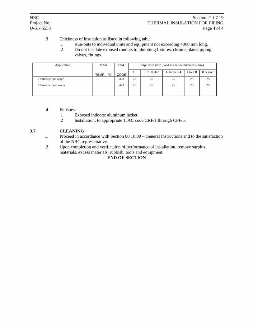
NRC Section 21 07 19 Project No. THERMAL INSULATION FOR PIPING U-61- 5553 Page 4 of 4
.3 Thickness of insulation as listed in following table. .1 Run-outs to individual units and equipment not exceeding 4000 mm long. .2 Do not insulate exposed runouts to plumbing fixtures, chrome plated piping,
valves, fittings.
Application MAX TIAC Pipe sizes (NPS) and insulation thickness (mm)
TEMP. °C CODE < 1 1 to <1-1/2 1-1/2 to < 4 4 to < 8 8 & over
Domestic hot water A-3 25 25 25 25 25
Domestic cold water A-3 25 25 25 25 25
.4 Finishes:
.1 Exposed indoors: aluminum jacket.
.2 Installation: to appropriate TIAC code CRF/1 through CPF/5.
3.7 CLEANING .1 Proceed in accordance with Section 00 10 00 – General Instructions and to the satisfaction
of the NRC representative. .2 Upon completion and verification of performance of installation, remove surplus
materials, excess materials, rubbish, tools and equipment. END OF SECTION
NRC Section 21 13 13 Project No. WET PIPE SPRINKLER SYSTEMS U-61- 5553 Page 1 of 7
Part 1 General
1.1 SUMMARY
.1 Section Includes:
.1 Materials and installation for wet pipe fire protection and sprinkler systems for heated areas.
.2 Related Sections:
.1 Section 00 10 00 – General Instructions.
.2 Section 00 15 45 – Common Safety Section and Fire Instructions.
.3 Section 21 05 01 – Common Work Results - Mechanical
1.2 REFERENCES
.1 American National Standards Institute/National Fire Prevention Association (ANSI/NFPA)
.1 ANSI/NFPA 13, Installation of Sprinkler Systems.
.2 ANSI/NFPA 24, Installation of Private Fire Service Mains and Their Appurtenances.
.3 ANSI/NFPA 25, Standard for the Inspection, Testing, and Maintenance of Water-Based Fire Protection Systems.
.2 Health Canada/Workplace Hazardous Materials Information System (WHMIS)
.1 Material Safety Data Sheets (MSDS).
.3 Underwriter's Laboratories of Canada (ULC)
.1 CAN4 S543, Standard for Internal Lug Quick Connect Couplings for Fire Hose.
1.3 DESIGN REQUIREMENTS
.1 Design automatic wet pipe fire suppression sprinkler systems in accordance with required and advisory provisions of NFPA 13.
.2 Include with each system materials, accessories, and equipment inside and outside building to provide each system complete and ready for use.
.3 Design and provide each system to give full consideration to blind spaces, piping, electrical equipment, ducts, and other construction and equipment in accordance with detailed shop drawings.
.4 Locate sprinkler heads in consistent pattern with ceiling grid, lights, and air supply diffusers.
.5 Devices and equipment for fire protection service: ULC approved for use in wet pipe sprinkler systems.
.6 Location of Sprinkler Heads:
NRC Section 21 13 13 Project No. WET PIPE SPRINKLER SYSTEMS U-61- 5553 Page 2 of 7
.1 Locate heads in relation to ceiling and spacing of sprinkler heads not to exceed that permitted by NFPA 13 for ordinary.
.2 Uniformly space sprinklers on branch.
.7 Density of Application of Water:
.1 Size pipe to provide specified density when system is discharging specified total maximum required flow.
1.4 SUBMITTALS
.1 Product Data:
.1 Submit manufacturer's printed product literature, specifications and datasheet in accordance with Section 00 10 00 – General Instructions.
.2 Shop Drawings:
.1 Submit shop drawings in accordance with Section 00 10 00 – General Instructions.
.3 Quality assurance submittals: submit following in accordance with Section 00 10 00 – General Instructions.
.1 Test reports: .1 Submit certified test reports for wet pipe fire protection sprinkler systems
from approved independent testing laboratories, indicating compliance with specifications for specified performance characteristics and physical properties.
.2 Certificates: submit certificates signed by manufacturer certifying that materials comply with specified performance characteristics and physical properties.
.3 Instructions: submit manufacturer's installation instructions. .2 Manufacturer's Field Reports: manufacturer's field reports specified.
.4 Closeout Submittals:
.1 Submit maintenance and engineering data for incorporation into manual specified in Section 00 10 00 – General Instructions in accordance with ANSI/NFPA 20.
.2 Manufacturer's Catalog Data, including specific model, type, and size for: .1 Pipe and fittings. .2 Sprinkler heads. .3 Pipe hangers and supports. .4 Mechanical couplings.
.3 Field Test Reports: .1 Preliminary tests on piping system.
.4 Records: .1 As-built drawings of each system.
.1 After completion, but before final acceptance, submit complete set of as-built drawings of each system for record purposes.
.5 Operation and Maintenance Manuals:
NRC Section 21 13 13 Project No. WET PIPE SPRINKLER SYSTEMS U-61- 5553 Page 3 of 7
.1 Provide maintenance data for incorporation into manual specified in Section 00 10 00 – General Instructions.
1.5 QUALITY ASSURANCE
.1 Qualifications:
.1 Installer: company or person specializing in wet sprinkler systems with documented experience.
.2 Health and Safety:
.1 Do construction occupational health and safety in accordance with Section 00 15 45 – General Safety Section and Fire Instructions.
1.6 MAINTENANCE
.1 Extra Materials:
.1 Provide maintenance materials in accordance with Section 00 10 00 – General Instructions.
.2 Provide spare sprinklers and tools as required by ANSI/NFPA 13.
1.7 DELIVERY, STORAGE, AND HANDLING
.1 Packing, shipping, handling and unloading:
.1 Deliver, store and handle in accordance with Section 00 10 00 – General Instructions.
.2 Deliver, store and handle materials in accordance with manufacturer's written instructions.
.2 Storage and Protection:
.1 Store materials indoors, in dry location.
.3 Waste Management and Disposal:
.1 Construction/Demolition Waste Management and Disposal: in accordance with Section 00 10 00 – General Instructions.
Part 2 Products
2.1 ABOVE GROUND PIPING SYSTEMS
.1 Provide fittings for changes in direction of piping and for connections.
.1 Make changes in piping sizes through tapered reducing pipe fittings, bushings will not be permitted.
.2 Perform welding in shop; field welding will not be permitted.
.3 Conceal piping in areas with suspended ceiling.
2.2 PIPE, FITTINGS AND VALVES
.1 Pipe:
NRC Section 21 13 13 Project No. WET PIPE SPRINKLER SYSTEMS U-61- 5553 Page 4 of 7
.1 Ferrous: to ANSI/NFPA 13.
.2 Copper tube: to ANSI/NFPA 13.
.2 Fittings and joints to ANSI/NFPA 13:
.1 Ferrous: screwed, welded, flanged or roll grooved.
.2 Copper tube: screwed, soldered, brazed.
.3 Provide grooved-end type fittings into which sprinkler heads, sprinkler head riser nipples, or drop nipples are threaded.
.4 Plain-end fittings with mechanical couplings and fittings which use steel gripping devices to bite into pipe when pressure is applied will not be permitted.
.5 Rubber gasketted grooved-end pipe and fittings with mechanical couplings are permitted in pipe sizes 32 mm and larger.
.6 Fittings: ULC approved for use in wet pipe sprinkler systems.
.7 Ensure fittings, mechanical couplings, and rubber gaskets are supplied by same manufacturer.
.8 Side outlet tees using rubber gasketted fittings are not permitted.
.9 Sprinkler pipe and fittings: metal.
.3 Pipe hangers:
.1 ULC listed for fire protection services in accordance with NFPA.
2.3 SPRINKLER HEADS
.1 General: to ANSI/NFPA 13 and ULC listed for fire services.
.2 Match to existing sprinkler heads
.3 Sprinkler Head Type:
.1 Type C: pendant chrome glass bulb type.
.4 Provide nominal 1.2 cm orifice sprinkler heads.
.1 Release element of each head to be of standard temperature rating.
.2 Provide polished stainless steel ceiling plates for sprinklers below suspended ceilings.
.3 Provide corrosion-resistant sprinkler heads and sprinkler head guards in accordance with NFPA 13.
.4 Deflector: not more than 75 mm below suspended ceilings.
.5 Ceiling plates: not more than 25 mm deep.
.6 Ceiling cups: not permitted.
2.4 PIPE SLEEVES
.1 Provide pipe sleeves where piping passes through walls.
.2 Secure sleeves in position and location during construction.
.3 Provide sleeves of sufficient length to pass through entire thickness of walls.
NRC Section 21 13 13 Project No. WET PIPE SPRINKLER SYSTEMS U-61- 5553 Page 5 of 7
.4 Provide 2.5 cm minimum clearance between exterior of piping and interior of sleeve or core-drilled hole.
.1 Firmly pack space with mineral wool insulation.
.2 Seal space at both ends of sleeve or core-drilled hole with[plastic waterproof cement which will dry to firm but pliable mass,] [provide mechanically adjustable segmented elastomeric seal].
.3 In fire walls and fire floors, seal both ends of pipe sleeves or core-drilled holes with ULC listed fill, void, or cavity material.
.5 Sleeves in Masonry and Concrete Walls, Floors, and Roofs:
.1 Provide hot-dip galvanized steel sleeves.
.2 Core drilling of masonry and concrete may be provided in lieu of pipe sleeves when cavities in core-drilled hole are completely grouted smooth.
2.5 ESCUTCHEON PLATES
.1 Provide split hinge type metal plates for piping passing through walls in exposed spaces.
.2 Provide polished stainless steel plates in finished spaces.
.3 Provide paint finish on metal plates in unfinished spaces.
Part 3 Execution
3.1 MANUFACTURER'S INSTRUCTIONS
.1 Compliance: comply with manufacturer's written recommendations or specifications, including product technical bulletins, handling, storage and installation instructions, and datasheet.
3.2 INSTALLATION
.1 Install, inspect and test to acceptance in accordance with ANSI/NFPA 13 and ANSI/NFPA 25.
3.3 PIPE INSTALLATION
.1 Install piping straight and true to bear evenly on hangers and supports. Do not hang piping from plaster ceilings.
.2 Keep interior and ends of new piping and existing piping thoroughly cleaned of water and foreign matter.
.3 Keep piping systems clean during installation by means of plugs or other approved methods. When work is not in progress, securely close open ends of piping to prevent entry of water and foreign matter.
.4 Inspect piping before placing into position.

NRC Section 21 13 13 Project No. WET PIPE SPRINKLER SYSTEMS U-61- 5553 Page 6 of 7 3.4 FIELD PAINTING
.1 Clean, pretreat, prime, and paint new systems including valves, piping, conduit, hangers, supports, miscellaneous metalwork, and accessories.
.2 Apply coatings to clean, dry surfaces, using clean brushes.
.3 Clean surfaces to remove dust, dirt, rust, and loose mill scale.
.4 Immediately after cleaning, provide metal surfaces with coat of pretreatment primer applied to minimum dry film thickness of 0.3 ml, and one coat of zinc chromate primer applied to minimum dry film thickness of 1.0 ml.
.5 Shield sprinkler heads with protective covering while painting is in progress.
.6 Upon completion of painting, remove protective covering from sprinkler heads.
.7 Remove sprinkler heads which have been painted and replace with new sprinkler heads.
.8 Provide primed surfaces with following:
.1 Piping in Finished Areas: .1 Provide primed surfaces with 2 coats of paint to match adjacent surfaces. .2 Provide valves and operating accessories with 1 coat of red alkyd gloss
enamel applied to minimum dry film thickness of 1.0 mil.
3.5 FIELD QUALITY CONTROL
.1 Site Test, Inspection:
.1 Perform test to determine compliance with specified requirements in presence of NRC Representative.
.2 Test, inspect, and approve piping before covering or concealing.
.3 Preliminary Tests: .1 Piping above suspended ceilings: tested, inspected, and approved before
installation of ceilings.
.2 Manufacturer's Field Services:
.1 Obtain written report from manufacturer verifying compliance of Work, in handling, installing, applying, protecting and cleaning of product and submit Manufacturer's Field Reports as described in PART 1 - SUBMITTALS.
.2 Provide manufacturer's field services consisting of product use recommendations and periodic site visits for inspection of product installation in accordance with manufacturer's instructions.
.3 Schedule site visits, to review Work, as directed in PART 1 - QUALITY ASSURANCE.
3.6 CLEANING
.1 Proceed in accordance with Section 00 10 00 – General Instructions and to the satisfaction of the NRC representative.

NRC Section 21 13 13 Project No. WET PIPE SPRINKLER SYSTEMS U-61- 5553 Page 7 of 7
.2 Upon completion and verification of performance of installation, remove surplus materials, excess materials, rubbish, tools and equipment.
END OF SECTION
NRC Section 22 11 16 Project No. DOMESTIC WATER PIPING U-61- 5553 Page 1 of 5
Part 1 General 1.1 SUMMARY
.1 Section Includes:
.1 Selection of piping valves in domestic water system.
1.2 RELATED SECTIONS
.1 Section 00 10 00 – General Instructions
.2 Section 00 15 45 – General Safety Section and Fire Instructions
.3 Section 21 05 01 – Common Work Results - Mechanical
.4 Section 23 05 23.01 Valves – Bronze.
.5 Section 23 05 01 - Installation of Pipework
1.3 REFERENCES
.1 American National Standards Institute (ANSI)/American Society of Mechanical Engineers International (ASME)
.1 ANSI/ASME B16.15, Cast Bronze Threaded Fittings, Classes 125 and 250.
.2 ANSI/ASME B16.18, Cast Copper Alloy Solder Joint Pressure Fittings.
.3 ANSI/ASME B16.22, Wrought Copper and Copper Alloy Solder Joint Pressure Fittings.
.4 ANSI/ASME B16.24, Cast Copper Alloy Pipe Flanges and Flanged Fittings, Class 150, 300, 400, 600, 900, 1500 and 2500.
.2 American National Standards Institute/American Water Works Association (ANSI)/(AWWA)
.1 ANSI/AWWA C111/A21.11, Rubber-Gasket Joints for Ductile-Iron Pressure Pipe and Fittings.
.3 Canadian Standards Association (CSA International)
.1 CSA B242, Groove and Shoulder Type Mechanical Pipe Couplings.
.4 Department of Justice Canada (Jus)
.1 Canadian Environmental Protection Act, 1999, c. 33 (CEPA).
.5 Health Canada/Workplace Hazardous Materials Information System (WHMIS)
.1 Material Safety Data Sheets (MSDS).
.6 Manufacturer's Standardization Society of the Valve and Fittings Industry (MSS).
.1 MSS-SP-67, Butterfly Valves.
.2 MSS-SP-70, Gray Iron Gate Valves, Flanged and Threaded Ends.
.3 MSS-SP-71, Gray Iron Swing Check Valves, Flanged and Threaded Ends.

NRC Section 22 11 16 Project No. DOMESTIC WATER PIPING U-61- 5553 Page 2 of 5
.4 MSS-SP-80, Bronze Gate, Globe, Angle and Check Valves.
.7 National Research Council (NRC)/Institute for Research in Construction
.1 NRCC 38728, National Plumbing Code of Canada (NPC) .
.8 Transport Canada (TC)
.1 Transportation of Dangerous Goods Act, 1992, c. 34 (TDGA).
1.4 ACTION AND INFORMATIONAL SUBMITTALS
.1 Provide manufacturer shop drawings for all valves, piping, fittings and as specified on drawings and in section 00 10 00 – General Instructions
.2 Product Data:
.1 Provide manufacturer's printed product literature and datasheets for insulation and adhesives, and include product characteristics, performance criteria, physical size, finish and limitations.
1.5 DELIVERY, STORAGE AND HANDLING
.1 See section 00 10 00 – General Instructions
Part 2 Products
2.1 PIPING
.1 Domestic hot, cold and recirculation systems, within building.
.1 Above ground: copper tube, hard drawn, type L: to ASTM B88M.
.2 Buried or embedded: copper tube, soft annealed, type K: to ASTM B88M. No buried joints.
2.2 FITTINGS
.1 Wrought copper and copper alloy, solder type: to ANSI/ASME B16.22. NPS 2 and larger: roll grooved to CSA B242.
.3 Cast bronze threaded fittings, Class 150: to ANSI/ASME B16.15.
.4 Cast copper, solder type: to ANSI/ASME B16.18.
.5 Bronze pipe flanges and flanged fittings, Class 150 to ANSI/ASME B16.24.
2.3 JOINTS
.1 Solder: 95% tin / 5% copper alloy.
.2 Teflon tape: for threaded joints.
.3 Dielectric connections between dissimilar metals: dielectric fitting, complete with thermoplastic liner.
NRC Section 22 11 16 Project No. DOMESTIC WATER PIPING U-61- 5553 Page 3 of 5 2.4 SWING CHECK VALVES
.1 NPS 2 and under, soldered:
.1 To MSS-SP-80, Class 150, bronze body, bronze swing disc, screw in cap, see Section 23 05 23.01 - Valves – Bronze.
.2 NPS 2 and under, screwed:
.1 To MSS-SP-80, Class 150, bronze body, bronze swing disc, screw in cap, see Section 23 05 23.01 - Valves - Bronze.
2.5 BALL VALVES
.1 NPS 2 and under, screwed:
.1 Threaded, 2-Piece, Std. Port, Bronze Ball Valve, 600 CWP, with extension, see Section 23 05 23.01 - Valves - Bronze
.2 NPS 2 and under, soldered:
.1 Solder, 2-Piece, Std. Port, Bronze Ball Valve, 600 CWP, with extension, see Section 23 05 23.01 - Valves - Bronze.
Part 3 Execution
3.1 APPLICATION
.1 Manufacturer's Instructions: comply with manufacturer's written recommendations, including product technical bulletins, handling, storage and installation instructions, and datasheets.
3.2 INSTALLATION
.1 Install in accordance with Ontario Plumbing Code.
.2 Install pipe work in accordance with Section 23 05 01 - Installation of Pipework, supplemented as specified herein.
.3 Assemble piping using fittings manufactured to ANSI standards.
.4 Install CWS piping below and away from HWS and HWC and other hot piping so as to maintain temperature of cold water as low as possible.
.5 Connect to fixtures and equipment in accordance with manufacturer's written instructions unless otherwise indicated.
.6 Buried tubing:
.1 Lay in well compacted washed sand in accordance with AWWA Class B bedding.
.2 Bend tubing without crimping or constriction. Minimize use of fittings.
.7 Install valves with unions at each piece of equipment arranged to allow servicing, maintenance and equipment removal.
NRC Section 22 11 16 Project No. DOMESTIC WATER PIPING U-61- 5553 Page 4 of 5 3.3 VALVES
.1 Isolate equipment with unions, fixtures and branches with gate valves.
.2 Provide valves as indicated on drawing and in specifications.
.3 Balance recirculation system using balancing valve. Mark settings and record on as-built drawings on completion.
.4 Provide line size check valve on discharge of all pumps.
3.4 PRESSURE TESTS
.1 Test pressure: Hydrostatic test pressure (1.5 times maximum working pressure), Pneumatic test pressure (1.2 maximum working pressure pending NRC approval) for a minimum of 15 minutes. All tests must be witnessed and approved by NRC.
.2 Provide NRC with a minimum of 48 hours notice in writing before all pressure tests.
3.5 FLUSHING AND CLEANING
.1 Flush entire system for 8 h. Ensure outlets flushed for 2 h. Let stand for 24 h, then draw one sample off longest run. Submit to testing laboratory to verify that system is clean copper to Provincial potable water guidelines.
3.6 PRE-START-UP INSPECTIONS
.1 Systems to be complete, prior to flushing, testing and start-up.
.2 Verify that system can be completely drained.
.3 Ensure that pressure booster systems are operating properly.
.4 Ensure that air chambers, expansion compensators are installed properly.
3.7 START-UP
.1 Timing: Start up after:
.1 Pressure tests have been completed.
.2 Disinfection procedures have been completed.
.3 Certificate of static completion has been issued.
.4 Water treatment systems operational.
.2 Provide continuous supervision during start-up.
.3 Start-up procedures:
.1 Establish circulation and ensure that air is eliminated.
.2 Check pressurization to ensure proper operation and to prevent water hammer, flashing and/or cavitation.
.3 Bring HWS storage tank up to design temperature slowly.
NRC Section 22 11 16 Project No. DOMESTIC WATER PIPING U-61- 5553 Page 5 of 5
.4 Monitor piping HWS and HWC piping systems for freedom of movement, pipe expansion as designed.
.5 Check control, limit, safety devices for normal and safe operation.
3.8 PERFORMANCE VERIFICATION
.1 Scheduling:
.1 Verify system performance after pressure and leakage tests and disinfection are completed, and Certificate of Completion has been issued by authority having jurisdiction.
.2 Procedures:
.1 Verify that flow rate and pressure meet Design Criteria.
.2 Adjust pressure regulating valves while withdrawal is maximum and inlet pressure is minimum.
.3 Verify performance of temperature controls.
.4 Verify compliance with safety and health requirements.
.5 Check for proper operation of water hammer arrestors. Run [one][two…] outlet for 10 seconds, then shut of water immediately. If water hammer occurs, replace water hammer arrestor or re-charge air chambers. Repeat for outlets and flush valves.
.6 Confirm water quality consistent with supply standards, and ensure no residuals remain as result of flushing or cleaning
3.9 CLEANING
.1 As per section 00 10 00 – General Instructions and to the satisfaction of the NRC Representative.
END OF SECTION
NRC Section 22 13 17 Project No. DRAINAGE WASTE AND VENT PIPING- CAST IRON AND COPPER U-61- 5553 Page 1 of 3
Part 1 General
1.1 RELATED REQUIREMENTS
.1 Section 00 10 00 – General Instructions.
.2 Section 00 15 45 – General Safety Section and Fire Instructions.
.3 Section 01 74 11 – Cleaning.
.4 Section 21 05 01 – Common Work Results – Mechanical
.5 Section 21 05 02 – Mechanical Identification
.6 Section 23 05 05 – Installation of Pipework
1.2 REFERENCES
.1 ASTM International Inc.
.1 ASTM B32, Standard Specification for Solder Metal.
.2 ASTM B306, Standard Specification for Copper Drainage Tube (DWV).
.3 ASTM C564, Standard Specification for Rubber Gaskets for Cast Iron Soil Pipe and Fittings.
.2 Canadian Standards Association (CSA International).
.1 CSA B67, Lead Service Pipe, Waste Pipe, Traps, Bends and Accessories.
.2 CAN/CSA-B70, Cast Iron Soil Pipe, Fittings and Means of Joining.
.3 CAN/CSA-B125.3, Plumbing Fittings.
.3 Green Seal Environmental Standards (GSES)
.1 Standard GS-36, Commercial Adhesives.
1.3 ACTION AND INFORMATIONAL SUBMITTALS
.1 Provide submittals in accordance with Section 00 10 00 – General Instructions.
.2 Product Data:
.1 Provide manufacturer's printed product literature and datasheets for adhesives, and include product characteristics, performance criteria, physical size, finish and limitations.
1.4 DELIVERY, STORAGE AND HANDLING
.1 Deliver, store and handle in accordance with Section 00 10 00 – General Instructions and 00 15 45 - General Safety Section and Fire Instructions.
NRC Section 22 13 17 Project No. DRAINAGE WASTE AND VENT PIPING- CAST IRON AND COPPER U-61- 5553 Page 2 of 3
.2 Deliver materials to site in original factory packaging, labelled with manufacturer's name, address.
.3 Packaging Waste Management: in accordance with Section 00 10 00 – General Instructions.
Part 2 Products
2.1 COPPER TUBE AND FITTINGS
.1 Above ground sanitary and vent, NPS 2 and under Type DWV to: ASTM B306.
.1 Fittings. .1 Cast brass: to CAN/CSA-B125.3. .2 Wrought copper: to CAN/CSA-B125.3.
.2 Solder: lead free, tin-antimony 95:5, to ASTM B32.
2.2 CAST IRON PIPING AND FITTINGS
.1 Buried sanitary, storm and vent minimum NPS 3, to: CAN/CSA-B70, with one layer of protective coating of bitumen.
.1 Joints: .1 Mechanical joints:
.1 Neoprene or butyl rubber compression gaskets: to ASTM C564 or CAN/CSA-B70.
.2 Stainless steel clamps. .2 Hub and spigot:
.1 Caulking lead: to CSA B67.
.2 Cold caulking compounds.
.2 Above ground sanitary, storm and vent NPS 2-1/2 and greater: to CAN/CSA-B70.
.1 Joints: .1 Hub and spigot:
.1 Caulking lead: to CSA B67. .2 Mechanical joints:
.1 Neoprene or butyl rubber compression gaskets with stainless steel clamps.
Part 3 Execution
3.1 APPLICATION
.1 Manufacturer's Instructions: comply with manufacturer's written recommendations, including product technical bulletins, handling, storage and installation instructions, and datasheets.
NRC Section 22 13 17 Project No. DRAINAGE WASTE AND VENT PIPING- CAST IRON AND COPPER U-61- 5553 Page 3 of 3 3.2 INSTALLATION
.1 In accordance with Section 23 05 05 – Installation of Pipework.
.2 Install in accordance with National Plumbing Code, supplemented as per Provincial Plumbing Code.
3.3 TESTING
.1 Pressure test buried systems before backfilling.
.2 Hydraulically test to verify grades and freedom from obstructions.
3.4 PERFORMANCE VERIFICATION
.1 Cleanouts:
.1 Ensure accessible and that access doors are correctly located.
.2 Open, cover with linseed oil and re-seal.
.3 Verify that cleanout rods can probe as far as the next cleanout, at least.
.2 Test to ensure traps are fully and permanently primed.
.3 Storm water drainage:
.1 Verify domes are secure.
.2 Ensure weirs are correctly sized and installed correctly.
.3 Verify provisions for movement of roof system.
.4 Ensure that fixtures are properly anchored, connected to system and effectively vented.
.5 Affix applicable label (storm, sanitary, vent, pump discharge etc.) c/w directional arrows every floor or 4.5 m (whichever is less).
3.5 LABELLING
.1 Label all above ground (sanitary), (storm), (vent) piping as per section 21 05 02 – Mechanical Identification
3.6 CLEANING
.1 Clean in accordance with Section 00 10 00 – General Instructions and to the satisfaction of NRC representative.
END OF SECTION
NRC Section 22 42 01 Project No. PLUMBING SPECIALTIES AND ACCESSORIES U-61- 5553 Page 1 of 5
Part 1 General
1.1 SUMMARY
.1 Section Includes:
.1 Materials and installation for plumbing specialties and accessories.
1.2 REFERENCES
.1 American Society for Testing and Materials International (ASTM).
.1 ASTM A126, Specification for Gray Iron Castings for Valves, Flanges and Pipe Fittings.
.2 ASTM B62, Specification for Composition Bronze or Ounce Metal Castings.
.2 American Water Works Association (AWWA).
.1 AWWA C700, Cold Water Meters-Displacement Type, Bronze Main Case.
.2 AWWA C701, Cold Water Meters-Turbine Type for Customer Service.
.3 AWWA C702-1, Cold Water Meters-Compound Type.
.3 Canadian Standards Association (CSA International).
.1 CSA-B64 Series, Backflow Preventers and Vacuum Breakers.
.2 CSA-B79, Floor, Area and Shower Drains, and Cleanouts for Residential Construction.
.3 CSA-B356, Water Pressure Reducing Valves for Domestic Water Supply Systems.
.4 Health Canada/Workplace Hazardous Materials Information System (WHMIS).
.1 Material Safety Data Sheets (MSDS).
.5 Plumbing and Drainage Institute (PDI).
.1 PDI-G101, Testing and Rating Procedure for Grease Interceptors with Appendix of Sizing and Installation Data.
.2 PDI-WH201, Water Hammer Arresters Standard.
1.3 SUBMITTALS
.1 Product Data:
.1 Submit manufacturer's printed product literature, specifications and datasheet for fixtures and equipment.
.2 Indicate dimensions, construction details and materials for specified items.
.2 Shop Drawings:
.1 Submit shop drawings to indicate ,materials, finishes, method of anchorage, number of anchors, dimensions, color, construction and assembly details.
.3 Certificates: submit certificates signed by manufacturer certifying that materials comply with specified performance characteristics and physical properties.
.4 Instructions: submit manufacturer's installation instructions.
NRC Section 22 42 01 Project No. PLUMBING SPECIALTIES AND ACCESSORIES U-61- 5553 Page 2 of 5
.5 Manufacturers' Field Reports: manufacturers' field reports specified.
Part 2 Products
2.1 FLOOR DRAINS
.1 Type 1, General purpose: all duco coated cast iron body, reversible flashing clamp with seepage openings and adjustable 5" diameter nickel bronze 1/2" thick strainer, secured with S.S. screws, 4" throat on strainer. In quarry or mosaic tiled areas, provide 'BHD' - 5" x 5" square nickel bronze strainer. Provide trap primer connection ‘P’.
2.2 CLEANOUTS
.1 Line cleanout: in cast iron pipe with bolted neoprene gasketed cover secured to body with brass bolts, with full size pipe opening. Access shall be made by round stainless steel plate and slotted flat head stainless steel screws.
.2 Floor cleanout in unfinished areas: Duco coated cast iron body with flashing flange, and removable positive gasket seal closure plug and heavy duty 6” diameter adjustable cast iron cover secured with stainless steel screws, C.O. cast in cover. For water-proofed areas provide ‘FC’ flange with flashing clamp. In tiled areas: Duco coated cast iron body with flashing flange, and removable positive gasket seal closure plug and square nickel bronze cover and frame with 1/8” tile recess.
2.3 WATER HAMMER ARRESTORS
.1 Stainless steel construction, piston type: Normal operating pressure 35 to 250 PSIG. Spike pressure 1,500 PSIG. Copper construction, piston type, working pressure, 150 psig from 33 to 180 deg F PDI-WH201.
2.4 ACCESS DOORS .1 General : 14 GA. (1.7mm) steel, rust resistant, continuous concealed hinge, with positive
and self-opening screwdriver operated lock. Doors in tile walls shall be stainless steel and shall suit tile pattern. All other panels shall be prime painted steel. Unless otherwise stated all panel to be 16”x16”.
2.5 VACUUM BREAKERS
.1 Breakers: to CSA-B64 Series, vacuum breaker hose connection.
.2 Hose Connection Vacuum Breakers: chrome finish stainless steel working parts, a rubber diaphragm and disc, and a draining stem. Maximum Pressure:125psi
2.6 FLOOR DRAIN TRAP SEAL PRIMERS
.1 1/2" NPT connections with strainer and integral back flow preventer & vacuum breaker.
2.7 PIPE ESCUTCHEON
.1 Chrome plated brass solid type with set screws.
.2 Outside diameter shall cover opening or sleeve
NRC Section 22 42 01 Project No. PLUMBING SPECIALTIES AND ACCESSORIES U-61- 5553 Page 3 of 5 Part 3 Execution
3.1 MANUFACTURER'S INSTRUCTIONS
.1 Compliance: comply with manufacturer's written recommendations or specifications, including product technical bulletins, handling, storage and installation instructions, and data sheet.
3.2 INSTALLATION
.1 Install in accordance with latest version of Ontario Building Code.
.2 Install in accordance with manufacturer's instructions and as specified.
3.3 ACCESS DOORS
.1 Supply access doors to give access to all valves, cleanouts, strainers, duct access doors, and other similar mechanical work which may need maintenance or repair but which is concealed in inaccessible construction, except as otherwise specified herein or on the drawings.
.2 Locate access doors in walls and partitions to the Engineer's approval, and arrange mechanical work to suit.
.3 Group piping and ductwork to ensure the minimum number of access doors is required. Access doors will be installed by the trades responsible for the particular type of construction in which the doors are required.
.4 Access doors shall be, wherever possible, of a standard size for all applications. Confirm exact dimensions prior to ordering.
3.4 CLEANOUTS
.1 Install cleanouts at base of soil and waste stacks, and rainwater leaders, at locations required code, and as indicated.
.2 Bring cleanouts to wall or finished floor unless serviceable from below floor.
.3 Building drain cleanout and stack base cleanouts: line size to maximum NPS4.
3.5 WATER HAMMER ARRESTORS
.1 Install on branch supplies to fixtures or group of fixtures and where indicated.
.2 All arrestors shall be accessible. Provide access panels has required.
.3 Provide isolation ball valve.

NRC Section 22 42 01 Project No. PLUMBING SPECIALTIES AND ACCESSORIES U-61- 5553 Page 4 of 5 3.6 INSTALLATION OF PIPE ESCUTCHEON
.1 On pipes passing through walls, partitions, floors and ceilings in finished areas.
.2 Install the plates so that they are tight against the building surface concerned, and ensure that the plates completely cover pipe sleeves and/or openings.
.3 Where sleeve extends above finished floor, escutcheons or plates shall cover sleeve extension
3.7 TRAP SEAL PRIMERS
.1 Install for floor drains and elsewhere, as indicated.
.2 Install on cold water supply to nearest frequently used plumbing fixture, in concealed space, to approval of NRC. Where located in wall unit shall be c/w access panel sized to suit proper access to primer.
.3 Install soft copper tubing to floor drain.
3.8 START-UP
.1 General:
.1 In accordance with Section 00 10 00 – General Instructions.
.2 Timing: start-up only after:
.1 Pressure tests have been completed.
.2 Disinfection procedures have been completed.
.3 Certificate of static completion has been issued.
.3 Provide continuous supervision during start-up of all equipment.
3.9 TESTING AND ADJUSTING
.1 General:
.1 Contractor shall be responsible to verify that all equipment operates as per manufacturer specification to the satisfaction of NRC.
.2 Contractor shall be responsible to train NRC staff in the use of all equipment. Exact training schedule to be coordinated with NRC.
.2 Timing:
.1 After start-up deficiencies rectified.
.3 Application tolerances:
.1 Pressure at fixtures: +/- 20 kPa.
.2 Flow rate at fixtures: +/- 20%.
.4 Adjustments:
.1 Verify that flow rate and pressure meet design criteria.
NRC Section 22 42 01 Project No. PLUMBING SPECIALTIES AND ACCESSORIES U-61- 5553 Page 5 of 5
.2 Make adjustments while flow rate or withdrawal is (1) maximum and (2) 25% of maximum and while pressure is (1) maximum and (2) minimum.
.5 Floor drains:
.1 Verify operation of trap seal primer.
.2 Prime, using trap primer. Adjust flow rate to suit site conditions.
.3 Check operations of flushing features.
.4 Clean out baskets.
.6 Vacuum breakers, backflow preventers, backwater valves:
.1 Test tightness, accessibility for O&M of cover and of valve.
.2 Simulate reverse flow and back-pressure conditions to test operation of vacuum breakers, backflow preventers.
.3 Verify visibility of discharge from open ports.
.7 Access doors:
.1 Verify size and location relative to items to be accessed.
.8 Cleanouts:
.1 Verify covers are gas-tight, secure, yet readily removable.
.9 Water hammer arrestors:
.1 Verify proper installation of correct type of water hammer arrester.
END OF SECTION
NRC Section 22 42 03 Project No. COMMERCIAL WASHROOM FIXTURES U-61- 5553 Page 1 of 4
Part 1 General
1.1 RELATED REQUIREMENTS .1 Section 00 10 00 – General Instructions. .2 Section 00 15 45 – General Safety Section and Fire Instructions. .3 Section 21 05 01 – Common Work Results- Mechanical .4 Section 21 07 19 – Thermal Insulation for Piping .5 Section 22 11 16 – Domestic Water Piping .6 Section 22 42 01 – Plumbing Specialties and Accessories .7 Section 23 05 05 – Installation of Pipework
1.2 REFERENCES .1 Canadian Standards Association (CSA International)
.1 CAN/CSA-B45, Plumbing Fixtures.
.2 CAN/CSA-B125.3, Plumbing Fittings.
.3 CAN/CSA-B651, Accessible Design for the Built Environment.
1.3 ACTION AND INFORMATIONAL SUBMITTALS .1 Provide submittals in accordance with Section 00 10 00 – General Instructions. .2 Product Data:
.1 Provide manufacturer's printed product literature and datasheets for washroom fixtures, and include product characteristics, performance criteria, physical size, finish and limitations.
.3 Indicate fixtures and trim: .1 Dimensions, construction details, roughing-in dimensions. .2 Factory-set water consumption per flush at recommended pressure. .3 (For water closets, urinals): minimum pressure required for flushing.
1.4 CLOSEOUT SUBMITTALS .1 Provide operation and maintenance data for washroom fixtures, for incorporation
into manual specified in Section 00 10 00 – General Instructions. .2 Include:
.1 Description of fixtures and trim, giving manufacturer's name, type, model, year, capacity.
.2 Details of operation, servicing, maintenance.
.3 List of recommended spare parts.
1.5 DELIVERY, STORAGE AND HANDLING .1 Deliver, store and handle in accordance with Section 00 10 00 – General
Instructions. .2 Deliver materials to site in original factory packaging, labelled with
manufacturer's name, address.

NRC Section 22 42 03 Project No. COMMERCIAL WASHROOM FIXTURES U-61- 5553 Page 2 of 4 Part 2 Products
2.1 MANUFACTURED UNITS .1 Any alternates to basis of design shown on drawings must be submitted for
approval during the tendering process. .2 Fixtures: manufacture in accordance with CAN/CSA-B45 series. .3 Trim, fittings: manufacture in accordance with CAN/CSA-B125.3. .4 Exposed plumbing brass to be chrome plated. .5 Number, locations: as indicated on drawing 5553-M01.. .6 Fixtures in any one location to be product of one manufacturer and of same type. .7 Trim in any one location to be product of one manufacturer and of same type. .8 Water closets:
WC type
Mounting Bowl Flush valve Flush tank
Handicapped
Wall Floor Elong Reg Exp'd Conc'd WC1 X X X X
.1 WC1: floor-mounted, flush valve, for handicapped. .1 Top of seat to be between 400 mm and 460 mm from finished
floor. .2 Bowl: vitreous china, floor mounted, syphon jet, elongated rim,
top spud for flush valve, bolt caps. .3 Acceptable Material: American Standard Kholer, Crane or
approved equal. .2 Water Closet Flush Valves:
.1 Flush valve: exposed, polished chrome, externally adjustable, diaphragm type with NPS 1 screwdriver angle stop, oscillating handle, wall and spud escutcheons and vacuum breaker.
.2 Acceptable Material: American Standard, Sloan, Zurn, Moen, TAC or approved equal
.3 Water Closet Seat .1 Seat shall be heavy duty, open front, less cover, suitable injection
molded polypropylene suitable for bowl type, external check hinge with 304 stainless steel hinge posts. Colour: White
.2 Acceptable Material: American Standard model 5905.100, Enpoco or approved equal.
.9 Urinals:
.1 UR1: wall mounted, ultra-low flush, exposed flush valve, top spud. .1 Urinal: vitreous china, washout type, integral flushing rim,
extended shields, integral trap, removable stainless steel strainer, back outlet.
.2 Acceptable Material: American Standard, Kholer Model, Crane or approved equal.
.2 Urinal Electronic Flush Valves: .1 Surface mounted, controlled by infra-red] occupancy detector
with manual override.
NRC Section 22 42 03 Project No. COMMERCIAL WASHROOM FIXTURES U-61- 5553 Page 3 of 4
.1 Complete with removable filter, 9 second time delay, flush time adjustable from 0-8 seconds, factory set at 4.5 seconds, 4.5 L flush/cycle maximum.
.2 Sensor adjustable from 50-1220 mm, factory set to 860 mm.
.3 Solenoid valve: 12 VDC slow-closing type for 60 kPa (minimum), 1000 kPa (maximum), 85 degrees C with manual over-ride, adjustable flow control.
.2 Flush valve(s) controlled by programmed timer permitting 24 hour pre-scheduled flushing. Timer set to flush every 30 minutes from 20:00h till 6:00h plus once at midnight.
.3 Acceptable Material: American Standard, Sloan, Zurn, TAC or approved equal.
.10 Washroom Lavatories: .1 LAV1: wall-hung, for handicapped.
.1 Vitreous china, low shelf, with integral back, contoured front, shallow front basin, front overflow, soap depressions, supply openings on 200 mm centres, concealed supports. Sizes: 685 x 508 mm.
.2 Acceptable Material: American Standard, Kholer, Crane, Sloan, Zurn or approved equal.
.11 Washroom Lavatory Trim: .1 Wheelchair supply fitting with gooseneck spout, aerator, 150 mm blade
handles with indexed buttons, bent tailpiece. .1 Provide accessories to limit maximum flow rate to 8.35 l/minute
at 413 kPa. .2 Waste fitting: none. .3 Acceptable Material: American Standard, Delta, Moen, Chicago
Faucets, or approved equal. .12 Fixture piping:
.1 Hot and cold water supplies to fixtures: .1 Chrome plated flexible supply pipes with handwheel stop,
reducers, escutcheon. .2 Waste:
.1 Brass P trap with clean out on fixtures not having integral trap.
.2 Chrome plated in exposed places. .13 Chair carriers:
.1 Factory manufactured floor-mounted carrier systems for wall-mounted fixtures.
Part 3 Execution
3.1 APPLICATION .1 Manufacturer's Instructions: comply with manufacturer's written
recommendations, including product technical bulletins, handling, storage and installation instructions, and datasheets.
NRC Section 22 42 03 Project No. COMMERCIAL WASHROOM FIXTURES U-61- 5553 Page 4 of 4 3.2 INSTALLATION
.1 Mounting heights: .1 Wall-hung fixtures: as indicated on architectural drawings, measured
from finished floor. .2 Barrier free: to most stringent CAN/CSA B651.
3.3 ADJUSTING .1 Conform to water conservation requirements specified this section. .2 Adjustments:
.1 Adjust water flow rate to design flow rates.
.2 Adjust pressure to fixtures to ensure no splashing at maximum pressures.
.3 Adjust flush valves to suit actual site conditions.
.4 Adjust urinal flush timing mechanisms.
.5 Set controls of automatic flush valves for WCs and urinals to prevent unnecessary flush cycles.
.3 Checks: .1 Water closets, urinals: flushing action. .2 Aerators: operation, cleanliness. .3 Vacuum breakers, backflow preventers: operation under all conditions.
.4 Thermostatic controls: .1 Verify temperature settings, operation of control, limit and safety controls.
3.4 CLEANING .1 Clean in accordance with Section 00 10 00 – General Instructions.
.1 Remove surplus materials, excess materials, rubbish, tools and equipment.
.2 Waste Management: in accordance with Section 00 10 00 – General Instructions.
END OF SECTION
NRC Section 23 05 05 Project No. INSTALLATION OF PIPEWORK U-61- 5553 Page 1 of 6
Part 1 General
1.1 RELATED REQUIREMENTS SECTIONS
.1 Section 00 10 00 – General Instructions.
.2 Section 00 15 45 – General Safety Section and Fire Instructions
.3 Section 21 05 01 – Common Work Results – Mechanical.
1.2 REFERENCES
.1 Canadian General Standards Board (CGSB)
.1 CAN/CGSB-1.181, Ready-Mixed Organic Zinc-Rich Coating.
1.3 ACTION AND INFORMATIONAL SUBMITTALS
1.4 DELIVERY, STORAGE AND HANDLING
.1 Waste Management and Disposal:
.1 The contractor is responsibility to coordinate and dispose of all waste material to local provincial and municipality requirements.
.2 It is the full responsibility of the contractor to insure that all construction material, equipment, tools, etc. are stored and used in a safe and reasonable manor as per good industry standards.
.3 The contractor is responsible for all damaged and stolen material, tools or equipment on site.
.4 The contractor is responsible for the delivery of all material, tools or equipment.
Part 2 Products
2.1 NOT USED
Part 3 Execution
3.1 APPLICATION
.1 Manufacturer's Instructions: comply with manufacturer's written recommendations, including product technical bulletins, handling, storage and installation instructions, and datasheets.
NRC Section 23 05 05 Project No. INSTALLATION OF PIPEWORK U-61- 5553 Page 2 of 6 3.2 CONNECTIONS TO EQUIPMENT
.1 In accordance with manufacturer's instructions unless otherwise indicated.
.2 Use valves and either unions or flanges for isolation and ease of maintenance and assembly.
.3 Use double swing joints when equipment mounted on vibration isolation and when piping subject to movement and when penetrating ceiling/roof and has indicated..
3.3 CLEARANCES
.1 Provide clearance around systems, equipment and components for observation of operation, inspection, testing (x-ray, servicing, maintenance and as recommended by manufacturer.
.2 Provide space for disassembly, removal of equipment and components as recommended by manufacturer or as indicated (whichever is greater) without interrupting operation of other system, equipment, components.
3.4 DRAINS
.1 Install piping with grade in direction of flow except as indicated.
.2 Install drain valve at low points in piping systems, at equipment and at section isolating valves.
.3 Pipe each drain valve discharge separately to above floor drain. Discharge to be visible.
.4 Drain valves: NPS 3/4 gate or globe valves unless indicated otherwise, with hose end male thread, cap and chain.
3.5 AIR VENTS
.1 Install air vents at high points in piping systems.
.2 Install isolating valve at each air valve.
.3 Install drain piping to approved location and terminate where discharge is visible.
3.6 DIELECTRIC COUPLINGS
.1 General: compatible with system, to suit pressure rating of system.
.2 Locations: where dissimilar metals are joined.
.3 NPS 2 and under: isolating unions or bronze valves.
.4 Over NPS 2: isolating flanges.

NRC Section 23 05 05 Project No. INSTALLATION OF PIPEWORK U-61- 5553 Page 3 of 6 3.7 PIPEWORK INSTALLATION
.1 Screwed fittings jointed with Teflon tape.
.2 Protect openings against entry of foreign material.
.3 Install to isolate equipment and allow removal without interrupting operation of other equipment or systems.
.4 Assemble piping using fittings manufactured to ANSI standards.
.5 Saddle type branch fittings may be used on mains if branch line is no larger than half size of main.
.1 Hole saw (or drill) and ream main to maintain full inside diameter of branch line prior to welding saddle.
.6 Install exposed piping, equipment, rectangular cleanouts and similar items parallel or perpendicular to building lines.
.7 Install concealed pipework to minimize furring space, maximize headroom, conserve space.
.8 Slope piping, except where indicated, in direction of flow for positive drainage and venting.
.9 Install, except where indicated, to permit separate thermal insulation of each pipe.
.10 Group piping wherever possible.
.11 Ream pipes, remove scale and other foreign material before assembly.
.12 Use eccentric reducers at pipe size changes to ensure positive drainage and venting.
.13 Provide for thermal expansion as indicated.
.14 Valves:
.1 Install in accessible locations.
.2 Remove interior parts before soldering.
.3 Install with stems above horizontal position unless otherwise indicated.
.4 Valves accessible for maintenance without removing adjacent piping.
.5 Install globe valves in bypass around control valves.
.6 Use valves at branch take-offs for isolating purposes except where otherwise specified.
.7 Install butterfly valves between weld neck flanges to ensure full compression of liner.
.8 Install ball valves for glycol service and where indicated.
NRC Section 23 05 05 Project No. INSTALLATION OF PIPEWORK U-61- 5553 Page 4 of 6
.9 Use chain operators on valves NPS 2 1/2 and larger where installed more than 2400 mm above floor in Mechanical Rooms.
.15 Check Valves:
.1 Install silent check valves on discharge of pumps in vertical pipes with downward flow and elsewhere as indicated.
.2 Install swing check valves in horizontal lines on discharge of pumps and elsewhere as indicated.
3.8 SLEEVES
.1 General: install where pipes pass through masonry, concrete structures, fire rated assemblies, and elsewhere as indicated.
.2 Material: schedule 40 black steel pipe.
.3 Construction: foundation walls and where sleeves extend above finished floors to have annular fins continuously welded on at mid-point.
.4 Sizes: 6 mm minimum clearance between sleeve and uninsulated pipe or between sleeve and insulation.
.5 Installation:
.1 Concrete, masonry walls, concrete floors on grade: terminate flush with finished surface.
.2 Other floors: terminate 25 mm above finished floor.
.3 Before installation, paint exposed exterior surfaces with heavy application of zinc-rich paint to CAN/CGSB-1.181.
.6 Sealing:
.1 Foundation walls and below grade floors: fire retardant, waterproof non-hardening mastic.
.2 Elsewhere: Provide space for fire-stopping. Maintain fire rating integrity.
.3 Sleeves installed for future use: fill with lime plaster or other easily removable filler.
.4 Ensure no contact between copper pipe or tube and sleeve.
3.9 ESCUTCHEONS
.1 Install on pipes passing through walls, partitions, floors, and ceilings in finished areas.
.2 Construction: one piece type with set screws. Chrome or nickel plated brass or type 302 stainless steel.
.3 Sizes: outside diameter to cover opening or sleeve. Inside diameter to fit around pipe or outside of insulation if so provided.
NRC Section 23 05 05 Project No. INSTALLATION OF PIPEWORK U-61- 5553 Page 5 of 6 3.10 PREPARATION FOR FIRE STOPPING
.1 Material and installation within annular space between pipes, ducts, insulation and adjacent fire separation.
.2 Uninsulated unheated pipes not subject to movement: No special preparation.
.3 Uninsulated heated pipes subject to movement: wrap with non-combustible smooth material to permit pipe movement without damaging fires topping material or installation.
.4 Insulated pipes and ducts: ensure integrity of insulation and vapour barriers.
3.11 FLUSHING OUT OF PIPING SYSTEMS
.1 Flush system in accordance with good industry standards and as indicated.
3.12 PRESSURE TESTING OF EQUIPMENT AND PIPEWORK
.1 Advise NRC with 48 hours minimum prior to performance of pressure tests.
.2 Pipework: test as specified in relevant sections.
.3 Maintain specified test pressure without loss for 4 hours minimum unless specified for longer period of time in relevant mechanical sections.
.4 Prior to tests, isolate equipment and other parts which are not designed to withstand test pressure or media.
.5 Conduct tests in presence of NRC and has indicated in relevant mechanical sections.
.6 Pay all costs for repairs or replacement, retesting, and making good. NRC to determine whether repair or replacement is appropriate.
.7 Insulate or conceal work only after approval and certification of tests and approved by NRC.
3.13 EXISTING SYSTEMS
.1 Connect into existing piping systems at times approved by NRC.
.2 Request written approval 10 days minimum, prior to commencement of work.
.3 Be responsible for damage to existing plant by this work.
.4 Ensure daily clean-up of existing areas.
3.14 CLEANING
.1 Clean in accordance with Section 00 10 00 – General Instructions and to the satisfaction of NRC representative.

NRC Section 23 05 05 Project No. INSTALLATION OF PIPEWORK U-61- 5553 Page 6 of 6
.1 Remove surplus materials, excess materials, rubbish, tools and equipment.
END OF SECTION
NRC Section 23 05 23 -01 Project No. VALVES - BRONZE U-61- 5553 Page 1 of 3 Part 1 General
1.1 SUMMARY
.1 Section Includes: Bronze valves that may be used for the following systems unless otherwise stated.
.1 Pressure less then 100 psig : domestic water, chilled water, heating water, glycol piping and compressed air piping
.2 Pressure less then 15 psig: saturated steam
1.2 REFERENCES
.1 American National Standards Institute (ANSI)/ American Society of Mechanical Engineers (ASME).
.1 ANSI/ASME B1.20.1, Pipe Threads, General Purpose (Inch).
.2 ANSI/ASME B16.18, Cast Copper Alloy Solder Joint Pressure Fittings.
.2 American Society for Testing and Materials International, (ASTM).
.1 ASTM A276, Specification for Stainless Steel Bars and Shapes.
.2 ASTM B62, Specification for Composition Bronze or Ounce Metal Castings.
.3 ASTM B283, Specification for Copper and Copper Alloy Die Forgings (Hot-Pressed).
.4 ASTM B505/B505M, Specification for Copper-Base Alloy Continuous Castings.
.3 Manufacturers Standardization Society of the Valve and Fittings Industry, Inc. (MSS).
.1 MSS-SP-25, Standard Marking System for Valves, Fittings, Flanges and Unions.
.2 MSS-SP-80, Bronze Gate Globe, Angle and Check Valves.
.3 MSS-SP-110, Ball Valves, Threaded, Socket-Welding, Solder Joint, Grooved and Flared Ends.
1.3 SUBMITTALS
.1 Contractor shall submit detailed shop drawings for all valves for NRC review.
.2 Shop drawings shall include but not limited to the following:
.1 Fitting type
.2 Material for valve body and internals
.3 ASME Class
.3 Valve shall not be purchased until shop drawing has been approved by NRC.
1.4 QUALITY ASSURANCE
.1 Health and Safety:
.1 See Sections 00 10 00 – General Instructions and 00 15 45 – General Safety Section and Fire Instructions
1.5 DELIVERY STORAGE AND DISPOSAL
.1 See Section 00 10 00 – General Instructions
NRC Section 23 05 23 -01 Project No. VALVES - BRONZE U-61- 5553 Page 2 of 3 1.6 MAINTENANCE
.1 Furnish following spares
.1 Valves: supply NRC with one spare valve for every 10 valves provided
Part 2 Products
2.1 MATERIALS
.1 Valves:
.1 Except for specialty valves, to be single manufacturer.
.2 All valves on steam and compressed air above at or above 15 psig shall have Canadian Registration Number (CRN#)
.2 End Connections:
.1 Connection into adjacent piping/tubing:
.1 Steel pipe systems: Screwed ends to ANSI/ASME B1.20.1.
.2 Copper tube systems: Solder ends to ANSI/ASME B16.18.
.3 Lockshield Keys:
.1 Where lockshield valves are specified, provide 2 keys of each size: malleable iron cadmium plated.
.4 Silent Check Valves:
.1 NPS 2 and under, screwed ends:
.1 Body: cast high tensile bronze to ASTM B62 with integral seat.
.2 Minimum pressure rating: Class 150.
.3 Connections: screwed ends to ANSI B1.20.1 and with hex. shoulders.
.4 Disc and seat: renewable rotating disc.
.5 Stainless steel spring, heavy duty.
.6 Seat: regrindable.
.5 Ball Valves:
.1 NPS 2 and under, threaded ends:
.1 Body and cap: cast high tensile bronze
.2 Chrome plated brass ball, RPTFE seat.
.3 Minimum pressure rating: 1000 kPa saturated steam, 4130 kPa WOG
.4 Valves to be complete with minimal 31 mm stem extension for all insulated pipes, see section 21 07 19 THERMAL INSULATION FOR PIPING
.5 Operator: steel lever handle with securely attached vinyl grip
.6 Connections: Screwed ends to ANSI B1.20.1 and with hexagonal shoulders
.2 NPS 2 and under, soldered ends:
NRC Section 23 05 23 -01 Project No. VALVES - BRONZE U-61- 5553 Page 3 of 3
.1 Body and cap: cast high tensile bronze
.2 Chrome plated brass ball, RPTFE seat.
.3 Minimum pressure rating: 1000 kPa saturated steam, 4130 kPa WOG
.4 Valves to be complete with minimal 31 mm stem extension for all insulated pipes, see section 21 07 19 THERMAL INSULATION FOR PIPING
.5 Operator: steel lever handle with securely attached vinyl grip
.6 All internals to be removed prior to soldering.
.7 Connections: solder ends to ANSI. Soldered ends to ANSI B16.18, solder ends to ANSI.
Part 3 Execution
3.1 INSTALLATION
.1 Install rising stem valves in upright position with stem above horizontal.
.2 Where soldered values are used contractor shall remove internal parts before soldering. Before soldering, installation shall be inspected by NRC.
.3 Install valves with unions at each piece of equipment arranged to allow servicing, maintenance and equipment removal.
.4 No valve shall be insulated until all pressure tests relating to valve are completed and approved by NRC.
END OF SECTION
NRC Section 23 07 13 Project No. DUCT INSULATION U-61- 5553 Page 1 of 5
Part 1 General
1.1 RELATED REQUIREMENTS
.1 Section 00 10 00 – General Instructions
.2 Section 00 15 45 – General Safety Section and Fire Instructions
.3 Section 21 05 01 – Common Work Results - Mechanical.
1.2 REFERENCES
.1 Definitions:
.1 For purposes of this section: .1 "CONCEALED" - insulated mechanical services and equipment in
suspended ceilings and non-accessible chases and furred-in spaces. .2 "EXPOSED" - means "not concealed" as previously defined. .3 Insulation systems - insulation material, fasteners, jackets, and other
accessories. .2 TIAC Codes:
.1 CRD: Code Round Ductwork,
.2 CRF: Code Rectangular Finish.
.2 Reference Standards:
.1 American Society of Heating, Refrigeration and Air Conditioning Engineers (ASHRAE) .1 ANSI/ASHRAE/IESNA 90.1, SI; Energy Standard for Buildings Except
Low-Rise Residential Buildings. .2 ASTM International Inc.
.1 ASTM B209M, Standard Specification for Aluminum and Aluminum-Alloy Sheet and Plate (Metric).
.2 ASTM C335, Standard Test Method for Steady State Heat Transfer Properties of Pipe Insulation.
.3 ASTM C411, Standard Test Method for Hot-Surface Performance of High-Temperature Thermal Insulation.
.4 ASTM C449/C449M, Standard Specification for Mineral Fiber-Hydraulic-Setting Thermal Insulating and Finishing Cement.
.5 ASTM C547, Standard Specification for Mineral Fiber Pipe Insulation.
.6 ASTM C553, Standard Specification for Mineral Fiber Blanket Thermal Insulation for Commercial and Industrial Applications.
.7 ASTM C612, Standard Specification for Mineral Fiber Block and Board Thermal Insulation.
.8 ASTM C795, Standard Specification for Thermal Insulation for Use in Contact with Austenitic Stainless Steel.
.9 ASTM C921, Standard Practice for Determining the Properties of Jacketing Materials for Thermal Insulation.

NRC Section 23 07 13 Project No. DUCT INSULATION U-61- 5553 Page 2 of 5
.3 Canadian General Standards Board (CGSB) .1 CGSB 51-GP-52Ma, Vapour Barrier, Jacket and Facing Material for
Pipe, Duct and Equipment Thermal Insulation. .4 Green Seal Environmental Standards (GSES)
.1 Standard GS-36, Commercial Adhesives. .5 Thermal Insulation Association of Canada (TIAC): National Insulation Standards
(2005). .6 Underwriters Laboratories of Canada (ULC)
.1 CAN/ULC-S102, Method of Test for Surface Burning Characteristics of Building Materials and Assemblies.
.2 CAN/ULC-S701, Standard for Thermal Insulation, Polystyrene, Boards and Pipe Covering.
1.3 ACTION AND INFORMATIONAL SUBMITTALS
.1 Provide submittals in accordance with Section 00 10 00 – General Instructions.
.2 Product Data:
.1 Provide manufacturer's printed product literature and datasheets for duct insulation, and include product characteristics, performance criteria, physical size, finish and limitations. .1 Description of equipment giving manufacturer's name, type, model, year
and capacity. .2 Details of operation, servicing and maintenance. .3 Recommended spare parts list.
.3 Manufacturers' Instructions:
.1 Provide manufacture's written duct insulation jointing recommendations. and special handling criteria, installation sequence, cleaning procedures.
1.4 QUALITY ASSURANCE
.1 Qualifications:
.1 Installer: specialist in performing work of this section, and have at least 5 years successful experience in this size and type of project, qualified to standards of TIAC.
1.5 DELIVERY, STORAGE AND HANDLING
.1 Deliver, store and handle in accordance with Section 00 10 00 – General Instructions.
Part 2 Products
2.1 FIRE AND SMOKE RATING
.1 To CAN/ULC-S102:
.1 Maximum flame spread rating: 25.
.2 Maximum smoke developed rating: 50.

NRC Section 23 07 13 Project No. DUCT INSULATION U-61- 5553 Page 3 of 5 2.2 INSULATION
.1 Mineral fibre: as specified includes glass fibre, rock wool, slag wool.
.2 Thermal conductivity ("k" factor) not to exceed specified values at 24 degrees C mean temperature when tested in accordance with ASTM C335.
.3 TIAC Code C-1: Rigid mineral fibre board to ASTM C612, with factory applied vapour retarder jacket to CGSB 51-GP-52Ma (as scheduled in PART 3 of this Section).
.4 TIAC Code C-2: Mineral fibre blanket to ASTM C553 faced with factory applied vapour retarder jacket to CGSB 51-GP-52Ma (as scheduled in PART 3 of this section).
.1 Mineral fibre: to ASTM C553.
.2 Jacket: to CGSB 51-GP-52Ma.
.3 Maximum "k" factor: to ASTM C553.
2.3 JACKETS
.1 Canvas:
.1 220 gm/m2 cotton, plain weave, treated with dilute fire retardant lagging adhesive to ASTM C921.
.2 Lagging adhesive: compatible with insulation.
.1 Maximum VOC limit 200 g/L.
2.4 ACCESSORIES
.1 Vapour retarder lap adhesive:
.1 Water based, fire retardant type, compatible with insulation. .1 Maximum VOC limit 200 g/L .
.2 Indoor Vapour Retarder Finish:
.1 Vinyl emulsion type acrylic, compatible with insulation.
.3 ULC Listed Canvas Jacket:
.1 220 gm/m2 cotton, plain weave, treated with dilute fire retardant lagging adhesive to ASTM C921.
.4 Outdoor Vapour Retarder Mastic:
.1 Vinyl emulsion type acrylic, compatible with insulation.
.2 Reinforcing fabric: Fibrous glass, untreated 305 g/m2.
.5 Tape: self-adhesive, aluminum, reinforced, 50 mm wide minimum.
.6 Contact adhesive: quick-setting
.1 Maximum VOC limit 50 g/L.
.7 Canvas adhesive: washable.
.1 Maximum VOC limit 50 g/L.
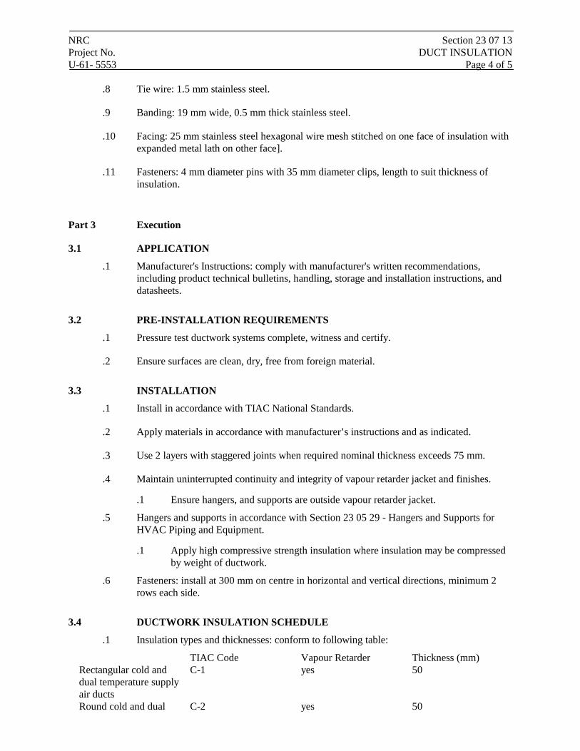
NRC Section 23 07 13 Project No. DUCT INSULATION U-61- 5553 Page 4 of 5
.8 Tie wire: 1.5 mm stainless steel.
.9 Banding: 19 mm wide, 0.5 mm thick stainless steel.
.10 Facing: 25 mm stainless steel hexagonal wire mesh stitched on one face of insulation with expanded metal lath on other face].
.11 Fasteners: 4 mm diameter pins with 35 mm diameter clips, length to suit thickness of insulation.
Part 3 Execution
3.1 APPLICATION
.1 Manufacturer's Instructions: comply with manufacturer's written recommendations, including product technical bulletins, handling, storage and installation instructions, and datasheets.
3.2 PRE-INSTALLATION REQUIREMENTS
.1 Pressure test ductwork systems complete, witness and certify.
.2 Ensure surfaces are clean, dry, free from foreign material.
3.3 INSTALLATION
.1 Install in accordance with TIAC National Standards.
.2 Apply materials in accordance with manufacturer’s instructions and as indicated.
.3 Use 2 layers with staggered joints when required nominal thickness exceeds 75 mm.
.4 Maintain uninterrupted continuity and integrity of vapour retarder jacket and finishes.
.1 Ensure hangers, and supports are outside vapour retarder jacket.
.5 Hangers and supports in accordance with Section 23 05 29 - Hangers and Supports for HVAC Piping and Equipment.
.1 Apply high compressive strength insulation where insulation may be compressed by weight of ductwork.
.6 Fasteners: install at 300 mm on centre in horizontal and vertical directions, minimum 2 rows each side.
3.4 DUCTWORK INSULATION SCHEDULE
.1 Insulation types and thicknesses: conform to following table:
TIAC Code Vapour Retarder Thickness (mm) Rectangular cold and dual temperature supply air ducts
C-1 yes 50
Round cold and dual C-2 yes 50
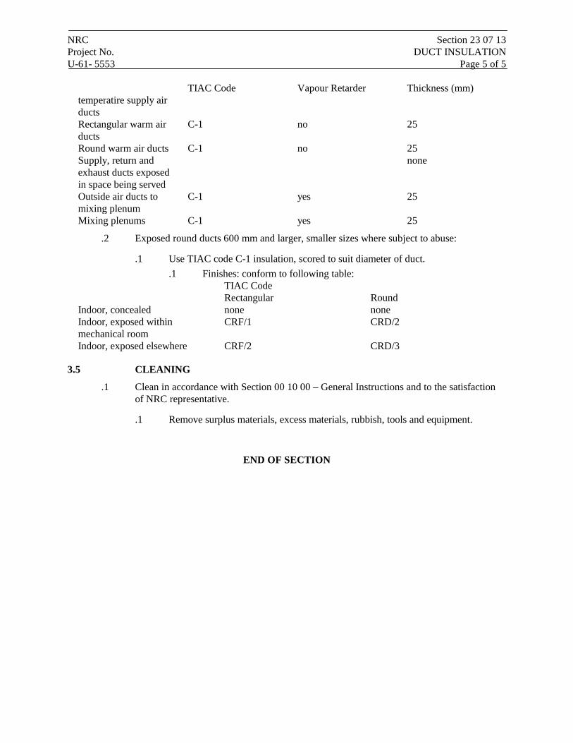
NRC Section 23 07 13 Project No. DUCT INSULATION U-61- 5553 Page 5 of 5
TIAC Code Vapour Retarder Thickness (mm) temperatire supply air ducts Rectangular warm air ducts
C-1 no 25
Round warm air ducts C-1 no 25 Supply, return and exhaust ducts exposed in space being served
none
Outside air ducts to mixing plenum
C-1 yes 25
Mixing plenums C-1 yes 25
.2 Exposed round ducts 600 mm and larger, smaller sizes where subject to abuse:
.1 Use TIAC code C-1 insulation, scored to suit diameter of duct. .1 Finishes: conform to following table:
TIAC Code Rectangular Round Indoor, concealed none none Indoor, exposed within mechanical room
CRF/1 CRD/2
Indoor, exposed elsewhere CRF/2 CRD/3
3.5 CLEANING
.1 Clean in accordance with Section 00 10 00 – General Instructions and to the satisfaction of NRC representative.
.1 Remove surplus materials, excess materials, rubbish, tools and equipment.
END OF SECTION
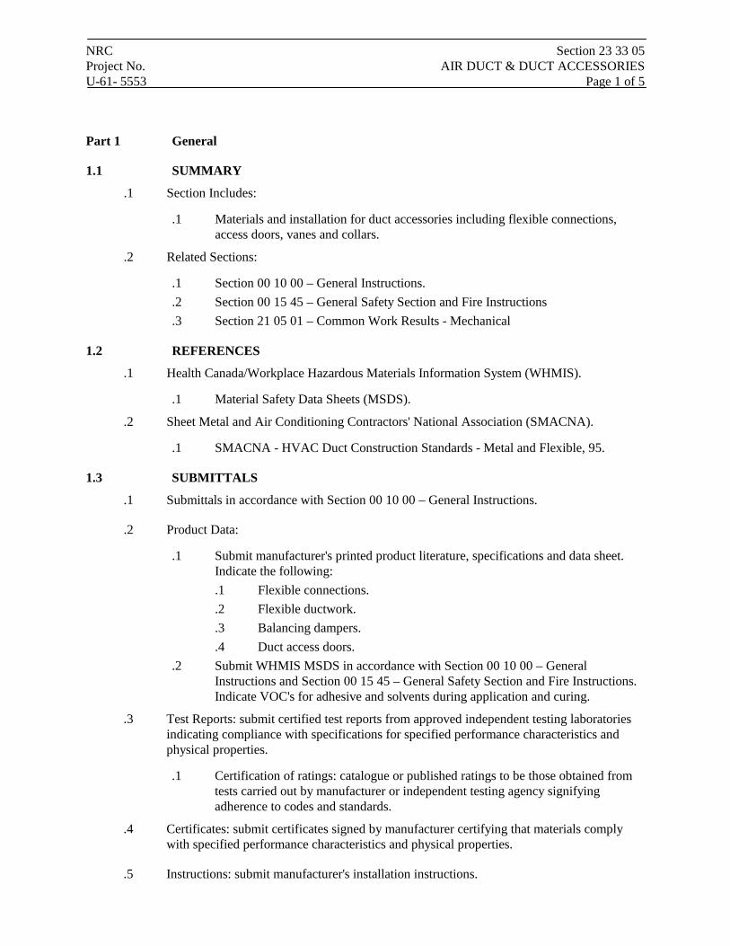
NRC Section 23 33 05 Project No. AIR DUCT & DUCT ACCESSORIES U-61- 5553 Page 1 of 5
Part 1 General
1.1 SUMMARY
.1 Section Includes:
.1 Materials and installation for duct accessories including flexible connections, access doors, vanes and collars.
.2 Related Sections:
.1 Section 00 10 00 – General Instructions.
.2 Section 00 15 45 – General Safety Section and Fire Instructions
.3 Section 21 05 01 – Common Work Results - Mechanical
1.2 REFERENCES
.1 Health Canada/Workplace Hazardous Materials Information System (WHMIS).
.1 Material Safety Data Sheets (MSDS).
.2 Sheet Metal and Air Conditioning Contractors' National Association (SMACNA).
.1 SMACNA - HVAC Duct Construction Standards - Metal and Flexible, 95.
1.3 SUBMITTALS
.1 Submittals in accordance with Section 00 10 00 – General Instructions.
.2 Product Data:
.1 Submit manufacturer's printed product literature, specifications and data sheet. Indicate the following: .1 Flexible connections. .2 Flexible ductwork. .3 Balancing dampers. .4 Duct access doors.
.2 Submit WHMIS MSDS in accordance with Section 00 10 00 – General Instructions and Section 00 15 45 – General Safety Section and Fire Instructions. Indicate VOC's for adhesive and solvents during application and curing.
.3 Test Reports: submit certified test reports from approved independent testing laboratories indicating compliance with specifications for specified performance characteristics and physical properties.
.1 Certification of ratings: catalogue or published ratings to be those obtained from tests carried out by manufacturer or independent testing agency signifying adherence to codes and standards.
.4 Certificates: submit certificates signed by manufacturer certifying that materials comply with specified performance characteristics and physical properties.
.5 Instructions: submit manufacturer's installation instructions.
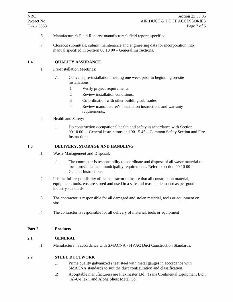
NRC Section 23 33 05 Project No. AIR DUCT & DUCT ACCESSORIES U-61- 5553 Page 2 of 5
.6 Manufacturer's Field Reports: manufacturer's field reports specified.
.7 Closeout submittals: submit maintenance and engineering data for incorporation into manual specified in Section 00 10 00 – General Instructions.
1.4 QUALITY ASSURANCE
.1 Pre-Installation Meetings:
.1 Convene pre-installation meeting one week prior to beginning on-site installations. .1 Verify project requirements. .2 Review installation conditions. .3 Co-ordination with other building sub-trades. .4 Review manufacturer's installation instructions and warranty
requirements.
.2 Health and Safety:
.1 Do construction occupational health and safety in accordance with Section 00 10 00. - General Instructions and 00 15 45 – Common Safety Section and Fire Instructions.
1.5 DELIVERY, STORAGE AND HANDLING
.1 Waste Management and Disposal:
.1 The contractor is responsibility to coordinate and dispose of all waste material to local provincial and municipality requirements. Refer to section 00 10 00 – General Instructions.
.2 It is the full responsibility of the contractor to insure that all construction material, equipment, tools, etc. are stored and used in a safe and reasonable manor as per good industry standards.
.3 The contractor is responsible for all damaged and stolen material, tools or equipment on site.
.4 The contractor is responsible for all delivery of material, tools or equipment
Part 2 Products
2.1 GENERAL
.1 Manufacture in accordance with SMACNA - HVAC Duct Construction Standards.
2.2 STEEL DUCTWORK .1 Prime quality galvanized sheet steel with metal gauges in accordance with
SMACNA standards to suit the duct configuration and classification. .2 Acceptable manufacturers are Flexmaster Ltd., Trans Continental Equipment Ltd.,
"Al-U-Flex", and Alpha Sheet Metal Co.
NRC Section 23 33 05 Project No. AIR DUCT & DUCT ACCESSORIES U-61- 5553 Page 3 of 5 2.3 FLEXIBLE DUCTWORK – INSULATED
.1 Flexmaster Triple Lock Type V U.L.C. listed flexible ductwork c/w a core of standard triple lock metal flexible ducting, factory supplied glass or mineral wool insulating blanket and an outer jacket of flexible PVC sheet.
.2 Acceptable manufacturers are Flexmaster Ltd., Trans Continental Equipment Ltd., "Al-U-Flex", and Alpha Sheet Metal Co.
2.4 BALANCING DAMPERS .1 Nailor-Hart Industries Inc. opposed blade galvanized steel control damper, Model
No. 1020 for rectangular ductwork, Model No. 1021 for round ductwork, each complete with No. 16 U.S.S. gauge frame, No. 18 U.S.S. gauge blades, nylon blade shaft bearings, linkage shaft extension, and a suitable and secure damper operator with locking device and visual indication of damper position from the duct exterior.
.2 Acceptable manufacturers are Nailor-Hart Industries Inc., Controlled Air Manufacturing Ltd., Ruskin Ltd., and Air Specialties Manufacturing Ltd.
2.5 DUCT ACCESS DOORS .1 General:
.1 Non-insulated sandwich construction of same material as duct, one sheet metal thickness heavier, minimum 0.7 mm thick (No. 24 gauge) complete with sheet metal angle frame.
.2 Insulated sandwich construction of same material as duct, one sheet metal thickness heavier, minimum 0.7 mm thick No. 24 gauge) complete with sheet metal angle frame and 25mm (1") thick rigid glass fibre insulation.
.2 Gaskets: neoprene or foam rubber.
.3 Hardware: .1 Up to 300 x 300 mm (12" x 12"): 2 sash locks. .2 301 to 450 mm (12" x 18"): 4 sash locks.
2.6 GRILLES, REGISTERS & DIFFUSERS .1 Grilles, registers and diffusers of the type, size and arrangement as specified on
the drawings. .2 Grilles, registers and diffusers shall be product of one manufacturer. .3 Catalogued or published ratings shall be those obtained from tests carried out by
manufacturer or those ordered by him from independent testing agency signifying adherence to codes and standards.
.4 Acceptable manufacturers are E.H. Price Ltd., Titus Ltd., Air Vector Ltd., Nailor Industries Inc., Krueger Manufacturing Co. and Carnes.
NRC Section 23 33 05 Project No. AIR DUCT & DUCT ACCESSORIES U-61- 5553 Page 4 of 5 Part 3 Execution
3.1 MANUFACTURER'S INSTRUCTIONS
.1 Compliance: comply with manufacturer's written recommendations or specifications, including product technical bulletins, handling, storage and installation instructions, and data sheet.
3.2 INSTALLATION
.1 DUCT, DAMPER & SIMILAR FORMED OPENINGS
.1 Duct openings, air inlet and outlet openings, fire damper openings, etc. will be provided in poured concrete work, masonry, drywall surfaces, etc., by the trade responsible for the particular construction in which the opening is required.
.2 Ensure that openings for fire dampers to 350 mm (14") high are sized to suit the damper arrangement with folding blade out of the air stream.
.2 FABRICATION & INSTALLATION OF STEEL DUCTWORK
.1 Provide all required steel ductwork. Unless otherwise noted, all ductwork shall be constructed of galvanized steel.
.2 Unless specifically noted otherwise, all duct, bends, elbows, transformations, branch fittings, etc. shall be fabricated, sealed and installed in accordance with the 1" water gauge (0.25 kPa) pressure class of the latest edition of SMACNA Hvac Duct Construction Standards, except for duct upstream of VAV boxes, which shall comply with the requirements of the 2" water gauge (0.50 kPa) pressure class..
.3 FLEXIBLE DUCTWORK
.1 Install flexible ductwork where indicated.
.2 At connections between sheet metal ducts and flexible ducts, provide galvanized steel round to rectangular duct connections as specified hereinbefore.
.3 Install flexible ducts as straight as possible, secure at each end with steel gear type clamps, and seal joints. Where bends are required, they shall be long radius.
.4 Maximum length of flexible duct to be 3m (10').
.4 BALANCING DAMPERS
.1 Provide volume type dampers in all open end ductwork and wherever else shown.
.2 Install the dampers such that the operating mechanism is positioned for easy operation, and such that the dampers cannot move or rattle.
.5 DUCT ACCESS DOORS
.1 Provide access doors in ductwork for access to all duct system components which will or may need maintenance and/or repair.
.2 Size: .1 300 x 300 mm for viewing. .2 As indicated.
.3 Locations:
NRC Section 23 33 05 Project No. AIR DUCT & DUCT ACCESSORIES U-61- 5553 Page 5 of 5
.1 Devices requiring maintenance.
.2 Required by code.
.3 Elsewhere as indicated. .4 Identify access doors provided for fusible link fire damper maintenance as such. .5 Access doors in insulated ductwork shall be sandwich construction type with
insulation between the inner and outer panels.
.6 GRILLES, REGISTERS & DIFFUSERS
.1 Provide grilles and diffusers of the type, size and arrangement specified and shown on the drawings.
.2 Exactly locate grilles and diffusers to conform to the final architectural reflected ceiling plans and detailed wall elevations, and to conform to the final lighting, ceiling layout, ornamental and other wall treatment.
.3 Equip supply diffusers having a basic four-way or all round air pattern for operation in one (1), two (2) or three (3) way pattern where so directed on the drawings.
.4 Confirm finish of grilles, registers and diffusers prior to ordering.
3.3 CLEANING
.1 Perform cleaning operations as specified in Section 00 10 00 – General Instructions in accordance with manufacturer's recommendations and to the satisfaction of the NRC representative.
.2 Upon completion and verification of performance of installation, remove surplus materials, excess materials, rubbish, tools and equipment.
END OF SECTION
NRC Section 23 37 13 Project No. DIFFUSERS, REGISTERS AND GRILLES U-61- 5553 Page 1 of 3
Part 1 General
1.1 SUMMARY .1 Section Includes:
.1 Supply, return and exhaust grilles and registers, diffusers and linear grilles, for commercial and residential use.
.2 Related Sections: .1 Section 00 10 00 – General Instructions. .2 Section 00 15 45 – General Safety Section and Fire Instructions .3 Section 21 05 01 – Common Work Results- Mechanical .4 Section 21 05 02 – Mechanical Identification .5 Section 23 05 13 – Common Motor Requirements for HVAC .6 Section 23 05 93 – Testing, Adjusting and Balancing for HVAC
1.2 SYSTEM DESCRIPTION .1 Performance Requirements:
.1 Catalogued or published ratings for manufactured items: obtained from tests carried out by manufacturer or those ordered by manufacturer from independent testing agency signifying adherence to codes and standards.
1.3 SUBMITTALS .1 Product Data:
.1 Submit manufacturer's printed product literature, specifications and datasheet in accordance with Section 00 10 00 – General Instructions. Include product characteristics, performance criteria, and limitations.
.2 Indicate following: .1 Capacity. .2 Throw and terminal velocity. .3 Noise criteria. .4 Pressure drop. .5 Neck velocity.
.2 Quality assurance submittals: submit following in accordance with Section 00 10 00 – General Instructions.
1.4 QUALITY ASSURANCE .1 Health and Safety Requirements: do construction occupational health and safety
in accordance with Section 00 15 45 – General Safety Section and Fire Instructions.
1.5 DELIVERY, STORAGE, AND HANDLING .1 Packing, shipping, handling and unloading:
.1 Deliver, store and handle in accordance with Section 00 10 00 – General Instructions.
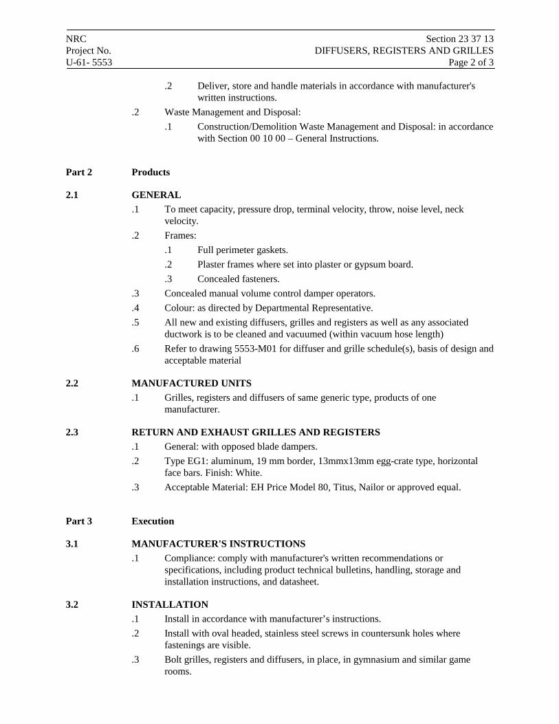
NRC Section 23 37 13 Project No. DIFFUSERS, REGISTERS AND GRILLES U-61- 5553 Page 2 of 3
.2 Deliver, store and handle materials in accordance with manufacturer's written instructions.
.2 Waste Management and Disposal: .1 Construction/Demolition Waste Management and Disposal: in accordance
with Section 00 10 00 – General Instructions.
Part 2 Products
2.1 GENERAL .1 To meet capacity, pressure drop, terminal velocity, throw, noise level, neck
velocity. .2 Frames:
.1 Full perimeter gaskets.
.2 Plaster frames where set into plaster or gypsum board.
.3 Concealed fasteners. .3 Concealed manual volume control damper operators. .4 Colour: as directed by Departmental Representative. .5 All new and existing diffusers, grilles and registers as well as any associated
ductwork is to be cleaned and vacuumed (within vacuum hose length) .6 Refer to drawing 5553-M01 for diffuser and grille schedule(s), basis of design and
acceptable material
2.2 MANUFACTURED UNITS .1 Grilles, registers and diffusers of same generic type, products of one
manufacturer.
2.3 RETURN AND EXHAUST GRILLES AND REGISTERS .1 General: with opposed blade dampers. .2 Type EG1: aluminum, 19 mm border, 13mmx13mm egg-crate type, horizontal
face bars. Finish: White. .3 Acceptable Material: EH Price Model 80, Titus, Nailor or approved equal.
Part 3 Execution
3.1 MANUFACTURER'S INSTRUCTIONS .1 Compliance: comply with manufacturer's written recommendations or
specifications, including product technical bulletins, handling, storage and installation instructions, and datasheet.
3.2 INSTALLATION .1 Install in accordance with manufacturer’s instructions. .2 Install with oval headed, stainless steel screws in countersunk holes where
fastenings are visible. .3 Bolt grilles, registers and diffusers, in place, in gymnasium and similar game
rooms.

NRC Section 23 37 13 Project No. DIFFUSERS, REGISTERS AND GRILLES U-61- 5553 Page 3 of 3 3.3 CLEANING
.1 Proceed in accordance with Section 00 10 00 – General Instructions and to the satisfaction of the NRC representative.
.2 Upon completion and verification of performance of installation, remove surplus materials, excess materials, rubbish, tools and equipment.
END OF SECTION
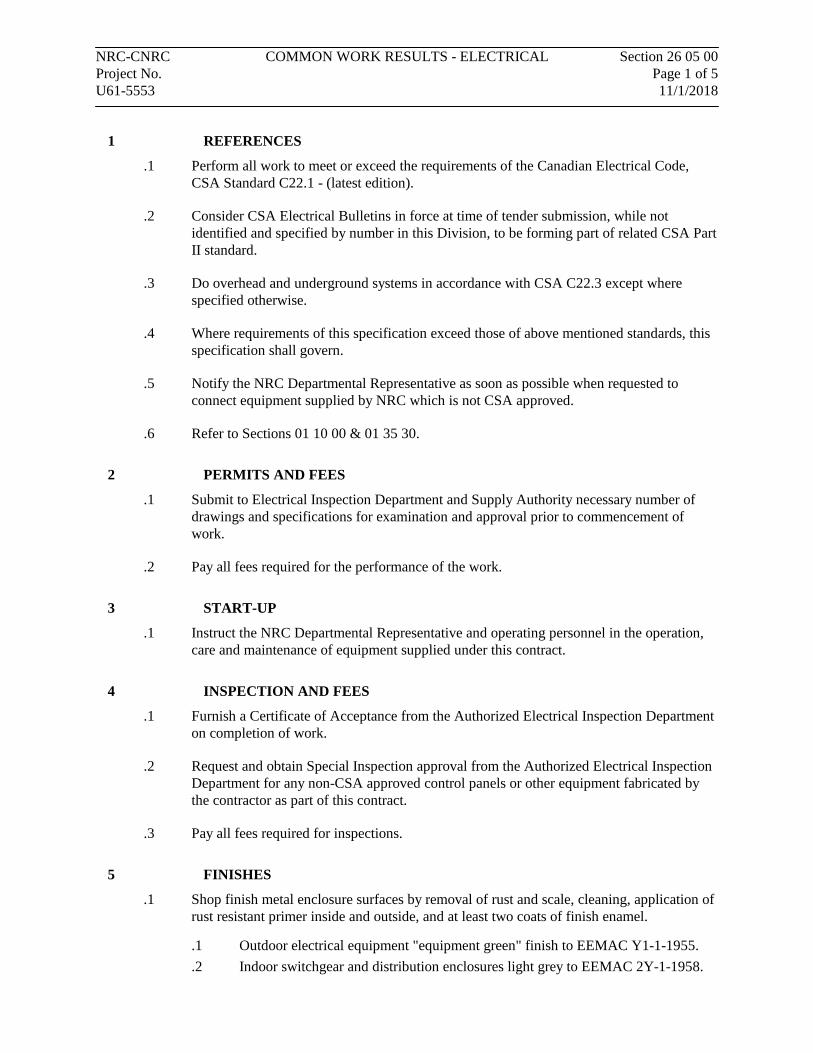
NRC-CNRC COMMON WORK RESULTS - ELECTRICAL Section 26 05 00 Project No. Page 1 of 5 U61-5553 11/1/2018
1 REFERENCES
.1 Perform all work to meet or exceed the requirements of the Canadian Electrical Code, CSA Standard C22.1 - (latest edition).
.2 Consider CSA Electrical Bulletins in force at time of tender submission, while not identified and specified by number in this Division, to be forming part of related CSA Part II standard.
.3 Do overhead and underground systems in accordance with CSA C22.3 except where specified otherwise.
.4 Where requirements of this specification exceed those of above mentioned standards, this specification shall govern.
.5 Notify the NRC Departmental Representative as soon as possible when requested to connect equipment supplied by NRC which is not CSA approved.
.6 Refer to Sections 01 10 00 & 01 35 30.
2 PERMITS AND FEES
.1 Submit to Electrical Inspection Department and Supply Authority necessary number of drawings and specifications for examination and approval prior to commencement of work.
.2 Pay all fees required for the performance of the work.
3 START-UP
.1 Instruct the NRC Departmental Representative and operating personnel in the operation, care and maintenance of equipment supplied under this contract.
4 INSPECTION AND FEES
.1 Furnish a Certificate of Acceptance from the Authorized Electrical Inspection Department on completion of work.
.2 Request and obtain Special Inspection approval from the Authorized Electrical Inspection Department for any non-CSA approved control panels or other equipment fabricated by the contractor as part of this contract.
.3 Pay all fees required for inspections.
5 FINISHES
.1 Shop finish metal enclosure surfaces by removal of rust and scale, cleaning, application of rust resistant primer inside and outside, and at least two coats of finish enamel.
.1 Outdoor electrical equipment "equipment green" finish to EEMAC Y1-1-1955.
.2 Indoor switchgear and distribution enclosures light grey to EEMAC 2Y-1-1958.
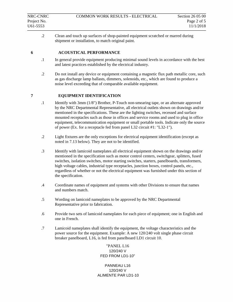
NRC-CNRC COMMON WORK RESULTS - ELECTRICAL Section 26 05 00 Project No. Page 2 of 5 U61-5553 11/1/2018
.2 Clean and touch up surfaces of shop-painted equipment scratched or marred during shipment or installation, to match original paint.
6 ACOUSTICAL PERFORMANCE
.1 In general provide equipment producing minimal sound levels in accordance with the best and latest practices established by the electrical industry.
.2 Do not install any device or equipment containing a magnetic flux path metallic core, such as gas discharge lamp ballasts, dimmers, solenoids, etc., which are found to produce a noise level exceeding that of comparable available equipment.
7 EQUIPMENT IDENTIFICATION
.1 Identify with 3mm (1/8") Brother, P-Touch non-smearing tape, or an alternate approved by the NRC Departmental Representative, all electrical outlets shown on drawings and/or mentioned in the specifications. These are the lighting switches, recessed and surface mounted receptacles such as those in offices and service rooms and used to plug in office equipment, telecommunication equipment or small portable tools. Indicate only the source of power (Ex. for a receptacle fed from panel L32 circuit #1: "L32-1").
.2 Light fixtures are the only exceptions for electrical equipment identification (except as noted in 7.13 below). They are not to be identified.
.3 Identify with lamicoid nameplates all electrical equipment shown on the drawings and/or mentioned in the specification such as motor control centers, switchgear, splitters, fused switches, isolation switches, motor starting switches, starters, panelboards, transformers, high voltage cables, industrial type receptacles, junction boxes, control panels, etc., regardless of whether or not the electrical equipment was furnished under this section of the specification.
.4 Coordinate names of equipment and systems with other Divisions to ensure that names and numbers match.
.5 Wording on lamicoid nameplates to be approved by the NRC Departmental Representative prior to fabrication.
.6 Provide two sets of lamicoid nameplates for each piece of equipment; one in English and one in French.
.7 Lamicoid nameplates shall identify the equipment, the voltage characteristics and the power source for the equipment. Example: A new 120/240 volt single phase circuit breaker panelboard, L16, is fed from panelboard LD1 circuit 10.
"PANEL L16 120/240 V
FED FROM LD1-10"
PANNEAU L16 120/240 V
ALIMENTE PAR LD1-10

NRC-CNRC COMMON WORK RESULTS - ELECTRICAL Section 26 05 00 Project No. Page 3 of 5 U61-5553 11/1/2018
.8 Provide warning labels for equipment fed from two or more sources - "DANGER MULTIPLE POWER FEED" black letters on a yellow background. These labels are available from NRC's Facilities Maintenance group in building M-19.
.9 Lamicoid nameplates shall be rigid lamicoid, minimum 1.5 mm (1/16") thick with:
.1 Black letters engraved on a white background for normal power circuits.
.2 Black letters engraved on a yellow background for emergency power circuits.
.3 White letters engraved on a red background for fire alarm equipment.
.10 For all interior lamicoid nameplates, mount nameplates using two-sided tape.
.11 For all exterior lamicoid nameplates, mount nameplates using self-tapping 2.3 mm (3/32") dia. slot head screws - two per nameplate for nameplates under 75 mm (3") in height and a minimum of 4 for larger nameplates. Holes in lamicoid nameplates to be 3.7 mm (3/16") diameter to allow for expansion of lamicoid due to exterior conditions.
.1 No drilling is to be done on live equipment.
.2 Metal filings from drilling are to be vacuumed from the enclosure interiors.
.12 All lamicoid nameplates shall have a minimum border of 3 mm (1/8"). Characters shall be 9 mm (3/8") in size unless otherwise specified.
.13 Identify lighting fixtures which are connected to emergency power with a label "EMERGENCY LIGHTING/ÉCLAIRAGE D'URGENCE", black letters on a yellow background. These labels are available from NRC's Facilities Maintenance group in building M-19.
.14 Provide neatly typed updated circuit directories in a plastic holder on the inside door of new panelboards.
.15 Carefully update panelboard circuit directories whenever adding, deleting, or modifying existing circuitry.
.16 Identify molded case breaker with lamicoid nameplate.
8 WIRING IDENTIFICATION
.1 Unless otherwise specified, identify wiring with permanent indelible identifying markings, using either numbered or coloured plastic tapes on both ends of phase conductors of feeders and branch circuit wiring.
.2 Maintain phase sequence and colour coding throughout.
9 CONDUIT AND CABLE IDENTIFICATION
.1 All new conduits to be factory painted, colour-coded EMT, type as follows:
.1 Fire alarm – red conduit
.2 Emergency power circuits – yellow conduit
.3 Voice/data – blue conduit
.4 Gas detection system – purple conduit
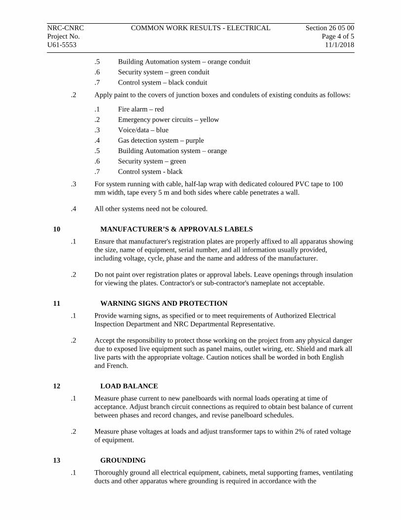
NRC-CNRC COMMON WORK RESULTS - ELECTRICAL Section 26 05 00 Project No. Page 4 of 5 U61-5553 11/1/2018
.5 Building Automation system – orange conduit
.6 Security system – green conduit
.7 Control system – black conduit
.2 Apply paint to the covers of junction boxes and condulets of existing conduits as follows:
.1 Fire alarm – red
.2 Emergency power circuits – yellow
.3 Voice/data – blue
.4 Gas detection system – purple
.5 Building Automation system – orange
.6 Security system – green
.7 Control system - black
.3 For system running with cable, half-lap wrap with dedicated coloured PVC tape to 100 mm width, tape every 5 m and both sides where cable penetrates a wall.
.4 All other systems need not be coloured.
10 MANUFACTURER’S & APPROVALS LABELS
.1 Ensure that manufacturer's registration plates are properly affixed to all apparatus showing the size, name of equipment, serial number, and all information usually provided, including voltage, cycle, phase and the name and address of the manufacturer.
.2 Do not paint over registration plates or approval labels. Leave openings through insulation for viewing the plates. Contractor's or sub-contractor's nameplate not acceptable.
11 WARNING SIGNS AND PROTECTION
.1 Provide warning signs, as specified or to meet requirements of Authorized Electrical Inspection Department and NRC Departmental Representative.
.2 Accept the responsibility to protect those working on the project from any physical danger due to exposed live equipment such as panel mains, outlet wiring, etc. Shield and mark all live parts with the appropriate voltage. Caution notices shall be worded in both English and French.
12 LOAD BALANCE
.1 Measure phase current to new panelboards with normal loads operating at time of acceptance. Adjust branch circuit connections as required to obtain best balance of current between phases and record changes, and revise panelboard schedules.
.2 Measure phase voltages at loads and adjust transformer taps to within 2% of rated voltage of equipment.
13 GROUNDING
.1 Thoroughly ground all electrical equipment, cabinets, metal supporting frames, ventilating ducts and other apparatus where grounding is required in accordance with the
NRC-CNRC COMMON WORK RESULTS - ELECTRICAL Section 26 05 00 Project No. Page 5 of 5 U61-5553 11/1/2018
requirements of the latest edition of the Canadian Electrical Code Part 1, C.S.A. C22.1 and corresponding Provincial and Municipal regulations. Do not depend upon conduits to provide the ground circuits.
.2 Run separate green insulated stranded copper grounding conductors in all electrical conduits including those feeding toggle switches and receptacles.
14 TESTS
.1 Provide any materials, equipment and labour required and make such tests deemed necessary to show proper execution of this work, in the presence of the NRC Departmental Representative.
.2 Correct any defects or deficiencies discovered in the work in an approved manner at no additional expense to the Owner.
.3 Megger all branch circuits and feeders using a 600V tester for 240V circuits and a 1000V tester for 600V circuits. If the resistance to ground is less than permitted by Table 24 of the Code, consider such circuits defective and do not energize.
.4 The final approval of insulation between conductors and ground, and the efficiency of the grounding system is left to the discretion of the local Electrical Inspection Department.
15 COORDINATION OF PROTECTIVE DEVICES
.1 Ensure circuit protective devices such as overcurrent trips, fuses, are installed to values and settings as indicated on the Drawings.
16 WORK ON LIVE EQUIPMENT & PANELS
.1 NRC requires that work be performed on non-energized equipment, installation, conductors and power panels. For purposes of quotation assume that all work is to be done after normal working hours and that equipment, installation, conductors and power panels are to be de-energized when worked upon.
END OF SECTION
NRC-CNRC WIRES AND CABLES (0-1000V) Section 26 05 21 Project No. Page 1 of 2 U61-5553 11/1/2018
Part 1 General
1.1 RELATED WORK SPECIFIED ELSEWHERE
.1 Common Work Results - Electrical Section 26 05 00
1.2 MATERIALS
.1 Provide only new equipment and materials, without blemish or defect, bearing Canadian Standards Association or Authorized Electrical Inspection Department labels, and subject to the approval of the NRC Departmental Representative.
.2 After a contract is awarded, utilize alternative methods and/or materials only after receiving the NRC Departmental Representative’s approval.
Part 2 Products
2.1 BUILDING WIRES AND GENERAL REQUIREMENTS
.1 Conductor material for branch circuit wiring and grounding:
.1 Stranded copper.
.2 Neutral wire: continuous throughout its length without breaks.
.3 Separate insulated green grounding conductors in all electrical conduits.
.4 All wire and cable insulation shall meet the C.S.A. Standards for the types and services hereinafter specified. Colours as per section 4-036 of Electrical Code.
.5 Where otherwise specified, use wire and cable types as follows: .1 Type R90 XLPE cross-link polyethylene stranded for applications using
wires sized No. 8 and larger. .2 Type T90 stranded for applications using wires sized No. 10 and smaller. .3 For fire alarm wiring refer to Section 283100. .4 Approved heat resistant wire for wiring through and at lighting and
heating fixtures. Where insulation types are shown on the drawings other types shall not be used unless the specification is more restrictive.
.6 Use AC90 (BX) cable only under the following conditions: .1 Wiring from a junction box to a recessed lighting fixture in suspended
ceilings. Cable length not to exceed 1.5 m (5'), or .2 Wiring switches or receptacles in existing or new hollow gypsum
partitions, vertical runs only with cable length not to exceed 3.5m (12’), or
.3 When specifically called for on drawings or approved in writing by departmental representative.
.4 AC90 shall not be used in isolated walls or masonry walls.
.5 Only AC90 cable of No. 12 AWG will be accepted. .7 Use stranded wire no smaller than No. 12 AWG for lighting and power and no
smaller than No. 16 AWG for control wiring.

NRC-CNRC WIRES AND CABLES (0-1000V) Section 26 05 21 Project No. Page 2 of 2 U61-5553 11/1/2018
.8 Conductors shall be soft copper properly refined and tinned having a minimum conductivity of 98%.
Part 3 Execution
3.1 BUILDING WIRES
.1 Install building wires as follows:
.1 Make joints, taps and splices in approved boxes with solderless connectors. Joints and/or splices are not acceptable inside a panelboard.
.2 Ensure the lugs accommodate all the strands of the conductor.
.3 Replace any wire or cable showing evidence of mechanical injury.
.4 Use No. 10 AWG for branch circuit wiring extending more than 30 m (100 ft.) to farthest outlet from panel.
.5 Circuit numbers indicated on the drawing are intended as a guide for the proper connection of multi-wire circuits at the panel.
.6 Take care to keep the conductors free from twisting.
.7 Use an approved lubricant for pulling in conduit.
.8 Leave sufficient slack on all runs to permit proper splicing and connection of electrical devices.
.9 Branch circuit wiring of 120 volt applications to be multi-wire utilizing common neutrals. Under no condition shall any switch break a neutral conductor.
.10 Provide and install an approved fire- retardant wrap or coating for PVC jacketed cables installed in a grouped configuration of two or more.
END OF SECTION
NRC-CNRC CONNECTORS AND TERMINATIONS Section 26 05 22 Project No. Page 1 of 2 U61-5553 11/1/2018
Part 1 General
1.1 RELATED WORK SPECIFIED ELSEWHERE
.1 Common Work Results - Electrical Section 26 05 00
1.2 MATERIALS
.1 Provide only new equipment and materials, without blemish or defect, bearing Canadian Standards Association or Authorized Electrical Inspection Department labels, and subject to the approval of the NRC Departmental Representative.
.2 After a contract is awarded, utilize alternative methods and/or materials only after receiving the NRC Departmental Representative’s approval.
Part 2 Products
2.1 WIRE AND BOX CONNECTORS
.1 Pressure type wire connectors sized to fit conductors.
2.2 WIRING TERMINATIONS
.1 Provide first grade wire and cable connectors suitable for the service on which they are used and install them in accordance with the latest trade practice.
.2 Provide high quality extruded copper-free aluminium (0.4% or less) connectors for single and multi conductor cable. Steel and then zinc plated connectors for multi conductor cables.
.3 When used in hazardous area, connectors should be certified for such location in Class, Division and Group.
.4 For large conductor sizes, use bolted or compression solderless type connectors.
.5 Use high temperature connectors and insulation on all connections of high temperature conductors.
.6 Where connector types are called for on the drawings or in the specification, do not use other types.
.7 Lugs, terminals, screws used for termination of wiring to be suitable for copper conductors.
NRC-CNRC CONNECTORS AND TERMINATIONS Section 26 05 22 Project No. Page 2 of 2 U61-5553 11/1/2018
Part 3 Execution
3.1 INSTALLATION
.1 Install stress cones, terminations, and splices in accordance with manufacturer's instructions.
.2 Bond and ground as required [to CSA C22.2No.41].
END OF SECTION
NRC-CNRC OUTLET BOXES, CONDUIT BOXES AND FITTINGS Section 26 05 32 Project No. Page 1 of 2 U61-5553 11/1/2018
Part 1 General
1.1 RELATED WORK SPECIFIED ELSEWHERE
.1 Common Work Results - Electrical Section 26 05 00
1.2 MATERIALS
.1 Provide only new equipment and materials, without blemish or defect, bearing Canadian Standards Association or Authorized Electrical Inspection Department labels, and subject to the approval of the NRC Departmental Representative.
.2 After a contract is awarded, utilize alternative methods and/or materials only after receiving the NRC Departmental Representative’s approval.
Part 2 Products
2.1 FITTINGS
.1 Fittings: manufactured for use with conduit specified. Coating: same as conduit.
.2 Steel coupling for EMT.
.3 Fittings for liquid-tight flexible conduits shall be liquid-tight connectors.
.4 Provide expansion couplings for all conduits running in slabs through expansion joints. These shall be the type approved for use in concrete with a bonding conductor.
.5 Factory bends are not permitted to be modified. Ensure conduit bends other than factory bends are made with an approved bender. Making offsets and other bends by cutting and rejoining factory bends are not permitted.
2.2 OUTLET BOXES
.1 Size boxes in accordance with CSA-C22.
.2 Unless otherwise specified, provide galvanized steel outlet boxes at least 40mm (1-1/2") deep, single or ganged style, of proper size to accommodate devices used and shall be equipped with covers as necessary of the type designed for the specified fittings. Pull boxes shall be steel and shall be galvanized or painted to prevent rusting. For lighting fixture outlets, use 100mm (4") octagon boxes.
.3 Equip with plaster rings for flush mounting devices in finished walls.
.4 Blank cover plates for boxes without wiring devices.
.5 Equip with centre fixture studs for light fixtures.
.6 Use cast boxes where indicated and for surface mounted wiring. In areas above hung ceilings where appearance is not significant, pressed steel surface boxes may be used.
NRC-CNRC OUTLET BOXES, CONDUIT BOXES AND FITTINGS Section 26 05 32 Project No. Page 2 of 2 U61-5553 11/1/2018
.7 Supply all outlet boxes and pull boxes sized according to code requirements unless specified otherwise on the drawings.
2.3 SUPPORT HARDWARE
.1 Use 10mm (3/8") threaded rod for suspended unistrut and conduit.
.2 Unless otherwise specified, use 41mm x 41mm (1-5/8" x 1-5/8") galvanized steel unistrut for conduit support systems.
Part 3 Execution
3.1 INSTALLATION
.1 Install outlet boxes as follows:
.1 Support boxes independently of connecting conduits.
.2 Make necessary mounting adjustments to the outlet to match interior finish.
.3 Fill boxes with paper, sponges or foam or similar approved material to prevent entry of construction material.
.4 Where more than one conduit enters a switch or receptacle box on the same side, provide a 100mm (4") minimum square box with a suitable plaster ring.
.5 Location and appearance to be to the NRC Departmental Representative's approval.
END OF SECTION
NRC-CNRC RACEWAYS FOR ELECTRICAL SYSTEMS Section 26 05 33 Project No. Page 1 of 2 U61-5553 11/1/2018
Part 1 General
1.1 RELATED WORK SPECIFIED ELSEWHERE
.1 Common Work Results - Electrical Section 26 05 00
1.2 MATERIALS
.1 Provide only new equipment and materials, without blemish or defect, bearing Canadian Standards Association or Authorized Electrical Inspection Department labels, and subject to the approval of the NRC Departmental Representative.
.2 After a contract is awarded, utilize alternative methods and/or materials only after receiving the NRC Departmental Representative’s approval.
Part 2 Products
2.1 RACEWAYS
.1 Conduit:
.1 Each length of conduit to be new and bear the CSA Stamp of Approval.
.2 Conduit, unless otherwise noted, to be EMT, no smaller than 16mm (1/2").
.3 Conduit to be coloured as required for systems described in section 260500.9.
.2 Bushings and Connectors:
.1 Insulated type, with the insulation an integral part of the fitting.
.3 Conduit Fastening:
.1 One hole malleable iron straps to secure surface conduits. Two hole straps for conduits larger than 50mm (2").
.2 Beam clamps to secure conduits to exposed steel work.
.3 Channel type supports for two or more conduits.
.4 Pull Cord:
.1 Polypropylene cord in empty conduit.
.5 Unless specifically called for on the drawings, do not use flexible conduits but it is recognized that there may be applications where this material will be useful, such as equipment connections, etc. In such cases, obtain permission for its use from the NRC Departmental Representative. For tender purposes, assume that flexible conduits will not be permitted unless specifically called for on the drawings or equipment specifications. All flexible conduits for vapour-tight applications shall be liquid-tight flexible conduits (seal-tight).
.6 Provide expansion couplings for all conduits running in slabs through expansion joints. These shall be the type approved for use in concrete with a bonding conductor.
NRC-CNRC RACEWAYS FOR ELECTRICAL SYSTEMS Section 26 05 33 Project No. Page 2 of 2 U61-5553 11/1/2018
2.2 SUPPORT HARDWARE
.1 Use 10mm (3/8") threaded rod for suspended unistrut and conduit.
.2 Unless otherwise specified, use 41mm x 41mm (1-5/8" x 1-5/8") galvanized steel unistrut for conduit support systems.
Part 3 Execution
3.1 RACEWAYS
.1 Install raceways as follows:
.1 Rigidly supported.
.2 Workmanlike manner.
.3 Maintain maximum headroom.
.4 Concealed in finished area.
.5 Surface-mounted in open area.
.6 Do not pass conduits through structural members except as indicated.
.7 Parallel to or at right angles to the building lines.
.8 Thoroughly ream all conduits at ends and terminate with appropriate locknuts and bushings.
.9 Cause minimum interference in spaces through which they pass.
.10 Plug or cap conduit during construction to protect from dust, dirt or water.
.11 Unless specifically indicated on drawings or with the permission of the NRC Departmental Representative, do not cast conduits in concrete.
.12 Dry conduits out before installing wire.
.13 Mechanically bend conduit of any size. Bend conduit cold.
.14 Do not cut or modify prefabricated bends.
.15 PVC conduit as indicated.
.16 Function and appearance to be to the NRC Departmental Representative's approval.
.17 Seal conduit and cable openings in fire- rated walls and floors with an approved fire stop material.
.18 Seal conduit and cable openings in exterior walls with a weatherproof silicone sealant.
.19 Paint exposed conduits and boxes to match existing wall / ceiling except the colored EMT specified in 260500.
END OF SECTION
NRC-CNRC WIRING DEVICES Section 26 27 26 Project No. Page 1 of 3 U61-5553 11/1/2018
Part 1 General
1.1 MATERIALS
.1 Provide only new equipment and materials, without blemish or defect, bearing Canadian Standards Association or Authorized Electrical Inspection Department labels, and subject to the approval of the NRC Departmental Representative.
.2 After a contract is awarded, utilize alternative methods and/or materials only after receiving the NRC Departmental Representative's approval.
1.2 SHOP DRAWINGS AND PRODUCT DATA
.1 Submit shop drawings and product data in accordance with Section 01 10 00.
1.3 IDENTIFICATION
.1 Identification as per Section 26 05 00.
Part 2 Products
2.1 WIRING DEVICES
.1 Switches:
.1 Specification grade, shallow body, designed to withstand high inductive fluorescent loads CSA C22.2 No. 55.
.2 Number of poles as indicated.
.3 Captive mounting screws, quiet safe mechanical action with rust-proofed mounting strap and silver alloy contact points.
.4 Toggle actuated, colour white unless otherwise indicated.
.5 Brass screw terminals rated 20 AMP at 125 volt.
.6 Standard of acceptance: Hubbell, Leviton.
.2 LED occupancy sensor (wall mounted):
.1 120V, suitable for use with installed light fixture.
.2 Rated for 600W LED.
.3 Can be set to Manual-ON/Automatic-OFF or Auto-ON/Auto-OFF.
.4 Adjustable delayed-OFF time.
.5 Suitable for use in “3-way” configuration where indicated.
.6 Fire year warranty.
.7 Standard of acceptance: Hubbell, Leviton, Philips or equivalent approved by NRC Departmental Representative.
.3 LED occupancy sensor (ceiling mounted):
.1 120V, suitable for use with installed light fixture.
NRC-CNRC WIRING DEVICES Section 26 27 26 Project No. Page 2 of 3 U61-5553 11/1/2018
.2 360° coverage pattern.
.3 No minimum load requirements.
.4 Adjustable delayed-OFF time.
.5 No field calibration or sensitivity adjustments required.
.6 Fire year warranty.
.7 Standard of acceptance: Philips LRM2377 or equivalent approved by NRC Departmental Representative.
.4 Receptacles:
.1 Duplex type, CSA type 5-15R, 125 volt, 15A, U ground, specification grade with the following features:
.1 Flush type with parallel blade slots.
.2 Double-wiping contacts.
.3 Double-grounding terminals.
.4 Break-off feature for separate feeds.
.5 One piece body, colour white unless otherwise indicated. .2 Special receptacles with ampacity and voltage as indicated. .3 Receptacles of one manufacturer throughout the project.
.5 Cover Plates:
.1 Cover plates for wiring devices.
.2 Smooth white plastic for wiring devices mounted in flush-mounted outlet box.
.3 Sheet metal cover plates for wiring devices mounted in surface-mounted outlet box.
.4 Multi-outlet covers as indicated.
Part 3 Execution
3.1 LOCATION OF OUTLETS
.1 The number and general location of outlets for lighting, power, telephones, etc., are to be as shown on the drawings. Install all outlets accurately and uniformly with respect to building details. When centering outlets, make allowance for overhead pipes, ducts, etc. and for variations in wall or ceiling finish, window trim, etc. Reinstall incorrectly installed outlets at no cost to the Owner. Make field power and control connections as indicated.
.2 The location of all outlets as shown on the plans are approximate and are subject to change, up to 3m (10') without extra cost or credit provided the information is given prior to the installation of the outlet.
.3 Unless otherwise specified, locate light switches on latch side of doors. Determine the direction of all door swings from the architectural drawings or on site, not from the electrical drawings.
.4 Locate roof top maintenance receptacle within 7.5m of the rooftop electrical equipment.

NRC-CNRC WIRING DEVICES Section 26 27 26 Project No. Page 3 of 3 U61-5553 11/1/2018
3.2 MOUNTING HEIGHTS
.1 Mounting height of equipment is from finished floor to centreline of equipment unless specified or indicated otherwise.
.2 If mounting height of equipment is not indicated verify before proceeding with installation.
.3 Generally, locate outlets as follows: (except those otherwise shown on the drawings):
.1 Local switches 1.2m (3'-11") to centreline.
.2 Wall receptacles 400mm (1'-4") to centreline.
.3 Clock receptacles 2.4m (8'-0") to centreline.
.4 Lighting panels 1.8m (6'-0") to top.
.5 Telephone and data communications outlet 400mm (1'-4") to centreline.
.6 Fan coil speed control switch 1.2m (3'-11") to centreline.
.7 Roof top maintenance receptacle: 750mm above the finished roof.
3.3 WIRING DEVICES
.1 Install wiring devices as follows:
.1 Where more than one local device is shown at one location, they are to be set under one cover plate.
.2 Install single throw switches with handle in "up" position when switch closed.
.3 Devices in gang type outlet box when more than one device is required in one location.
.4 Protect stainless steel cover plate finish with paper or plastic film until painting and other work is finished.
.5 Do not use cover plates meant for flush outlet boxes on surface-mounted boxes.
.6 Install metal barriers where required.
.7 Remove insulation carefully from ends of conductors and connect wiring as required.
.8 Bond and ground as required.
3.4 SPLITTERS AND DEVICES
.1 Installation of splitters, junction boxes, pull boxes & cabinets as follows:
.1 Mount plumb, true and square to the building lines.
.2 Install in inconspicuous but accessible locations.
.3 Install pull boxes so as not to exceed 30 m (100') of conduit run between boxes or as indicated.
END OF SECTION
NRC-CNRC LIGHTING Section 26 50 00 Project No. Page 1 of 2 U61-5553 11/1/2018
Part 1 General
1.1 RELATED WORK SPECIFIED ELSEWHERE
.1 Common Work Results - Electrical Section 26 05 00
1.2 MATERIALS
.1 Provide only new equipment and materials, without blemish or defect, bearing Canadian Standards Association or Authorized Electrical Inspection Department labels, and subject to the approval of the NRC Departmental Representative.
.2 After a contract is awarded, utilize alternative methods and/or materials only after receiving the NRC Departmental Representative's approval.
1.3 SHOP DRAWINGS AND PRODUCT DATA
.1 Submit shop drawings and product data in accordance with Section 01 10 00.
.2 Submit complete photometric data prepared by independent testing laboratory for luminaires where specified, for review by NRC Departmental Representative.
Part 2 Products
2.1 FINISHES
.1 Baked enamel finish.
.1 Metal surfaces of luminaire housing and reflectors finished with high gloss powder coated baked enamel applied after fabrication to give smooth uniform appearance, free from pinholes or defects.
2.2 METAL SURFACES
.1 Metal surfaces to be minimum 20 gauge steel.
2.3 LIGHT CONTROL DEVICES
.1 All luminaire lenses to be injection moulded clear virgin acrylic unless otherwise noted.
2.4 LUMINAIRES
.1 LED
.1 120V 610mm x 610mm, 30W-35W, suitable for recessed mounting in T-bar ceiling.
.2 Rigid die embossed steel housing, 100mm deep, powder coated housing.
.3 5-year warranty.
.4 Removable LED boards and driver for ease of service/replacement.
.5 0-10V DC dimming.
NRC-CNRC LIGHTING Section 26 50 00 Project No. Page 2 of 2 U61-5553 11/1/2018
.6 Rated to deliver L80 performance for 50,000 hours.
.7 3500k colour temperature, minimum 3200 Lumen output.
.8 Standard of acceptance: Philips 2AVE-G-32L-835-2-ACR-UNV-DIM or equivalent approved by the NRC Departmental Representative.
.2 LED Pot light
.1 l20V, 175mm open LED downlight, suitable for surfaced mounting in drywall ceiling.
.2 5-year warranty.
.3 3500k colour temperature, 82 CRI, minimum 1000 lumen output.
.4 Standard of acceptance: Philips S-7-R-8-35K-10-AL or equivalent approved by the NRC Departmental Representative.
Part 3 Execution
3.1 INSTALLATION
.1 Supply and install all lighting fixtures complete with lamps, switches, supports, etc., to provide a complete working lighting system.
.2 Locate and install luminaires as indicated.
3.2 LUMINAIRE SUPPORTS
.1 For suspended ceiling installations support each luminaire, including exit lights and pot lights, independently of the ceiling support system with separate chains at each end. No. 80 steel sash chain minimum.
.2 Unless otherwise specified support fluorescent luminaires mounted in continuous rows once every 3.6 m (12').
3.3 WIRING
.1 Connect luminaires to lighting circuits directly for exit fixtures and exterior floodlights.
3.4 LUMINAIRE ALIGNMENT
.1 Align luminaires mounted in continuous rows to form a straight uninterrupted line.
.2 Align luminaires mounted individually parallel or perpendicular to building grid lines as shown on drawing.
END OF SECTION