Embed Size (px)
Citation preview
WIKA Alexander Wiegand GmbH & Co. KGAlexander-Wiegand-Straße 3063911 Klingenberg/GermanyPhone (+49) 93 72/132-0Fax (+49) 93 72/132-406E-Mail [email protected]
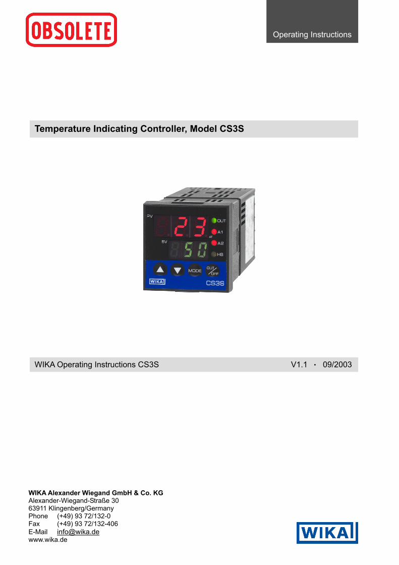
Temperature Indicating Controller, Model CS3S
WIKA Operating Instructions CS3S V1.1 • 09/2003
Operating Instructions
Operating Instructions Temperature Indicating Controller CS3S
V1.1 • 09/2003 - 2 -
To prevent accidents arising from the use of this controller, please ensure the operator using it receivesthis manual.
Caution• This instrument should be used according to the specifications described in the manual.
If it is used outside the specifications, it may malfunction or cause fire.• Be sure to follow the warnings, cautions and notices. If not, it could cause serious injury
or malfunction.• Specifications of the CS3S and the contents of this instruction manual are
subject to change without notice.• Care has been taken to assure that the contents of this instruction manual are correct, but if
there are any doubts, mistakes or questions, please inform our sales department.• Be sure to turn the power supplied to the instrunment OFF when cleaning.• Wipe the instrument dry using soft cloth or cotton.(If the paint thinner is used for wiping, the instrument may be deformed or discolored.)
• The display parts are more easily damaged. Do not strike them with hard objects or press hard on them.• Any unauthorized transfer or copying of this document, in part or in whole, is prohibited.• WIKA is not responsible for any damages or secondary damages incurred as a result of using this product, including any indirect damages.
Operating Instructions Temperature Indicating Controller CS3S
V1.1 • 09/2003 - 3 -
List of contents1. Model names ......................................................................................................................... Page 4
2. Name and functions of the sections ................................................................................... Page 5
3. Operation ............................................................................................................................... Page 53.1 Messages on the displays after power on ....................................................................... Page 53.2 Operation flow chart......................................................................................................... Page 63.3 Main setting mode............................................................................................................ Page 73.4 Sub setting mode ............................................................................................................. Page 73.5 Auxiliary function setting mode 1 ..................................................................................... Page 83.6 Auxiliary function setting mode 2 ..................................................................................... Page 93.7 Control output OFF function ............................................................................................ Page 113.8 Output manipulated variable indication............................................................................ Page 12
4. Running.................................................................................................................................. Page 12
5. Other functions ..................................................................................................................... Page 12
6. Action drawings .................................................................................................................... Page 136.1 Standard action drawings................................................................................................. Page 136.2 ON/OFF action drawings ................................................................................................. Page 136.3 Alarm action drawings...................................................................................................... Page 146.4 Heater burnout alarm drawing ......................................................................................... Page 14
7. PID auto-tuning of the CS3S................................................................................................ Page 15
8. Mounting to the control panel ............................................................................................. Page 168.1 Site selection.................................................................................................................... Page 168.2 External dimension drawing............................................................................................. Page 168.3 Panel cut out drawing ...................................................................................................... Page 168.4 Current transformer (CT) dimension drawing .................................................................. Page 178.5 Mounting .......................................................................................................................... Page 17
9. Terminal arrangement .......................................................................................................... Page 18
10. Specifications........................................................................................................................ Page 1910.1 Standard specifications .................................................................................................. Page 1910.2 Optional specifications................................................................................................... Page 21
11. Troubleshooting.................................................................................................................... Page 22
Operating Instructions Temperature Indicating Controller CS3S
V1.1 • 09/2003 - 4 -
1. Model names
CS3S - 3 - / M - - , ,... Series name CS3S 3 Control action PID (1)
0 withoutAlarm 1A Alarm action, output relais (2)
R Relais contact outputS Non contact voltage output (0/12 VDC)
Control output
A Current output 4 ... 20 mAInput M Multi-range input
H AC 100 ... 240 V, 50 ... 60 HzPower supplyL AC/DC 24 V
FT One-touch mounting bracketMounting provisionFS Screw bracket
B Factory adjustmentInstrument configuration# (?) To customers specification
2AS (4) Alarm output 2: process value monitoring2AR (4) Alarm output 2: control loop monitoring2AL (4) Alarm output 2: process value and control loop
monitoring with common terminalsW10 (4) Heater burnout alarm for 1 phase (max. 5 A)W11 (4) Heater burnout alarm for 1 phase (max. 10 A)W12 (4) Heater burnout alarm for 1 phase (max. 20 A)W15 (4) Heater burnout alarm for 1 phase (max. 50 A)CR5 (4) Serial communication RS 485SV2 (4) Parameter memory for 2 set values, external
selectable by connection terminalsIP4 (5) IP 54 front protectionIS5 (5) IP 55 (additional plastic cover on the front)
Options
KAB Terminal cover
(1) PID, PD and ON/OFF action are programmable.(2) 9 types of alarm action and no alarm action are selectable.(3) The input configuration can be selected from the user by the front keys.(4) Please note, that from these options only one can be selected.(5) Condition for this option is the screw type mounting bracket (FS).
Operating Instructions Temperature Indicating Controller CS3S
V1.1 • 09/2003 - 5 -
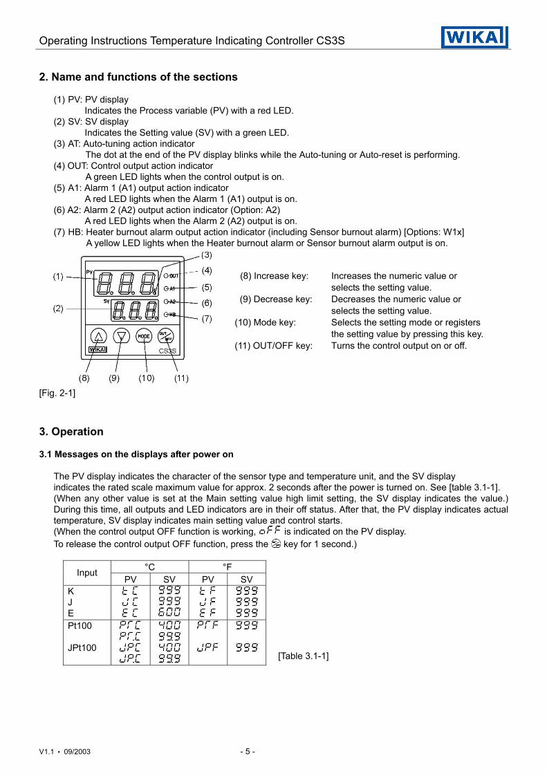
2. Name and functions of the sections
(1) PV: PV displayIndicates the Process variable (PV) with a red LED.
(2) SV: SV displayIndicates the Setting value (SV) with a green LED.
(3) AT: Auto-tuning action indicatorThe dot at the end of the PV display blinks while the Auto-tuning or Auto-reset is performing.
(4) OUT: Control output action indicatorA green LED lights when the control output is on.
(5) A1: Alarm 1 (A1) output action indicatorA red LED lights when the Alarm 1 (A1) output is on.
(6) A2: Alarm 2 (A2) output action indicator (Option: A2)A red LED lights when the Alarm 2 (A2) output is on.
(7) HB: Heater burnout alarm output action indicator (including Sensor burnout alarm) [Options: W1x]A yellow LED lights when the Heater burnout alarm or Sensor burnout alarm output is on.
(8) Increase key: Increases the numeric value orselects the setting value.
(9) Decrease key: Decreases the numeric value orselects the setting value.
(10) Mode key: Selects the setting mode or registersthe setting value by pressing this key.
(11) OUT/OFF key: Turns the control output on or off.
[Fig. 2-1]
3. Operation
3.1 Messages on the displays after power on
The PV display indicates the character of the sensor type and temperature unit, and the SV displayindicates the rated scale maximum value for approx. 2 seconds after the power is turned on. See [table 3.1-1].(When any other value is set at the Main setting value high limit setting, the SV display indicates the value.)During this time, all outputs and LED indicators are in their off status. After that, the PV display indicates actualtemperature, SV display indicates main setting value and control starts.(When the control output OFF function is working, is indicated on the PV display.To release the control output OFF function, press the key for 1 second.)
°C °FInputPV SV PV SV
KJE
Pt100
JPt100[Table 3.1-1]
Operating Instructions Temperature Indicating Controller CS3S
V1.1 • 09/2003 - 6 -
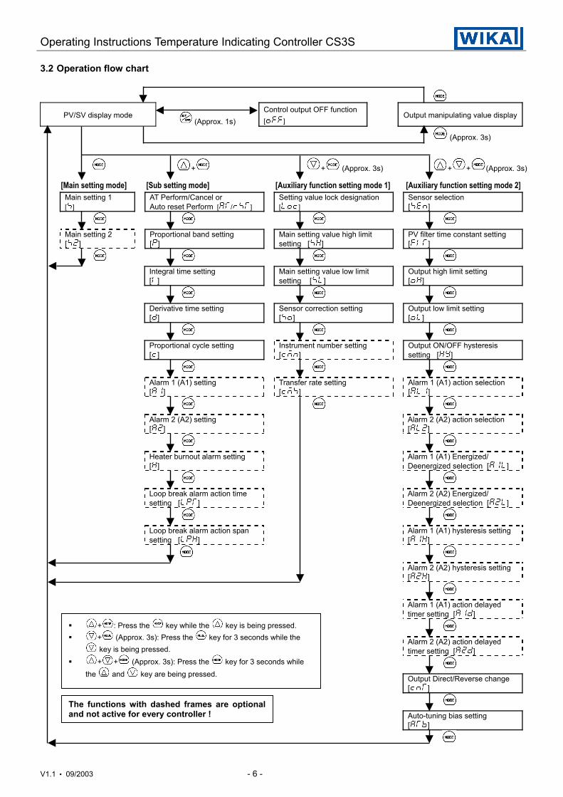
3.2 Operation flow chart
PV/SV display mode (Approx. 1s)
Control output OFF function[ ]
Output manipulating value display
(Approx. 3s)
+ + (Approx. 3s) + + (Approx. 3s)
[Main setting mode] [Sub setting mode] [Auxiliary function setting mode 1] [Auxiliary function setting mode 2]Main setting 1[ ]
AT Perform/Cancel orAuto reset Perform [ / ]
Setting value lock designation[ ]
Sensor selection[ ]
Main setting 2[ ]
Proportional band setting[ ]
Main setting value high limitsetting [ ]
PV filter time constant setting[ ]
Integral time setting[ ]
Main setting value low limitsetting [ ]
Output high limit setting[ ]
Derivative time setting[ ]
Sensor correction setting[ ]
Output low limit setting[ ]
Proportional cycle setting[ ]
Instrument number setting[ ]
Output ON/OFF hysteresissetting [ ]
Alarm 1 (A1) setting[ ]
Transfer rate setting[ ]
Alarm 1 (A1) action selection[ ]
Alarm 2 (A2) setting[ ]
Alarm 2 (A2) action selection[ ]
Heater burnout alarm setting[ ]
Alarm 1 (A1) Energized/Deenergized selection [ ]
Loop break alarm action timesetting [ ]
Alarm 2 (A2) Energized/Deenergized selection [ ]
Loop break alarm action spansetting [ ]
Alarm 1 (A1) hysteresis setting[ ]
Alarm 2 (A2) hysteresis setting[ ]
Alarm 1 (A1) action delayedtimer setting [ ]
Alarm 2 (A2) action delayedtimer setting [ ]
Output Direct/Reverse change[ ]
Auto-tuning bias setting[ ]
+ : Press the key while the key is being pressed. + (Approx. 3s): Press the key for 3 seconds while the
key is being pressed. + + (Approx. 3s): Press the key for 3 seconds while
the and key are being pressed.
The functions with dashed frames are optionaland not active for every controller !
Operating Instructions Temperature Indicating Controller CS3S
V1.1 • 09/2003 - 7 -
3.3 Main setting mode
Character Name, Description, Setting range InitialMain setting 1· Sets the 1st main setting value for the main control.· Main setting value low limit to main setting value high limit
0°C
Main setting 2· Sets the 2nd main setting value for the main control.· This setting item is not available if option [SV2] is not applied.· Main setting value low limit to main setting value high limit
0°C
Parameter memory for 2 set values (External selection)If the option [SV2] is applied, the setting value memory number can be selected by external operation.To select the setting value memory number 2, connect the terminals between 13 and 14.Memory number cannot be changed during setting mode or PID auto-tuning.
3.4 Sub setting mode
Character Name, Description, Setting range InitialAuto-tuning Perform/Cancel, or Auto-reset Perform· Designates auto-tuning perform/cancel, or auto-reset perform.· Auto-reset will be cancelled in approx. 4 minutes automatically.Proportional band value setting· Sets the proportional band for the control output.· ON/OFF action when setting the value to 0 or 0.0.· 0 to 999°C (°F), or 0.0 to 99.9°C
10°C
Integral time setting· Sets the integral time for the control output.· Setting the value to 0 disables the function.· With PD action (I value is set to 0), auto-reset can be performed.· 0 to 999 seconds
200s
Derivative time setting· Sets the derivative time for the control output.· Setting the value to 0 disables the function.· 0 to 300 seconds
50s
Proportional cycle setting· Sets the proportional cycle value for the control output.· This setting item is not available for ON/OFF action or current output type.· 1 to 120 seconds
R/ : 30sS/ : 3s
Alarm 1 (A1) setting· Sets the set point for the temperature alarm 1 (A1) output.· This setting item is not available for the CS3S-30 type.· This setting item is not available, if no alarm action is selected in Temperature alarm 1 (A1) action type selection (see table [3.3-1]).
0°C
Alarm 2 (A2) setting· Sets the set point for the temperature alarm 2 (A2) output.· This setting item is not available if option [2AS] or [2AL] is not applied, or no alarm action is selected in Temperature alarm 2 (A2) action type selection (see table [3.3-1]).
0°C
Heater burnout alarm output setting· Sets the heater current value for Heater burnout alarm.· This setting item is available only when one of the options [W1x] is applied.· Self-holding is not available to the alarm output.· For the rated current 5A [W10] : 0.0 to 5.0A For the rated current 10A [W11] : 0.0 to 10.0A For the rated current 20A [W12] : 0.0 to 20.0A For the rated current 50A [W15] : 0.0 to 50.0A
0.0A
Operating Instructions Temperature Indicating Controller CS3S
V1.1 • 09/2003 - 8 -
Loop break alarm time setting· Sets the time to assess the Loop break alarm.· This setting item is available only when the option [2AR] or [2AL] is applied.· 0 to 200 minutes
0 min.
Loop break alarm action span setting· Sets the temperature span to assess the Loop break alarm.· This setting item is available only when the option [2AR] or [2AL] is applied.· 0 to 150 °C (°F)
0°C
Loop break alarmThe alarm will be activated when the process variable (PV) does not rise as much value as the span orgreater within the time it takes to assess the loop break alarm after the manipulated variable has reached100% or the output high limit value.The alarm output will also be activated when the process variable (PV) does not fall as much value as thespan or greater within the time it takes to assess the loop break alarm after the manipulated variable hasreached 0% or the output low limit value.When the control action is Direct (Cooling), the alarm acts conversely.
[Table 3.3-1]
Type of alarm action Setting range(without decimal point)
Setting range(with decimal point)
High limit alarm -199 to Input rangemaximum value °C (°F) -19.9 to 99.9°C
Low limit alarm -199 to Input rangemaximum value °C (°F) -19.9 to 99.9°C
High/Low limits alarm ±(0 to Input rangemaximum value) °C (°F) ± (0.0 to 99.9)°C
High/Low limit range ± (0 to Input rangemaximum value) °C (°F) ± (0.0 to 99.9)°C
Process high limit Input range minimum toInput range maximum
Input range minimum toInput range maximum
Process low limit Input range minimum toInput range maximum
Input range minimum toInput range maximum
High limit with standby -199 to Input range maximum value °C (°F) -19.9 to 99.9°CLow limit with standby -199 to Input range maximum value °C (°F) -19.9 to 99.9°CHi/Lo limits with standby ± (0 to Input range maximum value) °C (°F) ± (0.0 to 99.9)°C
3.5 Auxiliary function setting mode 1
Character Name, Description, Setting range InitialSetting value lock designation· Locks the setting value to prevent errors. The setting item to be locked is dependant on the designation.· PID auto-tuning or auto-reset will not function if Lock 1 or Lock 2 is designated.· (Unlock): All setting values can be changed. (Lock 1): None of the setting values can be changed. (Lock 2): Only main setting value is changeable. (Lock 3): All setting values can be changed,
however, they returns to their former value afterthe power is turned off because they are not storedin the non-volatile memory.
Unlock
Main setting value high limit setting· Sets the high limit value for the main setting.· Main setting value low limit to Rated maximum value
Ratedmaximumvalue
Main setting value low limit setting· Sets the low limit value for the main setting.· Rated minimum value to Main setting value high limit
Ratedminimumvalue
Operating Instructions Temperature Indicating Controller CS3S
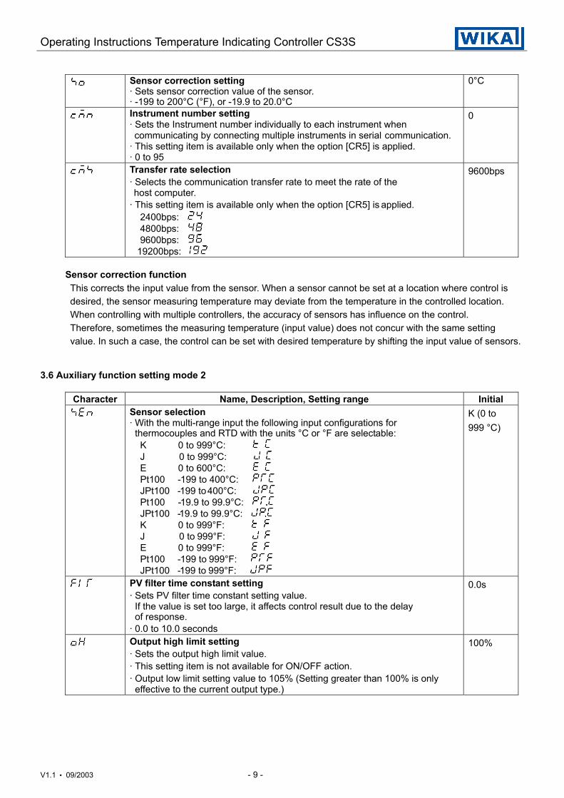
V1.1 • 09/2003 - 9 -
Sensor correction setting· Sets sensor correction value of the sensor.· -199 to 200°C (°F), or -19.9 to 20.0°C
0°C
Instrument number setting· Sets the Instrument number individually to each instrument when communicating by connecting multiple instruments in serial communication.· This setting item is available only when the option [CR5] is applied.· 0 to 95
0
Transfer rate selection· Selects the communication transfer rate to meet the rate of the host computer.· This setting item is available only when the option [CR5] is applied. 2400bps: 4800bps: 9600bps: 19200bps:
9600bps
Sensor correction functionThis corrects the input value from the sensor. When a sensor cannot be set at a location where control isdesired, the sensor measuring temperature may deviate from the temperature in the controlled location.When controlling with multiple controllers, the accuracy of sensors has influence on the control.Therefore, sometimes the measuring temperature (input value) does not concur with the same settingvalue. In such a case, the control can be set with desired temperature by shifting the input value of sensors.
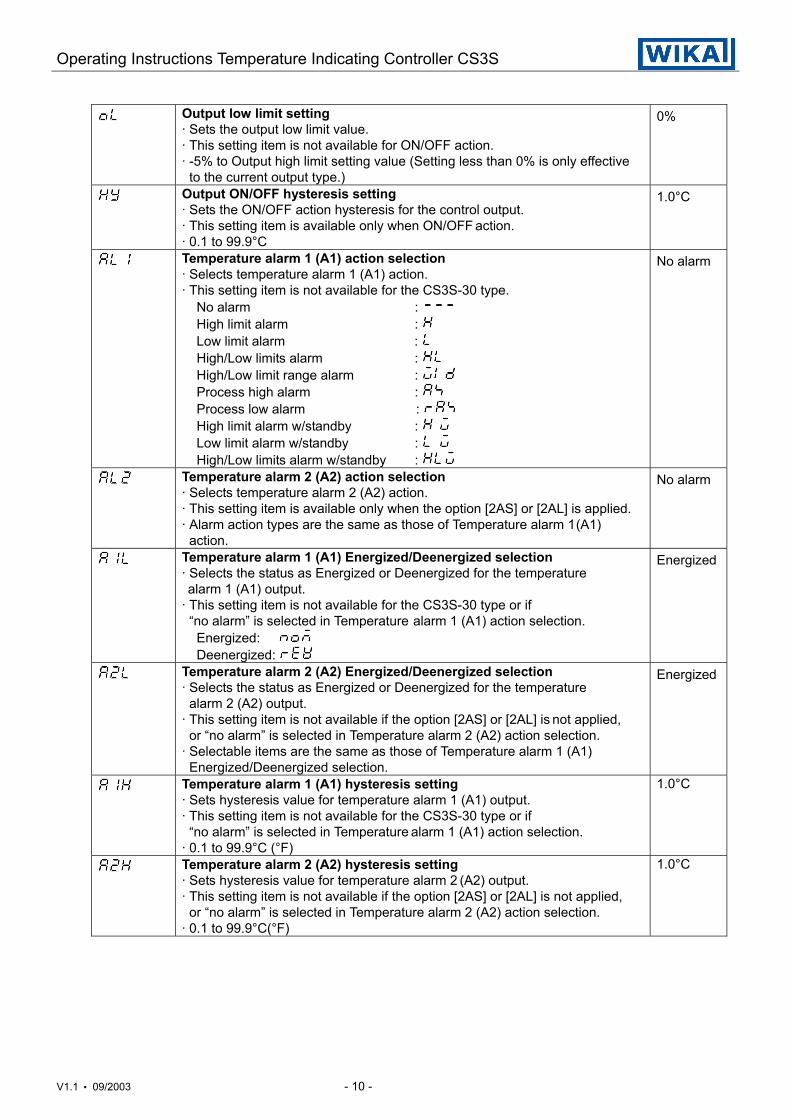
3.6 Auxiliary function setting mode 2
Character Name, Description, Setting range InitialSensor selection· With the multi-range input the following input configurations for thermocouples and RTD with the units °C or °F are selectable: K 0 to 999°C: J 0 to 999°C: E 0 to 600°C: Pt100 -199 to 400°C: JPt100 -199 to 400°C: Pt100 -19.9 to 99.9°C: JPt100 -19.9 to 99.9°C: K 0 to 999°F: J 0 to 999°F: E 0 to 999°F: Pt100 -199 to 999°F: JPt100 -199 to 999°F:
K (0 to999 °C)
PV filter time constant setting· Sets PV filter time constant setting value. If the value is set too large, it affects control result due to the delay of response.· 0.0 to 10.0 seconds
0.0s
Output high limit setting· Sets the output high limit value.· This setting item is not available for ON/OFF action.· Output low limit setting value to 105% (Setting greater than 100% is only effective to the current output type.)
100%
Operating Instructions Temperature Indicating Controller CS3S
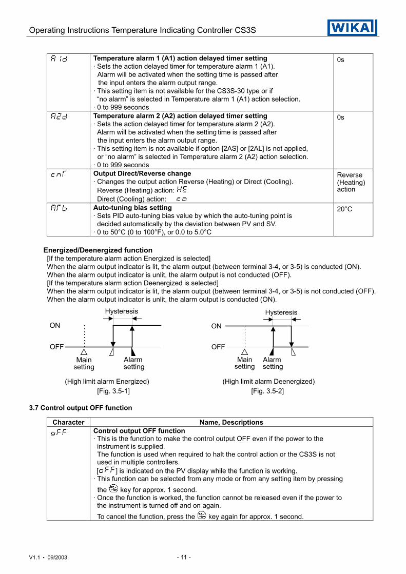
V1.1 • 09/2003 - 10 -
Output low limit setting· Sets the output low limit value.· This setting item is not available for ON/OFF action.· -5% to Output high limit setting value (Setting less than 0% is only effective to the current output type.)
0%
Output ON/OFF hysteresis setting· Sets the ON/OFF action hysteresis for the control output.· This setting item is available only when ON/OFF action.· 0.1 to 99.9°C
1.0°C
Temperature alarm 1 (A1) action selection· Selects temperature alarm 1 (A1) action.· This setting item is not available for the CS3S-30 type. No alarm : High limit alarm : Low limit alarm : High/Low limits alarm : High/Low limit range alarm : Process high alarm : Process low alarm : High limit alarm w/standby : Low limit alarm w/standby : High/Low limits alarm w/standby :
No alarm
Temperature alarm 2 (A2) action selection· Selects temperature alarm 2 (A2) action.· This setting item is available only when the option [2AS] or [2AL] is applied.· Alarm action types are the same as those of Temperature alarm 1 (A1) action.
No alarm
Temperature alarm 1 (A1) Energized/Deenergized selection· Selects the status as Energized or Deenergized for the temperature alarm 1 (A1) output.· This setting item is not available for the CS3S-30 type or if “no alarm” is selected in Temperature alarm 1 (A1) action selection. Energized: Deenergized:
Energized
Temperature alarm 2 (A2) Energized/Deenergized selection· Selects the status as Energized or Deenergized for the temperature alarm 2 (A2) output.· This setting item is not available if the option [2AS] or [2AL] is not applied, or “no alarm” is selected in Temperature alarm 2 (A2) action selection.· Selectable items are the same as those of Temperature alarm 1 (A1) Energized/Deenergized selection.
Energized
Temperature alarm 1 (A1) hysteresis setting· Sets hysteresis value for temperature alarm 1 (A1) output.· This setting item is not available for the CS3S-30 type or if “no alarm” is selected in Temperature alarm 1 (A1) action selection.· 0.1 to 99.9°C (°F)
1.0°C
Temperature alarm 2 (A2) hysteresis setting· Sets hysteresis value for temperature alarm 2 (A2) output.· This setting item is not available if the option [2AS] or [2AL] is not applied, or “no alarm” is selected in Temperature alarm 2 (A2) action selection. · 0.1 to 99.9°C(°F)
1.0°C
Operating Instructions Temperature Indicating Controller CS3S
V1.1 • 09/2003 - 11 -
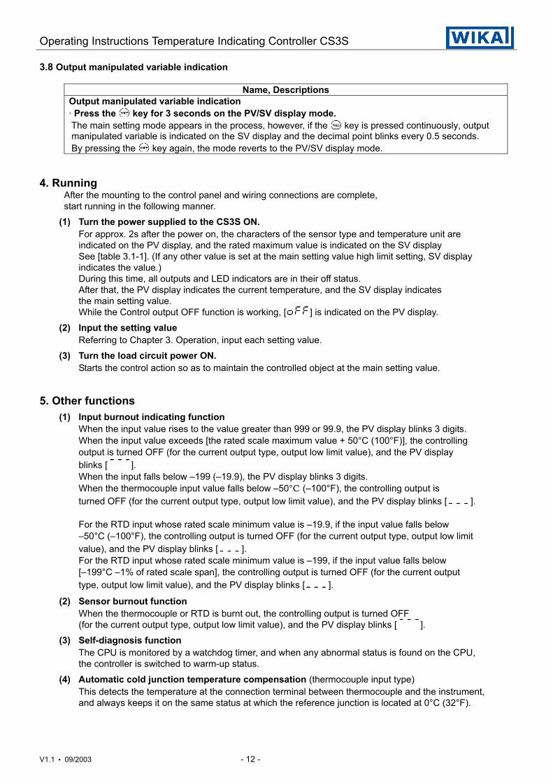
Temperature alarm 1 (A1) action delayed timer setting· Sets the action delayed timer for temperature alarm 1 (A1). Alarm will be activated when the setting time is passed after the input enters the alarm output range.· This setting item is not available for the CS3S-30 type or if “no alarm” is selected in Temperature alarm 1 (A1) action selection.· 0 to 999 seconds
0s
Temperature alarm 2 (A2) action delayed timer setting· Sets the action delayed timer for temperature alarm 2 (A2). Alarm will be activated when the setting time is passed after the input enters the alarm output range.· This setting item is not available if option [2AS] or [2AL] is not applied, or “no alarm” is selected in Temperature alarm 2 (A2) action selection.· 0 to 999 seconds
0s
Output Direct/Reverse change· Changes the output action Reverse (Heating) or Direct (Cooling). Reverse (Heating) action: Direct (Cooling) action:
Reverse(Heating)action
Auto-tuning bias setting· Sets PID auto-tuning bias value by which the auto-tuning point is decided automatically by the deviation between PV and SV.· 0 to 50°C (0 to 100°F), or 0.0 to 5.0°C
20°C
Energized/Deenergized function[If the temperature alarm action Energized is selected]When the alarm output indicator is lit, the alarm output (between terminal 3-4, or 3-5) is conducted (ON).When the alarm output indicator is unlit, the alarm output is not conducted (OFF).[If the temperature alarm action Deenergized is selected]
When the alarm output indicator is lit, the alarm output (between terminal 3-4, or 3-5) is not conducted (OFF).When the alarm output indicator is unlit, the alarm output is conducted (ON).
(High limit alarm Energized) (High limit alarm Deenergized)[Fig. 3.5-1] [Fig. 3.5-2]
3.7 Control output OFF function
Character Name, DescriptionsControl output OFF function· This is the function to make the control output OFF even if the power to the instrument is supplied. The function is used when required to halt the control action or the CS3S is not used in multiple controllers. [ ] is indicated on the PV display while the function is working.· This function can be selected from any mode or from any setting item by pressing the key for approx. 1 second.· Once the function is worked, the function cannot be released even if the power to the instrument is turned off and on again. To cancel the function, press the key again for approx. 1 second.
Hysteresis
ON
OFF
Mainsetting
Alarm setting
Hysteresis
ON
OFF
Mainsetting
Alarm setting
Operating Instructions Temperature Indicating Controller CS3S
V1.1 • 09/2003 - 12 -
3.8 Output manipulated variable indication
Name, DescriptionsOutput manipulated variable indication· Press the key for 3 seconds on the PV/SV display mode. The main setting mode appears in the process, however, if the key is pressed continuously, output manipulated variable is indicated on the SV display and the decimal point blinks every 0.5 seconds. By pressing the key again, the mode reverts to the PV/SV display mode.
4. RunningAfter the mounting to the control panel and wiring connections are complete,start running in the following manner.
(1) Turn the power supplied to the CS3S ON.For approx. 2s after the power on, the characters of the sensor type and temperature unit areindicated on the PV display, and the rated maximum value is indicated on the SV displaySee [table 3.1-1]. (If any other value is set at the main setting value high limit setting, SV displayindicates the value.)During this time, all outputs and LED indicators are in their off status.After that, the PV display indicates the current temperature, and the SV display indicatesthe main setting value.While the Control output OFF function is working, [ ] is indicated on the PV display.
(2) Input the setting valueReferring to Chapter 3. Operation, input each setting value.
(3) Turn the load circuit power ON.Starts the control action so as to maintain the controlled object at the main setting value.
5. Other functions(1) Input burnout indicating function
When the input value rises to the value greater than 999 or 99.9, the PV display blinks 3 digits.When the input value exceeds [the rated scale maximum value + 50°C (100°F)], the controlling
output is turned OFF (for the current output type, output low limit value), and the PV displayblinks [ ].When the input falls below –199 (–19.9), the PV display blinks 3 digits.When the thermocouple input value falls below –50°C (–100°F), the controlling output is
turned OFF (for the current output type, output low limit value), and the PV display blinks [ ].
For the RTD input whose rated scale minimum value is –19.9, if the input value falls below–50°C (–100°F), the controlling output is turned OFF (for the current output type, output low limit
value), and the PV display blinks [ ].For the RTD input whose rated scale minimum value is –199, if the input value falls below[–199°C –1% of rated scale span], the controlling output is turned OFF (for the current outputtype, output low limit value), and the PV display blinks [ ].
(2) Sensor burnout functionWhen the thermocouple or RTD is burnt out, the controlling output is turned OFF(for the current output type, output low limit value), and the PV display blinks [ ].
(3) Self-diagnosis functionThe CPU is monitored by a watchdog timer, and when any abnormal status is found on the CPU,the controller is switched to warm-up status.
(4) Automatic cold junction temperature compensation (thermocouple input type)This detects the temperature at the connection terminal between thermocouple and the instrument,and always keeps it on the same status at which the reference junction is located at 0°C (32°F).
Operating Instructions Temperature Indicating Controller CS3S
V1.1 • 09/2003 - 13 -
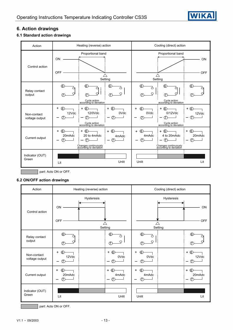
6. Action drawings6.1 Standard action drawings
6.2 ON/OFF action drawings
Non-contactvoltage output
Indicator (OUT)Green
ON
OFF
ON
OFF
12Vdc
Heating (reverse) action Cooling (direct) action
Proportional band Proportional band
Action
Setting Setting
Changes continuouslyaccording to deviation
Control action
Current output
Lit Unlit Unlit Lit
part: Acts ON or OFF.
Relay contactoutput
+ 12/0Vdc 0Vdc
6
7
6
7
6
7
6
7
6
77
6
6
7
6
7
6
7
+ + 0Vdc
7
6+0/12Vdc
77
66+ +12Vdc
6
77 7
6 6 6
7 7
6
7
6++ + + + + 20mAdc 20 to 4mAdc 4mAdc 4mAdc 4 to 20mAdc 20mAdc
Cycle actionaccording to deviation
Cycle actionaccording to deviation
Cycle actionaccording to deviation
Cycle actionaccording to deviation
Changes continuouslyaccording to deviation
ON
OFF
ON
OFF
7
6
Indicator (OUT)Green
Current output
Lit Unlit LitUnlit
part: Acts ON or OFF.
Non-contactvoltage output
Relay contactoutput
Setting
Control action
Action Heating (reverse) action Cooling (direct) action
Hysteresis Hysteresis
Setting
12Vdc
4mAdc
0Vdc
20mAdc
12Vdc 0Vdc
4mAdc 20mAdc
6
7
6
7 7
6 6
7
7
6 6
7
6
7
7
6
7
6
77
6 6
+ ++
+
+
++ +
Operating Instructions Temperature Indicating Controller CS3S
V1.1 • 09/2003 - 14 -
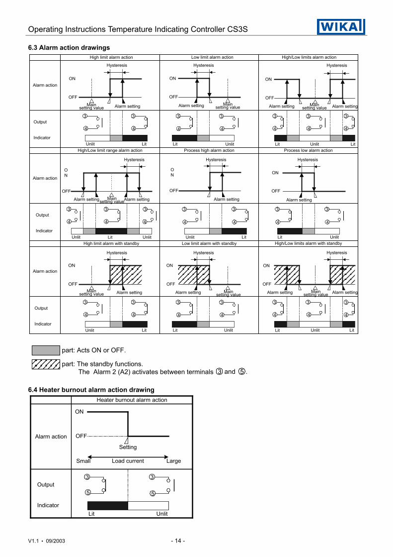
6.3 Alarm action drawings
6.4 Heater burnout alarm action drawing
ON
OFF
UnlitLit
Output
Indicator
Heater burnout alarm action
Setting
Small LargeLoad current
Alarm action
3
5
3
5
part: Acts ON or OFF.
part: The standby functions. The Alarm 2 (A2) activates between terminals 3 5and .
ON
OFF
Alarm actionON
OFF
ON
OFF
ON
OFF
ON
OFF
ON
OFF
ON
OFF
ON
OFF
ON
OFF
Hysteresis
High limit alarm action
Hysteresis
Low limit alarm action
Mainsetting value
Hysteresis
High/Low limits alarm action
Lit Unlit LitUnlit LitLit
Output
Indicator
Hysteresis Hysteresis Hysteresis
Process high alarm action
Low limit alarm with standby
High/Low limit range alarm action
LitUnlit Lit Unlit Unlit Lit
HysteresisHysteresisHysteresis
Output
Indicator
Output
IndicatorLit
LitLit UnlitUnlitUnlitUnlit Lit
Alarm action
Alarm action
UnlitProcess low alarm action
3
4
33
44 4
33
4
3
4
3
4
3
4
3
4
3
4
3
4
3
4
3
4
3
4
3
4
3
4
3
4
3
4
3
44
33
4
High limit alarm with standby High/Low limits alarm with standby
Alarm setting Alarm setting Alarm setting Alarm settingMainsetting valueMain
setting value
Mainsetting valueAlarm settingAlarm setting Alarm setting Alarm setting
Alarm settingMainsetting value Alarm setting Alarm setting Main
setting value Alarm settingMainsetting value
Operating Instructions Temperature Indicating Controller CS3S
V1.1 • 09/2003 - 15 -
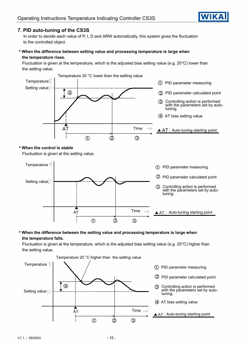
7. PID auto-tuning of the CS3S In order to decide each value of P, I, D and ARW automatically, this system gives the fluctuation to the controlled object.
hWhen the difference between setting value and processing temperature is large whenthe temperature rises.
Fluctuation is given at the temperature, which is the adjusted bias setting value (e.g. 20°C) lower than the setting value.
hWhen the control is stable Fluctuation is given at the setting value.
hWhen the difference between the setting value and processing temperature is large whenthe temperature falls.
Fluctuation is given at the temperature, which is the adjusted bias setting value (e.g. 20°C) higher than the setting value.
Temperature
AT :AT Auto-tuning starting point
PID parameter measuring
PID parameter calculated point
Controlling action is performedwith the parameters set by auto-tuning.
Setting value
Time
1
2
3
321
Temperature 20 °C lower than the setting value
AT bias setting value4
4
AT :AT
Temperature
Setting value
PID parameter measuring
PID parameter calculated point
Controlling action is performedwith the parameters set by auto-tuning.
Auto-tuning starting pointTime
1
2
3
2 31
AT :AT
Temperature
Setting value
PID parameter measuring
PID parameter calculated point
Controlling action is performedwith the parameters set by auto-tuning.
Auto-tuning starting pointTime
1
2
3
321
Temperature 20 °C higher than the setting value
AT bias setting value4
4
Operating Instructions Temperature Indicating Controller CS3S
V1.1 • 09/2003 - 16 -
8. Mounting to the control panel8.1 Site selection
This instrument is intended to be used under the following environmental conditions (IEC61010-1):Overvoltage category , Pollution degree 2
Mount the controller in a place with:(1) A minimum of dust, and an absence of corrosive gases(2) No flammable, explosive gasses(3) No mechanical vibrations or shocks(4) No exposure to direct sunlight(5) An ambient temperature of 0 to 50°C (32 to 122°F) that does not change suddenly(6) An ambient non-condensing humidity of 35 to 85%RH(7) The controller away from large capacity electromagnetic switches or cables through which
large current is flowing(8) No water, oil or chemicals or where the vapors of these substances can come
into direct contact with the controller
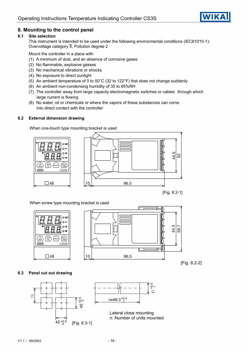
8.2 External dimension drawing
When one-touch type mounting bracket is used
[Fig. 8.2-1]
When screw type mounting bracket is used
[Fig. 8.2-2]
8.3 Panel cut out drawing
Lateral close mountingn: Number of units mounted
[Fig. 8.3-1]
QU NM VSKR
QQKR
RVKT
`pPp
75
nx48-3+0.50
45+0
.50
45+0
.5 0
45 +0.50
QU NM VSKR
QQKR
SO
`pPp
Operating Instructions Temperature Indicating Controller CS3S
V1.1 • 09/2003 - 17 -
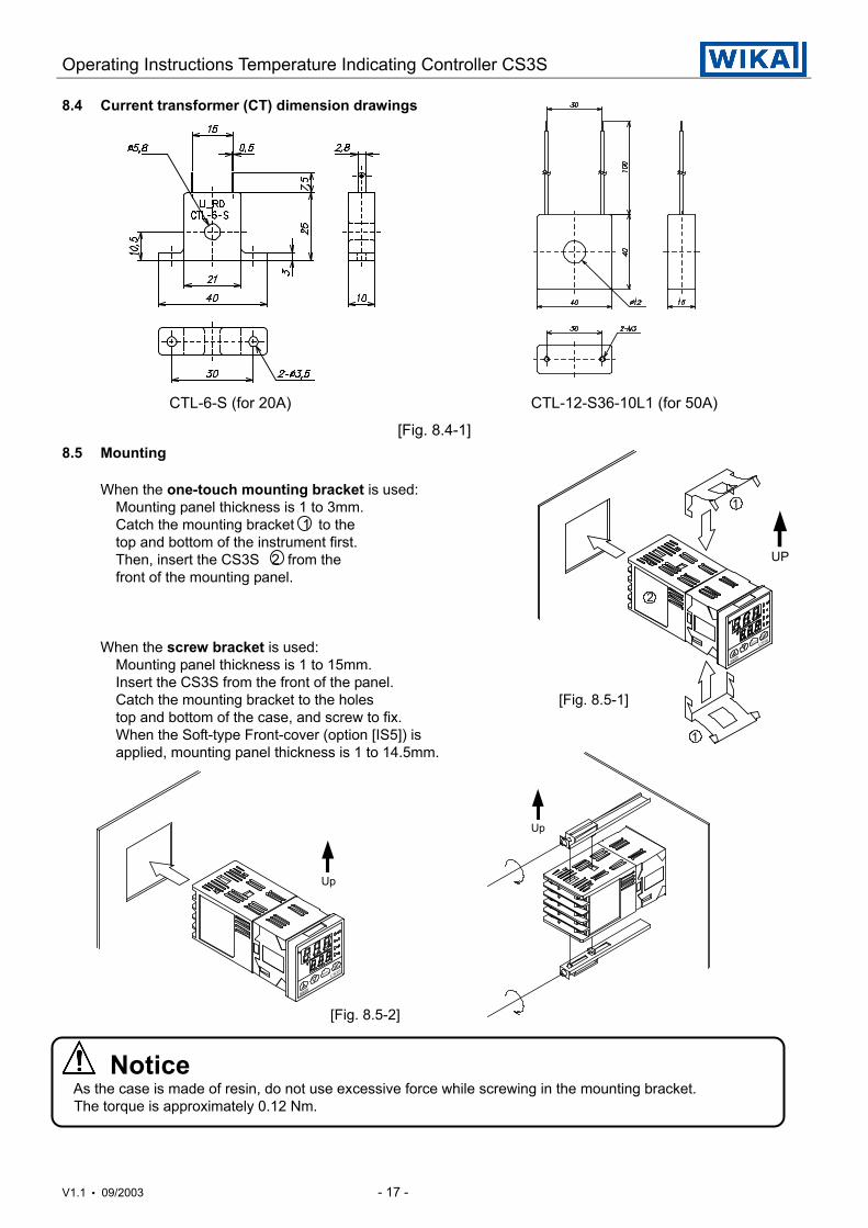
8.4 Current transformer (CT) dimension drawings
CTL-6-S (for 20A) CTL-12-S36-10L1 (for 50A)
[Fig. 8.4-1]8.5 Mounting
When the one-touch mounting bracket is used:Mounting panel thickness is 1 to 3mm.Catch the mounting bracket 1 to thetop and bottom of the instrument first.Then, insert the CS3S 2 from thefront of the mounting panel.
When the screw bracket is used:Mounting panel thickness is 1 to 15mm.Insert the CS3S from the front of the panel.Catch the mounting bracket to the holes [Fig. 8.5-1]top and bottom of the case, and screw to fix.When the Soft-type Front-cover (option [IS5]) isapplied, mounting panel thickness is 1 to 14.5mm.
[Fig. 8.5-2]
Notice As the case is made of resin, do not use excessive force while screwing in the mounting bracket. The torque is approximately 0.12 Nm.
Up
Up
UP
2
1
1
Operating Instructions Temperature Indicating Controller CS3S
V1.1 • 09/2003 - 18 -
φ3.2mm
5.8m
m o
r les
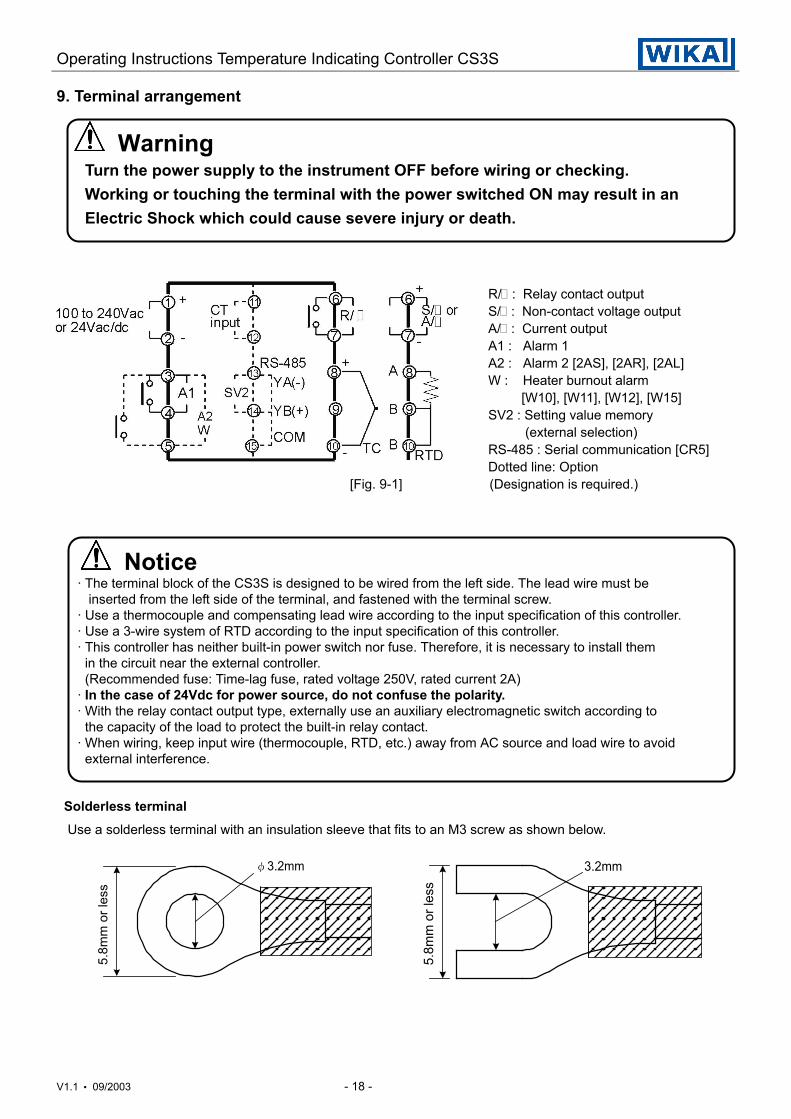
s9. Terminal arrangement
Warning Turn the power supply to the instrument OFF before wiring or checking. Working or touching the terminal with the power switched ON may result in an Electric Shock which could cause severe injury or death.
R/ : Relay contact outputS/ : Non-contact voltage outputA/ : Current outputA1 : Alarm 1A2 : Alarm 2 [2AS], [2AR], [2AL]W : Heater burnout alarm [W10], [W11], [W12], [W15]SV2 : Setting value memory (external selection)RS-485 : Serial communication [CR5]Dotted line: Option
[Fig. 9-1] (Designation is required.)
Notice· The terminal block of the CS3S is designed to be wired from the left side. The lead wire must be inserted from the left side of the terminal, and fastened with the terminal screw.· Use a thermocouple and compensating lead wire according to the input specification of this controller.· Use a 3-wire system of RTD according to the input specification of this controller.· This controller has neither built-in power switch nor fuse. Therefore, it is necessary to install them in the circuit near the external controller. (Recommended fuse: Time-lag fuse, rated voltage 250V, rated current 2A)· In the case of 24Vdc for power source, do not confuse the polarity.· With the relay contact output type, externally use an auxiliary electromagnetic switch according to the capacity of the load to protect the built-in relay contact.· When wiring, keep input wire (thermocouple, RTD, etc.) away from AC source and load wire to avoid external interference.
Solderless terminal Use a solderless terminal with an insulation sleeve that fits to an M3 screw as shown below.
3.2mm
5.8m
m o
r les
s
Operating Instructions Temperature Indicating Controller CS3S
V1.1 • 09/2003 - 19 -
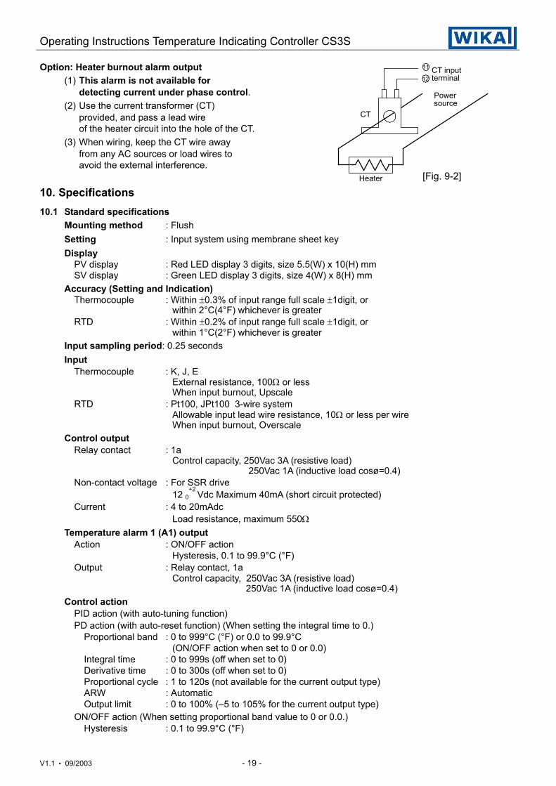
Option: Heater burnout alarm output(1) This alarm is not available for
detecting current under phase control.(2) Use the current transformer (CT)
provided, and pass a lead wireof the heater circuit into the hole of the CT.
(3) When wiring, keep the CT wire awayfrom any AC sources or load wires toavoid the external interference.
[Fig. 9-2]
10. Specifications10.1 Standard specifications
Mounting method : FlushSetting : Input system using membrane sheet keyDisplay
PV display : Red LED display 3 digits, size 5.5(W) x 10(H) mmSV display : Green LED display 3 digits, size 4(W) x 8(H) mm
Accuracy (Setting and Indication)Thermocouple : Within ±0.3% of input range full scale ±1digit, or
within 2°C(4°F) whichever is greaterRTD : Within ±0.2% of input range full scale ±1digit, or
within 1°C(2°F) whichever is greaterInput sampling period: 0.25 secondsInput
Thermocouple : K, J, EExternal resistance, 100Ω or lessWhen input burnout, Upscale
RTD : Pt100, JPt100 3-wire systemAllowable input lead wire resistance, 10Ω or less per wireWhen input burnout, Overscale
Control outputRelay contact : 1a
Control capacity, 250Vac 3A (resistive load)250Vac 1A (inductive load cosø=0.4)
Non-contact voltage : For SSR drive12 0
+2 Vdc Maximum 40mA (short circuit protected)
Current : 4 to 20mAdcLoad resistance, maximum 550Ω
Temperature alarm 1 (A1) outputAction : ON/OFF action
Hysteresis, 0.1 to 99.9°C (°F)Output : Relay contact, 1a
Control capacity, 250Vac 3A (resistive load)250Vac 1A (inductive load cosø=0.4)
Control actionPID action (with auto-tuning function)PD action (with auto-reset function) (When setting the integral time to 0.)
Proportional band : 0 to 999°C (°F) or 0.0 to 99.9°C(ON/OFF action when set to 0 or 0.0)
Integral time : 0 to 999s (off when set to 0)Derivative time : 0 to 300s (off when set to 0)Proportional cycle : 1 to 120s (not available for the current output type)ARW : AutomaticOutput limit : 0 to 100% (–5 to 105% for the current output type)
ON/OFF action (When setting proportional band value to 0 or 0.0.)Hysteresis : 0.1 to 99.9°C (°F)
Powersource
Heater
CT
CT inputterminal12
11
Operating Instructions Temperature Indicating Controller CS3S
V1.1 • 09/2003 - 20 -
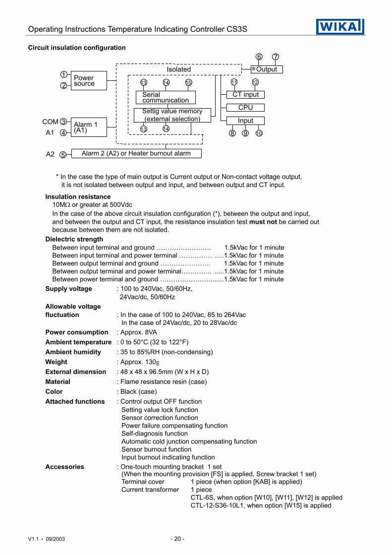
Circuit insulation configuration
* In the case the type of main output is Current output or Non-contact voltage output, it is not isolated between output and input, and between output and CT input.
Insulation resistance10MΩ or greater at 500VdcIn the case of the above circuit insulation configuration (*), between the output and input,and between the output and CT input, the resistance insulation test must not be carried outbecause between them are not isolated.
Dielectric strengthBetween input terminal and ground ……………………. 1.5kVac for 1 minuteBetween input terminal and power terminal …………… .....1.5kVac for 1 minuteBetween output terminal and ground ………………….. 1.5kVac for 1 minuteBetween output terminal and power terminal………….. .....1.5kVac for 1 minuteBetween power terminal and ground ……………………......1.5kVac for 1 minute
Supply voltage : 100 to 240Vac, 50/60Hz, 24Vac/dc, 50/60Hz
Allowable voltagefluctuation : In the case of 100 to 240Vac, 85 to 264Vac
In the case of 24Vac/dc, 20 to 28Vac/dcPower consumption : Approx. 8VAAmbient temperature : 0 to 50°C (32 to 122°F)Ambient humidity : 35 to 85%RH (non-condensing)Weight : Approx. 130gExternal dimension : 48 x 48 x 96.5mm (W x H x D)Material : Flame resistance resin (case)Color : Black (case)Attached functions : Control output OFF function
Setting value lock functionSensor correction functionPower failure compensating functionSelf-diagnosis functionAutomatic cold junction compensating functionSensor burnout functionInput burnout indicating function
Accessories : One-touch mounting bracket 1 set(When the mounting provision [FS] is applied, Screw bracket 1 set)Terminal cover 1 piece (when option [KAB] is applied)Current transformer 1 piece
CTL-6S, when option [W10], [W11], [W12] is appliedCTL-12-S36-10L1, when option [W15] is applied
Isolated
Serial communication
CT input
CPU
Input
OutputPowersource
Alarm 1(A1)
COMA1
A2
12
34
5
6 7
8 9 10
1113 14 15
13
12
Settig value memory(external selection)
Alarm 2 (A2) or Heater burnout alarm
14
*
Operating Instructions Temperature Indicating Controller CS3S
V1.1 • 09/2003 - 21 -
10.2 Optional specifications
Alarm output 2 (A2) process value monitoring [Option codes: 2AS or 2AL]The options [SV2] or [W1x] cannot be applied in combination with this option.When the option [2AL] process value and loop monitoring is selected, the output terminal is common.Action : ON/OFF action
Hysteresis, 0.1 to 99.9°C (°F)Output : Relay contact, 1a
Control capacity, 250Vac 3A (resistive load)250Vac 1A (inductive load cosø =0.4)
Alarm output 2 (A2) loop break alarm [Option codes: 2AR or 2AL]The alarm will be activated when the process variable (PV) does not change as much valueas the setting span or greater within the time it takes to assess the loop break alarm afterthe manipulating value reaches the maximum value or the minimum value.Also, this detects heater burnout, sensor burnout and abnormality at operation end.The options [CR5], [SV2] or [W1x] cannot be applied in combination with this option.When the option [AL] process value and loop monitoring is selected, the output terminal is common.Loop break alarm action time: 0 to 200 minutesLoop break alarm action span: 0 to 150°C (°F)Output : Relay contact, 1a
Control capacity, 250Vac 3A (resistive load), 250Vac 1A (inductive load, cosø=0.4)
Heater burnout alarm output [Option codes: W10, W11, W12, W15]Watches the heater current with CT (current transformer), and detects the burnout.The options [2AS], [2AR], [2AL], [SV2] or [CR5] cannot be applied in combination with this option.This option cannot be applied to the current output type.Rating : 5A [Option W10], 10A [Option W11], 20A [Option W12]
or 50A [Option W15] (Must be designated)Setting range : In the case of 5A [W10], 0.0 to 5.0A (off when set to 0.0)
In the case of 10A [W11], 0.0 to 10.0A (off when set to 0.0)In the case of 20A [W12], 0.0 to 20.0A (off when set to 0.0)In the case of 50A [W15], 0.0 to 50.0A (off when set to 0.0)
Setting accuracy : Within ±5% of the rated valueAction : ON/OFF actionOutput : Relay contact, 1a
Control capacity, 250Vac 3A (resistive load) 250Vac 1A (inductive load cosø =0.4)
Serial communication [Option code: CR5]The options [SV2], [2AR], [2AL] or [W1x] cannot be applied in combination with this option.The following operations can be executed from the external computer.(1) Reading and setting of the main setting value, PID values and various setting values(2) Reading of the input value and action status(3) Change of the functionsCommunication circuit : Based on EIA RS-485Communication method : Half-duplex communication start-stop synchronousTransfer rate : 2400, 4800, 9600 and 19200bps (selectable by key operation)Data format : Start bit 1
Data bit 7Parity EvenStop bit 1
Operating Instructions Temperature Indicating Controller CS3S
V1.1 • 09/2003 - 22 -
Setting value memory (external selection) [Option code: SV2]If this option is applied, the main setting value 1 or main setting value 2 can be selectedby external contact.The option [2AS], [2AR], [2AL], [CR5], or [W1x] cannot be applied in combination with this option.
Screw type mounting bracket [Mounting provision code: FS]Mounting panel thickness: 1 to 15mm
Dust-proof · Drip-proof [Option code: IP4 or IS5]Dust-proof and Drip-proof specification IP54 at option [IP4] by use of two additional gaskets.Dust-proof and Drip-proof specification IP55 at option [IS5] by use of an additional front cover.The IP-Protection is only effective to the front of the controller, case part is excluded.To protect the controller from water leak between the control panel and controller, the control panelsurface to be mounted should be planar and vertical.
Terminal cover [Option code: KAB]Electrical shock protecting terminal cover
11. Troubleshooting
If any malfunctions occur, refer to the following items after checking the power supply and wiring.
<Indication>
Phenomena Presumed cause and solutionIf the PV display isindicating [ ].
· Control output OFF function is working. Press the key for approx. 1s to release the function.
If [ ] is blinkingon the PV display.
· Thermocouple or RTD is burnt out. [In the case of Thermocouple] If the input terminal of the instrument is connected, and if near room temperature is indicated, the instrument should be normal and sensor may be burnout. [In the case of RTD] If approx. 100Ω of resistance is connected to the input terminal between A-B of the instrument and between B-B is connected, and if near 0°C (32°F) is indicated, the instrument should be normal and sensor may be burnout.· Lead wire of thermocouple or RTD is not securely mounted to the
instrument terminal.If [ ] is blinkingon the PV display.
· Polarity of thermocouple or compensating lead wire is reversed.· Codes (A, B, B) of RTD do not agree with the instrument terminal.
If indication of the PVdisplay is abnormalor unstable.
· Designation of the sensor input is improper.· Temperature unit (°C or °F) is mistaken.· Sensor correction value is not appropriate. Set the value properly.· Specification of the thermocouple or RTD is improper.· AC leaks into the thermocouple or RTD circuit.· There may be an equipment producing an inductive fault or noise near the controller.
Operating Instructions Temperature Indicating Controller CS3S
V1.1 • 09/2003 - 23 -
<Key operation>
Phenomena Presumed cause and solutionIf settings are impossible.If the value does notchange by the or
key.
· Setting value lock (mode 1 or 2) is designated. Release the lock designation.· During PID auto-tuning or auto-reset. In the case of PID auto-tuning, cancel the tuning if necessary. In the case of Auto-reset, it takes approx. 4 minutes until the auto-reset is completed.
If the setting indicationdoes not change withinthe rated scale rangeeven if the or key is pressed, andit is impossible to set.
· Main setting value high limit or low limit may be set at the point the value does not change. Set it again by Auxiliary function setting mode 1.
<Control>
Phenomena Presumed cause and solutionIf process variable (PV)does not rise.
· Thermocouple or RTD is burnt out.· Lead wire of thermocouple or RTD is not securely mounted to the instrument terminal.· Check if the output wiring is securely performed.
If the control outputremains in its ON status.
· Output low limit setting value is set to 100% or greater in Auxiliary function setting mode 2. Set the proper value.
If the control outputremains in its OFF status.
· Output high limit setting value is set to 0% or less in Auxiliary function setting mode 2. Set the proper value.
If happened unclear phenomenon other than the above mentioned, make inquiries about the mattersat our agency or dealers.


