Embed Size (px)
Citation preview
TEAC
TEAC FD-55BV-06
MINI FLEXIBLE DISK DRIVE
SPECIFICATION
REV. C
TABLE OF CONTENTS
Title Page
1-1 APPLICATION 101
1-2 DISK 101
1-3 PHYSICAL SPECIFICATION 101
1-4 REQUIRED POWER 104
1-5 ENVIRONMENTAL CONDITIONS 105
1-6 OPERATIONAL CHARACTERISTICS 107
1-7 RELIABILITY 11°
1-8 SIGNAL INTERFACE • • • • HI
1-8-1 Electrical Characteristics HI
1-8-2 Signal Connector and Cable 113
1-8-3 Input/Output Signals 115
1-9 POWER INTERFACE - 2A
1-10 FRAME GROUNDING • i:6
1-11 STRAPS 127
1-12 OPERATIONAL CONDITION 131
1-12-1 Front Bezel Indicator 131
1-12-2 Spindle Motor 13 3
- li -
1-1. APPLICATION
This SPECIFICATION provides a description for the TEAC FD-55BV-G6,
doubie sided 4Stpi mini flexible disk drive (hereinafter referred to as
the FDD) of CSS model without head load solenoid.
1-2. DISK
5.25 inch, soft or hard sectored flexible disks which comply with ISO,
ANSI, or ECMA standard.
1-3. PHYSICAL SPECIFICATION
(1) Width: 146mm (5.75 in), Norn.
(2) Height: 41.3mm (1.63 in) , Nom.
(3) Depth: 203mm (7.99 in) , Nom. (excludes projections of interface connectors)
(4) Weight: 1.2Xg (2.65 lbs), Nom., 1.3Xg (2.37 lbs), Max.
(5) External view: See Fig. 101
(6) Cooling: Natural air cooling
(7) Mounting: Mounting for the following directions are acceptable.
(a) Front loading, mounted vertically with front lever up.
(b) Front loading, mounted horizontally w^th indicator up. Do not mount
horizontally with spindle motor up.
(c) Mounting angle in items (a) and (b) should be less than 30° with
front bezel up.
Note: As to the other mounting directions than the above will be
considered separately.
- 101 -

(8) Installation: With installation holes on the side frame or on the
bottom frame of the FDD (see Fig. 101)
(9) Material of frame : Aluminum diecast
(10) Material of front bezel : PPHOX (Xyron) or ABS
Standard color : Black
- 102 -
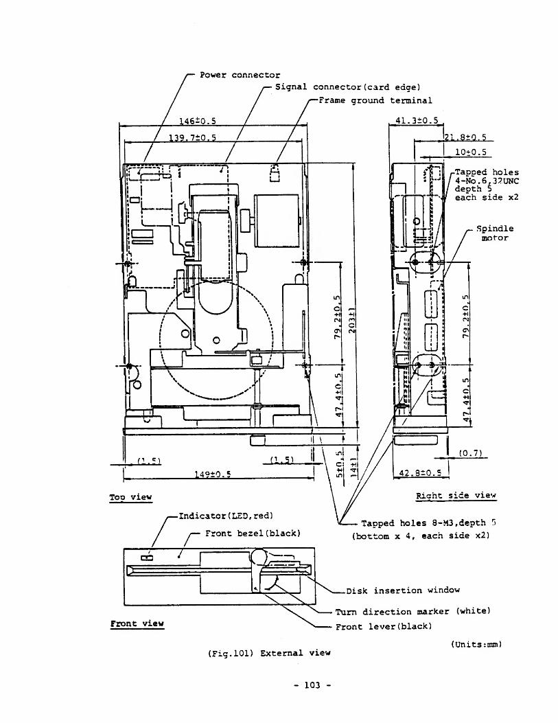
Power connector
Signal connector (card edge)
Frame ground terminal
.,21.9*9,5
10+0.5
-Tapped holes4-No.6,32UNCdepth 5
each side x2
Spindlemotor
Indicator (LED, red)
Front bezel (black)Tapped holes 8-M3, depth r
>
(bottom x 4, each side x2)
(Fig. 101) External view
Disk insertion window
Turn direction marker (white)
Front lever (black)
(Units :mm)
- 103 -
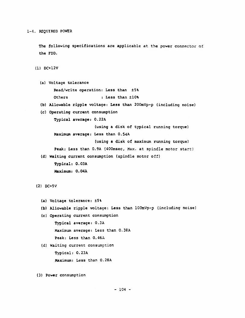
1-4. REQUIRED POWER
The following specifications are applicable at the power connector of
the FDD.
(1) DC+12V
(a) Voltage tolerance
Read/write operation: Less than ±5%
Others : Less than ±10%
(b) Allowable ripple voltage: Less than 200mVp-p (including noise)
(c) Operating current consumption
Typical average: 0.22A
(using a disk of typical running torque)
Maximum average: Less than 0.54A
(using a disk of maximum running torque)
Peak: Less than 0.9A (400msec, Max. at spindle motor start}
(d) Waiting current consumption (spindle motor off)
Typical: 0.03
A
Maximum: 0.04
A
(2) DC+5V
(a) Voltage tolerance: ±5%
(b) Allowable ripple voltage: Less than lOOmVp-p (including noise)
(c) Operating current consumption
Typical average: 0.3A
Maximum average: Less than 0.38A
Peak: Less than 0.46
A
(d) Waiting current consumption
Typical: 0.23A
Maximum: Less than 0.28
A
(3) Power consumption
- 104 -
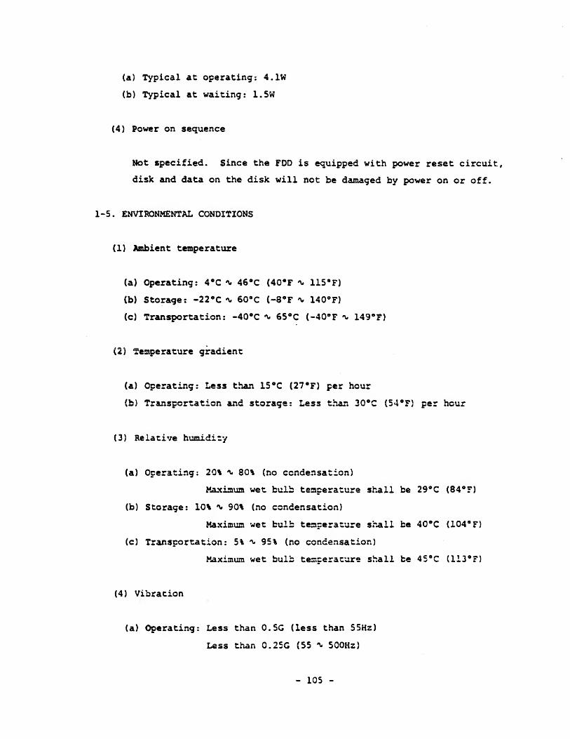
(a) Typical at operating : 4.1W
(b) Typical at waiting: 1.5W
(4) Power on sequence
Mot specified. Since the FDD is equipped with power reset circuit,
disk and data on the disk will not be damaged by power on or off.
1-5. ENVIRONMENTAL CONDITIONS
(1) Ambient temperature
(a) Operating: 4°C * 46°C (40*F ^ 115°F)
(b) Storage: -22°C % 60°C (-8°F ~ 140°F)
(c) Transportation: -40°C ~ 65°C (-40°F % 149°F)
(2) Temperature gradient
(a) Operating: Less than 15 °C (27°F) per hour
(b) Transportation and storage: Less than 30°C (54°F) per hour
(3) Relative humidity
(a) Operating: 20% *v 80% (no condensation)
Maximum wet bulb temperature shall be 29°C (84*F)
(b) Storage: 10% % 90% (no condensation)
Maximum wet bulb temperature shall be 40°C (104*F)
(c) Transportation: 5% ^ 95% (no condensation)
Maximum wet bulb temperature shall be 45°C (113°F)
(4) Vibration
(a) Operating: Less than 0.5G (less than 55Hz)
Less than 0.25G (55 A- 500Hz)
- 105 -
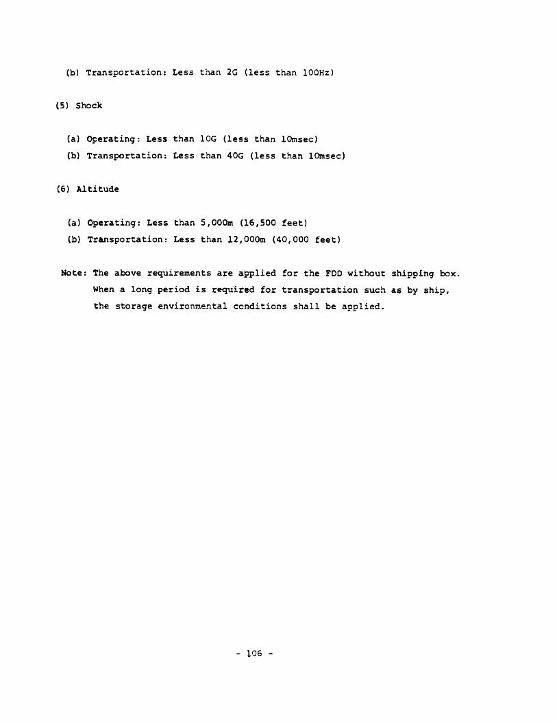
(b) Transportation: Less than 2G (less than 100Hz)
(5) Shock
(a) Operating: Less than 10G (less than 10msec)
(b) Transportation: Less than 40G (less than 10msec)
(6) Altitude
(a) Operating: Less than 5,000m (16,500 feet)
(b) Transportation: Less than 12,000m (40,000 feet)
Note: The above requirements are applied for the FDD without shipping box
When a long period is required for transportation such as by ship,
the storage environmental conditions shall be applied.
- 106
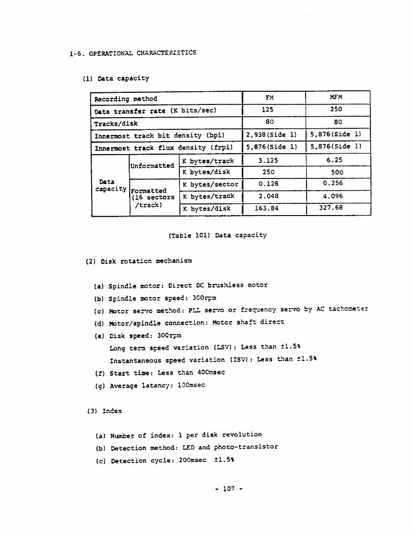
1-6, OPERATIONAL CHARACTERISTICS
(1) Data capacity
Recording method FM MFM
Data transfer rate (K bits/sec) 125 250
Tracks/disk 80 80
Innermost track bit density (bpi) 2, 938 (Side 1) 5, 876 (Side 1)
Innermost track flux density (frpi) 5,876(Side 1) 5,876(Side 1)
Datacapacity
UnformattedK bytes/track 3.125 6.25
K bytes/disk 250 500
Formatted(16 sectors/track)
K bytes/sector 0.128 0.256
K bytes/track 2.048 4.096
K bytes/disk 1 163.84 327.68
(Table 101) Data capacity
(2) Disk rotation mechanism
(a) Spindle motor: Direct DC brushless motor
(b) Spindle motor speed: 3C0rpm
(c) Motor servo method: PLL servo or frequency servo by AC tachcne 1
(d) Motor/spindle connection: Motor shaft direct
(e) Disk speed: 300r?n
Long term speed variation (LSV) : Less than ±1.5%
Instantaneous speed variation (ISV) : Less than ±1.5%
(f) Start time: Less than 40Cnsec
(g) Average latency: 100msec
(3) Index
(a) Number of index: 1 per disk revolution
(b) Detection method: LED and photo-transistor
(c) Detection cycle: 200msec ±1.5%
- 107 -
(d) Index burst detection timing error: Less than +200usec with specified
test disk.
(4) Track construction
(a) Track density: 48tpi
(b) Number of cylinders: 40 cylinders
(c) Number of tracks: 40 tracks/surface, 80 tracks/disk
(d) Outermost track radius (track 00): Side 57.150mm (2.2500 in)
Side 1 55.033mm (2.1667 in)
(e) Innermost track radius (track 39) : Side 36.513mm (1.4375 in)
Side 1 34.396mm (1.3542 in)
(f) Positioning accuracy: Less than ±30um, with specified test disk.
(Track 16, 23±2*C, 40 ^ 60%RH)
(5) Magnetic head
(a) Magnetic head: Flexure supported read/write head with tunnel erase,
2 sets
(b) Effective track width: 0.300 t 0.02£mm (0.0118 r 0.0010 in)
(c) Read/writs-erase gap spacing: 0.35=a (0.0235 in), Sen.
(d) Read/write gap azimuth: 0* s 18', with specified test disk.
(6) Track seek mechanism
(a) Head positioning mechanism: Band positioner
(b) Stepping motor: 4-phase, 200 steps per revolution
(c) Stepping motor drive: 2 steps per track
(d) Outermost and innermost sropper: Mechanical moving stopper of head
carriage
(e) Track 00 detection method: LED and photo-transistor
(f) Track to track time: Use 6msec, Min.
(g) Settling time: Less than 15msec (excludes track to track time)
(h) Average track access time: 93msec (includes settling time).
- 108 -
(7) Head load mechanism: Not used.
(When a disk is inserted and the door is closed,
the FDD becomes head load condition)
.
(8) File protect mechanism: Detection of write enable notch by LED and
photo transistor
(9) Window margin (shipping): More than 600nsec, with specified test disk,
MFM method, PLO separator, and zero write
pre-compensation
.
- 109 -

1-7. RELIABILITY
(1) MTBF: 10,000 power on hours or more (for typical usage)
(2) MTTR: 30 minutes
(3) Design component life: 5 years
(4) Preventive maintenance: Not required (for typical usage)
(5) Error rates
(a) Soft read error: 1 per 109 bits (up to 2 retries)
(b) Hard read error: 1 per 10 12 bits
(c) Seek error: 1 per 106 seeks
(6) Security standard: Complying with UL, CSA
- 110 -
1-3. SIGNAL INTERFACE
Four FDDs, Max. can be connected to one FDD controller by daisy chaining.
1-8-1. Electrical Characteristics
(1) Interface driver/receiver: See Fig. 102.
(2) Electrical characteristics
The following specifications are applicable at the signal connector of
the FDD.
(a) Input signal
LOW level (TRUE) : 0V *v 0.5V
Terminator current: 18mA, Max.
Receiver current: 3.2mA, Max.
HIGH level (FALSE): 2.5V % 5.25V
(b) Output signal
LOW level (TRUE): 0V % 0.4V
Driver sink current capability: 48mA, Max.
HIGH level (FALSE): 5.25V, Max.
(depending on controller terminator)
(3) Terminator
(a) Resistance value: 330ft t 5%
(b) Terminator for DRIVE SELECT % 3 input signals:
A terminator resistor is mounted ok the PC3 with soldering joint.
(c) Terminator for other input signals:
A resistor network is mounted on IC socket on the PCB.
(d) Shipping condition
Ail of the terminator resistors are mounted.
- Ill -
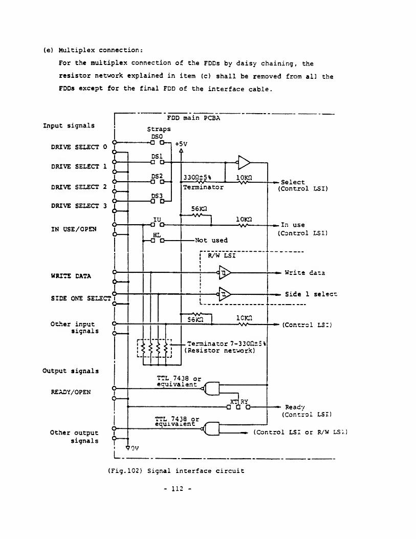
(e) Multiplex connection:
For the multiplex connection of the FDDs by daisy chaining, the
resistor network explained in item (c) shall be removed from all the
FDDs except for the final FDD of the interface cable.
Other inputsignals
Output signals
READY/OPEN
Other outputsignals
•• (Control LSI or R/W LSI
(Fig. 102) Signal interface circuit
- 112 -
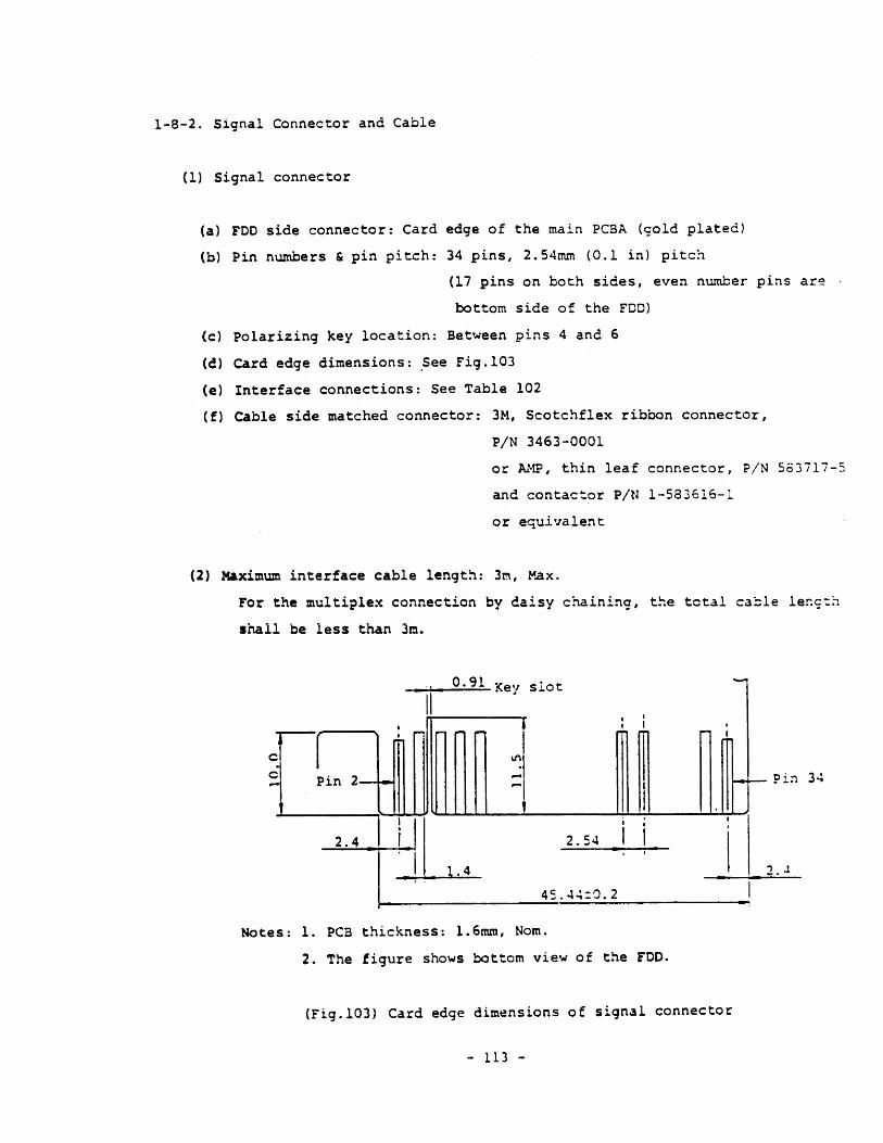
1-8-2, Signal Connector and Cable
(1) Signal connector
(a) FDD side connector: Card edge of the main PCBA (cold plated)
(b) Pin numbers & pin pitch: 34 pins, 2.54mm (0.1 in) pitch
(17 pins on both sides, even number pins are
bottom side of the FDD)
(c) Polarizing key location: Between pins 4 and 6
(d) Card edge dimensions: See Fig. 103
(e) Interface connections: See Table 102
(f) Cable side matched connector: 3M, Scotchflex ribbon connector,
P/N 3463-0001
or AMP, thin leaf connector, P/N 553717-
and contactor P/N 1-533616-1
or equivalent
(2) Maximum interface cable length: 3m, Max.
For the multiplex connection by daisy chaining, the total cable ler.ct:
shall be less than 3m.
0,91 Key slot
rmPin 2-
2.4 2.54 I j
UL
Pin 34
2 J
45.44:0.2
Notes: 1. PC3 thickness: 1.6mm, Nom.
2. The figure shows bottom view of the FDD.
(Fig. 103) Card edge dimensions of signal connector
- 113 -
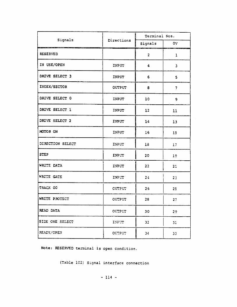
Signals DirectionsTerminal Nos.
Signals OV
RESERVED 2 1
IN USE/OPEN INPUT 4 3
DRIVE SELECT 3 INPUT 6 5
INDEX/SECTOR OUTPUT 8 7
DRIVE SELECT INPUT 10 9
DRIVE SELECT 1 INPUT 12 11
DRIVE SELECT 2 INPUT 14 13
MOTOR ON INPUT 16 15
DIRECTION SELECT INPUT 18 17
STEP INPUT 20 19
WRITE DATA1
INPUT 22 21
WRITE GATE INPUT 24 23
TRACK 00 OUTPUT 25 25
WRITE PROTECT OUTPUT 29 27
READ DATA OUTPUT 30 29
SIDE ONE SELECT INPUT 32 31
READY/OPEN OUTPUT 34 33
Note: RESERVED terminal is open condition.
(Table 102) Sicnal interface connection
- 114 -
1-3-3. Input/Output Signals
In the following, input signals are those transmitted to the FDD
while output signals are those transmitted from the FDD,
Refer to item 1-12 as to the relation between input signals and
operating conditions of the front bezel indicator and spindle motor.
LOW level of the signals is TRUE.
(1) DRIVE SELECT 0^3 input signals
(a) Signals of four lines to select a specific FDD for operating in
multiplex control by daisy chaining.
(b) Only the DRIVE SELECT signal of the same number as of on-state
strap among DSO * 3 straps is effective.
(c) All the input/output signals except for the MOTOR ON and IN USE are
effective when this signal is effectively received.
(d) The time required to make each input or output signal effective after
the transmission of this signal is 0.5usec, Max. including delay time
through the interface cable.
(2) MOTOR ON input signal
(a) Level signal to rotate the spindle motor.
(b) The spindle motor reaches to the rated rotational speed within 40Cmsec
after this signal becomes TRUE.
(3) DIRECTION SELECT input signal
(a) Level signal to define the moving direction of the head when the
STEP line is pulsed.
(b) Step-out (moving away from the center of the disk) is defined as
HIGH level of this signal. Conversely, step-in (moving toward the
center of the disk) is defined as LOW level of this signal.
- 115 -
(4) STEP input signal
(a) Pulse signal to move the head. The pulse width shall be more than
O.Sysec and the head moves one track space per one pulse.
(b) The access motion (head seek operation) is initiated at the trailing
edge of the pulse and completes within 21msec after starting the
access including the settling time. For the successive access motion
in the same direction, the pulses shall be input with the space of
more than 6msec, while the pulses shall be input with the space of
more than 21msec for the access motion in a different direction.
(c) This signal becomes ineffective when the WRITE PROTECT signal is
FALSE and the WRITE GATE signal is TRUE.
Also this signal becomes ineffective when the TRACK 00 signal is
TRUE and the DIRECTION SELECT signal is HIGH level (step-out)
.
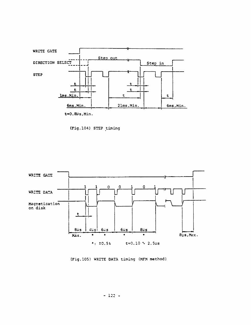
(d) This signal shall be input according to the timing in Fig. 104.
(5) WRITE GATE input signal
(a) Level signal to erase the written data and to enable the writing of
new data.
(b) The FDD is set to write mode when the following logical expression is
satisfied.
WRITE GATS * DRIVE SELECT * WRITE PROTECT
(c) This signal should be made TRUE after satisfying all of the following
three conditions,
i) The FDD is in ready state (refer to item (13) )
.
However, the host controller can ignore this item since the INDEX
and the READ DATA pulses are output only when the FDD is in ready
state.
ii) More than 2imsec after the effective receival of the final STEP
pulse.
Practical write operation, however, can be executed without error
more than 10msec after the final STEP pulse,
iii) More than lOOusec after the level change of the SIDE ONE SELECT
- 116 -
signal,
(d) None of the following operations shall be done for at least 1msec
after this signal is changed to FALSE.
X/ nai>c a mo w©r***o»* wOuui^a«tw r ^ • -^ • • i
ii) Make the DRIVE SELECT signal FALSE.
iii) Start the head access motion by the STEP pulse,
iv) Change the level of the SIDE ONE SELECT signal.
(6) WRITE DATA input signal
(a) Pulse signal to designate the contents of the data to be written on
the disk. The pulse width shall be O.lOusec through 2.5psec and the
leading edge of the pulse is used.
(b) This signal becomes ineffective when one of the following conditions
is satisfied,
i) WRITS GATE signal is FALSE.
ii) WRITE PROTECT signal is TRUE.
(c) This signal shall be input according to the timing in Fig.lOS.
(7) SIDE ONE SELECT input signal
(a) Level signal to define which side of a double sided disk is used for
reading or writing.
(b) When this signal is HIGH level, the magnetic head on the side
surface of the disk is selected, while the magnetic head on the
side 1 surface is selected when this signal is LCW level.
(c) The READ DATA signal on a selected surface becomes valid more than
lOOysec after the change of this signal level.
(c) Write operation (the WRITE GATE signal is TRUE) on a selected surfaci
shall be started more than lOOysec after the change of this signal
level.
(e) When the other side of the disk is selected after the completion of
a write operation, the level of this signal shall be switched more
than 1msec after making the WRITE GATE signal FALSE.
- 117 -
(8) IN USE/OPEN input signal
This signal is effective only when the IU strap is on-state (refer to
item 1-11).
(a) Level signal to indicate that all of the daisy chained FDDs are in
use condition under the control of the host system. Refer to item
1-12.
(b) When the IU strap is off-state, only the terminator is connected to
pin 4 of the signal interface connector and the input circuit becomes
open condition (refer to Fig. 102).
- 113 -
(9) TRACK 00 output signal
(a) Level signal to indicate that the head is on track 00 (the outermost
track) .
(b) This signal becomes valid more than 5.8msec after the effective
receival of the STEP pulse.
(10) INDEX/SECTOR output signal
(a) Pulse signal for the detection of the index hole or the sector holes.
(b) INDEX pulse is output when the following logical expression is
satisfied.
Hole detection * DRIVE SELECT * READY
Note: For a hard sectored disk, strap setting shall be changed
according to item 1-11 (9) and the ready state has no relation
to the INDEX/SECTOR output condition.
(c) When using a .soft sectored disk, there will be one index pulse on
this line per one revolution of the disk. When using a hard sectored
disk, sector pulses and index pulse are output together.
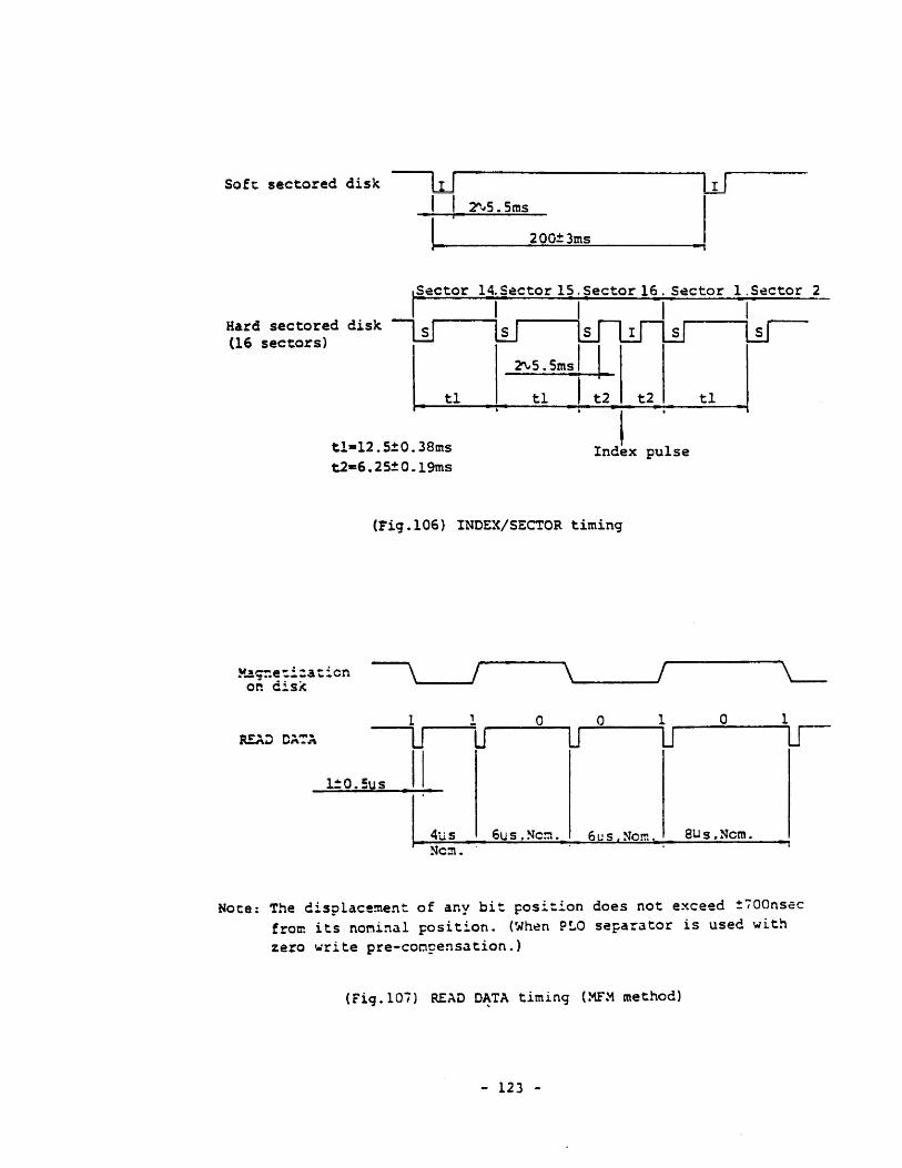
id) Fie. 106 shews the rising for this signal. Leading edge of t.ie puj.ss
shall be used as the reference.
(11) READ DATA output signal
(a) Pulse signal for the read data from the disk composing clock bits and
data bits together.
(b) Fi~.lQ"? shows the timing for this signal. Leading edge of the pulse
shall be used as the reference.
(c) This signal becomes valid when all of the following four conditions
are satisfied.
i) FDD is in ready state (refer to item (13) )
.
ii) More than 21msec after the effective receival of the final STEP
pulse.
< j» _____«, i __ __.. w.. *»»as~,it-A/4 tji fHont errorHowever, practical reac ©peratxuu ta» w« sssw-wg- w
- 119 -
more than 10msec after the final STEP pulse,
iii) More than 1msec after fche WRITE GATE signal becomes FALSE,
iv) More than lOOvsec after the level change of the SIDE ONE SELECT
signal.
(d) READ DATA pulse is output when the following logical expression is
satisfied.
READ DATA detection * DRIVE SELECT * READY * WRITE OPERATION
Notes: 1. WRITE OPERATION is the state when the WRITE GATE input
signal is FALSE and more than 1msec has been passed after
the WRITE GATE signal changed to FALSE.
2. For a hard sectored disk, strap setting shall be changed
according to item 1-11 (9) and the ready state has no
relation to the READ DATA output condition.
(12) WRITE PROTECT output signal
(a) Level signal to indicate that the write enable notch of the disk
is masked.
(b) When this signal is TRUE, the data on the disk are protected from
erasing and writing of new data is inhibited.
(13) READY/OPEN output signal
(a) Level signal to indicate that the FED is in ready state.
(b) The FDD becomes ready state when all of the following four conditions
are satisfied.
i) The FDD is powered on.
ii) A disk is installed and a motor-on command from the host side
is TRUE.
iii) The disk rotates at more than 50% of the rated speed and two
INDEX pulses have been counted after the 50% speed is satisfied.
iv) INDEX pulse interval is within the range of ±6% for the rated
value.
(c) The FDD becomes ready state within 800msec (550msec, approx. in
- 120 -
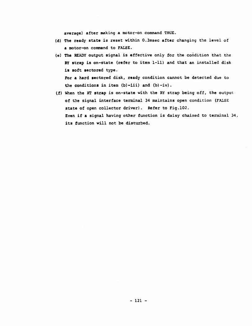
average) after making a motor-on command TRUE.
(d) The ready state is reset within 0.3msec after changing the level of
a motor-on command to FALSE.
(e) The READY output signal is effective only for the condition that the
RY strap is on-state (refer to item 1-11) and that an installed disk
is soft sectored type.
For a hard sectored disk, ready condition cannot be detected due to
the conditions in item (b)-iii) and (b)-iv).
(f) When the XT strap is on-state with the RY strap being off, the output
of the signal interface terminal 34 maintains open condition (FALSE
state of open collector driver). Refer to Fig. 102.
Even if a signal having other function is daisy chained to terminal 34,
its function will not be disturbed.
- 121 -
WRITE GATE«
Steo outDIRECTION SELECT
iSteo in
STEP
t
l_
t .
t
t IT t -
1ms, Min.'
t
—
*
6ms , Min
.
— 2 1ms, Min. 6ms, Min.
t*0.8Vs,Min.
(Fig. 104) STEP timing
WRITE GATE
1 1 10 1
A
WRITE DATA
1
i J J J
Magnetization
t
r1
6us 8Us
1
on disk
6us8Us 4Us
Max. * * * * 8us,Max.
*: ±0.51 t=0.10 ^ 2.5ys
(Fig. 105) WRITE DATA timing (MFM method)
- 122 -
Soft sectored disk kr2V5 . 5ms
200±3ms
Hard sectored disk(16 sectors)
Sector 14. Sector 15. Sector 16 . Sector 1. Sector 2
tl«12.5±0.38ms
t2«6.25± 0.19msIndex pulse
(Fig. 106) INDEX/SECTOR timing
Magnetizationor. disk / a r
READ DATA
Ncm.
Noce: The displacement of any bit position does not exceed ±700nsec
from its nominal position. (When PLO separator is used with
zero write pre-concensation.)
(Fig. 107) READ DATA timing (MFM method)
- 123 -
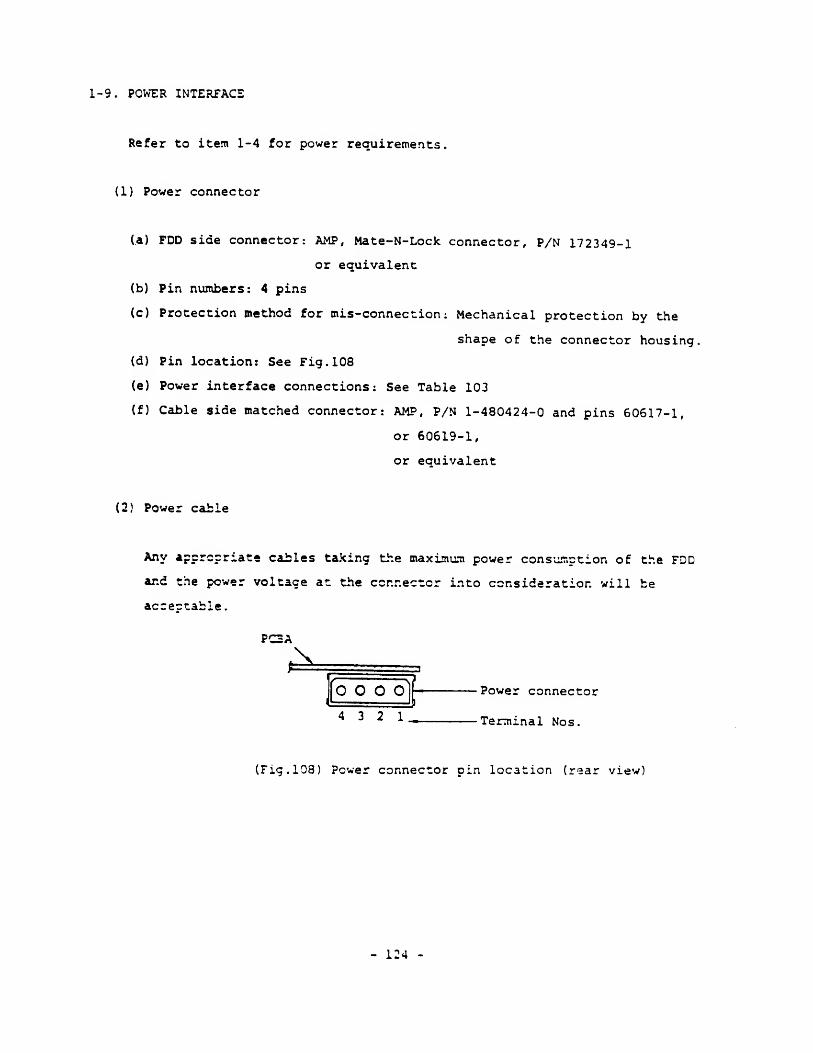
1-9. POWER INTERFACE
Refer to item 1-4 for power requirements.
(1) Power connector
(a) FDD side connector: AMP, Mate-N-Lock connector, P/N 172349-1
or equivalent
(b) Pin numbers: 4 pins
(c) Protection method for mis-connection: Mechanical protection by the
shape of the connector housing,
(d) Pin location: See Fig. 108
(e) Power interface connections: See Table 103
(f) Cable side matched connector: AMP, P/N 1-480424-0 and pins 60617-1,
or 60619-1,
or equivalent
(2) Power cable
Any appropriate cables taking the maximum power consumption of the FDD
ar.d the power voltage at the ccnnector into consideration will be
accectable.
PC2A
O O OI I
4 3 2 1. Terminal Nos.
(Fig. 108) Power connector pin location (rear view)
- 124 -

Voltage Terminal Nos
.
DC+12V 1
ov 2
ov 3
DC+5V 4
(Table 103) Power interface connections
- 125 -
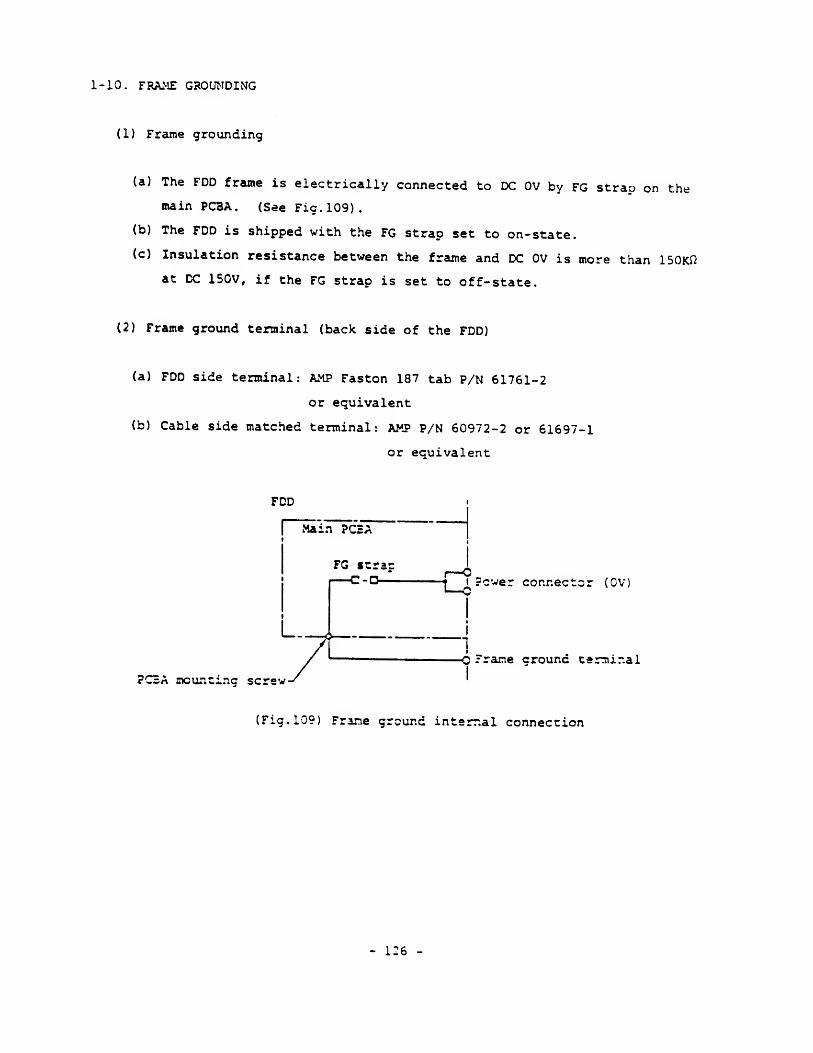
1-10. FRAME GROUNDING
(1} Frame grounding
(a) The FDD frame is electrically connected to DC 0V by FG strap on the
main PCBA. (See Fie. 109).
(b) The FDD is shipped with the FG strap set to on-state.
(c) Insulation resistance between the frame and DC 0V is more than 150Kfl
at DC 150V, if the FG strap is set to off-state.
(2) Frame ground terminal (back side of the FDD)
(a) FDD side terminal: AMP Faston 187 tab P/N 61761-2
or equivalent
(b) Cable side matched terminal: AMP P/N 60972-2 or 61697-1
or equivalent
FDD
Mam PC2A
t
L..
FG itrac—c-o-^- r-0-t i Power connector (0V]
-0 Frame crounc terminal
PCBA mounting screw-
(Fig. 109) Frame ground internal connection
- 126 -
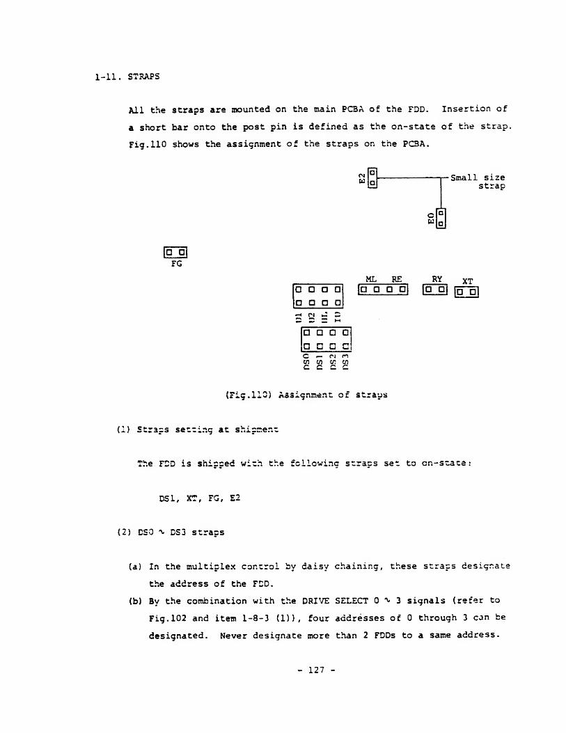
1-11. STRAPS
All the straps are mounted on the main PCBA of the FDD. Insertion of
a short bar onto the post pin is defined as the on-state of the strap.
Fig. 110 shows the assignment of the straps on the PCBA.
Small sizestrap
|g-5iFG
a a a a
a a a n
•*ri J 2
a a a d|m r^ n r-»lU U U U|
ML RE|D D O D|
RVfa"a1
XTd a
C f. m nen en w enc c c c
(Fig. 110) Assignment of straps
(1) Straps setting at shipment
The FDD is shipped with the following straps set to cn-state:
DS1, XT, FG, E2
(2) DSO ^ DS3 straps
(a) In the multiplex control by daisy chaining, these straps designate
the address of the FDD.
(b) By the combination with the DRIVE SELECT 0^3 signals (refer to
Fig. 102 and item 1-8-3 (D), four addresses of through 3 can be
designated. Never designate more than 2 FDDs to a same address.
- 127 -
(3) IU strap
(a) Strap to make the signal interface terminal 4 be used for the IN USE
input signal. In such application, this strap should be on-state.
(b) If this strap is off-state, the input circuit becomes open and the
IN USE signal becomes uneffective.
(4) Ul and U2 straps
(a) Straps to determine the turn-on condition of the front bezel indicator,
(b) Five turn-on conditions can be selected including the IU strap in
item (3). Refer to item 1-12-1.
(5) RY and XT straps
(a) Straps to select the function of the signal interface terminal 34.
It is used for either function of READY output signal or maintaining
open condition.
(b) When the RY strap is on-state, the READY signal is output frcm the
(c) When the XT strap is on-state, the terminal 34 will maintain open
rendition (FALSE state of open collector driver)
.
Caution: Never set both of the RY and the XT straps on-state. Be sure
to set either of them on.
(6) FG strap
(a) Strap to connect the FDD frame electrically to DC OV.
(b) Refer to item 1-10 as to the details.
(7) ML strap
(a) Strap to determine the rotational condition of the spindle motor by
- 128 -
an external command.
(b) When this strap is off-state, the spindle motor rotates only by the
MOTOR ON input signal.
(c) When this strap is on-state, the spindle motor rotates by either of
the following conditions. (Refer to item 1-12-2)
.
i) While the MOTOR ON input signal is TRUE.
ii) While the front bezel indicator turns on.
(8) RE strap
(a) Strap to make the head recalibrate automatically to track 00
immediately after the power on.
(b) When this strap is off-state, no auto-recalibration is executed.
(c) When this strap is on-state, auto-recalibration starts immediately
after the power on. It will be completed within 255msec (if the head
was on the innermost track) and the FDD maintains not-ready condition
(?) E0 and E2 straps
(a) Straps to select the output condition of INDEX/SECTOR pulse and READ
(b) When the E3 strap is off-state, INDEX/SECTOR pulse is output during
the ready state of the FDD, while it is output independently of
the ready state when the E0 strap is on.
(c) When the E2 strap is on-state, READ DATA pulse is output during the
ready state of the FDD, while it is output independently of the ready
state when the E2 strap is off.
(c) The FDD is shipped with the strap setting of E0 off and E2 on usually
It is required to change the strap setting for a hard sectored
disk so that E0 becomes on and E2 becomes off.
(10) HL strap
- 129 -

HL strap is not used on this FDD. Set it to off-state
- 130 -
1-12. OPERATIONAL CONDITIONS
1-12-1. Front Bezel Indicator
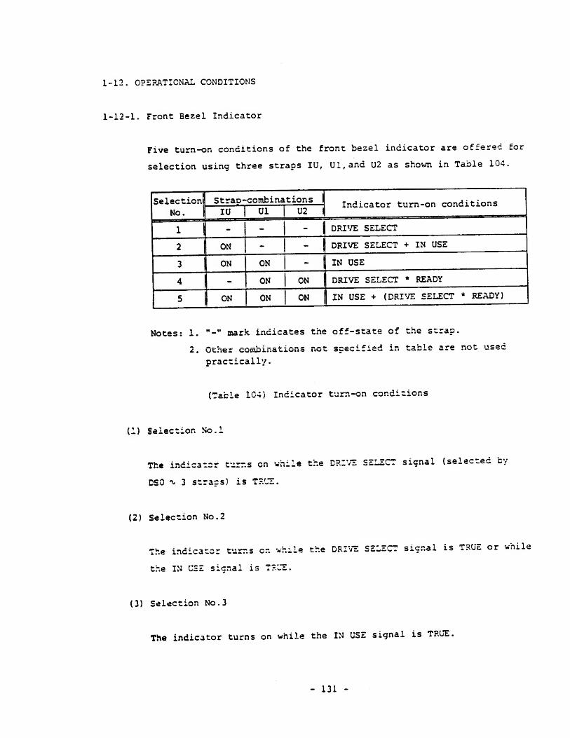
Five turn-on conditions of the front bezel indicator are offered for
selection using three straps IU, Ul,and U2 as shown in Table 104.
Selection Strap-combinations indicator turn-on conditions
| DRIVE SELECT
| DRIVE SELECT + IN USE
ON I DRIVE SELECT * READY
IN USE + (DRIVE SELECT * READY)
Notes: 1. "-" mark indicates the off-state of the strap
Other combin
practically.t. . vjcner conu3ir.atj.uii a *«jv- awc^i«j.<=v^ ^.u wow**. *.^~ ..—
(Table 1C4) Indicator turn-on conditions
(1) Selection No.l
The indicator turns en while the DRIVE SELECT signal (selected b;
DSO ^ 3 stracs) is TRUE.
(2) Selection No.
2
The indicator turns en
the IN USE sicnai is Tl
,-hile the DRIVE SELECT signal is TRUE or while
(3) Selection No.
3
The indicator turns on while the IN USE signal is TRUE,
- 131 -

(4) Selection No.
4
The indicator turns on while the DRIVE SELECT signal is TRUE and the
FDD is in ready state (refer to item 1-3-3 (13)}
(5) Selection No.
5
The indicator turns on in the condition of item (3) or (4) .
- 132 -
1-12-2. Spindle Motor
The spindle motor starts rotation in either of the following conditions
r i \ s / o » mu. __ a- — -. _—_—'—-»,- t-~ *•'...-. — - - o '' *»'» ^at'i^nal c^OP^ yi thin(xj ana v^; • -ine mouor rcai-.ica w uic ioi.au ^0^3.^-^..^.- ~~. *
400msec after the start.
(1) Rotation by a command from the host side
Either one of the conditions can be selected by the ML strap.
(a) Selection 1: Off-state of ML strap
While the MOTOR ON signal is TRUE, the spindle motor rotates.
(b) Selection 2 : On-state of ML strap
While the MOTOR ON signal is TRUE, or while the front bezel indicator
is on, the spindle motor rotates.
Note that the Selection Nos.4 and 5 of the turn-on conditions of
the front bezel indicator (refer to item 1-12-1) cannot be used for
this purpose.
(2) Automatic rotation by the internal circuit of the FDD
(a) Automatic rotation by the internal circuit will start under either
cf the following conditions.
i) when a disk is inserted into the front bezel,
ii) When the disk is removed.
Note that the automatic rotation will not start when a writs
protected disk is removed.
(b) Automatic rotation will step under one of the following conditions.
i) When the front lever is closed, disk starts rotation, and the FDD
becomes ready state. The READY signal maintains FALSE,
ii) Approximately 10 seconds after the removal of a disk from the FDD.
iii) The front lever is not closed for 10 seconds, approx.
- 133 -


