Embed Size (px)
Citation preview
Catalog 2014Electronic Products and Relays
Catalog |

2 ABB | Catalog Electronic Products and Relays 2013/2014 | 2CDC 110 004 C0209

2CDC 110 004 C0209 | Catalog Electronic Products and Relays 2013/2014 | ABB 3
Machine Safety
Jokab Safety products
Productivity and safety go hand in handJokab Safety was acquired by ABB in 2010. This gives us extra strength and a sales network in 120 countries. Our goal is to become
even better at supporting you as a customer through cooperation within ABB Jokab Safety globally and locally. The fact that the leading
power and automation technology company, ABB, and a leader in machine safety, Jokab Safety, have joined forces means a lot more
than just a new organizational chart. ABB has a huge footprint in the industry - from power supply to the control of each individual motor
- and has been delivering reliable solutions for decades that boost productivity in the industry. The acquisition of Jokab Safety means
the last building block is in place. We can now offer our customers tailored, turnkey solutions where machine safety is an integral and
value-enhancing component.
Jokab Safety offering: – Safety PLC
Pluto, Pluto AS-i, Gateways, Safe Encoder
– Safety controller Vital and Tina safety systems
– Safety relays
RT series, JSB series, safety timers, expansion relays
– Light curtains, light grids, light beams and scanner Focus II, Spot, Look
– Stop time measurement and machine diagnosis
Smart
– Sensors, switches and locks
Eden, Sense, MKey, Magne, Dalton, Knox
– Control devices
JSHD4, Safeball, Fox2
– Emergency stop devices
Inca, Smile, EStrong, LineStrong
– Contact rails, bumpers and safety mats
– Fencing systems
Quick-Guard, SafeCad, Roller doors
Further information: „ABB Safety Handbook“ - Order code: 2TLC172001C0202
4 ABB | Catalog Electronic Products and Relays 2013/2014 | 2CDC 110 004 C0209
Electronic Products and Relays
News
The requirements for rolling stock are increasing and will continue to do so. The task is to implement
ever faster connections, while also increasing traveler comfort. During their everyday work, the trains
are exposed to very high environmental, electrical and mechanical loads.
Selected products of the electronic timers and measuring and monitoring relays comply to the latest
rail standards NF F 16-101/102, EN 45545, EN 50155 and more standards which are relevant for
railway applications. Find more inforamtion in the rail brochure 2CDC110084B0201.
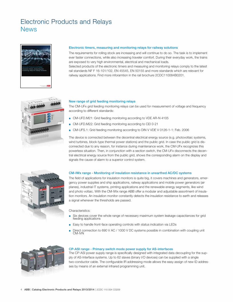
The CM-UFx grid feeding monitoring relays can be used for measurement of voltage and frequency
according to different standards:
� CM-UFD.M21: Grid feeding monitoring according to VDE AR-N 4105
� CM-UFD.M22: Grid feeding monitoring according to CEI 0-21
� CM-UFS.1: Grid feeding monitoring according to DIN V VDE V 0126-1-1: Feb. 2006
The device is connected between the decentral electrical energy source (e.g. photovoltaic systems,
wind turbines, block-type thermal power stations) and the public grid. In case the public grid is dis-
connected due to any reason, for instance during maintenance work, the CM-UFx recognizes this
powerless situation. Then, in conjunction with a section switch, the CM-UFx disconnects the decen-
tral electrical energy source from the public grid, shows the corresponding alarm on the display and
signals the cause of alarm to a superior control system.
The field of applications for insulation monitors is quite big, it covers machines and generators, emer-
gency power supplies and ship applications, railway applications and mobile power generators (air
planes), industrial IT systems, printing applications and the renewable energy segments, like wind
and photo voltaic. With the CM-IWx range ABB offer a modular and adjustable assortment of insula-
tion monitors. An insulation monitor constantly detects the insulation resistance to earth and releases
a signal whenever the thresholds are passed.
The CP-ASI power supply range is specifically designed with integrated data decoupling for the sup-
ply of AS-Interface systems. Up to 62 slaves (binary I/O devices) can be supplied with a single
two-conductor cable. The configurable IR addressing mode allows the easy assign of new ID addres-
ses by means of an external infrared programming unit.
Characteristics:
� Six devices cover the whole range of necessary maximum system leakage capacitances for grid feeding applications
� Easy to handle front-face operating controls with status indication via LEDs
� Direct connection to 690 V AC / 1000 V DC systems possible in combination with coupling unit CM-IVN
Electronic timers, measuring and monitoring relays for railway solutions
New range of grid feeding monitoring relays
CM-IWx range - Monitoring of insulation resistance in unearthed AC/DC systems
CP-ASI range - Primary switch mode power supply for AS-interface
2CDC 110 004 C0209 | Catalog Electronic Products and Relays 2013/2014 | ABB 5
1
5
3
7
2
6
8
4
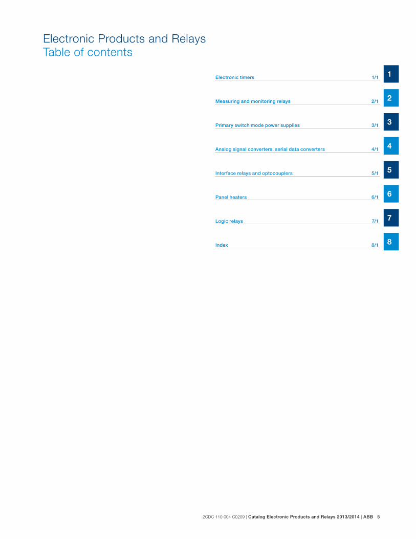
Electronic Products and Relays
Table of contents
Electronic timers 1/1
Measuring and monitoring relays 2/1
Primary switch mode power supplies 3/1
Analog signal converters, serial data converters 4/1
Interface relays and optocouplers 5/1
Panel heaters 6/1
Logic relays 7/1
Index 8/1

6 ABB | Catalog Electronic Products and Relays 2013/2014 | 2CDC 110 004 C0209
Approvals and marks for the world market
Overview
ABB low-voltage switching devices are developed and produced in accordance with the applicable regulations as stated in the international IEC publica-
tions, the European EN specifications and the national VDE standards.
In most countries, low-voltage switching devices are produced according to such regulations under the responsibility of the manufacturers. This is why the
devices are not subject to further approval. However, for those devices which are intended for use in household or for public use our customers can reque-
st test reports of our internal laboratory for presentation to the various qualified local organizations. In other countries, approvals are prescribed by law.
For devices installed in ships, an approval issued by independent shipping companies, such as the GL, are demanded by the maritime insurance
companies.
Marks of conformity and examples of approvals (device-dependent)
International
CB scheme KThe CB (Certification Body) Scheme is a
system designed to facilitate international
trade by establishing mutual acceptance
of test reports among participating safety
certification organizations (the National Cer-
tification Bodies) in more than 30 countries.
The CB Scheme was established by the
International
Electrotechnical Committee for Conformity
Testing to Standards for Electrical
Equipment (IECEE).
Europe
Conformité Européen (CE) aAll devices which comply with the European
low voltage directive and which are intended
for sale within the European Union must
have the CE sign applied. All products in this
catalog are CE marked.
The CE sign must not be confused with a
certificate of quality issued by the EU. It is
solely used to confirm that the respective
product complies with the applicable
European directives *). The CE sign is part
of an administrative procedure to guarantee
free movement of goods within the Europe-
an Community.
*) Directives:
Low Voltage Directive 2006/95/EC
EMC Directive 2004/108/EC
Machinery Directive 98/37/EEC
Verband der Elektrotechnik
Elektronik Informationstechnik
(VDE)J
Applicable for technical instruments covered
by the German Gerätesicherheitsgesetz
(GSG) as well as for single parts and electri-
cal wiring devices.
Berufsgenossenschaft
der Feinmechanik und
Elektrotechnik (BGFE) MThe BG-PRÜFZERT sign is a voluntary
safety mark, awarded by the BGFE following
successful safety testing.
Explosion protection (EX) IExplosion protection acc. to
Directive 94/9/EG (ATEX 100a)
Swiss insurance institution
(SUVA)Q
Department accident prevention suvaPRO
Germanischer Lloyd (GL) CShipping approval
Lloyds Register PShipping approval
Russia
In Russia, low-voltage switching devices are
subject to certification and have to be provi-
ded with a sign.
Gost Standard (GOST-R) 1) DGost R certification is mandatory for many
products. This certification is based on a
safety test (IEC standards with Russia-
specific deviations) and an EMC test.
Russian Maritime Register of
Shipping RMRS LShipping approval
Australia, New Zealand
C-Tick Mark bThe C-Tick Mark certifies compliance with
the Australian EMC requirements. The Mark
is also recognized in New Zealand.
China
CCC (China Compulsory
Certification) EIn China the CCC certification mark is a
compulsory certification mark in the field of
safety and quality for products sold on the
Chinese market.
North America
Canadian and US standards are more or
less equivalent but considerably differ from
the IEC and VDE regulations.
USA
Underwriters Laboratories (UL)
Listing BReleased for installation in systems and for
sale as individual component in the USA.
Recognition GReleased for installation in systems, if the
respective system has been completely
mounted and wired by qualified personnel.
Canada
Canadian Standards
Association (CSA) F
USA and Canada
The combined UL signs for the USA and
Canada are recognized by the authorities of
both countries. Devices with this certificate
meet the requirements of both countries.
Listing A
Recognition H
1) May have been replaced by EAC during the availability of this catalog edition.

2CDC 110 004 C0209 | Catalog Electronic Products and Relays 2013/2014 | ABB 7
Documentation in ABB Library
www.abb.com/lowvoltage
When you enter www.abb.com/lowvoltage for the first time, you will be asked to select your country and to select your preferred language (see screen
shot 1). You can change this setting later if you like.
Select Control Products to find Electronic Products and Relays in world wide web.

8 ABB | Catalog Electronic Products and Relays 2013/2014 | 2CDC 110 004 C0209
Documentation in ABB Library
www.abb.com/lowvoltage
Click on depen-
ding category for
further documen-
tation e.g.
Electronic Relays and Controls
After selecting e.g. Electronic Relays and Controls it is possible to select the product range of interest directly.
Please select one of the product ranges as listed below, e.g. Time Relays.
The whole EPR assortment is splitted in four different categories:
Electronic Relays and Controls
Motor Controllers
Power Supplies
Signal Converters
2CDC 110 004 C0209 | Catalog Electronic Products and Relays 2013/2014 | ABB 9
Documentation in ABB Library
www.abb.com/lowvoltage
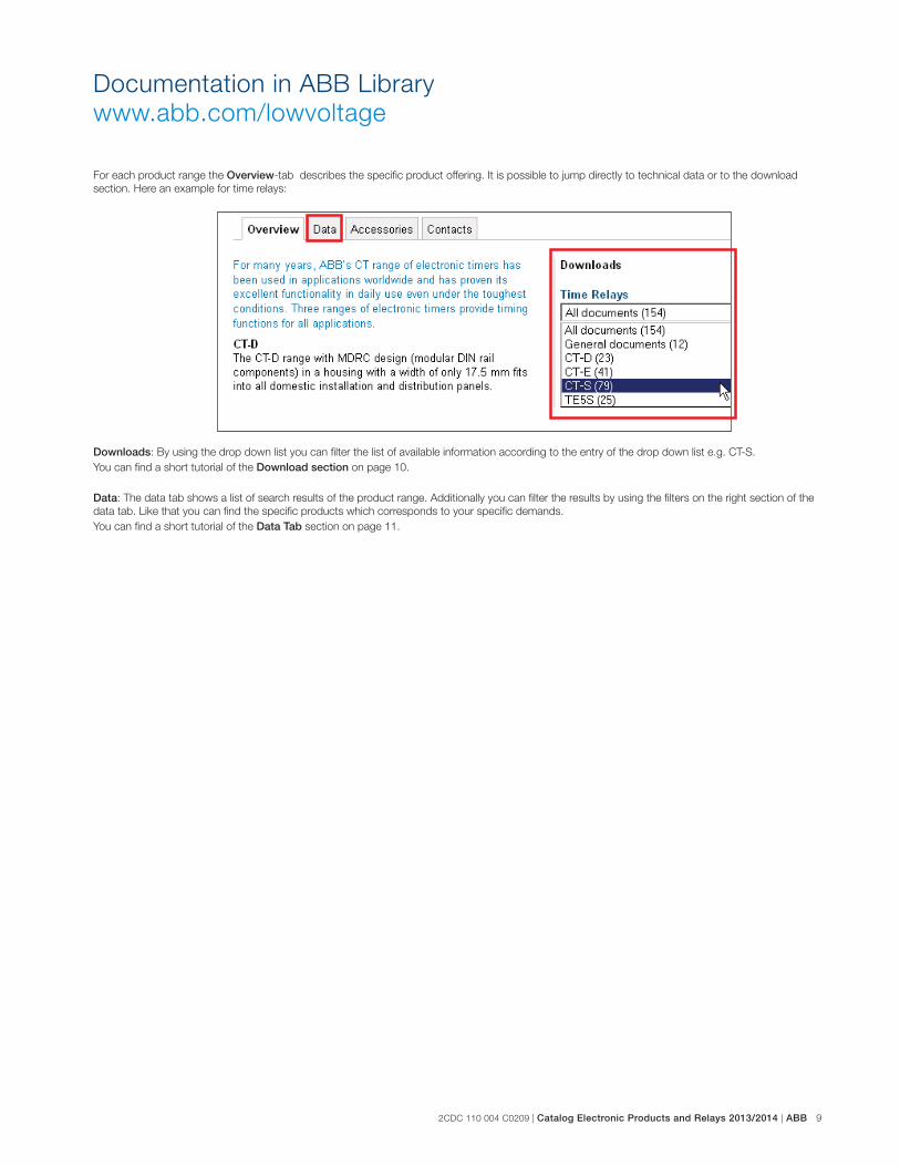
For each product range the Overview-tab describes the specific product offering. It is possible to jump directly to technical data or to the download
section. Here an example for time relays:
Downloads: By using the drop down list you can filter the list of available information according to the entry of the drop down list e.g. CT-S.
You can find a short tutorial of the Download section on page 10.
Data: The data tab shows a list of search results of the product range. Additionally you can filter the results by using the filters on the right section of the
data tab. Like that you can find the specific products which corresponds to your specific demands.
You can find a short tutorial of the Data Tab section on page 11.
10 ABB | Catalog Electronic Products and Relays 2013/2014 | 2CDC 110 004 C0209
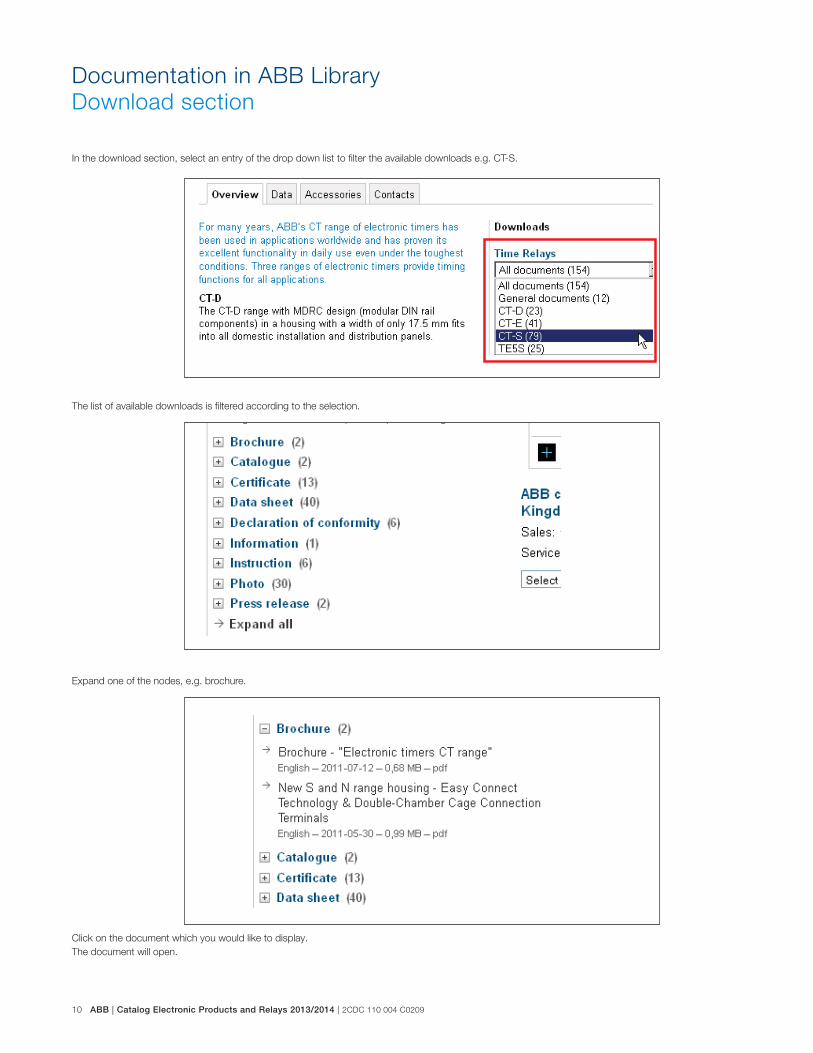
Documentation in ABB Library
Download section
In the download section, select an entry of the drop down list to filter the available downloads e.g. CT-S.
The list of available downloads is filtered according to the selection.
Expand one of the nodes, e.g. brochure.
Click on the document which you would like to display.
The document will open.

2CDC 110 004 C0209 | Catalog Electronic Products and Relays 2013/2014 | ABB 11
Documentation in ABB Library
Data Tab
Click on the tab Data to enter to the Data Tab of the product range (in this case Time Relays).
Use the filters on the right section of the page to customize the list of products displayed, e.g. Time Range.

12 ABB | Catalog Electronic Products and Relays 2013/2014 | 2CDC 110 004 C0209
A window is openend. Here you can add or remove a value of the filter you have chosen (in our example Time Range).
On the left side just click on the value you want to add. Then click on the Add-button. The value appears on the right side. After adding
the value just click on Apply to set the filter for the search results.
After clicking on Apply the search results are now shown with the defined filter.
Selecting a specific product opens the detailed information sheet, e.g. CT-ERE 1SVR550100R5100.
On the bottom of the page you can find further documentation and download information.
Documentation in ABB Library
Data Tab

2CDC 110 004 C0209 | Catalog Electronic Products and Relays 2013/2014 | ABB 13
Documentation in ABB Library
Notes

1/1 ABB | Catalog Electronic Products and Relays 2013/2014 | 2CDC 110 004 C0209
1
Electronic timers
Product group picture

2CDC 110 004 C0209 | Catalog Electronic Products and Relays 2013/2014 | ABB 1/2
1
Electronic timers
Table of contents
Electronic timers
Table of contents 1/2
Overview 1/3
Approvals and marks 1/4
CT-D range 1/5
Table of contents 1/6
Benefits and advantages 1/7
Ordering details 1/8
Function diagrams 1/9
Connection diagrams 1/12
Technical data 1/13
Technical data, Technical diagrams 1/15
Wiring notes, Dimensional drawings 1/16
CT-E range 1/17
Table of contents 1/18
Benefits and advantages 1/19
Ordering details 1/20
Function diagrams 1/22
Connection diagrams 1/27
Connection diagrams, Technical diagrams 1/28
Technical data 1/29
Wiring notes, Dimensional drawings 1/31
CT-S range 1/33
Table of contents 1/34
Benefits and advantages 1/35
Ordering details - multifunctional 1/37
Ordering details - singlefunctional 1/38
Ordering details - Accessories 1/39
Function diagrams 1/41
Connection diagrams 1/49
Technical data 1/52
Technical diagrams 1/55
Wiring notes, Dimensional drawings 1/56

1/3 ABB | Catalog Electronic Products and Relays 2013/2014 | 2CDC 110 004 C0209
1
CT-S rangeCT-E rangeCT-D range
Timing function multifunctional single-functional multifunctional single-functional multifunctional single-functional
A ON-delay CT-MFD CT-ERD CT-MFE, CT-MKE CT-ERE, CT-EKE CT-MVS, CT-MFS, CT-MBS, CT-WBS
CT-ERS
B OFF-delay CT-MFD CT-AHD CT-MFE CT-AHE, CT-ARE, CT-AKE
CT-MVS, CT-MFS, CT-MBS
CT-APS, CT-AHS, CT-ARS, CT-VBS
AB ON- and OFF-delay CT-MVS, CT-MXS, CT-MFS, CT-MBS
CA Impulse-ON CT-MFD CT-VWD CT-MFE, CT-MKE CT-VWE CT-MVS, CT-MFS, CT-MBS, CT-WBS
CB Impulse-OFF CT-MFD CT-AWE CT-MVS, CT-MFS, CT-MBS
CE Impulse-ON and OFF CT-MXS
DA Flasher starting with ON CT-MFD CT-EBD CT-MFE, CT-MKE CT-MFS, CT-MBS, CT-WBS
DB Flasher staring with OFF CT-MFD CT-MFE, CT-MKE CT-EBE CT-MFS, CT-MBS, CT-WBS
DE Flasher starting with ON
or OFF
CT-MVS
ED Pulse generator starting
with ON or OFF
CT-TGD CT-MXS
H Pulse former CT-MFD CT-MFE CT-MVS, CT-MFS, CT-MBS
F Star-delta change-over CT-SDD, CT-SAD CT-SDS
FC Star-delta change-over
with impulse
CT-SDE CT-MVS.2x, CT-MFS, CT-MBS
FA Star-delta change-over
twice ON-delayed
CT-YDE
A+ AC BC G further functions
(depending on device)
CT-MVS, CT-MXS, CT-MFS, CT-MBS, CT-WBS
G Switching relay CT-IRE CT-IRS
Technical data (extract)
Time ranges 7 (0.05 s - 100 h)
CT-SDD, CT-SAD: 4 (0.05 s - 10 min)
Multifunction devices:
8 (0.05 s - 100 h)
Single-function devices:
5 single ranges (0.05-1 s, 0.1-10 s,
0.3-30 s, 3-300 s, 0.3-300 min)
10 (0.05 s - 300 h)
CT-ARS, CT-SDS: 7 (0.05 s- 10 min)
Control supply voltage Wide and multi ranges Wide ranges Single and dual
ranges
Wide, multi and single ranges
Type and number of contacts 1 or 2 c/o contacts
CT-SDD, CT-SAD: 2 n/o contacts
1 c/ o contact
CT-SDE: 1 n/o contact and 1 n/c
contact
CT-MKE, CT-EKE, CT-AKE: 1 thyristor
1 or 2 c/o contacts
CT-MVS.21, CT-MFS, CT-MBS: 2nd
c/o contact selectable as inst. contact
CT-SDS: 2 n/o contacts
Control inputs voltage-related triggering, polarized,
capable of switching a parallel load
voltage-related triggering, polarized
CT-MFE, CT-AHE, CT-AWE:
with auxiliary voltage
voltage-related triggering, non-polarized,
capable of switching a parallel load
CT-MFS, CT-MBS, CT-AHS:
volt-free triggering
Electronic timers
Overview

2CDC 110 004 C0209 | Catalog Electronic Products and Relays 2013/2014 | ABB 1/4
1
Electronic timers
Approvals and marks
� existing � pending
CT-D
Approvals CT-
MFD
.12
CT-
MFD
.21
CT-
ER
D.1
2
CT-
ER
D.2
2
CT-
AH
D.1
2
CT-
AH
D.2
2
CT-
VW
D.1
2
CT-
EB
D.1
2
CT-
TG
D.1
2
CT-
TG
D.2
2
CT-
SD
D.2
2
CT-
SA
D.2
2
A UL 508, CAN/CSA C22.2 No.14 � � � � � � � � � � � �
K CB scheme � � � � � � � � � � � �
EAC � � � � � � � � � � � �
E CCC � � � � � � � � � � � �
L RMRS � � � � � � � � � �
Marks
a CE � � � � � � � � � � � �
b C-Tick � � � � � � � � � � � �
� existing � pending
CT-E
Approvals CT-
MFE
CT-
ER
E
CT-
AH
E
CT-
AR
E
CT-
VW
E
CT-
AW
E
CT-
EB
E
CT-
YD
E
CT-
SD
E
CT-
IRE
CT-
MK
E
CT-
EK
E
CT-
AK
E
A UL 508, CAN/CSA C22.2 No.14 � � � � � � � � � � � � �C GL � � � � � � � � � � � � �K CB scheme � � � � � � � � � �
EAC � � � � � � � � � � � � �E CCC � � � � � � � � � �L RMRS � � � � � � � � � � � � �
Marks
a CE � � � � � � � � � � � � �b C-Tick � � � � � � � � � � � � �
� existing � pending
CT-S
Approvals CT-
MV
S.1
2S
/P
CT-
MV
S.2
xS
/P
CT-
MX
S.2
2S
/P
CT-
MFS
.21
S/P
CT-
MB
S.2
2S
/P
CT-
WB
S.2
2S
/P
CT-
ER
S.1
2S
/P
CT-
ER
S.2
xS
/P
CT-
AP
S.1
2S
/P
CT-
AP
S.2
xS
/P
CT-
AH
S.2
2S
/P
CT-
AR
S.1
1S
/P
CT-
AR
S.2
1S
/P
CT-
VB
S.1
x
CT-
SD
S.2
xS
/P
CT-
IRS
.1x
CT-
IRS
.2x
CT-
IRS
.3x
A UL 508, CAN/CSA C22.2 No.14 � � � � � � � � � � � � � � �C GL � � � � � � � � � � � � � �
EAC � � � � � � � � � � � � � � � � � �K CB scheme � � � � � � � � � � � � � � � � � �E CCC � � � � � � � � � � � � � � � � � �
L RMRS � � � � � � � � � � � � � � � � � �Rail applications 1) � � � � � �
Marks
a CE � � � � � � � � � � � � � � � � � �b C-Tick � � � � � � � � � � � � � � � � � �
1) Applicable in rail application following the latest standards for rail applications. Further information are available in our rail segment brochure 2CDC110084B0201.

1/5 ABB | Catalog Electronic Products and Relays 2013/2014 | 2CDC 110 004 C0209
1
CT-D range
Product group picture

2CDC 110 004 C0209 | Catalog Electronic Products and Relays 2013/2014 | ABB 1/6
1
CT-D range
Table of contents
CT-D Range
Product group picture 1/5
Table of contents 1/6
Benefits and advantages 1/7
Ordering details 1/8
Function diagrams 1/9
Connection diagrams 1/12
Technical data 1/13
Technical data, Technical diagrams 1/15
Wiring notes, Dimensional drawings 1/16

1/7 ABB | Catalog Electronic Products and Relays 2013/2014 | 2CDC 110 004 C0209
1
CT-D range
Benefits and advantages
Operating controls1 LEDs for status indication
U - green LED:
V control supply voltage applied
W timing
R, R1, R2 - yellow LED:
V output relay energized
2 Time range adjustment
3 Fine adjustment of the time delay
4 Preselection of the timing function
multifunctionalsingle-functional
LEDs for status indication
All actual operational states are displayed by front-face LEDs, thus
simplifying commissioning and troubleshooting.
Connection terminals
Wide terminal spacing allows connection of wires:
2 x 1.5 mm² (2 x 16 AWG) with wire end ferrules or 2 x 2.5 mm²
(2 x 14 AWG) without ferrules.
Direct reading scales
Direct setting of the time delay without any additional calculation provides
accurate time delay adjustment.
Width 17,5 mm
With their width of 17.5 mm only, the CT-D range timers are ideally suited
for installation in distribution panels.
Switching currents
The CT-D range timers allow an output load of up to 6 A on devices
with 1 c/o contact and up to 5 A on devices with 2 c/o contacts.
17.5 mm
Characteristics
� Diversity:
� 2 multifunction timers
� 10 single-function timers
� Control supply voltages:
� Wide range: 12-240 V AC/DC
� Multi range: 24-48 V DC, 24-240 V AC
� 7 time ranges from 0.05 s to 100 h or
4 time ranges from 0.05 s to 10 min
� Width of only 17.5 mm
� Light-grey housing in RAL 7035
� Devices with:
1 c/o contact (250 V / 6 A) or 2 c/o contacts (250 V / 5 A)
Control input: voltage-related triggering, polarized,
capable of switching parallel loads
� Approvals / Marks (partly pending, details see page 1/4)
A, K, E, , L / a, b
Benefits
4
2
3
1
2
3
2C
DC
25
3 0
66
F0
00
6
2C
DC
25
3 1
32
F0
00
6
2C
DC
25
3 0
33
F0
00
4
2C
DC
25
3 0
21
F0
00
4
1
1
2
2
3
3
4
4

2CDC 110 004 C0209 | Catalog Electronic Products and Relays 2013/2014 | ABB 1/8
1
Synonyms
used expression alternative expression(s) used expression alternative expression(s)
1 c/o contact SPDT voltage-related wet / non-floating
2 c/o contacts DPDT volt-free dry / floating
2C
DC
25
1 0
89
F0
00
62
CD
C 2
51
09
1 F
00
06
CT-MFD.12
CT-ERD.22
A ON-delay
B OFF-delay
CA Impulse-ON
CB Impulse-OFF DA Flasher starting with ON DB Flasher staring with OFF
H Pulse former ED Pulse generator
F Star-delta change-over
CT-D range
Ordering details
1) Functions: ON-delay, OFF-delay with auxiliary voltage, Impulse-ON, Impulse-OFF with auxiliary voltage,
Flasher starting with ON, Flasher starting with OFF, Pulse former2) ON and OFF times adjustable independently: 2 x 7 time ranges 0.05 s - 100 h3) Transition time 50 ms fixed4) Transition time adjustable
DescriptionThe CT-D range in MDRC design with a width of only 17.5 mm fits into all domestic installati-
on and distribution panels.
The CT-D range represents a link between industry and the installation types. For maximum
flexibility in operation, 10 single-function as well as 2 multifunction devices with 7 timing
functions are available. The devices offer 4 or 7 time ranges from 0.05 seconds up to 100
hours. Their wide input range allows the use in applications worldwide..
Ordering detailsTiming
function
Rated
control
supply
voltage
Time
ranges
Con-
trol
input
Output Type Order code Price
1 pce
Weight
(1 pce)
kg (lb)
Multifunc-
tional1)
24-240 V AC
24-48 V DC
7 (0.05 s -
100 h)1 c/o CT-MFD.12 1SVR500020R0000
0.060
(0.132)
Multifunc-
tional1)
12-240
V AC/DC
7 (0.05 s -
100 h)2 c/o CT-MFD.21 1SVR500020R1100
0.065
(0.143)
ON-delay
24-240 V AC
24-48 V DC
7 (0.05 s -
100 h)
- 1 c/o CT-ERD.12 1SVR500100R00000.060
(0.132)
- 1 c/o CT-ERD.22 1SVR500100R01000.065
(0.143)
OFF-
delay
1 c/o CT-AHD.12 1SVR500110R00000.060
(0.132)
2 c/o CT-AHD.22 1SVR500110R01000.065
(0.143)
Impulse-
ON-
1 c/o
CT-VWD.12 1SVR500130R0000
0.060
(0.132)Flasher
starting
with ON
- CT-EBD.12 1SVR500150R0000
Pulse
generator
2×7 (0.05 s -
100 h)
CT-TGD.122) 1SVR500160R00000.060
(0.132)
2 c/o CT-TGD.222) 1SVR500160R01000.065
(0.143)
Star-delta
change-
over
4 (0.05 s -
10 min)
-
2 c/o
CT-SDD.223) 1SVR500211R01000.065
(0.143)- CT-SAD.224) 1SVR500210R0100
Control input with voltage-related triggering
- no triggering

1/9 ABB | Catalog Electronic Products and Relays 2013/2014 | 2CDC 110 004 C0209
1 Remarks
Legend
G Control supply voltage not applied / Output contact open
B Control supply voltage applied / Output contact closed
A1-Y1/B1 Control input with voltage-related triggering
Terminal designations on the device and in the diagrams
The 1st c/o contact is always designated 15-16/18.
The 2nd c/o contact is designated 25-26/28.The n/o contacts of the star-delta timers are designated with 17-18 and
17-28.
Control supply voltage is always applied to terminals A1-A2.
Function of the yellow LED
The yellow LED R glows as soon as the output relay energizes and turns
off when the output relay de-energizes.
A ON-delay (Delay on make) CT-ERD, CT-MFD
B OFF-delay with auxiliary voltage (Delay on break) CT-AHD, CT-MFD
This function requires continuous control supply voltage for timing.
Timing begins when control supply voltage is applied. The green LED
flashes during timing. When the selected time delay is complete, the
output relay energizes and the flashing green LED turns steady.
If control supply voltage is interrupted, the output relay de-energizes and
the time delay is reset.
Control input A1-Y1/B1 of the CT-MFD is disabled when this function is
selected.
This function requires continuous control supply voltage for timing.
If control input A1-Y1/B1 is closed, the output relay energizes imme-
diately. If control input A1-Y1/B1 is opened, the time delay starts. The
green LED flashes during timing. When the selected time delay is com-
plete, the output relay de- energizes and the flashing green LED turns
steady.
If control input A1-Y1/B1 recloses before the time delay is complete, the
time delay is reset and the output relay does not change state. Timing
starts again when control input A1-Y1/B1 re-opens.
If control supply voltage is interrupted, the output relay de-energizes and
the time delay is reset.
A1-A2
15-16, 25-26 15-18, 25-28
t < t
2CD
C 2
52 1
06 F
0206
green LED
t = adjusted time delay
A1-A2
15-16, 25-26 15-18, 25-28
t
A1-Y1/B1
< t
2CD
C 2
52 1
07 F
0206
green LED
t = adjusted time delay
CT-D range
Function diagrams
CA Impulse-ON (Interval) CT-VWD, CT-MFD
CB Impulse-OFF with auxiliary voltage (Trailing edge interval) CT-MFD
This function requires continuous control supply voltage for timing.
The output relay energizes immediately when control supply voltage is
applied and de-energizes after the set pulse time is complete. The green
LED flashes during timing. When the selected pulse time is complete,
the flashing green LED turns steady.
If control supply voltage is interrupted, the output relay de-energizes and
the time delay is reset.
Control input A1-Y1/B1 of the CT-MFD is disabled when this function is
selected.
This function requires continuous control supply voltage for timing.
If control supply voltage is applied, opening control input A1-Y1/B1
energizes the output relay immediately and starts timing. The green LED
flashes during timing. When the selected pulse time is complete, the
output relay de-energizes and the flashing green LED turns steady.
Closing control input A1-Y1/B1, before the time delay is complete, de-
energizes the output relay and resets the time delay.
If control supply voltage is interrupted, the output relay de-energizes and
the time delay is reset.
A1-A2
15-16, 25-26 15-18, 25-28
t < t
2CD
C 2
52 1
08 F
0206
green LED
t = adjusted pulse time
A1-A2
15-16, 25-26 15-18, 25-28
t
A1-Y1/B1
< t
2CD
C 2
52 1
09 F
0206
green LED
t = adjusted pulse time

2CDC 110 004 C0209 | Catalog Electronic Products and Relays 2013/2014 | ABB 1/10
1
DA Flasher, starting with the ON time (Recycling equal times, ON first) CT-EBD, CT-MFD
DB Flasher, starting with the OFF time (Recycling equal times, OFF first) CT-MFD
Applying control supply voltage starts timing with symmetrical ON & OFF
times. The cycle starts with an ON time first. The ON & OFF times are
displayed by the flashing green LED, which flashes twice as fast during
the OFF time.
If control supply voltage is interrupted, the output relay de-energizes and
the time delay is reset.
Control input A1-Y1/B1 of the CT-MFD is disabled when this function is
selected.
Applying control supply voltage starts timing with symmetrical ON & OFF
times. The cycle starts with an OFF time first. The ON & OFF times are
displayed by the flashing green LED, which flashes twice as fast during
the OFF time.
If control supply voltage is interrupted, the output relay de-energizes and
the time delay is reset.
Control input A1-Y1/B1 of the CT-MFD is disabled when this function is
selected.
A1-A2
15-16, 25-26 15-18, 25-28
t t
2CD
C 2
52 0
29 F
0206
green LED
t = adjusted flashing time
A1-A2
15-16, 25-26 15-18, 25-28
t t
2CD
C 2
52 0
30 F
0206
green LED
t = adjusted flashing time
CT-D range
Function diagrams
H Pulse former (Single shot) CT-MFD
E Pulse generator, starting with the ON or OFF time (Recycling unequal times, ON or OFF first) CT-TGDThis function requires continuous control supply voltage for timing.
Closing control input A1-Y1/B1 energizes the output relay immediately
and starts timing. Operating the control contact switch A1-Y1/B1 during
the time delay has no effect. The green LED flashes during timing. When
the selected ON time is complete, the output relay de-energizes and the
flashing green LED turns steady. After the ON time is complete, it can be
restarted by closing control input A1-Y1/B1.
If control supply voltage is interrupted, the output relay de-energizes and
the time delay is reset.
This function requires continuous control supply voltage for timing.
Applying control supply voltage, with open control input A1-Y1/B1,
starts timing with an ON time first. Applying control supply voltage, with
closed control input A1-Y1/B1, starts timing with an OFF time first. The
ON & OFF times are displayed by the flashing green LED, which flashes
twice as fast during the OFF time.
The ON & OFF times are independently adjustable.
If control supply voltage is interrupted, the output relay de-energizes and
the time delay is reset.
A1-A2
15-16, 25-26 15-18, 25-28
t t
A1-Y1/B1
2CD
C 2
52 1
10 F
0206
green LED
t = adjusted pulse time
A1-A2
A1-Y1/B1
15-16, 25-26 15-18, 25-28
t1 t1t2 t2
2CD
C 2
52 1
11 F
0206
green LED
t1 = adjusted OFF timet2 = adjusted ON time

1/11 ABB | Catalog Electronic Products and Relays 2013/2014 | 2CDC 110 004 C0209
1
K1T
K1T
K3
K3
Y � N
K2
K2
K2
L1
N
F3
F2
95
96
21
22
22
21
A1
A2
A1
A2
A1
A2
A1
A2
22
21
13
14
17
18
17
28
13
14
13
14
53
54
S10
IS2
K1
K1
K1
2CD
C 2
52 1
28 F
0b06
-K1-K3
L1
-F1
1
2
95
96
97
98
L2
3
4
L3
5
6
1
2
3
4
5
6
1
2
3
4
5
6-K2
-F2
1
2
3
4
5
6
1
3
5
2
4
6
M
3 ~
W2V2U2
W1V1U1
-M1
2CD
C 2
52 0
12 F
0b07
F Star-delta change-over (Star-delta starting) CT-SDD, CT-SADThis function requires continuous control supply voltage for timing.
Applying control supply voltage to terminals A1-A2, energizes the star
contactor connected to terminals 17-18 and begins the set starting time
t1. The green LED flashes during timing. When the starting time is com-
plete, the first output contact de-energizes the star contactor.
Now, the transition time t2 starts. When the transition time is complete,
the second output contact energizes the delta contactor connected to
terminals 17-28. The delta contactor remains energized as long as con-
trol supply voltage is applied to the unit.
A1-A2
t1 t2
2CD
C 2
52 1
12 F
0206
green LED
t1 = adjusted starting timet2 = transition timeCT-SDD: t2 = 50 msCT-SAD: t2 adjustable
17-18
17-28
Power circuit diagramControl circuit diagram
CT-D range
Function diagrams

2CDC 110 004 C0209 | Catalog Electronic Products and Relays 2013/2014 | ABB 1/12
1CT-MFD.21 CT-MFD.12 A CT-ERD.12
B CT-AHD.22
A1
A1
28
28
26
26
A218 16 Y1/B1
A2
15
25
1816
15
25
Y1/B1
2CD
C 2
52 1
13 F
0b06
A1
A1
28
28
26
26
A218 16 Y1/B1
A2
15
25
1816
15
25
Y1/B1
2CD
C 2
52 1
16 F
0b06
A1
A1
28
28
26
26
A218 16
A2
15 25
25
1816
15
2CD
C 2
52 1
15 F
0b06
A CT-ERD.22
B CT-AHD.12 CA CT-VWD.12 DA CT-EBD.12
ED CT-TGD.22
A1
A1
28
18
26
16
A218 16 Y1/B1
A2
15
15
2826
25
25
Y1/B1
2CD
C 2
52 1
18 F
0b06 A1
A1
A2 18 28
17
17
28 18 A2
2CD
C 2
52 1
60 F
0b06
ED CT-TGD.12 F CT-SDD.22 F CT-SAD.22
A1
A1
18
18
16
16
A2
A2
15
15
Y1/B1
Y1/B1
2CD
C 2
52 1
14 F
0b06 A1
A1
18
18
16
16
A2
A2
15
15
2CD
C 2
52 1
77 F
0b05
A1
A1
18
18
16
16
A2
A2
15
15
Y1/B1
Y1/B1
2CD
C 2
52 1
17 F
0b06 A1
A1
18
18
16
16
A2
A2
15
15
2CD
C 2
52 1
79 F
0b05 A1
A1
18
18
16
16
A2
A2
15
15
2CD
C 2
52 1
80 F
0b05
A1
A1
18
18
16
16
A2
A2
15
15
Y1/B1
Y1/B1
2CD
C 2
52 1
19 F
0b06 A1
A1
A2 18 28
17
17
28 18 A2
2CD
C 2
52 1
60 F
0b06
A1-A2 Supply:
12-240 V AC/DC
15-16/18 1. c/o contact
25-26/28 2. c/o contact
A1-Y1/B1 Control input
A1-A2 Supply:
24-48 V DC or
24-240 V AC
15-16/18 1. c/o contact
A1-Y1/B1 Control input
A1-A2 Supply:
24-48 V DC or
24-240 V AC
15-16/18 1. c/o contact
A1-A2 Supply:
24-48 V DC or
24-240 V AC
15-16/18 1. c/o contact
25-26/28 2. c/o contact
A1-Y1/B1 Control input
A1-A2 Supply:
24-48 V DC or
24-240 V AC
15-16/18 1. c/o contact
25-26/28 2. c/o contact
A1-A2 Supply:
24-48 V DC or
24-240 V AC
15-16/18 1. c/o contact
A1-Y1/B1 Control input
A1-A2 Supply:
24-48 V DC or
24-240 V AC
15-16/18 1. c/o contact
A1-A2 Supply:
24-48 V DC or
24-240 V AC
15-16/18 1. c/o contact
A1-A2 Supply:
24-48 V DC or
24-240 V AC
15-16/18 1. c/o contact
25-26/28 2. c/o contact
A1-Y1/B1 Control input
A1-A2 Supply:
24-48 V DC or
24-240 V AC
15-16/18 1. c/o contact
A1-Y1/B1 Control input
A1-A2 Supply:
24-48 V DC or
24-240 V AC
17-18 1. n/o contact
(star contactor)
17-28 2. n/o contact
(delta contactor)
A1-A2 Supply:
24-48 V DC or
24-240 V AC
17-18 1. n/o contact
(star contactor)
17-28 2. n/o contact
(delta contactor)
CT-D range
Connection diagrams

1/13 ABB | Catalog Electronic Products and Relays 2013/2014 | 2CDC 110 004 C0209
1
CT-D range
Technical data
Data at Ta = 25 °C and rated values, unless otherwise indicated
CT-D with 1 c/o
contact
CT-D with 2 c/o
contacts
CT-MFD.21
Input circuit - Supply circuitRated control supply voltage U
s24-240 V AC / 24-48 V DC 12-240 V AC/DC
Rated control supply voltage US tolerance -15...+10 %
Rated frequency AC/DC versions DC or 50/60 Hz
AC versions 50/60 Hz
Frequency range DC or 47-63 Hz
Typical current / power consumption see data sheet
Power failure buffering time min. 20 ms min. 30 ms
Input circuit - Control circuitKind of triggering voltage-related triggering
Control input, Control function A1-Y1/B1 start timing external
Parallel load / polarized yes / yes
Maximum cable length to the control inputs 50 m - 100 pF/m
Minimum control pulse length 30 ms
Control voltage potential see rated control supply voltage
Current consumption of the control input max. 4 mA see data sheet
Timing circuitTime ranges 7 time ranges 0.05 s - 100 h 1.) 0.05-1 s 2.) 0.5-10 s 3.) 5-100 s 4.) 0.5-10 min
5.) 5-100 min 6.) 0.5-10 h 7.) 5-100 h
4 time ranges 0.05 s - 10 min (CT-SDD, CT-SAD)
1.) 0.05-1 s 2.) 0.5-10 s 3.) 5-100 s 4.) 0.5-10 min
Recovery time < 50 ms
Accuracy within the rated control supply voltage tolerance �t < 0.005 % / V
Accuracy within the temperature range �t < 0.06 % / °C
Repeat accuracy (constant parameters) �t < ± 0.5 %
Star-delta transition time CT-SDD / CT-SAD fixed 50 ms / adjustable: 20-100 ms in steps of 10 ms
Star-delta transition time tolerance CT-SDD / CT-SAD ±3 ms
Indication of operational statesControl supply voltage / timing U: green LED V: control supply voltage applied
W: timing
Relay status R: yellow LED V: output relay energized
Output circuitKind of output 15-16/18 Relay, 1 c/o contact -
15-16/18; 25-26/28 - Relay, 2 c/o contacts
17-18; 17-28 relay, 2 n/o contacts (CT-SDD, CT-SAD)
Contact material Cd-free, see data sheet
Rated operational voltage Ue
IEC/EN 60947-1 250 V
Minimum switching voltage / minimum switching current 12 V / 100 mA
Maximum switching voltage / maximum switching current see load limit curves
Rated operational current Ie (IEC/EN 60947-5-1 ) AC12 (resistive) at 230 V 6 A 5 A
AC15 (inductive) at 230 V 3 A 3 A 0.75 A (n/c contact)
DC12 (resistive) at 24 V 6 A 5 A
DC13 (inductive) at 24 V 2 A 2 A 1) 1 A
AC rating (UL 508) Utilization category Rating Code B 300
max. rated operational voltage 300 V AC
Maximum continuous thermal current at B300 5 A
max. making/breaking apparent power at B300 3600 VA / 360 VA
AC rating (UL 508) only n/c contact (CT-MFD.21) Utilization category Rating Code C 300
max. rated operational voltage 300 V AC
Maximum continuous thermal current at C300 2.5 A
max. making/breaking apparent power at C300 1800 VA / 180 VA
Mechanical lifetime 30 x 106 switching cycles
Electrical lifetime 0.1 x 10⁶ switching cycles
Max. fuse rating to achieve short-circuit protection (IEC/EN 60947-5-1) n/c contact 6 A fast-acting
n/o contact 10 A fast-acting 6 A fast-acting
General dataDuty time 100%
Dimensions (W x H x D) 17.5 x 70 x 58 mm (0.69 x 2.76 x 2.28 in)
17.5 x 80 x 58 mm (0.69 x 3.15 x 2.28 in)
Weight see ordering details
Mounting DIN rail (IEC/EN 60715), snap-mounting without any tool
Mounting position any
Minimum distance to other units horizontal / vertical no / no
Degree of protection housing / terminals IP50 / IP20

2CDC 110 004 C0209 | Catalog Electronic Products and Relays 2013/2014 | ABB 1/14
1
CT-D range
Technical data
CT-D with 1 c/o
contact
CT-D with 2 c/o
contacts
CT-MFD.21
Electrical connectionWire size fine-strand with(out) wire end ferrule 2 x 0.5-1.5 mm2 (2 x 20-16 AWG)
1 x 0.5-2.5 mm2 (1 x 20-14 AWG)
rigid 2 x 0.5-1.5 mm2 (2 x 20-16 AWG)1 x 0.5-4 mm2 (1 x 20-12 AWG)
Stripping length 7 mm (0,28 in)
Tightening torque 0.5-0.8 Nm (4.43-7.08 lb.in)
Environmental dataAmbient temperature range operation / storage -20 ... +60 °C / -40 ... +85 °C
Damp heat (cyclic) IEC/EN 60068-2-30 6 x 24 h cycles, 55 °C, 95 % RH
Vibration (sinusoidal) IEC/EN 60068-2-6 40 m/s2, 20 cycles, 10....150...10 Hz
Shock (half-sine) IEC/EN 60068-2-27 100 m/s2, 11 ms
Isolation dataRated impulse withstand voltage U
imp between all
isolated circuitsVDE 0110, IEC/EN 60664-1 4 kV; 1.2/50 μs
Pollution category IEC/EN 60664-1, VDE 0110 3
Overvoltage category IEC/EN 60664-1, VDE 0110 III
Rated insulation voltage Ui
input circuit / output circuit 300 V
output circuit 1 / output circuit 2 300 V
Basic insulation (IEC/EN 61140) input circuit / output circuit 300 V
Protective separation (VDE 0106 part 101 and part 101/A1; IEC/EN 61140)
input circuit / output circuit 250 V
Power-frequency withstand voltage test (test vol-tage, routine test)
between all isolated circuits 2.5 kV, 50 Hz, 1 s
StandardsProduct standard IEC 61812-1, EN 61812-1 + A11, DIN VDE 0435 part 2021
Low Voltage Directive 2006/95/EC
EMC Directive 2004/108/EC
RoHS Directive 2002/95/EC
Electromagnetic compatibilityInterference immunity to IEC/EN 61000-6-1, IEC/EN 61000-6-2
electrostatic discharge IEC/EN 61000-4-2 Level 3 (6 kV / 8 kV)
radiated, radio-frequency, electromagnetic field IEC/EN 61000-4-3 Level 3 (10 V / m)
electrical fast transient / burst IEC/EN 61000-4-4 Level 3 (2 kV / 5 kHz)
surge IEC/EN 61000-4-5 Level 4 (2 kV L-L)
conducted disturbances, induced by radio-frequency fields IEC/EN 61000-4-6 Level 3 (10 V)
Interference emission IEC/EN 61000-6-3, IEC/EN 61000-6-4
high-frequency radiated IEC/CISPR 22, EN 55022 Class B
high-frequency conducted IEC/CISPR 22, EN 55022 Class B
„Approvals and marks“ see page 1/4.

1/15 ABB | Catalog Electronic Products and Relays 2013/2014 | 2CDC 110 004 C0209
1
CT-D range
Technical data, Technical diagrams
CT-D.2x CT-D.2x
Derating factor F for inductive AC load
Contact lifetime
DC current [A]
resistive load
DC
vo
ltag
e [V
]
2C
DC
25
2 1
21
F0
20
6
AC current [A]
resistive load
AC
vo
ltag
e [V
]
2C
DC
25
2 1
22
F0
20
6
Switching current [A]
250 V
resistive load
Sw
itchin
g c
ycle
s
2C
DC
25
2 1
23
F0
20
6
cos ϕ
0.5
0.1 0.2 0.3 0.4 0.5 0.6 0.7 0.8 0.9 1.0
0.6
0.7
0.8
0.9
1.0
Dera
ting
facto
r F
2C
DC
25
2 1
24
F0
20
6
CT-D.1x CT-D.1x
AC load (resistive) DC load (resistive)
Technical diagrams
Load limit curves
DC current [A]
resistive load
DC
vo
ltag
e [V
]
2C
DC
25
2 0
45
F0
20
7
AC current [A]
resistive load
AC
vo
ltag
e [V
]
2C
DC
25
2 0
44
F0
20
7

2CDC 110 004 C0209 | Catalog Electronic Products and Relays 2013/2014 | ABB 1/16
1
CT-D range
Wiring notes, Dimensional drawings
0.69“
2.76
“
0.2“2.28“
1.71“
1.77
“
17,5
70
5
58
43,4
45
2CD
C 2
52 1
31 F
0b06
0.69“17,5
3.15
“80
0.2“5
2.28“
1.71“
58
43,4
1.77
“45
2CD
C 2
52 1
30 F
0b06
CT-D devices with 1 c/o contact or 2 n/o contacts CT-D devices with 2 c/o contacts
Dimensional drawings dimensions in mm
L(+)
N(-)
A1 Y1/B1
A2
2C
DC
252 1
02 F
0b
06
Wiring notes for devices with control input
A parallel load to the control input is possible

1/17 ABB | Catalog Electronic Products and Relays 2013/2014 | 2CDC 110 004 C0209
1
CT-E range
Product group picture

2CDC 110 004 C0209 | Catalog Electronic Products and Relays 2013/2014 | ABB 1/18
1
CT-E range
Table of contents
CT-E Range
Product group picture 1/17
Table of contents 1/18
Benefits and advantages 1/19
Ordering details 1/20
Function diagrams 1/22
Connection diagrams 1/27
Connection diagrams, Technical diagrams 1/28
Technical data 1/29
Wiring notes, Dimensional drawings 1/31
Notes 1/32

1/19 ABB | Catalog Electronic Products and Relays 2013/2014 | 2CDC 110 004 C0209
1
CT-E range
Benefits and advantages
Characteristics
� Diversity:
� 2 multifunction timers
� 56 single-function timers
� 4 switching relays
� Control supply voltages:
� Dual range: 24 V AC/DC
� Single range: 110-130 V AC, 220-240 V AC
� Wide range: 24-240 V AC/DC (CT-MFE)
� Time ranges
� 5 single ranges: 0.05-1 s, 0.1-10 s, 0.3-30 s, 3-300 s, 0.3-30 min
� 8 time ranges: 0.05 s - 100 h (CT-MFE)
� Devices with 1 c/o (SPDT) contact (250 V / 4 A) or solid-state out-
put for high switching frequencies (thyristor 0.8 A)
� Switching relay CT-IRE for added switching contacts with either
side-by-side or diagonally positioned connection terminals
� Approvals / Marks (details see page 1/4)
A, C, , K, E, L / a, b
1 LEDs for status indication
U - green LED: V control supply voltage applied
R2: red LED: V output relay energized
2 Time range adjustment (only multifunctional devices)
3 Fine adjustment of the time delay
4 Preselection of the timing function (only multifunctional devices)
Operating controls
LEDs for status indication
All actual operational states are displayed by front-face LEDs, thus
simplifying commissioning and troubleshooting.
Direct reading scales
Direct setting of the time delay without any additional calculation
provides accurate time delay adjustment.
Connection screws in M3 (Pozidrive 1)
Easy and fast tightening and release of the connection screws with
pozidrive, pan- or crosshead screwdriver.
Solid-state output
Devices with solid-state output are the perfect solution for high
operation cycles.
4
1
2
3
Benefits
ALA1
A1
AL
1S
VC
11
0 0
00
F0
50
8
1S
VC
11
0 0
00
F0
50
0
1S
VC
11
0 0
00
F0
50
6
2C
DC
25
2 1
66
F0
00
5
1
1
2
2
3 4
4
3
Synonyms
used expression alternative expression(s) used expression alternative expression(s)
1 c/o contact SPDT voltage-related wet / non-floating
2 c/o contacts DPDT volt-free dry / floating

2CDC 110 004 C0209 | Catalog Electronic Products and Relays 2013/2014 | ABB 1/20
11
SV
R 5
50
02
9 F
81
00
1S
VR
55
0 1
11
F1
10
0
CT-MFE
CT-AHE
A ON-delay
B OFF-delay
CA Impulse-ON
CB Impulse-OFF DA Flasher starting with ON DB Flasher staring with OFF H Pulse former
CT-E range
Ordering details
1) Functions: ON-delay, OFF-delay with auxiliary voltage, Impulse-ON, Impulse-OFF with auxiliary voltage, Flasher starting with ON, Flasher starting with OFF, Pulse former2) without auxiliary voltage, True Off-delay timer
DescriptionThe CT-E range with its excellent price/performance ratio offers an ideal solution for serial
applications. 56 single-function devices with 5 different time ranges as well as 2 multifunction
timers with 6 functions and 8 time ranges offer the highest possible flexibility for almost every
application. For high operating cycles, contact-free CT-E timers with solid-state output are
available.
Ordering detailsTiming
function
Rated
control
supply
voltage
Time
ranges
Con-
trol
Input
Output Type Order code Price
1 pce
Weight
(1 pce)
kg (lb)
Multifunc-
tional 1)
24-240
V AC/DC
8 (0.05 s -
100 h)1 c/o CT-MFE 1SVR550029R8100 0.08 (0.18)
ON-delay
24 V AC/DC,
220-240 V AC
0.1-10 s
-
1 c/o CT-ERE
1SVR550107R1100
0.08 (0.18)
0.3-30 s 1SVR550107R4100
3-300 s 1SVR550107R2100
0.3-30 min 1SVR550107R5100
110-130 V AC
0.1-10 s
-
1SVR550100R1100
0.3-30 s 1SVR550100R4100
3-300 s 1SVR550100R2100
0.3-30 min 1SVR550100R5100
OFF-delay
24 V AC/DC
0.1-10 s
1 c/o CT-AHE
1SVR550118R1100
0.08 (0.18)
0.3-30 s 1SVR550118R4100
3-300 s 1SVR550118R2100
110-130 V AC
0.1-10 s 1SVR550110R1100
0.3-30 s 1SVR550110R4100
3-300 s 1SVR550110R2100
220-240 V AC
0.1-10 s 1SVR550111R1100
0.3-30 s 1SVR550111R4100
3-300 s 1SVR550111R2100
OFF-
delay2)
24 V AC/DC,
220-240 V AC
0.1-10 s
- 1 c/o CT-ARE
1SVR550127R1100
0.08 (0.18)0.3-30 s 1SVR550127R4100
110-130 V AC0.1-10 s 1SVR550120R1100
0.3-30 s 1SVR550120R4100
Impulse-
ON
24 V AC/DC,
220-240 V AC
0.1-10 s
- 1 c/o CT-VWE
1SVR550137R1100
0.08 (0.18)
0.3-30 s 1SVR550137R4100
3-300 s 1SVR550137R2100
110-130 V AC
0.1-10 s 1SVR550130R1100
0.3-30 s 1SVR550130R4100
3-300 s 1SVR550130R2100
Impulse-
OFF2)
24 V AC/DC
0.05-1 s - 1 c/o CT-AWE
1SVR550158R3100
0.08 (0.18)110-130 V AC 1SVR550150R3100
220-240 V AC 1SVR550151R3100
Control input with voltage-related triggering
- no triggering

1/21 ABB | Catalog Electronic Products and Relays 2013/2014 | 2CDC 110 004 C0209
1
CT-E range
Ordering details
2C
DC
25
1 1
25
F0
00
42
CD
C 2
51
12
8 F
00
04
CT-AWE
CT-IRE
A ON-delay
B OFF-delay
CA Impulse-ON
CB Impulse-OFF DA Flasher starting with ON DB Flasher staring with OFF H Pulse former
G Switching relay
FA Star-delta change-over
twice ON-delayed
FC Star-delta change-over
with impulse
DE Pulse generator starting
with ON or OFF
1) without auxiliary voltage2) with fixed transition time3) A1/A2 diagonal4) A1/A2 on top5) solid-state output, functions and time range selection via external jumpers6) symetric ON & OFF times7) common contact8) Functions: ON-delay (AC/DC), Impuls-ON (AC only), Flasher starting with OFF (AC only)
NoticeCT-...KE are solid-state timers with thyristor output for 2-wire applications. They are connected
directly in series with the control coil of contactors or relays. Voltage should not be applied
without a load connected, because there is no current limiting in the unit.
BestellangabenTiming
function
Rated
control
supply
voltage
Time
ranges
Con-
trol
Input
Output Type Order code Price
1 pce
Weight
(1 pce)
kg (lb)
Impulse-
OFF
24 V AC/DC
0.1-10 s
1 c/o CT-AWE
1SVR550148R1100
0.08 (0.18)
0.3-30 s 1SVR550148R4100
3-300 s 1SVR550148R2100
110-130 V AC
0.1-10 s 1SVR550140R1100
0.3-30 s 1SVR550140R4100
3-300 s 1SVR550140R2100
220-240 V AC
0.1-10 s 1SVR550141R1100
0.3-30 s 1SVR550141R4100
3-300 s 1SVR550141R2100
Flasher
staring
with OFF
24 V AC/DC,
220-240 V AC 0.1-10 s - 1 c/oCT-EBE 6)
1SVR550167R11000.08 (0.18)
110-130 V AC 1SVR550160R1100
Star-delta
change-
over
twice ON-
delayed
24 V AC/DC,
220-240 V AC
0.1-10 s
- 1 c/oCT-YDE 1) 2)
1SVR550207R1100
0.08 (0.18)
0.3-30 s 1SVR550207R4100
3-300 s 1SVR550207R2100
110-130 V AC
0.1-10 s 1SVR550200R1100
0.3-30 s 1SVR550200R4100
3-300 s 1SVR550200R2100
Star-delta
change-
over
with impuls
24 V AC/DC,
220-240 V AC
0.3-30 s -1 n/o +
1 n/c
CT-SDE 2) 7)
1SVR550217R4100
0.08 (0.18)110-130 V AC 1SVR550210R4100
380-415 V AC 1SVR550212R4100
Multifunc-
tional 8)
24-240
V AC/DC
0.1-10 s.
3-300 s-
solide-
state
CT-MKE 5) 8) 1SVR550019R0000 0.08 (0.18)
ON-delay24-240
V AC/DC
0.1-10 s
- CT-EKE
1SVR550509R1000
0.08 (0.18)0.3-30 s 1SVR550509R4000
3-300 s 1SVR550509R2000
OFF-delay 24-240 V AC
0.1-10 s
- CT-AKE
1SVR550519R1000
0.08 (0.18)0.3-30 s 1SVR550519R4000
3-300 s 1SVR550519R2000
Switching
relay
24 V AC/DC
- 1 c/o CT-IRE 3)
1SVR550228R9100
0.08 (0.18)220-240
V AC/DC1SVR550221R9100
24 V AC/DC
- 1 c/o CT-IRE 4)
1SVR550238R9100
0.08 (0.18)220-240
V AC/DC1SVR550231R9100
Control input with voltage-related triggering
- no triggering

2CDC 110 004 C0209 | Catalog Electronic Products and Relays 2013/2014 | ABB 1/22
1
CT-E range
Function diagrams
A ON-delay (Delay on make) CT-ERE, CT-MFE
B OFF-delay, with auxiliary voltage (Delay on break) CT-AHE, CT-MFE
t = adjusted time delay
t = adjusted time delay
Minimum control pulse length: 20 ms
< t
A1-A2/B1
15-1815-16
t 2CD
C 2
52 1
30 F
0205
green LED
red LED
A1-A2
A1-Y1
15-1615-18
t
2CD
C 2
52 1
32 F
0205
green LED
red LED
Applying control supply voltage starts timing. When the selected time
delay is complete, the output relay energizes. If control supply voltage
is interrupted, the output relay de-energizes and the time delay is reset.
Interrupting control supply voltage before the time delay is complete,
resets the time delay. The output relay does not energize.
This function requires continuous control supply voltage for timing.
Timing is controlled by control input A1-Y1. If the control input is closed,
the output relay energizes. If control input A1-Y1 is opened, the selected
time delay starts. When the time delay is complete, the output relay
de-energizes. If control input A1-Y1 is closed before the time delay is
complete, the time delay is reset. Timing starts again when the control
input re-opens.
Remarks
Legend
G Control supply voltage not applied / Output contact open
B Control supply voltage applied / Output contact closed
A1-Y1/B1 Control input with voltage-related triggering
Terminal designations on the device and in the diagrams
The c/o contact is always designated 15-16/18.
The n/o contacts are designated with 15-16 and 15-18.
Control supply voltage is always applied to terminals A1-A2/B1.
Function of the red LED
The red LED R glows as soon as the output relay energizes and turns off
when the output relay de-energizes.

1/23 ABB | Catalog Electronic Products and Relays 2013/2014 | 2CDC 110 004 C0209
1CA Impulse-ON (Interval) CT-VWE, CT-MFE
B OFF-delay, without auxiliary voltage (true delay on break) CT-ARE
t = adjusted time delay
A1-A2/B1
15-1815-16
t
2CD
C 2
52 1
33 F
0205
green LED
This function requires continuous control supply voltage for timing. Ti-
ming is controlled by control input A1-Y1. If the control input is opened,
the output relay energizes and timing begins. When the selected time
delay is complete, the output relay de-energizes. Interrupting control
supply voltage or closing control input A1-Y1, before the time delay is
complete, de-energizes the output relay and resets the time delay.
The Impulse-OFF function without auxiliary voltage does not require con-
tinuous control supply voltage for timing.
If control supply voltage is interrupted, the output relay energizes and the
OFF time starts. When timing is complete, the output relay de-energizes.
If control supply voltage is re-applied before the time delay is complete,
the time delay is reset and the output relay de-energizes.
Control supply voltage must be applied for the minimum energizing time
(200 ms), for proper operation.
t = adjusted pulse time
t = adjusted pulse time
A1-A2
A1-Y1
15-1615-18
t
2CD
C 2
52 1
37 F
0205
green LED
red LED
A1-A2
15-1615-18
t 2CD
C 2
52 1
38 F
0205
green LED
red LED
The output relay energizes immediately when control supply voltage is
applied and de-energizes after the selected time delay is complete. If
control supply voltage is interrupted before the time delay is complete,
the output relay de-energizes and the time delay is reset.
Control input A1-Y1 has to be jumpered, when this timing function is
selected.
CT-VWE:
CT-MFE:
The OFF-delay function without auxiliary voltage does not require conti-
nuous control supply voltage for timing.
Applying control supply voltage, energizes the output relay. If control
supply voltage is interrupted, the OFF-delay starts. When timing is
complete, the output relay de-energizes. If control supply voltage is re-
applied before the time delay is complete, the time delay is reset and the
output relay remains energized.
Control supply voltage must be applied for the minimum energizing time
(200 ms), for proper operation.
CB Impulse-OFF, with auxiliary voltage (Trailing edge interval) CT-AWE
CB Impulse-OFF, without auxiliary voltage (True trailing edge interval) CT-AWE
t = adjusted pulse time
t = adjusted pulse time
A1-A2/B1
15-1815-16
< tt 2CD
C 2
52 1
34 F
0205
green LED
red LED
A1-A2
15-1815-16
< tt
A1-Y1
2CD
C 2
52 1
35 F
0205
green LED
red LED
CT-E range
Function diagrams

2CDC 110 004 C0209 | Catalog Electronic Products and Relays 2013/2014 | ABB 1/24
1DA Flasher starting with ON (Recycling equal times, ON first) CT-MFE
t = adjusted flashing time
DB Flasher starting with OFF (Recycling equal times, OFF first) CT-EBE, CT-MFE
t = adjusted flashing time
G Switching relay CT-IRE
H Pulse former (Single shot) CT-MFE
t = adjusted pulse time
A1-A2
15-1615-18
2CD
C 2
52 1
45 F
0205
green LED
A1-A2
A1-Y1
15-1615-18
tt
2CD
C 2
52 1
36 F
0205
green LED
red LED
The switching relay may be used to increase the number of available
contacts or to reinforce contacts, or as a coupling/decoupling interface.
Applying control supply voltage, energizes the output relay. The output
relay de-energizes if control supply voltage is interrupted.
Closing the control input A1-Y1, with control supply voltage applied, en-
ergizes the output relay for the selected ON time. Operating the control
input during timing has no effect. When the ON time is complete, the
output relay de-energizes. Timing can be restarted by re-closing control
input A1-Y1. If control supply voltage is interrupted during timing, the
output relay de-energizes and the ON time is reset.
Applying control supply voltage starts timing with symmetrical ON & OFF
times. The cycle starts with an ON time first. If control supply voltage is
interrupted, the output relay de-energizes and the time delay is reset.
Control input A1-Y1 has to be open, when this timing function is se-
lected.
Applying control supply voltage starts timing with symmetrical ON & OFF
times. The cycle starts with an OFF time first. If control supply voltage is
interrupted, the output relay de-energizes and the time delay is reset.
Control input A1-Y1 has to be jumpered, when this timing function is
selected.
CT-EBE:
CT-MFE:
A1-A2
A1-Y1
15-16 15-18
t t 2C
DC
252
026
F02
09
green LED
red LED
A1-A2/B1
15-1615-18
t t 2CD
C 2
52 1
40 F
0205
green LED
red LED
15-1615-1815-1615-18
t t
A1-A2
A1-Y1
2CD
C 2
52 0
23 F
0209
green LED
red LED
t = adjusted flashing time
CT-E range
Function diagrams

1/25 ABB | Catalog Electronic Products and Relays 2013/2014 | 2CDC 110 004 C0209
1
-K1-K3
L1
-F1
1
2
95
96
97
98
L2
3
4
L3
5
6
1
2
3
4
5
6
1
2
3
4
5
6-K2
-F2
1
2
3
4
5
6
1
3
5
2
4
6
M
3 ~
W2V2U2
W1V1U1
-M1
2CD
C 2
53 0
09 F
0012
K1
K3
K3
Y � N
K2
K2
K2
L1
N
F3
F2
95
96
21
22
21
22
21
22
A1
A2
A1
A2
A1
A2
A1
A2
21
22
16
15
13
14
43
44
13
14
13
14
S10
IS2
K1
K1T
K1TK1
K1
2C
DC
25
3 0
02
F0
01
3
K1T
K1T K1T
K3
K3
Y � N
K2
K2
K2
L1
N
F3
F2
95
96
21
22
22
21
A1B1
A2
A1
A2
A1
A2
A1
A2
22
21
13
14
15
16
15
18
13
14
53
54
53
54
S10
IS2
K1
K1
K1
2C
DC
25
3 0
01
F0
01
3
FC Star-delta change-over CT-SDE
FA Star-delta change-over CT-YDE
Power circuit diagram
Control circuit diagram
Control circuit diagram
A1-A2/B1
15-16 15-18
t1 t2
2CD
C 2
52 1
33 F
0206
Star contactor
Delta contactor
green LED
red LED
t1 = adjustable starting timet2 = fixed transition time of 50 ms
A1-A2/B1
15-16 15-18
t1 t2
2CD
C 2
52 1
34 F
0206
Star contactor
Delta contactor
green LED
red LED
t1 = adjustable starting timet2 = fixed transition time of 30 ms
Applying control supply voltage energizes the star contactor (K1) and the
line contactor (K2) and begins the set starting time. When the starting
time is complete, contact 15-16 de-energizes the star contactor (K1)
Now, the fix transition time starts. When the transition time is complete,
contact 15-16 energizes the delta contactor (K3).
Applying control supply voltage energizes the star contactor (K1) and the
line contactor (K2) and begins the set starting time. When the starting
time is complete, contact 15-16 de-energizes the star contactor (K1).
Now, the fix transition time starts. When the transition time is complete,
contact 15-18 energizes the delta contactor (K3).
CT-E range
Function diagrams

2CDC 110 004 C0209 | Catalog Electronic Products and Relays 2013/2014 | ABB 1/26
1
2C
DC
25
2 0
01
F0
21
3
A1-A2
t < t
Thyristor A1-A2
2CD
C 2
52 1
46 F
0205
red LED
A1-A2
t < t
Thyristor A1-A2
2CD
C 2
52 1
47 F
0205
red LED
A1-A2
Thyristor A1-A2
t t
2CD
C 2
52 1
48 F
0205
red LED
A1-A2
t t
Thyristor A1-A2
2CD
C 2
52 1
49 F
0205
red LED
t = adjusted time delay
t = adjusted pulse time
t = adjusted flashing time
t = adjusted flashing time
A ON-delay (Delay on make) CT-EKE
t = adjusted time delay
B OFF-delay, with auxiliary voltage (Delay on break) CT-AKE
t = adjusted time delay
Multifunction timer CT-MKE
Functions and time ranges are programmed by simply plugging in external wire jumpers.
Notice:
CT-...KE are solid-state timers with thyristor output for 2-wire applications. They are connected directly in series with the control coil of contactors
or relays. Voltage should not be applied without a load connected, because there is no current limiting in the unit.
A ON-delay (Delay on Make)Without external connection. Timing begins when control supply voltage is applied
to terminal A1 and the load connected in series with A2. When the selected time
delay is complete, the load energizes. If control supply voltage is interrupted, the
load de-energizes and the time delay is reset. Interrupting supply voltage before
the time delay is complete, resets the time delay. The load does not energize.
CA Impulse-ON (Interval)External connection X1-X4 required. The load energizes and timing starts when
control supply voltage is applied to terminal A1 and the load connected in series
with A2. When the selected time delay is complete, the load de-energizes. Inter-
rupting control supply voltage before the time delay is complete, de-energizes the
load and resets the time delay.
DA Flasher, starting with ONExternal connection X1-X4 and X2-X4 required. When control supply voltage is
applied to terminal A1 and the load connected in series with A2, the load energizes
and de-energizes with the selected ON & OFF times. The ON & OFF times are
equal. The cycle starts with an ON time first (load energized). If control supply vol-
tage is interrupted, the load de-energizes and the time delay is reset.
DB Flasher, starting with OFFExternal connection X2-X4 required. When control supply voltage is applied to
terminal A1 and the load connected in series with A2, the load energizes and de-
energizes with the selected ON & OFF times. The ON & OFF times are equal. The
cycle starts with an OFF time first (load de-energized). If control supply voltage is
interrupted, the load de-energizes and the time delay is reset.
A1-AL
t < t
Thyristor A1-AL
2CD
C 2
52 1
50 F
0205
green LED
A1-AL
t
Y2-A2
Thyristor A1-AL
green LED
Programming the time rangesX3-X4 jumpered: 0,1-10 s
X3-X4 open: 3-300 s
Timing begins when control supply voltage is applied to terminal A1 and
the load connected in series with AL. When the selected time delay is
complete, the load energizes. The green LED glows as long as the load
is energized.
If control supply voltage is interrupted, the load de-energizes and the
time delay is reset. Interrupting control supply voltage before the time
delay is complete, resets the time delay. The load does not energize.
The OFF-delay function with auxiliary voltage requires continuous control
supply voltage at terminal A1, and the load connected in series with AL,
for timing.
Timing is controlled by control input Y2-A2. When the control input is
closed, the load energizes. If the control input is opened, the selected
time delay starts (minimum control pulse length is 20 ms). The green
LED glows as long as the load is energized. When the selected time
delay is complete, the load de-energizes. If control input Y2-A2 is clo-
sed before the time delay is complete, the time delay is reset and the
load remains energized. Timing starts again when the control input is
re-opened. Interrupting control supply voltage resets the time delay and
de-energizes the load.
CT-E range
Function diagrams

1/27 ABB | Catalog Electronic Products and Relays 2013/2014 | 2CDC 110 004 C0209
12C
DC
252
152
F00
05A1
A1
A2
15
15
16
16 18 A2
18
Y1
2CD
C 2
52 1
53 F
0005
A1 B1
16 18 A2
A2 16 18
A1 15
15
B1
2CD
C 2
52 1
54 F
0005A1
A1
A2 16 18
15
15 Y1
16 18 A2
2CD
C 2
52 1
55 F
0005
A1
A2 16 18
B1 15
15A1 B1
1816 A2
CT-MFE A CT-ERE B CT-AREB CT-AHE 1)
15 A1
A1
A2 B1 16 18
15
B1
18 16 A2
2CD
C 2
52 1
56 F
0b05 15 A1
A1
A2 16 18
15
18 16 A2
2CD
C 2
52 1
57 F
0b05 15 Y1 A1
A1
A2 16 18
15
18 16 A2
2CD
C 2
52 1
58 F
0b05
CA CT-VWE CB CT-AWE CB CT-AWE 1)
2CD
C 2
52 1
59 F
000515 B1A1
A1 B1 15
1816
A2 16 18
A2
DB CT-EBE
FAI CT-YDE FC CT-SDE FC CT-SDE
2CD
C 2
52 1
60 F
000515 B1A1
A1
A2 B1 16 18
15
1816 A2
2CD
C 2
52 1
61 F
000515 B1A1
A1
A2 B1 16 18
15
1816 A2
2CD
C 2
52 1
62 F
000515A1
A1
A2 16 18
15
1816 A2
G CT-IRE
2CD
C 2
52 1
63 F
000511A1
A1
A2 12 14
11
1412 A2
A1-A2 Supply:
24-240 V AC/DC
A1-Y1 Control input
15-16/18 c/o contact
Device without aux. voltage
A1-A2 Supply:
220-240 V AC or
110-130 V AC
A1-B1 Supply:
24 V AC/DC
15-16/18 c/o contact
A1(+)-A2(-) Supply:
24 V AC/DC or
110-240 V AC or
220-240 V AC
A1-Y1 Control input
15-16/18 c/o contact
A1-A2 Supply:
220-240 V AC or
110-130 V AC
A1-B1 Supply:
24 V AC/DC
15-16/18 c/o contact
A1-A2 Supply:
220-240 V AC or
110-130 V AC
A1-B1 Supply:
24 V AC/DC
15-16/18 c/o contact
Device with aux. voltage
A1(+)-A2(-) Supply:
24 V AC/DC or
110-240 V AC or
220-240 V AC
15-16/18 c/o contact
A1-A2 Supply:
24 V AC/DC or
110-240 V AC or
220-240 V AC
A1-Y1 Control input
15-16/18 c/o contact
A1-A2 Supply:
220-240 V AC or
110-130 V AC
A1-B1 Supply:
24 V AC/DC
15-16/18 c/o contact
A1-A2 Supply:
220-240 V AC or
110-130 V AC
A1-B1 Supply:
24 V AC/DC
15-16/18 c/o contact
A1-A2 Supply:
220-240 V AC
A1-B1 Supply:
24 V AC/DC
15-16 n/c contact
15-18 n/o contact
with common contact
Device: 1SVR 550 217 R4100 Devices:
1SVR 550 210 R4100, 1SVR 550 212 R4100
A1-A2 Supply:
110-130 V AC or
380-415 V AC
15-16 n/c contact
15-18 n/o contact
with common contact
A1-A2 Supply:
24 V AC/DC or
220-240 V AC/DC
11-12/14 c/o contact
Supply terminals
diagonally positioned
CT-E range
Connection diagrams

2CDC 110 004 C0209 | Catalog Electronic Products and Relays 2013/2014 | ABB 1/28
1
2CD
C 2
52 1
64 F
0005A2A1
A1
A2 12 14
11
1211 14
G CT-IRE
2CD
C 2
52 1
65 F
0005X2
A1
A2U
X1A1
X4X3 A2
CT-MKE
2CD
C 2
52 1
66 F
0005ALA1
A1
AL
2CD
C 2
52 1
67 F
0005ALA1
A1Y2
A2AL
A2Y2
A CT-EKE B CT-AKE
A1-A2 Supply:
24 V AC/DC or
220-240 V AC/DC
11-12/14 c/o contact
Supply terminals on one side of the
device
A1-A2 Supply:
24-240 V AC/DC
A1-A2 Thyristor
X1-X4 Timing function adjustment
X2-X4 Timing function adjustment
X3-X4 Time range adjustment
(Details see function diagrams)
A1-AL Supply:
24-240 V AC/DC
A1-AL Thyristor
A1-AL Supply:
24-240 V AC
A1-AL Thyristor
Y2-A2 Control input
1) Wiring notes 1/31
220 V 50 Hz AC1
360 cycles/h
300
200
100 80 60 50 40 30
20
10 1 2 4 6 10
I A
V
U
2CD
C 2
52 1
93 F
0205
0,1 0,2 0,5
cos ϕ
F
2CD
C 2
52 1
92 F
0205
0,5
0,1 0,2 0,3 0,4 0,5 0,6 0,7 0,8 0,9 1,0
0,6
0,7
0,8
0,9
1,0
300
200
100 80 60 50 40 30
20
10 1 2 4 6 10
I A
V
U
2CD
C 2
52 1
94 F
0205
0,1 0,2 0,5
4 3 2 1 105
2
3 4
N
I A
5
8 9
106
5 6 7 8
2CD
C 2
52 0
34 F
0208
AC load (resistive) DC load (resistive)
Technical diagrams
Load limit curves
Derating factor F for inductive AC load Contact lifetime
CT-E range
Connection diagrams, Technical diagrams

1/29 ABB | Catalog Electronic Products and Relays 2013/2014 | 2CDC 110 004 C0209
1
CT-E range
Technical data
Technical data
Data at Ta = 25 °C and rated values, unless otherwise indicated
CT-E (relays) CT-E (solid-state)
Input circuit - Supply circuitRated control supply voltage U
sA1-A2, A1-AL 24-240 V AC/DC
A1-A2, A1-AL 24-240 V AC
A1-A2 110-130 V AC -
A1-A2 220-240 V AC -
A1-A2 380-415 V AC -
A1-B1 24 V AC/DC -
Rated control supply voltage US tolerance -15...+10 %
Rated frequency AC/DC versions DC or 50/60 Hz
AC versions 50/60 Hz
Typical current / power consumption 24-240 V AC/DC, 24-240 V AC approx. 1.0-2.0 VA/W
110-130 V AC, 220-240 V AC approx. 2.0 VA -
380-415 V AC approx. 3.0 VA -
24 V AC/DC approx. 1.0 VA/W -
Minimum energizing time CT-ARE, CT-AWE w/o aux. voltage 200 ms -
Current consumption while timing - ≤ 2 mA (24-60 V AC/DC)≤ 8 mA (60-240 V AC/DC)
(CT-AKE only AC)
Input circuit - Control circuitKind of triggering voltage-related triggering -
Control input, Control function A1-Y1 start timing external -
Parallel load / polarized no / yes 1) -
Minimum control pulse length 20 ms -
Control voltage potential see rated control supply voltage -
Timing circuitTime ranges 1 of 5 time ranges per single-function device 0.05-1 s / 0.1-10 s / 0.3-30 s / 3-300 s / 0.3-30 min
8 time ranges 0.05 s - 100 h (CT-MFE) 1.) 0.05-1 s 3.) 5-100 s 5.) 0.5-10 min 7.) 0.5-10 h
2.) 0.5-10 s 4.) 50-1000 s 6.) 5-100 min 8.) 5-100 h
-
2 time ranges 0.1-300 s (CT-MKE) - 1.) 0.1-10 s 2.) 3-300 s
Recovery time <50 msCT-ARE: <200 msCT-AWE, CT-SDE: <400 msCT-YDE: <500 ms
CT-EKE: <50 msCT-MKE: <100 msCT-AKE: <300 ms
Accuracy within the rated control supply voltage tolerance �t < 0.5 % / V
Accuracy within the temperature range �t < 0.1 % / °C
CT-MFE: �t <0.06 % / °C -
Repeat accuracy (constant parameters) �t < 1 %
Star-delta transition time CT-YDE / CT-SDE 50 ms / 30 ms -
Output circuitKind of output 15-16/18 Relay, 1 c/o contact -
CT-SDE: 15-16, 15-18 1 n/c, 1 n/o contract with common contact
A1-A2. A1-AL - Thyristor
Contact material AgCdO -
Rated operational voltage Ue
IEC/EN 60947-1 250 V
Maximum switching voltage 250 V AC, 250 V DC
Rated operational current Ie
(IEC/EN 60947-5-1 )AC12 (resistive) at 230 V 4 A -
AC15 (inductive) at 230 V 3 A -
DC12 (resistive) at 24 V 4 A -
DC13 (inductive) at 24 V 2 A -
1) CT-MFE: yes / no

2CDC 110 004 C0209 | Catalog Electronic Products and Relays 2013/2014 | ABB 1/30
1CT-E (relays) CT-E (solid-state)
AC rating (UL 508) Utilization category (Control Circuit Rating Code)
B 300 -
max. rated operational voltage 300 V AC -
Maximum continuous thermal current at B300 5 A -
max. making/breaking apparent power at B300 3600 VA / 360 VA -
Mechanical lifetime 30 x 106 switching cycles -
Electrical lifetime at AC12, 230 V, 4 A 0.1 x 10⁶ switching cycles -
Max. fuse rating to achieve short-circuit protection (IEC/EN 60947-5-1)
n/c contact 10 A fast-acting, CT-ARE: 5 A -
n/o contact 10 A fast-acting, CT-ARE: 5 A -
Minimum load current - CT-MKE: 20 mACT-EKE, CT-AKE: 10 mA
Maximum load current - CT-MKE: 0.8 A at Ta = 20 °CCT-EKE, CT-AKE: 0.7 A
Load current reduction / Derating - 10 mA/°C
Maximum surge current - CT-MKE: ≤ 20 A for t ≤ 20 msCT-EKE, CT-AKE: ≤ 15 A
Voltage drop in connected state - ≤ 3 V
Cable length between solid-state timer and
connected load at 50 Hz and a cable capacity of
100 pF/m :
at 24 V AC - 220 m / 22 nF
at 42 V AC - 100 m / 10 nF
at 60 V AC - 65 m / 6.5 nF
at 110 V AC - 50 m / 5 nF
at 240 V AC - 22 m / 2.2 nF
General dataDuty time 100%
Dimensions (W x H x D) 22.5 x 78 x 78.5 mm (0.886 x 3.07 x 3.09 in)
Weight approx. 80 g (0.176 lb)
Mounting DIN rail (IEC/EN 60715)
Mounting position any
Minimum distance to other units horizontal / vertical no / no
Degree of protection housing / terminals IP50 / IP20
Electrical connectionWire size fine-strand with wire end ferrule 2 x 0.75-1.5 mm2 (2 x 18-16 AWG)
fine-strand without wire end ferrule 2 x 1-1.5 mm2 (2 x 18-16 AWG)
rigid 2 x 0.75-1.5 mm2 (2 x 18-16 AWG)
Stripping length 10 mm (0.39 in)
Tightening torque 0.6-0.8 Nm (5.31-7.08 lb.in)
Environmental dataAmbient temperature ranges operation / storage -20...+60 °C / -40...+85 °C
Damp heat IEC/EN 60068-2-30 24 h cycle, 55 °C, 93 % rel., 96 h
Operational reliability IEC/EN 60068-2-6 6 g
Mechanical resistance IEC/EN 60068-2-6 10 g
Isolation dataRated impulse withstand voltage U
imp between all
isolated circuitsIEC/EN 60664 4 kV; 1.2/50 μs
Pollution category IEC/EN 60664, IEC/EN 60255-5 III/C
Overvoltage category IEC/EN 60664, IEC/EN 60255-5 III/C
Rated insulation voltage Ui between supply circuit,
control circuit and output circuitinput circuit / output circuit 300 V (supply up to 240 V)
500 V (supply up to 440 V)
Test voltage between all isolated circuits routine test 2.5 kV, 50 Hz, 1 s
StandardsProduct standard IEC 61812-1, EN 61812-1 + A11, DIN VDE 0435 Teil 2021
Low Voltage Directive 2006/95/EC
EMC Directive 2004/108/EC
Electromagnetic compatibilityInterference immunity to IEC/EN 61000-6-2
electrostatic discharge IEC/EN 61000-4-2 Level 3 (6 kV / 8 kV)
radiated, radio-frequency electromag-netic field
IEC/EN 61000-4-3 Level 3 (10 V/m)
electrical fast transient / burst IEC/EN 61000-4-4 Level 3 (2 kV / 5 kHz)
surge IEC/EN 61000-4-5 Level 4 (2 kV L-L)
conducted disturbances, induced by radio-frequency fields IEC/EN 61000-4-6 Level 3 (10 V)
Interference emission IEC/EN 61000-6-4
„Approvals and marks“ see page 1/4.
CT-E range
Technical data

1/31 ABB | Catalog Electronic Products and Relays 2013/2014 | 2CDC 110 004 C0209
1
CT-E range
Wiring notes, Dimensional drawings
3.48“
3.19“
3.09“
.886“
3.07
“
88,5
81
78,5
78
22,5
2CD
C 2
52 1
89 F
0b05
A1 Y1
A2
I
I
I
2CD
C 2
52 2
00 F
0b05
U
A1
A2
Y1
2CD
C 2
52 1
99 F
0b05
U
Dimensional drawing Dimensions in mm
Wiring notesfor single-function devices with control contact
(CT-AHE, CT-AWE with auxiliary voltage)
I
I A1
A2
Y1
I
2CD
C 2
52 1
98 F
0b05
U A1 Y1
A2
2CD
C 2
52 2
01 F
0b05
U

2CDC 110 004 C0209 | Catalog Electronic Products and Relays 2013/2014 | ABB 1/32
1
CT-E range
Notes

1/33 ABB | Catalog Electronic Products and Relays 2013/2014 | 2CDC 110 004 C0209
1
CT-S range
Product group picture

2CDC 110 004 C0209 | Catalog Electronic Products and Relays 2013/2014 | ABB 1/34
1
CT-S range
Table of contents
CT-S Range
Product group picture 1/33
Table of contents 1/34
Benefits and advantages 1/35
Ordering details - multifunctional 1/37
Ordering details - singlefunctional 1/38
Ordering details - Accessories 1/39
Ordering details - Accessories 1/40
Function diagrams 1/41
Connection diagrams 1/49
Technical data 1/52
Technical diagrams 1/55
Wiring notes, Dimensional drawings 1/56

1/35 ABB | Catalog Electronic Products and Relays 2013/2014 | 2CDC 110 004 C0209
1
CT-S range
Benefits and advantages
Characteristics
� Diversity:
� 8 multifunction timers
� 13 single-function timers
� 8 switching relays
� Control supply voltages:
� Multi range: 24-48 V DC, 24-240 V AC
� Wide range: 24-240 V AC/DC
� Single range: 380-440 V AC
� Innovative connection technology
� Double-chamber cage connection terminals
� Easy Connect Technology
� Devices with:
� 1 or 2 c/o (SPDT) contacts
� 2nd c/o contact can be selected as instantaneous contact 1)
� Remote potentiometer connection 1)
� Control input with volt-free or voltage-related triggering
e.g. to start timing, pause timing
� Extended operating temperature range down to -40 °C 1)
� Sealable transparent cover for protection against unauthorized
changes of time values
� Integrated marker label
� Approvals / Marks (partly pending, details see page 1/4)
A, C, , E, K, L / a, b1) selected devices
1 2nd contact as an instantaneous contact
2 Preselection of the time range
3 Indication of
operational states
U/T: V control supply voltage applied / W timing
R: V Output relay energized
4 Fine adjustment of time delay
4 Preselection of timing function
Marker label
Operating controls
4
1
2
3
5
6

2CDC 110 004 C0209 | Catalog Electronic Products and Relays 2013/2014 | ABB 1/36
1LEDs for status indication
All actual operational states are displayed by front-face LEDs, thus
simplifying commissioning and troubleshooting.
Integrated marker label
Integrated marker labels allow the product to be marked quickly and
simply. No additional marker labels are required.
Sealable transparent cover
Protection against unauthorized changes of time and threshold values.
Available as an accessory.
Snap-On housing
Tool-free DIN rail installation and deinstallation of the electronic timer.
CT-S range
Benefits and advantages
Easy Connect Technology
Tool-free wiring and excellent vibration resistance. Push-in terminals provi-
de connection of wires up to 2 x 0,5 - 1,5 mm² (2 x 20 -16 AWG), rigid or
fine-strand with or without wire end ferrules. The extended type designa-
tors for products with push-in terminals are indicated by a P following the
extended type designator e.g. CT-xxS.xxP.
Double-chamber cage connection terminals
Double-chamber cage connection terminals provide connection of wires
up to 2 x 0,5-2,5 mm² (2 x 20-14 AWG) rigid or fine-strand, with or without
wire end ferrules. Potential distribution does not require additional termi-
nals. The extended type designators for products with double-chamber
cage connection terminals are indicated by a S following the extended
type designator e.g. CT-xxS.xxS.
Time range preselection and fine adjustment
Direct assignment of the preselected time range to the fine adjustment
potentiometer scale by multicolor scales.
Higher utility class
The Easy Connect Technology provides excellent vibration resistance
with gas tight push-in terminals – the right solution for harsh environment.
Selected products of the electronic timers and measuring and monitoring
relays comply to the latest rail standards NF F 16-101/102, EN 45545,
EN 50155 and more standards which are relevant for railway applications.
Find more inforamtion in the rail brochure 2CDC110084B0201.
1
2
3
4
6
5
7
8
4
2C
DC
25
3 0
35
F0
01
1
2C
DC
25
3 0
26
F0
01
12
CD
C 2
53
02
5 F
00
11
2C
DC
25
2 0
06
F0
01
2
2C
DC
25
5 0
06
S0
01
1
2C
DC
25
3 0
07
F0
01
2
2C
DC
25
3 0
13
F0
01
3
2
1 3 7
6 8
5

1/37 ABB | Catalog Electronic Products and Relays 2013/2014 | 2CDC 110 004 C0209
1
CT-S range
Ordering details - multifunctional
2C
DC
25
1 0
24
V0
01
1
CT-MVS.21P
2C
DC
25
1 0
23
V0
01
1
CT-MBS.22P
DescriptionThe highly sophisticated CT-S range in ABB’s new S-range housing offers two different
types of connection terminals and is ideally suited for universal use. Two different connection
technologies are available: � Double-chamber cage connection terminals
� Easy Connect Technology
Accessories:
The CT-S range offers the possibility of using accessories such as a remote potentiometer to
adjust the time delay or a sealable, transparent cover to protect against unauthorized changes.
of time and threshold values.
A(+) ON-delay (accumulative)
B OFF-delay without aux.
voltage
CA Impulse-ON
CB Impulse-OFF
AB Symmetrical ON-delay and
OFF-delay
DA Flasher starting with ON
DB Flasher staring with OFF
DE Pulse generator starting
FC Star-delta change-over with
impulse
H Pulse former
G ON/OFF-function
FA Star-delta change-over twice
ON-delayed
with ON or OFF
ED Pulse generator starting with
ON or OFF
EC Single-pulse generator
CE Impulse-ON/OFF
DA Flasher starting with ON
DB Flasher starting with OFF
AC fixed impulse with adjustable
time delay
BC Adjustable impulse with fixed
time delay
Timing
function
Rated
control
supply
voltage
Time
ranges
Con-
trol
input
Output Type Order code Price
1 pce
Weight
(1 pce)
kg (lb)
Multifunc-
tional 5)
24- 240
V AC/DC
10 (0.05 -
300 h)2 c/o
CT-MVS.21S 1) 2) 3) 1SVR730020R0200
0.148
(0.326)
CT-MVS.21P 1) 2) 3) 1SVR740020R0200
0.136
(0.30)
24-48 V DC,
24-240 V AC
CT-MVS.22S 1SVR730020R33000.142
(0.313)
CT-MVS.22P 1SVR740020R33000.131
(0.289)
380-440 V AC
CT-MVS.23S 1SVR730021R23000.144
(0.317)
CT-MVS.23P 1SVR740021R23000.133
(0.293)
Multifunc-
tional 6)
24-48 V DC,
24-240 V AC
10 (0.05 s
- 300 h)1 c/o
CT-MVS.12S 1SVR730020R31000.107
(0.236)
CT-MVS.12P 1SVR740020R31000.102
(0.225)
Multifunc-
tional 7)
24-48 V DC,
24-240 V AC
2×10
(0.05 s -
300 h)
2 c/o
CT- MXS.22S4) 1SVR730030R33000.142
(0.313)
CT-MXS.22P4) 1SVR740030R33000.131
(0.289)
Multifunc-
tional 8)
24-240
V AC/DC
10
(0.05 s -
300 h)
- 2 c/o
CT-MFS.21S 1) 2) 3) 1SVR730010R0200
0.145
(0.32)
CT-MFS.21P 1) 2) 3) 1SVR740010R0200
0.133
(0.293)
24-48 V DC,
24-240 V AC
10
(0.05 s -
300 h)
/ 2 c/o
CT-MBS.22S 2) 3) 1SVR730010R3200
0.14
(0.309)
CT-MBS.22P 2) 3) 1SVR740010R3200
0.129
(0.284)
Multifunc-
tional 9)
24-48 V DC,
24-240 V AC
10 (0.05 s
- 300 h)- 2 c/o
CT-WBS.22S 1SVR730040R33000.123
(0.271)
CT-WBS.22P 1SVR740040R33000.115
(0.254)
1) Extended temperature range -40 °C2) Remote potentiometer connection3) 2nd c/o contact selectable as instantaneous contact4) 2 remote potentiometer connections5) Functions: ON-delay, OFF-delay with auxiliary voltage, Impulse-ON, Impulse-OFF with auxiliary voltage, Symmetrical ON- and OFF-
delay, Flasher starting with ON or OFF, Star-delta change-over with impulse, Pulse former, Accumulative ON-delay, ON/OFF-function6) Functions: ON-delay, OFF-delay with auxiliary voltage, Impulse-ON, Impulse-OFF with auxiliary voltage, Symmetrical ON- and OFF-
delay, Flasher starting with ON or OFF, Pulse former, Accumulative ON-delay, ON/OFF-function7) Functions: Select function via DIP switches behind the marker label on the front of the unit, asymmetrical ON- and OFF-delay,
Impulse-ON/OFF, Pulse generator starting with ON or OFF, Single pulse generator, ON/OFF-function8) Functions: ON-delay, OFF-delay with auxiliary voltage, Impulse-ON, Impulse-OFF with auxiliary voltage, Symmetrical ON- and OFF-
delay, Flasher starting with ON, Flasher starting with OFF, Star-delta change-over with impulse, Pulse former, ON/OFF-function9) Functions: Flasher starting with ON, Flasher starting with OFF, Impulse-ON, ON-delay, fixed impulse with adjustable time delay,
Adjustable impulse with fixed time delay, ON/OFF-function
Control input with voltage-related triggering
Control input with volt-free triggering
/ two control input with volt-free triggering
- no triggering
S: screw connection
P: push-in / easy connect

2CDC 110 004 C0209 | Catalog Electronic Products and Relays 2013/2014 | ABB 1/38
1
CT-S range
Ordering details - singlefunctional
Timing
function
Rated
control
supply
voltage
Time
ranges
Con-
trol
input
Output Type Order code Price
1 pce
Weight
(1 pce)
kg (lb)
ON-delay
(accumu-
lative)
24-240
V AC/DC
10 (0.05 s
- 300 h)
- 2 c/o
CT-ERS.21S1) 1SVR730100R03000.13
(0.287)
CT-ERS.21P1) 1SVR740100R03000.121
(0.267)
24-48 V DC,
24-240 V AC
CT-ERS.22S 1SVR730100R33000.121
(0.267)
CT-ERS.22P 1SVR740100R33000.113
(0.249)
24-48 V DC,
24-240 V AC- 1 c/o
CT-ERS.12S 1SVR730100R31000.106
(0.234)
CT-ERS.12P 1SVR740100R31000.101
(0.222)
OFF-delay
24-240
V AC/DC
10 (0.05 s
- 300 h)
2 c/o
CT-APS.21S1) 1SVR730180R03000.146
(0.322)
CT-APS.21P1) 1SVR740180R03000.125
(0.276)
24-48 V DC,
24-240 V AC
CT-APS.22S 1SVR730180R33000.138
(0.304)
CT-APS.22P 1SVR740180R33000.127
(0.28)
1 c/o
CT-APS.12S 1SVR730180R31000.109
(0.24)
CT-APS.12P 1SVR740180R31000.103
(0.227)
24-48 V DC,
24-240 V AC
10 (0.05 s
- 300 h)2 c/o
CT-AHS.22S 1SVR730110R33000.136
(0.30)
CT-AHS.22P 1SVR740110R33000.125
(0.276)
OFF-
delay5)
24-240
V AC/DC
7 (0.05 s -
10 min)
- 1 c/o
CT-ARS.11S 1SVR730120R31000.106
(0.234)
CT-ARS.11P 1SVR740120R31000.10
(0.22)
- 2 c/o
CT-ARS.21S 1SVR730120R33000.124
(0.273)
CT-ARS.21P 1SVR740120R33000.115
(0.254)
OFF-
delay5)
110-127 V AC
oder
110 V DC
- CT-VBS.177) 1SVR430261R60000.123
(0.271)
200-240
V AC/DC- CT-VBS.187) 1SVR430261R5000
0.118
(0.26)
Star-delta
change-
over 6)
24-48 V DC,
24-240 V AC
7 (0.05 s -
10 min)- 2 n/o
CT-SDS.22S 1SVR730210R33000.114
(0.251)
CT-SDS.22P 1SVR740210R33000.108
(0.238)
380-440 V AC
CT-SDS.23S 1SVR730211R23000.118
(0.26)
CT-SDS.23P 1SVR740211R23000.112
(0.247)
ON/OFF-
function
24 V AC/DC
- 2 c/o
CT-IRS.16 1SVR430220R91000.121
(0.267)
110-240 V AC CT-IRS.14 1SVR430221R71000.126
(0.278)
24 V AC/DC CT-IRS.26 1SVR430220R93000.135
(0.298)
110-240 V AC CT-IRS.24 1SVR430221R73000.141
(0.311)
24 V AC/DC
- 2 c/o
CT-IRS.26G8) 1SVR430230R93000.147
(0.324)
110-240 V AC CT-IRS.24G8) 1SVR430231R73000.15
(0.331)
24 V AC/DC
- 3 c/o
CT-IRS.36 1SVR430220R94000.159
(0.351)
220-240 V AC CT-IRS.35 1SVR430221R14000.161
(0.355)
2C
DC
25
1 0
30
V0
01
1
CT-ERS.21P
2C
DC
25
1 0
33
V0
01
1
CT-AHS.22P
2C
DC
25
1 0
40
V0
01
1
CT-SDS.23P
2C
DC
25
1 0
73
F0
00
7
CT-IRS.35
1) Extended temperature range -40 °C2) Remote potentiometer connection3) 2nd c/o contact selectable as instantaneous contact4) 2 remote potentiometer connections5) Without auxiliary voltage6) 50 ms transition time7) For DC contactor coils8) with gold-plated contacts
A(+) ON-delay (accumulative)
B OFF-delay without aux.
voltage
CA Impulse-ON
DA Flasher starting with ON
DB Flasher staring with OFF
G ON/OFF-function
CE Impulse-ON/OFF
DA Flasher starting with ON
DB Flasher starting with OFF
AC fixed impulse with adjustable
time delay
BC Adjustable impulse with fixed
time delay
F Star-delta change-over
S: screw connection
P: push-in / easy connect
Control input with voltage-related triggering
Control input with volt-free triggering
/ two control input with volt-free triggering
- no triggering

1/39 ABB | Catalog Electronic Products and Relays 2013/2014 | 2CDC 110 004 C0209
1
Marker label 29.6 x 44.5 mm
Marker label with scale 0-10 48.5 x 44.5 mm
Marker label with scale 0-30 48.5 x 44.5 mm
30
1512
9
6
3
18
27
21
24
0
MT-x50B
30 mm adapters
2C
DC
25
2 0
41
F0
00
92
CD
C 2
52
04
2 F
00
09
2C
DC
25
2 0
43
F0
20
92
CD
C 2
52
04
4 F
02
09
2C
DC
25
2 0
45
F0
20
9
CT-S time relay Potentiometers
Z2
Z3Z1
Note: The connections of the potentiometer are not marked.
Remote potentiometer 50 k� ±20 % - 0,2 �, degree of protection IP66
Material Diameter
in mm
Type Order code Price
1 piece
Pack.-
unit
pieces
Weight
1 piece
g / oz
Plastic, black 22.5 MT-150B 1SFA611410R1506 1 0.040
Plastic, chrome 22.5 MT-250B 1SFA611410R2506 1 0.040
Metal, chrome 22.5 MT-350B 1SFA611410R3506 1 0.048
30 mm adapter for attaching the potentiometer 22 mm in 30 mm mounting hole
Marker label
Material Type Order code Price
1 piece
Pack.- unit pieces
Weight 1 piece g / oz
Plastic, black KA1-8029 1SFA616920R8029 1
Metal, chrome KA1-8030 1SFA616920R8030 1
Caption Type Order code Price
1 piece
Pack.-
unit
pieces
Weight
1 piece
g / oz
Symbol (see illustration) SK 615 562-87 GJD6155620R0087 1 0.002
Scale 0 - 10 SK 615 562-88 GJD6155620R0088 1 0.002
Scale 0 - 30 MA16-1060 1SFA611940R1060 1 0.002
Note: Technical specifications see data sheet
2C
DC
25
2 0
39
F0
00
9
2C
DC
25
2 0
40
F0
20
9
CT-S range
Ordering details - Accessories

2CDC 110 004 C0209 | Catalog Electronic Products and Relays 2013/2014 | ABB 1/40
1
2C
DC
25
2 0
08
F0
01
0
CT-S range
Ordering details - Accessories6.
5 62.5
60
1011
.5
20
0.25
6”
2.461”
2.362”
70 2.756”
0.39
4”
0.78
7”
0.45
3”
2CD
C 2
52 1
85 F
000522,5
68,5
73,5
.886”
2.70
”
.138”.275”
front-to-backsize 107
22.5 0.89”
68
2.68
”
110.5 4.31”
8 0.32”
4.8 0.19”
front to back
203A11 8
0.31
5”
0.787”
21
18
80.3
14“
0.709“
0.827“
4T22
19.94T22 7.
850.3
09”
0.783”
22.20.874”
ADP.01
COV.01
COV.11
MAR.01
MAR.02
MAR.12
2C
DC
25
2 0
10
F0
01
1
2C
DC
25
2 1
86
F0
00
52
CD
C 2
52
01
0 F
00
10
2C
DC
25
2 0
20
F0
01
0
Accessories for CT-S in new housing (1SVR7...)
Description Type Order code Price
1 piece
Pack.-
unit
pieces
Weight
1 piece
kg / lb
Adapter for screw mounting ADP.01 1SVR430029R0100 10.018
(0.040)
Sealable transparent cover COV.11 1SVR730005R0100 10.004
(0.009)
Marker label for devices w/o DIP switches MAR.01 1SVR366017R0100 100.001
(0.002)
Marker label for devices with DIP switches MAR.12 1SVR730006R0000 100.001
(0.002)
Accessories for CT-S in old housing (1SVR4...)
Description Type Order code Price
1 piece
Pack.-
unit
pieces
Weight
1 piece
kg / lb
Adapter for screw mounting ADP.01 1SVR430029R0100 10.018
(0.040)
Sealable transparent cover COV.01 1SVR430005R0100 10.004
(0.009)
Marker label for devices w/o DIP switches MAR.01 1SVR366017R0100 100.001
(0.002)
Marker label for devices with DIP switches MAR.02 1SVR430043R0000 100.001
(0.002)

1/41 ABB | Catalog Electronic Products and Relays 2013/2014 | 2CDC 110 004 C0209
1
CT-S range
Function diagrams
A ON-delay (Delay on make) CT-MVS, CT-ERS, CT-WBS
A ON-delay (Delay on make) CT-MFS, CT-MBS
A1-A2
15-16, 25-26
21-24 21-22
15-18, 25-28
t < t 2CD
C 2
52 0
17 F
0206
green LED
t = adjusted time delay
A1-A2
15-16, 25-26
21-24 21-22
15-18, 25-28
t1 t3 t2t
X1-Z2
Y1-Z2
2CD
C 2
52 0
18 F
0206
green LED
t = adjusted time delay t1 + t2 = tt3 = pause timing
This function requires continuous control supply voltage for timing.
Timing begins when control supply voltage is applied. The green LED
flashes during timing. When the selected time delay is complete, the
output relay energizes and the flashing green LED turns steady.
If control supply voltage is interrupted, the output relay de-energizes and
the time delay is reset.
This function requires continuous control supply voltage for timing.
If control input Y1-Z2 is open, timing begins when control supply voltage
is applied. Or, if control supply voltage is already applied, opening con-
trol input Y1-Z2 also starts timing. The green LED flashes during timing.
When the selected time delay is complete, the output relay energizes
and the flashing green LED turns steady.
If control input Y1-Z2 closes before the time delay is complete, the time
delay is reset and the output relay remains de-energized.
Pause timing / Accumulative ON-delay (CT-MFS):
Timing can be paused by closing control input X1-Z2. The elapsed time
t1 is stored and continues from this time value when X1-Z2 is re-opened.
This can be repeated as often as required.
If control supply voltage is interrupted, the output relay de-energizes and
the time delay is reset.
Remarks
Legend
G Control supply voltage not applied / Output contact open
B Control supply voltage applied / Output contact closed
A1-Y1/B1 Control input with voltage-related triggering
Y1-Z2 Control input with volt-free triggering
X1-Z2 Control input with volt-free triggering
Remote potentiometer connection:
When an external potentiometer is connected to the remote potentiometer
connection (terminals Z1-Z2, Z3-Z2 respectively), the internal, front-face
potentiometer is disabled and the time adjustment is made via the external
potentiometer.
2nd c/o contact selectable as instantaneous contact:
When switch position Inst. “I” is selected, the functionality of the 2nd c/o
contact changes to an instantaneous contact. It acts like the c/o contacts
of a switching relay, i.e. applying or interrupting the control supply voltage
energizes or de-energizes the c/o contact. The designation of the 2nd c/o
contact changes from 25-26/28 to 21-22/24, when selected as instanta-
neous contact.
Terminal designations on the device and in the diagrams:
The 1st c/o contact is always designated 15-16/18.
The 2nd c/o contact is designated 25-26/28, if it responds to the time
delay.
If the 2nd c/o contact is selected as an instantaneous contact, the desi-
gnation 25-26/28 is replaced by 21-22/24.
Control supply voltage is always applied to terminals A1-A2.
Function of the yellow LEDs:
On devices without the function ‘2nd c/o contact selectable as instanta-
neous contact’, the yellow LED R glows as soon as the output relay ener-
gizes and turns off when the output relay de-energizes.
Devices with the function ‘2nd c/o contact selectable as instantaneous
contact’ have two yellow LEDs, designated R1 and R2. LED R1 shows
the status of the 1st c/o contact (15-16/18) and LED R2 shows the status
of the 2nd c/o contact (25-26/28, 21-22/24 resp.). LED R1 or R2 glow as
soon as the corresponding output relay energizes and turns off when the
corresponding output relay de-energizes.

2CDC 110 004 C0209 | Catalog Electronic Products and Relays 2013/2014 | ABB 1/42
1
CT-S range
Function diagrams
B OFF-delay with auxiliary voltage (Delay on break) CT-MFS, CT-MBS, CT-AHS
A1-A2
15-16, 25-26
21-24 21-22
15-18, 25-28
t1 t3 t2t
X1-Z2
Y1-Z2
2CD
C 2
52 0
19 F
0206
green LED
t = adjusted time delay t1 + t2 = tt3 = pause timing
A+ Accumulative ON-delay (Accumulative delay on make) CT-MVS
A1-A2
15-16, 25-26
21-24 21-22
15-18, 25-28
t1 t3 t2t
A1-Y1/B1
2CD
C 2
52 0
43 F
0206
green LED
t = adjusted time delay t1 + t2 = tt3 = pause timing
This function requires continuous control supply voltage for timing.
Timing begins when control supply voltage is applied. The green LED
flashes during timing. When the selected time delay is complete, the out-
put relay energizes and the flashing green LED turns steady.
Timing can be paused by closing control input A1-Y1/B1. The
elapsed time t1 is stored and continues from this time value when
A1-Y1/B1 is re-opened.
This can be repeated as often as required.
If control supply voltage is interrupted, the output relay de-energizes and
the time delay is reset.
This function requires continuous control supply voltage for timing.
If control input Y1-Z2 is closed, the output relay energizes immediately.
If control input Y1-Z2 is opened, the time delay starts. The green LED
flashes during timing. When the selected time delay is complete, the out-
put relay de- energizes and the flashing green LED turns steady.
If control input Y1-Z2 closes before the time delay is complete, the time
delay is reset and the output relay does not change state. Timing starts
again when control input Y1-Z2 re-opens.
Pause timing / Accumulative OFF-delay (CT-MFS):
Timing can be paused by closing control input X1-Z2. The elapsed time t1
is stored and continues from this time value when X1-Z2 is re-opened.
This can be repeated as often as required.
If control supply voltage is interrupted, the output relay de-energizes and
the time delay is reset.
B OFF-delay with auxiliary voltage (Delay on break) CT-MVS, CT-APS
A1-A2
15-16, 25-26
21-24 21-22
15-18, 25-28
t
A1-Y1/B1
< t
2CD
C 2
52 0
20 F
0206
green LED
t = adjusted time delay
B OFF-delay without auxiliary voltage (True delay on break) CT-ARS
A1-A2
15-16, 25-26 15-18, 25-28
t
2CD
C 2
52 0
21 F
0206
green LED
t = adjusted time delay
This function requires continuous control supply voltage for timing.
If control input A1-Y1/B1 is closed, the output relay energizes immedia-
tely. If control input A1-Y1/B1 is opened, the time delay starts. The green
LED flashes during timing. When the selected time delay is complete, the
output relay de-energizes and the flashing green LED turns steady.
If control input A1-Y1/B1 recloses before the time delay is complete, the
time delay is reset and the output relay does not change state. Timing
starts again when control input A1-Y1/B1 re-opens.
If control supply voltage is interrupted, the output relay de-energizes and
the time delay is reset.
The OFF-delay function without auxiliary voltage does not require con-
tinuous control supply voltage for timing. After a storage time of several
months without any voltage, a formatting time of about 5
minutes is necessary.
Applying control supply voltage energizes the output relay immediately.
Applied control supply voltage is displayed by the glowing green LED. If
control supply voltage is interrupted, the OFF-delay starts
and the LED turns off. When timing is complete, the output relay
de-energizes.
For correct operation of the unit, it is necessary to complete the minimum
energizing time. As soon as timing starts, the LED turns off.

1/43 ABB | Catalog Electronic Products and Relays 2013/2014 | 2CDC 110 004 C0209
1
AB Symmetrical ON-delay and OFF-delay (Symmetrical delay on make and delay on break) CT-MFS, CT-MBS
A1-A2
15-16, 25-26
21-24 21-22
15-18, 25-28
t1a t3 t1bt1
X1-Z2
Y1-Z2
t2 t2a t3 t2b
2CD
C 2
52 0
22 F
0206
green LED
t1 = adjusted ON-delayt2 = adjusted OFF-delayt1 = t2
t1a + t1b = t1t2a + t2b = t2t3 = pause timing
AB Symmetrical ON-delay and OFF-delay (Symmetrical delay on make and delay on break) CT-MVS
A1-A2
15-16, 25-26
21-24 21-22
15-18, 25-28
t1
A1-Y1/B1
t2 t1 < t2
2CD
C 2
52 0
23 F
0206
green LED
t1 = adjusted ON-delayt2 = adjusted OFF-delayt1 = t2
This function requires continuous control supply voltage for timing.
Closing control input Y1-Z2 starts the ON-delay t1. When timing is com-
plete, the output relay energizes. Opening control input Y1-Z2 starts the
OFF-delay t2. Both timing functions are displayed by the flashing green
LED. When the OFF-delay t2 is complete, the output relay de-energizes.
If control input Y1-Z2 opens before the ON-delay t1 is complete, the time
delay is reset and the output relay remains de-energized. If
control input Y1-Z2 closes before the OFF-delay t2 is complete, the time
delay is reset and the output relay remains energized.
Pause timing / Accumulative, symmetrical ON-delay and OFF-delay (CT-
MFS): Timing can be paused by closing control input X1-Z2. The elapsed
time t1a
or t2a
is stored and continues from this time value when X1-Z2 is
re-opened. This can be repeated as often as required.
If control supply voltage is interrupted, the output relay de-energizes and
the time delay is reset.
This function requires continuous control supply voltage for timing.
Closing control input A1-Y1/B1 starts the ON-delay t1. When timing
is complete, the output relay energizes. Opening control input A1-Y1/B1 starts the OFF-delay t
2. Both timing functions are displayed by the
flashing green LED. When the OFF-delay t2 is complete, the output relay
de-energizes.
If control input A1-Y1/B1 opens before the ON-delay t1 is complete, the
time delay is reset and the output relay remains de-energized. If control
input A1-Y1/B1 closes before the OFF-delay t2 is complete, the time
delay is reset and the output relay remains energized.
If control supply voltage is interrupted, the output relay de-energizes and
the time delay is reset.
B OFF-delay without auxiliary voltage for DC contactor coils CT-VBS
A1-A2
3-41)
1+/2-
t1t2
1+/2-1)
2CD
C 2
52 0
45 F
0206
t1 = OFF-delay (without jumper between terminals 3 and 4 1))t2 = OFF-delay (with jumper between terminals 3 and 4 1))1) only for version 200-240 V AC
3 W
7 W
9 W
0
20
0
40
60
80
100
120
140
160
180
200
100 200
t [ms]
300 400
Con
tact
or c
oil d
rop
-out
vol
tage
[ V]
2CD
C 2
52 1
27 F
0205
3 W
7 W
9 W
0
20
0
40
60
80
100
120
140
160
180
200
1
t [s]
2
Con
tact
or c
oil d
rop
-out
vol
tage
[ V]
2CD
C 2
52 1
28 F
0205
3 W
7 W
9 W
0 0
120
100
80
60
40
20
1
t [s]
2
Con
tact
or c
oil d
rop
-out
vol
tage
[ V]
2CD
C 2
52 1
29 F
0205
The DC contactor coil connected to the output is energized when con-
trol supply voltage is applied.
If control supply voltage is disconnected, the DC contactor coil remains
energized for a short time delay. This time delay depends on the coil
drop-out voltage and on the wattage of the contactor coil.
Time delay guideline values
200-240 V AC version without jumper 3/4
Time delay guideline values
200-240 V AC version with jumper 3/4
Time delay guideline values
110-127 V AC version
CT-S range
Function diagrams

2CDC 110 004 C0209 | Catalog Electronic Products and Relays 2013/2014 | ABB 1/44
1CA Impulse-ON (Interval) CT-MVS, CT-WBS
A1-A2
15-16, 25-26
21-24 21-22
15-18, 25-28
t < t 2CD
C 2
52 0
24 F
0206
green LED
t = adjusted pulse time
AB Asymmetrical ON-delay and OFF-delay (Asymmetrical delay on make and delay on break) CT-MXS
A1-A2
15-16, 25-2615-18, 25-28
t1
A1-Y1/B1
t2 t1 < t2 2CD
C 2
52 0
38 F
0206
green LED
t1 = adjusted ON-delayt2 = adjusted OFF-delayt1 and t2 independently adjustable
This function requires continuous control supply voltage for timing.
Closing control input A1-Y1/B1 starts the ON-delay t1. When timing is
complete, the output relay energizes. Opening control input A1-Y1/B1
starts the OFF-delay t2. When the OFF-delay is complete, the output relay
de-energizes. Both timing functions are displayed by the flashing green
LED. The ON-delay and OFF-delay are independently adjustable.
If control input A1-Y1/B1 opens before the ON-delay is complete (<t1), the
time delay is reset and the output relay remains de-energized.
If control input A1-Y1/B1 closes before the OFF-delay is complete (<t2),
the time delay is reset and the output relay remains energized.
If control supply voltage is interrupted, the output relay de-energizes and
the time delay is reset.
This function requires continuous control supply voltage for timing.
The output relay energizes immediately when control supply voltage is
applied and de-energizes after the set pulse time is complete. The green
LED flashes during timing. When the selected pulse time is complete,
the flashing green LED turns steady.
If control supply voltage is interrupted, the output relay de-energizes and
the time delay is reset.
CA Impulse-ON (Interval) CT-MFS, CT-MBS
CB Impulse-OFF with auxiliary voltage (Trailing edge interval) CT-MFS, CT-MBS
A1-A2
15-16, 25-26
21-24 21-22
15-18, 25-28
t1 t3 t2t
X1-Z2
Y1-Z2
2CD
C 2
52 0
25 F
0206
green LED
t = adjusted pulse time t1 + t2 = tt3 = pause timing
A1-A2
15-16, 25-26
21-24 21-22
15-18, 25-28
t1 t3 t2t
X1-Z2
Y1-Z2
2CD
C 2
52 0
26 F
0206
green LED
t = adjusted pulse time t1 + t2 = tt3 = pause timing
This function requires continuous control supply voltage for timing.
The output relay energizes immediately when control supply voltage is
applied and de-energizes after the set pulse time is complete. If con-
trol input Y1-Z2 is open, timing begins when control supply voltage is
applied. Or, if control supply voltage is already applied, opening control
input Y1-Z2 starts timing. The green LED flashes during timing. When
the selected pulse time is complete, the output relay de-energizes and
the flashing green LED turns steady.
Closing control input Y1-Z2, before the pulse time is complete, de-
energizes the output relay and resets the pulse time.
Pause timing / Accumulative impulse-ON (CT-MFS):
Timing can be paused by closing control input X1-Z2. The elapsed time
t1 is stored and continues from this time value when X1-Z2 is re-opened.
This can be repeated as often as required.
If control supply voltage is interrupted, the output relay de-energizes and
the time delay is reset.
This function requires continuous control supply voltage for timing.
If control supply voltage is applied, opening control input Y1-Z2 ener-
gizes the output relay immediately and starts timing. The green LED
flashes during timing. When the selected pulse time is complete, the
output relay de-energizes and the flashing green LED turns steady.
Closing control input Y1-Z2, before the pulse time is complete, de-
energizes the output relay and resets the pulse time.
Pause timing / Accumulative impulse-OFF (CT-MFS):
Timing can be paused by closing control input X1-Z2. The elapsed time
t1 is stored and continues from this time value when X1-Z2 is re-opened.
This can be repeated as often as required.
If control supply voltage is interrupted, the output relay de-energizes and
the time delay is reset.
CT-S range
Function diagrams

1/45 ABB | Catalog Electronic Products and Relays 2013/2014 | 2CDC 110 004 C0209
1
DB Flasher, starting with the OFF time (Recycling equal times, OFF first) CT-WBS
DA Flasher, starting with the ON time (Recycling equal times, ON first) CT-WBS
A1-A2
15-16, 25-26 15-18, 25-28
t t
2CD
C 2
52 0
29 F
0206
green LED
t = adjusted flashing time
A1-A2
15-16, 25-26 15-18, 25-28
t t
2CD
C 2
52 0
30 F
0206
green LED
t = adjusted flashing time
Applying control supply voltage starts timing with symmetrical ON & OFF
times. The cycle starts with an ON time first. The ON & OFF times are
displayed by the flashing green LED, which flashes twice as fast during the
OFF time.
If control supply voltage is interrupted, the output relay de-energizes and
the time delay is reset.
Applying control supply voltage starts timing with symmetrical ON & OFF
times. The cycle starts with an OFF time first. The ON & OFF times are
displayed by the flashing green LED, which flashes twice as fast during
the OFF time.
If control supply voltage is interrupted, the output relay de-energizes and
the time delay is reset.
CB Impulse-OFF with auxiliary voltage (Trailing edge interval) CT-MVS
CE Impulse-ON and impulse-OFF (Interval and trailing edge interval) CT-MXS
A1-A2
15-16, 25-26
21-24 21-22
15-18, 25-28
t
A1-Y1/B1
< t
2CD
C 2
52 0
27 F
0206
green LED
t = adjusted pulse time
A1-A2
15-16, 25-26 15-18, 25-28
t1 < t1t2
A1-Y1/B1
2CD
C 2
52 0
28 F
0206
green LED
t1 = adjusted pulse time 1t2 = adjusted pulse time 2
This function requires continuous control supply voltage for timing.
If control supply voltage is applied, opening control input A1-Y1/B1 en-
ergizes the output relay immediately and starts timing. The green LED
flashes during timing. When the selected pulse time is complete, the out-
put relay de-energizes and the flashing green LED turns steady.
Closing control input A1-Y1/B1, before the pulse time is complete, de-
energizes the output relay and resets the pulse time.
If control supply voltage is interrupted, the output relay de-energizes and
the time delay is reset.
This function requires continuous control supply voltage for timing.
If control supply voltage is applied, closing control input A1-Y1/B1 ener-
gizes the output relay immediately and starts the pulse time t1. The green
LED flashes during timing. When t1 is complete, the output relay de-ener-
gizes and the flashing green LED turns steady.
Re-opening control input A1-Y1/B1 energizes the output relay immediately
and starts the pulse time t2. The green LED flashes during timing. When
t2 is complete, the output relay de-energizes and the flashing green LED
turns steady. t1 and t
2 are independently adjustable.
If control input A1-Y1/B1 changes state before the pulse time is complete,
the output relay de-energizes and the pulse time is reset. If control input
A1-Y1/B1 changes state again, the interrupted pulse time restarts.
If control supply voltage is interrupted, the output relay de-energizes and
the time delay is reset.
CT-S range
Function diagrams
DB Flasher with reset, starting with the OFF time (Recycling equal times with reset, OFF first) CT-MFS, CT-MBS
A1-A2
Y1-Z2
15-16, 25-26 15-18, 25-28
21-22 21-24
t t t t
2CD
C 2
52 0
32 F
0206
green LED
t = adjusted flashing time
Applying control supply voltage starts timing with symmetrical ON & OFF
times. The cycle starts with an OFF time first. The ON & OFF times are
displayed by the flashing green LED, which flashes twice as fast during
the OFF time.
The time delay can be reset by closing control input Y1-Z2. Opening
control input Y1-Z2 starts the timer pulsing again with symmetrical ON
& OFF times.
If control supply voltage is interrupted, the output relay de-energizes and
the time delay is reset.
DA Flasher with reset, starting with the ON time (Recycling equal times with reset, ON first) CT-MFS, CT-MBS
A1-A2
Y1-Z2
15-16, 25-26 15-18, 25-28
21-22 21-24
t t t t
2CD
C 2
52 0
31 F
0206
green LED
t = adjusted flashing time
Applying control supply voltage starts timing with symmetrical ON & OFF
times. The cycle starts with an ON time first. The ON & OFF times are
displayed by the flashing green LED, which flashes twice as fast during
the OFF time.
The time delay can be reset by closing control input Y1-Z2. Opening
control input Y1-Z2 starts the timer pulsing again with symmetrical ON
& OFF times.
If control supply voltage is interrupted, the output relay de-energizes and
the time delay is reset.

2CDC 110 004 C0209 | Catalog Electronic Products and Relays 2013/2014 | ABB 1/46
1DE Flasher, starting with the ON or OFF time (Recycling equal times, ON or OFF first) CT-MVS
H Pulse former (Single shot) CT-MFS, CT-MBS
A1-A2
A1-Y1/B1
15-16, 25-26 15-18, 25-28
21-22 21-24
t t t t
2CD
C 2
52 0
33 F
0206
green LED
t = adjusted flashing time
A1-A2
15-16, 25-26
21-24 21-22
15-18, 25-28
t t
Y1-Z2
2CD
C 2
52 0
34 F
0206
green LED
t = adjusted pulse time
Applying control supply voltage starts timing with symmetrical ON & OFF
times. The cycle starts with an ON time first.
Closing control input A1-Y1/B1, with control supply voltage applied,
starts the cycle with an OFF time first. The ON & OFF times are displa-
yed by the flashing green LED, which flashes twice as fast during the
OFF time.
If control supply voltage is interrupted, the output relay de-energizes and
the time delay is reset.
This function requires continuous control supply voltage for timing.
Closing control input Y1-Z2 energizes the output relay immediately and
starts timing. Operating the control contact switch Y1-Z2 during the
time delay has no effect. The green LED flashes during timing. When
the selected ON time is complete, the output relay de-energizes and the
flashing green LED turns steady. After the ON time is complete, it can be
restarted by closing control input Y1-Z2.
If control supply voltage is interrupted, the output relay de-energizes and
the time delay is reset.
CT-S range
Function diagrams
H Pulse former (Single shot) CT-MVS
A1-A2
15-16, 25-26
21-24 21-22
15-18, 25-28
t t
A1-Y1/B1
2CD
C 2
52 0
35 F
0206
green LED
t = adjusted pulse time
This function requires continuous control supply voltage for timing.
Closing control input A1-Y1/B1 energizes the output relay immediately
and starts timing. Operating the control contact switch A1-Y1/B1 during
the time delay has no effect. The green LED flashes during timing. When
the selected ON time is complete, the output relay de-energizes and the
flashing green LED turns steady. After the ON time is complete, it can be
restarted by closing control input A1-Y1/B1.
If control supply voltage is interrupted, the output relay de-energizes and
the time delay is reset.
ED Pulse generator, starting with the ON or OFF time (Recycling unequal times, ON or OFF first) CT-MXS
A1-A2
A1-Y1/B1
15-16, 25-26 15-18, 25-28
t1 t1t2 t2
2CD
C 2
52 0
75 F
0207
green LED
t1 = adjusted OFF timet2 = adjusted ON time
This function requires continuous control supply voltage for timing.
Applying control supply voltage, with open control input A1-Y1/B1,
starts timing with an ON time t2 first. Applying control supply voltage,
with closed control input A1-Y1/B1, starts timing with an OFF time
t1 first. The ON & OFF times are displayed by the flashing green LED,
which flashes twice as fast during the OFF time.
The ON & OFF times are independently adjustable.
If control supply voltage is interrupted, the output relay de-energizes and
the time delay is reset.

1/47 ABB | Catalog Electronic Products and Relays 2013/2014 | 2CDC 110 004 C0209
1EC Single-pulse generator, starting with the OFF time (Delay on make with interval output) CT-MXS
AC Fixed impulse with adjustable time delay (Delayed pulse output) CT-WBS
A1-A2
A1-Y1/B1
15-16, 25-26 15-18, 25-28
t1 t2 t2t1
2CD
C 2
52 0
37 F
0206
green LED
t1 = adjusted OFF timet2 = adjusted ON timet1 and t2 independently adjustable
A1-A2
t1 < t1t2
15-18, 25-28 15-16, 25-26
2CD
C 2
52 0
41 F
0206
green LED
t1 = adjusted time delayt2 = pulse time fixed 500 ms
This function requires continuous control supply voltage for timing.
Applying control supply voltage, or, if control supply voltage is already
applied, opening control input A1-Y1/B1 energizes the output relay after
the OFF time t1 is complete. When the following ON time t
2 is complete,
the output relay de-energizes. The ON & OFF times are displayed by the
flashing green LED, which flashes twice as fast during the OFF time.
The ON & OFF times are independently adjustable.
Closing control input A1-Y1/B1, with control supply voltage applied, de-
energizes the output relay and resets the time delay.
If control supply voltage is interrupted, the output relay de-energizes and
the time delay is reset.
This function requires continuous control supply voltage for timing.
The time delay t1 starts when control supply voltage is applied. The
green LED flashes during timing. When t1 is complete, the output relay
energizes for the fixed impulse time t2 of 500 ms and the flashing green
LED turns steady.
If control supply voltage is interrupted, the time delay is reset. The output
relay does not change state.
CT-S range
Function diagrams
G ON/OFF-Function CT-MFS, CT-MBS, CT-MVS, CT-MXS, CT-WBS
A1-A2
15-16, 25-26 15-18, 25-28
2CD
C 2
52 0
44 F
0206
green LED
Time sector ≠ 300 h Time sector = 300 h
This function is used for test purposes during commissioning and trou-
bleshooting.
If the selected max. value of the time range is smaller than 300 h (front-
face potentiometer “Time sector” ≠ 300 h), applying control supply vol-
tage energizes the output relay immediately and the green LED glows.
Interrupting control supply voltage, de-energizes the output relay.
If the selected max. value of the time range is 300 h (front-face potenti-
ometer “Time sector” = 300 h) and control supply voltage is applied, the
green LED glows, but the output relay does not energize.
Time settings and operating of the control inputs have no effect on the
operation.
BC Adjustable impulse with fixed time delay (Delayed Interval) CT-WBS
A1-A2
t2 t2 < t1t1
15-18, 25-28 15-16, 25-26
2CD
C 2
52 0
42 F
0206
green LED
t1 = adjusted pulse timet2 = time delay fixed 500 ms
This function requires continuous control supply voltage for timing.
Applying control supply voltage starts the fixed time delay t2 of
500 ms. When t2 is complete, the output relay energizes and the se-
lected pulse time t1 starts. The green LED flashes during timing. When
t1 is complete, the output relay de-energizes and the flashing green LED
turns steady.
If control supply voltage is interrupted, the pulse time is reset. The out-
put relay does not change state.
G Switching relays CT-IRS
A1-A2
n1-n2n1-n4
2CD
C 2
52 0
55 F
0206
n = 1, 2 or 3
The switching relay may be used to increase the number of available
contacts or to reinforce contacts, or as a coupling/decoupling interface.
Approx. 10 ms after applying control supply voltage to terminals A1-A2,
the output relay energizes.
If control supply voltage is interrupted, the output relay de-energizes.

2CDC 110 004 C0209 | Catalog Electronic Products and Relays 2013/2014 | ABB 1/48
1
K1T
K1T
K3
K3
Y � N
K2
K2
K2
L1
N
F3
F2
95
96
21
22
22
21
A1
A2
A1
A2
A1
A2
A1
A2
22
21
13
14
17
18
17
28
13
14
13
14
53
54
S10
IS2
K1
K1
K1
2CD
C 2
52 1
28 F
0b06
-K1-K3
L1
-F1
1
2
95
96
97
98
L2
3
4
L3
5
6
1
2
3
4
5
6
1
2
3
4
5
6-K2
-F2
1
2
3
4
5
6
1
3
5
2
4
6
M
3 ~
W2V2U2
W1V1U1
-M1
2CD
C 2
53 0
09 F
0012
K1T
K1T
K3
K3
Y � N
K2
K2
K2
L1
N
F3
F2
95
96
21
22
22
21
A1
A2
A1
A2
A1
A2
A1
A2
22
21
13
14
15
18
25
28
13
14
13
14
53
54
S10
IS2
K1
K1
K1
2CD
C 2
52 1
29 F
0b06
F Star-delta change-over (Star-delta starting) CT-SDS
A1-A2
t1 t2
2CD
C 2
52 0
40 F
0206
green LED
t1 = adjusted starting timet2 = transition time (50 ms)
17-18
17-28
This function requires continuous control supply voltage for timing.
Applying control supply voltage to terminals A1-A2, energizes the star
contactor connected to terminals 17-18 and begins the set starting time
t1. The green LED flashes during timing. When the starting time is com-
plete, the first output contact de-energizes the star contactor.
Now, the fixed transition time t2 of 50 ms starts. When the transition time
is complete, the second output contact energizes the delta contactor
connected to terminals 17-28. The delta contactor remains energized as
long as control supply voltage is applied to the unit.
Power circuit diagram
Control circuit diagram
Control circuit diagram
CT-S range
Function diagrams
FC Star-delta change-over with impulse function (Star-delta starting, interval/delay on make) CT-MFS, CT-MBS, CT-MVS.2x
A1-A2
15-16
25-26
t1 t2 2CD
C 2
52 0
39 F
0206
green LED
t1 = adjusted starting timet2 = transition time (50 ms)
15-18
25-28
This function requires continuous control supply voltage for timing.
Applying control supply voltage to terminals A1-A2, energizes the star
contactor connected to terminals 15-18 and begins the set starting time
t1. The green LED flashes during timing. When the starting time is com-
plete, the first c/o contact de-energizes the star contactor.
Now, the fixed transition time t2 of 50 ms starts. When the transition
time is complete, the second c/o contact energizes the delta contactor
connected to terminals 25-28. The delta contactor remains energized as
long as control supply voltage is applied to the unit.

1/49 ABB | Catalog Electronic Products and Relays 2013/2014 | 2CDC 110 004 C0209
1CT-MVS.21 CT-MVS.22 CT-MVS.12
CT-MXS.22
2CD
C 2
52 0
02 F
0b06A1
A1Y1/B1 15
A2 16 18
15Z2
18 16 A2
Y1/B1 Z125 21
28 24 26 22
2125
26 2822 24
A1
A1Y1/B1 15 25
A2 16 18 26 28
15
28 26
25
18 16 A2
Y1/B1
2CD
C 2
52 0
03 F
0b06 A1
A1Y1/B1 15
A2 16 18
15 Y1/B1
18 16 A2
2CD
C 2
52 0
04 F
0b06
A1
A1Y1/B1 15 25
A2 16 18 26 28
15Z2
28 26 Y1/B1
25
18 16 A2
Z3 Z1
2CD
C 2
52 0
05 F
0b06
A1
A1Y1/B1 15 25
A2 16 18 26 28
15
28 26
25
18 16 A2
Y1/B1
2CD
C 2
52 0
03 F
0b06
CT-MVS.23
A1
A1 15 2125
A2 16 18 26 2822 24
15Z2
28 2624 22 Y1
Z1
18 16 A2
X125 21
2CD
C 2
52 0
06 F
0b06 A1
A1 15 2125
A2 16 18 26 2822 24
15Z2
28 2624 22 Y1
Z1
18 16 A2
25 21
2CD
C 2
52 0
07 F
0b06 A1
A1 15 25
A2 16 18 26 28
15
28 26
25
18 16 A2
2CD
C 2
52 0
08 F
0b06
CT-MFS.21 CT-MBS.22 CT-WBS.22
A CT-ERS.21
A1
A1 15
A2 16 18
15
18 1628 26
A2
25
25
26 28 2CD
C 2
52 0
09 F
0b06 A1
A1
A2 16 18
15
15
18 16 A2
2CD
C 2
52 0
10 F
0b06
A CT-ERS.22 A CT-ERS.12
A1
A1 15
A2 16 18
15
18 1628 26
A2
25
25
26 28 2CD
C 2
52 0
09 F
0b06
A1-A2 Supply:
24-240 V AC/DC
15-16/18 1. c/o contact
25-26/28 2. c/o contact
21-22/24 2. c/o contact as
instantaneous contact
A1-Y1/B1 Control input
Z1-Z2 Remote potentiometer
connection
A1-A2 Supply:
24-48 V DC or
24-240 V AC
15-16/18 1. c/o contact
25-26/28 2. c/o contact
A1-Y1/B1 Control input
A1-A2 Supply:
24-48 V DC or
24-240 V AC
15-16/18 1. c/o contact
A1-Y1/B1 Control input
A1-A2 Supply:
24-48 V DC or
24-240 V AC
15-16/18 1. c/o contact
25-26/28 2. c/o contact
A1-Y1/B1 Control input
Z1-Z2 Remote potentiometer
connection
Z3-Z2 Remote potentiometer
connection
A1-A2 Supply:
380-440 V AC
15-16/18 1. c/o contact
25-26/28 2. c/o contact
A1-Y1/B1 Control input
A1-A2 Supply:
24-240 V AC/DC
15-16/18 1. c/o contact
25-26/28 2. c/o contact
21-22/24 2. c/o contact as
instantaneous contact
Y1-Z2 Control input
X1-Z2 Control input
Z1-Z2 Remote potentiometer
connection
A1-A2 Supply:
24-48 V DC or
24-240 V AC
15-16/18 1. c/o contact
25-26/28 2. c/o contact
21-22/24 2. c/o contact as
instantaneous contact
Y1-Z2 Control input
Z1-Z2 Remote potentiometer
connection
A1-A2 Supply:
24-48 V DC or
24-240 V AC
15-16/18 1. c/o contact
25-26/28 2. c/o contact
A1-A2 Supply:
24-240 V AC/DC
15-16/18 1. c/o contact
25-26/28 2. c/o contact
A1-A2 Supply:
24-48 V DC or
24-240 V AC
15-16/18 1. c/o contact
25-26/28 2. c/o contact
A1-A2 Supply:
24-48 V DC or
24-240 V AC
15-16/18 1. c/o contact
CT-S range
Connection diagrams

2CDC 110 004 C0209 | Catalog Electronic Products and Relays 2013/2014 | ABB 1/50
1B CT-APS.21 B CT-APS.22 B CT-AHS.22
B CT-ARS.11
A1
Y1/B1 A1 15 25
A2 16 18 26 28
15Y1/B1
2628
25
18 16 A2
2CD
C 2
52 0
11 F
0b06 A1
A1 15 25
A2 16 18 26 28
15Z2
2628
25
18 16 A2Y1
2CD
C 2
52 0
13 F
0b06
15A1
A1
A2 16 18
15
18 16 A2
2CD
C 2
52 0
14 F
0b06
A1
Y1/B1 A1
A2 16 18
15
15 Y1/B1
18 16 A2
2CD
C 2
52 0
12 F
0b06
B CT-APS.12
A1
A1 15 25
A2 16 18 26 28
15
2628
25
18 16 A2
2CD
C 2
52 0
15 F
0b06 A1
A1
A2 2-
1+
1+ 2- A2
2CD
C 2
52 1
07 F
0b05 A1
A1
A2 2-
4
3
1+
3 4
1+ 2- A2
2CD
C 2
52 1
08 F
0b05
B CT-ARS.21 B CT-VBS.17 B CT-VBS.18
F CT-SDS.22
A1
A1
A2 18 28
17
17
18 28 A2
2CD
C 2
52 0
16 F
0b06
F CT-SDS.23
A1
Y1/B1 A1 15 25
A2 16 18 26 28
15Y1/B1
2628
25
18 16 A2
2CD
C 2
52 0
11 F
0b06
A1
A1
A2 18 28
17
17
18 28 A2
2CD
C 2
52 0
16 F
0b06
A1-A2 Supply:
24-240 V AC/DC
15-16/18 1. c/o contact
25-26/28 2. c/o contact
A1-Y1/B1 Control input
A1-A2 Supply:
24-48 V DC or
24-240 V AC
15-16/18 1. c/o contact
25-26/28 2. c/o contact
A1-Y1/B1 Control input
A1-A2 Supply:
24-48 V DC or
24-240 V AC
15-16/18 1. c/o contact
25-26/28 2. c/o contact
Y1-Z2 Control input
A1-A2 Supply:
24-240 V AC/DC
15-16/18 1. c/o contact
A1-A2 Supply:
24-48 V DC or
24-240 V AC
15-16/18 1. c/o contact
A1-Y1/B1 Control input
A1-A2 Supply:
24-240 V AC/DC
15-16/18 1. c/o contact
25-26/28 2. c/o contact
A1-A2 Supply:
110-127 V AC
1+ - 2- Contactor coil
A1-A2 Supply:
200-240 V AC
1+ - 2- Contactor coil
3-4 Jumper for setting
the time delay
(see time delay diagram)
A1-A2 Supply:
24-48 V DC or
24-240 V AC
17-18 1. n/o contact
17-28 2. n/o contact
A1-A2 Supply:
380-440 V AC
17-18 1. n/o contact
17-28 2. n/o contact
CT-S range
Connection diagrams

1/51 ABB | Catalog Electronic Products and Relays 2013/2014 | 2CDC 110 004 C0209
1G CT-IRS.16 G CT-IRS.14 G CT-IRS.24
A1
A1 11
A2 12 14
14 12 A2
112C
DC
252
123
F0b
05
A1
A1
A2
21
21
22
22
24
24
A2
11
11
14
14
12
12
2CD
C 2
52 1
25 F
0b05
A1
A1
A2 12 14 22 24
11 21
212224
A2
1114 12
2CD
C 2
52 1
24 F
0b05
G CT-IRS.26
A1
A1
A2
21
22
22
24
24
A2
11
11 21 31
32
32
31 34
34
14
14
12
12
2CD
C 2
52 0
35 F
0b08
G CT-IRS.36 G CT-IRS.35
A1
A1 11
A2 12 14
14 12 A2
11
2CD
C 2
52 1
23 F
0b05 A1
A1
A2 12 14 22 24
11 21
212224
A2
1114 12
2CD
C 2
52 1
24 F
0b05
A1
A1
A2
21
21
22
22
24
24
A2
11
11
14
14
12
12
2CD
C 2
52 1
25 F
0b05 A1
A1
A2
21
22
22
24
24
A2
11
11 21 31
32
32
31 34
34
14
14
12
12
2CD
C 2
52 0
35 F
0b08
A1-A2 Supply:
24 AC/DC
11-12/14 1. c/o contact
A1-A2 Supply:
110-240 V AC
11-12/14 1. c/o contact
A1-A2 Supply:
110-240 V AC
11-12/14 1. c/o contact
21-22/24 2. c/o contact
A1-A2 Supply:
24 AC/DC
11-12/14 1. c/o contact
21-22/24 2. c/o contact
A1-A2 Supply:
24 AC/DC
11-12/14 1. c/o contact
21-22/24 2. c/o contact
A1-A2 Supply:
110-240 V AC
11-12/14 1. c/o contact
21-22/24 2. c/o contact
A1-A2 Supply:
24 V AC/DC
11-12/14 1. c/o contact
21-22/24 2. c/o contact
31-32/34 3. c/o contact
A1-A2 Supply:
220-240 V AC
11-12/14 1. c/o contact
21-22/24 2. c/o contact
31-32/34 3. c/o contact
G CT-IRS.26G (gold-plated cont.) G CT-IRS.24G (gold-plated cont.)
CT-S range
Connection diagrams

2CDC 110 004 C0209 | Catalog Electronic Products and Relays 2013/2014 | ABB 1/52
1Data at T
a = 25 °C and rated values, unless otherwise indicated
CT-S
Input circuit - Supply circuit
Rated control supply voltage Us
CT-xxx.x1 24-240 V AC/DC
CT-xxx.x2 24-48 V DC, 24-240 V AC
CT-xxx.x3 380-440 V AC
CT-xxx.x4 110-240 V AC
CT-xxx.x5 220-240 V AC
CT-xxx.x6 24 V AC/DC
CT-xxx.x7 100-127 V AC or 110 V DC
CT-xxx.x8 200-240V AC/DC
Rated control supply voltage US tolerance -15...+10 %
Rated frequency DC or 50/60 Hz
Frequency range AC 47-63 Hz
Typical current / power consumption depending on device, see data sheet
Power failure buffering time 24 V DC min. 15 ms
230/400 V AC min. 20 ms
Input circuit - Control circuitKind of triggering CT-MVS, CT-MXS, CT-APS voltage-related triggering
Control input, Control function A1-Y1/B1 start timing external
Parallel load / polarized yes / no
Maximum cable length to the control input 50 m - 100 pF/m
Minimum control pulse length 20 ms
Control voltage potential see rated control supply voltage
Current consumption of the control input 24 V DC 1.2 mA
230 V AC 8 mA
400 V AC 6 mA
Kind of triggering CT-MFS, CT-MBS, CT-AHS volt-free triggering
Control input, Control function Y1-Z2 start timing external
X1-Z2 pause timing / accumulative functions (CT-MFS)
Maximum switching current in the control circuit 1 mA
Maximum cable length to the control input 50 m - 100 pF/m
Minimum control pulse length 20 ms
No-load voltage at the control inputs 10-40 V DC
Remote potentiometerRemote potentiometer connections, Resistance value Z1-Z2 50 kΩ (CT-MFS, CT-MBS, CT-MVS.21, CT-MXS)
Z3-Z2 50 kΩ (CT-MXS)
Maximum cable length to remote potentiometer 2 x 25 m, shielded with 100 pF/m
Shield connection Z2
Timing circuitTime ranges 10 time ranges 0.05 s - 300 h 1.) 0.05-1 s 2.) 0.15-3 s 3.) 0.5-10 s 4.) 1.5-30 s 5.) 5-100 s
6.) 15-300 s 7.) 1.5-30 min 8.) 15-300 min 9.) 1.5-30 h 10.) 15-300 h
7 time ranges 0.05 s - 10 min (CT-SDS, CT-ARS) 1.) 0.05-1 s 2.) 0.15-3 s 3.) 0.5-10 s4.) 1.5-30 s 5.) 5-100 s 6.) 15-300 s 7.) 0.5-10 min
Recovery time 24-240 V AC/DC <50 ms
24-48 V DC, 24-240 V AC < 80 ms
380-440 V AC < 60 ms
Accuracy within the rated control supply voltage tolerance �t < 0.004 % / V
Accuracy within the temperature range �t < 0.03 % / °C
Repeat accuracy (constant parameters) < ±0.2 %
Star-delta transition time fixed 50 ms (CT-SDS, CT-MBS, CT-MFS, CT-MVS.2x)
Star-delta transition time tolerance ±2 ms
Minimum energizing time 100 ms (CT-ARS)
Formatting time 1) 5 min (CT-ARS)
CT-S range
Technical data
1) prior to first commisioning and after a six-month stop in operation

1/53 ABB | Catalog Electronic Products and Relays 2013/2014 | 2CDC 110 004 C0209
1
CT-S range
Technical data
Indication of operational statesControl supply voltage / timing U/T: green LED V: control supply voltage applied / W: timing
Control supply voltage U: green LED V: control supply voltage applied
Relay state R, R1, R2: yellow LED V: output relay energized
Output circuitKind of output 15-16/18 relay, 1 c/o contact
15-16/18; 25-26/28 relay, 2 c/o contacts
15-16/18; 25(21)-26(22)/28(24) relay, 2 c/o contacts, 2nd c/o contact selectable as inst. contact
17-18; 17-28 relay, 2 n/o contacts (CT-SDS)
Contact material Cd-free, on request
Rated operational voltage Ue
IEC/EN 60947-1 250 V
Minimum switching voltage / minimum switching current 12 V / 10 mA (CT-IRS.2xG: 10 mV / 10 μA)
Maximum switching voltage / maximum switching current see load limit curves (CT-IRS.2xG: 10 V / 200 mA)
Rated operational current Ie
(IEC/EN 60947-5-1 )
AC12 (resistive) at 230 V 4 A
AC15 (inductive) at 230 V 3 A
DC12 (resistive) at 24 V 4 A
DC13 (inductive) at 24 V 2 A (CT-ARS; 1.5 A)
AC rating (UL 508) Utilization category (Control Circuit Rating Code) B 300
max. rated operational voltage 300 V AC
Maximum continuous thermal current at B3005 A
max. making/breaking apparent power at B3003600 VA / 360 VA
Mechanical lifetime 30 x 106 switching cycles
Electrical lifetime at AC12, 230 V, 4 A 0.1 x 10⁶ switching cycles
Max. fuse rating to achieve short-circuit protection
(IEC/EN 60947-5-1)
n/c contact 6 A fast-acting
n/o contact 10 A fast-acting
General data 2)
MTBF on request
Duty time 100%
Dimensions (W x H x D) product dimensions 22.5 x 85.6 x 103.7 mm (0.89 x 3.37 x 4.08 in)
packaging dimensions 97 x 109 x 30 mm (3.82 x 4.29 x 1.18 in)
Weight depending on device, see ordering details
Mounting DIN rail (IEC/EN 60715), snap-on mounting without any tool
Mounting position any
Minimum distance to other units vertical / horizontal not necessary / not necessary
Material of housing UL 94 V-0
Degree of protection housing / terminals IP50 / IP20
Electrical connection 2)
Screw connection technology Easy Connect Technology
(Push-in)Wire size fine-strand with(out) wire end ferrule 1 x 0.5-2.5 mm2 (1 x 20-14 AWG)
2 x 0.5-1.5 mm2 (2 x 20-16 AWG)2 x 0.5-1.5 mm2 (2 x 20-16 AWG)
rigid 1 x 0.5-4 mm2 (1 x 20-12 AWG)2 x 0.5-2.5 mm2 (2 x 20-14 AWG)
2 x 0.5-1.5 mm2 (2 x 20-16 AWG)
Stripping length 8 mm (0.32 in)
Tightening torque 0.6-0.8 Nm (5.31-7.08 lb.in) -
2) Data for all references 1SVR 730 xxx xxx and 1SVR 740 xxx xxx. For devices with 1SVR 430 xxx xxx please refer to the data sheet.

2CDC 110 004 C0209 | Catalog Electronic Products and Relays 2013/2014 | ABB 1/54
1
CT-S range
Technical data
Environmental dataAmbient temperature ranges operation / storage -25...+60 °C / -40...+85 °C,
-40...+60 °C / -40...+85 °C (CT-MVS.21, CT-MFS.21, CT-ERS.21, CT-APS.21)
Damp heat (cyclic) (IEC/EN 60068-2-30) 6 x 24 h cycle, 55 °C, 95 % RH
Vibration, sinusoidal (IEC/EN 60068-2-6) functioning 40 m/s2, 10-58/60-150 Hz
resistance 60 m/s2, 10-58/60-150 Hz, 20 cycles
Vibration, seismic (IEC/EN 60068-3-3) functioning 20 m/s2
Shock, half-sine (IEC/EN 60068-2-27) functioning 100 m/s2, 11 ms, 3 shocks/direction
resistance 300 m/s2 , 11 ms, 3 shocks/direction
Isolation dataRated insulation voltage U
iinput circuit / output circuit 500 V
output circuit 1 / output circuit 2 300 V
Rated impulse withstand voltage Uimp
between all isolated circuits
VDE 0110, IEC/EN 60664 4 kV; 1.2/50 μs
Power-frequency withstand voltage test between all isolated circuits (test voltage)
routine test 2.0 kV, 50 Hz, 1 s
type test 2.5 kV, 50 Hz, 1 min
Basic insulation (IEC/EN 61140) input circuit / output circuit 500 V
Protective separation (IEC/EN 61140; EN 50178) input circuit / output circuit 250 V
Pollution degree (IEC/EN 60664-1) 3
Overvoltage category (IEC/EN 60664-1) III
StandardsProduct standard IEC 61812-1, EN 61812-1 + A11, DIN VDE 0435 part 2021
Low Voltage Directive 2006/95/EC
EMC Directive 2004/108/EC
RoHS Directive 2002/95/EC
Electromagnetic compatibilityInterference immunity to IEC/EN 61000-6-1, IEC/EN 61000-6-2
electrostatic discharge IEC/EN 61000-4-2 Level 3, 6 kV / 8 kV
radiated, radio-frequency electromagnetic field
IEC/EN 61000-4-3 Level 3, 10 V/m (1 GHz) 3 V/m (2 GHz) 1 V/m (2.7 GHz)
electrical fast transient / burst IEC/EN 61000-4-4 Level 3, 2 kV / 5 kHz
surge IEC/EN 61000-4-5 Level 4, 2 kV A1-A2
conducted disturbances, induced by radio-frequency fields
IEC/EN 61000-4-6 Level 3, 10 V
harmonics and interharmonics IEC/EN 61000-4-13 Class 3
Interference emission IEC/EN 61000-6-3, IEC/EN 61000-6-4
high-frequency radiated IEC/CISPR 22, EN 55022 Class B
high-frequency conducted IEC/CISPR 22, EN 55022 Class B
„Approvals and marks“ see page 1/4.

1/55 ABB | Catalog Electronic Products and Relays 2013/2014 | 2CDC 110 004 C0209
1
CT-S range
Technical diagrams
AC load (resistive) DC load (resistive)
Technical diagrams
Load limit curves
Derating factor F for inductive AC load
Contact lifetime
DC current [A]
resistive load
DC
vo
ltag
e [V
]
2C
DC
25
2 1
50
F0
20
6
cos ϕ
0.5
0.1 0.2 0.3 0.4 0.5 0.6 0.7 0.8 0.9 1.0
0.6
0.7
0.8
0.9
1.0
Dera
ting
facto
r F
2C
DC
25
2 1
24
F0
20
6
AC current [A]
resistive loadAC
vo
ltag
e [V
]
2C
DC
25
2 1
49
F0
20
6
Switching current [A]
250 V
resistive load
Sw
itchin
g c
ycle
s
2C
DC
25
2 1
48
F0
20
6

2CDC 110 004 C0209 | Catalog Electronic Products and Relays 2013/2014 | ABB 1/56
1
CT-S range
Wiring notes, Dimensional drawings
2CD
C 2
52 1
88 F
0b05
100
102
109,5 4.31“ 22,5
.886“
78
3.07
“
4.02“
3.94“
L(+)
N(-)
A1 Y1
Z2
X1
A2
2C
DC
252 1
01 F
0b
06
L(+)
N(-)
A1 Y1/B1
A2
2C
DC
252 1
02 F
0b
06 L(+) L(+)
N(-) L(-)
A1 Y1/B1
A22C
DC
252 1
03 F
0b
06
L(+)
N(-)
A1 Z1
Z2
Z3
A2
2C
DC
252 1
04 F
0b
06
L(+) +V
N(-) 0 V
A1 Y1
Z2A2
2C
DC
252 1
05 F
0b
06
Dimensional drawing Dimensions in mm and inches
Wiring notes
Remote potentiometer
Control inputs (volt-free triggering)
Control inputs (voltage-related triggering)
Triggering of the control inputs (volt-free) with a proximity switch (3 wire)
The control input Y1/B1 is triggered with electric potential against A2. It is possible to use the
control supply voltage from terminal A1 or any other voltage within the rated control supply vol-
tage range.
113.4 4.47”
22.5 0.89”
85.6
3
.37”
103.7 4.08”
105.9 4.17”
2C
DC
252 0
09 F
0011
1SVR 430 XXX XXX 1SVR 730 XXX XXX, 1SVR 740 XXX XXX

2/1 ABB | Catalog Electronic Products and Relays 2013/2014 | 2CDC 110 004 C0209
2
Measuring and monitoring relays
Product group picture

2CDC 110 004 C0209 | Catalog Electronic Products and Relays 2013/2014 | ABB 2/2
2
Measuring and monitoring relays
Table of contents
Measuring and monitoring relays
Product group picture 1
Table of contents 2
Benefits and advantages 3
Monitoring features and application ranges 5
Approvals and marks 7
Current and voltage monitoring relays, single-phase ............................... 9
Three-phase monitoring relays ............................................................ 27
Grid feeding monitoring relays - Voltage and frequency monitoring
functions ............................................................................................ 49
Insulation monitoring relays for unearthed supply systems .................... 63
Motor load monitoring relays ............................................................... 77
Motor control and protection ............................................................... 83
Thermistor motor protection relays ...................................................... 89
Temperature monitoring relays ............................................................. 99
Liquid level monitors and controls...................................................... 111
Contact protection relays .................................................................. 125
Sensor interface relays ...................................................................... 131
Cycle monitoring relay with watchdog function ................................... 137
General technical data, Accessories, Current transformers ................. 143

2/3 ABB | Catalog Electronic Products and Relays 2013/2014 | 2CDC 110 004 C0209
2
Measuring and monitoring relays
Benefits and advantages
1S
VR
55
0 8
51
F9
40
0
2C
DC
25
1 0
52
V0
01
1
2C
DC
25
1 0
62
V0
01
1
� Only 22.5 mm wide housing
� Output contacts: 1 c/o contact or 1 n/o contact
� One supply voltage range
� One monitoring function
� Cost-efficient solution for OEM applications
� Preset monitoring ranges
� Only 22.5 mm wide housing
� Output contacts: 1 or 2 c/o (SPDT) contacts
� One supply voltage range or supplied by measuring circuit
� Setting and operation via front-face operating controls
� Adjustment of threshold values and switching hysteresis via direct reading scale
� Integrated and snap-fitted front-face marker
� Snap-on housing: The relays can be placed on a DIN rail tool-free - just snap it on or remove it tool-free
� Sealable transparent cover (accessory)
� 45 mm wide housing
� Output contacts: 2 c/o (SPDT) contacts
� Continuous voltage range (24-240 V AC/DC) or single-supply
� Setting and operation via front-face operating controls
� Adjustment of threshold values and switching hysteresis via direct reading scale
� Adjustable time delays
� Integrated and snap-fitted front-face marker label
� Sealable transparent cover (accessory)
CM-N range: Multifunctional CM-S range: Universal and multifunctional CM-E range: Economy
ABB‘s measuring and monitoring relays in a new housing
Benefits at a glance
Easy Connect Technology
New options:Additionally to the existing well established screw connections a new inno-vative connection technology can be offered: Easy Connect Technology with push-in terminals.
Tool-free wiring:The push-in terminals can be wired with rigid or fine stranded wires with wire end ferrules totally tool-free. The connection direction is exactly the same as the screw version.
Higher utility class:The Easy Connect Technology provides excellent vibration resistance with gas tight push-in terminals – the right solution for harsh environment.
Extended features
Flammability:The plastic housing material used meets the requirements for the highest flammability class. (UL94 V-0 rated)
Look and feel:The new housing fits perfectly with ABB’s control products offer.

2CDC 110 004 C0209 | Catalog Electronic Products and Relays 2013/2014 | ABB 2/4
2LED‘s for status indicationAll actual operational states are displayed by front-face LEDs, thus simp-lifying commissioning and troubleshooting.
Integrated marker labelIntegrated marker labels allow the product to be marked quickly and sim-ply. No additional marker labels are required.
Sealable transparent coverProtection against unauthorized changes of time and threshold values. Available as an accessory.
Snap-On housingTool-free DIN rail installation and deinstallation of the monitoring relay.
Measuring and monitoring relays
Benefits and advantages
2C
DC
25
3 0
11
F0
00
31
SV
C 1
10
00
0 F
05
06
2C
DC
25
3 0
26
F0
01
12
CD
C 2
53
02
5 F
00
11
2C
DC
25
2 0
06
F0
01
2
2C
DC
25
5 0
06
S0
01
1
2C
DC
25
3 0
07
F0
01
2
Combination screws for CM-E rangeEasy tightening and release of the connection screws with pozidrive, pan- or crosshead screwdriver.
SafetyThe „real distance“ is hidden. The clearance and the creepage distances of our products exceed inter-national standards and substantially increase the safety of our products.
Easy Connect TechnologyTool-free wiring and excellent vibration resistance. Push-in terminals pro-vide connection of wires up to 2 x 0.5 - 1.5 mm² (2 x 20 -16 AWG), rigid or fine-strand with or without wire end ferrules. The extended type designa-tors for products with push-in terminals are indicated by a P following the extended type designator e.g. CM-xxS.xxP.
Double-chamber cage connection terminalsDouble-chamber cage connection terminals provide connection of wires up to 2 x 0,5-2.5 mm² (2 x 20-14 AWG) rigid or fine-strand, with or without wire end ferrules. Potential distribution does not require additional termi-nals. The extended type designators for products with double-chamber cage connection terminals are indicated by a S following the extended type designator e.g. CM-xxS.xxS.
1
1
3
3
4
4
5 7
7
5
6 8
6
2
2
8
2C
DC
25
3 0
13
F0
01
3

2/5 ABB | Catalog Electronic Products and Relays 2013/2014 | 2CDC 110 004 C0209
2
Measuring and monitoring relays
Monitoring features and application ranges
v2C
DC
25
2 0
25
F0
00
4
2C
DC
25
2 0
26
F0
00
4
Single-phase current and voltage monitoring Three-phase monitoring � Phase failure CM-PBE
� Over- and undervoltage CM-PVE
� Phase sequence and phase failure CM-PFE and CM-PFS
� Phase sequence and phase failure, over- and undervoltage CM-PSS.xx and CM-PVS.xx
� Phase sequence and phase failure, unbalance CM-PAS.xx
� Phase sequence and phase failure, unbalance, over- and undervoltage CM-MPS.xx and CM-MPN.xx
� Over- and undervoltage, over- and underfrequency CM-UFS.1
Motor load monitoringCM-LWN monitoring relays load states of single- and three-phase asynchronous motors.
Current monitoring � Monitoring of motor current consumption
� Monitoring of lighting installations and heating circuits
� Monitoring of hoisting gear and transportation equipment overload
� Monitoring of locking devices, electromechanical brake gear and locked rotor
Voltage monitoring � Speed monitoring of DC motors
� Monitoring of battery voltages and other supply networks
� Monitoring of upper and lower voltage threshold values
� For electrically isolated AC systems: CM-IWS.2
� For electrically isolated AC, DC and mixed AC/DC systems: CM-IWS.1, CM-IWN.1 and especially for solar applications: � 500 μF: CM-IWN.4 � 1000 μF: CM.IWN.5 � 2000 μF: CM-IWN.6
Three-phase voltage monitoring � Voltage monitoring of mobile three-phase equipment
� Protection of personnel and installations against phase reversal
� Monitoring of the supply voltage to machines and installations
� Protection of equipment against damage caused by unstable supply voltage
� Switching to emergency or auxiliary supply
� Protection of motors against damage caused by unbalanced phase volta-ges and phase loss
� Automatic connection & disconnection of decentralised power stations to the grid
2C
DC
25
2 0
27
F0
00
4
2C
DC
25
2 0
28
F0
00
4
Insulation monitoring
� Monitoring of electrically isolated supply mains for insulation resistance failure
� Detection of initial faults
� Protection against earth faults
� Detection of V-belt breaking
� Motor protection against overload
� Monitoring of filters for clogging
� Protection of pumps against dry running
� Detection of high pressure in conduit systems
� Monitoring for dulling blades in sawing and cutting machines
� Over- or undercurrent monitoring CM-SRS and CM-SRS.M
� Over- and undercurrent monitoring CM-SFS
� Over- or undervoltage monitoring CM-ESS and CM-ESS.M
� Over- and undervoltage monitoring CM-EFS
ϑ
2C
DC
25
2 0
29
F0
00
4
Thermistor motor protection
Grid feeding monitoring relays
CM-MSE, CM-MSS and CM-MSN provide full protection of motors with integrated PTC resistor sensors.
The CM-UFx range monitors all voltage and frequency parameters in a grid and ensures the safe feeding of decentral produced eletrical energy into the grid.
� Monitoring of the voltage with up to 2 thresholds for over- and undervoltage
� Monitoring of the frequency with up to 2 thresholds for over- and underfrequency
� Optional ROCOF (rate of change of frequency) and vector shift
� Acc. to national grid feeding standards such as CEI 0-21, VDE AR-N 4105 etc.
� Protection of motors against thermal overload, e. g. caused by insuf-ficient cooling, heavy load starting conditions, undersized motors, etc.
V,f
L1L2L3N
2C
DC
25
2 0
09
F0
01
3

2CDC 110 004 C0209 | Catalog Electronic Products and Relays 2013/2014 | ABB 2/6
2
2C
DC
25
2 0
30
F0
00
4
CM-ENE, CM-ENS and CM-ENN for control and regulation of liquid levels and ratios of mixtures of conductive fluids.
� Protection of pumps against dry running
� Protection against container overflow
� Control of liquid levels
� Detection of leaks
� Control of mixing ratios
Liquid level monitoring and control
ϑ
2C
DC
25
2 0
31
F0
00
4
2C
DC
25
2 0
32
F0
00
4
2C
DC
25
2 0
36
F0
00
4
The CM-KRN protects sensitive control contacts from excessive loads and can store switch positions. The CM-SIS supplies and evaluates NPN and PNP sensors.
Contact protection, sensor evaluation Temperature monitoring
Cycle monitoring
� Motor and system protection
� Control panel temperature monitoring
� Frost monitoring
� Temperature limits for process variables, e.g. in the packing or electro-plating industry
� Control of systems and machines like heating, air-conditioning and ven-tilation systems, solar collectors, heat pumps or hot water supply systems
� Monitoring of servomotors with KTY sensors
� Bearing and gear oil monitoring
� Coolant monitoring
� Storage of the switching states of bouncing contacts
� Amplification of the switch state information of sensitive contacts
� Supply and evaluation of NPN or PNP sensors
� External monitoring of the correct function of programmable logic cont-rollers (plc) and industrial pcs (ipc)
Acquisition, messaging and regulation of temperatures of solid, liquid and gaseous media in processes and machines
� with CM-TCS via PT100 sensor
� with C512 and C513 with PT100, PT1000 KTY83, KTY84 or NTC sensors
Measuring and monitoring relays
Monitoring features and application ranges
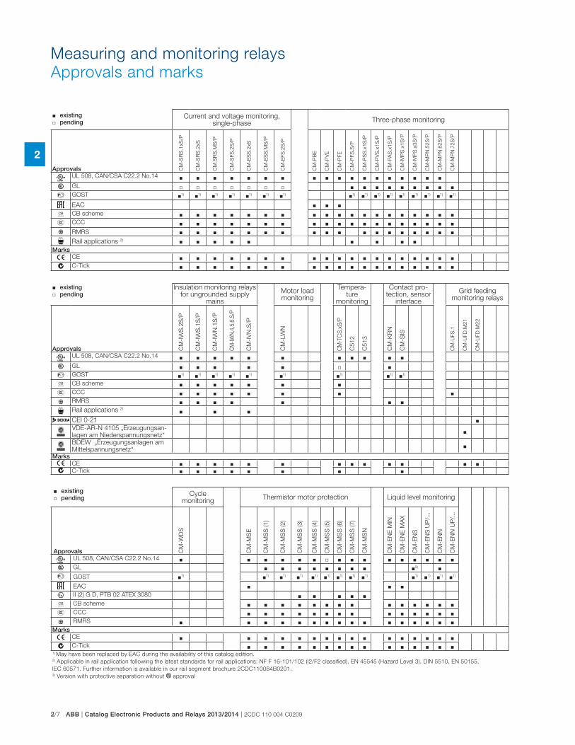
2/7 ABB | Catalog Electronic Products and Relays 2013/2014 | 2CDC 110 004 C0209
2
Measuring and monitoring relays
Approvals and marks
� existing � pending
Current and voltage monitoring, single-phase
Three-phase monitoring
Approvals CM
-SR
S.1
xS
/P
CM
-SR
S.2
xS
CM
.SR
S.M
S/P
CM
-SFS
.2S
/P
CM
-ES
S.2
xS
CM
-ES
S.M
S/P
CM
-EFS
.2S
/P
CM
-PB
E
CM
-PV
E
CM
-PFE
CM
-PFS
.S/P
CM
-PS
S.x
1S
/P
CM
-PV
S.x
1S
/P
CM
-PA
S.x
1S
/P
CM
-MP
S.x
1S
/P
CM
-MP
S.x
3S
/P
CM
-MP
N.5
2S
/P
CM
-MP
N.6
2S
/P
CM
-MP
N.7
2S
/P
A UL 508, CAN/CSA C22.2 No.14 � � � � � � � � � � � � � � � � � �C GL � � � � � � � � � � � � � � � �D GOST �1) �1) �1) �1) �1) �1) �1) �1) �1) �1) �1) �1) �1) �1) �1) �1)
EAC � � �K CB scheme � � � � � � � � � � � � � � � � � � �E CCC � � � � � � � � � � � � � � � � � � �L RMRS � � � � � � � � � � � � � � � � � �
Rail applications 2) � � � � � � � � �Marksa CE � � � � � � � � � � � � � � � � � � �b C-Tick � � � � � � � � � � � � � � � � � � �
� existing � pending
Insulation monitoring relays for ungrounded supply
mains
Motor load monitoring
Tempera-ture
monitoring
Contact pro-tection, sensor
interface
Grid feeding monitoring relays
Approvals CM
-IW
S.2
S/P
CM
-IW
S.1
S/P
CM
-IW
N.1
S/P
CM
-IW
N.4
,5,6
.S/P
CM
-IV
N.S
/P
CM
-LW
N
CM
-TC
S.x
S/P
C5
12
C5
13
CM
-KR
N
CM
-SIS
CM
-UFS
.1
CM
-UFD
.M2
1
CM
-UFD
.M2
2
A UL 508, CAN/CSA C22.2 No.14 � � � � � � � � � � �C GL � � � � � � �D GOST �1) �1) �1) �1) �1) �1) �1) �1) �1)
K CB scheme � � � � � � �E CCC � � � � � � � �L RMRS � � � � � � �
Rail applications 2) � � �CEI 0-21 �VDE-AR-N 4105 „Erzeugungsan-lagen am Niederspannungsnetz“
�
BDEW „Erzeugungsanlagen am Mittelspannungsnetz“
�
Marksa CE � � � � � � � � � � � � �b C-Tick � � � � � � � �
� existing � pending
Cycle monitoring
Thermistor motor protection Liquid level monitoring
Approvals CM
-WD
S
CM
-MS
E
CM
-MS
S (1
)
CM
-MS
S (2
)
CM
-MS
S (3
)
CM
-MS
S (4
)
CM
-MS
S (5
)
CM
-MS
S (6
)
CM
-MS
S (7
)
CM
-MS
N
CM
-EN
E M
IN
CM
-EN
E M
AX
CM
-EN
S
CM
-EN
S U
P/.
..
CM
-EN
N
CM
-EN
N U
P/.
..
A UL 508, CAN/CSA C22.2 No.14 � � � � � � � � � � � � � � � �C GL � � � � � � � � �3) �D GOST �1) �1) �1) �1) �1) �1) �1) �1) �1) �1) �1) �1) �1)
EAC � � �I II (2) G D, PTB 02 ATEX 3080 � � � � �K CB scheme � � � � � � � � � � � � � �E CCC � � � � � � � � � � � � � �L RMRS � � � � � � � � � � � � � � � �
Marksa CE � � � � � � � � � � � � � � � �b C-Tick � � � � � � � � � � � � � � �
1) May have been replaced by EAC during the availability of this catalog edition.2) Applicable in rail application following the latest standards for rail applications: NF F 16-101/102 (I2/F2 classified), EN 45545 (Hazard Level 3), DIN 5510, EN 50155,
IEC 60571. Further information is available in our rail segment brochure 2CDC110084B0201.3) Version with protective separation without C approval
2CDC 110 004 C0209 | Catalog Electronic Products and Relays 2013/2014 | ABB 2/8
2
Measuring and monitoring relays
Notes
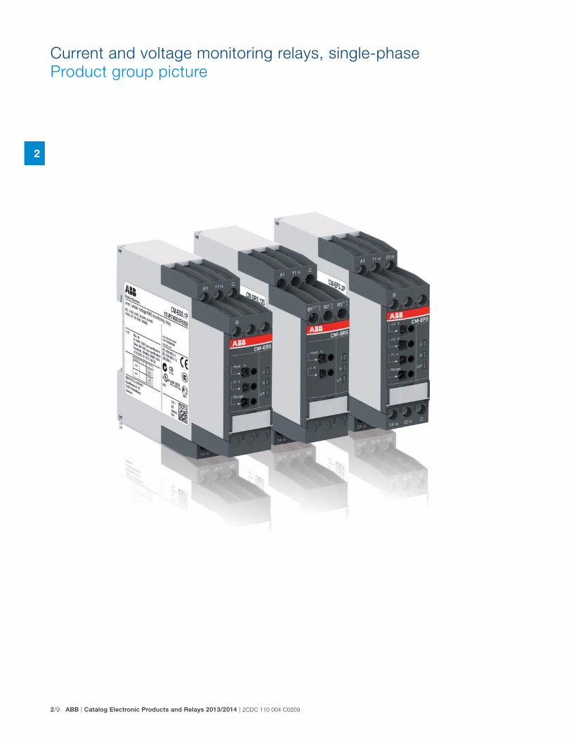
2/9 ABB | Catalog Electronic Products and Relays 2013/2014 | 2CDC 110 004 C0209
2
Current and voltage monitoring relays, single-phase
Product group picture
2CDC 110 004 C0209 | Catalog Electronic Products and Relays 2013/2014 | ABB 2/10
2
Current and voltage monitoring relays, single-phase
Table of contents
Current and voltage monitoring relays, single-phase
Product group picture 9
Table of contents 10
Benefits and advantages 11
Operating controls 12
Selection table - Current monitoring relays 13
Selection table - Voltage monitoring relays 14
Ordering details - Current monitoring relays 15
Ordering details - Voltage monitoring relays 16
Function diagrams 17
Connection diagrams, DIP switches 20
Technical data - Current monitoring relays 22
Technical data - Voltage monitoring relays 24
Notes 26
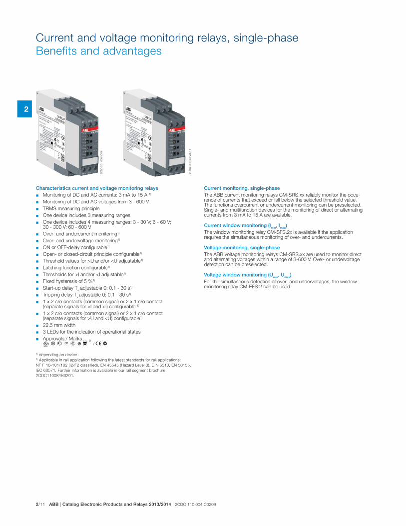
2/11 ABB | Catalog Electronic Products and Relays 2013/2014 | 2CDC 110 004 C0209
2
Current and voltage monitoring relays, single-phase
Benefits and advantages
Characteristics current and voltage monitoring relays � Monitoring of DC and AC currents: 3 mA to 15 A 1)
� Monitoring of DC and AC voltages from 3 - 600 V
� TRMS measuring principle
� One device includes 3 measuring ranges
� One device includes 4 measuring ranges: 3 - 30 V; 6 - 60 V; 30 - 300 V; 60 - 600 V
� Over- and undercurrent monitoring1)
� Over- and undervoltage monitoring1)
� ON or OFF-delay configurable1)
� Open- or closed-circuit principle configurable1)
� Threshold values for >U and/or <U adjustable1)
� Latching function configurable1)
� Thresholds for >I and/or <I adjustable1)
� Fixed hysteresis of 5 %1)
� Start-up delay Tv adjustable 0; 0.1 - 30 s1)
� Tripping delay Tv adjustable 0; 0.1 - 30 s1)
� 1 x 2 c/o contacts (common signal) or 2 x 1 c/o contact (separate signals for >I and <I) configurable 1)
� 1 x 2 c/o contacts (common signal) or 2 x 1 c/o contact (separate signals for >U and <U) configurable1)
� 22.5 mm width
� 3 LEDs for the indication of operational states
� Approvals / Marks A C D K E L
2)
/ a b
1) depending on device2) Applicable in rail application following the latest standards for rail applications:
NF F 16-101/102 (I2/F2 classified), EN 45545 (Hazard Level 3), DIN 5510, EN 50155,
IEC 60571. Further information is available in our rail segment brochure
2CDC110084B0201.
Current monitoring, single-phaseThe ABB current monitoring relays CM-SRS.xx reliably monitor the occu-rence of currents that exceed or fall below the selected threshold value. The functions overcurrent or undercurrent monitoring can be preselected. Single- and multifunction devices for the monitoring of direct or alternating currents from 3 mA to 15 A are available.
Current window monitoring (Imin, Imax)The window monitoring relay CM-SFS.2x is available if the application requires the simultaneous monitoring of over- and undercurrents.
Voltage monitoring, single-phaseThe ABB voltage monitoring relays CM-SRS.xx are used to monitor direct and alternating voltages within a range of 3-600 V. Over- or undervoltage detection can be preselected.
Voltage window monitoring (Umin, Umax)For the simultaneous detection of over- and undervoltages, the window monitoring relay CM-EFS.2 can be used.
2C
DC
25
1 0
56
V0
01
1
2C
DC
25
1 0
59
V0
01
1
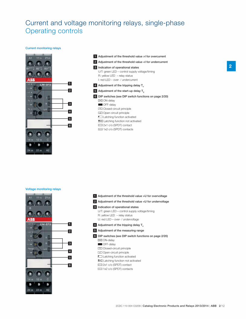
2CDC 110 004 C0209 | Catalog Electronic Products and Relays 2013/2014 | ABB 2/12
2
Current and voltage monitoring relays, single-phase
Operating controls
4
1
2
3
5
1 Adjustment of the threshold value >I for overcurrent
2 Adjustment of the threshold value <I for undercurrent
3 Indication of operational statesU/T: green LED – control supply voltage/timing
R: yellow LED – relay status
I: red LED – over- / undercurrent
4 Adjustment of the tripping delay TV
5 Adjustment of the start-up delay TS
6 DIP switches (see DIP switch functions on page 2/20)A ON-delay
B OFF-delay
g Closed-circuit principle
h Open-circuit principle
f Latching function activated
e Latching function not activated
i 2x1 c/o (SPDT) contact
j 1x2 c/o (SPDT) contacts
1 Adjustment of the threshold value >U for overvoltage
2 Adjustment of the threshold value <U for undervoltage
3 Indication of operational statesU/T: green LED – control supply voltage/timing
R: yellow LED – relay status
U: red LED – over- / undervoltage
4 Adjustment of the tripping delay TV
5 Adjustment of the measuring range
6 DIP switches (see DIP switch functions on page 2/20)A ON-delay
B OFF-delay
g Closed-circuit principle
h Open-circuit principle
f Latching function activated
e Latching function not activated
i 2x1 c/o (SPDT) contact
j 1x2 c/o (SPDT) contacts
4
1
2
3
5
Current monitoring relays
Voltage monitoring relays
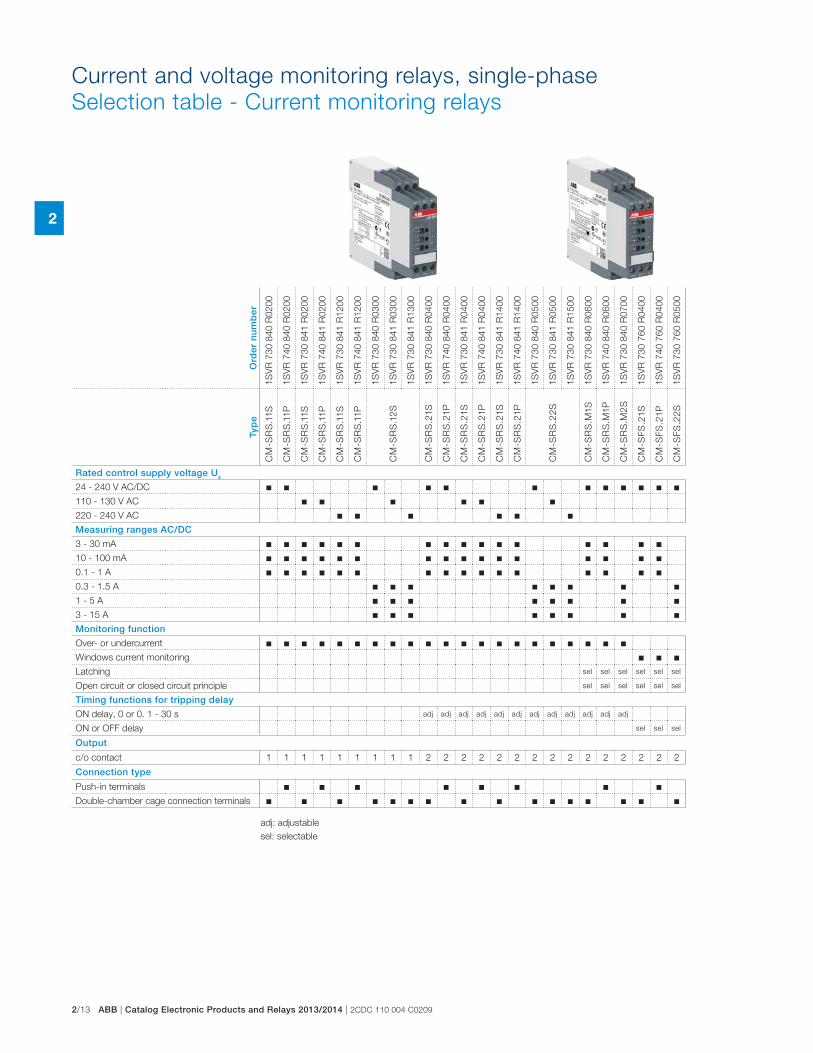
2/13 ABB | Catalog Electronic Products and Relays 2013/2014 | 2CDC 110 004 C0209
2
Current and voltage monitoring relays, single-phase
Selection table - Current monitoring relays
Ord
er n
um
ber
1SV
R 7
30 8
40 R
0200
1SV
R 7
40 8
40 R
0200
1SV
R 7
30 8
41 R
0200
1SV
R 7
40 8
41 R
0200
1SV
R 7
30 8
41 R
1200
1SV
R 7
40 8
41 R
1200
1SV
R 7
30 8
40 R
0300
1SV
R 7
30 8
41 R
0300
1SV
R 7
30 8
41 R
1300
1SV
R 7
30 8
40 R
0400
1SV
R 7
40 8
40 R
0400
1SV
R 7
30 8
41 R
0400
1SV
R 7
40 8
41 R
0400
1SV
R 7
30 8
41 R
1400
1SV
R 7
40 8
41 R
1400
1SV
R 7
30 8
40 R
0500
1SV
R 7
30 8
41 R
0500
1SV
R 7
30 8
41 R
1500
1SV
R 7
30 8
40 R
0600
1SV
R 7
40 8
40 R
0600
1SV
R 7
30 8
40 R
0700
1SV
R 7
30 7
60 R
0400
1SV
R 7
40 7
60 R
0400
1SV
R 7
30 7
60 R
0500
Typ
e
CM
-SR
S.1
1S
CM
-SR
S.1
1P
CM
-SR
S.1
1S
CM
-SR
S.1
1P
CM
-SR
S.1
1S
CM
-SR
S.1
1P
CM
-SR
S.1
2S
CM
-SR
S.2
1S
CM
-SR
S.2
1P
CM
-SR
S.2
1S
CM
-SR
S.2
1P
CM
-SR
S.2
1S
CM
-SR
S.2
1P
CM
-SR
S.2
2S
CM
-SR
S.M
1S
CM
-SR
S.M
1P
CM
-SR
S.M
2S
CM
-SF
S.2
1S
CM
-SF
S.2
1P
CM
-SF
S.2
2S
Rated control supply voltage Us
24 - 240 V AC/DC � � � � � � � � � � � �110 - 130 V AC � � � � � �220 - 240 V AC � � � � � �Measuring ranges AC/DC
3 - 30 mA � � � � � � � � � � � � � � � �10 - 100 mA � � � � � � � � � � � � � � � �0.1 - 1 A � � � � � � � � � � � � � � � �0.3 - 1.5 A � � � � � � � �1 - 5 A � � � � � � � �3 - 15 A � � � � � � � �Monitoring function
Over- or undercurrent � � � � � � � � � � � � � � � � � � � � �Windows current monitoring � � �Latching sel sel sel sel sel sel
Open circuit or closed circuit principle sel sel sel sel sel sel
Timing functions for tripping delay
ON delay, 0 or 0. 1 - 30 s adj adj adj adj adj adj adj adj adj adj adj adj
ON or OFF delay sel sel sel
Output
c/o contact 1 1 1 1 1 1 1 1 1 2 2 2 2 2 2 2 2 2 2 2 2 2 2 2
Connection type
Push-in terminals � � � � � � � �Double-chamber cage connection terminals � � � � � � � � � � � � � � � �
adj: adjustable
sel: selectable
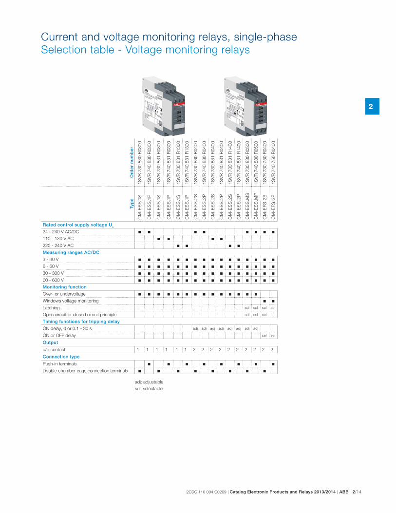
2CDC 110 004 C0209 | Catalog Electronic Products and Relays 2013/2014 | ABB 2/14
2
Current and voltage monitoring relays, single-phase
Selection table - Voltage monitoring relays
Ord
er n
um
ber
1SV
R 7
30 8
30 R
0300
1SV
R 7
40 8
30 R
0300
1SV
R 7
30 8
31 R
0300
1SV
R 7
40 8
31 R
0300
1SV
R 7
30 8
31 R
1300
1SV
R 7
40 8
31 R
1300
1SV
R 7
30 8
30 R
0400
1SV
R 7
40 8
30 R
0400
1SV
R 7
30 8
31 R
0400
1SV
R 7
40 8
31 R
0400
1SV
R 7
30 8
31 R
1400
1SV
R 7
40 8
31 R
1400
1SV
R 7
30 8
30 R
0500
1SV
R 7
40 8
30 R
0500
1SV
R 7
30 7
50 R
0400
1SV
R 7
40 7
50 R
0400
Typ
e
CM
-ES
S.1
S
CM
-ES
S.1
P
CM
-ES
S.1
S
CM
-ES
S.1
P
CM
-ES
S.1
S
CM
-ES
S.1
P
CM
-ES
S.2
S
CM
-ES
S.2
P
CM
-ES
S.2
S
CM
-ES
S.2
P
CM
-ES
S.2
S
CM
-ES
S.2
P
CM
-ES
S.M
S
CM
-ES
S.M
P
CM
-EF
S.2
S
CM
-EF
S.2
P
Rated control supply voltage Us
24 - 240 V AC/DC � � � � � � � �110 - 130 V AC � � � �220 - 240 V AC � � � �Measuring ranges AC/DC
3 - 30 V � � � � � � � � � � � � � � � �6 - 60 V � � � � � � � � � � � � � � � �30 - 300 V � � � � � � � � � � � � � � � �60 - 600 V � � � � � � � � � � � � � � � �Monitoring function
Over- or undervoltage � � � � � � � � � � � � � �Windows voltage monitoring � �Latching sel sel sel sel
Open circuit or closed circuit principle sel sel sel sel
Timing functions for tripping delay
ON delay, 0 or 0.1 - 30 s adj adj adj adj adj adj adj adj
ON or OFF delay sel sel
Output
c/o contact 1 1 1 1 1 1 2 2 2 2 2 2 2 2 2 2
Connection type
Push-in terminals � � � � � � � �Double-chamber cage connection terminals � � � � � � � �
adj: adjustable
sel: selectable
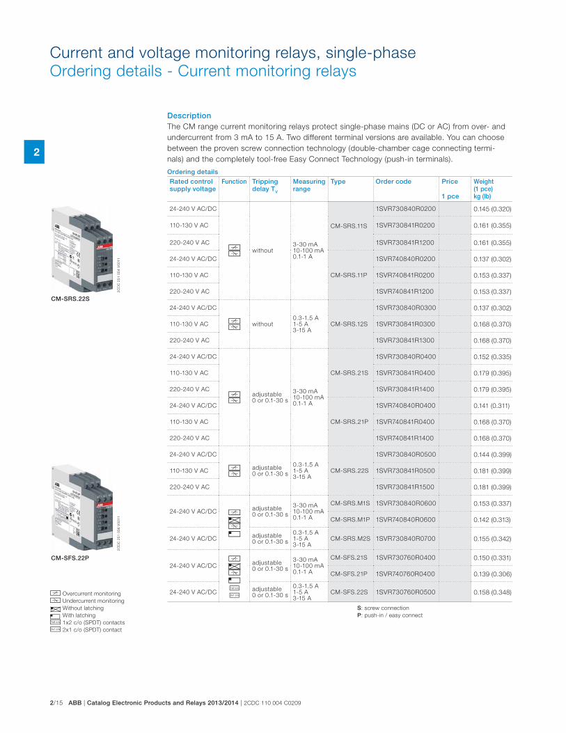
2/15 ABB | Catalog Electronic Products and Relays 2013/2014 | 2CDC 110 004 C0209
2
Current and voltage monitoring relays, single-phase
Ordering details - Current monitoring relays
DescriptionThe CM range current monitoring relays protect single-phase mains (DC or AC) from over- and
undercurrent from 3 mA to 15 A. Two different terminal versions are available. You can choose
between the proven screw connection technology (double-chamber cage connecting termi-
nals) and the completely tool-free Easy Connect Technology (push-in terminals).
Ordering details
Rated control supply voltage
Function Tripping delay TV
Measuring range
Type Order code Price
1 pce
Weight (1 pce)kg (lb)
24-240 V AC/DC
ba without
3-30 mA 10-100 mA 0.1-1 A
CM-SRS.11S
1SVR730840R0200 0.145 (0.320)
110-130 V AC 1SVR730841R0200 0.161 (0.355)
220-240 V AC 1SVR730841R1200 0.161 (0.355)
24-240 V AC/DC
CM-SRS.11P
1SVR740840R0200 0.137 (0.302)
110-130 V AC 1SVR740841R0200 0.153 (0.337)
220-240 V AC 1SVR740841R1200 0.153 (0.337)
24-240 V AC/DC
ba without
0.3-1.5 A 1-5 A 3-15 A
CM-SRS.12S
1SVR730840R0300 0.137 (0.302)
110-130 V AC 1SVR730841R0300 0.168 (0.370)
220-240 V AC 1SVR730841R1300 0.168 (0.370)
24-240 V AC/DC
ba
adjustable 0 or 0.1-30 s
3-30 mA 10-100 mA 0.1-1 A
CM-SRS.21S
1SVR730840R0400 0.152 (0.335)
110-130 V AC 1SVR730841R0400 0.179 (0.395)
220-240 V AC 1SVR730841R1400 0.179 (0.395)
24-240 V AC/DC
CM-SRS.21P
1SVR740840R0400 0.141 (0.311)
110-130 V AC 1SVR740841R0400 0.168 (0.370)
220-240 V AC 1SVR740841R1400 0.168 (0.370)
24-240 V AC/DC
ba
adjustable 0 or 0.1-30 s
0.3-1.5 A 1-5 A 3-15 A
CM-SRS.22S
1SVR730840R0500 0.144 (0.399)
110-130 V AC 1SVR730841R0500 0.181 (0.399)
220-240 V AC 1SVR730841R1500 0.181 (0.399)
24-240 V AC/DC beaf
adjustable 0 or 0.1-30 s
3-30 mA 10-100 mA 0.1-1 A
CM-SRS.M1S 1SVR730840R0600 0.153 (0.337)
CM-SRS.M1P 1SVR740840R0600 0.142 (0.313)
24-240 V AC/DCadjustable 0 or 0.1-30 s
0.3-1.5 A 1-5 A 3-15 A
CM-SRS.M2S 1SVR730840R0700 0.155 (0.342)
24-240 V AC/DCbeafji
adjustable 0 or 0.1-30 s
3-30 mA 10-100 mA 0.1-1 A
CM-SFS.21S 1SVR730760R0400 0.150 (0.331)
CM-SFS.21P 1SVR740760R0400 0.139 (0.306)
24-240 V AC/DCadjustable 0 or 0.1-30 s
0.3-1.5 A 1-5 A 3-15 A
CM-SFS.22S 1SVR730760R0500 0.158 (0.348)
2C
DC
25
1 0
54
V0
01
12
CD
C 2
51
05
6 V
00
11
CM-SRS.22S
CM-SFS.22P
b Overcurrent monitoring
a Undercurrent monitoring
e Without latching
f With latching
j 1x2 c/o (SPDT) contacts
i 2x1 c/o (SPDT) contact
S: screw connection
P: push-in / easy connect
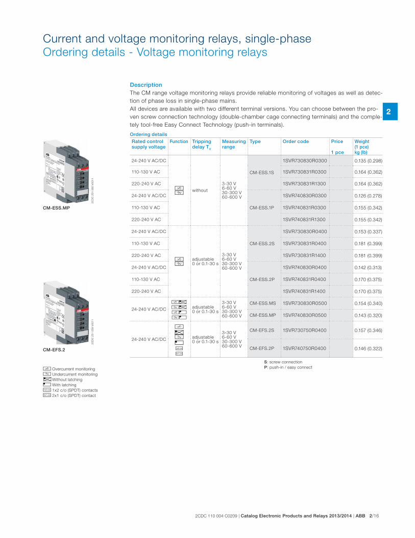
2CDC 110 004 C0209 | Catalog Electronic Products and Relays 2013/2014 | ABB 2/16
2
Current and voltage monitoring relays, single-phase
Ordering details - Voltage monitoring relays
DescriptionThe CM range voltage monitoring relays provide reliable monitoring of voltages as well as detec-
tion of phase loss in single-phase mains.
All devices are available with two different terminal versions. You can choose between the pro-
ven screw connection technology (double-chamber cage connecting terminals) and the comple-
tely tool-free Easy Connect Technology (push-in terminals).
Ordering details
Rated control supply voltage
Function Tripping delay TV
Measuring range
Type Order code Price
1 pce
Weight (1 pce)kg (lb)
24-240 V AC/DC
d c without
3-30 V 6-60 V 30-300 V 60-600 V
CM-ESS.1S
1SVR730830R0300 0.135 (0.298)
110-130 V AC 1SVR730831R0300 0.164 (0.362)
220-240 V AC 1SVR730831R1300 0.164 (0.362)
24-240 V AC/DC
CM-ESS.1P
1SVR740830R0300 0.126 (0.278)
110-130 V AC 1SVR740831R0300 0.155 (0.342)
220-240 V AC 1SVR740831R1300 0.155 (0.342)
24-240 V AC/DC
d c
adjustable 0 or 0.1-30 s
3-30 V 6-60 V 30-300 V 60-600 V
CM-ESS.2S
1SVR730830R0400 0.153 (0.337)
110-130 V AC 1SVR730831R0400 0.181 (0.399)
220-240 V AC 1SVR730831R1400 0.181 (0.399)
24-240 V AC/DC
CM-ESS.2P
1SVR740830R0400 0.142 (0.313)
110-130 V AC 1SVR740831R0400 0.170 (0.375)
220-240 V AC 1SVR740831R1400 0.170 (0.375)
24-240 V AC/DC
de ce df cf
adjustable 0 or 0.1-30 s
3-30 V 6-60 V 30-300 V 60-600 V
CM-ESS.MS 1SVR730830R0500 0.154 (0.340)
CM-ESS.MP 1SVR740830R0500 0.143 (0.320)
24-240 V AC/DC
beafji
adjustable 0 or 0.1-30 s
3-30 V 6-60 V 30-300 V 60-600 V
CM-EFS.2S 1SVR730750R0400 0.157 (0.346)
CM-EFS.2P 1SVR740750R0400 0.146 (0.322)
2C
DC
25
1 0
60
V0
01
12
CD
C 2
51
05
9 V
00
11
CM-ESS.MP
CM-EFS.2
b Overcurrent monitoring
a Undercurrent monitoring
e Without latching
f With latching
j 1x2 c/o (SPDT) contacts
i 2x1 c/o (SPDT) contact
S: screw connection
P: push-in / easy connect
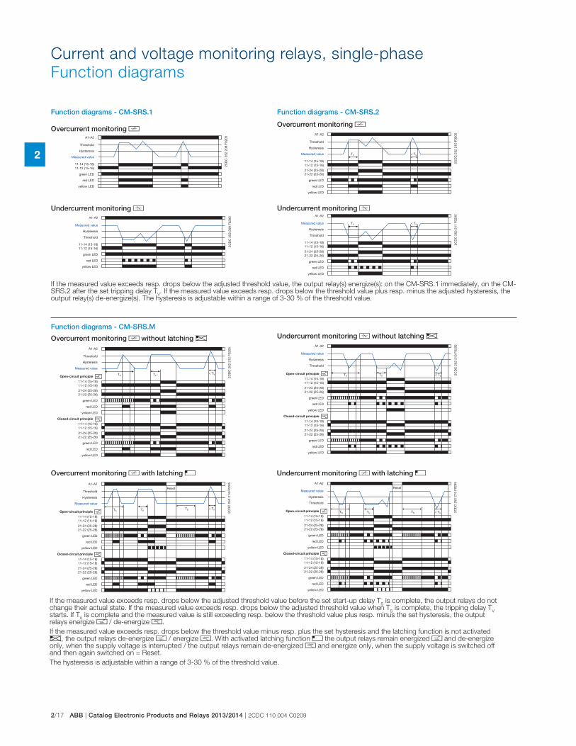
2/17 ABB | Catalog Electronic Products and Relays 2013/2014 | 2CDC 110 004 C0209
2
Function diagrams - CM-SRS.1
Overcurrent monitoring b
Undercurrent monitoring a
Function diagrams - CM-SRS.2
Overcurrent monitoring b
Undercurrent monitoring a
A1-A2
11-14 (15-18) 11-12 (15-16)
Threshold
Hysteresis
Measured value
green LED
red LED
yellow LED
2CD
C 2
52 2
08 F
0205
A1-A2
11-14 (15-18) 11-12 (15-16)
Threshold
Hysteresis
Measured value
green LED
red LED
yellow LED
2CD
C 2
52 2
09 F
0205
A1-A2
11-14 (15-18) 11-12 (15-16)
21-24 (25-28) 21-22 (25-26)
Threshold
Hysteresis
Measured value
green LED
red LED
yellow LED
2CD
C 2
52 2
10 F
0205
TV < TV
A1-A2
11-14 (15-18) 11-12 (15-16)
21-24 (25-28) 21-22 (25-26)
Threshold
Hysteresis
Measured value
green LED
red LED
yellow LED
2CD
C 2
52 2
11 F
0205
TV < TV
Function diagrams - CM-SRS.M
Overcurrent monitoring b without latching e
Overcurrent monitoring b with latching f
Undercurrent monitoring a without latching e
Undercurrent monitoring b with latching f
A1-A2
11-14 (15-18) 11-12 (15-16)
21-24 (25-28) 21-22 (25-26)
11-14 (15-18) 11-12 (15-16)
21-24 (25-28) 21-22 (25-26)
closed
open
Threshold
Hysteresis
Measured value
green LED
red LED
yellow LED
2CD
C 2
52 2
12 F
0205
TS
green LED
red LED
yellow LED
Open-circuit principle
Closed-circuit principle
TV < TV
A1-A2
11-14 (15-18) 11-12 (15-16)
21-24 (25-28) 21-22 (25-26)
11-14 (15-18) 11-12 (15-16)
21-24 (25-28) 21-22 (25-26)
open
closed
Threshold
Hysteresis
Measured value
green LED
red LED
yellow LED
2CD
C 2
52 2
14 F
0205
TS
green LED
red LED
yellow LED
Open-circuit principle
Closed-circuit principle
TV < TV TS
Reset
A1-A2
11-14 (15-18) 11-12 (15-16)
21-24 (25-28) 21-22 (25-26)
11-14 (15-18) 11-12 (15-16)
21-24 (25-28) 21-22 (25-26)
closed
open
Threshold
Hysteresis
Measured value
green LED
red LED
yellow LED
2CD
C 2
52 2
13 F
0205
TS
green LED
red LED
yellow LED
Open-circuit principle
Closed-circuit principle
TV < TV
A1-A2
11-14 (15-18) 11-12 (15-16)
21-24 (25-28) 21-22 (25-26)
11-14 (15-18) 11-12 (15-16)
21-24 (25-28) 21-22 (25-26)
closed
open
Threshold
Hysteresis
Measured value
green LED
red LED
yellow LED
2CD
C 2
52 2
15 F
0205
TS
green LED
red LED
yellow LED
Open-circuit principle
Closed-circuit principle
TV < TV TS
Reset
If the measured value exceeds resp. drops below the adjusted threshold value, the output relay(s) energize(s): on the CM-SRS.1 immediately, on the CM-SRS.2 after the set tripping delay T
V. If the measured value exceeds resp. drops below the threshold value plus resp. minus the adjusted hysteresis, the
output relay(s) de-energize(s). The hysteresis is adjustable within a range of 3-30 % of the threshold value.
If the measured value exceeds resp. drops below the adjusted threshold value before the set start-up delay TS is complete, the output relays do not
change their actual state. If the measured value exceeds resp. drops below the adjusted threshold value when TS is complete, the tripping delay T
V
starts. If TV is complete and the measured value is still exceeding resp. below the threshold value plus resp. minus the set hysteresis, the output
relays energize h / de-energize g.
If the measured value exceeds resp. drops below the threshold value minus resp. plus the set hysteresis and the latching function is not activated e, the output relays de-energize h / energize g. With activated latching function f the output relays remain energized h and de-energize only, when the supply voltage is interrupted / the output relays remain de-energized g and energize only, when the supply voltage is switched off and then again switched on = Reset.
The hysteresis is adjustable within a range of 3-30 % of the threshold value.
Current and voltage monitoring relays, single-phase
Function diagrams
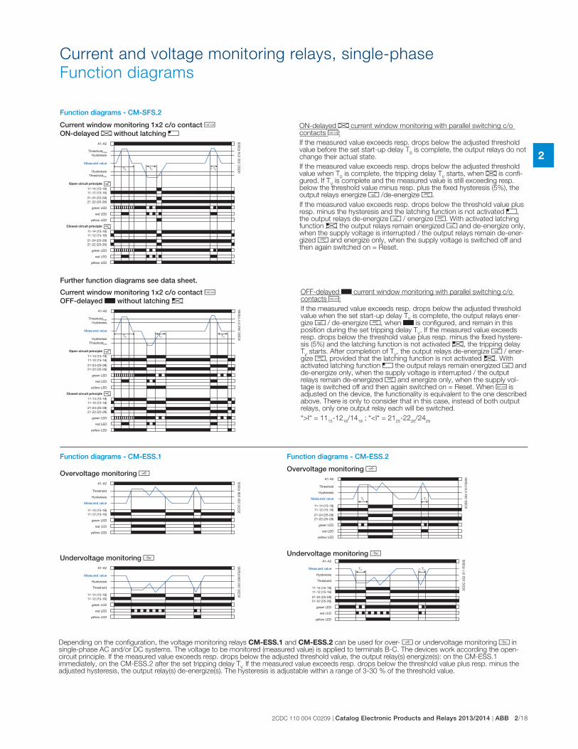
2CDC 110 004 C0209 | Catalog Electronic Products and Relays 2013/2014 | ABB 2/18
2
Current and voltage monitoring relays, single-phase
Function diagrams
Function diagrams - CM-ESS.1
Overvoltage monitoring d
Undervoltage monitoring c
Function diagrams - CM-ESS.2
Overvoltage monitoring d
Undervoltage monitoring c
A1-A2
11-14 (15-18) 11-12 (15-16)
Threshold
Hysteresis
Measured value
green LED
red LED
yellow LED
2CD
C 2
52 2
08 F
0205
A1-A2
11-14 (15-18) 11-12 (15-16)
Threshold
Hysteresis
Measured value
green LED
red LED
yellow LED
2CD
C 2
52 2
09 F
0205
A1-A2
11-14 (15-18) 11-12 (15-16)
21-24 (25-28) 21-22 (25-26)
Threshold
Hysteresis
Measured value
green LED
red LED
yellow LED
2CD
C 2
52 2
10 F
0205
TV < TV
A1-A2
11-14 (15-18) 11-12 (15-16)
21-24 (25-28) 21-22 (25-26)
Threshold
Hysteresis
Measured value
green LED
red LED
yellow LED
2CD
C 2
52 2
11 F
0205
TV < TV
OFF-delayed B current window monitoring with parallel switching c/o contacts j:
If the measured value exceeds resp. drops below the adjusted threshold value when the set start-up delay T
S is complete, the output relays ener-
gize h / de-energize g, when B is configured, and remain in this position during the set tripping delay T
V. If the measured value exceeds
resp. drops below the threshold value plus resp. minus the fixed hystere-sis (5%) and the latching function is not activated e, the tripping delay T
V starts. After completion of T
V, the output relays de-energize h / ener-
gize g, provided that the latching function is not activated e. With activated latching function f the output relays remain energized h and de-energize only, when the supply voltage is interrupted / the output relays remain de-energized g and energize only, when the supply vol-tage is switched off and then again switched on = Reset. When i is adjusted on the device, the functionality is equivalent to the one described above. There is only to consider that in this case, instead of both output relays, only one output relay each will be switched.
“>I“ = 1115
-1216
/1418
; “<I“ = 2125
-2226
/2428
Function diagrams - CM-SFS.2
Current window monitoring 1x2 c/o contact j ON-delayed A without latching f
Current window monitoring 1x2 c/o contact j OFF-delayed B without latching e
Further function diagrams see data sheet.
A1-A2
11-14 (15-18) 11-12 (15-16)
21-24 (25-28) 21-22 (25-26)
11-14 (15-18) 11-12 (15-16)
21-24 (25-28) 21-22 (25-26)
open
closed
Thresholdmax
Hysteresis
green LED
red LED
yellow LED
2CD
C 2
52 2
16 F
0205
TS
green LED
red LED
yellow LED
Open-circuit principle
Closed-circuit principle
TV < TV Hysteresis
Measured value
Thresholdmin
A1-A2
11-14 (15-18) 11-12 (15-16)
21-24 (25-28) 21-22 (25-26)
11-14 (15-18) 11-12 (15-16)
21-24 (25-28) 21-22 (25-26)
open
closed
Thresholdmax
Hysteresis
green LED
red LED
yellow LED
2CD
C 2
52 2
17 F
0205
TS
green LED
red LED
yellow LED
Open-circuit principle
Closed-circuit principle
TV TV Hysteresis
Measured value
Thresholdmin
ON-delayed A current window monitoring with parallel switching c/o contacts j:
If the measured value exceeds resp. drops below the adjusted threshold value before the set start-up delay T
S is complete, the output relays do not
change their actual state.
If the measured value exceeds resp. drops below the adjusted threshold value when T
S is complete, the tripping delay T
V starts, when A is confi-
gured. If TV is complete and the measured value is still exceeding resp.
below the threshold value minus resp. plus the fixed hysteresis (5%), the output relays energize h /de-energize g.
If the measured value exceeds resp. drops below the threshold value plus resp. minus the hysteresis and the latching function is not activated f, the output relays de-energize h / energize g. With activated latching function e the output relays remain energized h and de-energize only, when the supply voltage is interrupted / the output relays remain de-ener-gized g and energize only, when the supply voltage is switched off and then again switched on = Reset.
Depending on the configuration, the voltage monitoring relays CM-ESS.1 and CM-ESS.2 can be used for over- d or undervoltage monitoring c in single-phase AC and/or DC systems. The voltage to be monitored (measured value) is applied to terminals B-C. The devices work according the open-circuit principle. If the measured value exceeds resp. drops below the adjusted threshold value, the output relay(s) energize(s): on the CM-ESS.1 immediately, on the CM-ESS.2 after the set tripping delay T
V. If the measured value exceeds resp. drops below the threshold value plus resp. minus the
adjusted hysteresis, the output relay(s) de-energize(s). The hysteresis is adjustable within a range of 3-30 % of the threshold value.
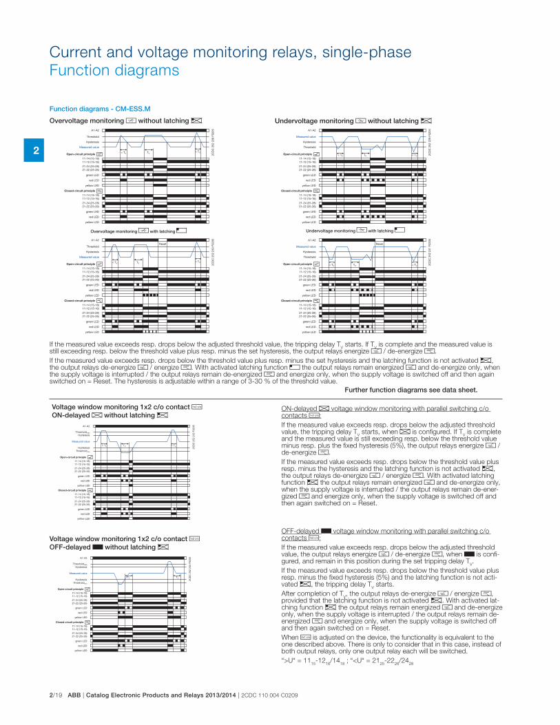
2/19 ABB | Catalog Electronic Products and Relays 2013/2014 | 2CDC 110 004 C0209
2
If the measured value exceeds resp. drops below the adjusted threshold value, the tripping delay TV starts. If T
V is complete and the measured value is
still exceeding resp. below the threshold value plus resp. minus the set hysteresis, the output relays energize h / de-energize g.
If the measured value exceeds resp. drops below the threshold value plus resp. minus the set hysteresis and the latching function is not activated e, the output relays de-energize h / energize g. With activated latching function f the output relays remain energized h and de-energize only, when the supply voltage is interrupted / the output relays remain de-energized g and energize only, when the supply voltage is switched off and then again switched on = Reset. The hysteresis is adjustable within a range of 3-30 % of the threshold value.
Function diagrams - CM-ESS.M
Overvoltage monitoring d without latching e
Overvoltage monitoring d with latching f
Undervoltage monitoring c without latching e
Undervoltage monitoring c with latching f
A1-A2
11-14 (15-18) 11-12 (15-16)
21-24 (25-28) 21-22 (25-26)
11-14 (15-18) 11-12 (15-16)
21-24 (25-28) 21-22 (25-26)
open
closed
Threshold
Hysteresis
Measured value
green LED
red LED
yellow LED
2CD
C 2
52 2
28 F
0205
< TV
green LED
red LED
yellow LED
Open-circuit principle
Closed-circuit principle
TV < TV
A1-A2
11-14 (15-18) 11-12 (15-16)
21-24 (25-28) 21-22 (25-26)
11-14 (15-18) 11-12 (15-16)
21-24 (25-28) 21-22 (25-26)
open
closed
Threshold
Hysteresis
Measured value
green LED
red LED
yellow LED
2CD
C 2
52 2
30 F
0205
green LED
red LED
yellow LED
Open-circuit principle
Closed-circuit principle
TV < TV
Reset
< TV
A1-A2
11-14 (15-18) 11-12 (15-16)
21-24 (25-28) 21-22 (25-26)
11-14 (15-18) 11-12 (15-16)
21-24 (25-28) 21-22 (25-26)
closed
open
Threshold
Hysteresis
Measured value
green LED
red LED
yellow LED
2CD
C 2
52 2
29 F
0205
green LED
red LED
yellow LED
Open-circuit principle
Closed-circuit principle
TV < TV < TV
A1-A2
11-14 (15-18) 11-12 (15-16)
21-24 (25-28) 21-22 (25-26)
11-14 (15-18) 11-12 (15-16)
21-24 (25-28) 21-22 (25-26)
closed
open
Threshold
Hysteresis
Measured value
green LED
red LED
yellow LED
2CD
C 2
52 2
31 F
0205
green LED
red LED
yellow LED
Open-circuit principle
Closed-circuit principle
TV < TV
Reset
< TV
ON-delayed A voltage window monitoring with parallel switching c/o contacts j:
If the measured value exceeds resp. drops below the adjusted threshold value, the tripping delay T
V starts, when A is configured. If T
V is complete
and the measured value is still exceeding resp. below the threshold value minus resp. plus the fixed hysteresis (5%), the output relays energize h /de-energize g.
If the measured value exceeds resp. drops below the threshold value plus resp. minus the hysteresis and the latching function is not activated e, the output relays de-energize h / energize g. With activated latching function e the output relays remain energized h and de-energize only, when the supply voltage is interrupted / the output relays remain de-ener-gized g and energize only, when the supply voltage is switched off and then again switched on = Reset.
OFF-delayed B voltage window monitoring with parallel switching c/o contacts j:
If the measured value exceeds resp. drops below the adjusted threshold value, the output relays energize h / de-energize g, when B is confi-gured, and remain in this position during the set tripping delay T
V.
If the measured value exceeds resp. drops below the threshold value plus resp. minus the fixed hysteresis (5%) and the latching function is not acti-vated e, the tripping delay T
V starts.
After completion of TV, the output relays de-energize h / energize g,
provided that the latching function is not activated e. With activated lat-ching function e the output relays remain energized h and de-energize only, when the supply voltage is interrupted / the output relays remain de-energized g and energize only, when the supply voltage is switched off and then again switched on = Reset.
When i is adjusted on the device, the functionality is equivalent to the one described above. There is only to consider that in this case, instead of both output relays, only one output relay each will be switched.
“>U“ = 1115
-1216
/1418
; “<U“ = 2125
-2226
/2428
Voltage window monitoring 1x2 c/o contact j ON-delayed A without latching e
Voltage window monitoring 1x2 c/o contact j OFF-delayed B without latching e
Further function diagrams see data sheet.
A1-A2
11-14 (15-18) 11-12 (15-16)
21-24 (25-28) 21-22 (25-26)
11-14 (15-18) 11-12 (15-16)
21-24 (25-28) 21-22 (25-26)
open
closed
Thresholdmax
Hysteresis
green LED
red LED
yellow LED
2CD
C 2
52 2
32 F
0205
green LED
red LED
yellow LED
Open-circuit principle
Closed-circuit principle
TV < TV Hysteresis
Measured value
Thresholdmin
< TV
A1-A2
11-14 (15-18) 11-12 (15-16)
21-24 (25-28) 21-22 (25-26)
11-14 (15-18) 11-12 (15-16)
21-24 (25-28) 21-22 (25-26)
closed
open
Thresholdmax
Hysteresis
green LED
red LED
yellow LED
2CD
C 2
52 2
33 F
0205
green LED
red LED
yellow LED
Open-circuit principle
Closed-circuit principle
TV TV Hysteresis
Measured value
Thresholdmin
Current and voltage monitoring relays, single-phase
Function diagrams
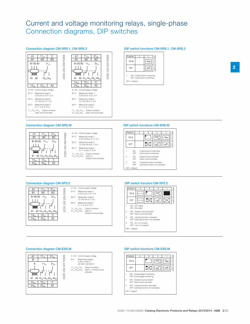
2CDC 110 004 C0209 | Catalog Electronic Products and Relays 2013/2014 | ABB 2/20
2
A1 A2
A1 1115
B1 B2 B3
A2
1115
1216 1418
1418 1216
C
B1 B2 B3
C
2C
DC
25
2 2
04
F0
00
5
A1-A2 Control supply voltage
B1-C Measuring range 1:
3-30 mA or 0.3-1.5 A
B2-C Measuring range 2:
10-100 mA or 1-5 A
B3-C Measuring range 3:
0.1-1 A or 3-15 A
1115
-1216
/1418
Output contacts -
open-circuit principle
Connection diagram CM-SRS.1, CM-SRS.2
A1 A2
2125
2226 2428
A1 1115 2125
B1 B2 B3
2428 2226 A2
1115
1216 1418
1418 1216 C
B1 B2 B3
C
2C
DC
25
2 2
05
F0
00
5
A1-A2 Control supply voltage
B1-C Measuring range 1:
3-30 mA or 0.3-1.5 A
B2-C Measuring range 2:
10-100 mA or 1-5 A
B3-C Measuring range 3:
0.1-1 A or 3-15 A
1115
-1216
/1418
Output contacts -
2125
-2226
/2428
open-circuit principle
A1 A2
2125
2226 2428
A1 1115 2125
B1 B2 B3
2428 2226 A2
1115
1216 1418
1418 1216 C
B1 B2 B3
C
2C
DC
252 2
05 F
0005 A1-A2 Control supply voltage
B1-C Measuring range 1:
3-30 mA bzw. 0.3-1.5 A
B2-C Measuring range 2:
10-100 mA bzw. 1-5 A
B3-C Measuring range 3:
0.1-1 A bzw. 3-15 A
1115
-1216
/1418
Output contacts -
2125
-2226
/2428
open-or
closed circuit principle
Connection diagram CM-SRS.M
A1 A2
2125
2226 2428
A1 1115 2125
B1 B2 B3
2428 2226 A2
1115
1216 1418
1418 1216 C
B1 B2 B3
C
2C
DC
252 2
05 F
0005
Connection diagram CM-SFS.2A1-A2 Control supply voltage
B1-C Measuring range 1:
3-30 mA or 0.3-1.5 A
B2-C Measurign range 2:
10-100 mA or 1-5 A
B3-C Measuring range 3:
0.1-1 A or 3-15 A
1115
-1216
/1418
Output contacts -
2125
-2226
/2428
open-or
closed circuit principle
2CD
C 2
52 2
72 F
0005
DIP switch functions CM-SRS.1, CM-SRS.2
1 ON Undercurrent monitoring
OFF Overcurrent monitoring
OFF = Default
closed
open
Position 4 123
ON
OFF
I
I
2CD
C 2
52 2
73 F
0005
DIP switch functions CM-SRS.M
1 ON Undercurrent monitoring
OFF Overcurrent monitoring
2 ON Closed-circuit principle
OFF Open-circuit principle
3 ON Latching function activated
OFF Latching function not activated
OFF = Default
closed
open
2x1 c/o
1x2 c/o
Position 4 123
ON
OFF
2CD
C 2
52 2
74 F
0005
DIP switch function CM-SFS.2
1 ON OFF-delay
OFF ON-delay
2 ON Closed-circuit principle
OFF Open-circuit principle
3 ON Latching function activated
OFF Latching function not activated
4 ON 2x1 c/o contact
OFF 1x2 c/o contacts
OFF = Default
closed
open V
V
Position 4 123
ON
OFF
2CD
C 2
52 2
76 F
0005
DIP switch functions CM-ESS.M
1 ON Undervoltage monitoring
OFF Overvoltage monitoring
2 ON Closed-circuit principle
OFF Open-circuit principle
3 ON Latching function activated
OFF Latching function not activated
OFF = Default
A1 A2
2125
2226 2428
A1 1115 2125
B
2428 2226 A2
1115
1216 1418
1418 1216 C
B
C
2C
DC
252 2
07 F
0005 A1-A2 Control supply voltage
B-C Measuring ranges:
3-30 V; 6-60 V;
30-300 V; 60-600 V
1115
-1216
/1418
Output contacts -
2125
-2226
/2428
Open- or closed circuit
principle
Connection diagram CM-ESS.M
Current and voltage monitoring relays, single-phase
Connection diagrams, DIP switches
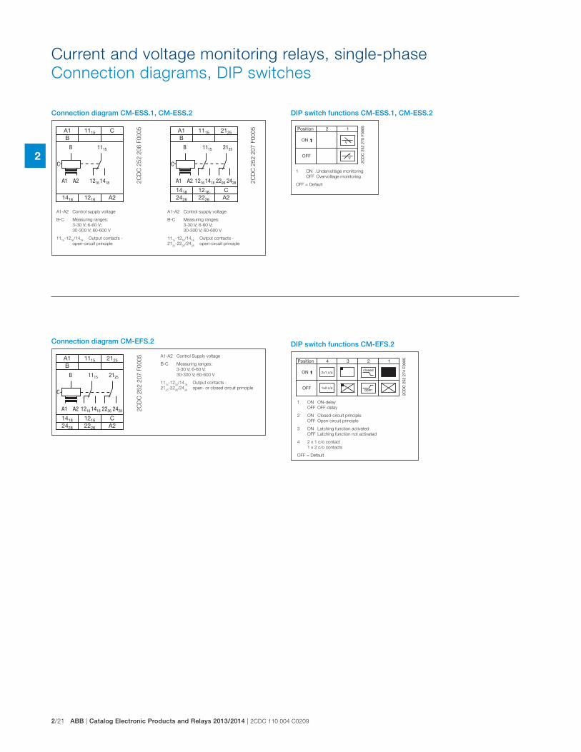
2/21 ABB | Catalog Electronic Products and Relays 2013/2014 | 2CDC 110 004 C0209
2
closed
open
2x1 c/o
1x2 c/o
Position 4 123
ON
OFF
2CD
C 2
52 2
74 F
0005
DIP switch functions CM-EFS.2
A1 A2
2125
2226 2428
A1 1115 2125
B
2428 2226 A2
1115
1216 1418
1418 1216 C
B
C
2C
DC
252 2
07 F
0005
Connection diagram CM-EFS.2
A1-A2 Control Supply voltage
B-C Measuring ranges:
3-30 V; 6-60 V;
30-300 V; 60-600 V
1115
-1216
/1418
Output contacts -
2125
-2226
/2428
open- or closed circuit principle
A1 A2
A1 1115
B
A2
1115
1216 1418
1418 1216
C
B
C
2C
DC
25
2 2
06
F0
00
5
Connection diagram CM-ESS.1, CM-ESS.2
A1 A2
2125
2226 2428
A1 1115 2125
B
2428 2226 A2
1115
1216 1418
1418 1216 C
B
C
2C
DC
25
2 2
07
F0
00
5
A1-A2 Control supply voltage
B-C Measuring ranges:
3-30 V; 6-60 V;
30-300 V; 60-600 V
1115
-1216
/1418
Output contacts -
2125
-2226
/2428
open-circuit principle
A1-A2 Control supply voltage
B-C Measuring ranges:
3-30 V; 6-60 V;
30-300 V; 60-600 V
1115
-1216
/1418
Output contacts -
open-circuit principle
2CD
C 2
52 2
75 F
0005
DIP switch functions CM-ESS.1, CM-ESS.2
1 ON Undervoltage monitoring
OFF Overvoltage monitoring
OFF = Default
Current and voltage monitoring relays, single-phase
Connection diagrams, DIP switches
1 ON ON-delay
OFF OFF-delay
2 ON Closed-circuit principle
OFF Open-circuit principle
3 ON Latching function activated
OFF Latching function not activated
4 2 x 1 c/o contact
1 x 2 c/o contacts
OFF = Default
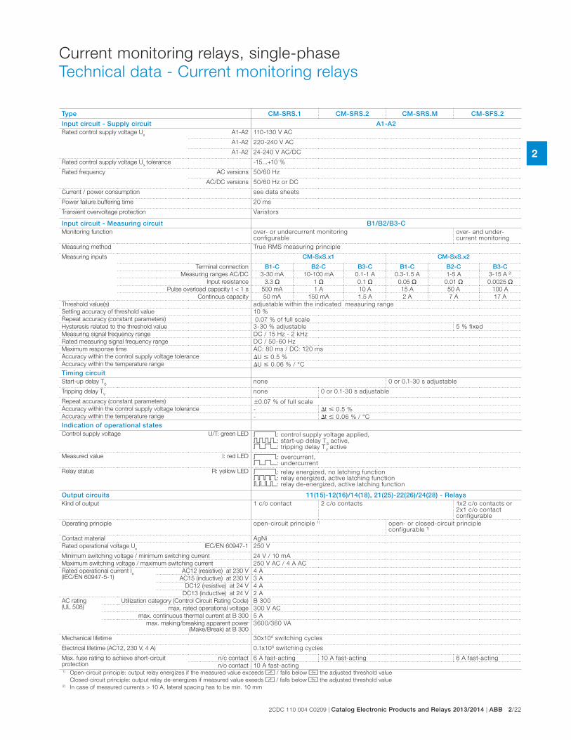
2CDC 110 004 C0209 | Catalog Electronic Products and Relays 2013/2014 | ABB 2/22
2
Current monitoring relays, single-phase
Technical data - Current monitoring relays
Type CM-SRS.1 CM-SRS.2 CM-SRS.M CM-SFS.2
Input circuit - Supply circuit A1-A2Rated control supply voltage U
sA1-A2 110-130 V AC
A1-A2 220-240 V AC
A1-A2 24-240 V AC/DC
Rated control supply voltage Us tolerance -15...+10 %
Rated frequency AC versions 50/60 Hz
AC/DC versions 50/60 Hz or DC
Current / power consumption see data sheets
Power failure buffering time 20 ms
Transient overvoltage protection Varistors
Input circuit - Measuring circuit B1/B2/B3-CMonitoring function over- or undercurrent monitoring
configurableover- and under- current monitoring
Measuring method True RMS measuring principle
Measuring inputs CM-SxS.x1 CM-SxS.x2
Terminal connection B1-C B2-C B3-C B1-C B2-C B3-CMeasuring ranges AC/DC 3-30 mA 10-100 mA 0.1-1 A 0.3-1.5 A 1-5 A 3-15 A 2)
Input resistance 3.3 � 1 � 0.1 � 0.05 � 0.01 � 0.0025 �Pulse overload capacity t < 1 s 500 mA 1 A 10 A 15 A 50 A 100 A
Continous capacity 50 mA 150 mA 1.5 A 2 A 7 A 17 A
Threshold value(s) adjustable within the indicated measuring range
Setting accuracy of threshold value 10 %
Repeat accuracy (constant parameters) 0.07 % of full scale
Hysteresis related to the threshold value 3-30 % adjustable 5 % fixed
Measuring signal frequency range DC / 15 Hz - 2 kHz
Rated measuring signal frequency range DC / 50-60 Hz
Maximum response time AC: 80 ms / DC: 120 ms
Accuracy within the control supply voltage tolerance �U � 0.5 %
Accuracy within the temperature range �U � 0.06 % / °C
Timing circuitStart-up delay T
Snone 0 or 0.1-30 s adjustable
Tripping delay TV
none 0 or 0.1-30 s adjustable
Repeat accuracy (constant parameters) �0.07 % of full scale
Accuracy within the control supply voltage tolerance - �t � 0.5 %
Accuracy within the temperature range - �t � 0.06 % / °C
Indication of operational statesControl supply voltage U/T: green LED V: control supply voltage applied,
X: start-up delay TS active,
W: tripping delay TV active
Measured value I: red LED V: overcurrent, W: undercurrent
Relay status R: yellow LED V: relay energized, no latching function Z: relay energized, active latching function Y: relay de-energized, active latching function
Output circuits 11(15)-12(16)/14(18), 21(25)-22(26)/24(28) - RelaysKind of output 1 c/o contact 2 c/o contacts 1x2 c/o contacts or
2x1 c/o contact configurable
Operating principle open-circuit principle 1) open- or closed-circuit principle configurable 1)
Contact material AgNi
Rated operational voltage Ue
IEC/EN 60947-1 250 V
Minimum switching voltage / minimum switching current 24 V / 10 mA
Maximum switching voltage / maximum switching current 250 V AC / 4 A AC
Rated operational current Ie
(IEC/EN 60947-5-1)AC12 (resistive) at 230 V 4 A
AC15 (inductive) at 230 V 3 A
DC12 (resistive) at 24 V 4 A
DC13 (inductive) at 24 V 2 A
AC rating (UL 508)
Utilization category (Control Circuit Rating Code) B 300
max. rated operational voltage 300 V AC
max. continuous thermal current at B 300 5 A
max. making/breaking apparent power (Make/Break) at B 300
3600/360 VA
Mechanical lifetime 30x106 switching cycles
Electrical lifetime (AC12, 230 V, 4 A) 0.1x10⁶ switching cycles
Max. fuse rating to achieve short-circuit protection
n/c contact 6 A fast-acting 10 A fast-acting 6 A fast-acting
n/o contact 10 A fast-acting1) Open-circuit principle: output relay energizes if the measured value exceeds b / falls below a the adjusted threshold value
Closed-circuit principle: output relay de-energizes if measured value exeeds b / falls below a the adjusted threshold value2) In case of measured currents > 10 A, lateral spacing has to be min. 10 mm
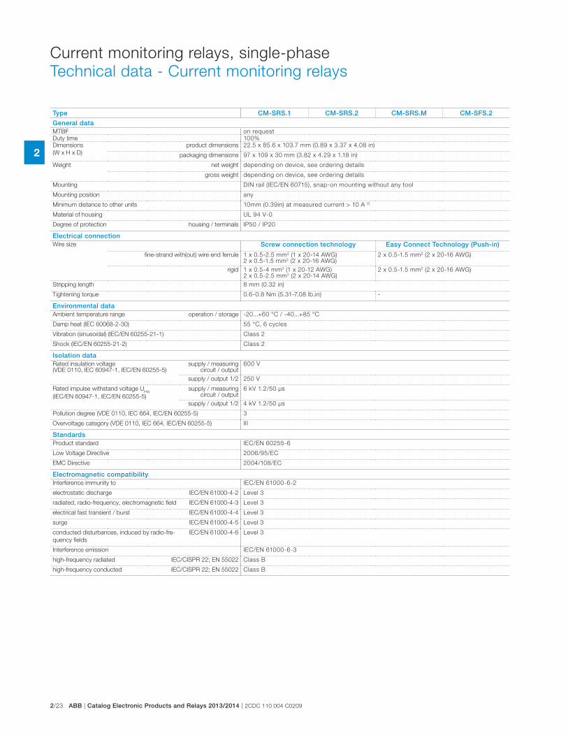
2/23 ABB | Catalog Electronic Products and Relays 2013/2014 | 2CDC 110 004 C0209
2
Type CM-SRS.1 CM-SRS.2 CM-SRS.M CM-SFS.2
General dataMTBF on request
Duty time 100%
Dimensions
(W x H x D)
product dimensions 22.5 x 85.6 x 103.7 mm (0.89 x 3.37 x 4.08 in)
packaging dimensions 97 x 109 x 30 mm (3.82 x 4.29 x 1.18 in)
Weight net weight depending on device, see ordering details
gross weight depending on device, see ordering details
Mounting DIN rail (IEC/EN 60715), snap-on mounting without any tool
Mounting position any
Minimum distance to other units 10mm (0.39in) at measured current > 10 A 2)
Material of housing UL 94 V-0
Degree of protection housing / terminals IP50 / IP20
Electrical connectionWire size Screw connection technology Easy Connect Technology (Push-in)
fine-strand with(out) wire end ferrule 1 x 0.5-2.5 mm2 (1 x 20-14 AWG)2 x 0.5-1.5 mm2 (2 x 20-16 AWG)
2 x 0.5-1.5 mm2 (2 x 20-16 AWG)
rigid 1 x 0.5-4 mm2 (1 x 20-12 AWG)2 x 0.5-2.5 mm2 (2 x 20-14 AWG)
2 x 0.5-1.5 mm2 (2 x 20-16 AWG)
Stripping length 8 mm (0.32 in)
Tightening torque 0.6-0.8 Nm (5.31-7.08 lb.in) -
Environmental dataAmbient temperature range operation / storage -20...+60 °C / -40...+85 °C
Damp heat (IEC 60068-2-30) 55 °C, 6 cycles
Vibration (sinusoidal) (IEC/EN 60255-21-1) Class 2
Shock (IEC/EN 60255-21-2) Class 2
Isolation dataRated insulation voltage (VDE 0110, IEC 60947-1, IEC/EN 60255-5)
supply / measuring circuit / output
600 V
supply / output 1/2 250 V
Rated impulse withstand voltage Uimp
(IEC/EN 60947-1, IEC/EN 60255-5)
supply / measuring circuit / output
6 kV 1.2/50 μs
supply / output 1/2 4 kV 1.2/50 μs
Pollution degree (VDE 0110, IEC 664, IEC/EN 60255-5) 3
Overvoltage category (VDE 0110, IEC 664, IEC/EN 60255-5) III
StandardsProduct standard IEC/EN 60255-6
Low Voltage Directive 2006/95/EC
EMC Directive 2004/108/EC
Electromagnetic compatibilityInterference immunity to IEC/EN 61000-6-2
electrostatic discharge IEC/EN 61000-4-2 Level 3
radiated, radio-frequency, electromagnetic field IEC/EN 61000-4-3 Level 3
electrical fast transient / burst IEC/EN 61000-4-4 Level 3
surge IEC/EN 61000-4-5 Level 3
conducted disturbances, induced by radio-fre-
quency fields
IEC/EN 61000-4-6 Level 3
Interference emission IEC/EN 61000-6-3
high-frequency radiated IEC/CISPR 22; EN 55022 Class B
high-frequency conducted IEC/CISPR 22; EN 55022 Class B
Current monitoring relays, single-phase
Technical data - Current monitoring relays
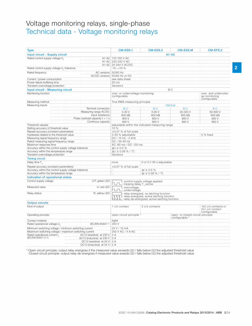
2CDC 110 004 C0209 | Catalog Electronic Products and Relays 2013/2014 | ABB 2/24
2
Voltage monitoring relays, single-phase
Technical data - Voltage monitoring relays
Type CM-ESS.1 CM-ESS.2 CM-ESS.M CM-EFS.2
Input circuit - Supply circuit A1-A2Rated control supply voltage U
sA1-A2 110-130 V AC
A1-A2 220-240 V AC
A1-A2 24-240 V AC/DC
Rated control supply voltage Us tolerance -15...+10 %
Rated frequency AC versions 50/60 Hz
AC/DC versions 50/60 Hz or DC
Current / power consumption see data sheet
Power failure buffering time 20 ms
Transient overvoltage protection Varistors
Input circuit - Measuring circuit B-C
Monitoring function over- or undervoltage monitoring configurable
over- and undervolta-ge monitoring configurable
Measuring method True RMS measuring principle
Measuring inputs CM-ExS
Terminal connection B-C B-C B-C B-C
Measuring range AC/DC 3-30 V 6-60 V 30-300 V 60-600 V
Input resistance 600 k� 600 k� 600 k� 600 k�Pulse overload capacity t < 1 s 800 V 800 V 800 V 800 V
Continous capacity 660 V 660 V 660 V 660 V
Threshold value(s) adjustable within the indicated measuring range
Setting accuracy of threshold value 10 %
Repeat accuracy (constant parameters) �0.07 % of full scale
Hysteresis related to the threshold value 3-30 % adjustable 5 % fixed
Measuring signal frequency range DC / 15 Hz - 2 kHz
Rated measuring signal frequency range DC / 50-60 Hz
Maximum response time AC: 80 ms / DC: 120 ms
Accuracy within the control supply voltage tolerance �U � 0.5 %
Accuracy within the temperature range �U � 0.06 % / °C
Transient overvoltage protection Varistors
Timing circuitDelay time T
Vnone 0 or 0.1-30 s adjustable
Repeat accuracy (constant parameters) �0.07 % of full scale
Accuracy within the control supply voltage tolerance - �t � 0.5 %
Accuracy within the temperature range - �t � 0.06 % / °C
Indication of operational statesControl supply voltage U/T: green LED V: control supply voltage applied
W: tripping delay TV active
Measured value U: red LED V: overvoltage, W: undervoltage
Relay status R: yellow LED V: relay energized, no latching function Z: relay energized, active latching function Y: relay de-energized, active latching function
Output circuits Kind of output 1 c/o contact 2 c/o contacts 1x2 c/o contacts or
2x1 c/o contact configurable
Operating principle open-circuit principle 1) open- or closed-circuit principle configurable 1)
Contact material AgNi
Rated operational voltage Ue
IEC/EN 60947-1 250 V
Minimum switching voltage / minimum switching current 24 V / 10 mA
Maximum switching voltage / maximum switching current 250 V AC / 4 A AC
Rated operational current Ie
(IEC/EN 60947-5-1)AC12 (resistive) at 230 V 4 A
AC15 (inductive) at 230 V 3 A
DC12 (resistive) at 24 V 4 A
DC13 (inductive) at 24 V 2 A
1) Open-circuit principle: output relay energizes if the measured value exceeds d / falls below c the adjusted threshold value Closed-circuit principle: output relay de-energizes if measured value exeeds d / falls below c the adjusted threshold value
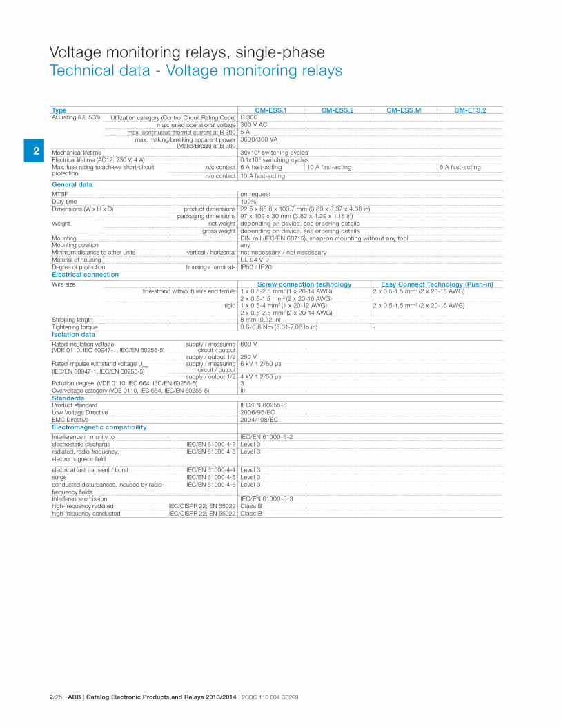
2/25 ABB | Catalog Electronic Products and Relays 2013/2014 | 2CDC 110 004 C0209
2
Voltage monitoring relays, single-phase
Technical data - Voltage monitoring relays
Type CM-ESS.1 CM-ESS.2 CM-ESS.M CM-EFS.2AC rating (UL 508) Utilization category (Control Circuit Rating Code) B 300
max. rated operational voltage 300 V AC
max. continuous thermal current at B 300 5 A
max. making/breaking apparent power (Make/Break) at B 300
3600/360 VA
Mechanical lifetime 30x106 switching cycles
Electrical lifetime (AC12, 230 V, 4 A) 0.1x10⁶ switching cycles
Max. fuse rating to achieve short-circuit protection
n/c contact 6 A fast-acting 10 A fast-acting 6 A fast-acting
n/o contact 10 A fast-acting
General dataMTBF on request
Duty time 100%
Dimensions (W x H x D) product dimensions 22.5 x 85.6 x 103.7 mm (0.89 x 3.37 x 4.08 in)
packaging dimensions 97 x 109 x 30 mm (3.82 x 4.29 x 1.18 in)
Weight net weight depending on device, see ordering details
gross weight depending on device, see ordering details
Mounting DIN rail (IEC/EN 60715), snap-on mounting without any tool
Mounting position any
Minimum distance to other units vertical / horizontal not necessary / not necessary
Material of housing UL 94 V-0
Degree of protection housing / terminals IP50 / IP20
Electrical connectionWire size Screw connection technology Easy Connect Technology (Push-in)
fine-strand with(out) wire end ferrule 1 x 0.5-2.5 mm2 (1 x 20-14 AWG)
2 x 0.5-1.5 mm2 (2 x 20-16 AWG)
2 x 0.5-1.5 mm2 (2 x 20-16 AWG)
rigid 1 x 0.5-4 mm2 (1 x 20-12 AWG)
2 x 0.5-2.5 mm2 (2 x 20-14 AWG)
2 x 0.5-1.5 mm2 (2 x 20-16 AWG)
Stripping length 8 mm (0.32 in)
Tightening torque 0.6-0.8 Nm (5.31-7.08 lb.in) -
Isolation dataRated insulation voltage (VDE 0110, IEC 60947-1, IEC/EN 60255-5)
supply / measuring circuit / output
600 V
supply / output 1/2 250 V
Rated impulse withstand voltage Uimp
(IEC/EN 60947-1, IEC/EN 60255-5)
supply / measuring circuit / output
6 kV 1.2/50 μs
supply / output 1/2 4 kV 1.2/50 μs
Pollution degree (VDE 0110, IEC 664, IEC/EN 60255-5) 3
Overvoltage category (VDE 0110, IEC 664, IEC/EN 60255-5) III
StandardsProduct standard IEC/EN 60255-6
Low Voltage Directive 2006/95/EC
EMC Directive 2004/108/EC
Electromagnetic compatibilityInterference immunity to IEC/EN 61000-6-2
electrostatic discharge IEC/EN 61000-4-2 Level 3
radiated, radio-frequency,
electromagnetic field
IEC/EN 61000-4-3 Level 3
electrical fast transient / burst IEC/EN 61000-4-4 Level 3
surge IEC/EN 61000-4-5 Level 3
conducted disturbances, induced by radio-
frequency fields
IEC/EN 61000-4-6 Level 3
Interference emission IEC/EN 61000-6-3
high-frequency radiated IEC/CISPR 22; EN 55022 Class B
high-frequency conducted IEC/CISPR 22; EN 55022 Class B
2CDC 110 004 C0209 | Catalog Electronic Products and Relays 2013/2014 | ABB 2/26
2
Current and voltage monitoring relays, single-phase
Notes
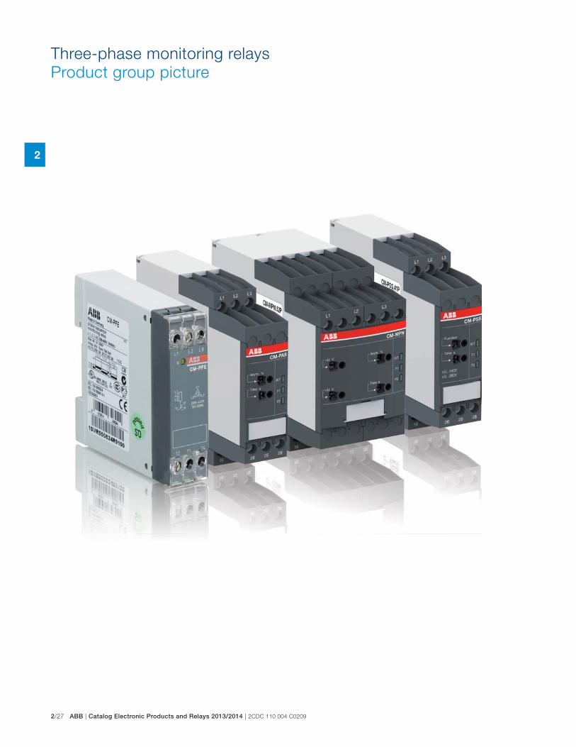
2/27 ABB | Catalog Electronic Products and Relays 2013/2014 | 2CDC 110 004 C0209
2
Three-phase monitoring relays
Product group picture

2CDC 110 004 C0209 | Catalog Electronic Products and Relays 2013/2014 | ABB 2/28
2
Three-phase monitoring relays
Table of contents
Three-phase monitoring relays
Product group picture 27
Table of contents 28
Benefits and advantages, Applications 29
Operating controls 30
Selection table singlefunctional 31
Selection table multifunctional 32
Ordering details - Singlefunctional 33
Ordering details - Multifunctional 34
Function diagrams 35
Connection diagrams, DIP switches 39
DIP switches, Rotary switches 40
Technical data 41

2/29 ABB | Catalog Electronic Products and Relays 2013/2014 | 2CDC 110 004 C0209
2
Extended functionalityABB’s new generation of three-phase monitoring relays feature additional functions making the application field for the devices considerably larger.
Selectable phase sequence monitoringThe phase sequence monitoring can be switched off by means of a rotary switch or a DIP switch. This enables monitoring of three-phase mains where phase sequence is not relevant for the application, for example in case of motors with forward and reverse rotation, heating applications, etc.
Automatic phase sequence correctionThe automatic phase sequence correction is activated by means of a DIP switch. With activated phase sequence correction, it is ensured that for any non-fixed or portable equipment, e.g. construction machinery, the cor-rect phase sequence is always applied to the input terminals of the load. For details regarding the wiring, please see function description / diagrams.
Structure of the type designationCM-_ _ x.yzx: width of enclosure
y: Control supply voltage / measuring range
1 110, 115, 120, 127 V supply systems (phase-neutral)
2 220, 230, 240 V supply systems (phase-neutral)
3 200, 208, 220, 230, 240, 257, 260 V supply systems
(phase-phase)
4 440, 460 V supply systems (phase-phase)
5 480, 500 V supply systems (phase-phase)
6 575, 600 V supply systems (phase-phase)
7 660, 690 V supply systems (phase-phase)
8 200, 400 V supply systems (phase-phase)
z: Rated frequency / output circuit
1 50/60 Hz – 1x2 c/o
2 50/60 Hz – 1x2 or 2x1 c/o
3 50/60/400 Hz – 1x2 oder 2x1 c/o
Three-phase monitoring relays
Benefits and advantages, Applications
Phase unbalance monitoringIf the supply by the three-phase system is unbalanced due to uneven dis-tribution of the load, the motor will convert a part of the energy into reactive power. This energy gets lost unexploited; also the motor is exposed to hig-her thermal stress. Other thermal protection devices fail to detect continuing unbalances which can lead to damage or destruction of the motor. The CM range three-phase monitors with phase unbalance monito-ring can reliably detect this critical situation.
Phase sequenceChanging the phase sequence during operation or a wrong phase sequence prior to startup causes a change of the rotational direction of the connected device. Generators, pumps or fans rotate in the wrong direction and the installation is no longer working properly. Especially for moveable equipment, such as construction machinery, phase sequence detection prior to the startup process is highly reasonable.
Phase lossIn case of phase loss, undefined stats of the installation are likely to occur. E.g. the startup process of motors is disturbed. All three-phase monitors of the ABB CM range detect a phase loss as soon as the voltage of one phase drops below 60% of its nominal value.
Voltage monitoringAll electric devices can be damaged when operated continuously in a net-work with out-of-range voltages. For example, safe starting is not ensured in case of undervoltage. Also, the switching state of a contactor is not clearly defined when operated in a „forbidden“ voltage range. This can lead to undefined states of the installtion and cause damage or destruction of valuable parts.
Characteristics of the CM range three-phase monitors � Adjustable phase unbalance threshold value 1)
� Adjustable ON-delay/OFF-delay time 1)
� Dual frequency measuring 50/60 Hz
� Powered by the measuring circuit
� 1 n/o contact, 1 or 2 c/o contacts
� LEDs for the indication of operational states
� Multifunctional and single-functional devices
� Phase failure detection
� Phase sequence monitoring 1)
� Over- and undervoltage monitoring (fixed or adjustable)1)
� Wide-range operating voltage guarantees world-wide operation
� Approvals / Marks A C D K E
2)
/ a b1) depending on device type2) Applicable in rail application following the latest standards for rail applications: NF F
16-101/102 (I2/F2 classified), EN 45545 (Hazard Level 3), DIN 5510, EN 50155,
IEC 60571. Further information is available in our rail segment brochure 2CD-
C110084B0201.

2CDC 110 004 C0209 | Catalog Electronic Products and Relays 2013/2014 | ABB 2/30
2
Three-phase monitoring relays
Operating controls
4
1
2
3
5
1 Adjustment of the hysteresis >U for overvoltage
2 Adjustment of the threshold value <U for undervoltage
3 Indication of operational statesR/T: red LED – Relay status / timing
F1: yellow LED – Fault message
F2: yellow LED – Fault message
4 Adjustment of the threshold value Asym. for phase unbalance
5 Adjustment of the tripping delay Tv
6 DIP switches (see DIP switch functions on page 2/40)A ON-delay
B OFF-delay
l Phase sequence monitoring deactivated
k Phase sequence monitoring activated
m Phase sequence correction activated
n Phase sequence correction deactivated
i 2x1 c/o (SPDT) contact
j 1x2 c/o (SPDT) contacts
1 Adjustment of the hysteresis >U for overvoltage
2 Adjustment of the threshold value Asym. for phase unbalance
3 Indication of operational statesR/T: red LED – Relay status / timing
F1: yellow LED – Fault message
F2: yellow LED – Fault message
4 Adjustment of the tripping delay Tv
5 Adjustment of the hysteresis <U for undervoltage
6 DIP switches (see DIP switch functions on page 2/40)A ON-delay
B OFF-delay
l Phase sequence monitoring deactivated
k Phase sequence monitoring activated
m Phase sequence correction activated
n Phase sequence correction deactivated
i 2x1 c/o (SPDT) contact
j 1x2 c/o (SPDT) contacts
1
3
2
4
5
6
S-Range Housing
N-Range Housing

2/31 ABB | Catalog Electronic Products and Relays 2013/2014 | 2CDC 110 004 C0209
2
Three-phase monitoring relays
Selection table singlefunctional
Ord
er n
um
ber
1S
VR
550 8
81 R
9400
1S
VR
550 8
82 R
9500
1S
VR
550 8
70 R
9400
1S
VR
550 8
71 R
9500
1S
VR
550 8
24 R
9100
1S
VR
730 8
24 R
9300
1S
VR
740 8
24 R
9300
1S
VR
730 7
84 R
2300
1S
VR
740 7
84 R
2300
1S
VR
730 7
84 R
3300
1S
VR
740 7
84 R
3300
1S
VR
730 7
94 R
1300
1S
VR
730 7
94 R
3300
1S
VR
740 7
94 R
3300
1S
VR
730 7
94 R
2300
1S
VR
740 7
94 R
2300
1S
VR
730 7
74 R
1300
1S
VR
740 7
74 R
1300
1S
VR
730 7
74 R
3300
1S
VR
740 7
74 R
3300
Rated control supply voltage Us Ty
pe
CM
-PB
E
CM
-PB
E
CM
-PV
E
CM
-PV
E
CM
-PFE
CM
-PFS
.S
CM
-PFS
.P
CM
-PS
S.3
1S
CM
-PS
S.3
1P
CM
-PS
S.4
1S
CM
-PS
S.4
1P
CM
-PV
S.3
1S
CM
-PV
S.4
1S
CM
-PV
S.4
1P
CM
-PV
S.8
1S
CM
-PV
S.8
1P
CM
-PA
S.3
1S
CM
-PA
S.3
1P
CM
-PA
S.4
1S
CM
-PA
S.4
1P
Phase to Phase160-300 V AC � � �200-400 V AC � �200-500 V AC � �208-440 V AC �300-500 V AC � � � �320-460 V AC � �350-580 V AC
380 V AC � �380-440 V AC � �400 V AC � �Phase to Neutral185-265 V AC �220-240 V AC �Rated frequency50/60 Hz � � � � � � � � � � � � � � � � � � � �Suitable for monitoring
Single-phase mains � �Three-phase mains � � � � � � � � � � � � � � � � � � � �Monitoring function
Phase failure � � � � � � � � � � � � � � � � � � � �Phase sequence � � � sel sel sel sel sel sel sel sel sel � � � �Automatic phase sequence correction
Overvoltage � � � � � � � � � � �Undervoltage � � � � � � � � � � �Unbalance � � � �Neutral 1) � �Thresholds fix fix fix fix fix fix fix fix fix fix fix fix adj adj adj adj adj adj adj adj
Timing functions for tripping delay
ON delay fix fix sel sel sel sel
On and OFF delay fix fix fix fix fix adj adj adj adj adj adj adj adj adj
Connection type
Push-in terminals � � � � � �Double-chamber cage connection terminals � � � � � � �
adj: adjustable
sel: selectable
1) The external conductor voltage towards the neutral conductor is measured.

2CDC 110 004 C0209 | Catalog Electronic Products and Relays 2013/2014 | ABB 2/32
2
Three-phase monitoring relays
Selection table multifunctional
adj: adjustable
sel: selectable
Ord
er n
um
ber
1S
VR
730 8
85 R
1300
1S
VR
740 8
85 R
1300
1S
VR
730 8
85 R
3300
1S
VR
740 8
85 R
3300
1S
VR
730 8
84 R
1300
1S
VR
740 8
84 R
1300
1S
VR
730 8
84 R
3300
1S
VR
740 8
84 R
3300
1S
VR
730 8
85 R
4300
1S
VR
740 8
85 R
4300
1S
VR
730 8
84 R
4300
1S
VR
740 8
84 R
4300
1S
VR
750 4
87 R
8300
1S
VR
760 4
87 R
8300
1S
VR
750 4
88 R
8300
1S
VR
760 4
88 R
8300
1S
VR
750 4
89 R
8300
1S
VR
760 4
89 R
8300
Rated control supply voltage Us Ty
pe
CM
-MP
S.1
1S
CM
-MP
S.1
1P
CM
-MP
S.2
1S
CM
-MP
S.2
1P
CM
-MP
S.3
1S
CM
-MP
S.3
1P
CM
-MP
S.4
1S
CM
-MP
S.4
1P
CM
-MP
S.2
3S
CM
-MP
S.2
3P
CM
-MP
S.4
3S
CM
-MP
S.4
3P
CM
-MP
N.5
2S
CM
-MP
N.5
2P
CM
-MP
N.6
2S
CM
-MP
N.6
2P
CM
-MP
N.7
2S
CM
-MP
N.7
2P
Phase to Phase160-300 V AC � �300-500 V AC � � � �350-580 V AC � �450-720 V AC � �530-820 V AC � �Phase to Neutral90-170 V AC � �180-280 V AC � � � �Rated frequency50/60 Hz � � � � � � � � � � � � � �50/60/400 Hz � � � �Suitable for monitoring
Single-phase mains � � � � � �Three-phase mains � � � � � � � � � � � � � � � � � �Monitoring function
Phase failure � � � � � � � � � � � � � � � � � �Phase sequence sel sel sel sel sel sel sel sel adj adj adj adj adj adj adj adj adj adj
Automatic phase sequence correction adj adj adj adj adj adj adj adj adj adj
Overvoltage � � � � � � � � � � � � � � � � � �Undervoltage � � � � � � � � � � � � � � � � � �Unbalance � � � � � � � � � � � � � � � � � �Neutral 1) �2) �2) �2) �2) �2) �2)
Thresholds adj adj adj adj adj adj adj adj adj adj adj adj adj adj adj adj adj adj
Timing functions for tripping delay
On and OFF delay adj adj adj adj adj adj adj adj adj adj adj adj adj adj adj adj adj adj
Connection type
Push-in terminals � � � � � � � � �Double-chamber cage connection terminals � � � � � � � � �
1) The external conductor voltage towards the neutral conductor is measured.2) Interrupted neutral monitoring

2/33 ABB | Catalog Electronic Products and Relays 2013/2014 | 2CDC 110 004 C0209
2
Three-phase monitoring relays
Ordering details - Singlefunctional
DescriptionOnly reliable and continuous monitoring of a three-phase network guarantees the trouble-free
and economic operation of machines and installations.
Ordering detailsRated control supply voltage = measuring voltage
Monitoring function
Neutral moni-toring
Type Order code Price
1 pce
Weight(1 pce)kg (lb)
3x380-440 V AC, 220-240 V AC Phase failure
detection (Single- and three-phase)
CM-PBE 1) 1SVR550881R9400 0.08 (0.17)
3x380-440 V AC CM-PBE 1SVR550882R9500 0.08 (0.17)
3x320-460 V AC, 185-265 V AC
Over- / under-voltage and phase failure detection (Single- and three-phase)
CM-PVE 1) 1SVR550870R9400 0.08 (0.17)
3x320-460 V AC CM-PVE 1SVR550871R9500 0.08 (0.17)
3x208-440 V AC
Phase sequence monitoring and phase failure detection (Three-phase)
CM-PFE 2) 1SVR550824R9100 0.08 (0.17)
2C
DC
25
1 0
63
V0
01
12
CD
C 2
51
06
4 V
00
11
2C
DC
25
1 0
64
V0
01
1
CM-PAS.31P
CM-PSS.41P
CM-PBE
1) The version with neutral monitoring is also suitable for monitoring single-phase mains. For this, all three external conductors (L1,L2,L3)
have to be jumpered and connected as one single conductor.2) For applications where a reverse fed voltage >60% is expected, we recommend to use our three-phase monitoring relays for unbalance
CM-PAS.xx
S: screw connection
P: push-in / easy connect
Ordering detailsRated control supply voltage = measuring voltage
Monitoring function Type Order code Price
1 pce
Weight(1 pce)kg (lb)
3x200-500 V ACPhase sequence moni-toring and phase failure detection (Three-phase)
CM-PFS.S 1SVR730824R9300 0.127 (0.280)
CM-PFS.P 1SVR740824R9300 0.119 (0.262)
3x380 V AC
Over- / undervoltage with fixed threshold values ± 10 %
CM-PSS.31S 1SVR730784R2300 0.132 (0.291)
CM-PSS.31P 1SVR740784R2300 0.123 (0.271)
3x400 V AC
CM-PSS.41S 1SVR740784R3300 0.132 (0.291)
CM-PSS.41P 1SVR730784R3300 0.123 (0.271)
3x160-300 V AC
Over- and undervol-tage with adjustable threshold values (Three-phase)
CM-PVS.31S 1SVR730794R1300 0.141 (0.311)
CM-PVS.31P 1SVR740794R1300 0.132 (0.291)
3x300-500 V AC
CM-PVS.41S 1SVR730794R3300 0.139 (0.306)
CM-PVS.41P 1SVR740794R3300 0.131 (0.289)
3x200-400 V AC
CM-PVS.81S 1SVR730794R2300 0.136 (0.300)
CM-PVS.81P 1SVR740794R2300 0.128 (0.282)
3x160-300 V AC
Phase unbalance (Three-phase)
CM-PAS.31S 1SVR730774R1300 0.133 (0.293)
CM-PAS.31P 1SVR740774R1300 0.124 (0.273)
3x300-500 V AC
CM-PAS.41S 1SVR730774R3300 0.132 (0.291)
CM-PAS.41P 1SVR740774R3300 0.123 (0.271)

2CDC 110 004 C0209 | Catalog Electronic Products and Relays 2013/2014 | ABB 2/34
2
Three-phase monitoring relays
Ordering details - Multifunctional
Ordering detailsRated control supply voltage = measuring voltage
DIP switch
Monitoring function
Neutral moni-toring
Type Order code Price
1 pce
Weight(1 pce)kg (lb)
90-170 V AC
ABkl
Multifunctional (Three-phase phase failure detection, Phase sequence monitoring, overvoltage, undervoltage, Phase unba-lance)
CM-MPS.11S 1SVR730885R1300 0.148 (0.326)
CM-MPS.11P 1SVR740885R1300 0.137 (0.302)
180-280 V AC
CM-MPS.21S 1SVR730885R3300 0.146 (0.322)
CM-MPS.21P 1SVR740885R3300 0.135 (0.298)
3x160-300 V AC
CM-MPS.31S 1SVR730884R1300 0.142 (0.313)
CM-MPS.31P 1SVR740884R1300 0.133 (0.293)
3x300-500 V AC
CM-MPS.41S 1SVR730884R3300 0.140 (0.309)
CM-MPS.41P 1SVR740884R3300 0.132 (0.291)
180-280 V ACABklmnij
Multifunctional (Three-phase phase failure detection, Phase sequence monitoring, overvoltage, undervoltage, Phase unba-lance)
CM-MPS.23S 1SVR730885R4300 0.149 (0.328)
CM-MPS.23P 1SVR740885R4300 0.138 (0.304)
3x300-500 V AC
CM-MPS.43S 1SVR730884R4300 0.148 (0.327)
CM-MPS.43P 1SVR740884R4300 0.137 (0.302)
3x350-580 V AC
ABklmnij
CM-MPN.52S 1SVR750487R8300 0.230 (0.507)
CM-MPN.52P 1SVR760487R8300 0.226 (0.498)
3x450-720 V AC
CM-MPN.62S 1SVR750488R8300 0.229 (0.505)
CM-MPN.62P 1SVR760488R8300 0.225 (0.496)
3x530-820 V AC
CM-MPN.72S 1SVR750489R8300 0.224 (0.494)
CM-MPN.72P 1SVR760489R8300 0.220 (0.485)
2C
DC
25
1 0
65
V0
01
1
2C
DC
25
1 0
62
V0
01
1
CM-MPS.23P
CM-MPN.52P
A ON-delayed
B OFF-delayed
k Phase sequence
monitoring activated
l Phase sequence
monitoring deactivated
m Phase sequence
correction activated
n Phase sequence
correction deactivated
i 2x1 c/o (SPDT) contacts
j 1x2 c/o (SPDT) contacts
S: screw connection
P: push-in / easy connect

2/35 ABB | Catalog Electronic Products and Relays 2013/2014 | 2CDC 110 004 C0209
2
Three-phase monitoring relays
Function diagrams
L1, L2, L3, N
13-14
L1, L2, L3, N L1, L2, L3, N L1, L2, L3, N L1, L2, L3, NL1, L2L3
N
ts
L1, L2, N
L3
tv
L2, L3, N
L1
<ts ts <tv
2CD
C 2
52 0
45 F
0203
R: yellow LED
Measuring value
ts = Start-up delay fixed 500 mstv = Tripping delay fixed 150 ms
L1, L2, L3
13-14
L1, L2, L3 L1, L2, L3 L1, L2, L3 L1, L2, L3L1, L2
L3
ts
L1, L2
L3
tv
L1, L2
L3
<ts ts <tv
2CD
C 2
52 0
46 F
0203
R: yellow LED
Measuring value
ts = Start-up delay fixed 500 mstv = Tripping delay fixed 150 ms
Function diagrams - Phase failure detection CM-PBE
with neutral
without neutral
Function diagrams - Phase failure under- / overvoltage detection CM-PVE
with neutral
without neutral
L1, L2, L3, N
13-14
Umax
Umax - 5 %
Umin + 5 %Umin
ts ts tstv tv<ts <tv
2CD
C 2
52 0
47 F
0203
R: yellow LED
Measuring value
L1, L2, L3
13-14
Umax
Umax - 5 %
Umin + 5 %Umin
ts tststv tv<ts <tv
2CD
C 2
52 0
48 F
0203
R: yellow LED
Measuring value
ts = Start-up delay fixed 500 mstv = Tripping delay fixed 500 ms
If all phases (and the neutral) are present, the output relay energizes after the start-up delay t
s is complete. If a phase failure occurs, the
tripping delay tv starts. When timing is complete, the output relay de-
energizes. As soon as the voltage returns to the tolerance range, timing of t
s starts. When timing is complete, the output relay re-ener-
gizes automatically. The yellow LED glows when the output relay is energized.
If all phases (and the neutral) are present with correct voltage, the output relay energizes after the start-up delay t
s is complete. If the
voltage exceeds or falls below the fixed threshold value or if a phase failure occurs, the tripping delay t
v starts. When timing is complete,
the output relay de-energizes. As soon as the voltage returns to the tolerance range, timing of t
s starts. When timing is complete, the out-
put relay re-energizes automatically. The yellow LED glows when the output relay is energized.
Function diagram - Phase failure detection, phase sequence monitoring CM-PFE
L1, L2, L3
11-1211-14
L1, L2, L3 L1, L2, L3 L1, L2, L3L1, L3, L2 L1, L2
L3ts tv ts tvts
2CD
C 2
52 0
61 F
0208
R: yellow LED
Measuring value
ts = Start-up delay fixed 500 mstv = Tripping delay fixed 500 ms
If all phases are present with the correct phase sequence, the output relay energizes after the start-up delay t
s is complete. If a phase fai-
lure or a phase sequence error occurs, the tripping delay tv starts.
When timing is complete, the output relay de-energizes. The yellow LED glows when the output relay is energized.
In case of motors which continue running with only two phases, the CM-PFE detects phase failure if the reverse fed voltage is less than 60 % of the originally applied voltage.
ATTENTIONIf several CM-PFS units are placed side by side and the control supply voltage is higher
than 415 V, spacing of at least 10 mm has to be kept between the individual units.
Function diagram - Phase failure detection, phase sequence monitoring CM-PFS
L1, L2, L3
11-1211-14
21-2221-24
L1, L2, L3 L1, L2, L3 L1, L2, L3 L1, L2, L3L1, L3, L2 L1, L2 L1
L3 L2, L3ts
2CD
C 2
52 0
13 F
0208
R: yellow LED
Measuring value
ts = start-up delay fixed 500 ms
If all phases are present with the correct phase sequence, the output relay energizes after the start-up delay t
s is complete. If a phase fai-
lure or a phase sequence error occurs, the output relay de-energizes instantaneous. The yellow LED glows when the output relay is energized.
In case of motors which continue running with only two phases, the CM-PFS detects phase failure if the reverse fed voltage is less than 60 % of the originally applied voltage.

2CDC 110 004 C0209 | Catalog Electronic Products and Relays 2013/2014 | ABB 2/36
2
Three-phase monitoring relays
Function diagrams
K1
K1
K1
K3 H1
L1
L2
L3
N
16
28
A1
25
26
15
18
K2
A2
A1
A2
2C
DC
25
2 0
86
F0
b0
7
-K3
L1
-F1
1
2
95
96
97
98
L2
3
4
L3
5
6
1
2
3
4
5
6-K2
-F2
1
2
3
4
5
6
1
3
5
2
4
6
M
3 ~
W1V1U1
-M1
2CD
C 2
52 0
87 F
0b07
CM-PSS.xx, CM-PVS.xx, CM.PAS.xx, CM-MPS.xx, CM-MPN.xx Phase sequence monitoring and phase failure detectionApplying control supply voltage begins the fixed start-up delay t
S. When
tS is complete and all phases are present with correct voltage, the out-
put relays energize and the yellow LED R/T glows.
Phase sequence monitoringIf phase sequence monitoring is activated, the output relays de- energize as soon as a phase sequence error occurs. The fault is displayed by alternated flashing of the LEDs F1 and F2. The output relays re-energize automatically as soon as the phase sequence is cor-rect again.
Phase failure detectionThe output relays de-energize instantaneous if a phase failure occurs. The fault is indicated by lightning of LED F1 and flashing of LED F2. The output relays re-energize automatically as soon as the voltage returns to the tolerance range.
25-2625-28
L1, L2, L3
15-1615-18
L1, L2, L3 L1, L2, L3 L1, L2, L3 L1, L2, L3L1, L3, L2 L1, L2 L1
L3 L2, L3ts
2CD
C 2
52 0
94 F
0207
F1: red LED
F2: red LED
R/T: yellow LED
Measuring value
ts = start-up delay fixed 200 ms
L1, L2, L3
15-1615-18
tS2
tS1 tS1
L1, L2, L3L1, L2, L3 L1, L3, L2L1, L2
L3
25-2625-28
tS2
2CD
C 2
52 0
85 F
0207
F1: red LED
F2: red LED
R/T: yellow LED
Measuring value
tS1 = start-up delay of R1 fixed 250 mstS2 = start-up delay of R2 fixed 200 ms
CM-MPS.x3, CM-MPN.x2 Automatic phase sequence correctionThis function can be selected only if phase sequence monitoring is acti-vated k and operating mode 2x1 c/o (SPDT) contact j is selected.
Applying control supply voltage begins the fixed start-up delay tS1
. When t
S1 is complete and all phases are present with correct voltage,
output relay R1 energizes. Output relay R2 energizes when the fixed start-up delay t
S2 is complete and all phases are present with correct
phase sequence. Output relay R2 remains de-energized if the phase sequence is incorrect.
If the voltage to be monitored exceeds or falls below the set threshold values for phase unbalance, over- or undervoltage or if a phase failure occurs, output relay R1 de-energizes and the LEDs F1 and F2 indicate the fault.
Output relay R2 is responsive only to a false phase sequence. In con-junction with a reversing contactor combination, this enables an automatic correction of the rotation direction. See circuit diagrams on the right.
CM-MPS.11, CM-MPS.21, CM-MPS.23 Interrupted neutral monitoringThe interruption of the neutral in the main to be monitored is detected by means of phase unbalance evaluation.
Determined by the system, in case of unloaded neutral, i.e. symmetrical load between all three phases, it may happen that an interruption of the neutral will not be detected.
If the star point is displaced by asymmetrical load in the three-phase main, an interrupted neutral will be detected.
Control circuit diagram (K1 = CM-MPS.xx or CM-MPN.xx)
Power circuit diagram
Displacement of the star point

2/37 ABB | Catalog Electronic Products and Relays 2013/2014 | 2CDC 110 004 C0209
2
ON-delay A, 2x1 c/o contact i
OFF-delay B, 2x1 c/o contact i
OFF-delay B, 1x2 c/o contacts j
ON-delay A, 1x2 c/o contacts j
CM-PSS.xx1), CM-PVS.xx2), CM-MPS.xx2), CM-MPN.xx2)
Over- and undervoltage monitoring jApplying control supply voltage begins the fixed start-up delay t
S. When
tS is complete and all phases are present with correct voltage and with
correct phase sequence, the output relays energize and the yellow LED R/T glows.
Type of tripping delay = ON-delayIf the voltage to be monitored exceeds or falls below the fixed1) or set2) threshold value, the output relays de-energize after the set tripping delay t
V is complete. The LED R/T flashes during timing and turns off as
soon as the output relays de-energize.
The output relays re-energize automatically as soon as the voltage returns to the tolerance range, taking into account a fixed hysteresis of 5 % and the LED R/T glows.
Type of tripping delay = OFF-delayIf the voltage to be monitored exceeds or falls below the fixed1) or set2) threshold value, the output relays de-energize instantaneously and the LED R/T turns off.
As soon as the voltage returns to the tolerance range, taking into account a fixed hysteresis of 5 %, the output relays re-energize automatically after the set tripping delay t
V is complete. The LED R/T
flashes during timing and turns steady when timing is complete.
L1, L2, L3
15-1615-18
25-2625-28
> U> U - 5 %
< U + 5 %< U
ts <tv<tvtv
2CD
C 2
52 0
07 F
0207
F1: red LED
F2: red LED
R/T: yellow LED
Measuring value
ts = start-up delay fixed 200 mstv = adjustable tripping delay
L1, L2, L3
15-1615-18
25-2625-28
> U> U - 5 %
< U + 5 %< U
ts tv tv<tv2C
DC
252
006
F02
07
F1: red LED
F2: red LED
R/T: yellow LED
Measuring value
ts = start-up delay fixed 200 mstv = adjustable tripping delay
CM-MPS.x3, CM-MPN.x2
Over- and undervoltage monitoring iApplying control supply voltage begins the fixed start-up delay t
S. When
tS is complete and all phases are present with correct voltage and with
correct phase sequence, the output relays energize. The yellow LED R/T glows as long as at least one output relay is energized.
Type of tripping delay = ON-delayIf the voltage to be monitored exceeds or falls below the set threshold value, output relay R1 (overvoltage) or output relay R2 (undervoltage) de-energizes after the set tripping delay t
V is complete. The LED R/T
flashes during timing.
The corresponding output relay re-energizes automatically as soon as the voltage returns to the tolerance range, taking into account a fixed hysteresis of 5 %.
Type of tripping delay = OFF-delayIf the voltage to be monitored exceeds or falls below the set threshold value, output relay R1 (overvoltage) or output relay R2 (undervoltage) de-energizes instantaneously.
As soon as the voltage returns to the tolerance range, taking into account a fixed hysteresis of 5 %, the corresponding output relay re-energizes automatically after the set tripping delay t
V is complete. The
LED R/T flashes during timing.
L1, L2, L3
15-1615-18
> U> U - 5 %
< U + 5 %< U
ts tv tv<tv
25-2625-28
2CD
C 2
52 0
90 F
0207
F1: red LED
F2: red LED
R/T: yellow LED
Measuring value
ts = start-up delay fixed 200 mstv = adjustable tripping delay
25-2625-28
L1, L2, L3
15-1615-18
> U> U - 5 %
< U + 5 %< U
ts <tv<tvtv
2CD
C 2
52 0
91 F
0207
F1: red LED
F2: red LED
R/T: yellow LED
Measuring value
ts = start-up delay fixed 200 mstv = adjustable tripping delay
Three-phase monitoring relays
Function diagrams

2CDC 110 004 C0209 | Catalog Electronic Products and Relays 2013/2014 | ABB 2/38
2
Three-phase monitoring relays
Function diagrams
CM-PAS.xx, CM-MPS.xx, CM-MPN.xx Phase unbalance monitoringApplying control supply voltage begins the fixed start-up delay t
S. When t
S
is complete and all phases are present with correct voltage and with cor-rect phase sequence, the output relays energize and the yellow LED R/T glows.
Type of tripping delay = ON-delayIf the voltage to be monitored exceeds or falls below the set phase unba-lance threshold value, the output relays de-energize after the set tripping delay tV is complete. The LED R/T flashes during timing and turns off as soon as the output relays de-energize.
The output relays re-energize automatically as soon as the voltage returns to the tolerance range, taking into account a fixed hysteresis of 20 % and the LED R/T glows.
Type of tripping delay = OFF-delay If the voltage to be monitored exceeds or falls below the set phase unba-lance threshold value, the output relays de-energize instantaneously and the LED R/T turns off.
As soon as the voltage returns to the tolerance range, taking into account a fixed hysteresis of 20 %, the output relays re-energize automatically after the set tripping delay t
V is complete. The LED R/T flashes during timing
and turns steady when timing is complete.
25-2625-28
L1, L2, L3
15-1615-18
ts <tv<tvtv
L1, L2, L3 L1, L2
L3
2CD
C 2
52 0
93 F
0207
F1: red LED
F2: red LED
R/T: yellow LED
Measuring value
UnbalanceUnbalance - Hysteresis
Unbalance + HysteresisUnbalance
ts = start-up delay fixed 200 mstv = adjustable tripping delay
L1, L2, L3
15-1615-18
L1, L2, L3 L1, L2
L3
ts tv tv<tv
25-2625-28
2CD
C 2
52 0
92 F
0207
F1: red LED
F2: red LED
R/T: yellow LED
Measuring value
UnbalanceUnbalance - Hysteresis
Unbalance + HysteresisUnbalance
ts = start-up delay fixed 200 mstv = adjustable tripping delay
OFF-delay B
ON-delay A
CM-PSS.xx, CM-PSV.xx, CM-PAS.xx, CM-MPS.xx, CM-MPN.xx LED functions
Function R/T:
yellow LED
F1:
red LED
F2:
red LED
Control supply voltage applied, output relay energized
V - -
Tripping delay tV active W - -
Phase failure - V W
Phase sequence - W alternating
Overvoltage - V -
Undervoltage - - V
Phase unbalance - V V
Interruption of the neutral - V W
Adjustment error 1) W W W
1) Possible misadjustments of the front-face operating controls:
Overlapping of the threshold values: An overlapping of the threshold values is given, if the threshold value for overvoltage is set to a smaller value than the threshold value for undervoltage.
DIP switch 3 = OFF and DIP switch 4 = ON: Automatic phase sequence correction is activated and selected operating mode is 1x2 c/o contacts
DIP switch 2 and 4 = ON: Phase sequence detection is deactivated and the automatic phase sequence correction is actived
CM-PSS.xx, CM-PSV.xx, CM-PAS.xx, CM-MPS.xx, CM-MPN.xx Type of tripping delayThe type of tripping delay A / B can be adjusted via a rotary (CM-PxS.xx) or a DIP switch (CM-MPx.xx).
Switch position ON-delay A: In case of a fault, the de-energizing of the output relays and the respective fault message are suppressed for the adjusted tripping delay t
V.
Switch position OFF-delay B: In case of a fault, the output relays de-energize instantaneously and a fault message is displayed and stored for the length of the adjusted tripping delay t
V. Thereby, also momentary undervoltage conditions are
recognized.

2/39 ABB | Catalog Electronic Products and Relays 2013/2014 | 2CDC 110 004 C0209
2
Three-phase monitoring relays
Connection diagrams
1S
VC
11
0 0
00
F0
11
7
L1-L2-L3 Control supply voltage =
Measuring voltage
11-12/14 Output contact
Closed-circuit principle
Connection diagram CM-PFE
Connection diagram CM-PFS
L1 L2
28252618
L3
L3 15
16 18 26 28
25L2L1
16 15
L1, L2, L3 Control supply voltage =
measuring voltage
15-16/18 Output contacts -
25-26/28 closed-circuit principle
Connection diagram CM-PVS.x1, CM-PSS.x1, CM-PAS.x1
L1 L2
282615 25
L3
L3 15
16 18 26 28
25L2L1
16 18
L1, L2, L3 Control supply voltage =
measuring voltage
15-16/18 Output contacts -
25-26/28 closed-circuit principle
Connection diagram CM-MPN.x2
1S
VC
11
0 0
00
F 0
11
8
L1-L2-L3 Control supply voltage =
Measuring voltage
1115
-1216
/1418
, Output contact -
2125
-2226
/2428
Closed-circuit principle
1S
VC
11
0 0
00
F 0
11
2
1S
VC
11
0 0
00
F 0
11
3L1, L2, L3, (N) Control supply voltage =
Measuring voltage
13-14 Output contact -
closed-circuit principle
Connection diagrams CM-PBE, CM-PVE
with neutral without neutral
L1N
L2
28252618
L3
L3 15
16 18 26 28
25L2
N
L1
16 15
L1 L2
28252618
L3
L3 15
16 18 26 28
25L2L1
16 15
Connection diagram CM-MPS.x3
L1, L2, L3, (N) Control supply voltage =
measuring voltage
15-16/18 Output contacts -
25-26/28 closed-circuit principle
L1N
L2
28252618
L3
L3 15
16 18 26 28
25L2
N
L1
16 15
L1 L2
28252618
L3
L3 15
16 18 26 28
25L2L1
16 15
L1, L2, L3, (N) Control supply voltage =
measuring voltage
15-16/18 Output contacts -
25-26/28 closed-circuit principle
Connection diagram CM-MPS.x1
2C
DC
25
2 0
38
F0
b0
8
2C
DC
25
2 0
36
F0
b0
8
2C
DC
25
2 0
37
F0
b0
8
2C
DC
25
2 0
37
F0
b0
8
2C
DC
25
2 0
37
F0
b0
8
2C
DC
25
2 0
36
F0
b0
8

2CDC 110 004 C0209 | Catalog Electronic Products and Relays 2013/2014 | ABB 2/40
2
Three-phase monitoring relays
DIP switches, Rotary switches
Rotary switch "Function" CM-PSS
ON-delay with phase sequence monitoring
OFF-delay with phase sequence monitoring
ON-delay without phase sequence monitoring
OFF-delay without phase sequence monitoring
Rotary switch "Function" CM-PVS
ON-delay with phase sequence monitoring
OFF-delay with phase sequence monitoring
ON-delay without phase sequence monitoring
OFF-delay without phase sequence monitoring
Position 1 2
ON
OFF
Position 4 1 2 3
ON
OFF
DIP switch functions CM-MPS.x3 and CM-MPN.x2
1 Timing function 2 Phase sequence monitoringON
OFF
ON-delayed
OFF-delayed
ON
OFF
deactivated
activated
3 Operating principle of output 4 Phase sequence correctionON
OFF
2x1 c/o contact
1x2 c/o contacts
ON
OFF
activated
deactivated1) Output relay R1 is responsive to overvoltage, output relay R2 is responsive to
undervoltage. In case of other faults, both output relays react synchronously.
DIP switch functions CM-MPS.x1
1 Timing function 2 Phase sequence monitoringON
OFF
ON-delayed
OFF-delayed
ON
OFF
deactivated
activated
2C
DC
25
2 0
41
F0
b0
8
2C
DC
25
2 0
40
F0
b0
8

2/41 ABB | Catalog Electronic Products and Relays 2013/2014 | 2CDC 110 004 C0209
2
Three-phase monitoring relays
Technical data
Type CM-PBE 1) CM-PBE CM-PVE 1) CM-PVE CM-PFE CM-PFS
Supply circuit = measuring circuit L1-L2-L3-N L1-L2-L3 L1-L2-L3-N L1-L2-L3 L1-L2-L3Rated control supply voltage U
S = measuring voltage 3x380-
440 V AC, 220-240 V C
3x380- 440 V AC
3x320- 460 V AC, 185-265 V AC
3x320- 460 V AC
3x208- 440 V AC
3x200- 500 V AC
Power consumption approx. 15 VA
Rated control supply voltage US tolerance -15...+15 % -15...+10 % -10...+10 % -15...+10 %
Rated frequency 50/60 Hz 50/60 Hz (-10...+10 %) 50/60 Hz
Duty time 100 %
Measuring circuit L1-L2-L3-N L1-L2-L3 L1-L2-L3-N L1-L2-L3 L1-L2-L3
Monitoring functions phase failure � � � � � �phase sequence - - - - � �
over- / undervoltage - - � � - -
neutral � - � - - -
Measuring ranges 3x380- 440 V AC, 220-240 V AC
3x380- 440 V AC
3x320- 460 V AC, 185-265 V AC
3x320- 460 V AC
3x208- 440 V AC
3x200- 500 V AC
Thresholds Umin
0.6 x UN fixed 185 V / 320 V
fixed 320 V
0.6 x UN
Umax
fixed 265 V / 460 V
fixed 460 V
Hysteresis related to the threshold value fixed 5 % (release value = 0.65 x U
N)
fixed 5 % -
Measuring voltage frequency 50/60 Hz (-10 %...+10 %) 50/60 Hz
Response time 40 ms 80 ms 500 ms
Accuracy within the rated control supply voltage tolerance - �U � 0.5 %
Accuracy within the temperature range - �U � 0.06 % / °C
Timing circuitStart-up delay t
Sfixed 500 ms (�20 %) fixed 500 ms
Tripping tV
fixed 150 ms (�20 %)
at over-/ undervoltage fixed 500 ms (�20 %)
fixed 500 ms -
Indication of operational statesRelay status R: yellow LED V Output relay energized
Fault message F: red LED Only CM-PFS: V Phase failure / V Phase sequence error
Output circuits 13-14 11-12/1411(15)-12(16)
/ 14(18), 21(25)-22(26)
/ 24(28)Kind of output 1 n/o contact 1 c/o contact 2 c/o contacts
Operating principle closed-circuit principle 2)
Contact material AgCdO AgNi allow, Cd free
Rated operational voltage Ue
IEC/EN 60947-1 250 V 250 V AC
Minimum switching voltage / Minimum switching current - / -
Maximum switching voltage 250 V AC, 250 V DC
Rated operational current Ie
(IEC/EN 60947-5-1)AC12 (resistive) 230 V 4 A
AC15 (inductive) 230 V 3 A
DC12 (resistive) 24 V 4 A
DC13 (inductive) 24 V 2 A
Mechanical lifetime 30 x 106 switching cycles
Electrical lifetime (AC12, 230 V, 4 A) 0.1 x 10⁶ switching cycles
Max. fuse rating to achieve short-circuit protection
n/c contact 10 A fast-acting 6 A fast- acting
n/o contact 10 A fast-acting
AC rating (UL 508)
Utilization category (Control Circuit Rating Code) B 300, CM-PFS: B300, pilot duty general purpose (250 V, 4 A, cos phi 0.75)
max. rated operational voltage 300 V AC
max. continuous thermal current at B 300 5 A
max. making/breaking apparent power at B 300 3600/360 VA
1) Device with neutral monitoring: The external conductor voltage towards the neutral conductor is measured.2) Closed-circuit principle: Output relay is de-energized if the measured value exceeds/drops below the adjusted threshold.

2CDC 110 004 C0209 | Catalog Electronic Products and Relays 2013/2014 | ABB 2/42
2
Type CM-PBE 1) CM-PBE CM-PVE 1) CM-PVE CM-PFE CM-PFS
General dataDimensions (W x H x D) 22.5 x 78 x 78.5 mm (0.89 x 3.07 x 3.09 in)
CM-PFS: 22.5 x 78 x 100 mm (0.89 x 3.07 x 3.94 in)
Weight see data sheet
Mounting DIN rail (IEC/EN 60715)
Mounting position any
Degree of protection housing / terminals IP50 / IP20
Electrical connectionWire size fine-strand with wire end ferrule 2 x 0.75-1.5 mm² (2 x 18-16 AWG) 2 x 0.75-
2.5 mm² (2 x 8-14 AWG)fine-strand without wire end ferrule 2 x 1-1.5 mm² (2 x 18-16 AWG)
rigid 2 x 0.75-1.5 mm² (2 x 18-16 AWG) 2 x 0.5-4 mm² (2 x 20-12 AWG)
Stripping length 10 mm (0.39 in) 7 mm (0.28 in)
Tightening torque 0.6-0.8 Nm
Environmental dataAmbient temperature range operation / storage -20..+60 °C / -40...+85 °C
Environmental testing (IEC 68-2-30) 24 h cycle time, 55 °C, 93 % rel., 96 h -Operational reliability (IEC 68-2-6) 6 g -
Mechanical resistance (IEC 68-2-6) 10 g -
Climatic category IEC/EN 60721-3-3 - 3K3
Damp heat, cyclic IEC/EN 60068-2-30 CM-PFS: 6 x 24 h cycle, 55 °C, 95 % RH
Vibration, sinusoidal IEC/EN 60255-21-1 - Class 2
Shock IEC/EN 60255-21-2 - Class 2
Isolation dataRated insulation voltage U
i
(IEC/EN 60947-1, IEC/EN 60664-1)
between supply, measu-ring and output circuits
400 V -
supply circuit / output circuit
- 600 V
output circuit 1 / output circuit 2
- 300 V
Rated impulse withstand voltage Uimp
between all isolated circuits (VDE 0110, IEC 664)
4 kV / 1.2 - 50 μs -
supply circuit / output circuit - 6 kV
output circuit 1 / output circuit 2
- 4 kV
Basic insulation for rated control supply voltage (IEC/EN 60664-1)
supply circuit / output circuit - 600 V AC
Protective seperation (IEC/EN 61140, EN 50178)
supply circuit / output circuit - n/a
Test voltage (routine test) 2.5 kV, 50 Hz, 1 min. -
supply circuit / output circuit
- 2.5 kV, 50 Hz, 1 min.
output circuit 1 / output circuit 2
- 2.5 kV, 50 Hz, 1 min.
Pollution degree (IEC/EN 60664-1) 3
Overvoltage category (IEC/EN 60664-1) III
StandardsProduct standard IEC 255-6, EN 60255-6, CM-PFS: IEC/60255-1:2010
Other standards CM-PFS: EN 50178, IEC/EN 60204
Low Voltage Directive 2006/95/EC
EMC Directive 2004/108/EC
RoHS Directive CM-PFS: 2002/95/EC
Electromagnetic compatibilityInterference immunity to EN 61000-6-2, CM-PFS: EN 61000-6-1, EN 61000-6-2
electrostatic discharge IEC/EN 61000-4-2 Level 3 - 6 kV/ 8 kV
radiated, radio-frequency, electromag-netic field
IEC/EN 61000-4-3 Level 3 - 10 V/m (1 GHz) / 3 V/m (2 GHz) / 1 V/m (2.7 GHz)
electrical fast transient / burst IEC/EN 61000-4-4 Level 3 - 2 kV / 5 kHz
surge IEC/EN 61000-4-5 Level 4 - 2 kVL-L
conducted disturbances, induced by radio-frequency fields
IEC/EN 61000-4-6 Level 3 - 10 V
voltage dips, short interruptions and voltage variations
IEC/EN 61000-4-11 - Class 3
harmonics and interharmonics IEC/EN 61000-4-13 - Class 3
Interference emission EN 61000-6-4, CM-PFS:
high-frequency radiated IEC/CISPR 22, EN 55022 Class B
high-frequency conducted IEC/CISPR 22, EN 55022 Class B
1) Device with neutral monitoring: The external conductor voltage towards the neutral conductor is measured.
Three-phase monitoring relays
Technical data

2/43 ABB | Catalog Electronic Products and Relays 2013/2014 | 2CDC 110 004 C0209
2
Three-phase monitoring relays
Technical data
Type CM-PSS.31 CM-PSS.41 CM-PVS.31 CM-PVS.41 CM-PVS.81 CM-PAS.31 CM-PAS.41
Input circuit = Measuring circuit L1, L2, L3Rated control supply voltage U
S = measuring voltage
3x380 V AC 3x400 V AC3x160- 300 V AC
3x300- 500 V AC
3x200- 400 V AC
3x160- 300 V AC
3x300- 500 V AC
Rated control supply voltage US tolerance -15...+10 %
Rated frequency 50/60 Hz
Frequency range 45-65 Hz
Typical current / power consumption 25 mA / 18 VA (380 V AC)
25 mA / 18 VA (400 V AC)
25 mA / 10 VA (230 V AC)
25 mA / 18 VA (400 V AC)
19 mA / 10 VA (300 V AC)
25 mA / 10 VA (230 V AC)
25 mA / 18 VA (400 V AC)
Measuring circuit L1, L2, L3Monitoring functions Phase failure � � � � � � �
Phase sequence can be switched off � �Automatic phase sequence
correction - - - - - - -
Over- / undervoltage � � � � � - -
Phase unbalance - - - - - � �Neutral - - - - - - -
Measuring range Overvoltage3x418 V AC 3x440 V AC
3x220- 300 V AC
3x420- 500 V AC
3x300- 400 V AC
- -
Undervoltage3x342 V AC 3x360 V AC
3x160- 230 V AC
3x300- 380 V AC
3x210- 300 V AC
- -
Phase
unbalance- - - - -
2-25 % of average of phase voltages
Thresholds Overvoltage fixed adjustable within measuring range - -
Undervoltage fixed adjustable within measuring range - -
Phase unbalance (switch-off value) - - - - - adjust. within meas. range
Hysteresis related to the threshold value
Over- / undervoltage fixed 5 % -
Phase unbalance - - - - - fixed 20 %
Rated frequency of the measuring signal 50/60 Hz
Frequency range of the measuring signal 45-65 Hz
Maximum measuring cycle time 100 ms
Accuracy within the rated control supply voltage tolerance �U � 0.5 %
Accuracy within the temperature range �U � 0.06 % / °C
Measuring method True RMS
Timing circuitStart-up delay t
S fixed 200 ms
Tripping delay tV ON- or OFF-delay
0; 0.1-30 s adjustableON- delay 0; 0.1-30 s adjustable
Repeat accuracy (constant parameters) - - - - l w 0.2 % - -
Accuracy within the rated control supply voltage tolerance �t � 0.5 %
Accuracy within the temperature range �t � 0.06 % / °C
Indication of operational states 1 yellow LED, 2 red LED's
Details see function description / -diagrams
Details see operating mode and function description / -diagrams
Details see function description / -diagrams
Output circuits 15-16/18, 25-26/28Kind of output relay, 2 x 1 c/o contact
Operating principle closed-circuit principle 1)
Contact material AgNi alloy, Cd free
Rated operational voltage Ue
IEC/EN 60947-1 250 V
Minimum switching power 24 V / 10 mA
Maximum switching voltage see load limit curve 1) Closed-circuit principle: Output relay(s) de-energize(s) if measured value exceeds or falls below the adjusted threshold value

2CDC 110 004 C0209 | Catalog Electronic Products and Relays 2013/2014 | ABB 2/44
2
Three-phase monitoring relays
Technical data
Type CM-PSS.31 CM-PSS.41 CM-PVS.31 CM-PVS.41 CM-PVS.81 CM-PAS.31 CM-PAS.41Rated operational current I
e
(IEC/EN 60947-5-1)AC12 (resistive) 230 V 4 A
AC15 (inductive) 230 V 3 A
DC12 (resistive) 24 V 4 A
DC13 (inductive) 24 V 2 A
AC rating (UL 508) Utilization category (Control Circuit Rating Code) B 300
max. rated operational voltage 300 V AC
max. continuous thermal current at B 300 5 A
max. making/breaking apparent power at B 300 3600/360 VA
Mechanical lifetime 30 x 106 switching cycles
Electrical lifetime (AC12, 230 V, 4 A) 0.1 x 10⁶ switching cycles
Max. fuse rating to achieve short-circuit protection
n/c contact 6 A fast-acting
n/o contact 10 A fast-acting
General dataMTBF on request
Duty time 100%
Dimensions (W x H x D) product dimensions 22.5 x 85.6 x 103.7 mm (0.89 x 3.37 x 4.08 in)
packaging dimensions 97 x 109 x 30 mm (3.82 x 4.29 x 1.18 in)
Weight depending on device, see ordering details
Mounting DIN rail (IEC/EN 60715),
snap-on mounting without any tool
Mounting position any
Minimum distance to other units vertical / horizontal not necessary / not necessary
Material of housing UL 94 V-0
Degree of protection housing / terminals IP50 / IP20
Electrical connectionWire size
Screw connection technology Easy Connect Technology (Push-in)
fine-strand with(out) wire end ferrule 1 x 0.5-2.5 mm2 (1 x 20-14 AWG)
2 x 0.5-1.5 mm2 (2 x 20-16 AWG)
2 x 0.5-1.5 mm2 (2 x 20-16 AWG)
rigid 1 x 0.5-4 mm2 (1 x 20-12 AWG)
2 x 0.5-2.5 mm2 (2 x 20-14 AWG)
2 x 0.5-1.5 mm2 (2 x 20-16 AWG)
Stripping length 8 mm (0.32 in)
Tightening torque 0.6-0.8 Nm (5.31-7.08 lb.in) -
Environmental data
Ambient temperature ranges operation / storage -25...+60 °C / -40...+85 °C
Damp heat (IEC 60068-2-30) 55 °C, 6 cycles
Climatic category 3K3
Vibration (sinusoidal) (IEC/EN 60255-21-1) Class 2
Shock (IEC/EN 60255-21-2) Class 2
Isolation dataRated insulation voltage U
i
input circuit / output circuit 600 V
output circuit 1 / output circuit 2 300 V
Rated impulse withstand voltage U
imp (VDE 0110, IEC/EN 60664)
input circuit 6 kV; 1.2/50 μs
output circuit 4 kV; 1.2/50 μs
Test voltage between all isolated circuits (routine test) 2.5 kV, 50 Hz, 1 s
Basic insulation input circuit / output circuit 600 V
Protective separation (VDE 0106 part 101 and 101/A, IEC/EN 1140)
input circuit / output circuit -
Pollution degree (VDE 0110, IEC/EN 60664) 3
Overvoltage category (VDE 0110, IEC 60664) III
StandardsProduct standard IEC/EN 60255-6, EN 50178
Low Voltage Directive 2006/95/EC
EMC directive 2004/108/EC
RoHS directive 2002/95/EC
Electromagnetic compatibilityInterference immunity to EN 61000-6-1, EN 61000-6-2
electrostatic discharge IEC/EN 61000-4-2 Level 3 (6 kV / 8 kV)
radiated, radio-frequency, elec-tromagnetic field
IEC/EN 61000-4-3Level 3 (10 V/m)
electrical fast transient / burst IEC/EN 61000-4-4 Level 3 (2 kV / 2 kHz)
surge IEC/EN 61000-4-5 Level 4 (2 kV L-L)
conducted disturbances,induced by radio-frequency fields
IEC/EN 61000-4-6Level 3 (10 V)
Interference emission Class 3
high-frequency radiated IEC/CISPR 22, EN 55022 EN 61000-6-3, EN 61000-6-4
high-frequency conducted IEC/CISPR 22, EN 55022 Class B

2/45 ABB | Catalog Electronic Products and Relays 2013/2014 | 2CDC 110 004 C0209
2
Three-phase monitoring relays
Technical data
Type CM-MPS.11 CM-MPS.21 CM-MPS.31 CM-MPS.41
Input circuit = Measuring circuit L1, L2, L3, N L1, L2, L3Rated control supply voltage U
S = measuring voltage 3x90-170 V AC 3x180-280 V AC 3x160-300 V AC 3x300-500 V AC
Rated control supply voltage US tolerance -15...+10 %
Rated frequency 50/60 Hz
Frequency range 45-65 Hz
Typical current / power consumption 25 mA / 10 VA(115 V AC)
25 mA / 18 VA (230 V AC)
25 mA / 10 VA (230 V AC)
25 mA / 18 VA (400 V AC)
Measuring circuit L1, L2, L3, N L1, L2, L3Monitoring functions Phase failure � � � �
Phase sequence can be switched off
Automatic phase sequence correction - - - -
Over- / undervoltage � � � �Phase unbalance � � � �
Interrupted neutral � � - -
Measuring range Overvoltage 3x120-170 V AC 3x240-280 V AC 3x220-300 V AC 3x420-500 V AC
Undervoltage 3x90-130 V AC 3x180-220 V AC 3x160-230 V AC 3x300-380 V AC
Phase unbalance 2-25 % of average of phase voltages
Thresholds Overvoltage adjustable within measuring range
Undervoltage adjustable within measuring range
Phase unbalance (switch-off value) adjustable within measuring range
Hysteresis related to the threshold value
Over- / undervoltage fixed 5 %
Phase unbalance fixed 20 %
Rated frequency of the measuring signal 50/60 Hz
Frequency range of the measuring signal 45-65 Hz
Maximum measuring cycle time 100 ms
Accuracy within the rated control supply voltage tolerance �U � 0.5 %
Accuracy within the temperature range �U � 0.06 % / °C
Measuring method True RMS
Timing circuitStart-up delay t
Sfixed 200 ms
Tripping delay tV
ON- or OFF-delay 0; 0.1-30 s adjustable
Accuracy within the rated control supply voltage tolerance �t � 0.5 %
Accuracy within the temperature range �t � 0.06 % / °C
Indication of operational states Details see function description / -diagrams
Output circuits 15-16/18, 25-26/28
Kind of output relay, 1 x 2 c/o contacts
Operating principle closed-circuit principle 1)
Contact material AgNi alloy, Cd free
Rated operational voltage Ue
(IEC/EN 60947-1) 250 V
Minimum switching power 24 V / 10 mA
Maximum switching voltage see load limit curve
Rated operational current Ie
(IEC/EN 60947-5-1)AC12 (resistive) 230 V 4 A
AC15 (inductive) 230 V 3 A
DC12 (resistive) 24 V 4 A
DC13 (inductive) 24 V 2 A
AC rating (UL 508) Utilization category (Control Circuit Rating Code)
B 300
max. rated operational voltage 300 V AC
max. continuous thermal current at B 300 5 A
max. making/breaking apparent power at B 300 3600/360 VA
Mechanical lifetime 30 x 106 switching cycles
Electrical lifetime (AC12, 230 V, 4 A) 0,1 x 10⁶ switching cycles
Max. fuse rating to achieve short-circuit protection
n/c contact 6 A fast-acting
n/o contact 10 A fast-acting
1) Closed-circuit principle: Output relay(s) de-energize(s) if measured value exceeds or falls below the adjusted threshold value

2CDC 110 004 C0209 | Catalog Electronic Products and Relays 2013/2014 | ABB 2/46
2
Type CM-MPS.11 CM-MPS.21 CM-MPS.31 CM-MPS.41
General dataMTBF on request
Duty time 100%
Dimensions (W x H x D) product dimensions 22.5 x 85.6 x 103.7 mm (0.89 x 3.37 x 4.08 in)
packaging dimensions 97 x 109 x 30 mm (3.82 x 4.29 x 1.18 in)
Weight Screw connection technology Easy Connect Technology (Push-in)net weight depending on device, see ordering details
gross weight depending on device, see ordering details
Mounting DIN rail (IEC/EN 60715), snap-on mounting without any tool
Mounting position any
Minimum distance to other units vertical / horizontal not necessary / not necessary
Material of housing UL 94 V-0
Degree of protection housing / terminals IP50 / IP20
Electrical connectionWire size Screw connection technology Easy Connect Technology (Push-in)
fine-strand with(out) wire end ferrule 1 x 0.5-2.5 mm2 (1 x 20-14 AWG)2 x 0.5-1.5 mm2 (2 x 20-16 AWG)
2 x 0.5-1.5 mm2 (2 x 20-16 AWG)
rigid 1 x 0.5-4 mm2 (1 x 20-12 AWG)2 x 0.5-2.5 mm2 (2 x 20-14 AWG)
2 x 0.5-1.5 mm2 (2 x 20-16 AWG)
Stripping length 8 mm (0.32 in)
Tightening torque 0.6-0.8 Nm (5.31-7.08 lb.in) -
Environmental dataAmbient temperature ranges operation / storage -25...+60 °C / -40...+85 °C
Damp heat (IEC 60068-2-30) 55 °C, 6 cycles
Climatic category 3K3
Vibration (sinusoidal) (IEC/EN 60255-21-1) Class 2
Shock (IEC/EN 60255-21-2) Class 2
Isolation dataRated insulation voltage U
iinput circuit / output circuit 600 V
output circuit 1 / output circuit 2 300 V
Rated impulse withstand voltage Uimp
(VDE 0110, IEC/EN 60664)
input circuit 6 kV; 1.2/50 μs
output circuit 4 kV; 1.2/50 μs
Test voltage between all isolated circuits (routine test) 2.5 kV, 50 Hz, 1 s
Basic insulation input circuit / output circuit 600 V
Protective separation (VDE 0106 part 101 and 101/A, IEC/EN 61140)
input circuit / output circuit yes -
Pollution degree (VDE 0110, IEC/EN 60664) 3
Overvoltage category (VDE 0110, IEC 60664) III
StandardsProduct standard IEC/EN 60255-6, EN 50178
Low Voltage Directive 2006/95/EC
EMC directive 2004/108/EC
RoHS directive 2002/95/EC
Electromagnetic compatibilityInterference immunity to EN 61000-6-1, EN 61000-6-2
electrostatic discharge IEC/EN 61000-4-2 Level 3 (6 kV / 8 kV)
radiated, radio-frequency, electromagnetic field
IEC/EN 61000-4-3 Level 3 (10 V/m)
electrical fast transient / burst IEC/EN 61000-4-4 Level 3 (2 kV / 2 kHz)
surge IEC/EN 61000-4-5 Level 4 (2 kV L-L)
conducted disturbances, induced by radio-frequency fields
IEC/EN 61000-4-6 Level 3 (10 V)
harmonics and interharmonics IEC/EN 61000-4-13 Class 3
Interference emission EN 61000-6-3, EN 61000-6-4
high-frequency radiated IEC/CISPR 22, EN 55022 Class B
high-frequency conducted IEC/CISPR 22, EN 55022 Class B
Three-phase monitoring relays
Technical data

2/47 ABB | Catalog Electronic Products and Relays 2013/2014 | 2CDC 110 004 C0209
2
Three-phase monitoring relays
Technical data
Type CM-MPS.23 CM-MPS.43 CM-MPN.52 CM-MPN.62 CM-MPN.72
Input circuit = Measuring circuit L1, L2, L3, N L1, L2, L3Rated control supply voltage U
S = measuring voltage 3x180-280
V AC3x300-500 V AC
3x350-580 V AC
3x450-720 V AC
3x530-820 V AC
Rated control supply voltage US tolerance -15...+10 %
Rated frequency 50/60/400 Hz 50/60 Hz
Frequency range 45-440 Hz 45-65 Hz
Typical current / power consumption 5 mA / 4 VA (230 V AC)
5 mA / 4 VA (400 V AC)
29 mA / 41 VA (480 V AC)
29 mA / 52 VA (600 V AC)
29 mA / 59 VA (690 V AC)
Measuring circuit L1, L2, L3, N L1, L2, L3Monitoring functions Phase failure � � � � �
Phase sequence can be switched off
Automatic phase sequence correction configurable
Over- / undervoltage � � � � �Phase unbalance � � � � �
Interrupted neutral � - - - -
Measuring range Overvoltage 3x240-280 V AC
3x420-500 V AC
3x480-580 V AC
3x600-720 V AC
3x690-820 V AC
Undervoltage 3x180-220 V AC
3x300-380 V AC
3x350-460 V AC
3x450-570 V AC
3x530-660 V AC
Phase unbalance 2-25 % of average of phase voltages
Thresholds Overvoltage adjustable within measuring range
Undervoltage adjustable within measuring range
Phase unbalance (switch-off value) adjustable within measuring range
Hysteresis related to the threshold value
Over- / undervoltage fixed 5 %
Phase unbalance fixed 20 %
Rated frequency of the measuring signal 50/60/400 Hz 50/60 Hz
Frequency range of the measuring signal 45-440 Hz 45-65 Hz
Maximum measuring cycle time 100 ms
Accuracy within the rated control supply voltage tolerance �U � 0.5 %
Accuracy within the temperature range �U � 0.06 % / °C
Measuring method True RMS
Timing circuitStart-up delay t
S and t
S2fixed 200 ms
Start-up delay tS1
fixed 250 ms
Tripping delay tV
ON- or OFF-delay 0; 0.1-30 s adjustable
Accuracy within the rated control supply voltage tolerance �t � 0.5 %
Accuracy within the temperature range �t � 0.06 % / °C
Indication of operational states Details see function description / -diagrams
Output circuits 15-16/18, 25-26/28Kind of output relay, 2 x 1 or 1 x 2 c/o contacts configurable
Operating principle closed-circuit principle 1)
Contact material AgNi alloy, Cd free
Rated operational voltage Ue
IEC/EN 60947-1 250 V
Minimum switching power 24 V / 10 mA
Maximum switching voltage see load limit curve
Rated operational current Ie
(IEC/EN 60947-5-1)AC12 (resistive) 230 V 4 A
AC15 (inductive) 230 V 3 A
DC12 (resistive) 24 V 4 A
DC13 (inductive) 24 V 2 A
AC rating (UL 508) Utilization category (Control Circuit Rating Code) B 300
max. rated operational voltage 300 V AC
max. continuous thermal current at B 300 5 A
max. making/breaking apparent power at B 300 3600/360 VA
Mechanical lifetime 30 x 106 switching cycles
Electrical lifetime (AC12, 230 V, 4 A) 0,1 x 10⁶ switching cycles
Max. fuse rating to achieve short-circuit protection
n/c contact 6 A fast-acting 10 A fast-acting
n/o contact 10 A fast-acting 1) Closed-circuit principle: Output relay(s) de-energize(s) if measured value exceeds or falls below the adjusted threshold value

2CDC 110 004 C0209 | Catalog Electronic Products and Relays 2013/2014 | ABB 2/48
2
Three-phase monitoring relays
Technical data
Type CM-MPS.23 CM-MPS.43 CM-MPN.52 CM-MPN.62 CM-MPN.72
General dataMTBF on request
Duty time 100%
Dimensions (W x H x D) product dimensions 22.5 x 85.6 x 103.7 mm (0.89 x 3.37 x 4.08 in)
packaging dimensions 97 x 109 x 30 mm (3.82 x 4.29 x 1.18 in)
Weight depending on device, see ordering details
Mounting DIN rail (IEC/EN 60715), snap-on mounting without any tool
Mounting position any
Minimum distance to other units vertical / horizontal not necessary / not necessary
Material of housing UL 94 V-0
Degree of protection housing / terminals IP50 / IP20
Electrical connectionWire size Screw connection technology Easy Connect Technology (Push-in)
fine-strand with(out) wire end ferrule 1 x 0.5-2.5 mm2 (1 x 20-14 AWG)2 x 0.5-1.5 mm2 (2 x 20-16 AWG)
2 x 0.5-1.5 mm2 (2 x 20-16 AWG)
rigid 1 x 0.5-4 mm2 (1 x 20-12 AWG)2 x 0.5-2.5 mm2 (2 x 20-14 AWG)
2 x 0.5-1.5 mm2 (2 x 20-16 AWG)
Stripping length 8 mm (0.32 in)
Tightening torque 0.6-0.8 Nm (5.31-7.08 lb.in) -
Environmental dataAmbient temperature ranges operation / storage -25...+60 °C / -40...+85 °C
Damp heat (IEC 60068-2-30) 55 °C, 6 cycles
Climatic category 3K3
Vibration (sinusoidal) (IEC/EN 60255-21-1) Class 2
Shock (IEC/EN 60255-21-2) Class 2
Isolation dataRated insulation voltage U
iinput circuit / output circuit 600 V 1000 V
output circuit 1 / 2 300 V
Rated impulse withstand voltage Uimp
(VDE 0110, IEC/EN 60664)
input circuit 6 kV; 1.2/50 μs 8 kV; 1.2/50 μs
output circuit 4 kV; 1.2/50 μs
Test voltage (routine test) between
isolated output circuits 2.5 kV, 50 Hz, 1 s
input circuit and isolated output circuits 2.5 kV, 50 Hz, 1 s 4 kV, 50 Hz, 1 s
Basic insulation input circuit / output circuit 600 V 1000 V
Protective separation (VDE 0106 part 101 and 101/A, IEC/EN 61140)
input circuit / output circuit
-
Pollution degree (VDE 0110, IEC/EN 60664) 3
Overvoltage category (VDE 0110, IEC 60664) III
StandardsProduct standard IEC/EN 60255-6, EN 50178
Low Voltage Directive 2006/95/EC
EMC directive 2004/108/EC
RoHS directive 2002/95/EC
Electromagnetic compatibilityInterference immunity to EN 61000-6-1, EN 61000-6-2
electrostatic discharge IEC/EN 61000-4-2 Level 3 (6 kV / 8 kV)
radiated, radio-frequency, electromagnetic field
IEC/EN 61000-4-3 Level 3 (10 V/m)
electrical fast transient / burst IEC/EN 61000-4-4 Level 3 (2 kV / 2 kHz)
surge IEC/EN 61000-4-5 Level 4 (2 kV L-N) Level 4 (2 kV L-L)
conducted disturbances, induced by radio-frequency fields
IEC/EN 61000-4-6 Level 3 (10 V)
harmonics and interharmonics IEC/EN 61000-4-13 Class 3
Interference emission EN 61000-6-3, EN 61000-6-4
high-frequency radiated IEC/CISPR 22, EN 55022 Class B
high-frequency conducted IEC/CISPR 22, EN 55022 Class B

2/49 ABB | Catalog Electronic Products and Relays 2013/2014 | 2CDC 110 004 C0209
2
Grid feeding monitoring relays -
Voltage and frequency monitoring functions
Product group picture

2CDC 110 004 C0209 | Catalog Electronic Products and Relays 2013/2014 | ABB 2/50
2
Grid feeding monitoring relays -
Voltage and frequency monitoring functions
Table of contents
Grid feeding monitoring relays - Voltage and frequency monitoring
functions
Product group picture 49
Table of contents 50
Benefits and advantages, applications 51
Operating controls - CM-UFD.Mxx 52
Operating controls - CM-UFS.1 53
Applications 54
Ordering and selection 55
Functional diagrams - CM-UFS.1 56
Connection diagrams 57
Technical data - CM-UFD.Mxx 58
Technical data - CM-UFS.1 63

2/51 ABB | Catalog Electronic Products and Relays 2013/2014 | 2CDC 110 004 C0209
2
Grid feeding monitoring relays -
Voltage and frequency monitoring functions
Benefits and advantages, Applications
Characteristics CM-UFD.M21 � Monitoring of three-phase mains for grid feeding
� Type-tested in accordance with VDE AR-N 4105
� Two-channel measuring circuit and two processors to ensure single-fault tolerance
� Over- and undervoltage, 10 minutes average value as well as over- and underfrequency monitoring
� Two-level threshold settings for over-/undervoltage/-frequency configu-rable according to ‘BDEW guideline for generating plants connected to the medium voltage grid’
� Vector shift detection configurable
� Measured values, thresholds and settings shown on the display
� All threshold values adjustable as absolute values
� Default setting according to VDE AR-N 4105
� True RMS measuring principle
� 2 control inputs for feedback signal of subsequent section switch
� Monitoring of subsequent section switch configurable
� Tripping delay (0.05-130.00 s) for each single threshold adjustable
� Alarm memory for up to 99 entries (incl. cause of alarm, measured value, relative timestamp)
� Test function
� Simulation mode
� Code lock and mechanical sealing possible
� 5 digital outputs (transistor outputs) for signalling the cause of alarm to a superior control system
� 2 c/o (SPDT) contacts
� 105 mm (4.13 in) width
� LEDs for the indication of operational states
� Standby mode
� Optimized for use with generators
� Automatic restart after a failure in the feedback loop
Characteristics CM-UFD.M22 � Monitoring of voltage and frequency in single- and three-phase mains
2-wire, 3-wire or 4-wire
� Type tested in accordance to CEI 0-21
� Over- and undervoltage, 10 minutes average value as well as over- and underfrequency monitoring
� Two-level threshold settings for over-/undervoltage and frequency
� ROCOF (rate of change of frequency) monitoring configurable
� Integrated management of redundancy function (acc. CEI 0-21, mandatory in plants with P>20 kW)
� Measured values, thresholds and settings shown on the display
� All threshold values adjustable as absolute values
� Default setting according to CEI 0-21
� True RMS measuring principle
� High measurement accuracy
� 3 control inputs for remote trip, feedback signal, and external signal
� Tripping delay for each threshold adjustable
� Interrupted neutral detection
� Error memory for up to 99 entries (incl. cause of error, measured value, relative timestamp)
� Autotest function
� Password setting protection
� 3 c/o (SPDT) contacts
� LEDs for the indication of operational states
Characteristics CM-UFS.1 � Monitoring of three-phase mains for grid feeding
� Type-tested in accordance with DIN V VDE V 0126-1-1: February 2006
� Neutral conductor connection configurable
� Can also be used to monitor single-phase mains
� Threshold value for the 10 minutes average value adjustable (110-115% of U
s)
� Start-up delay tS1
prior to first grid connection and after a short-term interruption, 30 s fixed
� Restart delay tS2
, 30 s fixed
� Powered by the measuring circuit
� True RMS measuring principle
� 2 c/o (SPDT) contacts
� 3 LEDs for the indication of operational states

2CDC 110 004 C0209 | Catalog Electronic Products and Relays 2013/2014 | ABB 2/52
2
Grid feeding monitoring relays -
Voltage and frequency monitoring functions
Operating controls - CM-UFD.Mxx
1 Button Test
2 Indication of operational statesQ1: red LED - overvoltage
Q2: red LED - undervoltage
Q3: red LED - overfrequency
Q4: red LED - underfrequency
Q5: red LED - error, if PR1 or PR2 activated 1)
3 : red LED - vector shift4 11: yellow LED - 1st c/o (SPDT) contact energized
21: yellow LED - 2nd c/o (SPDT) contact energized5 Display (4-digits)
Voltage, 10 minutes average value, frequency or vector shift value, alarm and error messages
6 Indication of timeTime: yellow LED - a time delay is displayed
7 Indication of device mode8 Button Set / Reset 9 Button Up / Down
10 Indication of operational statesL1: yellow LED - kind of measured value
L2: yellow LED - kind of measured value
L3: yellow LED - kind of measured value
N: yellow LED - kind of measured value
11 Status indication of device locking and sealable lock buttonRed LED - device is locked
1) if PR3 or PR4 activated, 2nd threshold referring to LED Q1-Q4.
1
32
4
5
67
8
9
10
11
1
2
3
1 DisplayR1 R2 R3 - relay status; in this case R3 is de-energized
FB - status feedback loop Y0-Y1; in this case FB is closed
EXT – status input external signal; in this case input is closed
REM – status remote trip input; in this case input is closed
2 Indication of operational statesU/T: green LED – supply voltage applied / flashing = timing active
F: red LED - failure
3 KeypadESC: escape / return to previous menu
^: up / value increase
: down / value decrease
OK: enter / confirm selection
CM-UFD.M21
CM-UFD.M22

2/53 ABB | Catalog Electronic Products and Relays 2013/2014 | 2CDC 110 004 C0209
2
Grid feeding monitoring relays -
Voltage and frequency monitoring functions
Operating controls - CM-UFS.1
1
4
2
3
1 Adjustment of the threshold value for the 10 minutes average value
2 Indication of operational statesR/T: yellow LED - relay status, timing
F1: red LED - fault message
F2: red LED - fault message
3 Selection of neutral conductor, connected or not
4 Marker label
CM-UFS.1

2CDC 110 004 C0209 | Catalog Electronic Products and Relays 2013/2014 | ABB 2/54
2
Grid feeding monitoring relays -
Voltage and frequency monitoring functions
Applications
Example of application - CM-UFD.M21
L1
L2L3
N
K1
*)
K2
A1
�6 A
A2 11
14 22 24
21
12 Y2 Y1 Y0
L2L1 L3 N
A
B
K1
K2
A
B
Low voltage grid
Inverter(s)Generator(s)Power plant
Optional use of n/o contacts, automatic recognition
For example, remote disconnection via ripple control receiver
in series with
Expansion of existing installation:
in series with
where applicable, a transformer
*)
A B
2C
DC
25
2 0
13
F0
21
2
Example of application - CM-UFS
K1
K2
L1 NL2 L3 15
18 26 28
25
16
CM-UFS.x<U<<f<
L1
L2
L3
N Low voltage grid
Inverter(s) Generator(s) Power plant
Externalswitch-off conditions
Coordination of short-circuit protection, welding free
May also be the inverter output. In this case, apply the signal of relay R2 to the relevant input
2C
DC
25
2 0
22
F0
20
9
Example of single-phase application CM-UFD.M22
Contactor as DDI 1)
L1
L2L3
N
K1
K2
�6 A
DG
DDI
�
��
� ��Y0Y23438 Y332362428222614181216 Y1
A2A1 21251115 3135 L3L2L1 N
Low voltage grid
Inverter(s)Generator(s)Power plant
� Feedback loop DDI
� Input external signal
� Input remote trip / remote off
� Switching device DG
� Switching device DDI
where applicable, a transformer
Example of three-phase application CM-UFD.M22
Contactor as DDI 1), breaker as DG 2t)
L1
L2L3
N
K1
U <CB1
DG
DDI
�6 A
�
��
� ��
�
�
Y0Y23438 Y332362428222614181216 Y1
A2A1 21251115 3135 L3L2L1 N
M
Low voltage grid
Inverter(s)Generator(s)Power plant
� Feedback loop DDI
� Input external signal
� Input remote trip / remote off
� Switching device DG
� Switching device DDI
� Undervoltage release DG breaker
� Motor drive for circuit breaker
where applicable, a transformer
2C
DC
25
2 0
04
F0
21
3
2C
DC
25
2 0
05
F0
21
3
1) 1)
2)2)
1) DDI acc. to CEI 0-212) DG acc. to CEI 0-21

2/55 ABB | Catalog Electronic Products and Relays 2013/2014 | 2CDC 110 004 C0209
22
CD
C 2
51
00
3 S
00
12
2C
DC
25
1 0
05
S0
01
3
2C
DC
25
1 0
14
S0
00
9
CM-UFD.M21
CM-UFD.M22
CM-UFS.1
Grid feeding monitoring relays -
Voltage and frequency monitoring functions
Ordering and selection
DescriptionOnly reliable and continuous monitoring of a three-phase network guarantees the trouble-free
and economic operation of machines and installations.
Ordering detailsRated control supply voltage = measuring voltage
Type Order code Price
1 pce
Weight(1 pce)kg (lb)
24-240 V AC/DC CM-UFD.M21 1SVR510730R0300 0.225 (0.496)
24-240 V AC/DC CM-UFD.M22 1SVR560730R34000.283 (0.624)
3 x 400 V AC (L-L) / 230 V AC (L-N) CM-UFS.1 1SVR630736R0300 0.14 (0.31)
Ord
er n
um
ber
1S
VR
510 7
30 R
0300
1S
VR
56
0 7
30
R3
40
0
1S
VR
630 7
36 R
0300
Typ
e
CM
-UFD
.M21
CM
-UFD
.M22
CM
-UFS
.1
Rated control supply voltage Us
24-240 V AC/DC � �3 x 400 V AC (L-L) / 230 V AC (L-N) �Rated frequencyDC and 50/60 Hz respectively �50 Hz �DC or 50 Hz �Suitable for monitoring
Single-phase mains �Three-phase mains � � �Monitoring function
Over-/undervoltage � � �Over-/underfrequency � � �ROCOF (rate of change of frequency) �10 minutes average value � � �Phase failure �Vector shift �Thresholds adj adj adj

2CDC 110 004 C0209 | Catalog Electronic Products and Relays 2013/2014 | ABB 2/56
2
Grid feeding monitoring relays -
Voltage and frequency monitoring functions
Function diagrams - CM-UFS.1
10 minutes average value monitoringApplying control supply voltage begins the fixed start-up delay t
S1.
When tS1
is complete and all phases are present with correct voltage and frequency, the output relays energize.
The voltages of the individual phases are measured over a period of 10 minutes and the average value is calculated. If the 10 minutes average value of a phase exceeds the set threshold value, the output relays de-energize instantaneously. The fault is indicated by LEDs.
As soon as the 10 minutes average value drops again below the set threshold value, the output relays reenergize instantaneously.
Function of the yellow LEDThe yellow LED is flashing during timing and turns steady as soon as the output relays are energized.
Phase failure monitoringApplying control supply voltage begins the fixed start-up delay t
S1.
When tS1
is complete and all phases are present with correct voltage and frequency, the output relays energize.
They de-energize instantaneously if a phase failure occurs. The fault is indicated by LEDs.
As soon as all 3 phases are present again, the output relays re-energize automatically after the fixed restart delay t
S2 is complete.
Over- and undervoltage monitoringApplying control supply voltage begins the fixed start-up delay t
S1.
When tS1
is complete and all phases are present with correct voltage and frequency, the output relays energize.
If the voltage to be monitored exceeds or falls below the fixed threshold value, the output relays de-energize instantaneously. The fault type is indicated by LEDs.
As soon as the voltage returns to the tolerance range, taking into account a fixed hysteresis of 5 %, the output relays re-energize after the fixed restart delay t
S2 is complete.
L1, L2, L3 (N)
15-16, 25-2615-18, 25-28
> U> U - Hyst.
< U + Hyst.< U
tS1 < tS2< tS2tS2
2CD
C 2
52 0
16 F
0209
F1: red LED
F2: red LED
R/T: yellow LED
Measuring value
tS1 = Start-up delay prior to first grid connection and after a short-term interruption, 30 s fixedtS2 = Restart delay, 30 s fixed
L1, L2, L3 (N)
15-16, 25-2615-18, 25-28
> f> f - Hyst.
< f + Hyst.< f
tS1 < tS2< tS2tS2
2CD
C 2
52 0
20 F
0209
F1: red LED
F2: red LED
R/T: yellow LED
Measuring value
tS1 = Start-up delay prior to first grid connection and after a short-term interruption, 30 s fixedtS2 = Restart delay, 30 s fixed
L1, L2, L3 (N)
15-16, 25-2615-18, 25-28
> U> U - Hyst.
tS1
2CD
C 2
52 0
02 F
0209
F1: red LED
F2: red LED
R/T: yellow LED
Measuring value
tS1 = Start-up delay prior to first grid connection and after a short-term interruption, 30 s fixed
L1, L2, L3 (N)
15-16, 25-2615-18, 25-28
L1, L2, L3 L1, L2, L3L1, L2
L3tS1 tS2
2CD
C 2
52 0
18 F
0209
F1: red LED
F2: red LED
R/T: yellow LED
Measuring value
tS1 = Start-up delay prior to first grid connection and after a short-term interruption, 30 s fixedtS2 = Restart delay, 30 s fixed
Over- and underfrequency monitoringApplying control supply voltage begins the fixed start-up delay t
S1. When
tS1
is complete and all phases are present with correct voltage and fre-quency, the output relays energize.
If the frequency to be monitored exceeds or falls below the fixed threshold value, the output relays deenergize instantaneously. The fault type is indi-cated by LEDs.
As soon as the frequency returns to the tolerance range, taking into account a fixed hysteresis, the output relays re-energize after the fixed restart delay t
S2 is complete.

2/57 ABB | Catalog Electronic Products and Relays 2013/2014 | 2CDC 110 004 C0209
2
Grid feeding monitoring relays -
Voltage and frequency monitoring functions
Connection diagrams
Electrical connection - CM-UFD.M21
A1
A1 A2
U <, U>, U>>, f<, f>, �ϕ
A2
Y0 Y1 Y2 L1 L2 L3 N
A2 Q1Q2Q3Q4Q5 12 11 14 22 21 24VQ
L3 N
11
12 14 22 24
21
L2L1
�ϕ1�ϕ2
2C
DC
25
2 0
02
F0
01
2
A1-A2
L1, L2, L3, N
11-12/14
21-22/24
Y0-Y1
Y0-Y2
Dj1-Dj2
VQ
Q1
Q2
Q3
Q4
Q5
Control supply voltage
Measuring input
1st c/o (SPDT) contact
2nd c/o (SPDT) contact
1st input contact for feedback signal
2nd input contact for feedback signal
Vector shift detection
Jumper = vector shift detection disabled
Supply voltage of digital outputs
Digital output for overvoltage
Digital output for undervoltage
Digital output for overfrequency
Digital output for underfrequency
Digital output for:
error, if PR1 or PR2 activated
if PR3 or PR4 activated, 2nd threshold referring to LED Q1-Q4
L1N
L2
28252618
L3
L3 15
16 18 26 28
25L2
N
L1
16 15
2C
DC
25
2 0
36
F0
b0
8Electrical connection - CM-UFS.1
Y0Y23438 Y332362428222614181216 Y1
A2A1 21251115 3135 L3L2L1 N A1-A2
Y0-Y1
Y0-Y2
Y0-Y3
L1, L2, L3, N
1115
-1216
/1418
2125
-2226
/2428
3135
-3236
/3438
Control supply voltage
Control input for feedback signal
Control input for external signal
Control input for remote trip
Measuring input
1st c/o (SPDT) contact
2nd c/o (SPDT) contact
3rd c/o (SPDT) contact
L1, L2, L3, N Control supply voltage = Measuring voltage
15-16/18 Output contacts -
25-26/28 closed-circuit principle
2C
DC
25
3 0
23
F0
01
3
Electrical connection - CM-UFD.M22

2CDC 110 004 C0209 | Catalog Electronic Products and Relays 2013/2014 | ABB 2/58
2
Grid feeding monitoring relays -
Voltage and frequency monitoring functions
Technical data - CM-UFD.Mxx
Technical dataData at T
a = 25 °C and rated values, unless otherwise indicated
Type CM-UFD.M21 CM-UFD.M22
Input circuit - Supply circuit A1-A2Rated control supply voltage U
s 24-240 V AC/DC
Rated control supply voltage Us tolerance -15...+20 % -15…+10 %
Rated frequency DC and 50/60 Hz respectively DC or 50 Hz
Frequency range AC 40-70 Hz 40-60 Hz
Typical current / power consumption 24 V DC 92 mA / 2.2 W 64 mA / 1.5 W
230 V AC 25 mA / 5.7 VA 6.4 mA / 1.5 VA
Power failure buffering time 5 ms 200 ms, according to LVFRT (Low Voltage Fault Ride Through)
Measuring circuit L1, L2, L3 (N) L1-N, L2-N, L3-N or L-LMonitoring functions over-/undervoltage U,,, U, / U_, U__ yes, can be switched off -
over-/underfrequency F,,, F, / F_, F__ yes, can be switched off -
10 minutes average value per phase UM yes, can be switched off -
vector shift v5r yes, can be switched off -
overvoltage av. (59 S1) - �overvoltage (59 S2) - �
undervoltage (27 S1) - �undervoltage (27 S2) - �
overfrequency (81>S1) - �underfrequency (81<S1) - �
overfrequency (81>S2) - �underfrequency (81<S2) - �
ROCOF - � configurable
Neutral - � activated, if L-N
Measuring ranges over-/undervoltage U,,, U, / U_, U__ 10-310 V AC (L1, L2, L3, N) -
15-530 V AC (L1, L2, L3) -
- -
over-/underfrequency F,,, F, / F_, F__ 40-70 Hz -
vector shift v5r 0…+45° -
voltage (4-wire system L1, L2, L3-N) - 0-312 V AC
(3-wire system L1,L2,L3) - 0-540 V AC
(2-wire system L-N) - 0-312 V AC
frequency - 40-60 Hz
Threshold values over-/undervoltage, 10 minutes average value U,,, U, / U_, U__, UM
15-300 V AC, adjustable in 0.1 V steps (< 100 V) / in 1 V steps (> 100 V) (L1, L2, L3, N)
-
15-520 V AC, adjustable in 0.1 V steps (< 100 V) / in 1 V steps (> 100 V) (L1, L2, L3)
-
-
over-/underfrequency F,,, F, / F_, F__ 45-65 Hz, adjustable in 0.01 Hz steps
-
vector shift v5r 2-20 °, adjustable in 0.1° steps -
overvoltage med. (59 S1) CM-UFD.M22: adjustable, 1.00-1.30 * Us in 0.01 * Us steps
overvoltage (59 S2) CM-UFD.M22: adjustable, 1.00-1.20 * Us in 0.01 * Us steps
undervoltage (27 S1) CM-UFD.M22: adjustable, 0.20-1.00 * Us in 0.01 * Us steps
undervoltage (27 S2) CM-UFD.M22: adjustable, 0.05-1.00 * Us in 0.01 * Us steps
overfrequency (81>S1) CM-UFD.M22: adjustable, 50-54 Hz in 0.1 Hz steps
underfrequency (81<S1) CM-UFD.M22: adjustable, 46-50 Hz in 0.1 Hz steps
overfrequency (81>S2) CM-UFD.M22: adjustable, 50-54 Hz in 0.1 Hz steps
underfrequency (81<S2) CM-UFD.M22: adjustable, 46-50 Hz in 0.1 Hz steps
ROCOF adjustable, 0.1-1 Hz/s, in 0.1 Hz/s steps
Hysteresis related to the threshold value over-/undervoltage, 10 minutes average value H,,, H, / H_, H__, HM
1.0-99.9 V, adjustable in 0.1 V steps
-
over-/underfrequency H,,, H, / H_, H__ 0.05-10.00 Hz, adjustable in 0.05 Hz steps
-
Overvoltage - 0.95-0.97 * Us
Undervoltage - 1.03-1.05 * Us
Overfrequency - 0.997-0.999 * fn
underfrequency - 1.001-1.003 * fn
Accuracy of measurements voltage measurement L1,L2,L3,N ± 0.6 % of measured value -
voltage measurement L1,L2,L3 ± 0.8 % of measured value -
frequency measurement ± 0.04 Hz ± 1 digit -
Voltage - ≤ 2 %
Frequency - ± 20 mHz
Delay times - ≤ 5 % ± 20 ms
Display accuracy > 100 V: ± 1 digit (1 V) -
< 100 V: ± 1 digit (0.1 V) -
Rated frequency of measuring signal 50/60 Hz 50 Hz
Frequency range of the measuring signal 40-70 Hz 40-60 Hz

2/59 ABB | Catalog Electronic Products and Relays 2013/2014 | 2CDC 110 004 C0209
2
Grid feeding monitoring relays -
Voltage and frequency monitoring functions
Technical data - CM-UFD.Mxx
Type CM-UFD.M21 CM-UFD.M22Measuring principle True RMS
overvoltage U,,, U, < 65 ms adjustable, 0.05-600 s in 0.05 steps, ±3 % ±20 msundervoltage U_, U__ < 65 ms
overfrequency F,,, F, < 65 ms
underfrequency F_, F__ < 65 ms
10 minutes average value per phase UM depending on the voltage jump -
vector shift v5r < 50 ms -
Measuring cycle at 50 Hz ROCOF - 640 ms
Reaction time neutral interruption - < 150 ms
Accuracy within the rated control supply voltage tolerance ΔU ≤ 0.1 % -
Accuracy within the temperature range ΔU ≤ 0.15 % / °C ΔU ≤ 0.02 % / °C
Input circuit - Feedback circuits Y10-Y11, Y20-Y21, Y30-Y31 Y0, Y1, Y2, Y3Number 2 3Kind of inputs (Y0-Y1) feedback contact of section
switch 1DDI feedback, trip and release monitoring times adjustable
(Y0-Y2) feedback contact of section switch 2
external signal
(Y0-Y3) - remote tripElectrical isolation from supply voltage yes
from the measuring circuit no
from the relay outputs yesType of triggering volt-free triggering
Max. switching current in the control circuit 4 mA 6 mA
Max. cable length at the control input 5 m 10 m
No-load voltage at the control inputs < 35 V DC 22-26 V DC (V0-V1, V2, V3)
Feedback time section switch 0.5-99 s, adjustable in steps of 0.1 s
20 ms
Control circuit vector shift detection (only CM-UFD.M21) 1- 2Type of triggering volt-free triggering
Electrical isolation from the supply voltage yes
from the measuring circuit no
from the relay outputs yes
from the transistor outputs yes
Control input, control function jumpered = vector shift detection de-activatedopen = vector shift detection activated (additional configuration in the software is necessary)
Max. switching current in the control circuit 4 mA
Max. cable length at the control input 5 m
No-load voltage at the control inputs < 35 V DC
Timing circuits CM-UFD.M21 CM-UFD.M22Start-up delay (prior to first grid connection) see 'adjustable OFF-delay' dof -
Start-up delay, R1 (prior to first grid connection or re-connection after interruption) - adjustable, 1.00-600.00 s in 0.05 s steps
Restart delay (after a short-term interruption <3 s) 5 s (fixed) -
Restart delay, R1 - adjustable, 0.05-600.00 s in 0.05 s steps
Start-up delay, R2 (prior to first grid connection or re-connection after interruption) - 1 s, fixed
ON-delay, R3 - adjustable, 0.00-10.00 s in 0.05 s steps
On-time, R3 - adjustable, 0.05-10.00 s in 0.05 s steps
Trip window, feedback loop Y1 - adjustable, 0.05-0.50 s in 0.05 s steps
Release window, feedback loop Y1 - adjustable, 0.05-10.00 s in 0.05 s steps
Tripping delay ON-and/or OFF-delay confi-gurable
adjustable, 0.05-600.00 s in 0.05 s steps
ROCOF error time - adjustable, 0.05-600.00 s in 0.05 s steps
Adjustment range of the ON-delay over-/undervoltage, over-/ underfrequency dAL
0.05-130.00 s, adjustable in 0.01 s steps
-
Tolerance of the ON-delay 0.1 % ± 5 ms -
Adjustment range of the OFF-delay over-/undervoltage, over-/ underfrequency doF
0 (>200 ms)-999 s, adjustable in 1 s steps
-
vector shift doF 3-240 s, adjustable in 1 s steps
-
Tolerance of the OFF-delay 0.1 % ± 105 ms -
Delayed activation of the vector shift detection dEon
2-20 s, adjustable in 1 s steps (Delay is effective just once after switching on or restart)
-
Accuracy within the rated control supply voltage tolerance Δt ≤ 0.01 % Δt ≤ 0.5 % ± 20 ms
Accuracy within the temperature range Δt ≤ 0.0001 % / °C Δt ≤ 1 % ± 20 ms

2CDC 110 004 C0209 | Catalog Electronic Products and Relays 2013/2014 | ABB 2/60
2
Grid feeding monitoring relays -
Voltage and frequency monitoring functions
Technical data - CM-UFD.Mxx
Relay outputs Kind of outputs 11-12/14 Relay, 1st c/o (SPDT) contact -
21-22/24 Relay, 2nd c/o (SPDT) contact -
2 x 1 c/o (SPDT) contact -
11-12/14 (15-16/18) - relay, 1st c/o (SPDT) contact, trip delay for DDI
21-22/24 (25-26/28) - relay, 2nd c/o (SPDT) contact, redundancy relay for DG
31-32/34 (35-36/38) - relay, 3rd c/o (SPDT) contact, closing commander for breaker motor, also sync. with relay 1
Operating principle 11-12/14 closed-circuit principle
21-22/24 - open- or closed-circuit principle configurable31-32/34 -
Contact material AgNi AgNi allow, Cd free
Rated operational voltage Ue (IEC/EN 60947-1) 250 V AC
Minimum switching voltage / minimum switching current 12 V / 10 mA
Maximum switching voltage / maximum switching current 400 V AC / 6A see load limit curves
Rated operational current Ie(IEC/EN 60947-5-1) AC12 (resistive) 230 V 6 A 4 A
AC15 (inductive) 230 V 1.5 A 3 A
DC12 (resistive) 24 V 6 A 4 A
DC13 (inductive) 24 V 2 A 2 A
Mechanical lifetime 30 x 106 switching cycles
Electrical lifetime at AC12, 230 V AC, 6 A 1 x 10⁶ switching cycles 50 x 10³ switching cycles
Maximum fuse rating to achieve short-circuit protection n/c contact 6 A, operating class gG/gL 10 A fast tripping
n/o contact 6 A, operating class gG/gL 10 A fast tripping
Conventional thermal current Ith (IEC/EN 60947-1) 6 A 5 A
Transistor outputs (only CM-UFD.M21)Number 5
Rated operational voltage Ue
24 V DC
Operational voltage range 4.5-27 V DC
Residual ripple 5 %
Current state "0" max. 0.1 mA / output
state "1" max. 20 mA / output
Electrical isolation from the supply voltage yes
from the measuring circuit yes
from the relay outputs yes
from the inputs of the feedback contacts
yes
Maximum fuse rating to achieve short-circuit protection 100 mA fast-acting
General data CM-UFD.M21 CM-UFD.M22MTBF on request
Repeat accuracy (constant parameters) - < ±0.5 %
Duty time 100%
Dimensions (W x H x D) product dimensions 105 x 90 x 69 mm (4.13 x 3.54 x 2.72 in)
108 x 90 x 67 mm (4.25 x 3.54 x 2.64 in)
packaging dimensions 175 x 107 x 130 mm (6.89 x 4.21 x 5.12 in)
121 x 99 x 71 mm (4.76 x 3.90 x 2.80 in)
Weight net weight 0.225 kg (0.496 lb) 0.283 kg (0.624 lb)
gross weight 0.343 kg (0.756 lb) 0.334 kg (0.736 lb)
Mounting DIN rail (IEC/EN 60715) TH 35-7.5 and TH 35-15, snap-on mounting without any tool
Mounting position any
Minimum distance to other units vertical not necessary
horizontal not necessary
Material of housing - PA666FR
Degree of protection housing / terminals IP30 / IP20 IP20
Electrical connection CM-UFD.M21 CM-UFD.M22Wire size fine-strand with wire end ferrule 1 x 0.5 - 2.5 mm²
(1 x 20 - 14 AWG)1 x 0.25-4 mm² (1 x 24-12 AWG), 2 x 0.25-0.75 mm² (2 x 24-18 AWG)
fine-strand without wire end ferrule 1 x 0.5 - 2.5 mm² (1 x 20 - 14 AWG)
1 x 0.2-4 mm² (1 x 24-12 AWG), 2 x 0.2-1.5 mm² (2 x 24-16 AWG)
rigid 1 x 0.5 - 4 mm² (1 x 20 - 12 AWG)
1 x 0.2-0.6 mm² (1 x 24-10 AWG), 2 x 0.2-1.5 mm² (2 x 24-16 AWG)
Stripping length 7 mm (0.28 in) 8 mm (0.314 in)
Tightening torque 0.5 Nm (4.42 lb.in) 0.5-0.6 Nm (4.4-5.3 lb.in)

2/61 ABB | Catalog Electronic Products and Relays 2013/2014 | 2CDC 110 004 C0209
2
Isolation dataRated insulation voltage U
i (IEC/EN 60947-1,
IEC/EN 60664-1, VDE 0110-1)
supply / measuring / output circuits 300 V 600 V
output 1 / output 2 / output 3 300 V 300 V
Rated impulse withstand voltage Uimp
(IEC/EN 60947-1, IEC/EN 60664-1, VDE 0110-1)
supply / measuring / output circuits 4 kV 6 kV; 1.2/50 μs
output 1 / output 2 / output 3 4 kV 4 kV; 1.2/50 μs
Basic insulation acc. rated control supply voltage (IEC/EN 60664-1, VDE 0110-1)
supply / measuring / output circuits 300 V 600 V
output 1 / output 2 / output 3 300 V 300 V
Protective seperation acc. rated voltage (VDE 0106 part 101 and 101/A1; IEC/EN 61440)
supply / measuring / output circuits - 250 V
output 1 / output 2 / output 3 - 250 V
Test voltage, routine test (IEC/EN 60255-5, IEC/EN 61010-1)
supply / measuring / output circuits 3.82 kV DC 2.2 kV, 50 Hz, 1s
output 1 / output 2 / output 3 3.82 kV DC 2.2 kV, 50 Hz, 1s
Test voltage, type test (CEI 0-21) supply / measuring / output circuits - 5 kV, 50 Hz, 1s
output 1 / output 2 / output 3 - 4 kV, 50 Hz, 1s
Pollution degree (IEC/EN 60664-1, VDE 0110-1) 2 3
Overvoltage category (IEC/EN 60664-1, VDE 0110-1) II IV
Environmental dataAmbient temperature ranges operation -20...+55 °C -20...+60 °C
storage -20…+70 °C -20...+80 °C
transport -20…+70 °C -20...+80 °C
Damp heat, cyclic (IEC 60068-2-30) 55 °C, 6 cycles 6 x 24 h cycle, 55 °C, 95 % RH
Climatic category (EN 50178) 3K3 3K5 (w/o condensation, w/o icing)
Vibration, sinusoidal (IEC/EN 60255-21-1) Class 1 Class 2
Shock (IEC/EN 60255-21-2) Class 1 Class 2
Standards / DirectivesProduct standard IEC/EN 60255 IEC/EN 60255-1
Application standards VDE-AR-N 4105, BDEW CEI 0-21: 2012-06 + CEI 0-12; V1: 2012-12 + A70 Terna
Low Voltage Directive 2006/95/EC
EMC Directive 2004/108/EC
RoHS Directive 2002/95/EC 2011/65/EC
Electromagnetic compatibilityInterference immunity to IEC/EN 61000-6-1, IEC/EN 61000-6-2. CM-UFD.M22: CEI 0-21
Tab.11
electrostatic discharge IEC/EN 61000-4-2 Level 3, 6 kV / 8 kV
radiated, radio-frequency, electromagnetic field IEC/EN 61000-4-3 CM-UFD.M22: Level 3, 10 V/m CM-UFD.M21: Level 3, 10 V/m (80-1000 MHz) Level 2, 3 V/m (1400-2000 MHz) Level 1, 1 V/m (2000-2700 MHz)
electrical fast transient / burst IEC/EN 61000-4-4 Level 4, 4 kV / 5 kHz Level 3, 2 kV / 5 kHz
surge IEC/EN 61000-4-5 Level 3, 1 kV L-L, 2kV L-earth Level 3, installation class 3, supply and measuring input 1 kV L-L, 2 kV L-earth
conducted disturbances, induced by radio-frequency fields
IEC/EN 61000-4-6 Level 3, 10 V
Interference emission IEC/EN 61000-6-3, IEC/EN 61000-6-4
high-frequency radiated IEC/CISPR 22, EN 55022 Class B
high-frequency conducted IEC/CISPR 22, EN 55022 Class B
Grid feeding monitoring relays -
Voltage and frequency monitoring functions
Technical data - CM-UFD.Mxx

2CDC 110 004 C0209 | Catalog Electronic Products and Relays 2013/2014 | ABB 2/62
2
Type CM-UFS.1
Input circuit - Supply circuit L1, L2, L3 L-NRated control supply voltage U
S = measuring voltage 3 x 400 V AC 3 x 230 V AC
Rated control supply voltage tolerance US
-20...+20 %
Control supply voltage range 3 x 300-500 V AC 3 x 180-280 V AC
Rated frequency 50 Hz
Frequency range 45-55 Hz
Typical current / power consumption 23 mA / 16 VA
Power failure buffering time min. 20 ms
Input circuit - Measuring circuitMonitoring functions Phase failure �
Over-/ undervoltage �Over-/ underfrequency �
10 minutes average value �Measuring range Voltage range 3 x 320-460 V AC 3 x 184-264.5 V AC
Frequency range 45-55 Hz
Thresholds Overvoltage 115 % of Us, fixed
Undervoltage 80 % of Us, fixed
Overfrequency 50.2 Hz fixed
Underfrequency 47.5 Hz fixed
10 minutes average value 110-115% of Us, adjustable
Hysteresis related to the threshold value
Over-/ undervoltage 5 % fixed
Over-/ underfrequency 20 mHz fixed
Rated frequency of the measuring signal 50 Hz
Frequency range of the measuring signal 45-55 Hz
Maximum measuring cycle time 50 ms
Maximum reaction time (time between fault detection and change of switching status of the relay)
Over-/ undervoltage < 120 ms
Over-/ underfrequency < 100 ms
10 minutes average value without delay
Accuracy within the rated control supply voltage tolerance �U � 0.5 %
Accuracy within the temperature range �U � 0.06 % / °C
Measuring method True RMS
Timing circuitStart-up delay t
S1 prior to grid connection after a short interruption 30 s fixed
Restart delay tS2
30 s fixed
Accuracy within the rated control supply voltage tolerance �t � 0,5 %
Accuracy within the temperature range �t � 0.06 % / °C
Indication of operational states 1 yellow LED, 2 red LEDsDetails see operation mode and function description/diagrams
Output circuits 15-16/18, 25-26/28Kind of output Relay, 1 x 2 c/o (SPDT) contacts
Operation principle closed-circuit principle 1)
Contact material AgNi alloy, Cd free
Rated operational voltage Ue (IEC/EN 60947-1) 250 V
Minimum switching voltage / switching current 24 V / 10 mA
Maximum switching voltage / switching current see load limit curve
Rated operational current Ie
(IEC/EN 60947-5-1)AC12 (resistive) 230 V 4 A
AC15 (inductive) 230 V 3 A
DC12 (resistive) 24 V 4 A
DC13 (inductive) 24 V 2 A
Mechanical lifetime 30 x 106 switching cycles
Electrical lifetime (AC12, 230 V, 4 A) 0.1 x 10⁶ switching cycles
Max. fuse rating to achieve short-circuit protection
n/c contact 6 A fast-acting
n/o contact 10 A fast-acting
1) Closed-circuit principle: Output relay(s) de-energize(s) if measured value exceeds or falls below the adjusted threshold value
Grid feeding monitoring relays -
Voltage and frequency monitoring functions
Technical data - CM-UFS.1

2/63 ABB | Catalog Electronic Products and Relays 2013/2014 | 2CDC 110 004 C0209
2
Type CM-UFS.1
General dataMTBF on request
Duty time 100%
Repeat accuracy (constant parameters) < � 50Dimensions (W x H x D) product dimensions 22.5 x 78 x 100 mm (0.89 x 3.07 x 3.94 in)
Weight gross weight 0.140 kg (0.31 lb)
Mounting DIN rail (IEC/EN 60715), snap-on mounting without any tool
Mounting position any
Minimum distance to other units vertical / horizontal not necessary / not necessary
Degree of protection housing / terminals IP50 / IP20
Electrical connectionWire size fine-strand with(out) wire end ferrule 2 x 0.75 - 2.5 mm² (2 x 18-14 AWG)
rigid 2 x 0.5 - 4 mm² (2 x 20-12 AWG)
Stripping length 7 mm (0.28 in)
Tightening torque 0.6-0.8 Nm (5.31-7.08 lb.in)
Environmental dataAmbient temperature range operation / storage -25...+60 °C / -40...+85 °C
Damp heat, cyclic (IEC/EN 60068-2-30) 2 x 12 h cycle, 55 °C, 95 % RH
Climatic category (IEC/EN 60721-3-1) 3K3
Vibration (sinusoidal) (IEC/EN 60255-21-1) Class 2
Shock (IEC/EN 60255-21-2) Class 2
Isolation dataRated impulse withstand voltage U
iinput circuit / output circuit 600 V
output circuit 1 / 2 300 V
Rated impulse withstand voltage Uimp
(VDE 0110, IEC/EN 60664)
input circuit 6 kV; 1.2/50 μs
output circuit 4 kV; 1.2/50 μs
Test voltage between all isolated circuits (routine test) 2.5 kV, 50 Hz, 1 s
Basic insulation input circuit / output circuit 600 V
Protective separation (VDE 0160 Part 101 and 101/A, IEC/EN 61140)
input circuit / output circuit yes
Pollution degree (VDE 0110, IEC/EN 60664) 3
Overvoltage category (VDE 0110, IEC 60664) III
StandardsProduct standard IEC/EN 60255-6, DIN V VDE V
0126-1-1: February 2006IEC/EN 60255-6, Guideline for connections to ENEL distribution network Ed. 2.1, January 2011
Further standards EN 50178, EN 61727
Low Voltage Directive 2006/95/EC
EMV-Directive 2004/108/EC
RoHS-Directive 2002/95/EC
Electromagnetic compatibilityInterference immunity to IEC/EN 61000-6-1, IEC/EN 61000-6-2
electrostatic discharge IEC/EN 61000-4-2 Level 3 (6 kV / 8 kV)
radiated, radio-frequency, electromagnetic field
IEC/EN 61000-4-3 Level 3 (10 V/m)
electrical fast transient / burst IEC/EN 61000-4-4 Level 3 (2 kV / 2 kHz)
surge IEC/EN 61000-4-5 Level 4 (2 kV L-L, L-N)
conducted disturbances, induced by radio- frequency fields
IEC/EN 61000-4-6 Level 3 (10 V)
harmonics and interharmonics IEC/EN 61000-4-13 Class 3
Interference emission IEC/EN 61000-6-3, IEC/EN 61000-6-4
high-frequency radiated IEC/CISPR 22, EN 50022 Class B
high-frequency conducted IEC/CISPR 22, EN 50022 Class B
Grid feeding monitoring relays -
Voltage and frequency monitoring functions
Technical data - CM-UFS.1

2CDC 110 004 C0209 | Catalog Electronic Products and Relays 2013/2014 | ABB 2/64
2
Grid feeding monitoring relays -
Voltage and frequency monitoring functions
Notes

2/65 ABB | Catalog Electronic Products and Relays 2013/2014 | 2CDC 110 004 C0209
2
Insulation monitoring relays for unearthed supply systems
Product group picture

2CDC 110 004 C0209 | Catalog Electronic Products and Relays 2013/2014 | ABB 2/66
2
Insulation monitoring relays for unearthed supply systems
Table of contents
Insulation monitoring relays for unearthed supply systems
Product group picture 63
Table of contents 64
Benefits and advantages 65
Benefits and advantages, applications 66
Operating controls 67
Selection table 68
Insulation monitoring in IT systems 69
Ordering details 70
Operating state indication, Connection diagrams, DIP switches 71
Connection diagrams, DIP switches 72
Technical data 73
Technical data CM-IVN 76

2/67 ABB | Catalog Electronic Products and Relays 2013/2014 | 2CDC 110 004 C0209
2
Insulation monitoring relays for unearthed supply systems
Benefits and advantages
Insulation monitoring relays for unearthed pure AC systems:
Characteristics
� For monitoring the insulation resistance of unearthed IT systems: up to U
n = 400 V AC
� According to IEC/EN 61227-8 "Electrical safety in low voltage distribution systems up to 1000 V AC and 1500 V DC – Equipment for testing, measuring or monitoring of protective measures – Part 8: Insulation monitoring devices for IT systems"
� Rated control supply voltage 24–240 V AC/DC
� Superimposed DC signal
� One measuring range 1–100 k
� Precise adjustment of the threshold value in 1 k steps
� Interrupted wire detection
� Fault storage/latching configurable by control input
� 1 c/o (SPDT) contact, closed-circuit principle
� 22.5 mm [0.89 in] width
� 3 LEDs for status indication
� For monitoring the insulation resistance of unearthed IT systems up to U
n= 250 V AC and 300 V DC or U
n= 400 V AC and 600 V DC
� According to IEC/EN 61227-8 "Electrical safety in low voltage distribution systems up to 1000 V AC and 1500 V DC – Equipment for testing, measuring or monitoring of protective measures – Part 8: Insulation monitoring devices for IT systems"1)
� CM-IWN.4,5,6: Specifically for applications with high system leakage capacitances, for example in photovoltaic environments
� Rated control supply voltage 24-240 V AC/DC
� Prognostic measuring principle with superimposed square wave signal
� 1 or 2 measuring ranges (1-100 k or 1-100 k + 2-200 k )
� 1 or 2 (configurable) c/o contacts1)
� Precise adjustmemt of the measuring value in 1 or 2 k steps
� (non-volatile) fault storage, configurable latching, interrupted wire protection, open- or closed-circuit principle selectable1)
� 22.5 or 45 mm width
� 3 LEDs for status indication
1) depending on devices
Additional characteristics for CM-IWN.1,4,5,6: � One (1 x 2 c/o) or two (2 x 1 c/o) threshold values R
an1/R11) (final
switch-off) and Ran
2/R22) (prewarning) configurable3)
� Precise adjustment of the threshold values in 1 kΩ steps (R1) and 2 kΩ steps (R2)
� Interrupted wire detection configurable
� Non-volatile fault storage configurable
� Open- or closed-circuit principle configurable
1) CM-IWN.6 does not meet the requirements of IEC/EN 61557-8 regarding the respon-
se time tan
.2) term acc. to IEC/EN 61557-83) R2 only active with 2 x 1 c/o configuration
Insulation monitoring relays for unearthed AC, DC or mixed AC/DC systems:
Characteristics
2C
DC
25
1 0
17
V0
01
2
2C
DC
25
1 0
09
V0
01
2
2C
DC
25
1 0
20
V0
01
2
CM-IWS.2 CM-IWS.1 CM-IWN.1

2CDC 110 004 C0209 | Catalog Electronic Products and Relays 2013/2014 | ABB 2/68
2
Insulation monitoring relays for unearthed supply systems
Benefits and advantages, Applications
Application / monitoring function CM-IWxThe CM-IWx serve to monitor insulation resistance in accordance with IEC 61557-8 in unearthed IT AC systems, IT AC sytems with galvanically connected DC circuits, or unearthed IT DC systems. The insulation resis-tance between system lines and system earth is measured. If this falls below the adjustable threshold values, the output relay(s) energize or de-energize. The CM-IWS.x can monitor control circuits (single-phase) and main circuits (3-phase). Supply systems with voltages U
n= 0-400 V AC
(45-65 Hz), Un=0-250 V AC (15-400 Hz) or 0-300 V DC can be directly
connected. For systems with voltages above 400 V AC the insulation monitoring relay with or without the coupling unit CM-IVN can be used.
Application / monitoring function CM-IWN.xThe CM-IWN.x serves to monitor insulation resistance in accordance with IEC 61557-8 in unearthed IT AC systems, IT AC systems with galvanically connected DC circuits, or unearthed IT DC systems. The insulation resis-tance between system lines and system earth is measured. If this falls below the adjustable threshold values, the output relays switch into the fault state. The device can monitor control circuits (single-phase) and main circuits (3-phase). Supply systems with voltages U
n = 0-400 V AC (15-400
Hz) or 0-600 V DC can be directly connected to the measuring inputs and their insulation resistance being monitored. For systems with voltages above 400 V AC and 600 V DC the coupling unit CM-IVN can be used for the expansion of the CM-IWN.x voltage range.
Expansion of assortment for the requirements of decentral eletrical energy sourcesABB‘s insulation monitoring relays from the CM-IWN range provide higher system leakage capacitances which are necessary especially for solar applications. This expanded product range covers the requirements of decentral eletrical sources (e.g. photovoltaic systems). The range of system leakage capacitances is 20 - 2000 μF.
Application / monitoring function CM-IVNThe coupling unit CM-IVN is designed to extend the nominal voltage range of the insulation monitoring relay CM-IWN.1 up to 690 V AC and 1000 V DC. The coupling unit can be connected to the system to be monitored by means of the terminals VL+ and VL-. The terminal Vw has to be connected to the earth potential. The terminals L+, V1+, L-, V1-, VS and VE have to be connected to the CM-IWN.1 as shown in the connection diagrams below. Supply systems with voltages Un = 0-690 V AC (15-400 Hz) or 0-1000 V DC can be connected.
Measuring principle CM-IWS.2A superimposed DC measuring signal is used for measurement. From the superimposed DC measuring voltage and its resultant current the value of the insulation resistance of the system to be monitored is calculated.
Measuring principle CM-IWN.x, CM-IWS.1A pulsating measuring signal is fed into the system to be monitored and the insulation resistance is calculated. This pulsating measuring signal alters its form depending on the insulation resistance and system leakage capacitance. From this altered form the change in the insulation resistance is forecast. When the forecast insulation resistance corresponds to the insulation resistance calculated in the next measurement cycle and is smaller than the set threshold value, the output relay de-energizes. This measuring princiiple is also suitable for the detection of symmetrical insula-tion faults.

2/69 ABB | Catalog Electronic Products and Relays 2013/2014 | 2CDC 110 004 C0209
2
Insulation monitoring relays for unearthed supply systems
Operating controls
4
1
2
3
1 Test and reset button
2 Configuration and settingFront-face rotary switches for threshold value adjustment:
R.1 for R1 tens figures:
0, 10, 20, 30, 40, 50, 60, 70, 80, 90 kΩ in ten kΩ steps
R.2 for R1 units figures:
1, 2, 3, 4, 5, 6, 7, 8, 9, 10 kΩ in one kΩ steps
3 Indication of operational statesU: green LED - control supply voltage
F: red LED - fault message
R: yellow LED - relay status
4 Marker label for devices without DIP switches
1 Front-face rotary switches to adjust the threshold value:R1.1 for R1 tens figure: 0, 10, 20, 30, 40, 50, 60, 70, 80, 90 kΩ in ten kΩ steps
R1.2 for R1 units figure: 1, 2, 3, 4, 5, 6, 7, 8, 9, 10 kΩ in one kΩ steps
R2.1 for R2 tens figure: 0, 20, 40, 60, 80, 100, 120, 140, 160, 180 kΩ in twenty kΩ steps
R2.2 for R2 units figure: 2, 4, 6, 8, 10, 12, 14, 16, 18, 20 kΩ in two kΩ steps
2 Test and reset button
3 Indication of operational statesU: green LED – control supply voltage
F1: red LED – fault message
F2: yellow LED – relay status
4 DIP switches (see DIP switch functions)
1
2
3
4

2CDC 110 004 C0209 | Catalog Electronic Products and Relays 2013/2014 | ABB 2/70
2
Insulation monitoring relays for unearthed supply systems
Insulation monitoring in IT systems
L1
L2
L3
N
PE
M
A1 11 S2 S321 S1
L+ V12 14A2V1-V1+
22 24 L- K
Consumer3~
w
CM-IWN.x
In electricity supply systems, an earthing system defines the electrial potential of the conductors relative to that of the earth’s conductive sur-face. The choice of earthing system has implications for the safety and electromagnetic compatibility of the power supply. Note that regulati-ons for earthing (grounding) systems vary considerably among different countries.
The international standard IEC 60364 distinguishes three families of earthing arrangements, using the two-letter codes TN, TT and IT.
The first letter indicates the connection between earth and the power-supply equipment (generator or transformer): T: direct connection of a point with earth (Latin: terra) I: no point is connected with earth (insulation),
except perhaps via a high impendance
The second letter indicates the connection between earth and the electrical device being supplied: T: direct connection of a point with earth N: direct connection to neutral at the origin of installation,
which is connected to the earth
IT supply systemsThe IT system is supplied either by an isolation transformer or a voltage source, such as battery or a generator. In this system no active conductor is directly connected to earth potential. The advantage of this is that only a small fault current can flow in case of an insulation fault. This current is essentially caused by the leakage capacitance of the system. The fuse of the system or MCB does not respond, thus maintaining the voltage supply and therefore operation even in case of a phase-to-earth fault.
The high reliability of an IT system is guaranteed thanks to continous insulation monitoring. The insulation monitoring device recognizes insulation faults as they develop, and immediately reports that the value has fallen below the minimum. This prevents operational interruptions caused by a second more severe insulation fault.

2/71 ABB | Catalog Electronic Products and Relays 2013/2014 | 2CDC 110 004 C0209
2
Insulation monitoring relays for unearthed supply systems
Selection table
Ord
er n
um
ber
1S
VR
73
0 6
70
R0
20
0
1S
VR
74
0 6
70
R0
20
0
1S
VR
73
0 6
60
R0
10
0
1S
VR
74
0 6
60
R0
10
0
1S
VR
75
0 6
60
R0
20
0
1S
VR
76
0 6
60
R0
20
0
1S
VR
75
0 6
60
R0
30
0
1S
VR
76
0 6
60
R0
30
0
1S
VR
75
0 6
60
R0
40
0
1S
VR
76
0 6
60
R0
40
0
1S
VR
75
0 6
60
R0
50
0
1S
VR
76
0 6
60
R0
50
0
Typ
e
CM
-IW
S.2
S
CM
-IW
S.2
P
CM
-IW
S.1
S
CM
-IW
S.1
P
CM
-IW
N.1
S
CM
-IW
N.1
P
CM
-IW
N.4
S
CM
-IW
N.4
P
CM
-IW
N.5
S
CM
-IW
N.5
P
CM
-IW
N.6
S
CM
-IW
N.6
P
Rated control supply voltage Us
24 - 240 VAC/DC � � � � � � � � � � � �
Measuring voltages
250 V AC (L-PE) � �400 V AC (L-PE) � � � � � � � � � �690 V AC (L-PE) � 1) � 1) � 1) � 1) � 1) � 1) � 1) � 1)
300 V DC (L-PE) � �600 V DC (L-PE) � � � � � � � �1000 V DC (L-PE) � 1) � 1) � 1) � 1) � 1) � 1) � 1) � 1)
Measuring range
1 - 100 kΩ � � � � � � � � � � � �2 - 200 kΩ � � � � � � � �System leakage capacitance, max.
10 μF � � � �20 μF � �500 μF � �1000 μF � �2000 μF � �Output
1 c/o � � � �1 x 2 c/o or 2 x 1 c/o � � � � � � � �Operating principle
Open-circuit principle � � � �Open- or closed-circuit principle adjustable � � � � � � � �Test
Front face button or control input � � � � � � � � � � � �Reset
Front-face button or control input � � � � � � � � � � � �Fault storage / latching configurable � � � � � � � � � � � �Non volatile storage configurable � � � � � � � � � � � �Interrupted wire detection � � � � � � � �Threshold values configurable 1 1 1 1 2 2 2 2 2 2 2 2
1) With coupling unit CM-IVNscrew version CM-IVN.S: 1SVR750669R9400
push-in version CM-IVN.P: 1SVR760669R9400

2CDC 110 004 C0209 | Catalog Electronic Products and Relays 2013/2014 | ABB 2/72
2
Insulation monitoring relays for unearthed supply systems
Ordering details
Description
The high reliability of an IT system is guaranteed thanks to continuous insulation monitoring.
An insulation monitoring device recognizes insulation faults as they develop, and immediately
reports that the value has fallen below the minimum. This prevents operational interruption
caused by a second, more severe insulation fault.
ABB developed a totally new range of insulation monitors for AC, DC or mixed AC/DC IT Sys-
tems up to 690 V AC or 1000 V DC. With only 4 devices most standard applications can be
served. Additionally a version for solar applications with increased earth leakage capacitance
has been added.
Ordering detailsRated control supply voltage = measuring voltage
Nominal vol-tage Un of the distribu-tion system to be monitored
System leakage capaci-tance, max.
Adjust-ment range of the specified response value Ran (threshold)
Type Order code Price
1 pce
Weight(1 pce)
kg (lb)
24-240 V AC/DC0-250 V AC /0-300 V DC
10 μF 1-100 k
CM-IWS.1S 1SVR730660R0100 0.148 (0.326)
CM-IWS.1P 1SVR740660R0100 0.137 (0.302)
24-240 V AC/DC 0-400 V AC 10 μF 1-100 k
CM-IWS.2S 1SVR730670R0200 0.141 (0.311)
CM-IWS.2P 1SVR740670R0200 0.130 (0.287)
24-240 V AC/DC0-400 V AC / 0-600 V DC
20 μF
1-100 k
2-200 k
(activated /
de-activated
by DIP-
switch)
CM-IWN.1S 1SVR750660R0200 0.241 (0.531)
CM-IWN.1P 1SVR760660R0200 0.217 (0.478)
24-240 V AC/DC0-400 V AC / 0-600 V DC
500 μF
CM-IWN.4S 1SVR750660R0300 0.241 (0.531)
CM-IWN.4P 1SVR760660R0300 0.217 (0.478)
24-240 V AC/DC0-400 V AC / 0-600 V DC
1000 μF
CM-IWN.5S 1SVR750660R0400 0.241 (0.531)
CM-IWN.5P 1SVR760660R0400 0.217 (0.478)
24-240 V AC/DC0-400 V AC / 0-600 V DC
2000 μF
CM-IWN.6S 1SVR760660R0500 0.241 (0.531)
CM-IWN.6P 1SVR760660R0500 0.217 (0.478)
Ordering details - Coupling unitRated control supply voltage = measuring voltage
Nominal voltage Un of the distribution system to be moni-tored
Type Order code Price
1 pce
Weight(1 pce)
kg (lb)
Passive device, no control supply voltage needed
0-690 V AC / 0-1000 V DC
CM-IVN.S 1SVR750669R9400 0.179 (0.395)
CM-IVN.P 1SVR760669R9400 0.165 (0.364)
2C
DC
25
1 0
17
V0
01
22
CD
C 2
51
00
9 V
00
12
2C
DC
25
1 0
20
V0
01
22
CD
C 2
52
02
7 V
00
12
CM-IWS.2
CM-IWS.1
CM-IWN.1
CM-IVNS: screw connection
P: push-in / easy connect

2/73 ABB | Catalog Electronic Products and Relays 2013/2014 | 2CDC 110 004 C0209
2
Operational state LED U (green)
LED F (red)
LED R (yellow)
Start-up W OFF OFF
No fault V OFF 1)
Prewarning V W W
Insulation fault (below threshold value) V V1)
KE/w wire interruption V U1)
L+/L- wire interruption during system start-up / test function
W /
XT
1)
System leakage capacitance too high / invalid measurement result V T
1)
Internal system fault 1)X
1)
Setting fault 2)W W W
Test function X OFF 1)
No fault after fault storage 3) V
4)X
Operational state LED U (green)
LED F (red)
LED R (yellow)
Start-up W OFF OFF
No fault V OFF V
Insulation fault (below threshold value) V V OFF
Invalid measuring result V T OFF
KE/w wire interruption (only CM-IWS.1) V U OFF
CM-IWS.1: System leakage capaci-tance too high / invalid measurement result
V T OFF
CM-IWS.2: Invalid measurement result V T OFF
Internal system fault OFF X OFF
Test function X OFF OFF
No fault after fault storage 3) V
4)X
LEDs, status information and fault messages CM-IWN.x LEDs, status information and fault messages CM-IWS.x
Insulation monitoring relays for unearthed supply systems
Operating state indication, Connection diagrams, DIP switches
Connection diagram CM-IWS.2
A1S1 S2 S3
11
w
LA2
w
A1
R < w
A2
L
14 12
12 14
11
2C
DC
25
2 1
02
F0
00
9 A1-A2
S1-S3
S2-S3
L
w 11-12/14
Control supply voltage
Remote test
Remote reset
Measuring circuit/input, system connection
Measuring circuit/input, earth connections
Output relay, closed-circuit principle
Connection diagram CM-IWS.1
Connection diagram CM-IWN.1, 4, 5, 6 Connection diagram CM-IVN
A1S1 S2 S3
KE11
w
L-L+A2
KEw
L-
A1
R < w
A2
L+
14 12
12 14
11
2C
DC
25
2 1
03
F0
00
9 A1-A2
S1-S3
S2-S3
L+, L–
w, KE
11-12/14
Control supply voltage
Remote test
Remote reset
Measuring circuit/input, system connection
Measuring circuit/input, earth connections
Output relay, closed-circuit principle
A1-A2
S1-S3
S2-S3
L+, L–
w, KE
VS, V1+, V1-
11-12/14
21-22/24
Control supply voltage
Remote test
Remote reset
Measuring circuit/input, system connection
Measuring circuit/input, earth connections
Connections for the coupling unit (if used)
Output relay 1, open- or closed-circuit principle
Output relay 2, open- or closed-circuit principle
VE Connection to CM-IWN.x - w
VS Connection to CM-IWN.x - VS
L+ Connection to CM-IWN.x - L+
V1+ Connection to CM-IWN.x - V1+
L- Connection to CM-IWN.x - L-
V1- Connection to CM-IWN.x - V1-
VL+, VL- Measuring circuit / Measuring inputConnection to the system
Vw Measuring circuit / Measuring inputConnection to earth
2C
DC
25
2 1
04
F0
00
9
2C
DC
25
2 0
10
F0
01
3A1 11 S2 S321 S1
w
L+ VS12 14A2V1-V1+
KEw
L-
A1
R < w
A2
L+
22 24 L- KE
12 14
11
22 24
21
VL+ VL-
VL- VL+
Vw
L-L+
L+
VEV1-
L- V1-
V1+
V1+
VS
ON OFF (default)
DIP switch 1 Operating principle of the
output relays
Closed-circuit principle gIf closed-circuit principle is selected, the
output relays de-energize in case a fault is
occuring. In non-fault state the relays are
energized.
Open-circuit principle hIf open-circuit principle is selected, the
output relays energize in case a fault is
occuring. In non-fault state the relays are
de-energized.
DIP switch 2 Non-volatile fault storage
Fault storage activated (latching) fIf the fault storage function is activated,
the output relays remain in tripped position
until a reset is done either by the front-face
button or by the remote reset connection
S2-S3. This function is non-volatile.
Fault storage de-activated (non latching) eIf the fault storage function is de-activated,
the output relays switch back to their original
position as soon as the insulation fault no
longer exists.
DIP switch 3 Interrupted wire detection
Interrupted wire detection activated uWith this configuration, the CM-IWN.1 moni-
toring relays the wires connected to w and
KE for interruptions.
Interrupted wire detection de-activated v
With this configuration the inter-rupted wire
detection is de-activated.
DIP switch 42 x 1 c/o, 1 x 2 c/o
2 x 1 c/o (SPDT) contact iIf operating principle 2 x 1 c/o contact is
selected, the output relay R1 (11-12/14)
reacts to threshold value R1 (final switch-off )
and the output relay R2 (21-22/24) reacts to
threshold value R2 (prewarning)
1 x 2 c/o (SPDT) contacts jIf operating principle 1 x 2 c/o contacts is
selected, both output relays R1 (11-12/14)
and R2 (21-22/24) react synchronously to
threshold value R1. Settings of the threshold
value R2 have no effect on the operation.
2C
DC
25
2 0
50
F0
b0
9Position 4 123
ON
OFF
i u f g
he
v
j
DIP switches of CM-IWN.1, 4, 5, 6
1) Depending on the configuration.2) Possible faulty setting: The threshold value for final switch-off is set at a higher value than the threshold value for prewarning3) The device has triggered after an insulation fault. The fault has been stored and the insulation resistance has returned to a higher value than the threshold value plus hysteresis.4) Depending on the fault

2CDC 110 004 C0209 | Catalog Electronic Products and Relays 2013/2014 | ABB 2/74
2
Insulation monitoring relays for unearthed supply systems
Technical data
*in combination with CM-IVN ±1.5 k
Data at Ta = 25 °C and rated values, unless otherwise indicated
CM-IWS.2 CM-IWS.1 CM-IWN.1, 4, 5, 6
Input circuit - Supply circuit A1 - A2Rated control supply voltage U
s24-240 V AC/DC
Rated control supply voltage tolerance -15...+10 %
Typical current / power consumption 24 V DC 30 mA / 0.7 VA 35 mA / 0.9 VA 55 mA / 1.3 VA
115 V AC 12 mA / 1.4 VA 17 mA / 2.0 VA 20 mA / 2.3 VA
230 V AC 12 mA / 2.8 VA 14 mA / 3.2 VA 15 mA / 3.5 VA
Rated frequency fs
DC or 15-400 Hz
Frequency range AC 13.5-440 Hz
Power failure buffering time min. 20 ms
Input circuit - Measuring circuit L, w L+, L-, w, KE L+, L-, w, KEMonitoring function insulation resistance monitoring of IT systems (IEC/EN 61557-8)
Measuring principle superimposed DC voltage
prognostic measuring principle with superim-posed square wave signal
Nominal voltage Un of the distribution system to be monitored 0-400 V AC 0-250 V AC /
0-300 V DC400 V AC / 0-600 V DC
Voltage range of the distribution system to be monitored 0-460 V AC (tolerance +15 %)
0-287.5 V AC / 0-345 V DC (tolerance +15 %)
0-460 V AC / 0-690 V DC (tolerance +15 %)
Rated frequency fN of the distribution system to be monitored 50-60 Hz DC or 15-400 Hz DC or 15-400 Hz
System leakage capacitance Ce
max. 10 μF CM-IWN.1: 20 μF
CM-IWN.4: 500 μF
CM-IWN.5 1000 μF
CM-IWN.6: 2000 μF
Tolerance of the rated frequency fN
45-65 Hz 13.5-440 Hz 13.5-440 Hz
Extraneous DC voltage Ufg (when connected to an AC system) max. none 290 V DC 460 V DC
Number of possible response / threshold values 1 2
Adjustment range of the specified response value Ran
(threshold) min.-max. 1-100 k –
min.-max. R1 – 1-100 k
min.-max. R2 – 2-200 k (activated / de-activa-ted by DIP-switch)
Adjustment resolution 1 k
R1 1 k 1 k
R2 – 2 k
Tolerance of the adjusted threshold value / Relative percentage uncertainty A at -5...+45 °C, U
n = 0-115 %, U
s = 85-110 %, f
N, f
s, C
e = 1μF
at 1-10 k RF
±0.5 k –
at 10-100 k RF
±6 % –
at 1-15 k RF
– ±1 k *
at 15-200 k RF
– ±8 %
Hysteresis related to the threshold value 25 %; min. 2 k
Internal impedance Zi
at 50 Hz 135 k 100 k 155 k
Internal DC resistance Ri
185 k 115 k 185 k
Measuring voltage Um
15 V 22 V 24 V
Tolerance of measuring voltage Um
+10 %
Measuring current Im
max. 0.1 mA 0.3 mA 0.15 mA
Response time tan
pure AC system 0.5 x Ran
and Ce = 1 μF max. 10 s
DC system or AC system with connected rectifiers – max. 15 s
Repeat accuracy (constant parameters) < 0.1 % of full scale
Accuracy of Ra (measured value) within the rated control supply voltage tolerance < 0.05 % of full scale
Accuracy of Ra (measured value) within the operation
temperature rangeat 1-10 k R
F5 W / K
at 10-100 k RF
0.05 % / K –
at 10-200 k RF
– 0.05 % / K
Transient overvoltage protection (w - terminal)Z-diode avalanche diode
Input circuit - Control circuits S1 - S2 - S3Control inputs - volt free S1-S3 remote test
S2-S3 remote reset
Maximum switching current in the control circuit 1 mA
Maximum cable length to the control inputs 50 m - 100 pF/m [164 ft - 30.5 pF/ft]
Minimum control pulse length 150 ms
No-load voltage at the control input ≤ 24 V ± 5 % ≤ 24 V DC

2/75 ABB | Catalog Electronic Products and Relays 2013/2014 | 2CDC 110 004 C0209
2
Insulation monitoring relays for unearthed supply systems
Technical data
CM-IWS.2 CM-IWS.1 CM-IWN.1, 4, 5, 6
Indication of operational statesControl supply voltage LED U (green)
Fault message LED F (red)
Relay status LED R (yellow)
Output circuitsKind of output relay, 1 c/o (SPDT) contact 2 x 1 or 1 x 2 c/o
(SPDT) contactsconfigurable
Operating principle closed-circuit principle 1) open- or closedcircuit principle 1)
configurable
Contact material AgNi alloy, Cd free
Rated voltage (VDE 0110, IEC 60947-1) 250 V AC / 300 V DC
Min. switching voltage / Min. switching current 24 V / 10 mA
Max. switching voltage / Max. switching current see data sheet
Rated operational current Ie (IEC/EN 60947-5-1) AC12 (resistive) at 230 V 4 A
AC15 (inductive) at 230 V 3 A
DC12 (resistive) at 24 V 4 A
DC13 (inductive) at 24 V 2 A
AC rating (UL 508) Utilization category (Control Circuit Rating Code)
B 300, pilot duty general purpose (250 V, 4 A, cos 0.75)
max. rated operational voltage 250 V AC
max. continuous thermal current at B 300
4 A
max. making/breaking apparent power at B 300
3600/360 VA
Mechanical lifetime 30 x 106 switching cycles
Electrical lifetime (AC12, 230 V, 4 A) 0.1 x 10⁶ switching cycles
Max. fuse rating to achieve short-circuit protection n/c contact 6 A fast-acting
n/o contact 10 A fast-acting
Conventional thermal current Ith (IEC/EN 60947-1) 4 A
General dataDuty time 100 %
Dimensions (W x H x D)
product dimension 22.5 x 85.6 x 103.7 mm (0.89 x 3.37 x 4.08 in) 45 x 85.6 x 103.7 mm (0.89 x 3.37 x 4.08 in)
packaging dimenesion 97 x 109 x 30 mm (3.82 x 4.29 x 1.18 in) 97 x 109 x 30 mm (3.82 x 4.29 x 1.18 in)
Weight grossweight CM-IWS.2P: 0.130 kg (0.287 lb) CM-IWS.2S: 0.141 kg (0.311 lb)
CM-IWS.1P: 0.137 kg (0.302 lb)CM-IWS.1S: 0.148 kg (0.326 lb)
CM-IWN.xP: 0.217 kg (0.478 lb)CM-IWN.xS: 0.241 kg (0.531 lb)
netweight CM-IWS.2P: 0.155 kg (0.342 lb) CM-IWS.2S: 0.166 kg (0.366 lb)
CM-IWS.1P: 0.162 kg (0.357 lb)CM-IWS.1S: 0.173 kg (0.381 lb)
CM-IWN.xP: 0.246 kg (0.542 lb)CM-IWN.xS: 0.270 kg (0.595 lb)
Mounting DIN rail (IEC/EN 60715), snap-on mounting without any tool
Mounting position any
Minimum distance to other units vertical not necessary
horizontal 10 mm (0.39 in)at U
n > 240 V
not necessary 10 mm (0.39 in)at U
n > 400 V
Material of housing UL 94 V-0
Degree of protection housing / terminal IP50 / IP20
Electrical connectionScrew connection technology Easy Connect Technology
(Push-in)
Wire size fine-strand with(out) wire end ferrule 1 x 0.5-2.5 mm2 (1 x 20-14 AWG)2 x 0.5-1.5 mm2 (2 x 20-16 AWG)
2 x 0.5-1.5 mm2 (2 x 20-16 AWG)
rigid 1 x 0.5-4 mm2 (1 x 20-12 AWG)2 x 0.5-2.5 mm2 (2 x 20-14 AWG)
2 x 0.5-1.5 mm2 (2 x 20-16 AWG)
Stripping length 8 mm (0.32 in)
Tightening torque 0.6-0.8 Nm (5.31-7.08 lb.in)
1) Closed-circuit principle: Output relay(s) de-energize(s) if a fault is occuring Open-circuit principle: Output relay(s) energize(s) if a fault is occuring

2CDC 110 004 C0209 | Catalog Electronic Products and Relays 2013/2014 | ABB 2/76
2
Insulation monitoring relays for unearthed supply systems
Technical data
CM-IWS.2 CM-IWS.1 CM-IWN.1, 4, 5, 6
Environmental dataAmbient temperature ranges operation / storage / transport -25...+60 °C/-40...+85 °C/-40...+85 °C
Climatic category IEC/EN 60721-3-3 3K5 (no condensation, no ice formation)
Damp heat, cyclic IEC/EN 60068-2-30 6 x 24 h cycle, 55 °C, 95 % RH
Vibration, sinusoidal IEC/EN 60255-21-1 Class 2
Shock, half-sine IEC/EN 60255-21-2 Class 2
Isolation dataRated impulse withstand voltage U
imp between all iso-
lated circuits (IEC/EN 60947-1, IEC/EN 60664-1, VDE 0110-1)
supply / measuring circuit 6 kV
supply / output circuit 6 kV
measuring / output circuit 6 kV
output 1 / output circuit 2 4 kV
Pollution degree (IEC/EN 60664-1, VDE 0110-1) 3
Overvoltage category (IEC/EN 60664-1, VDE 0110-1) III
Rated insulation voltage Ui
(IEC/EN 60947-1, IEC/EN 60664-1, VDE 0110-1)supply / measuring circuit 400 V 300 V 600 V
supply / output circuit 300 V
supply / measuring circuit 400 V 300 V 600 V
output 1 / output circuit 2 - - 300 V
Basis isolation for rated control supply voltage (IEC/EN 60664-1, VDE 0110-1)
supply / measuring circuit 400 V AC / 300 V DC 250 V AC / 300 V DC 400 V AC / 600 V DC
supply / output circuit 250 V AC / 300 V DC
measuring / output circuit 400 V AC / 300 V DC 250 V AC / 300 V DC 400 V AC / 600 V DC
output 1 / output 2 250 V AC / 300 V DC
Protective separation (IEC/EN 61140) supply / output circuit 250 V AC / 250 V DC
supply / measuring circuit 250 V AC / 250 V DC
measuring / output circuit 250 V AC / 250 V DC
Test voltage between all isolated circuits, routine test (IEC/EN 60255-5, IEC/EN 61010-1)
supply / output circuit 2.32 kV, 50 Hz, 2 s
supply / measuring circuit 2.32 kV, 50 Hz, 2 s
measuring / output circuit 2.2 kV, 50 Hz, 1 s 2.53 kV, 50 Hz, 1 s
StandardsProduct standard IEC/EN 61557-8, IEC/EN 60255-6
Other standards EN 50178
Low Voltage Directive 2006/95/EC
EMC Directive 2004/108/EC
RoHS Directive 2002/95/EC
Electromagnetic compabilityInterference immunity to IEC/EN 61000-6-1, IEC/EN 61000-6-2, IEC/EN 61326-2-4
electrostatic discharge IEC/EN 61000-4-2 Level 3, 6 kV / 8 kV
radiated, radio-frequency, electromagnetic field IEC/EN 61000-4-3 Level 3, 10 V/m (1 GHz) / 3 V/m (2 GHz) / 1 V/m (2.7 GHz)
electrical fast transient/burst IEC/EN 61000-4-4 Level 3, 2 kV / 5 kHz
surge IEC/EN 61000-4-5 Level 3, installation class 3, supply circuit and measuring circuit 1 kV L-L, 2 kV L-earth
conducted disturbances, induced by radio-frequency fields
IEC/EN 61000-4-6 Level 3, 10 V
voltage dips, short interruptions and voltage variations
IEC/EN 61000-4-11 Class 3
harmonics and interharmonics IEC/EN 61000-4-13 Class 3
Interference emissions IEC/EN 61000-6-3, IEC/EN 61000-6-4
high-frequency radiated IEC/CISPR 22, EN 55022 Class B
high-frequency conducted IEC/CISPR 22, EN 55022 Class B

2/77 ABB | Catalog Electronic Products and Relays 2013/2014 | 2CDC 110 004 C0209
2
Insulation monitoring relays for unearthed supply systems
Technical data CM-IVN
Input circuit - Measuring circuit VL+, VL-, VwFunction expansion of the nominal voltage range of the insulation monitoring relay
CM-IWN to 690 V AC or 1000 V DC, max. length of connection cable 40 cm
Measuring principle see CM-IWN
Nominal voltage Un of the distribution system to be monitored 0-690 V AC / 0-1000 V DC
Voltage range of the distribution system to be monitored 0-793.5 V AC / 0-1150 V DC (tolerance +15 %)
Rated frequency fN of the distribution system to be monitored DC or 15-400 Hz
Tolerance of the rated frequency fN
13.5-440 Hz
System leakage capacitance Ce
max. identical to that of the insulation monitoring relay used
Extraneous DC voltage Ufg (when connected to an
AC system)max. 793.5 V DC
Tolerance of the adjusted threshold value /
Relative percentage uncertainty A at
-5...+ 45 °C, Un = 0-115 %, U
s = 85-110 %, f
N, f
s, C
e = 1 μF
at 1-15 kΩ RF
±1.5 kΩ
at 15-200 kΩ RF
±8 %
Internal impedance Zi
at 50 Hz 195 kΩ
Internal DC resistance Ri
200 kΩ
Measuring voltage Um
24 V
Tolerance of measuring voltage Um +10 %
Measuring current Im
0.15 mA
General dataMTBF on request
Duty time 100 %
Dimensions (W x H x D) 45 x 78 x 100 mm (1.78 x 3.07 x 3.94 in)
Weight gross weight 0.200 kg (0.441 lb)
net weight 0.169 kg (0.373 lb)
Mounting DIN rail (IEC/EN 60715), snap-on mounting without any tool
Mounting position any
Minimum distance to other units vertical not necessary
horizontal 10 mm (0.39 in) at Un > 600 V
Degree of protection IP50 / IP20
Electrical connectionWire size fine-strand with(out) wire
end ferrule2 x 0.75-2.5 mm² (2 x 18-14 AWG)
rigid 2 x 0.5-4 mm² (2 x 20-12 AWG)
Stripping length 7 mm (0.28 in)
Tightening torque 0.6-0.8 Nm (5.31-7.08 lb.in)
Max. length of connection cable to CM-IWN 40 cm
Environmental dataAmbient temperature ranges operation / storage / transport -25...+60 °C / -40...+85 °C / -40...+85 °C
Climatic category IEC/EN 60721-3-3 3K5 (no condensation, no ice formation)
Damp heat, cyclic IEC/EN 60068-2-30 6 x 24 h cycle, 55 °C, 95 % RH
Vibration, sinusoidal IEC/EN 60255-21-1 Class 2
Shock, half-sine IEC/EN 60255-21-2 Class 2
Isolation dataRated impulse withstand voltage U
imp between all isolated circuits
IEC/EN 60947-1, IEC/EN 60664-1,VDE 0110-1)
input circuit / PE
8 kV
Pollution degree (IEC/EN 60664-1, VDE 0110-1) 3
Overvoltage category (IEC/EN 60664-1, VDE 0110-1) III
Rated insulation voltage Ui
(IEC/EN 60947-1, IEC/EN 60664-1,VDE 0110-1)
input circuit / PE
1000 V
Test voltage between all isolated circuits, routine test (IEC/EN 60255-5, IEC/EN 61010-1)
input circuit / PE
3.3 kV, 50 Hz, 1 s
StandardsProduct standard IEC/EN 61557-8, IEC/EN 60255-6
Other standards EN 50178
Low Voltage Directive 2006/95/EC
EMC Directive 2004/108/EC
RoHS Directive 2002/95/EC
Electromagnetic compabilityInterference immunity to IEC/EN 61000-6-1, IEC/EN 61000-6-2, IEC/EN 61326-2-4
electrostatic discharge IEC/EN 61000-4-2 Level 3, 6 kV / 8 kV
radiated, radio-frequency, electromagnetic field IEC/EN 61000-4-3 Level 3, 10 V/m (1 GHz) / 3 V/m (2 GHz) / 1 V/m (2.7 GHz)
electrical fast transient/burst IEC/EN 61000-4-4 Level 3, 2 kV / 5 kHz
surge IEC/EN 61000-4-5 Level 3, installation class 3, supply circuitand measuring circuit 1 kV L-L, 2 kV L-earth
conducted disturbances, induced by radio-frequency fields
IEC/EN 61000-4-6 Level 3, 10 V
voltage dips, short interruptions and voltage variations
IEC/EN 61000-4-11 Level 3
harmonics and interharmonics IEC/EN 61000-4-13 Level 3
Interference emission IEC/EN 61000-6-3, IEC/EN 61000-6-4
high-frequency radiated IEC/CISPR 22, EN 50022 Class B
high-frequency conducted IEC/CISPR 22, EN 50022 Class B

2CDC 110 004 C0209 | Catalog Electronic Products and Relays 2013/2014 | ABB 2/78
2
Insulation monitoring relays for unearthed supply systems
Notes

2/79 ABB | Catalog Electronic Products and Relays 2013/2014 | 2CDC 110 004 C0209
2
Motor load monitoring relays
Product picture

2CDC 110 004 C0209 | Catalog Electronic Products and Relays 2013/2014 | ABB 2/80
2
Motor load monitoring relays
Table of contents
Motor load monitoring relays
Product picture 77
Table of contents 78
Fields of application 79
Ordering details 80
Technical information 81
Technical data 82

2/81 ABB | Catalog Electronic Products and Relays 2013/2014 | 2CDC 110 004 C0209
2
Motor load monitoring relays
Fields of application
1S
VC
11
0 0
00
F 0
47
0
1S
VC
11
0 0
00
F 0
47
31
SV
C 1
10
00
0 F
04
71
1S
VC
11
0 0
00
F 0
47
2
1S
VC
11
0 0
00
F 0
13
1
1S
VC
11
0 0
00
F 0
13
2
1S
VC
11
0 0
00
F 0
13
3
NL3L2L1
K1
U V W
M 3~
50-60 Hz
NL1
K1
U1 U2
M 1~
50-60 Hz
NL3L2L1
K1
U V W
M 3~
~~
50-60 Hz 110-500 V, 15-400 Hz
1S
VC
11
0 0
00
F 0
13
11
SV
C 1
10
00
0 F
01
32
1S
VC
11
0 0
00
F 0
13
3
NL3L2L1
K1
U V W
M 3~
l
k
L
K
50-60 Hz
NL1
K1
U1 U2
M 1~
l
k
L
K
50-60 Hz
L3L2L1
K1
U V W
M 3~
DC AC
110-240 V 15-400 Hz
The motor load monitor relay monitors the load states of single-phase
and three-phase asynchronous motors.
The evaluation of the phase angle between current and voltage allows a
very precise monitoring of the load states.
Main applications � Pump monitoring
� Dry-running protection (underload)
� Closed valves (overload)
� Pipe break (overload)
� Heating, air-conditioning, ventilation
� Monitoring of filter pollution
� V-belt breakage (underload)
� Closed shutters/valves (overload)
� Air ventilating volume
� Agitating machines
� High consistency within the tank (overload)
� Pollution of the tank (overload)
� Transport/Conveyance
� Congested conveyor belts (overload)
� Jamming of belts (overload)
� Material accumulation in spiral conveyors (overload)
� Lifting platforms
� Machine installation
� Wear of tools, e.g. worn saw blades in circular saws, etc. (overload)
� Tool breakage (underload)
� V-belt drives (breakage underload)
..............................2/103
Compared with other conventional measuring principles (e.g. pressure
transducers, current measurement), cos monitoring is a more precise
and economical alternative.
The motor is used as a sensor for its own load status.
Wiring examples (for motor currents � 20 A)
Detected fault - installation is
switched off
Starting time delay
Filter pollution
Detected fault - installation is
switched offStarting time delay
Starting time delay Detected fault - installation is
switched off
V-belt monitoring
Starting time delay Detected fault - installation is
switched off
Dry-running protection
Pump control
Response delay Response delay
Ventilator monitoring
Filter pollution
Wiring examples (for motor cur-
rents � 20 A)

2CDC 110 004 C0209 | Catalog Electronic Products and Relays 2013/2014 | ABB 2/82
2
Motor load monitoring relays
Ordering details
Description
The motor load monitor CM-LWN monitors the load of single-phase and three-phase asyn-
chronous motors. The evaluation of the phase angle between current and voltage (cos
monitoring) allows a very precise monitoring of the load status.
Ordering detailsRated control supply voltage = measuring voltage
Current range Type Order code Price
1 pce
Weight(1 pce)
kg (lb)
24-240 V AC/DC
0.5-5 A
CM-LWN
1SVR450335R0000 0.30 (0.66)
110-130 V AC 1SVR450330R0000 0.30 (0.66)
220-240 V AC 1SVR450331R0000 0.30 (0.66)
380- 440 V AC 1SVR450332R0000 0.30 (0.66)
480-500 V AC 1SVR450334R0000 0.30 (0.66)
24-240 V AC/DC
2-20 A
1SVR450335R0100 0.30 (0.66)
110-130 V AC 1SVR450330R0100 0.30 (0.66)
220-240 V AC 1SVR450331R0100 0.30 (0.66)
380- 440 V AC 1SVR450332R0100 0.30 (0.66)
480-500 V AC 1SVR450334R0100 0.30 (0.66)
1S
VR
45
0 3
35
F0
10
0
CM-LWN
Current transformers see page 2/132.
Characteristics � Pump monitoring
� Under- and overload monitoring cos in one unit
� Adjustable starting delay 0.3-30 s
� Direct measurement of currents up to 20 A
� Adjustable response time delay 0.2-2 s
� Single-phase or three-phase monitoring
� 2 x 1 c/o contact, closed-circuit principle
� 3 LEDs for status indication
4
12
3
5
7
1 Starting delay „Time S“
2 Response delay „Time R“
3 Threshold for load limit cos max
4 Threshold for load limit cos min
5 Reset button
6 Indication of operational statesU: green LED – control supply voltage
cos max
: red LED – cos max
exceeded
cos min
: red LED – below cos min
7 Marker label

2/83 ABB | Catalog Electronic Products and Relays 2013/2014 | 2CDC 110 004 C0209
2
Motor load monitoring relays
Technical information
The CM-LWN module monitors the load status of inductive loads.
The primary application is the monitoring of single- or three-phase asynchronous motors (squirrel cage) under varying load conditions. The measuring principle is based on the evaluation of the phase shift ( ) between the voltage and the current in one phase.
The phase difference is nearly inversely proportional to the load. Therefore, cos , measured relatively from 0 to 1, measures the relationship of effective power to apparent power. A value towards 0 indicates low load and a value towards 1 indicates high load.
Threshold values can be set individually for cos max
and cos min
If the set threshold value is reached, a LED lights up and the relay is de-energized.
If cos returns to the acceptable limits (taking into account the hysteresis), the relay is reset to its original state and the LED flashes permanently to indi-cate the occurrence of the trip event. This message can be deleted using the reset button or by switching off the supply.
A time delay (Time S) of 0.3 to 30 s can be set for the starting phase of the motor. It is also possible to set a response delay time (Time R) of 0.2 to 2 s to suppress unwanted tripping due to unavoidable short load changes during normal operation.
To guarantee correct operation of the response delay (Time R), the adjusted value for cos max
has to be higher than the value for cos min
plus the hyste-resis. Consequently, the overload and underload indication must not be active at the same time.
Due to the internal electrical isolation of the supply circuit and the measuring circuit, it is also possible to use the device in systems with different supply voltages.
TS TSTR TR TR
1S
VC
11
0 0
00
F0
13
0
2C
DC
25
2 1
05
F0
00
4
Function diagram - CM-LWN
A1-A2
Current in L1
con max
hysteresis con
min
15-18 15-16
25-28 25-26
Reset button
Red LED - cos min
Red LED - cos max
A1-A2 Rated control supply voltage
L1/K-L1/L Measuring current
L1/K-L2-L3 Measuring voltage
15-16/18 Output contacts - underload (cos min
) 25-26/28 Output contacts - overload (cos
max)
closed-circuit principle
Connection diagram CM-LWN

2CDC 110 004 C0209 | Catalog Electronic Products and Relays 2013/2014 | ABB 2/84
2
Motor load monitoring relays
Technical data
Type CM-LWNInput circuit - Supply circuit A1-A2Rated control supply voltage U
s - power
consumption
A1-A2 24-240 V AC/DC approx. 8.4 VA/W
A1-A2 110-130 V AC approx. 3.6 VA
A1-A2 220-240 V AC approx. 3.6 VA
A1-A2 380-440 V AC approx. 3.6 VA
A1-A2 480-500 V AC approx. 3.6 VA
Rated control supply voltage Us tolerance -15 %...+10 %
Rated frequency AC versions 50-60 Hz
AC/DC versions 15-400 Hz or DC
Duty time 100 %
Measuring circuit L1/L-L1/K-L2-L3Monitoring function Motor load monitoring by cos
Voltage range L1/K-L2-L3 110-500 V AC single-phase or three-phase
Current range L1/L-L1/K 0.5-5 A version 2-20 A version
Permissible overload of current input 25 A for 3 s 100 A for 3 s
Thresholds cos min
and cos max
adjustable from 0 to 1
Hysteresis (related to phase angle in °) 4°
Frequency of measuring voltage 15-400 Hz
Response time 300 ms
Timing circuits indication of over- and undervoltage faultStart-up time (Time S) 0.3-30 s, adjustable
Response delay (Time R) 0.2-2 s, adjustable
Accuracy within the rated control supply voltage tolerance �t � 0.5 %
Accuracy within the temperature range �t � 0.06 % / °C
Indication of operational statesControl supply voltage U: green LED
below cos min
cos min
: red LED
cos max
exceeded cos max
: red LED
Output circuits 15-16/18, 25-26/28Kind of output 2 x 1 c/o contact
Operational principle closed-circuit principle 1)
Contact material AgCdO
Rated voltage (VDE 0110, IEC 664-1, IEC 947-1) 250 V
Max. switching voltage 400 V AC, 300 V DC
Rated operational current Ie (IEC/EN 60947-1)
AC12 (resistive) 230 V 4 A
AC15 (inductive) 230 V 3 A
DC12 (resistive) 24 V 4 A
DC13 (inductive) 24 V 2 A
AC rating (UL 508) Utilization category (Control Circuit Rating Code) B 300
max. rated operational voltage 300 V AC
max. continuous thermal current at B 300 5 A
max. making/breaking apparent power at B 300 3600/360 VA
Mechanical lifetime 30 x 106 switching cycles
Electrical lifetime at AC12, 230 V, 4 A 0.1 x 10⁶ switching cycles
Max. fuse rating to achieve short-circuit protection n/c / n/o contact 10 A fast-acting / 10 A fast-acting
General dataDimensions (W x H x D) 45 mm x 78 mm x 100 mm (1.77 inch x 3.07 inch x 3.94 inch)
Mounting position any
Degree of protection housing / terminals IP50 / IP20
Ambient temperature range operation / storage -25...+65 °C / -40...+85 °C
Mounting DIN rail (IEC/EN 60715)
Electrical connectionWire size fine-strand with wire end ferrule 2 x 2.5 mm2 (2 x 14 AWG)
StandardsProduct standard IEC 255-6, EN 60255-6
Low Voltage Directive 2006/95/EC
EMC Directive 2004/108/EC, 91/263/EEC, 92/31/EEC, 93/68/EEC, 93/67/EEC
Electromagnetic compatibility EN 61000-6-2, EN 61000-6-4electrostatic discharge IEC/EN 61000-4-2 Level 3 (6 kV / 8 kV)
radiated, radio-frequency, electromagnetic field IEC/EN 61000-4-3 Level 3 (10 V/m)
electrical fast transient / burst IEC/EN 61000-4-4 Level 3 (2 kV / 5 kHz)
surge IEC/EN 61000-4-5 Level 4 (2 kV L-L)
conducted disturbances, induced by radio-frequency fields IEC/EN 61000-4-6 Level 3 (10 V)
Operational reliability (IEC 68-2-6) 5 g
Mechanical resistance (IEC 68-2-6) 10 g
Environmental testing (IEC 68-2-30) 24 h cycle time, 55 °C, 93 % rel., 96 h
Isolation dataRating (HD 625.1 S1, VDE 0110, IEC 664-1, IEC 60255-5)
Rated insulation voltage between supply- , measuring- and output circuit 250 V, 400 V, 500 V depending on the version
Rated impulse withstand voltage between all isolated circuits 4 kV / 1.2 - 50 μs
Test voltage between all isolated circuits 2,5 kV, 50 Hz, 1 min.
Pollution category 3
Overvoltage category III1) Open-circuit principle: Output relay is energized if the measured value exceeds/drops below the adjusted threshold.
Closed-circuit principle: Output relay is de-energized if the measured value exceeds/drops below the adjusted threshold.

2/85 ABB | Catalog Electronic Products and Relays 2013/2014 | 2CDC 110 004 C0209
2
Motor control and protection
Product group picture

2CDC 110 004 C0209 | Catalog Electronic Products and Relays 2013/2014 | ABB 2/86
2
Motor control and protection
Table of contents
Motor control and protection
Product group picture 83
Table of contents 84
Benefits and advantages 85
Technical data 86
Notes 88

2/87 ABB | Catalog Electronic Products and Relays 2013/2014 | 2CDC 110 004 C0209
2
Motor control and protection
Benefits and advantages
Motor protection � Overload, underload
� Overvoltage, undervoltage
� Blocked rotor, low / high current
� Phase failure, imbalance, phase sequence
� Earth leakage
� Thermistor protection
� Limitation of starts per time
� One single version with integrated measuring system covers the rated motor current from 0,24 to 63 A
Motor control � Integrated and easy to parametrize motor starter functions like direct,
reverse, star-delta,...
� Additionally free programmable logic for application specific control functions
� Expansion modules DX111, DX122 for more I/Os
� Expansion modules VI150, VI155 for 3-phase voltage measuring
Motor diagnostics � Quick and comprehensive access to all relevant data via fieldbus and/
or operator panel
� Current, thermal load
� Phase voltages
� Power factor
� Energy
Communication � Communication-independent basic device � Freely selectable fieldbus protocol with FieldBusPlug
� Profibus DP
� DeviceNet
� Modbus RTU
� Ethernet Modbus TCP
� CANopen
Typical application segments � Oil & gas
� Cement
� Paper
� Mining
� Steel
� Chemical industry
UMC100-FBP is a flexible, modular and expandable motor management system for constant-speed low-voltage range motors.
It's most important tasks include motor protection, prevention of plant standstills and the reduction of down time. This is made possible by early information relating to possible motor problems which avoids unplanned plant standstills. Even if a motor trips, quick diagnosis of the cause of the fault serves to reduce downtime.
UMC100-FBP combines in a very compact unit:
Further information
UMC & FBP Catalog 2CDC 190 022 C0205
UMC & FBP Brochure 2CDC 135 011 B0203

2CDC 110 004 C0209 | Catalog Electronic Products and Relays 2013/2014 | ABB 2/88
2
Motor control and protection
Technical data
Basic device UMC100-FBPUMC100-FBP allows the connection of one I/O-expansion module DX111 or DX122, and one voltage module VI150
or VI155. Expansion modules are connected via 2-wire bus, the max. distance to UMC100-FBP is 3 m.
Main power
Voltage max 1000 V AC
Frequency 45 to 65 Hz
Rated motor current 0.24 to 63 A, without accessories
Greater currents with transformer
Transformer diameter 11 mm (max 25 mm2)
Tripping classes 5, 10, 20, 30, 40 in accordance with EN/IEC 60947-4-1
Short-circuit protection Separate fuse on network side
Control unit
Supply voltage 24 V DC
Reverse polarity protection yes
Inputs 6 digital inputs 24 V DC
1 PTC input
Outputs 3 relay outputs relay
1 digital output transistor
Interfaces 1 for ABB FieldBusPlug
1 for UMC100-PAN control station
1 for expansion module
Parametric assignment via fieldbus, control station and / or software
Addressing Control station or addressing set
LEDs 3 LEDs: green, yellow, red
Environment and mechanical data
Fastening on DIN busbar (EN50022-35) or with 4 screws x M4
Dimensions (W x H x D) 70 x 105 x 110 mm (incl. FieldBusPlug and control panel)
Weight 0.39 kg
Terminal cross-section max. 2.5 mm² or 2 x 1.5 mm²
Supply voltage 24 V DC
Inputs DX111 8 digital inputs 24 V DC
DX122 8 digital inputs 110/230 V AC
Outputs 4 relay outputs relay
1 analogue output, 0/4 to 20 mA / 0 to 10 V configurable
Fastening on DIN busbar (EN50022-35)
Dimensions (W x H x D) 45 x 77 x 100 mm (without terminal block)
I/O-expansion modules DX111 / DX122Expansion modules to increase the number of I/Os of a UMC100-FBP. Easy use of inputs by parametrizing for fault or warn-
ing; individual message on operator panel configurable.

2/89 ABB | Catalog Electronic Products and Relays 2013/2014 | 2CDC 110 004 C0209
2
Supply voltage 24 V DC
Inputs VI150 3 analogue inputs 150 - 690 V AC
For use in grounded networks
Maximum operation altitude 2000 m
VI155 3 analogue inputs 150 - 690 V AC
For use in all networks
Maximum operation altitude > 2000 m
Outputs 1 relay output
Fastening on DIN busbar (EN50022-35)
Dimensions (W x H x D) 22.5 x 77 x 100 mm (without terminal block)
Supply voltage 24 V DC (+30 % ... -20 %) (19.2 ... 31.2 V DC) including ripple
Current consumption Max. 180 mA (at 19.2 ... 31.2 V DC)
Pollution degree terminals 3
Total power dissipation max. 3.5 W
Short-circuit protection at port 1 ... 4 PTC resistor
Reverse polarity protection of supply inputs
Yes
Voltage expansion modulesMeasures the 3 phase voltages of a motor. Different versions for use in grounded and ungrounded networks.
Ethernet-Modbus TCP interface MTQ22-FBPEthernet connectivity for up to four UMC100. Supports all network topologies.
Motor control and protection
Technical data

2CDC 110 004 C0209 | Catalog Electronic Products and Relays 2013/2014 | ABB 2/90
2
Motor control and protection
Notes

2/91 ABB | Catalog Electronic Products and Relays 2013/2014 | 2CDC 110 004 C0209
2
Thermistor motor protection relays
Product group picture

2CDC 110 004 C0209 | Catalog Electronic Products and Relays 2013/2014 | ABB 2/92
2
Thermistor motor protection relays
Table of contents
Thermistor motor protection relays
Product group picture 89
Table of contents 90
Benefits and advantages, Applications 91
Operating controls 92
Selection table thermistor motor protection relays 93
Ordering details 94
Ordering details - PTC temperature sensors C011 95
Technical data 96
Connection diagrams 98
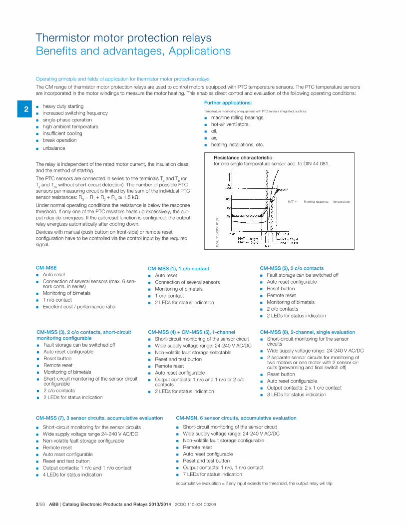
2/93 ABB | Catalog Electronic Products and Relays 2013/2014 | 2CDC 110 004 C0209
2
Thermistor motor protection relays
Benefits and advantages, Applications
1S
VC
11
0 0
00
F0
13
9
Operating principle and fields of application for thermistor motor protection relays
The CM range of thermistor motor protection relays are used to control motors equipped with PTC temperature sensors. The PTC temperature sensors
are incorporated in the motor windings to measure the motor heating. This enables direct control and evaluation of the following operating conditions:
� heavy duty starting
� increased switching frequency
� single-phase operation
� high ambient temperature
� insufficient cooling
� break operation
� unbalance
The relay is independent of the rated motor current, the insulation class
and the method of starting.
The PTC sensors are connected in series to the terminals Ta and T
b (or
Ta and T
bx without short-circuit detection). The number of possible PTC
sensors per measuring circuit is limited by the sum of the individual PTC
sensor resistances: RG = R
1 + R
2 + R
N � 1.5 k�.
Under normal operating conditions the resistance is below the response
threshold. If only one of the PTC resistors heats up excessively, the out-
put relay de-energizes. If the autoreset function is configured, the output
relay energizes automatically after cooling down.
Devices with manual (push button on front-side) or remote reset
configuration have to be controlled via the control input by the required
signal.
Further applications:
Temperature monitoring of equipment with PTC sensors integrated, such as:
� machine rolling bearings,
� hot-air ventilators,
� oil,
� air,
� heating installations, etc.
Resistance characteristic for one single temperature sensor acc. to DIN 44 081.
NAT = Nominal response temperature
CM-MSE � Auto reset
� Connection of several sensors (max. 6 sen-sors conn. in series)
� Monitoring of bimetals
� 1 n/o contact
� Excellent cost / performance ratio
CM-MSS (1), 1 c/o contact � Auto reset
� Connection of several sensors
� Monitoring of bimetals
� 1 c/o contact
� 2 LEDs for status indication
CM-MSS (2), 2 c/o contacts � Fault storage can be switched off
� Auto reset configurable
� Reset button
� Remote reset
� Monitoring of bimetals
� 2 c/o contacts
� 2 LEDs for status indication
CM-MSS (3), 2 c/o contacts, short-circuit monitoring configurable
� Fault storage can be switched off
� Auto reset configurable
� Reset button
� Remote reset
� Monitoring of bimetals
� Short-circuit monitoring of the sensor circuit configurable
� 2 c/o contacts
� 2 LEDs for status indication
CM-MSS (4) + CM-MSS (5), 1-channel � Short-circuit monitoring of the sensor circuit
� Wide supply voltage range: 24-240 V AC/DC
� Non-volatile fault storage selectable
� Reset and test button
� Remote reset
� Auto reset configurable
� Output contacts: 1 n/c and 1 n/o or 2 c/o contacts
� 2 LEDs for status indication
CM-MSS (6), 2-channel, single evaluation � Short-circuit monitoring for the sensor
circuits
� Wide supply voltage range: 24-240 V AC/DC
� 2 separate sensor circuits for monitoring of two motors or one motor with 2 sensor cir-cuits (prewarning and final switch off)
� Reset button
� Auto reset configurable
� Output contacts: 2 x 1 c/o contact
� 3 LEDs for status indication
� Short-circuit monitoring for the sensor circuits
� Wide supply voltage range 24-240 V AC/DC
� Non-volatile fault storage configurable
� Remote reset
� Auto reset configurable
� Reset and test button
� Output contacts: 1 n/c and 1 n/o contact
� 4 LEDs for status indication
CM-MSS (7), 3 sensor circuits, accumulative evaluation
� Short-circuit monitoring of the sensor circuit
� Wide supply voltage range: 24-240 V AC/DC
� Non-volatile fault storage configurable
� Remote reset
� Auto reset configurable
� Reset and test button
� Output contacts: 1 n/c, 1 n/o contact
� 7 LEDs for status indication
CM-MSN, 6 sensor circuits, accumulative evaluation
accumulative evaluation = if any input exeeds the threshold, the output relay will trip
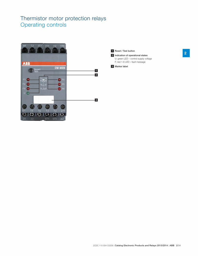
2CDC 110 004 C0209 | Catalog Electronic Products and Relays 2013/2014 | ABB 2/94
2
Thermistor motor protection relays
Operating controls
1
2
3
1 Reset / Test button
2 Indication of operational statesU: green LED – control supply voltage
F: red 1-6 LED – fault message
3 Marker label
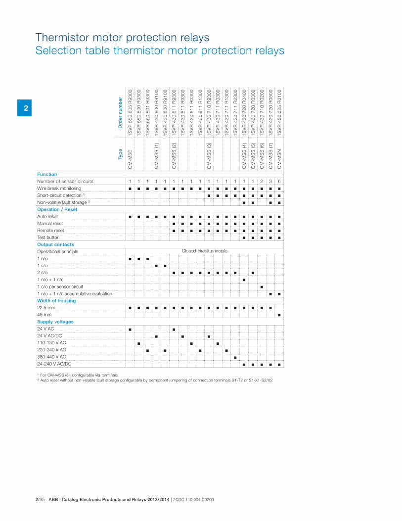
2/95 ABB | Catalog Electronic Products and Relays 2013/2014 | 2CDC 110 004 C0209
2
Thermistor motor protection relays
Selection table thermistor motor protection relays
1) For CM-MSS (3): configurable via terminals2) Auto reset without non-volatile fault storage configurable by permanent jumpering of connection terminals S1-T2 or S1/X1-S2/X2
Ord
er n
um
ber
1S
VR
55
0 8
05
R9
30
0
1S
VR
55
0 8
00
R9
30
0
1S
VR
55
0 8
01
R9
30
0
1S
VR
43
0 8
00
R9
10
0
1S
VR
43
0 8
00
R9
10
0
1S
VR
43
0 8
11
R9
30
0
1S
VR
43
0 8
11
R9
30
0
1S
VR
43
0 8
11
R0
30
0
1S
VR
43
0 8
11
R1
30
0
1S
VR
43
0 7
10
R9
30
0
1S
VR
43
0 7
11
R0
30
0
1S
VR
43
0 7
11
R1
30
0
1S
VR
43
0 7
11
R2
30
0
1S
VR
43
0 7
20
R0
40
0
1S
VR
43
0 7
20
R0
30
0
1S
VR
43
0 7
10
R0
20
0
1S
VR
43
0 7
20
R0
50
0
1S
VR
45
0 0
25
R0
10
0
Typ
e
CM
-MS
E
CM
-MS
S (
1)
CM
-MS
S (
2)
CM
-MS
S (
3)
CM
-MS
S (
4)
CM
-MS
S (
5)
CM
-MS
S (
6)
CM
-MS
S (
7)
CM
-MS
N
Function
Number of sensor circuits 1 1 1 1 1 1 1 1 1 1 1 1 1 1 1 2 3 6
Wire break monitoring � � � � � � � � � � � � � � � � � �Short-circuit detection 1) � � � � � � � � �Non-volatile fault storage 2) � � � �Operation / Reset
Auto reset � � � � � � � � � � � � � � � � � �Manual reset � � � � � � � � � � � � �Remote reset � � � � � � � � � � � � �Test button � � � � �Output contacts
Operational principle Closed-circuit principle
1 n/o � � �1 c/o � �2 c/o � � � � � � � � �1 n/o + 1 n/c �1 c/o per sensor circuit �1 n/o + 1 n/c accumulative evaluation � �Width of housing
22.5 mm � � � � � � � � � � � � � � � � �45 mm �Supply voltages
24 V AC � �24 V AC/DC � � �110-130 V AC � � �220-240 V AC � � � �380-440 V AC �24-240 V AC/DC � � � � �
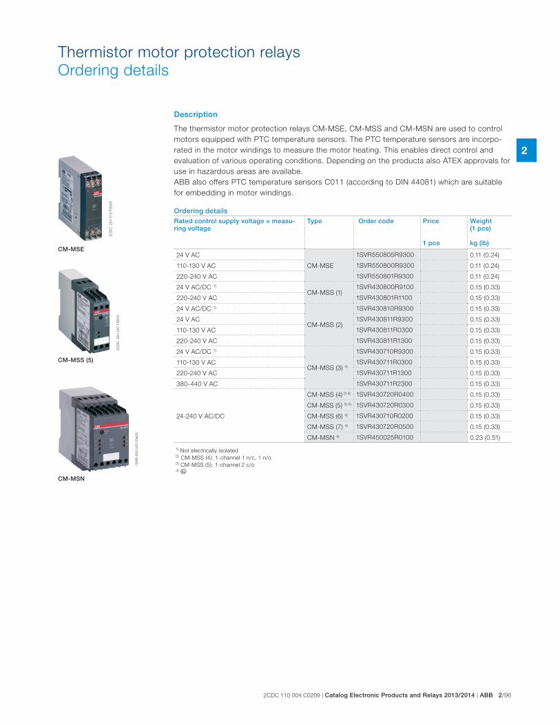
2CDC 110 004 C0209 | Catalog Electronic Products and Relays 2013/2014 | ABB 2/96
2
Thermistor motor protection relays
Ordering details
Description
The thermistor motor protection relays CM-MSE, CM-MSS and CM-MSN are used to control
motors equipped with PTC temperature sensors. The PTC temperature sensors are incorpo-
rated in the motor windings to measure the motor heating. This enables direct control and
evaluation of various operating conditions. Depending on the products also ATEX approvals for
use in hazardous areas are availabe.
ABB also offers PTC temperature sensors C011 (according to DIN 44081) which are suitable
for embedding in motor windings.
Ordering detailsRated control supply voltage = measu-ring voltage
Type Order code Price
1 pce
Weight(1 pce)
kg (lb)
24 V AC
CM-MSE
1SVR550805R9300 0.11 (0.24)
110-130 V AC 1SVR550800R9300 0.11 (0.24)
220-240 V AC 1SVR550801R9300 0.11 (0.24)
24 V AC/DC 1)
CM-MSS (1)1SVR430800R9100 0.15 (0.33)
220-240 V AC 1SVR430801R1100 0.15 (0.33)
24 V AC/DC 1)
CM-MSS (2)
1SVR430810R9300 0.15 (0.33)
24 V AC 1SVR430811R9300 0.15 (0.33)
110-130 V AC 1SVR430811R0300 0.15 (0.33)
220-240 V AC 1SVR430811R1300 0.15 (0.33)
24 V AC/DC 1)
CM-MSS (3) 4)
1SVR430710R9300 0.15 (0.33)
110-130 V AC 1SVR430711R0300 0.15 (0.33)
220-240 V AC 1SVR430711R1300 0.15 (0.33)
380-440 V AC 1SVR430711R2300 0.15 (0.33)
24-240 V AC/DC
CM-MSS (4) 2) 4) 1SVR430720R0400 0.15 (0.33)
CM-MSS (5) 3) 4) 1SVR430720R0300 0.15 (0.33)
CM-MSS (6) 4) 1SVR430710R0200 0.15 (0.33)
CM-MSS (7) 4) 1SVR430720R0500 0.15 (0.33)
CM-MSN 4) 1SVR450025R0100 0.23 (0.51)
2C
DC
2
51
01
2 F
00
03
2C
DC
2
51
04
7 F
00
04
1S
VR
45
0 0
25
F0
40
0
CM-MSE
CM-MSS (5)
CM-MSN
1) Not electrically isolated2) CM-MSS (4): 1-channel 1 n/c, 1 n/o3) CM-MSS (5): 1-channel 2 c/o4) I
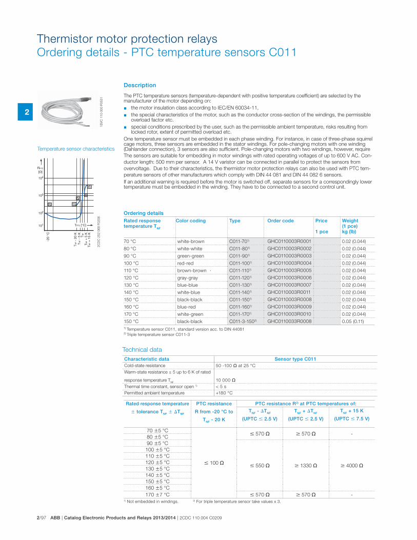
2/97 ABB | Catalog Electronic Products and Relays 2013/2014 | 2CDC 110 004 C0209
2
Thermistor motor protection relays
Ordering details - PTC temperature sensors C011
1S
VC
11
0 0
00
F0
53
1
Temperature sensor characteristics
Characteristic data Sensor type C011Cold-state resistance 50 -100 � at 25 °C
Warm-state resistance ± 5 up to 6 K of rated
response temperature TNF
10 000 �
Thermal time constant, sensor open 1) < 5 s
Permitted ambient temperature +180 °C
Technical data
.
Rated response temperature
� tolerance TNF � �TNF
PTC resistance
R from -20 °C to
TNF - 20 K
PTC resistance R2) at PTC temperatures of:
TNF - �TNF
(UPTC � 2.5 V)
TNF + �TNF
(UPTC � 2.5 V)
TNF + 15 K
(UPTC � 7.5 V)
70 �5 °C
� 100 �
� 570 � � 570 � -80 �5 °C
90 �5 °C
� 550 � � 1330 � � 4000 �
100 �5 °C
110 �5 °C
120 �5 °C
130 �5 °C
140 �5 °C
150 �5 °C
160 �5 °C
170 �7 °C � 570 � � 570 � -1) Not embedded in windings. 2) For triple temperature sensor take values x 3.
-20
°C
101
102
103
104
TNF
- 20
KTN
F -
5 K
TNF
TNF
+ 5
KTN
F +
15
K
RPTC
[�]
TPTC [°C]
2C
DC
25
2 0
68
F0
20
8
Ordering detailsRated response temperature TNF
Color coding Type Order code Price
1 pce
Weight(1 pce) kg (lb)
70 °C white-brown C011-701) GHC0110003R0001 0.02 (0.044)
80 °C white-white C011-801) GHC0110003R0002 0.02 (0.044)
90 °C green-green C011-901) GHC0110003R0003 0.02 (0.044)
100 °C red-red C011-1001) GHC0110003R0004 0.02 (0.044)
110 °C brown-brown C011-1101) GHC0110003R0005 0.02 (0.044)
120 °C gray-gray C011-1201) GHC0110003R0006 0.02 (0.044)
130 °C blue-blue C011-1301) GHC0110003R0007 0.02 (0.044)
140 °C white-blue C011-1401) GHC0110003R0011 0.02 (0.044)
150 °C black-black C011-1501) GHC0110003R0008 0.02 (0.044)
160 °C blue-red C011-1601) GHC0110003R0009 0.02 (0.044)
170 °C white-green C011-1701) GHC0110003R0010 0.02 (0.044)
150 °C black-black C011-3-1502) GHC0110033R0008 0.05 (0.11)
1) Temperature sensor C011, standard version acc. to DIN 440812) Triple temperature sensor C011-3
Description
The PTC temperature sensors (temperature-dependent with positive temperature coefficient) are selected by the manufacturer of the motor depending on:
� the motor insulation class according to IEC/EN 60034-11,
� the special characteristics of the motor, such as the conductor cross-section of the windings, the permissible overload factor etc.
� special conditions prescribed by the user, such as the permissible ambient temperature, risks resulting from locked rotor, extent of permitted overload etc.
One temperature sensor must be embedded in each phase winding. For instance, in case of three-phase squirrel cage motors, three sensors are embedded in the stator windings. For pole-changing motors with one winding (Dahlander connection), 3 sensors are also sufficient. Pole-changing motors with two windings, however, require
The sensors are suitable for embedding in motor windings with rated operating voltages of up to 600 V AC. Con-
ductor length: 500 mm per sensor. A 14 V varistor can be connected in parallel to protect the sensors from
overvoltage. Due to their characteristics, the thermistor motor protection relays can also be used with PTC tem-
perature sensors of other manufacturers which comply with DIN 44 081 and DIN 44 082 6 sensors.
If an additional warning is required before the motor is switched off, separate sensors for a correspon dingly lower temperature must be embedded in the winding. They have to be connected to a second control unit.
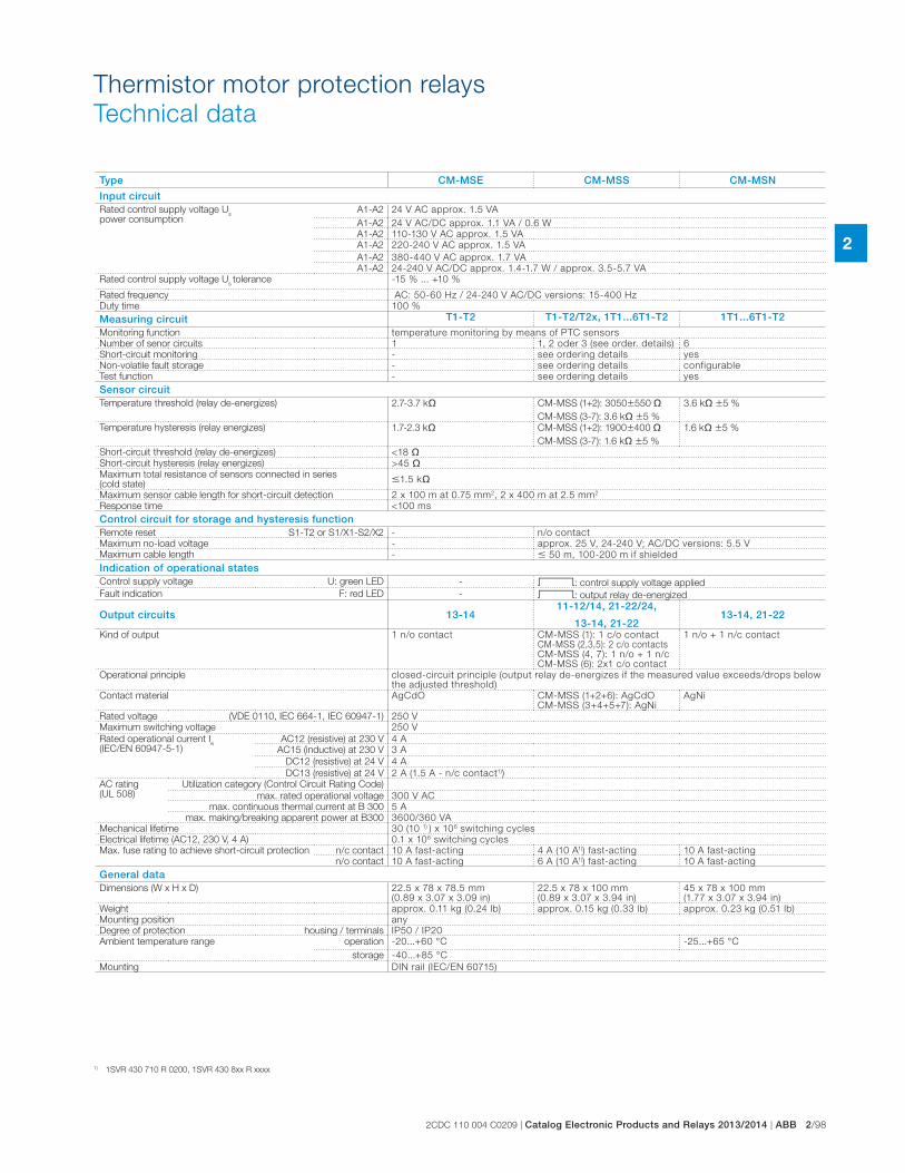
2CDC 110 004 C0209 | Catalog Electronic Products and Relays 2013/2014 | ABB 2/98
2
Thermistor motor protection relays
Technical data
Type CM-MSE CM-MSS CM-MSN
Input circuitRated control supply voltage U
s
power consumptionA1-A2 24 V AC approx. 1.5 VA
A1-A2 24 V AC/DC approx. 1.1 VA / 0.6 W
A1-A2 110-130 V AC approx. 1.5 VA
A1-A2 220-240 V AC approx. 1.5 VA
A1-A2 380-440 V AC approx. 1.7 VA
A1-A2 24-240 V AC/DC approx. 1.4-1.7 W / approx. 3.5-5.7 VA
Rated control supply voltage Us tolerance -15 % ... +10 %
Rated frequency AC: 50-60 Hz / 24-240 V AC/DC versions: 15-400 Hz
Duty time 100 %
Measuring circuit T1-T2 T1-T2/T2x, 1T1...6T1-T2 1T1...6T1-T2Monitoring function temperature monitoring by means of PTC sensors
Number of senor circuits 1 1, 2 oder 3 (see order. details) 6
Short-circuit monitoring - see ordering details yes
Non-volatile fault storage - see ordering details configurable
Test function - see ordering details yes
Sensor circuitTemperature threshold (relay de-energizes) 2.7-3.7 k� CM-MSS (1+2): 3050�550 �
CM-MSS (3-7): 3.6 k� �5 %
3.6 k� �5 %
Temperature hysteresis (relay energizes) 1.7-2.3 k� CM-MSS (1+2): 1900�400 �
CM-MSS (3-7): 1.6 k� �5 %
1.6 k� �5 %
Short-circuit threshold (relay de-energizes) <18 �Short-circuit hysteresis (relay energizes) >45 �Maximum total resistance of sensors connected in series (cold state)
�1.5 k�
Maximum sensor cable length for short-circuit detection 2 x 100 m at 0.75 mm2, 2 x 400 m at 2.5 mm2
Response time <100 ms
Control circuit for storage and hysteresis functionRemote reset S1-T2 or S1/X1-S2/X2 - n/o contact
Maximum no-load voltage - approx. 25 V, 24-240 V; AC/DC versions: 5.5 V
Maximum cable length - � 50 m, 100-200 m if shielded
Indication of operational statesControl supply voltage U: green LED - V: control supply voltage applied
Fault indication F: red LED - V: output relay de-energized
Output circuits 13-1411-12/14, 21-22/24,
13-14, 21-2213-14, 21-22
Kind of output 1 n/o contact CM-MSS (1): 1 c/o contact CM-MSS (2,3,5): 2 c/o contacts CM-MSS (4, 7): 1 n/o + 1 n/c CM-MSS (6): 2x1 c/o contact
1 n/o + 1 n/c contact
Operational principle closed-circuit principle (output relay de-energizes if the measured value exceeds/drops below the adjusted threshold)
Contact material AgCdO CM-MSS (1+2+6): AgCdO CM-MSS (3+4+5+7): AgNi
AgNi
Rated voltage (VDE 0110, IEC 664-1, IEC 60947-1) 250 V
Maximum switching voltage 250 V
Rated operational current Ie
(IEC/EN 60947-5-1)AC12 (resistive) at 230 V 4 A
AC15 (inductive) at 230 V 3 A
DC12 (resistive) at 24 V 4 A
DC13 (resistive) at 24 V 2 A (1.5 A - n/c contact1))
AC rating (UL 508)
Utilization category (Control Circuit Rating Code)
max. rated operational voltage 300 V AC
max. continuous thermal current at B 300 5 A
max. making/breaking apparent power at B300 3600/360 VA
Mechanical lifetime 30 (10 1) ) x 106 switching cycles
Electrical lifetime (AC12, 230 V, 4 A) 0.1 x 10⁶ switching cycles
Max. fuse rating to achieve short-circuit protection n/c contact 10 A fast-acting 4 A (10 A1)) fast-acting 10 A fast-acting
n/o contact 10 A fast-acting 6 A (10 A1)) fast-acting 10 A fast-acting
General dataDimensions (W x H x D) 22.5 x 78 x 78.5 mm
(0.89 x 3.07 x 3.09 in)22.5 x 78 x 100 mm (0.89 x 3.07 x 3.94 in)
45 x 78 x 100 mm (1.77 x 3.07 x 3.94 in)
Weight approx. 0.11 kg (0.24 lb) approx. 0.15 kg (0.33 lb) approx. 0.23 kg (0.51 lb)
Mounting position anyDegree of protection housing / terminals IP50 / IP20
Ambient temperature range operation -20...+60 °C -25...+65 °C
storage -40...+85 °C
Mounting DIN rail (IEC/EN 60715)
1) 1SVR 430 710 R 0200, 1SVR 430 8xx R xxxx
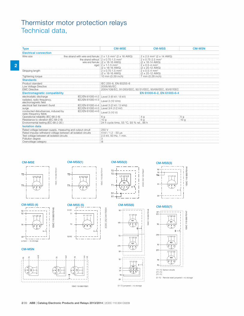
2/99 ABB | Catalog Electronic Products and Relays 2013/2014 | 2CDC 110 004 C0209
2
Thermistor motor protection relays
Technical data,
Type CM-MSE CM-MSS CM-MSN
Electrical connectionWire size fine strand with wire end ferrule 2 x 1.5 mm2 (2 x 16 AWG) 2 x 2.5 mm2 (2 x 14 AWG)
fine strand without wire end ferrule
2 x 0.75-1.5 mm2 (2 x 18-16 AWG)
2 x 0.75-2.5 mm2 (2 x 18-14 AWG)
rigid 2 x 1-1.5 mm2 (2 x 18-16 AWG)
2 x 0.5-4 mm2 (2 x 20-12 AWG)
Stripping length 2 x 0.75-1.5 mm2 (2 x 18-16 AWG)
2 x 0.5-4 mm2 (2 x 20-12 AWG)
Tightening torque 10 mm (0.39 inch) 7 mm (0.28 inch)
StandardsProduct standard IEC 255-6, EN 60255-6
Low Voltage Directive 2006/95/EC
EMC Directive 2004/108/EC, 91/263/EEC, 92/31/EEC, 93/68/EEC, 93/67/EEC
Electromagnetic compatibility EN 61000-6-2, EN 61000-6-4electrostatic discharge IEC/EN 61000-4-2 Level 3 (6 kV / 8 kV)
radiated, radio-frequency, electromagnetic field
IEC/EN 61000-4-3Level 3 (10 V/m)
electrical fast transient /burst IEC/EN 61000-4-4 Level 3 (2 kV / 5 kHz)
surge IEC/EN 61000-4-5 Level 3/4 (1/2 kV)
conducted disturbances, induced by radio-frequency fields
IEC/EN 61000-4-6Level 3 (10 V)
Operational reliability (IEC 68-2-6) 6 g 4 g 5 g
Resistance to vibration (IEC 68-2-6) 10 g 6 g 10 g
Environmental testing (IEC 68-2-30 ) 24 h cycle time, 55 °C, 93 % rel., 96 h
Isolation dataRated voltage between supply, measuring and output circuit 250 V
Rated impulse withstand voltage between all isolated circuits 4 kV / 1.2 - 50 μs
Test voltage between all isolated circuits 2.5 kV, 50 Hz, 1 min.
Pollution degree 3
Overvoltage category III
CM-MSE CM-MSS(1) CM-MSS(2) CM-MSS(3)
CM-MSS(6) CM-MSS(7)
CM-MSN
CM-MSS (4) CM-MSS (5)
1S
VC
11
0 0
00
F0
14
1
1S
VC
11
0 0
00
F0
14
1
2C
DC
25
2 1
23
F0
b0
7
X1
T2
S1
M
L1 L2 L3
3�
T2
T1ϑ ϑ ϑ
1SV
C 1
10 0
00 F
0144
1SV
C 1
10 0
00 F
0145
jumper = no storage
S1/X1
S2/X2
T2
T1L1 L2 L3
2C
DC
25
2 0
44
F0
00
4
1SV
C 1
10 0
00 F
0146
S1-T2 jumpered = no storage
1SV
C 1
10 0
00 F
0147
1T1-T2 Sensor circuits
2T1-T2
3T1-T2
S1-T2 Remote reset jumpered = no storage
1SVC 110 000 F0521
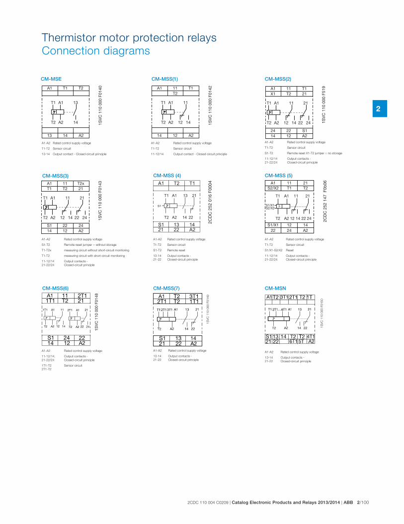
2CDC 110 004 C0209 | Catalog Electronic Products and Relays 2013/2014 | ABB 2/100
2
Thermistor motor protection relays
Connection diagrams
A1
A1
13
14
14 A2
A2
T1
13
T2
T1
T2 1SV
C 1
10 0
00 F
0140
A1-A2 Rated control supply voltage
T1-T2 Sensor circuit
13-14 Output contact - Closed-circuit principle
CM-MSE CM-MSS(1) CM-MSS(2)
CM-MSS(3)
CM-MSS(6) CM-MSS(7) CM-MSN
A1
A1
14
14
12
12
A2
A2
11
11
T1T2
T1
T2 1SV
C 1
10 0
00 F
0142
A1-A2 Rated control supply voltage
T1-T2 Sensor circuit
11-12/14 Output contact - Closed-circuit principle
A1
A1
14
14
12
12
A224 22 S1
A2
11
11
2422
21
T1X1 T2 21
T1
T2 1SV
C 1
10 0
00 F
519
A1-A2 Rated control supply voltage
T1-T2 Sensor circuit
S1-T2 Remote reset X1-T2 jumper = no storage
11-12/14 Output contacts -
21-22/24 Closed-circuit principle
A1-A2 Rated control supply voltage
S1-T2 Remote reset jumper = without storage
T1-T2x measuring circuit without short-circuit monitoring
T1-T2 measuring circuit with short-circuit monitoring
11-12/14 Output contacts -
21-22/24 Closed-circuit principle
A1
A1
14
14
12
12
A2S1 22 24
A2
11
11
2422
21
T2xT1 T2 21
T1
T2 1SV
C 1
10 0
00 F
0143 A1 T2 T1
S1 13 14
21 22 A2
T1 13A1 21
T2 A2 14 22
S1
2CD
C 2
52 0
16 F
0004
CM-MSS (4)
A1-A2 Rated control supply voltage
T1-T2 Sensor circuit
S1-T2 Remote reset
13-14 Output contacts -
21-22 Closed-circuit principle
T1 11A1 21
T2 12A2 14 22 24
S1/X1S2/X2
ϑ
A1 11 21S2/X2 T1 T2
S1/X1 12 1422 24 A2
2CD
C 2
52 1
47 F
0b06
CM-MSS (5)
A1-A2 Rated control supply voltage
T1-T2 Sensor circuit
S1/X1-S2/X2 Reset
11-12/14 Output contacts -
21-22/24 Closed-circuit principle
1SV
C 1
10 0
00 F
0148
A1-A2 Rated control supply voltage
11-12/14, Output contacts -
21-22/24 Closed-circuit principle
1T1-T2 Sensor circuit
2T1-T2
1S
VC
11
0 0
00
F0
14
9
A1-A2 Rated control supply voltage
13-14 Output contacts -
21-22 Closed-circuit principle
1S
VC
11
0 0
00
F0
15
0
A1-A2 Rated control supply voltage
13-14 Output contacts -
21-22 Closed-circuit principle
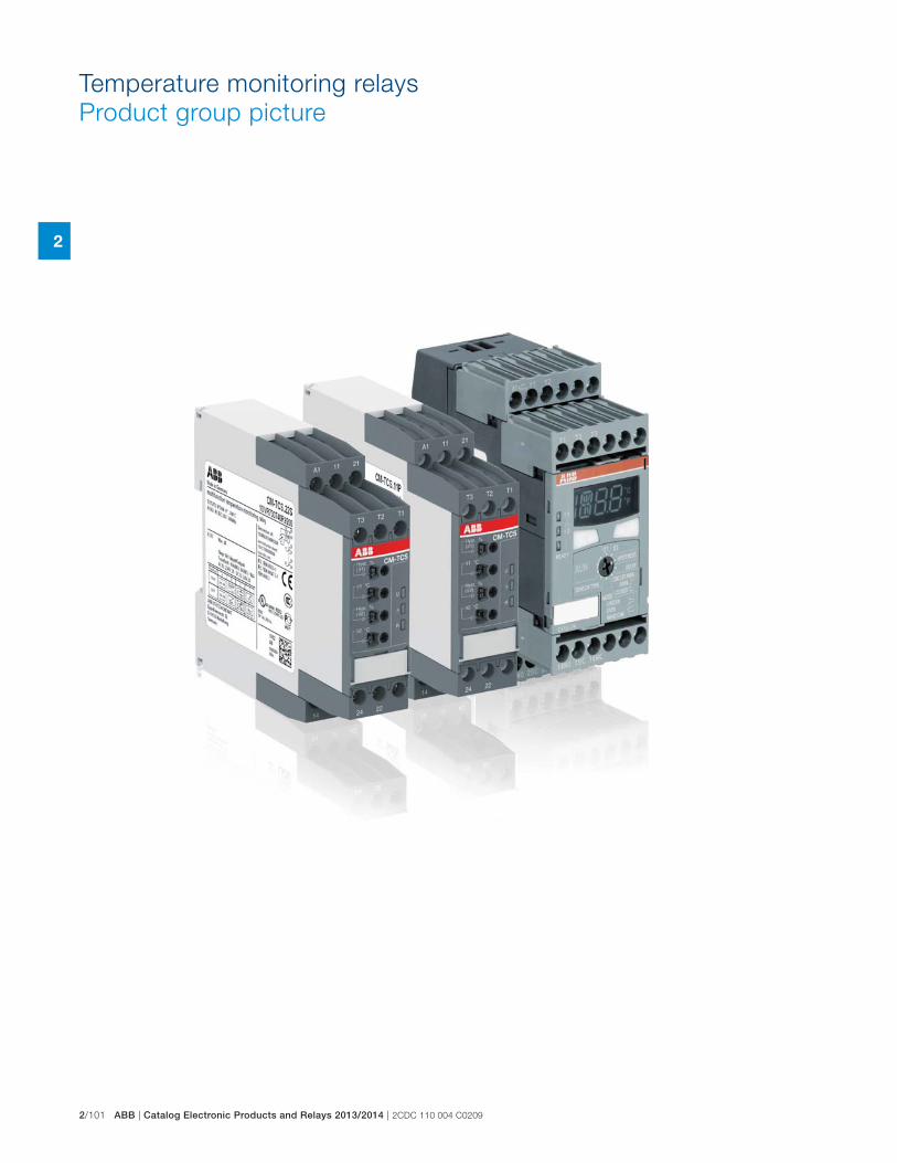
2/101 ABB | Catalog Electronic Products and Relays 2013/2014 | 2CDC 110 004 C0209
2
Temperature monitoring relays
Product group picture
2CDC 110 004 C0209 | Catalog Electronic Products and Relays 2013/2014 | ABB 2/102
2
Temperature monitoring relays
Table of contents
Temperature monitoring relays
Product group picture 99
Table of contents 100
Benefits and adv antages, Applications 101
Operating controls 102
Selection 103
Ordering details 104
Function diagrams 105
Overview, functional description and diagrams 106
Connection diagrams, Resistance thermometer sensors 107
Technical data - CM-TCS.xx 108
Technical data - C51x 110
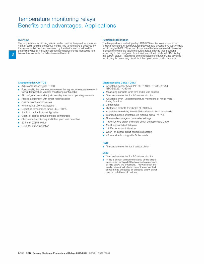
2/103 ABB | Catalog Electronic Products and Relays 2013/2014 | 2CDC 110 004 C0209
2
Temperature monitoring relays
Benefits and advantages, Applications
Characteristics CM-TCS � Adjustable sensor type: PT100
� Functionality like overtemperature monitoring, undertemperature moni-toring, temperature window monitoring configurable
� All configurations and adjustments by front-face operating elements
� Precise adjustment with direct reading scales
� One or two threshold values
� Hysteresis 2...20 % adjustable
� Operating temperature range -40...+60 °C
� 1 x 2 c/o or 2 x 1 c/o configurable
� Open- or closed-circuit principle configurable
� Short-circuit monitoring and interrupted wire detection
� 22.5 mm (0.89 in) width
� LEDs for status indication
Characteristics C512 + C513 � Adjustable sensor types: PT100, PT1000, KTY83, KTY84,
NTC-B57227-K333-A1
� Measuring principle for 2-wire and 3-wire sensors
� Temperature monitor for 1-3 sensor circuits
� Adjustable over-, undertemperature monitoring or range moni-toring function
� 2 thresholds
� Hysteresis for both thresholds (1-99 Kelvin)
� Adjustable time delay from 0-999 s affects to both thresholds
� Storage function selectable via external signal (Y1-Y2)
� Non volatile storage of parameter settings
� 1 n/o (for wire-break and short-circuit detection) and 2 c/o
� Multifunctional digital display
� 3 LEDs for status indication
� Open- or closed-circuit principle selectable
� 45 mm wide housing with 24 terminals
C513 � Temperature monitor for 1-3 sensor circuits
� In the 3-sensor version the status of the single sensors is displayed if the temperature exceeds or falls below the threshold. This way it can be easily determined which one of the connected sensors has exceeded or dropped below either one or both threshold values.
C512 � Temperature monitor for 1 sensor circuit
Functional descriptionThe temperature monitoring relays CM-TCS monitor overtemperature, undertemperature, or temperatures between two threshold values (window monitoring) with PT100 sensor. As soon as the temperature falls below or exceeds the threshold value the output relays change their positions according to the configured functionality and the front-face LEDs display the current status. Regardless of the selected configuration, the device is monitoring its measuring circuit for interrupted wires or short-circuits.
OverviewThe temperature monitoring relays can be used for temperature measure-ment in solid, liquid and gaseous media. The temperature is acquired by the sensor in the medium, evaluated by the device and monitored to determine whether it is within an operating range (range monitoring func-tion) or has exceeded or fallen below a threshold.
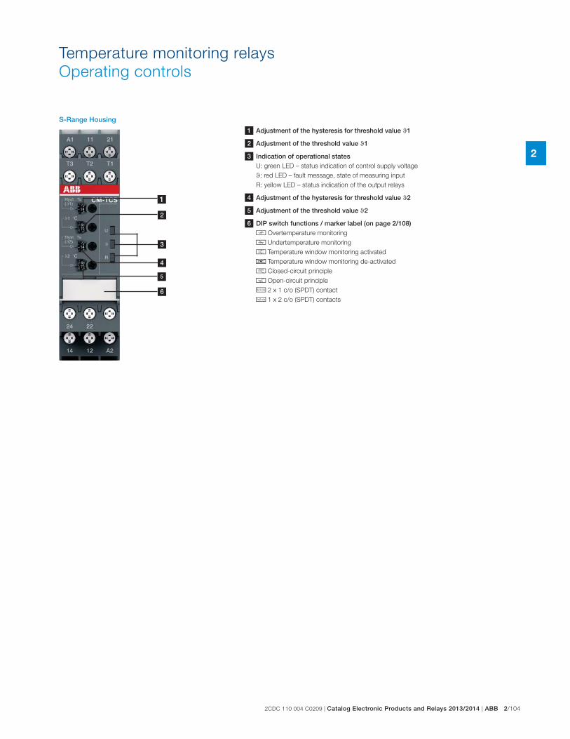
2CDC 110 004 C0209 | Catalog Electronic Products and Relays 2013/2014 | ABB 2/104
2
Temperature monitoring relays
Operating controls
4
1
2
3
5
1 Adjustment of the hysteresis for threshold value t1
2 Adjustment of the threshold value t1
3 Indication of operational statesU: green LED – status indication of control supply voltage
t: red LED – fault message, state of measuring input
R: yellow LED – status indication of the output relays
4 Adjustment of the hysteresis for threshold value t2
5 Adjustment of the threshold value t2
6 DIP switch functions / marker label (on page 2/108)p Overtemperature monitoring
q Undertemperature monitoring
r Temperature window monitoring activated
s Temperature window monitoring de-activated
g Closed-circuit principle
h Open-circuit principle
i 2 x 1 c/o (SPDT) contact
j 1 x 2 c/o (SPDT) contacts
S-Range Housing
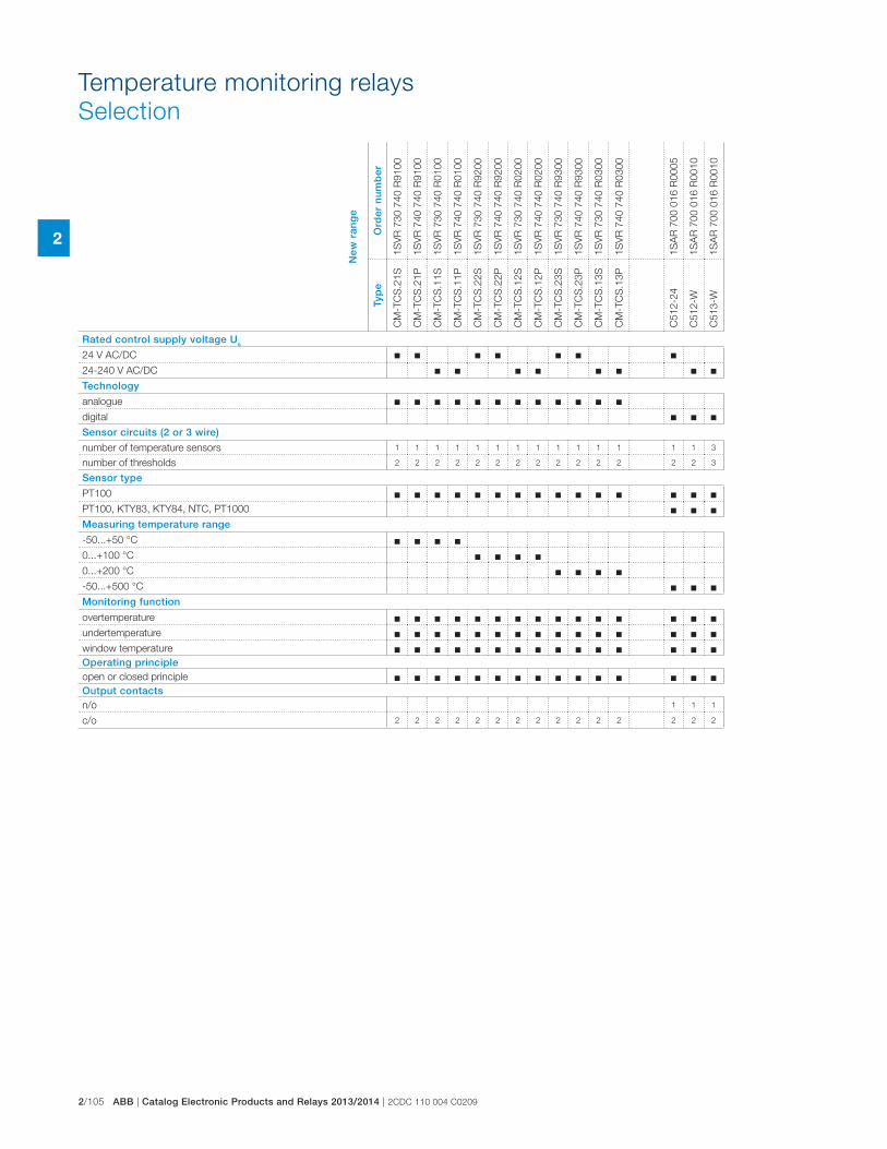
2/105 ABB | Catalog Electronic Products and Relays 2013/2014 | 2CDC 110 004 C0209
2
Temperature monitoring relays
Selection
New
ran
ge
Ord
er n
um
ber
1S
VR
730 7
40 R
9100
1S
VR
740 7
40 R
9100
1S
VR
730 7
40 R
0100
1S
VR
740 7
40 R
0100
1S
VR
730 7
40 R
9200
1S
VR
740 7
40 R
9200
1S
VR
730 7
40 R
0200
1S
VR
740 7
40 R
0200
1S
VR
730 7
40 R
9300
1S
VR
740 7
40 R
9300
1S
VR
730 7
40 R
0300
1S
VR
740 7
40 R
0300
1S
AR
700 0
16 R
0005
1S
AR
700 0
16 R
0010
1S
AR
700 0
16 R
0010
Typ
e
CM
-TC
S.2
1S
CM
-TC
S.2
1P
CM
-TC
S.1
1S
CM
-TC
S.1
1P
CM
-TC
S.2
2S
CM
-TC
S.2
2P
CM
-TC
S.1
2S
CM
-TC
S.1
2P
CM
-TC
S.2
3S
CM
-TC
S.2
3P
CM
-TC
S.1
3S
CM
-TC
S.1
3P
C512-2
4
C512-W
C513-W
Rated control supply voltage Us
24 V AC/DC � � � � � � �24-240 V AC/DC � � � � � � � �Technology
analogue � � � � � � � � � � � �digital � � �Sensor circuits (2 or 3 wire)
number of temperature sensors 1 1 1 1 1 1 1 1 1 1 1 1 1 1 3
number of thresholds 2 2 2 2 2 2 2 2 2 2 2 2 2 2 3
Sensor type
PT100 � � � � � � � � � � � � � � �PT100, KTY83, KTY84, NTC, PT1000 � � �Measuring temperature range
-50...+50 °C � � � �0...+100 °C � � � �0...+200 °C � � � �-50...+500 °C � � �Monitoring function
overtemperature � � � � � � � � � � � � � � �undertemperature � � � � � � � � � � � � � � �window temperature � � � � � � � � � � � � � � �Operating principleopen or closed principle � � � � � � � � � � � � � � �Output contactsn/o 1 1 1
c/o 2 2 2 2 2 2 2 2 2 2 2 2 2 2 2
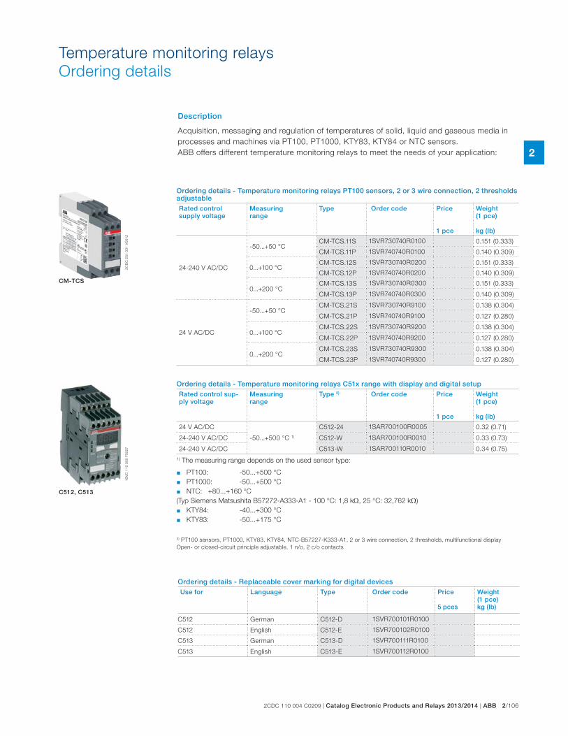
2CDC 110 004 C0209 | Catalog Electronic Products and Relays 2013/2014 | ABB 2/106
2
Temperature monitoring relays
Ordering details
Description
Acquisition, messaging and regulation of temperatures of solid, liquid and gaseous media in
processes and machines via PT100, PT1000, KTY83, KTY84 or NTC sensors.
ABB offers different temperature monitoring relays to meet the needs of your application:
Ordering details - Temperature monitoring relays C51x range with display and digital setupRated control sup-ply voltage
Measuringrange
Type 2) Order code Price
1 pce
Weight(1 pce) kg (lb)
24 V AC/DC
-50...+500 °C 1)
C512-24 1SAR700100R0005 0.32 (0.71)
24-240 V AC/DC C512-W 1SAR700100R0010 0.33 (0.73)
24-240 V AC/DC C513-W 1SAR700110R0010 0.34 (0.75)
Ordering details - Replaceable cover marking for digital devicesUse for Language Type Order code Price
5 pces
Weight(1 pce) kg (lb)
C512 German C512-D 1SVR700101R0100
C512 English C512-E 1SVR700102R0100
C513 German C513-D 1SVR700111R0100
C513 English C513-E 1SVR700112R0100
2C
DC
25
1 0
31
V0
01
21
SV
C 1
10
00
0 F
05
57
CM-TCS
C512, C513
1) The measuring range depends on the used sensor type:
� PT100: -50...+500 °C � PT1000: -50...+500 °C
� NTC: +80...+160 °C
(Typ Siemens Matsushita B57272-A333-A1 - 100 °C: 1,8 k , 25 °C: 32,762 k )
� KTY84: -40...+300 °C
� KTY83: -50...+175 °C
3) PT100 sensors, PT1000, KTY83, KTY84, NTC-B57227-K333-A1, 2 or 3 wire connection, 2 thresholds, multifunctional display
Open- or closed-circuit principle adjustable, 1 n/o, 2 c/o contacts
Ordering details - Temperature monitoring relays PT100 sensors, 2 or 3 wire connection, 2 thresholds adjustableRated control supply voltage
Measuringrange
Type Order code Price
1 pce
Weight(1 pce) kg (lb)
24-240 V AC/DC
-50...+50 °CCM-TCS.11S 1SVR730740R0100 0.151 (0.333)
CM-TCS.11P 1SVR740740R0100 0.140 (0.309)
0...+100 °CCM-TCS.12S 1SVR730740R0200 0.151 (0.333)
CM-TCS.12P 1SVR740740R0200 0.140 (0.309)
0...+200 °CCM-TCS.13S 1SVR730740R0300 0.151 (0.333)
CM-TCS.13P 1SVR740740R0300 0.140 (0.309)
24 V AC/DC
-50...+50 °CCM-TCS.21S 1SVR730740R9100 0.138 (0.304)
CM-TCS.21P 1SVR740740R9100 0.127 (0.280)
0...+100 °CCM-TCS.22S 1SVR730740R9200 0.138 (0.304)
CM-TCS.22P 1SVR740740R9200 0.127 (0.280)
0...+200 °CCM-TCS.23S 1SVR730740R9300 0.138 (0.304)
CM-TCS.23P 1SVR740740R9300 0.127 (0.280)
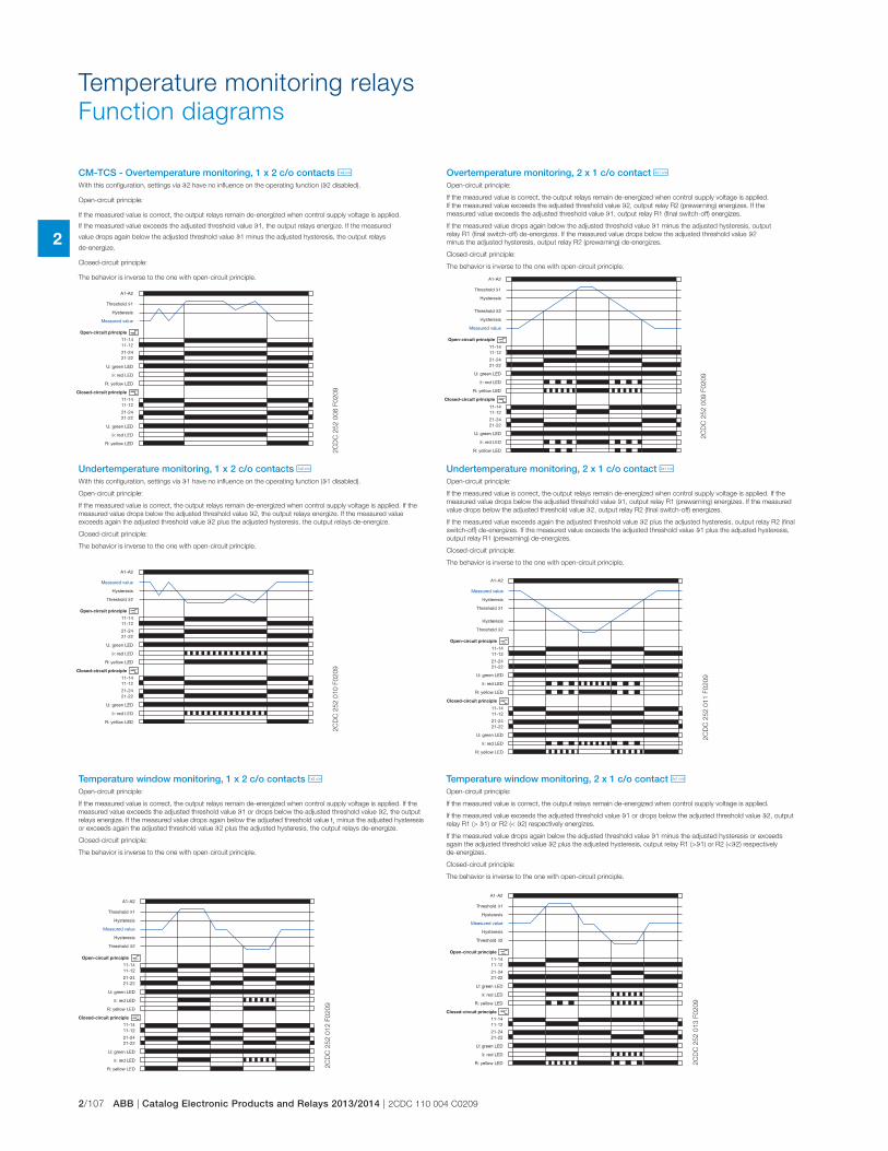
2/107 ABB | Catalog Electronic Products and Relays 2013/2014 | 2CDC 110 004 C0209
2
Temperature monitoring relays
Function diagrams
CM-TCS - Overtemperature monitoring, 1 x 2 c/o contacts j
Undertemperature monitoring, 1 x 2 c/o contacts j
Temperature window monitoring, 1 x 2 c/o contacts j Temperature window monitoring, 2 x 1 c/o contact i
Undertemperature monitoring, 2 x 1 c/o contact i
Overtemperature monitoring, 2 x 1 c/o contact i
A1-A2
11-1411-12
21-2421-22
11-1411-12
21-2421-22
closed
open
Threshold ϑ1
Hysteresis
Measured value
U: green LED
ϑ: red LED
R: yellow LED
U: green LED
ϑ: red LED
R: yellow LED
Open-circuit principle
Closed-circuit principle
A1-A2
11-1411-12
21-2421-22
11-1411-12
21-2421-22
closed
open
Hysteresis
Measured value
U: green LED
ϑ: red LED
R: yellow LED
U: green LED
ϑ: red LED
R: yellow LED
Open-circuit principle
Closed-circuit principle
Threshold ϑ2
A1-A2
11-1411-12
21-2421-22
11-1411-12
21-2421-22
closed
open
Threshold ϑ1
Hysteresis
Measured value
Threshold ϑ2
Hysteresis
Open-circuit principle
U: green LED
ϑ: red LED
R: yellow LED
Closed-circuit principle
U: green LED
ϑ: red LED
R: yellow LED
A1-A2
11-1411-12
21-2421-22
11-1411-12
21-2421-22
closed
open
Threshold ϑ1
Hysteresis
Measured value
Threshold ϑ2
Hysteresis
Open-circuit principle
U: green LED
ϑ: red LED
R: yellow LED
Closed-circuit principle
U: green LED
ϑ: red LED
R: yellow LED
A1-A2
11-1411-12
21-2421-22
11-1411-12
21-2421-22
closed
open
Threshold ϑ1
Hysteresis
Measured value
Hysteresis
Threshold ϑ2
Open-circuit principle
U: green LED
ϑ: red LED
R: yellow LED
Closed-circuit principle
U: green LED
ϑ: red LED
R: yellow LED
A1-A2
11-1411-12
21-2421-22
11-1411-12
21-2421-22
closed
open
Threshold ϑ1
Hysteresis
Measured value
Hysteresis
Threshold ϑ2
Open-circuit principle
U: green LED
ϑ: red LED
R: yellow LED
Closed-circuit principle
U: green LED
ϑ: red LED
R: yellow LED2C
DC
25
2 0
08
F0
20
92
CD
C 2
52
01
0 F
02
09
2C
DC
25
2 0
12
F0
20
9
2C
DC
25
2 0
13
F0
20
9
2C
DC
25
2 0
11
F0
20
92
CD
C 2
52
00
9 F
02
09
With this configuration, settings via t2 have no influence on the operating function (t2 disabled).
Open-circuit principle:
If the measured value is correct, the output relays remain de-energized when control supply voltage is applied.
If the measured value exceeds the adjusted threshold value t1, the output relays energize. If the measured
value drops again below the adjusted threshold value t1 minus the adjusted hysteresis, the output relays
de-energize.
Closed-circuit principle:
The behavior is inverse to the one with open-circuit principle.
With this configuration, settings via t1 have no influence on the operating function (t1 disabled).
Open-circuit principle:
If the measured value is correct, the output relays remain de-energized when control supply voltage is applied. If the
measured value drops below the adjusted threshold value t2, the output relays energize. If the measured value
exceeds again the adjusted threshold value t2 plus the adjusted hysteresis, the output relays de-energize.
Closed-circuit principle:
The behavior is inverse to the one with open-circuit principle.
Open-circuit principle:
If the measured value is correct, the output relays remain de-energized when control supply voltage is applied. If the
measured value exceeds the adjusted threshold value t1 or drops below the adjusted threshold value t2, the output
relays energize. If the measured value drops again below the adjusted threshold value t1 minus the adjusted hysteresis
or exceeds again the adjusted threshold value t2 plus the adjusted hysteresis, the output relays de-energize.
Closed-circuit principle:
The behavior is inverse to the one with open-circuit principle.
Open-circuit principle:
If the measured value is correct, the output relays remain de-energized when control supply voltage is applied.
If the measured value exceeds the adjusted threshold value t1 or drops below the adjusted threshold value t2, output
relay R1 (> t1) or R2 (< t2) respectively energizes.
If the measured value drops again below the adjusted threshold value t1 minus the adjusted hysteresis or exceeds
again the adjusted threshold value t2 plus the adjusted hysteresis, output relay R1 (>t1) or R2 (<t2) respectively
de-energizes.
Closed-circuit principle:
The behavior is inverse to the one with open-circuit principle.
Open-circuit principle:
If the measured value is correct, the output relays remain de-energized when control supply voltage is applied. If the
measured value drops below the adjusted threshold value t1, output relay R1 (prewarning) energizes. If the measured
value drops below the adjusted threshold value t2, output relay R2 (final switch-off) energizes.
If the measured value exceeds again the adjusted threshold value t2 plus the adjusted hysteresis, output relay R2 (final
switch-off) de-energizes. If the measured value exceeds the adjusted threshold value t1 plus the adjusted hysteresis,
output relay R1 (prewarning) de-energizes.
Closed-circuit principle:
The behavior is inverse to the one with open-circuit principle.
Open-circuit principle:
If the measured value is correct, the output relays remain de-energized when control supply voltage is applied.
If the measured value exceeds the adjusted threshold value t2, output relay R2 (prewarning) energizes. If the
measured value exceeds the adjusted threshold value t1, output relay R1 (final switch-off) energizes.
If the measured value drops again below the adjusted threshold value t1 minus the adjusted hysteresis, output
relay R1 (final switch-off) de-energizes. If the measured value drops below the adjusted threshold value t2
minus the adjusted hysteresis, output relay R2 (prewarning) de-energizes.
Closed-circuit principle:
The behavior is inverse to the one with open-circuit principle.
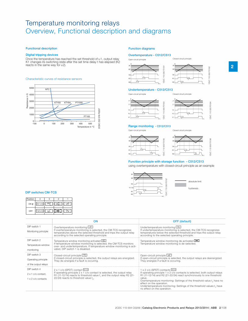
2CDC 110 004 C0209 | Catalog Electronic Products and Relays 2013/2014 | ABB 2/108
2
DIP switches CM-TCS
Position 4 1 2 3
ON
OFF
i g r p
qs
h
j
ON OFF (default)
DIP switch 1
Monitoring principle
Overtemperature monitoring pIf overtemperature monitoring is selected, the CM-TCS recognizes temperatures above the selected threshold and trips the output relay according to the selected operating principle.
Undertemperature monitoring qIf undertemperature monitoring is selected, the CM-TCS recognizes temperatures below the selected threshold and trips the output relay according to the selected operating principle.
DIP switch 2
Temperature window
monitoring
Temperature window monitoring activated rIf temperature window monitoring is selected, the CM-TCS monitors over- and undertemperature. If temperature window monitoring is acti-vated, DIP switch 1 is disabled.
Temperature window monitoring de-activated sTemperature window monitoring is de-selected.
DIP switch 3
Operating principle
of the output relays
Closed-circuit principle gIf closed-circuit principle is selected, the output relays are energized. They de-energize if a fault is occuring.
Open-circuit principle hIf open-circuit principle is selected, the output relays are deenergized. They energize if a fault is occuring.
DIP switch 4
2 x 1 c/o contact,
1 x 2 c/o contacts
2 x 1 c/o (SPDT) contact iIf operating principle 2 x 1 c/o contact is selected, the output relay R1 (11-12/14) reacts to threshold value t
1 and the output relay R2 (21-
22/24) reacts to threshold value t2.
1 x 2 c/o (SPDT) contacts jIf operating principle 1 x 2 c/o contacts is selected, both output relays R1 (11-12/14) and R2 (21-22/24) react synchronously to one threshold value.Overtemperature monitoring: Settings of the threshold value t
2 have no
effect on the operation.Undertemperature monitoring: Settings of the threshold values t
2 have
no effect on the operation.
Characteristic curves of resistance sensors
-100 0 100 200 300 400 500
5000
4000
3000
2000
1000
0
NTC
KTY83 KTY84 PT1000
PT100
Res
ista
nce
in �
Temperature in °C 2CD
C 2
52 0
76 F
0207
t
t
t
Us
K1
K2
1
2
t
t t
Us
K1
K2
1
2
t
t
t
Us
K 2
K 1
1J
2J
t
t
t
Us
K1
K2
1
2
tt
t
Us
K1
K2
1
2
t
t
Us
-Y1 Y2
K1
tK2
1
2
1S
VC
11
0 0
00
F0
19
1
1S
VC
11
0 0
00
F0
19
2
1S
VC
11
0 0
00
F0
19
5
1S
VC
11
0 0
00
F0
19
6
t
t t
Us
K 2
K 1
1J
2J
1S
VC
11
0 0
00
F0
19
3
1S
VC
11
0 0
00
F0
19
4
1S
VC
11
0 0
00
F0
19
7
Function principle with storage function - C512/C513using overtemperature with closed-circuit principle as an example
Range monitoring - C512/C513
absolute limit
hysteresis
Overtemperature - C512/C513Open-circuit principle
Open-circuit principle
Closed-circuit principle
Closed-circuit principle
Closed-circuit principle
Undertemperature - C512/C513
Open-circuit principle
Temperature monitoring relays
Overview, Functional description and diagrams
Functional description
Digital tripping devicesOnce the temperature has reached the set threshold of 1, output relay K1 changes its switching state after the set time delay t has elapsed (K2 reacts in the same way for 2).
Function diagrams
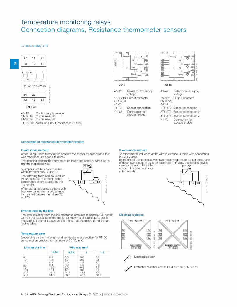
2/109 ABB | Catalog Electronic Products and Relays 2013/2014 | 2CDC 110 004 C0209
2
Temperature monitoring relays
Connection diagrams, Resistance thermometer sensors
A2
A1
K1 15
1618
K2 25
28
K3 33
34
26
Y2Y1
1T11T21T32T12T22T33T13T23T3
Memory
Ready
1
2
A2
A1
T1
K1 15
16T2T3
18
K2 25
28
K3 33
34
26
Y2Y1
Memory
Ready
1
2
2C
DC
25
2 0
25
F0
01
0
1S
VC
11
0 0
00
F0
20
2
CM-TCS
C512 C513
Connection diagrams
Connection of resistance thermometer sensors
A1-A2 Control supply voltage 11-12/14 Output relay R1 21-22/24 Output relay R2
T1, T2, T3 Measuring input, connection PT100
A1-A2 Rated control suppy voltage
15-16/18 Output contacts 25-26/28 33-34
T1-T3 Sensor connection
Y1-Y2 Connection for storage bridge
A1-A2 Rated control suppy voltage
15-16/18 Output contacts 25-26/28 33-34
1T1-1T3 Sensor connection 1
2T1-2T3 Sensor connection 2
3T1-3T3 Sensor connection 3
Y1-Y2 Connection for storage bridge
A 1 11 21
T3
24
T2 T1
22
14 12 A2
T1 T2 T3 11 21
A1 A2 12 14 22 24
T2
PT100
T3T1 T2
PT100
T3T1
2C
DC
25
2
02
1 F
00
10
2C
DC
25
2
02
2 F
00
10
Temperature error(depending on the line length and conductor cross section for PT100 sensors at an ambient temperature of 20 °C, in K)
2-wire measurementWhen using 2-wire temperature sensors the sensor resistance and the wire resistance are added together.
The resulting systematic errors must be taken into account when adjus-ting the tripping device.
Error caused by the lineThe error resulting from the line resistance amounts to approx. 2.5 Kelvin/Ohm. If the resistance of the line is not known and it is not possible to measure it, the error caused by the line can be estimated using the fol-lowing table.
3-wire measurementTo minimize the influence of the wire resistance, a three-wire connection is usually used. By means of the additional wire two measuring circuits are created. One of these two circuits is used for reference. This way, the tripping device
Electrical isolation
A jumper must be connected bet-ween the terminals T2 and T3.
The following table can be used for PT100 sensors to determine the temperature errors caused by the line length.
When using resistance sensors with two-wire connection a bridge must be inserted between terminals T2 and T3.
can calculate and take into account the wire resistance automatically.
Line length in m Wire size mm2
0.50 0.75 1 1.5
010255075100200500
0.01.84.59.013.618.136.391.6
0.01.23.06.09.012.124.260.8
0.00.92.34.56.89.018.145.5
0.00.61.53.04.56.012.130.2
2C
DC
25
2 0
19
F0
01
0
2C
DC
25
2 0
20
F0
01
0
Electrical isolation
Protective searation acc. to IEC/EN 61140; EN 50178
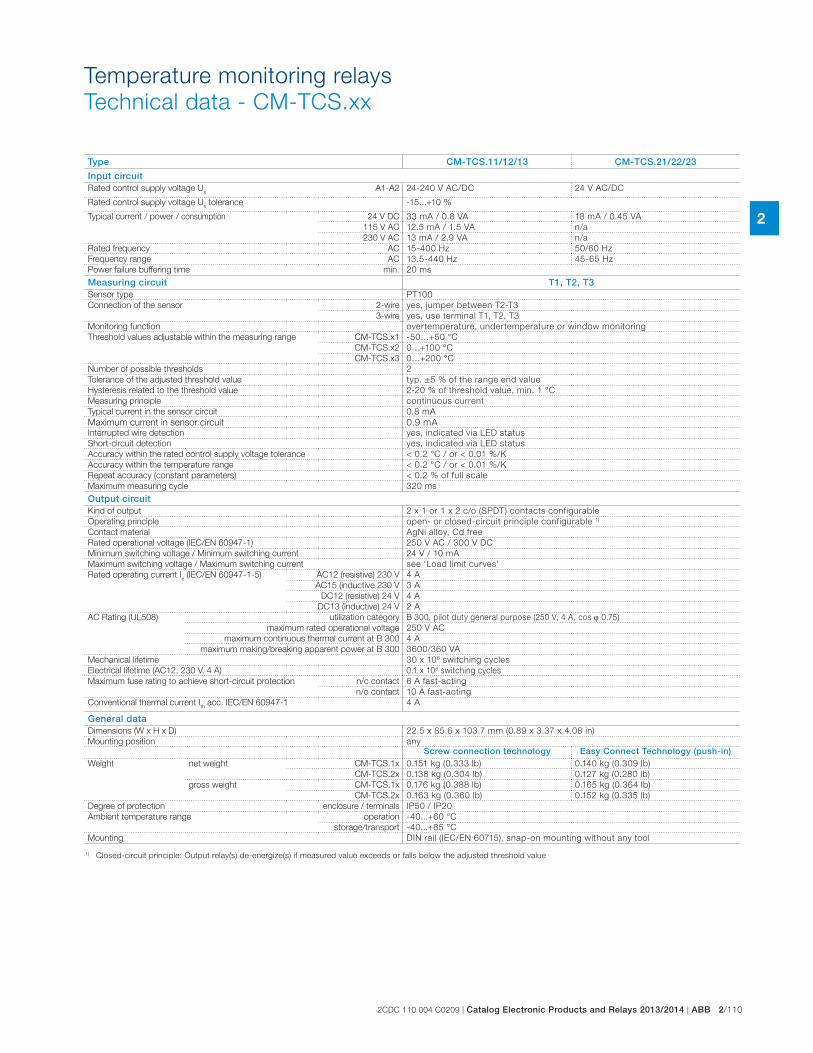
2CDC 110 004 C0209 | Catalog Electronic Products and Relays 2013/2014 | ABB 2/110
2
Temperature monitoring relays
Technical data - CM-TCS.xx
Type CM-TCS.11/12/13 CM-TCS.21/22/23
Input circuitRated control supply voltage U
sA1-A2 24-240 V AC/DC 24 V AC/DC
Rated control supply voltage Us tolerance -15...+10 %
Typical current / power / consumption
24 V DC 33 mA / 0.8 VA 18 mA / 0.45 VA
115 V AC 12.5 mA / 1.5 VA n/a
230 V AC 13 mA / 2.9 VA n/a
Rated frequency AC 15-400 Hz 50/60 Hz
Frequency range AC 13.5-440 Hz 45-65 Hz
Power failure buffering time min. 20 ms
Measuring circuit T1, T2, T3Sensor type PT100
Connection of the sensor 2-wire yes, jumper between T2-T3
3-wire yes, use terminal T1, T2, T3
Monitoring function overtemperature, undertemperature or window monitoring
Threshold values adjustable within the measuring range CM-TCS.x1 -50…+50 °C
CM-TCS.x2 0…+100 °C
CM-TCS.x3 0…+200 °C
Number of possible thresholds 2
Tolerance of the adjusted threshold value typ. ±5 % of the range end value
Hysteresis related to the threshold value 2-20 % of threshold value, min. 1 °C
Measuring principle continuous current
Typical current in the sensor circuit 0.8 mA
Maximum current in sensor circuit 0.9 mAInterrupted wire detection yes, indicated via LED status
Short-circuit detection yes, indicated via LED status
Accuracy within the rated control supply voltage tolerance < 0.2 °C / or < 0.01 %/K
Accuracy within the temperature range < 0.2 °C / or < 0.01 %/K
Repeat accuracy (constant parameters) < 0.2 % of full scale
Maximum measuring cycle 320 ms
Output circuitKind of output 2 x 1 or 1 x 2 c/o (SPDT) contacts configurable
Operating principle open- or closed-circuit principle configurable 1)
Contact material AgNi alloy, Cd free
Rated operational voltage (IEC/EN 60947-1) 250 V AC / 300 V DC
Minimum switching voltage / Minimum switching current 24 V / 10 mA
Maximum switching voltage / Maximum switching current see ‘Load limit curves'
Rated operating current Ie (IEC/EN 60947-1-5) AC12 (resistive) 230 V 4 A
AC15 (inductive 230 V 3 A
DC12 (resistive) 24 V 4 A
DC13 (inductive) 24 V 2 A
AC Rating (UL508) utilization category B 300, pilot duty general purpose (250 V, 4 A, cos 0.75)
maximum rated operational voltage 250 V AC
maximum continuous thermal current at B 300 4 A
maximum making/breaking apparent power at B 300 3600/360 VA
Mechanical lifetime 30 x 106 switching cycles
Electrical lifetime (AC12, 230 V, 4 A) 0.1 x 10⁶ switching cycles
Maximum fuse rating to achieve short-circuit protection
n/c contact 6 A fast-acting
n/o contact 10 A fast-acting
Conventional thermal current Ith acc. IEC/EN 60947-1 4 A
General dataDimensions (W x H x D) 22.5 x 85.6 x 103.7 mm (0.89 x 3.37 x 4.08 in)
Mounting position any
Screw connection technology Easy Connect Technology (push-in)Weight net weight CM-TCS.1x 0.151 kg (0.333 lb) 0.140 kg (0.309 lb)
CM-TCS.2x 0.138 kg (0.304 lb) 0.127 kg (0.280 lb)
gross weight CM-TCS.1x 0.176 kg (0.388 lb) 0.165 kg (0.364 lb)
CM-TCS.2x 0.163 kg (0.360 lb) 0.152 kg (0.335 lb)
Degree of protection enclosure / terminals IP50 / IP20
Ambient temperature range operation -40...+60 °C
storage/transport -40...+85 °C
Mounting DIN rail (IEC/EN 60715), snap-on mounting without any tool
1) Closed-circuit principle: Output relay(s) de-energize(s) if measured value exceeds or falls below the adjusted threshold value

2/111 ABB | Catalog Electronic Products and Relays 2013/2014 | 2CDC 110 004 C0209
2
Temperature monitoring relays
Technical data - CM-TCS.xx
Type CM-TCS.11/12/13) CM-TCS.21/22/23
Electrical connectionWire size Screw connection technology Easy Connect Technology (Push-in)
fine-strand without wire end ferrule
A1, A2, 11, 12, 14, 21, 22, 24 1 x 0.5-2.5 mm² (1 x 20-14 AWG)2 x 0.5-1.5 mm² (2 x 20-16 AWG)
2 x 0.5-1.5 mm² (2 x 20-16 AWG)connection with lever
T1, T2, T3 1 x 0.2-2.5 mm² (1 x 24-14 AWG)2 x 0.2-1.5 mm² (2 x 24-16 AWG)
2 x 0.2-1.5 mm² (2 x 24-16 AWG)connection with lever
fine-strand with wire end ferrule
A1, A2, 11, 12, 14, 21, 22, 24 1 x 0.5-2.5 mm² (1 x 20-14 AWG)2 x 0.5-1.5 mm² (2 x 20-16 AWG)
2 x 0.5-1.5 mm² (2 x 20-16 AWG)connection: push-in
T1, T2, T3 1 x 0.2-2.5 mm² (1 x 24-14 AWG)2 x 0.2-1.5 mm² (2 x 24-16 AWG)
2 x 0.2-1.5 mm² (2 x 24-16 AWG)insulated ferrule (DIN 46228-4-E):connection: push-inferrule (DIN 46228-1-A):< 0.5 mm², connection with lever� 0.5 mm², connection: push-in
rigid A1, A2, 11, 12, 14, 21, 22, 24 1 x 0.5-4 mm² (1 x 20-12 AWG)2 x 0.5-2.5 mm² (2 x 20-14 AWG)
2 x 0.5-1.5 mm² (2 x 20-16 AWG)connection: push-in
T1, T2, T3 1 x 0.2-4 mm² (1 x 24-12 AWG)2 x 0.2-2.5 mm² (2 x 24-14 AWG)
2 x 0.2-1.5 mm² (2 x 24-16 AWG)< 0.5 mm², connection with lever� 0.5 mm², connection: push-in
Stripping length 8 mm (0.32 in)
Tightening torque < 0.5 mm² 0.5 Nm (4.43 lb.in) -
� 0.5 mm² 0.6 - 0.8 Nm (5.31 - 7.08 lb.in) -
StandardsProduct standard IEC/EN 60255-6: 2008
Other standards EN 50178, IEC/EN 60204
Low Voltage Directive 2006/95/EC
EMC Directive 2004/108/EC
RoHS Directive 2002/95/EC
Environmental dataAmbient temperature ranges operation/storage/ transport -40...+60°C/-40...+85°C/-40...+85°C
Climatic category 3K5 (no condensation, no ice formation)
Damp heat, cyclic 6 x 24 h cycle, 55 °C, 95 % RH
Vibration, sinusoidal Class 2
Shock Class 2
Isolation dataRated impulse withstand voltage U
imp between all
isolated circuits (IEC/EN 60947-1, IEC/EN 60664-1)
supply circuit / measuring circuit
4 kV -
supply circuit / output circuits 4 kV
measuring circuit / output circuits 4 kV
output circuit 1 / output circuit 2 4 kV
Pollution degree (IEC/EN 60664-1) 3
Overvoltage category (IEC/EN 60664-1) III
Rated insulation voltage Ui
(IEC/EN 60947-1, IEC/EN 60664-1)
supply circuit / measuring circuit 300 V -
supply circuit / output circuits 300 V
measuring circuit / output circuits 300 V
output circuit 1 / output circuit 2 300 V
Basis isolation for rated control supply voltage (IEC/EN 60664-1)
supply circuit / measuring circuit 250 V AC / 300 V DC -
supply circuit / output circuits 250 V AC / 300 V DC
measuring circuit / output circuits 250 V AC / 300 V DC
output circuit 1 / output circuit 2 250 V AC / 300 V DC
Protective separation (IEC/EN 61140, EN 50178) supply circuit / measuring circuit 250 V AC / 250 V DC -
supply circuit / output circuits 250 V AC / 300 V DC 250 V AC / 250 V DC
measuring circuit / output circuits 250 V AC / 300 V DC 250 V AC / 250 V DC
Test voltage between all isolated circuits, routine test (IEC/EN 60255-5, IEC/EN 61010-1)
supply circuit / measuring circuit 2.0 kV, 50 Hz, 1 s -
supply circuit / output circuits 2.0 kV, 50 Hz, 1 s
measuring circuit / output circuits 2.0 kV, 50 Hz, 1 s
Test voltage between all isolated circuits, type test (IEC/EN 60255-5)
supply circuit / measuring circuit 4.0 kV, 50 Hz, 1 s -
supply circuit / output circuits 4.0 kV, 50 Hz, 1 s
measuring circuit / output circuits 4.0 kV, 50 Hz, 1 s
Electromagnetic compatibilityInterference immunity to IEC/EN 61000-6-1, IEC/EN 61000-6-2, IEC/EN 61326-2-4
electrostatic discharge IEC/EN 61000-4-2 Level 3, 6 kV / 8 kV
radiated, radio-frequency, electromagnetic field IEC/EN 61000-4-3 Level 3, 10 V/m (1 GHz) / 3 V/m (2 GHz) / 1 V/m (2.7 GHz)
electrical fast transient/burst IEC/EN 61000-4-4 Level 3, 2 KV / 5 kHz
surge IEC/EN 61000-4-5 Level 3, installation class 3, supply circuit and measuring circuit 1 kV L-L, 2 kV L-earth
conducted disturbances, induced by radio-fre-quency fields
IEC/EN 61000-4-6 Level 3, 10 V
voltage dips, short interruptions and voltage variations
IEC/EN 61000-4-11 Class 3
harmonics and interharmonics IEC/EN 61000-4-13 Class 3
Interference emission EN 61000-6-3, EN 61000-6-4
high-frequency radiated IEC/CISPR 22, EN 55022 Class B
high-frequency conducted IEC/CISPR 22, EN 55022 Class B
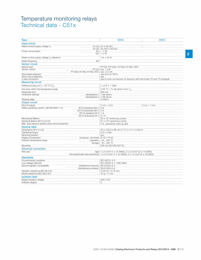
2CDC 110 004 C0209 | Catalog Electronic Products and Relays 2013/2014 | ABB 2/112
2
Temperature monitoring relays
Technical data - C51x
Type C512 C513
Input circuitRated control supply voltage U
sA1-A2 24 V AC/DC -
A1-A2 24-240 V AC/DC
Power consumption
AC < 7 VA
DC < 4 W
Rated control supply voltage US tolerance -15...+10 %
Rated frequency AC
Sensor circuitSensor type PT100, PT1000, KTY83, KTY84, NTC
Sensor current PT100 typ. 1 mA
PT1000, KTY83, KTY84, NTC typ. 0.2 mA
Wire-break detection yes (not for NTC)
Short-circuit detection yes
3-wire connection yes (2-wire connection of sensors with terminals T2 and T3 bridged)
Measuring circuit
Setting accuracy at Ta = 20 °C (T
20) < ±2 K ± 1 digit
Accuracy within the temperature range 0.05 °C / °C deviation from T20
Response time 500 ms
Hysteresis settings temperature 1 1-99 kelvin
temperature 2 1-99 kelvin
Tripping delay 0-999 s
Output circuitKind of output 2 c/o + 1n/o 2 c/o + 1 n/o
Rated operating current Ie (IEC/EN 60947-1-5)
AC12 (resistive) 230 V n/a
AC15 (inductive) 230 V 3 A
DC12 (resistive) 24 V 1 A
DC13 (inductive) 24 V 0.1 A
Mechanical lifetime 30 x 106 switching cycles
Electrical lifetime (AC15 at 3 A) 0.1 x 10⁵ switching cycles
Max. fuse rating to achieve short-circuit protection 4 A, operating class gL/gG
General dataDimensions (W x H x D) 45 x 105.9 x 86 mm (1.77 x 4.17 x 3.39 in)
Tightening torque 0.8-1.2 Nm
Mounting position any
Degree of protection enclosure / terminals IP 40 / IP 20
Ambient temperature range operation -25...+60 °C
storage -40...+80 °C
Mounting DIN rail (IEC/EN 60715)
Electrical connectionWire size rigid 1 x 4 mm² (1 x 12 AWG), 2 x 2.5 mm² (2 x 14 AWG)
fine-strand with wire end ferrule 1 x 2.5 mm² (1 x 14 AWG), 2 x 1.5 mm² (2 x 16 AWG)
StandardsEnvironmental conditions IEC 60721-3-3
Low Voltage Directive IEC 60947-5-1, VDE 0660
Electromagnetic compatibility Interference immunity EN 61000-6-2
Interferenece emission EN 61000-6-4
Vibration resistance (IEC 68-2-6) 5-26 Hz / 0.75 mm
Shock resistance (IEC 68-2-27) 15 g / 11 ms
Isolation dataRated insulation voltage 300 V AC
Pollution degree 3
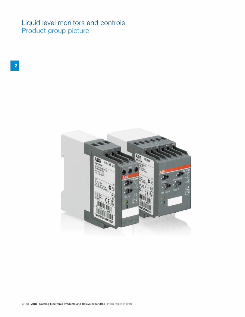
2/113 ABB | Catalog Electronic Products and Relays 2013/2014 | 2CDC 110 004 C0209
2
Liquid level monitors and controls
Product group picture
2CDC 110 004 C0209 | Catalog Electronic Products and Relays 2013/2014 | ABB 2/114
2
Liquid level monitors and controls
Table of contents
Liquid level monitors and controls
Product group picture 111
Table of contents 112
Benefits and advantages 113
Operating controls 114
Ordering details 115
Ordering details - Accessories 116
Function diagrams 117
Connection diagrams 119
Application examples 120
Application examples 121
Technical data 122
2/115 ABB | Catalog Electronic Products and Relays 2013/2014 | 2CDC 110 004 C0209
2
Liquid level monitors and controls
Benefits and advantages
� Monitoring of pump systems for dry running (ENE MIN) and overflow (ENE MAX)
� Connection of 2 electrodes possible at C and MIN/MAX
� 3 supply voltage versions
� Optimal price/performance ratio
� 1 n/o contact: Open-circuit principle for CM-ENE MIN, Closed-circuit principle for CM-ENE MAX
� LED for status indication
� Monitoring and control of liquid levels (when draining or filling liquids in tanks)
� Monitoring and control of mixture ratios (conductivity of liquids)
� Adjustable response sensitivity 5-100 k� � 4 supply voltage versions 24 - 415 V AC
� Version with protective separation acc. to VDE 0160 J � Cascadable
� 1 c/o contact or 1 n/o and 1 n/c contact
� 2 LEDs for status indication
� Monitoring and control of liquid levels
� Selectable function "fill" or "drain"
� Adjustable response sensitivity 5-100 k� � Cascadable
� 1 c/o contact
� 2 LEDs for status indication
� Monitoring and control of liquid levels (when emptying or filling liquids in tanks)
� Monitoring and control of mixture ratios (conductivity of liquids)
� 3 response sensitivities from 250 � - 500 k� in one unit
� 5 supply voltage versions 24 V AC/DC - 415 V AC
� Selectable ON- or OFF-delay 0.1-10 s
� 2 c/o contacts
� 2 LEDs for status indication
CM-ENE MIN/MAX
CM-ENN
CM-ENN UP/DOWN
CM-ENS
CM-ENS UP/DOWN
� Liquid level relay with 5 electrode inputs
� Level control with integrated overflow and dry-running protection
� Adjustable response sensitivity 5-100 k� � Cascadable
� 1 c/o contact and 2 n/c contacts as alarm outputs
� 4 LEDs for status indication
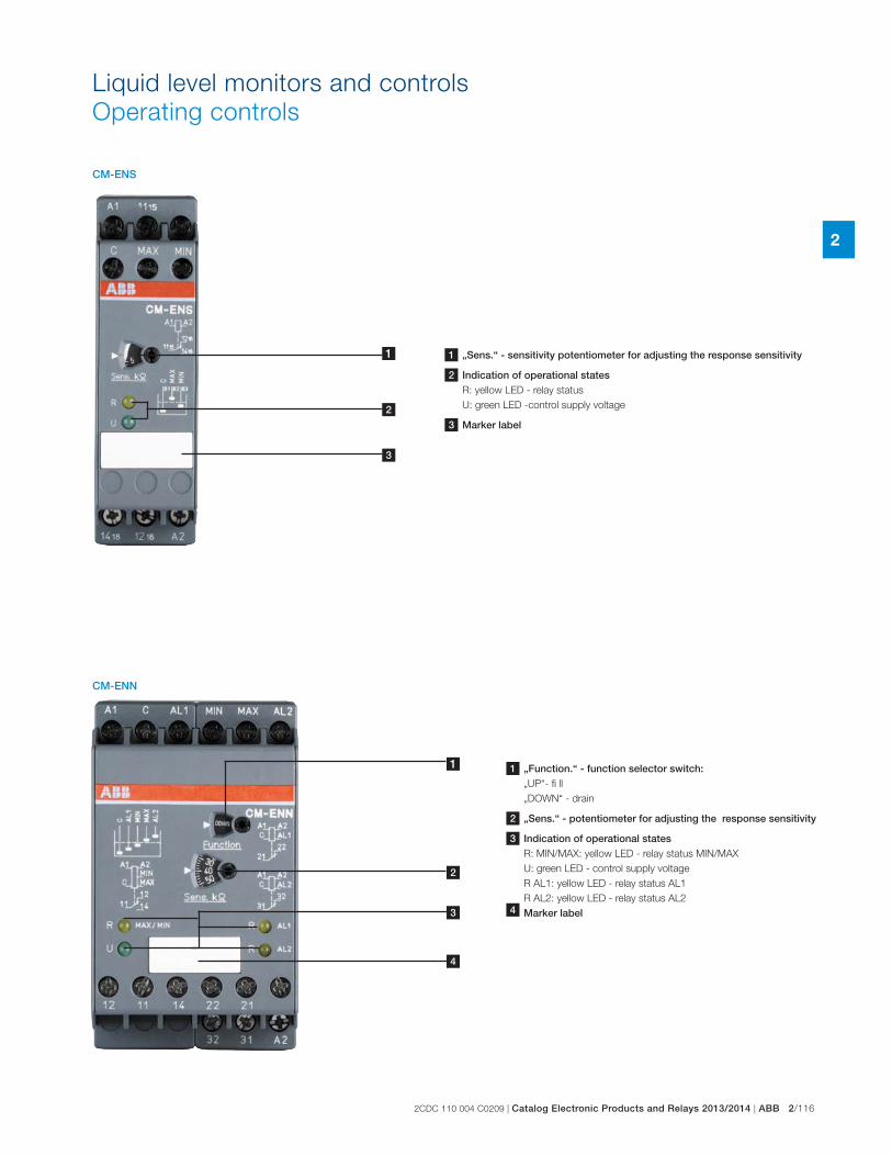
2CDC 110 004 C0209 | Catalog Electronic Products and Relays 2013/2014 | ABB 2/116
2
Liquid level monitors and controls
Operating controls
4
1
1
2
2
3
3
CM-ENS
CM-ENN
1 „Sens.“ - sensitivity potentiometer for adjusting the response sensitivity
2 Indication of operational statesR: yellow LED - relay status
U: green LED -control supply voltage
3 Marker label
1 „Function.“ - function selector switch:„UP“- fi ll
„DOWN“ - drain
2 „Sens.“ - potentiometer for adjusting the response sensitivity
3 Indication of operational statesR: MIN/MAX: yellow LED - relay status MIN/MAX
U: green LED - control supply voltage
R AL1: yellow LED - relay status AL1
R AL2: yellow LED - relay status AL2
4 Marker label
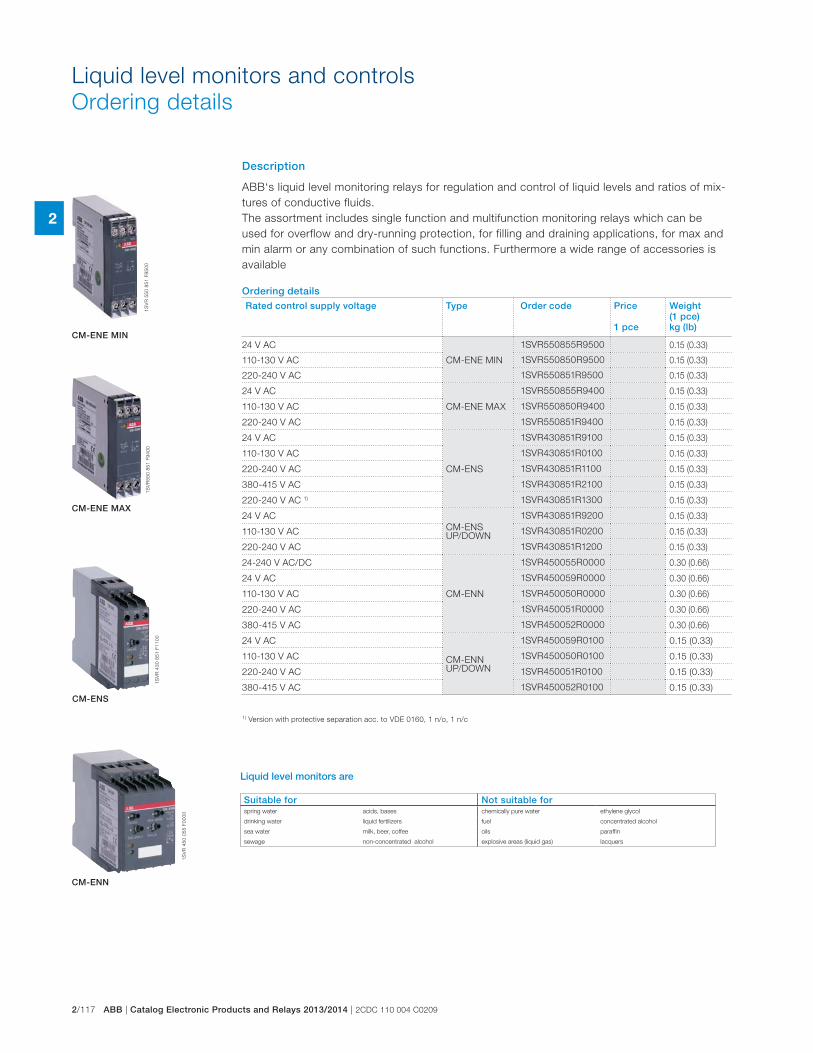
2/117 ABB | Catalog Electronic Products and Relays 2013/2014 | 2CDC 110 004 C0209
2
Liquid level monitors and controls
Ordering details
Description
ABB‘s liquid level monitoring relays for regulation and control of liquid levels and ratios of mix-
tures of conductive fluids.
The assortment includes single function and multifunction monitoring relays which can be
used for overflow and dry-running protection, for filling and draining applications, for max and
min alarm or any combination of such functions. Furthermore a wide range of accessories is
available
Ordering detailsRated control supply voltage Type Order code Price
1 pce
Weight(1 pce) kg (lb)
24 V AC
CM-ENE MIN
1SVR550855R9500 0.15 (0.33)
110-130 V AC 1SVR550850R9500 0.15 (0.33)
220-240 V AC 1SVR550851R9500 0.15 (0.33)
24 V AC
CM-ENE MAX
1SVR550855R9400 0.15 (0.33)
110-130 V AC 1SVR550850R9400 0.15 (0.33)
220-240 V AC 1SVR550851R9400 0.15 (0.33)
24 V AC
CM-ENS
1SVR430851R9100 0.15 (0.33)
110-130 V AC 1SVR430851R0100 0.15 (0.33)
220-240 V AC 1SVR430851R1100 0.15 (0.33)
380-415 V AC 1SVR430851R2100 0.15 (0.33)
220-240 V AC 1) 1SVR430851R1300 0.15 (0.33)
24 V AC
CM-ENS UP/DOWN
1SVR430851R9200 0.15 (0.33)
110-130 V AC 1SVR430851R0200 0.15 (0.33)
220-240 V AC 1SVR430851R1200 0.15 (0.33)
24-240 V AC/DC
CM-ENN
1SVR450055R0000 0.30 (0.66)
24 V AC 1SVR450059R0000 0.30 (0.66)
110-130 V AC 1SVR450050R0000 0.30 (0.66)
220-240 V AC 1SVR450051R0000 0.30 (0.66)
380-415 V AC 1SVR450052R0000 0.30 (0.66)
24 V AC
CM-ENN UP/DOWN
1SVR450059R0100 0.15 (0.33)
110-130 V AC 1SVR450050R0100 0.15 (0.33)
220-240 V AC 1SVR450051R0100 0.15 (0.33)
380-415 V AC 1SVR450052R0100 0.15 (0.33)
1S
VR
55
0 8
51
F9
50
01
SV
R5
50
85
1 F
94
00
1S
VR
43
0 8
51
F1
10
0
1S
VR
45
0 0
55
F0
00
0
CM-ENE MIN
CM-ENE MAX
CM-ENS
CM-ENN
1) Version with protective separation acc. to VDE 0160, 1 n/o, 1 n/c
Suitable for Not suitable forspring water acids, bases chemically pure water ethylene glycol
drinking water liquid fertilizers fuel concentrated alcohol
sea water milk, beer, coffee oils paraffin
sewage non-concentrated alcohol explosive areas (liquid gas) lacquers
Liquid level monitors are
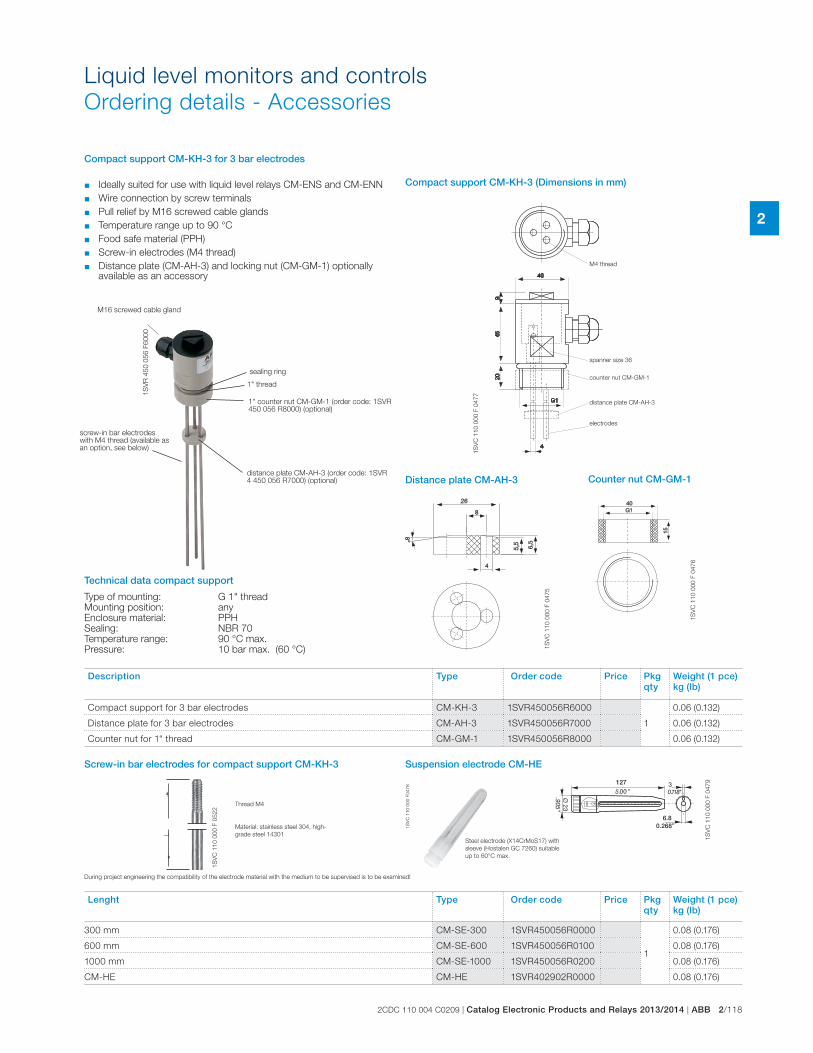
2CDC 110 004 C0209 | Catalog Electronic Products and Relays 2013/2014 | ABB 2/118
2
Liquid level monitors and controls
Ordering details - Accessories
127
6.80.2681
SV
C 1
10
00
0 F
04
78
1S
VR
45
0 0
56
F6
00
0
1S
VC
11
0 0
00
F 0
47
7
1S
VC
11
0 0
00
F 0
47
6
1S
VC
11
0 0
00
F 0
47
5
1S
VC
11
0 0
00
F 0
47
9
1S
VC
11
0 0
00
F 0
52
2
L
➛
➛
1" thread
Compact support CM-KH-3 for 3 bar electrodes
sealing ring
1" counter nut CM-GM-1 (order code: 1SVR 450 056 R8000) (optional)
distance plate CM-AH-3 (order code: 1SVR 4 450 056 R7000) (optional)
Suspension electrode CM-HE
Steel electrode (X14CrMoS17) with
sleeve (Hostalen GC 7260) suitable
up to 60°C max.
M16 screwed cable gland
screw-in bar electrodes with M4 thread (available as an option, see below)
� Ideally suited for use with liquid level relays CM-ENS and CM-ENN
� Wire connection by screw terminals
� Pull relief by M16 screwed cable glands
� Temperature range up to 90 °C
� Food safe material (PPH)
� Screw-in electrodes (M4 thread)
� Distance plate (CM-AH-3) and locking nut (CM-GM-1) optionally available as an accessory
spanner size 36
electrodes
distance plate CM-AH-3
counter nut CM-GM-1
M4 thread
Compact support CM-KH-3 (Dimensions in mm)
Counter nut CM-GM-1Distance plate CM-AH-3
Technical data compact support
Type of mounting: G 1" thread Mounting position: any Enclosure material: PPH Sealing: NBR 70 Temperature range: 90 °C max. Pressure: 10 bar max. (60 °C)
Screw-in bar electrodes for compact support CM-KH-3
Thread M4
Material: stainless steel 304, high-
grade steel 14301
During project engineering the compatibility of the electrode material with the medium to be supervised is to be examined!
Description Type Order code Price Pkg qty
Weight (1 pce) kg (lb)
Compact support for 3 bar electrodes CM-KH-3 1SVR450056R6000
1
0.06 (0.132)
Distance plate for 3 bar electrodes CM-AH-3 1SVR450056R7000 0.06 (0.132)
Counter nut for 1“ thread CM-GM-1 1SVR450056R8000 0.06 (0.132)
Lenght Type Order code Price Pkg qty
Weight (1 pce) kg (lb)
300 mm CM-SE-300 1SVR450056R0000
1
0.08 (0.176)
600 mm CM-SE-600 1SVR450056R0100 0.08 (0.176)
1000 mm CM-SE-1000 1SVR450056R0200 0.08 (0.176)
CM-HE CM-HE 1SVR402902R0000 0.08 (0.176)
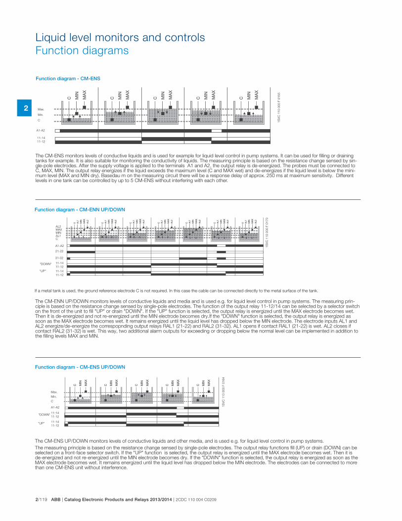
2/119 ABB | Catalog Electronic Products and Relays 2013/2014 | 2CDC 110 004 C0209
2
Liquid level monitors and controls
Function diagrams
1S
VC
11
0 0
00
F 0
16
4
"DOWN"
"UP"
11-14
11-12
Max.
Min.
C
11-14
11-12
A1-A2
Function diagram - CM-ENS UP/DOWN
If a metal tank is used, the ground reference electrode C is not required. In this case the cable can be connected directly to the metal surface of the tank.
1S
VC
11
0 0
00
F 0
17
0
AL2MAXMINAL1C
21-22
31-32
11-14
11-12
11-14
11-12
"DOWN"
"UP"
A1-A2
Function diagram - CM-ENN UP/DOWN
The CM-ENS monitors levels of conductive liquids and is used for example for liquid level control in pump systems. It can be used for filling or draining tanks for example. It is also suitable for monitoring the conductivity of liquids. The measuring principle is based on the resistance change sensed by sin-gle-pole electrodes. After the supply voltage is applied to the terminals A1 and A2, the output relay is de-energized. The probes must be connected to C, MAX, MIN. The output relay energizes if the liquid exceeds the maximum level (C and MAX wet) and de-energizes if the liquid level is below the mini-mum level (MAX and MIN dry). Basedau m on the measuring circuit there will be a response delay of approx. 250 ms at maximum sensitivity. Different levels in one tank can be controlled by up to 5 CM-ENS without interfering with each other.
1S
VC
11
0 0
00
F 0
15
5
Max.
Min.
C
11-14
11-12
A1-A2
Function diagram - CM-ENS
The CM-ENS UP/DOWN monitors levels of conductive liquids and other media, and is used e.g. for liquid level control in pump systems.
The measuring principle is based on the resistance change sensed by single-pole electrodes. The output relay functions fill (UP) or drain (DOWN) can be selected on a front-face selector switch. If the "UP" function is selected, the output relay is energized until the MAX electrode becomes wet. Then it is de-energized and not re-energized until the MIN electrode becomes dry. If the "DOWN" function is selected, the output relay is energized as soon as the MAX electrode becomes wet. It remains energized until the liquid level has dropped below the MIN electrode. The electrodes can be connected to more than one CM-ENS unit without interference.
The CM-ENN UP/DOWN monitors levels of conductive liquids and media and is used e.g. for liquid level control in pump systems. The measuring prin-ciple is based on the resistance change sensed by single-pole electrodes. The function of the output relay 11-12/14 can be selected by a selector switch on the front of the unit to fill "UP" or drain "DOWN". If the "UP" function is selected, the output relay is energized until the MAX electrode becomes wet. Then it is de-energized and not re-energized until the MIN electrode becomes dry.If the "DOWN" function is selected, the output relay is energized as soon as the MAX electrode becomes wet. It remains energized until the liquid level has dropped below the MIN electrode. The electrode inputs AL1 and AL2 energize/de-energize the correspopnding output relays RAL1 (21-22) and RAL2 (31-32). AL1 opens if contact RAL1 (21-22) is wet. AL2 closes if contact RAL2 (31-32) is wet. This way, two additional alarm outputs for exceeding or dropping below the normal level can be implemented in addition to the filling levels MAX and MIN.
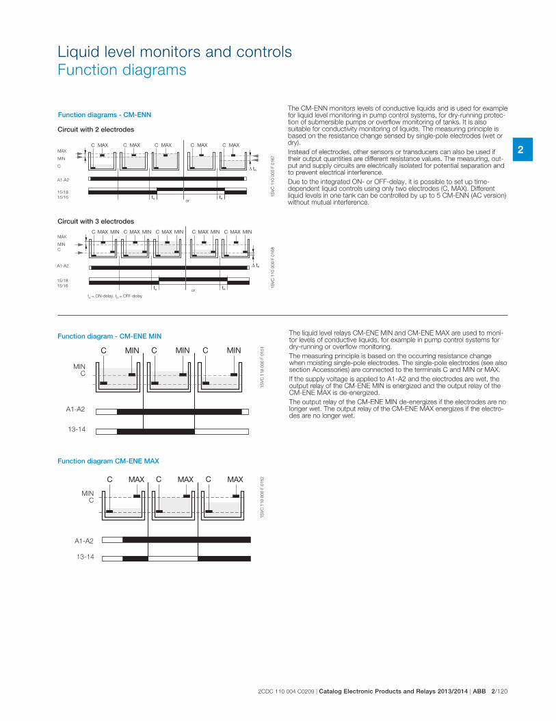
2CDC 110 004 C0209 | Catalog Electronic Products and Relays 2013/2014 | ABB 2/120
2
Liquid level monitors and controls
Function diagrams
1S
VC
11
0 0
00
F 0
15
11
SV
C 1
10
00
0 F
01
52
Function diagram - CM-ENE MIN
A1-A2
13-14
MIN C
Function diagram CM-ENE MAX
A1-A2
13-14
MIN C
1S
VC
11
0 0
00
F 0
16
71
SV
C 1
10
00
0 F
01
68
MAX
MIN
C
Circuit with 2 electrodes
tA = ON-delay, t
R = OFF-delay
Circuit with 3 electrodes
or
or
15/18
15/16
A1-A2
MAX
MIN
C
15/18
15/16
A1-A2
Function diagrams - CM-ENN
The liquid level relays CM-ENE MIN and CM-ENE MAX are used to moni-tor levels of conductive liquids, for example in pump control systems for dry-running or overflow monitoring.
The measuring principle is based on the occurring resistance change when moisting single-pole electrodes. The single-pole electrodes (see also section Accessories) are connected to the terminals C and MIN or MAX.
If the supply voltage is applied to A1-A2 and the electrodes are wet, the output relay of the CM-ENE MIN is energized and the output relay of the CM-ENE MAX is de-energized.
The output relay of the CM-ENE MIN de-energizes if the electrodes are no longer wet. The output relay of the CM-ENE MAX energizes if the electro-des are no longer wet.
The CM-ENN monitors levels of conductive liquids and is used for example for liquid level monitoring in pump control systems, for dry-running protec-tion of submersible pumps or overflow monitoring of tanks. It is also suitable for conductivity monitoring of liquids. The measuring principle is based on the resistance change sensed by single-pole electrodes (wet or dry).
Instead of electrodes, other sensors or transducers can also be used if their output quantities are different resistance values. The measuring, out-put and supply circuits are electrically isolated for potential separation and to prevent electrical interference.
Due to the integrated ON- or OFF-delay, it is possible to set up time-dependent liquid controls using only two electrodes (C, MAX). Different liquid levels in one tank can be controlled by up to 5 CM-ENN (AC version) without mutual interference.
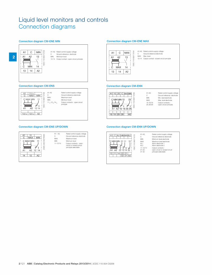
2/121 ABB | Catalog Electronic Products and Relays 2013/2014 | 2CDC 110 004 C0209
2
Liquid level monitors and controls
Connection diagrams
1S
VC
11
0 0
00
F 0
15
8
Connection diagram CM-ENS
1214 A2
C
A1
MAX
11
MIN
MIN 11MAXC
A2A1 12 14
2C
DC
25
2 0
42
F0
00
3 A1 - A2 Rated control supply voltage
C Ground reference electrode
MAX Maximum level
MIN Minimum level
11-12/14 Output contacts - open-
circuit or closed-circuit
principle selectable
Connection diagram CM-ENS UP/DOWN
1S
VC
11
0 0
00
F 0
16
9 A1-A2 Rated control supply voltage
C Ground reference electrode
MIN Min. level electrode
MAX Max. level electrode
15-16/18 Output contacts -
25-26/28 open-circuit principle
Connection diagram CM-ENN
1S
VC
11
0 0
00
F 0
15
3
1S
VC
11
0 0
00
F 0
15
4
A1-A2 Rated control supply voltage
C Ground reference electrode
MIN Minimum level
13-14 Output contact -open-circuit principle
A1-A2 Rated control supply voltage
C Ground reference electrode
MAX Max. level
13-14 Output contact -closed-circuit principle
Connection diagram CM-ENE MIN Connection diagram CM-ENE MAX
A1-A2 Rated control supply voltage
C Ground reference electrode
MAX Maximum level
MIN Minimum level
1115
-1216
/1418
Output contacts - open-circuit
principle
1S
VC
11
0 0
00
F 0
17
2 A1-A2 Rated control supply voltage
C Ground reference electrode
MIN Minimum level electrode
MAX Maximum level electrode
AL1 Alarm electrode 1
AL2 Alarm electrode 2
11-12/14 Output contacts -
21-22 open-circuit or closed-circuit
31-32 principle selectable
Connection diagram CM-ENN UP/DOWN
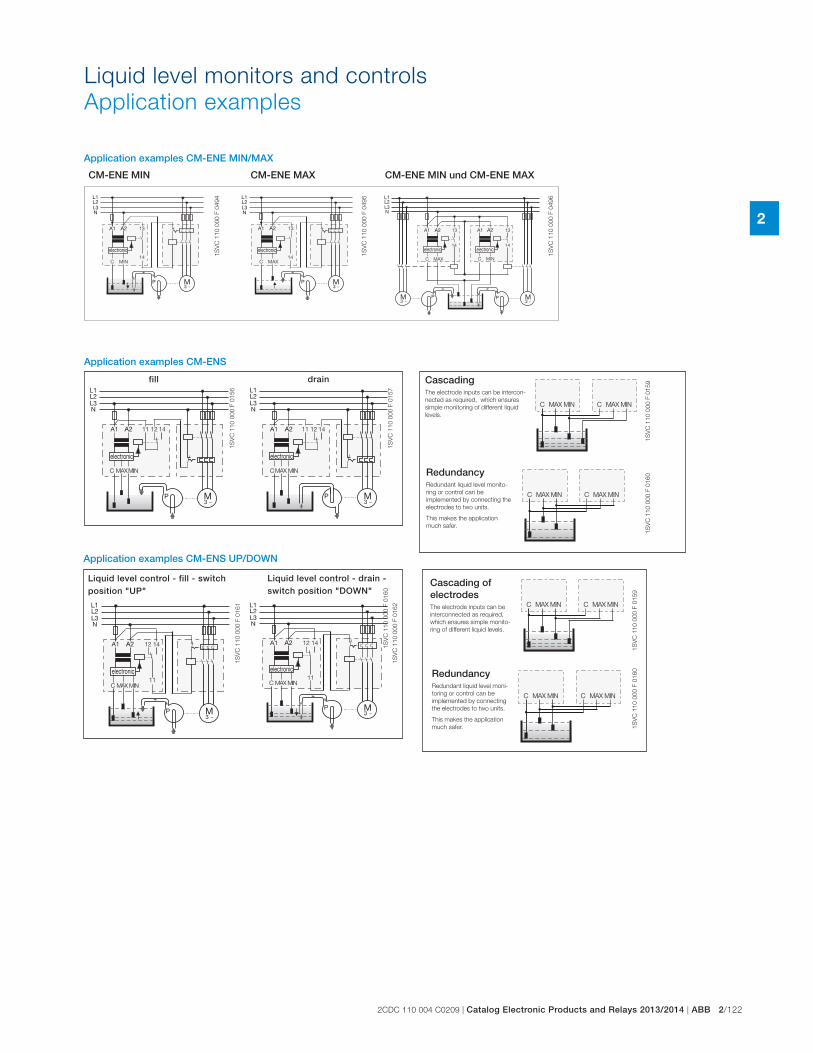
2CDC 110 004 C0209 | Catalog Electronic Products and Relays 2013/2014 | ABB 2/122
21
SV
C 1
10
00
0 F
04
94
1S
VC
11
0 0
00
F 0
49
5
1S
VC
11
0 0
00
F 0
49
6
Application examples CM-ENE MIN/MAX
CM-ENE MIN CM-ENE MAX CM-ENE MIN und CM-ENE MAX
Liquid level monitors and controls
Application examples
1S
VC
11
0 0
00
F 0
15
91
SV
C 1
10
00
0 F
01
60
1S
VC
11
0 0
00
F 0
15
6
1S
VC
11
0 0
00
F 0
15
7
CascadingThe electrode inputs can be intercon-
nected as required, which ensures
simple monitoring of different liquid
levels.
RedundancyRedundant liquid level monito-
ring or control can be
implemented by connecting the
electrodes to two units.
This makes the application
much safer.
Application examples CM-ENS
fill drain
1S
VC
11
0 0
00
F 0
15
91
SV
C 1
10
00
0 F
01
60
1S
VC
11
0 0
00
F 0
16
0
1S
VC
11
0 0
00
F 0
16
1
1S
VC
11
0 0
00
F 0
16
2
Liquid level control - fill - switch position "UP"
Liquid level control - drain - switch position "DOWN"
Application examples CM-ENS UP/DOWN
Cascading of electrodesThe electrode inputs can be
interconnected as required,
which ensures simple monito-
ring of different liquid levels.
RedundancyRedundant liquid level moni-
toring or control can be
implemented by connecting
the electrodes to two units.
This makes the application
much safer.
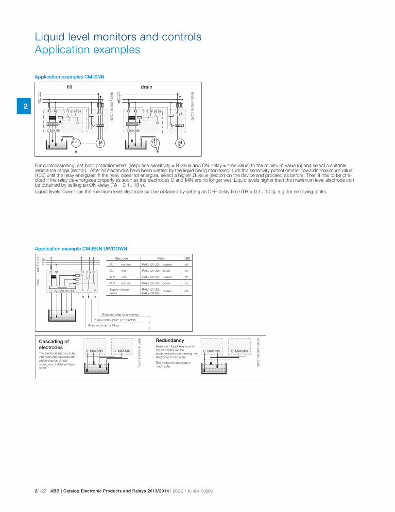
2/123 ABB | Catalog Electronic Products and Relays 2013/2014 | 2CDC 110 004 C0209
2
Liquid level monitors and controls
Application examples
1S
VC
11
0 0
00
F 0
16
5
1S
VC
11
0 0
00
F 0
16
6
fill drain
Application examples CM-ENN
For commissioning, set both potentiometers (response sensitivity = R value and ON-delay = time value) to the minimum value (5) and select a suitable resistance range (sector). After all electrodes have been wetted by the liquid being monitored, turn the sensitivity potentiometer towards maximum value (100) until the relay energizes. If the relay does not energize, select a higher � value (sector) on the device and proceed as before. Then it has to be che-cked if the relay de-energizes properly as soon as the electrodes C and MIN are no longer wet. Liquid levels higher than the maximum level electrode can be obtained by setting an ON-delay (TA = 0.1...10 s).
Liquid levels lower than the minimum level electrode can be obtained by setting an OFF-delay time (TR = 0.1...10 s), e.g. for emptying tanks.
1S
VC
11
0 0
00
F 0
15
9
1S
VC
11
0 0
00
F 0
16
0
1S
VC
11
0 0
00
F 0
17
1
Application example CM-ENN UP/DOWN
Cascading of electrodesThe electrode inputs can be
interconnected as required,
which ensures simple
monitoring of different liquid
levels.
RedundancyRedundant liquid level monito-
ring or control can be
implemented by connecting the
electrodes to two units.
This makes the application
much safer.
Electrode Relay LED
AL1 not wet RAL1 (21-22) closed off
AL1 wet RAL1 (21-22) open on
AL2 wet RAL2 (31-32) closed off
AL2 not wet RAL2 (31-32) open on
Supply voltage RAL1 (21-22)
failure RAL2 (31-32) closed off
Reserve pump for emptying
Pump control ("UP" or "DOWN")
Reserve pump for filling
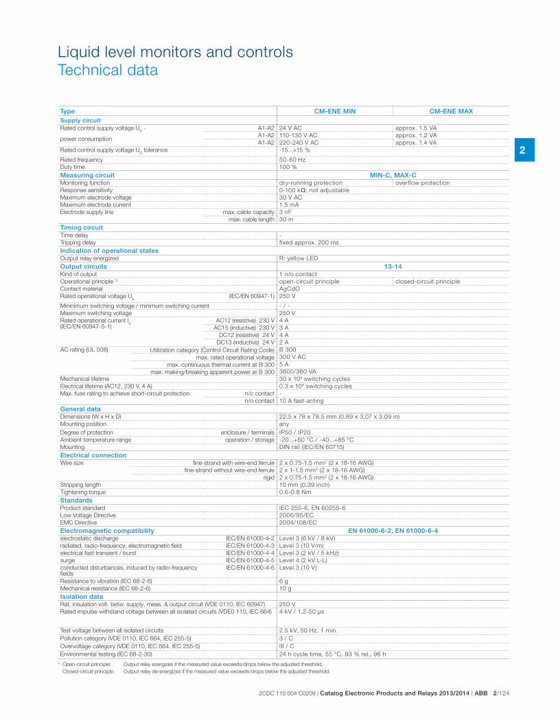
2CDC 110 004 C0209 | Catalog Electronic Products and Relays 2013/2014 | ABB 2/124
2
Liquid level monitors and controls
Technical data
Type CM-ENE MIN CM-ENE MAXSupply circuitRated control supply voltage U
S -
power consumption
A1-A2 24 V AC approx. 1.5 VA
A1-A2 110-130 V AC approx. 1.2 VA
A1-A2 220-240 V AC approx. 1.4 VA
Rated control supply voltage US tolerance -15...+15 %
Rated frequency 50-60 Hz
Duty time 100 %
Measuring circuit MIN-C, MAX-CMonitoring function dry-running protection overflow protection
Response sensitivity 0-100 k�, not adjustable
Maximum electrode voltage 30 V AC
Maximum electrode current 1.5 mA
Electrode supply line max. cable capacity 3 nF
max. cable length 30 m
Timing circuitTime delay -
Tripping delay fixed approx. 200 ms
Indication of operational statesOutput relay energized R: yellow LED
Output circuits 13-14Kind of output 1 n/o contact
Operational principle 1) open-circuit principle closed-circuit principle
Contact material AgCdO
Rated operational voltage Ue (IEC/EN 60947-1) 250 V
Mininimum switching voltage / minimum switching current - / -
Maximum switching voltage 250 V
Rated operational current Ie
(IEC/EN 60947-5-1)AC12 (resistive) 230 V 4 A
AC15 (inductive) 230 V 3 A
DC12 (resistive) 24 V 4 A
DC13 (inductive) 24 V 2 A
AC rating (UL 508) Utilization category (Control Circuit Rating Code) B 300
max. rated operational voltage 300 V AC
max. continuous thermal current at B 300 5 A
max. making/breaking apparent power at B 300 3600/360 VA
Mechanical lifetime 30 x 106 switching cycles
Electrical lifetime (AC12, 230 V, 4 A) 0.3 x 10⁶ switching cycles
Max. fuse rating to achieve short-circuit protection n/c contact -
n/o contact 10 A fast-acting
General dataDimensions (W x H x D) 22.5 x 78 x 78.5 mm (0.89 x 3.07 x 3.09 in)
Mounting position any
Degree of protection enclosure / terminals IP50 / IP20
Ambient temperature range operation / storage -20...+60 °C / -40...+85 °C
Mounting DIN rail (IEC/EN 60715)
Electrical connectionWire size fine-strand with wire-end ferrule 2 x 0.75-1.5 mm2 (2 x 18-16 AWG)
fine-strand without wire-end ferrule 2 x 1-1.5 mm2 (2 x 18-16 AWG)
rigid 2 x 0.75-1.5 mm2 (2 x 18-16 AWG)
Stripping length 10 mm (0.39 inch)
Tightening torque 0.6-0.8 Nm
StandardsProduct standard IEC 255-6, EN 60255-6
Low Voltage Directive 2006/95/EC
EMC Directive 2004/108/EC
Electromagnetic compatibility EN 61000-6-2, EN 61000-6-4electrostatic discharge IEC/EN 61000-4-2 Level 3 (6 kV / 8 kV)
radiated, radio-frequency, electromagnetic field IEC/EN 61000-4-3 Level 3 (10 V/m)
electrical fast transient / burst IEC/EN 61000-4-4 Level 3 (2 kV / 5 kHz)
surge IEC/EN 61000-4-5 Level 4 (2 kV L-L)
conducted disturbances, induced by radio-frequency fields
IEC/EN 61000-4-6 Level 3 (10 V)
Resistance to vibration (IEC 68-2-6) 6 g
Mechanical resistance (IEC 68-2-6) 10 g
Isolation dataRat. insulation volt. betw. supply, meas. & output circuit (VDE 0110, IEC 60947) 250 V
Rated impulse withstand voltage between all isolated circuits (VDE0 110, IEC 664) 4 kV / 1.2-50 μs
Test voltage between all isolated circuits 2.5 kV, 50 Hz, 1 min.
Pollution category (VDE 0110, IEC 664, IEC 255-5) 3 / C
Overvoltage category (VDE 0110, IEC 664, IEC 255-5) III / C
Environmental testing (IEC 68-2-30) 24 h cycle time, 55 °C, 93 % rel., 96 h
1) Open-circuit principle: Output relay energizes if the measured value exceeds/drops below the adjusted threshold.
Closed-circuit principle: Output relay de-energizes if the measured value exceeds/drops below the adjusted threshold.
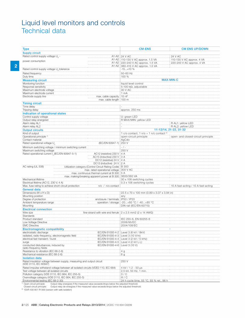
2/125 ABB | Catalog Electronic Products and Relays 2013/2014 | 2CDC 110 004 C0209
2
Liquid level monitors and controls
Technical data
Type CM-ENS CM ENS UP/DOWNSupply circuitRated control supply voltage U
S -
power consumption
A1-A2 24 V AC 24 V AC
A1-A2 110-130 V AC approx. 1.5 VA 110-130 V AC approx. 4 VA
A1-A2 220-240 V AC approx. 1.5 VA 220-240 V AC approx. 4 VA
A1-A2 380-415 V AC approx. 1.5 VA
Rated control supply voltage US tolerance -15...+10 %
Rated frequency 50-60 Hz
Duty time 100 %
Measuring circuit MAX-MIN-CMonitoring function liquid level control
Response sensitivity 5-100 k , adjustable
Maximum electrode voltage 30 V AC
Maximum electrode current 1 mA
Electrode supply line max. cable capacity 10 nF
max. cable length 100 m
Timing circuitTime delay -
Tripping delay approx. 250 ms
Indication of operational statesControl supply voltage U: green LED
Output relay energized R MAX/MIN: yellow LED
Alarm relay AL1 - R AL1: yellow LED
Alarm relay AL2 - R AL2: yellow LED
Output circuits 11-12/14, 21-22, 31-32Kind of output 1 c/o contact, 1 n/o + 1 n/c contact 2)
Operational principle 1) open-circuit principle open- and closed-circuit principle
Contact material AgCdo
Rated operational voltage Ue (IEC/EN 60947-1) 250 V
Minimum switching voltage / minimum switching current - / -
Maximum switching voltage 250 V
Rated operational current Ie (IEC/EN 60947-5-1) AC12 (resistive) 230 V 4 A
AC15 (inductive) 230 V 3 A
DC12 (resistive) 24 V 4 A
DC13 (inductive) 24 V 2 A
AC rating (UL 508) Utilization category (Control Circuit Rating Code) B 300
max. rated operational voltage 300 V AC
max. continuous thermal current at B 300 5 A
max. making/breaking apparent power at B 300 3600/360 VA
Mechanical lifetime 30 x 106 switching cycles
Electrical lifetime (AC12, 230 V, 4 A) 0.3 x 10⁶ switching cycles
Max. fuse rating to achieve short-circuit protection n/c / n/o contact 10 A fast-acting / 10 A fast-acting
General dataDimensions (W x H x D) 22.5 x 70 x 100 mm (0.89 x 3.07 x 3.94 in)
Mounting position any
Degree of protection enclosure / terminals IP50 / IP20
Ambient temperature range operation / storage -20...+60 °C / -40...+85 °C
Mounting DIN rail (IEC/EN 60715)
Electrical connectionWire size fine-strand with wire end ferrule 2 x 2.5 mm2 (2 x 14 AWG)
Standards
Product standard IEC 255-6, EN 60255-6
Low Voltage Directive 2006/95/EC
EMC Directive 2004/108/EC
Electromagnetic compatibility -electrostatic discharge IEC/EN 61000-4-2 Level 3 (6 kV / 8kV)
radiated, radio-frequency, electromagnetic field IEC/EN 61000-4-3 Level 3 (10 V/m)
electrical fast transient / burst IEC/EN 61000-4-4 Level 3 (2 kV / 5 kHz)
surge IEC/EN 61000-4-5 Level 4 (2 kV L-L)
conducted disturbances, induced by radio-frequency fields
IEC/EN 61000-4-6 Level 3 (10 V)
Resistance to vibration (IEC 68-2-6) 4 g
Mechanical resistance (IEC 68-2-6) 6 g
Isolation dataRated insulation voltage between supply, measuring and output circuit (VDE 0110, IEC 60947)
250 V
Rated impulse withstand voltage between all isolated circuits (VDE0 110, IEC 664) 4 kV / 1.2 - 50 μs
Test voltage between all isolated circuits 2,5 kV, 50 Hz, 1 min.
Pollution category (VDE 0110, IEC 664, IEC 255-5) 3 / C
Overvoltage category (VDE 0110, IEC 664, IEC 255-5) III / C
Environmental testing (IEC 68-2-30) 24 h cycle time, 55 °C, 93 % rel., 96 h1) Open-circuit principle: Output relay energizes if the measured value exceeds/drops below the adjusted threshold.
Closed-circuit principle: Output relay de-energizes if the measured value exceeds/drops below the adjusted threshold. 2) 1SVR 430 851 R1300 (version with safe isolation)
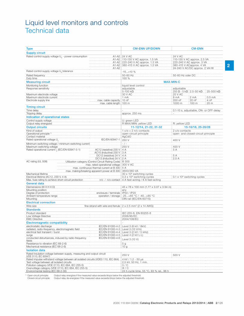
2CDC 110 004 C0209 | Catalog Electronic Products and Relays 2013/2014 | ABB 2/126
2
Type CM-ENN UP/DOWN CM-ENN
Supply circuitRated control supply voltage U
S - power consumption A1-A2 24 V AC 24 V AC
A1-A2 110-130 V AC approx. 1.5 VA 110-130 V AC approx. 2.5 VA
A1-A2 220-240 V AC approx. 1.5 VA 220-240 V AC approx. 3 VA
A1-A2 380-415 V AC approx. 1.5 VA 380-415 V ACapprox. 4 VA
A1-A2 24-240 V AC/DC approx. 2 VA/W
Rated control supply voltage US tolerance -15...+10 %
Rated frequency 50-60 Hz 50-60 Hz oder DC
Duty time 100 %
Measuring circuit MAX-MIN-CMonitoring function liquid level control
Response sensitivity adjustable adjustable
5-100 k� 250 � - 5 k� 2.5-50 k� 25-500 k�Maximum electrode voltage 30 V AC 20 V AC
Maximum electrode current 1 mA 8 mA 2 mA 0.5 mA
Electrode supply line max. cable capacity 10 nF 200 nF 20 nF 4 nF
max. cable length 100 m 1000 m 100 m 20 m
Timing circuitTime delay - 0.1-10 s, adjustable, ON- or OFF-delay
Tripping delay approx. 250 ms -
Indication of operational statesControl supply voltage U: green LED
Output relay energized R MAX/MIN: yellow LED R: yellow LED
Output circuits 11-12/14, 21-22, 31-32 15-16/18, 25-26/28Kind of output 1 c/o + 2 n/c contacts 2 c/o contacts
Operational principle 1) open-circuit principle open- and closed-circuit principle
Contact material AgCdO
Rated operational voltage Ue IEC/EN 60947-1 250 V 400 V
Minimum switching voltage / minimum switching current - / -
Maximum switching voltage 250 V 400 V
Rated operational current Ie (IEC/EN 60947-5-1) AC12 (resistive) 230 V 4 A 5 A
AC15 (inductive) 230 V 3 A
DC12 (resistive) 24 V 4 A 5 A
DC13 (inductive) 24 V 2 A 2.5 A
AC rating (UL 508) Utilization category (Control Circuit Rating Code) B 300
max. rated operational voltage 300 V AC
max. continuous thermal current at B 300 5 A
max. making/breaking apparent power at B 300 3600/360 VA
Mechanical lifetime 30 x 106 switching cycles
Electrical lifetime (AC12, 230 V, 4 A) 0.3 x 10⁶ switching cycles 0.1 x 10⁶ switching cycles
Max. fuse rating to achieve short-circuit protection n/c / n/o contact 4 A fast-acting / 6 A fast-acting
General dataDiemensions (W X H X D) 45 x 78 x 100 mm (1.77 x 3.07 x 3.94 in)
Mounting position any
Degree of protection enclosure / terminals IP50 / IP20
Ambient temperature range operation / storage -25...+65 °C / -40...+85 °C
Mounting DIN rail (IEC/EN 60715)
Electrical connectionWire size fine-strand with wire end ferrule 2 x 2.5 mm2 (2 x 14 AWG)
StandardsProduct standard IEC 255-6, EN 60255-6
Low Voltage Directive 2006/95/EC
EMC Directive 2004/108/EC
Electromagnetic compatibility -
electrostatic discharge IEC/EN 61000-4-2 Level 3 (6 kV / 8kV)
radiated, radio-frequency, electromagnetic field IEC/EN 61000-4-3 Level 3 (10 V/m)
electrical fast transient / burst IEC/EN 61000-4-4 Level 3 (2 kV / 5 kHz)
surge IEC/EN 61000-4-5 Level 4 (2 kV L-L)
conducted disturbances, induced by radio-frequency fields
IEC/EN 61000-4-6Level 3 (10 V)
Resistance to vibration (IEC 68-2-6) 5 g
Mechanical resistance (IEC 68-2-6) 10 g
Isolation dataRated insulation voltage between supply, measuring and output circuit (VDE 0110, IEC 60947)
250 V 500 V
Rated impulse withstand voltage between all isolated circuits (VDE0 110, IEC 664) 4 kV / 1.2 - 50 μs
Test voltage between all isolated circuits 2,5 kV, 50 Hz, 1 min.
Pollution category (VDE 0110, IEC 664, IEC 255-5) 3 / C
Overvoltage category (VDE 0110, IEC 664, IEC 255-5) III / C
Environmental testing (IEC 68-2-30) 24 h cycle time, 55 °C, 93 % rel., 96 h
1) Open-circuit principle: Output relay energizes if the measured value exceeds/drops below the adjusted threshold.
Closed-circuit principle: Output relay de-energizes if the measured value exceeds/drops below the adjusted threshold.
Liquid level monitors and controls
Technical data
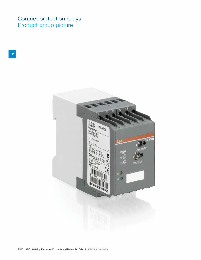
2/127 ABB | Catalog Electronic Products and Relays 2013/2014 | 2CDC 110 004 C0209
2
Contact protection relays
Product group picture
2CDC 110 004 C0209 | Catalog Electronic Products and Relays 2013/2014 | ABB 2/128
2
Contact protection relays
Table of contents
Contact protection relays
Product group picture 125
Table of contents 126
Benefits, advantages and operating controls 127
Ordering details 128
Technical information 129
Technical data 130
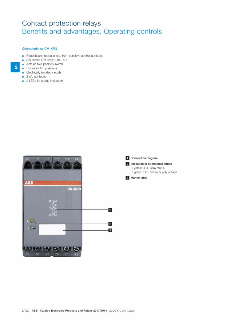
2/129 ABB | Catalog Electronic Products and Relays 2013/2014 | 2CDC 110 004 C0209
2
Contact protection relays
Benefits and advantages, Operating controls
Characteristics CM-KRN
� Protects and reduces load from sensitive control contacts
� Adjustable ON-delay 0.05-30 s
� Acts as two-position switch
� Stores switch positions
� Electrically isolated circuits
� 2 c/o contacts
� 2 LEDs for status indication
1 Connection diagram
2 Indication of operational statesR: yellow LED - relay status
U: green LED - control supply voltage
3 Marker label
1
2
3
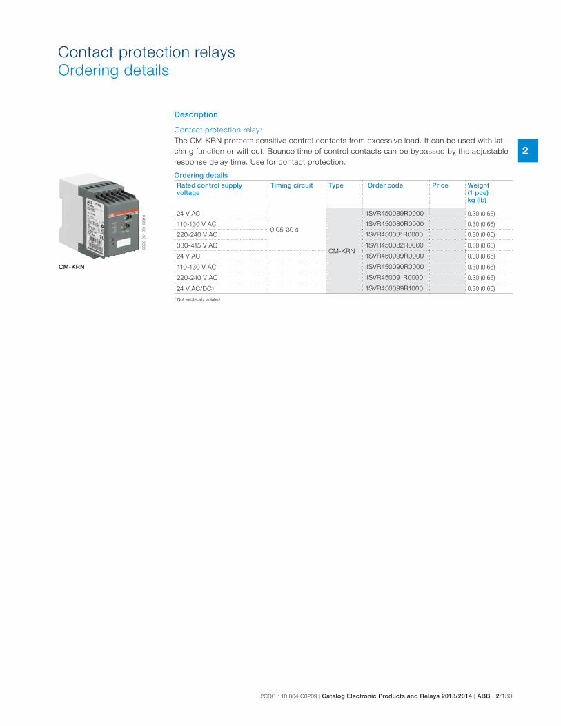
2CDC 110 004 C0209 | Catalog Electronic Products and Relays 2013/2014 | ABB 2/130
2
Description
Contact protection relay:
The CM-KRN protects sensitive control contacts from excessive load. It can be used with lat-
ching function or without. Bounce time of control contacts can be bypassed by the adjustable
response delay time. Use for contact protection.
Ordering detailsRated control supply voltage
Timing circuit Type Order code Price Weight(1 pce) kg (lb)
24 V AC
0.05-30 s
CM-KRN
1SVR450089R0000 0.30 (0.66)
110-130 V AC 1SVR450080R0000 0.30 (0.66)
220-240 V AC 1SVR450081R0000 0.30 (0.66)
380-415 V AC 1SVR450082R0000 0.30 (0.66)
24 V AC 1SVR450099R0000 0.30 (0.66)
110-130 V AC 1SVR450090R0000 0.30 (0.66)
220-240 V AC 1SVR450091R0000 0.30 (0.66)
24 V AC/DC1) 1SVR450099R1000 0.30 (0.66)
2C
DC
25
1 0
01
S0
01
3
CM-KRN
Contact protection relays
Ordering details
1) Not electrically isolated
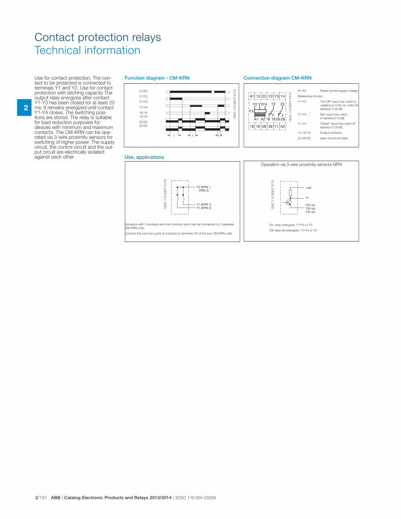
2/131 ABB | Catalog Electronic Products and Relays 2013/2014 | 2CDC 110 004 C0209
2
Contact protection relays
Technical information
1S
VC
11
0 0
00
F 0
17
3
1S
VC
11
0 0
00
F 0
17
4
1S
VC
11
0 0
00
F 0
17
6
1S
VC
11
0 0
00
F 0
17
5
Function diagram - CM-KRN
Use, applications
A1-A2 Rated control supply voltage
Measuring circuits:
Y1-Y2 "On-Off" input (max. switch-on
resistance 6-10 k�, min. switch-off
resistance 15-20 k�)
Y1-Y3 " Set" input (max. switch-
on resistance 6-10 k�)
Y1-Y4 "Reset" input (max. switch-off
resistance 15-20 k�)
15-16/18 Output contacts -
25-26/28 open-circuit principle
A1/A2
Y1/Y2
Y1/Y3
Y1/Y4
15/18
15/16
25/28
25/26
Operation via 3-wire proximity sensors NPN
On; relay energizes, Y1/Y3 or Y2
Off; relay de-energizes, Y1/Y4 or Y2
Actuators with 2 contacts and one common point can be connected to 2 separate
CM-KRN units.
Connect the common point of contacts to terminals Y2 of the two CM-KRN units.
Connection diagram CM-KRNUse for contact protection. The con-tact to be protected is connected to terminals Y1 and Y2. Use for contact protection with latching capacity The output relay energizes after contact Y1-Y3 has been closed for at least 20 ms. It remains energized until contact Y1-Y4 closes. The switching posi-tions are stored. The relay is suitable for load reduction purposes for devices with minimum and maximum contacts. The CM-KRN can be ope-rated via 3-wire proximity sensors for switching of higher power. The supply circuit, the control circuit and the out-put circuit are electrically isolated against each other
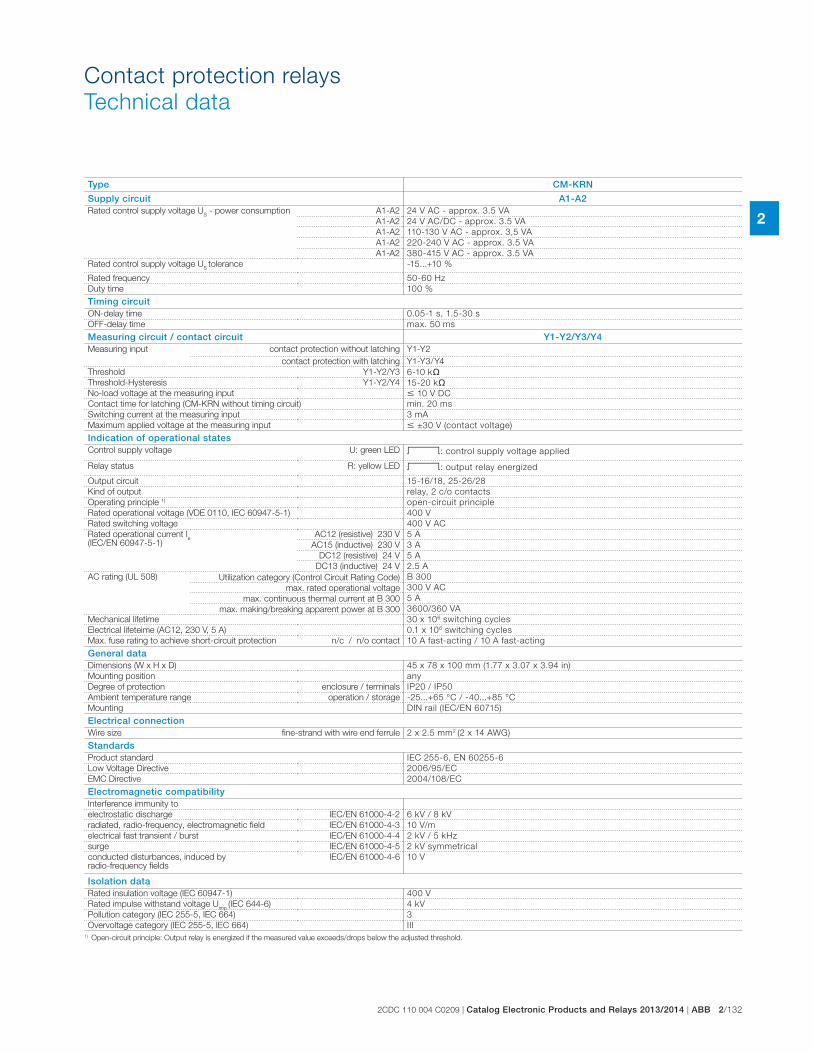
2CDC 110 004 C0209 | Catalog Electronic Products and Relays 2013/2014 | ABB 2/132
2
Type CM-KRN
Supply circuit A1-A2Rated control supply voltage U
S - power consumption A1-A2 24 V AC - approx. 3.5 VA
A1-A2 24 V AC/DC - approx. 3.5 VA
A1-A2 110-130 V AC - approx. 3,5 VA
A1-A2 220-240 V AC - approx. 3.5 VA
A1-A2 380-415 V AC - approx. 3.5 VA
Rated control supply voltage US tolerance -15...+10 %
Rated frequency 50-60 Hz
Duty time 100 %
Timing circuitON-delay time 0.05-1 s, 1.5-30 s
OFF-delay time max. 50 ms
Measuring circuit / contact circuit Y1-Y2/Y3/Y4Measuring input contact protection without latching Y1-Y2
contact protection with latching Y1-Y3/Y4
Threshold Y1-Y2/Y3 6-10 k�Threshold-Hysteresis Y1-Y2/Y4 15-20 k�No-load voltage at the measuring input � 10 V DC
Contact time for latching (CM-KRN without timing circuit) min. 20 ms
Switching current at the measuring input 3 mA
Maximum applied voltage at the measuring input � ±30 V (contact voltage)
Indication of operational states Control supply voltage U: green LED V: control supply voltage applied
Relay status R: yellow LED V: output relay energized
Output circuit 15-16/18, 25-26/28
Kind of output relay, 2 c/o contacts
Operating principle 1) open-circuit principle
Rated operational voltage (VDE 0110, IEC 60947-5-1) 400 V
Rated switching voltage 400 V AC
Rated operational current Ie
(IEC/EN 60947-5-1)AC12 (resistive) 230 V 5 A
AC15 (inductive) 230 V 3 A
DC12 (resistive) 24 V 5 A
DC13 (inductive) 24 V 2.5 A
AC rating (UL 508) Utilization category (Control Circuit Rating Code) B 300
max. rated operational voltage 300 V AC
max. continuous thermal current at B 300 5 A
max. making/breaking apparent power at B 300 3600/360 VA
Mechanical lifetime 30 x 106 switching cycles
Electrical lifeteime (AC12, 230 V, 5 A) 0.1 x 10⁶ switching cycles
Max. fuse rating to achieve short-circuit protection n/c / n/o contact 10 A fast-acting / 10 A fast-acting
General dataDimensions (W x H x D) 45 x 78 x 100 mm (1.77 x 3.07 x 3.94 in)
Mounting position any
Degree of protection enclosure / terminals IP20 / IP50
Ambient temperature range operation / storage -25...+65 °C / -40...+85 °C
Mounting DIN rail (IEC/EN 60715)
Electrical connectionWire size fine-strand with wire end ferrule 2 x 2.5 mm2 (2 x 14 AWG)
StandardsProduct standard IEC 255-6, EN 60255-6
Low Voltage Directive 2006/95/EC
EMC Directive 2004/108/EC
Electromagnetic compatibilityInterference immunity to
electrostatic discharge IEC/EN 61000-4-2 6 kV / 8 kV
radiated, radio-frequency, electromagnetic field IEC/EN 61000-4-3 10 V/m
electrical fast transient / burst IEC/EN 61000-4-4 2 kV / 5 kHz
surge IEC/EN 61000-4-5 2 kV symmetrical
conducted disturbances, induced by radio-frequency fields
IEC/EN 61000-4-6 10 V
Isolation dataRated insulation voltage (IEC 60947-1) 400 V
Rated impulse withstand voltage Uimp
(IEC 644-6) 4 kV
Pollution category (IEC 255-5, IEC 664) 3
Overvoltage category (IEC 255-5, IEC 664) III1) Open-circuit principle: Output relay is energized if the measured value exceeds/drops below the adjusted threshold.
Contact protection relays
Technical data
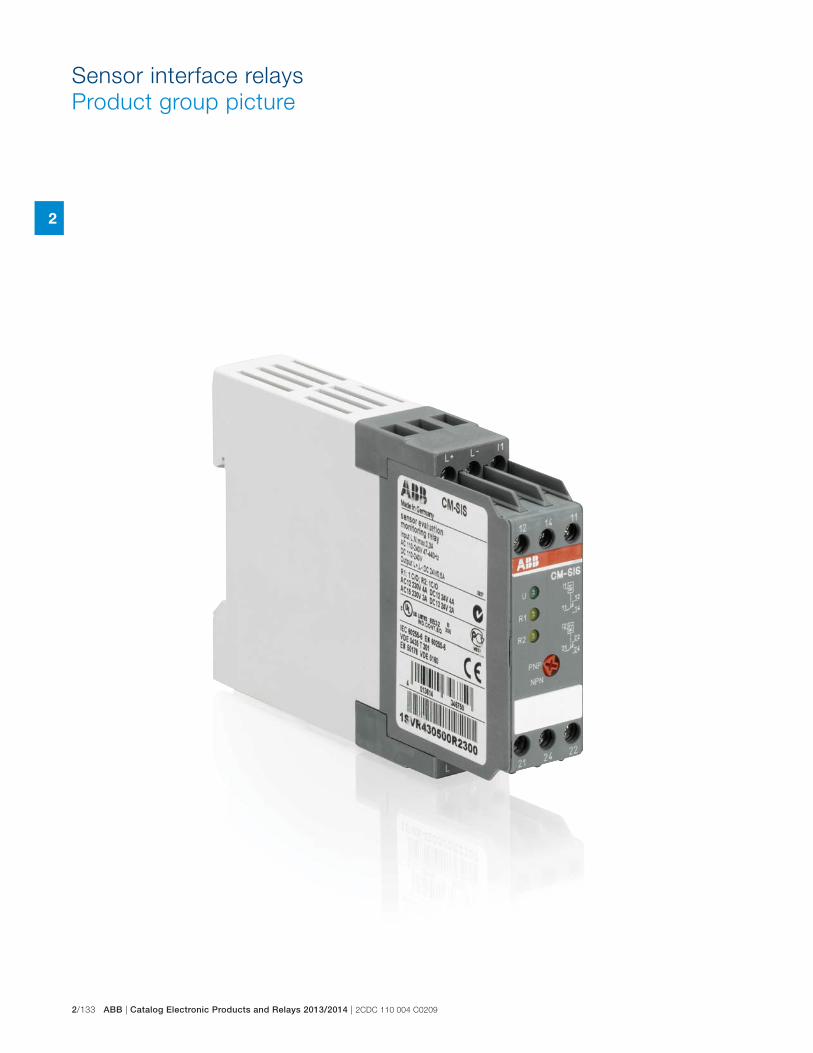
2/133 ABB | Catalog Electronic Products and Relays 2013/2014 | 2CDC 110 004 C0209
2
Sensor interface relays
Product group picture
2CDC 110 004 C0209 | Catalog Electronic Products and Relays 2013/2014 | ABB 2/134
2
Sensor interface relays
Table of contents
Sensor interface relays
Product group picture 131
Table of contents 132
Benefits, advantages and operating controls 133
Ordering details 134
Technical information 135
Technical data 136
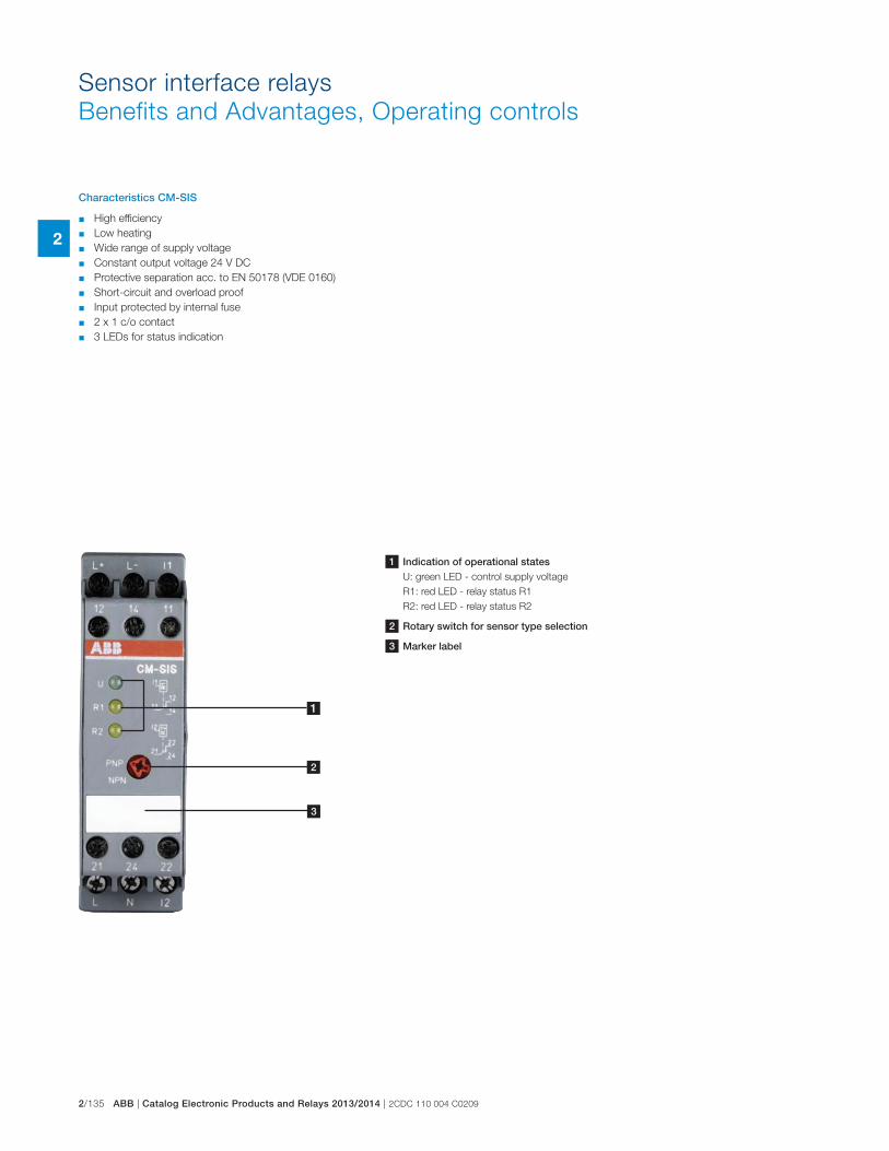
2/135 ABB | Catalog Electronic Products and Relays 2013/2014 | 2CDC 110 004 C0209
2
Sensor interface relays
Benefits and Advantages, Operating controls
1 Indication of operational statesU: green LED - control supply voltage
R1: red LED - relay status R1
R2: red LED - relay status R2
2 Rotary switch for sensor type selection
3 Marker label
1
2
3
Characteristics CM-SIS
� High efficiency
� Low heating
� Wide range of supply voltage
� Constant output voltage 24 V DC
� Protective separation acc. to EN 50178 (VDE 0160)
� Short-circuit and overload proof
� Input protected by internal fuse
� 2 x 1 c/o contact
� 3 LEDs for status indication
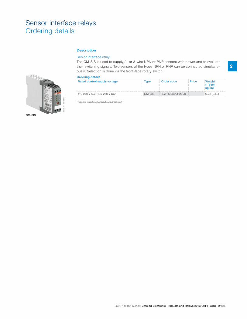
2CDC 110 004 C0209 | Catalog Electronic Products and Relays 2013/2014 | ABB 2/136
2
Description
Senior interface relay:
The CM-SIS is used to supply 2- or 3-wire NPN or PNP sensors with power and to evaluate
their switching signals. Two sensors of the types NPN or PNP can be connected simultane-
ously. Selection is done via the front-face rotary switch.
Ordering detailsRated control supply voltage Type Order code Price Weight
(1 pce) kg (lb)
110-240 V AC / 105-260 V DC1) CM-SIS 1SVR430500R2300 0.22 (0.48)
2C
DC
25
1 0
02
S0
01
3
CM-SIS
Sensor interface relays
Ordering details
1) Protective separation, short circuit and overload proof
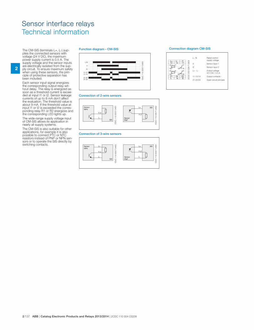
2/137 ABB | Catalog Electronic Products and Relays 2013/2014 | 2CDC 110 004 C0209
2
Sensor interface relays
Technical information
A1 I1
A2
A1 I2
A2
11
12 14
2422
21
1S
VC
11
0 0
00
F 0
48
0
2C
DC
25
2 0
26
F 0
00
3
1S
VC
11
0 0
00
F 0
48
2
1S
VC
11
0 0
00
F 0
48
11
SV
C 1
10
00
0 F
04
83
1S
VC
11
0 0
00
F 0
48
4
Function diagram - CM-SIS
L - N Rated control
supply voltage
I1 Sensor input 1
I2 Sensor input 2
L+ - L- Output voltage
24 V DC / 0.5 A
11-12/14 Output contacts -
21-22/24 Open-circuit principle
Connection of 2-wire sensors
Connection of 3-wire sensors
Connection diagram CM-SISThe CM-SIS (terminals L+, L-) sup-plies the connected sensors with voltage (24 V DC), the maximum power supply current is 0.5 A. The supply voltage and the sensor inputs are electrically isolated from the sup-ply circuit. To ensure maximum safety when using these sensors, the prin-ciple of protective separation has been included.
Each sensor input signal energizes the corresponding output relay wit-hout delay. The relay is energized as soon as a threshold current is excee-ded at input I1 or I2. Sensor leakage currents of up to 8 mA don`t affect the evaluation. The threshold value is about 9 mA. If the threshold value at input I1 or I2 is exceeded the corres-ponding relay R1 or R2 energizes and the corresponding LED lights up.
The wide-range supply voltage input of CM-SIS allows its application in nearly all supply systems.
The CM-SIS is also suitable for other applications, for example it is also possible to connect PTC or NTC resistors instead of PNP or NPN sen-sors or to operate the SIS directly by switching contacts.
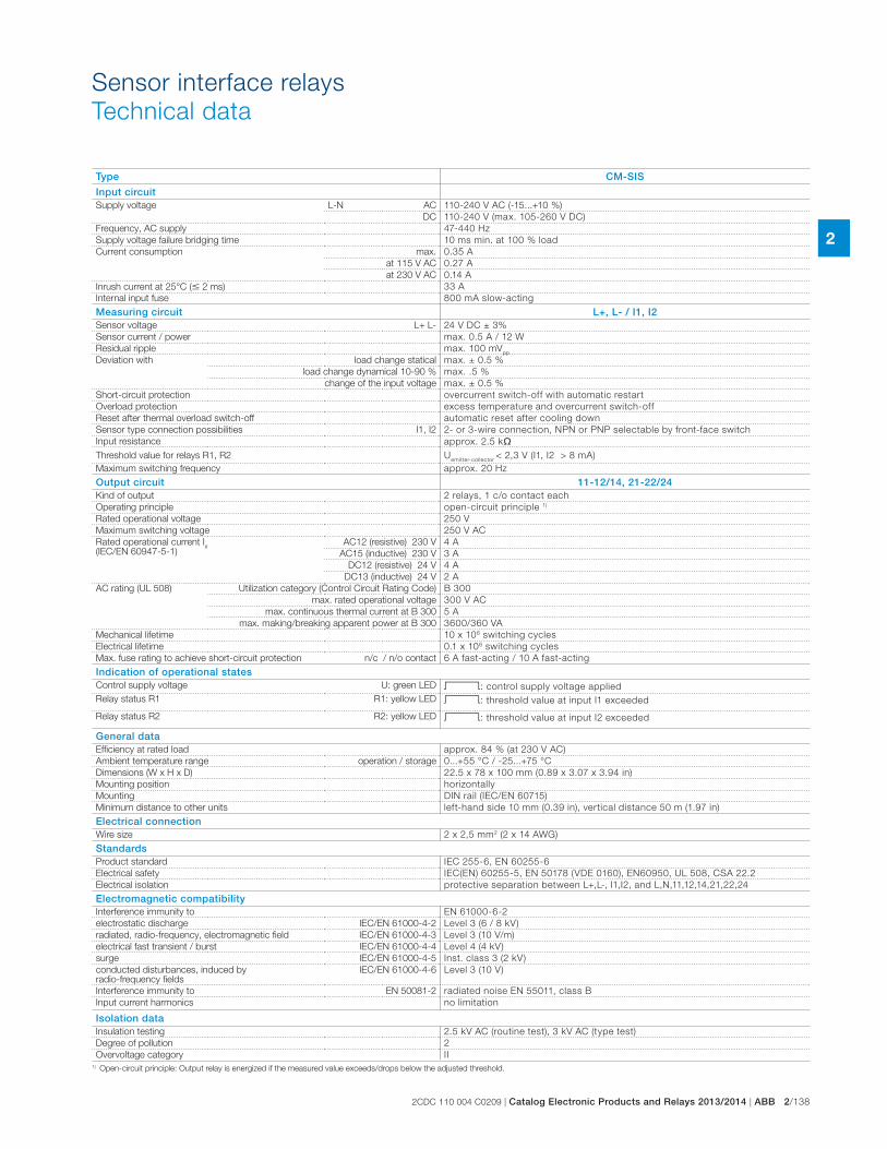
2CDC 110 004 C0209 | Catalog Electronic Products and Relays 2013/2014 | ABB 2/138
2
Sensor interface relays
Technical data
Type CM-SIS
Input circuitSupply voltage L-N AC 110-240 V AC (-15...+10 %)
DC 110-240 V (max. 105-260 V DC)
Frequency, AC supply 47-440 Hz
Supply voltage failure bridging time 10 ms min. at 100 % load
Current consumption max. 0.35 A
at 115 V AC 0.27 A
at 230 V AC 0.14 A
Inrush current at 25°C (� 2 ms) 33 A
Internal input fuse 800 mA slow-acting
Measuring circuit L+, L- / I1, I2Sensor voltage L+ L- 24 V DC ± 3%
Sensor current / power max. 0.5 A / 12 W
Residual ripple max. 100 mVpp
Deviation with load change statical max. ± 0.5 %
load change dynamical 10-90 % max. .5 %
change of the input voltage max. ± 0.5 %
Short-circuit protection overcurrent switch-off with automatic restart
Overload protection excess temperature and overcurrent switch-off
Reset after thermal overload switch-off automatic reset after cooling down
Sensor type connection possibilities I1, I2 2- or 3-wire connection, NPN or PNP selectable by front-face switch
Input resistance approx. 2.5 k�
Threshold value for relays R1, R2 Uemitter-collector
< 2,3 V (I1, I2 > 8 mA)
Maximum switching frequency approx. 20 Hz
Output circuit 11-12/14, 21-22/24Kind of output 2 relays, 1 c/o contact each
Operating principle open-circuit principle 1)
Rated operational voltage 250 V
Maximum switching voltage 250 V AC
Rated operational current Ie
(IEC/EN 60947-5-1)AC12 (resistive) 230 V 4 A
AC15 (inductive) 230 V 3 A
DC12 (resistive) 24 V 4 A
DC13 (inductive) 24 V 2 A
AC rating (UL 508) Utilization category (Control Circuit Rating Code) B 300
max. rated operational voltage 300 V AC
max. continuous thermal current at B 300 5 A
max. making/breaking apparent power at B 300 3600/360 VA
Mechanical lifetime 10 x 106 switching cycles
Electrical lifetime 0.1 x 10⁶ switching cycles
Max. fuse rating to achieve short-circuit protection n/c / n/o contact 6 A fast-acting / 10 A fast-acting
Indication of operational statesControl supply voltage U: green LED V: control supply voltage applied
Relay status R1 R1: yellow LED V: threshold value at input I1 exceeded
Relay status R2 R2: yellow LED V: threshold value at input I2 exceeded
General dataEfficiency at rated load approx. 84 % (at 230 V AC)
Ambient temperature range operation / storage 0...+55 °C / -25...+75 °C
Dimensions (W x H x D) 22.5 x 78 x 100 mm (0.89 x 3.07 x 3.94 in)
Mounting position horizontally
Mounting DIN rail (IEC/EN 60715)
Minimum distance to other units left-hand side 10 mm (0.39 in), vertical distance 50 m (1.97 in)
Electrical connectionWire size 2 x 2,5 mm2 (2 x 14 AWG)
StandardsProduct standard IEC 255-6, EN 60255-6
Electrical safety IEC(EN) 60255-5, EN 50178 (VDE 0160), EN60950, UL 508, CSA 22.2
Electrical isolation protective separation between L+,L-, I1,I2, and L,N,11,12,14,21,22,24
Electromagnetic compatibilityInterference immunity to EN 61000-6-2
electrostatic discharge IEC/EN 61000-4-2 Level 3 (6 / 8 kV)
radiated, radio-frequency, electromagnetic field IEC/EN 61000-4-3 Level 3 (10 V/m)
electrical fast transient / burst IEC/EN 61000-4-4 Level 4 (4 kV)
surge IEC/EN 61000-4-5 Inst. class 3 (2 kV)
conducted disturbances, induced by radio-frequency fields
IEC/EN 61000-4-6 Level 3 (10 V)
Interference immunity to EN 50081-2 radiated noise EN 55011, class B
Input current harmonics no limitation
Isolation dataInsulation testing 2.5 kV AC (routine test), 3 kV AC (type test)
Degree of pollution 2
Overvoltage category II1) Open-circuit principle: Output relay is energized if the measured value exceeds/drops below the adjusted threshold.
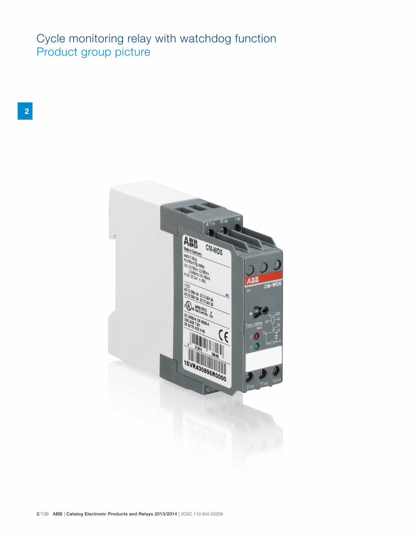
2/139 ABB | Catalog Electronic Products and Relays 2013/2014 | 2CDC 110 004 C0209
2
Cycle monitoring relay with watchdog function
Product group picture
2CDC 110 004 C0209 | Catalog Electronic Products and Relays 2013/2014 | ABB 2/140
2
Cycle monitoring relay with watchdog function
Table of contents
Cycle monitoring relay with watchdog function
Product group picture 137
Table of contents 138
Benefits, advantages and operating controls 139
Ordering details 140
Technical information 141
Technical data 142
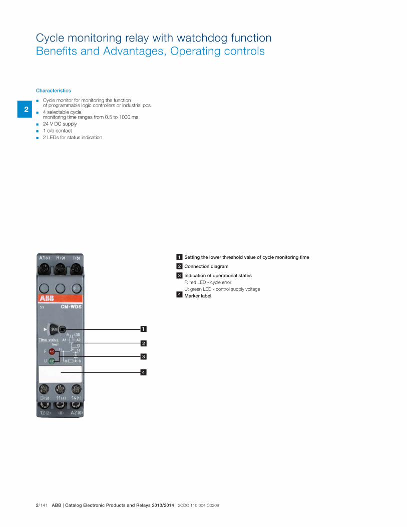
2/141 ABB | Catalog Electronic Products and Relays 2013/2014 | 2CDC 110 004 C0209
2
Cycle monitoring relay with watchdog function
Benefits and Advantages, Operating controls
Characteristics
� Cycle monitor for monitoring the function of programmable logic controllers or industrial pcs
� 4 selectable cycle monitoring time ranges from 0.5 to 1000 ms
� 24 V DC supply
� 1 c/o contact
� 2 LEDs for status indication
1 Setting the lower threshold value of cycle monitoring time
2 Connection diagram
3 Indication of operational statesF: red LED - cycle error
U: green LED - control supply voltage
4 Marker label
1
2
3
4
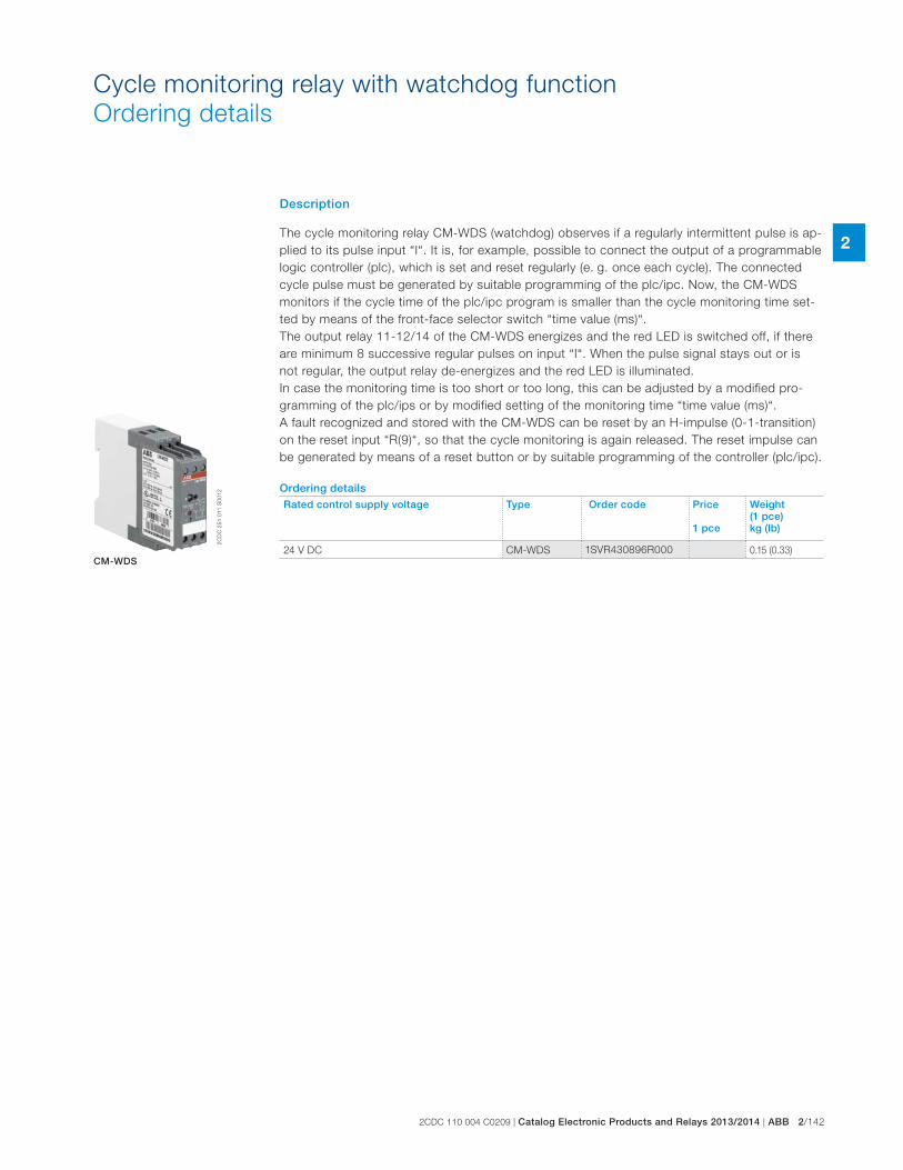
2CDC 110 004 C0209 | Catalog Electronic Products and Relays 2013/2014 | ABB 2/142
2
Cycle monitoring relay with watchdog function
Ordering details
The cycle monitoring relay CM-WDS (watchdog) observes if a regularly intermittent pulse is ap-
plied to its pulse input “I“. It is, for example, possible to connect the output of a programmable
logic controller (plc), which is set and reset regularly (e. g. once each cycle). The connected
cycle pulse must be generated by suitable programming of the plc/ipc. Now, the CM-WDS
monitors if the cycle time of the plc/ipc program is smaller than the cycle monitoring time set-
ted by means of the front-face selector switch “time value (ms)“.
The output relay 11-12/14 of the CM-WDS energizes and the red LED is switched off, if there
are minimum 8 successive regular pulses on input “I“. When the pulse signal stays out or is
not regular, the output relay de-energizes and the red LED is illuminated.
In case the monitoring time is too short or too long, this can be adjusted by a modified pro-
gramming of the plc/ips or by modified setting of the monitoring time “time value (ms)“.
A fault recognized and stored with the CM-WDS can be reset by an H-impulse (0-1-transition)
on the reset input “R(9)“, so that the cycle monitoring is again released. The reset impulse can
be generated by means of a reset button or by suitable programming of the controller (plc/ipc).
Ordering detailsRated control supply voltage Type Order code Price
1 pce
Weight(1 pce) kg (lb)
24 V DC CM-WDS 1SVR430896R000 0.15 (0.33)
2C
DC
25
1 0
11
S0
01
2
CM-WDS
Description
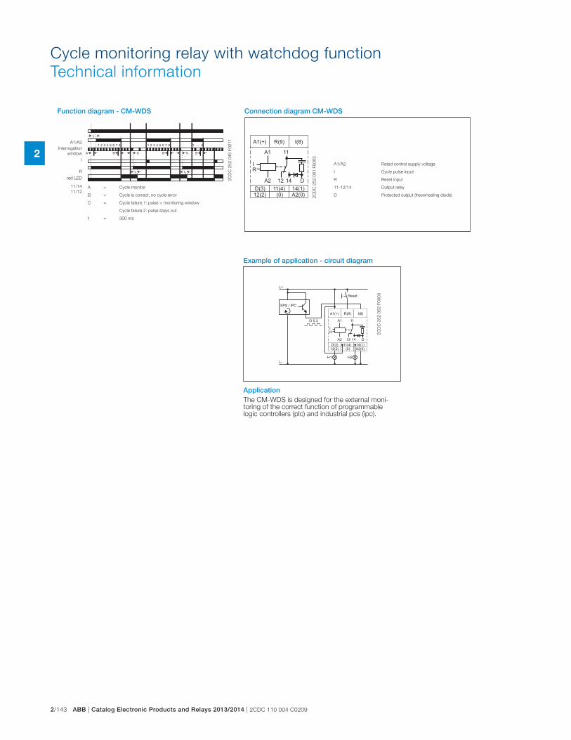
2/143 ABB | Catalog Electronic Products and Relays 2013/2014 | 2CDC 110 004 C0209
2
Cycle monitoring relay with watchdog function
Technical information
1 2 3 4 5 6 7 8
B C
1 2 3 4 5 6 7 8
t
2
t
2
t
1
A B C
1 8
...
B
...
2C
DC
25
2 0
45
F0
21
1
2C
DC
25
2 0
61
F0
00
3
2C
DC
25
2 0
62
F0
00
3
A1(+)
I
R
12(2) (0) A2(0)
R(9) I(8)
D(3) 11(4) 14(1)
A1
A2
11
12 14 D
A1(+)
I
R
12(2) (0) A2(0)
R(9) I(8)
D(3) 11(4) 14(1)
A1
A2
11
12 14 D
SPS / IPC
Reset
L+
L-
H1 H2
O 5.3
A1/A2
Interrogation
window
I
R
red LED
11/14
11/12 A = Cycle monitor
B = Cycle is correct, no cycle error
C = Cycle failure 1: pulse > monitoring window
Cycle failure 2: pulse stays out
t
= 300 ms
A1/A2 Rated control supply voltage
I Cycle pulse input
R Reset input
11-12/14 Output relay
D Protected output (freewheeling diode)
ApplicationThe CM-WDS is designed for the external moni-toring of the correct function of programmable logic controllers (plc) and industrial pcs (ipc).
Function diagram - CM-WDS
Example of application - circuit diagram
Connection diagram CM-WDS
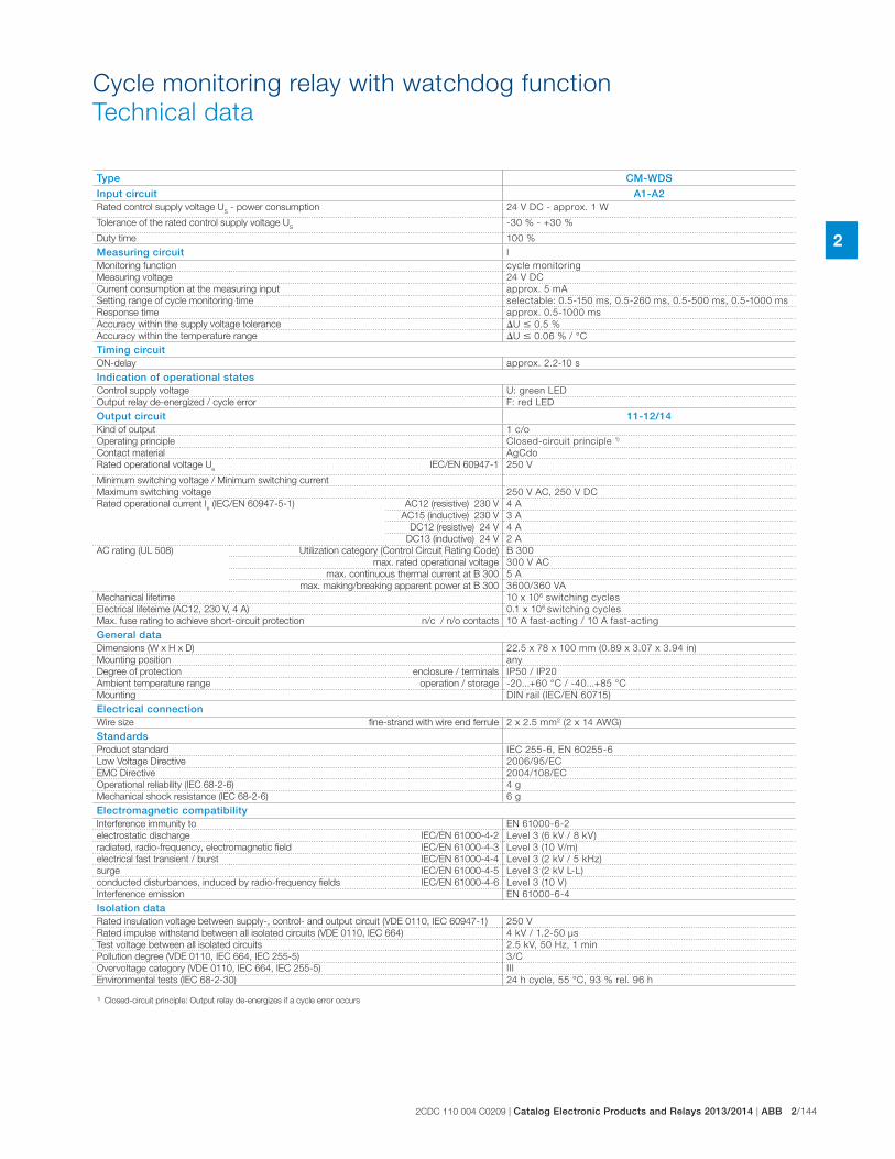
2CDC 110 004 C0209 | Catalog Electronic Products and Relays 2013/2014 | ABB 2/144
2
Cycle monitoring relay with watchdog function
Technical data
Type CM-WDS
Input circuit A1-A2Rated control supply voltage U
S - power consumption 24 V DC - approx. 1 W
Tolerance of the rated control supply voltage US
-30 % - +30 %
Duty time 100 %
Measuring circuit I
Monitoring function cycle monitoring
Measuring voltage 24 V DC
Current consumption at the measuring input approx. 5 mA
Setting range of cycle monitoring time selectable: 0.5-150 ms, 0.5-260 ms, 0.5-500 ms, 0.5-1000 ms
Response time approx. 0.5-1000 ms
Accuracy within the supply voltage tolerance �U � 0.5 %
Accuracy within the temperature range �U � 0.06 % / °C
Timing circuitON-delay approx. 2.2-10 s
Indication of operational statesControl supply voltage U: green LED
Output relay de-energized / cycle error F: red LED
Output circuit 11-12/14Kind of output 1 c/o
Operating principle Closed-circuit principle 1)
Contact material AgCdo
Rated operational voltage Ue
IEC/EN 60947-1 250 V
Minimum switching voltage / Minimum switching current
Maximum switching voltage 250 V AC, 250 V DC
Rated operational current Ie (IEC/EN 60947-5-1) AC12 (resistive) 230 V 4 A
AC15 (inductive) 230 V 3 A
DC12 (resistive) 24 V 4 A
DC13 (inductive) 24 V 2 A
AC rating (UL 508) Utilization category (Control Circuit Rating Code) B 300
max. rated operational voltage 300 V AC
max. continuous thermal current at B 300 5 A
max. making/breaking apparent power at B 300 3600/360 VA
Mechanical lifetime 10 x 106 switching cycles
Electrical lifeteime (AC12, 230 V, 4 A) 0.1 x 10⁶ switching cycles
Max. fuse rating to achieve short-circuit protection n/c / n/o contacts 10 A fast-acting / 10 A fast-acting
General dataDimensions (W x H x D) 22.5 x 78 x 100 mm (0.89 x 3.07 x 3.94 in)
Mounting position any
Degree of protection enclosure / terminals IP50 / IP20
Ambient temperature range operation / storage -20...+60 °C / -40...+85 °C
Mounting DIN rail (IEC/EN 60715)
Electrical connectionWire size fine-strand with wire end ferrule 2 x 2.5 mm2 (2 x 14 AWG)
StandardsProduct standard IEC 255-6, EN 60255-6
Low Voltage Directive 2006/95/EC
EMC Directive 2004/108/EC
Operational reliability (IEC 68-2-6) 4 g
Mechanical shock resistance (IEC 68-2-6) 6 g
Electromagnetic compatibilityInterference immunity to EN 61000-6-2
electrostatic discharge IEC/EN 61000-4-2 Level 3 (6 kV / 8 kV)
radiated, radio-frequency, electromagnetic field IEC/EN 61000-4-3 Level 3 (10 V/m)
electrical fast transient / burst IEC/EN 61000-4-4 Level 3 (2 kV / 5 kHz)
surge IEC/EN 61000-4-5 Level 3 (2 kV L-L)
conducted disturbances, induced by radio-frequency fields IEC/EN 61000-4-6 Level 3 (10 V)
Interference emission EN 61000-6-4
Isolation dataRated insulation voltage between supply-, control- and output circuit (VDE 0110, IEC 60947-1) 250 V
Rated impulse withstand between all isolated circuits (VDE 0110, IEC 664) 4 kV / 1.2-50 μs
Test voltage between all isolated circuits 2.5 kV, 50 Hz, 1 min
Pollution degree (VDE 0110, IEC 664, IEC 255-5) 3/C
Overvoltage category (VDE 0110, IEC 664, IEC 255-5) III
Environmental tests (IEC 68-2-30) 24 h cycle, 55 °C, 93 % rel. 96 h
1) Closed-circuit principle: Output relay de-energizes if a cycle error occurs
2/145 ABB | Catalog Electronic Products and Relays 2013/2014 | 2CDC 110 004 C0209
2
General technical data, Accessories, Current transformers
Notes

2CDC 110 004 C0209 | Catalog Electronic Products and Relays 2013/2014 | ABB 2/146
2
General technical data, Accessories, Current transformers
Table of contents
General technical data, Accessories, Current transformers
Table of contents 144
Technical diagrams - CM-range 145
Dimensional drawings 147
Ordering details - CM-range accessories 149

2/147 ABB | Catalog Electronic Products and Relays 2013/2014 | 2CDC 110 004 C0209
2
DC load (resistive)AC load (resistive)
Contact lifetimeDerating factor F for inductive AC load
DC load (resistive)AC load (resistive)
CM-N (45 mm)
Load limit curves
CM-S (22.5 mm), CM-E (22.5 mm), CM-UFD.M22
Contact lifetimeDerating factor F for inductive AC load
cos ϕ
F
2CD
C 2
52 1
92 F
0205
0.5
0.1 0.2 0.3 0.4 0.5 0.6 0.7 0.8 0.9 1.0
0.6
0.7
0.8
0.9
1.0
300
200
100 80 60 50 40 30
20
10 1 2 4 6 10
I A
V
2CD
C 2
52 1
93 F
0205
V
0.1 0.2 0.5
300
200
100 80 60 50 40 30
20
10 1 2 4 6 10
I A
V
2CD
C 2
52 1
94 F
0205
V
0.1 0.2 0.5
cos ϕ
F
2CD
C 2
52 1
92 F
0205
0.5
0.1 0.2 0.3 0.4 0.5 0.6 0.7 0.8 0.9 1.0
0.6
0.7
0.8
0.9
1.0
1 2 4 6 10
10
20
30
405060
80100
200
300
400
AC current [A]
resistive load
AC
vo
ltag
e [V
]
2C
DC
25
2 1
57
F0
20
6
0.1 0.2 0.5
4321
105
104
106
5 6 7 8
2C
DC
25
2 1
56
F0
20
6
Switching current [A]
Sw
itchin
g c
ycle
s
250 V AC
resistive load
Switching current [A]
250 V
resistive load
Sw
itchin
g c
ycle
s
2C
DC
25
2 1
48
F0
20
6
1 2 4 6 10
10
20
30
405060
80100
200
300
400
0.1 0.2 0.5
AC current [A]
resistive load
AC
vo
ltag
e [V
]
2C
DC
25
2 1
58
F0
20
6
General technical data, Accessories, Current transformers
Technical diagrams - CM-range
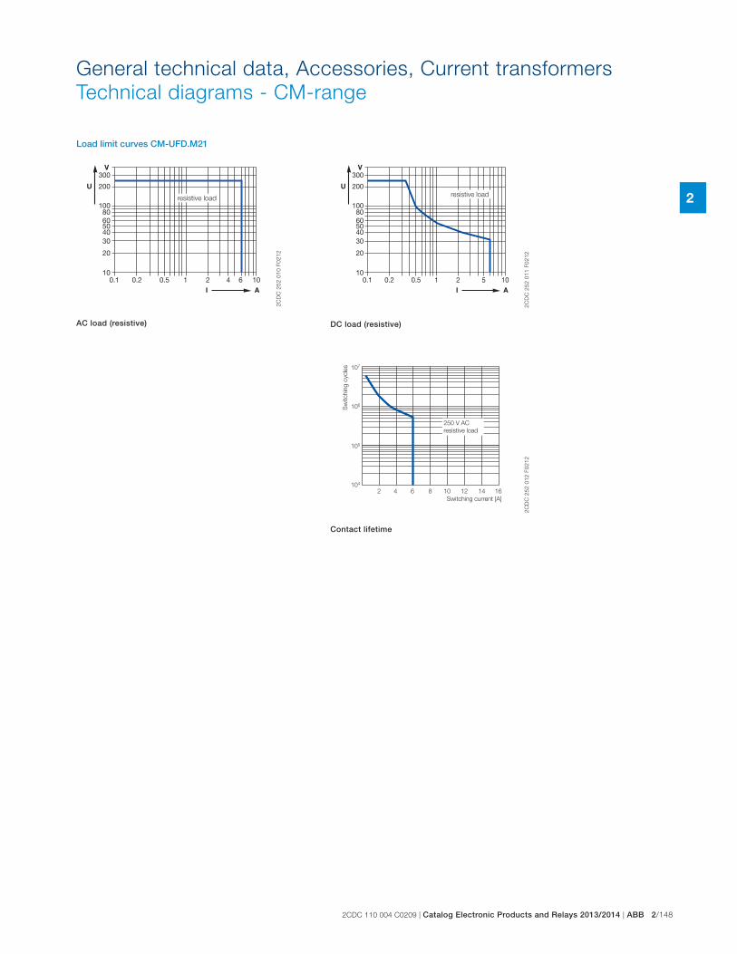
2CDC 110 004 C0209 | Catalog Electronic Products and Relays 2013/2014 | ABB 2/148
2
General technical data, Accessories, Current transformers
Technical diagrams - CM-range
Load limit curves CM-UFD.M21
300
200
100 80 60 50 40 30
20
10 1 2 4 6 10
I A
V
U
0.1 0.2 0.5
resistive load
2C
DC
25
2 0
10
F0
21
2
AC load (resistive)
300
200
100 80 60 50 40 30
20
10 1 2 5 10
I A
V
U
0.1 0.2 0.5
resistive load
2C
DC
25
2 0
11
F0
21
2
DC load (resistive)
104
2 4 6 8 10 12 14 16
105
106
107
Switching current [A]
250 V AC
resistive load
Sw
itchin
g c
ycle
s
2C
DC
25
2 0
12
F0
21
2
Contact lifetime
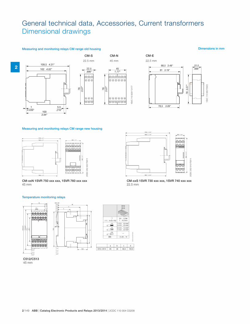
2/149 ABB | Catalog Electronic Products and Relays 2013/2014 | 2CDC 110 004 C0209
2
General technical data, Accessories, Current transformers
Dimensional drawings
0.039
1S
VC
11
0 0
00
F 0
17
7
C512C513
5 ... 6 mm / PZ20,8 ... 1,2 Nm7 ... 10.3 lb·in
1 x 0,5 ... 4,0 mm²2 x 0,5 ... 2,5 mm²
2 x 0,5 ... 1,5 mm²1 x 0,5 ... 2,5 mm²
—
AWG 2 x 20 ... 14
10
10
10
a b c d
C512, C513 65 36 82,6 105,9
6
b
a
86
28,8
c d
201
6
45
7,2
2,86
5,19
73x5,811
73x5,831
2C
DC
25
2 2
88
F0
00
5
1S
VC
11
0 0
00
F0
42
3
CM-S
22.5 mm
CM-N
45 mm
CM-E
22.5 mm
Measuring and monitoring relays CM range old housing
Measuring and monitoring relays CM range new housing
C512/C513 45 mm
CM-xxN 1SVR 750 xxx xxx, 1SVR 760 xxx xxx
45 mm
CM-xxS 1SVR 730 xxx xxx, 1SVR 740 xxx xxx
22.5 mm
Dimensions in mm
Temperature monitoring relays
2C
DC
25
2 0
22
F0
01
1
2C
DC
25
2 0
10
F0
01
1
114.5 4.51”
45.0 1.77”
85.6
3
.37”
104.8 4.13”
107.0 4.21”
113.4 44.65”
22.5 0.89”
85.6
3
3.70
”
103.7 40.83”
105.9 41.69”
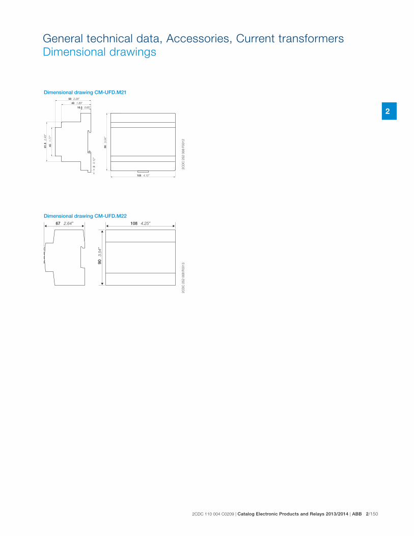
2CDC 110 004 C0209 | Catalog Electronic Products and Relays 2013/2014 | ABB 2/150
2
General technical data, Accessories, Current transformers
Dimensional drawings
Dimensional drawing CM-UFD.M21
Dimensional drawing CM-UFD.M22
2C
DC
25
2 0
08
F0
01
22
CD
C 2
52
00
8 F
00
13
48 1.89”
45
1.77
”
90
3.54
”
3 0
.12”
61.8
2.
43”
16.5 0.65”
105 4.13”
58 2.28”90
3.
54”
108 4.25”67 2.64”
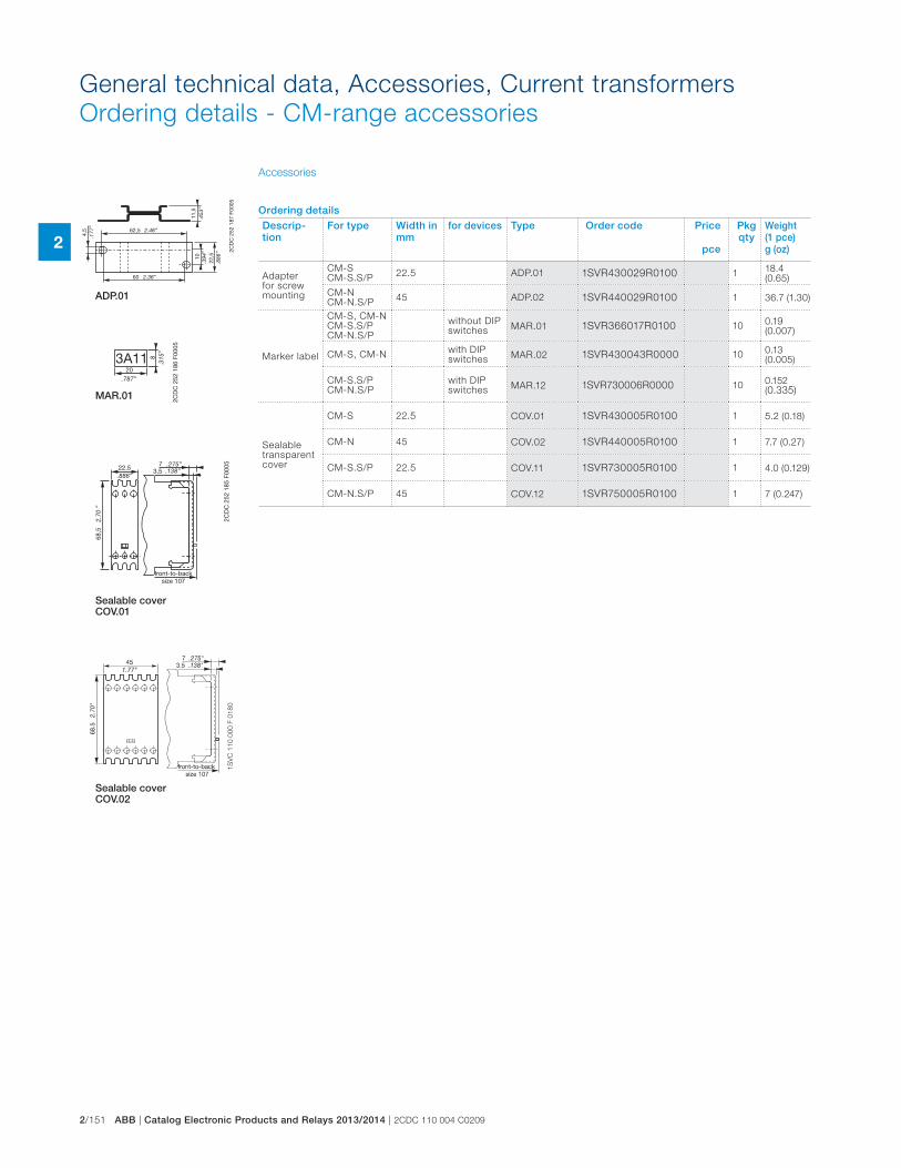
2/151 ABB | Catalog Electronic Products and Relays 2013/2014 | 2CDC 110 004 C0209
22C
DC
252
187
F00
05
4,5 62,5
60
1011
,5
22,5
.177
”
2.46”
2.36”
.394
”
.886
”
.453
”
203A11 8
.315
”
.787”
2CD
C 2
52 1
86 F
0005
2CD
C 2
52 1
85 F
000522,5
68,5
73,5
.886”
2.70
”
.138”.275”
front-to-backsize 107
1S
VC
11
0 0
00
F 0
18
0
ADP.01
MAR.01
Sealable cover COV.01
Sealable cover COV.02
Accessories
General technical data, Accessories, Current transformers
Ordering details - CM-range accessories
Ordering details
Descrip-tion
For type Width in mm
for devices Type Order code Price
pce
Pkg qty
Weight(1 pce)g (oz)
Adapter for screw mounting
CM-SCM-S.S/P
22.5 ADP.01 1SVR430029R0100 118.4 (0.65)
CM-NCM-N.S/P
45 ADP.02 1SVR440029R0100 1 36.7 (1.30)
Marker label
CM-S, CM-NCM-S.S/PCM-N.S/P
without DIP switches
MAR.01 1SVR366017R0100 100.19 (0.007)
CM-S, CM-Nwith DIPswitches
MAR.02 1SVR430043R0000 100.13 (0.005)
CM-S.S/PCM-N.S/P
with DIPswitches
MAR.12 1SVR730006R0000 100.152 (0.335)
Sealable transparent cover
CM-S 22.5 COV.01 1SVR430005R0100 1 5.2 (0.18)
CM-N 45 COV.02 1SVR440005R0100 1 7.7 (0.27)
CM-S.S/P 22.5 COV.11 1SVR730005R0100 1 4.0 (0.129)
CM-N.S/P 45 COV.12 1SVR750005R0100 1 7 (0.247)
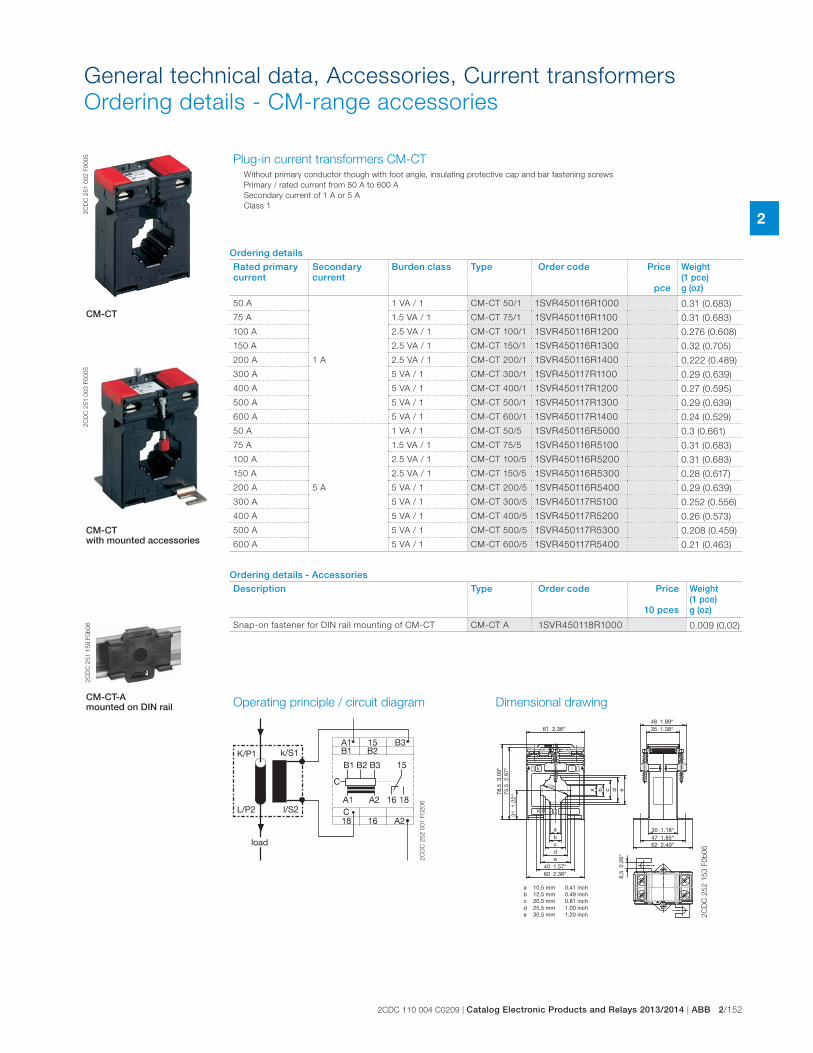
2CDC 110 004 C0209 | Catalog Electronic Products and Relays 2013/2014 | ABB 2/152
2
General technical data, Accessories, Current transformers
Ordering details - CM-range accessories2
CD
C 2
51
00
2 F
00
05
2C
DC
25
1 0
03
F0
00
5
CM-CT
k l
K-P1
26
a
abcde
10,5 mm12,5 mm20,5 mm25,5 mm30,5 mm
0.41 inch0.49 inch0.81 inch1.00 inch1.20 inch
31 1
.22“
6,5
0.2
6“
75,5
2.9
7“78
,5 3
.09“
61 2.36“48 1.89“35 1.38“
a b c d e
bcde
40 1.57“
30 1.18“47 1.85“62 2.40“
60 2.36“
2C
DC
25
2 1
53
F0
b0
6
2C
DC
25
1 1
59
F0
b0
6
CM-CT with mounted accessories
Plug-in current transformers CM-CT Without primary conductor though with foot angle, insulating protective cap and bar fastening screws
Primary / rated current from 50 A to 600 A
Secondary current of 1 A or 5 A
Class 1
Operating principle / circuit diagram Dimensional drawing
K/P1 k/S1
l/S2L/P2
load
2C
DC
25
2 0
01
F0
20
6
CM-CT-A mounted on DIN rail
Ordering details
Rated primary current
Secondary current
Burden class Type Order code Price
pce
Weight(1 pce)g (oz)
50 A
1 A
1 VA / 1 CM-CT 50/1 1SVR450116R1000 0.31 (0.683)
75 A 1.5 VA / 1 CM-CT 75/1 1SVR450116R1100 0.31 (0.683)
100 A 2.5 VA / 1 CM-CT 100/1 1SVR450116R1200 0.276 (0.608)
150 A 2.5 VA / 1 CM-CT 150/1 1SVR450116R1300 0.32 (0.705)
200 A 2.5 VA / 1 CM-CT 200/1 1SVR450116R1400 0.222 (0.489)
300 A 5 VA / 1 CM-CT 300/1 1SVR450117R1100 0.29 (0.639)
400 A 5 VA / 1 CM-CT 400/1 1SVR450117R1200 0.27 (0.595)
500 A 5 VA / 1 CM-CT 500/1 1SVR450117R1300 0.29 (0.639)
600 A 5 VA / 1 CM-CT 600/1 1SVR450117R1400 0.24 (0.529)
50 A
5 A
1 VA / 1 CM-CT 50/5 1SVR450116R5000 0.3 (0.661)
75 A 1.5 VA / 1 CM-CT 75/5 1SVR450116R5100 0.31 (0.683)
100 A 2.5 VA / 1 CM-CT 100/5 1SVR450116R5200 0.31 (0.683)
150 A 2.5 VA / 1 CM-CT 150/5 1SVR450116R5300 0.28 (0.617)
200 A 5 VA / 1 CM-CT 200/5 1SVR450116R5400 0.29 (0.639)
300 A 5 VA / 1 CM-CT 300/5 1SVR450117R5100 0.252 (0.556)
400 A 5 VA / 1 CM-CT 400/5 1SVR450117R5200 0.26 (0.573)
500 A 5 VA / 1 CM-CT 500/5 1SVR450117R5300 0.208 (0.459)
600 A 5 VA / 1 CM-CT 600/5 1SVR450117R5400 0.21 (0.463)
Ordering details - Accessories
Description Type Order code Price
10 pces
Weight(1 pce)g (oz)
Snap-on fastener for DIN rail mounting of CM-CT CM-CT A 1SVR450118R1000 0.009 (0.02)
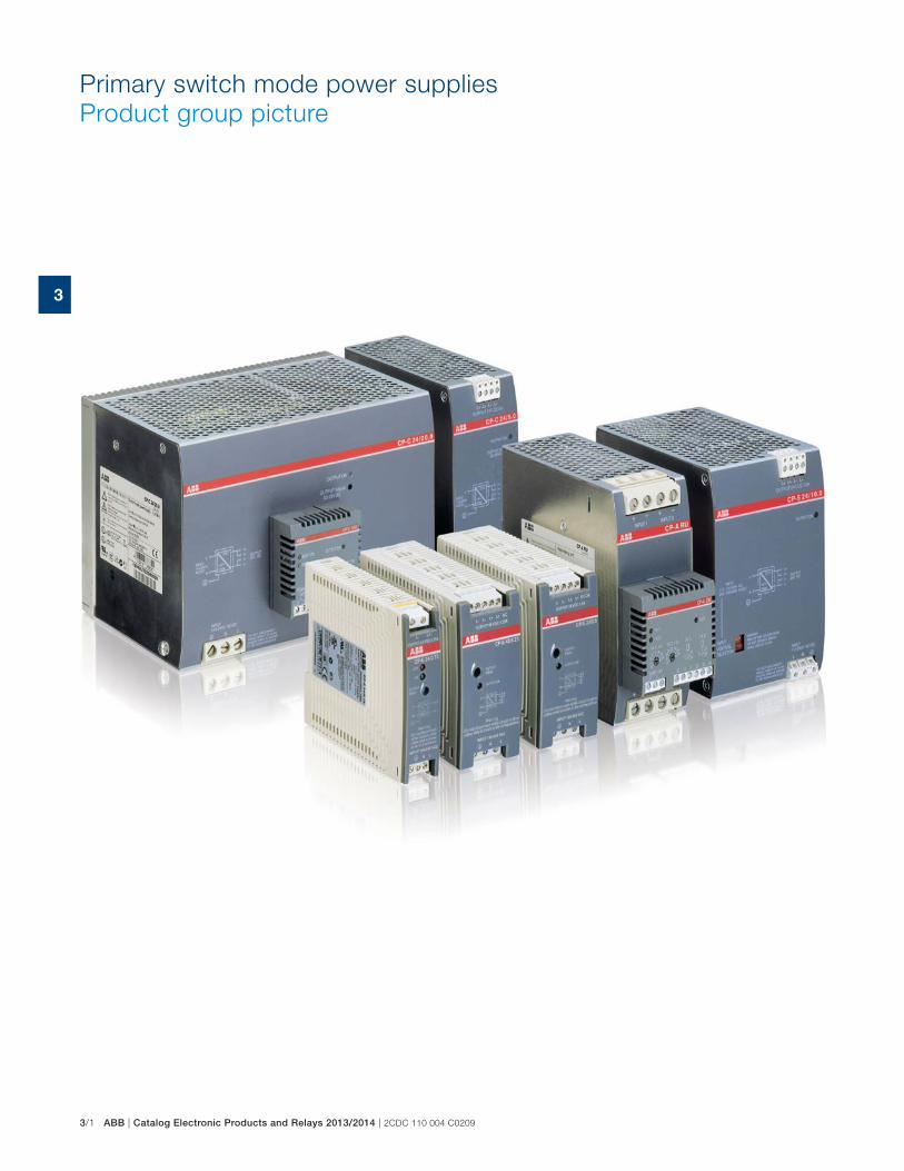
3/1 ABB | Catalog Electronic Products and Relays 2013/2014 | 2CDC 110 004 C0209
3
Primary switch mode power supplies
Product group picture
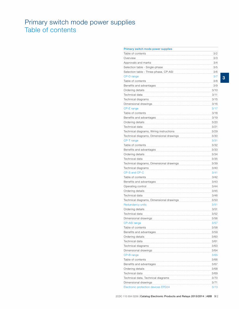
3
Primary switch mode power supplies
Table of contents
2CDC 110 004 0209 | Catalog Electronic Products and Relays 2013/2014 | ABB 3/2
Primary switch mode power supplies
Table of contents 3/2
Overview 3/3
Approvals and marks 3/4
Selection table - Single-phase 3/5
Selection table - Three-phase, CP-ASI 3/6
CP-D range 3/7
Table of contents 3/8
Benefits and advantages 3/9
Ordering details 3/10
Technical data 3/11
Technical diagrams 3/15
Dimensional drawings 3/16
CP-E range 3/17
Table of contents 3/18
Benefits and advantages 3/19
Ordering details 3/20
Technical data 3/21
Technical diagrams, Wiring instructions 3/29
Technical diagrams, Dimensional drawings 3/30
CP-T range 3/31
Table of contents 3/32
Benefits and advantages 3/33
Ordering details 3/34
Technical data 3/35
Technical diagrams, Dimensional drawings 3/39
Technical diagrams 3/40
CP-S and CP-C 3/41
Table of contents 3/42
Benefits and advantages 3/43
Operating control 3/44
Ordering details 3/45
Technical data 3/46
Technical diagrams, Dimensional drawings 3/50
Redundancy units 3/51
Ordering details 3/51
Technical data 3/52
Dimensional drawings 3/56
CP-ASI range 3/57
Table of contents 3/58
Benefits and advantages 3/59
Ordering details 3/60
Technical data 3/61
Technical diagrams 3/63
Dimensional drawings 3/64
CP-B range 3/65
Table of contents 3/66
Benefits and advantages 3/67
Ordering details 3/68
Technical data 3/69
Technical data, Technical diagrams 3/70
Dimensional drawings 3/71
Electronic protection devices EPD24 3/73
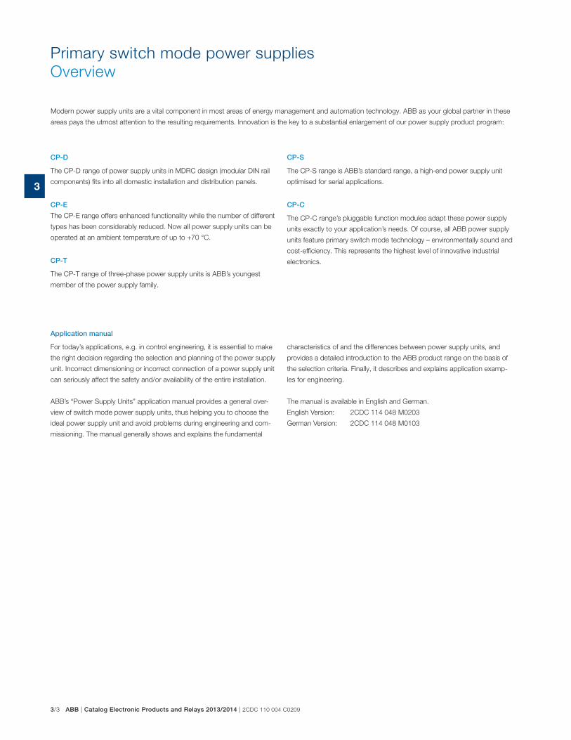
3/3 ABB | Catalog Electronic Products and Relays 2013/2014 | 2CDC 110 004 C0209
3
Primary switch mode power supplies
Overview
Application manual
For today’s applications, e.g. in control engineering, it is essential to make
the right decision regarding the selection and planning of the power supply
unit. Incorrect dimensioning or incorrect connection of a power supply unit
can seriously affect the safety and/or availability of the entire installation.
ABB’s “Power Supply Units” application manual provides a general over-
view of switch mode power supply units, thus helping you to choose the
ideal power supply unit and avoid problems during engineering and com-
missioning. The manual generally shows and explains the fundamental
CP-D
The CP-D range of power supply units in MDRC design (modular DIN rail
components) fits into all domestic installation and distribution panels.
CP-E
The CP-E range offers enhanced functionality while the number of different
types has been considerably reduced. Now all power supply units can be
operated at an ambient temperature of up to +70 °C.
CP-T
The CP-T range of three-phase power supply units is ABB’s youngest
member of the power supply family.
CP-S
The CP-S range is ABB’s standard range, a high-end power supply unit
optimised for serial applications.
CP-C
The CP-C range’s pluggable function modules adapt these power supply
units exactly to your application’s needs. Of course, all ABB power supply
units feature primary switch mode technology – environmentally sound and
cost-efficiency. This represents the highest level of innovative industrial
electronics.
characteristics of and the differences between power supply units, and
provides a detailed introduction to the ABB product range on the basis of
the selection criteria. Finally, it describes and explains application examp-
les for engineering.
The manual is available in English and German.
English Version: 2CDC 114 048 M0203
German Version: 2CDC 114 048 M0103
Modern power supply units are a vital component in most areas of energy management and automation technology. ABB as your global partner in these
areas pays the utmost attention to the resulting requirements. Innovation is the key to a substantial enlargement of our power supply product program:
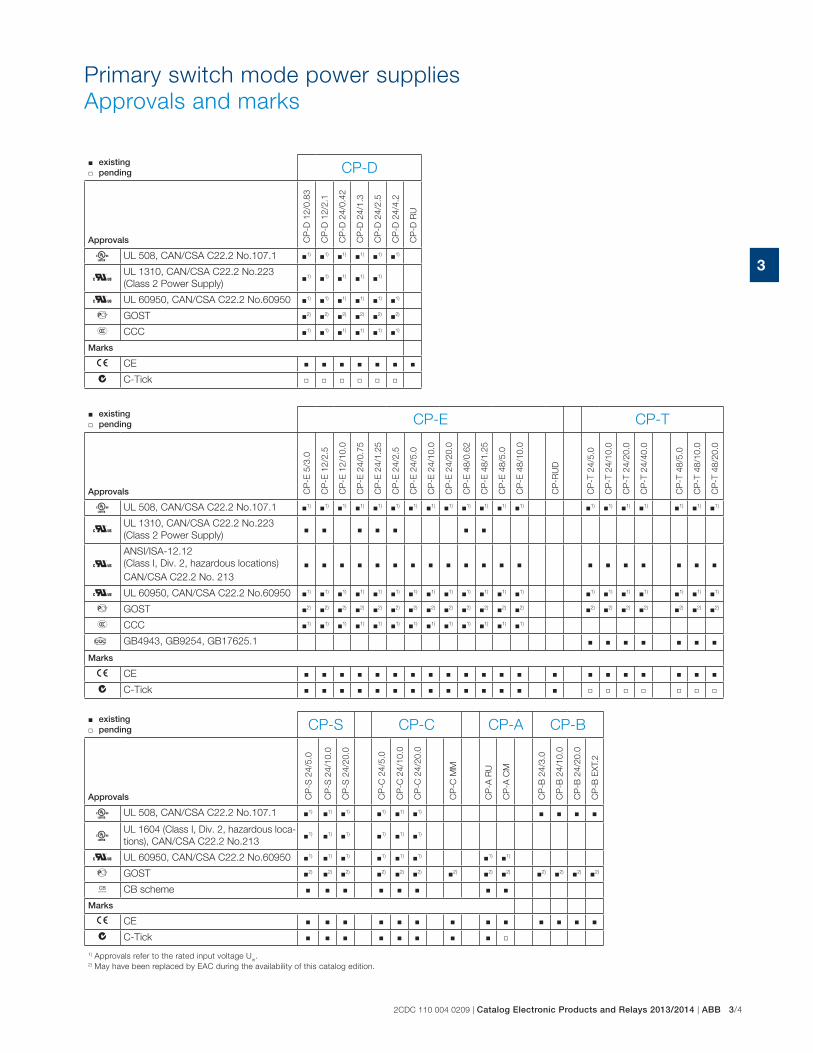
2CDC 110 004 0209 | Catalog Electronic Products and Relays 2013/2014 | ABB 3/4
3
� existing � pending CP-D
Approvals CP
-D 1
2/0
.83
CP
-D 1
2/2
.1
CP
-D 2
4/0
.42
CP
-D 2
4/1
.3
CP
-D 2
4/2
.5
CP
-D 2
4/4
.2
CP
-D R
U
A UL 508, CAN/CSA C22.2 No.107.1 �1) �1) �1) �1) �1) �1)
HUL 1310, CAN/CSA C22.2 No.223
(Class 2 Power Supply)�1) �1) �1) �1) �1)
H UL 60950, CAN/CSA C22.2 No.60950 �1) �1) �1) �1) �1) �1)
D GOST �2) �2) �2) �2) �2) �2)
E CCC �1) �1) �1) �1) �1) �1)
Marks
a CE � � � � � � �
b C-Tick � � � � � �
� existing � pending CP-E CP-T
Approvals CP
-E 5
/3.0
CP
-E 1
2/2
.5
CP
-E 1
2/1
0.0
CP
-E 2
4/0
.75
CP
-E 2
4/1
.25
CP
-E 2
4/2
.5
CP
-E 2
4/5
.0
CP
-E 2
4/1
0.0
CP
-E 2
4/2
0.0
CP
-E 4
8/0
.62
CP
-E 4
8/1
.25
CP
-E 4
8/5
.0
CP
-E 4
8/1
0.0
CP
-RU
D
CP
-T 2
4/5
.0
CP
-T 2
4/1
0.0
CP
-T 2
4/2
0.0
CP
-T 2
4/4
0.0
CP
-T 4
8/5
.0
CP
-T 4
8/1
0.0
CP
-T 4
8/2
0.0
A UL 508, CAN/CSA C22.2 No.107.1 �1) �1) �1) �1) �1) �1) �1) �1) �1) �1) �1) �1) �1) �1) �1) �1) �1) �1) �1) �1)
HUL 1310, CAN/CSA C22.2 No.223
(Class 2 Power Supply)� � � � � � �
HANSI/ISA-12.12
(Class I, Div. 2, hazardous locations)
CAN/CSA C22.2 No. 213
� � � � � � � � � � � � � � � � � � � �
H UL 60950, CAN/CSA C22.2 No.60950 �1) �1) �1) �1) �1) �1) �1) �1) �1) �1) �1) �1) �1) �1) �1) �1) �1) �1) �1) �1)
D GOST �2) �2) �2) �2) �2) �2) �2) �2) �2) �2) �2) �2) �2) �2) �2) �2) �2) �2) �2) �2)
E CCC �1) �1) �1) �1) �1) �1) �1) �1) �1) �1) �1) �1) �1)
� GB4943, GB9254, GB17625.1 � � � � � � �
Marks
a CE � � � � � � � � � � � � � � � � � � � � �
b C-Tick � � � � � � � � � � � � � � � � � � � � �
� existing � pending CP-S CP-C CP-A CP-B
Approvals CP
-S 2
4/5
.0
CP
-S 2
4/1
0.0
CP
-S 2
4/2
0.0
CP
-C 2
4/5
.0
CP
-C 2
4/1
0.0
CP
-C 2
4/2
0.0
CP
-C M
M
CP
-A R
U
CP
-A C
M
CP
-B 2
4/3
.0
CP
-B 2
4/1
0.0
CP
-B 2
4/2
0.0
CP
-B E
XT.
2
A UL 508, CAN/CSA C22.2 No.107.1 �1) �1) �1) �1) �1) �1) � � � �
AUL 1604 (Class I, Div. 2, hazardous loca-
tions), CAN/CSA C22.2 No.213�1) �1) �1) �1) �1) �1)
H UL 60950, CAN/CSA C22.2 No.60950 �1) �1) �1) �1) �1) �1) �1) �1)
D GOST �2) �2) �2) �2) �2) �2) �2) �2) �2) �2) �2) �2) �2)
K CB scheme � � � � � � � �
Marks
a CE � � � � � � � � � � � � �
b C-Tick � � � � � � � � �
1) Approvals refer to the rated input voltage Uin.
2) May have been replaced by EAC during the availability of this catalog edition.
Primary switch mode power supplies
Approvals and marks
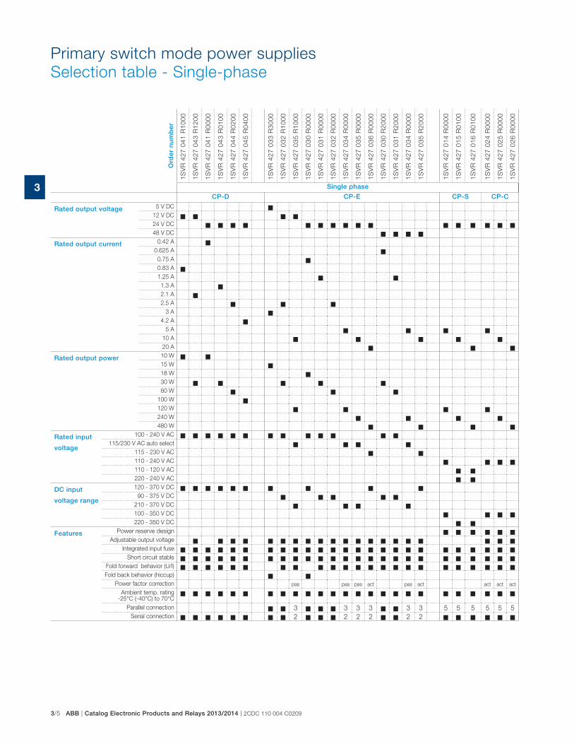
3/5 ABB | Catalog Electronic Products and Relays 2013/2014 | 2CDC 110 004 C0209
3
Ord
er n
um
ber
1SV
R 4
27 0
41 R
1000
1SV
R 4
27 0
43 R
1200
1SV
R 4
27 0
41 R
0000
1SV
R 4
27 0
43 R
0100
1SV
R 4
27 0
44 R
0200
1SV
R 4
27 0
45 R
0400
1SV
R 4
27 0
33 R
3000
1SV
R 4
27 0
32 R
1000
1SV
R 4
27 0
35 R
1000
1SV
R 4
27 0
30 R
0000
1SV
R 4
27 0
31 R
0000
1SV
R 4
27 0
32 R
0000
1SV
R 4
27 0
34 R
0000
1SV
R 4
27 0
35 R
0000
1SV
R 4
27 0
36 R
0000
1SV
R 4
27 0
30 R
2000
1SV
R 4
27 0
31 R
2000
1SV
R 4
27 0
34 R
0000
1SV
R 4
27 0
35 R
2000
1SV
R 4
27 0
14 R
0000
1SV
R 4
27 0
15 R
0100
1SV
R 4
27 0
16 R
0100
1SV
R 4
27 0
24 R
0000
1SV
R 4
27 0
25 R
0000
1SV
R 4
27 0
26 R
0000
Single phase
CP-D CP-E CP-S CP-C
Rated output voltage 5 V DC
12 V DC
24 V DC
48 V DC
Rated output current 0.42 A
0.625 A
0.75 A
0.83 A
1.25 A
1.3 A
2.1 A
2.5 A
3 A
4.2 A
5 A
10 A
20 A
Rated output power 10 W
15 W
18 W
30 W
60 W
100 W
120 W
240 W
480 W
Rated input
voltage
100 - 240 V AC
115/230 V AC auto select
115 - 230 V AC
110 - 240 V AC
110 - 120 V AC
220 - 240 V AC
DC input
voltage range
120 - 370 V DC
90 - 375 V DC
210 - 370 V DC
100 - 350 V DC
220 - 350 V DC
Features Power reserve design
Adjustable output voltage
Integrated input fuse
Short circuit stable
Fold forward behavior (U/I)
Fold back behavior (hiccup)
Power factor correction pas pas pas act pas act act act act
Ambient temp. rating -25°C (-40°C) to 70°C
Parallel connection 3 3 3 3 3 3 5 5 5 5 5 5
Serial connection 2 2 2 2 2 2
Primary switch mode power supplies
Selection table - Single-phase
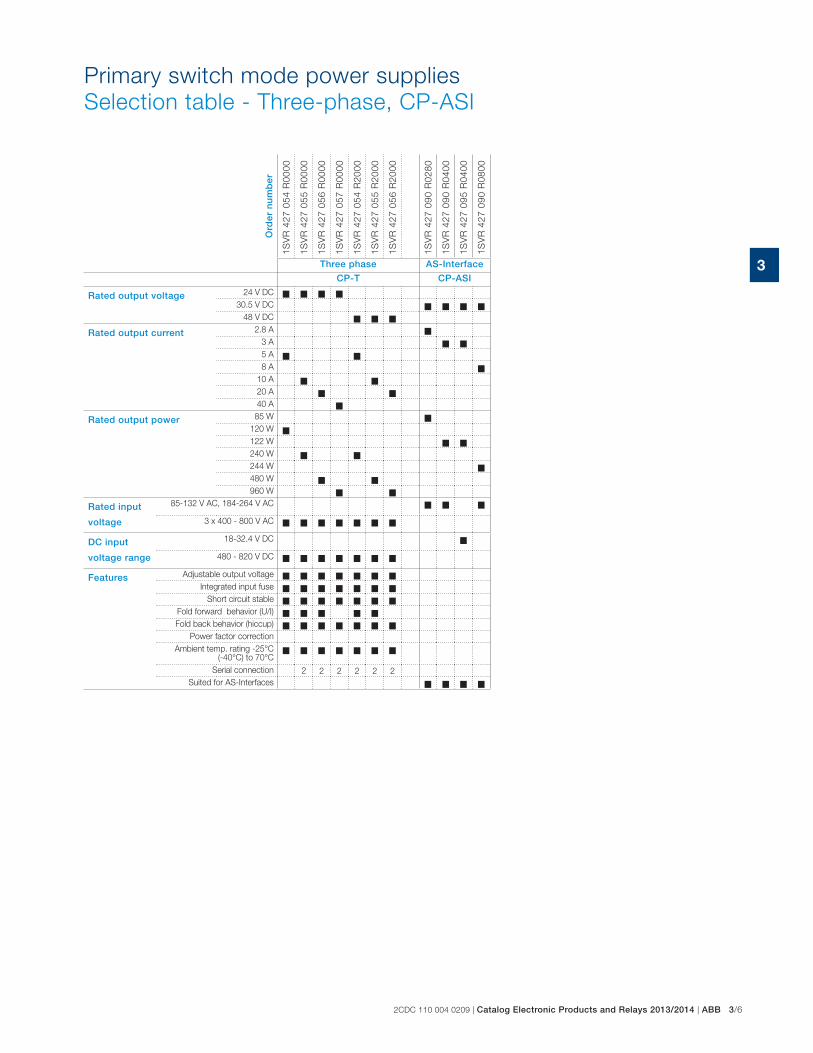
2CDC 110 004 0209 | Catalog Electronic Products and Relays 2013/2014 | ABB 3/6
3O
rder
nu
mb
er
1SV
R 4
27 0
54 R
0000
1SV
R 4
27 0
55 R
0000
1SV
R 4
27 0
56 R
0000
1SV
R 4
27 0
57 R
0000
1SV
R 4
27 0
54 R
2000
1SV
R 4
27 0
55 R
2000
1SV
R 4
27 0
56 R
2000
1SV
R 4
27 0
90 R
0280
1SV
R 4
27 0
90 R
0400
1SV
R 4
27 0
95 R
0400
1SV
R 4
27 0
90 R
0800
Three phase AS-Interface
CP-T CP-ASI
Rated output voltage 24 V DC
30.5 V DC
48 V DC
Rated output current 2.8 A
3 A
5 A
8 A
10 A
20 A
40 A
Rated output power 85 W
120 W
122 W
240 W
244 W
480 W
960 W
Rated input
voltage
85-132 V AC, 184-264 V AC
3 x 400 - 800 V AC
DC input
voltage range
18-32.4 V DC
480 - 820 V DC
Features Adjustable output voltage
Integrated input fuse
Short circuit stable
Fold forward behavior (U/I)
Fold back behavior (hiccup)
Power factor correction
Ambient temp. rating -25°C (-40°C) to 70°C
Serial connection 2 2 2 2 2 2
Suited for AS-Interfaces
Primary switch mode power supplies
Selection table - Three-phase, CP-ASI
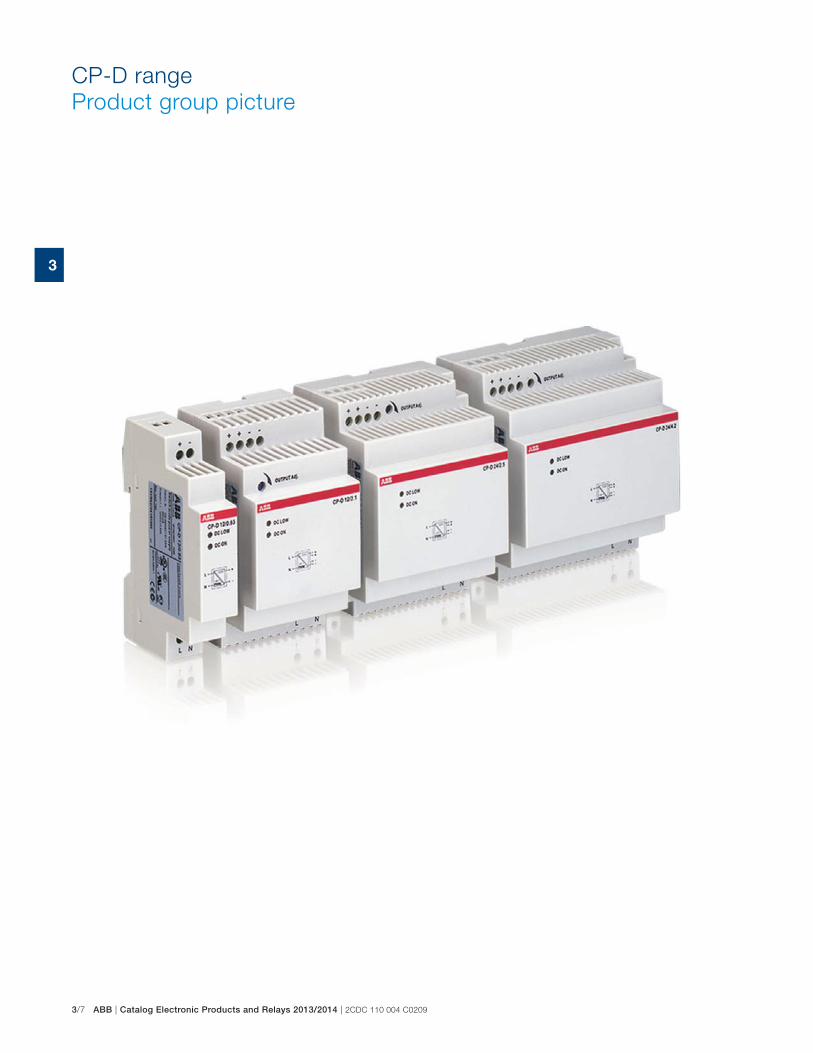
3/7 ABB | Catalog Electronic Products and Relays 2013/2014 | 2CDC 110 004 C0209
3
CP-D range
Product group picture
2CDC 110 004 0209 | Catalog Electronic Products and Relays 2013/2014 | ABB 3/8
3
CP-D range
Table of contents
CP-D range
Product group picture 3/7
Table of contents 3/8
Benefits and advantages 3/9
Ordering details 3/10
Technical data 3/11
Technical diagrams 3/15
Dimensional drawings 3/16
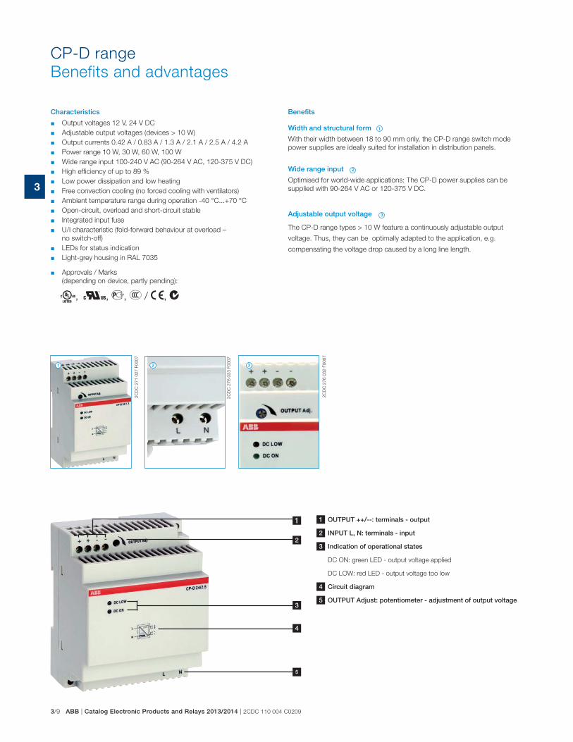
3/9 ABB | Catalog Electronic Products and Relays 2013/2014 | 2CDC 110 004 C0209
3
2C
DC
27
1 0
27
F0
00
7
2C
DC
27
6 0
32
F0
00
7
2C
DC
27
6 0
33
F0
00
7
Characteristics
� Output voltages 12 V, 24 V DC
� Adjustable output voltages (devices > 10 W)
� Output currents 0.42 A / 0.83 A / 1.3 A / 2.1 A / 2.5 A / 4.2 A
� Power range 10 W, 30 W, 60 W, 100 W
� Wide range input 100-240 V AC (90-264 V AC, 120-375 V DC)
� High efficiency of up to 89 %
� Low power dissipation and low heating
� Free convection cooling (no forced cooling with ventilators)
� Ambient temperature range during operation -40 °C...+70 °C
� Open-circuit, overload and short-circuit stable
� Integrated input fuse
� U/I characteristic (fold-forward behaviour at overload –
no switch-off)
� LEDs for status indication
� Light-grey housing in RAL 7035
� Approvals / Marks
(depending on device, partly pending):
A, H, D, E / a, b
Width and structural form
With their width between 18 to 90 mm only, the CP-D range switch mode
power supplies are ideally suited for installation in distribution panels.
Wide range input
Optimised for world-wide applications: The CP-D power supplies can be
supplied with 90-264 V AC or 120-375 V DC.
Adjustable output voltage
The CP-D range types > 10 W feature a continuously adjustable output
voltage. Thus, they can be optimally adapted to the application, e.g.
compensating the voltage drop caused by a long line length.
Benefits
1
1
2
2
3
3
CP-D range
Benefits and advantages
4
1
2
3
5
1 OUTPUT ++/--: terminals - output
2 INPUT L, N: terminals - input
3 Indication of operational states
DC ON: green LED - output voltage applied
DC LOW: red LED - output voltage too low
4 Circuit diagram
5 OUTPUT Adjust: potentiometer - adjustment of output voltage

2CDC 110 004 0209 | Catalog Electronic Products and Relays 2013/2014 | ABB 3/10
3
DescriptionThe CP-D range of modular power supply units in MDRC design (modular DIN rail compo-
nents) is ideally suited for installation in distribution panels. This range offers devices with
output voltages of 12 V DC and 24 V DC at output currents of 0.42 A to 4.2 A. Thanks to a
high thermal efficiency corresponding to low power and heat dissipation, the devices can be
operated without forced cooling. All devices feature the U/I output characteristic (fold forward
behaviour). All power supply units in the CP-D range are approved according to all relevant
international standards.
Ordering details
Input voltage range Rated
output voltage /
current
Type Order code Price
1 pce
Weight
(1 pce)
kg (lb)
90-264 V AC/ 120-375 V DC 12 V DC / 0.83 A CP-D 12/0.83 1SVR427041R10000.06
(0.13)
90-264 V AC/ 120-375 V DC 12 V DC / 2.1 A CP-D 12/2.1 1SVR427043R12000.19
(0.41)
90-264 V AC/ 120-375 V DC 24 V DC / 0.42 A CP-D 24/0.42 1SVR427041R00000.06
(0.13)
90-264 V AC/ 120-375 V DC 24 V DC / 1.3 A CP-D 24/1.3 1SVR427043R01000.19
(0.41)
90-264 V AC/ 120-375 V DC 24 V DC / 2.5 A CP-D 24/2.5 1SVR427044R02000.25
(0.56)
90-264 V AC/ 120-375 V DC 24 V DC / 4.2 A CP-D 24/4.2 1SVR427045R04000.32
(0.71)
2C
DC
27
1 0
24
F0
00
7
2C
DC
27
1 0
25
F0
00
7
2C
DC
27
1 0
28
F0
00
7
CP-D 12/0.83, CP-D 24/0.42
CP-D 12/2.1, CP-D 24/1.3
CP-D 24/2.5
CP-D range
Ordering details
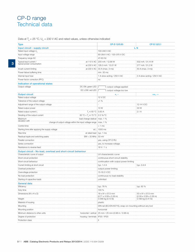
3/11 ABB | Catalog Electronic Products and Relays 2013/2014 | 2CDC 110 004 C0209
3
Data at Ta = 25 °C, U
in = 230 V AC and rated values, unless otherwise indicated
Type CP-D 12/0.83 CP-D 12/2.1
Input circuit - supply circuit L, NRated input voltage U
in100-240 V AC
Input voltage range 90-264 V AC / 120-375 V DC
Frequency range AC 47-63 Hz
Typical input current / typical power consumption
at 110 V AC 200 mA / 12.68 W 502 mA / 31.14 W
at 230 V AC 128.3 mA / 13.01 W 277 mA / 31.2 W
Inrush current limiting at 230 V AC 30 A (max. 3 ms) 50 A (max. 3 ms)
Power failure buffering time min. 30 ms
Internal input fuse 1 A slow-acting / 250 V AC 2 A slow-acting / 250 V AC
Power factor correction (PFC) no
Indication of operational statesOutput voltage DC ON: green LED V: output voltage applied
DC LOW: red LED V: output voltage too low
Output circuit +, - ++, --Rated output voltage 12 V DC
Tolerance of the output voltage ±1 %
Adjustment range of the output voltage - 12-14 V DC
Rated output power 10 W 30 W
Rated output current Ir
Ta � 60 °C 0.83 A 2.1 A
Derating of the output current 60 °C < Ta � 70 °C 2.5 %/°C
Maximum deviation with
load change statical max. 1 %
change of output voltage within the input voltage range max. 1 %
Control time < 1 ms
Starting time after applying the supply voltage at Ir
1000 ms
Rise time at rated load typ. 1 ms
Residual ripple and switching peaks BW = 20 MHz 50 mV
Parallel connection yes, using CP-D RU
Series connection yes, to increase voltage
Resistance to reverse feed 18 V / 1 s
Output circuit - No-load, overload and short-circuit behaviourCharacteristic curve of output U/I characteristic curve
Short-circuit protection continuous short-circuit stability
Short-circuit behaviour continuation with output power limiting
Current limiting at short circuit typ. 1.4 A typ. 5.9 A
Overload protection output power limiting
Overvoltage protection 15-16.5 V DC
No-load protection continuous no-load stability
Starting of capacitive loads unlimited
General dataEfficiency typ. 78 % typ. 82 %
Duty time 100 %
Dimensions (W x H x D) 18 x 91 x 57.5 mm
(0.71 x 3.58 x 2.26 in)
53 x 91 x 57.5 mm
(2.09 x 3.58 x 2.26 in)
Weight 0.066 kg (0.13 lb) 0.196 kg (0.41 lb)
Material of housing plastic
Mounting DIN rail (IEC/EN 60715), snap-on mounting without any tool
Mounting position horizontal
Minimum distance to other units horizontal / vertical 25 mm / 25 mm (0.98 in / 0.98 in)
Degree of protection housing / terminals IP20 / IP20
Protection class II
CP-D range
Technical data
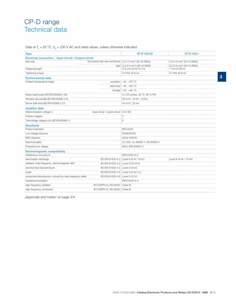
2CDC 110 004 0209 | Catalog Electronic Products and Relays 2013/2014 | ABB 3/12
3
Data at Ta = 25 °C, U
in = 230 V AC and rated values, unless otherwise indicated
Type CP-D 12/0.83 CP-D 12/2.1
Electrical connection - Input circuit / Output circuitWire size fine-strand with wire end ferrule 0.2-1.5 mm2 (24-16 AWG) 0.2-2.5 mm2 (24-14 AWG)
rigid 0.2-2.5 mm2 (26-12 AWG) 0.2-2.5 mm2 (24-12 AWG)
Stripping length 4-5 mm (0.16-0.2 in) 7 mm (0.28 in)
Tightening torque 0.6 Nm (5 lb.in) 0.7 Nm (6 lb.in)
Environmental dataAmbient temperature range operation -40…+70 °C
rated load -40…+60 °C
storage -40…+85 °C
Damp heat (cyclic) (IEC/EN 60068-2-30) 4 x 24 cycles, 40 °C, 95 % RH
Vibration (sinusoidal) (IEC/EN 60068-2-6) 50 m/s2, 10 Hz - 2 kHz
Shock (half-sine) (IEC/EN 60068-2-27) 40 m/s2, 22 ms
Isolation dataRated insulation voltage U
iinput circuit / output circuit 3 kV AC
Pollution degree 2
Overvoltage category (UL/IEC/EN 60950-1) ll
StandardsProduct standard EN 61204
Low Voltage Directive 2006/95/EC
EMC Direcitve 2004/108/EC
Electrical safety UL 508, UL 60950-1, EN 60950-1
Protective low voltage SELV (EN 60950-1)
Electromagnetic compatibilityInterference immunity to EN 61000-6-2
electrostatic discharge IEC/EN 61000-4-2 Level 4 (4 kV / 8 kV) Level 4 (4 kV / 15 kV)
radiated, radio-frequency, electromagnetic field IEC/EN 61000-4-3 Level 3 (10 V/m)
electrical fast transient/burst IEC/EN 61000-4-4 Level 4 (4 kV)
surge IEC/EN 61000-4-5 Level 3 (2 kV L-L)
conducted disturbances, induced by radio-frequency fields IEC/EN 61000-4-6 Level 3 (10 V)
Interference emission EN 61000-6-3
high-frequency radiated IEC/CISPR 22, EN 55022 Class B
high-frequency conducted IEC/CISPR 22, EN 55022 Class B
„Approvals and marks“ on page 3/4.
CP-D range
Technical data
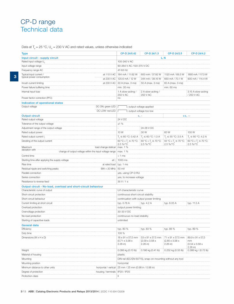
3/13 ABB | Catalog Electronic Products and Relays 2013/2014 | 2CDC 110 004 C0209
3
CP-D range
Technical data
Data at Ta = 25 °C, U
in = 230 V AC and rated values, unless otherwise indicated
Type CP-D 24/0.42 CP-D 24/1.3 CP-D 24/2.5 CP-D 24/4.2
Input circuit - supply circuit L, NRated input voltage U
in100-240 V AC
Input voltage range 90-264 V AC /120-375 V DC
Frequency range AC 47-63 Hz
Typical input current / typical power consumption
at 110 V AC 184 mA / 11.62 W 600 mA / 37.92 W 1120 mA / 69.3 W 1800 mA / 117.3 W
at 230 V AC 120.6 mA / 12 W 344 mA / 38.16 W 660 mA / 70.1 W 900 mA / 114.4 W
Inrush current limiting at 230 V AC 30 A (max. 3 ms) 50 A (max. 3 ms) 60 A (max. 3 ms)
Power failure buffering time min. 30 ms min. 60 ms
Internal input fuse 1 A slow-acting /
250 V AC
2 A slow-acting /
250 V AC
3.15 A slow-acting
/ 250 V AC
Power factor correction (PFC) no
Indication of operational statesOutput voltage DC ON: green LED V: output voltage applied
DC LOW: red LED V: output voltage too low
Output circuit +, - ++, --Rated output voltage 24 V DC
Tolerance of the output voltage ±1 %
Adjustment range of the output voltage - 24-28 V DC
Rated output power 10 W 30 W 60 W 100 W
Rated output current Ir
Ta � 60 °C: 0.42 A T
a � 60 °C: 1.3 A T
a � 55 °C: 2.5 A T
a � 60 °C: 4.2 A
Derating of the output current 60 °C < Ta � 70 °C:
2.5 %/°C
60 °C < Ta � 70 °C:
2.5 %/°C
55 °C < Ta � 70 °C:
2.5 %/°C
60 °C < Ta � 70 °C:
2.5 %/°C
Maximum deviation with
load change statical max. 1 %
change of output voltage within the input voltage range max. 1 %
Control time < 1 ms
Starting time after applying the supply voltage at Ir
1000 ms
Rise time at rated load typ. 1 ms
Residual ripple and switching peaks BW = 20 MHz 50 mV
Parallel connection yes, using CP-D RU
Series connection yes, to increase voltage
Resistance to reverse feed 35 V / 1 s
Output circuit - No-load, overload and short-circuit behaviourCharacteristic curve of output U/I characteristic curve
Short-circuit protection continuous short-circuit stability
Short-circuit behaviour continuation with output power limiting
Current limiting at short circuit typ. 0.78 A typ. 4.2 A typ. 6.05 A typ. 11.5 A
Overload protection output power limiting
Overvoltage protection 30-33 V DC
No-load protection continuous no-load stability
Starting of capacitive loads unlimited
General dataEfficiency typ. 80 % typ. 83 % typ. 86 % typ. 89 %
Duty time 100 %
Dimensions (W x H x D) 18 x 91 x 57.5 mm
(0.71 x 3.58 x
2.26 in)
53 x 91 x 57.5 mm
(2.09 x 3.58 x
2.26 in)
71 x 91 x 57.5 mm
(2.80 x 3.58 x
2.26 in)
89.9 x 91 x 57,5
mm
(3.54 x 3.58 x
2.26 in)
Weight 0.066 kg (0.13 lb) 0.196 kg (0.41 lb) 0.252 kg (0.55 lb) 0.386 kg / (0.72 lb)
Material of housing plastic
Mounting DIN rail (IEC/EN 60715), snap-on mounting without any tool
Mounting position horizontal
Minimum distance to other units horizontal / vertical 25 mm / 25 mm (0.98 in / 0.98 in)
Degree of protection housing / terminals IP20 / IP20
Protection class II
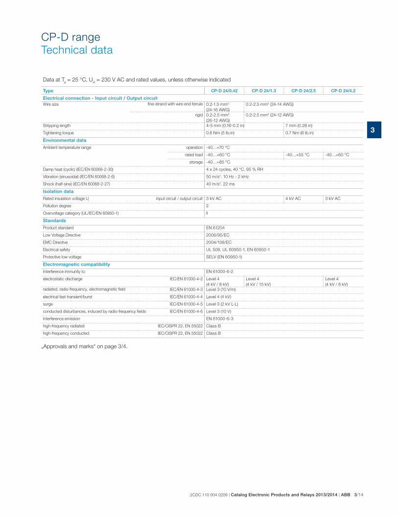
2CDC 110 004 0209 | Catalog Electronic Products and Relays 2013/2014 | ABB 3/14
3
CP-D range
Technical data
Data at Ta = 25 °C, U
in = 230 V AC and rated values, unless otherwise indicated
Type CP-D 24/0.42 CP-D 24/1.3 CP-D 24/2.5 CP-D 24/4.2
Electrical connection - Input circuit / Output circuitWire size fine-strand with wire end ferrule 0.2-1.5 mm2
(24-16 AWG)
0.2-2.5 mm2 (24-14 AWG)
rigid 0.2-2.5 mm2
(26-12 AWG)
0.2-2.5 mm2 (24-12 AWG)
Stripping length 4-5 mm (0.16-0.2 in) 7 mm (0.28 in)
Tightening torque 0.6 Nm (5 lb.in) 0.7 Nm (6 lb.in)
Environmental data
Ambient temperature range operation -40…+70 °C
rated load -40…+60 °C -40…+55 °C -40…+60 °C
storage -40…+85 °C
Damp heat (cyclic) (IEC/EN 60068-2-30) 4 x 24 cycles, 40 °C, 95 % RH
Vibration (sinusoidal) (IEC/EN 60068-2-6) 50 m/s2, 10 Hz - 2 kHz
Shock (half-sine) (IEC/EN 60068-2-27) 40 m/s2, 22 ms
Isolation data
Rated insulation voltage Ui
input circuit / output circuit 3 kV AC 4 kV AC 3 kV AC
Pollution degree 2
Overvoltage category (UL/IEC/EN 60950-1) ll
Standards
Product standard EN 61204
Low Voltage Directive 2006/95/EC
EMC Direcitve 2004/108/EC
Electrical safety UL 508, UL 60950-1, EN 60950-1
Protective low voltage SELV (EN 60950-1)
Electromagnetic compatibility
Interference immunity to EN 61000-6-2
electrostatic discharge IEC/EN 61000-4-2 Level 4
(4 kV / 8 kV)
Level 4
(4 kV / 15 kV)
Level 4
(4 kV / 8 kV)
radiated, radio-frequency, electromagnetic field IEC/EN 61000-4-3 Level 3 (10 V/m)
electrical fast transient/burst IEC/EN 61000-4-4 Level 4 (4 kV)
surge IEC/EN 61000-4-5 Level 3 (2 kV L-L)
conducted disturbances, induced by radio-frequency fields IEC/EN 61000-4-6 Level 3 (10 V)
Interference emission EN 61000-6-3
high-frequency radiated IEC/CISPR 22, EN 55022 Class B
high-frequency conducted IEC/CISPR 22, EN 55022 Class B
„Approvals and marks“ on page 3/4.
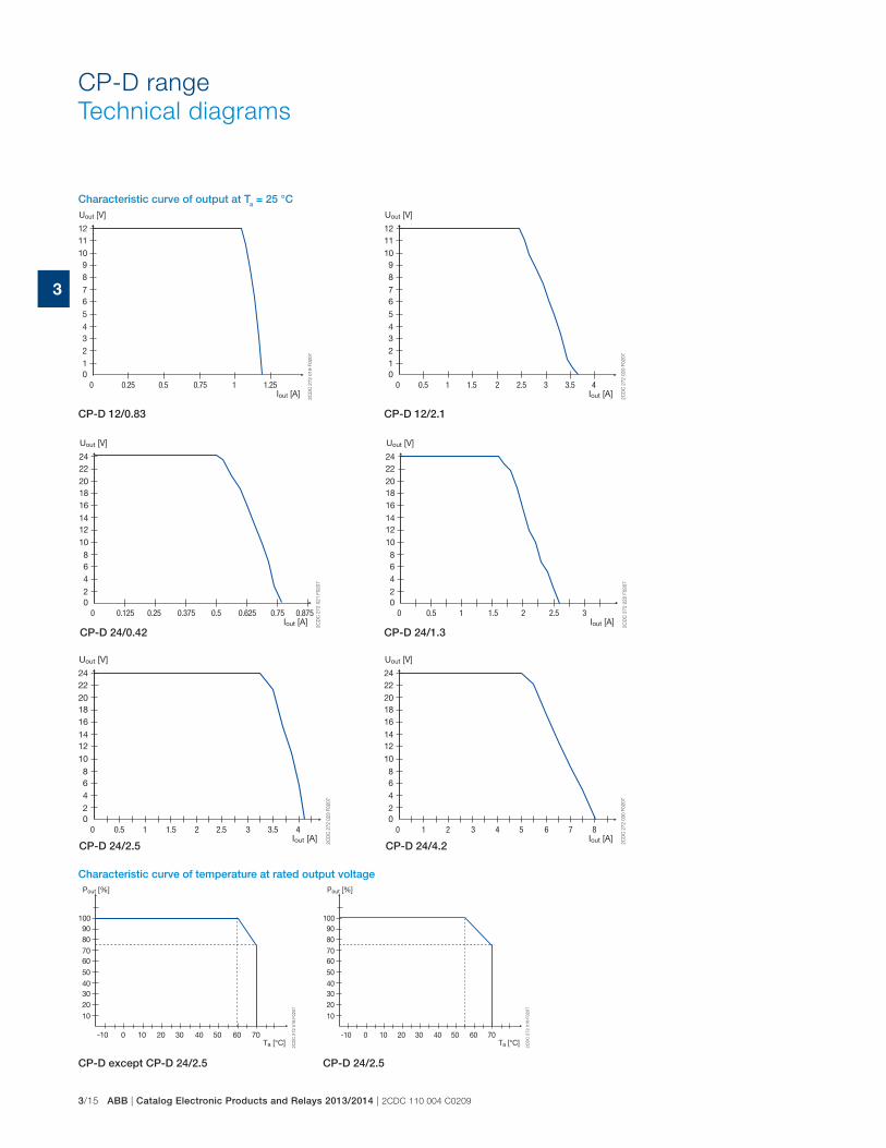
3/15 ABB | Catalog Electronic Products and Relays 2013/2014 | 2CDC 110 004 C0209
3
CP-D range
Technical diagrams
CP-D except CP-D 24/2.5 CP-D 24/2.5
CP-D 12/0.83 CP-D 12/2.1
CP-D 24/0.42 CP-D 24/1.3
CP-D 24/2.5 CP-D 24/4.2
Characteristic curve of output at Ta = 25 °C
-10 0 10 20 30 40 50 60 70
10
203040
50
6070
8090
100
2C
DC
272 0
18 F
0207
Pout [%]
Ta [°C]-10 0 10 20 30 40 50 60 70
10
203040
50
6070
8090
100
Pout [%]
Ta [°C]
2C
DC
27
2 0
18
F0
20
7
0
10
234
5
67
89
10
1112
2C
DC
27
2 0
19
F0
20
7
Uout [V]
Iout [A]0.50.25 0.75 1 1.25 0
10
234
5
67
89
10
1112
2C
DC
27
2 0
20
F0
20
7
Uout [V]
Iout [A]0.5 1 1.5 2 2.5 3 43.5
0
20
468
10
1214
161820
2224
2C
DC
27
2 0
21
F0
20
7
Uout [V]
Iout [A]0.125 0.25 0.5 0.6250.375 0.8750.75 0
20
468
10
1214
161820
2224
2C
DC
27
2 0
22
F0
20
7
Uout [V]
Iout [A]0.5 1 1.5 2 2.5 3
0
20
468
10
1214
161820
2224
2C
DC
27
2 0
23
F0
20
7
Uout [V]
Iout [A]0.5 1 1.5 2 2.5 3 43.5 0
20
468
10
1214
161820
2224
1 2 3 4 5 6 87
2C
DC
27
2 0
30
F0
20
7
Uout [V]
Iout [A]
Characteristic curve of temperature at rated output voltage
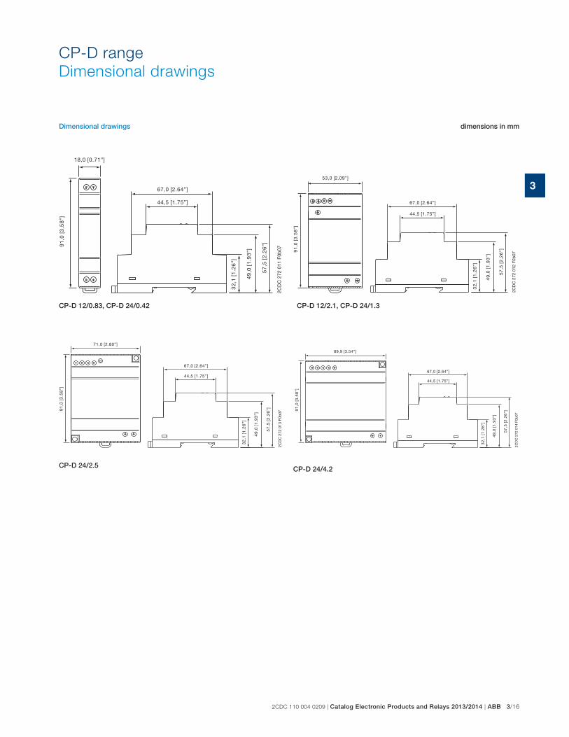
2CDC 110 004 0209 | Catalog Electronic Products and Relays 2013/2014 | ABB 3/16
3
CP-D range
Dimensional drawings
CP-D 24/4.2
CP-D 12/2.1, CP-D 24/1.3
CP-D 24/2.5
CP-D 12/0.83, CP-D 24/0.42
Dimensional drawings dimensions in mm
18,0 [0.71”]
67,0 [2.64”]
44,5 [1.75”]
91
,0 [
3.5
8”]
32
,1 [
1.2
6”]
57
,5 [
2.2
6”]
49
,0 [
1.9
3”]
2CD
C 2
72 0
11 F
0b07
67,0 [2.64”]
44,5 [1.75”]
32
,1 [
1.2
6”]
57
,5 [
2.2
6”]
49
,0 [
1.9
3”]
91
,0 [
3.5
8”]
53,0 [2.09”]
2CD
C 2
72 0
12 F
0b07
67,0 [2.64”]
44,5 [1.75”]
32
,1 [
1.2
6”]
57
,5 [
2.2
6”]
49
,0 [
1.9
3”]
91
,0 [
3.5
8”]
71,0 [2.80”]
2CD
C 2
72 0
13 F
0b07
67,0 [2.64”]
44,5 [1.75”]
32
,1 [
1.2
6”]
57
,5 [
2.2
6”]
49
,0 [
1.9
3”]
91
,0 [
3.5
8”]
89,9 [3.54”]
2CD
C 2
72 0
14 F
0b07
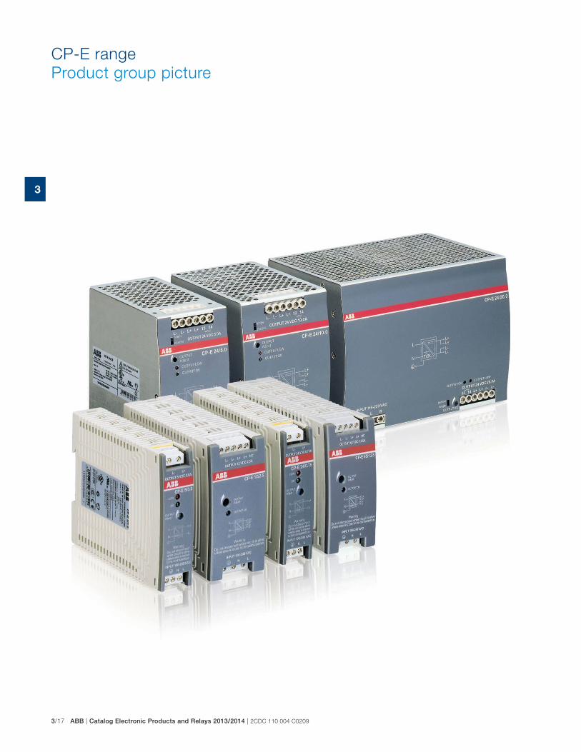
3/17 ABB | Catalog Electronic Products and Relays 2013/2014 | 2CDC 110 004 C0209
3
CP-E range
Product group picture
2CDC 110 004 0209 | Catalog Electronic Products and Relays 2013/2014 | ABB 3/18
3
CP-E range
Table of contents
CP-E range
Product group picture 3/17
Table of contents 3/18
Benefits and advantages 3/19
Ordering details 3/20
Technical data 3/21
Technical diagrams, Wiring instructions 3/29
Technical diagrams, Dimensional drawings 3/30
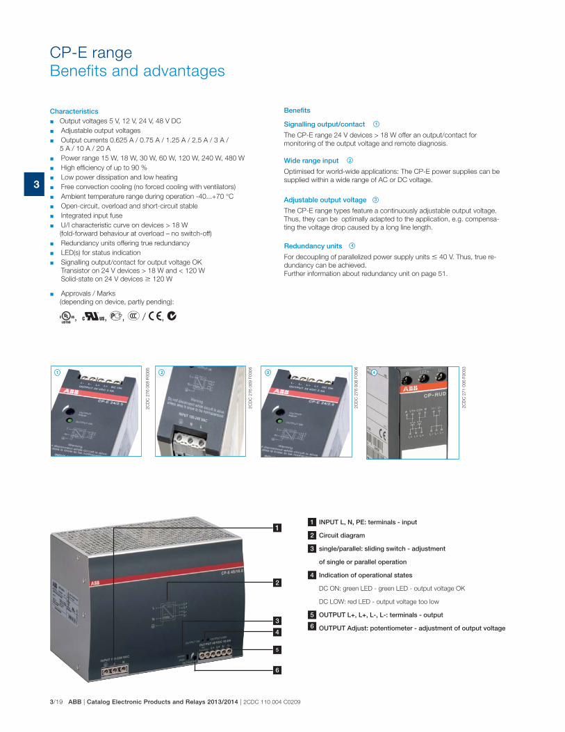
3/19 ABB | Catalog Electronic Products and Relays 2013/2014 | 2CDC 110 004 C0209
3
2C
DC
27
6 0
08
F0
00
6
2C
DC
27
6 0
08
F0
00
6
2C
DC
27
1 0
06
F0
00
3
2C
DC
27
6 0
09
F0
00
6
Characteristics � Output voltages 5 V, 12 V, 24 V, 48 V DC
� Adjustable output voltages
� Output currents 0.625 A / 0.75 A / 1.25 A / 2.5 A / 3 A /
5 A / 10 A / 20 A
� Power range 15 W, 18 W, 30 W, 60 W, 120 W, 240 W, 480 W
� High efficiency of up to 90 %
� Low power dissipation and low heating
� Free convection cooling (no forced cooling with ventilators)
� Ambient temperature range during operation -40...+70 °C
� Open-circuit, overload and short-circuit stable
� Integrated input fuse
� U/I characteristic curve on devices > 18 W
(fold-forward behaviour at overload – no switch-off)
� Redundancy units offering true redundancy
� LED(s) for status indication
� Signalling output/contact for output voltage OK
Transistor on 24 V devices > 18 W and < 120 W
Solid-state on 24 V devices � 120 W
� Approvals / Marks
(depending on device, partly pending):
A, H, D, E / a, b
Signalling output/contact
The CP-E range 24 V devices > 18 W offer an output/contact for
monitoring of the output voltage and remote diagnosis.
Wide range input
Optimised for world-wide applications: The CP-E power supplies can be
supplied within a wide range of AC or DC voltage.
Redundancy units
For decoupling of parallelized power supply units � 40 V. Thus, true re-
dundancy can be achieved.
Further information about redundancy unit on page 51.
Adjustable output voltage
The CP-E range types feature a continuously adjustable output voltage.
Thus, they can be optimally adapted to the application, e.g. compensa-
ting the voltage drop caused by a long line length.
Benefits
1
1
2
2
3
3
4
4
CP-E range
Benefits and advantages
4
1
2
3
5
1 INPUT L, N, PE: terminals - input
2 Circuit diagram
3 single/parallel: sliding switch - adjustment
of single or parallel operation
4 Indication of operational states
DC ON: green LED - green LED - output voltage OK
DC LOW: red LED - output voltage too low
5 OUTPUT L+, L+, L-, L-: terminals - output
OUTPUT Adjust: potentiometer - adjustment of output voltage
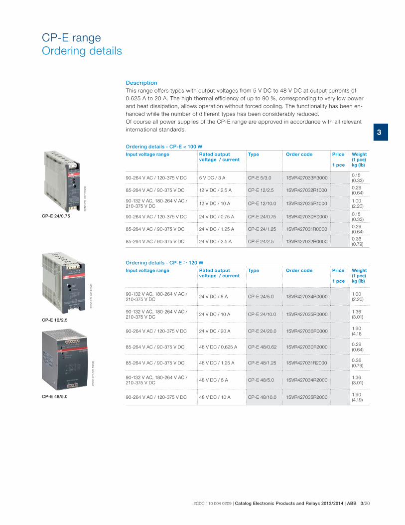
2CDC 110 004 0209 | Catalog Electronic Products and Relays 2013/2014 | ABB 3/20
3
DescriptionThis range offers types with output voltages from 5 V DC to 48 V DC at output currents of
0.625 A to 20 A. The high thermal efficiency of up to 90 %, corresponding to very low power
and heat dissipation, allows operation without forced cooling. The functionality has been en-
hanced while the number of different types has been considerably reduced.
Of course all power supplies of the CP-E range are approved in accordance with all relevant
international standards.
Ordering details - CP-E < 100 W
Input voltage range Rated output
voltage / current
Type Order code Price
1 pce
Weight
(1 pce)
kg (lb)
90-264 V AC / 120-375 V DC 5 V DC / 3 A CP-E 5/3.0 1SVR427033R30000.15
(0.33)
85-264 V AC / 90-375 V DC 12 V DC / 2.5 A CP-E 12/2.5 1SVR427032R10000.29
(0.64)
90-132 V AC, 180-264 V AC /
210-375 V DC12 V DC / 10 A CP-E 12/10.0 1SVR427035R1000
1.00
(2.20)
90-264 V AC / 120-375 V DC 24 V DC / 0.75 A CP-E 24/0.75 1SVR427030R00000.15
(0.33)
85-264 V AC / 90-375 V DC 24 V DC / 1.25 A CP-E 24/1.25 1SVR427031R00000.29
(0.64)
85-264 V AC / 90-375 V DC 24 V DC / 2.5 A CP-E 24/2.5 1SVR427032R00000.36
(0.79)
Ordering details - CP-E � 120 W
Input voltage range Rated output
voltage / current
Type Order code Price
1 pce
Weight
(1 pce)
kg (lb)
90-132 V AC, 180-264 V AC /
210-375 V DC24 V DC / 5 A CP-E 24/5.0 1SVR427034R0000
1.00
(2.20)
90-132 V AC, 180-264 V AC /
210-375 V DC24 V DC / 10 A CP-E 24/10.0 1SVR427035R0000
1.36
(3.01)
90-264 V AC / 120-375 V DC 24 V DC / 20 A CP-E 24/20.0 1SVR427036R00001.90
(4.18
85-264 V AC / 90-375 V DC 48 V DC / 0.625 A CP-E 48/0.62 1SVR427030R20000.29
(0.64)
85-264 V AC / 90-375 V DC 48 V DC / 1.25 A CP-E 48/1.25 1SVR427031R20000.36
(0.79)
90-132 V AC, 180-264 V AC /
210-375 V DC48 V DC / 5 A CP-E 48/5.0 1SVR427034R2000
1.36
(3.01)
90-264 V AC / 120-375 V DC 48 V DC / 10 A CP-E 48/10.0 1SVR427035R20001.90
(4.19)
2C
DC
27
1 0
13
F0
00
62
CD
C 2
71
02
8 F
00
08
2C
DC
27
1 0
17
F0
00
6
CP-E 12/2.5
CP-E 48/5.0
CP-E 24/0.75
CP-E range
Ordering details
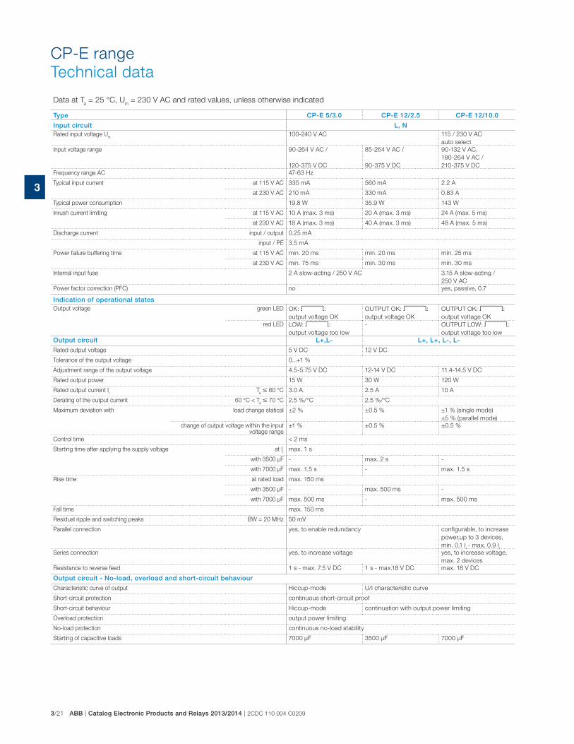
3/21 ABB | Catalog Electronic Products and Relays 2013/2014 | 2CDC 110 004 C0209
3
CP-E range
Technical data
Data at Ta = 25 °C, U
in = 230 V AC and rated values, unless otherwise indicated
Type CP-E 5/3.0 CP-E 12/2.5 CP-E 12/10.0
Input circuit L, NRated input voltage U
in100-240 V AC 115 / 230 V AC
auto select
Input voltage range 90-264 V AC /
120-375 V DC
85-264 V AC /
90-375 V DC
90-132 V AC,
180-264 V AC /
210-375 V DC
Frequency range AC 47-63 Hz
Typical input current at 115 V AC 335 mA 560 mA 2.2 A
at 230 V AC 210 mA 330 mA 0.83 A
Typical power consumption 19.8 W 35.9 W 143 W
Inrush current limiting at 115 V AC 10 A (max. 3 ms) 20 A (max. 3 ms) 24 A (max. 5 ms)
at 230 V AC 18 A (max. 3 ms) 40 A (max. 3 ms) 48 A (max. 5 ms)
Discharge current input / output 0.25 mA
input / PE 3.5 mA
Power failure buffering time at 115 V AC min. 20 ms min. 20 ms min. 25 ms
at 230 V AC min. 75 ms min. 30 ms min. 30 ms
Internal input fuse 2 A slow-acting / 250 V AC 3.15 A slow-acting /
250 V AC
Power factor correction (PFC) no yes, passive, 0.7
Indication of operational statesOutput voltage green LED OK: V:
output voltage OK
OUTPUT OK: V:
output voltage OK
OUTPUT OK: V:
output voltage OK
red LED LOW: V:
output voltage too low
- OUTPUT LOW: V:
output voltage too low
Output circuit L+,L- L+, L+, L-, L-
Rated output voltage 5 V DC 12 V DC
Tolerance of the output voltage 0...+1 %
Adjustment range of the output voltage 4.5-5.75 V DC 12-14 V DC 11.4-14.5 V DC
Rated output power 15 W 30 W 120 W
Rated output current Ir
Ta � 60 °C 3.0 A 2.5 A 10 A
Derating of the output current 60 °C < Ta � 70 °C 2.5 %/°C 2.5 %/°C
Maximum deviation with load change statical ±2 % ±0.5 % ±1 % (single mode)
±5 % (parallel mode)
change of output voltage within the input voltage range
±1 % ±0.5 % ±0.5 %
Control time < 2 ms
Starting time after applying the supply voltage at Ir
max. 1 s
with 3500 μF - max. 2 s -
with 7000 μF max. 1.5 s - max. 1.5 s
Rise time at rated load max. 150 ms
with 3500 μF - max. 500 ms -
with 7000 μF max. 500 ms - max. 500 ms
Fall time max. 150 ms
Residual ripple and switching peaks BW = 20 MHz 50 mV
Parallel connection yes, to enable redundancy configurable, to increase
power,up to 3 devices,
min. 0.1 Ir - max. 0.9 I
r
Series connection yes, to increase voltage yes, to increase voltage,
max. 2 devices
Resistance to reverse feed 1 s - max. 7.5 V DC 1 s - max.18 V DC max. 18 V DC
Output circuit - No-load, overload and short-circuit behaviour
Characteristic curve of output Hiccup-mode U/I characteristic curve
Short-circuit protection continuous short-circuit proof
Short-circuit behaviour Hiccup-mode continuation with output power limiting
Overload protection output power limiting
No-load protection continuous no-load stability
Starting of capacitive loads 7000 μF 3500 μF 7000 μF
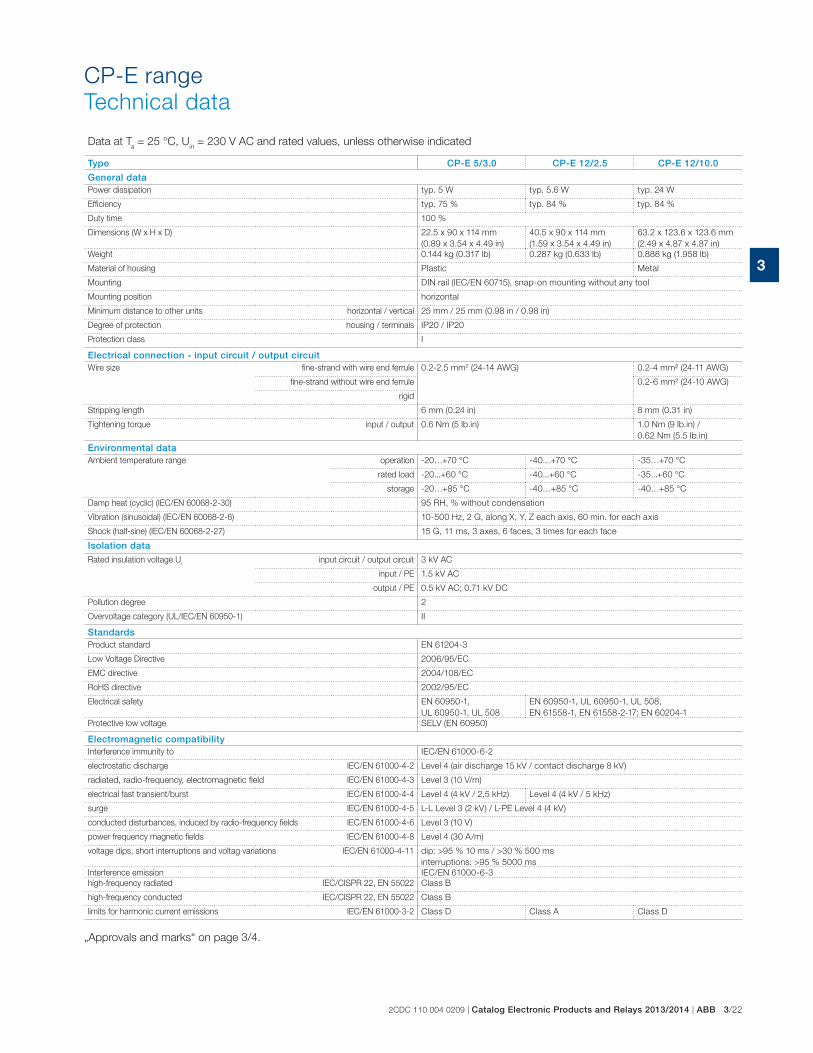
2CDC 110 004 0209 | Catalog Electronic Products and Relays 2013/2014 | ABB 3/22
3
CP-E range
Technical data
Data at Ta = 25 °C, U
in = 230 V AC and rated values, unless otherwise indicated
Type CP-E 5/3.0 CP-E 12/2.5 CP-E 12/10.0
General dataPower dissipation typ. 5 W typ. 5.6 W typ. 24 W
Efficiency typ. 75 % typ. 84 % typ. 84 %
Duty time 100 %
Dimensions (W x H x D) 22.5 x 90 x 114 mm
(0.89 x 3.54 x 4.49 in)
40.5 x 90 x 114 mm
(1.59 x 3.54 x 4.49 in)
63.2 x 123.6 x 123.6 mm
(2.49 x 4.87 x 4.87 in)
Weight 0.144 kg (0.317 lb) 0.287 kg (0.633 lb) 0.888 kg (1.958 lb)
Material of housing Plastic Metal
Mounting DIN rail (IEC/EN 60715), snap-on mounting without any tool
Mounting position horizontal
Minimum distance to other units horizontal / vertical 25 mm / 25 mm (0.98 in / 0.98 in)
Degree of protection housing / terminals IP20 / IP20
Protection class I
Electrical connection - input circuit / output circuitWire size fine-strand with wire end ferrule 0.2-2.5 mm2 (24-14 AWG) 0.2-4 mm² (24-11 AWG)
fine-strand without wire end ferrule 0.2-6 mm² (24-10 AWG)
rigid
Stripping length 6 mm (0.24 in) 8 mm (0.31 in)
Tightening torque input / output 0.6 Nm (5 lb.in) 1.0 Nm (9 lb.in) /
0.62 Nm (5.5 lb.in)
Environmental dataAmbient temperature range operation -20…+70 °C -40…+70 °C -35…+70 °C
rated load -20...+60 °C -40...+60 °C -35...+60 °C
storage -20…+85 °C -40…+85 °C -40…+85 °C
Damp heat (cyclic) (IEC/EN 60068-2-30) 95 RH, % without condensation
Vibration (sinusoidal) (IEC/EN 60068-2-6) 10-500 Hz, 2 G, along X, Y, Z each axis, 60 min. for each axis
Shock (half-sine) (IEC/EN 60068-2-27) 15 G, 11 ms, 3 axes, 6 faces, 3 times for each face
Isolation data
Rated insulation voltage Ui
input circuit / output circuit 3 kV AC
input / PE 1.5 kV AC
output / PE 0.5 kV AC; 0.71 kV DC
Pollution degree 2
Overvoltage category (UL/IEC/EN 60950-1) II
StandardsProduct standard EN 61204-3
Low Voltage Directive 2006/95/EC
EMC directive 2004/108/EC
RoHS directive 2002/95/EC
Electrical safety EN 60950-1,
UL 60950-1, UL 508
EN 60950-1, UL 60950-1, UL 508,
EN 61558-1, EN 61558-2-17; EN 60204-1
Protective low voltage SELV (EN 60950)
Electromagnetic compatibilityInterference immunity to IEC/EN 61000-6-2
electrostatic discharge IEC/EN 61000-4-2 Level 4 (air discharge 15 kV / contact discharge 8 kV)
radiated, radio-frequency, electromagnetic field IEC/EN 61000-4-3 Level 3 (10 V/m)
electrical fast transient/burst IEC/EN 61000-4-4 Level 4 (4 kV / 2,5 kHz) Level 4 (4 kV / 5 kHz)
surge IEC/EN 61000-4-5 L-L Level 3 (2 kV) / L-PE Level 4 (4 kV)
conducted disturbances, induced by radio-frequency fields IEC/EN 61000-4-6 Level 3 (10 V)
power frequency magnetic fields IEC/EN 61000-4-8 Level 4 (30 A/m)
voltage dips, short interruptions and voltag variations IEC/EN 61000-4-11 dip: >95 % 10 ms / >30 % 500 ms
interruptions: >95 % 5000 ms
Interference emission IEC/EN 61000-6-3
high-frequency radiated IEC/CISPR 22, EN 55022 Class B
high-frequency conducted IEC/CISPR 22, EN 55022 Class B
limits for harmonic current emissions IEC/EN 61000-3-2 Class D Class A Class D
„Approvals and marks“ on page 3/4.
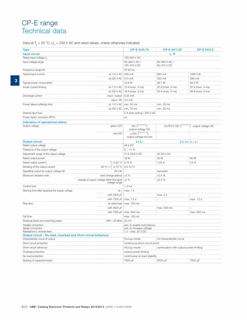
3/23 ABB | Catalog Electronic Products and Relays 2013/2014 | 2CDC 110 004 C0209
3
CP-E range
Technical data
Data at Ta = 25 °C, U
in = 230 V AC and rated values, unless otherwise indicated
Type CP-E 24/0.75 CP-E 24/1.25 CP-E 24/2.5
Input circuit L, NRated input voltage U
in100-240 V AC
Input voltage range 90-264 V AC /
120-375 V DC
85-264 V AC /
90-375 V DC
Frequency range AC 47-63 Hz
Typical input current at 115 V AC 335 mA 560 mA 1060 mA
at 230 V AC 210 mA 330 mA 590 mA
Typical power consumption 22.8 W 36.7 W 69.2 W
Inrush current limiting at 115 V AC 10 A (max. 3 ms) 20 A (max. 3 ms) 20 A (max. 3 ms)
at 230 V AC 18 A (max. 3 ms) 40 A (max. 3 ms) 40 A (max. 3 ms)
Discharge current input / output 0.25 mA
input / PE 3.5 mA
Power failure buffering time at 115 V AC min. 20 ms min. 20 ms
at 230 V AC min. 75 ms min. 30 ms
Internal input fuse 2 A slow-acting / 250 V AC
Power factor correction (PFC) no
Indication of operational statesOutput voltage green LED OK: V:
output voltage OK
OUTPUT OK: V: output voltage OK
red LED LOW: V:
output voltage too low
- -
Output circuit L+,L- L+, L+, L-, L-Rated output voltage 24 V DC
Tolerance of the output voltage 0 ... +1 %
Adjustment range of the output voltage 21.6-28.8 V DC 24-28 V DC
Rated output power 18 W 30 W 60 W
Rated output current Ir
Ta � 60 °C 0.75 A 1.25 A 2.5 A
Derating of the output current 60 °C < Ta � 70 °C 2.5 %/°C
Signalling output for output voltage OK DC OK - transistor
Maximum deviation with load change statical ±2 % ±0.5 %
change of output voltage within the input voltage range
±1 % ±0.5 %
Control time < 2 ms
Starting time after applying the supply voltage at Ir
max. 1 s
with 3500 μF - max. 2 s -
with 7000 μF max. 1.5 s - max. 1.5 s
Rise time at rated load max. 150 ms
with 3500 μF - max. 500 ms -
with 7000 μF max. 500 ms - max. 500 ms
Fall time max. 150 ms
Residual ripple and switching peaks BW = 20 MHz 50 mV
Parallel connection yes, to enable redundancy
Series connection yes, to increase voltage
Resistance to reverse feed 1 s - max. 35 V DC
Output circuit - No-load, overload and short-circuit behaviourCharacteristic curve of output Hiccup-mode U/I characteristic curve
Short-circuit protection continuous short-circuit proof
Short-circuit behaviour Hiccup-mode continuation with output power limiting
Overload protection output power limiting
No-load protection continuous no-load stability
Starting of capacitive loads 7000 μF 3500 μF 7000 μF
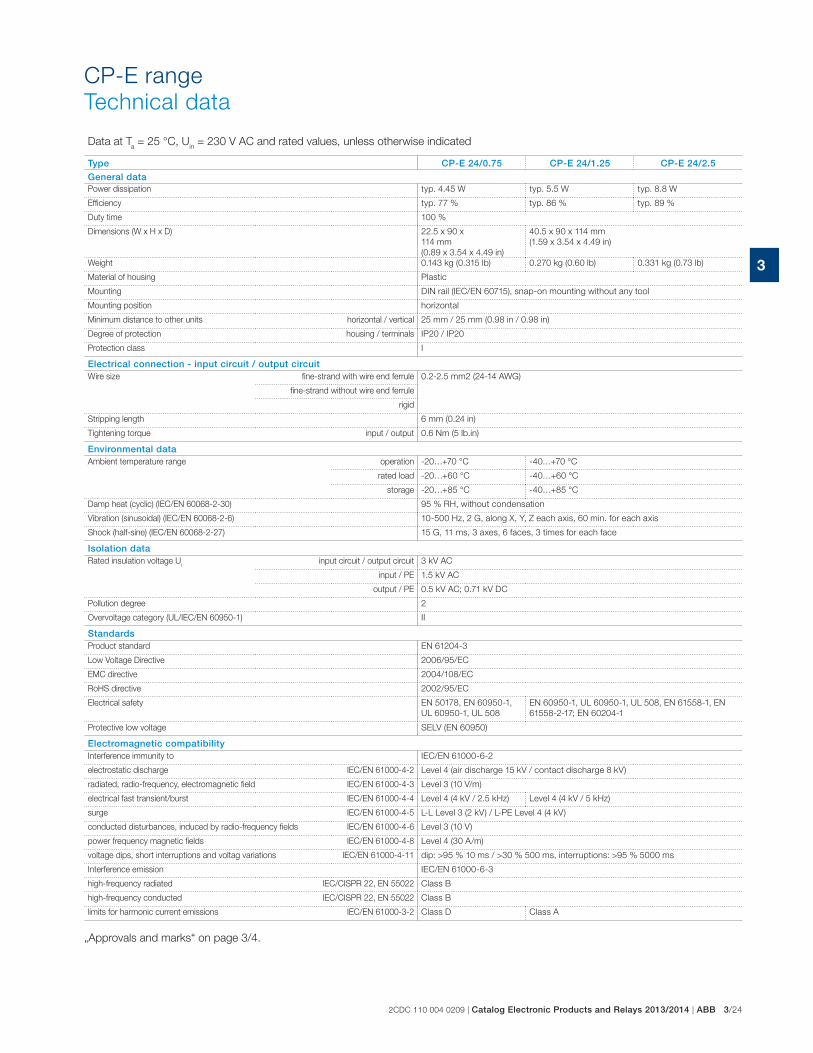
2CDC 110 004 0209 | Catalog Electronic Products and Relays 2013/2014 | ABB 3/24
3
CP-E range
Technical data
Data at Ta = 25 °C, U
in = 230 V AC and rated values, unless otherwise indicated
Type CP-E 24/0.75 CP-E 24/1.25 CP-E 24/2.5General dataPower dissipation typ. 4.45 W typ. 5.5 W typ. 8.8 W
Efficiency typ. 77 % typ. 86 % typ. 89 %
Duty time 100 %
Dimensions (W x H x D) 22.5 x 90 x
114 mm
(0.89 x 3.54 x 4.49 in)
40.5 x 90 x 114 mm
(1.59 x 3.54 x 4.49 in)
Weight 0.143 kg (0.315 lb) 0.270 kg (0.60 lb) 0.331 kg (0.73 lb)
Material of housing Plastic
Mounting DIN rail (IEC/EN 60715), snap-on mounting without any tool
Mounting position horizontal
Minimum distance to other units horizontal / vertical 25 mm / 25 mm (0.98 in / 0.98 in)
Degree of protection housing / terminals IP20 / IP20
Protection class I
Electrical connection - input circuit / output circuitWire size fine-strand with wire end ferrule 0.2-2.5 mm2 (24-14 AWG)
fine-strand without wire end ferrule
rigid
Stripping length 6 mm (0.24 in)
Tightening torque input / output 0.6 Nm (5 lb.in)
Environmental dataAmbient temperature range operation -20…+70 °C -40…+70 °C
rated load -20…+60 °C -40…+60 °C
storage -20…+85 °C -40…+85 °C
Damp heat (cyclic) (IEC/EN 60068-2-30) 95 % RH, without condensation
Vibration (sinusoidal) (IEC/EN 60068-2-6) 10-500 Hz, 2 G, along X, Y, Z each axis, 60 min. for each axis
Shock (half-sine) (IEC/EN 60068-2-27) 15 G, 11 ms, 3 axes, 6 faces, 3 times for each face
Isolation dataRated insulation voltage U
iinput circuit / output circuit 3 kV AC
input / PE 1.5 kV AC
output / PE 0.5 kV AC; 0.71 kV DC
Pollution degree 2
Overvoltage category (UL/IEC/EN 60950-1) II
StandardsProduct standard EN 61204-3
Low Voltage Directive 2006/95/EC
EMC directive 2004/108/EC
RoHS directive 2002/95/EC
Electrical safety EN 50178, EN 60950-1,
UL 60950-1, UL 508
EN 60950-1, UL 60950-1, UL 508, EN 61558-1, EN
61558-2-17; EN 60204-1
Protective low voltage SELV (EN 60950)
Electromagnetic compatibilityInterference immunity to IEC/EN 61000-6-2
electrostatic discharge IEC/EN 61000-4-2 Level 4 (air discharge 15 kV / contact discharge 8 kV)
radiated, radio-frequency, electromagnetic field IEC/EN 61000-4-3 Level 3 (10 V/m)
electrical fast transient/burst IEC/EN 61000-4-4 Level 4 (4 kV / 2.5 kHz) Level 4 (4 kV / 5 kHz)
surge IEC/EN 61000-4-5 L-L Level 3 (2 kV) / L-PE Level 4 (4 kV)
conducted disturbances, induced by radio-frequency fields IEC/EN 61000-4-6 Level 3 (10 V)
power frequency magnetic fields IEC/EN 61000-4-8 Level 4 (30 A/m)
voltage dips, short interruptions and voltag variations IEC/EN 61000-4-11 dip: >95 % 10 ms / >30 % 500 ms, interruptions: >95 % 5000 ms
Interference emission IEC/EN 61000-6-3
high-frequency radiated IEC/CISPR 22, EN 55022 Class B
high-frequency conducted IEC/CISPR 22, EN 55022 Class B
limits for harmonic current emissions IEC/EN 61000-3-2 Class D Class A
„Approvals and marks“ on page 3/4.
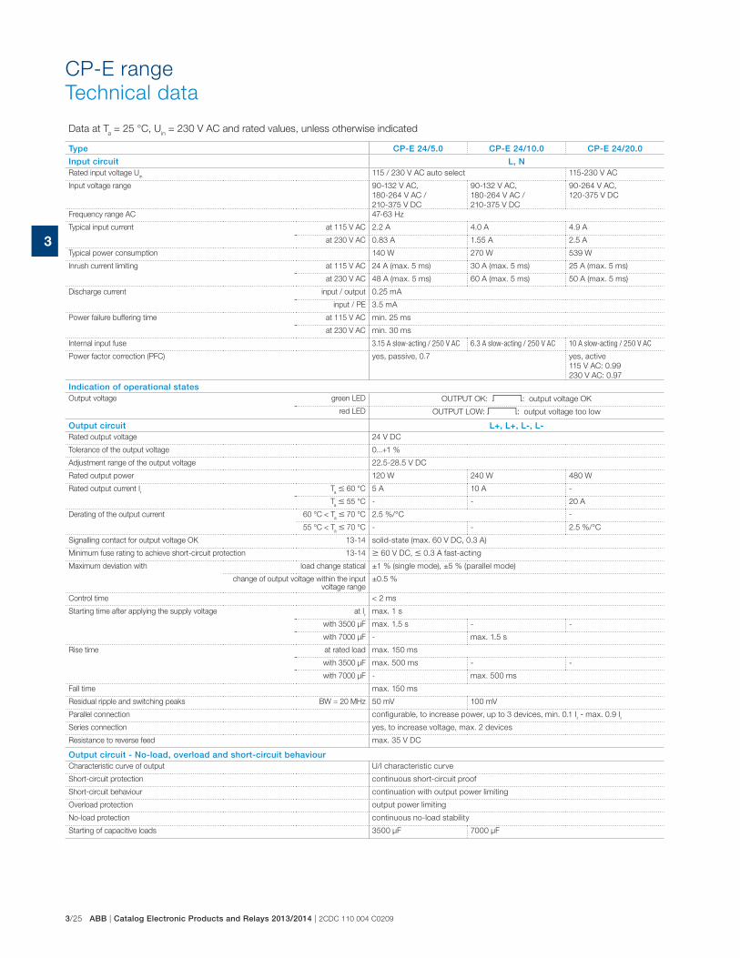
3/25 ABB | Catalog Electronic Products and Relays 2013/2014 | 2CDC 110 004 C0209
3
CP-E range
Technical data
Data at Ta = 25 °C, U
in = 230 V AC and rated values, unless otherwise indicated
Type CP-E 24/5.0 CP-E 24/10.0 CP-E 24/20.0
Input circuit L, NRated input voltage U
in115 / 230 V AC auto select 115-230 V AC
Input voltage range 90-132 V AC,
180-264 V AC /
210-375 V DC
90-132 V AC,
180-264 V AC /
210-375 V DC
90-264 V AC,
120-375 V DC
Frequency range AC 47-63 Hz
Typical input current at 115 V AC 2.2 A 4.0 A 4.9 A
at 230 V AC 0.83 A 1.55 A 2.5 A
Typical power consumption 140 W 270 W 539 W
Inrush current limiting at 115 V AC 24 A (max. 5 ms) 30 A (max. 5 ms) 25 A (max. 5 ms)
at 230 V AC 48 A (max. 5 ms) 60 A (max. 5 ms) 50 A (max. 5 ms)
Discharge current input / output 0.25 mA
input / PE 3.5 mA
Power failure buffering time at 115 V AC min. 25 ms
at 230 V AC min. 30 ms
Internal input fuse 3.15 A slow-acting / 250 V AC 6.3 A slow-acting / 250 V AC 10 A slow-acting / 250 V AC
Power factor correction (PFC) yes, passive, 0.7 yes, active
115 V AC: 0.99
230 V AC: 0.97
Indication of operational statesOutput voltage green LED OUTPUT OK: V: output voltage OK
red LED OUTPUT LOW: V: output voltage too low
Output circuit L+, L+, L-, L-Rated output voltage 24 V DC
Tolerance of the output voltage 0...+1 %
Adjustment range of the output voltage 22.5-28.5 V DC
Rated output power 120 W 240 W 480 W
Rated output current Ir
Ta � 60 °C 5 A 10 A -
Ta � 55 °C - - 20 A
Derating of the output current 60 °C < Ta � 70 °C 2.5 %/°C -
55 °C < Ta � 70 °C - - 2.5 %/°C
Signalling contact for output voltage OK 13-14 solid-state (max. 60 V DC, 0.3 A)
Minimum fuse rating to achieve short-circuit protection 13-14 � 60 V DC, � 0.3 A fast-acting
Maximum deviation with load change statical ±1 % (single mode), ±5 % (parallel mode)
change of output voltage within the input voltage range
±0.5 %
Control time < 2 ms
Starting time after applying the supply voltage at Ir
max. 1 s
with 3500 μF max. 1.5 s - -
with 7000 μF - max. 1.5 s
Rise time at rated load max. 150 ms
with 3500 μF max. 500 ms - -
with 7000 μF - max. 500 ms
Fall time max. 150 ms
Residual ripple and switching peaks BW = 20 MHz 50 mV 100 mV
Parallel connection configurable, to increase power, up to 3 devices, min. 0.1 Ir - max. 0.9 I
r
Series connection yes, to increase voltage, max. 2 devices
Resistance to reverse feed max. 35 V DC
Output circuit - No-load, overload and short-circuit behaviourCharacteristic curve of output U/I characteristic curve
Short-circuit protection continuous short-circuit proof
Short-circuit behaviour continuation with output power limiting
Overload protection output power limiting
No-load protection continuous no-load stability
Starting of capacitive loads 3500 μF 7000 μF
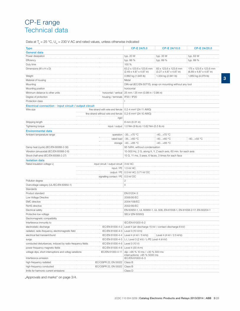
2CDC 110 004 0209 | Catalog Electronic Products and Relays 2013/2014 | ABB 3/26
3
CP-E range
Technical data
Data at Ta = 25 °C, U
in = 230 V AC and rated values, unless otherwise indicated
Type CP-E 24/5.0 CP-E 24/10.0 CP-E 24/20.0
General dataPower dissipation typ. 20 W typ. 35 W typ. 63 W
Efficiency typ. 86 % typ. 89 % typ. 89 %
Duty time 100 %
Dimensions (W x H x D) 63.2 x 123.6 x 123.6 mm
(2.49 x 4.87 x 4.87 in)
83 x 123.6 x 123.6 mm
(3.27 x 4.87 x 4.87 in)
175 x 123.6 x 123.6 mm
(6.89 x 4.87 x 4.87 in)
Weight 0.882 kg (1.945 lb) 1.334 kg (2.941 lb) 1.850 kg (4.079 lb)
Material of housing Metal
Mounting DIN rail (IEC/EN 60715), snap-on mounting without any tool
Mounting position horizontal
Minimum distance to other units horizontal / vertical 25 mm / 25 mm (0.98 in / 0.98 in)
Degree of protection housing / terminals IP20 / IP20
Protection class I
Electrical connection - input circuit / output circuitWire size fine-strand with wire end ferrule 0.2-4 mm² (24-11 AWG)
fine-strand without wire end ferrule 0.2-6 mm² (24-10 AWG)
rigid
Stripping length 8 mm (0.31 in)
Tightening torque input / output 1.0 Nm (9 lb.in) / 0.62 Nm (5.5 lb.in)
Environmental dataAmbient temperature range operation -35…+70 °C -40…+70 °C
rated load -35…+60 °C -40…+60 °C -40…+55 °C
storage -40…+85 °C -40…+85 °C
Damp heat (cyclic) (IEC/EN 60068-2-30) 95 %RH, without condensation
Vibration (sinusoidal) (IEC/EN 60068-2-6) 10-500 Hz, 2 G, along X, Y, Z each axis, 60 min. for each axis
Shock (half-sine) (IEC/EN 60068-2-27) 15 G, 11 ms, 3 axes, 6 faces, 3 times for each face
Isolation dataRated insulation voltage U
iinput circuit / output circuit 3 kV AC
input / PE 1.5 kV AC
output / PE 0.5 kV AC; 0.71 kV DC
signalling contact / PE 0.5 kV DC
Pollution degree 2
Overvoltage category (UL/IEC/EN 60950-1) II
Standards
Product standard EN 61204-3
Low Voltage Directive 2006/95/EC
EMC directive 2004/108/EC
RoHS directive 2002/95/EC
Electrical safety EN 60950-1, UL 60950-1, UL 508, EN 61558-1, EN 61558-2-17; EN 60204-1
Protective low voltage SELV (EN 60950)
Electromagnetic compatibility
Interference immunity to IEC/EN 61000-6-2
electrostatic discharge IEC/EN 61000-4-2 Level 4 (air discharge 15 kV / contact discharge 8 kV)
radiated, radio-frequency, electromagnetic field IEC/EN 61000-4-3 Level 3 (10 V/m)
electrical fast transient/burst IEC/EN 61000-4-4 Level 4 (4 kV / 5 kHz) Level 4 (4 kV / 2.5 kHz)
surge IEC/EN 61000-4-5 L-L Level 3 (2 kV) / L-PE Level 4 (4 kV)
conducted disturbances, induced by radio-frequency fields IEC/EN 61000-4-6 Level 3 (10 V)
power frequency magnetic fields IEC/EN 61000-4-8 Level 4 (30 A/m)
voltage dips, short interruptions and voltag variations IEC/EN 61000-4-11 dip: >95 % 10 ms / >30 % 500 ms
interruptions: >95 % 5000 ms
Interference emission IEC/EN 61000-6-3
high-frequency radiated IEC/CISPR 22, EN 55022 Class B
high-frequency conducted IEC/CISPR 22, EN 55022 Class B
limits for harmonic current emissions Class D
„Approvals and marks“ on page 3/4.

3/27 ABB | Catalog Electronic Products and Relays 2013/2014 | 2CDC 110 004 C0209
3
CP-E range
Technical data
Data at Ta = 25 °C, U
in = 230 V AC and rated values, unless otherwise indicated
Type CP-E 48/0.62 CP-E 48/1.25 CP-E 48/5.0 CP-E 48/10.0
Input circuit L, NRated input voltage U
in 100-240 V AC115 / 230 V AC
auto select115-230 V AC
Input voltage range85-264 V AC /
90-375 V DC
90-132 V AC,
180-264 V AC /
210-375 V DC
90-264 V AC,
120-375 V DC
Frequency range AC 47-63 Hz
Typical input current at 115 V AC 560 mA 1060 mA 4.0 A 4.9 A
at 230 V AC 330 mA 590 mA 1.55 A 2.5 A
Typical power consumption 35.7 W 69.0 W 267 W 528 W
Inrush current limiting at 115 V AC 20 A (max. 3 ms) 20 A (max. 3 ms) 30 A (max. 5 ms) 25 A (max. 5 ms)
at 230 V AC 40 A (max. 3 ms) 40 A (max. 3 ms) 60 A (max. 5 ms) 50 A (max. 5 ms)
Discharge current input / output 0.25 mA
input / PE 3.5 mA
Power failure buffering time at 115 V AC min. 20 ms min. 25 ms min. 25 ms
at 230 V AC min. 30 ms
Internal input fuse 2 A slow-acting /
250 V AC
6.3 A slow-acting /
250 V AC
10 A slow-acting /
250 V AC
Power factor correction (PFC)
no yes, passive, 0.7
yes, active
115 V AC: 0.99
230 V AC: 0.97
Indication of operational statesOutput voltage green LED OUTPUT OK: V: output voltage OK
red LED- -
OUTPUT LOW: V:
output voltage too low
Output circuit L+, L+, L-, L-Rated output voltage 48 V DC
Tolerance of the output voltage 0...+1 %
Adjustment range of the output voltage 48-55 V DC 47-56 V DC
Rated output power 30 W 60 W 240 W 480 W
Rated output current Ir
Ta � 60 °C 0.625 A 1.25 A 5 A -
Ta � 55 °C - - - 10 A
Derating of the output current 60 °C < Ta � 70 °C 2.5 %/°C -
55 °C < Ta � 70 °C - - - 2.5 %/°C
Signalling output for output voltage OK DC OK - - - -
Maximum deviation with load change statical±0.5 %
±1 % (single mode)
±5 % (parallel mode)
change of output voltage within the input voltage range
±0.5 % ±0.5 %
Control time < 2 ms
Starting time after applying the supply voltage at Ir max. 1 s
with 3500 μF max. 2 s - - -
with 7000 μF - max. 1.5 s max. 1.5 s
Rise time at rated load max. 150 ms
with 3500 μF max. 500 ms - - -
with 7000 μF - max. 500 ms max. 500 ms
Fall time max. 150 ms
Residual ripple and switching peaks BW = 20 MHz 50 mV 100 mV
Parallel connection
yes, to enable redundancy
configurable, to increase power,
up to 3 devices,
min. 0.1 Ir - max. 0.9 I
r
Series connectionyes, to increase voltage
yes, to increase voltage,
max. 2 devices
Resistance to reverse feed 1 s - max. 63 V DC
Output circuit - No-load, overload and short-circuit behaviourCharacteristic curve of output U/I characteristic curve
Short-circuit protection continuous short-circuit proof
Short-circuit behaviour continuation with output power limiting
Overload protection output power limiting
No-load protection continuous no-load stability
Starting of capacitive loads 3500 μF 7000 μF unlimited 7000 μF

2CDC 110 004 0209 | Catalog Electronic Products and Relays 2013/2014 | ABB 3/28
3
CP-E range
Technical data
Data at Ta = 25 °C, U
in = 230 V AC and rated values, unless otherwise indicated
Type CP-E 48/0.62 CP-E 48/1.25 CP-E 48/5.0 CP-E 48/10.0
General dataPower dissipation typ. 4.9 W typ. 7.8 W typ. 32 W typ. 60 W
Efficiency typ. 86 % typ. 89 % typ. 90 %
Duty time 100 %
Dimensions (W x H x D)
40.5 x 90 x 114 mm
(1.59 x 3.54 x 4.49 in)
83 x 123.6 x
123.6 mm
(3.27 x 4.87 x
4.87 in)
175 x 123.6 x
123.6 mm
(6.89 x 4.87 x
4.87 in)
Weight 0.264 kg (0.582 lb) 0.316 kg (0.697 lb) 1.322 kg (2.915 lb) 1.839 kg (4.054 lb)
Material of housing Plastic Metal
Mounting DIN rail (IEC/EN 60715), snap-on mounting without any tool
Mounting position horizontal
Minimum distance to other units horizontal / vertical 25 mm / 25 mm (0.98 in / 0.98 in)
Degree of protection housing / terminals IP/20 / IP20
Protection class I
Electrical connection - input circuit / output circuitWire size fine-strand with wire end ferrule
0.2-2.5 mm² (24-14 AWG)
0.2-4 mm² (24-11 AWG)
fine-strand without wire end ferrule0.2-6 mm² (24-10 AWG)
rigid
Stripping length 6 mm (0.24 in) 8 mm (0.31 in)
Tightening torque input / output 0.6 Nm (5 lb.in) 1.0 Nm (9 lb.in) / 0.62 Nm (5.5 lb.in)
Environmental dataAmbient temperature range operation -40…+70 °C
rated load -40…+60 °C -40…+55 °C
storage -40…+85 °C
Damp heat (cyclic) (IEC/EN 60068-2-30) 95 % RH, without condensation
Vibration (sinusoidal) (IEC/EN 60068-2-6) 10-500 Hz, 2 G, along X, Y, Z each axis, 60 min. for each axis
Shock (half-sine) (IEC/EN 60068-2-27) 15 G, 11 ms, 3 axes, 6 faces, 3 times for each face
Isolation data
Rated insulation voltage Ui
input circuit / output circuit 3 kV AC
input / PE 1.5 kV AC
output / PE 0.5 kV AC; 0.71 kV DC
Pollution degree 2
Overvoltage category (UL/IEC/EN 60950-1) II
Standards
Product standard EN 61204-3
Low Voltage Directive 2006/95/EC
EMC directive 2004/108/EC
RoHS directive 2002/95/EC
Electrical safety EN 60950-1, UL 60950-1, UL 508, EN 61558-1, EN 61558-2-17; EN 60204-1
Protective low voltage SELV (EN 60950)
Electromagnetic compatibility
Interference immunity to IEC/EN 61000-6-2
electrostatic discharge IEC/EN 61000-4-2 Level 4 (air discharge 15 kV / contact discharge 8 kV)
radiated, radio-frequency, electromagnetic field IEC/EN 61000-4-3 Level 3 (10 V/m)
electrical fast transient/burst IEC/EN 61000-4-4 Level 4 (4 kV / 5 kHz) Level 4 (4 kV / 2.5 kHz)
surge IEC/EN 61000-4-5 L-L Level 3 (2 kV) / L-PE Level 4 (4 kV)
conducted disturbances, induced by radio-frequency fields IEC/EN 61000-4-6 Level 3 (10 V/m)
power frequency magnetic fields IEC/EN 61000-4-8 Level 4 (30 A/m)
voltage dips, short interruptions and voltag variations IEC/EN 61000-4-11 dip: >95 % 10 ms / >30 % 500 ms, interruptions: >95 % 5000 ms
Interference emission IEC/EN 61000-6-3
high-frequency radiated IEC/CISPR 22, EN 55022 Class B
high-frequency conducted IEC/CISPR 22, EN 55022 Class B
limits for harmonic current emissions Class A Class D
„Approvals and marks“ on page 3/4.

3/29 ABB | Catalog Electronic Products and Relays 2013/2014 | 2CDC 110 004 C0209
3
CP-E range
Technical diagrams, Wiring instructions
Uout [V]
Iout [A] 1.25 1.35 1.45 1.55 1.65 1.75 1.85 1.95 2.05 2.15
2C
DC
272 0
06 F
0b
07
Uout [V]
Iout [A] 2.75 2.85 2.95 3.05 3.15 3.25 3.35 3.45 3.55 3.65
2C
DC
272 0
07 F
0b
07
Uout [V]
Iout [A] 2.8 2.9 3.0 3.1 3.2 3.3 3.4 3.5 3.6 3.7
1
3
5
7
9
11
13
15
2C
DC
272 0
08 F
0b
07
Uout [V]
Iout [A] 1.73 1.81 1.89 1.97 2.051.33 1.41 1.49 1.57 1.65
10
20
30
40
50
60
70
2C
DC
272 0
10 F
0b
07
CP-E 24/1.25
CP-E 24/2.5
CP-E 12/2.5
CP-E 48/0.62 CP-E 48/1.25
Uout [V]
Iout [A] 0.865 0.905 0.945 0.985 1.0250.665 0.705 0.745 0.785 0.825
10
20
30
40
50
60
70
2C
DC
272 0
09 F
0b
07
Uout [V]
Iout [A] 4 6 8 10 14 16122
2
4
6
8
10
12
14
2C
DC
272 0
05 F
0b
08
CP-E 12/10.0
Uout [V]
Iout [A] 2 3 4 5 7 861
4
8
12
16
20
24
28
2C
DC
272 0
06 F
0b
08
CP-E 24/5.0
Uout [V]
Iout [A] 4 6 8 10 14 16122
4
8
12
16
20
24
28
2C
DC
272 0
07 F
0b
08
CP-E 24/10.0
Uout [V]
Iout [A] 8 12 16 20 28 32244
4
8
12
16
20
24
28
2C
DC
272 0
08 F
0b
08
CP-E 24/20.0
CP-E 48/10.0CP-E 48/5.0
Uout [V]
Iout [A] 2 3 4 5 7 861
8
16
24
32
40
48
56
2C
DC
272 0
09 F
0b
08
Uout [V]
Iout [A] 4 6 8 10 14 16122
8
16
24
32
40
48
56
2C
DC
272 0
10 F
0b
08
CP-E 24/1.25, CP-E 24/2.5
Output curve at Ta = 25 °C
Wiring instructions
DC OK
L-L-
DC OK
2CD
C 2
72 0
17 F
0207
RelayRL > 700 �
5 V Signal
2.2 k�0.5 W
5.1 V0.3 W

2CDC 110 004 0209 | Catalog Electronic Products and Relays 2013/2014 | ABB 3/30
3
Temperature behaviour at Ta = 25 °C
CP-E range
Technical diagrams, Dimensional drawings
CP-E 12/10.0, CP-E 24/5.0
CP-E 5/3.0, CP-E 24/0.75 CP-E 12/2.5, CP-E 24/1.25, CP-E 48/0.62, CP-E 24/2.5, CP-E 48/1.25, CP-E 24/10.0, CP-E 48/5.0
CP-E 24/20.0, CP-E 48/10.0
2C
DC
27
2 0
15
F0
21
12
CD
C 2
72
01
6 F
02
11
2C
DC
27
2 0
17
F0
21
12
CD
C 2
72
01
8 F
02
11
-35 60 70
10
203040
50
6070
8090
100
Pout [%]
Ta [°C]
-20 60 70
10
203040
50
6070
8090
100
Pout [%]
Ta [°C]-40 60 70
10
203040
50
6070
8090
100
Pout [%]
Ta [°C]
-40 55 70
10
203040
50
6070
8090
100
Pout [%]
Ta [°C]
CP-E 5/3.0, CP-E 24/0.75
CP-E 12/2.5, CP-E 24/1.25, CP-E 24/2.5, CP-E 48/0.62, CP-E 48/1.25
CP-E 12/10.0, CP-E 24/5.0
CP-E 24/20.0, CP-E 48/10.0
CP-E 24/10.0, CP-E 48/5.0
175,0 [6.89“]
12
3,6
[4.
87“]
116,6 [4.59“]
123,6 [4.87“] 83,0 [3.27“]
12
3,6
[4.
87“]
63,2 [2.49“]
12
3,6
[4.
87“]
22.5 0.89“114 4.49“
90
3.
54“
40.5 1.59”
90
3
.54”
2C
DC
27
2
02
1 F
00
11
2C
DC
27
2
01
3 F
00
8Dimensional drawings dimensions in mm

3/31 ABB | Catalog Electronic Products and Relays 2013/2014 | 2CDC 110 004 C0209
3
CP-T range
Product group picture

2CDC 110 004 0209 | Catalog Electronic Products and Relays 2013/2014 | ABB 3/32
3
CP-T range
Table of contents
CP-T range
Product group picture 3/31
Table of contents 3/32
Benefits and advantages 3/33
Ordering details 3/34
Technical data 3/35
Technical diagrams, Dimensional drawings 3/39
Technical diagrams 3/40

3/33 ABB | Catalog Electronic Products and Relays 2013/2014 | 2CDC 110 004 C0209
3
CP-T range
Benefits and advantages
Characteristics
� Rated output voltages 24 V, 48 V DC
� Output voltage adjustable via front-face rotary potentiometer “OUTPUT Adjust”
� Rated output currents 5 A, 10 A, 20 A, 40 A
� Rated output powers 120 W, 240 W, 480 W, 960 W
� Three-phase or two-phase operation (see derating note)
� Supply range 3 x 400 – 500 V AC (3 x 340 – 575 V AC, 480 – 820 V DC)
� Typical efficiency of 93 %
� Low power dissipation and low heating
� Free convection cooling (no forced cooling with ventilators)
� Ambient temperature range during operation -40...+70 °C 1)
� Open-circuit, overload and short-circuit stable
� Integrated input fuse
� Redundancy unit CP-A RU offering true redundancy, available as
accessory
� LEDs for status indication
� Signalling contact "13-14" (solid state) for output voltage OK
� Approvals / marks (depending on device, partly pending):
A, H D, E / a , b
Signalling output
The devices of the CP-T series offer a solid state output for function
monitoring and remote diagnostics.
Wide input range
Wide range input optimized for world-wide applications:
The CP-T power supplies can be used in 340 - 575 V AC or 480 - 820 V
DC supply systems.
Adjustable output voltage
The CP-T range feature a continuously adjustable output voltage. Thus,
they can be optimally adapted to the application, e.g. compensating the
voltage drop caused by a long line length.
Benefits
1
1
2
2
1) 480 W variants: -30...+70°C
2C
DC
27
1 0
43
S0
00
9
2C
DC
27
1 0
43
S0
00
9
4
1
2
3
5
1 Circuit diagram
2 Indication of operational states
DC ON: green LED - green LED - output voltage OK
DC LOW: red LED - output voltage too low
3 single/parallel: sliding switch - adjustment
of single or parallel operation
4 Configuration of single or parallel operation
5 Signalling contact
OUTPUT 13-14: terminals - signalling contact
A solid-state output indicates the error-free operation of the output
voltage.
OUTPUT L+, L+, L-, L-: terminals - output
7 INPUT L1, L2, L3, PE: terminals - input7

2CDC 110 004 0209 | Catalog Electronic Products and Relays 2013/2014 | ABB 3/34
3
CP-T range
Ordering details
2C
DC
27
1 0
43
S0
00
9
2C
DC
27
1 0
45
S0
00
92
CD
C 2
71
04
7 S
00
09
CP-T 24/5.0
CP-T 24/10.0, CP-T 48/5.0
CP-T 24/20.0, CP-T 48/10.0
DescriptionThe CP-T range of three-phase power supply units is the youngest member of ABB‘s power
supply family. In terms of design and functionality, the new range perfectly supplements the
existing products and extends the range appropriately. The devices can be supplied with a
three-phase voltage as well as with two-phase mains. Here, ABB offers power supply units
with 24 V DC and 48 V DC outputs with 5 A, 10 A, 20 A and 40 A and efficiency of up to 92 %.
As in the case of all products, they are designed for an ambient temperature of up to 70 °C. All
products can be supplied within an AC supply voltage range between 340 to 575 V AC and a
DC supply voltage range between 480 to 820 V DC.
Ordering details
Input voltage range Rated output voltage / current
Type Order code Price
1 pce
Weight(1 pce)kg (lb)
340-575 V AC / 480-820 V DC 24 V DC / 5 A CP-T 24/5.0 1SVR427054R00000.80
(1.77)
340-575 V AC / 480-820 V DC 24 V DC / 10 A CP-T 24/10.0 1SVR427055R00001.05
(2.31)
340-575 V AC / 480-820 V DC 24 V DC / 20 A CP-T 24/20.0 1SVR427056R00001.75
(3.86)
340-575 V AC / 480-820 V DC 24 V DC / 40 A CP-T 24/40.0 1SVR427057R00003.20
(7.05)
340-575 V AC / 480-820 V DC 48 V DC / 5 A CP-E 48/5.0 1SVR427054R20001.05
(2.31)
340-575 V AC / 480-820 V DC 48 V DC / 10 A CP-E 48/10.0 1SVR427055R20001.75
(3.86)
340-575 V AC / 480-820 V DC 48 V DC / 20 A CP-E 48/20.0 1SVR427056R20003.40
(7.50)

3/35 ABB | Catalog Electronic Products and Relays 2013/2014 | 2CDC 110 004 C0209
3
CP-T range
Technical data
Data at Ta = 25 °C, U
in = 3 x 400 V AC and rated values, unless otherwise indicated
Type CP-T 24/5.0 CP-T 24/10.0 CP-T 24/20.0 CP-T 24/40.0
Input circuit L1, L2, L3Rated input voltage U
in3 x 400-500 V AC
Input voltage range 340-575 V AC
480-820 V DC
Frequency range AC 47-63 Hz
Typical input current 0.36 A 0.65 A 1.1 A 1.72 A
Typical power consumption 135 W 270 W 538 W 1058 W
Inrush current limiting 10 A 20 A 30 A
Power failure buffering time min. 20 ms min. 15 ms
Internal input fuse per phase 2 A / 600 V AC T 3.15 A / 500 V AC T 5 A / 500 V AC
Recommended backup fuse 3 pole miniature circuit breaker ABB Type S203
Power factor correction (PFC) Yes, passive
Discharge current towards PE < 3.5 mA
input / output < 0.25 mA
Indication of operational statesOutput voltage OUTPUT OK: green LED output voltage OK
OUTPUT LOW: red LED output voltage too low
Output circuit L+, L+, L-, L-Rated output voltage 24 V DC
Tolerance of the output voltage 0...+1 %
Adjustment range of the output voltage 22.5-28.5 V DC
Rated output power 120 W 240 W 480 W 960 W
Rated output current Ir
Ta 60 °C 5 A 10 A 20 A 40 A
Derating of the output current 60 °C < Ta 70 °C 2.5 %/°C 3.5 %/°C
Signalling contact for output voltage OK
13-14 solid state (max. 60 V DC, 0.3 A)
Threshold 17.6-19.4 V
Insulation voltage 500 V DC
Mininum fuse rating to achieve short-circuit protection 13-14 � 60 V DC, � 0.3 A fast-acting
Maximum deviation with load change statical ±1 % ±1 % (single mode)
- ± 5 % (parallel mode)
change of output voltage within the input voltage range
± 0.5 %
Control time at nominal load < 2 ms
Starting time after applying the supply voltage
at Ir
max. 1 s
with 3500 μF max. 1.5 s
Rise time at nominal load max. 150 ms
with 3500 μF max. 500 ms
Fall time max. 150 ms
Residual ripple and switching peaks BW = 20 MHz 100 mV 80 mV
Parallel connection not supported configurable, to increase
power, up to 2 devices,
min. 0.1 Ir - max 0.9 I
r)
to increase power,
up to 2 devices,
min. 0.1 Ir - max.
0.9 Ir use active
current balancing
Series connection not supported yes, to increase voltage, max. 2 devices
Resistance to reverse feed approx. 35 V
Output circuit - No-load, overload and short-circuit behaviourCharacteristic curve of output combined U/I characteristic curve
and hiccup mode
U/I- or Hiccup-
mode adjustable
hiccup /
fold back behavior
Short-circuit protection continuous short-circuit proof
Short-circuit behaviour current limiting
Overload protection hiccup mode
No-load protection continuous no-load stability
Overtemperature protection yes, automatic recovery after temperature went down
Starting of capacitive loads 3500 μF 7000 μF 7000 μF 7000 μF

2CDC 110 004 0209 | Catalog Electronic Products and Relays 2013/2014 | ABB 3/36
3
CP-T range
Technical data
Data at Ta = 25 °C, U
in = 3 x 400 V AC and rated values, unless otherwise indicated
Type CP-T 24/5.0 CP-T 24/10.0 CP-T 24/20.0 CP-T 24/40.0
General dataEfficiency typ. 89 % typ. 90 % typ. 92 %
Duty time 100%
Dimensions (W x H x D) 74.3 x 124 x 118.8
mm
(2.92 x 4.88 x
4.68 in)
89 x 124 x 118.8
mm
(3.5 x 4.88 x 4.68
in)
150 x 124 x 118.8
mm
(5.91 x 4.88 x
4.68 in)
275.8 x 124 x 118.8
mm
(10.86 x 4.88 x
4.68 in)
Weight 0.78 kg (1.72 lb) 1.045 kg (2.30 lb) 1.657 kg (3.653 lb) 3.275 kg (7.220 lb)
Material of housing Metal
Mounting DIN rail (IEC EN 60715), snap-on mounting without any tool
Mounting position horizontal
Minimum distance to other units horizontal / vertical 25 mm / 25 mm (0.98 in / 0.98 in)
Degree of protection housing / terminals IP20 / IP20
Protection class I
Electrical connection - input circuit / output circuit / signalling circuitWire size fine-strand with wire end ferrule 0,2-4 mm² (24-11 AWG)
fine-strand without wire end ferrule 0,2-6 mm² (24-10 AWG)
rigid 0,2-6 mm² (24-10 AWG)
Stripping length 8 mm (0.31 in)
Tightening torque input / output 1 Nm (9 lb.in) / 0.6 Nm (5.5 lb.in) 1 Nm (9 lb.in) /
1.8 Nm (15.6 lb.in)
Environmental data Ambient temperature range operation -40...+70 °C -30…+70 °C -40...+70 °C
rated load -40...+60 °C -30…+60 °C -40...+60 °C
storage -40…+85 °C
Damp heat (cyclic) (IEC/EN 60068-2-30) 95 % without condensation
Vibration (sinusoidal) (IEC/EN 60068-2-6) 2 g, 10-500 Hz, 2G, each along X, Y, Z axes 60 min / cycle
Shock (half-sine) (IEC/EN 60068-2-27) 15 g, 11 ms, 3 axes, 6 faces, 3 times for each face
Isolation dataRated insulation voltage U
iinput circuit / output circuit 3 kV AC
input / PE 1.5 kV AC
output / PE 0.5 kV AC; 0.71 kV DC
signalling output / PE 0.5 kV DC
Pollution degree 2
StandardsProduct standard EN 61204-3
Low Voltage Directive 2006/95/EC
EMC directive 2004/108/EC
RoHS directive 2002/95/EC
Electrical safety EN 60950-1, UL 60950-1, UL 508, EN 61558-1, EN 61558-2-17; EN 60204-1
Protective low voltage SELV
Electromagnetic compatibilityInterference immunity to IEC/EN 61000-6-2
electrostatic discharge IEC/EN 61000-4-2 Level 4 (air discharge 15 kV / contact discharge 8 kV)
radiated, radio-frequency, electromagnetic field IEC/EN 61000-4-3 Level 3 (10 V/m)
electrical fast transient/burst IEC/EN 61000-4-4 Level 4
(4 kV / 2.5 kHz)
Level 4 (4 kV / 5 kHz)
surge IEC/EN 61000-4-5 L-L Level 3 (2 kV) / L-PE Level 4 (4 kV)
conducted disturbances, induced by radio-frequency fields IEC/EN 61000-4-6 Level 3 (10 V)
power frequency magnetic fields IEC/EN 61000-4-8 Level 4 (30 A/m)
voltage dips, short interruptions and voltage variations IEC/EN 61000-4-11 dips: >95 % 0.5 ms / >30 % 0.5 ms, interruptions: >95 % 250 ms
Interference emission IEC/EN 61000-6-3
high-frequency radiated IEC/CISPR 22, EN 55022 Class B
high-frequency conducted IEC/CISPR 22, EN 55022 Class B
limits for harmonic current emissions IEC/EN 61000-3-2 Class A
„Approvals and marks“ on page 3/4.

3/37 ABB | Catalog Electronic Products and Relays 2013/2014 | 2CDC 110 004 C0209
3
CP-T range
Technical data
Data at Ta = 25 °C, U
in = 3 x 400 V AC and rated values, unless otherwise indicated
Type CP-T 48/5.0 CP-T 48/10.0 CP-T 48/20.0
Input circuit L1, L2, L3Rated input voltage U
in3 x 400-500 V AC
Input voltage ranget 340-575 V AC
480-820 V DC
Frequency range AC 47-63 Hz
Typical input current 0.65 A 1.1 A 1.72 A
Typical power consumption 264 W 535 W 1050 W
Inrush current limiting 20 A 30 A
Power failure buffering time min. 20 ms min. 15 ms
Internal input fuse per phase 2 A / 600 V AC T3.15 A / 500 V AC T 5 A / 500 V AC
Power factor correction (PFC) yes, passive
Discharge current towards PE < 3.5 mA
input / output < 0.25 mA
Indication of operational statesOutput voltage OUTPUT OK: green LED output voltage OK
OUTPUT LOW: red LED output voltage too low
Output circuit L+, L+, L-, L-Rated output voltage 48 V DC
Tolerance of the output voltage 0...+1 %
Adjustment range of the output voltage 47-56 V DC
Rated output power 240 W 480 W 960 W
Rated output current Ir
Ta � 60 °C 5 A 10 A 20 A
Derating of the output current 60 °C < Ta � 70 °C 2.5 %/°C 3.5 %/°C
Maximum deviation with load change statical ±1 % (single mode)
± 5 % (parallel mode)
change of output voltage within the input voltage range
±0.5 %
Control time at rated load < 2 ms
Starting time after applying the supply voltage at Ir max. 1 s
with 7000 μF max. 1.5 s
Rise time at rated load max. 150 ms
with 7000 μF max. 500 ms
Fall time max. 150 ms
Residual ripple and switching peaks BW = 20 MHz 100 mV 80 mV
Parallel connection configurable, to increase
power, up to 2 devices,
min. 0.1 Ir - max 0.9 I
r)
to increase power, up to 2
devices, min. 0.1 Ir - max.
0.9 Ir use active current
balancing
Series connection yes, to increase voltage, max. 2 devices
Resistance to reverse feed approx. 35 V approx. 63 V approx. 63 V
Output circuit - No-load, overload and short-circuit behaviourCharacteristic curve of output combined U/I and hiccup
mode
U/I or hiccup mode,
configurable
hiccup mode /
fold back behavior
Short-circuit protection continuous short-circuit proof
Short-circuit behaviour current limiting
Overload protection hiccup mode
No-load protection continuous no-load stability
Over temperature protection yes, automatic recovery after temperature went down
Starting of capacitive loads 7000 μF

2CDC 110 004 0209 | Catalog Electronic Products and Relays 2013/2014 | ABB 3/38
3
CP-T range
Technical data
Data at Ta = 25 °C, U
in = 3 x 400 V AC and rated values, unless otherwise indicated
Type CP-T 48/5.0 CP-T 48/10.0 CP-T 48/20.0
General dataEfficiency typ. 91 % typ. 93 %
Duty time 100%
Dimensions (W x H x D) 89 x 124 x 118.8 mm
(3.5 x 4.88 x 4.68 in)
150 x 124 x 118.8 mm
(5.91 x 4.88 x 4.68 in)
275.8 x 124 x 118.8 mm
(10.86 x 4.88 x 4.68 in)
Weight 1.045 kg (2.30 lb) 1.657 kg (3.653 lb) 3.275 kg (7.22 lb)
Material of housing Metal
Mounting DIN rail (IEC EN 60715), snap-on mounting without any tool
Mounting position horizontal
Minimum distance to other units horizontal / vertical 25 mm / 25 mm (0.98 in / 0.98 in)
Degree of protection housing / terminals IP20 / IP20
Protection class I
Electrical connection - input circuit / output circuitWire size fine-strand with wire end ferrule 0.2-4 mm² (24-11 AWG) 0.2-4 mm² (24-11 AWG) /
0.5-10 mm² (20-8 AWG)
fine-strand without wire end ferrule 0.2-6 mm² (24-10 AWG)
rigid
Stripping length 8 mm (0.31 in)
Tightening torque input / output 1 Nm (9 lb.in) / 0.6 Nm (5.5 lb.in) 1 Nm (9 lb.in) /
1.8 Nm (15.6 lb.in)
Environmental data Ambient temperature range operation -40…+70 °C -30…+70 °C -40…+70 °C
rated load -40…+60 °C -30…+60 °C -40…+60 °C
storage -40…+85 °C -40…+85 °C -40…+85 °C
Damp heat (cyclic) (IEC/EN 60068-2-30) 95 % without condensation
Vibration (sinusoidal) (IEC/EN 60068-2-6) 10-500 Hz, 2G, each along X, Y, Z axes 6 min / cycle
Shock (half-sine) (IEC/EN 60068-2-27) 15G, 11 ms, 3 axes, 6 Faces, 3 times for each face
Isolation dataRated insulation voltage U
iinput circuit / output circuit 3 kV AC
input / PE 1.5 kV AC
output / PE 0.5 kV AC; 0.71 kV DC
Pollution degree 2
Standards
Product standard EN 61204-3
Low Voltage Directive 2006/95/EC
EMC directive 2004/108/EC
RoHS directive 2002/95/EC
Electrical safety EN 60950-1, UL 60950-1, UL 508, EN 61558-1, EN 61558-2-17;
EN 60204-1
Protective low voltage SELV
Electromagnetic compatibility
Interference immunity to IEC/EN 61000-6-2
electrostatic discharge IEC/EN 61000-4-2 Level 4 (air discharge 15 kV / contact discharge 8 kV)
radiated, radio-frequency, electromagnetic field IEC/EN 61000-4-3 Level 3 (10 V/m)
electrical fast transient/burst IEC/EN 61000-4-4 Level 4 (4 kV / 5 kHz)
surge IEC/EN 61000-4-5 L-L Level 3 (2 kV) / L-PE Level 4 (4 kV)
conducted disturbances, induced by radio-frequency fields IEC/EN 61000-4-6 Level 3 (10 V)
power frequency magnetic fields IEC/EN 61000-4-8 Level 4 (30 A/m)
voltage dips, short interruptions and voltage variations IEC/EN 61000-4-11 dips: >95 % 0.5 ms / >30 % 0.5 ms
interruptions: >95 % 250 ms
Interference emission IEC/EN 61000-6-3
high-frequency radiated IEC/CISPR 22, EN 55022 Class B
high-frequency conducted IEC/CISPR 22, EN 55022 Class B
limits for harmonic current emissions IEC/EN 61000-3-2 Class A
„Approvals and marks“ on page 3/4.

3/39 ABB | Catalog Electronic Products and Relays 2013/2014 | 2CDC 110 004 C0209
3
CP-T range
Technical diagrams, Dimensional drawings
CP-T 24/5.0
CP-T 24/20.0 Hiccup mode
CP-T 48/10.0 U/I curve
CP-T 24/10.0
CP-T 24/40.0
CP-T 48/10.0 Hiccup mode
CP-T 24/20.0 U/I curve
CP-T 48/5.0
CP-T 48/20.0
CP-T 24/20.0, CP-T 48/10.0CP-T 24/10.0, CP-T 48/5.0 CP-T 24/40.0, CP-T 48/20.0
Output curve at TU = 25 °C
CP-T 24/5.0
Dimensional drawings dimensions in mm
2C
DC
27
2 0
32
F0
x0
92
CD
C 2
72
03
5 F
0x0
92
CD
C 2
72
03
8 F
0x0
9
2C
DC
27
2 0
33
F0
x0
92
CD
C 2
72
02
7 F
02
11
2C
DC
27
2 0
39
F0
x0
9
2C
DC
27
2 0
34
F0
x0
92
CD
C 2
72
03
7 F
0x0
92
CD
C 2
72
02
8 F
02
11
1 2 3 4 5 6 7 8
4
8
12
16
20
24
28
Uout [V]
Iout [A]
Hiccup mode
@ 3 x 400V supply@ 3 x 500V supply
4 8 12 16 20 24 28 32
4
8
12
16
20
24
28
Uout [V]
Iout [A]
@ 3 x 400V supply
@ 3 x 500V supply
Hiccup mode
2 4 6 8 10 12 14 16
8
16
24
32
40
48
56
Uout [V]
Iout [A]
@ 3 x 400V supply
@ 3 x 500V supply
2 4 6 8 10 12 14 16
4
8
12
16
20
24
28
Uout [V]
Iout [A]
Hiccup mode
@ 3 x 400V supply
@ 3 x 500V supply
8 16 24 32 40 48 56 64
4
8
12
16
20
24
28
Uout in V
72 80 Iout in A
Hiccup mode
after 5-10 s overload
U/I
@ 3 x 400 V supply
2 4 6 8 10 12 14 16
8
16
24
32
40
48
56
Uout [V]
Iout [A]
@ 3 x 400V supply
@ 3 x 500V supply
Hiccup mode
4 8 12 16 20 24 28 32
4
8
12
16
20
24
28
Uout [V]
Iout [A]
@ 3 x 400V supply
@ 3 x 500V supply
1 2 3 4 5 6 7 8
8
16
24
32
40
48
56
Uout [V]
Iout [A]
Hiccup mode
@ 3 x 400V supply
@ 3 x 500V supply
4 8 12 16 20 24 28 32
8
16
24
32
40
48
56
Uout in V
36 40 Iout in A
Hiccup mode
after 5-10 s overload
U/I
@ 3 x 400 V supply
2C
DC
27
2 0
21
F0
00
9
2C
DC
27
2 0
22
F0
00
9
89 3,5‘‘
131
5,1
6‘‘
124
4,8
8‘‘
2C
DC
27
2 0
23
F0
00
9
150 5,91‘‘
131
5,1
6‘‘
124
4,8
8‘‘
2C
DC
27
2 0
24
F0
00
9
131
5.1
6‘‘
275.8 10.86‘‘
124
4.8
8‘‘
Technical diagrams dimensions in mm

2CDC 110 004 0209 | Catalog Electronic Products and Relays 2013/2014 | ABB 3/40
3
CP-T range
Technical diagrams
CP-T 24/40.0, CP-T 48/20.0 CP-T 24/20.0, CP-T 48/10.0
CP-T 24/5.0, CP-T 24/10.0, CP-T 48/5.0
Temperature curve at rated load
2C
DC
27
2 0
26
F0
21
1
2C
DC
27
2 0
30
F0
21
1
2C
DC
27
2 0
25
F0
21
1
-40 60 70
10
203040
50
6070
8090
100
Pout [%]
Ta [°C]-30 60 70
10
203040
50
6070
8090
100
Pout [%]
Ta [°C]
-40 60 70
10
203040
50
6070
8090
100
Pout [%]
Ta [°C]

3/41 ABB | Catalog Electronic Products and Relays 2013/2014 | 2CDC 110 004 C0209
3
CP-S and CP-C
Product group picture

2CDC 110 004 0209 | Catalog Electronic Products and Relays 2013/2014 | ABB 3/42
3
CP-S and CP-C
Table of contents
CP-S and CP-C range
Product group picture 3/41
Table of contents 3/42
Benefits and advantages 3/43
Operating control 3/44
Ordering details 3/45
Technical data 3/46
Technical diagrams, Dimensional drawings 3/50

3/43 ABB | Catalog Electronic Products and Relays 2013/2014 | 2CDC 110 004 C0209
3
CP-S and CP-C
Benefits and advantages
2C
DC
27
3 0
56
F0
00
4
2C
DC
27
3 0
46
F0
00
4
2C
DC
27
3 0
58
F0
00
4
2C
DC
27
3 0
57
F0
00
4
Characteristics
CP-S and CP-C range
� Output current 5 A, 10 A and 20 A
� Integrated power reserve of up to 50 %
� 5 A and 10 A devices with pluggable connecting terminals
� Approvals / marks
(depending on device, partly pending)
A, H, D, K, / a, b
CP-S range � 10 A and 20 A device with front-face selector switch to adjust rated
input voltage range: 110-120 V AC or 220-240 V AC
� Output voltage fixed at 24 V DC
� Parallel operation for redundancy
CP-C range
� Wide range input 110-240 V AC
(85-264 V AC, 100-350 V DC)
� Output voltage adjustable within a range of 22-28 V DC
� Parallel operation for increased capacity and redundancy
� Power factor correction (PFC) acc. to EN 61000-3-2
� Function module pluggable onto the front side
Messaging module CP-C MM:
� LED for status indication
� Relay outputs "Input OK" and "Output OK"
� REMOTE ON/OFF function to switch on and off the power
supply externally
� Output voltage monitoring is only possible in decoupled
parallel operation
Integrated power reserve
The new CP-S and CP-C range power supplies feature an integrated
power reserve of up to 50 %. No oversized electricity supply is needed,
especially under heavy load conditions.
Pluggable connecting terminals
Extended flexibility in operation due to pluggable connecting
terminals (this feature is not offered on all devices).
Pluggable function modules
The CP-C range power supplies can be equipped with pluggable modules
to add additional functions (e.g. messaging module). Thus, the power sup-
plies can be ideally adapted to the relevant application.
Adjustable output voltage
The CP-C range types feature a continuously adjustable output voltage
from 22 to 28 V. Thus, they can be optimally adapted to the application,
e.g. compensating the voltage drop caused by long line length.
Benefits
1
1
2
2
3
3
4
4

2CDC 110 004 0209 | Catalog Electronic Products and Relays 2013/2014 | ABB 3/44
3
CP-S and CP-C
Operating control
4
4
1
1
2
2
3
3
5
1 OUTPUT L+, L-: terminals - output
2 Indication of operational states
OUTPUT OK: green LED - output voltage OK
3 OUTPUT Adj.: rotary potentiometer - adjustment of output voltage
4 Circuit diagram
5 INPUT L, N, PE: terminals - input
1 OUTPUT L+, L-: terminals - output
2 Indication of operational states
OUTPUT OK: green LED - output voltage OK
3 Circuit diagram
4 INPUT L, N, PE: terminals - input

3/45 ABB | Catalog Electronic Products and Relays 2013/2014 | 2CDC 110 004 C0209
3
CP-S and CP-C
Ordering details
DescriptionThe power supply units in the CP-S and CP-C range are ABB’s high-end solutions. Designed
with an integrated 50 % power reserve and an efficiency of approximately 89 % these are the
perfect products for all complex, highly reliable applications. All the devices cover the U-I out-
put characteristic and are built with thermal protection which switches off in case of overhea-
ting. In particular, the devices of the CP-C range feature a much broader functionality, including
active power factor correction and pluggable function modules.
These products are designed to trip MCB‘s in the 24VDC output circuit. Coordination tables
are available.
Ordering details - CP-S
Input voltage range Rated output
voltage / current
Type Order code Price
1 pce
Weight
(1 pce)
kg (lb)
85-264 V AC / 110-350 V DC 24 V DC / 5 A CP-S 24/5.0 1SVR427014R00000.96
(2.11)
85-132 V AC, 184-264 V AC /
220-350 V DC24 V DC / 10 A CP-S 24/10.0 1SVR427015R0100
1.07
(2.35)
85-132 V AC, 184-264 V AC /
220-350 V DC24 V DC / 20 A CP-S 24/20.0 1SVR427016R0100
2.83
(6.23)
Ordering details - CP-C
Input voltage range Rated output
voltage / current
Type Order code Price
1 pce
Weight
(1 pce)
kg (lb)
85-264 V AC / 110-350 V DC 24 V DC / 5 A CP-C 24/5.0 1SVR427024R00000.96
(2.11)
85-264 V AC / 110-350 V DC 24 V DC / 10 A CP-C 24/10.0 1SVR427025R00001.34
(2.95)
85-264 V AC / 110-350 V DC 24 V DC / 20 A CP-C 24/20.0 1SVR427026R00003.15
(6.94)
2C
DC
27
1 0
61
F0
00
4
2C
DC
27
1 0
65
F0
00
4
2C
DC
27
1 0
63
F0
00
4
CP-S 24/5.0
CP-C 24/10.0
CP-S 24/20.0
Description Type Order code Price
1 pce
Weight
(1 pce)
kg (lb)
Messaging module for CP-C range power supplies CP-C MM 1SVR427081R00000.065
(0.14)

2CDC 110 004 0209 | Catalog Electronic Products and Relays 2013/2014 | ABB 3/46
3
CP-S and CP-C
Technical data
Data at Ta = 25 °C, U
in = 230 V AC and rated values, unless otherwise indicated
Type CP-C 24/5.0 CP-S 24/5.0
CP-C 24/10.0 CP-S 24/10.0
CP-C 24/20.0 CP-S 24/20.0
Input circuit - supply circuit L, NRated input voltage U
inCP-C 110-240 V AC
CP-S switch position 115 110-240 V AC 110-120 V AC
switch position 230 220-240 V AC
Input voltage range CP-C 85-264 V AC / 100-350 V DC 1)
CP-S switch position 115 85-264 V AC /
100-350 V DC 1)
85-132 V AC
switch position 230 184-264 V AC / 220-350 V DC 1)
Frequency range AC 47-63 Hz
Typical input current CP-S and CP-C at 110-240 V AC 2.2-1.2 A 2.6-1.2 A 5.5-2.5 A
CP-S at 110-120 V AC - 4.2-4.0 A 9.0-8.0 A
CP-S at 220-240 V AC - 2.4-2.2 A 4.5-4.0 A
Typ. power consumption 135 W 269 W 538 W
Inrush current limiting / I2t ( cold start) CP-C < 23 A / approx. 0.9 A2s < 33 A / approx. 0.2 A2s < 40 A / approx. 1.9 A2s
CP-S < 40 A / approx. 1.8 A2s < 70 A / approx. 8 A2s
Power failure buffering time min. 100 ms min. 40 ms min. 40 ms
Transient overvoltage protection varistors
Internal input fuse (apparatus protection, not accessible) 4 A (slow-acting) 6.3 A (slow-acting) 12 A (fast-acting)
Power factor correction (PFC) CP-C yes, active
CP-S no
Indication of operational statesOutput voltage OUTPUT OK: green LED V: output voltage OK
Output circuit L+, L+, L-, L- : short-circuit, no-load and overload proofRated output voltage 24 V DC
Tolerance of the output voltage CP-C ±1 %
CP-S -1...+5 %
Adjustment range of the output voltage
CP-C 22-28 V DC, default setting 24 V ±0.5 %
CP-S fixed
Rated output power 120 W 240 W 480 W
Rated output current Ta � 60 °C 5 A 10 A 20 A
Peak output current (power reserve) Ta � 40 °C typ. � 7.25 A typ. � 12.25 A typ. � 22.5 A
Derating 60 °C < Ta � 70 °C 2.5 % per Kelvin temperature increase
Deviation with CP-C load change statical 10-90 % typ. < ±0.05 %
CP-S load change statical 10-90 % typ. < ±0.1 %
load change dynamical 10-90 % typ. < ±3 %
change of the input voltage of ±10 % typ. < ±0.05 %
Control time typ. < 1 ms
Starting time after applying supply voltage
CP-C < 200 ms < 200 ms typ. < 200 ms
CP-S < 250 ms typ. < 300 ms
Rise time 10-90 % CP-C typ. < 30 ms typ. < 4 ms typ. < 12 ms
CP-S typ. < 5 ms typ. < 15 ms
Residual ripple and switching peaks BW = 20 MHz typ. < 50 mVPP
Parallel connection yes, up to 5 devices, to enable redundancy and to increase
power, current not symmetrical (CP-S only redundancy)
Series connection yes, to increase voltage, for decoupling refer to the application manual
Resistance to reverse feed approx. 35 V DC
Output circuit - No-load, overload and short-circuit behaviour see also U/I- and I/T-characteristic curvesCharacteristic curve of output U/I characteristic curve with power reserve
Current limiting at short circuit approx. 11 A approx. 19 A approx. 25 A
Short-circuit protection continuous short-circuit stability
Overload protection thermal protection
Starting of capacitive loads unlimited
General dataPower dissipation typ. < 15 W typ. < 29 W typ. < 58 W
Efficiency typ. 89 %
Discharge current for PE < 3.5 mA
MTBF CP-C 500.000 h
CP-S 350.000 h
Dimensions (W x H x D) 56.5 (60 2)) x 130 x 135.5 mm (2.22 (2.36 2)) x 5.12 x 5.35 in)
90 (93.5 2)) x 130 x 135.5 mm (3.54 (3.68 2)) x 5.12 x 5.35 in)
200 (203.5 2)) x 130 x 135.5 mm (7.87 (8.01 2)) x 5.12 x 5.35 in)
Weight CP-C approx. 0.96 kg (2.12 lb) approx. 1.34 kg (2.95 lb) approx. 3.15 kg (6.94 lb)
CP-S approx. 1.07 kg (2.36 lb) approx. 2.83 kg (6.23 lb)
Minimum distance to other units horizontal / vertical 10 mm / 80 mm (0.39 in / 3.15 in)
Degree of protection housing / terminals IP20 / IP20
Material of housing housing shell / cover aluminium / zinc-coated sheet steel
Protection class (EN 61140) I
Mounting DIN rail (IEC/EN 60715), snap-on mounting
Mounting position horizontal

3/47 ABB | Catalog Electronic Products and Relays 2013/2014 | 2CDC 110 004 C0209
3
CP-S and CP-C
Technical data
Data at Ta = 25 °C, U
in = 230 V AC and rated values, unless otherwise indicated
Type CP-C 24/5.0 CP-S 24/5.0
CP-C 24/10.0 CP-S 24/10.0
CP-C 24/20.0 CP-S 24/20.0
Electrical connection - Input circuit 3) 3) -Wire size fine-strand with wire end ferrule 0.2-2.5 mm2 (24-14 AWG) 2.5-10 mm2 (14-8 AWG)
fine-strand without wire end ferrule 0.5-10 mm2 (20-8 AWG)
rigid 0.5-16 mm2 (20-6 AWG)
Stripping length 7 mm (0.28 in) 12 mm (0.47 in)
Tightening torque 0.4 Nm 1.2-1.5 Nm
Electrical connection - Output circuit 3) 3) -Wire size fine-strand with wire end ferrule 0.12-2.5 mm2 (26-14 AWG) 2.5-10 mm2 (14-8 AWG)
fine-strand without wire end ferrule 0.5-10 mm2 (20-8 AWG)
rigid 0.5-16 mm2 (20-6 AWG)
Stripping length 8 mm (0.31 in) 12 mm (0,47 in)
Tightening torque 0.4 Nm 1.2-1.5 Nm
Environmental dataAmbient temperature range operation -25...+70 °C
rated load 0...+60 °C (without derating)
storage -40...+85 °C
Damp heat (IEC/EN 60068-2-3) 93 % at +40 °C, no condensation
Climatic category (IEC/EN 60721) 3K3
Vibration (IEC/EN 60068-2-6)
Shock (IEC/EN 60068-2-27)
Isolation dataRated insulation voltage U
i
between all isolated circuits
(IEC/EN 60950-1; EN 50178)
input / output 300 V
input / PE 300 V
output / PE 50 V
Rated impulse withstand voltage Uimp
between all isolated circuits
(IEC/EN 60950-1; EN 50178)
input / output 4 kV; 1.2/50 μs
input / PE 2.5 kV; 1.2/50 μs
output / PE 500 V; 1.2/50 μs
Power-frequency withstand
voltage test (test voltage)
(routine test / type test)
input / output 1.5 kV AC / 3.0 kV AC
input / PE 1.5 kV AC / 3.0 kV AC
output / PE 500 V DC / 500 V DC
Pollution degree (IEC/EN 60950-1; EN 50178) 2
Overvoltage category (IEC/EN 60950-1; EN 50178) II
StandardsProduct standard IEC/EN 61204
Low Voltage Directive 2006/95/EC
EMC Directive 2004/108/EC
Electrical safety EN 50178, EN 60950, UL 60950, UL 508
Protective low voltage SELV (EN 60950)
Electromagnetic compatibilityInterference immunity to IEC/EN 61000-6-2
electrostatic discharge IEC/EN 61000-4-2 Level 4 (8 kV / 15 kV)
radiated, radio-frequency, electromagnetic field IEC/EN 61000-4-3 Level 3 (10 V/m)
electrical fast transient / burst IEC/EN 61000-4-4 Level 4 (4 kV)
surge IEC/EN 61000-4-5 Level 4 (2 kV symmetrical, level 3 - 3 kV asymmetrical)
conducted disturbances, induced by radio-frequency fields IEC/EN 61000-4-6 Level 3 (10 V)
Interference emission IEC/EN 61000-6-3
high-frequency radiated IEC/CISPR 22; EN 55022 Class B
high-frequency conducted IEC/CISPR 22; EN 55022 Class B
1) at U > 264 V use additionally an appropriate external fuse2) with lateral screw3) pluggable connecting terminals, actuate only when power is off
„Approvals and marks“ on page 3/4.

2CDC 110 004 0209 | Catalog Electronic Products and Relays 2013/2014 | ABB 3/48
3
CP-S and CP-C
Technical data
Data at Ta = 25 °C, U
in = 230 V AC and rated values, unless otherwise indicated
Type CP-C MM
Input circuit - Supply circuit
Rated input voltage Uin
110-240 V AC / 100-350 V DC
Input voltage range 70-264 V AC / 80-350 V DC
Power consumption 2.5 VA / 1.5 W
Input circuit - Control circuit
Kind of triggering volt-free triggering
Control input, control function Remote OFF remote off
Threshold "Switching-off power supply unit" R � 1 k�
Threshold "Switching-on power supply unit" R � 10 k�
Input current typ. 1 mA (200 mA for 200 μs)
Maximum cable length to the control input 25 m - 100 pF/m
Measuring circuit - INPUT powered by the input circuit of the power supply unit
Monitoring function undervoltage monitoring of input voltage of the power supply unit
Thresholds 85 V AC / 90 V DC
Hysteresis, related to the threshold value AC: typ. -8 % / DC -30 %
Accuracy, tolerance -5 % at AC and DC
Maximum measuring cycle typ. < 50 ms
Measuring circuit - OUTPUT powered by the output circuit of the power supply unit
Monitoring function undervoltage monitoring of output voltage of the power supply unit
Thresholds 20 V DC
Hysteresis, related to the threshold value typ. 5 %
Accuracy, tolerance ±1 %
Maximum measuring cycle typ. < 10 ms
Indication of operational states
Remote off REMOTE OFF: green LED V: „REMOTE OFF“ input R � 1k�
Status of power supply input Input OK: green LED V: relay „INPUT OK“ energized
Status of power supply output OUTPUT OK: green LED V: relay „OUTPUT OK“ energized
Output circuits 11-12/14, 21-22/24
Kind of output relays, 2 x 1 c/o contacts
Operating principle closed-circuit principle
Contact material AgNi
Rated voltage (VDE 0110, IEC/EN 60947-1) 250 V
Minimum switching voltage / Minimum switching current 24 V / 10 mA
Maximum switching voltage / Maximum switching current 250 V / 1 A
Rated operating current Ie (IEC/EN 60947-1) AC12 (resistive) at 230 V 1 A
AC15 (inductive) at 230 V 1 A
DC12 (resistive) at 24 V 1 A
DC13 (inductive) at 24 V 1 A
Mechanical lifetime 30 x 106 switching cycles
Electrical lifetime 0.1 x 10⁶ switching cycles
Short circuit proof, maximum fuse rating
n/c contact 2 A, gL
n/o contact 2 A, gL
General data
Duty time 100 %
Dimensions (W x H x D, when mounted) 56.5 x 54 x 24 mm (2.22 x 2.13 x 0.94 in)
Weight 0.065 kg (0.14 lb)
Degree of protection housing / terminals IP20 / IP20
Material of housing Plastic
Protection class (EN 61140) II
Mounting snap-on mounting, without any tool
Mounting position plugged onto the power supply unit
Electrical connection
Wire size fine-strand with wire end ferrule0.2-2.5 mm2 (24-14 AWG)
fine-strand without wire end ferrule
rigid 0.2-4 mm2 (24-12 AWG)
Stripping length 7.5 mm (0.3 inch)
Tightening torque 0.4-0.6 Nm
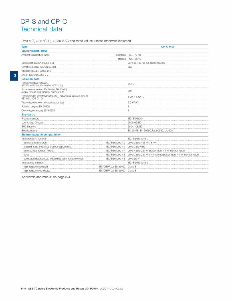
3/49 ABB | Catalog Electronic Products and Relays 2013/2014 | 2CDC 110 004 C0209
3
CP-S and CP-C
Technical data
Data at Ta = 25 °C, U
in = 230 V AC and rated values, unless otherwise indicated
Type CP-C MM
Environmental data
Ambient temperature range operation -25...+70 °C
storage -40...+85 °C
Damp heat (IEC/EN 60068-2-3) 93 % at +40 °C, no condensation
Climatic category (IEC/EN 60721) 3K3
Vibration (IEC/EN 60068-2-6)
Shock (IEC/EN 60068-2-27)
Isolation data
Rated insulation voltage Ui
(IEC/EN 60974-1, EN 50178, VDE 0160)250 V
Protective separation (EN 50178, EN 60950) supply / measuring circuits / relay outputs
yes
Rated impulse withstand voltage Uimp
between all isolated circuits (IEC 664, VDE 0110)
4 kV; 1.2/50 μs
Test voltage between all circuits (type test) 2.5 kV AC
Pollution degree (EN 60950) 2
Overvoltage category (EN 60950) II
Standards
Product standard IEC/EN 61204
Low Voltage Directive 2006/95/EC
EMC Directive 2004/108/EC
Electrical safety EN 50178, EN 60950, UL 60950, UL 508
Elektromagnetic compatibility
Interference immunity to IEC/EN 61000-6-2
electrostatic discharge IEC/EN 61000-4-2 Level 3 and 4 (6 kV / 8 kV)
radiated, radio-frequency, electromagnetic field IEC/EN 61000-4-3 Level 3 (10 V/m)
electrical fast transient / burst IEC/EN 61000-4-4 Level 4 and 2 (4 kV power input / 1 kV control input)
surge IEC/EN 61000-4-5 Level 3 and 2 (4 kV symmetrical power input / 1 kV control input)
conducted disturbances, induced by radio-frequency fields IEC/EN 61000-4-6 Level (10 V)
Interference emission IEC/EN 61000-6-3
high-frequency radiated IEC/CISPR 22; EN 55022 Class B
high-frequency conducted IEC/CISPR 22; EN 55022 Class B
„Approvals and marks“ on page 3/4.

2CDC 110 004 0209 | Catalog Electronic Products and Relays 2013/2014 | ABB 3/50
3
CP-S and CP-C
Technical diagrams, Dimensional drawings
Uout [V]
Iout [A]
2C
DC
272 0
03 F
0b
04
Uout [V]
Iout [A]
2C
DC
272 0
04 F
0b
04
Uout [V]
Iout [A]
2C
DC
272 0
05 F
0b
04
CP-S 24/5.0 CP-S 24/5.0, CP-C 24/5.0CP-C 24/5.0
CP-S 24/10.0 CP-S 24/10.0, CP-C 24/10.0CP-C 24/10.0
CP-S 24/20.0 CP-S 24/20.0, CP-C 24/20.0CP-C 24/20.0
Uout [V]
Iout [A]
2C
DC
272 0
26 F
0b
04
Uout [V]
Iout [A]
2C
DC
272 0
27 F
0b
04
Uout [V]
Iout [A]
2C
DC
272 0
28 F
0b
04
144,5 [5.69”] 60,0 [2.36”]
137,0 [5.39”]
13
0,0
[5
.12
”]
13
0,0
[5
.12
”]
56,5 [2.22”]
93,5 [3.68”]
90,0 [3.54”]
203,5 [8.01”]
200,0 [7.87”]
135,5 [5.33”]
13
0,0
[5
.12
”]
2CD
C 2
72 0
15 F
0b07
CP-S 24/5.0 CP-S 24/10.0 CP-S 24/20.0 CP-C 24/5.0 CP-C 24/10.0 CP-C 24/20.0 CP-A RU
Technical diagramsOutput curve at 25 °C Temperature curve at Uout = 24 V DCOutput curve at 25 °C
Iout [A]
Ta [°C]
2C
DC
272 0
75 F
0204
Iout [A]
Ta [°C]
2C
DC
272 0
06 F
0204
Iout [A]
Ta [°C]
2C
DC
272 0
88 F
0204
Dimensional drawings dimensions in mm
CP-C MM
54 [
2.13
”]
56,5 [2.22”]24 [0
.94”]
2C
DC
272 0
16 F
0b
07

3/51 ABB | Catalog Electronic Products and Relays 2013/2014 | 2CDC 110 004 C0209
3
Redundancy units
Ordering details
Ordering details
Description suitable for decoupling
of two CP-24 V DC power
supply units or suitable
for decoupling of CP-E
power supply units
Type Order code Price
1 pce
Weight
(1 pce)
kg (lb)
2 inputs each up to 20 A
and 1 output up to 40 A� 40 V and � 5 A CP-A RU 1SVR427071R0000
0.89
(1.96)
Control module for CP-A
RU redundancy units- CP-A CM 1SVR427075R0000
0.063
(0.14)
2 inputs each up to 2.5 A
and 1 output up to 5 A� 35 V and < 5 A CP-RUD 1SVR423418R9000
0.15
(0.33)
2C
DC
27
1 0
03
F0
00
5
CP-A RU + CP-A CM
CP-A RU
CP-RUD
CP-D RU
2C
DC
27
1 0
10
F0
00
6
2C
DC
27
1 0
06
F0
00
32
CD
C 2
71
01
0 F
00
06
Ordering details - CP-D RU for decoupling of two CP-D power supply units
Input voltage
range
Rated input
current
Rated output voltage
/ current
Type Order code Price Weight
(1 pce)
kg (lb)
9-35 V DC 2 x 5 A24 V DC /
1 x 10 ACP-D RU 1SVR427049R0000
0.075
(0.165)
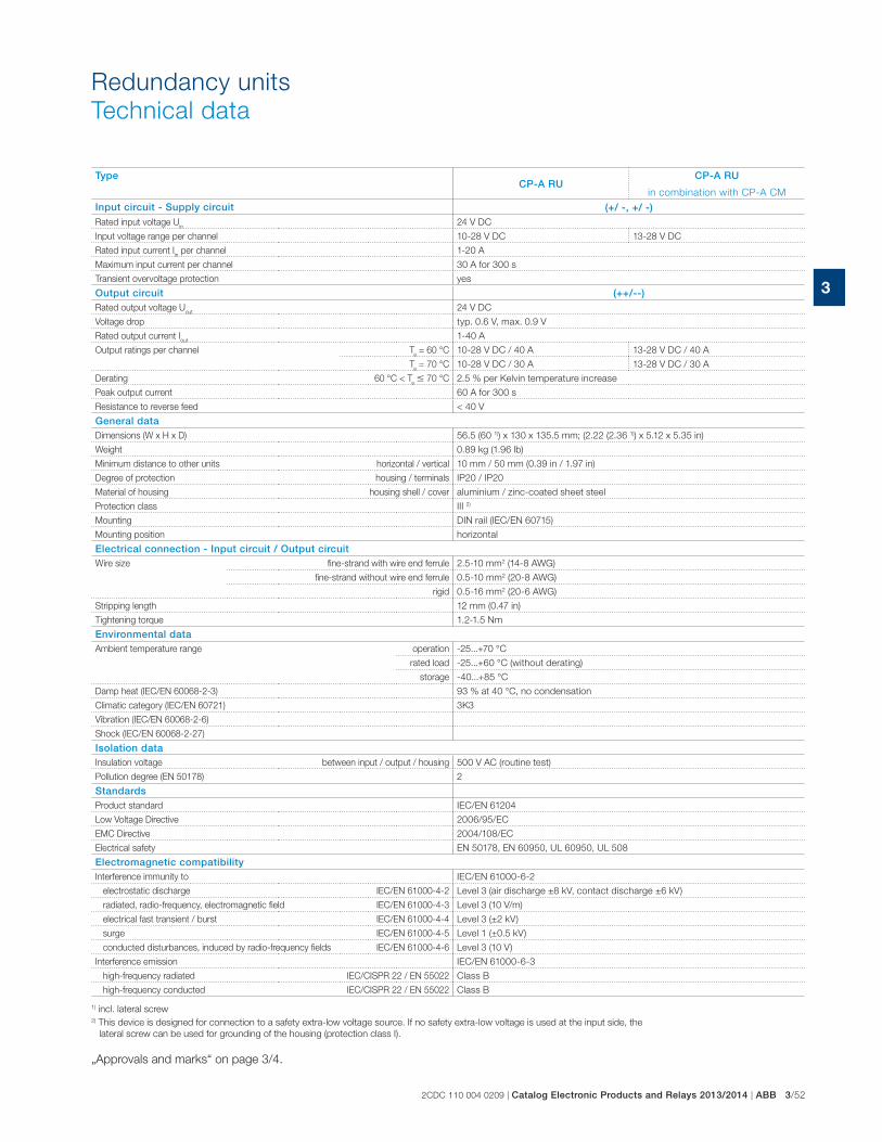
2CDC 110 004 0209 | Catalog Electronic Products and Relays 2013/2014 | ABB 3/52
3
Redundancy units
Technical data
TypeCP-A RU
CP-A RU
in combination with CP-A CM
Input circuit - Supply circuit (+/ -, +/ -)Rated input voltage U
in24 V DC
Input voltage range per channel 10-28 V DC 13-28 V DC
Rated input current Iin per channel 1-20 A
Maximum input current per channel 30 A for 300 s
Transient overvoltage protection yes
Output circuit (++/--)Rated output voltage U
out24 V DC
Voltage drop typ. 0.6 V, max. 0.9 V
Rated output current Iout
1-40 A
Output ratings per channel Ta = 60 °C 10-28 V DC / 40 A 13-28 V DC / 40 A
Ta = 70 °C 10-28 V DC / 30 A 13-28 V DC / 30 A
Derating 60 °C < Ta � 70 °C 2.5 % per Kelvin temperature increase
Peak output current 60 A for 300 s
Resistance to reverse feed < 40 V
General dataDimensions (W x H x D) 56.5 (60 1)) x 130 x 135.5 mm; (2.22 (2.36 1)) x 5.12 x 5.35 in)
Weight 0.89 kg (1.96 lb)
Minimum distance to other units horizontal / vertical 10 mm / 50 mm (0.39 in / 1.97 in)
Degree of protection housing / terminals IP20 / IP20
Material of housing housing shell / cover aluminium / zinc-coated sheet steel
Protection class III 2)
Mounting DIN rail (IEC/EN 60715)
Mounting position horizontal
Electrical connection - Input circuit / Output circuitWire size fine-strand with wire end ferrule 2.5-10 mm2 (14-8 AWG)
fine-strand without wire end ferrule 0.5-10 mm2 (20-8 AWG)
rigid 0.5-16 mm2 (20-6 AWG)
Stripping length 12 mm (0.47 in)
Tightening torque 1.2-1.5 Nm
Environmental dataAmbient temperature range operation -25...+70 °C
rated load -25...+60 °C (without derating)
storage -40...+85 °C
Damp heat (IEC/EN 60068-2-3) 93 % at 40 °C, no condensation
Climatic category (IEC/EN 60721) 3K3
Vibration (IEC/EN 60068-2-6)
Shock (IEC/EN 60068-2-27)
Isolation dataInsulation voltage between input / output / housing 500 V AC (routine test)
Pollution degree (EN 50178) 2
StandardsProduct standard IEC/EN 61204
Low Voltage Directive 2006/95/EC
EMC Directive 2004/108/EC
Electrical safety EN 50178, EN 60950, UL 60950, UL 508
Electromagnetic compatibilityInterference immunity to IEC/EN 61000-6-2
electrostatic discharge IEC/EN 61000-4-2 Level 3 (air discharge ±8 kV, contact discharge ±6 kV)
radiated, radio-frequency, electromagnetic field IEC/EN 61000-4-3 Level 3 (10 V/m)
electrical fast transient / burst IEC/EN 61000-4-4 Level 3 (±2 kV)
surge IEC/EN 61000-4-5 Level 1 (±0.5 kV)
conducted disturbances, induced by radio-frequency fields IEC/EN 61000-4-6 Level 3 (10 V)
Interference emission IEC/EN 61000-6-3
high-frequency radiated IEC/CISPR 22 / EN 55022 Class B
high-frequency conducted IEC/CISPR 22 / EN 55022 Class B
1) incl. lateral screw2) This device is designed for connection to a safety extra-low voltage source. If no safety extra-low voltage is used at the input side, the
lateral screw can be used for grounding of the housing (protection class I).
„Approvals and marks“ on page 3/4.

3/53 ABB | Catalog Electronic Products and Relays 2013/2014 | 2CDC 110 004 C0209
3
Type CP-A CMInput circuit - Supply circuitRated input voltage U
in24 V DC
Input voltage range 13-28 V DC
Rated input current at rated sense load and 24 V DC 120 mA
Power consumption at 24 V DC approx. 1 W
Measuring circuit 11-12/14, 21-22/24Monitoring function undervoltage monitoring
Measuring voltage rated operational voltage
Thresholds 14-28 V
Hysteresis, related to the threshold value fix: 3-5 %
Accuracy, tolerance 10 % of full-scale value
Maximum measuring cycle 6 ms
Indication of operational states
Status of input 1 IN 1: green LED : voltage at input 1 > than threshold 1 = no faults present
Status of input 2 IN 2: green LED : voltage at input 2 > than threshold 2 = no faults present
Output status OUT: green LED : UOUT
> 3 V = no faults present
Output circuit +, +, -Kind of output relays, 2 x 1 c/o contact
Contact material AgNi
Operating principle closed-circuit principle
Rated operational voltage Ue (IEC/EN 60947-1, VDE 0110) 250 V
Minimum switching voltage / Minimum switching current 24 V / 10 mA
Maximum switching voltage / Maximum switching current 250 V / 1 A
Rated operational current Ie
(IEC/EN 60947-5-1)AC12 (resistive) at 230 V 1 A
AC15 (inductive) at 230 V 1 A
DC12 (resistive) at 24 V 1 A
DC13 (inductive) at 24 V 1 A
Mechanical lifetime 30 x 106 switching cycles
Electrical lifetime 0.1 x 10⁶ switching cycles
Rating according UL 508 General purpose (GP) 250 V AC 1 A
Maximum fuse rating to achieve short-circuit protection
n/o contact 2 A, gL
n/c contact 2 A, gL
Sense output (+, +, -) 1 SVR 427 075 R0000
Sense output voltage 13-28 V DC
Sense output current 0.1 A
Maximum fuse rating For applications acc. UL the sense output shall be provided with a listed
DC fuse 3 A
General dataDuty time 100 %
Dimensions (W x H x D, when mounted) 56.5 x 54 x 24 mm (2.22 x 2.13 x 0.94 in)
Material of housing plastic
Weight 0.063 kg (0.14 lb)
Degree of protection housing / terminals IP20 / IP20
Protection class II
Mounting snap-on mounting, without any tool
Mounting position plugged onto the redundancy unit CP-A RU
Electrical conectionWire size fine-strand with wire end ferrule
0.2-2.5 mm2 (24-14 AWG)fine-strand without wire end ferrule
rigid 0.2-4 mm2 (24-12 AWG)
Stripping length 7.5 mm (0.3 in)
Tightening torque 0.4-0.6 Nm
Isolation dataRated insulation voltage U
i (IEC/EN 60947-1, EN 50178, VDE 0160) 250 V
Rated impulse withstand voltage Uimp
(type test) between all circuits (IEC 664, VDE 0110) 2.5 kV
Power-frequency withstand voltage test (routine test) between all circuits 1.2 kV AC
Protective separation (EN 50178) between input and output yes
Pollution degree 2
Overvoltage category II
Environmental dataAmbient temperature range operation -25...+70 °C
storage -40...+85 °C
Damp heat (IEC/EN 60068-2-3) 93 %at 40 °C, no condensation
Climatic category (IEC/EN 60721) 3K3
Vibration (IEC/EN 60068-2-6)
Shock (IEC/EN 60068-2-27)
Redundancy units
Technical data

2CDC 110 004 0209 | Catalog Electronic Products and Relays 2013/2014 | ABB 3/54
3
Type CP-RUD
Input circuit - Supply circuit A: U1+/-U ; B: U2+/-URated input voltage U
in 24 V DC
Input voltage range 5-35 V DC
Rated input current Iin per channel 0.5-2.5 A
Maximum input current per channel 10 A for 300 s
Transient overvoltage protection no
Output circuit L+, L+, L+, L-, L-, L-Rated output voltage U
out 24 V DC
Voltage drop typ. 0.6 V, max. 0.7 V
Rated output current Iout 0.5-5 A
Peak output current 20 A for 150 s
Resistance to reverse feed < 35 V
General dataDimensions (W x H x D) 22.5 x 78 x 100 mm
(0.89 x 3.07 x 4.02 in)
Weight 0.135 kg (0.30 lb)
Minimum distance to other units horizontal / vertical 10 mm / 10 mm (0.39 in / 0.39 in)
Degree of protection housing / terminals IP20 / IP20
Material of housing housing shell / cover plastic / plastic
Protection class -
Mounting DIN rail (IEC/EN 60715)
Mounting position horizontal
Electrical connection - Input circuit / Output circuit
Wire size fine-strand with wire end ferrule2 x 0.75-2.5 mm2 (2 x 18-14 AWG)
fine-strand without wire end ferrule
rigid 2 x 0.5-4 mm2 (2 x 20-12 AWG)
Stripping length 7 mm (0.28 in)
Tightening torque 0.6-0.8 Nm
Environmental dataAmbient temperature range operation -20...+60 °C
rated load -20...+60 °C
storage -40...+85 °C
Damp heat (IEC/EN 60068-2-3) 93 % at 40 °C, no condensation
Climatic category (IEC/EN 60721) -
Vibration (IEC/EN 60068-2-6)
Shock (IEC/EN 60068-2-27)
Isolation dataInsulation voltage between input / output / housing -
Pollution degree (EN 50178) 2
StandardsProduct standard
Low Voltage Directive 2006/95/EC
EMC Directive 2004/108/EC
Electrical safetyEN 50178
Electromagnetic compatibilityInterference immunity to IEC/EN 61000-6-2
electrostatic discharge IEC/EN 61000-4-2 Level 3 (air discharge ±8 kV, contact discharge ±6 kV)
radiated, radio-frequency, electromagnetic field IEC/EN 61000-4-3 Level 3 (10 V/m)
electrical fast transient/burst IEC/EN 61000-4-4 Level 3 (�2 kV)
surge IEC/EN 61000-4-5 Level 1 (�0.5 kV)
conducted disturbances, induced by radio-frequency fields IEC/EN 61000-4-6 Level 3 (10 V)
Interference emission IEC/EN 61000-6-3
high-frequency radiated IEC/CISPR 22 / EN 55022 Class B
high-frequency conducted IEC/CISPR 22 / EN 55022 Class B
1) incl. lateral screw2) This device is designed for connection to a safety extra-low voltage source. If no safety extra-low voltage is used at the input side, the lateral screw can be used for
grounding of the housing (protection class I).
Redundancy units
Technical data

3/55 ABB | Catalog Electronic Products and Relays 2013/2014 | 2CDC 110 004 C0209
3
Type CP- D RU
Input circuit - Supply circuit IN 1 + + -, IN 2 + + -Rated input voltage U
in24 V DC
Input voltage range 9-35 V DC
Rated input current Iin per channel 5 A
Maximum input current per channel 10 A for 300 s
Transient overvoltage protection no
Output circuit OUT + + +, - - -Rated output voltage U
out24 V DC
Voltage drop typ. 0.5 V
Rated output current Iout
10 A
Resistance to reverse feed < 35 V
General dataMTBF on request
Duty time 100 %
Dimensions (W x H x D) product dimensions 35 x 91 x 56.5 mm (1.38 x 3.58 x 2.22 in)
packaging dimensions 134 x 94 x 48 mm (5.28 x 3.70 x 1.89 in)
Weight net weight 0.075 kg (0.165 lb)
gross weight 0.130 kg (0.286 lb)
Material of housing plastic
Mounting DIN rail, snap-on mounting without any tool
Mounting position horizontal
Minimum distance to other units horizontal / vertical 25 mm (0.98 in) / 25 mm (0.98 in)
Electrical connection - Input circuit / Output circuitWire size fine-strand with (out)
wire end ferrule
0.2-2.5 mm2 (24-14 AWG)
rigid 0.2-2.5 mm2 (24-12 AWG)
Stripping length 7.0 mm (0.28 in)
Tightening torque 0.67 Nm (6 Ib.in)
Environmental dataAmbient temperature range operation -40...+70 °C
storage -40...+85 °C
Relative humidity RH at 40 °C 20-95 %, no condensation
Vibration (IEC/EN 60068-2-6) Mounting by rail:
10-500 Hz, 2 G, along X, Y, Z each axis, 60 min for each axis
Shock (IEC/EN 60068-2-27) 15 G, 11 ms, 3 axis, 6 faces, 3 times for each face
StandardsProduct standard IEC/EN 61204-3
Low Voltage Directive 2006/95/EC
EMC Directive 2004/108/EC
RoHS Directive 2002/95/EC
Electromagnetic compatibilityInterference immunity to EN 55024
electrostatic discharge IEC/EN 61000-4-2 Level 3, air discharge 8 kV, contact discharge 4 kV
radiated, radio-frequency, electromagnetic field IEC/EN 61000-4-3 Level 3, 10 V/m
electrical fast transient/burst IEC/EN 61000-4-4 Level 3, 2 kV / 5 kHz
conducted disturbances, induced by radio-frequency fields IEC/EN 61000-4-6 Level 3, 10 V
Interference emission EN 55022
high-frequency radiated IEC/CISPR 22 / EN 55022 Class B
high-frequency conducted IEC/CISPR 22 / EN 55022 Class B
Redundancy units
Technical data

2CDC 110 004 0209 | Catalog Electronic Products and Relays 2013/2014 | ABB 3/56
3
CP-A CM
54 [
2.13
”]
56,5 [2.22”]24 [0
.94”]
2C
DC
272 0
16 F
0b
07
2CD
C 2
52 1
88 F
0b05
100
102
109,5 [4.31“] 22,5
[.886“]
78
[3.0
7“]
[4.02“]
[3.94“]
CP-RUD
144,5 [5.69”] 60,0 [2.36”]
137,0 [5.39”]
13
0,0
[5
.12
”]
56,5 [2.22”]
135,5 [5.33”]
CP-A RU
2CD
C 2
72 0
15 F
0b07
2C
DC
27
20
33
F0
01
0
CP-D RU
67.0 2.64”
44.5 1.75”
32
.1 1
.26
”
57
.5
2.2
6”
49
.0
1.9
3”
91
.0 3
.58
”
35.0 1.38”
+ + + - - -O U T
+ - -+ + +IN1 IN2 IN2IN1
Redundancy units
Dimensional drawings

3/57 ABB | Catalog Electronic Products and Relays 2013/2014 | 2CDC 110 004 C0209
3
CP-ASI range
Product group picture

2CDC 110 004 0209 | Catalog Electronic Products and Relays 2013/2014 | ABB 3/58
3
CP-ASI range
Table of contents
CP-ASI
Product group picture 3/57
Table of contents 3/58
Benefits and advantages 3/59
Ordering details 3/60
Technical data 3/61
Technical diagrams 3/63
Dimensional drawings 3/64

3/59 ABB | Catalog Electronic Products and Relays 2013/2014 | 2CDC 110 004 C0209
3
CP-ASI range
Benefits and advantages
Characterics
� Rated output voltage 30.5 V DC for ASI-bus
� Rated output current up to 8.0 A
� High efficiency of up to 92 % 1)
� Infrared addressing mode 2)
� Low power dissipation and low heating
� Free convection cooling (no forced cooling with ventilators)
� Ambient temperature range during operation -10…70 °C 3)
� Open-circuit, overload and short-circuit stable
� Integrated input fuse
� Tool-free mounting on DIN rail as well as demounting
� LEDs for the indication of operational states
� Approval: A / Mark: a1) Efficiency is depending on device2) Except CP-ASI/4.0 DC/DC3) Ambient temperature range CP-ASI/4.0 DC/DC -25…70°C4) Approvals are related to rated input voltage U
in
4
1
2
3
1 Output +, -, +, -, SHIELD: output terminals
2 Signalling contact 11-12: ground fault signalling terminals
3 Indication of operational states
AS-I OK: green LED - output voltage OK
4 Configuration of operation mode Jumper
5 Indication of operational states
IR ADDRESSING ON: red LED - infrared addressing mode active
6 Test and reset button
7 Indication of operational states
GROUND FAULT: red LED - ground fault detected
8 Circuit diagram
9 Input voltage selector Adjustment of input voltage
10 Input L, N, PE: input terminals
5
6
7
8
9
10

2CDC 110 004 0209 | Catalog Electronic Products and Relays 2013/2014 | ABB 3/60
3
CP-ASI range
Ordering details
DescriptionThe CP-ASI power supply range is specifically designed with integrated data decoupling for
the supply of AS-Interface systems.
Up to 62 slaves (binary I/O devices) can be supplied with a single two-conductor cable.
The configurable IR addressing mode allows the easy assign of new ID addresses by means of
an external infrared programming unit.
Ordering details
Input Voltage Range Rated
Output
Voltage
Rated
Output
Current
Type Order code Price
1 pce
Weight
(1 pce)
kg (lb)
85-132 V AC, 184-264 V AC 30.5 V DC 2.8 A CP-ASI/2.8 1SVR427090R0280 0.495 (1.091)
85-132 V AC, 184-264 V AC 30.5 V DC 4.0 A CP-ASI/4.0 1SVR427090R0400 0.653 (1.440)
18-32.4 V DC 30.5 V DC 4.0 ACP-ASI/4.0
DC/DC1SVR427095R0400 0.488 (1.076)
85-132 V AC, 184-264 V AC 30.5 V DC 8.0 A CP-ASI/8.0 1SVR427090R0800 0.897 (1.978)
2C
DC
27
1 0
02
S0
01
22
CD
C 2
71
00
3 S
00
12
2C
DC
27
1 0
04
S0
01
22
CD
C 2
71
00
5 S
00
12
CP-ASI/2.8
CP-ASI/4.0 DC/DC
CP-ASI/4.0
CP-ASI/8.0

3/61 ABB | Catalog Electronic Products and Relays 2013/2014 | 2CDC 110 004 C0209
3
CP-ASI range
Technical data
Data at Ta = 25 °C, U
in = 230 V AC and rated values, unless otherwise indicated
Type CP-ASI/2.8 CP-ASI/4.0 CP-ASI/8.0 CP-ASI/4.0 DC/DCInput circuit - Supply circuit L, NRated input voltage U
in- 24 V DC
switch position 115 V 100-120 V AC -
switch position 230 V 220-240 V AC -
Input voltage range - 18.0-32.4 V DC
switch position 115 V 85-132 V AC -
switch position 230 V184-264 V AC
184-264 V AC /
240-300 V DC184-264 V AC -
Frequency range AC 47-63 Hz
Typical input current - 5.6 A
switch position 115 V 2.0 A 2.7 A 6.0 A -
switch position 230 V 0.9 A 1.3 A 2.8 A -
Allowed voltage between input and earth (ground) - max. 60 V DC / 42.4 V AC
Allowed input ripple voltage-
max. 5 Vpp, 47 Hz -
40 kHz
Continuous input voltage with no damage to the DC/DC converter - max. 36.0 V DC
Turn-on voltage - typ. 17.5 V DC
Shut-down voltage - typ. 14.0 V DC
- typ. 35 V DC
Typical power consumption 94 W 135 W 261 W 132 W
Inrush current limiting / I²t (cold start) < 20 A (132 V AC) /
approx. 1.5 A²/s
< 44.7 A (120 V AC) /
approx. 3.7 A²/s
< 12 A (100 V AC) /
approx. 1.0 A²/s
< 1.8 A / approx. 1.0
A²/s
< 38 A (264 V AC) /
approx. 1.8 A²/s
< 49.3 A (132 V AC) /
approx. 4.6 A²/s
< 14 A (120 V AC) /
approx. 1.5 A²/s-
-< 49.7 A (230 V AC) /
approx. 2.5 A²/s
< 24 A (220 V AC) /
approx. 1.4 A²/s-
-< 57.5 A (264 V AC) /
approx. 3.3 A²/s
< 27 A (240 V AC) /
approx. 1.6 A²/s-
Discharge current towards PE < 3.5 mA -
Power failure buffering time - max. 0.5 ms
at 115 V AC min. 35 ms min. 40 ms min. 20 ms -
at 230 V AC min. 40 ms min. 30 ms -
Transient overvoltage protection varistors
Reverse input polarity protection
-
included, unit does
not start at reversed
polarity
Internal input fuse 8 A slow acting /
250 V AC
3.15 A slow acting /
250 V AC
8 A slow acting /
250 V AC10 A slow acting
External fusing (not necessary, but recommended) circuit breaker with C characteristic min 6 A, or alternatively 10 A with B characteristic -
Power factor correction (PFC) at 115 V AC 0.58 0.53 -
at 230 V AC 0.53 0.48 -
Indication of operational states
Output voltage AS-I OK LED green
IR addressing mode IR ADDRESSING ON LED red -
Overload OVERLOAD LED red -
Output circuit +,-
Rated output voltage 30.5 V DC
Rated output power 85 W 122 W 244 W 122 W
Tolerance of the output voltage ± 3 %
Adjustment range of the output voltage - - -
Rated output current Ir
Ta � 60 °C 2.8 A 4.0 A 8.0 A 4.0 A
Derating of the output current 60 °C < Ta � 70 °C 2.5 %/°C
Signalling contact for ground fault - max. 25 V AC or
60 V DC, 0.5 A- -
Control time < 2 ms
Starting time after applying the supply voltage max. 400 ms max. 700 ms max. 500 ms max. 1 s (typ. 650 ms)
Rise time max. 100 ms -
at rated load - typ. 100 ms
with 5 mF - typ. 200 ms
Residual ripple BW = 500 kHz typ. < 50 mVpp
Switching peaks BW = 20 MHz typ. < 100 mVpp
Output circuit - No-load, overload and short-circuit behaviour
Characteristic curve of output
U/I characteristic curve
Combined U/I cha-
racteristic curve and
hiccup mode
U/I characteristic
curve
Short-circuit protectioncontinuous short-circuit stability
temporary short-
circuit stability
continuous short-
circuit stability
Short-circuit behaviourcontinuation with output power limiting -
continuation with out-
put power limiting
Current limiting at short circuit min / max 3.2 A / 4.6 A 4.2 A / 6.5 A 12 A / 25 A (max. 5 s) 5.0 A / 9.0 A
Overload protectionoutput power limiting
temporary output
power limitingoutput power limiting

2CDC 110 004 0209 | Catalog Electronic Products and Relays 2013/2014 | ABB 3/62
3
CP-ASI range
Technical data
Data at Ta = 25 °C, U
in = 230 V AC and rated values, unless otherwise indicated
Type CP-ASI/2.8 CP-ASI/4.0 CP-ASI/8.0 CP-ASI/4.0 DC/DCOvertemperature, overload and short circuit behaviour CP-ASI/8.0: at 8.4 A < I
max < 12 A continuous current for 2-5 s, afterwards safety switch-off
Overtemperature protection CP-ASI/4.0 DC/DC: yes, automatic recovery after temperature went down
No-load protection continuous no-load stability
General data
MTBF on request
Power dissipation typ. < 9.1 W (230 V AC, 2.8 A)
typ. < 13.5 W (230 V AC, 4.0 A)
typ. < 21.2 W (230 V AC, 8.0 A)
typ. < 12.7 W (24 V DC, 4.0 A)
Efficiency typ. 90.5 % typ. 90 % typ. 92.0 % typ. 90.5 %
Duty time 100 %
Dimensions (W x H x D) product dimensions 49 x 131 x 107 mm (1.93 x 5.16 x 4.21 in)
73 x 131 x 107 mm (2.87 x 5.16 x 4.21 in)
91 x 131 x 107 mm (3.58 x 5.16 x 4.21 in)
40 x 131 x 107 mm (1.58 x 5.16 x 4.21 in)
packaging dimensions 151 x 65 x 140 mm (5.94 x 2.56 x 5.51 in)
151 x 98 x 140 mm (5.94 x 3.86 x 5.51 in)
151 x 120 x 140 mm (5.94 x 4.72 x 5.51 in)
151 x 65 x 140 mm (5.94 x 2.56 x 5.51 in)
Weight net weight 0.495 kg (1.019 lb) 0.653 kg (1.440 lb) 0.897 kg (1.997 lb) 0.488 kg (1.076 lb)
gross weight 0.568 kg (1.252 lb) 0.750 kg (1.653 lb) 1.015 kg (2.238 lb) 0.750 kg (1.287 lb)
Material of housing metal
Mounting DIN rail (IEC/EN 60715), snap-on mounting without any tool
Mounting position horizontal
Minimum distance to other units horizontal / vertical 15 mm / 25 mm (0.59 / 0.99 in)
Degree of protection housing / terminals IP20 / IP20
Protection class I
Electrical connection
Wire size fine-strand with wire end ferrule 0.5-4 mm² (20-12 AWG)
fine-strand without wire end ferrule 0.5-4 mm² (20-12 AWG)
rigid 0.5-6 mm² (20-10 AWG)
Stripping length 7 mm (0.28 in)
Tightening torque 0.8 Nm (7.08 lb.in)
Environmental data
Ambient temperature range operation -10...+70 °C -25...+70 °C
rated load -10...+60 °C -25...+60 °C
storage -25...+85 °C -40...+85 °C
Vibration (sinusoidal) (IEC/EN 60068-2-6) 2-17.8 Hz, amplitude ± 1.6 mm
sinusoidal (IEC/EN 60068-2-6) 17.8 Hz - 500 Hz, 2 g
random (IEC 60068-2-64) 2-800 Hz 0.5 s² (s³)
Shock (half-sine) (IEC/EN 60068-2-27) 15 g (6 ms), 10 g (11 ms)
Isolation data
Rated insulation voltage Ui
(IEC/EN 60950-1, EN 50178)
input circuit / output circuit 300 V 50 V
input / PE 300 V 50 V
output / PE 50 V
shield / output 50 V
shield / PE 50 V
Rated impulse withstand voltage Uimp
(EN 50178)
input / output 6 kV 1.2/50 μs 1.5 kV 1.2/50 μs
input / PE 4 kV 1.2/50 μs 0.8 kV 1.2/50 μs
output / PE 500 V 1.2/50 μs 500 V 1.2/50 μs
Power-frequency withstand voltage test
(test voltage) (routine test / type test)
input / output 2.5 kV AC / 3.0 kV AC 1.5 kV AC / 1.5 kV AC
input / PE 2.5 kV AC / 2.5 kV AC 1.5 kV AC / 1.5 kV AC
output / PE 500 V AC / 500 V AC
Pollution degree (IEC/EN 60950-1) 2
Overvoltage category (UL/IEC/EN 60950-1) input II (IEC/EN 60950-1), III (EN 50178)
output II (IEC/EN 60950-1), II (EN 50178)
Standards
Low Voltage Directive 2006/95/EC
EMC directive 2004/108/EC
RoHS directive 2011/65/EC
Electrical safety IEC/EN 60950-1
Protective low voltage SELV (IEC/EN 60950-1), PELV
Electromagnetic compatibility
Interference immunity to IEC/EN 61000-6-2
electrostatic discharge IEC/EN 61000-4-2 Level 4 (8 kV / 15 kV)
radiated, radio-frequency, electromagnetic field IEC/EN 61000-4-3
Level 3 (10 V/m)
electrical fast transient/burst IEC/EN 61000-4-4 input circuit: Level 4 (4 kV) input circuit: Level 3 (2 kV)
output circuit: Level 3 (2 kV) output circuit: Level 2 (1 kV)
surge IEC/EN 61000-4-5input circuit: L-L Level 3 (2 kV) / L-PE Level 4 (4 kV)
input circuit: L-L Level 2 (1 kV) / L-PE Level 3 (2 kV)
output circuit: Level 1 (0.5 kV)output circuit: Level 1 (0.5 kV)
conducted disturbances, induced by radio-frequency fields IEC/EN 61000-4-6
Level 3 (10 V, 150 kHz - 80 MHz)Level 3 (10 V, 150 kHz - 80 MHz)
voltage dips, short interruptions and voltag variations IEC/EN 61000-4-11
Class 3
Interference emission IEC/EN 61000-6-3 IEC/EN 61000-6-4 IEC/EN 61000-6-3
high-frequency radiated IEC/CISPR 22, EN 55022 Class B
high-frequency conducted IEC/CISPR 22, EN 55022 Class B
limits for harmonic current emissions IEC/EN 61000-3-2 Class A - -

3/63 ABB | Catalog Electronic Products and Relays 2013/2014 | 2CDC 110 004 C0209
3
CP-ASI range
Technical diagrams
12
16
20
24
28
32
8
4
00 1 2 3 4
Uout [V]
Iout [A]
15
20
25
30
35
10
5
00 1 2 3 4 5
Uout [V]
6 7 8 Iout [A]
15
20
25
30
35
10
5
00 1 2 3 4 5
Uout [V]
6 Iout [A]
15
20
25
30
35
10
5
00 2 4 6 8 10
Uout [V]
12 Iout [A]
-10 60 70 Ta [°C]
Iout [A]
2.8
2.1
-25 60 70 Ta [°C]
Iout [A]
4
3
-10 60 70 Ta [°C]
Iout [A]
4
3
-10 60 70 Ta [°C]
Iout [A]
8
6
Output behaviour
Output behaviour
Output behaviour
Output behaviour
Temperaturkennlinie bei Bemessungslast
Characteristic curve of temperature at rated load
Characteristic curve of temperature at rated load
Characteristic curve of temperature at rated load
CP-ASI 2.8
CP-ASI 4.0 DC/DC
CP-ASI 4.0
CP-ASI 8.0
Characteristic curve at Ta = 25 °C
2C
DC
27
2 0
07
F0
01
2
2C
DC
27
2 0
11
F0
01
22
CD
C 2
72
00
9 F
00
12
2C
DC
27
2 0
13
F0
01
2
2C
DC
27
2 0
06
F0
21
22
CD
C 2
72
01
0 F
02
12
2C
DC
27
2 0
08
F0
21
2
2C
DC
27
2 0
12
F0
21
2

2CDC 110 004 0209 | Catalog Electronic Products and Relays 2013/2014 | ABB 3/64
3
CP-ASI range
Dimensional drawings
102 4.02”
49 1.93”62
2
.44”
131
5.1
6”
5 0.20”
94 3.78”62
2
.44”
102 4.02”
62 2
.44”
5 0.20”
94 3.78”
62 2
.44”
73 2.87”
131
5.
16”
102 4.02”
62 2
.44”
5 0.20”
94 3.78”
62 2
.44”
40 1.58”
131
5.
16”
102 4.02”
62 2
.44”
5 0.20”
94 3.78”
62 2
.44”
91 3.58”
131
5.
16”
CP-ASI 2.8
CP-ASI 4.0
CP-ASI 4.0 DC/DC
CP-ASI 8.0
2C
DC
27
2 0
14
F0
01
2
2C
DC
27
2 0
15
F0
01
2
2C
DC
27
2 0
16
F0
01
2
2C
DC
27
2 0
17
F0
01
2
Dimensions in mm/inch

3/65 ABB | Catalog Electronic Products and Relays 2013/2014 | 2CDC 110 004 C0209
3
CP-B range
Product group picture

2CDC 110 004 0209 | Catalog Electronic Products and Relays 2013/2014 | ABB 3/66
3
CP-B range
Table of contents
CP-B
Product group picture 3/65
Table of contents 3/66
Benefits and advantages 3/67
Ordering details 3/68
Technical data 3/69
Technical data, Technical diagrams 3/70
Dimensional drawings 3/71
Technical data 3/72

3/67 ABB | Catalog Electronic Products and Relays 2013/2014 | 2CDC 110 004 C0209
3
1 Input terminals
SHUT-DOWN+, SHUT-DOWN-: Input signal terminals
INPUT OK, BUFFER STATUS, FAILURE: Signalling contact – terminals
L+IN, L-
IN: Input voltage terminals
2 Indication of operational states
OPERATION: Buffer module in operation (standby or buffering)
INPUT OK: Input voltage applied
3 Output terminals
L+OUT
, L-OUT
, L-OUT
: Output voltage terminals
CP-B range
Benefits and advantages
CP-B 24/3.0 CP-B 24/10.0 CP-B 24/20.0 CP-B EXT.2Order code 1SVR427060R0300 1SVR427060R1000 1SVR427060R2000 1SVR427065R0000
Rated input voltage 24 V DC 24 V DC 24 V DC –
Rated current 3 A DC 10 A DC 20 A DC 3 A DC
Energy storage (min.) 1.000 Ws 10.000 Ws 8.000 Ws 2.000 Ws
Typical charging time at load current
100 % 65 s 134 s 135 s
0 % 56 s 82 s 62 s
Typical
buffering time1)
at load current
100 % 13 s 38 s 15 s
50 % 28 s 76 s 30 s
25 % 66 s 140 s 60 s
10 % 148 s 380 s 150 s
1) buffering time
Power supply systems have to be highly reliable in most areas of energy
management and automation technology.
Often batteries are used for supporting the supply system in case of
mains failures. Batteries have limited lifetimes depending on environmen-
tal parameters and have to be maintained regularly, which causes efforts
and costs.
Using the latest ultra-capacitor technology, ABB offers an innovative and
completely maintenance free new product for buffering the 24 V DC
supply in case of interrupted mains on the primary side of the switch
mode power supply.
The CP-B range is an ultra-capacitor buffer energy storage for power
supply units which ensures a short term uninterrupted power supply
system. In case of a power loss, the energy stored in the capacitor
guarantees that the load is continually provided up to several hundred
seconds depending on the load current.
Characteristics
� 3 buffer modules for buffering 24 V DC:
CP-B 24/3.0 (3 A / 1 kWs1))
CP-B 24/10.0 (10 A / 10 kWs1))
CP-B 24/20.0 (20 A / 8 kWs1))
� CP-B 24/3.0 and CP-B 24/20.0 expandable with
additional extension module(s) CP-B EXT.2 (2 kWs1))
� LEDs for status indication
� Relay contacts for status messaging
� Very high backup times (e.g. with CP-B 24/10.0
up to 8 minutes at 1 A load current)
� Short charging times
� High efficiency, higher than 90%
� Wide temperature range
� DIN rail mountable, compact housing
Advantages in comparison to battery buffers:
� Maintenance free
� No deep discharge
� Temperature resistant
� A approval (UL508, CSA22.2 No 14)
1) internal energy buffer
energy storage x 0.9
current x output voltage
1
1
2
3

2CDC 110 004 0209 | Catalog Electronic Products and Relays 2013/2014 | ABB 3/68
3
CP-B range
Ordering details
DescriptionUltra capacitor based buffer units of the CP-B range offer highest reliability also in harsh
enivronment. Due to the ultra-cap based technology the units are maintenance free, there will
be no deep discharge and these products offer a very wide operational ambient temperature
range.
CP-B range buffer units are an excellent solution to avoid voltage drops, for example in solar
applications.
Ordering details
Rated input voltage Rated current Type Order code Price
1 pce
Weight
(1 pce)
kg (lb)
24 V DC
3 A DC CP-B 24/3.0 1SVR427060R0300 0.55 (1.21)
10 A DC CP-B 24/10.0 1SVR427060R1000 2.10 (4.63)
20 A DC CP-B 24/20.0 1SVR427060R2000 2.20 (4.85)
2C
DC
27
1 0
01
S0
01
02
CD
C 2
71
00
2 S
00
10
2C
DC
27
1 0
03
S0
01
0
CP-B 24/3.0
CP-B 24/10.0
CP-B 24/20.0
Ordering details - Extension unit for CP-B 24/3.0 and CP-B 24/20.0
Rated voltage Voltage range Type Order code Price
1 pce
Weight
(1 pce)
kg (lb)
24 V DC 0-26.4 V DC CP-B EXT.2 1SVR427065R0000 1.00 (2.20)
CP
-B 2
4/10
.0
L+IN L-IN
L+OUT L-OUT
max. 20 A
CP
-C 2
4/20
.0
L N
L+ L-
max. 10 A
... ...
L+
L-
L+
L-
buffered unbuffered
load 1 load n load 1 load n
Example of application

3/69 ABB | Catalog Electronic Products and Relays 2013/2014 | 2CDC 110 004 C0209
3
CP-B range
Technical data
Data at Ta = 25 °C and rated values, unless otherwise indicated
Type CP-B 24/3.0 CP-B 24/10.0 CP-B 24/20.0
Input circuit - Supply circuit L+IN L-IN
Rated input voltage Uin
24 V DC
Input voltage range 23.7-26.4 V DC 23.9-27 V DC 23.4-27.4 V DC
Minimum charging potential 23.7 V DC 23.9 V DC 23.4 V DC
Rated input current 3 A DC 10 A DC 20 A DC
Inrush current limiting 50 A / 1 ms 35 A / 2 ms 35 A / 2 ms
Transient overvoltage protectionsuppressor diode
varistor / suppressor
diode
varistor / suppressor
diode
Internal input fuse (apparatus protection, not accessible) 4 A slow acting 15 A (FK2) 30 A (FK2)
Internal fuse capacitors circuit (not accessible) 25 A (FK2)
Kind of input SHUT-DOWN - control input control input
rated voltage - 24 V DC 24 V DC
voltage range - 6-45 V DC 6-45 V DC
Output circuit L+OUT L-OUT L-OUT
Rated output power 69 W 240 W 480 W
Rated output voltage Uout
24 V DC
Output voltage (buffer mode) 23.0 V DC 23.2 V DC 23.2 V DC
Tolerance of the output voltage +2...-10 %
Rated output current Ir
Ta � 60 °C 3 A DC 10 A DC 20 A DC
Peak output current (fully loaded capacitors required) Ta � 60 °C
6 A DC (min. 1.5 s)20 A DC (10 A power supply + 10 A CP-B, min. 1.5 s)
40 A DC (min. 1.5 s)
Control of limiting current - 10.3 A DC �0.1A -
Shut-down if limiting current is exceeded - after 1.5 s -
Short-circuit protection (only via external fuse) no continuous short-circuit stability
Internal output fuse (not accessible) - 15 A (FK2) -
Required external fuse 3.15 A slow acting 10 A slow acting 25 A slow acting
Current limiting at output circuit - 1.05...1.2 x Ir
-
Breaking capacity of output circuit = 2.5 ms - 24 V DC, 10 A -
Power failure buffering time 1)
load-dependent, min.
13 s at 100 % load
load-dependent, min.
38 s at 100 % load
load-dependent, min.
15 s at 100 % load
Overload protection thermal protection
Kind of output INPUT OK n/o contact
BUFFER STATUS - n/o contact
FAILURE - c/o contact
Contact material Ag + Au-clad
Minimum switching voltage / Minimum switching current 5 V DC / 1 mA
Maximum switching voltage / Maximum switching current 50 V AC / 1.0 A, 30 V DC / 0.5 A
Mechanical lifetime 5 x 10⁶ switching cycles
Electrical lifetime 0.1 x 10⁶ switching cycles
Maximum fuse rating to achieve short-circuit protection n/o or n/c contact 1.0 A AC / 0.5 A DC
General dataMaximum internal power consumption 7 W 20 W 40 W
Power consumption with unloaded output 0.75 W 3 W 1.6 W
Energy storage (min.) 1000 Ws 10000 Ws 8000 Ws
Typical charging time at load current 100 % 65 s 134 s 135 s
0 % 56 s 82 s 62 s
Typical buffering time at load current1) 100 % 13 s 38 s 15 s
50 % 28 s 76 s 30 s
25 % 66 s 140 s 60 s
10 % 148 s 380 s 150 s
Efficiency greater than 90 %
Dimensions (W x H x D) product dimensions 60 x 99 x 120 mm
(2.36 x 3.90 x 4.72 in)
116 x 170 x 147 mm
(4.57 x 6.69 x 5.79 in)
84 x 197 x 213 mm
(3.31 x 7.76 x 8.39 in)
Weight net weight 0.55 kg (1.21 lb) 2.1 kg (4.63 lb) 2.2 kg (4.85 lb)
Material cover / housing shell steel sheet powdered
Mounting DIN rail (IEC/EN 60715), snap-on mounting without any tool
Mounting position horizontal
Minimum distance to other units horizontal not necessary
vertical 40 mm (1.58 in) 80 mm (3.15 in)
Pollution degree 2
Degree of protection housing / terminal IP20
Protection class (IEC/EN 61140) III SELV / PELV (condition: power supply fulfills class III)
Electrical connection - Input circuit / Output circuit pull spring terminals pull spring terminals pluggable screw type terminals
Wire size fine-strand with(out) wire end ferrule 0.08-1.0 mm²
(28-18 AWG)
0.08-1.5 mm²
(28-18 AWG)
0.2-4.0 mm²
(24-12 AWG)
rigid 0.08-1.5 mm²
(28-16 AWG)
0.08-4.0 mm²
(28-16 AWG)
0.2-6.0 mm²
(24-10 AWG)

2CDC 110 004 0209 | Catalog Electronic Products and Relays 2013/2014 | ABB 3/70
3
CP-B range
Technical data, Technical diagrams
Data at Ta = 25 °C and rated values, unless otherwise indicated
Type CP-B 24/3.0 CP-B 24/10.0 CP-B 24/20.0Stripping length 6.0 mm (0.24 in) 7.0 mm (0.28 in)
Signalling circuitWire size fine-strand with(out) wire end ferrule 0.08-1.0 mm² (28-18 AWG) 0.14-1.0 mm² (26-16 AWG)
rigid 0.08-1.5 mm² (28-16 AWG) 0.14-1.5 mm² (28-16 AWG)Stripping length 6.0 mm (0.24 in) 7.0 mm (0.28 in)
Environmental dataAmbient temperature operation -40...+60 °C -20...+60 °C
storage -40...+60 °C -20...+60 °C
StandardsProduct standard EN 50178
Low Voltage Directive 2006/95/EC
EMC Directive 2004/108/EC
RoHS Directive 2002/95/EC
Electrical safety EN 50178, EN 60950, UL 508
Electromagnetic compatibilityInterference immunity to IEC/EN 61000-6-1, IEC/EN 61000-6-2
electrostatic discharge IEC/EN 61000-4-2 Level 3, 6 kV / 8 kV
radiated, radio-frequency, electromagnetic field IEC/EN 61000-4-3 Level 3, 10 V/m (27-1000 MHz) / Level 2, 3 V/m (1400-2700 MHz)
electrical fast transient/burst IEC/EN 61000-4-4 Level 3, 2(1) kV / 5 kHz
surge IEC/EN 61000-4-5 Level 1, 0.5 kV
conducted disturbances, induced by radio-frequency fields IEC/EN 61000-4-6 Level 3, 10 V (150 kHz-80 MHz)
voltage dips, short interruptions and voltage variations IEC/EN 61000-4-11 buffered by ultra-capacitors
Interference emission EN 61000-6-3, EN 61000-6-4
high-frequency radiated DIN EN 55011 B/C1
high-frequency conducted DIN EN 55011 B/C1
„Approvals and marks“ on page 3/4.
1) buffering time energy storage x 0.9
load current x output voltage
CP-B 24/3.0 CP-B 24/20.0
CP-B 24/10.0
Output curve at TU = 25 °C
Technical diagrams
Caracteristic curve of the temperature at rated load Capacitor's life span over temperature
Iout [A]
0 20 40 60-40Ta [°C]
1.5
3.0
Normal application (up to 50 % buffer mode, 5 chargingand discharging cycles in direct series)
Continuous charging and discharging in direct series.As this is not typical of a real application, this should be considered as theoretical indication
Iout [A]
0 20 40 60-40Ta [°C]
Normal application (up to 50 % buffer mode, 5 chargingand discharging cycles in direct series)
Continuous charging and discharging in direct series.As this is not typical of a real application, this should be considered as theoretical indication
5.0
7.5
10.0
Iout [A]
0 20 40 60-20
10
15
20
Ta [°C]
Normal application (up to 50 % buffer mode, 5 chargingand discharging cycles in direct series)
Continuous charging and discharging in direct series.As this is not typical of a real application, this should be considered as theoretical indication
3020100
10
20
30
40
50
60
60 7040 50
Temperature [°C]
Ye
ars
2C
DC
27
2 0
28
F0
21
0
2C
DC
27
2 0
30
F0
21
0
2C
DC
27
2 0
29
F0
21
0
2C
DC
27
2 0
31
F0
21
0

3/71 ABB | Catalog Electronic Products and Relays 2013/2014 | 2CDC 110 004 C0209
3
CP-B range
Dimensional drawings
Dimensional drawings dimensions in mm and inches
CP-B 24/3.0
93 3
.66‘
‘
60 2.36‘‘ 112 4.41‘‘
119 4.69‘‘
120 4.72‘‘
99 3
.90‘‘
CP-B EXT.2CP-B 24/10.0
93 3
.66‘‘
99 3
.90‘‘
60 2.36‘‘ 112 4.41‘‘
119 4.69‘‘
120 4.72‘‘
163
6.4
2‘‘
116 4.57‘‘
170
6.6
9‘‘
138 5.43‘‘
147 5.79‘‘146 5.75‘‘
CP-B 24/20.019
3 7
.60‘
‘
196 7.72‘‘
188 7.40‘‘
213 8.39‘‘
84 3.31‘‘
197
7.7
6‘‘
2C
DC
27
2 0
37
F0
01
0
2C
DC
27
2 0
39
F0
01
02
CD
C 2
72
03
6 F
00
10
2C
DC
27
2 0
38
F0
01
0

2CDC 110 004 0209 | Catalog Electronic Products and Relays 2013/2014 | ABB 3/72
3
CP-B range
Technical data
Data at Ta = 25 °C and rated values, unless otherwise indicated
Type CP-B EXT 2.0
Extension circuit EXT+ EXT+ EXT- EXT-
Rated voltage 24 V DC
Voltage range 0-26.4 V DC
Rated current 3 A DC
Internal input fuse (apparatus protection, not accessible) 4 A slow acting (PTC)
Short-circuit protection via internal 3 A fuse
Overload protection only in combination with CP-B 24/3.0 or CP-B 24/20.0
Indication of operational states
status information and fault messages of the buffer module apply
General data
Power consumption without load 0.5 W
Energy storage (min.) 2000 Ws
Dimensions (W x H x D) product dimensions 60 x 99 x 120 mm (2.36 x 3.90 x 4.72 in)
packaging dimensions 85 x 220 x 170 mm (3.35 x 8.66 x 6.69 in)
Weight net weight 1.00 kg (0.20 lb)
Material cover / housing shell steel sheet powdered
Mounting DIN rail (IEC/EN 60715), snap-on mounting without any tool
Mounting position horizontal
Minimum distance to other units horizontal not necessary
vertical 40 mm (1.58 in)
Pollution degree 2
Degree of protection housing / terminal IP20
Protection class (IEC/EN 61140) III SELV / PELV (condition: power supply fulfills class III)
Electrical connection - Extension circuit
Wire size fine-strand with(out) wire end ferrule 0.08-1.0 mm² (28-18 AWG)
rigid 0.08-1.5 mm² (28-16 AWG)
Stripping length 6.0 mm (0.24 in)
Signalling circuit
Wire size fine-strand with(out) wire end ferrule 0.08-1.0 mm² (28-18 AWG)
rigid 0.08-1.5 mm² (28-16 AWG)
Stripping length 6.0 mm (0.24 in)
Environmental data
Ambient temperature operation -40...+60 °C
storage -40...+60 °C
Vibration, sinusoidal based on IEC/EN 60068-2-6 1.5 mm, 3-57.55 Hz; 2 g, 57.55-500 Hz, 10 cycles
Shock, half-sine based on IEC/EN 60068-2-27 15 g, 11 ms, 3 axes, 6 faces, 3 times for each face
Standards
Product standard EN 50178
Low Voltage Directive 2006/95/EC
EMC Directive 2004/108/EC
RoHS Directive 2002/95/EC
Electrical safety EN 50178, EN 60950, UL 508
Electromagnetic compatibility
Interference immunity to IEC/EN 61000-6-1, IEC/EN 61000-6-2
electrostatic discharge IEC/EN 61000-4-2 Level 3, 6 kV / 8 kV
radiated, radio-frequency, electromagnetic field IEC/EN 61000-4-3 Level 3, 10 V/m (27-1000 MHz) / Level 2, 3 V/m (1400-2700 MHz)
electrical fast transient/burst IEC/EN 61000-4-4 Level 3, 2(1) kV / 5 kHz
surge IEC/EN 61000-4-5 Level 1, 0.5 kV
conducted disturbances, induced by radio-frequency fields IEC/EN 61000-4-6 Level 3, 10 V (150 kHz-80 MHz)
voltage dips, short interruptions and voltage variations IEC/EN 61000-4-11 buffered by ultra-capacitors
Interference emission EN 61000-6-3, EN 61000-6-4
high-frequency radiated DIN EN 55011 B/C1
high-frequency conducted DIN EN 55011 B/C1
„Approvals and marks“ on page 3/4.

3/73 ABB | Catalog Electronic Products and Relays 2013/2014 | 2CDC 110 004 C0209
3
Electronic protection devices EPD24
Product group picture

2CDC 110 004 0209 | Catalog Electronic Products and Relays 2013/2014 | ABB 3/74
3
Electronic protection devices EPD24
Table of contents
Electronic protection devices EPD24
Product group picture 3/73
Table of contents 3/74
Ordering details 3/75
Technical data 3/76
Technical information 3/78
Approvals, safety instructions 3/79
Installation guidelines 3/80

3/75 ABB | Catalog Electronic Products and Relays 2013/2014 | 2CDC 110 004 C0209
3
Electronic protection devices EPD24
Ordering details
The protection devices EPD24 extend the ABB product range of Modular DIN rail components by electronic
overcurrent protection modules for selective protection of 24V DC load circuits.
This protection is achieved by a combination of active electronic current limitation in the case of a short circuit and
an overload deactivation from 1.1 x In upwards.
If a fault occurs in a load circuit, the protection device EPD24 will detect this rapidly and reliably, disable the power
output transistor and hence interrupt the current flow in the defective circuit. The maximum possible overcurrent
is always limited to 1.3…1.8 times the selected rated current. An activation of capacitive loads up to 20,000 μF
is possible, deactivation only occurring in the case of overloads or short circuits. Selective deactivation of the
defective current circuit means undefined error states and a complete system stop are prevented.
Features
� Selective load protection, one electronic tripping characteristic.
� Active current limitation for safe connection of capacitive loads up to 20,000 μF and on overload/short circuit.
� Current ratings 0.5 A...12 A.
� Reliable overload disconnection with 1.1 x IN
� Manual ON/OFF button
� Clear status and failure indication through LED and integrated auxiliary contact.
� Integral fail-safe element adjusted to current rating.
� Width per unit only 12.5 mm.
� Rail mounting
� Ease of wiring through busbar LINE+ and 0 V as well as signal bars.
� UL- and CSA-approvals allow international use of the devices.
Ordering details
Ratedcurrent IN
A
bbn 40 16779 EAN Type Order code Price Pkg
qty
Weight
(1 pce)
kg (lb)
0.5 829960 EPD24-TB-101-0.5A 2CDE601101R2905 40.065
(1.433)
1 829984 EPD24-TB-101-1A 2CDE601101R2001 40.065
(1.433)
2 830003 EPD24-TB-101-2A 2CDE601101R2002 40.065
(1.433)
3 830027 EPD24-TB-101-3A 2CDE601101R2003 40.065
(1.433)
4 830041 EPD24-TB-101-4A 2CDE601101R2004 40.065
(1.433)
6 830065 EPD24-TB-101-6A 2CDE601101R2006 40.065
(1.433)
8 830089 EPD24-TB-101-8A 2CDE601101R2008 40.065
(1.433)
10 830102 EPD24-TB-101-10A 2CDE601101R2010 40.065
(1.433)
12 830126 EPD24-TB-101-12A 2CDE601101R2012 40.065
(1.433)
Ordering details
Description bbn 40
16779 EAN
Type Order code Price Pkg
qty
Weight
(1 pce)
kg (lb)
Busbars for LINE+ and 0 V,
grey insulation, length 500 mm 1)830140 EPD-BB500 2CDE605100R0500 10
0.2
(0.441)
Signal Bars for aux. contacts,
grey insulation, length 21 mm830164 EPD-SB21 2CDE605200R0021 10
0.4
(0.882)
1) Max. load with one line entry Imax = 50 A (recommended: mid line entry)
Max. load with two line entries Imax = 63 A
2C
DC
05
1 0
01
S0
01
0
EPD24-TB-101-3A

2CDC 110 004 0209 | Catalog Electronic Products and Relays 2013/2014 | ABB 3/76
3
Electronic protection devices EPD24
Technical data
LINE+ 1
14
13
2 LOAD+
0V 3
Wiring diagramm
EPD24-TB-101without signal input
with signal output F
(Single signal, N/O)
Operating condition: 13-14 closed
Fault condition: 13-14 open
Operating data
Operating voltage UB: 24 V DC (18...32 V)
Current rating IN: fixed current ratings: 0.5, 1, 2, 3, 4, 6, 8, 10, 12 A
Closed current I0: ON condition: typically 20...30 mA depending on signal output
Staus indication by means of: – multicolour LED:
Green: – unit is ON
– load circuit / Power-MOSFET
is switched on
Orange: – in the event of overload or short circuit until
electronic disconnection
Red: – unit electronically disconnected
– load circuit/Power-MOSFET OFF
– undervoltage (UB < 8 V)
– after switch-on till the end of the delay period
OFF: – manually switched off
or device is dead
– potential-free auxiliary contact F
– ON/OFF/ condition of switch
Load circuit
Load output Power-MOSFET switching output (high slide switch)
Overload disconnection typically 1.1 x IN
(1.05...1.35 x IN)
Short-circuit current IK active current limitation
Trip time see time/current characteristics
For electronic disconnection typically 3 s at ILoad
> 1.1 x IN
typically 100 ms...3 s at ILoad
> 1.8 x IN
(or 1.5 x IN/1.3 x I
N, )
Temperature disconnection internal temperature monitoring with electronic disconnection
Low voltage monitoring load output with hysteresis, no reset required:
load »OFF« at UB< 8 V
Starting delay tStart
typically 0.5 sec after every switch-on and after applying UB
Disconnection of
load circuit
electronic disconnection
Free-wheeling circuit suitable external free-wheeling circuit to be used
with inductive load
Several load outputs must not be connected in parallel
Signal output
Electrical data potential-free auxiliary contact
max. 30 V DC/0.5 A, min. 10 V DC/10 mA
ON condition LED green voltage UB applied, switch is in ON position
no overload, no short circuit
OFF condition LED off – device switched off (switch is in OFF position)
– no voltage UB applied
Fault condition LED orange overload condition > 1.1 x IN up to electronic disconnection
Fault condition LED red – electronic disconnection upon overload or short circuit
– Device switched off with control signal
(switch is in ON position)
Aux. contact single signal, make contact
contact open, terminal 13-14
Fault signal output fault conditions
– no operating voltage UB
– ON/OFF switch is in OFF position
– red LED lighted (electronic disconnection)

3/77 ABB | Catalog Electronic Products and Relays 2013/2014 | 2CDC 110 004 C0209
3
Electronic protection devices EPD24
Technical data
General data
Fail-Safe element backup fuse for EPD24 not required
because of the integral redundant fail-safe element
Housing material moulded
Mounting symmetrical rail to EN 50022-35x7.5
Ambient temperature 0...+50 °C (without condensation, see EN 60204-1)
Storage temperature -20...+70 °C
Humidity 96 hrs/95 % RH/40 °C to IEC 60068-2-78, test Cab.
climate class 3K3 to EN 60721
Vibration 3 g, test to IEC 60068-2-6 test Fc
Degree of protection housing: IP20 DIN 40050
terminals: IP20 DIN 40050
EMC
(EMC directive, CE logo)
emission: EN 61000-6-3
susceptibility: EN 61000-6-2
Isolations coordination (IEC 60934)
0.5 kV/pollution degree 2
reinforced insulation in operating area
Dielectric strength max. 32 V DC (load circuit)
Isolation resistance (OFF condition) n/a, only electronic disconnection
Approvals/Declarations of conformity
UL 2367 Solid State Overcurrent Protectors
UL 1604, (class I, division 2, groups A, B, C, D)
UL 508
CSA C22.2 No. 213 (class I, division 2)
CSA C22.2 No. 142
CE logo
Dimensions (B x H x T) 12.5 x 80 x 83 mm
Weight approx. 65 g
Terminals Line+/LOAD+/0V
Screw terminals M4
Max. cable cross section flexible with wire end ferrule w/wo plastic sleeve 0.5 – 10 mm2
Multi-lead connection (2 identical cables) rigid/flexible 0.5 – 4 mm2
Flexible with wire end ferrule without plastic sleeve 0.5 – 2.5 mm2
Flexible with TWIN wire end ferrule with plastic sleeve 0.5 – 6 mm2
Wire stripping length 10 mm
Tightening torque (EN 60934) 1.5 – 1.8 Nm
Terminals aux. contacts
Screw terminals M3
Max. cable cross section flexible with wire end ferrule w/wo plastic sleeve 0.25 - 2.5 mm2
Wire stripping length 8 mm
Tightening torque (EN 60934) 0.5 Nm
Table 1: voltage drop, current limitation, max. load current
current rating typically voltage drop active current max. load current at 100 % ON duty
IN
UON
at IN
limitation (typically) Tambient
= 40 °C Tambient
= 40 °C
0.5 A 70 mV 1.8 x IN
0.5 A 0.5 A
1 A 80 mV 1.8 x IN
1 A 1 A
2 A 130 mV 1.8 x IN
2 A 2 A
3 A 80 mV 1.8 x IN
3 A 3 A
4 A 100 mV 1.8 x IN
4 A 4 A
6 A 130 mV 1.8 x IN
6 A 5 A
8 A 120 mV 1.5 x IN
8 A 7 A
10 A 150 mV 1.5 x IN
10 A 9 A
12 A 180 mV 1.3 x IN
12 A 10.8 A
Attention: when mounted side-by-side without convection the ERD24 should not carry more than 80 % of its rated load with 100 % ON duty due to thermal effects.

2CDC 110 004 0209 | Catalog Electronic Products and Relays 2013/2014 | ABB 3/78
3
Electronic protection devices EPD24
Technical information
Time/Current characteristic curve (Tambient = 25 °C)
– The trip time is typically 3 s in the range between 1.1 and 1.8 x IN
1).
– Electronic current limitation occurs at typically 1.8 x IN
1) which means that under all overload conditions (independent of the power supply and the
resistance of the load circuit) the max. overload before disconnection will not exceed 1.8 x IN
1) times
the current rating. Trip time is between 100 ms and 3 sec (depending on overload or at short circuit).
– Without this current limitation a considerably higher overload current would flow in the event of an overload or short circuit.
disconnection typically 1.1 x IN
current limitationtypically 1.8 x IN
1)
IK
10000
1000
1 2 4
trip
tim
e in
sec
ond
s
...times rated current
100
10
1
0.1
0.01
3 50
1.8 x IN1)
5
1) Current limitation typically 1.8 x IN
at IN
= 0.5 A...6 A
Current limitation typically 1.5 x IN at I
N = 8 A or 10 A
Current limitation typically 1.3 x IN at I
N = 12 A
Maximum cable lenghts
EPD24 reliably trips from 0 up to max. circuit resistance Rmax
.
Calculation of Rmax
Selected rating IN
(A) 3 6
Operating voltage US (V DC) (= 80 % of 24 V) 2) 19.2 19.2
Trip current Iab
= 1.25 x IN
(A) (EPD24 trips after 3 s) 3.75 7.50
Rmax ( ) = (UB/Iab) -0.050 5.07 2.51
2) Voltage drop of EPD24 and tolerance of trip point (typically 1.1 x IN = 1.05 ... 1.35 x I
N) have been taken into account
Selection table for the incoming cable lengths with different cable cross-sections
Cable cross section A (mm2) 0.14 0.25 0.34 0.5 0.75 1.00 1.50
Cable length L (m) (= single length) cable resistance ( = ( 0 x 2 x L) / A 3)
5 1.27 0.71 0.52 0.36 0.24 0.18 0.12
10 2.54 1.42 1.05 0.71 0.47 0.36 0.24
15 3.81 2.14 1.57 1.07 0.71 0.53 0.36
20 5.09 2.85 2.09 1.42 0.95 0.71 0.47
25 6.36 3.56 2.62 1.78 1.19 0.89 0.59
30 7.63 4.27 3.14 2.14 1.42 1.07 0.71
35 8.90 4.98 3.66 2.49 1.66 1.25 0.83
40 10.17 5.70 4.19 2.85 1.90 1.42 0.95
45 11.44 6.41 4.71 3.20 2.14 1.60 1.07
50 12.71 7.12 5.24 3.56 2.37 1.78 1.19
75 19.07 10.68 7.85 5.34 3.56 2.67 1.78
100 25.34 14.24 10.47 7.12 4.75 3.56 2.37
125 31.79 17.80 13.09 8.90 5.93 4.45 2.97
150 38.14 21.36 15.71 10.68 7.12 5.34 3.56
175 44.50 24.92 18.32 12.46 8.31 6.23 4.15
200 50.86 28.48 20.94 14.24 9.49 7.12 4.75
225 57.21 32.04 23.56 16.02 10.68 8.01 5.34
250 63.57 35.60 26.18 17.80 11.87 8.90 5.93
3) Resistivity of copper o = 0.0178 ( x mm2)/m
Example 1: max. length for 1.5 mm2 and 3 A: 214 m
Example 2: max. length for 1.5 mm2 and 6 A: 106 m
Example 3: mixed wiring: (Control cabinet --- sensor/actuator level)
R1 = 40 m for 1.5 mm2 and R2 = 5 m for 0.25 mm2:
R1 = 0.95 , R2 = 0.71 , total (R1 + R2) = 1.66

3/79 ABB | Catalog Electronic Products and Relays 2013/2014 | 2CDC 110 004 C0209
3
Electronic protection devices EPD24
Approvals, Safety instructions
Please noteThe user must ensure that the cable cross sections of the relevant load circuit are suitable for the current rating of the EPD24 used.
Automatic start-up of machinery after shut down must be prevented (Machinery Directive 98/37/EG and EN 60204-1).
In the event of a short circuit or overload the load circuit will be disconnected electronically by the EPD24.
Information on UL approvals/CSA approvals UL1604
UL File # E 339238
CSA C22.2 No. 213 (Class I, Division 2)
CSA File # 2305929
Operating Temperature Code T5
– This equipment is suitable for use in Class I, Division 2, Groups A, B, C and D or non-hazardous locations only
WARNING:
– Exposure to some chemicals may degrade the sealing properties of materials used in the following device: relay
Sealant Material:
Generic Name: Modified diglycidyl ether of bisphenol A
Supplier: Fine Polymers Corporation
Type: Epi Fine 4616L-160PK
Casing Material:
Generic Name: Liquid Crystal Polymer
Supplier: Sumitomo Chemical
Type: E4008, E4009, or E6008
RECOMMENDATION:
– Periodically inspect the device named above for any degradation of properties and replace if degradation is found
WARNING – EXPLOSION HAZARD:
– Do not disconnect equipment unless power has been removed or the area is known to be non-hazardous
– Substitution of any components may impair suitability for Class I, Division 2
UL2367
Non-hazardous use - UL File # E 339236
UL 508
Non-hazardous use - UL File # E 149922
CSA C22.2 No. 14
CSA C22.2 No. 142 - CSA File # E 2305929
Class 2
Meets requirement for Class 2 current limitation (EPD24 ... -0,5 A/1 A/2 A/3 A)

2CDC 110 004 0209 | Catalog Electronic Products and Relays 2013/2014 | ABB 3/80
3
Electronic protection devices EPD24
Installation guidelines
The EPD24 features an integral power distribution system.
The following wiring modes are possible with various pluggable current and signal busbars:
– LINE+ (24 V DC)
– 0 V
Caution: The electronic devices EPD24 require a 0 V connection
– Auxiliary contacts
Mounting procedureBefore wiring insert busbars into protector block. A maximum of 10 connection cycles are permissible using connecting busbars.
RecommendationAfter 10 units the busbars should be interrupted and receive a new entry live.
Table of length for busbars(Order code 2CDE605100R0500)
No. of units 2 3 4 5 6 7 8 9 10
Length of busbar (mm) ± 0.5 mm 22 34.5 47 59.5 72 84.5 97 109.5 122
12.5 x n = width of protector block
e. g. 12.5 x 5 = 62.5insert busbarsand protection slidesto be flush with housing sides
insert signal
bars to be flush with
housing and place them
centrally over the contacts
LINE+ busbar2CDE605100R0500
0 V busbar2CDE605100R0500
signal bar2CDE605200R0021
remove protection againstbrush contact from bottom side
(12.5 x n)-3 = length of busbars ± 0.5
e. g. (12.5 x 5)-3 = 59.5 ± 0.5
insert protection againstbrush contact
continuous busbar
500 mm length, cut

4/1 ABB | Catalog Electronic Products and Relays 2013/2014 | 2CDC 110 004 C0209
4
Analog signal converters, Serial data converters
Product group picture

2CDC 110 004 C0209 | Catalog Electronic Products and Relays 2013/2014 | ABB 4/2
4
Analog signal converters, Serial data converters
Table of contents
Analog signal converters, serial data converters
Table of contents 4/2
Overview 4/3
Overview 4/4
Analog signal converters - CC-E range 4/5
Table of contents 4/6
Benefits and advantages 4/7
Ordering details - Standard signal converters 4/8
Ordering details - RTD converters 4/9
Ordering details - Thermocouple converters 4/10
Ordering details - Measuring converters 4/11
DIP switch settings and dimensional drawings 4/12
Wiring instructions 4/13
Technical data 4/14
Analog signal converters - CC-U range 4/17
Table of contents 4/18
Overview 4/19
Ordering details 4/21
Ordering details - Accessories 4/22
DIP switch settings 4/23
Wiring instructions 4/25
Technical information 4/26
Technical data 4/29
Technical diagr., Connection diagr., Dimensional drawings 4/32
Serial data converters 4/33
Table of contents 4/34
Benefits and advantages 4/35
Selection table 4/36
Ordering details 4/37
Connection diagrams and jumper settings 4/38
Technical data 4/45
Dimensional drawings 4/55
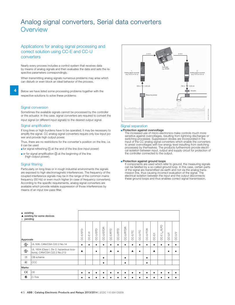
4/3 ABB | Catalog Electronic Products and Relays 2013/2014 | 2CDC 110 004 C0209
4
Analog signal converters, Serial data converters
Overview
Nearly every process includes a control system that receives data
by means of analog signals and then evaluates the data and sets the re-
spective parameters correspondingly.
When transmitting analog signals numerous problems may arise which
can disturb or even block an ideal behavior of the process.
Below we have listed some processing problems together with the
respective solutions to solve these problems:
Signal conversion
Sometimes the available signals cannot be processed by the controller
or the actuator. In this case, signal converters are required to convert the
input signal (or different input signals) to the desired output signal.
Signal amplification
If long lines or high burdens have to be operated, it may be necessary to
amplify the signal. CC analog signal converters require only low input po-
wer and provide high output power.
Thus, there are no restrictions for the converter's position on the line, i.e.
it can be used
� for signal refreshing � at the end of the line (low input power)
� or for signal amplification � at the beginning of the line (high output power).
Signal filtering
Particularly on long lines or in rough industrial environments the signals
are exposed to high electromagnetic interferences. The frequency of the
coupled interference signals may be in the range of the common mains
frequency (50 Hz) or even much higher (in case of frequency converters).
According to the specific requirements, analog signal converters are
available which provide reliable suppression of those interferences by
means of an input low-pass filter.
Applications for analog signal processing and
correct solution using CC-E and CC-U
converters
Signal separation � Protection against overvoltage
The increased use of micro-electronics make controls much more sensitive against overvoltages, resulting from lightning discharges or switching processes. Suppression diodes are incorporated in the input of the CC analog signal converters which enable the converters to arrest overvoltages with low energy level (resulting from switching processes) by themselves. The products furthermore provide electri-cal isolation between input, output and supply circuit for protection of the controller connected to the output.
� Protection against ground loops If components are used which refer to ground, the measuring signals can be falsified by a so-called ground loop. In this case, certain parts of the signal are transmitted via earth and not via the analog trans-mission line, thus causing incorrect evaluation of the signal. The electrical isolation between the input and the output disconnects these ground loops and thus enables correct signal transmission.
� existing � existing for some devices � pending
Approvals CC
-E/S
TD
CC
-E I/I
CC
-U/S
TD
CC
-U/S
TD
R
CC
-E/R
TD
CC
-U/R
TD
CC
-U/R
TD
R
CC
-E/T
C
CC
-U/T
C
CC
-U/T
CR
CC
-E/I
CC
-E I
AC/ILP
O
CC
-U/I
CC
-U/V
A UL 508, CAN/CSA C22.2 No.14 � � � � � � � � � � � � � �
A UL 1604 (Class I, Div 2, hazardous loca-
tions), CAN/CSA C22.2 No.213� � � � � � � � �
K CB scheme � � �
E CCC � � �
Marks
a CE � � � � � � � � � � � � � �
b C-Tick � � � � � � � � � � � � � �
0-10 V0-10 V
100 m 0-20 mA 100 m 4-20 mA
2C
DC
282 0
13 F
0206
Controllere.g. AC500
Measuring sensor
Actuator
1. Analog signal converter
(e.g. CC-E or CC-U)
2. Analog signal converter
(e.g. CC-E or CC-U)

2CDC 110 004 C0209 | Catalog Electronic Products and Relays 2013/2014 | ABB 4/4
4
Analog signal converters, Serial data converters
Overview
RS-232
RS-232
RS-485
RS-485
RS-232
RS-232
RS-232
RS-232
RS-422 RS-422
RS-422 RS-422
RS-232 RS-232 RS-232 RS-232
RS-23215 m max.
1.2 km max.
1.2 km max.
15 mmax.
TCPRS-232 RS-485
Modbus / RTU
Modbus / TCP
In the field of industrial data transmission, various processes of data transmission and interfaces are used today. Already existing systems need to be updated or connected to new devices for continuity of process. When new communication functions are not build-in, ABB propose a range of converters to be able to use from the standard RS232 or RS485, to the Ethernet open products or the Optical Fiber.
Ethernet communication is now one of the main features need in open communication, ABB propose the e-ILPH to connect the serial devices to the web world.
Uses
AdaptationThe use of converters allows the connection of two devices using different interfaces. To add new equipment to existing installations.
Electrical IsolationTo protect sensitive equipment it is sometimes necessary to use converters which allow electrical isolation.
Type of connection Immunity to noise RS232 Low
RS422 High
RS485 High
CL High
OF Very high
Ethernet High
To cross a disturbed environmentSome interfaces are more sensitive to noise. Electrically, it is preferable, in some cases, to change the interface or support.
Multipoint connectionsSome equipments are only designed to communicate in RS232 point to point connec-tion. To communicate with several devices it is then necessary to use converters RS232 to RS422, RS485, CL or OF to reach multipoint mode.
Type of connection Connection RS232 Point to point
RS422 12 points
RS485 32 points
CL 5-6 points
OF 32 points
Ethernet Point to point or multipoint
Type of connection Max. distances * RS232 15m
RS422 1.2km
RS485 1.2km
CL 300-500m
OF 4km
Ethernet 100 m with CAT5 cable
Increase in the transmission and amplification distances of the signalsEvery connection has its own limits, to increase the communication distances you only have to change the type of link (converter) or amplify the signal (Repeater) using an ILPH.
* Depending on transmission speed.
Example :
Example :
Example :
Example :
Example :
Example :
Example :
Line 1
Line 2
Power
Converter Repeater
Noisy elements
RS-485 2-/4 wires
"World Wide" communicationCommunication is more and more used with Ethernet support. The interests are to have a distant access, to use an already existing network and to upload information and data on a supervisor or a computer. The conversions from serial to Ethernet protocol are used to connect local network to Ethernet.
Protocol conversionModbus is one of the main protocols used in the industrial networks. The creation of Modbus/TCP allows an adapted access to the Ethernet network. So, the conversion between these 2 protocols is necessary.

4/5 ABB | Catalog Electronic Products and Relays 2013/2014 | 2CDC 110 004 C0209
4
Analog signal converters - CC-E range
Product group picture

2CDC 110 004 C0209 | Catalog Electronic Products and Relays 2013/2014 | ABB 4/6
4
Analog signal converters - CC-E range
Table of contents
Analog signal converters - CC-E range
Product group picture 4/5
Table of contents 4/6
Benefits and advantages 4/7
Ordering details - Standard signal converters 4/8
Ordering details - RTD converters 4/9
Ordering details - Thermocouple converters 4/10
Ordering details - Measuring converters 4/11
DIP switch settings and dimensional drawings 4/12
Wiring instructions 4/13
Technical data 4/14

4/7 ABB | Catalog Electronic Products and Relays 2013/2014 | 2CDC 110 004 C0209
4
Analog signal converters - CC-E range
Benefits and advantages
CC-E/STD analog signal converter with 3-way electrical isolation � 2 universally configurable devices (type CC-E/STD)
� 2x10 single-function devices
� "Plug and Work", no adjustment of single-function devices required
CC-E/RTD temperature signal converter for RTD sensors, linearized with 3-way electrical isolation � 2 universally configurable devices (type CC-E/RTD)
� 2x12 single-function devices
� Plug and Work", no adjustment of single-function devices required
� Temperature signal converter for PT100 sensors
� 2- or 3-wire connection
CC-E/TC analog signal converter for thermocouple signals of the types J and K with 3-way electrical isolation
� 2 universally configurable devices (type CC-E/TC)
� 2x6 single-function devices
� "Plug and Work", no adjustment of single-function devices required
� Integrated cold-junction compensation
CC-E/I measuring converter for current signals 0-5 A, 0-20 A, AC/DC with 3-way electrical isolation � 2 universally configurable devices (type CC-E/I)
� 2x6 single-function devices
� "Plug and Work", no adjustment of single-function devices required
CC-E IAC/ILPO measuring converter without auxiliary power for sinu-soidal currents 0-1 A, 0-5 A, output 4-20 mA � Measuring converter for sinusoidal currents (0-1 A, 0-5 A)
� Measuring range selection by front-face sliding switch
� 4-20 mA output current in proportion to input current
� no additional power supply required
CC-E range � Universally configurable devices and single-function devices
� Adjustment and operating elements on the front side
� Safe operation by electrical 3-way isolation
� Unambiguous and clear connecting terminal markings
Conversion, measurement and separation of � Standard signals (0-5 V, 0-10 V, 0-20 mA, 4-20 mA)
� Temperature signals of RTD sensors (PT 100)
� Thermocouple signals (types J and K)
� Current measurement signals (0-5 A, 0-20 A AC/DC)
Characteristics of single-function devices � No adjustment or balancing necessary.
Characteristics of universal devices � The required input and output ranges can be configured by means of
directly accessible DIP switches positioned on the side
� Gain adjustment of ± 5 % by means of an adjustment potentiometer on the front-side
� Offset adjustment of ±5 % by means of adjustment potentiometers on the front-side
Loop-powered current/current isolator without external power supply for analog current signals of 0-20 mA and 4-20 mA � Electrical isolation between input and output
� Very low internal voltage drop � 2.5 V
� Available with one or two independent channels
� Width only 18 mm (1 and 2 channels)
4
1
1
2
2
3
5
1 Terminals M, K, J, H, G
2 Terminal explanation
3 Adjustment of gain
4 Adjustment of offset
4 Indication of operational states
U - control supply voltage applied

2CDC 110 004 C0209 | Catalog Electronic Products and Relays 2013/2014 | ABB 4/8
4
Analog signal converters - CC-E range
Ordering details - Standard signal converters
1) B 1604 Class I, Div.2 (universal device) 2) CC-E-I/I-1 has 1 channel, CC-E-I/I-1 has 2 channels
3) 3-way electrical isolation 4) with relay output
Ordering details - Standard signal converters
Supply voltage range
Input signal Output signal Type Order code Price
1 pce
Weight(1 pce)kg (lb)
24 V DC
0-5 V, 0-10 V
0-20 mA,
4-20 mA
0-5 V, 0-10 V
0-20 mA,
4-20 mA
CC-E/STD1) 3) 1SVR011700R00000.088
(0.194)
0-10 V
0-10 V CC-E V/V 1SVR011710R21000.083
(0.183)
0-20 mA CC-E V/I 1SVR011711R16000.084
(0.185)
4-20 mA CC-E V/I 1SVR011712R17000.084
(0.187)
0-20 mA
0-10 V CC-E I/V 1SVR011713R10000.082
(0.181)
0-20 mA CC-E I/I 1SVR011714R11000.084
(0.187)
4-20 mA CC-E I/I 1SVR011715R12000.084
(0.185)
4-20 mA
0-10 V CC-E I/V 1SVR011716R13000.084
(0.185)0-20 mA CC-E I/I 1SVR011717R1400
4-20 mA CC-E I/I 1SVR011718R25000.084
(0.187)
-10...+10 V -10...+10 V CC-E V/V 1SVR011719R26000.082
(0.181)
110-240 V AC
0-5 V, 0-10 V
0-20 mA, 4-20
mA
0-5 V, 0-10 V
0-20 mA, 4-20 mACC-E/STD 3) 1SVR011705R2100
0.090
(0.198)
0-10 V
0-10 V CC-E V/V 1SVR011720R23000.096
(0.212)
0-20 mA CC-E V/I 1SVR011721R10000.087
(0.192)
4-20 mA CC-E V/I 1SVR011722R11000.091
(0.200)
0-20 mA
0-10 V CC-E V/V 1SVR011723R12000.091
(0.200)
0-20 mA CC-E I/I 1SVR011724R13000.088
(0.194)4-20 mA CC-E I/I 1SVR011725R1400
4-20 mA
0-10 V CC-E V/V 1SVR011726R15000.096
(0.212)
0-20 mA CC-E I/I 1SVR011727R16000.087
(0.192)
4-20 mA CC-E I/I 1SVR011728R27000.088
(0.194)
loop powered
-10...+10 V -10...+10 V CC-E V/V 1SVR011729R20000.086
(0.190)
0-20 mA, 4-20
mA0-20 mA, 4-20 mA
CC-E I/I-12) 1SVR010200R16000.038
(0.084)
CC-E I/I-22) 1SVR010201R03000.044
(0.097)
2C
DC
28
1 0
10
F0
00
32
CD
C 2
81
00
1 F
00
03
2C
DC
28
1 0
41
F0
00
3
CC-E/I
CC-E V/V
CC-E I/I-2

4/9 ABB | Catalog Electronic Products and Relays 2013/2014 | 2CDC 110 004 C0209
4
Analog signal converters - CC-E range
Ordering details - RTD converters
2C
DC
28
1 0
04
F0
00
3
CC-E/RTD
4) with relay output
Ordering details - RTD converters
Supply voltage range
Input signal Output signal Type Order code Price
1 pce
Weight(1 pce)kg (lb)
24 V DC
refer to table0-10 V, 0-20 mA,
4-20 mACC-E/RTD1) 1SVR011701R2500
0.091
(0.200)
PT100
0...100 °C
0-10 VCC-E RTD/V 1SVR011730R2500
0.084
(0.185)
0-20 mA CC-E RTD/I 1SVR011731R12000.086
(0.190)4-20 mA CC-E RTD/I 1SVR011732R1300
PT100
-50...+50 °C
0-10 VCC-E RTD/V 1SVR011733R1400
0.083
(0.183)
0-20 mACC-E RTD/I 1SVR011734R1500
0.084
(0.185)
4-20 mA CC-E RTD/I 1SVR011735R16000.084
(0.187)
PT100
0...300 °C
0-10 VCC-E RTD/V 1SVR011736R1700
0.084
(0.185)
0-20 mACC-E RTD/I 1SVR011737R1000
0.084
(0.187)
4-20 mA CC-E RTD/I 1SVR011738R2100 0.101
PT100
-50...+250 °C
0-10 VCC-E RTD/V 1SVR011739R2200
0.084
(0.185)
0-20 mA CC-E RTD/I 1SVR011740R07000.084
(0.187)4-20 mA CC-E RTD/I 1SVR011741R2400
110-240 V AC
refer to table0-10 V, 0-20 mA,
4-20 mACC-E/RTD 1SVR011706R2200
0.093
(0.205)
PT100
0...100 °C
0-10 V CC-E RTD/V 1SVR011788R24000.086
(0.190)
0-20 mACC-E RTD/I 1SVR011789R2500
0.088
(0.194)
4-20 mA CC-E RTD/I 1SVR011790R22000.089
(0.196)
PT100
-50...+50 °C
0-10 VCC-E RTD/V 1SVR011791R1700
0.087
(0.192)
0-20 mA CC-E RTD/I 1SVR011792R10000.089
(0.196)4-20 mA CC-E RTD/I 1SVR011793R1100
PT100
0...300 °C
0-10 VCC-E RTD/V 1SVR011794R1200
0.087
(0.192)
0-20 mA CC-E RTD/I 1SVR011795R13000.089
(0.196)4-20 mA CC-E RTD/I 1SVR011796R1400
PT100
-50...+250 °C
0-10 VCC-E RTD/V 1SVR011797R1500
0.086
(0.190)
0-20 mACC-E RTD/I 1SVR011798R2600
0.089
(0.196)
4-20 mA CC-E RTD/I 1SVR011799R27000.088
(0.194)
1) B 1604 Class I, Div.2 (universal device) 2) CC-E-I/I-1 has 1 channcel, CC-E-I/I-1 has 2 channels

2CDC 110 004 C0209 | Catalog Electronic Products and Relays 2013/2014 | ABB 4/10
4
Analog signal converters - CC-E range
Ordering details - Thermocouple converters
2C
DC
28
1 0
07
F0
00
3
CC-E TC
Ordering details - Thermocouple Converters
Supply voltage range
Input signal Output signal Type Order code Price
1 pce
Weight(1 pce)kg (lb)
24 V DC
thermocouple
types J and K
0-10 V, 0-20 mA,
4-20 mACC-E/TC1) 1SVR011702R2600
0.089
(0.196)
type J
0...600 °C
0-10 VCC-E TC/V 1SVR011750R0100
0.087
(0.192)
0-20 mACC-E TC/I 1SVR011751R2600
0.084
(0.187)
4-20 mA CC-E TC/I 1SVR011752R2700 0.102
type K
0...1000 °C
0-10 VCC-E TC/V 1SVR011753R2000
0.084
(0.185)0-20 mACC-E TC/I 1SVR011754R2100
4-20 mA CC-E TC/I 1SVR011755R22000.086
(0.190)
110-240 V AC
thermocouple
types J and K
0-10 V, 0-20 mA,
4-20 mACC-E/TC 1SVR011707R2300
0.088
(0.194)
type J
0...600 °C
0-10 VCC-E TC/V 1SVR011760R0300
0.084
(0.187)
0-20 mACC-E TC/I 1SVR011761R2000
0.088
(0.194)
4-20 mA CC-E TC/I 1SVR011762R21000.1
(0.220)
type K
0...1000 °C
0-10 VCC-E TC/V 1SVR011763R2200
0.086
(0.190)
0-20 mACC-E TC/I 1SVR011764R2300
0.088
(0.194)
4-20 mA CC-E TC/I 1SVR011765R24000.086
(0.190)
4) with relay output
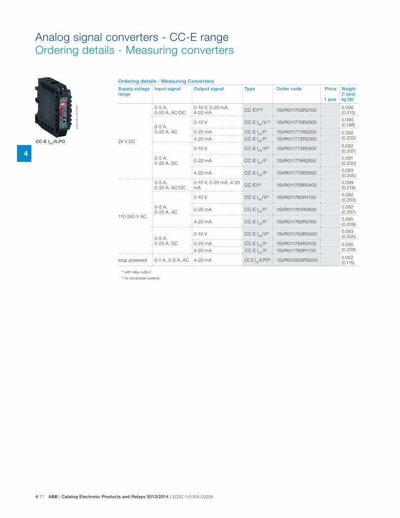
4/11 ABB | Catalog Electronic Products and Relays 2013/2014 | 2CDC 110 004 C0209
4
Ordering details - Measuring Converters
Supply voltage range
Input signal Output signal Type Order code Price
1 pce
Weight(1 pce)kg (lb)
24 V DC
0-5 A,
0-20 A, AC/DC
0-10 V, 0-20 mA,
4-20 mACC-E/I1)5) 1SVR011703R2700
0.096
(0.212)
0-5 A,
0-20 A, AC
0-10 V CC-E IAC
/V 5) 1SVR011770R05000.090
(0.198)
0-20 mA CC-E IAC
/I5) 1SVR011771R2200 0.092
(0.203)4-20 mA CC-E IAC
/I5) 1SVR011772R2300
0-5 A,
0-20 A, DC
0-10 V CC-E IDC
/V5) 1SVR011773R24000.092
(0.207)
0-20 mA CC-E IDC
/I5) 1SVR011774R25000.091
(0.200)
4-20 mA CC-E IDC
/I5) 1SVR011775R26000.093
(0.205)
110-240 V AC
0-5 A,
0-20 A, AC/DC
0-10 V, 0-20 mA, 4-20
mACC-E/I5) 1SVR011708R0400
0.099
(0.218)
0-5 A,
0-20 A, AC
0-10 V CC-E IAC
/V5) 1SVR011780R11000.092
(0.203)
0-20 mA CC-E IAC
/I5) 1SVR011781R06000.092
(0.207)
4-20 mA CC-E IAC
/I5) 1SVR011782R07000.095
(0.209)
0-5 A,
0-20 A, DC
0-10 V CC-E IDC
/V5) 1SVR011783R00000.093
(0.205)
0-20 mA CC-E IDC
/I5) 1SVR011784R0100 0.095
(0.209)4-20 mA CC-E IDC
/I5) 1SVR011785R1100
loop powered 0-1 A, 0-5 A, AC 4-20 mA CC-E IAC
/ILPO6) 1SVR010203R05000.052
(0.115)
2C
DC
28
1 0
18
F0
00
4
CC-E IAC/ILPO
5) with relay output
6) for sinusoidal currents
Analog signal converters - CC-E range
Ordering details - Measuring converters
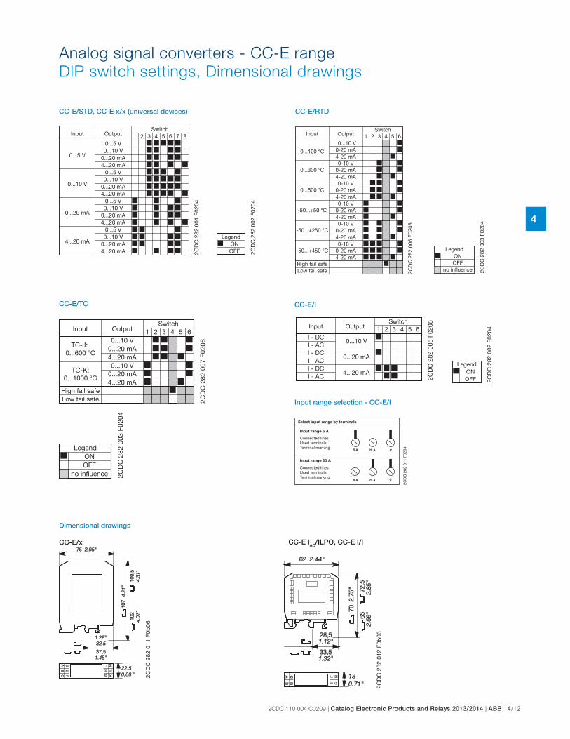
2CDC 110 004 C0209 | Catalog Electronic Products and Relays 2013/2014 | ABB 4/12
4
Analog signal converters - CC-E range
DIP switch settings, Dimensional drawings
81 2 43 5 6 7
0...5 V
0...10 V
0...20 mA
4...20 mA
0...5 V0...10 V
0...20 mA4...20 mA
0...5 V0...10 V
0...20 mA4...20 mA
0...5 V0...10 V
0...20 mA4...20 mA
0...5 V0...10 V
0...20 mA4...20 mA 2C
DC
282
001
F02
04
Input OutputSwitch
2CD
C 2
82 0
02 F
0204
ONLegend
OFF
CC-E/STD, CC-E x/x (universal devices)
2CD
C 2
82 0
03 F
0204
OFF
Legend
no influence
ON
1 2 43 5 6
0...300 °C
0...100 °C
0...500 °C
-50...+50 °C
-50...+250 °C
-50...+450 °C
High fail safeLow fail safe
0...10 V0-20 mA4-20 mA0-10 V
0-20 mA4-20 mA0-10 V
0-20 mA4-20 mA0-10 V
0-20 mA4-20 mA0-10 V
0-20 mA4-20 mA0-10 V
0-20 mA4-20 mA
2CD
C 2
82 0
06 F
0208
Input OutputSwitch
CC-E/RTD 2C
DC
282
003
F02
04
OFF
Legend
no influence
ON
1 2 43 5 6
TC-J: 0...600 °C
TC-K:0...1000 °C
High fail safeLow fail safe
0...10 V0...20 mA4...20 mA0...10 V
0...20 mA4...20 mA
2CD
C 2
82 0
07 F
0208
Input OutputSwitch
CC-E/TC CC-E/I
Dimensional drawings
2CD
C 2
82 0
02 F
0204
ONLegend
OFF
1 2 43 5 6
I - DCI - AC
I - AC
I - DCI - ACI - DC
0...10 V
0...20 mA
4...20 mA
2CD
C 2
82 0
05 F
0208Input Output
Switch
2CD
C 2
82 0
11 F
0204
Select input range by terminals
Input range 5 A
Connected linesUsed terminalsTerminal marking
Input range 20 A
Connected linesUsed terminalsTerminal marking
Input range selection - CC-E/I
CC-E/x CC-E IAC/ILPO, CC-E I/I
22.50,88 " 2C
DC
282
011
F0b
06
180.71" 2C
DC
282
012
F0b
06
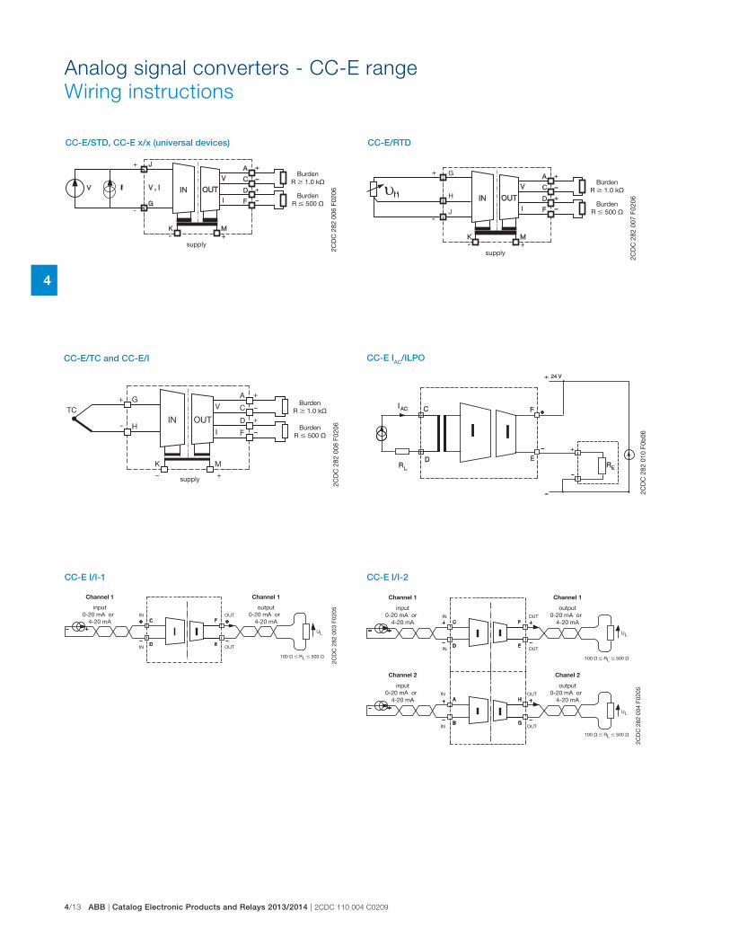
4/13 ABB | Catalog Electronic Products and Relays 2013/2014 | 2CDC 110 004 C0209
4
CC-E/STD, CC-E x/x (universal devices)
2CD
C 2
82 0
06 F
0206
BurdenR � 1.0 k�
BurdenR � 500 �
supply
CC-E/RTD
J
H
G
2CD
C 2
82 0
07 F
0206
BurdenR � 1.0 k�
BurdenR � 500 �
supply
CC-E/TC and CC-E/I
2CD
C 2
82 0
08 F
0206
BurdenR � 1.0 k�
BurdenR � 500 �
supply
100 � � RL � 500 �
UL
C
D
F
E
IN
IN
OUT
OUT
2CD
C 2
82 0
03 F
0205
Channel 1
input0-20 mA or
4-20 mA
Channel 1
output0-20 mA or
4-20 mA
100 � � RL � 500 �
100 � � RL � 500 �
UL
UL
C
D
F
E
A
B
H
G
IN
IN
IN
IN
OUT
OUT
OUT
OUT
2CD
C 2
82 0
04 F
0205
Channel 1
input0-20 mA or
4-20 mA
Channel 2
input0-20 mA or
4-20 mA
Channel 1
output0-20 mA or
4-20 mA
Chanel 2
output0-20 mA or
4-20 mA
CC-E I/I-1
2CD
C 2
82 0
10 F
0b06
CC-E IAC/ILPO
Analog signal converters - CC-E range
Wiring instructions
CC-E I/I-2
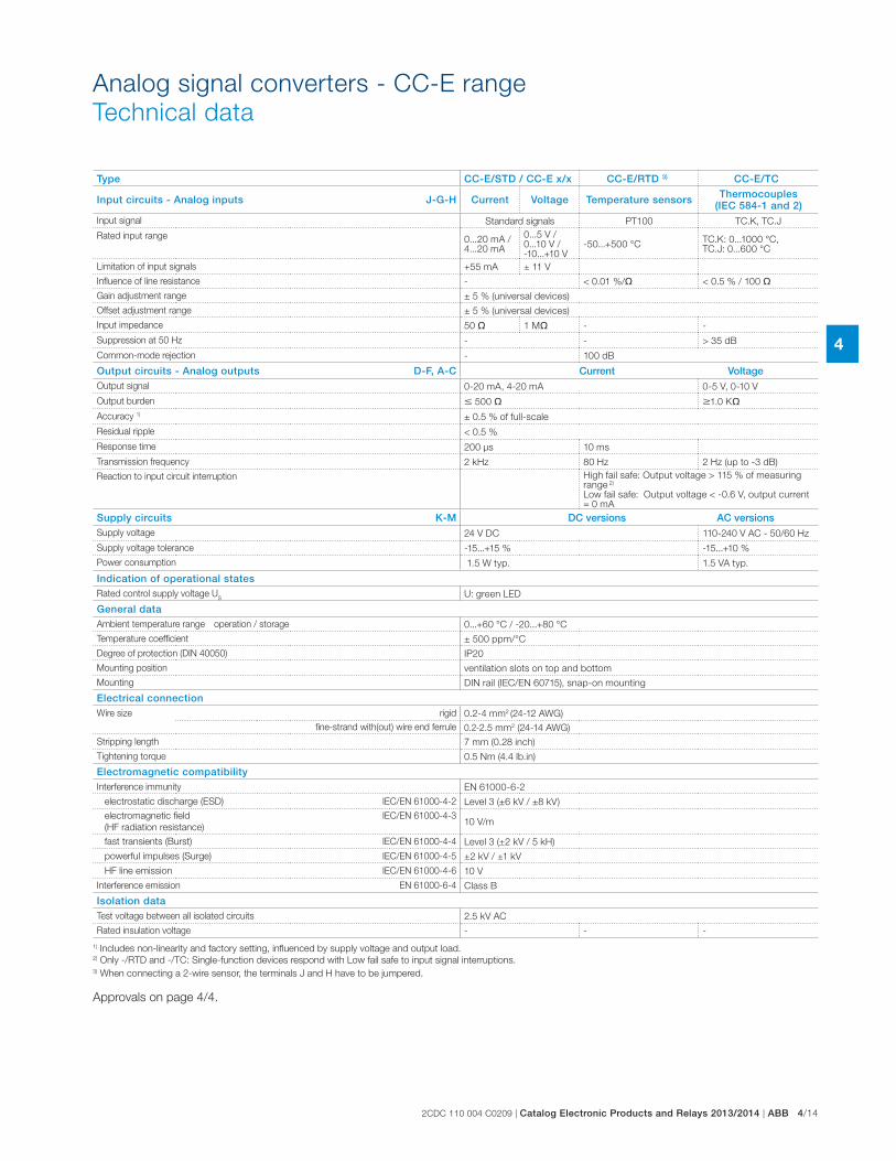
2CDC 110 004 C0209 | Catalog Electronic Products and Relays 2013/2014 | ABB 4/14
4
Analog signal converters - CC-E range
Technical data
Type CC-E/STD / CC-E x/x CC-E/RTD 3) CC-E/TC
Input circuits - Analog inputs J-G-H Current Voltage Temperature sensors Thermocouples (IEC 584-1 and 2)
Input signal Standard signals PT100 TC.K, TC.J
Rated input range 0...20 mA /4...20 mA
0...5 V /0...10 V /-10...+10 V
-50...+500 °CTC.K: 0...1000 °C, TC.J: 0...600 °C
Limitation of input signals +55 mA ± 11 V
Influence of line resistance - < 0.01 %/� < 0.5 % / 100 �
Gain adjustment range ± 5 % (universal devices)
Offset adjustment range ± 5 % (universal devices)
Input impedance 50 � 1 M� - -
Suppression at 50 Hz - - > 35 dB
Common-mode rejection - 100 dB
Output circuits - Analog outputs D-F, A-C Current VoltageOutput signal 0-20 mA, 4-20 mA 0-5 V, 0-10 V
Output burden � 500 � �1.0 K�
Accuracy 1) ± 0.5 % of full-scale
Residual ripple < 0.5 %
Response time 200 μs 10 ms
Transmission frequency 2 kHz 80 Hz 2 Hz (up to -3 dB)
Reaction to input circuit interruption High fail safe: Output voltage > 115 % of measuring range 2)
Low fail safe: Output voltage < -0.6 V, output current = 0 mA
Supply circuits K-M DC versions AC versionsSupply voltage 24 V DC 110-240 V AC - 50/60 Hz
Supply voltage tolerance -15...+15 % -15...+10 %
Power consumption 1.5 W typ. 1.5 VA typ.
Indication of operational statesRated control supply voltage U
SU: green LED
General dataAmbient temperature range operation / storage 0...+60 °C / -20...+80 °C
Temperature coefficient ± 500 ppm/°C
Degree of protection (DIN 40050) IP20
Mounting position ventilation slots on top and bottom
Mounting DIN rail (IEC/EN 60715), snap-on mounting
Electrical connectionWire size rigid 0.2-4 mm2 (24-12 AWG)
fine-strand with(out) wire end ferrule 0.2-2.5 mm2 (24-14 AWG)
Stripping length 7 mm (0.28 inch)
Tightening torque 0.5 Nm (4.4 lb.in)
Electromagnetic compatibilityInterference immunity EN 61000-6-2
electrostatic discharge (ESD) IEC/EN 61000-4-2 Level 3 (±6 kV / ±8 kV)
electromagnetic field
(HF radiation resistance)
IEC/EN 61000-4-310 V/m
fast transients (Burst) IEC/EN 61000-4-4 Level 3 (±2 kV / 5 kH)
powerful impulses (Surge) IEC/EN 61000-4-5 ±2 kV / ±1 kV
HF line emission IEC/EN 61000-4-6 10 V
Interference emission EN 61000-6-4 Class B
Isolation dataTest voltage between all isolated circuits 2.5 kV AC
Rated insulation voltage - - -
1) Includes non-linearity and factory setting, influenced by supply voltage and output load.2) Only -/RTD and -/TC: Single-function devices respond with Low fail safe to input signal interruptions.3) When connecting a 2-wire sensor, the terminals J and H have to be jumpered.
Approvals on page 4/4.
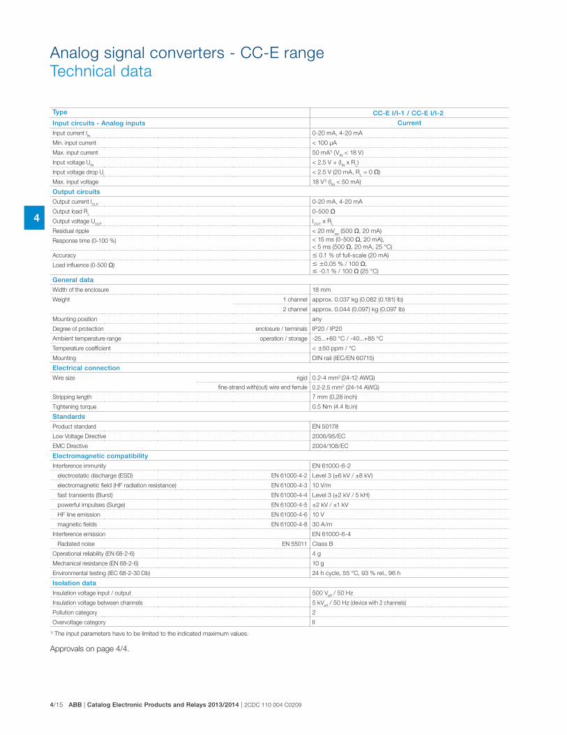
4/15 ABB | Catalog Electronic Products and Relays 2013/2014 | 2CDC 110 004 C0209
4
Type CC-E I/I-1 / CC-E I/I-2
Input circuits - Analog inputs Current
Input current IIN
0-20 mA, 4-20 mA
Min. input current < 100 μA
Max. input current 50 mA1) (VIN < 18 V)
Input voltage UIN
< 2.5 V + (IIN x R
L)
Input voltage drop Ui
< 2.5 V (20 mA, RL = 0 �)
Max. input voltage 18 V1) (IIN < 50 mA)
Output circuits
Output current IOUT
0-20 mA, 4-20 mA
Output load RL
0-500 �
Output voltage UOUT
IOUT
x RL
Residual ripple < 20 mVpp
(500 �, 20 mA)
Response time (0-100 %) < 15 ms (0-500 �, 20 mA),
< 5 ms (500 �, 20 mA, 25 °C)
Accuracy � 0.1 % of full-scale (20 mA)
Load influence (0-500 �) � �0.05 % / 100 �,
� -0.1 % / 100 � (25 °C)
General data
Width of the enclosure 18 mm
Weight 1 channel approx. 0.037 kg (0.082 (0.181) lb)
2 channel approx. 0.044 (0.097) kg (0.097 lb)
Mounting position any
Degree of protection enclosure / terminals IP20 / IP20
Ambient temperature range operation / storage -25...+60 °C / -40...+85 °C
Temperature coefficient < �50 ppm / °C
Mounting DIN rail (IEC/EN 60715)
Electrical connection
Wire size rigid 0.2-4 mm2 (24-12 AWG)
fine-strand with(out) wire end ferrule 0.2-2.5 mm2 (24-14 AWG)
Stripping length 7 mm (0,28 inch)
Tightening torque 0.5 Nm (4.4 lb.in)
Standards
Product standard EN 50178
Low Voltage Directive 2006/95/EC
EMC Directive 2004/108/EC
Electromagnetic compatibility
Interference immunity EN 61000-6-2
electrostatic discharge (ESD) EN 61000-4-2 Level 3 (±6 kV / ±8 kV)
electromagnetic field (HF radiation resistance) EN 61000-4-3 10 V/m
fast transients (Burst) EN 61000-4-4 Level 3 (±2 kV / 5 kH)
powerful impulses (Surge) EN 61000-4-5 ±2 kV / ±1 kV
HF line emission EN 61000-4-6 10 V
magnetic fields EN 61000-4-8 30 A/m
Interference emission EN 61000-6-4
Radiated noise EN 55011 Class B
Operational reliability (EN 68-2-6) 4 g
Mechanical resistance (EN 68-2-6) 10 g
Environmental testing (IEC 68-2-30 Db) 24 h cycle, 55 °C, 93 % rel., 96 h
Isolation data
Insulation voltage input / output 500 Veff
/ 50 Hz
Insulation voltage between channels 5 kVeff
/ 50 Hz (device with 2 channels)
Pollution category 2
Overvoltage category II
1) The input parameters have to be limited to the indicated maximum values.
Approvals on page 4/4.
Analog signal converters - CC-E range
Technical data
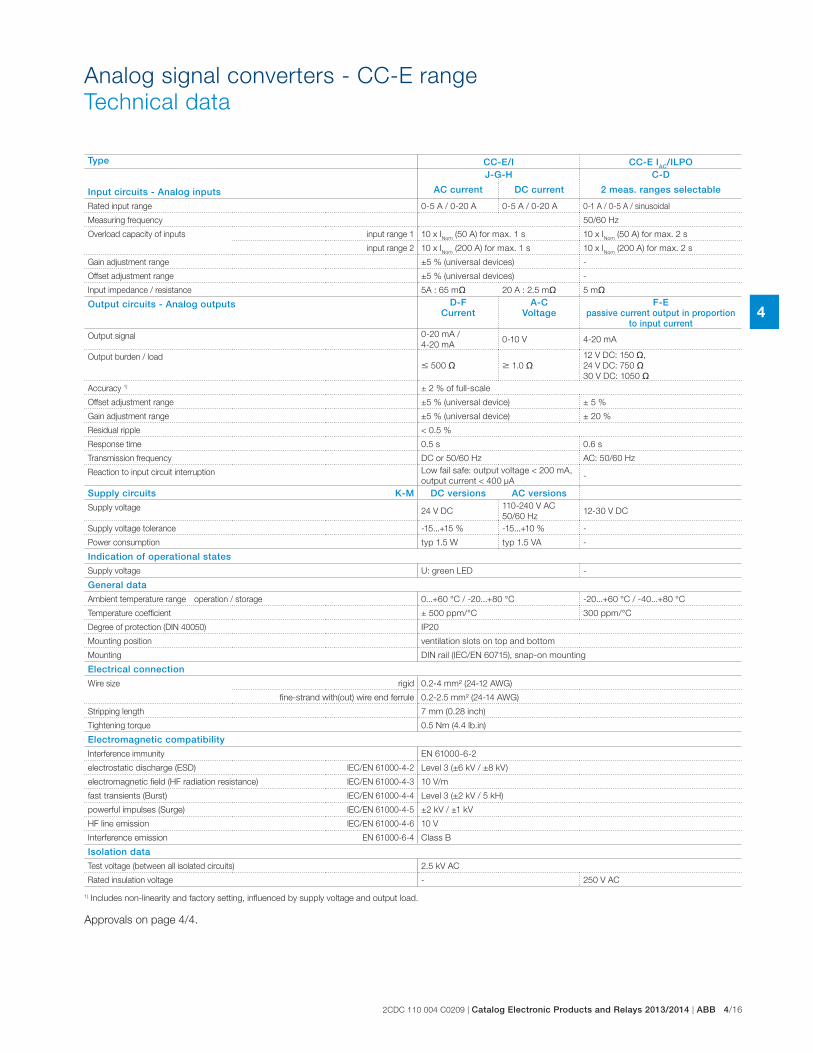
2CDC 110 004 C0209 | Catalog Electronic Products and Relays 2013/2014 | ABB 4/16
4
Analog signal converters - CC-E range
Technical data
Type CC-E/I CC-E IAC/ILPO
Input circuits - Analog inputs
J-G-H C-D
AC current DC current 2 meas. ranges selectable
Rated input range 0-5 A / 0-20 A 0-5 A / 0-20 A 0-1 A / 0-5 A / sinusoidal
Measuring frequency 50/60 Hz
Overload capacity of inputs input range 1 10 x INom
(50 A) for max. 1 s 10 x INom
(50 A) for max. 2 s
input range 2 10 x INom
(200 A) for max. 1 s 10 x INom
(200 A) for max. 2 s
Gain adjustment range ±5 % (universal devices) -
Offset adjustment range ±5 % (universal devices) -
Input impedance / resistance 5A : 65 m� 20 A : 2.5 m� 5 m�
Output circuits - Analog outputs D-F Current
A-C Voltage
F-E passive current output in proportion
to input currentOutput signal 0-20 mA /
4-20 mA0-10 V 4-20 mA
Output burden / load� 500 � � 1.0 �
12 V DC: 150 �,
24 V DC: 750 �30 V DC: 1050 �
Accuracy 1) ± 2 % of full-scale
Offset adjustment range ±5 % (universal device) ± 5 %
Gain adjustment range ±5 % (universal device) ± 20 %
Residual ripple < 0.5 %
Response time 0.5 s 0.6 s
Transmission frequency DC or 50/60 Hz AC: 50/60 Hz
Reaction to input circuit interruption Low fail safe: output voltage < 200 mA,
output current < 400 μA-
Supply circuits K-M DC versions AC versions
Supply voltage 24 V DC110-240 V AC
50/60 Hz12-30 V DC
Supply voltage tolerance -15...+15 % -15...+10 % -
Power consumption typ 1.5 W typ 1.5 VA -
Indication of operational states
Supply voltage U: green LED -
General data
Ambient temperature range operation / storage 0...+60 °C / -20...+80 °C -20...+60 °C / -40...+80 °C
Temperature coefficient ± 500 ppm/°C 300 ppm/°C
Degree of protection (DIN 40050) IP20
Mounting position ventilation slots on top and bottom
Mounting DIN rail (IEC/EN 60715), snap-on mounting
Electrical connection
Wire size rigid 0.2-4 mm² (24-12 AWG)
fine-strand with(out) wire end ferrule 0.2-2.5 mm² (24-14 AWG)
Stripping length 7 mm (0.28 inch)
Tightening torque 0.5 Nm (4.4 lb.in)
Electromagnetic compatibility
Interference immunity EN 61000-6-2
electrostatic discharge (ESD) IEC/EN 61000-4-2 Level 3 (±6 kV / ±8 kV)
electromagnetic field (HF radiation resistance) IEC/EN 61000-4-3 10 V/m
fast transients (Burst) IEC/EN 61000-4-4 Level 3 (±2 kV / 5 kH)
powerful impulses (Surge) IEC/EN 61000-4-5 ±2 kV / ±1 kV
HF line emission IEC/EN 61000-4-6 10 V
Interference emission EN 61000-6-4 Class B
Isolation data
Test voltage (between all isolated circuits) 2.5 kV AC
Rated insulation voltage - 250 V AC
1) Includes non-linearity and factory setting, influenced by supply voltage and output load.
Approvals on page 4/4.
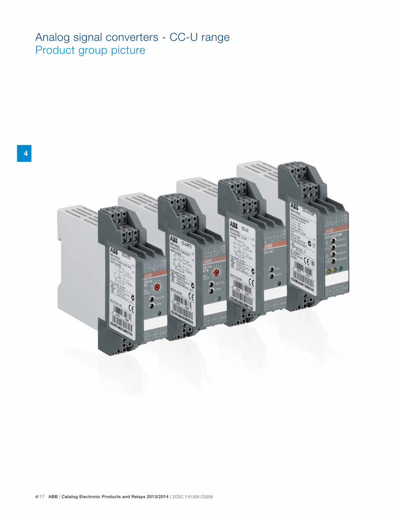
4/17 ABB | Catalog Electronic Products and Relays 2013/2014 | 2CDC 110 004 C0209
4
Analog signal converters - CC-U range
Product group picture
2CDC 110 004 C0209 | Catalog Electronic Products and Relays 2013/2014 | ABB 4/18
4
Analog signal converters - CC-U range
Table of contents
Analog signal converters - CC-U range
Product group picture 4/17
Table of contents 4/18
Overview 4/19
Ordering details 4/21
Ordering details - Accessories 4/22
DIP switch settings 4/23
Wiring instructions 4/25
Technical information 4/26
Technical data 4/29
Technical diagr., Connection diagr., Dimensional drawings 4/32
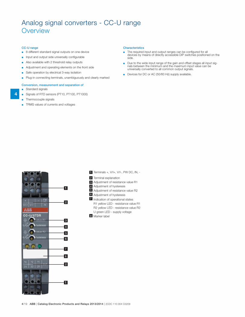
4/19 ABB | Catalog Electronic Products and Relays 2013/2014 | 2CDC 110 004 C0209
4
Analog signal converters - CC-U range
Overview
CC-U range � 8 different standard signal outputs on one device
� Input and output side universally configurable
� Also available with 2 threshold relay outputs
� Adjustment and operating elements on the front side
� Safe operation by electrical 3-way isolation
� Plug-in connecting terminals, unambiguously and clearly marked
Conversion, measurement and separation of � Standard signals
� Signals of RTD sensors (PT10, PT100, PT1000)
� Thermocouple signals
� TRMS values of currents and voltages
Characteristics � The required input and output ranges can be configured for all
devices by means of directly accessible DIP switches positioned on the side.
� Due to the wide input range of the gain and offset stages all input sig-nals between the minimum and the maximum input value can be universally converted to all common output signals.
� Devices for DC or AC (50/60 Hz) supply available.
4
1
1
2
2
3
5
1 Terminals +, V/I+, V/I-, PW DC, IN, -
2 Terminal explanation
3 Adjustment of resistance value R1
4 Adjustment of hysteresis
4 Adjustment of resistance value R2
Adjustment of hysteresis
7 Indication of operational states
R1 yellow LED - resistance value R1
R2 yellow LED - resistance value R2
U green LED - supply voltage
8 Marker label
7
8
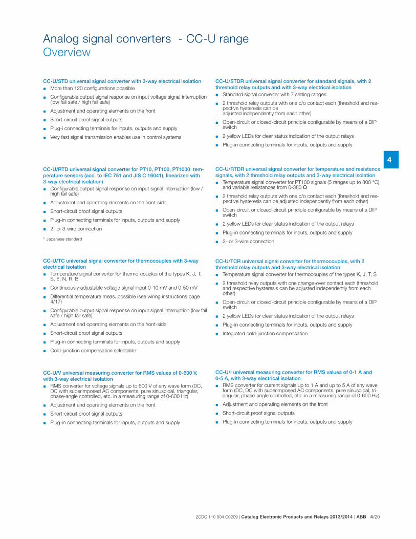
2CDC 110 004 C0209 | Catalog Electronic Products and Relays 2013/2014 | ABB 4/20
4
Analog signal converters - CC-U range
Overview
CC-U/STD universal signal converter with 3-way electrical isolation � More than 120 configurations possible
� Configurable output signal response on input voltage signal interruption (low fail safe / high fail safe)
� Adjustment and operating elements on the front
� Short-circuit proof signal outputs
� Plug-i connecting terminals for inputs, outputs and supply
� Very fast signal transmission enables use in control systems
CC-U/STDR universal signal converter for standard signals, with 2 threshold relay outputs and with 3-way electrical isolation
� Standard signal converter with 7 setting ranges
� 2 threshold relay outputs with one c/o contact each (threshold and res-pective hysteresis can be adjusted independently from each other)
� Open-circuit or closed-circuit principle configurable by means of a DIP switch
� 2 yellow LEDs for clear status indication of the output relays
� Plug-in connecting terminals for inputs, outputs and supply
CC-U/RTD universal signal converter for PT10, PT100, PT1000 tem-perature sensors (acc. to IEC 751 and JIS C 16041), linearized with 3-way electrical isolation)
� Configurable output signal response on input signal interruption (low / high fail safe)
� Adjustment and operating elements on the front-side
� Short-circuit proof signal outputs
� Plug-in connecting terminals for inputs, outputs and supply
� 2- or 3-wire connection
CC-U/RTDR universal signal converter for temperature and resistance signals, with 2 threshold relay outputs and 3-way electrical isolation � Temperature signal converter for PT100 signals (5 ranges up to 800 °C)
and variable resistances from 0-380 �
� 2 threshold relay outputs with one c/o contact each (threshold and res-pective hysteresis can be adjusted independently from each other)
� Open-circuit or closed-circuit principle configurable by means of a DIP switch
� 2 yellow LEDs for clear status indication of the output relays
� Plug-in connecting terminals for inputs, outputs and supply
� 2- or 3-wire connection
CC-U/TC universal signal converter for thermocouples with 3-way electrical isolation
� Temperature signal converter for thermo-couples of the types K, J, T, S, E, N, R, B
� Continuously adjustable voltage signal input 0-10 mV and 0-50 mV
� Differential temperature meas. possible (see wiring instructions page 4/17)
� Configurable output signal response on input signal interruption (low fail safe / high fail safe)
� Adjustment and operating elements on the front-side
� Short-circuit proof signal outputs
� Plug-in connecting terminals for inputs, outputs and supply
� Cold-junction compensation selectable
CC-U/TCR universal signal converter for thermocouples, with 2 threshold relay outputs and 3-way electrical isolation
� Temperature signal converter for thermocouples of the types K, J, T, S
� 2 threshold relay outputs with one change-over contact each (threshold and respective hysteresis can be adjusted independently from each other)
� Open-circuit or closed-circuit principle configurable by means of a DIP switch
� 2 yellow LEDs for clear status indication of the output relays
� Plug-in connecting terminals for inputs, outputs and supply
� Integrated cold-junction compensation
CC-U/I universal measuring converter for RMS values of 0-1 A and 0-5 A, with 3-way electrical isolation
� RMS converter for current signals up to 1 A and up to 5 A of any wave form (DC, DC with superimposed AC components, pure sinusoidal, tri-angular, phase-angle controlled, etc. in a measuring range of 0-600 Hz)
� Adjustment and operating elements on the front
� Short-circuit proof signal outputs
� Plug-in connecting terminals for inputs, outputs and supply
CC-U/V universal measuring converter for RMS values of 0-600 V, with 3-way electrical isolation
� RMS converter for voltage signals up to 600 V of any wave form (DC, DC with superimposed AC components, pure sinusoidal, triangular, phase-angle controlled, etc. in a measuring range of 0-600 Hz)
� Adjustment and operating elements on the front
� Short-circuit proof signal outputs
� Plug-in connecting terminals for inputs, outputs and supply
1) Japanese standard
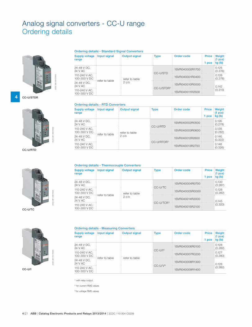
4/21 ABB | Catalog Electronic Products and Relays 2013/2014 | 2CDC 110 004 C0209
4
Analog signal converters - CC-U range
Ordering details
1) with relay output
2) for current RMS values
3) for voltage RMS values
Ordering details - RTD Converters
Supply voltage range
Input signal Output signal Type Order code Price
1 pce
Weight(1 pce)kg (lb)
24-48 V DC,
24 V AC
refer to tablerefer to table
2 c/o
CC-U/RTD
1SVR040002R05000.126
(0.278)
110-240 V AC,
100-300 V DC1SVR040003R0600
0.128
(0.282)
24-48 V DC,
24 V ACCC-U/RTDR1)
1SVR040012R26000.146
(0.322)
110-240 V AC,
100-300 V DC1SVR040013R2700
0.148
(0.326)
Ordering details - Standard Signal Converters
Supply voltage range
Input signal Output signal Type Order code Price
1 pce
Weight(1 pce)kg (lb)
24-48 V DC,
24 V AC
refer to tablerefer to table
2 c/o
CC-U/STD
1SVR040000R17000.125
(0.276)
110-240 V AC,
100-300 V DC1SVR040001R0400
0.126
(0.278)
24-48 V DC,
24 V ACCC-U/STDR1)
1SVR040010R00000.142
(0.313)110-240 V AC,
100-300 V DC1SVR040011R2500
2C
DC
28
1 0
03
F0
00
3
2C
DC
28
1 0
05
F0
00
32
CD
C 2
81
00
8 F
00
03
2C
DC
28
1 0
12
F0
00
3
CC-U/STDR
CC-U/RTD
CC-U/TC
CC-U/I
Ordering details - Thermocouple Converters
Supply voltage range
Input signal Output signal Type Order code Price
1 pce
Weight(1 pce)kg (lb)
24-48 V DC,
24 V AC
refer to tablerefer to table
2 c/o
CC-U/TC
1SVR040004R07000.130
(0.287)
110-240 V AC,
100-300 V DC1SVR040005R0000
0.128
(0.282)
24-48 V DC,
24 V ACCC-U/TCR1)
1SVR040014R20000.145
(0.320)110-240 V AC,
100-300 V DC1SVR040015R2100
Ordering details - Measuring Converters
Supply voltage range
Input signal Output signal Type Order code Price
1 pce
Weight(1 pce)kg (lb)
24-48 V DC,
24 V AC
refer to table refer to table
CC-U/I2)
1SVR040006R01000.128
(0.282)
110-240 V AC,
100-300 V DC1SVR040007R0200
0.127
(0.280)
24-48 V DC,
24 V ACCC-U/V3)
1SVR040008R13000.128
(0.282)110-240 V AC,
100-300 V DC1SVR040009R1400
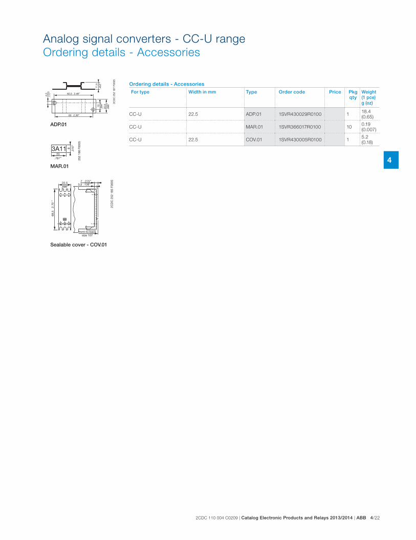
2CDC 110 004 C0209 | Catalog Electronic Products and Relays 2013/2014 | ABB 4/22
4
Ordering details - Accessories
For type Width in mm Type Order code Price Pkg qty
Weight(1 pce)g (oz)
CC-U 22.5 ADP.01 1SVR430029R0100 118.4
(0.65)
CC-U MAR.01 1SVR366017R0100 100.19
(0.007)
CC-U 22.5 COV.01 1SVR430005R0100 15.2
(0.18)
Analog signal converters - CC-U range
Ordering details - Accessories
2CD
C 2
52 1
87 F
0005
4,5 62,5
60
1011
,5
22,5
.177
”
2.46”
2.36”
.394
”
.886
”
.453
”
2CD
C 2
52 1
85 F
000522,5
68,5
73,5
.886”
2.70
”
.138”.275”
front-to-backsize 107
ADP.01
203A11 8
.315
”
.787” 252
186
F000
5
MAR.01
Sealable cover - COV.01
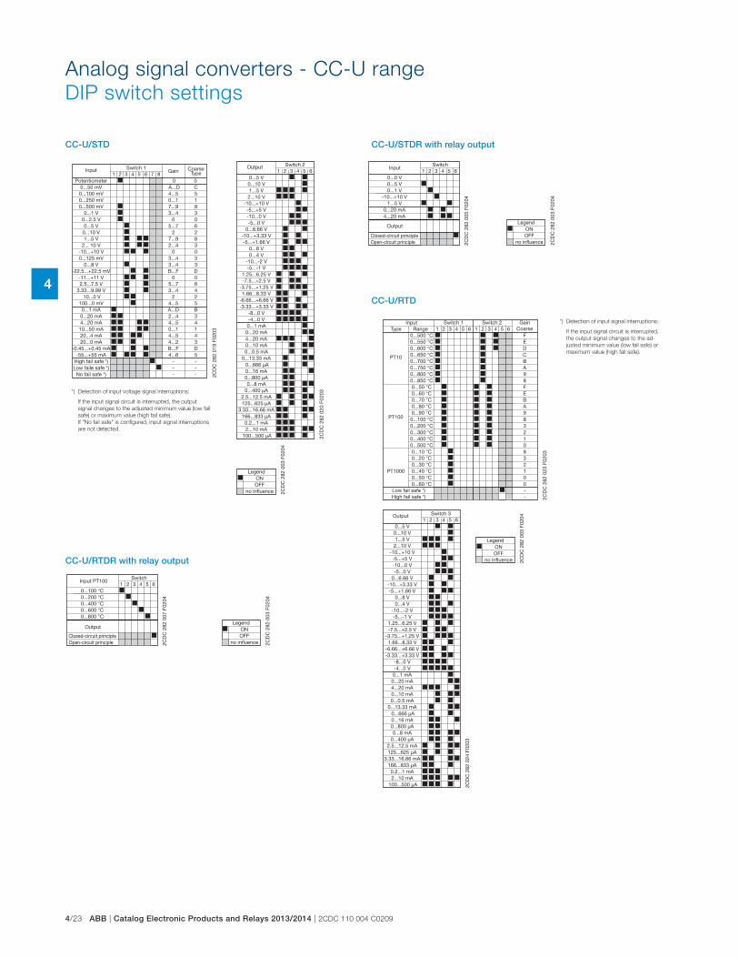
4/23 ABB | Catalog Electronic Products and Relays 2013/2014 | 2CDC 110 004 C0209
4
Analog signal converters - CC-U range
DIP switch settings
*) Detection of input voltage signal interruptions:
If the input signal circuit is interrupted, the output
signal changes to the adjusted minimum value (low fail
safe) or maximum value (high fail safe).
If "No fail safe" is configured, input signal interruptions
are not detected.
4321 5 876
0...8 V
0...20 mA4...20 mA10...50 mA20...4 mA20...0 mA
0...50 mV0...100 mV0...250 mV0...500 mV
0...1 V
0...5 V
-10...+10 V0...125 mV
1...5 V0...10 V
2... 10 V
-11...+11 V
10...0 V100...0 mV0...1 mA
-55...+55 mA
3...4
2...44...50...14...54...2
A...D4...50...17...93...4
5...7
03...4
7...92
2...4
0
24...5A...D
4...6
3
34143
C5183
6
03
82
3
0
25B
5
64
0
0
D
D
0
0
B...F
5...73...4
---
---
B...F
2CD
C 2
82 0
19 F
0203
Switch 1Input
2.5...7.5 V3.33...9.99 V
High fail safe *)
Gain CoarseType
Potentiometer
0...2.5 V
-22.5...+22.5 mV
-0.45...+0.45 mA
Low faile safe *)No fail safe *)
1 2 43 5 6
-10...-2 V-5...-1 V
-8...0 V-4...0 V0...1 mA
0...20 mA4...20 mA0...10 mA
0...800 μA0...8 mA
0...400 μA
125...625 μA
166...833 μA
2...10 mA100...500 μA
0...666 μA0...16 mA
0...5 V0...10 V1...5 V
2...10 V-10...+10 V
-5...+5 V-10...0 V-5...0 V
0...8 V0...4 V
2CD
C 2
82 0
20 F
0203
Switch 2Output
1.25...6.25 V
0...6.66 V-10...+3.33 V-5...+1.66 V
-7.5...+2.5 V-3.75...+1.25 V1.66...8.33 V
-6.66...+6.66 V-3.33...+3.33 V
0...0.5 mA0...13.33 mA
2.5...12.5 mA
3.33...16.66 mA
0.2...1 mA
2CD
C 2
82 0
03 F
0204
OFF
Legend
no influence
ON
CC-U/STD CC-U/STDR with relay output
2CD
C 2
82 0
03 F
0204
OFF
Legend
no influence
ON
1 2 43 5 60...0 V0...5 V0...1 V
-10...+10 V1...5 V
0...20 mA4...20 mA
2CD
C 2
82 0
05 F
0204
SwitchInput
Output
Closed-circuit principleOpen-circuit principle
*) Detection of input signal interruptions:
If the input signal circuit is interrupted,
the output signal changes to the ad-
justed minimum value (low fail safe) or
maximum value (high fail safe).
CC-U/RTD
2CD
C 2
82 0
03 F
0204
OFF
Legend
no influence
ON
1 2 43 5 6 1 2 43 5 6
PT10
PT100
PT1000
0...500 °C0...550 °C0...600 °C0...650 °C0...700 °C0...750 °C0...800 °C0...850 °C0...50 °C0...60 °C0...70 °C0...80 °C0...90 °C0...100 °C0...200 °C
0...400 °C0...300 °C
0...500 °C0...10 °C0...20 °C0...30 °C0...40 °C0...50 °C0...60 °C
FEDCBA98FEBA983
12
0832100
--
2CD
C 2
82 0
23 F
0203
Type RangeSwitch 1 Switch 2Input
Low fail safe *)High fail safe *)
GainCoarse
1 2 43 5 6
-10...-2 V-5...-1 V
-8...0 V-4...0 V0...1 mA0...20 mA4...20 mA0...10 mA
0...800 μA0...8 mA
0...400 μA
125...625 μA
166...833 μA
2...10 mA100...500 μA
0...666 μA0...16 mA
0...5 V0...10 V1...5 V2...10 V
-10...+10 V-5...+5 V-10...0 V-5...0 V
0...8 V0...4 V
2CD
C 2
82 0
24 F
0203
Switch 3Output
1.25...6.25 V
0...6.66 V-10...+3.33 V-5...+1.66 V
-7.5...+2.5 V-3.75...+1.25 V1.66...8.33 V
-6.66...+6.66 V-3.33...+3.33 V
0...0.5 mA0...13.33 mA
2.5...12.5 mA
3.33...16.66 mA
0.2...1 mA
CC-U/RTDR with relay output
2CD
C 2
82 0
03 F
0204
OFF
Legend
no influence
ON
1 2 43 5 60...100 °C0...200 °C0...400 °C0...600 °C0...800 °C
2CD
C 2
82 0
07 F
0204
SwitchInput PT100
Output
Closed-circuit principleOpen-circuit principle
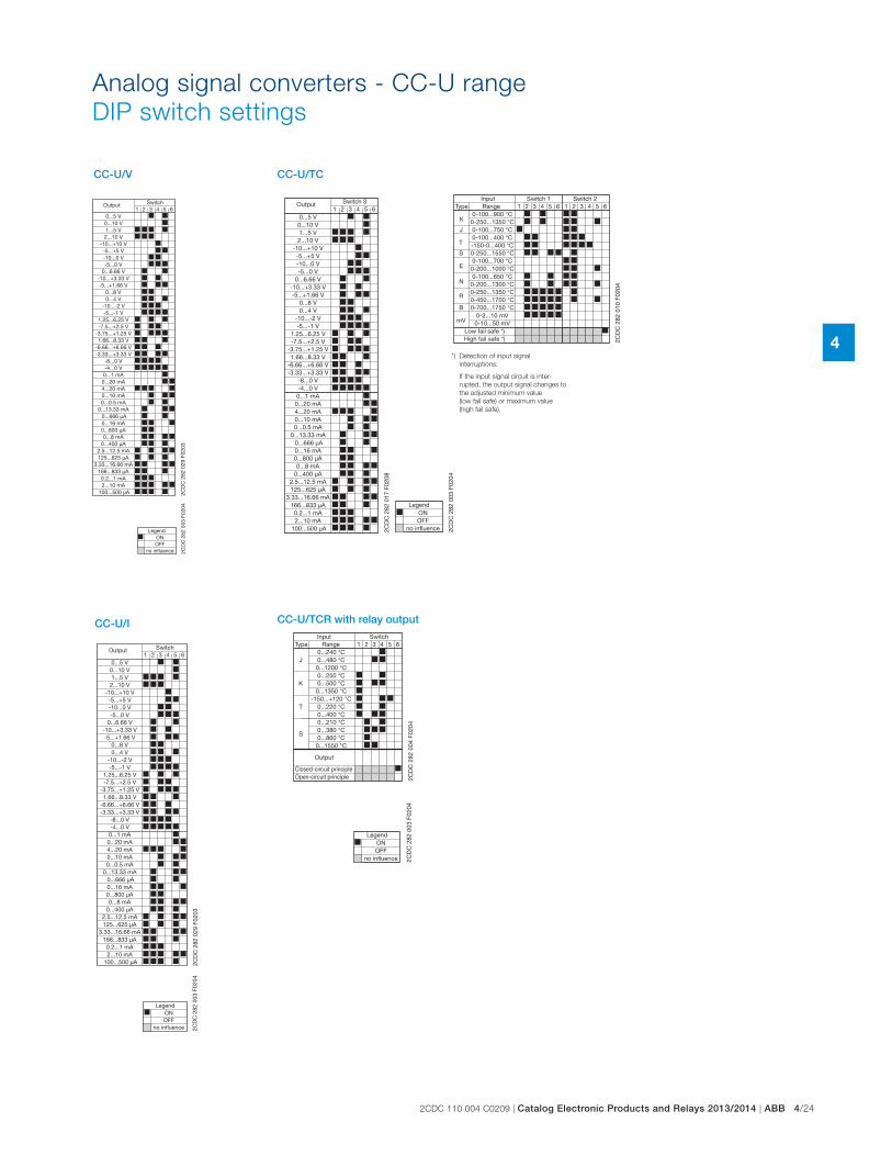
2CDC 110 004 C0209 | Catalog Electronic Products and Relays 2013/2014 | ABB 4/24
4
Analog signal converters - CC-U range
DIP switch settings
CC-U/I
2CD
C 2
82 0
03 F
0204
OFF
Legend
no influence
ON
1 2 43 5 6
-10...-2 V-5...-1 V
-8...0 V-4...0 V0...1 mA0...20 mA4...20 mA0...10 mA
0...800 μA0...8 mA
0...400 μA
125...625 μA
166...833 μA
2...10 mA100...500 μA
0...666 μA0...16 mA
0...5 V0...10 V1...5 V2...10 V
-10...+10 V-5...+5 V-10...0 V-5...0 V
0...8 V0...4 V
2CD
C 2
82 0
29 F
0203
SwitchOutput
1.25...6.25 V
0...6.66 V-10...+3.33 V-5...+1.66 V
-7.5...+2.5 V-3.75...+1.25 V1.66...8.33 V
-6.66...+6.66 V-3.33...+3.33 V
0...0.5 mA0...13.33 mA
2.5...12.5 mA
3.33...16.66 mA
0.2...1 mA
CC-U/V2C
DC
282
003
F02
04
OFF
Legend
no influence
ON
1 2 43 5 6
-10...-2 V-5...-1 V
-8...0 V-4...0 V0...1 mA0...20 mA4...20 mA0...10 mA
0...800 μA0...8 mA
0...400 μA
125...625 μA
166...833 μA
2...10 mA100...500 μA
0...666 μA0...16 mA
0...5 V0...10 V1...5 V2...10 V
-10...+10 V-5...+5 V-10...0 V-5...0 V
0...8 V0...4 V
2CD
C 2
82 0
29 F
0203
SwitchOutput
1.25...6.25 V
0...6.66 V-10...+3.33 V-5...+1.66 V
-7.5...+2.5 V-3.75...+1.25 V1.66...8.33 V
-6.66...+6.66 V-3.33...+3.33 V
0...0.5 mA0...13.33 mA
2.5...12.5 mA
3.33...16.66 mA
0.2...1 mA
*) Detection of input signal
interruptions:
If the input signal circuit is inter-
rupted, the output signal changes to
the adjusted minimum value
(low fail safe) or maximum value
(high fail safe).
CC-U/TC
1 2 43 5 6
-10...-2 V-5...-1 V
-8...0 V-4...0 V0...1 mA
0...20 mA4...20 mA0...10 mA
0...800 μA0...8 mA
0...400 μA
125...625 μA
166...833 μA
2...10 mA100...500 μA
0...666 μA0...16 mA
0...5 V0...10 V1...5 V
2...10 V-10...+10 V
-5...+5 V-10...0 V-5...0 V
0...8 V0...4 V
2CD
C 2
82 0
17 F
0208
Switch 3Output
1.25...6.25 V
0...6.66 V-10...+3.33 V-5...+1.66 V
-7.5...+2.5 V-3.75...+1.25 V1.66...8.33 V
-6.66...+6.66 V-3.33...+3.33 V
0...0.5 mA0...13.33 mA
2.5...12.5 mA
3.33...16.66 mA
0.2...1 mA
2CD
C 2
82 0
03 F
0204
OFF
Legend
no influence
ON
1 2 43 5 6 1 2 43 5 6
R
B
mV
N
K
J
T
S
E
0-100...900 °C0-250...1350 °C0-100...750 °C0-100...400 °C-150-0...400 °C0-250...1550 °C0-100...700 °C0-200...1000 °C0-100...650 °C0-200...1300 °C0-250...1350 °C0-450...1700 °C0-700...1750 °C
0-2...10 mV0-10...50 mV
2CD
C 2
82 0
10 F
0204
Type RangeSwitch 1 Switch 2Input
Low fail safe *)High fail safe *)
CC-U/TCR with relay output
2CD
C 2
82 0
03 F
0204
OFF
Legend
no influence
ON
1 2 43 5 6
S
J
K
T
0...240 °C0...480 °C
0...1200 °C0...250 °C0...500 °C
0...1350 °C-150...+120 °C
0...220 °C0...400 °C0...210 °C0...380 °C0...860 °C
0...1550 °C
2CD
C 2
82 0
04 F
0204
Type RangeSwitchInput
Output
Closed-circuit principleOpen-circuit principle
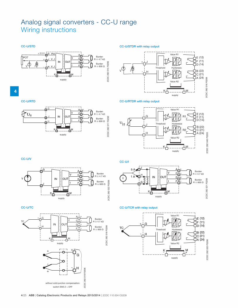
4/25 ABB | Catalog Electronic Products and Relays 2013/2014 | 2CDC 110 004 C0209
4
Pot.G
H
J
2CD
C 2
82 0
15 F
0206
BurdenR � 4.7 k�
BurdenR � 600 �
supply
+ 2.5 V
CC-U/STD
Analog signal converters - CC-U range
Wiring instructions
2CD
C 2
82 0
16 F
0206
Value R1
Value R2
Threshold Hysteresis
supply
CC-U/STDR with relay output
J
H
G2C
DC
282
017
F02
06
BurdenR � 4.7 k�
BurdenR � 600 �
supply
CC-U/RTD
υG
J
H
K M
B (22)C (21)A (24)
E (12)F (11)D (14)
R1
R2
2CD
C 2
82 0
45 F
0203
Value R1
Value R2
Threshold Hysteresis
supply
CC-U/RTDR with relay output
2CD
C 2
82 0
22 F
0206
BurdenR � 4.7 k�
BurdenR � 600 �
supply
CC-U/V
2CD
C 2
82 0
21 F
0206
BurdenR � 4.7 k�
BurdenR � 600 �
supply
CC-U/I
2CD
C 2
82 0
19 F
0206
without cold-junction compensation:
switch SW2.2 = OFF
2CD
C 2
82 0
18 F
0206
BurdenR � 4.7 k�
BurdenR � 600 �
supply
CC-U/TC2C
DC
282
020
F02
06
Value R1
Value R2
Threshold Hysteresis
supply
CC-U/TCR with relay output
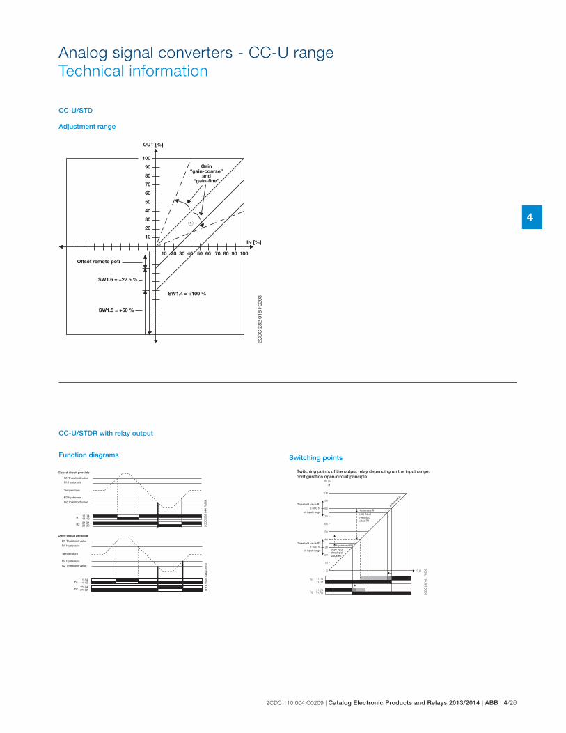
2CDC 110 004 C0209 | Catalog Electronic Products and Relays 2013/2014 | ABB 4/26
4
Adjustment range
OUT [%]
IN [%]
SW1.4 = +100 %
SW1.5 = +50 %
100
90
80
70
60
50
40
30
20
10
10 20 30 40 50 60 70 80 90 100
2CD
C 2
82 0
18 F
0203
Offset remote poti
SW1.6 = +22.5 %
Gain“gain-coarse”
and“gain-fine”
CC-U/STD
Analog signal converters - CC-U range
Technical information
Function diagrams
Switching points of the output relay depending on the input range, configuration open-circuit principle
OUT
11-14
11-12
21-24
21-22
R1
R2
IN [%]
100
90
80
70
60
50
40
30
20
10
0
2CD
C 2
82 0
21 F
0203
Hysteresis R15-50 % of threshold value R1
Threshold value R12-100 %
of input range
Threshold value R22-100 %
of input range
Hysteresis R25-50 % of threshold value R2
Actua
l valu
e
Switching points
21-2421-22
11-1411-12
R2
R1
2CD
C 2
82 0
44 F
0203
R1 Threshold value
R1 Hysteresis
R2 Hysteresis
R2 Threshold value
Temperature
Closed-circuit principle
21-2421-22
11-1411-12
R2
R1
2CD
C 2
82 0
46 F
0203
R1 Threshold value
R1 Hysteresis
R2 Hysteresis
R2 Threshold value
Temperature
Open-circuit principle
CC-U/STDR with relay output
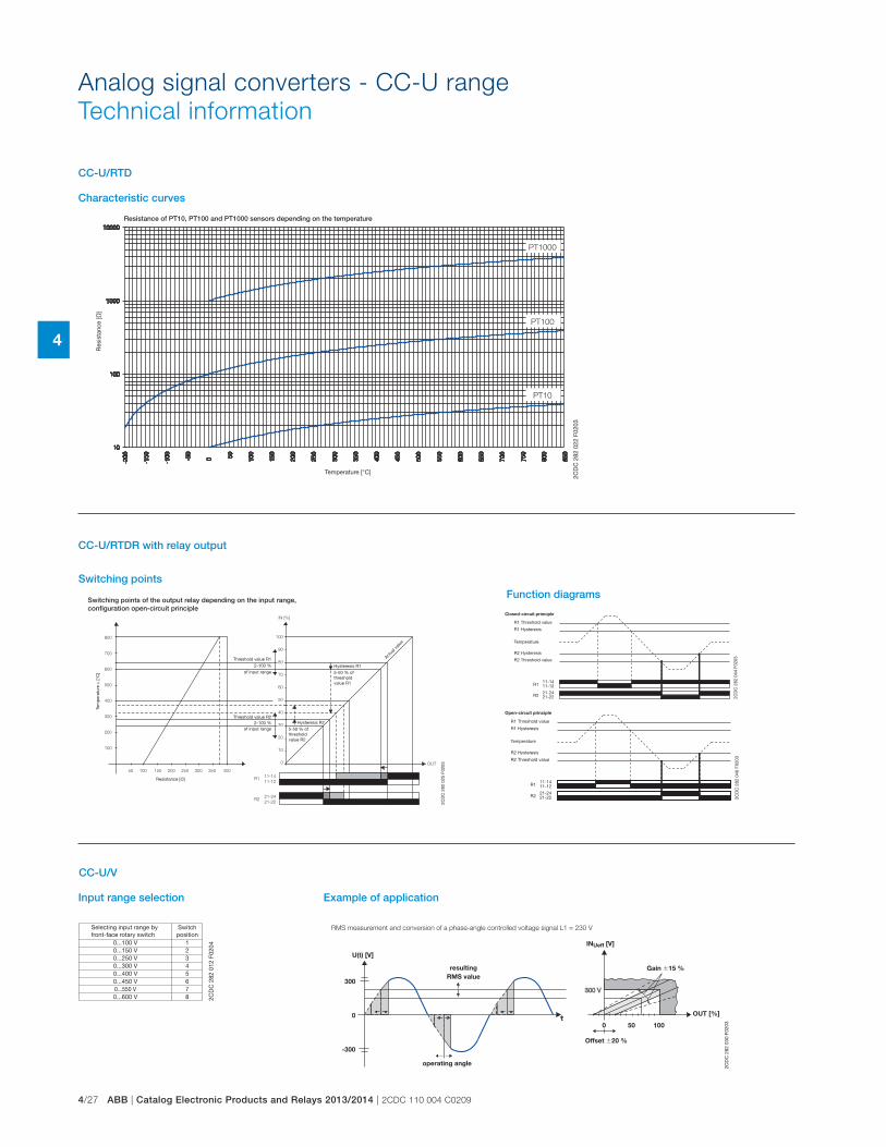
4/27 ABB | Catalog Electronic Products and Relays 2013/2014 | 2CDC 110 004 C0209
4
Resistance of PT10, PT100 and PT1000 sensors depending on the temperature
PT1000
PT100
PT10
2CD
C 2
82 0
22 F
0203
Res
ista
nce
[�]
Temperature [°C]
Characteristic curves
Analog signal converters - CC-U range
Technical information
CC-U/RTD
Switching points of the output relay depending on the input range, configuration open-circuit principle
OUT
11-14
11-12
21-24
21-22
R1
R2
100
90
80
70
60
50
40
30
20
10
0
IN [%]
800
700
600
500
400
300
200
100
50 100 150 200 250 300 350 400
2CD
C 2
82 0
25 F
0203
Resistance [�]
Tem
per
atur
e υ
[°C
]
Hysteresis R15-50 % of threshold value R1
Threshold value R12-100 %
of input range
Threshold value R22-100 %
of input range Hysteresis R25-50 % of threshold value R2
Actua
l valu
e
Switching pointsFunction diagrams
21-2421-22
11-1411-12
R2
R1
2CD
C 2
82 0
44 F
0203
R1 Threshold value
R1 Hysteresis
R2 Hysteresis
R2 Threshold value
Temperature
Closed-circuit principle
21-2421-22
11-1411-12
R2
R1
2CD
C 2
82 0
46 F
0203
R1 Threshold value
R1 Hysteresis
R2 Hysteresis
R2 Threshold value
Temperature
Open-circuit principle
CC-U/RTDR with relay output
0...100 V0...150 V0...250 V0...300 V0...400 V
0...600 V
0...450 V0...550 V
12345
8
67
2CD
C 2
82 0
12 F
0204
Switchposition
Selecting input range by front-face rotary switch
U(t) [V]
INUeff [V]
OUT [%]
0 50 100
300
0
-300
2CD
C 2
82 0
30 F
0203
Offset �20 %
Gain �15 %resulting
RMS value
operating angle
Example of application
CC-U/V
Input range selection
RMS measurement and conversion of a phase-angle controlled voltage signal L1 = 230 V
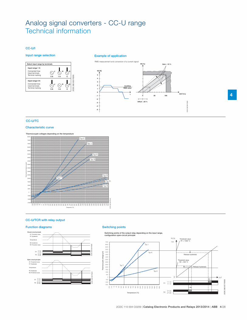
2CDC 110 004 C0209 | Catalog Electronic Products and Relays 2013/2014 | ABB 4/28
4
Analog signal converters - CC-U range
Technical information
J H G
J H G
5 A 1 A C
5 A 1 A C
2CD
C 2
82 0
33 F
0203
Select input range by terminals
Input range 1 A
Connected linesUsed terminalsTerminal marking
Input range 5 A
Connected linesUsed terminalsTerminal marking
Input range selection
RMS measurement and conversion of a current signal
I(t) [A]
IN [%]
OUT [%]0 50 100
t
5
4
3
2
1
0
-1
-2
-3
-4
-5
2CD
C 2
82 0
28 F
0203Offset �20 %
Gain �15 %
resulting
RMS value
Example of application
CC-U/I
Thermocouple voltages depending on the temperature
Typ T
Typ N
Typ K
Typ J
Typ E
Typ R
Typ S
Typ B
-250
-200
-150
-100
-50 0 50 100
150
200
250
300
350
400
450
500
550
600
650
700
750
800
850
900
950
1000
1050
1100
1150
1200
1250
1300
1350
1400
1450
1500
1550
1600
1650
1700
1750
1800
80000
75000
70000
65000
60000
55000
50000
45000
40000
35000
30000
25000
20000
15000
10000
5000
0
-5000
-10000
-15000
2CD
C 2
82 0
26 F
0103
Temperatur [°C]
Ther
moe
lem
ent-
Sp
annu
ng [μ
V]
Characteristic curve
CC-U/TC
CC-U/TCR with relay output
Function diagrams
21-2421-22
11-1411-12
R2
R1
2CD
C 2
82 0
44 F
0203
R1 Threshold value
R1 Hysteresis
R2 Hysteresis
R2 Threshold value
Temperature
Closed-circuit principle
21-2421-22
11-1411-12
R2
R1
2CD
C 2
82 0
46 F
0203
R1 Threshold value
R1 Hysteresis
R2 Hysteresis
R2 Threshold value
Temperature
Open-circuit principle
Switching points of the output relay depending on the input range, configuration open-circuit principle
Typ T
Typ J
Typ K
Typ S
IN [%]
100
0 OUT
11-14
11-12
21-24
21-22
R1
R2
7000
6500
6000
5500
5000
4500
4000
3500
3000
2500
2000
1500
1000
500
0
-500
-1000
-1500
-27
5
-17
5
-75
25
12
5
22
5
32
5
42
5
52
5
62
5
72
5
82
5
92
5
10
25
11
25
12
25
13
25
14
25
15
25
16
25
17
25
18
25
2CD
C 2
82 0
27 F
0203
Temperature [°C]
Ther
moc
oup
le v
olta
ge [μ
V]
Threshold value R2 = 400 °C
Release hysteresis
Threshold value R1 = 1000 °C
Release hysteresis
Switching points
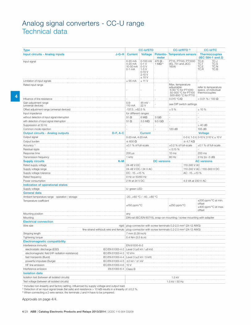
4/29 ABB | Catalog Electronic Products and Relays 2013/2014 | 2CDC 110 004 C0209
4
Analog signal converters - CC-U range
Technical data
Type CC-U/STD CC-U/RTD 3) CC-U/TCInput circuits - Analog inputs J-G-H Current Voltage Potentio-
meterTemperature sensors Thermocouples
(IEC 584-1 and 2)Input signal 0-20 mA
4-20 mA10-50 mA0-1 mA
0-100 mV0-1 V0-5 V1-5 V0-10 V2-10 V± 10 V
470 � -1 M� 2)
PT10, PT100, PT1000(IEL 751 and JICC 1604)
TC.KTC.TTC.ETC.R
TC.JTC.STC.NTC.B
Limitation of input signals ± 55 mA ± 11 V - -
Rated input range
- - -
Max. temperature adjustable: 6-60 °C for PT1000 50-500 °C for PT100 500-850 °C for PT10
refer to temperature specs. of individual thermocouples
Influence of line resistance - - - 0.015 °C/� < 0.01 % / 100 �
Gain adjustment range (universal devices)
0.9-110 mA
45 mV -22 V
- see DIP switch settings
Offset adjustment range (universal devices) -137.5...+62.5 % ± 5 % ± 10 %
Input impedance for different ranges - -
without detection of input signal interruption 51 � 6 M� 3 G� - -
with detection of input signal interruption 51 � 3.5 M� 9.5 G� - -
Suppression at 50 Hz - - - - > 40 dB
Common-mode rejection - - - 120 dB 105 dB
Output circuits - Analog outputs D-F, A-C Current VoltageOutput signal 0-20 mA, 4-20 mA 0-5 V, 1-5 V, 0-10 V, 2-10 V, ± 10 V
Output burden � 600 � � 4.7 K�
Accuracy 1) ±0.1 % of full-scale ±0.2 % of full-scale ±0.1 % of full-scale
Residual ripple - < 0.15 % -
Response time 200 μs 10 ms 200 ms
Transmission frequency 1 kHz 80 Hz 2 Hz (to -3 dB)
Supply circuits K-M DC versions AC versionsRated supply voltage 24-48 V DC 110-240 V AC
Supply voltage range 24-48 V DC / 24 V AC 110-240 V AC / 100-300 V DC
Supply voltage tolerance DC: -15...+15 % AC: -15...+10 %
Rated frequency 0 Hz or 50/60 Hz
Power consumption 2 W at 24 V DC 4.5 VA at 230 V AC
Indication of operational statesSupply voltage U: green LED
General dataAmbient temperature range operation / storage -20...+60 °C / -40...+80 °C
Temperature coefficient
±150 ppm/°C ±250 ppm/°C
±200 ppm/°C at min.
offset
±400 ppm/°C at max.
offset
Mounting position any
Mounting DIN rail (IEC/EN 60715), snap-on mounting / screw mounting with adapter
Electrical connectionWire size rigid plug-connector with screw terminals 0.2-2.5 mm2 (24-12 AWG)
fine-strand with(out) wire end ferrule plug-connector with screw terminals 0.2-2.5 mm2 (24-12 AWG)
Stripping length 7 mm (0.28 inch)
Tightening torque 0.4 Nm (3.5 ib.in)
Electromagnetic compatibilityInterference immunity EN 61000-6-2
electrostatic discharge (ESD) IEC/EN 61000-4-2 Level 3 (±6 kV / ±8 kV)
electromagnetic field (HF radiation resistance) IEC/EN 61000-4-3 10 V/m
fast transients (Burst) IEC/EN 61000-4-4 Level 3 (±2 kV / 5 kH)
powerful impulses (Surge) IEC/EN 61000-4-5 �2 kV / �1 kV
HF line emission IEC/EN 61000-4-6 10 V
Interference emission EN 61000-6-4 Class B
Isolation dataIsolation test (between all isolated circuits) 1.5 kV
Test voltage (between all isolated circuits) 1.5 kV / 50 Hz
1) Includes non-linearity and factory setting, influenced by supply voltage and output load.2) Detection of an input signal break (fail safe) and resistance > 10 k� results in a linearity of �0,2 %.3) When connecting a 2-wire sensor, the terminals J and H have to be jumpered.
Approvals on page 4/4.
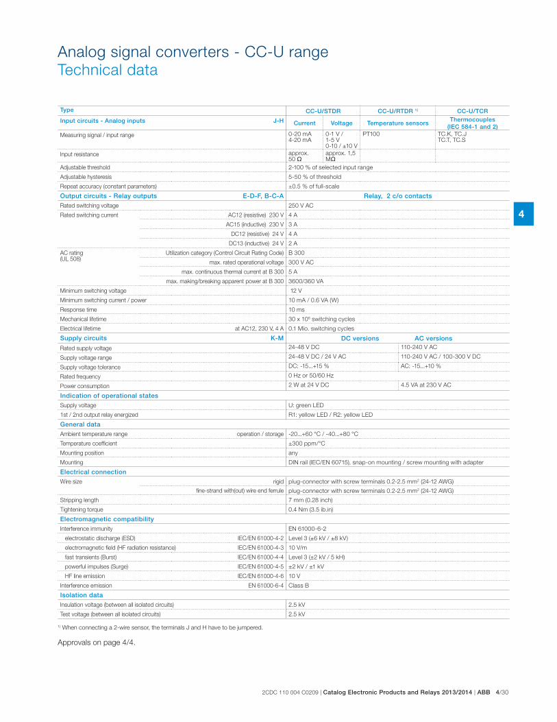
2CDC 110 004 C0209 | Catalog Electronic Products and Relays 2013/2014 | ABB 4/30
4
Analog signal converters - CC-U range
Technical data
Type CC-U/STDR CC-U/RTDR 1) CC-U/TCR
Input circuits - Analog inputs J-H Current Voltage Temperature sensorsThermocouples
(IEC 584-1 and 2)Measuring signal / input range 0-20 mA
4-20 mA0-1 V / 1-5 V0-10 / ±10 V
PT100 TC.K, TC.JTC.T, TC.S
Input resistance approx. 50 �
approx. 1,5 M�
Adjustable threshold 2-100 % of selected input range
Adjustable hysteresis 5-50 % of threshold
Repeat accuracy (constant parameters) ±0.5 % of full-scale
Output circuits - Relay outputs E-D-F, B-C-A Relay, 2 c/o contacts
Rated switching voltage 250 V AC
Rated switching current AC12 (resistive) 230 V 4 A
AC15 (inductive) 230 V 3 A
DC12 (resistive) 24 V 4 A
DC13 (inductive) 24 V 2 A
AC rating (UL 508)
Utilization category (Control Circuit Rating Code) B 300
max. rated operational voltage 300 V AC
max. continuous thermal current at B 300 5 A
max. making/breaking apparent power at B 300 3600/360 VA
Minimum switching voltage 12 V
Minimum switching current / power 10 mA / 0.6 VA (W)
Response time 10 ms
Mechanical lifetime 30 x 106 switching cycles
Electrical lifetime at AC12, 230 V, 4 A 0.1 Mio. switching cycles
Supply circuits K-M DC versions AC versions
Rated supply voltage 24-48 V DC 110-240 V AC
Supply voltage range 24-48 V DC / 24 V AC 110-240 V AC / 100-300 V DC
Supply voltage tolerance DC: -15...+15 % AC: -15...+10 %
Rated frequency 0 Hz or 50/60 Hz
Power consumption 2 W at 24 V DC 4.5 VA at 230 V AC
Indication of operational states
Supply voltage U: green LED
1st / 2nd output relay energized R1: yellow LED / R2: yellow LED
General data
Ambient temperature range operation / storage -20...+60 °C / -40...+80 °C
Temperature coefficient ±300 ppm/°C
Mounting position any
Mounting DIN rail (IEC/EN 60715), snap-on mounting / screw mounting with adapter
Electrical connection
Wire size rigid plug-connector with screw terminals 0.2-2.5 mm2 (24-12 AWG)
fine-strand with(out) wire end ferrule plug-connector with screw terminals 0.2-2.5 mm2 (24-12 AWG)
Stripping length 7 mm (0.28 inch)
Tightening torque 0.4 Nm (3.5 ib.in)
Electromagnetic compatibility
Interference immunity EN 61000-6-2
electrostatic discharge (ESD) IEC/EN 61000-4-2 Level 3 (±6 kV / ±8 kV)
electromagnetic field (HF radiation resistance) IEC/EN 61000-4-3 10 V/m
fast transients (Burst) IEC/EN 61000-4-4 Level 3 (±2 kV / 5 kH)
powerful impulses (Surge) IEC/EN 61000-4-5 ±2 kV / ±1 kV
HF line emission IEC/EN 61000-4-6 10 V
Interference emission EN 61000-6-4 Class B
Isolation data
Insulation voltage (between all isolated circuits) 2.5 kV
Test voltage (between all isolated circuits) 2.5 kV
1) When connecting a 2-wire sensor, the terminals J and H have to be jumpered.
Approvals on page 4/4.
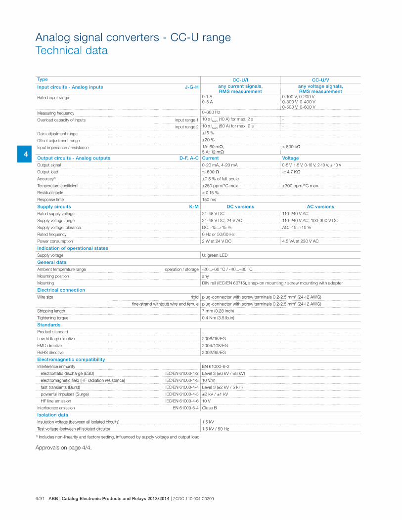
4/31 ABB | Catalog Electronic Products and Relays 2013/2014 | 2CDC 110 004 C0209
4
Analog signal converters - CC-U range
Technical data
Type CC-U/I CC-U/V
Input circuits - Analog inputs J-G-H any current signals, RMS measurement
any voltage signals, RMS measurement
Rated input range 0-1 A
0-5 A
0-100 V, 0-200 V
0-300 V, 0-400 V
0-500 V, 0-600 V
Measuring frequency 0-600 Hz
Overload capacity of inputs input range 1 10 x INom
(10 A) for max. 2 s -
input range 2 10 x INom
(50 A) for max. 2 s -
Gain adjustment range ±15 %
Offset adjustment range ±20 %
Input impedance / resistance 1A: 60 m�,
5 A: 12 m�> 800 k�
Output circuits - Analog outputs D-F, A-C Current Voltage
Output signal 0-20 mA, 4-20 mA 0-5 V, 1-5 V, 0-10 V, 2-10 V, ± 10 V
Output load � 600 � � 4.7 K�
Accuracy1) ±0.5 % of full-scale
Temperature coefficient ±250 ppm/°C max. ±300 ppm/°C max.
Residual ripple < 0.15 %
Response time 150 ms
Supply circuits K-M DC versions AC versions
Rated supply voltage 24-48 V DC 110-240 V AC
Supply voltage range 24-48 V DC, 24 V AC 110-240 V AC, 100-300 V DC
Supply voltage tolerance DC: -15...+15 % AC: -15...+10 %
Rated frequency 0 Hz or 50/60 Hz
Power consumption 2 W at 24 V DC 4.5 VA at 230 V AC
Indication of operational states
Supply voltage U: green LED
General data
Ambient temperature range operation / storage -20...+60 °C / -40...+80 °C
Mounting position any
Mounting DIN rail (IEC/EN 60715), snap-on mounting / screw mounting with adapter
Electrical connection
Wire size rigid plug-connector with screw terminals 0.2-2.5 mm2 (24-12 AWG)
fine-strand with(out) wire end ferrule plug-connector with screw terminals 0.2-2.5 mm2 (24-12 AWG)
Stripping length 7 mm (0.28 inch)
Tightening torque 0.4 Nm (3.5 lb.in)
Standards
Product standard -
Low Voltage directive 2006/95/EG
EMC directive 2004/108/EG
RoHS directive 2002/95/EG
Electromagnetic compatibility
Interference immunity EN 61000-6-2
electrostatic discharge (ESD) IEC/EN 61000-4-2 Level 3 (±6 kV / ±8 kV)
electromagnetic field (HF radiation resistance) IEC/EN 61000-4-3 10 V/m
fast transients (Burst) IEC/EN 61000-4-4 Level 3 (±2 kV / 5 kH)
powerful impulses (Surge) IEC/EN 61000-4-5 ±2 kV / ±1 kV
HF line emission IEC/EN 61000-4-6 10 V
Interference emission EN 61000-6-4 Class B
Isolation data
Insulation voltage (between all isolated circuits) 1.5 kV
Test voltage (between all isolated circuits) 1.5 kV / 50 Hz
1) Includes non-linearity and factory setting, influenced by supply voltage and output load.
Approvals on page 4/4.
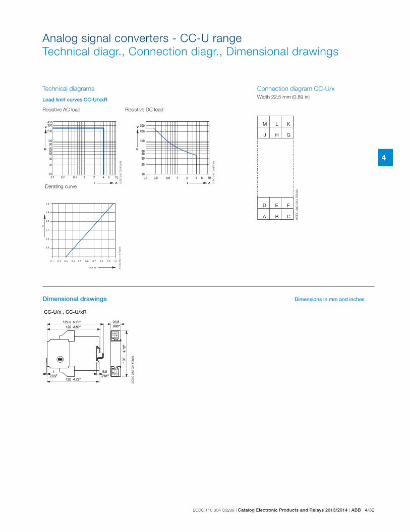
2CDC 110 004 C0209 | Catalog Electronic Products and Relays 2013/2014 | ABB 4/32
4
Analog signal converters - CC-U range
Technical diagr., Connection diagr., Dimensional drawings
.039
2CD
C 2
82 0
24 F
0b06
J
D F
G
M
H
L K
A C
E
B
2C
DC
28
2 0
23
F0
b0
6
CC-U/x , CC-U/xR
2C
DC
28
2 0
25
F0
b0
6
1.0
0.9
0.8
0.7
0.6
0.5
F
0.1 0.2 0.3 0.4 0.5 0.6 0.7 0.8 0.9 1.0
cos
2C
DC
28
2 0
14
F0
b0
6
2C
DC
28
2 0
26
F0
b0
6
Dimensional drawings Dimensions in mm and inches
Connection diagram CC-U/x
Width 22.5 mm (0.89 in)
Technical diagrams
Load limit curves CC-U/xxR
Resistive AC load Resistive DC load
Derating curve
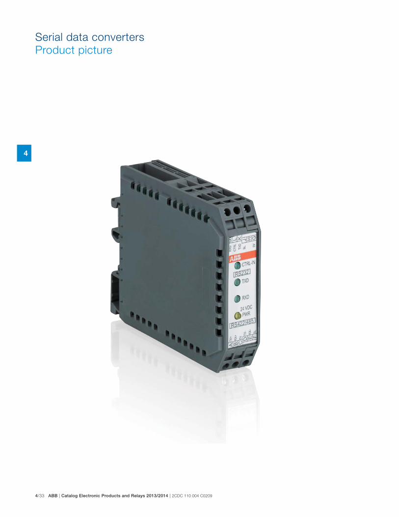
4/33 ABB | Catalog Electronic Products and Relays 2013/2014 | 2CDC 110 004 C0209
4
Serial data converters
Product picture
2CDC 110 004 C0209 | Catalog Electronic Products and Relays 2013/2014 | ABB 4/34
4
Serial data converters
Table of contents
Serial data converters
Product picture 4/33
Table of contents 4/34
Benefits and advantages 4/35
Selection table 4/36
Ordering details 4/37
Connection diagrams and jumper settings 4/38
Technical data 4/45
Dimensional drawings 4/55
Notes 4/56
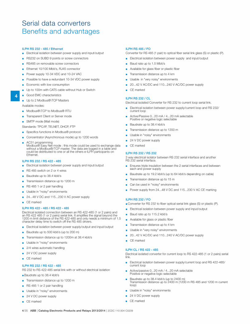
4/35 ABB | Catalog Electronic Products and Relays 2013/2014 | 2CDC 110 004 C0209
4
ILPH RS 232 - 485 / Ethernet � Electrical isolation between power supply and input/output
� RS232 on SUBD 9 points or screw connectors
� RS485 on removable screw connectors
� Ethernet 10/100 Mbit/s, RJ45 connector
� Power supply 10-34 VDC and 10-24 VAC
� Possible to have a redundant 10-34 VDC power supply
� Economic with low consumption
� Up to 100m with CAT5 cable without Hub or Switch
� Good EMC characteristics
� Up to 2 Modbus®\TCP Masters
Available modes:
� Modbus®\TCP to Modbus® RTU
� Transparent Client or Server mode
� SMTP mode (Mail mode)
Standards: TPC/IP, TELNET, DHCP, FTP
� Specifics functions in Modbus® protocol:
� Concentrator (Asynchronous mode) up to 1200 words
� AC31 programming Modbus® Easy Net mode : this mode could be used to exchange data without a Modbus®/TCP master. The data are logged in a table and could be distributed to one or all the others e-ILPH participants on Ethernet.
ILPH RS 232 / RS 422 - 485RS 232 to RS 422-485 serial link with or without electrical isolation
� Baudrate up to 38.4 kbit/s
� Transmission distance up to 1200 m
� RS 485 1 or 2 pair handling
� Usable in "noisy" environments
� 24 V DC power supply
� CE marked
ILPH RS 232 / RS 422 - 485 � Electrical isolation between power supply and input/output
� RS 485 switch on 2 or 4 wires
� Baudrate up to 38.4 kbit/s
� Transmission distance up to 1200 m
� RS 485 1 or 2 pair handling
� Usable in "noisy" environments
� 24...48 V DC and 115...230 V AC power supply
� CE marked
ILPH RS 232 / RS 2323 way electrical isolator between RS 232 serial interface and another RS 232 serial interface.
� Ensures triple insulation between the 2 serial interfaces and between each and power supply
� Baudrate up to 19.2 kbit/s (up to 64 kbit/s depending on cable)
� Transmission distance up to 15 m
� Can be used in "noisy" environments
� Power supply from 24...48 V DC and 115...230 V AC CE marking
ILPH RS 422 - 485 / RS 422 - 485Electrical isolated connection between an RS 422-485 (1 or 2 pairs) and an RS 422 485 (1 or 2 pairs) serial link. It amplifies the signal beyond the 1200 m limit distance of the RS 422-485 and only needs a minimum of 1.5 character delay time to switch off the RS 485 drivers.
� Electrical isolation between power supply/output and input/output
� Baudrate up to 500 kbit/s (up to 200 m)
� Transmission distance up to 1200m at 38.4 kbit/s
� Usable in "noisy" environments
� 2/4 wires automatic handling
� 24 V DC power supply
� CE marked
ILPH RS 232 / FO � Converter for RS 232 to fiber optical serial link glass (S) or plastic (P).
� Electrical isolation between power supply and input/output
� Baud rate up to 115.2 kbit/s
� Available for glass or plastic fiber
� Transmission distance up to 4 km
� Usable in "very noisy" environments
� 20...42 V AC/DC and 110...240 V AC/DC power supply
� CE marked
ILPH RS 485 / FOConverter for RS 485 (1 pair) to optical fiber serial link glass (S) or plastic (P).
� Electrical isolation between power supply and input/output
� Baud rate up to 1.5 Mbit/s
� Available for glass fiber or plastic fiber
� Transmission distance up to 4 km
� Usable in "very noisy" environments
� 20...42 V AC/DC and 110...240 V AC/DC power supply
� CE marked
ILPH CL / RS 422 - 485Electrical isolated converter for current loop to RS 422-485 (1 or 2 pairs) serial link.
� Electrical isolation between power supply/current loop and RS 422-485/current loop
� Active/passive 0...20 mA / 4...20 mA selectable Positive or negative logic selectable
� Baudrate up to 38.4 kbit/s (up to 2400 m) Transmission distance up to 2400 m (1200 m RS 485 and 1200 m current loop)
� Usable in "noisy" environments
� 24 V DC power supply
� CE marked
ILPH RS 232 / CLElectrical isolated Converter for RS 232 to current loop serial link.
� Electrical isolation between power supply/current loop and RS 232/current loop
� Active/Passive 0...20 mA / 4...20 mA selectable Positive or negative logic selectable
� Baudrate up to 38.4 kbit/s
� Transmission distance up to 1200 m
� Usable in "noisy" environments
� 24 V DC power supply
� CE marked
Serial data converters
Benefits and advantages
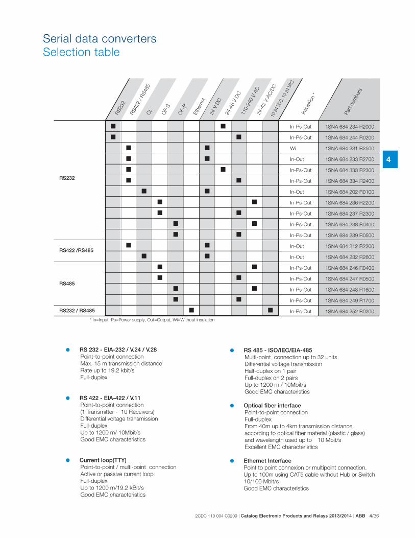
2CDC 110 004 C0209 | Catalog Electronic Products and Relays 2013/2014 | ABB 4/36
4
Serial data converters
Selection table
1SNA 684 234 R2000
1SNA 684 244 R0200
1SNA 684 231 R2500
1SNA 684 233 R2700
1SNA 684 333 R2300
1SNA 684 334 R2400
1SNA 684 202 R0100
1SNA 684 236 R2200
1SNA 684 237 R2300
1SNA 684 238 R0400
1SNA 684 239 R0500
1SNA 684 212 R2200
1SNA 684 232 R2600
1SNA 684 246 R0400
1SNA 684 247 R0500
1SNA 684 248 R1600
1SNA 684 249 R1700
1SNA 684 252 R0200
RS232
RS422 /RS485
RS485
RS232 / RS485
RS232
RS422 / R
S485
24 V
DC
24-4
8 V
DC
110-2
40 V
AC
24-4
2 V
AC
/DC
Eth
ern
et
10-3
4 VD
C, 1
0-24
VAC
RS 232 - EIA-232 / V.24 / V.28 Point-to-point connection
Max. 15 m transmission distance
Rate up to 19.2 kbit/s
Full-duplex
RS 422 - EIA-422 / V.11 Point-to-point connection
(1 Transmitter - 10 Receivers)
Differential voltage transmission
Full-duplex
Up to 1200 m/ 10Mbit/s
Good EMC characteristics
Current loop(TTY) Point-to-point / multi-point connection
Active or passive current loop
Full-duplex
Up to 1200 m/19.2 kBit/s
Good EMC characteristics
RS 485 - ISO/IEC/EIA-485 Multi-point connection up to 32 units
Differential voltage transmission
Half-duplex on 1 pair
Full-duplex on 2 pairs
Up to 1200 m / 10Mbit/s
Good EMC characteristics
Optical fiber interface Point-to-point connection
Full-duplex
From 40m up to 4km transmission distance
according to optical fiber material (plastic / glass)
and wavelength used up to 10 Mbit/s
Excellent EMC characteristics
Ethernet Interface Point to point connexion or multipoint connection.
Up to 100m using CAT5 cable without Hub or Switch
10/100 Mbit/s
Good EMC characteristics
In-Ps-Out
In-Ps-Out
Wi
In-Out
In-Ps-Out
In-Ps-Out
In-Out
In-Ps-Out
In-Ps-Out
In-Ps-Out
In-Ps-Out
In-Out
In-Out
In-Ps-Out
In-Ps-Out
In-Ps-Out
In-Ps-Out
In-Ps-Out
Insu
latio
n *
Part n
um
bers
* In=Input, Ps=Power supply, Out=Output, Wi=Without insulation
CL
OF-S
OF-P
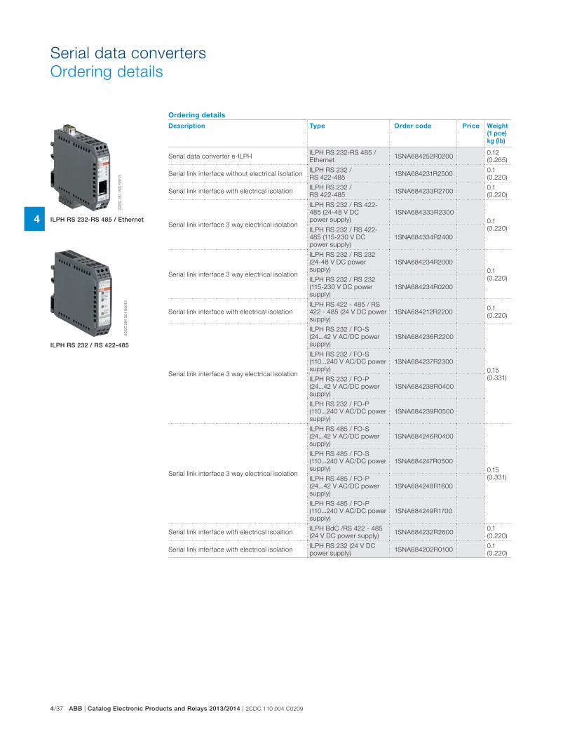
4/37 ABB | Catalog Electronic Products and Relays 2013/2014 | 2CDC 110 004 C0209
4
Serial data converters
Ordering details
Ordering details
Description Type Order code Price Weight
(1 pce)
kg (lb)
Serial data converter e-ILPHILPH RS 232-RS 485 /
Ethernet1SNA684252R0200
0.12
(0.265)
Serial link interface without electrical isolationILPH RS 232 /
RS 422-4851SNA684231R2500
0.1
(0.220)
Serial link interface with electrical isolationILPH RS 232 /
RS 422-4851SNA684233R2700
0.1
(0.220)
Serial link interface 3 way electrical isolation
ILPH RS 232 / RS 422-
485 (24-48 V DC
power supply)
1SNA684333R2300
0.1
(0.220)ILPH RS 232 / RS 422-
485 (115-230 V DC
power supply)
1SNA684334R2400
Serial link interface 3 way electrical isolation
ILPH RS 232 / RS 232
(24-48 V DC power
supply)
1SNA684234R2000
0.1
(0.220)ILPH RS 232 / RS 232
(115-230 V DC power
supply)
1SNA684234R0200
Serial link interface with electrical isolation
ILPH RS 422 - 485 / RS
422 - 485 (24 V DC power
supply)
1SNA684212R22000.1
(0.220)
Serial link interface 3 way electrical isolation
ILPH RS 232 / FO-S
(24...42 V AC/DC power
supply)
1SNA684236R2200
0.15
(0.331)
ILPH RS 232 / FO-S
(110...240 V AC/DC power
supply)
1SNA684237R2300
ILPH RS 232 / FO-P
(24...42 V AC/DC power
supply)
1SNA684238R0400
ILPH RS 232 / FO-P
(110...240 V AC/DC power
supply)
1SNA684239R0500
Serial link interface 3 way electrical isolation
ILPH RS 485 / FO-S
(24...42 V AC/DC power
supply)
1SNA684246R0400
0.15
(0.331)
ILPH RS 485 / FO-S
(110...240 V AC/DC power
supply)
1SNA684247R0500
ILPH RS 485 / FO-P
(24...42 V AC/DC power
supply)
1SNA684248R1600
ILPH RS 485 / FO-P
(110...240 V AC/DC power
supply)
1SNA684249R1700
Serial link interface with electrical isoaltionILPH BdC /RS 422 - 485
(24 V DC power supply)1SNA684232R2600
0.1
(0.220)
Serial link interface with electrical isolationILPH RS 232 (24 V DC
power supply)1SNA684202R0100
0.1
(0.220)
2C
DC
28
1 0
03
F0
01
3
2C
DC
28
1 0
01
S0
01
3
ILPH RS 232-RS 485 / Ethernet
ILPH RS 232 / RS 422-485
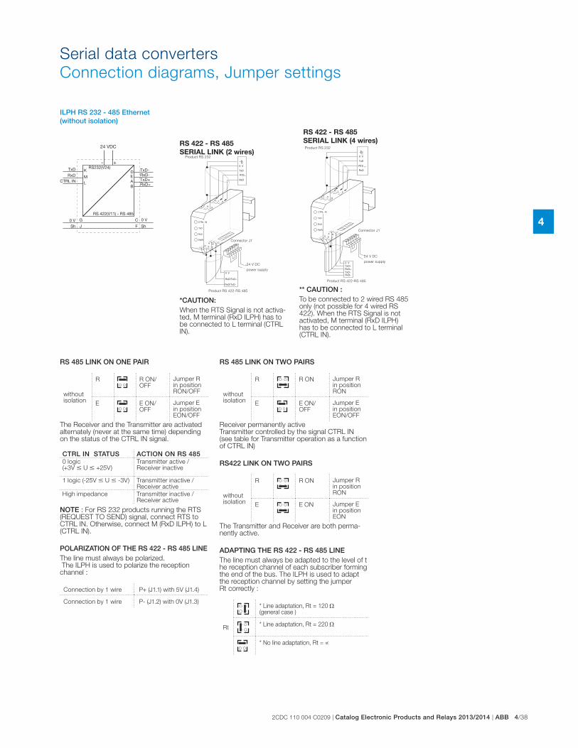
2CDC 110 004 C0209 | Catalog Electronic Products and Relays 2013/2014 | ABB 4/38
4
Serial data converters
Connection diagrams, Jumper settings
ILPH RS 232 - 485 Ethernet (without isolation)
RS 485 LINK ON ONE PAIR
without isolation
R R ON/OFF
Jumper R in position RON/OFF
E E ON/OFF
Jumper E in positionEON/OFF
The Receiver and the Transmitter are activated alternately (never at the same time) depending on the status of the CTRL IN signal.
CTRL IN STATUS ACTION ON RS 4850 logic (+3V � U � +25V)
Transmitter active / Receiver inactive
1 logic (-25V � U � -3V) Transmitter inactive / Receiver active
High impedance Transmitter inactive / Receiver active
NOTE : For RS 232 products running the RTS (REQUEST TO SEND) signal, connect RTS to CTRL IN. Otherwise, connect M (RxD ILPH) to L (CTRL IN).
POLARIZATION OF THE RS 422 - RS 485 LINEThe line must always be polarized. The ILPH is used to polarize the reception channel :
Connection by 1 wire P+ (J1.1) with 5V (J1.4)
Connection by 1 wire P- (J1.2) with 0V (J1.3)
RS 485 LINK ON TWO PAIRS
without isolation
R R ON Jumper R in position RON
E E ON/OFF
Jumper E in position EON/OFF
Receiver permanently active Transmitter controlled by the signal CTRL IN (see table for Transmitter operation as a function of CTRL IN)
RS422 LINK ON TWO PAIRS
without isolation
R R ON Jumper R in position RON
E E ON Jumper E in position EON
The Transmitter and Receiver are both perma-nently active.
ADAPTING THE RS 422 - RS 485 LINEThe line must always be adapted to the level of t he reception channel of each subscriber forming the end of the bus. The ILPH is used to adapt the reception channel by setting the jumper Rt correctly :
Rt
* Line adaptation, Rt = 120 (general case )
* Line adaptation, Rt = 220
* No line adaptation, Rt =
*CAUTION: When the RTS Signal is not activa-ted, M terminal (RxD ILPH) has to be connected to L terminal (CTRL IN).
RS 422 - RS 485
SERIAL LINK (2 wires)Product RS 232
Connector J1
24 V DC
power supply
Product RS 422-RS 485 ** CAUTION :To be connected to 2 wired RS 485 only (not possible for 4 wired RS 422). When the RTS Signal is not activated, M terminal (RxD ILPH) has to be connected to L terminal (CTRL IN).
RS 422 - RS 485
SERIAL LINK (4 wires)Product RS 232
Connector J1
24 V DC
power supply
Product RS 422-RS 485
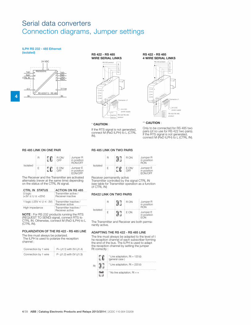
4/39 ABB | Catalog Electronic Products and Relays 2013/2014 | 2CDC 110 004 C0209
4
** CAUTION :
Only to be connected for RS 485 two pairs (of no use for RS 422 two pairs). If the RTS signal is not generated, connect M (RxD ILPH) to L (CTRL IN).
* CAUTION :
If the RTS signal is not generated, connect M (RxD ILPH) to L (CTRL IN).
RS 422 - RS 485
WIRE SERIAL LINKS
RS 422 - RS 485
4 WIRE SERIAL LINKS
Connector J1
24 V DC
power supply
RS 422-RS 485
product
RS 232 product
Connector J1
24 V DC
power supply
RS 422-RS 485
product
RS 232 product
ILPH RS 232 - 485 Ethernet (isolated)
RS 485 LINK ON ONE PAIR
Isolated
R R ON/OFF
Jumper R in position RON/OFF
E E ON/OFF
Jumper E in position EON/OFF
The Receiver and the Transmitter are activated alternately (never at the same time) depending on the status of the CTRL IN signal.
CTRL IN STATUS ACTION ON RS 4850 logic (+3V � U � +25V)
Transmitter active / Receiver inactive
1 logic (-25V � U � -3V) Transmitter inactive / Receiver active
High impedance Transmitter inactive / Receiver active
NOTE : For RS 232 products running the RTS (REQUEST TO SEND) signal, connect RTS to CTRL IN. Otherwise, connect M (RxD ILPH) to L (CTRL IN).
POLARIZATION OF THE RS 422 - RS 485 LINEThe line must always be polarized. The ILPH is used to polarize the reception channel :
Connection by 1 wire P+ (J1.1) with 5V (J1.4)
Connection by 1 wire P- (J1.2) with 0V (J1.3)
RS 485 LINK ON TWO PAIRS
Isolated
R R ON Jumper R in position RON
E E ON/OFF
Jumper E in position EON/OFF
Receiver permanently active Transmitter controlled by the signal CTRL IN (see table for Transmitter operation as a function of CTRL IN)
RS422 LINK ON TWO PAIRS
Isolated
R R ON Jumper R in position RON
E E ON Jumper E in position EON
The Transmitter and Receiver are both perma-nently active.
ADAPTING THE RS 422 - RS 485 LINEThe line must always be adapted to the level of t he reception channel of each subscriber forming the end of the bus. The ILPH is used to adapt the reception channel by setting the jumper Rt correctly :
Rt
* Line adaptation, Rt = 120 (general case )
* Line adaptation, Rt = 220
* No line adaptation, Rt =
Serial data converters
Connection diagrams, Jumper settings
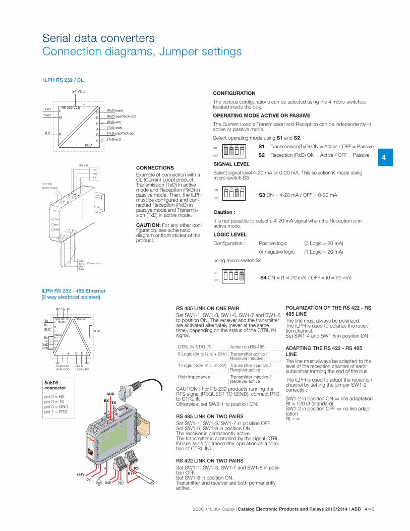
2CDC 110 004 C0209 | Catalog Electronic Products and Relays 2013/2014 | ABB 4/40
4
ILPH RS 232 / CL
ON
OFF
CONFIGURATION
The various configurations can be selected using the 4 micro-switches located inside the box.
OPERATING MODE ACTIVE OR PASSIVE
The Current Loop's Transmission and Reception can be independently in active or passive mode.
Select operating mode using S1 and S2.
S1 Transmission(TxD) ON = Active / OFF = Passive
S2 Reception (RxD) ON = Active / OFF = Passive
S1 S2 S3 S4
ON
OFF
ON
OFF
SIGNAL LEVEL
Select signal level 4-20 mA or 0-20 mA. This selection is made using micro-switch S3
S3 ON = 4-20 mA / OFF = 0-20 mA
Caution :
It is not possible to select a 4-20 mA signal when the Reception is in active mode.
LOGIC LEVEL
Configuration : Positive logic (0 Logic = 20 mA)
or negative logic (1 Logic = 20 mA)
using micro-switch S4
S4 ON = (1 = 20 mA) / OFF = (0 = 20 mA)
S1 S2 S3 S4
S1 S2 S3 S4
Current loop
24 V DC
power supply
CONNECTIONS
Example of connection with a CL (Current Loop) product, Transmission (TxD) in active mode and Reception (RxD) in passive mode. Then, the ILPH must be configured and con-nected Reception (RxD) in passive mode and Transmis-sion (TxD) in active mode. CAUTION: For any other con-figuration, see schematic diagram or front sticker of the product.
ILPH RS 232 - 485 Ethernet (3 way electrical isolated)
RS 485 LINK ON ONE PAIRSet SW1-1, SW1-3, SW1-6, SW1-7 and SW1-8 to position ON. The receiver and the transmitter are activated alternately (never at the same time), depending on the status of the CTRL IN signal.
CTRL IN STATUS Action on RS 485
0 Logic (3V � U � + 25V) Transmitter active / Receiver inactive
1 Logic (-25V � U � -3V) Transmitter inactive / Receiver active
High impedance Transmitter inactive / Receiver active
CAUTION : For RS 232 products running the RTS signal (REQUEST TO SEND), connect RTS to CTRL IN. Otherwise, set SW2-1 to position ON.
RS 485 LINK ON TWO PAIRSSet SW1-1, SW1-3, SW1-7 in position OFF. Set SW1-6, SW1-8 in position ON. The receiver is permanently active. The transmitter is controlled by the signal CTRL IN (see table for transmitter operation as a fonc-tion of CTRL IN).
RS 422 LINK ON TWO PAIRSSet SW1-1, SW1-3, SW1-7 and SW1-8 in posi-tion OFF. Set SW1-6 in position ON. Transmitter and receiver are both permanently active.
+24V0V
24V
TXTX
GND
RXRX
B1+
B2-
M
JH
G
ML
K
DE
A
GND
RX
TX
Ethernet
LINK
TXD
RXD
e-IL
PHSP
EED
PWR
ACTI
VITY
M LK
JH
G
ML
K
43
21
ON
43
21
ON56
78
KL
DE A
SubD9
connector
pin 2 = RX
pin 3 = TX
pin 5 = GND
pin 7 = RTS
POLARIZATION OF THE RS 422 - RS 485 LINEThe line must always be polarized. The ILPH is used to polarize the recep-tion channel. Set SW1-4 and SW1-5 in position ON.
ADAPTING THE RS 422 - RS 485 LINEThe line must always be adapted to the level of the reception channel of each subscriber forming the end of the bus.
The ILPH is used to adapt the reception channel by setting the jumper SW1-2 correctly :
SW1-2 in position ON line adaptation Rt = 120 (standard) SW1-2 in position OFF no line adap-tation Rt =
Serial data converters
Connection diagrams, Jumper settings
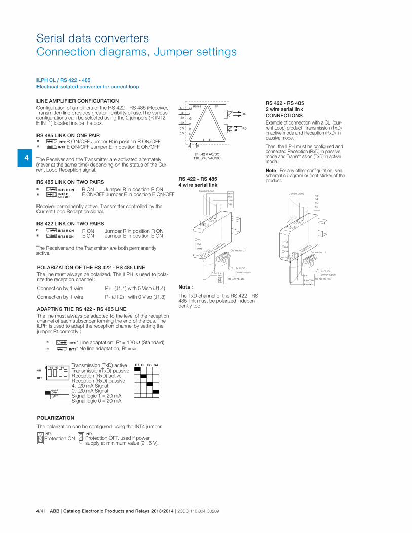
4/41 ABB | Catalog Electronic Products and Relays 2013/2014 | 2CDC 110 004 C0209
4
LINE AMPLIFIER CONFIGURATIONConfiguration of amplifiers of the RS 422 - RS 485 (Receiver, Transmitter) line provides greater flexibility of use.The various configurations can be selected using the 2 jumpers (R INT2, E INT1) located inside the box.
RS 485 LINK ON ONE PAIR
The Receiver and the Transmitter are activated alternately (never at the same time) depending on the status of the Cur-rent Loop Reception signal.
RS 485 LINK ON TWO PAIRS
Receiver permanently active. Transmitter controlled by the Current Loop Reception signal.
RS 422 LINK ON TWO PAIRS
The Receiver and the Transmitter are both permanently active.
ILPH CL / RS 422 - 485 Electrical isolated converter for current loop
INT4
R
E
INT2
INT3
R
E
INT2 R ON
INT3 E ON / OFF
R
E
INT2 R ON
INT3 E ON
Rt
Rt INT1
INT1
S1 S2 S3 S4ON
OFF
INT4
on
off
Protection ON Protection OFF, used if power
supply at minimum value (21.6 V).
E ON/OFF Jumper E in position E ON/OFFR ON/OFF Jumper R in position R ON/OFF
R ON Jumper R in position R ONE ON/OFF Jumper E in position E ON/OFF
R ON Jumper R in position R ONE ON Jumper E in position E ON
POLARIZATION OF THE RS 422 - RS 485 LINEThe line must always be polarized. The ILPH is used to pola-rize the reception channel :
Connection by 1 wire P+ (J1.1) with 5 Viso (J1.4)
Connection by 1 wire P- (J1.2) with 0 Viso (J1.3)
ADAPTING THE RS 422 - RS 485 LINEThe line must always be adapted to the level of the reception channel of each subscriber forming the end of the bus. The ILPH is used to adapt the reception channel by setting the jumper Rt correctly :
POLARIZATION
The polarization can be configured using the INT4 jumper.
* Line adaptation, Rt = 120 (Standard)
* No line adaptation, Rt =
Transmission (TxD) active Transmission(TxD) passive Reception (RxD) active Reception (RxD) passive 4...20 mA Signal 0...20 mA Signal Signal logic 1 = 20 mA Signal logic 0 = 20 mA
Legend
ON
OFF
RS 422 - RS 485 2 wire serial linkCONNECTIONSExample of connection with a CL (cur-rent Loop) product, Transmission (TxD) in active mode and Reception (RxD) in passive mode.
Then, the ILPH must be configured and connected Reception (RxD) in passive mode and Transmission (TxD) in active mode.
Note : For any other configuration, see schematic diagram or front sticker of the product.
Current Loop
Connector J1
24 V DC
power supply
Note :
The TxD channel of the RS 422 - RS 485 link must be polarized indepen-dently too.
RS 422 - RS 485
4 wire serial linkCurrent Loop
Connector J1
24 V DC
power supply
Serial data converters
Connection diagrams, Jumper settings
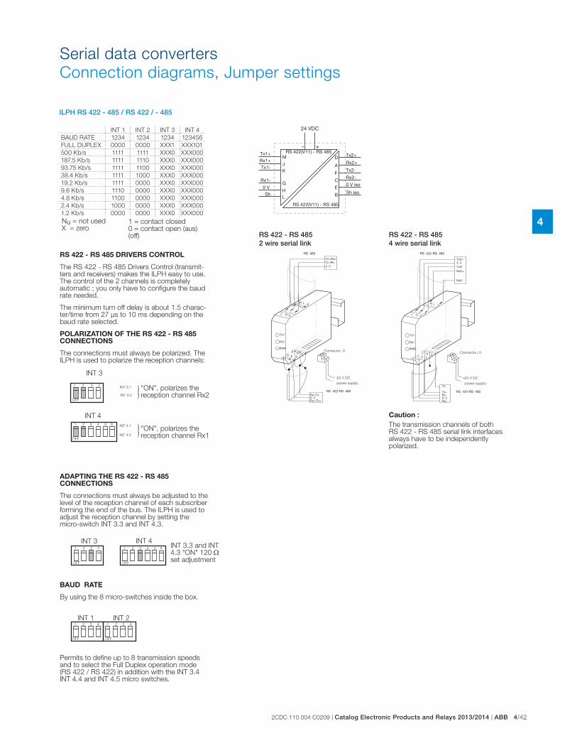
2CDC 110 004 C0209 | Catalog Electronic Products and Relays 2013/2014 | ABB 4/42
4
Serial data converters
Connection diagrams, Jumper settings
ILPH RS 422 - 485 / RS 422 / - 485
Nu = not used X = zero
1 = contact closed 0 = contact open (aus) (off)
OFF
1 2 3 4
1 2 3 4 5 6
OFF
INT 3
INT 4
INT 3.1
INT 3.2
INT 4.1
INT 4.2
OFF
OFF
INT 31 2 3 4 5 6
INT 41 2 3 4
OFF
1 2 3 4
OFF
INT 1 INT 2
"ON", polarizes the reception channel Rx2
"ON", polarizes the reception channel Rx1
RS 422 - RS 485 DRIVERS CONTROL
The RS 422 - RS 485 Drivers Control (transmit-ters and receivers) makes the ILPH easy to use. The control of the 2 channels is completely automatic ; you only have to configure the baud rate needed.
The minimum turn off delay is about 1.5 charac-ter/time from 27 μs to 10 ms depending on the baud rate selected.
POLARIZATION OF THE RS 422 - RS 485 CONNECTIONS
The connections must always be polarized. The ILPH is used to polarize the reception channels:
ADAPTING THE RS 422 - RS 485 CONNECTIONS
The connections must always be adjusted to the level of the reception channel of each subscriber forming the end of the bus. The ILPH is used to adjust the reception channel by setting the micro-switch INT 3.3 and INT 4.3.
BAUD RATE
By using the 8 micro-switches inside the box.
Permits to define up to 8 transmission speeds and to select the Full Duplex operation mode (RS 422 / RS 422) in addition with the INT 3.4 INT 4.4 and INT 4.5 micro switches.
INT 3.3 and INT 4.3 "ON" 120 set adjustment
Caution : The transmission channels of both RS 422 - RS 485 serial link interfaces always have to be independently polarized.
RS 422 - RS 485 4 wire serial link
RS 422 - RS 485 2 wire serial link
24 V DC
power supply
Connector J1
24 V DC
power supply
Connector J1
INT 1 INT 2 INT 3 INT 4
BAUD RATE 1234 1234 1234 123456
FULL DUPLEX 0000 0000 XXX1 XXX101
500 Kb/s 1111 1111 XXX0 XXX000
187.5 Kb/s 1111 1110 XXX0 XXX000
93.75 Kb/s 1111 1100 XXX0 XXX000
38.4 Kb/s 1111 1000 XXX0 XXX000
19.2 Kb/s 1111 0000 XXX0 XXX000
9.6 Kb/s 1110 0000 XXX0 XXX000
4.8 Kb/s 1100 0000 XXX0 XXX000
2.4 Kb/s 1000 0000 XXX0 XXX000
1.2 Kb/s 0000 0000 XXX0 XXX000
1 2 3 4
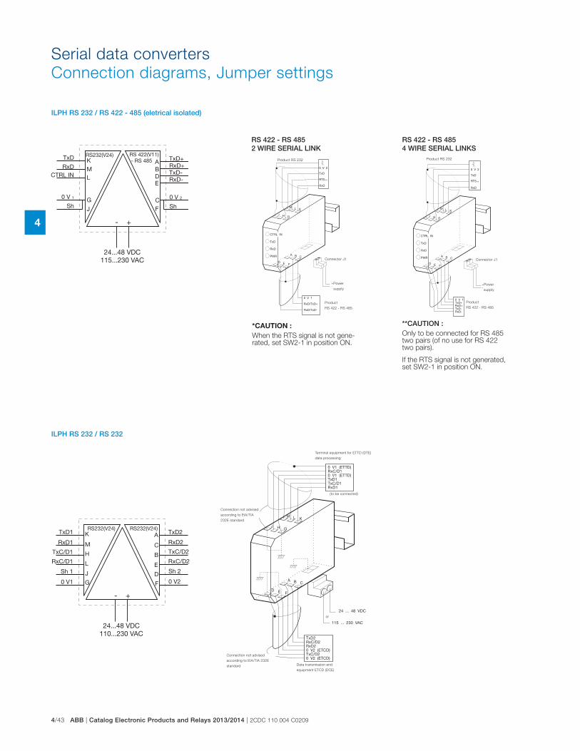
4/43 ABB | Catalog Electronic Products and Relays 2013/2014 | 2CDC 110 004 C0209
4
ILPH RS 232 / RS 422 - 485 (eletrical isolated)
ILPH RS 232 / RS 232
RS 422 - RS 485 2 WIRE SERIAL LINK
**CAUTION :Only to be connected for RS 485 two pairs (of no use for RS 422 two pairs).
If the RTS signal is not generated, set SW2-1 in position ON.
*CAUTION :
When the RTS signal is not gene-rated, set SW2-1 in position ON.
RS 422 - RS 485 4 WIRE SERIAL LINKS
Product RS 232
Connector J1
Power
supply
Product
RS 422 - RS 485
Product RS 232
Connector J1
Power
supply
Product
RS 422 - RS 485
Connection not advised
according to EIA/TIA 232E
standard
or
Connection not advised
according to EIA/TIA
232E standard
(to be connected)
Terminal equipment for ETTD (DTE)
data processing
Data transmission end
equipment ETCD (DCE)
Serial data converters
Connection diagrams, Jumper settings

2CDC 110 004 C0209 | Catalog Electronic Products and Relays 2013/2014 | ABB 4/44
4
ILPH RS 232 / FO
ILPH RS 485 / FO
RxD
OV
TxD
OV
~+
~-
(L)
(K)
(M)
(JH
G)
(E)
(F)
(D)
(B)
(C)
(A)
Shielding
FO Sending
FO Receiving
Shielding
OVD - D +
Shielding
FO Sending
FO Receiving
OV
~-
~+
Shielding
Serial data converters
Connection diagrams, Jumper settings

4/45 ABB | Catalog Electronic Products and Relays 2013/2014 | 2CDC 110 004 C0209
4
Serial data converters
Technical data
Technical dataData at T
a = 25 °C and rated values, unless otherwise indicated
ILPH RS 232 - 485 / Ethernet
Power supply 1Voltage 10...34 V DC, 10...24 V AC
Voltage tolerance -10%, +10%
Consumption 2 W max
Connections coding screw removable connector 0 to 2.5 mm² (22-14 AWG)
Power supply 2Voltage 10...34 V DC
Voltage tolerance -10%, +10%
Consumption 2 W max
Connections screw connector (AWG 20)
Serial link 1: RS 232 EIA RS 232
Overvoltage protection integrated
Baud rate / Transmission distance max. 115.2 kbits/s / max. 15 m
Connections 2.5 mm² screw connector (AWG 20) or male SubD 9 points
Serial link 2: RS 485 EIA RS 485
Voltage integrated
Line polarization integrated
End line resistance integrated
Baud rate / Transmission distance max. 115.2 kbits/s / max. 1200 m
Connections coding screw removable connector 0 to 2.5 mm² (22-14 AWG)
Ethernet linkOvervoltage protection integrated
Baud rate / Transmission distance 10-100 Mbits/s / max. 100 m without Hub or Switch with CAT5 cable
Connections RJ45 connector
Traffic indicationVoltage 1 yellow LED
Status of signal 3 green LED (RxD, TxD, LINK), 2 amber or green LED (Speed, Activity)
EMC behaviorElectrostatic discharge EN 61000-4-2
Radiated electromagnetic field EN 61000-4-3
Burst EN 61000-4-4
Surge EN 61000-4-5
Electromagnetic compatibility EN 55022
Other characteristicsElectrical isolation between serial link / power supply / Ethernet link 750 VDC / 1500 VAC
Configuration of the operating mode using internal switches or/and software (TELNET or HYPERTERMINAL)
Operating temperature 0°C ... +60°C
Storage temperature -20°C ... +70°C
Mounting any required
DIN rail fixing (EN 50002) snap-on mounting
Wire size 2.5 mm² / stranded with ferrule, 4 mm² solid
Dimensions (WxDxH) 94 x 22.5 x 100 mm
Weight 120 g

2CDC 110 004 C0209 | Catalog Electronic Products and Relays 2013/2014 | ABB 4/46
4
Serial data converters
Technical data
Technical dataData at T
a = 25 °C and rated values, unless otherwise indicated
ILPH RS 232 / RS 422 - 485 (without isolation)
Power supply polarized
Voltage 24 V DC
Voltage tolerance 8.5...28 V DC
Supply current 100 mA max
Connections removable screw connectors (AWG 20)
Serial link 1: RS 232 EIA RS 232 C / CCITT V24 V28
Overvoltage protection integrated (transil 8 kV 1.2/50 μs)
Baud rate / Transmission distance max. 38.4 kbits/s / max. 1200 m
Connections 2.5 mm² screw connectors (AWG 20)
Serial link 2: RS 422-485 EIA RS 485 and EIA RS 422 / CCITT V11
Overvoltage protection integrated (transil 8 kV 1.2/50 μs)
Baud rate / Transmission distance max. 38.4 kbits / max. 1200 m
Connections 2.5 mm² screw connectors (AWG 20)
Traffic indicationVoltage 1 yellow LED
Connections 2 green LED (RxD, TxD)
EMC behaviorElectrostatic discharge EN 61000-4-2 level 3 6/8 kV
Radiated electromagnetic field EN 61000-4-3 level 310 V/m
Burst EN 61000-4-4 level 3 1 kV
Electromagnetic compatibility EN 55022 class B
Other characteristicsElectrical isolation between serial link / power supply / Ethernet link no
Configuration of the operating mode using internal jumper
Operating temperature 0°C ... +50°C
Storage temperature -25°C ... +80°C
Mounting any required
DIN rail fixing (EN 50002) snap-on mounting
Wire size 2.5 mm² / stranded with ferrule, 4 mm² solid
Dimensions (WxDxH) 88 x 22.5 x 100 mm
Weight 100 g

4/47 ABB | Catalog Electronic Products and Relays 2013/2014 | 2CDC 110 004 C0209
4
Serial data converters
Technical data
Technical dataData at T
a = 25 °C and rated values, unless otherwise indicated
ILPH RS 232 / RS 422 - 485 (isolated)
Power supply polarized
Voltage 24 V DC
Voltage tolerance 8.5...28 V DC
Supply current 100 mA max
Connections Removable screw connectors (Omniconnect)
Serial link 1: RS 232 EIA RS 232 C / CCITT V24 V28
Overvoltage protection integrated (transil 8 kV 1.2/50μs)
Baud rate / Transmission distance max. 38.4 kbits/s / max. 15 m
Connections 2.5 mm² screw connectors (AWG 20)
Serial link 2: RS 422-485 EIA RS 485 and EIA RS 422 / CCITT V11
Overvoltage protection integrated (transil 8 kV 1.2/50 μs)
Baud rate / Transmission distance max. 38.4 kbits / max. 1200 m
Connections 2.5 mm² screw connectors (AWG 20)
Traffic indicationVoltage 1 yellow LED
Connections 3 green LED (RxD, TxD and CTRL-IN)
EMC behaviorElectrostatic discharge EN 61000-4-2 level 3 6/8 kV
Radiated electromagnetic field EN 61000-4-3 level 310 V/m
Burst EN 61000-4-4 level 3 1 kV
Electromagnetic compatibility EN 55022 class B
Other characteristicsElectrical isolation between serial link / power supply / Ethernet link 500 V DC
Configuration of the operating mode using internal jumper
Operating temperature 0°C ... +50°C
Storage temperature -25°C ... +80°C
Mounting any required
DIN rail fixing (EN 50002) snap-on mounting
Wire size 2.5 mm² / stranded with ferrule, 4 mm² solid
Dimensions (WxDxH) 88 x 22.5 x 100 mm
Weight 100 g

2CDC 110 004 C0209 | Catalog Electronic Products and Relays 2013/2014 | ABB 4/48
4
Serial data converters
Technical data
Technical dataData at T
a = 25 °C and rated values, unless otherwise indicated
ILPH RS 232 / RS 422 - 485 (3 way electrical isolated)
Power supply Polarization for DC model
Voltage 24...48 V DC 115...230 V AC (50/60 Hz)
Voltage tolerance -15% ... +20% -15% ... +15%
Supply current 24 V DC<110 mA, 48 V DC<55 mA, 115 V AC<40 mA, 230 V DC<26 mA
Supply power ~ 3 W ~ 3 VA
Connections Removable screw connector (Omniconnect)
Serial link 1: RS 232 EA / TIA RS 232 new revision / CCITT V24 V28
Overvoltage protection integrated (transil 8 kV 1.2/50 μs)
Baud rate / Transmission distance max. 19,2 kbits/s / max. 15 m / 2500 pF
Connections 2.5 mm² screw (AWG 20)
Serial link 2: RS 422-485 EIA / TIA RS 232 new revision / CCITT V24 V28
Overvoltage protection integrated (transil 8 kV 1.2/50μs)
Baud rate / Transmission distance max. 19.2 kbits/s / max. 15 m
Connections 2.5 mm² screw (AWG 20)
Traffic indicationVoltage 1 yellow LED
Connections 4 green LED (RxD, RxC/D, TxD, TxC/D)
EMC behaviorElectrostatic discharge EN 61000-4-2 level 3 6/8 kV
Radiated electromagnetic field EN 61000-4-3 level 3 10 V/m
Burst EN 61000-4-4 level 3 1 kV
Electromagnetic compatibility EN 55022 class B
Other characteristicsElectrical isolation between RS 232 / Power supply / RSS 422-RS 485 1,5 kV
Configuration of the operating mode No
Operating temperature 0°C ... +50°C
Storage temperature -25°C ... +80°C
Mounting any required
DIN rail fixing (EN 50002) snap-on mounting
Wire size 2.5 mm² / stranded with ferrule, 4 mm² solid
Dimensions (WxDxH) 88 x 22,5 x 100 mm
Weight 100 g

4/49 ABB | Catalog Electronic Products and Relays 2013/2014 | 2CDC 110 004 C0209
4
Serial data converters
Technical data
Technical dataData at T
a = 25 °C and rated values, unless otherwise indicated
ILPH RS 232 / RS 232
Power supply DC model polarized
Voltage 24...48 V DC 115...230 V AC (50/60Hz)
Voltage tolerance -15%...+20% -15%...+15%
Supply current 24 V DC<155 mA;48 V DC<77 mA;110 V AC<40 mA;230 V DC<26 mA
Supply power ~ 3.15 W ~ 3.15 VA
Connections Removable screw connector (Omniconnect)
Interface 1: RS 232 EIA / TIA RS 232 new revision / CCITT V24 V28
Overvoltage protection integrated (transil 8 kV 1.2/50 μs)
Transmission capacity / Transmission distance max. 19.2 kbits/s / max. 15 m / 2500 pF
Connections 2.5 mm² screw (AWG 20)
Interface 2: RS 232 EIA / TIA RS 232 new revision / CCITT V24 V28
Overvoltage protection integrated (transil 8 kV 1.2/50 μs)
Transmission capacity / Transmission distance max. 19.2 kbits/s / max. 15 m
Connections 2.5 mm² screw (AWG 20)
Traffic indicationVoltage 1 yellow LED
Connections 4 green LED (RxD, RxC/D, TxD, TxC/D)
EMC behaviorElectrostatic discharge EN 61000-4-2 level 3 6/8 kV
Radiated electromagnetic field EN 61000-4-3 level 3 10 V/m
Burst EN 61000-4-4 level 3 1 kV
Electromagnetic compatibility EN 55022 class B
Other characteristicsElectrical isolation between serial link / power supply / Ethernet link 1.5 kV
Configuration of the operating mode No
Operating temperature 0°C ... +50°C
Storage temperature -25°C ... +80°C
Mounting any required
DIN rail fixing (EN 50002) snap-on mounting
Wire size 2.5 mm² / stranded with ferrule, 4 mm² solid
Dimensions (WxDxH) 88 x 22.5 x 100 mm
Weight 100 g

2CDC 110 004 C0209 | Catalog Electronic Products and Relays 2013/2014 | ABB 4/50
4
Serial data converters
Technical data
Technical dataData at T
a = 25 °C and rated values, unless otherwise indicated
ILPH RS 422 - 485 / RS 422 - 485
Power supply DC model polarized
Voltage 24 V DC
Voltage tolerance +/-15%
Supply current 120 mA max.
Connections Removable screw connector (Omniconnect)
Interface 1: RS 422-485 EIA / RS 485 and EIA RS 422 / CCITT V11
Overvoltage protection integrated (transil 8 kV 1.2/50 μs)
RS 485 data switching Time switching / Time delay transmission/reception 27 μs ...10 ms
Baud rate / Transmission distance from 1.2 to 500 kbits/s / max. 1200 m up to 38.4 kbit/s
Connections 2.5 mm² screw (AWG 20)
Interface 2: RS 422-485 EIA / RS 485 and EIA RS 422 / CCITT V11
Overvoltage protection integrated (transil 8 kV 1.2/50 μs)
RS 485 data switching Time switching / Time delay transmission/reception 27 μs ...10 ms
Baud rate / Transmission distance from 1.2 to 500 kbits/s / max. 1200 m up to 38.4 kbit/s
Connections 2.5 mm² screw (AWG 20)
Traffic indicationVoltage 1 yellow LED
Connections 2 green LED (RxD, TxD, )
EMC behaviorElectrostatic discharge EN 61000-4-2 level 3 6/8 kV
Radiated electromagnetic field EN 61000-4-3 level 3 10 V/m
Burst EN 61000-4-4 level 3 1 kV
Electromagnetic compatibility EN 55022 class B
Other characteristicsElectrical isolation between RS 232 / Power supply / RSS 422-RS 485 500 V DC
Configuration of the operating mode using internal DIP switches
Operating temperature 0°C ... +50°C
Storage temperature -25°C ... +80°C
Mounting any required
DIN rail fixing (EN 50002) snap-on mounting
Wire size 2.5 mm² / stranded with ferrule, 4 mm² solid
Dimensions (WxDxH) 88 x 22.5 x 100 mm
Weight 100 g

4/51 ABB | Catalog Electronic Products and Relays 2013/2014 | 2CDC 110 004 C0209
4
Serial data converters
Technical data
Technical dataData at T
a = 25 °C and rated values, unless otherwise indicated
ILPH RS 232 / FO
Power suppliesSupply voltage 24...42 V AC/DC (50/60 Hz) 110...240 V AC/DC (50/60 Hz)
Voltage tolerance -15% ... +10% -15% ... +10%
Connections Omniconnect pluggable connector
Interface 1: RS 232 CCITT V.24/DIN 66020- CCITT V.28 DIN 66259-EIA 232 E
Protection Integrated (transil 8 kV 1.2/50μs)
Max. speed / max. distance Max. 115.2 kbits/s / max. 15 m / 2500 pF
Connections Omniconnect pluggable connector
Fiber optic interface 2 DIN VDE 0888-1
Type of fiber / ConnectionsMultimode fiber
Glass : ST connector; Plastic : FSMA screw connector
Wave length Glass : 820 nm; Plastic : 655 nm
Max. transmission power Glass : 50/125 μm : -14.4 db/m; Glass : 62.5/125 μm : -14 db/m; Plastic : 980/1000 μm : -8 db/m
Max. reception power Glass : -28 db/m; Plastic : -20 db/m
Max. speed Max. 115.2 kbits/s
Max. distance Glass : 50/125 μm : 3 km; Glass : 62.5/125 μm : 4 km; Plastic : 980/1000 μm : 40 m
Status indicationPower supply / Data exchange 1 green LED / 2 green LEDs (RxD, TxD)
EMC behaviorElectrostatic discharge EN 61000-4-2 Level 3 6/8 kV
Radiated electromagnetic field EN 61000-4-3 Level 3 10 V/m
Burst EN 61000-4-4 Level 3 1 kV
Electromagnetic compatibility EN 55022 Class B
Other characteristicsElectrical isolation input / power supply / output 2.5 kV
Operating temperature -20°C ... +60°C
Storage temperature -40°C ... +85°C
Mounting Onto DIN Rail (EN 50002)
Connections 14 AWG (2.5 mm²) fine stranded / 12 AWG (4 mm²) rigid
Dimensions (WxDxH) 105 x 22.5 x 112 mm / 4.13 x 0.89 x 4.41"
Weight 150 g / 0.33 lb

2CDC 110 004 C0209 | Catalog Electronic Products and Relays 2013/2014 | ABB 4/52
4
Serial data converters
Technical data
Technical dataData at T
a = 25 °C and rated values, unless otherwise indicated
ILPH RS 485 / FO
Power suppliesSupply voltage 24...42 V AC/DC (50/60 Hz) 110...240 V AC/DC (50/60 Hz)
Voltage tolerance -15% ... +10% -15% ... +10%
Connections Omniconnect pluggable connector
Interface 1: RS 232 ISO / IEC 8482 / DIN 66 259-4; EIA 485
Protection Integrated (transil 8 kV 1.2/50μs)
Max. speed / max. distance Max. 1.5 Mbits/s / max. 1200 m (38.4 kbit/s)
Connections Omniconnect pluggable connector
Fiber optic interface 2 DIN VDE 0888-1
Type of fiber / ConnectionsMultimode fiber
Glass : ST connector; Plastic : FSMA screw connector
Wave length Glass : 820 nm; Plastic : 655 nm
Max. transmission power Glass : 50/125 μm : -14.4 db/m; Glass : 62.5/125 μm : -14 db/m; Plastic : 980/1000 μm : -8 db/m
Max. reception power Glass : -28 db/m; Plastic : -20 db/m
Max. speed Max. 1.5 Mbits/s
Max. distance Glass : 50/125 μm : 3 km; Glass : 62.5/125 μm : 4 km; Plastic : 980/1000 μm : 40 m
Status indicationPower supply / Data exchange 1 green LED / 2 green LEDs (RxD, TxD)
EMC behaviorElectrostatic discharge EN 61000-4-2 Level 3 6/8 kV
Radiated electromagnetic field EN 61000-4-3 Level 3 10 V/m
Burst EN 61000-4-4 Level 3 1 kV
Electromagnetic compatibility EN 55022 Class B
Other characteristicsElectrical isolation input / power supply / output 2.5 kV
Operating temperature -20°C ... +60°C
Storage temperature -40°C ... +85°C
Mounting Onto DIN Rail
Connections 14 AWG (2.5mm²) / fine stranded, 12 AWG (4 mm²) rigid
Dimensions (WxDxH) 105 x 22.5 x 112 mm / 4.13 x 0.89 x 4.41"
Weight 150 g / 0.33 lb

4/53 ABB | Catalog Electronic Products and Relays 2013/2014 | 2CDC 110 004 C0209
4
Serial data converters
Technical data
Technical dataData at T
a = 25 °C and rated values, unless otherwise indicated
ILPH RS 422 - 485 (for current loop)
Power supply DC model polarized
Voltage 24 V DC
Voltage tolerance +/-10%
Supply current 120 mA max.
Connections Removable screw connector (Omniconnect)
Interface 1: Current loop active/passive 0...20 mA / 4...20 mA, mode is settable
Logic level 0 = 20 mA or 1 = 20 mA, settable
Baud rate / Transmission distance max. 38.4 kbit/s / max. 1200 m
Connections 2.5 mm² screw (AWG 20)
Serial link 2: RS 422/485 EIA RS 485 and EIA RS 422 / CCITT V 11
Overvoltage protection integrated (transil 8 kV 1.2/50 μs)
Baud rate / Transmission distance max. 38.4 kbit/s / max. 1200 m
Connections 2.5 mm² screw (AWG 20)
Traffic indicationVoltage 1 yellow LED
Status of signal 2 green LED (RxD, TxD)
EMC behaviorElectrostatic discharge EN 61000-4-2 level 2 4/4 kV
Radiated electromagnetic field EN 61000-4-3 level 3 10 V/m
Burst EN 61000-4-4 level 1 0.5 kV
Electromagnetic compatibility EN 55022 class B
Other characteristicsElectrical isolation between input / output and power supply / output depending on Current Loop (active/passive); 500 V DC (active) / 2000 V DC (passive)
RS 422-485 power supply 500 V DC
Configuration of the operating mode using internal DIP switches
Operating temperature 0°C ... +50°C
Storage temperature -25°C ... +80°C
Mounting any required
DIN rail fixing (EN 50002) snap-on mounting
Wire size 2.5 mm² / stranded with ferrule, 4 mm² solid
Dimensions (WxDxH) 88 x 22.5 x 100 mm
Weight 100 g

2CDC 110 004 C0209 | Catalog Electronic Products and Relays 2013/2014 | ABB 4/54
4
Serial data converters
Technical data
Technical dataData at T
a = 25 °C and rated values, unless otherwise indicated
ILPH RS 232 / CL
Power supply DC model polarized
Voltage 24 V DC
Voltage tolerance +/-10%
Supply current 120 mA max.
Connections Removable screw connector (Omniconnect)
Serial link 2: RS 232 EIA RS 232 C / CCITT V 24 V 28
Logic level integrated (transil 8 kV 1.2/50 μs)
Baud rate / Transmission distance max. 38.4 kbit/s / max. 15 m
Connections 2.5 mm² screw (AWG 20)
BdC serial link 2: RS 422/485 active/passive 0...20 mA / 4...20 mA mode settable
Overvoltage protection 0=20 mA or 1=20 mA settable
Baud rate / Transmission distance max. 38.4 kbit/s / max. 1200 m
Connections 2.5 mm² screw (AWG 20)
Traffic indicationVoltage 1 yellow LED
Status signal 2 green LED (RxD, TxD)
EMC behaviorElectrostatic discharge EN 61000-4-2 level 3 6/8 kV
Radiated electromagnetic field EN 61000-4-3 level 3 10 V/m
Burst EN 61000-4-4 level 3 1 kV
Electromagnetic compatibility EN 55022 class B
Other characteristicsElectrical isolation between Current loop / RS 232 depending on current loop (active/passive) 500 V DC (active) / 2000 V DC (passive)
Electrical isolation between Current loop / power supply 500 V DC (active) / 2000 V DC (passive)
Configuration of the operating mode using internal DIP switches
Operating temperature 0°C ... +50°C
Storage temperature -25°C ... +80°C
Mounting any required
DIN rail fixing (EN 50002) snap-on mounting
Wire size 2.5 mm² / stranded with ferrule, 4 mm² solid
Dimensions (WxDxH) 88 x 22.5 x 100 mm
Weight 100 g
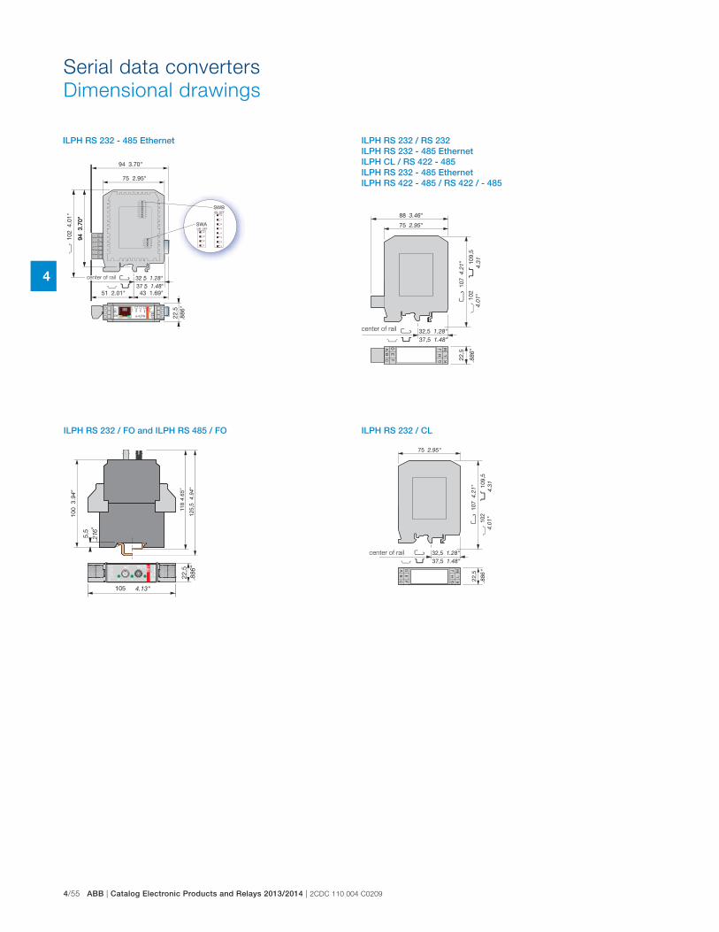
4/55 ABB | Catalog Electronic Products and Relays 2013/2014 | 2CDC 110 004 C0209
4
Serial data converters
Dimensional drawings
center of rail
ILPH RS 232 - 485 Ethernet ILPH RS 232 / RS 232 ILPH RS 232 - 485 Ethernet ILPH CL / RS 422 - 485 ILPH RS 232 - 485 Ethernet ILPH RS 422 - 485 / RS 422 / - 485
center of rail
ILPH RS 232 / FO and ILPH RS 485 / FO ILPH RS 232 / CL
center of rail

2CDC 110 004 C0209 | Catalog Electronic Products and Relays 2013/2014 | ABB 4/56
4
Serial data converters
Notes

5/1 ABB | Catalog Electronic Products and Relays 2013/2014 | 2CDC 110 004 C0209
5
Interface relays and optocouplers
Product group picture

2CDC 110 004 C0209 | Catalog Electronic Products and Relays 2013/2014 | ABB 5/2
5
Interface relays and optocouplers
Table of contents
Interface Relays and Optocouplers
Pluggable interface relays 5/3
Table of contents 5/4
Benefits and advantages 5/5
Approvals and marks 5/6
Ordering details 5/7
Technical data 5/14
Technical data, Load limit curves 5/16
Load limit curves 5/17
Connection diagrams 5/18
Interface relays and optocouplers R500 / R600 range 5/21
Table of contents 5/22
Benefits and advantages 5/23
Type designators 5/24
Interface relays and optocouplers R500 range 5/25
Table of contents 5/26
Interface relays R500 range 5/27
Table of contents 5/28
Selection 5/29
Ordering details 5/30
Technical information 5/31
Optocouplers R500 range 5/33
Table of contents 5/34
Selection 5/35
Ordering details 5/36
Connection diagrams 5/37
Technical data 5/38
Interface relays and optocouplers R600 range 5/45
Table of contents 5/46
Interface relays R600 range 5/47
Table of contents 5/48
Benefits and advantages 5/49
Selection 5/51
Ordering details 5/53
Connection diagrams 5/55
Technical data 5/56
General technical data 5/61
Dimensional drawings, Load limit curves 5/62
Optocouplers R600 range 5/63
Table of contents 5/64
Selection 5/65
Ordering details 5/67
Connection diagrams 5/68
Technical data 5/69

5/3 ABB | Catalog Electronic Products and Relays 2013/2014 | 2CDC 110 004 C0209
5
Pluggable interface relays
Product group picture

2CDC 110 004 C0209 | Catalog Electronic Products and Relays 2013/2014 | ABB 5/4
5
Pluggable interface relays
Table of contents
Pluggable interface relays
Product group picture 5/3
Table of contents 5/4
Benefits and advantages 5/5
Approvals and marks 5/6
Ordering details 5/7
Technical data 5/14
Technical data, Load limit curves 5/16
Load limit curves 5/17
Connection diagrams 5/18
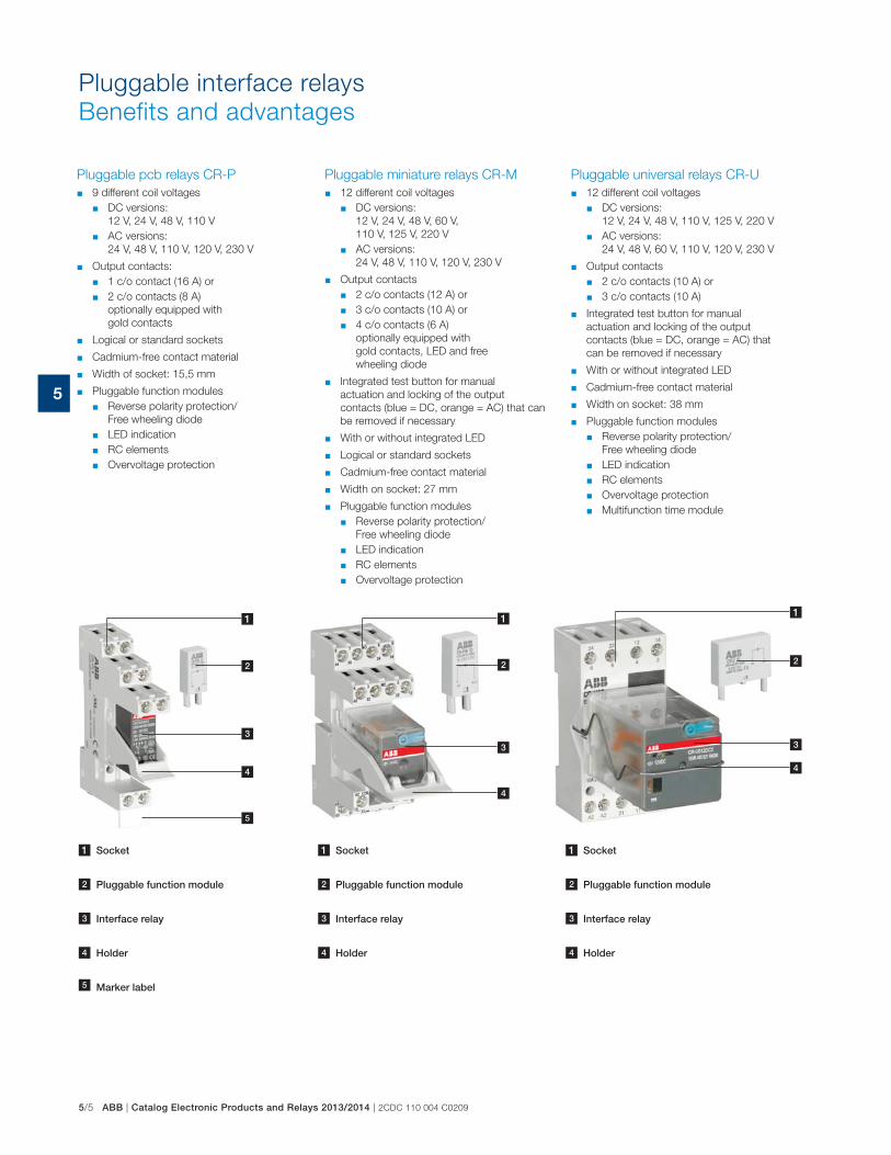
5/5 ABB | Catalog Electronic Products and Relays 2013/2014 | 2CDC 110 004 C0209
5
Pluggable pcb relays CR-P
� 9 different coil voltages
� DC versions:
12 V, 24 V, 48 V, 110 V
� AC versions:
24 V, 48 V, 110 V, 120 V, 230 V
� Output contacts:
� 1 c/o contact (16 A) or
� 2 c/o contacts (8 A)
optionally equipped with
gold contacts
� Logical or standard sockets
� Cadmium-free contact material
� Width of socket: 15,5 mm
� Pluggable function modules
� Reverse polarity protection/
Free wheeling diode
� LED indication
� RC elements
� Overvoltage protection
Pluggable universal relays CR-U
� 12 different coil voltages
� DC versions:
12 V, 24 V, 48 V, 110 V, 125 V, 220 V
� AC versions:
24 V, 48 V, 60 V, 110 V, 120 V, 230 V
� Output contacts
� 2 c/o contacts (10 A) or
� 3 c/o contacts (10 A)
� Integrated test button for manual
actuation and locking of the output
contacts (blue = DC, orange = AC) that
can be removed if necessary
� With or without integrated LED
� Cadmium-free contact material
� Width on socket: 38 mm
� Pluggable function modules
� Reverse polarity protection/
Free wheeling diode
� LED indication
� RC elements
� Overvoltage protection
� Multifunction time module
Pluggable miniature relays CR-M
� 12 different coil voltages
� DC versions:
12 V, 24 V, 48 V, 60 V,
110 V, 125 V, 220 V
� AC versions:
24 V, 48 V, 110 V, 120 V, 230 V
� Output contacts
� 2 c/o contacts (12 A) or
� 3 c/o contacts (10 A) or
� 4 c/o contacts (6 A)
optionally equipped with
gold contacts, LED and free
wheeling diode
� Integrated test button for manual
actuation and locking of the output
contacts (blue = DC, orange = AC) that can
be removed if necessary
� With or without integrated LED
� Logical or standard sockets
� Cadmium-free contact material
� Width on socket: 27 mm
� Pluggable function modules
� Reverse polarity protection/
Free wheeling diode
� LED indication
� RC elements
� Overvoltage protection
Pluggable interface relays
Benefits and advantages
1 Socket
2 Pluggable function module
3 Interface relay
4 Holder
1 Socket
2 Pluggable function module
3 Interface relay
4 Holder
11
2 2
3 3
4
4
1 Socket
2 Pluggable function module
3 Interface relay
4 Holder
4 Marker label
1
2
3
4
4
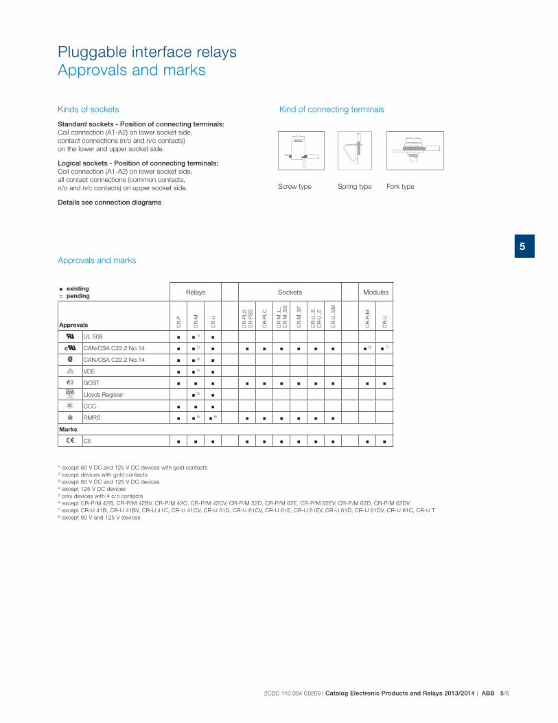
2CDC 110 004 C0209 | Catalog Electronic Products and Relays 2013/2014 | ABB 5/6
5
Pluggable interface relays
Approvals and marks
Approvals and marks
� existing
� pendingRelays Sockets Modules
Approvals CR
-P
CR
-M
CR
-U
CR
-PLS
CR
-PS
S
CR
-PLC
CR
-M..
L..
CR
-M..
SS
CR
-M..
SF
CR
-U..
S
CR
-U..
E
CR
-U..
SM
CR
-P/M
CR
-U
G UL 508 � � 1) �
cG CAN/CSA C22.2 No.14 � � 2) � � � � � � � � 6) � 7)
F CAN/CSA C22.2 No.14 � � 3) �
J VDE � � 4) �
D GOST � � � � � � � � � � �
P Lloyds Register � 5) �
E CCC � � �
L RMRS � � 8) � 8) � � � � � �
Marks
a CE � � � � � � � � � � �
1) except 60 V DC and 125 V DC devices with gold contacts2) except devices with gold contacts3) except 60 V DC and 125 V DC devices4) except 125 V DC devices5) only devices with 4 c/o contacts6) except CR-P/M 42B, CR-P/M 42BV, CR-P/M 42C, CR-P/M 42CV, CR-P/M 52D, CR-P/M 62E, CR-P/M 62EV, CR-P/M 62D, CR-P/M 62DV7) except CR-U 41B, CR-U 41BV, CR-U 41C, CR-U 41CV, CR-U 51D, CR-U 61CV, CR-U 61E, CR-U 61EV, CR-U 61D, CR-U 61DV, CR-U 91C, CR-U T8) except 60 V and 125 V devices
Kinds of sockets
Standard sockets - Position of connecting terminals: Coil connection (A1-A2) on lower socket side,
contact connections (n/o and n/c contacts)
on the lower and upper socket side.
Logical sockets - Position of connecting terminals: Coil connection (A1-A2) on lower socket side,
all contact connections (common contacts,
n/o and n/c contacts) on upper socket side.
Details see connection diagrams
Kind of connecting terminals
Screw type Spring type Fork type
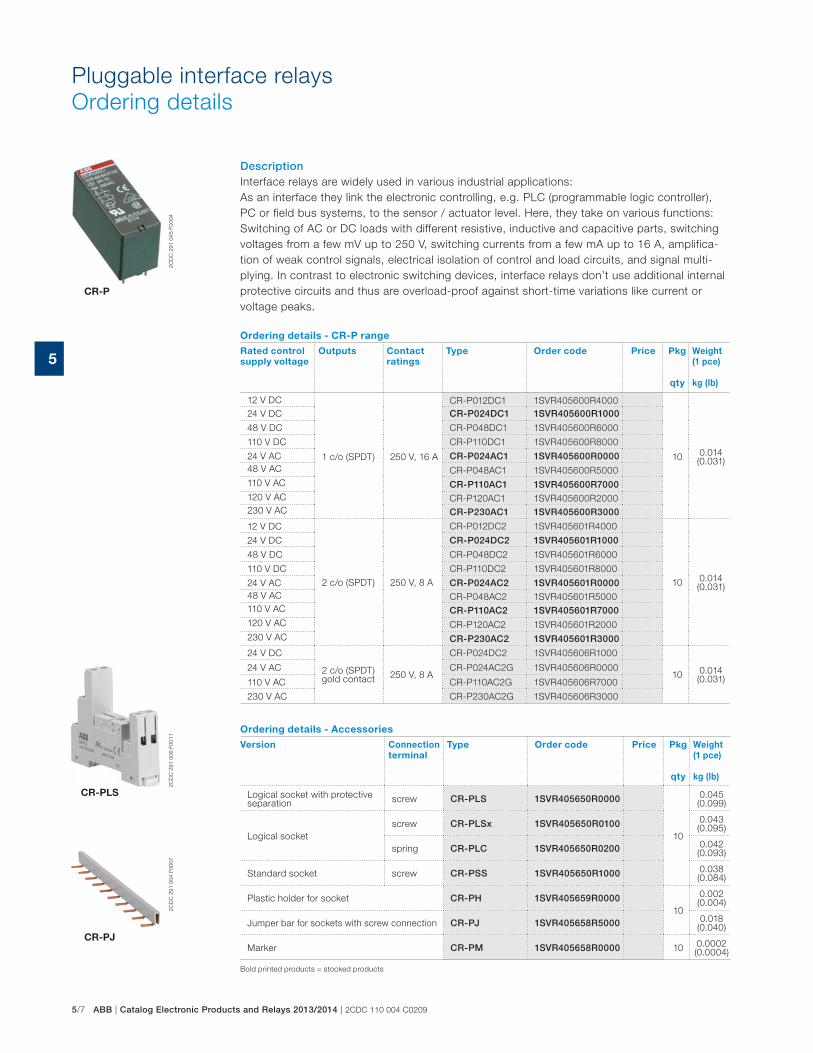
5/7 ABB | Catalog Electronic Products and Relays 2013/2014 | 2CDC 110 004 C0209
5
Pluggable interface relays
Ordering details
DescriptionInterface relays are widely used in various industrial applications:
As an interface they link the electronic controlling, e.g. PLC (programmable logic controller),
PC or field bus systems, to the sensor / actuator level. Here, they take on various functions:
Switching of AC or DC loads with different resistive, inductive and capacitive parts, switching
voltages from a few mV up to 250 V, switching currents from a few mA up to 16 A, amplifica-
tion of weak control signals, electrical isolation of control and load circuits, and signal multi-
plying. In contrast to electronic switching devices, interface relays don’t use additional internal
protective circuits and thus are overload-proof against short-time variations like current or
voltage peaks.
Ordering details - CR-P range
Rated control
supply voltage
Outputs Contact
ratings
Type Order code Price Pkg
qty
Weight
(1 pce)
kg (lb)
12 V DC
1 c/o (SPDT) 250 V, 16 A
CR-P012DC1 1SVR405600R4000
100.014 (0.031)
24 V DC CR-P024DC1 1SVR405600R1000
48 V DC CR-P048DC1 1SVR405600R6000
110 V DC CR-P110DC1 1SVR405600R8000
24 V AC CR-P024AC1 1SVR405600R000048 V AC CR-P048AC1 1SVR405600R5000
110 V AC CR-P110AC1 1SVR405600R7000120 V AC CR-P120AC1 1SVR405600R2000
230 V AC CR-P230AC1 1SVR405600R3000
12 V DC
2 c/o (SPDT) 250 V, 8 A
CR-P012DC2 1SVR405601R4000
100.014 (0.031)
24 V DC CR-P024DC2 1SVR405601R1000
48 V DC CR-P048DC2 1SVR405601R6000
110 V DC CR-P110DC2 1SVR405601R8000
24 V AC CR-P024AC2 1SVR405601R000048 V AC CR-P048AC2 1SVR405601R5000
110 V AC CR-P110AC2 1SVR405601R7000120 V AC CR-P120AC2 1SVR405601R2000
230 V AC CR-P230AC2 1SVR405601R3000
24 V DC
2 c/o (SPDT) gold contact
250 V, 8 A
CR-P024DC2 1SVR405606R1000
100.014 (0.031)
24 V AC CR-P024AC2G 1SVR405606R0000
110 V AC CR-P110AC2G 1SVR405606R7000
230 V AC CR-P230AC2G 1SVR405606R3000
Ordering details - Accessories
Version Connection
terminal
Type Order code Price Pkg
qty
Weight
(1 pce)
kg (lb)
Logical socket with protective separation
screw CR-PLS 1SVR405650R0000
10
0.045 (0.099)
Logical socket
screw CR-PLSx 1SVR405650R0100 0.043 (0.095)
spring CR-PLC 1SVR405650R0200 0.042 (0.093)
Standard socket screw CR-PSS 1SVR405650R1000 0.038 (0.084)
Plastic holder for socket CR-PH 1SVR405659R000010
0.002 (0.004)
Jumper bar for sockets with screw connection CR-PJ 1SVR405658R5000 0.018 (0.040)
Marker CR-PM 1SVR405658R0000 100.0002 (0.0004)
2C
DC
291 0
04 F
0007
2C
DC
291 0
06 F
0011
CR-PLS
CR-P
CR-PJ
2C
DC
291 0
45 F
0004
Bold printed products = stocked products
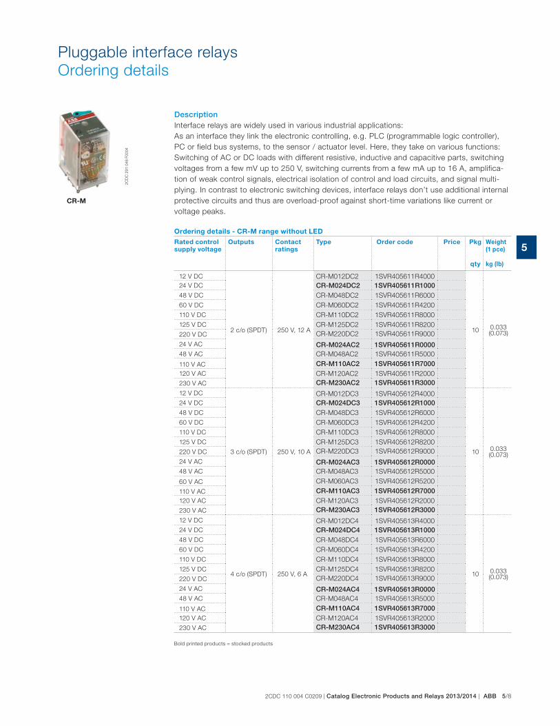
2CDC 110 004 C0209 | Catalog Electronic Products and Relays 2013/2014 | ABB 5/8
5
Pluggable interface relays
Ordering details
DescriptionInterface relays are widely used in various industrial applications:
As an interface they link the electronic controlling, e.g. PLC (programmable logic controller),
PC or field bus systems, to the sensor / actuator level. Here, they take on various functions:
Switching of AC or DC loads with different resistive, inductive and capacitive parts, switching
voltages from a few mV up to 250 V, switching currents from a few mA up to 16 A, amplifica-
tion of weak control signals, electrical isolation of control and load circuits, and signal multi-
plying. In contrast to electronic switching devices, interface relays don’t use additional internal
protective circuits and thus are overload-proof against short-time variations like current or
voltage peaks.
Ordering details - CR-M range without LED
Rated control
supply voltage
Outputs Contact
ratings
Type Order code Price Pkg
qty
Weight
(1 pce)
kg (lb)
12 V DC
2 c/o (SPDT) 250 V, 12 A
CR-M012DC2 1SVR405611R4000
100.033 (0.073)
24 V DC CR-M024DC2 1SVR405611R100048 V DC CR-M048DC2 1SVR405611R6000
60 V DC CR-M060DC2 1SVR405611R4200
110 V DC CR-M110DC2 1SVR405611R8000
125 V DC CR-M125DC2 1SVR405611R8200
220 V DC CR-M220DC2 1SVR405611R9000
24 V AC CR-M024AC2 1SVR405611R000048 V AC CR-M048AC2 1SVR405611R5000
110 V AC CR-M110AC2 1SVR405611R7000120 V AC CR-M120AC2 1SVR405611R2000
230 V AC CR-M230AC2 1SVR405611R3000
12 V DC
3 c/o (SPDT) 250 V, 10 A
CR-M012DC3 1SVR405612R4000
100.033 (0.073)
24 V DC CR-M024DC3 1SVR405612R100048 V DC CR-M048DC3 1SVR405612R6000
60 V DC CR-M060DC3 1SVR405612R4200
110 V DC CR-M110DC3 1SVR405612R8000
125 V DC CR-M125DC3 1SVR405612R8200
220 V DC CR-M220DC3 1SVR405612R9000
24 V AC CR-M024AC3 1SVR405612R000048 V AC CR-M048AC3 1SVR405612R5000
60 V AC CR-M060AC3 1SVR405612R5200
110 V AC CR-M110AC3 1SVR405612R7000120 V AC CR-M120AC3 1SVR405612R2000
230 V AC CR-M230AC3 1SVR405612R3000
12 V DC
4 c/o (SPDT) 250 V, 6 A
CR-M012DC4 1SVR405613R4000
100.033 (0.073)
24 V DC CR-M024DC4 1SVR405613R100048 V DC CR-M048DC4 1SVR405613R6000
60 V DC CR-M060DC4 1SVR405613R4200
110 V DC CR-M110DC4 1SVR405613R8000
125 V DC CR-M125DC4 1SVR405613R8200
220 V DC CR-M220DC4 1SVR405613R9000
24 V AC CR-M024AC4 1SVR405613R000048 V AC CR-M048AC4 1SVR405613R5000
110 V AC CR-M110AC4 1SVR405613R7000120 V AC CR-M120AC4 1SVR405613R2000
230 V AC CR-M230AC4 1SVR405613R3000
CR-M
2C
DC
291 0
46 F
0004
Bold printed products = stocked products

5/9 ABB | Catalog Electronic Products and Relays 2013/2014 | 2CDC 110 004 C0209
5
Pluggable interface relays
Ordering details
Ordering details - CR-M range
Rated control
supply voltage
Outputs Contact
ratings
Type Order code Price Pkg
qty
Weight
(1 pce)
kg (lb)
12 V DC
2 c/o (SPDT) with LED
250 V, 12 A
CR-M012DC2L 1SVR405611R4100
100.033 (0.073)
24 V DC CR-M024DC2L 1SVR405611R1100
48 V DC CR-M048DC2L 1SVR405611R6100
60 V DC CR-M060DC2L 1SVR405611R4300
110 V DC CR-M110DC2L 1SVR405611R8100
125 V DC CR-M125DC2L 1SVR405611R8300
220 V DC CR-M220DC2L 1SVR405611R9100
24 V AC CR-M024AC2L 1SVR405611R010048 V AC CR-M048AC2L 1SVR405611R5100
110 V AC CR-M110AC2L 1SVR405611R7100
120 V AC CR-M120AC2L 1SVR405611R2100
230 V AC CR-M230AC2L 1SVR405611R3100
12 V DC
3 c/o (SPDT) with LED
250 V, 10 A
CR-M012DC3L 1SVR405612R4100
100.033 (0.073)
24 V DC CR-M024DC3L 1SVR405612R1100
48 V DC CR-M048DC3L 1SVR405612R6100
60 V DC CR-M060DC3L 1SVR405612R4300
110 V DC CR-M110DC3L 1SVR405612R8100
125 V DC CR-M125DC3L 1SVR405612R8300
220 V DC CR-M220DC3L 1SVR405612R9100
24 V AC CR-M024AC3L 1SVR405612R0100
48 V AC CR-M048AC3L 1SVR405612R5100
110 V AC CR-M110AC3L 1SVR405612R7100
120 V AC CR-M120AC3L 1SVR405612R2100
230 V AC CR-M230AC3L 1SVR405612R3100
12 V DC
4 c/o (SPDT) with LED
250 V, 6 A
CR-M012DC4L 1SVR405613R4100
100.033 (0.073)
24 V DC CR-M024DC4L 1SVR405613R1100
48 V DC CR-M048DC4L 1SVR405613R6100
60 V DC CR-M060DC4L 1SVR405613R4300
110 V DC CR-M110DC4L 1SVR405613R8100
125 V DC CR-M125DC4L 1SVR405613R8300
220 V DC CR-M220DC4L 1SVR405613R9100
24 V AC CR-M024AC4L 1SVR405613R010048 V AC CR-M048AC4L 1SVR405613R5100
110 V AC CR-M110AC4L 1SVR405613R7100
120 V AC CR-M120AC4L 1SVR405613R2100
230 V AC2 CR-M230AC4L 1SVR405613R3100
24 V DC
4 c/o (SPDT), LED and free-wheeling diode
250 V, 6 A CR-M024DC4LD 1SVR405614R1100 100.033 (0.073)
24 V DC
4 c/o (SPDT), gold contacts
250 V, 6 A
CR-M024DC4G 1SVR405618R1000
10 0.033 (0.073)
24 V AC CR-M024AC4G 1SVR405618R0000
110 V AC CR-M110AC4G 1SVR405618R7000
230 V AC CR-M230AC4G 1SVR405618R3000
CR-M
2C
DC
291 0
46 F
0004
Bold printed products = stocked products

2CDC 110 004 C0209 | Catalog Electronic Products and Relays 2013/2014 | ABB 5/10
5
Pluggable interface relays
Ordering details
CR-M
2C
DC
291 0
46 F
0004
Rated control
supply voltage
Outputs Contact
ratings
Type Order code Price Pkg
qty
Weight
(1 pce)
kg (lb)
12 V DC
4 c/o (SPDT) with gold contacts and LED
250 V / 6 A
CR-M012DC4LG 1SVR405618R4100
10 0.033 (0.073)
24 V DC CR-M024DC4LG 1SVR405618R110048 V DC CR-M048DC4LG 1SVR405618R6100
60 V DC CR-M060DC4LG 1SVR405618R4300
110 V DC CR-M110DC4LG 1SVR405618R8100
125 V DC CR-M125DC4LG 1SVR405618R8300
220 V DC CR-M220DC4LG 1SVR405618R9100
24 V AC CR-M024AC4LG 1SVR405618R0100
100.033 (0.073)
48 V AC CR-M048AC4LG 1SVR405618R5100
110 V AC CR-M110AC4LG 1SVR405618R7100120 V AC CR-M120AC4LG 1SVR405618R2100
230 V AC CR-M230AC4LG 1SVR405618R3100
12 V DC4 c/o (SPDT)with gold contacts, LED and free-wheeling diode
CR-M012DC4LDG 1SVR405618R4400
100.033 (0.073)
24 V DC CR-M024DC4LDG 1SVR405618R1400
Ordering details - Accessories
Version Connection
terminal
Type Order code Price Pkg
qty
Weight
(1 pce)
kg (lb)
Logical socket for 2 c/o
screw
CR-M2LS 1SVR405651R1100
10
0.055 (0.121)
Logical socket for 3 c/o CR-M3LS 1SVR405651R2100 0.062 (0.137)
Logical socket for 2/4 c/o CR-M4LS 1SVR405651R3100 0.066 (0.146)
Logical socket for 2 c/o
spring
CR-M2LC 1SVR405651R120010
0.065 (0.143)
Logical socket for 2/4 c/o CR-M4LC 1SVR405651R3200 0.066 (0.146)
Standard socket for 2 c/o
screw
CR-M2SS 1SVR405651R1000
10
0.066 (0.146)
Standard socket for 3 c/o CR-M3SS 1SVR405651R2000 0.068 (0.150)
Standard socket for 2/4 c/o CR-M4SS 1SVR405651R3000 0.070 (0.154)
Standard socket for 2 c/o
fork type
CR-M2SF 1SVR405651R130010
0.040 (0.088)
Standard socket for 2/4 c/o CR-M4SF 1SVR405651R3300 0.048 (0.106)
Plastic holder CR-MH 1SVR405659R1000 100.003 (0.007)
Metal holder CR-MH1 1SVR405659R1100 100.0005 (0.001)
Jumper bar for sockets with
screw connectionCR-MJ 1SVR405658R6000 10
0.029 (0.064)
Marker CR-MM 1SVR405658R1000 100.0005 (0.001)
2C
DC
291 0
09 F
0011
CR-M4SS
CR-MJ
Bold printed products = stocked products

5/11 ABB | Catalog Electronic Products and Relays 2013/2014 | 2CDC 110 004 C0209
5
Pluggable interface relays
Ordering details
Ordering details - CR-P/M range (all products stocked)
Rated control
supply voltage
Description Version Type Order code Price Pkg
qty
Weight
(1 pce)
kg (lb)
6-220 V DC
Diode - Reverse polarity protection/free wheeling diode
A1+, A2- CR-P/M 22 1SVR405651R0000 100.003 (0.007)
6-24 V DCDiode and LED - Rever-se polarity protection/free wheeling diode
red, A1+, A2- CR-P/M 42 1SVR405652R0000
100.003 (0.007)
green, A1+, A2- CR-P/M 42V 1SVR405652R1000
24-60 V DCred, A1+, A2- CR-P/M 42B 1SVR405652R4000
green, A1+, A2- CR-P/M 42BV 1SVR405652R4100
110 V DCred, A1+, A2- CR-P/M 42C 1SVR405652R9000
green, A1+, A2- CR-P/M 42CV 1SVR405652R9100
6-24 V AC
Spark quen-ching
CR-P/M 52B 1SVR405653R0000
100.003 (0.007)
24-60 V AC CR-P/M 52D 1SVR405653R4000
110-230
V AC/DCCR-P/M 52C 1SVR405653R1000
6-24 V AC/DC
Diode, LED and reverse polarity protection
red, for DC A1+, A2-
CR-P/M 62 1SVR405654R0000
100.003 (0.007)
green, for DC A1+, A2-
CR-P/M 62V 1SVR405654R1000
24-60 V AC/DC
red, for DC A1+, A2-
CR-P/M 62E 1SVR405654R4000
green, for DC A1+, A2-
CR-P/M 62EV 1SVR405654R4100
110 V DC
110-230 V AC
red, for DC A1+, A2-
CR-P/M 92 1SVR405654R0100
green, for DC A1+, A2-
CR-P/M 92V 1SVR405654R1100
6-24 V AC/DC
Varistor and LED Overvoltage protection
red, for DC A1+, A2-
CR-P/M 62C 1SVR405655R0000
100.003 (0.007)
green, for DC A1+, A2-
CR-P/M 62CV 1SVR405655R1000
24-60 V AC/DC
red, for DC A1+, A2-
CR-P/M 62D 1SVR405655R4000
green, for DC A1+, A2-
CR-P/M 62DV 1SVR405655R4100
110 V DC
110-230 V AC
red, for DC A1+, A2-
CR-P/M 92C 1SVR405655R0100
green, for DC A1+, A2-
CR-P/M 92CV 1SVR405655R1100
24 V ACOvervoltage protection
CR-P/M 72 1SVR405656R0000
100.002 (0.004)
115 V AC CR-P/M 72A 1SVR405656R1000
230 V AC CR-P/M 82 1SVR405656R2000
Connection diagrams
2C
DC
29
2 0
13
F0
00
5
CR-P/M 22
2C
DC
29
2 0
14
F0
00
5
CR-P/M 42, CR-P/M 42B,
CR-P/M 42C, CR-P/M 42V,
CR-P/M 42BV, CR-P/M 42CV
2C
DC
29
2 0
15
F0
00
5
CR-P/M 52B, CR-P/M 52C
CR-P/M 52D,
2C
DC
29
2 0
16
F0
00
5
CR-P/M 62, CR-P/M 62E,
CR-P/M 92, CR-P/M 62V,
CR-P/M 62EV, CR-P/M 92V
2C
DC
29
2 0
17
F0
00
5
CR-P/M 62C, CR-P/M 62D,
CR-P/M 92C, CR-P/M 62CV,
CR-P/M 62DV CR-P/M 92CV
2C
DC
29
2 0
18
F0
00
5
CR-P/M 72, CR-P/M 82
CR-P/M 72A,
CR-P/M ...
2C
DC
291 0
05 S
0011

2CDC 110 004 C0209 | Catalog Electronic Products and Relays 2013/2014 | ABB 5/12
5
Pluggable interface relays
Ordering details
DescriptionInterface relays are widely used in various industrial applications:
As an interface they link the electronic controlling, e.g. PLC (programmable logic controller),
PC or field bus systems, to the sensor / actuator level. Here, they take on various functions:
Switching of AC or DC loads with different resistive, inductive and capacitive parts, switching
voltages from a few mV up to 250 V, switching currents from a few mA up to 16 A, amplifica-
tion of weak control signals, electrical isolation of control and load circuits, and signal multi-
plying. In contrast to electronic switching devices, interface relays don’t use additional internal
protective circuits and thus are overload-proof against short-time variations like current or
voltage peaks.
Ordering details - CR-U range
Rated control
supply voltage
Outputs Contact
ratings
Type Order code Price Pkg
qty
Weight
(1 pce)
kg (lb)
12 V DC
2 c/o without LED
250 V, 10 A
CR-U012DC2 1SVR405621R4000
100.083 (0.183)
24 V DC CR-U024DC2 1SVR405621R100048 V DC CR-U048DC2 1SVR405621R6000
110 V DC CR-U110DC2 1SVR405621R8000
220 V DC CR-U220DC2 1SVR405621R9000
24 V AC CR-U024AC2 1SVR405621R000048 V AC CR-U048AC2 1SVR405621R5000
110 V AC CR-U110AC2 1SVR405621R7000120 V AC CR-U120AC2 1SVR405621R2000
230 V AC CR-U230AC2 1SVR405621R300012 V DC
3 c/o without LED
250 V, 10 A
CR-U012DC3 1SVR405622R4000
100.083 (0.183)
24 V DC CR-U024DC3 1SVR405622R100048 V DC CR-U048DC3 1SVR405622R6000
110 V DC CR-U110DC3 1SVR405622R8000
125 V DC CR-U125DC3 1SVR405622R8200
220 V DC CR-U220DC3 1SVR405622R9000
24 V AC CR-U024AC3 1SVR405622R000048 V AC CR-U048AC3 1SVR405622R5000
60 V AC CR-U060AC3 1SVR405622R5200
110 V AC CR-U110AC3 1SVR405622R7000120 V AC CR-U120AC3 1SVR405622R2000
230 V AC CR-U230AC3 1SVR405622R300012 V DC
2 c/o with LED
250 V, 10 A
CR-U012DC2L 1SVR405621R4100
100.083 (0.183)
24 V DC CR-U024DC2L 1SVR405621R110048 V DC CR-U048DC2L 1SVR405621R6100
110 V DC CR-U110DC2L 1SVR405621R8100
220 V DC CR-U220DC2L 1SVR405621R9100
24 V AC CR-U024AC2L 1SVR405621R010048 V AC CR-U048AC2L 1SVR405621R5100
110 V AC CR-U110AC2L 1SVR405621R7100120 V AC CR-U120AC2L 1SVR405621R2100
230 V AC CR-U230AC2L 1SVR405621R310012 V DC
3 c/o with LED
250 V, 10 A
CR-U012DC3L 1SVR405622R4100
100.083 (0.183)
24 V DC CR-U024DC3L 1SVR405622R110048 V DC CR-U048DC3L 1SVR405622R6100
110 V DC CR-U110DC3L 1SVR405622R8100
220 V DC CR-U220DC3L 1SVR405622R9100
24 V AC CR-U024AC3L 1SVR405622R010048 V AC CR-U048AC3L 1SVR405622R5100
110 V AC CR-U110AC3L 1SVR405622R7100120 V AC CR-U120AC3L 1SVR405622R2100
230 V AC CR-U230AC3L 1SVR405622R3100
CR-U
CR-U2S
2C
DC
291 0
47 F
0004
2C
DC
291 0
07 S
0011
Ordering details - Accessories
Version Type Order code Price Pkg
qty
Weight
(1 pce)
kg (lb)
Socket for 2 c/o and module CR-U2S 1SVR405670R0000
10
Socket for 3 c/o and module CR-U3S 1SVR405660R0000Socket for 3 c/o CR-U3E 1SVR405660R0100Socket small for 2 c/o CR-U2SM 1SVR405670R1100Socket small for 3 c/o CR-U3SM 1SVR405660R1100Holder for CR-U socket CR-UH 1SVR405669R0000Bold printed products = stocked products

5/13 ABB | Catalog Electronic Products and Relays 2013/2014 | 2CDC 110 004 C0209
5
Ordering details - CR-U range (all products stocked)
Rated control
supply voltage
Description Version Type Order code Price Pkg
qty
Weight
(1 pce)
kg (lb)
6-220 V DC
Diode - Reverse polarity protection/free wheeling diode
A1+, A2- CR-U 21 1SVR405661R0000 100.007 (0.015)
6-24 V DCDiode and LED - Rever-se polarity protection/free wheeling diode
red, A1+, A2- CR-U 41 1SVR405662R0000
100.007 (0.015)
green, A1+, A2- CR-U 41V 1SVR405662R1000
24-60 V DCred, A1+, A2- CR-U 41B 1SVR405662R4000
green, A1+, A2- CR-U 41BV 1SVR405662R4100
110 V DCred, A1+, A2- CR-U 41C 1SVR405662R9000
green, A1+, A2- CR-U 41CV 1SVR405662R9100
6-24 V AC/DC
Spark quen-ching
CR-U 51B 1SVR405663R0000
100.007 (0.015)
24-60 V AC/DC CR-U 51D 1SVR405663R4000
110-230
V AC/DCCR-U 51C 1SVR405663R1000
6-24 V AC/DC
Diode and LED
red, for DC A1+, A2-
CR-U 61 1SVR405664R0000
100.007 (0.015)
green, for DC A1+, A2-
CR-U 61V 1SVR405664R1000
24-60 V AC/DC
red, for DC A1+, A2-
CR-U 61E 1SVR405664R4000
green, for DC A1+, A2-
CR-U 61EV 1SVR405664R4100
110 V DC
110-230 V AC
red, for DC A1+, A2-
CR-U 91 1SVR405664R0100
green, for DC A1+, A2-
CR-U 91V 1SVR405664R1100
6-24 V AC/DC
Varistor and LED Overvoltage protection
red, for DC A1+, A2-
CR-U 61C 1SVR405665R0000
100.007 (0.015)
green, for DC A1+, A2-
CR-U 61CV 1SVR405665R1000
24-60 V AC/DC
red, for DC A1+, A2-
CR-U 61D 1SVR405665R4000
green, for DC A1+, A2-
CR-U 61DV 1SVR405665R4100
110 V DC
110-230 V AC
red, for DC A1+, A2-
CR-U 91C 1SVR405665R0100
green, for DC A1+, A2-
CR-U 91CV 1SVR405665R1100
24 V ACOvervoltage protection, varistor
CR-U 71 1SVR405666R0000
100.007 (0.015)
115 V AC CR-U 71A 1SVR405666R1000
230 V AC CR-U 81 1SVR405666R2000
24-240
V AC/DCMultifunction time module
pluggable onto CR-U2S and CR-U3S
CR-U T 1SVR405667R0000 100.014 (0.031)
CR-U...
2C
DC
291 0
04 S
0011
2C
DC
291 0
32 F
0005
Pluggable interface relays
Ordering details
CR-U T
Connection diagrams
2C
DC
29
2 0
13
F0
00
5
CR-U 21
2C
DC
29
2 0
14
F0
00
5
CR-U 41, CR-U 41B, CR-U 41C,
CR-U 41V, CR-U 41BV, CR-U 41CV
2C
DC
29
2 0
15
F0
00
5
CR-U 51B, CR-U 51C CR-U 51D,
2C
DC
29
2 0
16
F0
00
5
CR-U 61, CR-U 61E, CR-U 91,
CR-U 61V, CR-U 61EV, CR-U 91V
2C
DC
29
2 0
17
F0
00
5
CR-U 61C, CR-U 61D, CR-U 91C,
CR-U 61CV, CR-U 61DV CR-U 91CV
2C
DC
29
2 0
18
F0
00
5
CR-U 71, CR-U 81 CR-U
71A,
All CR-U modules can be plugged onto sockets CR-U2S and CR-U3S.

2CDC 110 004 C0209 | Catalog Electronic Products and Relays 2013/2014 | ABB 5/14
5
Pluggable interface relays
Technical data
Input circuit - coil data
Rated control supply voltage US
Rated frequency
Make voltage (at 20 °C)
Maximum voltage (at 55 °C)
Break voltage
Rated power
Coil resistance (at 20 °C)
Tolerance of coil resistance
DC coils 12 V DC - 8.4 V DC 30.6 V DC � 0.1 US
0.4-0.48 W 360 � � 10%
24 V DC - 16.8 V DC 61.2 V DC � 0.1 US
0.4-0.48 W 1440 � � 10%
48 V DC - 33.6 V DC 122.4 V DC � 0.1 US
0.4-0.48 W 5700 � � 10%
110 V DC - 77 V DC 280 V DC � 0.1 US
0.4-0.48 W 25200 � � 10%
AC coils 24 V AC 50 / 60 Hz 19.2 V AC 28.8 V AC � 0.15 US
0.75 VA 400 � � 10%
48 V AC 50 / 60 Hz 38.4 V AC 57.6 V AC � 0.15 US
0.75 VA 1550 � � 10%
110 V AC 50 / 60 Hz 88 V AC 132 V AC � 0.15 US
0.75 VA 8900 � � 10%
120 V AC 50 / 60 Hz 96 V AC 144 V AC � 0.15 US
0.75 VA 10200 � � 10%
230 V AC 50 / 60 Hz 184 V AC 276 V AC � 0.15 US
0.75 VA 38500 � � 10%
CR-P range
CR-M range
Rated control supply voltage US
Rated frequency
Make voltage (at 20 °C)
Maximum voltage (at 55 °C)
Break voltage
Rated power
Coil resistance (at 20 °C)
Tolerance of coil resistance
DC coils 12 V DC - 9.6 V DC 13.2 V DC � 0.1 US
0.9 W 160 � � 10%
24 V DC - 19.2 DC 26.4 V DC � 0.1 US
0.9 W 640 � � 10%
48 V DC - 38.4 V DC 52.8 V DC � 0.1 US
0.9 W 2600 � � 10%
60 V DC - 48.0 V DC 66.0 V DC � 0.1 US
0.9 W 4000 � � 10%
110 V DC - 88 V DC 121 V DC � 0.1 US
0.9 W 13600 � � 10%
125 V DC - 100 V DC 137,5 V DC � 0.1 US
0.9 W 16000 � � 10%
220 V DC - 176 V DC 242 V DC � 0.1 US
0.9 W 54000 � � 10%
AC coils 24 V AC 50 / 60 Hz 19.2 V AC 26.4 V AC � 0.2 US
1.6 VA 158 � � 10%
48 V AC 50 / 60 Hz 38.4 V AC 52.8 V AC � 0.2 US
1.6 VA 640 � � 10%
60 V AC 50 / 60 Hz 48.0 V AC 66.0 V AC � 0.2 US
1.6 VA 930 � � 10%
110 V AC 50 / 60 Hz 88 V AC 121 V AC � 0.2 US
1.6 VA 3450 � � 10%
120 V AC 50 / 60 Hz 96 V AC 132 V AC � 0.2 US
1.6 VA 3770 � � 10%
230 V AC 50 / 60 Hz 184 V AC 253 V AC � 0.2 US
1.6 VA 16100 � � 10%
Rated control supply voltage US
Rated frequency
Make voltage (at 20 °C)
Maximum voltage (at 55 °C)
Break voltage
Rated power
Coil resistance (at 20 °C)
Tolerance of coil resistance
DC coils 12 V DC - 9.6 V DC 13.2 V DC � 0.1 Us
1.5 W 110 � � 10 %
24 V DC - 19.2 V DC 26.4 V DC � 0.1 Us
1.5 W 430 � � 10 %
48 V DC - 38.4 V DC 52.8 V DC � 0.1 Us
1.5 W 1750 � � 10 %
110 V DC - 88.0 V DC 121.0 V DC � 0.1 Us
1.5 W 9200 � � 10 %
125 V DC - 96.0 V DC 132.0 V DC � 0.1 Us
1.5 W 11000 � � 10 %
220 V DC - 176.0 V DC 242.0 V DC � 0.1 Us
1.5 W 37000 � � 10 %
AC coils 24 V AC 50 / 60 Hz 19.2 V AC 26.4 V AC � 0.15 Us
2.8 VA (50 Hz)
2.5 VA (60 Hz)
75 � � 10 %
48 V AC 50 / 60 Hz 38.4 V AC 52.8 V AC � 0.15 Us
2.8 VA (50 Hz)
2.5 VA (60 Hz)
305 � � 10 %
60 V AC 50 / 60 Hz 48.0 V AC 66.0 V AC � 0.15 Us
2.8 VA (50 Hz)
2.5 VA (60 Hz)
475 � � 10 %
110 V AC 50 / 60 Hz 88.0 V AC 121.0 V AC � 0.15 Us
2.8 VA (50 Hz)
2.5 VA (60 Hz)
1700 � � 10 %
120 V AC 50 / 60 Hz 96.0 V AC 132.0 V AC � 0.15 Us
2.8 VA (50 Hz)
2.5 VA (60 Hz)
1910 � � 10 %
230 V AC 50 / 60 Hz 184.0 V AC 253.0 V AC � 0.15 Us
2.8 VA (50 Hz)
2.5 VA (60 Hz)
7080 � � 10 %
CR-U range

5/15 ABB | Catalog Electronic Products and Relays 2013/2014 | 2CDC 110 004 C0209
5
Type CR-P...1 CR-P...2 CR-M...2 CR-M...3 CR-M...4 CR-U...2 CR-U...3
Output circuit(s) 11-12/1411-12/14 21-22/24
11-12/1421-22/24
11-12/1421-22/2431-32/34
11-12/1421-22/2431-32/3441-42/44
11-12/1431-32/34
11-12/1421-22/2431-32/34
Kind of output Relay, 1 c/o Relay, 2 c/o Relay, 2 c/o Relay, 3 c/o Relay, 4 c/o Relay, 2 c/o Relay, 3 c/o
Contact material AgNiAgNi AgNi/Au 5 μm
AgNi AgNiAgNi AgNi/Au 5 μm
AgNi
Rated operational voltage Ue (VDE 0110, IEC 60947-1) 250 V
Minimum switching voltage 5 V 10 V 10 V 5 V 10 V
Maximum switching voltage DC 300 V DC 250 V DC
AC 440 V AC 250 V AC 440 V AC
Minimum switching current 5 mA (AgNi)2 mA (AgNi/Au)
5 mA (AgNi) 5 mA (AgNi)2 mA (AgNi/Au)
5 mA
Rated free air thermal current Ith
16 A 8 A 12 A 10 A 6 A 10 A
Rated operational
current
(IEC 60947-5-1)
AC12 (resistive) 230 V 16 A 8 A 12 A 10 A 6 A 10 A
AC15 (inductive) 230 V 1.5 A 1.5 A 1.5 A 1.5 A 1 A 1.5 A
AC15 (inductive) 120 V 3 A
DC12 (resistive) 24 V 16 A 8 A 12 A 10 A 6 A 10 A
DC13 (inductive) 24 V 2.5 A 2 A 2.5 A 2.5 A 2 A 2 A
DC13 (inductive) 120 V 0.22 A
DC13 (inductive) 250 V 0.1 A
AC rating
(UL 508)
Utilization category (pilot duty)
(Contact rating code designation)B300 B300 - B300
max. rated operational voltage 300 V AC 300 V AC - 300 V AC
Max. continuous thermal current
at utilization category5 A 5 A 5 A 2.5 A - 5 A
Max. making / breaking apparent
power at utilization category3600 / 360 VA 3600 / 360 VA
1800 / 180 VA
- 3600/360 VA
Utilization category (resistive)
(CSA22.2 No.14....)
16 A, 250 V AC
8 A, 250 V AC
10 A, 250 V AC12 A, 150 V AC
6 A, 250 V AC10 A, 150 V AC
5 A, 250 V AC10 A, 150 V AC
10 A, 250 V AC
DC rating *
(UL 508;
NEMA ICS-5)
Utilization category (pilot duty)
(Contact rating code designation)R300
Max. rated operational voltage 300 V DC
Max. continuous thermal current
at utilization category1 A
Max. making / breaking apparent
power at utilization category28 VA
Utilization category (resistive)
(CSA22.2 No.14....)-
10 A, 24 V DC
-10 A, 28 V DC
Maximum making (inrush) current 30 A 24 A 20 A 12 A 20 A
Minimum switching power 0.3 W (AgNi), 0.05 W (AgNi/Au) 0.3 W (AgNi), 0.1 W (AgNi/Au) 0.3 W
Maximum switching (breaking) power AC1 (resistive) 4000 VA 2000 VA 3000 VA 2500 VA 1500 VA 2500 VA
Contact resistance � 100 m�
Maximum operating frequency rated load AC-1 600 switching cycles/h 1200 switching cycles/h
without load 72000 switching cycles/h 18000 switching cycles/h 12000 switching cycles/h
Mechanical lifetime > 3 x 10⁷ switching cycles > 2 x 10⁷ switching cycles
Electrical lifetime electrical AC1
(resistive)
> 0.7 x 10⁵
switching cycles(16 A, 250 V)
> 105
switching cycles(8 A, 250 V)
> 105 switching cycles> 105 switching cycles (10 A, 250 V)(12 A, 250 V) (10 A, 250 V) (6 A, 250 V)
cos see reduction factor F
Response time typ. 7 ms typ. 13 ms (DC),10 ms (AC) typ. 18 ms (DC), 12 ms (AC)
Release time typ. 3 ms typ. 3 ms (DC), 8 ms (AC) typ. 7 ms (DC), 10 ms (AC)
Isolation dataRated insulation voltage 400 V AC 250 V AC
Insulation class C250 / B400 C250 / B250 C250
Rated impulse
withstand
voltage Uimp
between coil and contacts 5 kV AC 2.5 kV AC
between open contacts 1 kV AC 1.5 kV AC
between c/o (SPDT) contacts - 2.5 kV AC 2.5 kV AC � 2 kV AC 2 kV AC
Pluggable interface relays
Technical data
* Those ratings are based on different type tests but they are not covered by the cULus or CSA approvals.

2CDC 110 004 C0209 | Catalog Electronic Products and Relays 2013/2014 | ABB 5/16
5
Type CR-P...1 CR-P...2 CR-M...2 CR-M...3 CR-M...4 CR-U...2 CR-U...3Clearance between coil and
contacts� 10 mm � 2.5 mm � 1.6 mm � 3 mm
Creepage distance between coil and contacts
� 10 mm � 4 mm � 3.2 mm � 4.2 mm
Overvoltage category III III II III
Pollution degree 3 3 2 3
General dataDimensions (W x H x D) when mounted 12.7 x 29 x 15.7 mm 21.2 x 27.5 x 35.6 mm 35 x 35 x 54.4 mm
Weight 14 g (0.031 lb) 35 g (0.077 lb) 83 g (0.18 lb)
Mounting on socket (see accessories)
Mounting position any
Degree of protection IP 67 IP 40
Electrical connectionConnection by socket
Environmental dataAmbient temperature range operation DC: -40...+85 °;
AC: -40...+70 °CDC: -40...+70 °; AC: -40...+55 °C
storage -40 ... +85 °C
Vibration resistance 10-150 Hz n/o contact 10 g 5 g 5 g
n/c contact 10 g 5 g 5 g 5 g
Shock resistance n/o contact 30 g 20 g 10 g 10 g
n/c contact 30 g 20 g 5 g 10 g
StandardsProduct standard EN 61810-1, EN 60255-23
IEC 60664-1EN 60810-1, EN 60255-23, IEC 61810-7 EN 60255-1-00
Low Voltage Directive 2006/95/EC
Load limit curves - Maximum switching power at resistive DC load
CR-P with 1 c/o contact CR-P with 2 c/o contacts CR-U with 2 and 3 c/o contacts
CR-M with 2 c/o contacts CR-M with 3 c/o contacts CR-M with 4 c/o contacts
2C
DC
29
2 0
05
F0
20
4
DC
cur
rent
[A]
DC voltage [V]
2C
DC
29
2 0
10
F0
20
4
DC
cur
rent
[A]
DC voltage [V]
1 = resistive load, T = 0 ms
2 = inductive load, T = 40 ms
2C
DC
29
2 0
28
F0
20
4
DC voltage [V]
DC
cur
rent
[A]
2C
DC
29
2 0
15
F0
20
4
DC
cur
rent
[A]
DC voltage [V]
1 = resistive load, T = 0 ms
2 = inductive load, T = 40 ms
2C
DC
29
2 0
19
F0
20
4
DC voltage [V]
DC
cur
rent
[A]
2C
DC
29
2 0
23
F0
20
4
DC voltage [V]
DC
cur
rent
[A]
Pluggable interface relays
Technical data, Load limit curves
Approvals see page 5/6.

5/17 ABB | Catalog Electronic Products and Relays 2013/2014 | 2CDC 110 004 C0209
5
Load limit curves - Electrical lifetime at resistive AC load
CR-P with 1 c/o contact CR-P with 2 c/o contacts CR-U with 2 and 3 c/o contacts
CR-M with 2 c/o contacts CR-M with 3 c/o contacts CR-M with 4 c/o contacts
2C
DC
29
2 0
03
F0
20
4
Sw
itchi
ng c
ycle
s
Switching power [kVA]
2C
DC
29
2 0
09
F0
20
4
Sw
itchi
ng c
ycle
s
Switching power [kVA]
2C
DC
29
2 0
27
F0
20
4
Sw
itchi
ng c
ycle
s
Switching power [kVA]
2C
DC
29
2 0
13
F0
20
4
Sw
itchi
ng c
ycle
s
Switching power [kVA]
2C
DC
29
2 0
18
F0
20
4
Sw
itchi
ng c
ycle
s
Switching power [kVA]
2C
DC
29
2 0
22
F0
20
4
Sw
itchi
ng c
ycle
s
Switching power [kVA]
Reduction factor F at inductive AC load
2C
DC
29
2 0
04
F0
20
4
Red
uctio
n fa
ctor
Power factor
2C
DC
29
2 0
14
F0
20
4
Red
uctio
n fa
ctor
Power factor Power factor
Red
uctio
n fa
ctor
2C
DC
29
2 0
29
F0
20
4
CR-P CR-M CR-U
Pluggable interface relays
Load limit curves

2CDC 110 004 C0209 | Catalog Electronic Products and Relays 2013/2014 | ABB 5/18
5
Connection diagrams
Dimensional drawings Dimensions in mm and inches
CR-M with 2 c/o contacts
CR-P with 1 c/o contact CR-M with 2 c/o contacts CR-M with 3 c/o contacts CR-U with 2 c/o contacts
CR-P with 2 c/o contacts CR-M with 4 c/o contacts CR-U with 3 c/o contacts
CR-U with 2 c/o contacts
CR-P
CR-M with 3 c/o contacts
CR-U with 3 c/o contacts
2C
DC
29
2 0
01
F0
00
42
CD
C 2
92
00
8 F
00
04
2C
DC
29
2 0
02
F0
00
4
2C
DC
29
2 0
11
F0
00
4
2C
DC
29
2 0
16
F0
00
4
2C
DC
29
2 0
20
F0
00
4
2C
DC
29
2 0
12
F0
00
42
CD
C 2
92
01
7 F
00
04
2C
DC
29
2 0
21
F0
00
4
2C
DC
29
2 0
24
F0
00
42
CD
C 2
92
03
0 F
00
04
2C
DC
29
2 0
25
F0
00
42
CD
C 2
92
02
6 F
00
04
Pluggable interface relays
Connection diagrams

5/19 ABB | Catalog Electronic Products and Relays 2013/2014 | 2CDC 110 004 C0209
5
Pluggable interface relays
Connection diagrams
Dimensional drawings Dimensions in mm and inches
Sockets for screw connection
Holder
Pluggable func-
tion module
Relay
2C
DC
29
2 0
81
F0
00
4
CR-PLS
CR-PLSx
CR-PSS
CR-U2S - CR-U3S
CR-M2SS - CR-M3SS - CR-M4SS
20.3
2
5.08
5.08
15.5
7.62
29.4
3.2
78.5
24
50
62
61
42.5
CR-M2LS - CR-M3LS - CR-M4LS
CR-U3E
2C
DC
29
2 0
33
F0
00
4
CR-U2SM
2C
DC
29
2 0
02
F0
00
5
CR-U3SM
9 - M3
12 - M3
37,3 38,1
29,8 29,8
4
75,3
75,3
35,4
CR-U2S CR-U3S
62
51,2
2915,87,5
76
20
10
Marker
Relay
Holder
Pluggable function module
42.8
15,8
24
76
10
20
Marker
Holder
Relay
Pluggablefunction module
27,2
27,2 27,2
75,2
35,4
24
42,6
Marker
Relay
Holder
Pluggable function module
2C
DC
29
2 0
08
F0
01
1
29,1
2442,6
75
60,827,2
27,2 27,2
75 35,4
Marker
Relay
Holder
Pluggablefunction module
CR-M2LS CR-M3LS CR-M4LS
2C
DC
29
2 0
06
F0
21
12
CD
C 2
92
00
7 F
02
11
2C
DC
29
2 0
04
F0
21
12
CD
C 2
92
00
3 F
02
11
11 - M3
27,8
38,126
61,8
4
35,4
27,8
38,1
CR-U2SM CR-U3SM
8 - M3
61,8
2C
DC
29
2 0
09
F0
01
1

2CDC 110 004 C0209 | Catalog Electronic Products and Relays 2013/2014 | ABB 5/20
5
Pluggable interface relays
Connection diagrams
Dimensional drawings Dimensions in mm and inches
Sockets for spring connection
Jumper
31
27 26
79,5
42,5
33,2
24
12,4
12,4
15
95
5,5
2C
DC
292 0
06 F
0005
CR-PLC CR-M2LC , CR-M4LC
CR-PJ
CR-MJ
7,62
97,5
25,9
20,3
2
5,08
5,08
24,4
16,3
33,8
43,5
34,4
246.8
19,5
10
R1
9 x 27.2 (=244,8)
27.2 ±0.2
6±0,
2
2±0,2
1,510
10
R1
2±0,2
15,5±0,2
9x15 (=139,5)
141,5+16±0,
2
2C
DC
29
2 0
10
F0
01
12
CD
C 2
92
01
1 F
00
11
2C
DC
29
2 0
12
F0
01
1

5/21 ABB | Catalog Electronic Products and Relays 2013/2014 | 2CDC 110 004 C0209
5
Interface relays and optocouplers R500 / R600 range
Product group picture

2CDC 110 004 C0209 | Catalog Electronic Products and Relays 2013/2014 | ABB 5/22
5
Interface relays and optocouplers R500 / R600 range
Table of contents
Interface relays and optocouplers R500/R600 range
Table of contents 5/22
Benefits and advantages 5/23
Type designators 5/24
Interface relays and optocouplers R500 range 5/25
Table of contents 5/26
Interface relays R500 range 5/27
Table of contents 5/28
Selection 5/29
Ordering details 5/30
Technical information 5/31
Notes 5/32
Optocouplers R500 range 5/33
Table of contents 5/34
Selection 5/35
Ordering details 5/36
Connection diagrams 5/37
Technical data 5/38
Interface relays and optocouplers R600 range 5/45
Table of contents 5/46
Interface relays R600 range 5/47
Table of contents 5/48
Benefits and advantages 5/49
Selection 5/51
Ordering details 5/53
Connection diagrams 5/55
Technical data 5/56
General technical data 5/61
Dimensional drawings, Load limit curves 5/62
Optocouplers R600 range 5/63
Table of contents 5/64
Selection 5/65
Ordering details 5/67
Connection diagrams 5/68
Technical data 5/69

5/23 ABB | Catalog Electronic Products and Relays 2013/2014 | 2CDC 110 004 C0209
5
Interface relays and optocouplers R500 / R600 range
Benefits and advantages
In today’s automation systems, PLCs are the core of industry. They link sensors and actuators to the process, which are connected to the PLC via
conventional wires.
However these PLCs are not completely isolated from the industrial environment, hence over voltage picks and transient currents can affect their opera-
ting functions. And additionally, their application field is often limited to 24 VDC / 100 mA.
So, with the aim to adapt application voltage and/or current and provide as well the right electrical isolation to the PLC, it is recommended to install per
I/O the right interface providing both voltage-current level adaptation and isolation protection.
This interfacing is possible thanks to ABB’s relays and optocouplers ranges, which offer wide adaptation in both voltage (from 5 to 400 V) and current
(from 10-7 to 16 A) as well as high isolation between input and output from 2 to 4 KV.
R500 series
It is our range offering pluggable functions
� Spacing : 5.08 mm (the smallest in the market)
� Wire size : 2.5 mm² (4 mm² solid)
� Contact type : 1 SPDT from 10 mA to 6 A / 250 V
R600 series
Standard range in screw clamp or spring clamp versions
� Spacing : 6 mm or 12 mm
� Wire size : 2.5 mm² (4 mm² solid wire)
� Contact type : 1 NO, 1 NC, 1 SPDT, 1 DPDT from
1 mA to 8 A / 250 V
2C
DC
291 0
02 F
0013
2C
DC
291 0
24 F
0013

2CDC 110 004 C0209 | Catalog Electronic Products and Relays 2013/2014 | ABB 5/24
5
Interface relays and optocouplers R500 / R600 range
Type designators
SERIES CODE NB OF RELAYS CONTACT TYPE NB OF CONTACTS PARTICULARITIES
PER RELAY
R 600
R B
R 600 R B R
R 500 D 2,5/5 R
0 None
1 1 1 A
2 2 B
R
I
Description of contact types
0 1 Normally Closed 1 NC
1 1 Normally Open 1 NO
2 1 Change Over or Single Pole Double Through
Features
None Input voltage DC A Input voltage AC/DC
R
RC circuit protection : - Input protection against leakage current
- Increases relay contacts life
I Switch to force the coil for maintenance and/or installation purposes
A1
A3
Autooff
Manu

5/25 ABB | Catalog Electronic Products and Relays 2013/2014 | 2CDC 110 004 C0209
5
Interface relays and optocouplers R500 range
Product group picture

2CDC 110 004 C0209 | Catalog Electronic Products and Relays 2013/2014 | ABB 5/26
5
Interface relays and optocouplers R500 range
Table of contents
Interface relays and optocouplers R500 range
Product group picture 5/25
Table of contents 5/26
Interface relays R500 range 5/27
Product group picture 5/27
Table of contents 5/28
Selection 5/29
Ordering details 5/30
Technical information 5/31
Optocouplers R500 range 5/33
Product group picture 5/33
Table of contents 5/34
Selection 5/35
Ordering details 5/36
Connection diagrams 5/37
Technical data 5/38

5/27 ABB | Catalog Electronic Products and Relays 2013/2014 | 2CDC 110 004 C0209
5
Interface relays R500 range
Product group picture

2CDC 110 004 C0209 | Catalog Electronic Products and Relays 2013/2014 | ABB 5/28
5
Interface relays R500 range
Table of contents
Interface relays R500 range
Table of contents 5/28
Selection 5/29
Ordering details 5/30
Technical information 5/31
Notes 5/32

5/29 ABB | Catalog Electronic Products and Relays 2013/2014 | 2CDC 110 004 C0209
5
Interface relays R500 range
Selection
Ord
er n
umb
er
1SN
A 6
45 0
47 R
0000
1SN
A 6
45 5
47 R
0200
1SN
A 6
45 0
21 R
2600
1SN
A 6
45 5
21 R
2000
1SN
A 6
45 0
49 R
1200
1SN
A 6
45 5
49 R
1400
Typ
e
D 2
,5/5
-R12
1-24
VD
C
D 2
,5/5
-R12
1L-2
4VD
C
D 2
,5/5
-R12
1AL-
24VA
C/D
C
D 2
,5/5
-R12
1AL-
48VA
C/D
C
D 2
,5/5
-R12
1BL-
110V
AC
D 2
,5/5
-R12
1BL-
230V
AC
Input voltage
24 V DC
48 V DC
24 V AC
48 V AC
110 V AC
230 V AC
Output rating
10 mA - 6 A
Output contacts
c/o
Type
with LED
without LED
111111
R500 series
Characteristics � Spacing : 5.08 mm (the smallest in the market)
� Wire size : 2.5 mm² (4 mm² solid)
� Contact type : 1 SPDT from 10 mA to 6 A / 250 V
2C
DC
291 0
15 F
0011

2CDC 110 004 C0209 | Catalog Electronic Products and Relays 2013/2014 | ABB 5/30
5
Interface relays R500 range
Ordering details
Description of R500 Relay Type Order code Price Pkg
qty
Weight
(1 pce)
kg (lb)
Relay module 1 SPDT high level D 2,5/5-R121-24VDC 1SNA607217R0200
10
0.032 (0.071)
Relay module with LED 1 SPDT high level
D 2,5/5-R121L-24VDC 1SNA607201R1300
D 2,5/5-R121AL-24VAC/DC 1SNA607231R0000
0.04 (0.088)
D 2,5/5-R121AL-48VAC/DC 1SNA607232R0100
D 2,5/5-R121BL-110VAC 1SNA607264R1100
D 2,5/5-R121BL-230VAC 1SNA607265R1200
R500 Accessories Type Order code Price Pkg
qty
Weight
(1 pce)
kg (lb)
High end stop
BAMH 9,1 mm 1SNA114836R0000
50BAMH V0 9,1 mm 1SNA194836R0100
BADH 12 mm 1SNA116900R2700
Comb type jumper bar 2 to 22 poles consult us
Jumper bar 10 poles grey PCMS V0 1SNA205523R2200 8
Relay / Opto base D 2,5/5-MP 1SNA607224R0100
10
0.028 (0.062)Relay / Opto base with LED 24 VDC D 2,5/5-MP-24VDC 1SNA607222R0700
Relay / Opto base with LED 24 VAC/VDC D 2,5/5-MP-24VAC/DC 1SNA607260R2100
0.036 (0.0794)
Relay / Opto base with LED 48 VAC/VDC D 2,5/5-MP-48VAC/DC 1SNA607261R1600
Relay / Opto base with LED 110 VAC D 2,5/5-MP-110VAC 1SNA607266R1300
Relay / Opto base with LED 230 VAC D 2,5/5-MP-230VAC 1SNA607267R1400
Plug relay 24 V 1 SPDT 10 mA to 6 A BNMS R24V-1 1SNA031820R1400
Plug relay 24 V 1 SPDT 1 mA to 6 A BNMS R24V-2 1SNA031847R13004
Test device blue DCB 1) 1SNA105028R2100
Test plug DIA. 2 mm FC2 1SNA007865R260010
Marking method RC55 see marking
R500
D 2,5/5-R121AL-24V
D 2,5/5-R121AL-48V D 2,5/5-R121BL
D 2,5/5-R121 D 2,5/5-R121L
BAMH
BADH
PCMS
BNMS R24V-...
DCB FC2
D2,5/5-MP...
1) Only on top decks
Connection diagrams
2C
DC
291 0
15 F
0011

5/31 ABB | Catalog Electronic Products and Relays 2013/2014 | 2CDC 110 004 C0209
5
Interface relays R500 range
Technical information
Technical data
Relay : 1 SPDT high level with contact 10 mA to 6 A - 5.08mm 0.200“ spacing
D 2.5/5-R121 D 2.5/5-R121L D 2.5/5-R121AL D 2.5/5-R121BL
Relay characteristics coil
Rated voltage: +20%, -15% on DC ; 10%, -10% on AC 24 V DC 24 V DC 24 V AC 24 V DC 48 V AC 48 V DC 110 V AC 230 V AC
Frequency 50/60 Hz 50/60 Hz 50/60 Hz 50/60 Hz
Power 0.17 W 0.3 W 0.35 W 0.35 W 0.44 W 0.47 W 1.08 W 2.13 W
Rated current 7 mA 12 mA 12.4 mA 10 mA 7.6 mA 6.8 mA 8.4 mA 8 mA
Drop-out voltage at 20°C 2.4 V 2.4 V 4.8 V 4.8 V 10 V 10 V 25 V 45 V
Status device green LED
Relay characteristics contact
Type 1 SPDT
Voltage switching range min./max. 12 V / 250 V AC
Current switching range min./max. 10 mA / 6 A
Load switching rangeAC1 min./max. 0.6 VA / 1500 VA (ohmic load)
DC1 min./max. 0.6 W / 140 W
Number of on-load operations 105 on AC15
Number of off-load operations 10 x 107
Operation speedF 5 ms 5 ms 5 ms 5 ms 5 ms 5 ms 6 ms 7 ms
O 8 ms 8 ms 15 ms 15 ms 15 ms 15 ms 15 ms 15 ms
Insulation coil / contact 4000 V RMS
Resistance to shock coil / contact 4000 V RMS
Insulation contact / contact 1000 V RMS
Ambient temperaturestorage -40 °C to -80 °C
operating See derating curves
Other characteristics
Body material grey UL 94 V0
Wire sizeSolid wire 0.2 - 4 mm² (24-12 AWG)
Stranded wire 0.22 - 2.5 mm² (24-12 AWG)
Rated wire size 2.5 mm² (12 AWG)
Wire stripping length 10 mm (0.394 in)
Recommended screwdriver 3.5 mm (0.137 in)
Protection IP20 NEMA1
Recommended torque 0.4-0.6 Nm (3.5-5.3 lb.in)
Approvals (pending) ,
Reference standards CEI 947-7-1 / CEI 947-1 / CEI 1131-2 (in relevant parts) / CEI 60664-1 / CEM : IEC 1000-4-2, 3, 4, 5, 6.
Dimensional drawings
D 2,5/5-R121
1 : 24 V 2 : 48 V 3 : 110 V 4 : 230 V
Current (Acc)
Vo
ltage (V
cc)
DC12 AC12 DC13 AC15
24 V 6 A 6 A 1 A 3 A
110/120 V 0,3 A 6 A 0,2 A 3 A
220/230 V 0,2 A 6 A 0,1 A 3 A

2CDC 110 004 C0209 | Catalog Electronic Products and Relays 2013/2014 | ABB 5/32
5
Interface relays R500 range
Notes

5/33 ABB | Catalog Electronic Products and Relays 2013/2014 | 2CDC 110 004 C0209
5
Optocouplers R500 range
Product group picture

2CDC 110 004 C0209 | Catalog Electronic Products and Relays 2013/2014 | ABB 5/34
5
Optocouplers R500 range
Table of contents
Optocouplers R500 range
Product group picture 5/33
Table of contents 5/34
Selection 5/35
Ordering details 5/36
Connection diagrams 5/37
Technical data 5/38
Notes 5/44

5/35 ABB | Catalog Electronic Products and Relays 2013/2014 | 2CDC 110 004 C0209
5
Optocouplers R500 range
Selection
Ord
er n
umb
er
1SN
A 6
07 2
74 R
1300
1SN
A 6
07 2
10 R
1700
1SN
A 6
07 2
11 R
0400
1SN
A 6
07 2
75 R
1400
1SN
A 6
07 2
12 R
0500
1SN
A 6
07 2
13 R
0600
1SN
A 6
07 2
14 R
0700
1SN
A 6
07 2
15 R
0000
1SN
A 6
07 2
03 R
1500
1SN
A 6
07 2
04 R
1600
1SN
A 6
07 2
05 R
1700
1SN
A 6
07 2
06 R
1000
1SN
A 6
07 2
07 R
1100
1SN
A 6
07 2
50 R
2700
1SN
A 6
07 2
51 R
1400
1SN
A 6
07 2
70 R
2300
1SN
A 6
07 2
71 R
1000
1SN
A 6
07 2
08 R
2200
1SN
A 6
07 2
09 R
2300
1SN
A 6
07 2
55 R
1000
1SN
A 6
07 2
56 R
1100
1SN
A 6
07 2
72 R
1100
1SN
A 6
07 2
73 R
1200
1SN
A 6
07 2
38 R
1700
1SN
A 6
07 2
40 R
2500
1SN
A 6
07 2
41 R
1200
1SN
A 6
07 2
68 R
2500
1SN
A 6
07 2
69 R
2600
Typ
e
D 2
,5/5
-OB
IC-0
030-
5VD
C
D 2
,5/5
-OB
IC-0
030-
24V
DC
D 2
,5/5
-OB
IC-0
030-
48V
DC
D 2
,5/5
-OB
IC-0
030-
125V
DC
D 2
,5/5
-OB
IA-0
030-
24VA
C
D 2
,5/5
-OB
IA-0
030-
48VA
C
D 2
,5/5
-OB
IA-0
030-
115V
AC
D 2
,5/5
-OB
IA-0
030-
230V
AC
D 2
,5/5
-OB
OC
-010
0-5V
DC
D 2
,5/5
-OB
OC
-010
0-24
VD
C
D 2
,5/5
-OB
OC
-010
0-48
VD
C
D 2
,5/5
-OB
OC
-100
0-5V
DC
D 2
,5/5
-OB
OC
-100
0-24
VD
C
D 2
,5/5
-OB
OC
-100
0-24
VAC
/DC
D 2
,5/5
-OB
OC
-100
0-48
VAC
/DC
D 2
,5/5
-OB
OC
-100
0-11
0VA
C
D 2
,5/5
-OB
OC
-100
0-23
0VA
C
D 2
,5/5
-OB
OC
-200
0-5V
DC
D 2
,5/5
-OB
OC
-200
0-24
VD
C
D 2
,5/5
-OB
OC
-200
0-24
VAC
/DC
D 2
,5/5
-OB
OC
-200
0-48
VAC
/DC
D 2
,5/5
-OB
OC
-200
0-11
0VA
C
D 2
,5/5
-OB
OC
-200
0-23
0VA
C
D 2
,5/5
-OB
OA
-100
0-24
VD
C
D 2
,5/5
-OB
OA
-100
0-24
VAC
/DC
D 2
,5/5
-OB
OA
-100
0-48
VAC
/DC
D 2
,5/5
-OB
OA
-100
0-11
0VA
C
D 2
,5/5
-OB
OA
-100
0-23
0VA
C
Input voltage
5 V DC
24 V DC
48 V DC
125 V DC
24 V AC
48 V AC
110 V AC
115 V AC
230 V AC
Output rating
30 mA
100 mA
2 A
1 A
Output voltage
30 V DC
58 V DC
253 V AC
Type
input optocoupler
output optocoupler

2CDC 110 004 C0209 | Catalog Electronic Products and Relays 2013/2014 | ABB 5/36
5
Optocouplers R500 range
Ordering details
Description of R600
Optocoupler
Type Order code Price Pkg
qty
Weight
(1 pce)
kg (lb)
Optocoupler module 30 mA/DC Transistor
D 2,5/5-OBIC-0030-5VDC 1SNA607274R1300
10.032 (0.071)
D 2,5/5-OBIC-0030-24VDC 1SNA607210R1700
D 2,5/5-OBIC-0030-48VDC 1SNA607211R0400
D 2,5/5-OBIC-0030-125VDC 1SNA607275R1400
Optocoupler module 30 mA/DC Transistor
D 2,5/5-OBIA-0030-24VAC 1SNA607212R0500
10.032 (0.071)
D 2,5/5-OBIA-0030-48VAC 1SNA607213R0600
D 2,5/5-OBIA-0030-115VAC 1SNA607214R0700
D 2,5/5-OBIA-0030-230VAC 1SNA607215R0000
Optocoupler module 100 mA/DC Transistor
D 2,5/5-OBOC-0100-5VAC 1SNA607203R1500
10.032 (0.071)
D 2,5/5-OBOC-0100-24VDC 1SNA607204R1600
D 2,5/5-OBOC-0100-48VAC 1SNA607205R1700
Optocoupler module 1 A/DC MOS-FET
D 2,5/5-OBOC-1000-5VDC 1SNA607206R1000
10.04 (0.088)
D 2,5/5-OBOC-1000-24VDC 1SNA607207R1100
D 2,5/5-OBOC-1000-24VAC/DC 1SNA607250R2700
D 2,5/5-OBOC-1000-48VAC/DC 1SNA607251R1400
D 2,5/5-OBOC-1000-110VAC 1SNA607270R2300
D 2,5/5-OBOC-1000-230VAC 1SNA607271R1000
Optocoupler module 2 A/DC MOS-FET
D 2,5/5-OBOC-2000-5VDC 1SNA607208R2200
10.04 (0.088)
D 2,5/5-OBOC-2000-24VDC 1SNA607209R2300
D 2,5/5-OBOC-2000-24VAC/DC 1SNA607255R1000
D 2,5/5-OBOC-2000-48VAC/DC 1SNA607256R1100
D 2,5/5-OBOC-2000-110VAC 1SNA607272R1100
D 2,5/5-OBOC-2000-230VAC 1SNA607273R1200
Optocoupler module 1 A/AC Thyristor
D 2,5/5-OBOA-1000-24VDC 1SNA607238R1700
1
0.032 (0.071)
D 2,5/5-OBOA-1000-24VAC/DC 1SNA607240R2500
0.04 (0.088)
D 2,5/5-OBOA-1000-48VAC/DC 1SNA607241R1200
D 2,5/5-OBOA-1000-110VAC 1SNA607268R2500
D 2,5/5-OBOA-1000-230VAC 1SNA607269R2600
Description of Accessories Type Order code Price Pkg
qty
Weight
(1 pce)
kg (lb)
High end stop
BAMH 9.1 mm 1SNA114836R0000
50BAMH V0 9.1 mm 1SNA194836R0100
BADH 12 mm 1SNA116900R2700
Comb type jumper bar 2 to 22 poles consult us
Jumper bar 10 poles grey PCMS V0 1SNA205523R2200 8
Input opto base D 2.5-5-MP1 1SNA607223R0000 100.028 (0.062)
Plug OBIC 5 V white BNMS T5V-1 1SNA031831R0300
4Plug OBIC 24 V white BNMS T24V-1 1SNA031800R2100
Plug OBIC 48 V white BNMS T48V-1 1SNA031801R1600
Plug OBIC 125 V white BNMS T125V-1 1SNA031845R1100
Test device blue DCB (1) 1SNA105028R210010
Test plug DIA 2 mm FC2 1SNA105028R2100
Marking method RC55 see marking
BAMH
BADH
PCMS
BNMS P...
FC2
D2,5/5-MP...
2C
DC
291 0
02 F
0013

5/37 ABB | Catalog Electronic Products and Relays 2013/2014 | 2CDC 110 004 C0209
5
D 2,5/5-OBIC-0030
IN
D 2,5/5-OBIA-0030
IN
D 2,5/5-OBOC-0100
IN
D 2,5/5-OBOC-1000 5/24 VDC
IN
IN
D 2,5/5-OBOC-1000 24/48 VAC/DC 110/230 VAC
D 2,5/5-OBOC-2000
IN
D 2,5/5-OBOA-1000
IN
Optocouplers R500 range
Connection diagrams

2CDC 110 004 C0209 | Catalog Electronic Products and Relays 2013/2014 | ABB 5/38
5
Technical data
Pluggable optocoupler : 5 to 58 V DC output / 30 mA - 5.08 mm 0.200“ spacing
D 2,5/5-OBIC-0030
Input
Input voltage 4.5 V to 5.5 VDC 19.2 V to 27.6 VDC 38.4 V to 55.2 VDC 93.5 V to 140 VDC
Input current 6 mA 5 mA 4.1 mA 3 mA
Pull-in voltage at Is=100% 3.5 V 12 V 21 V 50 V
Switching time C / O 20 μs / 1.3 ms
Operating frequency 400 Hz
Permissible leakage current 1 mA 0.8 mA
Output
Output voltage 4.5 to 58 V DC
Output current min. 0.5 mA
Output current max. 30 mA
Output leakage current at Umax.
< 50 μA
Redidual voltage at I max and U ratedtypical 2.3 V DC
max 2.7 V DC
Frequency on inductive load
Isolation Input / Output input / Output 2500 V RMS
Ambient temperature storage -40...+80 °C
operating See derating curve
Other characteristics
Body material grey UL 94 V0
Wire sizeSolid wire 0.2 - 4 mm² (24-12 AWG)
Stranded wire 0.22 - 2.5 mm² (24-12 AWG)
Rated wire size 2.5 mm² (12 AWG)
Wire stripping length 9 mm (0.354 in)
Recommended screwdriver 3.5 mm (0.137 in)
Protection IP20 NEMA1
Recommended torque 0.4-0.6 Nm (3.5-5.3 lb.in)
Approvals (pending),
Reference standards CEI 947-7-1 / CEI 947-1 / CEI 1131-2 (in relevant parts) / CEI 60664-1 / CEM : IEC 1000-4-2, 3, 4, 5, 6.
D 2,5/5-OBIC-0030
1 : 5 V - 24 V - 48 V
2 : 115 V
Derating curve
14
A2
A1
13
center of rail
Dimensional drawings
Optocouplers R500 range
Technical data

5/39 ABB | Catalog Electronic Products and Relays 2013/2014 | 2CDC 110 004 C0209
5
Technical data
Pluggable optocoupler : 5 to 58 V DC output / 30 mA - 5.08 mm 0.200“ spacing
D 2,5/5-OBIA-0030
Input
Input voltage 20.4 to 26.4 V AC 40.8 V to 52.8 V AC 98 V to 126.5 V AC 195.5 V to 253 V AC
50 / 60 Hz 50 Hz
Input current 8.5 mA 4.5 mA 8 mA 7 mA
Pull-in voltage at Is=100% 13 V 22 V 50 V 95 V
Switching time C / O 6 ms / 10 ms
Operating frequency 30 Hz
Permissible leakage current 1 mA 2 mA
Output
Output voltage 4.5 V to 58 V DC
Output current min. 0.5 mA
Output current max. 30 mA
Output leakage current at Umax.
< 50 μA
Redidual voltage at I max and U ratedtypical 2.3 V DC
max 2.7 V DC
Frequency on inductive load 2500 V RMS
Isolation Input / Output input / Output
Temperature
Ambient temperature storage -40...+80 °C
operating See derating curve
Other characteristics
Body material grey UL 94 V0
Wire sizeSolid wire 0.2 - 4 mm² (24-12 AWG)
Stranded wire 0.22 - 2.5 mm² (24-12 AWG)
Rated wire size 2.5 mm² (12 AWG)
Wire stripping length 9 mm (0.354 in)
Recommended screwdriver 3.5 mm (0.137 in)
Protection IP20 NEMA1
Recommended torque 0.4-0.6 Nm (3.5-5.3 lb.in)
Approvals (pending),
Reference standards CEI 947-7-1 / CEI 947-1 / CEI 1131-2 (in relevant parts) / CEI 60664-1 / CEM : IEC 1000-4-2, 3, 4, 5, 6.
D 2,5/5-OBIA-0030
1 : 24 V - 48 V
2 : 115 V - 230 V
Dimensional drawings
14
A2
A1
13
center of rail
Derating curve
Optocouplers R500 range
Technical data

2CDC 110 004 C0209 | Catalog Electronic Products and Relays 2013/2014 | ABB 5/40
5
Technical data
Pluggable optocoupler : 5 to 58 V DC output / 100 mA - 5.08 mm 0.200“ spacing
D 2,5/5-OBOC-0100 5 V DC / 24 V DC D 2,5/5-OBOC-0100 48 V DC
Input
Input voltage 4.5 V to 5.5 V DC 20.4 V to 28.8 V DC 40.8 V to 57.6 V DC
Frequency
Input current 8.5 mA 4.8 mA 3.9 mA
Pull-in voltage at Is=100% 2.9 V DC 16 V DC 26 V DC
Switching time C / O 20 μs / 1.3 ms
Operating frequency 400 Hz
Permissible leakage current 1 mA
Output
Output voltage 4.5 V to 58 V DC
Output current min. 1 mA
Output current max. 100 mA
Output leakage current at Umax.
< 50 μA
Redidual voltage at I max and U ratedtypical 1 V DC
max 1.3 V DC
Frequency on inductive load See Note 1
Isolation Input / Output input / Output 2500 V RMS
Temperature
Ambient temperature storage -40...+80 °C
operating See derating curve
Other characteristics
Body material grey UL 94 V0
Wire sizeSolid wire 0.2 - 4 mm² (24-12 AWG)
Stranded wire 0.22 - 2.5 mm² (24-12 AWG)
Rated wire size 2.5 mm² (12 AWG)
Wire stripping length 9 mm (0.354 in)
Recommended screwdriver 3.5 mm (0.137 in)
Protection IP20 NEMA1
Recommended torque 0.4-0.6 Nm (3.5-5.3 lb.in)
Approvals (pending),
Reference standards CEI 947-7-1 / CEI 947-1 / CEI 1131-2 (in relevant parts) / CEI 60664-1 / CEM : IEC 1000-4-2, 3, 4, 5, 6.
Dimensional drawings
14
A2
A1
13
center of rail
D 2,5/5-OBOC-0100 5 V DC / 24 V DC D 2,5/5-OBOC-0100 48 V DC
L
R
Fmax = (1-0,007 x Us) / (L x Is²)
Fmax = (1-0,007 x Us) / (P x )
or
Us = Output voltage
Is = Output current
L = Inductance of load
P = Power of load
R = Resistance of load
Note 1 :
Derating curve
Optocouplers R500 range
Technical data

5/41 ABB | Catalog Electronic Products and Relays 2013/2014 | 2CDC 110 004 C0209
5
Technical data
Pluggable optocoupler : 5 to 58 V DC output / 1 A - 5.08 mm 0.200“ spacing
D 2,5/5-OBOC-1000
5/24 V DCD 2,5/5-OBOC-1000 24/48 V AC/DC
D 2,5/5-OBOC-1000
110/230 V AC
Input 5 V DC 24 V DC 24 V AC 24 V DC 48 V AC 48 V DC 110 V AC 230 V AC
Input voltage4.5 - 5.5 V DC
20.4 - 28.8 V DC
24 ± 10 %20.4 - 28.8 V DC
48 ± 10 %40.8 to 57.6 V DC
110 ± 10 % 230 ± 10 %
Frequency 50 / 60 Hz 50 / 60 Hz 50 / 60 Hz 50 / 60 Hz
Input current 12.3 mA 6.7 mA 10.5 mA 8 mA 6.8 mA 5.8 mA 8.5 mA 7.5 mA
Pull-in voltage at Is=100% 3.5 V DC 10 V DC
Switching time C / O 20 / 250 μs 50 / 350 μs 15 / 13 ms 5 / 13 ms 15 / 15 ms 6 / 25 ms 15 / 15 ms 15 / 15 ms
Operating frequency 2000 Hz 1500 Hz 20 Hz
Permissible leakage current
Output
Output voltage 4.5 V to 58 V DC
Output current min. 1 mA
Output current max. 1 A
Output leakage current at Umax.
< 50 μA
Redidual voltage at I max and U ratedtypical 0.1 V DC
max 0.5 V DC
Frequency on inductive load See Note 1
Isolation Input / Output input / Output 2500 V RMS
Temperature
Ambient temperature storage -40...+80 °C
operating See derating curve
Other characteristics
Body material grey UL 94 V0
Wire sizeSolid wire 0.2 - 4 mm² (24-12 AWG)
Stranded wire 0.22 - 2.5 mm² (24-12 AWG)
Rated wire size 2.5 mm² (12 AWG)
Wire stripping length 10 mm (0.394 in)
Recommended screwdriver 3.5 mm (0.137 in)
Protection IP20 NEMA1
Recommended torque 0.4-0.6 Nm (3.5-5.3 lb.in)
Approvals (pending),
Reference standards CEI 947-7-1 / CEI 947-1 / CEI 1131-2 (in relevant parts) / CEI 60664-1 / CEM : IEC 1000-4-2, 3, 4, 5, 6.
Dimensional drawings
L
R
Fmax = (1-0,007 x Us) / (L x Is²)
Fmax = (1-0,007 x Us) / (P x )
or
Us = Output voltage
Is = Output current
L = Inductance of load
P = Power of load
R = Resistance of load
Note 1 :
Derating curveA1
13+
14
A2
center of rail
Optocouplers R500 range
Technical data

2CDC 110 004 C0209 | Catalog Electronic Products and Relays 2013/2014 | ABB 5/42
5
Technical data
Pluggable optocoupler : 5 to 30 V DC output / 2 A - 5.08 mm 0.200“ spacing
D 2,5/5-OBOC-2000
5/24 V DCD 2,5/5-OBOC-2000 24/48 V AC/DC
D 2,5/5-OBOC-2000
110/230 V AC
Input 5 V DC 24 V DC 24 V AC 24 V DC 48 V AC 48 V DC 110 V AC 230 V AC
Input voltage4.5 - 5.5 V DC
20.4 - 28.8 V DC
24 ± 10 %20.4 - 28.8 V DC
48 ± 10 %40.8 to 57.6 V DC
110 ± 10 % 230 ± 10 %
Frequency 50 / 60 Hz 50 / 60 Hz 50 / 60 Hz 50 / 60 Hz
Input current 12.3 mA 6.7 mA 10.5 mA 8 mA 6.8 mA 5.8 mA 8.5 mA 7.5 mA
Pull-in voltage at Is=100% 3.5 V DC 10 V DC
Switching time C / O 20 / 250 μs 50 / 350 μs 15 / 13 ms 5 / 13 ms 15 / 15 ms 6 / 25 ms 15 / 15 ms 15 / 15 ms
Operating frequency 2000 Hz 1500 Hz 20 Hz
Permissible leakage current
Output
Output voltage 4.5 V to 30 V DC
Output current min. 1 mA
Output current max. 2 A
Output leakage current at Umax.
< 50 μA
Redidual voltage at I max and U ratedtypical 0.1 V DC
max 0.5 V DC
Frequency on inductive load See Note 1
Isolation Input / Output input / Output 2500 V RMS
Temperature
Ambient temperature storage -40...+80 °C
operating See derating curve
Other characteristics
Body material grey UL 94 V0
Wire sizeSolid wire 0.2 - 4 mm² (24-12 AWG)
Stranded wire 0.22 - 2.5 mm² (24-12 AWG)
Rated wire size 2.5 mm² (12 AWG)
Wire stripping length 10 mm (0.394 in)
Recommended screwdriver 3.5 mm (0.137 in)
Protection IP20 NEMA1
Recommended torque 0.4-0.6 Nm (3.5-5.3 lb.in)
Approvals (pending),
Reference standards CEI 947-7-1 / CEI 947-1 / CEI 1131-2 (in relevant parts) / CEI 60664-1 / CEM : IEC 1000-4-2, 3, 4, 5, 6.
Dimensional drawings
13+
14
center of rail
L
R
Fmax = (1-0,012 x Us) / (L x Is²)
Fmax = (1-0,012 x Us) / (P x )
or
Us = Output voltage
Is = Output current
L = Inductance of load
P = Power of load
R = Resistance of load
Note 1 :
Derating curve
Optocouplers R500 range
Technical data

5/43 ABB | Catalog Electronic Products and Relays 2013/2014 | 2CDC 110 004 C0209
5
Optocouplers R500 range
Technical data
Technical data
Pluggable optocoupler : 24 to 253 V AC output / 1 A - 5.08 mm 0.200“ spacing
D 2,5/5-...
24 V DCD 2,5/5-OBOA-1000 24 V AC/DC - 48 V AC/DC
D 2,5/5-OBOA-1000 110 V
AC - 230 V AC
Input 24 V DC 24 V AC 24 V DC 48 V AC 48 V DC 110 V AC 230 V AC
Input voltage20.4 - 28.8 V DC
24 ± 10 %20.6 - 28.8 V DC
48 ± 10 %40.8 -57.6 V DC
110 ± 10 % 230 ± 10 %
Frequency 50 / 60 Hz 50 / 60 Hz 50 / 60 Hz 50 / 60 Hz
Input current 4 mA 10 mA 7 mA 6 mA 5 mA 8 mA 7.5 mA
Pull-in voltage at Is=100%
Switching time C / O 10/20 ms 20/20 ms 10/20 ms 20/20 ms 10/20 ms 20/20 ms 20/20 ms
Operating frequency 15 Hz
Permissible leakage current
Output
Output voltage 24-253 V AC - 50/60 Hz
Output current min. 25 mA
Output current max. 1 A
Output leakage current at Umax.
< 0.50 mA
Redidual voltage at I max and U ratedtypical 1 V
max 1.6 V
Frequency on inductive load See Note 1
Isolation Input / Output input / Output 2500 V RMS
Temperature
Ambient temperature storage -40...+80 °C
operating See derating curve
Other characteristics
Body material grey UL 94 V0
Wire sizeSolid wire 0.2 - 4 mm² (24-12 AWG)
Stranded wire 0.22 - 2.5 mm² (24-12 AWG)
Rated wire size 2.5 mm² (12 AWG)
Wire stripping length 10 mm (0.394 in)
Recommended screwdriver 3.5 mm (0.137 in)
Protection IP20 NEMA1
Recommended torque 0.4-0.6 Nm (3.5-5.3 lb.in)
Approvals (pending),
Reference standards CEI 947-7-1 / CEI 947-1 / CEI 1131-2 (in relevant parts) / CEI 60664-1 / CEM : IEC 1000-4-2, 3, 4, 5, 6.
L
R
Fmax = (1-0,012 x Us) / (L x Is²)
Fmax = (1-0,012 x Us) / (P x )
or
Us = Output voltage
Is = Output current
L = Inductance of load
P = Power of load
R = Resistance of load
Note 1 :
Dimensional drawings
A1
13+
14
A2
center of rail
Derating curve

2CDC 110 004 C0209 | Catalog Electronic Products and Relays 2013/2014 | ABB 5/44
5
Optocouplers R500 range
Notes

5/45 ABB | Catalog Electronic Products and Relays 2013/2014 | 2CDC 110 004 C0209
5
Interface relays and optocouplers R600 range
Product group picture

2CDC 110 004 C0209 | Catalog Electronic Products and Relays 2013/2014 | ABB 5/46
5
Interface relays and optocouplers R600 range
Table of contents
Interface relays and optocouplers R600 range
Product group picture 5/45
Table of contents 5/46
Interface relays R600 range 5/47
Product group picture 5/47
Table of contents 5/48
Benefits and advantages 5/49
Selection 5/51
Ordering details 5/53
Connection diagrams 5/55
Technical data 5/56
General technical data 5/61
Dimensional drawings, Load limit curves 5/62
Optocouplers R600 range 5/63
Product group picture 5/63
Table of contents 5/64
Selection 5/65
Ordering details 5/67
Connection diagrams 5/68
Technical data 5/69

5/47 ABB | Catalog Electronic Products and Relays 2013/2014 | 2CDC 110 004 C0209
5
Interface relays R600 range
Product group picture

2CDC 110 004 C0209 | Catalog Electronic Products and Relays 2013/2014 | ABB 5/48
5
Interface relays R600 range
Table of contents
Interface relays R600 range
Product group picture 5/47
Table of contents 5/48
Benefits and advantages 5/49
Selection 5/51
Ordering details 5/53
Connection diagrams 5/55
Technical data 5/56
General technical data 5/61
Dimensional drawings, Load limit curves 5/62

5/49 ABB | Catalog Electronic Products and Relays 2013/2014 | 2CDC 110 004 C0209
5
Interface relays R600 range
Benefits and advantages
Characteristics
� Standard range available with screw or spring-type terminals
� 8 different rated control supply voltages:
DC versions: 5 V, 12 V, 24 V
AC/DC versions: 24 V, 48-60 V, 115 V, 230 V, 60-230 V
� Output: 1 n/c contact, 1 n/o contact, 1 c/o (SPDT) contact, 2 c/o
(SPDT) contacts
� Devices with output contacts protected by built in RC circuit, which re-
sult in increased contact life
� Devices with leakage current protection on the input side
� Available with visible or covered switch on the front of the unit, for the
configuration of manual or automatic actuation
� With connection for jumper bar, except 2 c/o devices and some discon-
tinued devices
� Width: 6 mm (0.236 in) or 12 mm (0.472 in)
� LED for the indication of the operational state
� Accessories: Jumper bars, separator end section and distribution blocks
Excellent adaption and conversion of digital signals
AC 110 V DC 24 V DC 24 V AC 110 V AC 380 V
AC 230V AC 230 V
Pushbutton R 600 Relay or R 600 Relay or Motor
Position Optocoupler PLC Optocoupler contactor Motor
switch
Sensor
1 Input - Control supply voltage
2 Jumper bar connection
3 Indication of operational states (green LED)
4 Output
1
2
3
4

2CDC 110 004 C0209 | Catalog Electronic Products and Relays 2013/2014 | ABB 5/50
5
Interface relays R600 range
Benefits and advantages
Increased contact lifeThe contacts of some devices are proteced by built
in RC-circuits which result in increased contact life.
Space safingWith a width of only 6 mm or 12 mm the com-
pact design safes space in each cabinet.
12
mm
sp
acin
g
6 m
m s
pacin
g
Variety of connectionsR600 relays and optocouplers are avai-
lable with both screw terminals or spring
terminals.
Functionning statusFunctionning display through a green LED.
Only one part number AC/DC
Measurement & TestHoles for holding DIA. 2 mm test plugs to
simplify any measury or test.
0.2 to 2.5 mm²
0.22 to 4 mm²
Interface relays are electromechanic and electronic input and output modules for electrical isolation, levelling, noise suppression or signal
amplification between control unit and process.
Boxed interface relays are used for electrical isolation, amplification and signal matching between the electronic controlling, e.g. PLC
(programmable logic controller), PC or field bus systems and the sensor / actuator level. The compact design and different connection
terminal possibilities optimize your panel installation.
Approvals
H UL 508
CAN/CSA C22.2 No.14
P Lloyds Register pending
Marks
a CE

5/51 ABB | Catalog Electronic Products and Relays 2013/2014 | 2CDC 110 004 C0209
5
Interface relays R600 range
Selection
Typ
e
RB
121
-5V
DC
RB
121
-5V
DC
RB
R 1
21-5
VD
C
RB
R 1
21-5
VD
C
RB
121
-12V
DC
RB
121
-12V
DC
RB
R 1
21-1
2VD
C
RB
101
AR
-24V
AC
/DC
RB
R 1
01A
R-2
4VA
C/D
C
RB
111
A-2
4VA
C/D
C
RB
111
AI-
24VA
C/D
C
RB
111
AR
-24V
AC
/DC
RB
R 1
11A
-24V
AC
/DC
RB
R 1
11A
I-24
VAC
/DC
RB
R 1
11A
R-2
4VA
C/D
C
RB
121
-24V
DC
RB
121
-24V
DC
RB
121
A-2
4VA
C/D
C
RB
121
A-2
4VA
C/D
C
RB
121
AI-
24VA
C/D
C
RB
121
AI-
24VA
C/D
C
RB
121
AI-
24VA
C/D
C
RB
121
AI-
24VA
C/D
C
RB
R 1
21-2
4VD
C
RB
R 1
21-2
4VD
C
RB
R 1
21A
-24V
AC
/DC
RB
R 1
21A
-24V
AC
/DC
RB
R 1
21A
I-24
VAC
/DC
RB
R 1
21A
I-24
VAC
/DC
RB
R 1
21A
I-24
VAC
/DC
RB
R 1
21A
I-24
VAC
/DC
RB
122
A-2
4VA
C/D
C
RB
R 1
22A
-24V
AC
/DC
Ord
er n
um
ber
1SN
A 6
45 0
34 R
2300
1SN
A 6
45 0
36 R
2500
1SN
A 6
45 5
34 R
2500
1SN
A 6
45 5
36 R
2700
1SN
A 6
45 0
69 R
0000
1SN
A 6
45 0
37 R
2600
1SN
A 6
45 5
37 R
2000
1SN
A 6
45 0
19 R
0400
1SN
A 6
45 5
19 R
0600
1SN
A 6
45 0
14 R
2700
1SN
A 6
45 0
63 R
0000
1SN
A 6
45 0
18 R
0300
1SN
A 6
45 5
14 R
2100
1SN
A 6
45 5
63 R
0200
1SN
A 6
45 5
18 R
0500
1SN
A 6
45 0
64 R
0100
1SN
A 6
45 0
65 R
0200
1SN
A 6
45 0
01 R
0300
1SN
A 6
45 0
05 R
0700
1SN
A 6
45 0
32 R
2100
1SN
A 6
45 0
09 R
1300
1SN
A 6
45 0
33 R
2200
1SN
A 6
45 0
10 R
0700
1SN
A 6
45 5
64 R
0300
1SN
A 6
45 5
65 R
0400
1SN
A 6
45 5
01 R
0500
1SN
A 6
45 5
05 R
0100
1SN
A 6
45 5
32 R
2300
1SN
A 6
45 5
09 R
1500
1SN
A 6
45 5
33 R
2400
1SN
A 6
45 5
10 R
0100
1SN
A 6
45 0
12 R
2500
1SN
A 6
45 5
12 R
2700
Input voltage
5 V DC
12 V DC
24 V DC
48 - 60 V DC
115 V DC
230 V DC
60 - 230 V DC
24 V AC
48 - 60 V AC
115 V AC
230 V AC
60 - 230 V AC
Output rating
10 mA - 6 A
1 mA - 6 A
1 mA - 8 A
Output contacts
c/o 1 1 1 1 1 1 1 1 1 1 1 1 1 1 1 1 1 1 1 1 1 1 1 2 2
n/o 1 1 1 1 1 1
n/c 1 1
Terminal type
Screw
Spring

2CDC 110 004 C0209 | Catalog Electronic Products and Relays 2013/2014 | ABB 5/52
5
Interface relays R600 range
Selection
RB
111
A-4
8-60
VAC
/DC
RB
R 1
11A
-48-
60VA
C/D
C
RB
121
A-4
8-60
VAC
/DC
RB
121
A-4
8-60
VAC
/DC
RB
R 1
21A
-48-
60VA
C/D
C
RB
R 1
21A
-48-
60VA
C/D
C
RB
122
A-4
8-60
VAC
/DC
RB
R 1
22A
-48-
60VA
C/D
C
RB
121
A-1
15VA
C/D
C
RB
121
A-1
15VA
C/D
C
RB
121
AR
-115
VAC
/DC
RB
R 1
21A
-115
VAC
/DC
RB
R 1
21A
-115
VAC
/DC
RB
R 1
21A
R-1
15VA
C/D
C
RB
122
A-1
15VA
C/D
C
RB
R 1
22A
-115
VAC
/DC
RB
111
A-1
15VA
C/D
C
RB
R 1
11A
-115
VAC
/DC
RB
111
A-2
30VA
C/D
C
RB
R 1
11A
-230
VAC
/DC
RB
121
A-2
30VA
C/D
C
RB
121
A-2
30VA
C/D
C
RB
121
AR
-230
VAC
/DC
RB
R 1
21A
-230
VAC
/DC
RB
R 1
21A
-230
VAC
/DC
RB
R 1
21A
R-2
30VA
C/D
C
RB
122
A-2
30VA
C/D
C
RB
R 1
22A
-230
VAC
/DC
RB
121
A 6
0-23
0VU
C
RB
R 1
21A
60-
230V
UC
1SN
A 6
45 0
15 R
2000
1SN
A 6
45 5
15 R
2200
1SN
A 6
45 0
02 R
0400
1SN
A 6
45 0
06 R
0000
1SN
A 6
45 5
02 R
0600
1SN
A 6
45 5
06 R
0200
1SN
A 6
45 0
40 R
1500
1SN
A 6
45 5
40 R
1700
1SN
A 6
45 0
03 R
0500
1SN
A 6
45 0
07 R
0100
1SN
A 6
45 0
46 R
0700
1SN
A 6
45 5
03 R
0700
1SN
A 6
45 5
07 R
0300
1SN
A 6
45 5
46 R
0100
1SN
A 6
45 0
41 R
0200
1SN
A 6
45 5
41 R
0400
1SN
A 6
45 0
16 R
2100
1SN
A 6
45 5
16 R
2300
1SN
A 6
45 0
17 R
2200
1SN
A 6
45 5
17 R
2400
1SN
A 6
45 0
04 R
0400
1SN
A 6
45 0
08 R
1200
1SN
A 6
45 0
11 R
2400
1SN
A 6
45 5
04 R
0000
1SN
A 6
45 5
08 R
1400
1SN
A 6
45 5
11 R
2600
1SN
A 6
45 0
13 R
2600
1SN
A 6
45 5
13 R
2000
1SN
A 6
45 0
20 R
0100
1SN
A 6
45 5
20 R
0300
1 1 1 1 2 2 1 1 1 1 1 1 2 2 1 1 1 1 1 1 2 2 1 1
1 1 1 1 1 1

5/53 ABB | Catalog Electronic Products and Relays 2013/2014 | 2CDC 110 004 C0209
5
Interface relays R600 range
Ordering details
R600 Relay Type Order code Price Pkg
qty
Weight
(1 pce)
kg (lb)
Relay module 1 NO high level 6 mm spacing
RB 111 A-24VAC/DC 1SNA645014R2700
100.02 (0.44)
RB 111 A-48-60VAC/DC 1SNA645015R2000
RB 111 A-115VAC/DC 1SNA645016R2100
RB 111 A-230VAC/DC 1SNA645017R2200
Relay mod. 1 NO high level w/safety switch 6 mm spacing
RB 111 AI-24VAC/DC 1SNA645063R0000
Relay mod. 1 NO high level w/contact protection 12 mm spacing
RB 111 AR-24VAC/DC 1SNA645018R0300
50.03 (0.44)Relay mod. 1 NC high level w/con-
tact protection 12 mm spacing RB 101 AR-24VAC/DC 1SNA645019R0400
Relay module 1 NO high level 6 mm spacing
RBR 111 A-24VAC/DC 1SNA645514R2100
100.02 (0.44)
RBR 111 A-48-60VAC/DC 1SNA645515R2200
RBR 111 A-115VAC/DC 1SNA645516R2300
RBR 111 A-230VAC/DC 1SNA645517R2400
Relay mod. 1 NO high level w/safety switch 6 mm spacing
RBR 111 AI-24VAC/DC 1SNA645563R0200
Relay mod. 1 NO high level w/contact protection 12 mm spacing
RBR 111 AR-24VAC/DC 1SNA645518R0500
50.03 (0.44)Relay mod. 1 NC high level w/con-
tact protection 12 mm spacingRBR 101 AR-24VAC/DC 1SNA645519R0600
Relay module 1 SPDT high level
RB 121-5VDC 1SNA645034R2300
100.02 (0.44)
RB 121-12VDC 1SNA645069R0100
RB 121-24VDC 1SNA645064R0100
RB 121 A-24VAC/DC 1SNA645001R0300
RB 121 A-48-60VAC/DC 1SNA645002R0400
RB 121 A-115VAC/DC 1SNA645003R0500
RB 121 A-230VAC/DC 1SNA645004R0400
Relay module 1 SPDT high level
RB 121-5VDC 1SNA645534R2500
RB 121-12VDC 1SNA645569R0000
RB 121-24VDC 1SNA645564R0300
RB 121 A-24VAC/DC 1SNA645501R0500
RB 121 A-48-60VAC/DC 1SNA645502R0600
RB 121 A-115VAC/DC 1SNA645503R0700
RB 121 A-230VAC/DC 1SNA645504R0000
Relay module 1 SPDT low level
RB 121-5VDC 1SNA645036R2500
100.02 (0.44)
RB 121-12VDC 1SNA645037R2600
RB 121-24VDC 1SNA645065R0200
RB 121 A-24VAC/DC 1SNA645005R0700
RB 121 A-48-60VAC/DC 1SNA645006R0000
RB 121 A-115VAC/DC 1SNA645007R0100
RB 121 A-230VAC/DC 1SNA645008R1200
Relay module 1 SPDT low level
RB 121-5VDC 1SNA645536R2700
RB 121-12VDC 1SNA645537R2000
RB 121-24VDC 1SNA645565R0400
RB 121 A-24VAC/DC 1SNA645505R0100
RB 121 A-48-60VAC/DC 1SNA645506R0200
RB 121 A-115VAC/DC 1SNA645507R0300
RB 121 A-230VAC/DC 1SNA645508R1400
R600
2C
DC
291 0
24 S
0013

2CDC 110 004 C0209 | Catalog Electronic Products and Relays 2013/2014 | ABB 5/54
5
Interface relays R600 range
Ordering details
R600 Relay Type Order code Price Pkg
qty
Weight
(1 pce)
kg (lb)
Relay mod. 1SPDT high level w/leakage current protec.
RB 121 AR-115VAC/DC 1SNA645046R0700
50.03 (0.066)
RB 121 AR-230VAC/DC 1SNA645011R2400
Relay mod. 1SPDT high level w/large coil voltage range
RB 121 A 60-230VAC/DC 1SNA645020R0100
Relay mod. 1SPDT high level with switch
RB 121 AI-24VAC/DC 1SNA645032R2100
Relay mod. 1SPDT high level with safety switch
RB 121 AI-24VAC/DC 1SNA645009R1300
Relay module 1SPDT low level with switch
RB 121 AI-24VAC/DC 1SNA645033R2200
Relay module 1SPDT low level with safety switch
RB 121 AI-24VAC/DC 1SNA645010R0700
Relay mod. 1SPDT high level w/leakage current protec.
RB 121 AR-115VAC/DC 1SNA645546R0100
RB 121 AR-230VAC/DC 1SNA645511R2600
Relay mod. 1SPDT high level w/large coil voltage range
RB 121 A 60-230VAC/DC 1SNA645520R0300
Relay mod. 1SPDT high level with switch
RB 121 AI-24VAC/DC 1SNA645532R2300
Relay mod. 1SPDT high level with safety switch
RB 121 AI-24VAC/DC 1SNA645509R1500
Relay module 1SPDT low level with switch
RB 121 AI-24VAC/DC 1SNA645533R2400
Relay module 1SPDT low level with safety switch
RB 121 AI-24VAC/DC 1SNA645510R0100
Relay module 1 DPDT low level
RB 122 A-24VAC/DC 1SNA645012R2500
50.03 (0.066)
RB 122 A-48-60VAC/DC 1SNA645040R1500
RB 122 A-115VAC/DC 1SNA645041R0200
RB 122 A-230VAC/DC 1SNA645013R2600
Relay module 1 DPDT low level
RBR 122 A-24VAC/DC 1SNA645512R2700
RBR 122 A-48-60VAC/DC 1SNA645540R1700
RBR 122 A-115VAC/DC 1SNA645541R0400
RBR 122 A-230VAC/DC 1SNA645513R2000
R600
Accessories R600 Type Order code Price Pkg
qty
Weight
(1 pce)
kg (lb)
End section
BADH V0 1SNA116900R2700 50
BADL V0 1SNA399903R0200 50
BAM2 V0 1SNA399967R0100 50
Seperator end section SC 612 1SNA290474R0200 10
Divisible shunt 10 poles BJ 612-10 1SNA290488R0100 10
Divisible shunt 20 poles BJ 612-20 1SNA206754R0000 10
Screw clamp distribution block sp. 12 mm D4/12-3-3 1SNA645031R2000 5
Spring clamp distribution block sp. 12 mm D4/12-3R-3R 1SNA645531R2200 5
Test plug DIA. 2 mm FC2 1SNA645531R2200 10
Marking method RC65 / RC610 see marking
SC612BADL BJ...
FC2D 4/12-3...
BADH

5/55 ABB | Catalog Electronic Products and Relays 2013/2014 | 2CDC 110 004 C0209
5
Interface relays R600 range
Connection diagrams
11-12 n/c contact A1-A2 Control supply voltage
13-14 n/o contact S1 Connection for jumper bar (input side)
11-12/14 1st c/o contact S2 Connection for jumper bar (output side)
21-22/24 2nd c/o contact
A1
A2
S111S2
12
2C
DC
29
2 0
30
F0
01
3A1
A2
S1
14S2
13
2C
DC
29
2 0
31
F0
01
3
A1
A2
S1
14S2
13
2C
DC
29
2 0
33
F0
01
3
RB/RBR 101 AR RB/RBR 111 A - 24 V AC/DC RB/RBR 111 A - 48/60/115/230 V AC/DC
autooff
manu
A1
A3
A2
S1
14S2
13
2C
DC
29
2 0
34
F0
01
3
A1
A2
S1
14S2
13
2C
DC
29
2 0
35
F0
01
3
A1
A2
S1
11S2
12 14
2C
DC
29
2 0
36
F0
01
3
RB/RBR 111 AI RB/RBR 111 AR RB/RBR 121 - 5 V DC, A1-A2 polarized - 12 V DC, A1-A2 polarized, i.e. only: 1SNA645035R2400, 1SNA645535R2600 1SNA645037R2600, 1SNA645537R2000
A1
A2
S111
12 14
2C
DC
29
2 0
37
F0
01
3
A1
A2
S111S2
12 14
2C
DC
29
2 0
38
F0
01
3
A1
A2
S111S2
12 14
2C
DC
29
2 0
39
F0
01
3
RB/RBR 121 - 12/24 V DC, only discontinued versions: 1SNA645069R0000 1SNA645064R0100, 1SNA645564R0300 1SNA645065R0200, 1SNA645565R0400
RB/RBR 121 (AU) - 12/24 V DC, except: 1SNA645035R2400, 1SNA645535R2600 1SNA645037R2600, 1SNA645537R2000 see connection diagram RB...121-5VDC
RB/RBR 121 A - 24 V AC/DC
A1
A2
S1
11S2
12 14
2C
DC
29
2 0
40
F0
01
3
A2
S111S2
12 14
autooff
manu
A1
A3
2C
DC
29
2 0
41
F0
01
3
A1
A2
S111S2
12 14
2C
DC
29
2 0
42
F0
01
3
RB/RBR 121 A - 48/60/115/230 V AC/DC RB/RBR 121 AI RB/RBR 121 AR
A1
A2
S111 21
12 14 22 24
2C
DC
29
2 0
43
F0
01
3
A1
A2
S111 21
12 14 22 24
2C
DC
29
2 0
44
F0
01
3
RB/RB 122 A - 24/48/60 V AC/DC RB/RBR 122 A - 115/230 V AC/DC

2CDC 110 004 C0209 | Catalog Electronic Products and Relays 2013/2014 | ABB 5/56
5
Interface relays R600 range
Technical data
Technical data
RB 111 A RB 111 AI
Input circuitRated control supply voltage U
s24 V AC/DC 48 V AC/DC 60 V AC/DC 115 V AC/DC 230 V AC/DC 24 V AC/DC
Rated control supply voltage Us tolerance DC -15 %, +20 % -15 %, +10 % -15 %, +20 %
AC -/+ 10 %
Rated frequency 50/60 Hz
Typical power consumption 0.24 W 0.34 W 0.54 W 0.46 W 0.8 W 0.24 W
Typical current 10 mA 7 mA 9 mA 4 mA 3.5 mA 10 mA
Drop-out 4.5 V 8 V 8 V 17 V 27 V 4.5 V
Indication of operational states green LED V: control supply voltage applied
Output circuitKind of output 13-14 relay, 1 n/o contact
Rated operational voltage Ue (IEC/EN 60947-1) 250 V AC
Minimum switching voltage 12 V
Maximum switching voltage 250 V AC
Minimum switching current 10 mA
Rated operational current (IEC/EN 60947-5-1)
AC12 (resistive) 230 V 6 A
AC15 (inductive) 230 V A
AC15 (inductive) 120 V 3 A
DC12 (resistive) 24 V 6 A
DC13 (inductive) 24 V 1 A
DC13 (inductive) 120 V 0.2 A
DC13 (inductive) 230 V 0.1 A
AC rating (UL 508; NEMA ICS-5)
Utilization category (pilot duty) B300
DC rating (UL 508; NEMA ICS-5)
Utilization category (pilot duty) R300
Minimum switching power 0.6 W / 0.6 VA
Mechanical lifetime 1 x 10⁷ switching cycles
Electrical lifetime at AC15 1 x 10⁵ switching cycles
Response time 5 ms 5 ms 5 ms 6 ms 7 ms 5 ms
Release time 8 ms 8 ms 8 ms 15 ms 15 ms 8 ms
Dimensions and weight RB 111 A / RB 111 AI high level RBR 111 A / RBR 111 AI high levelWeight net weight 0.02 kg (0.044 lb)
Dimension product dimension 6 x 75 x 75 mm (0.236 x 2.95 x 2.95 in)
packaging dimension

5/57 ABB | Catalog Electronic Products and Relays 2013/2014 | 2CDC 110 004 C0209
5
Interface relays R600 range
Technical data
Technical data
RB... 111AR high level RB... 101AR high level
Input circuitRated control supply voltage U
s24 V AC/DC
Rated control supply voltage Us tolerance DC -15 %, +20 %
AC -/+ 10 %
Rated frequency 50/60 Hz
Typical power consumption 0.24 W
Typical current 10 mA
Drop-out 4.5 V
Indication of operational states green LED V: control supply voltage applied
Output circuitKind of output 11-12 - relay, 1 n/c contact
13-14 relay, 1 n/o contact -
Rated operational voltage Ue (IEC/EN 60947-1) 250 V AC
Minimum switching voltage 12 V
Maximum switching voltage 250 V AC
Minimum switching current 10 mA
Rated operational current (IEC/EN 60947-5-1)
AC12 (resistive) 230 V 6 A
AC15 (inductive) 230 V A
AC15 (inductive) 120 V 3 A
DC12 (resistive) 24 V 6 A
DC13 (inductive) 24 V 1 A
DC13 (inductive) 120 V 0.2 A
DC13 (inductive) 230 V 0.1 A
AC rating (UL 508; NEMA ICS-5)
Utilization category (pilot duty) B300
DC rating (UL 508; NEMA ICS-5)
Utilization category (pilot duty) R300
Minimum switching power 0.6 W / 0.6 VA
Mechanical lifetime 1 x 10⁷ switching cycles
Electrical lifetime at AC15 1 x 10⁵ switching cycles
Response time 5 ms
Release time 8 ms
Dimensions and weight RB 111AR / RB 101AR high level RBR 111A / RBR 111AR high levelWeight net weight 0.03 kg (0.066 lb)
Dimension product dimension 12 x 70 x 75 mm (0.472 x 2.76 x 2.95 in) 12 x 75 x 75 mm (0.472 x 2.95 x 2.95 in)
packaging dimension
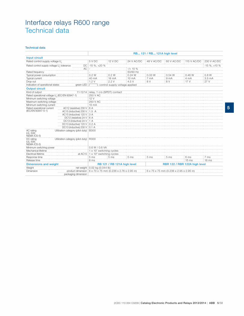
2CDC 110 004 C0209 | Catalog Electronic Products and Relays 2013/2014 | ABB 5/58
5
Interface relays R600 range
Technical data
Technical data
RB... 121 / RB... 121A high level
Input circuitRated control supply voltage U
s5 V DC 12 V DC 24 V AC/DC 48 V AC/DC 60 V AC/DC 115 V AC/DC 230 V AC/DC
Rated control supply voltage Us tolerance DC -15 %, +20 % -15 %, +10 %
AC - -/+ 10 %
Rated frequency - 50/60 Hz
Typical power consumption 0.2 W 0.2 W 0.24 W 0.33 W 0.54 W 0.46 W 0.8 W
Typical current 40 mA 16 mA 10 mA 7 mA 9 mA 4 mA 3.5 mA
Drop-out 1.2 V 2.2 V 4.5 V 8 V 8 V 17 V 27 V
Indication of operational states green LED V: control supply voltage applied
Output circuitKind of output 11-12/14 relay, 1 c/o (SPDT) contact
Rated operational voltage Ue (IEC/EN 60947-1) 250 V AC
Minimum switching voltage 12 V
Maximum switching voltage 250 V AC
Minimum switching current 10 mA
Rated operational current (IEC/EN 60947-5-1)
AC12 (resistive) 230 V 6 A
AC15 (inductive) 230 V A
AC15 (inductive) 120 V 3 A
DC12 (resistive) 24 V 6 A
DC13 (inductive) 24 V 1 A
DC13 (inductive) 120 V 0.2 A
DC13 (inductive) 230 V 0.1 A
AC rating (UL 508; NEMA ICS-5)
Utilization category (pilot duty) B300
DC rating (UL 508; NEMA ICS-5)
Utilization category (pilot duty) R300
Minimum switching power 0.6 W / 0.6 VA
Mechanical lifetime 1 x 10⁷ switching cycles
Electrical lifetime at AC15 1 x 10⁵ switching cycles
Response time 5 ms 5 ms 5 ms 5 ms 5 ms 6 ms 7 ms
Release time 8 ms 15 ms 16 ms
Dimensions and weight RB 121 / RB 121A high level RBR 122 / RBR 122A high levelWeight net weight 0.02 kg (0.044 lb)
Dimension product dimension 6 x 70 x 75 mm (0.236 x 2.76 x 2.95 in) 6 x 75 x 75 mm (0.236 x 2.95 x 2.95 in)
packaging dimension
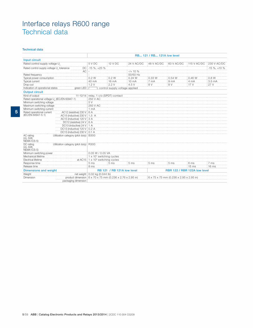
5/59 ABB | Catalog Electronic Products and Relays 2013/2014 | 2CDC 110 004 C0209
5
Interface relays R600 range
Technical data
Technical data
RB... 121 / RB... 121A low level
Input circuitRated control supply voltage U
s5 V DC 12 V DC 24 V AC/DC 48 V AC/DC 60 V AC/DC 115 V AC/DC 230 V AC/DC
Rated control supply voltage Us tolerance DC -15 %, +20 % -15 %, +10 %
AC - -/+ 10 %
Rated frequency - 50/60 Hz
Typical power consumption 0.2 W 0.2 W 0.24 W 0.33 W 0.54 W 0.46 W 0.8 W
Typical current 40 mA 16 mA 10 mA 7 mA 9 mA 4 mA 3.5 mA
Drop-out 1.2 V 2.2 V 4.5 V 8 V 8 V 17 V 27 V
Indication of operational states green LED V: control supply voltage applied
Output circuitKind of output 11-12/14 relay, 1 c/o (SPDT) contact
Rated operational voltage Ue (IEC/EN 60947-1) 250 V AC
Minimum switching voltage 5 V
Maximum switching voltage 250 V AC
Minimum switching current 1 mA
Rated operational current (IEC/EN 60947-5-1)
AC12 (resistive) 230 V 6 A
AC15 (inductive) 230 V A
AC15 (inductive) 120 V 3 A
DC12 (resistive) 24 V 6 A
DC13 (inductive) 24 V 1 A
DC13 (inductive) 120 V 0.2 A
DC13 (inductive) 230 V 0.1 A
AC rating (UL 508; NEMA ICS-5)
Utilization category (pilot duty) B300
DC rating (UL 508; NEMA ICS-5)
Utilization category (pilot duty) R300
Minimum switching power 0.05 W / 0.05 VA
Mechanical lifetime 1 x 10⁷ switching cycles
Electrical lifetime at AC15 1 x 10⁵ switching cycles
Response time 5 ms 5 ms 5 ms 5 ms 5 ms 6 ms 7 ms
Release time 8 ms 15 ms 16 ms
Dimensions and weight RB 121 / RB 121A low level RBR 122 / RBR 122A low levelWeight net weight 0.02 kg (0.044 lb)
Dimension product dimension 6 x 70 x 75 mm (0.236 x 2.76 x 2.95 in) 6 x 75 x 75 mm (0.236 x 2.95 x 2.95 in)
packaging dimension
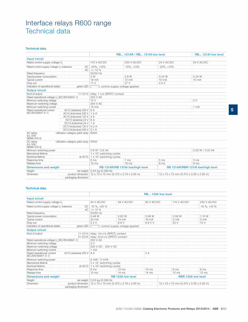
2CDC 110 004 C0209 | Catalog Electronic Products and Relays 2013/2014 | ABB 5/60
5
Interface relays R600 range
Technical data
Technical data
RB... 121AR / RB... 121AI low level RB... 121AI low level
Input circuitRated control supply voltage U
s115 V AC/DC 230 V AC/DC 24 V AC/DC 24 V AC/DC
Rated control supply voltage Us tolerance DC -20%, +15% -10%, +15% -20%, +15%
AC -/+ 10 %
Rated frequency 50/60 Hz
Typical power consumption 2 W 2.8 W 0.24 W 0.24 W
Typical current 18 mA 12 mA 10 mA 10 mA
Drop-out 17 V 27 V 4.5 V
Indication of operational states green LED V: control supply voltage applied
Output circuitKind of output 11-12/14 relay, 1 c/o (SPDT) contact
Rated operational voltage Ue (IEC/EN 60947-1) 250 V AC
Minimum switching voltage 12 V 5 V
Maximum switching voltage 250 V AC
Minimum switching current 10 mA 1 mA
Rated operational current (IEC/EN 60947-5-1)
AC12 (resistive) 230 V 6 A
AC15 (inductive) 230 V A
AC15 (inductive) 120 V 3 A
DC12 (resistive) 24 V 6 A
DC13 (inductive) 24 V 1 A
DC13 (inductive) 120 V 0.2 A
DC13 (inductive) 230 V 0.1 A
AC rating (UL 508; NEMA ICS-5)
Utilization category (pilot duty) B300
DC rating (UL 508; NEMA ICS-5)
Utilization category (pilot duty) R300
Minimum switching power 0.6 W / 0.6 VA 0.05 W / 0.05 VA
Mechanical lifetime 1 x 10⁷ switching cycles
Electrical lifetime at AC15 1 x 10⁵ switching cycles
Response time 6 ms 7 ms 5 ms 5 ms
Release time 15 ms 16 ms 8 ms 8 ms
Dimensions and weight RB 121AR/RB 121AI low/high level RB 121AR/RBR 121AI low/high levelWeight net weight 0.03 kg (0.066 lb)
Dimension product dimension 12 x 70 x 75 mm (0.472 x 2.76 x 2.95 in) 12 x 75 x 75 mm (0.472 x 2.95 x 2.95 in)
packaging dimension
Technical data
RB... 122A low level
Input circuitRated control supply voltage U
s24 V AC/DC 48 V AC/DC 60 V AC/DC 115 V AC/DC 230 V AC/DC
Rated control supply voltage Us tolerance DC -15 %, +20 % -15 %, +10 %
AC -/+ 10 %
Rated frequency 50/60 Hz
Typical power consumption 0.48 W 0.62 W 0.96 W 0.58 W 1.15 W
Typical current 20 mA 13 mA 16 mA 5 mA 5 mA
Drop-out 5.4 V 8.8 V 8.8 V V 20 V 10 V
Indication of operational states green LED V: control supply voltage applied
Output circuitKind of output 11-12/14 relay, 1st c/o (SPDT) contact
21-22/24 relay, 2nd c/o (SPDT) contact
Rated operational voltage Ue (IEC/EN 60947-1) 250 V AC
Minimum switching voltage 5 V
Maximum switching voltage 250 V DC - 250 V AC
Minimum switching current 1 mA
Rated operational current (IEC/EN 60947-5-1)
AC12 (resistive) 230 V 8 A 5 A
Minimum switching power W / 5 VA
Mechanical lifetime x 107 switching cycles
Electrical lifetime at AC15 1 x 10⁵ switching cycles
Response time 6 ms 10 ms 10 ms 6 ms 6 ms
Release time 10 ms 14 ms 14 ms 15 ms 15 ms
Dimensions and weight RB 122A low level RBR 122A low levelWeight net weight 0.03 kg (0.066 lb)
Dimension product dimension 12 x 70 x 75 mm (0.472 x 2.76 x 2.95 in) 12 x 75 x 75 mm (0.472 x 2.95 x 2.95 in)
packaging dimension
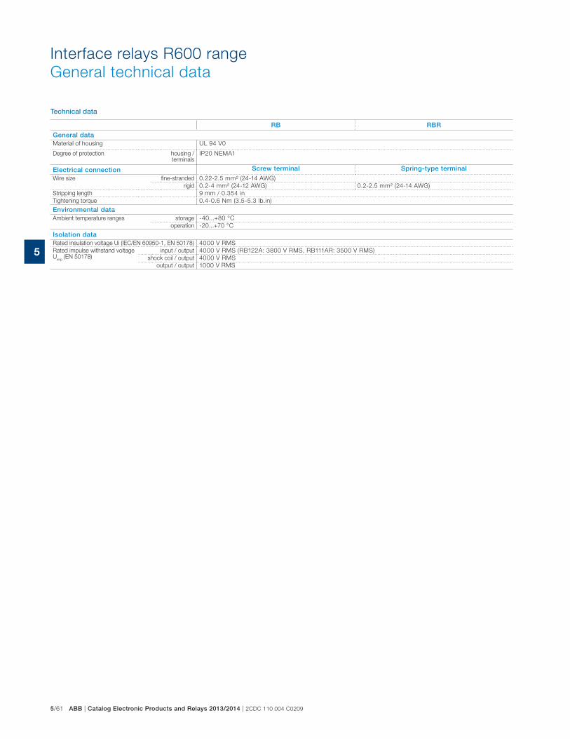
5/61 ABB | Catalog Electronic Products and Relays 2013/2014 | 2CDC 110 004 C0209
5
Technical data
RB RBR
General dataMaterial of housing UL 94 V0
Degree of protection housing / terminals
IP20 NEMA1
Electrical connection Screw terminal Spring-type terminalWire size fine-stranded 0.22-2.5 mm² (24-14 AWG)
rigid 0.2-4 mm² (24-12 AWG) 0.2-2.5 mm² (24-14 AWG)
Stripping length 9 mm / 0.354 in
Tightening torque 0.4-0.6 Nm (3.5-5.3 lb.in)
Environmental dataAmbient temperature ranges storage -40...+80 °C
operation -20...+70 °C
Isolation dataRated insulation voltage Ui (IEC/EN 60950-1, EN 50178) 4000 V RMS
Rated impulse withstand voltage U
imp (EN 50178)
input / output 4000 V RMS (RB122A: 3800 V RMS, RB111AR: 3500 V RMS)
shock coil / output 4000 V RMS
output / output 1000 V RMS
Interface relays R600 range
General technical data
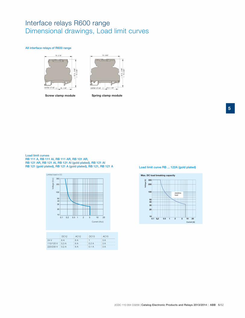
2CDC 110 004 C0209 | Catalog Electronic Products and Relays 2013/2014 | ABB 5/62
5
Interface relays R600 range
Dimensional drawings, Load limit curves
center of rail
Screw clamp module
center of rail
Spring clamp module
All interface relays of R600 range
Load limit curves RB 111 A, RB 111 AI, RB 111 AR, RB 101 AR, RB 121 AR, RB 121 AI, RB 121 AI (gold plated), RB 121 AI RB 121 (gold plated), RB 121 A (gold plated), RB 121, RB 121 A Load limit curve RB ... 122A (gold plated)
Current (Acc)
Vo
ltag
e (V
cc)
Limited load in CC
DC12 AC12 DC13 AC15
24 V 6 A 6 A 1 3 A
110/120 V 0,3 A 6 A 0.2 A 3 A
220/230 V 0.2 A 6 A 0.1 A 3 A
Current [A]
Volta
ge
[V]
resistive load
Max. DC load breaking capacity
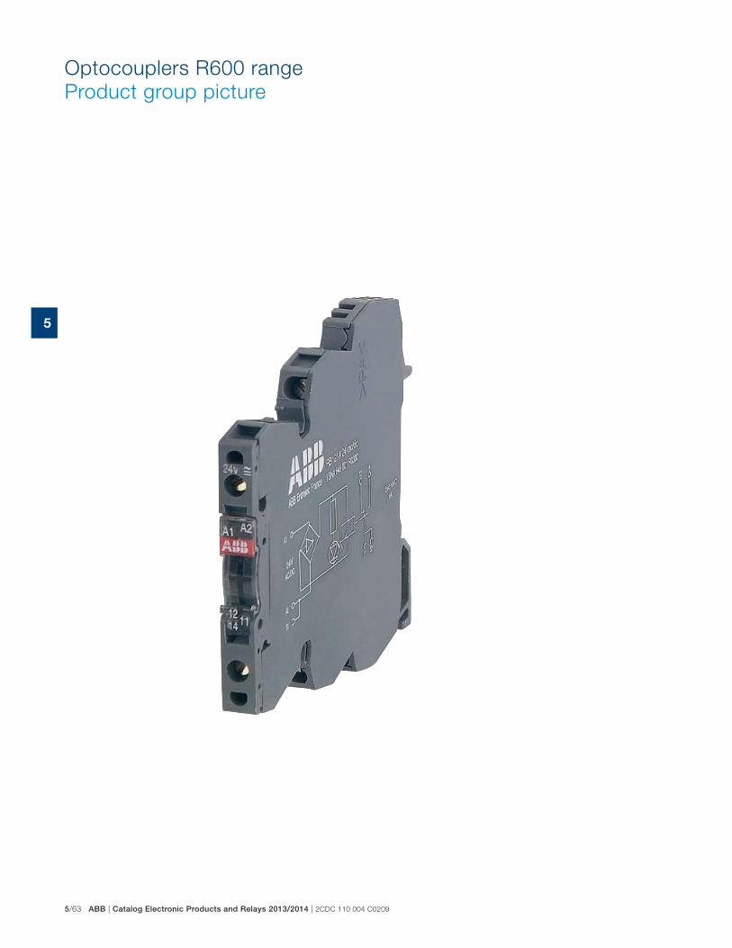
5/63 ABB | Catalog Electronic Products and Relays 2013/2014 | 2CDC 110 004 C0209
5
Optocouplers R600 range
Product group picture
2CDC 110 004 C0209 | Catalog Electronic Products and Relays 2013/2014 | ABB 5/64
5
Optocouplers R600 range
Table of contents
Optocouplers R600 range
Product group picture 5/63
Table of contents 5/64
Selection 5/65
Ordering details 5/67
Connection diagrams 5/68
Technical data 5/69
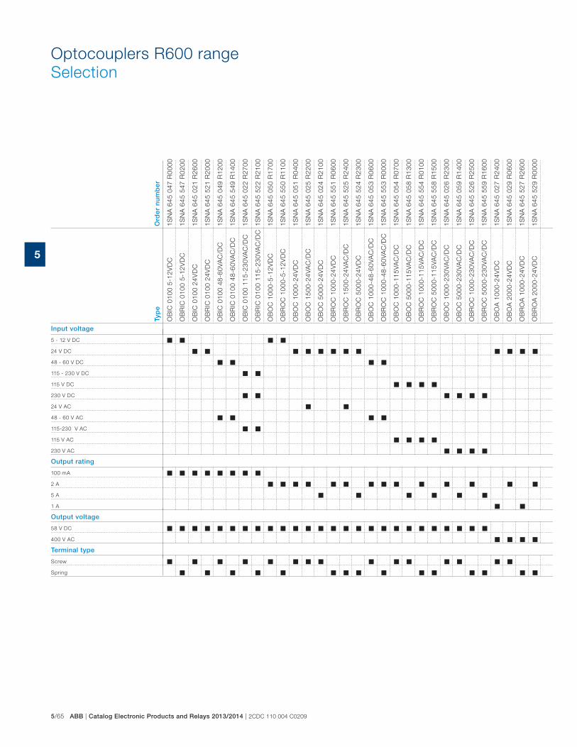
5/65 ABB | Catalog Electronic Products and Relays 2013/2014 | 2CDC 110 004 C0209
5
Optocouplers R600 range
Selection
Typ
e
OB
IC 0
100
5-12
VD
C
OB
RIC
010
0 5-
12V
DC
OB
IC 0
100
24V
DC
OB
RIC
010
0 24
VD
C
OB
IC 0
100
48-6
0VA
C/D
C
OB
RIC
010
0 48
-60V
AC
/DC
OB
IC 0
100
115-
230V
AC
/DC
OB
RIC
010
0 11
5-23
0VA
C/D
C
OB
OC
100
0-5-
12V
DC
OB
RO
C 1
000-
5-12
VD
C
OB
OC
100
0-24
VD
C
OB
OC
150
0-24
VAC
/DC
OB
OC
500
0-24
VD
C
OB
RO
C 1
000-
24V
DC
OB
RO
C 1
500-
24VA
C/D
C
OB
RO
C 5
000-
24V
DC
OB
OC
100
0-48
-60V
AC
/DC
OB
RO
C 1
000-
48-6
0VA
C/D
C
OB
OC
100
0-11
5VA
C/D
C
OB
OC
500
0-11
5VA
C/D
C
OB
RO
C 1
000-
115V
AC
/DC
OB
RO
C 5
000-
115V
AC
/DC
OB
OC
100
0-23
0VA
C/D
C
OB
OC
500
0-23
0VA
C/D
C
OB
RO
C 1
000-
230V
AC
/DC
OB
RO
C 5
000-
230V
AC
/DC
OB
OA
100
0-24
VD
C
OB
OA
200
0-24
VD
C
OB
RO
A 1
000-
24V
DC
OB
RO
A 2
000-
24V
DC
Ord
er n
um
ber
1SN
A 6
45 0
47 R
0000
1SN
A 6
45 5
47 R
0200
1SN
A 6
45 0
21 R
2600
1SN
A 6
45 5
21 R
2000
1SN
A 6
45 0
49 R
1200
1SN
A 6
45 5
49 R
1400
1SN
A 6
45 0
22 R
2700
1SN
A 6
45 5
22 R
2100
1SN
A 6
45 0
50 R
1700
1SN
A 6
45 5
50 R
1100
1SN
A 6
45 0
51 R
0400
1SN
A 6
45 0
25 R
2200
1SN
A 6
45 0
24 R
2100
1SN
A 6
45 5
51 R
0600
1SN
A 6
45 5
25 R
2400
1SN
A 6
45 5
24 R
2300
1SN
A 6
45 0
53 R
0600
1SN
A 6
45 5
53 R
0000
1SN
A 6
45 0
54 R
0700
1SN
A 6
45 0
58 R
1300
1SN
A 6
45 5
54 R
0100
1SN
A 6
45 5
58 R
1500
1SN
A 6
45 0
26 R
2300
1SN
A 6
45 0
59 R
1400
1SN
A 6
45 5
26 R
2500
1SN
A 6
45 5
59 R
1600
1SN
A 6
45 0
27 R
2400
1SN
A 6
45 0
29 R
0600
1SN
A 6
45 5
27 R
2600
1SN
A 6
45 5
29 R
0000
Input voltage
5 - 12 V DC
24 V DC
48 - 60 V DC
115 - 230 V DC
115 V DC
230 V DC
24 V AC
48 - 60 V AC
115-230 V AC
115 V AC
230 V AC
Output rating
100 mA
2 A
5 A
1 A
Output voltage
58 V DC
400 V AC
Terminal type
Screw
Spring
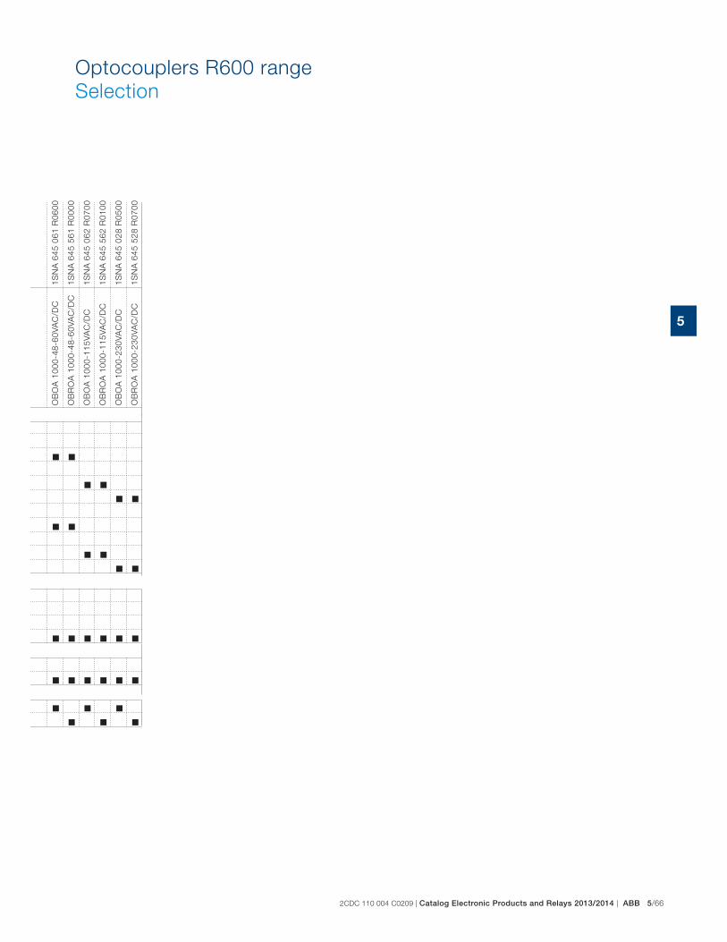
2CDC 110 004 C0209 | Catalog Electronic Products and Relays 2013/2014 | ABB 5/66
5
Optocouplers R600 range
Selection
OB
OA
100
0-48
-60V
AC
/DC
OB
RO
A 1
000-
48-6
0VA
C/D
C
OB
OA
100
0-11
5VA
C/D
C
OB
RO
A 1
000-
115V
AC
/DC
OB
OA
100
0-23
0VA
C/D
C
OB
RO
A 1
000-
230V
AC
/DC
1SN
A 6
45 0
61 R
0600
1SN
A 6
45 5
61 R
0000
1SN
A 6
45 0
62 R
0700
1SN
A 6
45 5
62 R
0100
1SN
A 6
45 0
28 R
0500
1SN
A 6
45 5
28 R
0700
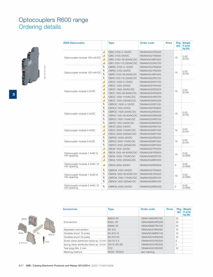
5/67 ABB | Catalog Electronic Products and Relays 2013/2014 | 2CDC 110 004 C0209
5
Optocouplers R600 range
Ordering details
R600 Optocoupler Type Order code Price Pkg
qty
Weight
(1 pce)
kg (lb)
Optocoupler module 100 mA/DC
OBIC 0100-5-12VDC 1SNA645047R0000
100.02 (0.44)
OBIC 0100-24VDC 1SNA645021R2600
OBIC 0100-48-60VAC/DC 1SNA645049R1200
OBIC 0100-115-230VAC/DC 1SNA645022R2700
Optocoupler module 100 mA/DC
OBRIC 0100-5-12VDC 1SNA645547R0200
100.02 (0.44)
OBRIC 0100-24VDC 1SNA645521R2000
OBRIC 0100-48-60VAC/DC 1SNA645549R1400
OBRIC 0100-115-230VAC/DC 1SNA645522R2100
Optocoupler module 2 A/DC
OBOC 1000-5-12VDC 1SNA645050R1700
100.02 (0.44)
OBOC 1000-24VDC 1SNA645051R0400
OBOC 1500-24VAC/DC 1SNA645025R2200
OBOC 1000-48-60VAC/DC 1SNA645053R0600
OBOC 1000-115VAC/DC 1SNA645054R0700
OBOC 1000-230VAC/DC 1SNA645026R2300
Optocoupler module 2 A/DC
OBROC 1000-5-12VDC 1SNA645550R1100
100.02 (0.44)
OBROC 1000-24VDC 1SNA645551R0600
OBROC 1500-24VAC/DC 1SNA645525R2400
OBROC 1000-48-60VAC/DC 1SNA645553R0000
OBROC 1000-115VAC/DC 1SNA645554R0100
OBROC 1000-230VAC/DC 1SNA645526R2500
Optocoupler module 5 A/DC
OBOC 5000-24VDC 1SNA645024R2100
100.02 (0.44)
OBOC 5000-115VAC/DC 1SNA645058R1300
OBOC 5000-230VAC/DC 1SNA645059R1400
Optocoupler module 5 A/DC
OBROC 5000-24VDC 1SNA645524R2300
100.02 (0.44)
OBROC 5000-115VAC/DC 1SNA645558R1500
OBROC 5000-230VAC/DC 1SNA645559R1600
Optocoupler module 1 A/AC 6 mm spacing
OBOA 1000-24VDC 1SNA645027R2400
100.03 (0.066)
OBOA 1000-48-60VAC/DC 1SNA645061R0600
OBOA 1000-115VAC/DC 1SNA645062R0700
OBOA 1000-230VAC/DC 1SNA645028R0500
Optocoupler module 2 A/AC 12 mm spacing
OBOA 2000-24VDC 1SNA645029R0600 50.03 (0.066)
Optocoupler module 1 A/AC 6 mm spacing
OBROA 1000-24VDC 1SNA645527R2600
100.03 (0.066)
OBROA 1000-48-60VAC/DC 1SNA645561R0000
OBROA 1000-115VAC/DC 1SNA645562R0100
OBROA 1000-230VAC/DC 1SNA645528R0700
Optocoupler module 2 A/AC 12 mm spacing
OBROA 2000-24VDC 1SNA645529R0000 50.03 (0.066)
Accessories Type Order code Price Pkg
qty
Weight
(1 pce)
kg (lb)
End section
BADH V0 1SNA116900R2700 50
BADL V0 1SNA399903R0200 50
BAM2 V0 1SNA399967R0100 50
Seperator end section SC 612 1SNA290474R0200 10
Divisible shunt 10 poles BJ 612-10 1SNA290488R0100 10
Divisible shunt 20 poles BJ 612-20 1SNA206754R0000 10
Screw clamp distribution block sp. 12 mm D4/12-3-3 1SNA645031R2000 5
Spring clamp distribution block sp. 12 mm D4/12-3R-3R 1SNA645531R2200 5
Test plug DIA. 2 mm FC2 1SNA645531R2200 10
Marking method RC65 / RC610 see marking
SC612BADL BJ...
FC2D 4/12-3...
BADH
2C
DC
291 0
01 F
0013
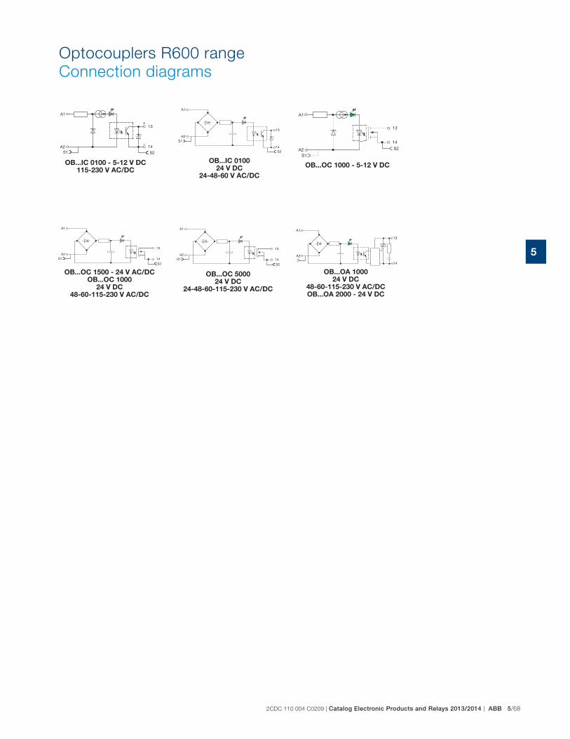
2CDC 110 004 C0209 | Catalog Electronic Products and Relays 2013/2014 | ABB 5/68
5
Optocouplers R600 range
Connection diagrams
OB...IC 0100 - 5-12 V DC115-230 V AC/DC
OB...IC 010024 V DC
24-48-60 V AC/DC
OB...OC 1000 - 5-12 V DC
OB...OC 1500 - 24 V AC/DC OB...OC 1000
24 V DC48-60-115-230 V AC/DC
OB...OC 500024 V DC
24-48-60-115-230 V AC/DC
OB...OA 100024 V DC
48-60-115-230 V AC/DC OB...OA 2000 - 24 V DC
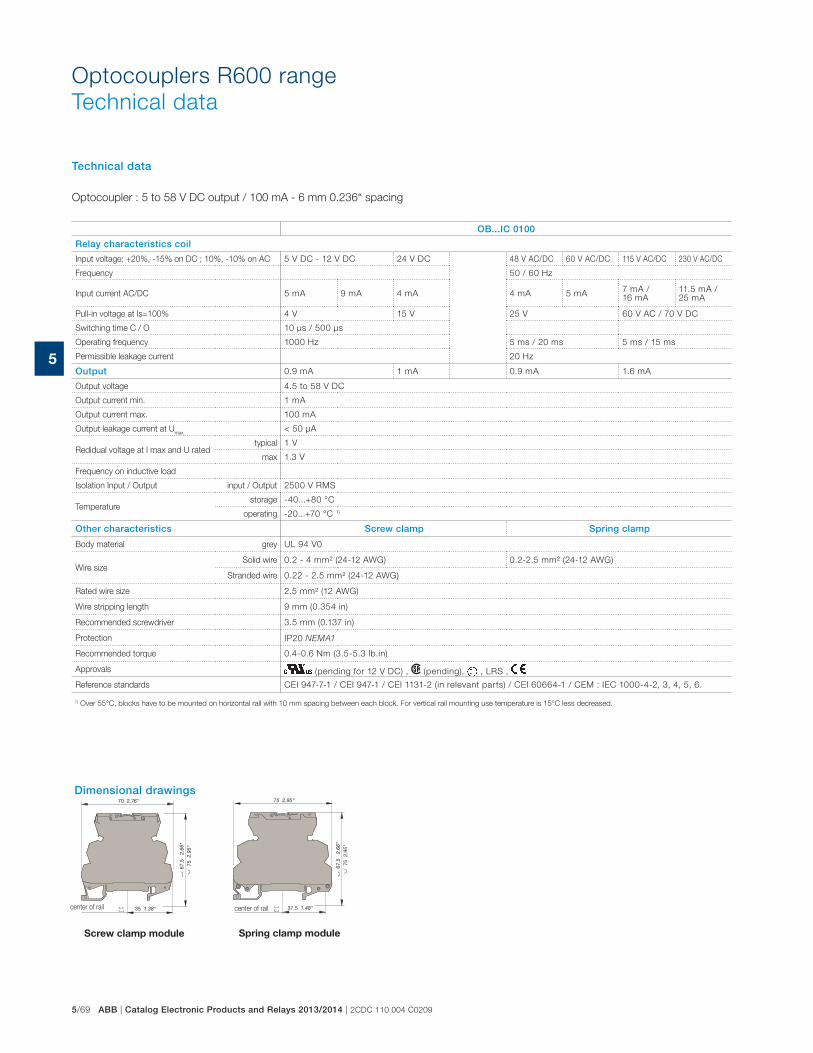
5/69 ABB | Catalog Electronic Products and Relays 2013/2014 | 2CDC 110 004 C0209
5
Optocouplers R600 range
Technical data
Technical data
Optocoupler : 5 to 58 V DC output / 100 mA - 6 mm 0.236“ spacing
OB...IC 0100
Relay characteristics coil
Input voltage: +20%, -15% on DC ; 10%, -10% on AC 5 V DC - 12 V DC 24 V DC 48 V AC/DC 60 V AC/DC 115 V AC/DC 230 V AC/DC
Frequency 50 / 60 Hz
Input current AC/DC 5 mA 9 mA 4 mA 4 mA 5 mA7 mA /16 mA
11.5 mA /25 mA
Pull-in voltage at Is=100% 4 V 15 V 25 V 60 V AC / 70 V DC
Switching time C / O 10 μs / 500 μs
Operating frequency 1000 Hz 5 ms / 20 ms 5 ms / 15 ms
Permissible leakage current 20 Hz
Output 0.9 mA 1 mA 0.9 mA 1.6 mA
Output voltage 4.5 to 58 V DC
Output current min. 1 mA
Output current max. 100 mA
Output leakage current at Umax.
< 50 μA
Redidual voltage at I max and U ratedtypical 1 V
max 1.3 V
Frequency on inductive load
Isolation Input / Output input / Output 2500 V RMS
Temperaturestorage -40...+80 °C
operating -20...+70 °C 1)
Other characteristics Screw clamp Spring clamp
Body material grey UL 94 V0
Wire sizeSolid wire 0.2 - 4 mm² (24-12 AWG) 0.2-2.5 mm² (24-12 AWG)
Stranded wire 0.22 - 2.5 mm² (24-12 AWG)
Rated wire size 2.5 mm² (12 AWG)
Wire stripping length 9 mm (0.354 in)
Recommended screwdriver 3.5 mm (0.137 in)
Protection IP20 NEMA1
Recommended torque 0.4-0.6 Nm (3.5-5.3 lb.in)
Approvals (pending for 12 V DC) , (pending), , LRS ,
Reference standards CEI 947-7-1 / CEI 947-1 / CEI 1131-2 (in relevant parts) / CEI 60664-1 / CEM : IEC 1000-4-2, 3, 4, 5, 6.
1) Over 55°C, blocks have to be mounted on horizontal rail with 10 mm spacing between each block. For vertical rail mounting use temperature is 15°C less decreased.
center of rail
Screw clamp module
center of rail
Spring clamp module
Dimensional drawings
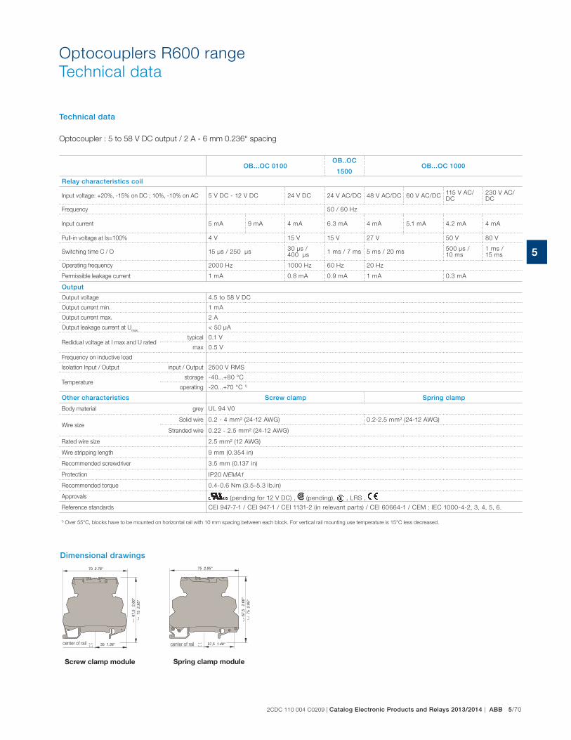
2CDC 110 004 C0209 | Catalog Electronic Products and Relays 2013/2014 | ABB 5/70
5
Technical data
Optocoupler : 5 to 58 V DC output / 2 A - 6 mm 0.236“ spacing
OB...OC 0100OB..OC
1500OB...OC 1000
Relay characteristics coil
Input voltage: +20%, -15% on DC ; 10%, -10% on AC 5 V DC - 12 V DC 24 V DC 24 V AC/DC 48 V AC/DC 60 V AC/DC115 V AC/DC
230 V AC/DC
Frequency 50 / 60 Hz
Input current 5 mA 9 mA 4 mA 6.3 mA 4 mA 5.1 mA 4.2 mA 4 mA
Pull-in voltage at Is=100% 4 V 15 V 15 V 27 V 50 V 80 V
Switching time C / O 15 μs / 250 μs30 μs / 400 μs
1 ms / 7 ms 5 ms / 20 ms500 μs / 10 ms
1 ms / 15 ms
Operating frequency 2000 Hz 1000 Hz 60 Hz 20 Hz
Permissible leakage current 1 mA 0.8 mA 0.9 mA 1 mA 0.3 mA
Output
Output voltage 4.5 to 58 V DC
Output current min. 1 mA
Output current max. 2 A
Output leakage current at Umax.
< 50 μA
Redidual voltage at I max and U ratedtypical 0.1 V
max 0.5 V
Frequency on inductive load
Isolation Input / Output input / Output 2500 V RMS
Temperaturestorage -40...+80 °C
operating -20...+70 °C 1)
Other characteristics Screw clamp Spring clamp
Body material grey UL 94 V0
Wire sizeSolid wire 0.2 - 4 mm² (24-12 AWG) 0.2-2.5 mm² (24-12 AWG)
Stranded wire 0.22 - 2.5 mm² (24-12 AWG)
Rated wire size 2.5 mm² (12 AWG)
Wire stripping length 9 mm (0.354 in)
Recommended screwdriver 3.5 mm (0.137 in)
Protection IP20 NEMA1
Recommended torque 0.4-0.6 Nm (3.5-5.3 lb.in)
Approvals (pending for 12 V DC) , (pending), , LRS ,
Reference standards CEI 947-7-1 / CEI 947-1 / CEI 1131-2 (in relevant parts) / CEI 60664-1 / CEM : IEC 1000-4-2, 3, 4, 5, 6.
1) Over 55°C, blocks have to be mounted on horizontal rail with 10 mm spacing between each block. For vertical rail mounting use temperature is 15°C less decreased.
center of rail
Screw clamp module
center of rail
Spring clamp module
Dimensional drawings
Optocouplers R600 range
Technical data
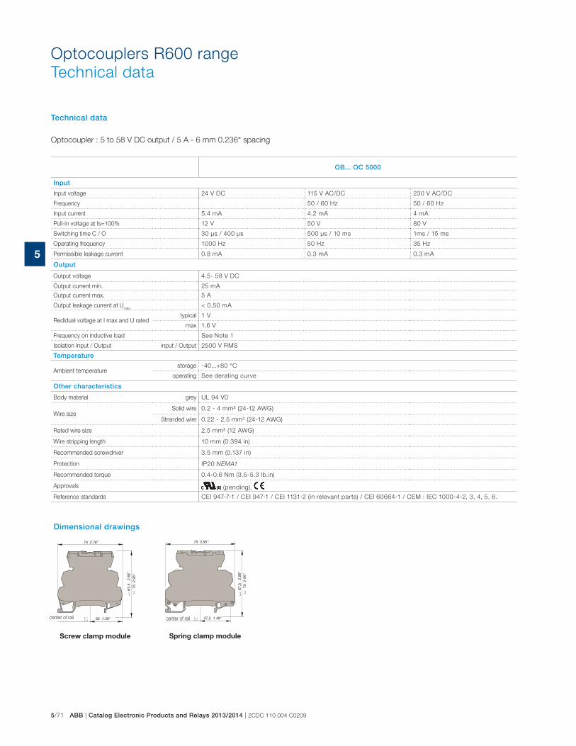
5/71 ABB | Catalog Electronic Products and Relays 2013/2014 | 2CDC 110 004 C0209
5
Optocouplers R600 range
Technical data
Technical data
Optocoupler : 5 to 58 V DC output / 5 A - 6 mm 0.236“ spacing
OB... OC 5000
Input
Input voltage 24 V DC 115 V AC/DC 230 V AC/DC
Frequency 50 / 60 Hz 50 / 60 Hz
Input current 5.4 mA 4.2 mA 4 mA
Pull-in voltage at Is=100% 12 V 50 V 80 V
Switching time C / O 30 μs / 400 μs 500 μs / 10 ms 1ms / 15 ms
Operating frequency 1000 Hz 50 Hz 35 Hz
Permissible leakage current 0.8 mA 0.3 mA 0.3 mA
Output
Output voltage 4.5- 58 V DC
Output current min. 25 mA
Output current max. 5 A
Output leakage current at Umax.
< 0.50 mA
Redidual voltage at I max and U ratedtypical 1 V
max 1.6 V
Frequency on inductive load See Note 1
Isolation Input / Output input / Output 2500 V RMS
Temperature
Ambient temperature storage -40...+80 °C
operating See derating curve
Other characteristics
Body material grey UL 94 V0
Wire sizeSolid wire 0.2 - 4 mm² (24-12 AWG)
Stranded wire 0.22 - 2.5 mm² (24-12 AWG)
Rated wire size 2.5 mm² (12 AWG)
Wire stripping length 10 mm (0.394 in)
Recommended screwdriver 3.5 mm (0.137 in)
Protection IP20 NEMA1
Recommended torque 0.4-0.6 Nm (3.5-5.3 lb.in)
Approvals (pending),
Reference standards CEI 947-7-1 / CEI 947-1 / CEI 1131-2 (in relevant parts) / CEI 60664-1 / CEM : IEC 1000-4-2, 3, 4, 5, 6.
Dimensional drawings
center of rail
Screw clamp module
center of rail
Spring clamp module

2CDC 110 004 C0209 | Catalog Electronic Products and Relays 2013/2014 | ABB 5/72
5
Optocouplers R600 range
Technical data
Technical data
Optocoupler : 24 to 400 V AC output / 2 A max. - 6 mm or 12 mm spacing
OB...OA 1000OB...OA
2000
Relay characteristics coil
Input voltage: +20%, -15% on DC ; 10%, -10% on AC 24 V DC 48 V AC/DC 60 V AC/DC 115 V AC/DC 230 V AC/DC 24 V DC
Frequency 50/60 Hz
Input current 3.6 mA 4.3 mA 5.5 mA 4.15 mA 4.6 mA 3.6 mA
Pull-in voltage at Is=100% 14 V 15 V 18 V 60 V 135 V 14 V
Switching time C / O 150 μs / 1 ms 3 ms / 30 ms 2.2 ms / 18 ms 2.5 ms / 25 ms150 μs / 1 ms
Operating frequency 500 Hz 20 Hz 25 Hz 20 Hz 500 Hz
Permissible leakage current 1 mA
Output
Output voltage 24-400 V AC
Frequency 50/60 Hz
Output current min. 25 mA
Output current max. 1 A 2 A
Output leakage current at Umax.
< 0.50 mA
Redidual voltage at I max and U ratedtypical 1 V
max 1.6 V
Frequency on inductive load
Isolation Input / Output input / Output 2500 V RMS
Temperaturestorage -40...+80 °C
operating -20...+70 °C 1)
Other characteristics Screw clamp Spring clamp
Body material grey UL 94 V0
Wire sizeSolid wire 0.2 - 4 mm² (24-12 AWG) 0.2-2.5 mm² (24-12 AWG)
Stranded wire 0.22 - 2.5 mm² (24-12 AWG)
Rated wire size 2.5 mm² (12 AWG)
Wire stripping length 9 mm (0.354 in)
Recommended screwdriver 3.5 mm (0.137 in)
Protection IP20 NEMA1
Recommended torque 0.4-0.6 Nm (3.5-5.3 lb.in)
Approvals (pending for 12 V DC) , (pending), , LRS ,
Reference standards CEI 947-7-1 / CEI 947-1 / CEI 1131-2 (in relevant parts) / CEI 60664-1 / CEM : IEC 1000-4-2, 3, 4, 5, 6.
1) Over 55°C, blocks have to be mounted on horizontal rail with 10 mm spacing between each block. For vertical rail mounting use temperature is 15°C less decreased.
Dimensional drawings
center of rail
Screw clamp module
center of rail
Spring clamp module

5/73 ABB | Catalog Electronic Products and Relays 2013/2014 | 2CDC 110 004 C0209
5
0,2-4 mm² 24-12 AWG
0,22-2,5 mm² 24-12 AWG
320 V 300 V
4 kV
3
6 A 6 A
2,5 mm² 12 AWG
10 mm / .394"
3,5 mm / .137"
0,4-0,6 Nm / 3,5-5,3 lb.in
IP 20 / NEMA1
IEC UL/CSA
D 2,5/5-MP
D 2,5/5-MP
1
2
3, 4, 5, 6,
7, 8, 9
10
1
4
5
6
2
3
RC 55R
0,2-4 mm² 24-12 AWG
0,22-2,5 mm² 24-12 AWG
320 V 300 V
4 kV
3
6 A 6 A
2,5 mm² 12 AWG
10 mm / .394"
3,5 mm / .137"
0,4-0,6 Nm / 3,5-5,3 lb.in
IP 20 / NEMA1
IEC UL/CSA
D 2,5/5-MP1
D 2,5/5-MP1
DCB (1)
FC2
BNMS T5V-1
BNMS T24V-1
BNMS T24V-2
BNMS T48V-1
BNMS T125V-1
BNMS T24V-1
BNMS T48V-1
BNMS T115V-1
BNMS T230V-1
BNMS F125mA-1
BNMS F500mA-1
BNMS F2A-1
BNMS F5A-1
BNMS F125mA-2
BNMS F2A-2
BNMS F5A-2
BNMS F2A-7
BNMS ST1
BNMS ST2
PCMS V0 (2)
RC 55
0,2-4 mm² 24-12 AWG
0,22-2,5 mm² 24-12 AWG
320 V 300 V
4 kV
3
6 A 6 A
2,5 mm² 12 AWG
10 mm / .394"
3,5 mm / .137"
0,4-0,6 Nm / 3,5-5,3 lb.in
IP 20 / NEMA1
IEC UL/CSA
D 2,5/5-MP-24VDC
D 2,5/5-MP-24VAC/DC
D 2,5/5-MP-48VAC/DC
D 2,5/5-MP-110VAC
D 2,5/5-MP-230VAC
D 2,5/5-MP...
DCB (1)
FC2
BNMS R24V-1
BNMS R24V-2
BNMS N24V-3
BNMS P24V-3
BNMS N24V-1
BNMS P24V-1
BNMS N24V-2
BNMS P24V-2
BNMS A24V-4
BNMS F125mA-1
BNMS F500mA-1
BNMS F2A-1
BNMS F5A-1
BNMS F125mA-2
BNMS F2A-2
BNMS F5A-2
BNMS F125mA-3
BNMS F125mA-4
BNMS ST1
PCMS V0 (2)
RC 55
1
4
5
6
2
3
1
4
5
6
2
3
Type Part numbers
Characteristics
Rated
Rated / GaugeWire size
Current
Wire size
Accessories
Compression Solid wire
clamp Stranded wire
Rated
Pulse
Pollution degree
Voltage
Grey V0
Wire stripping length
Recommended screwdriver
Recommended torque
Protection
Observations
Terminal blocks are delivered without plugs.
Max. working temperature
version without LED : 100°C
version with LED : 85°C
Contact resistance : < 5 m
Spacing 5,08 mm (.200")
blue
DIA. 2
beige
beige
red
red
red
red
red
red
black
red
red
red
red
red
red
red
red
grey
grey
grey
grey
grey
grey
grey
grey
grey
grey
grey
grey
grey
grey
grey
pending
(1) Solely on the top stage. (2) Comb type jumper bar from 2 to 22 poles, see accessories.
center of rail
Order plugs separately
Terminal blocks component holderBase for pluggable plug
R500 Series
DIN 3
End stop th. 9 mm BADL V0
End stop th. 9,1 mm BAM V2
End stop th. 9,1 mm BAM V0 V0
Rail 35 x 7,5 x 1 PR3.Z2
Rail 35 x 15 x 2,3 PR4
Rail 35 x 15 x 1,5 PR5
Type Part numbers
Grey V0
Spacing 5,08 mm (.200")
pending
blue
DIA. 2
white
white
white
white
white
yellow
yellow
yellow
yellow
grey
grey
grey
grey
grey
grey
grey
grey
grey
grey
Order plugs separately
Type Part numbers
Grey V0
Spacing 5,08 mm (.200")
pending
blue
DIA. 2
beige
beige
red
red
red
red
red
red
black
grey
grey
grey
grey
grey
grey
grey
grey
grey
grey
Order plugs separately
Relay/opto. base without output LED Relay/opto. base without input LED Relay/opto. base with output LED
center of rail center of rail
1SNA607224R0100
1SNA105028R2100
1SNA007865R2600
1SNA031820R1400
1SNA031847R1300
1SNA031807R1400
1SNA031810R1200
1SNA031813R0100
1SNA031815R0300
1SNA031817R0500
1SNA031819R1700
1SNA031839R1300
1SNA031806R1300
1SNA031809R2600
1SNA031808R2500
1SNA031811R0700
1SNA031812R0000
1SNA031814R0200
1SNA031816R0400
1SNA031818R1600
1SNA031821R0100
1SNA031838R1200
1SNA031822R0200
1SNA031823R0300
1SNA031824R0400
1SNA031825R0500
1SNA031826R0600
1SNA031827R0700
1SNA031828R1000
1SNA031849R2500
1SNA031829R1100
1SNA031830R1600
1SNA031832R0400
1SNA031832R0400
1SNA031833R0500
1SNA031833R0500
1SNA205523R2200
1SNA 399 903 R0200
1SNA 103 002 R2600
1SNA 199 306 R0300
1SNA 174 300 R1700
1SNA 168 500 R1200
1SNA 168 700 R2200
1SNA607223R0000
1SNA105028R2100
1SNA007865R2600
1SNA031831R0300
1SNA031848R2400
1SNA031800R2100
1SNA031801R1600
1SNA031845R1100
1SNA031802R1700
1SNA031803R1000
1SNA031804R1100
1SNA031805R1200
1SNA031821R0100
1SNA031838R1200
1SNA031822R0200
1SNA031823R0300
1SNA031824R0400
1SNA031825R0500
1SNA031826R0600
1SNA031849R2500
1SNA031829R1100
1SNA031830R1600
1SNA205523R2200
1SNA607222R0700
1SNA607260R2100
1SNA607261R1600
1SNA607266R1300
1SNA607267R1400
1SNA105028R2100
1SNA007865R2600
1SNA031820R1400
1SNA031847R1300
1SNA031807R1400
1SNA031810R1200
1SNA031813R0100
1SNA031815R0300
1SNA031817R0500
1SNA031819R1700
1SNA031839R1300
1SNA031821R0100
1SNA031838R1200
1SNA031822R0200
1SNA031823R0300
1SNA031824R0400
1SNA031825R0500
1SNA031826R0600
1SNA031827R0700
1SNA031828R1000
1SNA031829R1100
1SNA 205523R2200
Type Part numbers Type Part numbers Type Part numbers
DCB (1)
FC2
BNMS R24V-1
BNMS R24V-2
BNMS N24V-3
BNMS P24V-3
BNMS N24V-1
BNMS P24V-1
BNMS N24V-2
BNMS P24V-2
BNMS A24V-4
BNMS N5V-3
BNMS P5V-3
BNMS N48V-3
BNMS P48V-3
BNMS N5V-1
BNMS P5V-1
BNMS N5V-2
BNMS P5V-2
BNMS F125mA-1
BNMS F500mA-1
BNMS F2A-1
BNMS F5A-1
BNMS F125mA-2
BNMS F2A-2
BNMS F5A-2
BNMS F125mA-3
BNMS F125mA-4
BNMS F2A-7
BNMS ST1
BNMS ST2
BNMS CAI/U-500
BNMS CAI/U-500
BNMS CAI/U-250
BNMS CAI/U-250
PCMS V0 (2)
1 Test device
2 Test plug
3 Relay plug 1 SPDT 10 mA/6 A
1 SPDT 1 mA/6 A
4 Input optocoupler plug 5 V DC
24 V DC
24 V DC
48 V DC
125 V DC
24 V AC
48 V AC
115 V AC
230 V AC
5 Output optocoupler 24 V DC/100 mA
plug 24 V DC/100 mA
24 V DC/2 A
24 V DC/2 A
24 V DC/1 A
24 V DC/1 A
24 V DC/1 A
5 Output optocoupler 5 V DC/100 mA
plug 5 V DC/100 mA
48 V DC/100 mA
48 V DC/100 mA
5 V DC/2 A
5 V DC/2 A
5 V DC/1 A
5 V DC/1 A
7 Fuse plug 125 V/125 mA
125 V/500 mA
125 V/2 A
125 V/5 A
250 V/125 mA
250 V/2 A
250 V/5 A
125 V/125 mA
250 V/125 mA
125 V/2 A
8 Strap plug
9 Converter plug 0-20 mA/0-10 V
4-20 mA/2-10 V
0-20 mA/0-5 V
4-20 mA/1-5 V
10 Comb type jumper bar 10 poles
R See section on marking

2CDC 110 004 C0209 | Catalog Electronic Products and Relays 2013/2014 | ABB 5/74
5
BNMS T5V-1 BNMS T24V-1 BNMS T48V-1
BNMS T24V-1 BNMS T48V-1 BNMS T115V-1
5 V DC 24 V DC 48 V DC
24 V AC 48 V AC 115 V AC 230 V AC
BNMS T230V-1
125 V DC
BNMS T125V-1
432 1 432 1
BNMS T24V-2
BNMS T24V-1 BNMS T24V-2
19,2 V to 27,6 V DC
5 mA
12 V DC
20 μs / 1,3 ms 10 μs / see curve 1
1 mA
58 V / 30 mA 58 V / 5 mA
2,3 V DC 0,3 V DC
2,7 V DC 0,5 V DC
TTL
2,5 kV
- 30°C to + 80°C
-20°C to + 55°C
Characteristics
Part number Type P/N Type P/N
Type P/N
Type P/N
Input optocoupler plugs
INPUT
Voltage
Max. current
Typical triggering threshol at Is = 100%
Switching time C/O
Leakage current
OUTPUT
Max. voltage. / Max. current
Residual voltage max. I and rated U standard
max.
Compatibility
Input / Ouput isolation
TEMPERATURE
Storage
Operating
Charateristics
Part number Type P/N Type P/NType P/N
INPUT
Voltage
Max. current
Typical triggering threshold at Is = 100%
Switching time C/O
Leakage current
OUPUT
Max. voltage / Max. current
Residual voltage max. I and rated U standard
max.
Input / Ouput isolation
TEMPERATURE
Storage
Operating
4,5 V to 5,5 V DC
6 mA
3,5 V
20 μs / 1,3 ms
58 V / 30 mA
2,3 V DC
2,7 V DC
2,5 kV
- 30°C to + 80°C
- 20°C to + 55°C
38,4 V to 55,2 V DC
4,1 mA
21 V DC
20 μs / 1,3 ms
0,8 mA
58 V / 30 mA
2,3 V DC
2,7 V DC
2,5 kV
- 30°C to + 80°C
- 20°C to + 55°C
20,4 V to 26,4 V AC
8,5 mA
13 V AC
6 ms / 10 ms
1 mA
58 V / 30 mA
2,3 V DC
2,7 V DC
2,5 kV
- 30°C to + 80°C
- 20°C to + 55°C
40,8 V to 52,8 V AC
4,5 mA
22 V AC
6 ms / 10 ms
1 mA
58 V / 30 mA
2,3 V
2,7 V
2,5 kV
- 30°C to + 80°C
- 20°C to + 55°C
98 V to 126,5 V AC
8 mA
50 V AC
6 ms / 10 ms
2 mA
58 V / 30 mA
2,3 V
2,7 V
2,5 kV
- 30°C to + 80°C
- 20°C to + 55°C
195,5 V to 253 V AC
7 mA
95 V AC
6 ms / 10 ms
2 mA
58 V / 30 mA
2,3 V
2,7 V
2,5 kV
- 30°C to + 80°C
- 20°C to + 55°C
Derating curveDerating curve
Type P/N
93,5 V to 140 V DC
3 mA
50 V DC
20 μs / 1,3 ms
58 V / 30 mA
2,3 V DC
2,7 V DC
2,5 kV
- 30°C to + 80°C
- 20°C to + 55°C
DC plugs AC plugs Switching time RL curve 1
for 24 V DC plugs only
Sw
itchin
g t
ime (μs)
Load resistance RL (k )
1SNA031831R0300
1SNA031800R2100
1SNA031801R1600
1SNA031802R1700
1SNA031803R1000
1SNA031804R1100
1SNA031805R1200
1SNA031845R1100
1SNA031848R2400
2C
DC
29
2 0
13
F0
01
3

5/75 ABB | Catalog Electronic Products and Relays 2013/2014 | 2CDC 110 004 C0209
5
BNMS N5V-3 BNMS N24V-3 BNMS N48V-3
BNMS N5V-2 BNMS N24V-2
N5V-3 P5V-3
BNMS P5V-3
N24V-3 P24V-3
BNMS P24V-3
N48V-3 P48V-3
BNMS P48V-3
N5V-2 P5V-2
BNMS P5V-2
N24V-2 P24V-2
BNMS P24V-2
I (mA)
� (°C)0
100
57 60
I (mA)
� (°C)0
100
57 60
I (mA)
� (°C)0
100
57 60
432 1 432 1 432 1 432 1 432 1 432 1
432 1 432 1 432 1 432 1
Characteristics
Transistor output optocoupler plugs
Type P/N Type P/N Type P/NPart numbers
Characteristics
MOS output optocoupler plugs
Type P/N Type P/NPart numbers
100 mA output optocoupler
24 V DC
1 A output optocoupler
5 V DC1 A output optocoupler
24 V DC
INPUT
Voltage
Max. current
Typical triggering threshold at Is=100%
Switching time C/O
Leakage current
OUTPUT
Max. voltage / Max. current
Residual voltage max. I and rated U
standard U
max.
Frequency on inductive load
Input / Output isolation
TEMPERATURE
Storage
Operating
100 mA output optocoupler 5 V DC
100 mA output optocoupler
48 V DC
4,5 V to 5,5 V DC
12,5 mA
3,5 V DC
20 μs / 250 μs
1 mA
58 V / See graphs
1 V DC
1,3 V DC
See Note 1
2,5 kV
- 30°C to + 80°C
- 20°C to + 60°C
20,4 V to 28,8 V DC
6,7 mA
10 V DC
50 μs / 350 μs
1 mA
58 V / See graphs
1 V DC
1,3 V DC
See Note 1
2,5 kV
- 30°C to + 80°C
- 20°C to + 60°C
Note 1 :
Fmax = (1-0,007 x Us) / (L x Is²)orFmax = (1-0,007 x Us) / (P x )
Us = Output voltage supplyIs = Output currentL = Inductive loadP = Load powerR = Load resistance
LR
INPUT
Voltage
Max. current
Typical triggering threshold at Is = 100 %
Switching time C/O
Leakage current
OUTPUT
Max. voltage / Max. current
Residual voltage max. I and rated U
standard U
max.
Frequency on inductive load
Input / Output isolation
TEMPERATURE
Storage
Operating
4,5 V to 5,5 V DC
8,5 mA
2,9 V DC
20 μs / 1,3 ms
1 mA
58 V / 100 mA
1 V DC
1,3 V DC
See Note 1
2,5 kV
- 30°C to + 80°C
- 20°C to + 60°C
20,4 V to 28,8 V DC
4,8 mA
16 V DC
20 μs / 1,3 ms
1 mA
58 V / 100 mA
1 V DC
1,3 V DC
See Note 1
2,5 kV
- 30°C to + 80°C
- 20°C to + 60°C
40,8 V to 57,6 V DC
3,9 mA
26 V DC
20 μs / 1,3 ms
1 mA
58 V / 100 mA
1 V DC
1,3 V DC
See Note 1
2,5 kV
- 30°C to + 80°C
- 20°C to + 60°C
Derating curve Derating curveDerating curve
Derating curve Derating curve
1SNA031806R1300 1SNA031807R1400 1SNA031808R2500
1SNA031816R0400 1SNA031817R0500
1SNA031809R2600 1SNA031810R1200 1SNA031811R0700
1SNA031818R1600 1SNA031819R1700
2C
DC
29
2 0
13
F0
01
32
CD
C 2
92
01
3 F
00
13

2CDC 110 004 C0209 | Catalog Electronic Products and Relays 2013/2014 | ABB 5/76
5
BNMS N5V-1 BNMS N24V-1
BNMS A24V-4
N5V-1 P5V-1
BNMS P5V-1
N24V-1 P24V-1
BNMS P24V-1
432 1
432 1 432 1 432 1 432 1
Characteristics
MOS output optocoupler plug
Type P/N Type P/NPart numbers
Characteristics
Triac output optocoupler plug
Type P/NPart numbers
2 A output optocoupler
24 V DC2 A output optocoupler
5 V DC
4,5 V to 5,5 V DC
12,5 mA
3,5 V DC
20 μs / 250 μs
1 mA
30 V DC / See graphs
1 V DC
1,3 V DC
See Note 2
2,5 kV
- 30°C to + 80°C
- 20°C to + 60°C
20,4 V to 28,8 V DC
6,7 mA
10 V DC
50 μs / 350 μs
1 mA
30 V / See graphs
1 V DC
1,3 V DC
See Note 2
2,5 kV
- 30°C to + 80°C
- 20°C to + 60°C
Note 2 :
Fmax = (1 - 0,012 x Us) / (L x Is²)orFmax = (1 - 0,012 x Us) / (P x )
Us = Output voltage supplyIs = Output currentL = Inductive loadP = Load powerR = Load resistance
LR
Derating curve Derating curve
INPUT
Voltage
Max. current
Typical triggering threshold
Switching time C/O
Leakage current
OUTPUT
Max. voltage / Max. current
Residual voltage max. I and rated U
standard U
max.
Input / Output isolation
TEMPERATURE
Storage
Operating
20,4 V to 28,8 V DC
3,8 mA
10 V DC
9,5 ms / 12 ms
24 V to 253 V AC / See derating curve
1 V AC
1,3 V AC
2,5 kV
- 30°C to + 80°C
- 20°C to + 70°C
1 A output optocoupler 24 V DC
Derating curve
1SNA031812R0000 1SNA031813R0100
1SNA031814R0200 1SNA031815R0300
1SNA031839R1300
INPUT
Voltage
Max. current
Typical triggering threshold
Switching time C/O
Leakage current
OUTPUT
Max. voltage / Max. current
Residual voltage max. I and rated U
standard U
max.
Frequency on inductive load
Input / Output isolation
TEMPERATURE
Storage
Operating
2C
DC
29
2 0
13
F0
01
32
CD
C 2
92
01
3 F
00
13

5/77 ABB | Catalog Electronic Products and Relays 2013/2014 | 2CDC 110 004 C0209
5
BNMS F125mA-1
BNMS F500mA-1
BNMS F2A-1
BNMS F5A-1
BNMS F125mA-2
BNMS F2A-2
BNMS F5A-2
BNMS F125mA-3
BNMS F125mA-4
BNMS ST1
BNMS ST2
BNMS ST1 BNMS ST2
125 V / 125 mA
125 V / 500 mA
125 V / 2 A
125 V / 5 A
250 V / 125 mA
250 V / 2 A
250 V / 5 A
125 V / 125 mA
250 V / 125 mA
42 1 5 12 4 12 12 3
BNMS R24V-1
R24V-1
624 V DC
2
I(A)
Θ(°C)0 10 20 30 40 44 52 55
Current (Acc)
Voltage (V
cc)
DC12 AC12 DC13 AC15
24 V 6 A 6 A 1 A 3 A
110/120 V 0,3 A 6 A 0,2 A 3 A
220/230 V 0,2 A 6 A 0,1 A 3 A
BNMS CA I/U-250
250
0,35 W
0,1 %
25 ppm
BNMS CA I/U-500
500
0,35 W
0,1 %
25 ppm
1432 5
432 1 432 1
BNMS R24V-2
BNMS R24V-1 BNMS R24V-2
Fuse and strap plugs
Type P/N Type P/N Type P/NPart numbers
Output fuse plug Input fuse plug Strap plug
Characteristics
Part numbers
Characteristics
Relay plugs
Type P/N
Part numbers
1 SPDT relay
Limited load in CC
Current (Acc)
Vo
ltag
e (V
cc)
Derating curve
COIL
Voltage
Current max.
Trip voltage
CONTACT
Type
Voltage mini. / max.
Switching current mini. / max.
Switching current AC1 mini. / max.
DC1 mini. / max.
Number of operations on load
Number of operations off load
Operating speed C/O
Bounce
Isolation Coil / Contact
Resistance to shock waves Coil / Contact
Isolation Contact / Contact
TEMPERATURE
Storage
Operating
Analogical plugs
Type P/N
Resistance
Power
Accuracy
Stability
Type P/N
Current / Voltage Converter
Plug with 250 accuracy resistance for
analogical signals.
Current / Voltage Converter
Plug with 500 accuracy resistance for
analogical signals.
20,4 V to 28,8 V DC
7 mA
1,2 V
1 SPDT
12 V / 250 V 5 V / 250 V
10 mA / 6 A 1 mA / 6 A
0,6 VA/1500 VA (resistance) 0,05 VA/1500 VA (resistance)
0,6 W / 140 W 0,05 W / 140 W
105 operations for AC15
10x106 operations
6 ms / 8 ms
1,5 ms
4 kV
4 kV
1 kV
- 40°C to + 80°C
- 20°C to + 55°C
1SNA031821R0100
1SNA031838R1200
1SNA031822R0200
1SNA031823R0300
1SNA031824R0400
1SNA031825R0500
1SNA031826R0600
1SNA031827R0700
1SNA031828R1000
1SNA031829R1100
1SNA031830R1600
1SNA031820R1400
1SNA031832R0400 1SNA031833R0500
1SNA031847R1300
2C
DC
29
2 0
13
F0
01
32
CD
C 2
92
01
3 F
00
13
2C
DC
29
2 0
13
F0
01
3

2CDC 110 004 C0209 | Catalog Electronic Products and Relays 2013/2014 | ABB 5/78
5
BADL
BADL 9 mm 50
BAM2 V0 10 mm 50
BAM2 10 mm 50
BAM2 V0 10 mm 50
BAMH 9,1 mm 50
BAMH V0 9,1 mm 50
BADH 12 mm 50
BAM2
BAMH
BADH
PR30 2 m 1
PR3.Z2 2 m 1
PR3.G2 2 m 1
PR5 2 m 1
PR4 2 m 1
PR30PR3.Z2
PR3.G2PR5
PR4
FC2 FC2 10
BJ612-10 10
BJ612-20 10
BJ612-...
SC612 10SC612
D4/12-3-3 5
D4/12-3R-3R 5
D4/12-3...
2,5 mm²
4 mm²
4 mm²
4 mm²
BJ612-...
BJ612-...
2,5 mm²
End stops
Description Type Order P/N Packaging Weight
kg
End stop DIN 3
grey V0
End stop with screws DIN 3
grey V0
grey V2
beige V0
High end stop with screws DIN 1
and DIN 3 grey
beige V0
High end stop with screws DIN 3
grey
The end stops are mounted at the extremity of the terminal board assembly, giving additional support to the terminal blocks
as markers. For various types of marking, refer to the marker section.
Mounting rails
Symmetrical zinc bichromate plated
steel prepunched rail
Symmetrical zinc bichromate plated
steel rail
White, symmetrical passivated
galvanized steel rail
Symmetrical zinc bichromate plated
steel rail
Symmetrical zinc bichromate plated
steel rail
Test devices
Test plug DIA. 2 mm
Assembled jumper bar 10 poles - 24 A
Assembled jumper bar 20 poles - 24 A
Assembled jumper bar
This accessory permits electrical connection between 2 to 70 blocks with 6 mm spacing placed side by side.
It can be used with screw clamp or spring clamp blocks with 6 mm or 12 mm spacing.
Interconnection of blocks not placed side by side is possible if teeth of the jumper bar have been cut in front
of the blocks not to be connected. These teeth can be removed using pliers.
Use of separator end sections before and after the jumper bar is required to preserve IP20 protection of the
assembly.
Separator end section
Separator end section
Directly mounted on the rail beside the block, it permits to identify and make electrical insulation of product
groups using jumper bars. Dimensions are the same as screw clamp blocks : width 70 mm and height on rail
67,5 mm with 2 mm spacing.
Screw clamp distribution block sp. 12 mm
Spring clamp distribution block sp. 12 mm
Distribution module This terminal block with BJ612-... jumper bars permits
2 polarities distribution (PCL side and process side) thanks to
two separate circuits, each of them including :
- one 4 mm² input,
- two 2,5 mm² outputs
- one double output for jumper bar BJ612-...
It permits also the connection of ground to the rail though a 4
mm² input.
Rated voltage : 250 VAC-DC
Rated current : 32 A (4 mm²) - 16 A (2,5 mm²)
Recommended torque : 0,4 - 0,6 Nm
1SNA399903R0200
1SNA399967R0100
1SNA206351R1600
1SNA296351R0000
1SNA114836R0000
1SNA194836R0100
1SNA116900R2700
1SNA173220R0500
1SNA174300R1700
1SNA164800R0300
1SNA168700R2200
1SNA168500R1200
1SNA007865R2600
1SNA290488R0100
1SNA206754R0000
1SNA290474R0200
1SNA645031R2000
1SNA645531R2200

5/79 ABB | Catalog Electronic Products and Relays 2013/2014 | 2CDC 110 004 C0209
5
2
3
4
5
6
7
8
9
10
11
12
13
14
15
16
17
18
19
20
21
22
PCMS
DC
DCB
PC EIP
PC
1SNA113550R2000EIP
PC9 15 A 10 poles
BJS
BJ
EV6D
BJS9 32 A
BJS9 32 A
RL RLV
-55°C -> +110°C
IP20 / NEMA1
600 600
26 15
2,5 mm2 14 AWG
2,5 mm² 14 AWG 2,5 mm²
IEC CSA NFC VDE
4
2
1
3
1
4
3
2
AD 2,5RLV
RPEV
Accessories
Comb-type jumperThis accessory permits the electrical connection of
2 to 22 blocks.
No. Grey Red Blue Green/Yellow
of UL94V0 UL94V0 UL94V0 UL94V0
poles
Designed to hold RPEV label (see opposite).
PEF *
* Delivered with labels.
The label holders are removable and the labels can be changed easily.
For mounting on a PCB block in a 2 mm
diameter hole (no support leg).
PEFIdentification label holders
Sheets of 99 pre-cut labels
✓ Blank
RPEVLabel for PEF 29 x 6 mm
This patented device is mounted on the round
screwdriver opening. It is used for trouble shooting,
measuring and control for monitoring and repairing
an installation, on blocks without a test socket. For
this, the device receives an FC2 test plug.
The DC's are differentiated by their colour :
blue for MA 2,5/5 blocks
Test device on screw head Comb-type jumper bar
This accessory can be used only on the terminal blocks with at least
one compression clamp connection. It permits the electrical connec-
tion of 2 to 10 blocks.
Interconnection of non-consecutive blocks is possible by removing
the teeth opposite the blocks which must not be connected. The
comb-type jumper bars can be cut using pliers (or a saw) : in this case,
the use of an insulating tip EIP is recommended. The comb is placed
in the compression clamp before tightening the screws, above the
eventual conductor.
To be mounted on blocks series R900 and R910 :
Insulating tip for comb
Comb-type jumper bar
Subassembly
screw + washer + post
Perforated jumper bar
to be cut to length
Jumper bar not assembled
Jumper bar
To connect terminal blocks, place the metal tube into
the top center hole on each terminal block to be
connected.
The metal tube contacts the terminal block's internal
connector bar.
The perforated bar is cut to length and placed flat
along the center opening of the series of terminal blocks.
The screw is inserted into the perforated bar's hole which is located directly
above the blocks being connected. The screw goes through the threaded
metal tube and is screwed into the terminal block's internal connector bar.
This completes the electrical connection to the perforated bar and connects
the block.
To be mounted on blocks series R910 :
Screw + washer + post
Perforated jumper bar 8 poles
16 poles
Lengthwise marker
Lengthwise marker
Width 9 mm .354"
Large area for writing.
To be snapped onto the top of blocks.
Blank marker for writing :
For mounting on PCB in a 3,7 mm
diameter hole.
Characteristics
Wire size
mm² / AWG
Voltage V
Current A
Rated wire size mm² / AWG
Working temperature °C
Protection
Rigid
Flexible
IDC jumper(insulation displacement jumper)
Quick-jump lets you interconnect screw clamp terminals of different sizes, levels and all manufacturers
quickly and safely. Its insulation displacement technology makes it easy to use, fast, economical and does
not require a special tool. Use as a jumper between relays, switches and other electronic components.
ABB Quick-jump will fit any screw clamp type terminal block, from 6 mm .238" spacing and larger.
Adding a shunt in an installation :
1 - Insert ABB Quick-jump into your terminal screw clamp.
2 - Guide the terminal screw clamp into contact with the wire.
3 - Secure the wire by closing the Quick-jump lever with any flat nose
pliers.
4 - Tighten the terminal screw.
How to use : connecting Quick-jump to your terminal
1 - Insert ABB Quick-jump into your terminal screw clamp.
2 - Tighten the terminal screw.
3 - Guide jumper wire through the V-shaped opening in the Quick-jump.
4 - Secure the wire by closing the Quick-jump lever with any flat nose pliers.
Insulation displacement jumper
1SNA205491R2300 1SNA205492R2400 1SNA205493R2500 1SNA205494R2600
1SNA205495R2700 1SNA205496R2000 1SNA205497R2100 1SNA205498R0200
1SNA205499R0300 1SNA205500R1000 1SNA205501R0500 1SNA205502R0600
1SNA205503R0700 1SNA205504R0000 1SNA205505R0100 1SNA205506R0200
1SNA205507R0300 1SNA205508R1400 1SNA205509R1500 1SNA205510R0100
1SNA205511R2600 1SNA205512R2700 1SNA205513R2000 1SNA205514R2100
1SNA205515R2200 1SNA205516R2300 1SNA205517R2400 1SNA205518R0500
1SNA205519R0600 1SNA205520R0300 1SNA205521R2000 1SNA205522R2100
1SNA205523R2200 1SNA205524R2300 1SNA205525R2400 1SNA205526R2500
1SNA205527R2600 1SNA205528R0700 1SNA205529R0000 1SNA205530R0500
1SNA205531R2200 1SNA205532R2300 1SNA205533R2400 1SNA205534R2500
1SNA205535R2600 1SNA205536R2700 1SNA205537R2000 1SNA205538R0100
1SNA205539R0200 1SNA205540R1700 1SNA205541R0400 1SNA205542R0500
1SNA205543R0600 1SNA205544R0700 1SNA205545R0000 1SNA205546R0100
1SNA205547R0200 1SNA205548R1300 1SNA205549R1400 1SNA205550R1100
1SNA205551R0600 1SNA205552R0700 1SNA205553R0000 1SNA205554R0100
1SNA205555R0200 1SNA205556R0300 1SNA205557R0400 1SNA205558R1500
1SNA205559R1600 1SNA205560R1300 1SNA205561R0000 1SNA205562R0100
1SNA205563R0200 1SNA205564R0300 1SNA205565R0400 1SNA205566R0500
1SNA205567R0600 1SNA205568R1700 1SNA205569R1000 1SNA205570R1500
1SNA205571R0200 1SNA205572R0300 1SNA205573R0400 1SNA205574R0500
1SNA020568R0400
1SNA173178R0700
1SNA105028R2100
1SNA168400R1600
1SNA177583R1200
1SNA177584R1300
1SNA103849R0300 1SNA114205R2000
1SNA210160R1200

2CDC 110 004 C0209 | Catalog Electronic Products and Relays 2013/2014 | ABB 5/80
5
1
2
3
1
1
1
1
Marking for Interface Modules
Selection table
Remove one of the side bands of the card.
Separate the chosen strip from the rest
of the card.
Press the first marker in place, hold it and slide
your thomb on the rest of the strip.
Possible mounting : POSSIBLE
Recommended mounting :
Impossible mounting :
Marking kit RC 5 mm spacing or 6 mm spacing
Box with 100 cards with 18 various part numbers (see table next page)
Description Type Order P/N Packaging Weight
kg
Box with 100 cards RC 5 mm spacing
Refill for box RC 5 mm
Box with 100 cards RC 6 mm spacing
Refill for box RC 6 mm
Refilable box of 100 cards of 18 RC markers
Horizontal marking
Vertical marking
Marking for terminal blocks
Standard RC marker cards
Marker sizes RC55 RC65 RC610
Blank cards
Horizontal marking
10 strips from 1 to 10
10 strips from 11 to 20
10 strips from 21 to 30
10 strips from 31 to 40
10 strips from 41 to 50
10 strips from 51 to 60
10 strips from 61 to 70
From 1 to 100
From 101 to 200
20 times L1-L2-L3-N-PE
Vertical marking
10 strips from 1 to 10
10 strips from 11 to 20
10 strips from 21 to 30
10 strips from 31 to 40
From 1 to 100
(x) = Nb of cards (x) = Nb of cards (x) = Nb of cards
in 5 mm spacing kit in 6 mm spacing kit in 6 mm spacing kit
Markers for modules : RC610 RC55 RC65
R500
R600 POSSIBLE
R900
R910 POSSIBLE
R1800
1SNA400085R2700
1SNA400145R0700
1SNA400084R2600
1SNA400144R0600
1SNA230000R1200 1SNA232000R0000 1SNA233000R0100
1SNA230002R0000 (5) 1SNA232002R2600 (5) 1SNA233002R2700 (25)
1SNA230003R0100 (2) 1SNA232003R2700 (2) 1SNA233003R2000 (10)
1SNA230004R0200 1SNA232004R2000 1SNA233004R2100 (6)
1SNA230005R0300 1SNA232005R2100 1SNA233005R2200 (4)
1SNA230006R0400 1SNA232006R2200 1SNA233006R2300 (3)
1SNA230007R0500 1SNA232007R2300 1SNA233007R2400 (2)
1SNA230008R1600 1SNA232008R0400 1SNA233008R0500 (2)
1SNA230030R0700 (2) 1SNA232030R2500 (2) 1SNA233030R2600 (15)
1SNA230031R2400 1SNA232031R1200 1SNA233031R1300 (2)
1SNA230131R2500 1SNA232131R1300 1SNA233131R1400 (2)
1SNA230041R0600 1SNA232041R2400 1SNA233041R2500 (5)
1SNA230042R0700 1SNA232042R2500 1SNA233042R2600 (3)
1SNA230043R0000 1SNA232043R2600 1SNA233043R2700 (2)
1SNA230044R0100 1SNA232044R2700 1SNA233044R2000 (2)
1SNA230060R1500 1SNA232060R0300 1SNA233060R0400 (8)

6/1 ABB | Catalog Electronic Products and Relays 2013/2014 | 2CDC 110 004 C0209
6
Panel heaters
Product group picture

2CDC 110 004 C0209 | Catalog Electronic Products and Relays 2013/2014 | ABB 6/2
6
Panel heaters
Table of contents
Panel heaters
Product group picture 6/1
Table of contents 6/2
Benefits and advantages, heat demand calculation 6/3
Ordering details 6/4
Technical data 6/5
Dimensional drawings, Application note 6/7
Notes 6/8

6/3 ABB | Catalog Electronic Products and Relays 2013/2014 | 2CDC 110 004 C0209
6
Panel heaters
Benefits and advantages, heat demand calculation
Why do I need a panel heater?Whenever the ambient temperature around the control panel exceeds
the temperature inside the control panel, condensation may occur inside
the control panel. Humidity may be deposited as condensation water
on the devices and terminals in the control panel, leading to malfunction
and short circuits.
A simple solution is heating the inside of the control panel. This ensures
that the temperature inside the control panel is always a little bit higher
than the outside temperature, thus avoiding condensation.
To ensure that this does not happen to your control panel or subsidiary
distribution box in the winter, we recommend using panel heaters to pro-
tect your equipment from frost damages and to ensure the
trouble-free functioning of your systems.
ABB’s panel heaters are characterized by their flat structural form that
enables positive fastening at the control panel wall without disturbing
other devices. A mounting clip also enables DIN rail mounting.
Each panel heater includes overheating protection.
Fields of application � Anti-condensation
Avoidance of water condensation inside the control panel
(eg. in carpark ticket machines)
� Anti-frost
Avoidance of undercooling of systems and control panels inside
of free-standing distributors or mobile equipment.
Features � Flat structural form: only 3 mm thick
� Rated input power stages stages:
20 W, 40 W, 100 W, 200 W, 250 W, 300 W
� Voltages: 110 V or 230 V, 50/60 Hz
� Plate temperature fixed at +70 °C or +80 °C or adjustable
from +30 °C to +150 °C
� Long lifetime through low surface temperature (70 °C or 80 °C)
� Even heat distribution on the whole heating surface
� Good resistance against chemicals
� Isolation out of silicone rubber, continuous 180 °C, puncture-
proof until 12 kV/mm
� Bracket: anodized aluminium
� Connecting line: 0.5 m silicone rubber, 2 x 0.75 mm2
� The heating elements are tested in accordance to VDE 720,
CEE publication 11
� Lowest ambient temperature -40 °C
� Fastening: Snap on 35 mm top hat rail, optionally fastening with
M 4 screws or by bonding
� Separate thermostat for exact temperature control
Heat demand calculationThe calculation of the heat demand (watt) and the selection of the
appropriate heating plate depends on different factors such as:
� size of the control panel
� material of the control panel
� place of installation
� relative humidity
� power dissipation (self-heating) of the chassis-mounted units
� ventilation of the control panel
To aid installation, we have established the guideline values on the right.
Location case content indoors outdoors in litres heated unheated
up to 20 10 W 20 W 40 W
30 20 W 33 W 55 W
50 30 W 55 W 90 W
75 30 W 75 W 130 W
100 55 W 90 W 150 W
120 55 W 90 W 150 W
160 55 W 130 W 180 W
240 90 W 180 W 235 W
300 90 W 180 W 275 W
420 90 W 180 W 310 W
500 90 W 240 W 360 W
600 90 W 280 W 415 W
800 130 W 280 W 630 W
1000 130 W 280 W 810 W
1200 150 W 360 W 1300 W
The panel heaters have to be installed to provide sufficient heat dissipation

2CDC 110 004 C0209 | Catalog Electronic Products and Relays 2013/2014 | ABB 6/4
6
Panel heaters
Ordering details
Ordering details
Rated input power
Rated operationalvoltage
Plate tempe-rature
Cable length
Type Order code Price Pkg qty
Weight(1 pce)kg (lb)
20 W
230 V AC
max.
80 °C
0.5 m
20W-230V-HE GHV6000020V0006
1
0.10
(0.22)
40 W 40W-230V-HE GHV6000040V00060.25
(0.55)
100 W
max.
70 °C
100W-230V-HE GHV6000100V00060.30
(0.66)
200 W 200W-230V-HE GHV6000200V00060.50
(1.10)
300 W 300W-230V-HE GHV6000300V00060.50
(1.10)
40 W 110 V AC
70 °C
fixed0.5 m
40W-110V-HP GHV6000040V0004
1
0.13
(0.29)
40 W 230 V AC 40W-230V-HP GHV6010040V00060.13
(0.29)
100 W 110 V AC 100W-110V-HP GHV6010100V00040.37
(0.80)
100 W 230 V AC 100W-230V-HP GHV6010100V00060.37
(0.80)
250 W 110 V AC 250W-110V-HP GHV6010250V00040.58
(1.28)
250 W 230 V AC 250W-230V-HP GHV6010250V00060.54
(1.19)
40 W
230 V AC70 °C
fixed3 m
40W-230V-HP-E GHV6010040V0007 10.13
(0.29)
100 W100W-230V-
HP-EGHV6010100V0007 1
0.37
(0.80)
100 W 230 V AC adjustab-
le from
30-150
°C
-
100W-230V-HP-
ADJGHV6017100V0006
1
0.39
(0.85)
250 W 230 V AC250W-230V-HP-
ADJGHV6017250V0006
0.54
(1.19)
Ordering details - Accessories
Description Type Order code Price Pkg qty
Weight(1 pce)kg (lb)
Mounting clips for heating elements to snap on
DIN rail (Heating Power 20-100W)20-100W-MC GHV6000000V0001 1
0.01
(0.22)
Mounting clips for heating elements to snap on
DIN rail (Heating Power 200-300W)200-300W-MC GHV6000000V0002 1
0.02
(0.44)
Thermostat with rated operational voltage 230
V AC (Temperature adjustable from 10 to 60 °C)Thermostat GHV6011060V0001 1
0.25
(0.55)
2C
DC
31
1 0
01
F0
00
52
CD
C 3
11
01
2 F
00
05
2C
DC
31
1 0
10
F0
00
5
2C
DC
31
1 0
05
F0
00
52
CD
C 3
11
00
6 F
00
05
Heating element 20 W1)
Heating element 250 W1)
Heating plate 100 W1) adjustable
Mounting clips
Thermostat
1) Rated input power

6/5 ABB | Catalog Electronic Products and Relays 2013/2014 | 2CDC 110 004 C0209
6
Panel heaters
Technical data
Data at Ta = 25 °C and rated values, if noting else indicated.
Type 20W-230V-HE 40W-230V-HE 100W-230V-HE 200W-230V-HE 300W-230V-HE
Input circuit - supply circuit
Rated operational voltage 230 V AC
Operational voltage range 210-240 V AC/DC
Rated frequency 50/60 Hz
Frequency range DC; 47-63 Hz
Typical current /
power consumption
230 V AC 87 mA / 20 VA 170 mA / 40 VA 439 mA / 100 VA 870 mA / 200 VA 1300 mA / 300 VA
110 V AC - - - - -
Typical inrush current 87 mA 170 mA 430 mA 870 mA 1300 mA
Output circuit
Heating element silicone heating element
Bracket of the heating element anodized aluminium
Isolation of the heating element silicone
Maximum peak heating power1) 20 W 40 W 100 W 200 W 300 W
Maximum plate temperature 80 °C 70 °C
Plate temperature adjustable no
Power density 0.17 W/cm2 0.13 W/cm2 0.33 W/cm2 0.5 W/cm2
General data
Duty time 100 %
Mounting screw, bond, DIN rail (optional)
Degree of protection IP53
Electrical connection
Connecting line out of silicone rubber 2x0.75 mm2 (2x18 AWG)
Length of connecting line 0.5 m
Environmental data
Ambient
temperature range
operation -40...+20 °C -40...+40 °C
storage -60...+100 °C
transport -60...+100 °C
Standards
Product standard DIN EN 60335-1, DIN EN 60335-1 (VDE 0700-1):2007-02, EN 60335-1:2002+ A11+ A1+ A12+ Corr.+ A2:2006
Low Voltage Directive 2006/95/EC
1)Maximum peak heating power = Rated input power

2CDC 110 004 C0209 | Catalog Electronic Products and Relays 2013/2014 | ABB 6/6
6
Panel heaters
Technical data
Data at Ta = 25 °C and rated values, if noting else indicated.
Type 40W- 110V-
HP
40W- 230V-
HP
40W- 230V- HP-E
100W- 110V-
HP
100W- 230V-
HP
100W- 230V- HP-E
250W- 110V-
HP
250W- 230V-
HP
100W- 230V-
HP-ADJ
250W- 230V-
HP-ADJ
Input circuit - supply circuit
Rated operational voltage 110 V AC 230 V AC 110 V AC 230 V AC 110 V AC 230 V AC
Rated voltage range 105-
115 V AC210-240 V AC
105-
115 V AC210-240 V AC
105-
115 V AC210-240 V AC
Rated frequency 50/60 Hz
Frequency range 47-63 Hz
Typical current / power consumption
230 V AC-
170 mA /
40 VA-
430 mA /
100 VA-
1086 mA
/ 250 VA
430 mA /
100 VA
1086 mA
/ 250 VA
110 V AC 360 mA /
40 VA-
910 mA /
100 VA-
2270 mA
/ 250 VA-
Typical inrush current 360 mA 170 mA 910 mA 430 mA 2270 mA 1086 mA 430 mA 1086 mA
Output circuit
Heating element silicone heating element
Bracket of the heating element anodized aluminium
Isolation of the heating element silicone
Maximum peak heating power1) 40 W 100 W 250 W 100 W 250 W
Maximum plate temperature 70 °C 150 °C
Plate temperature adjustableno
yes,
+30...+150 °C
Power density0.33 W/cm2 0.42 W/cm2
0.33 W/
cm2
0.42 W/
cm2
General data
Duty time 100 %
Mounting screw, bond, DIN rail
Degree of protection IP53
Electrical connection
Connecting line out of silicone rubber 2x0.75 mm2 (2x18 AWG)
Length of connecting line 0.5 m
Environmental data
Ambient temperature range
operation -40...+40 °C
storage -60...+100 °C
transport -60...+100 °C
Standards
Product standard DIN EN 60335-1, DIN EN 60335-1 (VDE 0700-1):2007-02, EN 60335-1:2002+ A11+ A1+ A12+ Corr.+ A2:2006
Low Voltage Directive 2006/95/EC
1)Maximum peak heating power = Rated input power

6/7 ABB | Catalog Electronic Products and Relays 2013/2014 | 2CDC 110 004 C0209
6
Panel heaters
Dimensional drawings, Application note
AB
B_8
37
43
5
AB
B_8
37
43
4
Table of dimensions in mm
Dimensions
Application note
Dimensional drawing 1 Dimensional drawing 2
Type L L1 L2 B B1 B2 H H1 H2 Drawing no.
Heating elements for screw mounting, optionally DIN rail mounting with mounting clips
20W-230V-HE 150 134 65 80 64 32 2.5 10 - 2
40W-230V-HE 150 130 65 200 180 45 2.5 10 - 1
100W-230V-HE 150 130 65 200 180 45 2.5 10 - 1
200W-230V-HE 300 280 95 200 180 45 2.5 10 - 2
300W-230V-HE 300 280 95 200 180 45 2.5 10 - 2
Heating plates, temperature fixed, with mounting clip for DIN rail mounting
40W-110V-HP
40W-230V-HP
40W-230V-HP-E
150 134 65 80 64 32 2.5 10 - 2
100W-110V-HP
100W-230V-HP
100W-230V-HP-E
150 130 65 200 180 45 2.5 10 - 1
250W-110V-HP
250W-230V-HP300 280 85 200 180 45 2.5 10 - 2
Heating plates, temperature adjustable from 30 to 150 °C, with mounting clip for DIN rail mounting
100W-230V-HP-ADJ 150 130 65 200 180 45 2.5 10 50 1
250W-230V-HP-ADJ 300 280 85 200 180 45 2.5 10 50 2
The panel heaters regulate their surface temperature themselves. Depending on the environmental conditions and
the heat dissipation, the heating power could therefore be smaller than the electrical peak input power.

2CDC 110 004 C0209 | Catalog Electronic Products and Relays 2013/2014 | ABB 6/8
6
Panel heaters
Notes

7/1 ABB | Catalog Electronic Products and Relays 2013/2014 | 2CDC 110 004 C0209
7
Logic relays
Product group picture

2CDC 110 004 C0209 | Catalog Electronic Products and Relays 2013/2014 | ABB 7/2
7
Logic relays
Table of contents
Logic relays
Product group picture 7/1
Table of contents 7/2
System overview 7/3
Approvals and marks 7/5
Ordering details - Stand alone logic relays 7/6
Ordering details - Expandable logic relays 7/7
Ordering details 7/8
Ordering details - Display systems 7/9
Technical data 7/10
Dimensional drawings 7/24

7/3 ABB | Catalog Electronic Products and Relays 2013/2014 | 2CDC 110 004 C0209
7
Logic relays
System overview
1SV
C 1
10 0
00 F
055
4
S1 K1 S4
S5
K1 K2 T1
T1
T1
S6
Documentation (download from the internet)
Logic relay manual 1SVC 440 795 M0100
Remote display manual 1SVC 440 795 M2100
Display system manual 1SVC 440 795 M1100
Concept
CL range logic relays are suitable for small and medium-sized
control tasks and are able to substitute logic wiring in a quick and sim-
ple manner.
They can be used for applications in control as well as for timing func-
tions, e. g.
� in buildings, lighting systems, air-conditioning systems,
general control functions,
� in small machines and systems or
� as stand-alone control module for small applications.
Steps to the application of CL range
� CL range can be used easily, rapidly and comfortably without any
time-consuming planning and programming.
� The user can discover the advantages and the benefit of these logic
relays in no time at all.
� CL range provides for the control statements according to a
simple circuit diagram.
� Setup, storage, simulation and documentation are performed using
the compact and user-friendly CL-SOFT software
(CL-LAS.PS002).
Software characteristics (CL-SOFT)
� display on a PC monitor according to IEC, ANSI
� different languages to choose from
� easy installation on all Microsoft WindowsTM operating systems
Logic links instead of wiring
Technical Data overviewLogic relays
� 8 or 12 digital inputs
� 4 or 6 digital relay outputs
� optionally with 4 or 8 transistor outputs
� 128 rungs
� 3 contacts as n/o or n/c contacts in series plus 1 coil per rung
� optionally with 2 or 4 analog inputs (not 100-240 V AC version)
� power flow display for checking the circuit diagram (devices with
display)
� expansions for local or remote level
� enclosure color RAL 7035
� DIN rail mounting
Display system
� useable as compact HMI logic relay
� fully graphic, backlit display module
� 12 digital inputs
� 4 digital relay outputs
� optionally with 4 transistor outputs
� 256 rungs
� 4 contacts as n/o or n/c contacts in series plus 1 coil per rung
� optionally with 4 analog inputs (not 100-240 V AC version)
� networking-compatible via CL-NET
� front panel mounting
� expansion for local
Remote display
� Remote display up to a distance of 5 m
� Illustration of text and status displays
� Remote adjustment via keypad
� Front panel mounting
Software
� 16 timing relays 0.01-99:59 h
� 16 counting relays for up-, down counting
� 8 weekly timer, 8 annual timers
� 16 analog value comparators
� 16 freely editable display texts
� 32 markers or auxiliary relays

2CDC 110 004 C0209 | Catalog Electronic Products and Relays 2013/2014 | ABB 7/4
7
Logic relays
System overview
Power
98a
8b
3
4
6, 8b
5
71b1a
2 2
6, 8b
5
98a
8b
Power
2C
DC
31
2 0
01
F0
b0
8
1a Logic relay CL-LS..
1b Expandable logic relay CL-LM..
2 Power supply CP-D...
3 I/O expansion CL-LER.., CL-LET.. for logic relays CL-LM..
4 Coupler unit CL-LEC.. for remote expansion of logic relays CL-LM..
5 Memory module CL-LAS.MD003 for logic relays CL-LS.., CL-LM..
6 Connecting cable CL-LAS.TK001, CL-LAS.TK002 to connect PC
7 CL-LINK plug CL-LAS.TK011
to connect expansion to logic relays CL-LM..
8a Remote display connection module CL-LDC.S..
8b Connecting cable CL-LAD.TK007
to connect a remote displays to a logic relay
9 Display module CL-LDD..
Logic relays
Stand alone Expandable
2b
1
3
2a
5
4
2C
DC
31
2 0
37
F0
b0
7
Expansion of logic relays*
1 Logic relay CL-LM..
2 I/O expansion CL-LER.., CL-LET..
2a local expansion
2b remote expansion
3 Coupler unit CL-LEC.. for remote expansion of logic relays CL-LM..
4 CL-LINK plug CL-LAS.TK011 for expansion of logic relays CL-LM..
5 up to 30 m
* max. 1 expansion per logic relay
79
8
6
5
32
13
21
...4
4
CL-NET
10
2C
DC
31
2 0
25
F0
b0
6
1
2
3
2C
DC
31
2 0
27
F0
b0
6
32
1
32
1
4
...5 5
CL-NET
2C
DC
312 0
26 F
0b
06
Stand alone with I/O module
Communication via CL-NET
1 Display CL-LDD..
2 Remote display connection module CL-LDC.S..
incl. connecting cable
3 Display base module CL-LDC.L..
1 Display module CL-LDD..
2 Display base module CL-LDC.LN..
3 Display I/O module CL-LDR.., CL-LDT..
4 Termination resistor CL-LAD.TK009
5 I/O expansion CL-LER.., CL-LET..
6 Coupler unit CL-LEC.. for remote expansion
7 Memory module CL-LAD.MD004 for display base module
8 Connecting cable CL-LAD.TK002, CL-LAD.TK003,
CL-LAD.TK004
9 Connecting cable CL-LAD.TK001, CL-LAD.TK011
to connect PC
10 CL-LINK plug CL-LAS.TK011
for expansion of logic relays CL-LM..
� e.g. door of switchgear cabinet
Display system � Compact HMI logic relay
1 Display CL-LDD..
2 Display base module CL-LDC.LN.. for CL-NET
3 Display I/O module CL-LDR.., CL-LDT..
4 Connecting cable CL-LAD.TK002,
CL-LAD.TK003, CL-LAD.TK004
5 Termination resistor CL-LAD.TK009

7/5 ABB | Catalog Electronic Products and Relays 2013/2014 | 2CDC 110 004 C0209
7
Logic relays
Approvals and marks
� existing � pending Logic relays Expansions Display system Accessories
Approvals CL-
LSR
CL-
LST
CL-
LMR
CL-
LMT
CL-
LER
CL-
LET
CL-
LEC
CL-
LDD
CL-
LDC
CL-
LDR
CL-
LDT
CL-
LAS
CL-
LAD
B UL � � � � � � � � � � � � 1) � 2)
F CAN/CSA C22.2 No.14 � � � � � � � � � � � � 1) � 2)
F CAN/CSA C22.2 No.213
(hazardous locations)� � � � � � � � � � � � 1) � 2)
C GL � � � � � � 3) � 4) �
D GOST � 5) � 5) � 5) � 5) � 5) � 5) � 5) � 5) � 5) � 5) � 5) � 5) � 5)
P Lloyds Register � � � � � � 3) � 4) �
Marks
a CE � � � � � � � � � � � � �
b C-Tick � � � � � � � � � � � � �
1) not for: CL-LAS-PS002, CL-LAS.TD001, CL-LAS.FD001, CL-LAS.TK002, CL-LAS.TK011 2) not for: CL-LAD.TK006, CL-LAD.TK011, CL-LAD.FD0023) not for: CL-LDC.SDC2, CL-LDC.SAC2, CL-LDC.LAC2, CL-LDC.LNAC24) not for: CL-LDR.16AC25) May have been replaced by EAC during the availability of this catalog edition

2CDC 110 004 C0209 | Catalog Electronic Products and Relays 2013/2014 | ABB 7/6
7
Logic relays
Ordering details - Stand alone logic relays
Ordering details - Logic relays stand alone
Rated opera-
tional voltage
Display
+
Keypad
Timer Input /
Output
Type Order code Price
1 pce
Weight
(1 pce)
kg (lb)
24 V AC� �
8 inputs / 4
relay outputs
CL-LSR.C12AC1 1SVR440712R0300
0.20 (0.44)
� CL-LSR.CX12AC1 1SVR440712R0200
100-240
V AC
� CL-LSR.12AC2 1SVR440713R0100
� � CL-LSR.C12AC2 1SVR440713R0300
� CL-LSR.CX12AC2 1SVR440713R0200
12 V DC� � CL-LSR.C12DC1 1SVR440710R0300
� CL-LSR.CX12DC1 1SVR440710R0200
24 V DC
� CL-LSR.12DC2 1SVR440711R0100
� CL-LSR.C12DC2 1SVR440711R0300
� CL-LSR.CX12DC2 1SVR440711R0200
24 V DC� � 8 inputs /
4 transistor
outputs
CL-LST.C12DC2 1SVR440711R1300
� CL-LST.CX12DC2 1SVR440711R1200
Ordering details - Display modules
Rated opera-
tional voltage
Description Type Order code Price
1 pce
Weight
(1 pce)
kg (lb)
- Graphic display 132 x 64 pixel CL-LDD.XK 1SVR440839R4500 0.14 (0.30)
-Graphic display
132 x 64 pixel, with keypadCL-LDD.K 1SVR440839R4400 0.13 (0.29)
24 V DC Module to displace the display
from the logic relay, incl.
connecting cable CL-LAD.
TK007, 5m, lenght adaptable
CL-LDC.SDC2 1SVR440841R0000 0.16 (0.36)
100-240
V DCCL-LDC.SAC2 1SVR440843R0000 0.16 (0.36)
CL-LSR
CL-LST
CL-LDD.K
CL-LDC.S..
2C
DC
28
1 0
34
F0
00
62
CD
C 2
81
03
3 F
00
06
2C
DC
28
1 0
28
F0
00
6
2C
DC
28
1 0
17
F0
00
7

7/7 ABB | Catalog Electronic Products and Relays 2013/2014 | 2CDC 110 004 C0209
7
Logic relays
Ordering details - Expandable logic relays
Ordering details - Logic relays expandable
Rated opera-
tional voltage
Display
+
Keypad
Timer Input /
Output
Type Order code Price
1 pce
Weight
(1 pce)
kg (lb)
24 V AC� �
12 inputs /
6 relay
outputs
CL-LMR.C18AC1 1SVR440722R0300
0.36 (0.79)
� CL-LMR.CX18AC1 1SVR440722R0200
100-240
V AC
� � CL-LMR.C18AC2 1SVR440723R0300
� CL-LMR.CX18AC2 1SVR440723R0200
12 V DC� � CL-LMR.C18DC1 1SVR440720R0300
� CL-LMR.CX18DC1 1SVR440720R0200
24 V DC� � CL-LMR.C18DC2 1SVR440721R0300
� CL-LMR.CX18DC2 1SVR440721R0200
24 V DC� � 12 inputs,
8 transistor
outputs
CL-LMT.C20DC2 1SVR440721R13000.36 (0.79)
� CL-LMT.CX20DC2 1SVR440721R1200
Ordering details - Expansions
Rated opera-
tional voltage
Description Type Order code Price
1 pce
Weight
(1 pce)
kg (lb)
- 2 relay outputs CL-LER.2O 1SVR440709R5000 0.07 (0.15)
100-240
V AC12 inputs, 6 relay outputs
CL-LER.18AC2 1SVR440723R0000 0.26 (0.57)
24 V DC CL-LER.18DC2 1SVR440721R0000 0.22 (0.49)
24 V DC 12 inputs, 8 transistor outputs CL-LET.20DC2 1SVR440721R1000 0.21 (0.46)
-
Coupler unit for remote
expansion with a distance
of up to 30 m
CL-LEC.CI000 1SVR440709R0000 0.07 (0.15)
CL-LER
CL-LEC
CL-LMR
2C
DC
31
1 0
36
F0
00
62
CD
C 3
11
03
7 F
00
07
2C
DC
31
1 0
38
F0
00
6

2CDC 110 004 C0209 | Catalog Electronic Products and Relays 2013/2014 | ABB 7/8
7
Logic relays
Ordering details
Ordering details - CL-LA...
Description Type Order code Price
1 pce
Weight
(1 pce)
kg (lb)
Software for programming and control of
CL range devices. Installation CD-ROM for
Microsoft WindowsTM.
CL-LAS.PS002 1SVR440799R80000.10
(0.21)
Memory module for logic relays
Memory size: 32 kBCL-LAS.MD003 1SVR440799R7000 0.02 (0.04
Cable with serial interface to connect PC and
logic relay. Length: 2 mCL-LAS.TK001 1SVR440799R6000 0.10 (0.22)
Cable with USB interface to connect PC and
logic relay. Length: 2 mCL-LAS.TK002 1SVR440799R6100 0.06 (0.13)
Cable for point-to-point connection of remote-
display connection module and logic relay,
length: 5m, adaptable
CL-LAD.TK007 1SVR440899R6600 0.20 (0.44)
Fixing brackets for screw mounting of logic
relay, expansion, display base moduleCL-LAS.FD001 1SVR440799R5000 0.01 (0.01)
Spare plug (CL-LINK) for connection of logic
relay to expansionCL-LAS.TK011 1SVR440799R5100 0.10 (0.22)
Primary switch mode power supplies,
Rated input voltage: 100-240 V AC
Rated output voltage/current: 24 V DC / 0.42 A
CP-D 24/0.421) 1SVR427041R0000 0.06 (0.13)
Primary switch mode power supplies,
Rated input voltage: 100-240 V AC
Rated output voltage/current: 24 V DC / 1.3 A
CP-D 24/1.32) 1SVR427043R0100 0.19 (0.41)
1) replaces CL-LAS.SD001, technical data see chapter “Primary switch mode power supplies”2) replaces CL-LAS.SD002, technical data see chapter “Primary switch mode power supplies”
CL-LAS.PS002
CL-LAS.MD003
CL-LAS.TK001
2C
DC
31
1 0
12
F0
00
72
CD
C 3
11
01
3 F
00
07
2C
DC
31
1 0
14
F0
00
7

7/9 ABB | Catalog Electronic Products and Relays 2013/2014 | 2CDC 110 004 C0209
7
Ordering details - Display systems
Rated opera-
tional voltage
Description Type Order code Price
1 pce
Weight
(1 pce)
kg (lb)
-Display module
Graphic display 132 x 64 pixelCL-LDD.XK 1SVR440839R4500 0.14 (0.30)
-
Display module
Graphic display 132 x 64
pixel, with keypad
CL-LDD.K 1SVR440839R4400 0.13 (0.29)
24 V DC Display base module
CPU / power supply
CL-LDC.LDC2 1SVR440821R00000.16 (0.36)
100-240 V AC CL-LDC.LAC2 1SVR440823R0000
24 V DC Display base module
CPU / power supply, networ-
king-compatible (CL-NET)
CL-LDC.LNDC2 1SVR440821R10000.17 (0.38)
100-240 V AC CL-LDC.LNAC2 1SVR440823R1000
100-240 V AC Display I/O module
12 inputs, 4 relay outputs
CL-LDR.16AC2 1SVR440853R00000.17 (0.38)
24 V DC CL-LDR.16DC2 1SVR440851R0000
24 V DC
Display I/O module
12 inputs, 4 relay outputs,
1 analog output
CL-LDR.17DC2 1SVR440851R2000 0.17 (0.38)
24 V DCDisplay I/O module
12 inputs, 4 transistor outputsCL-LDT.16DC2 1SVR440851R1000 0.14 (0.30)
24 V DC
Display I/O module
12 inputs, 4 transistor out-
puts, 1 analog output
CL-LDT.17DC2 1SVR440851R3000 0.14 (0.30)
Logic relays
Ordering details - Display systems
CL-LDD.K
CL-LDC.LN..
2C
DC
31
1 0
28
F0
00
62
CD
C 3
11
03
1 F
00
06
Ordering details - CL-LAD...
Description Type Order code Price
1 pce
Weight
(1 pce)
kg (lb)
Memory module for display base modules
Memory size: 256 kBCL-LAD.MD004 1SVR440899R7000 0.02 (0.03)
Cable with serial interface to connect PC and
display base moduleCL-LAD.TK001 1SVR440899R6000 0.11 (0.23)
Cable with USB interface to connect PC and
display base moduleCL-LAD.TK011 1SVR440899R6700
Network cable (CL-NET) to connect 2 display
base modules Length: 0.3 mCL-LAD.TK002 1SVR440899R6100 0.05 (0.12)
Network cable (CL-NET) to connect 2 display
base modules Length: 0.8 mCL-LAD.TK003 1SVR440899R6200 0.07 (0.14)
Network cable (CL-NET) to connect 2 display
base modules Length: 1.5 mCL-LAD.TK004 1SVR440899R6300 0.08 (0.18)
Cable for point-to-point connection of remote
display connection modules and display base
module, length adaptable, Length: 5 m
CL-LAD.TK005 1SVR440899R6400 0.20 (0.44)
Cable for point-to-point connection of 2
display base modules, length adaptable.
Length: 5 m
CL-LAD.TK006 1SVR440899R6500 0.12 (0.26)
Termination resistor, content: 2 pieces CL-LAD.TK009 1SVR440899R6900 0.01 (0.02)
Protective cover, transparent, for harsh envi-
ronmental conditions and application in the
food industry
CL-LAD.FD001 1SVR440899R1000 0.03 (0.07)
Protective cover, transparent and sealable CL-LAD.FD011 1SVR440899R2000 0.03 (0.07)
Assembly tool for mounting of display mo-
dulesCL-LAD.FD002 1SVR440899R3000
CL-LAD.MD004
CL-LAD.TK001
CL-LAD.TK002
2C
DC
31
1 0
18
F0
00
7
2C
DC
31
1 0
19
F0
00
72
CD
C 3
11
02
0 F
00
06

2CDC 110 004 C0209 | Catalog Electronic Products and Relays 2013/2014 | ABB 7/10
7
Logic relays
Technical data
Data at Ta = 25 °C and rated values, if nothing else indicated.
Type CL-LSR.C...12DC1 CL-LSR....12DC2 CL-LST.C...12DC2 CL-LSR.C...12AC1 CL-LSR...12AC2
Input circuit - supply circuitRated operational voltage U
e12 V DC 24 V DC 24 V AC 100-240 V AC
Rated operational voltage tolerance -15...+30 % -15...+20 % -15...+10 %
Operational voltage range 10.2-15.6 V DC 20.4-28.8 V DC 20.4-26.4 V AC 85-264 V AC
Rated frequency 0 Hz 50/60 Hz
Rated frequency tolerance - ±5 %
Residual ripple � 5 % -
Input current at 12 V DC typ. 140 mA - - -
at 24 V DC - typ. 80 mA - -
at 24 V AC - - typ. 200 mA -
at 115/120 V AC (60 Hz) - - - typ. 40 mA
at 230/240 V AC (50 Hz) - - - typ. 20 mA
Power failure buffering (IEC/EN 61131-2) 10 ms 20 ms
Power dissipation at 12 V DC typ. 2 W - - -
at 24 V DC - typ. 2 W - -
at 24 V AC - - typ 5 VA -
at 115/120 V AC - - - typ. 5 VA
at 230/240 V AC - - - typ. 5 VA
Type CL-LMR.C...18DC1 CL-LMR.C...18DC2 CL-LMT.C...20DC2 CL-LMR.C...18AC1 CL-LMR.C...18AC2
Input circuit - supply circuitRated operational voltage U
e12 V DC 24 V DC 24 V AC 100-240 V AC
Rated operational voltage tolerance -15...+30 % -15...+20 % -15...+10 %
Operational voltage range 10.2-15.6 V DC 20.4-28.8 V DC 20.4-26.4 V AC 85-264 V AC
Rated frequency 0 Hz 50/60 Hz
Rated frequency tolerance - ±5 %
Residual ripple � 5 % -
Input current at 12 V DC typ. 200 mA - - -
at 24 V DC - typ. 140 mA - -
at 24 V AC - - typ. 300 mA -
at 115/120 V AC (60 Hz) - - - typ. 70 mA
at 230/240 V AC (50 Hz) - - - typ. 35 mA
Power failure buffering (IEC/EN 61131-2) 10 ms 20 ms
Power dissipation at 12 V DC typ. 3.5 W - - -
at 24 V DC - typ. 3.5 W - -
at 24 V AC - - typ. 7 VA -
at 115/120 V AC - - - typ. 10 VA
at 230/240 V AC - - - typ. 10 VA
Type CL-LER.18DC2 CL-LET.20DC2 CL-LER.18AC2
Input circuit - supply circuitRated operational voltage U
e24 V DC 100-240 V AC
Rated operational voltage tolerance -15...+20 % -15...+10 %
Operational voltage range 20.4-28.8 V DC 85-264 V AC
Rated frequency 0 Hz 50/60 Hz
Rated frequency tolerance - ±5 %
Residual ripple � 5 % -
Input current at 24 V DC typ. 140 mA -
at 115/120 V AC (60 Hz) - typ. 70 mA
at 230/240 V AC (50 Hz) - typ. 35 mA
Power failure buffering (IEC/EN 61131-2) 10 ms 20 ms
Power dissipation at 24 V DC typ. 3.4 W -
at 115/120 V AC - typ. 10 VA
at 230/240 V AC - typ. 10 VA

7/11 ABB | Catalog Electronic Products and Relays 2013/2014 | 2CDC 110 004 C0209
7
Logic relays
Technical data
Data at Ta = 25 °C and rated values, if nothing else indicated.
Type CL-LSR.C...12DC1 CL-LSR....12DC2 CL-LST.C...12DC2 CL-LSR.C...12AC1 CL-LSR.C...12AC2
Input circuit - Digital inputs 12 V DC 24 V DC 24 V AC 115 / 230 V AC
Number 8
Inputs can be used as analog inputs 2 (I7, I8) -
Indication of operational states LCD-Display (if existing)
Electrical isolation from voltage supply no
between digital inputs no
from the outputs yes
Rated operational voltage U
e
12 V DC 24 V DC 24 V AC
Ue on „0“ signal 4 V DC (I1-I8) < 5 V DC (I1-I8) 0-6 V AC (sinusoidal) 0-40 V AC (sinusoidal)
Ue on „1“ signal
8 V DC (I1-I8)> 15 V DC (I1-I6),
> 8 V DC (I7, I8)
> 9,5 V DC, 14-26,4 V AC (sinusoidal) (I1-I6), > 7 V AC (sinusoidal) (I7,I8)
79-264 V AC
(sinusoidal)
Rated frequency - 50-60 Hz
Input current on „1“ signal
3.3 mA (at 12 V DC, I1-I6), 1.1 mA (at 12 V DC, I7, I8)
3.3 mA (at 24 V DC, I6-I7), 2.2 mA (at 24 V DC, I7, I8)
4 mA (at 24 V AC, 50 Hz, I1-I6),2 mA (at 24 V AC, 50 Hz, I7,I8),2 mA (at 24 V DC, I7, I8)
6x0.25 mA (at 115 V AC, 60 Hz, I1-I6), 6x0.5 mA (at 230 V AC, 50 Hz, I1-I6)2x4 mA (at 115 V AC, 60 Hz, I7, I8), 2x6 mA (at 230 V AC, 50 Hz, I7, I8)
Time delay from „0“ to „1“
debounce ON 20 ms 80 ms (at 50 Hz), 66 2/3 ms (at 60 Hz)
debounce OFF typ. 0.3 ms (I1-I6),
typ. 0.35 ms (I7, I8)typ. 0,25 ms (I1-I8) 20 ms (at 50 Hz), 16 2/3 ms (at 60 Hz)
Time delay from „1“ to „0“
debounce ON
20 ms80 ms (at 50 Hz, 66 2/3 ms (at 60 Hz)
80 ms (at 50 Hz, I1-I6), 66 2/3 ms (at 60 Hz, I1-I6)160 ms (at 50 Hz, I7, I8), 150 ms (at 60 Hz, I7, I8)
debounce OFF
typ. 0.3 ms (I1-I6),
typ. 0.15 ms (I7, I8)-
20 ms (at 50 Hz), 16 2/3 ms (at 60 Hz)
20 ms (at 50 Hz, I1-I6), 16 2/3 ms (at 60 Hz, I1-I6)100 ms (at 50 Hz, I7. I8), 100 ms (at 60 Hz, I7, I8)
Cable length (unshielded) 100 m - -
Maximum cable length per input - 40 m 40 m (I1-I6), 100 m (I7, I8)
Frequency counter Number 2 (I3, I4) - -
counting frequency < 1 kHz - -
pulse shape square-wave - -
pulse / pause ratio 1:1 - -
Rapid counter inputs Number 2 (I1, I2) - -
counting frequency < 1 kHz - -
pulse shape square-wave - -
pulse / pause ratio 1:1 - -
Cable length (shielded) < 20 m - -
Input circuit - Analog inputs
Number 2 (I7, I8) -
Electrical isolation from voltage supply no -
from the digital inputs no -
from the outputs yes -
from PC interface, memory module, CL-NET, CL-LINK
no -
Input type DC voltage -
Signal range 0-10 V DC -
Resolution analog 0.01 V -
digital 0.01 V; 10 Bit (value 1-1023) -
Input impedance 11.2 k� -
Accuracy of the actual value
two CL devices ±3 % -
within one device ±2 %, ±0.12 V -
Conversion time analog/digital
Input delay ON 20 ms -
Input delay OFF each cycle -
Input current < 1 mA -
Cable length (shielded) < 30 m -

2CDC 110 004 C0209 | Catalog Electronic Products and Relays 2013/2014 | ABB 7/12
7
Logic relays
Technical data
Data at Ta = 25 °C and rated values, if nothing else indicated.
Type CL-LMR.C...18DC1 CL-LMR.C...18DC2 CL-LMT.C...20DC2 CL-LMR.C...18AC1 CL-LMR.C...18AC2
Input circuit - Digital inputs 12 V DC 24 V DC 24 V AC 115 / 230 V ACNumber 12
Inputs can be used as analog inputs 4 (I7, I8, I11, I12) -
Indication of operational states LCD-Display (if existing)
Electrical isolation from voltage supply no
between digital inputs no
from the outputs yes
from PC interface, memory module, CL-NET, CL-LINK
no yes
Rated operational voltage U
e
12 V DC 24 V DC 24 V AC
Ue on „0“ signal 4 V DC (I1-I12) < 5 V DC (I1-I12, R1-R12) 0-6 V AC (sinusoidal) 0-40 V AC (sinusoidal)
Ue on „1“ signal
8 V DC (I1-I12)> 15 V DC (I1-I6, I9, I10) > 8 V DC (I7, I8, I11, I12)
> 9.5 V DC, 14-26.4 V AC (sinusoidal) (I1-I6, I9, I10) > 7 V AC (sinusoidal) (I7,I8; I11, I12)
79-264 V AC
(sinusoidal)
Rated frequency - 50-60 Hz
Input current on „1“ signal
3.3 mA (at 12 V DC, I1-I6, I9-I12),1.1 mA (at 12 V DC, I7, I8)
3.3 mA (at 24 V DC, I1-I6, I9, I10), 2.2 mA (at 24 V DC, I7, I8, I11, I12)
4 mA (at 24 V AC, 50 Hz, I1-I6, I9, I10), 2 mA (at 24 V AC, 50 Hz, I7, I8, I11, I12), 2 mA (at 24 V DC, I7, I8, I11, I12)
6x0.25 mA (at 115 V AC, 60 Hz, I1-I6), 6x0.5 mA (at 230 V AC, 50 Hz, I1-I6) 2x4 mA (at 115 V AC, 60 Hz, I7, I8), 2x6 mA (at 230 V AC, 50 Hz, I7, I8), 4x0.25 mA (at 115 V AC, 60 Hz, I9-I12), 4x0.5 mA (at 230 V AC, 50 Hz, I9-I12)
Time delay from „0“ to „1“
debounce ON 20 ms 80 ms (at 50 Hz), 66 2/3 ms (at 60 Hz)
debounce OFF typ. 0.3 ms (I1-I6, I9, I10),
typ. 0.35 ms (I7, I8, I11, I12)typ. 0.25 ms 20 ms (at 50 Hz), 16 2/3 ms (at 60 Hz)
Time delay from „1“ to „0“
debounce ON 20 ms 80 ms (at 50 Hz), 66 2/3 ms (at 60 Hz)
debounce OFF typ. 0.4 ms (I1-I6, I9, I10),
typ. 0.35 ms (I7, I8, I11, I12)- 20 ms (at 50 Hz), 16 2/3 ms (at 60 Hz)
Cable length (unshielded) 100 m
Maximum cable length per input max. 40 m,
typ. 40 m (I9, I10)
typ. 40 m (I1-I6, I9-I12),
typ. 100 m (I7, I8)
Frequency counter number 2 (I3, I4) - -
counting frequency < 1 kHz - -
pulse shape square-wave - -
pulse / pause ratio 1:1 - -
Rapid counter inputs number 2 (I1, I2) - -
counting frequency < 1 kHz - -
pulse shape square-wave - -
pulse / pause ratio 1:1 - -
Cable length (shielded) < 20 m - -
Input circuit - Analog inputsNumber 4 (I7, I8, I11, I12) -
Electrical isolation from voltage supply no -
from the digital inputs no -
from the outputs yes -
from PC interface, memory module, CL-NET, CL-LINK
no -
Input type DC voltage -
Signal range 0-10 V DC -
Resolution analog 0.01 V -
digital 0.01 V; 10 Bit (value 1-1023) -
Input impedance 11.2 k� -
Accuracy of the actual value
two CL devices ±3 % -
within one device ±2 %, ±0.12 V -
Conversion time analog/digital
Input delay ON 20 ms -
Input delay OFF each cycle -
Input current < 1 mA -
Cable length (shielded) < 30 m -

7/13 ABB | Catalog Electronic Products and Relays 2013/2014 | 2CDC 110 004 C0209
7
Logic relays
Technical data
Data at Ta = 25 °C and rated values, if nothing else indicated.
Type CL-LER.18DC2 CL-LET.20DC2 CL-LER.18AC2
Input circuit - Digital inputs 24 V DC 115 / 230 V ACNumber 12
Inputs can be used as analog inputs -
Indication of operational states -
Electrical isolation from voltage supply no
between digital inputs no
from the outputs yes
from PC interface, memory module, CL-NET, CL-LINK
no
Rated operational voltage U
e
24 V DC
Ue on „0“ signal < 5 V DC (I1-I12, R1-R12) 0-40 V AC (sinusoidal)
Ue on „1“ signal - 79-264 V AC (sinusoidal)
Rated frequency - 50-60 Hz
Input current on „1“ signal
3.3 mA (at 24 V DC, R1-R12)
12x0.25 mA
(at 115 V AC, 60 Hz, R1-R12),
12x0.5 mA
(at 230 V AC, 50 Hz, R1-R12)
Time delay from „0“ to „1“
debounce ON20 ms
80 ms (at 50 Hz, I1-I12, R1-R12),
66 2/3 ms (at 60 Hz, I1-I12, R1-R12)
debounce OFFtyp. 0.25 ms (R1-R12)
20 ms (at 50 Hz, I1-I12, R1-R12),
16 2/3 ms (at 60 Hz, I1-I12, R1-R12)
Time delay from „1“ to „0“
debounce ON20 ms
80 ms (at 50 Hz, I1-I12, R1-R12),
66 2/3 ms (at 60 Hz, I1-I12, R1-R12)
debounce OFF-
20 ms (at 50 Hz, I1-I12, R1-R12),
16 2/3 ms (at 60 Hz, I1-I12, R1-R12)
Cable length (unshielded) 100 m -
Maximum cable length per input-
typ. 40 m (I1-I6, I9-I12, R1-R12),
typ. 100 m (I7, I8)

2CDC 110 004 C0209 | Catalog Electronic Products and Relays 2013/2014 | ABB 7/14
7
Logic relays
Technical data
Data at Ta = 25 °C and rated values, if nothing else indicated.
Type CL-LSR... CL-LMR... CL-LER... CL-LER.2O
Output circuit - Relay outputs
Number 4 6 2
Outputs in groups of 1 2
Parallel switching of outputs to increase capacity not permissible
Fusing of the output relay circuit-breaker B16 or fuse 8 A (slow-acting)
Electrical isolation from voltage supply yes
from the inputs yes
from PC interface, memory module, CL-NET, CL-LINK no
protective separation 300 V AC
basic isolation 600 V AC
Mechanical lifetime 10x106 switching cycles
Rung conventional thermal current (10 A UL) 8 A
recommended for load 12 V AC/DC > 500 mA
short-circuit proof cos = 1;
characteristic B16 at 600 A16 A
short-circuit proof cos = 0,5 up to 0,7;
characteristic B16 at 900 A16 A
Rated impulse withstand voltage Uimp
contact-coil 6 kV
Rated operational voltage Ue
250 V AC
Rated insulation voltage Ui
250 V AC
Protective separation (EN 50178) between coil and contact 300 V AC
between two contacts 300V AC
Making capacity AC15, 250 V AC, 3 A (600 ops./h) 300.000 switching cycles
DC13, L/R � 150 ms, 24 V DC, 1 A (500 ops./h) 200.000 switching cycles
Breaking capacity AC15, 250 V AC, 3 A (600 ops./h) 300.000 switching cycles
DC13, L/R � 150 ms, 24 V DC, 1 A (500 ops./h) 200.000 switching cycles
Incandesent lamp load 1000 W at 230/240 V AC 25.000 switching cycles
500 W at 115/120 V AC 25.000 switching cycles
Fluorescent lamp load 10 x 58 W at 230/240 V AC
with electrical control gear25.000 switching cycles
10 x 58 W at 230/240 V AC
uncompensated25.000 switching cycles
1 x 58 W at 230/240 V AC
conventional compensated25.000 switching cycles
Switching frequency mechanical operations 10x106
switching frequency 10 Hz
resistive load / lamp load 2 Hz
inductive load 0.5 Hz
UL/CSA
Continuous current at 240 V 10 A AC
Continuous current at 24 V 8 A DC
AC Utilization catagory (Control Circuit Rating Codes) B 300 Light Pilot Duty
max. rated operational voltage 300 V AC
max. continuous thermal current cos = 1 at B
3005 A
max. making / breaking apparent power
(Make/Break) cos 1 at B 3003600/360 VA
DC Utilization catagory (Control Circuit Rating Codes) R 300 Light Pilot Duty
max. rated operational voltage 300 V DC
max. continuous thermal current at R 300 1 A
max. making / breaking apparent power
(Make/Break) at R 30028/28 VA

7/15 ABB | Catalog Electronic Products and Relays 2013/2014 | 2CDC 110 004 C0209
7
Logic relays
Technical data
Data at Ta = 25 °C and rated values, if nothing else indicated.
Type CL-LST... CL-LMT... CL-LET...
Output circuit - Transistor outputs
Number 4 8
Rated operational voltage Ue
24 V DC
Operational voltage range 20.4-28.8 V DC
Residual ripple � 5 %
Supply current on „0“ signal typ. 9 mA /
max. 16 mA
typ. 18 mA /
max. 32 mA
on „1“ signal typ. 12 mA /
max. 22 mA
typ. 24 mA /
max. 44 mA
Reverse voltage protection yes (Attention: If supply voltage is reversed,
applying voltage at the outputs, causes a short circuit.)
Electrical isolation from voltage supply yes
from the inputs yes
from PC interface, memory module,
CL-NET, CL-LINK-
Rated operational current Ie on„1“ signal DC max. 0.5 A
Lamp load without Rv
5 W
Residual current on „0“ signal per channel < 0.1 mA
Max. output voltage on „0“ signal at external load < 10 M� 2.5 V
on „1“ signal at Ie = 0.5 A U = U
e - 1 V
Short-circuit protection yes, thermal (analysis results from
diagnosis input I16, I15; R15, R16)
Short-circuit tripping current for Ra � 10 m� 0.7 A � I
e � 2 A per output
Total short-circuit current 8 A 16 A
Peak short-circuit current 16 A 32 A
Thermal tripping yes
Max. switching frequency with constant resistive load RL < 100 k�
(depending on active channels and their load)40.000 switching cycles/h
Parallel connection of outputs with resistive load, inductive load with external
suppressor, combination within one groupgroup 1: Q1-Q4
group 1: Q1-Q4,
group 2: Q5-Q8
group 1: S1-S4, group 2:
S5-S8
number of outputs max. 4
max. total current 2 A (Attention! Outputs must be actuated simultaneously
and for the same length of time.)
Indication of operational states of the outputs LCD-Display (if existing)
Inductive load1) without external suppressor
T0.95
= 1 ms,
R = 48 �,
L = 16 mH
utilization factor 0.25 g
duty time 100 %
max. switching frequency f = 0,5 Hz
(max. duty time = 50 %)1500 switching cycles
DC13,
T0.95
= 72 ms,
R = 48 �,
L = 1.15 H
utilization factor 0.25 g
duty time 100 %
max. switching frequency f = 0,5 Hz
(max. duty time = 50 %)1500 switching cycles
T0.95
= 15 ms,
R = 48 �,
L = 0.24 H
utilization factor 0.25 g
duty time 100 %
max. switching frequency f = 0,5 Hz
(max. duty time = 50 %)1500 switching cycles
Inductive load1) with external suppressor
demand factor 1 g
duty time 100 %
max. switching frequency
max. duty timedepends on suppressor
1) For inductive loading, without external suppression of the transistor outputs, the following applies:
T0.95
= time in ms, until 95 % of the steady-state current is achieved. T0.95
3 × T0.65
= 3 × L/R.
Data transfer rate in the CL-NET network: bus lengths of 40 m and over only attainable with cables with additional cross-section and connection adapter.

2CDC 110 004 C0209 | Catalog Electronic Products and Relays 2013/2014 | ABB 7/16
7
Logic relays
Technical data
Data at Ta = 25 °C and rated values, if nothing else indicated.
Type CL-LSR..., CL-LST... CL-LMR... CL-LMT.. CL-LET.., CL-LER.18..
CL-LER.2O CL-LEC.CI000
General dataDimensions (W x H x D) 71.5 mm x 90 mm x 58 mm
(2.81 inch x 3.54 inch x 2.28 inch)107.5 mm x 90 mm x 58 mm (4.23 inch x 3.54 inch x 2.28 inch)
35.5 mm x 90 mm x 58 mm (1.40 inch x 3.54 inch x 2.28 inch)
Weight 0.2 kg (0.44 lb) 0.3 kg (0.66 lb) 0.07 kg (0.15 lb)
Mounting DIN rail (IEC/EN 60715),
35 mm or screw mounting with fixing brackets CL-LAS.FD001 (accessories)
Mounting position horizontal / vertical
Electrical connectionWire size rigid 0.2-4 mm2 (22–12 AWG)
fine-strand with wire end ferrule 0.2-2.5 mm2 (22–12 AWG)
Max. tightening torque 0.6 Nm
Environmental dataAmbient temperature range operation -25...+55 °C, cold acc. to IEC 60068-2-1, heat acc. to IEC 60068-2-2
storage -40...+70 °C
LCD-Display (clearly legible) 0...+55 °C
Condensation avoid condensation with suitable methods
Humidity, no condensation (IEC/EN 60068-2-30) 5-95 %
Air pressure (operation) 795-1080 hPa
Degree of protection (IEC/EN 60529) IP20
Vibration (IEC/EN 60068-2-6) 10-57 Hz (constant amplitude 0.15 mm), 57-150 Hz (constant acceleration 2 g)
Shock resistance (half-sine 15 g / 11 ms) (IEC/EN 60068-2-27) 18 Shocks
Drop (IEC/EN 60068-2-31) height of fall 50 mm
Free fall, packaged (IEC/EN 60068-2-32) 1 m
Insulation dataOvervoltage category II
Pollution degree (DIN EN 60947) 2
Rating of air and creepage distances EN 50178, UL 508, CSA C22.2, No. 142
Insulation resistance EN 50178
StandardsStandards and directives EN 55011, EN 55022, IEC/EN 61000-4, IEC 60068-2-6, IEC 60068-2-27
Electromagnetic compatibilityInterference immunity
electrostatic discharge (ESD) IEC/EN 61000-4-2 Level 3 (air discharge 8 kV, contact discharge 6 kV)
electromag. field (HF radiation resistance) IEC/EN 61000-4-3 10 V/m
fast transients (Burst) IEC/EN 61000-4-4 Level 3 (supply cable 2 kV, signal lines 2 kV)
powerful impulses (Surge) IEC/EN 61000-4-5 supply cable symmetrical (AC) 2 kV,
Level 2 (supply cable symmetrical (DC) 0.5 kV)
HF line emission IEC/EN 61000-4-6 10 V
Interference suppression (EN 55011, EN 55022) class B
Real time clockBack-up time see diagram -
Accuracy typ. ±5 (±0.5 h/year) -
Repeat accuracy of the time relayAccuracy (from value) ±1 -
Resolution range „S“ 10 ms -
range „M:S“ 1 s -
range „H:M“ 1 min -
Retention behaviourWrite cycles of retention memory (minimum) 1.000.000 (106) -
180200
160140120100806040200
55 ˚C
25 ˚C
0 1 2 3 4 5 6 7 8 9 10 11 12 13 14 15 16 17 18 19 20
Buf
fer
time
(hou
rs)
2CD
C 3
12 0
23 F
0206
Operating time (years)
Technical diagram
Back-up time of the real time clock

7/17 ABB | Catalog Electronic Products and Relays 2013/2014 | 2CDC 110 004 C0209
7
Logic relays
Technical data
Data at Ta = 25 °C and rated values, if nothing else indicated.
Type CL-LDD...
Input circuit - Supply circuit
Power failure buffering (IEC/EN 61131-2) 10 ms
General data
Dimensions (W x H x D) with keypad:
86.5 x 86.5 x 21.5 mm (3.41 x 3.41 x 0.85 inch)
without keypad:
86.5 x 86.5 x 20 mm (3.41 x 3.41 x 0.79 inch)
Weight 0.13 kg (0.29 lb)
Mounting 2 x 22.5 mm, with 2 retainers screwed
Mounting position horizontal / vertical
Environmental data
Ambient temperature range operation -25...+55 °C (cold acc. to IEC 60068-2-1, heat acc. to IEC 60068-2-2)
storage -40...+70 °C
LCD-Display (clearly legible) -5...+50 °C,
-10...0 °C (with backlit / continuous operation)
Condensation avoid condensation with suitable methods
Humidity, no condensation (IEC/EN 60068-2-30) 5-95 %
Air pressure (operation) 795-1080 hPa
Degree of protection (IEC/EN 60529) IP65
Vibration (IEC/EN 60068-2-6) 10-57 Hz (constant amplitude 0.15 mm), 57-150 Hz (constant acceleration 2 g)
Shock resistance (half-sine 15 g / 11 ms) (IEC/EN 60068-2-27) 18 Shocks
Drop (IEC/EN 60068-2-31) height of fall 50 mm
Free fall, packaged (IEC/EN 60068-2-32) 1 m
Insulation data
Pollution degree (DIN EN 60947) 3
Rating of air and creepage distances EN 50178, UL 508, CSA 22.2, No 142
Insulation resistance EN 50178
Standards
Standards and directives EN 61000-6-1, EN 61000-6-2, EN 61000-6-3, EN 61000-6-4,
IEC 60068-2-6, IEC 60068-2-27
Electromagnetic compatibility
Interference immunity
electrostatic discharge (ESD) IEC/EN 61000-4-2 Level 3 (air discharge 8 kV, contact discharge 6 kV)
electromag. field (HF radiation resistance) IEC/EN 61000-4-3 10 V/m
fast transients (Burst) IEC/EN 61000-4-4 Level 3 (supply cable 2 kV, signal lines 2 kV)
powerful impulses (Surge) IEC/EN 61000-4-5 Level 3 (supply cable symmetrical 2 kV, CL-LDC.L...AC2)
Level 2 (0.5 kV supply cable symmetrical, CL-LDC.L...AC2)
HF line emission IEC/EN 61000-4-6 10 V
Interference suppression (EN 55011, EN 55022) class B

2CDC 110 004 C0209 | Catalog Electronic Products and Relays 2013/2014 | ABB 7/18
7
Logic relays
Technical data
Data at Ta = 25 °C and rated values, if nothing else indicated.
Type CL-LDC.SDC2 CL-LDC.SAC2 CL-LDC.LDC2 CL-LCD.LAC2 CL-LDC.LNDC2 CL-LDC.LNAC2
Input circuit - Supply circuitRated operational voltage U
e24 V DC 100-240 V AC 24 V DC 100-240 V AC 24 V DC 100-240 V AC
Rated operational voltage tolerance -15...+20 % -15...+10 % -15...+20 % -15...+10 % -15...+20 % -15...+10 %
Operational voltage range 20.4-28.8 V DC 85-264 V AC 20.4-28.8 V DC 85-264 V AC 20.4-28.8 V DC 85-264 V AC
Frequency 0 Hz 50/60 Hz 0 Hz 50/60 Hz 0 Hz 50/60 Hz
Frequency tolerance - ± 5 % - ± 5 % - ± 5 %
Residual ripple � 5 % - � 5 % - � 5 % -
Input current at 24 V DC typ. 185 mA - typ. 200 mA - typ. 200 mA -
at 115/120 V AC (60 Hz) - typ. 90 mA - typ. 90 mA - typ. 90 mA
at 230/240 V AC (50 Hz) - typ. 60 mA - typ. 60 mA - typ. 60 mA
Power failure buffering (IEC/EN 61131-2) 10 ms
Power dissipation at 24 V DC 1.5 W - 3.4 W - 3.4 W -
at 115/120 V AC - typ. 11 VA - typ. 11 VA - typ. 11 VA
at 230/240 V AC - typ. 15 VA - typ. 15 VA - typ. 15 VA
Network - point-to-point connectionNumber of stations 1 -
Data transfer rate CL-LS..., CL-LM... 9,6 kBaud -
CL-LDD 19,2 kBaud -
Distance max. 5 m -
Electrical isolation to voltage supply yes -
to connected device yes -
Termination system spring-type terminal -
Network - CL-NETNumber of stations max. 1 - max. 8
Data transfer rate 6 m - 1000 kBit/s
25 m - 500 kBit/s
40 m - 250 kBit/s
125 m - 125 kBit/s
300 m - 50 kBit/s
700 m - 20 kBit/s
1000 m - 10 kBit/s
Electrical isolation to voltage supply - yes
to inputs - yes
to outputs - yes
to PC interface, memory module, CL-NET, CL-LINK
- yes
Bus terminator (first and last station) - yes
Termination system - RJ45, 8 pole
General dataDimensions (W x H x D) 75 x 58 x 36.2 mm
(2.95 x 2.28 x 1.43 inch)
107.5 x 90 x 30 mm
(4.23 x 3.54 x 1.18 inch)
Weight 0.164 kg (0.36 lb) 0.145 kg (0.32 lb)
Mountingplugged onto CL-LDD
plugged onto CL-LDD or
on DIN rail (IEC/EN 60715)
Mounting position
Electrical connection - Supply circuitWire size fine-strand with wire end ferrule 0.2 mm2 / 2.5 mm2 (24-12 AWG)
rigid 0.2 mm2 / 4 mm2 (24-12 AWG)
Electrical connection - Data cable
Wire size fine-strand with wire end ferrule 0.08 mm2 / 1.5 mm2 (28-12 AWG) - 0.2 mm2 / 2.5 mm2 (24-12 AWG)
rigid 0.08 mm2 / 2.5 mm2 (28-12 AWG) - 0.2 mm2 / 4 mm2 (24-12 AWG)
Environmental dataAmbient temperature range operation -25...+55 °C (cold acc. to IEC 60068-2-1, heat acc. to IEC 60068-2-2)
storage -40...+70 °C
Condensation avoid condensation with suitable methods
Humidity, no condensation (IEC/EN 60068-2-30) 5-95 %
Air pressure (operation) 795-1080 hPa
Degree of protection (IEC/EN 60529) IP20
Vibration (IEC/EN 60068-2-6) 10-57 Hz (constant amplitude 0.15 mm), 57-150 Hz (constant acceleration 2 g)

7/19 ABB | Catalog Electronic Products and Relays 2013/2014 | 2CDC 110 004 C0209
7
Logic relays
Technical data
Data at Ta = 25 °C and rated values, if nothing else indicated.
Type CL-LDC.SDC2 CL-LDC.SAC2 CL-LDC.LDC2 CL-LCD.LAC2 CL-LDC.LNDC2 CL-LDC.LNAC2
Shock (half-sine 15 g / 11 ms) (IEC/EN 60068-2-27) 18 Shocks
Drop (IEC/EN 60068-2-31) height of fall 50 mm
Free fall, packaged (IEC/EN 60068-2-32) 1 m
Insulation data
Degree of protection (DIN EN 60947) 2
Rating of air and creepage distances EN 50178, UL 508, CSA 22.2, No 142
Isolation resistance EN 50178
Standards
Standards and directives EN 61000-6-1, EN 61000-6-2, EN 61000-6-3, EN 61000-6-4, IEC 60068-2-6, IEC 60068-2-27
Electromagnetical compatibility
Interference immunity
electrostatic discharge (ESD) IEC/EN 61000-4-2 Level 3 (air discharge 8 kV, contact discharge 6 kV)
electromag. field (HF radiation resistance) IEC/EN 61000-4-3 10 V/m
fast transients (Burst) IEC/EN 61000-4-4 Level 3 (supply cable 2 kV, signal lines 2 kV)
powerful impulses (Surge) IEC/EN 61000-4-5 Level 3 (supply cable symmetrical 2 kV, CL-LDC.L...AC2)
Level 2 (1 kV supply cable
symmetrical)Level 2 (0.5 kV supply cable symmetrical, CL-LDC.L...AC2)
HF line emission IEC/EN 61000-4-6 10 V
Interference suppression (EN 55011, EN 55022) class B
Real time clock
Back-up time - see diagram
Accuracy - typ. ± 5 s/day (± 0,5 h/year)
Repeat accuracy of the time relay
Accuracy (from value) - ± 0.02 %
Resolution range „S“ - 5 ms
range „M:S“ - 1 s
range „H:M“ - 1 min
Retention behaviour
Write cycles of retention memory (minimum) - 1010 (read/ write cycles)
180200
160140120100806040200
55 ˚C
25 ˚C
0 1 2 3 4 5 6 7 8 9 10 11 12 13 14 15 16 17 18 19 20
Buf
fer
time
(hou
rs)
2CD
C 3
12 0
23 F
0206
Operating time (years)
Technical diagram
Back-up time of the real time clock

2CDC 110 004 C0209 | Catalog Electronic Products and Relays 2013/2014 | ABB 7/20
7
Logic relays
Technical data
Data at Ta = 25 °C and rated values, if nothing else indicated.
Type CL-LD...16DC2 CL-LD...17DC2 CL-LDR.16AC2
Input circuit - Digital inputs 24 V DC 115/230 V
Number 12
Inputs can be used as analog inputs 4 (I7, I8, I11, I12) -
Indication of operational states - LCD-Display (if existing)
Electrical isolation from supply voltage no
from digital inputs no
from the outputs yes
from PC interface, memory module, CL-NET, CL-LINK
yes
Rated operational voltage Ue
24 V DC -
Ue on „0“ signal < 5 V DC (I1-I6, I9, I10), < 8 V DC (I7, I8, I11, I12) 0-40 V AC (sinusoidal)
Ue on „1“ signal > 15 V DC (I1-I6, I9, I10), > 8 V DC (I7, I8, I11, I12) 79-264 V AC (sinusoidal)
Rated frequency 0 Hz 50-60 Hz
Input current on „1“ signal 3.3 mA (at 24 V DC, I1-I6, I9, I10),
2.2 mA (at 24 V DC, I7, I8, I11, I12)
12x0.2 mA
(at 115 V AC, 60 Hz, I1-I12),
12x0.5 mA
(at 230 V AC, 50 Hz, I1-I12)
Time delay from „0“ to „1“
debounce ON20 ms
10 ms (at 50 Hz),
100 ms (at 60 Hz)
debounce OFFtyp. 0.1 ms (I1-I4), typ. 0.25 ms (I5-I12)
10 ms (at 50 Hz),
100 ms (at 60 Hz)
Time delay from „1“ to „0“
debounce ON20 ms
10 ms (at 50 Hz),
100 ms (at 60 Hz)
debounce OFF typ. 0.1 ms (I1-I4), typ. 0.4 ms (I5, I6, I9, I10),
typ. 0.2 ms (I7, I8, I11, I12)
10 ms (at 50 Hz),
100 ms (at 60 Hz)
Cable length (unshielded) 100 m -
Maximum cable length per input - typ. 60 m
Frequency counter number 4 (I1, I2, I3, I4) -
counting frequency < 3 kHz -
pulse shape square-wave -
pulse / pause ratio 1:1 -
Incremental counter number 2 (I1 + I2, I3 + I4) -
counting frequency < 3 kHz -
pulse shape square-wave -
signal offset 90° -
pulse / pause ratio 1:1 -
Rapid counter inputs number 4 (I1, I2, I3, I4) -
counting frequency < 3 kHz -
pulse shape square-wave -
pulse / pause ratio 1:1 -
Cable length (shielded) < 20 m -
Input circuit - Analog inputs
Number 4 (I7, I8, I11, I12) -
Electrical isolation to voltage supply no -
to digital inputs no -
to outputs yes -
to PC interface, memory modul, CL-NET, CL-LINK
yes -
Input type DC voltage -
Signal range 0-10 V DC -
Resolution analog 0.01 V -
digital 0.01 V; 10 Bit (value 0-1023) -
Input impedance 11.2 k� -
Accuracy of the actual value two CL-LD... devices ± 3 % -
within one device ± 2 % -
Conversion time analog/digital each cycle -
Input current < 1 mA -
Cable length (shielded) < 30 m -

7/21 ABB | Catalog Electronic Products and Relays 2013/2014 | 2CDC 110 004 C0209
7
Logic relays
Technical data
Data at Ta = 25 °C and rated values, if nothing else indicated.
Type CL-LD...16DC2 CL-LD...17DC2 CL-LDR.16AC2
Output circuit - Analog outputs
Number - 1 -
Electrical separation from voltage supply - no -
from the digital inputs - no -
from the digital outputs - yes -
from PC interface, memory module, CL-NET, CL-LINK
- yes -
Output type - DC voltage -
Signal range - 0-10 V DC -
Max. output current - 0.01 A -
Burden resistance - 1 k� -
Overload and short-circuit protection - yes -
Resolution analog - 0.01 V DC -
digital - 10 Bit, (value: 0-1023) -
Setting time - 100 ms -
Accuracy -25...+55 °C - 2 % -
25 °C - 1 % -
Conversion time - each CPU cycle -
General data
Dimensions (W x H x D) CL-LDR: 89 x 90 x 44 mm (3.5 x 3.54 x 1.73 inch)
CL-LDT (build-in): 89 x 90 x 25 mm (3.5 x 3.54 x 0.98 inch)
89 x 90 x 44 mm
(3.5 x 3.54 x 1.73 inch)
Weight CL-LDR: 0.15 kg (0.33 lb) / CL-LDT: 014 kg (0.31 lb) 0.15 kg (0.33 lb)
Mounting snap-on power supply unit
Mounting position horizontal / vertical
Electrical connection
Wire size fine-strand with wire end ferrule 0.2 mm2 / 2.5 mm2 (24-12 AWG)
rigid 0.2 mm2 / 4 mm2 (24-12 AWG)
Electrical connection - Data cable
Wire size fine-strand with wire end ferrule 0.08 mm2 / 1.5 mm2 (28-12 AWG)
rigid 0.08 mm2 / 2.5 mm2 (28-12 AWG)
Environmental data
Ambient temperature range operation -25...+55 °C (cold acc. to IEC 60068-2-1, heat acc. to IEC 60068-2-2)
storage -40...+70 °C
Condensation avoid condensation with suitable methods
Humidity, no condensation (IEC/EN 60068-2-30) 5-95 %
Atmospheric pressure (operation) 795-1080 hPa
Degree of protection (IEC/EN 60529) IP20
Vibration (IEC/EN 60068-2-6) 10-57 Hz (constant amplitude 0.15 mm), 57-150 Hz (constant acceleration 2 g)
Shock (half-sine 15 g / 11 ms) (IEC/EN 60068-2-27) 18 Shocks
Drop (IEC/EN 60068-2-31) height of fall 50 mm
Free fall, packaged (IEC/EN 60068-2-32) 1 m
Insulation data
Pollution degree 2
Rating of air and creepage distances EN 50178, UL 508, CSA C22.2, No. 142
Isolation resistance EN 50178
Standards
Standards and directives EN 61000-6-1/-2/-3/-4, IEC/EN 61000-4, IEC 60068-2-6, IEC 60068-2-27
Electromagnetic compatibility
electrostatic discharge (ESD) IEC/EN 61000-4-2 Level 3 (air discharge 8 kV, contact discharge 6 kV)
electromag. field (HF radiation res.) IEC/EN 61000-4-3 10 V/m
fast transients (Burst) IEC/EN 61000-4-4 Level 3 (supply cable 2 kV, signal cable 2 kV)
powerful impulses (Surge) IEC/EN 61000-4-5 2 kV (supply cable symmetrical),
Level 2 (0.5 kV supply cable symmetrical)
HF line emission IEC/EN 61000-4-6 10 V
Interference suppression (EN 55011, EN 55022) class B

2CDC 110 004 C0209 | Catalog Electronic Products and Relays 2013/2014 | ABB 7/22
7
Logic relays
Technical data
Data at Ta = 25 °C and rated values, if nothing else indicated.
Type CL-LDR...
Output circuit - Relay outputs
Number 4
Outputs in groups of -
Parallel switching of outputs to increase capacity not permissible
Fusing of the output relay circuit-breaker B16 or fuse 8 A (slow-acting)
Electrical isolation from voltage supply yes
from the inputs yes
from PC interface, memory module, CL-NET, CL-LINK yes
protective separation 300 V AC
Basic isolation 600 V AC
Mechanical lifetime 10x106 switching cycles
Rung conventional thermal current (10 A UL) 8 A
recommended load 12 V AC/DC > 500 mA
short-circuit proof cos = 1; characteristic B16 at 600 A
16 A
short-circuit proof cos = 0.5 up to 0.7; characteristic B16 at 900 A
16 A
Rated impulse withstand voltage Uimp
contact-coil 6 kV
Rated operational voltage Ue
250 V AC
Rated insulation voltage Ui
250 V AC
Protective separation (EN 50178) between coil and contact 300 V AC
between two contacts 300V AC
Making capacity AC15, 250 V AC, 3 A (600 ops./h) 300.000 switching cycles
DC13, L/R � 150 ms, 24 V DC, 1 A (500 ops./h) 200.000 switching cycles
Breaking capacity AC15, 250 V AC, 3 A (600 ops./h) 300.000 switching cycles
DC13, L/R � 150 ms, 24 V DC, 1 A (500 ops/h) 200.000 switching cycles
Incandesent lamp load 1000 W at 230/240 V AC 25.000 switching cycles
500 W at 115/120 V AC 25.000 switching cycles
Fluorescent lamp load 10 x 58 W at 230/240 V AC with electrical control gear
25.000 switching cycles
10 x 58 W at 230/240 V AC uncompensated
25.000 switching cycles
1 x 58 W at 230/240 V AC conventional compensated
25.000 switching cycles
Switching frequency mechanical operations 10x106
switching frequency 10 Hz
resistive load / lamp load 2 Hz
inductive load 0.5 Hz
UL/CSA
Continuous current at 240 V 10 A AC
Continuous current at 24 V 8 A DC
AC Utilization category (Control Circuit Rating Codes) B 300 Light Pilot Duty
max. rated operational voltage 300 V AC
max. continuous thermal current cos = 1 at B 300 5 A
max. making / breaking apparent power (Make/Break) cos 1 at B 300
3600/360 VA
DC Utilization category (Control Circuit Rating Codes) R 300 Light Pilot Duty
max. rated operational voltage 300 V DC
max. continuous thermal current at R 300 1 A
max. making / breaking apparent power (Make/Break) at R 300
28/28 VA

7/23 ABB | Catalog Electronic Products and Relays 2013/2014 | 2CDC 110 004 C0209
7
Logic relays
Technical data
Data at Ta = 25 °C and rated values, if nothing else indicated.
Type CL-LDT...
Output circuit - Transistor outputs
Number 4
Rated operational voltage Ue
24 V DC
Operational voltage range 20.4-28.8 V DC
Residual ripple -
Supply current on „0“ signal typ. 18 mA / max. 32 mA
on „1“ signal typ. 24 mA / max. 44 mA
Reverse voltage protection yes (Attention: If supply voltage is reversed,
applying voltage at the outputs, causes a short circuit.)
Electrical isolation from voltage supply yes
from the inputs yes
from PC interface, memory module, CL-NET, CL-LINK
yes
Rated operational current Ie on„1“ signal DC max. 0.5 A
Lamp load without Rv
5 W (Q1-Q4)
Residual current on „0“ signal per channel < 0.1 mA
Max. output voltage on „0“ signal at external load < 10 M� 2.5 V
on „1“ signal at Ie = 0.5 A U = U
e - 1 V
Short-circuit protection thermal (Q1-Q4), (analysis results from diagnosis input I16)
Short-circuit tripping current for Ra � 10 m� 0.7 A � I
e � 2 A per output
Total short-circuit current 8 A
Peak short-circuit current 16 A
Thermal tripping yes
Max. switching frequency with constant resistive load RL < 100 k�
(depending on active channels and their load)40.000 switching cycles/h
Parallel connection of outputs with resistive load, inductive load with external suppressor, combination within one group
group 1: Q1-Q4
number of outputs max. 4
max. total current 2 A (Attention! Outputs must be actuated simultaneously
and for the same length of time.)
Indication of operational states of the outputs LCD-Display (if existing)
Inductive load1) without external suppressor
T0.95
= 1 ms, R = 48 �, L = 16 mH
utilization factor 0.25 g
duty time 100 %
max. switching frequency f = 0,5 Hz (max. duty time = 50 %)
1500 switching cycles
DC13, T
0.95 = 72 ms,
R = 48 �, L = 1.15 H
utilization factor 0.25 g
duty time 100 %
max. switching frequency f = 0,5 Hz (max. duty time = 50 %)
1500 switching cycles
T0.95
= 15 ms, R = 48 �, L = 0.24 H
utilization factor 0.25 g
duty time 100 %
max. switching frequency f = 0,5 Hz (max. duty time = 50 %)
1500 switching cycles
Inductive load1) with external suppressor
demand factor 1 g
duty time 100 %
max. switching frequency max. duty time
depends on suppressor
1) For inductive loading, without external suppression of the transistor outputs, the following applies:
T0.95
= time in ms, until 95 % of the steady-state current is achieved. T0.95
3 × T0.65
= 3 × L/R.
Data transfer rate in the CL-NET network: bus lengths of 40 m and over only attainable with cables with additional cross-section and connection adapter.

2CDC 110 004 C0209 | Catalog Electronic Products and Relays 2013/2014 | ABB 7/24
7
Logic relays
Dimensional drawings
90 102
110
71.5
M4
10.75 50
35.75
45
58
56.5
47.5
4.5
2C
DC
31
2 0
11
F0
b0
6
90 102
110
M4
107.5
75 16.2516.25
45
58
56.5
47.5
4.5
2C
DC
31
2 0
12
F0
b0
6
CL-LSR, CL-LST CL-LMR, CL-LMT
CL-LDD
3217
20 13.7
86.5
30
62
86.5
28.25 28.25
22.3
30
2C
DC
31
2 0
18
F0
b0
6
90 102
110
45
58
56.5
47.5
4.5
7.5
35.5
7.5
M4
2C
DC
31
2 0
13
F0
b0
6
CL-LER.2O
90
88.2
107.5
20 43.2
33.7
2C
DC
31
2 0
14
F0
b0
6
65.5
29.3 36.2
86.5
75
86.5
58
2C
DC
31
2 0
15
F0
b0
6
90
88.1 19 25
2C
DC
31
2 0
16
F0
b0
6
CL-LDC.S..
CL-LDR, CL-LDT
CL-LDD.K + CL-LDC.L.. + (CL-LDR or CL-LDT)
Dimensional drawings dimensions in mm

8
8/1 ABB | Catalog Electronic Products and Relays 2013/2014 | 2CDC 110 004 C0209
Index
Alphanumerical
Type Page Type Page Type Page Type Page
Numbers
20-100W-MC ............................. 6/4
20W-230V-HE ............................ 6/4
40W-110V-HP ............................ 6/4
40W-230V-HE ............................ 6/4
40W-230V-HP ............................ 6/4
40W-230V-HP-E ......................... 6/4
100W-110V-HP .......................... 6/4
100W-230V-HE .......................... 6/4
100W-230V-HP .......................... 6/4
100W-230V-HP-ADJ ................... 6/4
100W-230V-HP-E ....................... 6/4
200-300W-MC ........................... 6/4
200W-230V-HE .......................... 6/4
250W-110V-HP .......................... 6/4
250W-230V-HP .......................... 6/4
250W-230V-HP-ADJ ................... 6/4
300W-230V-HE .......................... 6/4
A
AD 2,5 .....................................5/79z
ADP.01 ................................... 4/22
ADP.01 ................................. 2/151
ADP.02 ................................. 2/151
B
BADH ..................................5/30, 78
BADH V0................................... 5/54
BADL ........................................ 5/78
BADL V0 ................................... 5/54
BAM2 ....................................... 5/78
BAM2 V0..............................5/54, 78
BAMH ....................................... 5/78
BAMH V0 .................................. 5/78
BJ 612-10 ................................. 5/54
BJ612-10 .................................. 5/78
BJ 612-70 ................................. 5/54
BJ612-70 .................................. 5/78
BJS9......................................... 5/79
BNMS A24V-4 ........................... 5/73
BNMS CA I/U-250 ..................... 5/77
BNMS CAI/U-250 ...................... 5/73
BNMS CAI/U-500 ...................... 5/73
BNMS F2A-1 ............................. 5/73
BNMS F2A-2 ............................. 5/73
BNMS F2A-7 ............................. 5/73
BNMS F5A-1 ............................. 5/73
BNMS F5A-2 ............................. 5/73
BNMS F125mA-1 ...................... 5/73
BNMS F125mA-2 ...................... 5/73
BNMS F125mA-3 ...................... 5/73
BNMS F125mA-4 ...................... 5/73
BNMS F500mA-1 ...................... 5/73
BNMS N5V-1 ............................. 5/73
BNMS N5V-2 ............................. 5/73
BNMS N5V-3 ............................. 5/73
BNMS N24V-1 ........................... 5/73
BNMS N24V-2 ........................... 5/73
BNMS N24V-3 ........................... 5/73
BNMS N48V-3 ........................... 5/73
BNMS P5V-1 ............................. 5/73
BNMS P5V-2 ............................. 5/73
BNMS P5V-3 ............................. 5/73
BNMS P24V-1 ........................... 5/73
BNMS P24V-2 ........................... 5/73
BNMS P24V-3 ........................... 5/73
BNMS P48V-3 ........................... 5/73
BNMS R24V-1 ......................5/30, 73
BNMS R24V-2 ......................5/30, 73
BNMS ST1 ................................ 5/73
BNMS ST2 ................................ 5/73
BNMS T5V-1 ............................. 5/73
BNMS T24V-1 ........................... 5/73
BNMS T24V-2 ........................... 5/73
BNMS T48V-1 ........................... 5/73
BNMS T115V-1 ......................... 5/73
BNMS T125V-1 ......................... 5/73
BNMS T230V-1 ......................... 5/73
C
C011-3-150 ........................... 2/97
C011-70 ................................ 2/97
C011-80 ................................ 2/97
C011-90 ................................ 2/97
C011-100 .............................. 2/97
C011-110 .............................. 2/97
C011-120 .............................. 2/97
C011-130 .............................. 2/97
C011-140 .............................. 2/97
C011-150 .............................. 2/97
C011-160 .............................. 2/97
C011-170 .............................. 2/97
C512-24 .............................. 2/106
C512-D ................................ 2/106
C512-E ................................ 2/106
C512-W ............................... 2/106
C513-D ................................ 2/106
C513-E ................................ 2/106
C513-W ............................... 2/106
CC-E/I ................................... 4/11
CC-E IAC/I ............................. 4/11
CC-E IAC/ILPO ....................... 4/11
CC-E IAC/V ............................ 4/11
CC-E IDC/I ............................. 4/11
CC-E IDC/V ............................ 4/11
CC-E I/I .................................... 4/8
CC-E I/I-1 ................................ 4/8
CC-E I/I-2 ................................ 4/8
CC-E I/V .................................. 4/8
CC-E/RTD ................................ 4/9
CC-E RTD/I .............................. 4/9
CC-E RTD/V ............................. 4/9
CC-E/STD ................................ 4/8
CC-E/TC ................................ 4/10
CC-E TC/I .............................. 4/10
CC-E TC/V ............................. 4/10
CC-E V/I .................................. 4/8
CC-E V/V ................................. 4/8
CC-U/I ................................... 4/21
CC-U/RTD ............................. 4/21
CC-U/RTDR ........................... 4/21
CC-U/STD .............................. 4/21
CC-U/STDR ........................... 4/21
CC-U/TC ................................ 4/21
CC-U/TCR ............................. 4/21
CC-U/V .................................. 4/21
CL-LAD.FD001 ......................... 7/9
CL-LAD.FD002 ......................... 7/9
CL-LAD.FD011 ......................... 7/9
CL-LAD.MD004 ........................ 7/9
CL-LAD.TK001 ......................... 7/9
CL-LAD.TK002 ......................... 7/9
CL-LAD.TK003 ......................... 7/9
CL-LAD.TK004 ......................... 7/9
CL-LAD.TK005 ......................... 7/9
CL-LAD.TK006 ......................... 7/9
CL-LAD.TK007 ......................... 7/8
CL-LAD.TK009 ......................... 7/9
CL-LAD.TK011 ......................... 7/9
CL-LAS.FD001 ......................... 7/8
CL-LAS.MD003 ........................ 7/8
CL-LAS.PS002 ......................... 7/8
CL-LAS.TK001 ......................... 7/8
CL-LAS.TK002 ......................... 7/8
CL-LAS.TK011 ......................... 7/8
CL-LDC.LAC2 .......................... 7/9
CL-LDC.LDC2 .......................... 7/9
CL-LDC.LNAC2 ........................ 7/9
CL-LDC.LNDC2 ........................ 7/9
CL-LDC.SAC2 .......................... 7/6
CL-LDC.SDC2 .......................... 7/6
CL-LDD.K ............................ 7/6, 9
CL-LDD.XK .......................... 7/6, 9
CL-LDR.16AC2 ........................ 7/9
CL-LDR.16DC2 ........................ 7/9
CL-LDR.17DC2 ........................ 7/9
CL-LDT.16DC2 ......................... 7/9
CL-LDT.17DC2 ......................... 7/9
CL-LEC.CI000 .......................... 7/7
CL-LER.2O .............................. 7/7
CL-LER.18AC2 ......................... 7/7
CL-LER.18DC2 ........................ 7/7
CL-LET.20DC2 ......................... 7/7
CL-LMR.C18AC1 ...................... 7/7
CL-LMR.C18AC2 ...................... 7/7
CL-LMR.C18DC1 ..................... 7/7
CL-LMR.C18DC2 ..................... 7/7
CL-LMR.CX18AC1 .................... 7/7
CL-LMR.CX18AC2 .................... 7/7
CL-LMR.CX18DC1 ................... 7/7
CL-LMR.CX18DC2 ................... 7/7
CL-LMT.C20DC2 ...................... 7/7
CL-LMT.CX20DC2 .................... 7/7
CL-LSR.12AC2 ......................... 7/6
CL-LSR.12DC2 ........................ 7/6
CL-LSR.C12AC1 ...................... 7/6
CL-LSR.C12AC2 ...................... 7/6
CL-LSR.C12DC1 ...................... 7/6
CL-LSR.C12DC2 ...................... 7/6
CL-LSR.CX12AC1 .................... 7/6
CL-LSR.CX12AC2 .................... 7/6
CL-LSR.CX12DC1 .................... 7/6
CL-LSR.CX12DC2 .................... 7/6
CL-LST.C12DC2 ....................... 7/6
CL-LST.CX12DC2 ..................... 7/6
CP-D 24/0.42 ........................... 7/8
CP-D 24/0.421) ........................ 7/8
CP-D 24/1.3 ............................. 7/8
CP-D 24/1.32) .......................... 7/8
COV.01 .................................. 4/22
COV.01 ................................ 2/151
COV.02 ................................ 2/151
COV.11 ................................ 2/151
COV.12 ................................ 2/151
CM-AH-3 ............................. 2/118
CM-CT 50/1 ......................... 2/152
CM-CT 50/5 ......................... 2/152
CM-CT 75/1 ......................... 2/152
CM-CT 75/5 ......................... 2/152
CM-CT 100/1 ....................... 2/152
CM-CT 100/5 ....................... 2/152
CM-CT 150/1 ....................... 2/152
CM-CT 150/5 ....................... 2/152

8
2CDC 110 004 C0209 | Catalog Electronic Products and Relays 2013/2014 | ABB 8/2
Index
Alphanumerical
Type Page Type Page Type Page Type Page
CM-CT 200/1 ....................... 2/152
CM-CT 200/5 ....................... 2/152
CM-CT 300/1 ....................... 2/152
CM-CT 300/5 ....................... 2/152
CM-CT 400/1 ....................... 2/152
CM-CT 400/5 ....................... 2/152
CM-CT 500/1 ....................... 2/152
CM-CT 500/5 ....................... 2/152
CM-CT 600/1 ....................... 2/152
CM-CT 600/5 ....................... 2/152
CM-CT A .............................. 2/152
CM-EFS.2P ............................ 2/16
CM-EFS.2S ............................ 2/16
CM-ENE MAX ....................... 2/117
CM-ENE MIN ........................ 2/117
CM-ENN .............................. 2/117
CM-ENS ............................... 2/117
CM-ESS.1P ............................ 2/16
CM-ESS.1S ............................ 2/16
CM-ESS.2P ............................ 2/16
CM-ESS.2S ............................ 2/16
CM-ESS.MP ........................... 2/16
CM-ESS.MS ........................... 2/16
CM-GM-1 ............................. 2/118
CM-HE ................................. 2/118
CM-IVN.P ............................... 2/72
CM-IVN.S ............................... 2/72
CM-IWN.1P ............................ 2/72
CM-IWN.1S ............................ 2/72
CM-IWN.4P ............................ 2/72
CM-IWN.4S ............................ 2/72
CM-IWN.5P ............................ 2/72
CM-IWN.5S ............................ 2/72
CM-IWN.6P ............................ 2/72
CM-IWN.6S ............................ 2/72
CM-IWS.1P ............................ 2/72
CM-IWS.1S ............................ 2/72
CM-IWS.2P ............................ 2/72
CM-IWS.2S ............................ 2/72
CM-KH-3 ............................. 2/118
CM-KRN .............................. 2/130
CM-LWN ................................ 2/82
CM-MPN.52P ......................... 2/34
CM-MPN.52S ......................... 2/34
CM-MPN.62P ......................... 2/34
CM-MPN.62S ......................... 2/34
CM-MPN.72P ......................... 2/34
CM-MPN.72S ......................... 2/34
CM-MPS.11P ......................... 2/34
CM-MPS.11S ......................... 2/34
CM-MPS.21P ......................... 2/34
CM-MPS.21S ......................... 2/34
CM-MPS.23P ......................... 2/34
CM-MPS.23S ......................... 2/34
CM-MPS.31P ......................... 2/34
CM-MPS.31S ......................... 2/34
CM-MPS.41P ......................... 2/34
CM-MPS.41S ......................... 2/34
CM-MPS.43P ......................... 2/34
CM-MPS.43S ......................... 2/34
CM-MSE ................................ 2/96
CM-MSN ................................ 2/96
CM-MSS (1) ........................... 2/96
CM-MSS (2) ........................... 2/96
CM-MSS (3) ........................... 2/96
CM-MSS (4) ........................... 2/96
CM-MSS (5) ........................... 2/96
CM-MSS (6) ........................... 2/96
CM-MSS (7) ........................... 2/96
CM-PAS.31P .......................... 2/33
CM-PAS.31S .......................... 2/33
CM-PAS.41P .......................... 2/33
CM-PAS.41S .......................... 2/33
CM-PBE ................................. 2/33
CM-PFE ................................. 2/33
CM-PFS.P .............................. 2/33
CM-PFS.S .............................. 2/33
CM-PSS.31P .......................... 2/33
CM-PSS.31S .......................... 2/33
CM-PSS.41P .......................... 2/33
CM-PSS.41S .......................... 2/33
CM-PVE ................................. 2/33
CM-PVS.31P .......................... 2/33
CM-PVS.31S .......................... 2/33
CM-PVS.41P .......................... 2/33
CM-PVS.41S .......................... 2/33
CM-PVS.81P .......................... 2/33
CM-PVS.81S .......................... 2/33
CM-SE-300 .......................... 2/118
CM-SE-600 .......................... 2/118
CM-SE-1000 ........................ 2/118
CM-SFS.21P .......................... 2/15
CM-SFS.21S .......................... 2/15
CM-SFS.22S .......................... 2/15
CM-SIS ................................ 2/136
CM-SRS.11P .......................... 2/15
CM-SRS.11S .......................... 2/15
CM-SRS.12S .......................... 2/15
CM-SRS.21P .......................... 2/15
CM-SRS.21S .......................... 2/15
CM-SRS.22S .......................... 2/15
CM-SRS.M1P ......................... 2/15
CM-SRS.M1S ......................... 2/15
CM-SRS.M2S ......................... 2/15
CM-TCS.11P ........................ 2/106
CM-TCS.11S ........................ 2/106
CM-TCS.12P ........................ 2/106
CM-TCS.12S ........................ 2/106
CM-TCS.13P ........................ 2/106
CM-TCS.13S ........................ 2/106
CM-TCS.21P ........................ 2/106
CM-TCS.21S ........................ 2/106
CM-TCS.22P ........................ 2/106
CM-TCS.22S ........................ 2/106
CM-TCS.23P ........................ 2/106
CM-TCS.23S ........................ 2/106
CM-UFD.M21 ......................... 2/55
CM-UFD.M22 ......................... 2/55
CM-UFS.1 .............................. 2/55
CM-WDS .............................. 2/142
CP-A CM ................................ 3/51
CP-A RU ................................. 3/51
CP-ASI/2.8 .............................. 3/60
CP-ASI/4.0 .............................. 3/60
CP-ASI/4.0 DC/DC .................. 3/60
CP-ASI/8.0 .............................. 3/60
CP-B 24/3.0 ............................ 3/68
CP-B 24/10.0 .......................... 3/68
CP-B 24/20.0 .......................... 3/68
CP-B EXT.2 ............................. 3/68
CP-D 12/0.83 .......................... 3/10
CP-D 12/2.1 ............................ 3/10
CP-D 24/0.42 .......................... 3/10
CP-D 24/1.3 ............................ 3/10
CP-D 24/2.5 ............................ 3/10
CP-D 24/4.2 ............................ 3/10
CP-D RU ................................. 3/51
CP-E 5/3.0 .............................. 3/20
CP-E 12/2.5 ............................ 3/20
CP-E 12/10.0 .......................... 3/20
CP-E 24/0.75 .......................... 3/20
CP-E 24/1.25 .......................... 3/20
CP-E 24/2.5 ............................ 3/20
CP-E 24/5.0 ............................ 3/20
CP-E 24/10.0 .......................... 3/20
CP-E 24/20.0 .......................... 3/20
CP-E 48/0.62 .......................... 3/20
CP-E 48/1.25 .......................... 3/20
CP-E 48/5.0 .......................3/20, 34
CP-E 48/10.0 .....................3/20, 34
CP-E 48/20.0 .......................... 3/34
CP-RUD .................................. 3/51
CP-T 24/5.0 ............................ 3/34
CP-T 24/10.0 .......................... 3/34
CP-T 24/20.0 .......................... 3/34
CP-T 24/40.0 .......................... 3/34
CR-M2LC .................................. 5/10
CR-M2LS .................................. 5/10
CR-M2SF .................................. 5/10
CR-M2SS .................................. 5/10
CR-M3LS .................................. 5/10
CR-M3SS .................................. 5/10
CR-M4LC .................................. 5/10
CR-M4LS .................................. 5/10
CR-M4SF .................................. 5/10
CR-M4SS .................................. 5/10
CR-M012DC2 ............................. 5/8
CR-M012DC2L ............................ 5/9
CR-M012DC3 ............................. 5/8
CR-M012DC3L ............................ 5/9
CR-M012DC4 ............................. 5/8
CR-M012DC4L ............................ 5/9
CR-M012DC4LDG ..................... 5/10
CR-M012DC4LG ....................... 5/10
CR-M024AC2 .............................. 5/8
CR-M024AC2L ............................ 5/9
CR-M024AC3 .............................. 5/8
CR-M024AC3L ............................ 5/9
CR-M024AC4 .............................. 5/8
CR-M024AC4G ........................... 5/9
CR-M024AC4L ............................ 5/9
CR-M024AC4LG ....................... 5/10
CR-M024DC2 ............................. 5/8
CR-M024DC2L ............................ 5/9
CR-M024DC3 ............................. 5/8
CR-M024DC3L ............................ 5/9
CR-M024DC4 ............................. 5/8
CR-M024DC4G ........................... 5/9
CR-M024DC4L ............................ 5/9
CR-M024DC4LD ......................... 5/9
CR-M024DC4LDG ..................... 5/10
CR-M024DC4LG ....................... 5/10
CR-M048AC2 .............................. 5/8
CR-M048AC2L ............................ 5/9
CR-M048AC3 .............................. 5/8
CR-M048AC3L ............................ 5/9
CR-M048AC4 .............................. 5/8
CR-M048AC4L ............................ 5/9
CR-M048AC4LG ....................... 5/10
CR-M048DC2 ............................. 5/8
CR-M048DC2L ............................ 5/9
CR-M048DC3 ............................. 5/8
CR-M048DC3L ............................ 5/9
CR-M048DC4 ............................. 5/8

8
8/3 ABB | Catalog Electronic Products and Relays 2013/2014 | 2CDC 110 004 C0209
Index
Alphanumerical
Type Page Type Page Type Page Type Page
CR-M048DC4L ............................ 5/9
CR-M048DC4LG ....................... 5/10
CR-M060AC3 .............................. 5/8
CR-M060DC2 ............................. 5/8
CR-M060DC2L ............................ 5/9
CR-M060DC3 ............................. 5/8
CR-M060DC3L ............................ 5/9
CR-M060DC4 ............................. 5/8
CR-M060DC4L ............................ 5/9
CR-M060DC4LG ....................... 5/10
CR-M110AC2 .............................. 5/8
CR-M110AC2L ............................ 5/9
CR-M110AC3 .............................. 5/8
CR-M110AC3L ............................ 5/9
CR-M110AC4 .............................. 5/8
CR-M110AC4G ........................... 5/9
CR-M110AC4L ............................ 5/9
CR-M110AC4LG ....................... 5/10
CR-M110DC2 ............................. 5/8
CR-M110DC2L ............................ 5/9
CR-M110DC3 ............................. 5/8
CR-M110DC3L ............................ 5/9
CR-M110DC4 ............................. 5/8
CR-M110DC4L ............................ 5/9
CR-M110DC4LG ....................... 5/10
CR-M120AC2 .............................. 5/8
CR-M120AC2L ............................ 5/9
CR-M120AC3 .............................. 5/8
CR-M120AC3L ............................ 5/9
CR-M120AC4 .............................. 5/8
CR-M120AC4L ............................ 5/9
CR-M120AC4LG ....................... 5/10
CR-M125DC2 ............................. 5/8
CR-M125DC2L ............................ 5/9
CR-M125DC3 ............................. 5/8
CR-M125DC3L ............................ 5/9
CR-M125DC4 ............................. 5/8
CR-M125DC4L ............................ 5/9
CR-M125DC4LG ....................... 5/10
CR-M220DC2 ............................. 5/8
CR-M220DC2L ............................ 5/9
CR-M220DC3 ............................. 5/8
CR-M220DC3L ............................ 5/9
CR-M220DC4 ............................. 5/8
CR-M220DC4L ............................ 5/9
CR-M220DC4LG ....................... 5/10
CR-M230AC2 .............................. 5/8
CR-M230AC2L ............................ 5/9
CR-M230AC3 .............................. 5/8
CR-M230AC3L ............................ 5/9
CR-M230AC4 .............................. 5/8
CR-M230AC4G ........................... 5/9
CR-M230AC4L ............................ 5/9
CR-M230AC4LG ....................... 5/10
CR-MH ..................................... 5/10
CR-MH1.................................... 5/10
CR-MJ ...................................... 5/10
CR-MM ..................................... 5/10
CR-P012DC1 .............................. 5/7
CR-P012DC2 .............................. 5/7
CR-P024AC1 .............................. 5/7
CR-P024AC2 .............................. 5/7
CR-P024AC2G ............................ 5/7
CR-P024DC1 .............................. 5/7
CR-P024DC2 .............................. 5/7
CR-P048AC1 .............................. 5/7
CR-P048AC2 .............................. 5/7
CR-P048DC1 .............................. 5/7
CR-P048DC2 .............................. 5/7
CR-P110AC1 .............................. 5/7
CR-P110AC2 .............................. 5/7
CR-P110AC2G ............................ 5/7
CR-P110DC1 .............................. 5/7
CR-P110DC2 .............................. 5/7
CR-P120AC1 .............................. 5/7
CR-P120AC2 .............................. 5/7
CR-P230AC1 .............................. 5/7
CR-P230AC2 .............................. 5/7
CR-P230AC2G ............................ 5/7
CR-PH ........................................ 5/7
CR-PJ ......................................... 5/7
CR-PLC ...................................... 5/7
CR-PLS ...................................... 5/7
CR-PLSx ..................................... 5/7
CR-PM ........................................ 5/7
CR-P/M 22 ................................ 5/11
CR-P/M 42 ................................ 5/11
CR-P/M 42B ............................. 5/11
CR-P/M 42BV ........................... 5/11
CR-P/M 42C ............................. 5/11
CR-P/M 42CV ........................... 5/11
CR-P/M 42V .............................. 5/11
CR-P/M 52B ............................. 5/11
CR-P/M 52C ............................. 5/11
CR-P/M 52D ............................. 5/11
CR-P/M 62 ................................ 5/11
CR-P/M 62C ............................. 5/11
CR-P/M 62CV ........................... 5/11
CR-P/M 62D ............................. 5/11
CR-P/M 62DV ........................... 5/11
CR-P/M 62E .............................. 5/11
CR-P/M 62EV ............................ 5/11
CR-P/M 62V .............................. 5/11
CR-P/M 72 ................................ 5/11
CR-P/M 72A.............................. 5/11
CR-P/M 82 ................................ 5/11
CR-P/M 92 ................................ 5/11
CR-P/M 92C ............................. 5/11
CR-P/M 92CV ........................... 5/11
CR-P/M 92V .............................. 5/11
CR-PSS ...................................... 5/7
CR-U2S .................................... 5/12
CR-U2SM ................................. 5/12
CR-U3E .................................... 5/12
CR-U3S .................................... 5/12
CR-U3SM ................................. 5/12
CR-U012DC2 ............................ 5/12
CR-U012DC2L .......................... 5/12
CR-U012DC3 ............................ 5/12
CR-U012DC3L .......................... 5/12
CR-U 21 ................................... 5/13
CR-U024AC2 ............................ 5/12
CR-U024AC2L .......................... 5/12
CR-U024AC3 ............................ 5/12
CR-U024AC3L .......................... 5/12
CR-U024DC2 ............................ 5/12
CR-U024DC2L .......................... 5/12
CR-U024DC3 ............................ 5/12
CR-U024DC3L .......................... 5/12
CR-U 41 ................................... 5/13
CR-U 41B ................................. 5/13
CR-U 41BV ............................... 5/13
CR-U 41C ................................. 5/13
CR-U 41CV ............................... 5/13
CR-U 41V ................................. 5/13
CR-U048AC2 ............................ 5/12
CR-U048AC2L .......................... 5/12
CR-U048AC3 ............................ 5/12
CR-U048AC3L .......................... 5/12
CR-U048DC2 ............................ 5/12
CR-U048DC2L .......................... 5/12
CR-U048DC3 ............................ 5/12
CR-U048DC3L .......................... 5/12
CR-U 51B ................................. 5/13
CR-U 51C ................................. 5/13
CR-U 51D ................................. 5/13
CR-U060AC3 ............................ 5/12
CR-U 61 ................................... 5/13
CR-U 61C ................................. 5/13
CR-U 61CV ............................... 5/13
CR-U 61D ................................. 5/13
CR-U 61DV ............................... 5/13
CR-U 61E ................................. 5/13
CR-U 61EV ............................... 5/13
CR-U 61V ................................. 5/13
CR-U 71 ................................... 5/13
CR-U 71A ................................. 5/13
CR-U 81 ................................... 5/13
CR-U 91 ................................... 5/13
CR-U 91C ................................. 5/13
CR-U 91CV ............................... 5/13
CR-U 91V ................................. 5/13
CR-U110AC2 ............................ 5/12
CR-U110AC2L .......................... 5/12
CR-U110AC3 ............................ 5/12
CR-U110AC3L .......................... 5/12
CR-U110DC2 ............................ 5/12
CR-U110DC2L .......................... 5/12
CR-U110DC3 ............................ 5/12
CR-U110DC3L .......................... 5/12
CR-U120AC2 ............................ 5/12
CR-U120AC2L .......................... 5/12
CR-U120AC3 ............................ 5/12
CR-U120AC3L .......................... 5/12
CR-U125DC3 ............................ 5/12
CR-U220DC2 ............................ 5/12
CR-U220DC2L .......................... 5/12
CR-U220DC3 ............................ 5/12
CR-U220DC3L .......................... 5/12
CR-U230AC2 ............................ 5/12
CR-U230AC2L .......................... 5/12
CR-U230AC3 ............................ 5/12
CR-U230AC3L .......................... 5/12
CR-UH ...................................... 5/12
CR-U T ..................................... 5/13
D
D 2,5/5-MP ..........................5/30, 73
D 2,5/5-MP1 ............................. 5/73
D 2,5/5-MP-24VAC/DC .........5/30, 73
D 2,5/5-MP-24VDC ..............5/30, 73
D 2,5/5-MP-48VAC/DC .........5/30, 73
D 2,5/5-MP-110VAC .............5/30, 73
D 2,5/5-MP-230VAC .............5/30, 73
D 2,5/5-OBIA-0030-24VAC ........ 5/36
D 2,5/5-OBIA-0030-48VAC ........ 5/36
D 2,5/5-OBIA-0030-115VAC ...... 5/36
D 2,5/5-OBIA-0030-230VAC ...... 5/36
D 2,5/5-OBIC-0030-5VDC ......... 5/36
D 2,5/5-OBIC-0030-24VDC ....... 5/36
D 2,5/5-OBIC-0030-48VDC ....... 5/36
D 2,5/5-OBIC-0030-125VDC ..... 5/36
D 2,5/5-OBOA-1000-24VAC ...... 5/36
D 2,5/5-OBOA-1000-24VAC/DC 5/36

8
2CDC 110 004 C0209 | Catalog Electronic Products and Relays 2013/2014 | ABB 8/4
Index
Alphanumerical
Type Page Type Page Type Page Type Page
D 2,5/5-OBOA-1000-48VAC/DC 5/36
D 2,5/5-OBOA-1000-110VAC .... 5/36
D 2,5/5-OBOA-1000-230VAC .... 5/36
D 2,5/5-OBOC-0100-5VAC ........ 5/36
D 2,5/5-OBOC-0100-24VAC ...... 5/36
D 2,5/5-OBOC-0100-48VAC ...... 5/36
D 2,5/5-OBOC-1000-5VDC ........ 5/36
D 2,5/5-OBOC-1000-24VAC/DC 5/36
D 2,5/5-OBOC-1000-24VDC ...... 5/36
D 2,5/5-OBOC-1000-48VAC/DC 5/36
D 2,5/5-OBOC-1000-110VAC .... 5/36
D 2,5/5-OBOC-1000-230VAC .... 5/36
D 2,5/5-OBOC-2000-5VDC ........ 5/36
D 2,5/5-OBOC-2000-24VAC/DC 5/36
D 2,5/5-OBOC-2000-24VDC ...... 5/36
D 2,5/5-OBOC-2000-48VAC/DC 5/36
D 2,5/5-OBOC-2000-110VAC .... 5/36
D 2,5/5-OBOC-2000-230VAC .... 5/36
D 2,5/5-R121-24VDC ................ 5/30
D 2,5/5-R121AL-24VAC/DC ....... 5/30
D 2,5/5-R121AL-48VAC/DC ....... 5/30
D 2,5/5-R121BL-110VAC ........... 5/30
D 2,5/5-R121BL-230VAC ........... 5/30
D 2,5/5-R121L-24VDC .............. 5/30
D4/12-3-3 ............................5/54, 78
D4/12-3R-3R .......................5/54, 78
DCB ...............................5/30, 73, 79
DX111 / DX122 ...................... 2/88
E
EIP ............................................ 5/79
EV6D ........................................ 5/79
EPD24-TB-101-0.5A ................ 3/75
EPD24-TB-101-1A .................. 3/75
EPD24-TB-101-2A .................. 3/75
EPD24-TB-101-3A .................. 3/75
EPD24-TB-101-4A .................. 3/75
EPD24-TB-101-6A .................. 3/75
EPD24-TB-101-8A .................. 3/75
EPD24-TB-101-10A ................. 3/75
EPD24-TB-101-12A ................. 3/75
EPD-BB500 ............................. 3/75
EPD-SB21 ............................... 3/75
F
FC2 ......................... 5/30, 54, 73, 78
I
IDC jumper ................................ 5/79
ILPH BdC /RS 422 - 485 ........ 4/37
ILPH RS 232 / ........................ 4/37
ILPH RS 232 BdC ................... 4/37
ILPH RS 232 / FO-P (24...42 V AC/
DC power supply) ................... 4/37
ILPH RS 232 / FO-P (110...240 V AC/
DC power supply) ................... 4/37
ILPH RS 232 / FO-S (24...42 V AC/
DC power supply) ................... 4/37
ILPH RS 232 / FO-S (110...240 V AC/
DC power supply) ................... 4/37
ILPH RS 232 / RS 232 (24-48 V DC
power supply) ......................... 4/37
ILPH RS 232 / RS 232 (115-230 V
DC power supply) ................... 4/37
ILPH RS 232 / RS 422-485 (24-48 V
DC ......................................... 4/37
ILPH RS 232 / RS 422-485 (115-230
V DC ...................................... 4/37
ILPH RS 232-RS 485 / Ethernet ......
4/37
ILPH RS 422 - 485 / RS 422 - 485
(24 V DC power supply) .......... 4/37
ILPH RS 485 / FO-P (24...42 V AC/
DC power supply) ................... 4/37
ILPH RS 485 / FO-P (110...240 V AC/
DC power supply) ................... 4/37
ILPH RS 485 / FO-S (24...42 V AC/
DC power supply) ................... 4/37
ILPH RS 485 / FO-S (110...240 V AC/
DC power supply) ................... 4/37
J
Jumper bar ............................... 5/79
M
MAR.01 ................................ 2/151
MAR.01 .................................. 4/22
MAR.02 ................................ 2/151
MAR.12 ................................ 2/151
Marking for Interface Modules .... 5/80
Marking for terminal blocks ........ 5/80
MOS output optocoupler plug .... 5/76
MOS output optocoupler plugs .. 5/75
MTQ22-FBP ........................... 2/89
O
OBIC 0100-5-12VDC ................. 5/67
OBIC 0100-24VDC .................... 5/67
OBIC 0100-48-60VAC/DC.......... 5/67
OBIC 0100-115-230VAC/DC ...... 5/67
OBOA 1000-24VDC ................... 5/67
OBOA 1000-48-60VAC/DC ........ 5/67
OBOA 1000-115VAC/DC ........... 5/67
OBOA 1000-230VAC/DC ........... 5/67
OBOA 2000-24VDC ................... 5/67
OBOC 1000-5-12VDC ............... 5/67
OBOC 1000-24VDC .................. 5/67
OBOC 1000-48-60VAC/DC ........ 5/67
OBOC 1000-115VAC/DC ........... 5/67
OBOC 1000-230VAC/DC ........... 5/67
OBOC 1500-24VAC/DC ............. 5/67
OBOC 5000-24VDC .................. 5/67
OBOC 5000-115VAC/DC ........... 5/67
OBOC 5000-230VAC/DC ........... 5/67
OBRIC 0100-5-12VDC ............... 5/67
OBRIC 0100-24VDC .................. 5/67
OBRIC 0100-48-60VAC/DC ....... 5/67
OBRIC 0100-115-230VAC/DC ... 5/67
OBROA 1000-24VDC ................ 5/67
OBROA 1000-48-60VAC/DC ...... 5/67
OBROA 1000-115VAC/DC ......... 5/67
OBROA 1000-230VAC/DC ......... 5/67
OBROA 2000-24VDC ................ 5/67
OBROC 1000-5-12VDC ............. 5/67
OBROC 1000-24VDC ................ 5/67
OBROC 1000-48-60VAC/DC ...... 5/67
OBROC 1000-115VAC/DC ......... 5/67
OBROC 1000-230VAC/DC ......... 5/67
OBROC 1500-24VAC/DC ........... 5/67
OBROC 5000-24VDC ................ 5/67
OBROC 5000-115VAC/DC ......... 5/67
OBROC 5000-230VAC/DC ......... 5/67
P
PC9 .......................................... 5/79
PCMS ....................................... 5/79
PCMS V0 .................................. 5/73
PEF........................................... 5/79
PR3.G2 ..................................... 5/78
PR3.Z2 ..................................... 5/78
PR4 .......................................... 5/78
PR5 .......................................... 5/78
PR30 ........................................ 5/78
R
RB 101 AR-24VAC/DC ............... 5/53
RB 111 A-24VAC/DC ................. 5/53
RB 111 A-48-60VAC/DC ............ 5/53
RB 111 A-115VAC/DC ............... 5/53
RB 111 A-230VAC/DC ............... 5/53
RB 111 AI-24VAC/DC ................ 5/53
RB 111 AR-24VAC/DC ............... 5/53
RB 121-5VDC ........................... 5/53
RB 121-12VDC ......................... 5/53
RB 121-24VDC ......................... 5/53
RB 121 A-24VAC/DC ................. 5/53
RB 121 A-48-60VAC/DC ............ 5/53
RB 121 A 60-230VAC/DC .......... 5/54
RB 121 A-115VAC/DC ............... 5/53
RB 121 A-230VAC/DC ............... 5/53
RB 121 AI-24VAC/DC ................ 5/54
RB 121 AR-115VAC/DC ............. 5/54
RB 121 AR-230VAC/DC ............. 5/54
RB 122 A-24VAC/DC ................. 5/54
RB 122 A-48-60VAC/DC ............ 5/54
RB 122 A-115VAC/DC ............... 5/54
RB 122 A-230VAC/DC ............... 5/54
RBR 101 AR-24VAC/DC ............ 5/53
RBR 111 A-24VAC/DC ............... 5/53
RBR 111 A-48-60VAC/DC ......... 5/53
RBR 111 A-115VAC/DC ............. 5/53
RBR 111 A-230VAC/DC ............. 5/53
RBR 111 AI-24VAC/DC .............. 5/53
RBR 111 AR-24VAC/DC ............ 5/53
RBR 122 A-24VAC/DC ............... 5/54
RBR 122 A-48-60VAC/DC ......... 5/54
RBR 122 A-115VAC/DC ............. 5/54
RBR 122 A-230VAC/DC ............. 5/54
RC55 ...................................5/30, 80
RC65 ........................................ 5/80
RC65 / RC610 ........................... 5/54
RC610 ...................................... 5/80
RLV ........................................... 5/79
RPEV ........................................ 5/79
RS 422-485 ........................... 4/37
S
SC 612 ..................................... 5/54
SC612 ...................................... 5/78
T
Terminal blocks .......................... 5/73
Thermostat ................................. 6/4
Transistor output optocoupler plugs ..
5/75
Triac output optocoupler plug ..... 5/76
U
UMC100-FBP ......................... 2/88

8
8/5 ABB | Catalog Electronic Products and Relays 2013/2014 | 2CDC 110 004 C0209
Index
Numerical
1SAR
1SAR700100R0005 C512-24 ................................... 2/106
1SAR700100R0010 C512-W .................................... 2/106
1SAR700110R0010 C513-W .................................... 2/106
1SFA
1SFA611410R1506 MT-150B................................... 1/39
1SFA611410R2506 MT-250B................................... 1/39
1SFA611410R3506 MT-350B................................... 1/39
1SFA611940R1060 MA16-1060 .............................. 1/39
1SFA616920R8029 KA1-8029 ................................. 1/39
1SFA616920R8030 KA1-8030 ................................. 1/39
1SNA
1SNA007865R2600 FC2 ............................................ 5/30
1SNA031820R1400 BNMS R24V-1 ............................ 5/30
1SNA031847R1300 BNMS R24V-2 ............................ 5/30
1SNA105028R2100 DCB ........................................... 5/30
1SNA607201R1300 D 2,5/5-R121L-24VDC ................ 5/30
1SNA607203R1500 D 2,5/5-OBOC-0100-5VAC ....... 5/36
1SNA607204R1600 D 2,5/5-OBOC-0100-24VDC ..... 5/36
1SNA607205R1700 D 2,5/5-OBOC-0100-48VAC...... 5/36
1SNA607206R1000 D 2,5/5-OBOC-1000-5VDC ....... 5/36
1SNA607207R1100 D 2,5/5-OBOC-1000-24VDC ..... 5/36
1SNA607208R2200 D 2,5/5-OBOC-2000-5VDC ....... 5/36
1SNA607209R2300 D 2,5/5-OBOC-2000-24VDC ..... 5/36
1SNA607210R1700 D 2,5/5-OBIC-0030-24VDC ....... 5/36
1SNA607211R0400 D 2,5/5-OBIC-0030-48VDC ....... 5/36
1SNA607212R0500 D 2,5/5-OBIA-0030-24VAC ....... 5/36
1SNA607213R0600 D 2,5/5-OBIA-0030-48VAC ....... 5/36
1SNA607214R0700 D 2,5/5-OBIA-0030-115VAC ...... 5/36
1SNA607215R0000 D 2,5/5-OBIA-0030-230VAC ...... 5/36
1SNA607217R0200 D 2,5/5-R121-24VDC .................. 5/30
1SNA607222R0700 D 2,5/5-MP-24VDC ..................... 5/30
1SNA607224R0100 D 2,5/5-MP ................................. 5/30
1SNA607231R0000 D 2,5/5-R121AL-24VAC/DC ........ 5/30
1SNA607232R0100 D 2,5/5-R121AL-48VAC/DC ........ 5/30
1SNA607238R1700 D 2,5/5-OBOA-1000-24VDC ..... 5/36
1SNA607240R2500 D 2,5/5-OBOA-1000-24VAC/DC 5/36
1SNA607241R1200 D 2,5/5-OBOA-1000-48VAC/DC 5/36
1SNA607250R2700 D 2,5/5-OBOC-1000-24VAC/DC 5/36
1SNA607251R1400 D 2,5/5-OBOC-1000-48VAC/DC 5/36
1SNA607255R1000 D 2,5/5-OBOC-2000-24VAC/DC 5/36
1SNA607256R1100 D 2,5/5-OBOC-2000-48VAC/DC 5/36
1SNA607260R2100 D 2,5/5-MP-24VAC/DC ............... 5/30
1SNA607261R1600 D 2,5/5-MP-48VAC/DC ............... 5/30
1SNA607264R1100 D 2,5/5-R121BL-110VAC ............ 5/30
1SNA607265R1200 D 2,5/5-R121BL-230VAC ............ 5/30
1SNA607266R1300 D 2,5/5-MP-110VAC ................... 5/30
1SNA607267R1400 D 2,5/5-MP-230VAC ................... 5/30
1SNA607268R2500 D 2,5/5-OBOA-1000-110VAC .... 5/36
1SNA607269R2600 D 2,5/5-OBOA-1000-230VAC .... 5/36
1SNA607270R2300 D 2,5/5-OBOC-1000-110VAC .... 5/36
1SNA607271R1000 D 2,5/5-OBOC-1000-230VAC .... 5/36
1SNA607272R1100 D 2,5/5-OBOC-2000-110VAC .... 5/36
1SNA607273R1200 D 2,5/5-OBOC-2000-230VAC .... 5/36
1SNA607274R1300 D 2,5/5-OBIC-0030-5VDC ......... 5/36
1SNA607275R1400 D 2,5/5-OBIC-0030-125VDC ..... 5/36
1SNA645001R0300 RB 121 A-24VAC/DC ................ 5/53
1SNA645002R0400 RB 121 A-48-60VAC/DC ........... 5/53
1SNA645003R0500 RB 121 A-115VAC/DC .............. 5/53
1SNA645004R0400 RB 121 A-230VAC/DC .............. 5/53
1SNA645005R0700 RB 121 A-24VAC/DC ................ 5/53
1SNA645006R0000 RB 121 A-48-60VAC/DC ........... 5/53
1SNA645007R0100 RB 121 A-115VAC/DC .............. 5/53
1SNA645008R1200 RB 121 A-230VAC/DC .............. 5/53
1SNA645009R1300 RB 121 AI-24VAC/DC................ 5/54
1SNA645010R0700 RB 121 AI-24VAC/DC................ 5/54
1SNA645011R2400 RB 121 AR-230VAC/DC ............ 5/54
1SNA645012R2500 RB 122 A-24VAC/DC ................ 5/54
1SNA645013R2600 RB 122 A-230VAC/DC .............. 5/54
1SNA645014R2700 RB 111 A-24VAC/DC ................ 5/53
1SNA645015R2000 RB 111 A-48-60VAC/DC ........... 5/53
1SNA645016R2100 RB 111 A-115VAC/DC .............. 5/53
1SNA645017R2200 RB 111 A-230VAC/DC .............. 5/53
1SNA645018R0300 RB 111 AR-24VAC/DC .............. 5/53
1SNA645019R0400 RB 101 AR-24VAC/DC .............. 5/53
1SNA645020R0100 RB 121 A 60-230VAC/DC .......... 5/54
1SNA645021R2600 OBIC 0100-24VDC .................... 5/67
1SNA645022R2700 OBIC 0100-115-230VAC/DC ..... 5/67
1SNA645024R2100 OBOC 5000-24VDC .................. 5/67
1SNA645025R2200 OBOC 1500-24VAC/DC ............ 5/67
1SNA645026R2300 OBOC 1000-230VAC/DC ........... 5/67
1SNA645027R2400 OBOA 1000-24VDC .................. 5/67
1SNA645028R0500 OBOA 1000-230VAC/DC ........... 5/67
1SNA645029R0600 OBOA 2000-24VDC .................. 5/67
1SNA645032R2100 RB 121 AI-24VAC/DC................ 5/54
1SNA645033R2200 RB 121 AI-24VAC/DC................ 5/54
1SNA645034R2300 RB 121-5VDC ........................... 5/53
1SNA645036R2500 RB 121-5VDC ........................... 5/53
1SNA645037R2600 RB 121-12VDC ......................... 5/53
1SNA645040R1500 RB 122 A-48-60VAC/DC ........... 5/54
1SNA645041R0200 RB 122 A-115VAC/DC .............. 5/54
1SNA645046R0700 RB 121 AR-115VAC/DC ............ 5/54
1SNA645047R0000 OBIC 0100-5-12VDC ................ 5/67
1SNA645049R1200 OBIC 0100-48-60VAC/DC ......... 5/67
1SNA645050R1700 OBOC 1000-5-12VDC ............... 5/67
1SNA645051R0400 OBOC 1000-24VDC .................. 5/67
1SNA645053R0600 OBOC 1000-48-60VAC/DC ....... 5/67
1SNA645054R0700 OBOC 1000-115VAC/DC ........... 5/67
1SNA645058R1300 OBOC 5000-115VAC/DC ........... 5/67
1SNA645059R1400 OBOC 5000-230VAC/DC ........... 5/67
1SNA645061R0600 OBOA 1000-48-60VAC/DC ........ 5/67
1SNA645062R0700 OBOA 1000-115VAC/DC ........... 5/67
1SNA645063R0000 RB 111 AI-24VAC/DC................ 5/53
1SNA645064R0100 RB 121-24VDC ......................... 5/53
1SNA645065R0200 RB 121-24VDC ......................... 5/53
1SNA645069R0100 RB 121-12VDC ......................... 5/53
1SNA645501R0500 RB 121 A-24VAC/DC ................ 5/53
1SNA645502R0600 RB 121 A-48-60VAC/DC ........... 5/53
1SNA645503R0700 RB 121 A-115VAC/DC .............. 5/53
1SNA645504R0000 RB 121 A-230VAC/DC .............. 5/53
1SNA645505R0100 RB 121 A-24VAC/DC ................ 5/53
1SNA645506R0200 RB 121 A-48-60VAC/DC ........... 5/53
1SNA645507R0300 RB 121 A-115VAC/DC .............. 5/53
1SNA645508R1400 RB 121 A-230VAC/DC .............. 5/53
1SNA645509R1500 RB 121 AI-24VAC/DC................ 5/54
1SNA645510R0100 RB 121 AI-24VAC/DC................ 5/54
1SNA645511R2600 RB 121 AR-230VAC/DC ............ 5/54
1SNA645512R2700 RBR 122 A-24VAC/DC .............. 5/54
1SNA645513R2000 RBR 122 A-230VAC/DC ............ 5/54
1SNA645514R2100 RBR 111 A-24VAC/DC .............. 5/53
1SNA645515R2200 RBR 111 A-48-60VAC/DC ......... 5/53
1SNA645516R2300 RBR 111 A-115VAC/DC ............ 5/53
1SNA645517R2400 RBR 111 A-230VAC/DC ............ 5/53
1SNA645518R0500 RBR 111 AR-24VAC/DC ............ 5/53
1SNA645519R0600 RBR 101 AR-24VAC/DC ............ 5/53
1SNA645520R0300 RB 121 A 60-230VAC/DC .......... 5/54
1SNA645521R2000 OBRIC 0100-24VDC ................. 5/67
1SNA645522R2100 OBRIC 0100-115-230VAC/DC ... 5/67
1SNA645524R2300 OBROC 5000-24VDC ................ 5/67
1SNA645525R2400 OBROC 1500-24VAC/DC .......... 5/67
1SNA645526R2500 OBROC 1000-230VAC/DC ........ 5/67
1SNA645527R2600 OBROA 1000-24VDC ................ 5/67
1SNA645528R0700 OBROA 1000-230VAC/DC......... 5/67
1SNA645529R0000 OBROA 2000-24VDC ................ 5/67
1SNA645532R2300 RB 121 AI-24VAC/DC................ 5/54
1SNA645533R2400 RB 121 AI-24VAC/DC................ 5/54
1SNA645534R2500 RB 121-5VDC ........................... 5/53
1SNA645536R2700 RB 121-5VDC ........................... 5/53
1SNA645537R2000 RB 121-12VDC ......................... 5/53
1SNA645540R1700 RBR 122 A-48-60VAC/DC ......... 5/54
1SNA645541R0400 RBR 122 A-115VAC/DC ............ 5/54
1SNA645546R0100 RB 121 AR-115VAC/DC ............ 5/54
1SNA645547R0200 OBRIC 0100-5-12VDC .............. 5/67
1SNA645549R1400 OBRIC 0100-48-60VAC/DC ....... 5/67
1SNA645550R1100 OBROC 1000-5-12VDC............. 5/67
1SNA645551R0600 OBROC 1000-24VDC ................ 5/67
1SNA645553R0000 OBROC 1000-48-60VAC/DC ..... 5/67
1SNA645554R0100 OBROC 1000-115VAC/DC ........ 5/67
1SNA645558R1500 OBROC 5000-115VAC/DC ........ 5/67
1SNA645559R1600 OBROC 5000-230VAC/DC ........ 5/67
1SNA645561R0000 OBROA 1000-48-60VAC/DC ..... 5/67
Order code Type Page Order code Type Page Order code Type Page

8
2CDC 110 004 C0209 | Catalog Electronic Products and Relays 2013/2014 | ABB 8/6
Index
Numerical
1SNA645562R0100 OBROA 1000-115VAC/DC......... 5/67
1SNA645563R0200 RBR 111 AI-24VAC/DC ............. 5/53
1SNA645564R0300 RB 121-24VDC ......................... 5/53
1SNA645565R0400 RB 121-24VDC ......................... 5/53
1SNA645569R0000 RB 121-12VDC ......................... 5/53
1SNA684202R0100 ILPH RS 232 ............................. 4/37
1SNA684212R2200 ILPH RS 422 - 485 / RS 422 - 485 (24
V DC power supply) ................................................ 4/37
1SNA684231R2500 ILPH RS 232 / RS 422-485 ....... 4/37
1SNA684232R2600 ILPH BdC /RS 422 - 485 (24 V DC
power supply) ................................................ 4/37
1SNA684233R2700 ILPH RS 232 / RS 422-485 ....... 4/37
1SNA684234R0200 ILPH RS 232 / RS 232 (115-230 V DC
power supply) ................................................ 4/37
1SNA684234R2000 ILPH RS 232 / RS 232 (24-48 V DC
power supply) ................................................ 4/37
1SNA684236R2200 ILPH RS 232 / FO-S (24...42 V AC/DC
power supply) ................................................ 4/37
1SNA684237R2300 ILPH RS 232 / FO-S (110...240 V AC/
DC power supply) ................................................ 4/37
1SNA684238R0400 ILPH RS 232 / FO-P (24...42 V AC/DC
power supply) ................................................ 4/37
1SNA684239R0500 ILPH RS 232 / FO-P (110...240 V AC/
DC power supply) ................................................ 4/37
1SNA684246R0400 ILPH RS 485 / FO-S (24...42 V AC/DC
power supply) ................................................ 4/37
1SNA684247R0500 ILPH RS 485 / FO-S (110...240 V AC/
DC power supply) ................................................ 4/37
1SNA684248R1600 ILPH RS 485 / FO-P (24...42 V AC/DC
power supply) ................................................ 4/37
1SNA684249R1700 ILPH RS 485 / FO-P (110...240 V AC/
DC power supply) ................................................ 4/37
1SNA684252R0200 ILPH RS 232-RS 485 / Ethernet . 4/37
1SNA684333R2300 ILPH RS 232 / RS 422-485 (24-48 V
DC power supply) ................................................ 4/37
1SNA684334R2400 ILPH RS 232 / RS 422-485 (115-230 V
DC power supply) ................................................ 4/37
1SVR
1SVR010200R1600 CC-E I/I-1 ..................................... 4/8
1SVR010201R0300 CC-E I/I-2 ..................................... 4/8
1SVR010203R0500 CC-E IAC/ILPO ......................... 4/11
1SVR011700R0000 CC-E/STD .................................... 4/8
1SVR011701R2500 CC-E/RTD .................................... 4/9
1SVR011702R2600 CC-E/TC..................................... 4/10
1SVR011703R2700 CC-E/I ...................................... 4/11
1SVR011705R2100 CC-E/STD .................................... 4/8
1SVR011706R2200 CC-E/RTD .................................... 4/9
1SVR011707R2300 CC-E/TC..................................... 4/10
1SVR011708R0400 CC-E/I ...................................... 4/11
1SVR011710R2100 CC-E V/V ...................................... 4/8
1SVR011711R1600 CC-E V/I ....................................... 4/8
1SVR011712R1700 CC-E V/I ....................................... 4/8
1SVR011713R1000 CC-E I/V ....................................... 4/8
1SVR011714R1100 CC-E I/I ........................................ 4/8
1SVR011715R1200 CC-E I/I ........................................ 4/8
1SVR011716R1300 CC-E I/V ....................................... 4/8
1SVR011717R1400 CC-E I/I ........................................ 4/8
1SVR011718R2500 CC-E I/I ........................................ 4/8
1SVR011719R2600 CC-E V/V ...................................... 4/8
1SVR011720R2300 CC-E V/V ...................................... 4/8
1SVR011721R1000 CC-E V/I ....................................... 4/8
1SVR011722R1100 CC-E V/I ....................................... 4/8
1SVR011723R1200 CC-E V/V ...................................... 4/8
1SVR011724R1300 CC-E I/I ........................................ 4/8
1SVR011725R1400 CC-E I/I ........................................ 4/8
1SVR011726R1500 CC-E V/V ...................................... 4/8
1SVR011727R1600 CC-E I/I ........................................ 4/8
1SVR011728R2700 CC-E I/I ........................................ 4/8
1SVR011729R2000 CC-E V/V ...................................... 4/8
1SVR011730R2500 CC-E RTD/V ................................. 4/9
1SVR011731R1200 CC-E RTD/I .................................. 4/9
1SVR011732R1300 CC-E RTD/I .................................. 4/9
1SVR011733R1400 CC-E RTD/V ................................. 4/9
1SVR011734R1500 CC-E RTD/I .................................. 4/9
1SVR011735R1600 CC-E RTD/I .................................. 4/9
1SVR011736R1700 CC-E RTD/V ................................. 4/9
1SVR011737R1000 CC-E RTD/I .................................. 4/9
1SVR011738R2100 CC-E RTD/I .................................. 4/9
1SVR011739R2200 CC-E RTD/V ................................. 4/9
1SVR011740R0700 CC-E RTD/I .................................. 4/9
1SVR011741R2400 CC-E RTD/I .................................. 4/9
1SVR011750R0100 CC-E TC/V.................................. 4/10
1SVR011751R2600 CC-E TC/I ................................... 4/10
1SVR011752R2700 CC-E TC/I ................................... 4/10
1SVR011753R2000 CC-E TC/V.................................. 4/10
1SVR011754R2100 CC-E TC/I ................................... 4/10
1SVR011755R2200 CC-E TC/I ................................... 4/10
1SVR011760R0300 CC-E TC/V.................................. 4/10
1SVR011761R2000 CC-E TC/I ................................... 4/10
1SVR011762R2100 CC-E TC/I ................................... 4/10
1SVR011763R2200 CC-E TC/V.................................. 4/10
1SVR011764R2300 CC-E TC/I ................................... 4/10
1SVR011765R2400 CC-E TC/I ................................... 4/10
1SVR011770R0500 CC-E IAC/V ............................. 4/11
1SVR011771R2200 CC-E IAC/I ................................ 4/11
1SVR011772R2300 CC-E IAC/I ................................ 4/11
1SVR011773R2400 CC-E IDC/V .............................. 4/11
1SVR011774R2500 CC-E IDC/I ............................... 4/11
1SVR011775R2600 CC-E IDC/I ............................... 4/11
1SVR011780R1100 CC-E IAC/V .............................. 4/11
1SVR011781R0600 CC-E IAC/I ................................ 4/11
1SVR011782R0700 CC-E IAC/I ................................ 4/11
1SVR011783R0000 CC-E IDC/V .............................. 4/11
1SVR011784R0100 CC-E IDC/I ............................... 4/11
1SVR011785R1100 CC-E IDC/I ............................... 4/11
1SVR011788R2400 CC-E RTD/V ................................. 4/9
1SVR011789R2500 CC-E RTD/I .................................. 4/9
1SVR011790R2200 CC-E RTD/I .................................. 4/9
1SVR011791R1700 CC-E RTD/V ................................. 4/9
1SVR011792R1000 CC-E RTD/I .................................. 4/9
1SVR011793R1100 CC-E RTD/I .................................. 4/9
1SVR011794R1200 CC-E RTD/V ................................. 4/9
1SVR011795R1300 CC-E RTD/I .................................. 4/9
1SVR011796R1400 CC-E RTD/I .................................. 4/9
1SVR011797R1500 CC-E RTD/V ................................. 4/9
1SVR011798R2600 CC-E RTD/I .................................. 4/9
1SVR011799R2700 CC-E RTD/I .................................. 4/9
1SVR040000R1700 CC-U/STD ................................ 4/21
1SVR040001R0400 CC-U/STD ................................ 4/21
1SVR040002R0500 CC-U/RTD ................................ 4/21
1SVR040003R0600 CC-U/RTD ................................ 4/21
1SVR040004R0700 CC-U/TC .................................. 4/21
1SVR040005R0000 CC-U/TC .................................. 4/21
1SVR040006R0100 CC-U/I ...................................... 4/21
1SVR040007R0200 CC-U/I ...................................... 4/21
1SVR040008R1300 CC-U/V .................................... 4/21
1SVR040009R1400 CC-U/V .................................... 4/21
1SVR040010R0000 CC-U/STDR .............................. 4/21
1SVR040011R2500 CC-U/STDR .............................. 4/21
1SVR040012R2600 CC-U/RTDR .............................. 4/21
1SVR040013R2700 CC-U/RTDR .............................. 4/21
1SVR040014R2000 CC-U/TCR ................................ 4/21
1SVR040015R2100 CC-U/TCR ................................ 4/21
1SVR366017R0100 MAR.01 .................................... 1/40
1SVR366017R0100 MAR.01 .................................... 1/40
1SVR366017R0100 MAR.01 .................................... 2/151
1SVR366017R0100 MAR.01 ...................................... 4/22
1SVR402902R0000 CM-HE ..................................... 2/118
1SVR405600R0000 CR-P024AC1 .............................. 5/7
1SVR405600R1000 CR-P024DC1 .............................. 5/7
1SVR405600R2000 CR-P120AC1 .............................. 5/7
1SVR405600R3000 CR-P230AC1 .............................. 5/7
1SVR405600R4000 CR-P012DC1 .............................. 5/7
1SVR405600R5000 CR-P048AC1 .............................. 5/7
1SVR405600R6000 CR-P048DC1 .............................. 5/7
1SVR405600R7000 CR-P110AC1 .............................. 5/7
1SVR405600R8000 CR-P110DC1 .............................. 5/7
1SVR405601R0000 CR-P024AC2 .............................. 5/7
1SVR405601R1000 CR-P024DC2 .............................. 5/7
1SVR405601R2000 CR-P120AC2 .............................. 5/7
1SVR405601R3000 CR-P230AC2 .............................. 5/7
1SVR405601R4000 CR-P012DC2 .............................. 5/7
Order code Type Page Order code Type Page Order code Type Page

8
8/7 ABB | Catalog Electronic Products and Relays 2013/2014 | 2CDC 110 004 C0209
Index
Numerical
1SVR405601R5000 CR-P048AC2 .............................. 5/7
1SVR405601R6000 CR-P048DC2 .............................. 5/7
1SVR405601R7000 CR-P110AC2 .............................. 5/7
1SVR405601R8000 CR-P110DC2 .............................. 5/7
1SVR405606R0000 CR-P024AC2G ........................... 5/7
1SVR405606R1000 CR-P024DC2 .............................. 5/7
1SVR405606R3000 CR-P230AC2G ........................... 5/7
1SVR405606R7000 CR-P110AC2G ........................... 5/7
1SVR405611R0000 CR-M024AC2 ............................. 5/8
1SVR405611R0100 CR-M024AC2L ........................... 5/9
1SVR405611R1000 CR-M024DC2 ............................. 5/8
1SVR405611R1100 CR-M024DC2L ........................... 5/9
1SVR405611R2000 CR-M120AC2 ............................. 5/8
1SVR405611R2100 CR-M120AC2L ........................... 5/9
1SVR405611R3000 CR-M230AC2 ............................. 5/8
1SVR405611R3100 CR-M230AC2L ........................... 5/9
1SVR405611R4000 CR-M012DC2 ............................. 5/8
1SVR405611R4100 CR-M012DC2L ........................... 5/9
1SVR405611R4200 CR-M060DC2 ............................. 5/8
1SVR405611R4300 CR-M060DC2L ........................... 5/9
1SVR405611R5000 CR-M048AC2 ............................. 5/8
1SVR405611R5100 CR-M048AC2L ........................... 5/9
1SVR405611R6000 CR-M048DC2 ............................. 5/8
1SVR405611R6100 CR-M048DC2L ........................... 5/9
1SVR405611R7000 CR-M110AC2 ............................. 5/8
1SVR405611R7100 CR-M110AC2L ........................... 5/9
1SVR405611R8000 CR-M110DC2 ............................. 5/8
1SVR405611R8100 CR-M110DC2L ........................... 5/9
1SVR405611R8200 CR-M125DC2 ............................. 5/8
1SVR405611R8300 CR-M125DC2L ........................... 5/9
1SVR405611R9000 CR-M220DC2 ............................. 5/8
1SVR405611R9100 CR-M220DC2L ........................... 5/9
1SVR405612R0000 CR-M024AC3 ............................. 5/8
1SVR405612R0100 CR-M024AC3L ........................... 5/9
1SVR405612R1000 CR-M024DC3 ............................. 5/8
1SVR405612R1100 CR-M024DC3L ........................... 5/9
1SVR405612R2000 CR-M120AC3 ............................. 5/8
1SVR405612R2100 CR-M120AC3L ........................... 5/9
1SVR405612R3000 CR-M230AC3 ............................. 5/8
1SVR405612R3100 CR-M230AC3L ........................... 5/9
1SVR405612R4000 CR-M012DC3 ............................. 5/8
1SVR405612R4100 CR-M012DC3L ........................... 5/9
1SVR405612R4200 CR-M060DC3 ............................. 5/8
1SVR405612R4300 CR-M060DC3L ........................... 5/9
1SVR405612R5000 CR-M048AC3 ............................. 5/8
1SVR405612R5100 CR-M048AC3L ........................... 5/9
1SVR405612R5200 CR-M060AC3 ............................. 5/8
1SVR405612R6000 CR-M048DC3 ............................. 5/8
1SVR405612R6100 CR-M048DC3L ........................... 5/9
1SVR405612R7000 CR-M110AC3 ............................. 5/8
1SVR405612R7100 CR-M110AC3L ........................... 5/9
1SVR405612R8000 CR-M110DC3 ............................. 5/8
1SVR405612R8100 CR-M110DC3L ........................... 5/9
1SVR405612R8200 CR-M125DC3 ............................. 5/8
1SVR405612R8300 CR-M125DC3L ........................... 5/9
1SVR405612R9000 CR-M220DC3 ............................. 5/8
1SVR405612R9100 CR-M220DC3L ........................... 5/9
1SVR405613R0000 CR-M024AC4 ............................. 5/8
1SVR405613R0100 CR-M024AC4L ........................... 5/9
1SVR405613R1000 CR-M024DC4 ............................. 5/8
1SVR405613R1100 CR-M024DC4L ........................... 5/9
1SVR405613R2000 CR-M120AC4 ............................. 5/8
1SVR405613R2100 CR-M120AC4L ........................... 5/9
1SVR405613R3000 CR-M230AC4 ............................. 5/8
1SVR405613R3100 CR-M230AC4L ........................... 5/9
1SVR405613R4000 CR-M012DC4 ............................. 5/8
1SVR405613R4100 CR-M012DC4L ........................... 5/9
1SVR405613R4200 CR-M060DC4 ............................. 5/8
1SVR405613R4300 CR-M060DC4L ........................... 5/9
1SVR405613R5000 CR-M048AC4 ............................. 5/8
1SVR405613R5100 CR-M048AC4L ........................... 5/9
1SVR405613R6000 CR-M048DC4 ............................. 5/8
1SVR405613R6100 CR-M048DC4L ........................... 5/9
1SVR405613R7000 CR-M110AC4 ............................. 5/8
1SVR405613R7100 CR-M110AC4L ........................... 5/9
1SVR405613R8000 CR-M110DC4 ............................. 5/8
1SVR405613R8100 CR-M110DC4L ........................... 5/9
1SVR405613R8200 CR-M125DC4 ............................. 5/8
1SVR405613R8300 CR-M125DC4L ........................... 5/9
1SVR405613R9000 CR-M220DC4 ............................. 5/8
1SVR405613R9100 CR-M220DC4L ........................... 5/9
1SVR405614R1100 CR-M024DC4LD ......................... 5/9
1SVR405618R0000 CR-M024AC4G ........................... 5/9
1SVR405618R0100 CR-M024AC4LG ......................... 5/10
1SVR405618R1000 CR-M024DC4G........................... 5/9
1SVR405618R1100 CR-M024DC4LG ......................... 5/10
1SVR405618R1400 CR-M024DC4LDG ...................... 5/10
1SVR405618R2100 CR-M120AC4LG ......................... 5/10
1SVR405618R3000 CR-M230AC4G ........................... 5/9
1SVR405618R3100 CR-M230AC4LG ......................... 5/10
1SVR405618R4100 CR-M012DC4LG ......................... 5/10
1SVR405618R4300 CR-M060DC4LG ......................... 5/10
1SVR405618R4400 CR-M012DC4LDG ...................... 5/10
1SVR405618R5100 CR-M048AC4LG ......................... 5/10
1SVR405618R6100 CR-M048DC4LG ......................... 5/10
1SVR405618R7000 CR-M110AC4G ........................... 5/9
1SVR405618R7100 CR-M110AC4LG ......................... 5/10
1SVR405618R8100 CR-M110DC4LG ......................... 5/10
1SVR405618R8300 CR-M125DC4LG ......................... 5/10
1SVR405618R9100 CR-M220DC4LG ......................... 5/10
1SVR405621R0000 CR-U024AC2 ............................ 5/12
1SVR405621R0100 CR-U024AC2L .......................... 5/12
1SVR405621R1000 CR-U024DC2............................ 5/12
1SVR405621R1100 CR-U024DC2L .......................... 5/12
1SVR405621R2000 CR-U120AC2 ............................ 5/12
1SVR405621R2100 CR-U120AC2L .......................... 5/12
1SVR405621R3000 CR-U230AC2 ............................ 5/12
1SVR405621R3100 CR-U230AC2L .......................... 5/12
1SVR405621R4000 CR-U012DC2............................ 5/12
1SVR405621R4100 CR-U012DC2L .......................... 5/12
1SVR405621R5000 CR-U048AC2 ............................ 5/12
1SVR405621R5100 CR-U048AC2L .......................... 5/12
1SVR405621R6000 CR-U048DC2............................ 5/12
1SVR405621R6100 CR-U048DC2L .......................... 5/12
1SVR405621R7000 CR-U110AC2 ............................ 5/12
1SVR405621R7100 CR-U110AC2L .......................... 5/12
1SVR405621R8000 CR-U110DC2............................ 5/12
1SVR405621R8100 CR-U110DC2L .......................... 5/12
1SVR405621R9000 CR-U220DC2............................ 5/12
1SVR405621R9100 CR-U220DC2L .......................... 5/12
1SVR405622R0000 CR-U024AC3 ............................ 5/12
1SVR405622R0100 CR-U024AC3L .......................... 5/12
1SVR405622R1000 CR-U024DC3............................ 5/12
1SVR405622R1100 CR-U024DC3L .......................... 5/12
1SVR405622R2000 CR-U120AC3 ............................ 5/12
1SVR405622R2100 CR-U120AC3L .......................... 5/12
1SVR405622R3000 CR-U230AC3 ............................ 5/12
1SVR405622R3100 CR-U230AC3L .......................... 5/12
1SVR405622R4000 CR-U012DC3............................ 5/12
1SVR405622R4100 CR-U012DC3L .......................... 5/12
1SVR405622R5000 CR-U048AC3 ............................ 5/12
1SVR405622R5100 CR-U048AC3L .......................... 5/12
1SVR405622R5200 CR-U060AC3 ............................ 5/12
1SVR405622R6000 CR-U048DC3............................ 5/12
1SVR405622R6100 CR-U048DC3L .......................... 5/12
1SVR405622R7000 CR-U110AC3 ............................ 5/12
1SVR405622R7100 CR-U110AC3L .......................... 5/12
1SVR405622R8000 CR-U110DC3............................ 5/12
1SVR405622R8100 CR-U110DC3L .......................... 5/12
1SVR405622R8200 CR-U125DC3............................ 5/12
1SVR405622R9000 CR-U220DC3............................ 5/12
1SVR405622R9100 CR-U220DC3L .......................... 5/12
1SVR405650R0000 CR-PLS ...................................... 5/7
1SVR405650R0100 CR-PLSx .................................... 5/7
1SVR405650R0200 CR-PLC ...................................... 5/7
1SVR405650R1000 CR-PSS ...................................... 5/7
1SVR405651R0000 CR-P/M 22 ............................... 5/11
1SVR405651R1000 CR-M2SS ................................... 5/10
1SVR405651R1100 CR-M2LS ................................... 5/10
1SVR405651R1200 CR-M2LC ................................... 5/10
1SVR405651R1300 CR-M2SF ................................... 5/10
1SVR405651R2000 CR-M3SS ................................... 5/10
1SVR405651R2100 CR-M3LS ................................... 5/10
Order code Type Page Order code Type Page Order code Type Page

8
2CDC 110 004 C0209 | Catalog Electronic Products and Relays 2013/2014 | ABB 8/8
1SVR405651R3000 CR-M4SS ................................... 5/10
1SVR405651R3100 CR-M4LS ................................... 5/10
1SVR405651R3200 CR-M4LC ................................... 5/10
1SVR405651R3300 CR-M4SF ................................... 5/10
1SVR405652R0000 CR-P/M 42 ............................... 5/11
1SVR405652R1000 CR-P/M 42V ............................. 5/11
1SVR405652R4000 CR-P/M 42B ............................. 5/11
1SVR405652R4100 CR-P/M 42BV ........................... 5/11
1SVR405652R9000 CR-P/M 42C ............................. 5/11
1SVR405652R9100 CR-P/M 42CV ........................... 5/11
1SVR405653R0000 CR-P/M 52B ............................. 5/11
1SVR405653R1000 CR-P/M 52C ............................. 5/11
1SVR405653R4000 CR-P/M 52D ............................. 5/11
1SVR405654R0000 CR-P/M 62 ............................... 5/11
1SVR405654R0100 CR-P/M 92 ............................... 5/11
1SVR405654R1000 CR-P/M 62V ............................. 5/11
1SVR405654R1100 CR-P/M 92V ............................. 5/11
1SVR405654R4000 CR-P/M 62E ............................. 5/11
1SVR405654R4100 CR-P/M 62EV ........................... 5/11
1SVR405655R0000 CR-P/M 62C ............................. 5/11
1SVR405655R0100 CR-P/M 92C ............................. 5/11
1SVR405655R1000 CR-P/M 62CV ........................... 5/11
1SVR405655R1100 CR-P/M 92CV ........................... 5/11
1SVR405655R4000 CR-P/M 62D ............................. 5/11
1SVR405655R4100 CR-P/M 62DV ........................... 5/11
1SVR405656R0000 CR-P/M 72 ............................... 5/11
1SVR405656R1000 CR-P/M 72A ............................. 5/11
1SVR405656R2000 CR-P/M 82 ............................... 5/11
1SVR405658R0000 CR-PM ....................................... 5/7
1SVR405658R1000 CR-MM....................................... 5/10
1SVR405658R5000 CR-PJ ........................................ 5/7
1SVR405658R6000 CR-MJ ........................................ 5/10
1SVR405659R0000 CR-PH ........................................ 5/7
1SVR405659R1000 CR-MH ....................................... 5/10
1SVR405659R1100 CR-MH1 ..................................... 5/10
1SVR405660R0000 CR-U3S .................................... 5/12
1SVR405660R0100 CR-U3E .................................... 5/12
1SVR405660R1100 CR-U3SM ................................. 5/12
1SVR405661R0000 CR-U 21 ................................... 5/13
1SVR405662R0000 CR-U 41 ................................... 5/13
1SVR405662R1000 CR-U 41V ................................. 5/13
1SVR405662R4000 CR-U 41B ................................. 5/13
1SVR405662R4100 CR-U 41BV ............................... 5/13
1SVR405662R9000 CR-U 41C ................................. 5/13
1SVR405662R9100 CR-U 41CV ............................... 5/13
1SVR405663R0000 CR-U 51B ................................. 5/13
1SVR405663R1000 CR-U 51C ................................. 5/13
1SVR405663R4000 CR-U 51D ................................. 5/13
1SVR405664R0000 CR-U 61 ................................... 5/13
1SVR405664R0100 CR-U 91 ................................... 5/13
1SVR405664R1000 CR-U 61V ................................. 5/13
1SVR405664R1100 CR-U 91V ................................. 5/13
1SVR405664R4000 CR-U 61E ................................. 5/13
1SVR405664R4100 CR-U 61EV ............................... 5/13
1SVR405665R0000 CR-U 61C ................................. 5/13
1SVR405665R0100 CR-U 91C ................................. 5/13
1SVR405665R1000 CR-U 61CV ............................... 5/13
1SVR405665R1100 CR-U 91CV ............................... 5/13
1SVR405665R4000 CR-U 61D ................................. 5/13
1SVR405665R4100 CR-U 61DV ............................... 5/13
1SVR405666R0000 CR-U 71 ................................... 5/13
1SVR405666R1000 CR-U 71A ................................. 5/13
1SVR405666R2000 CR-U 81 ................................... 5/13
1SVR405667R0000 CR-U T ..................................... 5/13
1SVR405669R0000 CR-UH ..................................... 5/12
1SVR405670R0000 CR-U2S .................................... 5/12
1SVR405670R1100 CR-U2SM ................................. 5/12
1SVR423418R9000 CP-RUD ..................................... 3/51
1SVR427014R0000 CP-S 24/5.0 ............................... 3/45
1SVR427015R0100 CP-S 24/10.0 ............................. 3/45
1SVR427016R0100 CP-S 24/20.0 ............................. 3/45
1SVR427024R0000 CP-C 24/5.0 ............................... 3/45
1SVR427025R0000 CP-C 24/10.0 ............................. 3/45
1SVR427026R0000 CP-C 24/20.0 ............................. 3/45
1SVR427030R0000 CP-E 24/0.75............................ 3/20
1SVR427030R2000 CP-E 48/0.62............................ 3/20
1SVR427031R0000 CP-E 24/1.25............................ 3/20
1SVR427031R2000 CP-E 48/1.25............................ 3/20
1SVR427032R0000 CP-E 24/2.5 ............................. 3/20
1SVR427032R1000 CP-E 12/2.5 ............................. 3/20
1SVR427033R3000 CP-E 5/3.0 ............................... 3/20
1SVR427034R0000 CP-E 24/5.0 ............................. 3/20
1SVR427034R2000 CP-E 48/5.0 ............................. 3/20
1SVR427035R0000 CP-E 24/10.0............................ 3/20
1SVR427035R1000 CP-E 12/10.0............................ 3/20
1SVR427035R2000 CP-E 48/10.0............................ 3/20
1SVR427036R0000 CP-E 24/20.0............................ 3/20
1SVR427041R0000 CP-D 24/0.42 ........................... 3/10
1SVR427041R0000 CP-D 24/0.42 ............................. 7/8
1SVR427041R1000 CP-D 12/0.83 ........................... 3/10
1SVR427043R0100 CP-D 24/1.3 ............................. 3/10
1SVR427043R0100 CP-D 24/1.3 ............................... 7/8
1SVR427043R1200 CP-D 12/2.1 ............................. 3/10
1SVR427044R0200 CP-D 24/2.5 ............................. 3/10
1SVR427045R0400 CP-D 24/4.2 ............................. 3/10
1SVR427049R0000 CP-D RU .................................... 3/51
1SVR427054R0000 CP-T 24/5.0 .............................. 3/34
1SVR427054R2000 CP-E 48/5.0 ............................. 3/34
1SVR427055R0000 CP-T 24/10.0 ............................ 3/34
1SVR427055R2000 CP-E 48/10.0............................ 3/34
1SVR427056R0000 CP-T 24/20.0 ............................ 3/34
1SVR427056R2000 CP-E 48/20.0............................ 3/34
1SVR427057R0000 CP-T 24/40.0 ............................ 3/34
1SVR427060R0300 CP-B 24/3.0 ............................. 3/68
1SVR427060R1000 CP-B 24/10.0 ........................... 3/68
1SVR427060R2000 CP-B 24/20.0 ........................... 3/68
1SVR427065R0000 CP-B EXT.2 ............................... 3/68
1SVR427071R0000 CP-A RU..................................... 3/51
1SVR427075R0000 CP-A CM .................................... 3/51
1SVR427081R0000 CP-C MM ................................... 3/45
1SVR427090R0280 CP-ASI/2.8 ................................. 3/60
1SVR427090R0400 CP-ASI/4.0 ................................. 3/60
1SVR427090R0800 CP-ASI/8.0 ................................. 3/60
1SVR427095R0400 CP-ASI/4.0 DC/DC ...................... 3/60
1SVR430005R0100 COV.01 ..................................... 1/40
1SVR430005R0100 COV.01 ..................................... 2/151
1SVR430005R0100 COV.01 ....................................... 4/22
1SVR430029R0100 ADP.01 ..................................... 1/40
1SVR430029R0100 ADP.01 ..................................... 1/40
1SVR430029R0100 ADP.01 ..................................... 2/151
1SVR430029R0100 ADP.01 ....................................... 4/22
1SVR430043R0000 MAR.02 .................................... 1/40
1SVR430043R0000 MAR.02 .................................... 2/151
1SVR430220R9100 CT-IRS.16 ................................. 1/38
1SVR430220R9300 CT-IRS.26 ................................. 1/38
1SVR430220R9400 CT-IRS.36 ................................. 1/38
1SVR430221R1400 CT-IRS.35 ................................. 1/38
1SVR430221R7100 CT-IRS.14 ................................. 1/38
1SVR430221R7300 CT-IRS.24 ................................. 1/38
1SVR430230R9300 CT-IRS.26G .............................. 1/38
1SVR430231R7300 CT-IRS.24G .............................. 1/38
1SVR430261R5000 CT-VBS.18 ................................ 1/38
1SVR430261R6000 CT-VBS.17 ................................ 1/38
1SVR430500R2300 CM-SIS .................................... 2/136
1SVR430710R0200 CM-MSS (6) ................................ 2/96
1SVR430710R9300 CM-MSS (3) ................................ 2/96
1SVR430711R0300 CM-MSS (3) ................................ 2/96
1SVR430711R1300 CM-MSS (3) ................................ 2/96
1SVR430711R2300 CM-MSS (3) ................................ 2/96
1SVR430720R0300 CM-MSS (5) ................................ 2/96
1SVR430720R0400 CM-MSS (4) ................................ 2/96
1SVR430720R0500 CM-MSS (7) ................................ 2/96
1SVR430800R9100 CM-MSS (1) ................................ 2/96
1SVR430801R1100 CM-MSS (1) ................................ 2/96
1SVR430810R9300 CM-MSS (2) ................................ 2/96
1SVR430811R0300 CM-MSS (2) ................................ 2/96
1SVR430811R1300 CM-MSS (2) ................................ 2/96
1SVR430811R9300 CM-MSS (2) ................................ 2/96
1SVR430851R0100 CM-ENS ................................... 2/117
1SVR430851R0200 CM-ENS UP/DOWN ................. 2/117
1SVR430851R1100 CM-ENS ................................... 2/117
1SVR430851R1200 CM-ENS UP/DOWN ................. 2/117
1SVR430851R1300 CM-ENS ................................... 2/117
Index
Numerical
Order code Type Page Order code Type Page Order code Type Page

8
8/9 ABB | Catalog Electronic Products and Relays 2013/2014 | 2CDC 110 004 C0209
1SVR430851R2100 CM-ENS ................................... 2/117
1SVR430851R9100 CM-ENS ................................... 2/117
1SVR430851R9200 CM-ENS UP/DOWN ................. 2/117
1SVR430896R000 CM-WDS .................................. 2/142
1SVR440005R0100 COV.02 ..................................... 2/151
1SVR440029R0100 ADP.02 ..................................... 2/151
1SVR440709R0000 CL-LEC.CI000 .............................. 7/7
1SVR440709R5000 CL-LER.2O ................................... 7/7
1SVR440710R0200 CL-LSR.CX12DC1 ......................... 7/6
1SVR440710R0300 CL-LSR.C12DC1........................... 7/6
1SVR440711R0100 CL-LSR.12DC2 ............................. 7/6
1SVR440711R0200 CL-LSR.CX12DC2 ......................... 7/6
1SVR440711R0300 CL-LSR.C12DC2........................... 7/6
1SVR440711R1200 CL-LST.CX12DC2 ......................... 7/6
1SVR440711R1300 CL-LST.C12DC2 ........................... 7/6
1SVR440712R0200 CL-LSR.CX12AC1 ......................... 7/6
1SVR440712R0300 CL-LSR.C12AC1 ........................... 7/6
1SVR440713R0100 CL-LSR.12AC2 ............................. 7/6
1SVR440713R0200 CL-LSR.CX12AC2 ......................... 7/6
1SVR440713R0300 CL-LSR.C12AC2 ........................... 7/6
1SVR440720R0200 CL-LMR.CX18DC1 ........................ 7/7
1SVR440720R0300 CL-LMR.C18DC1 .......................... 7/7
1SVR440721R0000 CL-LER.18DC2 ............................. 7/7
1SVR440721R0200 CL-LMR.CX18DC2 ........................ 7/7
1SVR440721R0300 CL-LMR.C18DC2 .......................... 7/7
1SVR440721R1000 CL-LET.20DC2 .............................. 7/7
1SVR440721R1200 CL-LMT.CX20DC2 ......................... 7/7
1SVR440721R1300 CL-LMT.C20DC2 ........................... 7/7
1SVR440722R0200 CL-LMR.CX18AC1 ........................ 7/7
1SVR440722R0300 CL-LMR.C18AC1 .......................... 7/7
1SVR440723R0000 CL-LER.18AC2 ............................. 7/7
1SVR440723R0200 CL-LMR.CX18AC2 ........................ 7/7
1SVR440723R0300 CL-LMR.C18AC2 .......................... 7/7
1SVR440799R5000 CL-LAS.FD001 ............................ 7/8
1SVR440799R5100 CL-LAS.TK011 ............................ 7/8
1SVR440799R6000 CL-LAS.TK001 ............................ 7/8
1SVR440799R6100 CL-LAS.TK002 ............................ 7/8
1SVR440799R7000 CL-LAS.MD003 ........................... 7/8
1SVR440799R8000 CL-LAS.PS002 ........................... 7/8
1SVR440821R0000 CL-LDC.LDC2 ............................. 7/9
1SVR440821R1000 CL-LDC.LNDC2 .......................... 7/9
1SVR440823R0000 CL-LDC.LAC2 ............................. 7/9
1SVR440823R1000 CL-LDC.LNAC2 .......................... 7/9
1SVR440839R4400 CL-LDD.K ..................................... 7/6
1SVR440839R4400 CL-LDD.K ................................... 7/9
1SVR440839R4500 CL-LDD.XK ................................... 7/6
1SVR440839R4500 CL-LDD.XK ................................. 7/9
1SVR440841R0000 CL-LDC.SDC2 .............................. 7/6
1SVR440843R0000 CL-LDC.SAC2 .............................. 7/6
1SVR440851R0000 CL-LDR.16DC2 ........................... 7/9
1SVR440851R1000 CL-LDT.16DC2 ........................... 7/9
1SVR440851R2000 CL-LDR.17DC2 ........................... 7/9
1SVR440851R3000 CL-LDT.17DC2 ........................... 7/9
1SVR440853R0000 CL-LDR.16AC2 ........................... 7/9
1SVR440899R1000 CL-LAD.FD001 ........................... 7/9
1SVR440899R2000 CL-LAD.FD011 ........................... 7/9
1SVR440899R3000 CL-LAD.FD002 ........................... 7/9
1SVR440899R6000 CL-LAD.TK001 ........................... 7/9
1SVR440899R6100 CL-LAD.TK002 ........................... 7/9
1SVR440899R6200 CL-LAD.TK003 ........................... 7/9
1SVR440899R6300 CL-LAD.TK004 ........................... 7/9
1SVR440899R6400 CL-LAD.TK005 ........................... 7/9
1SVR440899R6500 CL-LAD.TK006 ........................... 7/9
1SVR440899R6600 CL-LAD.TK007 ........................... 7/8
1SVR440899R6700 CL-LAD.TK011 ........................... 7/9
1SVR440899R6900 CL-LAD.TK009 ........................... 7/9
1SVR440899R7000 CL-LAD.MD004 .......................... 7/9
1SVR450025R0100 CM-MSN .................................... 2/96
1SVR450050R0000 CM-ENN ................................... 2/117
1SVR450050R0100 CM-ENN UP/DOWN .................. 2/117
1SVR450051R0000 CM-ENN ................................... 2/117
1SVR450051R0100 CM-ENN UP/DOWN .................. 2/117
1SVR450052R0000 CM-ENN ................................... 2/117
1SVR450052R0100 CM-ENN UP/DOWN .................. 2/117
1SVR450055R0000 CM-ENN ................................... 2/117
1SVR450056R0000 CM-SE-300 .............................. 2/118
1SVR450056R0100 CM-SE-600 .............................. 2/118
1SVR450056R0200 CM-SE-1000............................. 2/118
1SVR450056R6000 CM-KH-3 .................................. 2/118
1SVR450056R7000 CM-AH-3 .................................. 2/118
1SVR450056R8000 CM-GM-1 ................................. 2/118
1SVR450059R0000 CM-ENN ................................... 2/117
1SVR450059R0100 CM-ENN UP/DOWN .................. 2/117
1SVR450080R0000 CM-KRN ................................... 2/130
1SVR450081R0000 CM-KRN ................................... 2/130
1SVR450082R0000 CM-KRN ................................... 2/130
1SVR450089R0000 CM-KRN ................................... 2/130
1SVR450090R0000 CM-KRN ................................... 2/130
1SVR450091R0000 CM-KRN ................................... 2/130
1SVR450099R0000 CM-KRN ................................... 2/130
1SVR450099R1000 CM-KRN ................................... 2/130
1SVR450116R1000 CM-CT 50/1 ............................. 2/152
1SVR450116R1100 CM-CT 75/1 ............................. 2/152
1SVR450116R1200 CM-CT 100/1............................ 2/152
1SVR450116R1300 CM-CT 150/1............................ 2/152
1SVR450116R1400 CM-CT 200/1............................ 2/152
1SVR450116R5000 CM-CT 50/5 ............................. 2/152
1SVR450116R5100 CM-CT 75/5 ............................. 2/152
1SVR450116R5200 CM-CT 100/5............................ 2/152
1SVR450116R5300 CM-CT 150/5............................ 2/152
1SVR450116R5400 CM-CT 200/5............................ 2/152
1SVR450117R1100 CM-CT 300/1............................ 2/152
1SVR450117R1200 CM-CT 400/1............................ 2/152
1SVR450117R1300 CM-CT 500/1............................ 2/152
1SVR450117R1400 CM-CT 600/1............................ 2/152
1SVR450117R5100 CM-CT 300/5............................ 2/152
1SVR450117R5200 CM-CT 400/5............................ 2/152
1SVR450117R5300 CM-CT 500/5............................ 2/152
1SVR450117R5400 CM-CT 600/5............................ 2/152
1SVR450118R1000 CM-CT A .................................. 2/152
1SVR450330R0000 CM-LWN..................................... 2/82
1SVR450330R0100 CM-LWN..................................... 2/82
1SVR450331R0000 CM-LWN..................................... 2/82
1SVR450331R0100 CM-LWN..................................... 2/82
1SVR450332R0000 CM-LWN..................................... 2/82
1SVR450332R0100 CM-LWN..................................... 2/82
1SVR450334R0000 CM-LWN..................................... 2/82
1SVR450334R0100 CM-LWN..................................... 2/82
1SVR450335R0000 CM-LWN..................................... 2/82
1SVR450335R0100 CM-LWN..................................... 2/82
1SVR500020R0000 CT-MFD.12 ................................. 1/8
1SVR500020R1100 CT-MFD.21 ................................. 1/8
1SVR500100R0000 CT-ERD.12.................................. 1/8
1SVR500100R0100 CT-ERD.22.................................. 1/8
1SVR500110R0000 CT-AHD.12 ................................. 1/8
1SVR500110R0100 CT-AHD.22 ................................. 1/8
1SVR500130R0000 CT-VWD.12 ................................. 1/8
1SVR500150R0000 CT-EBD.12.................................. 1/8
1SVR500160R0000 CT-TGD.12 ................................. 1/8
1SVR500160R0100 CT-TGD.22 ................................. 1/8
1SVR500210R0100 CT-SAD.22.................................. 1/8
1SVR500211R0100 CT-SDD.22 ................................. 1/8
1SVR510730R0300 CM-UFD.M21............................ 2/55
1SVR550019R0000 CT-MKE .................................... 1/21
1SVR550029R8100 CT-MFE .................................... 1/20
1SVR550100R1100 CT-ERE ..................................... 1/20
1SVR550100R2100 CT-ERE ..................................... 1/20
1SVR550100R4100 CT-ERE ..................................... 1/20
1SVR550100R5100 CT-ERE ..................................... 1/20
1SVR550107R1100 CT-ERE ..................................... 1/20
1SVR550107R2100 CT-ERE ..................................... 1/20
1SVR550107R4100 CT-ERE ..................................... 1/20
1SVR550107R5100 CT-ERE ..................................... 1/20
1SVR550110R1100 CT-AHE .................................... 1/20
1SVR550110R2100 CT-AHE .................................... 1/20
1SVR550110R4100 CT-AHE .................................... 1/20
1SVR550111R1100 CT-AHE .................................... 1/20
1SVR550111R2100 CT-AHE .................................... 1/20
1SVR550111R4100 CT-AHE .................................... 1/20
1SVR550118R1100 CT-AHE .................................... 1/20
1SVR550118R2100 CT-AHE .................................... 1/20
1SVR550118R4100 CT-AHE .................................... 1/20
1SVR550120R1100 CT-ARE .................................... 1/20
Index
Numerical
Order code Type Page Order code Type Page Order code Type Page

8
2CDC 110 004 C0209 | Catalog Electronic Products and Relays 2013/2014 | ABB 8/10
1SVR550120R4100 CT-ARE .................................... 1/20
1SVR550127R1100 CT-ARE .................................... 1/20
1SVR550127R4100 CT-ARE .................................... 1/20
1SVR550130R1100 CT-VWE .................................... 1/20
1SVR550130R2100 CT-VWE .................................... 1/20
1SVR550130R4100 CT-VWE .................................... 1/20
1SVR550137R1100 CT-VWE .................................... 1/20
1SVR550137R2100 CT-VWE .................................... 1/20
1SVR550137R4100 CT-VWE .................................... 1/20
1SVR550140R1100 CT-AWE ................................... 1/21
1SVR550140R2100 CT-AWE ................................... 1/21
1SVR550140R4100 CT-AWE ................................... 1/21
1SVR550141R1100 CT-AWE ................................... 1/21
1SVR550141R2100 CT-AWE ................................... 1/21
1SVR550141R4100 CT-AWE ................................... 1/21
1SVR550148R1100 CT-AWE ................................... 1/21
1SVR550148R2100 CT-AWE ................................... 1/21
1SVR550148R4100 CT-AWE ................................... 1/21
1SVR550150R3100 CT-AWE .................................... 1/20
1SVR550151R3100 CT-AWE .................................... 1/20
1SVR550158R3100 CT-AWE .................................... 1/20
1SVR550160R1100 CT-EBE .................................... 1/21
1SVR550167R1100 CT-EBE .................................... 1/21
1SVR550200R1100 CT-YDE .................................... 1/21
1SVR550200R2100 CT-YDE .................................... 1/21
1SVR550200R4100 CT-YDE .................................... 1/21
1SVR550207R1100 CT-YDE .................................... 1/21
1SVR550207R2100 CT-YDE .................................... 1/21
1SVR550207R4100 CT-YDE .................................... 1/21
1SVR550210R4100 CT-SDE .................................... 1/21
1SVR550212R4100 CT-SDE .................................... 1/21
1SVR550217R4100 CT-SDE .................................... 1/21
1SVR550221R9100 CT-IRE ...................................... 1/21
1SVR550228R9100 CT-IRE ...................................... 1/21
1SVR550231R9100 CT-IRE ...................................... 1/21
1SVR550238R9100 CT-IRE ...................................... 1/21
1SVR550509R1000 CT-EKE ..................................... 1/21
1SVR550509R2000 CT-EKE ..................................... 1/21
1SVR550509R4000 CT-EKE ..................................... 1/21
1SVR550519R1000 CT-AKE ..................................... 1/21
1SVR550519R2000 CT-AKE ..................................... 1/21
1SVR550519R4000 CT-AKE ..................................... 1/21
1SVR550800R9300 CM-MSE ..................................... 2/96
1SVR550801R9300 CM-MSE ..................................... 2/96
1SVR550805R9300 CM-MSE ..................................... 2/96
1SVR550824R9100 CM-PFE .................................... 2/33
1SVR550850R9400 CM-ENE MAX ........................... 2/117
1SVR550850R9500 CM-ENE MIN ............................ 2/117
1SVR550851R9400 CM-ENE MAX ........................... 2/117
1SVR550851R9500 CM-ENE MIN ............................ 2/117
1SVR550855R9400 CM-ENE MAX ........................... 2/117
1SVR550855R9500 CM-ENE MIN ............................ 2/117
1SVR550870R9400 CM-PVE ................................... 2/33
1SVR550871R9500 CM-PVE ................................... 2/33
1SVR550881R9400 CM-PBE ................................... 2/33
1SVR550882R9500 CM-PBE ................................... 2/33
1SVR560730R3400 CM-UFD.M22............................ 2/55
1SVR630736R0300 CM-UFS.1 ................................ 2/55
1SVR700101R0100 C512-D .................................... 2/106
1SVR700102R0100 C512-E ..................................... 2/106
1SVR700111R0100 C513-D .................................... 2/106
1SVR700112R0100 C513-E ..................................... 2/106
1SVR730005R0100 COV.11 ..................................... 1/40
1SVR730005R0100 COV.11 ..................................... 2/151
1SVR730006R0000 MAR.12 .................................... 1/40
1SVR730006R0000 MAR.12 .................................... 2/151
1SVR730010R0200 CT-MFS.21S ............................. 1/37
1SVR730010R3200 CT-MBS.22S ............................. 1/37
1SVR730020R0200 CT-MVS.21S ............................. 1/37
1SVR730020R3100 CT-MVS.12S ............................. 1/37
1SVR730020R3300 CT-MVS.22S ............................. 1/37
1SVR730021R2300 CT-MVS.23S ............................. 1/37
1SVR730030R3300 CT- MXS.22S ............................ 1/37
1SVR730040R3300 CT-WBS.22S............................. 1/37
1SVR730100R0300 CT-ERS.21S.............................. 1/38
1SVR730100R3100 CT-ERS.12S.............................. 1/38
1SVR730100R3300 CT-ERS.22S ............................. 1/38
1SVR730110R3300 CT-AHS.22S ............................. 1/38
1SVR730120R3100 CT-ARS.11S ............................. 1/38
1SVR730120R3300 CT-ARS.21S ............................. 1/38
1SVR730180R0300 CT-APS.21S ............................. 1/38
1SVR730180R3100 CT-APS.12S.............................. 1/38
1SVR730180R3300 CT-APS.22S.............................. 1/38
1SVR730210R3300 CT-SDS.22S ............................. 1/38
1SVR730211R2300 CT-SDS.23S ............................. 1/38
1SVR730660R0100 CM-IWS.1S ................................. 2/72
1SVR730670R0200 CM-IWS.2S ................................. 2/72
1SVR730740R0100 CM-TCS.11S ........................... 2/106
1SVR730740R0200 CM-TCS.12S ........................... 2/106
1SVR730740R0300 CM-TCS.13S ........................... 2/106
1SVR730740R9100 CM-TCS.21S ........................... 2/106
1SVR730740R9200 CM-TCS.22S ........................... 2/106
1SVR730740R9300 CM-TCS.23S ........................... 2/106
1SVR730750R0400 CM-EFS.2S................................. 2/16
1SVR730760R0400 CM-SFS.21S............................. 2/15
1SVR730760R0500 CM-SFS.22S............................. 2/15
1SVR730830R0300 CM-ESS.1S ................................ 2/16
1SVR730830R0400 CM-ESS.2S ................................ 2/16
1SVR730830R0500 CM-ESS.MS ............................... 2/16
1SVR730831R0300 CM-ESS.1S ................................ 2/16
1SVR730831R0400 CM-ESS.2S ................................ 2/16
1SVR730831R1300 CM-ESS.1S ................................ 2/16
1SVR730831R1400 CM-ESS.2S ................................ 2/16
1SVR730840R0200 CM-SRS.11S ............................ 2/15
1SVR730840R0300 CM-SRS.12S ............................ 2/15
1SVR730840R0400 CM-SRS.21S ............................ 2/15
1SVR730840R0500 CM-SRS.22S ............................ 2/15
1SVR730840R0600 CM-SRS.M1S ........................... 2/15
1SVR730840R0700 CM-SRS.M2S ........................... 2/15
1SVR730841R0200 CM-SRS.11S ............................ 2/15
1SVR730841R0300 CM-SRS.12S ............................ 2/15
1SVR730841R0400 CM-SRS.21S ............................ 2/15
1SVR730841R0500 CM-SRS.22S ............................ 2/15
1SVR730841R1200 CM-SRS.11S ............................ 2/15
1SVR730841R1300 CM-SRS.12S ............................ 2/15
1SVR730841R1400 CM-SRS.21S ............................ 2/15
1SVR730841R1500 CM-SRS.22S ............................ 2/15
1SVR730884R1300 CM-MPS.31S .............................. 2/34
1SVR730884R3300 CM-MPS.41S .............................. 2/34
1SVR730884R4300 CM-MPS.43S .............................. 2/34
1SVR730885R1300 CM-MPS.11S .............................. 2/34
1SVR730885R3300 CM-MPS.21S .............................. 2/34
1SVR730885R4300 CM-MPS.23S .............................. 2/34
1SVR740010R0200 CT-MFS.21P ............................. 1/37
1SVR740010R3200 CT-MBS.22P ............................. 1/37
1SVR740020R0200 CT-MVS.21P ............................. 1/37
1SVR740020R3100 CT-MVS.12P ............................. 1/37
1SVR740020R3300 CT-MVS.22P ............................. 1/37
1SVR740021R2300 CT-MVS.23P ............................. 1/37
1SVR740030R3300 CT-MXS.22P ............................. 1/37
1SVR740040R3300 CT-WBS.22P............................. 1/37
1SVR740100R0300 CT-ERS.21P.............................. 1/38
1SVR740100R3100 CT-ERS.12P.............................. 1/38
1SVR740100R3300 CT-ERS.22P ............................. 1/38
1SVR740110R3300 CT-AHS.22P ............................. 1/38
1SVR740120R3100 CT-ARS.11P ............................. 1/38
1SVR740120R3300 CT-ARS.21P ............................. 1/38
1SVR740180R0300 CT-APS.21P.............................. 1/38
1SVR740180R3100 CT-APS.12P.............................. 1/38
1SVR740180R3300 CT-APS.22P.............................. 1/38
1SVR740210R3300 CT-SDS.22P ............................. 1/38
1SVR740211R2300 CT-SDS.23P ............................ 1/38
1SVR740660R0100 CM-IWS.1P ................................. 2/72
1SVR740670R0200 CM-IWS.2P ................................. 2/72
1SVR740740R0100 CM-TCS.11P ........................... 2/106
1SVR740740R0200 CM-TCS.12P ........................... 2/106
1SVR740740R0300 CM-TCS.13P ........................... 2/106
1SVR740740R9100 CM-TCS.21P ........................... 2/106
1SVR740740R9200 CM-TCS.22P ........................... 2/106
1SVR740740R9300 CM-TCS.23P ........................... 2/106
1SVR740750R0400 CM-EFS.2P................................. 2/16
1SVR740760R0400 CM-SFS.21P............................. 2/15
1SVR740830R0300 CM-ESS.1P ................................ 2/16
Index
Numerical
Order code Type Page Order code Type Page Order code Type Page

8
8/11 ABB | Catalog Electronic Products and Relays 2013/2014 | 2CDC 110 004 C0209
1SVR740830R0400 CM-ESS.2P ................................ 2/16
1SVR740830R0500 CM-ESS.MP ............................... 2/16
1SVR740831R0300 CM-ESS.1P ................................ 2/16
1SVR740831R0400 CM-ESS.2P ................................ 2/16
1SVR740831R1300 CM-ESS.1P ................................ 2/16
1SVR740831R1400 CM-ESS.2P ................................ 2/16
1SVR740840R0200 CM-SRS.11P ............................ 2/15
1SVR740840R0400 CM-SRS.21P ............................ 2/15
1SVR740840R0600 CM-SRS.M1P ........................... 2/15
1SVR740841R0200 CM-SRS.11P ............................ 2/15
1SVR740841R0400 CM-SRS.21P ............................ 2/15
1SVR740841R1200 CM-SRS.11P ............................ 2/15
1SVR740841R1400 CM-SRS.21P ............................ 2/15
1SVR740884R1300 CM-MPS.31P .............................. 2/34
1SVR740884R3300 CM-MPS.41P .............................. 2/34
1SVR740884R4300 CM-MPS.43P .............................. 2/34
1SVR740885R1300 CM-MPS.11P .............................. 2/34
1SVR740885R3300 CM-MPS.21P .............................. 2/34
1SVR740885R4300 CM-MPS.23P .............................. 2/34
1SVR750005R0100 COV.12 ..................................... 2/151
1SVR750487R8300 CM-MPN.52S ............................. 2/34
1SVR750488R8300 CM-MPN.62S ............................. 2/34
1SVR750489R8300 CM-MPN.72S ............................. 2/34
1SVR750660R0200 CM-IWN.1S ................................ 2/72
1SVR750660R0300 CM-IWN.4S ................................ 2/72
1SVR750660R0400 CM-IWN.5S ................................ 2/72
1SVR750669R9400 CM-IVN.S ................................... 2/72
1SVR760487R8300 CM-MPN.52P ............................. 2/34
1SVR760488R8300 CM-MPN.62P ............................. 2/34
1SVR760489R8300 CM-MPN.72P ............................. 2/34
1SVR760660R0200 CM-IWN.1P ................................ 2/72
1SVR760660R0300 CM-IWN.4P ................................ 2/72
1SVR760660R0400 CM-IWN.5P ................................ 2/72
1SVR760660R0500 CM-IWN.6S ................................ 2/72
1SVR760660R0500 CM-IWN.6P ................................ 2/72
1SVR760669R9400 CM-IVN.P ................................... 2/72
2CDE
2CDE601101R2001 EPD24-TB-101-1A ...................... 3/75
2CDE601101R2002 EPD24-TB-101-2A ...................... 3/75
2CDE601101R2003 EPD24-TB-101-3A ...................... 3/75
2CDE601101R2004 EPD24-TB-101-4A ...................... 3/75
2CDE601101R2006 EPD24-TB-101-6A ...................... 3/75
2CDE601101R2008 EPD24-TB-101-8A ...................... 3/75
2CDE601101R2010 EPD24-TB-101-10A .................... 3/75
2CDE601101R2012 EPD24-TB-101-12A .................... 3/75
2CDE601101R2905 EPD24-TB-101-0.5A ................... 3/75
2CDE605100R0500 EPD-BB500 ................................ 3/75
2CDE605200R0021 EPD-SB21 .................................. 3/75
GHC
GHC0110003R0001 C011-70 ..................................... 2/97
GHC0110003R0002 C011-80 ..................................... 2/97
GHC0110003R0003 C011-90 ..................................... 2/97
GHC0110003R0004 C011-100 ................................... 2/97
GHC0110003R0005 C011-110 ................................... 2/97
GHC0110003R0006 C011-120 ................................... 2/97
GHC0110003R0007 C011-130 ................................... 2/97
GHC0110003R0008 C011-150 ................................... 2/97
GHC0110003R0009 C011-160 ................................... 2/97
GHC0110003R0010 C011-170 ................................... 2/97
GHC0110003R0011 C011-140 ................................... 2/97
GHC0110033R0008 C011-3-150 ................................ 2/97
GHV6000000V0001 20-100W-MC ................................ 6/4
GHV6000000V0001 20-100W-MC ................................ 6/4
GHV6000000V0002 200-300W-MC .............................. 6/4
GHV6000000V0002 200-300W-MC .............................. 6/4
GHV6000020V0006 20W-230V-HE ............................... 6/4
GHV6000040V0004 40W-110V-HP ............................... 6/4
GHV6000040V0006 40W-230V-HE ............................... 6/4
GHV6000100V0006 100W-230V-HE ............................. 6/4
GHV6000200V0006 200W-230V-HE ............................. 6/4
GHV6000300V0006 300W-230V-HE ............................. 6/4
GHV6010040V0006 40W-230V-HP ............................... 6/4
GHV6010040V0007 40W-230V-HP-E ........................... 6/4
GHV6010100V0004 100W-110V-HP ............................. 6/4
GHV6010100V0006 100W-230V-HP ............................. 6/4
GHV6010100V0007 100W-230V-HP-E ......................... 6/4
GHV6010250V0004 250W-110V-HP ............................. 6/4
GHV6010250V0006 250W-230V-HP ............................. 6/4
GHV6011060V0001 Thermostat ................................... 6/4
GHV6011060V0001 Thermostat ................................... 6/4
GHV6017100V0006 100W-230V-HP-ADJ ..................... 6/4
GHV6017250V0006 250W-230V-HP-ADJ ..................... 6/4
GJD6155620R0087 SK 615 562-87 ......................... 1/39
GJD6155620R0088 SK 615 562-88 ......................... 1/39
Index
Numerical
Order code Type Page Order code Type Page

Index
Notes
8
2CDC 110 004 C0209 | Catalog Electronic Products and Relays 2013/2014 | ABB 8/12

Index
Notes
8
8/13 ABB | Catalog Electronic Products and Relays 2013/2014 | 2CDC 110 004 C0209

Index
Notes
8
2CDC 110 004 C0209 | Catalog Electronic Products and Relays 2013/2014 | ABB 8/14

Index
Notes
8
8/15 ABB | Catalog Electronic Products and Relays 2013/2014 | 2CDC 110 004 C0209

Index
Notes
8
2CDC 110 004 C0209 | Catalog Electronic Products and Relays 2013/2014 | ABB 8/16

Index
Notes
8
8/17 ABB | Catalog Electronic Products and Relays 2013/2014 | 2CDC 110 004 C0209

Index
Notes
8
2CDC 110 004 C0209 | Catalog Electronic Products and Relays 2013/2014 | ABB 8/18

Index
Notes
8
8/19 ABB | Catalog Electronic Products and Relays 2013/2014 | 2CDC 110 004 C0209

Index
Notes
8
2CDC 110 004 C0209 | Catalog Electronic Products and Relays 2013/2014 | ABB 8/20

Index
Notes
8
8/21 ABB | Catalog Electronic Products and Relays 2013/2014 | 2CDC 110 004 C0209

Index
Notes
8
2CDC 110 004 C0209 | Catalog Electronic Products and Relays 2013/2014 | ABB 8/22

Index
Notes
8
8/23 ABB | Catalog Electronic Products and Relays 2013/2014 | 2CDC 110 004 C0209

Index
Notes
8
2CDC 110 004 C0209 | Catalog Electronic Products and Relays 2013/2014 | ABB 8/24

Index
Notes
8
8/25 ABB | Catalog Electronic Products and Relays 2013/2014 | 2CDC 110 004 C0209

Index
Notes
8
2CDC 110 004 C0209 | Catalog Electronic Products and Relays 2013/2014 | ABB 8/26

Index
Notes
8
8/27 ABB | Catalog Electronic Products and Relays 2013/2014 | 2CDC 110 004 C0209

Index
Notes
8
2CDC 110 004 C0209 | Catalog Electronic Products and Relays 2013/2014 | ABB 8/28

Index
Notes
8
8/29 ABB | Catalog Electronic Products and Relays 2013/2014 | 2CDC 110 004 C0209

Index
Notes
8
2CDC 110 004 C0209 | Catalog Electronic Products and Relays 2013/2014 | ABB 8/30

Index
Notes
8
8/31 ABB | Catalog Electronic Products and Relays 2013/2014 | 2CDC 110 004 C0209

Index
Notes
8
2CDC 110 004 C0209 | Catalog Electronic Products and Relays 2013/2014 | ABB 8/32

Index
Notes
8
8/33 ABB | Catalog Electronic Products and Relays 2013/2014 | 2CDC 110 004 C0209

Index
Notes
8
2CDC 110 004 C0209 | Catalog Electronic Products and Relays 2013/2014 | ABB 8/34

Index
Notes
8
8/35 ABB | Catalog Electronic Products and Relays 2013/2014 | 2CDC 110 004 C0209

Index
Notes
8
2CDC 110 004 C0209 | Catalog Electronic Products and Relays 2013/2014 | ABB 8/36

Index
Notes
8
8/37 ABB | Catalog Electronic Products and Relays 2013/2014 | 2CDC 110 004 C0209

Index
Notes
8
2CDC 110 004 C0209 | Catalog Electronic Products and Relays 2013/2014 | ABB 8/38

Index
Notes
8
8/39 ABB | Catalog Electronic Products and Relays 2013/2014 | 2CDC 110 004 C0209

Index
Notes
8
2CDC 110 004 C0209 | Catalog Electronic Products and Relays 2013/2014 | ABB 8/40

Index
Notes
8
8/41 ABB | Catalog Electronic Products and Relays 2013/2014 | 2CDC 110 004 C0209

Index
Notes
8
2CDC 110 004 C0209 | Catalog Electronic Products and Relays 2013/2014 | ABB 8/42

Index
Notes
8
8/43 ABB | Catalog Electronic Products and Relays 2013/2014 | 2CDC 110 004 C0209

Index
Notes
8
2CDC 110 004 C0209 | Catalog Electronic Products and Relays 2013/2014 | ABB 8/44

Index
Notes
8
8/45 ABB | Catalog Electronic Products and Relays 2013/2014 | 2CDC 110 004 C0209

Index
Notes
8
2CDC 110 004 C0209 | Catalog Electronic Products and Relays 2013/2014 | ABB 8/46

Note: We reserve the right to make technical changes
or modify the contents of this document
without prior notice. With regard to purchase
orders, the agreed particulars shall prevail.
ABB AG does not accept any responsibility
whatsoever for potential errors or possible lack
of information in this document.
We reserve all rights in this document and
in the subject matter and illustrations contained
therein. Any reproduction, disclosure to third parties
or utilization of its contents – in whole
or in parts – is forbidden without prior written
consent of ABB AG.
Copyright© 2014 ABB
All rights reserved
DE
AB
B 2
CD
C 1
10 0
04 C
0209
Printe
d in t
he F
ed
era
l R
ep
ub
lic o
f G
erm
any (01.2
014-K
HD
)
Contact
ABB STOTZ-KONTAKT GmbHABB Entrelechttp://www.abb.com/lowvoltage
-> Control Products -> Electronic Relays and Controls
-> Signal Converters
-> Power Supplies
-> Motor Controllers
www.abb.com/contacts


