Embed Size (px)
Citation preview
Tool
sSy
stem
Sid
e Ba
rs a
nd S
yste
m A
ncho
rsM
ater
ials
I1
System Side Bars and System Anchors
System side bars and system anchors are connecting elements. A system side bar can, for example, directly connect a system knee joint with a system ankle joint. The bands of a Strong Light orthosis are attached to the system side bars. A system anchor connects a system knee joint or a system ankle joint with the shell of a laminated orthosis. It is embedded into the laminate. System side bars and system anchors are available in different system widths and materials for three production techniques which can be used for unilateral and for bilateral constructions. To ensure an optimum choice of system side bar and system anchor material for each orthosis type, use our Orthosis Configurator. It selects the most suitable
system side bar and system anchor material based on the patient data and the desired production technique and according to the principle The lightest possible and the strongest necessary!
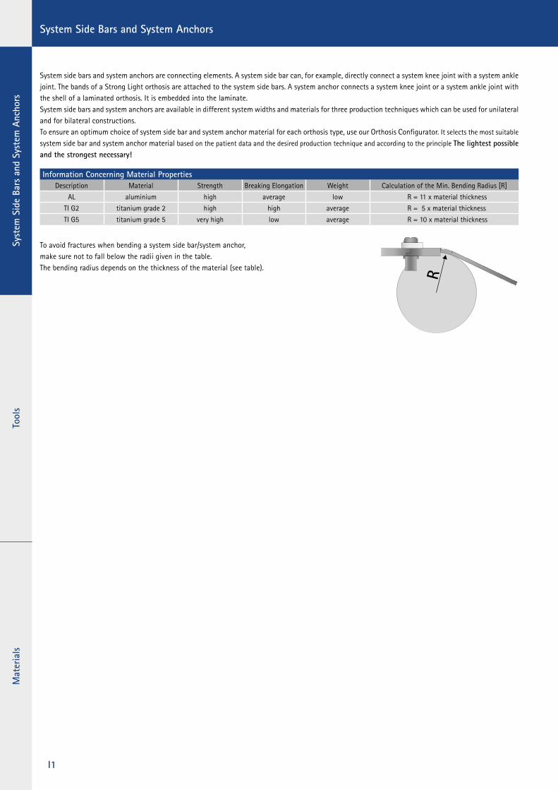
To avoid fractures when bending a system side bar/system anchor, make sure not to fall below the radii given in the table. The bending radius depends on the thickness of the material (see table).
Information Concerning Material PropertiesDescription Material Strength Breaking Elongation Weight Calculation of the Min. Bending Radius [R]
AL aluminium high average low R = 11 x material thickness
TI G2 titanium grade 2 high high average R = 5 x material thickness
TI G5 titanium grade 5 very high low average R = 10 x material thickness
ToolsSystem
Side Bars and System Anchors
Materials
I2
Service/Support Hotline +49 4131 24445-0
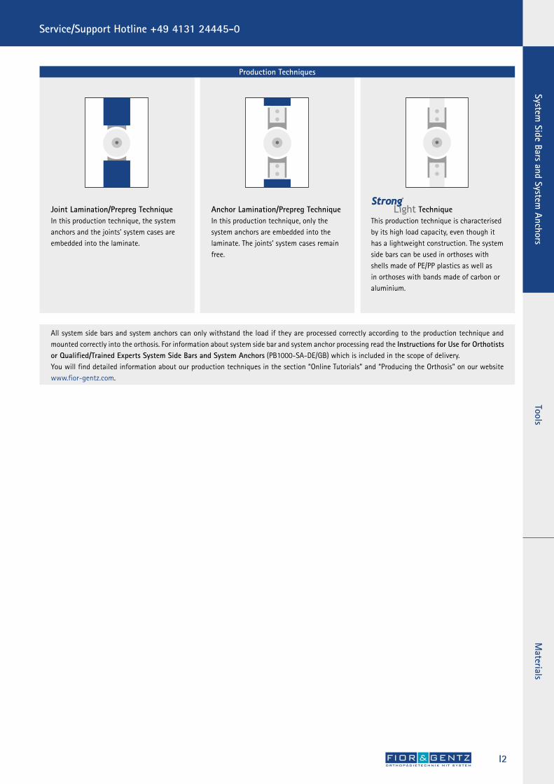
Joint Lamination/Prepreg TechniqueIn this production technique, the system anchors and the joints’ system cases are embedded into the laminate.
Anchor Lamination/Prepreg TechniqueIn this production technique, only the system anchors are embedded into the laminate. The joints’ system cases remain free.
All system side bars and system anchors can only withstand the load if they are processed correctly according to the production technique and mounted correctly into the orthosis. For information about system side bar and system anchor processing read the Instructions for Use for Orthotists or Qualified/Trained Experts System Side Bars and System Anchors (PB1000-SA-DE/GB) which is included in the scope of delivery. You will find detailed information about our production techniques in the section “Online Tutorials” and “Producing the Orthosis” on our website www.fior-gentz.com.
Production Techniques
Strong Light TechniqueThis production technique is characterised by its high load capacity, even though it has a lightweight construction. The system side bars can be used in orthoses with shells made of PE/PP plastics as well as in orthoses with bands made of carbon or aluminium.
Tool
sSy
stem
Sid
e Ba
rs a
nd S
yste
m A
ncho
rsM
ater
ials
I3
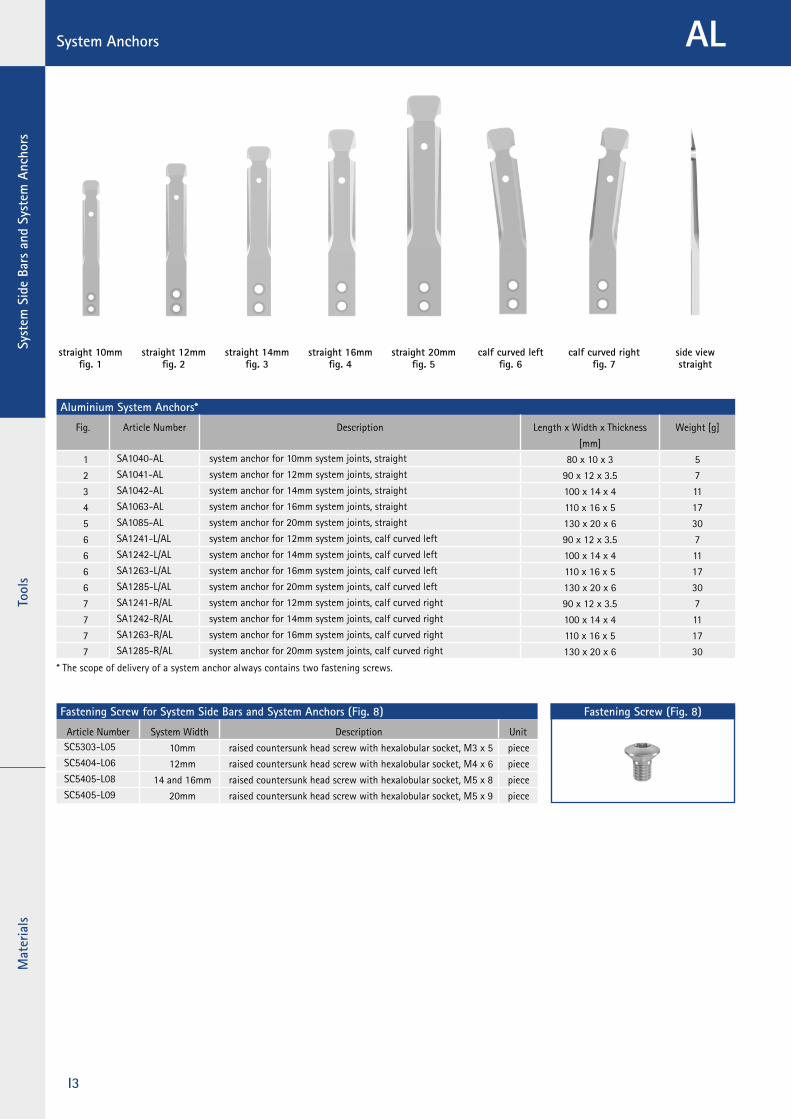
System Anchors
straight 16mmfig. 4
straight 14mm fig. 3
straight 20mm fig. 5
calf curved left fig. 6
calf curved rightfig. 7
straight 10mm fig. 1
straight 12mmfig. 2
side viewstraight
AL
Aluminium System Anchors*
Fig. Article Number Description Length x Width x Thickness
[mm]
Weight [g]
1 SA1040-AL system anchor for 10mm system joints, straight 80 x 10 x 3 5
2 SA1041-AL system anchor for 12mm system joints, straight 90 x 12 x 3.5 7
3 SA1042-AL system anchor for 14mm system joints, straight 100 x 14 x 4 11
4 SA1063-AL system anchor for 16mm system joints, straight 110 x 16 x 5 17
5 SA1085-AL system anchor for 20mm system joints, straight 130 x 20 x 6 30
6 SA1241-L/AL system anchor for 12mm system joints, calf curved left 90 x 12 x 3.5 7
6 SA1242-L/AL system anchor for 14mm system joints, calf curved left 100 x 14 x 4 11
6 SA1263-L/AL system anchor for 16mm system joints, calf curved left 110 x 16 x 5 17
6 SA1285-L/AL system anchor for 20mm system joints, calf curved left 130 x 20 x 6 30
7 SA1241-R/AL system anchor for 12mm system joints, calf curved right 90 x 12 x 3.5 7
7 SA1242-R/AL system anchor for 14mm system joints, calf curved right 100 x 14 x 4 11
7 SA1263-R/AL system anchor for 16mm system joints, calf curved right 110 x 16 x 5 17
7 SA1285-R/AL system anchor for 20mm system joints, calf curved right 130 x 20 x 6 30
* The scope of delivery of a system anchor always contains two fastening screws.
Fastening Screw for System Side Bars and System Anchors (Fig. 8)
Article Number System Width Description UnitSC5303-L05 10mm raised countersunk head screw with hexalobular socket, M3 x 5 pieceSC5404-L06 12mm raised countersunk head screw with hexalobular socket, M4 x 6 pieceSC5405-L08 14 and 16mm raised countersunk head screw with hexalobular socket, M5 x 8 pieceSC5405-L09 20mm raised countersunk head screw with hexalobular socket, M5 x 9 piece
Fastening Screw (Fig. 8)

ToolsSystem
Side Bars and System Anchors
Materials
I4
Aluminium System Side Bars*
Fig. Article Number Description Length x Width x Thickness
[mm]
Weight [g/cm]
9 SS1040-AL system side bar for 10mm system joints, straight 200 x 10 x 3 0.8
10 SS1041-AL system side bar for 12mm system joints, straight 225 x 12 x 3.5 1.1
11 SS1042-AL system side bar for 14mm system joints, straight 250 x 14 x 4 1.5
12 SS1063-AL system side bar for 16mm system joints, straight 410 x 16 x 5 2.1
13 SS1085-AL system side bar for 20mm system joints, straight 480 x 20 x 6 3.1
14 SS1241-L/AL system side bar for 12mm system joints, calf curved left 265 x 12 x 3.5 1.1
14 SS1242-L/AL system side bar for 14mm system joints, calf curved left 300 x 14 x 4 1.5
14 SS1263-L/AL system side bar for 16mm system joints, calf curved left 450 x 16 x 5 2.1
14 SS1285-L/AL system side bar for 20mm system joints, calf curved left 530 x 20 x 6 3.1
15 SS1241-R/AL system side bar for 12mm system joints, calf curved right 265 x 12 x 3.5 1.1
15 SS1242-R/AL system side bar for 14mm system joints, calf curved right 300 x 14 x 4 1.5
15 SS1263-R/AL system side bar for 16mm system joints, calf curved right 450 x 16 x 5 2.1
15 SS1285-R/AL system side bar for 20mm system joints, calf curved right 530 x 20 x 6 3.1
* The scope of delivery of a system side bar always contains two fastening screws.
One-Metre System Side Bars
Fig. Article Number Description Length x Thickness [mm] Weight [g/cm]
similar to fig. 10 without bore SS1041-AL/00 one-metre system side bar for 12mm system joints 1000 x 3.5 1.1
similar to fig. 11 without bore SS1042-AL/00 one-metre system side bar for 14mm system joints 1000 x 4 1.5
similar to fig. 12 without bore SS1063-AL/00 one-metre system side bar for 16mm system joints 1000 x 5 2.1
similar to fig. 13 without bore SS1085-AL/00 one-metre system side bar for 20mm system joints 1000 x 6 3.1
System Side Bars
straight 16mm fig. 12
straight 14mm fig. 11
straight 12mm fig. 10
straight 20mm fig. 13
calf curved leftfig. 14
calf curved rightfig. 15
straight 10mmfig. 9
Fastening Screw for System Side Bars and System Anchors (Fig. 16)
Article Number System Width Description UnitSC5303-L05 10mm raised countersunk head screw with hexalobular socket, M3 x 5 pieceSC5404-L06 12mm raised countersunk head screw with hexalobular socket, M4 x 6 pieceSC5405-L08 14 and 16mm raised countersunk head screw with hexalobular socket, M5 x 8 pieceSC5405-L09 20mm raised countersunk head screw with hexalobular socket, M5 x 9 piece
AL
Fastening Screw (Fig. 16)

Tool
sSy
stem
Sid
e Ba
rs a
nd S
yste
m A
ncho
rsM
ater
ials
I5
System Anchors TI G2
Titanium Grade 2 System Anchors*
Fig. Article Number Description Length x Width x Thickness [mm] Weight [g]
1 SA1040-TI system anchor for 10mm system joints, straight 80 x 10 x 3 8
2 SA1041-TI system anchor for 12mm system joints, straight 90 x 12 x 3.5 12
3 SA1042-TI system anchor for 14mm system joints, straight 100 x 14 x 4 18
4 SA1063-TI system anchor for 16mm system joints, straight 110 x 16 x 5 28
5 SA1085-TI system anchor for 20mm system joints, straight 130 x 20 x 6 51
6 SA1241-L/TI system anchor for 12mm system joints, calf curved left 90 x 12 x 3.5 12
6 SA1242-L/TI system anchor for 14mm system joints, calf curved left 100 x 14 x 4 18
6 SA1263-L/TI system anchor for 16mm system joints, calf curved left 110 x 16 x 5 28
6 SA1285-L/TI system anchor for 20mm system joints, calf curved left 130 x 20 x 6 51
7 SA1241-R/TI system anchor for 12mm system joints, calf curved right 90 x 12 x 3.5 12
7 SA1242-R/TI system anchor for 14mm system joints, calf curved right 100 x 14 x 4 18
7 SA1263-R/TI system anchor for 16mm system joints, calf curved right 110 x 16 x 5 28
7 SA1285-R/TI system anchor for 20mm system joints, calf curved right 130 x 20 x 6 51
* The scope of delivery of a system anchor always contains two fastening screws.
Fastening Screw for System Side Bars and System Anchors (Fig. 8)
Article Number System Width Description UnitSC5303-L05 10mm raised countersunk head screw with hexalobular socket, M3 x 5 pieceSC5404-L06 12mm raised countersunk head screw with hexalobular socket, M4 x 6 pieceSC5405-L08 14 and 16mm raised countersunk head screw with hexalobular socket, M5 x 8 pieceSC5405-L09 20mm raised countersunk head screw with hexalobular socket, M5 x 9 piece
Fastening Screw (Fig. 8)
side viewstraight
straight 16mmfig. 4
straight 14mm fig. 3
straight 20mm fig. 5
calf curved left fig. 6
calf curved rightfig. 7
straight 10mm fig. 1
straight 12mmfig. 2
ToolsSystem
Side Bars and System Anchors
Materials
I6
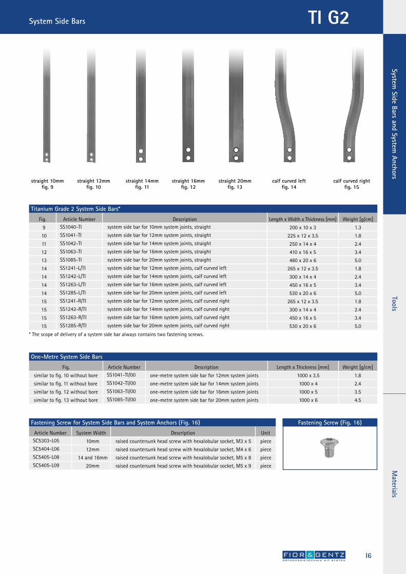
System Side Bars TI G2
Titanium Grade 2 System Side Bars*
Fig. Article Number Description Length x Width x Thickness [mm] Weight [g/cm]
9 SS1040-TI system side bar for 10mm system joints, straight 200 x 10 x 3 1.3
10 SS1041-TI system side bar for 12mm system joints, straight 225 x 12 x 3.5 1.8
11 SS1042-TI system side bar for 14mm system joints, straight 250 x 14 x 4 2.4
12 SS1063-TI system side bar for 16mm system joints, straight 410 x 16 x 5 3.4
13 SS1085-TI system side bar for 20mm system joints, straight 480 x 20 x 6 5.0
14 SS1241-L/TI system side bar for 12mm system joints, calf curved left 265 x 12 x 3.5 1.8
14 SS1242-L/TI system side bar for 14mm system joints, calf curved left 300 x 14 x 4 2.4
14 SS1263-L/TI system side bar for 16mm system joints, calf curved left 450 x 16 x 5 3.4
14 SS1285-L/TI system side bar for 20mm system joints, calf curved left 530 x 20 x 6 5.0
15 SS1241-R/TI system side bar for 12mm system joints, calf curved right 265 x 12 x 3.5 1.8
15 SS1242-R/TI system side bar for 14mm system joints, calf curved right 300 x 14 x 4 2.4
15 SS1263-R/TI system side bar for 16mm system joints, calf curved right 450 x 16 x 5 3.4
15 SS1285-R/TI system side bar for 20mm system joints, calf curved right 530 x 20 x 6 5.0
* The scope of delivery of a system side bar always contains two fastening screws.
Fastening Screw for System Side Bars and System Anchors (Fig. 16)
Article Number System Width Description UnitSC5303-L05 10mm raised countersunk head screw with hexalobular socket, M3 x 5 pieceSC5404-L06 12mm raised countersunk head screw with hexalobular socket, M4 x 6 pieceSC5405-L08 14 and 16mm raised countersunk head screw with hexalobular socket, M5 x 8 pieceSC5405-L09 20mm raised countersunk head screw with hexalobular socket, M5 x 9 piece
Fastening Screw (Fig. 16)
One-Metre System Side Bars
Fig. Article Number Description Length x Thickness [mm] Weight [g/cm]
similar to fig. 10 without bore SS1041-TI/00 one-metre system side bar for 12mm system joints 1000 x 3.5 1.8
similar to fig. 11 without bore SS1042-TI/00 one-metre system side bar for 14mm system joints 1000 x 4 2.4
similar to fig. 12 without bore SS1063-TI/00 one-metre system side bar for 16mm system joints 1000 x 5 3.5
similar to fig. 13 without bore SS1085-TI/00 one-metre system side bar for 20mm system joints 1000 x 6 4.5
straight 16mm fig. 12
straight 14mm fig. 11
straight 12mm fig. 10
straight 20mm fig. 13
calf curved leftfig. 14
calf curved rightfig. 15
straight 10mmfig. 9
Tool
sSy
stem
Sid
e Ba
rs a
nd S
yste
m A
ncho
rsM
ater
ials
I7
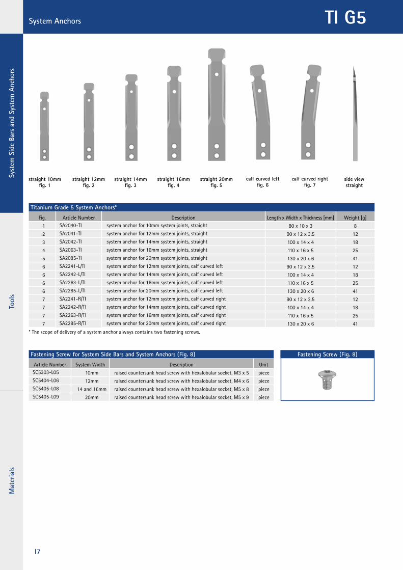
System Anchors TI G5
Titanium Grade 5 System Anchors*
Fig. Article Number Description Length x Width x Thickness [mm] Weight [g]
1 SA2040-TI system anchor for 10mm system joints, straight 80 x 10 x 3 8
2 SA2041-TI system anchor for 12mm system joints, straight 90 x 12 x 3.5 12
3 SA2042-TI system anchor for 14mm system joints, straight 100 x 14 x 4 18
4 SA2063-TI system anchor for 16mm system joints, straight 110 x 16 x 5 25
5 SA2085-TI system anchor for 20mm system joints, straight 130 x 20 x 6 41
6 SA2241-L/TI system anchor for 12mm system joints, calf curved left 90 x 12 x 3.5 12
6 SA2242-L/TI system anchor for 14mm system joints, calf curved left 100 x 14 x 4 18
6 SA2263-L/TI system anchor for 16mm system joints, calf curved left 110 x 16 x 5 25
6 SA2285-L/TI system anchor for 20mm system joints, calf curved left 130 x 20 x 6 41
7 SA2241-R/TI system anchor for 12mm system joints, calf curved right 90 x 12 x 3.5 12
7 SA2242-R/TI system anchor for 14mm system joints, calf curved right 100 x 14 x 4 18
7 SA2263-R/TI system anchor for 16mm system joints, calf curved right 110 x 16 x 5 25
7 SA2285-R/TI system anchor for 20mm system joints, calf curved right 130 x 20 x 6 41
* The scope of delivery of a system anchor always contains two fastening screws.
Fastening Screw for System Side Bars and System Anchors (Fig. 8)
Article Number System Width Description UnitSC5303-L05 10mm raised countersunk head screw with hexalobular socket, M3 x 5 pieceSC5404-L06 12mm raised countersunk head screw with hexalobular socket, M4 x 6 pieceSC5405-L08 14 and 16mm raised countersunk head screw with hexalobular socket, M5 x 8 pieceSC5405-L09 20mm raised countersunk head screw with hexalobular socket, M5 x 9 piece
Fastening Screw (Fig. 8)
side viewstraight
straight 16mmfig. 4
straight 14mm fig. 3
straight 20mm fig. 5
calf curved left fig. 6
calf curved rightfig. 7
straight 10mm fig. 1
straight 12mmfig. 2

ToolsSystem
Side Bars and System Anchors
Materials
I8
System Side Bars TI G5
Titanium Grade 5 System Side Bars*
Fig. Article Number Description Length x Width x Thickness [mm] Weight [g/cm]
9 SS2040-TI system side bar for 10mm system joints, straight 200 x 10 x 3 1.3
10 SS2041-TI system side bar for 12mm system joints, straight 225 x 12 x 3.5 1.8
11 SS2042-TI system side bar for 14mm system joints, straight 250 x 14 x 4 2.4
12 SS2063-TI system side bar for 16mm system joints, straight 410 x 16 x 4.5 3.0
13 SS2085-TI system side bar for 20mm system joints, straight 480 x 20 x 6 4.1
14 SS2241-L/TI system side bar for 12mm system joints, calf curved left 265 x 12 x 3.5 1.8
14 SS2242-L/TI system side bar for 14mm system joints, calf curved left 300 x 14 x 4 2.4
14 SS2263-L/TI system side bar for 16mm system joints, calf curved left 450 x 16 x 4.5 3.0
14 SS2285-L/TI system side bar for 20mm system joints, calf curved left 530 x 20 x 6 4.1
15 SS2241-R/TI system side bar for 12mm system joints, calf curved right 265 x 12 x 3.5 1.8
15 SS2242-R/TI system side bar for 14mm system joints, calf curved right 300 x 14 x 4 2.4
15 SS2263-R/TI system side bar for 16mm system joints, calf curved right 450 x 16 x 4.5 3.0
15 SS2285-R/TI system side bar for 20mm system joints, calf curved right 530 x 20 x 6 4.1
* The scope of delivery of a system side bar always contains two fastening screws.
One-Metre System Side Bars
Fig. Article Number Description Length x Thickness [mm] Weight [g/cm]
similar to fig. 10 without bore SS2041-TI/00 one-metre system side bar for 12mm system joints 1000 x 3.5 1.8
similar to fig. 11 without bore SS2042-TI/00 one-metre system side bar for 14mm system joints 1000 x 4 2.4
similar to fig. 12 without bore SS2063-TI/00 one-metre system side bar for 16mm system joints 1000 x 5 3.1
similar to fig. 13 without bore SS2085-TI/00 one-metre system side bar for 20mm system joints 1000 x 6 4.2
Fastening Screw for System Side Bars and System Anchors (Fig. 16)
Article Number System Width Description UnitSC5303-L05 10mm raised countersunk head screw with hexalobular socket, M3 x 5 pieceSC5404-L06 12mm raised countersunk head screw with hexalobular socket, M4 x 6 pieceSC5405-L08 14 and 16mm raised countersunk head screw with hexalobular socket, M5 x 8 pieceSC5405-L09 20mm raised countersunk head screw with hexalobular socket, M5 x 9 piece
Fastening Screw (Fig. 16)
straight 16mm fig. 12
straight 14mm fig. 11
straight 12mm fig. 10
straight 20mm fig. 13
calf curved leftfig. 14
calf curved rightfig. 15
straight 10mmfig. 9
Tool
sSy
stem
Sid
e Ba
rs a
nd S
yste
m A
ncho
rsM
ater
ials
I9
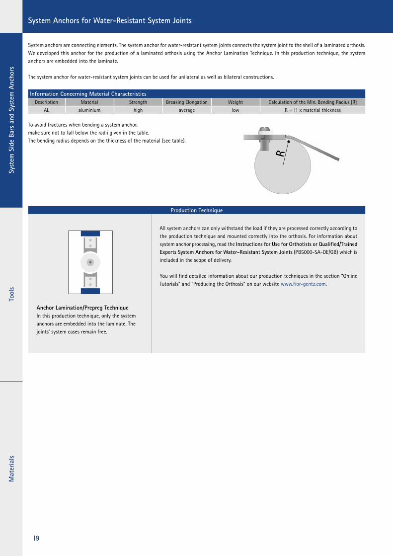
All system anchors can only withstand the load if they are processed correctly according to the production technique and mounted correctly into the orthosis. For information about system anchor processing, read the Instructions for Use for Orthotists or Qualified/Trained Experts System Anchors for Water-Resistant System Joints (PB5000-SA-DE/GB) which is included in the scope of delivery.
You will find detailed information about our production techniques in the section “Online Tutorials” and “Producing the Orthosis” on our website www.fior-gentz.com.
Production Technique
Anchor Lamination/Prepreg TechniqueIn this production technique, only the system anchors are embedded into the laminate. The joints’ system cases remain free.
System anchors are connecting elements. The system anchor for water-resistant system joints connects the system joint to the shell of a laminated orthosis. We developed this anchor for the production of a laminated orthosis using the Anchor Lamination Technique. In this production technique, the system anchors are embedded into the laminate.
The system anchor for water-resistant system joints can be used for unilateral as well as bilateral constructions.
Information Concerning Material CharacteristicsDescription Material Strength Breaking Elongation Weight Calculation of the Min. Bending Radius [R]
AL aluminium high average low R = 11 x material thickness
To avoid fractures when bending a system anchor,make sure not to fall below the radii given in the table.The bending radius depends on the thickness of the material (see table).
System Anchors for Water-Resistant System Joints

ToolsSystem
Side Bars and System Anchors
Materials
I10
side viewstraight
straight 16mmfig. 3
straight 14mm fig. 2
straight 20mm fig. 4
calf curved leftfig. 5
calf curved rightfig. 6
straight 12mmfig. 1
Straight System Anchors for the NEURO SWING H2O System Ankle Joint
Fig. Article Number Description Length x Width x Thickness [mm] Weight [g]
1 SA5051-AL system anchor for 12mm system joints, straight 90 x 15 x 4.7 12
2 SA5052-AL system anchor for 14mm system joints, straight 100 x 18 x 4.9 17
3 SA5063-AL system anchor for 16mm system joints, straight 110 x 20 x 5.9 25
4 SA5075-AL system anchor for 20mm system joints, straight 130 x 26 x 7 47
Straight System Anchors for the NEURO LOCK H2O and the NEURO CLASSIC H2O System Knee Joints
Fig. Article Number Description Length x Width x Thickness [mm] Weight [g]
2 SA5052-AL system anchor for 14mm system joints, straight 100 x 18 x 4.9 17
3 SA5063-AL system anchor for 16mm system joints, straight 110 x 20 x 5.9 25
4 SA5075-AL system anchor for 20mm system joints, straight 130 x 26 x 7 47
5 SA5252-L/AL system anchor for 14mm system joints, calf curved left, straight 100 x 18 x 4.9 17
5 SA5263-L/AL system anchor for 16mm system joints, calf curved left, straight 110 x 20 x 5.9 25
5 SA5275-L/AL system anchor for 20mm system joints, calf curved left, straight 130 x 26 x 7 47
6 SA5252-R/AL system anchor for 14mm system joints, calf curved right, straight 100 x 18 x 4.9 17
6 SA5263-R/AL system anchor for 16mm system joints, calf curved right, straight 110 x 20 x 5.9 25
6 SA5275-R/AL system anchor for 20mm system joints, calf curved right, straight 130 x 26 x 7 47
System Anchors for Water-Resistant System Joints – Straight
Tool
sSy
stem
Sid
e Ba
rs a
nd S
yste
m A
ncho
rsM
ater
ials
I11
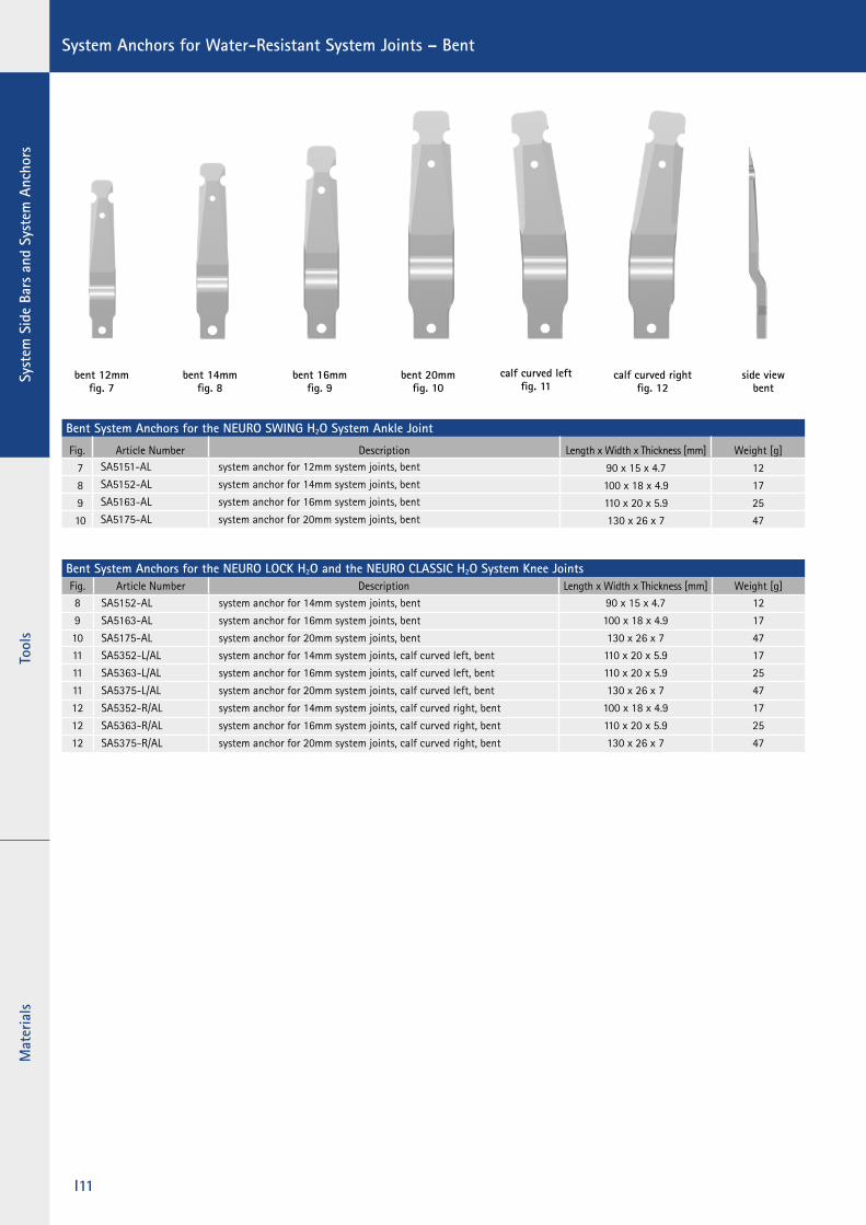
System Anchors for Water-Resistant System Joints – Bent
Bent System Anchors for the NEURO SWING H2O System Ankle Joint
Fig. Article Number Description Length x Width x Thickness [mm] Weight [g]
7 SA5151-AL system anchor for 12mm system joints, bent 90 x 15 x 4.7 12
8 SA5152-AL system anchor for 14mm system joints, bent 100 x 18 x 4.9 17
9 SA5163-AL system anchor for 16mm system joints, bent 110 x 20 x 5.9 25
10 SA5175-AL system anchor for 20mm system joints, bent 130 x 26 x 7 47
Bent System Anchors for the NEURO LOCK H2O and the NEURO CLASSIC H2O System Knee JointsFig. Article Number Description Length x Width x Thickness [mm] Weight [g]8 SA5152-AL system anchor for 14mm system joints, bent 90 x 15 x 4.7 12
9 SA5163-AL system anchor for 16mm system joints, bent 100 x 18 x 4.9 17
10 SA5175-AL system anchor for 20mm system joints, bent 130 x 26 x 7 4711 SA5352-L/AL system anchor for 14mm system joints, calf curved left, bent 110 x 20 x 5.9 17
11 SA5363-L/AL system anchor for 16mm system joints, calf curved left, bent 110 x 20 x 5.9 25
11 SA5375-L/AL system anchor for 20mm system joints, calf curved left, bent 130 x 26 x 7 47
12 SA5352-R/AL system anchor for 14mm system joints, calf curved right, bent 100 x 18 x 4.9 17
12 SA5363-R/AL system anchor for 16mm system joints, calf curved right, bent 110 x 20 x 5.9 25
12 SA5375-R/AL system anchor for 20mm system joints, calf curved right, bent 130 x 26 x 7 47
bent 12mm fig. 7
bent 16mm fig. 9
bent 14mm fig. 8
bent 20mmfig. 10
side viewbent
calf curved leftfig. 11
calf curved right fig. 12

ToolsSystem
Side Bars and System Anchors
Materials
I12
CROSSROADSOrthosis Shoes. Different.
with elastic
vibram® flat sole
with elastic outsole
made of EVA material
Size: 36–48Material: high quality leather, certifi ed cow leather used for the upper material and
calf leather used for the inner lining ensure the highest wearing comfort.Shoe Types: REGULAR left and right REGULAR left/SLIM right
SLIM left and right SLIM left/REGULAR right
Shoe Measurements toe spring 18 mmpitch 15 mmheel height 25 mm
Comfortable fi t with and without orthosis.CROSSROADS orthosis shoes always guarantee a perfect fi t thanks to their special design and the carefully chosen material. The integrated elastic textile material as well as two removable insoles o� er a fl exible volume. Furthermore, it is possible to create an outsole elevation with an EVA sheet and to re-attach a vibram® fl at sole to the shoe. CROSSROADS is available as a pair in four di� erent combinations of the widths REGULAR and SLIM, which makes the fi t ideal for any foot – with and without orthosis.
All orthosis shoes are sold in pairs for each shoe size. The CROSSROADS orthosis shoes can be found from catalogue page L10.1.