Embed Size (px)
Citation preview
Edition No. 10 April 2021
April 2021 5
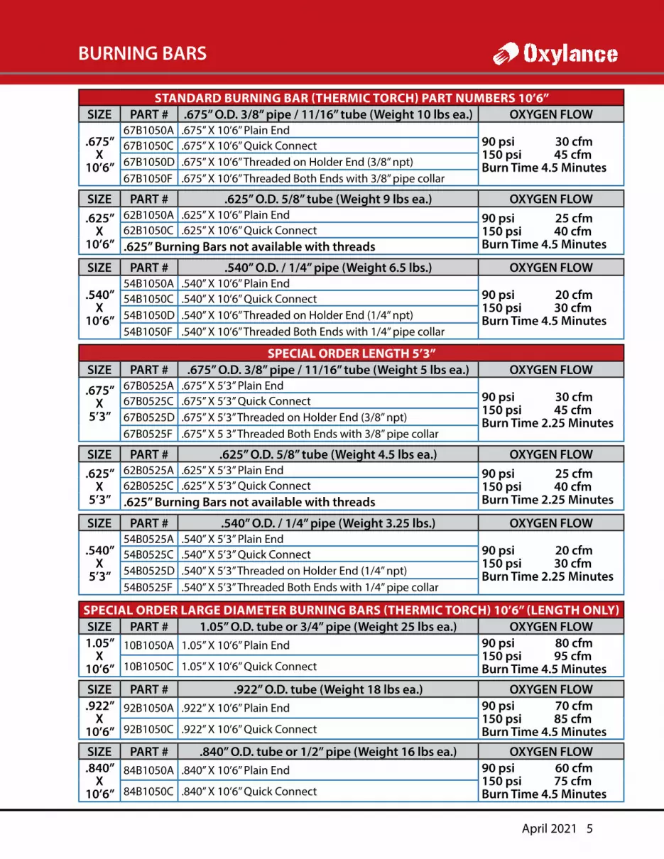
STANDARD BURNING BAR (THERMIC TORCH) PART NUMBERS 10’6”SIZE PART # .675” O.D. 3/8” pipe / 11/16” tube (Weight 10 lbs ea.) OXYGEN FLOW
.675”X
10’6”
67B1050A .675” X 10’6” Plain End90 psi 30 cfm150 psi 45 cfmBurn Time 4.5 Minutes
67B1050C .675” X 10’6” Quick Connect67B1050D .675” X 10’6” Threaded on Holder End (3/8” npt)67B1050F .675” X 10’6” Threaded Both Ends with 3/8” pipe collar
SIZE PART # .625” O.D. 5/8” tube (Weight 9 lbs ea.) OXYGEN FLOW.625”
X 10’6”
62B1050A .625” X 10’6” Plain End 90 psi 25 cfm150 psi 40 cfmBurn Time 4.5 Minutes
62B1050C .625” X 10’6” Quick Connect.625” Burning Bars not available with threads
SIZE PART # .540” O.D. / 1/4” pipe (Weight 6.5 lbs.) OXYGEN FLOW
.540” X
10’6”
54B1050A .540” X 10’6” Plain End90 psi 20 cfm150 psi 30 cfmBurn Time 4.5 Minutes
54B1050C .540” X 10’6” Quick Connect54B1050D .540” X 10’6” Threaded on Holder End (1/4” npt)54B1050F .540” X 10’6” Threaded Both Ends with 1/4” pipe collar
SPECIAL ORDER LENGTH 5’3”SIZE PART # .675” O.D. 3/8” pipe / 11/16” tube (Weight 5 lbs ea.) OXYGEN FLOW
.675” X
5’3”
67B0525A .675” X 5’3” Plain End90 psi 30 cfm150 psi 45 cfmBurn Time 2.25 Minutes
67B0525C .675” X 5’3” Quick Connect67B0525D .675” X 5’3” Threaded on Holder End (3/8” npt)67B0525F .675” X 5 3” Threaded Both Ends with 3/8” pipe collar
SIZE PART # .625” O.D. 5/8” tube (Weight 4.5 lbs ea.) OXYGEN FLOW.625”
X5’3”
62B0525A .625” X 5’3” Plain End 90 psi 25 cfm150 psi 40 cfmBurn Time 2.25 Minutes
62B0525C .625” X 5’3” Quick Connect.625” Burning Bars not available with threads
SIZE PART # .540” O.D. / 1/4” pipe (Weight 3.25 lbs.) OXYGEN FLOW
.540” X
5’3”
54B0525A .540” X 5’3” Plain End90 psi 20 cfm150 psi 30 cfmBurn Time 2.25 Minutes
54B0525C .540” X 5’3” Quick Connect54B0525D .540” X 5’3” Threaded on Holder End (1/4” npt)54B0525F .540” X 5’3” Threaded Both Ends with 1/4” pipe collar
SPECIAL ORDER LARGE DIAMETER BURNING BARS (THERMIC TORCH) 10’6” (LENGTH ONLY)SIZE PART # 1.05” O.D. tube or 3/4” pipe (Weight 25 lbs ea.) OXYGEN FLOW1.05”
X10’6”
10B1050A 1.05” X 10’6” Plain End 90 psi 80 cfm150 psi 95 cfmBurn Time 4.5 Minutes10B1050C 1.05” X 10’6” Quick Connect
SIZE PART # .922” O.D. tube (Weight 18 lbs ea.) OXYGEN FLOW.922”
X10’6”
92B1050A .922” X 10’6” Plain End 90 psi 70 cfm150 psi 85 cfmBurn Time 4.5 Minutes92B1050C .922” X 10’6” Quick Connect
SIZE PART # .840” O.D. tube or 1/2” pipe (Weight 16 lbs ea.) OXYGEN FLOW.840”
X10’6”
84B1050A .840” X 10’6” Plain End 90 psi 60 cfm150 psi 75 cfmBurn Time 4.5 Minutes84B1050C .840” X 10’6” Quick Connect
BURNING BARS
6 Edition No. 10
LEVER ACTION HOLDERS
#1 LEVER ACTION HOLDER for .405” to .675” ( 1/8” to 3/8” pipe and tube sizes)PART # DESCRIPTION
.405” O.D. tube or 1/8” Pipe HOLDER WITH SHIELDLA1405 #1 Lever Action Holder (no valve) w/ .405 Grommet LA1405-S with Hand ShieldPL1/8-6 LA 1 Rubber Grommet for 405” pipeLA1405F #1 Lever Action Holder w/ 1/2” Thermal Shutoff LA1405FS with Hand ShieldLA1405FG #1 Lever Action Holder w/ Ball Valve & Thermal Shutoff LA1405FGS with Hand Shield*LA1405FV #1 Lever Action Holder w/ Lever Valve* & Thermal Shutoff LA1405FVS with Hand Shield
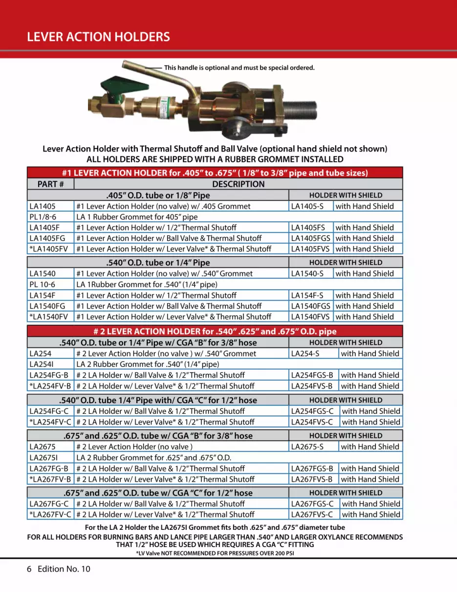
Lever Action Holder with Thermal Shutoff and Ball Valve (optional hand shield not shown)ALL HOLDERS ARE SHIPPED WITH A RUBBER GROMMET INSTALLED
.540” O.D. tube or 1/4” Pipe HOLDER WITH SHIELDLA1540 #1 Lever Action Holder (no valve) w/ .540” Grommet LA1540-S with Hand ShieldPL 10-6 LA 1Rubber Grommet for .540” (1/4” pipe)LA154F #1 Lever Action Holder w/ 1/2” Thermal Shutoff LA154F-S with Hand ShieldLA1540FG #1 Lever Action Holder w/ Ball Valve & Thermal Shutoff LA1540FGS with Hand Shield*LA1540FV #1 Lever Action Holder w/ Lever Valve* & Thermal Shutoff LA1540FVS with Hand Shield
# 2 LEVER ACTION HOLDER for .540” .625” and .675” O.D. pipe.540” O.D. tube or 1/4” Pipe w/ CGA “B” for 3/8” hose HOLDER WITH SHIELD
LA254 # 2 Lever Action Holder (no valve ) w/ .540” Grommet LA254-S with Hand ShieldLA254I LA 2 Rubber Grommet for .540” (1/4” pipe)LA254FG-B # 2 LA Holder w/ Ball Valve & 1/2” Thermal Shutoff LA254FGS-B with Hand Shield*LA254FV-B # 2 LA Holder w/ Lever Valve* & 1/2” Thermal Shutoff LA254FVS-B with Hand Shield
.540” O.D. tube 1/4” Pipe with/ CGA “C” for 1/2” hose HOLDER WITH SHIELDLA254FG-C # 2 LA Holder w/ Ball Valve & 1/2” Thermal Shutoff LA254FGS-C with Hand Shield*LA254FV-C # 2 LA Holder w/ Lever Valve* & 1/2” Thermal Shutoff LA254FVS-C with Hand Shield
.675” and .625” O.D. tube w/ CGA “B” for 3/8” hose HOLDER WITH SHIELDLA2675 # 2 Lever Action Holder (no valve ) LA2675-S with Hand ShieldLA2675I LA 2 Rubber Grommet for .625” and .675” O.D.LA267FG-B # 2 LA Holder w/ Ball Valve & 1/2” Thermal Shutoff LA267FGS-B with Hand Shield*LA267FV-B # 2 LA Holder w/ Lever Valve* & 1/2” Thermal Shutoff LA267FVS-B with Hand Shield
.675” and .625” O.D. tube w/ CGA “C” for 1/2” hose HOLDER WITH SHIELDLA267FG-C # 2 LA Holder w/ Ball Valve & 1/2” Thermal Shutoff LA267FGS-C with Hand Shield*LA267FV-C # 2 LA Holder w/ Lever Valve* & 1/2” Thermal Shutoff LA267FVS-C with Hand Shield
For the LA 2 Holder the LA2675I Grommet fits both .625” and .675” diameter tubeFOR ALL HOLDERS FOR BURNING BARS AND LANCE PIPE LARGER THAN .540” AND LARGER OXYLANCE RECOMMENDS
THAT 1/2” HOSE BE USED WHICH REQUIRES A CGA “C” FITTING*LV Valve NOT RECOMMENDED FOR PRESSURES OVER 200 PSI
This handle is optional and must be special ordered.

April 2021 7
LEVER ACTION HOLDERS continued
# 3 LEVER ACTION HOLDER for .840”, .922” or 1.050” O.D. pipePART # DESCRIPTION
.840” O.D. tube or 1/2” pipe HOLDER WITH SHIELDLA384 # 3 Lever Action Holder (no valve) LA384S with Hand ShieldLA3840I LA 3 Rubber Grommet for .840” O.D. tube or 1/2” pipeLA384F # 3 LA Holder 3/4” NPT Thermal Shutoff (no valve) LA384FS with Hand ShieldLA384FG # 3 LA Holder w/ Ball Valve & 3⁄4”Thermal Shutoff LA384FGS with Hand ShieldLA384FG-C Same as LA384FG with CGA “C” Fitting LA384FGS-C with Hand Shield
922” O.D. tube HOLDER WITH SHIELDLA392 # 3 Lever Action Holder (no valve ) LA392S with Hand ShieldLA3922I LA 3 Rubber Grommet for .922” O.D. tubeLA3922F # 3 LA Holder 3/4” NPT Thermal Shutoff (no valve) LA392FS with Hand ShieldLA3922FG # 3 LA Holder w/ Ball Valve & 3⁄4”Thermal Shutoff LA392FGS with Hand ShieldLA3922FG-C Same as LA392FG with CGA “C” Fitting LA392FGS-C with Hand Shield
Lever Action Holder with Thermal Shutoff and Ball Valve (optional hand shield not shown)ALL HOLDERS ARE SHIPPED WITH A RUBBER GROMMET INSTALLED
1.05” O.D. tube or 3/4” pipe HOLDER WITH SHIELDLA3105 # 3 Lever Action Holder (no valve ) LA3105S with Hand ShieldLA3105I LA 3 Rubber Grommet for 1.05” O.D. tube or 3/4” pipeLA3105F # 3 LA Holder 3/4” NPT Thermal Shutoff (no valve) LA3105FS with Hand ShieldLA3105FG # 3 LA Holder w/ Ball Valve & 3/4”Thermal Shutoff LA3105FGS with Hand ShieldLA3105FG-C Same as LA3105FG with CGA “C” Fitting LA3105FGS-C with Hand Shield
This handle is optional and must be special ordered.
8 Edition No. 10
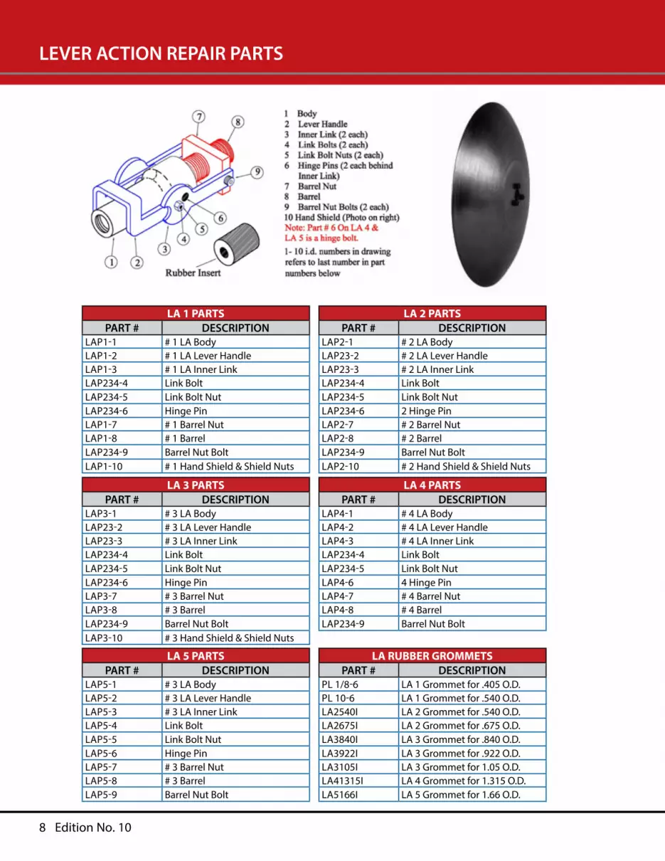
LEVER ACTION REPAIR PARTS
LA 1 PARTSPART # DESCRIPTION
LAP1-1 # 1 LA BodyLAP1-2 # 1 LA Lever HandleLAP1-3 # 1 LA Inner LinkLAP234-4 Link BoltLAP234-5 Link Bolt NutLAP234-6 Hinge PinLAP1-7 # 1 Barrel NutLAP1-8 # 1 BarrelLAP234-9 Barrel Nut BoltLAP1-10 # 1 Hand Shield & Shield Nuts
LA 2 PARTSPART # DESCRIPTION
LAP2-1 # 2 LA BodyLAP23-2 # 2 LA Lever HandleLAP23-3 # 2 LA Inner LinkLAP234-4 Link BoltLAP234-5 Link Bolt NutLAP234-6 2 Hinge PinLAP2-7 # 2 Barrel NutLAP2-8 # 2 BarrelLAP234-9 Barrel Nut BoltLAP2-10 # 2 Hand Shield & Shield Nuts
LA 3 PARTSPART # DESCRIPTION
LAP3-1 # 3 LA BodyLAP23-2 # 3 LA Lever HandleLAP23-3 # 3 LA Inner LinkLAP234-4 Link BoltLAP234-5 Link Bolt NutLAP234-6 Hinge PinLAP3-7 # 3 Barrel NutLAP3-8 # 3 BarrelLAP234-9 Barrel Nut BoltLAP3-10 # 3 Hand Shield & Shield Nuts
LA 4 PARTSPART # DESCRIPTION
LAP4-1 # 4 LA BodyLAP4-2 # 4 LA Lever HandleLAP4-3 # 4 LA Inner LinkLAP234-4 Link BoltLAP234-5 Link Bolt NutLAP4-6 4 Hinge PinLAP4-7 # 4 Barrel NutLAP4-8 # 4 BarrelLAP234-9 Barrel Nut Bolt
LA 5 PARTSPART # DESCRIPTION
LAP5-1 # 3 LA BodyLAP5-2 # 3 LA Lever HandleLAP5-3 # 3 LA Inner LinkLAP5-4 Link BoltLAP5-5 Link Bolt NutLAP5-6 Hinge PinLAP5-7 # 3 Barrel NutLAP5-8 # 3 BarrelLAP5-9 Barrel Nut Bolt
LA RUBBER GROMMETSPART # DESCRIPTION
PL 1/8-6 LA 1 Grommet for .405 O.D.PL 10-6 LA 1 Grommet for .540 O.D.LA2540I LA 2 Grommet for .540 O.D.LA2675I LA 2 Grommet for .675 O.D.LA3840I LA 3 Grommet for .840 O.D.LA3922I LA 3 Grommet for .922 O.D.LA3105I LA 3 Grommet for 1.05 O.D.LA41315I LA 4 Grommet for 1.315 O.D.LA5166I LA 5 Grommet for 1.66 O.D.

12 Edition No. 10
THERMAL SHUTOFFS (ANTI SLAG DEVICE)
Cut Away L to R 1/2” 3/4” 1”PART # DESCRIPTION
OXY0002 ½” Male NPT Thermal Shutoff (Anti Slag Device)OXY0003 ¾” Male NPT Thermal Shutoff (Anti Slag Device)OXY0004 1” Male NPT Thermal Shutoff (Anti Slag Device)
The Oxylance anti-slag safety device performs three (3) important safety functions which help protect the user and the equipment. These functions are as follows:
1. HIGH GAS VOLUME NON-RETURN VALVE: The high gas volume non-return valve prevents the reverse flow of oxygen into the hose.
2. THERMAL SHUTOFF DEVICE: The thermal shutoff activates cutting off the oxygen flow instantly extinguishing the burning bar / oxygen lance pipe if the bar / pipe burns back into the holder, if slag enters the holder, and / or heating of the holder to the point of injuring the operator (i.e., 3 to 5 second internal heating to 160 C +/- 5 degrees).
3. ANTI-SLAG & BACKFIRE BARRIER: The combination anti-slag anti-back fire element provides several safety functions. The barrier prevents molten slag and backfires from igniting the oxygen hose. In addition, the barrier helps activate the thermal shut off stopping the flow of oxygen and extinguishing the fire.
April 2021 13
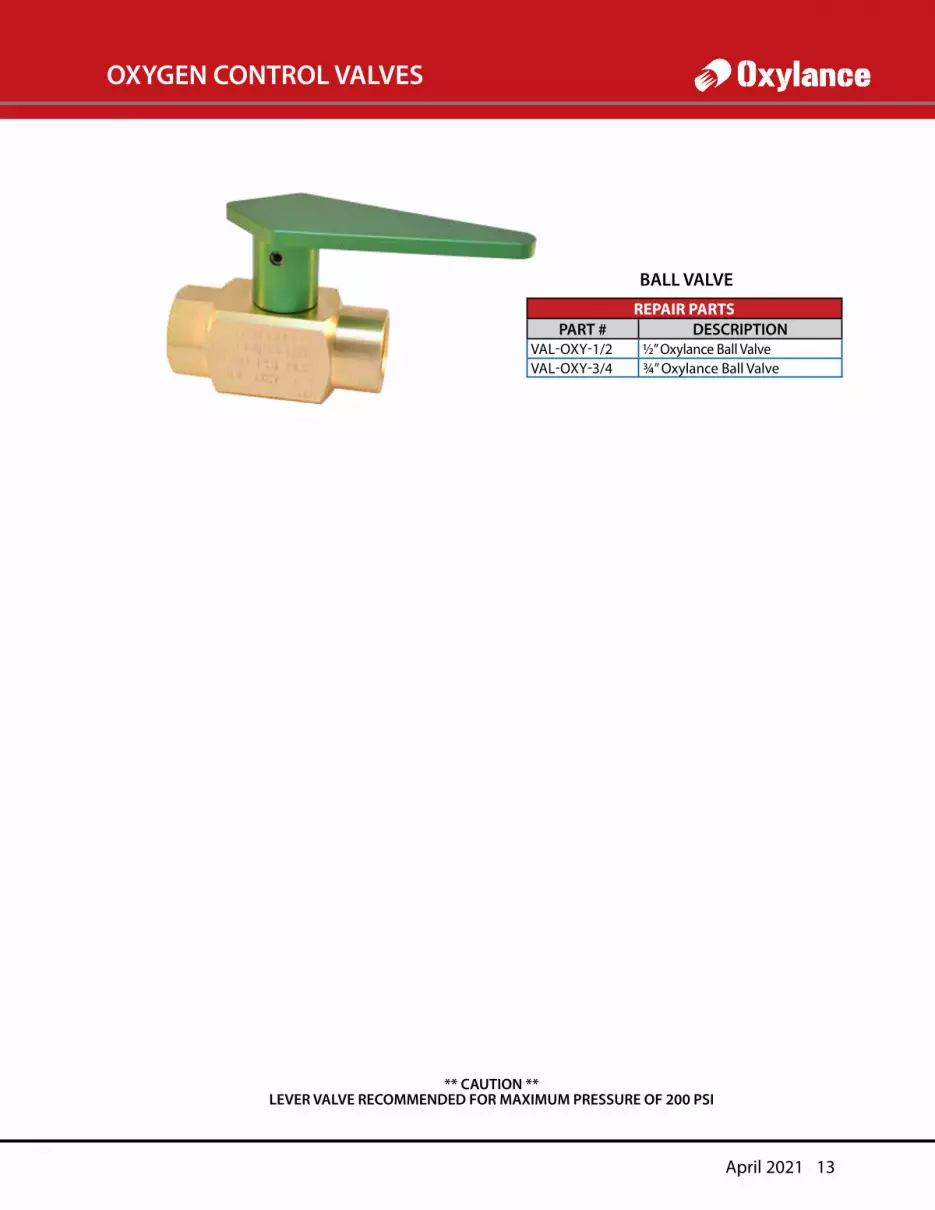
OXYGEN CONTROL VALVES
** CAUTION **LEVER VALVE RECOMMENDED FOR MAXIMUM PRESSURE OF 200 PSI
REPAIR PARTSPART # DESCRIPTION
VAL-OXY-1/2 ½” Oxylance Ball ValveVAL-OXY-3/4 ¾” Oxylance Ball Valve
BALL VALVE
14 Edition No. 10
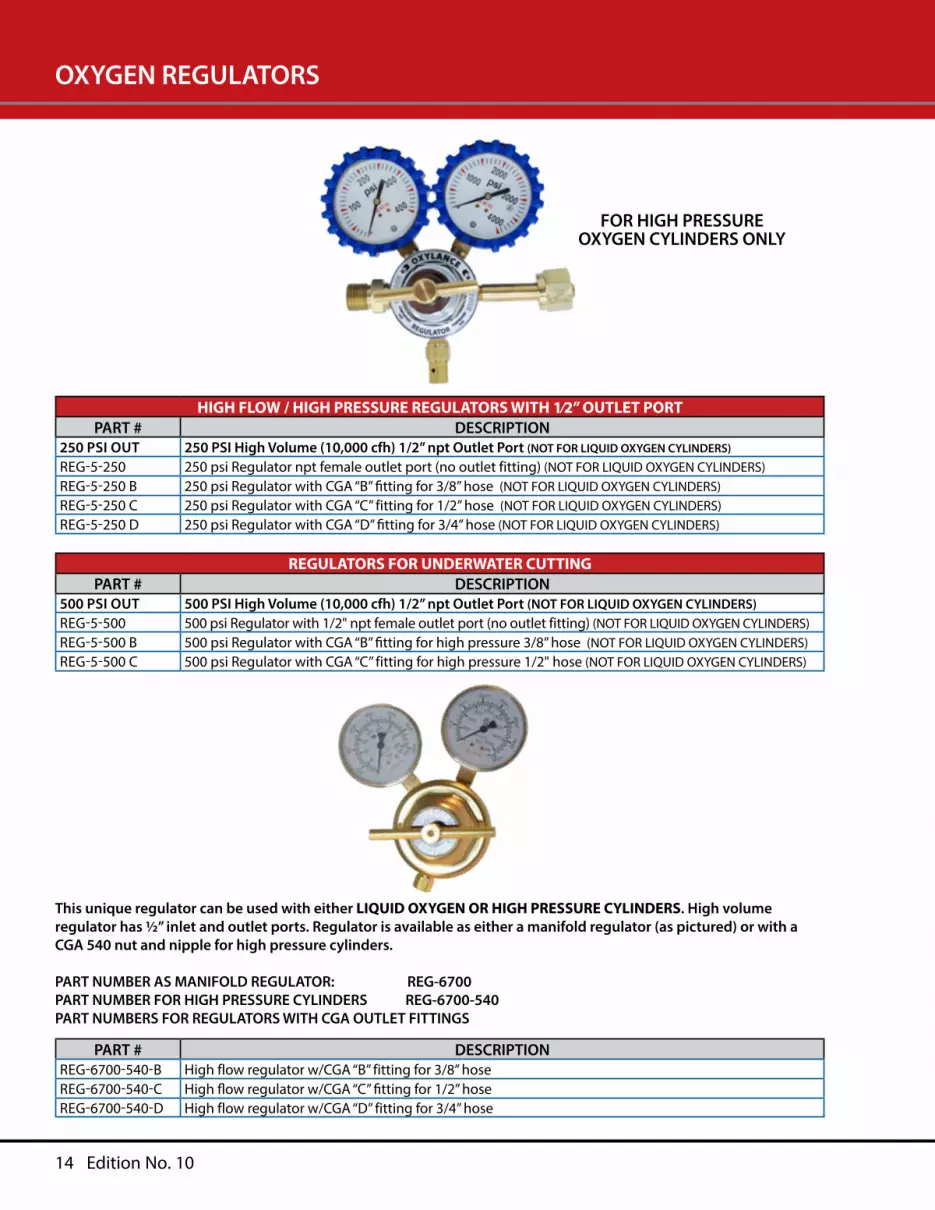
OXYGEN REGULATORS
HIGH FLOW / HIGH PRESSURE REGULATORS WITH 1⁄2” OUTLET PORTPART # DESCRIPTION
250 PSI OUT 250 PSI High Volume (10,000 cfh) 1/2” npt Outlet Port (NOT FOR LIQUID OXYGEN CYLINDERS)
REG-5-250 250 psi Regulator npt female outlet port (no outlet fitting) (NOT FOR LIQUID OXYGEN CYLINDERS)REG-5-250 B 250 psi Regulator with CGA “B” fitting for 3/8” hose (NOT FOR LIQUID OXYGEN CYLINDERS)REG-5-250 C 250 psi Regulator with CGA “C” fitting for 1/2” hose (NOT FOR LIQUID OXYGEN CYLINDERS)REG-5-250 D 250 psi Regulator with CGA “D” fitting for 3/4” hose (NOT FOR LIQUID OXYGEN CYLINDERS)
This unique regulator can be used with either LIQUID OXYGEN OR HIGH PRESSURE CYLINDERS. High volume regulator has ½” inlet and outlet ports. Regulator is available as either a manifold regulator (as pictured) or with a CGA 540 nut and nipple for high pressure cylinders.
PART NUMBER AS MANIFOLD REGULATOR: REG-6700PART NUMBER FOR HIGH PRESSURE CYLINDERS REG-6700-540PART NUMBERS FOR REGULATORS WITH CGA OUTLET FITTINGS
REGULATORS FOR UNDERWATER CUTTINGPART # DESCRIPTION
500 PSI OUT 500 PSI High Volume (10,000 cfh) 1/2” npt Outlet Port (NOT FOR LIQUID OXYGEN CYLINDERS)REG-5-500 500 psi Regulator with 1/2" npt female outlet port (no outlet fitting) (NOT FOR LIQUID OXYGEN CYLINDERS)REG-5-500 B 500 psi Regulator with CGA “B” fitting for high pressure 3/8” hose (NOT FOR LIQUID OXYGEN CYLINDERS)REG-5-500 C 500 psi Regulator with CGA “C” fitting for high pressure 1/2" hose (NOT FOR LIQUID OXYGEN CYLINDERS)
PART # DESCRIPTIONREG-6700-540-B High flow regulator w/CGA “B” fitting for 3/8” hoseREG-6700-540-C High flow regulator w/CGA “C” fitting for 1/2” hoseREG-6700-540-D High flow regulator w/CGA “D” fitting for 3/4” hose
FOR HIGH PRESSUREOXYGEN CYLINDERS ONLY

April 2021 15
OXYGEN LANCE HOSE
CALL FOR PART NUMBERS FOR 500 PSI LANCING OR SCARFING HOSE. THESE HOSES ARE SPECIAL ORDER AND ARE AVAILABLE IN 50 AND 100 FOOT LENGTHS ONLY.
AVAILABLE IN 1/2”, 3/4”, 1”, 1-1/4” AND 1-1/2” i.d.
PART # DESCRIPTIONHL3/8X25B Lance Hose 3/8” id X 25 feet long with CGA “B” fittingsHL3/8X50B Lance Hose 3/8” id X 50 feet long with CGA “B” fittingsHL3/8X75B Lance Hose 3/8” id X 75 feet long with CGA “B” fittingsHL3/8X100B Lance Hose 3/8” id X 100 feet long with CGA “B” fittingsHL3/8X50C Lance Hose 3/8” id X 50 feet long with CGA “C” fittingsHL3/8X75C Lance Hose 3/8” id X 75 feet long with CGA “C” fittingsHL3/8X100C Lance Hose 3/8” id X 100 feet long with CGA “C” fittings
3/8”, 1/2”, 3/4”PART # DESCRIPTION
HL1/2X50C Lance Hose 1/2” id X 50 feet long with CGA “C” fittingsHL1/2X75C Lance Hose 1/2” id X 75 feet long with CGA “C” fittingsHL1/2X100C Lance Hose 1/2” id X 100 feet long with CGA “C” fittingsHL1/2X150C Lance Hose 1/2” id X 150 feet long with CGA “C” fittingsHL3/4X50D Lance Hose 3/4” id X 50 feet long with CGA “D” fittingsHL3/4X100D Lance Hose 3/4” id X 100 feet long with CGA “D” fittingsHL3/4X125D Lance Hose 3/4” id X 125 feet long with CGA “D” fittings
Oxylance Inc. recommends minimum of 1/2” hose for all burning bar applications.
IF 3/8” HOSE IS USED IT MUST BE A SINGLE RUN OF HOSE WITH NO SPLICES OR CONNECTORS THAT WILL RESTRICT THE OXYGEN FLOW. REPAIRING 3/8” HOSE OR JOINING 2 SECTIONS TOGETHER WILL REDUCE THE FLOW TOO MUCH
FOR THE BURNING BAR TO OPERATE PROPERLY.
WE WILL NOT BE RESPONSIBLE FOR BURNING BAR PERFORMANCE IF USED WITH 3/8” HOSE.
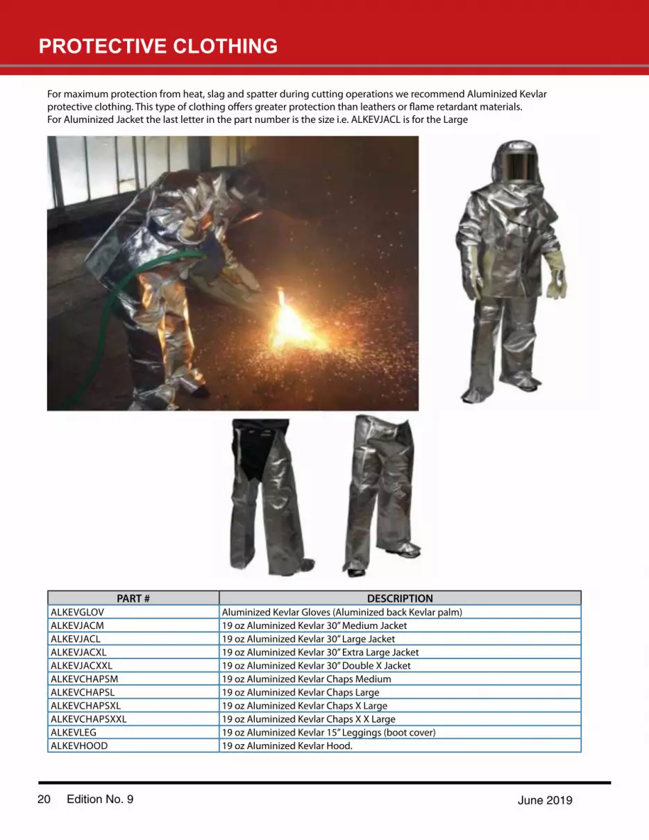
PROTECTIVE CLOTHING
20 Edition No. 9 June 2019
For maximum protection from heat, slag and spatter during cutting operations we recommend Aluminized Kevlar
For Aluminized Jacket the last letter in the part number is the size i.e. ALKEVJACL is for the Large
PART # DESCRIPTIONALKEVGLOV Aluminized Kevlar Gloves (Aluminized back Kevlar palm)ALKEVJACM 19 oz Aluminized Kevlar 30” Medium JacketALKEVJACL 19 oz Aluminized Kevlar 30” Large JacketALKEVJACXL 19 oz Aluminized Kevlar 30” Extra Large JacketALKEVJACXXL 19 oz Aluminized Kevlar 30” Double X JacketALKEVCHAPSM 19 oz Aluminized Kevlar Chaps MediumALKEVCHAPSL 19 oz Aluminized Kevlar Chaps LargeALKEVCHAPSXL 19 oz Aluminized Kevlar Chaps X LargeALKEVCHAPSXXL 19 oz Aluminized Kevlar Chaps X X LargeALKEVLEG 19 oz Aluminized Kevlar 15” Leggings (boot cover)ALKEVHOOD 19 oz Aluminized Kevlar Hood.
16 Edition No. 10
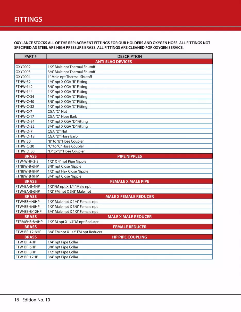
FITTINGS
PART # DESCRIPTIONANTI SLAG DEVICES
OXY0002 1/2” Male npt Thermal ShutoffOXY0003 3/4” Male npt Thermal ShutoffOXY0004 1” Male npt Thermal ShutoffFTHW-32 1/4” npt X CGA “B” FittingFTHW-142 3/8” npt X CGA “B” FittingFTHW-144 1/2” npt X CGA “B” FittingFTHW-C-34 1/4” npt X CGA “C” FittingFTHW-C-40 3/8” npt X CGA “C” FittingFTHW-C-32 1/2” npt X CGA “C” FittingFTHW-C-7 CGA "C" NutFTHW-C-17 CGA "C" Hose BarbFTHW-D-34 1/2” npt X CGA “D” FittingFTHW-D-32 3/4” npt X CGA “D” FittingFTHW-D-7 CGA "D" NutFTHW-D-18 CGA "D" Hose BarbFTHW-30 “B” to “B” Hose CouplerFTHW-C-30 “C” to “C” Hose CouplerFTHW-D-30 “D” to “D” Hose Coupler
BRASS PIPE NIPPLESFTW-WHF-3-3 1/2” X 4” npt Pipe NippleFTNBW-B-6HP 3/8” npt Close NippleFTNBW-B-8HP 1/2” npt Hex Close NippleFTNBW-B-9HP 3/4” npt Close Nipple
BRASS FEMALE X MALE PIPEFTW-BA-8-4HP 1/2”FM npt X 1/4” Male nptFTW-BA-8-6HP 1/2” FM npt X 3/8” Male npt
BRASS MALE X FEMALE REDUCERFTW-BB-4-8HP 1/2” Male npt X 1/4” Female nptFTW-BB-6-8HP 1/2” Male npt X 3/8” Female nptFTW-BB-8-12HP 3/4” Male npt X 1/2” Female npt
BRASS MALE X MALE REDUCERFTRMW-B-8-4HP 1/2” M npt X 1/4” M npt Reducer
BRASS FEMALE REDUCERFTW-BF-12-8HP 3/4” FM npt X 1/2” FM npt Reducer
BRASS HP PIPE COUPLINGFTW-BF-4HP 1/4” npt Pipe CollarFTW-BF-6HP 3/8” npt Pipe CollarFTW-BF-8HP 1/2” npt Pipe CollarFTW-BF-12HP 3/4” npt Pipe Collar
OXYLANCE STOCKS ALL OF THE REPLACEMENT FITTINGS FOR OUR HOLDERS AND OXYGEN HOSE. ALL FITTINGS NOT SPECIFIED AS STEEL ARE HIGH PRESSURE BRASS. ALL FITTINGS ARE CLEANED FOR OXYGEN SERVICE.
April 2021 22
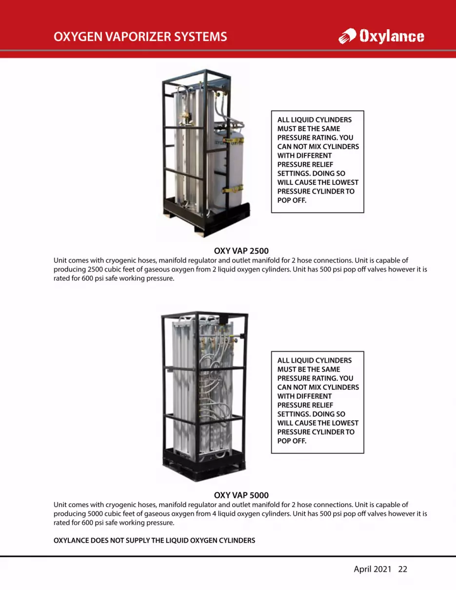
OXYGEN VAPORIZER SYSTEMS
ALL LIQUID CYLINDERS MUST BE THE SAME PRESSURE RATING. YOU CAN NOT MIX CYLINDERS WITH DIFFERENT PRESSURE RELIEF SETTINGS. DOING SO WILL CAUSE THE LOWEST PRESSURE CYLINDER TO POP OFF.
OXY VAP 2500Unit comes with cryogenic hoses, manifold regulator and outlet manifold for 2 hose connections. Unit is capable of producing 2500 cubic feet of gaseous oxygen from 2 liquid oxygen cylinders. Unit has 500 psi pop off valves however it is rated for 600 psi safe working pressure.
ALL LIQUID CYLINDERS MUST BE THE SAME PRESSURE RATING. YOU CAN NOT MIX CYLINDERS WITH DIFFERENT PRESSURE RELIEF SETTINGS. DOING SO WILL CAUSE THE LOWEST PRESSURE CYLINDER TO POP OFF.
OXY VAP 5000Unit comes with cryogenic hoses, manifold regulator and outlet manifold for 2 hose connections. Unit is capable of producing 5000 cubic feet of gaseous oxygen from 4 liquid oxygen cylinders. Unit has 500 psi pop off valves however it is rated for 600 psi safe working pressure.
OXYLANCE DOES NOT SUPPLY THE LIQUID OXYGEN CYLINDERS
HIGH VOLUME GASOUS OXYGENFROM LIQUID CONTAINERS
28 Edition No. 9 June 2019
Liquid Oxygen is used daily to supply gaseous oxygen for a wide variety of construction and demolition projects. Its convenient size is advantageous when you consider that a single XL-45 liquid container will produce 4350 cubic feet of gaseous oxygen. This is equivalent to sixteen 276 cubic feett, high pressure cylinders.
With convenience there is always a drawback. In the case of liquid oxygen the down side is available pressure and volume. For potential users who do not know and understand the pressure verses volume issue, using liquid oxygen may cause performance problems with some equipment.
The volume of gaseous oxygen that a portable liquid container can supply is limited by the vaporization rate of the
feet per hour (CFH) at 125 PSI, at an ambient temperature of 70o F. Newer models have been designed to supply up to 350 CFH at 250 PSI. Some models have been increased to 450 psi and up to 500 CFH, High-pressure cylinders, can supply 50 or more cubic feet per minute depending on the regulator and hose diameter. Manifolded together a bank of high-
there is a group of laws called the Gas Laws. “Charles Law” states that; “At a constant pressure the volume of a gas is directly proportional to the change in the absolute temperature. If the pressure is kept constant and the absolute temperature is doubled, the volume will double. As temperature decreases, so does the volume”.
A liquid oxygen container is a vacuum-insulated cylinder, basically a giant thermos bottle. It is designed to supply oxygen in either a liquid state or gas in the form of oxygen vapor. The boiling point of liquid oxygen is minus 297 F (297 below 0). When it reaches its boiling point, liquid oxygen becomes oxygen vapor. In order to get the optimum volume of vapor from the liquid source the temperature of the oxygen vapor must be elevated to ambient temperature. Portable containers incorporate an internal vaporizer (heat exchanger) to elevate the gas temperature.
drop to the point that the external plumbing and the attached regulator will become crusted with ice. When this occurs, the density and temperature of the gas drops to the point that it becomes a safety hazard and can cause damage to regulators, hoses and other downstream components.
is to manifold multiple liquid containers together. By manifolding two or more containers together and making their
provide 450 CFH. You can manifold as many tanks together as are required for the application.
The second method is to add an external vaporizer (heat exchanger) to the liquid container. External vaporizers come in a variety of sizes from 250 CFH to over 10,000 CFH. The most common one hangs on the side of the liquid container and is
on ambient air temperature 70o F). Any combination of liquid containers and vaporizers can be assembled to meet the volume requirements.
separate manifold, manifold the VENT valves together. This manifold will cause the liquid tanks to equalize so when gas is withdrawn from the system it draws equally from all of the tanks.
When using multiple containers with or without an external vaporizer, the following valve settings are required for maximum vaporization: Liquid valve CLOSED, Vent valves FULL OPEN, Use valves FULL OPEN, and the Pressure Building valves FULL OPEN. When using the external heat exchanger, you connect the use valve or use valve manifold, to the input side of the vaporizer and the regulator on the output side. You DO NOT put the regulator between the liquid container and the external vaporizer.
Edition No. 9 June 2019 29
HIGH VOLUME GASOUS OXYGENFROM LIQUID CONTAINERS contunued
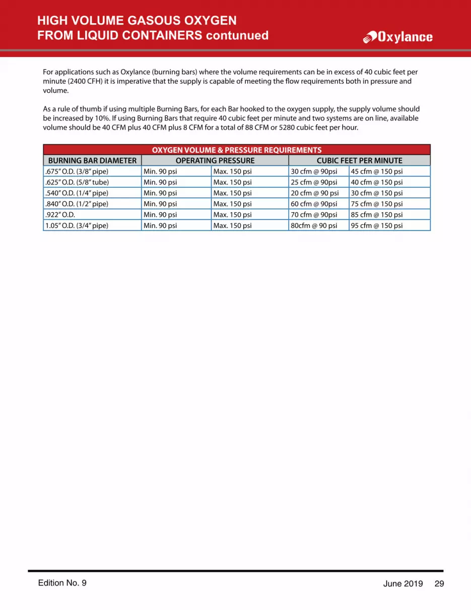
For applications such as Oxylance (burning bars) where the volume requirements can be in excess of 40 cubic feet per
volume.
As a rule of thumb if using multiple Burning Bars, for each Bar hooked to the oxygen supply, the supply volume should be increased by 10%. If using Burning Bars that require 40 cubic feet per minute and two systems are on line, available volume should be 40 CFM plus 40 CFM plus 8 CFM for a total of 88 CFM or 5280 cubic feet per hour.
OXYGEN VOLUME & PRESSURE REQUIREMENTS BURNING BAR DIAMETER OPERATING PRESSURE CUBIC FEET PER MINUTE
.675” O.D. (3/8” pipe) Min. 90 psi Max. 150 psi 30 cfm @ 90psi 45 cfm @ 150 psi
.625” O.D. (5/8” tube) Min. 90 psi Max. 150 psi 25 cfm @ 90psi 40 cfm @ 150 psi
.540” O.D. (1/4” pipe) Min. 90 psi Max. 150 psi 20 cfm @ 90 psi 30 cfm @ 150 psi
.840” O.D. (1/2” pipe) Min. 90 psi Max. 150 psi 60 cfm @ 90psi 75 cfm @ 150 psi
.922” O.D. Min. 90 psi Max. 150 psi 70 cfm @ 90psi 85 cfm @ 150 psi1.05” O.D. (3/4” pipe) Min. 90 psi Max. 150 psi 80cfm @ 90 psi 95 cfm @ 150 psi
April 2021 17
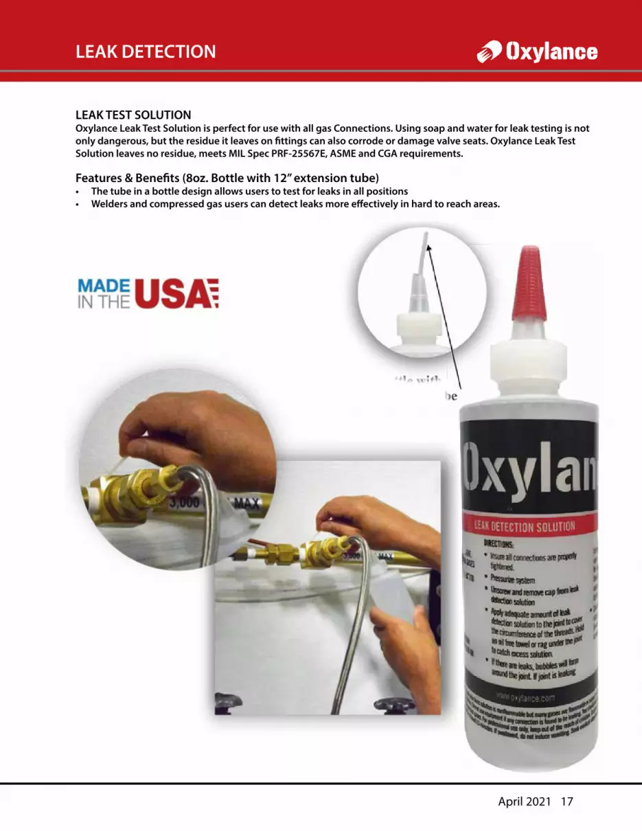
LEAK DETECTION
LEAK TEST SOLUTIONOxylance Leak Test Solution is perfect for use with all gas Connections. Using soap and water for leak testing is not only dangerous, but the residue it leaves on fittings can also corrode or damage valve seats. Oxylance Leak Test Solution leaves no residue, meets MIL Spec PRF-25567E, ASME and CGA requirements.
Features & Benefits (8oz. Bottle with 12” extension tube)• The tube in a bottle design allows users to test for leaks in all positions• Welders and compressed gas users can detect leaks more effectively in hard to reach areas.


