Embed Size (px)
Citation preview
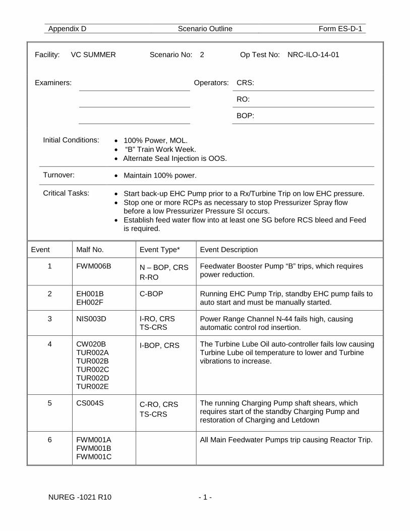
Appendix D Scenario Outline Form ES-D-1
NUREG -1021 R10 - 1 -
Facility: VC SUMMER Scenario No: 2 Op Test No: NRC-ILO-14-01
Examiners: Operators: CRS:
RO:
BOP:
Initial Conditions: • 100% Power, MOL. • “B” Train Work Week. • Alternate Seal Injection is OOS.
Turnover: • Maintain 100% power.
Critical Tasks: • Start back-up EHC Pump prior to a Rx/Turbine Trip on low EHC pressure. • Stop one or more RCPs as necessary to stop Pressurizer Spray flow
before a low Pressurizer Pressure SI occurs. • Establish feed water flow into at least one SG before RCS bleed and Feed
is required.
Event Malf No. Event Type* Event Description
1 FWM006B N – BOP, CRS R-RO
Feedwater Booster Pump “B” trips, which requires power reduction.
2 EH001B EH002F
C-BOP
Running EHC Pump Trip, standby EHC pump fails to auto start and must be manually started.
3 NIS003D I-RO, CRS TS-CRS
Power Range Channel N-44 fails high, causing automatic control rod insertion.
4 CW020B TUR002A TUR002B TUR002C TUR002D TUR002E
I-BOP, CRS The Turbine Lube Oil auto-controller fails low causing Turbine Lube oil temperature to lower and Turbine vibrations to increase.
5 CS004S C-RO, CRS TS-CRS
The running Charging Pump shaft shears, which requires start of the standby Charging Pump and restoration of Charging and Letdown
6 FWM001A FWM001B FWM001C
All Main Feedwater Pumps trip causing Reactor Trip.
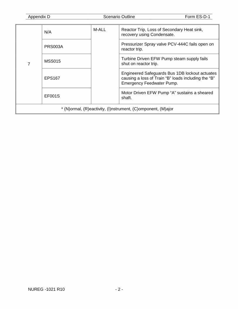
Appendix D Scenario Outline Form ES-D-1
NUREG -1021 R10 - 2 -
7
N/A M-ALL Reactor Trip, Loss of Secondary Heat sink, recovery using Condensate.
PRS003A Pressurizer Spray valve PCV-444C fails open on reactor trip.
MSS015 Turbine Driven EFW Pump steam supply fails shut on reactor trip.
EPS167 Engineered Safeguards Bus 1DB lockout actuates causing a loss of Train “B” loads including the “B” Emergency Feedwater Pump.
EF001S Motor Driven EFW Pump “A” sustains a sheared shaft.
* (N)ormal, (R)eactivity, (I)nstrument, (C)omponent, (M)ajor
Appendix D Scenario Outline Form ES-D-1
NUREG -1021 R10 - 3 -
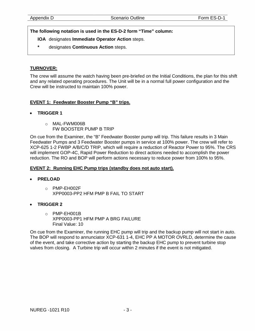
The following notation is used in the ES-D-2 form “Time” column: IOA designates Immediate Operator Action steps.
* designates Continuous Action steps.
TURNOVER: The crew will assume the watch having been pre-briefed on the Initial Conditions, the plan for this shift and any related operating procedures. The Unit will be in a normal full power configuration and the Crew will be instructed to maintain 100% power.
EVENT 1: Feedwater Booster Pump “B” trips. • TRIGGER 1
o MAL-FWM006B
FW BOOSTER PUMP B TRIP
On cue from the Examiner, the “B” Feedwater Booster pump will trip. This failure results in 3 Main Feedwater Pumps and 3 Feedwater Booster pumps in service at 100% power. The crew will refer to XCP-625 1-2 FWBP A/B/C/D TRIP, which will require a reduction of Reactor Power to 95%. The CRS will implement GOP-4C, Rapid Power Reduction to direct actions needed to accomplish the power reduction. The RO and BOP will perform actions necessary to reduce power from 100% to 95%.
EVENT 2: Running EHC Pump trips (standby does not auto start). • PRELOAD
o PMP-EH002F XPP0003-PP2 HFM PMP B FAIL TO START
• TRIGGER 2
o PMP-EH001B XPP0003-PP1 HFM PMP A BRG FAILURE Final Value: 10
On cue from the Examiner, the running EHC pump will trip and the backup pump will not start in auto. The BOP will respond to annunciator XCP-631 1-4, EHC PP A MOTOR OVRLD, determine the cause of the event, and take corrective action by starting the backup EHC pump to prevent turbine stop valves from closing. A Turbine trip will occur within 2 minutes if the event is not mitigated.
Appendix D Scenario Outline Form ES-D-1
NUREG -1021 R10 - 4 -
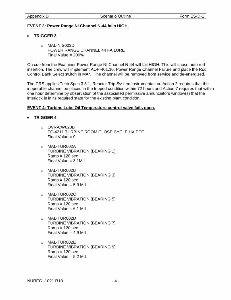
EVENT 3: Power Range NI Channel N-44 fails HIGH. • TRIGGER 3
o MAL-NIS003D
POWER RANGE CHANNEL 44 FAILURE Final Value = 200%
On cue from the Examiner Power Range NI Channel N-44 will fail HIGH. This will cause auto rod insertion. The crew will implement AOP-401.10, Power Range Channel Failure and place the Rod Control Bank Select switch in MAN. The channel will be removed from service and de-energized. The CRS applies Tech Spec 3.3.1, Reactor Trip System Instrumentation. Action 2 requires that the inoperable channel be placed in the tripped condition within 72 hours and Action 7 requires that within one hour determine by observation of the associated permissive annunciators window(s) that the interlock is in its required state for the existing plant condition. EVENT 4: Turbine Lube Oil Temperature control valve fails open. • TRIGGER 4
o OVR-CW020B
TC-4211 TURBINE ROOM CLOSE CYCLE HX POT Final Value = 0
o MAL-TUR002A TURBINE VIBRATION (BEARING 1) Ramp = 120 sec Final Value = 3.1MIL
o MAL-TUR002B TURBINE VIBRATION (BEARING 3) Ramp = 120 sec Final Value = 5.9 MIL
o MAL-TUR002C TURBINE VIBRATION (BEARING 5) Ramp = 120 sec Final Value = 6.1 MIL
o MAL-TUR002D TURBINE VIBRATION (BEARING 7) Ramp = 120 sec Final Value = 4.9 MIL
o MAL-TUR002E TURBINE VIBRATION (BEARING 9) Ramp = 120 sec Final Value = 5.2 MIL
Appendix D Scenario Outline Form ES-D-1
NUREG -1021 R10 - 5 -
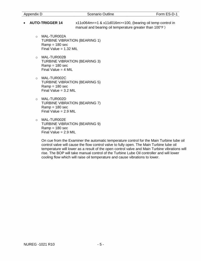
• AUTO-TRIGGER 14 x11o064m==1 & x11d016m>=100, (bearing oil temp control in manual and bearing oil temperature greater than 100°F)
o MAL-TUR002A
TURBINE VIBRATION (BEARING 1) Ramp = 180 sec Final Value = 1.32 MIL
o MAL-TUR002B TURBINE VIBRATION (BEARING 3) Ramp = 180 sec Final Value = 4 MIL
o MAL-TUR002C
TURBINE VIBRATION (BEARING 5) Ramp = 180 sec Final Value = 3.2 MIL
o MAL-TUR002D TURBINE VIBRATION (BEARING 7) Ramp = 180 sec Final Value = 2.9 MIL
o MAL-TUR002E TURBINE VIBRATION (BEARING 9) Ramp = 180 sec Final Value = 2.9 MIL On cue from the Examiner the automatic temperature control for the Main Turbine lube oil control valve will cause the flow control valve to fully open. The Main Turbine lube oil temperature will lower as a result of the open control valve and Main Turbine vibrations will rise. The BOP will take manual control of the Turbine Lube Oil controller and will lower cooling flow which will raise oil temperature and cause vibrations to lower.
Appendix D Scenario Outline Form ES-D-1
NUREG -1021 R10 - 6 -
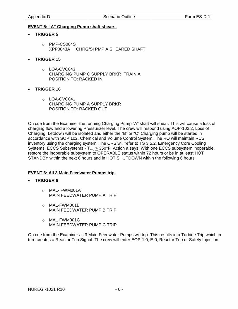
EVENT 5: “A” Charging Pump shaft shears.
• TRIGGER 5
o PMP-CS004S XPP0043A CHRG/SI PMP A SHEARED SHAFT
• TRIGGER 15
o LOA-CVC043 CHARGING PUMP C SUPPLY BRKR TRAIN A POSITION TO: RACKED IN
• TRIGGER 16
o LOA-CVC041 CHARGING PUMP A SUPPLY BRKR POSITION TO: RACKED OUT
On cue from the Examiner the running Charging Pump “A” shaft will shear. This will cause a loss of charging flow and a lowering Pressurizer level. The crew will respond using AOP-102.2, Loss of Charging. Letdown will be isolated and either the “B” or “C” Charging pump will be started in accordance with SOP 102, Chemical and Volume Control System. The RO will maintain RCS inventory using the charging system. The CRS will refer to TS 3.5.2, Emergency Core Cooling Systems, ECCS Subsystems - Tavg > 350°F. Action a says: With one ECCS subsystem inoperable, restore the inoperable subsystem to OPERABLE status within 72 hours or be in at least HOT STANDBY within the next 6 hours and in HOT SHUTDOWN within the following 6 hours. EVENT 6: All 3 Main Feedwater Pumps trip.
• TRIGGER 6
o MAL- FWM001A MAIN FEEDWATER PUMP A TRIP
o MAL-FWM001B MAIN FEEDWATER PUMP B TRIP
o MAL-FWM001C MAIN FEEDWATER PUMP C TRIP
On cue from the Examiner all 3 Main Feedwater Pumps will trip. This results in a Turbine Trip which in turn creates a Reactor Trip Signal. The crew will enter EOP-1.0, E-0, Reactor Trip or Safety Injection.
Appendix D Scenario Outline Form ES-D-1
NUREG -1021 R10 - 7 -
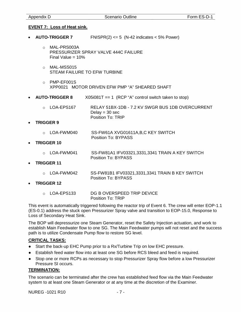
EVENT 7: Loss of Heat sink. • AUTO-TRIGGER 7 FNISPR(2) <= 5 (N-42 indicates < 5% Power)
o MAL-PRS003A PRESSURIZER SPRAY VALVE 444C FAILURE Final Value = 10%
o MAL-MSS015
STEAM FAILURE TO EFW TURBINE o PMP-EF001S
XPP0021 MOTOR DRIVEN EFW PMP “A” SHEARED SHAFT
• AUTO-TRIGGER 8 X05i081T == 1 (RCP “A” control switch taken to stop)
o LOA-EPS167 RELAY 51BX-1DB - 7.2 KV SWGR BUS 1DB OVERCURRENT Delay = 30 sec Position To: TRIP
• TRIGGER 9
o LOA-FWM040 SS-FW61A XVG01611A,B,C KEY SWITCH Position To: BYPASS • TRIGGER 10
o LOA-FWM041 SS-FW81A1 IFV03321,3331,3341 TRAIN A KEY SWITCH Position To: BYPASS • TRIGGER 11
o LOA-FWM042 SS-FW81B1 IFV03321,3331,3341 TRAIN B KEY SWITCH Position To: BYPASS • TRIGGER 12
o LOA-EPS133 DG B OVERSPEED TRIP DEVICE Position To: TRIP
This event is automatically triggered following the reactor trip of Event 6. The crew will enter EOP-1.1 (ES-0.1) address the stuck open Pressurizer Spray valve and transition to EOP-15.0, Response to Loss of Secondary Heat Sink.
The BOP will depressurize one Steam Generator, reset the Safety Injection actuation, and work to establish Main Feedwater flow to one SG. The Main Feedwater pumps will not reset and the success path is to utilize Condensate Pump flow to restore SG level.
CRITICAL TASKS: ● Start the back-up EHC Pump prior to a Rx/Turbine Trip on low EHC pressure. ● Establish feed water flow into at least one SG before RCS bleed and feed is required. ● Stop one or more RCPs as necessary to stop Pressurizer Spray flow before a low Pressurizer
Pressure SI occurs. TERMINATION: The scenario can be terminated after the crew has established feed flow via the Main Feedwater system to at least one Steam Generator or at any time at the discretion of the Examiner.
Appendix D Scenario Outline Form ES-D-1
NUREG -1021 R10 - 8 -
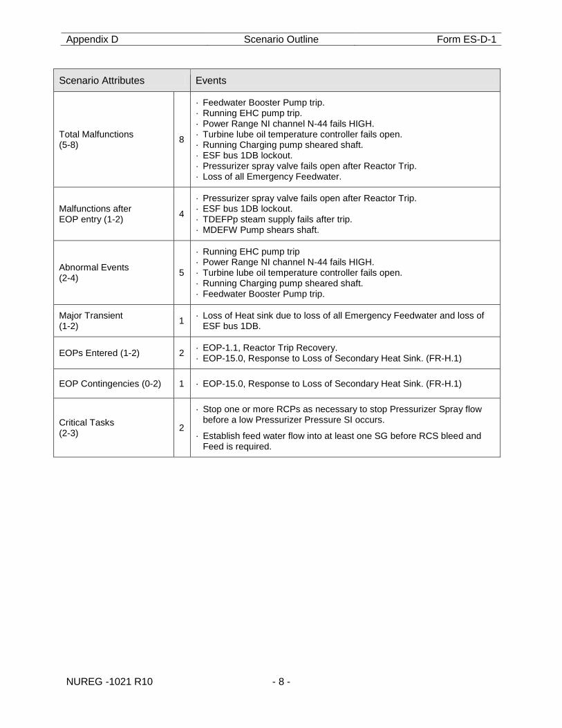
Scenario Attributes Events
Total Malfunctions (5-8) 8
· Feedwater Booster Pump trip. · Running EHC pump trip. · Power Range NI channel N-44 fails HIGH. · Turbine lube oil temperature controller fails open. · Running Charging pump sheared shaft. · ESF bus 1DB lockout. · Pressurizer spray valve fails open after Reactor Trip. · Loss of all Emergency Feedwater.
Malfunctions after EOP entry (1-2) 4
· Pressurizer spray valve fails open after Reactor Trip. · ESF bus 1DB lockout. · TDEFPp steam supply fails after trip. · MDEFW Pump shears shaft.
Abnormal Events (2-4) 5
· Running EHC pump trip · Power Range NI channel N-44 fails HIGH. · Turbine lube oil temperature controller fails open. · Running Charging pump sheared shaft. · Feedwater Booster Pump trip.
Major Transient (1-2) 1 · Loss of Heat sink due to loss of all Emergency Feedwater and loss of
ESF bus 1DB.
EOPs Entered (1-2) 2 · EOP-1.1, Reactor Trip Recovery. · EOP-15.0, Response to Loss of Secondary Heat Sink. (FR-H.1)
EOP Contingencies (0-2) 1 · EOP-15.0, Response to Loss of Secondary Heat Sink. (FR-H.1)
Critical Tasks (2-3) 2
· Stop one or more RCPs as necessary to stop Pressurizer Spray flow before a low Pressurizer Pressure SI occurs.
· Establish feed water flow into at least one SG before RCS bleed and Feed is required.
Appendix D Scenario Outline Form ES-D-1
NUREG -1021 R10 - 9 -
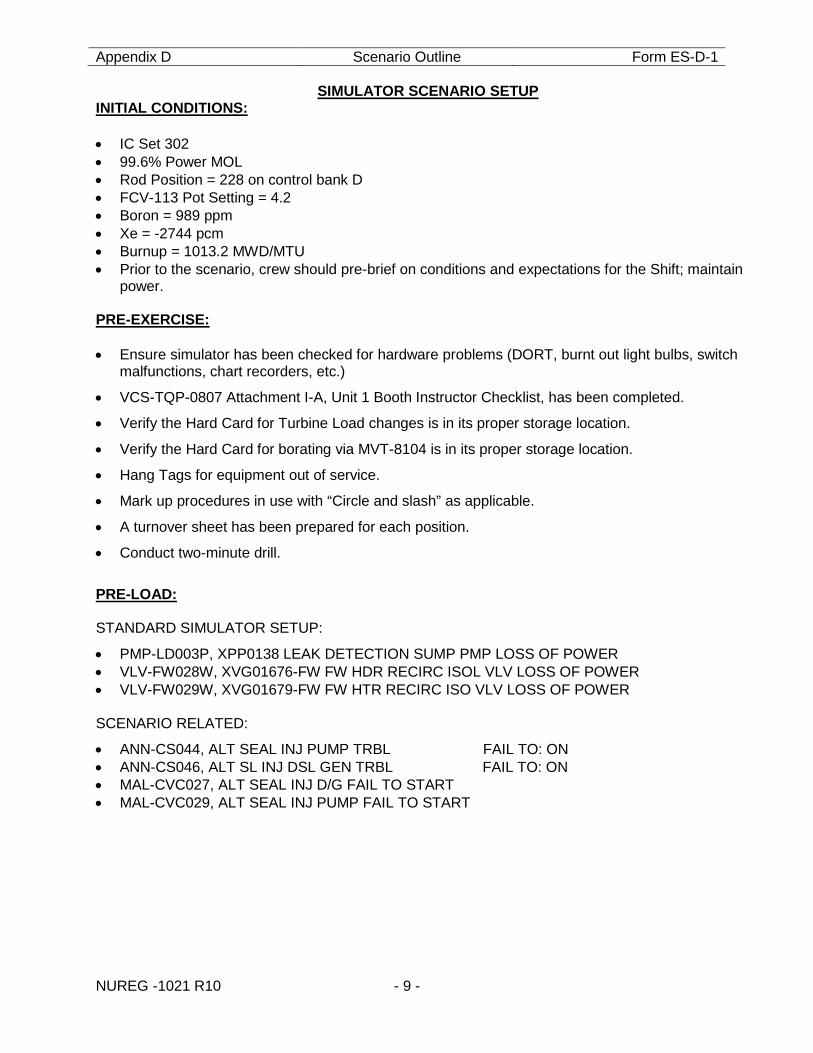
SIMULATOR SCENARIO SETUP INITIAL CONDITIONS: • IC Set 302 • 99.6% Power MOL • Rod Position = 228 on control bank D • FCV-113 Pot Setting = 4.2 • Boron = 989 ppm • Xe = -2744 pcm • Burnup = 1013.2 MWD/MTU • Prior to the scenario, crew should pre-brief on conditions and expectations for the Shift; maintain
power. PRE-EXERCISE: • Ensure simulator has been checked for hardware problems (DORT, burnt out light bulbs, switch
malfunctions, chart recorders, etc.)
• VCS-TQP-0807 Attachment I-A, Unit 1 Booth Instructor Checklist, has been completed.
• Verify the Hard Card for Turbine Load changes is in its proper storage location.
• Verify the Hard Card for borating via MVT-8104 is in its proper storage location.
• Hang Tags for equipment out of service.
• Mark up procedures in use with “Circle and slash” as applicable.
• A turnover sheet has been prepared for each position.
• Conduct two-minute drill.
PRE-LOAD: STANDARD SIMULATOR SETUP:
• PMP-LD003P, XPP0138 LEAK DETECTION SUMP PMP LOSS OF POWER • VLV-FW028W, XVG01676-FW FW HDR RECIRC ISOL VLV LOSS OF POWER • VLV-FW029W, XVG01679-FW FW HTR RECIRC ISO VLV LOSS OF POWER SCENARIO RELATED:
• ANN-CS044, ALT SEAL INJ PUMP TRBL FAIL TO: ON • ANN-CS046, ALT SL INJ DSL GEN TRBL FAIL TO: ON • MAL-CVC027, ALT SEAL INJ D/G FAIL TO START • MAL-CVC029, ALT SEAL INJ PUMP FAIL TO START
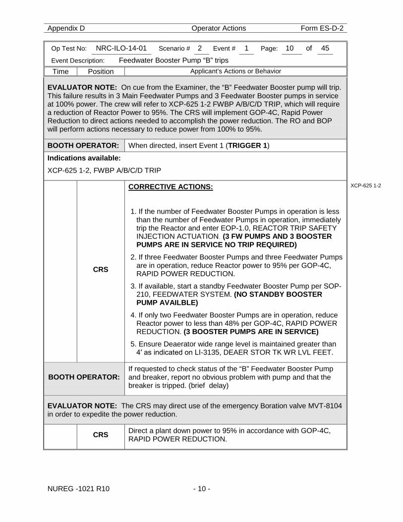
Appendix D Operator Actions Form ES-D-2
Op Test No: NRC-ILO-14-01 Scenario # 2 Event # 1 Page: 10 of 45
Event Description: Feedwater Booster Pump “B” trips
Time Position Applicant’s Actions or Behavior
NUREG -1021 R10 - 10 -
EVALUATOR NOTE: On cue from the Examiner, the “B” Feedwater Booster pump will trip. This failure results in 3 Main Feedwater Pumps and 3 Feedwater Booster pumps in service at 100% power. The crew will refer to XCP-625 1-2 FWBP A/B/C/D TRIP, which will require a reduction of Reactor Power to 95%. The CRS will implement GOP-4C, Rapid Power Reduction to direct actions needed to accomplish the power reduction. The RO and BOP will perform actions necessary to reduce power from 100% to 95%.
BOOTH OPERATOR: When directed, insert Event 1 (TRIGGER 1)
Indications available: XCP-625 1-2, FWBP A/B/C/D TRIP
CRS
CORRECTIVE ACTIONS: 1. If the number of Feedwater Booster Pumps in operation is less
than the number of Feedwater Pumps in operation, immediately trip the Reactor and enter EOP-1.0, REACTOR TRIP SAFETY INJECTION ACTUATION. (3 FW PUMPS AND 3 BOOSTER PUMPS ARE IN SERVICE NO TRIP REQUIRED)
2. If three Feedwater Booster Pumps and three Feedwater Pumps are in operation, reduce Reactor power to 95% per GOP-4C, RAPID POWER REDUCTION.
3. If available, start a standby Feedwater Booster Pump per SOP-210, FEEDWATER SYSTEM. (NO STANDBY BOOSTER PUMP AVAILBLE)
4. If only two Feedwater Booster Pumps are in operation, reduce Reactor power to less than 48% per GOP-4C, RAPID POWER REDUCTION. (3 BOOSTER PUMPS ARE IN SERVICE)
5. Ensure Deaerator wide range level is maintained greater than 4′ as indicated on LI-3135, DEAER STOR TK WR LVL FEET.
XCP-625 1-2
BOOTH OPERATOR: If requested to check status of the “B” Feedwater Booster Pump and breaker, report no obvious problem with pump and that the breaker is tripped. (brief delay)
EVALUATOR NOTE: The CRS may direct use of the emergency Boration valve MVT-8104 in order to expedite the power reduction.
CRS Direct a plant down power to 95% in accordance with GOP-4C, RAPID POWER REDUCTION.
Appendix D Operator Actions Form ES-D-2
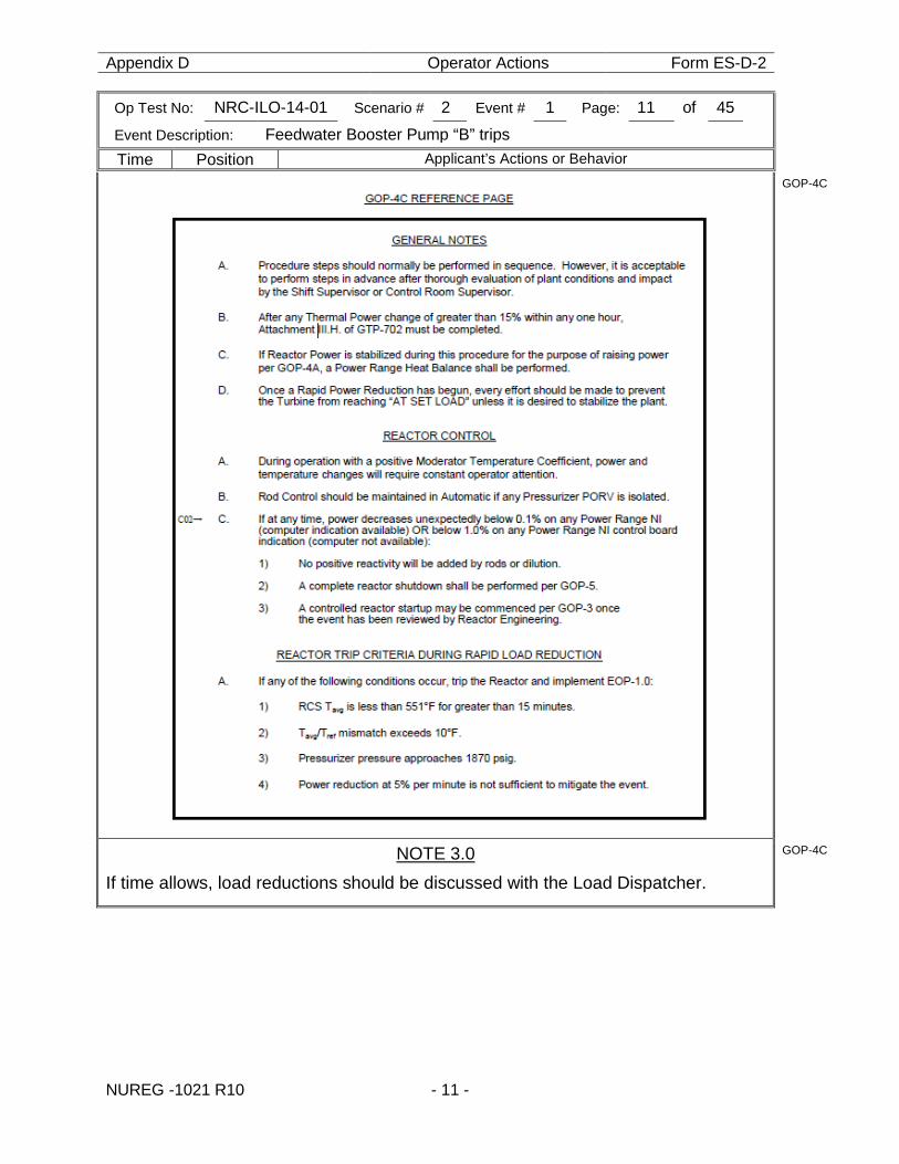
Op Test No: NRC-ILO-14-01 Scenario # 2 Event # 1 Page: 11 of 45
Event Description: Feedwater Booster Pump “B” trips
Time Position Applicant’s Actions or Behavior
NUREG -1021 R10 - 11 -
GOP-4C
NOTE 3.0 If time allows, load reductions should be discussed with the Load Dispatcher.
GOP-4C
Appendix D Operator Actions Form ES-D-2
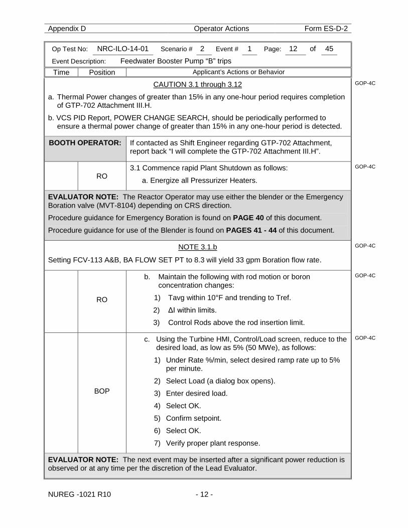
Op Test No: NRC-ILO-14-01 Scenario # 2 Event # 1 Page: 12 of 45
Event Description: Feedwater Booster Pump “B” trips
Time Position Applicant’s Actions or Behavior
NUREG -1021 R10 - 12 -
CAUTION 3.1 through 3.12
a. Thermal Power changes of greater than 15% in any one-hour period requires completion of GTP-702 Attachment III.H.
b. VCS PID Report, POWER CHANGE SEARCH, should be periodically performed to ensure a thermal power change of greater than 15% in any one-hour period is detected.
GOP-4C
BOOTH OPERATOR: If contacted as Shift Engineer regarding GTP-702 Attachment, report back “I will complete the GTP-702 Attachment III.H”.
RO
3.1 Commence rapid Plant Shutdown as follows:
a. Energize all Pressurizer Heaters.
GOP-4C
EVALUATOR NOTE: The Reactor Operator may use either the blender or the Emergency Boration valve (MVT-8104) depending on CRS direction.
Procedure guidance for Emergency Boration is found on PAGE 40 of this document.
Procedure guidance for use of the Blender is found on PAGES 41 - 44 of this document.
NOTE 3.1.b
Setting FCV-113 A&B, BA FLOW SET PT to 8.3 will yield 33 gpm Boration flow rate.
GOP-4C
RO
b. Maintain the following with rod motion or boron concentration changes:
1) Tavg within 10°F and trending to Tref.
2) ΔI within limits.
3) Control Rods above the rod insertion limit.
GOP-4C
BOP
c. Using the Turbine HMI, Control/Load screen, reduce to the desired load, as low as 5% (50 MWe), as follows:
1) Under Rate %/min, select desired ramp rate up to 5% per minute.
2) Select Load (a dialog box opens).
3) Enter desired load.
4) Select OK.
5) Confirm setpoint.
6) Select OK.
7) Verify proper plant response.
GOP-4C
EVALUATOR NOTE: The next event may be inserted after a significant power reduction is observed or at any time per the discretion of the Lead Evaluator.
Appendix D Operator Actions Form ES-D-2
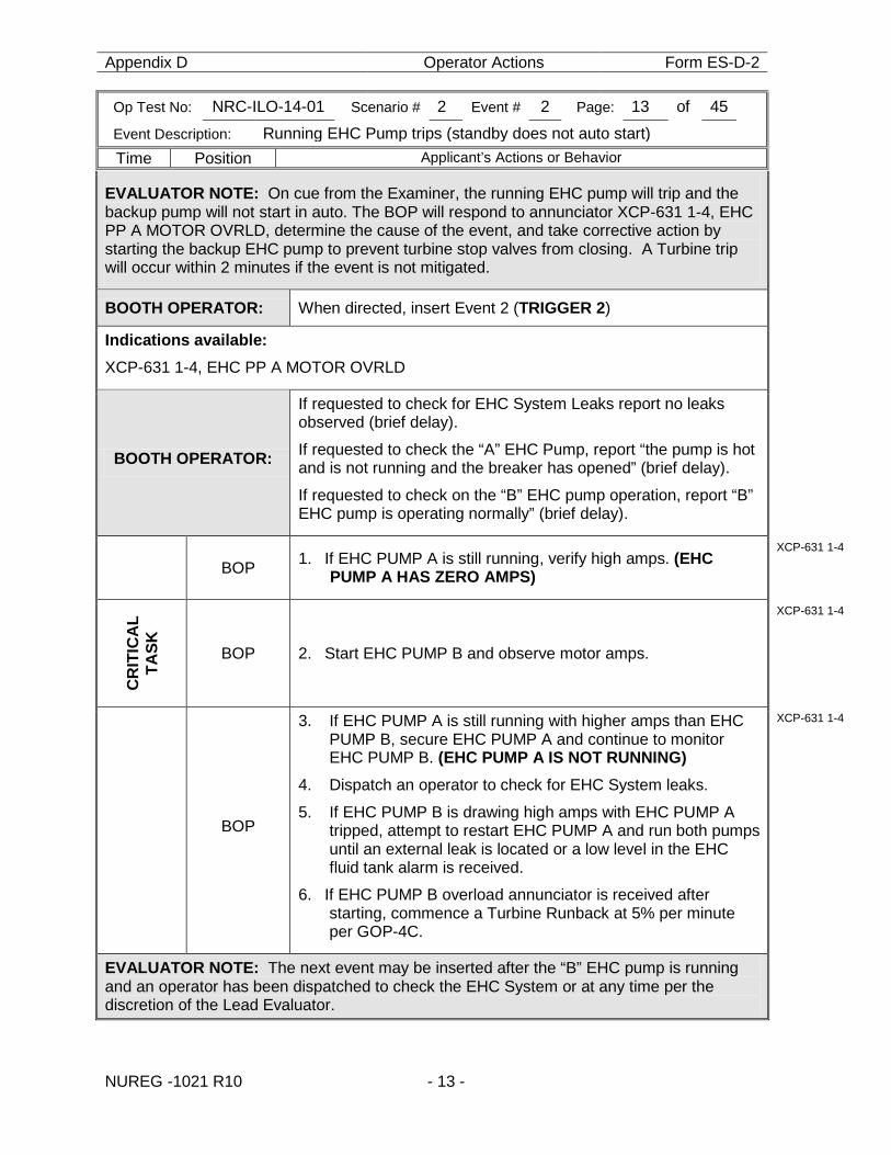
Op Test No: NRC-ILO-14-01 Scenario # 2 Event # 2 Page: 13 of 45
Event Description: Running EHC Pump trips (standby does not auto start)
Time Position Applicant’s Actions or Behavior
NUREG -1021 R10 - 13 -
EVALUATOR NOTE: On cue from the Examiner, the running EHC pump will trip and the backup pump will not start in auto. The BOP will respond to annunciator XCP-631 1-4, EHC PP A MOTOR OVRLD, determine the cause of the event, and take corrective action by starting the backup EHC pump to prevent turbine stop valves from closing. A Turbine trip will occur within 2 minutes if the event is not mitigated.
BOOTH OPERATOR: When directed, insert Event 2 (TRIGGER 2)
Indications available: XCP-631 1-4, EHC PP A MOTOR OVRLD
BOOTH OPERATOR:
If requested to check for EHC System Leaks report no leaks observed (brief delay).
If requested to check the “A” EHC Pump, report “the pump is hot and is not running and the breaker has opened” (brief delay).
If requested to check on the “B” EHC pump operation, report “B” EHC pump is operating normally” (brief delay).
BOP 1. If EHC PUMP A is still running, verify high amps. (EHC PUMP A HAS ZERO AMPS)
XCP-631 1-4
CR
ITIC
AL
TASK
BOP 2. Start EHC PUMP B and observe motor amps.
XCP-631 1-4
BOP
3. If EHC PUMP A is still running with higher amps than EHC PUMP B, secure EHC PUMP A and continue to monitor EHC PUMP B. (EHC PUMP A IS NOT RUNNING)
4. Dispatch an operator to check for EHC System leaks.
5. If EHC PUMP B is drawing high amps with EHC PUMP A tripped, attempt to restart EHC PUMP A and run both pumps until an external leak is located or a low level in the EHC fluid tank alarm is received.
6. If EHC PUMP B overload annunciator is received after starting, commence a Turbine Runback at 5% per minute per GOP-4C.
XCP-631 1-4
EVALUATOR NOTE: The next event may be inserted after the “B” EHC pump is running and an operator has been dispatched to check the EHC System or at any time per the discretion of the Lead Evaluator.
Appendix D Operator Actions Form ES-D-2
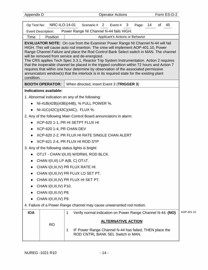
Op Test No: NRC-ILO-14-01 Scenario # 2 Event # 3 Page: 14 of 45
Event Description: Power Range NI Channel N-44 fails HIGH.
Time Position Applicant’s Actions or Behavior
NUREG -1021 R10 - 14 -
EVALUATOR NOTE: On cue from the Examiner Power Range NI Channel N-44 will fail HIGH. This will cause auto rod insertion. The crew will implement AOP-401.10, Power Range Channel Failure and place the Rod Control Bank Select switch in MAN. The channel will be removed from service and de-energized. The CRS applies Tech Spec 3.3.1, Reactor Trip System Instrumentation. Action 2 requires that the inoperable channel be placed in the tripped condition within 72 hours and Action 7 requires that within one hour determine by observation of the associated permissive annunciators window(s) that the interlock is in its required state for the existing plant condition.
BOOTH OPERATOR: When directed, insert Event 3 (TRIGGER 3)
Indications available: 1. Abnormal indication on any of the following:
● NI-41B(42B)(43B)(44B), % FULL POWER %.
● NI-41C(42C)(43C)(44C), FLUX %.
2. Any of the following Main Control Board annunciators in alarm:
● XCP-620 1-1, PR HI SETPT FLUX HI
● XCP-620 1-4, PR CHAN DEV
● XCP-620 2-2, PR FLUX HI RATE SINGLE CHAN ALERT
● XCP-621 2-4, PR FLUX HI ROD STP
3. Any of the following status lights is bright:
● OT∆T - CHAN I(II,III) W/DRWL ROD BLCK.
● CHAN I(II,III) LP A(B, C) OT∆T.
● CHAN I(II,III,IV) PR FLUX RATE HI.
● CHAN I(II,III,IV) PR FLUX LO SET PT.
● CHAN I(II,III,IV) PR FLUX HI SET PT.
● CHAN I(II,III,IV) P10.
● CHAN I(II,III,IV) P8.
● CHAN I(II,III,IV) P9.
4. Failure of a Power Range channel may cause unwarranted rod motion.
IOA
RO
1 Verify normal indication on Power Range Channel N-44. (NO)
ALTERNATIVE ACTION 1 IF Power Range Channel N-44 has failed, THEN place the
ROD CNTRL BANK SEL Switch in MAN.
AOP-401.10
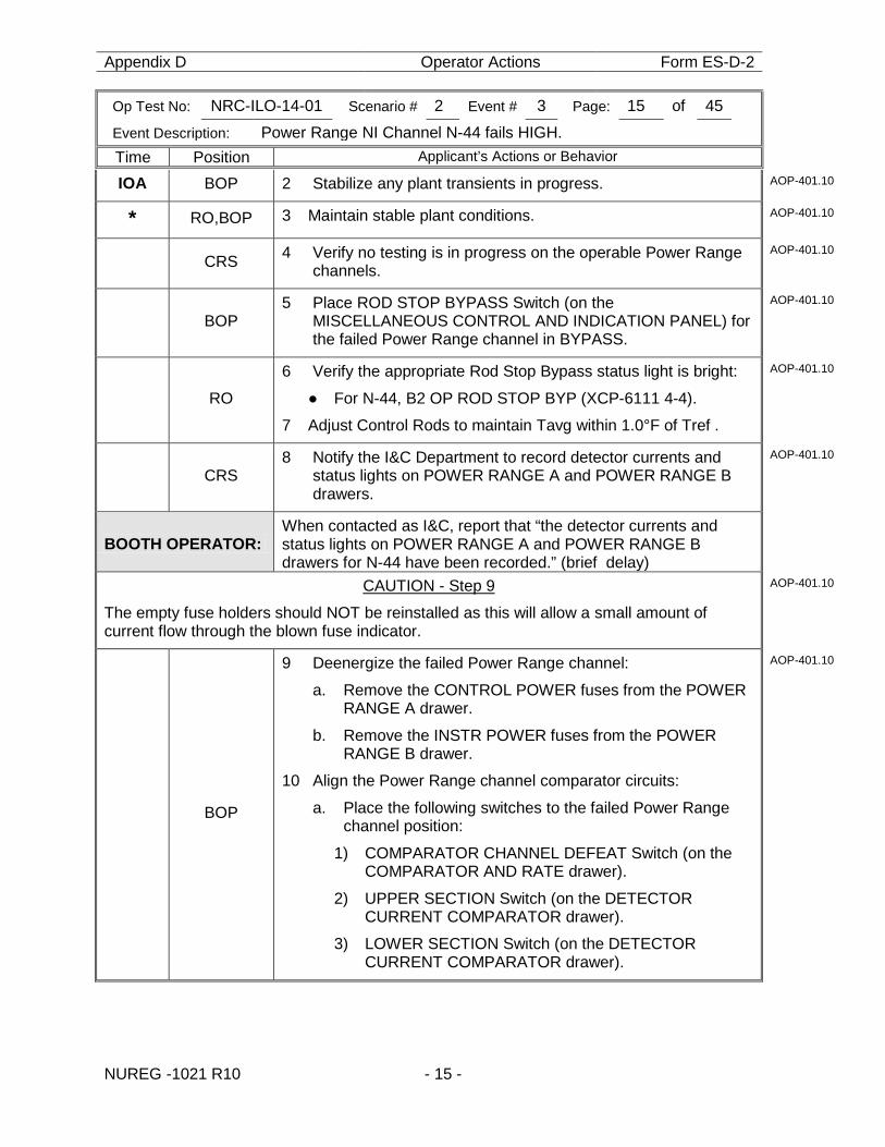
Appendix D Operator Actions Form ES-D-2
Op Test No: NRC-ILO-14-01 Scenario # 2 Event # 3 Page: 15 of 45
Event Description: Power Range NI Channel N-44 fails HIGH.
Time Position Applicant’s Actions or Behavior
NUREG -1021 R10 - 15 -
IOA BOP 2 Stabilize any plant transients in progress. AOP-401.10
* RO,BOP 3 Maintain stable plant conditions. AOP-401.10
CRS 4 Verify no testing is in progress on the operable Power Range channels.
AOP-401.10
BOP
5 Place ROD STOP BYPASS Switch (on the MISCELLANEOUS CONTROL AND INDICATION PANEL) for the failed Power Range channel in BYPASS.
AOP-401.10
RO
6 Verify the appropriate Rod Stop Bypass status light is bright:
● For N-44, B2 OP ROD STOP BYP (XCP-6111 4-4).
7 Adjust Control Rods to maintain Tavg within 1.0°F of Tref .
AOP-401.10
CRS
8 Notify the I&C Department to record detector currents and status lights on POWER RANGE A and POWER RANGE B drawers.
AOP-401.10
BOOTH OPERATOR: When contacted as I&C, report that “the detector currents and status lights on POWER RANGE A and POWER RANGE B drawers for N-44 have been recorded.” (brief delay)
CAUTION - Step 9
The empty fuse holders should NOT be reinstalled as this will allow a small amount of current flow through the blown fuse indicator.
AOP-401.10
BOP
9 Deenergize the failed Power Range channel: a. Remove the CONTROL POWER fuses from the POWER
RANGE A drawer.
b. Remove the INSTR POWER fuses from the POWER RANGE B drawer.
10 Align the Power Range channel comparator circuits:
a. Place the following switches to the failed Power Range channel position:
1) COMPARATOR CHANNEL DEFEAT Switch (on the COMPARATOR AND RATE drawer).
2) UPPER SECTION Switch (on the DETECTOR CURRENT COMPARATOR drawer).
3) LOWER SECTION Switch (on the DETECTOR CURRENT COMPARATOR drawer).
AOP-401.10
Appendix D Operator Actions Form ES-D-2
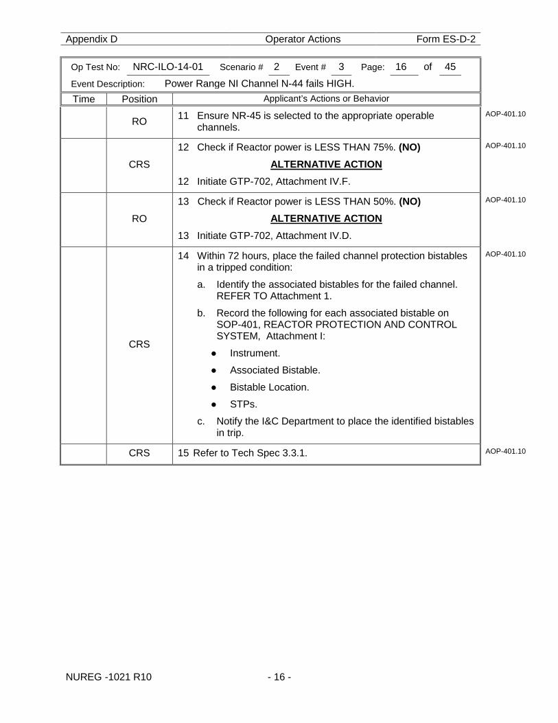
Op Test No: NRC-ILO-14-01 Scenario # 2 Event # 3 Page: 16 of 45
Event Description: Power Range NI Channel N-44 fails HIGH.
Time Position Applicant’s Actions or Behavior
NUREG -1021 R10 - 16 -
RO 11 Ensure NR-45 is selected to the appropriate operable channels.
AOP-401.10
CRS
12 Check if Reactor power is LESS THAN 75%. (NO) ALTERNATIVE ACTION
12 Initiate GTP-702, Attachment IV.F.
AOP-401.10
RO
13 Check if Reactor power is LESS THAN 50%. (NO) ALTERNATIVE ACTION
13 Initiate GTP-702, Attachment IV.D.
AOP-401.10
CRS
14 Within 72 hours, place the failed channel protection bistables in a tripped condition:
a. Identify the associated bistables for the failed channel. REFER TO Attachment 1.
b. Record the following for each associated bistable on SOP-401, REACTOR PROTECTION AND CONTROL SYSTEM, Attachment I:
● Instrument.
● Associated Bistable.
● Bistable Location.
● STPs.
c. Notify the I&C Department to place the identified bistables in trip.
AOP-401.10
CRS 15 Refer to Tech Spec 3.3.1. AOP-401.10
Appendix D Operator Actions Form ES-D-2
Op Test No: NRC-ILO-14-01 Scenario # 2 Event # 3 Page: 17 of 45
Event Description: Power Range NI Channel N-44 fails HIGH.
Time Position Applicant’s Actions or Behavior
NUREG -1021 R10 - 17 -
CRS
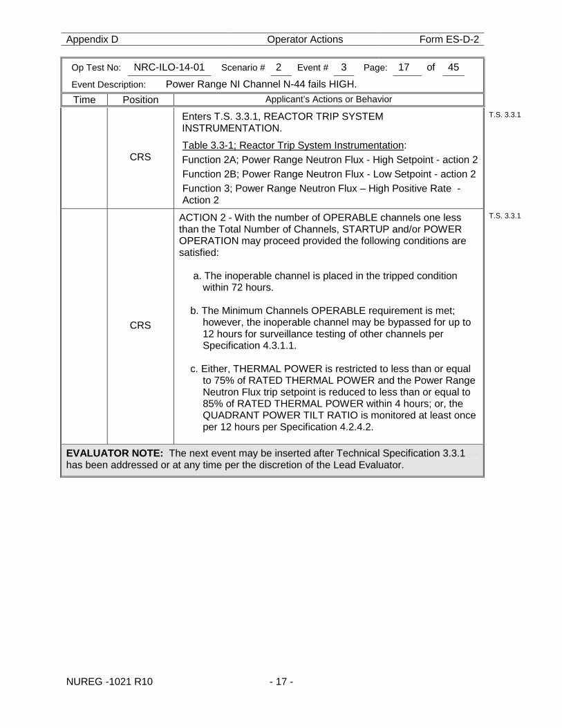
Enters T.S. 3.3.1, REACTOR TRIP SYSTEM INSTRUMENTATION.
Table 3.3-1; Reactor Trip System Instrumentation: Function 2A; Power Range Neutron Flux - High Setpoint - action 2 Function 2B; Power Range Neutron Flux - Low Setpoint - action 2 Function 3; Power Range Neutron Flux – High Positive Rate - Action 2
T.S. 3.3.1
CRS
ACTION 2 - With the number of OPERABLE channels one less than the Total Number of Channels, STARTUP and/or POWER OPERATION may proceed provided the following conditions are satisfied:
a. The inoperable channel is placed in the tripped condition within 72 hours.
b. The Minimum Channels OPERABLE requirement is met;
however, the inoperable channel may be bypassed for up to 12 hours for surveillance testing of other channels per Specification 4.3.1.1.
c. Either, THERMAL POWER is restricted to less than or equal
to 75% of RATED THERMAL POWER and the Power Range Neutron Flux trip setpoint is reduced to less than or equal to 85% of RATED THERMAL POWER within 4 hours; or, the QUADRANT POWER TILT RATIO is monitored at least once per 12 hours per Specification 4.2.4.2.
T.S. 3.3.1
EVALUATOR NOTE: The next event may be inserted after Technical Specification 3.3.1 has been addressed or at any time per the discretion of the Lead Evaluator.
Appendix D Operator Actions Form ES-D-2
Op Test No: NRC-ILO-14-01 Scenario # 2 Event # 4 Page: 18 of 45
Event Description: Turbine Lube Oil Temperature control valve fails open
Time Position Applicant’s Actions or Behavior
NUREG -1021 R10 - 18 -
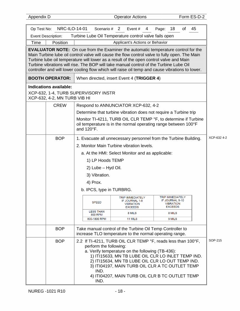
EVALUATOR NOTE: On cue from the Examiner the automatic temperature control for the Main Turbine lube oil control valve will cause the flow control valve to fully open. The Main Turbine lube oil temperature will lower as a result of the open control valve and Main Turbine vibrations will rise. The BOP will take manual control of the Turbine Lube Oil controller and will lower cooling flow which will raise oil temp and cause vibrations to lower.
BOOTH OPERATOR: When directed, insert Event 4 (TRIGGER 4)
Indications available: XCP-632, 1-4, TURB SUPERVISORY INSTR XCP-632, 4-2, MN TURB VIB HI
CREW Respond to ANNUNCIATOR XCP-632, 4-2 Determine that turbine vibration does not require a Turbine trip Monitor TI-4211, TURB OIL CLR TEMP °F, to determine if Turbine oil temperature is in the normal operating range between 100°F and 120°F.
BOP 1. Evacuate all unnecessary personnel from the Turbine Building.
2. Monitor Main Turbine vibration levels.
a. At the HMI: Select Monitor and as applicable:
1) LP Hoods TEMP
2) Lube – Hyd Oil.
3) Vibration.
4) Prox.
b. IPCS, type in TURBRG.
XCP-632 4-2
BOP Take manual control of the Turbine Oil Temp Controller to increase TLO temperature to the normal operating range.
BOP 2.2 If TI-4211, TURB OIL CLR TEMP °F, reads less than 100°F, perform the following: a. Verify temperature on the following (TB-436):
1) ITI15633, MN TB LUBE OIL CLR LO INLET TEMP IND. 2) ITI15634, MN TB LUBE OIL CLR LO OUT TEMP IND. 3) ITI04197, MAIN TURB OIL CLR A TC OUTLET TEMP
IND. 4) ITI04207, MAIN TURB OIL CLR B TC OUTLET TEMP
IND.
SOP-215
Appendix D Operator Actions Form ES-D-2
Op Test No: NRC-ILO-14-01 Scenario # 2 Event # 4 Page: 19 of 45
Event Description: Turbine Lube Oil Temperature control valve fails open
Time Position Applicant’s Actions or Behavior
NUREG -1021 R10 - 19 -
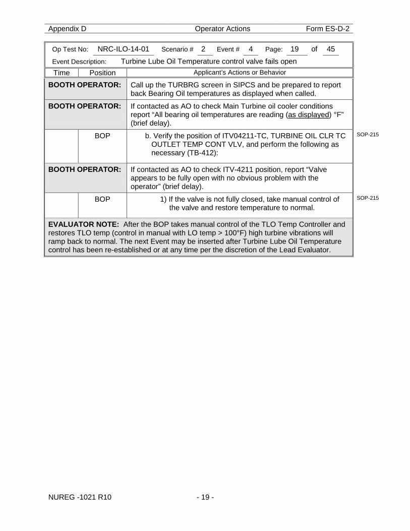
BOOTH OPERATOR: Call up the TURBRG screen in SIPCS and be prepared to report back Bearing Oil temperatures as displayed when called.
BOOTH OPERATOR:
If contacted as AO to check Main Turbine oil cooler conditions report “All bearing oil temperatures are reading (as displayed) °F” (brief delay).
BOP b. Verify the position of ITV04211-TC, TURBINE OIL CLR TC OUTLET TEMP CONT VLV, and perform the following as necessary (TB-412):
SOP-215
BOOTH OPERATOR:
If contacted as AO to check ITV-4211 position, report “Valve appears to be fully open with no obvious problem with the operator” (brief delay).
BOP 1) If the valve is not fully closed, take manual control of the valve and restore temperature to normal.
SOP-215
EVALUATOR NOTE: After the BOP takes manual control of the TLO Temp Controller and restores TLO temp (control in manual with LO temp > 100°F) high turbine vibrations will ramp back to normal. The next Event may be inserted after Turbine Lube Oil Temperature control has been re-established or at any time per the discretion of the Lead Evaluator.
Appendix D Operator Actions Form ES-D-2
Op Test No: NRC-ILO-14-01 Scenario # 2 Event # 5 Page: 20 of 45
Event Description: “A” Charging Pump shaft shears
Time Position Applicant’s Actions or Behavior
NUREG -1021 R10 - 20 -
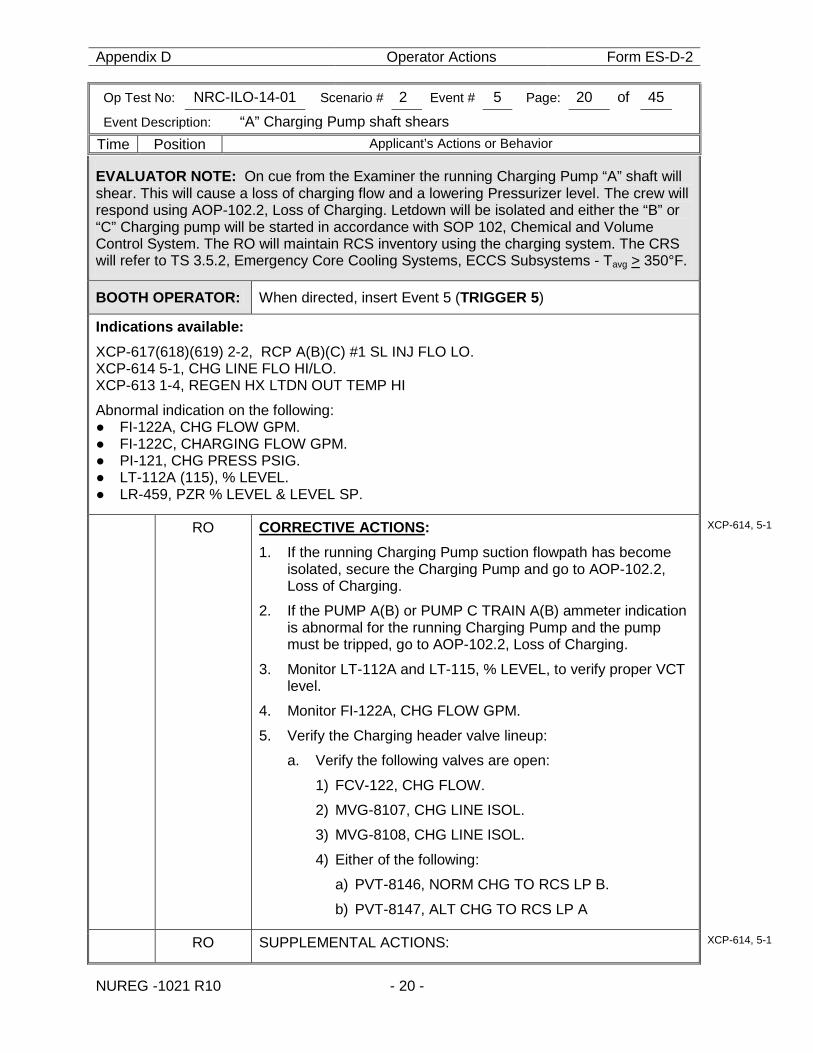
EVALUATOR NOTE: On cue from the Examiner the running Charging Pump “A” shaft will shear. This will cause a loss of charging flow and a lowering Pressurizer level. The crew will respond using AOP-102.2, Loss of Charging. Letdown will be isolated and either the “B” or “C” Charging pump will be started in accordance with SOP 102, Chemical and Volume Control System. The RO will maintain RCS inventory using the charging system. The CRS will refer to TS 3.5.2, Emergency Core Cooling Systems, ECCS Subsystems - Tavg > 350°F.
BOOTH OPERATOR: When directed, insert Event 5 (TRIGGER 5)
Indications available: XCP-617(618)(619) 2-2, RCP A(B)(C) #1 SL INJ FLO LO. XCP-614 5-1, CHG LINE FLO HI/LO. XCP-613 1-4, REGEN HX LTDN OUT TEMP HI
Abnormal indication on the following: ● FI-122A, CHG FLOW GPM. ● FI-122C, CHARGING FLOW GPM. ● PI-121, CHG PRESS PSIG. ● LT-112A (115), % LEVEL. ● LR-459, PZR % LEVEL & LEVEL SP.
RO CORRECTIVE ACTIONS: 1. If the running Charging Pump suction flowpath has become
isolated, secure the Charging Pump and go to AOP-102.2, Loss of Charging.
2. If the PUMP A(B) or PUMP C TRAIN A(B) ammeter indication is abnormal for the running Charging Pump and the pump must be tripped, go to AOP-102.2, Loss of Charging.
3. Monitor LT-112A and LT-115, % LEVEL, to verify proper VCT level.
4. Monitor FI-122A, CHG FLOW GPM.
5. Verify the Charging header valve lineup:
a. Verify the following valves are open:
1) FCV-122, CHG FLOW.
2) MVG-8107, CHG LINE ISOL.
3) MVG-8108, CHG LINE ISOL.
4) Either of the following:
a) PVT-8146, NORM CHG TO RCS LP B.
b) PVT-8147, ALT CHG TO RCS LP A
XCP-614, 5-1
RO SUPPLEMENTAL ACTIONS: XCP-614, 5-1
Appendix D Operator Actions Form ES-D-2
Op Test No: NRC-ILO-14-01 Scenario # 2 Event # 5 Page: 21 of 45
Event Description: “A” Charging Pump shaft shears
Time Position Applicant’s Actions or Behavior
NUREG -1021 R10 - 21 -
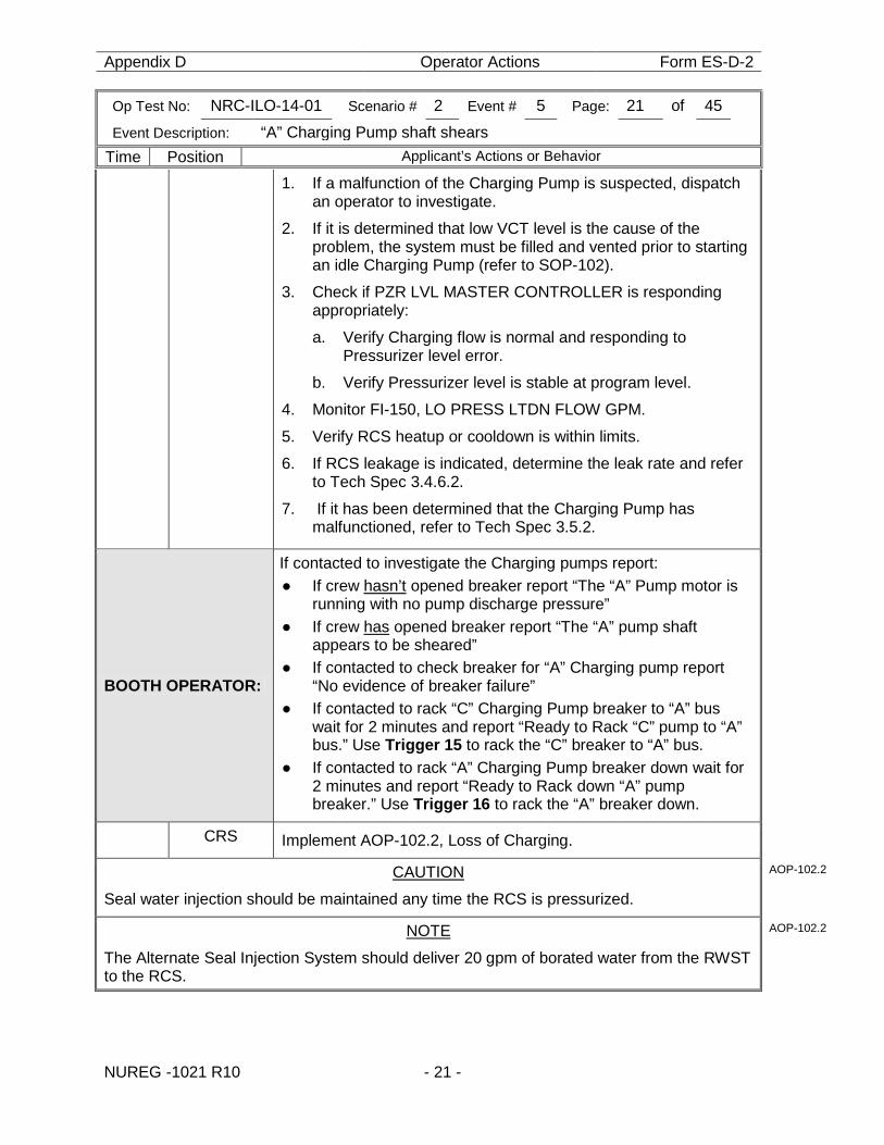
1. If a malfunction of the Charging Pump is suspected, dispatch an operator to investigate.
2. If it is determined that low VCT level is the cause of the problem, the system must be filled and vented prior to starting an idle Charging Pump (refer to SOP-102).
3. Check if PZR LVL MASTER CONTROLLER is responding appropriately:
a. Verify Charging flow is normal and responding to Pressurizer level error.
b. Verify Pressurizer level is stable at program level.
4. Monitor FI-150, LO PRESS LTDN FLOW GPM.
5. Verify RCS heatup or cooldown is within limits.
6. If RCS leakage is indicated, determine the leak rate and refer to Tech Spec 3.4.6.2.
7. If it has been determined that the Charging Pump has malfunctioned, refer to Tech Spec 3.5.2.
BOOTH OPERATOR:
If contacted to investigate the Charging pumps report: ● If crew hasn’t opened breaker report “The “A” Pump motor is
running with no pump discharge pressure” ● If crew has opened breaker report “The “A” pump shaft
appears to be sheared” ● If contacted to check breaker for “A” Charging pump report
“No evidence of breaker failure” ● If contacted to rack “C” Charging Pump breaker to “A” bus
wait for 2 minutes and report “Ready to Rack “C” pump to “A” bus.” Use Trigger 15 to rack the “C” breaker to “A” bus.
● If contacted to rack “A” Charging Pump breaker down wait for 2 minutes and report “Ready to Rack down “A” pump breaker.” Use Trigger 16 to rack the “A” breaker down.
CRS Implement AOP-102.2, Loss of Charging.
CAUTION
Seal water injection should be maintained any time the RCS is pressurized.
AOP-102.2
NOTE
The Alternate Seal Injection System should deliver 20 gpm of borated water from the RWST to the RCS.
AOP-102.2
Appendix D Operator Actions Form ES-D-2
Op Test No: NRC-ILO-14-01 Scenario # 2 Event # 5 Page: 22 of 45
Event Description: “A” Charging Pump shaft shears
Time Position Applicant’s Actions or Behavior
NUREG -1021 R10 - 22 -
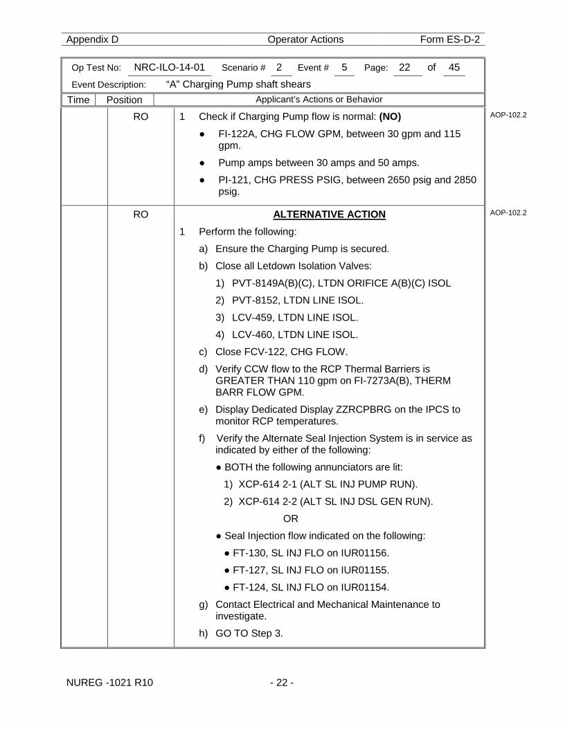
RO 1 Check if Charging Pump flow is normal: (NO) ● FI-122A, CHG FLOW GPM, between 30 gpm and 115
gpm.
● Pump amps between 30 amps and 50 amps.
● PI-121, CHG PRESS PSIG, between 2650 psig and 2850 psig.
AOP-102.2
RO ALTERNATIVE ACTION 1 Perform the following:
a) Ensure the Charging Pump is secured.
b) Close all Letdown Isolation Valves:
1) PVT-8149A(B)(C), LTDN ORIFICE A(B)(C) ISOL
2) PVT-8152, LTDN LINE ISOL.
3) LCV-459, LTDN LINE ISOL.
4) LCV-460, LTDN LINE ISOL.
c) Close FCV-122, CHG FLOW.
d) Verify CCW flow to the RCP Thermal Barriers is GREATER THAN 110 gpm on FI-7273A(B), THERM BARR FLOW GPM.
e) Display Dedicated Display ZZRCPBRG on the IPCS to monitor RCP temperatures.
f) Verify the Alternate Seal Injection System is in service as indicated by either of the following:
● BOTH the following annunciators are lit:
1) XCP-614 2-1 (ALT SL INJ PUMP RUN).
2) XCP-614 2-2 (ALT SL INJ DSL GEN RUN).
OR
● Seal Injection flow indicated on the following:
● FT-130, SL INJ FLO on IUR01156.
● FT-127, SL INJ FLO on IUR01155.
● FT-124, SL INJ FLO on IUR01154.
g) Contact Electrical and Mechanical Maintenance to investigate.
h) GO TO Step 3.
AOP-102.2
Appendix D Operator Actions Form ES-D-2
Op Test No: NRC-ILO-14-01 Scenario # 2 Event # 5 Page: 23 of 45
Event Description: “A” Charging Pump shaft shears
Time Position Applicant’s Actions or Behavior
NUREG -1021 R10 - 23 -
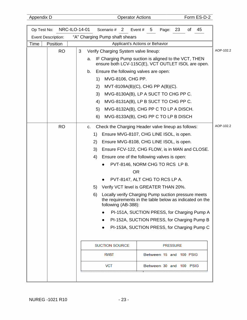
RO 3 Verify Charging System valve lineup: a. IF Charging Pump suction is aligned to the VCT, THEN
ensure both LCV-115C(E), VCT OUTLET ISOL are open.
b. Ensure the following valves are open:
1) MVG-8106, CHG PP.
2) MVT-8109A(B)(C), CHG PP A(B)(C).
3) MVG-8130A(B), LP A SUCT TO CHG PP C.
4) MVG-8131A(B), LP B SUCT TO CHG PP C.
5) MVG-8132A(B), CHG PP C TO LP A DISCH.
6) MVG-8133A(B), CHG PP C TO LP B DISCH
AOP-102.2
RO c. Check the Charging Header valve lineup as follows:
1) Ensure MVG-8107, CHG LINE ISOL, is open.
2) Ensure MVG-8108, CHG LINE ISOL, is open.
3) Ensure FCV-122, CHG FLOW, is in MAN and CLOSE.
4) Ensure one of the following valves is open:
● PVT-8146, NORM CHG TO RCS LP B.
OR
● PVT-8147, ALT CHG TO RCS LP A.
5) Verify VCT level is GREATER THAN 20%.
6) Locally verify Charging Pump suction pressure meets the requirements in the table below as indicated on the following (AB-388):
● PI-151A, SUCTION PRESS, for Charging Pump A
● PI-152A, SUCTION PRESS, for Charging Pump B
● PI-153A, SUCTION PRESS, for Charging Pump C
AOP-102.2
Appendix D Operator Actions Form ES-D-2
Op Test No: NRC-ILO-14-01 Scenario # 2 Event # 5 Page: 24 of 45
Event Description: “A” Charging Pump shaft shears
Time Position Applicant’s Actions or Behavior
NUREG -1021 R10 - 24 -
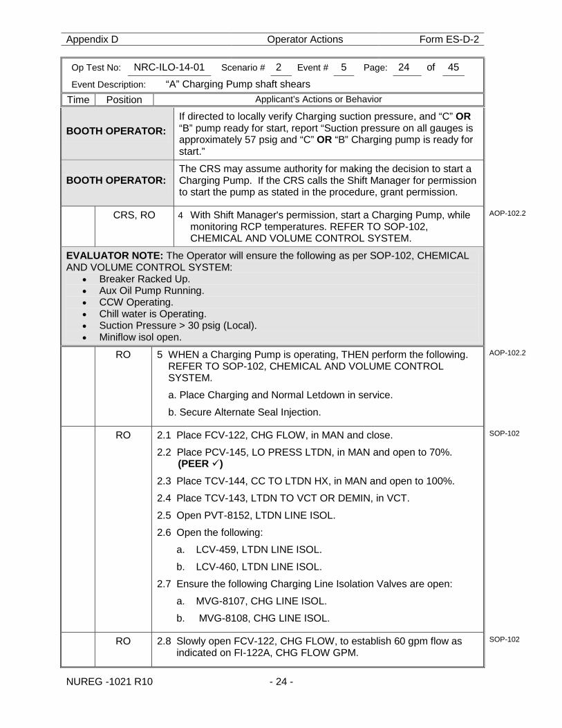
BOOTH OPERATOR: If directed to locally verify Charging suction pressure, and “C” OR “B” pump ready for start, report “Suction pressure on all gauges is approximately 57 psig and “C” OR “B” Charging pump is ready for start.”
BOOTH OPERATOR: The CRS may assume authority for making the decision to start a Charging Pump. If the CRS calls the Shift Manager for permission to start the pump as stated in the procedure, grant permission.
CRS, RO 4 With Shift Manager's permission, start a Charging Pump, while monitoring RCP temperatures. REFER TO SOP-102, CHEMICAL AND VOLUME CONTROL SYSTEM.
AOP-102.2
EVALUATOR NOTE: The Operator will ensure the following as per SOP-102, CHEMICAL AND VOLUME CONTROL SYSTEM:
• Breaker Racked Up. • Aux Oil Pump Running. • CCW Operating. • Chill water is Operating. • Suction Pressure > 30 psig (Local). • Miniflow isol open.
RO 5 WHEN a Charging Pump is operating, THEN perform the following. REFER TO SOP-102, CHEMICAL AND VOLUME CONTROL SYSTEM.
a. Place Charging and Normal Letdown in service.
b. Secure Alternate Seal Injection.
AOP-102.2
RO 2.1 Place FCV-122, CHG FLOW, in MAN and close.
2.2 Place PCV-145, LO PRESS LTDN, in MAN and open to 70%. (PEER )
2.3 Place TCV-144, CC TO LTDN HX, in MAN and open to 100%.
2.4 Place TCV-143, LTDN TO VCT OR DEMIN, in VCT.
2.5 Open PVT-8152, LTDN LINE ISOL.
2.6 Open the following:
a. LCV-459, LTDN LINE ISOL.
b. LCV-460, LTDN LINE ISOL.
2.7 Ensure the following Charging Line Isolation Valves are open:
a. MVG-8107, CHG LINE ISOL.
b. MVG-8108, CHG LINE ISOL.
SOP-102
RO 2.8 Slowly open FCV-122, CHG FLOW, to establish 60 gpm flow as indicated on FI-122A, CHG FLOW GPM.
SOP-102
Appendix D Operator Actions Form ES-D-2
Op Test No: NRC-ILO-14-01 Scenario # 2 Event # 5 Page: 25 of 45
Event Description: “A” Charging Pump shaft shears
Time Position Applicant’s Actions or Behavior
NUREG -1021 R10 - 25 -
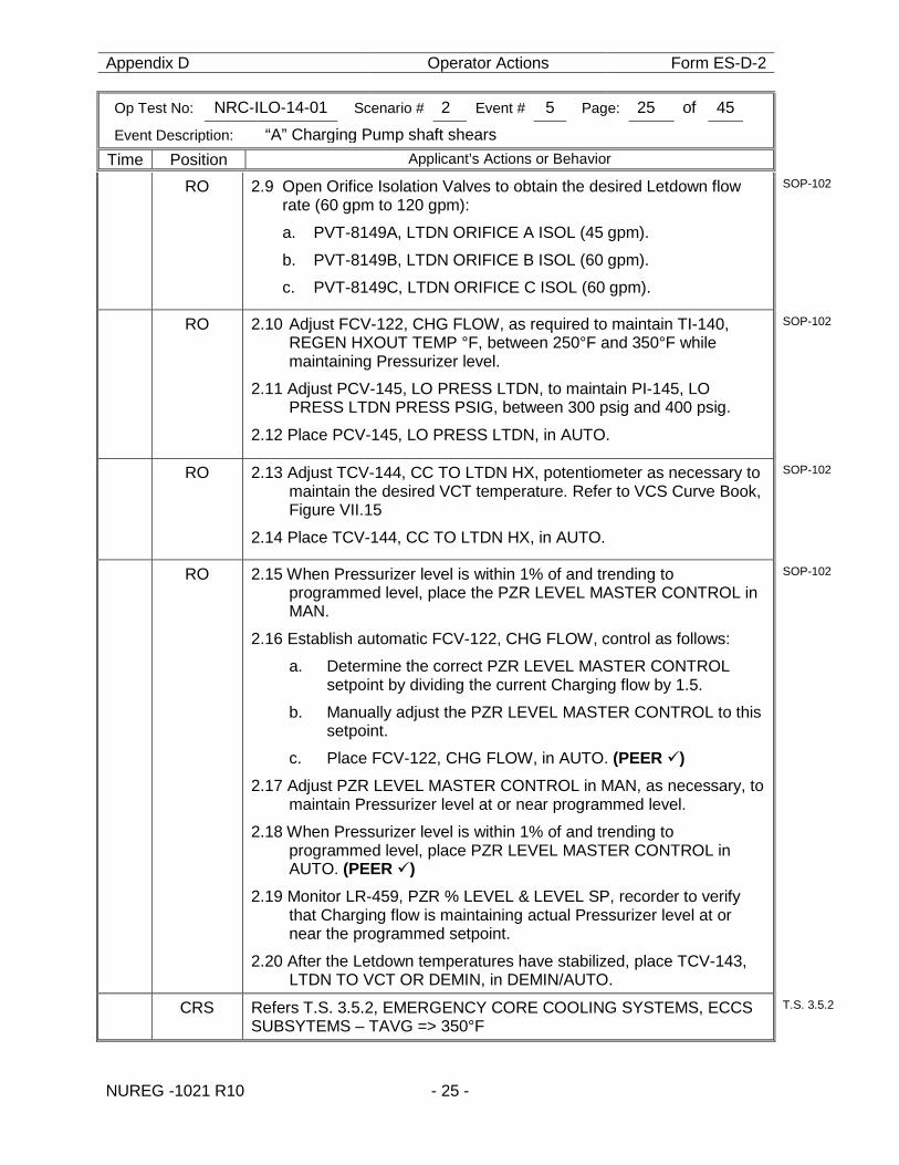
RO 2.9 Open Orifice Isolation Valves to obtain the desired Letdown flow rate (60 gpm to 120 gpm):
a. PVT-8149A, LTDN ORIFICE A ISOL (45 gpm).
b. PVT-8149B, LTDN ORIFICE B ISOL (60 gpm).
c. PVT-8149C, LTDN ORIFICE C ISOL (60 gpm).
SOP-102
RO 2.10 Adjust FCV-122, CHG FLOW, as required to maintain TI-140, REGEN HXOUT TEMP °F, between 250°F and 350°F while maintaining Pressurizer level.
2.11 Adjust PCV-145, LO PRESS LTDN, to maintain PI-145, LO PRESS LTDN PRESS PSIG, between 300 psig and 400 psig.
2.12 Place PCV-145, LO PRESS LTDN, in AUTO.
SOP-102
RO 2.13 Adjust TCV-144, CC TO LTDN HX, potentiometer as necessary to maintain the desired VCT temperature. Refer to VCS Curve Book, Figure VII.15
2.14 Place TCV-144, CC TO LTDN HX, in AUTO.
SOP-102
RO 2.15 When Pressurizer level is within 1% of and trending to programmed level, place the PZR LEVEL MASTER CONTROL in MAN.
2.16 Establish automatic FCV-122, CHG FLOW, control as follows:
a. Determine the correct PZR LEVEL MASTER CONTROL setpoint by dividing the current Charging flow by 1.5.
b. Manually adjust the PZR LEVEL MASTER CONTROL to this setpoint.
c. Place FCV-122, CHG FLOW, in AUTO. (PEER ) 2.17 Adjust PZR LEVEL MASTER CONTROL in MAN, as necessary, to
maintain Pressurizer level at or near programmed level.
2.18 When Pressurizer level is within 1% of and trending to programmed level, place PZR LEVEL MASTER CONTROL in AUTO. (PEER )
2.19 Monitor LR-459, PZR % LEVEL & LEVEL SP, recorder to verify that Charging flow is maintaining actual Pressurizer level at or near the programmed setpoint.
2.20 After the Letdown temperatures have stabilized, place TCV-143, LTDN TO VCT OR DEMIN, in DEMIN/AUTO.
SOP-102
CRS Refers T.S. 3.5.2, EMERGENCY CORE COOLING SYSTEMS, ECCS SUBSYTEMS – TAVG => 350°F
T.S. 3.5.2
Appendix D Operator Actions Form ES-D-2
Op Test No: NRC-ILO-14-01 Scenario # 2 Event # 5 Page: 26 of 45
Event Description: “A” Charging Pump shaft shears
Time Position Applicant’s Actions or Behavior
NUREG -1021 R10 - 26 -
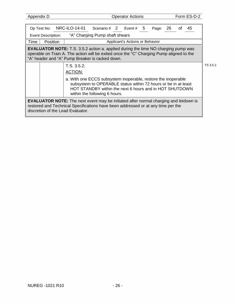
EVALUATOR NOTE: T.S. 3.5.2 action a. applied during the time NO charging pump was operable on Train A. The action will be exited once the “C” Charging Pump aligned to the “A” header and “A” Pump Breaker is racked down.
T.S. 3.5.2; ACTION:
a. With one ECCS subsystem inoperable, restore the inoperable subsystem to OPERABLE status within 72 hours or be in at least HOT STANDBY within the next 6 hours and in HOT SHUTDOWN within the following 6 hours.
TS 3.5.2
EVALUATOR NOTE: The next event may be initiated after normal charging and letdown is restored and Technical Specifications have been addressed or at any time per the discretion of the Lead Evaluator.
Appendix D Operator Actions Form ES-D-2
Op Test No: NRC-ILO-14-01 Scenario # 2 Event # 6 Page: 27 of 45
Event Description: All Main Feedwater Pumps Trip.
Time Position Applicant’s Actions or Behavior
NUREG -1021 R10 - 27 -
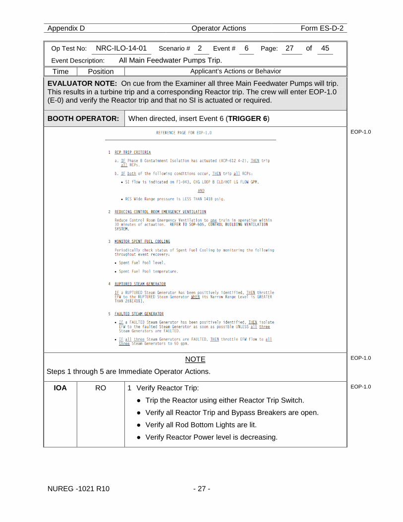
EVALUATOR NOTE: On cue from the Examiner all three Main Feedwater Pumps will trip. This results in a turbine trip and a corresponding Reactor trip. The crew will enter EOP-1.0 (E-0) and verify the Reactor trip and that no SI is actuated or required.
BOOTH OPERATOR: When directed, insert Event 6 (TRIGGER 6)
EOP-1.0
NOTE
Steps 1 through 5 are Immediate Operator Actions.
EOP-1.0
IOA RO 1 Verify Reactor Trip:
● Trip the Reactor using either Reactor Trip Switch.
● Verify all Reactor Trip and Bypass Breakers are open.
● Verify all Rod Bottom Lights are lit.
● Verify Reactor Power level is decreasing.
EOP-1.0
Appendix D Operator Actions Form ES-D-2
Op Test No: NRC-ILO-14-01 Scenario # 2 Event # 6 Page: 28 of 45
Event Description: All Main Feedwater Pumps Trip.
Time Position Applicant’s Actions or Behavior
NUREG -1021 R10 - 28 -
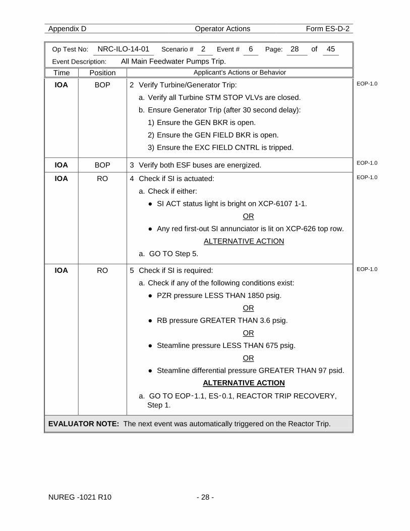
IOA BOP 2 Verify Turbine/Generator Trip:
a. Verify all Turbine STM STOP VLVs are closed.
b. Ensure Generator Trip (after 30 second delay):
1) Ensure the GEN BKR is open.
2) Ensure the GEN FIELD BKR is open.
3) Ensure the EXC FIELD CNTRL is tripped.
EOP-1.0
IOA BOP 3 Verify both ESF buses are energized. EOP-1.0
IOA RO 4 Check if SI is actuated:
a. Check if either:
● SI ACT status light is bright on XCP-6107 1-1.
OR
● Any red first-out SI annunciator is lit on XCP-626 top row.
ALTERNATIVE ACTION
a. GO TO Step 5.
EOP-1.0
IOA RO 5 Check if SI is required:
a. Check if any of the following conditions exist:
● PZR pressure LESS THAN 1850 psig.
OR
● RB pressure GREATER THAN 3.6 psig.
OR
● Steamline pressure LESS THAN 675 psig.
OR
● Steamline differential pressure GREATER THAN 97 psid.
ALTERNATIVE ACTION
a. GO TO EOP‑1.1, ES‑0.1, REACTOR TRIP RECOVERY, Step 1.
EOP-1.0
EVALUATOR NOTE: The next event was automatically triggered on the Reactor Trip.
Appendix D Operator Actions Form ES-D-2
Op Test No: NRC-ILO-14-01 Scenario # 2 Event # 7 Page: 29 of 45
Event Description: Loss of Heat Sink
Time Position Applicant’s Actions or Behavior
NUREG -1021 R10 - 29 -
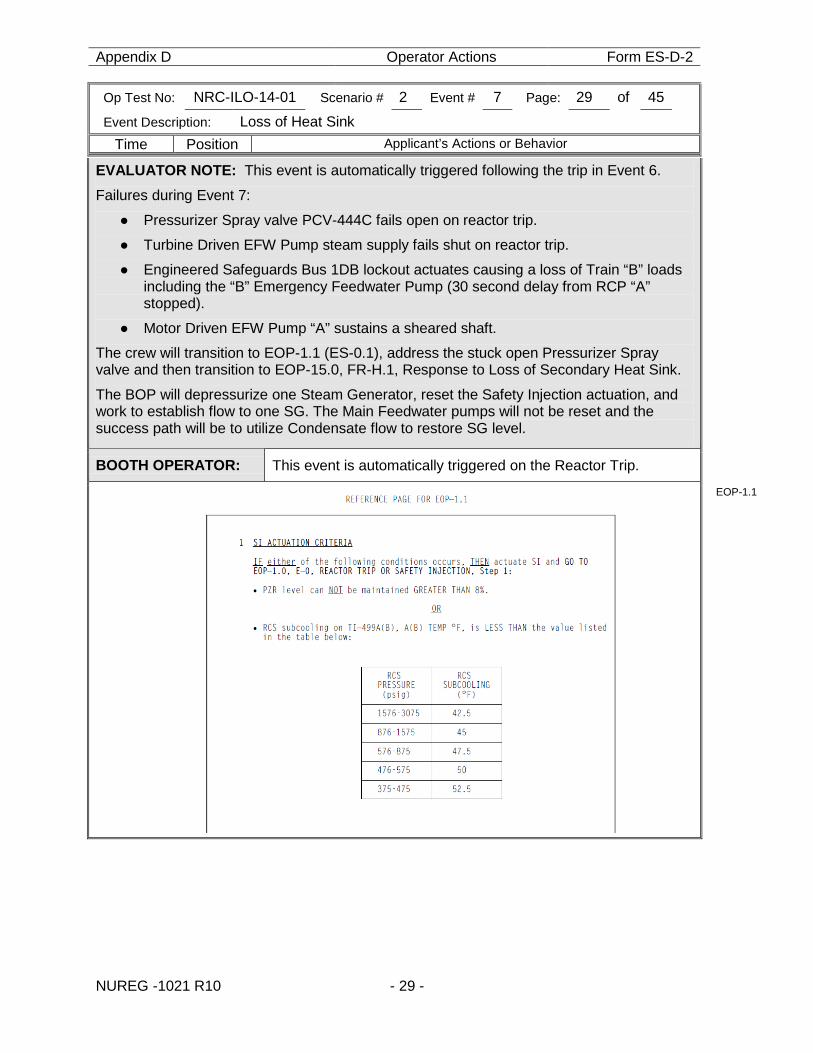
EVALUATOR NOTE: This event is automatically triggered following the trip in Event 6.
Failures during Event 7:
● Pressurizer Spray valve PCV-444C fails open on reactor trip.
● Turbine Driven EFW Pump steam supply fails shut on reactor trip.
● Engineered Safeguards Bus 1DB lockout actuates causing a loss of Train “B” loads including the “B” Emergency Feedwater Pump (30 second delay from RCP “A” stopped).
● Motor Driven EFW Pump “A” sustains a sheared shaft.
The crew will transition to EOP-1.1 (ES-0.1), address the stuck open Pressurizer Spray valve and then transition to EOP-15.0, FR-H.1, Response to Loss of Secondary Heat Sink.
The BOP will depressurize one Steam Generator, reset the Safety Injection actuation, and work to establish flow to one SG. The Main Feedwater pumps will not be reset and the success path will be to utilize Condensate flow to restore SG level.
BOOTH OPERATOR: This event is automatically triggered on the Reactor Trip.
EOP-1.1
Appendix D Operator Actions Form ES-D-2
Op Test No: NRC-ILO-14-01 Scenario # 2 Event # 7 Page: 30 of 45
Event Description: Loss of Heat Sink
Time Position Applicant’s Actions or Behavior
NUREG -1021 R10 - 30 -
CAUTION If SI actuation occurs during this procedure, EOP‑1.0, E‑0, REACTOR TRIP OR SAFETY INJECTION, should be performed to stabilize the plant.
EOP-1.1
NOTE ● Main Turbine vibration should be monitored during coastdown. ●The EOP REFERENCE PAGE should be monitored throughout the use of this procedure.
EOP-1.1
CREW 1 Announce plant conditions over the page system. EOP-1.1
* RO
2 Check if RCS Tavg is LESS THAN 564°F. ALTERNATIVE ACTION
2 WHEN RCS Tavg is LESS THAN 564°F, THEN COMPLETE Steps 3 and 4. CONTINUE WITH Step 5.
EOP-1.1
3 Close IPV-2231, MS/PEGGING STM TO DEAERATOR. EOP-1.1
BOP
4 Check FW status: a. Verify FW Isolation:
• Ensure the FW Flow Control Valves, FCV-478(488)(498), are closed.
• Ensure the Main FW Isolation Valves, PVG-1611A(B)(C), are closed.
• Ensure the FW Flow Control Bypass Valves, FCV-3321(3331)(3341), are closed.
b. Ensure EFW Pumps are running: 1) Ensure both MD EFW Pumps are running. 2) Verify the TD EFW Pump is running if necessary to
maintain SG levels. c. Verify total EFW flow is GREATER THAN 450 gpm. d. Trip all Main FW Pumps.
EOP-1.1
BOOTH OPERATOR:
If contacted concerning TDEFW pump status, report “The steam supply to the pump is closed and I can’t get it to manually open”
If contacted concerning “A” MDEFW pump status, report “ The “A” MDEFW pump appears to have a sheared shaft”
* RO
5 Check RCS temperature:
● With any RCP running, RCS Tavg is stable at OR trending to 557°F.
OR
● With no RCP running, RCS Tcold is stable at OR trending to 557°F.
EOP-1.1
Appendix D Operator Actions Form ES-D-2
Op Test No: NRC-ILO-14-01 Scenario # 2 Event # 7 Page: 31 of 45
Event Description: Loss of Heat Sink
Time Position Applicant’s Actions or Behavior
NUREG -1021 R10 - 31 -
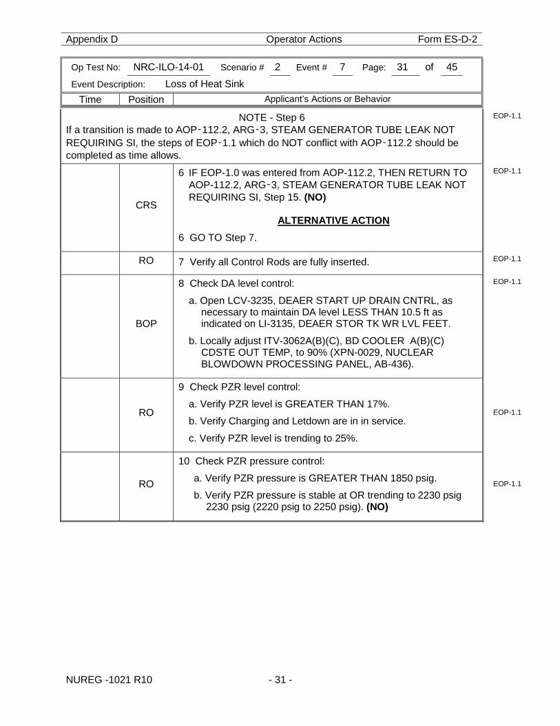
NOTE - Step 6 If a transition is made to AOP‑112.2, ARG‑3, STEAM GENERATOR TUBE LEAK NOT REQUIRING SI, the steps of EOP‑1.1 which do NOT conflict with AOP‑112.2 should be completed as time allows.
EOP-1.1
CRS
6 IF EOP-1.0 was entered from AOP-112.2, THEN RETURN TO AOP-112.2, ARG‑3, STEAM GENERATOR TUBE LEAK NOT REQUIRING SI, Step 15. (NO)
ALTERNATIVE ACTION
6 GO TO Step 7.
EOP-1.1
RO 7 Verify all Control Rods are fully inserted. EOP-1.1
BOP
8 Check DA level control:
a. Open LCV-3235, DEAER START UP DRAIN CNTRL, as necessary to maintain DA level LESS THAN 10.5 ft as indicated on LI-3135, DEAER STOR TK WR LVL FEET.
b. Locally adjust ITV-3062A(B)(C), BD COOLER A(B)(C) CDSTE OUT TEMP, to 90% (XPN-0029, NUCLEAR BLOWDOWN PROCESSING PANEL, AB-436).
EOP-1.1
RO
9 Check PZR level control:
a. Verify PZR level is GREATER THAN 17%.
b. Verify Charging and Letdown are in in service.
c. Verify PZR level is trending to 25%.
EOP-1.1
RO
10 Check PZR pressure control:
a. Verify PZR pressure is GREATER THAN 1850 psig.
b. Verify PZR pressure is stable at OR trending to 2230 psig 2230 psig (2220 psig to 2250 psig). (NO)
EOP-1.1
Appendix D Operator Actions Form ES-D-2
Op Test No: NRC-ILO-14-01 Scenario # 2 Event # 7 Page: 32 of 45
Event Description: Loss of Heat Sink
Time Position Applicant’s Actions or Behavior
NUREG -1021 R10 - 32 -
CR
ITIC
AL
TA
SK
BOP
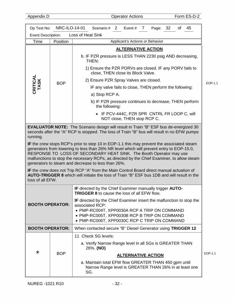
ALTERNATIVE ACTION b. IF PZR pressure is LESS THAN 2230 psig AND decreasing,
THEN:
1) Ensure the PZR PORVs are closed. IF any PORV fails to close, THEN close its Block Valve.
2) Ensure PZR Spray Valves are closed.
IF any valve fails to close, THEN perform the following:
a) Stop RCP A.
b) IF PZR pressure continues to decrease, THEN perform the following:
• IF PCV-444C, PZR SPR CNTRL FR LOOP C, will NOT close, THEN stop RCP C.
EOP-1.1
EVALUATOR NOTE: The Scenario design will result in Train “B” ESF bus de-energized 30 seconds after the “A” RCP is stopped. The loss of Train “B” bus will result in no EFW pumps running. IF the crew stops RCP’s prior to step 10 in EOP-1.1 this may prevent the associated steam generators from lowering to less than 26% NR level which will prevent entry to EOP-15.0, RESPONSE TO LOSS OF SECONDARY HEAT SINK. The Booth Operator may use malfunctions to stop the necessary RCPs, as directed by the Chief Examiner, to allow steam generators to steam and decrease to less than 26%.
IF the crew does not Trip RCP “A” from the Main Control Board direct manual actuation of AUTO-TRIGGER 8 which will initiate the loss of Train “B” ESF bus 1DB and will result in the loss of all EFW.
BOOTH OPERATOR:
IF directed by the Chief Examiner manually trigger AUTO-TRIGGER 8 to cause the loss of all EFW flow.
IF directed by the Chief Examiner insert the malfunction to stop the associated RCP: • PMP-RC004T, XPP0030A RCP A TRIP ON COMMAND • PMP-RC005T, XPP0030B RCP B TRIP ON COMMAND • PMP-RC006T, XPP0030C RCP C TRIP ON COMMAND
BOOTH OPERATOR: When contacted secure “B” Diesel Generator using TRIGGER 12
* BOP
11 Check SG levels:
a. Verify Narrow Range level in all SGs is GREATER THAN 26%. (NO)
ALTERNATIVE ACTION a. Maintain total EFW flow GREATER THAN 450 gpm until
Narrow Range level is GREATER THAN 26% in at least one SG.
EOP-1.1
Appendix D Operator Actions Form ES-D-2
Op Test No: NRC-ILO-14-01 Scenario # 2 Event # 7 Page: 33 of 45
Event Description: Loss of Heat Sink
Time Position Applicant’s Actions or Behavior
NUREG -1021 R10 - 33 -
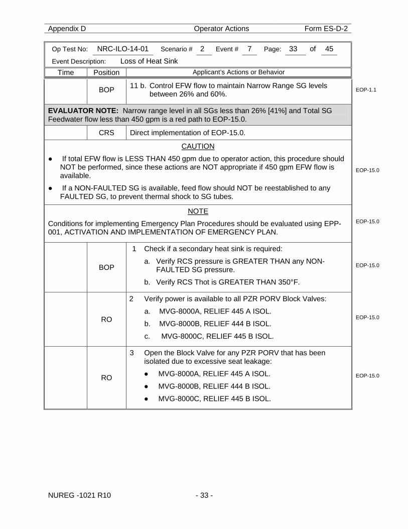
BOP 11 b. Control EFW flow to maintain Narrow Range SG levels between 26% and 60%.
EOP-1.1
EVALUATOR NOTE: Narrow range level in all SGs less than 26% [41%] and Total SG Feedwater flow less than 450 gpm is a red path to EOP-15.0.
CRS Direct implementation of EOP-15.0.
CAUTION
● If total EFW flow is LESS THAN 450 gpm due to operator action, this procedure should NOT be performed, since these actions are NOT appropriate if 450 gpm EFW flow is available.
● If a NON-FAULTED SG is available, feed flow should NOT be reestablished to any FAULTED SG, to prevent thermal shock to SG tubes.
EOP-15.0
NOTE
Conditions for implementing Emergency Plan Procedures should be evaluated using EPP-001, ACTIVATION AND IMPLEMENTATION OF EMERGENCY PLAN.
EOP-15.0
BOP
1 Check if a secondary heat sink is required: a. Verify RCS pressure is GREATER THAN any NON-
FAULTED SG pressure.
b. Verify RCS Thot is GREATER THAN 350°F.
EOP-15.0
RO
2 Verify power is available to all PZR PORV Block Valves: a. MVG-8000A, RELIEF 445 A ISOL.
b. MVG-8000B, RELIEF 444 B ISOL.
c. MVG-8000C, RELIEF 445 B ISOL.
EOP-15.0
RO
3 Open the Block Valve for any PZR PORV that has been isolated due to excessive seat leakage:
● MVG-8000A, RELIEF 445 A ISOL.
● MVG-8000B, RELIEF 444 B ISOL.
● MVG-8000C, RELIEF 445 B ISOL.
EOP-15.0
Appendix D Operator Actions Form ES-D-2
Op Test No: NRC-ILO-14-01 Scenario # 2 Event # 7 Page: 34 of 45
Event Description: Loss of Heat Sink
Time Position Applicant’s Actions or Behavior
NUREG -1021 R10 - 34 -
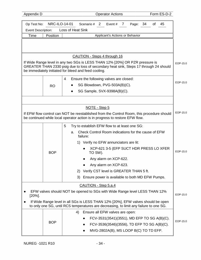
CAUTION - Steps 4 through 16
If Wide Range level in any two SGs is LESS THAN 12% [20%] OR PZR pressure is GREATER THAN 2330 psig due to loss of secondary heat sink, Steps 17 through 24 should be immediately initiated for bleed and feed cooling.
EOP-15.0
RO
4 Ensure the following valves are closed: ● SG Blowdown, PVG-503A(B)(C).
● SG Sample, SVX-9398A(B)(C).
EOP-15.0
NOTE - Step 5
If EFW flow control can NOT be reestablished from the Control Room, this procedure should be continued while local operator action is in progress to restore EFW flow.
EOP-15.0
BOP
5 Try to establish EFW flow to at least one SG:
a. Check Control Room indications for the cause of EFW failure:
1) Verify no EFW annunciators are lit:
● XCP-621 3-5 (EFP SUCT HDR PRESS LO XFER TO SW).
● Any alarm on XCP-622.
● Any alarm on XCP-623.
2) Verify CST level is GREATER THAN 5 ft.
3) Ensure power is available to both MD EFW Pumps.
EOP-15.0
CAUTION - Step 5.a.4
● EFW valves should NOT be opened to SGs with Wide Range level LESS THAN 12% [20%].
● If Wide Range level in all SGs is LESS THAN 12% [20%], EFW valves should be open to only one SG, until RCS temperatures are decreasing, to limit any failure to one SG.
EOP-15.0
BOP
4) Ensure all EFW valves are open:
● FCV-3531(3541)(3551), MD EFP TO SG A(B)(C).
● FCV-3536(3546)(3556), TD EFP TO SG A(B)(C).
● MVG-2802A(B), MS LOOP B(C) TO TD EFP.
EOP-15.0
Appendix D Operator Actions Form ES-D-2
Op Test No: NRC-ILO-14-01 Scenario # 2 Event # 7 Page: 35 of 45
Event Description: Loss of Heat Sink
Time Position Applicant’s Actions or Behavior
NUREG -1021 R10 - 35 -
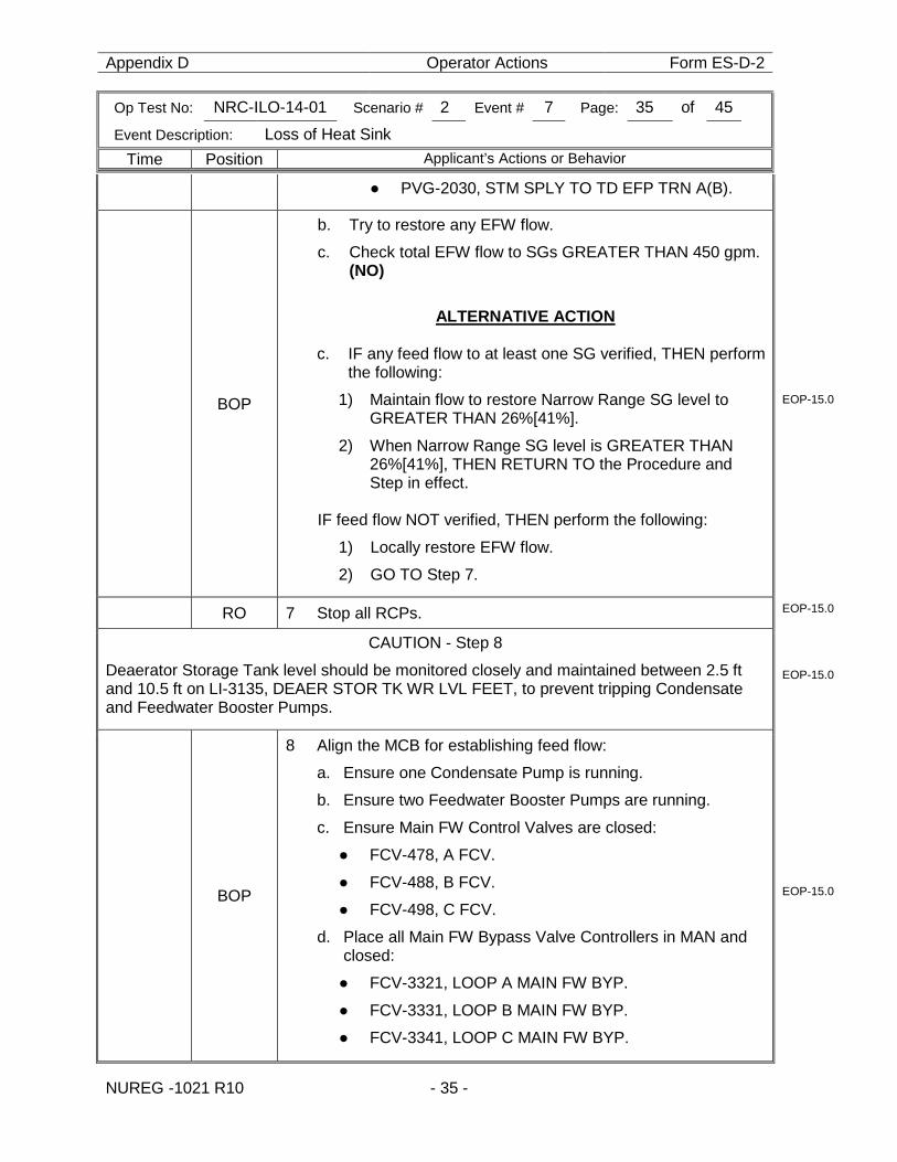
● PVG-2030, STM SPLY TO TD EFP TRN A(B).
BOP
b. Try to restore any EFW flow.
c. Check total EFW flow to SGs GREATER THAN 450 gpm. (NO)
ALTERNATIVE ACTION
c. IF any feed flow to at least one SG verified, THEN perform
the following:
1) Maintain flow to restore Narrow Range SG level to GREATER THAN 26%[41%].
2) When Narrow Range SG level is GREATER THAN 26%[41%], THEN RETURN TO the Procedure and Step in effect.
IF feed flow NOT verified, THEN perform the following:
1) Locally restore EFW flow.
2) GO TO Step 7.
EOP-15.0
RO 7 Stop all RCPs. EOP-15.0
CAUTION - Step 8
Deaerator Storage Tank level should be monitored closely and maintained between 2.5 ft and 10.5 ft on LI-3135, DEAER STOR TK WR LVL FEET, to prevent tripping Condensate and Feedwater Booster Pumps.
EOP-15.0
BOP
8 Align the MCB for establishing feed flow: a. Ensure one Condensate Pump is running.
b. Ensure two Feedwater Booster Pumps are running.
c. Ensure Main FW Control Valves are closed:
● FCV-478, A FCV.
● FCV-488, B FCV.
● FCV-498, C FCV.
d. Place all Main FW Bypass Valve Controllers in MAN and closed:
● FCV-3321, LOOP A MAIN FW BYP.
● FCV-3331, LOOP B MAIN FW BYP.
● FCV-3341, LOOP C MAIN FW BYP.
EOP-15.0
Appendix D Operator Actions Form ES-D-2
Op Test No: NRC-ILO-14-01 Scenario # 2 Event # 7 Page: 36 of 45
Event Description: Loss of Heat Sink
Time Position Applicant’s Actions or Behavior
NUREG -1021 R10 - 36 -
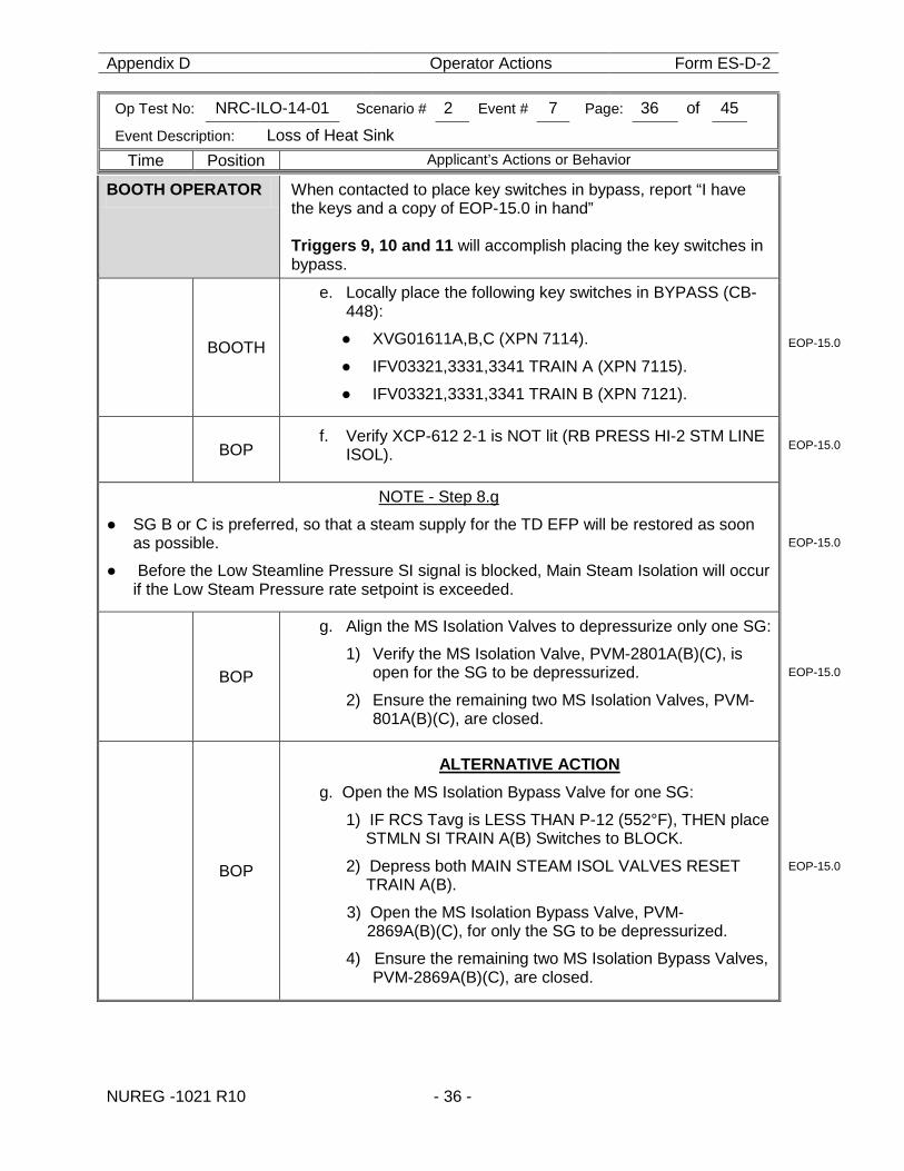
BOOTH OPERATOR When contacted to place key switches in bypass, report “I have the keys and a copy of EOP-15.0 in hand” Triggers 9, 10 and 11 will accomplish placing the key switches in bypass.
BOOTH
e. Locally place the following key switches in BYPASS (CB-448):
● XVG01611A,B,C (XPN 7114).
● IFV03321,3331,3341 TRAIN A (XPN 7115).
● IFV03321,3331,3341 TRAIN B (XPN 7121).
EOP-15.0
BOP f. Verify XCP-612 2-1 is NOT lit (RB PRESS HI-2 STM LINE
ISOL). EOP-15.0
NOTE - Step 8.g
● SG B or C is preferred, so that a steam supply for the TD EFP will be restored as soon as possible.
● Before the Low Steamline Pressure SI signal is blocked, Main Steam Isolation will occur if the Low Steam Pressure rate setpoint is exceeded.
EOP-15.0
BOP
g. Align the MS Isolation Valves to depressurize only one SG:
1) Verify the MS Isolation Valve, PVM-2801A(B)(C), is open for the SG to be depressurized.
2) Ensure the remaining two MS Isolation Valves, PVM-801A(B)(C), are closed.
EOP-15.0
BOP
ALTERNATIVE ACTION g. Open the MS Isolation Bypass Valve for one SG:
1) IF RCS Tavg is LESS THAN P-12 (552°F), THEN place STMLN SI TRAIN A(B) Switches to BLOCK.
2) Depress both MAIN STEAM ISOL VALVES RESET TRAIN A(B).
3) Open the MS Isolation Bypass Valve, PVM-2869A(B)(C), for only the SG to be depressurized.
4) Ensure the remaining two MS Isolation Bypass Valves, PVM-2869A(B)(C), are closed.
EOP-15.0
Appendix D Operator Actions Form ES-D-2
Op Test No: NRC-ILO-14-01 Scenario # 2 Event # 7 Page: 37 of 45
Event Description: Loss of Heat Sink
Time Position Applicant’s Actions or Behavior
NUREG -1021 R10 - 37 -
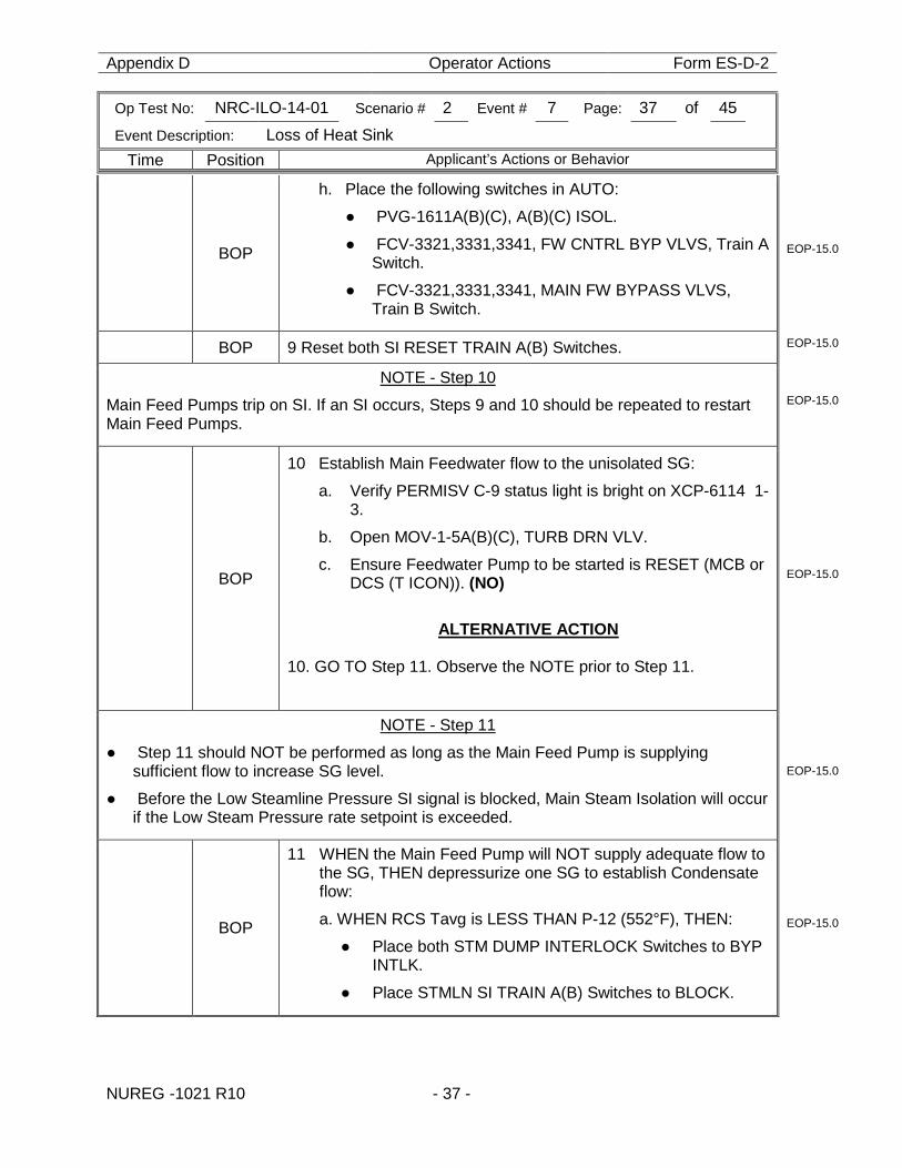
BOP
h. Place the following switches in AUTO:
● PVG-1611A(B)(C), A(B)(C) ISOL.
● FCV-3321,3331,3341, FW CNTRL BYP VLVS, Train A Switch.
● FCV-3321,3331,3341, MAIN FW BYPASS VLVS, Train B Switch.
EOP-15.0
BOP 9 Reset both SI RESET TRAIN A(B) Switches. EOP-15.0
NOTE - Step 10
Main Feed Pumps trip on SI. If an SI occurs, Steps 9 and 10 should be repeated to restart Main Feed Pumps.
EOP-15.0
BOP
10 Establish Main Feedwater flow to the unisolated SG:
a. Verify PERMISV C-9 status light is bright on XCP-6114 1-3.
b. Open MOV-1-5A(B)(C), TURB DRN VLV.
c. Ensure Feedwater Pump to be started is RESET (MCB or DCS (T ICON)). (NO)
ALTERNATIVE ACTION
10. GO TO Step 11. Observe the NOTE prior to Step 11.
EOP-15.0
NOTE - Step 11
● Step 11 should NOT be performed as long as the Main Feed Pump is supplying sufficient flow to increase SG level.
● Before the Low Steamline Pressure SI signal is blocked, Main Steam Isolation will occur if the Low Steam Pressure rate setpoint is exceeded.
EOP-15.0
BOP
11 WHEN the Main Feed Pump will NOT supply adequate flow to the SG, THEN depressurize one SG to establish Condensate flow:
a. WHEN RCS Tavg is LESS THAN P-12 (552°F), THEN:
● Place both STM DUMP INTERLOCK Switches to BYP INTLK.
● Place STMLN SI TRAIN A(B) Switches to BLOCK.
EOP-15.0
Appendix D Operator Actions Form ES-D-2
Op Test No: NRC-ILO-14-01 Scenario # 2 Event # 7 Page: 38 of 45
Event Description: Loss of Heat Sink
Time Position Applicant’s Actions or Behavior
NUREG -1021 R10 - 38 -
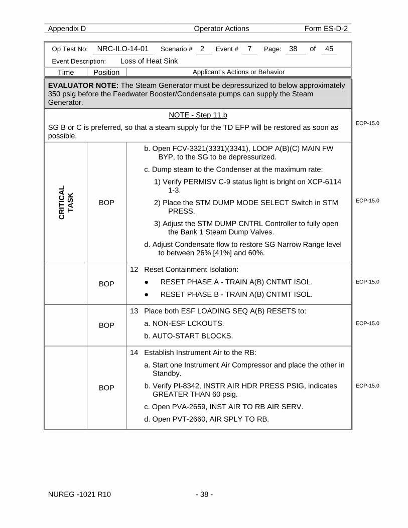
EVALUATOR NOTE: The Steam Generator must be depressurized to below approximately 350 psig before the Feedwater Booster/Condensate pumps can supply the Steam Generator.
NOTE - Step 11.b
SG B or C is preferred, so that a steam supply for the TD EFP will be restored as soon as possible.
EOP-15.0
CR
ITIC
AL
TA
SK
BOP
b. Open FCV-3321(3331)(3341), LOOP A(B)(C) MAIN FW BYP, to the SG to be depressurized.
c. Dump steam to the Condenser at the maximum rate:
1) Verify PERMISV C-9 status light is bright on XCP-6114 1-3.
2) Place the STM DUMP MODE SELECT Switch in STM PRESS.
3) Adjust the STM DUMP CNTRL Controller to fully open the Bank 1 Steam Dump Valves.
d. Adjust Condensate flow to restore SG Narrow Range level to between 26% [41%] and 60%.
EOP-15.0
BOP
12 Reset Containment Isolation:
● RESET PHASE A - TRAIN A(B) CNTMT ISOL.
● RESET PHASE B - TRAIN A(B) CNTMT ISOL.
EOP-15.0
BOP
13 Place both ESF LOADING SEQ A(B) RESETS to:
a. NON-ESF LCKOUTS.
b. AUTO-START BLOCKS.
EOP-15.0
BOP
14 Establish Instrument Air to the RB:
a. Start one Instrument Air Compressor and place the other in Standby.
b. Verify PI-8342, INSTR AIR HDR PRESS PSIG, indicates GREATER THAN 60 psig.
c. Open PVA-2659, INST AIR TO RB AIR SERV.
d. Open PVT-2660, AIR SPLY TO RB.
EOP-15.0
Appendix D Operator Actions Form ES-D-2
Op Test No: NRC-ILO-14-01 Scenario # 2 Event # 7 Page: 39 of 45
Event Description: Loss of Heat Sink
Time Position Applicant’s Actions or Behavior
NUREG -1021 R10 - 39 -
BOP
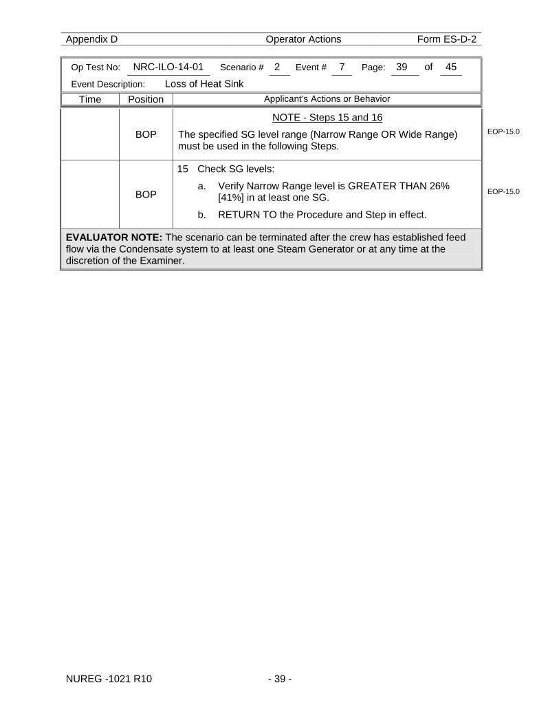
NOTE - Steps 15 and 16
The specified SG level range (Narrow Range OR Wide Range) must be used in the following Steps.
EOP-15.0
BOP
15 Check SG levels:
a. Verify Narrow Range level is GREATER THAN 26% [41%] in at least one SG.
b. RETURN TO the Procedure and Step in effect.
EOP-15.0
EVALUATOR NOTE: The scenario can be terminated after the crew has established feed flow via the Condensate system to at least one Steam Generator or at any time at the discretion of the Examiner.

Appendix D Operator Actions Form ES-D-2
Op Test No: NRC-ILO-14-01 Scenario # 2 Event # NA Page: 40 of 45
Event Description: SOP-106, Section IV, D, BORATING THE RCS USING THE EMERGENCY BORATE VALVE
NUREG -1021 R10 - 40 -
Appendix D Operator Actions Form ES-D-2
Op Test No: NRC-ILO-14-01 Scenario # 2 Event # NA Page: 41 of 45
Event Description: SOP-106, Section III, F, BORATE OPERATIONS
NUREG -1021 R10 - 41 -
Appendix D Operator Actions Form ES-D-2
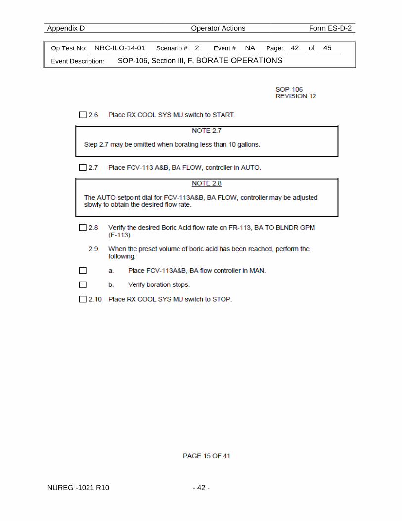
Op Test No: NRC-ILO-14-01 Scenario # 2 Event # NA Page: 42 of 45
Event Description: SOP-106, Section III, F, BORATE OPERATIONS
NUREG -1021 R10 - 42 -
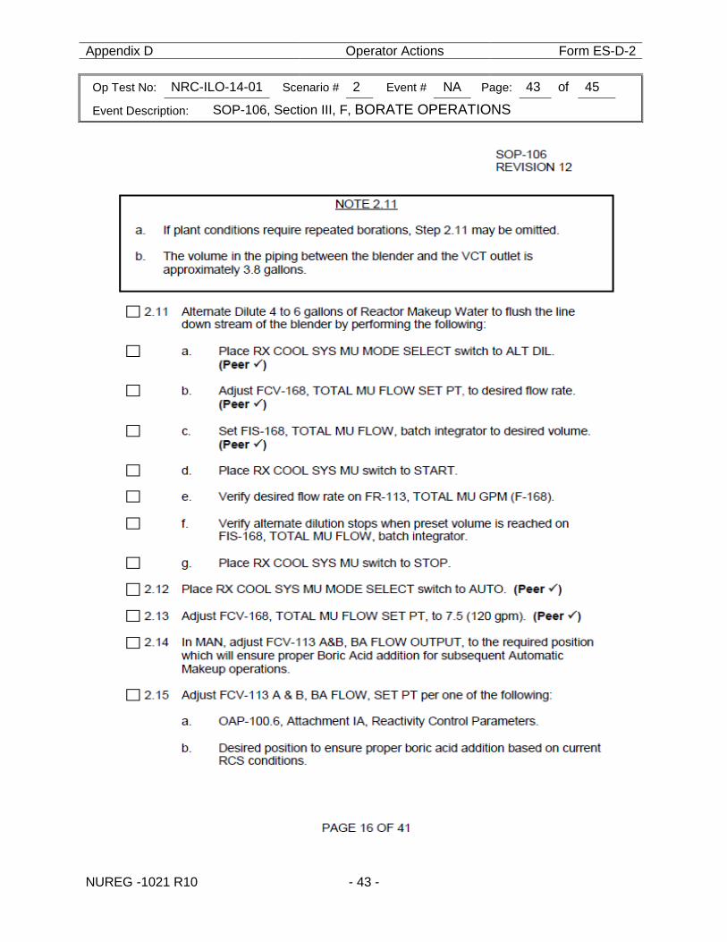
Appendix D Operator Actions Form ES-D-2
Op Test No: NRC-ILO-14-01 Scenario # 2 Event # NA Page: 43 of 45
Event Description: SOP-106, Section III, F, BORATE OPERATIONS
NUREG -1021 R10 - 43 -
Appendix D Operator Actions Form ES-D-2
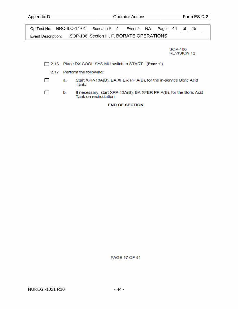
Op Test No: NRC-ILO-14-01 Scenario # 2 Event # NA Page: 44 of 45
Event Description: SOP-106, Section III, F, BORATE OPERATIONS
NUREG -1021 R10 - 44 -
Appendix D Form ES-D-2
Op Test No: NRC-ILO-14-01 Scenario # 2 Event # NA Page: 45 of 45
Event Description: NA
NUREG -1021 R10 - 45 -
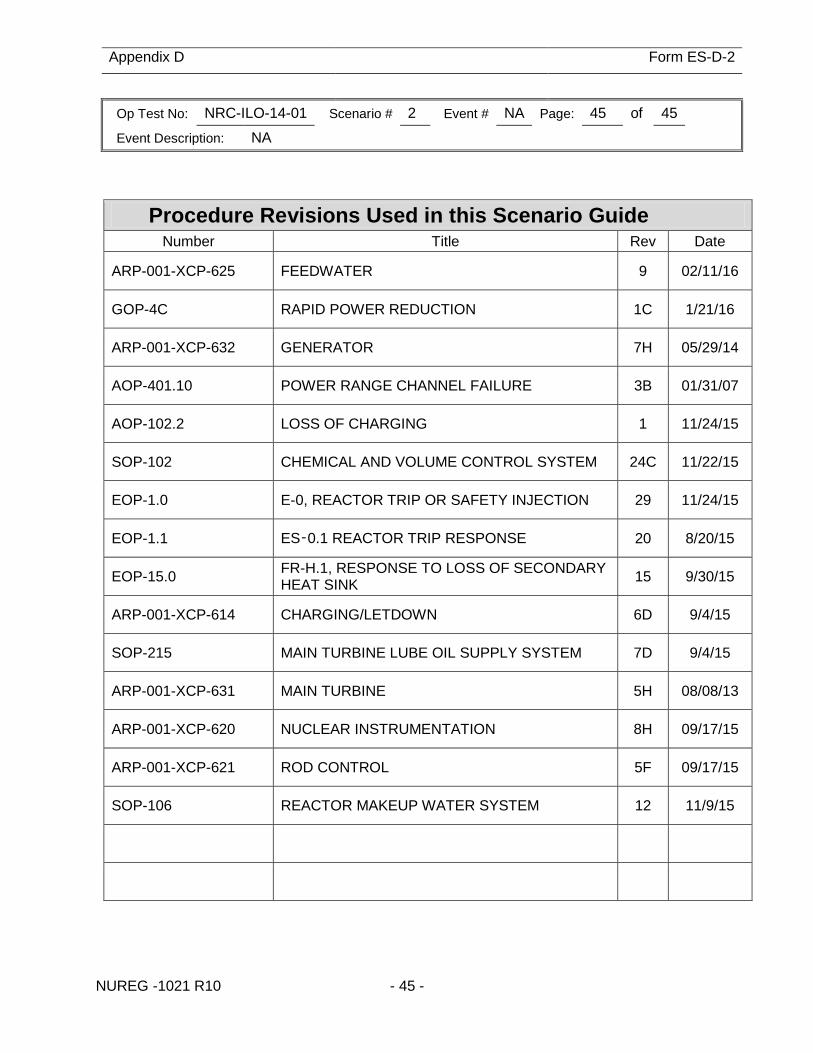
Procedure Revisions Used in this Scenario Guide Number Title Rev Date
ARP-001-XCP-625 FEEDWATER 9 02/11/16
GOP-4C RAPID POWER REDUCTION 1C 1/21/16
ARP-001-XCP-632 GENERATOR 7H 05/29/14
AOP-401.10 POWER RANGE CHANNEL FAILURE 3B 01/31/07
AOP-102.2 LOSS OF CHARGING 1 11/24/15
SOP-102 CHEMICAL AND VOLUME CONTROL SYSTEM 24C 11/22/15
EOP-1.0 E-0, REACTOR TRIP OR SAFETY INJECTION 29 11/24/15
EOP-1.1 ES‑0.1 REACTOR TRIP RESPONSE 20 8/20/15
EOP-15.0 FR-H.1, RESPONSE TO LOSS OF SECONDARY HEAT SINK 15 9/30/15
ARP-001-XCP-614 CHARGING/LETDOWN 6D 9/4/15
SOP-215 MAIN TURBINE LUBE OIL SUPPLY SYSTEM 7D 9/4/15
ARP-001-XCP-631 MAIN TURBINE 5H 08/08/13
ARP-001-XCP-620 NUCLEAR INSTRUMENTATION 8H 09/17/15
ARP-001-XCP-621 ROD CONTROL 5F 09/17/15
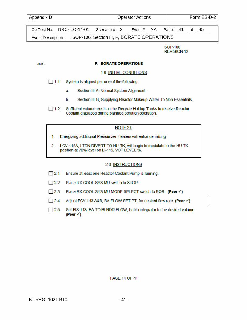
SOP-106 REACTOR MAKEUP WATER SYSTEM 12 11/9/15
Appendix D Scenario Outline Form ES-D-1
NRC 2016 Scenario 3 - 1 - NUREG -1021 R10
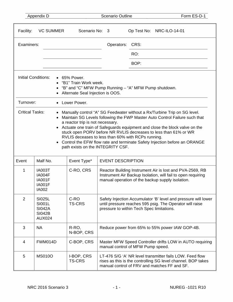
Facility: VC SUMMER Scenario No: 3 Op Test No: NRC-ILO-14-01
Examiners: Operators: CRS:
RO:
BOP:
Initial Conditions: 65% Power. “B1” Train Work week. “B” and “C” MFW Pump Running – “A” MFW Pump shutdown. Alternate Seal Injection is OOS.
Turnover: Lower Power.
Critical Tasks: Manually control “A” SG Feedwater without a Rx/Turbine Trip on SG level. Maintain SG Levels following the FWP Master Auto Control Failure such that
a reactor trip is not necessary. Actuate one train of Safeguards equipment and close the block valve on the
stuck open PORV before NR RVLIS decreases to less than 61% or WR RVLIS deceases to less than 60% with RCPs running.
Control the EFW flow rate and terminate Safety Injection before an ORANGE path exists on the INTEGRITY CSF.
Event Malf No. Event Type* EVENT DESCRIPTION
1 IA003T IA004F IA001F IA001F IA002
C-RO, CRS Reactor Building Instrument Air is lost and PVA-2569, RB Instrument Air Backup Isolation, will fail to open requiring manual operation of the backup supply isolation.
2 SI025L SI001L SI042A SI042B AUX024
C-RO TS-CRS
Safety Injection Accumulator ‘B’ level and pressure will lower until pressure reaches 595 psig. The Operator will raise pressure to within Tech Spec limitations.
3 NA R-RO, N-BOP, CRS
Reduce power from 65% to 55% power IAW GOP-4B.
4 FWM014D C-BOP, CRS Master MFW Speed Controller drifts LOW in AUTO requiring manual control of MFW Pump speed.
5 MS010O I-BOP, CRS TS-CRS
LT-476 S/G ‘A’ NR level transmitter fails LOW. Feed flow rises as this is the controlling SG level channel. BOP takes manual control of FRV and matches FF and SF.
Appendix D Scenario Outline Form ES-D-1
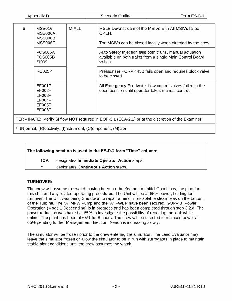
NRC 2016 Scenario 3 - 2 - NUREG -1021 R10
6 MSS016 MSS006A MSS006B MSS006C
M-ALL MSLB Downstream of the MSIVs with All MSIVs failed OPEN. The MSIVs can be closed locally when directed by the crew.
PCS005A PCS005B SI009
Auto Safety Injection fails both trains, manual actuation available on both trains from a single Main Control Board switch.
RC005P Pressurizer PORV 445B fails open and requires block valve to be closed.
EF001P EF002P EF003P EF004P EF005P EF006P
All Emergency Feedwater flow control valves failed in the open position until operator takes manual control.
TERMINATE: Verify SI flow NOT required in EOP-3.1 (ECA-2.1) or at the discretion of the Examiner.
* (N)ormal, (R)eactivity, (I)nstrument, (C)omponent, (M)ajor
The following notation is used in the ES-D-2 form “Time” column:
IOA designates Immediate Operator Action steps. * designates Continuous Action steps.
TURNOVER:
The crew will assume the watch having been pre-briefed on the Initial Conditions, the plan for this shift and any related operating procedures. The Unit will be at 65% power, holding for turnover. The Unit was being Shutdown to repair a minor non-isolable steam leak on the bottom of the Turbine. The “A” MFW Pump and the “A” FWBP have been secured. GOP-4B, Power Operation (Mode 1 Descending) is in progress and has been completed through step 3.2.d. The power reduction was halted at 65% to investigate the possibility of repairing the leak while online. The plant has been at 65% for 8 hours. The crew will be directed to maintain power at 65% pending further Management direction. Xenon is increasing slowly.
The simulator will be frozen prior to the crew entering the simulator. The Lead Evaluator may leave the simulator frozen or allow the simulator to be in run with surrogates in place to maintain stable plant conditions until the crew assumes the watch.
Appendix D Scenario Outline Form ES-D-1
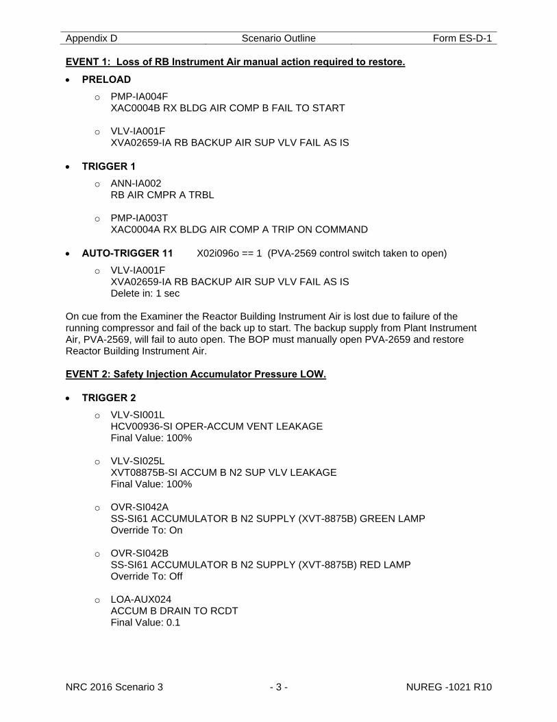
NRC 2016 Scenario 3 - 3 - NUREG -1021 R10
EVENT 1: Loss of RB Instrument Air manual action required to restore.
PRELOAD
o PMP-IA004F XAC0004B RX BLDG AIR COMP B FAIL TO START
o VLV-IA001F
XVA02659-IA RB BACKUP AIR SUP VLV FAIL AS IS TRIGGER 1
o ANN-IA002 RB AIR CMPR A TRBL
o PMP-IA003T
XAC0004A RX BLDG AIR COMP A TRIP ON COMMAND AUTO-TRIGGER 11 X02i096o == 1 (PVA-2569 control switch taken to open)
o VLV-IA001F XVA02659-IA RB BACKUP AIR SUP VLV FAIL AS IS Delete in: 1 sec
On cue from the Examiner the Reactor Building Instrument Air is lost due to failure of the running compressor and fail of the back up to start. The backup supply from Plant Instrument Air, PVA-2569, will fail to auto open. The BOP must manually open PVA-2659 and restore Reactor Building Instrument Air. EVENT 2: Safety Injection Accumulator Pressure LOW. TRIGGER 2
o VLV-SI001L HCV00936-SI OPER-ACCUM VENT LEAKAGE Final Value: 100%
o VLV-SI025L
XVT08875B-SI ACCUM B N2 SUP VLV LEAKAGE Final Value: 100%
o OVR-SI042A
SS-SI61 ACCUMULATOR B N2 SUPPLY (XVT-8875B) GREEN LAMP Override To: On
o OVR-SI042B SS-SI61 ACCUMULATOR B N2 SUPPLY (XVT-8875B) RED LAMP Override To: Off
o LOA-AUX024
ACCUM B DRAIN TO RCDT Final Value: 0.1
Appendix D Scenario Outline Form ES-D-1
NRC 2016 Scenario 3 - 4 - NUREG -1021 R10
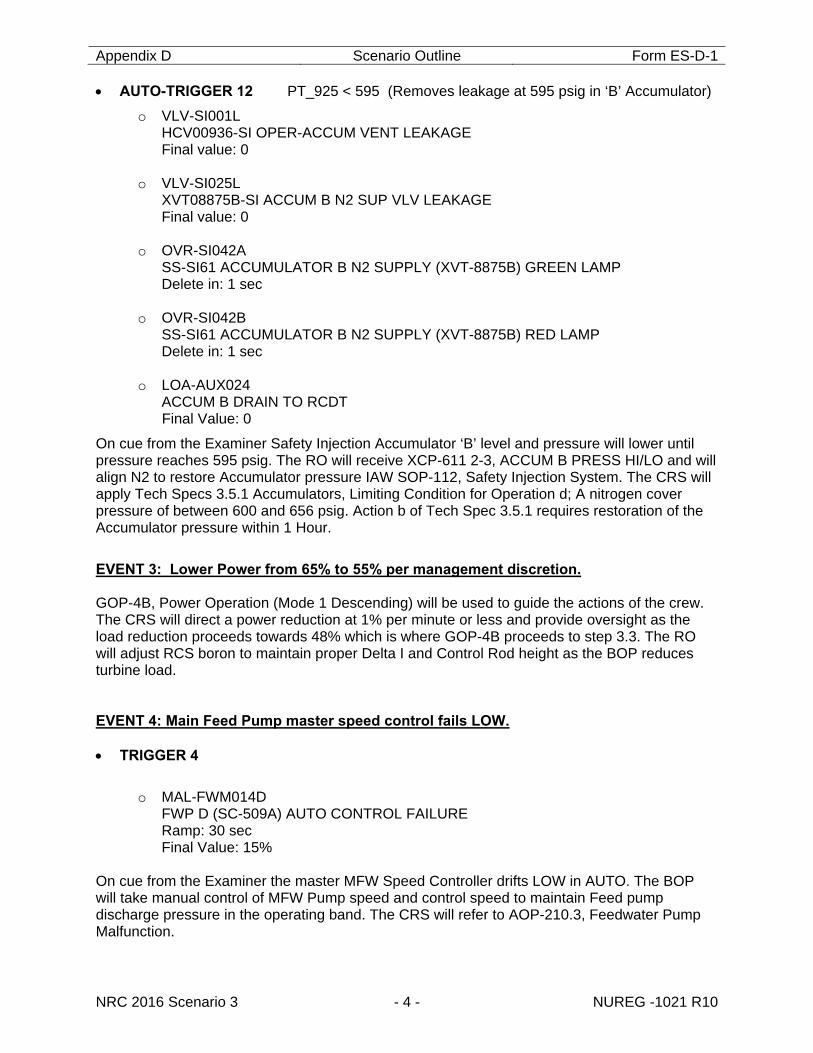
AUTO-TRIGGER 12 PT_925 < 595 (Removes leakage at 595 psig in ‘B’ Accumulator)
o VLV-SI001L HCV00936-SI OPER-ACCUM VENT LEAKAGE Final value: 0
o VLV-SI025L XVT08875B-SI ACCUM B N2 SUP VLV LEAKAGE Final value: 0
o OVR-SI042A SS-SI61 ACCUMULATOR B N2 SUPPLY (XVT-8875B) GREEN LAMP Delete in: 1 sec
o OVR-SI042B SS-SI61 ACCUMULATOR B N2 SUPPLY (XVT-8875B) RED LAMP Delete in: 1 sec
o LOA-AUX024 ACCUM B DRAIN TO RCDT Final Value: 0
On cue from the Examiner Safety Injection Accumulator ‘B’ level and pressure will lower until pressure reaches 595 psig. The RO will receive XCP-611 2-3, ACCUM B PRESS HI/LO and will align N2 to restore Accumulator pressure IAW SOP-112, Safety Injection System. The CRS will apply Tech Specs 3.5.1 Accumulators, Limiting Condition for Operation d; A nitrogen cover pressure of between 600 and 656 psig. Action b of Tech Spec 3.5.1 requires restoration of the Accumulator pressure within 1 Hour.
EVENT 3: Lower Power from 65% to 55% per management discretion. GOP-4B, Power Operation (Mode 1 Descending) will be used to guide the actions of the crew. The CRS will direct a power reduction at 1% per minute or less and provide oversight as the load reduction proceeds towards 48% which is where GOP-4B proceeds to step 3.3. The RO will adjust RCS boron to maintain proper Delta I and Control Rod height as the BOP reduces turbine load. EVENT 4: Main Feed Pump master speed control fails LOW. TRIGGER 4
o MAL-FWM014D
FWP D (SC-509A) AUTO CONTROL FAILURE Ramp: 30 sec Final Value: 15%
On cue from the Examiner the master MFW Speed Controller drifts LOW in AUTO. The BOP will take manual control of MFW Pump speed and control speed to maintain Feed pump discharge pressure in the operating band. The CRS will refer to AOP-210.3, Feedwater Pump Malfunction.
Appendix D Scenario Outline Form ES-D-1
NRC 2016 Scenario 3 - 5 - NUREG -1021 R10
EVENT 5: S/G “A” Controlling level channel fails LOW.
TRIGGER 5
o XMT-MS010O ILT00476 SG A NR LVL LI-476 FAIL TO POSN Ramp: 2 min Final Value: 0%
On cue from the Examiner Steam Generator “A” Narrow Range level transmitter, LT-476 fails LOW. This is the controlling SG level channel and the failure will cause feed flow to rise. The BOP takes manual control of FRV and matches FF and SF. Crew implements AOP-401.11, Steam Generator Level Control and Protection Channel Failure. The CRS will apply Tech Spec 3.3.1, Reactor Trip System Instrumentation and Tech Spec 3.3.3, Engineered Safety Feature Actuation System Instrumentation.
Tech Spec 3.3.1 function 13, Steam Generator Water Level Low-Low is affected. This function invokes action 6 which requires; with the number of OPERABLE channels one less than the Total Number of Channels, STARTUP and/or POWER OPERATION may proceed provided the following conditions are satisfied: a. the inoperable channel is placed in the tripped condition within 72 hours.
Tech Spec 3.3.3 Functions 5.a; Turbine Trip and Feedwater Isolation and 6.c; Emergency Feedwater Low Low Level start of EFW pumps are affected. Both functions invoke action 24 which requires: with the number of OPERABLE channels one less than the Total Number of Channels, STARTUP and/or POWER OPERATION may proceed provided the following conditions are satisfied: a. the inoperable channel is placed in the tripped condition within 72 hours.
EVENT 6: MSLB downstream of the MSIVs with all MSIV failed open. PRELOAD
o MAL-PCS005A SAFETY INJECTION FAILURE TRAIN A Fail To: FAIL TO AUTO INIT
o MAL-PCS005B SAFETY INJECTION FAILURE TRAIN B Fail To: FAIL TO AUTO INIT
o OVR-SI009 CS-CR01B SAFETY INJ ACTUATION ACTUATE Override To: False
o VLV-EF001P IFV03531-EF EF ISO FRM MD PMPS TO SG A FAIL POSITION Final Value: 100
o VLV-EF002P IFV03536-EF EF ISO FRM TD PMPS TO SG A FAIL POSITION Final Value: 100
o VLV-EF003P IFV03541-EF EF ISO FRM MD PMPS TO SG B FAIL POSITION Final Value: 100
Appendix D Scenario Outline Form ES-D-1
NRC 2016 Scenario 3 - 6 - NUREG -1021 R10
o VLV- EF004P IFV03546-EF EF ISO FRM TD PMPS TO SG B FAIL POSITION Final Value: 100
o VLV-EF005P IFV03551-EF EF ISO FRM MD PMPS TO SG C FAIL POSITION Final Value: 100
o VLV-EF006P IFV03556-EF EF ISO FRM TD PMPS TO SG C FAIL POSITION Final Value: 100
TRIGGER 6
o MAL-MSS016 STEAMLINE BREAK DOWNSTREAM THE MSIV'S Final Value: 4E6 LBM/HR
o MAL-MSS006A MAIN STEAM ISOLATION VALVE (S/G A) FAILURE Fail To: FAILURE TO CLOSE
o MAL-MSS006B MAIN STEAM ISOLATION VALVE (S/G B) FAILURE Fail To: FAILURE TO CLOSE
o MAL-MSS006C MAIN STEAM ISOLATION VALVE (S/G C) FAILURE Fail To: FAILURE TO CLOSE
AUTO-TRIGGER 10 fnispr(2)<=2 (Fails PZR PORV open at Reactor trip)
o VLV-RC005P PCV00445B-RC PZR PWR REL VLV FAIL POSITION Final Value: 100%
TRIGGER 14
o VLV-MS008W XVG02802A-MS MS LP B TO TD EF PMP LOSS OF POWER
TRIGGER 15
o VLV-MS008P XVG02802A-MS MS LP B TO TD EF PMP FAIL POSITION Final value: 0
TRIGGER 16
o VLV-MS009W XVG02802B-MS MS LP C TO TD EF PMP LOSS OF POWER
TRIGGER 17
o VLV-MS009P XVG02802B-MS MS LP C TO TD EF PMP FAIL POSITION Final value: 0
Appendix D Scenario Outline Form ES-D-1
NRC 2016 Scenario 3 - 7 - NUREG -1021 R10
AUTO-TRIGGER 18 x07i557R==1 (Removes MD EFW valves failed open when reset switch is operated)
o VLV-EF001P IFV03531-EF EF ISO FRM MD PMPS TO SG A FAIL POSITION Delete in: 1 sec.
o VLV-EF003P IFV03541-EF EF ISO FRM MD PMPS TO SG B FAIL POSITION Delete in: 1 sec
o VLV-EF005P IFV03551-EF EF ISO FRM MD PMPS TO SG C FAIL POSITION Delete in: 1 sec
AUTO-TRIGGER 19 x07i556R==1 (Removes TD EFW valves failed open when reset switch is operated)
o VLV-EF002P IFV03536-EF EF ISO FRM TD PMPS TO SG A FAIL POSITION Delete in: 1 sec
o VLV-EF004P IFV03546-EF EF ISO FRM TD PMPS TO SG B FAIL POSITION Delete in: 1 sec
o VLV-EF006P IFV03556-EF EF ISO FRM TD PMPS TO SG C FAIL POSITION Delete in: 1 sec
TRIGGER 20
o LOA-RHR006 ACCUM A ISO VLV 8808A BKR Position To: CLOSE
o LOA-RHR008 ACCUM C ISO VLV 8808C BKR Position To: CLOSE Delay: 60 sec
TRIGGER 21
o LOA-RHR007 ACCUM B ISO VLV 8808B BKR Position To: CLOSE Delay: 120 sec
Appendix D Scenario Outline Form ES-D-1
NRC 2016 Scenario 3 - 8 - NUREG -1021 R10
TRIGGER 7
o VLV-MS021P XVM02801B-MS MS ISO VLV B FAIL POSITION Final Value: 0%
o VLV-MS020P XVM02801A-MS MS ISO VLV A FAIL POSITION Final Value: 0% Delay: 120 sec
o VLV-MS022P XVM02801C-MS MS ISO VLV C FAIL POSITION Final Value: 0% Delay: 240 sec
Main Steam Line Break downstream of the MSIVs with all MSIVs failed OPEN. The crew will enter EOP-1.0 (E-0) address the failure of Automatic Safety Injection by operating the Train “A” manual switch and the stuck open Pressurizer PORV by closing its block valve. All Emergency Feedwater flow control valves will remain full open, until the Operator takes the control to manual. A transition to EOP-3.0, Faulted Steam Generator Isolation (E-2) will be made. When it is recognized that all Steam Generators are faulted the crew will transition to EOP-3.1, ECA-2.1, Uncontrolled Depressurization of All Steam Generators. The MSIVs will be locally closed after the crew has stopped all but one Charging Pump at step 13 of EOP-3.1.
CRITICAL TASKS:
Maintain SG Levels following the FWP Master Auto Control Failure such that a reactor trip is not necessary.
Manually control “A” SG Feedwater without a Rx/Turbine Trip on SG level.
Actuate one train of Safeguards equipment and close the block valve on the stuck open PORV before NR RVLIS decreases to less than 61% or WR RVLIS deceases to less than 60% with RCPs running.
Control the EFW flow rate and terminate Safety Injection before an ORANGE path exists on the INTEGRITY CSF.
TERMINATION:
The scenario may be terminated when Step 18 of EOP-3.1 (ECA-2.1), Verify SI flow is NOT required is completed or at the discretion of the Examiner.
Appendix D Scenario Outline Form ES-D-1
NRC 2016 Scenario 3 - 9 - NUREG -1021 R10
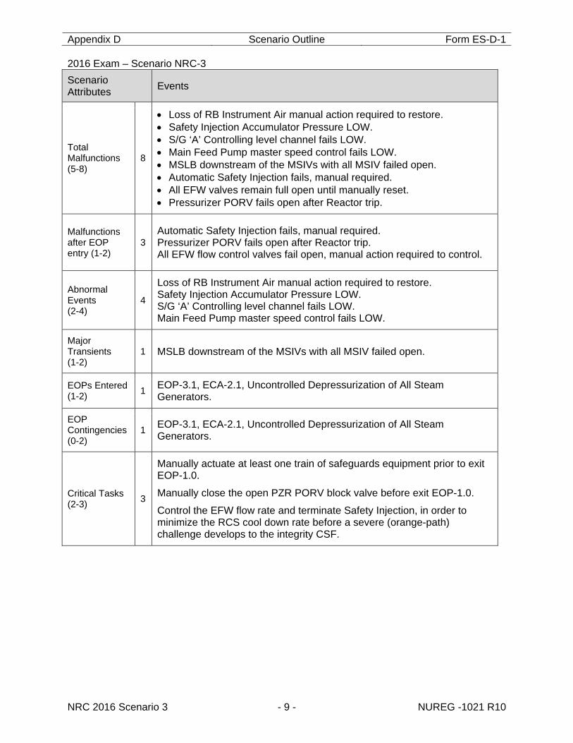
2016 Exam – Scenario NRC-3 Scenario Attributes Events
Total Malfunctions (5-8)
8
Loss of RB Instrument Air manual action required to restore. Safety Injection Accumulator Pressure LOW. S/G ‘A’ Controlling level channel fails LOW. Main Feed Pump master speed control fails LOW. MSLB downstream of the MSIVs with all MSIV failed open. Automatic Safety Injection fails, manual required. All EFW valves remain full open until manually reset. Pressurizer PORV fails open after Reactor trip.
Malfunctions after EOP entry (1-2)
3 Automatic Safety Injection fails, manual required. Pressurizer PORV fails open after Reactor trip. All EFW flow control valves fail open, manual action required to control.
Abnormal Events (2-4)
4
Loss of RB Instrument Air manual action required to restore. Safety Injection Accumulator Pressure LOW. S/G ‘A’ Controlling level channel fails LOW. Main Feed Pump master speed control fails LOW.
Major Transients (1-2)
1 MSLB downstream of the MSIVs with all MSIV failed open.
EOPs Entered (1-2) 1 EOP-3.1, ECA-2.1, Uncontrolled Depressurization of All Steam
Generators.
EOP Contingencies (0-2)
1 EOP-3.1, ECA-2.1, Uncontrolled Depressurization of All Steam Generators.
Critical Tasks (2-3) 3
Manually actuate at least one train of safeguards equipment prior to exit EOP-1.0.
Manually close the open PZR PORV block valve before exit EOP-1.0.
Control the EFW flow rate and terminate Safety Injection, in order to minimize the RCS cool down rate before a severe (orange-path) challenge develops to the integrity CSF.
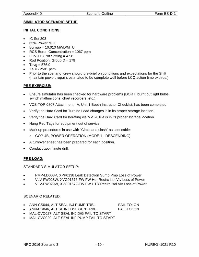
Appendix D Scenario Outline Form ES-D-1
NRC 2016 Scenario 3 - 10 - NUREG -1021 R10
SIMULATOR SCENARIO SETUP INITIAL CONDITIONS: IC Set 303 65% Power MOL Burnup = 10,010 MWD/MTU RCS Boron Concentration = 1067 ppm FCV-113 Pot Setting = 4.58 Rod Position: Group D = 179 Tavg = 576.9 Xe = - 2581 pcm Prior to the scenario, crew should pre-brief on conditions and expectations for the Shift
(maintain power, repairs estimated to be complete well before LCO action time expires.) PRE-EXERCISE: Ensure simulator has been checked for hardware problems (DORT, burnt out light bulbs,
switch malfunctions, chart recorders, etc.).
VCS-TQP-0807 Attachment I-A, Unit 1 Booth Instructor Checklist, has been completed.
Verify the Hard Card for Turbine Load changes is in its proper storage location.
Verify the Hard Card for borating via MVT-8104 is in its proper storage location.
Hang Red Tags for equipment out of service.
Mark up procedures in use with “Circle and slash” as applicable:
o GOP-4B, POWER OPERATION (MODE 1 - DESCENDING)
A turnover sheet has been prepared for each position.
Conduct two-minute drill.
PRE-LOAD: STANDARD SIMULATOR SETUP: PMP-LD003P, XPP0138 Leak Detection Sump Pmp Loss of Power VLV-FW028W, XVG01676-FW FW Hdr Recirc Isol Vlv Loss of Power VLV-FW029W, XVG01679-FW FW HTR Recirc Isol Vlv Loss of Power SCENARIO RELATED: ANN-CS044, ALT SEAL INJ PUMP TRBL FAIL TO: ON ANN-CS046, ALT SL INJ DSL GEN TRBL FAIL TO: ON MAL-CVC027, ALT SEAL INJ D/G FAIL TO START MAL-CVC029, ALT SEAL INJ PUMP FAIL TO START
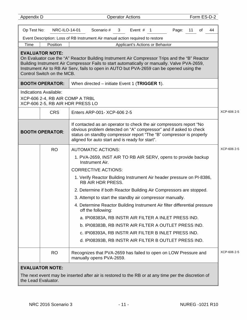
Appendix D Operator Actions Form ES-D-2
Op Test No: NRC-ILO-14-01 Scenario # 3 Event # 1 Page: 11 of 44
Event Description: Loss of RB Instrument Air manual action required to restore
Time Position Applicant’s Actions or Behavior
NRC 2016 Scenario 3 - 11 - NUREG -1021 R10
EVALUATOR NOTE: On Evaluator cue the “A” Reactor Building Instrument Air Compressor Trips and the “B” Reactor Building Instrument Air Compressor Fails to start automatically or manually. Valve PVA-2659, Instrument Air to RB Air Serv, fails to open in AUTO but PVA-2659 can be opened using the Control Switch on the MCB.
BOOTH OPERATOR: When directed – initiate Event 1 (TRIGGER 1).
Indications Available: XCP-606 2-4, RB AIR COMP A TRBL XCP-606 2-5, RB AIR HDR PRESS LO
CRS Enters ARP-001- XCP-606 2-5 XCP-606 2-5
BOOTH OPERATOR:
If contacted as an operator to check the air compressors report “No obvious problem detected on “A” compressor” and if asked to check status on standby compressor report “The “B” compressor is properly aligned for auto start and is ready for start”.
RO AUTOMATIC ACTIONS:
1. PVA-2659, INST AIR TO RB AIR SERV, opens to provide backup Instrument Air.
CORRECTIVE ACTIONS:
1. Verify Reactor Building Instrument Air header pressure on PI-8386, RB AIR HDR PRESS.
2. Determine if both Reactor Building Air Compressors are stopped.
3. Attempt to start the standby air compressor manually.
4. Determine Reactor Building Instrument Air filter differential pressure off the following:
a. IPI08383A, RB INSTR AIR FILTER A INLET PRESS IND.
b. IPI08383B, RB INSTR AIR FILTER A OUTLET PRESS IND.
c. IPI08393A, RB INSTR AIR FILTER B INLET PRESS IND.
d. IPI08393B, RB INSTR AIR FILTER B OUTLET PRESS IND.
XCP-606 2-5
RO Recognizes that PVA-2659 has failed to open on LOW Pressure and manually opens PVA-2659.
XCP-606 2-5
EVALUATOR NOTE:
The next event may be inserted after air is restored to the RB or at any time per the discretion of the Lead Evaluator.
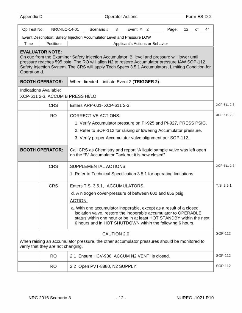
Appendix D Operator Actions Form ES-D-2
Op Test No: NRC-ILO-14-01 Scenario # 3 Event # 2 Page: 12 of 44
Event Description: Safety Injection Accumulator Level and Pressure LOW
Time Position Applicant’s Actions or Behavior
NRC 2016 Scenario 3 - 12 - NUREG -1021 R10
EVALUATOR NOTE: On cue from the Examiner Safety Injection Accumulator ‘B’ level and pressure will lower until pressure reaches 595 psig. The RO will align N2 to restore Accumulator pressure IAW SOP-112, Safety Injection System. The CRS will apply Tech Specs 3.5.1 Accumulators, Limiting Condition for Operation d.
BOOTH OPERATOR: When directed – initiate Event 2 (TRIGGER 2).
Indications Available: XCP-611 2-3, ACCUM B PRESS HI/LO
CRS Enters ARP-001- XCP-611 2-3 XCP-611 2-3
RO CORRECTIVE ACTIONS:
1. Verify Accumulator pressure on PI-925 and PI-927, PRESS PSIG.
2. Refer to SOP-112 for raising or lowering Accumulator pressure.
3. Verify proper Accumulator valve alignment per SOP-112.
XCP-611 2-3
BOOTH OPERATOR: Call CRS as Chemistry and report “A liquid sample valve was left open on the “B” Accumulator Tank but it is now closed”.
CRS SUPPLEMENTAL ACTIONS:
1. Refer to Technical Specification 3.5.1 for operating limitations.
XCP-611 2-3
CRS Enters T.S. 3.5.1, ACCUMULATORS.
d. A nitrogen cover-pressure of between 600 and 656 psig.
ACTION:
a. With one accumulator inoperable, except as a result of a closed isolation valve, restore the inoperable accumulator to OPERABLE status within one hour or be in at least HOT STANDBY within the next 6 hours and in HOT SHUTDOWN within the following 6 hours.
T.S. 3.5.1
CAUTION 2.0
When raising an accumulator pressure, the other accumulator pressures should be monitored to verify that they are not changing.
SOP-112
RO 2.1 Ensure HCV-936, ACCUM N2 VENT, is closed. SOP-112
RO 2.2 Open PVT-8880, N2 SUPPLY. SOP-112
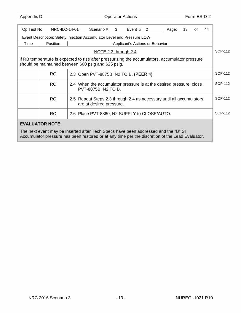
Appendix D Operator Actions Form ES-D-2
Op Test No: NRC-ILO-14-01 Scenario # 3 Event # 2 Page: 13 of 44
Event Description: Safety Injection Accumulator Level and Pressure LOW
Time Position Applicant’s Actions or Behavior
NRC 2016 Scenario 3 - 13 - NUREG -1021 R10
NOTE 2.3 through 2.4
If RB temperature is expected to rise after pressurizing the accumulators, accumulator pressure should be maintained between 600 psig and 625 psig.
SOP-112
RO 2.3 Open PVT-8875B, N2 TO B. (PEER √) SOP-112
RO 2.4 When the accumulator pressure is at the desired pressure, close PVT-8875B, N2 TO B.
SOP-112
RO 2.5 Repeat Steps 2.3 through 2.4 as necessary until all accumulators are at desired pressure.
SOP-112
RO 2.6 Place PVT-8880, N2 SUPPLY to CLOSE/AUTO. SOP-112
EVALUATOR NOTE:
The next event may be inserted after Tech Specs have been addressed and the "B" SI Accumulator pressure has been restored or at any time per the discretion of the Lead Evaluator.
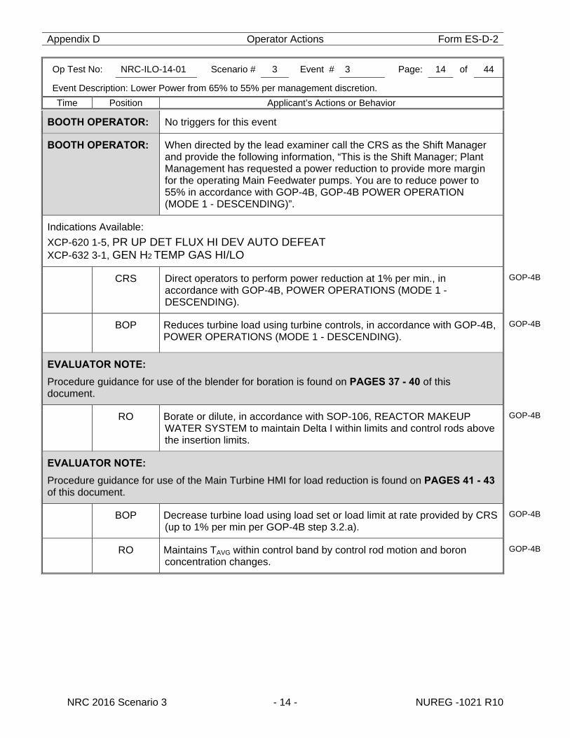
Appendix D Operator Actions Form ES-D-2
Op Test No: NRC-ILO-14-01 Scenario # 3 Event # 3 Page: 14 of 44
Event Description: Lower Power from 65% to 55% per management discretion.
Time Position Applicant’s Actions or Behavior
NRC 2016 Scenario 3 - 14 - NUREG -1021 R10
BOOTH OPERATOR: No triggers for this event
BOOTH OPERATOR: When directed by the lead examiner call the CRS as the Shift Manager and provide the following information, “This is the Shift Manager; Plant Management has requested a power reduction to provide more margin for the operating Main Feedwater pumps. You are to reduce power to 55% in accordance with GOP-4B, GOP-4B POWER OPERATION (MODE 1 - DESCENDING)”.
Indications Available: XCP-620 1-5, PR UP DET FLUX HI DEV AUTO DEFEAT XCP-632 3-1, GEN H2 TEMP GAS HI/LO
CRS Direct operators to perform power reduction at 1% per min., in accordance with GOP-4B, POWER OPERATIONS (MODE 1 - DESCENDING).
GOP-4B
BOP Reduces turbine load using turbine controls, in accordance with GOP-4B, POWER OPERATIONS (MODE 1 - DESCENDING).
GOP-4B
EVALUATOR NOTE:
Procedure guidance for use of the blender for boration is found on PAGES 37 - 40 of this document.
RO Borate or dilute, in accordance with SOP-106, REACTOR MAKEUP WATER SYSTEM to maintain Delta I within limits and control rods above the insertion limits.
GOP-4B
EVALUATOR NOTE:
Procedure guidance for use of the Main Turbine HMI for load reduction is found on PAGES 41 - 43 of this document.
BOP Decrease turbine load using load set or load limit at rate provided by CRS (up to 1% per min per GOP-4B step 3.2.a).
GOP-4B
RO Maintains TAVG within control band by control rod motion and boron concentration changes.
GOP-4B
Appendix D Operator Actions Form ES-D-2
Op Test No: NRC-ILO-14-01 Scenario # 3 Event # 3 Page: 15 of 44
Event Description: Lower Power from 65% to 55% per management discretion.
Time Position Applicant’s Actions or Behavior
NRC 2016 Scenario 3 - 15 - NUREG -1021 R10
EVALUATOR NOTE:
IF at any time RCS pressure lowers to less than 2206 PSIG in Mode 1, then T.S. 3.2.5, DNB PARAMETERS must be entered. T.S. 3.2.5, DNB PARAMETERS With any of the above parameters exceeding its limit, restore the parameter to within its limit within 2 hours or reduce THERMAL POWER to less than 5% of RATED THERMAL POWER within the next 4 hours.
EVALUATOR NOTE:
The next event may be inserted after a significant power change is observed or at any time per the discretion of the Lead Evaluator.
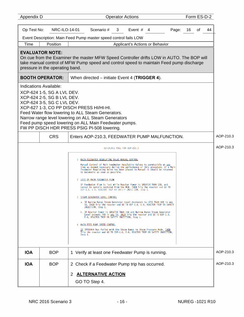
Appendix D Operator Actions Form ES-D-2
Op Test No: NRC-ILO-14-01 Scenario # 3 Event # 4 Page: 16 of 44
Event Description: Main Feed Pump master speed control fails LOW
Time Position Applicant’s Actions or Behavior
NRC 2016 Scenario 3 - 16 - NUREG -1021 R10
EVALUATOR NOTE: On cue from the Examiner the master MFW Speed Controller drifts LOW in AUTO. The BOP will take manual control of MFW Pump speed and control speed to maintain Feed pump discharge pressure in the operating band.
BOOTH OPERATOR: When directed – initiate Event 4 (TRIGGER 4).
Indications Available: XCP-624 1-5, SG A LVL DEV. XCP-624 2-5, SG B LVL DEV. XCP-624 3-5, SG C LVL DEV. XCP-627 1-3, CO PP DISCH PRESS HI/HI-HI. Feed Water flow lowering to ALL Steam Generators. Narrow range level lowering on ALL Steam Generators Feed pump speed lowering on ALL Main Feedwater pumps. FW PP DISCH HDR PRESS PSIG PI-508 lowering.
CRS Enters AOP-210.3, FEEDWATER PUMP MALFUNCTION. AOP-210.3
AOP-210.3
IOA BOP 1 Verify at least one Feedwater Pump is running. AOP-210.3
IOA BOP 2 Check if a Feedwater Pump trip has occurred. 2 ALTERNATIVE ACTION
GO TO Step 4.
AOP-210.3
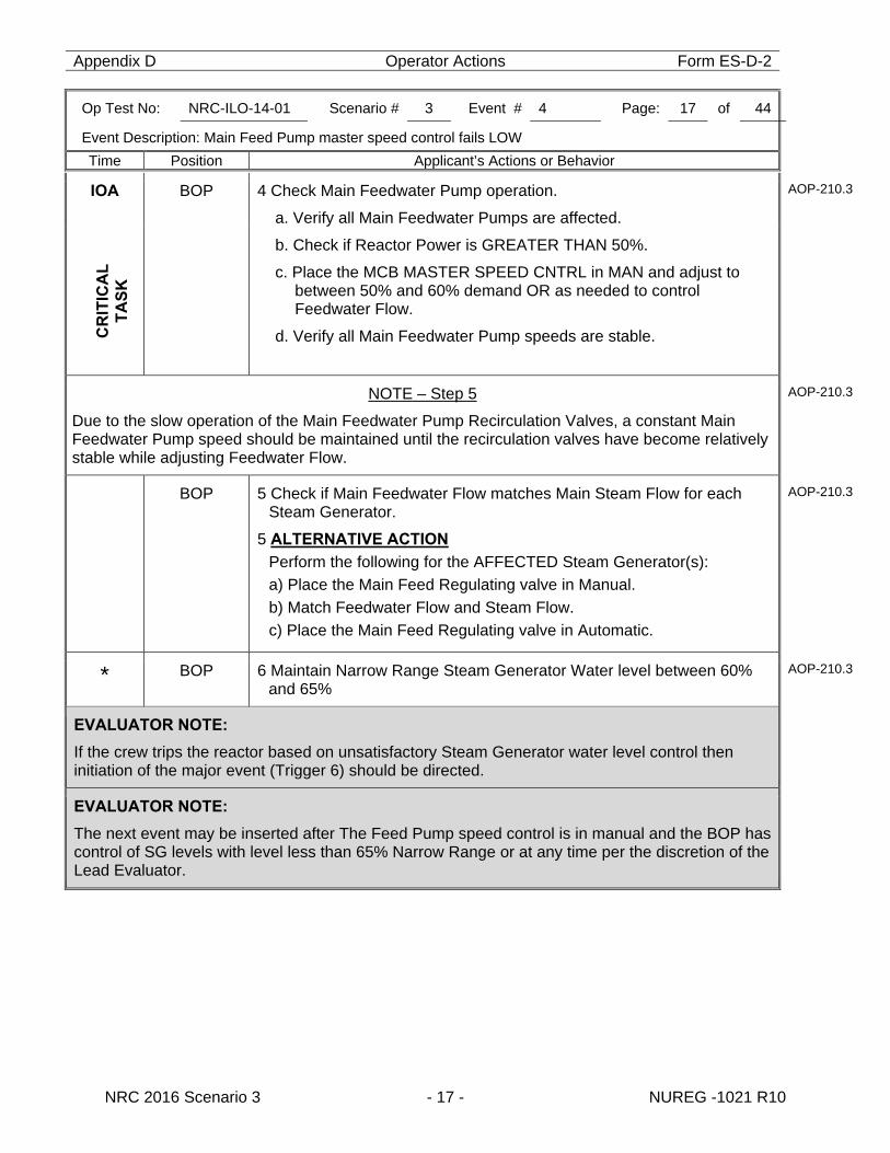
Appendix D Operator Actions Form ES-D-2
Op Test No: NRC-ILO-14-01 Scenario # 3 Event # 4 Page: 17 of 44
Event Description: Main Feed Pump master speed control fails LOW
Time Position Applicant’s Actions or Behavior
NRC 2016 Scenario 3 - 17 - NUREG -1021 R10
IOA
BOP 4 Check Main Feedwater Pump operation.
a. Verify all Main Feedwater Pumps are affected.
b. Check if Reactor Power is GREATER THAN 50%.
c. Place the MCB MASTER SPEED CNTRL in MAN and adjust to between 50% and 60% demand OR as needed to control Feedwater Flow.
d. Verify all Main Feedwater Pump speeds are stable.
AOP-210.3
C
RIT
ICA
L
TA
SK
NOTE – Step 5
Due to the slow operation of the Main Feedwater Pump Recirculation Valves, a constant Main Feedwater Pump speed should be maintained until the recirculation valves have become relatively stable while adjusting Feedwater Flow.
AOP-210.3
BOP 5 Check if Main Feedwater Flow matches Main Steam Flow for each Steam Generator.
5 ALTERNATIVE ACTION
Perform the following for the AFFECTED Steam Generator(s): a) Place the Main Feed Regulating valve in Manual. b) Match Feedwater Flow and Steam Flow. c) Place the Main Feed Regulating valve in Automatic.
AOP-210.3
* BOP 6 Maintain Narrow Range Steam Generator Water level between 60% and 65%
AOP-210.3
EVALUATOR NOTE:
If the crew trips the reactor based on unsatisfactory Steam Generator water level control then initiation of the major event (Trigger 6) should be directed.
EVALUATOR NOTE:
The next event may be inserted after The Feed Pump speed control is in manual and the BOP has control of SG levels with level less than 65% Narrow Range or at any time per the discretion of the Lead Evaluator.
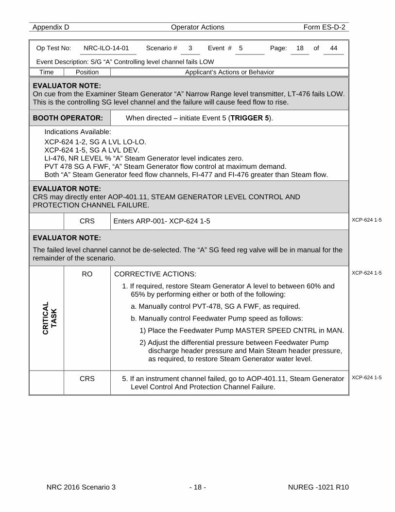
Appendix D Operator Actions Form ES-D-2
Op Test No: NRC-ILO-14-01 Scenario # 3 Event # 5 Page: 18 of 44
Event Description: S/G “A” Controlling level channel fails LOW
Time Position Applicant’s Actions or Behavior
NRC 2016 Scenario 3 - 18 - NUREG -1021 R10
EVALUATOR NOTE: On cue from the Examiner Steam Generator “A” Narrow Range level transmitter, LT-476 fails LOW. This is the controlling SG level channel and the failure will cause feed flow to rise.
BOOTH OPERATOR: When directed – initiate Event 5 (TRIGGER 5).
Indications Available: XCP-624 1-2, SG A LVL LO-LO. XCP-624 1-5, SG A LVL DEV. LI-476, NR LEVEL % “A” Steam Generator level indicates zero. PVT 478 SG A FWF, “A” Steam Generator flow control at maximum demand. Both “A” Steam Generator feed flow channels, FI-477 and FI-476 greater than Steam flow.
EVALUATOR NOTE: CRS may directly enter AOP-401.11, STEAM GENERATOR LEVEL CONTROL AND PROTECTION CHANNEL FAILURE.
CRS Enters ARP-001- XCP-624 1-5 XCP-624 1-5
EVALUATOR NOTE:
The failed level channel cannot be de-selected. The “A” SG feed reg valve will be in manual for the remainder of the scenario.
C
RIT
ICA
L
TA
SK
RO CORRECTIVE ACTIONS:
1. If required, restore Steam Generator A level to between 60% and 65% by performing either or both of the following:
a. Manually control PVT-478, SG A FWF, as required.
b. Manually control Feedwater Pump speed as follows:
1) Place the Feedwater Pump MASTER SPEED CNTRL in MAN.
2) Adjust the differential pressure between Feedwater Pump discharge header pressure and Main Steam header pressure, as required, to restore Steam Generator water level.
XCP-624 1-5
CRS 5. If an instrument channel failed, go to AOP-401.11, Steam Generator Level Control And Protection Channel Failure.
XCP-624 1-5
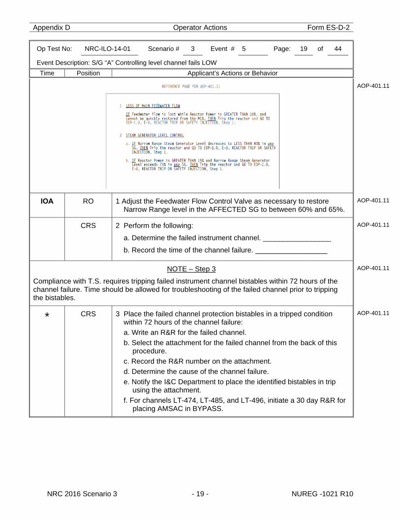
Appendix D Operator Actions Form ES-D-2
Op Test No: NRC-ILO-14-01 Scenario # 3 Event # 5 Page: 19 of 44
Event Description: S/G “A” Controlling level channel fails LOW
Time Position Applicant’s Actions or Behavior
NRC 2016 Scenario 3 - 19 - NUREG -1021 R10
AOP-401.11
IOA RO 1 Adjust the Feedwater Flow Control Valve as necessary to restore Narrow Range level in the AFFECTED SG to between 60% and 65%.
AOP-401.11
CRS 2 Perform the following:
a. Determine the failed instrument channel. _________________
b. Record the time of the channel failure. __________________
AOP-401.11
NOTE – Step 3
Compliance with T.S. requires tripping failed instrument channel bistables within 72 hours of the channel failure. Time should be allowed for troubleshooting of the failed channel prior to tripping the bistables.
AOP-401.11
* CRS 3 Place the failed channel protection bistables in a tripped condition within 72 hours of the channel failure: a. Write an R&R for the failed channel. b. Select the attachment for the failed channel from the back of this
procedure. c. Record the R&R number on the attachment. d. Determine the cause of the channel failure. e. Notify the I&C Department to place the identified bistables in trip
using the attachment. f. For channels LT-474, LT-485, and LT-496, initiate a 30 day R&R for
placing AMSAC in BYPASS.
AOP-401.11
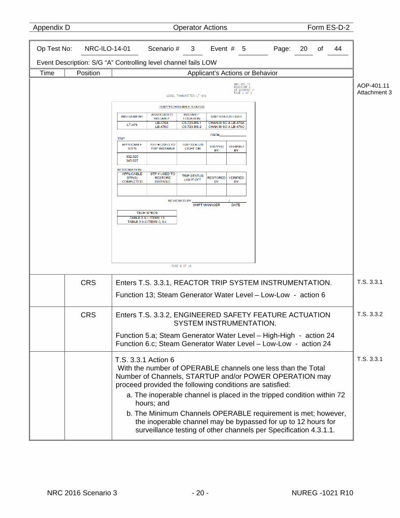
Appendix D Operator Actions Form ES-D-2
Op Test No: NRC-ILO-14-01 Scenario # 3 Event # 5 Page: 20 of 44
Event Description: S/G “A” Controlling level channel fails LOW
Time Position Applicant’s Actions or Behavior
NRC 2016 Scenario 3 - 20 - NUREG -1021 R10
AOP-401.11 Attachment 3
CRS Enters T.S. 3.3.1, REACTOR TRIP SYSTEM INSTRUMENTATION.
Function 13; Steam Generator Water Level – Low-Low - action 6
T.S. 3.3.1
CRS Enters T.S. 3.3.2, ENGINEERED SAFETY FEATURE ACTUATION SYSTEM INSTRUMENTATION.
Function 5.a; Steam Generator Water Level – High-High - action 24 Function 6.c; Steam Generator Water Level – Low-Low - action 24
T.S. 3.3.2
T.S. 3.3.1 Action 6 With the number of OPERABLE channels one less than the Total Number of Channels, STARTUP and/or POWER OPERATION may proceed provided the following conditions are satisfied:
a. The inoperable channel is placed in the tripped condition within 72 hours; and
b. The Minimum Channels OPERABLE requirement is met; however, the inoperable channel may be bypassed for up to 12 hours for surveillance testing of other channels per Specification 4.3.1.1.
T.S. 3.3.1
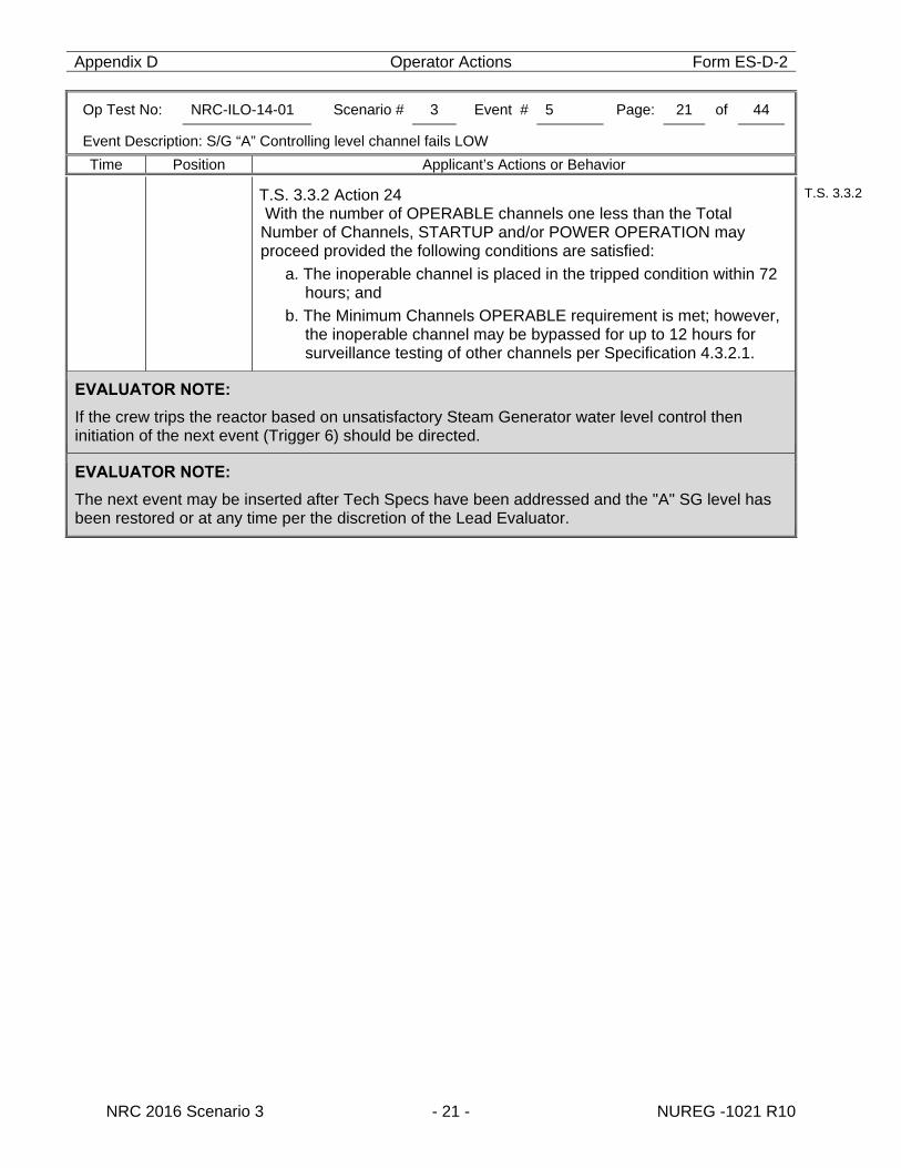
Appendix D Operator Actions Form ES-D-2
Op Test No: NRC-ILO-14-01 Scenario # 3 Event # 5 Page: 21 of 44
Event Description: S/G “A” Controlling level channel fails LOW
Time Position Applicant’s Actions or Behavior
NRC 2016 Scenario 3 - 21 - NUREG -1021 R10
T.S. 3.3.2 Action 24 With the number of OPERABLE channels one less than the Total Number of Channels, STARTUP and/or POWER OPERATION may proceed provided the following conditions are satisfied:
a. The inoperable channel is placed in the tripped condition within 72 hours; and
b. The Minimum Channels OPERABLE requirement is met; however, the inoperable channel may be bypassed for up to 12 hours for surveillance testing of other channels per Specification 4.3.2.1.
T.S. 3.3.2
EVALUATOR NOTE:
If the crew trips the reactor based on unsatisfactory Steam Generator water level control then initiation of the next event (Trigger 6) should be directed.
EVALUATOR NOTE:
The next event may be inserted after Tech Specs have been addressed and the "A" SG level has been restored or at any time per the discretion of the Lead Evaluator.
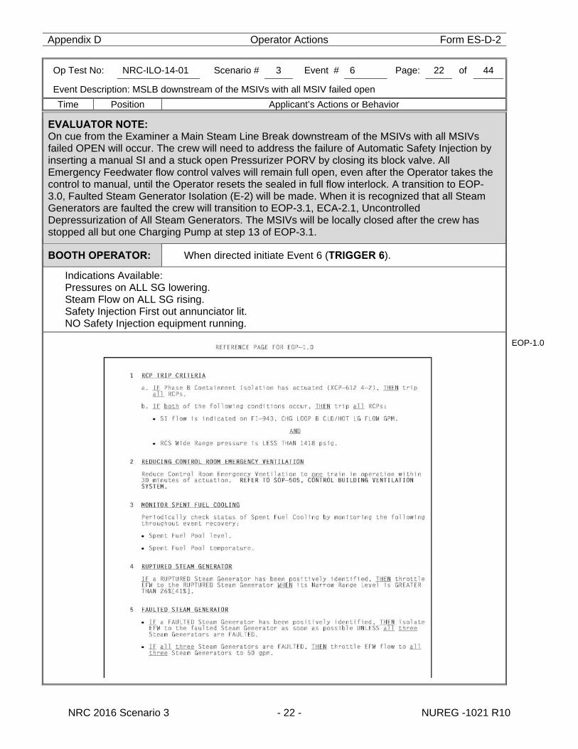
Appendix D Operator Actions Form ES-D-2
Op Test No: NRC-ILO-14-01 Scenario # 3 Event # 6 Page: 22 of 44
Event Description: MSLB downstream of the MSIVs with all MSIV failed open
Time Position Applicant’s Actions or Behavior
NRC 2016 Scenario 3 - 22 - NUREG -1021 R10
EVALUATOR NOTE: On cue from the Examiner a Main Steam Line Break downstream of the MSIVs with all MSIVs failed OPEN will occur. The crew will need to address the failure of Automatic Safety Injection by inserting a manual SI and a stuck open Pressurizer PORV by closing its block valve. All Emergency Feedwater flow control valves will remain full open, even after the Operator takes the control to manual, until the Operator resets the sealed in full flow interlock. A transition to EOP-3.0, Faulted Steam Generator Isolation (E-2) will be made. When it is recognized that all Steam Generators are faulted the crew will transition to EOP-3.1, ECA-2.1, Uncontrolled Depressurization of All Steam Generators. The MSIVs will be locally closed after the crew has stopped all but one Charging Pump at step 13 of EOP-3.1.
BOOTH OPERATOR: When directed initiate Event 6 (TRIGGER 6).
Indications Available: Pressures on ALL SG lowering. Steam Flow on ALL SG rising. Safety Injection First out annunciator lit. NO Safety Injection equipment running.
EOP-1.0
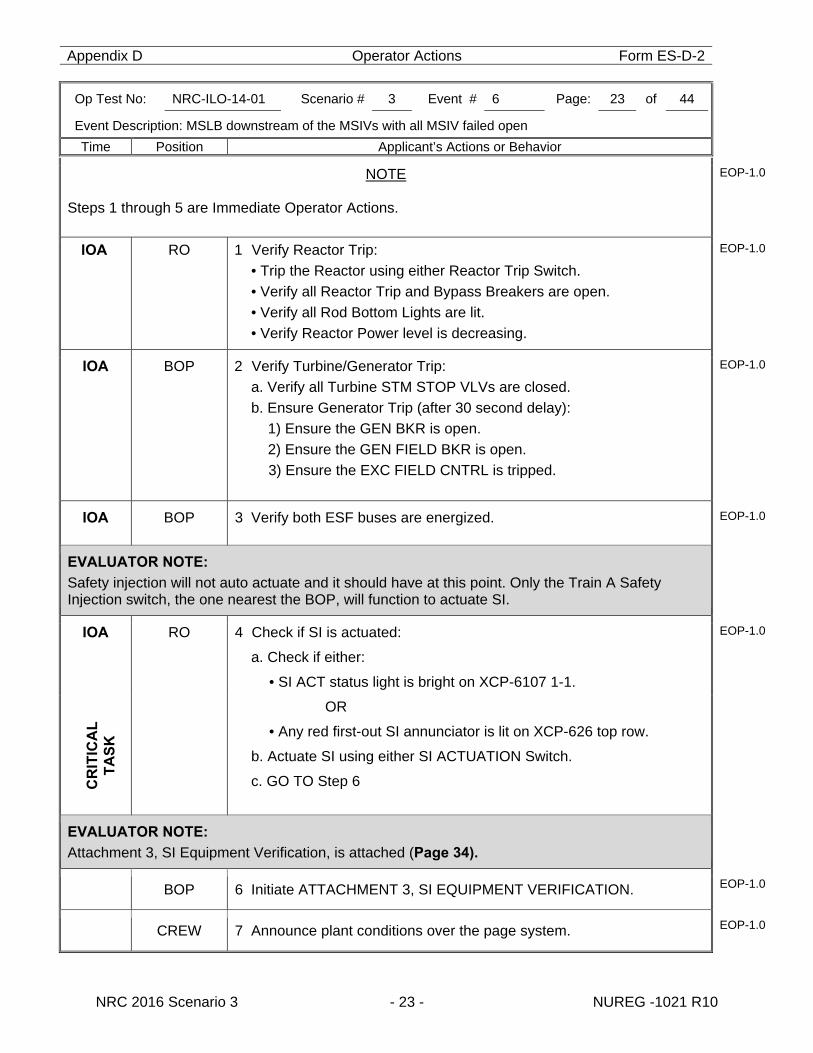
Appendix D Operator Actions Form ES-D-2
Op Test No: NRC-ILO-14-01 Scenario # 3 Event # 6 Page: 23 of 44
Event Description: MSLB downstream of the MSIVs with all MSIV failed open
Time Position Applicant’s Actions or Behavior
NRC 2016 Scenario 3 - 23 - NUREG -1021 R10
NOTE
Steps 1 through 5 are Immediate Operator Actions.
EOP-1.0
IOA
RO 1 Verify Reactor Trip: • Trip the Reactor using either Reactor Trip Switch. • Verify all Reactor Trip and Bypass Breakers are open. • Verify all Rod Bottom Lights are lit. • Verify Reactor Power level is decreasing.
EOP-1.0
IOA BOP 2 Verify Turbine/Generator Trip: a. Verify all Turbine STM STOP VLVs are closed. b. Ensure Generator Trip (after 30 second delay):
1) Ensure the GEN BKR is open. 2) Ensure the GEN FIELD BKR is open. 3) Ensure the EXC FIELD CNTRL is tripped.
EOP-1.0
IOA BOP 3 Verify both ESF buses are energized. EOP-1.0
EVALUATOR NOTE: Safety injection will not auto actuate and it should have at this point. Only the Train A Safety Injection switch, the one nearest the BOP, will function to actuate SI.
IOA
RO 4 Check if SI is actuated:
a. Check if either:
• SI ACT status light is bright on XCP-6107 1-1.
OR
• Any red first-out SI annunciator is lit on XCP-626 top row.
b. Actuate SI using either SI ACTUATION Switch.
c. GO TO Step 6
EOP-1.0
C
RIT
ICA
L
T
AS
K
EVALUATOR NOTE: Attachment 3, SI Equipment Verification, is attached (Page 34).
BOP 6 Initiate ATTACHMENT 3, SI EQUIPMENT VERIFICATION. EOP-1.0
CREW 7 Announce plant conditions over the page system. EOP-1.0
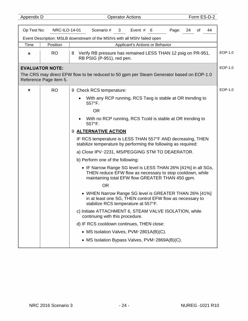
Appendix D Operator Actions Form ES-D-2
Op Test No: NRC-ILO-14-01 Scenario # 3 Event # 6 Page: 24 of 44
Event Description: MSLB downstream of the MSIVs with all MSIV failed open
Time Position Applicant’s Actions or Behavior
NRC 2016 Scenario 3 - 24 - NUREG -1021 R10
* RO 8 Verify RB pressure has remained LESS THAN 12 psig on PR-951, RB PSIG (P-951), red pen.
EOP-1.0
EVALUATOR NOTE: The CRS may direct EFW flow to be reduced to 50 gpm per Steam Generator based on EOP-1.0 Reference Page item 5.
EOP-1.0
* RO 9 Check RCS temperature:
With any RCP running, RCS Tavg is stable at OR trending to 557°F.
OR
With no RCP running, RCS Tcold is stable at OR trending to 557°F.
9 ALTERNATIVE ACTION
IF RCS temperature is LESS THAN 557°F AND decreasing, THEN stabilize temperature by performing the following as required:
a) Close IPV‑2231, MS/PEGGING STM TO DEAERATOR.
b) Perform one of the following:
IF Narrow Range SG level is LESS THAN 26% [41%] in all SGs, THEN reduce EFW flow as necessary to stop cooldown, while maintaining total EFW flow GREATER THAN 450 gpm.
OR
WHEN Narrow Range SG level is GREATER THAN 26% [41%] in at least one SG, THEN control EFW flow as necessary to stabilize RCS temperature at 557°F.
c) Initiate ATTACHMENT 6, STEAM VALVE ISOLATION, while continuing with this procedure.
d) IF RCS cooldown continues, THEN close:
MS Isolation Valves, PVM‑2801A(B)(C).
MS Isolation Bypass Valves, PVM‑2869A(B)(C).
EOP-1.0
Appendix D Operator Actions Form ES-D-2
Op Test No: NRC-ILO-14-01 Scenario # 3 Event # 6 Page: 25 of 44
Event Description: MSLB downstream of the MSIVs with all MSIV failed open
Time Position Applicant’s Actions or Behavior
NRC 2016 Scenario 3 - 25 - NUREG -1021 R10
EVALUATOR NOTE: PZR PORV PCV-445B failed open at the time of the Reactor Trip. The operator must close its block valve.
C
RIT
ICA
L
TA
SK
RO 10 Check PZR PORVs and Spray Valves:
a. PZR PORVs are closed.
10 a ALTERNATIVE ACTION
a. IF PZR pressure is LESS THAN 2330 psig, THEN close the PZR PORVs.
IF any PZR PORV can NOT be closed, THEN close its Block Valve.
IF the Block Valve can NOT be closed, THEN GO TO EOP‑2.0, E‑1, LOSS OF REACTOR OR SECONDARY COOLANT, Step 1.
EOP-1.0
RO b. PZR Spray Valves are closed.
c. Verify power is available to at least one PZR PORV Block Valve:
MVG‑8000A, RELIEF 445 A ISOL.
MVG‑8000B, RELIEF 444 B ISOL.
MVG‑8000C, RELIEF 445 B ISOL.
d. Ensure one of the following Block Valves is open unless it was closed to isolate an open PZR PORV:
MVG‑8000A, RELIEF 445 A ISOL.
MVG‑8000B, RELIEF 444 B ISOL.
EOP-1.0
NOTE - Step 11
Seal Injection flow should be maintained to all RCPs.
EOP-1.0
RO 11 Check if RCPs should be stopped:
a. Check if either of the following criteria is met:
Annunciator XCP‑612 4‑2 is lit (PHASE B ISOL).
OR
RCS pressure is LESS THAN 1418 psig AND SI flow is indicated on FI‑943, CHG LOOP B CLD/HOT LG FLOW GPM.
b. Stop all RCPs.
EOP-1.0
Appendix D Operator Actions Form ES-D-2
Op Test No: NRC-ILO-14-01 Scenario # 3 Event # 6 Page: 26 of 44
Event Description: MSLB downstream of the MSIVs with all MSIV failed open
Time Position Applicant’s Actions or Behavior
NRC 2016 Scenario 3 - 26 - NUREG -1021 R10
BOP 12 Verify no SG is FAULTED: No SG pressure is decreasing in an uncontrolled manner.
No SG is completely depressurized.
12 ALTERNATIVE ACTION
GO TO EOP-3.0, E-2, FAULTED STEAM GENERATOR ISOLATION, Step 1.
EOP-1.0
CRS Implements EOP-3.0, E-2, Faulted Steam Generator Isolation.
EVALUATOR NOTE:
Upon exit from EOP-1.0 Critical Safety Function status trees are in effect. If EFW has been throttled to 50 gpm per Steam Generator at this point then a Red Path on Heat Sink will exist and crew will exit EOP-1.0 to EOP-15.0, RESPONSE TO LOSS OF SECONDARY HEAT SINK, read the first caution and then proceed to EOP-3.0.
CAUTION
If total EFW flow is LESS THAN 450 gpm due to operator action, this procedure should NOT be performed, since these actions are NOT appropriate if 450 gpm EFW flow is available.
EOP-15.0
CAUTION
At least one SG must be maintained available for RCS cooldown.
Any FAULTED SG or secondary break should remain isolated during subsequent recovery actions unless needed for RCS cooldown, to prevent reinitiating the break.
EOP-3.0
BOOTH OPERATOR: If contacted to locally close the MS Isolation valves acknowledge the request and WAIT until completion of step 13 of EOP-3.1.
If called by the Control Room regarding the steam leak report: “There is a Steam Leak in the Turbine Building but I can't identify its exact location”.
BOP 1 Ensure all the following are closed:
MS Isolation Valves, PVM-2801A(B)(C).
MS Isolation Bypass Valves, PVM-2869A(B)(C).
EOP-3.0
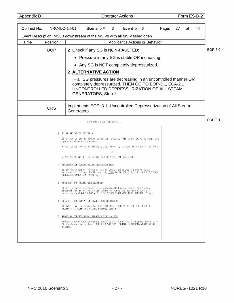
Appendix D Operator Actions Form ES-D-2
Op Test No: NRC-ILO-14-01 Scenario # 3 Event # 6 Page: 27 of 44
Event Description: MSLB downstream of the MSIVs with all MSIV failed open
Time Position Applicant’s Actions or Behavior
NRC 2016 Scenario 3 - 27 - NUREG -1021 R10
BOP 2 Check if any SG is NON-FAULTED:
Pressure in any SG is stable OR increasing.
Any SG is NOT completely depressurized.
2 ALTERNATIVE ACTION
IF all SG pressures are decreasing in an uncontrolled manner OR completely depressurized, THEN GO TO EOP-3.1, ECA-2.1 UNCONTROLLED DEPRESSURIZATION OF ALL STEAM GENERATORS, Step 1.
EOP-3.0
CRS Implements EOP-3.1, Uncontrolled Depressurization of All Steam Generators.
EOP-3.1
Appendix D Operator Actions Form ES-D-2
Op Test No: NRC-ILO-14-01 Scenario # 3 Event # 6 Page: 28 of 44
Event Description: MSLB downstream of the MSIVs with all MSIV failed open
Time Position Applicant’s Actions or Behavior
NRC 2016 Scenario 3 - 28 - NUREG -1021 R10
BOP 1 Isolate secondary pressure boundaries for all SGs: a. Close all of the following valves: MS Isolation, PVM‑2801A(B)(C). MS Isolation Bypass, PVM‑2869A(B)(C). FW Flow Control, FCV‑478(488)(498). FW Isolation, PVG‑1611A(B)(C). SG Blowdown, PVG‑503A(B)(C). FW Flow Control Bypass, FCV‑3321(3331)(3341).
EOP-3.1
CAUTION – Step 1.b
If the TD EFW Pump is the only available source of feed flow, the steam supply to the TD EFW Pump must be maintained from at least one SG, to maintain a secondary heat sink.
EOP-3.1
BOP b. Complete isolation of all SGs: 1) Close all the following valves:
SG Chemical Feed Isolation, MVK‑1633A(B)(C). MS Drain Isolation, PVT‑2843A(B)(C) PVT‑2877A(B).
EOP-3.1
BOOTH OPERATOR: When contacted to locally isolate the MS supply valves to the TDEFP, wait 3 minutes and then activate the appropriate trigger: TRIGGER 14 to de-energize XVG-2802A (XMC-1DA2X 05EH). (IB) TRIGGER 15 to isolate XVG-2802A. (IB) TRIGGER 16 to de-energize XVG-2802B (XMC-1DB2Y 05EH). (AB) TRIGGER 17 to isolate XVG-2802B (IB) Once the breaker is open report “Breaker for XVG-2802A(B) is open”
Once the valve is isolated report “XVG-2802A(B) is locally closed”
BOP 2) Locally open the following breakers: XMC1DA2X 05EH, EF PUMP MAIN STEAM BLOCK VLV
XVG2802A-MS (IB-463). XMC1DB2Y 05EH, EMERG FEEDWATER PUMP MAIN STEAM
BLOCK XVG2802B-MS (AB-463). 3) Locally close the following valves (IB.436 East Pen):
XVG02802A.MS, MS HEADER B EF PUMP TURBINE SUPPLY VLV.
XVG02802B.MS, MS HEADER C EF PUMP TURBINE SUPPLY VLV.
EOP-3.1
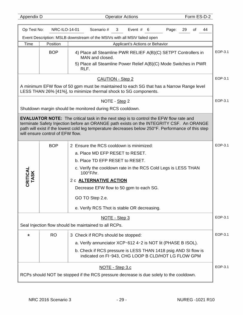
Appendix D Operator Actions Form ES-D-2
Op Test No: NRC-ILO-14-01 Scenario # 3 Event # 6 Page: 29 of 44
Event Description: MSLB downstream of the MSIVs with all MSIV failed open
Time Position Applicant’s Actions or Behavior
NRC 2016 Scenario 3 - 29 - NUREG -1021 R10
BOP 4) Place all Steamline PWR RELIEF A(B)(C) SETPT Controllers in MAN and closed.
5) Place all Steamline Power Relief A(B)(C) Mode Switches in PWR RLF.
EOP-3.1
CAUTION - Step 2
A minimum EFW flow of 50 gpm must be maintained to each SG that has a Narrow Range level LESS THAN 26% [41%], to minimize thermal shock to SG components.
EOP-3.1
NOTE - Step 2
Shutdown margin should be monitored during RCS cooldown.
EOP-3.1
EVALUATOR NOTE: The critical task in the next step is to control the EFW flow rate and terminate Safety Injection before an ORANGE path exists on the INTEGRITY CSF. An ORANGE path will exist if the lowest cold leg temperature decreases below 250°F. Performance of this step will ensure control of EFW flow.
C
RIT
ICA
L
TA
SK
BOP 2 Ensure the RCS cooldown is minimized:
a. Place MD EFP RESET to RESET.
b. Place TD EFP RESET to RESET.
c. Verify the cooldown rate in the RCS Cold Legs is LESS THAN 100°F/hr.
2 c ALTERNATIVE ACTION
Decrease EFW flow to 50 gpm to each SG. GO TO Step 2.e. e. Verify RCS Thot is stable OR decreasing.
EOP-3.1
NOTE - Step 3
Seal Injection flow should be maintained to all RCPs.
EOP-3.1
* RO 3 Check if RCPs should be stopped:
a. Verify annunciator XCP‑612 4‑2 is NOT lit (PHASE B ISOL).
b. Check if RCS pressure is LESS THAN 1418 psig AND SI flow is indicated on FI‑943, CHG LOOP B CLD/HOT LG FLOW GPM
EOP-3.1
NOTE - Step 3.c
RCPs should NOT be stopped if the RCS pressure decrease is due solely to the cooldown.
EOP-3.1
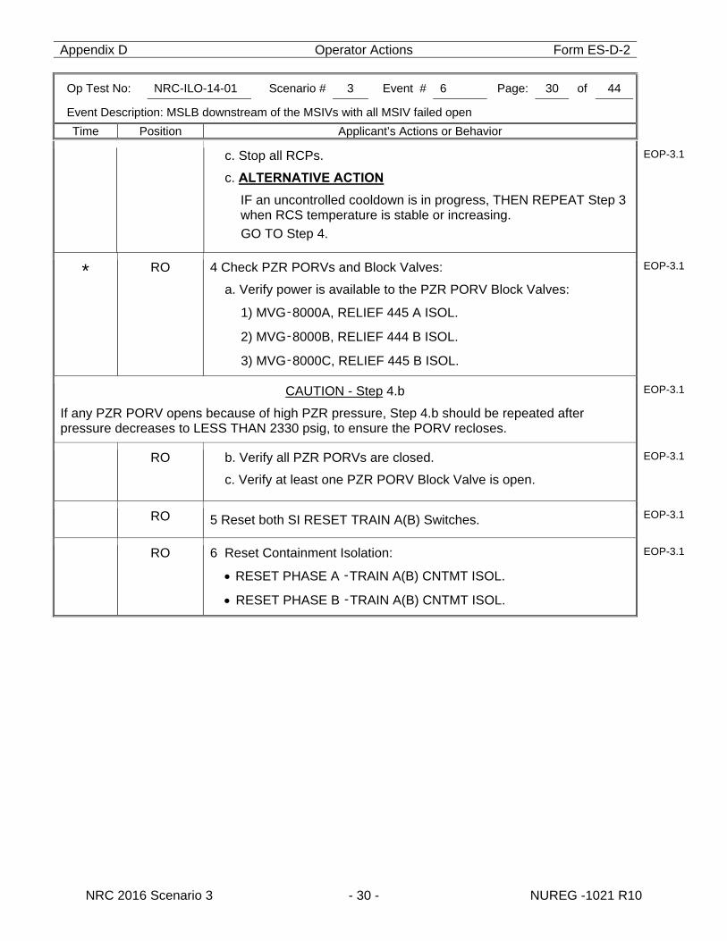
Appendix D Operator Actions Form ES-D-2
Op Test No: NRC-ILO-14-01 Scenario # 3 Event # 6 Page: 30 of 44
Event Description: MSLB downstream of the MSIVs with all MSIV failed open
Time Position Applicant’s Actions or Behavior
NRC 2016 Scenario 3 - 30 - NUREG -1021 R10
c. Stop all RCPs.
c. ALTERNATIVE ACTION
IF an uncontrolled cooldown is in progress, THEN REPEAT Step 3 when RCS temperature is stable or increasing. GO TO Step 4.
EOP-3.1
* RO 4 Check PZR PORVs and Block Valves:
a. Verify power is available to the PZR PORV Block Valves:
1) MVG‑8000A, RELIEF 445 A ISOL.
2) MVG‑8000B, RELIEF 444 B ISOL.
3) MVG‑8000C, RELIEF 445 B ISOL.
EOP-3.1
CAUTION - Step 4.b
If any PZR PORV opens because of high PZR pressure, Step 4.b should be repeated after pressure decreases to LESS THAN 2330 psig, to ensure the PORV recloses.
EOP-3.1
RO b. Verify all PZR PORVs are closed.
c. Verify at least one PZR PORV Block Valve is open.
EOP-3.1
RO 5 Reset both SI RESET TRAIN A(B) Switches. EOP-3.1
RO 6 Reset Containment Isolation:
RESET PHASE A ‑TRAIN A(B) CNTMT ISOL.
RESET PHASE B ‑TRAIN A(B) CNTMT ISOL.
EOP-3.1
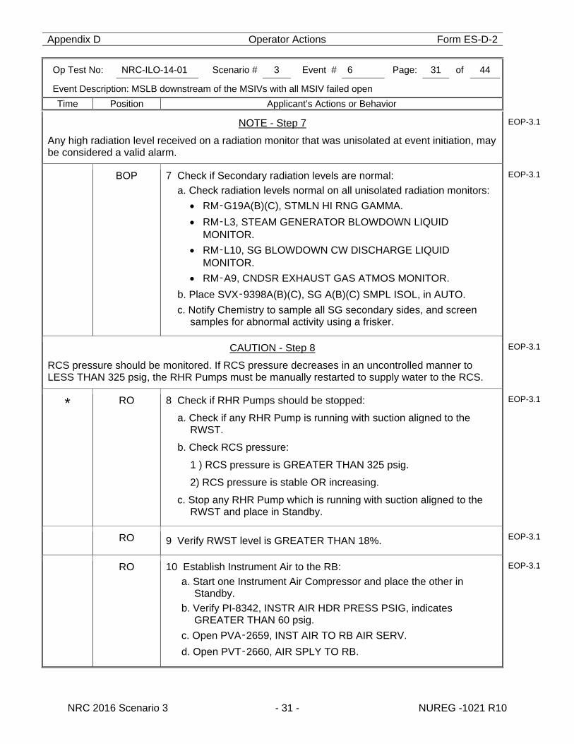
Appendix D Operator Actions Form ES-D-2
Op Test No: NRC-ILO-14-01 Scenario # 3 Event # 6 Page: 31 of 44
Event Description: MSLB downstream of the MSIVs with all MSIV failed open
Time Position Applicant’s Actions or Behavior
NRC 2016 Scenario 3 - 31 - NUREG -1021 R10
NOTE - Step 7
Any high radiation level received on a radiation monitor that was unisolated at event initiation, may be considered a valid alarm.
EOP-3.1
BOP 7 Check if Secondary radiation levels are normal: a. Check radiation levels normal on all unisolated radiation monitors:
RM‑G19A(B)(C), STMLN HI RNG GAMMA. RM‑L3, STEAM GENERATOR BLOWDOWN LIQUID
MONITOR. RM‑L10, SG BLOWDOWN CW DISCHARGE LIQUID
MONITOR. RM‑A9, CNDSR EXHAUST GAS ATMOS MONITOR.
b. Place SVX‑9398A(B)(C), SG A(B)(C) SMPL ISOL, in AUTO. c. Notify Chemistry to sample all SG secondary sides, and screen
samples for abnormal activity using a frisker.
EOP-3.1
CAUTION - Step 8
RCS pressure should be monitored. If RCS pressure decreases in an uncontrolled manner to LESS THAN 325 psig, the RHR Pumps must be manually restarted to supply water to the RCS.
EOP-3.1
* RO 8 Check if RHR Pumps should be stopped:
a. Check if any RHR Pump is running with suction aligned to the RWST.
b. Check RCS pressure:
1 ) RCS pressure is GREATER THAN 325 psig.
2) RCS pressure is stable OR increasing.
c. Stop any RHR Pump which is running with suction aligned to the RWST and place in Standby.
EOP-3.1
RO 9 Verify RWST level is GREATER THAN 18%. EOP-3.1
RO 10 Establish Instrument Air to the RB: a. Start one Instrument Air Compressor and place the other in
Standby. b. Verify PI-8342, INSTR AIR HDR PRESS PSIG, indicates
GREATER THAN 60 psig. c. Open PVA‑2659, INST AIR TO RB AIR SERV. d. Open PVT‑2660, AIR SPLY TO RB.
EOP-3.1
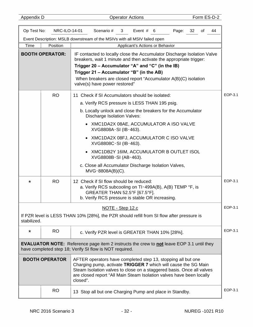
Appendix D Operator Actions Form ES-D-2
Op Test No: NRC-ILO-14-01 Scenario # 3 Event # 6 Page: 32 of 44
Event Description: MSLB downstream of the MSIVs with all MSIV failed open
Time Position Applicant’s Actions or Behavior
NRC 2016 Scenario 3 - 32 - NUREG -1021 R10
BOOTH OPERATOR: IF contacted to locally close the Accumulator Discharge Isolation Valve breakers, wait 1 minute and then activate the appropriate trigger: Trigger 20 – Accumulator “A” and “C” (in the IB)
Trigger 21 – Accumulator “B” (in the AB)
When breakers are closed report “Accumulator A(B)(C) isolation valve(s) have power restored”
RO 11 Check if SI Accumulators should be isolated:
a. Verify RCS pressure is LESS THAN 195 psig.
b. Locally unlock and close the breakers for the Accumulator Discharge Isolation Valves:
XMC1DA2X 08AE, ACCUMULATOR A ISO VALVE XVG8808A‑SI (IB‑463).
XMC1DA2X 08FJ, ACCUMULATOR C ISO VALVE XVG8808C‑SI (IB‑463).
XMC1DB2Y 16IM, ACCUMULATOR B OUTLET ISOL XVG8808B‑SI (AB‑463).
c. Close all Accumulator Discharge Isolation Valves, MVG‑8808A(B)(C).
EOP-3.1
* RO 12 Check if SI flow should be reduced: a. Verify RCS subcooling on TI‑499A(B), A(B) TEMP °F, is
GREATER THAN 52.5°F [67.5°F]. b. Verify RCS pressure is stable OR increasing.
EOP-3.1
NOTE - Step 12.c
If PZR level is LESS THAN 10% [28%], the PZR should refill from SI flow after pressure is stabilized.
EOP-3.1
* RO c. Verify PZR level is GREATER THAN 10% [28%]. EOP-3.1
EVALUATOR NOTE: Reference page item 2 instructs the crew to not leave EOP 3.1 until they have completed step 18; Verify SI flow is NOT required.
BOOTH OPERATOR AFTER operators have completed step 13, stopping all but one Charging pump, activate TRIGGER 7 which will cause the SG Main Steam Isolation valves to close on a staggered basis. Once all valves are closed report “All Main Steam Isolation valves have been locally closed”.
RO 13 Stop all but one Charging Pump and place in Standby. EOP-3.1
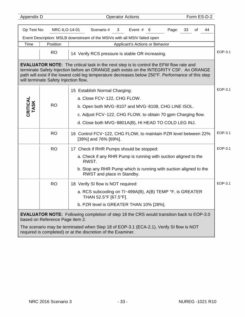
Appendix D Operator Actions Form ES-D-2
Op Test No: NRC-ILO-14-01 Scenario # 3 Event # 6 Page: 33 of 44
Event Description: MSLB downstream of the MSIVs with all MSIV failed open
Time Position Applicant’s Actions or Behavior
NRC 2016 Scenario 3 - 33 - NUREG -1021 R10
RO 14 Verify RCS pressure is stable OR increasing. EOP-3.1
EVALUATOR NOTE: The critical task in the next step is to control the EFW flow rate and terminate Safety Injection before an ORANGE path exists on the INTEGRITY CSF. An ORANGE path will exist if the lowest cold leg temperature decreases below 250°F. Performance of this step will terminate Safety Injection flow.
C
RIT
ICA
L
TA
SK
RO
15 Establish Normal Charging:
a. Close FCV‑122, CHG FLOW.
b. Open both MVG‑8107 and MVG‑8108, CHG LINE ISOL.
c. Adjust FCV‑122, CHG FLOW, to obtain 70 gpm Charging flow.
d. Close both MVG‑8801A(B), HI HEAD TO COLD LEG INJ.
EOP-3.1
RO 16 Control FCV‑122, CHG FLOW, to maintain PZR level between 22% [39%] and 76% [69%].
EOP-3.1
RO 17 Check if RHR Pumps should be stopped:
a. Check if any RHR Pump is running with suction aligned to the RWST.
b. Stop any RHR Pump which is running with suction aligned to the RWST and place in Standby.
EOP-3.1
RO 18 Verify SI flow is NOT required:
a. RCS subcooling on TI‑499A(B), A(B) TEMP °F, is GREATER THAN 52.5°F [67.5°F].
b. PZR level is GREATER THAN 10% [28%].
EOP-3.1
EVALUATOR NOTE: Following completion of step 18 the CRS would transition back to EOP-3.0 based on Reference Page item 2.
The scenario may be terminated when Step 18 of EOP-3.1 (ECA-2.1), Verify SI flow is NOT required is completed) or at the discretion of the Examiner.
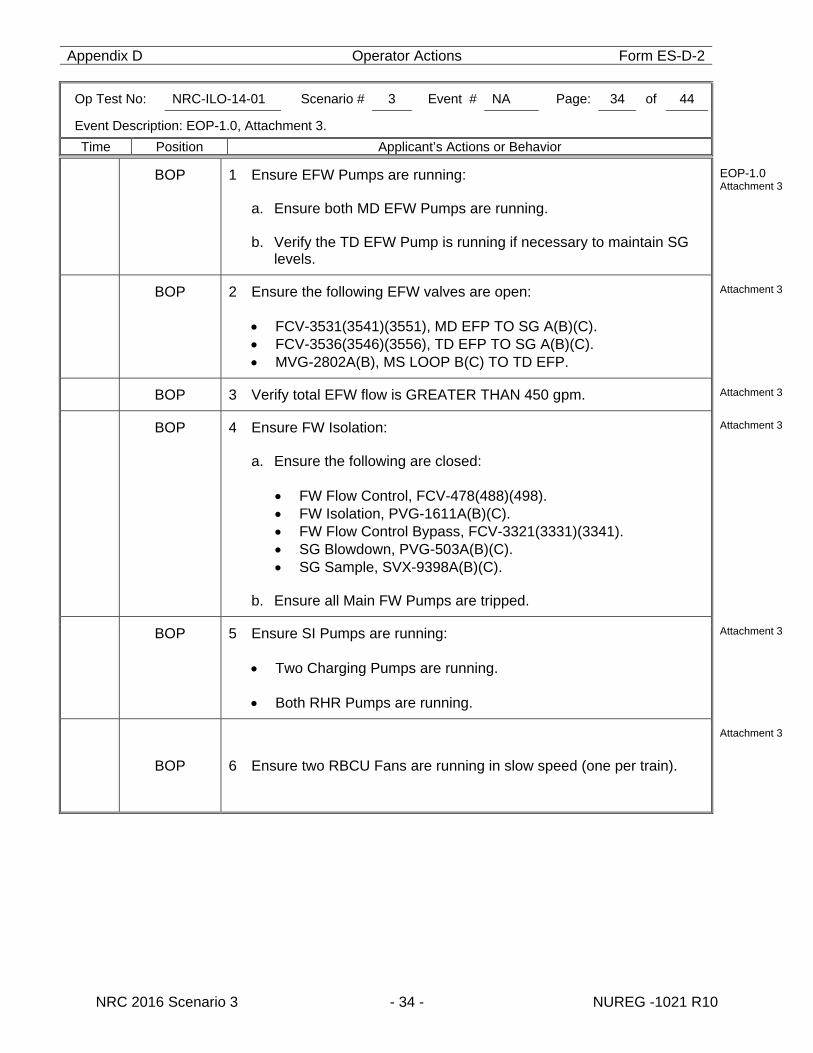
Appendix D Operator Actions Form ES-D-2
Op Test No: NRC-ILO-14-01 Scenario # 3 Event # NA Page: 34 of 44
Event Description: EOP-1.0, Attachment 3.
Time Position Applicant’s Actions or Behavior
NRC 2016 Scenario 3 - 34 - NUREG -1021 R10
BOP 1 Ensure EFW Pumps are running:
a. Ensure both MD EFW Pumps are running. b. Verify the TD EFW Pump is running if necessary to maintain SG
levels.
EOP-1.0 Attachment 3
BOP 2 Ensure the following EFW valves are open:
FCV-3531(3541)(3551), MD EFP TO SG A(B)(C). FCV-3536(3546)(3556), TD EFP TO SG A(B)(C). MVG-2802A(B), MS LOOP B(C) TO TD EFP.
Attachment 3
BOP 3 Verify total EFW flow is GREATER THAN 450 gpm. Attachment 3
BOP 4 Ensure FW Isolation: a. Ensure the following are closed:
FW Flow Control, FCV-478(488)(498). FW Isolation, PVG-1611A(B)(C). FW Flow Control Bypass, FCV-3321(3331)(3341). SG Blowdown, PVG-503A(B)(C). SG Sample, SVX-9398A(B)(C).
b. Ensure all Main FW Pumps are tripped.
Attachment 3
BOP 5 Ensure SI Pumps are running:
Two Charging Pumps are running.
Both RHR Pumps are running.
Attachment 3
BOP 6 Ensure two RBCU Fans are running in slow speed (one per train).
Attachment 3
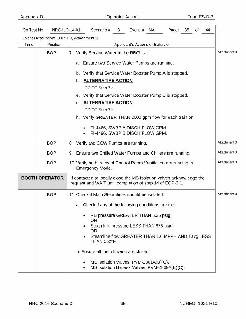
Appendix D Operator Actions Form ES-D-2
Op Test No: NRC-ILO-14-01 Scenario # 3 Event # NA Page: 35 of 44
Event Description: EOP-1.0, Attachment 3.
Time Position Applicant’s Actions or Behavior
NRC 2016 Scenario 3 - 35 - NUREG -1021 R10
BOP 7 Verify Service Water to the RBCUs:
a. Ensure two Service Water Pumps are running. b. Verify that Service Water Booster Pump A is stopped.
b. ALTERNATIVE ACTION
GO TO Step 7.e.
e. Verify that Service Water Booster Pump B is stopped.
e. ALTERNATIVE ACTION
GO TO Step 7.h.
h. Verify GREATER THAN 2000 gpm flow for each train on:
FI-4466, SWBP A DISCH FLOW GPM. FI-4496, SWBP B DISCH FLOW GPM.
Attachment 3
BOP 8 Verify two CCW Pumps are running. Attachment 3
BOP 9 Ensure two Chilled Water Pumps and Chillers are running. Attachment 3
BOP 10 Verify both trains of Control Room Ventilation are running in Emergency Mode.
Attachment 3
BOOTH OPERATOR If contacted to locally close the MS Isolation valves acknowledge the request and WAIT until completion of step 14 of EOP-3.1.
BOP 11 Check if Main Steamlines should be isolated:
a. Check if any of the following conditions are met: RB pressure GREATER THAN 6.35 psig. OR Steamline pressure LESS THAN 675 psig. OR Steamline flow GREATER THAN 1.6 MPPH AND Tavg LESS
THAN 552°F.
b. Ensure all the following are closed:
MS Isolation Valves, PVM-2801A(B)(C). MS Isolation Bypass Valves, PVM-2869A(B)(C).
Attachment 3
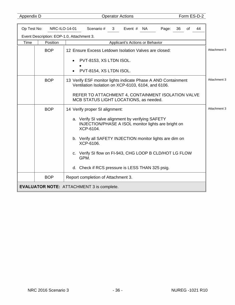
Appendix D Operator Actions Form ES-D-2
Op Test No: NRC-ILO-14-01 Scenario # 3 Event # NA Page: 36 of 44
Event Description: EOP-1.0, Attachment 3.
Time Position Applicant’s Actions or Behavior
NRC 2016 Scenario 3 - 36 - NUREG -1021 R10
BOP 12 Ensure Excess Letdown Isolation Valves are closed:
PVT-8153, XS LTDN ISOL.
PVT-8154, XS LTDN ISOL.
Attachment 3
BOP 13 Verify ESF monitor lights indicate Phase A AND Containment Ventilation Isolation on XCP-6103, 6104, and 6106.
REFER TO ATTACHMENT 4, CONTAINMENT ISOLATION VALVE MCB STATUS LIGHT LOCATIONS, as needed.
Attachment 3
BOP 14 Verify proper SI alignment:
a. Verify SI valve alignment by verifying SAFETY INJECTION/PHASE A ISOL monitor lights are bright on XCP-6104.
b. Verify all SAFETY INJECTION monitor lights are dim on
XCP-6106.
c. Verify SI flow on FI-943, CHG LOOP B CLD/HOT LG FLOW GPM.
d. Check if RCS pressure is LESS THAN 325 psig.
Attachment 3
BOP Report completion of Attachment 3.
EVALUATOR NOTE: ATTACHMENT 3 is complete.
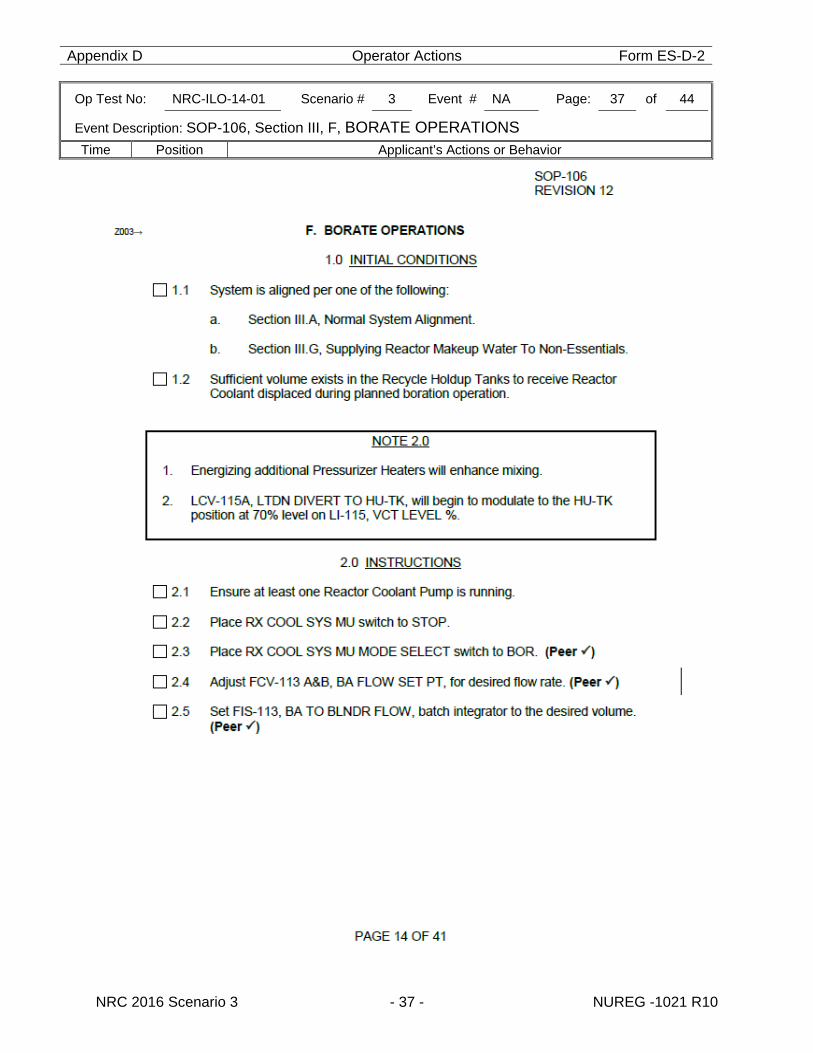
Appendix D Operator Actions Form ES-D-2
Op Test No: NRC-ILO-14-01 Scenario # 3 Event # NA Page: 37 of 44
Event Description: SOP-106, Section III, F, BORATE OPERATIONS
Time Position Applicant’s Actions or Behavior
NRC 2016 Scenario 3 - 37 - NUREG -1021 R10
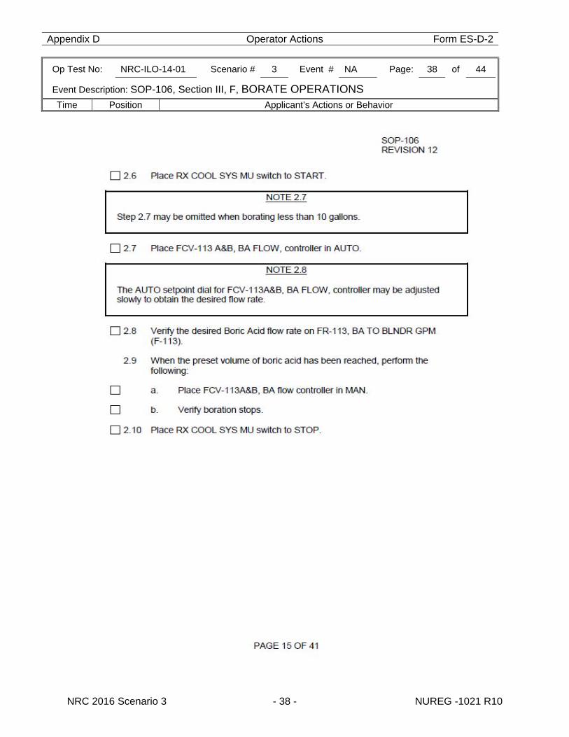
Appendix D Operator Actions Form ES-D-2
Op Test No: NRC-ILO-14-01 Scenario # 3 Event # NA Page: 38 of 44
Event Description: SOP-106, Section III, F, BORATE OPERATIONS
Time Position Applicant’s Actions or Behavior
NRC 2016 Scenario 3 - 38 - NUREG -1021 R10
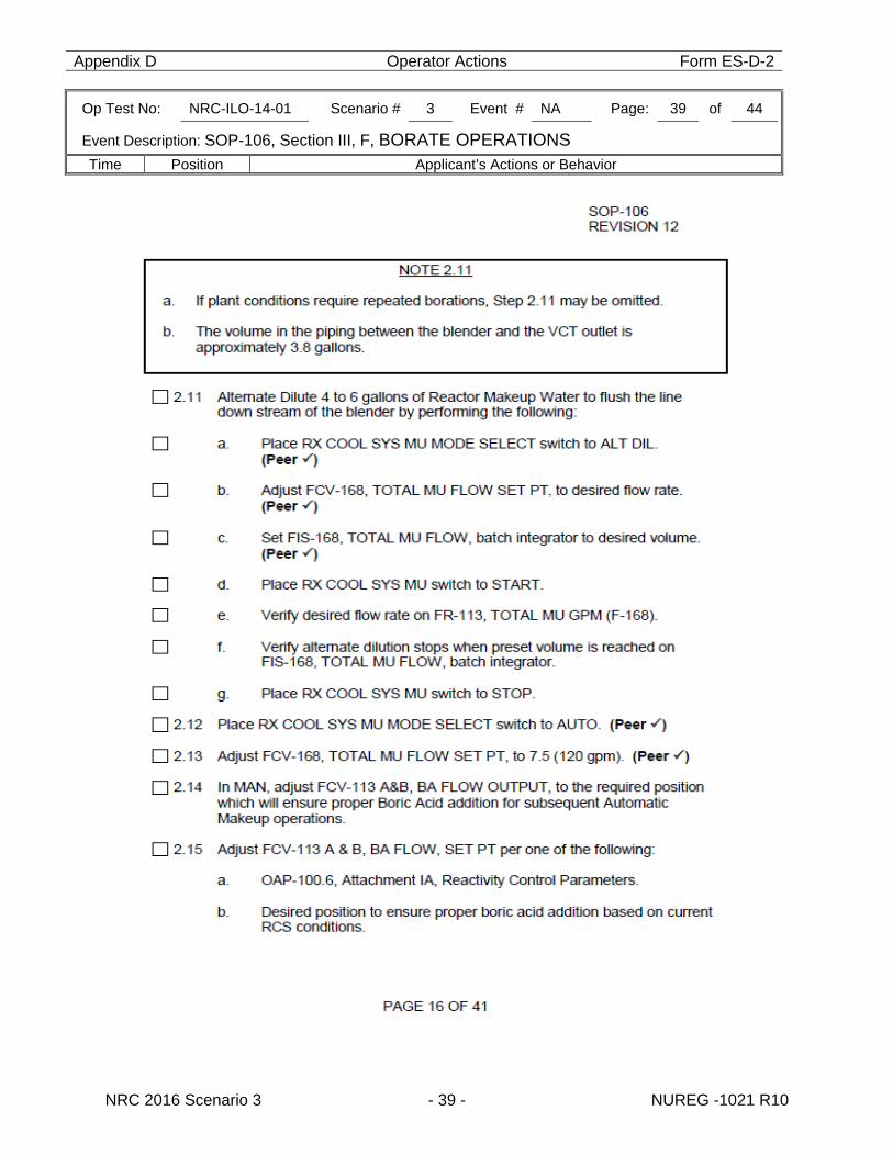
Appendix D Operator Actions Form ES-D-2
Op Test No: NRC-ILO-14-01 Scenario # 3 Event # NA Page: 39 of 44
Event Description: SOP-106, Section III, F, BORATE OPERATIONS
Time Position Applicant’s Actions or Behavior
NRC 2016 Scenario 3 - 39 - NUREG -1021 R10
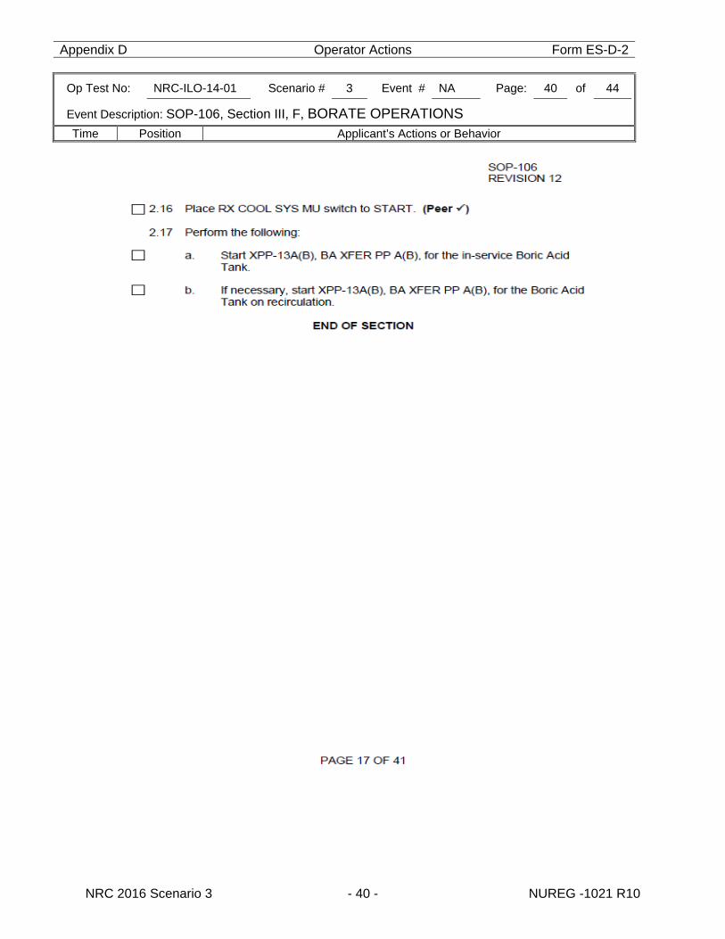
Appendix D Operator Actions Form ES-D-2
Op Test No: NRC-ILO-14-01 Scenario # 3 Event # NA Page: 40 of 44
Event Description: SOP-106, Section III, F, BORATE OPERATIONS
Time Position Applicant’s Actions or Behavior
NRC 2016 Scenario 3 - 40 - NUREG -1021 R10
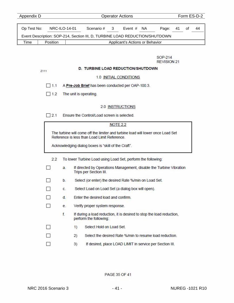
Appendix D Operator Actions Form ES-D-2
Op Test No: NRC-ILO-14-01 Scenario # 3 Event # NA Page: 41 of 44
Event Description: SOP-214, Section III, D, TURBINE LOAD REDUCTION/SHUTDOWN
Time Position Applicant’s Actions or Behavior
NRC 2016 Scenario 3 - 41 - NUREG -1021 R10
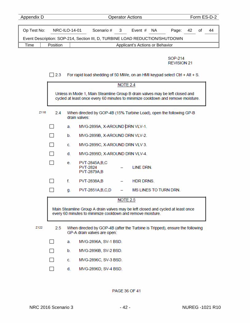
Appendix D Operator Actions Form ES-D-2
Op Test No: NRC-ILO-14-01 Scenario # 3 Event # NA Page: 42 of 44
Event Description: SOP-214, Section III, D, TURBINE LOAD REDUCTION/SHUTDOWN
Time Position Applicant’s Actions or Behavior
NRC 2016 Scenario 3 - 42 - NUREG -1021 R10
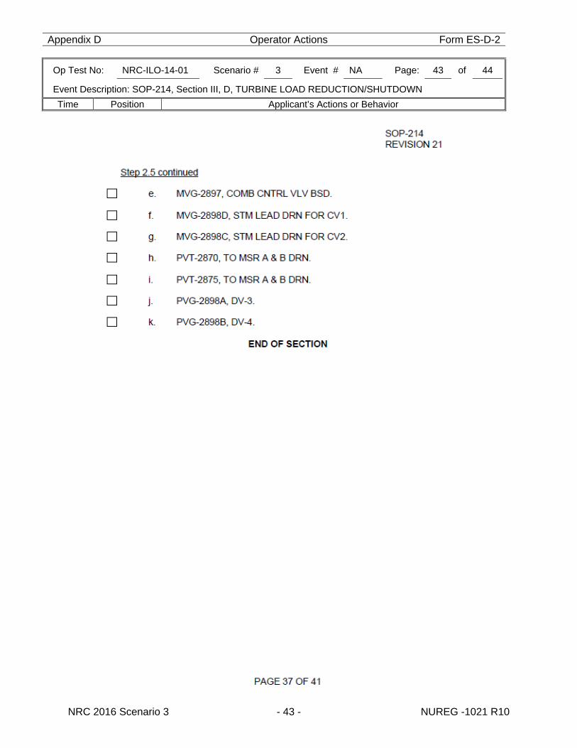
Appendix D Operator Actions Form ES-D-2
Op Test No: NRC-ILO-14-01 Scenario # 3 Event # NA Page: 43 of 44
Event Description: SOP-214, Section III, D, TURBINE LOAD REDUCTION/SHUTDOWN
Time Position Applicant’s Actions or Behavior
NRC 2016 Scenario 3 - 43 - NUREG -1021 R10
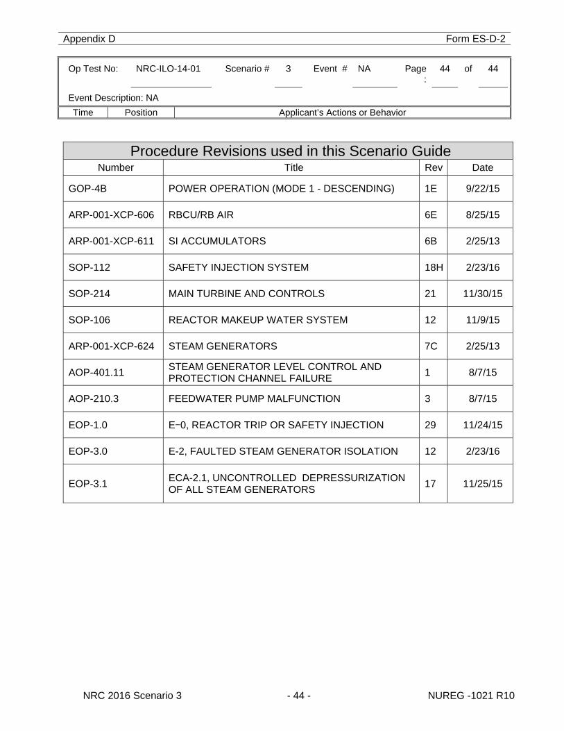
Appendix D Form ES-D-2
Op Test No: NRC-ILO-14-01 Scenario # 3 Event # NA Page:
44 of 44
Event Description: NA
Time Position Applicant’s Actions or Behavior
NRC 2016 Scenario 3 - 44 - NUREG -1021 R10
Procedure Revisions used in this Scenario Guide Number Title Rev Date
GOP-4B POWER OPERATION (MODE 1 - DESCENDING) 1E 9/22/15
ARP-001-XCP-606 RBCU/RB AIR 6E 8/25/15
ARP-001-XCP-611 SI ACCUMULATORS 6B 2/25/13
SOP-112 SAFETY INJECTION SYSTEM 18H 2/23/16
SOP-214 MAIN TURBINE AND CONTROLS 21 11/30/15
SOP-106 REACTOR MAKEUP WATER SYSTEM 12 11/9/15
ARP-001-XCP-624 STEAM GENERATORS 7C 2/25/13
AOP-401.11 STEAM GENERATOR LEVEL CONTROL AND PROTECTION CHANNEL FAILURE 1 8/7/15
AOP-210.3 FEEDWATER PUMP MALFUNCTION 3 8/7/15
EOP-1.0 E-0, REACTOR TRIP OR SAFETY INJECTION 29 11/24/15
EOP-3.0 E-2, FAULTED STEAM GENERATOR ISOLATION 12 2/23/16
EOP-3.1 ECA-2.1, UNCONTROLLED DEPRESSURIZATION OF ALL STEAM GENERATORS 17 11/25/15
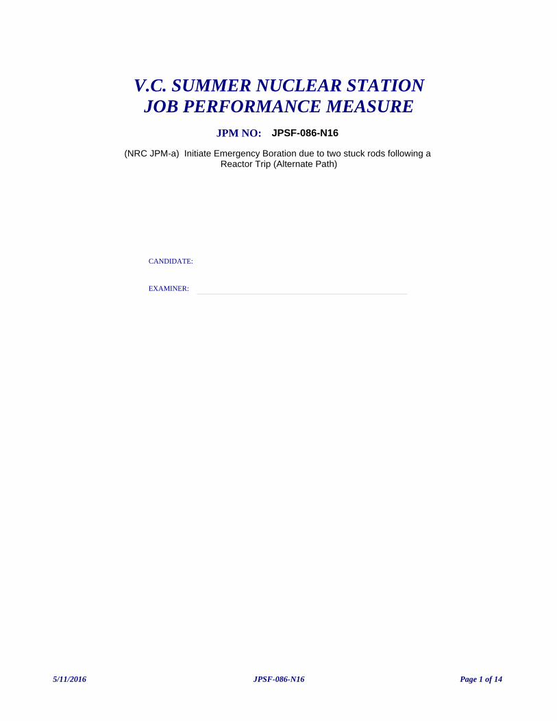
(NRC JPM-a) Initiate Emergency Boration due to two stuck rods following a Reactor Trip (Alternate Path)
V.C. SUMMER NUCLEAR STATIONJOB PERFORMANCE MEASURE
CANDIDATE:
EXAMINER:
JPM NO: JPSF-086-N16
5/11/2016 Page 1 of 14JPSF-086-N16
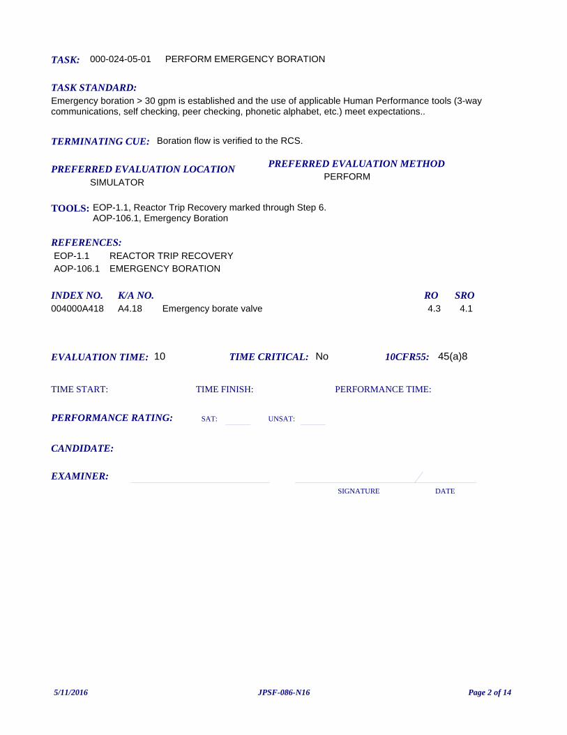
TASK: 000-024-05-01
PREFERRED EVALUATION METHODPERFORM
EVALUATION TIME: 10 TIME CRITICAL: No
TASK STANDARD:Emergency boration > 30 gpm is established and the use of applicable Human Performance tools (3-way communications, self checking, peer checking, phonetic alphabet, etc.) meet expectations..
PREFERRED EVALUATION LOCATIONSIMULATOR
TIME START: TIME FINISH:
PERFORMANCE RATING: SAT: UNSAT:
PERFORMANCE TIME:
EXAMINER:SIGNATURE DATE
10CFR55: 45(a)8
PERFORM EMERGENCY BORATION
TOOLS: EOP-1.1, Reactor Trip Recovery marked through Step 6.AOP-106.1, Emergency Boration
REFERENCES:
TERMINATING CUE: Boration flow is verified to the RCS.
CANDIDATE:
EOP-1.1 REACTOR TRIP RECOVERYAOP-106.1 EMERGENCY BORATION
INDEX NO. RO SROK/A NO.004000A418 Emergency borate valve 4.3 4.1A4.18
5/11/2016 Page 2 of 14JPSF-086-N16
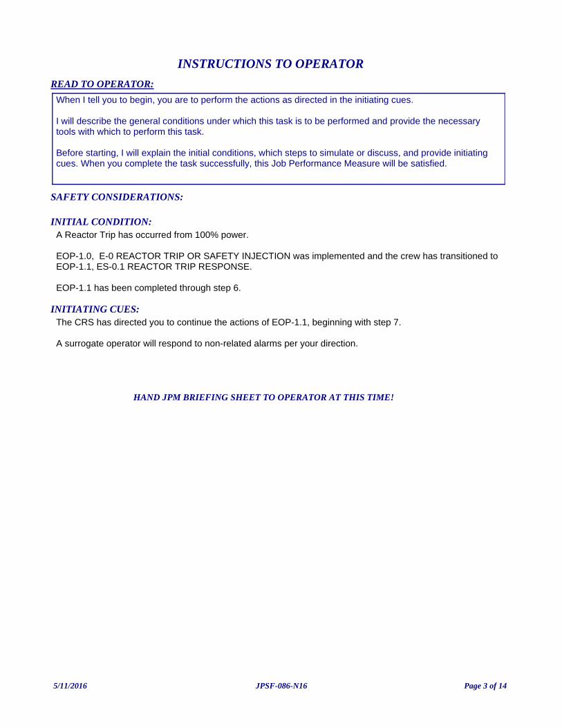
INITIATING CUES:The CRS has directed you to continue the actions of EOP-1.1, beginning with step 7.
A surrogate operator will respond to non-related alarms per your direction.
INITIAL CONDITION:A Reactor Trip has occurred from 100% power.
EOP-1.0, E-0 REACTOR TRIP OR SAFETY INJECTION was implemented and the crew has transitioned to EOP-1.1, ES-0.1 REACTOR TRIP RESPONSE.
EOP-1.1 has been completed through step 6.
READ TO OPERATOR:
SAFETY CONSIDERATIONS:
When I tell you to begin, you are to perform the actions as directed in the initiating cues.
I will describe the general conditions under which this task is to be performed and provide the necessary tools with which to perform this task.
Before starting, I will explain the initial conditions, which steps to simulate or discuss, and provide initiating cues. When you complete the task successfully, this Job Performance Measure will be satisfied.
INSTRUCTIONS TO OPERATOR
HAND JPM BRIEFING SHEET TO OPERATOR AT THIS TIME!
5/11/2016 Page 3 of 14JPSF-086-N16
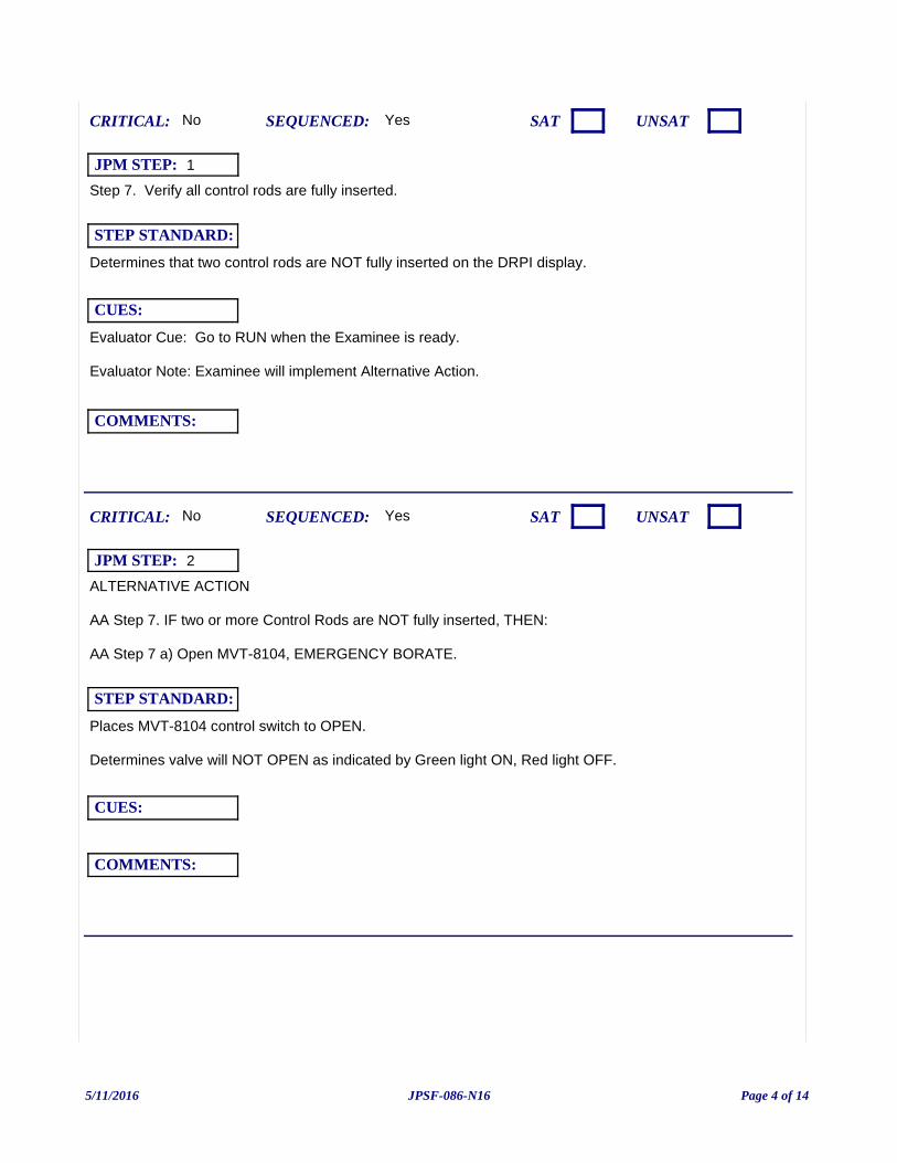
Step 7. Verify all control rods are fully inserted.
Evaluator Cue: Go to RUN when the Examinee is ready.
Evaluator Note: Examinee will implement Alternative Action.
Yes
Determines that two control rods are NOT fully inserted on the DRPI display.
CUES:
SEQUENCED:
STEP STANDARD:
COMMENTS:
SAT UNSATCRITICAL: No
JPM STEP: 1
ALTERNATIVE ACTION
AA Step 7. IF two or more Control Rods are NOT fully inserted, THEN:
AA Step 7 a) Open MVT-8104, EMERGENCY BORATE.
Yes
Places MVT-8104 control switch to OPEN.
Determines valve will NOT OPEN as indicated by Green light ON, Red light OFF.
CUES:
SEQUENCED:
STEP STANDARD:
COMMENTS:
SAT UNSATCRITICAL: No
JPM STEP: 2
5/11/2016 Page 4 of 14JPSF-086-N16
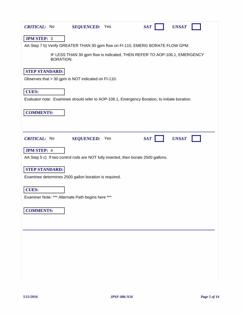
AA Step 7 b) Verify GREATER THAN 30 gpm flow on FI-110, EMERG BORATE FLOW GPM.
IF LESS THAN 30 gpm flow is indicated, THEN REFER TO AOP-106.1, EMERGENCY BORATION.
Evaluator note: Examinee should refer to AOP-106.1, Emergency Boration, to initiate boration.
Yes
Observes that > 30 gpm is NOT indicated on FI-110.
CUES:
SEQUENCED:
STEP STANDARD:
COMMENTS:
SAT UNSATCRITICAL: No
JPM STEP: 3
AA Step 5 c) If two control rods are NOT fully inserted, then borate 2500 gallons.
Examiner Note: *** Alternate Path begins here ***
Yes
Examinee determines 2500 gallon boration is required.
CUES:
SEQUENCED:
STEP STANDARD:
COMMENTS:
SAT UNSATCRITICAL: No
JPM STEP: 4
5/11/2016 Page 5 of 14JPSF-086-N16
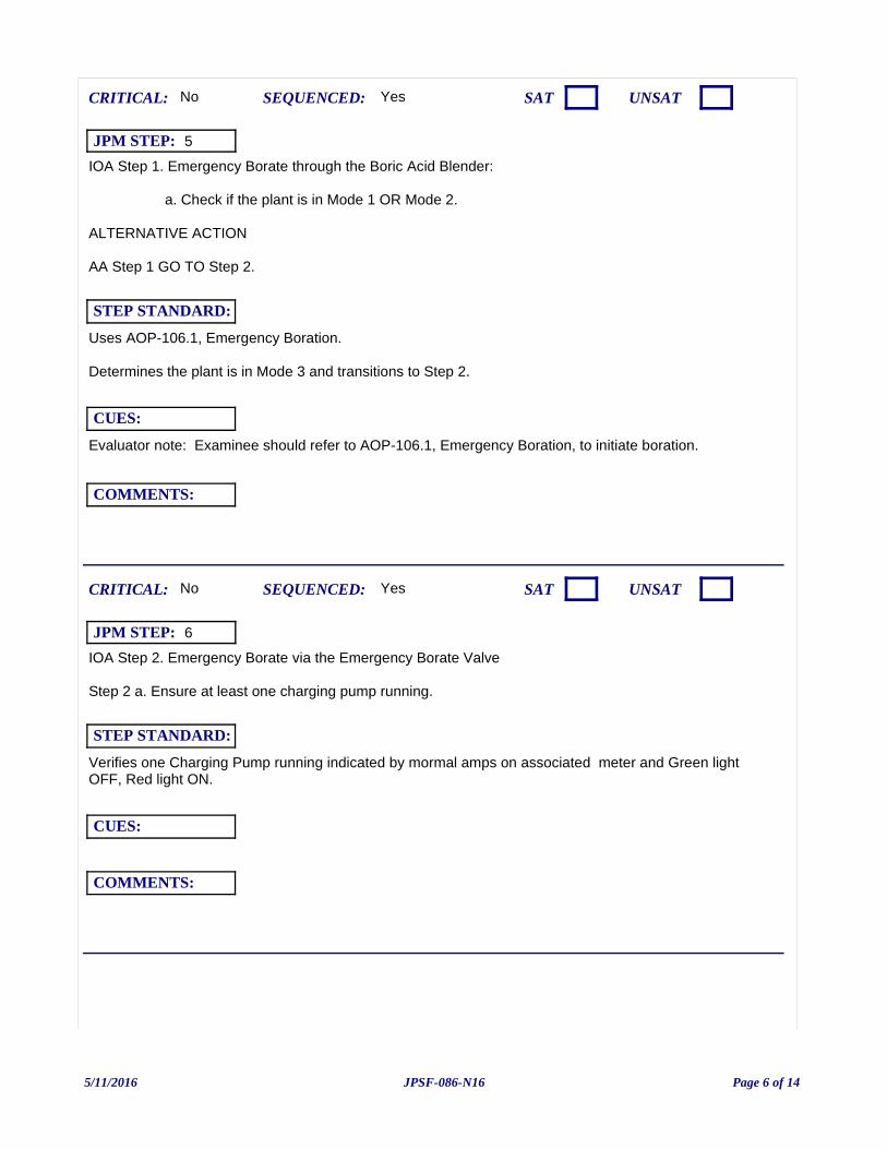
IOA Step 1. Emergency Borate through the Boric Acid Blender:
a. Check if the plant is in Mode 1 OR Mode 2.
ALTERNATIVE ACTION
AA Step 1 GO TO Step 2.
Evaluator note: Examinee should refer to AOP-106.1, Emergency Boration, to initiate boration.
Yes
Uses AOP-106.1, Emergency Boration.
Determines the plant is in Mode 3 and transitions to Step 2.
CUES:
SEQUENCED:
STEP STANDARD:
COMMENTS:
SAT UNSATCRITICAL: No
JPM STEP: 5
IOA Step 2. Emergency Borate via the Emergency Borate Valve
Step 2 a. Ensure at least one charging pump running.
Yes
Verifies one Charging Pump running indicated by mormal amps on associated meter and Green light OFF, Red light ON.
CUES:
SEQUENCED:
STEP STANDARD:
COMMENTS:
SAT UNSATCRITICAL: No
JPM STEP: 6
5/11/2016 Page 6 of 14JPSF-086-N16
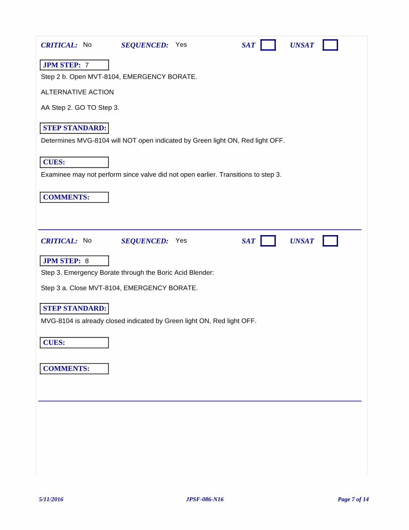
Step 2 b. Open MVT-8104, EMERGENCY BORATE.
ALTERNATIVE ACTION
AA Step 2. GO TO Step 3.
Examinee may not perform since valve did not open earlier. Transitions to step 3.
Yes
Determines MVG-8104 will NOT open indicated by Green light ON, Red light OFF.
CUES:
SEQUENCED:
STEP STANDARD:
COMMENTS:
SAT UNSATCRITICAL: No
JPM STEP: 7
Step 3. Emergency Borate through the Boric Acid Blender:
Step 3 a. Close MVT-8104, EMERGENCY BORATE.
Yes
MVG-8104 is already closed indicated by Green light ON, Red light OFF.
CUES:
SEQUENCED:
STEP STANDARD:
COMMENTS:
SAT UNSATCRITICAL: No
JPM STEP: 8
5/11/2016 Page 7 of 14JPSF-086-N16
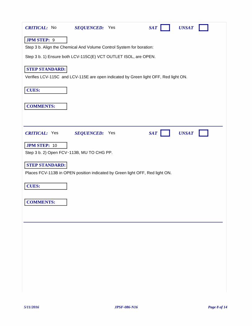
Step 3 b. Align the Chemical And Volume Control System for boration:
Step 3 b. 1) Ensure both LCV-115C(E) VCT OUTLET ISOL, are OPEN.
Yes
Verifies LCV-115C and LCV-115E are open indicated by Green light OFF, Red light ON.
CUES:
SEQUENCED:
STEP STANDARD:
COMMENTS:
SAT UNSATCRITICAL: No
JPM STEP: 9
Step 3 b. 2) Open FCV‑113B, MU TO CHG PP.
Yes
Places FCV-113B in OPEN position indicated by Green light OFF, Red light ON.
CUES:
SEQUENCED:
STEP STANDARD:
COMMENTS:
SAT UNSATCRITICAL: Yes
JPM STEP: 10
5/11/2016 Page 8 of 14JPSF-086-N16
Step 3 c. Close FCV-168B, MU WTR TO BLENDER
Yes
Verifies FCV-168B, MU WTR TO BLENDER is closed as indicated by Green light ON, Red light OFF.
CUES:
SEQUENCED:
STEP STANDARD:
COMMENTS:
SAT UNSATCRITICAL: No
JPM STEP: 11
Step 3 d. Ensure XPP-13A(B), BA XFER PP A (B) is running.
Yes
Verifies BA XFER PP A or BA XFER PP B is running as indicated by Green light OFF, Red light ON for either pump.
CUES:
SEQUENCED:
STEP STANDARD:
COMMENTS:
SAT UNSATCRITICAL: No
JPM STEP: 12
5/11/2016 Page 9 of 14JPSF-086-N16

Step 3 e. Open FCV-113A, BA to BLENDER
Yes
Places FCV-113A in OPEN position as indicated by Green light OFF, Red light ON.
CUES:
SEQUENCED:
STEP STANDARD:
COMMENTS:
SAT UNSATCRITICAL: Yes
JPM STEP: 13
Step 3 f. Ensure at least one Charging Pump is operating.
Yes
Verifies one Charging Pump running as indicated by Green light OFF, red light ON, and normal amps on associated meter.
CUES:
SEQUENCED:
STEP STANDARD:
COMMENTS:
SAT UNSATCRITICAL: No
JPM STEP: 14
5/11/2016 Page 10 of 14JPSF-086-N16
Step 3 g. Verify GREATER THAN 30 gpm flow on FR‑113, BA TO BLNDR AND TOTAL MU.
Yes
Verifies >30 gpm on FI-113.
CUES:
SEQUENCED:
STEP STANDARD:
COMMENTS:
SAT UNSATCRITICAL: No
JPM STEP: 15
Step 3 h. GO TO Step 5. Observe the NOTE prior to Step 5.
Yes
Transitions to step 5.
CUES:
SEQUENCED:
STEP STANDARD:
COMMENTS:
SAT UNSATCRITICAL: No
JPM STEP: 16
5/11/2016 Page 11 of 14JPSF-086-N16
Examiner ends JPM at this point.
NOTE - Step 5: If PZR level is above program, FCV‑122, CHG FLOW, will throttle closed and inhibit Emergency Boration flow to the RCS.
* Step 5. Verify FI‑122A, CHG FLOW GPM, indicates GREATER THAN 30 gpm.
This JPM may be terminated when Emergency Boration flow is verified at greater than 30 gpm.
Yes
Verifies FI‑122A indicates GREATER THAN 30 gpm.
CUES:
SEQUENCED:
STEP STANDARD:
COMMENTS:
SAT UNSATCRITICAL: No
JPM STEP: 17
5/11/2016 Page 12 of 14JPSF-086-N16
JPM: JPSF-086-N16 (NRC JPM-a) Initiate Emergency Boration due to two stuck rods following a Reactor Trip (Alternate Path)
IC SET: 251
INSTRUCTIONS:
Load the designated IC Set.
Provide EOP-1.1, Reactor Trip Recovery marked through Step 6.
When Examinee is ready: RUN.
-----------------
To recreate this IC Set::
1.Load IC-10
2. Insert the following malfunctions:
MAL-CRF007K10 (Stuck Rod K-10 fail to "untrippable") MAL-CRF007K4 (Stuck Rod K-04 fail to "untrippable")
VLV-CS046P Severity: 0 (XVT-8104 failed closed)
3. RUN
4. Manually trip reactor
5. Complete steps of EOP-1.0 and EOP-1.1 up to step 5.
6. FREEZE
COMMENTS:
JPM SETUP SHEET
5/11/2016 Page 13 of 14JPSF-086-N16
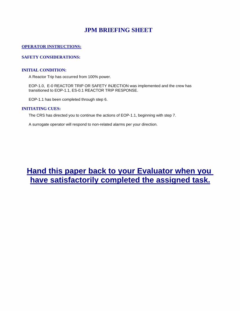
INITIATING CUES:
The CRS has directed you to continue the actions of EOP-1.1, beginning with step 7.
A surrogate operator will respond to non-related alarms per your direction.
INITIAL CONDITION:
A Reactor Trip has occurred from 100% power.
EOP-1.0, E-0 REACTOR TRIP OR SAFETY INJECTION was implemented and the crew has transitioned to EOP-1.1, ES-0.1 REACTOR TRIP RESPONSE.
EOP-1.1 has been completed through step 6.
SAFETY CONSIDERATIONS:
OPERATOR INSTRUCTIONS:
Hand this paper back to your Evaluator when you have satisfactorily completed the assigned task.
JPM BRIEFING SHEET
5/11/2016 Page 14 of 14JPSF-086-N16

(NRC JPM-b) Transfer In-Service Changing Pump (Alternate Path)
V.C. SUMMER NUCLEAR STATIONJOB PERFORMANCE MEASURE
CANDIDATE:
EXAMINER:
JPM NO: JPSF-046-N16
6/13/2016 Page 1 of 13JPSF-046-N16
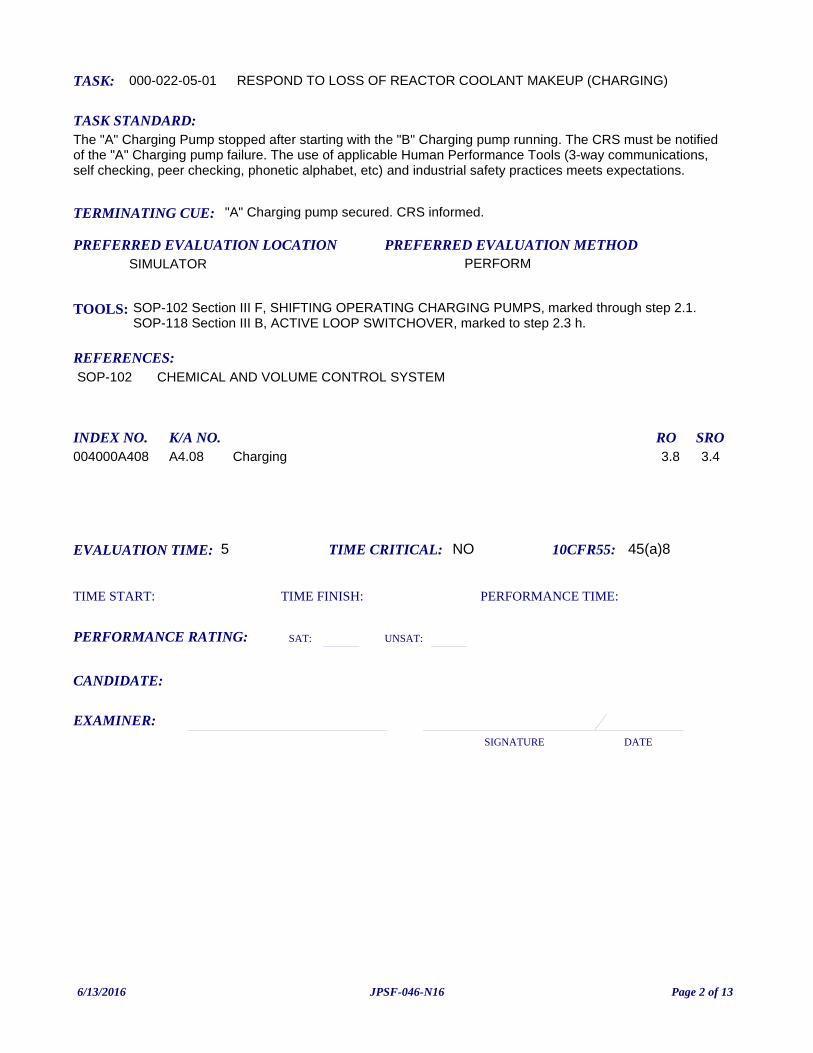
TASK: 000-022-05-01
PREFERRED EVALUATION METHODPERFORM
EVALUATION TIME: 5 TIME CRITICAL: NO
TASK STANDARD:The "A" Charging Pump stopped after starting with the "B" Charging pump running. The CRS must be notified of the "A" Charging pump failure. The use of applicable Human Performance Tools (3-way communications, self checking, peer checking, phonetic alphabet, etc) and industrial safety practices meets expectations.
PREFERRED EVALUATION LOCATIONSIMULATOR
TIME START: TIME FINISH:
PERFORMANCE RATING: SAT: UNSAT:
PERFORMANCE TIME:
EXAMINER:SIGNATURE DATE
10CFR55: 45(a)8
RESPOND TO LOSS OF REACTOR COOLANT MAKEUP (CHARGING)
TOOLS: SOP-102 Section III F, SHIFTING OPERATING CHARGING PUMPS, marked through step 2.1.SOP-118 Section III B, ACTIVE LOOP SWITCHOVER, marked to step 2.3 h.
REFERENCES:
TERMINATING CUE: "A" Charging pump secured. CRS informed.
CANDIDATE:
SOP-102 CHEMICAL AND VOLUME CONTROL SYSTEM
INDEX NO. RO SROK/A NO.004000A408 Charging 3.8 3.4A4.08
6/13/2016 Page 2 of 13JPSF-046-N16
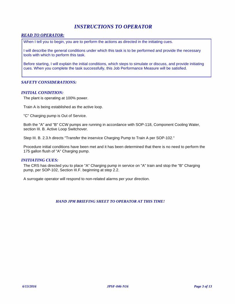
INITIATING CUES:The CRS has directed you to place "A" Charging pump in service on "A" train and stop the "B" Charging pump, per SOP-102, Section III.F. beginning at step 2.2.
A surrogate operator will respond to non-related alarms per your direction.
INITIAL CONDITION:The plant is operating at 100% power.
Train A is being established as the active loop.
"C" Charging pump is Out of Service.
Both the "A" and "B" CCW pumps are running in accordance with SOP-118, Component Cooling Water, section III. B. Active Loop Switchover.
Step III. B. 2.3.h directs "Transfer the inservice Charging Pump to Train A per SOP-102."
Procedure initial conditions have been met and it has been determined that there is no need to perform the 175 gallon flush of "A" Charging pump.
READ TO OPERATOR:
SAFETY CONSIDERATIONS:
When I tell you to begin, you are to perform the actions as directed in the initiating cues.
I will describe the general conditions under which this task is to be performed and provide the necessary tools with which to perform this task.
Before starting, I will explain the initial conditions, which steps to simulate or discuss, and provide initiating cues. When you complete the task successfully, this Job Performance Measure will be satisfied.
INSTRUCTIONS TO OPERATOR
HAND JPM BRIEFING SHEET TO OPERATOR AT THIS TIME!
6/13/2016 Page 3 of 13JPSF-046-N16
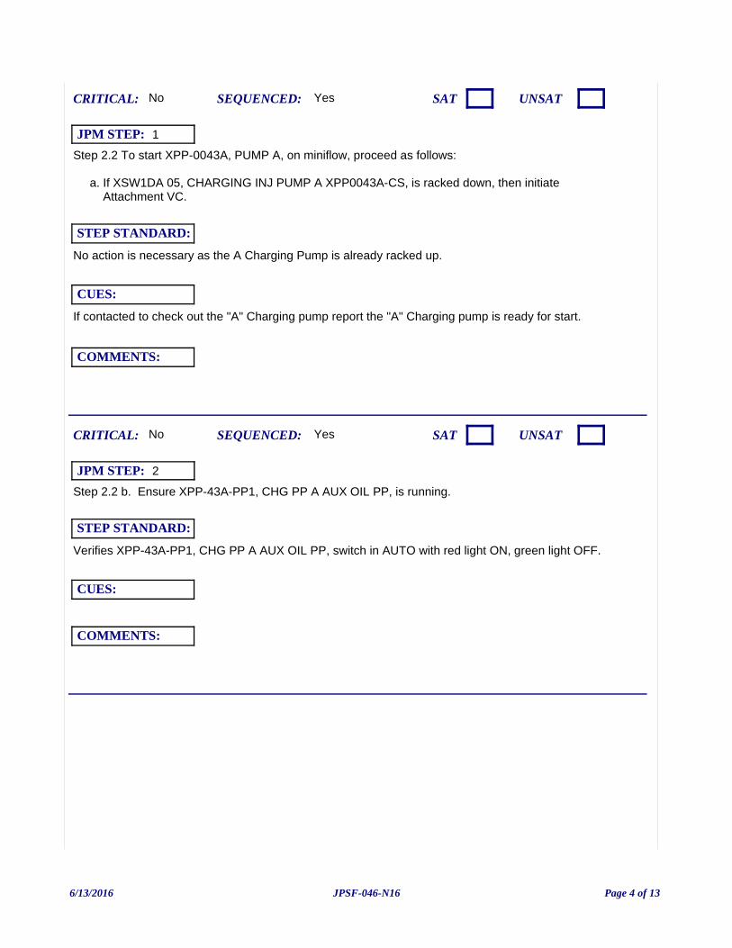
Step 2.2 To start XPP-0043A, PUMP A, on miniflow, proceed as follows:
a. If XSW1DA 05, CHARGING INJ PUMP A XPP0043A-CS, is racked down, then initiate Attachment VC.
If contacted to check out the "A" Charging pump report the "A" Charging pump is ready for start.
Yes
No action is necessary as the A Charging Pump is already racked up.
CUES:
SEQUENCED:
STEP STANDARD:
COMMENTS:
SAT UNSATCRITICAL: No
JPM STEP: 1
Step 2.2 b. Ensure XPP-43A-PP1, CHG PP A AUX OIL PP, is running.
Yes
Verifies XPP-43A-PP1, CHG PP A AUX OIL PP, switch in AUTO with red light ON, green light OFF.
CUES:
SEQUENCED:
STEP STANDARD:
COMMENTS:
SAT UNSATCRITICAL: No
JPM STEP: 2
6/13/2016 Page 4 of 13JPSF-046-N16
Step 2.2 c. Ensure Train A Component Cooling is operating per SOP-118.
Yes
Verifies that "A" CCW pp is running via red light ON and ammeter indication.
CUES:
SEQUENCED:
STEP STANDARD:
COMMENTS:
SAT UNSATCRITICAL: No
JPM STEP: 3
Step 2.2 d. Ensure Train A Chill Water is operating per SOP-501.
Yes
Verifies that 'A' Train Chill Water is running via red light ON on 'A' Train Chiller and Chill Water PP.
CUES:
SEQUENCED:
STEP STANDARD:
COMMENTS:
SAT UNSATCRITICAL: No
JPM STEP: 4
6/13/2016 Page 5 of 13JPSF-046-N16
Step 2.2 e. Verify IPI00151A, CHARGING PUMP A SUCTION PRESS IND (AB-388), indicates pump suction pressure is greater than one of the following:
1) 15 psig if the Charging Pump suction is aligned to the RWST.
2) 30 psig if the Charging Pump suction is aligned to the VCT with VCT level 20% or greater.
When contacted report "A" charging pump suction pressure as read on IPI00151A is 52 psig.
If contacted to check out the "A" Charging pump report the "A" Charging pump is ready for start.
Yes
Contacts field operator for pump suction pressure indication.
CUES:
SEQUENCED:
STEP STANDARD:
COMMENTS:
SAT UNSATCRITICAL: No
JPM STEP: 5
Step 2.2 f. Ensure MINIFLOW ISOL, MVT-8109A, CHG PP A, is open.
Yes
Verifies that MVT-8109A is open via red light ON, green light OFF.
CUES:
SEQUENCED:
STEP STANDARD:
COMMENTS:
SAT UNSATCRITICAL: No
JPM STEP: 6
6/13/2016 Page 6 of 13JPSF-046-N16
Step 2.2 g. Start XPP-0043A, PUMP A. (Peer Check)
Should request a peer check.
Yes
"A" charging pump indicates red light ON, green light OFF, and normal running amps.
CUES:
SEQUENCED:
STEP STANDARD:
COMMENTS:
SAT UNSATCRITICAL: Yes
JPM STEP: 7
Step 2.2 h. Verify XPP-43A-PP1, CHG PP A AUX OIL PP, stops automatically when the Charging Pump comes up to full speed.
Yes
Verifies green Off light is ON and red AUTO light is OFF.
CUES:
SEQUENCED:
STEP STANDARD:
COMMENTS:
SAT UNSATCRITICAL: No
JPM STEP: 8
6/13/2016 Page 7 of 13JPSF-046-N16
Step 2.2 i. Monitor the following to verify proper pump operation:
1) Charging Pump A running current is between 30 amps and 50 amps.
2) PI-121, CHG PRESS PSIG, is between 2650 psig and 2850 psig.
Yes
Verifies current between 30 and 50 amps.
Verifies PI-121, CHG PRESS PSIG, is between 2650 and 2850 psig.
CUES:
SEQUENCED:
STEP STANDARD:
COMMENTS:
SAT UNSATCRITICAL: No
JPM STEP: 9
Step 2.2 i. Monitor the following to verify proper pump operation: (cont.)
3) XVG-9684A-CC, CCW TO CHG PP A, is open.
Examiner Note: The annunciator is delayed 20 seconds after the A Charging Pump is started. The Examinee should investigate the status of XVG-9684A-CC until XCP-614 2-6 alarms.
Examiner Note: *** Alternate Path begins here ***
Yes
Recognizes that XVG-9684A, CCW TO CHG PP A is NOT open (Green light ON, Red light OFF).
Reponds to annunciator XCP-614 2-6, CCW TO CHG PP A VLV NOT FULL OPEN.
CUES:
SEQUENCED:
STEP STANDARD:
COMMENTS:
SAT UNSATCRITICAL: No
JPM STEP: 10
6/13/2016 Page 8 of 13JPSF-046-N16
Annunciator XCP-614 2-6, CCW TO CHG PP A VLV NOT FULL OPEN
CORRECTIVE ACTIONS:
Step 1. Check XVG-9684A-CC, CC WTR TO CHG PP A, position indication.
Yes
Recognizes that XVG-9684A, CCW TO CHG PP A is NOT open (green light ON, red light OFF).
CUES:
SEQUENCED:
STEP STANDARD:
COMMENTS:
SAT UNSATCRITICAL: No
JPM STEP: 11
CAUTION 2: Any Charging Pump can continue to be operated on a loss of Component Cooling Water to its oil coolers within one of the following:
1) 20 minutes without local temperature monitoring. OR2) No time limit as long as any maximum temperature of Attachment 5, Charging Pump Temperature Monitoring, of AOP-118.1, Loss of Component Cooling, is NOT exceeded AND local Charging Pump temperature monitoring remains in place.
Examiner Note: The ARP allows examinee up to 20 minutes to secure the charging pump unmonitored and unlimited time if temperatures are being constantly monitored.
If the examinee requests local temperature monitoring:•. CUE Examinee that local temperature monitoring is NOT available.
Yes
No immediate action is necessary.
CUES:
SEQUENCED:
STEP STANDARD:
COMMENTS:
SAT UNSATCRITICAL: No
JPM STEP: 12
6/13/2016 Page 9 of 13JPSF-046-N16
Step 2. If the pump is running without Component Cooling Water, perform the following:
a. Check electrical alignment of C Charging Pump. If aligned to A Train, start C Charging Pump per SOP-102.
Examiner Note: The "C" Charging Pump is unavailable as stated in the Initial Conditions.
Yes
CUES:
SEQUENCED:
STEP STANDARD:
COMMENTS:
SAT UNSATCRITICAL: No
JPM STEP: 13
Step 2 a (cont.)
IF NOT:
1) Ensure a Train B Component Cooling Pump is running.
2) Start a Train B Charging Pump per SOP-102.
b. Stop Charging Pump A.
Examiner Note: The "B" Chaging pump should still be running. If it was stopped it must be restarted IAW SOP-102.
Yes
Takes "A" Charging pump switch to STOP position. Verifies the "A" Charging pump has stopped.
CUES:
SEQUENCED:
STEP STANDARD:
COMMENTS:
SAT UNSATCRITICAL: Yes
JPM STEP: 14
6/13/2016 Page 10 of 13JPSF-046-N16
Examiner ends JPM at this point.
Inform the CRS of failure on "A" charging pump.
Examiner Note: This JPM may be terminated after the "A" charging pump is stopped.
Yes
Informs the CRS of failure of CCW valve to "A" Charging pump (XVG-9684A) to open.
CUES:
SEQUENCED:
STEP STANDARD:
COMMENTS:
SAT UNSATCRITICAL: No
JPM STEP: 15
6/13/2016 Page 11 of 13JPSF-046-N16
JPM: JPSF-046-N16 (NRC JPM-b) Transfer In-Service Changing Pump (Alternate Path)
IC SET: 252
INSTRUCTIONS:
Load the designated IC Set.
Put Hold Tag on the "C" Charging pump.
Ensure the CCW placard is on the "B" CCW Pump.
Ensure the Charging Pump placard is on the "A" Charging Pump.
Provide a copy of SOP-118 Section III B marked to step h.
Provide a copy of SOP-102 Section III F marked through step 2.1.
When the examinee is ready: RUN
-----------------
To recreate this IC Set:
1. Load IC-10
2. Start the "B" Charging Pump.
3. Stop the "A" Charging Pump.
4. Insert the following OVR-CC046A 9684A - GREEN ON OVR-CC046B 9684A - RED OFF
Trigger #1: Condition: X04I055S == 1 (A Charging Pump Started) ANN-CC045 ON delay=20s
Trigger #2: JN14F02==1 & X04I055T==1 ("A" Charging Pump Breaker is opened and the annunciator is lit) ANN-CC045 ON Delete (deletes the alarm after the A Charging pump is stopped)
3. FREEZE
COMMENTS:NOTE TO BOOTH OPERATOR:
Provide a copy or mark up :
SOP-118 Section III B, ACTIVE LOOP SWITCHOVER, marked to step h.
SOP-102 Section III F marked through step 2.1.
JPM SETUP SHEET
6/13/2016 Page 12 of 13JPSF-046-N16
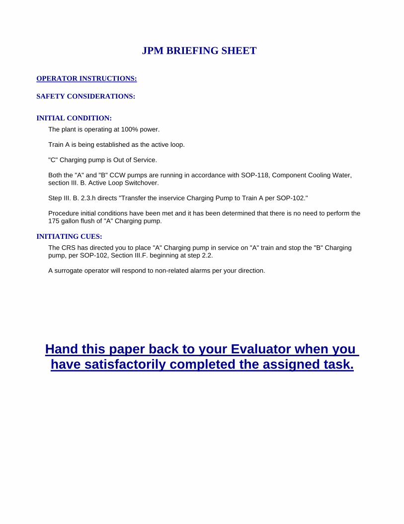
INITIATING CUES:
The CRS has directed you to place "A" Charging pump in service on "A" train and stop the "B" Charging pump, per SOP-102, Section III.F. beginning at step 2.2.
A surrogate operator will respond to non-related alarms per your direction.
INITIAL CONDITION:
The plant is operating at 100% power.
Train A is being established as the active loop.
"C" Charging pump is Out of Service.
Both the "A" and "B" CCW pumps are running in accordance with SOP-118, Component Cooling Water, section III. B. Active Loop Switchover.
Step III. B. 2.3.h directs "Transfer the inservice Charging Pump to Train A per SOP-102."
Procedure initial conditions have been met and it has been determined that there is no need to perform the 175 gallon flush of "A" Charging pump.
SAFETY CONSIDERATIONS:
OPERATOR INSTRUCTIONS:
Hand this paper back to your Evaluator when you have satisfactorily completed the assigned task.
JPM BRIEFING SHEET
6/13/2016 Page 13 of 13JPSF-046-N16
(NRC JPM-c) Isolate the SI Accumulators and depressurize the “B” SI Accumulator by venting due to a failed open discharge isolation valve.
(Alternate Path)
V.C. SUMMER NUCLEAR STATIONJOB PERFORMANCE MEASURE
CANDIDATE:
EXAMINER:
JPM NO: JPSF-142A-N16
6/13/2016 Page 1 of 9JPSF-142A-N16
TASK: 006-005-01-01
PREFERRED EVALUATION METHODPERFORM
EVALUATION TIME: 15 TIME CRITICAL: NO
TASK STANDARD:"A" AND "B" Si accumulators are isolated and "B" SI accumulator has been vented.
PREFERRED EVALUATION LOCATIONSIMULATOR
TIME START: TIME FINISH:
PERFORMANCE RATING: SAT: UNSAT:
PERFORMANCE TIME:
EXAMINER:SIGNATURE DATE
10CFR55: 41(b)2
Adjust Accumulator Pressure
TOOLS: EOP-2.1, ES‑1.2, POST‑LOCA COOLDOWN AND DEPRESSURIZATION, marked up to step 19.
REFERENCES:
TERMINATING CUE: Task is complete when any unisolated SI Accumulator is vented.
CANDIDATE:
EOP-2.1 POST-LOCA COOLDOWN AND DEPRESSURIZATION
INDEX NO. RO SROK/A NO.006000A402 Valves 4.0 3.8A4.02
6/13/2016 Page 2 of 9JPSF-142A-N16
INITIATING CUES:Continue in EOP-2.1 at step 19.
A surrogate operator will respond to non-related alarms per your direction.
INITIAL CONDITION:• A Small Break LOCA is in progress.
• The Reactor has tripped and safety injection has initiated.
• The crew entered EOP-2.0,LOSS OF REACTOR OR SECONDARY COOLANT, when a transition to EOP-2.1, ES-2.1 POST-LOCA COOLDOWN AND DEPRESSURIZATION, was required.
• RCS Cooldown and Depressurization has continued to step 19 of EOP-2.1.
READ TO OPERATOR:
SAFETY CONSIDERATIONS:
When I tell you to begin, you are to perform the actions as directed in the initiating cues.
I will describe the general conditions under which this task is to be performed and provide the necessary tools with which to perform this task.
Before starting, I will explain the initial conditions, which steps to simulate or discuss, and provide initiating cues. When you complete the task successfully, this Job Performance Measure will be satisfied.
INSTRUCTIONS TO OPERATOR
HAND JPM BRIEFING SHEET TO OPERATOR AT THIS TIME!
6/13/2016 Page 3 of 9JPSF-142A-N16
Step 19 Check if SI Accumulators should be isolated:
a. Verify RCS subcooling on TI-499A(B), A(B) TEMP °F, is GREATER THAN 52.5°F [67.5°F].
b. Verify PZR level is GREATER THAN 10% [28%].
NOTE: Examinee must use bracketed values if adverse containment values (Hi-1 RB pressure 3.6 psig or Hi Rad) are exceeded.
Yes
Examinee verifies RCS subcooling and PZR level.
CUES:
SEQUENCED:
STEP STANDARD:
COMMENTS:
SAT UNSATCRITICAL: No
JPM STEP: 1
6/13/2016 Page 4 of 9JPSF-142A-N16
Step 19 c. Locally unlock and close the breakers for the Accumulator Discharge Isolation Valves:
• XMC1DA2X 08AE, ACCUMULATOR A ISO VALVE, XVG8808A-SI (IB-463).
• XMC1DA2X 08FJ, ACCUMULATOR C ISO VALVE, XVG8808C-SI (IB-463).
• XMC1DB2Y 16IM, ACCUMULATOR B OUTLET ISOL, XVG8808B-SI (AB-463).
Booth Operator: Insert the following actions to complete the local operator task:
LOA-RHR006, LOA-RHR007, LOA-RHR008 or EVENT 1 if available.
Wait approximately 1 minute and report that the breakers are closed.
Yes
Dispatches an local operator to unlock and close the following breakers:
• XMC1DA2X 08AE, ACCUMULATOR A ISO VALVE, XVG8808A-SI (IB-463).
• XMC1DA2X 08FJ, ACCUMULATOR C ISO VALVE, XVG8808C-SI (IB-463).
• XMC1DB2Y 16IM, ACCUMULATOR B OUTLET ISOL, XVG8808B-SI (AB-463).
CUES:
SEQUENCED:
STEP STANDARD:
COMMENTS:
SAT UNSATCRITICAL: No
JPM STEP: 2
6/13/2016 Page 5 of 9JPSF-142A-N16
Step 19 d. Close all Accumulator Discharge Isolation Valves, MVG-8808A(B)(C).
Examiner Note: *** Alternate Path begins here ***
Yes
Operator takes the control switches for MVG-8808A(B)(C) to the CLOSE position.
Each valve travels closed as indicated by the red light OFF and the green light ON.
Identifies the 8808B does not go closed and implements Alternative Action.
CUES:
SEQUENCED:
STEP STANDARD:
COMMENTS:
SAT UNSATCRITICAL: Yes
JPM STEP: 3
ALTERNATIVE ACTION
Step 19 d. IF any Accumulator Discharge Isolation Valve can NOT be closed, THEN vent the AFFECTED Accumulator:
1) Close PVT-8880, N2 SUPPLY.
NOTE: PVT-8880 is already closed.
Yes
Operator takes the control switch for PVT-8880, N2 SUPPLY, to the CLOSE postion and verifies red light OFF, green light ON.
CUES:
SEQUENCED:
STEP STANDARD:
COMMENTS:
SAT UNSATCRITICAL: No
JPM STEP: 4
6/13/2016 Page 6 of 9JPSF-142A-N16
Examiner ends JPM at this point.
AA Step 19 d. IF any Accumulator Discharge Isolation Valve can NOT be closed, THEN vent the AFFECTED Accumulator: (cont.)
2) Open PVT-8875A(B)(C), N2 TO A(B)(C).
Yes
Examinee takes the control switch for PVT-8875B, N2 TO B, to OPEN. Vefiries red Light ON and green light OFF.
CUES:
SEQUENCED:
STEP STANDARD:
COMMENTS:
SAT UNSATCRITICAL: Yes
JPM STEP: 5
AA Step 19 d. IF any Accumulator Discharge Isolation Valve can NOT be closed, THEN vent the AFFECTED Accumulator: (cont.)
3) Open HCV-936, ACCUM N2 VENT.
This JPM may be terminated when "B" SI Accumulator Pressure decreases.
Yes
Operator opens HCV-936, ACCUM N2 VENT by increasing the Hagen controller output to approximately 100%.
CUES:
SEQUENCED:
STEP STANDARD:
COMMENTS:
SAT UNSATCRITICAL: Yes
JPM STEP: 6
6/13/2016 Page 7 of 9JPSF-142A-N16
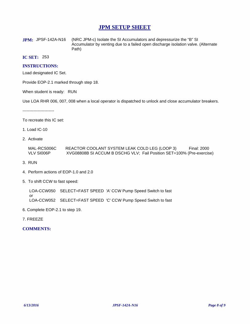
JPM: JPSF-142A-N16 (NRC JPM-c) Isolate the SI Accumulators and depressurize the “B” SI Accumulator by venting due to a failed open discharge isolation valve. (Alternate Path)
IC SET: 253
INSTRUCTIONS:
Load designated IC Set.
Provide EOP-2.1 marked through step 18.
When student is ready: RUN
Use LOA RHR 006, 007, 008 when a local operator is dispatched to unlock and close accumulator breakers.
-----------------------
To recreate this IC set:
1. Load IC-10
2. Activate
MAL-RCS006C REACTOR COOLANT SYSTEM LEAK COLD LEG (LOOP 3) Final: 2000 VLV SI006P XVG08808B SI ACCUM B DSCHG VLV; Fail Position SET=100% (Pre-exercise)
3. RUN
4. Perform actions of EOP-1.0 and 2.0
5. To shift CCW to fast speed:
LOA-CCW050 SELECT=FAST SPEED 'A' CCW Pump Speed Switch to fast or LOA-CCW052 SELECT=FAST SPEED 'C' CCW Pump Speed Switch to fast
6. Complete EOP-2.1 to step 19.
7. FREEZE
COMMENTS:
JPM SETUP SHEET
6/13/2016 Page 8 of 9JPSF-142A-N16
INITIATING CUES:
Continue in EOP-2.1 at step 19.
A surrogate operator will respond to non-related alarms per your direction.
INITIAL CONDITION:
• A Small Break LOCA is in progress.
• The Reactor has tripped and safety injection has initiated.
• The crew entered EOP-2.0,LOSS OF REACTOR OR SECONDARY COOLANT, when a transition to EOP-2.1, ES-2.1 POST-LOCA COOLDOWN AND DEPRESSURIZATION, was required.
• RCS Cooldown and Depressurization has continued to step 19 of EOP-2.1.
SAFETY CONSIDERATIONS:
OPERATOR INSTRUCTIONS:
Hand this paper back to your Evaluator when you have satisfactorily completed the assigned task.
JPM BRIEFING SHEET
6/13/2016 Page 9 of 9JPSF-142A-N16

(NRC JPM-d) Initiate Hot Leg Recirculation following a LOCA.
V.C. SUMMER NUCLEAR STATIONJOB PERFORMANCE MEASURE
CANDIDATE:
EXAMINER:
JPM NO: JPS-002A-N16
5/11/2016 Page 1 of 12JPS-002A-N16
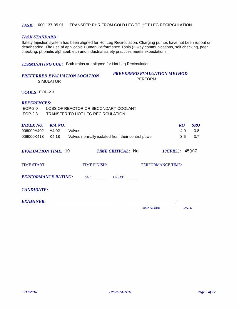
TASK: 000-137-05-01
PREFERRED EVALUATION METHODPERFORM
EVALUATION TIME: 10 TIME CRITICAL: No
TASK STANDARD:Safety Injection system has been aligned for Hot Leg Recirculation. Charging pumps have not been runout or deadheaded. The use of applicable Human Performance Tools (3-way communications, self checking, peer checking, phonetic alphabet, etc) and industrial safety practices meets expectations.
PREFERRED EVALUATION LOCATIONSIMULATOR
TIME START: TIME FINISH:
PERFORMANCE RATING: SAT: UNSAT:
PERFORMANCE TIME:
EXAMINER:SIGNATURE DATE
10CFR55: 45(a)7
TRANSFER RHR FROM COLD LEG TO HOT LEG RECIRCULATION
TOOLS: EOP-2.3
REFERENCES:
TERMINATING CUE: Both trains are aligned for Hot Leg Recirculation.
CANDIDATE:
EOP-2.0 LOSS OF REACTOR OR SECONDARY COOLANTEOP-2.3 TRANSFER TO HOT LEG RECIRCULATION
INDEX NO. RO SROK/A NO.006000A402 Valves 4.0 3.8A4.02006000K418 Valves normally isolated from their control power 3.6 3.7K4.18
5/11/2016 Page 2 of 12JPS-002A-N16
INITIATING CUES:The CRS has directed you to transfer from Cold Leg to Hot Leg Recirculation in accordance withEOP-2.3.
A surrogate operator will respond to non-related alarms per your direction.
INITIAL CONDITION:• A LOCA occurred approximately 8 hours ago.
• The plant is in Cold Leg Recirculation mode.
• CHG/SI Pump "C" is aligned to "B" train.
• The CRS has entered EOP-2.3 (Hot Leg Recirculation) from EOP-2.0.
READ TO OPERATOR:
SAFETY CONSIDERATIONS:
When I tell you to begin, you are to perform the actions as directed in the initiating cues.
I will describe the general conditions under which this task is to be performed and provide the necessary tools with which to perform this task.
Before starting, I will explain the initial conditions, which steps to simulate or discuss, and provide initiating cues. When you complete the task successfully, this Job Performance Measure will be satisfied.
INSTRUCTIONS TO OPERATOR
HAND JPM BRIEFING SHEET TO OPERATOR AT THIS TIME!
5/11/2016 Page 3 of 12JPS-002A-N16
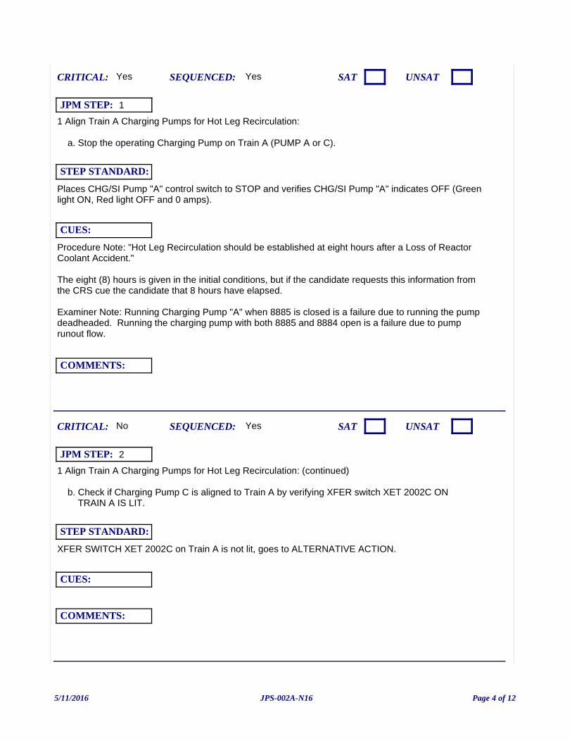
1 Align Train A Charging Pumps for Hot Leg Recirculation:
a. Stop the operating Charging Pump on Train A (PUMP A or C).
Procedure Note: "Hot Leg Recirculation should be established at eight hours after a Loss of Reactor Coolant Accident."
The eight (8) hours is given in the initial conditions, but if the candidate requests this information from the CRS cue the candidate that 8 hours have elapsed.
Examiner Note: Running Charging Pump "A" when 8885 is closed is a failure due to running the pump deadheaded. Running the charging pump with both 8885 and 8884 open is a failure due to pump runout flow.
Yes
Places CHG/SI Pump "A" control switch to STOP and verifies CHG/SI Pump "A" indicates OFF (Green light ON, Red light OFF and 0 amps).
CUES:
SEQUENCED:
STEP STANDARD:
COMMENTS:
SAT UNSATCRITICAL: Yes
JPM STEP: 1
1 Align Train A Charging Pumps for Hot Leg Recirculation: (continued)
b. Check if Charging Pump C is aligned to Train A by verifying XFER switch XET 2002C ON TRAIN A IS LIT.
Yes
XFER SWITCH XET 2002C on Train A is not lit, goes to ALTERNATIVE ACTION.
CUES:
SEQUENCED:
STEP STANDARD:
COMMENTS:
SAT UNSATCRITICAL: No
JPM STEP: 2
5/11/2016 Page 4 of 12JPS-002A-N16
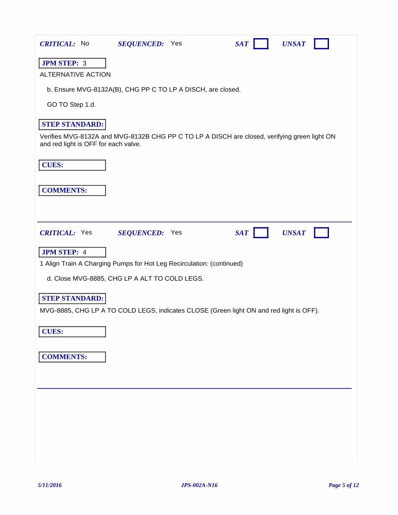
ALTERNATIVE ACTION
b. Ensure MVG-8132A(B), CHG PP C TO LP A DISCH, are closed.
GO TO Step 1.d.
Yes
Verifies MVG-8132A and MVG-8132B CHG PP C TO LP A DISCH are closed, verifying green light ON and red light is OFF for each valve.
CUES:
SEQUENCED:
STEP STANDARD:
COMMENTS:
SAT UNSATCRITICAL: No
JPM STEP: 3
1 Align Train A Charging Pumps for Hot Leg Recirculation: (continued)
d. Close MVG-8885, CHG LP A ALT TO COLD LEGS.
Yes
MVG-8885, CHG LP A TO COLD LEGS, indicates CLOSE (Green light ON and red light is OFF).
CUES:
SEQUENCED:
STEP STANDARD:
COMMENTS:
SAT UNSATCRITICAL: Yes
JPM STEP: 4
5/11/2016 Page 5 of 12JPS-002A-N16
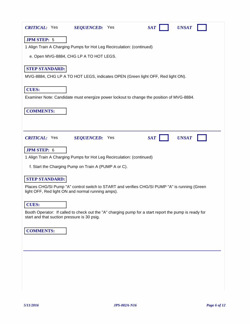
1 Align Train A Charging Pumps for Hot Leg Recirculation: (continued)
e. Open MVG-8884, CHG LP A TO HOT LEGS.
Examiner Note: Candidate must energize power lockout to change the position of MVG-8884.
Yes
MVG-8884, CHG LP A TO HOT LEGS, indicates OPEN (Green light OFF, Red light ON).
CUES:
SEQUENCED:
STEP STANDARD:
COMMENTS:
SAT UNSATCRITICAL: Yes
JPM STEP: 5
1 Align Train A Charging Pumps for Hot Leg Recirculation: (continued)
f. Start the Charging Pump on Train A (PUMP A or C).
Booth Operator: If called to check out the "A" charging pump for a start report the pump is ready for start and that suction pressure is 30 psig.
Yes
Places CHG/SI Pump "A" control switch to START and verifies CHG/SI PUMP "A" is running (Green light OFF, Red light ON and normal running amps).
CUES:
SEQUENCED:
STEP STANDARD:
COMMENTS:
SAT UNSATCRITICAL: Yes
JPM STEP: 6
5/11/2016 Page 6 of 12JPS-002A-N16
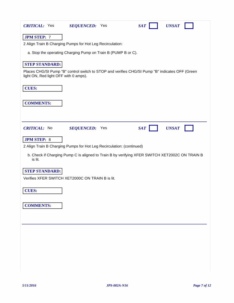
2 Align Train B Charging Pumps for Hot Leg Recirculation:
a. Stop the operating Charging Pump on Train B (PUMP B or C).
Yes
Places CHG/SI Pump "B" control switch to STOP and verifies CHG/SI Pump "B" indicates OFF (Green light ON, Red light OFF with 0 amps).
CUES:
SEQUENCED:
STEP STANDARD:
COMMENTS:
SAT UNSATCRITICAL: Yes
JPM STEP: 7
2 Align Train B Charging Pumps for Hot Leg Recirculation: (continued)
b. Check if Charging Pump C is aligned to Train B by verifying XFER SWITCH XET2002C ON TRAIN B is lit.
Yes
Verifies XFER SWITCH XET2000C ON TRAIN B is lit.
CUES:
SEQUENCED:
STEP STANDARD:
COMMENTS:
SAT UNSATCRITICAL: No
JPM STEP: 8
5/11/2016 Page 7 of 12JPS-002A-N16
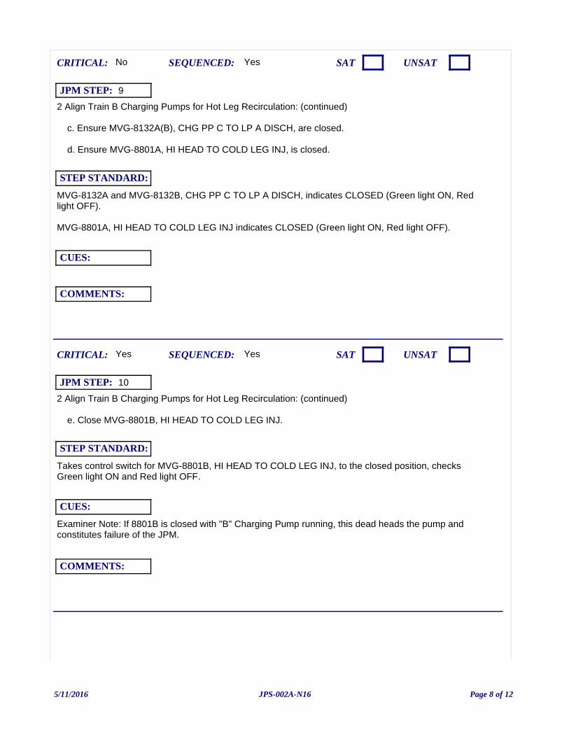
2 Align Train B Charging Pumps for Hot Leg Recirculation: (continued)
c. Ensure MVG-8132A(B), CHG PP C TO LP A DISCH, are closed.
d. Ensure MVG-8801A, HI HEAD TO COLD LEG INJ, is closed.
Yes
MVG-8132A and MVG-8132B, CHG PP C TO LP A DISCH, indicates CLOSED (Green light ON, Red light OFF).
MVG-8801A, HI HEAD TO COLD LEG INJ indicates CLOSED (Green light ON, Red light OFF).
CUES:
SEQUENCED:
STEP STANDARD:
COMMENTS:
SAT UNSATCRITICAL: No
JPM STEP: 9
2 Align Train B Charging Pumps for Hot Leg Recirculation: (continued)
e. Close MVG-8801B, HI HEAD TO COLD LEG INJ.
Examiner Note: If 8801B is closed with "B" Charging Pump running, this dead heads the pump and constitutes failure of the JPM.
Yes
Takes control switch for MVG-8801B, HI HEAD TO COLD LEG INJ, to the closed position, checks Green light ON and Red light OFF.
CUES:
SEQUENCED:
STEP STANDARD:
COMMENTS:
SAT UNSATCRITICAL: Yes
JPM STEP: 10
5/11/2016 Page 8 of 12JPS-002A-N16
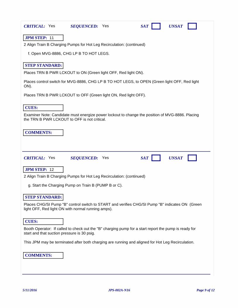
2 Align Train B Charging Pumps for Hot Leg Recirculation: (continued)
f. Open MVG-8886, CHG LP B TO HOT LEGS.
Examiner Note: Candidate must energize power lockout to change the position of MVG-8886. Placing the TRN B PWR LCKOUT to OFF is not critical.
Yes
Places TRN B PWR LCKOUT to ON (Green light OFF, Red light ON).
Places control switch for MVG-8886, CHG LP B TO HOT LEGS, to OPEN (Green light OFF, Red light ON).
Places TRN B PWR LCKOUT to OFF (Green light ON, Red light OFF).
CUES:
SEQUENCED:
STEP STANDARD:
COMMENTS:
SAT UNSATCRITICAL: Yes
JPM STEP: 11
2 Align Train B Charging Pumps for Hot Leg Recirculation: (continued)
g. Start the Charging Pump on Train B (PUMP B or C).
Booth Operator: If called to check out the "B" charging pump for a start report the pump is ready for start and that suction pressure is 30 psig.
This JPM may be terminated after both charging are running and aligned for Hot Leg Recirculation.
Yes
Places CHG/SI Pump "B" control switch to START and verifies CHG/SI Pump "B" indicates ON (Green light OFF, Red light ON with normal running amps).
CUES:
SEQUENCED:
STEP STANDARD:
COMMENTS:
SAT UNSATCRITICAL: Yes
JPM STEP: 12
5/11/2016 Page 9 of 12JPS-002A-N16

Examiner ends JPM at this point.
5/11/2016 Page 10 of 12JPS-002A-N16
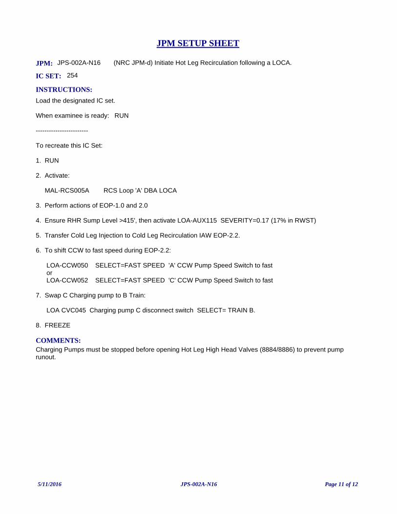
JPM: JPS-002A-N16 (NRC JPM-d) Initiate Hot Leg Recirculation following a LOCA.
IC SET: 254
INSTRUCTIONS:
Load the designated IC set.
When examinee is ready: RUN
------------------------
To recreate this IC Set:
1. RUN
2. Activate:
MAL-RCS005A RCS Loop 'A' DBA LOCA
3. Perform actions of EOP-1.0 and 2.0
4. Ensure RHR Sump Level >415', then activate LOA-AUX115 SEVERITY=0.17 (17% in RWST)
5. Transfer Cold Leg Injection to Cold Leg Recirculation IAW EOP-2.2.
6. To shift CCW to fast speed during EOP-2.2:
LOA-CCW050 SELECT=FAST SPEED 'A' CCW Pump Speed Switch to fast or LOA-CCW052 SELECT=FAST SPEED 'C' CCW Pump Speed Switch to fast
7. Swap C Charging pump to B Train:
LOA CVC045 Charging pump C disconnect switch SELECT= TRAIN B.
8. FREEZE
COMMENTS:Charging Pumps must be stopped before opening Hot Leg High Head Valves (8884/8886) to prevent pump runout.
JPM SETUP SHEET
5/11/2016 Page 11 of 12JPS-002A-N16
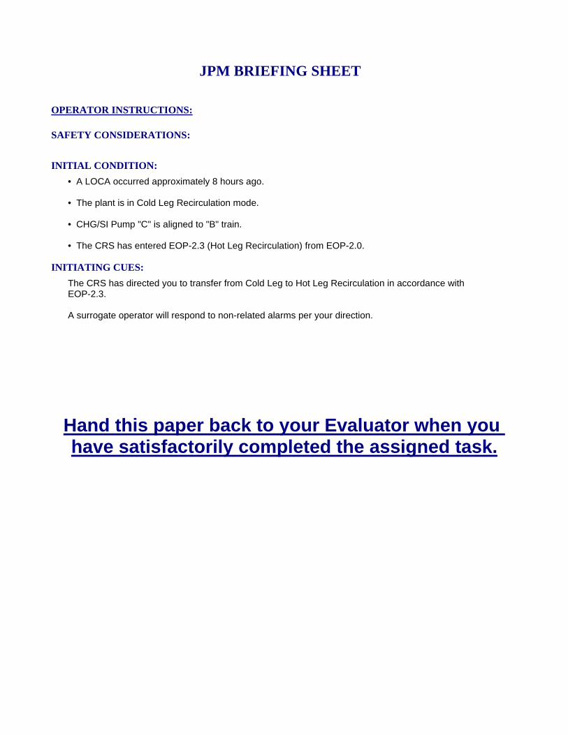
INITIATING CUES:
The CRS has directed you to transfer from Cold Leg to Hot Leg Recirculation in accordance withEOP-2.3.
A surrogate operator will respond to non-related alarms per your direction.
INITIAL CONDITION:
• A LOCA occurred approximately 8 hours ago.
• The plant is in Cold Leg Recirculation mode.
• CHG/SI Pump "C" is aligned to "B" train.
• The CRS has entered EOP-2.3 (Hot Leg Recirculation) from EOP-2.0.
SAFETY CONSIDERATIONS:
OPERATOR INSTRUCTIONS:
Hand this paper back to your Evaluator when you have satisfactorily completed the assigned task.
JPM BRIEFING SHEET
5/11/2016 Page 12 of 12JPS-002A-N16
(NRC JPM-e) Respond to Steam Generator Overpressure (Alternate Path)
V.C. SUMMER NUCLEAR STATIONJOB PERFORMANCE MEASURE
CANDIDATE:
EXAMINER:
JPM NO: JPSF-149B-N16
5/11/2016 Page 1 of 11JPSF-149B-N16
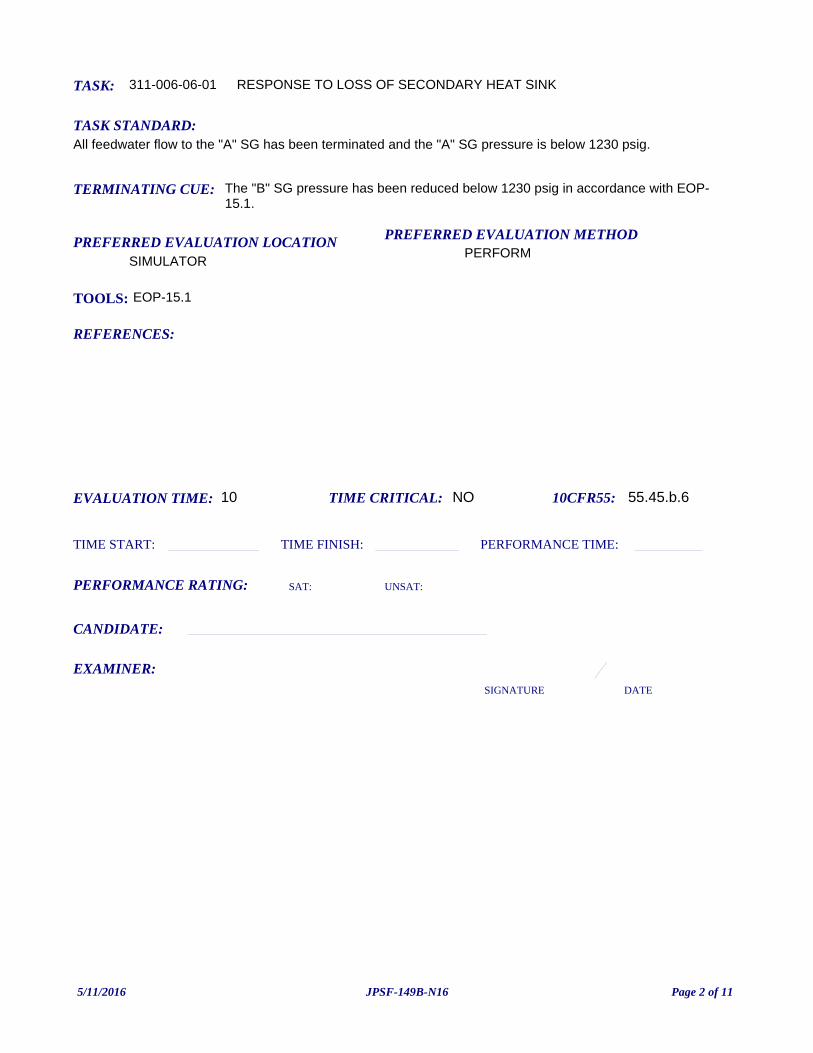
TASK: 311-006-06-01
PREFERRED EVALUATION METHODPERFORM
EVALUATION TIME: 10 TIME CRITICAL: NO
TASK STANDARD:All feedwater flow to the "A" SG has been terminated and the "A" SG pressure is below 1230 psig.
PREFERRED EVALUATION LOCATIONSIMULATOR
TIME START: TIME FINISH:
PERFORMANCE RATING: SAT: UNSAT:
PERFORMANCE TIME:
EXAMINER:SIGNATURE DATE
10CFR55: 55.45.b.6
RESPONSE TO LOSS OF SECONDARY HEAT SINK
TOOLS: EOP-15.1
REFERENCES:
TERMINATING CUE: The "B" SG pressure has been reduced below 1230 psig in accordance with EOP-15.1.
CANDIDATE:
5/11/2016 Page 2 of 11JPSF-149B-N16
INITIATING CUES:The CRS directs you to implement EOP-15.1, RESPONSE TO STEAM GENERATOR OVERPRESSURE in response to a Yellow Path on the Critical Safety Function Status Tree for Heat Sink.
A surrogate operator will respond to non-related alarms per your direction.
INITIAL CONDITION:The plant has tripped due to a turbine trip from 100% power.
The Shift Engineer has identified a Yellow Path on Heat Sink due to Steam Generator overpressurization on the "B" SG.
READ TO OPERATOR:
SAFETY CONSIDERATIONS: NONE
When I tell you to begin, you are to perform the actions as directed in the initiating cues.
I will describe the general conditions under which this task is to be performed and provide the necessary tools with which to perform this task.
Before starting, I will explain the initial conditions, which steps to simulate or discuss, and provide initiating cues. When you complete the task successfully, this Job Performance Measure will be satisfied.
INSTRUCTIONS TO OPERATOR
HAND JPM BRIEFING SHEET TO OPERATOR AT THIS TIME!
5/11/2016 Page 3 of 11JPSF-149B-N16
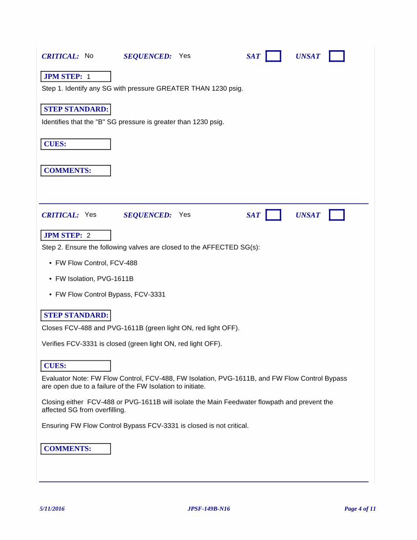
Step 1. Identify any SG with pressure GREATER THAN 1230 psig.
Yes
Identifies that the "B" SG pressure is greater than 1230 psig.
CUES:
SEQUENCED:
STEP STANDARD:
COMMENTS:
SAT UNSATCRITICAL: No
JPM STEP: 1
Step 2. Ensure the following valves are closed to the AFFECTED SG(s):
• FW Flow Control, FCV-488
• FW Isolation, PVG-1611B
• FW Flow Control Bypass, FCV-3331
Evaluator Note: FW Flow Control, FCV-488, FW Isolation, PVG-1611B, and FW Flow Control Bypass are open due to a failure of the FW Isolation to initiate.
Closing either FCV-488 or PVG-1611B will isolate the Main Feedwater flowpath and prevent the affected SG from overfilling.
Ensuring FW Flow Control Bypass FCV-3331 is closed is not critical.
Yes
Closes FCV-488 and PVG-1611B (green light ON, red light OFF).
Verifies FCV-3331 is closed (green light ON, red light OFF).
CUES:
SEQUENCED:
STEP STANDARD:
COMMENTS:
SAT UNSATCRITICAL: Yes
JPM STEP: 2
5/11/2016 Page 4 of 11JPSF-149B-N16
Step 3. Check Narrow Range level in AFFECTED SG(s) is LESS THAN 90% [83%].
Yes
Determines that "B" SG Narrow Range level is less than 90%.
CUES:
SEQUENCED:
STEP STANDARD:
COMMENTS:
SAT UNSATCRITICAL: No
JPM STEP: 3
Step 4. Dump steam from each AFFECTED SG to the Condenser:
a. Verify PERMISV C-9 status light is bright on XCP-6114 1-3.
Yes
Verifies PERMISV C-9 status light is bright.
CUES:
SEQUENCED:
STEP STANDARD:
COMMENTS:
SAT UNSATCRITICAL: No
JPM STEP: 4
5/11/2016 Page 5 of 11JPSF-149B-N16
Step 4 b. Perform the following:
• Verify the MS Isolation Valves, PVM-2801A(B)(C), are open for the AFFECTED SG(s).
OR
• Open MS Isolation Bypass Valves:
1) Depress both MAIN STEAM ISOL VALVES RESET TRAIN A(B).
Yes
Notes that MS Isolation Valve PVM-2801B is closed (green light ON, red light OFF).
Depresses both MAIN STEAM ISOL VALVES RESET TRAIN A(B).
CUES:
SEQUENCED:
STEP STANDARD:
COMMENTS:
SAT UNSATCRITICAL: No
JPM STEP: 5
Step 4 b. 2) Open MS Isolation Bypass Valves, PVM-2869A(B)(C), for the AFFECTED SG(s).
Examiner Note: *** Alternate Path begins here ***
Yes
Attempts to open MS Isolation Bypass Valves, PVM-2869B. Notes the valve did not open (green light ON, red light OFF).
Refers to ALTERNATIVE ACTION.
CUES:
SEQUENCED:
STEP STANDARD:
COMMENTS:
SAT UNSATCRITICAL: No
JPM STEP: 6
5/11/2016 Page 6 of 11JPSF-149B-N16
ALTERNATIVE ACTION
AA Step 4. Dump steam from each AFFECTED SG using the Steamline PORV:
a) Place the PWR RELIEF A(B)(C) SETPT Controller in MAN and closed.
b) Place the Steamline Power Relief A(B)(C) Mode Switch in PWR RLF.
c) Adjust the PWR RELIEF A(B)(C) SETPT Controller to reduce AFFECTED SG(s) pressure.
B SG pressure lowers.
Yes
• PWR RELIEF B SETPT Controller in MAN and closed.
• Steamline Power Relief B Mode Switch in PWR RLF.
• PWR RELIEF B SETPT Controller adjusted to reduce B SG pressure.
CUES:
SEQUENCED:
STEP STANDARD:
COMMENTS:
SAT UNSATCRITICAL: Yes
JPM STEP: 7
5/11/2016 Page 7 of 11JPSF-149B-N16
Examiner ends JPM at this point.
Step 5. Check AFFECTED SG(s) pressures:
a. Verify each AFFECTED SG(s) pressure is decreasing.
b. Verify each AFFECTED SG(s) pressure is LESS THAN 1230 psig.
This JPM may bew terminated when "B" SG pressure is less than 1230 psig.
Yes
SG pressure is decreasing.
CUES:
SEQUENCED:
STEP STANDARD:
COMMENTS:
SAT UNSATCRITICAL: Yes
JPM STEP: 8
5/11/2016 Page 8 of 11JPSF-149B-N16
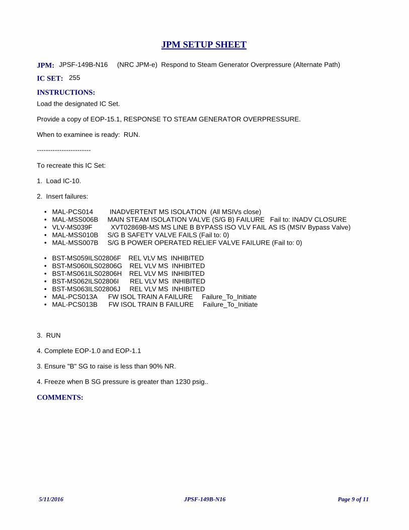
JPM: JPSF-149B-N16 (NRC JPM-e) Respond to Steam Generator Overpressure (Alternate Path)
IC SET: 255
INSTRUCTIONS:
Load the designated IC Set.
Provide a copy of EOP-15.1, RESPONSE TO STEAM GENERATOR OVERPRESSURE.
When to examinee is ready: RUN.
------------------------
To recreate this IC Set:
1. Load IC-10.
2. Insert failures:
• MAL-PCS014 INADVERTENT MS ISOLATION (All MSIVs close) • MAL-MSS006B MAIN STEAM ISOLATION VALVE (S/G B) FAILURE Fail to: INADV CLOSURE • VLV-MS039F XVT02869B-MS MS LINE B BYPASS ISO VLV FAIL AS IS (MSIV Bypass Valve) • MAL-MSS010B S/G B SAFETY VALVE FAILS (Fail to: 0) • MAL-MSS007B S/G B POWER OPERATED RELIEF VALVE FAILURE (Fail to: 0)
• BST-MS059ILS02806F REL VLV MS INHIBITED • BST-MS060ILS02806G REL VLV MS INHIBITED • BST-MS061ILS02806H REL VLV MS INHIBITED • BST-MS062ILS02806I REL VLV MS INHIBITED • BST-MS063ILS02806J REL VLV MS INHIBITED
• MAL-PCS013A FW ISOL TRAIN A FAILURE Failure_To_Initiate • MAL-PCS013B FW ISOL TRAIN B FAILURE Failure_To_Initiate
3. RUN
4. Complete EOP-1.0 and EOP-1.1
3. Ensure "B" SG to raise is less than 90% NR.
4. Freeze when B SG pressure is greater than 1230 psig..
COMMENTS:
JPM SETUP SHEET
5/11/2016 Page 9 of 11JPSF-149B-N16
INITIATING CUES:
The CRS directs you to implement EOP-15.1, RESPONSE TO STEAM GENERATOR OVERPRESSURE in response to a Yellow Path on the Critical Safety Function Status Tree for Heat Sink.
A surrogate operator will respond to non-related alarms per your direction.
INITIAL CONDITION:
The plant has tripped due to a turbine trip from 100% power.
The Shift Engineer has identified a Yellow Path on Heat Sink due to Steam Generator overpressurization on the "B" SG.
SAFETY CONSIDERATIONS: NONE
OPERATOR INSTRUCTIONS:
Hand this paper back to your Evaluator when you have satisfactorily completed the assigned task.
JPM BRIEFING SHEET
5/11/2016 Page 10 of 11JPSF-149B-N16
(NRC JPM-f) Respond to High RB Radiation Level (Alternate Path)
V.C. SUMMER NUCLEAR STATIONJOB PERFORMANCE MEASURE
CANDIDATE:
EXAMINER:
JPM NO: JPSF-1003-N16
5/11/2016 Page 1 of 9JPSF-1003-N16
TASK: 311-018-06-01
PREFERRED EVALUATION METHODPERFORM
EVALUATION TIME: 10 TIME CRITICAL: NO
TASK STANDARD:Both RBCU Filter Trains are operating.
PREFERRED EVALUATION LOCATIONSIMULATOR
TIME START: TIME FINISH:
PERFORMANCE RATING: SAT: UNSAT:
PERFORMANCE TIME:
EXAMINER:SIGNATURE DATE
10CFR55: 55.45(a)8
Response to High RB Radiation Level
TOOLS: EOP-17.2, RESPONSE TO HIGH REACTOR BUILDING RADIATION LEVEL
REFERENCES:
TERMINATING CUE: Both RBCU Filter Trains are operating.
CANDIDATE:
EOP-17.2 RESPONSE TO HIGH REACTOR BUILDING RADIATION LEVEL
5/11/2016 Page 2 of 9JPSF-1003-N16
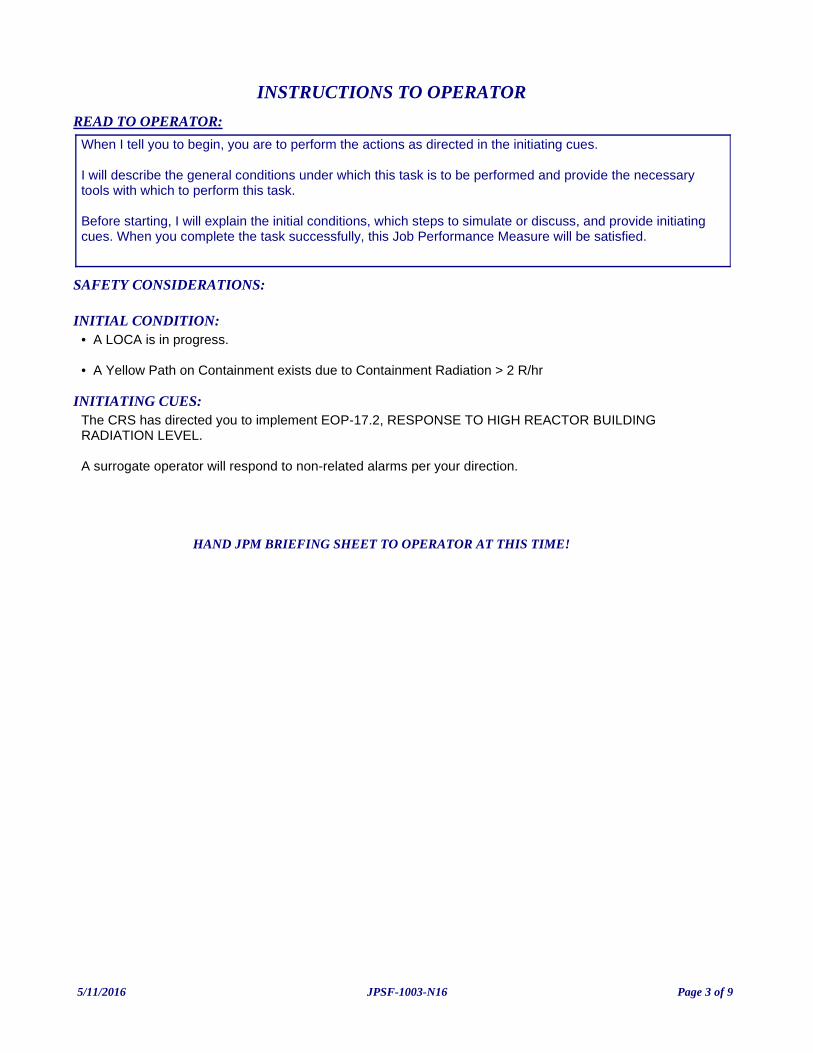
INITIATING CUES:The CRS has directed you to implement EOP-17.2, RESPONSE TO HIGH REACTOR BUILDINGRADIATION LEVEL.
A surrogate operator will respond to non-related alarms per your direction.
INITIAL CONDITION:• A LOCA is in progress.
• A Yellow Path on Containment exists due to Containment Radiation > 2 R/hr
READ TO OPERATOR:
SAFETY CONSIDERATIONS:
When I tell you to begin, you are to perform the actions as directed in the initiating cues.
I will describe the general conditions under which this task is to be performed and provide the necessary tools with which to perform this task.
Before starting, I will explain the initial conditions, which steps to simulate or discuss, and provide initiating cues. When you complete the task successfully, this Job Performance Measure will be satisfied.
INSTRUCTIONS TO OPERATOR
HAND JPM BRIEFING SHEET TO OPERATOR AT THIS TIME!
5/11/2016 Page 3 of 9JPSF-1003-N16
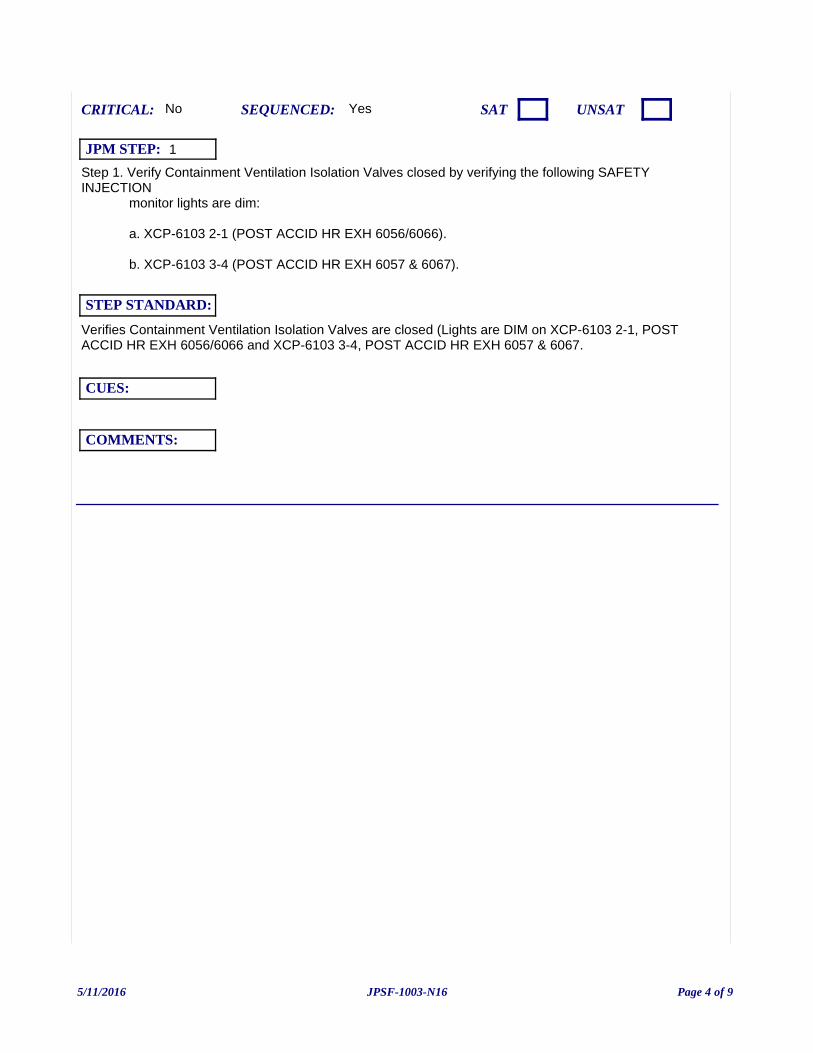
Step 1. Verify Containment Ventilation Isolation Valves closed by verifying the following SAFETY INJECTION monitor lights are dim:
a. XCP-6103 2-1 (POST ACCID HR EXH 6056/6066).
b. XCP-6103 3-4 (POST ACCID HR EXH 6057 & 6067).
Yes
Verifies Containment Ventilation Isolation Valves are closed (Lights are DIM on XCP-6103 2-1, POST ACCID HR EXH 6056/6066 and XCP-6103 3-4, POST ACCID HR EXH 6057 & 6067.
CUES:
SEQUENCED:
STEP STANDARD:
COMMENTS:
SAT UNSATCRITICAL: No
JPM STEP: 1
5/11/2016 Page 4 of 9JPSF-1003-N16
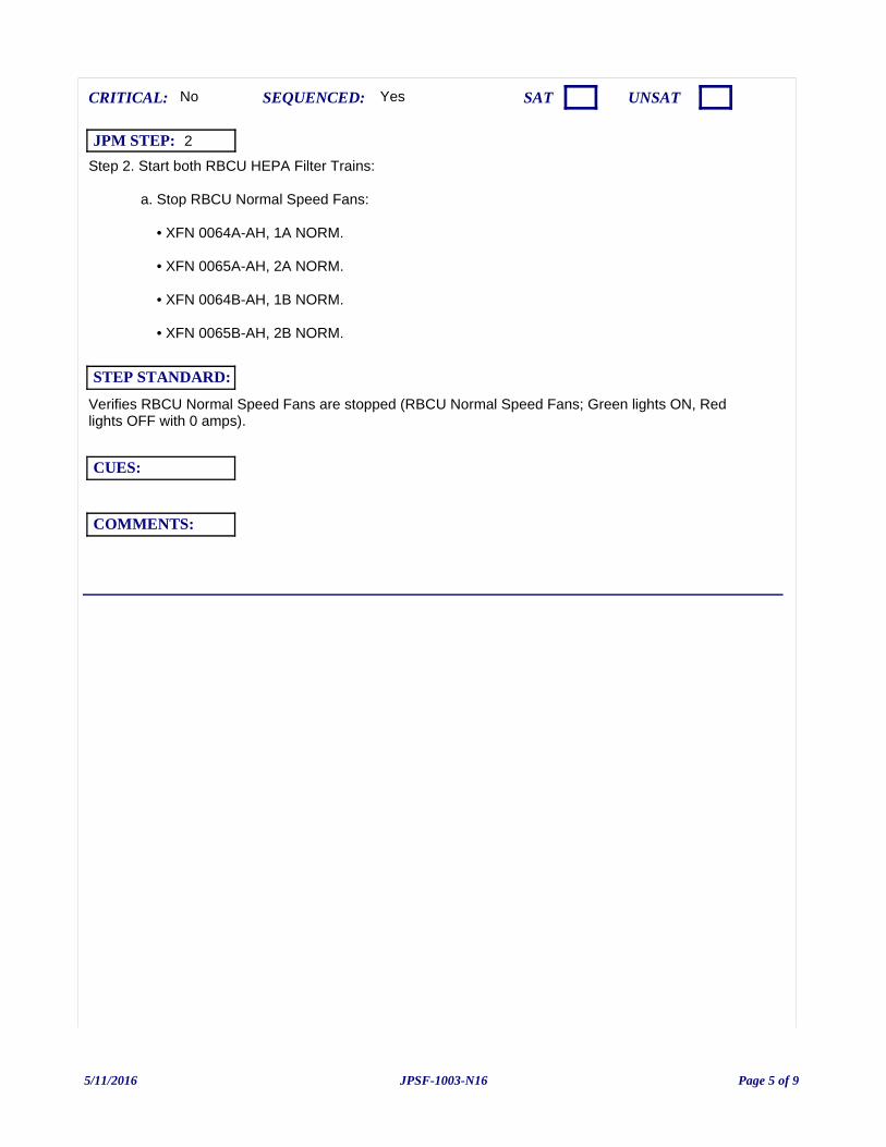
Step 2. Start both RBCU HEPA Filter Trains:
a. Stop RBCU Normal Speed Fans:
• XFN 0064A-AH, 1A NORM.
• XFN 0065A-AH, 2A NORM.
• XFN 0064B-AH, 1B NORM.
• XFN 0065B-AH, 2B NORM.
Yes
Verifies RBCU Normal Speed Fans are stopped (RBCU Normal Speed Fans; Green lights ON, Red lights OFF with 0 amps).
CUES:
SEQUENCED:
STEP STANDARD:
COMMENTS:
SAT UNSATCRITICAL: No
JPM STEP: 2
5/11/2016 Page 5 of 9JPSF-1003-N16
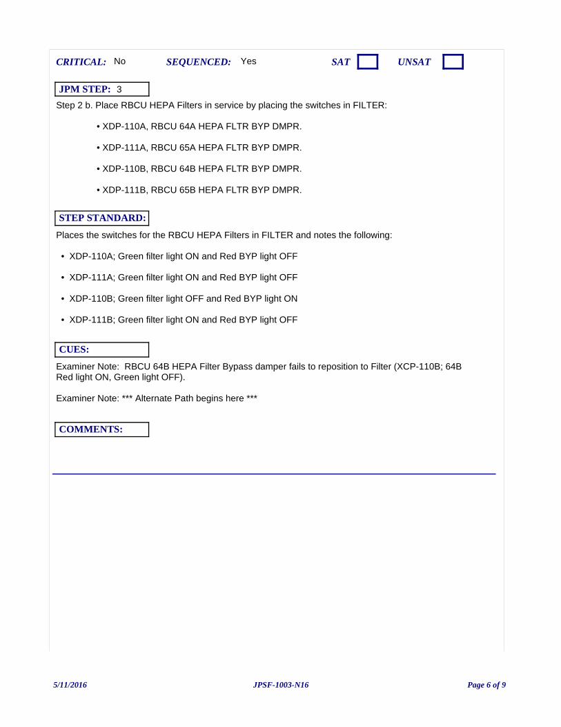
Step 2 b. Place RBCU HEPA Filters in service by placing the switches in FILTER:
• XDP-110A, RBCU 64A HEPA FLTR BYP DMPR.
• XDP-111A, RBCU 65A HEPA FLTR BYP DMPR.
• XDP-110B, RBCU 64B HEPA FLTR BYP DMPR.
• XDP-111B, RBCU 65B HEPA FLTR BYP DMPR.
Examiner Note: RBCU 64B HEPA Filter Bypass damper fails to reposition to Filter (XCP-110B; 64B Red light ON, Green light OFF).
Examiner Note: *** Alternate Path begins here ***
Yes
Places the switches for the RBCU HEPA Filters in FILTER and notes the following:
• XDP-110A; Green filter light ON and Red BYP light OFF
• XDP-111A; Green filter light ON and Red BYP light OFF
• XDP-110B; Green filter light OFF and Red BYP light ON
• XDP-111B; Green filter light ON and Red BYP light OFF
CUES:
SEQUENCED:
STEP STANDARD:
COMMENTS:
SAT UNSATCRITICAL: No
JPM STEP: 3
5/11/2016 Page 6 of 9JPSF-1003-N16
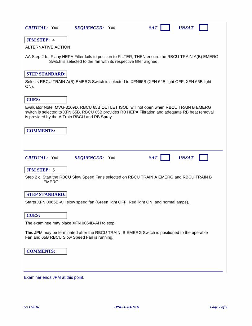
Examiner ends JPM at this point.
ALTERNATIVE ACTION
AA Step 2 b. IF any HEPA Filter fails to position to FILTER, THEN ensure the RBCU TRAIN A(B) EMERG Switch is selected to the fan with its respective filter aligned.
Evaluator Note: MVG-3109D, RBCU 65B OUTLET ISOL, will not open when RBCU TRAIN B EMERG switch is selected to XFN 65B. RBCU 65B provides RB HEPA Filtration and adequate RB heat removal is provided by the A Train RBCU and RB Spray.
Yes
Selects RBCU TRAIN A(B) EMERG Switch is selected to XFN65B (XFN 64B light OFF, XFN 65B light ON).
CUES:
SEQUENCED:
STEP STANDARD:
COMMENTS:
SAT UNSATCRITICAL: Yes
JPM STEP: 4
Step 2 c. Start the RBCU Slow Speed Fans selected on RBCU TRAIN A EMERG and RBCU TRAIN B EMERG.
The examinee may place XFN 0064B-AH to stop.
This JPM may be terminated after the RBCU TRAIN B EMERG Switch is positioned to the operable Fan and 65B RBCU Slow Speed Fan is running.
Yes
Starts XFN 0065B-AH slow speed fan (Green light OFF, Red light ON, and normal amps).
CUES:
SEQUENCED:
STEP STANDARD:
COMMENTS:
SAT UNSATCRITICAL: Yes
JPM STEP: 5
5/11/2016 Page 7 of 9JPSF-1003-N16
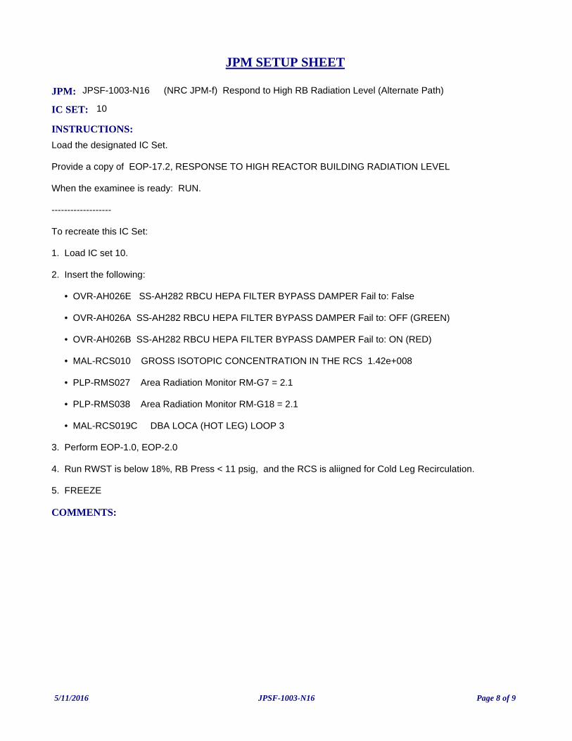
JPM: JPSF-1003-N16 (NRC JPM-f) Respond to High RB Radiation Level (Alternate Path)
IC SET: 10
INSTRUCTIONS:
Load the designated IC Set.
Provide a copy of EOP-17.2, RESPONSE TO HIGH REACTOR BUILDING RADIATION LEVEL
When the examinee is ready: RUN.
-------------------
To recreate this IC Set:
1. Load IC set 10.
2. Insert the following:
• OVR-AH026E SS-AH282 RBCU HEPA FILTER BYPASS DAMPER Fail to: False
• OVR-AH026A SS-AH282 RBCU HEPA FILTER BYPASS DAMPER Fail to: OFF (GREEN)
• OVR-AH026B SS-AH282 RBCU HEPA FILTER BYPASS DAMPER Fail to: ON (RED)
• MAL-RCS010 GROSS ISOTOPIC CONCENTRATION IN THE RCS 1.42e+008
• PLP-RMS027 Area Radiation Monitor RM-G7 = 2.1
• PLP-RMS038 Area Radiation Monitor RM-G18 = 2.1
• MAL-RCS019C DBA LOCA (HOT LEG) LOOP 3
3. Perform EOP-1.0, EOP-2.0
4. Run RWST is below 18%, RB Press < 11 psig, and the RCS is aliigned for Cold Leg Recirculation.
5. FREEZE
COMMENTS:
JPM SETUP SHEET
5/11/2016 Page 8 of 9JPSF-1003-N16
INITIATING CUES:
The CRS has directed you to implement EOP-17.2, RESPONSE TO HIGH REACTOR BUILDINGRADIATION LEVEL.
A surrogate operator will respond to non-related alarms per your direction.
INITIAL CONDITION:
• A LOCA is in progress.
• A Yellow Path on Containment exists due to Containment Radiation > 2 R/hr
SAFETY CONSIDERATIONS:
OPERATOR INSTRUCTIONS:
Hand this paper back to your Evaluator when you have satisfactorily completed the assigned task.
JPM BRIEFING SHEET
5/11/2016 Page 9 of 9JPSF-1003-N16
(NRC JPM-g) Loss of Intermediate Range Instrumentation (Alternate Path)
V.C. SUMMER NUCLEAR STATIONJOB PERFORMANCE MEASURE
CANDIDATE:
EXAMINER:
JPM NO: JPSF-029A-N16
5/19/2016 Page 1 of 13JPSF-029A-N16
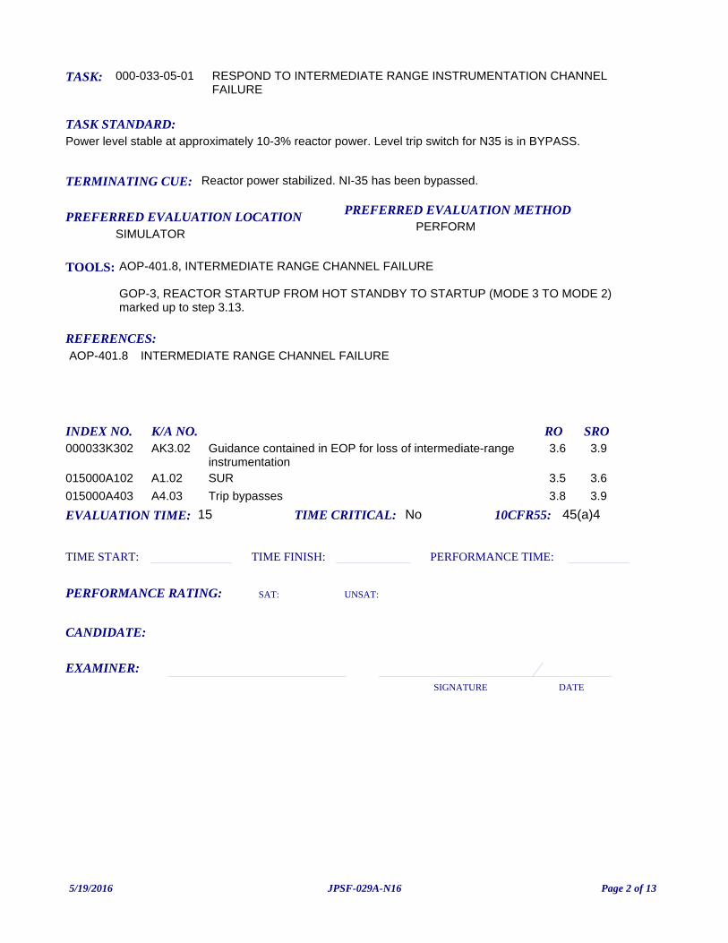
TASK: 000-033-05-01
PREFERRED EVALUATION METHODPERFORM
EVALUATION TIME: 15 TIME CRITICAL: No
TASK STANDARD:Power level stable at approximately 10-3% reactor power. Level trip switch for N35 is in BYPASS.
PREFERRED EVALUATION LOCATIONSIMULATOR
TIME START: TIME FINISH:
PERFORMANCE RATING: SAT: UNSAT:
PERFORMANCE TIME:
EXAMINER:SIGNATURE DATE
10CFR55: 45(a)4
RESPOND TO INTERMEDIATE RANGE INSTRUMENTATION CHANNEL FAILURE
TOOLS: AOP-401.8, INTERMEDIATE RANGE CHANNEL FAILURE
GOP-3, REACTOR STARTUP FROM HOT STANDBY TO STARTUP (MODE 3 TO MODE 2) marked up to step 3.13.
REFERENCES:
TERMINATING CUE: Reactor power stabilized. NI-35 has been bypassed.
CANDIDATE:
AOP-401.8 INTERMEDIATE RANGE CHANNEL FAILURE
INDEX NO. RO SROK/A NO.000033K302 Guidance contained in EOP for loss of intermediate-range
instrumentation3.6 3.9AK3.02
015000A102 SUR 3.5 3.6A1.02015000A403 Trip bypasses 3.8 3.9A4.03
5/19/2016 Page 2 of 13JPSF-029A-N16
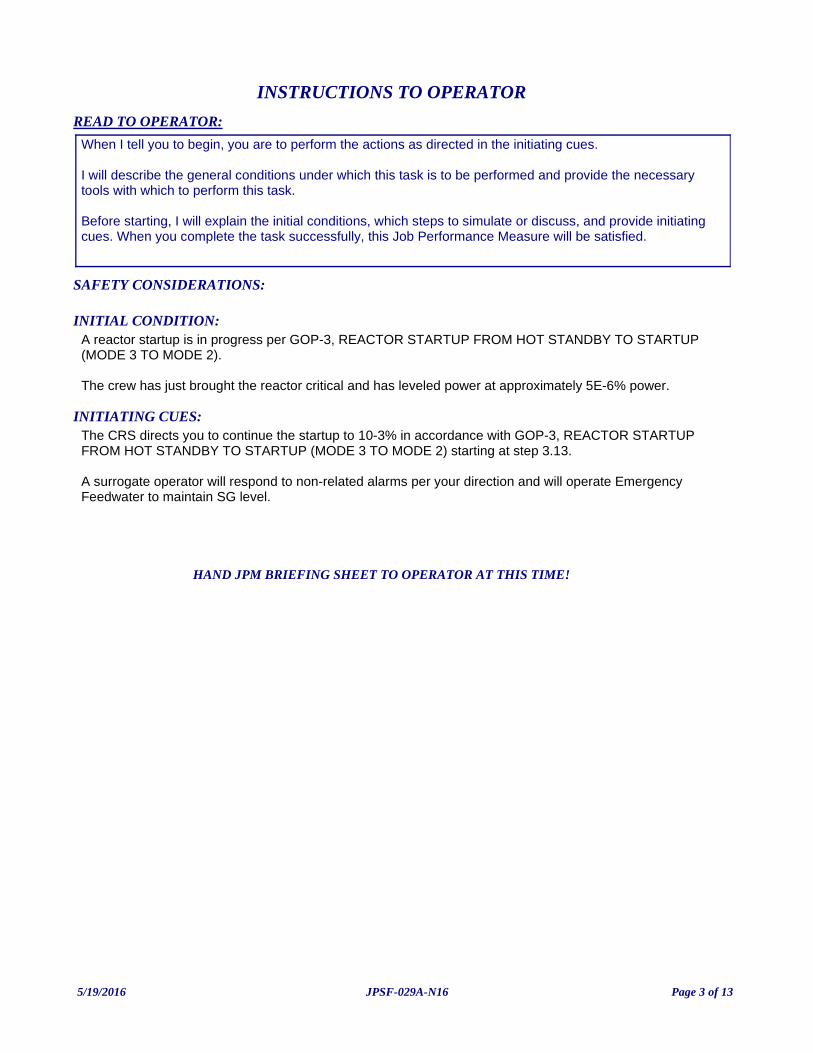
INITIATING CUES:The CRS directs you to continue the startup to 10-3% in accordance with GOP-3, REACTOR STARTUP FROM HOT STANDBY TO STARTUP (MODE 3 TO MODE 2) starting at step 3.13.
A surrogate operator will respond to non-related alarms per your direction and will operate Emergency Feedwater to maintain SG level.
INITIAL CONDITION:A reactor startup is in progress per GOP-3, REACTOR STARTUP FROM HOT STANDBY TO STARTUP (MODE 3 TO MODE 2).
The crew has just brought the reactor critical and has leveled power at approximately 5E-6% power.
READ TO OPERATOR:
SAFETY CONSIDERATIONS:
When I tell you to begin, you are to perform the actions as directed in the initiating cues.
I will describe the general conditions under which this task is to be performed and provide the necessary tools with which to perform this task.
Before starting, I will explain the initial conditions, which steps to simulate or discuss, and provide initiating cues. When you complete the task successfully, this Job Performance Measure will be satisfied.
INSTRUCTIONS TO OPERATOR
HAND JPM BRIEFING SHEET TO OPERATOR AT THIS TIME!
5/19/2016 Page 3 of 13JPSF-029A-N16
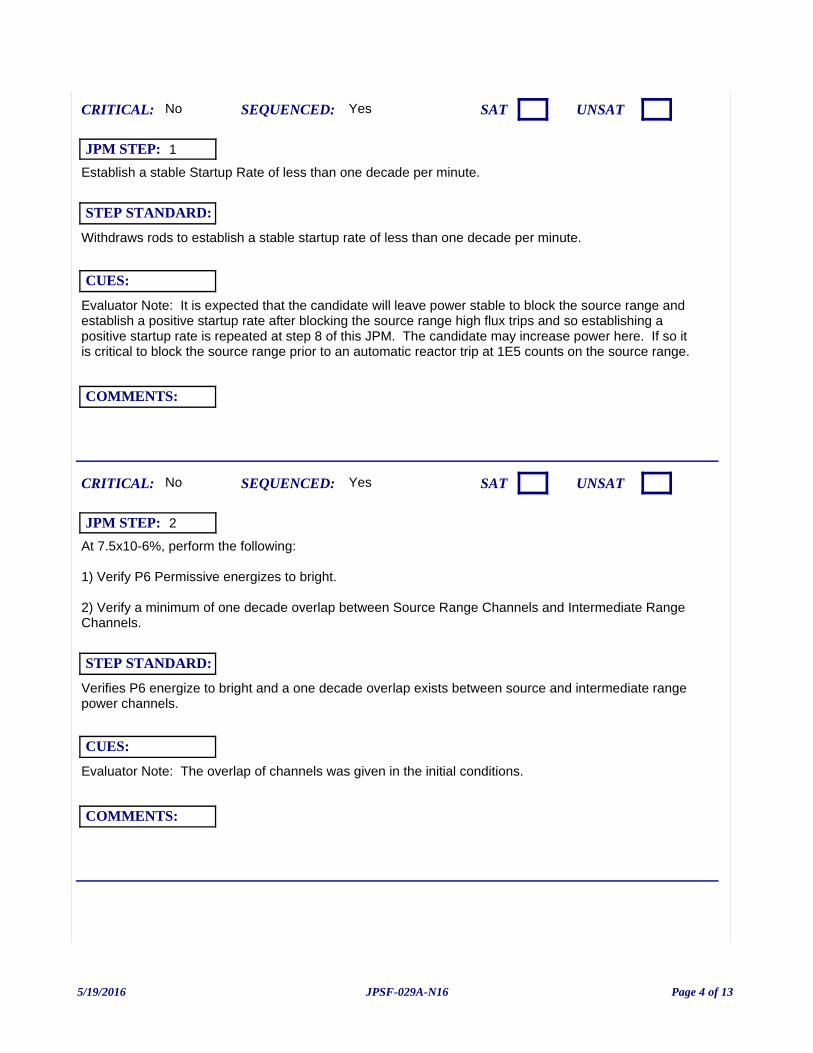
Establish a stable Startup Rate of less than one decade per minute.
Evaluator Note: It is expected that the candidate will leave power stable to block the source range and establish a positive startup rate after blocking the source range high flux trips and so establishing a positive startup rate is repeated at step 8 of this JPM. The candidate may increase power here. If so it is critical to block the source range prior to an automatic reactor trip at 1E5 counts on the source range.
Yes
Withdraws rods to establish a stable startup rate of less than one decade per minute.
CUES:
SEQUENCED:
STEP STANDARD:
COMMENTS:
SAT UNSATCRITICAL: No
JPM STEP: 1
At 7.5x10⁻⁶%, perform the following:
1) Verify P6 Permissive energizes to bright.
2) Verify a minimum of one decade overlap between Source Range Channels and Intermediate Range Channels.
Evaluator Note: The overlap of channels was given in the initial conditions.
Yes
Verifies P6 energize to bright and a one decade overlap exists between source and intermediate range power channels.
CUES:
SEQUENCED:
STEP STANDARD:
COMMENTS:
SAT UNSATCRITICAL: No
JPM STEP: 2
5/19/2016 Page 4 of 13JPSF-029A-N16
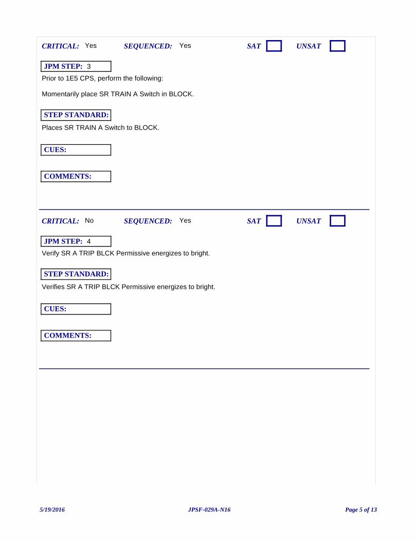
Prior to 1E5 CPS, perform the following:
Momentarily place SR TRAIN A Switch in BLOCK.
Yes
Places SR TRAIN A Switch to BLOCK.
CUES:
SEQUENCED:
STEP STANDARD:
COMMENTS:
SAT UNSATCRITICAL: Yes
JPM STEP: 3
Verify SR A TRIP BLCK Permissive energizes to bright.
Yes
Verifies SR A TRIP BLCK Permissive energizes to bright.
CUES:
SEQUENCED:
STEP STANDARD:
COMMENTS:
SAT UNSATCRITICAL: No
JPM STEP: 4
5/19/2016 Page 5 of 13JPSF-029A-N16
Momentarily place SR TRAIN B Switch in BLOCK.
Yes
Places SR TRAIN B Switch to BLOCK.
CUES:
SEQUENCED:
STEP STANDARD:
COMMENTS:
SAT UNSATCRITICAL: Yes
JPM STEP: 5
Verify SR B TRIP BLCK Permissive energizes to bright.
Yes
Verifies SR B TRIP BLCK Permissive energizes to bright.
CUES:
SEQUENCED:
STEP STANDARD:
COMMENTS:
SAT UNSATCRITICAL: No
JPM STEP: 6
5/19/2016 Page 6 of 13JPSF-029A-N16
Perform one of the following for continued monitoring of Intermediate and Power Range instrument:
1) If available for use, select one Intermediate Range Channel and one Power Range Channel on NR-45, NIS RECORDER.
2) Ensure at least one Intermediate Range and at least one Power Range instrument are selected for continuous monitoring using computer display NR45.
Yes
Selects one power range and one intermediate range channel on NR-45.
CUES:
SEQUENCED:
STEP STANDARD:
COMMENTS:
SAT UNSATCRITICAL: No
JPM STEP: 7
Establish a stable Startup Rate of less than one decade per minute.
Evaluator Note: The candidate may have established a SUR prior to blocking the source range, but if not power should be raised here.
The critical aspect of this step is to raise reactor power.
No
Withdraws rods to establish a stable startup rate of less than one decade per minute.
CUES:
SEQUENCED:
STEP STANDARD:
COMMENTS:
SAT UNSATCRITICAL: Yes
JPM STEP: 8
5/19/2016 Page 7 of 13JPSF-029A-N16
1 Stabilize Reactor power at the current level.
Evaluator Note: The failure will occur at 1E-4% power or insert MAL-NIS008A (Channel 35 High Voltage Failure) fails low.
Evaluator Note: The student may refer to ARP for directions to AOP-401.8, INTERMEDIATE RANGE CHANNEL FAILURE.
Examiner Note: *** Alternate Path begins here ***
Yes
NROATC drives control rods inward to achieve a stable 0 DPM SUR and stabilize reactor power. Examinee may use multiple indications to determine that power is stable at approximately 0 DPM.
CUES:
SEQUENCED:
STEP STANDARD:
COMMENTS:
SAT UNSATCRITICAL: Yes
JPM STEP: 9
2 Bypass the failed Intermediate Range channel:
a. Place LEVEL TRIP Switch for the AFFECTED channel in BYPASS.
Evaluator Cue: The surrogate operator will take over monitoring the Reactor.
Yes
Positions the level trip switch for NI-35 to the BYPASS position.
CUES:
SEQUENCED:
STEP STANDARD:
COMMENTS:
SAT UNSATCRITICAL: Yes
JPM STEP: 10
5/19/2016 Page 8 of 13JPSF-029A-N16
2 Bypass the failed Intermediate Range channel:
b. Verify IR&SR TRIP BYP (XCP-620 4-5), annunciator is lit.
Yes
Observes IR&SR TRIP BYP annunciator (XCP-620-4-5) energizes by visual observation and acknowledges alarm.
CUES:
SEQUENCED:
STEP STANDARD:
COMMENTS:
SAT UNSATCRITICAL: Yes
JPM STEP: 11
3 Check if Reactor Power is less than 7.5 x 10⁻⁶%.
Yes
Notes that Reactor Power is GREATER than 7.5 x 10⁻⁶%.
CUES:
SEQUENCED:
STEP STANDARD:
COMMENTS:
SAT UNSATCRITICAL: No
JPM STEP: 12
5/19/2016 Page 9 of 13JPSF-029A-N16
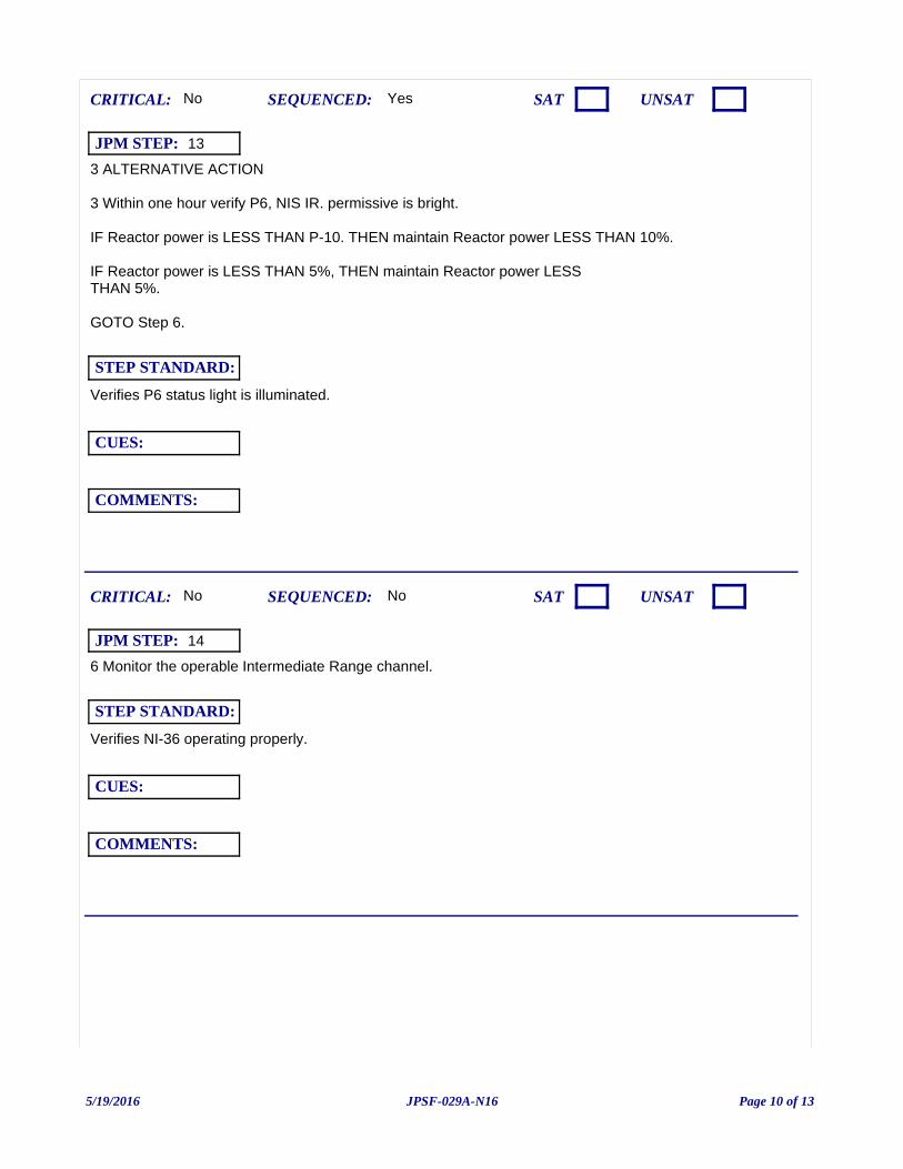
3 ALTERNATIVE ACTION
3 Within one hour verify P6, NIS IR. permissive is bright.
IF Reactor power is LESS THAN P-10. THEN maintain Reactor power LESS THAN 10%.
IF Reactor power is LESS THAN 5%, THEN maintain Reactor power LESSTHAN 5%.
GOTO Step 6.
Yes
Verifies P6 status light is illuminated.
CUES:
SEQUENCED:
STEP STANDARD:
COMMENTS:
SAT UNSATCRITICAL: No
JPM STEP: 13
6 Monitor the operable Intermediate Range channel.
No
Verifies NI-36 operating properly.
CUES:
SEQUENCED:
STEP STANDARD:
COMMENTS:
SAT UNSATCRITICAL: No
JPM STEP: 14
5/19/2016 Page 10 of 13JPSF-029A-N16
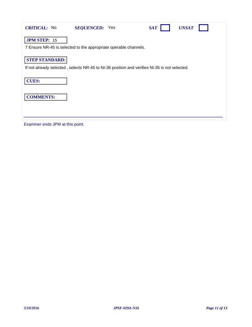
Examiner ends JPM at this point.
7 Ensure NR-45 is selected to the appropriate operable channels.
Yes
If not already selected , selects NR-45 to NI-36 position and verifies NI-35 is not selected.
CUES:
SEQUENCED:
STEP STANDARD:
COMMENTS:
SAT UNSATCRITICAL: No
JPM STEP: 15
5/19/2016 Page 11 of 13JPSF-029A-N16
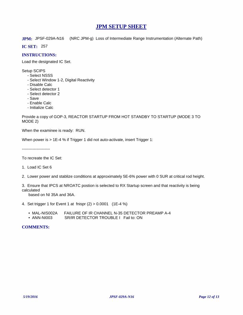
JPM: JPSF-029A-N16 (NRC JPM-g) Loss of Intermediate Range Instrumentation (Alternate Path)
IC SET: 257
INSTRUCTIONS:
Load the designated IC Set.
Setup SCIPS - Select NSSS - Select Window 1-2, Digital Reactivity - Disable Calc - Select detector 1 - Select detector 2 - Save - Enable Calc - Initialize Calc
Provide a copy of GOP-3, REACTOR STARTUP FROM HOT STANDBY TO STARTUP (MODE 3 TO MODE 2)
When the examinee is ready: RUN.
When power is > 1E-4 % if Trigger 1 did not auto-activate, insert Trigger 1:
---------------------
To recreate the IC Set:
1. Load IC Set 6
2. Lower power and stablize conditions at approximately 5E-6% power with 0 SUR at critical rod height.
3. Ensure that IPCS at NROATC postion is selected to RX Startup screen and that reactivity is being calculated based on NI 35A and 36A.
4. Set trigger 1 for Event 1 at fnispr (2) > 0.0001 (1E-4 %)
• MAL-NIS002A FAILURE OF IR CHANNEL N-35 DETECTOR PREAMP A-4 • ANN-NI003 SR/IR DETECTOR TROUBLE I Fail to: ON
COMMENTS:
JPM SETUP SHEET
5/19/2016 Page 12 of 13JPSF-029A-N16
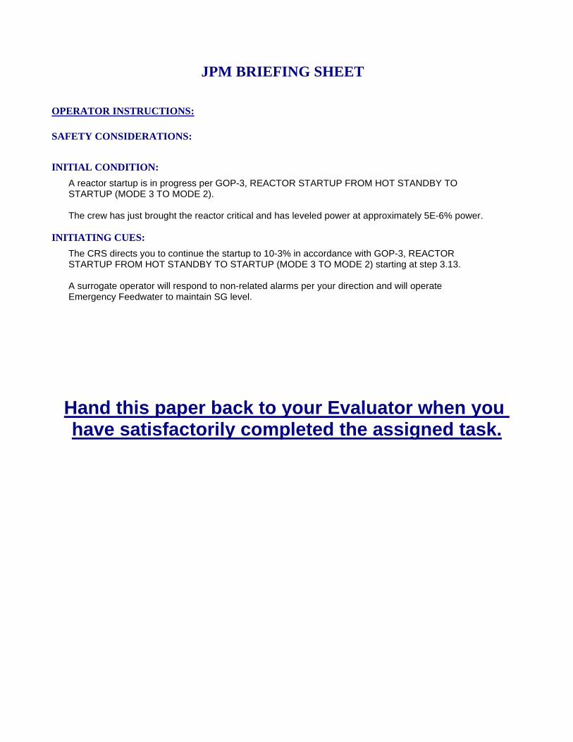
INITIATING CUES:
The CRS directs you to continue the startup to 10-3% in accordance with GOP-3, REACTOR STARTUP FROM HOT STANDBY TO STARTUP (MODE 3 TO MODE 2) starting at step 3.13.
A surrogate operator will respond to non-related alarms per your direction and will operate Emergency Feedwater to maintain SG level.
INITIAL CONDITION:
A reactor startup is in progress per GOP-3, REACTOR STARTUP FROM HOT STANDBY TO STARTUP (MODE 3 TO MODE 2).
The crew has just brought the reactor critical and has leveled power at approximately 5E-6% power.
SAFETY CONSIDERATIONS:
OPERATOR INSTRUCTIONS:
Hand this paper back to your Evaluator when you have satisfactorily completed the assigned task.
JPM BRIEFING SHEET
5/19/2016 Page 13 of 13JPSF-029A-N16
(NRC JPM-h) Establish Reactor Building Purge Supply and Exhaust
V.C. SUMMER NUCLEAR STATIONJOB PERFORMANCE MEASURE
CANDIDATE:
EXAMINER:
JPM NO: JPS-1001-N16
5/16/2016 Page 1 of 15JPS-1001-N16
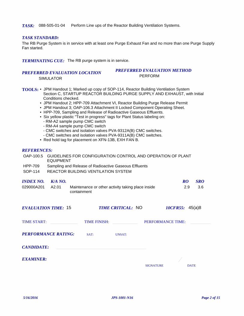
TASK: 088-505-01-04
PREFERRED EVALUATION METHODPERFORM
EVALUATION TIME: 15 TIME CRITICAL: NO
TASK STANDARD:The RB Purge System is in service with at least one Purge Exhaust Fan and no more than one Purge Supply Fan started.
PREFERRED EVALUATION LOCATIONSIMULATOR
TIME START: TIME FINISH:
PERFORMANCE RATING: SAT: UNSAT:
PERFORMANCE TIME:
EXAMINER:SIGNATURE DATE
10CFR55: 45(a)8
Perform Line ups of the Reactor Building Ventilation Systems.
TOOLS: • JPM Handout 1; Marked up copy of SOP-114, Reactor Building Ventilation System Section C, STARTUP REACTOR BUILDING PURGE SUPPLY AND EXHAUST, with Initial Conditions checked.• JPM Handout 2; HPP-709 Attachment VI, Reactor Building Purge Release Permit• JPM Handout 3; OAP-106.3 Attachment II Locked Component Operating Sheet.• HPP-709, Sampling and Release of Radioactive Gaseous Effluents.• Six yellow plastic "Test in progress" tags for Plant Status labeling on: - RM-A2 sample pump CMC switch - RM-A4 sample pump CMC switch - CMC switches and isolation valves PVA-9312A(B) CMC switches. - CMC switches and isolation valves PVA-9311A(B) CMC switches.• Red hold tag for placement on XFN-13B, EXH FAN B.
REFERENCES:
TERMINATING CUE: The RB purge system is in service.
CANDIDATE:
OAP-100.5 GUIDELINES FOR CONFIGURATION CONTROL AND OPERATION OF PLANT EQUIPMENT
HPP-709 Sampling and Release of Radioactive Gaseous EffluentsSOP-114 REACTOR BUILDING VENTILATION SYSTEM
INDEX NO. RO SROK/A NO.029000A201 Maintenance or other activity taking place inside
containment2.9 3.6A2.01
5/16/2016 Page 2 of 15JPS-1001-N16
INITIATING CUES:You are being directed to place Reactor Building Purge in service using SOP-114, Reactor Building Ventilation System Section III.C .
All applicable procedure Initial Conditions are completed.
A surrogate operator will respond to non-related alarms per your direction.
INITIAL CONDITION:The plant is in Mode 5 with preparations for a refueling outage in progress.
The equipment hatch is open.
The RB atmosphere sample analysis has been completed and RB Charcoal Cleanup is NOT required.
The RM-A2 and RM-A4 setpoints have been adjusted for this release and source checks are completed on both channels.
Plant status labels have been placed on the radiation monitoring equipment required for RB ventilation operability; RMA-2 and RMA-4.
Reactor Building Purge had been in service but was shutdown on the previous shift.
Reactor Building Purge Exhaust Fan, XFN-13B is tagged out for corrective maintenance.
READ TO OPERATOR:
SAFETY CONSIDERATIONS: None
When I tell you to begin, you are to perform the actions as directed in the initiating cues.
I will describe the general conditions under which this task is to be performed and provide the necessary tools with which to perform this task.
Before starting, I will explain the initial conditions, which steps to simulate or discuss, and provide initiating cues. When you complete the task successfully, this Job Performance Measure will be satisfied.
INSTRUCTIONS TO OPERATOR
HAND JPM BRIEFING SHEET TO OPERATOR AT THIS TIME!
5/16/2016 Page 3 of 15JPS-1001-N16
Step 2.1; Ensure RMA0004, ATM GASEOUS IODINE-RB PURGE EXHAUST (gas channel) is in service (Rad Monitoring Panel).
Evaluator cue: Provide a marked copy of the following: • SOP-114, Reactor Building Ventilation System (Handout 1) • HPP-709, Attachment VI Reactor Building Purge Release Permit (Handout 2). • OAP-106.3 Locked Component Tracking sheets if not already provided.(Handout 3)
Evaluator Note: A surrogate operator will provide plant monitoring and acknowledge all Main Control Board alarms when the examinee is at the Ventilation Control Panel.
Yes
Ensures RMA-4 is in service by checking for power and indication at Rad Monitoring Panel.
CUES:
SEQUENCED:
STEP STANDARD:
COMMENTS:
SAT UNSATCRITICAL: No
JPM STEP: 1
Step 2.2; If core alterations are in progress, ensure RMA0002, ATM GASEOUS IODINE RB SAMPLE LINE (gas channel), is in service (Rad Monitoring Panel).
Evaluator note: Since Unit is NOT in Mode 6 and no core alterations are in progress Steps 2.2 (Check of RMA-2) is N/A. Examinee may mark step complete as RM-A2 is in service and will be required in service once core alterations begin.
Yes
Marks step N/A and proceeds to step 2.3.
CUES:
SEQUENCED:
STEP STANDARD:
COMMENTS:
SAT UNSATCRITICAL: No
JPM STEP: 2
5/16/2016 Page 4 of 15JPS-1001-N16
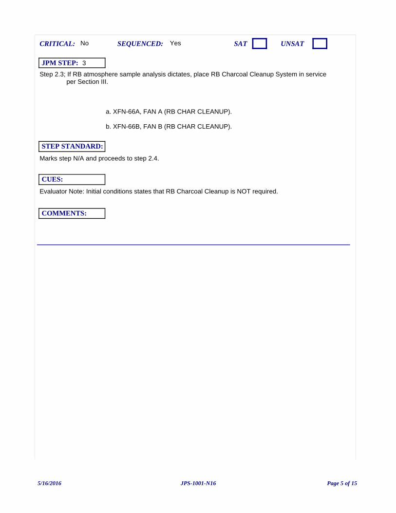
Step 2.3; If RB atmosphere sample analysis dictates, place RB Charcoal Cleanup System in service per Section III.
a. XFN-66A, FAN A (RB CHAR CLEANUP).
b. XFN-66B, FAN B (RB CHAR CLEANUP).
Evaluator Note: Initial conditions states that RB Charcoal Cleanup is NOT required.
Yes
Marks step N/A and proceeds to step 2.4.
CUES:
SEQUENCED:
STEP STANDARD:
COMMENTS:
SAT UNSATCRITICAL: No
JPM STEP: 3
5/16/2016 Page 5 of 15JPS-1001-N16
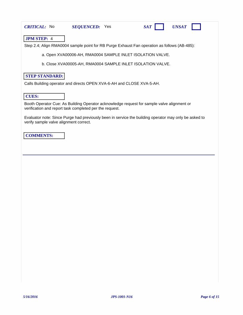
Step 2.4; Align RMA0004 sample point for RB Purge Exhaust Fan operation as follows (AB-485):
a. Open XVA00006-AH, RMA0004 SAMPLE INLET ISOLATION VALVE.
b. Close XVA00005-AH, RMA0004 SAMPLE INLET ISOLATION VALVE.
Booth Operator Cue: As Building Operator acknowledge request for sample valve alignment or verification and report task completed per the request.
Evaluator note: Since Purge had previously been in service the building operator may only be asked to verify sample valve alignment correct.
Yes
Calls Building operator and directs OPEN XVA-6-AH and CLOSE XVA-5-AH.
CUES:
SEQUENCED:
STEP STANDARD:
COMMENTS:
SAT UNSATCRITICAL: No
JPM STEP: 4
5/16/2016 Page 6 of 15JPS-1001-N16
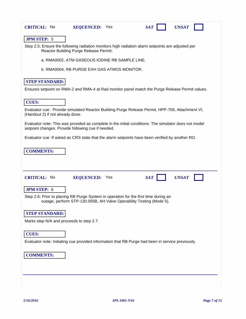
Step 2.5; Ensure the following radiation monitors high radiation alarm setpoints are adjusted per Reactor Building Purge Release Permit:
a. RMA0002, ATM GASEOUS IODINE RB SAMPLE LINE.
b. RMA0004, RB PURGE EXH GAS ATMOS MONITOR.
Evaluator cue: Provide simulated Reactor Building Purge Release Permit, HPP-709, Attachment VI, (Handout 2) if not already done.
Evaluator note: This was provided as complete in the initial conditions. The simulator does not model setpoint changes. Provide following cue if needed.
Evaluator cue: If asked as CRS state that the alarm setpoints have been verified by another RO.
Yes
Ensures setpoint on RMA-2 and RMA-4 at Rad monitor panel match the Purge Release Permit values.
CUES:
SEQUENCED:
STEP STANDARD:
COMMENTS:
SAT UNSATCRITICAL: No
JPM STEP: 5
Step 2.6; Prior to placing RB Purge System in operation for the first time during an outage, perform STP-130.005B, AH Valve Operability Testing (Mode 5).
Evaluator note: Initiating cue provided information that RB Purge had been in service previously.
Yes
Marks step N/A and proceeds to step 2.7.
CUES:
SEQUENCED:
STEP STANDARD:
COMMENTS:
SAT UNSATCRITICAL: No
JPM STEP: 6
5/16/2016 Page 7 of 15JPS-1001-N16
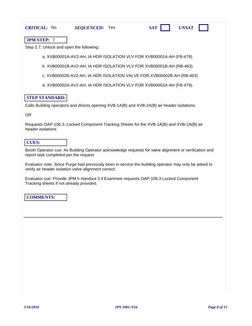
Step 2.7; Unlock and open the following:
a. XVB00001A-AV2-AH, IA HDR ISOLATION VLV FOR XVB00001A-AH (FB-479).
b. XVB00001B-AV2-AH, IA HDR ISOLATION VLV FOR XVB00001B-AH (RB-463).
c. XVB00002B-AV2-AH, IA HDR ISOLATION VALVE FOR XVB00002B-AH (RB-463).
d. XVB00002A-AV2-AH, IA HDR ISOLATION VLV FOR XVB00002A-AH (FB-479).
Booth Operator cue: As Building Operator acknowledge requests for valve alignment or verification and report task completed per the request.
Evaluator note: Since Purge had previously been in service the building operator may only be asked to verify air header isolation valve alignment correct.
Evaluator cue: Provide JPM h Handout 3 if Examinee requests OAP-106.3 Locked Component Tracking sheets if not already provided.
Yes
Calls Building operators and directs opening XVB-1A(B) and XVB-2A(B) air header isolations.
OR
Requests OAP-106.3, Locked Component Tracking Sheets for the XVB-1A(B) and XVB-2A(B) air header isolations
CUES:
SEQUENCED:
STEP STANDARD:
COMMENTS:
SAT UNSATCRITICAL: No
JPM STEP: 7
5/16/2016 Page 8 of 15JPS-1001-N16
Step 2.8; Ensure a Reactor Building Purge Release Permit has been issued per HPP-709.
Evaluator note: The NJPS-1001 Handout 2 (Release Permit) already indicates a SAT source check.
Evaluator note: Have a Copy of HPP-709 available for Examinee to refer to if they ask for it.
Yes
Ensures permit is current and less than 24 hours old.
CUES:
SEQUENCED:
STEP STANDARD:
COMMENTS:
SAT UNSATCRITICAL: No
JPM STEP: 8
Step 2.9; Start Reactor Building Purge as follows:
a. Open PVB-2A, CNTMT EXH ISOL
Evaluator note: This task is critical in order to ensure that the Reactor Building atmosphere is exchanged with fresh air.
Yes
Places control switch to OPEN and holds in OPEN until Red light ON and Green light OFF.
CUES:
SEQUENCED:
STEP STANDARD:
COMMENTS:
SAT UNSATCRITICAL: Yes
JPM STEP: 9
5/16/2016 Page 9 of 15JPS-1001-N16
Procedure NOTE 2.9.b; If both trains of RB Purge are to be run, both exhaust fans should be started simultaneously.
Step 2.9 b; Hold PVB-2B, CNTMT EXH ISOL, to OPEN while simultaneously holding one or both of the following fan control switches in the START position:
1) XFN-13A, EXH FAN A.
2) XFN-13B, EXH FAN B.
Evaluator note: Only Exh Fan A (XFN-13A) should be started. Examinee should ask for a peer check.Evaluator note: This task is critical in order to ensure that the Reactor Building atmosphere is exchanged with fresh air. Completion of the Purge Release Permit Data is NOT critical.
Yes
Places control switch for PVB-2B to OPEN and Holds in OPEN. Places control switches for XFN-13A in START and holds in START until Red light ON and Green light OFF for fans and PVB-2B.
Completes Section II, Actual Release Data on Purge Release Permit:
1. Release Start Date and Time (current date and time)2. Start Readings on RM-A2 and RM-A4 in cps.
CUES:
SEQUENCED:
STEP STANDARD:
COMMENTS:
SAT UNSATCRITICAL: Yes
JPM STEP: 10
5/16/2016 Page 10 of 15JPS-1001-N16
Step 2.9 c; Verify the following:
1) XFN-13A(B)-AH inlet damper opens.
2) XFN-13A(B)-AH outlet damper opens.
Evaluator note: Fan inlet and outlet damper indications are on the mimic board above the control switches.
Yes
Verifies White light ON for the INLET and OUTLET dampers for the Fan that was started (XFN-13A).
CUES:
SEQUENCED:
STEP STANDARD:
COMMENTS:
SAT UNSATCRITICAL: No
JPM STEP: 11
Step 2.9 d; Open XDP-28, INTAKE DMPR.
Yes
Places control Switch for XDP-28 to OPEN and verifies Red light ON and Green light OFF.
CUES:
SEQUENCED:
STEP STANDARD:
COMMENTS:
SAT UNSATCRITICAL: No
JPM STEP: 12
5/16/2016 Page 11 of 15JPS-1001-N16
Step 2.9 e; Open the following:
1) PVB-1A, CNTMT SPLY ISOL. 2) PVB-1B, CNTMT SPLY ISOL.
Yes
Places control Switch for PVB-1A to OPEN and holds until Red light ON and Green light OFF.
Places control Switch for PVB-1B to OPEN and holds until Red light ON and Green light OFF.
CUES:
SEQUENCED:
STEP STANDARD:
COMMENTS:
SAT UNSATCRITICAL: No
JPM STEP: 13
5/16/2016 Page 12 of 15JPS-1001-N16
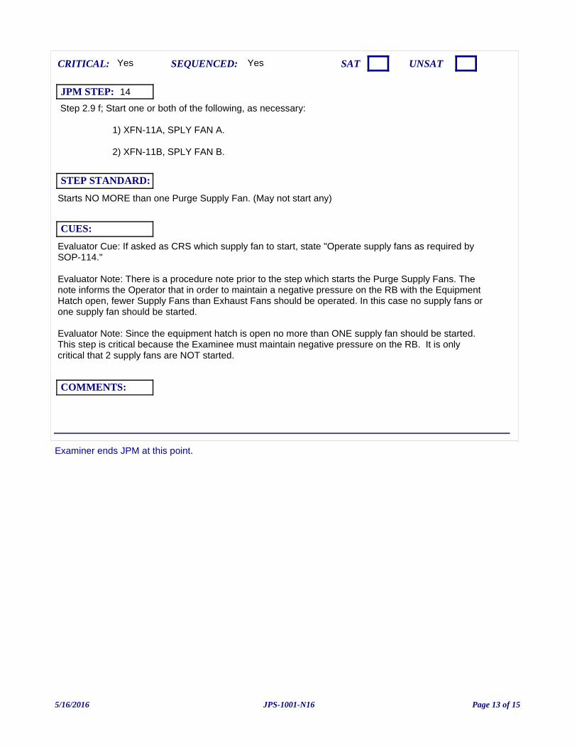
Examiner ends JPM at this point.
Step 2.9 f; Start one or both of the following, as necessary:
1) XFN-11A, SPLY FAN A.
2) XFN-11B, SPLY FAN B.
Evaluator Cue: If asked as CRS which supply fan to start, state "Operate supply fans as required by SOP-114."
Evaluator Note: There is a procedure note prior to the step which starts the Purge Supply Fans. The note informs the Operator that in order to maintain a negative pressure on the RB with the Equipment Hatch open, fewer Supply Fans than Exhaust Fans should be operated. In this case no supply fans or one supply fan should be started.
Evaluator Note: Since the equipment hatch is open no more than ONE supply fan should be started. This step is critical because the Examinee must maintain negative pressure on the RB. It is only critical that 2 supply fans are NOT started.
Yes
Starts NO MORE than one Purge Supply Fan. (May not start any)
CUES:
SEQUENCED:
STEP STANDARD:
COMMENTS:
SAT UNSATCRITICAL: Yes
JPM STEP: 14
5/16/2016 Page 13 of 15JPS-1001-N16
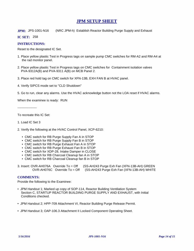
JPM: JPS-1001-N16 (NRC JPM-h) Establish Reactor Building Purge Supply and Exhaust
IC SET: 258
INSTRUCTIONS:
Reset to the designated IC Set.
1. Place yellow plastic Test in Progress tags on sample pump CMC switches for RM-A2 and RM-A4 at the rad monitor panel.
2. Place yellow plastic Test in Progress tags on CMC switches for Containment isolation valves PVA-9312A(B) and PVA-9311 A(B) on MCB Panel 2.
3. Place red hold tag on CMC switch for XFN-13B, EXH FAN B at HVAC panel.
4. Verify SIPCS mode set to "CLD Shutdown"
5. Go to run, clear any alarms. Use the HVAC acknowledge button not the LOA reset if HVAC alarms.
When the examinee is ready: RUN
------------------
To recreate this IC Set:
1. Load IC Set 3
2. Verify the following at the HVAC Control Panel, XCP-6210:
• CMC switch for RB Purge Supply Fan A in STOP • CMC switch for RB Purge Supply Fan B in STOP • CMC switch for RB Purge Exhaust Fan A in STOP • CMC switch for RB Purge Exhaust Fan B in STOP • CMC switch for XDP-28, Intake Damper in CLOSE • CMC switch for RB Charcoal Cleanup fan A in STOP • CMC switch for RB Charcoal Cleanup fan B in STOP
3. Insert: OVR-AH076A Override To = Off (SS-AH243 Purge Exh Fan (XFN-13B-AH) GREEN OVR-AH076C Override To = Off (SS-AH243 Purge Exh Fan (XFN-13B-AH) WHITE
COMMENTS:Provide the following to the Examinee:
• JPM Handout 1; Marked up copy of SOP-114, Reactor Building Ventilation System Section C, STARTUP REACTOR BUILDING PURGE SUPPLY AND EXHAUST, with Initial Conditions checked.
• JPM Handout 2; HPP-709 Attachment VI, Reactor Building Purge Release Permit.
• JPM Handout 3; OAP-106.3 Attachment II Locked Component Operating Sheet.
JPM SETUP SHEET
5/16/2016 Page 14 of 15JPS-1001-N16
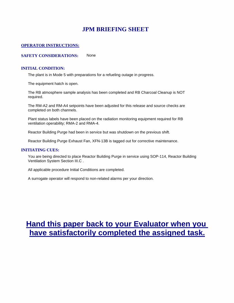
INITIATING CUES:
You are being directed to place Reactor Building Purge in service using SOP-114, Reactor Building Ventilation System Section III.C .
All applicable procedure Initial Conditions are completed.
A surrogate operator will respond to non-related alarms per your direction.
INITIAL CONDITION:
The plant is in Mode 5 with preparations for a refueling outage in progress.
The equipment hatch is open.
The RB atmosphere sample analysis has been completed and RB Charcoal Cleanup is NOT required.
The RM-A2 and RM-A4 setpoints have been adjusted for this release and source checks are completed on both channels.
Plant status labels have been placed on the radiation monitoring equipment required for RB ventilation operability; RMA-2 and RMA-4.
Reactor Building Purge had been in service but was shutdown on the previous shift.
Reactor Building Purge Exhaust Fan, XFN-13B is tagged out for corrective maintenance.
SAFETY CONSIDERATIONS: None
OPERATOR INSTRUCTIONS:
Hand this paper back to your Evaluator when you have satisfactorily completed the assigned task.
JPM BRIEFING SHEET
5/16/2016 Page 15 of 15JPS-1001-N16
(NRC JPM-i) Locally Reset Safety Injection IAW SOP-112 (B Train Only)
V.C. SUMMER NUCLEAR STATIONJOB PERFORMANCE MEASURE
CANDIDATE:
EXAMINER:
JPM NO: JPP-006B-N16
5/18/2016 Page 1 of 9JPP-006B-N16
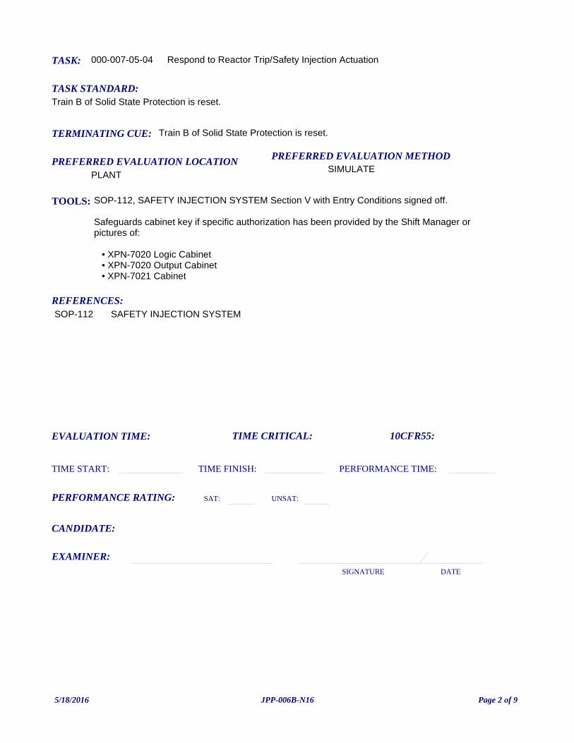
TASK: 000-007-05-04
PREFERRED EVALUATION METHODSIMULATE
EVALUATION TIME: TIME CRITICAL:
TASK STANDARD:Train B of Solid State Protection is reset.
PREFERRED EVALUATION LOCATIONPLANT
TIME START: TIME FINISH:
PERFORMANCE RATING: SAT: UNSAT:
PERFORMANCE TIME:
EXAMINER:SIGNATURE DATE
10CFR55:
Respond to Reactor Trip/Safety Injection Actuation
TOOLS: SOP-112, SAFETY INJECTION SYSTEM Section V with Entry Conditions signed off.
Safeguards cabinet key if specific authorization has been provided by the Shift Manager or pictures of:
• XPN-7020 Logic Cabinet • XPN-7020 Output Cabinet • XPN-7021 Cabinet
REFERENCES:
TERMINATING CUE: Train B of Solid State Protection is reset.
CANDIDATE:
SOP-112 SAFETY INJECTION SYSTEM
5/18/2016 Page 2 of 9JPP-006B-N16
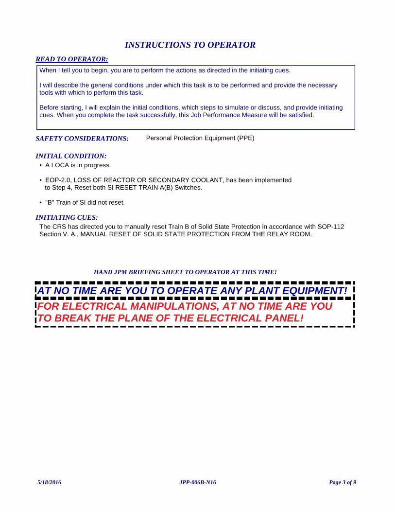
INITIATING CUES:The CRS has directed you to manually reset Train B of Solid State Protection in accordance with SOP-112 Section V. A., MANUAL RESET OF SOLID STATE PROTECTION FROM THE RELAY ROOM.
INITIAL CONDITION:• A LOCA is in progress.
• EOP-2.0, LOSS OF REACTOR OR SECONDARY COOLANT, has been implemented to Step 4, Reset both SI RESET TRAIN A(B) Switches.
• "B" Train of SI did not reset.
READ TO OPERATOR:
SAFETY CONSIDERATIONS: Personal Protection Equipment (PPE)
When I tell you to begin, you are to perform the actions as directed in the initiating cues.
I will describe the general conditions under which this task is to be performed and provide the necessary tools with which to perform this task.
Before starting, I will explain the initial conditions, which steps to simulate or discuss, and provide initiating cues. When you complete the task successfully, this Job Performance Measure will be satisfied.
INSTRUCTIONS TO OPERATOR
HAND JPM BRIEFING SHEET TO OPERATOR AT THIS TIME!
FOR ELECTRICAL MANIPULATIONS, AT NO TIME ARE YOU TO BREAK THE PLANE OF THE ELECTRICAL PANEL!
AT NO TIME ARE YOU TO OPERATE ANY PLANT EQUIPMENT!
5/18/2016 Page 3 of 9JPP-006B-N16
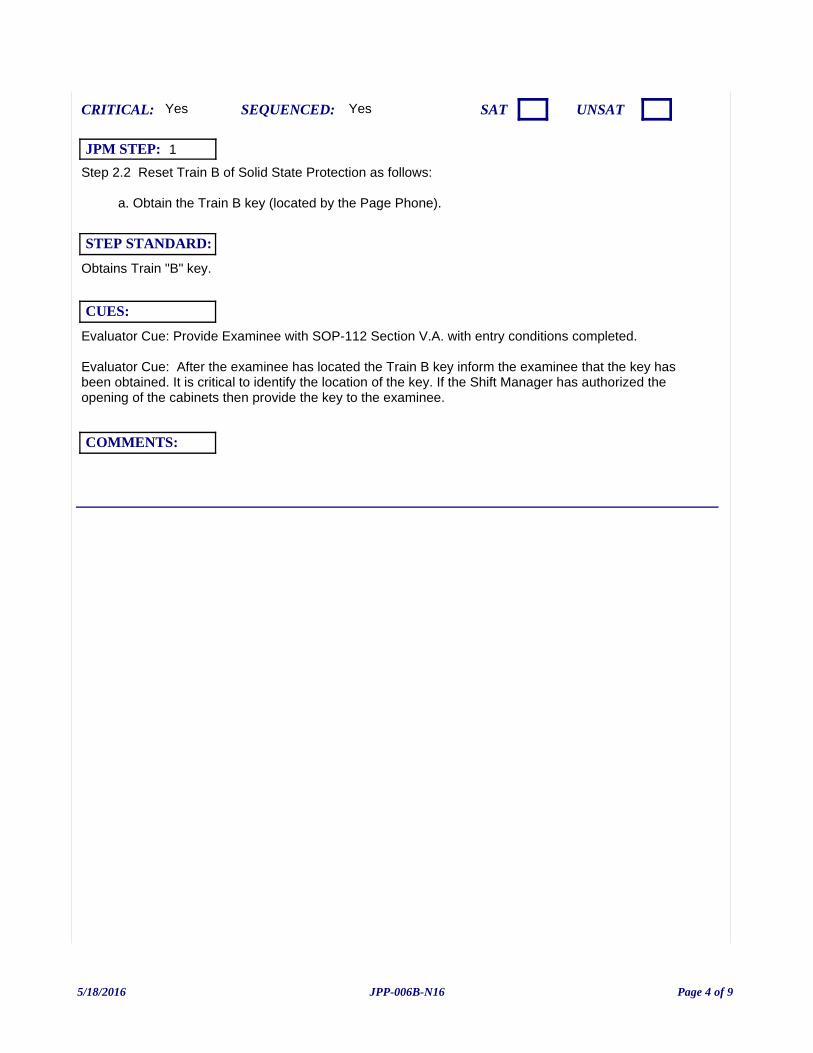
Step 2.2 Reset Train B of Solid State Protection as follows:
a. Obtain the Train B key (located by the Page Phone).
Evaluator Cue: Provide Examinee with SOP-112 Section V.A. with entry conditions completed.
Evaluator Cue: After the examinee has located the Train B key inform the examinee that the key has been obtained. It is critical to identify the location of the key. If the Shift Manager has authorized the opening of the cabinets then provide the key to the examinee.
Yes
Obtains Train "B" key.
CUES:
SEQUENCED:
STEP STANDARD:
COMMENTS:
SAT UNSATCRITICAL: Yes
JPM STEP: 1
5/18/2016 Page 4 of 9JPP-006B-N16
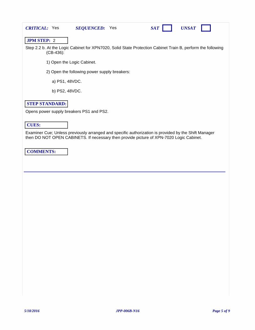
Step 2.2 b. At the Logic Cabinet for XPN7020, Solid State Protection Cabinet Train B, perform the following (CB-436):
1) Open the Logic Cabinet.
2) Open the following power supply breakers:
a) PS1, 48VDC.
b) PS2, 48VDC.
Examiner Cue; Unless previously arranged and specific authorization is provided by the Shift Manager then DO NOT OPEN CABINETS. If necessary then provide picture of XPN-7020 Logic Cabinet.
Yes
Opens power supply breakers PS1 and PS2.
CUES:
SEQUENCED:
STEP STANDARD:
COMMENTS:
SAT UNSATCRITICAL: Yes
JPM STEP: 2
5/18/2016 Page 5 of 9JPP-006B-N16
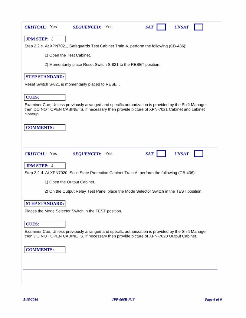
Step 2.2 c. At XPN7021, Safeguards Test Cabinet Train A, perform the following (CB-436):
1) Open the Test Cabinet.
2) Momentarily place Reset Switch S-821 to the RESET position.
Examiner Cue; Unless previously arranged and specific authorization is provided by the Shift Manager then DO NOT OPEN CABINETS. If necessary then provide picture of XPN-7021 Cabinet and cabinet closeup.
Yes
Reset Switch S-821 is momentarily placed to RESET.
CUES:
SEQUENCED:
STEP STANDARD:
COMMENTS:
SAT UNSATCRITICAL: Yes
JPM STEP: 3
Step 2.2 d. At XPN7020, Solid State Protection Cabinet Train A, perform the following (CB-436):
1) Open the Output Cabinet.
2) On the Output Relay Test Panel place the Mode Selector Switch in the TEST position.
Examiner Cue; Unless previously arranged and specific authorization is provided by the Shift Manager then DO NOT OPEN CABINETS. If necessary then provide picture of XPN-7020 Output Cabinet.
Yes
Places the Mode Selector Switch in the TEST position.
CUES:
SEQUENCED:
STEP STANDARD:
COMMENTS:
SAT UNSATCRITICAL: Yes
JPM STEP: 4
5/18/2016 Page 6 of 9JPP-006B-N16
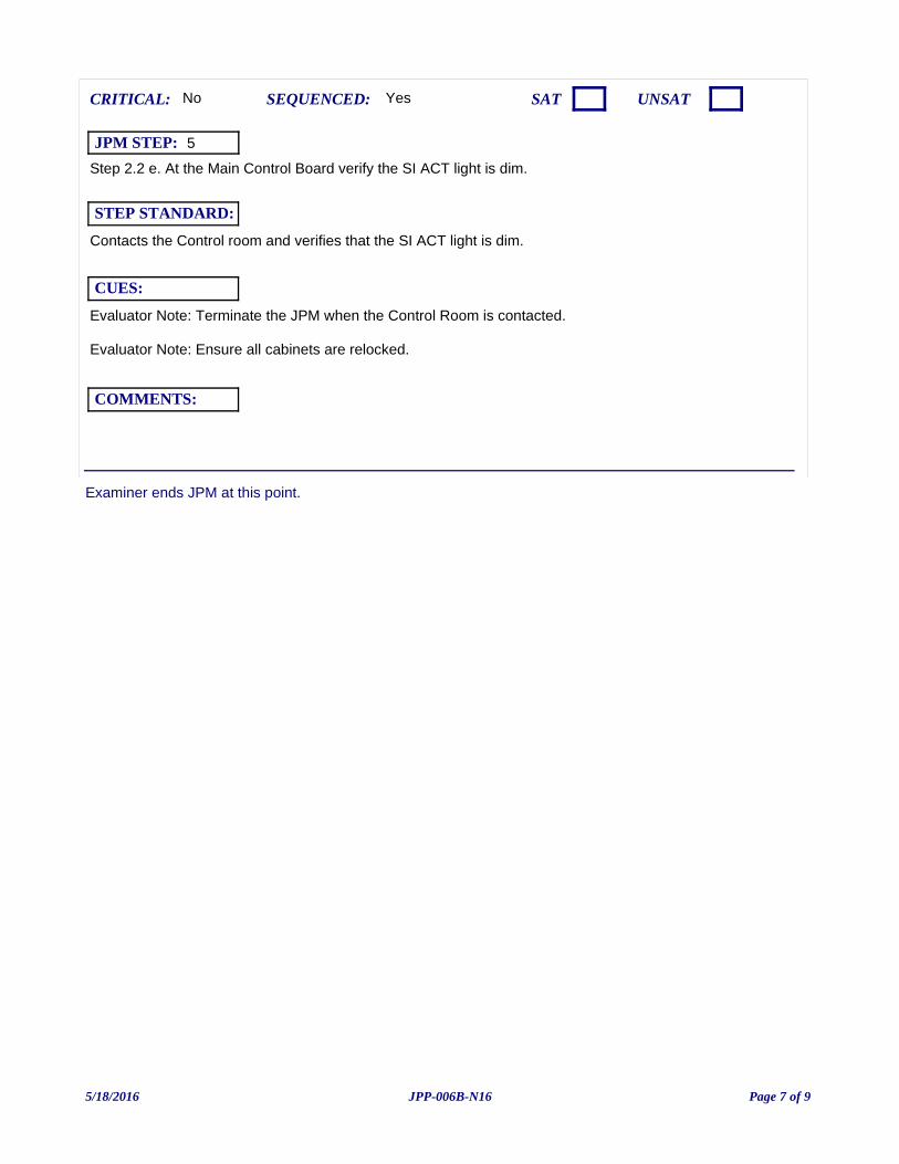
Examiner ends JPM at this point.
Step 2.2 e. At the Main Control Board verify the SI ACT light is dim.
Evaluator Note: Terminate the JPM when the Control Room is contacted.
Evaluator Note: Ensure all cabinets are relocked.
Yes
Contacts the Control room and verifies that the SI ACT light is dim.
CUES:
SEQUENCED:
STEP STANDARD:
COMMENTS:
SAT UNSATCRITICAL: No
JPM STEP: 5
5/18/2016 Page 7 of 9JPP-006B-N16
JPM: JPP-006B-N16 (NRC JPM-i) Locally Reset Safety Injection IAW SOP-112 (B Train Only)
IC SET:
INSTRUCTIONS:
COMMENTS:
JPM SETUP SHEET
5/18/2016 Page 8 of 9JPP-006B-N16
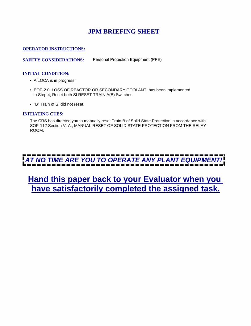
INITIATING CUES:
The CRS has directed you to manually reset Train B of Solid State Protection in accordance with SOP-112 Section V. A., MANUAL RESET OF SOLID STATE PROTECTION FROM THE RELAY ROOM.
INITIAL CONDITION:
• A LOCA is in progress.
• EOP-2.0, LOSS OF REACTOR OR SECONDARY COOLANT, has been implemented to Step 4, Reset both SI RESET TRAIN A(B) Switches.
• "B" Train of SI did not reset.
SAFETY CONSIDERATIONS: Personal Protection Equipment (PPE)
OPERATOR INSTRUCTIONS:
Hand this paper back to your Evaluator when you have satisfactorily completed the assigned task.
JPM BRIEFING SHEET
AT NO TIME ARE YOU TO OPERATE ANY PLANT EQUIPMENT!
5/18/2016 Page 9 of 9JPP-006B-N16
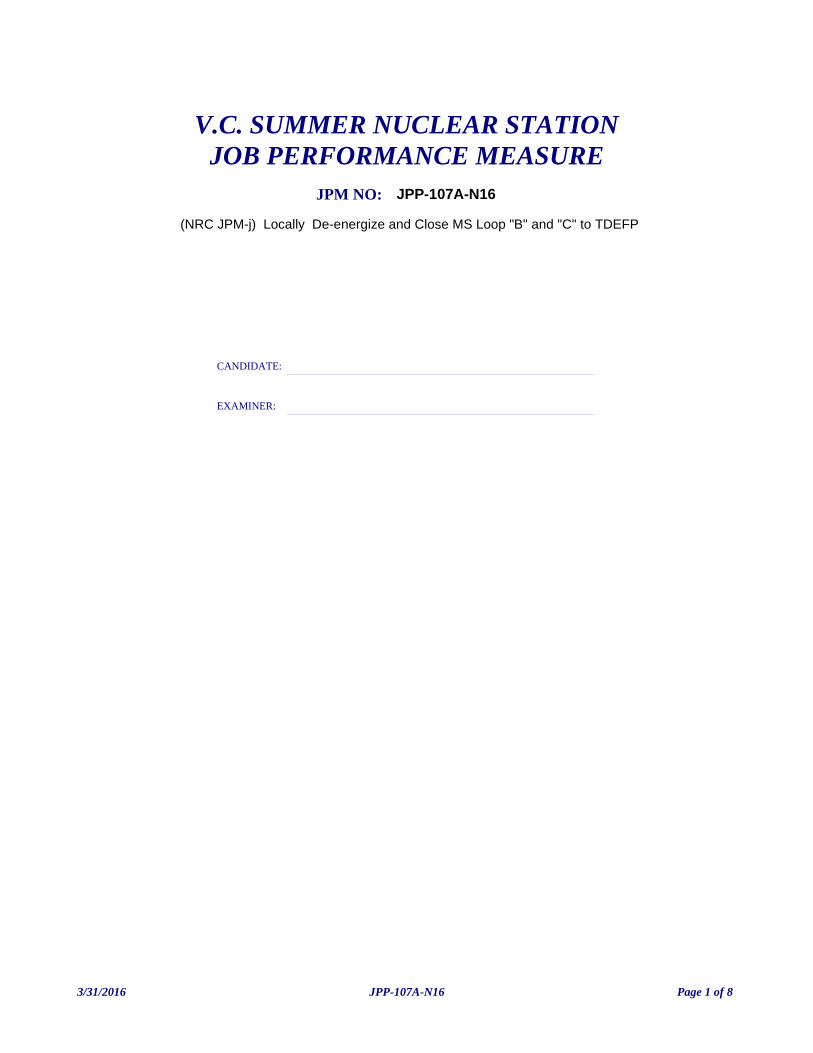
(NRC JPM-j) Locally De-energize and Close MS Loop "B" and "C" to TDEFP
V.C. SUMMER NUCLEAR STATIONJOB PERFORMANCE MEASURE
CANDIDATE:
EXAMINER:
JPM NO: JPP-107A-N16
3/31/2016 Page 1 of 8JPP-107A-N16
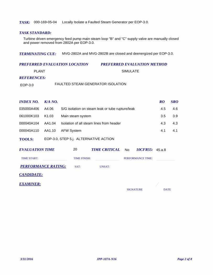
TASK: 000-169-05-04
PREFERRED EVALUATION METHOD
SIMULATE
EVALUATION TIME 20 TIME CRITICAL No
TASK STANDARD:
Turbine driven emergency feed pump main steam loop "B" and "C" supply valve are manually closed and power removed from 2802A per EOP-3.0.
PREFERRED EVALUATION LOCATION
PLANT
TIME START: TIME FINISH:
PERFORMANCE RATING: SAT: UNSAT:
PERFORMANCE TIME:
EXAMINER:SIGNATURE DATE
10CFR55: 45.a.8
Locally Isolate a Faulted Steam Generator per EOP-3.0.
TOOLS: EOP-3.0, STEP 5.j. ALTERNATIVE ACTION
REFERENCES:
TERMINATING CUE: MVG-2802A and MVG-2802B are closed and deenergized per EOP-3.0.
CANDIDATE:
EOP-3.0 FAULTED STEAM GENERATOR ISOLATION
INDEX NO. RO SROK/A NO.
035000A406 S/G isolation on steam leak or tube rupture/leak 4.5 4.6A4.06
061000K103 Main steam system 3.5 3.9K1.03
000040A104 Isolation of all steam lines from header 4.3 4.3AA1.04
000040A110 AFW System 4.1 4.1AA1.10
3/31/2016 Page 2 of 8JPP-107A-N16
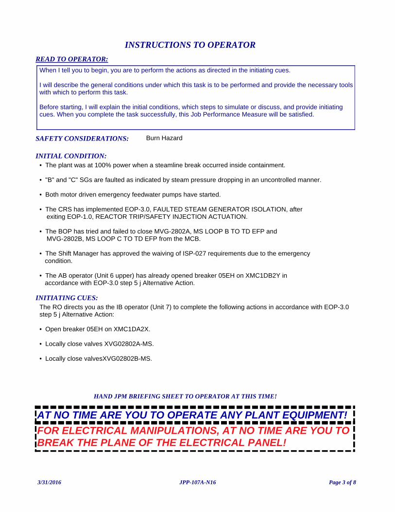
INITIATING CUES:The RO directs you as the IB operator (Unit 7) to complete the following actions in accordance with EOP-3.0 step 5 j Alternative Action:
• Open breaker 05EH on XMC1DA2X.
• Locally close valves XVG02802A-MS.
• Locally close valvesXVG02802B-MS.
INITIAL CONDITION:• The plant was at 100% power when a steamline break occurred inside containment.
• "B" and "C" SGs are faulted as indicated by steam pressure dropping in an uncontrolled manner.
• Both motor driven emergency feedwater pumps have started.
• The CRS has implemented EOP-3.0, FAULTED STEAM GENERATOR ISOLATION, after exiting EOP-1.0, REACTOR TRIP/SAFETY INJECTION ACTUATION.
• The BOP has tried and failed to close MVG-2802A, MS LOOP B TO TD EFP and MVG-2802B, MS LOOP C TO TD EFP from the MCB.
• The Shift Manager has approved the waiving of ISP-027 requirements due to the emergency condition.
• The AB operator (Unit 6 upper) has already opened breaker 05EH on XMC1DB2Y in accordance with EOP-3.0 step 5 j Alternative Action.
READ TO OPERATOR:
SAFETY CONSIDERATIONS: Burn Hazard
When I tell you to begin, you are to perform the actions as directed in the initiating cues.
I will describe the general conditions under which this task is to be performed and provide the necessary toolswith which to perform this task.
Before starting, I will explain the initial conditions, which steps to simulate or discuss, and provide initiating cues. When you complete the task successfully, this Job Performance Measure will be satisfied.
INSTRUCTIONS TO OPERATOR
HAND JPM BRIEFING SHEET TO OPERATOR AT THIS TIME!
FOR ELECTRICAL MANIPULATIONS, AT NO TIME ARE YOU TO BREAK THE PLANE OF THE ELECTRICAL PANEL!
AT NO TIME ARE YOU TO OPERATE ANY PLANT EQUIPMENT!
3/31/2016 Page 3 of 8JPP-107A-N16
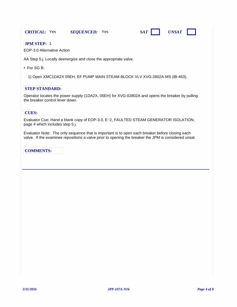
EOP-3.0 Alternative Action
AA Step 5.j. Locally deenergize and close the appropriate valve.
• For SG B:
1) Open XMC1DA2X 05EH, EF PUMP MAIN STEAM BLOCK VLV XVG-2802A-MS (IB-463).
Evaluator Cue: Hand a blank copy of EOP-3.0, E‑2, FAULTED STEAM GENERATOR ISOLATION, page 4 which includes step 5 j.
Evaluator Note: The only sequence that is important is to open each breaker before closing each valve. If the examinee repositions a valve prior to opening the breaker the JPM is considered unsat.
Yes
Operator locates the power supply (1DA2X, 05EH) for XVG-02802A and opens the breaker by pulling the breaker control lever down.
CUES:
SEQUENCED:
STEP STANDARD:
COMMENTS:
SAT UNSATCRITICAL: Yes
JPM STEP: 1
3/31/2016 Page 4 of 8JPP-107A-N16
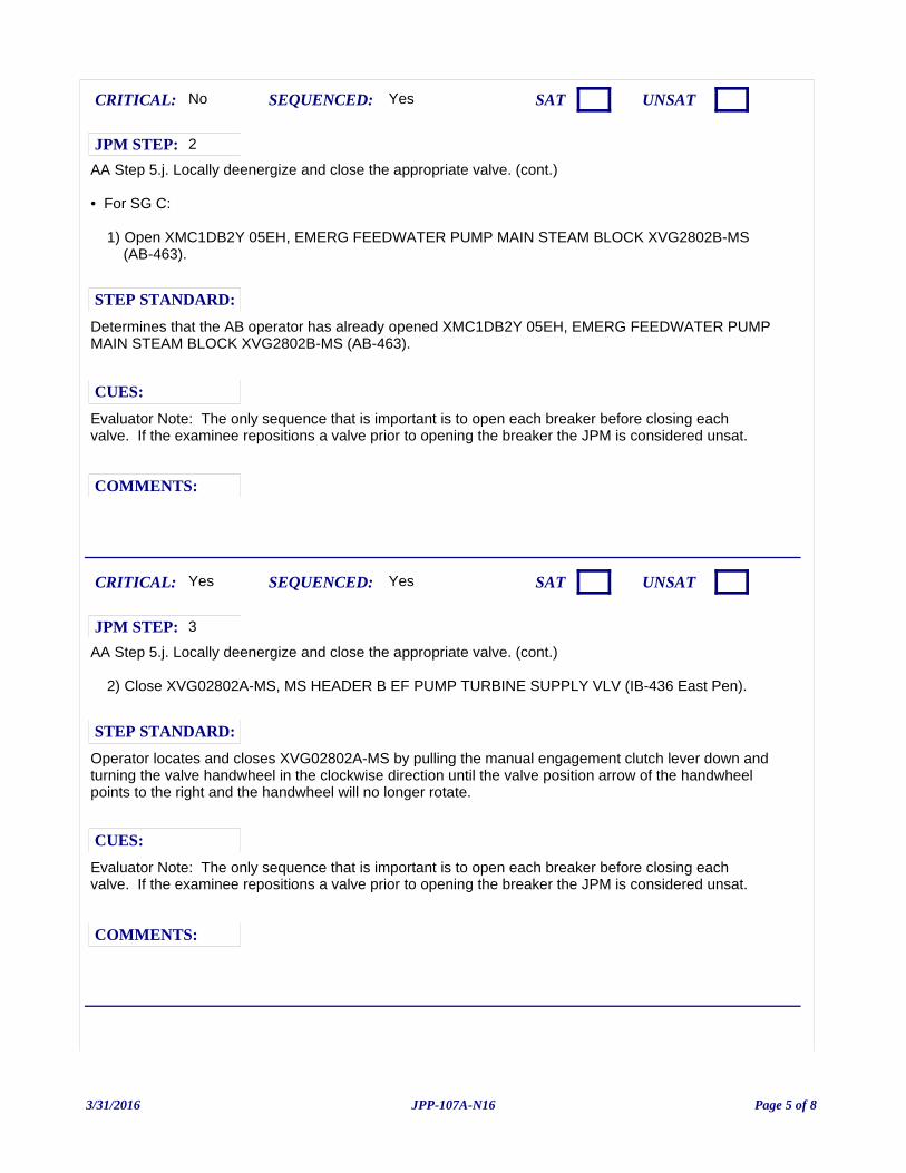
AA Step 5.j. Locally deenergize and close the appropriate valve. (cont.)
• For SG C:
1) Open XMC1DB2Y 05EH, EMERG FEEDWATER PUMP MAIN STEAM BLOCK XVG2802B-MS (AB-463).
Evaluator Note: The only sequence that is important is to open each breaker before closing each valve. If the examinee repositions a valve prior to opening the breaker the JPM is considered unsat.
Yes
Determines that the AB operator has already opened XMC1DB2Y 05EH, EMERG FEEDWATER PUMP MAIN STEAM BLOCK XVG2802B-MS (AB-463).
CUES:
SEQUENCED:
STEP STANDARD:
COMMENTS:
SAT UNSATCRITICAL: No
JPM STEP: 2
AA Step 5.j. Locally deenergize and close the appropriate valve. (cont.)
2) Close XVG02802A-MS, MS HEADER B EF PUMP TURBINE SUPPLY VLV (IB-436 East Pen).
Evaluator Note: The only sequence that is important is to open each breaker before closing each valve. If the examinee repositions a valve prior to opening the breaker the JPM is considered unsat.
Yes
Operator locates and closes XVG02802A-MS by pulling the manual engagement clutch lever down and turning the valve handwheel in the clockwise direction until the valve position arrow of the handwheel points to the right and the handwheel will no longer rotate.
CUES:
SEQUENCED:
STEP STANDARD:
COMMENTS:
SAT UNSATCRITICAL: Yes
JPM STEP: 3
3/31/2016 Page 5 of 8JPP-107A-N16
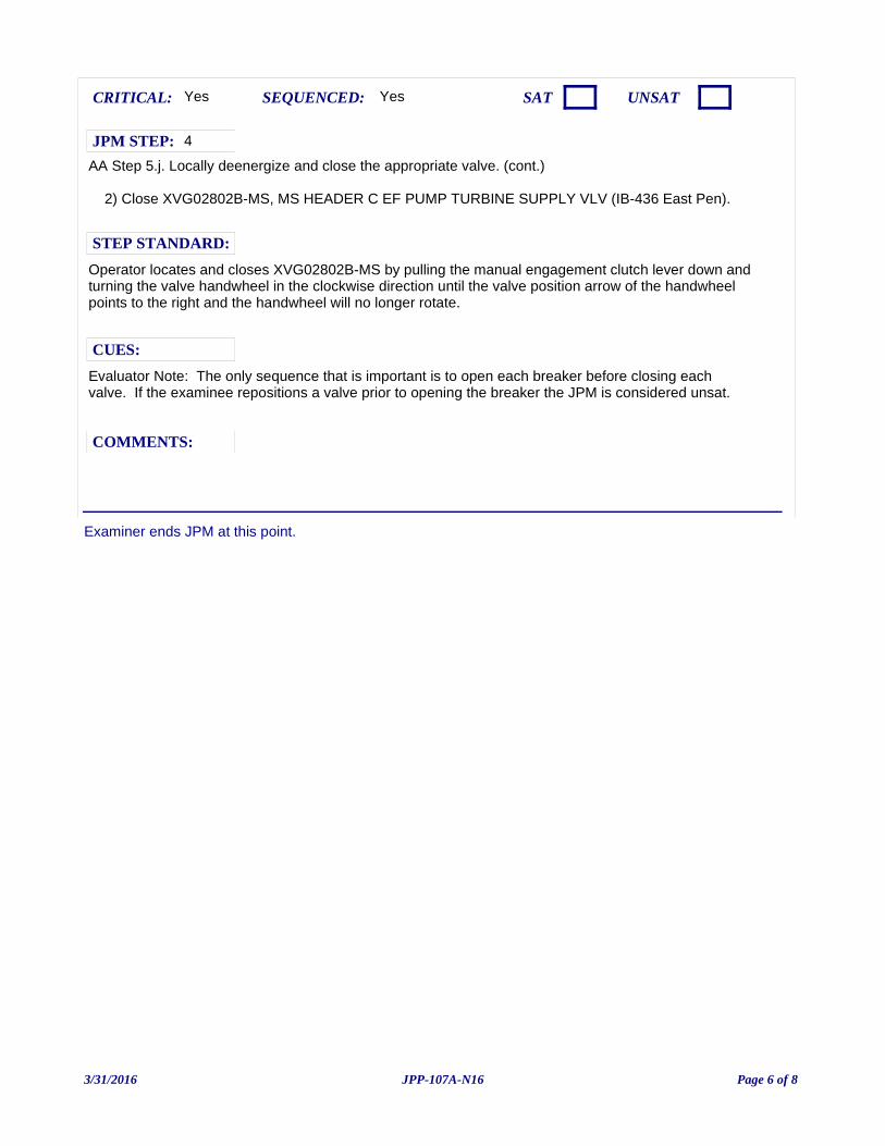
Examiner ends JPM at this point.
AA Step 5.j. Locally deenergize and close the appropriate valve. (cont.)
2) Close XVG02802B-MS, MS HEADER C EF PUMP TURBINE SUPPLY VLV (IB-436 East Pen).
Evaluator Note: The only sequence that is important is to open each breaker before closing each valve. If the examinee repositions a valve prior to opening the breaker the JPM is considered unsat.
Yes
Operator locates and closes XVG02802B-MS by pulling the manual engagement clutch lever down and turning the valve handwheel in the clockwise direction until the valve position arrow of the handwheel points to the right and the handwheel will no longer rotate.
CUES:
SEQUENCED:
STEP STANDARD:
COMMENTS:
SAT UNSATCRITICAL: Yes
JPM STEP: 4
3/31/2016 Page 6 of 8JPP-107A-N16

JPM: JPP-107A-N16 (NRC JPM-j) Locally De-energize and Close MS Loop "B" and "C" to TDEFP
IC SET:
INSTRUCTIONS:
COMMENTS:
JPM SETUP SHEET
3/31/2016 Page 7 of 8JPP-107A-N16
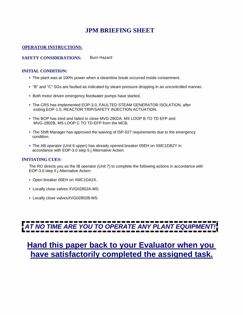
INITIATING CUES:
The RO directs you as the IB operator (Unit 7) to complete the following actions in accordance with EOP-3.0 step 5 j Alternative Action:
• Open breaker 05EH on XMC1DA2X.
• Locally close valves XVG02802A-MS.
• Locally close valvesXVG02802B-MS.
INITIAL CONDITION:
• The plant was at 100% power when a steamline break occurred inside containment.
• "B" and "C" SGs are faulted as indicated by steam pressure dropping in an uncontrolled manner.
• Both motor driven emergency feedwater pumps have started.
• The CRS has implemented EOP-3.0, FAULTED STEAM GENERATOR ISOLATION, after exiting EOP-1.0, REACTOR TRIP/SAFETY INJECTION ACTUATION.
• The BOP has tried and failed to close MVG-2802A, MS LOOP B TO TD EFP and MVG-2802B, MS LOOP C TO TD EFP from the MCB.
• The Shift Manager has approved the waiving of ISP-027 requirements due to the emergency condition.
• The AB operator (Unit 6 upper) has already opened breaker 05EH on XMC1DB2Y in accordance with EOP-3.0 step 5 j Alternative Action.
SAFETY CONSIDERATIONS: Burn Hazard
OPERATOR INSTRUCTIONS:
Hand this paper back to your Evaluator when you have satisfactorily completed the assigned task.
JPM BRIEFING SHEET
AT NO TIME ARE YOU TO OPERATE ANY PLANT EQUIPMENT!
3/31/2016 Page 8 of 8JPP-107A-N16

(NRC JPM-k) Startup the "Swing Battery Charger" and Place on DPN 1HA.
V.C. SUMMER NUCLEAR STATIONJOB PERFORMANCE MEASURE
CANDIDATE:
EXAMINER:
JPM NO: JPP-052A-N16
5/12/2016 Page 1 of 15JPP-052A-N16
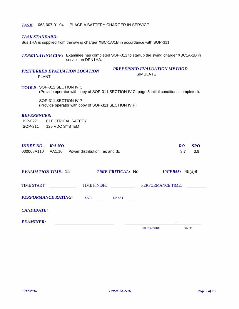
TASK: 063-007-01-04
PREFERRED EVALUATION METHODSIMULATE
EVALUATION TIME: 15 TIME CRITICAL: No
TASK STANDARD:Bus 1HA is supplied from the swing charger XBC-1A/1B in accordance with SOP-311.
PREFERRED EVALUATION LOCATIONPLANT
TIME START: TIME FINISH:
PERFORMANCE RATING: SAT: UNSAT:
PERFORMANCE TIME:
EXAMINER:SIGNATURE DATE
10CFR55: 45(a)8
PLACE A BATTERY CHARGER IN SERVICE
TOOLS: SOP-311 SECTION IV.C (Provide operator with copy of SOP-311 SECTION IV.C, page 5 initial conditions completed).
SOP-311 SECTION IV.P (Provide operator with copy of SOP-311 SECTION IV.P)
REFERENCES:
TERMINATING CUE: Examinee has completed SOP-311 to startup the swing charger XBC1A-1B in service on DPN1HA.
CANDIDATE:
ISP-027 ELECTRICAL SAFETYSOP-311 125 VDC SYSTEM
INDEX NO. RO SROK/A NO.000068A110 Power distribution: ac and dc 3.7 3.9AA1.10
5/12/2016 Page 2 of 15JPP-052A-N16
INITIATING CUES:Control Room directs startup of the swing charger XBC1A-1B in service on DPN1HA in accordance with SOP-311 Section IV.C and IV.P.
INITIAL CONDITION:• DPN-1HA is being powered from Battery Charger 1A.
• Battery Charger XBC1A is to be removed from service for scheduled maintenance.
• DPN-1HA must be transferred to the swing battery charger XBC-1A-1B.
• XMC1DA2Y 08KM, BATTERY CHARGER 1A-1B XBC1A-1B-ED, is closed.
• The initial conditions for removing Battery Charger XBC1A from service, SOP-311 Section IV.C, are met:
- Battery Charger XBC1A FLOAT/EQUALIZE Switch is selected to FLOAT. - The battery charger timer for XBC1A is set at zero hours and zero minutes.
• A manual STTS for the electricians to adjust Battery Charger voltage has been generated.
READ TO OPERATOR:
SAFETY CONSIDERATIONS: Energizing electrical equipment
When I tell you to begin, you are to perform the actions as directed in the initiating cues.
I will describe the general conditions under which this task is to be performed and provide the necessary tools with which to perform this task.
Before starting, I will explain the initial conditions, which steps to simulate or discuss, and provide initiating cues. When you complete the task successfully, this Job Performance Measure will be satisfied.
INSTRUCTIONS TO OPERATOR
HAND JPM BRIEFING SHEET TO OPERATOR AT THIS TIME!
FOR ELECTRICAL MANIPULATIONS, AT NO TIME ARE YOU TO BREAK THE PLANE OF THE ELECTRICAL PANEL!
AT NO TIME ARE YOU TO OPERATE ANY PLANT EQUIPMENT!
5/12/2016 Page 3 of 15JPP-052A-N16
Section IV.C. REMOVING BATTERY CHARGER XBC1A FROM SERVICE
INITIAL CONDITIONS
Step 1.1 The FLOAT/EQUALIZER Switch is selected to FLOAT.
Step 1.2 The battery charger timer for XBC1A is set at zero hours and zero minutes.
Evaluator Note: Initial conditions are completed on the copy provided to the operator and the conditions are stated in the JPM Initial Conditions.
Evaluator Cue: If requested, inform examinee of the following initial conditions:
The FLOAT/EQUALIZER switch is in the FLOAT position. The Battery Charger timer for XBC-1B is set at 0 hours and 0 minutes.
Yes
Verifies the FLOAT/EQUALIZER Switch is selected to FLOAT and the battery charger timer for XBC1A is set at zero hours and zero minutes.
CUES:
SEQUENCED:
STEP STANDARD:
COMMENTS:
SAT UNSATCRITICAL: No
JPM STEP: 1
Step 2.1 Place XBC1A-1B, DC DISTRI BUS 1A-1B BACKUP BATTERY CHRG, in service per Section IV.
Yes
Examinee transitions to Section IV. P. PLACING BATTERY CHARGER XBC1A-1B IN SERVICE ON DPN1HA.
CUES:
SEQUENCED:
STEP STANDARD:
COMMENTS:
SAT UNSATCRITICAL: No
JPM STEP: 2
5/12/2016 Page 4 of 15JPP-052A-N16
Section P. PLACING BATTERY CHARGER XBC1A-1B IN SERVICE ON DPN1HA
Step 2.1 Generate a manual STTS for the electricians to adjust Battery Charger voltage per STP-501.001A, Battery XBA1A Weekly Test, at the conclusion of this procedure.
Examiner Note: The Initial Conditions states that an STTS has been generated.
Examiner Note: If the examinee starts at Section C, Step 2.1 directs the operator to place XBC1A-1B in service.
Yes
Indicates that this step has been completed.
CUES:
SEQUENCED:
STEP STANDARD:
COMMENTS:
SAT UNSATCRITICAL: No
JPM STEP: 4
Step 2.2 Ensure the following breakers are open on the Swing Battery Charger, XBC1A-1B:
a. CB2, DC OUTPUT.
b. CB1, AC INPUT.
Examiner Cue: XBC1A-1B CB2 and CB1 are open.
Yes
Verifies that XBC1A-1B CB2 and CB1 are open.
CUES:
SEQUENCED:
STEP STANDARD:
COMMENTS:
SAT UNSATCRITICAL: No
JPM STEP: 5
5/12/2016 Page 5 of 15JPP-052A-N16
Step 2.3 Ensure XMC1DA2Y 08KM, BATTERY CHARGER 1A-1B XBC1A-1B-ED, is closed (AB-412).
Examiner Cue: XMC1DA2Y 08KM is closed.
Yes
Verifies that XMC1DA2Y 08KM is closed.
CUES:
SEQUENCED:
STEP STANDARD:
COMMENTS:
SAT UNSATCRITICAL: No
JPM STEP: 6
Step 2.4 Ensure the following breakers on XET-4003-ED are open:
a. TRAIN A-AC.
b. TRAIN A-DC.
c. TRAIN B-AC.
d. TRAIN B-DC.
Examiner Cue: Breakers TRAIN A-AC, TRAIN A-DC, TRAIN B-AC, and TRAIN B-DC are open.
Yes
Verifies that breakers; TRAIN A-AC, TRAIN A-DC, TRAIN B-AC, and TRAIN B-DC are open.
CUES:
SEQUENCED:
STEP STANDARD:
COMMENTS:
SAT UNSATCRITICAL: No
JPM STEP: 7
5/12/2016 Page 6 of 15JPP-052A-N16
NOTE 2.5; The keys for the mechanical breaker interlocks fit in the breakers diagonally opposed to each other. The key that fits the upper left hand breaker also fits the lower right hand breaker and the key that fits the upper right hand breaker also fits the lower left hand breaker
Yes
No further actions for this step.
CUES:
SEQUENCED:
STEP STANDARD:
COMMENTS:
SAT UNSATCRITICAL: No
JPM STEP: 8
Step 2.5 Align XET-4003-ED Transfer Switch to supply DPN1HA as follows:
a. Close TRAIN A-AC Breaker to Battery Charger XBC1A-1B.
b. Close TRAIN A-DC Breaker from Battery Charger XBC1A-1B.
Evaluator Note: The keys for the mechanical breaker interlocks fit in the breakers diagonally opposed to each other. The key that fits the upper left hand breaker also fits the lower righthand breaker and the key that fits the upper right hand breaker also fits the lower lefthand breaker. (Train "A" AC to Train "B" DC and Train "A" DC goes to Train "B" AC).
Evaluator Note: If the operator tries to swap AC to AC or DC to DC inform him that the key will not turn.
Yes
Closes TRAIN A-AC breaker and Train B-DC breaker for battery charger 1A-1B on XET-4003-ED using key interlocks.
CUES:
SEQUENCED:
STEP STANDARD:
COMMENTS:
SAT UNSATCRITICAL: Yes
JPM STEP: 9
5/12/2016 Page 7 of 15JPP-052A-N16
Step 2.6 Verify the FLOAT/EQUALIZER is selected to FLOAT.
Evaluator Cue: If asked cue examinee that the switch is in the 'Float' position or 'As Seen'.
Yes
FLOAT/EQUALIZER Switch verified in the FLOAT position ON XBC1A-1B.
CUES:
SEQUENCED:
STEP STANDARD:
COMMENTS:
SAT UNSATCRITICAL: No
JPM STEP: 10
Note: 2.7; Breaker #13 controls the incoming line from XET-4003-ED.
Step 2.7 Ensure DPN1HA 13, BATTERY CHARGER 1A-1B FEED TO DPN1HA, is open.
Evaluator Note: Breaker 13 aligns the incoming line from XET-4003-ED
Yes
Checks DPN-1HA-ED BKR 13, BATTERY CHARGER 1A-1B FEED TO DPN 1HA is in the OPEN position.
CUES:
SEQUENCED:
STEP STANDARD:
COMMENTS:
SAT UNSATCRITICAL: No
JPM STEP: 11
5/12/2016 Page 8 of 15JPP-052A-N16
Step 2.8 Close the following on the front of the Swing Battery Charger, XBC1A-1B:
a. CB2, DC OUTPUT
b. CB1, AC INPUT
Yes
Closes the DC OUTPUT (CB2) and AC INPUT (CB1) breakers on battery charger XBC1A-1B in the ON position.
CUES:
SEQUENCED:
STEP STANDARD:
COMMENTS:
SAT UNSATCRITICAL: Yes
JPM STEP: 12
Note 2.9 through 2.14; Electrical Maintenance should be notified of abnormal output voltage fluctuations. Continued voltage fluctuations following the performance of Step 2.14 require the generation of an MWR to investigate and correct the cause of such fluctuations
Step 2.9 Verify DC OUPUT voltmeter is between 131 volts and 137 volts.
Evaluator Cue: When operator points to DC OUTPUT VOLTMETER and indicates expected voltage, inform the operator that voltage is 133 volts.
Yes
Checks DC OUTPUT VOLTMETER stabilizes at 131-137 volts.
CUES:
SEQUENCED:
STEP STANDARD:
COMMENTS:
SAT UNSATCRITICAL: No
JPM STEP: 13
5/12/2016 Page 9 of 15JPP-052A-N16
NOTE 2.10; Five to ten seconds should be allowed for the capacitors to fully charge and the battery charger to stabilize. Illumination of the red indicator lights indicates charged capacitors.
Step 2.10 Verify the capacitors are fully charged by observing the red indicator lights on XPN5294, BATTERY CHARGER FILTER CAPACITOR BOX.
Evaluator Cue: When the indicator lights are identified, inform the operator that the red indicator lights are ON.
Yes
Waits approximately 5 to 10 seconds, then checks red indicator lights on capacitor cabinet XPN5294-ED lit.
CUES:
SEQUENCED:
STEP STANDARD:
COMMENTS:
SAT UNSATCRITICAL: No
JPM STEP: 14
Step 2.11 Close DPN1HA 13, BATTERY CHARGER 1A-1B FEED TO DPN1HA.
Evaluator Note: Located in the 1A Battery Charger Room.
Yes
Close DPN1HA 13, BATTERY CHARGER 1A-1B FEED TO DPN1HA.
CUES:
SEQUENCED:
STEP STANDARD:
COMMENTS:
SAT UNSATCRITICAL: Yes
JPM STEP: 15
5/12/2016 Page 10 of 15JPP-052A-N16
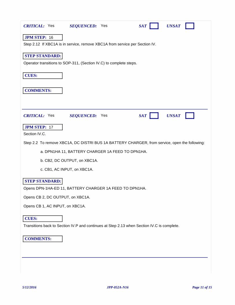
Step 2.12 If XBC1A is in service, remove XBC1A from service per Section IV.
Yes
Operator transitions to SOP-311, (Section IV.C) to complete steps.
CUES:
SEQUENCED:
STEP STANDARD:
COMMENTS:
SAT UNSATCRITICAL: Yes
JPM STEP: 16
Section IV.C.
Step 2.2 To remove XBC1A, DC DISTRI BUS 1A BATTERY CHARGER, from service, open the following:
a. DPN1HA 11, BATTERY CHARGER 1A FEED TO DPN1HA.
b. CB2, DC OUTPUT, on XBC1A.
c. CB1, AC INPUT, on XBC1A.
Transitions back to Section IV.P and continues at Step 2.13 when Section IV.C is complete.
Yes
Opens DPN-1HA-ED 11, BATTERY CHARGER 1A FEED TO DPN1HA.
Opens CB 2, DC OUTPUT, on XBC1A.
Opens CB 1, AC INPUT, on XBC1A.
CUES:
SEQUENCED:
STEP STANDARD:
COMMENTS:
SAT UNSATCRITICAL: Yes
JPM STEP: 17
5/12/2016 Page 11 of 15JPP-052A-N16
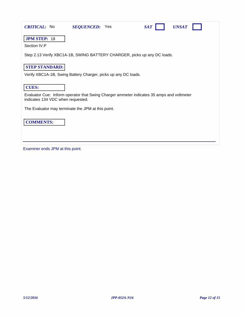
Examiner ends JPM at this point.
Section IV.P
Step 2.13 Verify XBC1A-1B, SWING BATTERY CHARGER, picks up any DC loads.
Evaluator Cue: Inform operator that Swing Charger ammeter indicates 35 amps and voltmeter indicates 134 VDC when requested.
The Evaluator may terminate the JPM at this point.
Yes
Verify XBC1A-1B, Swing Battery Charger, picks up any DC loads.
CUES:
SEQUENCED:
STEP STANDARD:
COMMENTS:
SAT UNSATCRITICAL: No
JPM STEP: 18
5/12/2016 Page 12 of 15JPP-052A-N16
JPM: JPP-052A-N16 (NRC JPM-k) Startup the "Swing Battery Charger" and Place on DPN 1HA.
IC SET:
INSTRUCTIONS:
COMMENTS:
JPM SETUP SHEET
5/12/2016 Page 13 of 15JPP-052A-N16
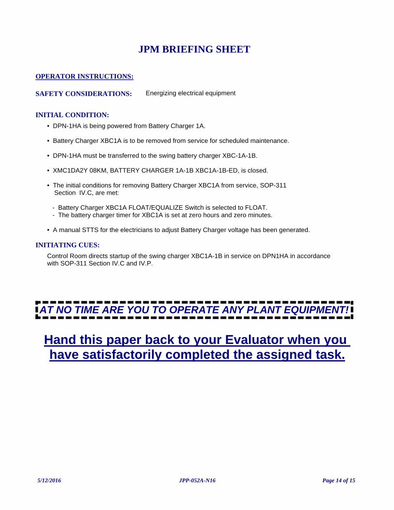
INITIATING CUES:
Control Room directs startup of the swing charger XBC1A-1B in service on DPN1HA in accordance with SOP-311 Section IV.C and IV.P.
INITIAL CONDITION:
• DPN-1HA is being powered from Battery Charger 1A.
• Battery Charger XBC1A is to be removed from service for scheduled maintenance.
• DPN-1HA must be transferred to the swing battery charger XBC-1A-1B.
• XMC1DA2Y 08KM, BATTERY CHARGER 1A-1B XBC1A-1B-ED, is closed.
• The initial conditions for removing Battery Charger XBC1A from service, SOP-311 Section IV.C, are met:
- Battery Charger XBC1A FLOAT/EQUALIZE Switch is selected to FLOAT. - The battery charger timer for XBC1A is set at zero hours and zero minutes.
• A manual STTS for the electricians to adjust Battery Charger voltage has been generated.
SAFETY CONSIDERATIONS: Energizing electrical equipment
OPERATOR INSTRUCTIONS:
Hand this paper back to your Evaluator when you have satisfactorily completed the assigned task.
JPM BRIEFING SHEET
AT NO TIME ARE YOU TO OPERATE ANY PLANT EQUIPMENT!
5/12/2016 Page 14 of 15JPP-052A-N16
2016 NRC A1-a (Common): Perform Boric Acid Dilution Volume Determination
V.C. SUMMER NUCLEAR STATIONJOB PERFORMANCE MEASURE
CANDIDATE:
EXAMINER:
JPM NO: JPA-021A-(C)N16
5/6/2016 Page 1 of 7
TASK: 004-006-01-01
PREFERRED EVALUATION METHOD
PERFORM
EVALUATION TIME 20 TIME CRITICAL NO
TASK STANDARD:
Examinee determines that about 9359 gals (interpolated value) will be required for dilution. A range of 9250 to 9450 (~ +/- 100 gal or ~ 1%) would be acceptable. If the examinee elects to calculate vice interpolate, the calculated value is the same range. Examinee determines that available volume in Recycle Holdup Tank is NOT sufficient to accomodate the calculated dilution. Volume required exceeds the volume at overflow 44,353 gallons required vice 42,989 gallons at overflow.
PREFERRED EVALUATION LOCATION
CLASSROOM
TIME START: TIME FINISH:
PERFORMANCE RATING: SAT: UNSAT:
PERFORMANCE TIME:
EXAMINER:SIGNATURE DATE
10CFR55: 45b(1)(12)
PERFORM BORON CHANGE CALCULATIONS
TOOLS: Curve Book (Accessible via Desk Top Computers)CalculatorJPM A1-a, Dilution Calculation hand out.
REFERENCES:
TERMINATING CUE: Calculations completed.
CANDIDATE:
SOP-106 REACTOR MAKEUP WATER SYSTEM
INDEX NO. RO SROK/A NO.
1940012125 Ability to interpret reference materials such as graphs, curves, tables, etc.
3.9 4.22.1.25
1940012137 Knowledge of procedures, guidelines, or limitations associated with reactivity management.
4.3 4.62.1.37
5/6/2016 Page 2 of 7
INITIATING CUES:The SM directs you to perform the following:
1. Determine the dilution volume required to establish the estimated critical boron concentration.
2. Determine if the necessary volume is available in 'A' Recycle Holdup Tank to accommodate the dilution. Assume that RCS temperature and Pressurizer Level remain constant. Show evidence to support your determination.
Show all work on the JPM A1-a Dilution Calculation hand out provided.
INITIAL CONDITION:The plant is in MODE 3 preparing for reactor startup in accordance with GOP-3.
- Latest RCS boron sample was 2038 ppm.- Estimated critical boron concentration is 1688 ppm.- "A" Recycle Holdup Tank is in service.- "A" Recycle Holdup Tank level is 83%.
READ TO OPERATOR:
SAFETY CONSIDERATIONS:
When I tell you to begin, you are to perform the actions as directed in the initiating cues.
I will describe the general conditions under which this task is to be performed and provide the necessary tools with which to perform this task.
Before starting, I will explain the initial conditions, which steps to simulate or discuss, and provide initiating cues. When you complete the task successfully, this Job Performance Measure will be satisfied.
INSTRUCTIONS TO OPERATOR
HAND JPM BRIEFING SHEET TO OPERATOR AT THIS TIME!
5/6/2016 Page 3 of 7
Examinee determines that the amount of dilution required.
Evaluator note: Ci and Cf values are given in the initiating cue.
Yes
Determines Ci - Cf = 350 ppm dilution required.
CUES:
SEQUENCED:
STEP STANDARD:
COMMENTS:
SAT UNSATCRITICAL: Yes
JPM STEP: 1
Selects correct curve from curve book.
Evaluator note: Do NOT prompt Examinee on location of the dilution tables.
Yes
The examinee refers to Figure III-3, RCS Dilution Gallons (Vw) of Dilution Water Required, in the Curve Book.
CUES:
SEQUENCED:
STEP STANDARD:
COMMENTS:
SAT UNSATCRITICAL: Yes
JPM STEP: 2
5/6/2016 Page 4 of 7
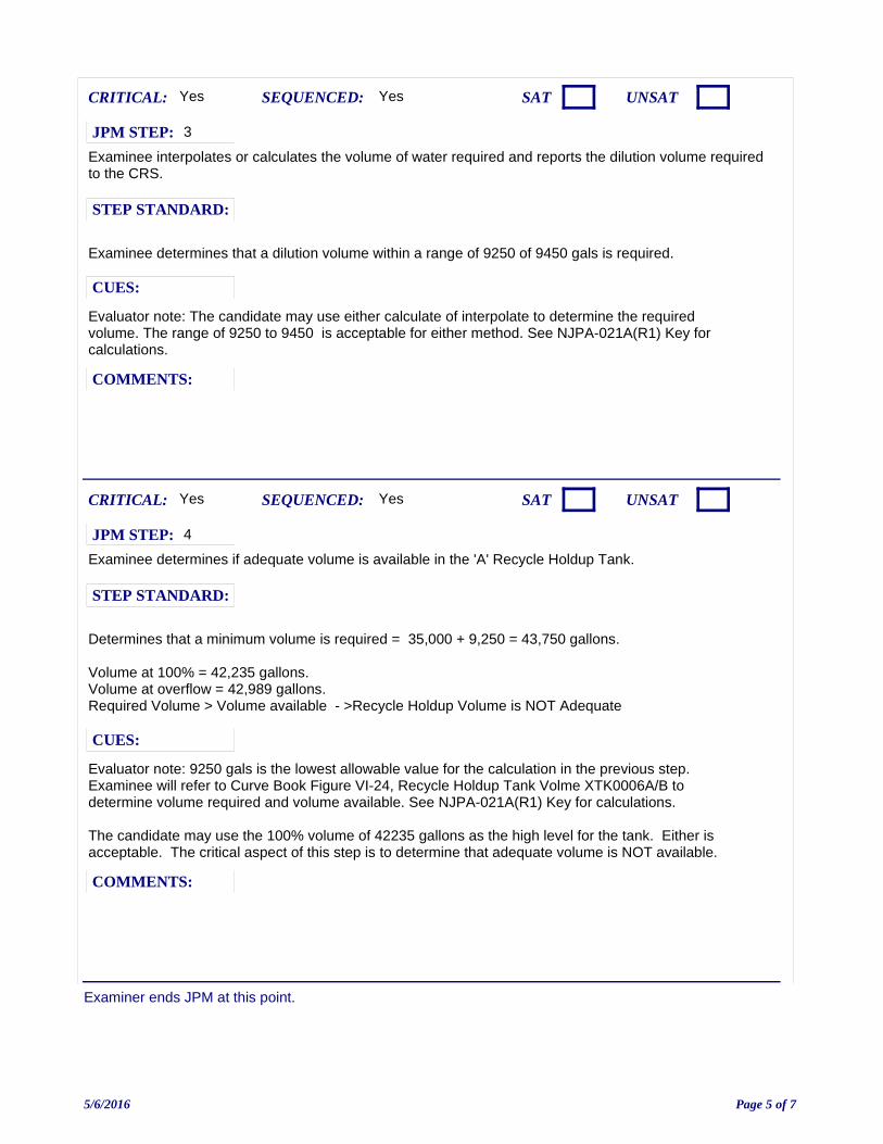
Examiner ends JPM at this point.
Examinee interpolates or calculates the volume of water required and reports the dilution volume required to the CRS.
Evaluator note: The candidate may use either calculate of interpolate to determine the required volume. The range of 9250 to 9450 is acceptable for either method. See NJPA-021A(R1) Key for calculations.
Yes
Examinee determines that a dilution volume within a range of 9250 of 9450 gals is required.
CUES:
SEQUENCED:
STEP STANDARD:
COMMENTS:
SAT UNSATCRITICAL: Yes
JPM STEP: 3
Examinee determines if adequate volume is available in the 'A' Recycle Holdup Tank.
Evaluator note: 9250 gals is the lowest allowable value for the calculation in the previous step. Examinee will refer to Curve Book Figure VI-24, Recycle Holdup Tank Volme XTK0006A/B to determine volume required and volume available. See NJPA-021A(R1) Key for calculations.
The candidate may use the 100% volume of 42235 gallons as the high level for the tank. Either is acceptable. The critical aspect of this step is to determine that adequate volume is NOT available.
Yes
Determines that a minimum volume is required = 35,000 + 9,250 = 43,750 gallons.
Volume at 100% = 42,235 gallons.Volume at overflow = 42,989 gallons.Required Volume > Volume available - >Recycle Holdup Volume is NOT Adequate
CUES:
SEQUENCED:
STEP STANDARD:
COMMENTS:
SAT UNSATCRITICAL: Yes
JPM STEP: 4
5/6/2016 Page 5 of 7

JPM: JPA-021A-( 2016 NRC A1-a (Common): Perform Boric Acid Dilution Volume Determination
IC SET: NA
INSTRUCTIONS:
COMMENTS:
JPM SETUP SHEET
5/6/2016 Page 6 of 7
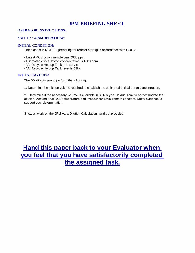
INITIATING CUES:
The SM directs you to perform the following:
1. Determine the dilution volume required to establish the estimated critical boron concentration.
2. Determine if the necessary volume is available in 'A' Recycle Holdup Tank to accommodate the dilution. Assume that RCS temperature and Pressurizer Level remain constant. Show evidence to support your determination.
Show all work on the JPM A1-a Dilution Calculation hand out provided.
INITIAL CONDITION:The plant is in MODE 3 preparing for reactor startup in accordance with GOP-3.
- Latest RCS boron sample was 2038 ppm.- Estimated critical boron concentration is 1688 ppm.- "A" Recycle Holdup Tank is in service.- "A" Recycle Holdup Tank level is 83%.
SAFETY CONSIDERATIONS:
OPERATOR INSTRUCTIONS:
Hand this paper back to your Evaluator when you feel that you have satisfactorily completed
the assigned task.
JPM BRIEFING SHEET
5/6/2016 Page 7 of 7
2016 NRC A1-b (RO only): Verify Operability of Offsite Power Sources
V.C. SUMMER NUCLEAR STATIONJOB PERFORMANCE MEASURE
CANDIDATE:
EXAMINER:
JPM NO: JPA-050-(R)N16
5/18/2016 Page 1 of 8
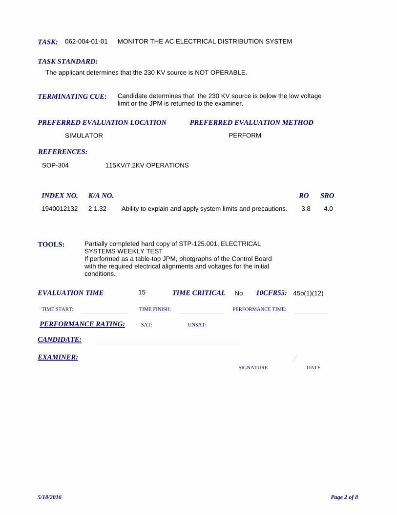
TASK: 062-004-01-01
PREFERRED EVALUATION METHOD
PERFORM
EVALUATION TIME 15 TIME CRITICAL No
TASK STANDARD:
The applicant determines that the 230 KV source is NOT OPERABLE.
PREFERRED EVALUATION LOCATION
SIMULATOR
TIME START: TIME FINISH:
PERFORMANCE RATING: SAT: UNSAT:
PERFORMANCE TIME:
EXAMINER:SIGNATURE DATE
10CFR55: 45b(1)(12)
MONITOR THE AC ELECTRICAL DISTRIBUTION SYSTEM
TOOLS: Partially completed hard copy of STP-125.001, ELECTRICAL SYSTEMS WEEKLY TEST If performed as a table-top JPM, photgraphs of the Control Board with the required electrical alignments and voltages for the initial conditions.
REFERENCES:
TERMINATING CUE: Candidate determines that the 230 KV source is below the low voltage limit or the JPM is returned to the examiner.
CANDIDATE:
SOP-304 115KV/7.2KV OPERATIONS
INDEX NO. RO SROK/A NO.
1940012132 Ability to explain and apply system limits and precautions. 3.8 4.02.1.32
5/18/2016 Page 2 of 8
INITIATING CUES:You have been directed to perform the following:
1) Using the partially completed copy of STP-125.001 that is provided to you:
- Complete STP-125.001, Attachment I, page 1 of 2.
- Complete STP-125.001, Attachment II, page 2 of 3.
2) Report any voltage that does not meet the limits contained in STP-125.001 for the current system status, if any.
INITIAL CONDITION:The plant is Mode 3 after an outage.
BUS 1DA NORM FEED is racked down while a visual inspection requested by engineering is completed.
System Control reports that grid voltage transients may occur due to thunderstorms in other part of the state.
The Shift Manager has directed the crew to perform a verification that any requirement for Offsite Power source voltage is met in accordance with STP-125.001, ELECTRICAL SYSTEMS WEEKLY TEST.
READ TO OPERATOR:
SAFETY CONSIDERATIONS: NONE.
When I tell you to begin, you are to perform the actions as directed in the initiating cues.
I will describe the general conditions under which this task is to be performed and provide the necessary tools with which to perform this task.
Before starting, I will explain the initial conditions, which steps to simulate or discuss, and provide initiating cues. When you complete the task successfully, this Job Performance Measure will be satisfied.
INSTRUCTIONS TO OPERATOR
HAND JPM BRIEFING SHEET TO OPERATOR AT THIS TIME!
5/18/2016 Page 3 of 8
Completes STP-125.001 Attachment I, page 1 of 2.
Evaluator Notes:
Steps can be performed in any order.
Only Section II is required for this breaker configuration.
If this is performed as a tabletop, the candidate will verify the electrical alignment for 1DA and 1DB using the photograph of the Main Control Board which is provided.
Yes
Records the following information obtained from the Main Control Board:
- ESF XFMR FEED KV (115 KV) as read on the Main Control Board.- Section II Breaker positions BUS 1DA NORM FEED > OPEN BUS 1DB ALT FEED > OPEN ESF XFMR 4 FEED CKT SW 1826 (XES 4) > CLOSED ESF XFMR 5 FEED CKT SW 1838 (XES 5) > CLOSED
CUES:
SEQUENCED:
STEP STANDARD:
COMMENTS:
SAT UNSATCRITICAL: No
JPM STEP: 1
5/18/2016 Page 4 of 8
Completes STP-125.001 Attachment II, page 2 of 3.
Evaluator Notes:
Steps can be performed in any order.
Only Section I is required for this breaker configuration. The critical aspect of this step is the identification of the correct 230 KV voltage. If the candidate records breaker indications improperly and determines the correct voltage limit later, this is a non-critical error if the follow-on questions indicate that it was a simple recording error and that the candidate was aware of the current electric plant lineup.
If this is performed as a tabletop, the candidate will verify voltage and the electrical alignment for 1DA and 1DB using the photograph of the Main Control Board which is provided.
Yes
Records the following information obtained from the Main Control Board:
- INCOMING 230 KV BUS (230 KV voltage)
- EMERG AUX XFMR FEED XCB 8892 > CLOSED
- Section I Breaker positions BUS 1DB NORM FEED > CLOSED BUS 1DA ALT FEED > CLOSED
CUES:
SEQUENCED:
STEP STANDARD:
COMMENTS:
SAT UNSATCRITICAL: Yes
JPM STEP: 2
5/18/2016 Page 5 of 8
Examiner ends JPM at this point.
Determines the voltage limits for the offsite power sources.
Evaluator Notes:
The candidate may refer to SOP-304, 115KV/7.2KV OPERATIONS. The voltage limits in that procedure are the same as in STP-125.001.
The limit is located on the far right column on the second row under the 230 KV Source section.
There is no applicable limit for 115 KV voltage on Enclosure A since neither 1DA or 1DB are supplied by that source.
No
Refers to STP-125.001, Enclosure A. Refers to the 230 KV Source section, XTF-31, connected buses 1DA and 1DB, Generator Off Line. Determines a low voltage limit for the 230KV source of 225.7 KV.
CUES:
SEQUENCED:
STEP STANDARD:
COMMENTS:
SAT UNSATCRITICAL: Yes
JPM STEP: 3
Compares the reading on INCOMING 230 KV BUS to the allowed limit from Attachment 1 and determines that actual voltage is below the limit.
No
Reports that the actual voltage read on INCOMING 230 KV BUS is less than the lower limt contained in STP-125.001.
CUES:
SEQUENCED:
STEP STANDARD:
COMMENTS:
SAT UNSATCRITICAL: Yes
JPM STEP: 4
5/18/2016 Page 6 of 8
JPM: JPA-050-(R 2016 NRC A1-b (RO only): Verify Operability of Offsite Power Sources
IC SET: IC-5
INSTRUCTIONS:
Use IC-290 for 2016 NRC exam. If not available, bring up a IC that is mode 3, TAVG 557°F and perform the following:
Align IDA to breaker BUS 1DA ALT FEED using the BUS 1DA XFER INIT Switch (refer to SOP-304).Adjust 230KV voltage until digital meter on XCP-6118 reads 225.4 KV.
Provide a partially completed copy of STP-125.001 that is marked-up as follows:
An entry is made for each component position on Attachment I, page 2 of 2 which is the same as the NORMAL POSITION".
An entry is made for each component position on Attachment II, page 1 of 3 which is the same as the NORMAL POSITION".
COMMENTS:NOTE: This alignment can be photographed if the JPM will be run as a table top. After the setup, photgraph panels XCP-6117 and XCP-6118 showing breaker alignments and 115KV and 230KV voltages on digital meters
JPM SETUP SHEET
5/18/2016 Page 7 of 8
INITIATING CUES:
You have been directed to perform the following:
1) Using the partially completed copy of STP-125.001 that is provided to you:
- Complete STP-125.001, Attachment I, page 1 of 2.
- Complete STP-125.001, Attachment II, page 2 of 3.
2) Report any voltage that does not meet the limits contained in STP-125.001 for the current system status, if any.
INITIAL CONDITION:The plant is Mode 3 after an outage.
BUS 1DA NORM FEED is racked down while a visual inspection requested by engineering is completed.
System Control reports that grid voltage transients may occur due to thunderstorms in other part of the state.
The Shift Manager has directed the crew to perform a verification that any requirement for Offsite Power source voltage is met in accordance with STP-125.001, ELECTRICAL SYSTEMS WEEKLY TEST.
SAFETY CONSIDERATIONS: NONE.
OPERATOR INSTRUCTIONS:
Hand this paper back to your Evaluator when you feel that you have satisfactorily completed
the assigned task.
JPM BRIEFING SHEET
5/18/2016 Page 8 of 8
2016 NRC A1-b (SRO only): Verify Operability of Offsite Power Sources
V.C. SUMMER NUCLEAR STATIONJOB PERFORMANCE MEASURE
CANDIDATE:
EXAMINER:
JPM NO: JPA-051-(S)N16
5/18/2016 Page 1 of 7
TASK: 341-032-03-02
PREFERRED EVALUATION METHOD
PERFORM
EVALUATION TIME 15 TIME CRITICAL No
TASK STANDARD:
The applicant determines that both OFFSITE power sources are NOT OPERABLE and that T.S. Action Statement 3.8.1.1.d is in effect.
PREFERRED EVALUATION LOCATION
CLASSROOM
TIME START: TIME FINISH:
PERFORMANCE RATING: SAT: UNSAT:
PERFORMANCE TIME:
EXAMINER:SIGNATURE DATE
10CFR55: 45b(1)(12)
EVALUATE PLANT SYSTEMS PERFORMANCE AND COORDINATE APPROPRIATE ACTIONS PER TECHNICAL SPECIFICATIONS IN THE EVENT AN LIMITING CONDITION FOR OPERATION IS ENTERED/NOT SATISFIED.
TOOLS: Partially completed copy STP-125.001, ELECTRIC POWER SYSTEMS WEEKLY TEST.Handout for recording Technical Specification.Hardcopy or electronic V.C. Summer procedures.
REFERENCES:
TERMINATING CUE: The applicant returns the JPM briefing sheet and completed handout to the examiner.
CANDIDATE:
SOP-304 115KV/7.2KV OPERATIONS
INDEX NO. RO SROK/A NO.
1940012132 Ability to explain and apply system limits and precautions. 3.8 4.02.1.32
1940012240 Ability to apply technical specifications for a system. 3.4 4.72.2.40
5/18/2016 Page 2 of 7
INITIATING CUES:You are directed to perform the following:
- Review the partially completed copy of STP-125.001 Attachments I and II.
- Check the box for the ONE applicable statement on STP-125.001, Attachment I, page 2 of 2.
- Check the box for the ONE applicable statement on STP-125.001, Attachment II, page 3 of 3.
- ON THE HANDOUT PROVIDED TO YOU, record your anwer(s) to the required information regarding Offsite Power Source OPERABILITY.
INITIAL CONDITION:The plant is mode 3 after an outage.
Bus 1DA is being powered from breaker BUS 1DA ALT FEED to allow a visual inspection of BUS 1DA NORM FEED as requested by engineering.
All Balance of Plant bus breakers are normally aligned.
STP-125.001, ELECTRIC POWER SYSTEMS WEEKLY TEST is in progress.
READ TO OPERATOR:
SAFETY CONSIDERATIONS: NONE.
When I tell you to begin, you are to perform the actions as directed in the initiating cues.
I will describe the general conditions under which this task is to be performed and provide the necessary tools with which to perform this task.
Before starting, I will explain the initial conditions, which steps to simulate or discuss, and provide initiating cues. When you complete the task successfully, this Job Performance Measure will be satisfied.
INSTRUCTIONS TO OPERATOR
HAND JPM BRIEFING SHEET TO OPERATOR AT THIS TIME!
5/18/2016 Page 3 of 7
Reviews copy of STP-125.001.
Note to Examiner: The candidate should have been provided with the partially completed copy of STP-125.001, ELECTRIC POWER SYSTEMS WEEKLY TEST and JPM Handout as part of the initial briefing.
Yes
N/A
CUES:
SEQUENCED:
STEP STANDARD:
COMMENTS:
SAT UNSATCRITICAL: No
JPM STEP: 1
Identifies that the 115 KV Offsite power source is NOT OPERABLE.
Note to Examiner: This determination is made by noting that both BUS 1DA NORM FEED and BUS 1DB NORM FEED are open on Attachment I, page 1 of 2. This alignment fails to tie the 115 KV offsite power source to either 1DA or 1DB rendering that source inoperable.
If the candidate does not demonstrate this review, this can be probed by follow-on questions.
Yes
Checks the box for the second statement on Attachment I, page 2 of 2.
CUES:
SEQUENCED:
STEP STANDARD:
COMMENTS:
SAT UNSATCRITICAL: Yes
JPM STEP: 2
5/18/2016 Page 4 of 7
Examiner ends JPM at this point.
Determines that the 230 KV offsite power source is NOT OPERABLE.
Examiner note: This determination is made by comparing the voltage recorded on Attachment II, page 2 of 3, and the lower voltage limit of 225.7 KV. This is contained in Enclosure A, on the second row of the 230 KV section, far right column. Since actual voltage is less than the limit, this renders the 230 KV offsite power source inoperable.
If the candidate does not demonstrate this review, this can be probed by follow-on questioning.
No
Checks the box for the second statement on STP-125.001, Attachment II, page 3 of 3.
CUES:
SEQUENCED:
STEP STANDARD:
COMMENTS:
SAT UNSATCRITICAL: Yes
JPM STEP: 3
Candidate determines the applicable Technical Specification action statement.
The JPM can be terminated after the handout is completed or when the candidate returns the briefing sheet.
Yes
The candidate, on the handout provided, checks the YES line and indicates that T.S. Action Statement 3.8.1.1.d. must be entered.
CUES:
SEQUENCED:
STEP STANDARD:
COMMENTS:
SAT UNSATCRITICAL: Yes
JPM STEP: 4
5/18/2016 Page 5 of 7
JPM: JPA-051-(S 2016 NRC A1-b (SRO only): Verify Operability of Offsite Power Sources
IC SET:
INSTRUCTIONS:
Provide a partially completed copy of STP-125.001, ELECTRICAL SYSTEMS WEEKLY TEST with the following items performed.
Complete Attachment I with ACTUAL VOLTS indicated as 115.0 KV, Section I lined through, OPEN indicated in Section II for both BUS 1DA NORM FEED and BUS 1DB ALT FEED. and ALL other items indicated the same as NORMAL POSITION.
Complete Attachment II with ACTUAL VOLTS indicated as 225.1 KV,Section II lined through, and ALL other items indicated the same as NORMAL POSITION.
Also provide a Handout sheet that contains the following text:
Name:Date:
Technical Specification Action Statement for OFFSITE power sources in effect?
(Circle ONE) YES NO
If YES, record the Technical Specification Action Statement that must be entered for the current condition and that will require taking the plant to a lower mode the soonest.
COMMENTS:
JPM SETUP SHEET
5/18/2016 Page 6 of 7
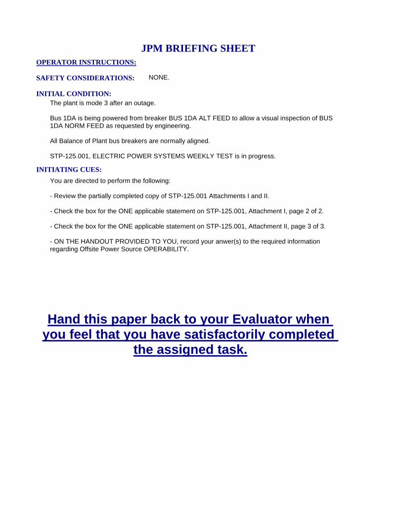
INITIATING CUES:
You are directed to perform the following:
- Review the partially completed copy of STP-125.001 Attachments I and II.
- Check the box for the ONE applicable statement on STP-125.001, Attachment I, page 2 of 2.
- Check the box for the ONE applicable statement on STP-125.001, Attachment II, page 3 of 3.
- ON THE HANDOUT PROVIDED TO YOU, record your anwer(s) to the required information regarding Offsite Power Source OPERABILITY.
INITIAL CONDITION:The plant is mode 3 after an outage.
Bus 1DA is being powered from breaker BUS 1DA ALT FEED to allow a visual inspection of BUS 1DA NORM FEED as requested by engineering.
All Balance of Plant bus breakers are normally aligned.
STP-125.001, ELECTRIC POWER SYSTEMS WEEKLY TEST is in progress.
SAFETY CONSIDERATIONS: NONE.
OPERATOR INSTRUCTIONS:
Hand this paper back to your Evaluator when you feel that you have satisfactorily completed
the assigned task.
JPM BRIEFING SHEET
5/18/2016 Page 7 of 7
2016 NRC A2 (RO Only) Calculate Leakrate W/O IPCS Leak Rate Program Available
V.C. SUMMER NUCLEAR STATIONJOB PERFORMANCE MEASURE
CANDIDATE:
EXAMINER:
JPM NO: JPA-81D-(R)N16
5/18/2016 Page 1 of 10
TASK: 002-002-02-01
PREFERRED EVALUATION METHOD
PERFORM
EVALUATION TIME 30 TIME CRITICAL NO
TASK STANDARD:
Candidate correctly calculates the leak rate to within the specified tolarance contained in the answer key.
PREFERRED EVALUATION LOCATION
CLASSROOM
TIME START: TIME FINISH:
PERFORMANCE RATING: SAT: UNSAT:
PERFORMANCE TIME:
EXAMINER:SIGNATURE DATE
10CFR55: 45b(1)(12)
PERFORM AN RCS LEAKRATE CALCULATION WITH THE IPCS UNAVAILABLE IAW STP-114.002
TOOLS: CalculatorComplete copy of STP-114.002, OPERATIONAL LEAKAGE CALCULATIONVCS STATION CURVE BOOK
REFERENCES:
TERMINATING CUE: The candidate has completed STP-114.002, ATTACHMENT I.
CANDIDATE:
STP-114.002 OPERATIONAL LEAK TEST
INDEX NO. RO SROK/A NO.
1940012132 Ability to explain and apply system limits and precautions. 3.8 4.02.1.32
1940012240 Ability to apply technical specifications for a system. 3.4 4.72.2.40
5/18/2016 Page 2 of 10
INITIATING CUES:You are directed to perform the following:
USING PLANT DATA ON THE HANDOUT PROVIDED, perform STP-114.002, OPERATIONALLEAKAGE CALCULATION starting at STEP 6.4.b.
Another operator will complete STEP 6.4.c when required.
- No RCS makeup or diversion to the recycle holdup tanks will occur.- No Chemical additions or primary samples will be performed.- RCS pressure will be maintained between 350 psig and 400 psig.- Primary to secondary leakage is 0 gpm.- There is no recorded leakage to atmosphere in the RB.
INITIAL CONDITION:The plant is in Mode 4. The IPCS Leak Rate Program unavailable. IPCS can be used to obtain plant data.
READ TO OPERATOR:
SAFETY CONSIDERATIONS: NONE
When I tell you to begin, you are to perform the actions as directed in the initiating cues.
I will describe the general conditions under which this task is to be performed and provide the necessary tools with which to perform this task.
Before starting, I will explain the initial conditions, which steps to simulate or discuss, and provide initiating cues. When you complete the task successfully, this Job Performance Measure will be satisfied.
INSTRUCTIONS TO OPERATOR
HAND JPM BRIEFING SHEET TO OPERATOR AT THIS TIME!
5/18/2016 Page 3 of 10
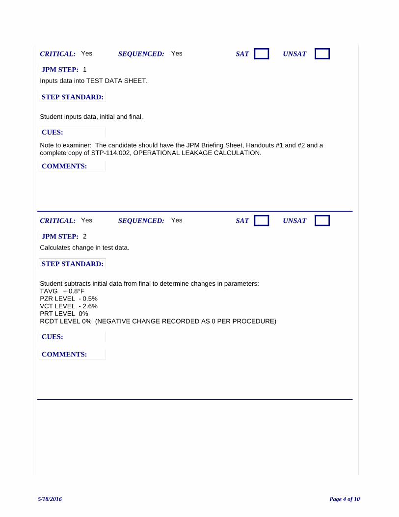
Inputs data into TEST DATA SHEET.
Note to examiner: The candidate should have the JPM Briefing Sheet, Handouts #1 and #2 and a complete copy of STP-114.002, OPERATIONAL LEAKAGE CALCULATION.
Yes
Student inputs data, initial and final.
CUES:
SEQUENCED:
STEP STANDARD:
COMMENTS:
SAT UNSATCRITICAL: Yes
JPM STEP: 1
Calculates change in test data.
Yes
Student subtracts initial data from final to determine changes in parameters: TAVG + 0.8°FPZR LEVEL - 0.5%VCT LEVEL - 2.6%PRT LEVEL 0%RCDT LEVEL 0% (NEGATIVE CHANGE RECORDED AS 0 PER PROCEDURE)
CUES:
SEQUENCED:
STEP STANDARD:
COMMENTS:
SAT UNSATCRITICAL: Yes
JPM STEP: 2
5/18/2016 Page 4 of 10
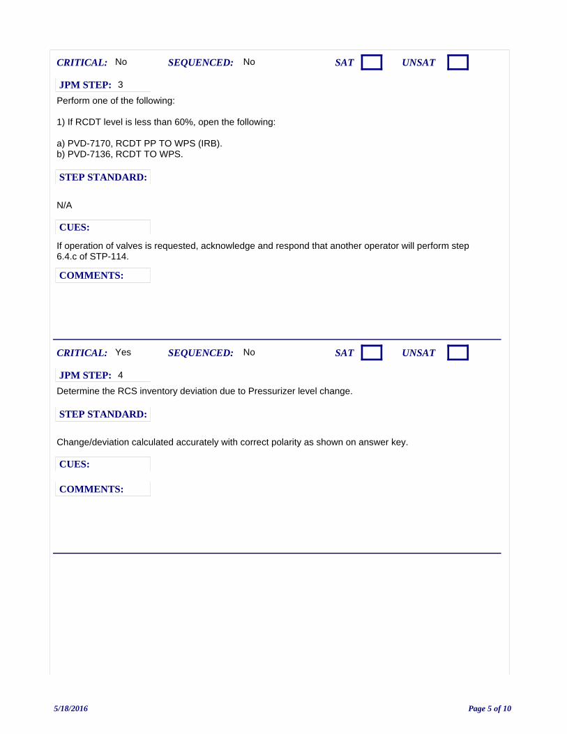
Perform one of the following:
1) If RCDT level is less than 60%, open the following:
a) PVD-7170, RCDT PP TO WPS (IRB).b) PVD-7136, RCDT TO WPS.
If operation of valves is requested, acknowledge and respond that another operator will perform step 6.4.c of STP-114.
No
N/A
CUES:
SEQUENCED:
STEP STANDARD:
COMMENTS:
SAT UNSATCRITICAL: No
JPM STEP: 3
Determine the RCS inventory deviation due to Pressurizer level change.
No
Change/deviation calculated accurately with correct polarity as shown on answer key.
CUES:
SEQUENCED:
STEP STANDARD:
COMMENTS:
SAT UNSATCRITICAL: Yes
JPM STEP: 4
5/18/2016 Page 5 of 10
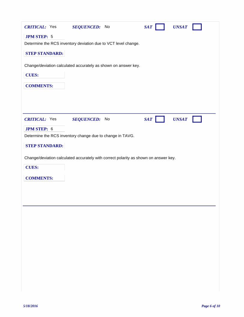
Determine the RCS inventory deviation due to VCT level change.
No
Change/deviation calculated accurately as shown on answer key.
CUES:
SEQUENCED:
STEP STANDARD:
COMMENTS:
SAT UNSATCRITICAL: Yes
JPM STEP: 5
Determine the RCS inventory change due to change in TAVG.
No
Change/deviation calculated accurately with correct polarity as shown on answer key.
CUES:
SEQUENCED:
STEP STANDARD:
COMMENTS:
SAT UNSATCRITICAL: Yes
JPM STEP: 6
5/18/2016 Page 6 of 10

Determine the RCS inventory deviation due to PRT level change.
No
Recorded as zero.
CUES:
SEQUENCED:
STEP STANDARD:
COMMENTS:
SAT UNSATCRITICAL: No
JPM STEP: 7
Determine the RCS inventory deviation due to RCDT level change.
NOTE TO EXAMINER: The change is recorded as zero (0) in accordance with NOTE on page 11 of of STP-114.002.
No
Change/deviation calculated accurately as shown on answer key.
CUES:
SEQUENCED:
STEP STANDARD:
COMMENTS:
SAT UNSATCRITICAL: No
JPM STEP: 8
5/18/2016 Page 7 of 10
Examiner ends JPM at this point.
Perform calculations as indicated on Attachment 1, Part 2.
Yes
Final leak rate is 1.8 +/- 0.1 GPM (1.7 TO 1.9)
CUES:
SEQUENCED:
STEP STANDARD:
COMMENTS:
SAT UNSATCRITICAL: Yes
JPM STEP: 9
5/18/2016 Page 8 of 10
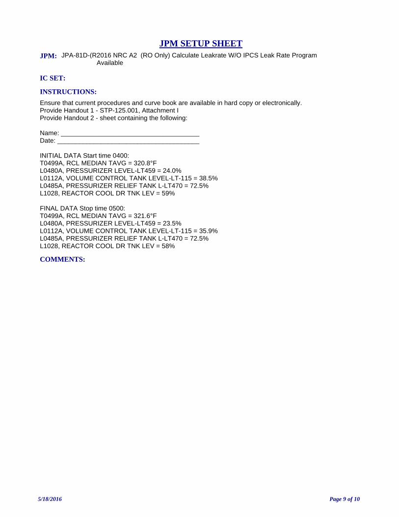
JPM: JPA-81D-(R2016 NRC A2 (RO Only) Calculate Leakrate W/O IPCS Leak Rate Program Available
IC SET:
INSTRUCTIONS:
Ensure that current procedures and curve book are available in hard copy or electronically.Provide Handout 1 - STP-125.001, Attachment IProvide Handout 2 - sheet containing the following:
Name: ______________________________________Date: _______________________________________
INITIAL DATA Start time 0400:T0499A, RCL MEDIAN TAVG = 320.8°FL0480A, PRESSURIZER LEVEL-LT459 = 24.0%L0112A, VOLUME CONTROL TANK LEVEL-LT-115 = 38.5%L0485A, PRESSURIZER RELIEF TANK L-LT470 = 72.5%L1028, REACTOR COOL DR TNK LEV = 59%
FINAL DATA Stop time 0500:T0499A, RCL MEDIAN TAVG = 321.6°FL0480A, PRESSURIZER LEVEL-LT459 = 23.5%L0112A, VOLUME CONTROL TANK LEVEL-LT-115 = 35.9%L0485A, PRESSURIZER RELIEF TANK L-LT470 = 72.5%L1028, REACTOR COOL DR TNK LEV = 58%
COMMENTS:
JPM SETUP SHEET
5/18/2016 Page 9 of 10
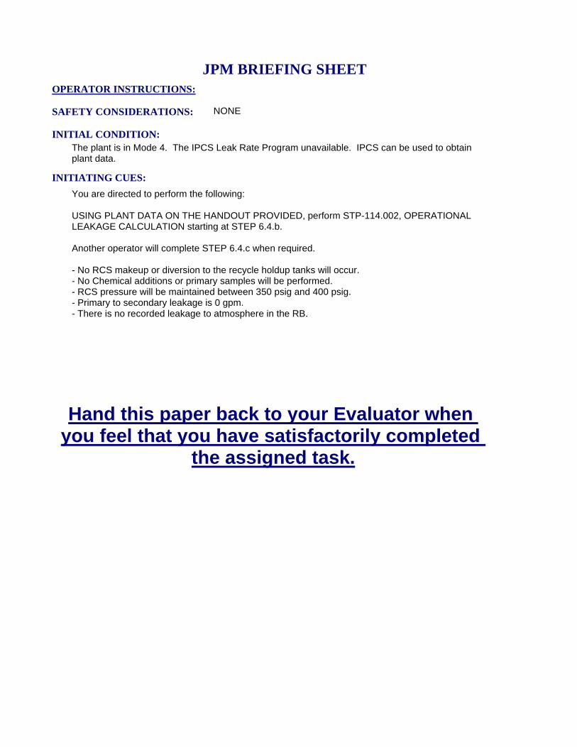
INITIATING CUES:
You are directed to perform the following:
USING PLANT DATA ON THE HANDOUT PROVIDED, perform STP-114.002, OPERATIONALLEAKAGE CALCULATION starting at STEP 6.4.b.
Another operator will complete STEP 6.4.c when required.
- No RCS makeup or diversion to the recycle holdup tanks will occur.- No Chemical additions or primary samples will be performed.- RCS pressure will be maintained between 350 psig and 400 psig.- Primary to secondary leakage is 0 gpm.- There is no recorded leakage to atmosphere in the RB.
INITIAL CONDITION:The plant is in Mode 4. The IPCS Leak Rate Program unavailable. IPCS can be used to obtain plant data.
SAFETY CONSIDERATIONS: NONE
OPERATOR INSTRUCTIONS:
Hand this paper back to your Evaluator when you feel that you have satisfactorily completed
the assigned task.
JPM BRIEFING SHEET
5/18/2016 Page 10 of 10
2016 NRC A2 (SRO Only) Calculate Leakrate W/O IPCS Leak Rate ProgramAvailable
V.C. SUMMER NUCLEAR STATIONJOB PERFORMANCE MEASURE
CANDIDATE:
EXAMINER:
JPM NO: JPA-81D-(S)N16
SRO ONLY
5/18/2016 Page 1 of 10
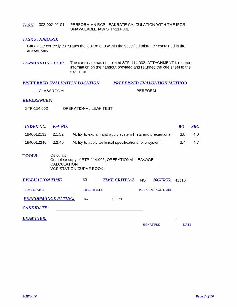
TASK: 002-002-02-01
PREFERRED EVALUATION METHOD
PERFORM
EVALUATION TIME 30 TIME CRITICAL NO
TASK STANDARD:
Candidate correctly calculates the leak rate to within the specified tolarance contained in the answer key.
PREFERRED EVALUATION LOCATION
CLASSROOM
TIME START: TIME FINISH:
PERFORMANCE RATING: SAT: UNSAT:
PERFORMANCE TIME:
EXAMINER:SIGNATURE DATE
10CFR55: 41b10
PERFORM AN RCS LEAKRATE CALCULATION WITH THE IPCS UNAVAILABLE IAW STP-114.002
TOOLS: CalculatorComplete copy of STP-114.002, OPERATIONAL LEAKAGE CALCULATIONVCS STATION CURVE BOOK
REFERENCES:
TERMINATING CUE: The candidate has completed STP-114.002, ATTACHMENT I, recorded information on the handout provided and returned the cue sheet to the examiner.
CANDIDATE:
STP-114.002 OPERATIONAL LEAK TEST
INDEX NO. RO SROK/A NO.
1940012132 Ability to explain and apply system limits and precautions. 3.8 4.02.1.32
1940012240 Ability to apply technical specifications for a system. 3.4 4.72.2.40
5/18/2016 Page 2 of 10
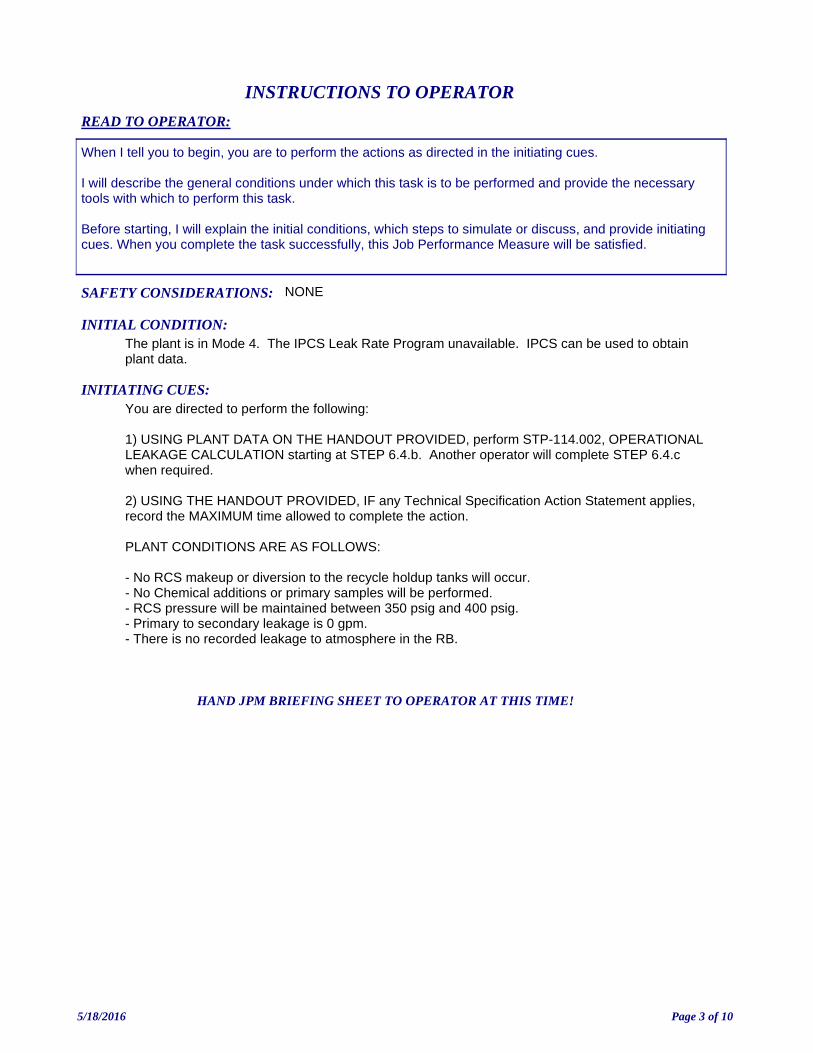
INITIATING CUES:You are directed to perform the following:
1) USING PLANT DATA ON THE HANDOUT PROVIDED, perform STP-114.002, OPERATIONAL LEAKAGE CALCULATION starting at STEP 6.4.b. Another operator will complete STEP 6.4.c when required.
2) USING THE HANDOUT PROVIDED, IF any Technical Specification Action Statement applies, record the MAXIMUM time allowed to complete the action.
PLANT CONDITIONS ARE AS FOLLOWS:
- No RCS makeup or diversion to the recycle holdup tanks will occur.- No Chemical additions or primary samples will be performed.- RCS pressure will be maintained between 350 psig and 400 psig.- Primary to secondary leakage is 0 gpm.- There is no recorded leakage to atmosphere in the RB.
INITIAL CONDITION:The plant is in Mode 4. The IPCS Leak Rate Program unavailable. IPCS can be used to obtain plant data.
READ TO OPERATOR:
SAFETY CONSIDERATIONS: NONE
When I tell you to begin, you are to perform the actions as directed in the initiating cues.
I will describe the general conditions under which this task is to be performed and provide the necessary tools with which to perform this task.
Before starting, I will explain the initial conditions, which steps to simulate or discuss, and provide initiating cues. When you complete the task successfully, this Job Performance Measure will be satisfied.
INSTRUCTIONS TO OPERATOR
HAND JPM BRIEFING SHEET TO OPERATOR AT THIS TIME!
5/18/2016 Page 3 of 10
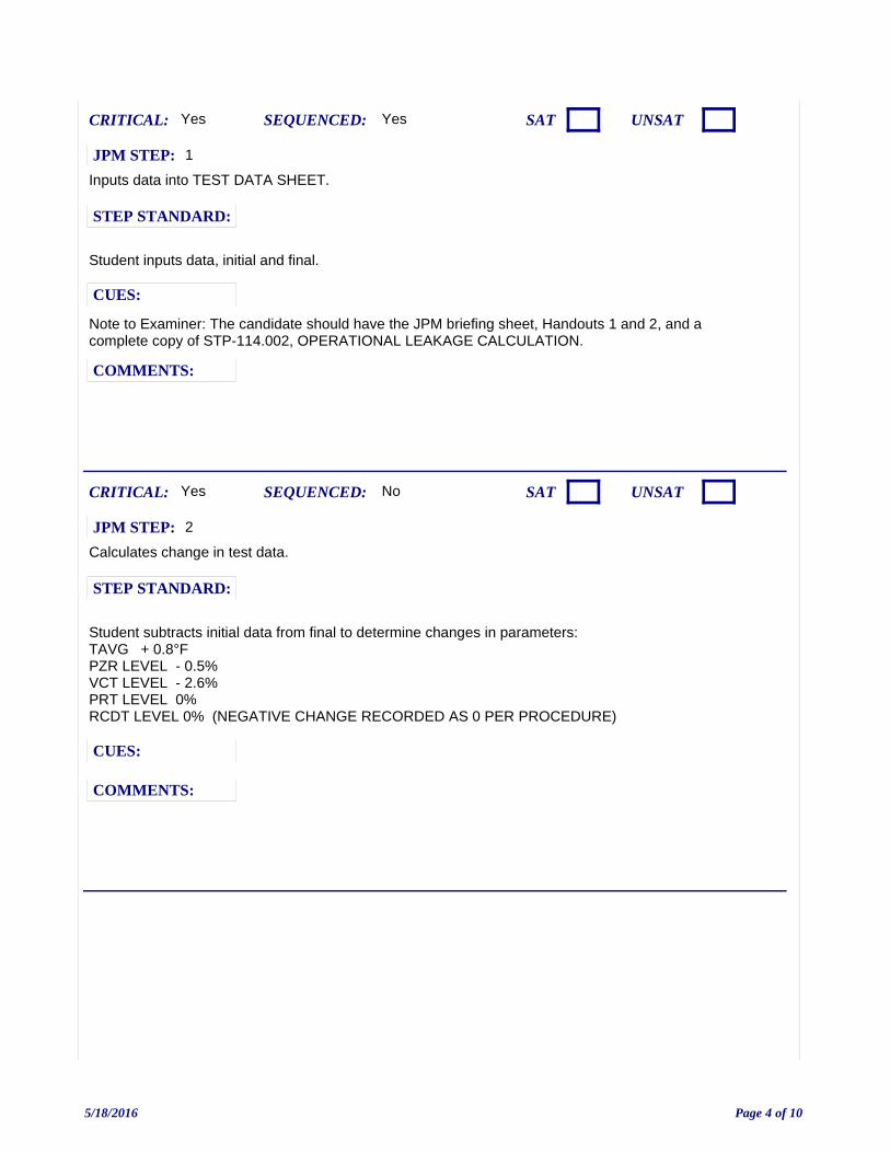
Inputs data into TEST DATA SHEET.
Note to Examiner: The candidate should have the JPM briefing sheet, Handouts 1 and 2, and a complete copy of STP-114.002, OPERATIONAL LEAKAGE CALCULATION.
Yes
Student inputs data, initial and final.
CUES:
SEQUENCED:
STEP STANDARD:
COMMENTS:
SAT UNSATCRITICAL: Yes
JPM STEP: 1
Calculates change in test data.
No
Student subtracts initial data from final to determine changes in parameters: TAVG + 0.8°FPZR LEVEL - 0.5%VCT LEVEL - 2.6%PRT LEVEL 0%RCDT LEVEL 0% (NEGATIVE CHANGE RECORDED AS 0 PER PROCEDURE)
CUES:
SEQUENCED:
STEP STANDARD:
COMMENTS:
SAT UNSATCRITICAL: Yes
JPM STEP: 2
5/18/2016 Page 4 of 10

Perform one of the following:
1) If RCDT level is less than 60%, open the following:
a) PVD-7170, RCDT PP TO WPS (IRB).b) PVD-7136, RCDT TO WPS.
If operation of valves is requested, acknowledge and respond that another operator will perform step 6.4.c of STP-114.
No
N/A
CUES:
SEQUENCED:
STEP STANDARD:
COMMENTS:
SAT UNSATCRITICAL: No
JPM STEP: 3
Determine the RCS inventory deviation due to Pressurizer level change.
No
Change/deviation calculated accurately with correct polarity as shown on answer key.
CUES:
SEQUENCED:
STEP STANDARD:
COMMENTS:
SAT UNSATCRITICAL: Yes
JPM STEP: 4
5/18/2016 Page 5 of 10

Determine the RCS inventory deviation due to VCT level change.
No
Change/deviation calculated accurately as shown on answer key.
CUES:
SEQUENCED:
STEP STANDARD:
COMMENTS:
SAT UNSATCRITICAL: Yes
JPM STEP: 5
Determine the RCS inventory change due to change in TAVG.
No
Change/deviation calculated accurately with correct polarity as shown on answer key.
CUES:
SEQUENCED:
STEP STANDARD:
COMMENTS:
SAT UNSATCRITICAL: Yes
JPM STEP: 6
5/18/2016 Page 6 of 10
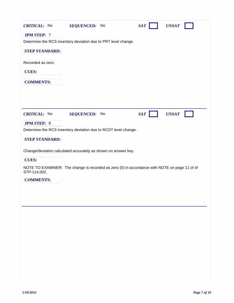
Determine the RCS inventory deviation due to PRT level change.
No
Recorded as zero.
CUES:
SEQUENCED:
STEP STANDARD:
COMMENTS:
SAT UNSATCRITICAL: No
JPM STEP: 7
Determine the RCS inventory deviation due to RCDT level change.
NOTE TO EXAMINER: The change is recorded as zero (0) in accordance with NOTE on page 11 of of STP-114.002.
No
Change/deviation calculated accurately as shown on answer key.
CUES:
SEQUENCED:
STEP STANDARD:
COMMENTS:
SAT UNSATCRITICAL: No
JPM STEP: 8
5/18/2016 Page 7 of 10
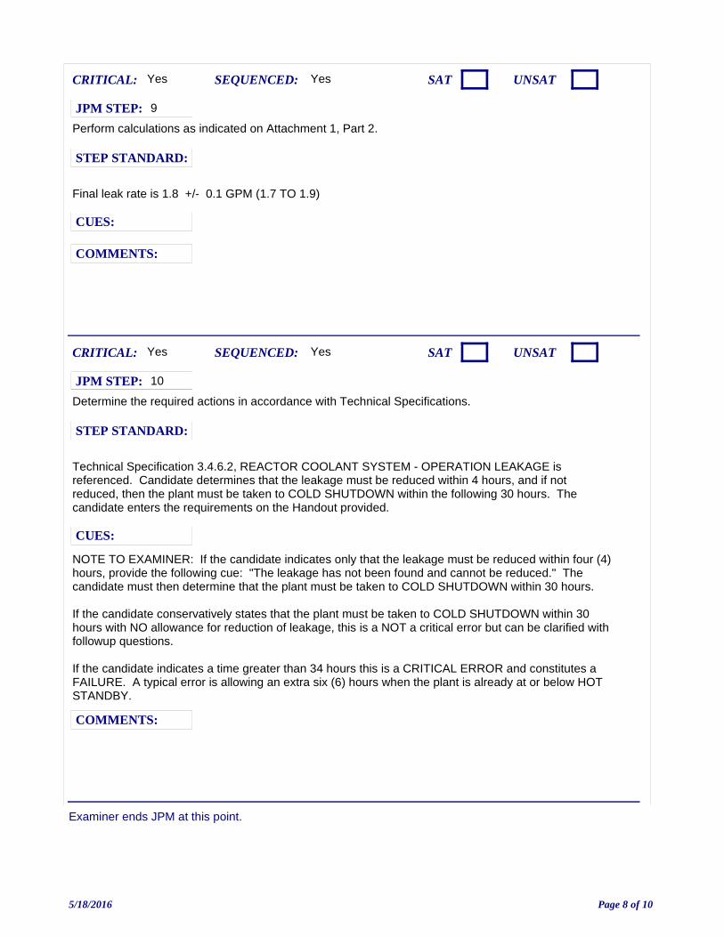
Examiner ends JPM at this point.
Perform calculations as indicated on Attachment 1, Part 2.
Yes
Final leak rate is 1.8 +/- 0.1 GPM (1.7 TO 1.9)
CUES:
SEQUENCED:
STEP STANDARD:
COMMENTS:
SAT UNSATCRITICAL: Yes
JPM STEP: 9
Determine the required actions in accordance with Technical Specifications.
NOTE TO EXAMINER: If the candidate indicates only that the leakage must be reduced within four (4) hours, provide the following cue: "The leakage has not been found and cannot be reduced." The candidate must then determine that the plant must be taken to COLD SHUTDOWN within 30 hours.
If the candidate conservatively states that the plant must be taken to COLD SHUTDOWN within 30 hours with NO allowance for reduction of leakage, this is a NOT a critical error but can be clarified with followup questions.
If the candidate indicates a time greater than 34 hours this is a CRITICAL ERROR and constitutes a FAILURE. A typical error is allowing an extra six (6) hours when the plant is already at or below HOT STANDBY.
Yes
Technical Specification 3.4.6.2, REACTOR COOLANT SYSTEM - OPERATION LEAKAGE is referenced. Candidate determines that the leakage must be reduced within 4 hours, and if not reduced, then the plant must be taken to COLD SHUTDOWN within the following 30 hours. The candidate enters the requirements on the Handout provided.
CUES:
SEQUENCED:
STEP STANDARD:
COMMENTS:
SAT UNSATCRITICAL: Yes
JPM STEP: 10
5/18/2016 Page 8 of 10
JPM: JPA-81D-(S2016 NRC A2 (SRO Only) Calculate Leakrate W/O IPCS Leak Rate ProgramAvailable
IC SET:
INSTRUCTIONS:
Ensure that current procedures and curve book are available in hard copy or electronically.Provide Handout 1 - STP-125.001, Attachment IProvide Handout 2 - sheet containing the following:
Name: ______________________________________Date: _______________________________________
INITIAL DATA Start time 0400:T0499A, RCL MEDIAN TAVG = 320.8°FL0480A, PRESSURIZER LEVEL-LT459 = 24.0%L0112A, VOLUME CONTROL TANK LEVEL-LT-115 = 38.5%L0485A, PRESSURIZER RELIEF TANK L-LT470 = 72.5%L1028, REACTOR COOL DR TNK LEV = 59%
FINAL DATA Stop time 0500:T0499A, RCL MEDIAN TAVG = 321.6°FL0480A, PRESSURIZER LEVEL-LT459 = 23.5%L0112A, VOLUME CONTROL TANK LEVEL-LT-115 = 35.9%L0485A, PRESSURIZER RELIEF TANK L-LT470 = 72.5%L1028, REACTOR COOL DR TNK LEV = 58%
Perform the following to complete this form:
1.Insert the time at which STP-114.002, Attachment 1 calculation completed: ________________.
2.Is entry into a Technical Specification action statement required as a result of the STP-114.002 results?
(Circle one) YES NO
2.If YES, indicate the V.C. Summer Technical Specification action(s) required and the longest time that can be taken to comply with any applicable action.
COMMENTS:
JPM SETUP SHEET
5/18/2016 Page 9 of 10
INITIATING CUES:
You are directed to perform the following:
1) USING PLANT DATA ON THE HANDOUT PROVIDED, perform STP-114.002, OPERATIONAL LEAKAGE CALCULATION starting at STEP 6.4.b. Another operator will complete STEP 6.4.c when required.
2) USING THE HANDOUT PROVIDED, IF any Technical Specification Action Statement applies, record the MAXIMUM time allowed to complete the action.
PLANT CONDITIONS ARE AS FOLLOWS:
- No RCS makeup or diversion to the recycle holdup tanks will occur.- No Chemical additions or primary samples will be performed.- RCS pressure will be maintained between 350 psig and 400 psig.- Primary to secondary leakage is 0 gpm.- There is no recorded leakage to atmosphere in the RB.
INITIAL CONDITION:The plant is in Mode 4. The IPCS Leak Rate Program unavailable. IPCS can be used to obtain plant data.
SAFETY CONSIDERATIONS: NONE
OPERATOR INSTRUCTIONS:
Hand this paper back to your Evaluator when you feel that you have satisfactorily completed
the assigned task.
JPM BRIEFING SHEET
5/18/2016 Page 10 of 10
2016 NRC A3 (Common): Evaluate Worker Exposure
V.C. SUMMER NUCLEAR STATIONJOB PERFORMANCE MEASURE
CANDIDATE:
EXAMINER:
JPM NO: JPA-042-(C)-N16
5/6/2016 Page 1 of 7
TASK: 343-029-03-02
PREFERRED EVALUATION METHOD
PERFORM
EVALUATION TIME 20 TIME CRITICAL NO
TASK STANDARD:
DETERMINES THAT ONLY OPERATORS 2 AND 3 CAN BE ALLOWED TO PERFORM THE WORK DESCRIBED IN THE INITIAL CONDITIONS.
PREFERRED EVALUATION LOCATION
CLASSROOM
TIME START: TIME FINISH:
PERFORMANCE RATING: SAT: UNSAT:
PERFORMANCE TIME:
EXAMINER:SIGNATURE DATE
10CFR55:
ASSESS EXPOSURE LIMITS OF PERSONNEL FOR ASSIGNED DUTIES
TOOLS: CALCULATORVCS-SAP-500, HEALTH PHYSICS MANUALVCS-HPP-0153 ADMINISTRATIVE EXPOSURE LIMITS
REFERENCES:
TERMINATING CUE: EXAMINEE HAS DETERMINED RETURNS THE CUE SHEET AND CALCULATION TO THE EXAMINER.
CANDIDATE:
VCS-HPP-153 ADMINISTRATIVE EXPOSURE LIMITS
INDEX NO. RO SROK/A NO.
1940012304 Knowledge of radiation exposure limits under normal or emergency conditions.
3.2 3.72.3.4
5/6/2016 Page 2 of 7
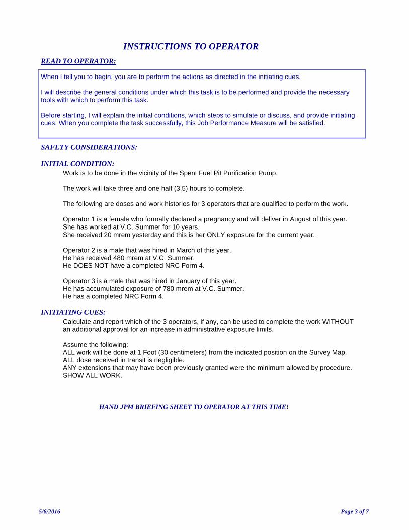
INITIATING CUES:Calculate and report which of the 3 operators, if any, can be used to complete the work WITHOUT an additional approval for an increase in administrative exposure limits.
Assume the following:ALL work will be done at 1 Foot (30 centimeters) from the indicated position on the Survey Map.ALL dose received in transit is negligible.ANY extensions that may have been previously granted were the minimum allowed by procedure.SHOW ALL WORK.
INITIAL CONDITION:Work is to be done in the vicinity of the Spent Fuel Pit Purification Pump.
The work will take three and one half (3.5) hours to complete.
The following are doses and work histories for 3 operators that are qualified to perform the work.
Operator 1 is a female who formally declared a pregnancy and will deliver in August of this year.She has worked at V.C. Summer for 10 years.She received 20 mrem yesterday and this is her ONLY exposure for the current year.
Operator 2 is a male that was hired in March of this year.He has received 480 mrem at V.C. Summer. He DOES NOT have a completed NRC Form 4.
Operator 3 is a male that was hired in January of this year.He has accumulated exposure of 780 mrem at V.C. Summer.He has a completed NRC Form 4.
READ TO OPERATOR:
SAFETY CONSIDERATIONS:
When I tell you to begin, you are to perform the actions as directed in the initiating cues.
I will describe the general conditions under which this task is to be performed and provide the necessary tools with which to perform this task.
Before starting, I will explain the initial conditions, which steps to simulate or discuss, and provide initiating cues. When you complete the task successfully, this Job Performance Measure will be satisfied.
INSTRUCTIONS TO OPERATOR
HAND JPM BRIEFING SHEET TO OPERATOR AT THIS TIME!
5/6/2016 Page 3 of 7
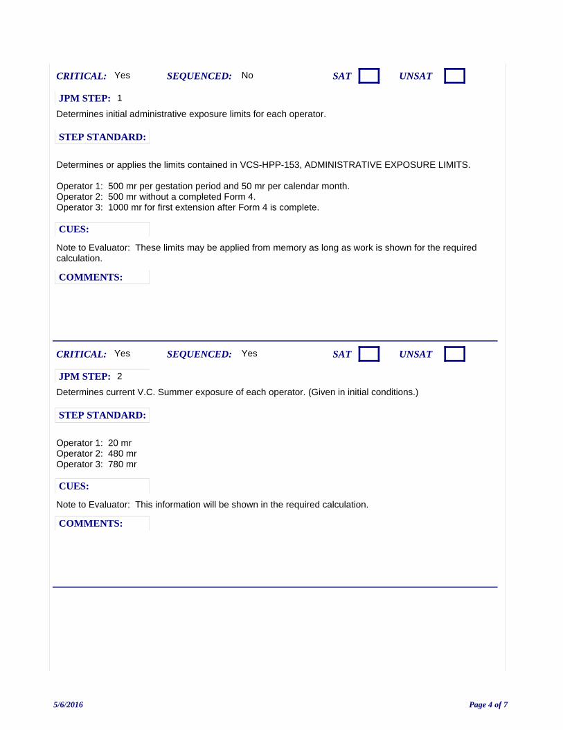
Determines initial administrative exposure limits for each operator.
Note to Evaluator: These limits may be applied from memory as long as work is shown for the required calculation.
No
Determines or applies the limits contained in VCS-HPP-153, ADMINISTRATIVE EXPOSURE LIMITS.
Operator 1: 500 mr per gestation period and 50 mr per calendar month.Operator 2: 500 mr without a completed Form 4.Operator 3: 1000 mr for first extension after Form 4 is complete.
CUES:
SEQUENCED:
STEP STANDARD:
COMMENTS:
SAT UNSATCRITICAL: Yes
JPM STEP: 1
Determines current V.C. Summer exposure of each operator. (Given in initial conditions.)
Note to Evaluator: This information will be shown in the required calculation.
Yes
Operator 1: 20 mrOperator 2: 480 mrOperator 3: 780 mr
CUES:
SEQUENCED:
STEP STANDARD:
COMMENTS:
SAT UNSATCRITICAL: Yes
JPM STEP: 2
5/6/2016 Page 4 of 7
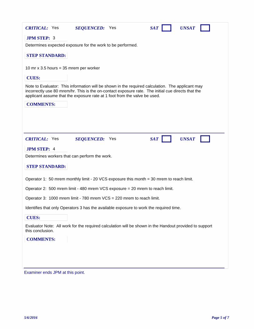
Examiner ends JPM at this point.
Determines expected exposure for the work to be performed.
Note to Evaluator: This information will be shown in the required calculation. The applicant may incorrectly use 80 mrem/hr. This is the on-contact exposure rate. The initial cue directs that the applicant assume that the exposure rate at 1 foot from the valve be used.
Yes
10 mr x 3.5 hours = 35 mrem per worker
CUES:
SEQUENCED:
STEP STANDARD:
COMMENTS:
SAT UNSATCRITICAL: Yes
JPM STEP: 3
Determines workers that can perform the work.
Evaluator Note: All work for the required calculation will be shown in the Handout provided to support this conclusion.
Yes
Operator 1: 50 mrem monthly limit - 20 VCS exposure this month = 30 mrem to reach limit.
Operator 2: 500 mrem limit - 480 mrem VCS exposure = 20 mrem to reach limit.
Operator 3: 1000 mrem limit - 780 mrem VCS = 220 mrem to reach limit.
Identifies that only Operators 3 has the available exposure to work the required time.
CUES:
SEQUENCED:
STEP STANDARD:
COMMENTS:
SAT UNSATCRITICAL: Yes
JPM STEP: 4
5/6/2016 Page 5 of 7
JPM: JPA-042-(C 2016 NRC A3 (Common): Evaluate Worker Exposure
IC SET:
INSTRUCTIONS:
Provide candidate with Handout 1 (Calculation worksheet) and Handout 2 (Survey map)Grade per JPM.
COMMENTS:
JPM SETUP SHEET
5/6/2016 Page 6 of 7
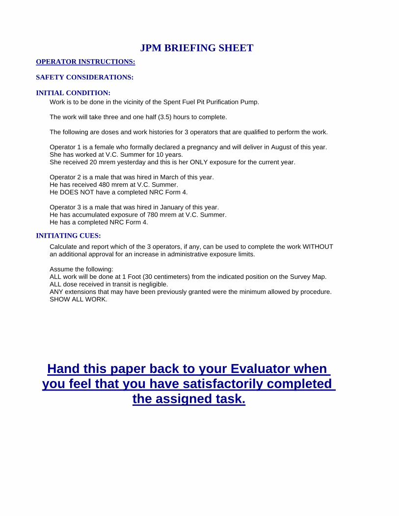
INITIATING CUES:
Calculate and report which of the 3 operators, if any, can be used to complete the work WITHOUT an additional approval for an increase in administrative exposure limits.
Assume the following:ALL work will be done at 1 Foot (30 centimeters) from the indicated position on the Survey Map.ALL dose received in transit is negligible.ANY extensions that may have been previously granted were the minimum allowed by procedure.SHOW ALL WORK.
INITIAL CONDITION:Work is to be done in the vicinity of the Spent Fuel Pit Purification Pump.
The work will take three and one half (3.5) hours to complete.
The following are doses and work histories for 3 operators that are qualified to perform the work.
Operator 1 is a female who formally declared a pregnancy and will deliver in August of this year.She has worked at V.C. Summer for 10 years.She received 20 mrem yesterday and this is her ONLY exposure for the current year.
Operator 2 is a male that was hired in March of this year.He has received 480 mrem at V.C. Summer. He DOES NOT have a completed NRC Form 4.
Operator 3 is a male that was hired in January of this year.He has accumulated exposure of 780 mrem at V.C. Summer.He has a completed NRC Form 4.
SAFETY CONSIDERATIONS:
OPERATOR INSTRUCTIONS:
Hand this paper back to your Evaluator when you feel that you have satisfactorily completed
the assigned task.
JPM BRIEFING SHEET
5/6/2016 Page 7 of 7
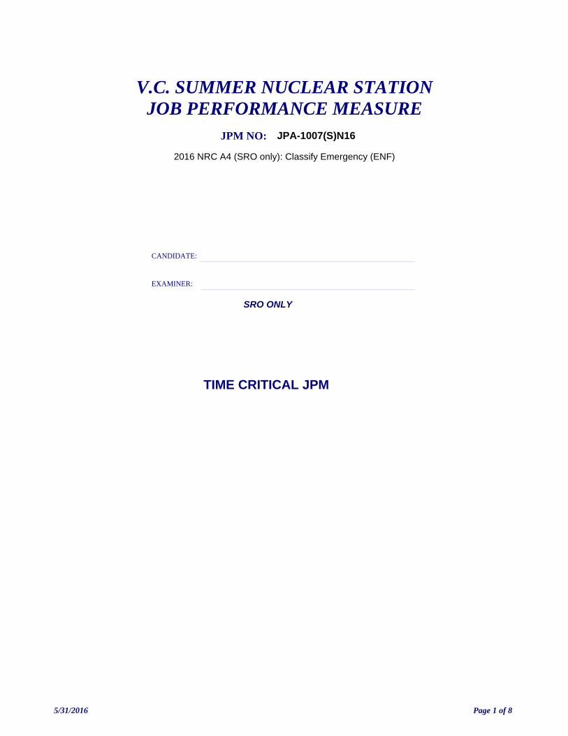
2016 NRC A4 (SRO only): Classify Emergency (ENF)
V.C. SUMMER NUCLEAR STATIONJOB PERFORMANCE MEASURE
CANDIDATE:
EXAMINER:
JPM NO: JPA-1007(S)N16
SRO ONLY
TIME CRITICAL JPM
5/31/2016 Page 1 of 8
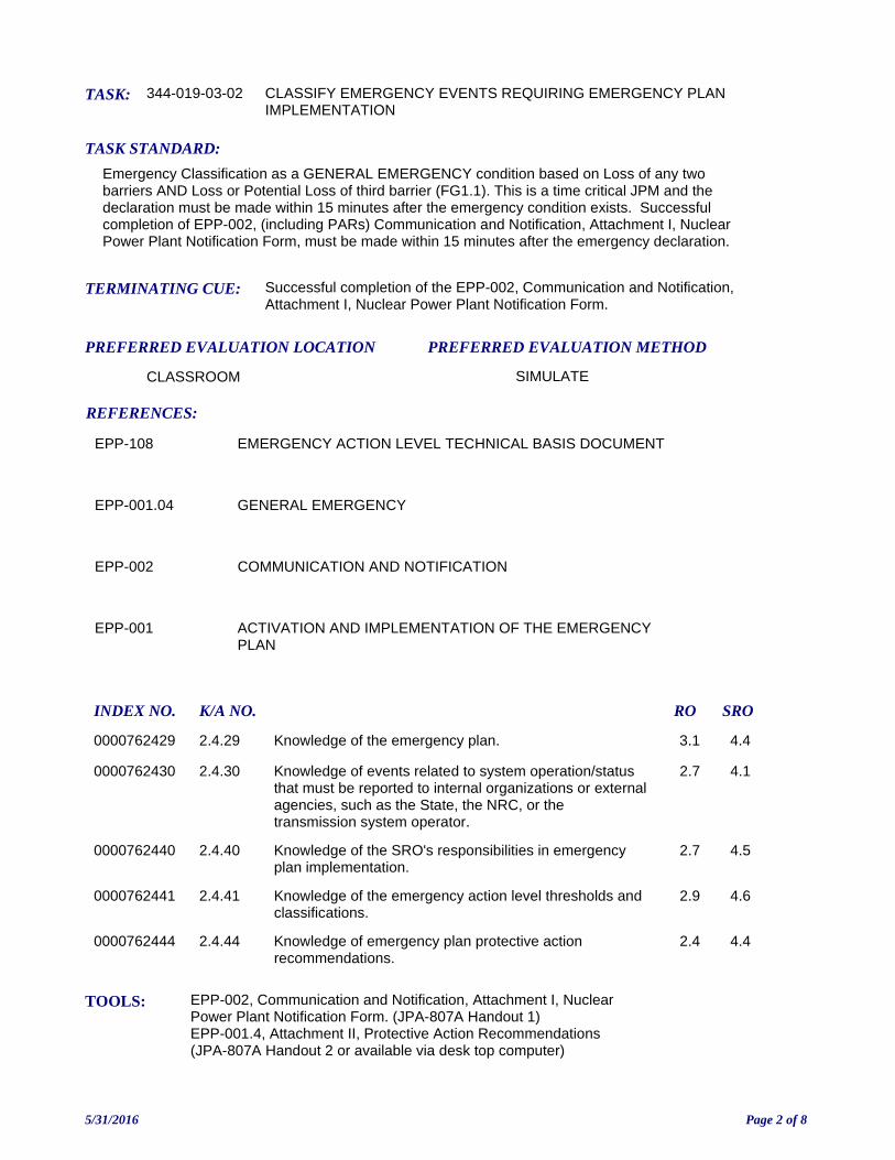
TASK: 344-019-03-02
PREFERRED EVALUATION METHOD
SIMULATE
TASK STANDARD:
Emergency Classification as a GENERAL EMERGENCY condition based on Loss of any two barriers AND Loss or Potential Loss of third barrier (FG1.1). This is a time critical JPM and the declaration must be made within 15 minutes after the emergency condition exists. Successful completion of EPP-002, (including PARs) Communication and Notification, Attachment I, Nuclear Power Plant Notification Form, must be made within 15 minutes after the emergency declaration.
PREFERRED EVALUATION LOCATION
CLASSROOM
CLASSIFY EMERGENCY EVENTS REQUIRING EMERGENCY PLAN IMPLEMENTATION
TOOLS: EPP-002, Communication and Notification, Attachment I, Nuclear Power Plant Notification Form. (JPA-807A Handout 1)EPP-001.4, Attachment II, Protective Action Recommendations (JPA-807A Handout 2 or available via desk top computer)
REFERENCES:
TERMINATING CUE: Successful completion of the EPP-002, Communication and Notification, Attachment I, Nuclear Power Plant Notification Form.
EPP-108 EMERGENCY ACTION LEVEL TECHNICAL BASIS DOCUMENT
EPP-001.04 GENERAL EMERGENCY
EPP-002 COMMUNICATION AND NOTIFICATION
EPP-001 ACTIVATION AND IMPLEMENTATION OF THE EMERGENCY PLAN
INDEX NO. RO SROK/A NO.
0000762429 Knowledge of the emergency plan. 3.1 4.42.4.29
0000762430 Knowledge of events related to system operation/status that must be reported to internal organizations or external agencies, such as the State, the NRC, or the transmission system operator.
2.7 4.12.4.30
0000762440 Knowledge of the SRO's responsibilities in emergency plan implementation.
2.7 4.52.4.40
0000762441 Knowledge of the emergency action level thresholds and classifications.
2.9 4.62.4.41
0000762444 Knowledge of emergency plan protective action recommendations.
2.4 4.42.4.44
5/31/2016 Page 2 of 8
EVALUATION TIME 25 TIME CRITICAL YES
TIME START: TIME FINISH:
PERFORMANCE RATING: SAT: UNSAT:
PERFORMANCE TIME:
EXAMINER:SIGNATURE DATE
10CFR55: 45(a)(11)
Stopwatch or other suitable timepieceEPP-001, Attachment 1 EAL Classification Matrix (available via desk top computer or as big board)
CANDIDATE:
5/31/2016 Page 3 of 8
INITIATING CUES:1. Classify the event and indicate the basis for the classification in accordance with EPP-001, Activation and Implementation of the Emergency Plan. Do NOT use ED Judgment as the basis for your classification.
2. Complete thEPP-002, Communication and Notification, Attachent I, Nuclear Power Plant Notification Form.
ASSUME THAT THE NOTIFICATION YOU ARE MAKING IS THE INITIAL NOTIFICATION.
INITIAL CONDITION:30 MINUTES AGO:A Reactor Trip AND Safety Injection occurred due to PZR Pressure Low.Charging pumps and RHR pumps could NOT be started manually or automatically.
10 MINUTES AGO:ALL Offsite Power was lost.Buses 1DA and 1DB reenergized automatically from the EDGs.Operators entered EOP-14.0 FR-C.1 RESPONSE TO INADEQUATE CORE COOLING based onthe status of CRITICAL SAFETY FUNCTIONS, as reported by the STA.
CURRENT CONDITIONS:RCS pressure is 1150 psigReactor Building pressure is 18 psig and rising.Core Exit Thermocouple temperatures are 780°F and increasing.NR RVLIS is 30% and decreasing..SG Narrow Range Levels are stable at 45%, 43%, 47%.Operators have depressurized steam generators to 50 psig.RM-G7 /G18 read 450 R/hr.ALL other radiation monitor readings are NORMAL.The System Controller reports that 230 KV will be restored in 2 hours.Electricians report that a Charging pump can be restored in approximately 30 minutes.
Met Data - Wind Direction is from 25 degreesMet Data - Wind Speed is 20 mphMet Data - Wind Stability is Class E
READ TO OPERATOR:
SAFETY CONSIDERATIONS: None
When I tell you to begin, you are to perform the actions as directed in the initiating cues.
I will describe the general conditions under which this task is to be performed and provide the necessary tools with which to perform this task.
Before starting, I will explain the initial conditions, which steps to simulate or discuss, and provide initiating cues. When you complete the task successfully, this Job Performance Measure will be satisfied.
THIS IS A TIME CRITICAL JPM!
INSTRUCTIONS TO OPERATOR
HAND JPM BRIEFING SHEET TO OPERATOR AT THIS TIME!
5/31/2016 Page 4 of 8
Determine that conditions require classification as a GENERAL EMERGENCY.
Evaluator Cue: A time can be provided to the candidate for Reactor trip that is the end of brief time (T0) minus 30 minutes for clarity. Normally this time would be obtained from IPCS screen.
Evaluator note: This JPM is intended to be run on one Examinee at a time. If multiple Examinees are evaluated at one time then provisions to segregate them must be made. This allows verbalization of the classification as necessary.
Evaluator note: The Examinee has 15 min from the end of the Plant Conditions brief (Time 0), tocomplete the event classification. Use the same clock or watch to record the time at the end of brief and the time of classification. Compute the difference between the two times as the elapsed time. This step is critical since proper classification must be made within 15 minutes.Evaluator cue: Provide a copy of JPA-1007-N16 Handout 2 (EPP-001.4 Attachment II) once theExaminee has determined that the event is a General Emergency.
Yes
Classifies event as a GENERAL EMERGENCY within 15 minutes based on:EAL FG1.1 - Loss of any two barriers AND Loss or Potential Loss of third barrier (Table F-1).
T0 = Time at end of brief ______________
T1 = Time of classification ______________
Elapsed time (T1 - T0) ______________
CUES:
SEQUENCED:
STEP STANDARD:
COMMENTS:
SAT UNSATCRITICAL: Yes
JPM STEP: 1
5/31/2016 Page 5 of 8
Examiner ends JPM at this point.
Complete EPP-002, Attachment I, Nuclear Power Plant Emergency Notification Form and provide basis for classification.
Evaluator cue: Hand Examinee their copy of EPP-002 Attachment 1 (JPA-1001 Handout) with the classification time entered. Commence timing for completion of Attachment 1.
Evaluator cue: If asked provide 803-334-1234 as the confirmation phone number.
Evaluator cue: Examinee must explain basis for classification. Ask Examinee for basis if it is not offered. If the basis is not correct, this constitutes failure even if the classification was correct and within 15 minutes.
Evaluator note: Record elapsed time when Examinee hands you the EPP-002 Attachment as theApproved by time (line 17 on the EPP-002 Attachment 1). Must be within 15 minutes of time whentheir classification had been completed. Refer to JPA-1001 Key for critical items on EPP-002Attachment 1.
Yes
Correctly completes EPP-002 Attachment 1 within 15 minutes of declaring event classification.
Classification Basis:
1. (FUEL CLAD LOSS) Core Cooling Red Path conditions met. Item 2.A2. (RCS LOSS) EITHER RM-G7/ G18 > 100 R/hr - Item 3.A - OR - Automatic ECCS actuation required by UNISOLABLE RCS leakage, Item 1.A.3. (CONTAINMENT POTENTIAL LOSS) Core Cooling Red Path conditions met and restoration procedure not effective within 15 min. Item 2.A.
Referring to EPP-001.4, General Emergency, Attachment II, determines that evacuation of 2 mile radius and 5 miles downwind is required and that sheltering 5-10 mile downwind required.
Determines sectors for evacuation/shelter:
1. Evacuate EPZ zones A-0, E-12. Shelter zones D-1, D-2 and E-2
T1 = Time of classification ______________
T2 = Time Attachment II complete ______________
Elapsed time (T2 - T1) ______________
CUES:
SEQUENCED:
STEP STANDARD:
COMMENTS:
SAT UNSATCRITICAL: Yes
JPM STEP: 2
5/31/2016 Page 6 of 8
JPM: JPA-1007(S2016 NRC A4 (SRO only): Classify Emergency (ENF)
IC SET: NA
INSTRUCTIONS:
The following items, as indicated on the JPA -1006 key are considered as "Critical Items":
- Class of Emergency- Description of Emergency
- Wind Direction and Speed- Whether Offsite Protective Measures are necessary
- Potentially affected population and areas - Whether a release is taking place
- Time of Emergency Declaration- Whether the event is a Drill or Actual Event
COMMENTS:
JPM SETUP SHEET
5/31/2016 Page 7 of 8
INITIATING CUES:
1. Classify the event and indicate the basis for the classification in accordance with EPP-001, Activation and Implementation of the Emergency Plan. Do NOT use ED Judgment as the basis for your classification.
2. Complete thEPP-002, Communication and Notification, Attachent I, Nuclear Power Plant Notification Form.
ASSUME THAT THE NOTIFICATION YOU ARE MAKING IS THE INITIAL NOTIFICATION.
INITIAL CONDITION:30 MINUTES AGO:A Reactor Trip AND Safety Injection occurred due to PZR Pressure Low.Charging pumps and RHR pumps could NOT be started manually or automatically.
10 MINUTES AGO:ALL Offsite Power was lost.Buses 1DA and 1DB reenergized automatically from the EDGs.Operators entered EOP-14.0 FR-C.1 RESPONSE TO INADEQUATE CORE COOLING based onthe status of CRITICAL SAFETY FUNCTIONS, as reported by the STA.
CURRENT CONDITIONS:RCS pressure is 1150 psigReactor Building pressure is 18 psig and rising.Core Exit Thermocouple temperatures are 780°F and increasing.NR RVLIS is 30% and decreasing..SG Narrow Range Levels are stable at 45%, 43%, 47%.Operators have depressurized steam generators to 50 psig.RM-G7 /G18 read 450 R/hr.ALL other radiation monitor readings are NORMAL.The System Controller reports that 230 KV will be restored in 2 hours.Electricians report that a Charging pump can be restored in approximately 30 minutes.
Met Data - Wind Direction is from 25 degreesMet Data - Wind Speed is 20 mphMet Data - Wind Stability is Class E
SAFETY CONSIDERATIONS: None
OPERATOR INSTRUCTIONS:
Hand this paper back to your Evaluator when you feel that you have satisfactorily completed
the assigned task.
JPM BRIEFING SHEET
5/31/2016 Page 8 of 8


