Embed Size (px)
Citation preview
Copyright (2013) American Institute of Physics. This article may be downloaded for personal use only. Any other use requires prior permission of the author and the American Institute of Physics. The following article appeared in Journal of Applied Physics (Vol.114, Issue 2) and may be found at http://jap.aip.org/resource/1/japiau/v114/i2/p024701_s1 or http://dx.doi.org/10.1063/1.4813484 This Article is copyright the American Institute of Physics (AIP) Publishing LLC AIP Publishing LLC 2 Huntington Quadrangle Melville NY USA Email: [email protected] http://journals.aip.org

Study on an alternating current electrothermal micropump for microneedle-based fluid delivery systemsRumi Zhang, Graham A. Jullien, and Colin Dalton Citation: J. Appl. Phys. 114, 024701 (2013); doi: 10.1063/1.4813484 View online: http://dx.doi.org/10.1063/1.4813484 View Table of Contents: http://jap.aip.org/resource/1/JAPIAU/v114/i2 Published by the AIP Publishing LLC. Additional information on J. Appl. Phys.Journal Homepage: http://jap.aip.org/ Journal Information: http://jap.aip.org/about/about_the_journal Top downloads: http://jap.aip.org/features/most_downloaded Information for Authors: http://jap.aip.org/authors

Study on an alternating current electrothermal micropumpfor microneedle-based fluid delivery systems
Rumi Zhang,1 Graham A. Jullien,1 and Colin Dalton2,a)
1Advanced Technology Information Processing Systems (ATIPS) Laboratory, Electrical and ComputerEngineering, University of Calgary, Calgary, Alberta T2N 1N4, Canada2Advanced Micro/Nanosystems Integration Facility (AMIF), Electrical and Computer Engineering,University of Calgary, Calgary, Alberta T2N 1N4, Canada
(Received 4 January 2013; accepted 23 June 2013; published online 11 July 2013)
In this paper, we report on a modeling study of an AC electrothermal (ACET) micropump with
high operating pressures as well as fast flow rates. One specific application area is for fluid delivery
using microneedle arrays which require higher pressures and faster flow rates than have been
previously reported with ACET devices. ACET is very suitable for accurate actuation and control
of fluid flow, since the technique has been shown to be very effective in high conductivity fluids
and has the ability to create a pulsation free flow. However, AC electrokinetic pumps usually can
only generate low operating pressures of 1 to 100 Pa, where flow reversal is likely to occur with an
external load. In order to realize a high performance ACET micropump for continuous fluid
delivery, applying relatively high AC operating voltages (20 to 36 Vrms) to silicon substrate ACET
actuators and using long serpentine channel allows the boosting of operating pressure as well as
increasing the flow rates. Fast pumping flow rates (102–103 nl/s) and high operating pressures
(1–12 kPa) can be achieved by applying both methods, making them of significant importance for
continuous fluid delivery applications using microneedle arrays and other such biomedical devices.VC 2013 AIP Publishing LLC. [http://dx.doi.org/10.1063/1.4813484]
I. INTRODUCTION
With microfluidics, one of the significant technological
challenges is the precise control and manipulation of microli-
ter or nanoliter volumes of fluids. One of the key compo-
nents is the miniature fluid-dispensing system or micropump.
Over the past few decades, numerous papers have been pub-
lished on the development and fabrication of reciprocating
displacement micropumps, which use the oscillatory move-
ment of mechanical parts to transfer mechanical energy into
fluid movement.1,2 However, a major problem existing in
reciprocating displacement micropumps is that fluid from
these micropumps is delivered in a series of small discrete
volumes, which make up a pulsating flow.1,3 For a pulsating
flow, flow fluctuation is relatively large at low flow rates,
and therefore the accurate adjustment of uniform flow rates
might be difficult.3 Also, mechanical fatigue caused by wear
and stiction of moving parts in reciprocating mechanical
micropumps often restrict the operational environment and
limit the lifetime of these devices.3 Micropump failure can
also be caused by other problems such as lack of tolerance to
bubbles, leaks in the diaphragm, or valve causing pressure
loss, structural complexity, and slow response time.3,4
In previous studies, electrokinetics has been demon-
strated as having great potential for microfluidic actuation in
bio-MEMS and lab-on-a-chip systems, due to its basic imple-
mentation efficiency and reliability from having neither
mechanically moving parts nor valves to drive the fluid
flow.5–9 Compared to mechanical micropumps, advantages of
electrokinetic micropumps include simplicity in design and
fabrication, longer life cycle, and minimal issues with block-
age.10 More importantly, they do not have any moving parts,
and they are therefore capable of creating a pulsation free
flow, i.e., a very precise continuous steady fluid flow.9,14
Electrokinetic techniques with AC electric sources, such as
AC electrothermal (ACET), AC electro osmosis (ACEO), or
dielectrophoresis (DEP), can easily achieve high electric field
strengths for on-chip micropumping and particle manipula-
tion with only a few volts (�10 Vrms).3,11–14 Also, electrolysis
is avoided when an AC source is applied,9 since an AC
source avoids a net movement of ions within the solution.
In this paper, we carry out a modeling study of an ACET
micropump for the requirements of high operating pressures
as well as fast pumping flow rates. One specific application
area is for fluid delivery using microneedle arrays. In previous
studies of microneedles, reciprocating displacement micro-
pumps excited by piezoelectric or thermopneumatic actuators
have been designed for microneedle fluid delivery sys-
tems.4,18,19 It has been observed in Ref. 18 that net water flow
rates of approximately 2.0 nl/s out of microneedles were
obtained at a pressure of 3.9 kPa for continuous on-chip
micropumping. Other studies20,21 also suggested that micro-
needles be operated in the kPa range of pressures. ACET has
been shown to be very effective in high conductivity fluids
and therefore is useful for biological applications, which fre-
quently involve samples with conductivities higher than 0.1 S/m
(for example, saline solution has a conductivity of 1–2 S/m).14–17
ACET micropumping has been demonstrated at low voltages
(< 15 Vrms) for fluid conductivity of 0.02–1 S/m with
fluid velocity of 100–1000 lm/s.17 With this, ACET micro-
pumps are capable of pumping 0 to 500 nl/s fluid flow, and
the precisely controlled flow velocity can be achieved bya)Electronic mail: [email protected].
0021-8979/2013/114(2)/024701/8/$30.00 VC 2013 AIP Publishing LLC114, 024701-1
JOURNAL OF APPLIED PHYSICS 114, 024701 (2013)

adjusting the AC potential between electrode pairs.
However, we should note that the existing AC electrokinetic
pumps including ACET micropumps usually can only gener-
ate low operating pressures of 1 to 100 Pa, and thus flow
rates will decay rapidly and cannot even prevent flow rever-
sal against an external load.22
Recently, Huang et al. proposed a high-pressure (about
1.3 kPa) ACEO micropump, in which a long serpentine chan-
nel was used to boost its pressure.22 However, ACEO is not
effective in fluids with high electrical conductivities, which
excludes most biofluidic applications. Also, the microchannel
present in Ref. 22 is only 100 lm (W) and 25 lm (H), too
small to have high volume fluid flow rates (Q¼ outlet cross-
section area� velocity), as required for microneedle arrays or
other such microfluidic devices. It has been reported that
experiments using microneedles for intradermal delivery of
sterile salin23 used a flow rate of 0.3 ml/min (5000 nl/s). As
well, Roxhed et al. reported that a flow rate of 2.0 ll/h
(0.56 nl/s) ensured a leak-free delivery for insulin into rat der-
mis.24 Such a study was carried out using an array of 21 hol-
low microneedles on an effective area of 2� 2 mm2 only.
However, as stated in Ref. 24 such a low infusion rate is
impractically low for most human drug delivery applications
(for example, a representative real-time need of 10 units typi-
cally absorbed on the time scale of an hour for a conventional
formulation of 100 units/ml insulin for diabetic patients,
�27.8 nl/s), and, hence, the rate needs to be increased to
make the technique useful.24 As the total infusion rate
depends on the number of needles, using a large array with
an effective area of a few cm2 will allow much higher deliv-
ery rates (14 nl/s with 1� 1 cm2, 56 nl/s with 2� 2 cm2, or
126 nl/s with 3� 3 cm2, respectively) for leak-free delivery.24
In our study, we examine two means for increasing the oper-
ating pressures: applying relatively high AC operating vol-
tages (20 to 36 Vrms) to ACET actuators with silicon
substrates and increasing the channel length with a long ser-
pentine channel. Studies show that operating pressures of
1–12 kPa and pumping flow rates of 102–103 nl/s can be
achieved. This does not account for the reduction of flow
rates expected in the transition from the ACET actuator to the
complex channel geometry of the microneedle array. The
pressure and flow rate drop required to flow fluid through a
microneedle depends on needle geometry and fluid viscosity
and density.25 Needles of micron dimensions can exhibit sig-
nificant resistance to flow.25 Also, flow resistance into tissue
is expected during a microneedle injection into skin, and it
has been reported that the presence of skin tissue decreases
the flow rate by one or more orders of magnitude.25 Since the
flow rate decays linearly with the back pressure, P, improve-
ment in both pumping flow rates and pressures are of signifi-
cant importance for ACET micropumps when implemented
for continuous fluid delivery using microneedle arrays and
other microfluidic applications.
II. ACET FLUID FLOW
ACET refers to electrothermal flow induced by a non-
uniform thermal field generated in a fluid, i.e., a temperature
gradient, rT, in the presence of AC electric fields. The
temperature gradient, rT, can be obtained from Joule heat-
ing in Eq. (1) (Ref. 27)
kr2T þ rjEj2 ¼ 0; (1)
where r and k are the electrical conductivity and the thermal
conductivity of the fluid, respectively. jEj is the magnitude
of the electric field applied over the fluid, determined by the
gradient of the AC potential, V
E ¼ �rV: (2)
The time average electric force on the fluid is described
as27
hfeti ¼1
2
eða� bÞ1þ ðxsÞ2
ðrT � EÞE� 1
4eajEj2 � rT; (3)
where a ¼ 1=eð@e=@TÞ; b ¼ 1=rð@r=@TÞ, in which r and eare the electrical conductivity and permittivity of the me-
dium, respectively. s ¼ r=e is its charge relaxation time,
and x ¼ 2pf is the angular frequency of the applied AC
potential.
For an incompressible fluid of low Reynolds number,
the resulting steady fluid flow in the microchannel follows
the Navier-Stokes equations9,36
�rpþ gr2uþ hfeti ¼ 0; r � u ¼ 0; (4)
where u denotes the velocity field vector. g is the dynamic
viscosity, and p is the pressure, respectively. Equations
(1)–(4) provide the functional relationship between fluid ve-
locity and temperature gradient produced by the applied AC
electric field. For a more detailed explanation of ACET fluid
flow, please refer to Ref. 31.
III. DESIGN OF AN ACET MICROPUMP
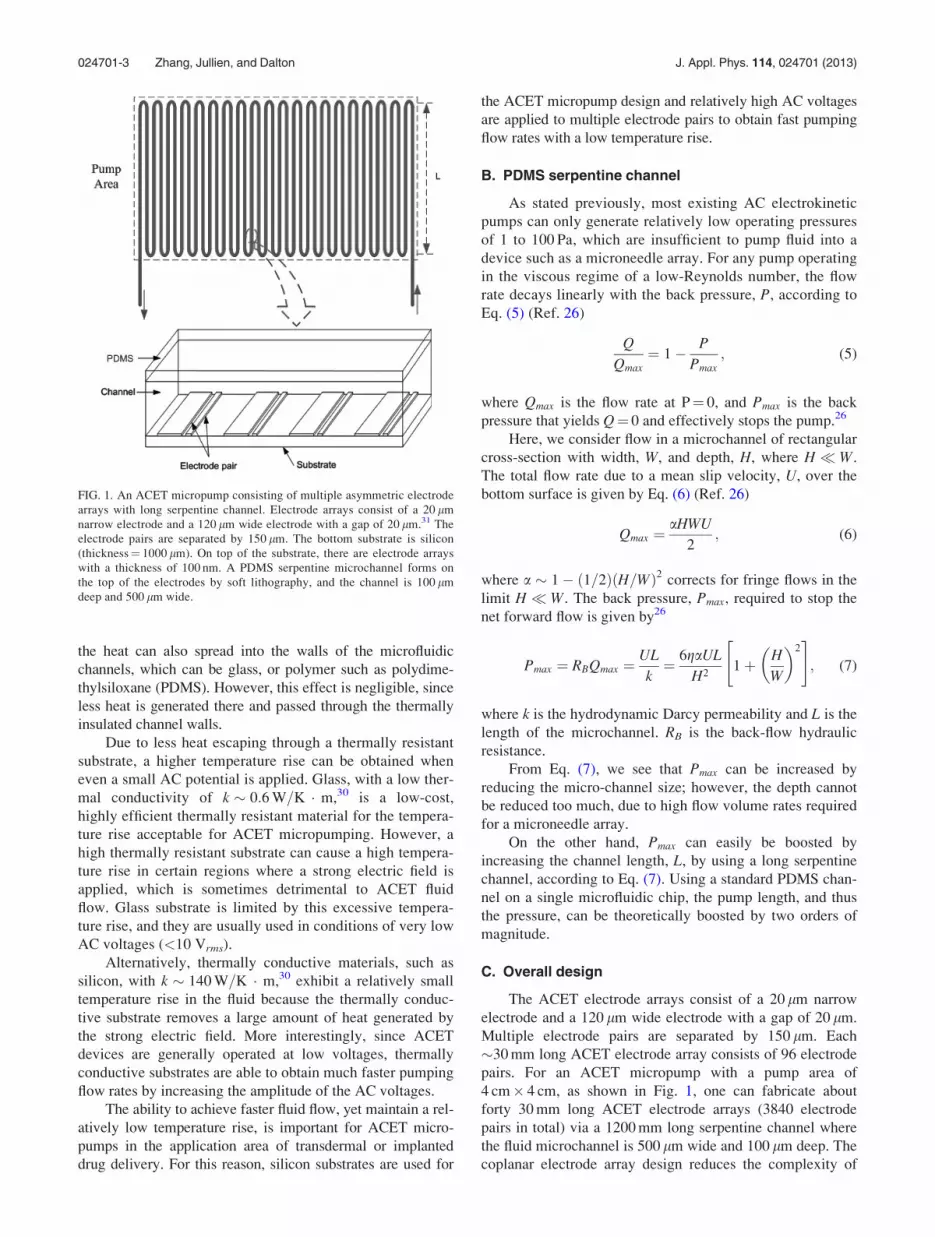
As shown in Fig. 1, the new ACET micropump consists
of multiple unequal width electrodes located at the bottom of
a long serpentine channel forming an interdigitated array,
with AC voltages applied between the narrow and the wide
electrodes. In the following sections, we will explain the
detailed design of the new ACET micropump, and how it is
able to achieve faster pumping flow rates as well as higher
operating pressures than previously reported designs.
A. Substrate
Substrate materials for ACET micropumps can be glass,
silicon, or other materials, such as ceramics. Coplanar elec-
trode arrays are positioned on the surface of the substrate,
which acts as a heat sink. The electric fields generated by the
electrode arrays are much stronger around the electrode arrays
than in the bulk fluid, and thus more heat is generated there.17
Part of the heat spreads into the substrate by conduction and
then from the underside surface of the substrate into the ambi-
ent air. Thus, the thermal properties of the substrate have a
significant effect on ACET micropumping abilities. Part of
024701-2 Zhang, Jullien, and Dalton J. Appl. Phys. 114, 024701 (2013)
the heat can also spread into the walls of the microfluidic
channels, which can be glass, or polymer such as polydime-
thylsiloxane (PDMS). However, this effect is negligible, since
less heat is generated there and passed through the thermally
insulated channel walls.
Due to less heat escaping through a thermally resistant
substrate, a higher temperature rise can be obtained when
even a small AC potential is applied. Glass, with a low ther-
mal conductivity of k � 0:6 W=K � m,30 is a low-cost,
highly efficient thermally resistant material for the tempera-
ture rise acceptable for ACET micropumping. However, a
high thermally resistant substrate can cause a high tempera-
ture rise in certain regions where a strong electric field is
applied, which is sometimes detrimental to ACET fluid
flow. Glass substrate is limited by this excessive tempera-
ture rise, and they are usually used in conditions of very low
AC voltages (<10 Vrms).
Alternatively, thermally conductive materials, such as
silicon, with k � 140 W=K � m,30 exhibit a relatively small
temperature rise in the fluid because the thermally conduc-
tive substrate removes a large amount of heat generated by
the strong electric field. More interestingly, since ACET
devices are generally operated at low voltages, thermally
conductive substrates are able to obtain much faster pumping
flow rates by increasing the amplitude of the AC voltages.
The ability to achieve faster fluid flow, yet maintain a rel-
atively low temperature rise, is important for ACET micro-
pumps in the application area of transdermal or implanted
drug delivery. For this reason, silicon substrates are used for
the ACET micropump design and relatively high AC voltages
are applied to multiple electrode pairs to obtain fast pumping
flow rates with a low temperature rise.
B. PDMS serpentine channel
As stated previously, most existing AC electrokinetic
pumps can only generate relatively low operating pressures
of 1 to 100 Pa, which are insufficient to pump fluid into a
device such as a microneedle array. For any pump operating
in the viscous regime of a low-Reynolds number, the flow
rate decays linearly with the back pressure, P, according to
Eq. (5) (Ref. 26)
Q
Qmax¼ 1� P
Pmax; (5)
where Qmax is the flow rate at P¼ 0, and Pmax is the back
pressure that yields Q¼ 0 and effectively stops the pump.26
Here, we consider flow in a microchannel of rectangular
cross-section with width, W, and depth, H, where H � W.
The total flow rate due to a mean slip velocity, U, over the
bottom surface is given by Eq. (6) (Ref. 26)
Qmax ¼aHWU
2; (6)
where a � 1� ð1=2ÞðH=WÞ2 corrects for fringe flows in the
limit H � W. The back pressure, Pmax, required to stop the
net forward flow is given by26
Pmax ¼ RBQmax ¼UL
k¼ 6gaUL
H21þ H
W
� �2" #
; (7)
where k is the hydrodynamic Darcy permeability and L is the
length of the microchannel. RB is the back-flow hydraulic
resistance.
From Eq. (7), we see that Pmax can be increased by
reducing the micro-channel size; however, the depth cannot
be reduced too much, due to high flow volume rates required
for a microneedle array.
On the other hand, Pmax can easily be boosted by
increasing the channel length, L, by using a long serpentine
channel, according to Eq. (7). Using a standard PDMS chan-
nel on a single microfluidic chip, the pump length, and thus
the pressure, can be theoretically boosted by two orders of
magnitude.
C. Overall design
The ACET electrode arrays consist of a 20 lm narrow
electrode and a 120 lm wide electrode with a gap of 20 lm.
Multiple electrode pairs are separated by 150 lm. Each
�30 mm long ACET electrode array consists of 96 electrode
pairs. For an ACET micropump with a pump area of
4 cm� 4 cm, as shown in Fig. 1, one can fabricate about
forty 30 mm long ACET electrode arrays (3840 electrode
pairs in total) via a 1200 mm long serpentine channel where
the fluid microchannel is 500 lm wide and 100 lm deep. The
coplanar electrode array design reduces the complexity of
FIG. 1. An ACET micropump consisting of multiple asymmetric electrode
arrays with long serpentine channel. Electrode arrays consist of a 20 lm
narrow electrode and a 120 lm wide electrode with a gap of 20 lm.31 The
electrode pairs are separated by 150 lm. The bottom substrate is silicon
(thickness¼ 1000 lm). On top of the substrate, there are electrode arrays
with a thickness of 100 nm. A PDMS serpentine microchannel forms on
the top of the electrodes by soft lithography, and the channel is 100 lm
deep and 500 lm wide.
024701-3 Zhang, Jullien, and Dalton J. Appl. Phys. 114, 024701 (2013)

the completed devices. Thus, all fluidic components may be
integrated onto one substrate, with a minimum of assembly
for future applications.
IV. NUMERICAL SIMULATIONS
A. Modeling
In this section, numerical simulations are carried out
using COMSOL MULTIPHYSICS software35 to evaluate the per-
formance of the ACET devices. First, the electric field is
solved using Eq. (2). Then the resulting thermal field is cal-
culated from Eq. (1), and finally the induced flow velocity is
solved from the Navier-Stokes equation, Eq. (4). From these
simulations, flow rates as well as operating pressures can be
obtained from Eqs. (6) and (7).
The schematic diagram of modeling domains and the
boundary conditions is given in Fig. 2. Three domains are
used for this study: the bottom 1000 lm thick substrate, the
100 lm thick fluid inside the channel, and finally a lid of a
100 lm thick PDMS layer.33 The boundary conditions for
the left and the right sides of the channel are set to be peri-
odic for electrostatic, thermal, and fluid flow simulation.
Besides these, for the electrostatic simulation, the electric
potentials on the asymmetric electrode pairs are set as Vrms
and 0, while the remainder of the boundaries is defined as
insulated/symmetry.27–31 For the thermal simulation, we
assume a fixed temperature of T¼ 20 �C (293.15 K) to the
top of the PDMS layer and the bottom of the substrate;33 for
the incompressible Navier-Stocks simulation, a non-slip wall
boundary condition is imposed on the fluid channel walls.
ACET actuators with glass and silicon substrates are
simulated at various operating AC potentials to evaluate the
performance of silicon ACET using relatively high poten-
tials. As with,30 the thermal conductivity, k, used for the
glass is 0:6 W=K �m, for the silicon 140 W=K �m, and for
the fluid, kf, is 0:598 W=K �m. Here, we use 1� phosphate
buffered saline (PBS) as an example, which is a buffer solu-
tion commonly used in biological research. The conductivity
and permittivity of 1� PBS buffer are r¼ 0.224 S/m and
e ¼ 80e0, respectively, where the permittivity of free space,
e0 ¼ 8:854� 10�12 F=m. The viscosity of water, g, taken as
a function of temperature T(K), are used to account for vis-
cosity change with rising temperature
g ¼ 2:414� 10�5 � 10247:8=ðT�140Þ: (8)
The number and type of mesh elements are critically im-
portant to obtain the minimum level of discretization to
achieve accurate results. For our simulation, more than
100 000 triangular elements were used in each simulation.
We have also performed a simple mesh-convergence analy-
sis to ensure the convergence of our simulation results. This
required that after solving for one situation, the mesh was
made finer and the simulation re-solved to check that the so-
lution was within acceptable bounds. Less than 0.5% change
was observed for our simulation results when more than
100 000 triangular elements were used. Stable convergence
was achieved in the numerical iteration in all cases.
Fig. 3 gives the simulation result of the 1-pair section,
part of the silicon ACET actuator, where an AC potential of
25 Vrms was applied to its corresponding structures. In this
figure, surface colors, arrows, and streamlines represent the
temperature, the electric field, and the fluid flow, respec-
tively. The temperature rise for the silicon ACET is
293–310.4 K where the volume flow rate obtained is 154 nl/s
(1.54� 108 lm3/s).
B. Preliminary experiments and accuracy
The performance and reliability of the numerical simula-
tion method used in this paper have been demonstrated in pre-
vious studies, in which COMSOL MULTIPHYSICS has proved to
provide good agreement between numerical simulation and
analytical solutions or available experimental data.9,17,28,30,36
In our previous preliminary experiments with glass substrates,
we used 8 electrode pairs of an electrode array for the study,
each consisting of an 18 lm narrow electrode and a 116 lm
wide electrode with a gap of 24 lm; we provided a separation
of 152 lm between electrode pairs, as shown in Fig. 4. The
PDMS microchannel sealed over the electrodes was 1000 lm
wide and 1000 lm deep.
Pumping was observed with fluids of 0.224 S/m when
applying 5 Vrms at 100 kHz. Fluid flow was determined using
time lapse video of beads traversing the array with an appliedFIG. 2. Domains and boundary conditions for solving the electrical field,
thermal field, and fluid flow inside the channel.31
FIG. 3. Numerical simulation result for the 1-pair section, part of the silicon
ACET actuator, where an AC potential of 25 Vrms was applied.
024701-4 Zhang, Jullien, and Dalton J. Appl. Phys. 114, 024701 (2013)

field. After analyzing dozens of moving latex beads �100 lm
above the ACET electrode array in (Figs. 5(a)–5(d)), the ex-
perimental data shown that fluid velocity was estimated to be
within 35–40 lm/s, compared to 33.2 lm/s in the same loca-
tion obtained from the simulation. The measured experiment
data thus agree with the simulation result, being within 20%.
Differences in the measured and simulated velocity can be
caused by many factors (for example, fluctuations in the
actual size of the fabricated electrodes and PDMS channel,
the resolution of the optical microscope, the size of time step
used in the video capture, and also viscous drag on the beads).
C. Flow rates
Figs. 6(a) and 6(b) show the effect of the applied AC
potentials, Vrms, on volume fluid flow rates, as well as maxi-
mum temperature, Tmax, occurring in the fluid, for both sili-
con and glass substrates, in which the AC potentials are
operated at a frequency of f¼ 100 kHz. Note that ACET fluid
flow is usually operated at frequencies of � 100 kHz. From
Ref. 36, there are three frequency regions (Coulomb force
dominated region, transition domain, and dielectric force
dominated region), and the fluid flow is independent of fre-
quency except in the transition domain. Both devices have
the same dimensions, sizes, and electrode geometry, the only
difference being the thermal conductivity and density of the
substrate, where k ¼ 0:6 W=K �m and q¼ 3000 kg/m3 are
for glass and k ¼ 140 W=K �m and q¼ 2330 kg/m3 are for
silicon, respectively.
From this simulation, we see that, with the same applied
AC potentials, the ACET device with the glass substrate
achieves much faster flow rates than that with the silicon
substrate. For example, for an AC signal with an amplitude
of 9 Vrms, the ACET with the glass substrate achieves a vol-
ume fluid flow rate of 8.30 nl/s (8.30� 106 lm3/s), approxi-
mately 400% more than that with the silicon substrate (2.33
nl/s or 2.33� 106 lm3/s), at the cost of a temperature
increase of about 23.5 �C (Tmax¼ 45.7 �C (318.9 K) for the
glass substrate and Tmax¼ 22.2 �C (295.4 K) for the silicon
substrate). It is noted that the faster fluid flow results mostly
from higher temperature rise due to the good thermal resist-
ance of the glass substrate. Compared to the thermally resist-
ant materials, a higher electric field, i.e., a high AC potential,
is required for the ACET device built on the thermally con-
ductive substrate in order to maintain the same flow rates as
that on the thermally resistant substrate.
As previously discussed, temperature rise is the major
concern in designing ACET actuators, due to the fact that ex-
cessive temperature rise might cause the degradation of
many reagents/analytes and even alter the functions of
biological systems.37 It is very difficult to further increase
the AC potential for the glass ACET devices (e.g., Tmax
> 58.4 �C (331.6 K) for an AC signal with an amplitude of
11 Vrms). In contrast, the silicon ACET devices are able to
enhance fluid flow by increasing the applied AC potentials,
since the maximum temperature is only 22.2 �C for an AC
signal with an amplitude of 9 Vrms.
As shown in Fig. 7(a), volume fluid flow rates increase
dramatically when the applied AC potentials increase. Fig.
7(b) depicts the relationship of volume fluid flow rates and
maximum temperature, Tmax (in which AC potentials for a
glass ACET are in the range of 0 to 11 Vrms). AC potentials of
more than 11 Vrms for a glass substrate ACET will cause the
temperature to rise to undesirable levels (above 60 �C). From
Fig. 7(b), the simulation results show that silicon ACET
devices are capable of achieving much faster pumping flow
rates, more than 20 times the rate of ACET devices built
on glass substrate, for all cases, where both devices are
maintained at the same temperature rise (e.g., 330 nl/s
(3.3� 108 lm3/s) at Tmax¼ 44.9 �C (318 K) for silicon, and 8.3
nl/s (8.3� 106 lm3/s) at Tmax¼ 45.7 �C (318.9 K) for glass).
FIG. 4. An ACET array.31,32
FIG. 5. Time lapse video images of beads traversing the array under an
applied AC field (dark areas are asymmetrical electrodes, latex beads were
used for tracking fluid movement). (a). t¼ 0 s; (b) t¼ 1 s; (c) t¼ 2 s; (d)
t¼ 3 s.
024701-5 Zhang, Jullien, and Dalton J. Appl. Phys. 114, 024701 (2013)

In general, thermally conductive materials are usually
electrically conductive. For example, silicon substrates have a
very low resistivity due to doping, making high resistivity sili-
con expensive. For this reason, it is very important to grow a
thin insulation layer, such as silicon dioxide (SiO2) or silicon
nitride (Si3N4), on top of a silicon substrate, to prevent a short
circuit occurring when applying AC potentials on the adjacent
ACET electrodes. Moreover, since silicon dioxide is a ther-
mally resistant material with a low thermal conductivity of
k � 1:0 W=K �m, a silicon ACET device coated with differ-
ent thickness of silicon dioxide layers can act as a material
with a thermal conductivity of less than 140 W=K �m.
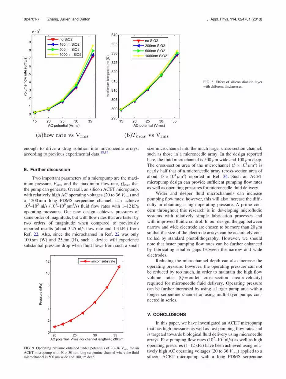
Fig. 8 shows the effect of a silicon dioxide layer fabri-
cated on silicon ACET electrodes on a silicon substrate.
From Fig. 8, we see that by controlling the silicon diox-
ide thickness, faster pumping flow rates can be achieved due
to a higher temperature rise as a result of a thicker insulation
layer.
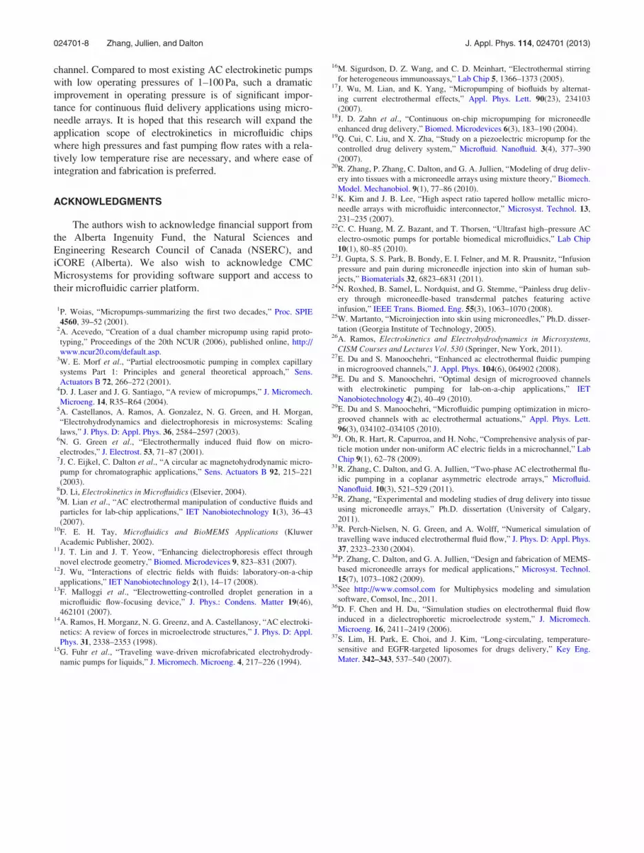
D. Operating pressure
For an ACET micropump with a pump area of
4 cm� 4 cm, as shown in Fig. 1, a 1200 mm long serpentine
channel can be fabricated on the top, where the fluid micro-
channel is 500 lm wide and 100 lm deep. Conducting traces
connected to the electrode array can be placed under the
spacing between the microchannel, which is greater than
500 lm. Fig. 9 gives the operating pressure, Pmax, obtained
under the applied AC potentials of 20–36 Vrms.
From Fig. 9, we see that it is easy to achieve higher
operating pressures exceeding 1 kPa, using an ACET micro-
pump with a long serpentine channel. This pressure is high
FIG. 6. Effect of the applied AC
potentials, Vrms, on volume fluid flow
rates, as well as maximum tempera-
ture, Tmax, in the fluid for both silicon
and glass substrate.
FIG. 7. The relationship of volume
fluid flow rates, as well as maximum
temperature, Tmax, occurred in the fluid
when higher AC potentials, Vrms, were
applied onto silicon.
024701-6 Zhang, Jullien, and Dalton J. Appl. Phys. 114, 024701 (2013)
enough to drive a drug solution into microneedle arrays,
according to previous experimental data.18,19
E. Further discussion
Two important parameters of a micropump are the maxi-
mum pressure, Pmax and the maximum flow-rate, Qmax that
the pump can generate. Overall, an silicon ACET micropump,
with relatively high AC operating voltages (20 to 36 Vrms) and
a 1200 mm long PDMS serpentine channel, can achieve
102–103 nl/s (108–109 lm3/s) fluid flow rates with 1–12 kPa
operating pressures. Our new design achieves pressures of
same order of magnitude, but with flow rates that are faster by
two orders of magnitude when compared to previously
reported results (about 3.25 nl/s flow rate and 1.3 kPa) from
Ref. 22. Also, since the microchannel in Ref. 22 was only
100 lm (W) and 25 lm (H), such a device will experience
substantial pressure drop when fluid flows from such a small
size microchannel into the much larger cross-section channel,
such as those in a microneedle array. In the design reported
here, the fluid microchannel is 500 lm wide and 100 lm deep.
The cross-section area of the microchannel (5� 104 lm2) is
nearly half that of a microneedle array (cross-section area of
about 13� 104 lm2) reported in Ref. 34. Such an ACET
micropump design can provide sufficient pumping flow rates
as well as operating pressures for microneedle fluid delivery.
Wider and deeper fluid microchannels can increase
pumping flow rates; however, this will also increase the diffi-
culty in obtaining a high operating pressure. A prime con-
cern throughout this research is in developing microfludic
systems with relatively simple fabrication processes and
with improved fluidic control. In our design, the gap between
narrow and wide electrode are chosen to be more than 20 lm
so that the size of the electrode arrays can be accurately con-
trolled by standard photolithography. However, we should
note that faster pumping flow rates can be further enhanced
by fabricating smaller gaps between the narrow and wide
electrodes.
Reducing the microchannel depth can also increase the
operating pressure; however, the operating pressure can not
be reduced by too much, in order to maintain the high flow
volume rates (Q¼ outlet cross-section area� velocity)
required for microneedle fluid delivery. Operating pressure
can be further increased by using a larger pump area with a
longer serpentine channel or using multi-layer pumps con-
nected in series.
V. CONCLUSIONS
In this paper, we have investigated an ACET micropump
that has high pressures as well as fast pumping flow rates and
is targeted towards biological fluid delivery using microneedle
arrays. Fast pumping flow rates (102–103 nl/s) as well as high
operating pressures (1–12 kPa) have been achieved using rela-
tively high AC operating voltages (20 to 36 Vrms) applied to a
silicon ACET micropump with a long PDMS serpentine
FIG. 8. Effect of silicon dioxide layer
with different thicknesses.
FIG. 9. Operating pressure obtained under potentials of 20–36 Vrms for an
ACET micropump with 40� 30 mm long serpentine channel where the fluid
microchannel is 500 lm wide and 100 lm deep.
024701-7 Zhang, Jullien, and Dalton J. Appl. Phys. 114, 024701 (2013)
channel. Compared to most existing AC electrokinetic pumps
with low operating pressures of 1–100 Pa, such a dramatic
improvement in operating pressure is of significant impor-
tance for continuous fluid delivery applications using micro-
needle arrays. It is hoped that this research will expand the
application scope of electrokinetics in microfluidic chips
where high pressures and fast pumping flow rates with a rela-
tively low temperature rise are necessary, and where ease of
integration and fabrication is preferred.
ACKNOWLEDGMENTS
The authors wish to acknowledge financial support from
the Alberta Ingenuity Fund, the Natural Sciences and
Engineering Research Council of Canada (NSERC), and
iCORE (Alberta). We also wish to acknowledge CMC
Microsystems for providing software support and access to
their microfluidic carrier platform.
1P. Woias, “Micropumps-summarizing the first two decades,” Proc. SPIE
4560, 39–52 (2001).2A. Acevedo, “Creation of a dual chamber micropump using rapid proto-
typing,” Proceedings of the 20th NCUR (2006), published online, http://
www.ncur20.com/default.asp.3W. E. Morf et al., “Partial electroosmotic pumping in complex capillary
systems Part 1: Principles and general theoretical approach,” Sens.
Actuators B 72, 266–272 (2001).4D. J. Laser and J. G. Santiago, “A review of micropumps,” J. Micromech.
Microeng. 14, R35–R64 (2004).5A. Castellanos, A. Ramos, A. Gonzalez, N. G. Green, and H. Morgan,
“Electrohydrodynamics and dielectrophoresis in microsystems: Scaling
laws,” J. Phys. D: Appl. Phys. 36, 2584–2597 (2003).6N. G. Green et al., “Electrothermally induced fluid flow on micro-
electrodes,” J. Electrost. 53, 71–87 (2001).7J. C. Eijkel, C. Dalton et al., “A circular ac magnetohydrodynamic micro-
pump for chromatographic applications,” Sens. Actuators B 92, 215–221
(2003).8D. Li, Electrokinetics in Microfluidics (Elsevier, 2004).9M. Lian et al., “AC electrothermal manipulation of conductive fluids and
particles for lab-chip applications,” IET Nanobiotechnology 1(3), 36–43
(2007).10F. E. H. Tay, Microfluidics and BioMEMS Applications (Kluwer
Academic Publisher, 2002).11J. T. Lin and J. T. Yeow, “Enhancing dielectrophoresis effect through
novel electrode geometry,” Biomed. Microdevices 9, 823–831 (2007).12J. Wu, “Interactions of electric fields with fluids: laboratory-on-a-chip
applications,” IET Nanobiotechnology 2(1), 14–17 (2008).13F. Malloggi et al., “Electrowetting-controlled droplet generation in a
microfluidic flow-focusing device,” J. Phys.: Condens. Matter 19(46),
462101 (2007).14A. Ramos, H. Morganz, N. G. Greenz, and A. Castellanosy, “AC electroki-
netics: A review of forces in microelectrode structures,” J. Phys. D: Appl.
Phys. 31, 2338–2353 (1998).15G. Fuhr et al., “Traveling wave-driven microfabricated electrohydrody-
namic pumps for liquids,” J. Micromech. Microeng. 4, 217–226 (1994).
16M. Sigurdson, D. Z. Wang, and C. D. Meinhart, “Electrothermal stirring
for heterogeneous immunoassays,” Lab Chip 5, 1366–1373 (2005).17J. Wu, M. Lian, and K. Yang, “Micropumping of biofluids by alternat-
ing current electrothermal effects,” Appl. Phys. Lett. 90(23), 234103
(2007).18J. D. Zahn et al., “Continuous on-chip micropumping for microneedle
enhanced drug delivery,” Biomed. Microdevices 6(3), 183–190 (2004).19Q. Cui, C. Liu, and X. Zha, “Study on a piezoelectric micropump for the
controlled drug delivery system,” Microfluid. Nanofluid. 3(4), 377–390
(2007).20R. Zhang, P. Zhang, C. Dalton, and G. A. Jullien, “Modeling of drug deliv-
ery into tissues with a microneedle arrays using mixture theory,” Biomech.
Model. Mechanobiol. 9(1), 77–86 (2010).21K. Kim and J. B. Lee, “High aspect ratio tapered hollow metallic micro-
needle arrays with microfluidic interconnector,” Microsyst. Technol. 13,
231–235 (2007).22C. C. Huang, M. Z. Bazant, and T. Thorsen, “Ultrafast high–pressure AC
electro-osmotic pumps for portable biomedical microfluidics,” Lab Chip
10(1), 80–85 (2010).23J. Gupta, S. S. Park, B. Bondy, E. I. Felner, and M. R. Prausnitz, “Infusion
pressure and pain during microneedle injection into skin of human sub-
jects,” Biomaterials 32, 6823–6831 (2011).24N. Roxhed, B. Samel, L. Nordquist, and G. Stemme, “Painless drug deliv-
ery through microneedle-based transdermal patches featuring active
infusion,” IEEE Trans. Biomed. Eng. 55(3), 1063–1070 (2008).25W. Martanto, “Microinjection into skin using microneedles,” Ph.D. disser-
tation (Georgia Institute of Technology, 2005).26A. Ramos, Electrokinetics and Electrohydrodynamics in Microsystems,
CISM Courses and Lectures Vol. 530 (Springer, New York, 2011).27E. Du and S. Manoochehri, “Enhanced ac electrothermal fluidic pumping
in microgrooved channels,” J. Appl. Phys. 104(6), 064902 (2008).28E. Du and S. Manoochehri, “Optimal design of microgrooved channels
with electrokinetic pumping for lab-on-a-chip applications,” IET
Nanobiotechnology 4(2), 40–49 (2010).29E. Du and S. Manoochehri, “Microfluidic pumping optimization in micro-
grooved channels with ac electrothermal actuations,” Appl. Phys. Lett.
96(3), 034102–034105 (2010).30J. Oh, R. Hart, R. Capurroa, and H. Nohc, “Comprehensive analysis of par-
ticle motion under non-uniform AC electric fields in a microchannel,” Lab
Chip 9(1), 62–78 (2009).31R. Zhang, C. Dalton, and G. A. Jullien, “Two-phase AC electrothermal flu-
idic pumping in a coplanar asymmetric electrode arrays,” Microfluid.
Nanofluid. 10(3), 521–529 (2011).32R. Zhang, “Experimental and modeling studies of drug delivery into tissue
using microneedle arrays,” Ph.D. dissertation (University of Calgary,
2011).33R. Perch-Nielsen, N. G. Green, and A. Wolff, “Numerical simulation of
travelling wave induced electrothermal fluid flow,” J. Phys. D: Appl. Phys.
37, 2323–2330 (2004).34P. Zhang, C. Dalton, and G. A. Jullien, “Design and fabrication of MEMS-
based microneedle arrays for medical applications,” Microsyst. Technol.
15(7), 1073–1082 (2009).35See http://www.comsol.com for Multiphysics modeling and simulation
software, Comsol, Inc., 2011.36D. F. Chen and H. Du, “Simulation studies on electrothermal fluid flow
induced in a dielectrophoretic microelectrode system,” J. Micromech.
Microeng. 16, 2411–2419 (2006).37S. Lim, H. Park, E. Choi, and J. Kim, “Long-circulating, temperature-
sensitive and EGFR-targeted liposomes for drugs delivery,” Key Eng.
Mater. 342–343, 537–540 (2007).
024701-8 Zhang, Jullien, and Dalton J. Appl. Phys. 114, 024701 (2013)


