Embed Size (px)
Citation preview
Composites: Part B 63 (2014) 77–84
Contents lists available at ScienceDirect
Composites: Part B
journal homepage: www.elsevier .com/locate /composi tesb
Structural limits of FRP-balsa sandwich decks in bridge construction
http://dx.doi.org/10.1016/j.compositesb.2014.03.0271359-8368/� 2014 Elsevier Ltd. All rights reserved.
⇑ Corresponding author. Tel.: +41 21 6933226; fax: +41 21 6936240.E-mail address: [email protected] (T. Keller).
Michael Osei-Antwi, Julia de Castro, Anastasios P. Vassilopoulos, Thomas Keller ⇑Composite Construction Laboratory (CCLab), Ecole Polytechnique Fédérale de Lausanne (EPFL), Station 16, Bâtiment BP, CH-1015 Lausanne, Switzerland
a r t i c l e i n f o
Article history:Received 3 March 2014Accepted 31 March 2014Available online 13 April 2014
Keywords:A. Layered structuresA. HybridB. ElasticityC. Finite element analysis (FEA)Bridges
a b s t r a c t
The span limits of two glass fiber-reinforced polymer (GFRP) bridge concepts involving GFRP-balsa sand-wich plates are discussed. The sandwich plates were either used directly as slab bridges or as decks of ahybrid sandwich-steel girder bridges. In the latter case, the potential of the sandwich decks to replacereinforced concrete (RC) decks was also evaluated. Taking the limits of manufacturing into account(800 mm slab thickness), maximum bridge spans of approximately 19 m can be reached with FRP-balsasandwich slab bridges, if a carbon-FRP (CFRP) arch is integrated into the balsa core. Above this limit,hybrid sandwich-steel girder bridges can be used up to spans of 30 m. RC deck replacement requirestimber and steel plate inserts into the balsa core above the steel girders. GFRP-balsa sandwich slabs ordecks exhibit full composite action between lower and upper face sheets. Stress concentrations occurat the joints between balsa core and timber inserts which however can effectively be reduced bychanging from butt to scarf joints.
� 2014 Elsevier Ltd. All rights reserved.
1. Introduction
Glass fiber-reinforced polymer (GFRP) composite bridge sys-tems offer favorable characteristics such as high strength per unitweight, resistance to corrosion, excellent fatigue performance,increased live load ratings in the case of bridge replacement andrapid field installation with minimized traffic disruptions [27,18].Two basic concepts of GFRP bridge systems exist: orthotropicsystems composed of adhesively bonded pultruded shapes andsandwich constructions. Both are used either as bridge decks indeck-girder bridges or as slabs in the case of slab bridges. Sandwichdecks or slabs have the advantage, amongst others, of flexible thick-ness contrary to pultruded decks or slabs and can thus be used formuch larger spans. Currently, they are composed of GFRP facesheets and honeycomb or foam cores. In the latter case, additionalGFRP webs are normally required to provide sufficient shear capac-ity of the core [24]. However, the honeycomb walls and internalGFRP webs in the foam core provide a non-uniform stiffness sup-port for the upper face sheet, which – under frequent wheel loads– may lead to the debonding of the upper face sheet from the core[23]. To overcome this drawback, i.e. provide a core with sufficientshear capacity and uniform support for the upper face sheet, balsawood was used as core material in the new Avançon Bridge, in Bex,Switzerland [20]. The use of balsa with fibers transverse to theupper face sheet and thus in line with the wheel load direction
did no longer require reinforcements by internal webs and provideda high indentation resistance against concentrated wheel loads. Thenew 11.45 m span and two-lane Avançon Bridge, composed of aGFRP-balsa sandwich deck adhesively bonded onto two steel gird-ers, replaced an old one-lane reinforced concrete (RC) bridge.
A further disadvantage of pultruded decks is manifested in thecase of RC deck replacement. RC decks normally act as top chordof hybrid RC-steel girders in the longitudinal bridge direction. Pul-truded GFRP decks, however, have low stiffness in this direction(which is transverse to the pultrusion direction) and are thus notable to transfer the longitudinal forces which are in the RC chord.Furthermore, depending on the geometry of the cells, compositeaction between the upper and lower face sheets may be reduced,which further decreases the possible contribution as top chord[19]. The effects of these drawbacks are increased deflections inthe longitudinal bridge direction and significant longitudinal stressincreases in the upper flanges of the steel girders, which mayrequire an additional strengthening of the bridge. This was demon-strated in the study by [17], where the compressive and tensilestresses in the upper and lower steel girder flanges increased by109% and 12% respectively, if the RC deck of a 17.5 m span bridgewould have been replaced by a pultruded GFRP bridge deck. Theincreased compressive stresses would have exceeded the compres-sive strength of the steel flanges and the deflection limit would nolonger have been met.
GFRP sandwich slabs, however, have demonstrated theircapacity to replace RC slab bridges because high slab thicknesscan be manufactured to provide the required bending stiffness.
78 M. Osei-Antwi et al. / Composites: Part B 63 (2014) 77–84
An example is the 7.6 m span Bennetts’ Creek Bridge, in Rexville(NY), where the RC slab was replaced by a GFRP-foam sandwichdeck composed of 12.8 mm GFRP face sheets and 621 mm foamcore [2].
In parallel to the above mentioned Avançon Bridge project,structural concepts for GFRP-balsa slab bridges with thick balsacores have also been developed. It has been shown that the balsacore thickness can be reduced by a complex core assembly com-posed of an upper high-density and lower low-density balsa corelayer, separated by a circular FRP arch to improve the shear andbending capacity [22]. Furthermore, composite action of theGFRP-balsa sandwich in the RC deck replacement case can beimproved by replacing the softer balsa wood above the steel gird-ers by timber with fibers oriented in the bridge direction. In a caseof even higher deck stiffness requirements, additional thin steelplates can be inserted between the timber inserts and the upperface sheet.
This paper investigates the span limits of new GFRP-balsa sand-wich slab and deck bridges. The potential of replacing RC deckswith GFRP-balsa sandwich decks is further explored. Also dis-cussed are structural effects arising from timber inserts such aslocal stress concentrations at the balsa/timber joints in the coreand the face sheets.
2. Structural concepts and materials
2.1. GFRP-balsa sandwich slab bridges
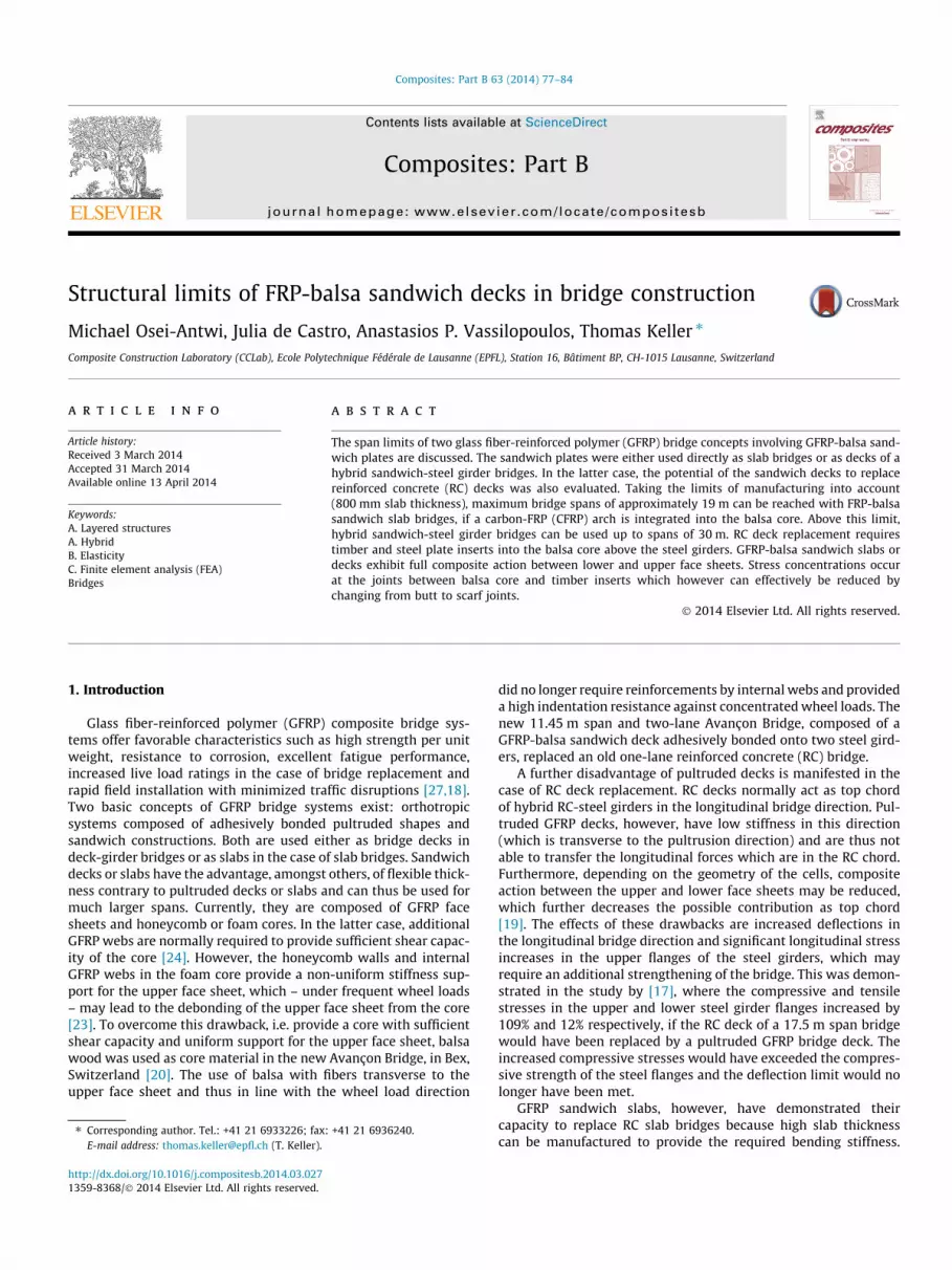
The span limits of three types of slab bridges were evaluated:(1) sandwich slabs with a uniform high-density balsa core (desig-nated S-U concept), (2) sandwich slabs with a complex core com-posed of high- and low-density balsa and an GFRP arch in theinterface, as shown in Fig. 1a (S-G concept), (3) the same case asS-G but instead with a carbon-FRP (CFRP) arch (S-C concept). TheS-G and S-C cases correspond to the concept shown in Osei-Antwiet al. [22]. In this concept, the high-density balsa is required to pre-vent indentation and wrinkling of the upper face sheet and providesufficient shear strength and stiffness in the support region of theslab. In the less-stressed lower zone between the supports, low-density balsa can be used to minimize the deck weight. The verticalcomponents of the FRP arch forces reduce the shear load borne bythe balsa core.
A two-lane bridge of 7.50 m width was investigated; the spanwas varied up to the limit span. The GFRP face sheets and GFRP/CFRP arch laminates were 30 mm thick and the upper and lowerbalsa cores together had a thickness of 710 mm, which resultedin a total sandwich slab thickness of 800 mm. From the
C/GFRPGFRP
GFRP
SB150
SB50
30+50+30+660+30
7500
l
(a)
800
39001800 1800
Timberinsert
SB150 l
7500
300
(b)
Fig. 1. Sandwich bridge concepts for (a) S-C/S-G slabs and (b) D-TI deck on steelgirders (dimensions in mm).
experiences gained with the Avançon Bridge construction, thesethicknesses were considered as the limits given by the manufactur-ing process (vacuum infusion). The GFRP face sheets werecomposed of E-glass fibers and vinylester resin. The E-glass archi-tecture was orthotropic with the same amount of unidirectional(UD)-layers in the bridge longitudinal (0�) and transverse direc-tions (90�). The same resin was used for the arch laminates butthe UD E-glass and carbon (T-700) fiber layers were arranged onlyin the longitudinal direction. The fiber volume fraction was 49% forboth laminates. The fibers of the balsa cores were oriented perpen-dicular to the faces sheets, thus providing the required indentationand shear resistances. The lowest possible thickness of the upperhigh-density balsa layer at mid-span was 50 mm, resulting in amaximum arch rise of 690 mm. The properties of the high-density(SB150) and low-density (SB50) balsa cores and the GFRP/CFRPUD-layers are listed in Table 1. The bridge slab was covered byan asphalt layer of ha = 60 mm thickness (similar to the AvançonBridge).
2.2. GFRP-balsa sandwich deck bridges
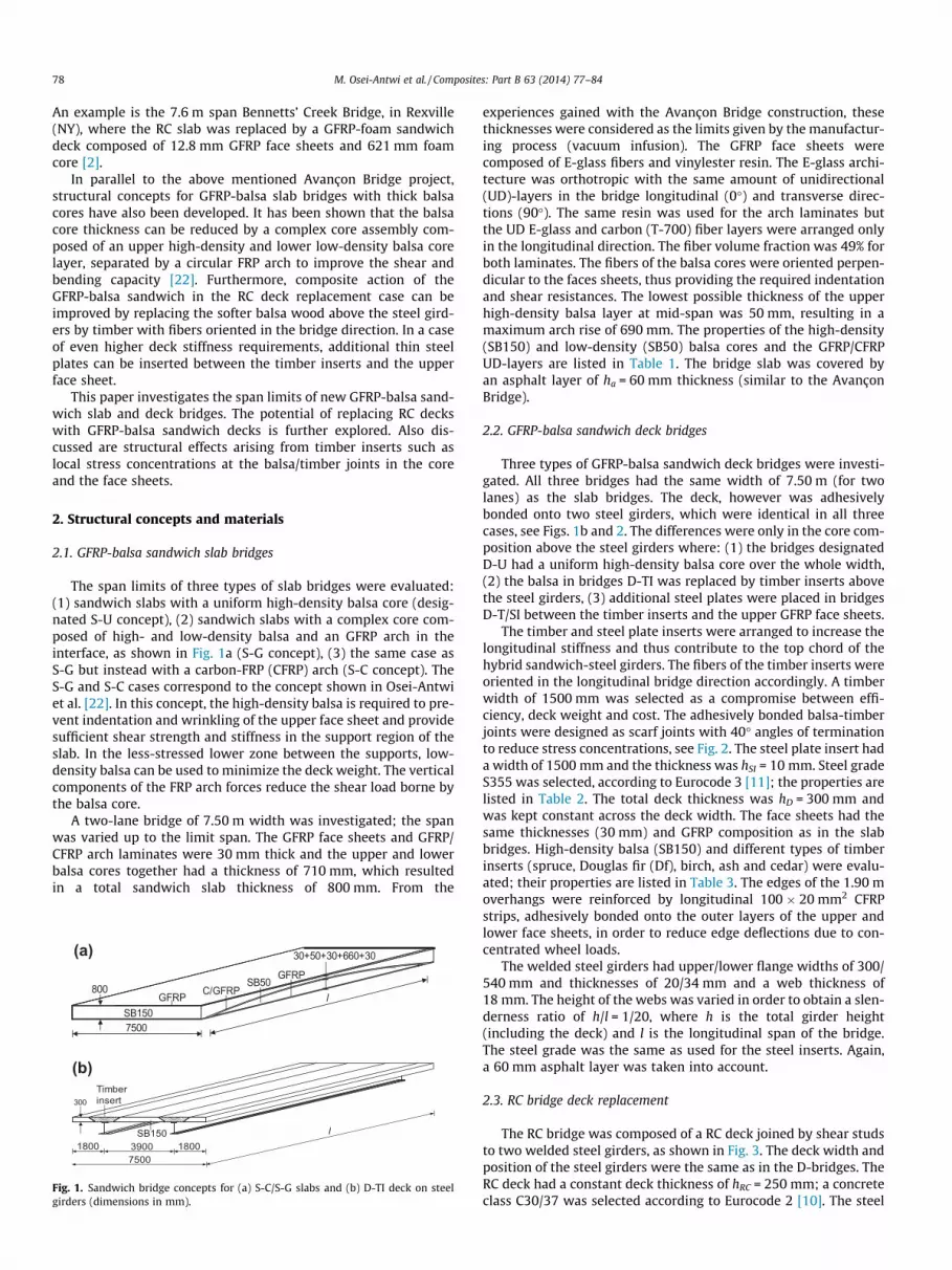
Three types of GFRP-balsa sandwich deck bridges were investi-gated. All three bridges had the same width of 7.50 m (for twolanes) as the slab bridges. The deck, however was adhesivelybonded onto two steel girders, which were identical in all threecases, see Figs. 1b and 2. The differences were only in the core com-position above the steel girders where: (1) the bridges designatedD-U had a uniform high-density balsa core over the whole width,(2) the balsa in bridges D-TI was replaced by timber inserts abovethe steel girders, (3) additional steel plates were placed in bridgesD-T/SI between the timber inserts and the upper GFRP face sheets.
The timber and steel plate inserts were arranged to increase thelongitudinal stiffness and thus contribute to the top chord of thehybrid sandwich-steel girders. The fibers of the timber inserts wereoriented in the longitudinal bridge direction accordingly. A timberwidth of 1500 mm was selected as a compromise between effi-ciency, deck weight and cost. The adhesively bonded balsa-timberjoints were designed as scarf joints with 40� angles of terminationto reduce stress concentrations, see Fig. 2. The steel plate insert hada width of 1500 mm and the thickness was hSI = 10 mm. Steel gradeS355 was selected, according to Eurocode 3 [11]; the properties arelisted in Table 2. The total deck thickness was hD = 300 mm andwas kept constant across the deck width. The face sheets had thesame thicknesses (30 mm) and GFRP composition as in the slabbridges. High-density balsa (SB150) and different types of timberinserts (spruce, Douglas fir (Df), birch, ash and cedar) were evalu-ated; their properties are listed in Table 3. The edges of the 1.90 moverhangs were reinforced by longitudinal 100 � 20 mm2 CFRPstrips, adhesively bonded onto the outer layers of the upper andlower face sheets, in order to reduce edge deflections due to con-centrated wheel loads.
The welded steel girders had upper/lower flange widths of 300/540 mm and thicknesses of 20/34 mm and a web thickness of18 mm. The height of the webs was varied in order to obtain a slen-derness ratio of h/l = 1/20, where h is the total girder height(including the deck) and l is the longitudinal span of the bridge.The steel grade was the same as used for the steel inserts. Again,a 60 mm asphalt layer was taken into account.
2.3. RC bridge deck replacement
The RC bridge was composed of a RC deck joined by shear studsto two welded steel girders, as shown in Fig. 3. The deck width andposition of the steel girders were the same as in the D-bridges. TheRC deck had a constant deck thickness of hRC = 250 mm; a concreteclass C30/37 was selected according to Eurocode 2 [10]. The steel
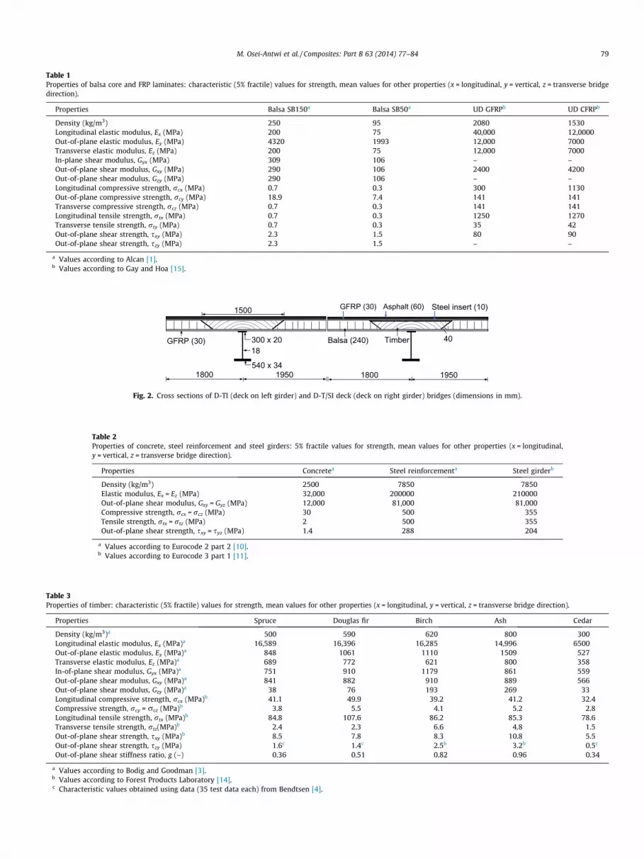
Table 1Properties of balsa core and FRP laminates: characteristic (5% fractile) values for strength, mean values for other properties (x = longitudinal, y = vertical, z = transverse bridgedirection).
Properties Balsa SB150a Balsa SB50a UD GFRPb UD CFRPb
Density (kg/m3) 250 95 2080 1530Longitudinal elastic modulus, Ex (MPa) 200 75 40,000 12,0000Out-of-plane elastic modulus, Ey (MPa) 4320 1993 12,000 7000Transverse elastic modulus, Ez (MPa) 200 75 12,000 7000In-plane shear modulus, Gyx (MPa) 309 106 – –Out-of-plane shear modulus, Gxy (MPa) 290 106 2400 4200Out-of-plane shear modulus, Gzy (MPa) 290 106 – –Longitudinal compressive strength, rcx (MPa) 0.7 0.3 300 1130Out-of-plane compressive strength, rcy (MPa) 18.9 7.4 141 141Transverse compressive strength, rcz (MPa) 0.7 0.3 141 141Longitudinal tensile strength, rtx (MPa) 0.7 0.3 1250 1270Transverse tensile strength, rty (MPa) 0.7 0.3 35 42Out-of-plane shear strength, sxy (MPa) 2.3 1.5 80 90Out-of-plane shear strength, szy (MPa) 2.3 1.5 – –
a Values according to Alcan [1].b Values according to Gay and Hoa [15].
1800 1950
18300 x 20
GFRP (30)
GFRP (30)
Asphalt (60)
1800 1950
Balsa (240)
Steel insert (10)
40Timber
1500
540 x 34
Fig. 2. Cross sections of D-TI (deck on left girder) and D-T/SI deck (deck on right girder) bridges (dimensions in mm).
Table 2Properties of concrete, steel reinforcement and steel girders: 5% fractile values for strength, mean values for other properties (x = longitudinal,y = vertical, z = transverse bridge direction).
Properties Concretea Steel reinforcementa Steel girderb
Density (kg/m3) 2500 7850 7850Elastic modulus, Ex = Ez (MPa) 32,000 200000 210000Out-of-plane shear modulus, Gxy = Gyz (MPa) 12,000 81,000 81,000Compressive strength, rcx = rcz (MPa) 30 500 355Tensile strength, rtx = rtz (MPa) 2 500 355Out-of-plane shear strength, sxy = syz (MPa) 1.4 288 204
a Values according to Eurocode 2 part 2 [10].b Values according to Eurocode 3 part 1 [11].
Table 3Properties of timber: characteristic (5% fractile) values for strength, mean values for other properties (x = longitudinal, y = vertical, z = transverse bridge direction).
Properties Spruce Douglas fir Birch Ash Cedar
Density (kg/m3)a 500 590 620 800 300Longitudinal elastic modulus, Ex (MPa)a 16,589 16,396 16,285 14,996 6500Out-of-plane elastic modulus, Ey (MPa)a 848 1061 1110 1509 527Transverse elastic modulus, Ez (MPa)a 689 772 621 800 358In-of-plane shear modulus, Gyx (MPa)a 751 910 1179 861 559Out-of-plane shear modulus, Gxy (MPa)a 841 882 910 889 566Out-of-plane shear modulus, Gzy (MPa)a 38 76 193 269 33Longitudinal compressive strength, rcx (MPa)b 41.1 49.9 39.2 41.2 32.4Compressive strength, rcy = rcz (MPa)b 3.8 5.5 4.1 5.2 2.8Longitudinal tensile strength, rtx (MPa)b 84.8 107.6 86.2 85.3 78.6Transverse tensile strength, rtz(MPa)b 2.4 2.3 6.6 4.8 1.5Out-of-plane shear strength, sxy (MPa)b 8.5 7.8 8.3 10.8 5.5Out-of-plane shear strength, szy (MPa) 1.6c 1.4c 2.5b 3.2b 0.5c
Out-of-plane shear stiffness ratio, g (–) 0.36 0.51 0.82 0.96 0.34
a Values according to Bodig and Goodman [3].b Values according to Forest Products Laboratory [14].c Characteristic values obtained using data (35 test data each) from Bendtsen [4].
M. Osei-Antwi et al. / Composites: Part B 63 (2014) 77–84 79
1800 1950 1950 1800
1000
Asphalt layer (100) Concrete deck (250)
18300 x 20
540 x 34
Fig. 3. Cross section of a 25 m RC bridge (dimensions in mm).
80 M. Osei-Antwi et al. / Composites: Part B 63 (2014) 77–84
girders had the same dimensions and grade as the D-bridges. Thedeck replacement case, however, was investigated at one specificspan only, i.e. l = 25.0 m and the corresponding steel girder heightwas 1000 mm. The properties of concrete, concrete steel reinforce-ment and steel girders are listed in Table 2. An asphalt layer thick-ness of 100 mm was selected, which is common for RC bridges inSwitzerland.
3. Structural design
3.1. Limit state design
All bridges were designed according to the limit state designspecified in Eurocode 2, 3 and 5 (2005), by verifying the ultimatelimit state (ULS) and serviceability limit state (SLS). Load factorswere applied to the actions and material factors to the characteris-tic (5% fractile) values of the material properties to obtain thedesign values of actions and properties. The load combinationsand load factors were obtained from Eurocode 0 [8]. Material fac-tors for concrete, steel reinforcements, steel girders and balsa/tim-ber were selected from Eurocode 2, 3 and 5 (2005) respectively. Forthe FRP materials, the same material factors were adopted as in theAvançon Bridge design [20], which were based on BÜV [5] andClarke [7]. The material factors applied at ULS and SLS are summa-rized in Table 4. At SLS, the deck deflections were limited to span/500 at short term, according to Eurocode 2 [10].
3.2. Design of GFRP-balsa sandwich slab and deck
The design procedure and criteria for the GFRP-balsa sandwichslab and deck were the same as for the Avançon Bridge, see Kelleret al. [20]. The bridges were modeled in 3D by the finite elementsoftware Ansys (version 13) for both ULS and SLS verifications.The face sheets and arch laminates were modeled with multi-lay-ered shell 91 elements while solid 95 elements were used for thesandwich core, RC deck and steel girders. The critical designcriterion was the deflection at SLS and not the ULS strength limit.Maximum deflections were obtained for the S- and D-bridges atthe traffic load positions shown in Figs. 4a and 4b (left). The trafficloads were composed of two groups of two axle loads, in total,
Table 4Material factors used in design.
Component and action Factor
ULS SLS
FRP laminates, traffic loada 2.64 1.50FRP laminates, permanent loada 2.88 1.50Balsa/timberb 1.50 1.60Concretec 1.50 1.00Steel reinforcementc 1.15 1.00Steel girderd 1.10 1.00
a Data from BÜV [5].b Data from Eurocode 5 part 1 [13].c Data from Eurocode 2 part 2 (2002).d Data from Eurocode 3 part 2 [12].
4 � 135 kN (1st lane) and 4 � 90 kN (2nd lane, characteristic val-ues). Additionally, uniformly distributed loads of 8.1 kN/m2 and2.25 kN/m2 were applied on the first and second lanes. The corre-sponding deflections are shown in Figs. 4b and 4b (left), which werecalculated at 75% of the characteristic loads [9]. The limits of span/500 were met in both the longitudinal and transverse directions.
4. Results and discussion
4.1. Bridge span design limits
The obtained bridge span limits according to the SLS deflectionrequirement are shown in Fig. 5. The S-G and S-C slabs could reachmaximum spans of 17.7 m and 18.9 m respectively. In comparisonto the 16.0 m maximum span of the S-U slabs, they showed a pos-sible span increase of 11% and 18% respectively due to the addi-tional bending and shear stiffness provided by the GFRP andCFRP arches. The D-U deck-girder bridges exhibited high deflec-tions of more than 20% above the deflection limit in the 20–30 mspan range. The D-TI (Douglas fir) deck-girder bridges, however,satisfied the deflection limit up to 30 m span due to the additionalcontribution of the timber inserts to the bending stiffness of thehybrid sandwich-steel girders.
4.2. Bending stiffness and composite action
The contribution of a FRP deck to the bending stiffness of ahybrid deck-steel girder depends not only on the deck stiffness(in the longitudinal bridge direction) but also on the compositeaction between the deck and steel girders (provided by the adhe-sive connections) and the composite action inside the deckbetween upper and lower face sheets, which is related to the in-plane shear stiffness of the core. Keller and Gürtler [19] demon-strated that adhesive connections in most cases provide fullcomposite action. They also showed that composite action withinpultruded decks largely depends on the cell geometry. Triangulardecks provide high composite action between upper and lowerface sheets while decks with trapezoidal or rectangular cell shapeshave very limited composite action since the upper face sheet inmost cases cannot be fully activated. In the following, the compos-ite action within GFRP-balsa/timber sandwich decks is investigatedand compared to that of pultruded and RC decks. The DuraSpan [6]and Asset [21] pultruded decks with trapezoidal and triangular cellgeometries respectively were selected.
The degree of composite action, c, according to Keller andGürtler [19] is calculated as follows:
c ¼ 11þ p2ExAx
Kbeff l2
ð1Þ
where Ex and Ax are elastic modulus and equivalent cross-sectionarea of upper face-sheet and core of the deck in the longitudinaldirection respectively, K is the in-plane shear stiffness of the decksystem according to Gürtler [16] and beff is the effective deck width.

135 kN
90 kN(a)
-37.3 mm
-33.1 mm
Edge
Field
90 kN
135 kN
(b)
Edge
-24.4 mm
-18.1 mm
-6.8 mm
Field
Girder
Fig. 4. Critical load positions according to Eurocode 1 part 2 [9] and corresponding SLS deck deflections for (a) S-C slab bridge of 19 m span and (b) D-TI deck-girder bridge of25 m span.
14 16 18 20 22 24 26 28 300
10
20
30
40
50
60
70
80
Limit: span/500
S-U S-G S-C D-U D-TI
Mid
-spa
n de
flect
ion
[mm
]
Bridge span [m]
S-G S-C
S-U
D-TI
D-U
Fig. 5. Bridge span limits at SLS for S-U, S-G, S-C slabs, and D-H, D-TI deck-girderbridges.
0 1000 2000 3000 4000 5000 6000 7000 8000-5.6
-5.8
-6.0
-6.2
-6.4
b1 0 b2beff
σmax
Long
itudi
nal s
tress
[MPa
]
Beam width [mm]
Shear lag model
FEM
Fig. 6. Longitudinal stress distribution in upper face sheet of D-U deck and effectivewidth at SLS load (l = 20 m, hD = 250 mm).
M. Osei-Antwi et al. / Composites: Part B 63 (2014) 77–84 81
A deck-girder bridge of 20 m span was selected for the compar-ative analysis. The deck of the D-U and D-TI bridges had a thicknessof 250 mm while inserts of five different timber species wereselected for the D-TI bridges (spruce, Douglas fir, birch, ash andcedar). The RC deck also had 250 mm thickness. The steel girdershad 750 mm height in all bridges.
The effective deck width was obtained from the longitudinalstress distribution in the upper face sheet at mid-span, under SLSloads, using the shear lag model according to Zou et al. [26]:
beff ¼R b2�b1
rx
rmaxð2Þ
where rx is the longitudinal stress in the upper face sheet across thedeck width, b1 and b2 are the distance between minimum longitu-dinal stresses on the left and right side of the steel girder axis andrmax is the maximum longitudinal stress above the steel girder axis.The result for the D-U deck is beff = 3550 mm, as shown in Fig. 6.Almost the whole deck width thus contributed as top chord.Accordingly, an effective width, twice the overhang width, i.e.beff = 3600 mm was assumed for all the decks, including RC andpultruded decks. In the latter case, the in-plane shear stiffness in
the face sheets was similar to those in the sandwich deck and theassumption thus justified.
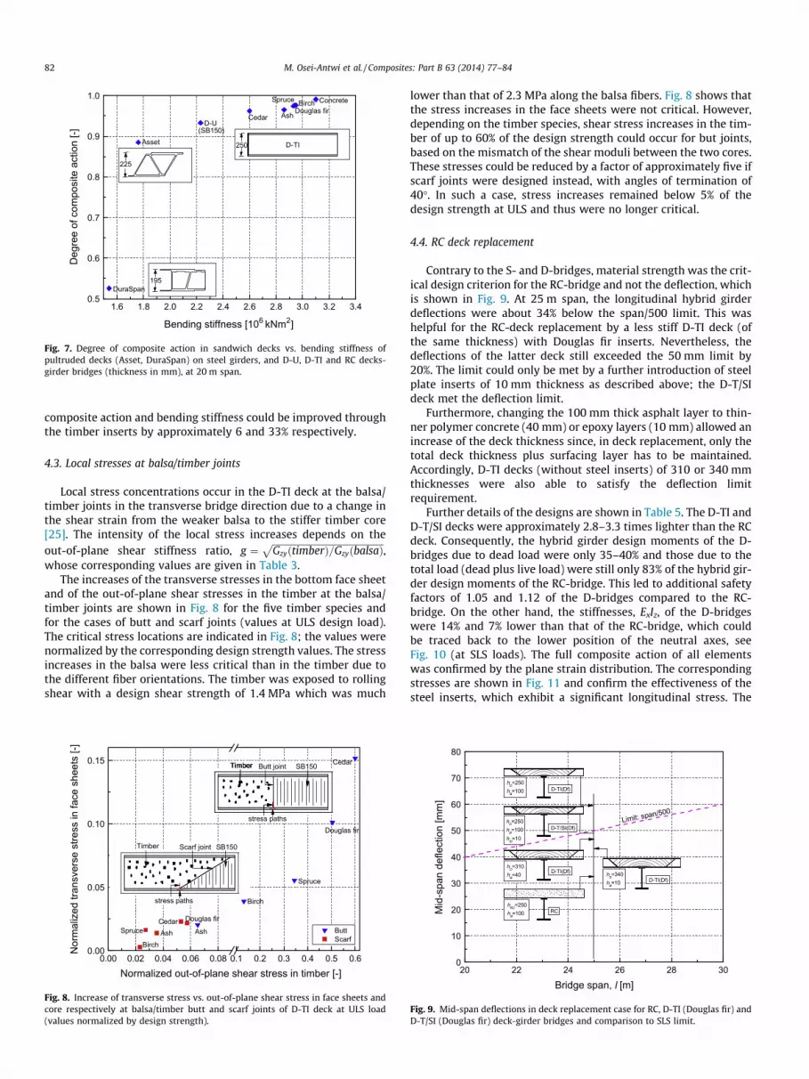
The degrees of composite action within the decks and the corre-sponding bending stiffnesses of the hybrid deck-steel girders, ExIz,in the longitudinal bridge direction are compared in Fig. 7. Fullcomposite action in the adhesive bond between decks and steelgirders was assumed. The bending stiffness was computed usingthe transformed-section method, taking into account the effectivedeck widths obtained above. The K-values were computed as thedeck’s in-plane shear modulus divided by the deck thickness. K-values for D-U decks (1.16 N/mm3) and D-TI decks (2.24–4.72 N/mm3) were computed from FEM results and those for the Dura-Span (0.03 N/mm3) and Asset decks (0.21 N/mm3) were selectedfrom Gürtler [16]. The DuraSpan deck showed a low partial com-posite action and the corresponding girder also exhibited the low-est bending stiffness mainly due to the deck’s low in-plane shearstiffness. The RC deck exhibited the highest (full) composite actionand bending stiffness. The composite action in the D-U and Assetdecks was similar, however, the bending stiffness of the formerwas much higher. Amongst the D-TI bridges, the decks with spruce,Douglas fir and birch showed almost full composite action andhighest bending stiffness, and both values approached that of theRC deck. Compared to the D-U bridge with uniform balsa core,
1.6 1.8 2.0 2.2 2.4 2.6 2.8 3.0 3.2 3.40.5
0.6
0.7
0.8
0.9
1.0
(SB150)
DuraSpan
Asset
BirchDouglas firAshCedar
D-U
Spruce Concrete
Deg
ree
of c
ompo
site
act
ion
[-]
Bending stiffness [106 kNm2]
225
195
250 D-TI
Fig. 7. Degree of composite action in sandwich decks vs. bending stiffness ofpultruded decks (Asset, DuraSpan) on steel girders, and D-U, D-TI and RC decks-girder bridges (thickness in mm), at 20 m span.
82 M. Osei-Antwi et al. / Composites: Part B 63 (2014) 77–84
composite action and bending stiffness could be improved throughthe timber inserts by approximately 6 and 33% respectively.
4.3. Local stresses at balsa/timber joints
Local stress concentrations occur in the D-TI deck at the balsa/timber joints in the transverse bridge direction due to a change inthe shear strain from the weaker balsa to the stiffer timber core[25]. The intensity of the local stress increases depends on theout-of-plane shear stiffness ratio, g ¼
ffiffiffiffiffiffiffiffiffiffiffiffiffiffiffiffiffiffiffiffiffiffiffiffiffiffiffiffiffiffiffiffiffiffiffiffiffiffiffiffiffiffiffiffiffiffiffiffiGzyðtimberÞ=GzyðbalsaÞ
p,
whose corresponding values are given in Table 3.The increases of the transverse stresses in the bottom face sheet
and of the out-of-plane shear stresses in the timber at the balsa/timber joints are shown in Fig. 8 for the five timber species andfor the cases of butt and scarf joints (values at ULS design load).The critical stress locations are indicated in Fig. 8; the values werenormalized by the corresponding design strength values. The stressincreases in the balsa were less critical than in the timber due tothe different fiber orientations. The timber was exposed to rollingshear with a design shear strength of 1.4 MPa which was much
0.00 0.02 0.04 0.06 0.08 0.1 0.2 0.3 0.4 0.5 0.60.00
0.05
0.10
0.15
SpruceCedar
Ash
Birch
Douglas fir Butt Scarf
Birch
Douglas fir
Ash
Cedar
Spruce
Nor
mal
ized
tran
sver
se s
tress
in fa
ce s
heet
s [-]
Normalized out-of-plane shear stress in timber [-]
Timber Butt joint SB150Timber Butt joint SB150
stress paths
Timber Butt joint SB150
stress paths
Timber Scarf joint SB150
Fig. 8. Increase of transverse stress vs. out-of-plane shear stress in face sheets andcore respectively at balsa/timber butt and scarf joints of D-TI deck at ULS load(values normalized by design strength).
lower than that of 2.3 MPa along the balsa fibers. Fig. 8 shows thatthe stress increases in the face sheets were not critical. However,depending on the timber species, shear stress increases in the tim-ber of up to 60% of the design strength could occur for but joints,based on the mismatch of the shear moduli between the two cores.These stresses could be reduced by a factor of approximately five ifscarf joints were designed instead, with angles of termination of40�. In such a case, stress increases remained below 5% of thedesign strength at ULS and thus were no longer critical.
4.4. RC deck replacement
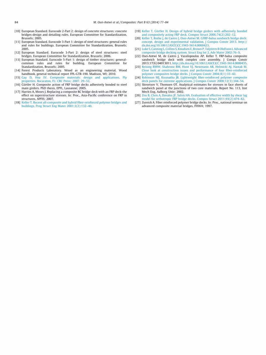
Contrary to the S- and D-bridges, material strength was the crit-ical design criterion for the RC-bridge and not the deflection, whichis shown in Fig. 9. At 25 m span, the longitudinal hybrid girderdeflections were about 34% below the span/500 limit. This washelpful for the RC-deck replacement by a less stiff D-TI deck (ofthe same thickness) with Douglas fir inserts. Nevertheless, thedeflections of the latter deck still exceeded the 50 mm limit by20%. The limit could only be met by a further introduction of steelplate inserts of 10 mm thickness as described above; the D-T/SIdeck met the deflection limit.
Furthermore, changing the 100 mm thick asphalt layer to thin-ner polymer concrete (40 mm) or epoxy layers (10 mm) allowed anincrease of the deck thickness since, in deck replacement, only thetotal deck thickness plus surfacing layer has to be maintained.Accordingly, D-TI decks (without steel inserts) of 310 or 340 mmthicknesses were also able to satisfy the deflection limitrequirement.
Further details of the designs are shown in Table 5. The D-TI andD-T/SI decks were approximately 2.8–3.3 times lighter than the RCdeck. Consequently, the hybrid girder design moments of the D-bridges due to dead load were only 35–40% and those due to thetotal load (dead plus live load) were still only 83% of the hybrid gir-der design moments of the RC-bridge. This led to additional safetyfactors of 1.05 and 1.12 of the D-bridges compared to the RC-bridge. On the other hand, the stiffnesses, ExIz, of the D-bridgeswere 14% and 7% lower than that of the RC-bridge, which couldbe traced back to the lower position of the neutral axes, seeFig. 10 (at SLS loads). The full composite action of all elementswas confirmed by the plane strain distribution. The correspondingstresses are shown in Fig. 11 and confirm the effectiveness of thesteel inserts, which exhibit a significant longitudinal stress. The
20 22 24 26 28 300
10
20
30
40
50
60
70
80
D-TI(Df)
D-TI(Df)
D-T/SI(Df)
D-TI(Df) hD=340ha=10
hD=250ha=100hSI=10
hD=310ha=40
hD=250ha=100
hRC=250ha=100
Limit: span/500
Mid
-spa
n de
flect
ion
[mm
]
Bridge span, l [m]
RC
Fig. 9. Mid-span deflections in deck replacement case for RC, D-TI (Douglas fir) andD-T/SI (Douglas fir) deck-girder bridges and comparison to SLS limit.
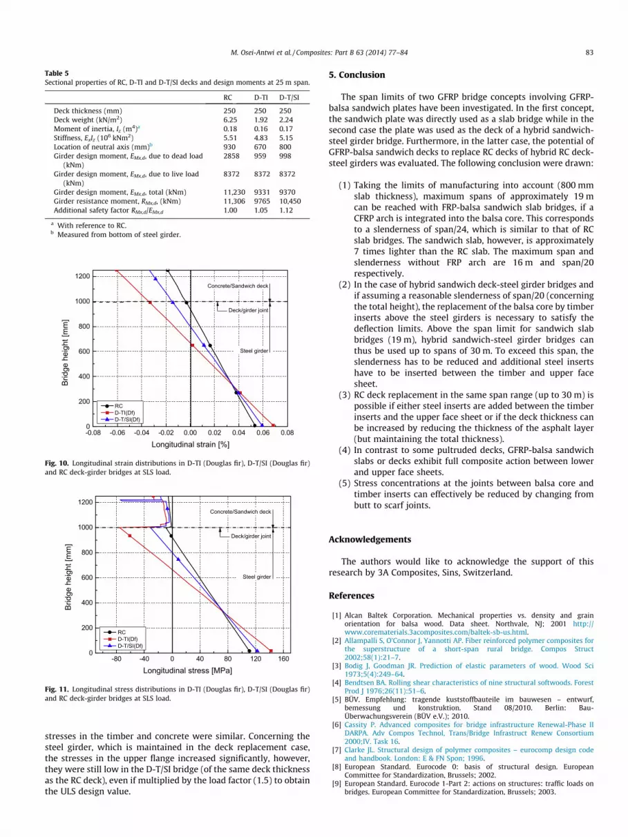
Table 5Sectional properties of RC, D-TI and D-T/SI decks and design moments at 25 m span.
RC D-TI D-T/SI
Deck thickness (mm) 250 250 250Deck weight (kN/m2) 6.25 1.92 2.24Moment of inertia, Iz (m4)a 0.18 0.16 0.17Stiffness, ExIz (106 kNm2) 5.51 4.83 5.15Location of neutral axis (mm)b 930 670 800Girder design moment, EMx,d, due to dead load
(kNm)2858 959 998
Girder design moment, EMx,d, due to live load(kNm)
8372 8372 8372
Girder design moment, EMx,d, total (kNm) 11,230 9331 9370Girder resistance moment, RMx,d, (kNm) 11,306 9765 10,450Additional safety factor RMx,d/EMx,d 1.00 1.05 1.12
a With reference to RC.b Measured from bottom of steel girder.
-0.08 -0.06 -0.04 -0.02 0.00 0.02 0.04 0.06 0.080
200
400
600
800
1000
1200
Deck/girder joint
RC D-TI(Df) D-T/SI(Df)
Steel girder
Concrete/Sandwich deck
Brid
ge h
eigh
t [m
m]
Longitudinal strain [%]
Fig. 10. Longitudinal strain distributions in D-TI (Douglas fir), D-T/SI (Douglas fir)and RC deck-girder bridges at SLS load.
-80 -40 0 40 80 120 1600
200
400
600
800
1000
1200
RC D-TI(Df) D-T/SI(Df)
Brid
ge h
eigh
t [m
m]
Longitudinal stress [MPa]
Concrete/Sandwich deck
Deck/girder joint
Steel girder
Fig. 11. Longitudinal stress distributions in D-TI (Douglas fir), D-T/SI (Douglas fir)and RC deck-girder bridges at SLS load.
M. Osei-Antwi et al. / Composites: Part B 63 (2014) 77–84 83
stresses in the timber and concrete were similar. Concerning thesteel girder, which is maintained in the deck replacement case,the stresses in the upper flange increased significantly, however,they were still low in the D-T/SI bridge (of the same deck thicknessas the RC deck), even if multiplied by the load factor (1.5) to obtainthe ULS design value.
5. Conclusion
The span limits of two GFRP bridge concepts involving GFRP-balsa sandwich plates have been investigated. In the first concept,the sandwich plate was directly used as a slab bridge while in thesecond case the plate was used as the deck of a hybrid sandwich-steel girder bridge. Furthermore, in the latter case, the potential ofGFRP-balsa sandwich decks to replace RC decks of hybrid RC deck-steel girders was evaluated. The following conclusion were drawn:
(1) Taking the limits of manufacturing into account (800 mmslab thickness), maximum spans of approximately 19 mcan be reached with FRP-balsa sandwich slab bridges, if aCFRP arch is integrated into the balsa core. This correspondsto a slenderness of span/24, which is similar to that of RCslab bridges. The sandwich slab, however, is approximately7 times lighter than the RC slab. The maximum span andslenderness without FRP arch are 16 m and span/20respectively.
(2) In the case of hybrid sandwich deck-steel girder bridges andif assuming a reasonable slenderness of span/20 (concerningthe total height), the replacement of the balsa core by timberinserts above the steel girders is necessary to satisfy thedeflection limits. Above the span limit for sandwich slabbridges (19 m), hybrid sandwich-steel girder bridges canthus be used up to spans of 30 m. To exceed this span, theslenderness has to be reduced and additional steel insertshave to be inserted between the timber and upper facesheet.
(3) RC deck replacement in the same span range (up to 30 m) ispossible if either steel inserts are added between the timberinserts and the upper face sheet or if the deck thickness canbe increased by reducing the thickness of the asphalt layer(but maintaining the total thickness).
(4) In contrast to some pultruded decks, GFRP-balsa sandwichslabs or decks exhibit full composite action between lowerand upper face sheets.
(5) Stress concentrations at the joints between balsa core andtimber inserts can effectively be reduced by changing frombutt to scarf joints.
Acknowledgements
The authors would like to acknowledge the support of thisresearch by 3A Composites, Sins, Switzerland.
References
[1] Alcan Baltek Corporation. Mechanical properties vs. density and grainorientation for balsa wood. Data sheet. Northvale, NJ; 2001 http://www.corematerials.3acomposites.com/baltek-sb-us.html.
[2] Allampalli S, O’Connor J, Yannotti AP. Fiber reinforced polymer composites forthe superstructure of a short-span rural bridge. Compos Struct2002;58(1):21–7.
[3] Bodig J, Goodman JR. Prediction of elastic parameters of wood. Wood Sci1973;5(4):249–64.
[4] Bendtsen BA. Rolling shear characteristics of nine structural softwoods. ForestProd J 1976;26(11):51–6.
[5] BÜV. Empfehlung: tragende kuststoffbauteile im bauwesen – entwurf,bemessung und konstruktion. Stand 08/2010. Berlin: Bau-Überwachungsverein (BÜV e.V.); 2010.
[6] Cassity P. Advanced composites for bridge infrastructure Renewal-Phase IIDARPA. Adv Compos Technol, Trans/Bridge Infrastruct Renew Consortium2000;IV. Task 16.
[7] Clarke JL. Structural design of polymer composites – eurocomp design codeand handbook. London: E & FN Spon; 1996.
[8] European Standard. Eurocode 0: basis of structural design. EuropeanCommittee for Standardization, Brussels; 2002.
[9] European Standard. Eurocode 1-Part 2: actions on structures: traffic loads onbridges. European Committee for Standardization, Brussels; 2003.
84 M. Osei-Antwi et al. / Composites: Part B 63 (2014) 77–84
[10] European Standard. Eurocode 2-Part 2: design of concrete structures: concretebridges-design and detailing rules. European Committee for Standardization,Brussels; 2005.
[11] European Standard. Eurocode 3-Part 1: design of steel structures: general rulesand rules for buildings. European Committee for Standardization, Brussels;2005.
[12] European Standard. Eurocode 3-Part 2: design of steel structures: steelbridges. European Committee for Standardization, Brussels; 2006.
[13] European Standard. Eurocode 5-Part 1: design of timber structures: general-common rules and rules for building. European Committee forStandardization, Brussels; 2005.
[14] Forest Products Laboratory. Wood as an engineering material. Woodhandbook, general technical report FPL-GTR-190. Madison, WI; 2010.
[15] Gay D, Hoa SV. Composite materials: design and applications. Plyproperties. Bocaraton, FL: CRC Press; 2007. 29–52.
[16] Gürtler H. Composite action of FRP bridge decks adhesively bonded to steelmain girders. PhD thesis, EPFL, Lausanne; 2005.
[17] Harries A, Moses J. Replacing a composite RC bridge deck with an FRP deck-theeffect on superstructure stresses. In: Proc., Asia-Pacific conference on FRP instructures, APFIS; 2007.
[18] Keller T. Recent all-composite and hybrid fibre-reinforced polymer bridges andbuildings. Prog Struct Eng Mater 2001;3(2):132–40.
[19] Keller T, Gürtler H. Design of hybrid bridge girders with adhesively bondedand compositely acting FRP deck. Compos Struct 2006;74(2):202–12.
[20] Keller T, Rothe J, de Castro J, Osei-Antwi M. GFRP-balsa sandwich bridge deck:concept, design and experimental validation. J Compos Constr 2013. http://dx.doi.org/10.1061/(ASCE)CC.1943-5614.0000423.
[21] Luke S, Canning L, Collins S, Knudsen E, Brown P, Taljstern B Olofsson I. Advancedcomposite bridge decking system. Struct Eng Int 2, Adv Mater 2002:76–9.
[22] Osei-Antwi M, de Castro J, Vassilopoulos AP, Keller T. FRP-balsa compositesandwich bridge deck with complex core assembly. J Comps Constr2013;17(6):04013011. http://dx.doi.org/10.1061/(ASCE)CC.1943-5614.0000435.
[23] Reising RMW, Shahrooz BM, Hunt VJ, Newmann AR, Helmicki AJ, Hastak M.Close look at construction issues and performance of four fiber-reinforcedpolymer composites bridge decks. J Compos Constr 2004;8(1):33–42.
[24] Robinson MJ, Kosmatka JB. Lightweight fiber-reinforced polymer compositedeck panels for extreme applications. J Compos Constr 2008;12(3):344–54.
[25] Skvortsov V, Thomsen OT. Analytical estimates for stresses in face sheets ofsandwich panel at the junctions of two core materials. Report No. 113, InstMech Eng, Aalborg Univ; 2002.
[26] Zou B, Chen A, Davalos JF, Salim HA. Evaluation of effective width by shear lagmodel for orthotropic FRP bridge decks. Compos Struct 2011;93(2):474–82.
[27] Zureick A. Fiber reinforced polymer bridge decks. In: Proc., national seminar onadvanced composite material bridges, FHWA; 1997.


