Embed Size (px)
Citation preview

8th International Conference on Sandwich Structures ICSS 8
A. J. M. Ferreira (Editor) FEUP, Porto, 2008
AIRCRAFT SANDWICH STRUCTURES WITH FOLDED CORE UNDER IMPACT LOAD
S. Heimbs*, P. Middendorf*, C. Hampf†, F. Hähnel†, K. Wolf†
* EADS Innovation Works Germany
81663 Munich, Germany e-mail: [email protected], web page: http://www.eads.net
† Institut für Luft- und Raumfahrttechnik Technische Universität Dresden
Marschnerstraße 32, 01307 Dresden, Germany web page: http://www.tu-dresden.de/mwilr
Key words: Sandwich structures, Folded core, Low velocity impact, Dynamic simulations.
Summary. Folded structures made of composite materials have gained interest in the aerospace industry as a promising sandwich core structure. In this paper the mechanical behaviour of such a sandwich structure with a folded core made of carbon fibre-reinforced plastic under low velocity impact loads is investigated experimentally and numerically. At first the core properties under compressive and transverse shear loads are characterised building a basis for the validation of the simulation models. Low velocity impact tests under various energy levels are described with respect to the evaluated damage of face and core and are finally simulated with LS-DYNA. These simulations were used to investigate the influence of different parameters on the impact behaviour numerically.
1 INTRODUCTION Sandwich structures with composite faces and a cellular core are known for their
outstanding weight-specific stiffness and strength properties and have therefore been used in aircraft structures for many decades. Examples are aerodynamic fairings (belly fairing, leading and trailing edge fairings) or control surfaces (rudders, ailerons) [1]. Since weight reduction is a main driver in aircraft design, the application of sandwich structures is constantly increasing. Even concepts for the utilisation of sandwich structures in the primary structure, i.e. the aircraft fuselage, have been developed in the past for large airliners [2]-[4] and have already been realised in smaller business jets [5]-[8]. One main issue is to identify an adequate sandwich core material for these purposes. Nowadays, Nomex® honeycomb cores are prevalently used in aircraft sandwich structures because of their favourable mechanical and fire safety properties. But these closed honeycomb cells can lead to an inclusion and accumulation of condensation water, which increases weight and reduces the properties [8]-[10]. Therefore, folded sandwich core structures have gained interest of the aerospace industry in the past years as an alternative allowing for a ventilation through drainage
369
S. Heimbs, P. Middendorf, C. Hampf, F. Hähnel and K. Wolf
channels and also for efficient fabrication processes [11]-[14]. Such folded core structures can be manufactured from a variety of materials and in unlimited geometries and can therefore be tailored for a specific application.
One known shortcoming of sandwich structures is their low resistance against impact loads acting normal to the sandwich plane, which is a result of the typically very thin faces and the low resistance of the core against local compressive loads. Impact scenarios affecting aircraft structures range from low velocity impacts (e.g. tool drop, hail on ground) over intermediate velocity impacts (e.g. runway debris, tire fragments) to high velocity impacts (e.g. bird strike, hail in flight, engine parts).
This paper presents an experimental and numerical investigation of the low velocity impact behaviour of a composite sandwich structure with a folded core made of carbon fibre-reinforced plastic (CFRP). First the core and sandwich structure are characterised by their material, geometry and manufacturing process. Then the experimental test series for the determination of the mechanical properties of the core and the impact behaviour under various energy levels is presented. Based on these data numerical simulation models of the sandwich structure were generated and dynamic impact simulations with LS-DYNA were conducted to gain further insights into the stress states during impact and to perform various parameter studies.
2 MATERIALS AND MANUFACTURING The focus of this paper is a composite sandwich structure made of the following
constituents:The faces were fabricated from the aerospace grade carbon fibre/epoxy (CF/EP) prepreg
Cytec 977-2/HTS in a 16-ply quasi-isotropic lay-up of [45°/90°/-45°/0°/45°/90°/-45°/0°]S and were cured in an autoclave. The resulting face thickness was 2 mm.
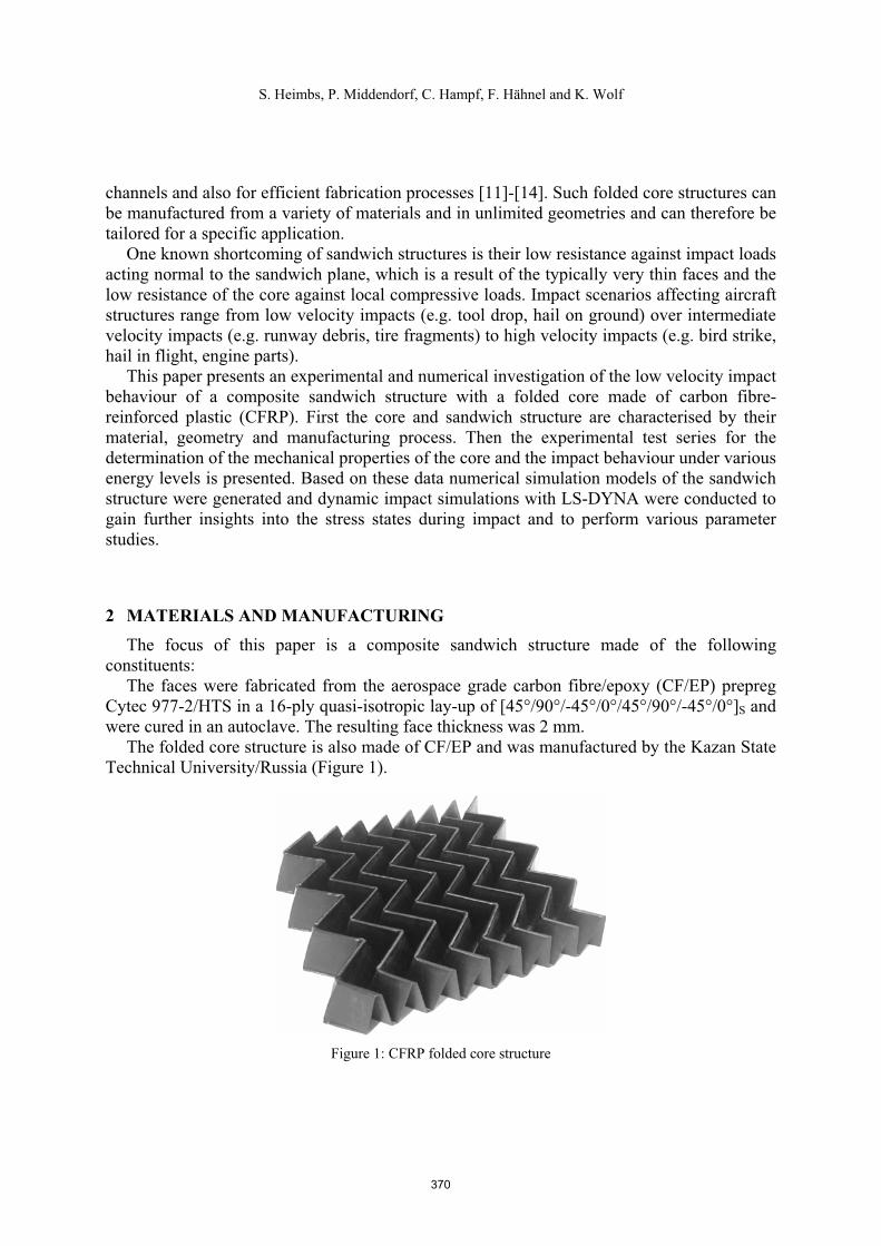
The folded core structure is also made of CF/EP and was manufactured by the Kazan State Technical University/Russia (Figure 1).
Figure 1: CFRP folded core structure
370
S. Heimbs, P. Middendorf, C. Hampf, F. Hähnel and K. Wolf
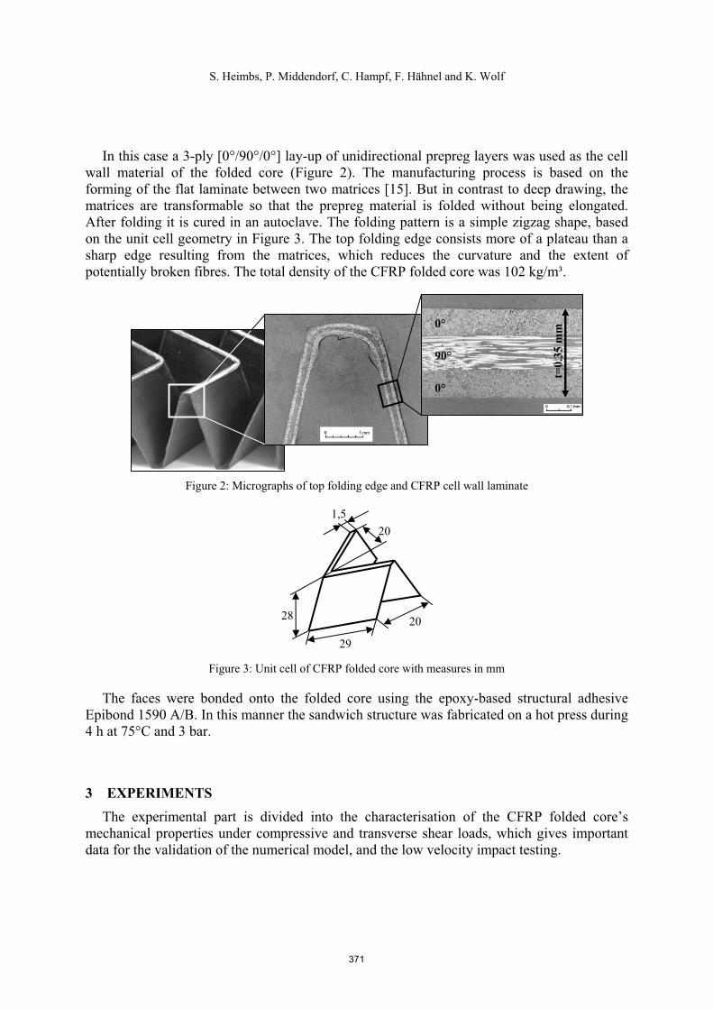
In this case a 3-ply [0°/90°/0°] lay-up of unidirectional prepreg layers was used as the cell wall material of the folded core (Figure 2). The manufacturing process is based on the forming of the flat laminate between two matrices [15]. But in contrast to deep drawing, the matrices are transformable so that the prepreg material is folded without being elongated. After folding it is cured in an autoclave. The folding pattern is a simple zigzag shape, based on the unit cell geometry in Figure 3. The top folding edge consists more of a plateau than a sharp edge resulting from the matrices, which reduces the curvature and the extent of potentially broken fibres. The total density of the CFRP folded core was 102 kg/m³.
Figure 2: Micrographs of top folding edge and CFRP cell wall laminate
Figure 3: Unit cell of CFRP folded core with measures in mm
The faces were bonded onto the folded core using the epoxy-based structural adhesive Epibond 1590 A/B. In this manner the sandwich structure was fabricated on a hot press during 4 h at 75°C and 3 bar.
3 EXPERIMENTS The experimental part is divided into the characterisation of the CFRP folded core’s
mechanical properties under compressive and transverse shear loads, which gives important data for the validation of the numerical model, and the low velocity impact testing.
0°
90°
0°
t=0.
35 m
m
29
2028
201,5
371
S. Heimbs, P. Middendorf, C. Hampf, F. Hähnel and K. Wolf
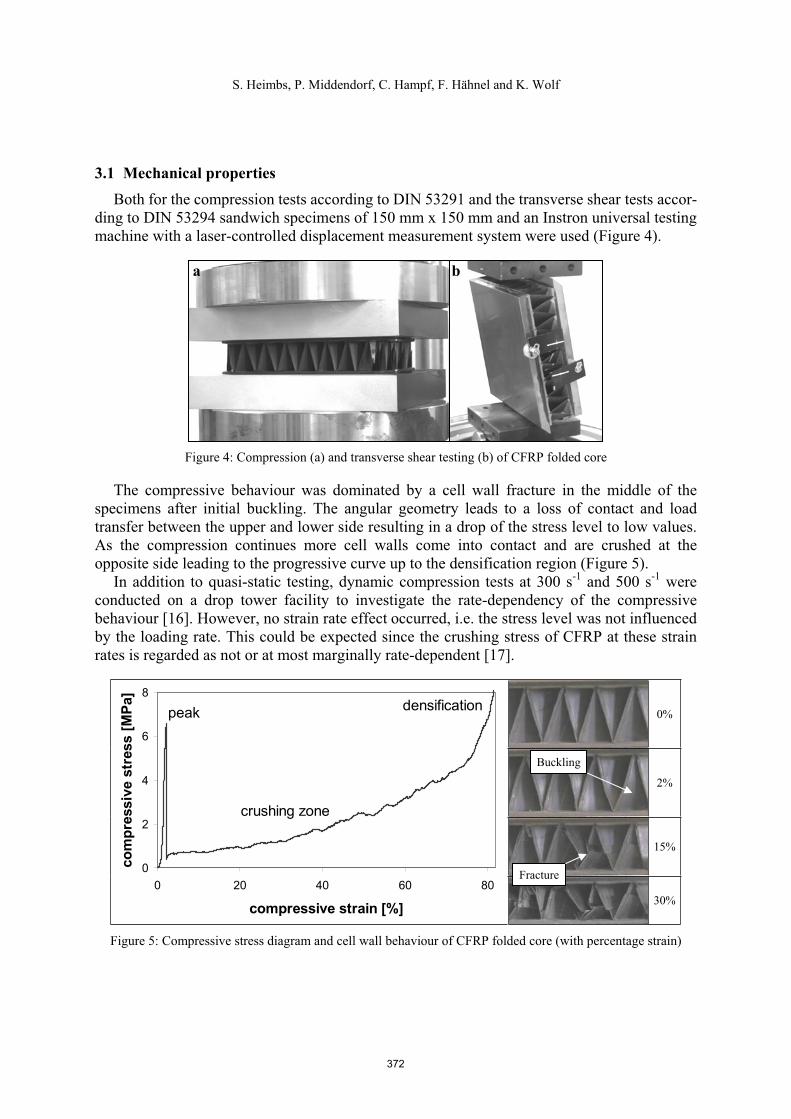
3.1 Mechanical properties Both for the compression tests according to DIN 53291 and the transverse shear tests accor-
ding to DIN 53294 sandwich specimens of 150 mm x 150 mm and an Instron universal testing machine with a laser-controlled displacement measurement system were used (Figure 4).
Figure 4: Compression (a) and transverse shear testing (b) of CFRP folded core
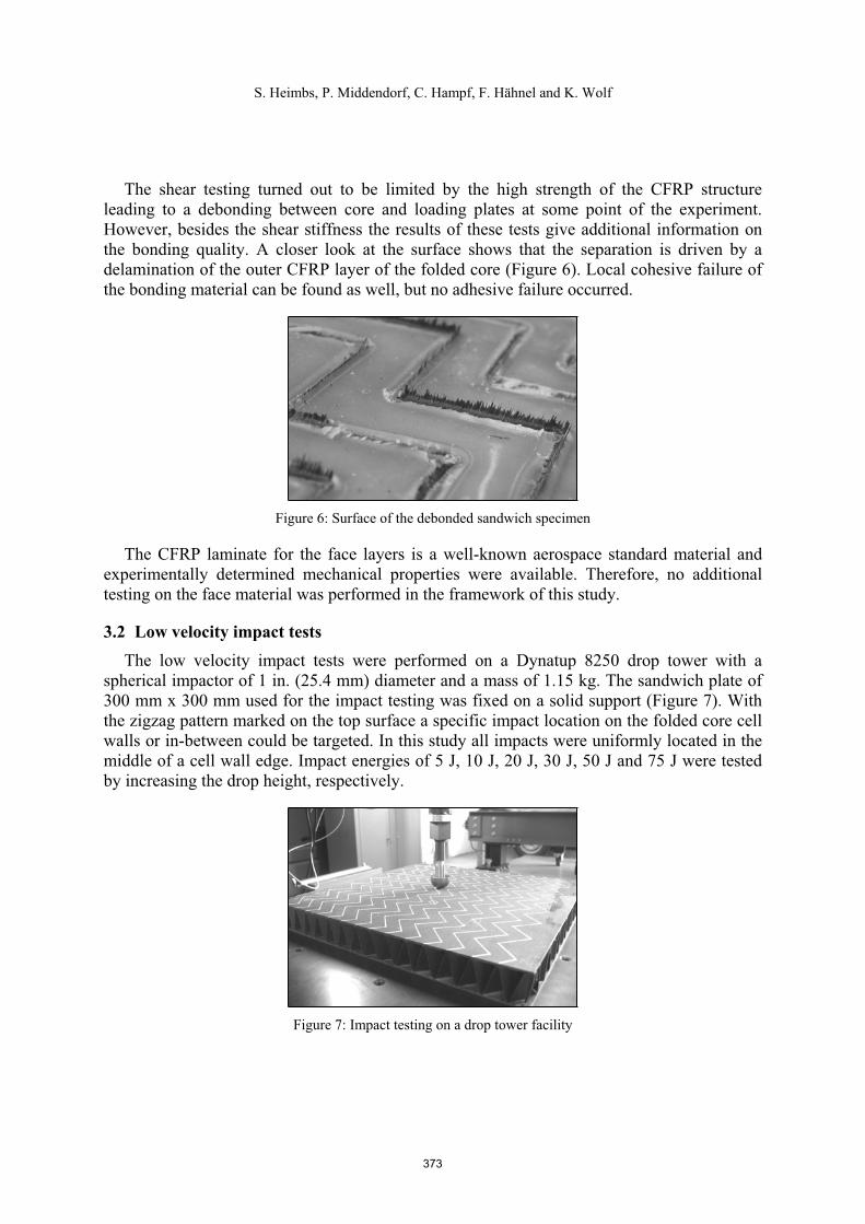
The compressive behaviour was dominated by a cell wall fracture in the middle of the specimens after initial buckling. The angular geometry leads to a loss of contact and load transfer between the upper and lower side resulting in a drop of the stress level to low values. As the compression continues more cell walls come into contact and are crushed at the opposite side leading to the progressive curve up to the densification region (Figure 5).
In addition to quasi-static testing, dynamic compression tests at 300 s-1 and 500 s-1 were conducted on a drop tower facility to investigate the rate-dependency of the compressive behaviour [16]. However, no strain rate effect occurred, i.e. the stress level was not influenced by the loading rate. This could be expected since the crushing stress of CFRP at these strain rates is regarded as not or at most marginally rate-dependent [17].
0%
2%
15%
0
2
4
6
8
0 20 40 60 80
compressive strain [%]
com
pres
sive
str
ess
[MPa
]
crushing zone
densificationpeak
30%
Figure 5: Compressive stress diagram and cell wall behaviour of CFRP folded core (with percentage strain)
a b
Buckling
Fracture
372
S. Heimbs, P. Middendorf, C. Hampf, F. Hähnel and K. Wolf
The shear testing turned out to be limited by the high strength of the CFRP structure leading to a debonding between core and loading plates at some point of the experiment. However, besides the shear stiffness the results of these tests give additional information on the bonding quality. A closer look at the surface shows that the separation is driven by a delamination of the outer CFRP layer of the folded core (Figure 6). Local cohesive failure of the bonding material can be found as well, but no adhesive failure occurred.
Figure 6: Surface of the debonded sandwich specimen
The CFRP laminate for the face layers is a well-known aerospace standard material and experimentally determined mechanical properties were available. Therefore, no additional testing on the face material was performed in the framework of this study.
3.2 Low velocity impact tests The low velocity impact tests were performed on a Dynatup 8250 drop tower with a
spherical impactor of 1 in. (25.4 mm) diameter and a mass of 1.15 kg. The sandwich plate of 300 mm x 300 mm used for the impact testing was fixed on a solid support (Figure 7). With the zigzag pattern marked on the top surface a specific impact location on the folded core cell walls or in-between could be targeted. In this study all impacts were uniformly located in the middle of a cell wall edge. Impact energies of 5 J, 10 J, 20 J, 30 J, 50 J and 75 J were tested by increasing the drop height, respectively.
Figure 7: Impact testing on a drop tower facility
373
S. Heimbs, P. Middendorf, C. Hampf, F. Hähnel and K. Wolf
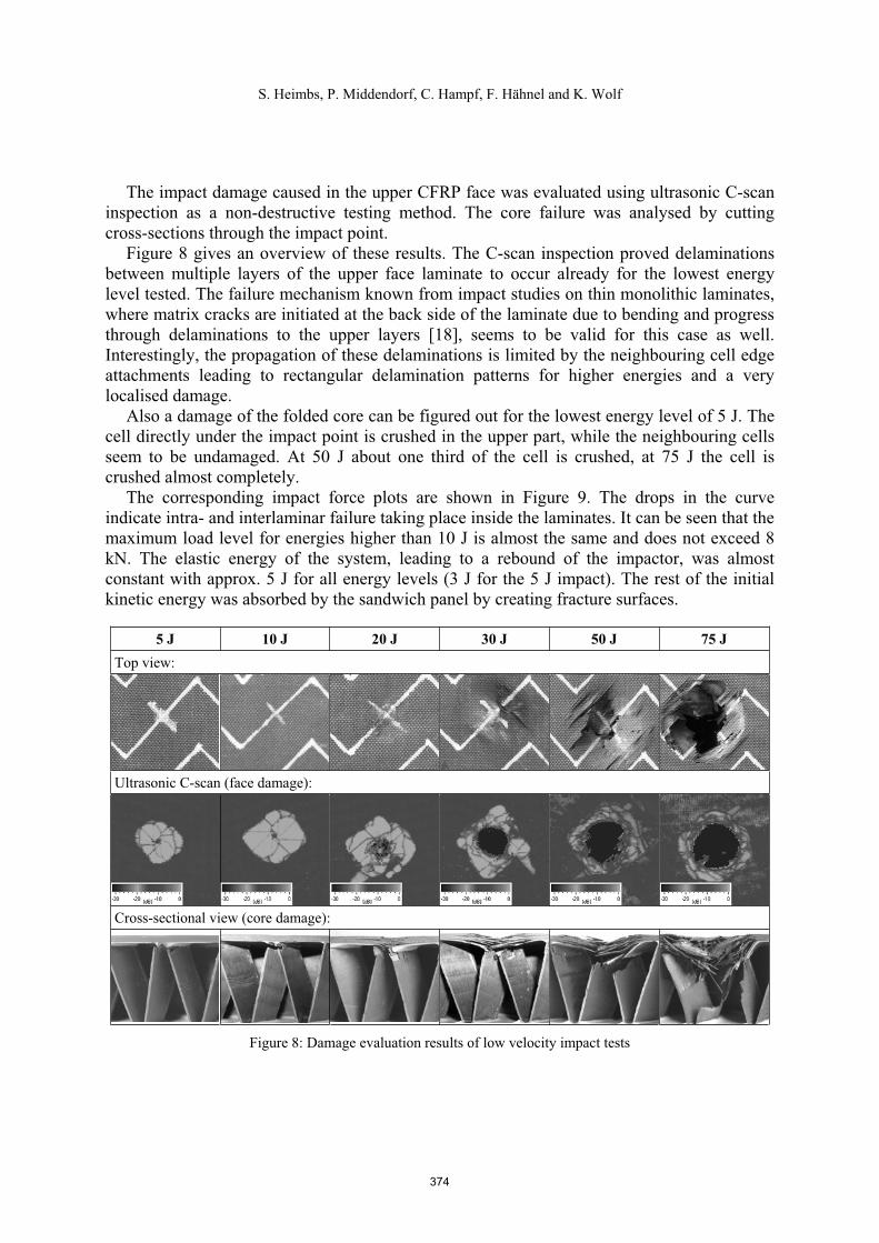
The impact damage caused in the upper CFRP face was evaluated using ultrasonic C-scan inspection as a non-destructive testing method. The core failure was analysed by cutting cross-sections through the impact point.
Figure 8 gives an overview of these results. The C-scan inspection proved delaminations between multiple layers of the upper face laminate to occur already for the lowest energy level tested. The failure mechanism known from impact studies on thin monolithic laminates, where matrix cracks are initiated at the back side of the laminate due to bending and progress through delaminations to the upper layers [18], seems to be valid for this case as well. Interestingly, the propagation of these delaminations is limited by the neighbouring cell edge attachments leading to rectangular delamination patterns for higher energies and a very localised damage.
Also a damage of the folded core can be figured out for the lowest energy level of 5 J. The cell directly under the impact point is crushed in the upper part, while the neighbouring cells seem to be undamaged. At 50 J about one third of the cell is crushed, at 75 J the cell is crushed almost completely.
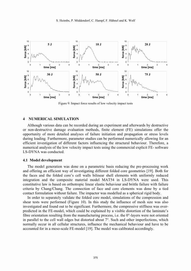
The corresponding impact force plots are shown in Figure 9. The drops in the curve indicate intra- and interlaminar failure taking place inside the laminates. It can be seen that the maximum load level for energies higher than 10 J is almost the same and does not exceed 8 kN. The elastic energy of the system, leading to a rebound of the impactor, was almost constant with approx. 5 J for all energy levels (3 J for the 5 J impact). The rest of the initial kinetic energy was absorbed by the sandwich panel by creating fracture surfaces.
5 J 10 J 20 J 30 J 50 J 75 J Top view:
Ultrasonic C-scan (face damage):
Cross-sectional view (core damage):
Figure 8: Damage evaluation results of low velocity impact tests
374
S. Heimbs, P. Middendorf, C. Hampf, F. Hähnel and K. Wolf
0
2
4
6
8
10
0 1 2 3 4time [ms]
forc
e [k
N]
0
2
4
6
8
10
0 1 2 3 4time [ms]
forc
e [k
N]
0
2
4
6
8
10
0 1 2 3 4time [ms]
forc
e [k
N]
0
2
4
6
8
10
0 1 2 3 4time [ms]
forc
e [k
N]
0
2
4
6
8
10
0 1 2 3 4time [ms]
forc
e [k
N]
0
2
4
6
8
10
0 1 2 3 4time [ms]
forc
e [k
N]
Figure 9: Impact force results of low velocity impact tests
4 NUMERICAL SIMULATION Although various data can be recorded during an experiment and afterwards by destructive
or non-destructive damage evaluation methods, finite element (FE) simulations offer the opportunity of more detailed analyses of failure initiation and propagation or stress levels during loading. Furthermore, parameter studies can be performed numerically allowing for an efficient investigation of different factors influencing the structural behaviour. Therefore, a numerical analysis of the low velocity impact tests using the commercial explicit FE- software LS-DYNA was conducted.
4.1 Model development The model generation was done on a parametric basis reducing the pre-processing work
and offering an efficient way of investigating different folded core geometries [19]. Both for the faces and the folded core’s cell walls bilinear shell elements with uniformly reduced integration and the composite material model MAT54 in LS-DYNA were used. This constitutive law is based on orthotropic linear elastic behaviour and brittle failure with failure criteria by Chang/Chang. The connection of face and core elements was done by a tied contact formulation without failure. The impactor was modelled as a spherical rigid body.
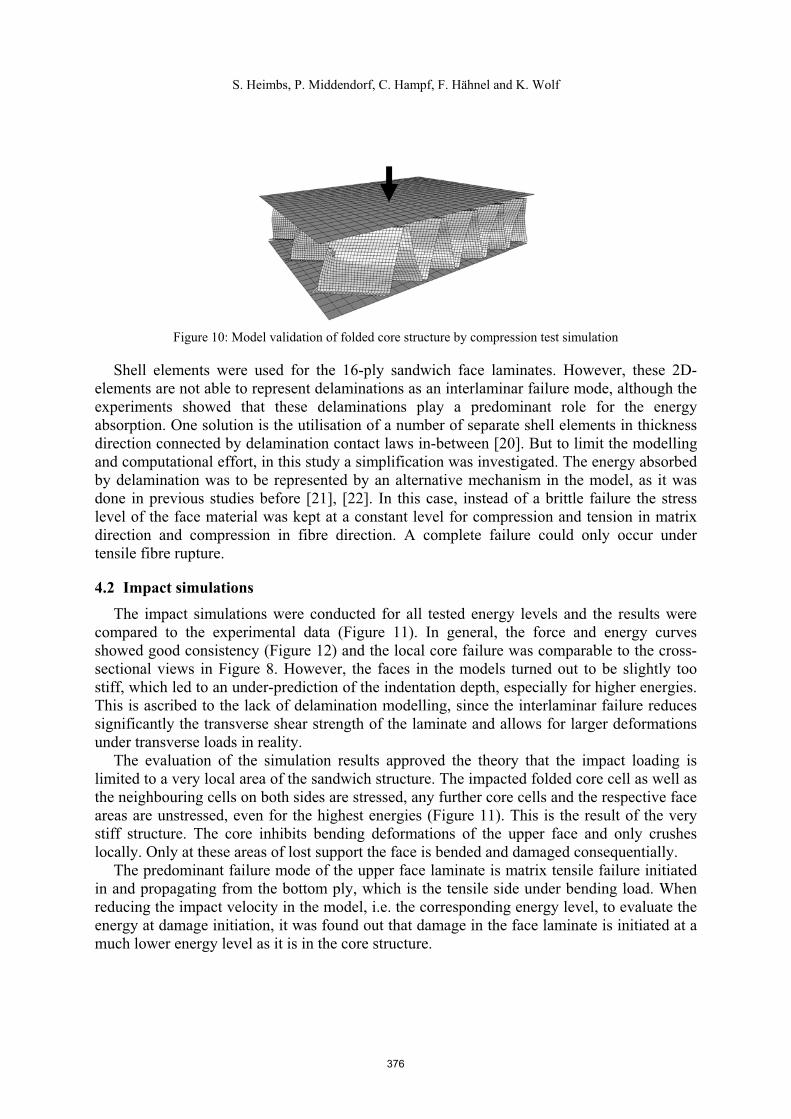
In order to separately validate the folded core model, simulations of the compression and shear tests were performed (Figure 10). In this study the influence of mesh size was also investigated and found out to be significant. Furthermore, the compressive stiffness was over-predicted in the FE-model, which could be explained by a visible distortion of the laminate’s fibre orientation resulting from the manufacturing process, i.e. the 0°-layers were not oriented in parallel to the cell wall edges but distorted about 7°. Such and other imperfections, which normally occur in all cellular structures, influence the mechanical behaviour and have to be accounted for in a meso-scale FE-model [19]. The model was calibrated accordingly.
5 J 10 J 20 J
30 J 50 J 75 J
375
S. Heimbs, P. Middendorf, C. Hampf, F. Hähnel and K. Wolf
Figure 10: Model validation of folded core structure by compression test simulation
Shell elements were used for the 16-ply sandwich face laminates. However, these 2D-elements are not able to represent delaminations as an interlaminar failure mode, although the experiments showed that these delaminations play a predominant role for the energy absorption. One solution is the utilisation of a number of separate shell elements in thickness direction connected by delamination contact laws in-between [20]. But to limit the modelling and computational effort, in this study a simplification was investigated. The energy absorbed by delamination was to be represented by an alternative mechanism in the model, as it was done in previous studies before [21], [22]. In this case, instead of a brittle failure the stress level of the face material was kept at a constant level for compression and tension in matrix direction and compression in fibre direction. A complete failure could only occur undertensile fibre rupture.
4.2 Impact simulations The impact simulations were conducted for all tested energy levels and the results were
compared to the experimental data (Figure 11). In general, the force and energy curves showed good consistency (Figure 12) and the local core failure was comparable to the cross-sectional views in Figure 8. However, the faces in the models turned out to be slightly too stiff, which led to an under-prediction of the indentation depth, especially for higher energies. This is ascribed to the lack of delamination modelling, since the interlaminar failure reduces significantly the transverse shear strength of the laminate and allows for larger deformations under transverse loads in reality.
The evaluation of the simulation results approved the theory that the impact loading is limited to a very local area of the sandwich structure. The impacted folded core cell as well as the neighbouring cells on both sides are stressed, any further core cells and the respective face areas are unstressed, even for the highest energies (Figure 11). This is the result of the very stiff structure. The core inhibits bending deformations of the upper face and only crushes locally. Only at these areas of lost support the face is bended and damaged consequentially.
The predominant failure mode of the upper face laminate is matrix tensile failure initiated in and propagating from the bottom ply, which is the tensile side under bending load. When reducing the impact velocity in the model, i.e. the corresponding energy level, to evaluate the energy at damage initiation, it was found out that damage in the face laminate is initiated at a much lower energy level as it is in the core structure.
376

S. Heimbs, P. Middendorf, C. Hampf, F. Hähnel and K. Wolf
Figure 11: Impact simulation (left) and cross-sectional view of effective stresses (right) (here: 30 J impact, moment of maximum indentation)
0
10
20
30
0 0,5 1 1,5 2 2,5 3 3,5 4
time [ms]
ener
gy [J
]
0
4
8
12
forc
e [k
N]
Energy: ExperimentEnergy: SimulationForce: ExperimentForce: Simulation
Figure 12: Force and energy plots of experiment and simulation (here: 30 J impact)
4.3 Parameter studies The simulation model was used - in consideration of its known simplifications - for several
parameter studies to investigate e.g. the influence of the clamping conditions, the influence of the impact location and the influence of the folded core geometry.
When the sandwich plate is supported only at the edges instead of the whole surface of the lower face, a larger bending deformation of the complete structure under impact load is permitted. On the one hand, the sum of elastic deformation of the structure is higher, and therefore the transformation of the kinetic energy into internal fracture is lower. On the other hand, in this case not only the upper but also the lower face laminate is damaged.
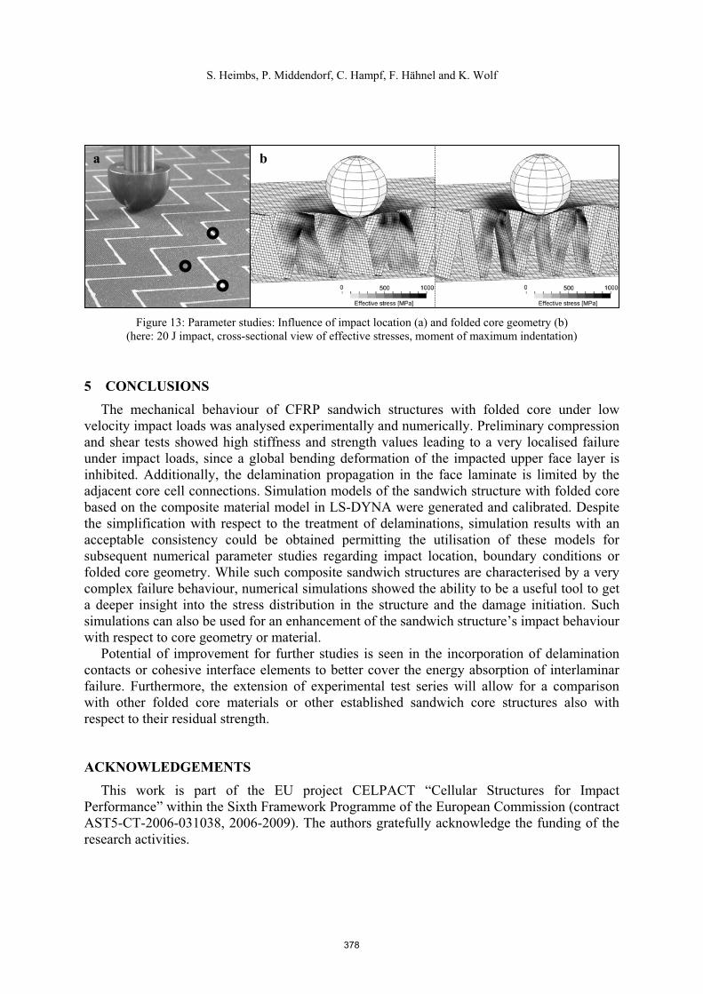
The impact location only has a minor influence on the simulation results. Besides impacting the middle of the folded core cell edges as before, the corner of two cell edges as well as the space between two cell walls were impacted (Figure 13a). In the latter case the indentation depth was marginally higher because less support of the core against local bending is present.
In the third study the folded core geometry was modified in the model by changing the zigzag measures while maintaining the same global density of the core structure. The cell space between two cells was lower for the modified geometry (Figure 13b). Therefore, the stressed area was even more localised than in the former case.
377
S. Heimbs, P. Middendorf, C. Hampf, F. Hähnel and K. Wolf
Figure 13: Parameter studies: Influence of impact location (a) and folded core geometry (b) (here: 20 J impact, cross-sectional view of effective stresses, moment of maximum indentation)
5 CONCLUSIONS The mechanical behaviour of CFRP sandwich structures with folded core under low
velocity impact loads was analysed experimentally and numerically. Preliminary compression and shear tests showed high stiffness and strength values leading to a very localised failure under impact loads, since a global bending deformation of the impacted upper face layer is inhibited. Additionally, the delamination propagation in the face laminate is limited by the adjacent core cell connections. Simulation models of the sandwich structure with folded core based on the composite material model in LS-DYNA were generated and calibrated. Despite the simplification with respect to the treatment of delaminations, simulation results with an acceptable consistency could be obtained permitting the utilisation of these models for subsequent numerical parameter studies regarding impact location, boundary conditions or folded core geometry. While such composite sandwich structures are characterised by a very complex failure behaviour, numerical simulations showed the ability to be a useful tool to get a deeper insight into the stress distribution in the structure and the damage initiation. Such simulations can also be used for an enhancement of the sandwich structure’s impact behaviour with respect to core geometry or material.
Potential of improvement for further studies is seen in the incorporation of delamination contacts or cohesive interface elements to better cover the energy absorption of interlaminar failure. Furthermore, the extension of experimental test series will allow for a comparison with other folded core materials or other established sandwich core structures also with respect to their residual strength.
ACKNOWLEDGEMENTS This work is part of the EU project CELPACT “Cellular Structures for Impact
Performance” within the Sixth Framework Programme of the European Commission (contract AST5-CT-2006-031038, 2006-2009). The authors gratefully acknowledge the funding of the research activities.
a b
378
S. Heimbs, P. Middendorf, C. Hampf, F. Hähnel and K. Wolf
REFERENCES [1] A.S. Herrmann, P.C. Zahlen and I. Zuardy, “Sandwich structures technology in
commercial aviation”, In: O.T. Thomsen et al. (eds.), Sandwich Structures 7: Advancing with Sandwich Structures and Materials, Proceedings of the 7th International Conference on Sandwich Structures, Aalborg, Danmark, 29-31 August 2005, pp. 13-26, (2005).
[2] R. Kehrle and M. Kolax, “Sandwich structures for advanced next generation fuselage concepts”, SAMPE Europe Technical Conference, Toulouse, France, 13-14 September 2006, pp. 11-16 (2006).
[3] M. Kolax, “Concept and technology: advanced composite fuselage structures”, JECComposites, 10(6/7), 31-33 (2004).
[4] B.Y. Kolesnikov and L. Herbeck, “Carbon fiber composite airplane fuselage: concept and analysis”, ILA International Conference, Berlin, Germany, 11–12 May 2004.
[5] M.J.L. van Tooren, Sandwich Fuselage Design, Delft University Press (1998). [6] J. Tomblin, T. Lacy, B. Smith, S. Hooper, A. Vizzini and S. Lee, “Review of damage
tolerance for composite sandwich airframe structures”, Report DOT/FAA/AR-99/49, U.S. Department of Transportation, Washington D.C., USA (1999).
[7] R. Abbott, “Damage tolerance evaluation of composite honeycomb structures”, 43rd Int. SAMPE Symposium, Anaheim, CA, USA, 31 May-4 June 1998, pp. 376-386 (1998).
[8] R. Wong, “Sandwich construction in the starship”, 37th International SAMPE Symposium and Exhibition, Anaheim, CA, USA, 9-12 March 1992, pp. 186-197 (1992).
[9] E.F. Schiantarelli, “Core composites in Swissair aircraft”, 1st Core Conference, Zurich, Switzerland, 20-21 October 1988.
[10] V. Vavilov, A. Klimov, D. Nesteruk, V. Shiryaev, “Detecting water in aviation honeycomb structures by using transient IR thermographic NDT”, Proceedings of the SPIE - The International Society for Optical Engineering, Vol. 5073, ThermoSense XXV Silver Anniversary Meeting, Orlando, FL, USA, 22-24 April 2003, pp. 345-355 (2003).
[11] D. Hachenberg, C. Mudra and M. Nguyen, “Folded structures - an alternative core material for future sandwich concepts”, DGLR Conference, Munich, Germany 17-21 November 2003, pp. 165-174 (2003).
[12] K. Drechsler and R. Kehrle, “Manufacturing of folded core-structures for technical applications“, 25th International SAMPE Europe Conference, Paris, France, 30 March-1 April 2004, pp. 508-513 (2004).
[13] I.M. Zakirov and K.A. Alexeev, “New folded structures for sandwich panels“, 51st International SAMPE Symposium, Long Beach, CA, USA, 30 April-4 May 2006.
[14] E.A. Elsayed and B.B. Basily, “A continuous folding process for sheet materials”, Int. J. Mater. Prod. Technol., 21(1/2/3), 217-238 (2004).
[15] V.I. Khaliulin and I.V. Dvoyeglazov, “On technological problems of fabrication of relief designs by isometric transformations of thin sheet”, Trans. Nanjing Univ. Aeronaut. Astronaut., 18(1), 11-16 (2001).
[16] S. Heimbs, Sandwichstrukturen mit Wabenkern: Experimentelle und numerische Untersuchung des Schädigungsverhaltens unter statischer und kurzzeitdynamischer Belastung, Ph.D. thesis, Kaiserslautern University of Technology, Germany (2008).
379

S. Heimbs, P. Middendorf, C. Hampf, F. Hähnel and K. Wolf
[17] J.F. Newill and J.R. Vinson, “Some high strain rate effects on composite materials”, 9thInternational Conference on Composite Materials, ICCM-9, Madrid, Spain, 12-16 July 1993, Part 5, pp. 269-277 (1993).
[18] S. Abrate, Impact on Composite Structures, Cambridge University Press (1998). [19] S. Heimbs, P. Middendorf, S. Kilchert, A.F. Johnson and M. Maier, “Numerical
simulation of advanced folded core materials for structural sandwich applications”, CEAS European Air and Space Conference, Berlin, Germany, 10-13 Sept. 2007, pp. 2889-2896 (2007).
[20] R. Borg, Simulation of Delamination Initiation and Growth in Fiber Composite Lami-nates, Ph.D. thesis, Linköping University, Sweden (2002).
[21] K.M. Mikkor, R.S. Thomson, I. Herszberg, T. Weller and A.P. Mouritz, “Finite element modelling of impact on preloaded composite panels”, Compos. Struct., 75, 501-513 (2006).
[22] M.Q. Nguyen, S.S Jacombs, R.S. Thomson, D. Hachenberg and M.L. Scott, “Simulation of impact on sandwich structures”, Compos. Struct., 67, 217-227 (2005).
380


![No free lunch with the sandwich [sandwich estimator]](https://img.dokumen.tips/doc/110x75/6348f90b7442d262850f4be4/no-free-lunch-with-the-sandwich-sandwich-estimator.jpg)


